Critical Release Notice - DMS-100.net
166
Critical Release Notice Publication number: 297-5001-549 Publication release: Standard 07.04 The content of this customer NTP supports the SN06 (DMS) and ISN06 (TDM) software releases. Bookmarks used in this NTP highlight the changes between the baseline NTP and the current release. The bookmarks provided are color-coded to identify release-specific content changes. NTP volumes that do not contain bookmarks indicate that the baseline NTP remains unchanged and is valid for the current release. Bookmark Color Legend Black: Applies to new or modified content for the baseline NTP that is valid through the current release. Red: Applies to new or modified content for NA017/ISN04 (TDM) that is valid through the current release. Blue: Applies to new or modified content for NA018 (SN05 DMS)/ISN05 (TDM) that is valid through the current release. Green: Applies to new or modified content for SN06 (DMS)/ISN06 (TDM) that is valid through the current release. Attention! Adobe Acrobat Reader 5.0 is required to view bookmarks in color.
-
Upload
khangminh22 -
Category
Documents
-
view
4 -
download
0
Transcript of Critical Release Notice - DMS-100.net

Critical Release Notice
Publication number: 297-5001-549 Publication release: Standard 07.04
The content of this customer NTP supports the SN06 (DMS) and ISN06 (TDM) software releases.
Bookmarks used in this NTP highlight the changes between the baseline NTP and the current release. The bookmarks provided are color-coded to identify release-specific content changes. NTP volumes that do not contain bookmarks indicate that the baseline NTP remains unchanged and is valid for the current release.
Bookmark Color Legend Black: Applies to new or modified content for the baseline NTP that is valid through the current release. Red: Applies to new or modified content for NA017/ISN04 (TDM) that is valid through the current release. Blue: Applies to new or modified content for NA018 (SN05 DMS)/ISN05 (TDM) that is valid through the current release. Green: Applies to new or modified content for SN06 (DMS)/ISN06 (TDM) that is valid through the current release.
Attention! Adobe Acrobat Reader 5.0 is required to view bookmarks in color.

Publication History March 2004
Standard release 07.04 for software release SN06 (DMS) and ISN06 (TDM). Change of phone number from 1-800-684-2273 to 1-877-662-5669, Option 4 + 1.

BASE10 Standard 07.03 April 1999
297-5001-549
DMS-100 Family
DMS SuperNode and DMS SuperNode SEMessage SwitchMaintenance Guide


DMS-100 Family DMS SuperNode and DMS SuperNode SE Message Switch Maintenance Guide BASE10
DMS-100 Family
DMS SuperNode and DMS SuperNode SE MessageSwitchMaintenance Guide
1993, 1994, 1995, 1996, 1997, 1998, 1999 Northern TelecomAll rights reserved
Printed in the United States of America
NORTHERN TELECOM CONFIDENTIAL: The information contained in this document is the property of NorthernTelecom. Except as specifically authorized in writing by Northern Telecom, the holder of this document shall keep theinformation contained herein confidential and shall protect same in whole or in part from disclosure and dissemination to thirdparties and use same for evaluation, operation, and maintenance purposes only.
Information is subject to change without notice. Northern Telecom reserves the right to make changes in design or componentsas progress in engineering and manufacturing may warrant.This equipment has been tested and found to comply with the limits for a Class A digital device pursuant to Part 15 of the FCCRules, and the radio interference regulations of the Canadian Department of Communications. These limits are designed toprovide reasonable protection against harmful interference when the equipment is operated in a commercial environment. Thisequipment generates, uses and can radiate radio frequency energy and, if not installed and used in accordance with theinstruction manual, may cause harmful interference to radio communications. Operation of this equipment in a residential areais likely to cause harmful interference in which case the user will be required to correct the interference at the user’s ownexpense Allowing this equipment to be operated in such a manner as to not provide for proper answer supervision is a viola-tion of Part 68 of FCC Rules, Docket No. 89-114, 55FR46066 The SL-100 system is certified by the Canadian StandardsAssociation (CSA) with the Nationally Recognized Testing Laboratory (NRTL). This equipment is capable of providing userswith access to interstate providers of operator services through the use of equal access codes. Modifications by aggregators toalter these capabilities is a violation of the Telephone Operator Consumer Service Improvement Act of 1990 and Part 68 of theFCC Rules
DMS, DMS SuperNode, MAP, and NT are trademarks of Northern Telecom.
Publication number: 297-5001-549Product release: BASE10Document release: Standard 07.03Date: April 1999


DMS-100 Family DMS SuperNode and DMS SuperNode SE Message Switch Maintenance Guide BASE10
iii
Publication historyApril 1999
BASE10 Standard 07.03
Minor technical changes requested by NTJI.
May 1998BASE10 Standard 07.02
• Editing changes
• Document migrated into new template
February 1998BASE10 Standard 07.01
• Added listed and unlisted menu command information to Chapter 5
• Added unlisted menu commands DPSYNCLK and SYNCLK toChapter 5 (feature AR1389)
August 1997BASE07 Standard 06.04
• Editing changes
September 1996BASE07 Standard 06.02
• Removed BCSMON information and inserted DMSMON information.(chapter 7)
August 1996BASE07 Standard 06.01
• Revised the ”IOAU112 and MS104 log descriptions” (Chapter 8) toinclude information associated with the Critical REx test disable feature.

iv Publication history
297-5001-549 Standard 07.03 April 1999
• Revised the ”RExByp alarm clearing procedure” (Chapter 9) to includeinformation associated with the Critical REx test disable feature.
April 1995CSP04 Standard 05.01
Added feature information to the following chapters:
• “Cards and paddle boards”
• “User interface and commands”
January 1995CSP03 Preliminary 04.01
Added feature information to the following chapters:
• “Preventive maintenance strategies”
• “Logs”
• “Troubleshooting charts”
• “Advanced troublshooting procedures”
March 1994CSP02 Preliminary 03.01
CSP02 is a temporary name that identifies a preliminary release ofpost-BCS36 NTPs.
Added feature information to the following chapters:
• “Overview”
• “Cards”
• “Troubleshooting charts”
• “Advanced troubleshooting procedures”
— “Troubleshooting an MS clock major alarm” section
December 1993BCS36 Standard 02.02
Completed the sections that are not complete for the Gate two release.Added the following sections based on designer review:
• “MS104 logs”
• “MSL100 logs”

Publication history v
DMS-100 Family DMS SuperNode and DMS SuperNode SE Message Switch Maintenance Guide BASE10
• “Troubleshooting an MaxPt alarm”
• “Troubleshooting an MSpair alarm”
• “Troubleshooting T-bus routing alarms”
• “Troubleshooting resource info logs”
• “Troubleshooting MSP logs”
September 1993BCS36 Preliminary 02.01
Added the following chapters:
• “Trouble isolation”
• “Troubleshooting chart”
• “Advanced Troubleshooting procedures”
Added information to all other chapters based on designer review andfeature updates.
March 1993BCS35 Preliminary 01.01 first release of document


DMS-100 Family DMS SuperNode and DMS SuperNode SE Message Switch Maintenance Guide BASE10
vii
ContentsAbout this document xiWhen to use this document xiReferences in this document xi
Overview 1-1DMS SuperNode and SuperNode SE system architecture 1-1DMS SuperNode and SuperNode SE cabinet layouts 1-4DMS SuperNode and SuperNode SE message switch architecture 1-6
CPU and memory 1-6Mapper 1-7Port interfaces 1-8Clock 1-8Power 1-10
DMS SuperNode and SuperNode SE message switch configuration 1-10
Preventive maintenance strategies 2-1Routine maintenance procedures 2-1Automatic maintenance 2-1
Routine exercise testing 2-2Software audits 2-4Hardware audits 2-7Indications of automatic test results 2-8
Logs 3-1DMS SuperNode and SuperNode SE MS-related logs 3-1
Input/output audit logs 3-1Message switch logs 3-2Sync logs 3-8
Operational measurements 4-1DMS SuperNode and SuperNode SE MS-related OMs 4-1
MS group 4-1MSCHAIN group 4-2MSCHNLK group 4-3
User interface and commands 5-1MS level 5-2
Example of an MS level MAP display 5-3MS level listed menu commands 5-3MS level unlisted menu commands 5-4

viii Contents
297-5001-549 Standard 07.03 April 1999
MS level system state indicators 5-4Shelf level 5-5
Example of a Shelf level MAP display 5-6Shelf level listed menu commands 5-6Shelf level unlisted menu commands 5-7SHELF level card state indicators 5-8
Card level 5-9Example of a system card MAP display 5-9Card level listed menu commands 5-9System card field indicators 5-9Example of an interface card MAP display 5-10Interface card status field indicators 5-10
Chain level 5-11Example of a Chain level MAP display 5-12Chain level listed menu commands 5-12Chain level state indicators 5-13
Clock level 5-14Example of a Clock level MAP display 5-14Clock level listed menu commands 5-15Clock level unlisted menu commands 5-15Clock level state indicators 5-16
Cards and paddle boards 6-1SN and SNSE-MS system cards and paddle boards 6-1
NT9X13 processor card 6-3NT9X14 memory card 6-4NT9X15 mapper card 6-4NT9X26 reset terminal interface paddle board 6-5NT9X30 +5V power converter card 6-5NT9X31 –5V power converter card 6-6NT9X32 bus-load paddle board 6-6NT9X49 P-bus terminator card 6-7NT9X52 MSP T-bus access card 6-7NT9X53 system clock card 6-8NT9X54 clock interface paddle board 6-9
SN and SNSE-MS interface cards and paddle boards 6-9NT9X17 port card 6-10NT9X19 filler card and paddle board 6-12NT9X20 DS512 interface paddle board 6-13NT9X23 4-port DS30 paddle board 6-13NT9X25 port expander or terminator paddle board 6-14NT9X62 SR512 paddle board 6-14NT9X69 16-link DS30 interface paddle board 6-15NT9X73 rate adapter card 6-15
Trouble isolation tools 7-1Diagnostic tools 7-1
Alarms 7-1DMSMON 7-3Log reports 7-3AMREPORT 7-4
Contents ix
DMS-100 Family DMS SuperNode and DMS SuperNode SE Message Switch Maintenance Guide BASE10
The OM log alarm cross-reference charts 7-4Operational measurements 7-5Sherlock 7-5Switch Performance Monitoring System 7-5TRAPINFO 7-6
Troubleshooting charts 8-1MS alarm and trouble condition procedures 8-1OM-log-alarm cross reference charts 8-6
Advanced troubleshooting procedures 9-1Task list 9-1Changing MS timing links 9-2MS104 logs 9-4SPAN alarm 9-7Troubleshooting a MaxPt alarm 9-8Troubleshooting a RExByp alarm 9-9Troubleshooting a RExFlt alarm 9-11Troubleshooting a MSpair alarm 9-13Troubleshooting an MS clock major alarm 9-14Troubleshooting MS resource info logs 9-45Troubleshooting T-bus routing alarms 9-47
List of terms 10-1


DMS-100 Family DMS SuperNode and DMS SuperNode SE Message Switch Maintenance Guide BASE10
xi
About this documentThis document provides advanced maintenance and troubleshootinginformation for the DMS SuperNode and DMS SuperNode SE messageswitch. The audience for this document is advanced maintenance personnel.
When to use this documentNumbers indicate the version and issue of the document. An example is01.01.
The first two digits indicate the version. The version number increases eachtime the user updates the document to support a new software release. Forexample, the first release of a document is 01.01. In the following softwarerelease cycle, the first release of the same document is 02.01.
The second two digits indicate the issue. The issue number increases eachtime the user revises the document and releases the document in the samesoftware release cycle. For example, the second release of a document inthe same software release cycle is 01.02.
This document is written for all DMS-100 Family offices. More than oneversion of this document can exist. Determine if you have the currentversion of this document and how you must organize documentation foryour product. Check the release information in Product DocumentationDirectory, 297-8991-001 to determine this information.
References in this documentThis document refers to the following documents:
• Alarm and Performance Monitoring Procedures
• Card Replacement Procedures
• Log Report Reference Manual
• Operational Measurements Reference Manual
• Routine Maintenance Procedures
• Translations Guide
• DMS-100 Family Commands Reference Manual, 297-1001-822


DMS-100 Family DMS SuperNode and DMS SuperNode SE Message Switch Maintenance Guide BASE10
1-1
OverviewThis chapter provides an summary of the DMS SuperNode (SN) and theDMS SuperNode SE (SNSE) switches and the architecture of the messageswitch (MS).
This chapter contains the following sections:
• “DMS SuperNode and SuperNode SE system architecture” on page 1-1describes SN and SNSE system architecture.
• “DMS SuperNode and SuperNode SE cabinet layouts” on page 1-4illustrates the SN and SNSE cabinet layouts.
• “DMS SuperNode and SuperNode SE message switch architecture” onpage 1-6 describes SN and SNSE MS architecture.
• “DMS SuperNode and SuperNode SE message switch configurations”on page 1-10 describes SN and SNSE MS configurations.
DMS SuperNode and SuperNode SE system architectureThe SN and SNSE systems are shown in figures 1-1 and 1-2. The SN andSNSE systems share the following common components:
• DMS-core
• DMS-bus
• DMS-link
The DMS-core provides computing and data storage resources. TheDMS-core contains a duplexed computing module (CM) and two systemload modules (SLM).
The DMS-bus processes and distributes messages to nodes in the SN andSNSE switches. The DMS-bus consists of two load-sharing MSs.
The DMS-link allows the DMS-core and DMS-bus to communicate witheach other and with other nodes in the SN and SNSE switches.

1-2 Overview
297-5001-549 Standard 07.03 April 1999
The SuperNode switch can be configured with a 64K or a 128K enhancednetwork (ENET). The ENET provides voice and data signal switching fornodes in the SuperNode SE switch and provides message routes to the MS.
The SuperNode SE switch can be configured with a 16K or a 32K enhancednetwork (ENET) and CCS7 link interface units (LIU7). The LIU7 providesCCS7 message processing.
Figure 1-1SN system architecture
Lines Trunks
Otherperipheralmodules
Datalinks
SLM
Networkmodule(optional)
Peripheralmodules
DMS-core
DMS-bus
IOCsLPP(optional)
CCS7 links I/Odevices
Message switch
Computing module

Overview 1-3
DMS-100 Family DMS SuperNode and DMS SuperNode SE Message Switch Maintenance Guide BASE10
Figure 1-2SNSE system architecture
Lines Trunks
Otherperipherals
Datalinks
SLM
16K ENET(optional)
Peripheralmodules
DMS-core
DMS-bus
IOCsLIU7s(optional)
CCS7 links I/Odevices
Message switch
Computing module

1-4 Overview
297-5001-549 Standard 07.03 April 1999
DMS SuperNode and SuperNode SE cabinet layoutsIn an SN cabinet, two shelves contain the MS. In an SNSE cabinet, a singleshelf contains the MS. The SN cabinet is known as the dual plane combinedcore (DPCC) cabinet. The SNSE cabinet is called the SuperNode combinedcore (SCC) cabinet. Figures 1-3 and 1-4 illustrate SN and SNSE cabinetlayouts.
Figure 1-3SN DPCC cabinet layout
Framesupervisory panel
Corecooling unit
SLM 0
MS 0
MS 1
SLM 1
CPU 0 CPU 1
DMS-bus
DMS-core
Computingmodule shelf

Overview 1-5
DMS-100 Family DMS SuperNode and DMS SuperNode SE Message Switch Maintenance Guide BASE10
Figure 1-4SNSE SCC cabinet layout
Framesupervisory panel
Corecooling unit
MS 0
LIS(optional–up to 12 LIUs)
16KENET 0
16KENET 1
DMS-bus
DMS-core
MS 1
CPU 0 / 1
LIU7s
SLM 0SLM 1

1-6 Overview
297-5001-549 Standard 07.03 April 1999
DMS SuperNode and SuperNode SE message switch architectureThe MS architecture is the same in the SN and SNSE switches. Figure 1-5shows the MS. The MS contains the following subsystems:
• CPU and memory
• mapper
• port interfaces
• clock
• power
Figure 1-5SN and SNSE MS subsystems
CPUandmemory
T-busaccess
Clock Mapper Portinterfacecards
P-bus (maintenance and configuration)
Resetterminalinterface
T-bus (messaging activity)
Copperlinks
Fiberlinks
Portinterfacecards
CPU and memoryThe SN and SNSE MS processor card (NT9X13) processes softwareinstructions. The CPU uses the asynchronous processor bus (P-bus) tocommunicate with other MS components for maintenance and controlpurposes. The CPU uses the transaction bus (T-bus) for port-to-portmessaging.

Overview 1-7
DMS-100 Family DMS SuperNode and DMS SuperNode SE Message Switch Maintenance Guide BASE10
The CPU uses the P-bus to perform the following functions:
• update mapper tables
• interact with the card maintenance units (CMU) on each port card forinitialization, configuration, and maintenance
• interact with the CMU on the clock card to check system clockparameters
• read element-ID proms for inventory
The T-bus allows messages to access all ports in the MS.
The SN and SNSE MS memory provide two types of memory. The twotypes of memory are data store and program store. Data store memoryprovides temporary storage for data. Program store memory providesstorage for the MS software. The SN and SNSE MS memory is normallyconfigured on the processor card.
If the SN switch uses the NT9X13DD card, the switch configuration canalso include an optional NT9X14 memory card. The processor or thecollection of the processor and optional memory card is called the messageswitch processor (MSP). The MSP communicates with MS ports throughthe T-bus access card (9X52).
The NT9X26 card provides the reset terminal interface (RTIF) to the MSP.The NT9X26 card allows the MSP to receive reset signals directly from theCM.
The bus termination unit consists of two cards. The two cards are theNT9X52 and the NT9X49. The NT9X52 T-bus access card provides T-busaccess and termination. The NT9X49 card provides P-bus termination. OnSN switches, the cards are at opposite ends of the MS shelves. On SNSEswitches, the NT9X52 cards in the two center slots of the MS shelf, and theNT9X49 cards are in the outer slots of the MS shelf.
MapperThe SN and SNSE MS mapper (NT9X15) is a specialized memory card thatconverts logical port addresses to port addresses. The NT9X15 convertslogical port addresses to port addresses for messages on the T-bus.
In real time, the mapper card looks at each message as the message is put onto the T-bus. The mapper card holds the T-bus cycle. The mapper cardstarts to translate the logical address to a physical address.
The mapper card takes the logical address from the message and translatesthe address into a card and port address. The mapper card uses informationin the primary logical address table to perform the translation. If the logical
1-8 Overview
297-5001-549 Standard 07.03 April 1999
route is available, and the card and the card’s port are in service, the systemallocates the route to the message. If the logical route is in use, or the cardand port are not in service, the mapper chooses another route. The mapperchooses another route from the secondary logical address table. If thesecond logical route is in use or the card and port are not in service, the MSsaves the message. The MS produces a log message that indicates this fault.The mapper also detects attempts to route messages before the systemobtains routing information.
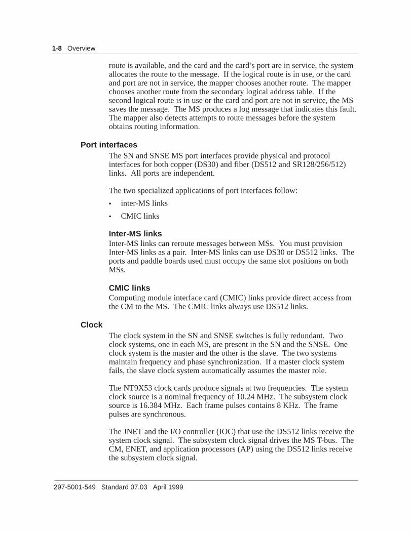
Port interfacesThe SN and SNSE MS port interfaces provide physical and protocolinterfaces for both copper (DS30) and fiber (DS512 and SR128/256/512)links. All ports are independent.
The two specialized applications of port interfaces follow:
• inter-MS links
• CMIC links
Inter-MS linksInter-MS links can reroute messages between MSs. You must provisionInter-MS links as a pair. Inter-MS links can use DS30 or DS512 links. Theports and paddle boards used must occupy the same slot positions on bothMSs.
CMIC links Computing module interface card (CMIC) links provide direct access fromthe CM to the MS. The CMIC links always use DS512 links.
ClockThe clock system in the SN and SNSE switches is fully redundant. Twoclock systems, one in each MS, are present in the SN and the SNSE. Oneclock system is the master and the other is the slave. The two systemsmaintain frequency and phase synchronization. If a master clock systemfails, the slave clock system automatically assumes the master role.
The NT9X53 clock cards produce signals at two frequencies. The systemclock source is a nominal frequency of 10.24 MHz. The subsystem clocksource is 16.384 MHz. Each frame pulses contains 8 KHz. The framepulses are synchronous.
The JNET and the I/O controller (IOC) that use the DS512 links receive thesystem clock signal. The subsystem clock signal drives the MS T-bus. TheCM, ENET, and application processors (AP) using the DS512 links receivethe subsystem clock signal.

Overview 1-9
DMS-100 Family DMS SuperNode and DMS SuperNode SE Message Switch Maintenance Guide BASE10
The NT9X54 provides the electrical interfaces for different clock signals.The types of clock signals include the following:
• analog external reference signals from atomic or loran-C clocks
• composite clock signals from a timing signal generator (TSG)
• DMS remote clock (Stratum 2 and 2.5)
• mate frame pulse
Stratum levelsA stratum level is a rating given to an oscillator to indicate the holdoveraccuracy of the oscillator. The highest level of accuracy is Stratum 1. Themost accurate oscillators available, like atomic and loran, can receive thisrating.
The following table shows the maximum acceptable drift for each stratumlevel. The numbers indicate how much of a complete cycle the oscillatordrifts on every cycle. When the numbers are inverted, the numbers indicatethe cycles required before the oscillator is out of synchronization by one fullcycle.
Table 1-1Drift accuracy for stratum ratings
Stratum 1 Stratum 2 Stratum 2.5 Stratum 3
Amount ofdrift (percycle)
1 x 10 –11 1.6 x 10 –8 6.2 x 10 –8 4.6 x 10 –5

1-10 Overview
297-5001-549 Standard 07.03 April 1999
Synchronization configurations You can set up the MS clock systems in any of the following configurations.
• Master internal In a master internal office, the master clock is freerunning. The master clock is not synchronized to any external reference.Only signaling transfer points use this configuration.
• Master external In a master external office, the master clocksynchronizes to an external reference clock by a phase lock loop (PLL).The system performs phase comparison between the master clock andthe reference on the NT9X53 card. In this configuration, the clocksource for the network is normally a Stratum 1.
• Slave In a slave office, the master clock synchronizes to an incoming T1carrier (DS-1). The system performs phase comparison between themaster clock and the reference at the peripheral module (PM).
Remote system clock functionThis function improves the accuracy of the system clock. A remoteoscillator shelf contains a Stratum 2 or 2.5 level oscillator on an NT3X16card. The remote clock is not packaged in the SN or SNSE cabinet. TheDMS continues to consider the remote clock internal.
With the NT9X53AA and AB clock cards, the system synchronizes thesubsystem oscillator directly to the remote oscillator. If the link between theremote shelf and the NT9X53 breaks, the NT9X53 card loses the systemoscillator.
With the NT9X53AC and AD clock cards, the system signal oscillator onthe NT9X53 card maintains synchronization with the remote oscillator. Ifthe link to the remote shelf breaks, the system oscillator on the NT9X53 canprovide a stable reference to the subsystem oscillator.
PowerThe SN and SNSE MS power converter cards provide +5 V dc (NT9X30)and –5 V dc (NT9X31) to the MS components.
DMS SuperNode and SuperNode SE message switch configurationFigures 1-6 and 1-7 illustrate example SN and SNSE MS shelf layouts.

Overview 1-11
DMS-100 Family DMS SuperNode and DMS SuperNode SE Message Switch Maintenance Guide BASE10
Figure 1-6SN MS shelf layout
NT9X19BA Filler faceplate
Paddle boards
32R
31R
30R
29R
28R
27R
26R
25R
24R
23R
22R
21R
20R
19R
18R
17R
16R
15R
14R
13R
12R
11R
10R09R
08R
07R
Rea
r
NT9X20 DS512
NT9X20 DS512
NT9X23 Four-port DS30
NT9X23 Four-port DS30
NT9X19BA Filler faceplate
NT9X32AA DMS-bus load
NT9X26 RTIF
NT9X54 MS ext. clock interface
NT9X32AA DMS-bus load
Legend:
Provisionable cardor paddle board Cards
33F32F
31F
30F
29F
28F
27F
26F
25F
24F
23F
22F
21F
20F
19F
18F
17F
16F
15F
14F
13F
12F
11F
10F09F
08F
07F
04F
01F
Fro
nt
36F
NT9X49 MS P-bus terminator
NT9X17 Port (CMIC)
NT9X17 Port (CMIC)
NT9X17 Port
NT9X17 Port
NT9X15AA Mapper
NT9X14 Memory (optional)
NT9X13 CPU
NT9X53 MS clock
NT9X31AA –5V 20-A power converter
NT9X30AA +5V 86-A power converter
NT9X52 MSP T-bus access
NT9X30AA +5V 86-A power converter
NT9X31AA –5V 20-A power converter

1-12 Overview
297-5001-549 Standard 07.03 April 1999
Figure 1-7SNSE MS shelf layout
Fro
nt
Paddle boards
Cards
33F32F
31F
30F29F
28F
27F
26F
25F
24F
23F
22F
21F
20F
19F
18F
17F
16F
15F
14F
13F
12F
11F
10F09F
08F
07F
04F
01F
32R
31R
30R29R
28R
27R
26R
25R
24R
23R
22R
21R
20R
19R
18R
17R
16R
15R
14R
13R
12R
11R
10R09R
08R
07R
Rea
r
36F
NT9X23AA Four-port DS30
NT9X62CA SR-512 subrate
NT9X26AB RTIF
NT9X54AC Subsystem clock
NT9X19BA Filler faceplate
NT9X19BA Filler faceplate
NT9X54AC Subsystem clock
NT9X26AB RTIF
NT9X62CA SR-512 subrate
NT9X23AA Four-port DS30
NT9X49CC P-bus terminator
NT9X15AA Mapper
NT9X17AD Message switch four port
NT9X17AD Message switch four port
NT9X13NA MS processor
NT9X53AC Clock
NT9X52AA MSP T-bus access
NT9X52AA MSP T-bus access
NT9X53AC Clock
NT9X13NA MS processor
NT9X17AD Message switch four port
NT9X17AD Message switch four port
NT9X15AA Mapper
NT9X31AA -5V 20-A power converter
NT9X30AA +5V 86-A power converter
NT9X49CC P-bus terminator
NT9X30 +5V 86-A power converter
NT9X31 -5V 20-A power converterLegend:
Provisionable cardor paddle board

DMS-100 Family DMS SuperNode and DMS SuperNode SE Message Switch Maintenance Guide BASE10
2-1
Preventive maintenance strategiesThis chapter lists the preventive routine maintenance procedures performedby operating company personnel. This chapter describes the automaticmaintenance activities of the DMS SuperNode (SN) and the DMSSuperNode SE (SNSE) message switch (MS).
This chapter contains the following sections:
• ”Routine maintenance procedures” lists the preventive maintenanceprocedures that apply to the SN and SNSE.
• ”Automatic maintenance” describes the system-run processes that detect,repair, and report problems.
Routine maintenance proceduresRoutine procedures can prevent problems in the hardware and software ofthe switch if performed according to a schedule. The following procedurescan affect switch operations.
The MS preventive maintenance procedures include the following:
• cleaning system load module (SLM) tape drive heads
• verifying and adjusting the time-of-day (TOD) clock
• testing wrist-strap grounding cords
• replacing cooling unit filters
• testing power converter voltages
For detailed instructions, refer to Routine Maintenance Procedures,297-8xxx-546.
Automatic maintenanceThe SN and SNSE switches continuously run diagnostic routines to makesure that no problems are present. The MS runs the following types of tests:
• routine exercise (REx) tests
• software audits

2-2 Preventive maintenance strategies
297-5001-549 Standard 07.03 April 1999
Routine exercise testingThe MS REx test performs a complete set of out-of-service tests on bothMSs. The system REx (SREx) controller can initiate the MS REx testautomatically. Operating compny personnel also can initiate the MS RExtests from the MS level MAP display. When the system executes a REx testthe RExTst indicator appears under the MS header of the MTC level MAPdisplay.
MS system routine exercise testDatafill in table REXINTEN defines the schedule for automatic MS RExtests. The default schedule is a full REx test on each Tuesday andWednesday on the slave MS. The system tests one plane (MS 0 or MS 1) oneach day. On all other days, the system runs a base (partial) REx test. Alterthe datafill in table REXINTEN to modify the schedule. Refer to theCustomer Data Schema manual for your system for details on datafilling thistable.
The SREx controller initiates an MS system REx test. A complete testexecutes the following activities:
• The MS REx test performs a stability check on the slave MS to makesure that the test can execute safely. If the stability requirements are notmet, the REx test does not occur. The system raises the RExByp alarm.The system generates an MS104 REx bypassed log. The requirementsfor the stability check are as follows:
— a computing module (CM) or an MS dump is not in progress
— both MS nodes must be in service and stable. The MS nodes mustnot be returned to service from an out-of-service state recently
— all computing module interface card (CMIC) links are in service andstable
— when the MS node is taken out-of-service, the peripherals are notisolated
— a load operation of an MS card cannot be in progress
— an MS is not out of service because of a clock problem in the past 24h
— did not execute any type of restart in the last 30 min
• The system queries the MS hardware to determine if there are any cardswith release codes below the baseline. If the system finds a card with aninvalid release code, the system generates an MS105 log. The testcontinues.
• The system performs the REx test on the slave MS. The REx testcontains the following stages:

Preventive maintenance strategies 2-3
DMS-100 Family DMS SuperNode and DMS SuperNode SE Message Switch Maintenance Guide BASE10
— out-of-band reset of the MS
— out-of-service clock test. If a clock test fails, or passes within-service trouble, the system generates an MS248 log.
— out-of-band reset of the MS
— out-of-band (OOB) channel reset tests. If an OOB channel reset testfails, or passes with in-service trouble, the system generates anMS104 log. The MS104 log specifies the reason the test fails.
— REx tests. If a REx test fails, or passes with in-service trouble, thesystem generates an MS104 log. The system generates an MS104log that specifies the failure reason.
— in-band channel reset tests. If an in-band channel reset test fails, orpasses with in-service trouble, the system generates an MS104 log.The system generates an MS104 log that specifies the reason the testfails.
• The Master clock becomes the slave and the slave clock becomes themaster. The MS REx test runs on the slave MS only. This switch makessure that the system tests both MSs. The system generates two MS104logs to indicate the switch: MS104 (MS acquired clock mastership) andMS104 (MS became slave). The switch does not occur if the systemdetects that the logs switched in the past 24 h because of non-RExactivity. Text in the MS104 log can indicate this condition.
After the clocks switch, the system repeats the stability check, hardwarequery, and MS REx test on the other MS.
The REx test fails and the node remains system busy if:
• the test finds any system cards that have faults
• more than 30% of the interface cards fail
• 30% of the interface cards fail in a single stage of testing.
When the whole test is complete, the system generates another log toindicate the success or failure of the test. If the test passes, the systemgenerates an MS104 REx passed log. If the test fails, the system generatesan MS103 REx failure log and raises a RExFlt alarm.
MS manual routine exercise testA manual REx test executes only the tests described in the MS REx testsection for the MS system REx. The system performs the tests on thespecified MS. The MS must be manual busy for the test to begin.

2-4 Preventive maintenance strategies
297-5001-549 Standard 07.03 April 1999
Software auditsThe three types of MS maintenance audits are communication, data, andhardware. The MS maintenance software consists of local and centralmaintenance. Local maintenance is the maintenance activity that originatesin the MS node. Central maintenance is the part of the CM software thatmaintains the MS node.
Communication auditsThe communication audit processes check the integrity of the connectionbetween the CM and the in-service MS nodes.
The sanity poll is the communication audit process that occurs most often.The sanity poll is also the highest priority communication audit process.The central MS uses addressing to route the messages over both CMIC linksevery second. The central MS waits for replies from the local MS. If thelocal MS fails to reply three consecutive times over a single link, the processinitiates an in-service test. The in-service test diagnoses the reason for thefailure. If the MS fails to reply three consecutive times on both links, theprocess takes the MS node out of service. The process generates an MS103log report.
The communication audit process initiates an FTS-routed message exchangeevery 20 s. This FTS-routed message exchange checks that the MS nodeconnects to the CM. The communication audit process expects a reply in 5s. After the local MS sends ten messages without receiving a reply. Thelocal MS audit process initiates an MS cold restart. An MS cold restartprompts the central MS maintenance to take the node out of service. Thelocal MS generates an MS103 log report.
The I/O audit process initiates the central communication audit process. TheI/O process is external to the MS maintenance system. The system initiatesan FTS-routed message exchange one time each minute to checkcommunication between the central and local MS maintenance systems.The I/O audit process expects a reply in 10 s. If the local MS fails twoattempts to reply, the central audit process takes the MS node out of service.The process generates an MS103 log.

Preventive maintenance strategies 2-5
DMS-100 Family DMS SuperNode and DMS SuperNode SE Message Switch Maintenance Guide BASE10
Table 2-1 lists the communication audit processes, together with some of thecharacteristics of the communication audit processes.
Table 2-1Communication audit processes
Name FrequencyCriteria forfailure
Action onfailure
Sanity poll 1 s (default,although thevalue can bedatafilled)
Threeconsecutiveattempts with noreply on bothCMICs
Take MS node outof service
Localcommunicationaudit
20 s Ten consecutiveattempts with noreply within 15 s
Local MS restart
Centralcommunicationaudit
1 min (approx.) Two consecutiveattempts with noreply within 10 s
Take MS node outof service
Data auditsWhen the MS node is out of service, the audit process attempts to return theMS to service. If the node does not return to service on the first attempt, theaudit process attempts more severe actions. The most severe actionattempted is a reload. To perform an automatic reload, the image table ofcontents (ITOC) for the primary autoload device must contain a correct load.When the system reloads the MS, the audit process returns the node toservice.
When an MS node is in service, the central and local MSs exchangeconfiguration and status data. This exchange of configuration and statusdata makes sure of the integrity of the MS databases. This informationexchange occurs after every fifth central communication audit.
The system audits the databases in order from highest to lowest element.The system must complete audits of owner resources before the system canaudit the dependent resources. An example of an owner resource is the nodethat owns its cards. Another example is the chain that owns its links of thechain. The system must complete audits of owner resources. If the auditdiscovers a mismatch and initiates a maintenance action, on an ownerresource, the system does not audit the dependents of the owner. The systemdoes not audit the dependents of the owner until the next audit cycle.

2-6 Preventive maintenance strategies
297-5001-549 Standard 07.03 April 1999
The system audits the elements in the order that follows:
• node data verification
• chain data verification
• chain card data verification
• channelized link data verification
• channelized port data verification
• stand alone card data verification
• unchannelized port data verification
The audit process performs the following functions for each element:
• returns system-busy elements to service
• tests in-service elements to find data mismatches
• tries to correct any data mismatches
One central MS audit process handles integrated link maintenance (ILM)maintained MS link and port resources. The process compares data from thecentral MS owner chain, the central MS link, and the ILM links. If amismatch occurs, the process attempts to correct the problem. The processinitiates a central MS link FSM to perform the required busy orreturn-to-service operation. Local ILM audit execution determines howoften the system runs this audit.
Table 2-2 lists the data audit processes and some of the characteristics of thedata audit processes.
Table 2-2Data audit processes
Name FrequencyCriteria forfailure
Action onfailure
Out-of-service MSnode recovery
1 min (approx) n/a n/a
In-service MSdata audit
5 min (approx) Mismatchedconfiguration orstatus data
Take element outof service
Central MS ILMlink and portstatus audit
Defined by ILM Mismatchedstatus data
Take element outof service

Preventive maintenance strategies 2-7
DMS-100 Family DMS SuperNode and DMS SuperNode SE Message Switch Maintenance Guide BASE10
Hardware auditsThe three types of hardware audits are:
• background audit
• inventory audit
• local card audit
The background audit is a low priority process that runs every 25 ms. Everycycle, the system executes a memory march test on a part of MS memory,like processor cards, memory cards, and mapper cards. The system executesthe memory march test to detect ECC errors. If the system finds an error,the memory parity error counter increases. The system reports the error tothe correct local MS card transactor. Every audit cycle, the system tests adifferent area of memory. The complete memory test takes approximately15 min.
Every 40 cycles, the system clears the memory parity error counters.
Every 2400 (40×60) cycles, the system compares the hardware mapperrouting table on the MS mapper card to software in local MS memory.When the user updates the hardware table to match the software table, thesystem corrects mismatches. The system reports corrections are to the localMS mapper card transactor.
Every 36 000 (40×60×15) cycles, the system sends a message to each localMS card transactor to clear any hit counts that accumulate. The systemclears any accumulated hit counts that are below threshold.
A local MS shelf inventory audit process runs every 10 ms to check accessto ID PROM memory on all MS cards. A trap occurs if the process fails toread the ID PROM correctly. If the card is an interface card, the systemtakes the card out of service. If the card is a system card, the system takesthe node out of service. Logs that associate with the node are MS103,MS153, and MS263.
The local card hardware audit runs on every tenth local MS communicationaudit. This audit performs a hardware check on all MS cards.
Local MS maintenance provides the following functions for use by localILM link and port audits:
• Compares local MS and ILM configuration data for a port. Reports anymismatches to ILM.
• Fetches the local MS status data for the specified link or port, forcomparison by ILM.

2-8 Preventive maintenance strategies
297-5001-549 Standard 07.03 April 1999
Table 2-3 lists the hardware audit processes and some of the characteristicsof the hardware audit processes.
Table 2-3Hardware audit processes
Name FrequencyCriteria forfailure
Action onfailure
Local MS background audit
—MS ECCmemory check
25 ms ECC error Report error tolocal MS cardtransactor
—MS memoryparity errorcounters reset
1 s n/a n/a
—MS mapperroute table audit
1 min Mismatchbetween softwareand hardwaretables
Correct hardwareand report error tolocal MS mappercard transactor
—MS hit countersreset
15 min n/a n/a
MS shelfinventory audit
10 ms Failure to read IDPROM on a card
Report error tolocal MS cardtransactor, takecard or node outof service
MS cardhardware audit
3.5 min (approx) Absent ordefective card
Report error tolocal MS cardtransactor, takecard out ofservice
Local MS ILM linkor portconfigurationaudit
Defined by ILM Mismatchbetween ILM dataand configurationof MS link or port
Report error tolocal ILMcontroller
Local MS ILM linkor port resourcestatus audit
Defined by ILM n/a n/a
Indications of automatic test resultsThe following indicators describe the results of automatic maintenance tests:
• alarms

Preventive maintenance strategies 2-9
DMS-100 Family DMS SuperNode and DMS SuperNode SE Message Switch Maintenance Guide BASE10
• logs
• operational measurements (OM)
Operating company personnel can monitor these indicators for directionsand patterns. Operating company personnel can monitor these indicators todetect and resolve minor problems before these problems become majorproblems.
For detailed information about how to clear alarms, refer to Alarm andPerformance Monitoring Procedures, and the “Troubleshooting charts”chapter of this document. For more information about logs, refer to the LogReport Reference Manual and the “Logs” chapter of this document. Formore information about the OMs, refer to the Operational MeasurementsReference Manual, and the “Operational measurements chapter” of thisdocument.


DMS-100 Family DMS SuperNode and DMS SuperNode SE Message Switch Maintenance Guide BASE10
3-1
LogsThis chapter describes logs related to the DMS SuperNode (SN) and DMSSuperNode SE (SNSE) message switch (MS).
Logs are a primary source of information for monitoring the components ofthe MS. Some logs can isolate a problem to a single card. Other logs canhelp identify problems that do not relate to a single card.
DMS SuperNode and SuperNode SE MS-related logsThe following types of logs relate to the MS:
• input/output audit (IOAU)
• MS
• sync
The “Advanced troubleshooting procedures” chapter of this documentprovides detailed information on how to analyze the cause of difficult logs.For more information, refer to the Log Report Reference Manual.
Input/output audit logsInput/output audit logs provide information related to I/O subsystem audits.
Table 3-1 lists the MS-related I/O audit logs and their triggers.
Table 3-1SN and SNSE I/O audit logs
Name Title Trigger
IOAU112 INFO REX SCHEDULERNOTICE
A change to the system REx(SREX) controller scheduleoccurs. This log reportschanges to the MS REx testschedule.

3-2 Logs
297-5001-549 Standard 07.03 April 1999
Message switch logsThe MS logs report information collected from the following sources:
• MS node
• MS cards
• chains
• channelized links
• ports
• channelized link ports
• inter-MS links
• inter-MS link ports
The system generates MS logs when any MS component changes state.These logs include:
• the reason for the state change
• notification of faults raised, cleared, or present
• the name of the resource that changed state
• an indication of the component the system connects to the other end ofthe resource.
Info logs report events that do not relate to state changes. For moreinformation, refer to the “Advanced troubleshooting procedures” chapter ofthis document.
In addition to the logs listed in the following chart, the system also generatesMS logs that relate to the F-bus (for SNSE only). The Common ChannelSignaling 7 alarm clearing documents discuss these logs.
The following table lists the SN and SNSE MS logs and the triggers of thelogs.

Logs 3-3
DMS-100 Family DMS SuperNode and DMS SuperNode SE Message Switch Maintenance Guide BASE10
Table 3-2xxxSN and SNSE MS logs
Name Title Trigger
MS100 RTS NODE STATE CHANGE An MS changed from manualbusy or system busy to inservice
MS101 MBSY NODE STATECHANGE
An MS changed from in serviceto manual busy
MS102 MBSY NODE STATECHANGE
An MS changed from systembusy to manual busy
MS103 SYSB NODE STATECHANGE
An MS changed from in serviceto system busy
MS104 INFO NODE —MS REx test started, passed,passed with in-service trouble,failed, canceled, and bypassed
—LOADMS operation started,completed, and failed
—switch of MS clock mastershipwhen slave clock acquiredmastership and master clockbecomes slave, or switch ofmastership fails
—recovery of an MS that is acomputing module (CM) restart,audit action, or manual
—DDM data sync of an MSfailed during manual return toservice, audit activity, or CMrestart
—audit recovery of asystem-busy MS
—patch mismatch between MSand CM
—MS REx testing disabled bydatafill in table REXSCHED
—continued—

3-4 Logs
297-5001-549 Standard 07.03 April 1999
Table 3-2xxxSN and SNSE MS logs (continued)
Name TriggerTitle
MS105 INFO MS HW MONITOR An MS card failed a releasecompatibility test
MS150 RTS CHAIN STATE CHANGE A chain changed from manualbusy or system busy to inservice
MS151 MANB CHAIN STATECHANGE
A chain changed from in serviceto manual busy
MS152 MANB CHAIN STATECHANGE
A chain changed from systembusy, C-side busy, or offline tomanual busy
MS153 SYSB CHAIN STATECHANGE
A chain changed from in serviceto system busy. All cards in thechain are system busy
MS154 SYSB CHAIN STATECHANGE
A chain changed from C-sidebusy to system busy. All cardsin the chain are system busy
MS155 CBSY CHAIN STATECHANGE
A chain changed from systembusy or manual busy to C-sidebusy
MS156 OFFL CHAIN STATECHANGE
A chain changed from manualbusy to offline. All cards in thechain are offline
MS157 INFO CHAIN A soft fault on the chain raisedor cleared
MS208 INFO FRNT CARD A soft fault on the card raised orcleared
MS238 INFO BACK CARD A soft fault on the paddle boardraised or cleared.
MS248 INFO SYSTEM CARD A soft fault on the card raises orclears.
MS260 RTS INTERFACE CARDSTATE CHANGE
An interface card changed frommanual busy or system busy toin service
MS261 MANB INTERFACE CARDSTATE CHANGE
An interface card changed fromin service to manual busy
—continued—

Logs 3-5
DMS-100 Family DMS SuperNode and DMS SuperNode SE Message Switch Maintenance Guide BASE10
Table 3-2xxxSN and SNSE MS logs (continued)
Name TriggerTitle
MS262 MANB INTERFACE CARDSTATE CHANGE
An interface card changed fromsystem busy, offline, or C-sidebusy to manual busy
MS263 SYSB INTERFACE CARDSTATE CHANGE
An interface card changed fromin service to system busy
MS264 SYSB INTERFACE CARDSTATE CHANGE
An interface card changed fromC-side busy to system busy
MS265 CBSY INTERFACE CARDSTATE CHANGE
An interface card changed fromsystem busy or manual busy toC-side busy
MS266 OFFL INTERFACE CARDSTATE CHANGE
An interface card changed frommanual busy to offline
MS267 INFO INTERFACE CARD A soft fault on the card raised orcleared
MS277 INFO CHAIN CARD A soft fault on the chain cardraised or cleared
MS280 RTS CHNL LINK STATECHANGE
A channelized link changes frommanual busy or system busy toin service. When a channelizedlink changes to in service, thesystem attempts to return all theports on the link to service
MS281 MANB CHNL LINK STATECHANGE
A channelized link changes fromin service to manual busy.When a channelized linkchanges to manual busy, allports on the link change tomanual busy
MS282 MANB CHNL LINK STATECHANGE
A channelized link changes fromsystem busy, C-side busy, orP-side busy to manual busy.When a channelized linkchanges to manual busy, allports on the link change tomanual busy
—continued—

3-6 Logs
297-5001-549 Standard 07.03 April 1999
Table 3-2xxxSN and SNSE MS logs (continued)
Name TriggerTitle
MS283 SYSB CHNL LINK STATECHANGE
A channelized link changes fromin service to system busy.When a channelized linkchanges to system busy, allports on the link change tosystem busy
MS284 SYSB CHNL LINK STATECHANGE
A channelized link changedfrom either C-side busy orP-side busy to system busy.When a channelized linkchanges to system busy, allports on the link change tosystem busy
MS285 CBSY CHNL LINK STATECHANGE
A channelized link changedfrom either system busy ormanual busy to C-side busy.The MS is out of service
MS286 PBSY CHNL LINK STATECHANGE
A channelized link changedfrom system busy or manualbusy to P-side busy
MS287 INFO CHNL LINK A soft fault on the channelizedlink raised or cleared
MS300 RTS PORT STATE CHANGE A port changed from systembusy or manual busy to inservice
MS301 MANB PORT STATECHANGE
A port changed from in serviceto manual busy
MS302 MANB PORT STATECHANGE
A port changed from systembusy, C-side busy, or P-sidebusy to manual busy
MS303 SYSB PORT STATECHANGE
A port changed from in serviceto system busy
MS304 SYSB PORT STATECHANGE
A port changed from eitherP-side busy or C-side busy tosystem busy
—continued—

Logs 3-7
DMS-100 Family DMS SuperNode and DMS SuperNode SE Message Switch Maintenance Guide BASE10
Table 3-2xxxSN and SNSE MS logs (continued)
Name TriggerTitle
MS305 CBSY PORT STATECHANGE
A port changed from systembusy to C-side busy. Either theMS, an MS card, or both, areout of service
MS306 PBSY PORT STATECHANGE
A port changed from systembusy to P-side busy.
MS307 INFO PORT A soft fault on the port raised orcleared
A hard fault was detected on aP-side busy port
MS310 RTS CHNL LINK PORTSTATE CHANGE
A channelized link changedfrom manual busy or systembusy to in service
MS311 MANB CHNL LINK PORTSTATE CHANGE
A port on a channelized linkchanged from in service tomanual busy
MS312 MANB CHNL LINK PORTSTATE CHANGE
A port on a channelized linkchanged from system busy,C-side busy, P-side busy, orL-side busy to manual busy
MS313 SYSB CHNL LINK PORTSTATE CHANGE
A port on a channelized linkchanged from in service tosystem busy
MS314 SYSB CHNL LINK PORTSTATE CHANGE
A port on a channelized linkchanged from either P-side busyor C-side busy to system busy
MS315 CBSY CHNL LINK PORTSTATE CHANGE
A port on a channelized linkchanged from system busy ormanual busy to C-side busy
MS316 PBSY CHNL LINK PORTSTATE CHANGE
A port on a channelized linkchanged from system busy ormanual busy to P-side busy
MS317 INFO CHNL LINK PORT A soft fault on the link portraised or cleared
—continued—

3-8 Logs
297-5001-549 Standard 07.03 April 1999
Table 3-2xxxSN and SNSE MS logs (continued)
Name TriggerTitle
MS318 LBSY CHNL LINK PORTSTATE CHANGE
A port on a channelized linkchanged from manual busy toL-side busy
MS320 RTS IMSL PORT STATECHANGE
An inter-MS link changed fromsystem busy or manual busy toin service
MS321 MANB IMSL PORT STATECHANGE
An inter-MS link changed fromin service to manual busy
MS322 MANB IMSL PORT STATECHANGE
An inter-MS link changed fromsystem busy, C-side busy, orR-side busy to manual busy
MS323 SYSB IMSL PORT STATECHANGE
An inter-MS link changed fromin service to system busy
MS324 SYSB IMSL PORT STATECHANGE
An inter-MS link changed fromC-side busy or R-side busy tosystem busy
MS325 CBSY IMSL PORT STATECHANGE
An inter-MS link changed fromsystem busy or manual busy toC-side busy
MS326 RBSY IMSL PORT STATECHANGE
An inter-MS link changed fromsystem busy or manual busy toR-side busy
MS327 INFO IMSL PORT A soft fault on the inter-MS linkport raised or cleared
—end—
Sync logsSynchronization logs contain information about MS clocks. The followingtable lists the synchronization logs and the triggers of the synchronizationlogs.

Logs 3-9
DMS-100 Family DMS SuperNode and DMS SuperNode SE Message Switch Maintenance Guide BASE10
Table 3-3SN and SNSE sync logs
Name Title Trigger
SYNC202 INFO Change in clock state, timinglink status, or an update to thetuning control
SYNC203 FLT Timing link fault, clock fault,office dropped synchronization,or digital-to-analog converter(DAC) adjust failure
SYNC205 INFO Change in clock state, timinglink status, or an update to thetuning control for the systemclock in a remotesynchronization officeconfiguration
SYNC206 FLT Timing link fault, clock fault,office dropped synchronization,or DAC adjust failure for thesystem clock in a remotesynchronization officeconfiguration
SYNC208 INFO A change in clock state, timinglink status, or an update to thetuning control for the remoteclock in a remotesynchronization officeconfiguration
SYNC209 FLT Timing link fault, clock fault,office dropped synchronization,or the DAC adjust fails for theremote clock in a remotesynchronization officeconfiguration


DMS-100 Family DMS SuperNode and DMS SuperNode SE Message Switch Maintenance Guide BASE10
4-1
Operational measurementsThis chapter describes operation measurements (OM) related to DMSSuperNode (SN) and DMS SuperNode SE (SNSE) message switches (MS).
DMS SuperNode and SuperNode SE MS-related OMsThe OMs provide load and performance information. The OM systemcontrols collection, display, and generation of OM data for the operatingcompany.
The following OM groups are associated with the SN and SNSE MS:
• MS
• MSCHAIN
• MSCHNLK
For more information on OMs, refer to the Operational MeasurementsReference Manual.
MS groupThe MS registers provide information about the reliability and availability ofthe MS. Table 4-1 lists the registers in the MS group, and the peg reason oruse description of the registers.
Table 4-1MS group registers
Register name Peg reason or use description
MSCDDIA Diagnostic tests performed on MS interface cards
MSCDDIAF Diagnostic test failures on MS interface cards
MSCDERR Errors on MS interface cards
MSCDFLT Faults on MS interface cards
—continued—

4-2 Operational measurements
297-5001-549 Standard 07.03 April 1999
Table 4-1MS group registers (continued)
Register name Peg reason or use description
MSCDMBP MS interface cards go manual busy
MSCDMBU Amount of time MS interface cards are manual busy
MSCDSBU Amount of time MS interface cards are system busy
MSDIA Diagnostic tests performed on MS system cards
MSDIAF Diagnostic test failures on MS system cards
MSERR Errors on MS system cards
MSFLT Faults on MS system cards
MSMBU Amount of time MS system cards are manual busy
MSPTDIA Diagnostic tests performed on MS ports
MSPTDIAF Diagnostic test failures on MS ports
MSPTERR Errors on MS ports
MSPTFLT Faults on MS ports
MSPTMBP Manual busy MS ports
MSPTMBU Amount of time MS ports are manual busy
MSPTSBU Amount of time MS ports are system busy
MSMBP Manual busy MS
MSSBU Amount of time the MS are system busy
—end—
MSCHAIN groupThe MSCHAIN registers monitor MS chain performance and maintenance.The MS chains are interface cards connected by a bus. Table 4-2 lists theregisters in the MSCHAIN group, and the peg reason or use description ofthe registers.

Operational measurements 4-3
DMS-100 Family DMS SuperNode and DMS SuperNode SE Message Switch Maintenance Guide BASE10
Table 4-2MSCHAIN group registers
Register name Peg reason or use description
MSCHDIA Diagnostic tests performed on MS chains or chain cards
MSCHDIAF Diagnostic test failures on MS chains or chain cards
MSCHERR Errors on MS chains or chain cards
MSCHFLT Faults on MS chains or chain cards
MSCHMBP Manual busy MS chains or chain cards
MSCHMBU Amount of time MS chains or chain cards are manual busy
MSCHSBU Amount of time MS chains or chain cards are system busy
MSCHNLK groupThe MSCHNLK registers monitor the performance and maintenance of MSchannelized links. MS channelized links are fiber optic links that connectthe MS chains to peripheral side (P-side) nodes. Table 4-3 lists the registersin the MSCHNLK group, and the peg reason or use description of theregisters.
Table 4-3MSCHNLK group registers
Register name Peg reason or use description
MSCLDIA Diagnostic tests performed on MS channelized links or ports
MSCLDIAF Diagnostic test failures on MS channelized links or ports
MSCLERR Errors on MS channelized links or ports
MSCLFLT Faults on MS channelized links or ports
MSCLMBP Manual busy MS channelized links or ports
MSCLMBU Time MS channelized links or ports are manual busy
MSCLSBU Time MS channelized links or ports are system busy


DMS-100 Family DMS SuperNode and DMS SuperNode SE Message Switch Maintenance Guide BASE10
5-1
User interface and commandsThis chapter describes the DMS SuperNode (SN) and DMS SuperNode SE(SNSE) message switch (MS) subsystem commands. This chapter providesexamples of MAP displays. This chapter describes the status field indicatorsthat appear in the MAP displays.
Enter the menu and non-menu commands contained in this chapter at anyMAP terminal. Refer to the DMS-100 Family Commands ReferenceManual, 297-1001-822 for more information. This manual includesinformation about these commands and the menu commands available at theMAP terminal.
This chapter consists of the following sections:
• MS level describes the following:
— the MS level menu commands
— the MAP display
— the MS level status field indicators in the display
• Shelf level describes the following:
— the Shelf level menu commands
— the MAP display
— the Shelf level status field indicators in the display
• Card level describes the following:
— the Card level menu commands
— the MAP display
— the Card level status field indicators in the display
• Chain level describes the following:
— the Chain level MAP display
— the Chain level status field indicators in the display

5-2 User interface and commands
297-5001-549 Standard 07.03 April 1999
• Clock level describes the following:
— the Clock level menu commands
— the MAP display
— the Clock level status field indicators in the display
Figure 5-1 illustrates the MAP levels of the MS subsystem.
Figure 5-1SN and SNSE MS subsystem MAP level hierarchy
CI
MAPCI
MTC
MS IOD
SHELF CLOCK
NET PM CCS TRKSCM LNS EXT
CHAIN CARD CLOCK
MS levelThis section covers the following:
• MS level MAP display
• listed menu commands at the MS level
• unlisted menu commands at the MS level
• MS subsystem state indicators

User interface and commands 5-3
DMS-100 Family DMS SuperNode and DMS SuperNode SE Message Switch Maintenance Guide BASE10
Example of an MS level MAP display
CM MS IOD Net PM CCS Lns Trks Ext APPL . . . . . . . . . . MS Message Switch Clock Shelf 0 Inter–MS Link 0 1 0 Quit MS 0 . Slave . . . 2 MS 1 . Master . . . 3 4 MS: 5 6 Tst_ 7 Bsy_ 8 RTS_ 9 10 LoadMS_ 11 12 SwMast 13 Shelf 14 QueryMS 15 16 17 InterMS_ 18 Clock TEAM18 Time 11:02 >
MS level listed menu commandsThe following table contains listed menu commands. You can enter thesecommands at the MS level of the MAP display.
Table 5-1xxxMS level listed menu commands
Command Description
BSY Busy the specified message switch node
CLOCK Enter the clock level
INTERMS Enter the card level for an inter-MS link
LOADMS Place a new load in the specified MS
QUERYMS Display general MS information
QUIT Quit the MS level
RTS Return the specified message switch node to service
SHELF Enter the specified MS shelf level
SWMAST Switch clock mastership to the mate MS
TST Test the specified message switch node

5-4 User interface and commands
297-5001-549 Standard 07.03 April 1999
MS level unlisted menu commandsThe following table lists unlisted MS menu commands. You can enter thesecommands at the MS level of the MAP display.
Table 5-2xxxMS level unlisted menu commands
Command Description
PSIDE Display MS physical side node information
SCANMS List MS cards in a particular state
SHOWBACKUP Specify or query whether MS ports used for backupserial messaging are identified by the letter “B” in theMS card level MAP display
MS level system state indicatorsThe following table lists MS level subsystem state indicators.
Table 5-3MS level status field indicators
Field Indicator Description
Message Switch . The MS is in service.
M The MS is manual busy.
S The MS is system busy.
T Maintenance action is in progress.
Clock Master The indicated MS is the master clocksource.
M Flt The master clock is synchronized but hasa fault.
M Free The master clock is free running.
S Flt The slave clock is synchronized but has afault.
S Free The slave clock is free running, the MS isout of service.
Slave The indicated MS is the slave clock and issynchronized to the master.
—continued—

User interface and commands 5-5
DMS-100 Family DMS SuperNode and DMS SuperNode SE Message Switch Maintenance Guide BASE10
Table 5-3MS level status field indicators (continued)
Field DescriptionIndicator
S OOS The slave clock is out of service.
Shelf n . All cards on the MS shelf are in service.
C All cards on MS shelf are C-side busy.
M All cards on MS shelf are manual busy.
S All cards on MS shelf are system busy.
F Access the shelf level to determine thereason the MS is not completely in service.
I A card on the MS shelf is in-servicetrouble.
Link Connectedto MS n
. An inter-MS link is in service.
– An inter-MS link MS is not equipped.
R Remote end is busy (the other MS).
C C-side is busy.
M An inter-MS link is manual busy.
S An inter-MS link is system busy.
—end—
Shelf levelThis section describes the following topics:
• Shelf level MAP display
• listed menu commands at the Shelf level
• unlisted menu commands at the Shelf level
• Shelf level card state indicators

5-6 User interface and commands
297-5001-549 Standard 07.03 April 1999
Example of a Shelf level MAP display
CM MS IOD Net PM CCS Lns Trks Ext APPL . . . . . . . . . . Shelf Message Switch Clock Shelf 0 Inter–MS Link 0 1 0 Quit MS 0 . Slave . . . 2 MS 1 . Master . . . 3 4 Shelf 0 1 1 1 1 1 1 1 1 1 1 2 2 2 2 2 2 2 5 Card 1 2 3 4 5 6 7 8 9 0 1 2 3 4 5 6 7 8 9 0 1 2 3 4 5 6 6 Tst_ Chain | | 7 Bsy_ MS 0 . . . . . . – – – . – – – – – – – – – . . . . . . . 8 RTS_ MS 1 . . . . . . – – – . – – – – – – – – – . . . . . . . 9 Offl_ 10 LoadMS_ SHELF: 11 LoadCd_ 12 Chain_ 13 Card_ 14 QueryMS 15 Trnsl_ 16 17 InterMS_ 18 Clock TEAM18 Time 11:02 >
Shelf level listed menu commandsThe following table contains listed menu commands. You can enter them atthe Shelf level of the MAP display.
Table 5-4xxxShelf level listed menu commands
Command Description
BSY Busy the specified front and back card slot
CARD Enter the MAP level for the specified card
CHAIN Enter the MAP level for the specified chain
INTERMS Enter the card level for the specified inter-MS link
LOADCD Place a new firmware load in the specified card
LOADMS Place a new load in the specified MS
OFFL Offline the front and back slots for the specified card
QUERYMS Display general MS information
RTS Return to service the specified front and back card slot
—continued—

User interface and commands 5-7
DMS-100 Family DMS SuperNode and DMS SuperNode SE Message Switch Maintenance Guide BASE10
Table 5-4xxxShelf level listed menu commands (continued)
Command Description
TRNSL Display P-side information for port(s), link(s), or tap(s).
TST Test the specified front and back card slot
—end—
Shelf level unlisted menu commandsThe following table contains unlisted menu commands. You can enter themat the Shelf level of the MAP display.
Table 5-5xxxShelf level unlisted menu commands
Command Description
BSYCHN Busy the specified chain
BSYMS Busy the specified MS node
OFFLCHN Offline the specified chain
QUERYCD Query the firmware in the specified card or comparethe firmware of two specified cards
RTSCHN Return the specified chain to service
RTSMS Return the specified MS node to service
SHWCHN Show the MS chain configuration
TSTCHN Test the specified chain
TSTMS Test the specified MS node

5-8 User interface and commands
297-5001-549 Standard 07.03 April 1999
SHELF level card state indicatorsThe Shelf level status field indicators appear in Table 5-6 .
Table 5-6Shelf level status field indicators
Field Indicator Description
Card n to nn < > Indicates the extent of a chain.
| Indicates a single card chain.
. The card is in service.
– The card is not equipped.
C The card is C-side busy.
F Access the port level to determine thereason the card is not completely inservice.
I The card is in-service trouble.
M The card is manual busy (interface cardsonly).
O The card is offline (interface cards only).
Card n to nn S The card is system busy (interface cardsonly).
T Maintenance action is in progress.

User interface and commands 5-9
DMS-100 Family DMS SuperNode and DMS SuperNode SE Message Switch Maintenance Guide BASE10
Card levelThe Card level MAP display is different for each type of card accessed.This section describes the MAP displays and the status field indicators forsystem cards and interface. cards.
Example of a system card MAP display
CM MS IOD Net PM CCS Lns Trks Ext APPL . . . . 2SysB 2 RSC . 18 CC 1Crit . *C* *C*CARD Message Switch Clock Shelf 0 Inter–MS Link 0 1 0 Quit MS 0 . M Free . – – 2 MS 1 . Slave . – – 3 4 Shelf 0 1 1 1 1 1 1 1 1 1 1 2 2 2 2 2 2 2 5 Card 1 2 3 4 5 6 7 8 9 0 1 2 3 4 5 6 7 8 9 0 1 2 3 4 5 6 6 Tst_ Chain 7 MS 0 . . . . . – – – – – – – – – – – – . . . . . . . . . 8 MS 1 . . . . . – – – – – – – – – – – – . . . . . . . . . 910 Card 01 Front: T–bus Acc. Term. Back: T–bus Acc. Ext.11 MS 0 . –12 MS 1 . –13 Card_14 QueryMS15161718 TEAM15Time 10:14 >
Card level listed menu commandsThe following table contains listed menu commands. You can enter them atthe Card level of the MAP display.
Table 5-7xxxShelf level listed menu commands
Command Description
QUERYMS Display general MS information
QUIT Quit the Card level
TST Test the specified card
System card field indicatorsThe system card field indicators appear in Table 5-8.

5-10 User interface and commands
297-5001-549 Standard 07.03 April 1999
Table 5-8xxxSystem card field indicators
Field Indicator Description
No entry Clock card
Mapper Card Mapper card
Memory Card Memory card
Front: MS ProcessorBack: RTIF
Processor cardRemote terminal interface card
Front: P–bus TerminatorBack: P–bus Extension
P-bus terminator
P-bus extension
Front: T–bus Acc. Term.Back: T–bus Acc. Ext.
T-bus access terminator
T-bus access extension
. The card is in service.
I The card has soft faults.
C The card is C–side busy.
Example of an interface card MAP display
CM MS IOD Net PM CCS Lns Trks Ext APPL . . . . . . . . . . Card Message Switch Clock Shelf 0 Inter–MS Link 0 1 0 Quit MS 0 . Slave . . . 2 MS 1 . Master . . . 3 4 Shelf 0 1 1 1 1 1 1 1 1 1 1 2 2 2 2 2 2 2 5 Card 1 2 3 4 5 6 7 8 9 0 1 2 3 4 5 6 7 8 9 0 1 2 3 4 5 6 6 Tst_ Chain | | 7 Bsy_ MS 0 . . . . . . – – – . – – – – – – – – – . . . . . . . 8 RTS_ MS 1 . . . . . . – – – . – – – – – – – – – . . . . . . . 9 Offl_ 10 Card 24 CMIC Interface Card Port: 0 11 LoadCd_ MS 0 . . 12 QueryCd_ MS 1 . . 13 Card_ 14 QueryMS CARD: 15 Trnsl_ 16 17 Next 18 Port_ TEAM18 Time 11:04 >
Interface card status field indicatorsThe interface card field indicators appear in Table 5-9.

User interface and commands 5-11
DMS-100 Family DMS SuperNode and DMS SuperNode SE Message Switch Maintenance Guide BASE10
Table 5-9Interface card field indicators
Field Indicator Description
CMIC interface card Central message interfacecontroller card
Protocol Port card
DS30 The protocol is DS30.
DS512 The protocol is DS512.
Card nn . The card is in service.
– The card is unequipped.
O The card is offline.
I The card has a soft fault.
M The card is manual busy.
T Maintenance action is in progress.
C The card is C-side busy.
S The card is system busy.
Port n to nn . The port is in service.
– The port is unequipped.
I The port has a noncritical fault.
M The port is manual busy.
C The port is C-side busy.
L The associated link is busy.
T Maintenance action is in progress.
P The port is P-side busy.
S The port is system busy.
Chain levelThis section covers the following:
• Chain level MAP display
• listed menu commands at the Chain level
• Chain level state indicators

5-12 User interface and commands
297-5001-549 Standard 07.03 April 1999
Example of a Chain level MAP display
CM MS IOD Net PM CCS Lns Trks Ext APPL . . . . . . . . . . Chain Message Switch Clock Shelf 0 Inter–MS Link 0 1 0 Quit MS 0 . Slave . . . 2 MS 1 . Master . . . 3 4 Shelf 0 1 1 1 1 1 1 1 1 1 1 2 2 2 2 2 2 2 5 Card 1 2 3 4 5 6 7 8 9 0 1 2 3 4 5 6 7 8 9 0 1 2 3 4 5 6 6 Tst_ Chain | | 7 Bsy_ MS 0 . . . . . . – – – . – – – – – – – – – . . . . . . . 8 RTS_ MS 1 . . . . . . – – – . – – – – – – – – – . . . . . . . 9 Offl_ 10 Chain 06 Range Link 0 11 MS 0 I 06–06 DS512 . 12 Chain_ MS 1 I 06–06 DS512 . 13 Card_ 14 QueryMS CHAIN: 15 Trnsl_ 16 17 18 TEAM18 Time 11:06 >
Chain level listed menu commandsThe following table contains the listed menu commands. You can enter thesecommands at the Chain level of the MAP display.
Table 5-10xxxShelf level listed menu commands
Command Description
BSY Busy the specified chain or channelized link
CARD Enter the MAP level for the specified card
CHAIN Enter the MAP level for the specified chain
OFFL Offline the specified chain
QUERYMS Display general message switch information
RTS Return the specified chain or channelized link toservice
—continued—

User interface and commands 5-13
DMS-100 Family DMS SuperNode and DMS SuperNode SE Message Switch Maintenance Guide BASE10
Table 5-10xxxShelf level listed menu commands (continued)
Command Description
TRNSL Display P-side information for the specified link(s)
TST Test the specified chain, card on a chain, or linkassociated with a chain
—end—
Chain level state indicatorsThe Chain level state indicators appear in table 5-11.
Table 5-11Chain level state indicators
Field Indicator Description
.
Chain n . The chain is in service.
– The chain is not equipped.
I The chain has a defect that is not critical.
M The chain is manual busy.
O The chain is offline.
S The chain is system busy.
T Maintenance action is in progress.
C The chain is C-side busy.
Range xx–xx Specifies the range of cards included in thechain.
Link DS512 The chain uses DS512 links.
n to n . The port on the card associated with thechain is in service.
T Maintenance action is in progress.
M The port on the card associated with thechain is manual busy.
—continued—

5-14 User interface and commands
297-5001-549 Standard 07.03 April 1999
Table 5-11Chain level state indicators (continued)
Field DescriptionIndicator
S The port on the card associated with thechain is system busy.
– The port on the card associated with thechain is not equipped.
P The port on the card associated with thechain is P-side busy.
O The port on the card associated with thechain is offline.
—end—
Clock levelThis section covers the following:
• Clock level MAP display
• listed menu commands at the Clock level
• unlisted menu commands at the Clock level
• Clock level state indicators
Example of a Clock level MAP display
CM MS IOD Net PM CCS Lns Trks Ext APPL . . . . . . . . . . Clock Message Switch Clock Shelf 0 Inter–MS Link 0 1 0 Quit MS 0 . Slave . . . 2 MS 1 . Master . . . 3 4 SwCarr Shelf 0 1 1 1 1 1 1 1 1 1 1 2 2 2 2 2 2 2 5 Card 1 2 3 4 5 6 7 8 9 0 1 2 3 4 5 6 7 8 9 0 1 2 3 4 5 6 6 Tst_ Chain | | 7 MS 0 . . . . . . – – – . – – – – – – – – – . . . . . . . 8 MS 1 . . . . . . – – – . – – – – – – – – – . . . . . . . 9 10 Sync Card 02 Alm Stat %Adj Src | Car Stat Sp PM CCT 11 DpSync MS 0 . . Syn +06.7 Ms1 | Lk0 Lck 2 LTC 000 00 12 SwMast MS 1 . . Syn –13.6 Lk0 | Lk1 Smp 3 LTC 001 00 13 Card_ Links Slipping: 5 out of 20 14 QueryMS SHELF: 15 CLOCK: 16 17 18 Adjust_ TEAM18 Time 11:07 >

User interface and commands 5-15
DMS-100 Family DMS SuperNode and DMS SuperNode SE Message Switch Maintenance Guide BASE10
Clock level listed menu commandsThe following table contains the listed menu commands. You can enter thesecommands at the Clock level of the MAP display.
Table 5-12xxxClock level listed menu commands
Command Description
ADJUST Adjust the frequency of the office clock
CARD Enter the MAP level for the specified card
DPSYNC Drop office synchronization
QUERYMS Display general message switch information
SWCARR Switch active and standby timing links
SWMAST Display P-side information for the specified link(s)
SYNC Synchronize the office
Clock level unlisted menu commandsThe following table contains unlisted menu commands. You can enter thesecommands at the Clock level of the MAP display.
Table 5-13xxxClock level unlisted menu commands
Command Description
CLKALMFREE Enable or suppress a clock alarm caused by the officefree synchronization condition
Use this command only if it is acceptable forsynchronization warning to be suppressed from theMAP display. This warning occurs only if the officeruns in a configuration that is not Master Internal and ifthe office is not synchronized to its timing reference.
DPSYNCLK Drop synchronization on a specific clock
QUERYCD Query the firmware in the specified card or comparethe firmware of two specified cards
QUERYCK Query the data and hardware state of the clock cards
—continued—

5-16 User interface and commands
297-5001-549 Standard 07.03 April 1999
Table 5-13xxxClock level unlisted menu commands (continued)
Command Description
SYNCLK Synchronize a specific clock to another clock
UPDAC Read the DAC value in the clock
—end—
Clock level state indicatorsThe state fields that appear in the MAP display are different for each type ofclock configuration. The procedure “Troubleshooting an MS clock majoralarm” in this document includes a description of each state field in theprocedure.

DMS-100 Family DMS SuperNode and DMS SuperNode SE Message Switch Maintenance Guide BASE10
6-1
Cards and paddle boardsThis chapter describes the DMS SuperNode (SN) and DMS SuperNode SE(SNSE) message switch (MS) cards and paddle boards.
This chapter includes the following sections:
• “The SN and SNSE-MS system cards and paddle boards” This section,on page 6-1, describes the SN and SNSE-MS system cards and paddleboards. The section describes the system cards and paddle boards innumeric order.
• “The SN and SNSE-MS interface cards and paddle boards”. Thissection, on page 6-9, describes the SN and SNSE-MS interface cardsand paddle boards. The section describes the interface cards and paddleboards in numeric order.
SN and SNSE-MS system cards and paddle boardsThe SN MS shelves and SNSE MS shelf are equipped with cards on thefront and with paddle boards on the back. Both MSs on a switch haveidentical circuit cards, paddle boards, and associated hardware. On an SNswitch, all cards and paddle boards appear in identical positions in bothshelves. On an SNSE switch, all cards and paddle boards in MS 0 appear inmirror image in MS 1. The card numbers also appear in mirror image. Thelogical numbering of the cards is identical for both MSs. On the SN andSNSE switches, the cards share a common bus with the paddle boards.
Table 6-1 lists the SN and SNSE MS system cards and paddle boards.
Table 6-1SN and SNSE MS system cards and paddle boards
PEC Name SN SNSE
NT9X13DA CPU 16-MHz card √
NT9X13DB CPU 16-MHz card √
—continued—

6-2 Cards and paddle boards
297-5001-549 Standard 07.03 April 1999
Table 6-1SN and SNSE MS system cards and paddle boards (continued)
PEC SNSESNName
NT9X13DC CPU 16-MHz card √
NT9X13DD CPU 16-MHz card √
NT9X13NA CPU 16-MHz card √
NT9X14BB 6-Mbyte memory card √
NT9X14DB 24-Mbyte memory card √
NT9X15AA Mapper card √ √
NT9X26AA Reset terminal interface paddle board √
NT9X26AB Reset terminal interface paddle board √ √
NT9X30AA +5V 86-A power converter √ √
NT9X31AA –5V 20-A power converter √ √
NT9X32AA DMS-bus load paddle board √
NT9X49CA MS P-bus terminator card √
NT9X49CB MS P-bus terminator card √
NT9X49CC MS P-bus terminator card √
NT9X52AA MSP T-bus access card √ √
NT9X53AA MS system clock card √
NT9X53AB MS system clock card √
NT9X53AC MS system clock card √ √
NT9X53AD MS dual-frequency oscillator clock card √ √
NT9X54AB Clock interface paddle board √
NT9X54AC Clock interface paddle board √ √
—end—

Cards and paddle boards 6-3
DMS-100 Family DMS SuperNode and DMS SuperNode SE Message Switch Maintenance Guide BASE10
NT9X13 processor cardThe SN and SNSE-MS processor cards (NT9X13) are high-performancemicrocomputer boards. The microcomputer boards are based on theMotorola 68000 group of 32-bit microprocessors.
The NT9X13 card consists of operating blocks as follows:
• CPU
• memory
• bus interface
CPU sectionThe processor on the NT9X13 card is a Motorola MC68000 series chip.
Memory sectionThe NT9X13 CPU card contains a RAM (DRAM). The SN switch can usethe NT9X13DD card with the optional NT9X14 memory card.
Bus interface sectionThe NT9X13 CPU card uses the asynchronous processor bus (P-bus) tocommunicate with the other MS cards for maintenance and control purposes.
The MS uses the following NT9X13 processor cards:
• The NT9X13DA card is based on the Motorola 68020 processor. TheSN applications use this card.
• The NT9X13DB card is like the NT9X13DA card. The NT9X13DBcard has different firmware, which supports memory parity. The SNapplications use this card.
• The NT9X13DC card is like the NT9X13DB card. The NT9X13DCcard has 4 Mbyte of DRAM and different firmware. The SNapplications use this card.
• The NT9X13DD card is like the NT9X13DC card. The NT9X13DD has16 Mbyte of DRAM and different firmware. The SN applications usethis card.
• The NT9X13NA card is like the NT9X13Dx-series cards used for SNapplications. The NT9X13NA card has 16 Mbyte of DRAM. The SNapplications use this card.

6-4 Cards and paddle boards
297-5001-549 Standard 07.03 April 1999
NT9X14 memory cardThe NT9X14 memory card is an optional card available for SN switchesonly. The MS uses the following NT9X14 memory cards:
• The NT9X14BB 6-Mbyte memory card is configured as three 2-Mbytemodules.
• The NT9X14DB 24-Mbyte memory card is configured as three 8-Mbytemodules.
NT9X15 mapper cardThe NT9X15 mapper card is a specialized memory card. The NT9X15translates logical addresses that occurs in message headers to addresses thatthe MS transaction-bus (T-bus) can process. The system can map from apossible 64000 logical address routes. Each node in the system has two ormore physical routes. The deeper in the system hierarchy the node is fromthe MS, the more possible routes are available to reach a node.
The mapper card operates as a large look-up table. The system accesses themapper card in the following ways:
• the MS processor-bus (P-bus) interface for first configuration of contentsand the maintenance that follows
• the MS T-bus interface for normal address translation (read only)
• internal method to search for secondary routes. Use this method if theprimary route is closed (read only).
The NT9X15 card has the following operational blocks:
• logical address register
• physical address register
• refresh
• address select
• mapping memory
• maintenance
• control state machine
• P-bus interface
SN and SNSE applications use the NT9X15AA card.
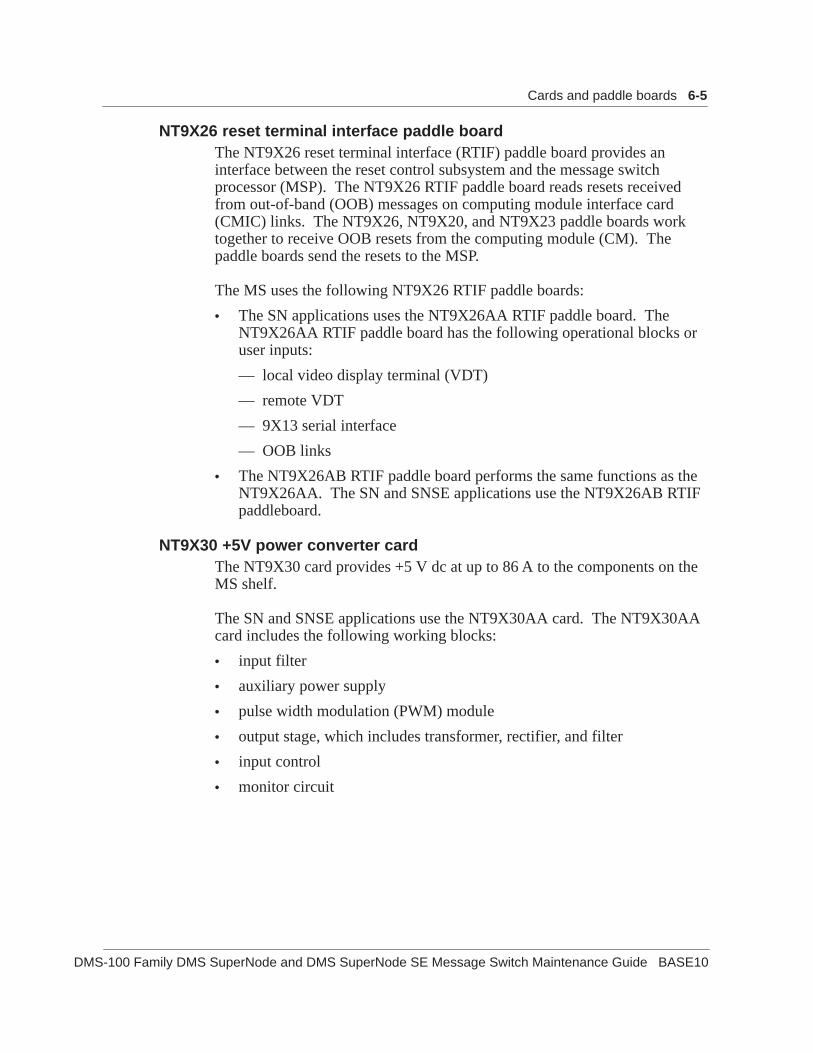
Cards and paddle boards 6-5
DMS-100 Family DMS SuperNode and DMS SuperNode SE Message Switch Maintenance Guide BASE10
NT9X26 reset terminal interface paddle boardThe NT9X26 reset terminal interface (RTIF) paddle board provides aninterface between the reset control subsystem and the message switchprocessor (MSP). The NT9X26 RTIF paddle board reads resets receivedfrom out-of-band (OOB) messages on computing module interface card(CMIC) links. The NT9X26, NT9X20, and NT9X23 paddle boards worktogether to receive OOB resets from the computing module (CM). Thepaddle boards send the resets to the MSP.
The MS uses the following NT9X26 RTIF paddle boards:
• The SN applications uses the NT9X26AA RTIF paddle board. TheNT9X26AA RTIF paddle board has the following operational blocks oruser inputs:
— local video display terminal (VDT)
— remote VDT
— 9X13 serial interface
— OOB links
• The NT9X26AB RTIF paddle board performs the same functions as theNT9X26AA. The SN and SNSE applications use the NT9X26AB RTIFpaddleboard.
NT9X30 +5V power converter cardThe NT9X30 card provides +5 V dc at up to 86 A to the components on theMS shelf.
The SN and SNSE applications use the NT9X30AA card. The NT9X30AAcard includes the following working blocks:
• input filter
• auxiliary power supply
• pulse width modulation (PWM) module
• output stage, which includes transformer, rectifier, and filter
• input control
• monitor circuit

6-6 Cards and paddle boards
297-5001-549 Standard 07.03 April 1999
NT9X31 –5V power converter cardThe NT9X31AA card provides –5V dc at up to 20 A to the components onthe MS shelf.
The SN and SNSE applications use the NT9X31AA card. The NT9X31AAcard includes of the following operational blocks:
• input filter
• auxiliary power supply
• PWM module
• output stage (transformer, rectifier, and filter)
• input control
• monitor circuit
• relay
NT9X32 bus-load paddle boardThe NT9X32 paddle board reduces the noise on the P-bus in the MS. TheP-bus runs the complete length of the MS shelf. Noise can occur on the bus.The NT9X32 provides enough load or impedance on the P-bus to reduce thenoise. The system can use NT9X32 paddle boards instead of NT9X19paddle boards in port interface paddle board slots if port interface paddleboards are not present.
SN applications use the NT9X32AA paddleboard.

Cards and paddle boards 6-7
DMS-100 Family DMS SuperNode and DMS SuperNode SE Message Switch Maintenance Guide BASE10
NT9X49 P-bus terminator cardThe P-bus gains resistive termination from the NT9X49 card.
The MS uses the following NT9X49 P-bus terminator cards:
• SN applications use the NT9X49CA card. The NT9X49CA cardperforms the following functions:
— P-bus termination
— lock of power converters on an in-service MS
— access to the ID PROMs on the power converters
— signal to clear the T-bus when timeouts occur
• The NT9X49CB card for SN applications performs the functions of theNT9X49CA card. The NT9X49CB card performs the followingfunctions:
— T-bus to P-bus interface which provides T-bus activity information tothe MSP
— logic analyzer to trace T-bus messages configurable by the MSP
— T-bus activity monitor with programmable threshold detection
• SNSE applications can use the NT9X49CC card.
NT9X52 MSP T-bus access cardThe NT9X52 card provides the interface between the P-bus and the T-bus.The MS processor card sends messages to the CM. To send messages, theMS processor card puts the messages on the P-bus to the NT9X52 card. TheNT9X52 puts the messages on the T-bus. On the T-bus, the system selects aport card to transmit the messages. The reverse process occurs when thesystem receives messages from the DMS-core component.
The NT9X52 is interrupt driven. The NT9X13 issues an interrupt to theNT9X52 to verify if the NT9X52 can handle a message. If the NT9X52 isavailable, the interrupt returns and the MSP transmits the message over theP-bus. The MSP sends data to the NT9X52 in byte form. The NT9X52converts the bytes to longwords. This conversion allows the bus accesscontroller (BAC) to transmit the data over the T-bus.
After the T-bus receives MSP data in longword format, the MSP receivesnotification from an interrupt that a message waits. The MSP extracts themessage off the P-bus in 1 byte segments.

6-8 Cards and paddle boards
297-5001-549 Standard 07.03 April 1999
The NT9X52 card provides the NT9X13 with access to the T-bus. TheNT9X52 card also provides the following functions:
• generation and check of cyclic redundancy check (CRC) codes for T-busmessages that the NT9X13 card sent and received
• locks power converter on an in-service MS
• access to the ID PROM on the NT9X24, NT9X30, and NT9X31 cards
• a loopback register used during diagnostics
• termination of T-bus backplane signals
• buffer of clock signals generated by NT9X53.
The SN and SNSE applications use the NT9X52AA card.
NT9X53 system clock cardThe NT9X53 card is a Stratum 3 clock that provides clock timing to allnodes in an office directly or indirectly. The NT9X53 works with theNT9X54 clock interface paddle board. The paddle board is behind theNT9X53 card.
The NT9X53 card accommodates two transmission frequencies: 10.24 MHzand 16.38 MHz. The system clock operates at 10.24 MHz and providestiming reference for PMs coupled to the MS with DS30 links. Thesubsystem clock operates at 16.38 MHz and provides timing references forthe T-bus and all nodes connected to the MS with DS512 fiber links. TheNT9X53 card contains a microprocessor that functions as the maintenanceunit of the card.
The system uses the phase error to adjust NT9X53 clocks. A phasecomparator measures the phase difference between the two clock references.The two clock references are the external oscillators and the on-boardoscillators. The phase difference controls the DAC value.
The DAC sends a voltage, calculated from the phase difference, to a voltagecontrolled oscillator. The oscillator adjusts the output frequency based onthe input voltage.

Cards and paddle boards 6-9
DMS-100 Family DMS SuperNode and DMS SuperNode SE Message Switch Maintenance Guide BASE10
The MS uses the following NT9X53 system clock cards:
• The SN applications use the NT9X53AA card.
• The SN applications use the NT9X53AB card. The NT9X53AB card islike the NT9X53AA card. The NT9X53AB card supports the followingexternal clock inputs:
— cesium/loran-C analog signals
— 64/8 kbit/s composite clock
• The NT9X53AC card is like the NT9X53AB card. The NT9X53ACcard supports 32 kbyte of firmware that the system can download. TheSN and SNSE applications use the NT9X53AC card.
• The NT9X53AD card uses a dual-frequency oscillator to generate boththe system and subsystem clock signals. The memory type is SRAMinstead of EEPROM. The SCRAM memory allows the card to performparity operations. The memory supports 64 kbyte of firmware that thesystem can download.
NT9X54 clock interface paddle boardThe NT9X54 paddle board provides cable connections for incoming externalclock signals. The NT9X54 provides cable connection for the outgoingreference signal to the mate clock in the other MS. The NT9X54 convertsthe external clock reference signals to internal frequencies.
The MS software designates the NT9X53/NT9X54 pair in one MS as themaster clock. The MS software designates the NT9X53/NT9X54 pair in theother MS as the slave clock.
The MS uses the following NT9X54 subsystem clock interface paddleboards:
• The SN applications use the NT9X54AB paddle board.
• The SN and SNSE applications use the NT9X54AC paddle board. TheNT9X54AC is like the NT9X54AB card. The NT9X54AC supportssystem ISG compliance and the following clock interfaces:
— cesium/loran-C analog signals
— 64/8 kbit/s composite clock
SN and SNSE-MS interface cards and paddle boardsThe MS interface cards and paddle boards connect the SN and SNSE MSand the other nodes in the SN and SNSE systems. Table 6-2 lists the MSinterface cards and paddle boards.
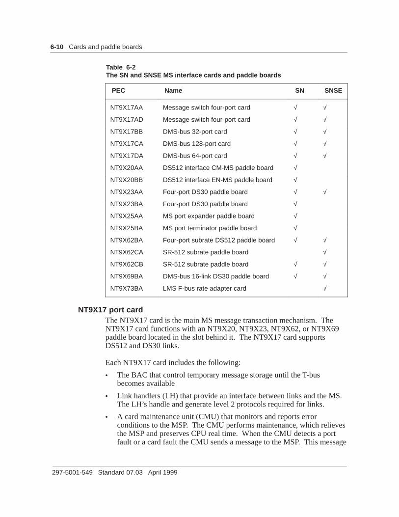
6-10 Cards and paddle boards
297-5001-549 Standard 07.03 April 1999
Table 6-2The SN and SNSE MS interface cards and paddle boards
PEC Name SN SNSE
NT9X17AA Message switch four-port card √ √
NT9X17AD Message switch four-port card √ √
NT9X17BB DMS-bus 32-port card √ √
NT9X17CA DMS-bus 128-port card √ √
NT9X17DA DMS-bus 64-port card √ √
NT9X20AA DS512 interface CM-MS paddle board √
NT9X20BB DS512 interface EN-MS paddle board √
NT9X23AA Four-port DS30 paddle board √ √
NT9X23BA Four-port DS30 paddle board √
NT9X25AA MS port expander paddle board √
NT9X25BA MS port terminator paddle board √
NT9X62BA Four-port subrate DS512 paddle board √ √
NT9X62CA SR-512 subrate paddle board √
NT9X62CB SR-512 subrate paddle board √ √
NT9X69BA DMS-bus 16-link DS30 paddle board √ √
NT9X73BA LMS F-bus rate adapter card √
NT9X17 port cardThe NT9X17 card is the main MS message transaction mechanism. TheNT9X17 card functions with an NT9X20, NT9X23, NT9X62, or NT9X69paddle board located in the slot behind it. The NT9X17 card supportsDS512 and DS30 links.
Each NT9X17 card includes the following:
• The BAC that control temporary message storage until the T-busbecomes available
• Link handlers (LH) that provide an interface between links and the MS.The LH’s handle and generate level 2 protocols required for links.
• A card maintenance unit (CMU) that monitors and reports errorconditions to the MSP. The CMU performs maintenance, which relievesthe MSP and preserves CPU real time. When the CMU detects a portfault or a card fault the CMU sends a message to the MSP. This message

Cards and paddle boards 6-11
DMS-100 Family DMS SuperNode and DMS SuperNode SE Message Switch Maintenance Guide BASE10
indicates the type of error.
At least one NT9X17 card connects the MS to an I/O controller (IOC).
The MS uses the following NT9X17 port cards:
• The SN and SNSE applications use the NT9X17AA four-port card. Thefunctionality of the NT9X17AA card is like that of the MSP T-busaccess card with the following exceptions:
— the NT9X17AA card is compatible with NT9X20AA and NT9X23paddle boards
— the port interface is the link handler gate array instead of the P-businterface
— the NT9X17AA card has four link handlers, each one with a BAC
— each port has private buffer space not shared with any other port
— an allocator circuit controls time sharing of internal buses
— the NT9X17AA card has internal regulation between ports
— the link handler performs CRC generation and checking
— loop-back register does not apply
— the CMU controls and supervises all gate arrays
— the P-bus interface provides decoding and buffering to access thepaddle board. These functions reduce P-bus loading.
• The NT9X17AD four-port card is like the NT9X17AA card. Thefirmware on the NT9X17AD card increased from 8kbyte to 32kbyte tosupport SR128, SR256, SR512 links. In order, the SR128, SR256, andSR512 links are four, two, and one port. The NT9X17AD card isbackward compatible with the NT9X17AA card. The SN and SNSEapplications use the NT9X17AD card. This card is compatible withNT9X20AA, NT9X20BB, NT9X23, and NT9X62 paddle boards.
• The NT9X17BB 32-port card is based on multiport link handlers(MPLH) and multiport bus access controllers (MPBAC) that control32 ports. The card runs multiport firmware and is compatible withNT9X20BB, NT9X62, and NT9X69 paddle boards. The SNSEapplications use the card.
• The NT9X17CA 128-port card is functionally equivalent to theNT9X17BB, with the following exceptions:
— the NT9X17CA 128-port has enough memory to support 8 kbyte ofmemory for each port in each direction
— the card has two additional MPBACs and MPLHs

6-12 Cards and paddle boards
297-5001-549 Standard 07.03 April 1999
— the EEPROM code expands from 64 kbyte to 128 kbyte
— the SN and SNSE applications use this card
• The NT9X17DA 64-port card is functionally equivalent to theNT9X17BB. The NT9X17DA 64-port card provides 64 ports. The SNand SNSE applications use it. This card is compatible with NT9X20BB,NT9X62, and NT9X69 paddle boards.
NT9X19 filler card and paddle boardUse NT9X19 cards and paddle boards to occupy empty slots. Filler cardsand paddle boards cool equipment and provide electromagnetic interference(EMI) protection.
The MS use the following NT9X19 filler cards:
• The NT9X19AA card can occupy empty card slots in SN and SNSEapplications.
• The NT9X19BA paddle board can occupy empty paddle board slots inSN and SNSE applications.

Cards and paddle boards 6-13
DMS-100 Family DMS SuperNode and DMS SuperNode SE Message Switch Maintenance Guide BASE10
NT9X20 DS512 interface paddle boardThe in SN switches only use the NT9X20 DS512 interface paddle board.The NT9X20 and the NT9X17 card work together to exchange input andoutput signals over the S-bus.
The NT9X20 converts incoming fiber link light pulses to parallel electricalmessages, and sends the messages to the NT9X17 through the S-bus. Totransmit messages from the MS on a fiber link, the NT9X20 convertsparallel messages from the NT9X17 to serial form, and changes electricalsignals to light pulses for transmission over the DS512 link.
The MS uses the following NT9X20 DS512 interface paddle boards:
• Each NT9X20AA provides an interface between one DS512 CM linkand one NT9X17A series card.
• The NT9X20BB paddle board provides messaging links between the MSand the enhanced network (ENET). The paddle board connects to theS-bus on the backplane. The paddle board is like the NT9X20AA. TheNT9X20BB has a different fiber module from the NT9X20AA for theENET connection. The optical interface includes a transmitter, areceiver, and clock recovery. In the transmit direction, the interfacetakes serial information from the fiber link interface chip (FLIC) andconverts the information to an optical signal. In the receive direction,the interface converts an incoming optical signal to a logic signal at theoutput of the receiver. The interface sends this converted signal to clockrecovery. The clock recovery extracts clock information from anincoming serial stream and uses the clock to sample the data again. Theinterface sends the new generated data and clock to the FLIC.
NT9X23 4-port DS30 paddle boardThe NT9X23 paddle board provides the interface between anNT9X17A series card and DS30 links. Each NT9X23 can terminate up tofour DS30 links. The NT9X23 provides maintenance and control functionsand parallel-serial data conversion.
Use the following NT9X23 4-port DS30 paddle boards in the MS:
• The SN and SNSE switches use the NT9X23AA .
• The NT9X23BA paddle board is like the NT9X23AA paddle board,except that NT9X23BA supports out-of-band resets. The SN applicationuse the NT9X23BA paddleboard.

6-14 Cards and paddle boards
297-5001-549 Standard 07.03 April 1999
NT9X25 port expander or terminator paddle boardThe NT9X25 paddle board connects both sides of chained bus.
The MS uses the following NT9X25 port expander or terminator:
• Use the NT9X25AA port expander paddle board between anNT9X20BB board and an NT9X25BA board in the S-bus daisy chain.The NT9X25AA connects the S-bus of slot n to the S-bus of slot n+1,while the NT9X25BA terminates the chain.
• The NT9X25BA paddle board terminates the S-bus daisy chain.
NT9X62 SR512 paddle boardThe NT9X62 paddle board provides an interface. This interface is betweenone NT9X17AD, NT9X17BB, NT9X17CA, or NT9X17DA card and two orfour fiber optic links. The interface functions on receive and transmit paths.On the path for receiving, the NT9X62 performs the following functions:
• conversion of optical data to electrical data
• conversion of serial data to parallel data
• the frame pulse (FP) and alarm code reception
• the OOB reset reception
On the transmit path, the NT9X62 performs the following functions:
• conversion of parallel data to serial data
• conversion of electrical data to optical data
• transmission of the FP and alarm codes
• generation of logical transfer buffer (LTBUFF) overflow signaling
• generation of OOB reset signaling
The MS uses the following NT9X62 SR512 paddle boards:
• The NT9X62BA paddle board supports four links. The SN and SNSEapplications use this paddle board.
• The NT9X62CA paddle board is like the NT9X62BA paddle board. TheNT9X62CA supports two fiber links and provides dual OOB resetcapability on the links. The SN and SNSE applications use theNT0X62BA.
• The NT9X62CB paddle board is like the NT9X62CA board. TheNT9X62CB is the only type of paddle board used in conjunction withthe fiber LIM. The SN and SNSE applications use this paddle board .

Cards and paddle boards 6-15
DMS-100 Family DMS SuperNode and DMS SuperNode SE Message Switch Maintenance Guide BASE10
NT9X69 16-link DS30 interface paddle boardThe SNSE applications use the NT9X69 paddle board to provide aninterface. This interface is to the DS30 links between the MS and LIM andthe DS30-based junctor networks (JNET). This interface extends to theIOC. This card provides one asynchronous CMIC link with OOB messagereception. This card supports the following features:
• 16 DS30 links mapped to all 512 channels on the S-bus
• two loopbacks (one internal to R41, the other on DS30 links)
• power-up register accessible through P-bus
• ID PROM accessible through P-bus
• compatible with NT9X17BB/DA cards
• OOB reset transmission
• OOB reset reception (on link 0)
• ESD/EMI compliant
The SN and SNSE applications use the NT9X69AB 16-link DS30 interfacepaddle board.
NT9X73 rate adapter cardThe SNSE switches use the NT9X73BA card to provide an interface. Thisinterface is between the T-bus, the 8-bit frame bus (F-bus), and the CCS7link interface units (LIU7).


DMS-100 Family DMS SuperNode and DMS SuperNode SE Message Switch Maintenance Guide BASE10
7-1
Trouble isolation toolsThis chapter describes the resident tools used to troubleshoot faultconditions. The fault conditions occcur on the Digital Multiplex System(DMS) SuperNode (SN) and DMS SuperNode SE (SNSE) message switch(MS). For information on tools other than resident tools, refer to theTechnical Assistance Manuals.
Diagnostic toolsThis chapter describes the following diagnostic tools:
• alarms
• the DMS monitoring (DMSMON) tool
• log reports
• the Maintenance Manager’s Morning Report (AMREPORT)
• the OM log-alarm cross reference charts
• operational measurements (OM)
• Sherlock
• Switch Performance Monitoring System (SPMS)
AlarmsAlarms are the primary indicators of problems with the system. Alarmsprovide information about the following types of problems:
• equipment failure
• equipment that operates at a degraded level
• equipment reached operating company defined capacity level
• loss of synchronization
• full or partly full system sanity
• software errors
• not complete automatic recovery attempt
• reboot that is not authorized

7-2 Trouble isolation tools
297-5001-549 Standard 07.03 April 1999
• auto transfer to standby
• cannot transfer from faulty to standby
• loss of communication between entities or subsystems
• loss of ability to store operational information (data exceeds threshold)
• inter-node transmission failure
• loss of communication with operation support systems
• power distribution failure
• security problems
• fire and trespass
The alarms are divided in three levels of seriousness: minor, major, andcritical.
A minor alarm indicates that a problem is present that does not cause visibleloss of service. Examples of minor alarm conditions include the following:
• conditions that can cause a major alarm if conditions are not corrected
• one busy piece of a pool of equipment
• service degradation that drops below a threshold defined by theoperating company
A major alarm indicates that one-half of a duplicated system is out ofservice. This event can cause a visible loss of service. Backup is notavailable if another fault occurs on the active system. The system generatesa major alarm when service degrades below a threshold defined by theoperating company.
A critical alarm indicates that a problem is present that causes a visible lossof service. The following are examples of critical alarm conditions:
• loss of call processing capability (dead system)
• part or full loss of system sanity
• service degradation below a threshold defined by the operating company
A log accompanies each alarm. The logs provide detailed information aboutconditions in the switch.
The MS system alarm codes appear under the MS header of the MTC levelMAP display. See the chapter “Troubleshooting charts” for a list of all MSalarm codes and the possible causes of alarms. The chapter indicates whereto find information to clear each alarm.

Trouble isolation tools 7-3
DMS-100 Family DMS SuperNode and DMS SuperNode SE Message Switch Maintenance Guide BASE10
DMSMONThe DMSMON monitors the changes in operation when operating companypersonnel change a release load. The DMSMON formats this information toa report. Generation of the report can be manual or automatic. The type ofinformation in the report includes the following:
• counts of internal events like warm and cold restarts and down timeinformation
• system trap information
• counts of different log occurrences
• configuration information like hardware counts
For additional information about the DMSMON tool, refer to the DMS-100Family Commands Reference Manual, 297-1001-822.
Log reportsLog reports are a primary source of information about the components of theMS. Logs can isolate a problem to a single card. Logs help to detectproblems that the system cannot attribute to a single card.
Log reports include the following information:
• seriousness of the logs, indicated by the number of asterisks
• type of log
• time and date
• suspected problem
• list of suspected cards
For information about the MS-related logs, see the “Logs” chapter of thisdocument.

7-4 Trouble isolation tools
297-5001-549 Standard 07.03 April 1999
AMREPORTThe AMREPORT provides a 24 h summary of performance, administrative,and maintenance information. This information helps operating companypersonnel correct and prevent maintenance programs. The system producesAMREPORT as a log that includes the following information:
• switch performance information
— the SPMS indicators
— call processing performance
— the central processing unit (CPU) occupancy
— network accuracy
— peripheral module (PM) switch of activity (SWACT) information
— software performance like trap and SWERR counts
— footprint (FP) and OM log counts
— extended multiprocessor system (XMS) based peripheral module(XPM) SWACT information
• scheduled test results
— automatic line test (ALT)
— automatic trunk test (ATT)
• switch operations
— image dump results
— patch summary
— outage indicators
— table data integrity check
— not scheduled XPM REx test
For additional information on AMREPORT, refer to the Digital SwitchingSystems DMS-100 Family Maintenance Managers Morning Report,297-1001-535.
The OM log alarm cross-reference chartsThe “Troubleshooting charts” chapter of this document contains a set ofthree charts on OMs, logs, and alarms. Each chart uses one of the indicatorsas the key. This condition allows operating company personnel to locate allassociated information based on any indicator presented by the switch.

Trouble isolation tools 7-5
DMS-100 Family DMS SuperNode and DMS SuperNode SE Message Switch Maintenance Guide BASE10
Operational measurementsOMs provide load and performance information. The OM system controlscollection, display, and generation of OM data for the operating company.
For information about OMs associated with the MS, see the “Operationalmeasurements” chapter of this document.
SherlockSherlock is a data collection tool. Operating company personnel can use thistool after a service outage. Sherlock automatically collects the data requiredto analyze the cause of the failure. Only one user at a time can use Sherlock.
Sherlock initiates a set of parallel processes that collect all the data availablefor the specified type of service failure. The system sends the data to aseries of temporary files. To access or manipulate these temporary files, youmust stop the Sherlock process before data collection completes.
When data collection completes, the system creates a data file and a consolefile on the specified storage device. This action detects the temporary files.The system names the data file SHRKyymmddhhmmss(Z) and contains thedata. The Z indicates that the system compressed the file. The systemnames the console file SHERLOCK$OUT. The console file contains all themessages and responses sent to your terminal. The console file can containadditional messages, like time stamps.
For additional information on how to use Sherlock, refer to the DMS-100Family Commands Reference Manual, 297-1001-822.
Switch Performance Monitoring SystemThe SPMS monitors all areas of switch operation and produces routinereports on performance from several different points of view. The systemprovides a medium-term review with reports that include detailed andsummary level data.
The reports collect a wide range of index values computed from OMs thatthe switch generates. The time period covered in each report ranges from30 min to 1 month. This range allows you to monitor day-to-day events andprovides a longer-term view of switch performance.
The operating company personnel use SPMS results in switch performanceindex plans for administrative purposes. The operating company can use thegeneral office performance index, a section of the lower-level indexes, orboth indexes.

7-6 Trouble isolation tools
297-5001-549 Standard 07.03 April 1999
The SPMS consists of three sections:
• the service section
• the maintenance performance section
• the provisionable resources section
For more information on SPMS, refer to the Switch Performance MonitoringSystem Application Guide, 297-1001-330.
TRAPINFOThe TRAPINFO tool displays information on new software traps at a MAPterminal. The tool extracts information from the log utility and displays theinformation in a number of formats.
For more information about the TRAPINFO tool, refer to the DMS-100Family Commands Reference Manual, 297-1001-822. For more informationon traps, see the procedure “Troubleshooting an MS104 log”. Thisprocedure is in the “Advanced troubleshooting procedures” chapter of thisdocument.

DMS-100 Family DMS SuperNode and DMS SuperNode SE Message Switch Maintenance Guide BASE10
8-1
Troubleshooting chartsThis chapter contains four charts to assist operating company personnel.The charts assist personnel to find information to clear alarmed andnonalarmed trouble conditions in the message switch (MS).
MS alarm and trouble condition proceduresTable 8-1 lists MS-related alarms and nonalarmed conditions and gives ashort description of the causes. Table 8-1 provides the location of thecorrect alarm clearing or trouble locating procedure for each alarm orcondition.
Table 8-1Message switch alarms and trouble conditions
Condition Possible cause Action
Critical alarms
MSpair Both MSs system busy 1 See the “Advanced troubleshootingprocedures” chapter in this document.
Major alarms
CLOCK Measurement problems 1 See the “Advanced troubleshootingprocedures” chapter in this document.
DDM Datasync problem 1 See the DDM major alarm clearingprocedure in the correct application specificdocument.
ManB Message switch manuallyremoved from service
1 See the “ManB major alarm clearingprocedure” in Alarm and PerformanceMonitoring Procedures.
—continued—

8-2 Troubleshooting charts
297-5001-549 Standard 07.03 April 1999
Table 8-1Message switch alarms and trouble conditions (continued)
Condition ActionPossible cause
Major alarms (continued)
NOIMSL All inter-MS links out of service 1 See the ”NOIMSL major alarm clearingprocedure” in Alarm and PerformanceMonitoring Procedure.
SysB The system removes the MS fromservice for one of the followingreasons:
• self-diagnostics run
• load problem
• critical card fault that isolatesthe MS from the CM
• system card inserted orremoved when MS was inservice
1 See the “SysB major alarm clearingprocedure” in Alarm and PerformanceMonitoring Procedures
TROOS T-bus routing threshold exceeded 1 See the “Advanced troubleshootingprocedures” chapter in this document.
Minor alarms
CMIC The CMIC link out of servicebecause of one of the followingconditions:
• port in MS or CM has faults
• port card in MS or CM hasfaults
• damaged link between MSand CM
1 See the “CMIC minor alarm clearingprocedure” in Alarm and PerformanceMonitoring Procedures.
IMSL Out-of-service inter-MS link 1 Refer to the “IMSL minor alarm clearingprocedure” in Alarm and PerformanceMonitoring Procedures.
—continued—

Troubleshooting charts 8-3
DMS-100 Family DMS SuperNode and DMS SuperNode SE Message Switch Maintenance Guide BASE10
Table 8-1Message switch alarms and trouble conditions (continued)
Condition ActionPossible cause
Minor alarms (continued)
Istb An MS card is in-service troublefor one of the following reasons:
• wrong or missing NT9X32 loadpaddle board
• PEC mismatch betweenhardware and datafill
1 Refer to the “Istb minor alarm clearingprocedure” in Alarm and PerformanceMonitoring Procedures.
MAXPT More ports datafilled thanallowable
1 See the “Advanced troubleshootingprocedures” chapter in this document.
MBCD Port card manually removed fromservice
1 Refer to the MBCD minor alarm clearingprocedure in Alarm and PerformanceMonitoring Procedures.
MBCH Port chain manually removed fromservice
1 Refer to the “MBCH minor alarm clearingprocedure” in Alarm and PerformanceMonitoring Procedures.
MBCL Channelized link manuallyremoved from service
1 Refer to the “MBCL minor alarm clearingprocedure” in Alarm and PerformanceMonitoring Procedures.
MBPT Port manually removed fromservice
1 Refer to the “MBPT minor alarm clearingprocedure” in Alarm and PerformanceMonitoring Procedures.
REx MS under REx test 1 Refer to the “REx minor alarm clearingprocedure” in Alarm and PerformanceMonitoring Procedures.
RExByp The system did not perform theMS REx test because the systemidentified a condition that wouldresult in service degradation. Thesystem uses the information intable REXSCHED to disable MSRex tests.
1 Refer to the “RExByp minor alarm clearingprocedure” in Alarm and PerformanceMonitoring Procedures.
2 See the “Advanced troubleshootingprocedures chapter” in this document.
—continued—

8-4 Troubleshooting charts
297-5001-549 Standard 07.03 April 1999
Table 8-1Message switch alarms and trouble conditions (continued)
Condition ActionPossible cause
Minor alarms (continued)
RExFlt The MS REx test failed for one ofthe following reasons:
• critical card fault
• critical fault on the MS node
1 Refer to the “RExFlt minor alarm clearingprocedure” in Alarm and PerformanceMonitoring Procedures.
2 See the “Advanced troubleshootingprocedures” chapter in this document.
SBCD The system removed the port cardfrom service for one of thefollowing reasons:
• hardware fault
• load problem
• card inserted or removed whileMS was in service
1 Refer to the “SBCD minor alarm clearingprocedure” in Alarm and PerformanceMonitoring Procedures.
SBCH The system removed the portchain from service for the followingreason:
• card that has faults
1 Refer to the “SBCH minor alarm clearingprocedure” in Alarm and PerformanceMonitoring Procedures.
SBCL The system removed thechannelized link from service forone of the following reasons:
• card that has faults
• fault on node to which the portlinks
• link between port and nodehas faults
1 Refer to the “SBCL minor alarm clearingprocedure” in Alarm and PerformanceMonitoring Procedures.
—continued—

Troubleshooting charts 8-5
DMS-100 Family DMS SuperNode and DMS SuperNode SE Message Switch Maintenance Guide BASE10
Table 8-1Message switch alarms and trouble conditions (continued)
Condition ActionPossible cause
SBPT The system removed a portremoved from service for one ofthe following reasons:
• card that has faults
• fault on node to which the portlinks
• link between port and nodehas faults
An SBPT alarm also appearswhen the MS detects apersistently babbling device.
1 See the “SBPT minor alarm clearingprocedure” Alarm and PerformanceMonitoring Procedures.
SPAN One of the two timing linksappears to not sample for one ofthe following reasons:
• carrier is out of service
• timing samples are bad
1 Refer to the “SPAN minor alarm clearingprocedure” in Alarm and PerformanceMonitoring Procedures.
2 See the “Advanced troubleshootingprocedures chapter in this document.
TRIstb T-bus routing threshold exceeded 1 See the “Advanced troubleshootingprocedures” chapter in this document.
Nonalarmed trouble conditions
MS104 logs Several triggers 1 See the the “Advanced troubleshootingprocedures” chapter in this document.
MS105 logs Invalid card installed 1 See the “Correcting release mismatchproblems procedure” in Trouble Locating andClearing Procedures.
—continued—

8-6 Troubleshooting charts
297-5001-549 Standard 07.03 April 1999
Table 8-1Message switch alarms and trouble conditions (continued)
Condition ActionPossible cause
Nonalarmed trouble conditions (continued)
MS resourceinfo logs(MS157,MS208,MS238,MS248,MS267,MS277, 287,MS307,MS317,MS327)
Different triggers 1 See the “Advanced troubleshootingprocedures” chapter in this document.
Cooling fanfailure
1 See one of the following procedures inTrouble Locating and Clearing Procedures:
— “Replacing a cooling unit assembly”
— “Replacing a cooling unit electronicmodule”
— “Replacing a cooling unit fan”
— “Replacing an NT9X95 card in acooling unit”
—end—
OM-log-alarm cross reference chartsTables 8-2, 8-3, and 8-4 list MS-related logs, OMs, and alarms. Each tablekeys on one of the three indicators and provides cross-references to the othertwo indicators.

Troubleshooting charts 8-7
DMS-100 Family DMS SuperNode and DMS SuperNode SE Message Switch Maintenance Guide BASE10
The following table groups registers, associated logs, and associated alarmsby MS-related OMs.
Table 8-2xxxOM-log-alarm cross reference chart
OM group Register Associated logs Associated alarms
MS MSCDDIA none none
MSCDDIAF none SBCD
MSCDERR MS263 SBCD
MSCDFLT MS263 SBCD
MSCDMBP MS261, MS262 MBCD
MSCDMBU none MBCD
MSCDSBU none SBCD
MSDIA none none
MSDIAF none SysB
MSERR MS103 SysB
MSFLT MS103 SysB
MSMBU none ManB
MSPTDIA none none
MSPTDIAF none SBPT
MSPTERR MS303 SBPT
MSPTFLT MS303 SBPT
MSPTMBP MS301, MS302 MBPT
MSPTMBU none MBPT
MSPTSBU none SBPT
MSMBP MS101, MS102 ManB
MSSBU none SysB
MSCHAIN MSCHDIA MS150 none
MSCHDIAF MS153 SBCH
MSCHERR MS150, MS153, MS154,MS157, MS277
SBCH
MSCHFLT MS153 SBCH
—continued—

8-8 Troubleshooting charts
297-5001-549 Standard 07.03 April 1999
Table 8-2xxxOM-log-alarm cross reference chart (continued)
OM group Associated alarmsAssociated logsRegister
MSCHMBP MS151, MS152 MBCH
MSCHMBU none MBCH
MSCHSBU none SBCH
MSCHNLK MSCLDIA MS310, MS280 none
MSCLDIAF MS283, MS313 SBCL
MSCLERR MS280, MS283, MS284,MS310, MS313, MS314, MS317
SBCL
MSCLFLT MS283, MS313 SBCL
MSCLMBP MS281, MS282, MS311, MS312 MBCL
MSCLMBU none MBCL
MSCLSBU none SBCL
—end—
The following table groups OMs and alarms by MS-related logs.
Table 8-3xxxLog-OM-alarm cross reference chart
Log Associated OMs Associated alarms
MS100 none none
MS101 MSMBU, MSMBP ManB
MS102 none ManB
MS103 MSSBU, MSDIAF, MSERR,MSFLT
SysB
MS104 none REx, RExByp, RExFlt
MS105 none none
MS150 none none
MS151 MSCHMBP, MSCHMPU MBCH
—continued—

Troubleshooting charts 8-9
DMS-100 Family DMS SuperNode and DMS SuperNode SE Message Switch Maintenance Guide BASE10
Table 8-3xxxLog-OM-alarm cross reference chart (continued)
Log Associated alarmsAssociated OMs
MS153 MSCHERR, MSCHDIAF,MSCHFLT, MSCHSBU
SBCH
MS154 none SBCH
MS155 none none
MS156 none none
MS157 none none
MS208 none none
MS238 none none
MS248 none none
MS249 none none
MS260 none SBCD
MS261 MSCDMBP, MSCDMBU MBCD
MS262 none MBCD
MS263 MSCDSBU, MSCDDIAF,MSCDERR, MSCDFLT
SBCD
MS264 none SBCD
MS265 none MBCD
MS266 none none
MS267 none none
MS277 none none
MS280 none none
MS281 MSCLMBP, MSCLMBU MBCL
MS282 none MBCL
MS283 MSCLSBU, MSCLDIAF,MSCLERR, MSCLFLT
SBCL
MS284 none SBCL
MS285 none none
MS286 none none
MS287 none none
—continued—

8-10 Troubleshooting charts
297-5001-549 Standard 07.03 April 1999
Table 8-3xxxLog-OM-alarm cross reference chart (continued)
Log Associated alarmsAssociated OMs
MS300 none none
MS301 MSPTMBP, MSPTMBU SBPT
MS302 none MBPT
MS303 MSPTSBU, MSPTDIAF,MSPTERR, MSPTFLT
SBPT
MS304 none SBPT
MS305 none none
MS306 none none
MS307 none SBPT
MS310 none none
MS311 none MBPT
MS312 none MBPT
MS313 none SBPT
MS314 none SBPT
MS315 none none
MS316 none none
MS317 none SBPT
MS318 none none
MS320 none none
MS321 none IMSL
MS322 none IMSL
MS323 none IMSL
MS324 none IMSL
MS325 none IMSL
MS326 none IMSL
MS327 none IMSL
SYNC101 none CLOCK
SYNC102 none CLOCK
—continued—

Troubleshooting charts 8-11
DMS-100 Family DMS SuperNode and DMS SuperNode SE Message Switch Maintenance Guide BASE10
Table 8-3xxxLog-OM-alarm cross reference chart (continued)
Log Associated alarmsAssociated OMs
SYNC103 none CLOCK
SYNC104 none CLOCK
SYNC105 none CLOCK
—end—
The following table groups logs and OMs by MS-related alarms.
Table 8-4xxxAlarm-log-OM cross reference chart
Alarms Associated logs Associated OMs
CLOCK MS248, SYNC logs none
CMIC none none
DDM none none
Istb none none
IMSL MS321, MS322, MS323,MS324, MS325, MS326
none
ManB MS101, MS102 MSMBP, MSMBU
MAXPT none none
MBCD MS261, MS262, MS265 MSCDMBU, MSCDMBP
MBCH MS151, MS152 MSCHMBU, MSCHMBP
MBCL MS281, MS282 MSCLMBU, MSCLMBP
MBPT MS301, MS302, MS311, MS312 MSPTMBU, MSPTMBP
MSpair none none
NOIMSL none none
REx MS104 none
RExByp MS104 none
RExFlt MS104 none
—continued—

8-12 Troubleshooting charts
297-5001-549 Standard 07.03 April 1999
Table 8-4xxxAlarm-log-OM cross reference chart (continued)
Alarms Associated OMsAssociated logs
SBCD MS260, MS263, MS264 MSCDDIAF, MSCDERR,MSCDFLT, MSCDSBU
SBCH MS153, MS154 MSCHDIAF, MSCHERR,MSCHFLT, MSCHSBU
SBCL MS283, MS284 MSCLDIAF, MSCLERR,MSCLFLT, MSCLSBU
SBPT MS303, MS404, MS313, MS314 MSPTDIAF, MSPTERR,MSPTFLT, MSPTSBU
SPAN none none
SysB MS103, MS104 MSSBU, MSFLT, MSERR,MSDIAF
TRIstb none none
TROOS none none
—end—

DMS-100 Family DMS SuperNode and DMS SuperNode SE Message Switch Maintenance Guide BASE10
9-1
Advanced troubleshooting proceduresTask list
The names of all the procedures in this chapter appear in the following list.The names of the procedures are in alphabetical order. To find the correctprocedure, look for the name of the procedure in the left column of the table.When you find the name of the procedure, go to the page number listed inthe right column. If more than one entry appears under a procedure name,look for the context of the task.
To perform Go to page
Changing MS timing links 9-2
MS104 logs 9-4
SPAN alarm 9-7
Troubleshooting a MaxPt alarm 9-8
Troubleshooting a RExByp alarm 9-9
Troubleshooting a RExFlt alarm 9-11
Troubleshooting an MSpair alarm 9-13
Troubleshooting an MS clock major alarm 9-14
Troubleshooting MS resource info logs 9-45
Troubleshooting T-bus routing alarms 9-47

297-5001-549 Standard 07.03 April 1999
ApplicationUse this procedure when changing the datafill to determine which linksprovide the external clocking signal. You can assign timing links todifferent circuits or P-side links on peripheral modules (PM). The type ofPM determines which circuits you can use. On digital carrier modules(DCMs), you can use circuits 0 to 4 as timing links. On digital trunkcontrollers (DTCs), line trunk controllers (LTCs), pulse code modulation-30(PCM-30) digital trunk controllers (PDTCs), Austrian digital trunkcontrollers (ADTCs), or international digital trunk controllers (IDTCs), youcan use only circuits 0 and 2 for timing links.
The flowchart on the next page shows the steps required to change the links.
9-2 Advanced troubleshooting procedures 9-29-2
Changing MS timing links

Changing MS timing links (continued)
Advanced troubleshooting procedures 9-3
DMS-100 Family DMS SuperNode and DMS SuperNode SE Message Switch Maintenance Guide BASE10
Summary of changing MS timing links
Determine if theuser added newhardware
POST, BSY, andRTS the carrier
Drop clocksynchronization
Enter datafill intable SYNCLKwith new linkinformation
Hardwareinstalled on
DCM?
New hardwareinstalled?
BSY and RTSslave MS
Y
N
Y
N
Enter datafill intable DCMINV
Enter datafill intable LTCPSINV
SWMAST BSY and RTSslave MS
Synchronizeclocks
Changing MS timing links (end)

297-5001-549 Standard 07.03 April 1999
ApplicationThis module provides information about MS104 logs. The module helpsyou understand the value of logs and helps you decide the correct action.The module does not provide detailed instructions for solving the problemsthat caused the system to generate logs. Analysis of the log data determinesthe problems that caused the system to generate logs.
The system generates MS104 node information logs when a maintenanceaction occurs and the node state did not change. The maintenance actionsthat produce these logs include the following:
• MS REx test
• MS load operations (manual or automatic)
• switch of MS clock mastership
• MS distributed data manager (DDM) datasync
• patcher audit detects a patch mismatch between the CM and the MS
• failure of the MS node audit to recover a system busy MS
The first line of the log report shows:
• the number of the log
• the date and time the system generated the log.
• the title of the log report.
The second line of the log report contains the reason the log systemgenerated the log. For example, MS REx Test Bypassed by System RExController. The remaining lines contain more information. The reason thatthe system generated the log determines this information.
REx testAn MS REx test produces an MS104 log when the test starts, passes, passeswith in-service trouble, fails, cancels, or is bypassed. The fourth line of thelog report indicates the reason for the report. When the MS REx test passeswith in-service trouble, the system generates a card list. The card list showscards that operating company personnel must manually test. When the MSREx test fails, the system displays the failure reason. The system generatesa card list.
9-4 Advanced troubleshooting procedures 9-49-4
MS104 logs

MS104 logs (continued)
Advanced troubleshooting procedures 9-5
DMS-100 Family DMS SuperNode and DMS SuperNode SE Message Switch Maintenance Guide BASE10
The following example shows the MS104 log generated when the systemREx controller bypasses the test:
MS104 OCT01 02:54:25 1300 INFO NODE
STATE: RTS BY REX TEST CODE REF: 0: REASON: 0000 MS: 0
FLT MAP: 0000 0000 0000
MS REx Test Bypassed by System REx Controller.
MS load operationsThe MS load operation uses MS104 logs to indicate when the operationstarts, completes, or fails. When the MS load operation fails, the systemdisplays the failure reason. The log report indicates if operating companypersonnel initiated the load operation or the system automatically initiatedthe operation.
The following example shows the MS104 log generated when the systemautomatically initiates the MS load operation.
MS104 JAN01 13:24:24 2400 INFO NODE
STATE: SYSB BY LOAD ACTION CODE REF:6: REASON: 0000 MS: 1
FLT MAP: 0000 0000 0080
Auto loading started
Switch of clock mastershipThe system generates MS104 logs when the MS clocks switch mastership.One log indicates that a new clock acquired mastership. A second logindicates that the master clock has become the slave. When the switch ofclock mastership fails, the system generates another MS104 log thatindicates the failure reason.
The following example shows an MS104 log that the system generates whenthe MS clocks switch mastership:
MS104 OCT01 09:51:10 9700 INFO NODE
STATE: RTS BY MANUAL ACTION CODE REF: 0: REASON: 0000 MS: 1
FLT MAP: 0000 0000 0000
MS acquired clock mastership
Recovering a message switchSeveral MS104 logs are associated with failures during MS recovery. AnMS data synchronization problem requires manual recovery action. Thesystem initiates automatic recovery actions when an MS fails to return to

9-6 Advanced troubleshooting procedures
MS104 logs (continued)
297-5001-549 Standard 07.03 April 1999
service during a CM restart. The system also initiates automatic recoveryactions when an MS fails a system audit.
All failures associated with MS data synchronization generate MS104 logs.These logs indicate why the DDM download failed. When the datasynchronization failure occurs during a manual return to service, the noderemains manual busy. Operating company personnel must collect all DDMlogs for analysis.
When the data synchronization failure occurs during a CM restart or systemaudit, the node returns to service. The system raises the DDM alarm underthe MS header of the MTC level MAP display. To clear this alarm, refer tothe “MS DDM alarm clearing procedure” in Alarm and PerformanceMonitoring Procedures.
If an MS fails to recover after a CM restart, the system generates an MS104log. The MS104 log indicates the reason the MS failed to recover. The MSremains system busy. The system initiates a node audit to recover the MS.
The MS node audit performs a series of operations to recover the node. Aseach operation executes, the results are reported in an MS104 log.
The following example shows an MS104 log generated when a system auditinitiated return to service fails:
MS104 JAN01 13:14:28 5500 INFO NODE
STATE: SYSB BY AUDIT ACTION CODE REF: 1: REASON: 0000 MS: 1
FLT MAP: 0000 0000 0020
RTS failed: RST node – mtc open mc link failed
MS104 logs (end)

SPAN alarm (continued)
DMS-100 Family DMS SuperNode and DMS SuperNode SE Message Switch Maintenance Guide BASE10
ApplicationA SPAN alarm occurs when the inactive timing link is not sampling. Astandby link is not available to take over if a problem develops on the activetiming link.
This alarm clears when the alarm associated with the resource clears. Thesealarms appear under the TRKS and peripheral module (PM) headers of themagnetic tape center (MTC) level MAP display. Refer to Alarm andPerformance Monitoring Procedures to clear these alarms.
9-7 Advanced troubleshooting procedures 9-79-7
SPAN alarm (continued)SPAN alarm (end)

Troubleshooting a MaxPt alarm (continued)
297-5001-549 Standard 07.03 April 1999
ApplicationA MS MaxPt alarm occurs when the number of ports datafilled for anapplication or node type exceeds the number allowed for the device. Thesystem automatically generates the alarm on system audits or on a routineexercise (REx) test. The system can also generate an alarm if operatingcompany personnel executes a QUERYMS command. This commandaccounts for all allocated series I and II peripheral module (PM) ports.
This alarm is not always a maintenance problem. This alarm must beaddressed with the provisioning group for the operating company.
9-8 Advanced troubleshooting procedures 9-89-8
Troubleshooting a MaxPt alarm (continued)Troubleshooting a MaxPt alarm (end)

Troubleshooting a RExByp alarm (continued)
DMS-100 Family DMS SuperNode and DMS SuperNode SE Message Switch Maintenance Guide BASE10
ApplicationA RExByp alarm occurs for the following reasons:
• The daily automatic REx test has been bypassed. Before the messagesystem (MS) performs a (routine exercise) REx test, the MS performs astability check. The stability check makes sure that the MS can be takenout of service without causing a disruption. When the stability checkfails or the node is not stable, the REx test is bypassed. The systemraises the RExByp alarm and generates an MS104 log. The log specifiesthe reason that the test was bypassed.
• The user used datafill in table REXSCHED to disable automatic MSREX testing.
The steps to take to clear this alarm appear in the flowchart on the followingpage.
9-9 Advanced troubleshooting procedures 9-99-9
Troubleshooting a RExByp alarm (continued)

9-10 Advanced troubleshooting procedures
Troubleshooting a RExByp alarm (continued)
297-5001-549 Standard 07.03 April 1999
Summary of troubleshooting a RExByp alarm
Collect MS104logs
Clear faultsspecified inMS104 logs
Manually busythe affected MS
Passed?
Contact nextlevel of support
End
Perform manualREx test onaffected MS
Y
N
Determine if MSREx testing isdisabled
MS RExtesting
disabled?
Intentionallydisabled?
Enable MS RExtesting
Alarm clearedat next mtce
window?
YY
N N
Y
N
1
1
2
2
1
Troubleshooting a RExByp alarm (end)

Troubleshooting a RExFlt alarm (continued)
DMS-100 Family DMS SuperNode and DMS SuperNode SE Message Switch Maintenance Guide BASE10
ApplicationA RExFlt alarm occurs when the automatic REx test finds a fault. Thesystem generates a series of logs.
When the clock test stage of the message system (MS) REx test fails, thesystem generates MS248 and MS104 logs. When any other test stage fails,the system generates an MS104 log. The MS104 log specifies the fault.This log includes a list of cards that have faults.
The system generates another log to indicate the completion or failure of theREx test. An MS104 REx pass log indicates the REx test passed. AnMS103 log indicates the REx test failed.
The steps to clear this alarm appear in the flowchart on the next page.
9-11 Advanced troubleshooting procedures 9-119-11
Troubleshooting a RExFlt alarm

9-12 Advanced troubleshooting procedures
Troubleshooting a RExFlt alarm (continued)
297-5001-549 Standard 07.03 April 1999
Summary of troubleshooting a RExFlT alarm
Determine ifMS248 logs arepresent
Clear clock fault.Refer toTroubleshootinga clock majoralarm.
Collect MS103and MS104 logs
Manually busythe affected MS
MS248 logspresent?
Clear faultindicated in theMS104 logs
Perform manualREx test onaffected MS
Contact nextlevel of support
EndPassed?
Y
N
Y
N
Troubleshooting a RExFlt alarm (end)

Troubleshooting an MSpair alarm (continued)
DMS-100 Family DMS SuperNode and DMS SuperNode SE Message Switch Maintenance Guide BASE10
ApplicationAn MSpair critical alarm occurs when both MSs are out of service. Thecomputing module (CM) performs a warm restart.
Contact the next level of support.
9-13 Advanced troubleshooting procedures 9-139-13
Troubleshooting an MSpair alarm (continued)Troubleshooting an MSpair alarm (end)

297-5001-549 Standard 07.03 April 1999
ApplicationThe MS CLOCK major alarm indicates one of several fault conditions. TheMS header of the MTC level MAP display indicates a clock major alarmwhen the system detects a discrete clock fault.
You must access the Clock level of the MAP display to determine the type ofclock alarm. The clocking configuration determines which one of four MAPdisplays is present. The ALM header of the MAP display indicates the exactclock alarm.
The MAP display provides the following information:
• the status of the internal clocks and remote clocks, if applicable
• the deviation values from the normal center frequency for the internalclocks and remote clocks in percentages, if applicable
• the timing sources for internal clocks and remote clocks, if applicable
The Clock level MAP displays for the main five clocking configurationsappear in Figures 9-1 to 9-4.
9-14 Advanced troubleshooting procedures 9-149-14
Troubleshooting an MS clock major alarm

Troubleshooting an MS clock major alarm (continued)
Advanced troubleshooting procedures 9-15
DMS-100 Family DMS SuperNode and DMS SuperNode SE Message Switch Maintenance Guide BASE10
Figure 9-1Clock level MAP display—master external remote sync
CM MS IOD Net PM CCS Lns Trks Ext APPL. . . . . . . . . .
CLOCK Message Switch Clock Shelf 0 Inter–MS Link 0 10 Quit MS 0 . Master . . .2 MS 1 . Slave . . .3 4 Shelf 0 1 1 1 1 1 1 1 1 1 1 2 2 2 2 2 2 25 Card 1 2 3 4 5 6 7 8 9 0 1 2 3 4 5 6 7 8 9 0 1 2 3 4 5 66 Tst_ Chain : : : :7 MS 0 . . . . . . – – – – . – – – – . . . . . . . . . . .8 MS 1 . . . . . . – – – – . – – – – . . . . . . . . . . .9 10 Sync Card 02 Alm Int %Adj Src Rem %Adj Src11 DpSync MS 0 . . Syn +00.7 Ex0 Syn +03.1 Ex012 SwMast MS 1 . . Syn +01.3 In0 Syn –02.7 In013 Card_ Links Slipping: 4 out of 1027614 QueryMS_15161718 Adjust_ TEAM2Time 08:00

9-16 Advanced troubleshooting procedures
Troubleshooting an MS clock major alarm (continued)
297-5001-549 Standard 07.03 April 1999
Figure 9-2Clock level MAP display—master external base and master internal
CM MS IOD Net PM CCS Lns Trks Ext APPL. . . . . . . . . .
CLOCK Message Switch Clock Shelf 0 Inter–MS Link 0 10 Quit MS 0 . Master . . .2 MS 1 . Slave . . .3 4 Shelf 0 1 1 1 1 1 1 1 1 1 1 2 2 2 2 2 2 25 Card 1 2 3 4 5 6 7 8 9 0 1 2 3 4 5 6 7 8 9 0 1 2 3 4 5 66 Tst_ Chain : : : :7 MS 0 . . . . . . – – – – . – – – – . . . . . . . . . . .8 MS 1 . . . . . . – – – – . – – – – . . . . . . . . . . .9 10 Sync Card 02 Alm Stat %Adj Src11 DpSync MS 0 . . Syn +00.7 Ex012 SwMast MS 1 . . Syn +01.3 Ms013 Card_ Links Slipping: 4 out of 1027614 QueryMS_15161718 Adjust_ TEAM2Time 08:00

Troubleshooting an MS clock major alarm (continued)
Advanced troubleshooting procedures 9-17
DMS-100 Family DMS SuperNode and DMS SuperNode SE Message Switch Maintenance Guide BASE10
Figure 9-3Clock level MAP display—slave base
CM MS IOD Net PM CCS Lns Trks Ext APPL. . . . . . . . . .
CLOCK Message Switch Clock Shelf 0 Inter–MS Link 0 10 Quit MS 0 . Master . . .2 MS 1 . Slave . . .3 4 SwCarr Shelf 0 1 1 1 1 1 1 1 1 1 1 2 2 2 2 2 2 25 Card 1 2 3 4 5 6 7 8 9 0 1 2 3 4 5 6 7 8 9 0 1 2 3 4 5 66 Tst_ Chain : : : :7 MS 0 . . . . . . – – – – . – – – – . . . . . . . . . . .8 MS 1 . . . . . . – – – – . – – – – . . . . . . . . . . .9 10 Sync Card 02 Alm Stat %Adj Src : Car Stat Sp PM CCT11 DpSync MS 0 . . Syn +00.7 Lk0 : Lk0 Lck 0 DTC 002 0212 SwMast MS 1 . . Syn +01.3 Ms0 : Lk1 Smp 0 DTC 001 0213 Card_ Links Slipping: 4 out of 1027614 QueryMS_15161718 Adjust_ TEAM2Time 08:00

9-18 Advanced troubleshooting procedures
Troubleshooting an MS clock major alarm (continued)
297-5001-549 Standard 07.03 April 1999
Figure 9-4Clock level MAP display—slave remote sync
CM MS IOD Net PM CCS Lns Trks Ext APPL. . . . . . . . . .
CLOCK Message Switch Clock Shelf 0 Inter–MS Link 0 10 Quit MS 0 . Master . . .2 MS 1 . Slave . . .3 4 SwCarr Shelf 0 1 1 1 1 1 1 1 1 1 1 2 2 2 2 2 2 25 Card 1 2 3 4 5 6 7 8 9 0 1 2 3 4 5 6 7 8 9 0 1 2 3 4 5 66 Tst_ Chain : : : :7 MS 0 . . . . . . – – – – . – – – – . . . . . . . . . . .8 MS 1 . . . . . . – – – – . – – – – . . . . . . . . . . .9 10 Sync Card 02 Alm Int %Adj Src Rem %Adj Src:Car Stat Sp PM CCT11 DpSync MS 0 . . Syn +00.7 Rm0 Syn +03.1 Lk0:Lk0 Lck 0 DTC 002 0212 SwMast MS 1 . . Syn +01.3 In0 Syn –02.7 In0:Lk1 Smp 0 DTC 001 0213 Card_ Links Slipping: 4 out of 1027614 QueryMS_15161718 Adjust_ TEAM2Time 08:00
To determine the discrete fault that caused the alarm, check the errormessages on the MS logs, or query the fault condition. To perform thisaction, type:
>QUERYMS ms_no 2 FLTThe type of alarm indicated and the error message displayed determine thesteps required to clear the fault.
Table 9-1 lists all clock alarm indications and error messages. This tablealso lists the correct MS clock troubleshooting procedure to stop the alarm.Troubleshooting procedures 1 to 20 follow the table, beginning on page9-19.

Troubleshooting an MS clock major alarm (continued)
Advanced troubleshooting procedures 9-19
DMS-100 Family DMS SuperNode and DMS SuperNode SE Message Switch Maintenance Guide BASE10
Table 9-1Troubleshooting MS clock alarms reference table
Alarmindication Error message
Troubleshootingprocedure
Alm0 Clock back card stratum1 office alarm0 15
Alm1 Clock back card stratum1 office alarm1 15
Ext External clock failure 14
Phase comparator C clock failure 14
Phase comparator C frame pulse failure 14
CMU Clock card CMU failure 2
Htr Stratum2/Stratum2p5 remote clock heater failure 9
Stratum 3 Clock oscillator heater failure 2
Mat Mate Clock frame pulse failure 3
Mate Clock frame pulse noisy 3
Mate Communication Protocol Error 22
MM Clock back card termination select incorrect 11
Clock card and database configuration parameters areincompatible
11
Clock card and database masterships are incompatible 12
Clock card and database office types are incompatible 11
Clock card and database remote SYNC configuration areincompatible
11
Clock firmware load mismatch 13
Clock types mismatch-clock type used is Strat2 11
Clock types mismatch-clock type used is Strat2p5 11
Clock types mismatch-clock type used is Strat3 11
Invalid clock parameters for the clock card 13
Invalid IP/IQ tracking level for the clock card 13
Invalid IP/IQ values for the clock card 13
No clock firmware resident in software 12
MSP Clock card cannot be accessed 5
—continued—

9-20 Advanced troubleshooting procedures
Troubleshooting an MS clock major alarm (continued)
297-5001-549 Standard 07.03 April 1999
Table 9-1Troubleshooting MS clock alarms reference table (continued)
Alarmindication
TroubleshootingprocedureError message
MSP Clock card experienced an error while accessing the P-bus 5
Clock card number corrupted in data 12
Clock card trapped 5
Clock front or back card not inserted 5
System processor bus reports a parity error for the clock card 13
Pwr Clock onboard power converter failure 2
Remote clock power converter failure 8
Rem Off board clock failure 7
Phase comparator D clock failure 7
Phase comparator D frame pulse failure 7
Phase comparator D phase latch failure 20
Remote clock communication error 6
Remote clock DAC compare fault 8
Remote clock EPROM error 8
Remote clock latch error 8
Remote clock RAM error 8
Stratum2/Strat2p5 remote clock sanity failure 10
Sub Phase comparator B clock failure 2
Phase comparator B frame pulse failure 2
Phase comparator B phase latch failure 17
Subsystem Clock DAC 50% value notification 21
Subsystem Clock DAC 70% limit reached 19
Subsystem Clock firmware PLL error 19
Subsystem clock frame pulse failure 2
Subsystem clock frame pulse noisy 2
Subsystem Clock frame pulse on backplane failure 2
—continued—

Troubleshooting an MS clock major alarm (continued)
Advanced troubleshooting procedures 9-21
DMS-100 Family DMS SuperNode and DMS SuperNode SE Message Switch Maintenance Guide BASE10
Table 9-1Troubleshooting MS clock alarms reference table (continued)
Alarmindication
TroubleshootingprocedureError message
Sub (cont) Subsystem Clock oscillator failure 2
Subsystem Clock signal failure 2
Subsystem Clock signal noisy 2
Subsystem Clock signal on backplane failure 2
Sys Clock CMU has entered WAIT state 18
Data RAM parity error 2
Phase comparator A clock failure 2
Phase comparator A frame pulse failure 2
Phase comparator A phase latch failure 16
Stratum 3 oscillator DAC delta error 12
Stratum 3 oscillator DAC failure 2
System clock firmware PLL error 18
System clock firmware PLL stopped 18
System Clock frame pulse failure 1
System Clock frame pulse noisy 2
System Clock frame pulse on backplane failure 1
System Clock oscillator failure 1
System Clock signal failure 1
System Clock signal noisy 2
System Clock signal on backplane failure 1
System/Subsystem frame pulses out of SYNC 2
TMt Frame pulse to mate clock has failed 4
Mate communications transmit fault 23
Tun Clock DAC value notification 21
System DAC 70 percent limit reached 18
—end—

9-22 Advanced troubleshooting procedures
Troubleshooting an MS clock major alarm (continued)
297-5001-549 Standard 07.03 April 1999
Summary of troubleshooting MS clock procedure 1
Determine if a Clock faultthreshold exceededmessage is present
Perform anin-service teston the clock
Original faultdetected by
test?
N
Y
Y
N
Perform anin-service teston the clock
Thresholdexceeded?
N
YClock PEC is
NT9X53AA or,NT9X53AB?
N
Y
Is officeStratum 3?
Replace theNT9X53 card
Replace thefollowingcomponents, oneat a time, in theorder specified,until the fault iscleared:NT3X16,remote cable,NT9X54,NT9X53
Determine if thebackplane faultis indicated
Backplanefault
indicated?
Y
N
Replace theNT9X52 card
Perform anin-service teston clock
EndPassed?
Y
N
Contact the nextlevel of support
1
1
2
2

Troubleshooting an MS clock major alarm (continued)
Advanced troubleshooting procedures 9-23
DMS-100 Family DMS SuperNode and DMS SuperNode SE Message Switch Maintenance Guide BASE10
Summary of troubleshooting MS clock procedure 2
Determine if the Clock faultthreshold exceededmessage is present
Perform anin-service teston the clock
N
YThresholdexceeded?
Determine if thebackplane faultis indicated
Backplanefault
indicated?
Y
N
Replace theNT9X52 card
Passed?End
Contact the nextlevel of support
Original faultdetected by
test?
Y
N
Perform anin-service teston the clock
Y
N
1
1
Replace theNT9X53 card

9-24 Advanced troubleshooting procedures
Troubleshooting an MS clock major alarm (continued)
297-5001-549 Standard 07.03 April 1999
Summary of troubleshooting MS clock procedure 3
Determine if themate clock isreporting one of thefollowing errormessages: “Framepulse to mate clockhas failed” or “Matecommunicationstransmit fault ”
Test mate MS
Replaceindicated cardson mate MS
Check clockcable betweenMSs
Passed?Is the Matereporting an
error?
Cableproperly
connected?
Remove slaveMS from service
N
Y
Y
N
Y
N
To matecleared?
N
Contact the nextlevel of support
Test the integrityof the cable
Reconnectcable
Return slaveMS to service
Test the MS thatoriginallyreported fault
Y
N
Replaceindicated cards
End
Passed?
Y
2
2
Use procedure 3 to clear faults that indicate loss of synchronization betweenthe two MS clocks. One of the following problems can cause the failure:
• a damaged or disconnected clock cable between the two MSs
• a fault on the mate MS clock

Troubleshooting an MS clock major alarm (continued)
Advanced troubleshooting procedures 9-25
DMS-100 Family DMS SuperNode and DMS SuperNode SE Message Switch Maintenance Guide BASE10
• a fault on the clock of the MS that reported the error
The mate alarm indicates that the clock that reports the fault cannot receivesignals from the mate clock. The to-mate alarm indicates that the clock thatreports the fault cannot send signals to the mate clock. The master clockcannot become the slave clock if the master clock uses a mate alarm.

9-26 Advanced troubleshooting procedures
Troubleshooting an MS clock major alarm (continued)
297-5001-549 Standard 07.03 April 1999
Summary of troubleshooting MS clock procedure 4
Replace theNT9X54 card
Test clock
N
Y
Contact the nextlevel of support
Replace theNT9X53 card
Test clock
EndPassed?
N
Y
Passed?

Troubleshooting an MS clock major alarm (continued)
Advanced troubleshooting procedures 9-27
DMS-100 Family DMS SuperNode and DMS SuperNode SE Message Switch Maintenance Guide BASE10
Summary of troubleshooting MS clock procedure 5
Determine ifclock card andpaddle boardare inserted
Test the clock
Contact the nextlevel of support
End
Passed?
Determine ifclock card andpaddle boardare correctlyseated
Determine ifthe lockinglevers on theclock card andpaddle boardare closed
Y
N
Y
N
Passed?Replace cardsindicated on thecard list
Test clock

9-28 Advanced troubleshooting procedures
Troubleshooting an MS clock major alarm (continued)
297-5001-549 Standard 07.03 April 1999
Summary of troubleshooting MS clock procedure 6
Determine ifcommunicationcable to theremote clock iscorrectlyconnected
Remove theaffected MSfrom service
Make sure thecables are notdamaged
Return MS toservice
Communicationcable correctly
connected?
Passed?
Connect thecables again
Test clock
Replace cardsindicated on thecard list
Test clock
Y
N
N
Y
Passed?Y
N
End
1
Contact the nextlevel of support
1

Troubleshooting an MS clock major alarm (continued)
Advanced troubleshooting procedures 9-29
DMS-100 Family DMS SuperNode and DMS SuperNode SE Message Switch Maintenance Guide BASE10
Summary of troubleshooting MS clock procedure 7
Determine if clockcable to theremote clock iscorrectlyconnected
Remove theaffected MSfrom service
Make sure thecables are notdamaged
Return MS toservice
Clock cablecorrectly
connected?
Passed?
Connect thecables again
Test clock
Replace cardsindicated on thecard list
Test clock
Y
N
N
Y
Passed?Y
N
End
1
Contact the nextlevel of support
1

9-30 Advanced troubleshooting procedures
Troubleshooting an MS clock major alarm (continued)
297-5001-549 Standard 07.03 April 1999
Summary of troubleshooting MS clock procedure 8
ReplaceNT3X16 card
Test the remoteclock
End
Contact the nextlevel of support
Passed?
Y
N

Troubleshooting an MS clock major alarm (continued)
Advanced troubleshooting procedures 9-31
DMS-100 Family DMS SuperNode and DMS SuperNode SE Message Switch Maintenance Guide BASE10
Summary of troubleshooting MS clock procedure 9
Determine theStratum versionnumber of theaffected clock
Determine whenthe clock cardwas installed
Contact the nextlevel of support
End
Stratum 2.5?
Passed?
Test remoteclock
Wait 12 h forclock to warmup
Replace theremote clockcard
Y
N
N
Y
Determine whenthe clock cardwas installed
Less than 1 hago?
Wait 1 h forclock to warmup
N
Y
Less than12 h ago?
Y
N
Test remoteclock
Passed?YN
Wait for clock towarm up

9-32 Advanced troubleshooting procedures
Troubleshooting an MS clock major alarm (continued)
297-5001-549 Standard 07.03 April 1999
Use procedure 9 to clear faults that can occur when the user installs theremote clock card in the remote shelf. The temperature of the remote clockcard determines the time required to clear this fault. The fault can require1 h to clear after installing card for a stratum 2.5 clock. The fault canrequire a maximum of 12 h to clear for a stratum 2 clock. If the remote cardis not replaced, or the problem continues, replace the remote clock card.
MS clock troubleshooting procedure 10This fault is generated in association with other remote faults. To clear thisfault, clear the remote fault reported with this fault. If this fault is generatedwith no remote fault, contact the next level of support.
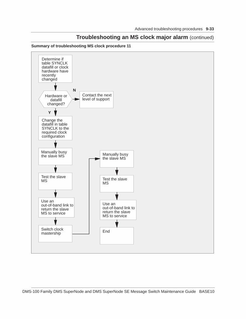
Troubleshooting an MS clock major alarm (continued)
Advanced troubleshooting procedures 9-33
DMS-100 Family DMS SuperNode and DMS SuperNode SE Message Switch Maintenance Guide BASE10
Summary of troubleshooting MS clock procedure 11
Change thedatafill in tableSYNCLK to therequired clockconfiguration
Manually busythe slave MS
Switch clockmastership End
Test the slaveMS
Use anout-of-band link toreturn the slaveMS to service
Manually busythe slave MS
Test the slaveMS
Use anout-of-band link toreturn the slaveMS to service
Determine iftable SYNCLKdatafill or clockhardware haverecentlychanged
Hardware ordatafill
changed?
Y
NContact the nextlevel of support

9-34 Advanced troubleshooting procedures
Troubleshooting an MS clock major alarm (continued)
297-5001-549 Standard 07.03 April 1999
Troubleshooting MS clock procedure 12Contact the next level of support.
Summary of troubleshooting MS clock procedure 13
Perform anin-service test onthe clock card
End
Manually busythe MS
Passed?
Y
N
Contact the nextlevel of support
Return the MSto service
Passed?
Y
N

Troubleshooting an MS clock major alarm (continued)
Advanced troubleshooting procedures 9-35
DMS-100 Family DMS SuperNode and DMS SuperNode SE Message Switch Maintenance Guide BASE10
Summary of troubleshooting MS clock procedure 14
Verify that thecable to theexternal clocksource isconnectedcorrectly
Connect thecable again
Cablecorrectly
connected?
Make sure thecable is notdamaged
Test clock
Validate theoutput of externalclock signal
Replace theNT9X54 card
End
Contact the nextlevel of support
Y
N
YN
Test clockPassed?
Y
N
Disconnectcable
Passed?

9-36 Advanced troubleshooting procedures
Troubleshooting an MS clock major alarm (continued)
297-5001-549 Standard 07.03 April 1999
Troubleshooting MS clock procedure 15The customer defines these faults. The faults indicate a problem with theStratum 1 clock source.
Contact the next level of support to determine how the operating companydefines this fault.

Troubleshooting an MS clock major alarm (continued)
Advanced troubleshooting procedures 9-37
DMS-100 Family DMS SuperNode and DMS SuperNode SE Message Switch Maintenance Guide BASE10
Summary of troubleshooting MS clock procedure 16
Determinewhich MSreports a fault
Perform MSclocktroubleshootingprocedure 3
Is officeconfigured as
the masterexternal?
Fault on slaveMS?
Test clockReplace theNT9X53 card
Contact the nextlevel of support
EndPassed?
Y
N
Y
N
Y
N
Clock PEC isNT9X53AD?
Y
N
Perform MSclocktroubleshootingprocedure 2
External clockfaults exist?
Y
N
Perform MSclocktroubleshootingprocedure 14
1
Officeconfigured as
masterexternal
remote syncor slave
remote sync?
Y
N
Remote clockfaults exist?
Y Perform MSclocktroubleshootingprocedure 7
N 1
1

9-38 Advanced troubleshooting procedures
Troubleshooting an MS clock major alarm (continued)
297-5001-549 Standard 07.03 April 1999
Summary of troubleshooting MS clock procedure 17
Determine thetype of clockcard installed
Is the clockcard
NT9X54AD?
Is the faultreported onmaster MS?
Y
N
Perform MSclocktroubleshootingprocedure 2
Y
N
Perform MSclocktroubleshootingprocedure 3

Troubleshooting an MS clock major alarm (continued)
Advanced troubleshooting procedures 9-39
DMS-100 Family DMS SuperNode and DMS SuperNode SE Message Switch Maintenance Guide BASE10
Summary of troubleshooting MS clock procedure 18 and 19
Clear all otherclock faults onthe slave andmaster MSs
Return MS toservice usingthe out-of-bandlinks
End
Replace theindicated cards
Passed?Y
N
Passed?
YNContact the nextlevel of support
Return the MSto service usingthe out-of-bandlinks
Determine if anyother clockfaults areindicated
Other clockfaults
indicated?
Y
N
Is officesynchronized?
Y
N
Synchronizeoffice clocks
Is Officeconfigured as
masterinternal?
Y
N
Manually adjustthe DAC valuesuntil the sum is,or is very closeto, zero

9-40 Advanced troubleshooting procedures
Troubleshooting an MS clock major alarm (continued)
297-5001-549 Standard 07.03 April 1999
Use procedures 18 and 19 to clear the following faults:
• the system clock on the slave MS cannot synchronize to the system clockon the master MS
• the subsystem clock cannot synchronize to the system clock

Troubleshooting an MS clock major alarm (continued)
Advanced troubleshooting procedures 9-41
DMS-100 Family DMS SuperNode and DMS SuperNode SE Message Switch Maintenance Guide BASE10
Summary of troubleshooting MS clock procedure 20
Performassociated MSclock alarmclearingprocedure
End
External alarmpresent?
Contact the nextlevel of support
Y
N
Replace theNT9X53 card
Replace theNT9X54 card
Alarmcleared?
Y
N
Alarmcleared?
Y
N
Determine if anExt fault ispresent
Determinewhich MS isreporting a fault
Master MSreports the
fault?
Y
N
Perform MSclocktroubleshootingprocedure 3

9-42 Advanced troubleshooting procedures
Troubleshooting an MS clock major alarm (continued)
297-5001-549 Standard 07.03 April 1999
Summary of troubleshooting MS clock procedure 21
Determine ifthere are otherfaults present
Investigateproblems withexternal timingsource
Replace theNT9X53 card
SWMAST
Other faultspresent?
DS1 carriersslipping?
Officeconfigurationis the master
external?
SWCARR andsync toalternate timinglink
End
Officeconfigurationis the master
internal?
Y
N
Performassociated MSclock alarmclearingprocedure
Y
N
Manually adjustthe DAC valuesuntil the sum is,or is very closeto, zero
Y
N
Y
N
Y
N
Fault clear onboth MSs?

Troubleshooting an MS clock major alarm (continued)
Advanced troubleshooting procedures 9-43
DMS-100 Family DMS SuperNode and DMS SuperNode SE Message Switch Maintenance Guide BASE10
Summary of troubleshooting MS clock procedure 22
Determine if theMS is in service
Replace theNT9X53 card onthe MS thatreports a fault
MS inservice?
Y
N
Perform theassociated MSalarm clearingprocedure

9-44 Advanced troubleshooting procedures
Troubleshooting an MS clock major alarm (continued)
297-5001-549 Standard 07.03 April 1999
Summary of troubleshooting MS clock procedure 23
Replace theNT9X53 card
Alarmcleared?
Y
N
Contact the nextlevel of support
End
Troubleshooting an MS clock major alarm (end)

Troubleshooting MS resource info logs (continued)
DMS-100 Family DMS SuperNode and DMS SuperNode SE Message Switch Maintenance Guide BASE10
ApplicationThe message switch (MS) resource information logs include the logs thatfollow:
• MS157 INFO CHAIN
• MS208 INFO FRNT CARD
• MS238 INFO BACK CARD
• MS248 INFO SYSTEM CARD
• MS267 INFO INTERFACE CARD
• MS277 INFO CHAIN CARD
• MS287 INFO CHNL LINK
• MS307 INFO PORT
• MS317 INFO CHNL LINK PORT
• MS327 INFO IMSL PORT
The system generates these logs when a soft fault:
• occurs
• clears
• threshold is reached
The fault did not cause a state change in the component. Refer to LogReport Reference Manual for details on each information field in these logreports.
The steps to clear this type of fault appear in the flowchart on the next page.
9-45 Advanced troubleshooting procedures 9-459-45
Troubleshooting MS resource info logs (continued)

9-46 Advanced troubleshooting procedures
Troubleshooting MS resource info logs (continued)
297-5001-549 Standard 07.03 April 1999
Summary of troubleshooting MS resource info logs
Monitor logs todetermine if“soft faultcleared”appears
EndSoft faultcleared?
Contact nextlevel of support
Y
N
Monitor logs todetermine iffault continuesreappearing
Faultreappears?
N
Y
End
Troubleshooting MS resource info logs (end)

DMS-100 Family DMS SuperNode and DMS SuperNode SE Message Switch Maintenance Guide BASE10
ApplicationT-bus routing alarms occur in the message switch (MS) subsystem. Thealarms are TROOS major and TRIstb minor. The MS raises the alarmswhen mapper-unable-to-map (MUMP) thresholds are exceeded.
The MUMP faults are normally software related. The mapper cardtranslates logical addresses in message headers to hardware addresses.When the mapper card cannot make this translation, the mapper card raises aMUMP interrupt and the message is lost.
When the minor alarm occurs, the subtending node or port does not alwaysrecognize the loss of messaging traffic. When the operating companypersonnel manually takes the node out of service and returns the node toservice again, the software initializes again. These actions clear the alarm.Report all occurrences of this alarm to the next level of support. The nextlevel of support will analyze the root cause of the fault.
When the major alarm occurs, the system audit tries to recover the node.The system audit takes the node out of service and performs a restart. Whenthis event occurs, the SysB alarm over-writes the major alarm. When theother MS is already out of service, the operating company personnel cannottake the node out of service. When the operating company personnelcannot take the node out of service for any reason, the alarm stands.
Report all occurrences of this alarm to the next level of support immediately.Address all port and PM-related faults at the next level of support. After thenext level of service resolves these problems, the MS takes up to 10 min tostabilize and clear the alarm.
The flowchart on the next page summarizes the steps to clear theseproblems.
9-47 Advanced troubleshooting procedures 9-479-47
Troubleshooting T-bus routing alarms

9-48 Advanced troubleshooting procedures
Troubleshooting T-bus routing alarms (continued)
297-5001-549 Standard 07.03 April 1999
Flowchart for troubleshooting T–bus routing alarms
Determine ifalarm is majoror minor
Manually busyaffected MS
Return MS toservice
Contact nextlevel of support
Minor alarmraised?
Run Sherlock tocollect data
Y
N
Troubleshooting T-bus routing alarms (end)

DMS-100 Family DMS SuperNode and DMS SuperNode SE Message Switch Maintenance Guide BASE10
10-1
List of termsalarm
A visual or audio indication of a fault condition in the digital multiplexsystem (DMS).
busAn electrical connection that connects two or more wires or lines.
bus termination unitThe logical grouping of the bus termination cards on the message switch(MS) shelf.
cardA plug-in circuit pack that contains components. In a DMS switch, thecorrect term for a printed circuit pack or a printed circuit board is card.
CCITTThis term is from the French for International Telegraph and TelephoneConsultative Committee (Comité Consultatif International Télégraphique etTéléphonique). Until March 1993, the CCITT was one of four permanentgroups in the International Telecommunication Union (ITU). The CCITTstudied technical issues in telecommunication on an international basis. TheCCITT issued recommendations to improve standards and performancewithin the industry. The work of the CCITT continues in the ITUTelecommunication Standardization Sector (ITU-T).
CCSRefer to common channel signaling (CCS).
CCS7Refer to Common Channel Signaling 7 (CCS7).

10-2 List of terms
297-5001-549 Standard 07.03 April 1999
central side (C-side)In DMS SuperNode, the side of a node that faces away from the peripheralmodules (PM) and toward the message switch (MS). See also peripheralside.
clock subsystemOne of the message switch (MS) subsystems. The clock subsystem providestiming for all nodes in the DMS SuperNode and SuperNode SE systems.
CMRefer to computing module (CM).
CMICRefer to computing-module interface card (CMIC).
CMIC linkThe fiber optic link that connects the MSs and the CM.
common channel signaling (CCS)A signaling method in which information transmits over a single channelusing time-division multiplex (TDM) digital techniques. This informationrelates to a large number of labeled messages.
Common Channel Signaling 7 (CCS7)A signaling standard defined by the CCITT for a digital message–basednetwork. The CCS7 separates call signaling information from voicechannels. The CCS7 uses a separate signaling link to exchange interofficesignaling.
computing module (CM)The processor and memory that the DMS SuperNode and DMS SuperNodeSE use. Each CM consists of a pair of central processing units (CPUs) withassociated memory. The CPUs operate in a synchronous matched mode ontwo separate planes. Only one plane is active. The active plane maintainscontrol of the system. The other plane is on standby.
computing-module interface card (CMIC)The card that the message switch uses to act as an interface with thecomputing module. The CMIC uses fiber optic transmission links.
C-sideSee central side (C-side).

List of terms 10-3
DMS-100 Family DMS SuperNode and DMS SuperNode SE Message Switch Maintenance Guide BASE10
data store (DS)One of the two elements of a DMS-100 memory. The DS contains transientinformation for each call. The DS also contains customer data and officeparameters. The other main element of a DMS-100 memory is programstore. See also program store (PS).
digital phase locked loop (DPLL)A digital circuit that controls an oscillator. The DPLL maintains a constantphase angle in relation to a reference signal source.
DMS-busThe messaging control system of the DMS SuperNode and DMS SuperNodeSE. The DMS-bus consists of a pair of message switches (MS).
DMS-coreThe call management and system control part of the DMS SuperNode andDMS SuperNode SE. The DMS-core consists of a computing module (CM)and a system load module (SLM).
DMS-linkThe networking software of the DMS SuperNode and DMS SuperNode SE.The DMS-link software consists of open and standard protocols. Theseprotocols allow the DMS SuperNode and DMS SuperNode SE to function ina multivendor environment.
DMS SuperNode (SN)A central control complex (CCC) for the DMS-100 switch. The two majorcomponents of DMS SuperNode are the computing module (CM) and themessage switch (MS). Both components are compatible with the networkmodule (NM), the input/output controller (IOC), and XMS-based peripheralmodules (XPM).
DMS SuperNode SE (SNSE)A compact version of the DMS SuperNode. DMS SuperNode SE providesthe same functions as the DMS SuperNode, but DMS SuperNode SE smallerand has a smaller capacity than the SuperNode.
DPCCSee dual-plane combined core (DPCC) cabinet.
DPLLSee digital phase locked loop (DPLL).

10-4 List of terms
297-5001-549 Standard 07.03 April 1999
DSSee data store (DS).
DS30• A 10-bit 32-channel 2.048-Mbit/s speech-signaling and
message-signaling link used in the DMS-100 Family switches.
• The protocol by which DS30 links communicate.
DS512 fiber linkThe fiber optic transmission link implemented in the DMS SuperNode andDMS SuperNode SE. Use the DS512 to connect the computing module tothe message switch. One DS512 fiber link is the equivalent of 16 DS30links.
dual-plane combined core (DPCC) cabinetOne of the three cabinet models for the DMS SuperNode. The DPCCcontains two message switch shelves, a computing module shelf, and asystem load module shelf.
ENETSee Enhanced Network (ENET).
Enhanced Network (ENET)A channel-matrixed time switch that provides pulse code modulated voiceand data connections between peripheral modules (PM). ENET alsoprovides message paths to the DMS-bus components.
F-busSee frame transport bus (F-bus).
frame supervisory panel (FSP)A facility that accepts the frame battery feed and ground return from thepower distribution center (PDC). The FSP distributes the battery feed to theshelves of the frame or bay that contains the FSP. The FSP distributes thebattery feed through axiliary fuses and feeds. The FSP also contains alarmcircuits.
frame transport bus (F-bus)An 8-bit bus that allows the link interface units (LIU) and a message switchto communicate data. To ensure readability, two load-sharing F-buses arepresent. Each message switch has a dedicated f-bus.

List of terms 10-5
DMS-100 Family DMS SuperNode and DMS SuperNode SE Message Switch Maintenance Guide BASE10
FSPSee frame supervisory panel (FSP).
HMISee human-machine interface (HMI).
human-machine interface (HMI)A series of commands and responses. Operating company personnel usethese commands and responses to communicate with the DMS-100 Familyswitches. The MAP (maintenance and administration position) terminal andother input/output devices (IOD) allow HMI. A previous name for HMI isman-machine interface.
ID PROMAn element on each card or paddle board, which software reads to identifythe component.
IMSLSee inter-MS link (IMSL).
input-output controller (IOC)An equipment shelf that provides an interface between up to 36 I/O devicesand the CM.
inter-MS link (IMSL)A DS512 fiber link that provides a communication path between themessage switches.
IOCSee input-output controller (IOC).
JNETSee junctored network (JNET).
junctored network (JNET)A time-division multiplexed system. The JNET allows switching of 1920channels for each network pair (completely duplicated). External junctors,internal junctors, and a digital network interconnecting (DNI) frameestablish additional channels. Then the system can route channels directly,or use junctors, or DNI frame, and software control. The capacity for aDMS-100 switch is 32 network pairs or 61 440 channels (1920 channels ×32 network pairs).

10-6 List of terms
297-5001-549 Standard 07.03 April 1999
LIMSee link interface module (LIM).
linkIn a DMS switch, a connection between any two nodes.
link interface module (LIM)A peripheral module (PM) that controls messaging between link interfaceunits (LIU) in a link peripheral processor (LPP). The LIM also controlsmessages between the LPP and the DMS-bus component. An LIM consistsof two local message switches (LMS) and two frame transport buses (F-bus).One LMS operates in a load sharing mode with the other LMS. This activitymakes sure the LIM is reliable in the event of an LMS failure. The LIM isreliable because each LMS has the capacity to carry the full message load ofan LPP. Each LMS uses a dedicated F-bus to communicate with the LIUs inthe LPP. See also frame transport bus, link peripheral processor.
link interface shelf (LIS)An optional shelf in the DMS SuperNode SE. This shelf controls messagingbetween link interface units (LIU). Each LIS uses a dedicated F-bus tocommunicate with the LIUs.
link interface unit (LIU)A peripheral module (PM) that processes messages that enter and leave alink peripheral processor (LPP) through an individual signaling-data link.See also link interface unit for CCS7.
link interface unit for CCS7 (LIU7)A peripheral module (PM) that processes messages that enter and leave alink peripheral processor (LPP) through an individual signaling-data link.Each LIU7 consists of a set of cards and a paddle board provisioned in oneof the link interface shelves. See also link interface unit, link peripheralprocessor.
link peripheral processor (LPP)The DMS SuperNode equipment cabinet for DMS-STP. The equipmentcabinet contains two types of peripheral modules (PM). The types are a linkinterface module (LIM) and a link interface unit (LIU). For DMS-STPapplications, link interface units for CCS7 (LIU7) are used in the LPP. Seealso link interface module, link interface unit for CCS7.
LISSee link interface shelf (LIS).

List of terms 10-7
DMS-100 Family DMS SuperNode and DMS SuperNode SE Message Switch Maintenance Guide BASE10
LIUSee link interface unit (LIU).
LIU7See link interface unit for CCS7 (LIU7).
LMSSee local message switch (LMS).
local message switch (LMS)A high-capacity communications hub that controls messaging between linkinterface units (LIU) in a link peripheral processor (LPP). An LMS alsocontrols messaging between the LPP and the DMS-bus component. The linkinterface module (LIM) uses a pair of LMSs to provide dual-planeredundancy.
logA message sent from the DMS switch. The DMS switch sends the messagewhen an important event occurs in the switch or one of the peripherals of theswitch. A log report include sreports on state, activity, hardware andsoftware faults, and test results. A log report can also include other eventsor conditions that affect the performance of the switch. The system cangenerate a log report in response to a system or manual action.
LPPSee link peripheral processor (LPP).
maintenance and administration position (MAP)See MAP.
MAPMaintenance and administration position. A group of components thatprovides a user interface between operating company personnel and theDMS-100 family switches. The interface consists of a visual display unit(VDU) and keyboard, a voice communications module, test facilities, andspecial furniture.
mapperA card used in routing messages in the DMS SuperNode and DMSSuperNode SE message switch (MS).
master externalA clock configuration used in the MS where the master clock source isexternal to the DMS switch.

10-8 List of terms
297-5001-549 Standard 07.03 April 1999
master internalA clock configuration used in the MS where the master clock source is theoscillator on the internal clock card.
MCSee message controller (MC).
memory sparingThe process where the system disables a memory module that has faults. Amemory module, called a spare, is configured in the place of the memorymodule that has faults. The spare has not been used and does not havefaults. Another name for memory sparing is sparing.
message controller (MC)A logical group of the hardware and software components. This groupforms the serial message links between the computing module (CM) and themessage switch (MS).
message switch (MS)A high-capacity communications facility that functions as the messaginghub of the DMS SuperNode and DMS SuperNode SE. The MS concentratesand distributes messages to control messaging. The MS allows other nodesto communicate directly with each other.
message switch processor (MSP)The logical group of the message switch processor card and the optionalmemory card.
MSSee message switch (MS).
MSPSee message switch processor (MSP).
network module (NM)The basic building block of the DMS-100 Family switches. The NMaccepts incoming calls and uses connection instructions from the CM toconnect the incoming calls to the correct outgoing channels.
NMSee network module (NM).

List of terms 10-9
DMS-100 Family DMS SuperNode and DMS SuperNode SE Message Switch Maintenance Guide BASE10
nodeThe end point of a link. The meaning of node depends on the environmentin which the term is used. For example, a circuit can be a node in relation toanother circuit in a module. The module can be a node in relation to anothercomponent of the network. Some common applications are:
• in network topology, a terminal of a branch of a network or a terminalcommon to two or more branches of a network
• in a switched communications network, the switching points, includingpatching and control facilities
• in a data network, the location of a data station that connects datatransmission lines
• a unit of intelligence within a system; in a DMS switch, the nodeincludes the CPU, network module (NM) and peripheral modules (PM)
OMSee operational measurements (OM).
OOB signalingSee out-of-band (OOB) signaling.
operational measurements (OM)The hardware and software resources of the DMS-100 Family switches. TheOMs control the collection and display of measurements of an operatingsystem. The OM subsystem organizes the measurement data and managesthe transfer of measurement data to displays and records. Use the OM datafor maintenance, traffic, accounting, and provisioning decisions.
out-of-band (OOB) signalingAnalog-generated signaling that uses the same path as a voice-frequencytransmission. The signaling frequencies are lower or higher than those usedfor voice frequency.
paddle boardA short circuit pack based on the standard circuit pack. The paddle boardcarries the cable interfaces and local service functions. Examples of cableinterfaces and local service functions are local clock sources and busterminations. Cable interfaces and local service functions are located on theback of a DMS SuperNode or DMS SuperNode SE shelf.
P-busSee processor bus (P-bus).

10-10 List of terms
297-5001-549 Standard 07.03 April 1999
PDCSee power distribution center (PDC).
PECSee product engineering code (PEC).
peripheral module (PM)All hardware modules in the DMS-100 Family switches that provideinterfaces with external line, trunk, or service facilities. A PM containsperipheral processors (PP). The PPs perform local routines that relieve theload on the CPU.
peripheral side (P-side)The side of a node facing away from the MS and toward the peripheralmodules (PM). See also central side.
PMSee peripheral module (PM).
power distribution center (PDC)The frame that contains the components for distributing office battery feedsto equipment frames of the DMS-100 Family switches. The PDC accepts Acables and B cables from the office battery. The PDC provides auxiliaryfeeds that are protected to each frame or shelf. The PDC contains noisesuppression and alarm circuits. The PDC provides a dedicated feed for thealarm battery supply.
processor bus (P-bus)The bus in DMS SuperNode and DMS SuperNode SE modules for processorcommunications.
product engineering code (PEC)An eight-character identifier for each hardware item manufactured by Nortelfor marketing.
program store (PS)In a DMS switch, programmed instructions for the procedures to process,administer, and maintain. The PS is one of the two different elements of aDMS-100 memory. The other main element is data store. See also datastore (DS).
protocolSet of rules, procedures, or standards that relate to format and timing of datatransmission between two devices.

List of terms 10-11
DMS-100 Family DMS SuperNode and DMS SuperNode SE Message Switch Maintenance Guide BASE10
PSSee program store (PS).
P-sideSee peripheral side (P-side).
remote oscillatorAn oscillator located external to the DMS. Use the remote oscillator as ahigher accuracy clock reference signal.
remote oscillator shelf (ROS)A shelf external to the DMS that houses the remote oscillator.
reset terminalSee reset terminal interface (RTIF).
reset terminal interface (RTIF)In DMS SuperNode, a terminal to reboot and monitor the status of thesystem. The RTIF can be a local terminal or a remote terminal connectedthrough a modem. Another name for RTIF is remote terminal interface.
restartThe process to establish again the execution a routine after a program or dataerror. A restart normally requires a return to checkpoints placed atappropriate intervals. When a failure occurs, a restart allows a job to startagain. The job does not have to start at the beginning of the run. A restarthas a severity that reflects the importance of the resources being reset.
RExSee routine exercise (REx) test.
ROSSee remote oscillator shelf (ROS).
routine exercise (REx) testAn automatic test that internal software performs at normal intervals onDMS equipment.
RTIFSee reset terminal interface.
SCCSee SuperNode combined core (SCC) cabinet.

10-12 List of terms
297-5001-549 Standard 07.03 April 1999
signaling transfer point (STP)A node in a Common Channel Signaling 7 (CCS7) network. An STP routesmessages between nodes. Signaling transfer points transfer messagesbetween incoming and outgoing signaling links. The STPs do not originateor terminate messages, except network management (NWM) information.Signaling transfer points are deployed in pairs. When one STP fails, themate takes over. The mate takes over so that service continues withoutinterruption.
slaveThe clock in the MS that is synchronized to the master. The clock is readyto assume mastership when a fault occurs on the master clock.
SLMSee system load module (SLM).
SNSee DMS SuperNode (SN).
SNSESee DMS SuperNode SE (SNSE).
stratum levelA rating given to an oscillator that indicates the level of accuracy of anoscillator.
STPSee signaling transfer point (STP).
SuperNode combined core (SCC) cabinetThe DMS SuperNode SE cabinet. The SCC contains two message switches,a computing module, and system load module.
SWACTSee switch of activity (SWACT).
switch of activity (SWACT)In a DMS fault-tolerant system, a switch that changes the states of twoidentical devices for the same function. A SWACT makes an active deviceinactive and an inactive device active.

List of terms 10-13
DMS-100 Family DMS SuperNode and DMS SuperNode SE Message Switch Maintenance Guide BASE10
system load module (SLM)A mass storage system in a DMS SuperNode or DMS SuperNode SE thatstores office images. From the SLM, new loads or stored images can bebooted into the computing module (CM).
T-busSee transaction bus (T-bus).
transaction bus (T-bus)The bus used in DMS SuperNode and DMS SuperNode SE systems formessaging.
trap• An unprogrammed conditional jump to a specified address. Hardware
automatically activates a trap. The system makes a record of thelocation from which the jump occurred.
• An error condition detected by the firmware, software, or hardwaredetects which causes a trap interrupt.
trap interruptAn interrupt that occurs because of a software or hardware error.


DMS-100 Family
DMS SuperNode and DMS SuperNode SEMessage SwitchMaintenance Guide
Product Documentation—Dept 3423 Northern TelecomP.O. Box 13010RTP, NC 27709–30101-877-662-5669, Option 4 + 1
1993, 1994, 1995, 1996, 1997, 1998, 1999 Northern TelecomAll rights reserved
NORTHERN TELECOM CONFIDENTIAL: The information contained in this document isthe property of Northern Telecom. Except as specifically authorized in writing by NorthernTelecom, the holder of this document shall keep the information contained herein confidentialand shall protect same in whole or in part from disclosure and dissemination to third parties anduse same for evaluation, operation, and maintenance purposes only.
Information is subject to change without notice. Northern Telecom reserves the right to makechanges in design or components as progress in engineering and manufacturing maywarrant.This equipment has been tested and found to comply with the limits for a Class A digitaldevice pursuant to Part 15 of the FCC Rules, and the radio interference regulations of theCanadian Department of Communications. These limits are designed to provide reasonableprotection against harmful interference when the equipment is operated in a commercialenvironment. This equipment generates, uses and can radiate radio frequency energy and, if notinstalled and used in accordance with the instruction manual, may cause harmful interference toradio communications. Operation of this equipment in a residential area is likely to cause harmfulinterference in which case the user will be required to correct the interference at the user’s ownexpense Allowing this equipment to be operated in such a manner as to not provide for properanswer supervision is a violation of Part 68 of FCC Rules, Docket No. 89-114, 55FR46066 TheSL-100 system is certified by the Canadian Standards Association (CSA) with the NationallyRecognized Testing Laboratory (NRTL). This equipment is capable of providing users withaccess to interstate providers of operator services through the use of equal access codes.Modifications by aggregators to alter these capabilities is a violation of the Telephone OperatorConsumer Service Improvement Act of 1990 and Part 68 of the FCC RulesDMS, DMS SuperNode, MAP, and NT are trademarks of Northern Telecom. Publication number: 297-5001-549Product release: BASE10Document release: Standard 07.03Date: April 1999Printed in the United States of America