Counter diffusion self assembly synthesis of ordered mesoporous silica membranes in straight pore...
10
Counter diffusion self assembly synthesis of ordered mesoporous silica membranes in straight pore supports Shriya K. Seshadri a , Hatem M. Alsyouri b , Y.S. Lin a, * a Department of Chemical Engineering, Arizona State University, Tempe, AZ 85287, USA b Department of Chemical Engineering, University of Jordan, Amman 11942, Jordan article info Article history: Received 27 May 2009 Received in revised form 21 September 2009 Accepted 24 September 2009 Available online 29 September 2009 Keywords: Ordered mesoporous materials Self assembly Oriented pores Silica membranes Gas permeation abstract Ordered mesoporous silica membranes in macroporous supports were synthesized by a novel acid cata- lyzed counter diffusion self assembly method. Mesoporous silica was grown in the pores of the support using tetrabutylorthosilicate and cetyltrimethylammonium bromide as the silica source and surfactant, respectively. The supports used were straight pore, track-etch polycarbonate membranes. Hydrophobic supports with a pore diameter of 5 lm and hydrophilic supports with a pore diameter of 8 lm were used. The grown silica plugs had a highly ordered structure as seen by XRD and TEM studies, with a high sur- face area of around 990 m 2 /g and a pore diameter of 2.7 nm. SEM studies and oxygen permeation exper- iments at constant transmembrane pressure were conducted to assess membrane quality. There was a two order magnitude decrease in the permeance after counter diffusion self assembly growth, showing that good quality membranes were synthesized. The use of hydrophobic supports, support placement and evaporation controlled self assembly are the key factors for the successful formation of these mem- branes by the CDSA approach. Ó 2009 Elsevier Inc. All rights reserved. 1. Introduction Ordered mesoporous materials have been the focus of extensive research since they were first synthesized by Mobil researchers using the surfactant-templated self assembly method [1]. The un- ique, highly ordered pore structure, well defined pore diameter (2–30 nm), high surface area (1000 m 2 /gm) and different pore con- nectivities make these materials highly desirable for a number of industrial applications. MCM-41 is a member of this class of molecular sieves, characterized by its hexagonally-arranged straight-through mesopores [2]. This pore alignment and uniformity identify MCM-41 as an exceptional candidate for various membrane applications such as facilitated separation [3,4], catalysis [5,6], sen- sors [7], low K dielectric materials [8] and nanoreactors [9,10]. The present challenge is to be able to fabricate these materials in membrane morphology such that the pore channels are aligned perpendicular to the membrane surface. This configuration is desirable as it will allow for better pore accessibility for use in a number of applications [3–10]. Numerous studies have been con- ducted on the synthesis of ordered mesoporous silica films on var- ious dense and porous substrates. These methods include tape casting, dip coating and use of orienting magnetic, electric or shear fields [11–16]. More involved methods such as eutectic deposition combined with etching, use of supercritical carbon dioxide to deli- ver the inorganic phase and making the support surface neutral to the template have also been tried [17–19]. Some of these methods have resulted in good quality membranes. However, the pores of the membranes synthesized were either randomly aligned or aligned parallel to the surface of the substrates. In some cases, ordering could be maintained only a few nanometers from the surface. Remarkable progress has been made in the recent years to- wards making ordered mesoporous silica rods by using a two dimensional physical confinement method [20–26]. A comprehen- sive review of the confinement method has been published by Stucky et al. [22,23]. Most of these studies have used non-ionic block co-polymers as templates to successfully synthesize meso- porous silica rods with pores that run in a circular fashion. Growth utilizing straight-pore anopore supports has also been investi- gated. Yamaguchi et al. [24] and Lu et al. [25] have reported syn- thesizing mesoporous silica-anodic composite membranes having the desired vertical pore orientation. However, these membranes suffer from certain drawbacks. Reports indicate that only 60% of the support pores are plugged and these plugs did not run the en- tire cross section of the support. Also, it was seen that the order in the plugs did not extend to the entire length of the pores in the support. Lu et al. have not reported any permeation data which makes it difficult to ascertain the quality for use in membrane applications. 1387-1811/$ - see front matter Ó 2009 Elsevier Inc. All rights reserved. doi:10.1016/j.micromeso.2009.09.020 * Corresponding author. Tel.: +1 480 965 7769. E-mail address: [email protected] (Y.S. Lin). Microporous and Mesoporous Materials 129 (2010) 228–237 Contents lists available at ScienceDirect Microporous and Mesoporous Materials journal homepage: www.elsevier.com/locate/micromeso
-
Upload
independent -
Category
Documents
-
view
2 -
download
0
Transcript of Counter diffusion self assembly synthesis of ordered mesoporous silica membranes in straight pore...

Microporous and Mesoporous Materials 129 (2010) 228–237
Contents lists available at ScienceDirect
Microporous and Mesoporous Materials
journal homepage: www.elsevier .com/locate /micromeso
Counter diffusion self assembly synthesis of ordered mesoporous silicamembranes in straight pore supports
Shriya K. Seshadri a, Hatem M. Alsyouri b, Y.S. Lin a,*
a Department of Chemical Engineering, Arizona State University, Tempe, AZ 85287, USAb Department of Chemical Engineering, University of Jordan, Amman 11942, Jordan
a r t i c l e i n f o
Article history:Received 27 May 2009Received in revised form 21 September2009Accepted 24 September 2009Available online 29 September 2009
Keywords:Ordered mesoporous materialsSelf assemblyOriented poresSilica membranesGas permeation
1387-1811/$ - see front matter � 2009 Elsevier Inc. Adoi:10.1016/j.micromeso.2009.09.020
* Corresponding author. Tel.: +1 480 965 7769.E-mail address: [email protected] (Y.S. Lin).
a b s t r a c t
Ordered mesoporous silica membranes in macroporous supports were synthesized by a novel acid cata-lyzed counter diffusion self assembly method. Mesoporous silica was grown in the pores of the supportusing tetrabutylorthosilicate and cetyltrimethylammonium bromide as the silica source and surfactant,respectively. The supports used were straight pore, track-etch polycarbonate membranes. Hydrophobicsupports with a pore diameter of 5 lm and hydrophilic supports with a pore diameter of 8 lm were used.The grown silica plugs had a highly ordered structure as seen by XRD and TEM studies, with a high sur-face area of around 990 m2/g and a pore diameter of 2.7 nm. SEM studies and oxygen permeation exper-iments at constant transmembrane pressure were conducted to assess membrane quality. There was atwo order magnitude decrease in the permeance after counter diffusion self assembly growth, showingthat good quality membranes were synthesized. The use of hydrophobic supports, support placementand evaporation controlled self assembly are the key factors for the successful formation of these mem-branes by the CDSA approach.
� 2009 Elsevier Inc. All rights reserved.
1. Introduction
Ordered mesoporous materials have been the focus of extensiveresearch since they were first synthesized by Mobil researchersusing the surfactant-templated self assembly method [1]. The un-ique, highly ordered pore structure, well defined pore diameter(2–30 nm), high surface area (1000 m2/gm) and different pore con-nectivities make these materials highly desirable for a number ofindustrial applications. MCM-41 is a member of this class ofmolecular sieves, characterized by its hexagonally-arrangedstraight-through mesopores [2]. This pore alignment and uniformityidentify MCM-41 as an exceptional candidate for various membraneapplications such as facilitated separation [3,4], catalysis [5,6], sen-sors [7], low K dielectric materials [8] and nanoreactors [9,10].
The present challenge is to be able to fabricate these materialsin membrane morphology such that the pore channels are alignedperpendicular to the membrane surface. This configuration isdesirable as it will allow for better pore accessibility for use in anumber of applications [3–10]. Numerous studies have been con-ducted on the synthesis of ordered mesoporous silica films on var-ious dense and porous substrates. These methods include tapecasting, dip coating and use of orienting magnetic, electric or shearfields [11–16]. More involved methods such as eutectic deposition
ll rights reserved.
combined with etching, use of supercritical carbon dioxide to deli-ver the inorganic phase and making the support surface neutral tothe template have also been tried [17–19]. Some of these methodshave resulted in good quality membranes. However, the pores ofthe membranes synthesized were either randomly aligned oraligned parallel to the surface of the substrates. In some cases,ordering could be maintained only a few nanometers from thesurface.
Remarkable progress has been made in the recent years to-wards making ordered mesoporous silica rods by using a twodimensional physical confinement method [20–26]. A comprehen-sive review of the confinement method has been published byStucky et al. [22,23]. Most of these studies have used non-ionicblock co-polymers as templates to successfully synthesize meso-porous silica rods with pores that run in a circular fashion. Growthutilizing straight-pore anopore supports has also been investi-gated. Yamaguchi et al. [24] and Lu et al. [25] have reported syn-thesizing mesoporous silica-anodic composite membranes havingthe desired vertical pore orientation. However, these membranessuffer from certain drawbacks. Reports indicate that only 60% ofthe support pores are plugged and these plugs did not run the en-tire cross section of the support. Also, it was seen that the order inthe plugs did not extend to the entire length of the pores in thesupport. Lu et al. have not reported any permeation data whichmakes it difficult to ascertain the quality for use in membraneapplications.
S.K. Seshadri et al. / Microporous and Mesoporous Materials 129 (2010) 228–237 229
Platschek et al. [26] have recently demonstrated the use of bothionic surfactant (CTAB) and non-ionic surfactants, P123 and Brij56,in the formation of nanorods of various pore orientations withinalumina anopore membranes. These studies were aimed at delin-eating the role of surfactant and EISA (Evaporation Induced SelfAssembly) in the formation of long range ordered mesoporousrods. However, no permeation data are available for these studiesas well, and SEM images revealed that not all the pores of thesupport were plugged, making this process unfavorable for mem-brane synthesis. Though these methods have shown some promise,there is still a need for a technique that can synthesize good qualitymembranes with pores oriented perpendicular to the supportsurface.
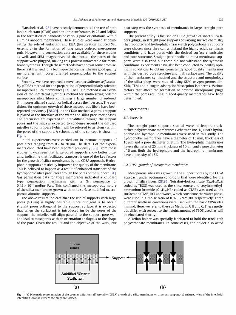
Recently, we have reported a novel counter diffusion self assem-bly (CDSA) method for the preparation of perpendicularly orientedmesoporous silica membranes [27]. The CDSA method is an exten-sion of the interfacial synthesis method for synthesizing orderedmesoporous silica fibers containing a large number of ordered,3 nm pores aligned straight or helical across the fiber axis. The con-ditions for optimum growth of these mesoporous fibers have beenreported previously [28,29]. In the CDSA method, a porous supportis placed at the interface of the water and silica precursor phases.The precursors are expected to inter-diffuse through the supportpores and the silica is expected to condense around the diffusedmicelles to form fibers (which will be referred to as plugs) withinthe pores of the support. A schematic of this concept is shown inFig. 1.
Initial experiments were carried out in tortuous supports ofpore sizes ranging from 0.2 to 20 lm. The details of the experi-ments conducted have been reported previously [30]. From thesestudies, it was seen that large-pored supports show better plug-ging, indicating that facilitated transport is one of the key factorsfor the growth of silica membranes by the CDSA approach. Hydro-phobic supports drastically improved the quality of the membrane.This is believed to happen as a result of enhanced transport of thehydrophobic silica precursor through the pores of the support [31].Gas permeation data for these membranes indicated a Knudsentype permeation mechanism with a N2 permeance of0.45 � 10�7 mol/m2 Pa s. This confirmed the mesoporous natureof the silica membranes grown within the surface modified macro-porous alumina supports.
The above results indicate that the use of supports with largepores (>3 lm) is highly desirable. Since our goal is to obtainstraight pores orthogonal to the support surface, it is expectedthat when the surfactant is introduced inside the pores of thesupport, the micelles will align parallel to the support pore walland lead to mesopores with an orientation analogous to the shapeof the pore. Given the results and the objective of the work, our
Fig. 1. (a) Schematic representation of the counter diffusion self assembly (CDSA) growinteraction locations where the plugs are formed.
next step was the synthesis of membranes in large, straight poresupports.
The present study is focused on CDSA growth of short silica fi-bers (plugs), in straight pore supports of varying surface chemistry(hydrophobic and hydrophilic). Track-etch polycarbonate supportswere chosen since they can withstand the highly acidic synthesisconditions and have pores with the desired surface chemistriesand pore structure. Straight pore anodic alumina membrane sup-ports were also tried but these did not withstand the synthesisconditions. Experiments have also been conducted to identify opti-mum conditions to obtain consistently good quality membraneswith the desired pore structure and high surface area. The qualityof the membranes synthesized and the structure and morphologyof the silica plugs were studied using SEM, oxygen permeation,XRD, TEM and nitrogen adsorption/desorption isotherms. Variousfactors that affect the formation of ordered mesoporous plugswithin the pores resulting in good quality membranes have beendetermined.
2. Experimental
2.1. Supports
The straight pore supports studied were nucleopore track-etched polycarbonate membranes (Whatman Inc., NJ). Both hydro-phobic and hydrophilic membranes were used in this study. Thehydrophobic membranes have a diameter of 13 mm, thickness of10 lm and a pore diameter of 8 lm. The hydrophilic membraneshave a diameter of 25 mm, thickness of 10 lm and a pore diameterof 5 lm. Both the hydrophobic and the hydrophilic membraneshave a porosity of 15%.
2.2. CDSA growth of mesoporous membranes
Mesoporous silica was grown in the support pores by the CDSAapproach under optimum conditions that were identified for thegrowth of silica fibers [28,29]. Tetrabutylorthosilicate (C16H36O4Sicoded as TBOS) was used as the silica source and cetyltrimethyl-ammonium bromide (C19H42NBr coded as CTAB) was used as thesurfactant. CTAB, HCl and water, which constitute the water phase,were used in a molar ratio of 0.025:2.92:100, respectively. Threedifferent synthesis conditions were used with the basic CDSA ideain mind. Here, we refer to these as Methods A, B and C. These meth-ods differ with respect to the height/amount of TBOS used, as willbe elucidated shortly.
A Teflon holder was specially fabricated to hold the track-etchpolycarbonate membranes. In some cases, the holder also acted
th of a silica membrane on a porous support, (b) enlarged view of the interfacial

230 S.K. Seshadri et al. / Microporous and Mesoporous Materials 129 (2010) 228–237
as a reservoir to hold the silica source. The holder consisted of a capwhere the polycarbonate support was placed and a tube that wasscrewed into it to hold the support in place. A schematic of theCDSA growth approach and experimental setups for the three dif-ferent methods are shown in Figs. 1 and 2. The three synthesismethods are described next.
2.2.1. Method AThe holder, with the support, was placed at the surface of the
aqueous solution of H2O, CTAB and HCl, with one surface of thesupports facing the solution, as shown in Fig. 2a. TBOS was addedinside the tube onto the top of the support surface. The height ofTBOS in the tube above the support is denoted by the letter Hand the thickness of the membrane support is denoted by the letterh, here H/h >> 1 (typically about 10,000).
2.2.2. Method BThis method aims to examine the effect of facilitated evapora-
tion on the pore structure of the plugs. A schematic of this methodis shown in Fig. 2b. Here, the holder was inverted so that the tubewas in the water phase and acted as a mechanical support to holdthe polycarbonate support in place. TBOS was added to the top sur-face of the support as a thin layer to facilitate evaporation of thebyproducts (H/h > 1, typically about 10).
2.2.3. Method CMethod C aims to examine the effect of evaporation and sup-
port placement on membrane quality. Fig. 2c shows a schematicof this method. In this case, the support was soaked in TBOS; henceacting as a reservoir for TBOS (H/h = 1). This was then placed at theinterface where it floated for the entire duration of the experiment.
Once the experiments were set up, the silica precursor andwater phases with surfactant were allowed to inter-diffusethrough the support for 14 days. After growth, the membraneswere dried in air at room temperature and were characterized.
2.3. Membrane characterization
Two important criteria were used in defining the quality of themembranes. The first defining criterion was the plugging of poresof the supports. A membrane was considered to be of good qualityif 90% or more of its pores were plugged. The second criterion wasthe microstructure of the plugs. A plug was said to have the re-quired microstructure if its pore diameter and ordering were sim-ilar to that seen in MCM-41. The first criterion was studied usingSEM images (FEI XL30) and gas permeation tests. SEM micrographswere used as a visual tool to assess the quality and the morphologyof the plugs in the support pores. Oxygen permeation experiments
H
hHh
H /h > > 1 H /h >
Water +HCl + Surfactant
(b)(a)
Fig. 2. Schematic representation of (a) Meth
with constant transmembrane pressure were conducted to charac-terize the overall quality of the membranes. Fig. 3 shows the sche-matic representation of the permeation setup used. This setup wasspecially built with a Wicke–Kalenbach cross flow pattern to avoidthe removal of the silica plugs. Here, 95% nitrogen and 5% oxygenwas fed on the feed side and a total flow rate of 50 cc/min wasmaintained. Nitrogen sweep was fed on the permeate side at a flowrate of 50 cc/min. Oxygen transmembrane pressure, defined as thepartial pressure difference between the feed and permeate, was5000 Pa. The oxygen concentration in the permeate side was ana-lyzed using an oxygen sensor (6000 Oxygen Analyzer, IllinoiseInstruments).
It should be noted that the upper limit of the gas permeancemeasured by the permeation apparatus under the flow conditionsdescribed above is 1.0 � 10�5 mol/m2 Pa s (measured with anempty cell). The gas permeance for the fresh polycarbonate poly-mer supports, due to the small support thickness and large pores,is higher than this value. Therefore, gas permeance for the polymersupport was estimated using the equimolecular counter diffusionmodel as shown in Eq. (1):
F ¼ JDP¼ Deff
1LRT
ð1Þ
where Deff is effective diffusion coefficient calculated from theChapman–Enskong equation considering 15% porosity of the mem-brane, R is the universal gas constant, T is temperature and L is thethickness of the membrane (10 � 10�6 m). The oxygen permeancewas estimated to be 1.2 � 10�4 mol/m2 Pa s, which is used as thepermeance for the polymer supports before deposition of silicaplugs.
The second criterion, that is the microstructure of the plugs,was analyzed using XRD, nitrogen porosimetry and TEM studies.The ordering of the mesopores in the silica plugs was examinedby XRD (Bruker D8 Focus, CuKa) on the membrane samples. Porestructure of the silica plugs was characterized by nitrogen porosi-metry (Micromeritics ASAP2020). Nitrogen adsorption/desorptionisotherms of mesoporous silica plugs were measured at liquidnitrogen temperature (77 K). For proper characterization of the sil-ica plugs, they had to be extracted from the support and calcined toremove the surfactant. The support is polymeric, thus it can be re-moved by decomposition at high temperature. Both supportdecomposition and surfactant removal can be performed in a sin-gle heat treatment step. TGA (Setaram TG-92) analysis was under-taken to determine the appropriate conditions for decompositionof the polymer support and surfactant. For this, the system washeated at a rate of 0.5 �C/min to 600 �C where it was held for 5 h,and then cooled to room temperature at a rate of 0.5 �C/min. Giventhat each membrane resulted in a small sample size of silica plugs
H~h
1 H /h ~1
Silica Source
(c)
Support
od A, (b) Method B, and (c) Method C.

Fig. 3. Schematic representation of oxygen permeation setup.
S.K. Seshadri et al. / Microporous and Mesoporous Materials 129 (2010) 228–237 231
which was insufficient for providing accurate characterization re-sults, 9–15 membranes of each type were collected. This resultedin approximately 5–10 mg worth of silica plugs for nitrogen poros-imetry analysis. The decomposition/calcination step, which wasascertained from TGA analysis, was performed as follows: Themembranes were collected in a porcelain dish and heated to600 �C, to ensure complete surfactant removal, at a ramp rate of2 �C/min. The furnace was held at this temperature for 6 h to en-sure complete decomposition of the polymer support and removalof the surfactant. Porosimetry studies were then conducted to ana-lyze nature of the pores present within the plugs. TEM imaging wasconducted using JOEL JEM-2010F transmission electron micro-scope operated at 200 kV to identify the pore structure and orien-tation within the plugs. The TEM samples were prepared bydispersing plugs, collected from the decomposition/calcinationstep in ethanol. The sample was then collected on the TEM gridsfor imaging.
3. Results and discussion
3.1. Results of membranes synthesized by three methods
3.1.1. CDSA growth by Methods A and BAs stated previously Method A involved the basic CDSA method
while Method B was a modification on the method to allow evap-oration. Fig. 4 compares SEM micrographs of hydrophobic (Fig. 4b)and hydrophilic (Fig. 4c) polycarbonate supports after CDSAgrowth of silica plugs by Method A with that of a fresh polycarbon-ate support (Fig. 4a). As shown, the pores of both supports werefilled with silica plugs. By using the CDSA method, we were ableto grow plugs that ran the entire length of the support pores. Themorphology of the plugs, as seen by SEM, was typical of that seenin MCM-41 fibers (Fig. 4d). Fig. 5a and b show SEM micrographs ofthe hydrophobic and hydrophilic supports after CDSA synthesis byMethod B. Complete plugging of the pores was achieved in the
hydrophobic support, whereas the hydrophilic support did notshow the formation of good quality plugs. There was however, asmall gap (around 0.2 lm), between the plug and the pore wallin all membranes synthesized by both methods. These gaps weremost likely formed due to the shrinkage of the plugs upon drying.
Results of permeation studies are summarized in Table 1. Thepermeance of the as-synthesized hydrophobic membranes was1.4 � 10�6 and 5.3 � 10�6 mol/m2 Pa s for Methods A and B,respectively. To verify that this is the expected permeance forthe as-synthesized membrane, the theoretical permeance was cal-culated for a membrane that was 100% plugged with a 0.2 lm gapbetween the plug and pore wall. This permeance was estimated tobe 9.0 � 10�6 mol/m2 Pa s. The experimental permeance of themembrane is lower than the estimated permeance. This differencecan be attributed to the fact that all the plugs do not have exactlythe same diameter. This results in gaps of various dimensions, butnot exceeding 0.2 lm. Hence the two order decrease in the magni-tude of permeance form the fresh membrane permeance indicatesthat all support pores were plugged.
XRD studies of the membranes synthesized by Method Ashowed no ordered peaks. Fig. 6a(i) and (ii) show the XRD patternsfor the hydrophobic and hydrophilic membranes synthesized byMethod B. XRD peaks revealed the presence of long range orderin the pores of the plug, as seen by the three peaks indexed as(1 0 0), (2 0 0) and (1 1 0) planes.
Fig. 7 shows the results of TGA analysis on two hydrophobicmembranes to find the optimum temperature for surfactant andpolymer decomposition. The data given in Fig. 7 reveal that boththe polymer and the surfactant are completely decomposed at600 �C. The initial weight loss of about 2.5% begins at around145 �C, which corresponds to the glass transition temperature ofthe polymer. At 220 �C, the surfactant begins to decompose, asindicated by the peak in the DTG curve [32]. Previous studies haveshown that beyond this stage, there is water loss due to condensa-tion of silanol groups to form siloxane bonds, which results in con-

Fig. 4. SEM image of polycarbonate track-etch supports, (a) top view of a fresh track-etch membrane before CDSA growth, (b) top view of hydrophobic support after CDSAgrowth by Method A showing complete plugging, (c) top view of hydrophilic support after CDSA growth by Method A showing complete plugging, (d) cross sectional view ofmembrane showing silica plug running through the length of the support pore.
Fig. 5. SEM micrograph of top view of (a) hydrophobic showing complete plugging and (b) hydrophilic support showing incomplete plugging after CDSA growth by Method B.
Table 1Results of permeation studies and characteristics of plugs from hydrophobic track-etch membrane supports.
Membrane Fresh support permeance(10�6 mol/m2 Pa s)a
O2 permeance (10�6 mol/m2 Pa s)
d100
spacingWall thickness(nm)
Pore volume(cm3/g)
BET surface area(m2/g)
BJH pore size(nm)
Method A 1.4 – – 0.20 312 3.1Method B 120 5.3 4.2 2.1 0.26 379 2.7Method C 3.7 4.2 2.1 0.60 990 2.7
a Theoretical permeance.
232 S.K. Seshadri et al. / Microporous and Mesoporous Materials 129 (2010) 228–237
tinued weight loss until 550 �C. The polymer begins to degrade ataround 350 �C and continues to degrade until around 550 �C atwhich complete decomposition is achieved [33]. Beyond this tem-perature, the weight of the sample remained constant indicatingthat complete decomposition of both polymer and surfactant hadtaken place. There was a total of 82% weight loss in the system.
Porosimetry studies on silica plugs removed from the mem-branes synthesized by Method A (on both hydrophobic and hydro-philic supports) did not show a narrow pore size distributioncharacteristic of MCM-41 type mesoporous material. It is possiblethat the test sample, consisting of plugs from nine different mem-branes, contained a mixture of plugs which had ordered pores and
those that did not exhibit any ordering, possibly resulting in theoutcome for the tests conducted. On the other hand, membranessynthesized by Method B revealed a Type-IV isotherm, which is acharacteristic of mesoporous materials with well-aligned channels(Figs. 8 and 9). Plugs from both hydrophobic and hydrophilic sup-ports revealed a narrow pore size distribution with mean BJHdiameter values, obtained from the desorption branch, being 2.7and 2.6 nm, respectively (inset of figures). These values are similarto those obtained from the adsorption branch which is indicative ofuniform cylindrical pore shapes. Porosimetry studies of the plugsfrom hydrophobic membranes are presented along with perme-ation data in Table 1. The plugs had a BET surface area of

(b)
2 3 4 5 6 7
(i)
(ii)
200110
100
100
200110
x 5
x 5
Inte
nsity
2θ2 3 4 5 6 7
x 5
x 5
100
100
200110
(i)
(ii)
200110
Inte
nsity
(a)
2θ
Fig. 6. XRD patterns showing an ordered mesoporous structure of plugs in the as-synthesized membrane after CDSA growth by (a) Method B and (b) Method C on (i)hydrophobic and (ii) hydrophilic track-etch supports, respectively.
0 5 10 15 20 25 30 35 40 45 50-3.5
-3.0
-2.5
-2.0
-1.5
-1.0
-0.5
0.0
0.5
-0.5
-0.4
-0.3
-0.2
-0.1
0.0
DTG
(%/m
in)
Wei
ght (
mg)
Time (hr)
Cooling
550oC
450oC
375oC
220oC
Fig. 7. TGA data of the as-synthesized hydrophobic polycarbonate membranes.
0.0 0.2 0.4 0.6 0.8 1.00
50
100
150
200
0 2 4 6 8 10 12 14
Pore
Vol
ume
Pore Diameter (A)Qua
ntity
Ads
orbe
d(cm
3 /g S
TP)
Relative pressure (P/Po )
Adsorption Desorption
Fig. 8. Nitrogen adsorption/desorption isotherm of the plugs from the membranessynthesized using hydrophobic supports by Method B; Inset – BJH pore sizedistribution.
0.0 0.2 0.4 0.6 0.8 1.00
50
100
150
200
250
300
350
Qua
ntity
Ads
orbe
d (c
m3/g
STP
)
Relative Pressure (P/PO)
Adroption Desoption
0 1 2 3 4 5 6 7 8
Pore
Vol
ume
Pore Diameter (nm)
Fig. 9. Nitrogen adsorption/desorption isotherm of the plugs from membranessynthesized using hydrophilic supports by Method B; Inset – BJH pore sizedistribution.
S.K. Seshadri et al. / Microporous and Mesoporous Materials 129 (2010) 228–237 233
379 m2/g and a pore volume of 0.26 cm3/g, while the plugs fromthe hydrophilic membranes had a surface area of 836 m2/g and apore volume of 0.59 m2/g.
It was seen that membranes formed by Method A had goodquality plugging, but the plugs did not show the required micro-
structure. Method B, on the other hand, showed good quality plug-ging and the plugs showed the required microstructure, indicatingthe evaporation of solvent and byproducts is key to the formationof an ordered structure. However, in some instances with MethodB, it was observed that silica deposited or grew as particulate mat-ter on the surface of the support and not as plugs within the pores.This was likely due to improper placement of the polycarbonatesupport at the surface of the water phase during synthesis. Thisvariability in results due to experimental error led to the develop-ment of Method C.
3.1.2. CDSA growth by Method CMethod C was used to ensure both precise placement of the
support and facilitated evaporation of solvent and byproducts. Itwas observed that membranes synthesized by Method C had a thinfilm on the surface of the polycarbonate support on the TBOS side.SEM micrographs (Fig. 10a) revealed that 90% or more of the poreswere plugged in the case of hydrophobic supports. On the otherhand, hydrophilic supports exhibited heavy particulate depositionand no plugging, as seen in Fig. 10b. The inset in Fig. 10a reveals aplug that was removed by decomposing the polycarbonatesupport.
The plugs in the hydrophobic supports were seen to be wellformed and uniform. The presence of plugs in all the support pores

0.0 0.2 0.4 0.6 0.8 1.00
100
200
300
400
0 2 4 6 8 10 12 14
Pore
Vol
ume
Pore Diameter (A)
Qua
ntity
Ads
orbe
d(cm
3 /g S
TP)
Relative Pressure (P/P0)
Adsorbtion Desorbtion
Fig. 11. Nitrogen adsorption/desorption isotherm of the plugs from membranessynthesized using hydrophobic supports by Method C; Inset – BJH pore sizedistribution.
0.0 0.2 0.4 0.6 0.8 1.0
0
100
200
300
400
Qua
ntity
Ads
orbe
d (c
m3 /g
STP
)
Relative pressure (P/P0)
Adsorbtion Desorbtion
0 2 4 6 8 10 12 14
Pore
Vol
ume
Pore Diameter (nm)
Fig. 12. Nitrogen adsorption/desorption isotherm of the plugs from membranessynthesized using hydrophilic supports made by Method C; Inset – BJH pore sizedistribution.
Fig. 10. SEM micrograph showing (a) good quality plugging of a polycarbonate track-etch hydrophobic support after CDSA growth by Method C, Inset – plug extracted afterpolymer decomposition and (b) no plugging in the hydrophilic support after CDSA growth by Method C.
234 S.K. Seshadri et al. / Microporous and Mesoporous Materials 129 (2010) 228–237
was further verified by permeation studies. Oxygen permeance ofthe as-synthesized hydrophobic membrane was 3.7 � 10�6 mol/m2 Pa s. The two order magnitude decrease in permeance showsthat good quality support plugging was achieved, as discussedearlier.
The presence of ordered mesoporous silica in hydrophobic sup-ports was also verified by XRD data as shown in Fig. 6b(i). Theseparticles deposited on hydrophilic support also showed an orderedmesoporous structure, as indicated by XRD studies (Fig. 6b(ii)). Thepresence of three peaks in the pattern verifies the presence of longrange order in both systems. The intensity of the peaks for thehydrophobic support systems is seen to be lower than that of peaksfor the hydrophilic system. This is believed to occur since the mes-oporous material is embedded in the polymer matrix which re-duces the intensity of the interfering reflected beam. Figs. 11 and12 show nitrogen sorption isotherms of the calcined silica plugsobtained from the hydrophobic and hydrophilic support, respec-tively. Table 1 summarizes the results of the characterization stud-ies. A narrow pore size distribution with a mean BJH diametervalue of 2.7 nm was obtained for the hydrophobic plugs. Theseplugs had a surface area of 990 m2/g and a pore volume of0.6 cm2/g. The hydrophilic membranes, on the other hand, showeda bimodal pore size distribution with pore sizes of 2.5 and 3.9 nm,a surface area of 823 m2/g and a pore volume of 0.57 cm2/g. It isobserved that the surface area of the plugs prepared by MethodC is larger than that for plugs synthesized by Method B. It has beenpreviously studied that amorphous silica has a surface area in therange of 200–300 m2/g [1]. On the other hand, mesoporous silicawith MCM-41 type structures has been observed to have surfaceareas greater than 800 m2/g (typically 1000 m2/g) [2]. The results
obtained in Method C are typical of what is expected for MCM-41 materials. It is believed that the high surface area is achievedin Method C due the reduction in experimental variability whichconsistently results in highly ordered MCM-41 membranes. Meth-od B, on the other hand, showed a lower BET surface area, which isindicative of a mixture of well ordered and amorphous silica.
TEM imaging was performed on plugs from membranes synthe-sized by Method C on hydrophobic supports, as these revealed thebest results of all synthesis procedures evaluated. Fig. 13a shows alow magnification image of the entire plug. Fig. 13b–f show highmagnification images of the edges of the plug, which were thinand electron transparent. The inset in these images shows the cor-responding diffraction pattern. Here, the image and the pattern aretaken with [1 0 0] incidence, which is perpendicular to the chan-nels. Highly organized parallel channels were observed in the highmagnification TEM images. It was also revealed that the channelsare tilted at an angle of about 30� to the surface of the plug. Thepresence of highly ordered channels at both extreme ends of theplug indicates that the channels run through the length of the plug.The diffraction patterns show two distinct points that confirm longrange, twofold symmetry in the system.
The TEM images, combined with XRD and porosimetry studiesreveal that the plugs have highly ordered pores with the requiredhexagonal ordering; a key characteristic of MCM-41 type mate-rial. SEM and permeation studies also revealed that good plug-ging of the hydrophobic support has been achieved. Thisindicates that evaporation induced self assembly and placementof support are the key factors that promote good membraneformation.

S.K. Seshadri et al. / Microporous and Mesoporous Materials 129 (2010) 228–237 235
3.2. Discussion
The above studies indicate that good quality membranes withcomplete pore plugging can be fabricated by the CDSA method.Three variables that affect plug formation have been studiedviz. surface chemistry, membrane position and evaporation in-duced self assembly. It has been seen that hydrophobic mem-branes yield the best quality membrane. In the case ofhydrophilic membranes, it was seen that the plugs were notformed or those that were formed were not of good quality. Thiscan be attributed to the forces in play in the two systems. Surfac-tants tend to assemble on the surface of the substrate based onattractive (hydrophobic/hydrophilic and van der Waals) forces.In the case of hydrophobic surfaces, the attractive forces betweenthe hydrophobic tail of the surfactant and the surface facilitateorientation of the surfactant in hemispherical tubes which givesrise to long range ordering. While in the case of hydrophilicsurfaces, interaction of the surface is with the smaller head groupwhich results in surfactants ordered in a tubular fashion. Becausethe area of contact is higher in the case of hydrophobic interac-tion better ordering is achieved in the system [34]. It is also be-lieved that the hydrophilic surface is preferentially wet by thewater phase, which wets both the pores and surface of thesupports. The silica source, having a higher concentration atthe surface, preferentially condenses at the surface formingparticulates.
Fig. 13. TEM image of a plug removed from a membrane synthesized on a hydrophmagnification images of the sections revealing well ordered channels in the plug. Inset
The second criterion for the formation of a good quality mem-brane is the position of the support. It is known that the fibers format the interface of the oil and water phases as the reactants and thestructure directing agents are all available at their optimum con-centrations. If the support is not placed exactly at the interface,the reaction interface is shifted to a lower or a higher positionresulting in supports that are not plugged. This is revealed byMethod B, where some membranes were better plugged than oth-ers. Our studies have shown that the best quality membranes areobtained by Method C. Since the alignment is not done manuallyand the support floats on the surface, the error in positioning themembrane is eliminated.
The third criterion for the formation of a good quality mem-brane by the CDSA method is allowing for the evaporation of sol-vent and byproducts. Numerous studies have indicated thatevaporation can influence the formation of specific micelle struc-tures [34–38]. The evaporation-induced self-assembly theory pro-poses that preferential evaporation of the solvent and alcoholbyproduct from the surface induces the formation of surfactant mi-celles and further organization of the mesophase. The role of evap-oration has not been studied for the interfacial growth of fibers toour knowledge. To understand why Method A does not result in or-dered mesopores, it is first necessary to understand the formationprocess of the silica fibers.
It is widely accepted that the formation of long range orderedmesoporous materials starts with the formation of a seed. Topo-
obic support by Method C. (a) Low magnification image of the plug (b–f) highin the images show the corresponding diffraction patterns.

236 S.K. Seshadri et al. / Microporous and Mesoporous Materials 129 (2010) 228–237
graphical defects in the seeds give rise to long range order in mes-opores [39]. The basic pathway for acid synthesis has been pro-posed by Huo et al. [40]. According to this mechanism, the anionfrom the acid forms a counter-ion pair with the cationic head ofthe surfactant forming an electrical double layer. The protonatedsilica species undergoes hydrolysis and condensation around thisdouble layer with the exclusion of the anionic halide.
During the formation of fibers, TBOS diffuses slowly through thewater phase and undergoes slow hydrolysis and condensationaround the preexisting micelles, following the same mechanismas observed in acid synthesis. This acts as a nucleation seed for fi-ber growth, which then grows to form worm like micelles. It hasbeen proposed in various studies that once formed, these micellesare flexible and undergo restructuring and aggregation due to vander Waals forces exerted by the condensed silica [41]. This restruc-turing results in the formation of long range ordered fibers. How-ever, for the formation of these aggregates, it is necessary for theseeds to grow. This is only possible if there is a constant supplyof reactants and surfactants to the interface. So far, there has beenno theory to our knowledge that explains this mechanism. We pro-pose a simple mechanism for maintaining a constant surfactantsupply.
Given the highly acidic conditions for synthesis, we expect ahydrolysis product, butanol, to be formed [42]. Butanol then mixeswith the TBOS, resulting in an increase in mixing between thewater and oil phases. As more TBOS diffuses into the water phaseand becomes protonated, more butanol is formed as a byproduct.When the oil layer is thin, fast mixing occurs between the twophases at the interface. As the reaction proceeds, more alcohol isformed. Consequently, alcohol and water begin to evaporate fromthe surface, thus causing an increase in the local surfactant concen-tration. Meanwhile, concentration gradients are established withinthe system. Surfactant consumption is accompanied by an increasein the condensation of silica, resulting in an increase in the alcoholbyproduct and evaporation of solvent. The process helps to main-tain a constant surfactant supply at the surface. A schematic of thisexplanation is shown in Fig. 14.
Platschek et al. [43] have conducted an in situ GISAXS study onthe formation of mesophases in anodic alumina membranes. Thesestudies indicate that mesostructure did not form until criticalmicellar concentration (CMC) of CTAB was reached. Given that inthe present system the surfactant concentration is lower thanCMC, evaporation will need to occur for the concentration to in-crease. Previous studies conducted in our laboratory have shownthat the fibers grow in a bottom-down approach [44]. This wouldmean that a constant supply of surfactant is maintained at theinterface, as growth is taking place at the interface. Again, this isonly possible if there is solvent evaporation which increases localsurfactant concentrations. Studies have shown that the morphol-ogy of the silica products formed at the interface is highly depen-dent on the silica source used [41]. When low order alkoxysilanes
SilicaSource
Silica Source Water Phase Mic
Surfactant
(1) (2)
Fig. 14. Schematic representation of fiber formation process (1) initial configuration shodiffusion of silica source and water phase accompanied by the evaporation of water andof water and alcohol resulting in a local increase in surfactant concentration making mice
are used in the absence of a co-solvent, various morphologies areobtained. It is seen that when higher order alkoxysilanes, such asTBOS, are used, fibers can be formed in the absence of a co-solvent.This is because the reaction rate is lower in the case of higher orderalkoxysilanes, allowing for an increase in local surfactant concen-tration by allowing time for the evaporation of the byproducts atthe interface. Lastly, this study has revealed that Methods B andC yielded well ordered plugs while Method A resulted in amor-phous plugs. The only difference between the three being thatMethods B and C allowed evaporation to occur while Method Adid not facilitate evaporation. All these factors indicate that theevaporation of solvent is a key point in maintaining a constant sup-ply of surfactant.
While we have been able to fabricate membranes that are wellplugged and have the desired pore structure, it is seen that a gap isformed between the plug and the support in all three methods,which needs to be addressed before these membranes can be usedfor separation purposes. Once the gaps are sealed, these mem-branes will offer separability of mixed gases determined primarilyby the Knudsen diffusion mechanism, where the selectivity is in-versely proportional to the square root of the molecular weight,due to pores in the meso-size range [27]. In contrast, other micro-porous silica membranes such as MFI type zeolite membranes [45]exhibit better separability for gas mixtures determined by a num-ber of different separation mechanisms including, but not limitedto the molecule sieving [46]. These membranes, obviously, offerseparability for large molecules including proteins of various sizes,making them attractive for liquid separation applications.
Overall, it has been shown that the CDSA growth method yieldsgood quality silica plugs in the case of hydrophobic supports byMethods B and C. Consistently good quality membranes were fab-ricated using Method C. Transport of precursors, placement of thesupport and evaporation of byproducts play the key roles in theformation of good quality membranes.
4. Conclusions
The counter diffusion self assembly (CDSA) approach wasshown to be effective for synthesizing mesoporous silica mem-branes. Results on straight pore polycarbonate track-etch supportshave shown that good quality membranes can be synthesized viathis method. It was seen that while good quality plugging can beachieved in Method A, in the absence of evaporation induced selfassembly, the desired microstructure of the plugs cannot beachieved. Methods B and C, on the other hand, showed not onlygood support pore plugging, but also the required pore structurein the plugs, with Method C showing higher consistency. The keyfactors for membrane formation were the facilitated transport ofthe precursors, support placement and evaporation of solventand byproducts. Macroporous straight pore supports facilitate the
Water +Alcohol
elle
(3)Water +Alcohol
Fibers
wing two distinct layers, viz. the silica source phase and the water phase, (2) inter-alcohol byproduct, increasing the local surfactant concentration, (3) the evaporationlles available at the interface to facilitate continuous growth of fibers at the interface.

S.K. Seshadri et al. / Microporous and Mesoporous Materials 129 (2010) 228–237 237
diffusion of the hydrophobic silica precursor and the amphiphilicsurfactant, leading to the formation of an ordered mesoporousstructure within support pores. The hydrophobic supports yieldbetter quality membranes than hydrophilic supports under thepresent synthesis conditions. There is however a small gap be-tween the plugs and pore due to shrinkage on drying that is seenin all synthesis methods. Future studies need to be undertaken toplug this gap. Overall, this study has shown a way to synthesizegood quality mesoporous silica membranes, which will lead tounprecedented applications in various industries.
Acknowledgments
The project was supported by Petroleum Research Fund admin-istered by the American Chemical Society. We gratefully acknowl-edge the support and use of the facilities in the LeRoy Eyring Centerfor Solid State Sciences (LE-CSSS) at Arizona State University.
References
[1] C.T. Kresge, M.E. Leonowicz, W.J. Roth, J.C. Vartuli, J.S. Beck, Nature 359 (1992)710–712.
[2] X.S. Zhao, G.Q. Lu, G.J. Millar, Ind. Eng. Chem. Res. 35 (1996) 2075–2090.[3] X. Liu, Y. Du, Z. Guo, S. Gunasekaran, C. Ching, Y. Chen, S.S.J. Leong, Y. Yang,
Microporous and Mesoporous Mater. 122 (2009) 114–120.[4] T. Salesch, S. Bachmann, S. Brugger, R. Rabelo-Schaefer, K. Albert, S.
Steinbrecher, E. Plies, A. Mehdi, C. Rey, R.J.P. Corriu, E. Lindner, Adv. Funct.Mater. 12 (2002) 134–142.
[5] S. Ajaikumar, A. Pandurangan, Appl. Catal. A Gen. 357 (2009) 184–192.[6] D. Moelans, P. Cool, J. Baeyens, E.F. Vansant, Catal. Commun. 6 (2005) 307–311.[7] J.Y. Chen, F.M. Pan, L. Chang, A.T. Cho, J. Chao, J. Vac. Sci. Technol. 23 (2005)
2034–2040.[8] P. Innocenzi, A. Martucci, M. Guglielmi, A. Bearzotti, E. Traversa, J.C. Pivin, J.
Eur. Ceram. Soc. 21 (2001) 1985–1988.[9] M.A. Semsarzadeh, A. Aghili, J Macromaol. Sci. A 45 (2008) 680–686.
[10] V.V. Guliants, M.A. Carreon, Y.S. Lin, J. Membr. Sci. 235 (2004) 53–72.[11] S.H. Zhong, C.F. Li, Q. Li, X.F. Xiao, Sep. Purif. Technol. 32 (2003) 17–22.[12] L. Huang, S. Kawi, K. Hidajat, S.C. Ng, Microporous Mesoporous Mater. 88
(2006) 254–265.[13] H. Miyata, T. Noma, M. Watanabe, K. Kuroda, Chem. Mater. 14 (2002) 766–772.[14] Y. Yamauchi, M. Sawada, T. Noma, H. Ito, S. Furumi, Y. Sakka, K. Kuroda, J.
Mater. Chem. 15 (2005) 1137–1140.[15] K. Kuraoka, Y. Tanaka, M. Yamashita, T. Yazawa, Chem. Commun. 10 (2004)
1198–1199.[16] H.W. Hillhouse, T. Okubo, J.W. van Egmond, M. Tsapatsis, Chem. Mater. 9
(1997) 1505–1507.
[17] J. Otomo, S. Wang, H. Takahashi, H. Nagamoto, J. Membr. Sci. 279 (2006) 256–265.
[18] S. Nagarajan, M. Li, R.A. Pai, J.K. Bosworth, P. Busch, D.-M. Smilgies, C.K. Ober,T.P. Russell, J.J. Watkins, Adv. Mater. 20 (2008) 246–251.
[19] V.R. Koganti, S.E. Rankin, J. Phys. Chem. 109 (2005) 3279–3283.[20] P. Lai, M.Z. Hu, D. Shib, D. Bloma, Chem. Commun. 11 (2008) 1338–1348.[21] Z. Liang, A.S. Susha, Chem. Eur. J. 10 (2004) 4910–4914.[22] Y. Wu, G. Cheng, K. Katsov, S.W. Sides, J. Wang, J. Tang, G.H. Fredrickson, M.
Moskovits, G.D. Stucky, Nat. Mater. 3 (2004) 816–822.[23] J. Fan, S.W. Boettcher, C.-K. Tsung, Q. Shi, M. Schierhorn, G.D. Stucky, Chem.
Mater. 20 (2008) 909–921.[24] A. Yamaguchi, F. Uejo, T. Yoda, T. Uchida, T. Tanamura, T. Yamashita, N.
Teramae, Nat. Mater. 3 (2004) 337–341.[25] Q. Lu, F. Gao, S. Komarneni, T.E. Mallouk, J. Am. Chem. Soc. 126 (2004) 8650–
8651.[26] B. Platschek, N. Petkov, Thomas Bein, Angew. Chem. Int. Ed. 45 (2006) 1134–
1138.[27] H.M. Alsyouri, D. Li, Y.S. Lin, Z. Ye, S.P. Zhu, J. Membr. Sci. 282 (2006) 266–275.[28] Q.S. Huo, D.Y. Zhao, J.L. Feng, K. Weston, S.K. Buratto, G.D. Stucky, S. Schacht, F.
Schuth, Adv. Mater. 9 (1997) 974–978.[29] H.M. Alsyouri, Y.S. Lin, Chem. Mater. 15 (2003) 2033–2039.[30] J. Wang, W. Wang, P. Sun, Z. Yuan, Q. Jin, D. Ding, T. Chen, Mater. Lett. 61
(2007) 4492–4495.[31] H.M. Alsyouri, Y.S. Lin, J. Phys. Chem. B 109 (2005) 13623–13629.[32] S.A. Araujo, M. Ionashiro1, V.J. Fernandes Jr., A.S. Araujo, J. Therm. Anal.
Calorim. 64 (2001) 801–805.[33] X. Huang, X. Ouyang, F. Ning, J. Wang, Polym. Degrad. Stab. 91 (2006) 606–613.[34] I.A. Aksay, M. Trau, S. Manne, I. Honma, N. Yao, L. Zhou, P. Fenter, P.M.
Eisenberger, S.M. Gruner, Science 273 (1996) 892–898.[35] D. Grosso, F. Cagnol, G.J. de A.A. Soler-Illia, E.L. Crepaldi, H. Amenitsch, A.
Brunet-Bruneau, A. Bourgeois, C. Sanchez, Adv. Funct. Mater. 14 (2004) 309–322.
[36] A. Gibaud, D. Grosso, B. Smarsly, A. Baptiste, J.F. Bardeau, F. Babonneau, D.A.Doshi, Z. Chen, J. Brinker, C. Sanchez, J. Phys. Chem. 107 (2003) 6114–6118.
[37] S.C. Rodner, P. Wedin, L. Bergstrom, Langmuir 18 (2002) 9327–9333.[38] K. Nakagawa, H. Matsuyama, T. Maki, M. Teramoto, N. Kubota, Sep. Purif.
Technol. 44 (2005) 145–151.[39] H. Yang, G.A. Ozin, C.T. Kresge, Adv. Mater. 10 (1998) 883–887.[40] Q. Huo, D.I. Margolese, U. Ciesla, P. Feng, T.E. Gier, P. Sieger, R. Leon, P.M.
Petroff, F. Schuth, G.D. Stucky, Nature 368 (1994) 317–321.[41] F. Kleitz, F. Marlow, G.D. Stucky, F. Schuth, Chem. Mater. 13 (2001) 3587–3595.[42] Q. Huo, D.I. Margolese, U. Ciesla, D.G. Demuth, P. Feng, T.E. Gier, P. Sieger, A.
Firouzi, B.F. Chmelka, F. Schuth, G.D. Stucky, Chem. Mater. 6 (1994) 1176–1191.
[43] B. Platschek, R. Köhn, M. Döblinger, T. Bein, Langmuir 24 (2008) 5018–5023.[44] H.M. Alsyouri, Ph.D. Dissertation, University of Cincinnati, Cincinnati, OH,
2004, p. 19.[45] M.R. Othman, S.C. Tan, S. Bhatia, Microporous Mesoporous Mater. 121 (2009)
138–144.[46] Y.S. Lin, I. Kumakiri, B.N. Nair, H. Alsyouri, Sep. Purif. Methods 31 (2002) 229–
379.