Correlations for heat generation and outer ring temperature of high speed and highly loaded ball...
7
Aerospace Science and Technology 10 (2006) 611–617 www.elsevier.com/locate/aescte Correlations for heat generation and outer ring temperature of high speed and highly loaded ball bearings in an aero-engine Korrelationen für die Wärmeentwicklung und die Aussenringtemperatur in schnelldrehenden und hochbelasteten Kugellagern eines Flugtriebwerks Michael Flouros ∗ MTU Aero Engines, Air and Oil Systems Group, Dachauer Str. 665, 80995 Munich, Germany Received 2 May 2006; received in revised form 1 August 2006; accepted 1 August 2006 Available online 18 September 2006 Abstract Advanced aircraft engine development in recent years has dictated increased rotational speeds with the consequence of increased mechanical stress requirements for rolling element bearings. A vast amount of heat is rejected which results in high oil scavenge and bearing metal temper- atures. A ball bearing and its associated chamber from an RB199 turbofan Engine were used in an experimental investigation to determine the impact of several operating parameters on the scavenge and bearing race temperatures. The test bearing was a 124 mm PCD ball bearing with a split inner-ring employing under-race lubrication by two individual jets providing oil through each half of the inner-ring. The bearing run over a wide range of D times N (DN) values ranging from 0.3 × 10 5 to 2.1 × 10 6 rpm × mm with D the bore diameter of the bearing. The direction of the oil ingestion in the bearing (for or against the direction of the axial load) was found to have a considerable effect to the oil distribution and consequently to the heat generation in it. A significant reduction in the heat to oil was achieved when the oil was fed at certain proportions (ratio) by the two nozzles. Heat to Oil and Outer ring metal temperature correlations which consider the influence of the direction of oil ingestion relative to the direction of the axial load have been developed and compared to test results. This work is part of the European Research programme Brite Euram ATOS (Advanced Transmission and Oil Systems). © 2006 Elsevier Masson SAS. All rights reserved. Zusammenfassung Die Forderung nach besser werdendem Kreisprozesswirkungsgrad hat in den letzten Jahren bei Flugtriebwerken dazu geführt, dass die Dreh- zahlen der Rotoren ständig ansteigen mit der Folge, dass auch die Lebensdaueranforderungen für die Triebwerkswälzlager ansteigen. Bedingt durch die höhere Beanspruchung der Wälzlager erreicht das für die Lagerschmierung verwendete Öl sehr hohe Austrittstemperaturen. Zudem führt die höhere Beanspruchung zu höheren Materialtemperaturen im Lager. Im Rahmen der nachfolgenden experimentellen Untersuchung wur- den ein Originalkugellager und eine Originallagerkammer aus dem RB199 Triebwerksprogramm herangezogen. Das Testkugellager hat einen Teilkreisdurchmesser von 124 mm und besitzt einen geteilten Innenring. Für die Schmierung wurden zwei Düsen eingesetzt, die das Öl jeweils durch die zwei Hälften des Innenrings in das Lager leiteten. Das Kugellager wurde im D×N -Bereich zwischen 0.3 × 10 5 bis 2.1 × 10 6 rpm × mm betrieben. D ist hier der Innenringdurchmesser (Wellendurchmesser) von 102.5 mm des Lagers und N ist die Drehzahl. Abhängig davon, wie das Öl in das Lager eingespritzt wurde (in Richtung bzw. in entgegengesetzter Richtung zur wirkenden Lageraxiallast) und zu welchen Proportionen dies geschah, gab es einen signifikanten Einfluss auf die Wärmebelastung des Öls. * Tel.: +49 89 14899192; fax: +49 89 148995341. E-mail address: michael.fl[email protected] (M. Flouros). 1270-9638/$ – see front matter © 2006 Elsevier Masson SAS. All rights reserved. doi:10.1016/j.ast.2006.08.002
-
Upload
independent -
Category
Documents
-
view
1 -
download
0
Transcript of Correlations for heat generation and outer ring temperature of high speed and highly loaded ball...
Aerospace Science and Technology 10 (2006) 611–617
www.elsevier.com/locate/aescte
Correlations for heat generation and outer ring temperature of high speedand highly loaded ball bearings in an aero-engine
Korrelationen für die Wärmeentwicklung und die Aussenringtemperaturin schnelldrehenden und hochbelasteten Kugellagern
eines Flugtriebwerks
Michael Flouros ∗
MTU Aero Engines, Air and Oil Systems Group, Dachauer Str. 665, 80995 Munich, Germany
Received 2 May 2006; received in revised form 1 August 2006; accepted 1 August 2006
Available online 18 September 2006
Abstract
Advanced aircraft engine development in recent years has dictated increased rotational speeds with the consequence of increased mechanicalstress requirements for rolling element bearings. A vast amount of heat is rejected which results in high oil scavenge and bearing metal temper-atures. A ball bearing and its associated chamber from an RB199 turbofan Engine were used in an experimental investigation to determine theimpact of several operating parameters on the scavenge and bearing race temperatures. The test bearing was a 124 mm PCD ball bearing with asplit inner-ring employing under-race lubrication by two individual jets providing oil through each half of the inner-ring. The bearing run over awide range of D times N (DN) values ranging from 0.3 × 10⁵ to 2.1 × 10⁶ rpm × mm with D the bore diameter of the bearing. The direction ofthe oil ingestion in the bearing (for or against the direction of the axial load) was found to have a considerable effect to the oil distribution andconsequently to the heat generation in it. A significant reduction in the heat to oil was achieved when the oil was fed at certain proportions (ratio)by the two nozzles.
Heat to Oil and Outer ring metal temperature correlations which consider the influence of the direction of oil ingestion relative to the directionof the axial load have been developed and compared to test results.
This work is part of the European Research programme Brite Euram ATOS (Advanced Transmission and Oil Systems).© 2006 Elsevier Masson SAS. All rights reserved.
Zusammenfassung
Die Forderung nach besser werdendem Kreisprozesswirkungsgrad hat in den letzten Jahren bei Flugtriebwerken dazu geführt, dass die Dreh-zahlen der Rotoren ständig ansteigen mit der Folge, dass auch die Lebensdaueranforderungen für die Triebwerkswälzlager ansteigen. Bedingtdurch die höhere Beanspruchung der Wälzlager erreicht das für die Lagerschmierung verwendete Öl sehr hohe Austrittstemperaturen. Zudemführt die höhere Beanspruchung zu höheren Materialtemperaturen im Lager. Im Rahmen der nachfolgenden experimentellen Untersuchung wur-den ein Originalkugellager und eine Originallagerkammer aus dem RB199 Triebwerksprogramm herangezogen. Das Testkugellager hat einenTeilkreisdurchmesser von 124 mm und besitzt einen geteilten Innenring. Für die Schmierung wurden zwei Düsen eingesetzt, die das Öl jeweilsdurch die zwei Hälften des Innenrings in das Lager leiteten. Das Kugellager wurde im D×N -Bereich zwischen 0.3×10⁵ bis 2.1×10⁶ rpm×mmbetrieben. D ist hier der Innenringdurchmesser (Wellendurchmesser) von 102.5 mm des Lagers und N ist die Drehzahl. Abhängig davon, wie dasÖl in das Lager eingespritzt wurde (in Richtung bzw. in entgegengesetzter Richtung zur wirkenden Lageraxiallast) und zu welchen Proportionendies geschah, gab es einen signifikanten Einfluss auf die Wärmebelastung des Öls.
* Tel.: +49 89 14899192; fax: +49 89 148995341.E-mail address: [email protected] (M. Flouros).
1270-9638/$ – see front matter © 2006 Elsevier Masson SAS. All rights reserved.doi:10.1016/j.ast.2006.08.002
612 M. Flouros / Aerospace Science and Technology 10 (2006) 611–617
Diese Arbeit wurde im Rahmen des Europäischen Forschungsprogramms Brite Euram ATOS (Advanced Transmission and Oil Systems) durch-geführt.© 2006 Elsevier Masson SAS. All rights reserved.
Keywords: Ball bearing; Heat to oil; Metal temperature; Correlations; Design guidelines
Schlüsselwörter: Kugellager; Wärmeproduktion; Metalltemperatur; Korrelationen; Auslegungsrichtlinien
1. Introduction
Highly loaded bearings generate heat in the contact areasbetween the rolling elements and the race, the rolling elementsand the cage and in the annular gaps between the cage and theraces. The generated heat is caused by friction in the contact ar-eas and by churning/windage as a result of dissipation of Eulerwork (acceleration to circumferential speed). Oil is usually sup-plied to rolling elements via the under-race lubrication method.Whereas only a very small amount of oil is used for lubricationmost of it is used to remove the heat from the bearing. The mainobjective in the ATOS programme was to reduce power lossesby using screens around a ball bearing in a vented chamber [4].Within the scope of this research the impact of the operating pa-rameters affecting the power losses in the bearing chamber wereinvestigated [2]. These were the oil and sealing air flow, thetemperature, the axial load, the rotor speed, the bearing cham-ber pressure and the split of the oil flow at any ratio throughthe inner ring. The wealth of information about power losses inbearings is specifically reflected in [1,5–12]. During testing aconsiderable temperature difference of the oil leaving the bear-ing from both sides was detected. This implied the presence ofa non uniform distribution of the oil in the bearing [3]. Resultsshowed minimum heat generation in the bearing when about25% of the oil was supplied through the unloaded side of theinner-ring. The correlations presented herein are the first of thiskind which take into account the direction of the oil ingestionrelative to the direction of the axial load. They have demon-
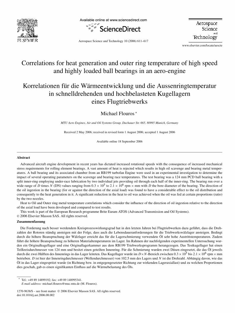
Fig. 1. Schematic of the test facility.
strated very good agreement with results from bearings withbore diameters ranging from 40 to 120 mm, a rotor speed rangebetween 6000 and 24000 rpm and up to 25 KN of axial load.
2. Rig description/instrumentation
Schematics of the test facility and the bearing chamber areshown in Figs. 1 and 2.
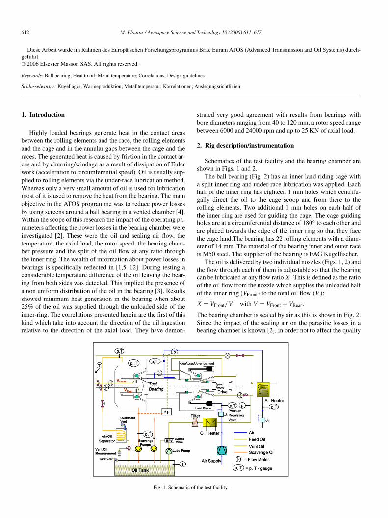
The ball bearing (Fig. 2) has an inner land riding cage witha split inner ring and under-race lubrication was applied. Eachhalf of the inner ring has eighteen 1 mm holes which centrifu-gally direct the oil to the cage scoop and from there to therolling elements. Two additional 1 mm holes on each half ofthe inner-ring are used for guiding the cage. The cage guidingholes are at a circumferential distance of 180◦ to each other andare placed towards the edge of the inner ring so that they facethe cage land.The bearing has 22 rolling elements with a diam-eter of 14 mm. The material of the bearing inner and outer raceis M50 steel. The supplier of the bearing is FAG Kugelfischer.
The oil is delivered by two individual nozzles (Figs. 1, 2) andthe flow through each of them is adjustable so that the bearingcan be lubricated at any flow ratio X. This is defined as the ratioof the oil flow from the nozzle which supplies the unloaded halfof the inner ring (VFront) to the total oil flow (V ):
X = VFront/V with V = VFront + VRear.
The bearing chamber is sealed by air as this is shown in Fig. 2.Since the impact of the sealing air on the parasitic losses in abearing chamber is known [2], in order not to affect the quality
M. Flouros / Aerospace Science and Technology 10 (2006) 611–617 613
Nomenclature
cpFS Mean specific heat Capacity FrontScavenge . . . . . . . . . . . . . . . . . . . . . . . . . . . KJ/Kg K
cpRS Mean specific heat Capacity RearScavenge . . . . . . . . . . . . . . . . . . . . . . . . . . . KJ/Kg K
D Bore diameter = 102.5 . . . . . . . . . . . . . . . . . . . . mmFax Axial load . . . . . . . . . . . . . . . . . . . . . . . . . . . . . . . . KNHTO Heat to Oil . . . . . . . . . . . . . . . . . . . . . . . . . . . . . . . . Wm Total mass flow = mFS + mRS . . . . . . . . . . . . Kg/smFS Front Scavenge mass flow . . . . . . . . . . . . . . . . Kg/smRS Rear Scavenge mass flow . . . . . . . . . . . . . . . . . Kg/sN Rotational speed . . . . . . . . . . . . . . . . . . . . . . . . . . rpmp Pressure . . . . . . . . . . . . . . . . . . . . . . . . . . . . . . . . . . barPCD Pitch Circle Diameter . . . . . . . . . . . . . . . . . . . . . mm
Q Heat to Oil (HTO) . . . . . . . . . . . . . . . . . . . . . . . . KWT Temperature . . . . . . . . . . . . . . . . . . . . . . . . . . . . . . ◦ CTA Front Scavenge Temperature . . . . . . . . . . . . . . . . ◦ CTB Rear Scavenge Temperature . . . . . . . . . . . . . . . . ◦ CTOI Oil Inlet Temperature . . . . . . . . . . . . . . . . . . . . . . ◦ CTOR Outer Ring Temperature . . . . . . . . . . . . . . . . . . . ◦ CV Total oil flow = VFront + VRear . . . . . . . . . . . . . L/HVFront Oil flow through Front jet . . . . . . . . . . . . . . . . . L/HVRear Oil flow through Rear jet . . . . . . . . . . . . . . . . . . L/HX Oil flow ratio = ratio of oil through front jet to the
total oil flow in the bearingν Kinematic viscosity of the oil at inlet temperature
(TOI)
Fig. 2. Schematic of the bearing chamber and the ball bearing.
of the results, a very small quantity of air at oil inlet temperaturewas introduced into the chamber just in order to avoid oil mi-gration through the seal (gap ring). The pressure in the chamberwas maintained 2–4 KPa above the ambient pressure.
Thermocouples were used to monitor the heat rejection fromthe bearing (Fig. 2). Two rows of three circumferential thermo-couples TA and TB were placed adjacent to the bearing in the
gap between the outer ring and the rotating cage on each side.Their circumferential distance was 120◦ on each side. TA andTB recorded the temperatures of the hot scavenge oil leaving thebearing through the gap between the outer ring and the cage asthis was recorded during bearing operation at several operatingconditions using an Endoscope (Fig. 2) and a High Speed cam-era [4]. Two additional rows of thermocouples, which are notshown in Fig. 2, were placed at a distance of 1 cm from eachside of the bearing for additional monitoring. Three circumfer-ential thermocouples (TOR) were also placed at a distance of120◦ in the outer ring material adjacent to the loaded side. TORthermocouples recorded the material temperature of the outerring. The scatter of the flow measurements was ±1.5% of theaverage flow and less than ±1% for the temperature.
The oil flow was varied between 15 and 450 L/H, the tem-peratures for air and oil were varied up to 130 ◦C, the rotationalspeed was between 6000 and 19000 rpm and the axial load wasbetween 4 and 22 KN. A lubricant meeting the MIL-PRF-23699standard was used (Mobil Jet II).
3. Correlations and results
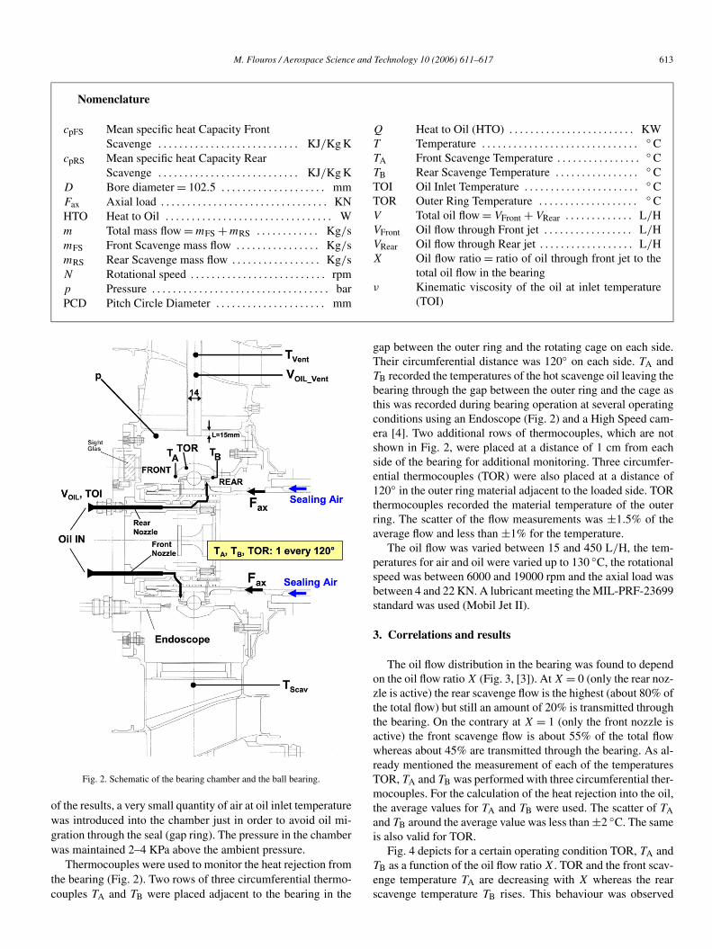
The oil flow distribution in the bearing was found to dependon the oil flow ratio X (Fig. 3, [3]). At X = 0 (only the rear noz-zle is active) the rear scavenge flow is the highest (about 80% ofthe total flow) but still an amount of 20% is transmitted throughthe bearing. On the contrary at X = 1 (only the front nozzle isactive) the front scavenge flow is about 55% of the total flowwhereas about 45% are transmitted through the bearing. As al-ready mentioned the measurement of each of the temperaturesTOR, TA and TB was performed with three circumferential ther-mocouples. For the calculation of the heat rejection into the oil,the average values for TA and TB were used. The scatter of TAand TB around the average value was less than ±2 ◦C. The sameis also valid for TOR.
Fig. 4 depicts for a certain operating condition TOR, TA andTB as a function of the oil flow ratio X. TOR and the front scav-enge temperature TA are decreasing with X whereas the rearscavenge temperature TB rises. This behaviour was observed
614 M. Flouros / Aerospace Science and Technology 10 (2006) 611–617
Fig. 3. Rear scavenge oil flows as a function of the oil flow ratio X and differentrotational speeds.
Fig. 4. Rear, front scavenge and outer ring temperatures as a function of the oilflow ratio X at 19000 rpm.
throughout the testing. A maximum temperature difference ofabout 76 ◦C between TA and TB was recorded when the bearingwas lubricated by only the front nozzle (X = 1) at the displayedconditions. Using the measured scavenge temperatures and thescavenge flows the heat which is transferred from the bearingto the oil (Heat to Oil) can be calculated.
This is defined as:
HTO = Q = mFS ∗ cpFS ∗ (TA − TOI)
+ mRS ∗ cpRS ∗ (TB − TOI).
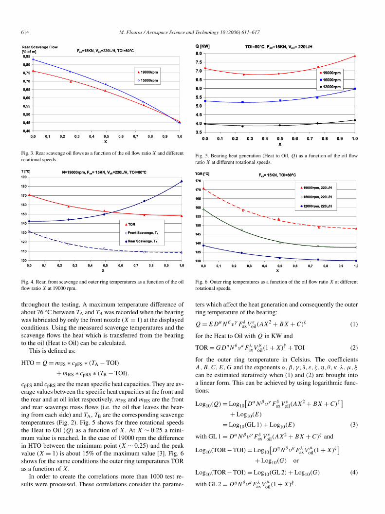
cpFS and cpRS are the mean specific heat capacities. They are av-erage values between the specific heat capacities at the front andthe rear and at oil inlet respectively. mFS and mRS are the frontand rear scavenge mass flows (i.e. the oil that leaves the bear-ing from each side) and TA, TB are the corresponding scavengetemperatures (Fig. 2). Fig. 5 shows for three rotational speedsthe Heat to Oil (Q) as a function of X. At X ∼ 0.25 a mini-mum value is reached. In the case of 19000 rpm the differencein HTO between the minimum point (X ∼ 0.25) and the peakvalue (X = 1) is about 15% of the maximum value [3]. Fig. 6shows for the same conditions the outer ring temperatures TORas a function of X.
In order to create the correlations more than 1000 test re-sults were processed. These correlations consider the parame-
Fig. 5. Bearing heat generation (Heat to Oil, Q) as a function of the oil flowratio X at different rotational speeds.
Fig. 6. Outer ring temperatures as a function of the oil flow ratio X at differentrotational speeds.
ters which affect the heat generation and consequently the outerring temperature of the bearing:
Q = EDαNβνγ F δaxV
εoil(AX2 + BX + C)ζ (1)
for the Heat to Oil with Q in KW and
TOR = GDηNθνκFλaxV
μoil(1 + X)ξ + TOI (2)
for the outer ring temperature in Celsius. The coefficientsA,B,C,E,G and the exponents α,β, γ, δ, ε, ζ, η, θ, κ,λ,μ, ξ
can be estimated iteratively when (1) and (2) are brought intoa linear form. This can be achieved by using logarithmic func-tions:
Log10(Q) = Log10[DαNβνγ F δ
axVεoil(AX2 + BX + C)ζ
]
+ Log10(E)
= Log10(GL 1) + Log10(E) (3)
with GL 1 = DαNβνγ F δaxV
εoil(AX2 + BX + C)ζ and
Log10(TOR−TOI) = Log10[DηNθνκFλ
axVμoil(1 + X)ξ
]
+ Log10(G) or
Log10(TOR−TOI) = Log10(GL 2) + Log10(G) (4)
with GL 2 = DηNθνκFλaxV
μ(1 + X)ξ .
oil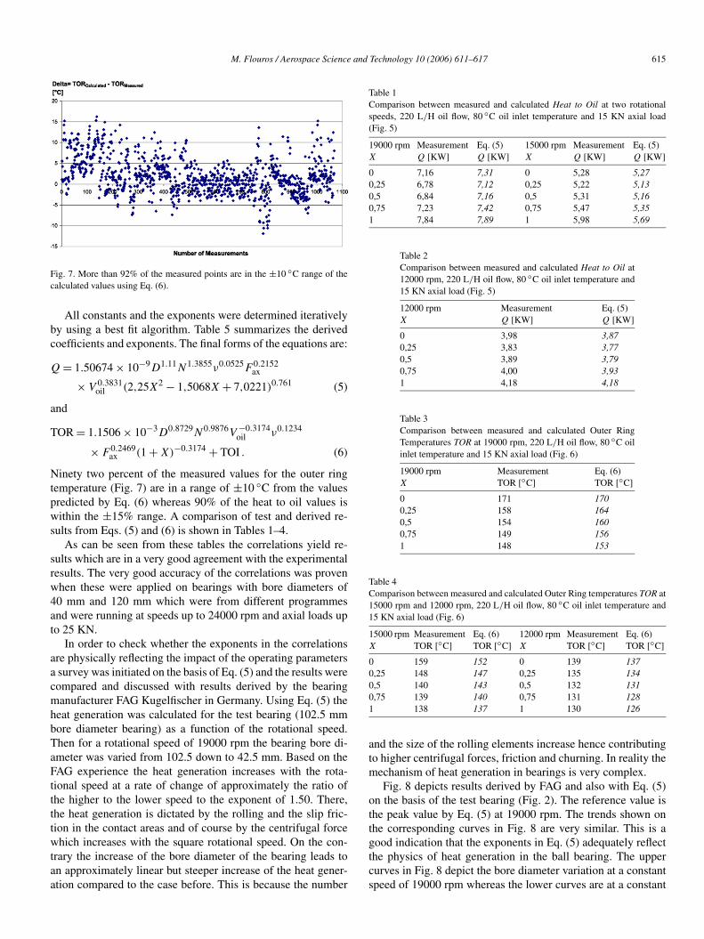
M. Flouros / Aerospace Science and Technology 10 (2006) 611–617 615
Fig. 7. More than 92% of the measured points are in the ±10 ◦C range of thecalculated values using Eq. (6).
All constants and the exponents were determined iterativelyby using a best fit algorithm. Table 5 summarizes the derivedcoefficients and exponents. The final forms of the equations are:
Q = 1.50674 × 10⁻⁹D1.11N1.3855ν0.0525F 0.2152ax
× V 0.3831oil (2,25X2 − 1,5068X + 7,0221)0.761 (5)
and
TOR = 1.1506 × 10⁻³D0.8729N0.9876V −0.3174oil ν0.1234
× F 0.2469ax (1 + X)−0.3174 + TOI . (6)
Ninety two percent of the measured values for the outer ringtemperature (Fig. 7) are in a range of ±10 ◦C from the valuespredicted by Eq. (6) whereas 90% of the heat to oil values iswithin the ±15% range. A comparison of test and derived re-sults from Eqs. (5) and (6) is shown in Tables 1–4.
As can be seen from these tables the correlations yield re-sults which are in a very good agreement with the experimentalresults. The very good accuracy of the correlations was provenwhen these were applied on bearings with bore diameters of40 mm and 120 mm which were from different programmesand were running at speeds up to 24000 rpm and axial loads upto 25 KN.
In order to check whether the exponents in the correlationsare physically reflecting the impact of the operating parametersa survey was initiated on the basis of Eq. (5) and the results werecompared and discussed with results derived by the bearingmanufacturer FAG Kugelfischer in Germany. Using Eq. (5) theheat generation was calculated for the test bearing (102.5 mmbore diameter bearing) as a function of the rotational speed.Then for a rotational speed of 19000 rpm the bearing bore di-ameter was varied from 102.5 down to 42.5 mm. Based on theFAG experience the heat generation increases with the rota-tional speed at a rate of change of approximately the ratio ofthe higher to the lower speed to the exponent of 1.50. There,the heat generation is dictated by the rolling and the slip fric-tion in the contact areas and of course by the centrifugal forcewhich increases with the square rotational speed. On the con-trary the increase of the bore diameter of the bearing leads toan approximately linear but steeper increase of the heat gener-ation compared to the case before. This is because the number
Table 1Comparison between measured and calculated Heat to Oil at two rotationalspeeds, 220 L/H oil flow, 80 ◦C oil inlet temperature and 15 KN axial load(Fig. 5)
19000 rpmX
MeasurementQ [KW]
Eq. (5)Q [KW]
15000 rpmX
MeasurementQ [KW]
Eq. (5)Q [KW]
0 7,16 7,31 0 5,28 5,270,25 6,78 7,12 0,25 5,22 5,130,5 6,84 7,16 0,5 5,31 5,160,75 7,23 7,42 0,75 5,47 5,351 7,84 7,89 1 5,98 5,69
Table 2Comparison between measured and calculated Heat to Oil at12000 rpm, 220 L/H oil flow, 80 ◦C oil inlet temperature and15 KN axial load (Fig. 5)
12000 rpmX
MeasurementQ [KW]
Eq. (5)Q [KW]
0 3,98 3,870,25 3,83 3,770,5 3,89 3,790,75 4,00 3,931 4,18 4,18
Table 3Comparison between measured and calculated Outer RingTemperatures TOR at 19000 rpm, 220 L/H oil flow, 80 ◦C oilinlet temperature and 15 KN axial load (Fig. 6)
19000 rpmX
MeasurementTOR [◦C]
Eq. (6)TOR [◦C]
0 171 1700,25 158 1640,5 154 1600,75 149 1561 148 153
Table 4Comparison between measured and calculated Outer Ring temperatures TOR at15000 rpm and 12000 rpm, 220 L/H oil flow, 80 ◦C oil inlet temperature and15 KN axial load (Fig. 6)
15000 rpmX
MeasurementTOR [◦C]
Eq. (6)TOR [◦C]
12000 rpmX
MeasurementTOR [◦C]
Eq. (6)TOR [◦C]
0 159 152 0 139 1370,25 148 147 0,25 135 1340,5 140 143 0,5 132 1310,75 139 140 0,75 131 1281 138 137 1 130 126
and the size of the rolling elements increase hence contributingto higher centrifugal forces, friction and churning. In reality themechanism of heat generation in bearings is very complex.
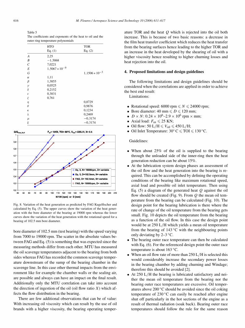
Fig. 8 depicts results derived by FAG and also with Eq. (5)on the basis of the test bearing (Fig. 2). The reference value isthe peak value by Eq. (5) at 19000 rpm. The trends shown onthe corresponding curves in Fig. 8 are very similar. This is agood indication that the exponents in Eq. (5) adequately reflectthe physics of heat generation in the ball bearing. The uppercurves in Fig. 8 depict the bore diameter variation at a constantspeed of 19000 rpm whereas the lower curves are at a constant
616 M. Flouros / Aerospace Science and Technology 10 (2006) 611–617
Table 5The coefficients and exponents of the heat to oil and theouter ring temperature polynomials
HTOEq. (1)
TOREq. (2)
A 2,25B −1,5068C 7,0221E 1,5067 ∗ 10−9
G 1,1506 ∗ 10−3
α 1,11β 1,3855γ 0,0525δ 0,2152ε 0,3831ζ 0,761η 0,8729θ 0,9876κ 0,1234λ 0,2469μ −0,3174ξ −0,3174
Fig. 8. Variation of the heat generation as predicted by FAG Kugelfischer andcalculated by Eq. (5). The upper curves show the variation of the heat gener-ation with the bore diameter of the bearing at 19000 rpm whereas the lowercurves show the variation of the heat generation with the rotational speed for abearing of 102.5 mm bore diameter.
bore diameter of 102.5 mm (test bearing) with the speed varyingfrom 7000 to 19000 rpm. The scatter in the absolute values be-tween FAG and Eq. (5) is something that was expected since themeasuring methods differ from each other. MTU has measuredthe oil scavenge temperatures adjacent to the bearing from bothsides whereas FAG has recorded the common scavenge temper-ature downstream of the sump of the bearing chamber in thescavenge line. In this case other thermal impacts from the envi-ronment like for example the chamber walls or the sealing air,are possible and always can have an impact on the final result.Additionally only the MTU correlation can take into accountthe direction of ingestion of the oil (oil flow ratio X) which af-fects the flow distribution in the bearing.
There are few additional observations that can be of value:With increasing oil viscosity which can result by the use of oilbrands with a higher viscosity, the bearing operating temper-
ature TOR and the heat Q which is rejected into the oil bothincrease. This is because of two basic reasons: a decrease inthe film heat transfer coefficient which reduces the heat transferfrom the bearing surfaces hence leading to the higher TOR andan increase in the heat developed by the shearing of oil with ahigher viscosity hence resulting to higher churning losses andheat rejection into the oil.
4. Proposed limitations and design guidelines
The following limitations and design guidelines should beconsidered when the correlations are applied in order to achievethe best end result:
Limitations:
• Rotational speed: 6000 rpm � N � 24000 rpm;• Bore diameter: 40 mm � D � 120 mm;• D × N : 0.24 × 10⁶–2.9 × 10⁶ rpm × mm;• Axial load: Fax � 25 KN;• Oil flow: 50 L/H � Voil � 450 L/H;• Oil Inlet Temperature: 30◦ C � TOI � 130 ◦C.
Guidelines:
• When about 25% of the oil is supplied to the bearingthrough the unloaded side of the inner-ring then the heatgeneration reduction can be about 15%.
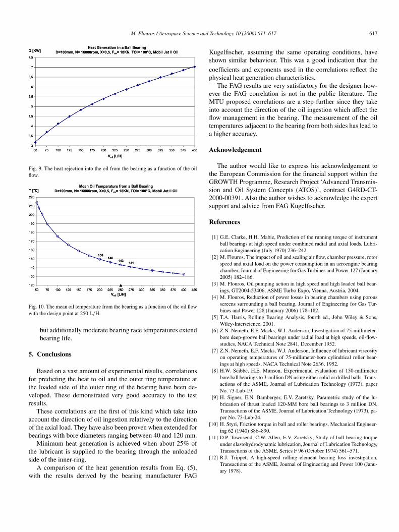
• At the lubrication system design phases an assessment ofthe oil flow and the heat generation into the bearing is re-quired. This can be accomplished by defining the operatingconditions of the bearing like maximum rotational speed,axial load and possible oil inlet temperature. Then usingEq. (5) a diagram of the generated heat Q against the oilflow should be created (Fig. 9). From Q the mean oil tem-perature from the bearing can be calculated (Fig. 10). Thedesign point for the bearing lubrication is there where therate of change of the oil temperature from the bearing getssmall. Fig. 10 depicts the oil temperature from the bearingas a function of the oil flow. In this case the design pointwould be at 250 L/H which yields a mean oil temperaturefrom the bearing of 143 ◦C with the neighbouring pointsonly deviating by 2–3 ◦C.
• The bearing outer race temperature can then be calculatedwith Eq. (6). For the referenced design point the outer racetemperature is about 163 ◦C.
• When an oil flow rate of more than 250 L/H is selected thiswould considerably increase the secondary power lossesin the bearing chamber by adding churning and Windage;therefore this should be avoided [2].
• At 250 L/H the bearing is lubricated satisfactory and nei-ther the mean oil temperature from the bearing nor thebearing outer race temperatures are excessive. Oil temper-atures above 200 ◦C should be avoided since the oil cokingtemperature of 230 ◦C can easily be reached after engineshut off particularly in the hot sections of the engine as aresult of thermal radiation (soak back). Bearing outer racetemperatures should follow the rule for the same reason
M. Flouros / Aerospace Science and Technology 10 (2006) 611–617 617
Fig. 9. The heat rejection into the oil from the bearing as a function of the oilflow.
Fig. 10. The mean oil temperature from the bearing as a function of the oil flowwith the design point at 250 L/H.
but additionally moderate bearing race temperatures extendbearing life.
5. Conclusions
Based on a vast amount of experimental results, correlationsfor predicting the heat to oil and the outer ring temperature atthe loaded side of the outer ring of the bearing have been de-veloped. These demonstrated very good accuracy to the testresults.
These correlations are the first of this kind which take intoaccount the direction of oil ingestion relatively to the directionof the axial load. They have also been proven when extended forbearings with bore diameters ranging between 40 and 120 mm.
Minimum heat generation is achieved when about 25% ofthe lubricant is supplied to the bearing through the unloadedside of the inner-ring.
A comparison of the heat generation results from Eq. (5),with the results derived by the bearing manufacturer FAG
Kugelfischer, assuming the same operating conditions, haveshown similar behaviour. This was a good indication that the
coefficients and exponents used in the correlations reflect thephysical heat generation characteristics.
The FAG results are very satisfactory for the designer how-ever the FAG correlation is not in the public literature. TheMTU proposed correlations are a step further since they takeinto account the direction of the oil ingestion which affect theflow management in the bearing. The measurement of the oiltemperatures adjacent to the bearing from both sides has lead toa higher accuracy.
Acknowledgement
The author would like to express his acknowledgement tothe European Commission for the financial support within theGROWTH Programme, Research Project ‘Advanced Transmis-sion and Oil System Concepts (ATOS)’, contract G4RD-CT-2000-00391. Also the author wishes to acknowledge the expertsupport and advice from FAG Kugelfischer.
References
[1] G.E. Clarke, H.H. Mabie, Prediction of the running torque of instrumentball bearings at high speed under combined radial and axial loads, Lubri-cation Engineering (July 1970) 236–242.
[2] M. Flouros, The impact of oil and sealing air flow, chamber pressure, rotorspeed and axial load on the power consumption in an aeroengine bearingchamber, Journal of Engineering for Gas Turbines and Power 127 (January2005) 182–186.
[3] M. Flouros, Oil pumping action in high speed and high loaded ball bear-ings, GT2004-53406, ASME Turbo Expo, Vienna, Austria, 2004.
[4] M. Flouros, Reduction of power losses in bearing chambers using porousscreens surrounding a ball bearing, Journal of Engineering for Gas Tur-bines and Power 128 (January 2006) 178–182.
[5] T.A. Harris, Rolling Bearing Analysis, fourth ed., John Wiley & Sons,Wiley-Interscience, 2001.
[6] Z.N. Nemeth, E.F. Macks, W.J. Anderson, Investigation of 75-millimeter-bore deep-groove ball bearings under radial load at high speeds, oil-flow-studies, NACA Technical Note 2841, December 1952.
[7] Z.N. Nemeth, E.F. Macks, W.J. Anderson, Influence of lubricant viscosityon operating temperatures of 75-millimeter-bore cylindrical roller bear-ings at high speeds, NACA Technical Note 2636, 1952.
[8] H.W. Scibbe, H.E. Munson, Experimental evaluation of 150-millimeterbore ball bearings to 3-million DN using either solid or drilled balls, Trans-actions of the ASME, Journal of Lubrication Technology (1973), paperNo. 73-Lub-19.
[9] H. Signer, E.N. Bamberger, E.V. Zaretsky, Parametric study of the lu-brication of thrust loaded 120-MM bore ball bearings to 3 million DN,Transactions of the ASME, Journal of Lubrication Technology (1973), pa-per No. 73-Lub-24.
[10] H. Styri, Friction torque in ball and roller bearings, Mechanical Engineer-ing 62 (1940) 886–890.
[11] D.P. Townsend, C.W. Allen, E.V. Zaretsky, Study of ball bearing torqueunder elastohydrodynamic lubrication, Journal of Lubrication Technology,Transactions of the ASME, Series F 96 (October 1974) 561–571.
[12] R.J. Trippet, A high-speed rolling element bearing loss investigation,Transactions of the ASME, Journal of Engineering and Power 100 (Janu-ary 1978).