
Copyright by Timothy Mark Jennings 2009
255
Copyright by Timothy Mark Jennings 2009
-
Upload
khangminh22 -
Category
Documents
-
view
1 -
download
0
Transcript of Copyright by Timothy Mark Jennings 2009

Copyright
by
Timothy Mark Jennings
2009

The Thesis committee for Timothy Mark Jennings
Certifies that this is the approved version of the following thesis
UT Fire, a Preprocessor for SAFIR2007, for Analysis of Heat Transfer
for Structural Members Exposed to Fire
APPROVED BY SUPERVISING COMMITTEE:
Supervisor:
Michael D. Engelhardt
Todd Helwig
UT Fire, a Preprocessor for SAFIR2007, for Analysis of Heat Transfer
for Structural Members Exposed to Fire
by
Timothy Mark Jennings, B.S.E
Thesis
Presented to the Faculty of the Graduate School of
The University of Texas at Austin
in Partial Fulfillment
of the Requirements
for the Degree of
Masters of Science in Engineering
The University of Texas at Austin
December 2009

iv
Abstract
UT Fire, a Preprocessor for SAFIR2007, for Analysis of Heat Transfer
for Structural Members Exposed to Fire
Timothy Mark Jennings, M.S.E.
The University of Texas at Austin, 2009
Supervisor: Michael D. Engelhardt
This thesis describes the development of the computer program UT Fire, which serves as a preprocessor for the computer program SAFIR2007. SAFIR2007, developed at the University of Liege in Belgium, conducts heat transfer analysis and structural response analysis for structures subjected to fire. The preprocessor UT Fire was developed to allow a simplified graphical interface for input to the heat transfer portion of SAFIR 2007. This thesis provides step by step instructions on the use of UT Fire and illustrates its use through a series of detailed examples.
v
Table of Contents
List of Tables ....................................................................................................... viii
List of Figures ........................................................................................................ ix
List of Illustrations ...................................................................................................x
Chapter 1: Introduction ...........................................................................................1
Overview .........................................................................................................1
UT Fire Capabilities .......................................................................................2
Heat Transfer Basics .......................................................................................3
Scope of Thesis ...............................................................................................5
Chapter 2: SAFIR2007 Capabilities ........................................................................6
SAFIR2007 Overview .....................................................................................6
SAFIR2007 Heat Transfer ...............................................................................6
Input Files ..............................................................................................7
Output Files ............................................................................................8
SAFIRWizard .........................................................................................8
GiD for SAFIR2007 ...............................................................................9
Diamond07 .............................................................................................9
Need for UT Fire ............................................................................................9
Chapter 3: UT Fire User Manual ..........................................................................11
Program Approach ........................................................................................11
Program Flow Chart .............................................................................12
Settings ..........................................................................................................13
Custom Material Colors .......................................................................13
Minimum Wizard Mesh Side ...............................................................13
SAFIR2007 and Diamond07 Executables ............................................14
Materials .......................................................................................................15
Materials Overview ..............................................................................15
vi
Available Materials .....................................................................17
Insulation (SFRM) ...............................................................................19
Metals ...................................................................................................20
Concretes..............................................................................................22
User Defined ........................................................................................25
Available Fires ..............................................................................................26
Standard Fires ......................................................................................26
Custom Fires ........................................................................................27
New Custom Fires.......................................................................27
Import Custom Fire .....................................................................29
Plot Custom Fire .........................................................................32
Sections .........................................................................................................35
Wizard Basics ......................................................................................35
Wizard ..................................................................................................37
I-Beam Section Wizard ...............................................................37
Rectangular Section Wizard .......................................................41
Circular Section Wizard ..............................................................44
Circular Hollow Section Wizard .................................................46
Apply Mesh .................................................................................48
Fire Exposure ..............................................................................49
Customize Nodes .................................................................................51
Customize Mesh ...................................................................................52
Time Steps ...........................................................................................55
Run Analysis .................................................................................................56
Export Section ......................................................................................56
Run Section ..........................................................................................57
Chapter 4: UT Fire Examples with Data Analysis and Observations ..................59
I-Section (Detailed How-To) ........................................................................59
Basic Conditions ..................................................................................70

vii
Comparison to OZone ..........................................................................70
Rectangular Section (Detailed How-To) ......................................................71
Basic Conditions ..................................................................................79
Various Moisture Content Comparisons ..............................................80
I-Section with and without Concrete Slab ....................................................81
Square Column with and without Reinforcement Steel ................................85
Square Column Modeling: ¼ of a Column vs. Entire Column .....................88
Circular Hollow Section with Center Modeled with a Void vs. Nothing vs. Air vs. Water ..............................................................................................91
APPENDIX A (UT FIRE SOURCE CODE PRINTOUT) 96
BIBLIOGRAPHY ................................................................................................242
VITA 243

viii
List of Tables
TABLE 3.1: AVAILABLE MATERIALS 17
TABLE 3.1: AVAILABLE MATERIALS CONTINUED 18
TABLE 4.1: DIFFERENCE IN PEAK TEMPERATURES FOR A RECTANGULAR SECTION WITH DIFFERENT MOISTURE CONTENTS 81
TABLE 4.2: PEAK I-BEAM TEMPERATURES WITH AND WITHOUT MODELING THE TOP SLAB 84
TABLE 4.3: VARIATION IN STEEL MATERIAL PROPERTIES FOR THE “WITH SLAB” CONDITION 85
TABLE 4.4: CONCRETE PEAK TEMPERATURES WITH AND WITHOUT REINFORCEMENT STEEL MODELED 88
TABLE 4.5: DIFFERENCES IN RESULTS WHEN THE COLD CONVECTION COEFFICIENT IS CHANGED 89
TABLE 4.6: DIFFERENCES IN RESULTS WHEN THE HOT CONVECTION COEFFICIENT IS CHANGED 89
TABLE 4.7: THERMAL PROPERTIES OF AIR AT ELEVATED TEMPERATURES 92
TABLE 4.8: THERMAL PROPERTIES OF WATER AT ELEVATED TEMPERATURES 93
ix
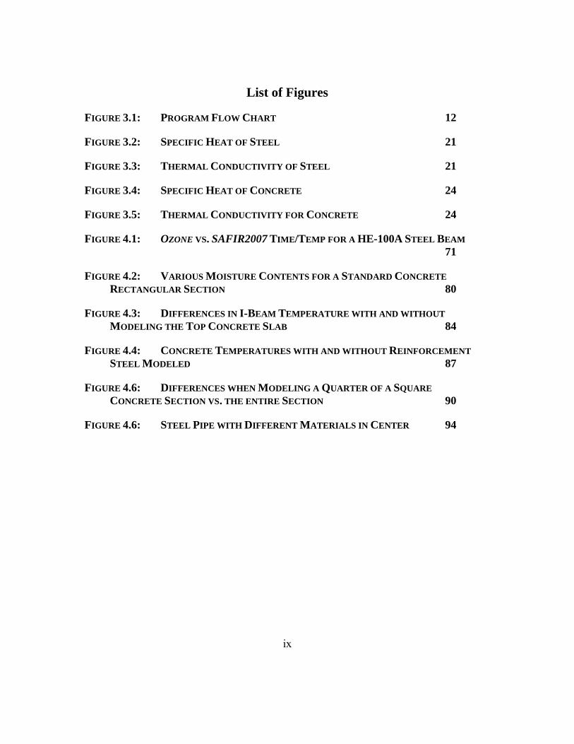
List of Figures
FIGURE 3.1: PROGRAM FLOW CHART 12
FIGURE 3.2: SPECIFIC HEAT OF STEEL 21
FIGURE 3.3: THERMAL CONDUCTIVITY OF STEEL 21
FIGURE 3.4: SPECIFIC HEAT OF CONCRETE 24
FIGURE 3.5: THERMAL CONDUCTIVITY FOR CONCRETE 24
FIGURE 4.1: OZONE VS. SAFIR2007 TIME/TEMP FOR A HE-100A STEEL BEAM 71
FIGURE 4.2: VARIOUS MOISTURE CONTENTS FOR A STANDARD CONCRETE RECTANGULAR SECTION 80
FIGURE 4.3: DIFFERENCES IN I-BEAM TEMPERATURE WITH AND WITHOUT MODELING THE TOP CONCRETE SLAB 84
FIGURE 4.4: CONCRETE TEMPERATURES WITH AND WITHOUT REINFORCEMENT STEEL MODELED 87
FIGURE 4.6: DIFFERENCES WHEN MODELING A QUARTER OF A SQUARE CONCRETE SECTION VS. THE ENTIRE SECTION 90
FIGURE 4.6: STEEL PIPE WITH DIFFERENT MATERIALS IN CENTER 94

x
List of Illustrations
ILLUSTRATION 3.1: MATERIAL COLORS 13
ILLUSTRATION 3.2: WIZARD MAX MESH SIDE 14
ILLUSTRATION 3.3: EXECUTABLES 15
ILLUSTRATION 3.4: MATERIALS FORM 16
ILLUSTRATION 3.5: INSULATION 19
ILLUSTRATION 3.6: METALS 20
ILLUSTRATION 3.7: CONCRETE 23
ILLUSTRATION 3.8: USER DEFINED 25
ILLUSTRATION 3.9: STANDARD FIRES 27
ILLUSTRATION 3.10: NEW CUSTOM FIRE 28
ILLUSTRATION 3.11: NEW CUSTOM FIRE NAME 28
ILLUSTRATION 3.12: EDIT CUSTOM FIRE TIME/TEMPERATURE VALUES 29
ILLUSTRATION 3.13: IMPORT CUSTOM FIRE 30
ILLUSTRATION 3.14: IMPORT CUSTOM FIRE DELIMITER 30
ILLUSTRATION 3.15: CUSTOM FIRE BEFORE IMPORT 31
ILLUSTRATION 3.16: SELECT CUSTOM FIRE FILE 32
ILLUSTRATION 3.17: PLOTTING FIRE CURVE 33
ILLUSTRATION 3.18: PLOT FIRE CURVE 2 34
ILLUSTRATION 3.19: PLOTTED FIRE CURVE 35
ILLUSTRATION 3.20: INITIAL WIZARD FORM 36
ILLUSTRATION 3.21: BEGIN THE I-BEAM WIZARD 38
ILLUSTRATION 3.22: I-BEAM STANDARD SIZE SELECTOR 39

xi
ILLUSTRATION 3.23: CUSTOMIZE I-BEAM DIMENSIONS 39
ILLUSTRATION 3.24: ADD SFRM AND A TOP SLAB TO AN I-BEAM 40
ILLUSTRATION 3.25: BEGIN RECTANGULAR SECTION WIZARD 42
ILLUSTRATION 3.26: DEFINE RECTANGULAR SECTION 42
ILLUSTRATION 3.27: ADD SFRM TO RECTANGULAR SECTION 43
ILLUSTRATION 3.28: BEGIN CIRCULAR SECTION WIZARD 44
ILLUSTRATION 3.29: DEFINE CIRCULAR SECTION GEOMETRY 45
ILLUSTRATION 3.30: BEGIN CIRCULAR HOLLOW SECTION WIZARD 46
ILLUSTRATION 3.31: DEFINE CIRCULAR HOLLOW GEOMETRY 47
ILLUSTRATION 3.32: APPLY MESH 48
ILLUSTRATION 3.33: DEFINE SECTION’S FIRE EXPOSURE 50
ILLUSTRATION 3.34: CUSTOMIZE NODES 51
ILLUSTRATION 3.35: NEW NODE 52
ILLUSTRATION 3.36: CUSTOMIZE MESH 53
ILLUSTRATION 3.37: NEW ELEMENT 54
ILLUSTRATION 3.38: DELETE ELEMENT 55
ILLUSTRATION 3.39: TIME STEPS 55
ILLUSTRATION 3.40: EXPORT SECTION 56
ILLUSTRATION 3.41: EXPORT SECTION LOCATION 57
ILLUSTRATION 3.42: RUN SECTION 57
ILLUSTRATION 4.1: UT FIRE INITIAL DIALOG 59
ILLUSTRATION 4.2: DEFINE WIZARD MAX. MESH SIDE 60
ILLUSTRATION 4.3: DEFINE MATERIALS 60

xii
ILLUSTRATION 4.4: BEGIN WIZARD 62
ILLUSTRATION 4.5: SELECT HE 100 A 63
ILLUSTRATION 4.6: CUSTOMIZE I-BEAM GEOMETRY 64
ILLUSTRATION 4.6: ADD INSULATION TO THE I-BEAM 65
ILLUSTRATION 4.8: DEFINE THE MESH FOR THE I-BEAM 66
ILLUSTRATION 4.9: DEFINE THE I-BEAM’S FIRE EXPOSURE 67
ILLUSTRATION 4.10: VIEW THE I-BEAM WIZARD RESULTS 68
ILLUSTRATION 4.11: CHECK THE EXECUTABLES BEFORE THE RUN 69
ILLUSTRATION 4.12: RUN THE I-BEAM 69
ILLUSTRATION 4.13: VIEW THE I-BEAM MODEL RESULTS 70
ILLUSTRATION 4.14: UT FIRE INITIALIZATION FOR RECTANGULAR SECTION 72
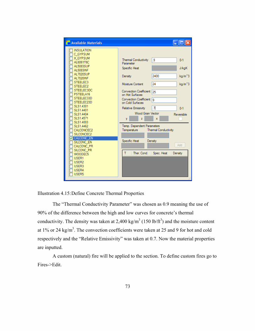
ILLUSTRATION 4.15: DEFINE CONCRETE THERMAL PROPERTIES 73
ILLUSTRATION 4.16: DEFINE CUSTOM FIRE 74
ILLUSTRATION 4.17: DEFINE CUSTOM FIRE 2 75
ILLUSTRATION 4.18: VIEW CUSTOM FIRE PLOT 76
ILLUSTRATION 4.19: START RECTANGULAR SECTION WIZARD 77
ILLUSTRATION 4.20: DEFINE RECTANGULAR SECTION DIMENSIONS 77
ILLUSTRATION 4.21: APPLY FIRE EXPOSURE TO RECTANGULAR SECTION 78
ILLUSTRATION 4.22: DEFINE CUSTOM TIME STEPS 79
ILLUSTRATION 4.23: CUSTOMIZING TOP SLAB FIRE EXPOSURE CONDITIONS 82
ILLUSTRATION 4.24: SQUARE CONCRETE COLUMN WITH REINFORCEMENT MODELED 86

1
Chapter 1: Introduction
OVERVIEW
A key issue in the design of most buildings is the need to provide structural fire
safety. Building codes in the U.S. and throughout most of the world require that a
building structure be able to withstand a severe fire for a specified period of time without
collapse. These requirements are intended to allow sufficient time for evacuating building
occupants and for fire fighters to undertake fire fighting and rescue operations within the
burning building. Building codes have conventionally specified highly prescriptive rules
for structural fire safety. However, there is increasing interest in the U.S. and elsewhere
in developing engineered approaches to structural fire safety as an alternative to
conventional code-based prescriptive approaches. With an engineered approach, the
response of a structure to fire is computed and appropriate design measures are taken to
assure acceptable response.
Engineered structural fire safety requires the ability to predict the response of a
structure to fire. There are two major steps in this process. The first step is to conduct a
heat transfer analysis to determine temperatures of structural elements at various times
throughout a fire. The second step is to compute structural response under the combined
action of externally applied loads (dead loads, live loads, etc) and elevated temperatures.
The elevated temperatures of structural members, computed in the heat transfer analysis,
can result in large thermally induced forces and deformations, as well as degradation in
material strength and stiffness.
A powerful tool for predicting the response of structures to fire is the computer
program SAFIR2007 (Franssen 2007). SAFIR2007 is a finite element program developed
at the University of Liege in Belgium, and conducts both heat transfer analysis and the

2
subsequent structural response analysis. While SAFIR2007 is a powerful program,
developing input files can be a difficult and time consuming process, particularly for new
users of the program. While a preprocessor known as SAFIRWizard is available for
SAFIR2007, the capabilities of this preprocessor are very limited.
The major goal of the work conducted in this thesis was the development of an
improved preprocessor for conducting two-dimensional heat transfer analyses using
SAFIR2007. The objective was to develop a preprocessor that allows the user to define a
wide variety of complex two-dimensional structural-fire heat transfer problems with a
simple and intuitive graphical user interface (GUI). The preprocessor that was developed
is known as UT Fire, and is described in this thesis.
The remainder of this chapter provides a brief overview of the capabilities of UT
Fire. This is followed by a brief discussion of heat transfer fundamentals. The chapter
ends with a description of the scope of the thesis.
UT FIRE CAPABILITIES UT Fire is a preprocessor for SAFIR2007. It is useful because it allows users to
define a mesh for common building shapes within minutes. The user can then model the
section’s heat transfer from a given fire. SAFIR2007 must be purchased, and Diamond 07
(free) is used to view the model results. Once a common shape (I-beam, rectangle, or
circle) is defined, the user can further customize the geometry to any 2D shape possible
using three- and four-sided elements (triangles and rectangles). The features of UT Fire
are listed on the next page:
3
1. Over 500 standard I‐Beam sections available
2. AISC, AASHTO, United Kingdom, and European standard sections
3. Customize I‐Beam sections to any dimension
4. Rectangular section wizard
5. Circular section wizard
6. Circular hollow section wizard
7. Wall system wizard
8. Quick and easy placement of insulation on common geometric shapes
9. Customize any geometry, post wizard, using three and four sided mesh elements
10. Use over 30 material types in defining sections
11. Use standard fire curves like ASTME119
12. Define any number of custom fire time temperature curves
13. Run and view sections from the program interface
HEAT TRANSFER BASICS
As described earlier, a key step in predicting the response of a structure to fire is
conducting heat transfer analysis. For structural-fire engineering purposes, the fire
environment is normally characterized by a time-temperature curve. The temperatures in
these curves represent the temperature of the fire gases in contact with structural
members. Heat transfer analysis is then needed to compute temperatures at various points
within the structural members throughout the course of the fire. Temperatures within
structural members will therefore vary both according to the location within the member
and according to time. Since the objective of UT Fire is to facilitate heat transfer analyses
using SAFIR2007, this section provides a very brief summary of key heat transfer
concepts of importance in structural-fire engineering heat transfer analysis. It is assumed
herein that the user of UT Fire and SAFIR2007 is familiar with heat transfer
fundamentals. Consequently, the discussion below is intended to review and highlight a

4
few key issues in structural-fire heat transfer analysis, particularly as they pertain to the
capabilities of UT Fire.
Heat transfer can occur by one of three modes: conduction, convection, and
radiation (Buchanan, 2002). In a fire environment, heat transfer between fire gases and
the surface of a structural member occurs both by convection and radiation. This heat
transfer process is controlled by the relative temperature between the fire gases and the
surface of the member, the convective heat transfer coefficient and the relative emissivity
of the surface of the structural member and the hot fire gases. Consequently, for a
structural-fire heat transfer analysis, the user must specify the time-temperature history of
the fire gases, and the convective heat transfer coefficient and relative emissivity that
characterize the interface of the hot gases and the surface of the structural element. In UT
Fire, the user can specify a variety of time-temperature curves to characterize the fire
environment, including standard building code-specified curves as well as custom user
defined curves. The user can also specify the convective heat transfer coefficient and the
relative emissivity at the surface of the structural element.
As noted above, heat transfer between hot fire gases and the surface of a structural
element occurs by convection and radiation. Subsequent heat transfer from the surface of
the structural element to the interior portions of the element occurs by conduction.
Computing conductive heat transfer within a structural element requires three material
properties: thermal conductivity, specific heat and density. For most structural materials,
such as steel and concrete, as well as for insulation materials used to protect structural
members, these properties are not only material dependent but also generally temperature
dependent. UT Fire provides the user a great deal of flexibility in specifying these
material properties, as well as facilitating the use of a large number of default properties
defined in SAFIR2007.

5
Temperature changes within a structural element during a fire can also be affected
by movement of moisture within the element, and by phase changes of free and
chemically bound water within the material. For example, the insulating properties of
gypsum board during a fire are largely the result of the heat energy used to vaporize
water contained within the gypsum. The effects of moisture movement and phase
changes are not explicitly modeled in SAFIR2007, and therefore are also not considered
in UT Fire. However, the effects of phase changes of water can be handled in an
approximate manner through the use of apparent thermal conductivities and specific heats
that reflect the influence of phase change in an indirect and approximate manner. These
apparent properties are included in SAFIR2007 for concrete and gypsum, and are
therefore also available through UT Fire. Further background on heat transfer
fundamentals is available through standard textbooks on heat transfer. An excellent
summary of heat transfer concepts applied to structural-fire engineering problems is
provided by Buchanan (2002).
SCOPE OF THESIS
Chapter 2 of this thesis provides a very brief overview of SAFIR2007, along with
some of the previously available pre- and postprocessors. Chapter 3 is a User Manual for
UT Fire, providing a detailed step by step description of the program. Chapter 4 then
provides a number of detailed examples of structural-fire heat transfer analyses. These
examples are intended to highlight many of the features of UT Fire, as well as to discuss
some important issues involved in structural-fire heat transfer analysis. The final chapter
of the thesis provides the summary and conclusions from the study, followed by an
appendix with a print out of the UT Fire source code.

6
Chapter 2: SAFIR2007 Capabilities
SAFIR2007 OVERVIEW
Since UT Fire is a preprocessor for the heat transfer module of SAFIR2007, this
chapter provides a brief overview of the basic input and output files related to heat
transfer analysis on SAFIR 2007, as well as currently available pre- and post-processors.
As described earlier, SAFIR2007 is a finite element computer program developed at the
University of Liege for the simulation of the behavior of building structures subjected to
fire (Franssen, 2007). SAFIR2007 conducts two- and three-dimensional heat transfer
analyses and structural analyses. The structural analysis module models the reduced
strength and stiffness of materials at elevated temperatures, and also considers inelasticity
and large deflections.
SAFIR2007 HEAT TRANSFER
The heat transfer portion of SAFIR2007 conducts a two-dimensional transient heat
conduction analysis. In transient heat conduction analyses, the boundary conditions at the
surface of the element should be properly specified either as the surface temperature of
the element or the heat flux at the surface of the element. In the case of a structural-fire
heat transfer analysis, neither of these two quantities is generally known. Rather, what is
known (or assumed) is the temperature of the hot fire gases in contact with the structural
element. Note that the surface temperature of the structural element will not, in general,
be the same as the temperature of the surrounding hot gases. Consequently, a common
approach for determining the boundary conditions of the conduction analysis is to
approximate the heat flux at the surface of the structural element. The surface heat flux
(i.e. the net heat flux entering the element) is approximated from the surrounding gas
temperatures through assumed convective and radiative heat transfer coefficients. The

7
approximate methods for establishing boundary conditions are the approach used by
SAFIR2007. Further information of the heat transfer capabilities and limitations of
SAFFIR2007 is provided in documentation that accompanies the program (Franssen
2007).
Input Files
SAFIR2007 uses ASCII (text) files as input into the program. These have an “.in”
prefix, and are segregated into 14 series sets (Franssen, 2007).
SERIES 1: Comments
SERIES 2: Blank Line to Indicate Start of the Nodes
SERIES 3: Number of Nodes
SERIES 4: Number of Dimensions
SERIES 6: Define Degrees of Freedom for each Node
SERIES 7: Calculation Parameters
SERIES 9: How or if to Renumber Nodes
SERIES 11: Number of Materials
SERIES 12: Number of Elements and Voids
SERIES 13: Node Definitions
SERIES 14: Geometric Center
SERIES 15: Displacements and Supports
SERIES 16: Element, Exposure, and Void Definitions
SERIES 17: Precision
SERIES 18: Material Definitions
SERIES 19: Time (Calculation and Print) Definitions
SAFIR2007 also uses “.in” for the structural analysis portion. The format is
similar but different input is needed for structural response calculations.

8
Output Files
Once SAFIR2007 runs, a file is generated with the same name as the input, except
the file has an “.out” extension. A post-processor for SAFIR2007 known as Diamond07
can load the “.out” file for viewing the analysis results (Franssen, 2007), as described
later. Viewing the output file is a useful way to diagnosis errors while running
SAFIR2007. The user can view how much input was loaded and usually then troubleshoot
why the section was not modeled if an error occurred during the analysis. The output file
consists of several sections listed below: 1. Copy of the input file
2. Set up data for the finite element matrixes
3. Node, element and exposure definitions
4. Material description and user defined thermal properties
5. A series of tables defined by time that have node IDs followed by their
temperatures at the time
6. Calculation run statistics
SAFIRWizard
SAFIRWizard is a preprocessor for SAFIR2007. This preprocessor allows the user
to select a standard I-Beam from approximately 100 different sections. The user can then
apply layers of insulation and define their thermal properties. Next, the user can place a
concrete slab on the section and then apply one of the three standard fires (ISO 834,
ASTM E119 and the standard hydrocarbon fire). Following this process, the user can
customize the mesh and define the calculation parameters such as frequency, duration,
and tolerance. When the user is finished, an input file is generated for later input into the
SAFIR2007 processor (Franssen, 2007).

9
GiD for SAFIR2007
GiD is a general pre and post processor for finite element analysis programs such
as ANSYS or ABAQUS. The interface is similar to a CAD interface where a user can
draw lines and build meshes. It can also be set up to develop sections for SAFIR2007.
Diamond07
Diamond07 is a postprocessor for SAFIR2007 and is used to view model run
results. This software is free for download from the SAFIR website (Franssen, 2007).
With the software you can view the mesh elements, the mesh sides exposed to fire, the
material of the mesh, colored time dependent contour temperature plots and plot
temperature vs. time for up to five points. Diamond07 is also used for the structural
analysis results where results such as stresses or deflections, can be viewed for a given
time step.
NEED FOR UT FIRE
As described above, there are already two preprocessors available for heat transfer
analyses on SAFIR2007: SAFIRWizard and GiD. SAFIRWizard is a very simple to use
preprocessor. However, SAFIRWizard is quite limited in the type, number and
complexity of member cross-sections that can be modeled, and in the choice of material
models. GiD on the other hand, is a more general preprocessor that can handle a wide
range of sections and materials. However, GiD is a complex program that has a steep
learning curve and requires significant experience with the software to become familiar
with the capabilities. UT Fire was developed in an attempt to maintain the simplicity of
SAFIRWizard with the power of GiD. UT Fire was designed to provide a rapid and

10
intuitive graphical user interface that could be easily mastered by new users in a short
time. UT Fire was primarily developed as an educational tool for use in teaching
structural-fire heat transfer analysis in a graduate class in Structural-Fire Engineering at
the University of Texas at Austin.

11
Chapter 3: UT Fire User Manual
PROGRAM APPROACH
UT Fire is written in Visual Basic, and presents the user with a series of input
screens and menus to develop a SAFIR2007 input file for a two-dimensional heat transfer
analysis. Figure 3.1 provides an overview of UT Fire in the form of a flowchart.
Appendix A provides a complete listing of the source code for UT Fire. The remainder of
this chapter is intended to serve as a User Manual for UT Fire, providing information on
the various wizards, screens and menus.

12
Define Custom
Fires
Customize the geometry
or fire exposure
Open existing section
Start Program
Define Materials (remember to check
their checkbox)
Define the geometry of the
section using the wizards
Define Fire Exposure
Run or Export the
section
Apply Mesh
Program Flow Chart
Figure 3.1: Program Flow Chart

13
SETTINGS
Custom Material Colors
Under File->Settings and then under the “Colors” tab, the user can select custom
colors for each material. These colors are the colors used to fill a mesh element while
using UT Fire.
Illustration 3.1: Material Colors
Select the material to define a fill color, and then select the desired color from the
“Material Color” combo box. The selected color will be displayed in the box below.
Minimum Wizard Mesh Side
Once the geometry is defined for the “I-Beam”, “Rectangular” or “Wall System”
the next section of the wizard is the “Apply Mesh” section. This form takes the user from
common geometric shapes to a set of mesh elements for running a finite element analysis.
The “Minimum Wizard Mesh Side” is the key to the initial cut lines used by the “Apply
Mesh” form.

14
Illustration 3.2: Wizard Max Mesh Side
Values larger than 15 mm are not recommended as this may generate meshes that
are too coarse.
The engine behind the “Apply Mesh” form looks at every Z and Y coordinate
previously defined, and makes cut lines for those coordinates. Then the engine evaluates
the difference between all Z coordinates and all Y coordinates. If the distance is greater
than the “Minimum Wizard Mesh Side”, then a series of evenly spaced cut lines are
produced to ensure no mesh side is larger than the “Minimum Wizard Mesh Side”
number.
For instance, if an I-Beam is defined with inside flange Y dimensions of 100 and
-100 (aka a 200 mm web depth), and a “Wizard Max Mesh Side” of 10 is selected so that
the “Apply Mesh” form will initially generate 20 cut lines between these two coordinates.
SAFIR2007 and Diamond07 Executables
The SAFIR2007 and Diamond07 executables are used when “Run Section” is
chosen from File->Run Section.

15
Illustration 3.3: Executables
“Run Section” will export the selected section to the SAFIR2007 directory, run
the section using SAFIR2007 and then display the results using Diamond07.
MATERIALS
Materials Overview
The “Available Materials” form is available by clicking Materials->Edit, and is
the form for editing the thermal properties of materials.

16
Illustration 3.4: Materials Form
All of the available materials are on the left hand side, and when one is chosen the
required thermal properties are available for editing. By double clicking on a material the
material is selected. All selected materials are available for later use inside of the
program.

17
Available Materials Material Name Description Applicable
Euro CodeTemperature Dependent Thermal
Properties
Notes
INSULATION Used to quickly define a SFRM material
N/A N
C_GYPSUM Gypsum with glass fibers and vermiculite ore for stability
N/A Y
X_GYPSUM Gypsum with glass fibers N/A Y AL6061T6C Aluminum, Alloy: 6061,
Temper: T6C EC 9 Y 1
AL5083SUP Aluminum, Alloy: 5083 EC 9 Y 1 AL5083INF Aluminum, Alloy: 5083 EC 9 Y 1 AL7020SUP Aluminum, Alloy: 7020 EC 9 Y 1 AL7020INF Aluminum, Alloy: 7020 EC 9 Y 1 STEELEC3 Structural Steel EC 3 Y STEELEC2 Steel Reinforcement EC 2 Y STEELEC3DC EC 3 Y PSTEELA16 EC 2 Y STEELEC33D Structural Steel with 3D stress
capabilities EC 3 Y
STEELEC23D Steel Reinforcement with 3D stress capabilities
EC 3 Y
SLS1.4301 Stainless Steel Grade 1.4301 EC 3 Y SLS1.4401 Stainless Steel Grade 1.4401 EC 3 Y SLS1.4404 Stainless Steel Grade 1.4404 EC 3 Y SLS1.4571 Stainless Steel Grade 1.4571 EC 3 Y SLS1.4003 Stainless Steel Grade 1.4003 EC 3 Y SLS1.4462 Stainless Steel Grade 4462 EC 3 Y CALCONCEC2 Calcareous aggregate concrete EC 2 Y SILCONCEC2 Siliceous aggregate concrete EC 2 Y CALCONC_EN Calcareous aggregate concrete EC 2 Y 2 SILCONC_EN Siliceous aggregate concrete EC 2 Y 2 CALCONC_PR Calcareous aggregate concrete EC 2 Y 2 SILCONC_PR Siliceous aggregate concrete EC 2 Y 2 WOODEC5 Wood EC 5 Y USER1 User Defined 1 N/A Y 3
Table 3.1: Available Materials

18
USER2 User Defined 2 N/A Y 3 USER3 User Defined 3 N/A Y 3 USER4 User Defined 4 N/A Y 3 USER5 User Defined 5 N/A Y 3 Notes:
1. 0.24 recommended for relative emissivity (Franssen, 2007) 2. The thermal conductivity parameter is a number between 0‐1 to arrive
at a thermal conductivity value between the high and low values (BSI, 2004)
3. Maximum of 20 steps for temperature dependent thermal properties
Table 3.1: Available Materials Continued
19
Insulation (SFRM)
The use of the insulation material is a quick way to get a non-temperature thermal
dependent material ready for use.
Illustration 3.5: Insulation
Insulation, also sometimes called spray applied fire resistive material (SFRM),
comes in many shapes, sizes, and the thermal properties. For a given material it is best to
get the thermal properties from the material manufacturers.

20
Metals
The following materials are considered metals: AL6061T6C, AL5083SUP,
AL5083INF, AL7020SUP, AL7020INF, STEELEC3, STEELEC2, STEELEC3DC,
PSTEELA16, STEELEC33D, STEELEC23D, SLS1.4301, SLS1.4401, SLS1.4404,
SLS1.4571, SLS1.4003, and SLS1.4462 are all metals and only their “Convection
Coefficient on Hot Surfaces”, “Convection Coefficient on Cold Surfaces”, and their
“Relative Emissivity” are required for an analysis. The rest of the thermal properties are
built into SAFIR2007.
Illustration 3.6: Metals
21
The steel values are built into SAFIR2007 according to EN1993-1-2 (BSI, 2004)
Figure 3.2: Specific Heat of Steel
Figure 3.3: Thermal Conductivity of Steel
0
1000
2000
3000
4000
5000
6000
0 200 400 600 800 1000 1200 1400
Specific he
at (J/kg*K)
Temperature (C)
Specific Heat of Steel
0
10
20
30
40
50
60
0 200 400 600 800 1000 1200 1400
Thermal Con
ductivity (W
/m*K
)
Temperature (C)
Thermal Conductivity of Steel

22
Concretes
The following materials are considered concretes: CALCONCEC2,
SILCONCEC2, CALCONC_EN, SILCONC_EN, CALCONC_PR, and SILCONC_PR
are all concretes and only their “Moisture Content”, “Convection Coefficient on Hot
Surfaces”, “Convection Coefficient on Cold Surfaces”, and their “Relative Emissivity”
are required for an analysis. The “Thermal Conductivity Parameter” and “Density” are
also required for materials: CALCONC_EN, SILCONC_EN, CALCONC_PR, and
SILCONC_PR.
The “Thermal Conductivity Parameter” is a parameter used to identify a thermal
conductivity number closer to the lower limit or higher limit (See Figure Below). The rest
of the thermal properties are built in to SAFIR2007 (Franssen, 2007).

23
Illustration 3.7: Concrete
The concrete values are built into SAFIR according to EN1992-1-2 (BSI, 2004)
24
Figure 3.4: Specific Heat of Concrete
Figure 3.5: Thermal Conductivity for Concrete
0
200
400
600
800
1000
1200
0 200 400 600 800 1000 1200 1400
Specific he
at (J/kg*K)
Temperature (C)
Specific Heat of Concrete
0
0.5
1
1.5
2
2.5
0 200 400 600 800 1000 1200 1400
Thermal Con
ductivity (W
/m*K
)
Temperature (C)
Thermal Conductivity for Concrete
Thermal Conductivity (Lower Limit)
Thermal Conductivity (Upper Limit)

25
User Defined
USER1, USER2, USER3, USER4 and USER5 are materials that the user can
specify temperature dependent values of thermal conductivity, specific heat, and density.
These materials cannot have mechanical properties for later structural analysis.
Illustration 3.8: User Defined
A maximum of twenty temperature dependent thermal properties can be input into
SAFIR2007. Users can input data into the table by filling out “Temperature”, “Thermal

26
Conductivity”, “Specific Heat” or “Density” and then clicking “Add”. The checkbox
“Reversible” is now enabled and this determines whether the properties are reversible or
not. In other words, this will determine whether the properties fall back along the defined
curve during the cool down phase. If “Reversible” is unchecked, then the maximum
temperature will be used to define the other thermal properties, during the start of the
cool down phase.
AVAILABLE FIRES
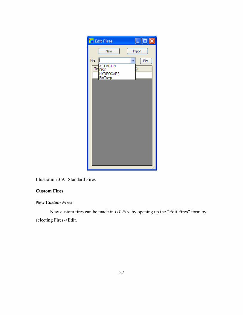
Standard Fires
SAFIR2007 comes with three standard fires (ASTME119, FISO, and
HYDROCARB). These fires are standard time/temperature fires used in testing to catalog
a structural components relative fire resistance. All three are available in UT Fire to
apply to a given section. The fire “RmTemp” also comes standard with the program. This
is for placing a time/temperature curve to model room temperature conditions. This fire
will appear as light blue instead of all other fires which will be viewed as red on the
outside edge of the mesh element. The time/temperature fire curves can be viewed from
the “Edit Fires” form at Fires->Edit.
27
Illustration 3.9: Standard Fires
Custom Fires
New Custom Fires
New custom fires can be made in UT Fire by opening up the “Edit Fires” form by
selecting Fires->Edit.

28
Illustration 3.10: New Custom Fire
From there the user can click on the “New” button to define a new fire.
Illustration 3.11: New Custom Fire Name
Fill out the new fire’s name (maximum of six characters), and click “Ok”. The
program takes the user back to “Edit Fires”, and from there can use the “Fire” combo box

29
to select the new fire. To begin entering time/temperature values, the user simply needs to
place the cursor into the first row of the table and enter the appropriate values.
Illustration 3.12: Edit Custom Fire Time/Temperature Values
Import Custom Fire
Custom Fires can be imported into UT Fire by opening up the “Edit Fires” form
and then selecting Fires->Edit.

30
Illustration 3.13: Import Custom Fire
The user can now click on the “Import” button to begin the next step.
Illustration 3.14: Import Custom Fire Delimiter

31
UT Fire supports importing of text files with the following format:
1. The time/temperature values separated by one of three delimiters (Comma,
Tab, and Space)
2. Each time/temperature set should be on its own line
Below is an example in Notepad of what this might look like.
Illustration 3.15: Custom Fire before Import
To import a custom fire, select the delimiter (“,” in the example above), and click
the “Select File” button. The next form asks for the file location on the user’s computer.

32
Illustration 3.16: Select Custom Fire File
Navigate to the appropriate file, then click “Open”. Clicking “Open” will go back
to the “Edit Fires” form where the user can view the imported fire.
Plot Custom Fire
Fires can be plotted in UT Fire by opening up the “Edit Fires” form under
Fires->Edit.

33
Illustration 3.17: Plotting Fire Curve
The user should first select the fire to be plotted from the “Fire” combo box, then
from there the user can click on the “Plot” button.

34
Illustration 3.18: Plot Fire Curve 2

35
Illustration 3.19: Plotted Fire Curve
SECTIONS
Wizard Basics
UT Fire has five wizard types including: “I-Beam”, “Rectangular”, “Circular”,
“Circular Hollow” and “Wall System”.

36
Illustration 3.20: Initial Wizard Form
I-Beam
This wizard allows the user to choose from over 500 standard sections, and then
further customize to their needs. Then the user can apply a layer of Insulation and a top
slab.
Rectangular
This wizard allows the user to specify a height and width, and then encapsulate
that rectangle with a layer of insulation.
Circular
This wizard allows the user to specify an outside “Main Material” diameter, and
then cover that section with a layer of insulation.

37
Circular Hollow
This wizard allows the user to specify an inside and outside diameter. Also the
user can then specify a layer of insulation to cover the section. The inside of the “Main
Material” is defined as a void.
Wall System
This wizard allows the user to build a system of rectangles with different heights,
widths, and materials.
Main Material
The “Main Material” combo box is a list of checked materials from the
“Available Materials” form. This material is the material of the actual I-Beam (aka steel),
Rectangle or Circle. The insulation material is chosen later in the wizard.
Section Name
The “Section Name” is the name of the section to be defined. No spaces are
allowed in the name because running the sections needs a DOS prompt.
Wizard
I-Beam Section Wizard
The “I-Beam” section wizard allows the user to select from over 500 American
(AISC), Concrete (AASHTO & WSDOT), European and United Kingdom sections. Once
the user has selected a standard section they are able to further edit the dimensions of the
section. After the section has been properly defined, the user can then add insulation and
a top slab of concrete.
To start the I-Beam Section Wizard go to Section->Wizard and then click on “I-
Beam.”

38
Illustration 3.21: Begin the I-Beam Wizard
Main Material
“Main Material” is the material of the “I-Beam” such as STEELEC3. The
insulating material and top slab material are asked for later in the wizard. The available
materials for use are defined in the “Materials” form as the materials with a check beside
their name.
Section Name
Use “Section Name” to define the name of the section for use throughout the
program. No spaces should be used because SAFIR2007 doesn’t accept files with spaces
since it is invoked from a DOS prompt.
Clicking “Next” takes the user to the “I-Beam Standard Sizes” Form.

39
Illustration 3.22: I-Beam Standard Size Selector
Use the tree view on the left hand side to navigate to the standard section of
choice. Clicking “Next” will take the user to the “Edit I-Section” form for customizing
the I-Section’s dimensions (all dimensions are in mm).
Illustration 3.23: Customize I-Beam Dimensions
40
The table of values on the right hand side is used to customize the I-Beam’s
dimensions. The section works on the premise of symmetry about the Y axis. Any
combination of elevations and widths are allowed, and “Apply” will allow the user to
view the section.
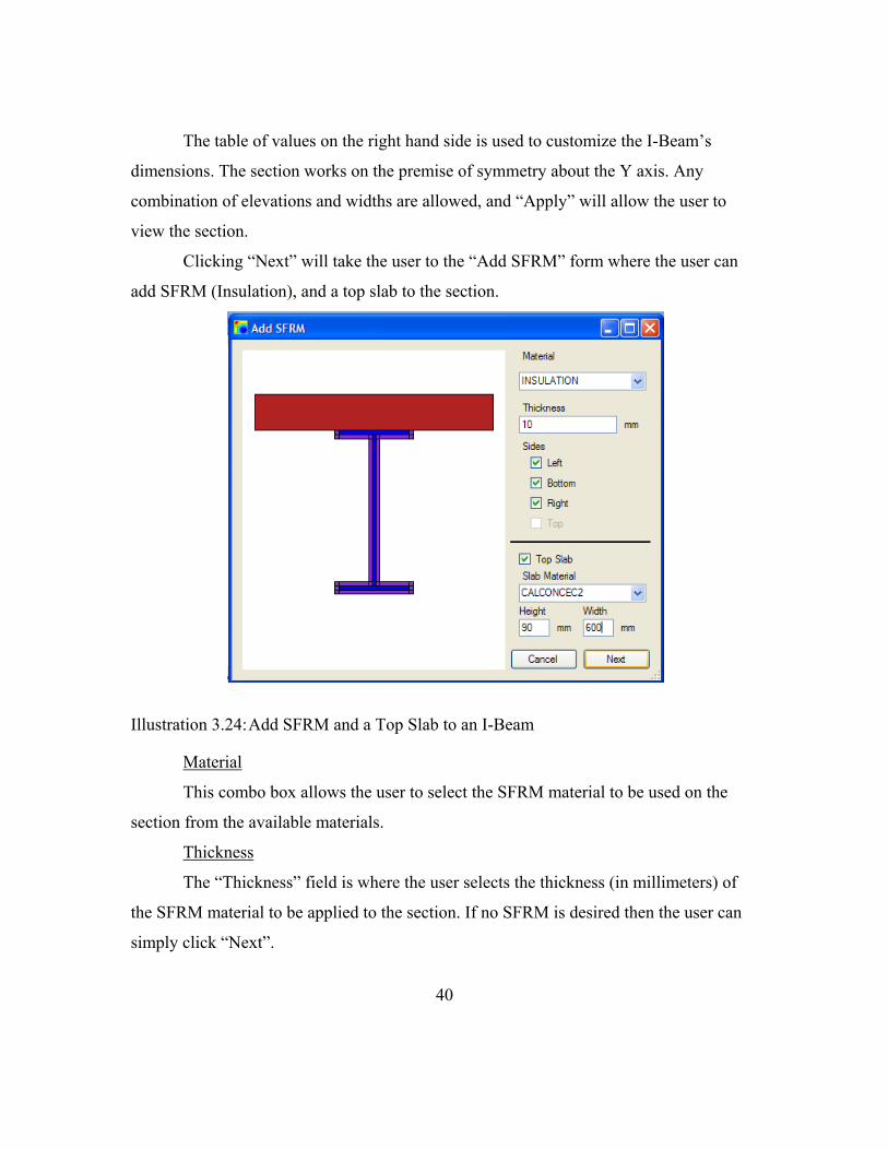
Clicking “Next” will take the user to the “Add SFRM” form where the user can
add SFRM (Insulation), and a top slab to the section.
Illustration 3.24: Add SFRM and a Top Slab to an I-Beam
Material
This combo box allows the user to select the SFRM material to be used on the
section from the available materials.
Thickness
The “Thickness” field is where the user selects the thickness (in millimeters) of
the SFRM material to be applied to the section. If no SFRM is desired then the user can
simply click “Next”.

41
Sides
Using the “Left”, “Bottom”, “Right”, and “Top” checkboxes the user can select
what part of the section SFRM is to be applied. “Bottom” is defined as the sides
connected to the least Y coordinate value and “Top” is defined as the sides connected to
the highest Y coordinate value. “Left” is defined as every side (that is not the top or
bottom) to the left of the web and “Right is to the right of the web. The “Top” Checkbox
is automatically turned off when the “Top Slab” Checkbox is turned on.
Top Slab
This Checkbox allows the user to add a top slab to the section.
Slab Material
The material selected here will be the material defined for the top slab portion of
the section.
Height & Width
Use the “Height” and “Width” fields to choose the slab depth and width. Once the
“Slab Material”, “Height” and “Width” controls are filled out the slab should display on
the section.
Clicking “Next” will take the user to the “Apply Mesh” form for transforming the
section into a mesh.
Rectangular Section Wizard
Get to the “Rectangular Section Form” by going to Section->Wizard and selecting
“Rectangular”.

42
Illustration 3.25: Begin Rectangular Section Wizard
Fill out the “Height” and “Width” fields in millimeters.
Illustration 3.26: Define Rectangular Section
43
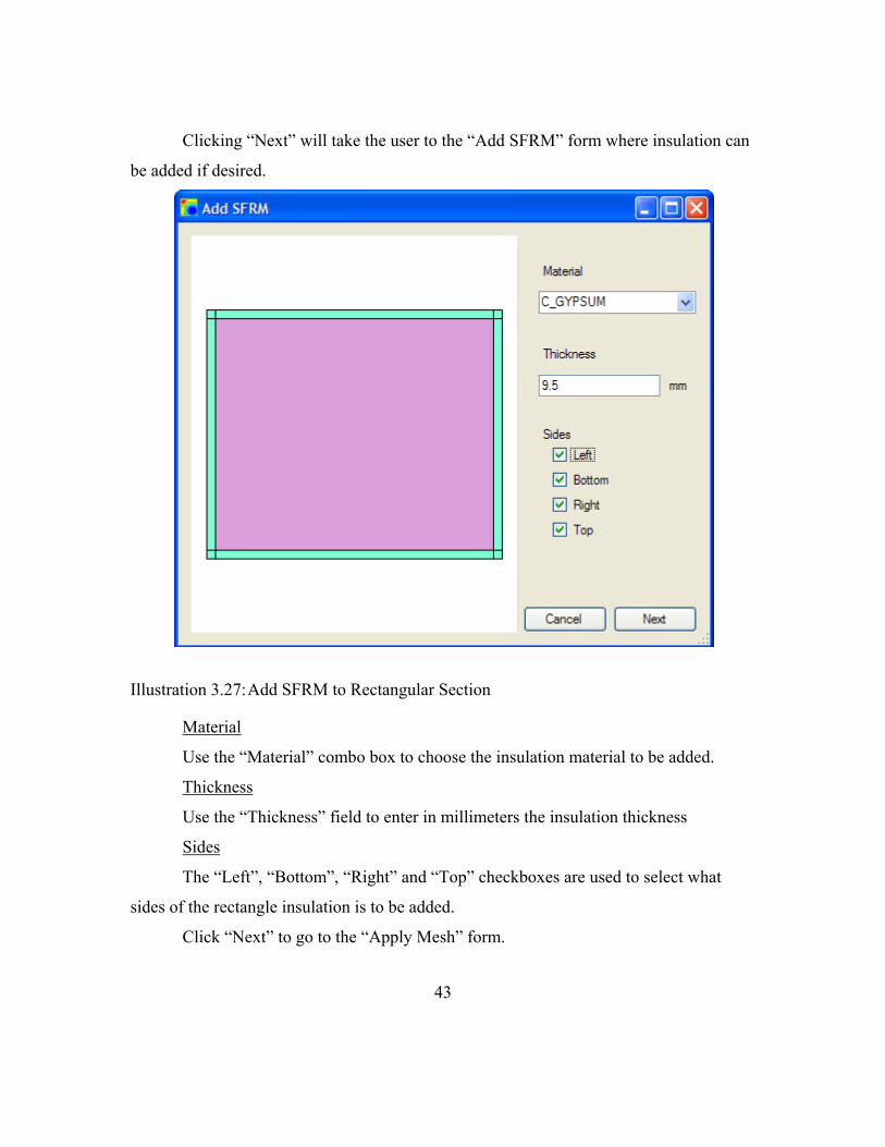
Clicking “Next” will take the user to the “Add SFRM” form where insulation can
be added if desired.
Illustration 3.27: Add SFRM to Rectangular Section
Material
Use the “Material” combo box to choose the insulation material to be added.
Thickness
Use the “Thickness” field to enter in millimeters the insulation thickness
Sides
The “Left”, “Bottom”, “Right” and “Top” checkboxes are used to select what
sides of the rectangle insulation is to be added.
Click “Next” to go to the “Apply Mesh” form.

44
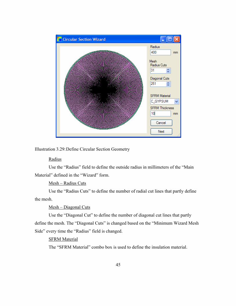
Circular Section Wizard
Get to the “Circular Section Form” by going to Section->Wizard and selecting
“Circular”.
Illustration 3.28: Begin Circular Section Wizard
Fill out the “Main Material” combo box and the “Section Name” field. Clicking
“Next” will load the “Circular Section Wizard” form.
45
Illustration 3.29: Define Circular Section Geometry
Radius
Use the “Radius” field to define the outside radius in millimeters of the “Main
Material” defined in the “Wizard” form.
Mesh – Radius Cuts
Use the “Radius Cuts” to define the number of radial cut lines that partly define
the mesh.
Mesh – Diagonal Cuts
Use the “Diagonal Cut” to define the number of diagonal cut lines that partly
define the mesh. The “Diagonal Cuts” is changed based on the “Minimum Wizard Mesh
Side” every time the “Radius” field is changed.
SFRM Material
The “SFRM Material” combo box is used to define the insulation material.
46
SFRM Thickness
The “SFRM Thickness” field is the total thickness in millimeters of the “SFRM
Material”.
Click “Next” to take the user to the “Fire Exposure” form.
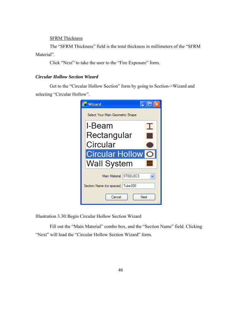
Circular Hollow Section Wizard
Get to the “Circular Hollow Section” form by going to Section->Wizard and
selecting “Circular Hollow”.
Illustration 3.30: Begin Circular Hollow Section Wizard
Fill out the “Main Material” combo box, and the “Section Name” field. Clicking
“Next” will load the “Circular Hollow Section Wizard” form.

47
Illustration 3.31: Define Circular Hollow Geometry
Radius Outer
Use the “Radius Outer” field to define the outside radius in millimeters of the
“Main Material” defined in the “Wizard” form.
Thickness
Use the “Thickness” field to define the thickness of the hollow section (e.g. if the
outside radius was 300 mm and the inside radius was 290 mm, then type 300 for “Radius
Outer”, and 10 for “Thickness”).
Mesh – Diagonal Cuts
Use the “Diagonal Cuts” to define the number of diagonal cut lines that define the
mesh. The “Diagonal Cut” is changed based on the “Minimum Wizard Mesh Side” every
time the “Radius” field is changed.
SFRM Material
The “SFRM Material” combo box is used to define the insulation material.

48
SFRM Thickness
The “SFRM Thickness” field is the total thickness (in millimeters) of the “SFRM
Material”.
Click “Next” to take the user to the “Fire Exposure” form.
Apply Mesh
The “I-Beam”, “Rectangular”, and “Wall System” wizard types take the user to
the “Apply Mesh” Form once the section geometry is defined.
Illustration 3.32: Apply Mesh
To allow for successful creation of the mesh, horizontal and vertical cut lines are
developed so that no free nodes are allowed except ones on the outside corners. Initial cut
lines are made based on the geometry and the “Wizard Mesh Max Side” field defined in
the “Settings” form. For instance, if the user has a 100 mm by 100 mm rectangular

49
section and “Wizard Mesh Max Side” is set to 10 mm (above 15 mm not recommended),
then “Apply Mesh” will load with horizontal cut lines at -50, -40, -30, -20, -10, 0, 10, etc.
and the same for vertical cut lines. If this example was executed, the program generates a
mesh using 100 elements.
Once the initial set of cut lines is produced, the user can highlight, delete and add
specific individual cut lines to split the original geometry into different mesh
configurations. A cut line is highlighted whenever the cut line is selected out of the table
of “Vertical Cut Lines” or “Horizontal Cut Lines”.
Delete
The “Delete” button deletes the currently selected cut line from either the
horizontal or vertical cut line tables
Add
The user can fill out the field to the left of the “Add” button and click “Add” to
apply a horizontal or vertical cut at the specified coordinate. Clicking the “Next” button
takes the user to the “Fire Exposure” form.
Fire Exposure
The “Fire Exposure” form allows the user to select the fire (time/temperature
curve) that will be applied to the section, and from what side the heat, caused by the fire,
will enter the section.

50
Illustration 3.33: Define Section’s Fire Exposure
Fire
This combo box gives the user the ability to place any of the SAFIR2007
predefined fires (ASTME119, FISO, and HYDROCARB) as well as any custom fires
developed under Fires->Edit.
Sides
Here, the user can select from which side the fire will affect the section. “Bottom”
is defined as the sides with the lowest Y coordinates, while “Top” is defined as the sides
with the highest Y coordinates. “Left” sides are all the other sides to the left of the zero Y
coordinate, while “Right” sides are right of the zero Y coordinate.
51
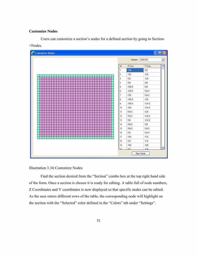
Customize Nodes
Users can customize a section’s nodes for a defined section by going to Section-
>Nodes.
Illustration 3.34: Customize Nodes
Find the section desired from the “Section” combo box at the top right hand side
of the form. Once a section is chosen it is ready for editing. A table full of node numbers,
Z Coordinates and Y coordinates is now displayed so that specific nodes can be edited.
As the user enters different rows of the table, the corresponding node will highlight on
the section with the “Selected” color defined in the “Colors” tab under “Settings”.

52
Use the “New Node” button to define new nodes.
Illustration 3.35: New Node
Clicking “Add” adds a new node to the section at the entered Z and Y coordinates
(in millimeters).
Customize Mesh You can customize a section’s mesh for a defined section by going to Section-
>Mesh.

53
Illustration 3.36: Customize Mesh
Find the section desired from the “Section” combo box at the top right hand side
of the form. Once a section is chosen it is ready for editing. The combo boxes will be
filled with all of the section’s available data. To view or change an element’s attributes,
either click on the element on the section image or navigate to it via the “Element #”
combo box. The selected element will highlight using the color chosen for “Selected” in
the “Colors” tab of the “Settings” form. Now the user can change the material, nodes or
fire exposure for a particular element.

54
Use the “New Element” button to define new elements.
Illustration 3.37: New Element
Clicking “Add” will add a new element to the section. A material type and four
node definitions are required to define an element. For three -sided elements define the
“Top Left Node” as “0”.
Use the “Delete Element” button to delete an existing element.

55
Illustration 3.38: Delete Element
Time Steps
Edit the time steps used by SAFIR2007 by going to Section->Time Steps.
Illustration 3.39: Time Steps
Whenever a section is finished using the wizard, the time steps shown above are
defined for the section.

56
Computation Time Steps
The first table “Computation time steps” is used to define how often SAFIR2007
will run a computation and for how long. Use a smaller time step for materials with sharp
peaks in their thermal properties like gypsum.
Print Time Steps
The “Print Time Steps” table is how often and how long the data will be printed
out for viewing later with Diamond07.
Both of the time steps tables can have multiple rows for different time steps
during the computation and printing.
RUN ANALYSIS
Export Section
Export a defined section by going to File->Export Section.
Illustration 3.40: Export Section
Select the appropriate section from the “Section to Export” combo box, and click
“Export”. The next form will ask the user where to export the file.

57
Illustration 3.41: Export Section Location
Navigate to the desired directory, click “Save”, and UT Fire will generate a file in
a format ready for input into SAFIR2007.
Run Section
Run a defined section by going to File->Run Section.
Illustration 3.42: Run Section

58
Select the appropriate section from the “Section to Run” combo box, and click
“Run”. “Run” will check to see if the SAFIR2007 and Diamond07 executables exist (See
SAFIR2007 and Diamond Executables); if they do, it will run the section analysis. Once
“Run” is clicked, the section is exported to the directory where SAFIR2007 is located
along with any custom fires. If the section runs properly the user sees a command
window with SAFIR2007 running. Diamond07 then loads and gives an error stating the
section cannot be loaded. Wait for the command window to finish loading, and then
Diamond07 asks to reload the .out file again. Reload, and the section is now ready for
viewing.
59
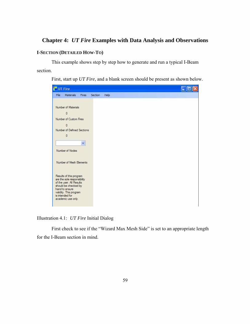
Chapter 4: UT Fire Examples with Data Analysis and Observations
I-SECTION (DETAILED HOW-TO)
This example shows step by step how to generate and run a typical I-Beam
section.
First, start up UT Fire, and a blank screen should be present as shown below.
Illustration 4.1: UT Fire Initial Dialog
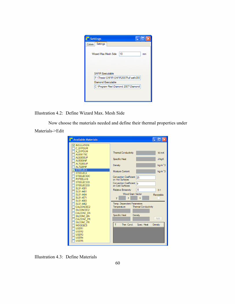
First check to see if the “Wizard Max Mesh Side” is set to an appropriate length
for the I-Beam section in mind.
60
Illustration 4.2: Define Wizard Max. Mesh Side
Now choose the materials needed and define their thermal properties under
Materials->Edit
Illustration 4.3: Define Materials

61
Choose “STEELEC3” to represent the steel material and “INSULATION” (a non-
temperature dependent thermal property material) to represent the spray applied fire
resistive material (SFRM) surrounding the steel I-Beam. The SFRM material modeled is
a common insulation BLAZE-SHIELD II. The thermal properties were chosen through a
combination of properties from Isolatek (BLAZE-SHIELD II manufacturer) (Isolatek,
2005) and NIST (NIST, 2003).
INSULATION
Thermal Conductivity: 0.2 W/mK
Specific Heat: 1200 J/kgK
Density: 240 kg/m^3
Moisture Content: 0 kg/m^3
Convection Coefficient on Hot Surfaces: 25
Convection Coefficient on Cold Surfaces: 9
Relative Emissivity: 0.5
STEELEC3
Convection Coefficient on Hot Surfaces: 25
Convection Coefficient on Cold Surfaces: 9
Relative Emissivity: 0.5
Now exit out of “Available Materials” and the user should see “Number of
Materials” incremented to 2 on the main screen. This example problem uses the standard
ASTM E119 fire time/temperature curve so there is no need to enter the fires form. Next
the user should start the wizard by going to Section->Wizard, and the following dialog
will be displayed.
62
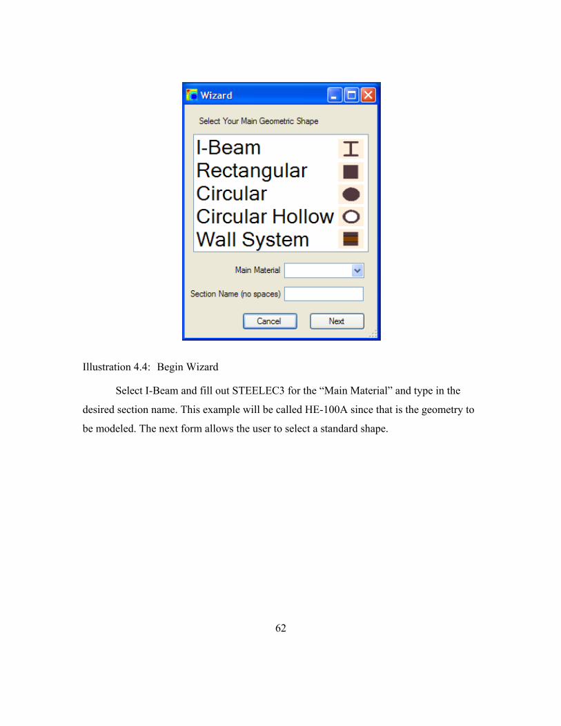
Illustration 4.4: Begin Wizard
Select I-Beam and fill out STEELEC3 for the “Main Material” and type in the
desired section name. This example will be called HE-100A since that is the geometry to
be modeled. The next form allows the user to select a standard shape.

63
Illustration 4.5: Select HE 100 A
Navigate to the desired section (in this case 100 A) and click on the name. The
section appear on the right-hand side. Click “Next” and the “Edit I-Section” form is
displayed where the user can specify a custom geometry.

64
Illustration 4.6: Customize I-Beam Geometry
This example models a HE-100 A I-Beam so no modifications will be made.
Click “Next” and the “Add SFRM” form is shown.

65
Illustration 4.6: Add Insulation to the I-Beam
For this example, 15 mm (6/10 of an inch) was chosen as a SFRM thickness. The
material chosen was “INSULATION”, which was defined earlier before the wizard was
started. Clicking “Next” takes the user to the “Apply Mesh” form which initially
develops a list of cut lines based on the “Wizard Min Mesh Side” parameter defined
under settings.
66
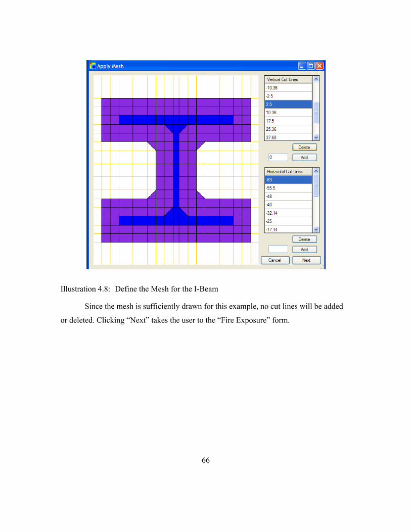
Illustration 4.8: Define the Mesh for the I-Beam
Since the mesh is sufficiently drawn for this example, no cut lines will be added
or deleted. Clicking “Next” takes the user to the “Fire Exposure” form.
67
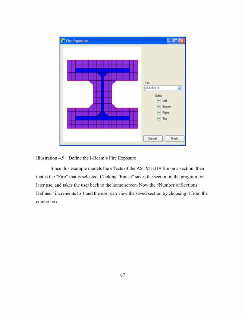
Illustration 4.9: Define the I-Beam’s Fire Exposure
Since this example models the effects of the ASTM E119 fire on a section, then
that is the “Fire” that is selected. Clicking “Finish” saves the section in the program for
later use, and takes the user back to the home screen. Now the “Number of Sections
Defined” increments to 1 and the user can view the saved section by choosing it from the
combo box.

68
Illustration 4.10: View the I-Beam Wizard Results
The section, the number of nodes and the number of mesh elements are now
viewable. Now the section is completely defined and can be run. Before the section is
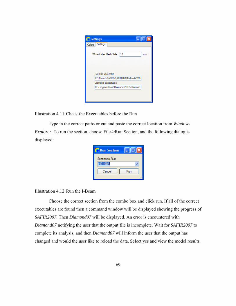
run, make sure that the SAFIR2007 and Diamond07 executables are pointing to the
correct files by looking under the settings at File->Settings.
69
Illustration 4.11: Check the Executables before the Run
Type in the correct paths or cut and paste the correct location from Windows
Explorer. To run the section, choose File->Run Section, and the following dialog is
displayed:
Illustration 4.12: Run the I-Beam
Choose the correct section from the combo box and click run. If all of the correct
executables are found then a command window will be displayed showing the progress of
SAFIR2007. Then Diamond07 will be displayed. An error is encountered with
Diamond07 notifying the user that the output file is incomplete. Wait for SAFIR2007 to
complete its analysis, and then Diamond07 will inform the user that the output has
changed and would the user like to reload the data. Select yes and view the model results.

70
Illustration 4.13: View the I-Beam Model Results
Basic Conditions
The basic conditions of the I-Beam section are:
1. A European HE-100A standard section
2. 15 millimeters of insulation surrounding the section
3. Insulation and steel thermal properties inputted based on manufacturer and
NIST data
4. ASTM E119 time/temperature fire curve applied to all sides of the section
Comparison to OZone OZone (Cadorin, 2007) is a computer program that allows a user to build a
time/temperature fire curve based on Euro Code standards. The program also allows the

71
user to apply a fire curve to a steel section. Using the Lumped-Capacitance Method,
OZone computes the fire induced steel temperatures. A comparison is listed below of
SAFIR2007’s computed steel temperatures vs. OZone’s computed steel temperatures.
Figure 4.1: Ozone vs. SAFIR2007 Time/Temp for a HE-100A Steel Beam
After two hours the steel temperatures differ by about 25 degrees C or
approximately 3%.
RECTANGULAR SECTION (DETAILED HOW-TO)
In UT Fire one can quickly define a rectangular section using the “Rectangular
Section Wizard” that comes with the program. Following this is a detailed example of
how to define 410mm x 360mm (about a 16in by 14in) concrete column. First start UT
Fire.
0
200
400
600
800
1000
0 2000 4000 6000 8000
Temp
(
C)
Time (S)
OZone vs. SAFIR2007 Time/Temp for a HE‐100A Steel Beam
Ozone ASTME119
Ozone Steel
SAFIR Insulation\Steel Interface
SAFIR Outside Insulation Edge
SAFIR Steel Center

72
Illustration 4.14: UT Fire Initialization for Rectangular Section
Now define the materials to be used by going to Materials->Edit. When choosing
concrete as a material the following materials are available: CALCONCEC2,
SILCONCEC2, CALCONC_EN, SILCONC_EN, CALCONC_PR, and SILCONC_PR.
The first two materials with EC2 at the end of their names require four defining
parameters. The parameters are moisture content, convection coefficient on hot surfaces,
convection coefficient on cold surfaces, and relative emissivity. The last four materials
require the above plus density and a thermal conductivity parameter. The thermal
conductivity parameter allows for picking a temperature dependent number between a
high thermal conductivity curve and a low thermal conductivity curve defined in Euro
Code 2. The main difference between the siliceous (SIL) and calcareous (CAL) concrete
types is their difference in coefficients of thermal expansion, which is not used in a heat
transfer solution (BSI, 2004). This example uses the following thermal properties as the
user would see them in the program.
73
Illustration 4.15: Define Concrete Thermal Properties
The “Thermal Conductivity Parameter” was chosen as 0.9 meaning the use of
90% of the difference between the high and low curves for concrete’s thermal
conductivity. The density was taken at 2,400 kg/m3 (150 lb/ft3) and the moisture content
at 1% or 24 kg/m3. The convection coefficients were taken at 25 and 9 for hot and cold
respectively and the “Relative Emissivity” was taken at 0.7. Now the material properties
are inputted.
A custom (natural) fire will be applied to the section. To define custom fires go to
Fires->Edit.

74
Illustration 4.16: Define Custom Fire
The next step is to hand type a set of times and temperatures to define a custom
fire for this example. Click “New” and give the fire function a name. This fire will be
called RM356. Find the fire in the “Fire” combo box and begin entering times and
temperatures.

75
Illustration 4.17: Define Custom Fire 2
To view the fire curve, click “Plot”.

76
Illustration 4.18: View Custom Fire Plot
If the user wants to model the cool- down phase of the section, the sufficient time
must be input into the fire curve. Even if SAFIR2007 computations were set to run to
10,000, the program would stop at 9,000 since that is the last point on the fire curve.
Once the user has completed inputting the fire, close out of “Edit Fires”, and notice the
“Number of Custom Fires” has incremented to “1”.
Now that the material and fires desired are defined, click Section->Wizard to
begin the “Rectangular Section Wizard”. Select “Rectangular” and fill out the “Main
Material” as well as the section’s name.

77
Illustration 4.19: Start Rectangular Section Wizard
Click “Next” to define the section’s rectangular geometry.
Illustration 4.20: Define Rectangular Section Dimensions

78
Click “Next” to apply a layer of SFRM if desired. This section will not have any
outer material so click “Next” to arrive at the “Apply Mesh” form. Since 10 is the value
of the “Min. Wizard Mesh Side” parameter, the section is divided into 1476 (41*36)
mesh elements. These mesh elements are defined by the horizontal and vertical cut lines
generated. If the user wishes to further customize the mesh, just “Add” and “Delete” cut
lines. Click “Next” to arrive at the “Fire Exposure” form.
Illustration 4.21: Apply Fire Exposure to Rectangular Section
Navigate to “RM356” in the “Fire” combo box. This section applies the fire on
every side so leave all of the “Sides” checkboxes checked. Click “Finish” to finish the
wizard, and notice that the “Number of Defined Sections” has incremented to “1”. Since
the cool down phase is to be modeled, go to Section->Time Steps to change the
computation and print end times to “9000”.

79
Illustration 4.22: Define Custom Time Steps
The section is now defined and ready to be analyzed. Go to File->Run Section to
send the section to SAFIR2007 for analysis.
Basic Conditions The Rectangular section defined was a normal weight concrete (2400 kg/m3)
having dimensions 410 millimeters by 360 millimeters. This section was run with
moisture contents of 12 (0.5%), 24 (1.0%), 36 (1.5%), 72 (3.0%), and 240 (10%) kg/m3.
Three points and their temperatures vs. time curves were graphed. These points were at
the surface, 50 millimeters and 100 millimeters into the section. The points were taken at
the very corner; therefore, the depths listed above are from two sides.

80
Various Moisture Content Comparisons
Figure 4.2: Various Moisture Contents for a Standard Concrete Rectangular Section
The 10% water content section is not shown because it is a typical design, but to
show two trends. The first is the trend of decreasing peak temperature, and the second
trend is the slight pause in temperature increases around 100 degrees C (Boiling Point).
0
50
100
150
200
250
300
350
400
450
500
0 2000 4000 6000 8000
Tempe
rature (C
)
Time (sec)
Various Moisture Contents
Surface
0.5% ‐ 50 mm
1.0% ‐ 50 mm
2.0% ‐ 50 mm
3.0% ‐ 50 mm
10% ‐ 50 mm
0.5% ‐ 100 mm
1.0% ‐ 100 mm
2.0% ‐ 100 mm
3.0% ‐ 100 mm
10% ‐ 100 mm

81
The differences in peak temperatures are shown below.
Depth 0.5% Peak Temperature (C) 3.0% Peak Temperature (C)
50 millimeters 366 339
100 millimeters 191 160
Table 4.1: Difference in Peak Temperatures for a Rectangular Section with Different Moisture Contents
I-SECTION WITH AND WITHOUT CONCRETE SLAB
This example demonstrates the differences in a single steel I-Beam with and
without a concrete slab above the beam. The natural fire (same as in the detailed
rectangular section example) will surround the beam on all sides (but the beam top) and
the underside of the concrete. When defining the fire exposure the easiest way to arrive at
this condition using UT Fire is to go through the “I-Beam Wizard”, apply insulation and
a top slab during the “Apply SFRM” form and then choose all but the top side of the
section while in the “Fire Exposures” form. Then under Section->Mesh take off the fire
exposure on the sides of the concrete slab while placing fire “RmTemp” to the top of the
concrete slab.

82
Illustration 4.23: Customizing Top Slab Fire Exposure Conditions
The geometries used are:
I-Beam – AISC Type W8x15
Insulation – 12 mm
Top Slab – 80 mm by 700 mm
The thermal properties used are:
Insulation:
Thermal Conductivity: 0.2 W/mK
Specific Heat: 1,200 J/kgK
Density: 250 kg/m^3
Moisture Content: 0 kg/m^3

83
Convection (Hot): 25
Convection (Cold): 9
Relative Emissivity: 0.5
Steel (STEELEC3):
Convection (Hot): 25
Convection (Cold): 9
Relative Emissivity: 0.5
Concrete (CALCONC_EN):
Thermal Conduct. Param.: 0.8
Density: 2300 kg/m3
Moisture Content: 23 kg/m3
Convection (Hot): 25
Convection (Cold): 9
Relative Emissivity: 0.7
Below is a graph showing the differences in temperature if concrete is allowed to
pull heat away from the I-Beam at different locations in the beam. Also included on this
graph is the time vs. temperature using a lump capacitance approach modified for
insulation (Buchanan, 2002).

84
Figure 4.3: Differences in I-Beam Temperature with and without Modeling the Top Concrete Slab
The following table lists the peak temperatures at the top and bottom of the I-
Beam.
Location With Slab Peak
Temperatures (C) Without Slab Peak Temperatures (C)
Bottom 651 659
Top 397 589
Table 4.2: Peak I-Beam Temperatures with and without Modeling the Top Slab
This example highlights the fact that steel can have a 254 degree difference in
temperature across a member. It should be remembered that steel properties such as
0
100
200
300
400
500
600
700
800
900
1000
0 2000 4000 6000 8000
Tempe
rature (C
)
Time (sec)
I‐Beam with and without Top Slab
Surface
Bottom With Slab
Top With Slab
Bottom Without Slab
Top Without Slab
Steel (Lump Cap.)

85
modulus and yield strength go down with increasing temperature. The following table
demonstrates the change in material properties across the section for 50 ksi yield strength
steel (Buchanan, 2002) for the “with slab” condition.
Location Modulus of Elasticity (ksi) Yield Strength (ksi)
Bottom 11,700 18.4
Top 23,400 36.8
Table 4.3: Variation in Steel Material Properties for the “with slab” Condition
SQUARE COLUMN WITH AND WITHOUT REINFORCEMENT STEEL The next example demonstrates the difference in concrete temperatures if the
reinforcement steel is modeled or if it is not. The section will be a 300 mm x 300 mm
concrete column with φ 19 longitudinal bars (#6 bars) and φ 10 transverse bars (#3 bars)
to model ties. One of the transverse bars is though the center and one surrounds the
longitudinal bars. The finished section looks like the one below once the steel is modeled
using Section->Mesh.
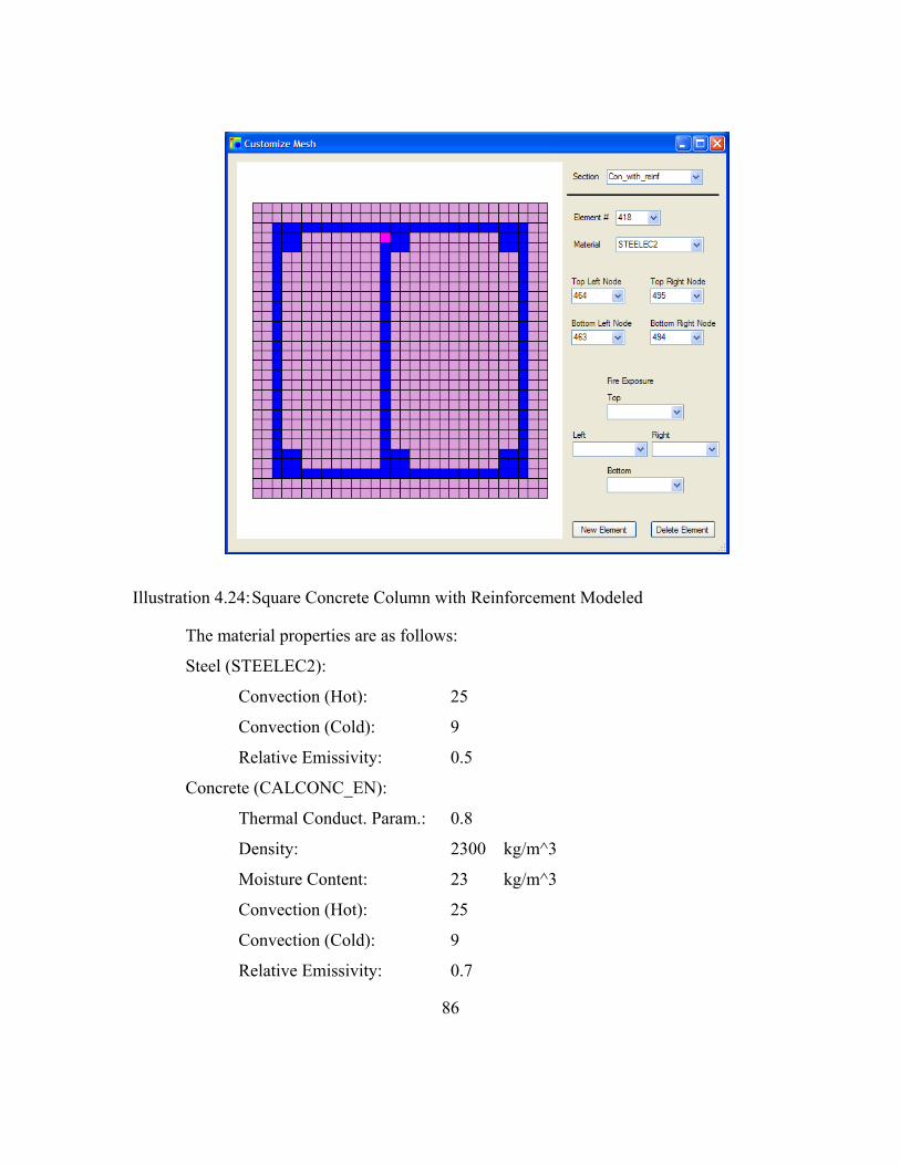
86
Illustration 4.24: Square Concrete Column with Reinforcement Modeled
The material properties are as follows:
Steel (STEELEC2):
Convection (Hot): 25
Convection (Cold): 9
Relative Emissivity: 0.5
Concrete (CALCONC_EN):
Thermal Conduct. Param.: 0.8
Density: 2300 kg/m^3
Moisture Content: 23 kg/m^3
Convection (Hot): 25
Convection (Cold): 9
Relative Emissivity: 0.7

87
The fire used was the same RM356 that is used in the previous examples. Below
is a graph of various points in the section vs. time.
Figure 4.4: Concrete Temperatures with and without Reinforcement Steel Modeled
As viewed above concrete temperatures rise faster and hotter if and when
reinforcement steel is modeled. Below is a table of peak temperatures for the three points
analyzed.
0
50
100
150
200
250
300
350
400
450
500
0 2000 4000 6000 8000 10000
Concrete with and without Reinforcement
Surface
50 mm Without Reinf.
50 mm With Reinf.
100 mm Without Reinf.
100 mm With Reinf.
Center Without Reinf.
Center With Reinf.
88
Location Without Reinforcement Peak Temperatures (C)
With Reinforcement Peak Temperatures (C)
50 mm 365 397
100 mm 203 261
Center 193 246
Table 4.4: Concrete Peak Temperatures with and without Reinforcement Steel Modeled
SQUARE COLUMN MODELING: ¼ OF A COLUMN VS. ENTIRE COLUMN This next example highlights boundary conditions and modeling portions of
sections. The boundaries in heat transfer are accomplished through convection and
radiation. SAFIR2007 doesn’t allow for radiation or convection off of a surface unless it
is a void or has a fire exposure associated with it. Therefore boundary conditions for
sections are determined by voids or assigning/not assigning time/temperature curves.
Radiation is the dominant heat transfer mode at elevated temperatures in fires. Knowing
that convection matters very little and is sometimes ignored for high temperatures,
convection coefficients affect the outcome of these analyses very little. Several iterations
were run with different convection coefficients on the same section to study how the
temperatures change. The Fire was only applied to the top of the section. Diamond07
divides the temperatures into nine color groups. The following is a table listing those
divisions for the section after an hour and a half.

89
Conv ‐ Hot 25 Conv ‐ Hot 25 Conv ‐ Hot 25 Conv ‐ Hot 25 Conv ‐ Cold 9 Conv ‐ Cold 20 Conv ‐ Cold 100 Conv ‐ Cold 1000
217.2 217.2 216.5 215.8 192.6 192.5 191.9 191.3 167.9 167.9 167.4 166.9 143.3 143.2 142.8 142.4 118.7 118.6 118.3 117.9 94.1 94.0 93.7 93.4 69.4 69.4 69.1 69.0 44.7 44.7 44.6 44.5 20.1 20.1 20.0 20.0
Table 4.5: Differences in Results when the Cold Convection Coefficient is Changed
Conv ‐ Hot 10 Conv ‐ Hot 50 Conv ‐ Hot 100 Conv ‐ Cold 9 Conv ‐ Cold 9 Conv ‐ Cold 9
226.5 210.3 205.7 200.7 186.5 182.5 174.9 162.8 159.3 149.1 139.0 136.1 123.3 115.2 112.9 97.5 91.4 89.7 71.7 67.6 66.5 45.9 43.9 43.3 20.1 20.1 20.1
Table 4.6: Differences in Results when the Hot Convection Coefficient is Changed
There is nearly no change in the results when the Cold Convection Coefficient is
changed, very little temperature differences for hotter temperatures, and nearly no
differences for colder temperatures.
A 300 millimeter by 300 millimeter section was analyzed as ¼ of a section and as
a full section, and their temperatures were nearly identical. No data was given to
SAFIR2007 to indicate that the quarter sections internal edges would have concrete
touching them. This is accomplished by not applying a time temperature curve to the

90
internal edges. Points were plotted at the surface, 30 millimeters into the section at the
corner, 70 millimeters into the section at the corner, and at the center.
Figure 4.6: Differences when Modeling a Quarter of a Square Concrete Section vs. the entire Section
In the figure above there are actually seven curves, however three are hidden due
to the modeling returning the same results. Boundary conditions should be established by
not placing time temperature curves on symmetry cut lines, and placing time temperature
curves (even if just a room temperature curve) on boundaries that will contact fluid
boundaries such that heat can be “lost” through convection and radiation.
0
100
200
300
400
500
600
700
800
900
1000
0 1000 2000 3000 4000
Tempe
rature (C
)
Time (Sec)
1/4 Section vs. Full Section
Surface
1/4 Section 30 mm
Full Section 30 mm
1/4 Section 70 mm
Full Section 70 mm
1/4 Section Center
Full Section Center

91
CIRCULAR HOLLOW SECTION WITH CENTER MODELED WITH A VOID VS. NOTHING VS. AIR VS. WATER
This next example shows the difference when different materials are modeled in
internal cavities of the section. The example to be modeled is a steel pipe with a partition
in the middle. Fire conditions will only apply to one half of the section, and the example
will show how heat moves from the fire side to the room temperature side of the pipe.
The four instances modeled are void, nothing, air, and water. The section modeled was a
pipe with outside diameter of 100 millimeters (4 inches), wall thickness of 10 millimeters
and 10 millimeters of insulation surrounding the pipe. The ASTM E119 fire curve was
placed on the right side (called Fire Side) and the RmTemp fire was placed on the left
side. Therefore, the only heat that could reach the left side (called Cold Side) would be
through conduction, convection, or radiation and not from the fire itself (Franssen, J.M.,
Kodur, V.K.R, Mason, J., 2002). The point on the Fire Side was taken as the centermost
point of the fire, and the Cold Side point was taken as the centermost point away from the
fire.
1. Void – Voids in SAFIR2007 are areas in a section where heat through
radiation and convection is allowed to leave one surface and enter other
surfaces. For this section the internal cavity of the pipe was modeled as a
void. This is accomplished by going through the “Circular Hollow Section
Wizard”. Heat can warm the Cold Side point through conduction around
the pipe, through the steel and insulation and through the cavity by
radiation and convection.
2. Nothing – For this section no information was given to SAFIR2007 about
the makeup of the cavities. This allowed the Cold Side to only be heated
through conduction around the pipe.
3. Air – This section uses the USER1 material (a function of temperature
dependent thermal properties) to model air. Using this method, heat is
allowed to transfer through the air by conduction, but no radiation or
convection is allowed to pass through the cavity. The thermal properties
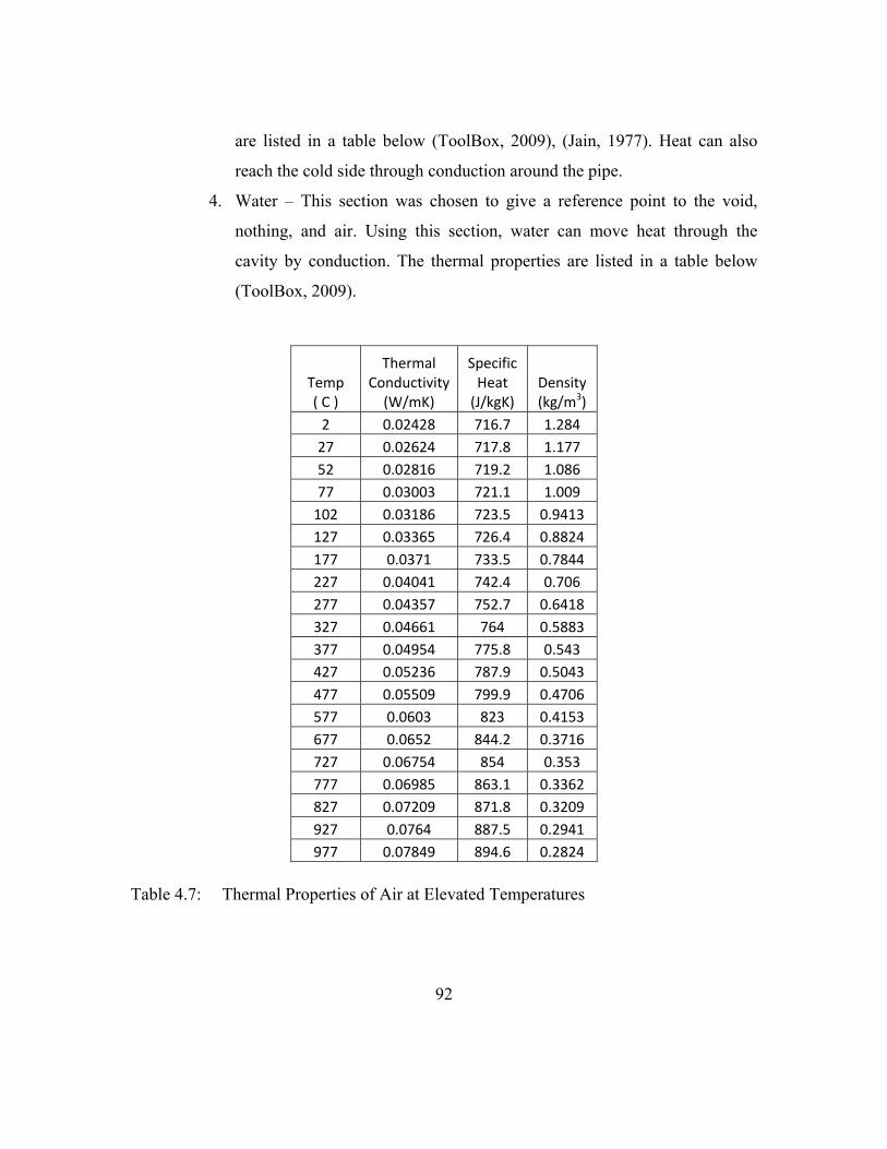
92
are listed in a table below (ToolBox, 2009), (Jain, 1977). Heat can also
reach the cold side through conduction around the pipe.
4. Water – This section was chosen to give a reference point to the void,
nothing, and air. Using this section, water can move heat through the
cavity by conduction. The thermal properties are listed in a table below
(ToolBox, 2009).
Temp ( C )
Thermal Conductivity (W/mK)
Specific Heat (J/kgK)
Density (kg/m3)
2 0.02428 716.7 1.284 27 0.02624 717.8 1.177 52 0.02816 719.2 1.086 77 0.03003 721.1 1.009 102 0.03186 723.5 0.9413 127 0.03365 726.4 0.8824 177 0.0371 733.5 0.7844 227 0.04041 742.4 0.706 277 0.04357 752.7 0.6418 327 0.04661 764 0.5883 377 0.04954 775.8 0.543 427 0.05236 787.9 0.5043 477 0.05509 799.9 0.4706 577 0.0603 823 0.4153 677 0.0652 844.2 0.3716 727 0.06754 854 0.353 777 0.06985 863.1 0.3362 827 0.07209 871.8 0.3209 927 0.0764 887.5 0.2941 977 0.07849 894.6 0.2824
Table 4.7: Thermal Properties of Air at Elevated Temperatures
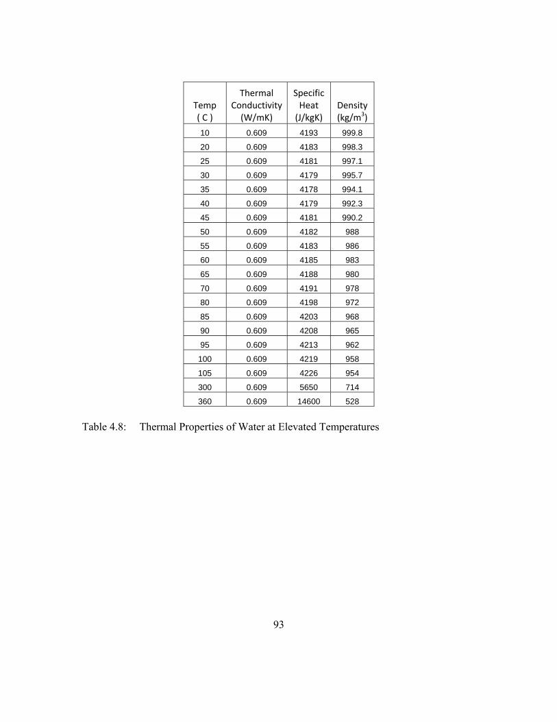
93
Temp ( C )
Thermal Conductivity (W/mK)
Specific Heat (J/kgK)
Density (kg/m3)
10 0.609 4193 999.8
20 0.609 4183 998.3
25 0.609 4181 997.1
30 0.609 4179 995.7
35 0.609 4178 994.1
40 0.609 4179 992.3
45 0.609 4181 990.2
50 0.609 4182 988
55 0.609 4183 986
60 0.609 4185 983
65 0.609 4188 980
70 0.609 4191 978
80 0.609 4198 972
85 0.609 4203 968
90 0.609 4208 965
95 0.609 4213 962
100 0.609 4219 958
105 0.609 4226 954
300 0.609 5650 714
360 0.609 14600 528
Table 4.8: Thermal Properties of Water at Elevated Temperatures

94
Figure 4.6: Steel Pipe with Different Materials in Center
The nothing section was left off of the figure because the curves are nearly
exactly the same as the air. The heating curves show that the fire side is not distributing
heat to the cold side unless radiation and convection are accounted for. In fact the air and
nothing models predict almost the exact some response leaving the air model (conduction
through air) inadequate at modeling heat transfer across cavities. Obviously, steel acts as
a good conductor which is why the cold side is heating at all for the nothing and air
models.
0
100
200
300
400
500
600
700
800
900
1000
0 1000 2000 3000 4000 5000
Tempe
rature (C
)
Time (Sec)
Steel Pipe with Different Materials in Center
Surface
Air ‐ Cold Side
Void ‐ Cold Side
Water ‐ Cold Side
Air ‐ Fire Side
Void ‐ Fire Side
Water ‐ Fire Side

95
Chapter 5: Conclusions
This thesis has described the development of the computer program UT Fire,
which serves as a preprocessor for the computer program SAFIR2007 that was developed
at the University of Liege in Belgium. The program conducts a heat transfer analysis and
structural response analysis for structures subjected to fire. The preprocessor UT Fire was
developed to allow a simplified graphical interface for input to the heat transfer portion of
SAFIR 2007. UT Fire, built with Visual Basic, allows user friendly production of
common structural sections. The user can produce common shapes with the I-beam,
rectangular, circular, circular hollow, and wall system wizards, and then further
customize those sections. The user can then assign up to 30 different materials for the
section, as well as define custom time/temperature fire curves for various parts of the
section. This thesis has also provided step by step instructions on the use of UT Fire and
has illustrated its use through a series of detailed example problems.

96
APPENDIX A (UT FIRE SOURCE CODE PRINTOUT)

Public NotInheritable Class AboutBox
Private Sub AboutBox_Load(ByVal sender As System.Object, ByVal e As System.EventArgs) Handles MyBase.Load
' Set the title of the form. Dim ApplicationTitle As String If My.Application.Info.Title <> "" Then ApplicationTitle = My.Application.Info.Title Else ApplicationTitle = System.IO.Path.
GetFileNameWithoutExtension(My.Application.Info.AssemblyName) End If Me.Text = String.Format("About {0}", ApplicationTitle) ' Initialize all of the text displayed on the About Box. ' TODO: Customize the application's assembly information in
the "Application" pane of the project ' properties dialog (under the "Project" menu). Me.LabelProductName.Text = My.Application.Info.ProductName Me.LabelVersion.Text = String.Format("Version {0}", My.
Application.Info.Version.ToString) Me.LabelCopyright.Text = My.Application.Info.Copyright Me.LabelCompanyName.Text = My.Application.Info.CompanyName Me.TextBoxDescription.Text = My.Application.Info.Description End Sub
Private Sub OKButton_Click(ByVal sender As System.Object, ByVal e As System.EventArgs) Handles OKButton.Click
Me.Close() End Sub
End Class
97

Public Class AdvFeaturesForm 'Allows Use of the Advanced Features
Private Sub ExtrudeSection_Click(ByVal sender As System.Object, ByVal e As System.EventArgs) Handles ExtrudeSectionForm.Click
Dim ExtrudeSection As New ExtrudeSectionForm ExtrudeSection.ShowDialog() ExtrudeSection.Refresh() End SubEnd Class
98

Public Class CircHolForm 'Form used to make a Circular section with voids in the middle 'This is the only portion of the program that makes voids Public Section As Main.Section Public NowUser As String = "No"
Private Sub DoCircularSection() Dim i, j, m, k As Integer Dim Radius As Double Dim MyBmp As Bitmap = New Bitmap(PictureBox1.Width,
PictureBox1.Height) Dim ImPref As Main.ImagePref
ReDim Section.Elem(0) m = 1 k = 1 If IsNumeric(TBRadius.Text) = True And IsNumeric(TBThick.Text)
= True Then For i = 1 To 2 If i = 1 Then Radius = TBRadius.Text - TBThick.Text ElseIf i = 2 Then Radius = TBRadius.Text End If For j = 1 To NumUpDownDia.Value ReDim Preserve Section.Nodes(m) Section.Nodes(m).Z = Radius * Math.Cos(j /
NumUpDownDia.Value * 2 * Math.PI) Section.Nodes(m).Y = Radius * Math.Sin(j /
NumUpDownDia.Value * 2 * Math.PI)
If i > 1 And j > 1 Then ReDim Preserve Section.Elem(k) Section.Elem(k).TL = m Section.Elem(k).BL = m - 1 Section.Elem(k).BR = m - NumUpDownDia.Value -
1 Section.Elem(k).TR = m - NumUpDownDia.Value Section.Elem(k).Mat = Main.WizMMat Section.Elem(k) = ElemAttribMod.SortElemSides
(Section, k) k = k + 1 End If If j = NumUpDownDia.Value And i > 1 Then ReDim Preserve Section.Elem(k) Section.Elem(k).TL = m Section.Elem(k).BL = m - NumUpDownDia.Value +
1 Section.Elem(k).BR = m - NumUpDownDia.Value *
2 + 1 Section.Elem(k).TR = m - NumUpDownDia.Value Section.Elem(k).Mat = Main.WizMMat Section.Elem(k) = ElemAttribMod.SortElemSides
(Section, k) k = k + 1 End If m = m + 1
99

Next Next 'Add on SFRM If CBMaterials.SelectedIndex >= 0 And IsNumeric
(TBSFRMThick.Text) = True Then For i = 1 To NumUpDownDia.Value ReDim Preserve Section.Nodes(m) Section.Nodes(m).Z = (TBSFRMThick.Text + Radius) *
Math.Cos(i / NumUpDownDia.Value * 2 * Math.PI) Section.Nodes(m).Y = (TBSFRMThick.Text + Radius) *
Math.Sin(i / NumUpDownDia.Value * 2 * Math.PI)
If i > 1 Then ReDim Preserve Section.Elem(k) Section.Elem(k).TL = m Section.Elem(k).BL = m - 1 Section.Elem(k).BR = m - NumUpDownDia.Value -
1 Section.Elem(k).TR = m - NumUpDownDia.Value Section.Elem(k).Mat = CBMaterials.Text Section.Elem(k) = ElemAttribMod.SortElemSides
(Section, k) k = k + 1 End If If i = NumUpDownDia.Value Then ReDim Preserve Section.Elem(k) Section.Elem(k).TL = m Section.Elem(k).BL = m - NumUpDownDia.Value +
1 Section.Elem(k).BR = m - NumUpDownDia.Value *
2 + 1 Section.Elem(k).TR = m - NumUpDownDia.Value Section.Elem(k).Mat = CBMaterials.Text Section.Elem(k) = ElemAttribMod.SortElemSides
(Section, k) k = k + 1 End If m = m + 1 Next End If 'Look at the section, find voids, and define them Section = ElemAttribMod.DoCircHolVoids(Section) ImPref = ImageMod.ImagePref(Section.Nodes, MyBmp) For i = 1 To Section.Elem.Length - 1 MyBmp = ImageMod.DrawShape(ImPref.Scale, ImPref.Start,
Section, i, MyBmp, True, Color.Black, False) Next
PictureBox1.Image = MyBmp End If End Sub
Private Sub TBRadius_TextChanged(ByVal sender As System.Object, ByVal e As System.EventArgs) Handles TBRadius.TextChanged
Dim Value As Integer If NowUser = "Yes" Then
100
Value = Math.Round(2 * Math.PI * TBRadius.Text / Main.WizMeshPar, 0)
If Value <= NumUpDownDia.Maximum And Value >= NumUpDownDia.Minimum Then
NumUpDownDia.Value = Value End If End If DoCircularSection() End Sub
Private Sub NumUpDownDia_ValueChanged(ByVal sender As System.Object, ByVal e As System.EventArgs) Handles NumUpDownDia.ValueChanged
NowUser = "No" TBRadius_TextChanged(Me, AcceptButton) NowUser = "Yes" End Sub
Private Sub NextButton_Click(ByVal sender As System.Object, ByVal e As System.EventArgs) Handles NextButton.Click
If IsNumeric(TBRadius.Text) = True And IsNumeric(TBThick.Text) = True Then
Main.MySection(0) = Section Dim FireExposure As New FireExposureForm Me.Close() FireExposure.ShowDialog() FireExposure.Refresh() Else MsgBox("Please Enter a Radius and Thickness", MsgBoxStyle.
Critical) End If End Sub
Private Sub CircularForm_Load(ByVal sender As Object, ByVal e As System.EventArgs) Handles Me.Load
Dim MatName As String
For i = 0 To Main.AllMaterials.Length - 1 If Main.AllMaterials(i).Checked = True Then MatName = Main.AllMaterials(i).Name CBMaterials.Items.Add(MatName) End If Next NowUser = "Yes" End Sub
Private Sub TBSFRMThick_TextChanged(ByVal sender As System.Object, ByVal e As System.EventArgs) Handles TBSFRMThick.TextChanged
TBRadius_TextChanged(Me, AcceptButton) End Sub
Private Sub TBThick_TextChanged(ByVal sender As System.Object, ByVal e As System.EventArgs) Handles TBThick.TextChanged
TBRadius_TextChanged(Me, AcceptButton) End SubEnd Class
101

Public Class CircularForm 'Wizard form used to make a circular section Public Section As Main.Section Public NowUser As String = "No"
Private Sub DoCircularSection() Dim i, j, m, k As Integer Dim Radius As Double = TBRadius.Text Dim MyBmp As Bitmap = New Bitmap(PictureBox1.Width,
PictureBox1.Height) Dim ImPref As Main.ImagePref
ReDim Section.Elem(0) ReDim Preserve Section.Nodes(1) Section.Nodes(1).Z = 0 Section.Nodes(1).Y = 0 m = 2 k = 1 'The main engine for making the radial section 'however it store the coordinates in rectangular coordinates 'SAFIR will allow polar coordinates For i = 1 To NumUpDownRadius.Value For j = 1 To NumUpDownDia.Value ReDim Preserve Section.Nodes(m) Section.Nodes(m).Z = (i / NumUpDownRadius.Value) *
Radius * Math.Cos(j / NumUpDownDia.Value * 2 * Math.PI) Section.Nodes(m).Y = (i / NumUpDownRadius.Value) *
Radius * Math.Sin(j / NumUpDownDia.Value * 2 * Math.PI)
If j > 1 Then If i = 1 Then ReDim Preserve Section.Elem(k) Section.Elem(k).TL = 0 Section.Elem(k).BL = m Section.Elem(k).BR = 1 Section.Elem(k).TR = m - 1 Section.Elem(k).Mat = Main.WizMMat k = k + 1 Else ReDim Preserve Section.Elem(k) Section.Elem(k).TL = m Section.Elem(k).BL = m - 1 Section.Elem(k).BR = m - NumUpDownDia.Value -
1 Section.Elem(k).TR = m - NumUpDownDia.Value Section.Elem(k).Mat = Main.WizMMat Section.Elem(k) = ElemAttribMod.SortElemSides
(Section, k) k = k + 1 End If End If If j = NumUpDownDia.Value Then If i = 1 Then ReDim Preserve Section.Elem(k) Section.Elem(k).TL = 0 Section.Elem(k).BL = m Section.Elem(k).BR = 2
102

Section.Elem(k).TR = 1 Section.Elem(k).Mat = Main.WizMMat k = k + 1 Else ReDim Preserve Section.Elem(k) Section.Elem(k).TL = m Section.Elem(k).BL = m - NumUpDownDia.Value +
1 Section.Elem(k).BR = m - NumUpDownDia.Value *
2 + 1 Section.Elem(k).TR = m - NumUpDownDia.Value Section.Elem(k).Mat = Main.WizMMat Section.Elem(k) = ElemAttribMod.SortElemSides
(Section, k) k = k + 1 End If End If m = m + 1 Next Next 'Add some SFRM to the section If CBMaterials.SelectedIndex >= 0 And IsNumeric(TBSFRMThick.
Text) = True Then For i = 1 To NumUpDownDia.Value ReDim Preserve Section.Nodes(m) Section.Nodes(m).Z = (TBSFRMThick.Text + Radius) *
Math.Cos(i / NumUpDownDia.Value * 2 * Math.PI) Section.Nodes(m).Y = (TBSFRMThick.Text + Radius) *
Math.Sin(i / NumUpDownDia.Value * 2 * Math.PI)
If i > 1 Then ReDim Preserve Section.Elem(k) Section.Elem(k).TL = m Section.Elem(k).BL = m - 1 Section.Elem(k).BR = m - NumUpDownDia.Value - 1 Section.Elem(k).TR = m - NumUpDownDia.Value Section.Elem(k).Mat = CBMaterials.Text Section.Elem(k) = ElemAttribMod.SortElemSides
(Section, k) k = k + 1 End If If i = NumUpDownDia.Value Then ReDim Preserve Section.Elem(k) Section.Elem(k).TL = m Section.Elem(k).BL = m - NumUpDownDia.Value + 1 Section.Elem(k).BR = m - NumUpDownDia.Value * 2 +
1 Section.Elem(k).TR = m - NumUpDownDia.Value Section.Elem(k).Mat = CBMaterials.Text Section.Elem(k) = ElemAttribMod.SortElemSides
(Section, k) k = k + 1 End If m = m + 1 Next End If
103
ImPref = ImageMod.ImagePref(Section.Nodes, MyBmp) For i = 1 To Section.Elem.Length - 1 MyBmp = ImageMod.DrawShape(ImPref.Scale, ImPref.Start,
Section, i, MyBmp, True, Color.Black, False) Next
PictureBox1.Image = MyBmp End Sub
Private Sub TBRadius_TextChanged(ByVal sender As System.Object, ByVal e As System.EventArgs) Handles TBRadius.TextChanged
Dim Value As Integer If NowUser = "Yes" Then If IsNumeric(TBRadius.Text) = True Then Value = Math.Round(2 * Math.PI * TBRadius.Text / Main.
WizMeshPar, 0) If Value <= NumUpDownDia.Maximum And Value >=
NumUpDownDia.Minimum Then NumUpDownDia.Value = Value End If DoCircularSection() Else MsgBox("Please Enter a Radius", MsgBoxStyle.Critical) End If End If End Sub
Private Sub NumUpDownRadius_ValueChanged(ByVal sender As System.Object, ByVal e As System.EventArgs) Handles NumUpDownRadius.ValueChanged
TBRadius_TextChanged(Me, AcceptButton) End Sub
Private Sub NumUpDownDia_ValueChanged(ByVal sender As System.Object, ByVal e As System.EventArgs) Handles NumUpDownDia.ValueChanged
TBRadius_TextChanged(Me, AcceptButton) End Sub
Private Sub NextButton_Click(ByVal sender As System.Object, ByVal e As System.EventArgs) Handles NextButton.Click
If IsNumeric(TBRadius.Text) = True Then Main.MySection(0) = Section Dim FireExposure As New FireExposureForm Me.Close() FireExposure.ShowDialog() FireExposure.Refresh() End If End Sub
Private Sub CircularForm_Load(ByVal sender As Object, ByVal e As System.EventArgs) Handles Me.Load
Dim matname As String
For i = 0 To Main.AllMaterials.Length - 1 If Main.AllMaterials(i).Checked = True Then
104

matname = Main.AllMaterials(i).Name CBMaterials.Items.Add(matname) End If Next NowUser = "Yes" End Sub
Private Sub TBSFRMThick_TextChanged(ByVal sender As System.Object, ByVal e As System.EventArgs) Handles TBSFRMThick.TextChanged
TBRadius_TextChanged(Me, AcceptButton) End SubEnd Class
105

Public Class CustomizeMeshForm 'Form used for editing and making new elements for the section Public NowUser As String = "no" Public Section As Main.Section Public GlobalScale As Double = 1 Public GlobalStart As Main.Coor3D
Private Sub CustumizeMeshForm_Load(ByVal sender As Object, ByVal e As System.EventArgs) Handles Me.Load
Dim i As Integer Dim Section As Main.Section 'Get all the availabe sections For i = 1 To Main.MySection.Length - 1 Section = Main.MySection(i) CBSections.Items.Add(Section.Name) Next 'Get all the materials available For i = 0 To Main.AllMaterials.Length - 1 If Main.AllMaterials(i).Checked = True Then CBMaterials.Items.Add(Main.AllMaterials(i).Name) End If Next 'Get all the fires available CBFET.Items.Add("") CBFEL.Items.Add("") CBFER.Items.Add("") CBFEB.Items.Add("") For i = 0 To Main.MyFires.Length - 1 CBFET.Items.Add(Main.MyFires(i).Name) CBFEL.Items.Add(Main.MyFires(i).Name) CBFER.Items.Add(Main.MyFires(i).Name) CBFEB.Items.Add(Main.MyFires(i).Name) Next
End Sub 'Load up a new section onto the form Private Sub CBSections_SelectedIndexChanged(ByVal sender As System
.Object, ByVal e As System.EventArgs) Handles CBSections.SelectedIndexChanged
If CBSections.Text <> "" Then Dim i As Integer = 1 Dim ImPref As Main.ImagePref Dim MyBmp As Bitmap
MyBmp = New Bitmap(PictureBox1.Width, PictureBox1.Height) While Main.MySection(i).Name <> CBSections.Text i = i + 1 End While Section = Main.MySection(i) ImPref = ImageMod.ImagePref(Section.Nodes, MyBmp) GlobalStart = ImPref.Start GlobalScale = ImPref.Scale For i = 1 To Section.Elem.Length - 1 MyBmp = ImageMod.DrawShape(ImPref.Scale, ImPref.Start,
Section, i, MyBmp, True, Color.Black, False) Next
106

'Reset before getting the nodes CBBL.Items.Clear() CBBR.Items.Clear() CBTR.Items.Clear() CBTL.Items.Clear() For i = 1 To Section.Nodes.Length - 1 CBBL.Items.Add(i) CBBR.Items.Add(i) CBTR.Items.Add(i) CBTL.Items.Add(i) Next 'In case somebody wants to switch to a Triangle CBTL.Items.Add("0") 'Reset before getting the Elements CBElements.Items.Clear() For i = 1 To Section.Elem.Length - 1 CBElements.Items.Add(i) Next CBElements.SelectedIndex = 0 PictureBox1.Image = MyBmp NowUser = "Yes" End If End Sub 'Load up the specifics of that element Private Sub CBElements_SelectedIndexChanged(ByVal sender As System
.Object, ByVal e As System.EventArgs) Handles CBElements.SelectedIndexChanged
Dim i As Integer Dim ImPref As Main.ImagePref Dim MyBmp As Bitmap
If CBSections.Text <> "" Then MyBmp = New Bitmap(PictureBox1.Width, PictureBox1.Height) NowUser = "No" CBMaterials.Text = Section.Elem(Int(CBElements.Text)).Mat CBTL.Text = Section.Elem(CBElements.Text).TL CBBL.Text = Section.Elem(CBElements.Text).BL CBBR.Text = Section.Elem(CBElements.Text).BR CBTR.Text = Section.Elem(CBElements.Text).TR CBFET.Text = Section.Front(CBElements.Text).T CBFEL.Text = Section.Front(CBElements.Text).L CBFEB.Text = Section.Front(CBElements.Text).B CBFER.Text = Section.Front(CBElements.Text).R ImPref = ImageMod.ImagePref(Section.Nodes, MyBmp)
For i = 1 To Section.Elem.Length - 1 MyBmp = ImageMod.DrawShape(GlobalScale, GlobalStart,
Section, i, MyBmp, True, Color.Black, False) Next MyBmp = ImageMod.DrawShape(GlobalScale, GlobalStart,
Section, Int(CBElements.Text), MyBmp, True, Color.Black, True) PictureBox1.Image = MyBmp NowUser = "Yes" End If End Sub
'Allow the user to click in the picturebox to find what element
107
that is 'Does not play well with triangles Private Sub PictureBox1_MouseDown(ByVal sender As Object, ByVal e
As System.Windows.Forms.MouseEventArgs) Handles PictureBox1.MouseDown
Dim Z, Y As Double Dim LocalMousePosition As Point
LocalMousePosition = PictureBox1.PointToClient(Cursor.Position)
Z = LocalMousePosition.X Y = LocalMousePosition.Y
Dim i As Integer Dim ImPref As Main.ImagePref Dim MyBmp As Bitmap
If CBSections.Text <> "" Then MyBmp = New Bitmap(PictureBox1.Width, PictureBox1.Height)
ImPref = ImageMod.ImagePref(Section.Nodes, MyBmp) Z = Z - GlobalStart.Z Y = Y - GlobalStart.Y Z = Z / GlobalScale Y = Y / GlobalScale * -1 For i = 1 To Section.Elem.Length - 1 If (Z > Section.Nodes(Section.Elem(i).BL).Z And Z <
Section.Nodes(Section.Elem(i).BR).Z) Then If (Y > Section.Nodes(Section.Elem(i).BL).Y And Y
< Section.Nodes(Section.Elem(i).TR).Y) Then CBElements.SelectedIndex = i - 1 End If End If Next End If End Sub 'Each of these change a parameter of the element as long as an
elements is selected Private Sub CBMaterials_SelectedIndexChanged(ByVal sender As
System.Object, ByVal e As System.EventArgs) Handles CBMaterials.SelectedIndexChanged
If CBElements.Text <> "" And NowUser = "Yes" Then Section.Elem(Int(CBElements.Text)).Mat = CBMaterials.Text CBElements_SelectedIndexChanged(Me, AcceptButton) End If End Sub
Private Sub CBTL_SelectedIndexChanged(ByVal sender As System.Object, ByVal e As System.EventArgs) Handles CBTL.SelectedIndexChanged
If CBElements.Text <> "" And NowUser = "Yes" Then Section.Elem(Int(CBElements.Text)).TL = CBTL.Text CBElements_SelectedIndexChanged(Me, AcceptButton) End If End Sub
Private Sub CBBL_SelectedIndexChanged(ByVal sender As System.
108
Object, ByVal e As System.EventArgs) Handles CBBL.SelectedIndexChanged
If CBElements.Text <> "" And NowUser = "Yes" Then Section.Elem(Int(CBElements.Text)).BL = CBBL.Text CBElements_SelectedIndexChanged(Me, AcceptButton) End If End Sub
Private Sub CBTR_SelectedIndexChanged(ByVal sender As System.Object, ByVal e As System.EventArgs) Handles CBTR.SelectedIndexChanged
If CBElements.Text <> "" And NowUser = "Yes" Then Section.Elem(Int(CBElements.Text)).TR = CBTR.Text CBElements_SelectedIndexChanged(Me, AcceptButton) End If End Sub
Private Sub CBBR_SelectedIndexChanged(ByVal sender As System.Object, ByVal e As System.EventArgs) Handles CBBR.SelectedIndexChanged
If CBElements.Text <> "" And NowUser = "Yes" Then Section.Elem(Int(CBElements.Text)).BR = CBBR.Text CBElements_SelectedIndexChanged(Me, AcceptButton) End If End Sub
Private Sub CBFET_SelectedIndexChanged(ByVal sender As System.Object, ByVal e As System.EventArgs) Handles CBFET.SelectedIndexChanged
If CBElements.Text <> "" And NowUser = "Yes" Then Section.Front(Int(CBElements.Text)).T = CBFET.Text CBElements_SelectedIndexChanged(Me, AcceptButton) End If End Sub
Private Sub CBFEL_SelectedIndexChanged(ByVal sender As System.Object, ByVal e As System.EventArgs) Handles CBFEL.SelectedIndexChanged
If CBElements.Text <> "" And NowUser = "Yes" Then Section.Front(Int(CBElements.Text)).L = CBFEL.Text CBElements_SelectedIndexChanged(Me, AcceptButton) End If End Sub
Private Sub CBFER_SelectedIndexChanged(ByVal sender As System.Object, ByVal e As System.EventArgs) Handles CBFER.SelectedIndexChanged
If CBElements.Text <> "" And NowUser = "Yes" Then Section.Front(Int(CBElements.Text)).R = CBFER.Text CBElements_SelectedIndexChanged(Me, AcceptButton) End If End Sub
Private Sub CBFEB_SelectedIndexChanged(ByVal sender As System.Object, ByVal e As System.EventArgs) Handles CBFEB.SelectedIndexChanged
If CBElements.Text <> "" And NowUser = "Yes" Then
109

Section.Front(Int(CBElements.Text)).B = CBFEB.Text CBElements_SelectedIndexChanged(Me, AcceptButton) End If End Sub 'Loads up the form to make a new element Private Sub ButtonNewElem_Click(ByVal sender As Object, ByVal e As
System.EventArgs) Handles ButtonNewElem.Click Main.FormPassInteger = CBSections.SelectedIndex + 1 If Main.FormPassInteger > 0 Then Dim NewElem As New NewElemForm NewElem.ShowDialog() NewElem.Refresh() CBSections_SelectedIndexChanged(Me, AcceptButton) Else MsgBox("Please Select a Section", MsgBoxStyle.Critical) End If Dim ImPref As Main.ImagePref Dim MyBmp As Bitmap Dim i As Integer
MyBmp = New Bitmap(PictureBox1.Width, PictureBox1.Height) While Main.MySection(i).Name <> CBSections.Text i = i + 1 End While Section = Main.MySection(i) ImPref = ImageMod.ImagePref(Section.Nodes, MyBmp) GlobalStart = ImPref.Start GlobalScale = ImPref.Scale End Sub 'Loads up the form for deleting an element Private Sub ButDel_Click(ByVal sender As System.Object, ByVal e As
System.EventArgs) Handles ButDel.Click Main.FormPassInteger = CBSections.SelectedIndex + 1 If Main.FormPassInteger > 0 Then Dim DeleteElem As New DeleteElemForm DeleteElem.ShowDialog() DeleteElem.Refresh() CBSections_SelectedIndexChanged(Me, AcceptButton) Else MsgBox("Please Select a Section", MsgBoxStyle.Critical) End If End Sub Private Sub PictureBox1_MouseEnter(ByVal sender As Object, ByVal e
As System.EventArgs) Handles PictureBox1.MouseEnter PictureBox1.Focus() End Sub Private Sub PictureBox1_MouseLeave(ByVal sender As Object, ByVal e
As System.EventArgs) Handles PictureBox1.MouseLeave CBElements.Focus() End Sub Private Sub PictureBox1_MouseWheel(ByVal sender As Object, ByVal e
As System.Windows.Forms.MouseEventArgs) Handles PictureBox1.MouseWheel
Dim Scale As Double Dim Start As Main.Coor3D Dim LocalMousePosition As Point Dim MyBmp As Bitmap
110

Dim Impref As Main.ImagePref Dim ScaleInc As Integer = 0 MyBmp = New Bitmap(PictureBox1.Width, PictureBox1.Height)
LocalMousePosition = PictureBox1.PointToClient(Cursor.Position)
ScaleInc = CInt(e.Delta * SystemInformation.MouseWheelScrollLines / 120) / 3
If ScaleInc > 0 Then GlobalStart.Z = GlobalStart.Z + PictureBox1.Width / 2 -
LocalMousePosition.X GlobalStart.Y = GlobalStart.Y + PictureBox1.Height / 2 -
LocalMousePosition.Y Else 'GlobalStart.Z = GlobalStart.Z - PictureBox1.Width -
LocalMousePosition.X 'GlobalStart.Y = GlobalStart.Y - PictureBox1.Height -
LocalMousePosition.Y End If Impref = ImageMod.ImagePref(Section.Nodes, MyBmp) GlobalScale = GlobalScale + ScaleInc If GlobalScale < Impref.Scale Then Impref.Scale = Impref.Scale Start.Z = Impref.Start.Z Start.Y = Impref.Start.Y GlobalStart = Impref.Start GlobalScale = Impref.Scale End If For i = 1 To Section.Elem.Length - 1 MyBmp = ImageMod.DrawShape(GlobalScale, GlobalStart,
Section, i, MyBmp, True, Color.Black, False) Next MyBmp = ImageMod.DrawShape(GlobalScale, GlobalStart, Section,
Int(CBElements.Text), MyBmp, True, Color.Black, True) PictureBox1.Image = MyBmp End SubEnd Class
111

Public Class CustomizeNodesForm 'Form used to edit coordinates of nodes or make new nodes Public NowUser As String = "no" Private Sub EditNodesForm_Load(ByVal sender As Object, ByVal e As
System.EventArgs) Handles Me.Load Dim i As Integer Dim Section As Main.Section
For i = 1 To Main.MySection.Length - 1 Section = Main.MySection(i) CBSections.Items.Add(Section.Name) Next End Sub 'Send the section nodes data into the form Private Sub CBSections_SelectedIndexChanged(ByVal sender As System
.Object, ByVal e As System.EventArgs) Handles CBSections.SelectedIndexChanged
If CBSections.Text <> "" Then Dim i As Integer = 1 Dim Section As Main.Section Dim ImPref As Main.ImagePref Dim MyBmp As Bitmap
MyBmp = New Bitmap(PictureBox1.Width, PictureBox1.Height) While Main.MySection(i).Name <> CBSections.Text i = i + 1 End While Section = Main.MySection(i) ImPref = ImageMod.ImagePref(Section.Nodes, MyBmp) For i = 1 To Section.Elem.Length - 1 MyBmp = ImageMod.DrawShape(ImPref.Scale, ImPref.Start,
Section, i, MyBmp, True, Color.Black, False) Next DataGridViewNodes.RowCount = Section.Nodes.Length - 1 For i = 1 To Section.Nodes.Length - 1 DataGridViewNodes.Item(0, i - 1).Value = i DataGridViewNodes.Item(1, i - 1).Value = Section.Nodes
(i).Z DataGridViewNodes.Item(2, i - 1).Value = Section.Nodes
(i).Y Next PictureBox1.Image = MyBmp NowUser = "Yes" End If End Sub 'Allow the user to edit the coordinates from the datagridview Private Sub DataGridViewNodes_CellValueChanged(ByVal sender As
Object, ByVal e As System.Windows.Forms.DataGridViewCellEventArgs) Handles DataGridViewNodes.CellValueChanged
If NowUser = "Yes" Then Dim i, j As Integer j = 1 While Main.MySection(j).Name <> CBSections.Text j = j + 1 End While i = DataGridViewNodes.SelectedCells(0).RowIndex + 1
112

Main.MySection(j).Nodes(i).Z = DataGridViewNodes.Item(1, i - 1).Value
Main.MySection(j).Nodes(i).Y = DataGridViewNodes.Item(2, i - 1).Value
DataGridViewNodes_RowEnter(Me, AcceptButton) End If End Sub 'Hightlight the selected node Private Sub DataGridViewNodes_RowEnter(ByVal sender As Object,
ByVal e As System.Windows.Forms.DataGridViewCellEventArgs) Handles DataGridViewNodes.RowEnter
If NowUser = "Yes" Then Dim i, PointNum As Integer Dim Point As Main.Coor3D Dim Section As Main.Section Dim ImPref As Main.ImagePref Dim MyBmp As Bitmap MyBmp = New Bitmap(PictureBox1.Width, PictureBox1.Height) While Main.MySection(i).Name <> CBSections.Text i = i + 1 End While Section = Main.MySection(i) ImPref = ImageMod.ImagePref(Section.Nodes, MyBmp) For i = 1 To Section.Elem.Length - 1 MyBmp = ImageMod.DrawShape(ImPref.Scale, ImPref.Start,
Section, i, MyBmp, True, Color.Black, False) Next PointNum = DataGridViewNodes.SelectedCells(0).RowIndex + 1 Point = Section.Nodes(PointNum) MyBmp = ImageMod.DrawPoint(ImPref, Point, MyBmp, Main.
SelecColor)
PictureBox1.Image = MyBmp End If End Sub
'Lets the user make a brand new node Private Sub ButNew_Click(ByVal sender As System.Object, ByVal e As
System.EventArgs) Handles ButNew.Click Main.FormPassInteger = CBSections.SelectedIndex + 1 Dim NewNode As New NewNodeForm NewNode.ShowDialog() NewNode.Refresh() CBSections_SelectedIndexChanged(Me, AcceptButton) End SubEnd Class
113

Public Class DeleteElemForm 'Form used to delete an element Private Sub ButDel_Click(ByVal sender As System.Object, ByVal e As
System.EventArgs) Handles ButDel.Click If CBElements.SelectedIndex >= 0 Then Dim i As Integer Dim Elem(), NewElem(0) As Main.Elem Dim Front(), NewFront(0) As Main.Frontier Elem = Main.MySection(Main.FormPassInteger).Elem Front = Main.MySection(Main.FormPassInteger).Front For i = 1 To CBElements.SelectedIndex ReDim Preserve NewElem(i) ReDim Preserve NewFront(i) NewElem(i) = Elem(i) NewFront(i) = Front(i) Next For i = CBElements.SelectedIndex + 2 To Elem.Length - 1 ReDim Preserve NewElem(i - 1) ReDim Preserve NewFront(i - 1) NewElem(i - 1) = Elem(i) NewFront(i - 1) = Front(i) Next Main.MySection(Main.FormPassInteger).Elem = NewElem Main.MySection(Main.FormPassInteger).Front = NewFront Main.MySection(Main.FormPassInteger) = ElemAttribMod.
CleanSection(Main.MySection(Main.FormPassInteger)) Me.Close() Else MsgBox("Please Select an Element", MsgBoxStyle.Critical) End If End Sub
Private Sub DeleteElemForm_Load(ByVal sender As Object, ByVal e As System.EventArgs) Handles Me.Load
CBElements.Items.Clear()
For i = 1 To Main.MySection(Main.FormPassInteger).Elem.Length - 1
CBElements.Items.Add(i) Next CBElements.SelectedIndex = 0 End SubEnd Class
114
Module ElemAttribMod 'This Module takes care of several universal element manipulations Public Function NewElem(ByVal Section As Main.Section, ByVal Index
As Integer, ByVal BL As Integer, ByVal BR As Integer, ByVal TR As Integer, ByVal TL As Integer, ByVal Mat As String) As Main.Elem
'Function to make a new element Section.Elem(Index).TL = TL Section.Elem(Index).BL = BL Section.Elem(Index).BR = BR Section.Elem(Index).TR = TR Section.Elem(Index).Mat = Mat 'This is needed because Sort Element Sides doesn't work with
Triangles If IsElemTri(Section.Elem(Index)) = False Then NewElem = SortElemSides(Section, Index) Else NewElem = Section.Elem(Index) End If
End Function 'Use Section Material to change material names to numbers for use
in exporting 'to SAFIR. SAFIR wants numbers in the element definition in the
order that 'they are defined in the SAFIR input file. Public Sub SecMater(ByVal SecNum As Integer) Dim i, j, k, p As Integer Dim AllMatNames As String = "" Dim Elem() As Main.Elem Dim Mater() As Main.Materials k = 1 ReDim Mater(1) Elem = Main.MySection(SecNum).Elem
For p = 1 To Elem.Length - 1
For i = 1 To Mater.Length - 1 AllMatNames = AllMatNames & Mater(i).Name Next If InStr(AllMatNames, Elem(p).Mat) = 0 Then ReDim Preserve Mater(k) Mater(k).Name = Elem(p).Mat j = 0 While Main.AllMaterials(j).Name <> Elem(p).Mat j = j + 1 End While Mater(k).Num = k Mater(k).Prop = Main.AllMaterials(j).Prop Mater(k).TDProp = Main.AllMaterials(j).TDProp k = k + 1 End If For i = 1 To Mater.Length - 1 If Mater(i).Name = Elem(p).Mat Then Main.MySection(SecNum).Elem(p).MatNum = i End If Next Next
115

Main.MySection(SecNum).Materials = Mater End Sub 'This sub deletes an element Public Function DeleteElem(ByVal Section As Main.Section, ByVal
DelNum As Integer) As Main.Section Dim i As Integer Dim Elem(), NewElem(0) As Main.Elem Dim Front(), NewFront(0) As Main.Frontier Elem = Section.Elem Front = Section.Front For i = 1 To DelNum - 1 ReDim Preserve NewElem(i) NewElem(i) = Elem(i) If Front.Length > 1 Then ReDim Preserve NewFront(i) NewFront(i) = Front(i) End If Next For i = DelNum + 1 To Elem.Length - 1 ReDim Preserve NewElem(i - 1) NewElem(i - 1) = Elem(i) If Front.Length > 1 Then ReDim Preserve NewFront(i - 1) NewFront(i - 1) = Front(i) End If Next Section.Elem = NewElem Section.Front = NewFront DeleteElem = Section End Function
'This Function trys to go through a section and makes it more useful
'for SAFIR input Public Function CleanSection(ByVal Section As Main.Section) As
Main.Section Dim DirtyNode As Boolean Dim i, j As Integer Dim Tol As Double = 0.01 Dim Area, Height, Width As Double Dim BL, BR, TR, TL As Main.Coor3D
'Look for Elements that should be Triangles but aren't and make them Triangles
'Just for the record I don't like Triangles For i = 1 To Section.Elem.Length - 1 If IsElemTri(Section.Elem(i)) = False Then BL = Section.Nodes(Section.Elem(i).BL) BR = Section.Nodes(Section.Elem(i).BR) TR = Section.Nodes(Section.Elem(i).TR) TL = Section.Nodes(Section.Elem(i).TL) If Math.Abs(BL.Z - BR.Z) < 0.01 And Math.Abs(BL.Y - BR
.Y) < 0.01 Then Section.Elem(i).BL = Section.Elem(i).BL Section.Elem(i).BR = Section.Elem(i).TR Section.Elem(i).TR = Section.Elem(i).TL
116

Section.Elem(i).TL = 0 ElseIf Math.Abs(BR.Z - TR.Z) < 0.01 And Math.Abs(BR.Y
- TR.Y) < 0.01 Then Section.Elem(i).BL = Section.Elem(i).BL Section.Elem(i).BR = Section.Elem(i).BR Section.Elem(i).TR = Section.Elem(i).TL Section.Elem(i).TL = 0 ElseIf Math.Abs(TR.Z - TL.Z) < 0.01 And Math.Abs(TR.Y
- TL.Y) < 0.01 Then Section.Elem(i).BL = Section.Elem(i).BL Section.Elem(i).BR = Section.Elem(i).BR Section.Elem(i).TR = Section.Elem(i).TR Section.Elem(i).TL = 0 ElseIf Math.Abs(BL.Z - TL.Z) < 0.01 And Math.Abs(BL.Y
- TL.Y) < 0.01 Then Section.Elem(i).BL = Section.Elem(i).BL Section.Elem(i).BR = Section.Elem(i).BR Section.Elem(i).TR = Section.Elem(i).TR Section.Elem(i).TL = 0 End If End If Next
'Delete Elements that have zero area i = 1 While i < Section.Elem.Length
If Math.Abs(Section.Nodes(Section.Elem(i).TR).Z - Section.Nodes(Section.Elem(i).BL).Z) > Math.Abs(Section.Nodes(Section.Elem(i).BR).Z - Section.Nodes(Section.Elem(i).BL).Z) Then
Width = Math.Abs(Section.Nodes(Section.Elem(i).TR).Z - Section.Nodes(Section.Elem(i).BL).Z)
Else Width = Math.Abs(Section.Nodes(Section.Elem(i).BR).Z -
Section.Nodes(Section.Elem(i).BL).Z) End If If Math.Abs(Section.Nodes(Section.Elem(i).TR).Y - Section.
Nodes(Section.Elem(i).BL).Y) > Math.Abs(Section.Nodes(Section.Elem(i).BR).Y - Section.Nodes(Section.Elem(i).BL).Y) Then
Height = Math.Abs(Section.Nodes(Section.Elem(i).TR).Y - Section.Nodes(Section.Elem(i).BL).Y)
Else Height = Math.Abs(Section.Nodes(Section.Elem(i).BR).Y
- Section.Nodes(Section.Elem(i).BL).Y) End If
Area = Width * Height If Math.Abs(Area) < 1 Then Section = DeleteElem(Section, i) i = i - 1 End If i = i + 1 End While
'Find Nodes that don't belong to any element and delete j = 1 i = 1
117

DirtyNode = True While i < Section.Nodes.Length While j < Section.Elem.Length And DirtyNode = True If i = Section.Elem(j).TL Or i = Section.Elem(j).BL Or
i = Section.Elem(j).BR Or i = Section.Elem(j).TR Then DirtyNode = False End If j = j + 1 End While If DirtyNode = True Then Section = DeleteNode(Section, 0, i) End If i = i + 1 j = 1 DirtyNode = True End While
'Remove Duplicate Nodes and redifine the element attached 'j Node is the one who gets hosed i = 1 j = 1 While i < Section.Nodes.Length DirtyNode = False While j < Section.Nodes.Length If i <> j Then If (Math.Abs(Section.Nodes(i).Z - Section.Nodes(j)
.Z) < Tol And Math.Abs(Section.Nodes(i).Y - Section.Nodes(j).Y) < Tol And Math.Abs(Section.Nodes(i).X - Section.Nodes(j).X) < Tol) Then
Section = DeleteNode(Section, i, j) j = j - 1 End If End If j = j + 1 End While j = 1 i = i + 1 End While
CleanSection = Section End Function 'Deletes a node and then renumbers all the element nodes 'since the attachment is not direct Public Function DeleteNode(ByVal Section As Main.Section, ByVal
GoodNode As Integer, ByVal BadNode As Integer) As Main.Section 'Have GoodNode = 0 if it is Loose, but it doesn't matter Dim i As Integer = GoodNode Dim j As Integer = BadNode Dim k As Integer
For k = j To Section.Nodes.Length - 2 Section.Nodes(k) = Section.Nodes(k + 1) Next Array.Resize(Section.Nodes, Section.Nodes.Length - 1) For l = 1 To Section.Elem.Length - 1 If Section.Elem(l).TL = j Then Section.Elem(l).TL = i
118

End If If Section.Elem(l).BL = j Then Section.Elem(l).BL = i End If If Section.Elem(l).BR = j Then Section.Elem(l).BR = i End If If Section.Elem(l).TR = j Then Section.Elem(l).TR = i End If If Section.Elem(l).TL > j Then Section.Elem(l).TL = Section.Elem(l).TL - 1 End If If Section.Elem(l).BL > j Then Section.Elem(l).BL = Section.Elem(l).BL - 1 End If If Section.Elem(l).BR > j Then Section.Elem(l).BR = Section.Elem(l).BR - 1 End If If Section.Elem(l).TR > j Then Section.Elem(l).TR = Section.Elem(l).TR - 1 End If Next
DeleteNode = Section End Function 'Checks to see if a node is on a particular element Public Function IsNodeOnElem(ByVal NodeList() As Integer, ByVal
Elem As Main.Elem, ByVal Side As String) As Boolean Dim i As Integer Dim IsIt As Boolean = False
For i = 1 To NodeList.Length - 1 If Side = "BL" Then If NodeList(i) = Elem.BL Then IsIt = True End If End If If Side = "BR" Then If NodeList(i) = Elem.BR Then IsIt = True End If End If If Side = "TR" Then If NodeList(i) = Elem.TR Then IsIt = True End If End If If Side = "TL" Then If NodeList(i) = Elem.TL Then IsIt = True End If End If Next IsNodeOnElem = IsIt End Function 'This function looks at the given elements and decides if nodes
119

'facing the inside have other elements touching them 'if they don't then the define a void for that element 'My use of Voids is a little different then the way SAFIR 'defines them. Currently my sections can only have one void 'but multiple elements surrounding it. NVOID for SAFIR input 'is the direct number of voids in the section while I just define 'one and the number of elements touching it Public Function DoCircHolVoids(ByVal Section As Main.Section) As
Main.Section Dim i, j, ClosestNodes(0) As Integer Dim Shortest As Double = 1000000 Dim Dist As Double
For i = 1 To Section.Nodes.Length - 1 Dist = ((Section.Nodes(i).Z) ^ 2 + (Section.Nodes(i).Y) ^
2) ^ 0.5 If Dist < Shortest Then Shortest = Dist End If Next
j = 1 For i = 1 To Section.Nodes.Length - 1 Dist = ((Section.Nodes(i).Z) ^ 2 + (Section.Nodes(i).Y) ^
2) ^ 0.5 If Math.Abs(Dist - Shortest) < 0.01 Then ReDim Preserve ClosestNodes(j) ClosestNodes(j) = i j = j + 1 End If Next
j = 1 For i = 1 To Section.Elem.Length - 1 If IsNodeOnElem(ClosestNodes, Section.Elem(i), "BL") =
True Then If IsNodeOnElem(ClosestNodes, Section.Elem(i), "BR") =
True Then ReDim Preserve Section.Void(j) Section.Void(j).ElemNum = i Section.Void(j).Side = 1 j = j + 1 ElseIf IsNodeOnElem(ClosestNodes, Section.Elem(i), "TL
") = True Then ReDim Preserve Section.Void(j) Section.Void(j).ElemNum = i Section.Void(j).Side = 4 j = j + 1 End If End If If IsNodeOnElem(ClosestNodes, Section.Elem(i), "TR") =
True Then If IsNodeOnElem(ClosestNodes, Section.Elem(i), "BR") =
True Then ReDim Preserve Section.Void(j) Section.Void(j).ElemNum = i Section.Void(j).Side = 2
120

j = j + 1 ElseIf IsNodeOnElem(ClosestNodes, Section.Elem(i), "TL
") = True Then ReDim Preserve Section.Void(j) Section.Void(j).ElemNum = i Section.Void(j).Side = 3 j = j + 1 End If End If Next
DoCircHolVoids = Section End Function 'Function to place the appropriate point on the appropriate 'corner of the element. The point farthest to the left and lowest 'gets placed in the BL spot of the element. Public Function SortElemSides(ByVal Section As Main.Section, ByVal
Index As Integer) As Main.Elem Dim Nodes(3) As Main.Coor3D Dim i, j, ElemCor(3), TopTwo(1), BotTwo(1), Used(1), Went As
Integer Dim YMax As Double Dim Elem As Main.Elem Elem = Section.Elem(Index)
Nodes(0) = Section.Nodes(Elem.TL) ElemCor(0) = Elem.TL Nodes(1) = Section.Nodes(Elem.BL) ElemCor(1) = Elem.BL Nodes(2) = Section.Nodes(Elem.BR) ElemCor(2) = Elem.BR Nodes(3) = Section.Nodes(Elem.TR) ElemCor(3) = Elem.TR
YMax = -10000000 'Finds the Top Most For i = 0 To 3 If Nodes(i).Y >= YMax Then TopTwo(0) = ElemCor(i) Used(0) = i YMax = Nodes(i).Y End If Next 'Finds the Bottom Most YMax = 10000000 For i = 0 To 3 If Nodes(i).Y <= YMax Then BotTwo(0) = ElemCor(i) Used(1) = i YMax = Nodes(i).Y End If Next 'Finds the other two Went = 0 For i = 0 To 3 For j = 0 To 3 If i <> Used(0) And i <> Used(1) And j <> Used(0) And
121

j <> Used(1) And i <> j And Went = 0 Then If Nodes(i).Y >= Nodes(j).Y Then TopTwo(1) = ElemCor(i) BotTwo(1) = ElemCor(j) Else TopTwo(1) = ElemCor(j) BotTwo(1) = ElemCor(i) End If Went = 1 End If Next Next 'Sorts those two out as in the bot or top two Went = 0 For i = 1 To 3 If ElemCor(0) = ElemCor(i) Then If TopTwo(0) <> TopTwo(1) And BotTwo(0) <> BotTwo(1)
Then If Section.Nodes(TopTwo(0)).Y = Section.Nodes
(TopTwo(1)).Y Then If Section.Nodes(BotTwo(0)).Y < Section.Nodes
(BotTwo(1)).Y Then BotTwo(1) = BotTwo(0) Else BotTwo(0) = BotTwo(1) End If Else If Section.Nodes(TopTwo(0)).Y > Section.Nodes
(TopTwo(1)).Y Then TopTwo(1) = TopTwo(0) Else TopTwo(0) = TopTwo(1) End If End If End If End If Next 'Sorts them left and right If Section.Nodes(TopTwo(0)).Z < Section.Nodes(TopTwo(1)).Z
Then Elem.TL = TopTwo(0) Elem.TR = TopTwo(1) Else Elem.TL = TopTwo(1) Elem.TR = TopTwo(0) End If If Section.Nodes(BotTwo(0)).Z < Section.Nodes(BotTwo(1)).Z
Then Elem.BL = BotTwo(0) Elem.BR = BotTwo(1) Else Elem.BL = BotTwo(1) Elem.BR = BotTwo(0) End If 'Decides if if the element is three sides and defines
appropriately If IsElemTri(Elem) = True Then
122

If TopTwo(0) = TopTwo(1) Then Elem.BL = Elem.TL Elem.BR = Elem.BL Elem.TR = Elem.BR Elem.TL = 0 Else Elem.BL = Elem.TL Elem.BR = Elem.BL Elem.TR = Elem.TR Elem.TL = 0 End If End If
SortElemSides = Elem End Function 'Test for if an element only has three sides Public Function IsElemTri(ByVal Elem As Main.Elem) As Boolean If Elem.TL = 0 Then IsElemTri = True ElseIf Elem.BR = Elem.BL Or Elem.BR = Elem.TL Or Elem.BR =
Elem.TR Then IsElemTri = True ElseIf Elem.TR = Elem.TL Or Elem.TR = Elem.BL Or Elem.TR =
Elem.BR Then IsElemTri = True ElseIf Elem.TL = Elem.BL Or Elem.TL = Elem.BR Or Elem.TL =
Elem.TR Then IsElemTri = True ElseIf Elem.BL = Elem.BR Or Elem.BL = Elem.TR Or Elem.BL =
Elem.TL Then IsElemTri = True Else IsElemTri = False End If End Function 'Function for making the SFRM elements 'After a few attempts this was the best way for me 'to make the actual elements. Accept all the points that 'ISecSFRMForm is making and then make elements out of them 'If there is a bug in making the SFRM first get rid of trying 'to model the fillets and go about your way. If that won't work 'then get in here and change the if statements to work the way you
want 'basically it loops through the points and tries to make a
rectangle out 'of the points, and under lots of cases it won't allow them to be
made Public Function MakeElem(ByVal Nodes() As Main.Coor3D, ByVal
BeamNodes() As Main.Coor3D, ByVal InsideTL() As Main.Coor3D, ByVal InsideBeam() As Main.Coor3D, ByVal Mat As String, ByVal InsulW As Double) As Main.Elem()
Dim i, j, m, k As Integer Dim Make As String = "Maybe" Dim Area, MaxArea As Double Dim Closest As Double = 1000000 Dim PosElem As Main.Elem Dim ElemCen, Thinest As Main.Coor3D
123

Dim Elem(0) As Main.Elem
m = 1 'Thinest is used to make sure the Web SFRM is made correctly Thinest.Z = 1000000 For i = 1 To BeamNodes.Length - 1 If Math.Abs(BeamNodes(i).Z) < Thinest.Z Then Thinest.Z = Math.Abs(BeamNodes(i).Z) Thinest.Y = Math.Abs(BeamNodes(i).Y) End If Next For i = 1 To Nodes.Length - 2 'Don't make any elements that are already made by the I-
Section Steel For j = 1 To InsideTL.Length - 1 If (Nodes(i).Z = InsideTL(j).Z And Nodes(i).Y =
InsideTL(j).Y) Then Make = "No" End If Next 'Now go through and see if the element makes sense to make 'If Make makes it to Yes then the element will get built 'if not then it moves on to the next If Make <> "No" Then Make = "Maybe" PosElem.TL = i PosElem.TR = i + 1 If Nodes(PosElem.TL).Y = Nodes(PosElem.TR).Y Then For j = 1 To Nodes.Length - 2 If Nodes(j).Z = Nodes(PosElem.TL).Z And Nodes
(j).Y < Nodes(PosElem.TL).Y And Math.Abs(Nodes(j).Y - Nodes(PosElem.TL).Y) < Closest Then
If Nodes(j + 1).Z = Nodes(PosElem.TR).Z Then
PosElem.BL = j PosElem.BR = j + 1 ElemCen.Y = (Nodes(PosElem.BL).Y +
Nodes(PosElem.TL).Y) / 2 ElemCen.Z = (Nodes(PosElem.TL).Z +
Nodes(PosElem.TR).Z) / 2 Area = Math.Abs(Nodes(PosElem.BR).Z -
Nodes(PosElem.BL).Z) * Math.Abs(Nodes(PosElem.TL).Y - Nodes(PosElem.BL).Y)
If Math.Abs(Nodes(PosElem.BR).Z - Nodes(PosElem.BL).Z) > Math.Abs(Nodes(PosElem.TL).Y - Nodes(PosElem.BL).Y) Then
MaxArea = Math.Abs(Nodes(PosElem.BR).Z - Nodes(PosElem.BL).Z) * InsulW
Else MaxArea = Math.Abs(Nodes(PosElem.
TL).Y - Nodes(PosElem.BL).Y) * InsulW End If For k = 1 To InsideBeam.Length - 1 If Closest > Math.Abs(Nodes(i).Y -
Nodes(PosElem.TL).Y) Then Closest = Math.Abs(Nodes(i).Y
124

- Nodes(PosElem.TL).Y) End If If ((Nodes(PosElem.TL).Y =
InsideBeam(k).Y And Nodes(PosElem.TL).Z = InsideBeam(k).Z) Or (Nodes(PosElem.BL).Y = InsideBeam(k).Y And Nodes(PosElem.BL).Z = InsideBeam(k).Z) Or (Nodes(PosElem.BR).Y = InsideBeam(k).Y And Nodes(PosElem.BR).Z = InsideBeam(k).Z) Or (Nodes(PosElem.TR).Y = InsideBeam(k).Y And Nodes(PosElem.TR).Z = InsideBeam(k).Z)) Or (Math.Abs(Math.Abs(ElemCen.Y) - Math.Abs(Thinest.Y)) < InsulW Or Math.Abs(ElemCen.Z) < Math.Abs(Thinest.Z) + InsulW) Then
If Area > 0.1 And 0.99 * Area < MaxArea Then
If ElemCen.Z < 0.01 And Not (Math.Abs(Nodes(PosElem.TL).Z) = Thinest.Z Or Math.Abs(Nodes(PosElem.BL).Z) = Thinest.Z Or Math.Abs(Nodes(PosElem.BR).Z) = Thinest.Z Or Math.Abs(Nodes(PosElem.TR).Z) = Thinest.Z) Then
PosElem.Mat = Mat Make = "Yes"
ElseIf Math.Abs(ElemCen.Z) >= 0.01 Then
PosElem.Mat = Mat Make = "Yes"
End If End If End If Next End If End If Next End If If Make = "Yes" Then ReDim Preserve Elem(m) Elem(m) = PosElem m = m + 1 End If End If Make = "Maybe" Closest = 1000000 Next MakeElem = Elem End Function 'This is used to make the nodes go from left to right and top to
bottom 'This only accepts points though. It will not change the elements 'if the points are associated with any elements, leaving garbage Public Function ArangeNodes(ByVal Nodes() As Main.Coor3D) As Main.
Coor3D() Dim i, j, k, m, Oldm As Integer Dim SNodes(Nodes.Length - 1)(), Max, LastMax, ZMin, LastZMin,
TempZ, TempY As Double Dim SortNodes(Nodes.Length - 1)() As Double
m = 1 Max = -10000000 ZMin = 10000000 LastMax = 1000000 LastZMin = -1000000
125

Oldm = 1
For i = 1 To Nodes.Length - 1 ReDim Preserve SNodes(i)(1) SNodes(i)(0) = Nodes(i).Z SNodes(i)(1) = Nodes(i).Y Next
For i = 1 To Nodes.Length - 1 For j = 1 To Nodes.Length - 1 If SNodes(j)(1) > Max And SNodes(j)(1) < LastMax Then Max = SNodes(j)(1) End If Next For j = 1 To Nodes.Length - 1 If Nodes(j).Y = Max Then ReDim Preserve SortNodes(m)(1) SortNodes(m)(0) = Nodes(j).Z SortNodes(m)(1) = Nodes(j).Y m = m + 1 End If Next For j = Oldm To m - 1 For k = Oldm To m - 1 If SortNodes(j)(0) < SortNodes(k)(0) Then TempZ = SortNodes(j)(0) TempY = SortNodes(j)(1) SortNodes(j)(0) = SortNodes(k)(0) SortNodes(j)(1) = SortNodes(k)(1) SortNodes(k)(0) = TempZ SortNodes(k)(1) = TempY End If Next Next Oldm = m LastMax = Max Max = -1000000 Next
For i = 1 To Nodes.Length - 1 Nodes(i).Z = SortNodes(i)(0) Nodes(i).Y = SortNodes(i)(1) Next ArangeNodes = Nodes End Function
Public Function AppSec(ByVal Section As Main.Section, ByVal Nodes() As Main.Coor3D, ByVal Elem() As Main.Elem) As Main.Section
'This Function will only append elem and nodes
Dim i, Ahead As Integer Dim AppSection As Main.Section = Section
ReDim Preserve AppSection.Nodes(AppSection.Nodes.Length + Nodes.Length - 2)
For i = Section.Nodes.Length To AppSection.Nodes.Length - 1 AppSection.Nodes(i) = Nodes(i - Section.Nodes.Length + 1)
126

Next
Ahead = Section.Nodes.Length - 1 For i = 1 To Elem.Length - 1 Elem(i).TR = Elem(i).TR + Ahead Elem(i).BL = Elem(i).BL + Ahead Elem(i).BR = Elem(i).BR + Ahead If Elem(i).TL = 0 Then Elem(i).TL = 0 Else Elem(i).TL = Elem(i).TL + Ahead End If Next
Ahead = Section.Elem.Length - 1 ReDim Preserve AppSection.Elem(AppSection.Elem.Length + Elem.
Length - 2) For i = Section.Elem.Length To AppSection.Elem.Length - 1 AppSection.Elem(i) = Elem(i - Ahead) Next
AppSec = AppSection End FunctionEnd Module
127

Public Class ExpSecForm 'This form is used to export out a section into a SAFIR type input
file Private Sub CanButton_Click(ByVal sender As System.Object, ByVal e
As System.EventArgs) Handles CanButton.Click Me.Close() End Sub
Private Sub ExpSecForm_Load(ByVal sender As Object, ByVal e As System.EventArgs) Handles Me.Load
Dim i As Integer 'Get all the available sections, remember MySections(0) is the
temp one used in the wizard For i = 1 To Main.MySection.Length - 1 CBSections.Items.Add(Main.MySection(i).Name) Next End Sub 'Function mainly used to see if the program has already output the
fire curve Public Function IsInArray(ByVal FindValue As Object, ByVal
arrSearch As Object) As Boolean If Not IsArray(arrSearch) Then Exit Function IsInArray = InStr(1, vbNullChar & Join(arrSearch, vbNullChar)
& vbNullChar, vbNullChar & FindValue & vbNullChar) > 0 End Function
Public Sub WriteFireFunction(ByVal FileName As String, ByVal Fire As String)
Dim FileInfo As System.IO.StreamWriter 'System.Text.Encoding.ASCII was necessary to keep SAFIR from
crashing 'unsure of why because I don't have to define this to save the
*.in file 'tried to add this, but still unsure about why on a new fire 'SAFIR won't find the file Dim testStream As System.IO.FileStream = IO.File.Create
(FileName) testStream.Close() testStream.Dispose() testStream = Nothing FileInfo = My.Computer.FileSystem.OpenTextFileWriter(FileName,
True, System.Text.Encoding.ASCII) 'FileInfo = My.Computer.FileSystem. For k = 2 To Main.MyFires.Length - 1 If Main.MyFires(k).Name = Fire Then FileInfo.Write(Main.MyFires(k).FireTT) If IO.File.Exists(FileName) = True Then MsgBox("A Fire Curve was Exported to: " &
FileName) End If End If Next FileInfo.Close() FileInfo.Dispose() FileInfo = Nothing 'Dim ClearFileForSAFIR As System.IO.TextReader 'ClearFileForSAFIR = My.Computer.FileSystem.OpenTextFileReader
128

(FileName, System.Text.Encoding.ASCII) 'ClearFileForSAFIR.Close() 'ClearFileForSAFIR.Dispose() End Sub 'Here is the sub to transfer the data from this program's data
structure 'to SAFIR's input file data structure Public Sub ExportSection(ByVal SectionNumber As Integer, ByVal
FileName As String) Dim i, j, k As Integer Dim Left, Bot, Right, Top As String Dim TDParamLines() As String
Dim FileNameShort, FilePath, FireFileName, WrittenFires(0) As String
Dim FireMaybe As Boolean i = SectionNumber 'Just goofing off with initializing arrays WrittenFires(0) = "What the Heck are you thinking" FileNameShort = Mid(FileName, FileName.LastIndexOf("\") + 2) FilePath = Mid(FileName, 1, FileName.LastIndexOf("\") + 1) Dim FileInfo As System.IO.StreamWriter 'Don't export the ASTME119, FISO, HYDROCARBON, or any user
defined fire more then once For j = 1 To Main.MySection(i).Elem.Length - 1 FireMaybe = IsInArray(Main.MySection(i).Front(j).B,
WrittenFires) If Main.MySection(i).Front(j).B <> "ASTME119" And Main.
MySection(i).Front(j).B <> "FISO" And Main.MySection(i).Front(j).B <> "HYDROCARB" And FireMaybe = False And Main.MySection(i).Front(j).B <> "" And Main.MySection(i).Front(j).B <> "NO" Then
FireFileName = FilePath & Main.MySection(i).Front(j).B & ".fct"
WriteFireFunction(FireFileName, Main.MySection(i).Front(j).B)
ReDim Preserve WrittenFires(WrittenFires.Length) WrittenFires(WrittenFires.Length - 1) = Main.MySection
(i).Front(j).B End If FireMaybe = IsInArray(Main.MySection(i).Front(j).R,
WrittenFires) If Main.MySection(i).Front(j).R <> "ASTME119" And Main.
MySection(i).Front(j).R <> "FISO" And Main.MySection(i).Front(j).R <> "HYDROCARB" And FireMaybe = False And Main.MySection(i).Front(j).R <> "" And Main.MySection(i).Front(j).R <> "NO" Then
FireFileName = FilePath & Main.MySection(i).Front(j).R & ".fct"
WriteFireFunction(FireFileName, Main.MySection(i).Front(j).R)
ReDim Preserve WrittenFires(WrittenFires.Length) WrittenFires(WrittenFires.Length - 1) = Main.MySection
(i).Front(j).R End If FireMaybe = IsInArray(Main.MySection(i).Front(j).T,
WrittenFires) If Main.MySection(i).Front(j).T <> "ASTME119" And Main.
MySection(i).Front(j).T <> "FISO" And Main.MySection(i).Front(j).T
129

<> "HYDROCARB" And FireMaybe = False And Main.MySection(i).Front(j).T <> "" And Main.MySection(i).Front(j).T <> "NO" Then
FireFileName = FilePath & Main.MySection(i).Front(j).T & ".fct"
WriteFireFunction(FireFileName, Main.MySection(i).Front(j).T)
ReDim Preserve WrittenFires(WrittenFires.Length) WrittenFires(WrittenFires.Length - 1) = Main.MySection
(i).Front(j).T End If FireMaybe = IsInArray(Main.MySection(i).Front(j).L,
WrittenFires) If Main.MySection(i).Front(j).L <> "ASTME119" And Main.
MySection(i).Front(j).R <> "FISO" And Main.MySection(i).Front(j).L <> "HYDROCARB" And FireMaybe = False And Main.MySection(i).Front(j).L <> "" And Main.MySection(i).Front(j).L <> "NO" Then
FireFileName = FilePath & Main.MySection(i).Front(j).L & ".fct"
WriteFireFunction(FireFileName, Main.MySection(i).Front(j).L)
ReDim Preserve WrittenFires(WrittenFires.Length) WrittenFires(WrittenFires.Length - 1) = Main.MySection
(i).Front(j).L End If Next 'Starts the raw writing of the input file 'SAFIR does seem to be faily robust in how it reads in the
file 'for instance it rarely matters how many spaces are between
sections of data FileInfo = My.Computer.FileSystem.OpenTextFileWriter(FileName,
False) FileInfo.WriteLine("Section: " & Main.MySection(i).Name) FileInfo.WriteLine("File Generated by UT Fire for use by SAFIR
") FileInfo.WriteLine("Use at your own risk") FileInfo.WriteLine("") FileInfo.WriteLine(" NNODE " & (Main.MySection(i).Nodes.
Length - 1)) FileInfo.WriteLine(" NDIM " & Main.MySection(i).NDIM) FileInfo.WriteLine(" NDOFMAX " & Main.MySection(i).NDOFMAX) FileInfo.WriteLine(" FROM 1 TO " & (Main.MySection(i).
Nodes.Length - 1) & " STEP 1 NDOF " & Main.MySection(i).NDOFMAX) FileInfo.WriteLine(" END_NDOF") FileInfo.WriteLine(" TEMPERAT") FileInfo.WriteLine(" TETA " & Main.MySection(i).TETA) FileInfo.WriteLine(" TINITIAL " & Main.MySection(i).TINITIAL) FileInfo.WriteLine(" MAKE.TEM") FileInfo.WriteLine(" NORENUM") FileInfo.WriteLine(Main.MySection(i).Name & ".tem") ElemAttribMod.SecMater(i) FileInfo.WriteLine(" NMAT " & (Main.MySection(i).
Materials.Length - 1)) FileInfo.WriteLine(" ELEMENTS") FileInfo.WriteLine(" SOLID " & (Main.MySection(i).Elem.
Length - 1)) FileInfo.WriteLine(" NG " & (Main.MySection(i).NG))
130

'Write the voids if any If (Main.MySection(i).Void.Length - 1) > 0 Then FileInfo.WriteLine(" NVOID 1") FileInfo.WriteLine("FRTIERVOID " & (Main.MySection(i).Void
.Length - 1)) ElseIf Main.MySection(i).NDIM = 2 Then FileInfo.WriteLine(" NVOID 0") End If FileInfo.WriteLine(" END_ELEM") 'Write the Nodes FileInfo.WriteLine(" NODES") For j = 1 To Main.MySection(i).Nodes.Length - 1 If Main.MySection(i).NDIM = 2 Then FileInfo.WriteLine(" NODE " & j & " " & Main.
MySection(i).Nodes(j).Y / 1000 & " " & Main.MySection(i).Nodes(j).Z / 1000)
ElseIf Main.MySection(i).NDIM = 3 Then FileInfo.WriteLine(" NODE " & j & " " & Main.
MySection(i).Nodes(j).Z / 1000 & " " & Main.MySection(i).Nodes(j).X / 1000 & " " & Main.MySection(i).Nodes(j).Y / 1000)
End If Next FileInfo.WriteLine(" NODELINE " & Main.MySection(i).NodeLine.
Y / 1000 & " " & Main.MySection(i).NodeLine.Z / 1000) FileInfo.WriteLine(" YC_ZC " & Main.MySection(i).YC_ZC.Y /
1000 & " " & Main.MySection(i).YC_ZC.Z / 1000) FileInfo.WriteLine(" FIXATIONS") FileInfo.WriteLine(" END_FIX") 'Write the Solids or elements FileInfo.WriteLine("NODOFSOLID") For j = 1 To Main.MySection(i).Elem.Length - 1 If Main.MySection(i).NDIM = 2 Then FileInfo.WriteLine(" ELEM " & j & " " & Main.
MySection(i).Elem(j).BL & " " & Main.MySection(i).Elem(j).BR & " " & Main.MySection(i).Elem(j).TR & " " & Main.MySection(i).Elem(j).TL & " " & Main.MySection(i).Elem(j).MatNum & " " & Main.MySection(i).Elem(j).PS)
ElseIf Main.MySection(i).NDIM = 3 Then FileInfo.WriteLine(" ELEM " & j & " " & Main.
MySection(i).Elem(j).BL & " " & Main.MySection(i).Elem(j).TL & " " & Main.MySection(i).Elem(j).TR & " " & Main.MySection(i).Elem(j).BR & " " & " " & Main.MySection(i).Elem(j).P2BL & " " & Main.MySection(i).Elem(j).P2TL & " " & Main.MySection(i).Elem(j).P2TR & " " & Main.MySection(i).Elem(j).P2BR & " " & Main.MySection(i).Elem(j).MatNum & " " & Main.MySection(i).Elem(j).PS)
End If Next 'Write the fire exposures and adjust if fire is user defined FileInfo.WriteLine(" FRONTIER") For j = 1 To Main.MySection(i).Front.Length - 1 If Main.MySection(i).Front(j).L <> "" Then Left = Main.MySection(i).Front(j).L If Left <> "ASTME119" And Left <> "FISO" And Left <>
"HYDROCARB" And Left <> "NO" Then Left = Left & ".fct" End If If Main.MySection(i).NDIM = 2 Then
131
FileInfo.WriteLine(" F " & j & " " & "NO" & " " & "NO" & " " & "NO" & " " & Left)
ElseIf Main.MySection(i).NDIM = 3 Then FileInfo.WriteLine(" F " & j & " " & "NO" & " "
& "NO" & " " & "NO" & " " & Left & " " & "NO" & " " & "NO") End If
End If If Main.MySection(i).Front(j).B <> "" Then Bot = Main.MySection(i).Front(j).B If Bot <> "ASTME119" And Bot <> "FISO" And Bot <>
"HYDROCARB" And Bot <> "NO" Then Bot = Bot & ".fct" End If If Main.MySection(i).NDIM = 2 Then FileInfo.WriteLine(" F " & j & " " & Bot & " "
& "NO" & " " & "NO" & " " & "NO") ElseIf Main.MySection(i).NDIM = 3 Then FileInfo.WriteLine(" F " & j & " " & Bot & " "
& "NO" & " " & "NO" & " " & "NO" & " " & "NO" & " " & "NO") End If
End If If Main.MySection(i).Front(j).R <> "" Then Right = Main.MySection(i).Front(j).R If Right <> "ASTME119" And Right <> "FISO" And Right
<> "HYDROCARB" And Right <> "NO" Then Right = Right & ".fct" End If If Main.MySection(i).NDIM = 2 Then FileInfo.WriteLine(" F " & j & " " & "NO" & " "
& Right & " " & "NO" & " " & "NO") ElseIf Main.MySection(i).NDIM = 3 Then FileInfo.WriteLine(" F " & j & " " & "NO" & " "
& Right & " " & "NO" & " " & "NO" & " " & "NO" & " " & "NO") End If End If If Main.MySection(i).Front(j).T <> "" Then Top = Main.MySection(i).Front(j).T If Top <> "ASTME119" And Top <> "FISO" And Top <>
"HYDROCARB" And Top <> "NO" Then Top = Top & ".fct" End If If Main.MySection(i).NDIM = 2 Then FileInfo.WriteLine(" F " & j & " " & "NO" & " "
& "NO" & " " & Top & " " & "NO") ElseIf Main.MySection(i).NDIM = 3 Then FileInfo.WriteLine(" F " & j & " " & "NO" & " "
& "NO" & " " & Top & " " & "NO" & " " & "NO" & " " & "NO") End If End If Next FileInfo.WriteLine(" END_FRONT") 'starts writing the voids If Main.MySection(i).Void.Length - 1 > 0 Then FileInfo.WriteLine(" VOID") For j = 1 To Main.MySection(i).Void.Length - 1
132

FileInfo.WriteLine(" ELEM " & Main.MySection(i).Void(j).ElemNum & " " & Main.MySection(i).Void(j).Side)
Next FileInfo.WriteLine(" END_VOID") End If FileInfo.WriteLine(" SYMMETRY") FileInfo.WriteLine(" END_SYM") FileInfo.WriteLine(" PRECISION " & Main.MySection(i).
Precision) 'Starts writing the Materials FileInfo.WriteLine(" MATERIALS") For j = 1 To Main.MySection(i).Materials.Length - 1 If Mid(Main.MySection(i).Materials(j).Name, 1, 4) = "USER"
Then FileInfo.Write(Main.MySection(i).Materials(j).Name) TDParamLines = Split(Main.MySection(i).Materials(j).
TDProp, vbNewLine, -1) FileInfo.WriteLine(" " & TDParamLines.Length)
For k = 0 To TDParamLines.Length - 1 FileInfo.WriteLine(TDParamLines(k) & " " & Main.
MySection(i).Materials(j).Prop) Next Else FileInfo.WriteLine(Main.MySection(i).Materials(j).
Name) FileInfo.WriteLine(Main.MySection(i).Materials(j).
Prop) End If Next FileInfo.WriteLine(" TIME") FileInfo.WriteLine(" " & Main.MySection(i).Time) FileInfo.WriteLine(" END_TIME") FileInfo.WriteLine("IMPRESSION") FileInfo.WriteLine(" TIMEPRINT") FileInfo.WriteLine(" " & Main.MySection(i).
TimePrint) FileInfo.WriteLine("END_TIMEPR") FileInfo.WriteLine("") FileInfo.Close() End Sub
'Sub used to initialize where the exported section should go Private Sub ExportButton_Click(ByVal sender As System.Object,
ByVal e As System.EventArgs) Handles ExportButton.Click Dim SaveFileDialog As New SaveFileDialog Dim Dir As String Dim i As Integer i = CBSections.SelectedIndex + 1 If CBSections.Text <> "" Then 'Allow for saving of the past directory used Dir = GetSetting(Application.ProductName, "DirNames",
"SectionExport", "") If Dir <> "" Then SaveFileDialog.InitialDirectory = Dir Else
133
SaveFileDialog.InitialDirectory = My.Computer.FileSystem.SpecialDirectories.MyDocuments
End If SaveFileDialog.InitialDirectory = My.Computer.FileSystem.
SpecialDirectories.MyDocuments SaveFileDialog.FileName = Main.MySection(i).Name & ".in" SaveFileDialog.Filter = "SAFIR Input Files (*.in)|*.in|All
Files (*.*)|*.*" If (SaveFileDialog.ShowDialog(Me) = System.Windows.Forms.
DialogResult.OK) Then Dim FileName As String = SaveFileDialog.FileName Dir = Mid(FileName, 1, FileName.LastIndexOf("\") + 1) SaveSetting(Application.ProductName, "DirNames",
"SectionExport", Dir) ExportSection(i, FileName) End If Else MsgBox("Please Give a Section", MsgBoxStyle.Critical,
"Warning") End If Me.Close() End SubEnd Class
134

Imports System.Windows.Forms
Public Class ExtrudeSectionForm
Public Sub ExtrudeThisSection(ByVal SectionNum As Integer, ByVal NumOfTimes As Integer, ByVal Distance As Double)
Dim Section As Main.Section Dim i, j, k, m, OrigNumElem, OrigNumNodes, ElemCount As
Integer Section = Main.MySection(SectionNum) Section.Name = TBNewName.Text Section.NDIM = 3 k = Section.Nodes.Length OrigNumElem = Section.Elem.Length - 1 OrigNumNodes = Section.Nodes.Length - 1 ElemCount = 1 For i = 1 To NumOfTimes If i > 1 Then ReDim Preserve Section.Elem(Section.Elem.Length - 1 +
OrigNumElem) ReDim Preserve Section.Front(Section.Elem.Length - 1 +
OrigNumElem) For m = Section.Elem.Length - OrigNumElem To Section.
Elem.Length - 1 Section.Elem(m).Mat = Section.Elem(OrigNumElem *
(i - 1) - OrigNumElem + ElemCount).Mat Section.Elem(m).BL = Section.Elem(OrigNumElem * (i
- 1) - OrigNumElem + ElemCount).P2BL Section.Elem(m).BR = Section.Elem(OrigNumElem * (i
- 1) - OrigNumElem + ElemCount).P2BR Section.Elem(m).TL = Section.Elem(OrigNumElem * (i
- 1) - OrigNumElem + ElemCount).P2TL Section.Elem(m).TR = Section.Elem(OrigNumElem * (i
- 1) - OrigNumElem + ElemCount).P2TR
Section.Front(m).B = Section.Front(OrigNumElem * (i - 1) - OrigNumElem + ElemCount).B
Section.Front(m).L = Section.Front(OrigNumElem * (i - 1) - OrigNumElem + ElemCount).L
Section.Front(m).R = Section.Front(OrigNumElem * (i - 1) - OrigNumElem + ElemCount).R
Section.Front(m).T = Section.Front(OrigNumElem * (i - 1) - OrigNumElem + ElemCount).T
ElemCount = ElemCount + 1 Next ElemCount = 1 End If For j = Section.Nodes.Length - OrigNumNodes To Section.
Nodes.Length - 1 ReDim Preserve Section.Nodes(k) Section.Nodes(k) = Section.Nodes(j) Section.Nodes(k).X = i * Distance
For m = Section.Elem.Length - OrigNumElem To Section.Elem.Length - 1
If Section.Elem(m).BL = j Then Section.Elem(m).P2BL = k
135

End If If Section.Elem(m).BR = j Then Section.Elem(m).P2BR = k End If If Section.Elem(m).TL = j Then Section.Elem(m).P2TL = k End If If Section.Elem(m).TR = j Then Section.Elem(m).P2TR = k End If Next k = k + 1 Next Next ReDim Preserve Main.MySection(Main.MySection.Length) Main.MySection(Main.MySection.Length - 1) = Section Main.CBSections.Items.Add(Main.MySection(Main.MySection.Length
- 1).Name) End Sub Private Sub ButExtrude_Click(ByVal sender As System.Object, ByVal
e As System.EventArgs) Handles ButExtrude.Click
If TBDistance.Text > 0 And TBNumOfTimes.Text > 0 Then ExtrudeThisSection(CBSections.SelectedIndex + 1,
TBNumOfTimes.Text, TBDistance.Text) End If
Me.Close() End Sub
Private Sub Cancel_Button_Click(ByVal sender As System.Object, ByVal e As System.EventArgs) Handles Cancel_Button.Click
Me.DialogResult = System.Windows.Forms.DialogResult.Cancel Me.Close() End Sub
Private Sub CBSections_SelectedIndexChanged(ByVal sender As System.Object, ByVal e As System.EventArgs) Handles CBSections.SelectedIndexChanged
End Sub
Private Sub ExtrudeSection_Load(ByVal sender As Object, ByVal e As System.EventArgs) Handles Me.Load
Dim i As Integer 'Get all the available sections, remember MySections(0) is the
temp one used in the wizard For i = 1 To Main.MySection.Length - 1 CBSections.Items.Add(Main.MySection(i).Name) Next End Sub
End Class
136

Public Class FireExposureForm 'This form is used to find the exterior sides of the section and 'apply a user selected time/temp fire to those sides. 'The basic premise of the engine is to find nodes that are
connected 'to less then three other elements. This should define it as an
exterior 'side. The engine works really well, but one know problem is if
like an 'I-beam is chosen with no insulation and only has one column of
elements 'in the web. This engine wants to put fire on every element in
that web. 'Not usually a problem, and easily fixed with a vertical cut line
at zero Public OutSideNodes(0) As Integer Public BotNodes(0) As Integer Public TopNodes(0) As Integer 'This test is used to make sure that no fires are placed where a
void edge is Public Function VoidTest(ByVal Section As Main.Section, ByVal
ElNum As Integer, ByVal Front As Integer) As Boolean Dim Test As Boolean = False Dim i As Integer
If IsNothing(Section.Void) = False Then For i = 1 To Section.Void.Length - 1 If Section.Void(i).ElemNum = ElNum And Section.Void(i)
.Side = Front Then Test = True End If Next Else Test = False End If VoidTest = Test End Function
Private Sub FireExposureForm_Load(ByVal sender As Object, ByVal e As System.EventArgs) Handles Me.Load
Dim i, j, k As Integer Dim IsTopOut, IsLeftOut, IsBotOut, IsRightOut As Boolean Dim FireName As String Dim IsTLOut, IsBLOut, IsBROut, IsTROut As Integer Dim MyBmp As Bitmap Dim Fire As Main.Fires Dim Elem() As Main.Elem Dim Nodes() As Main.Coor3D Dim ImPref As Main.ImagePref Dim MaxY As Double = -1000000 Dim MinY As Double = 1000000
MyBmp = New Bitmap(PictureBox1.Width, PictureBox1.Height) 'MyBmp = New Bitmap(PictureBox1.Image.Width, PictureBox1.Image
.Height) ImPref = ImageMod.ImagePref(Main.MySection(0).Nodes, MyBmp) For i = 1 To Main.MySection(0).Elem.Length - 1
137

MyBmp = ImageMod.DrawShape(ImPref.Scale, ImPref.Start, Main.MySection(0), i, MyBmp, True, Color.Black, False)
Next PictureBox1.Image = MyBmp 'Load up all the available fires For i = 0 To Main.MyFires.Length - 1 Fire = Main.MyFires(i) FireName = Main.MyFires(i).Name CBFires.Items.Add(FireName) Next
Elem = Main.MySection(0).Elem ReDim Main.MySection(0).Front(Elem.Length - 1) 'Get the max and min nodes to define what the "Top" and
"Bottom" mean Nodes = Main.MySection(0).Nodes For i = 1 To Nodes.Length - 1 If Nodes(i).Y > MaxY Then MaxY = Nodes(i).Y End If If Nodes(i).Y < MinY Then MinY = Nodes(i).Y End If Next 'Get all those "Top" and "Bottom" Nodes For i = 1 To Nodes.Length - 1 If Nodes(i).Y = MaxY Then ReDim Preserve TopNodes(TopNodes.Length) TopNodes(TopNodes.Length - 1) = i End If If Nodes(i).Y = MinY Then ReDim Preserve BotNodes(BotNodes.Length) BotNodes(BotNodes.Length - 1) = i End If Next 'Find all the outside nodes, these are the ones that could 'possibly use a fire exposure. Method of lines For i = 1 To Elem.Length - 1 IsTopOut = True IsBotOut = True IsLeftOut = True IsRightOut = True For j = 1 To Elem.Length - 1 If i <> j Then If Elem(i).BL = Elem(j).BL Or Elem(i).BL = Elem(j)
.BR Or Elem(i).BL = Elem(j).TR Or Elem(i).BL = Elem(j).TL Then If Elem(i).BR = Elem(j).TR Or Elem(i).BR =
Elem(j).BR Or Elem(i).BR = Elem(j).TL Then IsBotOut = False End If If Elem(i).TL = Elem(j).TR Or Elem(i).TL =
Elem(j).BR Or Elem(i).TR = Elem(j).TR Or Elem(i).TL = Elem(j).BR Then
IsLeftOut = False End If If Elem(i).TR = Elem(j).TR Then IsTopOut = False
138

End If End If If Elem(i).BR = Elem(j).BL Or Elem(i).BR = Elem(j)
.BR Or Elem(i).BR = Elem(j).TR Or Elem(i).BR = Elem(j).TL Then If Elem(i).BL = Elem(j).TL Or Elem(i).BL =
Elem(j).TR Or Elem(i).BL = Elem(j).BR Then IsBotOut = False End If If Elem(i).TR = Elem(j).TL Or Elem(i).TR =
Elem(j).TR Or Elem(i).TR = Elem(j).BL Or Elem(i).TR = Elem(j).BR Or Elem(i).BR = Elem(j).TL Then
IsRightOut = False End If End If If Elem(i).TR = Elem(j).BL Or Elem(i).TR = Elem(j)
.BR Or Elem(i).TR = Elem(j).TR Or Elem(i).TR = Elem(j).TL Then If Elem(i).BR = Elem(j).BL Or Elem(i).BR =
Elem(j).BR Or Elem(i).BR = Elem(j).TR Then IsRightOut = False End If If Elem(i).TR = Elem(j).BL Or Elem(i).BL =
Elem(j).BR Or Elem(i).BL = Elem(j).BR Or Elem(i).TL = Elem(j).BL Or Elem(i).BL = Elem(j).TR Then
IsTopOut = False End If End If If Elem(i).TL = Elem(j).BL Or Elem(i).TL = Elem(j)
.BR Or Elem(i).TL = Elem(j).TR Or Elem(i).TL = Elem(j).TL Then If Elem(i).BL = Elem(j).BR Or Elem(i).BL =
Elem(j).BL Or Elem(i).BL = Elem(j).TR Then IsLeftOut = False End If If Elem(i).TR = Elem(j).BR Or Elem(i).TR =
Elem(j).BL Or Elem(i).TR = Elem(j).TL Or Elem(i).TR = Elem(j).TR Then
IsTopOut = False End If End If End If Next If IsBotOut = True Then ReDim Preserve OutSideNodes(k) OutSideNodes(k) = Elem(i).BL k = k + 1 ReDim Preserve OutSideNodes(k) OutSideNodes(k) = Elem(i).BR k = k + 1 End If If IsRightOut = True Then ReDim Preserve OutSideNodes(k) OutSideNodes(k) = Elem(i).BR k = k + 1 ReDim Preserve OutSideNodes(k) OutSideNodes(k) = Elem(i).TR k = k + 1 End If
139

If IsTopOut = True Then ReDim Preserve OutSideNodes(k) OutSideNodes(k) = Elem(i).TR k = k + 1 ReDim Preserve OutSideNodes(k) OutSideNodes(k) = Elem(i).TL k = k + 1 End If If IsLeftOut = True Then ReDim Preserve OutSideNodes(k) OutSideNodes(k) = Elem(i).TL k = k + 1 ReDim Preserve OutSideNodes(k) OutSideNodes(k) = Elem(i).BL k = k + 1 End If Next
'Find all the outside nodes, these are the ones that could 'possibly use a fire exposure. Method of points 'k = 1 'For i = 1 To Elem.Length - 1 ' IsTROut = 0 ' IsBROut = 0 ' IsBLOut = 0 ' IsTLOut = 0 ' 'All these values are really "Maybe" ' For j = 1 To Elem.Length - 1 ' If i <> j Then ' If (Elem(i).TL = Elem(j).TL Or Elem(i).TL = Elem
(j).BL Or Elem(i).TL = Elem(j).BR Or Elem(i).TL = Elem(j).TR) And (Elem(i).TL <> 0 Or Elem(j).TL <> 0) Then
' If ElemAttribMod.IsElemTri(Elem(j)) = False Then
' IsTLOut = IsTLOut + 1 ' End If ' End If ' If Elem(i).BL = Elem(j).TL Or Elem(i).BL = Elem
(j).BL Or Elem(i).BL = Elem(j).BR Or Elem(i).BL = Elem(j).TR Then ' IsBLOut = IsBLOut + 1 ' End If ' If Elem(i).BR = Elem(j).TL Or Elem(i).BR = Elem
(j).BL Or Elem(i).BR = Elem(j).BR Or Elem(i).BR = Elem(j).TR Then ' IsBROut = IsBROut + 1 ' End If ' If Elem(i).TR = Elem(j).TL Or Elem(i).TR = Elem
(j).BL Or Elem(i).TR = Elem(j).BR Or Elem(i).TR = Elem(j).TR Then ' IsTROut = IsTROut + 1 ' End If ' End If ' Next ' If IsTLOut < 3 And Elem(i).TL <> 0 Then ' ReDim Preserve OutSideNodes(k) ' OutSideNodes(k) = Elem(i).TL ' k = k + 1 ' End If ' If IsBLOut < 3 Then
140

' ReDim Preserve OutSideNodes(k) ' OutSideNodes(k) = Elem(i).BL ' k = k + 1 ' End If ' If IsBROut < 3 Then ' ReDim Preserve OutSideNodes(k) ' OutSideNodes(k) = Elem(i).BR ' k = k + 1 ' End If ' If IsTROut < 3 Then ' ReDim Preserve OutSideNodes(k) ' OutSideNodes(k) = Elem(i).TR ' k = k + 1 ' End If 'Next
'Remove Duplicates i = 1 j = 1 While i < OutSideNodes.Length - 1 While j < OutSideNodes.Length If i <> j Then If OutSideNodes(i) = OutSideNodes(j) Then For k = j To OutSideNodes.Length - 2 OutSideNodes(k) = OutSideNodes(k + 1) Next Array.Resize(OutSideNodes, OutSideNodes.Length
- 1) j = j - 1 End If End If j = j + 1 End While j = 1 i = i + 1 End While End Sub
Private Sub CanButton_Click(ByVal sender As System.Object, ByVal e As System.EventArgs) Handles CanButton.Click
Me.Close() End Sub 'Applies the fire to the section on the given sides Private Sub CBFires_SelectedIndexChanged(ByVal sender As System.
Object, ByVal e As System.EventArgs) Handles CBFires.SelectedIndexChanged
Dim MyBmp As Bitmap Dim i, j As Integer Dim ImPref As Main.ImagePref Dim Elem() As Main.Elem Dim Front() As Main.Frontier Dim TL, BL, BR, TR, DoTop, DoBot As Boolean
Elem = Main.MySection(0).Elem ReDim Front(Main.MySection(0).Elem.Length - 1) 'See if the side can take a fire exposure
141

For i = 1 To Elem.Length - 1 TL = False BL = False BR = False TR = False DoTop = True DoBot = True For j = 1 To OutSideNodes.Length - 1 If Elem(i).TL = OutSideNodes(j) Then TL = True ElseIf Elem(i).BL = OutSideNodes(j) Then BL = True ElseIf Elem(i).BR = OutSideNodes(j) Then BR = True ElseIf Elem(i).TR = OutSideNodes(j) Then TR = True End If Next 'Now allow the user take off the fire from a certain side 'Left If TL = True And BL = True And Elem(i).TL <> 0 Then If CBLeft.Checked = True And VoidTest(Main.MySection
(0), i, 4) = False Then Front(i).L = CBFires.Text 'MyBmp = ImageMod.DrawLine(ImPref.Scale, ImPref.
Start, Main.MySection(0).Nodes(Elem(i).TL), Main.MySection(0).Nodes(Elem(i).BL), MyBmp, Color.Red)
End If End If 'Bottom If BL = True And BR = True And VoidTest(Main.MySection(0),
i, 1) = False Then If CBBottom.Checked = False Then For j = 1 To BotNodes.Length - 1 If BotNodes(j) = Elem(i).BR Or BotNodes(j) =
Elem(i).BL Then DoBot = False End If Next End If If CBRight.Checked = False And Main.MySection(0).Nodes
(Elem(i).BR).Z > 0 Then DoBot = False For j = 1 To BotNodes.Length - 1 If (BotNodes(j) = Elem(i).BR Or BotNodes(j) =
Elem(i).BL) And CBBottom.Checked = True Then DoBot = True End If Next End If If CBLeft.Checked = False And Main.MySection(0).Nodes
(Elem(i).BR).Z < 0 Then DoBot = False For j = 1 To BotNodes.Length - 1 If (BotNodes(j) = Elem(i).BR Or BotNodes(j) =
Elem(i).BL) And CBBottom.Checked = True Then DoBot = True
142

End If Next End If If DoBot = True Then Front(i).B = CBFires.Text 'MyBmp = ImageMod.DrawLine(ImPref.Scale, ImPref.
Start, Main.MySection(0).Nodes(Elem(i).BL), Main.MySection(0).Nodes(Elem(i).BR), MyBmp, Color.Red)
End If End If 'Right If BR = True And TR = True Then If CBRight.Checked = True And VoidTest(Main.MySection
(0), i, 2) = False Then Front(i).R = CBFires.Text 'MyBmp = ImageMod.DrawLine(ImPref.Scale, ImPref.
Start, Main.MySection(0).Nodes(Elem(i).BR), Main.MySection(0).Nodes(Elem(i).TR), MyBmp, Color.Red)
End If End If 'Top If TR = True And TL = True And VoidTest(Main.MySection(0),
i, 3) = False And Elem(i).TL <> 0 Then If CBTop.Checked = False Then For j = 1 To TopNodes.Length - 1 If TopNodes(j) = Elem(i).TR Or TopNodes(j) =
Elem(i).TL Then DoTop = False End If Next End If If CBRight.Checked = False And Main.MySection(0).Nodes
(Elem(i).TL).Z > 0 Then DoTop = False For j = 1 To TopNodes.Length - 1 If (TopNodes(j) = Elem(i).TL Or TopNodes(j) =
Elem(i).TR) And CBTop.Checked = True Then DoTop = True End If Next End If If CBLeft.Checked = False And Main.MySection(0).Nodes
(Elem(i).TL).Z < 0 Then DoTop = False For j = 1 To TopNodes.Length - 1 If (TopNodes(j) = Elem(i).TL Or TopNodes(j) =
Elem(i).TR) And CBTop.Checked = True Then DoTop = True End If Next End If If DoTop = True Then Front(i).T = CBFires.Text 'MyBmp = ImageMod.DrawLine(ImPref.Scale, ImPref.
Start, Main.MySection(0).Nodes(Elem(i).TR), Main.MySection(0).Nodes(Elem(i).TL), MyBmp, Color.Red)
End If
143
End If Next
Main.MySection(0).Front = Front MyBmp = New Bitmap(PictureBox1.Width, PictureBox1.Height) ImPref = ImageMod.ImagePref(Main.MySection(0).Nodes, MyBmp) For i = 1 To Main.MySection(0).Elem.Length - 1 MyBmp = ImageMod.DrawShape(ImPref.Scale, ImPref.Start,
Main.MySection(0), i, MyBmp, True, Color.Black, False) Next PictureBox1.Image = MyBmp End Sub 'On finish we are done with the wizard so save section into the
master array of sections Private Sub FinishButton_Click(ByVal sender As System.Object,
ByVal e As System.EventArgs) Handles FinishButton.Click Dim SecNum, NodeNum, ElemNum, MultNodeNum As Integer Dim Center As Main.Coor3D Center.Z = 0 Center.Y = 0 SecNum = Main.MySection.Length NodeNum = 1 ElemNum = 1 MultNodeNum = 0 ReDim Preserve Main.MySection(SecNum) Main.MySection(SecNum).Name = Main.WizSecName Main.MySection(SecNum).NDIM = 2 Main.MySection(SecNum).NDOFMAX = 1 Main.MySection(SecNum).TETA = 0.9 Main.MySection(SecNum).TINITIAL = 20 Main.MySection(SecNum).NG = 2 Main.MySection(SecNum).NodeLine = Center Main.MySection(SecNum).YC_ZC = Center Main.MySection(SecNum).Symmetry = "" Main.MySection(SecNum).Precision = "1.E-3" Main.MySection(SecNum).Time = "60 4800" Main.MySection(SecNum).TimePrint = "120 4800" Main.MySection(SecNum).Nodes = Main.MySection(0).Nodes Main.MySection(SecNum).Elem = Main.MySection(0).Elem If IsNothing(Main.MySection(0).Front) = True Then ReDim Main.MySection(0).Front(0) End If Main.MySection(SecNum).Front = Main.MySection(0).Front If IsNothing(Main.MySection(0).Void) = True Then ReDim Main.MySection(0).Void(0) End If Main.MySection(SecNum).Void = Main.MySection(0).Void
Main.MySection(SecNum) = ElemAttribMod.CleanSection(Main.MySection(SecNum))
Main.CBSections.Items.Add(Main.MySection(SecNum).Name) 'Relieve the resources Erase Main.MySection(0).Elem Erase Main.MySection(0).Front Erase Main.MySection(0).Nodes Erase Main.MySection(0).Void Me.Close()
144

End Sub
Private Sub CBLeft_CheckedChanged(ByVal sender As System.Object, ByVal e As System.EventArgs) Handles CBLeft.CheckedChanged
CBFires_SelectedIndexChanged(Me, AcceptButton) End Sub
Private Sub CBBottom_CheckedChanged(ByVal sender As System.Object, ByVal e As System.EventArgs) Handles CBBottom.CheckedChanged
CBFires_SelectedIndexChanged(Me, AcceptButton) End Sub
Private Sub CBRight_CheckedChanged(ByVal sender As System.Object, ByVal e As System.EventArgs) Handles CBRight.CheckedChanged
CBFires_SelectedIndexChanged(Me, AcceptButton) End Sub
Private Sub CBTop_CheckedChanged(ByVal sender As System.Object, ByVal e As System.EventArgs) Handles CBTop.CheckedChanged
CBFires_SelectedIndexChanged(Me, AcceptButton) End SubEnd Class
145
Public Class FiresForm 'Form used to view time/temp data for the fires 'The ASTME119, FISO, and HYDROCARB are just shown for grins 'even if you change it SAFIR will still use it's predefined curves
'Function to house ASTME119 time/temp data Public Function ASTME119() As String Dim FireTT As String
FireTT = "0 20" & vbNewLine FireTT = FireTT & "300 538" & vbNewLine FireTT = FireTT & "600 704" & vbNewLine FireTT = FireTT & "900 760" & vbNewLine FireTT = FireTT & "1200 795" & vbNewLine FireTT = FireTT & "1500 821" & vbNewLine FireTT = FireTT & "1800 843" & vbNewLine FireTT = FireTT & "2100 862" & vbNewLine FireTT = FireTT & "2400 878" & vbNewLine FireTT = FireTT & "2700 892" & vbNewLine FireTT = FireTT & "3000 905" & vbNewLine FireTT = FireTT & "3300 916" & vbNewLine FireTT = FireTT & "3600 927" & vbNewLine FireTT = FireTT & "3900 937" & vbNewLine FireTT = FireTT & "4200 946" & vbNewLine FireTT = FireTT & "4500 955" & vbNewLine FireTT = FireTT & "4800 963" & vbNewLine FireTT = FireTT & "5100 971" & vbNewLine FireTT = FireTT & "5400 978" & vbNewLine FireTT = FireTT & "5700 985" & vbNewLine FireTT = FireTT & "6000 991" & vbNewLine FireTT = FireTT & "6300 996" & vbNewLine FireTT = FireTT & "6600 1001" & vbNewLine FireTT = FireTT & "6900 1006" & vbNewLine FireTT = FireTT & "7200 1010" & vbNewLine FireTT = FireTT & "7800 1017" & vbNewLine FireTT = FireTT & "8400 1024" & vbNewLine FireTT = FireTT & "9000 1031" & vbNewLine FireTT = FireTT & "9600 1038" & vbNewLine FireTT = FireTT & "10200 1045" & vbNewLine FireTT = FireTT & "10800 1052" & vbNewLine FireTT = FireTT & "11400 1059" & vbNewLine FireTT = FireTT & "12000 1066" & vbNewLine FireTT = FireTT & "12600 1072" & vbNewLine FireTT = FireTT & "13200 1079" & vbNewLine FireTT = FireTT & "13800 1086" & vbNewLine FireTT = FireTT & "14400 1093" & vbNewLine FireTT = FireTT & "15000 1100" & vbNewLine FireTT = FireTT & "15600 1107" & vbNewLine FireTT = FireTT & "16200 1114" & vbNewLine FireTT = FireTT & "16800 1121" & vbNewLine FireTT = FireTT & "17400 1128" & vbNewLine FireTT = FireTT & "18000 1135" & vbNewLine FireTT = FireTT & "18600 1142" & vbNewLine FireTT = FireTT & "19200 1149" & vbNewLine FireTT = FireTT & "19800 1156" & vbNewLine FireTT = FireTT & "20400 1163" & vbNewLine FireTT = FireTT & "21000 1170" & vbNewLine
146

FireTT = FireTT & "21600 1177" & vbNewLine FireTT = FireTT & "22200 1184" & vbNewLine FireTT = FireTT & "22800 1191" & vbNewLine FireTT = FireTT & "23400 1198" & vbNewLine FireTT = FireTT & "24000 1204" & vbNewLine FireTT = FireTT & "24600 1211" & vbNewLine FireTT = FireTT & "25200 1218" & vbNewLine FireTT = FireTT & "25800 1225" & vbNewLine FireTT = FireTT & "26400 1232" & vbNewLine FireTT = FireTT & "27000 1239" & vbNewLine FireTT = FireTT & "27600 1246" & vbNewLine FireTT = FireTT & "28200 1253" & vbNewLine FireTT = FireTT & "28800 1260" & vbNewLine
ASTME119 = FireTT End Function 'Function used to house FISO time/temp data Public Function FISO() As String Dim FireTT As String FireTT = 0 & vbTab & 20 & vbNewLine FireTT = FireTT & 300 & vbTab & 576 & vbNewLine FireTT = FireTT & 600 & vbTab & 678 & vbNewLine FireTT = FireTT & 900 & vbTab & 739 & vbNewLine FireTT = FireTT & 1200 & vbTab & 781 & vbNewLine FireTT = FireTT & 1500 & vbTab & 815 & vbNewLine FireTT = FireTT & 1800 & vbTab & 842 & vbNewLine FireTT = FireTT & 2100 & vbTab & 865 & vbNewLine FireTT = FireTT & 2400 & vbTab & 885 & vbNewLine FireTT = FireTT & 2700 & vbTab & 902 & vbNewLine FireTT = FireTT & 3000 & vbTab & 918 & vbNewLine FireTT = FireTT & 3300 & vbTab & 932 & vbNewLine FireTT = FireTT & 3600 & vbTab & 945 & vbNewLine FireTT = FireTT & 3900 & vbTab & 957 & vbNewLine FireTT = FireTT & 4200 & vbTab & 968 & vbNewLine FireTT = FireTT & 4500 & vbTab & 979 & vbNewLine FireTT = FireTT & 4800 & vbTab & 988 & vbNewLine FireTT = FireTT & 5100 & vbTab & 997 & vbNewLine FireTT = FireTT & 5400 & vbTab & 1006 & vbNewLine FireTT = FireTT & 5700 & vbTab & 1014 & vbNewLine FireTT = FireTT & 6000 & vbTab & 1022 & vbNewLine FireTT = FireTT & 6300 & vbTab & 1029 & vbNewLine FireTT = FireTT & 6600 & vbTab & 1036 & vbNewLine FireTT = FireTT & 6900 & vbTab & 1043 & vbNewLine FireTT = FireTT & 7200 & vbTab & 1049 & vbNewLine FireTT = FireTT & 7800 & vbTab & 1061 & vbNewLine FireTT = FireTT & 8400 & vbTab & 1072 & vbNewLine FireTT = FireTT & 9000 & vbTab & 1082 & vbNewLine FireTT = FireTT & 9600 & vbTab & 1092 & vbNewLine FireTT = FireTT & 10200 & vbTab & 1101 & vbNewLine FireTT = FireTT & 10800 & vbTab & 1110 & vbNewLine FireTT = FireTT & 11400 & vbTab & 1118 & vbNewLine FireTT = FireTT & 12000 & vbTab & 1126 & vbNewLine FireTT = FireTT & 12600 & vbTab & 1133 & vbNewLine FireTT = FireTT & 13200 & vbTab & 1140 & vbNewLine FireTT = FireTT & 13800 & vbTab & 1146 & vbNewLine FireTT = FireTT & 14400 & vbTab & 1153 & vbNewLine FireTT = FireTT & 15000 & vbTab & 1159 & vbNewLine
147

FireTT = FireTT & 15600 & vbTab & 1165 & vbNewLine FireTT = FireTT & 16200 & vbTab & 1170 & vbNewLine FireTT = FireTT & 16800 & vbTab & 1176 & vbNewLine FireTT = FireTT & 17400 & vbTab & 1181 & vbNewLine FireTT = FireTT & 18000 & vbTab & 1186 & vbNewLine FireTT = FireTT & 18600 & vbTab & 1191 & vbNewLine FireTT = FireTT & 19200 & vbTab & 1196 & vbNewLine FireTT = FireTT & 19800 & vbTab & 1201 & vbNewLine FireTT = FireTT & 20400 & vbTab & 1205 & vbNewLine FireTT = FireTT & 21000 & vbTab & 1209 & vbNewLine FireTT = FireTT & 21600 & vbTab & 1214 & vbNewLine
FISO = FireTT End Function 'Function used to house HYDROCARB time/temp data Public Function HYDROCARB() As String Dim FireTT As String
FireTT = 0 & vbTab & 20 & vbNewLine FireTT = FireTT & 300 & vbTab & 948 & vbNewLine FireTT = FireTT & 600 & vbTab & 1034 & vbNewLine FireTT = FireTT & 900 & vbTab & 1071 & vbNewLine FireTT = FireTT & 1200 & vbTab & 1088 & vbNewLine FireTT = FireTT & 1500 & vbTab & 1095 & vbNewLine FireTT = FireTT & 1800 & vbTab & 1098 & vbNewLine FireTT = FireTT & 2100 & vbTab & 1099 & vbNewLine FireTT = FireTT & 2400 & vbTab & 1100 & vbNewLine FireTT = FireTT & 2700 & vbTab & 1100 & vbNewLine FireTT = FireTT & 21000 & vbTab & 1100 & vbNewLine FireTT = FireTT & 21600 & vbTab & 1100 & vbNewLine
HYDROCARB = FireTT End Function Public Function RmTemp() As String Dim FireTT As String FireTT = 0 & vbTab & 20 & vbNewLine FireTT = FireTT & 1000000 & vbTab & 20 & vbNewLine RmTemp = FireTT End Function 'Used to import a text file with time and temperature values Private Sub Import(ByVal FireTT As String, ByVal FireName As
String, ByVal SplitChar As String) Dim i As Integer = 0 Dim Lines(), Line, TT(), Time, Temp As String Dim Frozen As Boolean
Lines = Split(FireTT, vbNewLine, -1) If CBFires.SelectedIndex = 0 Or CBFires.SelectedIndex = 1 Or
CBFires.SelectedIndex = 2 Then Frozen = True Else Frozen = False End If i = 0 While i < Lines.Length If Lines(i) = "" Then For k = i To Lines.Length - 2
148
Lines(k) = Lines(k + 1) Next Array.Resize(Lines, Lines.Length - 1) i = i - 1 End If i = i + 1 End While i = 0 DataGridViewTT.RowCount = Lines.Length For Each Line In Lines TT = Split(Line, SplitChar, -1) If TT.Length = 2 Then Time = TT(0) Temp = TT(1) DataGridViewTT.Item(0, i).Value = Time DataGridViewTT.Item(1, i).Value = Temp If Frozen = True Then DataGridViewTT.Item(0, i).ReadOnly = True DataGridViewTT.Item(1, i).ReadOnly = True Else DataGridViewTT.Item(0, i).ReadOnly = False DataGridViewTT.Item(1, i).ReadOnly = False End If i = i + 1 End If Next End Sub
Private Sub FiresForm_Load(ByVal sender As Object, ByVal e As System.EventArgs) Handles Me.Load
Dim Fire As Main.Fires CBFires.Refresh() CBFires.Items.Clear() For Each Fire In Main.MyFires CBFires.Items.Add(Fire.Name) Next End Sub 'Display the Fire's time/temp in the datagridview Private Sub CBFires_SelectedIndexChanged(ByVal sender As System.
Object, ByVal e As System.EventArgs) Handles CBFires.SelectedIndexChanged
Dim i As Integer = 0
Do Until CBFires.SelectedItem.ToString = Main.MyFires(i).Name i = i + 1 Loop
Import(Main.MyFires(i).FireTT, CBFires.SelectedItem.ToString, vbTab)
End Sub
Private Sub CBFires_SelectionChangeCommitted(ByVal sender As Object, ByVal e As System.EventArgs) Handles CBFires.SelectionChangeCommitted
End Sub
149

'Lets the user add a new fire and then begin typing in times and temps
Private Sub ButtonNew_Click(ByVal sender As System.Object, ByVal e As System.EventArgs) Handles ButtonNew.Click
Dim NewFire As New NewFireForm NewFire.ShowDialog() NewFire.Refresh() If Main.FormPassInteger = 1 Then CBFires.Items.Add(Main.MyFires(Main.MyFires.Length - 1).
Name) CBFires.SelectedIndex = CBFires.Items.Count - 1 End If End Sub 'Saves the times/temps when user edits them Private Sub DataGridViewTT_CellLeave(ByVal sender As Object, ByVal
e As System.Windows.Forms.DataGridViewCellEventArgs) Handles DataGridViewTT.CellLeave
Dim FireTT As String = "" Dim i As Integer
For i = 0 To DataGridViewTT.RowCount - 1 If IsNumeric(DataGridViewTT(0, i).Value) = True And
IsNumeric(DataGridViewTT(1, i).Value) = True Then FireTT = FireTT & DataGridViewTT.Item(0, i).Value &
vbTab FireTT = FireTT & DataGridViewTT.Item(1, i).Value &
vbNewLine End If Next Main.MyFires(CBFires.SelectedIndex).FireTT = FireTT End Sub 'Plots up the currently selected fire Private Sub ButtonPlot_Click(ByVal sender As System.Object, ByVal
e As System.EventArgs) Handles ButtonPlot.Click Dim Graph As New GraphForm Main.FormPassInteger = CBFires.SelectedIndex Graph.ShowDialog() Graph.Refresh() End Sub 'Used to bring in a new fire Private Sub ButtonImport_Click(ByVal sender As System.Object,
ByVal e As System.EventArgs) Handles ButtonImport.Click Dim ImFire As New ImportFireForm ImFire.ShowDialog() ImFire.Refresh() Me.FiresForm_Load(Me, AcceptButton) End SubEnd Class
150

Public Class GraphForm 'Used to Display the Fire time temperature values on a plot Private Sub GraphForm_Load(ByVal sender As Object, ByVal e As
System.EventArgs) Handles Me.Load If Main.FormPassInteger >= 0 Then Dim FireTT, TT(), TTLine() As String Dim TTCoor(1) As Main.Coor3D Dim ImPref As Main.ImagePref Dim i As Integer Dim MyBmp As Bitmap
TTCoor(1).Z = 0 TTCoor(1).Y = 0 MyBmp = New Bitmap(PictureBox1.Width, PictureBox1.Height) MyBmp = DrawGrids(MyBmp) FireTT = Main.MyFires(Main.FormPassInteger).FireTT TT = Split(FireTT, vbNewLine) 'The form will only display the data with temperatures 'under 1400 and times less then 4 hours For i = 0 To TT.Length - 1 TTLine = Split(TT(i), vbTab) If TTLine.Length = 2 Then ReDim Preserve TTCoor(i + 1) TTCoor(i + 1).Z = TTLine(0) * PictureBox1.Width /
(3600 * 4) TTCoor(i + 1).Y = TTLine(1) * PictureBox1.Height /
1400 End If Next ImPref = ImageMod.ImagePref(TTCoor, MyBmp) ImPref.Start.Y = ImPref.Start.Y * 2 ImPref.Start.Z = 1 For i = 0 To TTCoor.Length - 2 MyBmp = ImageMod.DrawLine(1, ImPref.Start, TTCoor(i),
TTCoor(i + 1), MyBmp, Color.Red) Next
PictureBox1.Image = MyBmp End If End Sub 'Puts the hour and temperature grids on the picture box Public Function DrawGrids(ByVal MyBmp As Bitmap) As Bitmap Dim Origin, First, Second As Main.Coor3D Origin.Z = 0 Origin.Y = MyBmp.Height
'Vertical Lines First.Y = Origin.Y First.Z = (MyBmp.Width - 1) / 4 Second.Y = 0 Second.Z = First.Z MyBmp = ImageMod.DrawLine(1, Origin, First, Second, MyBmp,
Color.LightGray)
First.Z = (MyBmp.Width * 2 - 1) / 4 Second.Z = First.Z MyBmp = ImageMod.DrawLine(1, Origin, First, Second, MyBmp,
151

Color.LightGray)
First.Z = (MyBmp.Width * 3 - 1) / 4 Second.Z = First.Z MyBmp = ImageMod.DrawLine(1, Origin, First, Second, MyBmp,
Color.LightGray)
'Horizontal Lines First.Y = MyBmp.Height * 1 / 7 First.Z = 0 Second.Y = First.Y Second.Z = MyBmp.Width MyBmp = ImageMod.DrawLine(1, Origin, First, Second, MyBmp,
Color.LightGray)
First.Y = MyBmp.Height * 2 / 7 Second.Y = First.Y MyBmp = ImageMod.DrawLine(1, Origin, First, Second, MyBmp,
Color.LightGray)
First.Y = MyBmp.Height * 3 / 7 Second.Y = First.Y MyBmp = ImageMod.DrawLine(1, Origin, First, Second, MyBmp,
Color.LightGray)
First.Y = MyBmp.Height * 4 / 7 Second.Y = First.Y MyBmp = ImageMod.DrawLine(1, Origin, First, Second, MyBmp,
Color.LightGray)
First.Y = MyBmp.Height * 5 / 7 Second.Y = First.Y MyBmp = ImageMod.DrawLine(1, Origin, First, Second, MyBmp,
Color.LightGray)
First.Y = MyBmp.Height * 6 / 7 Second.Y = First.Y MyBmp = ImageMod.DrawLine(1, Origin, First, Second, MyBmp,
Color.LightGray)
DrawGrids = MyBmp End Function
End Class
152
Public Class IBeamForm 'Form used to show the available I-sections and allow the user to
choose one 'also updates the image with the section's dimensions Private Structure ISec Dim Name As String Dim Elev() As Double Dim Wid() As Double End Structure Dim ISects() As ISec
Private Sub NextButton_Click(ByVal sender As System.Object, ByVal e As System.EventArgs) Handles NextButton.Click
Dim ISection As New ISectionForm
ISection.ShowDialog() ISection.Refresh() Me.Close() End Sub
Private Sub CanButton_Click(ByVal sender As System.Object, ByVal e As System.EventArgs) Handles CanButton.Click
Me.Close() End Sub 'Loads the section that the user selects Private Sub TreeView1_AfterSelect(ByVal sender As System.Object,
ByVal e As System.Windows.Forms.TreeViewEventArgs) Handles TreeView1.AfterSelect
Dim i, j, k, m As Integer Dim MaxWidth, MaxHeight, CenterZ, CenterY, Elev(), Width() As
Double Dim Coor() As Main.Coor3D Dim Elem() As Main.Elem m = 0 For k = 0 To TreeView1.Nodes.Count - 1 For i = 0 To TreeView1.Nodes(k).Nodes.Count - 1 For j = 0 To TreeView1.Nodes(k).Nodes(i).Nodes.Count -
1 If ISects(m).Name = TreeView1.SelectedNode.Text
Then TreeView1.SelectedNode = TreeView1.Nodes(k).
Nodes(i).Nodes(j) Main.ISecElev = ISects(m).Elev Main.ISecWidth = ISects(m).Wid Elev = ISects(m).Elev Width = ISects(m).Wid End If m = m + 1 Next Next Next MaxWidth = -100000 MaxHeight = -100000 If IsNothing(Elev) = False Then For i = 0 To Elev.Length - 1 If Elev(i) > MaxHeight Then MaxHeight = Elev(i)
153

End If Next For i = 0 To Width.Length - 1 If Width(i) > MaxWidth Then MaxWidth = Width(i) End If Next CenterZ = MaxWidth / 2 CenterY = MaxHeight / 2 ReDim Coor(2 * Elev.Length) For i = 0 To Elev.Length - 1 Coor(i + 1).Z = -1 * Width(i) / 2 Coor(2 * Elev.Length - i).Z = Width(i) / 2 Coor(i + 1).Y = Elev(i) - CenterY Coor(2 * Elev.Length - i).Y = Elev(i) - CenterY Next ReDim Main.MySection(0).Nodes(Coor.Length) Main.MySection(0).Nodes = Coor ReDim Elem(0) j = 1 For i = 1 To Elev.Length - 1 If Coor(i).Y <> Coor(i + 1).Y Then ReDim Preserve Elem(j) Elem(j).TL = i Elem(j).BL = i + 1 Elem(j).BR = (2 * Elev.Length - i) Elem(j).TR = (2 * Elev.Length - i + 1) Elem(j).Mat = Main.WizMMat j = j + 1 End If Next ReDim Main.MySection(0).Elem(Elem.Length) Main.MySection(0).Elem = Elem PictureBox1.Image = ImageMod.SectionImage(PictureBox1,
Main.MySection(0).Name) End If
End Sub
Private Sub IBeamForm_Load(ByVal sender As Object, ByVal e As System.EventArgs) Handles Me.Load
Dim AllSections, Sections(), Sect, Info() As String Dim IsNewCat As Boolean = True Dim IsNew2Cat As Boolean = True Dim Isfirst As Boolean = True Dim i, j, FIndex, SIndex, m, el, w As Integer Dim Cat As TreeNodeCollection ReDim Preserve Main.ISecElev(0), Main.ISecWidth(0) Main.ISecElev(0) = 0 Main.ISecWidth(0) = 0 m = 0 'The sections are housed in a text database, and then pulled
in as a resource 'The first two values are the two category types, and the
third is the name AllSections = My.Resources.Sections Sections = Split(AllSections, vbNewLine)
154
Cat = TreeView1.Nodes For Each Sect In Sections Info = Split(Sect, vbTab) IsNewCat = True IsNew2Cat = True If Info(0) <> "" Then If Isfirst = True Then Cat.Add(Info(0)) Cat(0).Name = Info(0) Cat(0).Nodes.Add(Info(1)) Cat(0).Nodes(0).Name = Info(1) Isfirst = False End If
For i = 0 To Cat.Count - 1 If Cat(i).Name = Info(0) Then IsNewCat = False FIndex = i End If For j = 0 To Cat(i).Nodes.Count - 1 If Cat(i).Nodes(j).Name = Info(1) Then IsNew2Cat = False SIndex = j End If Next Next If IsNewCat = True Then Cat.Add(Info(0)) Cat(Cat.Count - 1).Name = Info(0) FIndex = Cat.Count - 1 End If If IsNew2Cat = True Then Cat(FIndex).Nodes.Add(Info(1)) SIndex = Cat(FIndex).Nodes.Count - 1 Cat(FIndex).Nodes(SIndex).Name = Info(1) End If Cat(FIndex).Nodes(SIndex).Nodes.Add(Info(2)) el = 0 w = 0 ReDim Preserve ISects(m) ISects(m).Name = Info(2) For i = 3 To Info.Length - 1 If Info(i) <> "" And Info(i + 1) <> "" Then ReDim Preserve ISects(m).Elev(el) ReDim Preserve ISects(m).Wid(w) ISects(m).Elev(el) = Info(i) ISects(m).Wid(w) = Info(i + 1) el = el + 1 w = w + 1 End If i = i + 1 Next m = m + 1 End If Next
End Sub
155

End Class
156

Module ImageMod 'This module handles all the graphics displayed by the program 'Most of the functions need the relavant information like point 'coordinates and colors as well as a bitmap. The bitmap is started 'in the parent form from the cooresponding picturebox. This is
mostly 'used as a frame or boundary to scale the desired geometry Public Function ImagePref(ByVal Coor() As Main.Coor3D, ByVal MyBmp
As Bitmap) As Main.ImagePref 'Image Preference returns a scale and center point 'This data is then used to scale and drawing to fit it's
picture 'boundaries and start in the center of that picture Dim MaxHeight, MaxWidth, ScaleZ, ScaleY, Scale As Double Dim Start As Main.Coor3D Dim Width, Height As Double
Start.Z = MyBmp.Width / 2 Start.Y = MyBmp.Height / 2 MaxHeight = 0 MaxWidth = 0 If IsNothing(Coor) = False Then For i = 1 To Coor.Length - 1 For j = 1 To Coor.Length - 1 Width = Math.Abs(Coor(i).Z) + Math.Abs(Coor(j).Z) If Width > MaxWidth Then MaxWidth = Width End If Next Next
For i = 1 To Coor.Length - 1 For j = 1 To Coor.Length - 1 Height = Math.Abs(Coor(i).Y) + Math.Abs(Coor(j).Y) If Height > MaxHeight Then MaxHeight = Height End If Next Next ScaleZ = Start.Z / (MaxWidth * 1.1 + 1) * 2 ScaleY = Start.Y / (MaxHeight * 1.1 + 1) * 2 If ScaleZ > ScaleY Then Scale = ScaleY Else Scale = ScaleZ End If Else Scale = 100 End If ImagePref.Scale = Scale ImagePref.Start = Start End Function
Public Function DrawLine(ByVal Scale As Double, ByVal Start As Main.Coor3D, ByVal First As Main.Coor3D, ByVal Second As Main.Coor3D, ByVal mybmp As Bitmap, ByVal Color As Color) As Bitmap
'Draw Line draws a line between the given coordinates
157

'I built this before I knew about graphics.drawline Dim Zdiff, YDiff As Double Dim ZSign, YSign, i As Integer Dim Per As Double Dim Spot As Main.Coor3D Zdiff = Math.Abs(First.Z - Second.Z) * Scale ZSign = Math.Sign(First.Z - Second.Z) * -1 YDiff = (First.Y - Second.Y) * Scale YSign = First.Y - Second.Y If Math.Abs(Zdiff) > Math.Abs(YDiff) Then Per = Math.Round(Math.Abs(Zdiff) * 1.1, 0) Else Per = Math.Round(Math.Abs(YDiff) * 1.1, 0) End If
For i = 0 To Per Spot.Z = Start.Z + First.Z * Scale + ZSign * Zdiff * i /
Per Spot.Y = Start.Y - First.Y * Scale + YDiff * i / Per If Math.Round(Spot.Z, 0) < mybmp.Width And Math.Round(Spot
.Z, 0) > 0 And Math.Round(Spot.Y, 0) < mybmp.Height And Math.Round(Spot.Y, 0) > 0 Then
mybmp.SetPixel(Spot.Z, Spot.Y, Color) End If Next
DrawLine = mybmp End Function
Private Function FillColor(ByVal Mat As String) As Color 'Gets the fill color for an element for filling the shape on
the screen Dim i As Integer Dim FColor As Color
For i = 0 To Main.AllMaterials.Length - 1 If Main.AllMaterials(i).Name = Mat Then FColor = Main.AllMaterials(i).Col End If Next FillColor = FColor End Function
Public Function GetEdgePen(ByVal OutColor As Color, ByVal Fire As String) As System.Drawing.Pen
Dim EdgePen As System.Drawing.Pen EdgePen = New System.Drawing.Pen(OutColor) EdgePen.Color = OutColor EdgePen.Width = 1 If Fire <> "" Then If Fire = "RmTemp" Then EdgePen.Color = Color.PowderBlue Else EdgePen.Color = Color.Red End If EdgePen.Width = 3
158

End If GetEdgePen = EdgePen End Function
Public Function DrawShape(ByVal Scale As Double, ByVal Start As Main.Coor3D, ByVal Section As Main.Section, ByVal ElNumb As Integer, ByVal MyBmp As Bitmap, ByVal DoFill As Boolean, ByVal OutColor As Color, ByVal Selected As Boolean) As Bitmap
'Draw Shape uses Drawing.Graphics to set pixels on the sent Bitmap
'This is where all the shapes for the elements are drawn Dim TopLeft, BotLeft, BotRight, TopRight As System.Drawing.
PointF Dim ShapePoints(0) As Drawing.PointF Dim Color As Color Dim Shape As System.Drawing.Graphics = Graphics.FromImage
(MyBmp)
If DoFill = True Then If Selected = True Then Color = Main.SelecColor Else Color = FillColor(Section.Elem(ElNumb).Mat) End If Dim myBrush As SolidBrush myBrush = New SolidBrush(Color) 'Set the Points for use by the graphics routines 'Seperate the four sided elements from the three sided If IsElemTri(Section.Elem(ElNumb)) = False Then ReDim ShapePoints(3) ShapePoints(0).X = Section.Nodes(Section.Elem(ElNumb).
TL).Z * Scale + Start.Z ShapePoints(1).X = Section.Nodes(Section.Elem(ElNumb).
BL).Z * Scale + Start.Z ShapePoints(2).X = Section.Nodes(Section.Elem(ElNumb).
BR).Z * Scale + Start.Z ShapePoints(3).X = Section.Nodes(Section.Elem(ElNumb).
TR).Z * Scale + Start.Z ShapePoints(0).Y = Section.Nodes(Section.Elem(ElNumb).
TL).Y * Scale * -1 + Start.Y ShapePoints(1).Y = Section.Nodes(Section.Elem(ElNumb).
BL).Y * Scale * -1 + Start.Y ShapePoints(2).Y = Section.Nodes(Section.Elem(ElNumb).
BR).Y * Scale * -1 + Start.Y ShapePoints(3).Y = Section.Nodes(Section.Elem(ElNumb).
TR).Y * Scale * -1 + Start.Y Else ReDim ShapePoints(2) ShapePoints(0).X = Section.Nodes(Section.Elem(ElNumb).
BL).Z * Scale + Start.Z ShapePoints(1).X = Section.Nodes(Section.Elem(ElNumb).
BR).Z * Scale + Start.Z ShapePoints(2).X = Section.Nodes(Section.Elem(ElNumb).
TR).Z * Scale + Start.Z ShapePoints(0).Y = Section.Nodes(Section.Elem(ElNumb).
BL).Y * Scale * -1 + Start.Y ShapePoints(1).Y = Section.Nodes(Section.Elem(ElNumb).
159

BR).Y * Scale * -1 + Start.Y ShapePoints(2).Y = Section.Nodes(Section.Elem(ElNumb).
TR).Y * Scale * -1 + Start.Y End If
Shape.FillPolygon(myBrush, ShapePoints)
End If 'Surround (frame) the filled shape Dim EdgePen As System.Drawing.Pen Dim FireB, FireR, FireT, FireL As String If IsNothing(Section.Front) = True Then FireB = "" FireR = "" FireT = "" FireL = "" ElseIf Section.Front.Length = 1 Then FireB = "" FireR = "" FireT = "" FireL = "" Else FireB = Section.Front(ElNumb).B FireR = Section.Front(ElNumb).R FireT = Section.Front(ElNumb).T FireL = Section.Front(ElNumb).L End If If IsElemTri(Section.Elem(ElNumb)) = False Then 'On Error Resume Next TopLeft.X = Section.Nodes(Section.Elem(ElNumb).TL).Z *
Scale + Start.Z TopLeft.Y = Section.Nodes(Section.Elem(ElNumb).TL).Y *
Scale * -1 + Start.Y BotLeft.X = Section.Nodes(Section.Elem(ElNumb).BL).Z *
Scale + Start.Z BotLeft.Y = Section.Nodes(Section.Elem(ElNumb).BL).Y *
Scale * -1 + Start.Y BotRight.X = Section.Nodes(Section.Elem(ElNumb).BR).Z *
Scale + Start.Z BotRight.Y = Section.Nodes(Section.Elem(ElNumb).BR).Y *
Scale * -1 + Start.Y TopRight.X = Section.Nodes(Section.Elem(ElNumb).TR).Z *
Scale + Start.Z TopRight.Y = Section.Nodes(Section.Elem(ElNumb).TR).Y *
Scale * -1 + Start.Y EdgePen = GetEdgePen(OutColor, FireL) Shape.DrawLine(EdgePen, TopLeft, BotLeft) EdgePen = GetEdgePen(OutColor, FireB) Shape.DrawLine(EdgePen, BotLeft, BotRight) EdgePen = GetEdgePen(OutColor, FireR) Shape.DrawLine(EdgePen, BotRight, TopRight) EdgePen = GetEdgePen(OutColor, FireT) Shape.DrawLine(EdgePen, TopRight, TopLeft) Else 'On Error Resume Next BotLeft.X = Section.Nodes(Section.Elem(ElNumb).BL).Z *
Scale + Start.Z
160

BotLeft.Y = Section.Nodes(Section.Elem(ElNumb).BL).Y * Scale * -1 + Start.Y
BotRight.X = Section.Nodes(Section.Elem(ElNumb).BR).Z * Scale + Start.Z
BotRight.Y = Section.Nodes(Section.Elem(ElNumb).BR).Y * Scale * -1 + Start.Y
TopRight.X = Section.Nodes(Section.Elem(ElNumb).TR).Z * Scale + Start.Z
TopRight.Y = Section.Nodes(Section.Elem(ElNumb).TR).Y * Scale * -1 + Start.Y
EdgePen = GetEdgePen(OutColor, FireB) Shape.DrawLine(EdgePen, BotLeft, BotRight) EdgePen = GetEdgePen(OutColor, FireR) Shape.DrawLine(EdgePen, BotRight, TopRight) EdgePen = GetEdgePen(OutColor, FireT) Shape.DrawLine(EdgePen, TopRight, BotLeft) End If DrawShape = MyBmp End Function
Public Function DrawElem(ByVal Scale As Double, ByVal Start As Main.Coor3D, ByVal Section As Main.Section, ByVal ElNumb As Integer, ByVal MyBmp As Bitmap, ByVal DoFill As Boolean, ByVal OutColor As Color, ByVal Selected As Boolean) As Bitmap
'This function was developed before I knew about Drawing.Graphics
'It is no longer used (I think) 'It needed to be replaced with Draw Shape because Draw Elem 'didn't always fill the shape completely Dim i, Per, FirstSign, SecondSign As Integer Dim Color As Color Dim FirstZDiff, FirstYDiff, SecondZDiff, SecondYDiff As Double Dim First, Second, TopLeft, BotLeft, BotRight, TopRight As
Main.Coor3D
TopLeft = Section.Nodes(Section.Elem(ElNumb).TL) BotLeft = Section.Nodes(Section.Elem(ElNumb).BL) BotRight = Section.Nodes(Section.Elem(ElNumb).BR) TopRight = Section.Nodes(Section.Elem(ElNumb).TR)
If Section.Elem(ElNumb).TL = 0 Then If Section.Nodes(Section.Elem(ElNumb).TR).Y = Section.
Nodes(Section.Elem(ElNumb).BR).Y Then TopLeft = Section.Nodes(Section.Elem(ElNumb).BR) Else TopLeft = Section.Nodes(Section.Elem(ElNumb).TR) End If End If
If DoFill = True Then If Selected = True Then Color = Main.SelecColor Else Color = FillColor(Section.Elem(ElNumb).Mat) End If First = BotLeft
161

Second = TopLeft FirstZDiff = Math.Abs(BotLeft.Z - BotRight.Z) FirstSign = Math.Sign(BotLeft.Z - BotRight.Z) * -1 FirstYDiff = BotLeft.Y - BotRight.Y SecondZDiff = Math.Abs(TopLeft.Z - TopRight.Z) SecondSign = Math.Sign(TopLeft.Z - TopRight.Z) * -1 SecondYDiff = TopLeft.Y - TopRight.Y If FirstZDiff > FirstYDiff And FirstZDiff > SecondZDiff
And FirstZDiff > SecondYDiff Then Per = Math.Abs(FirstZDiff) * Scale * 1.09 ElseIf FirstYDiff > FirstZDiff And FirstYDiff >
SecondZDiff And FirstYDiff > SecondYDiff Then Per = Math.Abs(FirstYDiff) * Scale * 1.09 ElseIf SecondYDiff > FirstZDiff And SecondYDiff >
SecondZDiff And SecondYDiff > FirstYDiff Then Per = Math.Abs(SecondYDiff) * Scale * 1.09 Else Per = Math.Abs(SecondZDiff) * Scale * 1.09 End If
For i = 1 To Per - 1 First.Z = BotLeft.Z + FirstSign * FirstZDiff * i / Per First.Y = BotLeft.Y - FirstYDiff * i / Per Second.Z = TopLeft.Z + SecondSign * SecondZDiff * i /
Per Second.Y = TopLeft.Y - SecondYDiff * i / Per MyBmp = DrawLine(Scale, Start, First, Second, MyBmp,
Color) Next End If
MyBmp = DrawLine(Scale, Start, TopLeft, BotLeft, MyBmp, OutColor)
MyBmp = DrawLine(Scale, Start, BotLeft, BotRight, MyBmp, OutColor)
MyBmp = DrawLine(Scale, Start, BotRight, TopRight, MyBmp, OutColor)
MyBmp = DrawLine(Scale, Start, TopRight, TopLeft, MyBmp, OutColor)
DrawElem = MyBmp End Function
Public Function DrawPoint(ByVal ImPref As Main.ImagePref, ByVal Point As Main.Coor3D, ByVal MyBmp As Bitmap, ByVal Color As Color) As Bitmap
'Draw Point is used by the Customize Nodes Form to display the current
'selected node 'Can also be used if you want to know where in the heck the
program 'has points stored, although Clean Section in ElemAttribMod
should remove 'all points not belonging to an element Dim i, j As Integer Dim Spot, Start, PCent As Main.Coor3D Dim Scale As Double
162

Scale = ImPref.Scale Start = ImPref.Start
Spot.Z = Start.Z + Point.Z * Scale Spot.Y = Start.Y - Point.Y * Scale PCent = Spot For i = -2 To 2 For j = -2 To 2 If Math.Round(Spot.Z, 0) < MyBmp.Width And Math.Round
(Spot.Z, 0) > 0 And Math.Round(Spot.Y, 0) < MyBmp.Height And Math.Round(Spot.Y, 0) > 0 Then
MyBmp.SetPixel(Spot.Z, Spot.Y, Color) End If Spot.Y = PCent.Y + j Next Spot.Z = PCent.Z + i Next
DrawPoint = MyBmp End Function
Public Function SectionImage(ByVal bmp As PictureBox, ByVal SectionName As String) As Bitmap
'This function is used in the I-Section Wizard to display the different
'I-Sections the user Selects 'Could be replaced with Draw Shape, but it works fine so
leaving Dim mybmp As Bitmap Dim Section As Main.Section = Main.MySection(0)
mybmp = New Bitmap(bmp.Width, bmp.Height) For i = 0 To Main.MySection.Length - 1 If Main.MySection(i).Name = SectionName Then Section = Main.MySection(i) End If Next If IsNothing(Section) = False Then If Section.Nodes.Length > 1 Then Dim Coor() As Main.Coor3D Dim i As Integer Dim First, Second As Main.Coor3D Dim ImagePref As Main.ImagePref
ReDim Preserve Coor(Main.MySection(0).Nodes.Length) Coor = Section.Nodes
If Coor.Length > 1 Then ImagePref = ImageMod.ImagePref(Coor, mybmp) i = 1 While i < Coor.Length If i <> Coor.Length - 1 Then First.Z = Coor(i).Z Second.Z = Coor(i + 1).Z First.Y = Coor(i).Y Second.Y = Coor(i + 1).Y
163
Else First.Z = Coor(i).Z Second.Z = Coor(1).Z First.Y = Coor(i).Y Second.Y = Coor(1).Y End If mybmp = DrawLine(ImagePref.Scale, ImagePref.
Start, First, Second, mybmp, Color.Black) i = i + 1 End While End If End If End If SectionImage = mybmp End FunctionEnd Module
164

Public Class ImportFireForm 'Form used to import a text file of time and temperatures Private Sub ImportFireForm_Load(ByVal sender As Object, ByVal e As
System.EventArgs) Handles Me.Load
End Sub
Private Sub ButSelect_Click(ByVal sender As System.Object, ByVal e As System.EventArgs) Handles ButSelect.Click
If CBDelim.SelectedIndex = 0 Or CBDelim.SelectedIndex = 1 Or CBDelim.SelectedIndex = 2 Then
Dim OpenFileDialog As New OpenFileDialog Dim Dir As String 'Allow for getting the previous directory the user
selected Dir = GetSetting(Application.ProductName, "DirNames",
"FireImport", "") If Dir <> "" Then OpenFileDialog.InitialDirectory = Dir Else OpenFileDialog.InitialDirectory = My.Computer.
FileSystem.SpecialDirectories.MyDocuments End If '.fct is the extension I saw for other custom SAFIR
functions OpenFileDialog.Filter = "Fire Curve Files (*.fct)|*.fct|(*
.txt)|*.txt|(*.csv)|*.csv" If (OpenFileDialog.ShowDialog(Me) = System.Windows.Forms.
DialogResult.OK) Then Dim FileName As String = OpenFileDialog.FileName Dim FileParts() As String Dim FileInfo As String Dim Delim As String 'Get the file into its seperate parts Dir = Mid(FileName, 1, FileName.LastIndexOf("\") + 1) SaveSetting(Application.ProductName, "DirNames",
"FireImport", Dir) FileInfo = My.Computer.FileSystem.ReadAllText
(FileName) FileParts = Split(FileName, "\") FileParts = Split(FileParts(FileParts.Length - 1), ".
") 'In order for SAFIR to run it then the total length
must be less then 10 (.fct) If FileParts(0).Length < 7 Then If CBDelim.SelectedIndex = 0 Then Delim = "," ElseIf CBDelim.SelectedIndex = 1 Then Delim = vbTab Else Delim = " " End If
FileInfo = Replace(FileInfo, Delim, vbTab, 1, -1) ReDim Preserve Main.MyFires(Main.MyFires.Length)
165
Main.MyFires(Main.MyFires.Length - 1).Name = FileParts(0)
Main.MyFires(Main.MyFires.Length - 1).FireTT = FileInfo
Else MsgBox("The File Name (minus extention) must be
Six or Less Characters", MsgBoxStyle.Critical) End If
Me.Close() End If Else MsgBox("Please Select a Delimiter", MsgBoxStyle.Critical) End If End SubEnd Class
166

Module ImportSecMod 'Module that inports in a section 'This module is not made to fix a broken file on import 'This module is given every opportunity to not actually import 'the section and give an error message Public WrittenFires(2) As String 'Function that returns an array based on the match that you set 'Yes Visual Basic does have regular expression capabilities Public Function PatternGrab(ByVal SplitString As String, ByVal
Pattern As String) As String() Dim PatMatch As New VBScript_RegExp_55.RegExp, LineData As
VBScript_RegExp_55.Match Dim Data(0) As String Dim i As Integer = 0 PatMatch.Pattern = Pattern PatMatch.Global = True For Each LineData In PatMatch.Execute(SplitString) ReDim Preserve Data(i) Data(i) = LineData.Value i = i + 1 Next PatternGrab = Data End Function 'Sub that imports a fire in the event that a custom fire is used Public Sub ImpFire(ByVal FileName As String, ByVal Fire As String) If ExpSecForm.IsInArray(Fire, WrittenFires) = False Then Dim FileInfo As String FileInfo = My.Computer.FileSystem.ReadAllText(FileName) FileInfo = Replace(FileInfo, " ", vbTab, 1, -1) FileInfo = Replace(FileInfo, " ", vbTab, 1, -1) FileInfo = Replace(FileInfo, " ", vbTab, 1, -1) FileInfo = Replace(FileInfo, " ", vbTab, 1, -1) FileInfo = Replace(FileInfo, " ", vbTab, 1, -1) FileInfo = Replace(FileInfo, " ", vbTab, 1, -1) FileInfo = Replace(FileInfo, " ", vbTab, 1, -1) FileInfo = Replace(FileInfo, " ", vbTab, 1, -1) FileInfo = Replace(FileInfo, " ", vbTab, 1, -1) FileInfo = Replace(FileInfo, " ", vbTab, 1, -1) ReDim Preserve Main.MyFires(Main.MyFires.Length) Main.MyFires(Main.MyFires.Length - 1).Name = Fire Main.MyFires(Main.MyFires.Length - 1).FireTT = FileInfo ReDim Preserve WrittenFires(WrittenFires.Length) WrittenFires(WrittenFires.Length - 1) = Fire End If
End Sub 'Sub that goes through the .in file line by line, and plugs that
data into the file Public Sub ImpSecMod(ByVal FileInfo As String, ByVal SectionName
As String, ByVal FileDir As String) Dim FileLines(), Data(), ErrorYesNo, FireName(), Materials(0)
As String Dim SectionImp As New Main.Section Dim CurLine As Integer = 0 Dim i, j As Integer 'pattern looks for any number of characters(lower and upper),
numbers, underbar, decimal, and negative
167

Dim Pat As String = "[A-Za-z0-9_.-]+" ErrorYesNo = "Yes" SectionImp.Name = SectionName
For i = 0 To Main.MyFires.Length - 1 ReDim Preserve WrittenFires(i) WrittenFires(i) = Main.MyFires(i).Name Next
On Error GoTo ErrorHand FileLines = Split(FileInfo, vbNewLine) 'Get Past Comment Lines Do Until FileLines(CurLine) = "" CurLine = CurLine + 1 If CurLine > 100000 Then GoTo ErrorHand End If Loop CurLine = CurLine + 1 'Node Definitions Data = PatternGrab(FileLines(CurLine), Pat) If Data.Length = 2 And Data(0) = "NNODE" Then ReDim SectionImp.Nodes(Data(1)) Else GoTo ErrorHand End If CurLine = CurLine + 1 Data = PatternGrab(FileLines(CurLine), Pat) If Data.Length = 2 And Data(0) = "NDIM" Then SectionImp.NDIM = Data(1) Else GoTo ErrorHand End If CurLine = CurLine + 1 Data = PatternGrab(FileLines(CurLine), Pat) If Data.Length = 2 And Data(0) = "NDOFMAX" Then SectionImp.NDOFMAX = Data(1) Else GoTo ErrorHand End If Do Until PatternGrab(FileLines(CurLine), Pat)(0) = "END_NDOF" CurLine = CurLine + 1 If CurLine > 100000 Then GoTo ErrorHand End If Loop 'Start with Temperature Stuff CurLine = CurLine + 1 Data = PatternGrab(FileLines(CurLine), Pat) If Data.Length = 1 And Data(0) = "TEMPERAT" Then Else GoTo ErrorHand End If CurLine = CurLine + 1 Data = PatternGrab(FileLines(CurLine), Pat) If Data.Length = 2 And Data(0) = "TETA" Then SectionImp.TETA = Data(1)
168

Else GoTo ErrorHand End If CurLine = CurLine + 1 Data = PatternGrab(FileLines(CurLine), Pat) If Data.Length = 2 And Data(0) = "TINITIAL" Then SectionImp.TINITIAL = Data(1) Else GoTo ErrorHand End If 'Start with the Elements Do Until PatternGrab(FileLines(CurLine), Pat)(0) = "ELEMENTS" CurLine = CurLine + 1 If CurLine > 100000 Then GoTo ErrorHand End If Loop CurLine = CurLine + 1 Data = PatternGrab(FileLines(CurLine), Pat) If Data.Length = 2 And Data(0) = "SOLID" Then ReDim SectionImp.Elem(Data(1)) ReDim SectionImp.Front(Data(1)) Else GoTo ErrorHand End If CurLine = CurLine + 1 Data = PatternGrab(FileLines(CurLine), Pat) If Data.Length = 2 And Data(0) = "NG" Then SectionImp.NG = Data(1) Else GoTo ErrorHand End If 'Start on Voids CurLine = CurLine + 1 Data = PatternGrab(FileLines(CurLine), Pat) If Data.Length = 2 And Data(0) = "NVOID" Then Else GoTo ErrorHand End If CurLine = CurLine + 1 Data = PatternGrab(FileLines(CurLine), Pat) If Data.Length = 2 And Data(0) = "FRTIERVOID" Then 'This isn't exactly what is meant by voids but my program
only likes one void ReDim SectionImp.Void(Data(1)) CurLine = CurLine + 1 ElseIf Data.Length = 1 And Data(0) = "END_ELEM" Then ReDim SectionImp.Void(0) 'Do Nothing Else GoTo ErrorHand End If 'Start on Nodes CurLine = CurLine + 1 Data = PatternGrab(FileLines(CurLine), Pat) If Data.Length = 1 And Data(0) = "NODES" Then Else
169

GoTo ErrorHand End If CurLine = CurLine + 1 Do Until PatternGrab(FileLines(CurLine), Pat)(0) = "NODELINE" Data = PatternGrab(FileLines(CurLine), Pat) If Data.Length = SectionImp.NDIM + 2 And Data(0) = "NODE"
Then SectionImp.Nodes(Data(1)).Y = Data(2) * 1000 SectionImp.Nodes(Data(1)).Z = Data(3) * 1000 If SectionImp.NDIM = 3 Then SectionImp.Nodes(Data(1)).X = Data(4) * 1000 End If End If CurLine = CurLine + 1 If CurLine > 100000 Then GoTo ErrorHand End If Loop CurLine = CurLine + 0 Data = PatternGrab(FileLines(CurLine), Pat) If Data.Length = 3 And Data(0) = "NODELINE" Then SectionImp.NodeLine.Y = Data(1) * 1000 SectionImp.NodeLine.Z = Data(2) * 1000 Else GoTo ErrorHand End If CurLine = CurLine + 1 Data = PatternGrab(FileLines(CurLine), Pat) If Data.Length = 3 And Data(0) = "YC_ZC" Then SectionImp.YC_ZC.Y = Data(1) * 1000 SectionImp.YC_ZC.Z = Data(2) * 1000 Else GoTo ErrorHand End If 'Start with the Solids CurLine = CurLine + 1 Do Until PatternGrab(FileLines(CurLine), Pat)(0) = "NODOFSOLID
" CurLine = CurLine + 1 If CurLine > 100000 Then GoTo ErrorHand End If Loop CurLine = CurLine + 1 Do Until PatternGrab(FileLines(CurLine), Pat)(0) = "FRONTIER" Data = PatternGrab(FileLines(CurLine), Pat) If Data.Length = 8 And Data(0) = "ELEM" Then SectionImp.Elem(Data(1)).BL = Data(2) SectionImp.Elem(Data(1)).BR = Data(3) SectionImp.Elem(Data(1)).TR = Data(4) SectionImp.Elem(Data(1)).TL = Data(5) SectionImp.Elem(Data(1)).MatNum = Data(6) SectionImp.Elem(Data(1)).PS = Data(7) End If CurLine = CurLine + 1 If CurLine > 100000 Then GoTo ErrorHand
170

End If Loop 'Start with the Frontiers CurLine = CurLine + 1 Do Until PatternGrab(FileLines(CurLine), Pat)(0) = "END_FRONT" Data = PatternGrab(FileLines(CurLine), Pat) If Data.Length = 6 And Data(0) = "F" Then If Data(2) <> "NO" Then FireName = Split(Data(2), ".") SectionImp.Front(Data(1)).B = FireName(0) If Data(2) <> "ASTME119" And Data(2) <> "FISO" And
Data(2) <> "HYDROCARB" Then ImpFire(FileDir & Data(2), FireName(0)) End If End If If Data(3) <> "NO" Then FireName = Split(Data(3), ".") SectionImp.Front(Data(1)).R = FireName(0) If Data(3) <> "ASTME119" And Data(3) <> "FISO" And
Data(3) <> "HYDROCARB" Then ImpFire(FileDir & Data(3), FireName(0)) End If End If If Data(4) <> "NO" Then FireName = Split(Data(4), ".") SectionImp.Front(Data(1)).T = FireName(0) If Data(4) <> "ASTME119" And Data(4) <> "FISO" And
Data(4) <> "HYDROCARB" Then ImpFire(FileDir & Data(4), FireName(0)) End If End If If Data(5) <> "NO" Then FireName = Split(Data(5), ".") SectionImp.Front(Data(1)).L = FireName(0) If Data(5) <> "ASTME119" And Data(5) <> "FISO" And
Data(5) <> "HYDROCARB" Then ImpFire(FileDir & Data(5), FireName(0)) End If End If End If CurLine = CurLine + 1 If CurLine > 100000 Then GoTo ErrorHand End If Loop CurLine = CurLine + 1 Data = PatternGrab(FileLines(CurLine), Pat) If Data.Length = 3 And Data(0) = "VOID" Then i = 1 Do Until PatternGrab(FileLines(CurLine), Pat)(0) =
"END_VOID" Data = PatternGrab(FileLines(CurLine), Pat) If Data.Length = 3 And Data(0) = "ELEM" Then SectionImp.Void(i).ElemNum = Data(1) SectionImp.Void(i).Side = Data(2) i = i + 1 End If
171
CurLine = CurLine + 1 If CurLine > 100000 Then GoTo ErrorHand End If Loop ElseIf Data(0) = "SYMMETRY" Then
End If 'Finish up with Symmetry (not imported) Precision, Materials,
and Time CurLine = CurLine + 1 Do Until PatternGrab(FileLines(CurLine), Pat)(0) = "PRECISION" CurLine = CurLine + 1 If CurLine > 100000 Then GoTo ErrorHand End If Loop CurLine = CurLine + 0 Data = PatternGrab(FileLines(CurLine), Pat) If Data.Length = 2 And Data(0) = "PRECISION" Then SectionImp.Precision = Data(1) End If CurLine = CurLine + 1 Data = PatternGrab(FileLines(CurLine), Pat) If Data.Length = 1 And Data(0) = "MATERIALS" Then 'Do Nothing Else GoTo ErrorHand End If Dim NumofMatTempSteps As Double CurLine = CurLine + 1 Do Until PatternGrab(FileLines(CurLine), Pat)(0) = "TIME" Data = PatternGrab(FileLines(CurLine), Pat) If Data(0) = "USER1" Or Data(0) = "USER2" Or Data(0) =
"USER3" Or Data(0) = "USER4" Or Data(0) = "USER5" Then For i = 0 To Main.AllMaterials.Length - 1 If Main.AllMaterials(i).Name = Data(0) Then ReDim Preserve Materials(Materials.Length) Materials(Materials.Length - 1) = Data(0) NumofMatTempSteps = Data(1) For j = 1 To NumofMatTempSteps CurLine = CurLine + 1 Data = PatternGrab(FileLines(CurLine),
Pat) Main.AllMaterials(i).Prop = Data(4) & " "
& Data(5) & " " & Data(6) & " " & Data(7) & " " & Data(8) Main.AllMaterials(i).TDProp = Main.
AllMaterials(i).TDProp & Data(0) & " " & Data(1) & " " & Data(2) & " " & Data(3)
If j <> NumofMatTempSteps Then Main.AllMaterials(i).TDProp = Main.
AllMaterials(i).TDProp & vbNewLine End If Next Main.AllMaterials(i).Checked = True Exit For End If
172

Next Else For i = 0 To Main.AllMaterials.Length - 1 If Main.AllMaterials(i).Name = Data(0) Then ReDim Preserve Materials(Materials.Length) Materials(Materials.Length - 1) = Data(0) CurLine = CurLine + 1 Main.AllMaterials(i).Prop = FileLines(CurLine) Main.AllMaterials(i).Checked = True Exit For End If Next End If
CurLine = CurLine + 1 If CurLine > 100000 Then GoTo ErrorHand End If Loop CurLine = CurLine + 1 Data = PatternGrab(FileLines(CurLine), Pat) If Data.Length = 2 Then SectionImp.Time = Data(0) & " " & Data(1) End If CurLine = CurLine + 1 Do Until PatternGrab(FileLines(CurLine), Pat)(0) = "TIMEPRINT" CurLine = CurLine + 1 Loop CurLine = CurLine + 1 Data = PatternGrab(FileLines(CurLine), Pat) If Data.Length = 2 Then SectionImp.TimePrint = Data(0) & " " & Data(1) End If
For i = 1 To SectionImp.Elem.Length - 1 SectionImp.Elem(i).Mat = Materials(SectionImp.Elem(i).
MatNum) Next 'if everything went smoothly then save the temporary section
in with the public array ReDim Preserve Main.MySection(Main.MySection.Length) Main.MySection(Main.MySection.Length - 1) = SectionImp Main.CBSections.Items.Add(Main.MySection(Main.MySection.Length
- 1).Name) ErrorYesNo = "No"
ErrorHand: If ErrorYesNo <> "No" Then MsgBox("An Error Occured While Importing File, Error: " &
Err.Description, MsgBoxStyle.Critical) End If End Sub
End Module
173
Public Class ISecSFRMForm 'I Sec SFRM Form is seperated from SFRM Form because of the
complications 'involved when adding an outer layer to an I-Section. The I-
Section Wizard 'allows for any geometry as long as it is semetrical about the z
axis. 'As this occurs the program needs to understand which way is out
(up/down and 'left/right). Because of these complications it is best if these
two forms are 'left independent of one another. Also I Sec SFRM Form allows the
user to add a top 'slab, and that is only available for I sections
Public Function GetRemainder(ByVal dNumber1 As Double, ByVal dNumber2 As Double) As Double
'Returns the remainder after diving dNumber1 by dNumber2 Dim dDiv As Double Dim iInt As Integer Dim dResult As Double dDiv = dNumber1 / dNumber2 iInt = Int(dDiv) dResult = dDiv - iInt GetRemainder = dResult * dNumber2 End Function
Public NextForm As String
Private Sub SFRMForm_Load(ByVal sender As Object, ByVal e As System.EventArgs) Handles Me.Load
PictureBox1.Image = ImageMod.SectionImage(PictureBox1, "Temp") Dim i As Integer Dim MatName As String Dim Mat As Main.Materials Dim MyBmp As Bitmap Dim ImPref As Main.ImagePref MyBmp = New Bitmap(PictureBox1.Width, PictureBox1.Height) ImPref = ImageMod.ImagePref(Main.MySection(0).Nodes, MyBmp)
NextForm = "No" 'Add the checked materials to the two material combo boxes For i = 0 To Main.AllMaterials.Length - 1 Mat = Main.AllMaterials(i) If Main.AllMaterials(i).Checked = True Then MatName = Main.AllMaterials(i).Name CBMaterials.Items.Add(MatName) CBSlabMat.Items.Add(MatName) End If Next 'Draw the element passed to it from the I-Section Forms For i = 1 To Main.MySection(0).Elem.Length - 1 MyBmp = ImageMod.DrawShape(ImPref.Scale, ImPref.Start,
Main.MySection(0), i, MyBmp, True, Color.Black, False) Next PictureBox1.Image = MyBmp
174

End Sub
Private Sub TBThick_Leave(ByVal sender As Object, ByVal e As System.EventArgs) Handles TBThick.Leave
'This is the real meat of the form where the insulation is added to the beam
Dim MyBmp As Bitmap Dim ImagePref As Main.ImagePref MyBmp = New Bitmap(PictureBox1.Width, PictureBox1.Height) Dim SlabImPref As Main.ImagePref 'Don't allow sorry data to get into the program If TBThick.Text = "" Then TBThick.Text = 0 End If If TBThick.Text <> "" And TBThick.Text > 0 Then Dim OrigNodes() As Main.Coor3D Dim SFRMNodes(), First, Second, Third, InsideTL(0),
InsideBeam(0), TriNodes(0) As Main.Coor3D Dim OrigSection As New Main.Section Dim SlabSection As New Main.Section Dim TriSection As New Main.Section Dim Angle, Angle2, Remain1, Remain2, WedgeZDiff,
WedgeYDiff As Double Dim i, j, ZSign, YSign, m, back, t As Integer Dim Elem(Main.MySection(0).Elem.Length - 1), NewWayElem(0)
, TriElem(0) As Main.Elem
OrigSection = Main.MySection(0) Elem = Main.MySection(0).Elem
ReDim OrigNodes(Main.MySection(0).Nodes.Length) ReDim SFRMNodes(OrigNodes.Length - 1) SFRMNodes = Main.MySection(0).Nodes OrigNodes = Main.MySection(0).Nodes ReDim Preserve Main.MySection(0).Nodes(OrigNodes.Length -
1) ReDim SlabSection.Elem(0) ReDim TriSection.Elem(0) ReDim SlabSection.Nodes(0)
m = OrigNodes.Length t = 1 'Cycle through each of the beam nodes (the outside edge of
the beam) 'and decide which way is out and if it should have
insulation For i = 1 To OrigNodes.Length - 1 If i = 1 Then First = OrigNodes(OrigNodes.Length - 1) Second = OrigNodes(1) Third = OrigNodes(2) ElseIf i = OrigNodes.Length - 1 Then First = OrigNodes(i - 1) Second = OrigNodes(i) Third = OrigNodes(1) Else
175

First = OrigNodes(i - 1) Second = OrigNodes(i) Third = OrigNodes(i + 1) End If 'Get the angles of the lines entering and leaving the
point 'Adjust YSign and ZSign so that the insulation is on 'the outside of the beam Angle = Math.Atan2(First.Y - Second.Y, First.Z -
Second.Z) Angle2 = Math.Atan2(Third.Y - Second.Y, Third.Z -
Second.Z) If Math.Abs(Third.Z) - Math.Abs(Second.Z) > 0 And Math
.Abs(Angle2 - Math.PI) < 0.001 Then Angle2 = Angle2 * -1 End If If Math.Abs(First.Z) - Math.Abs(Second.Z) < 0 And Math
.Abs(Angle - Math.PI) < 0.001 Then Angle = Angle * -1 End If
YSign = 1 If ((Second.Y < 0 And Angle + Angle2 < 0) Or (Second.Y
> 0 And Angle + Angle2 > 0)) And Second.Z < 0 Then YSign = -1 End If If ((Second.Y > 0 And Angle + Angle2 < 0) Or (Second.Y
< 0 And Angle + Angle2 < Math.PI)) And Second.Z > 0 Then YSign = -1 End If ZSign = 1 If Second.Z = 0 Then ZSign = 0 End If 'Adjust ZSign and YSign again for where the user wants
the SFRM 'Left, Right, Top, Bottom 'Top and Bottom are defined as the edge with the
highest and lowest 'Y values. Everthing else is Left or Right If CBTop.Checked = False Then If i = 1 Or i = OrigNodes.Length - 1 Then YSign = 0 End If End If If CBLeft.Checked = False And Second.Z <= 0 Then ZSign = 0 If Not (i = 1 Or i = (OrigNodes.Length - 1) / 2)
Then YSign = 0 End If End If If CBBottom.Checked = False Then If i = (OrigNodes.Length - 1) / 2 Or i =
(OrigNodes.Length - 1) / 2 + 1 Then YSign = 0 End If
176

End If If CBRight.Checked = False And Second.Z >= 0 Then ZSign = 0 If Not (i = OrigNodes.Length - 1 Or i = (OrigNodes
.Length - 1) / 2 + 1) Then YSign = 0 End If End If 'Get the Remainder from dividing by Pi/2. This way I
know which 'angles are right angles. The goal in making the mesh
later 'is to have as many rectangles as possible and as few
triangles 'as possible. Remain1 = GetRemainder(Angle, Math.PI / 2) Remain2 = GetRemainder(Angle2, Math.PI / 2) 'If the angle is not right make some triangles and get
to 'rectangles as soon as possible If Math.Abs(Remain2) >= 0.01 Then WedgeYDiff = Third.Y - Second.Y WedgeZDiff = Third.Z - Second.Z ReDim Preserve SFRMNodes(m + 5) ReDim Preserve Main.MySection(0).Nodes(m +
OrigNodes.Length - 1 + 5)
If (Second.Z > 0 And Second.Y > 0) Or (Second.Z < 0 And Second.Y < 0) Then
SFRMNodes(m).Z = OrigNodes(i).Z + WedgeZDiff SFRMNodes(m).Y = OrigNodes(i).Y Main.MySection(0).Nodes(m) = SFRMNodes(m) Else SFRMNodes(m).Z = OrigNodes(i).Z SFRMNodes(m).Y = OrigNodes(i).Y + WedgeYDiff Main.MySection(0).Nodes(m) = SFRMNodes(m) End If
SFRMNodes(m + 1).Z = OrigNodes(i).Z SFRMNodes(m + 1).Y = OrigNodes(i).Y + TBThick.Text
* YSign * Math.Sign(Second.Y) + Math.Abs(WedgeYDiff) * Math.Sign(Second.Y)
Main.MySection(0).Nodes(m + 1) = SFRMNodes(m + 1)
SFRMNodes(m + 2).Z = OrigNodes(i).Z SFRMNodes(m + 2).Y = OrigNodes(i).Y + TBThick.Text
* YSign * Math.Sign(Second.Y) Main.MySection(0).Nodes(m + 2) = SFRMNodes(m + 2)
SFRMNodes(m + 3).Z = OrigNodes(i).Z + WedgeZDiff SFRMNodes(m + 3).Y = OrigNodes(i).Y + TBThick.Text
* YSign * Math.Sign(Second.Y) + WedgeYDiff Main.MySection(0).Nodes(m + 3) = SFRMNodes(m + 3)
SFRMNodes(m + 4).Z = OrigNodes(i).Z + WedgeZDiff SFRMNodes(m + 4).Y = OrigNodes(i).Y + TBThick.Text
* YSign * Math.Sign(Second.Y)
177

Main.MySection(0).Nodes(m + 4) = SFRMNodes(m + 4) If (Second.Z > 0 And Second.Y > 0) Or (Second.Z <
0 And Second.Y < 0) Then
SFRMNodes(m + 5).Z = OrigNodes(i).Z + TBThick.Text * ZSign * Math.Sign(Second.Z)
SFRMNodes(m + 5).Y = OrigNodes(i).Y + TBThick.Text * YSign * Math.Sign(Second.Y) + WedgeYDiff
Main.MySection(0).Nodes(m + 5) = SFRMNodes(m + 5)
Else SFRMNodes(m + 5).Z = OrigNodes(i).Z + TBThick.
Text * ZSign * Math.Sign(Second.Z) + WedgeZDiff SFRMNodes(m + 5).Y = OrigNodes(i).Y + TBThick.
Text * YSign * Math.Sign(Second.Y) Main.MySection(0).Nodes(m + 5) = SFRMNodes(m +
5) End If
ReDim Preserve TriSection.Elem(t) ReDim Preserve TriSection.Nodes(t * 3) TriSection.Nodes(3 * t - 2) = OrigNodes(i) TriSection.Nodes(3 * t - 1) = SFRMNodes(m) TriSection.Nodes(3 * t) = OrigNodes(i + 1) TriSection.Elem(t) = ElemAttribMod.NewElem
(TriSection, t, 3 * t - 2, 3 * t - 1, 3 * t, 0, CBMaterials.Text) t = t + 1 m = m + 6 End If 'Make the node off in the Z direction, but only if
right angles are present 'otherwise the nodes are made with the triangles If Math.Abs(Remain1) < 0.01 And Math.Abs(Remain2) < 0.
01 Then ReDim Preserve SFRMNodes(m) ReDim Preserve Main.MySection(0).Nodes(m +
OrigNodes.Length - 1) SFRMNodes(m).Z = OrigNodes(i).Z + TBThick.Text *
Math.Sign(Second.Z) * ZSign SFRMNodes(m).Y = OrigNodes(i).Y Main.MySection(0).Nodes(m) = SFRMNodes(m) m = m + 1 Else back = 0 End If 'This node is made everytime, and is at a 45 degree
angle away ReDim Preserve SFRMNodes(m) ReDim Preserve Main.MySection(0).Nodes(m + OrigNodes.
Length - 1) SFRMNodes(m).Z = OrigNodes(i).Z + TBThick.Text * Math.
Sign(Second.Z) * ZSign SFRMNodes(m).Y = OrigNodes(i).Y + TBThick.Text * Math.
Sign(Second.Y) * YSign Main.MySection(0).Nodes(m) = SFRMNodes(m) m = m + 1 'If the angle is not right make some triangles and get
178

to 'rectangles as soon as possible If Math.Abs(Remain1) >= 0.01 Then WedgeYDiff = Second.Y - First.Y WedgeZDiff = Second.Z - First.Z ReDim Preserve SFRMNodes(m + 3) ReDim Preserve Main.MySection(0).Nodes(m +
OrigNodes.Length - 1 + 3)
SFRMNodes(m).Z = OrigNodes(i).Z + TBThick.Text * Math.Sign(Second.Z) * ZSign - WedgeZDiff
SFRMNodes(m).Y = OrigNodes(i).Y Main.MySection(0).Nodes(m) = SFRMNodes(m)
SFRMNodes(m + 1).Z = OrigNodes(i).Z + TBThick.Text * Math.Sign(Second.Z) * ZSign
SFRMNodes(m + 1).Y = OrigNodes(i).Y Main.MySection(0).Nodes(m + 1) = SFRMNodes(m + 1)
SFRMNodes(m + 2).Z = OrigNodes(i).Z + TBThick.Text * Math.Sign(Second.Z) * ZSign - WedgeZDiff
SFRMNodes(m + 2).Y = OrigNodes(i).Y - WedgeYDiff Main.MySection(0).Nodes(m + 2) = SFRMNodes(m + 2)
ReDim Preserve TriSection.Elem(t) ReDim Preserve TriSection.Nodes(t * 3) TriSection.Nodes(3 * t - 2) = SFRMNodes(m - 2) TriSection.Nodes(3 * t - 1) = SFRMNodes(m - 1) TriSection.Nodes(3 * t) = SFRMNodes(m - 3) TriSection.Elem(t) = ElemAttribMod.NewElem
(TriSection, t, 3 * t - 2, 3 * t - 1, 3 * t, 0, CBMaterials.Text) t = t + 1
If (Second.Z > 0 And Second.Y > 0) Or (Second.Z < 0 And Second.Y < 0) Then
SFRMNodes(m + 3).Z = OrigNodes(i).Z + TBThick.Text * Math.Sign(Second.Z) * ZSign
SFRMNodes(m + 3).Y = OrigNodes(i).Y - WedgeYDiff
Main.MySection(0).Nodes(m + 3) = SFRMNodes(m + 3)
Else ReDim Preserve SFRMNodes(m + 4) ReDim Preserve Main.MySection(0).Nodes(m +
OrigNodes.Length - 1 + 4) SFRMNodes(m + 3).Z = OrigNodes(i).Z -
WedgeZDiff SFRMNodes(m + 3).Y = OrigNodes(i).Y + TBThick.
Text * YSign * Math.Sign(Second.Y) Main.MySection(0).Nodes(m + 3) = SFRMNodes(m +
3) SFRMNodes(m + 4).Z = OrigNodes(i).Z + TBThick.
Text * Math.Sign(Second.Z) * ZSign SFRMNodes(m + 4).Y = OrigNodes(i).Y -
WedgeYDiff Main.MySection(0).Nodes(m + 4) = SFRMNodes(m +
179
4) m = m + 1 End If
m = m + 4 End If 'Make the node off in the Y direction, but only if
right angles are present 'otherwise the nodes are made with the triangles If Math.Abs(Remain1) < 0.01 And Math.Abs(Remain2) < 0.
01 Then ReDim Preserve SFRMNodes(m) ReDim Preserve Main.MySection(0).Nodes(m +
OrigNodes.Length - 1) SFRMNodes(m).Z = OrigNodes(i).Z SFRMNodes(m).Y = OrigNodes(i).Y + TBThick.Text *
Math.Sign(Second.Y) * YSign Main.MySection(0).Nodes(m) = SFRMNodes(m)
m = m + 1 End If Next j = 1 'Grab all the coordinates of the beam for use in Make Elem For i = 1 To (OrigSection.Elem.Length - 1) ReDim Preserve InsideTL(i) ReDim Preserve InsideBeam(4 * i) InsideTL(i) = OrigSection.Nodes(OrigSection.Elem(i).
TL) InsideBeam(4 * i - 3) = OrigSection.Nodes(OrigSection.
Elem(i).TL) InsideBeam(4 * i - 2) = OrigSection.Nodes(OrigSection.
Elem(i).BL) InsideBeam(4 * i - 1) = OrigSection.Nodes(OrigSection.
Elem(i).BR) InsideBeam(4 * i) = OrigSection.Nodes(OrigSection.Elem
(i).TR) Next
SFRMNodes = ElemAttribMod.ArangeNodes(SFRMNodes) NewWayElem = ElemAttribMod.MakeElem(SFRMNodes, OrigSection
.Nodes, InsideTL, InsideBeam, CBMaterials.Text, TBThick.Text)
Main.MySection(0).Elem = NewWayElem Main.MySection(0).Nodes = SFRMNodes 'Add a slab element to the top of the Beam if the user
wants it If CBHasSlab.Checked = True Then If IsNumeric(TBSlabHeight.Text) = True And IsNumeric
(TBSlabWidth.Text) = True Then If TBSlabHeight.Text > 0 And TBSlabWidth.Text > 0
And CBSlabMat.SelectedIndex >= 0 Then Dim MaxHeight As Double = -1000000 For i = 1 To Main.MySection(0).Nodes.Length -
1 If Main.MySection(0).Nodes(i).Y >
MaxHeight Then
180
MaxHeight = Main.MySection(0).Nodes(i).Y
End If Next ReDim SlabSection.Nodes(4) ReDim SlabSection.Elem(1) SlabSection.Nodes(1).Y = MaxHeight SlabSection.Nodes(2).Y = MaxHeight SlabSection.Nodes(3).Y = MaxHeight +
TBSlabHeight.Text SlabSection.Nodes(4).Y = MaxHeight +
TBSlabHeight.Text SlabSection.Nodes(1).Z = -1 * TBSlabWidth.Text
/ 2 SlabSection.Nodes(2).Z = 1 * TBSlabWidth.Text
/ 2 SlabSection.Nodes(3).Z = 1 * TBSlabWidth.Text
/ 2 SlabSection.Nodes(4).Z = -1 * TBSlabWidth.Text
/ 2 SlabSection.Elem(1).BL = 1 SlabSection.Elem(1).BR = 2 SlabSection.Elem(1).TR = 3 SlabSection.Elem(1).TL = 4 SlabSection.Elem(1).Mat = CBSlabMat.Text End If End If End If
If NextForm = "No" Then 'Draw out the various section parts ImagePref = ImageMod.ImagePref(SFRMNodes, MyBmp) SlabImPref = ImageMod.ImagePref(SlabSection.Nodes,
MyBmp) If SlabImPref.Scale < ImagePref.Scale Then ImagePref = SlabImPref End If For i = 1 To OrigSection.Elem.Length - 1 MyBmp = ImageMod.DrawShape(ImagePref.Scale,
ImagePref.Start, OrigSection, i, MyBmp, True, Color.Black, False) Next For i = 1 To NewWayElem.Length - 1 MyBmp = ImageMod.DrawShape(ImagePref.Scale,
ImagePref.Start, Main.MySection(0), i, MyBmp, True, Color.Black, False)
Next For i = 1 To TriSection.Elem.Length - 1 MyBmp = ImageMod.DrawShape(ImagePref.Scale,
ImagePref.Start, TriSection, i, MyBmp, True, Color.Black, False) Next For i = 1 To SlabSection.Elem.Length - 1 MyBmp = ImageMod.DrawShape(ImagePref.Scale,
ImagePref.Start, SlabSection, i, MyBmp, True, Color.Black, False) Next PictureBox1.Image = MyBmp End If
181
If NextForm = "No" Then 'Reset if the next button was not pressed Main.MySection(0) = OrigSection ElseIf NextForm = "Yes" Then 'Group all the sections together back into the
temporary wizard one. If IsNothing(TriSection.Nodes) = False Then Main.MySection(0) = ElemAttribMod.AppSec(Main.
MySection(0), TriSection.Nodes, TriSection.Elem) End If Main.MySection(0) = ElemAttribMod.AppSec(Main.
MySection(0), OrigNodes, OrigSection.Elem) If IsNothing(SlabSection.Nodes) = False Then Main.MySection(0) = ElemAttribMod.AppSec(Main.
MySection(0), SlabSection.Nodes, SlabSection.Elem) End If Main.MySection(0) = ElemAttribMod.CleanSection(Main.
MySection(0)) End If Else Dim SlabSection As New Main.Section If CBHasSlab.Checked = True Then If IsNumeric(TBSlabHeight.Text) = True And IsNumeric
(TBSlabWidth.Text) = True Then If TBSlabHeight.Text > 0 And TBSlabWidth.Text > 0
And CBSlabMat.SelectedIndex >= 0 Then Dim MaxHeight As Double = -1000000 For i = 1 To Main.MySection(0).Nodes.Length -
1 If Main.MySection(0).Nodes(i).Y >
MaxHeight Then MaxHeight = Main.MySection(0).Nodes(i)
.Y End If Next ReDim SlabSection.Nodes(4) ReDim SlabSection.Elem(1) SlabSection.Nodes(1).Y = MaxHeight SlabSection.Nodes(2).Y = MaxHeight SlabSection.Nodes(3).Y = MaxHeight +
TBSlabHeight.Text SlabSection.Nodes(4).Y = MaxHeight +
TBSlabHeight.Text SlabSection.Nodes(1).Z = -1 * TBSlabWidth.Text
/ 2 SlabSection.Nodes(2).Z = 1 * TBSlabWidth.Text
/ 2 SlabSection.Nodes(3).Z = 1 * TBSlabWidth.Text
/ 2 SlabSection.Nodes(4).Z = -1 * TBSlabWidth.Text
/ 2 SlabSection.Elem(1).BL = 1 SlabSection.Elem(1).BR = 2 SlabSection.Elem(1).TR = 3 SlabSection.Elem(1).TL = 4 SlabSection.Elem(1).Mat = CBSlabMat.Text End If
182

End If End If ImagePref = ImageMod.ImagePref(Main.MySection(0).Nodes,
MyBmp) SlabImPref = ImageMod.ImagePref(SlabSection.Nodes, MyBmp) If SlabImPref.Scale < ImagePref.Scale Then ImagePref = SlabImPref End If For i = 1 To Main.MySection(0).Elem.Length - 1 MyBmp = ImageMod.DrawShape(ImagePref.Scale, ImagePref.
Start, Main.MySection(0), i, MyBmp, True, Color.Black, False) Next If IsNothing(SlabSection.Elem) = False Then For i = 1 To SlabSection.Elem.Length - 1 MyBmp = ImageMod.DrawShape(ImagePref.Scale,
ImagePref.Start, SlabSection, i, MyBmp, True, Color.Black, False) Next End If PictureBox1.Image = MyBmp If NextForm = "Yes" Then 'Group all the sections together back into the
temporary wizard one. If IsNothing(SlabSection.Nodes) = False Then Main.MySection(0) = ElemAttribMod.AppSec(Main.
MySection(0), SlabSection.Nodes, SlabSection.Elem) End If Main.MySection(0) = ElemAttribMod.CleanSection(Main.
MySection(0)) End If End If End Sub
'For all the other events just call the TB Thick Leave sub 'and it will add the SFRM Private Sub CBLeft_CheckedChanged(ByVal sender As System.Object,
ByVal e As System.EventArgs) Handles CBLeft.CheckedChanged Call TBThick_Leave(Me, AcceptButton) End Sub
Private Sub CBBottom_CheckedChanged(ByVal sender As System.Object, ByVal e As System.EventArgs) Handles CBBottom.CheckedChanged
Call TBThick_Leave(Me, AcceptButton) End Sub
Private Sub CBRight_CheckedChanged(ByVal sender As System.Object, ByVal e As System.EventArgs) Handles CBRight.CheckedChanged
Call TBThick_Leave(Me, AcceptButton) End Sub
Private Sub CBTop_CheckedChanged(ByVal sender As System.Object, ByVal e As System.EventArgs) Handles CBTop.CheckedChanged
Call TBThick_Leave(Me, AcceptButton) End Sub
Private Sub NextButton_Click(ByVal sender As System.Object, ByVal e As System.EventArgs) Handles NextButton.Click
'Move on to the Wizard Mesh Making form with or without
183

'a layer of SFRM If CBMaterials.Text <> "" Or (CBSlabMat.Text <> "" And
IsNumeric(TBSlabHeight.Text) = True And IsNumeric(TBSlabWidth.Text) = True) Then
Dim WizMesh As New WizMeshForm NextForm = "Yes" Call TBThick_Leave(Me, AcceptButton) WizMesh.ShowDialog() WizMesh.Refresh() Me.Close() Else Dim WizMesh As New WizMeshForm Me.Close() WizMesh.ShowDialog() WizMesh.Refresh() End If
End Sub
Private Sub CanButton_Click(ByVal sender As System.Object, ByVal e As System.EventArgs) Handles CanButton.Click
Me.Close() End Sub 'Set up the form for if the user wants a slab Private Sub CBHasSlab_CheckedChanged(ByVal sender As System.Object
, ByVal e As System.EventArgs) Handles CBHasSlab.CheckedChanged If CBHasSlab.Checked = True Then CBTop.Checked = False CBTop.Enabled = False CBSlabMat.Enabled = True TBSlabHeight.Enabled = True TBSlabWidth.Enabled = True End If If CBHasSlab.Checked = False Then CBTop.Enabled = True CBSlabMat.Enabled = False TBSlabHeight.Enabled = False TBSlabWidth.Enabled = False End If Call TBThick_Leave(Me, AcceptButton) End Sub
Private Sub CBSlabMat_SelectedIndexChanged(ByVal sender As System.Object, ByVal e As System.EventArgs) Handles CBSlabMat.SelectedIndexChanged
Call TBThick_Leave(Me, AcceptButton) End Sub
Private Sub TBSlabHeight_TextChanged(ByVal sender As System.Object, ByVal e As System.EventArgs) Handles TBSlabHeight.TextChanged
Call TBThick_Leave(Me, AcceptButton) End Sub
Private Sub TBSlabWidth_TextChanged(ByVal sender As System.Object, ByVal e As System.EventArgs) Handles TBSlabWidth.TextChanged
Call TBThick_Leave(Me, AcceptButton) End Sub
184

End Class
185

Public Class ISectionForm 'Form used to customize a standard I-Beam size Public MainMaterial As String
Private Sub ISectionForm_Load(ByVal sender As System.Object, ByVal e As System.EventArgs) Handles MyBase.Load
'If no beam was selected then put out the following values If Main.ISecElev.Length < 2 Then ElevationTopWidthDataGridView.RowCount = 7 ElevationTopWidthDataGridView.Item(0, 0).Value = 50 ElevationTopWidthDataGridView.Item(0, 1).Value = 49 ElevationTopWidthDataGridView.Item(0, 2).Value = 49 ElevationTopWidthDataGridView.Item(0, 3).Value = 1 ElevationTopWidthDataGridView.Item(0, 4).Value = 1 ElevationTopWidthDataGridView.Item(0, 5).Value = 0 ElevationTopWidthDataGridView.Item(1, 0).Value = 30 ElevationTopWidthDataGridView.Item(1, 1).Value = 30 ElevationTopWidthDataGridView.Item(1, 2).Value = 3 ElevationTopWidthDataGridView.Item(1, 3).Value = 3 ElevationTopWidthDataGridView.Item(1, 4).Value = 30 ElevationTopWidthDataGridView.Item(1, 5).Value = 30 Else Dim i As Integer ElevationTopWidthDataGridView.RowCount = Main.ISecElev.
Length + 1 For i = 0 To Main.ISecElev.Length - 1 ElevationTopWidthDataGridView.Item(0, i).Value = Main.
ISecElev(i) ElevationTopWidthDataGridView.Item(1, i).Value = Main.
ISecWidth(i) Next End If Me.SecApplyButton_Click(Me, AcceptButton)
End Sub 'Save the datagridform data into the program and display Private Sub SecApplyButton_Click(ByVal sender As Object, ByVal e
As System.EventArgs) Handles SecApplyButton.Click Dim Elev() As Double Dim Width() As Double Dim Coor() As Main.Coor3D Dim Elem() As Main.Elem Dim i, j As Integer Dim MaxWidth, MaxHeight, CenterZ, CenterY As Double
ReDim Preserve Elev(1) ReDim Preserve Width(1)
Elev(1) = 25 Width(1) = 15 MaxWidth = 0 MaxHeight = 0 i = 0 j = 0 MainMaterial = Main.WizMMat While i <= ElevationTopWidthDataGridView.RowCount - 1 If Not ElevationTopWidthDataGridView.Rows(i).IsNewRow Then
186

ReDim Preserve Elev(j) ReDim Preserve Width(j) If ElevationTopWidthDataGridView.Item(0, i).Value <= 0
Then ElevationTopWidthDataGridView.Item(0, i).Value = 0 Elev(j) = 0 End If If ElevationTopWidthDataGridView.Item(1, i).Value <= 0
Then ElevationTopWidthDataGridView.Item(1, i).Value = 0 Width(j) = 0 ElevationTopWidthDataGridView.Rows.RemoveAt(i) Else Elev(j) = ElevationTopWidthDataGridView.Item(0, i)
.Value Width(j) = ElevationTopWidthDataGridView.Item(1,
i).Value If Width(j) > MaxWidth Then MaxWidth = Width(j) End If If Elev(j) > MaxHeight Then MaxHeight = Elev(j) End If j = j + 1 End If
End If i = i + 1
End While CenterZ = MaxWidth / 2 CenterY = MaxHeight / 2 ReDim Coor(2 * Elev.Length) For i = 0 To Elev.Length - 1 Coor(i + 1).Z = -1 * Width(i) / 2 Coor(2 * Elev.Length - i).Z = Width(i) / 2 Coor(i + 1).Y = Elev(i) - CenterY Coor(2 * Elev.Length - i).Y = Elev(i) - CenterY Next ReDim Main.MySection(0).Nodes(Coor.Length) Main.MySection(0).Nodes = Coor ReDim Elem(0) j = 1 For i = 1 To Elev.Length - 1 If Coor(i).Y <> Coor(i + 1).Y Then ReDim Preserve Elem(j) Elem(j).TL = i Elem(j).BL = i + 1 Elem(j).BR = (2 * Elev.Length - i) Elem(j).TR = (2 * Elev.Length - i + 1) Elem(j).Mat = MainMaterial j = j + 1 End If Next ReDim Main.MySection(0).Elem(Elem.Length) Main.MySection(0).Elem = Elem PictureBox1.Image = ImageMod.SectionImage(PictureBox1, Main.
187

MySection(0).Name) End Sub 'Call up the I Section SFRM form Private Sub NextButton_Click(ByVal sender As System.Object, ByVal
e As System.EventArgs) Handles NextButton.Click
Dim ISecSFRM As New ISecSFRMForm
ISecSFRM.ShowDialog() ISecSFRM.Refresh() Me.Close() End Sub
Private Sub CanButton_Click(ByVal sender As System.Object, ByVal e As System.EventArgs) Handles CanButton.Click
Me.Close() End SubEnd Class
188

Public Class Main 'Define the Data Structures that will be used throughout the
program Public Structure ImagePref 'Scale allows for the section to be scalled to fit the
picturebox 'Start puts the zero zero coordinate of the section at the
center of the picturebox Dim Scale As Double Dim Start As Coor3D End Structure Public Structure Fires Dim Name As String Dim FireTT As String End Structure Public Structure Elem 'T for Top, B for Bottom, L for Left, R for Right, 3D: P2 for
Second Plane Dim TL As Integer Dim BL As Integer Dim BR As Integer Dim TR As Integer Dim P2TL As Integer Dim P2BL As Integer Dim P2BR As Integer Dim P2TR As Integer Dim Mat As String Dim MatNum As Integer Dim PS As Double 'PS is for any pre or residual stress; used later in
structural analysis 'Not defined in this program End Structure 'Frontier is what SAFIR calls an edge of an element. Basically an
element 'has a gas temperature on this side of it Public Structure Frontier 'L for Left, B for Bottom, R for Right, T for Top, 3D: F for
Front, K for bacK 'Works in a counterclockwise fasion for 2D Dim L As String Dim B As String Dim R As String Dim T As String Dim F As String Dim K As String End Structure Public Structure Materials Dim Name As String Dim Num As Integer Dim Prop As String Dim TDProp As String 'The Following are Only Unsed Inside the Program Dim Checked As Boolean Dim Col As Drawing.Color End Structure 'Voids are lack of elements for SAFIR, but unsure what thermally
189

is happening Public Structure Voids Dim ElemNum As Integer Dim Side As Integer End Structure Public Structure Coor3D Dim Y As Double Dim Z As Double Dim X As Double End Structure 'This is the mega data structure for each section Public Structure Section Dim Name As String Dim NDIM As Integer Dim NDOFMAX As Integer Dim TETA As String Dim TINITIAL As Double Dim NG As Integer Dim Nodes() As Coor3D Dim NodeLine As Coor3D Dim YC_ZC As Coor3D Dim Fixations As String Dim Elem() As Elem Dim Front() As Frontier Dim Void() As Voids Dim Symmetry As String Dim Precision As String Dim Materials() As Materials Dim Time As String Dim Impression As String Dim TimePrint As String End Structure 'Set up some variables for everybody's use later Public MySection(0) As Section 'The materials are controled by the collection defined for the
materials form 'however the form will need to updated if a new material Public AllMaterials(MaterialsForm.MaterialsCheckedListBox.Items.
Count) As Materials Public MyFires() As Fires 'Wiz stands for Wizard Public WizSecName As String Public WizMMat As String Public ISecElev() As Double Public ISecWidth() As Double Public WizMeshPar As Double 'SelecColor is used as the color of the item that is selected
(starts out pink) Public SelecColor As Color 'Small resource variable used for passing information from one
form to the other Public FormPassInteger As Integer 'Executables for SAFIR and Diamond Public SAFIRexe As String Public Diamondexe As String
'imports up a previously exported section
190

Private Sub OpenToolStripMenuItem1_Click(ByVal sender As Object, ByVal e As System.EventArgs) Handles OpenToolStripMenuItem1.Click
Dim OpenFileDialog As New OpenFileDialog Dim Dir As String 'Allow for getting the previous directory the user selected Dir = GetSetting(Application.ProductName, "DirNames", "Open",
"") If Dir <> "" Then OpenFileDialog.InitialDirectory = Dir Else OpenFileDialog.InitialDirectory = My.Computer.FileSystem.
SpecialDirectories.MyDocuments End If OpenFileDialog.Filter = "SAFIR Input File Files (*.in)|*.in" If (OpenFileDialog.ShowDialog(Me) = System.Windows.Forms.
DialogResult.OK) Then Dim FileName As String = OpenFileDialog.FileName Dim FileInfo, FileParts(), FileDir As String Dim i As Integer Dir = Mid(FileName, 1, FileName.LastIndexOf("\") + 1) SaveSetting(Application.ProductName, "DirNames", "Open",
Dir) FileParts = Split(FileName, "\") FileDir = "" For i = 0 To FileParts.Length - 2 FileDir = FileDir & FileParts(i) & "\" Next FileParts = Split(FileParts(FileParts.Length - 1), ".")
FileInfo = My.Computer.FileSystem.ReadAllText(FileName) ImportSecMod.ImpSecMod(FileInfo, FileParts(0), FileDir)
FillGenText() End If End Sub
Private Sub EditMaterialsToolStripMenuItem_Click(ByVal sender As Object, ByVal e As System.EventArgs) Handles EditMaterialsToolStripMenuItem.Click
Dim Materials As New MaterialsForm Materials.ShowDialog() Materials.Refresh() FillGenText() End Sub Private Sub EditFiresToolStripMenuItem_Click(ByVal sender As
Object, ByVal e As System.EventArgs) Handles EditFiresToolStripMenuItem.Click
Dim Fires As New FiresForm Fires.ShowDialog() Fires.Refresh() FillGenText() End Sub Private Sub WizardToolStripMenuItem_Click(ByVal sender As Object,
ByVal e As System.EventArgs) Handles WizardToolStripMenuItem.Click Dim Wizard As New WizardForm Wizard.ShowDialog()
191

Wizard.Refresh() FillGenText() End Sub Private Sub ExitToolsStripMenuItem_Click(ByVal sender As Object,
ByVal e As EventArgs) Handles ExitToolStripMenuItem.Click Me.Close() End Sub
Private Sub SettingsToolsStripMenuItem_Click(ByVal sender As Object, ByVal e As EventArgs) Handles SettingsToolStripMenuItem.Click
Dim Settings As New SettingsForm Settings.ShowDialog() Settings.Refresh() End Sub Private Sub Main_DoubleClick(ByVal sender As Object, ByVal e As
System.EventArgs) Handles Me.DoubleClick Dim Settings As New SettingsForm Settings.ShowDialog() Settings.Refresh() End Sub
'Sub used to fill out the text like number of sections active in the program
Private Sub FillGenText() LBNumCustFires.Text = MyFires.Length - 4 Dim NumMat As Double = 0 Dim i As Integer For i = 0 To AllMaterials.Length - 1 If AllMaterials(i).Checked = True Then NumMat = NumMat + 1 End If Next LBNumMat.Text = NumMat LBNumSec.Text = MySection.Length - 1 End Sub
Private Sub Main_Load(ByVal sender As Object, ByVal e As System.EventArgs) Handles Me.Load
ReDim MySection(0).Nodes(0) ReDim MySection(0).Elem(0) ReDim MySection(0).Front(0) ReDim MySection(0).Void(0) MySection(0).Name = "Temp" Dim i As Integer For i = 0 To MaterialsForm.MaterialsCheckedListBox.Items.Count
- 1 ReDim Preserve AllMaterials(i) AllMaterials(i).Name = MaterialsForm.
MaterialsCheckedListBox.Items.Item(i).ToString Next SelecColor = Color.Fuchsia SetMatColors() 'Sets up the SAFIR standard fires ReDim MyFires(3) MyFires(0).Name = "ASTME119" MyFires(0).FireTT = FiresForm.ASTME119
192

MyFires(1).Name = "FISO" MyFires(1).FireTT = FiresForm.FISO MyFires(2).Name = "HYDROCARB" MyFires(2).FireTT = FiresForm.HYDROCARB MyFires(3).Name = "RmTemp" MyFires(3).FireTT = FiresForm.RmTemp 'Checks to see if the registry holds the next three vaules 'if they do then use that, if not set them to typical values WizMeshPar = GetSetting(Application.ProductName, "Settings",
"WizMeshPar", "0") Diamondexe = GetSetting(Application.ProductName, "DirNames",
"Diamondexe", "") SAFIRexe = GetSetting(Application.ProductName, "DirNames",
"SAFIRexe", "") If WizMeshPar = "0" Then WizMeshPar = 5 End If If Diamondexe = "" Then Diamondexe = "C:\Program Files\Diamond 2007\Diamond07.exe" End If If SAFIRexe = "" Then SAFIRexe = "C:\Program Files\SAFIR2007Full\SAFIR2007a.exe" End If FillGenText()
End Sub
Private Sub ExportSectionToolStripMenuItem_Click(ByVal sender As System.Object, ByVal e As System.EventArgs) Handles ExportSectionToolStripMenuItem.Click
Dim ExpSect As New ExpSecForm ExpSect.ShowDialog() ExpSect.Refresh() ExpSect.Close() End Sub Private Sub RunSectionToolStripMenuItem_Click(ByVal sender As
System.Object, ByVal e As System.EventArgs) Handles RunSectionToolStripMenuItem.Click
Dim RunSect As New RunSectionForm RunSect.ShowDialog() RunSect.Refresh() RunSect.Close() End Sub Private Sub NodesToolStripMenuItem_Click(ByVal sender As System.
Object, ByVal e As System.EventArgs) Handles NodesToolStripMenuItem.Click
Dim Nodes As New CustomizeNodesForm Nodes.ShowDialog() Nodes.Refresh() Nodes.Close() CBSections_SelectedIndexChanged(Me, AcceptButton) End Sub
Private Sub MeshToolStripMenuItem_Click(ByVal sender As System.Object, ByVal e As System.EventArgs) Handles MeshToolStripMenuItem.Click
Dim Mesh As New CustomizeMeshForm
193

Mesh.ShowDialog() Mesh.Refresh() Mesh.Close() CBSections_SelectedIndexChanged(Me, AcceptButton) End Sub 'Displays the section that is selected in the combo box Private Sub CBSections_SelectedIndexChanged(ByVal sender As System
.Object, ByVal e As System.EventArgs) Handles CBSections.SelectedIndexChanged
If CBSections.Text <> "" Then Dim i As Integer = 1 Dim j As Integer Dim MyBmp As Bitmap Dim ImPref As ImagePref
While MySection(i).Name <> CBSections.Text i = i + 1 End While MyBmp = New Bitmap(PictureBox1.Width, PictureBox1.Height) ImPref = ImageMod.ImagePref(MySection(i).Nodes, MyBmp) 'Display the number of nodes and elements LBNumNodes.Text = MySection(i).Nodes.Length - 1 LBNumMesh.Text = MySection(i).Elem.Length - 1 For j = 1 To MySection(i).Elem.Length - 1 MyBmp = ImageMod.DrawShape(ImPref.Scale, ImPref.Start,
MySection(i), j, MyBmp, True, Color.Black, False) Next
PictureBox1.Image = MyBmp End If End Sub 'Set Material Colors loads the colors that each material type will
use 'if none are saved in the registry then standard colors are set Private Sub SetMatColors() Dim i As Integer Dim Letters As String Dim Color(0) As String
For i = 0 To AllMaterials.Length - 1 Color(0) = GetSetting(Application.ProductName,
"MaterialColors", AllMaterials(i).Name, "") Color = ImportSecMod.PatternGrab(Color(0), "\[.+\]") If Color(0) = "" Then Letters = AllMaterials(i).Name If AllMaterials(i).Name = "INSULATION" Or AllMaterials
(i).Name = "C_GYPSUM" Or AllMaterials(i).Name = "X_GYPSUM" Or AllMaterials(i).Name = "USER1" Or AllMaterials(i).Name = "USER2" Or AllMaterials(i).Name = "USER3" Or AllMaterials(i).Name = "USER4" Or AllMaterials(i).Name = "USER5" Then
AllMaterials(i).Col = Drawing.Color.Aquamarine ElseIf Mid(Letters, 1, 1) = "A" And Mid(Letters, 2, 1)
= "L" Then AllMaterials(i).Col = Drawing.Color.DarkMagenta ElseIf Mid(Letters, 1, 1) = "S" And Mid(Letters, 2, 1)
= "T" Then AllMaterials(i).Col = Drawing.Color.Blue
194

ElseIf Mid(Letters, 1, 1) = "S" And Mid(Letters, 2, 1) = "L" Then
AllMaterials(i).Col = Drawing.Color.DarkGray ElseIf Mid(Letters, 1, 1) = "C" And Mid(Letters, 2, 1)
= "A" And Mid(Letters, 3, 1) = "L" Then AllMaterials(i).Col = Drawing.Color.Plum ElseIf Mid(Letters, 1, 1) = "S" And Mid(Letters, 2, 1)
= "I" And Mid(Letters, 3, 1) = "L" Then AllMaterials(i).Col = Drawing.Color.Purple ElseIf AllMaterials(i).Name = "WOODEC5" Then AllMaterials(i).Col = Drawing.Color.Moccasin Else AllMaterials(i).Col = Drawing.Color.Green End If Else AllMaterials(i).Col = Drawing.Color.FromName(Mid(Color
(0), 2, Color(0).Length - 2)) End If Next
End Sub
Private Sub TimeStepsToolStripMenuItem_Click(ByVal sender As System.Object, ByVal e As System.EventArgs) Handles TimeStepsToolStripMenuItem.Click
Dim TimeSteps As New TimeStepsForm TimeSteps.ShowDialog() TimeSteps.Refresh() End Sub
Private Sub HelpToolStripMenuItem1_Click(ByVal sender As System.Object, ByVal e As System.EventArgs) Handles HelpToolStripMenuItem1.Click
Help.ShowHelp(Me, "UT Fire.chm") End Sub
Private Sub AboutToolStripMenuItem_Click(ByVal sender As System.Object, ByVal e As System.EventArgs) Handles AboutToolStripMenuItem.Click
Dim About As New AboutBox About.ShowDialog() About.Refresh() End Sub
Private Sub AdvFeatures_Click(ByVal sender As System.Object, ByVal e As System.EventArgs) Handles AdvFeatures.Click
Dim AdvFeatures As New AdvFeaturesForm AdvFeatures.ShowDialog() AdvFeatures.Refresh() End SubEnd Class
195

Public Class MaterialsForm 'Form to control the thermal properties associated with each
material type Public DontGoIn As Boolean = False 'Used to reset the form Private Sub RefreshForm() TherCond1.BackColor = Color.White TherCond1.Enabled = True SpecHeat1.BackColor = Color.White SpecHeat1.Enabled = True Density1.BackColor = Color.White Density1.Enabled = True Moisture.BackColor = Color.White Moisture.Enabled = True Temp2.BackColor = Color.White Temp2.Enabled = True y.BackColor = Color.White y.Enabled = True z.BackColor = Color.White z.Enabled = True x.BackColor = Color.White x.Enabled = True TherCond2.BackColor = Color.White TherCond2.Enabled = True SpecHeat2.BackColor = Color.White SpecHeat2.Enabled = True Density2.BackColor = Color.White Density2.Enabled = True DontGoIn = True TempDepGridView.Enabled = True TempDepGridView.Refresh() TempDepGridView.RowCount = 0 TempDepGridView.DataSource = Nothing DontGoIn = False ReveCheckBox.Enabled = True ReveCheckBox.Checked = False Add.Enabled = True TherCondLabel.Text = "Thermal Conductivity" TherCondUnitLabel.Text = "W/mK" MoistureUnitLabel.Text = "kg/m^3"
End Sub 'Takes the values that have been input in and save them to the
material Private Sub SaveMatProp(ByVal Mater As String) If DontGoIn = False Then Dim i As Integer = 0 Dim Properties As String = ""
Do Until Mater = Main.AllMaterials(i).Name i = i + 1 Loop 'Four of the concretes and the Wood are special in the way
SAFIR loads them Main.AllMaterials(i).Checked = MaterialsCheckedListBox.
GetItemCheckState(i) If Mater = "CALCONC_EN" Or Mater = "SILCONC_EN" Or Mater =
196

"CALCONC_PR" Or Mater = "SILCONC_PR" Then Properties = Density1.Text Properties = Properties & " " & Moisture.Text & " " &
ConvHot.Text & " " & ConvCold.Text Properties = Properties & " " & Emmis.Text & " " &
TherCond1.Text ElseIf Mater = "WOODEC5" Then Properties = Density1.Text Properties = Properties & " " & Moisture.Text & " " &
ConvHot.Text & " " & ConvCold.Text Properties = Properties & " " & Emmis.Text & " " &
TherCond1.Text & " " & y.Text & " " & z.Text & " " & x.Text
Else Properties = TherCond1.Text & " " & SpecHeat1.Text & "
" & Density1.Text Properties = Properties & " " & Moisture.Text & " " &
ConvHot.Text & " " & ConvCold.Text Properties = Properties & " " & Emmis.Text & " " & y.
Text & " " & z.Text & " " & x.Text If ReveCheckBox.Checked = True Then Properties = Properties & " " & "1" Else Properties = Properties & " " & "-1" End If End If
Main.AllMaterials(i).Prop = Properties End If End Sub 'Read the material properties that are housed in the program for
viewing in the form Private Sub LoadMatProp(ByVal Mater As String) Dim i As Integer = 0 Dim j As Integer Dim Properties() As String Dim TDPropLines() As String Dim TDProp() As String
Do Until Mater = Main.AllMaterials(i).Name i = i + 1 Loop 'Pattern grab grabs that type of pattern. In other words it
doesn't matter 'what white space characters are inbetween the values. Properties = ImportSecMod.PatternGrab(Main.AllMaterials(i).
Prop, "[A-Za-z0-9_.-]+") TDPropLines = Split(Main.AllMaterials(i).TDProp, vbNewLine, -
1) DontGoIn = True TherCond1.Text = "" SpecHeat1.Text = "" Density1.Text = "" Moisture.Text = "" ConvHot.Text = "" ConvCold.Text = "" Emmis.Text = ""
197

y.Text = "" z.Text = "" z.Text = ""
If Mater = "STEELEC3" Or Mater = "STEELEC2" Or Mater = "SLS1.4301" Or Mater = "SLS1.4401" Or Mater = "SLS1.4404" Or Mater = "SLS1.4571" Or Mater = "SLS1.4003" Or Mater = "SLS1.4462" Then
'Density1.Text = 7850 'Moisture.Text = 0 End If 'Depending on the material type, that will decide what
material property 'a given value is for If Properties.Length > 2 Then If Mater = "C_GYPSUM" Or Mater = "X_GYPSUM" Or Mater =
"AL6061T6C" Or Mater = "AL5083SUP" Or Mater = "AL5083INF" Or Mater = "AL7020SUP" Or Mater = "AL7020INF" Or Mater = "STEELEC3" Or Mater = "STEELEC2" Or Mater = "STEELEC3DC" Or Mater = "PSTEELA16" Or Mater = "STEELEC33D" Or Mater = "STEELEC23D" Or Mater = "SLS1.4301" Or Mater = "SLS1.4401" Or Mater = "SLS1.4404" Or Mater = "SLS1.4571" Or Mater = "SLS1.4003" Or Mater = "SLS1.4462" Then
ConvHot.Text = Properties(0) ConvCold.Text = Properties(1) Emmis.Text = Properties(2) ElseIf Mater = "INSULATION" Then TherCond1.Text = Properties(0) SpecHeat1.Text = Properties(1) Density1.Text = Properties(2) Moisture.Text = Properties(3) ConvHot.Text = Properties(4) ConvCold.Text = Properties(5) Emmis.Text = Properties(6) ElseIf Mater = "CALCONCEC2" Or Mater = "SILCONCEC2" Then Moisture.Text = Properties(0) ConvHot.Text = Properties(1) ConvCold.Text = Properties(2) Emmis.Text = Properties(3) ElseIf Mater = "CALCONC_EN" Or Mater = "SILCONC_EN" Or
Mater = "CALCONC_PR" Or Mater = "SILCONC_PR" Then Density1.Text = Properties(0) Moisture.Text = Properties(1) ConvHot.Text = Properties(2) ConvCold.Text = Properties(3) Emmis.Text = Properties(4) TherCond1.Text = Properties(5) ElseIf Mater = "WOODEC5" Then Density1.Text = Properties(0) Moisture.Text = Properties(1) ConvHot.Text = Properties(2) ConvCold.Text = Properties(3) Emmis.Text = Properties(4) TherCond1.Text = Properties(5) y.Text = Properties(6) z.Text = Properties(7) x.Text = Properties(8) 'User defined materials are the only ones that allow
for user defined temperature dependent properties
198

ElseIf Mater = "USER1" Or Mater = "USER2" Or Mater = "USER3" Or Mater = "USER4" Or Mater = "USER5" Then
Moisture.Text = Properties(0) ConvHot.Text = Properties(1) ConvCold.Text = Properties(2) Emmis.Text = Properties(3) If Properties(4) = "1" Then Properties(4) = "True" Else Properties(4) = "False" End If ReveCheckBox.Checked = Properties(4) MaterialsCheckedListBox.SetItemChecked(i, Main.
AllMaterials(i).Checked) If TDPropLines(0) <> "" Then TempDepGridView.RowCount = TDPropLines.Length For j = 0 To TDPropLines.Length - 1 TDProp = Split(TDPropLines(j), " ", -1) If TDProp.Length = 4 Then TempDepGridView.Item(0, j).Value = TDProp
(0) TempDepGridView.Item(1, j).Value = TDProp
(1) TempDepGridView.Item(2, j).Value = TDProp
(2) TempDepGridView.Item(3, j).Value = TDProp
(3) End If Next End If End If End If DontGoIn = False End Sub
Private Sub MaterialsCheckedListBox_DoubleClick(ByVal sender As Object, ByVal e As System.EventArgs) Handles MaterialsCheckedListBox.DoubleClick
Dim i As Integer i = MaterialsCheckedListBox.SelectedIndex Main.AllMaterials(i).Checked = MaterialsCheckedListBox.
GetItemCheckState(i) End Sub
'This guys decides which part of the form is available for user input
'for instance the metals' density is defined inside of SAFIR so the program
'doesn't need its density Private Sub MaterialsCheckedListBox_SelectedIndexChanged(ByVal
sender As System.Object, ByVal e As System.EventArgs) Handles MaterialsCheckedListBox.SelectedIndexChanged
Dim Mater As String RefreshForm() Mater = MaterialsCheckedListBox.SelectedItem.ToString() LoadMatProp(Mater) If Mater = "C_GYPSUM" Or Mater = "X_GYPSUM" Or Mater =
199

"AL6061T6C" Or Mater = "AL5083SUP" Or Mater = "AL5083INF" Or Mater = "AL7020SUP" Or Mater = "AL7020INF" Or Mater = "STEELEC3" Or Mater = "STEELEC2" Or Mater = "STEELEC3DC" Or Mater = "PSTEELA16" Or Mater = "STEELEC33D" Or Mater = "STEELEC23D" Or Mater = "SLS1.4301" Or Mater = "SLS1.4401" Or Mater = "SLS1.4404" Or Mater = "SLS1.4571" Or Mater = "SLS1.4003" Or Mater = "SLS1.4462" Then
TherCond1.BackColor = Color.DarkGray TherCond1.Enabled = False SpecHeat1.BackColor = Color.DarkGray SpecHeat1.Enabled = False Density1.BackColor = Color.DarkGray Density1.Enabled = False Moisture.BackColor = Color.DarkGray Moisture.Enabled = False y.BackColor = Color.DarkGray y.Enabled = False z.BackColor = Color.DarkGray z.Enabled = False x.BackColor = Color.DarkGray x.Enabled = False Temp2.BackColor = Color.DarkGray Temp2.Enabled = False TherCond2.BackColor = Color.DarkGray TherCond2.Enabled = False SpecHeat2.BackColor = Color.DarkGray SpecHeat2.Enabled = False Density2.BackColor = Color.DarkGray Density2.Enabled = False TempDepGridView.Enabled = False ReveCheckBox.Enabled = False Add.Enabled = False ElseIf Mater = "INSULATION" Then y.BackColor = Color.DarkGray y.Enabled = False z.BackColor = Color.DarkGray z.Enabled = False x.BackColor = Color.DarkGray x.Enabled = False Temp2.BackColor = Color.DarkGray Temp2.Enabled = False TherCond2.BackColor = Color.DarkGray TherCond2.Enabled = False SpecHeat2.BackColor = Color.DarkGray SpecHeat2.Enabled = False Density2.BackColor = Color.DarkGray Density2.Enabled = False TempDepGridView.Enabled = False ReveCheckBox.Enabled = False Add.Enabled = False ElseIf Mater = "CALCONCEC2" Or Mater = "SILCONCEC2" Then TherCond1.BackColor = Color.DarkGray TherCond1.Enabled = False SpecHeat1.BackColor = Color.DarkGray SpecHeat1.Enabled = False Density1.BackColor = Color.DarkGray Density1.Enabled = False y.BackColor = Color.DarkGray
200

y.Enabled = False z.BackColor = Color.DarkGray z.Enabled = False x.BackColor = Color.DarkGray x.Enabled = False Temp2.BackColor = Color.DarkGray Temp2.Enabled = False TherCond2.BackColor = Color.DarkGray TherCond2.Enabled = False SpecHeat2.BackColor = Color.DarkGray SpecHeat2.Enabled = False Density2.BackColor = Color.DarkGray Density2.Enabled = False TempDepGridView.Enabled = False ReveCheckBox.Enabled = False Add.Enabled = False ElseIf Mater = "CALCONC_EN" Or Mater = "SILCONC_EN" Or Mater =
"CALCONC_PR" Or Mater = "SILCONC_PR" Then SpecHeat1.BackColor = Color.DarkGray SpecHeat1.Enabled = False y.BackColor = Color.DarkGray y.Enabled = False z.BackColor = Color.DarkGray z.Enabled = False x.BackColor = Color.DarkGray x.Enabled = False Temp2.BackColor = Color.DarkGray Temp2.Enabled = False TherCond2.BackColor = Color.DarkGray TherCond2.Enabled = False SpecHeat2.BackColor = Color.DarkGray SpecHeat2.Enabled = False Density2.BackColor = Color.DarkGray Density2.Enabled = False TempDepGridView.Enabled = False ReveCheckBox.Enabled = False Add.Enabled = False TherCondLabel.Text = "Thermal Conductivity Parameter" TherCondUnitLabel.Text = "0-1" ElseIf Mater = "WOODEC5" Then SpecHeat1.BackColor = Color.DarkGray SpecHeat1.Enabled = False Temp2.BackColor = Color.DarkGray Temp2.Enabled = False TherCond2.BackColor = Color.DarkGray TherCond2.Enabled = False SpecHeat2.BackColor = Color.DarkGray SpecHeat2.Enabled = False Density2.BackColor = Color.DarkGray Density2.Enabled = False TempDepGridView.Enabled = False Add.Enabled = False ReveCheckBox.Enabled = False TherCondLabel.Text = "Transverse Grain Conductivity" TherCondUnitLabel.Text = "" MoistureUnitLabel.Text = "%" ElseIf Mater = "USER1" Or Mater = "USER2" Or Mater = "USER3"
201

Or Mater = "USER4" Or Mater = "USER5" Then TherCond1.BackColor = Color.DarkGray TherCond1.Enabled = False SpecHeat1.BackColor = Color.DarkGray SpecHeat1.Enabled = False Density1.BackColor = Color.DarkGray Density1.Enabled = False y.BackColor = Color.DarkGray y.Enabled = False z.BackColor = Color.DarkGray z.Enabled = False x.BackColor = Color.DarkGray x.Enabled = False End If End Sub
'Any time one of the controls changes lets save that data in the program
Private Sub TherCond1_TextChanged(ByVal sender As System.Object, ByVal e As System.EventArgs) Handles TherCond1.TextChanged
SaveMatProp(MaterialsCheckedListBox.SelectedItem.ToString) End Sub
Private Sub SpecHeat1_TextChanged(ByVal sender As System.Object, ByVal e As System.EventArgs) Handles SpecHeat1.TextChanged
SaveMatProp(MaterialsCheckedListBox.SelectedItem.ToString) End Sub
Private Sub Density1_TextChanged(ByVal sender As System.Object, ByVal e As System.EventArgs) Handles Density1.TextChanged
SaveMatProp(MaterialsCheckedListBox.SelectedItem.ToString) End Sub
Private Sub Moisture_TextChanged(ByVal sender As System.Object, ByVal e As System.EventArgs) Handles Moisture.TextChanged
SaveMatProp(MaterialsCheckedListBox.SelectedItem.ToString) End Sub
Private Sub ConvHot_TextChanged(ByVal sender As System.Object, ByVal e As System.EventArgs) Handles ConvHot.TextChanged
SaveMatProp(MaterialsCheckedListBox.SelectedItem.ToString) End Sub
Private Sub ConvCold_TextChanged(ByVal sender As System.Object, ByVal e As System.EventArgs) Handles ConvCold.TextChanged
SaveMatProp(MaterialsCheckedListBox.SelectedItem.ToString) End Sub
Private Sub Emmis_TextChanged(ByVal sender As System.Object, ByVal e As System.EventArgs) Handles Emmis.TextChanged
SaveMatProp(MaterialsCheckedListBox.SelectedItem.ToString) End Sub
Private Sub y_TextChanged(ByVal sender As System.Object, ByVal e As System.EventArgs) Handles y.TextChanged
SaveMatProp(MaterialsCheckedListBox.SelectedItem.ToString) End Sub
202

Private Sub z_TextChanged(ByVal sender As System.Object, ByVal e As System.EventArgs) Handles z.TextChanged
SaveMatProp(MaterialsCheckedListBox.SelectedItem.ToString) End Sub
Private Sub x_TextChanged(ByVal sender As System.Object, ByVal e As System.EventArgs) Handles x.TextChanged
SaveMatProp(MaterialsCheckedListBox.SelectedItem.ToString) End Sub
Private Sub ReveCheckBox_CheckedChanged(ByVal sender As System.Object, ByVal e As System.EventArgs) Handles ReveCheckBox.CheckedChanged
DontGoIn = True SaveMatProp(MaterialsCheckedListBox.SelectedItem.ToString) DontGoIn = False End Sub
'what to do when the form first loads Private Sub MaterialsForm_Load(ByVal sender As Object, ByVal e As
System.EventArgs) Handles Me.Load Dim i As Integer
For i = 0 To Main.AllMaterials.Length - 1 MaterialsCheckedListBox.SetItemChecked(i, Main.
AllMaterials(i).Checked) Next MaterialsCheckedListBox.SelectedIndex = 0 End Sub 'Add a temperature dependent thermal set of properties Private Sub Add_Click(ByVal sender As System.Object, ByVal e As
System.EventArgs) Handles Add.Click If Temp2.Text <> "" And TherCond2.Text <> "" And SpecHeat2.
Text <> "" And Density2.Text <> "" Then Dim i As Integer = TempDepGridView.RowCount TempDepGridView.RowCount = TempDepGridView.RowCount + 1 TempDepGridView.Item(0, i).Value = Temp2.Text TempDepGridView.Item(1, i).Value = TherCond2.Text TempDepGridView.Item(2, i).Value = SpecHeat2.Text TempDepGridView.Item(3, i).Value = Density2.Text TempDepGridView_CellLeave(Me, AcceptButton) Else MsgBox("Please Fill Out the Temperature, Thermal
Conductivity, Specific Heat, and Density", MsgBoxStyle.Critical) End If End Sub 'Edit the temperature dependent values 'SAFIR wants these values sorted and no more then twenty of them Private Sub TempDepGridView_CellLeave(ByVal sender As Object,
ByVal e As System.Windows.Forms.DataGridViewCellEventArgs) Handles TempDepGridView.CellLeave
If DontGoIn = False Then Dim i As Integer Dim Index As Integer = MaterialsCheckedListBox.
SelectedIndex Dim TDData As String = ""
203

For i = 0 To TempDepGridView.RowCount - 1 TDData = TDData & TempDepGridView.Item(0, i).Value & "
" TDData = TDData & TempDepGridView.Item(1, i).Value & "
" TDData = TDData & TempDepGridView.Item(2, i).Value & "
" TDData = TDData & TempDepGridView.Item(3, i).Value If i <> TempDepGridView.RowCount - 1 Then TDData = TDData & vbNewLine End If Next Main.AllMaterials(Index).TDProp = TDData End If End SubEnd Class
204

Public Class NewElemForm 'Form to make a new element in the customize mesh form Private Sub NewElemForm_Load(ByVal sender As Object, ByVal e As
System.EventArgs) Handles Me.Load Dim i As Integer Dim Section As Main.Section
For i = 0 To Main.AllMaterials.Length - 1 If Main.AllMaterials(i).Checked = True Then CBMaterials.Items.Add(Main.AllMaterials(i).Name) End If Next CBFET.Items.Add("") CBFEL.Items.Add("") CBFER.Items.Add("") CBFEB.Items.Add("") For i = 0 To Main.MyFires.Length - 1 CBFET.Items.Add(Main.MyFires(i).Name) CBFEL.Items.Add(Main.MyFires(i).Name) CBFER.Items.Add(Main.MyFires(i).Name) CBFEB.Items.Add(Main.MyFires(i).Name) Next
i = Main.FormPassInteger Section = Main.MySection(i)
For i = 1 To Section.Nodes.Length - 1 CBBL.Items.Add(i) CBBR.Items.Add(i) CBTR.Items.Add(i) CBTL.Items.Add(i) Next
'Add zero so that triangles can be made CBTL.Items.Add("0") TBElemNum.Text = Section.Elem.Length
End Sub 'When the add button is clicked, if all the data is filled out,
then a new element is made Private Sub ButAdd_Click(ByVal sender As System.Object, ByVal e As
System.EventArgs) Handles ButAdd.Click If CBBL.SelectedIndex >= 0 And CBBR.SelectedIndex >= 0 And
CBTR.SelectedIndex >= 0 And CBTL.SelectedIndex >= 0 And CBMaterials.SelectedIndex >= 0 Then
Dim index As Integer = Main.FormPassInteger ReDim Preserve Main.MySection(index).Elem(TBElemNum.Text) Main.MySection(index).Elem(TBElemNum.Text).BL = CBBL.Text Main.MySection(index).Elem(TBElemNum.Text).BR = CBBR.Text Main.MySection(index).Elem(TBElemNum.Text).TR = CBTR.Text Main.MySection(index).Elem(TBElemNum.Text).TL = CBTL.Text Main.MySection(index).Elem(TBElemNum.Text).Mat =
CBMaterials.Text ReDim Preserve Main.MySection(index).Front(TBElemNum.Text) Main.MySection(index).Front(TBElemNum.Text).B = CBFEB.Text Main.MySection(index).Front(TBElemNum.Text).R = CBFER.Text Main.MySection(index).Front(TBElemNum.Text).T = CBFET.Text
205

Main.MySection(index).Front(TBElemNum.Text).L = CBFEL.Text Me.Close() Else MsgBox("Please Fill Out All Four Nodes and the Material",
MsgBoxStyle.Critical) End If End SubEnd Class
206

Public Class NewFireForm 'Form to allow the user to make a new fire by typing away 'The only way to save this data is to export the section 'if the section has a custom fire then that data is always 'exported when the section is exported. 'The reason why the program limits the number of characters 'is because SAFIR needs a fire with a name less then 10 characters 'it won't give you an error, it just won't compute any
temperatures 'The program limits it to six custom characters because when you
add ".fct" 'you add up to 10 characters. Private Sub CanButton_Click(ByVal sender As System.Object, ByVal e
As System.EventArgs) Handles CanButton.Click Me.Close() End Sub
Private Sub ButOk_Click(ByVal sender As System.Object, ByVal e As System.EventArgs) Handles ButOk.Click
If TBFireName.Text <> "" Then ReDim Preserve Main.MyFires(Main.MyFires.Length) Main.MyFires(Main.MyFires.Length - 1).Name = TBFireName.
Text Main.MyFires(Main.MyFires.Length - 1).FireTT = "0" & vbTab
& "20" Main.FormPassInteger = 1 Me.Close() Else MsgBox("Please Give the Fire's Name", MsgBoxStyle.
Critical) End If End Sub
Private Sub NewFireForm_Load(ByVal sender As Object, ByVal e As System.EventArgs) Handles Me.Load
Main.FormPassInteger = 0 End SubEnd Class
207

Public Class NewNodeForm 'Makes a new node, but doesn't connect it to a element Private Sub ButAdd_Click(ByVal sender As System.Object, ByVal e As
System.EventArgs) Handles ButAdd.Click If IsNumeric(TBY.Text) = True And IsNumeric(TBZ.Text) = True
Then Dim index As Integer = Main.FormPassInteger Dim NodeIndex As Integer = Main.MySection(index).Nodes.
Length ReDim Preserve Main.MySection(index).Nodes(NodeIndex) Main.MySection(index).Nodes(NodeIndex).Z = TBZ.Text Main.MySection(index).Nodes(NodeIndex).Y = TBY.Text Me.Close() Else MsgBox("Please Enter Z and Y Coordinates", MsgBoxStyle.
Critical) End If End SubEnd Class
208

Public Class RunSectionForm 'Form used to export out a section->Run it with SAFIR-> and then
open it with Diamond 'Diamond is bad about opening up a file that you send to it. 'aka "c:\Diamond.exe Beam.out" won't open beam.out 'The best way I have found so far is to go ahead and let Diamond
try and open 'the .out file to no avail. Then when SAFIR is done running the
section, Diamond 'will tell you and you can reload. Private Sub CanButton_Click(ByVal sender As System.Object, ByVal e
As System.EventArgs) Handles CanButton.Click Me.Close() End Sub
Private Sub RunSectionForm_Load(ByVal sender As Object, ByVal e As System.EventArgs) Handles Me.Load
Dim i As Integer
For i = 1 To Main.MySection.Length - 1 CBSections.Items.Add(Main.MySection(i).Name) Next End Sub
'Export Button is really the run button. It calls up the export section sub routine
'and tries to run it. If the user doesn't have both the Diamond and SAFIR files input
'correctly then the run section won't work. They can always just export and run the old fashioned way
Private Sub ExportButton_Click(ByVal sender As System.Object, ByVal e As System.EventArgs) Handles ExportButton.Click
If CBSections.SelectedIndex >= 0 Then If IO.File.Exists(Main.SAFIRexe) = True And IO.File.Exists
(Main.Diamondexe) = True Then Dim FileName As String = Main.SAFIRexe Dim Dir As String
Dir = Mid(FileName, 1, FileName.LastIndexOf("\") + 1) FileName = Dir & Main.MySection(CBSections.
SelectedIndex + 1).Name & ".in" ExpSecForm.ExportSection(CBSections.SelectedIndex + 1,
FileName) Shell(Main.SAFIRexe & " " & Dir & Main.MySection
(CBSections.SelectedIndex + 1).Name, AppWinStyle.NormalFocus, False, -1)
Shell(Main.Diamondexe & " " & Dir & Main.MySection(CBSections.SelectedIndex + 1).Name & ".out")
Else MsgBox("Check the Settings to make sure the SAFIR and
Diamond files exist", MsgBoxStyle.Critical) End If
Else MsgBox("Please Select a Section to Run!", MsgBoxStyle.
Critical)
209

End If End SubEnd Class
210

Public Class SettingsForm 'The Settings form houses the ability for the user to select 'custom colors for various materials. 'It also is where the minimum mesh size is set 'It also is where the SAFIR and Diamond executables are input in 'for use whenever run section is launched Private Sub TextBox1_TextChanged(ByVal sender As System.Object,
ByVal e As System.EventArgs) Handles TextBox1.TextChanged Main.WizMeshPar = TextBox1.Text SaveSetting(Application.ProductName, "Settings", "WizMeshPar",
TextBox1.Text) End Sub
Private Sub SettingsForm_Load(ByVal sender As Object, ByVal e As System.EventArgs) Handles Me.Load
Dim i As Integer Dim Col() As Color Dim ColorComboBox As New DataGridViewComboBoxColumn
TextBox1.Text = Main.WizMeshPar TBSAFIRExe.Text = Main.SAFIRexe TBDiamondExe.Text = Main.Diamondexe
Col = UsableColors() LBMaterials.Items.Add("Selected") For i = 0 To Main.AllMaterials.Length - 1 LBMaterials.Items.Add(Main.AllMaterials(i).Name) Next For i = 0 To Col.Length - 1 CBColors.Items.Add(Col(i)) Next
End Sub 'This is the list of usable colors for the user to pick from Public Function UsableColors() As Color() Dim Colors(20) As Color
Colors(0) = Drawing.Color.Aqua Colors(1) = Drawing.Color.Aquamarine Colors(2) = Drawing.Color.Blue Colors(3) = Drawing.Color.BlueViolet Colors(4) = Drawing.Color.Brown Colors(5) = Drawing.Color.Chocolate Colors(6) = Drawing.Color.DarkBlue Colors(7) = Drawing.Color.DarkGoldenrod Colors(8) = Drawing.Color.DarkGray Colors(9) = Drawing.Color.DarkMagenta Colors(10) = Drawing.Color.DarkOliveGreen Colors(11) = Drawing.Color.DarkOrange Colors(12) = Drawing.Color.DarkRed Colors(13) = Drawing.Color.DarkSeaGreen Colors(14) = Drawing.Color.DeepPink Colors(15) = Drawing.Color.Firebrick Colors(16) = Drawing.Color.Fuchsia Colors(17) = Drawing.Color.Green Colors(18) = Drawing.Color.Plum Colors(19) = Drawing.Color.Purple
211

Colors(20) = Drawing.Color.Moccasin
UsableColors = Colors End Function
Private Sub CBColors_SelectedIndexChanged(ByVal sender As System.Object, ByVal e As System.EventArgs) Handles CBColors.SelectedIndexChanged
If LBMaterials.SelectedItem <> "" Then Dim i As Integer
If LBMaterials.SelectedItem = "Selected" Then Main.SelecColor = CBColors.SelectedValue SaveSetting(Application.ProductName, "MaterialColors",
"Selected", TextBox1.Text) Else For i = 0 To Main.AllMaterials.Length - 1 If Main.AllMaterials(i).Name = LBMaterials.
SelectedItem Then Main.AllMaterials(i).Col = CBColors.
SelectedItem SaveSetting(Application.ProductName,
"MaterialColors", Main.AllMaterials(i).Name, CBColors.SelectedItem.ToString)
End If Next End If PictureBox1.BackColor = CBColors.SelectedItem End If End Sub
Private Sub LBMaterials_SelectedIndexChanged(ByVal sender As System.Object, ByVal e As System.EventArgs) Handles LBMaterials.SelectedIndexChanged
If LBMaterials.SelectedItem = "Selected" Then CBColors.SelectedItem = Main.SelecColor Else CBColors.SelectedItem = Main.AllMaterials(LBMaterials.
SelectedIndex - 1).Col End If End Sub 'Saves the SAFIR executable location in the program and in the
Registry Private Sub TBSAFIRExe_TextChanged(ByVal sender As System.Object,
ByVal e As System.EventArgs) Handles TBSAFIRExe.TextChanged Main.SAFIRexe = TBSAFIRExe.Text SaveSetting(Application.ProductName, "DirNames", "SAFIRexe",
TBSAFIRExe.Text) End Sub 'Saves the Diamond executable location in the program and in the
Registry Private Sub TBDiamondExe_TextChanged(ByVal sender As System.Object
, ByVal e As System.EventArgs) Handles TBDiamondExe.TextChanged Main.Diamondexe = TBDiamondExe.Text SaveSetting(Application.ProductName, "DirNames", "Diamondexe",
TBDiamondExe.Text) End Sub
212

End Class
213

Public Class SFRMForm 'SFRM Form is a lot more manageable then I Sec SFRM Form 'however it is only called by the rectangular section wizard 'Next Form is used to alter My Section (0) once Next is hit Public NextForm As String
Private Sub SFRMForm_Load(ByVal sender As Object, ByVal e As System.EventArgs) Handles Me.Load
Dim i As Integer Dim MatName As String Dim Mat As Main.Materials Dim MyBmp As Bitmap Dim ImPref As Main.ImagePref
NextForm = "no" MyBmp = New Bitmap(PictureBox1.Width, PictureBox1.Height) ImPref = ImageMod.ImagePref(Main.MySection(0).Nodes, MyBmp) 'Place values in the Materials Combo Boxes For i = 0 To Main.AllMaterials.Length - 1 Mat = Main.AllMaterials(i) If Main.AllMaterials(i).Checked = True Then MatName = Main.AllMaterials(i).Name CBMaterials.Items.Add(MatName) End If Next 'Display the section that was passed from previous form For i = 1 To Main.MySection(0).Elem.Length - 1 MyBmp = ImageMod.DrawShape(ImPref.Scale, ImPref.Start,
Main.MySection(0), i, MyBmp, True, Color.Black, False) Next PictureBox1.Image = MyBmp End Sub
Private Function SortElemSides(ByVal ElNum As Integer, ByVal Section As Main.Section) As Main.Elem
'This function looks at all the coordinates of an element and places
'them correctly. Such as the lowest left point gets placed in the element
'at BL and so on. Dim Nodes(3) As Main.Coor3D Dim Elem As Main.Elem Dim i, ElemCor(3), TopTwo(1), BotTwo(1), Used(1), Went As
Integer Dim YMax As Double
Elem = Section.Elem(ElNum) Nodes(0) = Section.Nodes(Elem.TL) ElemCor(0) = Elem.TL Nodes(1) = Section.Nodes(Elem.BL) ElemCor(1) = Elem.BL Nodes(2) = Section.Nodes(Elem.BR) ElemCor(2) = Elem.BR Nodes(3) = Section.Nodes(Elem.TR) ElemCor(3) = Elem.TR 'Get Highest and Lowest
214

YMax = -10000000 For i = 0 To 3 If Nodes(i).Y >= YMax Then TopTwo(0) = ElemCor(i) Used(0) = i YMax = Nodes(i).Y End If Next
YMax = 10000000 For i = 0 To 3 If Nodes(i).Y <= YMax Then BotTwo(0) = ElemCor(i) Used(1) = i YMax = Nodes(i).Y End If Next 'Get Second Hightest and Second Lowest Went = 0 For i = 0 To 3 For j = 0 To 3 If i <> Used(0) And i <> Used(1) And j <> Used(0) And
j <> Used(1) And i <> j And Went = 0 Then If Nodes(i).Y >= Nodes(j).Y Then TopTwo(1) = ElemCor(i) BotTwo(1) = ElemCor(j) Else TopTwo(1) = ElemCor(j) BotTwo(1) = ElemCor(i) End If Went = 1 End If Next Next Went = 0 For i = 1 To 3 If ElemCor(0) = ElemCor(i) Then If TopTwo(0) <> TopTwo(1) And BotTwo(0) <> BotTwo(1)
Then If Main.MySection(0).Nodes(TopTwo(0)).Y = Main.
MySection(0).Nodes(TopTwo(1)).Y Then If Main.MySection(0).Nodes(BotTwo(0)).Y < Main
.MySection(0).Nodes(BotTwo(1)).Y Then BotTwo(1) = BotTwo(0) Else BotTwo(0) = BotTwo(1) End If Else If Main.MySection(0).Nodes(TopTwo(0)).Y > Main
.MySection(0).Nodes(TopTwo(1)).Y Then TopTwo(1) = TopTwo(0) Else TopTwo(0) = TopTwo(1) End If End If End If End If
215

Next 'Sort out Left and Right If Section.Nodes(TopTwo(0)).Z < Section.Nodes(TopTwo(1)).Z
Then Elem.TL = TopTwo(0) Elem.TR = TopTwo(1) Else Elem.TL = TopTwo(1) Elem.TR = TopTwo(0) End If If Section.Nodes(BotTwo(0)).Z < Section.Nodes(BotTwo(1)).Z
Then Elem.BL = BotTwo(0) Elem.BR = BotTwo(1) Else Elem.BL = BotTwo(1) Elem.BR = BotTwo(0) End If
SortElemSides = Elem End Function
Private Sub TBThick_Leave(ByVal sender As Object, ByVal e As System.EventArgs) Handles TBThick.Leave
'This is where the SFRM is added to the section If TBThick.Text = "" Then TBThick.Text = 0 End If If TBThick.Text <> "" And TBThick.Text > 0 Then Dim OrigNodes() As Main.Coor3D Dim First, Second, Third As Main.Coor3D Dim OrigSection, SFRMSection As Main.Section Dim Angle, Angle2 As Double Dim i, j, m, ZSign, YSign, Back As Integer Dim MyBmp As Bitmap Dim ImagePref As Main.ImagePref OrigSection = Main.MySection(0) SFRMSection = Main.MySection(0) OrigNodes = Main.MySection(0).Nodes MyBmp = New Bitmap(PictureBox1.Image.Width, PictureBox1.
Image.Height)
m = SFRMSection.Nodes.Length
'Cycle through each of the beam nodes and add insulation 'in the correct direction up/down and right/left For i = 1 To OrigNodes.Length - 1 If i = 1 Then First = OrigNodes(OrigNodes.Length - 1) Second = OrigNodes(1) Third = OrigNodes(2) ElseIf i = OrigNodes.Length - 1 Then First = OrigNodes(i - 1) Second = OrigNodes(i) Third = OrigNodes(1) Else First = OrigNodes(i - 1)
216

Second = OrigNodes(i) Third = OrigNodes(i + 1) End If
Angle = Math.Atan2(First.Y - Second.Y, First.Z - Second.Z)
Angle2 = Math.Atan2(Third.Y - Second.Y, Third.Z - Second.Z)
If Math.Abs(Third.Z) - Math.Abs(Second.Z) > 0 And Math.Abs(Angle2 - Math.PI) < 0.001 Then
Angle2 = Angle2 * -1 End If If Math.Abs(First.Z) - Math.Abs(Second.Z) < 0 And Math
.Abs(Angle - Math.PI) < 0.001 Then Angle = Angle * -1 End If
YSign = 1 If ((Second.Y < 0 And Angle + Angle2 < 0) Or (Second.Y
> 0 And Angle + Angle2 > 0)) And Second.Z < 0 Then YSign = -1 End If If ((Second.Y > 0 And Angle + Angle2 < 0) Or (Second.Y
< 0 And Angle + Angle2 < Math.PI)) And Second.Z > 0 Then YSign = -1 End If ZSign = 1 If Second.Z = 0 Then ZSign = 0 End If 'Adjust for if the user wants insulation on that side 'Top and Bottom are the top and bottom most lines 'the rest of the edges are right and left If CBTop.Checked = False Then If i = 1 Or i = OrigNodes.Length - 1 Then YSign = 0 End If End If If CBLeft.Checked = False And Second.Z <= 0 Then ZSign = 0 If Not (i = 1 Or i = (OrigNodes.Length - 1) / 2)
Then YSign = 0 End If End If If CBBottom.Checked = False Then If i = (OrigNodes.Length - 1) / 2 Or i =
(OrigNodes.Length - 1) / 2 + 1 Then YSign = 0 End If End If If CBRight.Checked = False And Second.Z >= 0 Then ZSign = 0 If Not (i = OrigNodes.Length - 1 Or i = (OrigNodes
.Length - 1) / 2 + 1) Then YSign = 0 End If
217

End If 'Makes three new nodes so that an element can be made
at each corner ReDim Preserve SFRMSection.Nodes(m) SFRMSection.Nodes(m).Z = OrigNodes(i).Z + TBThick.Text
* Math.Sign(Second.Z) * ZSign SFRMSection.Nodes(m).Y = OrigNodes(i).Y m = m + 1
ReDim Preserve SFRMSection.Nodes(m) SFRMSection.Nodes(m).Z = OrigNodes(i).Z + TBThick.Text
* Math.Sign(Second.Z) * ZSign SFRMSection.Nodes(m).Y = OrigNodes(i).Y + TBThick.Text
* Math.Sign(Second.Y) * YSign m = m + 1
ReDim Preserve SFRMSection.Nodes(m) SFRMSection.Nodes(m).Z = OrigNodes(i).Z SFRMSection.Nodes(m).Y = OrigNodes(i).Y + TBThick.Text
* Math.Sign(Second.Y) * YSign m = m + 1
j = SFRMSection.Elem.Length ReDim Preserve SFRMSection.Elem(j) SFRMSection.Elem(j).BR = m - 3 SFRMSection.Elem(j).TL = m - 2 SFRMSection.Elem(j).TR = m - 1 SFRMSection.Elem(j).BL = i SFRMSection.Elem(j).Mat = CBMaterials.Text SFRMSection.Elem(j) = SortElemSides(j, SFRMSection) 'Makes an element between each corner element If i > 1 Then j = SFRMSection.Elem.Length If i > 2 Then Back = 3 Else Back = 2 End If ReDim Preserve SFRMSection.Elem(j) If Math.Abs(Angle - Math.PI / 2) < 0.01 Then SFRMSection.Elem(j).BL = SFRMSection.Elem(j -
1).TL SFRMSection.Elem(j).TL = SFRMSection.Elem(j -
Back).BL SFRMSection.Elem(j).TR = i - 1 SFRMSection.Elem(j).BR = i ElseIf Math.Abs(Angle - Math.PI) < 0.01 Then SFRMSection.Elem(j).BL = SFRMSection.Elem(j -
Back).BR SFRMSection.Elem(j).TL = i - 1 SFRMSection.Elem(j).TR = i SFRMSection.Elem(j).BR = SFRMSection.Elem(j -
1).BL ElseIf Math.Abs(Angle - Math.PI + Math.PI * 3 / 2)
< 0.01 Then SFRMSection.Elem(j).BL = i - 1 SFRMSection.Elem(j).TL = i
218
SFRMSection.Elem(j).TR = SFRMSection.Elem(j - 1).BR
SFRMSection.Elem(j).BR = SFRMSection.Elem(j - Back).TR
End If SFRMSection.Elem(j).Mat = CBMaterials.Text SFRMSection.Elem(j) = SortElemSides(j,
SFRMSection)
If i = OrigNodes.Length - 1 Then j = SFRMSection.Elem.Length ReDim Preserve SFRMSection.Elem(j) SFRMSection.Elem(j).TL = OrigNodes.Length + 2 SFRMSection.Elem(j).BL = 1 SFRMSection.Elem(j).BR = OrigNodes.Length - 1 SFRMSection.Elem(j).TR = SFRMSection.Nodes.
Length - 1 SFRMSection.Elem(j).Mat = CBMaterials.Text SFRMSection.Elem(j) = SortElemSides(j,
SFRMSection) End If End If Next j = 1 'Draw the shape If NextForm = "no" Then ImagePref = ImageMod.ImagePref(SFRMSection.Nodes,
MyBmp) For i = 1 To SFRMSection.Elem.Length - 1 MyBmp = ImageMod.DrawShape(ImagePref.Scale,
ImagePref.Start, SFRMSection, i, MyBmp, True, Color.Black, False) Next PictureBox1.Image = MyBmp End If 'Add the new nodes and elements to the section If NextForm = "no" Then Main.MySection(0) = OrigSection ElseIf NextForm = "yes" Then Main.MySection(0) = SFRMSection End If
End If End Sub
Private Sub CBLeft_CheckedChanged(ByVal sender As System.Object, ByVal e As System.EventArgs) Handles CBLeft.CheckedChanged
Call TBThick_Leave(Me, AcceptButton) End Sub
Private Sub CBBottom_CheckedChanged(ByVal sender As System.Object, ByVal e As System.EventArgs) Handles CBBottom.CheckedChanged
Call TBThick_Leave(Me, AcceptButton) End Sub
Private Sub CBRight_CheckedChanged(ByVal sender As System.Object, ByVal e As System.EventArgs) Handles CBRight.CheckedChanged
219

Call TBThick_Leave(Me, AcceptButton) End Sub
Private Sub CBTop_CheckedChanged(ByVal sender As System.Object, ByVal e As System.EventArgs) Handles CBTop.CheckedChanged
Call TBThick_Leave(Me, AcceptButton) End Sub
Private Sub NextButton_Click(ByVal sender As System.Object, ByVal e As System.EventArgs) Handles NextButton.Click
'Either add the SFRM elements to the section or move on If CBMaterials.Text <> "" Then Dim WizMesh As New WizMeshForm NextForm = "yes" Call TBThick_Leave(Me, AcceptButton) Me.Close() WizMesh.ShowDialog() WizMesh.Refresh() Else Dim WizMesh As New WizMeshForm Me.Close() WizMesh.ShowDialog() WizMesh.Refresh() End If
End Sub
Private Sub CanButton_Click(ByVal sender As System.Object, ByVal e As System.EventArgs) Handles CanButton.Click
Me.Close() End Sub
End Class
220
Public NotInheritable Class SplashScreen
'TODO: This form can easily be set as the splash screen for the application by going to the "Application" tab
' of the Project Designer ("Properties" under the "Project" menu).
Private Sub SplashScreen_Load(ByVal sender As Object, ByVal e As System.EventArgs) Handles Me.Load
'Set up the dialog text at runtime according to the application's assembly information.
'TODO: Customize the application's assembly information in the "Application" pane of the project
' properties dialog (under the "Project" menu).
'Application title If My.Application.Info.Title <> "" Then ApplicationTitle.Text = My.Application.Info.Title Else 'If the application title is missing, use the application
name, without the extension ApplicationTitle.Text = System.IO.Path.
GetFileNameWithoutExtension(My.Application.Info.AssemblyName) End If
'Format the version information using the text set into the Version control at design time as the
' formatting string. This allows for effective localization if desired.
' Build and revision information could be included by using the following code and changing the
' Version control's designtime text to "Version {0}.{1:00}.{2}.{3}" or something similar. See
' String.Format() in Help for more information. ' ' Version.Text = System.String.Format(Version.Text, My.
Application.Info.Version.Major, My.Application.Info.Version.Minor, My.Application.Info.Version.Build, My.Application.Info.Version.Revision)
Version.Text = System.String.Format(Version.Text, My.Application.Info.Version.Major, My.Application.Info.Version.Minor)
'Copyright info Copyright.Text = My.Application.Info.Copyright End Sub
End Class
221

Public Class TimeStepsForm 'Form to edit the time steps that SAFIR compute and display 'Now User is used to keep some of the events from working 'until the form is loaded or ready for user input Public NowUser As String = "No"
Private Sub TimeStepsForm_Load(ByVal sender As Object, ByVal e As System.EventArgs) Handles Me.Load
Dim i As Integer
For i = 1 To Main.MySection.Length - 1 CBSections.Items.Add(Main.MySection(i).Name) Next End Sub
Private Sub CBSections_SelectedIndexChanged(ByVal sender As System.Object, ByVal e As System.EventArgs) Handles CBSections.SelectedIndexChanged
If CBSections.SelectedIndex >= 0 Then NowUser = "No" Dim i, j As Integer Dim Comp, Print As String Dim Lines(), Data() As String
Comp = Main.MySection(CBSections.SelectedIndex + 1).Time Lines = Split(Comp, vbNewLine) DataGridViewComp.RowCount = Lines.Length j = 0 For i = 0 To Lines.Length - 1 Data = Split(Lines(i), " ") If Data.Length = 2 And Data(0) <> "" Then If IsNumeric(Data(0)) = True And IsNumeric(Data
(1)) = True Then DataGridViewComp.Item(0, j).Value = Data(0) DataGridViewComp.Item(1, j).Value = Data(1) j = j + 1 End If ElseIf Not DataGridViewComp.Rows(i).IsNewRow Then DataGridViewComp.Rows.RemoveAt(i) End If Next j = 0 Print = Main.MySection(CBSections.SelectedIndex + 1).
TimePrint Lines = Split(Print, vbNewLine) DataGridViewPrint.RowCount = Lines.Length For i = 0 To Lines.Length - 1 Data = Split(Lines(i), " ") If Data.Length = 2 And Data(0) <> "" Then If IsNumeric(Data(0)) = True And IsNumeric(Data
(1)) = True Then DataGridViewPrint.Item(0, j).Value = Data(0) DataGridViewPrint.Item(1, j).Value = Data(1) j = j + 1 End If ElseIf Not DataGridViewPrint.Rows(i).IsNewRow Then DataGridViewPrint.Rows.RemoveAt(i)
222

End If Next End If NowUser = "Yes" End Sub
Private Sub DataGridViewComp_CellLeave(ByVal sender As Object, ByVal e As System.Windows.Forms.DataGridViewCellEventArgs) Handles DataGridViewComp.CellLeave
If NowUser = "Yes" Then Dim i As Integer Dim Comp As String = ""
For i = 0 To DataGridViewComp.RowCount - 1 If Not DataGridViewComp.Rows(i).IsNewRow Then If IsNumeric(DataGridViewComp.Item(0, i).Value) =
True And IsNumeric(DataGridViewComp.Item(1, i).Value) = True Then Comp = Comp & DataGridViewComp.Item(0, i).
Value & " " Comp = Comp & DataGridViewComp.Item(1, i).
Value & vbNewLine If i < DataGridViewComp.RowCount - 2 Then Comp = Comp & vbNewLine End If End If End If Next If Comp.Length > 1 Then Comp = Mid(Comp, 1, Comp.Length - 2) End If
Main.MySection(CBSections.SelectedIndex + 1).Time = Comp End If End Sub
Private Sub DataGridViewPrint_CellLeave(ByVal sender As Object, ByVal e As System.Windows.Forms.DataGridViewCellEventArgs) Handles DataGridViewPrint.CellLeave
If NowUser = "Yes" Then Dim i As Integer Dim Print As String = ""
For i = 0 To DataGridViewPrint.RowCount - 1 If Not DataGridViewPrint.Rows(i).IsNewRow Then If IsNumeric(DataGridViewPrint.Item(0, i).Value) =
True And IsNumeric(DataGridViewPrint.Item(1, i).Value) = True Then
Print = Print & DataGridViewPrint.Item(0, i).Value & " "
Print = Print & DataGridViewPrint.Item(1, i).Value & vbNewLine
End If End If Next If Print.Length > 1 Then Print = Mid(Print, 1, Print.Length - 2) End If
223

Main.MySection(CBSections.SelectedIndex + 1).TimePrint = Print
End If End SubEnd Class
224

Public Class WallSystemForm 'Form called from the Wizard when ever wall system is called 'This form allows a user to add multiple layers 'Each layer has a height, width, and material 'the layers will then be stacked on top of each other with 'layer 1 being on the bottom and then moving up by layer number Public Structure StruLayer Dim Width As Double Dim Height As Double Dim Mat As String End Structure Public Layers() As StruLayer Public Section As New Main.Section
Private Sub WallSystemForm_Load(ByVal sender As Object, ByVal e As System.EventArgs) Handles Me.Load
Dim Matname As String ReDim Layers(1) CBLayer.Items.Add(1) For i = 0 To Main.AllMaterials.Length - 1 If Main.AllMaterials(i).Checked = True Then Matname = Main.AllMaterials(i).Name CBMaterials.Items.Add(Matname) End If Next
End Sub
Private Sub ButNewLayer_Click(ByVal sender As System.Object, ByVal e As System.EventArgs) Handles ButNewLayer.Click
'Add New Layer ReDim Preserve Layers(Layers.Length) CBLayer.Items.Add(Layers.Length - 1) End Sub
Private Sub ButDeleteLayer_Click(ByVal sender As System.Object, ByVal e As System.EventArgs) Handles ButDeleteLayer.Click
'Remove a Layer when Delete Buttom Clicked If CBLayer.SelectedIndex > 0 Then Dim i As Integer
For i = 1 To Layers.Length - 1 If i >= CBLayer.SelectedIndex + 1 Then If i <> Layers.Length - 1 Then Layers(i) = Layers(i + 1) End If End If Next Array.Resize(Layers, Layers.Length - 1) CBLayer.Items.RemoveAt(CBLayer.Items.Count - 1) DrawWall() End If End Sub
Private Sub TBWidth_TextChanged(ByVal sender As System.Object, ByVal e As System.EventArgs) Handles TBWidth.TextChanged
'Save the Layer's Width if data good
225

If CBLayer.SelectedIndex >= 0 Then Layers(CBLayer.SelectedIndex + 1).Mat = CBMaterials.
SelectedItem If TBWidth.Text <> "" Then Layers(CBLayer.SelectedIndex + 1).Width = TBWidth.Text Else Layers(CBLayer.SelectedIndex + 1).Width = 0 End If
DrawWall() End If End Sub
Private Sub TBHeight_TextChanged(ByVal sender As System.Object, ByVal e As System.EventArgs) Handles TBHeight.TextChanged
'Save the Layer's Height if data good If CBLayer.SelectedIndex >= 0 Then Layers(CBLayer.SelectedIndex + 1).Mat = CBMaterials.
SelectedItem If TBHeight.Text <> "" Then Layers(CBLayer.SelectedIndex + 1).Height = TBHeight.
Text Else Layers(CBLayer.SelectedIndex + 1).Height = 0 End If DrawWall() End If End Sub
Private Sub DrawWall() Dim i As Integer Dim TotalHeight, HeightInc, YOffset As Double TotalHeight = 0 HeightInc = 0
'Get Total Height for shifting the previous layers down For i = 1 To Layers.Length - 1 TotalHeight = TotalHeight + Layers(i).Height Next
'Draw all the layers down and shift each one so the geometric center
'is the center of the layer cluster For i = 1 To Layers.Length - 1 ReDim Preserve Section.Nodes(4 * i) ReDim Preserve Section.Elem(i) YOffset = -1 * TotalHeight / 2 + HeightInc + Layers(i).
Height / 2 Section.Nodes(4 * i - 3).Z = -1 * Layers(i).Width / 2 Section.Nodes(4 * i - 3).Y = -1 * Layers(i).Height / 2 +
YOffset Section.Nodes(4 * i - 2).Z = Layers(i).Width / 2 Section.Nodes(4 * i - 2).Y = -1 * Layers(i).Height / 2 +
YOffset Section.Nodes(4 * i - 1).Z = Layers(i).Width / 2 Section.Nodes(4 * i - 1).Y = Layers(i).Height / 2 +
YOffset
226
Section.Nodes(4 * i).Z = -1 * Layers(i).Width / 2 Section.Nodes(4 * i).Y = Layers(i).Height / 2 + YOffset Section.Elem(i).BL = 4 * i - 3 Section.Elem(i).BR = 4 * i - 2 Section.Elem(i).TR = 4 * i - 1 Section.Elem(i).TL = 4 * i Section.Elem(i).Mat = Layers(i).Mat HeightInc = HeightInc + Layers(i).Height Next
'Display the Elements Dim MyBmp As Bitmap = New Bitmap(PictureBox1.Width,
PictureBox1.Height) Dim ImPref As Main.ImagePref = ImageMod.ImagePref(Section.
Nodes, MyBmp) For i = 1 To Section.Elem.Length - 1 MyBmp = ImageMod.DrawShape(ImPref.Scale, ImPref.Start,
Section, i, MyBmp, True, Color.Black, False) Next PictureBox1.Image = MyBmp End Sub
Private Sub CanButton_Click(ByVal sender As System.Object, ByVal e As System.EventArgs) Handles CanButton.Click
Me.Close() End Sub
Private Sub NextButton_Click(ByVal sender As System.Object, ByVal e As System.EventArgs) Handles NextButton.Click
'Decide if Data Good and if good call the mesh making form If IsNothing(Section.Elem(1)) = False Then Main.MySection(0) = Section Dim WizMesh As New WizMeshForm Me.Close() WizMesh.ShowDialog() WizMesh.Refresh() Else MsgBox("Please Fill Out at Least one Layer", MsgBoxStyle.
Critical) End If
End Sub
Private Sub CBLayer_SelectedIndexChanged(ByVal sender As System.Object, ByVal e As System.EventArgs) Handles CBLayer.SelectedIndexChanged
'Display the selected layers information CBMaterials.SelectedItem = Layers(CBLayer.SelectedIndex + 1).
Mat TBHeight.Text = Layers(CBLayer.SelectedIndex + 1).Height TBWidth.Text = Layers(CBLayer.SelectedIndex + 1).Width End Sub
Private Sub CBMaterials_SelectedIndexChanged(ByVal sender As Object, ByVal e As System.EventArgs) Handles CBMaterials.SelectedIndexChanged
'Change the element's material
227

If CBLayer.SelectedIndex >= 0 Then Layers(CBLayer.SelectedIndex + 1).Mat = CBMaterials.
SelectedItem End If DrawWall() End Sub
Private Sub Wall_System_Wizard_Disposed(ByVal sender As Object, ByVal e As System.EventArgs) Handles Wall_System_Wizard.Disposed
Help.ShowHelp(Me, "F:\Thesis\VB\UT Fire\help\UT Fire.chm::\Wall_System_Wizard.htm")
End SubEnd Class
228

Public Class WizardForm 'This is the first form the user sees after they click the wizard
button 'this allows them to select their basic geometric shape, material,
and they have to name it Private Sub NextButton_Click(ByVal sender As System.Object, ByVal
e As System.EventArgs) Handles NextButton.Click If CBMaterials.Text <> "" And TBSectionName.Text <> "" Then 'Set the Main Material for later use as well as the name Main.WizSecName = TBSectionName.Text Main.WizMMat = CBMaterials.Text '0 is the index for I-Sections '1 is the index for Rectangular Sections '2 is the index for Circular Sections '3 is the index for Circular Hollow Sections '4 is the index for Wall Systems If GeometryListBox.SelectedIndex = 0 Then Dim IBeam As New IBeamForm Me.Close() IBeam.ShowDialog() IBeam.Refresh() ElseIf GeometryListBox.SelectedIndex = 1 Then Dim WizRect As New WizRectForm Me.Close() WizRect.ShowDialog() WizRect.Refresh() ElseIf GeometryListBox.SelectedIndex = 2 Then Dim Circular As New CircularForm Me.Close() Circular.ShowDialog() Circular.Refresh() ElseIf GeometryListBox.SelectedIndex = 3 Then Dim CircHow As New CircHolForm Me.Close() CircHow.ShowDialog() CircHolForm.Refresh() ElseIf GeometryListBox.SelectedIndex = 4 Then Dim WallSystem As New WallSystemForm Me.Close() WallSystem.ShowDialog() WallSystem.Refresh() End If Else MsgBox("Please Fill Out The Main Geometry, Material, and
Section Name", MsgBoxStyle.Critical, "Warning") End If
End Sub
Private Sub CanButton_Click(ByVal sender As System.Object, ByVal e As System.EventArgs) Handles CanButton.Click
Me.Close() End Sub
Private Sub WizardForm_Load(ByVal sender As Object, ByVal e As System.EventArgs) Handles Me.Load
Dim i As Integer
229

Dim MatName As String Dim Mat As Main.Materials
ReDim Main.MySection(0).Nodes(0) ReDim Main.MySection(0).Elem(0) ReDim Main.MySection(0).Front(0) ReDim Main.MySection(0).Void(0) 'Add the Materials to the combo Box For i = 0 To Main.AllMaterials.Length - 1 Mat = Main.AllMaterials(i) If Main.AllMaterials(i).Checked = True Then MatName = Main.AllMaterials(i).Name CBMaterials.Items.Add(MatName) End If Next End SubEnd Class
230
Public Class WizMeshForm 'Wizard Mesh Form is the form used to turn the larger building
blocks 'into smaller more manageable block. It does this by making cut 'lines at each of the verticies. Then it sees if it needs more 'cut lines based on the Minimum Mesh Side Parameter. 'For each of the cut lines, each of the elements are analyzed 'and to see if the cut lines pass through it. If so new nodes 'are made at the intersection of the original element boundaries 'and the cut line coordinate Public NewSection As New Main.Section Public HorizCuts() As Double Public VertCuts() As Double Public NowUser As String 'This is the function that actually does the splitting of the
larger elements Private Function SplitSectionByCuts(ByVal HCuts() As Double, ByVal
VCuts() As Double, ByVal Section As Main.Section) As Main.Section Dim i, j, k, TL As Integer Dim BotY, TopY, LeftZ, RightZ As Double
'This cycle is run to see if we have any trapizoids, so we can go ahead a cut at those edges
j = 1 While j < Section.Elem.Length For i = 0 To VCuts.Length - 1 If ElemAttribMod.IsElemTri(Section.Elem(j)) = False
Then If Math.Abs(Section.Nodes(Section.Elem(j).BL).Z -
Section.Nodes(Section.Elem(j).TL).Z) > 0.01 And Section.Nodes(Section.Elem(j).BL).Z > VCuts(i) And Section.Nodes(Section.Elem(j).TL).Z < VCuts(i) Then
BotY = Section.Nodes(Section.Elem(j).BL).Y + (Section.Nodes(Section.Elem(j).TL).Y - Section.Nodes(Section.Elem(j).BL).Y) * (VCuts(i) - Section.Nodes(Section.Elem(j).BL).Z) / (Section.Nodes(Section.Elem(j).TL).Z - Section.Nodes(Section.Elem(j).BL).Z)
ReDim Preserve HCuts(HCuts.Length) HCuts(HCuts.Length - 1) = BotY
ElseIf Math.Abs(Section.Nodes(Section.Elem(j).BL).Z - Section.Nodes(Section.Elem(j).TL).Z) > 0.01 And Section.Nodes(Section.Elem(j).TL).Z > VCuts(i) And Section.Nodes(Section.Elem(j).BL).Z < VCuts(i) Then
TopY = Section.Nodes(Section.Elem(j).TL).Y + (Section.Nodes(Section.Elem(j).BL).Y - Section.Nodes(Section.Elem(j).TL).Y) * (VCuts(i) - Section.Nodes(Section.Elem(j).TL).Z) / (Section.Nodes(Section.Elem(j).BL).Z - Section.Nodes(Section.Elem(j).TL).Z)
ReDim Preserve HCuts(HCuts.Length) HCuts(HCuts.Length - 1) = TopY
ElseIf Math.Abs(Section.Nodes(Section.Elem(j).BR).Z - Section.Nodes(Section.Elem(j).TR).Z) > 0.01 And Section.Nodes(Section.Elem(j).BR).Z < VCuts(i) And Section.Nodes(Section.Elem(j).TR).Z > VCuts(i) Then
BotY = Section.Nodes(Section.Elem(j).BR).Y +
231

(Section.Nodes(Section.Elem(j).TR).Y - Section.Nodes(Section.Elem(j).BR).Y) * (VCuts(i) - Section.Nodes(Section.Elem(j).BR).Z) / (Section.Nodes(Section.Elem(j).TR).Z - Section.Nodes(Section.Elem(j).BR).Z)
ReDim Preserve HCuts(HCuts.Length) HCuts(HCuts.Length - 1) = BotY
ElseIf Math.Abs(Section.Nodes(Section.Elem(j).BL).Z - Section.Nodes(Section.Elem(j).TL).Z) > 0.01 And Section.Nodes(Section.Elem(j).TL).Z < VCuts(i) And Section.Nodes(Section.Elem(j).BL).Z > VCuts(i) Then
TopY = Section.Nodes(Section.Elem(j).TR).Y + (Section.Nodes(Section.Elem(j).BR).Y - Section.Nodes(Section.Elem(j).TR).Y) * (VCuts(i) - Section.Nodes(Section.Elem(j).TR).Z) / (Section.Nodes(Section.Elem(j).BR).Z - Section.Nodes(Section.Elem(j).TR).Z)
ReDim Preserve HCuts(HCuts.Length) HCuts(HCuts.Length - 1) = TopY End If End If Next j = j + 1 End While Array.Sort(HCuts) 'Cut the original elements along the horizontal axis j = 1 While j < Section.Elem.Length For i = 0 To HCuts.Length - 1 If ElemAttribMod.IsElemTri(Section.Elem(j)) = False
Then If Section.Nodes(Section.Elem(j).BL).Y < HCuts(i)
And Section.Nodes(Section.Elem(j).TL).Y > HCuts(i) Then ReDim Preserve Section.Nodes(Section.Nodes.
Length + 1) 'If statement added to deal with trapizoids so
that their edges turn into triangles If Math.Abs(Section.Nodes(Section.Elem(j).BL).
Z - Section.Nodes(Section.Elem(j).TL).Z) > 0.01 Then LeftZ = Section.Nodes(Section.Elem(j).BL).
Z + (Section.Nodes(Section.Elem(j).TL).Z - Section.Nodes(Section.Elem(j).BL).Z) * (HCuts(i) - Section.Nodes(Section.Elem(j).BL).Y) / (Section.Nodes(Section.Elem(j).TL).Y - Section.Nodes(Section.Elem(j).BL).Y)
Else LeftZ = Section.Nodes(Section.Elem(j).BL).
Z End If Section.Nodes(Section.Nodes.Length - 2).Z =
LeftZ Section.Nodes(Section.Nodes.Length - 2).Y =
HCuts(i) 'If statement added to deal with trapizoids so
that their edges turn into triangles If Math.Abs(Section.Nodes(Section.Elem(j).BR).
Z - Section.Nodes(Section.Elem(j).TR).Z) > 0.01 Then RightZ = Section.Nodes(Section.Elem(j).BR)
.Z + (Section.Nodes(Section.Elem(j).TR).Z - Section.Nodes(Section.
232

Elem(j).BR).Z) * (HCuts(i) - Section.Nodes(Section.Elem(j).BR).Y) / (Section.Nodes(Section.Elem(j).TR).Y - Section.Nodes(Section.Elem(j).BR).Y)
Else RightZ = Section.Nodes(Section.Elem(j).BR)
.Z End If Section.Nodes(Section.Nodes.Length - 1).Z =
RightZ Section.Nodes(Section.Nodes.Length - 1).Y =
HCuts(i) ReDim Preserve Section.Elem(Section.Elem.
Length) Section.Elem(Section.Elem.Length - 1).TL =
Section.Nodes.Length - 2 Section.Elem(Section.Elem.Length - 1).BL =
Section.Elem(j).BL Section.Elem(Section.Elem.Length - 1).TR =
Section.Nodes.Length - 1 Section.Elem(Section.Elem.Length - 1).BR =
Section.Elem(j).BR Section.Elem(Section.Elem.Length - 1).Mat =
Section.Elem(j).Mat
Section.Elem(j).BL = Section.Nodes.Length - 2 Section.Elem(j).BR = Section.Nodes.Length - 1 End If End If Next j = j + 1 End While 'Cut the original and new elements along the Z axis j = 1 While j < Section.Elem.Length For i = 0 To VCuts.Length - 1 If ElemAttribMod.IsElemTri(Section.Elem(j)) = False
Then If (Section.Nodes(Section.Elem(j).BL).Z < VCuts(i)
And Section.Nodes(Section.Elem(j).BR).Z > VCuts(i)) Or (Section.Nodes(Section.Elem(j).TL).Z < VCuts(i) And Section.Nodes(Section.Elem(j).TR).Z > VCuts(i)) Then
ReDim Preserve Section.Nodes(Section.Nodes.Length + 1)
'If statement added to deal with trapizoids so that their edges turn into triangles (top heavy)
If Math.Abs(Section.Nodes(Section.Elem(j).BL).Z - Section.Nodes(Section.Elem(j).TL).Z) > 0.01 And Section.Nodes(Section.Elem(j).BL).Z > VCuts(i) And Section.Nodes(Section.Elem(j).TL).Z < VCuts(i) Then
BotY = Section.Nodes(Section.Elem(j).BL).Y + (Section.Nodes(Section.Elem(j).TL).Y - Section.Nodes(Section.Elem(j).BL).Y) * (VCuts(i) - Section.Nodes(Section.Elem(j).BL).Z) / (Section.Nodes(Section.Elem(j).TL).Z - Section.Nodes(Section.Elem(j).BL).Z)
Section.Nodes(Section.Nodes.Length - 2).Z = Section.Nodes(Section.Elem(j).BR).Z
Else
233

BotY = Section.Nodes(Section.Elem(j).BL).Y Section.Nodes(Section.Nodes.Length - 2).Z
= VCuts(i) End If Section.Nodes(Section.Nodes.Length - 2).Y =
BotY
'If statement added to deal with trapizoids so that their edges turn into triangles (bot heavy)
If Math.Abs(Section.Nodes(Section.Elem(j).BL).Z - Section.Nodes(Section.Elem(j).TL).Z) > 0.01 And Section.Nodes(Section.Elem(j).TL).Z > VCuts(i) And Section.Nodes(Section.Elem(j).BL).Z < VCuts(i) Then
TopY = Section.Nodes(Section.Elem(j).BL).Y + (Section.Nodes(Section.Elem(j).TL).Y - Section.Nodes(Section.Elem(j).BL).Y) * (VCuts(i) - Section.Nodes(Section.Elem(j).TL).Z) / (Section.Nodes(Section.Elem(j).BL).Z - Section.Nodes(Section.Elem(j).TL).Z)
Section.Nodes(Section.Nodes.Length - 1).Z = Section.Nodes(Section.Elem(j).TL).Z
ElseIf Math.Abs(Section.Nodes(Section.Elem(j).BR).Z - Section.Nodes(Section.Elem(j).TR).Z) > 0.01 And Section.Nodes(Section.Elem(j).BR).Z > VCuts(i) And Section.Nodes(Section.Elem(j).TR).Z < VCuts(i) Then
TopY = Section.Nodes(Section.Elem(j).TR).Y Section.Nodes(Section.Nodes.Length - 1).Z
= VCuts(i) Else TopY = Section.Nodes(Section.Elem(j).TL).Y Section.Nodes(Section.Nodes.Length - 1).Z
= VCuts(i) End If Section.Nodes(Section.Nodes.Length - 1).Y =
TopY ReDim Preserve Section.Elem(Section.Elem.
Length) Section.Elem(Section.Elem.Length - 1).TL =
Section.Nodes.Length - 1 Section.Elem(Section.Elem.Length - 1).BL =
Section.Nodes.Length - 2 Section.Elem(Section.Elem.Length - 1).TR =
Section.Elem(j).TR Section.Elem(Section.Elem.Length - 1).BR =
Section.Elem(j).BR Section.Elem(Section.Elem.Length - 1).Mat =
Section.Elem(j).Mat Section.Elem(j).BR = Section.Nodes.Length - 2 Section.Elem(j).TR = Section.Nodes.Length - 1 End If End If Next j = j + 1 End While SplitSectionByCuts = Section End Function 'Gets rid of Duplicate cut values
234

Private Function RemDupCuts(ByVal CutCoor() As Double) As Double() Dim i, j, k As Integer Dim Tol As Double = 0.01
'Remove Duplicates i = 0 j = 0 While i < CutCoor.Length While j < CutCoor.Length If i <> j Then If Math.Abs(CutCoor(i) - CutCoor(j)) < Tol Then For k = j To CutCoor.Length - 2 CutCoor(k) = CutCoor(k + 1) Next Array.Resize(CutCoor, CutCoor.Length - 1) j = j - 1 End If End If j = j + 1 End While j = 0 i = i + 1 End While
RemDupCuts = CutCoor End Function Private Function DrawHorizCutLine(ByVal ImPref As Main.ImagePref,
ByVal Cut As Double, ByVal MyBmp As Bitmap, ByVal Color As Color) As Bitmap
Dim First, Second As Main.Coor3D First.Z = -1 * (ImPref.Start.Z + MyBmp.Width / 2 * 0.95) /
ImPref.Scale First.Y = Cut Second.Z = (ImPref.Start.Z + MyBmp.Width / 2 * 0.95) / ImPref.
Scale Second.Y = Cut MyBmp = ImageMod.DrawLine(ImPref.Scale, ImPref.Start, First,
Second, MyBmp, Color) DrawhorizCutLine = MyBmp End Function
Private Function DrawVertCutLine(ByVal ImPref As Main.ImagePref, ByVal Cut As Double, ByVal MyBmp As Bitmap, ByVal Color As Color) As Bitmap
Dim First, Second As Main.Coor3D
First.Z = Cut First.Y = (ImPref.Start.Y + MyBmp.Height / 2 * 0.95) / ImPref.
Scale Second.Z = Cut Second.Y = -1 * (ImPref.Start.Y + MyBmp.Height / 2 * 0.95) /
ImPref.Scale MyBmp = ImageMod.DrawLine(ImPref.Scale, ImPref.Start, First,
Second, MyBmp, Color) DrawVertCutLine = MyBmp End Function
235

Private Sub WizMeshForm_Load(ByVal sender As Object, ByVal e As System.EventArgs) Handles Me.Load
Dim i As Integer = 1 Dim m As Integer = 1 Dim Diff, AddCuts As Double
Dim Section As Main.Section Dim ImPref As Main.ImagePref Dim MyBmp As Bitmap Dim MaxMeshSide As Double = Main.WizMeshPar
MyBmp = New Bitmap(PictureBox1.Width, PictureBox1.Height) NowUser = "No" Section = Main.MySection(0) ImPref = ImageMod.ImagePref(Section.Nodes, MyBmp)
ReDim VertCuts(Section.Nodes.Length - 3) ReDim HorizCuts(Section.Nodes.Length - 3) For i = 1 To Section.Nodes.Length - 2 HorizCuts(i - 1) = Section.Nodes(i).Y VertCuts(i - 1) = Section.Nodes(i).Z Next HorizCuts = RemDupCuts(HorizCuts) Array.Sort(HorizCuts) VertCuts = RemDupCuts(VertCuts) Array.Sort(VertCuts) For i = 0 To HorizCuts.Length - 2 Diff = HorizCuts(i) - HorizCuts(i + 1) AddCuts = Math.Round(Math.Abs(Diff) / Int(MaxMeshSide), 0) If Math.Abs(Diff) > MaxMeshSide Then ReDim Preserve HorizCuts(HorizCuts.Length - 1 +
AddCuts) For j = HorizCuts.Length - AddCuts To HorizCuts.Length
- 1 HorizCuts(j) = HorizCuts(i) + (m - 1) / AddCuts *
Math.Abs(Diff) m = m + 1 Next m = 1 End If Next For i = 0 To VertCuts.Length - 2 Diff = VertCuts(i) - VertCuts(i + 1) AddCuts = Math.Round(Math.Abs(Diff) / Int(MaxMeshSide), 0) If Math.Abs(Diff) > MaxMeshSide Then ReDim Preserve VertCuts(VertCuts.Length - 1 + AddCuts) For j = VertCuts.Length - AddCuts To VertCuts.Length -
1 VertCuts(j) = VertCuts(i) + (m - 1) / AddCuts *
Math.Abs(Diff) m = m + 1 Next m = 1 End If Next ChangeCutLines() NowUser = "Yes"
236
End Sub
Private Sub NextButton_Click(ByVal sender As System.Object, ByVal e As System.EventArgs) Handles NextButton.Click
Dim FireExposure As New FireExposureForm NewSection = ElemAttribMod.CleanSection(NewSection) Main.MySection(0) = NewSection FireExposure.ShowDialog() FireExposure.Refresh() Me.Close() End Sub 'This sub is called whenever the cut lines for the section have
been changed Private Sub ChangeCutLines() Dim MyBmp As Bitmap = New Bitmap(PictureBox1.Width,
PictureBox1.Height) Dim ImPref As Main.ImagePref = ImageMod.ImagePref(Main.
MySection(0).Nodes, MyBmp) HorizCuts = RemDupCuts(HorizCuts) VertCuts = RemDupCuts(VertCuts) Array.Sort(HorizCuts) Array.Sort(VertCuts) 'Adjust the datagridview that houses the cut lines DataGridViewHoriz.RowCount = HorizCuts.Length For i = 0 To HorizCuts.Length - 1 DataGridViewHoriz.Item(0, i).Value = HorizCuts(i) MyBmp = DrawHorizCutLine(ImPref, HorizCuts(i), MyBmp,
Color.Gold) Next DataGridViewVert.RowCount = VertCuts.Length For i = 0 To VertCuts.Length - 1 DataGridViewVert.Item(0, i).Value = VertCuts(i) MyBmp = DrawVertCutLine(ImPref, VertCuts(i), MyBmp, Color.
Gold) Next 'Split that baby up NewSection = SplitSectionByCuts(HorizCuts, VertCuts, Main.
MySection(0))
For i = 1 To NewSection.Elem.Length - 1 MyBmp = ImageMod.DrawShape(ImPref.Scale, ImPref.Start,
NewSection, i, MyBmp, True, Color.Black, False) Next
PictureBox1.Image = MyBmp End Sub 'Add Vertical Cut Line Private Sub ButAddVert_Click(ByVal sender As System.Object, ByVal
e As System.EventArgs) Handles ButAddVert.Click If IsNumeric(TBVertCut.Text) = True Then ReDim Preserve VertCuts(VertCuts.Length) VertCuts(VertCuts.Length - 1) = TBVertCut.Text ChangeCutLines() Else MsgBox("Enter Cut Line", MsgBoxStyle.Critical) End If End Sub
237
'Add Horizontal Cut Line Private Sub ButAddHoriz_Click(ByVal sender As System.Object, ByVal
e As System.EventArgs) Handles ButAddHoriz.Click If IsNumeric(TBHorizCut.Text) = True Then ReDim Preserve HorizCuts(HorizCuts.Length) HorizCuts(HorizCuts.Length - 1) = TBHorizCut.Text ChangeCutLines() Else MsgBox("Enter Cut Line", MsgBoxStyle.Critical) End If End Sub
'When a cut line is selected in the datagridview I want to highlight that cut line
Private Sub DataGridViewVert_RowEnter(ByVal sender As Object, ByVal e As System.Windows.Forms.DataGridViewCellEventArgs) Handles DataGridViewVert.RowEnter
If NowUser = "Yes" Then Dim MyBmp As Bitmap = New Bitmap(PictureBox1.Width,
PictureBox1.Height) Dim ImPref As Main.ImagePref = ImageMod.ImagePref(Main.
MySection(0).Nodes, MyBmp) Dim SelectedCut As Double
For i = 0 To HorizCuts.Length - 1 MyBmp = DrawHorizCutLine(ImPref, HorizCuts(i), MyBmp,
Color.Gold) Next For i = 0 To VertCuts.Length - 1 MyBmp = DrawVertCutLine(ImPref, VertCuts(i), MyBmp,
Color.Gold) Next For i = 1 To NewSection.Elem.Length - 1 MyBmp = ImageMod.DrawShape(ImPref.Scale, ImPref.Start,
NewSection, i, MyBmp, True, Color.Black, False) Next
SelectedCut = VertCuts(DataGridViewVert.SelectedCells(0).RowIndex)
MyBmp = DrawVertCutLine(ImPref, SelectedCut, MyBmp, Main.SelecColor)
PictureBox1.Image = MyBmp End If End Sub 'When a cut line is selected in the datagridview I want to
highlight that cut line Private Sub DataGridViewHoriz_RowEnter(ByVal sender As Object,
ByVal e As System.Windows.Forms.DataGridViewCellEventArgs) Handles DataGridViewHoriz.RowEnter
If NowUser = "Yes" Then Dim MyBmp As Bitmap = New Bitmap(PictureBox1.Width,
PictureBox1.Height) Dim ImPref As Main.ImagePref = ImageMod.ImagePref(Main.
MySection(0).Nodes, MyBmp) Dim SelectedCut As Double
For i = 0 To HorizCuts.Length - 1
238

MyBmp = DrawHorizCutLine(ImPref, HorizCuts(i), MyBmp, Color.Gold)
Next For i = 0 To VertCuts.Length - 1 MyBmp = DrawVertCutLine(ImPref, VertCuts(i), MyBmp,
Color.Gold) Next For i = 1 To NewSection.Elem.Length - 1 MyBmp = ImageMod.DrawShape(ImPref.Scale, ImPref.Start,
NewSection, i, MyBmp, True, Color.Black, False) Next
SelectedCut = HorizCuts(DataGridViewHoriz.SelectedCells(0).RowIndex)
MyBmp = DrawHorizCutLine(ImPref, SelectedCut, MyBmp, Main.SelecColor)
PictureBox1.Image = MyBmp End If End Sub 'Generic Function but it deletes a cut line Private Function DeleteDouble(ByVal Array() As Double, ByVal Index
As Integer) As Double() Dim NewArray() As Double NewArray = Array For i = 1 To Index - 1 ReDim Preserve NewArray(i) NewArray(i) = Array(i) Next For i = Index + 1 To Array.Length - 1 ReDim Preserve NewArray(i - 1) NewArray(i - 1) = Array(i) Next
DeleteDouble = NewArray End Function
Private Sub ButDeleteVert_Click(ByVal sender As System.Object, ByVal e As System.EventArgs) Handles ButDeleteVert.Click
VertCuts = DeleteDouble(VertCuts, DataGridViewVert.SelectedCells(0).RowIndex)
ChangeCutLines() End Sub
Private Sub ButDeleteHoriz_Click(ByVal sender As System.Object, ByVal e As System.EventArgs) Handles ButDeleteHoriz.Click
HorizCuts = DeleteDouble(HorizCuts, DataGridViewHoriz.SelectedCells(0).RowIndex)
ChangeCutLines() End SubEnd Class
239
Public Class WizRectForm 'This form exects a width and a height and makes an element out of
it Private Sub CanButton_Click(ByVal sender As System.Object, ByVal e
As System.EventArgs) Handles CanButton.Click Me.Close() End Sub 'All of the edits to the data structure happen inside of TB Wdith
Change 'Anything else that changes just calls this guy up Private Sub TBWidth_TextChanged(ByVal sender As System.Object,
ByVal e As System.EventArgs) Handles TBWidth.TextChanged If TBWidth.Text <> "" And TBHeight.Text <> "" Then Dim MyBmp As Bitmap Dim ImPref As Main.ImagePref ReDim Preserve Main.MySection(0).Nodes(4) ReDim Preserve Main.MySection(0).Elem(1)
MyBmp = New Bitmap(PictureBox1.Width, PictureBox1.Height) 'Send out four points that that have half of the height
and width 'This way the center of the element is at zero, zero Main.MySection(0).Nodes(1).Z = -1 * TBWidth.Text / 2 Main.MySection(0).Nodes(2).Z = -1 * TBWidth.Text / 2 Main.MySection(0).Nodes(3).Z = TBWidth.Text / 2 Main.MySection(0).Nodes(4).Z = TBWidth.Text / 2 Main.MySection(0).Nodes(1).Y = TBHeight.Text / 2 Main.MySection(0).Nodes(2).Y = -1 * TBHeight.Text / 2 Main.MySection(0).Nodes(3).Y = -1 * TBHeight.Text / 2 Main.MySection(0).Nodes(4).Y = TBHeight.Text / 2 'Now make the element Main.MySection(0).Elem(1).BL = 2 Main.MySection(0).Elem(1).BR = 3 Main.MySection(0).Elem(1).TR = 4 Main.MySection(0).Elem(1).TL = 1 Main.MySection(0).Elem(1).Mat = Main.WizMMat 'Now that the data is there, draw the element ImPref = ImageMod.ImagePref(Main.MySection(0).Nodes,
MyBmp) MyBmp = ImageMod.DrawShape(ImPref.Scale, ImPref.Start,
Main.MySection(0), 1, MyBmp, True, Color.Black, False) PictureBox1.Image = MyBmp End If End Sub
Private Sub NextButton_Click(ByVal sender As System.Object, ByVal e As System.EventArgs) Handles NextButton.Click
'Call the SFRM form if the data is good If TBWidth.Text > 0 And TBHeight.Text > 0 And IsNumeric
(TBWidth.Text) = True And IsNumeric(TBHeight.Text) = True Then Dim SFRM As New SFRMForm SFRM.ShowDialog() SFRM.Refresh() Me.Close() Else MsgBox("Please Fill out and Height and a Width!",
MsgBoxStyle.Critical)
240

End If End Sub
Private Sub TBHeight_TextChanged(ByVal sender As System.Object, ByVal e As System.EventArgs) Handles TBHeight.TextChanged
TBWidth_TextChanged(Me, AcceptButton) End SubEnd Class
241

242
BIBLIOGRAPHY
BSI BS 1992-1-2. General rules - Structural fire design. : European Committee for Standardization, 2004.
BSI BS 1993-1-2. General rules - Structural fire design. : European Committee for Standarization, 2004.
Buchanan Andrew H Structural Design for Fire Safety [Book]. : John Wiley & Sons, LTD, 2002.
Cadorin J.F. OZone. A tool to design steel elements submitted to compartment fires, ver. V2. - Liege, Belgium : University of Liege, 2007.
Engelhardt M.D. CE 397 Structural Fire Engineering Class Notes. - Austin : University of Texas, 2009.
Franssen J.M. Diamond 2007, a program for viewing SAFIR results, ver. 1.07. - Liege, Belgium : University of Liege, 2007.
Franssen J.M. SAFIR2007. A thermal/structural program modelling structures under fire, ver 2007. - Liege, Belgium : Univerisity of Liege, 2007.
Franssen J.M. SAFIRWizard [Online]. - 2007. - 9 15, 2009. - http://www.argenco.ulg.ac.be/logiciels/SAFIR/downloads-3.html.
Franssen J.M. User's Manual for SAFIR 2007, A Computer Program for Analysis of Structures Subjected to Fire. - July 11, 2007.
Franssen, J.M., Kodur, V.K.R, Mason, J. Elements of Theory for SAFIR 2002. - August 2002.
GiD GiD Version 9 Licence Prices [Online]. - 2009. - August 27, 2009. - http://www.micromechatronicsinc.com/Price_and_Order_GiD-8122.aspx.
Isolatek CAFCO Blaze-Shield II Brochure [Online] // Isolatek International Web site. - 2005. - August 14, 2009. - http://www.isolatek.com/pdfs/CAFCO%20BLAZE-SHIELD%20II%20Brochure.pdf.
Jain P.C. The computation of the thermal conductivity of air in the temperature range 400-1600 K. - New Delhi : July 5, 1977.
NIST Condition of Thermal Insulation: Methodology [Online]. - June 23, 2003. - September 15, 2009. - http://wtc.nist.gov/pubs/June2004ThermalInsulationMethodology.pdf.
ToolBox Engineering Dry Air Properties [Online]. - 2009. - August 18, 2009. - http://www.engineeringtoolbox.com/dry-air-properties-d_973.html.
ToolBox Engineering Thermal Conductivity Common Liquids [Online]. - 2009. - August 18, 2009. - http://www.engineeringtoolbox.com/thermal-conductivity-liquids-d_1260.html.
ToolBox Engineering Water - Thermal Properties [Online]. - 2009. - August 18, 2009. - http://www.engineeringtoolbox.com/water-thermal-properties-d_162.html.

243
VITA
I was born in Bethesda, MD on January 3, 1983 to Steve & Mary Jennings, and
from there I lived in Virginia, Missouri, Arizona, Alabama, Florida, and now Texas. I
spent most of my childhood in the small town of Atmore, AL, and then I completed high
school in Jacksonville, FL. I then attended the University of Florida and received a B.S.
in Civil Engineering. Upon graduation I married my lovely wife Abby (Ritchie) Jennings
and then went to work for MACTEC Engineering & Consulting in Austin, TX designing
transportation and site-civil facilities. After four years at MACTEC I was accepted into
the structural masters program at the University of Texas. In October of 2009 I took my
PE test, and after I graduate I hope to work for an energy company in Houston, TX
practicing structural engineering.
Permanent address: 9525 N Capital of TX Hwy #521, Austin, TX 78759;
Email: [email protected]
This thesis was typed by the author.