ITU Telecommunication Standardization Sector study group ...
Upload
independentCategory
view
1download
0
1
Copper Access Network

2
INTRODUCTION TO TELECOMMUNICATION NETWORK
WHAT IS TELECOMMUNICATIONS?
To be able to communicate at long distance through electrical or optical signals.
OR
A long distance communication via integration of information sharing networks all tied together.
TELECOMMUNICATION NET WORK
A set of nodes and links that provides connections b/w two or more defined points to carry out exchange of information b/w them

3
Public Switched Telephone Network (PSTN)
PSTN is the combination of:
Terminal Equipments
Access Network
Switching Network
Transmission Network

4
Terminal Equipments
5
Access Network
(Connectivity of Subscriber with Exchange)
6
• Local exchange • Remote subscriber switch • Tandem exchange. • Transit exchange. • International gateway exchange.
TYPES OF EXCHANGES
7
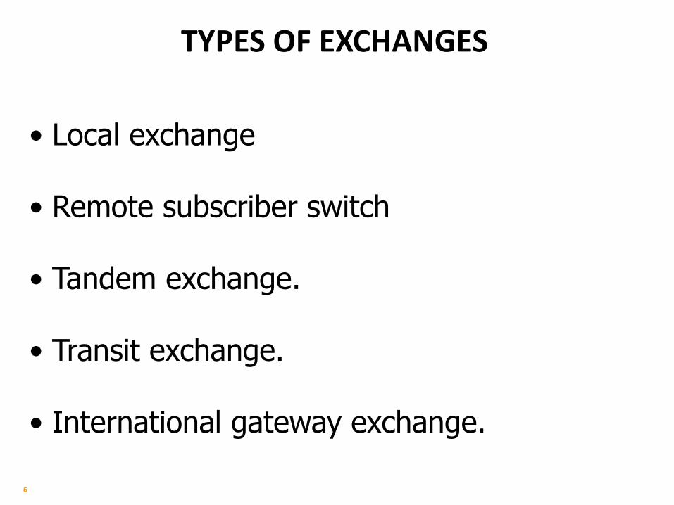
Call example in PSTN Following steps are involved in the establishment and
subsequent release of a call on PSTN:
1. DETECTION OF HOOK OFF
2. PROVISION OF DIAL TONE
3. DIALING OF DIGITS
4. RESERVATION OF RESOURCES FOR CALL
5. RINGING OF CALLED PARTY AND RING BACK TO CALLING
PARTY
6. DETECTION OF ANSWER FROM CALLED PARTY
7. NECESSARY CHARGING INITIATION
8. SPEECH
9. INITIATION OF CALL TERMINATION FROM EITHER END
10. CALL END, RELEASE OF ALL RESERVED RESOURCES
11. NECESSARY ACTION REGARDING BILLING

8
1 Off Hook
2 Dial Tone
3 Digits Dial
4 Siezure 5a Ringing
5b Ring Back
6 Off Hook
7 Charging Started 8 Conversation / Speech
9 Call End
10 Release Resources 10 Release Resources 10 Release Resources
11 Charging Stopped
GENERAL CALL SETUP
Local Exchange
Local Exchange A B
9
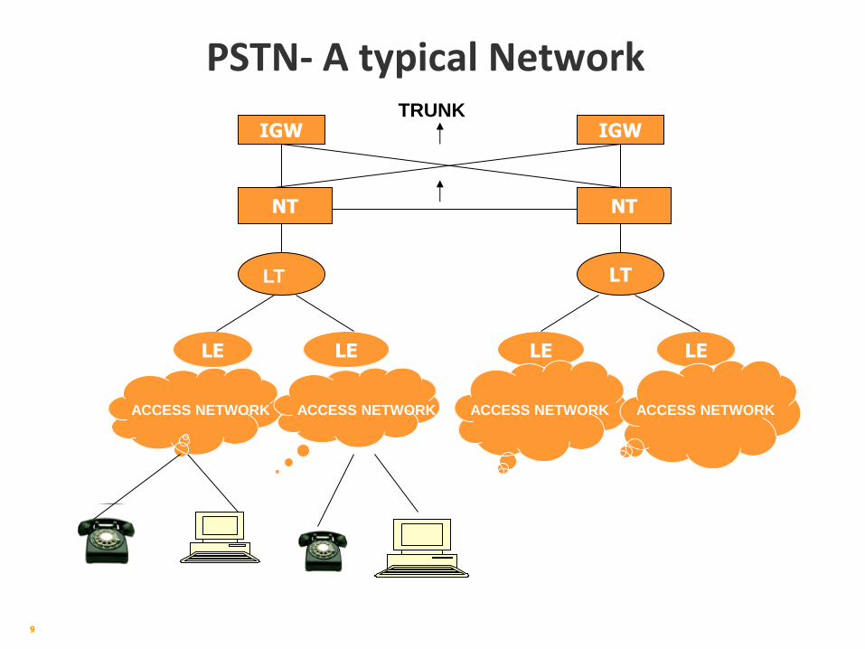
PSTN- A typical Network
LE LE
NT
IGW
NT
LT
LE LE
IGW
LT
TRUNK
ACCESS NETWORK ACCESS NETWORK ACCESS NETWORK ACCESS NETWORK

10
Access Network
LE END USER
EX
EX
AN is called “the last mile of Telecom Network”
Access Network
INTRODUCTION TO ACCESS NETWORK

11
Components and Structure of Access Network
MDF
user
Connection
Cabinet
Distribution
Box(DP)
Primary cable
Copper Cables Based
Secondary cable Drop Wire

12
COMPONENTS OF ACCESS NETWORK
MDF:- MDF stands for Main Distribution Frame. It is an
interface or test point between a telephone exchange
and subscriber local loop. There are Two sides,
horizontal and vertical side.
Horizontal Side: For Exchange Side
Vertical Side: For External Cable
Horizontal and Vertical sides connected via jumper wire.
Cabinet: Terminating Box where primary and Secondary
cables are terminated.
DP: Stands for Distribution point, Secondary cable
distributes at DP .

13
COMPONENTS OF ACCESS NETWORK
Primary Cable: From MDF to Cabinet
Secondary Cable: From Cabinet to DP
Drop wire: From DP to Subscriber premises.
Rosette is a connector that use to connect the
telephone wire with an output of RJ 11

14
Role of AN in the Operator’s Business
• Final tool for service delivery to the end users
Quality & flexibility of AN determine the speed and quality of service to the end users
• Major cost factor for the operator
Accounts for about 40~50% of total telecom network investment
• Very important in a competitive environment
End user oriented, generates revenue for operators
Services
node Access Network
End user
Services
Motive: revenue
Good AN, Better Services, More Revenue !

15
CABLES, TYPES OF CABLES &
COLOUR SCHEME

16
COPPER CABLE
Definition:
It is collection of insulated conductors
arranged in particular color scheme in
a single core and covered with several
protective layers.
17
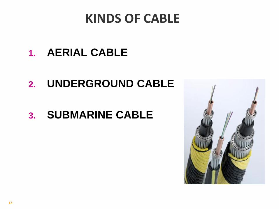
KINDS OF CABLE
1. AERIAL CABLE
2. UNDERGROUND CABLE
3. SUBMARINE CABLE

18
KINDS OF UNDER GROUND COPPER CABLE
1. COAXIAL CABLE.
2. OPTICAL FIBRE CABLE.
3. POLYETHELENE (PE) CABLE.

19
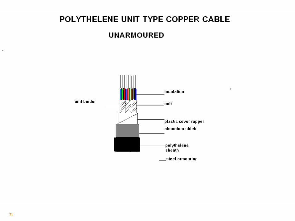
CONSTRUCTION OF P.E CABLE
1. ARMOURED 2. UNARMOURED

20
21

22
FOUR IMPORTANT PART OF COPPER CABLE
1. CONDUCTOR
2. INSULATION
3. PROTECTIVE LAYER
4. COLOUR SCHEME

23
CONDUCTOR
Any material that easily permits the flow of
electric current.
For example: Copper, Silver and Aluminum etc.
24
INSULATION
Any material that does not permit the flow of
electric current.
For example: Plastic, Paper and Glass etc.

25
PROTECTIVE LAYERS.
PROTECT THE CABLE FROM
MECHANICAL DAMAGES
MAGNETIC EFFECTS
ELECTRICAL INTERFERENCE
ENVIRONMENTAL EFFECTS

26
COLOR SCHEME OF P.E CABLE.
25 PAIR COLOR SCHEME IN ONE GROUP
A- WIRE B-WIRE
1. WHITE BLUE
2. WHITE ORANGE
3. WHITE GREEN
4. WHITE BROWN
5. WHITE GRAY

27
COLOR SCHEME OF P.E CABLE.
25 PAIR COLOR SCHEME IN ONE GROUP
A- WIRE B-WIRE
6. RED BLUE
7. RED ORANGE
8. RED GREEN
9. RED BROWN
10. RED GRAY

28
COLOR SCHEME OF P.E CABLE
25 PAIR COLOR SCHEME IN ONE GROUP
A- WIRE B-WIRE
11. BLACK BLUE
12. BLACK ORANGE
13. BLACK GREEN
14. BLACK BROWN
15. BLACK GRAY

29
COLOR SCHEME OF P.E CABLE
25 PAIR COLOR SCHEME IN ONE GROUP
A- WIRE B-WIRE
16. YELLOW BLUE
17. YELLOW ORANGE
18. YELLOW GREEN
19. YELLOW BROWN
20. YELLOW GRAY

30
COLOR SCHEME OF P.E CABLE
25 PAIR COLOR SCHEME IN ONE GROUP
A- WIRE B-WIRE
21. VIOLET BLUE
22. VIOLET ORANGE
23. VIOLET GREEN.
24. VIOLET BROWN.
25. VIOLET GRAY.

31
1. GROUP is of 25 pairs
2. UNIT is of 50 pairs
3. SUPER UNIT is of 100 pairs

32
PRIMARY CABLE
The cable laid from MDF to cabinet is called
primary cable.

33
CAPACITY OF PRIMARY CABLE
1. 200 pair.
2. 300 pair.
3. 400 pair. not used in Pakistan.
4. 600 pair.
5. 900 pair.
6. 1200 pair.
7. 1500 pair.
8. 1800 pair.
9. 2400 pair. not used in Pakistan.
10. 3200 pair. not used in Pakistan

34
SECONDARY CABLE.
The cable laid between cabinet to D.P is
called secondary cable.

35
CAPACITY OF SECONDARY CABLE
1. 10 pair.
2. 20 pair.
3. 30 pair.
4. 50 pair.
5. 100 pair.
6. 200 pair.
7. 300 pair.
8. 400 pair. Not used in Pakistan.
9. 600 pair.

36
MDF, Cabinet, DP, Cable
Terminations & Record
Keeping

37
Terminations
There are five positions of termination in the
Access Network
Main Distribution Frame (MDF)
Cross Connection Cabinets (CCC)
Distribution Point (DP)
Terminating Box
Rossette / Socket

38
The major connection frame in a telephone exchange
on which the local cable pairs and exchange cable
are terminated.
Here any cable pair can be cross-connected to any
exchange cable (number)
MDF Types
– Floor type
– Wall type
Main Distribution Frame (M.D.F)

39
Main Distribution Frame (M.D.F)
The M.D.F. must be installed in a separate
room nearest to the switch room
The frame must be supported with proper
nuts and bolts for disconnection strips and
fuse strips.
The M.D.F must be supported by the wall
brackets.
The M.D.F must be properly earthed.

40
Types of Wiring on M.D.F.
On mini strips the under ground installation cable is terminated on left/front side of M.D.F
Switch board cable from exchange side is terminated on right/rear side of the M.D.F

41
MDF JUMPERING
The jumper wires of 0.4 mm dia must be used
for jumpering.
The jumper wires must be used through
guide clamps
The underground cables/jumpers terminated
on the mini strips must be punched properly
using punching tool.

42
MINI STRIP
Mini strip consists upon 100 pairs and
counted from left side because cable side is
also on left side and right side is exchange
side .

43
TERMINATION OF JUNCTION CABLES
Cables connecting any two exchanges are called
junction cables.
Extreme ends of junction cables are terminated on
MDF’s (Main Distribution Frames) of each exchange.

44
TERMINATION OF PRIMARY CABLES
Primary cables connect MDF of an exchange to CCC’s (Cross Connection Cabinets) installed at suitable points of feeding areas.
Starting end of the cable (generally called NEAR END) is terminated on the MDF and remote end (called FAR END) is terminated on CCC (Cross Connection Cabinets) terminal blocks.

45
Main Distribution Frame (MDF)
MDF is a junction of switching system and
outside plant.
The cables coming from switches are
terminated on horizontal tag blocks mounted
on one side of the MDF.
Cables coming from outside are terminated on
vertical side terminal blocks/strips.

46
MDF (Cont..)
Horizontal side of the MDF is called switching
side and the vertical side is called
“Geographical side”.
Any switching side pair can be connected to
any pair of outside cable through jumper
wire.
100 pair mini strip is used on MDF.

47
MDF (Cont..)
A vertical row (Bay) can accommodate 800
pair termination of network cable.
The network cables are terminated on the left
side of the strip and right side is used for
jumping.
These strips also provides measuring &
testing facility for network cables.

48

49
TERMINATION OF SECONDARY CABLES
Secondary cables connect the CCC (Cross
Connection Cabinets) to DPs (Distribution Points)
may be pole mounted DPs or wall mounted indoor
DPs or pillar type DPs.
Starting end generally called near end) of secondary
cables is terminated on terminating blocks of CCC
and the remote ends (called Far Ends) of secondary
cables are terminated on 10 pair terminal blocks of
any kind of DPs.

50
CROSS CONNECT CABINET

51
CROSS CONNECTION CABINET (CCC)
It is a component of the Out Side Plant installed at the junction of Primary and Secondary cables
Standard size CCC can accommodate termination of 1200 pairs.
Some of the cabinet designs are double sided and cables can also be terminated on the other side of the cabinet. It doubles its termination capacity
Usually the ratio of 5:7 is maintained between primary cables & secondary cable pairs.

52
CROSS CONNECTION CABINET (CCC) (Cont..)
The cabinet is installed on a pre-cast RCC base.
Minimum height of the base plate of the cabinet shall
be 30 cm above the ground/road level (whichever is
higher).
The doors shall be water tight and the location of the
cabinet shall be such that it does not block the traffic
or pedestrians.
Sufficient working space ( 1m minimum) shall be
available on the back side of the cabinet.

53
Space Distribution Plan Of Primary & Secondary Termination

54
Record Keeping of Cabinet

55
DISTRIBUTION POINT
There are three types of DPs in use by the PTCL.
i) Pole Mounted DPs (External DPs)
ii) Wall mounted (Internal DPs
iii) Piller type DPs
The capacity of DP is generally 10 pairs. In case load is
concentrated (office buildings etc.) the termination capacity can
be increased up to 20, 30 or even 50 pairs in case of internal
DPs.

56
DISTRIBUTION POINT. D.P
DEFINITION
D.P means distribution point. It is
fixed on A4BC post. It is the last point in the
local cable network from where subscriber line
(loop) is extending to subscriber premises.

57
DISTRIBUTION POINT. D.P
CONSTRUCTION.
The D.P consists of
1. Housing/ body.
2. Terminal block
3. Cover
4. Earth Terminal.
58
DISTRIBUTION POINT. D.P
TYPE OF D.P.
There are three type of D.P.
1. Pole type D.P.
2. Wall type D.P.
3. Pillar type D.P.

59
POLE TYPE D.P

60
POLE TYPE D.P
61
DISTRIBUTION POINT. D.P
WALL TYPE D.P.
10 pair D.P. box is installed with wall at about 8 feet high from the ground level Underground cable 10 pair runs through the 10 feet. G.I. pipe 1” dia up to C.T. Box 8 feet out land two feet in the ground. G.I. pipe is clipped with wall at three places from internal D.P.

62
.WALL TYPE D.P

63
POLE/
WALL TYPE D.P

64
POLE/ WALL TYPE D.P

65
DISTRIBUTION POINT. D.P
PILLAR TYPE D.P.
This is a special D.P used in Islamabad.
Underground cable is terminated on 10 pair
C.T. box
fixed at top in the D.P on back side.

66
PILLAR TYPE D.P
PILLAR TYPE D.P.

67
Record Keeping of DP

68
DP Post, Post Types & Accessories,
Drop wire & SSA Cable Accessories
69
POLES
DEFINITION:
THE POST OR POLES USED TO SUPPORT
FOR OVER HEAD LINES.

70
POST
TYPE OF POST:
1. Tubular Post.
2. Rail Post.
3. Wooden Post.
4. Coupled Post.
5. Concrete Post.
6. Bridger fixture Post.

71
POST
TUBULAR POST.
These Post consist of Tubes made of steel
sheets fitted together to give a post of the height
and strength required.
72
POST
ADVANTAGES OF TUBULAR POST.
1. It is light and strong.
2. Easy for transportation.
3. Easy in fitting and dismantling.
4. Damaged parts can be easily changed.
5. Any type of post in length and strength can be
made according to our requirements.
6. It is durable being made of steel with
galvanized surface.

73
POST
TYPES OF TUBES & SIZES.
8 feet. T Tube
8 feet. A Tube
8 feet. B Tube
8 feet. C Tube
8 feet. D Tube
8 feet. E Tube
8 feet. F Tube

74
POST
4 feet. A 4 Tube.
4 feet. B 4 Tube.
4 feet. C 4 Tube.
5. TYPES OF TUBES & SIZES OF TUBES & SIZESTYPES

75
POST
D.P POST (A4BC) & ITS PARTS.
Five parts are there in D.P / A4BC Post.
1. Lightening Spike.
2. Cap.
3. A4BC Tube.
4. Socket.
5. Sole plate.

76
D.P BOX
CAP
A4 TUBE
B-TUBE
SOLE PLATE
SOCKET
D.P BOX
G.I. PIPE
VENT HOLE
C-TUBE STAINLESS STEEL BAND
LIGHTING SPIKE
G.I. PIPE

77

78
79
DROPWIRE
DEFINITION
Drop wire is a self-supporting aerial cable
capable of sustaining the span load and
wind pressure and greatly resistive to
climate and environmental effects.
80
DROPWIRE
USES.
It is used for extending exchange loop to
subscriber’s premises and erected from
distribution point (D.P) to subscriber’s office.

81
DROPWIRE
CONSTRUCTION.
Its construction is simple. It contains two
wires of hard drawn cadmium wire, bronze
wire or copper weld wire.
copper weld wire is more common in use.
The wire are enclosed in a jacket-cum
insulation of polyethylene.

82
DROPWIRE
STANDARDS.
Roll length 500 meters
Roll Weights 15 KG
Attenuation loss 0.87 db / Km
Dip 1 Cm/ Meter
Headway on main road 20 feet
Headway on branch road 16 feet

83
DROPWIRE

84
DROPWIRE
ADVANTAGES OF DROPWIRE.
1. Easy to erect.
2. Takes less times in erection.
3. Less labour is required.
4. Used to provide emergency circuits.
5. Can be used on electric posts, trees and wall
,etc.
6. Less exposed to faults due to contacts, kite
strings, vegitation etc.

85
DROPWIRE
7. Strongly resistive to climatic and weather effects.
8. Costly fittings are not required like
insulator, bracket etc.
9. Working connection are not interrupted when
new drop wires are being erected.

86
DROP WIRE ACCESSORIES.
ROSETTE.
It is provide in between ceiling rose and
subscriber’s instrument it links instrument with
line card.

87
DROP WIRE ACCESSORIES
G.I PIPE.
It used on distribution post and band with the
help of stainless steel band and seal to protect
cable from damage at D.P. (Its usual length will
be 10 feet).

88
DROPWIRE
GENERAL INSTRUCTION FOR DROPWIRE.
1. The length of the Drop wire section should be
kept as short as possible.
2. Crossing of main road highway as well as
railway by Drop wire should be avoided.
3. The Drop wire should be suspended properly in
any case as per specification.

89
DROPWIRE
4. Loose placing of Drop wire on balconies, roofs,
etc. should be avoided. The standard span of
Drop wire should be kept 50 meters and in
exceptional case it can be up to 70 meters.
5. The Parallel installation of more than three Drop
wire should be avoided. For more than three
lines in parallel it is better to used self
supporting aerial cable

90
DROPWIRE JOINTING
Drop wire joints have to
be avoided.
Only one joint shall be
allowed in one span.
Not more than two joints
in a complete drop wire
service line are allowed.
.

91
SELF SUPPORT AERIAL CABLE
DEFINITION.
An aerial cable whose conductors as well
as the guard wire are closed in one jacket and
can be suspended directly on the support.

92
AERIAL CABLE
CONSTRUCTION
Aerial cable consist of
Annealed copper twisted wire.
Polyethelene insulation.
Plastic paper.
Aluminium foil.
Earth wire.
Polyethelene sheath-cum-jacket.
Guard wire.

93
SURVEYING OF AERIAL CABLE
1. Choose the short route.
2. The strength, height and spacing of poles must
carefully be planned.
3. The proposed route must be surveyed.
4. Cable type and size should be selected.
5. Stay arrangement must be worked out.
6. Keep distance from electric wire .
7. The provision period for aerial cable is 7 years.
At the end of provision period the cable should
be relieved rather than replaced.

94
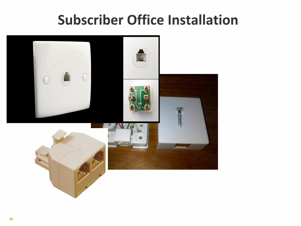
Subscriber Office Installation
95
Subscriber Office Installation
96
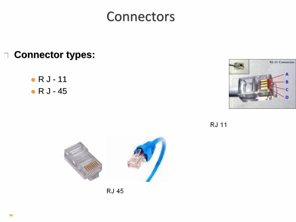
Connectors
Connector types:
R J - 11
R J - 45

97
Cables
Cable types
STP & UTP
Coaxial
Ethernet
Optical Fiber

98
JOINTING OF UNDERGROUND CABLE
99
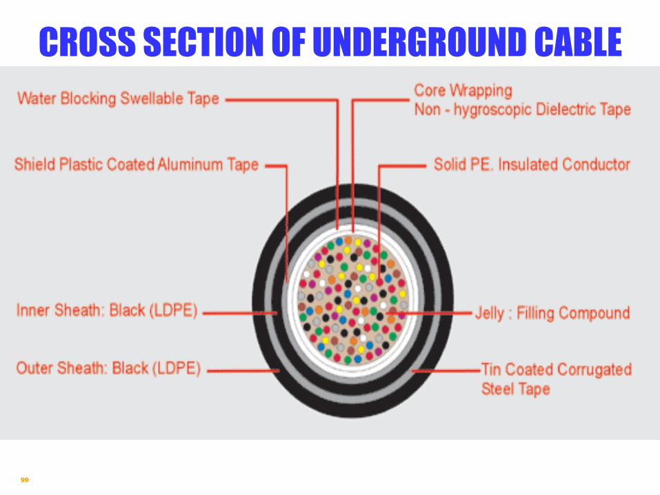
CROSS SECTION OF UNDERGROUND CABLE

100
CABLE CONSTRUCTION
CABLE CONSTRUCTION CONDUCTOR
Fully annealed high quality solid copper , the conductor sizes are 0.4, 0.5, 0.6 & 0.9 mm.
INSULATION
Color High Molecular Weight Solid High Density Polyethylene.
COLOUR CODING
Cables are fully color coded in accordance with PIC even count color code.
PAIRING
Two colored insulated conductors are uniformly twisted together to form a pair. Varying lay length is designed to minimize the cross talk and capacitance unbalance.
STRANDING / CABLING
Twisted pairs are assembled into unit of 10, 20, 25, 50 or 100 pairs. When desired for lay-up reason, the units are divided into two or more sub-units, which are bind with durably colored Polyethylene Tapes to form a compact and circular cable core.
FILLING COMPOUND
The water resistant filling compound is applied to fill the air spaces within the cable core
CORE COVERING
A non-hygroscopic and dielectric Polyester Tape and Water Blocking Tape are applied helically having a suitable overlap.
101
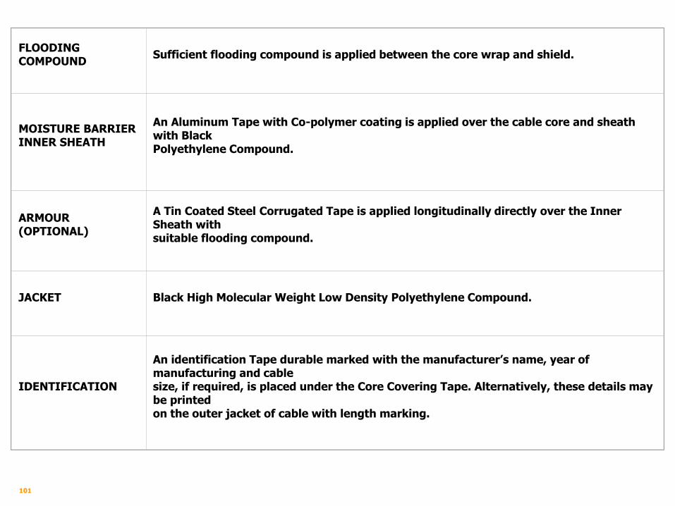
FLOODING COMPOUND
Sufficient flooding compound is applied between the core wrap and shield.
MOISTURE BARRIER INNER SHEATH
An Aluminum Tape with Co-polymer coating is applied over the cable core and sheath with Black Polyethylene Compound.
ARMOUR (OPTIONAL)
A Tin Coated Steel Corrugated Tape is applied longitudinally directly over the Inner Sheath with suitable flooding compound.
JACKET
Black High Molecular Weight Low Density Polyethylene Compound.
IDENTIFICATION
An identification Tape durable marked with the manufacturer’s name, year of manufacturing and cable size, if required, is placed under the Core Covering Tape. Alternatively, these details may be printed on the outer jacket of cable with length marking.

102
Cable Faults and Localization, Testing Equipment, Test parameters

103
TYPES OF MAINTENANCE
Preventive maintenance, is conducted to keep
equipment working and/or extend the life of the
equipment.
Corrective maintenance, sometimes called
"Repair", is conducted to get equipment working
again.

104
TESTING POINT OF ACCESS NETWORK
There are five testing points in Copper Access Network for fault localization:
1. Main Distribution Frame (MDF)
2. Divisional Cabinet / Cross Connection Cabinet
3. Distribution Point (DP)
4. Termination Box
5. Rossette / Socket
105
INSULATION RESISTANCE
Definition:
Insulation resistance is the resistance of the
insulation, which separates the conductors.
It is the total resistance of all the leakage path
throughout the cable.
Insulation resistance is inversely proportional to
length of the cable. i.e. Insulation resistance
decrease with the increases in length of cable.
106
INSULATION RESISTANCE (cont’d)
The low Insulation Resistance causes.
(a) Electricity Leakage in the Line,
(b) Heavy Loss of Energy,
(c) Weaken Signals.

107
INSULATION RESISTANCE (cont’d)
Unit of Insulation Resistance:
Insulation resistance is measured in
Mega ohm and expressed as
Mega Ohm / km (MΩ / km)
one mega ohm =1,000,000 ohms

108
INSULATION RESISTANCE (cont’d)
Standard Insulation Resistances are.
PE CABLE 10,000 mega ohm/km
DROP WIRE 10,000 mega ohm/km

109
INSULATION RESISTANCE (cont’d)
Equipment used for measuring insulation resistance:
1. Meggar 100V DC – 100 M ohm
500V DC – 500 M ohm
500V DC – 1000 M ohm
2. Insulation Tester.
3. Meggar ohm meter.
4. Digital Meggar.

110
DC LOOP RESISTANCE
• Telephone line consist of two wire (a & b wire)
• DC loop resistance is the total resistance of
telephone line conductors.
DC Loop Resistance = Resistance of A & B wire.

111
DC LOOP RESISTANCE (cont’d)
o It is expressed as ohm / km.
o Its value mainly depends on the diameter of
conductor of the cable.
o DC loop resistance decrease by the increase in
diameter of conductor.

112
DC LOOP RESISTANCE (cont’d)
Standards of DC Loop Resistance of PE Copper
Cable:
• 0.4 mm conductor diameter 290 ohm/km.
• 0.5 mm conductor diameter 184 ohm/km.
• 0.6 mm conductor diameter 126 ohm/km.
• 0.7 mm conductor diameter 92 ohm/km.
For Drop-wire
• 1.0 mm conductor diameter 144 ohm/km.

113
DC LOOP RESISTANCE (cont’d)
Equipment used for measuring of DC Loop
Resistance:
a) Bridge Meggar.
b) Digital Multimeter.

114
SIGNAL TO NOISE RATIO (SNR)
The ratio of signal to noise, an indication of
signal quality in analog system.
For DSL SNR > 7
For IPTV SNR > 10

115
CROSSTALK / TWISTED PAIR
The noise on a line caused by signals traveling
along another line.
Electromagnetic interference from one pair, can
create a noise over others pairs.
For the solution for this problem, is that the wire
pairs are twisted around each other at regular
intervals (between 2 and 12 twist per foot).

116
TYPES OF FAULTS
Insulation is that property of insulating material that
opposes the leakage of electricity through it .
Earth is touching of A or B wire with such a point which
resists flowing of current likely with each other or cabling
sheath.
A
B

117
Break of A or B wire from anywhere is known as Break
Fault.
Contact is touching of A or B wire with each other of
same pair
Cross Contact Joining of A or B wire of one pair to the
other pair
Types of Faults (Cont’d)
A
B
A
B
A
B
A
B

118
LOCALIZATION & RECTIFICATION
For the rectification of any faults different tests
are performed for the localization of fault, after
which these faults are removed. These are:
1. Insulation Test
2. Earth Test
3. Cross / Cross Contact Test
4. Break Test

119
INSULATION TEST
High resistance in case of good insulation.
Minimum Standard Insulation of underground
Cable is 5000 Mega Ohms/km

120
EARTH TEST
Low resistance in case of good earth

121
CONTACT/CROSS CONTACT TEST
In case of contact between two wires current
get the short alternate path hence low
resistance.

122
BREAK TEST
Current didn’t find a path to flow hence high
resistance.

123
TESTING INSTRUMENTS
Digital Meggar
Cable Fault Locator (mTDR-070)
Cable Route Locator
Digital Earth Tester
Multimeter
LQT (Line Quality Tester)
124
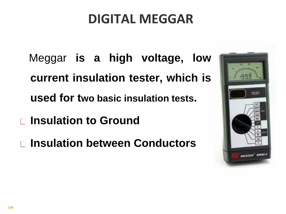
DIGITAL MEGGAR
Meggar is a high voltage, low
current insulation tester, which is
used for two basic insulation tests.
Insulation to Ground
Insulation between Conductors

125
NanoTronix CABLE FAULT LOCATOR (mTDR-070)
Time Domain Reflectometer
transmitting high frequency
pulses which are reflected by any
impedance defect in the cable
under test. The signature of the
fault are interpreted by moving
the curser at the beginning of the
curve and the distance to the fault
is indicated.

126
NanoTronix Cable Fault Locator
(mTDR-070)
It can test following faults of cable from a remote distance
• complete open & short,
• partial open & short,
• loose connection,
• broken lines
Break Fault _____
Contact/Earth ……..

127
NanoTronix Cable Fault Locator
(mTDR-070)

128
ROUTE LOCATOR (Metrotech 9800 Series)
This device is used to locate the route and the
depth of underground cable.
This meter consists of two parts
A Transmitter and a Receiver

129
DIGITAL EARTH TESTER
Earth is a easy path for the flow
of high current, which is tested
by Digital Earth Tester.
Standard Parameter to be
tested:
Exchange
(x Lines)
Earth Resistance
(Ohms)
500 10
1000 5
2000 2.5
Above 2000 0.5

130
MULTIMETER
Used for measuring resistance, DC/AC
Voltage and current.
• [1] Function/Range Switch: selects the
function (voltmeter, ammeter, or ohmmeter)
and the range for the measurement.
• [2] COM Input Terminal: Common ground,
used in ALL measurements.
• [3] V Input Terminal: for voltage or
resistance measurements.
• [4] 200 mA Input Terminal: for small
current measurements.
• [5] 10 A Input Terminal: for large current
measurements.
• [6] Low Battery LCD: appears when the
battery needs replacement

131
LQT (Line Quality Tester)
XGXC XG204
Automatically match with the ADSL
line standards
Support ADSL2+ and ADSL2
Testing Parameters:
SNR for DSL Line > 10
Attenuation < 45dB

132
Line Qualification Criteria
Test
Parameters
Recommended
Values
Comments
Attenuation
(Downstream/
Upstream)
Less than 45 dB < 30 dB is excellent
30-40 dB is very good
40-45 dB – Little or no connectivity issues
45-60 dB – Connectivity issues
progressively become worse
> 60 dB – will experience no synch or
intermittent synchronization problems
Signal to
Noise Ratio
Greater than 10 < 6 – will experience no synch or
intermittent synch problems
6 - 10 – does not leave much room for
variances in condition
10 - 20 – Little or no synch problems
> 20 dB is excellent

133
Cable Route, Ducts, Manhole and their types

134
CABLE ROUTES
Before laying cable route be selected with proper
inspections, surveys and testing. At regular
intervals test pits be dig out to check underground
installations and hindrances. The road and other
local authorities may be consulted and their
existing and further planning maps be studied.
Proper selected cable prolonged the life of cable
and reduces the laying cost.

135
INSTRUCTION FOR SELECTION OF CABLE ROUTES
It should be short as possible
Other underground installations may be avoided
as much as possible.
Road and Railway crossing may be avoided.
Route should be earth and be free from chemical
injuries.
Route should follow the approved road and
streets.
Route should be as far away from the edge of
the metal road as possible.

136
INSTRUCTION FOR SELECTION OF CABLE ROUTES
The route may not pass through the private land
and expansion of building be taken under
consideration.
Narrow streets and congested bazaars may be
avoided.
Low cost of execution and reinstatement.
Less hindrance to traffic.
Safety to the workman during operation.

137
TYPES OF CABLE DUCTS
Cement concrete (precast and cast-in-site) re-
enforced or non-reinforced ducts.
Cement asbestos.
Earthenware or burnt clay ducts.
Fiber ducts.
Steel ducts.
Pipe/PVC conduit.
Copyright © 2022 FDOKUMEN