Cooper Nuclear Station, Revisions to Tech Requirements Manual ...
82
LIST OF EFFECTIVE PAGES - TRM Page No. Revision No./Date Page No. Revision No./Date 12/21/16 3.4-4 07/30/04 ii 10/15/19 3.4-5 01/02/04 iii 10/15/19 3.4-6 02/04/10 iv 10/15/19 V 10/15/19 3.6-1 02/22/16 1.0-1 02/24/04 3.7-1 05/17/19 3.7-2 04/17/03 3.0-1 10/10/01 3.7-3 04/17/03 3.0-2 09/17/10 3.7-4 12/21/16 3.0-3 08/15/03 3.0-4 09/17/10 3.8-1 10/10/01 3.8-2 1 3.1-1 10/20/99 3.9-1 10/05/06 3.2-1 09/11/15 3.9-2 08/30/10 3.2-2 09/11/15 3.9-3 12/15/10 3.3-1 10/10/01 3.11-1 10/17/16 3.3-2 10/10/01 3.11-2 06/25/15 3.3-3 01/08/15 3.11-3 10/17/16 3.3-4 11/18/20 3.11-4 10/17/16 3.3-5 08/27/14 3.11-5 07/05/16 3.3-6 08/27/14 3.11-6 12/30/15 3.3-7 11/18/20 3.11-7 12/30/15 3.3-8 10/10/01 3.11-8 12/30/15 3.3-9 02/22/16 3.11-9 12/30/15 3.3-10 01/08/15 3.11-10 12/30/15 3.3-11 01/08/15 3.11-11 12/30/15 3.3-12 05/15/19 3.11-12 12/30/15 3.3-13 02/22/16 3.11-13 12/30/15 3.3-14 03/02/20 3.11-14 12/30/15 3.3-15 03/18/20 3.11-15 12/30/15 3.3-16 03/18/20 3.11-16 12/30/15 3.3-17 10/28/11 3.11-17 12/30/15 3.3-18 03/18/20 3.11-18 12/30/15 3.3-19 03/18/20 3.11-19 12/30/15 3.3-20 05/15/13 3.11-20 12/30/15 3.3-21 05/15/13 3.11-21 12/30/15 3.3-22 05/15/13 3.11-22 12/30/15 3.4-1 10/10/01 3.12-1 11/06/16 3.4-2 02/04/10 3.12-2 11/06/16 3.4-3 02/04/10 3.12-3 07/09/18 CNS TRM 1 11/18/20
-
Upload
khangminh22 -
Category
Documents
-
view
1 -
download
0
Transcript of Cooper Nuclear Station, Revisions to Tech Requirements Manual ...

LIST OF EFFECTIVE PAGES - TRM
Page No. Revision No./Date Page No. Revision No./Date
12/21/16 3.4-4 07/30/04 ii 10/15/19 3.4-5 01/02/04 iii 10/15/19 3.4-6 02/04/10 iv 10/15/19 V 10/15/19 3.6-1 02/22/16
1.0-1 02/24/04 3.7-1 05/17/19 3.7-2 04/17/03
3.0-1 10/10/01 3.7-3 04/17/03 3.0-2 09/17/10 3.7-4 12/21/16 3.0-3 08/15/03 3.0-4 09/17/10 3.8-1 10/10/01
3.8-2 1 3.1-1 10/20/99
3.9-1 10/05/06 3.2-1 09/11/15 3.9-2 08/30/10 3.2-2 09/11/15 3.9-3 12/15/10
3.3-1 10/10/01 3.11-1 10/17/16 3.3-2 10/10/01 3.11-2 06/25/15 3.3-3 01/08/15 3.11-3 10/17/16 3.3-4 11/18/20 3.11-4 10/17/16 3.3-5 08/27/14 3.11-5 07/05/16 3.3-6 08/27/14 3.11-6 12/30/15 3.3-7 11/18/20 3.11-7 12/30/15 3.3-8 10/10/01 3.11-8 12/30/15 3.3-9 02/22/16 3.11-9 12/30/15 3.3-10 01/08/15 3.11-10 12/30/15 3.3-11 01/08/15 3.11-11 12/30/15 3.3-12 05/15/19 3.11-12 12/30/15 3.3-13 02/22/16 3.11-13 12/30/15 3.3-14 03/02/20 3.11-14 12/30/15 3.3-15 03/18/20 3.11-15 12/30/15 3.3-16 03/18/20 3.11-16 12/30/15 3.3-17 10/28/11 3.11-17 12/30/15 3.3-18 03/18/20 3.11-18 12/30/15 3.3-19 03/18/20 3.11-19 12/30/15 3.3-20 05/15/13 3.11-20 12/30/15 3.3-21 05/15/13 3.11-21 12/30/15 3.3-22 05/15/13 3.11-22 12/30/15
3.4-1 10/10/01 3.12-1 11/06/16 3.4-2 02/04/10 3.12-2 11/06/16 3.4-3 02/04/10 3.12-3 07/09/18
CNS TRM 1 11/18/20
LIST OF EFFECTIVE PAGES - TRM (continued)
Page No. Revision No./Date
3.12-4 11/06/16 3.12-5 11/06/16 3.12-6 03/12/18 3.12-7 11/06/16 3.12-8 11/06/16 3.12-9 11/06/16 3.12-10 11/06/16 3.12-11 11/06/16 3.12-12 10/15/19 3.12-13 10/15/19
5.1-1 0
5.2-1 08/27/14
5.3-1 07/28/15
5.4-1 n u
5.5-1 0
5.6-1 08/09/17
5.7-1 03/28/06
5.8-1 0
5.9-1 0
5.10-1 0
5.11-1 03/20/03
5.12-1 10/27/04
5.13-1 10/29/08
5.14-1 10/09/15 5.14-2 10/09/15 5.14-3 10/09/15
6.1-1 10/10/01
6.2-1 10/10/01 6.2-2 10/10/01 6.2-3 11/29/17
CNS TRM 2 11/18/20

TRM Specifications Applicability T 3.0
T 3.0 TRM Specifications Applicability
TLCO 3.0.1 TLCOs shall be met during the MODES or other specified conditions in the Applicability, except as provided in TLCO 3.0.2.
TLCO 3.0.2 Upon discovery of a failure to meet a TLCO, the Required Actions of the associated Conditions shall be met, except as provided in TLCO 3.0.5.
If the TLCO is met or is no longer applicable prior to expiration of the specified Completion Time(s), completion of the Required Action(s) is not required, unless otherwise stated.
TLCO 3.0.3 When a TLCO is not met and the associated ACTIONS are not met, an associated ACTION is not provided, or if directed by the associated ACTIONS, action shall be initiated to:
a. Restore compliance with the TLCO or associated ACTIONS, and
b. Enter the circumstances into the Corrective Action Program.
----------------NOTE-----·---TLCO 3.0.3.b shall be completed if TLCO 3.0.3 is entered.
Exceptions to this Specification are stated in the individual Specifications.
CNS TRM 3.0-1 10/10/01

TRM Specifications Applicability T 3.0
T 3.0 TRM Specifications Applicability ( continued)
TLCO 3.0.4 When a TLCO is not met, entry into a MODE or other specified condition in the Applicability shall only be made:
a. When the associated ACTIONS to be entered permit continued operation in the MODE or other specified condition in the Applicability for an unlimited period of time; or
b. After performance of a risk assessment addressing inoperable systems and components, consideration of the results, determination of the acceptability of entering the MODE or other specified condition in the Applicability, and establishment of risk management actions, if appropriate; exceptions to this Specification are stated in the individual Specifications; or
c. When an allowance is stated in the individual value, parameter, or other Specification.
This Specification shall not prevent changes in MODES or other specified conditions in the Applicability that are required to comply with ACTIONS or that are part of a shutdown of the unit.
TLCO 3.0.5 Equipment removed from service or declared inoperable to comply with ACTIONS may be returned to service under administrative control solely to perform testing required to demonstrate its OPERABILITY or the OPERABILITY of other equipment. This is an exception to TLCO 3.0.2 for the system returned to service under administrative control to perform the testing required to demonstrate OPERABILITY.
CNS TRM 3.0-2 09/17/10

TRM Specifications Applicability T 3.0
T 3.0 TRM Specifications Applicability ( continued)
TSR 3.0.1 TSRs shall be met during the MODES or other specified conditions in the Applicability for individual TLCOs, unless otherwise stated in the TSR. Failure to meet a Surveillance, whether such failure is experienced during the performance of the Surveillance or between performances of the Surveillance, shall be failure to meet the TLCO. Failure to perform a Surveillance within the specified Frequency shall be failure to meet the TLCO except as provided in TSR 3.0.3. Surveillances do not have to be performed on inoperable equipment or variables outside specified limits.
TSR 3.0.2 The specified Frequency for each TSR is met if the Surveillance is performed within 1.25 times the interval specified in the Frequency, as measured from the previous performance or as measured from the time a specified condition of the Frequency is met.
TSR 3.0.3
CNS TRM
For Frequencies specified as "once," the above interval extension does not apply.
If a Completion Time requires periodic performance on a "once per ... " basis, the above Frequency extension applies to each performance after the initial performance.
Exceptions to this Specification are stated in the individual Specifications.
If it is discovered that a Surveillance was not performed within its specified Frequency, then compliance with the requirement to declare the TLCO not met may be delayed, from the time of discovery, up to 24 hours or up to the limit of the specified Frequency, whichever is greater. This delay period is permitted to allow performance of the Surveillance. A risk evaluation shall be performed for any Surveillance delayed greater than 24 hours and the risk impact shall be managed.
If the Surveillance is not performed within the delay period, the TLCO must immediately be declared not met, and the applicable Condition( s) must be entered.
When the Surveillance is performed within the delay period and the Surveillance is not met, the TLCO must immediately be declared not met, and the applicable Condition( s) must be entered.
3.0-3 08/15/03

T 3.0 TRM Specifications Applicability ( continued)
TRM Specifications Applicability T 3.0
TSR 3.0.4 Entry into a MODE or other specified condition in the Applicability of a TLCO shall only be made when the TLCO's Surveillances have been met within their specified Frequency, except as provided by TSR 3.0.3. When a TLCO is not met due to Surveillances not having been met, entry into a MODE or other specified condition in the Applicability shall only be made in accordance with TLCO 3.0.4. This provision shall not prevent entry into MODES or other specified conditions in the Applicability that are required to comply with Actions or that are part of a shutdown of the unit.
CNS TRM 3.0-4 09/17/10

T 3.1 REACTIVITY CONTROL SYSTEMS
T 3.1.1 Control Rod Scram Times
Control Rod Scram Times T 3.1.1
----------------NOTE---------------This limit supplements Technical Specifications Table 3.1.4-1, see footnote (b). ----------------------------------TLCO 3.1.1 Time for 90% insertion when control rod scram testing conducted at zero
reactor pressure.
APPLICABILITY: Control Rod Scram Insertion Time Test at Zero Pressure
NOTCH POSITION SCRAM TIMES (seconds) (a)(b)(c) WHEN REACTOR STEAM DOME PRl::SSU~E IS ZERO
06 2.15
(a) Maximum scram time from fully withdrawn position, based on de-energization of scram pilot valve solenoids at time zero.
(b) For intermediate reactor steam dome pressures, the scram time criteria are determined by linear interpolation for notch position 06 using this Table and Technical Specifications Table 3.1.4-1.
(c) For reactor steam dome pressure< 800 psig, only notch position 06 scram time limit applies.
SURVEILLANCE REQUIREMENTS
SURVEILLANCE FREQUENCY
TSR 3.1.1.1 Per Technical Specifications 3.1.4 See SR 3.1.4.3
CNS TRM 3.1-1 10/20/99

T 3.2 [DELETED]
T 3.2.1 [DELETED]
CNS TRM 3.2-1
[DELETED] T 3.2.1
09/11/15

T 3.2 [DELETED]
T 3.2.2 [DELETED]
CNS TRM 3.2-2
[DELETED] T 3.2.2
09/11/15

T 3.3 INSTRUMENTATION
T 3.3.1 Control Rod Block Instrumentation
Control Rod Block Instrumentation T 3.3.1
TLCO 3.3.1 The control rod block instrumentation for each Function in Table T3.3.1-1 shall be OPERABLE.
APPLICABILITY: According to Table T3.3.1-1.
ACTIONS
----------------------------NOTE--------------------Separate Condition entry is allowed for each channel. -------------------------------------------------------------------------------------
CONDITION
A. One or more Functions with less than minimum channels OPERABLE.
CNS TRM
A.1
REQUIRED ACTION
Initiate Reactor Manual Control System rod withdrawal block.
3.3-1
COMPLETION TIME
1 hour
10/10/01

Control Rod Block Instrumentation T 3.3.1
SURVEILLANCE REQUIREMENTS
------------------------------NOTES---------------1. Refer to Table T3.3.1-1 to determine which TSRs apply for each Control Rod Block Function.
2. When a channel is placed in an inoperable status solely for performance of required Surveillances, entry into associated Conditions and Required Actions may be delayed for up to 6 hours provided the associated Function maintains control rod block capability.
------------------------------------------------------------------------------------------------------------
TSR 3.3.1.1
TSR 3.3.1.2
TSR 3.3.1.3
CNS TRM
SURVEILLANCE
Perform CHANNEL CHECK.
-------------------------------NOTE------------------------------Not required to be performed until 12 hours after THERMAL POWER~ 25% RTP. ----------------------------------------------------------
FREQUENCY
24 hours
Verify the absolute difference between the average 7 days power range monitor (APRM) channels and the calculated power is ~ 2% RTP plus any gain adjustment required by TS LCO 3.4.1, "Recirculation Loops Operating" while operating at~ 25% RTP.
Perform CHANNEL FUNCTIONAL TEST.
3.3-2
Within 7 days prior to rod withdrawal for the purpose of going critical
10/10/01

Control Rod Block Instrumentation T 3.3.1
SURVEILLANCE REQUIREMENTS
TSR 3.3.1.4
TSR 3.3.1.5
TSR 3.3.1.6
CNS TRM
--------NOTES--------1. For Function 1, not required to be performed
when entering the MODE 2 IRM range Applicability from a higher IRM range until 12 hours after entering the MODE 2 IRM range Applicability.
2. For Function 2, not required to be performed when entering MODE 2 from MODE 1 until 12 hours after entering MODE 2.
Perform CHANNEL FUNCTIONAL TEST.
--------NOTE-------1. For Function 3.b, not required to be performed
when entering MODE 2 from MODE 1 until 12 hours after entering MODE 2.
Perform CHANNEL FUNCTIONAL TEST.
Perform CHANNEL CALIBRATION.
3.3-3
31 days
92 days
184 days
01/08/15

Control Rod Block Instrumentation T 3.3.1
SURVEILLANCE REQUIREMENTS
TSR 3.3.1.7
TSR 3.3.1.8
TSR 3.3.1.9
CNS TRM
--------NOTE------------1. For Function 3.b, not required to be performed
when entering MODE 2 from MODE 1 until 12 hours after entering MODE 2.
Perform CHANNEL CALIBRATION.
-------NOTES-----------1. For Function 1, not required to be performed
when entering the MODE 2 IRM range Applicability from a higher IRM range until 12 hours after entering the MODE 2 IRM range Applicability.
2. For Function 2, not required to be performed when entering MODE 2 from MODE 1 until 12 hours after entering MODE 2.
3. Neutron detectors are excluded.
Perform CHANNEL CALIBRATION.
Perform CHANNEL FUNCTIONAL TEST.
3.3-4
184 days
24 months
184 days
11/18/20

Control Rod Block Instrumentation T 3.3.1
Table T3.3.1-1 (Page 1 of 3) Control Rod Block Instrumentation
FUNCTION
1. SRM
a. Detector Not Full In
b. Upscale
c. Inoperative
d. Downscale
APPLICABLE MODES OR
OTHER SPECIFIED
CONDITIONS
2(a),(b)
5
5
5
5
(a) With IRMs on Range 2 or below.
(b) With SRM count rate < 100 cps.
REQUIRED CHANNELS
1 per circuit loop
(c)
1 per circuit loop
(c)
1 per circuit loop
(c)
1 per circuit loop
(c)
(c) As required by Technical Specifications LCO 3.3.1.2.
CNS TRM 3.3-5
SURVEILLANCE REQUIREMENTS
TSR 3.3.1.3 TSR 3.3.1.8
TSR 3.3.1.3 TSR 3.3.1.8
TSR 3.3.1.1 TSR 3.3.1.3 TSR 3.3.1.4 TSR 3.3.1.8
TSR 3.3.1.3 TSR 3.3.1.4 TSR 3.3.1.8
TSR 3.3.1.3 TSR 3.3.1.4
TSR 3.3.1.3 TSR 3.3.1.4
TSR 3.3.1.1 TSR 3.3.1.3 TSR 3.3.1.4 TSR 3.3.1.8
TSR 3.3.1.3 TSR 3.3.1.4 TSR 3.3.1.8
ACCEPTANCE LIMITS
NA
NA
~ 1 x 10 5 cps
~ 1 x 10 5 cps
NA
NA
~ 3 cps
~ 3 cps
(continued)
08/27/14

2.
3.
(d)
(e)
(f)
(g)
Control Rod Block Instrumentation T 3.3,.1
FUNCTION
IRM a. Detector Not Full
In
b. Upscale
c. Inoperative
d. Downscale
APRM a. Upscale (Flow
Biased)
b. Upscale (Startup)
c. Inoperative
d. Downscale
e. Upscale (Fixed)
Table T3.3.1-1 (Page 2 of 3) Control Rod Block Instrumentation
APPLICABLE REQUIRED SURVEILLANCE MODES OR CHANNELS REQUIREMENTS
OTHER SPECIFIED
CONDITIONS
2 6 TSR 3.3.1.1 TSR 3.3.1.3 TSR 3.3.1.8
2 6 TSR 3.3.1.1 TSR 3.3.1.3 TSR 3.3.1.4 TSR 3.3.1.8
2 6 TSR 3.3.1.3 TSR 3.3.1.4
id) 6 TSR 3.3.1.1 TSR 3.3.1.3 TSR 3.3.1.4 TSR 3.3.1.8
4 TSR 3.3.1.1 TSR 3.3.1.2 TSR 3.3.1.5 TSR 3.3.1. ytel
2 4 TSR 3.3.1.1 TSR 3.3.1.4 TSR 3.3.1.7
1, 2 4 TSR 3.3.1.1 TSR 3.3.1.5
4 TSR 3.3.1.1 TSR 3.3.1.5 TSR 3.3.1.7
4 TSR 3.3.1.1 TSR 3.3.1.2 TSR 3.3.1.5 TSR 3.3.1.7
With IRMs on Range 2 or above.
Calibration of the recirculation loop flow transmitters is only required once every 24 months.
ACCEPTANCE LIMITS
NA
:::;; 108/125 of Full Scale
NA
;;:: 2.5/125 of Full Scale
:::;; (0.75W + 51.0% -0.75 llW) (fX9l
:::;; 11.5%
NA
~3%
:::;; 109.5%
(continued)
Wis the two-loop recirculation flow rate in percent of rated. Trip level setting is in percent of rated power (2419 = 100% RTP).
llW is the difference between two-loop and single-loop effective drive flow and is used for single recirculation loop operation. llW = 0 for two loop recirculation loop operation.
CNS TRM 3.3-6 08/27/14

Control Rod Block Instrumentation T 3.3.1
Table T3.3.1-1 (Page 3 of 3) Control Rod Block Instrumentation
FUNCTION APPLICABLE MODES OR
OTHER SPECIFIED
CONDITIONS
4. Flow Bias 1, 2 Comparator
5. Flow Bias 1, 2 Upscale
6. Scram Discharge 1, 2, 5 Volume Water Level High
REQUIRED CHANNELS
2
2
2
SURVEILLANCE REQUIREMENTS
TSR 3.3.1.4 TSR 3.3.1.8
TSR 3.3.1.4 TSR 3.3.1.6(eJ
TSR 3.3.1.9 TSR 3.3.1.8
(e) Calibration of the recirculation loop flow transmitters is only required once every 24 months.
CNS TRM 3.3-7
ACCEPTANCE LIMITS
s 10% Difference In Recirculation Flows
s 110% Recirculation Flow
s 46 inches
11/18/20

ECCS and RCIC Instrumentation
T 3.3 INSTRUMENTATION
T 3.3.2 ECCS and RCIC Instrumentation
TLCO 3.3.2 The ECCS and RCIC instrumentation for each Function in Table T3.3.2-1 shall be OPERABLE.
APPLICABILITY: According to Table T3.3.2-1.
ACTIONS
-------------------------NOTE-----Separate Condition entry is allowed for each Function.
-------------
T 3.3.2
CONDITION REQUIRED ACTION COMPLETION TIME
A. One or more channels A. 1 Enter the Condition Immediately inoperable. referenced in Table T3.3.2-
1 for the channel.
B. As required by Required B.1 Repair and return to 24 hours Action A.1 and OPERABLE status. referenced in Table T3.3.2-1.
CNS TRM 3.3-8 10/10/01

ACTIONS
CONDITION
C. Required Action and associated Completion Time of Condition 8 not met.
OR
As required by Required Action A.1 and referenced in Table T3.3.2-1.
OR
One or more channels inoperable in both trip systems.
D. As required by Required Action A. 1 and referenced in Table T3.3.2-1.
CNS TRM
C. 1
D.1
ECCS and RCIC Instrumentation T 3.3.2
REQUIRED ACTION COMPLETION TIME
Declare system or Immediately component inoperable.
Vent discharge line high Immediately point vent.
AND
7 days thereafter
3.3-9 02/22/16

ECCS and RCIC Instrumentation T 3.3.2
ACTIONS
CONDITION REQUIRED ACTION COMPLETION TIME
E. As required by Required E.1 Initiate repair to return to Immediately Action A.1 and referenced in Table T3.3.2-1.
AND
E.2
SURVEILLANCE REQUIREMENTS
OPERABLE status.
Initiate compensatory measures for the inoperable function.
----------------------------NOTES----
Immediately
1. Refer to Table T3.3.2-1 to determine which TSRs apply for each ECCS Function.
2. When a channel is placed in an inoperable status solely for performance of required Surveillances, entry into associated Conditions and Required Actions may be delayed for up to 6 hours provided the associated Function or the redundant Function maintains ECCS initiation capability.
SURVEILLANCE FREQUENCY
TSR 3.3.2.1 Deleted Deleted
TSR 3.3.2.2 Perform CHANNEL FUNCTIONAL TEST. 92 days
TSR 3.3.2.3 Perform CHANNEL CALIBRATION. 24 months
CNS TRM 3.3-10 01/08/15

SURVEILLANCE REQUIREMENTS
TSR 3.3.2.4 Perform CHANNEL CALIBRATION.
ECCS and RCIC Instrumentation T 3.3.2
24 months
TSR 3.3.2.5 Perform LOGIC SYSTEM FUNCTIONAL TEST. 24 months
TSR 3.3.2.6 Perform CHANNEL FUNCTIONAL TEST. 24 months
TSR 3.3.2.7 Perform CHANNEL CALIBRATION. 18 months
CNS TRM 3.3-11 01/08/15

ECCS and RCIC Instrumentation T 3.3.2
Table T3.3.2-1 (Page 1 of 3) ECCS and RCIC Instrumentation
FUNCTION
1. Core Spray System
a. Logic Power Monitor
b. Discharge Line Low Pressure
2. RHR System (LPCI mode)
a. Logic Bus Monitor
b. Loop A Discharge Line Low Pressure
c. Loop B Discharge Line Low Pressure
d. Outboard Injection Valve Time Delay Relays
e. RHR Heat Exchanger Bypass Time Delay Relays
f. RHR Crosstie Valve Position
APPLICABLE MODES OR
OTHER SPECIFIED
CONDITIONS
1,2,3 4(a)' 5(a)
1, 2, 3 4(a)' 5(a)
1,2,3 4(a)' 5(a)
1, 2, 3 4(a), 5(a)
1, 2, 3 4(a)' 5(a)
1,2,3 4(a)' 5(a)
1,2,3 4(a), 5(a)
1,2,3 4(a)' 5(a)
REQUIRED CHANNELS PER TRIP SYSTEM
1 per subsystem
1 (d)
1 per subsystem
1 (d)(e)
CONDITIONS REFERENCED
FROM REQUIRED ACTIONA.1
E
D
E
D
D
B
C
E
(a) When associated subsystem(s) are required to be OPERABLE.
(b) In only one trip system
(c) When reactor steam dome pressure> 150 psig.
(d) Not considered in a trip system.
SURVEILLANCE REQUIREMENTS
TSR 3.3.2.5
TSR 3.3.2.2 TSR 3.3.2.3
TSR 3.3.2.5
TSR 3.3.2.2 TSR 3.3.2.3
TSR 3.3.2.2 TSR 3.3.2.3
TSR 3.3.2.2 TSR 3.3.2.7
TSR 3.3.2.2 TSR 3.3.2.4
TSR 3.3.2.6
ACCEPTANCE LIMITS
NA
~ 10 psig
NA
~ 15 psig
~ 5 psig
4.25 s Ts 5.75 min
1.8 s Ts 2.2 min
Crosstie Valve Closed
( continued)
(e) Main Control Room RHR Crosstie Valve Position Instrumentation/indication is required to be OPERABLE, or the valve must be closed and deenergized under administrative control.
CNS TRM 3.3-12 05/15/19

APPLICABLE MODES OR
OTHER SPECIFIED
FUNCTION CONDITIONS
3. [DELETED]
4. HPCI System
a. Logic Power 1 , 2 (c), 3 Monitor (c)
b. Turbine High 1 , 2 (c), 3 Exhaust (c)
Pressure
c. Pump Low 1 , 2 (c}, 3 Suction (c)
Pressure
d. Gland Seal 1 , 2 (c}, 3 Condenser Low (c}
Hotwell Level
e. Gland Seal 1 , 2 (c}, 3 Condenser High (c)
Hotwell Level
f. Turbine 1 , 2 (c), 3 Conditional (c)
Supervisory Alarm Actuation Timer
g. Discharge Line 1, 2 (cl, 3(c} Low Pressure
ECCS and RCIC Instrumentation T 3.3.2
Table T3.3.2-1 (Page 2 of 3) ECCS and RCIC Instrumentation
CONDITIONS REQUIRED REFERENCED CHANNELS FROM PER TRIP REQUIRED SURVEILLANCE ACCEPTANCE SYSTEM ACTION A.1 REQUIREMENTS LIMITS
1 per subsystem E TSR 3.3.2.5 NA
1 (b) B TSR 3.3.2.2 s 150 psig TSR 3.3.2.3 TSR 3.3.2.5
1 (b) B TSR 3.3.2.2 :S15"Hg TSR 3.3.2.3 Vacuum TSR 3.3.2.5
1 (d} B TSR 3.3.2.2 ~ 18"
1 (d} B TSR 3.3.2.2 s 46"
1 (d) E TSR 3.3.2.2 13.5 s Ts 16.5 TSR 3.3.2.4 sec
1 (d} D TSR 3.3.2.2 ~ 10 psig TSR 3.3.2.3
(continued)
(a) When associated subsystem(s) are required to be OPERABLE.
(b) In only one trip system
(c) When reactor steam dome pressure > 150 psig.
(d) Not considered in a trip system.
CNS TRM 3.3-13 02/22/16
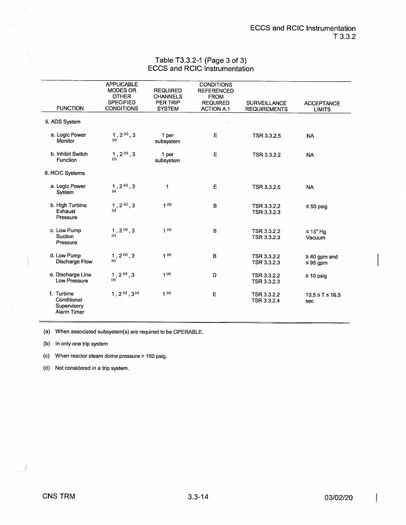
ECCS and RCIC Instrumentation
Table T3.3.2-1 (Page 3 of 3) ECCS and RCIC Instrumentation
APPLICABLE CONDITIONS MODES OR REQUIRED REFERENCED
OTHER CHANNELS FROM SPECIFIED PER TRIP REQUIRED
FUNCTION CONDITIONS SYSTEM ACTION A.1
5. ADS System
a. Logic Power 1, 2 (c), 3 1 per E Monitor (c) subsystem
b. Inhibit Switch 1, 2 (c), 3 1 per E Function (c) subsystem
6. RCIC Systems
a. Logic Power 1, 2 (c), 3 E System (c)
b. High Turbine 1, 2 (c), 3 1 (b) B Exhaust (c)
Pressure
c. Low Pump 1 , 2 (c), 3 ..a th, B I ,-,
Suction (c)
Pressure
d. Low Pump 1 I 2 (c) J 3 1 (b) B Discharge Flow (c)
e. Discharge Line 1, 2 (c), 3 1 (d) D Low Pressure (c)
f. Turbine 1 , 2 (c) , 3 (c) 1 (d) E Conditional Supervisory Alarm Timer
(a) When associated subsystem(s) are required to be OPERABLE.
(b) In only one trip system
(c) When reactor steam dome pressure> 150 psig.
(d) Not considered in a trip system.
CNS TRM 3.3-14
SURVEILLANCE REQUIREMENTS
TSR 3.3.2.5
TSR 3.3.2.2
TSR 3.3.2.5
TSR 3.3.2.2 TSR 3.3.2.3
TSR 3.3.2.2 TSR3.3.2.3
TSR 3.3.2.2 TSR 3.3.2.3
TSR 3.3.2.2 TSR 3.3.2.3
TSR 3.3.2.2 TSR 3.3.2.4
T 3.3.2
ACCEPTANCE LIMITS
NA
NA
NA
s 50 psig
s 15" Hg Vacuum
~ 40 gpm and s 95 gpm
~ 10 psig
13.5 s Ts 16.5 sec
03/02/20

Non-Type A, Non-Category 1 Post Accident Monitoring (PAM) Instrumentation T 3.3.3
T 3.3 INSTRUMENTATION
T 3.3.3 Non-Type A, Non-Category 1 Post Accident Monitoring (PAM) Instrumentation
TLCO 3.3.3 The PAM instrumentation for each Function in Table T3.3.3-1 shall be OPERABLE.
APPLICABILITY: According to Table T3.3.3-1.
ACTIONS ---------------------------------------NOTE----------------------------------------------Separate Condition entry is allowed for each Function.
----------------------
CONDITION REQUIRED ACTION
A. For Functions 1, 2, 3, A.1 4, 11, and 12 one required channel inoperable.
CNS TRM
AND
A.2
----NOTE----------------Not applicable to Function 11 safety valve indication.
Restore channel to OPERABLE status.
-------NOTE-----Only applicable to Function 11 safety vaive indication. --------------------Enter TLCO 3.0.3.
3.3-15
COMPLETION TIME
30 days
Immediately
03/18/20

Non-Type A, Non-Category 1 Post Accident Monitoring (PAM) Instrumentation T 3.3.3
ACTIONS
CONDITION REQUIRED ACTION COMPLETION TIME
B. For Functions 1, 2, 3, B.1 Restore one channel to 7 days and 12 one or more OPERABLE status. Functions with two channels inoperable. AND
OR B.2 NOTE -----Only applicable for Functions
For Functions 5, 6, 7, 8, 9, and 10. 8, 9, and 10 one or ---------more required channels inoperable. Initiate the preplanned 72 hours
alternate method of monitoring the parameter.
C. For Function 4, two C. 1 Restore one channel to 6 hours required channels OPERABLE status. inoperable.
CNS TRM 3.3-16 03/18/20

Non-Type A, Non-Category 1 Post Accident Monitoring (PAM) Instrumentation T 3.3.3
SURVEILLANCE REQUIREMENTS
---------------NOTES---1. Refer to Table T3.3.3-1 to determine which TSRs apply for each Function.
2. When a channel is placed in an inoperable status solely for performance of required Surveillances, entry into associated Conditions and Required Actions may be delayed for up to 6 hours provided the associated Function or the redundant Function maintains monitoring capability.
TSR 3.3.3.1
TSR 3.3.3.2
SURVEILLANCE
Perform CHANNEL CHECK.
----------NOTE--------Not required to be performed until 12 hours after THERMAL POWER~ 25% RTP.
Verify the absolute difference between the average power range monitor (APRM) channels and the calculated power is .::5. 2% RTP plus any gain adjustment required by LCO 3.4.1 "Recirculation Loops Operating" while operating at~ 25% RTP.
TSR 3.3.3.3 Perform CHANNEL CHECK.
TSR 3.3.3.4 Perform CHANNEL FUNCTIONAL TEST.
TSR 3.3.3.5 Perform CHANNEL CALIBRATION.
CNS TRM 3.3-17
FREQUENCY
12 hours
7 days
31 days
31 days
184 days
10/28/11

Non-Type A, Non-Category 1 Post Accident Monitoring (PAM) Instrumentation T 3.3.3
SURVEILLANCE REQUIREMENTS
TSR 3.3.3.6
TSR 3.3.3.7
TSR 3.3.3.8
TSR 3.3.3.9
CNS TRM
SURVEILLANCE
-------NOTES--------------------1. For Function 7b, not required to be performed
when entering MODE 2 from MODE 1 until 12 hours after entering MODE 2.
2. Neutron detectors are excluded. -------------------------------------Perform CHANNEL CALIBRATION.
Perform CHANNEL FUNCTIONAL TEST.
--------------~NOTES-----------~ 1. For Function 7a, not required to be performed
until 12 hours after IRMs on Range 2 or below.
2. Neutron detectors are excluded.
Perform CHANNEL CALIBRATION
Perform CHANNEL CALIBRATION
3.3-18
FREQUENCY
24 months
24 months
18 months
92 days
03/18/20

Non-Type A, Non-Category 1 Post Accident Monitoring (PAM) Instrumentation T 3.3.3
FUNCTION
1. Drywell Temperature
2. Suppression Chamber/ Torus Air Temperature
3. Suppression Chamber/ Torus Water Level (Range: -4' to +6')
4. Suppression Chamber/ Torus Water Level (Range: -10" to +10")
5. Suppression Chamber/ Torus Pressure
6. Control Rod Position
7. Neutron Monitoring a. SRM
b. lRM
c. APRM
8. Elevated Release Point (ERP) Monitor (High Range Noble Gas)
9. Turbine Building Ventilation Exhaust Monitor (High Range Noble Gas)
1 O. Radwaste/ Augmented Radwaste Exhaust Monitor (High Range Noble Gas)
11.Safety and Safety Relief Valve Position Indication
12.Primary Containment H2 & 02 Analyzer
CNS TRM
APPLICABLE MODES OR
OTHER SPECIFIED
CONDITIONS
1 , 2
1 , 2
1 , 2
1 , 2
1 , 2
1 , 2
2
2
1 , 2, 3
1 , 2, 3
1 , 2, 3
1 , 2
1, 2
Table T3.3.3-1 PAM Instrumentation
MINIMUM NUMBER OF OPERABLE INSTRUMENTS
CHANNELS
2
2
2
2
1 per control rod
1 per valve
2
3.3-19
SURVEILLANCE REQUIREMENTS
TSR 3.3.3.1 TSR 3.3.3.6
TSR 3.3.3.1 TSR 3.3.3.5
TSR 3.3.3.1 TSR 3.3.3.8
TSR 3.3.3.1 TSR 3.3.3.8
TSR 3.3.3.1 TSR 3.3.3.8
TSR 3.3.3.1
TSR 3.3.3.1 TSR 3.3.3.8 TSR 3.3.3.1 TSR 3.3.3.6 TSR 3.3.3.1 TSR 3.3.3.2
TSR 3.3.3.4 TSR 3.3.3.8
TSR 3.3.3.4 TSR 3.3.3.8
TSR 3.3.3.4 TSR 3.3.3.8
TSR 3.3.3.3 TSR 3.3.3.7
TSR 3.3.3.3 TSR 3.3.3.9
03/18/20

T 3.3 INSTRUMENTATION
T 3.3.4 [DELETED]
CNS TRM 3.3-20
[DELETED] T 3.3.4
05/15/13

T 3.3 INSTRUMENTATION
Feedwater Flow Instrumentation T 3.3.5
T 3.3.5 Feedwater Flow Instrumentation
TLCO 3.3.5 Both Leading Edge Flow Meter CheckPlus instrumentation systems shall be OPERABLE.
APPLICABILITY: MODE 1 and THERMAL POWER> 2177 MWt
ACTIONS
CONDITION REQUIRED ACTION COMPLETION TIME
A. One or more systems A.1 Verify no reduction in power to Immediately inoperable. ~ 2177 MWt occurs during the
72 hour COMPLETION TIME of REQUIRED ACTION A.2.
AND
A.2 Restore required instruments 72 hours to OPERABLE status.
B. Required Action and 8.1 Initiate an orderly power Immediately associated Completion reduction to~ 2381 MWt. Time of CONDITION A not met. OR
8.2 Verify power is no greater than Immediately 2381 MWt.
CNS TRM 3.3-21 05115113 I

SURVEILLANCE REQUIREMENTS
Feedwater Flow Instrumentation T 3.3.5
-----------------------------------------------------NOTE-----------------------------------------Not required to be performed until 12 hours after THERMAL POWER > 2177 MWt.
----------------·--- -----------------------------
SURVEILLANCE FREQUENCY
TSR 3.3.5.1 Perform CHANNEL CHECK. 12 hours
CNS TRM 3.3-22 05115113 I

T 3.4 REACTOR COOLANT SYSTEM (RCS)
T 3.4.1 RCS Chemistry
RCS Chemistry T 3.4.1
TLCO 3.4.1 The chemistry of the Reactor Coolant System (RCS) shall be maintained within the limits of Table T3.4.1-1.
APPLICABILITY: According to Table T3.4.1-1.
ACTIONS
-----------------------------------------------------NOTE------------------------------------TLCO 3.0.4 is not applicable.
------------
CONDITION REQUIRED ACTION COMPLETION TIME
A. RCS chemistry not within A.1 Restore RCS chemistry to 48 hours from the the limits of Table T3.4.1-1, within limits. time the limit(s) were Condition 2. exceeded
B. RCS chemistry not within B.1 Restore RCS chemistry to 72 hours from the the limits of Table T3.4.1-1, within limits. time the limit(s) were Condition 1. exceeded
AND
B.2 NOTE -Only applicable to chloride concentration and conductivity limits.
Restore RCS chemistry to 336 hours cumulative within limits. in past 365 days
CNS TRM 3.4-1 10/10/01

ACTIONS
CONDITION REQUIRED ACTION
C. RCS chemistry not within C. 1 Restore chloride the limits of Table 3.4.1-1, concentration to within limits. Condition 4.
AND
C.2 Restore conductivity to within limits.
AND
C.3 Restore pH to within limits.
D. RCS chemistry not within D.1 Discontinue Classic the limits of Table 3.4.1-1, NobleChem Application Condition 3. activities - except as
necessary for required actions D.2, D.3, and D.4.
AND
D.2 Restore chloride concentration to within limits.
AND
D.3 Restore conductivity to within limits.
AND
D.4 Restore pH to within limits.
E. Required Action and E.1 Be in MODE 2. associated Completion Time of Condition B not met.
CNS TRM 3.4-2
RCS Chemistry T 3.4.1
COMPLETION TIME
24 hours from the time the limit( s) were exceeded
72 hours from the time the limit(s) were exceeded
72 hours from the time the limit(s) were exceeded
Immediately
24 hours from the time the limit( s) were exceeded
24 hours from the time the limit(s) were exceeded
24 hours from the time the limit( s) were exceeded
8 hours
02/04/10
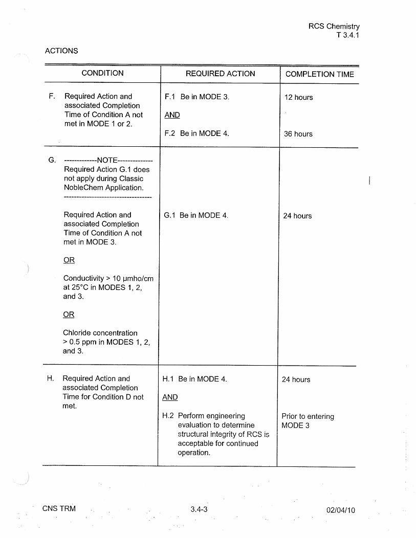
ACTIONS
CONDITION
F. Required Action and associated Completion Time of Condition A not met in MODE 1 or 2.
G. NOTE Required Action G.1 does not apply during Classic NobleChem Application. -----------------------------------
Required Action and associated Completion Time of Condition A not met in MODE 3.
OR
Conductivity > 10 µmho/cm at 25°C in MODES 1, 2, and 3.
OR
Chloride concentration > 0.5 ppm in MODES 1, 2, and 3.
H. Required Action and associated Completion Time for Condition D not met.
CNS TRM
REQUIRED ACTION
F.1 Be in MODE 3.
AND
F.2 Be in MODE 4.
G.1 Be in MODE 4.
H.1 Be in MODE 4.
AND
H.2 Perform engineering evaluation to determine cfr1 ll"h 1r-:il infartrih, nf er~ ic-vu UvlUI UI II llv~I llJ VI I '\.'-JV Iv
acceptable for continued operation.
3.4-3
RCS Chemistry T 3.4.1
COMPLETION TIME
12 hours
36 hours
24 hours
24 hours
Prior to entering MODE3
-02/04/10

ACTIONS
I.
CONDITION
---------------NOTE-------------Required Action 1.1 shall be completed if this Condition is entered
Required Action and associated Completion Time for Condition C not met.
SURVEILLANCE REQUIREMENTS
REQUIRED ACTION
1.1 Perform engineering evaluation to determine structural integrity of RCS is acceptable for continued operation.
SURVEILLANCE
TSR 3.4.1.1
CNS TRM
Verify conductivity is within limits of Table T3.4.1-1. If conductivity is~ 1.0 µmho/cm at 25°C verify pH is within limits of Table T3.4.1-1.
3.4-4
RCS Chemistry T 3.4.1
COMPLETION TIME
Prior to entering MODE2 or 3
FREQUENCY
4 hours when the continuous conductivity monitor is inoperable in MODES 1, 2, and 3
07/30/04

SURVEILLANCE REQUIREMENTS
TSR 3.4.1.2
TSR 3.4.1.3
TSR 3.4.1.4
CNS TRM
SURVEILLANCE
Analyze reactor coolant sample for conductivity and chloride concentration.
Analyze reactor coolant sample for conductivity, chloride concentration and pH.
Analyze reactor coolant sample for conductivity and chloride concentration. If conductivity is~ 1.0 µmho/cm at 25°C analyze for pH.
3.4-5
RCS Chemistry T 3.4.1
FREQUENCY
80 hours when conductivity is ~ 0.7 µmho/cm at 25°C in MODES 1, 2, and 3
24 hours when conductivity is > 0.7 but ~ 2.0 µmho/cm at 25°C in MODES 1, 2, and 3
AND
8 hours when conductivity is > 2.0 but ~ 3.5 µmho/cm at 25°C in MODES 1, 2, and 3
4 hours when conductivity is > 3.5 µmho/cm at 25°C in MODES 1, 2, and 3
80 hours when in MODES 4 and 5
01/02/04

SPECIFIED CONDITIONS
1. > 10% Rated Power
2. * ~ 10% Rated Power
AND
> 212°F
3. ** During Classic NobleChem Application
4.* All other times
Table T3.4.1-1 RCS Chemistry Limits
CHLORIDE CONDUCTIVITY CONCENTRATION LIMIT
LIMIT {AT 25°C)
~ 0.2 ppm ~ 1.0 µmho/cm
~ 0.1 ppm ~ 2.0 µmho/cm
~ 0.1 ppm if 2: 212°F ~ 0.5 ppm if< 212°F ~ 20 µmho/cm
~ 0.5 ppm ~ 10.0 µmho/cm
RCS Chemistry T 3.4.1
pH LIMIT***
5.6 ~pH~ 8.6
5.6 ~pH~ 8.6
4.3 ~pH~ 9.9
5.3 ~pH~ 8.6
* Except during Classic NobleChem Application. On-line NobleChem Application uses Condition 1 limits.
** Classic NobleChem Application includes up to 48 hours of noble metal injection, followed by up to 24 hours for restoration to acceptable chemistry limits for either Condition 2 or 4. RCS tAmnAr~h trA m~\/ rlrnn hAlmJ\/ ?1 ? 0 t= rl1 ,rinn thA rAc:tnr~tinn nArinrl .. -,,,....,....,, ............ ,...., 111 ..... J ""''""f"' .._,_,"WW'.._, ... I """"1111"::::J .. ,,- •---..-, ...... ,,...,, • ,..,.-••--•
*** When conductivity is <1.0 µmho the pH can not be out of limits and pH analysis is not necessary.
CNS TRM 3.4-6 02/04/10

T 3.6 [DELETED]
T 3.6.1 [DELETED]
CNS TRM 3.6-1
[DELETED] T 3.6.1
02/22/16

T 3.7 PLANT SYSTEMS
T 3.7.1 River Level
River Level T 3.7.1
TLCO 3.7.1 The River Level shall be< 895 ft. MSL and upstream system dams intact.
APPLICABILITY: At all times.
ACTIONS
CONDITION REQUIRED ACTION
A. River Level is ~ 895 ft. A.1 Implement CNS Site Flood MSL or notification of Procedure. upstream dam failure.
B. River Level is ~ 901 ft. 8.1 Be in MODE 3. 8 in. MSL.
AND
8.2 Be in MODE 4, with the reactor vessel vented to atmosphere.
SURVEILLANCE REQUIREMENTS
SURVEILLANCE
TSR 3.7.1.1
CNS TRM
Visually observe and log river water level at the intake structure.
3.7-1
COMPLETION TIME
Immediately
12 hours
36 hours
FREQUENCY
12 hours
05111119 I

T 3.7 PLANT SYSTEMS
T 3. 7 .2 Structural Integrity
Structural Integrity T 3.7.2
TLCO 3.7.2 The structural integrity of the ASME Code Class 1, 2, and 3 components shall be maintained in accordance with Section XI of the ASME Boiler and Pressure Vessel Code and applicable Addenda as required by 10 CFR 50.55a(g), except where approved relief has been granted.
APPLICABILITY: At all times
ACTIONS
CONDITION REQUIRED ACTION COMPLETION TIME
A. Structural integrity of Class A.1 Declare component inoperable Immediately 1, 2, or 3 component not met.
SURVEILLANCE REQUIREMENTS
TSR 3.7.2.1
CNS TRM
SURVEILLANCE
lnservice inspection shall be performed in accordance with the requirements for ASME Class 1, 2, and 3 components contained in Section XI of the ASME Boiler and Pressure Vessel Code and applicable Addenda as required by 10 CFR 50, Section 50.55a(g), except where relief has been granted by the Commission pursuant to 10 CFR 50, Section 50.55a.
3.7-2
FREQUENCY
In accordance with the inservice inspection program.
( continued)
04/17/03

SURVEILLANCE REQUIREMENTS (continued)
TSR 3.7.2.2
CNS TRM
SURVEILLANCE
The inservice inspection program for piping identified in NRC Generic Letter 88-01 shall be performed in accordance with BWRVIP-75 and the NRC Safety Evaluation (TAC No. MA5012).
3.7-3
Structural Integrity T 3.7.2
FREQUENCY
In accordance with BWRVIP-75 and the NRC Safety Evaluation.
04/17/03

T 3. 7 [DELETED]
T 3. 7.3 [DELETED]
CNS TRM 3.7-4
[DELETED] T 3.7.3
12/21/16

T 3.8 ELECTRICAL POWER SYSTEMS
T 3.8.1 Battery Room Ventilation
Battery Room Ventilation T 3.8.1
TLCO 3.8.1 The Station Service Battery Room Ventilation system with two ventilation fans shall be OPERABLE.
APPLICABILITY: When either 125v or either 250v Station Service battery is required to be OPERABLE.
ACTIONS
CONDITION REQUIRED ACTION COMPLETION TIME
A. One Battery Room A.1 Restore the Battery Room 7 days Ventilation fan Ventilation fan to OPERABLE inoperable. status.
B. Battery Room B.1 Initiate action to establish battery Immediately Ventilation system room ventilation. inoperable for reasons other than Condition A.
CNS TRM 3.8-1 10/10/01

Battery Room Ventilation : ~ T 3.8.1
SURVEILLANCE REQUIREMENTS
TSR 3. 8 .1.1
CNS TRM
SURVEILLANCE
Check OPERABILITY of Battery Room Ventilation fans by rotation of the fans.
3.8-2
FREQUENCY
7 days
REVISION 1

T 3.9 REFUELING OPERATIONS
T 3.9.1 Time Limitation
Time Limitation T 3.9.1
TLCO 3.9.1 The reactor shall be shutdown for 2:: 24 hours.
APPLICABILITY: Whenever handling irradiated fuel in or above the reactor.
ACTIONS
CONDITION
A. Reactor shutdown for -< 24 hours.
CNS TRM
REQUIRED ACTION COMPLETION TIME
A.1 Suspend handling of irradiated Immediately fuel in and above the reactor.
3.9-1 10/05/06

T 3.9 REFUELING OPERATIONS
T 3.9.2 Spent Fuel Cask Handling
Spent Fuel Cask Handling T 3.9.2
TLCO 3.9.2 The fuel cask handling equipment used shall be OPERABLE in the restricted mode.
APPLICABILITY: During fuel cask movement.
ACTIONS
CONDITION REQUIRED ACTION COMPLETION TIME
A. Controlled area A.1 Station an operator on the Immediately Programmable Logic refueling floor to assure Controller inoperable. the crane is operated
within the restricted zone AND painted on the floor.
Fuel cask movement AND above the 931' level of the Reactor Building. A.2 Restore the Programmable 48 hours
Logic Controller to OPERABLE status.
B. Required Action and B.1 Move cask to the closest Immediately associated Completion acceptable stable location. Time of Condition A not met.
OR
Fuel cask handling equipment inoperable for reasons other than Condition A.
OR
An emergency condition develops.
CNS TRM 3.9-2 08/30/10

Spent Fuel Cask Handling T 3.9.2
SURVEILLANCE REQUIREMENTS
TSR 3.9.2.1
TSR 3.9.2.2
TSR 3.9.2.3
CNS TRM
SURVEILLANCE
Inspect redundant crane including rope, hooks, slings, shackles and other operating mechanisms. Replace rope, if any of the following conditions exist;
a. Twelve ( 12) randomly distributed broken wires in one lay or four ( 4) broken wires in one strand of one rope lay.
b. Wear of one-third the original diameter of outside individual wire.
c. Kinking, crushing, or any other damage resulting in distortion of the rope.
d. Evidence of any type of heat damage.
e. Reductions from nominal diameter of more than 1/16" for a rope diameter from 7/8" to 1 1 /4" inclusive.
Perform the following tests;
a. controlled area Programmable Logic Controller test.
b. "two-block" limit switches test.
c. "Hoist Micro Speed" controls test.
Lift empty transfer cask free of all support by a maximum of 1 ft and hold for 5 min.
3.9-3
FREQUENCY
Prior to dry fuel storage campaign
Prior to operations in the restricted mode.
Prior to fuel cask handling operations
12/15/10

T 3.11 FIRE PROTECTION SYSTEMS
T 3.11.1 Fire Detection Instrumentation
Fire Detection Instrumentation T 3.11.1
TLCO 3.11.1 The Fire Detection Instrumentation shown in Table T3.11.1-1 shall be OPERABLE.
APPLICABILITY: At all times.
ACTIONS ------------------NOTE-------------------------
Separate Condition entry is allowed for each fire detection instrument. --~--·-------------------------------------------
CONDITION
A. One or more required fire detection instrument( s) inoperable.
CNS TRM
A.1
A.2
AND
A.3
REQUIRED ACTION
---NOTE---Only applicable to Table T3.11.1-1, Group 1, 2, and 3
Establish an hourly fire watch patrol for the zone(s) with the inoperable instrument( s ).
OR
NOTE-------------Only applicable to Table T3.11.1-1 , Group 4 -----------------
Establish a continuous fire watch for the zone( s) with the inoperable instrument(s).
Restore the fire detection instrumentation to OPERABLE status.
3.11-1
COMPLETION TIME
1 hour
1 hour
14 days
10/17/16

Fire Detection Instrumentation T3.11.1
SURVEILLANCE REQUIREMENTS
TSR 3.11.1.1
TSR 3.11.1.2
CNS TRM
SURVEILLANCE
Perform CHANNEL FUNCTIONAL TEST for each detector in Table T3.11.1-1.
---------------NOTE---------Not required to be met for FP-SD-1001 or FP-SD-9-32_33.
------------------------
Demonstrate OPERABLE the NFPA Standard 72.D Class A or B supervised circuits associated with the detector alarms of each of the required fire detection instruments.
3.11-2
FREQUENCY
Annually
Annually
06/25/15

GROUP
1.
2.
CNS TRM
TABLE T3.11.1-1
Fire Detection Instrumentation T 3.11.1
FIRE DETECTION INSTRUMENTS
LOCATION INSTRUMENT ID NO.
Cable Spreading Room FP-SD-16-1 Cable Expansion Room FP-SD-16-2
FP-SD-16-3 FP-SD-16-4 FP-SD-16-5 FP-SD-16-6 FP-SD-1001
FP-SD-16-7 FP-SD-16-8
Diesel Generator Rooms FP-TD-10-1 FP-TD-10-2 FP-TD-10-3 FP-TD-10-4 FP-TD-10-5 FP-TD-10-6 FP-TD-10-7 FP-TD-10-8 FP-TD-10-9 FP-TD-10-10 FP-TD-10-11 FP-TD-10-12 FP-TD-10-13 FP-TD-10-14 FP-TD-10-15 FP-TD-10-16 FP-TD-10-17 FP-TD-10-18 FP-TD-10-19 FP-TD-10-20 FP-TD-10-21 FP-TD-10-22 FP-TD-10-23 FP-TD-10-24 FP-TD-10-25 FP-TD-10-26 FP-TD-10-27
( continued)
3.11-3 10/17/16

GROUP LOCATION
2. ( continued} Diesel Generator Rooms
3. Service Water Pumps
4. Auxiliary Relay Room
CNS TRM 3.11-4
Fire Detection Instrumentation T 3.11.1
INSTRUMENT ID NO.
FP-TD-10-28 FP-TD-10-29 FP-TD-10-30 FP-TD-10-31 FP-TD-10-32 FP-TD-10-33 FP-TD-10-34 FP-TD-10-35 FP-TD-10-36 CO2-SD-DG-1 A CO2-SD-DG-1 B CO2-SD-DG-1 C CO2-SD-DG-1 D CO2-SD-DG-2A CO2-SD-DG-2B CO2-SD-DG-2C CO2-SD-DG-2D
FP-SD-32-1 FP-SD-32-2 FP-SD-32-3 FP-SD-32-4 FP-SD-1003A FP-SD-1003B FP-SD-H1 FP-SD-H2 FP-SD-H3 FP-SD-H4 FP-SD-H5 FP-SD-H6 FP-TD-H11 FP-TD-H12 FP-TD-H13 FP-TD-H14 FP-TD-H15 FP-TD-H16
FP-SD-9-32_33
10/17/16

LEGEND
FP = Fire Protection TD = Thermal Detector SD= Smoke Detector
CNS TRM
CO2 = Carbon Dioxide DG = Diesel Generator 1st Digit Instr. ID No. = Zone
Fire Detection Instrumentation T3.11.1
2nd Digit Instr. ID No. = Instr. No.
3.11-5 07/05/16

Fire Suppression Water System T 3.11.2
T 3.11 FIRE PROTECTION SYSTEMS
T 3.11.2 Fire Suppression Water System
TLCO 3.11.2
APPLICABILITY:
ACTIONS
The Fire Suppression Water System shall be OPERABLE with:
a. Two OPERABLE fire pumps with their discharge aligned to the fire suppression header.
b. An OPERABLE flow path capable of taking suction from either of two 500,000 gallon water storage tanks and transferring the water through distribution piping with OPERABLE sectionalizing control or isolation valves to the yard hydrant valves and the front valve ahead of the water flow alarm device on each sprinkler, hose standpipe or spray system riser.
At all times.
CONDITION REQUIRED ACTION COMPLETION TIME
A. One required fire pump inoperable.
CNS TRM
A.1 Restore fire pump to OPERABLE status.
3.11-6
7 days
( continued)
12130115 I

ACTIONS (continued)
CONDITION
B. The Fire Suppression Water 8.1 System inoperable for reasons other than Condition A.
CNS TRM
AND
B.2
Fire Suppression Water System T 3.11.2
REQUIRED ACTION
Establish a backup fire suppression water system.
Restore Fire Suppression Water System to OPERABLE status.
3.11-7
COMPLETION TIME
24 hours
7 days
12/30/15

Fire Suppression Water System T 3.11.2
SURVEILLANCE REQUIREMENTS
TSR 3.11.2.1
TSR 3.11.2.2
TSR 3.11.2.3
TSR 3.11.2.4
TSR 3.11.2.5
CNS TRM
SURVEILLANCE FREQUENCY
Verify the electrolyte level of each battery for the 7 days diesel engine driven fire pump is above the plates.
Verify the overall battery voltage for the diesel engine 7 days driven fire pump is ~ 24 volts.
-------------NOTE----------------Testing of the fire pumps shall be staggered such that only one pump is being tested at a time. ---------------- ------------------~-Start each fire pump from ambient conditions and operate it for:
a. ~ 30 minutes for a diesel engine driven fire Quarterly pump.
b. ~ 10 minutes for an electrical motor driven fire Quarterly pump.
Verify each Fire Suppression Water System manual, Quarterly power operated, and automatic valve in the flow path that is not locked, sealed, or otherwise secured in position, is in the correct position.
Verify the diesel engine driven fire pump fuel storage Quarterly tank contains ~ 250 gallons of fuel.
3.11-8
( continued) I
12/30/15
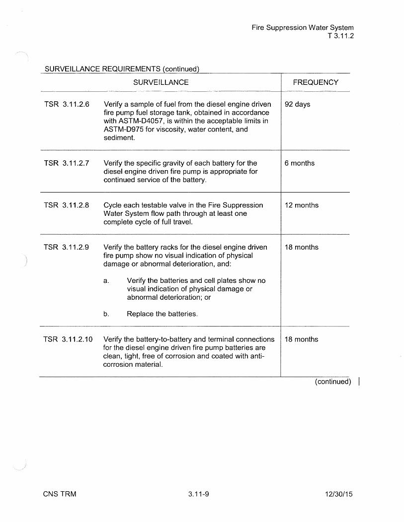
Fire Suppression Water System T 3.11.2
SURVEILLANCE REQUIREMENTS (continued)
TSR 3.11.2.6
TSR 3.11.2.7
TSR 3.11.2.8
TSR 3.11.2.9
SURVEILLANCE
Verify a sample of fuel from the diesel engine driven fire pump fuel storage tank, obtained in accordance with ASTM-D4057, is within the acceptable limits in ASTM-D975 for viscosity, water content, and sediment.
Verify the specific gravity of each battery for the diesel engine driven fire pump is appropriate for continued service of the battery.
Cycle each testable valve in the Fire Suppression Water System flow path through at least one complete cycle of full travel.
Verify the battery racks for the diesel engine driven fire pump show no visual indication of physical damage or abnormal deterioration, and:
a. Verify the batteries and cell plates show no visual indication of physical damage or abnormal deterioration; or
b. Replace the batteries.
FREQUENCY
92 days
6 months
12 months
18 months
TSR 3.11.2.10 Verify the battery-to-battery and terminal connections 18 months for the diesel engine driven fire pump batteries are clean, tight, free of corrosion and coated with anti-corrosion material.
( continued) I
CNS TRM 3.11-9 12/30/15

Fire Suppression Water System T 3.11.2
SURVEILLANCE REQUIREMENTS (continued)
SURVEILLANCE FREQUENCY
TSR 3.11.2.11 Inspect the diesel of the diesel engine driven fire 24 months pump in accordance with procedures prepared in conjunction with the manufacturer's recommendations for the class of service.
TSR 3.11.2.12 Verify the diesel of the diesel engine driven fire pump 24 months starts from ambient conditions on the auto-start signal and operates for 2:: 15 minutes while loaded with the fire pump.
TSR 3.11.2.13 Perform a system functional test which includes 24 months actual or simulated automatic actuation of the Fire Suppression Water System throughout its operating sequence, and:
a. Verifying that each fire pump develops 2:: 2000 gpm at a pressure 2:: 110 psig,
b. Verifying that each fire pump starts sequentially to maintain the fire suppression water system pressure 2:: 65 psig.
TSR 3.11.2.14 Perform an underground and exposed piping flow test 60 months of the Fire Suppression Water System to determine the internal condition of piping.
CNS TRM 3.11-10 12I3011 s I

T 3.11 FIRE PROTECTION SYSTEMS
T 3.11.3 Sprinkler Systems
Sprinkler Systems T 3.11.3
TLCO 3.11.3 The Fire Protection Automatic Sprinkler Systems protecting the Cable Spreading Room (918 ft. elev. of Control Building), and the Cable Expansion Room (918 ft. elev. of Controlled Corridor) shall be OPERABLE.
APPLICABILITY: At all times.
ACTIONS ---------------------------------NOTE--------·---------Separate Condition entry is allowed for each Sprinkler System.
CONDITION
A. Required Sprinkler System inoperable.
CNS TRM
A.1
A.2
REQUIRED ACTION
Establish a continuous fire watch with backup fire suppression equipment for the unprotected area.
Restore Sprinkler System to OPERABLE status.
3.11-11
COMPLETION TIME
1 hour
14 days
12/30/15

Sprinkler Systems T 3.11.3
SURVEILLANCE REQUIREMENTS
TSR 3.11.3.1
TSR 3.11.3.2
TSR 3.11.3.3
CNS TRM
SURVEILLANCE FREQUENCY
Cycle each testable valve in the Sprinkler Systems 12 months flow paths through at least one complete cycle of full travel.
Perform a system functional test which includes 18 months actual or simulated automatic actuation of the Sprinkler Systems, and verifying that each automatic valve in the flow paths actuates to its correct position on a test signal.
Inspect the Sprinkler Systems spray headers to verify 18 months their integrity.
3.11-12 1213011s I

T 3.11 FIRE PROTECTION SYSTEMS
High Pressure Carbon Dioxide Extinguishing System T 3.11.4
T 3.11.4 High Pressure Carbon Dioxide Extinguishing System
TLCO 3.11.4 The High Pressure Carbon Dioxide Extinguishing System protecting the Diesel Generator Rooms shall be OPERABLE.
APPLICABILITY: At all times.
ACTIONS
CONDITION
A. Required High Pressure Carbon Dioxide Extinguishing System inoperable.
CNS TRM
A.1
AND
A.2
REQUIRED ACTION
Establish a continuous fire watch with backup fire suppression equipment for the unprotected area( s ).
COMPLETION TIME
1 hour
Restore High Pressure 14 days Carbon Dioxide Extinguishing System to OPERABLE status.
3.11-13 12130115 I

High Pressure Carbon Dioxide Extinguishing System T 3.11.4
SURVEILLANCE REQUIREMENTS
SURVEILLANCE FREQUENCY
TSR 3.11.4.1 Weigh the High Pressure Carbon Dioxide storage Annually cylinders.
TSR 3.11.4.2 Verify the High Pressure Carbon Dioxide 24 months Extinguishing System valves, alarms, and associated ventilation motor interlocks and dampers actuate to a simulated automatic and manual actuation signal.
CNS TRM 3.11-14 12I3011s I
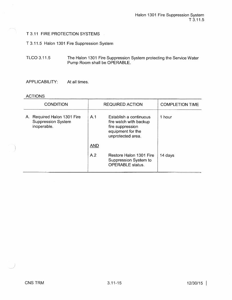
T 3.11 FIRE PROTECTION SYSTEMS
Halon 1301 Fire Suppression System T 3.11.5
T 3.11.5 Halon 1301 Fire Suppression System
TLCO 3.11.5 The Halon 1301 Fire Suppression System protecting the Service Water Pump Room shall be OPERABLE.
APPLICABILITY: At all times.
ACTIONS
CONDITION
A. Required Halon 1301 Fire Suppression System inoperable.
CNS TRM
A.1
A.2
REQUIRED ACTION
Establish a continuous fire watch with backup fire suppression equipment for the unprotected area.
COMPLETION TIME
1 hour
Restore Halon 1301 Fire 14 days Suppression System to OPERABLE status.
3.11-15 12130115 I

Halon 1301 Fire Suppression System T3.11.5
SURVEILLANCE REQUIREMENTS
TSR 3.11.5.1
TSR 3.11.5.2
TSR 3.11.5.3
CNS TRM
SURVEILLANCE
Record the quantity of Halon and the pressure of each Halon storage tank for the Halon 1301 Fire Suppression System and verify that at least one storage tank is:
a. Charged to at least 95% of the design quantity (650 lbs.), and
b. 90% of full charge pressure.
FREQUENCY
Annually
Verify the Halon 1301 Fire Suppression System 18 months valves, alarms, and associated ventilation motor interlocks and dampers actuate to a simulated automatic and manual actuation signal.
Perform an inspection to assure the Halon 1301 Fire 18 months Suppression System nozzles are unobstructed.
3.11-16 12130115 I

T 3.11 FIRE PROTECTION SYSTEMS
T 3.11.6 Fire Hose Stations
Fire Hose Stations T 3.11.6
TLCO 3.11.6 The Fire Hose Stations in Table T3.11.6-1 shall be OPERABLE.
APPLICABILITY: At all times.
ACTIONS ----NOTE--------------------
Separate Condition entry is allowed for each Fire Hose Station. -------------------------------------------------~--
CONDITION
A. Required Fire Hose Station A.1 inoperable.
CNS TRM
REQUIRED ACTION COMPLETION TIME
Route an additional hose 1 hour to the area protected by the inoperable Fire Hose Station from an OPERABLE Fire Hose Station of equivalent capacity.
3.11-17 12I30I1 s I
Fire Hose Stations T 3.11.6
SURVEILLANCE REQUIREMENTS
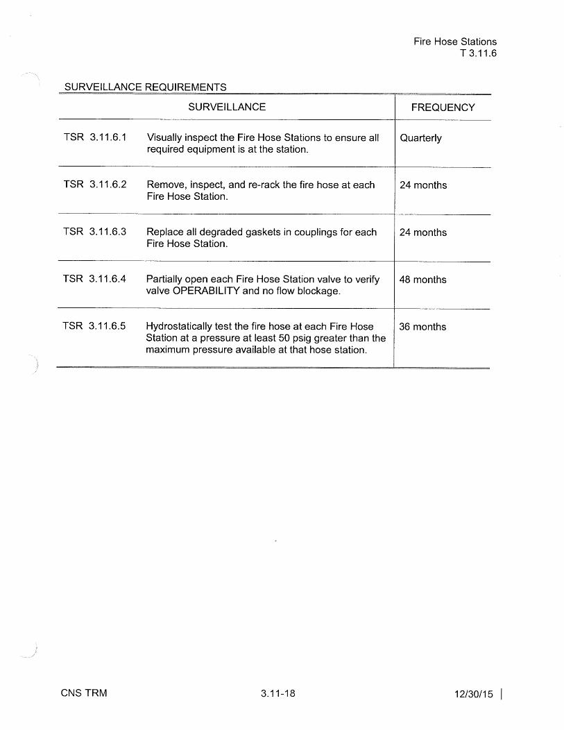
SURVEILLANCE FREQUENCY
TSR 3.11.6.1 Visually inspect the Fire Hose Stations to ensure all Quarterly required equipment is at the station.
TSR 3.11.6.2 Remove, inspect, and re-rack the fire hose at each 24 months Fire Hose Station.
TSR 3.11.6.3 Replace all degraded gaskets in couplings for each 24 months Fire Hose Station.
TSR 3.11.6.4 Partially open each Fire Hose Station valve to verify 48 months valve OPERABILITY and no flow blockage.
TSR 3.11.6.5 Hydrostatically test the fire hose at each Fire Hose 36 months Station at a pressure at least 50 psig greater than the maximum pressure available at that hose station.
CNS TRM 3.11-18 12130115 I

Fire Hose Stations T 3.11.6
Table T3.11.6-1
FIRE HOSE STATIONS
Location Identification # Hose Size
1. Reactor Building
859 & 881 Elevation HV-31 1 1/2" HV-32 1 1/2" HV-33 1 1/2"
903 Elevation HV-35 1 1/2" HV-36 1 1/2" HV-38 1 1/2" HV-34 1 1/2" HV-62 1 1/2"
931 Elevation HV-37 1 1/2" HV-57 1 1/2" HV-59 1 1/2"
958 Elevation HV-39 1 1/2" HV-40 1 1/2" HV-42 1 1/2"
976 Elevation HV-41 1 1/2" HV-46 1 1/2" HV-56 1 1/2" HV-58 1 1/2" HV-63 1 1/2"
1 001 Elevation HV-43 1 1/2" HV-44 1 1/2" HV-45 1 1/2"
2. Cable Spreading Room HV-18 1 1/2"
3. Computer & Control Rooms HV-19 1 1/2"
4. Switchgear Rooms & Station Battery Room
D.C. Switchgear Room and HV-17 1 1/2" Station Battery Rooms
CNS TRM 3.11-19 12130115 I

Location
5. Safety Related Pumps not in Reactor Building
RHR Service Water Booster Pumps
CNS TRM
Identification #
HV-16
3.11-20
Fire Hose Stations T 3.11.6
Hose Size
1 1/2"
12130115 I
Fire Barrier and Fire Wall Penetration Fire Seals T 3.11.7
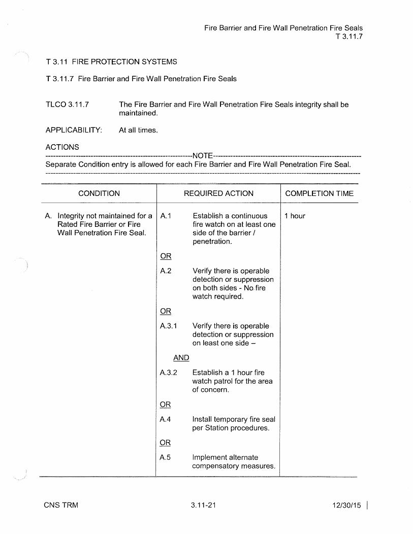
T 3.11 FIRE PROTECTION SYSTEMS
T 3.11. 7 Fire Barrier and Fire Wall Penetration Fire Seals
TLCO 3.11.7 The Fire Barrier and Fire Wall Penetration Fire Seals integrity shall be maintained.
APPLICABILITY: At all times.
ACTIONS -------------------------------------------NOTE-----Separate Condition entry is allowed for each Fire Barrier and Fire Wall Penetration Fire Seal. -------------------------------------------
CONDITION REQUIRED ACTION COMPLETION TIME
A. Integrity not maintained for a A.1 Rated Fire Barrier or Fire
Establish a continuous 1 hour fire watch on at least one
Wall Penetration Fire Seal.
CNS TRM
side of the barrier I penetration.
A.2 Verify there is operable detection or suppression on both sides - No, fire watch required.
OR
A.3.1 Verify there is operable detection or suppression on least one side -
AND
A.3.2 Establish a 1 hour fire watch patrol for the area of concern.
OR
A.4 Install temporary fire seal per Station procedures.
OR
A.5 Implement alternate compensatory measures.
3.11-21 12I30I1 s I
Fire Barrier and Fire Wall Penetration Fire Seals T3.11.7
SURVEILLANCE REQUIREMENTS
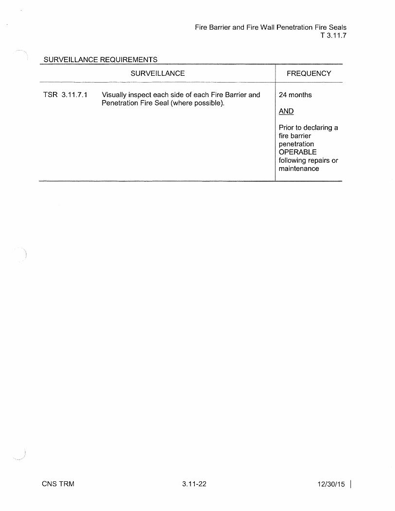
TSR 3.11.7.1
CNS TRM
SURVEILLANCE
Visually inspect each side of each Fire Barrier and Penetration Fire Seal (where possible).
3.11-22
FREQUENCY
24 months
Prior to declaring a fire barrier penetration OPERABLE following repairs or maintenance
1213011 s I

Diverse and Flexible Coping Strategies (FLEX) Equipment T 3.12.1
T 3.12 BEYOND DESIGN BASIS COMPONENTS
T 3.12.1 Diverse and Flexible Coping Strategies (FLEX) Equipment
TLCO 3.12.1 The FLEX Equipment specified in Table 3.12.1-1 shall be functional.
APPLICABILITY: At all times.
ACTIONS ---------------NOTE----------------Separate Condition entry is allowed for each FLEX component.
CONDITION REQUIRED ACTION COMPLETION TIME
A. One or more FLEX A.1 Restore the FLEX 45 days components specified in component to functional Table 3.12.1-1 not functional status. in one FLEX Storage Building.
B. Action A.1 completion time B.1 Initiate action to Immediately not met. supplement the FLEX
component with alternate OR suitable equipment.
One or more FLEX components specified in Table 3.12.1-1 not functional during a forecast site specific external event.
( continued)
CNS TRM 3.12-1 11/06/16

ACTIONS ( continued)
CONDITION
Diverse and Flexible Coping Strategies (FLEX) Equipment T 3.12.1
REQUIRED ACTION COMPLETION TIME
C. One or more FLEX C.1 Initiate actions to restore 24 hours one FLEX Storage components specified in
Table 3.12.1-1 not functional in both FLEX Storage Buildings.
CNS TRM
AND
C.2
Building's components to functional status.
Implement compensatory measures.
3.12-2
72 hours
11/06/16

Diverse and Flexible Coping Strategies (FLEX) Equipment T3.12.1
Table 3.12.1-1
FLEX Equipment that Directly Performs a FLEX Mitigation Strategy for the Key Safety Functions
COMPONENT NUMBER OF COMPONENTS REQUIRED IN EACH FLEX STORAGE
BUILDING
FLEX 175KW Diesel Generator 1 (FLEX-DG-175KW 1/FLEX-DG-175KW 2)
FLEX Pump 1 (FLEX-P-1 /FLEX-P-2 )
FLEX 60KW Diesel Generator 1 (FLEX-DG-60KW 1 /FLEX-DG-60KW 2)
FLEX 6KW Diesel Generator1 11 (FLEX-DG-6KW * / FLEX-DG-6KW *)
FLEX Air Compressor 1 (FLEX-CPSR-1 /FLEX-CPSR-2)
FLEX Tractor 1 (FL-GN-CNST-MANT-SUPT)
FLEX Hoses and Cables 1 set2
FLEX Refueling Trailer 1
RCIC Ventilation 1 set2
1 .. There are six (6) 6KW Diesel Generators in each FLEX Storage Building. One in each FLEX Storage Building is mounted on the refueling trailer, which leaves five (5) in each FLEX Storage Building to meet this specification.
2The set is specified in the FLEX Storage Building inventory procedure.
CNS TRM 3.12-3 07/09/18

FLEX Fluid and Electrical Connection Components T 3.12.2
T 3.12 BEYOND DESIGN BASIS COMPONENTS
T 3.12.2 FLEX Fluid and Electrical Connection Components
TLCO 3.12.2 The FLEX Fluid and Electrical Connection Components required to implement the FLEX Strategy when the FLEX Equipment is connected at the point specified in Table 3.12.2-1 shall be functional.
APPLICABILITY: At all times.
ACTIONS -------------------NOTE--------------Separate Condition entry is allowed for each FLEX connection. ---------------------------
CONDITION REQUIRED ACTION COMPLETION TIME
A. The Primary or Secondary A.1 Restore the FLEX 90 days Connection for one or more Connection to functional Safety Functions/FLEX status. components specified in Table 3.12.2-1 is not functional.
B. Action A.1 completion time 8.1 Initiate action to Immediately not met. supplement the FLEX
Connection with an additional Connection that meets the requirements of NEI 12-06 including diversity.
( continued)
CNS TRM 3.12-4 11/06/16

ACTIONS ( continued)
CONDITION
C. The Primary and Secondary C.1 Connection for one or more Safety Functions/FLEX components specified in AND Table 3.12.2-1 are not functional. C.2
CNS TRM
FLEX Fluid and Electrical Connection Components T 3.12.2
REQUIRED ACTION COMPLETION TIME
Initiate actions to restore 24 hours site FLEX capability.
Implement 72 hours compensatory measures.
3.12-5 11/06/16

FLEX Fluid and Electrical Connection Components T 3.12.2
Table 3.12.2-1
FLEX Connections that Directly Perform a FLEX Mitigation Strategy for the Key Safety Functions
SAFETY FUNCTION/FLEX PRIMARY CONNECTION SECONDARY COMPONENT POINT CONNECTION POINT
Maintain Core Cooling/FLEX Pump SW-V-1531 RHR-V-147 Discharge
Maintain Core Cooling/175KW FLEX EE-DSC-125C FLEX/ EE-MCC-LX(1 B)/(2C) or Generator EE-DSC-250C FLEX EE-MCC-TX( 1 B)/(2C)
Maintain Core Cooling/FLEX Air SA-V-677 SA-V-660 Compressor
Maintain SFP Cooling/SFP Makeup FPC FLEX Hose Routed to Pool or FLEX Pump Discharge CONNECTION Spray Monitor
Maintain Core Cooling/Phase 3 FLEX SDG MODS 4160 FLEX cart Generator
CNSTRM 3.12-6 03/12/18
Hotwell to Emergency Condensate Storage Tank (ECST) Transfer Pump T 3.12.3
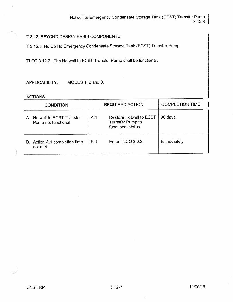
T 3.12 BEYOND DESIGN BASIS COMPONENTS
T 3.12.3 Hotwell to Emergency Condensate Storage Tank (ECST) Transfer Pump
TLCO 3.12.3 The Hotwell to ECST Transfer Pump shall be functional.
APPLICABILITY: MODES 1, 2 and 3.
ACTIONS
CONDITION REQUIRED ACTION COMPLETION TIME
A. Hotwell to ECST Transfer A.1 Restore Hotwell to ECST 90 days Pump not functional. Transfer Pump to
functional status.
B. Action A.1 completion time 8.1 Enter TLCO 3.0.3. Immediately not met.
CNS TRM 3.12-7 11/06/16

T 3.12 BEYOND DESIGN BASIS COMPONENTS
T 3.12.4 North Well Pump
TLCO 3.12.4 The North Well Pump shall be functional.
APPLICABILITY: At all times.
ACTIONS
CONDITION REQUIRED ACTION
A. North Well Pump not A.1 Restore North Well functional. Pump to functional
status.
B. Action A.1 completion time 8.1 Enter TLCO 3.0.3. not met.
CNS TRM 3.12-8
North Well Pump T3.12.4
COMPLETION TIME
45 days
Immediately
11/06/16
FLEX Staging Areas and Pathways T 3.12.5
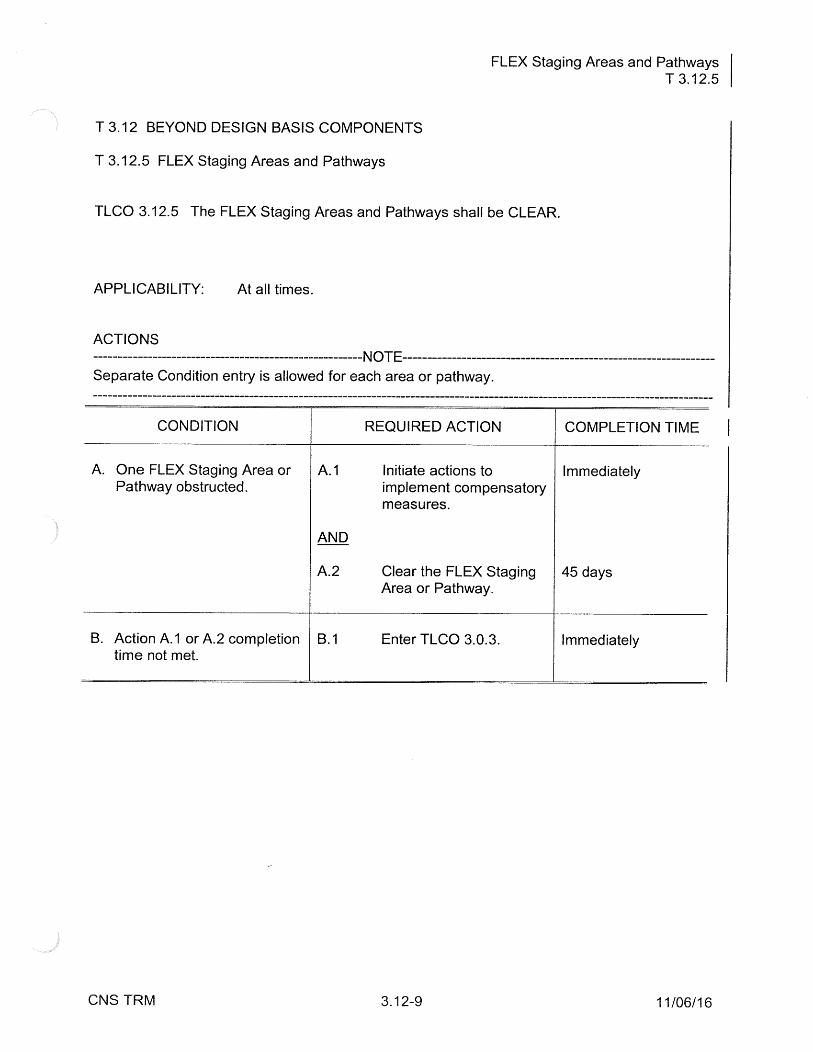
T 3.12 BEYOND DESIGN BASIS COMPONENTS
T 3.12.5 FLEX Staging Areas and Pathways
TLCO 3.12.5 The FLEX Staging Areas and Pathways shall be CLEAR.
APPLICABILITY: At all times.
ACTIONS --NOTE---------------
Separate Condition entry is allowed for each area or pathway. ------------------------------ -----------------------
CONDITION REQUIRED ACTION COMPLETION TIME
A. One FLEX Staging Area or A.1 Initiate actions to Immediately Pathway obstructed. implement compensatory
measures.
AND
A.2 Clear the FLEX Staging 45 days Area or Pathway.
B. Action A.1 or A.2 completion B.1 Enter TLCO 3.0.3. Immediately time not met.
CNS TRM 3.12-9 11/06/16
Spent Fuel Pool Level Instrumentation T 3.12.6
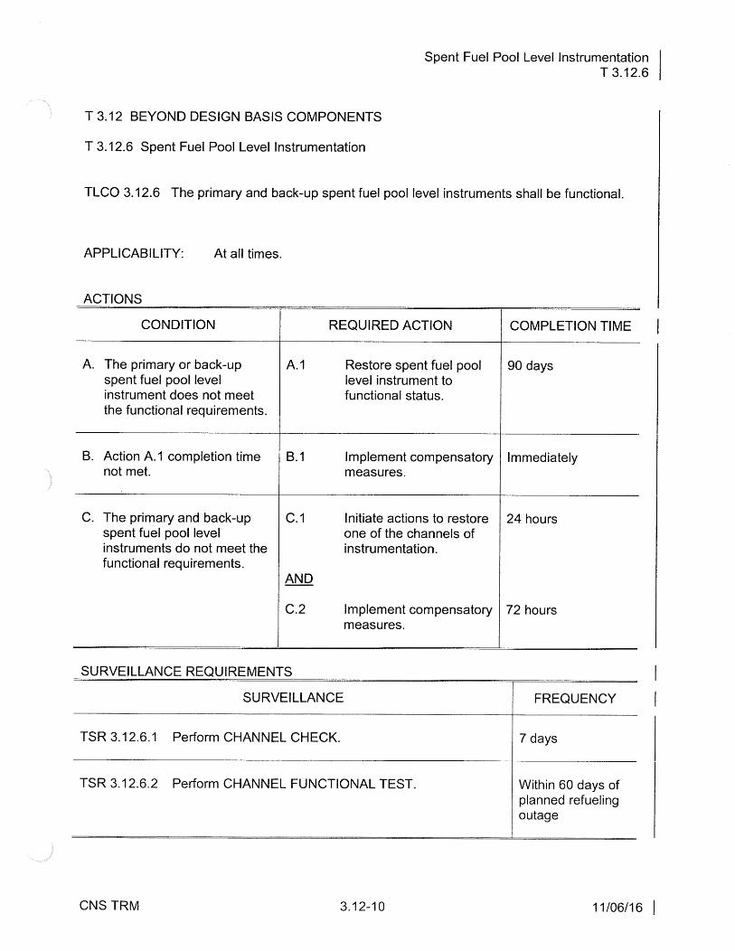
T 3.12 BEYOND DESIGN BASIS COMPONENTS
T 3.12.6 Spent Fuel Pool Level Instrumentation
TLCO 3.12.6 The primary and back-up spent fuel pool level instruments shall be functional.
APPLICABILITY: At all times.
ACTIONS
CONDITION REQUIRED ACTION
A. The primary or back-up A. 1 Restore spent fuel pool spent fuel pool level level instrument to instrument does not meet functional status. the functional requirements.
B. Action A.1 completion time 8.1 Implement compensatory not met. measures.
C. The primary and back-up C. 1 Initiate actions to restore spent fuel pool level one of the channels of instruments do not meet the instrumentation. functional requirements.
AND
C.2 Implement compensatory measures.
SURVEILLANCE REQUIREMENTS
SURVEILLANCE
TSR 3.12.6.1 Perform CHANNEL CHECK.
TSR 3.12.6.2 Perform CHANNEL FUNCTIONAL TEST.
CNS TRM 3.12-10
COMPLETION TIME
90 days
Immediately
24 hours
72 hours
FREQUENCY
7 days
Within 60 days of planned refueling outage
11106116 I

Hardened Containment Vent System (HCVS) T 3.12.7
T 3.12 BEYOND DESIGN BASIS COMPONENTS
T 3.12. 7 Hardened Containment Vent System (HCVS)
TLCO 3.12. 7 The HCVS shall be functional.
APPLICABILITY: MODES 1, 2 and 3.
ACTIONS
CONDITION REQUIRED ACTION COMPLETION TIME
A. Primary control and A.1 Initiate actions to restore 90 days monitoring elements Q! functionality of the alternate valve control HCVS. elements of HCVS render operation of the HCVS non-functional.
8. Primary control and 8.1 Initiate actions to restore 30 days monitoring elements and functionality of the alternate valve control HCVS. elements of HCVS render operation of the HCVS non-functional.
C. Required Action and C.1 Enter TLCO 3.0.3. Immediately associated Completion Time of Condition A or B not met. AND
C.2 Initiate action to Immediately implement appropriate compensatory actions.
CNS TRM 3.12-11 11/06/16

Dam Accident Mitigation System (DAMS) Equipment T 3.12.8
T 3.12 BEYOND DESIGN BASIS COMPONENTS
T 3.12.8 Dam Accident Mitigation System (DAMS) Equipment
TLCO 3.12.8 The DAMS Equipment specified in Table 3.12.8-1 shall be functional.
APPLICABILITY: At all times.
ACTIONS -----------------~ -----------NOTE---------------------------------------------~--Separate Condition entry is allowed for each DAMS component. ----------------------------------------------------------------------------------------------------------
CONDITION REQUIRED ACTION COMPLETION TIME
A. One or more DAMS A.1 Restore the DAMS 90 days components specified in component(s) to Table 3.12.8-1 not functional functional status. but both trains collectively can produce one functional train.
B. One or more DAMS B.1 Restore one DAMS train 45 days components specified in components to functional Table 3.12.8-1 not functional status. and both trains collectively cannot produce one functional train.
C. Required Action and C.1 Enter TLCO 3.0.3. Immediately associated Completion Time of Condition A or B not met.
OR
One or more DAMS components specified in Table 3.12.8-1 not functional during a forecast site specific external flood event.
CNS TRM 3.12-12 10/15/19

Dam Accident Mitigation System (DAMS) Equipment T 3.12.8
Table 3.12.8-1
DAMS Equipment that Directly Performs a Mitigation Strategy Function
COMPONENT NUMBER OF COMPONENTS REQUIRED IN EACH TRAIN
FLEX 175KW Diesel Generator 1 (FLEX-DG-175KW 1 /FLEX-DG-175KW 2)
FLEX Chopper Pump 1 ( FLEX-P-3/FLEX-P-4)
FLEX Booster Pump 1 (FLEX-P-5/FLEX-P-6)
FLEX Hoses and Cables 1 set1
DAMS Distribution Panel 12
Booster Pump Control Panel 1
Chopper Pump Control Panel 12
1The set is specified as 1/phase 2/0 FLEX cabling & ?/phase FLEX #2 cabling. DAM Building hosing set consists of 39 - 4" hoses & 12 - 6" hoses.
2Single panel used for both DAMS trains. Panel contains redundant breakers/starters for each train.
CNS TRM 3.12-13 10/15/19