Cooling Tower Design and Optimization - UQ eSpace
74
1 Cooling Tower Design and Optimization Student name – Srikanth Srinivasa Reddy Student number – 45720635 Course Code – Engg7241 Supervisor – A. Prof. Kamel Hooman Submission Date – 29 October, 2020
-
Upload
khangminh22 -
Category
Documents
-
view
0 -
download
0
Transcript of Cooling Tower Design and Optimization - UQ eSpace

1
Cooling Tower Design and Optimization
Student name – Srikanth Srinivasa Reddy
Student number – 45720635
Course Code – Engg7241
Supervisor – A. Prof. Kamel Hooman
Submission Date – 29 October, 2020

3
Table of Contents Nomenclature..................................................................................................................................6
Abstract ...........................................................................................................................................8
Acknowledgments..........................................................................................................................9
1. Introduction........................................................................................................................ 10
1.1. Background and motivation ......................................................................................... 10
1.2. Thesis Definition ............................................................................................................ 12
1.3. Purpose ........................................................................................................................... 12
1.4. Aims ................................................................................................................................ 13
1.5. Scope .............................................................................................................................. 13
1.6. Constraints ..................................................................................................................... 14
1.7. Methodology and thesis structure............................................................................... 14
2. Literature review................................................................................................................ 15
2.1. Supercritical Carbon Dioxide (sCO2) Brayton cycle. ................................................. 15
2.2. Cooling of (sCO2) Brayton cycle. ................................................................................. 16
2.3. Air-cooled heat exchanger ........................................................................................... 17
2.4. Natural Draft Dry Cooling Tower.................................................................................. 18
2.5. NDDCT designed for performance .............................................................................. 20
2.6. Components of NDDCT ................................................................................................. 21
2.7. Tower foundation and supports .................................................................................. 22
2.8. Finned tube Air-cooled Heat exchanger ..................................................................... 22
2.9. Tower shell ..................................................................................................................... 24
2.10. Tower shell material....................................................................................................... 24
2.11. Construction Parameters of the existing NDDCT ...................................................... 25
2.12. Costing ............................................................................................................................ 26
2.13. Costing of Natural draft dry cooling tower ................................................................. 27
3. Boundary conditions ........................................................................................................ 28
3.1. Concentrated solar power plant design points .......................................................... 28
3.2. Design conditions.......................................................................................................... 28
3.3. sCO2 Brayton recompression cycle............................................................................. 30
3.4. NDDCT Conditions from the cycle............................................................................... 31
3.5. Summary......................................................................................................................... 32
4. Design for performance.................................................................................................... 33
4.1. Constraints ..................................................................................................................... 33

4
4.2. Draft equation................................................................................................................. 33
4.3. Detailed Directly cooled HE mathematical model for sCO2 in 1D NDDCT.............. 35
4.4. Performance of Finned elliptical tube heat exchanger ............................................. 37
4.5. Performance of wetted media ...................................................................................... 40
4.6. Summary......................................................................................................................... 45
5. Structure design ................................................................................................................ 47
5.1. Constraints ..................................................................................................................... 47
5.2. Land and foundation ..................................................................................................... 47
5.3. Tower supports .............................................................................................................. 48
5.4. Heat exchanger .............................................................................................................. 48
5.5. Tower shell ..................................................................................................................... 50
5.6. Material selection........................................................................................................... 50
5.7. Geometry and volume ................................................................................................... 51
5.8. Summary......................................................................................................................... 52
6. Capital cost model ............................................................................................................ 53
6.1. Capitalized costs ........................................................................................................... 53
6.2. Costing constraints ....................................................................................................... 54
6.3. Costing methods ........................................................................................................... 54
6.4. The literature on Cost estimation equations .............................................................. 55
6.4.1. Analogy method of cost estimation............................................................................ 55
6.4.2. Engineering Build-UP Method of Cost estimation .................................................... 56
6.4.3. Land excavation and foundation costs ...................................................................... 56
6.4.4. Tower supports ............................................................................................................. 56
6.4.5. Heat exchanger cost .................................................................................................... 57
6.4.6. Heat exchanger bundle cost ....................................................................................... 57
6.4.7. Tower shell .................................................................................................................... 59
6.4.8. Material cost.................................................................................................................. 59
6.4.9. Equipment cost ............................................................................................................ 59
6.4.10. Labor costs ................................................................................................................... 60
6.4.11. Total construction cost ............................................................................................... 60
6.4.12. Indirect costs ............................................................................................................... 60
6.4.13. Costing summary ........................................................................................................ 61
7. Results and discussion .................................................................................................... 63
7.1. Cost model comparison................................................................................................ 63

5
7.2. Component cost analysis ............................................................................................. 64
7.3. Geometry change analysis ........................................................................................... 65
7.4. Alternative performance influencing characteristics ................................................ 65
7.5. Change in ambient conditions ..................................................................................... 66
7.6. Change in ACHE characteristics ................................................................................. 67
8. Conclusion and Recommendations ................................................................................ 69
9. Reference ........................................................................................................................... 71
10. Appendices ........................................................................................................................ 75

6
Nomenclature
Nomenclature Subscripts
C Cost ($) a Air
Cp Fluid specific heat capacity
(J/Kg.K)
af
alum
Fin Fabrication
Aluminum
D Diameter (m) amb Ambient
E Energy (W) app Approach
F Fin at Tube Fabrication
F Factor b Bundle
g Gravitational Acceleration
(m/s2)
Con
eng
Construction
Engineering
h Specific Enthalpy (J/Kg) f Fin
H
I
Height (m)
Interest (i)
FEL Land excavation
and foundation
L Length (m) fr Frontal
m Mass flow rate (kg/s) ft Finned tube
N
P
Number
Pitch
HE Heat Exchanger
P
Q
Pressure (Pa)
Heat Transfer (W)
header Heat Exchanger
header
R
Re
Radius (m)
Reynolds number
hepl Heat Exchanger
Platform
T Thickness (m) i In
T Temperature (oC) id Internal diameter
V Volume (m3) mat Material
W Weighting o Out
W Workflow rate power (W) od Outside diameter
Abbreviations
OH Overhead
ACHE Air-cooled Heat
Exchanger
Prof
Stl
Profit
Steel

7
AR Aspect Ratio tb Tubes per bundle
ASTRI Australian Solar Thermal
Research Institute
th Thermal
CSP Concentrated Solar Power ts Tower support
CST Concentrated Solar Thermal TS Tower Shell
FCTHE Finned Circular Tube Heat
Exchanger
Tube Heat Exchanger
Tube
FETHE Finned Elliptical Tube Heat
Exchanger
U
LH
Unit
Lower Hyperbola
HE Heat Exchanger UH Upper Hyperbola
NDDCT Natural Draft Dry Cooling
Tower
Exponents
NDWCT Natural Draft Wet Cooling
Tower
n Number of years
QGECE Queensland Geothermal
energy Centre of Excellence
Greek
Symbols
RECCE Renewable Energy Conversion
Centre of Excellence
𝜌
𝜂
Density (Kg/m3)
Efficiency
sCO2 Supercritical Carbon Dioxide ΔU Overall heat
transfer
SR Split Ratio ΔP Pressure drop

8
Abstract
In concentrated solar thermal power plants, opportunities to introduce Natural Draft Dry
Cooling Towers (NDDCTs) to sCO2 power cycles have expanded. The design and
development of these high capital cost cooling systems lead to reach the target of lower-
cost renewable energy. The design of NDDCTs must take into account the performance,
structural requirements, and economic considerations. A literature review is conducted To
enhance the feasibility of the cooling system and improve the efficiency and decrease the
costs of NDDCT. Considering the past literature that uses water as working fluid in the
design of NDDCT. This thesis investigates the design of sCO2 cycle based NDDCT by
altering the tower geometry and design specifications. The boundary conditions for the
NDDCT are identified and using the detailed literature the constraints are assigned for the
design of NDDCT. A study on the performance influence of NDDCT through the ambient
conditions and air-cooled heat exchanger characteristics shows that they are extremely
sensitive to change. So, in this thesis to mitigate the effect of ambient conditions on the
performance of the cooling tower, the cellulose 7060 wetted media are installed and to
improve the performance and reduce the cost of the heat exchanger, finned elliptical tube
heat exchanger (FETHE) is replaced with the finned circular tube heat exchanger
(FCTHE). Conducting the detailed literature review, it is identified that heat exchanger and
tower shell contributes highest to the capital cost of NDDCT. So, to reduce the capital cost
of the NDDCT, FETHE based air-cooled heat exchanger is used in the thesis, this can
reduce the heat exchanger cost up to 23.1% based on its size and design. Another major
contributor to NDDCT high capital cost is tower shell, constructing hyperbolic designed
hybrid cooling tower shell made of steel supports and PVC membrane can reduce the
Labor and construction costs up to 40% when compared to traditional reinforced concrete
tower shell. Additionally, to optimize the cost of the NDDCT in the future, the structural
analysis should be performed and identify the method to mitigate crosswinds and
recognize the more economical tower shell materials and advanced construction methods
to optimize the cost and improve the performance of the NDDCT

9
Acknowledgments
I would like to acknowledge the A. Prof. Kamel Hooman for providing the opportunity to
broaden my learning and understanding of the thesis topic, I value and appreciate the
continuing assistance and support given along the way.
This thesis would not be completed without the directions of my supervisors Andrew lock
and Yuanshen lu, who have given me elaborate guidance and great supports throughout
the thesis. Many thanks to these knowledgeable scholars for spending time answering
questions and being a responsible mentor.
I would like to thank my beloved parents for providing this opportunity to complete the
Master’s program at this prestigious university.
I would like to thank the UQ school of mechanical and mining engineering for their
continuous support and for helping me to complete the thesis successfully.
I take this opportunity to thank all my colleagues and friends for supporting me in
completing the thesis. I sincerely thank my beloved friend Bhanu Prakash for helping me
in the thesis for collecting the resource and guiding me as a mentor during this COVID-
19 pandemic situation

10
1. Introduction
1.1. Background and motivation
In recent times, the Majority of the electricity is generated from concentrated solar thermal
power plants. as it is the best renewable source obtained to generate effective power in
dry and arid areas. Though an enormous amount of heat is obtained in the thermal power
plants, only a fraction of heat is converted to electricity, and the excessive heat is removed
using heat removal devices such as heat exchangers, condensers, etc. the CST power
plant cooling systems are usually referred as cooling towers of different methods. The
focus of this thesis project is on natural draft dry cooling towers (NDDCT). Usually,
NDDCT operates on convective heat transfer through ambient air and buoyancy effects
and they also possess excellent characteristics that are suitable for dry areas such as no
water loss and no parasitic energy consumption. Therefore, they are used widely in
traditional fossil-fired thermal plants.
The fundamental principle of an NDDCT is the airflow across the heat exchanger bundles
is powered by the buoyancy force caused by the density variation between the interior of
the hot air and exterior of the cold air [1]. The airflow in the NDDCT cooling towers highly
depends on the height of the tower. CST plants with a capacity of likely 1000 megawatts,
the size of the NDDCT tower will be over 100m tall and base diameter will be around 70-
90m.
The performance of the cooling tower is very essential for the reliability and efficiency of
the entire power plant. It is noted that when the cooling tower system operated at lower
efficiency than their design values, the output of the power plant is reduced almost by 4%
[2]. In the US itself, the loss of electricity is about 0.3GW per year which is almost a loss

11
of $20 million revenue every year. So, it is very essential to improve the efficiency of the
cooling tower. The most common factor that highly affects the performance of NDDCT is
ambient temperature. Australia has the world’s richest solar resource, and it has a
substantial amount of geothermal heat in the form of enhanced geothermal systems
(EGS). The main challenge of the country is to find possible ways to use them effectively.
Australia owns one of the major institutions i.e. Queensland Geothermal Energy Centre
of Excellence (QGECE) dedicated to the research and development of solar thermal
power plant and EGS technologies. The research center aims in the development of small
renewable CST plant applications for Australian remote areas. These are isolated areas
with limited demand for electricity. Even for small CST plants, we need cooling systems
so for this type of CST plant the low-maintenance small NDDCT with a height below 30m
is sufficient as these plants are located far from towns in remote and arid areas. Small
NDDCT are designed based on considering the structural requirement, performance, and
economic consideration. The NDDCT is configured with sets of horizontally positioned
finned tube heat exchangers placed above the air intake inside the tower. The
performance of the NDDCT highly depends on the specifications of air-cooled heat
exchanger characteristics, ambient conditions, and tower geometry. The ability to control
the efficiency and cost of the NDDCT can be accomplished by improving the overall
performance of finned tube heat exchangers and the tower’s geometry.

12
Figure 1 working of NDDCT using the sCO2 Brayton cycle in CST power plants presented by Ehsan et. al [3].
1.2. Thesis Definition
optimization of NDDCT to reduce the construction cost and improve the overall
performance of the cooling tower. The central mechanism of the cooling tower is air-
cooled heat exchangers. The research is conducted to know how cost-effective is the
cooling tower after modifying the heat exchangers and installing the wetted media. The
coolant used in the cooling tower is air and supercritical Carbon Dioxide is used as a
working fluid.
1.3. Purpose
The purpose of the thesis is to
➢ Optimize the air-cooled heat exchangers to improve the performance in NDDCT
➢ Contribute towards improving the overall performance of the cooling tower by
installing wetted media

13
➢ Developing a cost-effective cooling tower by improving the performance and
optimizing the capital cost
1.4. Aims
The aim of this thesis includes;
➢ Determine the effectiveness of the existing NDDCT
➢ Evaluating the performance of Finned tube heat exchangers
➢ Critically reviewing the performance of wetted media to improve the efficiency of
NDDCT
➢ Develop a relevant capital cost model for sCO2 based NDDCT
1.5. Scope
The scope of this thesis is;
In scope Out of scope
• Conduct a literature review on
the sCO2 cycle and FTHE
• Experimental study on FTHE
and sCO2 cycle
• Investigate and optimize FTHE • Structural analysis of NDDCT
• Investigate and optimize
suitable wetted media
• The detailed construction
method of this design
• Developing a cost-effective
NDDCT
• Evaluating the performance of
FCTHE
• Evaluating the performance of
FETHE

14
1.6. Constraints
Constraints of this thesis include;
➢ Constant NDDCT structure developed from the literature
➢ Analyzing the finned tube heat exchangers from literature
➢ Optimizing the suitable wetted medium from the available information
➢ A cost model that reflects fairly quantifiable costs for NDDCT designs that can be
capitalized
1.7. Methodology and thesis structure
Part 2 of the thesis provides a summary of the related literature and background on sCO2
Brayton cycle, NDDCTs, and costing methods apply in the thesis, Part 3 of the thesis
explains the boundary conditions of the NDDCT design, Part 4 of the thesis shows the
method for which NDDCTs are designed for performance based on their boundary
conditions with sCO2 as the working fluid, Part 5 of the thesis explains the NDDCT
performance calculations based on size, design, and appropriate structural needs, Part 6
of the thesis explains the costing methods for the NDDCTs performance and structural
design, Part 7 of the thesis describes the results for the NDDCTs, the relationship between
NDDCT costs and their design characteristics are analyzed and tested theoretically.

15
2. Literature review
2.1. Supercritical Carbon Dioxide (sCO2) Brayton cycle.
Supercritical Carbon Dioxide (sCO2) Brayton cycle is considered as the next choice of
power cycle for CSP plants by Crepsi et al [4] because of their ability to decrease the
capital cost of the power cycle and decreased footprint. sCO2 critical point (PsCO2 =
7.39MPa and TsCO2 = 31.1oC) has been used as a working fluid owing to its property
differences in this area. This cycle is proposed by Angelino [5] in 1967 and now in recent
times, this cycle has been the focus of research globally because of its potential to replace
the steam Rankine cycle in a process of converting thermal energy into mechanical work.
There is a range of advantages to the sCO2 Brayton cycle, which makes it an appealing
substitution for the generation of thermal power over the steam Rankine cycle.
Significantly, the cycle has the ability for high thermal efficiencies at average and high
thermal source temperatures. This cycle has an option of partially liquid and gas phase
cycle, yielded optimal cycle efficiencies and balanced losses throughout the cycle. These
cycle layouts have been examined and results are analyzed by demonstrating the optimal
efficiency of the recompression cycle. sCO2 Brayton cycle has all ability to prove that, it is
a more efficient, smaller, and cost-effective method of thermal energy conversion. The
sCO2 Brayton recompression cycle developed by the lock is applied in the thesis to check
and analyze the performance of NDDCT.
16
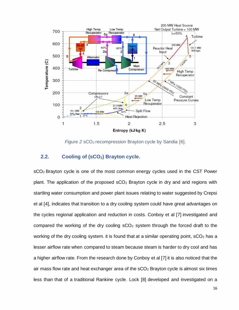
Figure 2 sCO2 recompression Brayton cycle by Sandia [6].
2.2. Cooling of (sCO2) Brayton cycle.
sCO2 Brayton cycle is one of the most common energy cycles used in the CST Power
plant. The application of the proposed sCO2 Brayton cycle in dry and arid regions with
startling water consumption and power plant issues relating to water suggested by Crepsi
et al [4], indicates that transition to a dry cooling system could have great advantages on
the cycles regional application and reduction in costs. Conboy et al [7] investigated and
compared the working of the dry cooling sCO2 system through the forced draft to the
working of the dry cooling system. it is found that at a similar operating point, sCO2 has a
lesser airflow rate when compared to steam because steam is harder to dry cool and has
a higher airflow rate. From the research done by Conboy et al [7] it is also noticed that the
air mass flow rate and heat exchanger area of the sCO2 Brayton cycle is almost six times
less than that of a traditional Rankine cycle. Lock [8] developed and investigated on a

17
heat exchanger model for direct dry cooling of sCO2. The study illustrates the relevance
of analyzing sCO2 properties near the critical point and discusses this further by splitting
the structure of the heat exchanger into cells. Using an optimized 1D NDDCT model, it is
emphasized that the required heat exchanger area is stated to be 27% greater for generic
fluid heat transfer correlations compared to sCO2 specific correlations.
Figure 3 sCO2 recompression Brayton cycle thermal efficiency and the split ratio [9].
2.3. Air-cooled heat exchanger
The heat exchanger used in the thesis is suggested by Hudson [10], it is an arrangement
of finned tubes, side frames, headers, and tube support. It is a system used for directly
discharging heat from a fluid to ambient air. The air-cooled heat exchanger bundles carry
the hot working fluid through them and the finned tubes inside the HE bundles have
expanded the surface area for the natural convection to occur. The ambient air is cooled
and flows into the tower and lowers the working fluid’s temperature. The size of the air-
cooled heat exchanger can be as small as the size of a car radiator or it might be up to
50m long, normally each bundle consists of many rows and columns of tubes. The flow

18
path in a bundle may also be calculated based on the specified number of rows and
columns.
Figure 4 Air-cooled heat exchanger bundle arrangement [11]
As stated by Kroger [1] the design of the bundle is significant because it takes into account
the transport requirements and its arrangement in the tower. He also outlines different
sizes and configurations for heat exchanger appear to have different sensitivities to
ambient conditions and maintenance needs while operating. Kroger [1] also stated a few
of the materials that can be used for ACHE’s. Due to its thermal conductivity, aluminum
is suggested as the best choice for fins and mild steel is sometimes used in heat
exchangers due to its low cost and ease of processing.
2.4. Natural Draft Dry Cooling Tower
The natural draft dry cooling tower is a very important device in CST power plants, which
conducts heat transfer through ACHE’s and helps in rejecting waste heat from the working
fluid. According to Kroger [1], the NDDCT operates through the buoyancy effect. This
effect works by using the tower shell and horizontally arranged air-cooled heat
exchangers. The operation of the cooling tower as follows; during the thermodynamic

19
cycle, the hot working fluid from the turbine exhaust flows through the heat exchangers.
Cold ambient air flows through the finned tubes of the heat exchanger, where the transfer
of energy takes place from the working fluid to ambient air. The hot buoyant air is less
dense and rises out from the top of the tower. This kind of operation causes natural
convection current to occur continuously which is shown in figure 5. this kind of cooling
solution reduces the parasitic losses of electricity faced by a power plant with the need to
supply electricity to mechanical fans and along with this reduction in maintenance cost of
such components. Gould et al [12] points out that the tower shell serves to protect the
airflow within the tower from changes in ambient conditions such as crosswinds.
Kroger [1] emphasizes that the design and dimensions of the NDDCT are typically
determined by three factors such as;
Structure;
Performance;
economic considerations.
Furthermore, QGECE has set up a new standard in developing hybrid cooling towers
which is very innovative and easy to implement in remote areas. Its simple design and
modular construction offer a cheaper and alternative option for conventional cooling
towers. The hybrid cooling towers implemented in the UQ Gatton campus is 20m tall and
12m in diameter. it is made up of a polymer-steel framework, the modular design of the
cooling tower has reduced up to 40% of the construction cost when compared to
traditional concrete NDDCT [13] which is 20m in tall and 12m in diameter. NDDCT in this
thesis employs modular structure and made up of a polymer-steel framework [13].

20
Figure 5 design and working of NDDCT [14]
2.5. NDDCT designed for performance
Hooman [15] points out that the NDDCT’s performance is predominantly influenced by
three main characteristics to their design and operating conditions;
the tower geometry and thus loss coefficients;
the design and characteristics of air-cooled heat exchangers;
the ambient conditions (temperature, wind, pressure, rain indicated by Kroger [1]) while
operating.
Furthermore, Kroger [1] explains the key approach to design NDDCT’s for performance.
this is solved by conducting iterative calculations to satisfy both the energy balance
equation and the draft equation. Designing the cooling tower for the effect of crosswinds
is also highly considered during the performance design. As it can decrease the cooling
efficiency of the cooling tower [16]. Li et al [17] used the UQ Gatton NDDCT design to
identify and analyze the effect of change in ambient conditions through 1D and 3D
simulations, showing that crosswinds decrease the cooling efficiency of the NDDCT. Liao
et al [18] found that a low height to diameter ratio is more effective during heavy winds

21
due to its wide inlet diameter, by studying the dynamics of ambient winds to tower
geometry ratios of the indirect dry cooling tower.
Considering all these factors the NDDCT in the UQ Gatton campus employs a hyperboloid
shape which has an equal diameter at the top and base of the cooling tower. This design
provides high structural stability to the membrane and also equips maximum draft
efficiency.
2.6. Components of NDDCT
Kroger [4] illustrated the key components of an NDDCT and their related subscripts that
defines the coordinates. This is shown in figure 6 and listed in Table 1 [1]
Figure 6 NDDCT components highlighted by Kroger [1]

22
Table 1 NDDCT component and condition description by Kroger [1]
2.7. Tower foundation and supports
The foundations of the tower are integral, for the tower to transfer loads from the tower
support to the soil below. Gould [12] suggested various choices for the foundations of
cooling tower structures such as ring beam, flat ring, and individual reinforced concrete
foundation. The precast reinforced concrete structure is transported to the site and
installed as a tower foundation.
2.8. Finned tube Air-cooled Heat exchanger
The fundamental framework of the finned tube heat exchanger is a tube bundle in which
the tubes are typically mounted in a staggered or Inline pattern. The most common tube
used in FTHE is a circular tube, but the use of elliptical tubes in FTHE has become
extremely popular. Based on fin geometry, the finned tube can be split into two simple
forms i.e. transverse fins and longitudinal fins. The fins may have round, plate, and
rectangular shapes. Additionally, the fins could be added to tubes simultaneously both
inside and outside. The material used in the fins is aluminum because of its high thermal
conductivity and sometimes steel is used in the development of heat exchangers because

23
of its lower cost and ease of processing. The size of the air-cooled heat exchanger
installed in NDDCT varies from 200-2000m2 based on the size of the cooling tower and
the cost of the air-cooled heat exchanger is calculated using the equation1, outlined by
smith [19].
cost of ACHE = 156,000 * (𝐴
200)0.89
Equation 1 Calculating the cost of ACHE
Figure 7 Finned tube heat exchanger outlined by Yang et. al. [20]
Figure 8 Horizontal arrangement Heat Exchanger bundles highlighted by Kroger [1]

24
2.9. Tower shell
Cooper [39] emphasized that the structure of hyperbolic design tower shell geometry has
structurally and economically optimal design, and even Kroger [1] also supported the
economic benefits of the hyperbolic shape of tower shell, as the material used to build the
tower from reinforced concrete is minimized, but this design is not applied practically due
to its thermal performance efficiency. Shaharuddin (21) conducted a study on structural
analysis and concluded that the hyperbolic design of the tower shell with the PVC
membrane is considered to be the best tower shell design for a hybrid cooling tower
because of its cost-effectiveness and to be safe from failure under maximum loading
conditions. Kroger [1] suggests various types of tower shell geometric designs such as
convergent, divergent, and cylindrical. Among all these geometric designs, cylindrical
design is considered to be the best for reinforced concrete tower shell material because
of its cost-effectiveness and good thermal performance. Ansary et al [22] suggested the
optimal thickness of the tower shell should be 165 mm which reduces 12.8% of the mass
of the tower shell when compared to the thickness of 190mm tower shell material.
Figure 9 Various cooling tower shell Geometries highlighted by Kroger [1]
2.10. Tower shell material

25
Kroger [1] suggested multiple materials that are suitable for tower shell construction such
as wood, aluminum sheets, etc. Busch [23] and Gould [12] indicate the application of
reinforced concrete (RC) structures with compressive strength of 85 MPa in hyperbolic
tower shell design can withstand wind loads and ambient conditions that NDDCT
experience. The RECCE (Renewable Energy Conversion Centre of Excellence)
constructed a small NDDCT which uses a modular structured steel frame and PVC
membrane to build the tower shell. based on the material, labor and construction costs in
Australia, the hybrid cooling tower shell used by RECCE is considered to be the cost-
effective tower shell when compared to reinforced concrete tower shell as it uses less
labor cost and construction cost.
2.11. Construction Parameters of the existing NDDCT
The construction method of the cooling tower is illustrated by shaharuddin [21]. The
geometrical structure of the hybrid cooling tower suggested by QGECE consists of two
12m diameters 323.9 x 9.5mm grade C350 CHS structural steel ring beams spaced 15m
apart, positioned 5m above ground level. The ring beams were supported by 4 pairs of
273.1 x 6.4mm C350 CHS structural steel columns vertically. Arranged properly to ensure
optimum tower stability. A PVC membrane affixed to the bottom and top ring beams give
the cooling tower a hyperbolic shape. Mobile cranes are used to construct the cooling
tower the method of constructing the hybrid cooling tower is suggested by RECCE [24]
which does not require long set up periods of the central tower crane.

26
Figure 10 Construction of RECCE's modular design NDDCT [24]
2.12. Costing
The cost of the project is one of the primary determining factors for the execution of a
project, so the cost estimating approaches are well recorded and detailed. To evaluate
the future costs of a program, the united states Government Accountability Office (GOA)
[25] defines the cost estimation as the summation of all the individual cost elements using
proven methodology and relevant data. The methodology for cost estimation helps to
assess, which approach is more suitable to the desired results and the necessary
evidence that helps to define the cost model. NASA [26] emphasizes three appropriate
cost estimating methodologies which include,
• Analogy; identification of an actual likable system that is identical to the suggested
system and adapts to variations. Technically, the cost of one previous system should
be considered reflective of the program and then allow the cost data to be scaled.
• Parametric; uses the statistical frameworks in which important pieces of information
are understood from different variables. This methodology used regression and is
applied to the architectural analysis.

27
• Engineering Build-Up; Cost estimation by describing each factor and each operation
using a work breakdown structure.it is often used in a commercial context to generate
forecasts and added to negotiations.
2.13. Costing of Natural draft dry cooling tower
The importance of high capital costs of NDDCT’s from increased HE and Decreased
efficiencies in the presence of high ambient temperatures contribute to the investigation
to Optimize previous costs. Due to the extreme environmental impacts of wet cooling
systems in power plants, The Battelle, Pacific Northwest Laboratory, initiated by the
energy research and development administration, undertook the development of dry
cooling as an alternative option and provided findings in their document, costs, and cost
algorithms for dry cooling tower. [21 [27]. Ard [27] outlined the cost algorithms based on
the dry cooling tower design, manufacturing methods, and component costs of the
currently available dry cooling system. the analysis further clarifies that there is no such
thing as the perfect cost for any design or construction. Conradie [28] researched on cost
and performance optimization of dry cooling systems using SQP methods and
emphasized the use of capital cost and operating cost estimation procedures. The cost
estimation techniques presented by Conradie [28] incorporates cost-efficient, variables,
factors, and coefficients that are illustrated, and outlines the equation for construction cost
for NDDCT. The equation, however, lacks information on the cost of labor and equipment
costs during the construction of the tower shell. Recently, Zou et. al. [29] investigated the
structural design optimization of SENDDCT’s using elements of Conradie’s proposed cost
model. He also combines the maintenance and operational costs to illustrate the
advantages of SENDDCT’s over the lifetime period and shows the payback period.

28
3. Boundary conditions
The thesis lays out the boundary conditions for the operation of NDDCT and to analyze
the application of NDDCT. Few of the boundaries are set up to investigate and examine
the NDDCT application in real-world such as;
What potential can be reached by CST power plants?
The operational conditions of the sCO2 Brayton cycle proposed are then illustrated to
show the Operational constraints for NDDCT’s.
3.1. Concentrated solar power plant design points
The 25MWe solar thermal power plant set up by ASTRI [30] is assumed to have 4 hours
of thermal storage and can produce 90GWh of electricity every year which could power
around 12000 houses. As outlined by Giovannelli [31] it is also assumed to have high
potential in the application of Concentrated solar power to small-scale projects, such as
rural off-grid sites and the industrial sectors. The design points to be examined in this
thesis from the highlighted applications of CSP are 10MWe, 25MWe, 50MWe, and
100MWe.
3.2. Design conditions
Ambient conditions have an important effect on the performance of NDDCT’s. Research
performed by RECCE at the University of Queensland’ Gatton campus aims to improve
and illustrate the use of innovative research. This site provides excellent prospects for
NDDCT’s to expand in the future. As highlighted by historical data from Climate-Data.org
[32], the highest average annual temperature in Gatton is 24.9oC. As outlined in 61
29
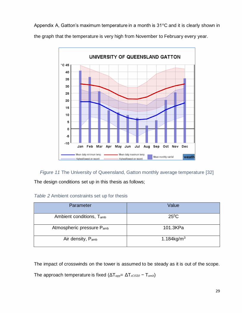
Appendix A, Gatton’s maximum temperature in a month is 31oC and it is clearly shown in
the graph that the temperature is very high from November to February every year.
Figure 11 The University of Queensland, Gatton monthly average temperature [32]
The design conditions set up in this thesis as follows;
Table 2 Ambient constraints set up for thesis
Parameter Value
Ambient conditions, Tamb 250C
Atmospheric pressure Pamb 101.3KPa
Air density, Pamb 1.184kg/m3
The impact of crosswinds on the tower is assumed to be steady as it is out of the scope.
The approach temperature is fixed (ΔT𝑎𝑝𝑝= ΔT𝑠𝐶𝑂2𝑂 − T𝑎𝑚𝑏)

30
3.3. sCO2 Brayton recompression cycle
The development of the sCO2 Brayton cycle is still underway to achieve its scalable
construction and deployment in power plants. operating conditions, scalability, and
development for vital processes at the critical point are all at SwRI’s focal point to further
commercialize the promising technology [33]. Developing a new cycle is out of scope in
this thesis. The sCO2 recompression Brayton cycle outline by lock [8] and accepted by
RECCE is used in the thesis. The modeled cycle used in this thesis is to demonstrate the
operational conditions and cycle efficiency for the NDDCT performance model.
Figure 12 Schematic representation of sCO2 Recompression Brayton cycle outlined by Lock [8]
The sCO2 cycle is modeled under the following conditions;
➢ It has constant turbomachinery and isentropic machinery for all scalable cycle
capacities,
➢ Pressure drop through the cooling tower is fixed [8]
Fixed constraints for the cycle are outlined below, split ratio (SR) of the cycle is
identified to be 0.65, and design thermal efficiency (𝜂𝑡ℎ) of the cycle is 0.488. This

31
means that just 65% of the mass flow rate for the cycle is used to achieve the optimal
net power output of the power cycle that passes through the NDDCT to remove heat
from the cycle. However, the split ratio can be modified to achieve maximum efficiency
under varying conditions.
Table 3 Operating parameters of sCO2 recompression Brayton cycle outlined by Lock [8]
3.4. NDDCT Conditions from the cycle
The operating conditions of the sCO2 Brayton cycle for the cooling tower is outlined by
Lock [8] and is used in this thesis.
Table 4 sCO2 recompression Brayton Cycle parameters for NDDCT outlined by Lock (8)
Parameter Value
NDDCT inlet temperature 87.3oC
NDDCT outlet temperature 35OC
Split ratio 0.65
Design Thermal Efficiency 0.488

32
The boundary conditions for the performance criteria of the NDDCT summarized in this
thesis are by adding the sCO2 recompression Brayton cycle Parameters to the CST power
plant design points.
Table 5 Design Point Parameters of NDDCT outlined by Lock [8]
3.5. Summary
The performance specifications for the NDDCT’s analyzed in this thesis are produced by
the implementation of the sCO2 recompression Brayton cycle from the literature to the
applicable CST power plants. the design points and design parameters are used to
optimize the cooling tower design and improve the performance of the cooling tower

33
4. Design for performance
This part of the thesis illustrates the performance of NDDCT based on their design
characteristics and boundary conditions. This emphasizes the performance of NDDCT
based on different aspect ratios and constrained parameters.
4.1. Constraints
The geometric design influences the performance of the NDDCT. It depends on the
NDDCT aspect ratio and few other design ratio characteristics. Constraints for the design
of NDDCT are indicated below.
Table 6 NDDCT fixed geometric ratios and parameters highlighted by Kroger [1]
4.2. Draft equation
The draft equation developed by Kroger [1] compares the flow of air using a natural draft
through the tower to the resistance that air experiences throughout the tower. The draft
equation is illustrated in equation 2 and equation 3. The flow resistance is shown in figure

34
13. the loss coefficients and its equations to calculate the tower’s geometry are shown in
table 7.
Natural draft force of tower = ∑𝑓𝑙𝑜𝑤 𝑟𝑒𝑠𝑖𝑠𝑡𝑎𝑛𝑐𝑒 (𝑡𝑜𝑤𝑒𝑟+ℎ𝑒𝑎𝑡 𝑒𝑥𝑐ℎ𝑎𝑛𝑔𝑒𝑟) = (𝜌𝑎𝑜−𝜌𝑎𝑖) x
𝑔𝐻
Equation 2 Draft equation for NDDCT [1]
Equation 3 Draft equation for Horizontal arrangement of Heat exchanger in NDDCT by
Kroger [1]
Figure 13 Flow resistances in NDDCT highlighted by Kroger [1]

35
Kroger [1] and Conradie [28] found that the requirements to satisfy both the energy
balance equation and the draft equation to evaluate and improve the overall performance
of the cooling tower. The energy balance equation outlined by Kroger [1] expresses the
heat transfer characteristics of the air-cooled heat exchangers.
𝑄=𝑚𝑎𝑐𝑝𝑎(𝑇𝑎4−𝑇𝑎3) = 𝑚𝑠𝐶𝑂2(ℎ𝑠𝐶𝑂2𝑖−ℎ𝑠𝐶𝑂2𝑜)
Equation 4 Energy Balance [1]
Table 7 loss coefficients and its equations [1]
4.3. Detailed Directly cooled HE mathematical model for sCO2 in 1D
NDDCT
The heat exchanger model suggested by Lopata [34] and lock [8] is used in this thesis to
calculate the heat transfer process of the Heat exchanger. The inlet diameter of NDDCT

36
is modified and sized for given operational conditions. The 1D NDDCT model uses the
loss Coefficient equation suggested by Kroger [1] and the Heat exchanger model
suggested by Lopata [34] and Lock [8] is used to solve through an iterative process. This
model solves the energy balance equation and draft equation simultaneously across the
C02 continuity, C02 momentum, discretized heat exchanger, and the boundary conditions.
sCO2 properties are obtained from the CoolProp Package in the python model developed
by Lock [8]. An iterative flow chart highlighted by Lock [8] for the incorporation of the 1D
NDDCT model and Heat exchanger model to solve for the NDDCT’s design for
performance requirements is used in the thesis.
Figure 14 Iterative model to find best FTHE [8]

37
To find the best cost-effective heat exchanger, the objective of the research must be
divided into several sub-tasks.
• Task 1 – calculate the airside performance of the finned tube heat exchangers in terms
of heat transfer and pressure drop on the heat exchanger.
• Task 2 - Find the conductive heat transfer in the tube wall
• Task 3 – identify the thermal performance of sCO2 on the tube side
• Task 4 – generating the overall heat transfer coefficient.
4.4. Performance of Finned elliptical tube heat exchanger
The finned elliptical tube heat exchanger (FETHE) has been used as an alternative to the
finned circular tube heat exchanger (FCTHE). The cost-effectiveness of the finned tube
heat exchangers has been evaluated by comparing a few of the parameters such as the
airside performance, heat transfer rate, and pressure drop. The finned circular tube heat
exchanger is very popular in past decades as they were considering more on the overall
heat transfer coefficient. In this thesis, the potentiality of FETHE in NDDCT is identified
and evaluated by considering a few of the parameters such as thermal analysis, overall
heat transfer coefficient, and pressure drop. Lopata et al [34] conducted a study on overall
heat transfer of FCTHE and FETHE at airflow rate from 1m/s to 5m/s and identified that
at 1m/s speed the overall FETHE heat transfer coefficient counts for 82% of the FCTHE.
Whereas at 5m/s the ratio of FETHE to FCTHE decreases about 79% at 5m/s. Lopata et
al [34] emphasized that, for the sCO2 working fluid the heat exchanger coefficient for
FCTHE is 3184 W/m2K whereas for FETHE is 5787 W/m2K. But Khan et al [35] outlined
that the thermal performance of FETHE is not as good as FCTHE. But in this thesis, the
FETHE is used in the cooling tower which uses the sCO2 Brayton cycle and the working

38
fluid is sCO2 which has a constant mass flow rate and also has a fixed temperature drop.
In the NDDCT the amount of heat energy needed to be extracted from the finned tube
bundle is fixed. From the equation Q = UAΔT for the fixed heat transfer rate, the overall
heat transfer coefficient is inversely proportional to the heat exchanger’s surface area.
From this analysis, it is outlined that, for the FETHE geometry design, the total surface
area of the heat exchanger is proportional to its size, length of the heat exchanger, and
column number. If FTHE has a high overall heat transfer coefficient then FTHE with a
small size can fulfill the requirements of NDDCT. From the analysis done by Lopata et al
[34] it is clearly defined that the overall heat transfer coefficient of FETHE is lower than
FCTHE. So, to deliver a similar amount of heat transfer, the size of FETHE must be larger
than FCTHE.
So, in practice, the construction of NDDCT with FETHE has a fundamental system that
will require a large land area and less construction material. This leads to a reduction in
construction fees. From this analysis, we can conclude that implementing FETHE we can
construct a cost-effective cooling tower.
Lopata et al. [34] conducted a study on the analysis of the pressure drop for FETHE and
FCTHE for the airflow rate of 1 m/s to 5 m/s. the FETHE has a lower pressure drop rate
at high inlet air-speed. As shown in figure 16, the FETHE pressure drop for 1m/s air flow
rate is 13.18 Pa and for 5m/s is 106.39 Pa whereas for FCTHE the pressure drop for 1m/s
is 20.69 Pa and for 5m/s is 146.81 Pa. so from this analysis it is observed that FETHE
has relatively increased in pressure drop when compared to FCTHE. Because of the
slender tube shape in FETHE, air passes smoothly in the tube bundle this makes the
FETHE have a lower pressure drop than FCTHE.

39
Figure 15 CFD model of FETHE by Min et. al. [36]
Figure 16 Pressure drop v/s Frontal velocity
As the airflow is very smooth in FETHE at any air-speed, a less powerful fan is sufficient
and can consume less energy for the fan which reduces the overall operational cost of
the NDDCT. From the analysis done by Lopata et al. [34] on U/ΔP of FETHE and FCTHE

40
to identify the cost-effective FTHE. The FETHE’s U/ΔP is highest at all times by having a
ratio of 343% when compared to FCTHE. From this analysis, it is clear that FETHE is
cost-effective than FCTHE. It is also outlined that FETHE can reduce the cost up to 23.1%
when compared with FCTHE, and the perfect installation of FETHE in the NDDCT can
increase the efficiency by 20%.[34]
Figure 17 airflow in FETHE [35]
Figure 18 U/ΔP v/s frontal velocity
4.5. Performance of wetted media
NDDCT implemented in the UQ Gatton Campus faces performance issues due to the
ambient conditions because the temperature in Gatton from November to February has
41
an average temperature of 30oC. as discussed above the ambient temperature designed
for this thesis is 25oC to have better performance. To maintain this temperature and
constant performance levels, wetted media is installed. As NDDCT has no parasitic loss
and low maintenance and no water consumption but the adversity of this tower is; it is not
as effective as wet cooling towers in disposing of waste heat. Since NDDCT uses the
convective heat transfer method to reject heat from the working fluid. Its performance
drastically reduces when the ambient temperature is high which also reduces the
efficiency of CST power plants. based on the literature conducted by Li [11] the cooling
performance of NDDCT with less than 30m height is more sensitive to ambient conditions
to overcome all these issues suitable wetted media is installed to the heat exchangers to
maintain the constant ambient conditions. from the Framework outlined by Suohing [37]
for selecting the suitable wetted media. Among all the wetted media available for use in
the small and medium-size cooling tower. Cellulose 7060 is the best-wetted media
because of its high cooling efficiency high operation air-speed with low drift, lower
pressure drops, and long life.

42
Figure 19 the framework for the selection of wetted media [37]
Table 8 Cellulose 7060 wetted media details [37]
Parameters details
Standard thickness 0.1 m, 0.15m, 0.2m, and 0.3m Channel structure Cross-flow
Material Cellulose paper
Life span More than 10yrs under proper maintenance
Manufacturer Munters Corp, Kista, Sweden

43
Table 9 shows the pressure drop and cooling efficiency of cellulose 7060 on hybrid cooling
towers for the height 150m and tower heat rejection rate of 92.3MW at an ambient
temperature of 50oC.
Table 9 Cellulose 7060 design specifications [37]
parameters Value
Pressure drop, Pa/m 28.6 – 272.1
Pressure drop, Pa 4.2- 61.2
Cooling Efficiency % 44.7 – 88.5
The NDDCT used in the thesis has a tower height of 20m and a heat rejection rate of 1
MWth and operated in the ambient condition of 31oC. Cellulose 7060 is the best suitable
wetted medium for the NDDCT. Another great advantage is that cellulose 7060 is a
removable wetted media and the temperature in Gatton is high only from November to
January. It is best to install the wetted media only in these times and remove it when it is
not necessary. Following this method and doing proper maintenance, wetted media can
last for more than 15years [38]
Figure 20 Benefit efficiency of wetted media at (a) l=0.15m, RH=30% (b) l=0.30m, RH=20% [38]

44
Figure 21 The Heat rejection rate of three cooling towers by He [38]
The heat transfer rate in pre-cooled NDDCT is higher than normal NDDCT. For the
NDDCT proposed in this thesis, cellulose 7060 wetted media with thickness 0.15m is the
best choice, and installing the wetted medium during these months can have a 46%
improvement in electric energy production [37]. Though the wetted medium consumes
some amount of water which is around 47.75t/year for 1 MW heat rejection. However,
concerning the water consumption levels of the wetted medium, the overall consumption
of water could be easily mitigated since the recommended usage period is during the
summer (November, December, and January) when there is an abundant seasonal
shower. By installing the wetted medium during the recommended period, the availability
of water through summer showers can be utilized to the fullest and also not result in
overconsumption or depletion of water resources.

45
4.6. Summary
The inlet diameter of the tower is optimized using the 1D NDDCT framework. This
diameter is used to optimize the rest of the tower’s geometry. The design optimization
improves the overall performance of the cooling tower and it can be used for costing
methods to reduce the capital cost of the NDDCT.
The finned elliptical tube heat exchanger used in the thesis is the best choice of the heat
exchanger to be implemented in the NDDCT to increase the performance of the tower.
As this FETHE uses more land and less construction cost it is best for small NDDCT like
UQ Gatton NDDCT to have better performance and it is highly cost-effective. From the
research conducted by Yuanshen [14] it is identified that the effect of wind loads and
crosswinds is high when the tower height is more. Yang et al. [20] suggested to decrease
the height of the cooling tower and increase the diameter in small NDDCT to overcome
the effect of wind loads and crosswinds. Constructing the cooling tower structure
suggested by yang requires more land and fewer construction costs. This also helps to
install FETHE, as the arrangement of heat exchangers in the NDDCT is horizontal so it
can be placed inside the tower with proper support and allowance. This design structure
overcomes the effect of crosswinds and increases the performance of the heat exchanger.
Besides this, it also increases the overall performance of the NDDCT and the efficiency
of the CST power plant.
The design of NDDCT used in the thesis is installed on the UQ Gatton campus where the
average temperature is around 30oC from November to January. As mentioned in section
4.5 the high ambient temperature reduces the heat rejection rate of the cooling tower so
installing the wetted medium i.e. cellulose 7060 of thickness 0.15m during the peak hot

46
months can increase the heat rejection rate and improve the overall performance of the
cooling tower.
Installation of FETHE, Cellulose 7060 wetted media, and changing the design structure
of the cooling tower i.e. by decreasing the aspect ratio can improve the performance of
the cooling tower and reduce the capital cost of the cooling tower. Overall, this
performance design improves the cost-effectiveness of the cooling tower.

47
5. Structure design
This part of the thesis illustrates the structural design of the NDDCT. It describes the cost-
effective materials to be used in NDDCT to optimize the capital cost of NDDCT. Literature
detailing the effective structural design of NDDCT’s in the past is used to provide a
suitable method for performance designs. The structure design is analyzed and priced.
5.1. Constraints
The NDDCT structural design is an extremely systematic method that takes all the
variables into account. Based on literature conducted on NDDCT, four of the major
components are considered that demonstrates the successful structural design which
contributes to its performance and cost
➢ Ground and foundation
➢ Tower support
➢ Tower shell, and
➢ Heat exchangers
Other materials are not considered as they are out of the scope of this thesis because
they lack supportive literature on their structural design, performance, and cost
5.2. Land and foundation
The land and foundations are intended to withstand the weight and pressure of the tower.
To withstand the heavy hyperbolic designed NDDCT, the ground conditions should be
considered. Based on the ground conditions further work should be carried out. Conradie
[28] developed an equation to find the area of the foundation that must be considered for
usage of land and excavation works.

48
Abase = 0.25π(d3 + 2H3/tanϕbase)2
Equation 5 The cost of land, Excavation, and foundation
Inlet height and diameter of the structural design of NDDCT is applied to determine the
base area needed for NDDCT. The area of the base is then used in the cost model to
calculate the cost of the ground, excavation, and foundation.
5.3. Tower supports
The tower support used in this thesis is indicated by shaharuddin [21]. This tower support
is made of modular steel frame structure attached with Meher PVC membrane; the fixed
angle of the tower base (ϕb) is 700
Lts = 𝐻3
𝑠𝑖𝑛(𝜙𝑏)
Equation 6 The length of the tower support
According to Shaharuddin [21] the number of tower supports varies depending on the
ratio to inlet diameter (nts/d3) of 0.724 for structural stability with modifications in the
NDDCT structure design. These relationships are believed to have adequate structural
stability for all AR designs to be implemented. The number of tower supports that need to
be used is calculated based on the inlet diameter and it is rounded up to the next whole
number [28].
5.4. Heat exchanger
The Heat exchanger used in this thesis is a finned elliptical tube heat exchanger. The
design incorporated in this thesis has met all the industry standards to provide end-users
with specific cost indicators. The specifications provided by Lock [8], and Lopata [34] is
presented in table 10. To keep the parameter constrained, the heat exchanger design is

49
kept constant for all tower ratings. This is one of the limitations to the thesis as the heat
exchanger should be designed ideally for each NDDCT design based on indicated air inlet
velocities.
Table 10 Heat Exchanger Design Specifications [8] [34]
The derived NDDCT performance designs use the face area (Af r) of heat exchangers to
determine the scale of the cooling infrastructure. The HE costs are obtained by calculating
the design number of bundles. i.e. by finding the number of HE columns required to meet

50
the mass flow rate requirements. The structure and arrangement of HE bundles are
believed to be reasonable to the area coverage of HE’s available with each design
specifications. The limitation of the HE Model design is, the process is a highly detailed
process for each NDDCT design and does not provide a substantial contribution to the
thesis.
5.5. Tower shell
The tower shell used in this thesis is chosen from QGECE hybrid cooling tower design
which is made of steel supports and PVC membrane as a tower shell material. The
modular design of the cooling tower outlined by shaharuddin [21] is the cost optimal choice
of the tower shell. Though, the hyperbolic design of the cooling tower made of reinforced
concrete outlined by Kroger, Gould, and cooper [1], [12], [39] is the cost-effective tower
shell design and offers acceptable thermal efficiency results. But the construction cost of
reinforced concrete tower shell is expensive in Australia due to high labor cost. So, to
achieve structural needs, improve the performance, and decrease the capital cost of the
cooling tower, the QGECE [24] suggested tower shell design is used in the thesis.
5.6. Material selection
The preference of modular steel frame tower with the PVC membrane suggested by
QGECE and used by RECCE [24] as the tower shell materials is acceptable as a practical
and feasible material for the construction of NDDCT in most places. This is considered to
be a suitable and cost-effective option that can be used in this thesis. Considering the
tower shell material costs and labor costs in Australia, the modular design tower shell
made of Mehler PVC Membrane [42] and steel supports contributes to 40% reduction in
costs when compared to traditional cooling towers made of reinforced concrete.

51
5.7. Geometry and volume
As indicated by Conradie [28] the tower shell volume can be measured by approximating
the means of two conical frustrum's. The lower hyperbola is determined by equation 7
where Ht – H3 = 0.75(H5-H3) and the upper hyperbola is determined by equation 8 where
H5 – Ht = 0.25(H5-H3) with rt=r5/1.05 this is shown in figure 5. the total volume of the tower
shell material is VTS = VTSLH + VTSUH. The structure of the tower used in this thesis is
outlined by shaharuddin [21], the Modular design cooling tower consists of two 12.525m
diameter 323.9 X 9.5mm grade C350 structural steel rings placed 15m apart. And located
5m above the ground level. The ring beams are supported vertically with 4 pairs of 273.1
X 6.4mm C350 structural steel columns, arranged to maintain tower stability. The PVC
membrane attached to the bottom and top of the ring gives the hyperbolic shape to the
tower.
Equation 7 The Tower shell material volume of Lower Hyperbola
Figure 22 NDDCT Parameters highlighted by Busch [23]

52
Equation 8 The Tower shell material volume of Upper Hyperbola.
5.8. Summary
The tangible elements used to create the NDDCT structure is defined and explained in
this thesis. Their calculating method concerning performance design is described. To
represent the NDDCT cost, their respective design dimensions are applied to the cost
model.

53
6. Capital cost model
The cost model used to calculate the capital cost value of the NDDCT is illustrated in this
part of the thesis. Contexts on capital costs and thesis constraints are addressed and cost
methodologies are defined because the need for cost estimation is significant in the
lifecycle of a project.
6.1. Capitalized costs
The capital cost can be viewed as the total one-off expenses that can be correlated with
a project. This expense can involve anything that can be specifically related to bringing
the project to its final operating form. The expenses from an accounting point of view tend
to reflect that the expenditures can be connected to form an asset on the balance sheet
of an organization that tends to reflect the financial status of an organization. Capital costs
may vary internationally based on the kinds of expenses that need to be included. The
permissible costs that can be included as part of the law are described by the Queensland
treasury [40]. Few of the expenditures provided by the Queensland treasury include;
1. Site preparation cost;
2. Raw material and equipment cost;
3. Assembly and installation cost;
4. handling and initial delivery costs;
5. associated professional fees
6. functionality testing
in this thesis, the capital cost of the NDDCT is optimized considering the maintenance
and operational costs are decreased comparatively. As a result, the capital cost is a good

54
indication to stakeholders of the potential Levelized cost of electricity of the plant that
functions as a part of the project
6.2. Costing constraints
Since each NDDCT is unique in its design decisions on area, scale, and availability of
some resources, certain costs in this model have been excluded to minimize confusion
with end-users. The costing constraints enable the fundamental elements of NDDCT’s to
indicate their design costs based on their geometry.
Table 11 Scope of Capital cost model
In Scope Out of Scope
• cost of land, excavation and
foundation
• Cost of raw materials
• Cost of tower shell material
• Cost of heat exchanger materials
• Cost of indirect costs
• Cost of delivery and handling of
raw materials
• Cost of equipment testing
• Cost of motor for pumps
• Maintenance and operation costs
The cost model is constrained from the information that is available to form cost
coefficients, factors, and weightings. This is obtained from the literature and adjustments
are done based on relevant time and currencies. Data is designed to reflect in Australian
dollars.
6.3. Costing methods

55
The cost estimation uses a mixture of basic cost estimation algorithms that have been
generated and perfected through literature and along with equations built through
estimating methodologies in this thesis to represent the improvement in tower geometry
for this thesis.
6.4. The literature on Cost estimation equations
The equation used to estimate the cost of NDCCT’s components in this thesis is utilized
from literature developed by Conradie [28]. Cost coefficients and values are updated to
represent present relevant costs. Cost coefficients used in the Conradie’s [28] literature
is updated for currency conversion and inflation. An average currency conversion rate in
1997 is 1 USD = 1.348 AUD obtained from OFX [41]. Though the cost coefficient used is
more than two decades old, the values are updated to represent their present value.
𝐹𝑢𝑡𝑢𝑟𝑒 𝑉𝑎𝑙𝑢𝑒=𝑃𝑟𝑒𝑠𝑒𝑛𝑡 𝑉𝑎𝑙𝑢𝑒 (1+𝑖)n
Equation 9 future value
where i (interest rate) = 2.45%, n (number of times interest rate is compounded) = 23.
The use of variables and weightings are illustrated on execution.
6.4.1. Analogy method of cost estimation
This method is used specifically to develop a cost estimation for construction equipment
and labor costs. The information available publicly has been used to evaluate and then
generalize the information to form cost coefficients that can be adjusted based on the
NDDCT’s design modifications.

56
6.4.2. Engineering Build-UP Method of Cost estimation
This method is used mainly to develop a cost estimation of complex structures using a
work break down structure. In this thesis this method is used in the cost estimation of land
excavation and foundation costs and indirect costs. The information obtained through
literature is used in a commercial context to generate forecasts and find optimal solution.
6.4.3. Land excavation and foundation costs
The land, excavation, and foundation costs are calculated using equation 10 outlined by
Conradie [28]
𝐶𝐿𝐸𝐹=𝐶𝑢𝐿𝐸𝐹𝐴𝑏𝑎𝑠𝑒
Equation 10 cost of land excavation and foundations
This value is applied to current cost conditions with comparison to Engineering Build-up
methods. The cost estimation for excavations is obtained from service seeking [ 43], the
cost of land in Gatton is obtained from Domain [ 44], the cost of foundations is obtained
from Eureka concrete [45], labor and equipment costs are associated with land excavation
and foundation costs.
The cost of land excavation and foundation obtained by using the analogy method and
the Engineering Build-up method is (CuLEF) = $153.78/m.
6.4.4. Tower supports
The cost of tower support is calculated using equation 11 outlined by Conradie [28]
𝐶𝑡𝑠=𝐶𝑢𝑡𝑠𝐿𝑡𝑠𝑑𝑡𝑠𝑛𝑡𝑠
Equation 11 cost of tower supports

57
The cost coefficients represent the labor costs and equipment costs associated with the
tower support. The cost of tower support obtained using the equation and the analogy
method is $360.89/m3
6.4.5. Heat exchanger cost
The heat exchanger used to construct NDDCT is a Finned elliptical tube air-cooled heat
exchanger. The cost of ACHE is calculated using equation 12 [19].
cost of ACHE = 156,000 * (𝐴
200)0.89
Equation 12 Cost of ACHE
The total cost of the heat exchanger contributed to NDDCT is calculated using equation
13,
𝐶𝐻𝐸=𝑛𝑏𝐶𝐻𝐸 𝐵𝑢𝑛𝑑𝑙𝑒+𝐶ℎ𝑒𝑝𝑙
Equation 13 Total cost of the heat exchanger
6.4.6. Heat exchanger bundle cost
The cost of HE bundles is calculated using the equation outlined by Conradie [28]. It
includes the cost of finned tubes, cost of headers, labor costs, total HE bundles costs,
cost of HE platforms, the equations for each of them is defined separately and calculated
using the analogy method.
The cost of an aluminum fin is calculated using equation 14 outlined by Conradie [28]
Equation 14 cost of aluminum fin

58
The cost of steel HE tube is calculated using equation 15 highlighted by Conradie [28]
Equation 15 Cost of steel tube
The total cost of finned tubes in a bundle is calculated using equation 16 defined by
Conradie [28]
Equation 16 total cost of finned tubes in a bundle
The weighting factor for the NDDCT finned tubes is Wf t = 1.2 as indicated by Conradie
[28]
The cost of the header is calculated using equation 17 outlined by Zou [29] and the
weighting factor for the header, Wheader = 0.2
Equation 17 Cost of heat exchanger headers
The cost of labor to design HE is calculated using equation 18 presented by Zou[29]
where the weighting factor for the Labor, Wlabor = 1.2
Equation 18 cost of the labor for designing HE
The equation to find the total heat exchanger cost is defined by Conradie [28], the
weighting factor for the HE Bundle installation cost indicated by Conradie [28] is Whe = 1.2
Equation 19 Total cost of heat exchanger per bundle.
59
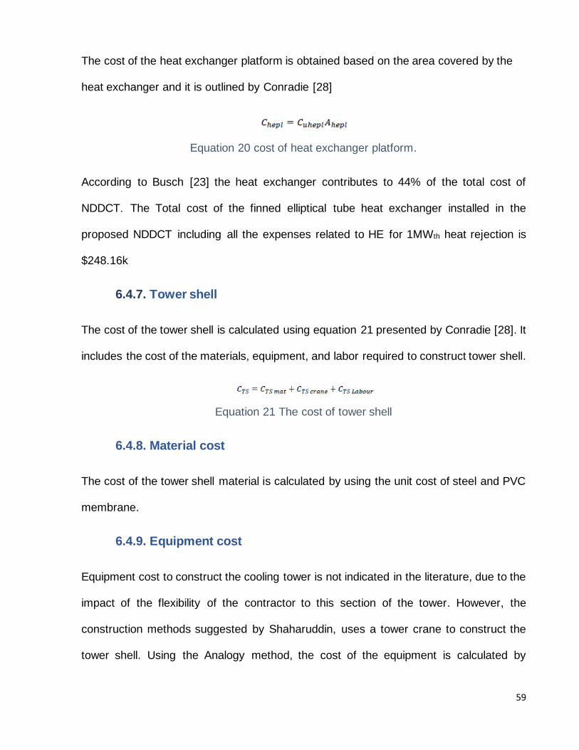
The cost of the heat exchanger platform is obtained based on the area covered by the
heat exchanger and it is outlined by Conradie [28]
Equation 20 cost of heat exchanger platform.
According to Busch [23] the heat exchanger contributes to 44% of the total cost of
NDDCT. The Total cost of the finned elliptical tube heat exchanger installed in the
proposed NDDCT including all the expenses related to HE for 1MWth heat rejection is
$248.16k
6.4.7. Tower shell
The cost of the tower shell is calculated using equation 21 presented by Conradie [28]. It
includes the cost of the materials, equipment, and labor required to construct tower shell.
Equation 21 The cost of tower shell
6.4.8. Material cost
The cost of the tower shell material is calculated by using the unit cost of steel and PVC
membrane.
6.4.9. Equipment cost
Equipment cost to construct the cooling tower is not indicated in the literature, due to the
impact of the flexibility of the contractor to this section of the tower. However, the
construction methods suggested by Shaharuddin, uses a tower crane to construct the
tower shell. Using the Analogy method, the cost of the equipment is calculated by

60
considering the data obtained in iSeekPlant [46], the cost of the tower crane determined
as the function of height is calculated using equation 22.
Equation 22 the cost of tower crane for tower shell construction
6.4.10. Labor costs
The construction of an RC tower shell requires a large amount of labor, there is no proper
equation available in the literature to calculate the labor cost, but the analogy cost
estimation method can be used to measure the cost of labor, the equation indicated by
Dion [47] in the construction of Brayton point’s NDWCT is used in the thesis to calculate
the labor cost. The labor cost depends on the length of the construction period, and the
number of laborers.
Equation 23 the cost of labor
The Unit cost of labor to construct tower shell is $936.13/m3.
According to Busch [23] The tower shell contributes 21% of the total cost of NDDCT, the
total cost of the tower shell for the proposed NDDCT is $126k
6.4.11. Total construction cost
The total cost for the construction of NDDCT is calculated using equation 24.
Equation 24 the cost of NDDCT construction
6.4.12. Indirect costs

61
Indirect costs are very common in any project and can differ dramatically based on the
organization and stakeholders involved, though it is difficult to indicate these costs. But
from data provided in the literature few of the important indirect costs for large construction
projects include overhead costs, profit margin, and engineering services. According to
Busch [23] the indirect costs of the cooling tower is given as profit margin (7%), overhead
costs (10%), and engineering services (14%)
The cost of engineering services is calculated using equation 25 as the cost factor for
engineering
Equation 25 the cost of engineering
The cost of overheads is calculated using equation 26 as the cost factor of overhead
Equation 26 the cost for overheads
The profit margins for costs is calculated using equation 27 as the cost factor for profit
Equation 27 the cost for profit margin
According to Busch [23] the indirect costs contribute to 31% of the total cost of NDDCT.
The total indirect costs for the proposed NDDCT is $186k.
6.4.13. Costing summary
The capital cost for the construction of the proposed NDDCT in this thesis can be defined
by the cost model that includes all the expenses.

62
From the data obtained in the literature presented by Busch [23] and the conradie’s [28]
and Zou's [29] cost calculation methods. The total cost used for the construction of the
proposed NDDCT is $573k.

63
7. Results and discussion
This part of the thesis shows the result of the cost-effective NDDCT that has been
designed with performance and structure. The cost model is developed and compared to
know the cooling tower costs. Results are presented concerning optimal geometry for
adjusted performance and design characteristics of NDDCT. The critical evaluation and
discussion of these results emphasize their importance to potential sCO2 NDDCTs.
7.1. Cost model comparison
The design of an NDDCT strongly determines its cost because of its unique performance
criteria. So, each NDDCTs have various requirements that render the comparison
extremely complicated due to changing variables. Using proven geometries and heat
rejection values of the NDDCTs present in Table 12. designs are implemented based on
the methods in the thesis to classify comparative costs.
Table 12 cost comparison of existing cooling tower’s actual, modeled and function derived costs
Parameters Gatton NDDCT China cooling tower
Aspect ratio, H5/d3 1.53 1.14
Outlet height, H5 20m 205m
Inlet diameter, d3 12.525m 180m
Heat rejection, Qout 1MWth 740MWth
Actual cost value $0.6M $67.5M
Modelled cost value $0.573M $130.2M
Percentage of cost model value
110% 52%

64
From the actual costs provided by Hooman [48] on the Gatton NDDCT the modeled cost
value obtained from the cost model used in this thesis is 0.027M less. This shows that the
relevance of the cost model used in this thesis is valid. The cost difference is largely due
to the installation of FETHE instead of FCTHE. Another reason for the cost difference is
the tower shell. In this thesis modular steel frame structure and Meher PVC membrane is
used as tower shell material which uses less labor and less construction cost. The change
in finned tube structure in the heat exchanger and the tower shell physical structure has
created an effective method of cost optimization and increased performance.
7.2. Component cost analysis
Figure 23 Optimal Cost breakdown of sCO2 NDDCT
A cost breakdown structure presented in figure 23 shows that the Heat exchanger
contributes highest cost for this optimal design. Although the indirect costs such as
overhead, engineering services, and profit margins for future designers are a measure of
the overall expense. The basic component cost and performance trade-off for geometry
lie between the tower shell and the heat exchanger.
44%
21%
7%
10%
14%
0%4%
cost breakdown of 1MW sCO2 NDDCT
heat exchanger tower shell profit marginoverhead engineering tower supportsland and foundations

65
As the heat exchanger contributes to the highest capital cost in the construction of
NDDCT, the implementation of a finned elliptical tube heat exchanger instead of the finned
circular tube heat exchanger can reduce the heat exchanger cost up to 23.1% based on
the size of the cooling tower. While considering the performance of the finned elliptical
tube heat exchanger in the sCO2 NDDCT, the FETHE has a higher heat transfer rate and
lower pressure drop at any frontal velocity, mainly at high inlet air-speed. Another major
capital cost contributor in the construction of NDDCT is the Physical structure of the tower
shell, for the small NDDCT less than 30m height, the tower shell material suggested by
QGECE made of steel supports and PVC Membrane is the best choice as it uses less
labor cost and construction cost. The tower shell made of Modular steel frame and PVC
membrane is almost 40% cheaper than the tower shell made of Reinforced Concrete.
7.3. Geometry change analysis
Based on the literature presented by Lu, et. al. [14] the cooling towers with large sizes are
highly affected by crosswinds. So, a reduction in cooling tower height and an increase in
the size of diameter can reduce the effect of crosswinds in the cooling tower. According
to QGECE [24] the minimum height of the cooling tower must be around 15m tall and 12m
wide, where the Heat exchanger bundle is arranged horizontally in the form of 4 rows and
2 passes that covers almost 70-75% of the NDDCT cross-sectional area. This
configuration can reject up to 567KW heat.
7.4. Alternative performance influencing characteristics
As per Kroger’s [1] literature, the performance of NDDCT mainly depends on tower
geometry, Air-cooled Heat exchanger design, and ambient conditions, The design of
NDDCT with modular steel frame and PVC membrane tower shell with a height of 18m

66
and diameter of 13m and finned elliptical tube heat exchanger as air-cooled heat
exchangers arranged horizontally and ambient conditions maintaining at 25oC can
improve the performance of NDDCT and seems to be the best cost-effective NDDCT.
7.5. Change in ambient conditions
The ambient conditions set for the thesis is 25oC. from the literature presented by suohing
[37] the ambient temperature significantly influences the size and cost of the NDDCT
needed to maintain performance levels. for instance, from the literature obtained from
Zhang et, al. the NDDCT design point with heat rejection of 27.16MWth, the change in
ambient temperature from 25oC to 32oC requires an NDDCT that costs $10.4M more. This
shows that ambient conditions are very sensitive to NDDCT design points. As mentioned
in Section 4.5 that the average temperature in Gatton from November to March is 31oC.
this ambient temperature affects the overall performance of the cooling tower So, to
maintain the ambient conditions at a standard point during this time, wetted media is to
be installed to the heat exchanger. The best suitable wetted media for the proposed
NDDCT design to have better performance and efficiency is Cellulose 7060 with a
thickness of 0.15m. as this is a removable wetted media it can be removed when not in
use, proper maintenance of this wetted media can last for more than 10years.

67
Figure 24 Cost of NDDCT based on Ambient temperature
7.6. Change in ACHE characteristics
Based on various range of factors, the design of ACHE is unique to its applications. Since
the ACHE characteristics are defined in this thesis while determining the design points, it
is, therefore, important to consider the change in these characteristics. The number of
rows and passes in the heat exchanger bundle might change and the effects can be
studied below.
Figure 25 aspect ratio v/s cost per unit of heat rejection
0.2
0.3
0.4
0.5
0.6
0.7
0.8
0
0.1
0.2
0.3
0.4
0.5
0.6
0.7
0.8
0.9
1
18 20 22 24 26 28 30
Co
st o
f ND
DC
T ($
M)
Ambient temperature (c)

68
As shown in figure 25, the change in ACHE characteristics is highly sensitive to the tower’s
geometry. From figure 25, it is identified that over single-pass designs the 3 rows – 1 pass
design offers cost-optimal performance and it is highly sensitive to AR. While considering
the two-pass design the 4 rows – 2 passes design shows that there are further cost-
optimal options if the passes are increased but if the passes are increased then it is very
hard to arrange the HE bundle in small NDDCT. From the literature, it is suggested that
in small NDDCT’s 4 rows- 2 passes HE arrangement covers 70-75% of its cross-sectional
area developed by QGECE. So, ACHE design with more than 2 passes is not a good
option for small NDDCT’s.

69
8. Conclusion and Recommendations
A real-world challenge was identified to minimize the costs associated with the
development of CST power plants through the implementation of sCO2 cycles. A literature
gap on the costs of NDDCT’s for sCO2 cycles offered an opportunity to demonstrate their
expenditures. The literature on the sCO2 Brayton cycle, NDDCT’s design points, and cost
methodologies have been analyzed to find out the issue. Furthermore, Boundary
conditions are set for the NDDCT designs in the thesis based on practicable scales in the
future. Performance designs are analyzed and related to a fixed structure using the
extensive literature on the NDDCTs’. The modification in air-cooled heat exchangers is
made to achieve better performance and reduce the cost of the NDDCT design. Suitable
Wetted media Is selected by conducting a detailed literature review to maintain the
ambient conditions and improve the performance of the cooling tower during peak
summer. The cost model was developed in-depth on the process of constructing
NDDCT’s under capital costs and illustrates a method that demonstrates the related cost
values. Constraints and objectives of these approaches have been illustrated and put into
context with the results and discussion. By the completion of this thesis outcomes and
recommendations are described;
Key outcomes of this thesis include;
• The FETHE has a lower pressure drop and higher heat transfer rate between the air inlet
and air outlet when it is operated using sCO2 recompression Brayton cycle and the
working fluid used in sCO2
• The detailed comparison of overall heat transfer v/s pressure drop shows that FETHE is
way better than FCTHE

70
• Implementation of FETHE can reduce the Heat exchanger cost up to 23.1% based on the
size of the NDDCT.
• Cellulose 7060 with thickness 0.15m is considered to be the best suitable wetted media
for the proposed NDDCT, installation of this wetted media during peak summer months
can have a 46% improvement in electric energy production.
• Hybrid cooling tower shell design made of Steel beam supports covered with PVC
membrane is used as the best tower shell material for NDDCT it can reduce up to 40% of
the labor and construction costs when compared to the Reinforced concrete tower shell
Recommendations for future work include;
• The improvement of the sCO2 Correlation in elliptical tubes can increase the accuracy of
FETHE analysis.
• Combination of elliptical and circular tube FTHE can be more effective than circular alone
or elliptical alone finned tube heat exchangers
• Cost values and cost methodology in this thesis can be used as a cost optimization guide
for future researcher and designers of sCO2 NDDCT
• Alternative materials and construction methods used in the thesis for constructing tower
shell can be used as a guide in the future to develop a cost optimization NDDCT

71
9. Reference
[1] D. Kroger, Air-cooled heat exchangers and cooling towers, PennWell Books, 2004,
pp. 37-131.
[2] Office of Electricity Delivery and Energy Reliability, Electricity Reliability Impacts of a
Mandatory Cooling Tower Rule for Existing Steam Generation Units, in: U.S. D. o.
Energy, 2008.
[3] Ehsan, M. M., Guan, Z., Gurgenci, H., & Klimenko, A. (2020). Novel design
measures for optimizing the yearlong performance of a concentrating solar thermal
power plant using thermal storage and a dry-cooled supercritical CO2 power block.
Energy Conversion and Management, 216, 112980.
doi:10.1016/j.enconman.2020.112980
[4] F. Crespi, G. Gavagnin, D. Snchez and G. S. Martnez, “Supercritical carbon dioxide
cycles for power generation:,” Applied Energy, vol. 195, pp. 152-183, 2017.
[5] G. Angelino, “Carbon Dioxide Condensation Cycles For Power Production,” Journal
of Engineering for Power, vol. 90, no. 3, pp. 287-295, 1968.
[6] Sandia National Laboratories , “Supercritical CO2 Brayton Cycles,” 4 August 2014.
[Online]. Available: https://www.osti.gov/servlets/purl/1221819
[7] T. Conboy, M. Carlson and G. Rochau, “Dry-cooled supercritical CO2 power for
advanced nuclear reactors,” Journal of Engineering for Gas Turbines and Power, vol.
137, no. 1, 2015.
[8] A. Lock, K. Hooman and Z. Guan, “A Detailed Model of Direct Dry-Cooling for the
Supercritical Carbon Dioxide Brayton Power Cycle,” Applied Thermal Engineering, vol.
163, 2019.
[9] S. Duniam, I. Jahn, K. Hooman, Y. Lu and A. Veeraragavan, “Comparison of direct
and indirect natural draft dry cooling tower cooling of the sCO2 Brayton cycle for
concentrated solar power plants,” Applied Thermal Engineering, vol. 130, pp. 1070-
1080, 2017.
[10] Hudson Products Corporation, “The Basics of AIR-COOLED HEAT
EXCHANGERS,” 2007. [Online]. Available:
http://files.chartindustries.com/hudson/BasicsofACHEBrochure-Web.pdf
[11] Xiaoxiao Li, Numerical and Experimental Study of Small Natural Draft Dry Cooling
Tower fir Concentrating Solar Thermal Power Plant, 2018, The University of
Queensland; St. Lucia, Queensland.
[12] P. L. Gould, W. B. Krätzig, W. Chen and E. Lui, “Cooling Tower Structures,” in
Handbook of Structural Engineering, CRC Press, 2005, pp. 1015-1049.
[13] Gwynn-Jones, S., et al., Hybrid Natural Draft Dry Cooling Towers - An Enabling
Technology for Remote Area Thermal Power Generation in Australia. 2014.

72
[14] Yuanshen Lu, Small Natural Draft Dry Cooling Towers for Renewable Power Plants,
2014, The University of Queensland; St. Lucia, Queensland
[15] K. Hooman, Z. Guan and H. Gurgenci, “Advances in dry cooling for concentrating
solar thermal (CST) power plants,” in Advances in Concentrating Solar Thermal
Research and Technology, Woodhead Publishing, 2017, pp. 179-212.
[16] K. Tanimizu and K. Hooman, “Scaling laws for a natural draft cooling tower: Porous
medium modelling of the heat exchangers,” in 3rd International Conference on Porous
Media and its Applications in Science and Engineering ICPM, Montecatini, Italy, 2010
[17] X. Li, Z. Guan, H. Gurgenci, Y. Lu and S. He, “Simulation of the UQ Gatton natural
draft dry cooling tower,” Applied Thermal Engineering, vol. 105, pp. 1013-1020, 2016.
[18] H. Liao, L. Yang, X. Du and Y. Yang, “Influences of height to diameter ratios of dry-
cooling tower upon thermo-flow characteristics of indirect dry cooling system,”
International Journal of Thermal Sciences, vol. 94, pp. 178-192, 2015
[19] Smith, P. (2008). Process Piping Design Handbook. Advanced Piping Design, Ii.
doi:10.1016/b978-1-933762-18-0.50001-5
[20] Yang, L., Du, X., & Yang, Y. (2012). Wind effect on the thermo-flow performances
and its decay characteristics for air-cooled condensers in a power plant. International
Journal of Thermal Sciences, 53, 175-187. doi:10.1016/j.ijthermalsci.2011.10.021
[21] Mohamed Shaharuddin, M.A., Structural Analysis of Gatton Cooling Tower. 2014,
The University of Queensland: St. Lucia, Queensland
[22] A. E. D. a. A. O. N. A. M. El Ansary, “Optimum Shape and Design of Cooling
Towers,” World Academy of Science, Engineering and Technology, vol. 60, 2011
[23] D. H. R. K. W. a. M. U. Busch, “New natural draft cooling tower of 200m of height,”
Engineering Structures, vol. 24, pp. 1509-1521, 1995
[24] QGECE, “Annual Report 2013-2014 QGECE,” 2014. [Online]. Available:
https://www.mechmining.uq.edu.au/filething/get/6891/QGECE_Annual_Report_2013-
2014_final%20print%20version.pdf.
[25] United States Government Accountability Office, “GAO Cost Estimating and
Assessment Guide,” March 2009. [Online]. Available:
http://www.acqnotes.com/Attachments/GAO%20Cost%20Estimating%20Guide%2009.p
df.
[26] NASA, “NASA Cost Estimating Handbook Version 4.0,” 4 August 2017. [Online].
Available: https://www.nasa.gov/offices/ocfo/nasa-cost-estimating-handbook-ceh.
[27] P. Ard, C. Henager, D. Pratt and L. Wiles, Costs and cost algorithms for dry cooling
tower systems, Washington, USA: Pacific Northwest Laboratory, 1976.

73
[28] A. Conradie, J. Buys and D. Kröger, “Performance optimization of dry-cooling
systems for power plants through SQP methods,” Applied Thermal Engineering, vol. 18,
no. 1, pp. 25-45, 1998
[29] Z. Zou, Z. Guan and H. Gurgenci, “Optimization design of solar enhanced natural
draft dry cooling tower,” Energy Conversion and Management, vol. 76, pp. 945-955, 12
June 2013.
[30] S. Vorrath, “Frustrated with slow solar thermal progress? Print your own 3D solar
plant,” Renew Economy, 21 October 2015. [Online]. Available:
https://reneweconomy.com.au/frustrated-with-slow-solar-thermal-progress-print-your-
own-3d-solar-plant-36570/.
[31] A. Giovannelli, “State of the Art on Small-Scale Concentrated Solar Power,” Energy
Procedia, vol. 82, pp. 607-614, 2015.
[32] Climate-Data.org, “Climate-Data.org > Oceania > Australia > Queensland >
Gatton,” Climate-Data.org, 2019. [Online]. Available:
https://en.climatedata.org/oceania/australia/queensland/gatton-29250/.
[33] Southwest Research Institute, “Supercritical Transformational Electric Power Pilot
Plant,” Southwest Research Institute, 2019. [Online]. Available:
https://www.swri.org/supercritical-transformational-electric-power-pilot-plant
[34] Lopata, S., & Oclon, P. (2012). Modelling and Optimizing Operating Conditions of
Heat Exchanger with Finned Elliptical Tubes. Fluid Dynamics, Computational Modeling
and Applications. doi:10.5772/27333
[35] Khan, M. G., Fartaj, A., & Ting, D. S. (2004). An experimental characterization of
cross-flow cooling of air via an in-line elliptical tube array. International Journal of Heat
and Fluid Flow, 25(4), 636-648. doi:10.1016/j.ijheatfluidflow.2004.01.002
[36] Min, J., Tao, T., & Peng, X. (2003). Efficiency of Fins Used in a Finned Oval Tube
Heat Exchanger. Journal of Enhanced Heat Transfer, 10(3), 323-334.
doi:10.1615/jenhheattransf.v10.i3.70
[37] Suohing he, Performance Improvement of Natural Draft Dry Cooling Towers Using
Wetted-medium Evaporative Pre-cooling, The University of Queensland; St. Lucia,
Queensland
[38] He, S., Gurgenci, H., Guan, Z., Huang, X., & Lucas, M. (2015). A review of wetted
media with potential application in the pre-cooling of natural draft dry cooling towers.
Renewable and Sustainable Energy Reviews, 44, 407-422.
doi:10.1016/j.rser.2014.12.037
[39] J. Cooper, “Introduction to Natural Draft Cooling Towers For Electric Power
Generating Plants,” 2018. [Online]. Available:
https://s3.amazonaws.com/suncam/docs/310.pdf?1538297613.

74
[40] QUEENSLAND TREASURY (QLD Government), “Non-Current Asset Policies for
the Queensland Public Sector,” May 2018. [Online]. Available:
https://s3.treasury.qld.gov.au/files/ncaps-combined-document-2017-18.pdf
[41] OFX, “Yearly Average Rates,” OFX, 2019. [Online]. Available:
https://www.ofx.com/en-gb/forex-news/historical-exchange-rates/yearly-average-rates/.
[42] Mehler Texnologies, Engineered fabrics for extraordinary tensile architecture
structures. 2013
[43] Service Seeking, “How Much Does Excavation Cost?,” Service Seeking, 2019.
[Online]. Available: https://www.serviceseeking.com.au/blog/cost-of-excavation-and-
earthmoving/
[44] Domain.com.au, “Gatton, QLD,” Domain.com.au, 30 September 2019. [Online].
Available: https://www.domain.com.au/sale/gatton-qld-4343/vacant-land/.
[45] Eureka Concrete, “Eureka Concrete - Pricing,” Eureka Concrete, 2019. [Online].
Available: http://m.eurekaconcrete.com.au/pricing
[46] iSeekPlant, “A Guide to Crane Hire Rates: What Should You Be Paying?,”
iSeekPlant, 7 November 2018. [Online]. Available:
https://blog.iseekplant.com.au/blog/crane-hire-rates-guide.
[47] M. M. Dion, “Brayton Point towers are stretching skyward,” The Herald News, 24
February 2010. [Online]. Available: https://fall-
river.wickedlocal.com/article/20100224/NEWS/302249007
[48] K. Hooman, Interviewee, Thesis Meeting [Interview] 31 august 2020

75
10. Appendices
Table 13 Cost values of proposed NDDCT
Variables Value
Cost of land, excavation, and foundation $153.78/m
Cost of construction of tower shell $126k
Cost of heat exchanger for 1MWth Heat
Rejection
$248.16k
Overall indirect costs 186k
Proposed cost value 573.6k
Actual cost value 600k