Accounting Information Systems The Processes Controls 2nd ...
Upload
khangminh22Category
view
2download
0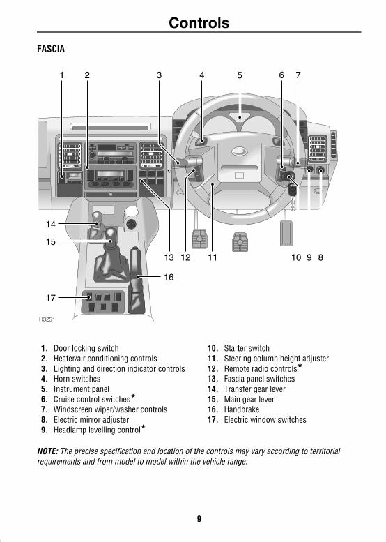
ControlsControls & Instruments
ControlsFASCIA1. Door locking switch2. Heater/air conditioning controls3. Lighting and direction indicator controls4. Horn switches5. Instrument panel6. Cruise control switches*7. Windscreen wiper/washer controls8. Electric mirror adjuster9. Headlamp levelling control*
10. Starter switch11. Steering column height adjuster12. Remote radio controls*13. Fascia panel switches14. Transfer gear lever15. Main gear lever16. Handbrake17. Electric window switches
NOTE: The precise specification and location of the controls may vary according to territorial requirements and from model to model within the vehicle range.
H3251
8910111213
14
15
17
2 3 74 5 61
16
9
Controls
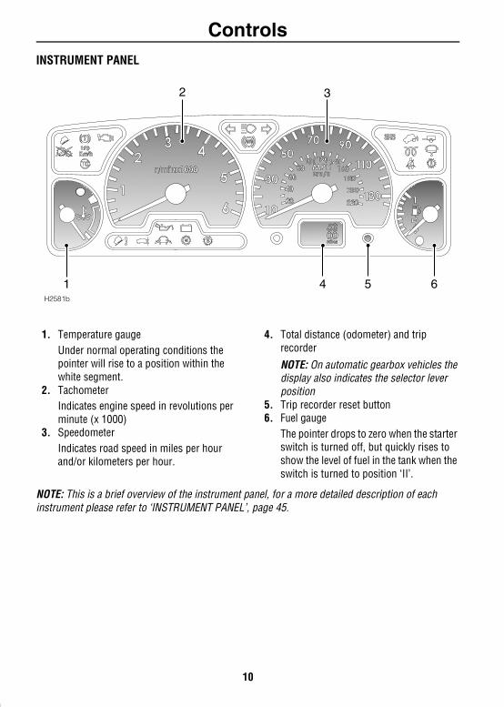
INSTRUMENT PANEL1. Temperature gaugeUnder normal operating conditions the pointer will rise to a position within the white segment.
2. TachometerIndicates engine speed in revolutions per minute (x 1000)
3. SpeedometerIndicates road speed in miles per hour and/or kilometers per hour.
4. Total distance (odometer) and trip recorder
NOTE: On automatic gearbox vehicles the display also indicates the selector lever position
5. Trip recorder reset button6. Fuel gauge
The pointer drops to zero when the starter switch is turned off, but quickly rises to show the level of fuel in the tank when the switch is turned to position ‘II’.
NOTE: This is a brief overview of the instrument panel, for a more detailed description of each instrument please refer to ‘INSTRUMENT PANEL’, page 45.
5300miles
H2581b
2 3
4 5 61
10
Controls
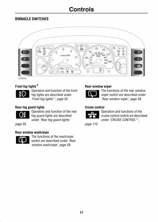
BINNACLE SWITCHESFront fog lights*Operation and function of the front fog lights are described under ‘Front fog lights*’, page 55.
Rear fog guard lightsOperation and function of the rear fog guard lights are described under ‘Rear fog guard lights’,
page 55.
Rear window wash/wipeThe functions of the wash/wipe switch are described under ‘Rear window wash/wipe’, page 59.
Rear window wiper The functions of the rear window wiper switch are described under ‘Rear window wiper’, page 59.
Cruise controlOperation and functions of the cruise control switch are described under ‘CRUISE CONTROL*’,
page 115.
5300km
H2585b
11
Controls
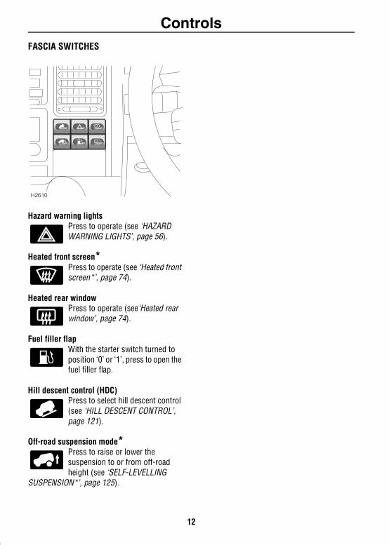
FASCIA SWITCHESHazard warning lights Press to operate (see ‘HAZARD WARNING LIGHTS’, page 56).
Heated front screen*Press to operate (see ‘Heated front screen*’, page 74).
Heated rear window Press to operate (see‘Heated rear window’, page 74).
Fuel filler flapWith the starter switch turned to position ‘0’ or ‘1’, press to open the fuel filler flap.
Hill descent control (HDC)Press to select hill descent control (see ‘HILL DESCENT CONTROL’, page 121).
Off-road suspension mode*Press to raise or lower the suspension to or from off-road height (see ‘SELF-LEVELLING
SUSPENSION*’, page 125).
H2610
12
Locks & AlarmLocks & Alarm
KEYS AND HANDSETS You have been supplied with two remote handsets with integral keys which operate all locks.The key number is stamped on a tag attached to the key ring. Check that the key number has been entered in the space provided on your Security card.
If the remote handset is lost, contact a Land Rover dealer, who can supply replacement units.
WARNINGKeep the Security card and spare handset in a safe place - NOT IN THE VEHICLE!
ALARM SYSTEMYour vehicle is fitted with a sophisticated electronic anti-theft alarm and engine immobilisation system. There are also a number of additional security features, some of which are selectable options and some are standard features of the vehicle. In order to ensure maximum security and operating convenience, you are strongly advised to gain a full understanding of the features and alternatives available, by thoroughly reading this section of the handbook.
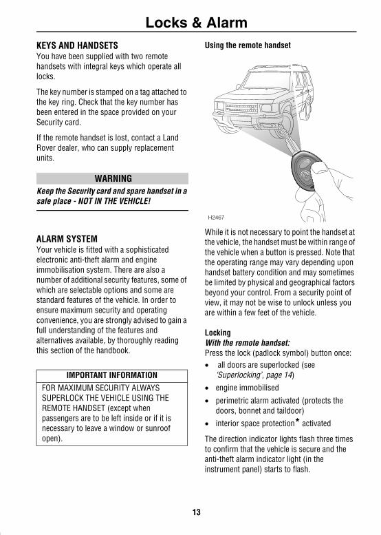
Using the remote handset
While it is not necessary to point the handset at the vehicle, the handset must be within range of the vehicle when a button is pressed. Note that the operating range may vary depending upon handset battery condition and may sometimes be limited by physical and geographical factors beyond your control. From a security point of view, it may not be wise to unlock unless you are within a few feet of the vehicle.
LockingWith the remote handset: Press the lock (padlock symbol) button once:• all doors are superlocked (see
‘Superlocking’, page 14)• engine immobilised
• perimetric alarm activated (protects the doors, bonnet and taildoor)
• interior space protection* activated
The direction indicator lights flash three times to confirm that the vehicle is secure and the anti-theft alarm indicator light (in the instrument panel) starts to flash.
IMPORTANT INFORMATIONFOR MAXIMUM SECURITY ALWAYS SUPERLOCK THE VEHICLE USING THE REMOTE HANDSET (except when passengers are to be left inside or if it is necessary to leave a window or sunroof open).
H2467
13
Locks & Alarm
With the key: Insert the key and turn the door lock towards the rear of the vehicle: • all doors locked (not superlocked)• engine immobilised
• perimetric alarm activated (protects the doors, bonnet and taildoor)
• NO INTERIOR SPACE PROTECTION
The direction indicator lights flash once to confirm that the vehicle is secure and the anti-theft alarm indicator light (in the instrument panel) starts to flash.
UnlockingWith the remote handset:• Press the unlock (Land Rover) button once
to disarm the alarm and unlock the driver's door only (see ‘Single point entry’, page 16).
• Press the unlock button twice to disarm the alarm and unlock ALL the doors.
In either case, the direction indicator lights flash once and the interior lights illuminate.
With the key: While the doors can be unlocked using the key, this method is NOT RECOMMENDED - depending on the specification of the vehicle the alarm may not be disarmed.
NOTE: If the handset does not operate after the vehicle has been parked for a long period, unlock the driver's door with the key and then try again. If the handset still fails to operate, enter the EKA code using the procedure shown later in this section.
SuperlockingProvided all the doors are fully closed, the Superlocking feature is activated automatically whenever the vehicle is locked using the remote handset. Superlocking immobilises the interior door handles, thereby preventing an intruder from gaining entry by smashing a window and reaching inside the vehicle to operate the door handles.
Note that locking with the key will not activate superlocking.
WARNINGFor safety, NEVER use Superlocking if passengers are to remain inside the vehicle - in an emergency they would not be able to escape.
14
Locks & Alarm
Anti-theft alarm indicator lightThis light provides information about the status of the alarm system, as follows:
When the vehicle is locked: The light flashes rapidly while the alarm is arming itself. After ten seconds, the light adjusts to a slower frequency and continues to flash as an anti-theft deterrent until the alarm is disarmed.
If the engine is immobilised (even though the alarm has been disarmed): The light flashes slowly until the engine is remobilised.
If the alarm has been triggered: The light will flash rapidly when the alarm is disarmed until the starter switch is turned to position II.
If the remote handset battery power is low: The light will flash rapidly for ten seconds after the handset has been used when the driver's door is opened.
MislockIf the driver's door is not fully closed when the handset lock button is pressed, the alarm sounder or vehicle horn will sound once, indicating a mislock. In this case, none of the doors will lock and the alarm system will not be armed.
If a passenger door or other aperture is not fully closed when the handset lock button is pressed, the alarm sounder or vehicle horn will sound once, indicating a mislock. However, the ‘partial arming’ attributes of the security system will enable as much of the system to be armed as possible (all fully closed door or bonnet apertures will be protected, but an open door will not!). As soon as the open aperture is closed, the system will automatically revert to a fully armed state.
NOTE: If a mislock occurs as a result of an open door, the superlocking and interior space protection* features will not be activated.
The mislock audible warning can be disabled by a Land Rover dealer.
If the alarm soundsIf the alarm is triggered, the alarm sounder or vehicle horn will sound for 30 seconds before switching off and resetting itself to the same protection status that existed prior to the alarm being triggered.
To silence the alarm, press either button on the remote handset.
H2546
15
Locks & Alarm
Headlight courtesy delayWhen locking the vehicle, the remote handset can be used to illuminate the headlights for 30 seconds. At night this will make it easier for you to unlock the garage, or walk to your house in safety. Operate this feature at the same time as you lock the car, by keeping the handset LOCK button pressed for more than 2 seconds (the doors lock and alarm system arms in the usual way).To extinguish the lights before the 30 second illumination period has expired, press the lock button again.
The headlight courtesy delay can be disabled by a Land Rover dealer.
Single point entryThis is a personal security feature, which enables the driver's door only to be unlocked, leaving the other doors in a locked state. It can be operated by the remote handset as follows:• press the unlock button once to unlock the
driver's door.
• press a second time (within one minute) to unlock the remaining doors.
Single point entry can be disabled by a Land Rover dealer.
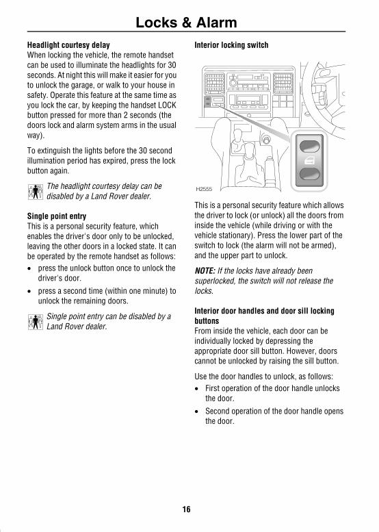
Interior locking switch
This is a personal security feature which allows the driver to lock (or unlock) all the doors from inside the vehicle (while driving or with the vehicle stationary). Press the lower part of the switch to lock (the alarm will not be armed), and the upper part to unlock.
NOTE: If the locks have already been superlocked, the switch will not release the locks.
Interior door handles and door sill locking buttonsFrom inside the vehicle, each door can be individually locked by depressing the appropriate door sill button. However, doors cannot be unlocked by raising the sill button.
Use the door handles to unlock, as follows:• First operation of the door handle unlocks
the door.
• Second operation of the door handle opens the door.
H2555
16
Locks & Alarm
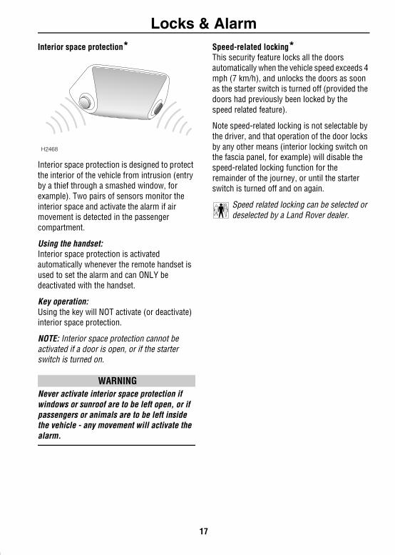
Interior space protection*Interior space protection is designed to protect the interior of the vehicle from intrusion (entry by a thief through a smashed window, for example). Two pairs of sensors monitor the interior space and activate the alarm if air movement is detected in the passenger compartment.
Using the handset: Interior space protection is activated automatically whenever the remote handset is used to set the alarm and can ONLY be deactivated with the handset.
Key operation: Using the key will NOT activate (or deactivate) interior space protection.
NOTE: Interior space protection cannot be activated if a door is open, or if the starter switch is turned on.
WARNINGNever activate interior space protection if windows or sunroof are to be left open, or if passengers or animals are to be left inside the vehicle - any movement will activate the alarm.
Speed-related locking*This security feature locks all the doors automatically when the vehicle speed exceeds 4 mph (7 km/h), and unlocks the doors as soon as the starter switch is turned off (provided the doors had previously been locked by the speed related feature).
Note speed-related locking is not selectable by the driver, and that operation of the door locks by any other means (interior locking switch on the fascia panel, for example) will disable the speed-related locking function for the remainder of the journey, or until the starter switch is turned off and on again.
Speed related locking can be selected or deselected by a Land Rover dealer.
H2468
17
Locks & Alarm
ENGINE IMMOBILISATIONEngine immobilisation is an important aspect of the security system and includes a feature known as ‘passive immobilisation’. This is designed to safeguard the vehicle from theft, should the driver forget to lock the doors and prevents the engine from being started unless the GENUINE handset key is inserted into the starter switch. Engine immobilisation is automatic whenever any of the following conditions occur.• The vehicle is locked using handset or key.• Thirty seconds after the starter switch has been turned off AND the driver's door opened.
• Five minutes after the starter switch is turned off, or the alarm system is disarmed.
NOTE: The engine will be re-mobilised automatically whenever the genuine handset key is inserted into the starter switch and turned to position ‘II’.
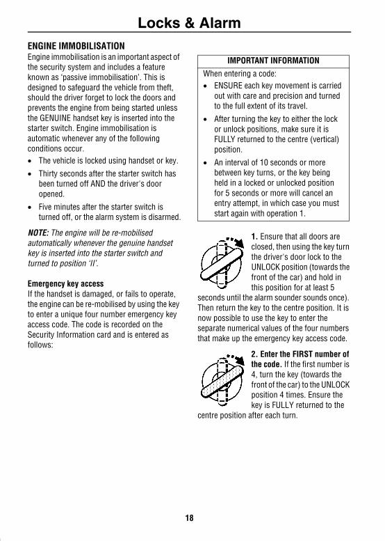
Emergency key accessIf the handset is damaged, or fails to operate, the engine can be re-mobilised by using the key to enter a unique four number emergency key access code. The code is recorded on the Security Information card and is entered as follows:
1. Ensure that all doors are closed, then using the key turn the driver's door lock to the UNLOCK position (towards the front of the car) and hold in this position for at least 5
seconds until the alarm sounder sounds once). Then return the key to the centre position. It is now possible to use the key to enter the separate numerical values of the four numbers that make up the emergency key access code.
2. Enter the FIRST number of the code. If the first number is 4, turn the key (towards the front of the car) to the UNLOCK position 4 times. Ensure the key is FULLY returned to the
centre position after each turn.
IMPORTANT INFORMATION
When entering a code:• ENSURE each key movement is carried
out with care and precision and turned to the full extent of its travel.
• After turning the key to either the lock or unlock positions, make sure it is FULLY returned to the centre (vertical) position.
• An interval of 10 seconds or more between key turns, or the key being held in a locked or unlocked position for 5 seconds or more will cancel an entry attempt, in which case you must start again with operation 1.
18
Locks & Alarm
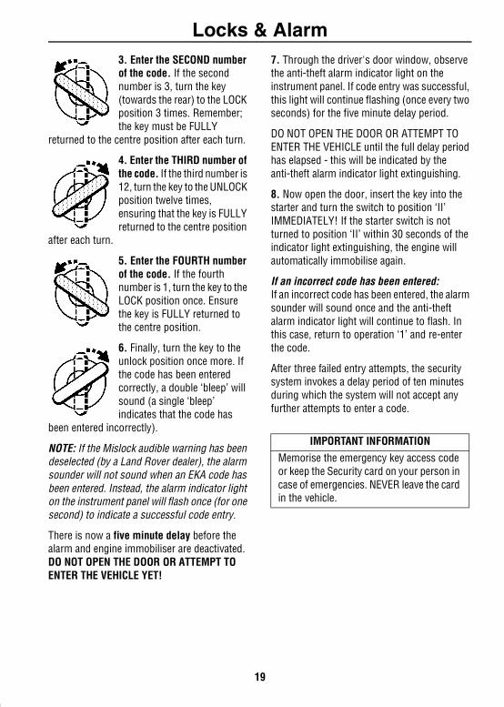
3. Enter the SECOND number of the code. If the second number is 3, turn the key (towards the rear) to the LOCK position 3 times. Remember; the key must be FULLYreturned to the centre position after each turn.
4. Enter the THIRD number of the code. If the third number is 12, turn the key to the UNLOCK position twelve times, ensuring that the key is FULLY returned to the centre position
after each turn.
5. Enter the FOURTH number of the code. If the fourth number is 1, turn the key to the LOCK position once. Ensure the key is FULLY returned to the centre position.
6. Finally, turn the key to the unlock position once more. If the code has been entered correctly, a double ‘bleep’ will sound (a single ‘bleep’ indicates that the code has
been entered incorrectly).
NOTE: If the Mislock audible warning has been deselected (by a Land Rover dealer), the alarm sounder will not sound when an EKA code has been entered. Instead, the alarm indicator light on the instrument panel will flash once (for one second) to indicate a successful code entry.
There is now a five minute delay before the alarm and engine immobiliser are deactivated. DO NOT OPEN THE DOOR OR ATTEMPT TO ENTER THE VEHICLE YET!
7. Through the driver's door window, observe the anti-theft alarm indicator light on the instrument panel. If code entry was successful, this light will continue flashing (once every two seconds) for the five minute delay period.
DO NOT OPEN THE DOOR OR ATTEMPT TO ENTER THE VEHICLE until the full delay period has elapsed - this will be indicated by the anti-theft alarm indicator light extinguishing.
8. Now open the door, insert the key into the starter and turn the switch to position ‘II’ IMMEDIATELY! If the starter switch is not turned to position ‘II’ within 30 seconds of the indicator light extinguishing, the engine will automatically immobilise again.
If an incorrect code has been entered:If an incorrect code has been entered, the alarm sounder will sound once and the anti-theft alarm indicator light will continue to flash. In this case, return to operation ‘1’ and re-enter the code.
After three failed entry attempts, the security system invokes a delay period of ten minutes during which the system will not accept any further attempts to enter a code.
IMPORTANT INFORMATIONMemorise the emergency key access code or keep the Security card on your person in case of emergencies. NEVER leave the card in the vehicle.
19

Locks & Alarm
REMOTE HANDSET BATTERYThe battery should last for approximately three years dependent upon use. When the battery needs replacing it will be apparent from the following symptoms:• A gradual deterioration in range andperformance.• The alarm indicator light in the instrument
panel will flash rapidly for 10 seconds after the driver's door is opened.
Always fit a Land Rover YWX10003L or a Panasonic CR2032 replacement battery (available from a Land Rover dealer).
WARNINGThe handset contains delicate electronic circuits and must be protected from impact and water damage, high temperatures and humidity, direct sunlight and the effects of solvents, waxes and abrasive cleaners.
Battery replacement
1. With the handset face down, insert the blade of a small flat-bladed screwdriver into the slot at the rear of the handset (see inset) and prise the back upwards.
2. Insert the screwdriver blade as shown in the right hand inset and then carefully slide it along the joint towards the key to release the back of the handset.
3. Use a small flat-bladed screwdriver to prise the battery from its mounting (see illustration), taking care to avoid touching the circuit board or the metal battery contacts.
4. Fit the new battery, ensuring that correct polarity is maintained (‘+’ side facing up). Finger marks will adversely affect battery life; if possible, avoid touching the flat surfaces of the battery and wipe them clean before fitting.
5. Press the two halves of the handset firmly together and ensure that both halves are fully joined to prevent dirt or moisture from entering the handset.
The handset is now ready for use.
H2794
20
Locks & Alarm
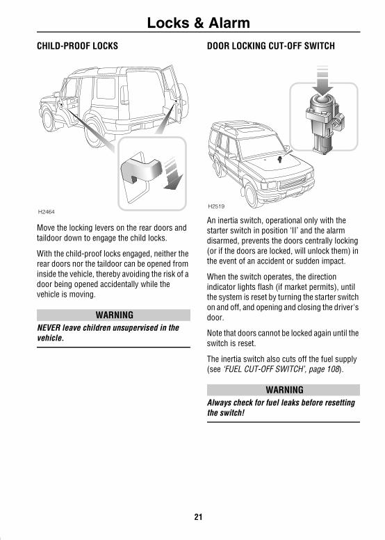
CHILD-PROOF LOCKSMove the locking levers on the rear doors and taildoor down to engage the child locks.
With the child-proof locks engaged, neither the rear doors nor the taildoor can be opened from inside the vehicle, thereby avoiding the risk of a door being opened accidentally while the vehicle is moving.
WARNINGNEVER leave children unsupervised in the vehicle.
DOOR LOCKING CUT-OFF SWITCH
An inertia switch, operational only with the starter switch in position ‘II’ and the alarm disarmed, prevents the doors centrally locking (or if the doors are locked, will unlock them) in the event of an accident or sudden impact.
When the switch operates, the direction indicator lights flash (if market permits), until the system is reset by turning the starter switch on and off, and opening and closing the driver's door.
Note that doors cannot be locked again until the switch is reset.
The inertia switch also cuts off the fuel supply (see ‘FUEL CUT-OFF SWITCH’, page 108).
WARNINGAlways check for fuel leaks before resetting the switch!
H2464H2519
21
SeatsSeats
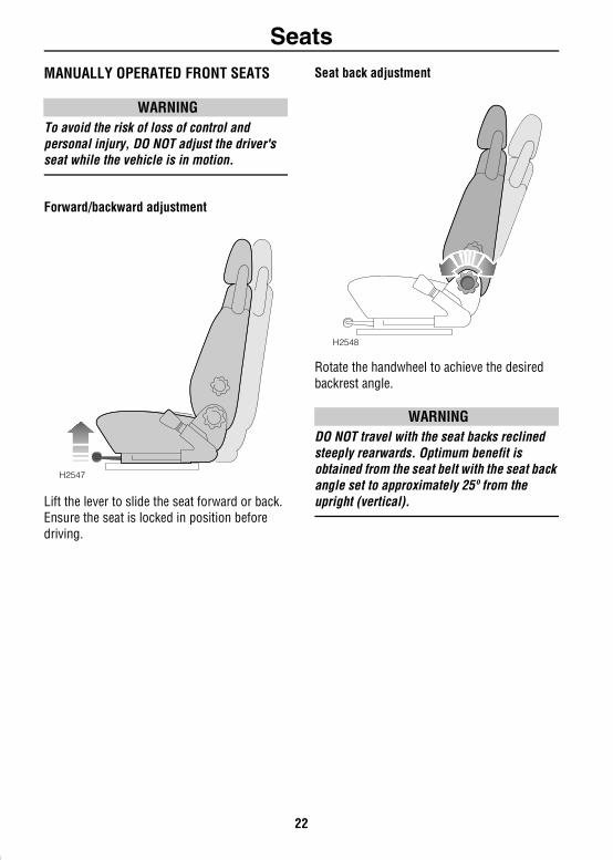
MANUALLY OPERATED FRONT SEATSWARNINGTo avoid the risk of loss of control and personal injury, DO NOT adjust the driver's seat while the vehicle is in motion.
Forward/backward adjustment
Lift the lever to slide the seat forward or back. Ensure the seat is locked in position before driving.
Seat back adjustment
Rotate the handwheel to achieve the desired backrest angle.
WARNINGDO NOT travel with the seat backs reclined steeply rearwards. Optimum benefit is obtained from the seat belt with the seat back angle set to approximately 25º from the upright (vertical).
H2547
H2548
22
Seats
Lumbar support adjustment*Rotate the handwheel to increase or decrease support to the lumbar region of the back.
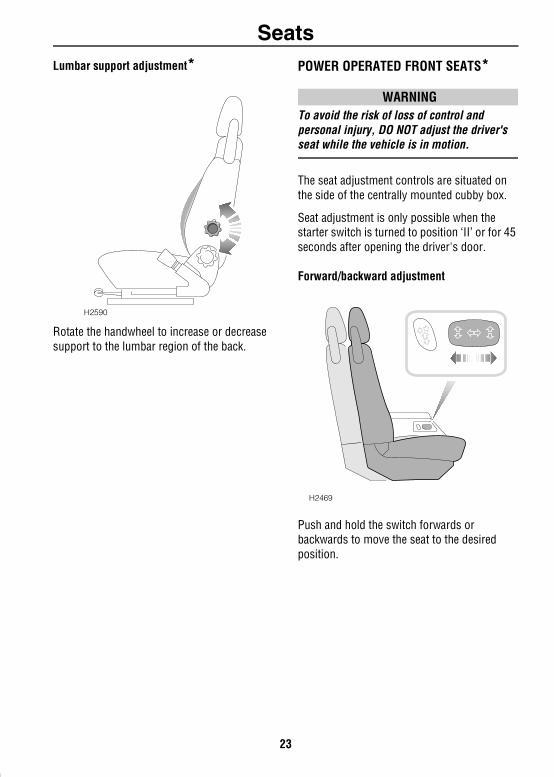
POWER OPERATED FRONT SEATS*
WARNINGTo avoid the risk of loss of control and personal injury, DO NOT adjust the driver's seat while the vehicle is in motion.
The seat adjustment controls are situated on the side of the centrally mounted cubby box.
Seat adjustment is only possible when the starter switch is turned to position ‘II’ or for 45 seconds after opening the driver's door.
Forward/backward adjustment
Push and hold the switch forwards or backwards to move the seat to the desired position.
H2590
H2469
23
Seats
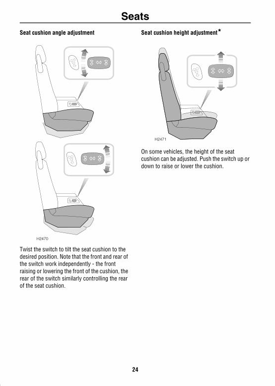
Seat cushion angle adjustmentTwist the switch to tilt the seat cushion to the desired position. Note that the front and rear of the switch work independently - the front raising or lowering the front of the cushion, the rear of the switch similarly controlling the rear of the seat cushion.
Seat cushion height adjustment*
On some vehicles, the height of the seat cushion can be adjusted. Push the switch up or down to raise or lower the cushion.
H2470
H2471
24
Seats
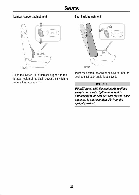
Lumbar support adjustmentPush the switch up to increase support to the lumbar region of the back. Lower the switch to reduce lumbar support.
Seat back adjustment
Twist the switch forward or backward until the desired seat back angle is achieved.
WARNINGDO NOT travel with the seat backs reclined steeply rearwards. Optimum benefit is obtained from the seat belt with the seat back angle set to approximately 25º from the upright (vertical).
H2472 H2473
25
Seats
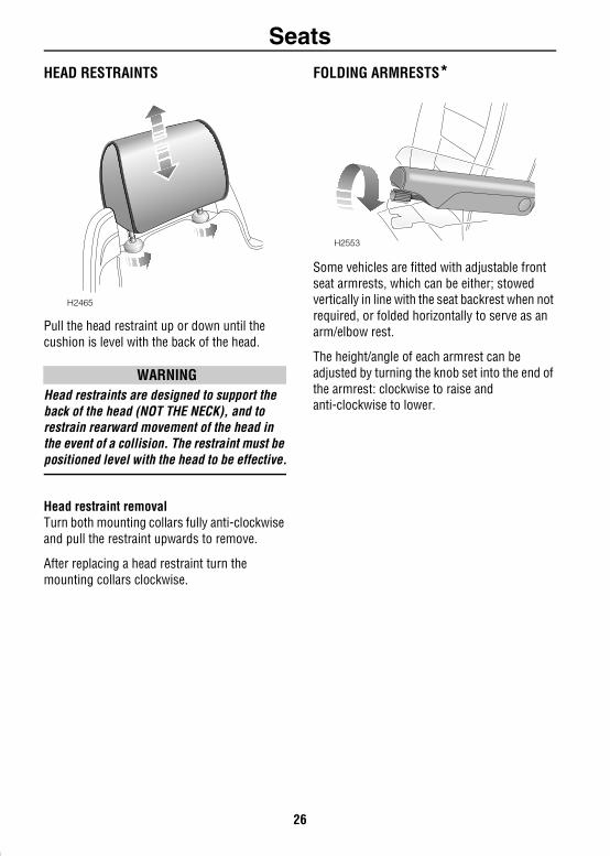
HEAD RESTRAINTSPull the head restraint up or down until the cushion is level with the back of the head.
WARNINGHead restraints are designed to support the back of the head (NOT THE NECK), and to restrain rearward movement of the head in the event of a collision. The restraint must be positioned level with the head to be effective.
Head restraint removalTurn both mounting collars fully anti-clockwise and pull the restraint upwards to remove.
After replacing a head restraint turn the mounting collars clockwise.
FOLDING ARMRESTS*
Some vehicles are fitted with adjustable front seat armrests, which can be either; stowed vertically in line with the seat backrest when not required, or folded horizontally to serve as an arm/elbow rest.
The height/angle of each armrest can be adjusted by turning the knob set into the end of the armrest: clockwise to raise and anti-clockwise to lower.
H2465
H2553
26
Seats
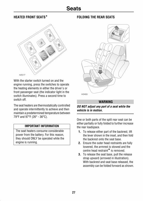
HEATED FRONT SEATS*With the starter switch turned on and the engine running, press the switches to operate the heating elements in either the driver's or front passenger seat (the indicator light in the switch illuminates). Press a second time to switch off.
The seat heaters are thermostatically controlled and operate intermittently to achieve and then maintain a predetermined temperature between 79°F and 97°F (26° - 36°C).
FOLDING THE REAR SEATS
WARNINGDO NOT adjust any part of a seat while the vehicle is in motion.
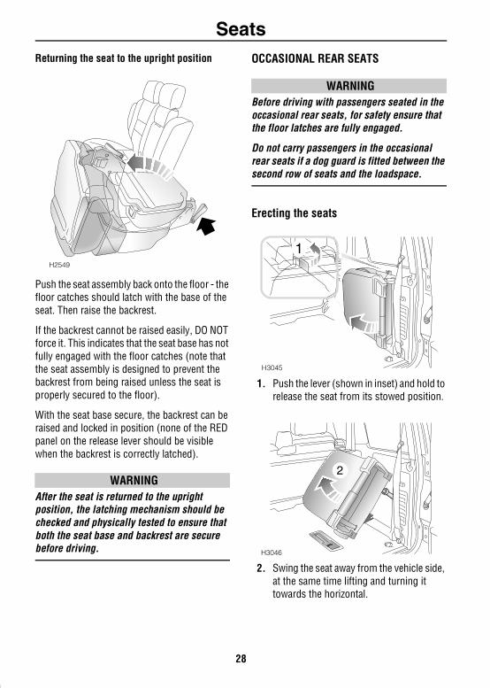
One or both parts of the split rear seat can be either partially or fully folded to further increase the rear loadspace.1. To release either part of the backrest, lift
the lever shown in the inset, and then fold the backrest onto the seat base.
2. Ensure the outer head restraints are fully lowered, the armrest is stowed and the centre head restraint* is removed.
3. To release the seat base, pull the release strap upward (arrowed in illustration). With backrest and seat base released, the assembly can be folded forward as shown.
IMPORTANT INFORMATION
The seat heaters consume considerablepower from the battery. For this reason, they should ONLY be operated while the engine is running.
H2517
H2493
27
Seats
Returning the seat to the upright positionPush the seat assembly back onto the floor - the floor catches should latch with the base of the seat. Then raise the backrest.
If the backrest cannot be raised easily, DO NOT force it. This indicates that the seat base has not fully engaged with the floor catches (note that the seat assembly is designed to prevent the backrest from being raised unless the seat is properly secured to the floor).
With the seat base secure, the backrest can be raised and locked in position (none of the RED panel on the release lever should be visible when the backrest is correctly latched).
WARNINGAfter the seat is returned to the upright position, the latching mechanism should be checked and physically tested to ensure that both the seat base and backrest are secure before driving.
SubTopic ‘Preventing Chafing’ deleted.
OCCASIONAL REAR SEATS
WARNINGBefore driving with passengers seated in the occasional rear seats, for safety ensure that the floor latches are fully engaged.
Do not carry passengers in the occasional rear seats if a dog guard is fitted between the second row of seats and the loadspace.
Erecting the seats
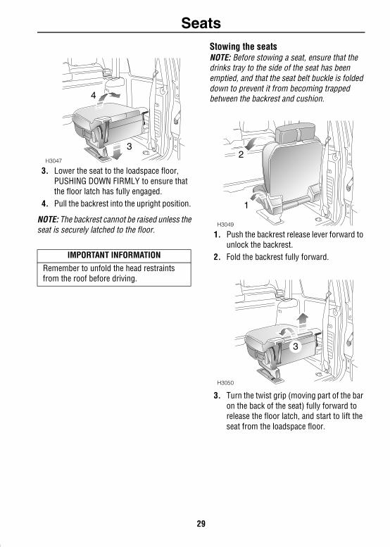
1. Push the lever (shown in inset) and hold to release the seat from its stowed position.
2. Swing the seat away from the vehicle side, at the same time lifting and turning it towards the horizontal.
H2549
H3045
1
H3046
2
28
Seats
3. Lower the seat to the loadspace floor, PUSHING DOWN FIRMLY to ensure that the floor latch has fully engaged.
4. Pull the backrest into the upright position.
NOTE: The backrest cannot be raised unless the seat is securely latched to the floor.
Stowing the seatsNOTE: Before stowing a seat, ensure that the drinks tray to the side of the seat has been emptied, and that the seat belt buckle is folded down to prevent it from becoming trapped between the backrest and cushion.
1. Push the backrest release lever forward to unlock the backrest.
2. Fold the backrest fully forward.
3. Turn the twist grip (moving part of the bar on the back of the seat) fully forward to release the floor latch, and start to lift the seat from the loadspace floor.
IMPORTANT INFORMATION
Remember to unfold the head restraints from the roof before driving.
H3047
3
4
H3049
1
2
H3050
3
29
Seats
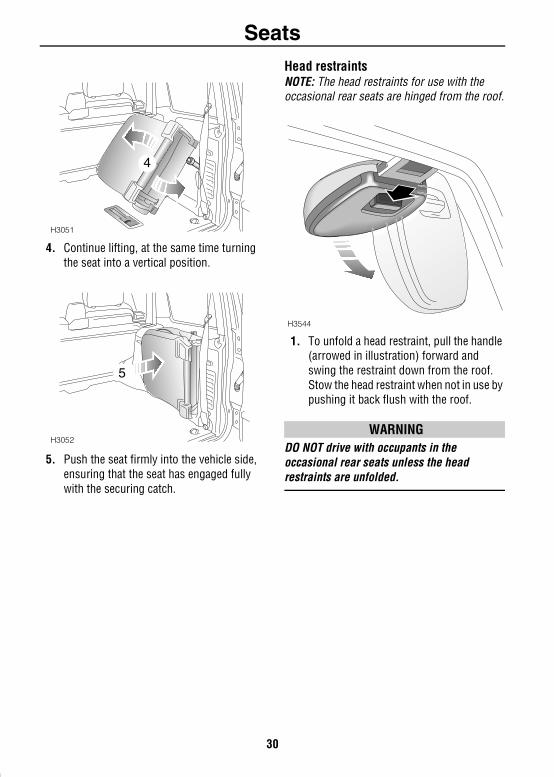
4. Continue lifting, at the same time turning the seat into a vertical position.
5. Push the seat firmly into the vehicle side, ensuring that the seat has engaged fully with the securing catch.
Head restraintsNOTE: The head restraints for use with the occasional rear seats are hinged from the roof.
1. To unfold a head restraint, pull the handle (arrowed in illustration) forward and swing the restraint down from the roof. Stow the head restraint when not in use by pushing it back flush with the roof.
WARNINGDO NOT drive with occupants in the occasional rear seats unless the head restraints are unfolded.
H3051
4
H3052
5
H3544
30
Seat BeltsSeat Belts
SEAT BELT SAFETYThe seat belts fitted to the front and second row seats are intended for use by adult sized occupants. Each belt should be used by one occupant only.Observe the following precautions:• DO make sure ALL passengers are securely
strapped in at all times - even for the shortest journeys.
• ALWAYS adjust seat belts to eliminate any slack in the webbing. DO NOT slacken the webbing by holding the belt away from the body - to be fully effective, the seat belt must remain in full contact with the body at all times.
• ALWAYS fit the lap strap as low on the hips as possible (never across the abdomen), and ensure that the diagonal belt passes across the shoulder without slipping off or pressing on the neck.
• DO NOT wear seat belts over hard, sharp or fragile items in clothing, such as pens, keys, spectacles etc.
• Always replace a seat belt assembly that has withstood the strain of a severe vehicle impact, or if the webbing shows signs of fraying.
• Where possible use the seat belts to secure large items of luggage that are to be carried on the seats - in the event of an accident, insecure items become flying missiles capable of causing serious injury.
• DO NOT use a seat belt that is twisted or obstructed in any way that could impede its smooth operation.
• DO NOT allow front seat occupants to travel with the seat backs reclined steeply rearwards. Optimum benefit is obtained from the seat belt with the seat back angle set to approximately 25º from the upright (vertical) position.
• DO NOT allow foreign matter (particularly sugary food and drink particles) to enter the seat belt locks - such substances can render the locks inoperative.
• In most countries, all occupants are required by law to wear a seat belt, unless they have been issued with a medical exemption certificate.
• During pregnancy, women should wear the lap belt across the hips below the baby, with the diagonal belt passing across the shoulder, between the breasts and to one side of the baby - if in doubt, consult a doctor.
WARNINGThe airbag supplementary restraint system (SRS) is designed to add to the overall effectiveness of the seat belts. It does not replace them. SEAT BELTS MUST ALWAYS BE WORN!
Ensure that all seat belts are worn correctly - an improperly worn seat belt increases the risk of death or serious injury in the event of a collision.
31
Seat Belts
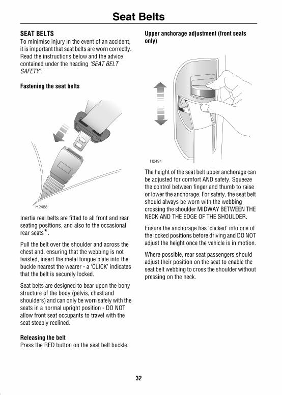
SEAT BELTSTo minimise injury in the event of an accident, it is important that seat belts are worn correctly. Read the instructions below and the advice contained under the heading ‘SEAT BELT SAFETY’.Fastening the seat belts
Inertia reel belts are fitted to all front and rear seating positions, and also to the occasional rear seats*.
Pull the belt over the shoulder and across the chest and, ensuring that the webbing is not twisted, insert the metal tongue plate into the buckle nearest the wearer - a ‘CLICK’ indicates that the belt is securely locked.
Seat belts are designed to bear upon the bony structure of the body (pelvis, chest and shoulders) and can only be worn safely with the seats in a normal upright position - DO NOT allow front seat occupants to travel with the seat steeply reclined.
Releasing the beltPress the RED button on the seat belt buckle.
Upper anchorage adjustment (front seats only)
The height of the seat belt upper anchorage can be adjusted for comfort AND safety. Squeeze the control between finger and thumb to raise or lower the anchorage. For safety, the seat belt should always be worn with the webbing crossing the shoulder MIDWAY BETWEEN THE NECK AND THE EDGE OF THE SHOULDER.
Ensure the anchorage has ‘clicked’ into one of the locked positions before driving and DO NOT adjust the height once the vehicle is in motion.
Where possible, rear seat passengers should adjust their position on the seat to enable the seat belt webbing to cross the shoulder without pressing on the neck.
H2488
H2491
32
Seat Belts
SEAT BELT PRE-TENSIONERSThe seat belt pre-tensioners activate in conjunction with the airbag SRS and provide additional protection in the event of a severe frontal impact on the vehicle (see ‘HOW THE AIRBAG SRS WORKS’, page 39). The pre-tensioners automatically retract the seat belts fitted to the front seats. This reduces any slack in both the lap and diagonal portions of the belts, thereby reducing forward movement of the belt wearer in the event of a severe frontal collision.The airbag SRS warning light on the instrument panel will alert you to any malfunction of the seat belt pre-tensioners.
If the pre-tensioners have been activated, the seat belts will still function as restraints, and must be worn in the event that the vehicle remains in a driveable condition.
NOTE: The seat belt pre-tensioners will NOT be activated by rear, side or minor frontal impacts.
CARING FOR SEAT BELTSRegularly inspect the belt webbing for signs of fraying, cuts and wear; also pay particular attention to the condition of the fixing points and adjusters.
DO NOT bleach or dye the webbing and avoid contaminating the webbing with polish, oil or chemicals (see ‘CLEANING THE INTERIOR’, page 171).
Testing inertia reel belts • With the seat belt fastened, give the
webbing near the buckle a quick upward pull. The buckle must remain securely locked.
• With the seat belt unfastened, unreel the webbing to the limit of its travel. Check that unreeling is free from snatches and snags and then allow the belt to FULLY retract.
• Partially unreel the webbing, then hold the tongue plate and give it a quick forward pull. The mechanism must lock automatically and prevent any further unreeling.
If a seat belt should fail any of these tests, contact your dealer immediately.
WARNINGAlways replace a seat belt that shows signs of webbing damage or has withstood the strain of a severe vehicle impact.
IMPORTANT INFORMATION
The seat belt pre-tensioners will only be activated once and then MUST BE REPLACED by a Land Rover dealer. Failure to replace the pre-tensioners will reduce the efficiency of the vehicle's front restraint systems.
After any frontal impact, always have the seat belts and pre-tensioners checked and, if necessary, replaced by a Land Rover dealer.
In the interests of safety, it is recommended that removal or replacement of the front seats and seat belts should only be carried out by a Land Rover dealer.
33
Child RestraintsChild Restraints
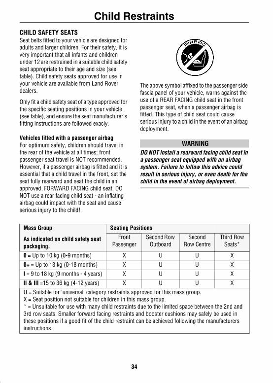
CHILD SAFETY SEATSSeat belts fitted to your vehicle are designed for adults and larger children. For their safety, it is very important that all infants and children under 12 are restrained in a suitable child safety seat appropriate to their age and size (see table). Child safety seats approved for use in your vehicle are available from Land Rover dealers.Only fit a child safety seat of a type approved for the specific seating positions in your vehicle (see table), and ensure the seat manufacturer’s fitting instructions are followed exacly.
Vehicles fitted with a passenger airbagFor optimum safety, children should travel in the rear of the vehicle at all times; front passenger seat travel is NOT recommended. However, if a passenger airbag is fitted and it is essential that a child travel in the front, set the seat fully rearward and seat the child in an approved, FORWARD FACING child seat. DO NOT use a rear facing child seat - an inflating airbag could impact with the seat and cause serious injury to the child!
The above symbol affixed to the passenger side fascia panel of your vehicle, warns against the use of a REAR FACING child seat in the front passenger seat, when a passenger airbag is fitted. This type of child seat could cause serious injury to a child in the event of an airbag deployment.
WARNINGDO NOT install a rearward facing child seat in a passenger seat equipped with an airbag system. Failure to follow this advice could result in serious injury, or even death for the child in the event of airbag deployment.
Mass Group
As indicated on child safety seat packaging.
Seating Positions
Front Passenger
Second Row Outboard
Second Row Centre
Third Row Seats*
0 = Up to 10 kg (0-9 months) X U U X
0+ = Up to 13 kg (0-18 months) X U U XI = 9 to 18 kg (9 months - 4 years) X U U X
II & III =15 to 36 kg (4-12 years) X U U X
U = Suitable for ‘universal’ category restraints approved for this mass group.X = Seat position not suitable for children in this mass group.* = Unsuitable for use with many child restraints due to the limited space between the 2nd and 3rd row seats. Smaller forward facing restraints and booster cushions may safely be used in these positions if a good fit of the child restraint can be achieved following the manufacturers instructions.
34
Child Restraints
Seat belt locking mechanismAll front passenger and second row seat belts have a special locking mechanism which aids the retention of child seats. The procedure to install a child seat is as follows:1. Install the child seat in the vehicle, attach the seat belt and secure the buckle in accordance with the manufacturers fitting instructions.
2. Pull on the shoulder section of the belt to unreel all of the remaining webbing to the limit of its travel. This will engage the automatic locking feature, which then acts as a ratchet, allowing the webbing to retract ONLY.
3. Allow the seat belt to retract onto the child seat (a ‘clicking’ sound will confirm that the ratchet has engaged), firmly pushing the child seat into the seat.
4. Ensure there is no slack in the seat belt by pulling upwards on the shoulder belt immediately above the child restraint. The seat belt should now be locked and the child seat held firmly in position.
Once the child seat is removed and all the seat belt webbing is allowed to retract, the seat belt locking mechanism reverts to normal operation.
NOTE: The automatic locking mechanism should also be used when securing large items of luggage to a seat.
35
Child Restraints
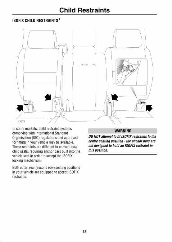
ISOFIX CHILD RESTRAINTS*In some markets, child restraint systems complying with International Standard Organisation (ISO) regulations and approved for fitting in your vehicle may be available. These restraints are different to conventional child seats, requiring anchor bars built into the vehicle seat in order to accept the ISOFIX locking mechanism.
Both outer, rear (second row) seating positions in your vehicle are equipped to accept ISOFIX restraints.
WARNINGDO NOT attempt to fit ISOFIX restraints to the centre seating position - the anchor bars are not designed to hold an ISOFIX restraint in this position.
H3675
36
Child Restraints
Fitting ISOFIX child restraintsISOFIX child restraints should only be fitted in the two outer seating positions of the second row seats. Anchor bars built into the rear seat frame enable the ISOFIX restraints to be securely attached to the vehicle seat in these positions only. The anchor bar locations are shown in the illustration above.When fitting ISOFIX child restraints, always follow the instructions supplied by the manufacturer of the restraint.
Once the ISOFIX restraint is installed, you are recommended to test the security of the installation before seating the child. Attempt to twist the restraint from side to side and to pull the restraint away from the vehicle seat; then check that the anchors are still securely in place.
WARNINGIf the restraint is not correctly anchored, there is a significant risk of injury to the child in the event of a collision or emergency braking.
37
Airbag SRSAirbag SRS
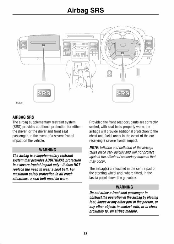
AIRBAG SRSThe airbag supplementary restraint system (SRS) provides additional protection for either the driver, or the driver and front seat passenger, in the event of a severe frontal impact on the vehicle.
WARNINGThe airbag is a supplementary restraint system that provides ADDITIONAL protection in a severe frontal impact only - it does NOT replace the need to wear a seat belt. For maximum safety protection in all crash situations, a seat belt must be worn.
Provided the front seat occupants are correctly seated, with seat belts properly worn, the airbags will provide additional protection to the chest and facial areas in the event of the car receiving a severe frontal impact.
NOTE: Inflation and deflation of the airbags takes place very quickly and will not protect against the effects of secondary impacts that may occur.
The airbag(s) are located in the centre pad of the steering wheel and, where fitted, in the fascia panel above the glovebox.
WARNINGDo not allow a front seat passenger to obstruct the operation of the airbag by placing feet, knees or any other part of the person, or any other objects in contact with, or in close proximity to, an airbag module.
H2551
38
Airbag SRS
To ensure correct deployment of the airbags, it is essential that obstructions are not allowed to intervene between an airbag and the occupant. The following are examples of the type of obstructions that could either, impede correct operation of the airbags, or jeopardise personal safety in the event of an airbag deployment:• Accessories attached to or obscuring anairbag cover.• Items of hand luggage, or other objects
placed on an airbag cover.
• Feet, knees or any other part of the anatomy in contact with, or in close proximity to, an airbag cover.
WARNINGDO NOT attach or position items on or to an airbag cover (steering wheel centre pad or fascia panel), which could interfere with the inflation of the airbag or, if the airbag inflates, be propelled inside the car causing injury to the occupants.
Seating positionsIn order to provide optimum protection in the event of a severe frontal impact, it is necessary for the airbags to deploy with considerable speed.
An inflating airbag can cause facial abrasions and other injuries if the occupant is too close to the airbag at the time of its deployment.
WARNINGTo minimise the risk of accidental Injury from inflating airbags, seat belts should be correctly worn at all times. In addition, both driver and front seat passenger should adjust their seat to provide the maximum practical distance from the airbags.
HOW THE AIRBAG SRS WORKSIn the event of a severe frontal impact, the airbag control unit monitors the rate of deceleration or acceleration induced by the collision, to determine whether the airbags should be deployed.
Operation of the airbag SRS is dependent entirely on the rate at which the vehicle's passenger compartment changes speed as a result of a collision. The circumstances affecting different collisions (vehicle speed, angle of impact, type and size of object hit, for example), vary considerably and will affect the rate of acceleration or deceleration accordingly.
NOTE: The airbag SRS is not designed to operate as a result of rear collisions, minor frontal or side Impacts, roll over accidents; nor will it operate as a result of heavy braking or driving over bumps and potholes.
It follows, therefore, that significant superficial damage can occur without the airbags deploying or, conversely, that a relatively small amount of structural damage may cause the airbags to be deployed.
Airbags will only deploy when they are required to supplement the restraining force of the seat belts.
In the case of a severe frontal collision, both front airbags and seat belt pre-tensioners will be deployed.
39
Airbag SRS
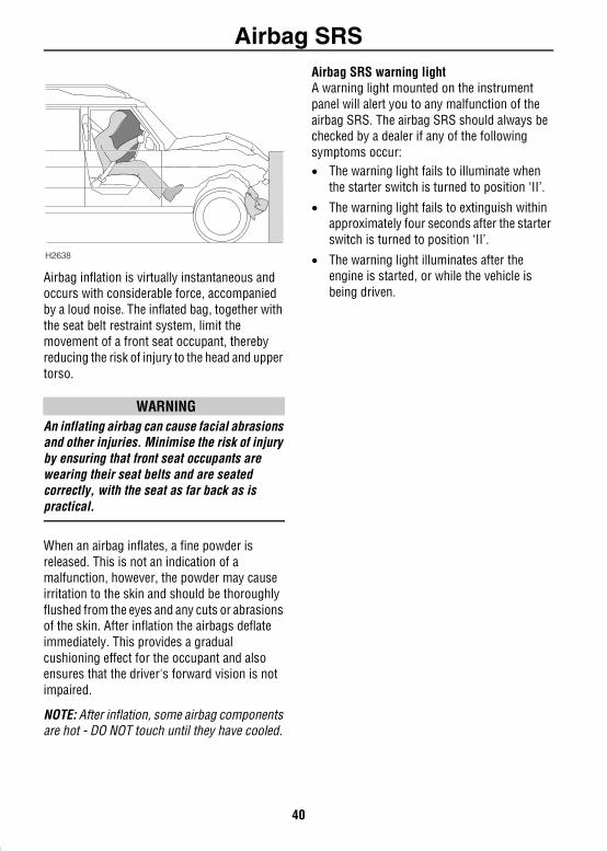
Airbag inflation is virtually instantaneous and occurs with considerable force, accompanied by a loud noise. The inflated bag, together with the seat belt restraint system, limit the movement of a front seat occupant, thereby reducing the risk of injury to the head and upper torso.
WARNINGAn inflating airbag can cause facial abrasions and other injuries. Minimise the risk of injury by ensuring that front seat occupants are wearing their seat belts and are seated correctly, with the seat as far back as is practical.
When an airbag inflates, a fine powder is released. This is not an indication of a malfunction, however, the powder may cause irritation to the skin and should be thoroughly flushed from the eyes and any cuts or abrasions of the skin. After inflation the airbags deflate immediately. This provides a gradual cushioning effect for the occupant and also ensures that the driver's forward vision is not impaired.
NOTE: After inflation, some airbag components are hot - DO NOT touch until they have cooled.
Airbag SRS warning lightA warning light mounted on the instrument panel will alert you to any malfunction of the airbag SRS. The airbag SRS should always be checked by a dealer if any of the following symptoms occur:• The warning light fails to illuminate when
the starter switch is turned to position ‘II’.
• The warning light fails to extinguish within approximately four seconds after the starter switch is turned to position ‘II’.
• The warning light illuminates after the engine is started, or while the vehicle is being driven.
H2638
40
Airbag SRS
SERVICE INFORMATIONWARNINGDO NOT attempt to service, repair, replace, modify or tamper with any part of the airbag SRS, or wiring in the vicinity of an airbag SRS component; this could cause the system to activate, resulting in personal injury.
After ten years from the original date of registration (or the installation date of a replacement airbag SRS), some components will need to be replaced by a Land Rover dealer (note the ‘airbag module replacement date’ shown on page 2 of the Service Portfolio book).
In addition, ALWAYS contact your dealer if: • an airbag inflates.
• the front of the vehicle is damaged, even if the airbag has not inflated.
• any part of an airbag module cover (the steering wheel centre pad or fascia panel) shows signs of cracking or damage.
Disposing of vehiclesIf you sell your vehicle, be sure to inform the new owner that the vehicle has an airbag SRS. In addition, make sure the new owner is aware of the airbag module replacement date shown on page 2 of the Service Portfolio book.
If your vehicle is to be scrapped; uninflated airbags are potentially very dangerous and must be safely deployed in a controlled environment by qualified personnel, before a vehicle is scrapped.
IMPORTANT INFORMATION
The components that make up the airbag SRS are sensitive to electrical or physical interference, either of which could easily damage the system and cause inadvertent operation or a malfunction of the airbag.
For your safety it is recommended that you seek the assistance of a Land Rover dealer to carry out any of the following:• Removal or repair of any wiring or
component in the vicinity of any of the SRS components (yellow wiring harness), including the steering wheel, steering column, instrument and fascia panels.
• Installation of electronic equipment such as a mobile phone, two-way radio or in-car entertainment system.
• Modification to the front of the vehicle, including the bumper and chassis.
• Attachment of accessories to the front of the vehicle.
41
Steering ColumnSteering Column
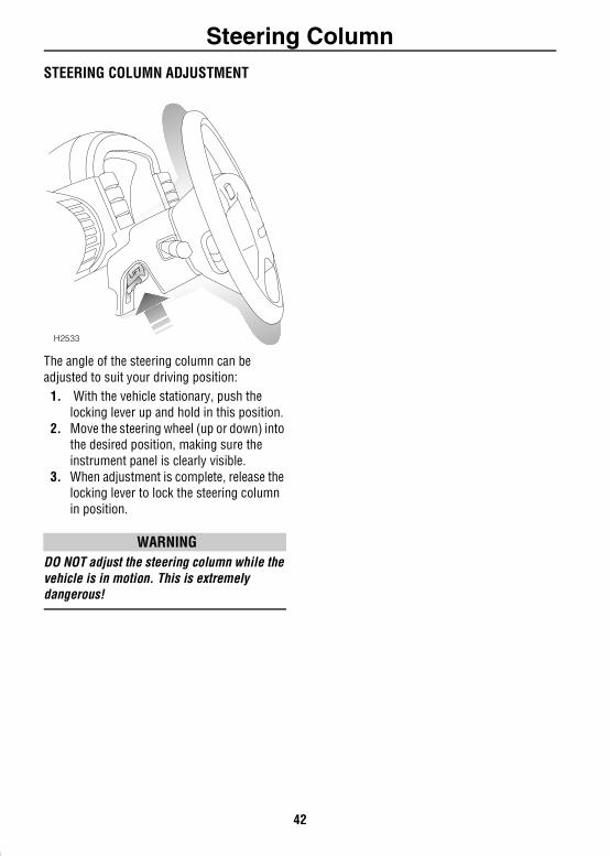
STEERING COLUMN ADJUSTMENTThe angle of the steering column can be adjusted to suit your driving position:
1. With the vehicle stationary, push the locking lever up and hold in this position.
2. Move the steering wheel (up or down) into the desired position, making sure the instrument panel is clearly visible.
3. When adjustment is complete, release the locking lever to lock the steering column in position.
WARNINGDO NOT adjust the steering column while the vehicle is in motion. This is extremely dangerous!
H2533
42
Door MirrorsDoor Mirrors
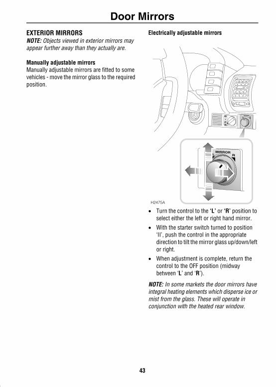
EXTERIOR MIRRORSNOTE: Objects viewed in exterior mirrors may appear further away than they actually are.Manually adjustable mirrorsManually adjustable mirrors are fitted to some vehicles - move the mirror glass to the required position.
Electrically adjustable mirrors
• Turn the control to the ‘L’ or ‘R’ position to select either the left or right hand mirror.
• With the starter switch turned to position ‘II’, push the control in the appropriate direction to tilt the mirror glass up/down/left or right.
• When adjustment is complete, return the control to the OFF position (midway between ‘L’ and ‘R’).
NOTE: In some markets the door mirrors have integral heating elements which disperse ice or mist from the glass. These will operate in conjunction with the heated rear window.
H2475A
43
Door Mirrors
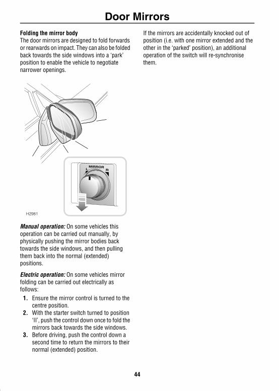
Folding the mirror bodyThe door mirrors are designed to fold forwards or rearwards on impact. They can also be folded back towards the side windows into a ‘park’ position to enable the vehicle to negotiate narrower openings.Manual operation: On some vehicles this operation can be carried out manually, by physically pushing the mirror bodies back towards the side windows, and then pulling them back into the normal (extended) positions.
Electric operation: On some vehicles mirror folding can be carried out electrically as follows:
1. Ensure the mirror control is turned to the centre position.
2. With the starter switch turned to position ‘II’, push the control down once to fold the mirrors back towards the side windows.
3. Before driving, push the control down a second time to return the mirrors to their normal (extended) position.
If the mirrors are accidentally knocked out of position (i.e. with one mirror extended and the other in the ‘parked’ position), an additional operation of the switch will re-synchronise them.
H2981
44
InstrumentsInstruments
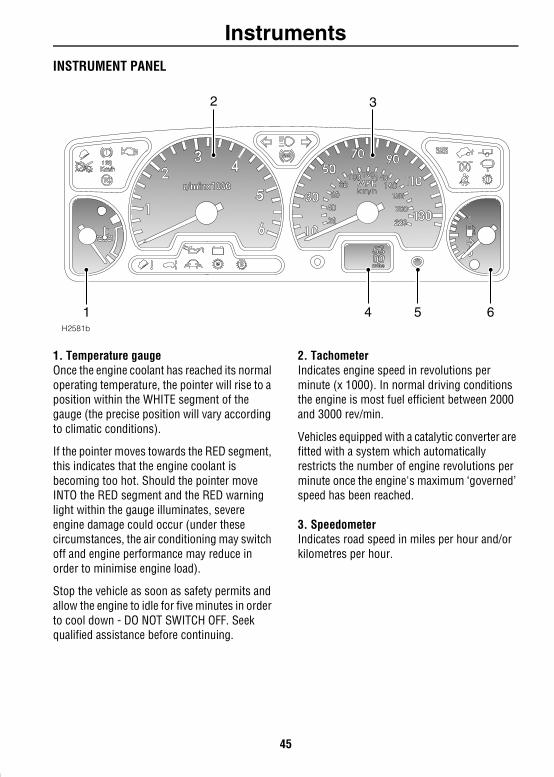
INSTRUMENT PANEL1. Temperature gaugeOnce the engine coolant has reached its normal operating temperature, the pointer will rise to a position within the WHITE segment of the gauge (the precise position will vary according to climatic conditions).
If the pointer moves towards the RED segment, this indicates that the engine coolant is becoming too hot. Should the pointer move INTO the RED segment and the RED warning light within the gauge illuminates, severe engine damage could occur (under these circumstances, the air conditioning may switch off and engine performance may reduce in order to minimise engine load).
Stop the vehicle as soon as safety permits and allow the engine to idle for five minutes in order to cool down - DO NOT SWITCH OFF. Seek qualified assistance before continuing.
2. TachometerIndicates engine speed in revolutions per minute (x 1000). In normal driving conditions the engine is most fuel efficient between 2000 and 3000 rev/min.
Vehicles equipped with a catalytic converter are fitted with a system which automatically restricts the number of engine revolutions per minute once the engine's maximum ‘governed’ speed has been reached.
3. SpeedometerIndicates road speed in miles per hour and/or kilometres per hour.
5300miles
H2581b
2 3
4 5 61
45
Instruments
4. Total distance (odometer) and trip recorderWith the starter switch turned to position ‘II’, the display indicates the total distance travelled by the vehicle, and also shows the most recent individual journey distance.In some markets, the display can be set to show either miles or kilometres. To convert from one to another, press and hold the trip recorder reset button for more than two seconds.NOTE: On automatic gearbox vehicles the display also indicates which selector position is selected.
5. Trip recorder reset buttonPress briefly to return the trip recorder display to zero.
6. Fuel gaugeThe pointer drops to zero when the starter switch is turned off, but quickly rises to show the level of fuel in the tank when the switch is turned to position ‘II’. After refuelling, the gauge rapidly rises to reflect the increase of fuel in the tank.
When the fuel remaining in the tank is a minimum of 3 gallons (14 litres) on petrol vehicles, or 2 gallons (9 litres) on diesel vehicles, the AMBER low fuel warning light in the fuel gauge illuminates. If the light illuminates, refuel at the first opportunity.
The small arrow visible below the fuel pump symbol on the gauge indicates the side of the vehicle on which the fuel filler is located - a useful reminder to help you position the vehicle on the correct side of the forecourt pumps before refuelling.
WARNINGNEVER allow petrol engined models to run out of fuel (the resultant misfire may destroy the catalytic converter).
46
Warning LightsWarning Lights
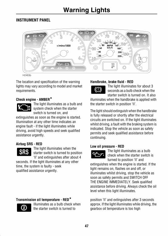
INSTRUMENT PANELThe location and specification of the warning lights may vary according to model and market requirements.
Check engine - AMBER*The light illuminates as a bulb and system check when the starter switch is turned on, and
extinguishes as soon as the engine is started. Illumination at any other time indicates an engine fault - if the light illuminates while driving, avoid high speeds and seek qualified assistance urgently.
Airbag SRS - RED The light illuminates when the starter switch is turned to position ‘II’ and extinguishes after about 4
seconds. If the light illuminates at any other time, the system is faulty - seek qualified assistance urgently.
Handbrake, brake fluid - REDThe light illuminates for about 3 seconds as a bulb check when the starter switch is turned on. It also
illuminates when the handbrake is applied with the starter switch in position ‘II’.
The light should extinguish when the handbrake is fully released or shortly after the electrical circuits are switched on. If the light illuminates whilst driving, a fault with the braking system is indicated. Stop the vehicle as soon as safety permits and seek qualified assistance before continuing.
Low oil pressure - RED The light illuminates as a bulb check when the starter switch isturned to position ‘II’ and
extinguishes when the engine is started. If the light remains on, flashes on and off, or illuminates whilst driving, stop the vehicle as soon as safety permits and SWITCH OFFTHE ENGINE IMMEDIATELY. Seek qualified assistance before driving. Always check the oil level when this light illuminates.
Transmission oil temperature - RED*Illuminates as a bulb check when the starter switch is turned to
position ‘II’ and extinguishes after 3 seconds approx. If the light illuminates while driving, the gearbox oil temperature is too high
H2483b
5300km
47
Warning Lights
(most likely to occur in very hot weather during continuous high speed driving, or whilst towing heavy loads on steep inclines or if the handbrake has been applied while driving).If the light illuminates, reduce speed. If the light remains on, stop the vehicle and allow the gearbox to cool. Do not drive until the light has extinguished. (Depending on the ambient temperature and the carrying loads imposed on the vehicle, it may take several minutes before the light extinguishes and it is safe to drive).
Anti-lock braking system - AMBERThe light illuminates as a bulb and system check when the starter switch is turned to position ‘II’. If
the light illuminates whilst driving or remains illuminated after the starter switch is turned on, a fault has occurred. This means that full ABS control may not be available and you should seek qualified assistance urgently.
NOTE: Faults which cause the ABS light to illuminate after the initial system checks, or whilst driving, will be accompanied by a warning chime sounding 3 times.
Headlight main beam - BLUEIlluminates when the headlights are switched to main beam.
Direction indicators - GREEN The left or right warning light flashes in time with the corresponding left or right
direction indicator lights whenever they are operated. If the warning light fails to flash, or flashes very rapidly, this may indicate a bulb failure in one of the direction indicator lights.
If the hazard switch is pressed, both warning lights will flash in conjunction with the direction indicator lights.
Trailer direction indicators - GREENThe light illuminates briefly as a bulb check when the starter switch is turned to position ‘II’. If a trailer
is attached, the light illuminates in conjunction with the vehicle direction indicator lights to show that all trailer indicator lights are functioning correctly. In the event of a bulb failure on the trailer, the warning light remains off.
Glow plug - AMBER (diesel only)Illuminates when the starter switch is turned to position ‘II’. Wait for the light to extinguish before
starting the engine.
Battery charging - REDThe light illuminates as a bulb check when the starter switchis turned to position ‘II’ and
extinguishes once the engine is running. If it remains on, or illuminates whilst driving, a fault is indicated. Seek qualified assistance urgently.
48
Warning Lights
Seat belt - RED*The light illuminates when the starter switch is turned to position ‘II’ and extinguishes after
approximately 6 seconds, even if the driver's seat belt remains unfastened. In some markets illumination of the light will be accompanied by a warning chime (see ‘AUDIBLE WARNINGS’, page 52)
Hill descent control (HDC) ‘information’ - GREEN
Illuminates briefly as a bulb and system check when the starter switch is turned to position 'II' and
also when HDC is selected.
If HDC is selected when Low Range gears are engaged the light will illuminate continuously indicating that HDC is active.
When HDC is selected and non-operating gears are engaged (i.e. High range), the light will flash to inform the driver that HDC is selected, but will not operate.
If the light starts to flash while HDC is active, normal functionality may seize and HDC ‘fade out’ may be induced (see ‘HILL DESCENT CONTROL’, page 121).
Hill descent control (HDC) ‘failure’ - AMBERIlluminates briefly as a bulb and system check when the starter switch is turned to position ‘II’.
If the light illuminates at any other time, either a fault has occurred which affects the functionality of the system, or over-use of the system has been detected, in which case HDC may ‘fade out’ (see ‘HILL DESCENT CONTROL’, page 121).
NOTE: Faults which cause the HDC ‘failure’ light to illuminate after the initial system checks, or whilst driving, will be accompanied by a warning chime sounding 3 times.
Traction Control - AMBERIlluminates as a bulb check when the starter switch is turned to position ‘II’ and extinguishes after
approximately 3 seconds. The light illuminates for a minimum of 2 seconds, whenever traction control is operating.
If the light illuminates continuously, and remains illuminated when the vehicle is stationary, a fault with the system is indicated; seek qualified assistance.
NOTE: Faults which cause the light to illuminate after the initial system checks, or whilst driving, will be accompanied by a warning chime sounding 3 times.
49

Warning Lights
Active cornering enhancement (ACE) - RED/AMBER*The light illuminates RED when the starter switch is turned toposition ‘II’. After two seconds, the
RED illumination changes to AMBER, and after a further two seconds, the light extinguishes.
If illumination occurs while driving, a fault with the system is indicated, as follows:• If the light shows RED (a flashing red light
which changes to constant illumination after two minutes, and is accompanied by a warning chime): This indicates a system fault that may result in serious damage to vehicle components and reduced ACE performance. Stop the vehicle as soon as safety permits and switch off the engine. DO NOT CONTINUE DRIVING! Seek qualified assistance immediately.
• If the light shows AMBER (constant illumination): This indicates a system fault that will result in reduced ACE performance but will not leave the vehicle in a dangerous condition. You may continue driving, but reduce speed, take additional care, and consult a Land Rover dealer at the earliest opportunity.
Fuel filter - AMBER (diesel only)Illuminates as a bulb check when the starter switch is turned toposition ‘II’ and extinguishes after
3 seconds approximately. If the light illuminates while driving, this indicates the presence of excessive amounts of water in the fuel. You may continue driving but should seek qualified assistance at the earliest convenient time.
Off Road - AMBER*Illuminates briefly as a bulb and system check when the starterswitch is turned to position ‘II’ and
then extinguishes.
If the off-road switch is pressed: The light flashes continually while the rear of the vehicle is either; rising to off-road height, or returning to standard ride height. The light illuminates constantly while the suspension remains at off-road height.
In addition, the light will flash if extended mode is induced.
Manual mode - GREEN (Auto only)Illuminates for 3 seconds as a bulb check when the starter switch is turned to position ‘II’. Illuminates
constantly while Manual mode is selected.
NOTE: If both the Manual and Sport mode lights (shown below) flash together, this indicates an electrical fault with the automatic gearbox. If the lights continue flashing after the vehicle has been brought to a halt and the starter switch has been turned off and then on again, you should seek qualified assistance urgently.
Sport mode - GREEN (Auto only)Illuminates for 3 seconds as a bulb check when the starter switch is turned to position ‘II’. Illuminates
constantly while Sport mode is selected.
50
Warning Lights
Self-levelling suspension - AMBER*Illuminates briefly as a bulb and system check when the starterswitch is turned to position ‘II’ and
then extinguishes.
If the remote handset is operated: The light flashes continually while the rear of the vehicle is being lowered, or raised.
If the light illuminates constantly: A fault with the suspension is indicated. Seek qualified assistance as soon as possible.
While it is possible to continue driving the vehicle in this condition, there is a considerable risk of causing further damage to the suspension. Preferably, the vehicle should be brought to a halt as soon as conditions allow. Further travel should be limited to reaching the nearest Land Rover dealer, or driving to a place of safety while awaiting recovery. In any event, speed must be restricted to a rate that will guarantee a smooth, and totally bump-free, ride at all times, ideally traversing only smooth, metalled roads.
51

Audible WarningsAudible Warnings
AUDIBLE WARNINGSThe market specification will determine which of the following audible warnings are appropriate to your vehicle.Lights on reminderIf the lights are left on after the starter switch is turned off, a warning chime will sound when the driver's door is opened. The chime will cease as soon as the lights are switched off or when the driver's door is closed.
Transfer box reminderA warning will chime continuously while the transfer gearbox is in neutral.
Self-levelling suspension warning• A single warning will chime whenever the
off-road switch is operated to raise the vehicle to off-road height, or to return it to standard ride height.
• A warning will chime continuously while the remote handset is used to lower the vehicle from standard ride height, and also while returning the vehicle to standard ride height.
• A warning chime will sound 3 times if changes to or from off-road height are requested but not permitted.
ABS warningIf a fault with the anti-lock braking system is detected, a warning will chime three times. You may continue driving, but should understand that full ABS control may not be available. Consult your dealer at the earliest opportunity.
ACE warningA single warning will chime if a fault with the active cornering enhancement system is detected. The chime will coincide with the ACE warning light flashing RED.
HDC warnings• A warning will chime continuously in
conjunction with the HDC warning light flashing green, whenever HDC has been selected but the system's operating criteria have not been met.
• A warning will chime continuously and the HDC failure warning light will illuminate (amber), whenever a fault is detected with the HDC system.
• A single warning will chime when HDC is deselected.
Starter key reminder If the key is left in the starter switch while the driver's door is open, a warning will chime continuously. The chime stops as soon as the door is closed or the key is removed from the starter switch.
Seat belt reminderIn some markets, if the driver's seat belt has not been fastened when the starter switch is turned on, a warning chime will sound (one second frequency). The chime operates in conjunction with the seat belt warning light and sounds for 6 seconds, or until the seat belt is fastened (whichever occurs first).
In Gulf States markets, either; the chime will continue sounding indefinitely until the seat belt is fastened, or; the chime will sound for 6 seconds whenever the driver's door is opened and closed with the starter switch turned on.
52
Lights & IndicatorsLights & Indicators
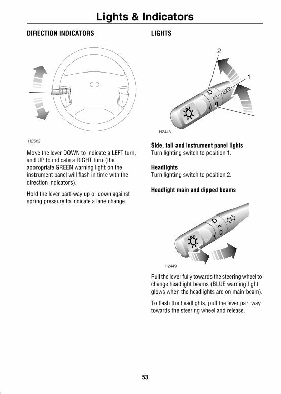
DIRECTION INDICATORSMove the lever DOWN to indicate a LEFT turn, and UP to indicate a RIGHT turn (the appropriate GREEN warning light on the instrument panel will flash in time with the direction indicators).
Hold the lever part-way up or down against spring pressure to indicate a lane change.
LIGHTS
Side, tail and instrument panel lightsTurn lighting switch to position 1.
HeadlightsTurn lighting switch to position 2.
Headlight main and dipped beams
Pull the lever fully towards the steering wheel to change headlight beams (BLUE warning light glows when the headlights are on main beam).
To flash the headlights, pull the lever part way towards the steering wheel and release.
H2582
H2448
2
1
H2449
53
Lights & Indicators
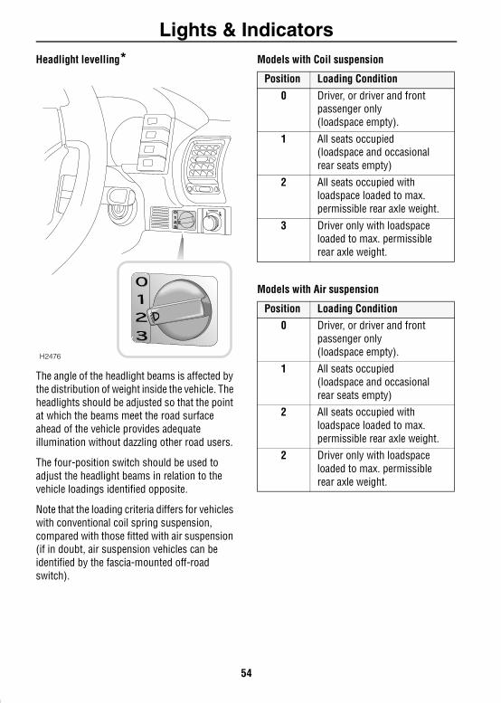
Headlight levelling*The angle of the headlight beams is affected by the distribution of weight inside the vehicle. The headlights should be adjusted so that the point at which the beams meet the road surface ahead of the vehicle provides adequate illumination without dazzling other road users.
The four-position switch should be used to adjust the headlight beams in relation to the vehicle loadings identified opposite.
Note that the loading criteria differs for vehicles with conventional coil spring suspension, compared with those fitted with air suspension (if in doubt, air suspension vehicles can be identified by the fascia-mounted off-road switch).
Models with Coil suspension
Models with Air suspension
H2476
Position Loading Condition
0 Driver, or driver and front passenger only(loadspace empty).
1 All seats occupied(loadspace and occasional rear seats empty)
2 All seats occupied with loadspace loaded to max. permissible rear axle weight.
3 Driver only with loadspace loaded to max. permissiblerear axle weight.
Position Loading Condition0 Driver, or driver and front
passenger only(loadspace empty).
1 All seats occupied(loadspace and occasional rear seats empty)
2 All seats occupied with loadspace loaded to max. permissible rear axle weight.
2 Driver only with loadspace loaded to max. permissiblerear axle weight.
54
Lights & Indicators
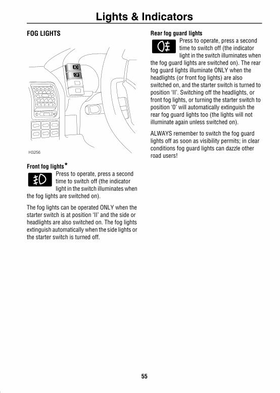
FOG LIGHTSFront fog lights*Press to operate, press a second time to switch off (the indicator light in the switch illuminates when
the fog lights are switched on).
The fog lights can be operated ONLY when the starter switch is at position ‘II’ and the side or headlights are also switched on. The fog lights extinguish automatically when the side lights or the starter switch is turned off.
Rear fog guard lightsPress to operate, press a second time to switch off (the indicator light in the switch illuminates when
the fog guard lights are switched on). The rear fog guard lights illuminate ONLY when the headlights (or front fog lights) are also switched on, and the starter switch is turned to position ‘II’. Switching off the headlights, or front fog lights, or turning the starter switch to position ‘0’ will automatically extinguish the rear fog guard lights too (the lights will not illuminate again unless switched on).
ALWAYS remember to switch the fog guard lights off as soon as visibility permits; in clear conditions fog guard lights can dazzle other road users!
H3256
55
Lights & Indicators
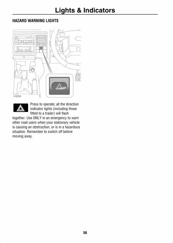
HAZARD WARNING LIGHTSPress to operate; all the direction indicator lights (including those fitted to a trailer) will flash
together. Use ONLY in an emergency to warn other road users when your stationary vehicle is causing an obstruction, or is in a hazardous situation. Remember to switch off before moving away.
H3254
56
Wipers & WashersWipers & Washers
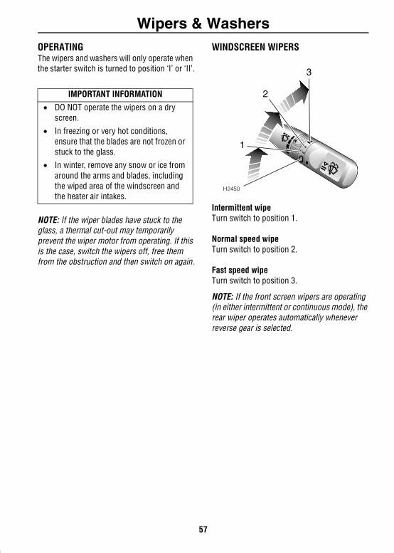
OPERATINGThe wipers and washers will only operate when the starter switch is turned to position ‘I’ or ‘II’.NOTE: If the wiper blades have stuck to the glass, a thermal cut-out may temporarily prevent the wiper motor from operating. If this is the case, switch the wipers off, free them from the obstruction and then switch on again.
WINDSCREEN WIPERS
Intermittent wipeTurn switch to position 1.
Normal speed wipeTurn switch to position 2.
Fast speed wipeTurn switch to position 3.
NOTE: If the front screen wipers are operating (in either intermittent or continuous mode), the rear wiper operates automatically whenever reverse gear is selected.
IMPORTANT INFORMATION
• DO NOT operate the wipers on a dry screen.
• In freezing or very hot conditions, ensure that the blades are not frozen or stuck to the glass.
• In winter, remove any snow or ice from around the arms and blades, including the wiped area of the windscreen and the heater air intakes.
H2450
1
2
3
57
Wipers & Washers
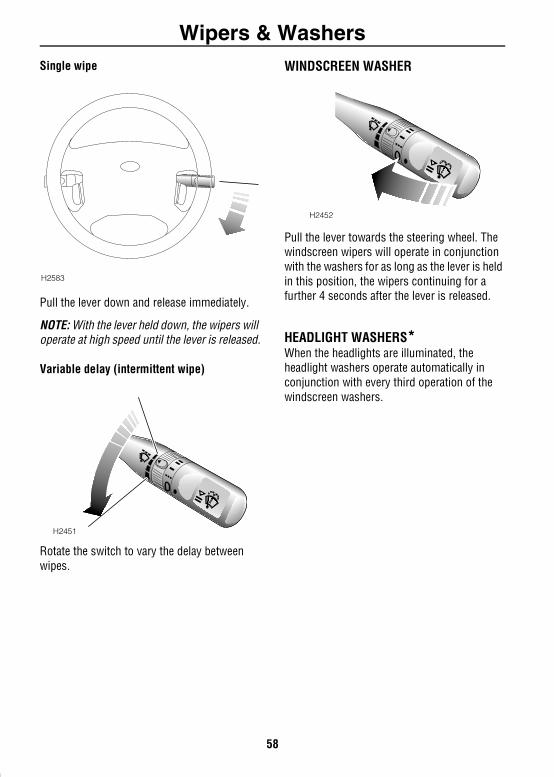
Single wipePull the lever down and release immediately.
NOTE: With the lever held down, the wipers will operate at high speed until the lever is released.
Variable delay (intermittent wipe)
Rotate the switch to vary the delay between wipes.
WINDSCREEN WASHER
Pull the lever towards the steering wheel. The windscreen wipers will operate in conjunction with the washers for as long as the lever is held in this position, the wipers continuing for a further 4 seconds after the lever is released.
HEADLIGHT WASHERS*When the headlights are illuminated, the headlight washers operate automatically in conjunction with every third operation of the windscreen washers.
H2583
H2451
H2452
58
Wipers & Washers
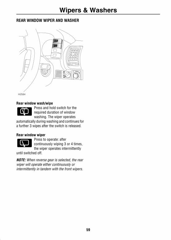
REAR WINDOW WIPER AND WASHERRear window wash/wipePress and hold switch for the required duration of window washing. The wiper operates
automatically during washing and continues for a further 3 wipes after the switch is released.
Rear window wiperPress to operate: after continuously wiping 3 or 4 times, the wiper operates intermittently
until switched off.
NOTE: When reverse gear is selected, the rear wiper will operate either continuously or intermittently in tandem with the front wipers.
H2584
59
HornHorn
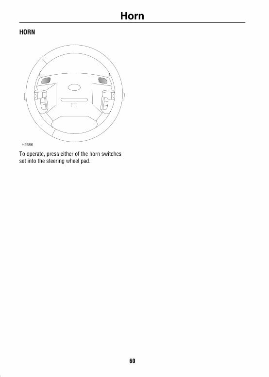
HORNTo operate, press either of the horn switches set into the steering wheel pad.
H2586
60
Electric WindowsElectric Windows
ELECTRIC WINDOW CONTROLSWARNINGAccidental closing of an electrically operated window on fingers, hands or any vulnerable part of the body, can result in serious injury. Always observe the following precautions:
• ENSURE the windows are not obstructed when opening or closing.
• DO NOT allow passengers to extend an part of their bodies through the windows while the vehicle is moving - injury from flying debris, branches of trees or other obstructions could occur.
• ALWAYS close the windows when the vehicle is left unattended.
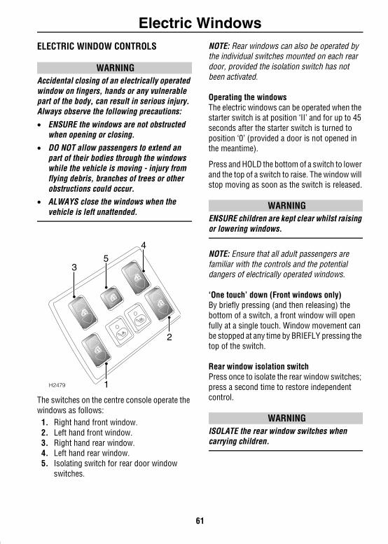
The switches on the centre console operate the windows as follows:
1. Right hand front window.2. Left hand front window.3. Right hand rear window.4. Left hand rear window.5. Isolating switch for rear door window
switches.
NOTE: Rear windows can also be operated by the individual switches mounted on each rear door, provided the isolation switch has not been activated.
Operating the windowsThe electric windows can be operated when the starter switch is at position ‘II’ and for up to 45 seconds after the starter switch is turned to position ‘0’ (provided a door is not opened in the meantime).
Press and HOLD the bottom of a switch to lower and the top of a switch to raise. The window will stop moving as soon as the switch is released.
WARNINGENSURE children are kept clear whilst raising or lowering windows.
NOTE: Ensure that all adult passengers are familiar with the controls and the potential dangers of electrically operated windows.
‘One touch’ down (Front windows only) By briefly pressing (and then releasing) thebottom of a switch, a front window will open fully at a single touch. Window movement can be stopped at any time by BRIEFLY pressing the top of the switch.
Rear window isolation switchPress once to isolate the rear window switches; press a second time to restore independent control.
WARNINGISOLATE the rear window switches when carrying children.
H2479
45
3
1
2
61
SunroofSunroof
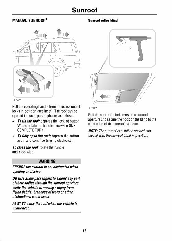
MANUAL SUNROOF*Pull the operating handle from its recess until it locks in position (see inset). The roof can be opened in two separate phases as follows:• To tilt the roof: depress the locking button
‘A’ and rotate the handle clockwise ONE COMPLETE TURN.
• To fully open the roof: depress the button again and continue turning clockwise.
To close the roof: rotate the handle anti-clockwise.
WARNINGENSURE the sunroof is not obstructed when opening or closing.
DO NOT allow passengers to extend any part of their bodies through the sunroof aperture while the vehicle is moving - injury from flying debris, branches of trees or other obstructions could occur.
ALWAYS close the roof when the vehicle is unattended.
Sunroof roller blind
Pull the sunroof blind across the sunroof aperture and secure the hook on the blind to the front edge of the sunroof cassette.
NOTE: The sunroof can still be opened and closed with the sunroof blind in position.
H2453
A
H2477
62
Sunroof
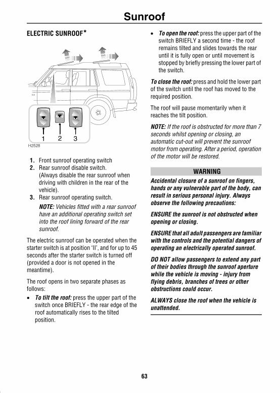
ELECTRIC SUNROOF*1. Front sunroof operating switch2. Rear sunroof disable switch.
(Always disable the rear sunroof when driving with children in the rear of the vehicle).
3. Rear sunroof operating switch.
NOTE: Vehicles fitted with a rear sunroof have an additional operating switch set into the roof lining forward of the rear sunroof.
The electric sunroof can be operated when the starter switch is at position ‘II’, and for up to 45 seconds after the starter switch is turned off (provided a door is not opened in the meantime).
The roof opens in two separate phases as follows:• To tilt the roof: press the upper part of the
switch once BRIEFLY - the rear edge of the roof automatically rises to the tilted position.
• To open the roof: press the upper part of the switch BRIEFLY a second time - the roof remains tilted and slides towards the rear until it is fully open or until movement is stopped by briefly pressing the lower part of the switch.
To close the roof: press and hold the lower part of the switch until the roof has moved to the required position.
The roof will pause momentarily when it reaches the tilt position.
NOTE: If the roof is obstructed for more than 7 seconds whilst opening or closing, an automatic cut-out will prevent the sunroof motor from operating. After a period, operation of the motor will be restored.
WARNINGAccidental closure of a sunroof on fingers, hands or any vulnerable part of the body, can result in serious personal injury. Always observe the following precautions:
ENSURE the sunroof is not obstructed when opening or closing.
ENSURE that all adult passengers are familiar with the controls and the potential dangers of operating an electrically operated sunroof.
DO NOT allow passengers to extend any part of their bodies through the sunroof aperture while the vehicle is moving - injury from flying debris, branches of trees or other obstructions could occur.
ALWAYS close the roof when the vehicle is unattended.
H2528
1 2 3
63
Sunroof
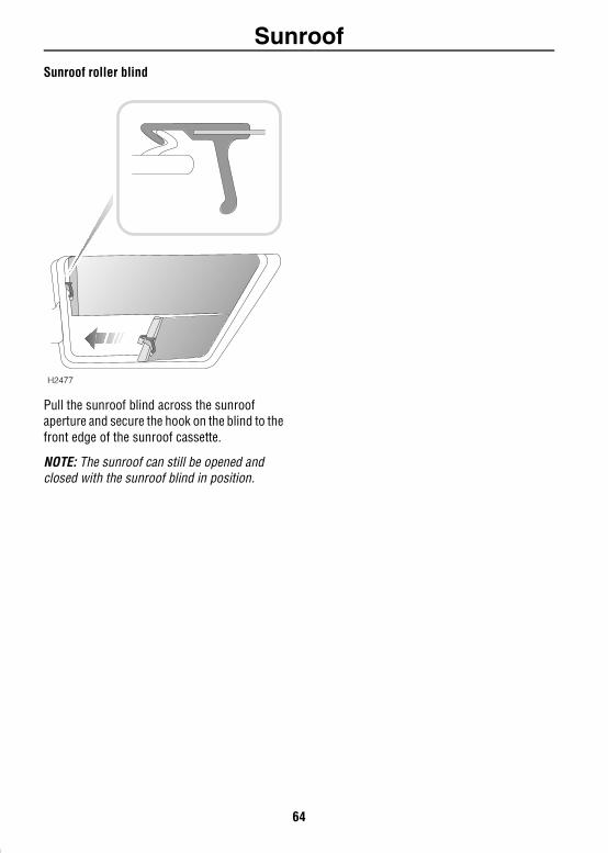
Sunroof roller blindPull the sunroof blind across the sunroof aperture and secure the hook on the blind to the front edge of the sunroof cassette.
NOTE: The sunroof can still be opened and closed with the sunroof blind in position.
H2477
64
Heating & VentilationHeating & Ventilation
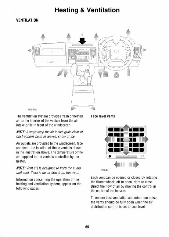
VENTILATIONThe ventilation system provides fresh or heated air to the interior of the vehicle from the air intake grille in front of the windscreen.
NOTE: Always keep the air intake grille clear of obstructions such as leaves, snow or ice.
Air outlets are provided to the windscreen, face and feet - the location of those vents is shown in the illustration above. The temperature of the air supplied to the vents is controlled by the heater.
NOTE: Vent (1) is designed to keep the audio unit cool, there is no air flow from this vent.
Information concerning the operation of the heating and ventilation system, appear on the following pages.
Face level vents
Each vent can be opened or closed by rotating the thumbwheel: left to open, right to close. Direct the flow of air by moving the control in the centre of the louvres.
To ensure best ventilation and minimum noise, the vents should be fully open when the air distribution control is set to face level.
1
H2587a
H2454a
65
Heating & Ventilation
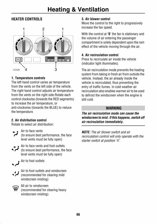
HEATER CONTROLS1. Temperature controlsThe left hand control varies air temperature from the vents on the left side of the vehicle. The right hand control adjusts air temperature from the vents on the right side.Rotate each control clockwise (towards the RED segments) to increase the air temperature, or anti-clockwise (towards the BLUE) to reduce the temperature.
2. Air distribution controlRotate to select air distribution:
Air to face vents(to ensure best performance, the face level vents must be fully open)
Air to face vents and foot outlets(to ensure best performance, the face level vents must be fully open)
Air to foot outlets
Air to foot outlets and windscreen(recommended for clearing mild windscreen misting)
All air to windscreen (recommended for clearing heavy windscreen misting)
3. Air blower controlMove the control to the right to progressively increase the fan speed.
With the control at ‘0’ the fan is stationary and the volume of air entering the passenger compartment is solely dependent upon the ram effect of the vehicle moving through the air.
4. Air recirculation controlPress to recirculate air inside the vehicle (indicator light illuminates).
The air recirculation mode prevents the heating system from taking in fresh air from outside the vehicle. Instead, the air already inside the vehicle is recirculated, thus preventing the entry of traffic fumes. In cold weather air recirculation also enables warmer air to be used to defrost the windscreen when the engine is still cold.
WARNINGThe air recirculation mode can cause the windscreen to mist. If this happens, switch off air recirculation immediately.
NOTE: The air blower switch and air recirculation control will only operate with the starter switch at position ‘II’.
0 1 2 3 4
3
1 12
H2599 4
66
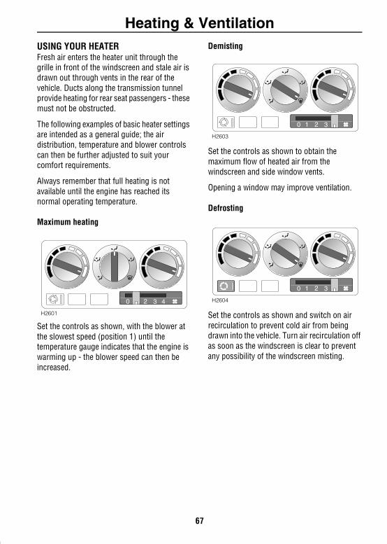
Heating & Ventilation
USING YOUR HEATERFresh air enters the heater unit through the grille in front of the windscreen and stale air is drawn out through vents in the rear of the vehicle. Ducts along the transmission tunnel provide heating for rear seat passengers - these must not be obstructed.The following examples of basic heater settings are intended as a general guide; the air distribution, temperature and blower controls can then be further adjusted to suit your comfort requirements.
Always remember that full heating is not available until the engine has reached its normal operating temperature.
Maximum heating
Set the controls as shown, with the blower at the slowest speed (position 1) until the temperature gauge indicates that the engine is warming up - the blower speed can then be increased.
Demisting
Set the controls as shown to obtain the maximum flow of heated air from the windscreen and side window vents.
Opening a window may improve ventilation.
Defrosting
Set the controls as shown and switch on air recirculation to prevent cold air from being drawn into the vehicle. Turn air recirculation off as soon as the windscreen is clear to prevent any possibility of the windscreen misting.
0 1 2 3 4
H2601
0 1 2 3 4
H2603
0 1 2 3 4
H2604
67
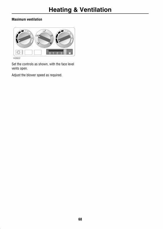
Heating & Ventilation
Maximum ventilationSet the controls as shown, with the face level vents open.
Adjust the blower speed as required.
0 1 2 3 4
H2602
68
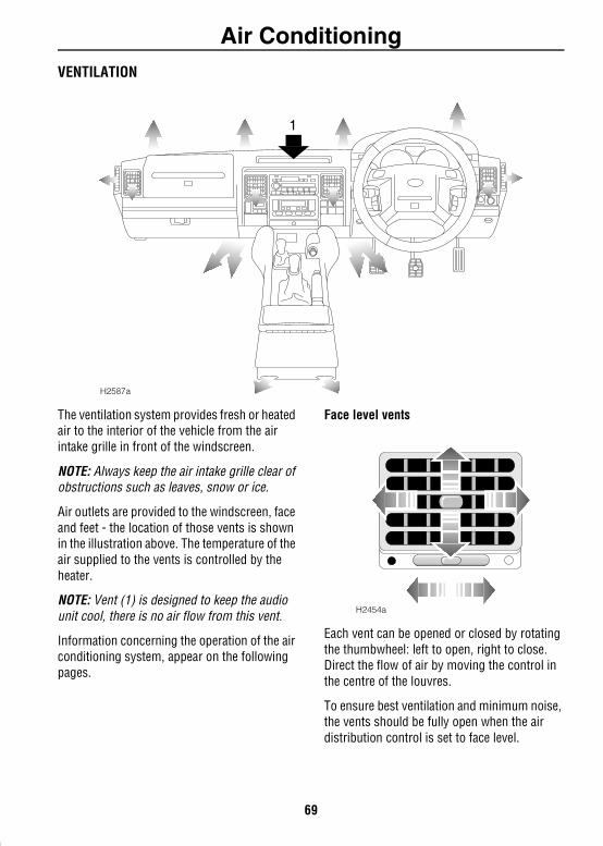
Air ConditioningAir Conditioning
VENTILATIONThe ventilation system provides fresh or heated air to the interior of the vehicle from the air intake grille in front of the windscreen.
NOTE: Always keep the air intake grille clear of obstructions such as leaves, snow or ice.
Air outlets are provided to the windscreen, face and feet - the location of those vents is shown in the illustration above. The temperature of the air supplied to the vents is controlled by the heater.
NOTE: Vent (1) is designed to keep the audio unit cool, there is no air flow from this vent.
Information concerning the operation of the air conditioning system, appear on the following pages.
Face level vents
Each vent can be opened or closed by rotating the thumbwheel: left to open, right to close. Direct the flow of air by moving the control in the centre of the louvres.
To ensure best ventilation and minimum noise, the vents should be fully open when the air distribution control is set to face level.
1
H2587a
H2454a
69
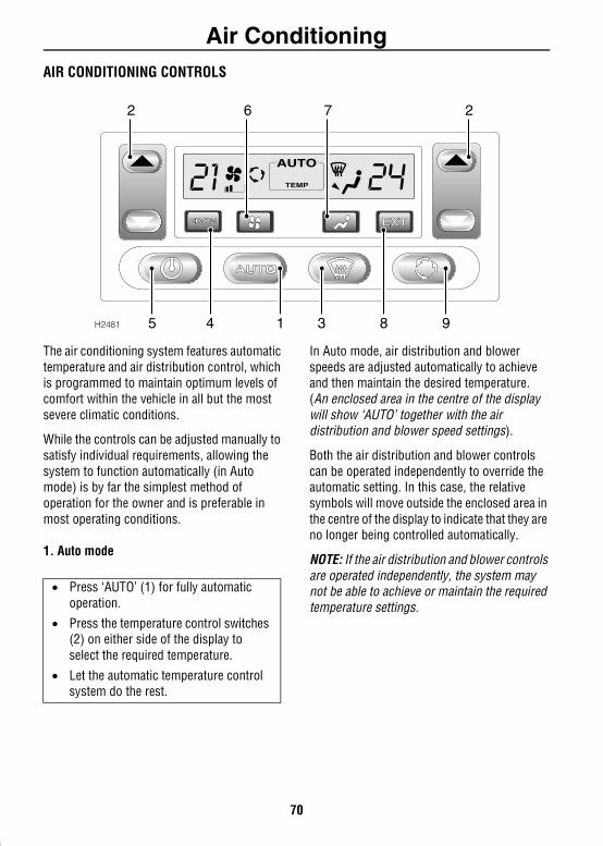
Air Conditioning
AIR CONDITIONING CONTROLSThe air conditioning system features automatic temperature and air distribution control, which is programmed to maintain optimum levels of comfort within the vehicle in all but the most severe climatic conditions.
While the controls can be adjusted manually to satisfy individual requirements, allowing the system to function automatically (in Auto mode) is by far the simplest method of operation for the owner and is preferable in most operating conditions.
1. Auto mode
In Auto mode, air distribution and blower speeds are adjusted automatically to achieve and then maintain the desired temperature. (An enclosed area in the centre of the display will show ‘AUTO’ together with the air distribution and blower speed settings).
Both the air distribution and blower controls can be operated independently to override the automatic setting. In this case, the relative symbols will move outside the enclosed area in the centre of the display to indicate that they are no longer being controlled automatically.
NOTE: If the air distribution and blower controls are operated independently, the system may not be able to achieve or maintain the required temperature settings.
H2481
TEMP
2762
983145
• Press ‘AUTO’ (1) for fully automatic operation.
• Press the temperature control switches (2) on either side of the display to select the required temperature.
• Let the automatic temperature control system do the rest.
70
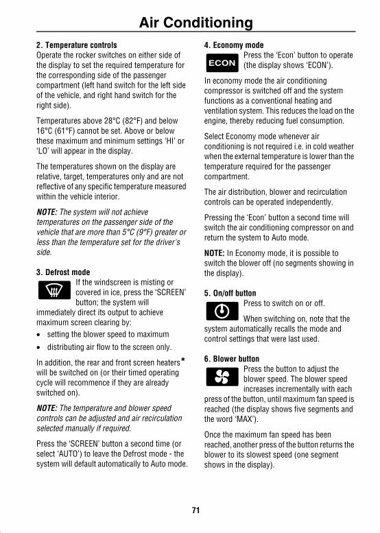
Air Conditioning
2. Temperature controls Operate the rocker switches on either side of the display to set the required temperature for the corresponding side of the passenger compartment (left hand switch for the left side of the vehicle, and right hand switch for the right side).Temperatures above 28°C (82°F) and below 16°C (61°F) cannot be set. Above or below these maximum and minimum settings ‘HI’ or ‘LO’ will appear in the display.
The temperatures shown on the display are relative, target, temperatures only and are not reflective of any specific temperature measured within the vehicle interior.
NOTE: The system will not achieve temperatures on the passenger side of the vehicle that are more than 5°C (9°F) greater or less than the temperature set for the driver's side.
3. Defrost modeIf the windscreen is misting or covered in ice, press the ‘SCREEN’ button; the system will
immediately direct its output to achieve maximum screen clearing by:• setting the blower speed to maximum
• distributing air flow to the screen only.
In addition, the rear and front screen heaters* will be switched on (or their timed operating cycle will recommence if they are already switched on).
NOTE: The temperature and blower speed controls can be adjusted and air recirculation selected manually if required.
Press the ‘SCREEN’ button a second time (or select ‘AUTO’) to leave the Defrost mode - the system will default automatically to Auto mode.
4. Economy modePress the ‘Econ’ button to operate (the display shows ‘ECON’).
In economy mode the air conditioning compressor is switched off and the system functions as a conventional heating and ventilation system. This reduces the load on the engine, thereby reducing fuel consumption.
Select Economy mode whenever air conditioning is not required i.e. in cold weather when the external temperature is lower than the temperature required for the passenger compartment.
The air distribution, blower and recirculation controls can be operated independently.
Pressing the ‘Econ’ button a second time will switch the air conditioning compressor on and return the system to Auto mode.
NOTE: In Economy mode, it is possible to switch the blower off (no segments showing in the display).
5. On/off button Press to switch on or off.
When switching on, note that the system automatically recalls the mode and control settings that were last used.
6. Blower buttonPress the button to adjust the blower speed. The blower speed increases incrementally with each
press of the button, until maximum fan speed is reached (the display shows five segments and the word ‘MAX’).
Once the maximum fan speed has been reached, another press of the button returns the blower to its slowest speed (one segment shows in the display).
71
Air Conditioning
7. Air distribution controlPress the button to adjust. Air distribution changes incrementally with each press of the switch in the
following sequence:
Face level vents
Foot and face level vents
Foot level vents
Foot level, windscreen and side window vents
Windscreen and side window vents
A further operation of the button returns to the start of the sequence.
NOTE: If the button is pressed for more than one second, air distribution will automatically default to foot and face level vents.
8. External temperaturePress the button to display. The external temperature is displayed for approximately 6 seconds, after
which the display reverts to its previous state.
NOTE: While the air conditioning system is switched off, the external temperature can be displayed briefly by pressing the button.
9. Air recirculationThe air recirculation feature can be used to prohibit the entry of air from outside the vehicle,
alternatively recirculating the air inside the vehicle instead. This is useful to prevent the entry of traffic fumes.
The feature also significantly influences the dehumidifying and cooling performance of the air-conditioning system. Therefore, in Auto mode, air recirculation is controlled automatically to enable the air-conditioning system to achieve its optimum performance.
However, the feature is also manually selectable in Auto, Defrost and Economy modes, as follows:
In Auto mode:• Press the button briefly (display shows
recirculation symbol):Air recirculation operates until the control is pressed a second time to switch off.
• Press and hold for 2 seconds (two bleeps will sound, display shows recirculation symbol):Air recirculation operates for a pre-timed period of 4-6 minutes only.
In Defrost and Economy modes: • Press the control briefly (display shows
recirculation symbol): Air recirculation operates for a pre-timed period of 4-6 minutes only.
• Press and hold for 2 seconds (two bleeps will sound, display shows recirculation symbol):Air recirculation operates until the control is pressed a second time to switch off.
NOTE: Prolonged recirculation may cause the windows to mist.
72
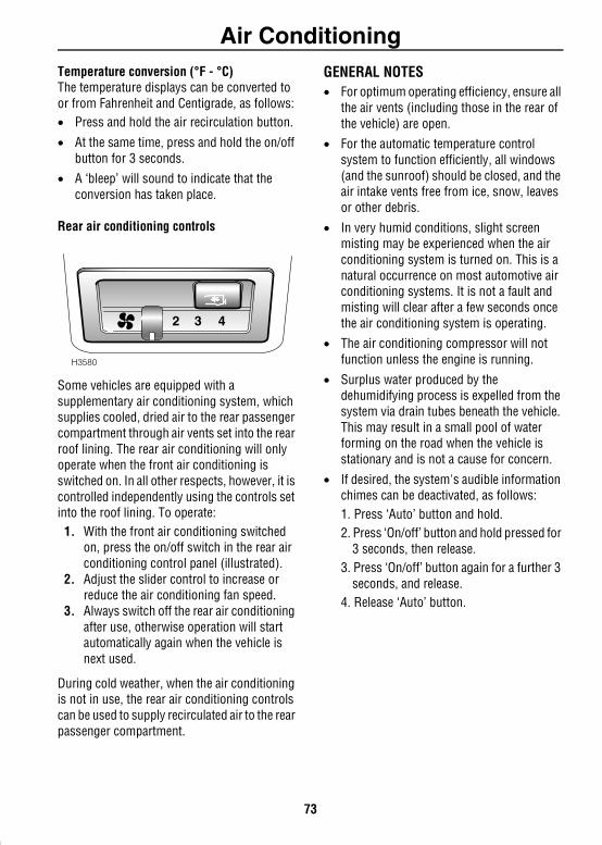
Air Conditioning
Temperature conversion (°F - °C)The temperature displays can be converted to or from Fahrenheit and Centigrade, as follows:• Press and hold the air recirculation button.• At the same time, press and hold the on/off button for 3 seconds.
• A ‘bleep’ will sound to indicate that the conversion has taken place.
Rear air conditioning controls
Some vehicles are equipped with a supplementary air conditioning system, which supplies cooled, dried air to the rear passenger compartment through air vents set into the rear roof lining. The rear air conditioning will only operate when the front air conditioning is switched on. In all other respects, however, it is controlled independently using the controls set into the roof lining. To operate:
1. With the front air conditioning switched on, press the on/off switch in the rear air conditioning control panel (illustrated).
2. Adjust the slider control to increase or reduce the air conditioning fan speed.
3. Always switch off the rear air conditioning after use, otherwise operation will start automatically again when the vehicle is next used.
During cold weather, when the air conditioning is not in use, the rear air conditioning controls can be used to supply recirculated air to the rear passenger compartment.
GENERAL NOTES• For optimum operating efficiency, ensure all
the air vents (including those in the rear of the vehicle) are open.
• For the automatic temperature control system to function efficiently, all windows (and the sunroof) should be closed, and the air intake vents free from ice, snow, leaves or other debris.
• In very humid conditions, slight screen misting may be experienced when the air conditioning system is turned on. This is a natural occurrence on most automotive air conditioning systems. It is not a fault and misting will clear after a few seconds once the air conditioning system is operating.
• The air conditioning compressor will not function unless the engine is running.
• Surplus water produced by the dehumidifying process is expelled from the system via drain tubes beneath the vehicle. This may result in a small pool of water forming on the road when the vehicle is stationary and is not a cause for concern.
• If desired, the system's audible information chimes can be deactivated, as follows:1. Press ‘Auto’ button and hold.2. Press ‘On/off’ button and hold pressed for
3 seconds, then release.3. Press ‘On/off’ button again for a further 3
seconds, and release.4. Release ‘Auto’ button.
2 43
H3580
73
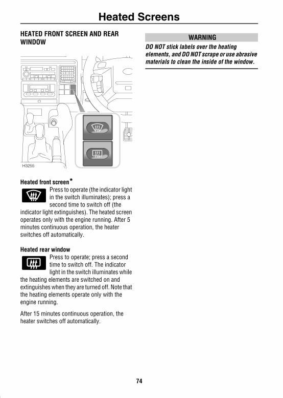
Heated ScreensHeated Screens
HEATED FRONT SCREEN AND REAR WINDOWHeated front screen*Press to operate (the indicator light in the switch illuminates); press a second time to switch off (the
indicator light extinguishes). The heated screen operates only with the engine running. After 5 minutes continuous operation, the heater switches off automatically.
Heated rear window Press to operate; press a second time to switch off. The indicator light in the switch illuminates while
the heating elements are switched on and extinguishes when they are turned off. Note that the heating elements operate only with the engine running.
After 15 minutes continuous operation, the heater switches off automatically.
WARNINGDO NOT stick labels over the heating elements, and DO NOT scrape or use abrasive materials to clean the inside of the window.
H3255
74
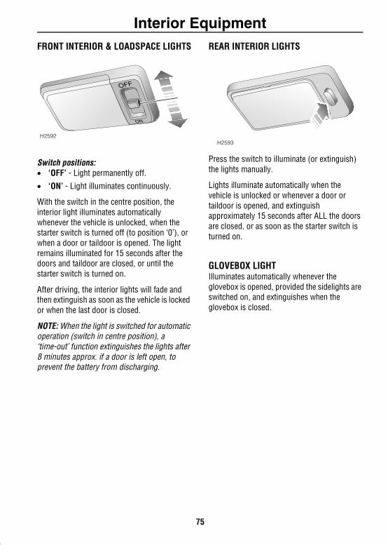
Interior EquipmentInterior Equipment
FRONT INTERIOR & LOADSPACE LIGHTSSwitch positions:• ‘OFF’ - Light permanently off.
• ‘ON’ - Light illuminates continuously.
With the switch in the centre position, the interior light illuminates automatically whenever the vehicle is unlocked, when the starter switch is turned off (to position ‘0’), or when a door or taildoor is opened. The light remains illuminated for 15 seconds after the doors and taildoor are closed, or until the starter switch is turned on.
After driving, the interior lights will fade and then extinguish as soon as the vehicle is locked or when the last door is closed.
NOTE: When the light is switched for automatic operation (switch in centre position), a ‘time-out’ function extinguishes the lights after 8 minutes approx. if a door is left open, to prevent the battery from discharging.
REAR INTERIOR LIGHTS
Press the switch to illuminate (or extinguish) the lights manually.
Lights illuminate automatically when the vehicle is unlocked or whenever a door or taildoor is opened, and extinguish approximately 15 seconds after ALL the doors are closed, or as soon as the starter switch is turned on.
GLOVEBOX LIGHTIlluminates automatically whenever the glovebox is opened, provided the sidelights are switched on, and extinguishes when the glovebox is closed.
H2592
OFF
ON
H2593
75
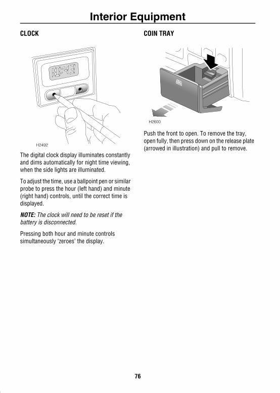
Interior Equipment
CLOCKThe digital clock display illuminates constantly and dims automatically for night time viewing, when the side lights are illuminated.
To adjust the time, use a ballpoint pen or similar probe to press the hour (left hand) and minute (right hand) controls, until the correct time is displayed.
NOTE: The clock will need to be reset if the battery is disconnected.
Pressing both hour and minute controls simultaneously ‘zeroes’ the display.
COIN TRAY
Push the front to open. To remove the tray, open fully, then press down on the release plate (arrowed in illustration) and pull to remove.
H2492
H2600
76
Interior Equipment
CIGAR LIGHTER*With the starter switch turned on, press the lighter in to heat up. When it has reached the correct temperature it will partially eject and can then be withdrawn for use.• ONLY hold the cigar lighter by the handle.
• DO NOT plug accessories into the cigar lighter socket unless they are approved by Land Rover (see ‘AUXILIARY POWER SOCKET’, page 79, for more information).
NOTE: On vehicles not fitted with a cigar lighter, the power socket is protected by a removable blank cover.
ASHTRAYS
WARNINGDO NOT use the ashtrays for disposing of waste paper or other combustible items.
FrontPush the front of the ashtray to open. To remove the ashtray, open fully, then press down on the release plate (arrowed in illustration) and pull to remove.
H2503
77
Interior Equipment
RearPush the front of the ashtray on the right hand side to open. To remove, open the ashtray and then carefully lever the tray downwards to disengage the upper pivot.
Refit by locating the upper pivot and then easing the ashtray into a position whereby the lower pivot can also be engaged.
UNDER SEAT STOWAGE BOX
To gain access, depress the catch (arrowed in illustration) and open the lid.
NOTE: On some models the stowage box provides the location for a CD autochanger.
H2594
H2526
78
Interior Equipment
AUXILIARY POWER SOCKETAn auxiliary power socket is mounted immediately behind the rear seat on the left hand side of the loadspace. This can be used to power Land Rover approved accessories that use a maximum of 180 watts.
Always run the engine during prolonged use of electrical accessories, otherwise the battery may become discharged.
WARNINGNEVER plug non-approved accessories into the power socket - damage to the vehicle's electrical systems could occur.
CUP HOLDERS
WARNINGThe driver should not drink and should not use the cup holder while driving.
If the cup holder is retractable, it should be kept closed when not in use.
DO NOT place anything other than suitable drinks containers in the cup holder, because such items may be thrown about in the compartment and possibly injure occupants in the event of an accident or emergency manoeuvre.
Do not carry open-top drink containers in the cup holders while the vehicle is in motion; a spilled hot drink could cause personal injury. Spilled drinks can also damage upholstery, carpeting and electrical components.
Use only for soft containers. DO NOT use to hold cups made of glass, china or hard plastic, as these may cause injury in the event of an accident or emergency manoeuvre. Unopened, sealed containers (drinks cans, for example) are hard objects and may also cause injury.
H2559
79
Interior Equipmentrd
Front*Push leading edge of tray to open.
Rear (2nd row seats)*
With the centre armrest lowered, press the front of the cup holder tray to open.
Rear (occasional 3 row seats)*
The cup holder and trinket tray are fitted to the individual seats and are accessible when the third row occasional rear seats are erected for use (see ‘OCCASIONAL REAR SEATS’, page 28). The cup holder and trinket tray are located on the outboard side of the seat.
WARNINGRemove any drink containers or personal belongings from the cup holders and trinket trays, BEFORE returning the occasional rear seats to their stowed position - damage to the seats could occur.
NOTE: If rear air conditioning is fitted to the vehicle, only the right-hand seat is equipped with a cup holder and trinket tray.
H2455
H2550
H3873
80
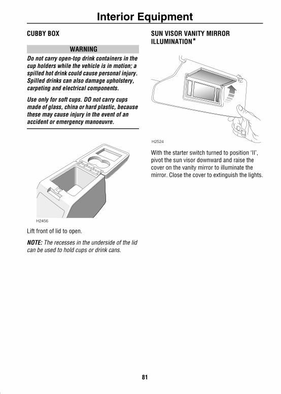
Interior Equipment
CUBBY BOXWARNINGDo not carry open-top drink containers in the cup holders while the vehicle is in motion; a spilled hot drink could cause personal injury. Spilled drinks can also damage upholstery, carpeting and electrical components.
Use only for soft cups. DO not carry cups made of glass, china or hard plastic, because these may cause injury in the event of an accident or emergency manoeuvre.
Lift front of lid to open.
NOTE: The recesses in the underside of the lid can be used to hold cups or drink cans.
SUN VISOR VANITY MIRROR ILLUMINATION*
With the starter switch turned to position ‘II’, pivot the sun visor downward and raise the cover on the vanity mirror to illuminate the mirror. Close the cover to extinguish the lights.
H2456
H2524
81
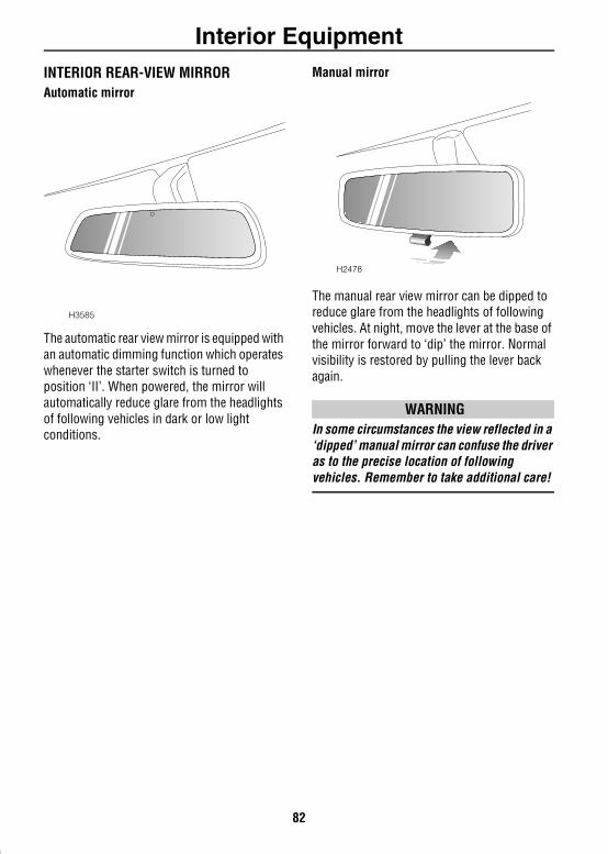
Interior Equipment
INTERIOR REAR-VIEW MIRRORAutomatic mirrorThe automatic rear view mirror is equipped with an automatic dimming function which operates whenever the starter switch is turned to position ‘II’. When powered, the mirror will automatically reduce glare from the headlights of following vehicles in dark or low light conditions.
Manual mirror
The manual rear view mirror can be dipped to reduce glare from the headlights of following vehicles. At night, move the lever at the base of the mirror forward to ‘dip’ the mirror. Normal visibility is restored by pulling the lever back again.
WARNINGIn some circumstances the view reflected in a ‘dipped’ manual mirror can confuse the driver as to the precise location of following vehicles. Remember to take additional care!
H3585
H2478
82

CompassCompass
COMPASS MIRROR*WARNINGThe compass is a direction aid only. While drivers may wish to observe the compass display while driving, it must not be allowed to distract from proper observation of traffic, road conditions and other hazards, either on the public highway or while driving off-road.
Whenever the starter switch is turned to position ‘II’, the vehicle’s direction of travel - ‘N’, ‘NE’, ‘E’, ‘SE’, ‘S’. ‘SW’, ‘W’ or ‘NW’ - will be displayed in the mirror display. The display will change whenever the vehicle direction changes by more than 22.5º from the midpoint of each compass segment (a short time delay is incorporated to prevent nuisance changes occurring).
To ensure accuracy, the compass must be calibrated and also set to the compass set zone in which the vehicle is to be used (see the appropriate map page that follows). Both operations will have been carried out before the vehicle was delivered. Re-calibration will not normally be necessary unless the battery has been disconnected for a period of time.
Calibrating the compass1. Turn the starter switch to position ‘II’. The
mirror display should show the letter ‘C’.2. If ‘C’ is not displayed, use a ballpoint pen
or similar probe to press the button on the underside of the mirror for six seconds, until ‘C’ is displayed. The button can then be released and the compass calibrated as follows.
3. Calibrate the compass by driving the vehicle in circles at 5 mph (3 km/h) or less - two circles should be sufficient - until the mirror display shows a direction (‘N’, ‘NE’, ‘E’, ‘SE’, ‘S’, ‘SW’, ‘W’ or ‘NW’).Alternatively, the compass will eventually calibrate itself during normal vehicle use, but depending upon the type of driving that is undertaken, this may take considerably longer.
Setting the compassVariations in the earth’s magnetic field cause changes to occur in the compass reading, as the vehicle is driven from one set zone to another. However, it should be noted that magnetic variation between adjacent zones is only 4º, and for most motoring situations, resetting the compass should only be necessary if the vehicle has crossed more than one zone, or calibration was carried out in any zone other than zone 8.
Note that the precise points at which the set zones change cannot be accurately plotted and that drivers situated in an area where zones merge, should not need to reset the compass every time the vehicle crosses from one to another.
H3055
83
Compass
To set the compass:1. Identify the appropriate zone for your location (see maps on the following pages).
2. Turn the starter switch to position ‘II’.3. Using a ballpoint pen or similar probe,
press and hold the button on the underside of the mirror until a zone number appears in the display. This will take approximately 3 seconds (note that the compass automatically defaults to zone 8).
4. Release the button, then continue pressing and releasing the button alternately, until the required zone number appears in the display.
5. Once the set zone has been selected, the display reappears (after approximately 10 seconds) and the compass is correctly set for the required zone.
84
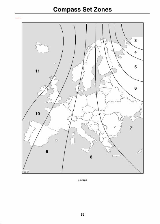
Compass Set ZonesCompass Set Zones
Europe
H3042
11
10
98
7
6
5
4
3
85
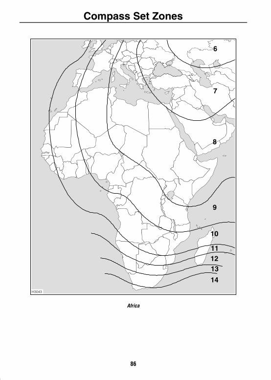
Compass Set Zones
Africa
H3043
6
7
8
9
10
111213
14
86
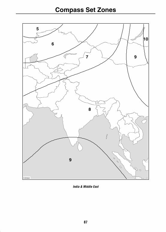
Compass Set Zones
India & Middle East
H3044
5
6
7 9
10
8
9
87
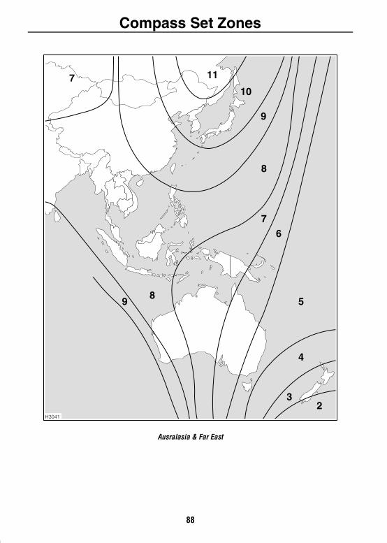
Compass Set Zones
Ausralasia & Far East
H3041
7 11
10
9
9
8
8
76
5
4
32
88
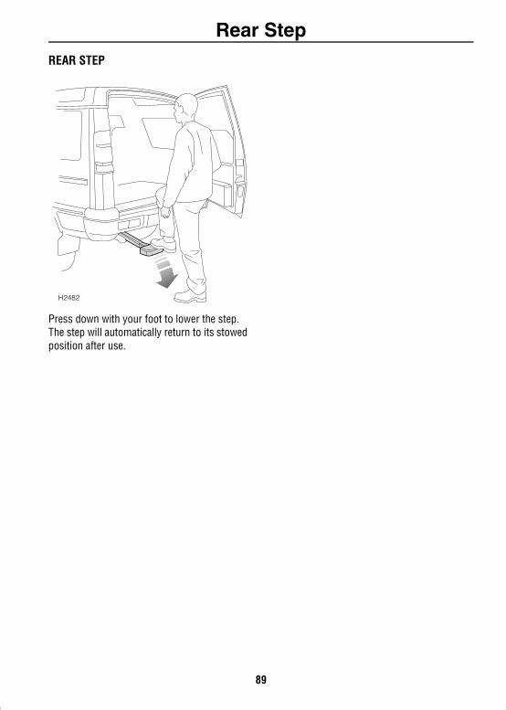
Rear StepRear Step
REAR STEPPress down with your foot to lower the step. The step will automatically return to its stowed position after use.
H2482
89
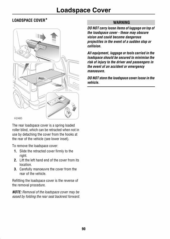
Loadspace CoverLoadspace Cover
LOADSPACE COVER*The rear loadspace cover is a spring loaded roller blind, which can be retracted when not in use by detaching the cover from the hooks at the rear of the vehicle (see lower inset).
To remove the loadspace cover:1. Slide the retracted cover firmly to the
right.2. Lift the left hand end of the cover from its
location.3. Carefully manoeuvre the cover from the
rear of the vehicle.
Refitting the loadspace cover is the reverse of the removal procedure.
NOTE: Removal of the loadspace cover may be eased by folding the rear seat backrest forward.
WARNINGDO NOT carry loose items of luggage on top of the loadspace cover - these may obscure vision and could become dangerous projectiles in the event of a sudden stop or collision.
All equipment, luggage or tools carried in the loadspace should be secured to minimise the risk of injury to the driver and passengers in the event of an accident or emergency manoeuvre.
DO NOT store the loadspace cover loose in the vehicle.
H2485
90
In-Car TelephonesIn-Car Telephones
IN-CAR TELEPHONESFor your safety, always note the following precautions before fitting an in-car telephone, or any mobile communication equipment.• Only use an installation kit incorporating anaerial external to the vehicle.
• Ensure that the installation is carried out by a competent installer.
For your safety
WARNINGUsing any hand-held appliance while driving can be dangerous. Always stop the vehicle before making a call and ensure the telephone is switched off while you are driving.
91
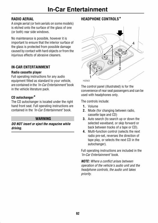
In-Car EntertainmentIn-Car Entertainment
RADIO AERIALA single aerial (or twin aerials on some models) is etched onto the surface of the glass of one (or both) rear side windows.No maintenance is possible, however it is important to ensure that the interior surface of the glass is protected from possible damage caused by contact with hard objects or from the injurious effects of abrasive cleaners.
IN-CAR ENTERTAINMENTRadio cassette playerFull operating instructions for any audio equipment fitted as standard to your vehicle, are contained in the ‘In-Car Entertainment’ book in the vehicle literature pack.
CD autochanger*The CD autochanger is located under the right hand front seat. Full operating instructions are contained in the ‘In-Car Entertainment’ book.
WARNINGDO NOT insert or eject the magazine while driving.
HEADPHONE CONTROLS*
The control panel (illustrated) is for the convenience of rear seat passengers and can be used with headphones only.
The controls include:1. Volume2. Mode (for changing between radio,
cassette tape and CD)3. Auto search (to search up or down the
selected waveband, or skip forward or back between tracks of a tape or CD).
4. Multi-function control (selects the next radio pre-set, reverses the direction of tape play, or selects the next CD in the autochanger).
Full operating instructions are included in the ‘In-Car Entertainment’ book.
NOTE: Where a conflict arises between operation of the vehicle's audio unit and the headphone controls, the audio unit takes priority.
H2563
MODE
1
3
2
4
92
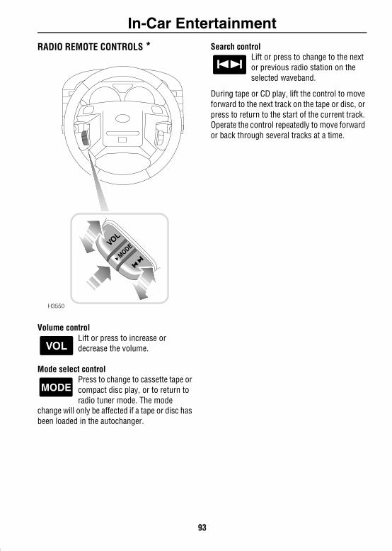
In-Car Entertainment
RADIO REMOTE CONTROLS *Volume controlLift or press to increase or decrease the volume.
Mode select controlPress to change to cassette tape or compact disc play, or to return to radio tuner mode. The mode
change will only be affected if a tape or disc has been loaded in the autochanger.
Search controlLift or press to change to the next or previous radio station on the selected waveband.
During tape or CD play, lift the control to move forward to the next track on the tape or disc, or press to return to the start of the current track. Operate the control repeatedly to move forward or back through several tracks at a time.
H3550
VOL
MODE
VOL
MODE
93

94
Driving & OperatingStarting & Driving
95
STEERING COLUMN LOCK . . . . . . . . . . . . . . . . . 89STARTER SWITCH. . . . . . . . . . . . . . . . . . . . . . . . 89STARTING - Petrol models . . . . . . . . . . . . . . . . . 90STARTING - Diesel models . . . . . . . . . . . . . . . . . 91DRIVING . . . . . . . . . . . . . . . . . . . . . . . . . . . . . . . 92FUEL ECONOMY . . . . . . . . . . . . . . . . . . . . . . . . . 93AUXILIARY EQUIPMENT . . . . . . . . . . . . . . . . . . . 93EMISSION CONTROL SYSTEM . . . . . . . . . . . . . . 93
Catalytic ConverterCATALYTIC CONVERTER . . . . . . . . . . . . . . . . . . . 94
Fuel FillingSAFETY ON THE FORECOURT . . . . . . . . . . . . . . . 96FUEL FILLER . . . . . . . . . . . . . . . . . . . . . . . . . . . . 96TYPE OF FUEL . . . . . . . . . . . . . . . . . . . . . . . . . . . 97FUEL FILLING . . . . . . . . . . . . . . . . . . . . . . . . . . . 98EMPTY FUEL TANK . . . . . . . . . . . . . . . . . . . . . . . 98FUEL CUT-OFF SWITCH. . . . . . . . . . . . . . . . . . . . 99
Manual GearboxGEAR LEVER . . . . . . . . . . . . . . . . . . . . . . . . . . . 100
Automatic TransmissionGEAR SELECTOR . . . . . . . . . . . . . . . . . . . . . . . . 101MODE SWITCH . . . . . . . . . . . . . . . . . . . . . . . . . 103
Transfer GearboxTRANSFER GEARBOX . . . . . . . . . . . . . . . . . . . . 104USING THE TRANSFER GEARBOX. . . . . . . . . . . 104
Cruise ControlCRUISE CONTROL . . . . . . . . . . . . . . . . . . . . . . 106
BrakesFOOT BRAKE. . . . . . . . . . . . . . . . . . . . . . . . . . . 108HANDBRAKE. . . . . . . . . . . . . . . . . . . . . . . . . . . 109ANTI-LOCK BRAKES . . . . . . . . . . . . . . . . . . . . . 109
Traction ControlELECTRONIC TRACTION CONTROL . . . . . . . . . 111
Hill Descent ControlHILL DESCENT CONTROL. . . . . . . . . . . . . . . . . 112
Active Cornering EnhancementACTIVE CORNERING ENHANCEMENT . . . . . . . 114
Self-levelling SuspensionSELF-LEVELLING SUSPENSION . . . . . . . . . . . . 116AUTOMATIC OPERATION . . . . . . . . . . . . . . . . . 116MANUAL OPERATION. . . . . . . . . . . . . . . . . . . . 116WARNING LIGHTS . . . . . . . . . . . . . . . . . . . . . . 118
TowingTOWING . . . . . . . . . . . . . . . . . . . . . . . . . . . . . . 119
Load CarryingLUGGAGE ANCHOR POINTS. . . . . . . . . . . . . . . 121STORAGE BINS. . . . . . . . . . . . . . . . . . . . . . . . . 121ROOF RACKS . . . . . . . . . . . . . . . . . . . . . . . . . . 122
96
Copyright © 2022 FDOKUMEN