CVSP 208M Crossroads of Modernity - American University of ...
Upload
khangminh22Category
view
0download
0
ICST 2016
Controlling of Traffic Light in Four Crossroads
By Visual Basic
Noveri Lysbetti Marpaung1*
, Edy Ervianto2, Rahyul Amri
3
1Department of Electrical Engineering, University of Riau
2Department of Electrical Engineering, University of Riau
3Department of Electrical Engineering, University of Riau
[email protected], [email protected], [email protected]
*Corresponding Author
Received: 11 October 2016, Accepted: 4 November 2016 Published online: 14 February 2017
Abstract: Many crossroads in highways can cause bustle for officers to control traffic flows in well organize
and accurately. Less of awareness of people who use the road, to follow traffic regulation when they are on the
roads, increases traffic jams or accidents, possible happen in crossroads is base of this research. Objective of
research is to make a simulation of traffic light circuit controller with four crossroads by Visual Basic. This
research discusses about controller of active time of traffic lights in four crossroads uses simulation program
based on Visual Basic. Supported components like transistor, relay, and regulation to keep stable in reading
program. This research produces a simulation to control traffic lights in four crossroads with two conditions,
Normal Condition (from 6am to 11pm), when all traffic lights active changeable and Quiet Condition (from
11pm to 6am) when yellow lamp actives flicker continuously. Sequence of active traffic lights, starts yellow
lamp actives 3seconds, followed green lamp actives 41seconds, red lamp actives 132seconds in every crossroad,
after got supply and program from software interface. Movement of traffic lights in four crossroads is
clockwise. Using of Data Ports in two conditions, Active High and Active Low. System works as its framework.
Keywords: Power supply; Traffic lights; Conditions of road; Timing Diagram; Based on The Sequence of
Active Lights, can be learned the using of Data Ports in two conditions, Active High and Active Low.
1. Introduction
Highway is transportation access that the most needed. Many crossroads in highway contribute to
increase traffic jam. The rising of crossroads in one street is a proof that level from users of road in
that part also raises. This circumtance will be followed with many traffic jams or accidents in that
path. To overcome this problem, a good controling is needed in every crossroad to avoid many
unpredictable things, for safety to every user of that road.
If this controling will be done by people, it will give many problems. For certain time, an officer
in a road will be easier to control the traffic jams in two or three crossroads. However, that person can
not do that in a long time without break because he/she will be tired if working continuously along the
day. In addition, if one road has four crossroads or more, so that officer has problems to control this
condition. It is also ineffective for one man to do it.
To handle this situation, using traffic lights in crossroads is effective. It can reduce the level of
traffic jams. It also helps the officers because it will never be tired like human. However, to make this
traffic light works continuously so, a good electrical source is needed to supply the system of traffic
light without stop. Traffic light is one of traffic signs which familiar and can be found in almost every
crossroad.
Generally, controling of traffic lights with four crossroads uses electronic components as
controling element so it is hard to maintain and change the pattern of time to adopt the change of
Controlling of Traffic Light In Four Crossroads By Visual Basic
Applied Science and Technology, Vol.1 No.1 2017 http://www.estech.org 522
traffic conditions. To anticipate the lack of electronic controling, the authors make a traffic controler
based on Visual Basic to make it easier in operation and changing traffic conditions.
Basically, context of the problem in this research is how to control traffic lights in every
crossroads to reduce traffic jams and accidents in the roads.
This problem can be observed by:
- displaying the length of active time from every traffic light in every crossroad so it can avoid the
traffic jam in every crossroad.
- displaying the timing diagram from every traffic light in every crossroad based on the conditions
of traffic, to see which path will go first.
This research can be used as replacement of officers in roads to control traffic lights in every
crossroad to reduce traffic jams and accidents in the roads.
The problem in this research is how to identify the length of active time from every traffic light
in every crossroad and how to produce the timing diagram from every traffic light in every crossroad
based on the conditions of traffic.
The objective of this research is to make a simulation of traffic light circuit controller with four
crossroads by Visual Basic.
The scopes of this research are:
- This research refers to traffic lights in Crossroad of Tuanku Tambusai Street –Soekarno Hatta
Street, Pekanbaru on Juli 1st, 2015 from 12 pm until 12 pm.
- The length of active time from every traffic light in every crossroad
- Timing diagram from every traffic light in every crossroad based on the conditions of traffic
- This research is focussed for controoling trafiic lights in four crossroads to avoid the meeting
point from two crossroads.
This paper is organized as follows. In section 2, Base Theory of this research, such as Traffic
light, Parallel Port, Visual Basic, and Form are explained. Section 3 describes Material and
Methodology. The implementation results and discussion are presented in section 4. Finally, section 5
concludes the paper.
2. Related Works/Literature Review
2.1. Traffic Light
Traffic light is one of control tools uses put lamps on the crossroad to control the flow of traffic.
This thing is done to control the movement of vehicles on each path of its, that can move changeable
so they will not disturb one each other’s flow from available vehicles.
Based on Regulation of Relationship Ministry Number : KM 62 Year 2003 about A Tool as
Traffic Signal Giver (APILL), traffic light is a set of technical equipment uses lamp signal to control
the movement of vehicles which crosses in parts of a road.
Based on Regulatalion from Director of Land Relationship General Number. 273/HK.105/DR
JD/96 about Technical Guidance of Traffic Controlling in The Stand Alone Crossroad with a Traffic
Giver Tool, that a crossroad should be put a traffic giver tool is:
1. The average of traffic minimal flow uses crossroad more than 750 vehicles/hour for eight hours
in a day.
2. When waiting time / average obstacle of vehicles in crossroad more than 30 seconds.
3. If accident often happens on the connected crossroad.
If designed traffic light is bad and does not maintain well so as a consequence number of
accidents will increase, give long delay and infringement of traffic light. Base principle to control
time of traffic light is releasing of traffic flow when traffic light is green, done as effective as possible
to produce the smallest delay.
2.2. Parallel Port of Computer
Parallel Port or Printer Port is one interface in a computer. Interface is used electronic circuit to
connect between two systems so that system can communicate. In this research, interface has a task to
adjust the framework of hardware instrument with the framework of compter. With assistance of
interface, computer can be used as a giver and receiver signal from controlled circuit.

Controlling of Traffic Light In Four Crossroads By Visual Basic
Applied Science and Technology, Vol.1 No.1 2017 http://www.estech.org 523
Parallel Port or Printer Port consists of three parts, such as Data Port (DP) address in 378h (888),
Printer Control (PC) address in 37Ah (890), and Printer Status (PS) address in 379h (889). DP is used
to send printed data by printer, PC is used to send controlled codes from computer to printer, and PS
is used to send status codes of printer to computer.
PC Port and DP Port are read/write ports. PS is read only port. This ability is only owned by
Enhanced Parallel Port (EPP). On the other hand, on Standar Parallel Port, DP Port has write only
ability. DB-25 Female configuration, is shown in Figure 1.
Figure 1. DB-25 Female configuration, is shown in
2.3. Visual Basic
Visual Basic is one of programming languages can be used to arrange and make interface
program. In its development, application of Visual Basic menggunakan uses visual Graphical User
Inteface (GUI) to arrange interface. Microsoft Visual Basic 6.0 has many superiorities. Some of these
superiorities are :
1. Its display is easy to understand.
2. Base of programming language uses Beginner All-Pulpose Symbolic Intruction Code (BASIC).
3. Can use the ability of Microsoft Windows well.
4. Compiler can be done quickly.
Display of Visual Basic interface with its parts, can be seen in Figure 2.
Figure 2. Display of Visual Basic interface with its parts

Controlling of Traffic Light In Four Crossroads By Visual Basic
Applied Science and Technology, Vol.1 No.1 2017 http://www.estech.org 524
2.4. Form
Form is work sheet can be used to design the displaying from every item that will be displayed
based on made program. Display of form sheets, is shown in Figure 3.
Figure 3. Display of form sheets
In this case, the size of form can be changed in making program interface. In a form, consists of
menu, knob, box of list and other items. Project name is a name of project.
3. Material & Methodology
3.1. Data
Data was collected by observation in the highway. Based on this data, Researchers make a design
of circuit and program to get the length of active time from every light in four crossroads and timing
diagrams for all conditions happen in the highway refer to the occurences in the highways.
3.2. Method
Methods in this research are :
1. Make a design and program from a circuit of traffic light controler for four crossroads.
2. To apply the circuit design in a real ricuit.
3. Execute the tool.
4. Do tests to the tool.
Diagram block from this research, is shown in Figure 4.
Figure 4. Diagram block from this research
From Figure 4, can be seen that power supply is a source to supply used Parallel Ports and Relay
Circuit Driver. Using of Parallel Ports for Relay Circuit Driver are determined by Visual Basic to
control which traffic light will be active in every second for 24 hours.
The framework of this system is started with initiation number of cross-roads, number of lights,
conditions of road, and active time of every traffic light in four crossroads for 24 hours. If condition is
quiet, means from 12 pm to 6 am, so yellow lamp will be active and flicker continuously in 4
crossroads. If condition is not quiet, means from 6 am to 11 pm, so the sequence of yellow lamp will
be active in three seconds, followed green lamp actives for 41 seconds, and red lamp will be active in
132 seconds will occur sontinuously. Flowchart of this research, shown in Figure 5.
Visual Basic (Parallel Ports) Relay Circuit Driver
Power Supply
Traffic Lights

Controlling of Traffic Light In Four Crossroads By Visual Basic
Applied Science and Technology, Vol.1 No.1 2017 http://www.estech.org 525
Figure 5. Flowchart of this research
Crossroads =
4
Start
Initiation number of cross-
roads, number of lights,
conditions of road, active time
No
Yes Yellow lamp will be active
and flicker continuously in 4
crossroads
Is a certain
crossroad quiet?
Yes
No
No
No Yes
No
No
Yes
Yes
Yes
No
Crossroad
1 =
yellow?
Crossroad 1
= green
lamp?
Time
is
over?
Vehicles get ready
Vehicles running
Time
is
Crossroad =
Crossroad + 1
Vehicles stop
Yes Crossroad =
4?
End
Yellow lamps active
continuously in four crossroads
Crossroad
1 = red

Controlling of Traffic Light In Four Crossroads By Visual Basic
Applied Science and Technology, Vol.1 No.1 2017 http://www.estech.org 526
4. Results and Discussion
4.1. Result
This research refers to traffic lights in Crossroad of Tuanku Tambusai Street –Soekarno Hatta
Street, Pekanbaru on Juli 1st, 2015 from 12 pm until 12 pm. There is no change in the active length of
green lamp in Normal Condition or Peak Condition. The sequences of active traffic lights in this
research are Yellow Lamp – Green Lamp – Red Lamp, whereas :
1. Yellow lamp will be active for three second after red lamp is off as a signal for rider/driver to
decrease the speed of their vehicles or stop.
2. Green Lamp is active for 41 seconds, after yellow lamp is off to beckon rider/driver to ride/drive
their vehicles.
3. Red Lamp will be active after green lamp is off as a signal for all of vehicles to stop.
The results of this work are :
1. Testing of Power Supply
Power Supply circuit is the most important part from one circuit system because the availability
of power supply determines the system can work as hoped. This testing performed to know whether
power supply circuit can work as its design.
The result of this test shows that circuit of power supply can produce output voltage as planned,
even there is a light reduction from measuring result. The produced output voltage is 0.26 Volt.
2. Form of Time Controlling
The content of this Form is controlling of traffic lights with the time condition in every
crossroad. Crossroad 1 is in Tuanku Tambusai Ujung Street, Crossroad 2 in Soekarno Hatta Street,
Crossroad 3 in Tuanku Tambusai Street, and Simpang 4 in Soekarno Hatta Street (Lottemart) in
Pekanbaru. With enter the length of active time of green and yellow lamp, so it shows the movement
of the timing as clockwise. Displaying of Controlling Time Form on every crossroad, is shown in
Figure 6.
a. Displaying of Controlling Time Form on
Crossroad 1
b. Displaying of Controlling Time Form on
Crossroad 2
c. Displaying of Controlling Time Form on
Crossroad 3
d. Displaying of Controlling Time Form on
Crossroad 4
Figure 6. Displaying of Controlling Time Form on every crossroad

Controlling of Traffic Light In Four Crossroads By Visual Basic
Applied Science and Technology, Vol.1 No.1 2017 http://www.estech.org 527
From Figure 6, can be seen that the movement of Controlling Time on every crossroad has
worked as the fact.
3. The Sequence of Active Lights
This testing is performed to determine which port will be used to turn on the available traffic
lights. To turn on the red, yellow and green lamp on Crossroad 1 and Crossroad 2, also red, yellow
lamp on Crossroad 3 use Port D0 – D7. All these ports are Data Ports, work as Input Ports. All of
them are Active High, means with logic 1 can activate the lamps. For green lamp on Crossroad 3 and
red, yellow and green lamp on Crossroad 4 use Port C0 – C3. These ports are Data Ports which is
Active Low, means with logic 0 will activate the lamps The Sequence of Active Lights, can be seen in
Tabel 1. It shows that all of the ports are used and working properly.
Tabel 1. The Sequence of Active Lights
Crossroad Lamp Port
D7 D6 D5 D4 D3 D2 D1 D0 C3 C2 C1 C0
1
Red 0 0 0 0 0 0 0 1 0 0 0 0
Yellow 0 0 0 0 0 0 1 0 0 0 0 0
Green 0 0 0 0 0 1 0 0 0 0 0 0
2
Red 0 0 0 0 1 0 0 0 0 0 0 0
Yellow 0 0 0 1 0 0 0 0 0 0 0 0
Green 0 0 1 0 0 0 0 0 0 0 0 0
3
Red 0 1 0 0 0 0 0 0 0 0 0 0
Yellow 1 0 0 0 0 0 0 0 0 0 0 0
Green 1 1 1 1 1 1 1 1 0 1 1 1
4
Red 1 1 1 1 1 1 1 1 1 0 1 1
Yellow 1 1 1 1 1 1 1 1 1 1 0 1
Green 1 1 1 1 1 1 1 1 1 1 1 0
4. Testing of Traffic Lights
The length of active time from every traffic light in every crossroad from available crossroads
does not depend on the traffic jam at the moment. Based on monitoring in the road, active or inactive
of traffic lights divided in two conditions, Normal condition and Quiet Condition of the road.
Figure 7. The Condition of Traffic Lights in Four Crossroads
Based on these, this highway is Quiet from 11.00 pm – 06.00 am so the active traffic light is just
the yellow lamp for all of crossroads. Normal Condition starts from 06.00 am – 11.00 pm so the
yellow lamp is active for 3 seconds, green lamp is active for 41 seconds as long as this time. Beside it,
Crossroad 1
Crossroad 3
Crossroad 4
Crossroad 2
Controlling of Traffic Light In Four Crossroads By Visual Basic
Applied Science and Technology, Vol.1 No.1 2017 http://www.estech.org 528
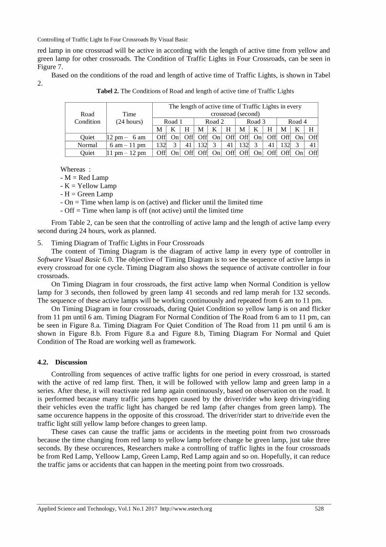
red lamp in one crossroad will be active in according with the length of active time from yellow and
green lamp for other crossroads. The Condition of Traffic Lights in Four Crossroads, can be seen in
Figure 7.
Based on the conditions of the road and length of active time of Traffic Lights, is shown in Tabel
2. Tabel 2. The Conditions of Road and length of active time of Traffic Lights
Road
Condition
Time
(24 hours)
The length of active time of Traffic Lights in every
crossroad (second)
Road 1 Road 2 Road 3 Road 4
M K H M K H M K H M K H
Quiet 12 pm – 6 am Off On Off Off On Off Off On Off Off On Off
Normal 6 am – 11 pm 132 3 41 132 3 41 132 3 41 132 3 41
Quiet 11 pm – 12 pm Off On Off Off On Off Off On Off Off On Off
Whereas :
- M = Red Lamp
- K = Yellow Lamp
- H = Green Lamp
- On = Time when lamp is on (active) and flicker until the limited time
- Off = Time when lamp is off (not active) until the limited time
From Table 2, can be seen that the controlling of active lamp and the length of active lamp every
second during 24 hours, work as planned.
5. Timing Diagram of Traffic Lights in Four Crossroads
The content of Timing Diagram is the diagram of active lamp in every type of controller in
Software Visual Basic 6.0. The objective of Timing Diagram is to see the sequence of active lamps in
every crossroad for one cycle. Timing Diagram also shows the sequence of activate controller in four
crossroads.
On Timing Diagram in four crossroads, the first active lamp when Normal Condition is yellow
lamp for 3 seconds, then followed by green lamp 41 seconds and red lamp merah for 132 seconds.
The sequence of these active lamps will be working continuously and repeated from 6 am to 11 pm.
On Timing Diagram in four crossroads, during Quiet Condition so yellow lamp is on and flicker
from 11 pm until 6 am. Timing Diagram For Normal Condition of The Road from 6 am to 11 pm, can
be seen in Figure 8.a. Timing Diagram For Quiet Condition of The Road from 11 pm until 6 am is
shown in Figure 8.b. From Figure 8.a and Figure 8.b, Timing Diagram For Normal and Quiet
Condition of The Road are working well as framework.
4.2. Discussion
Controlling from sequences of active traffic lights for one period in every crossroad, is started
with the active of red lamp first. Then, it will be followed with yellow lamp and green lamp in a
series. After these, it will reactivate red lamp again continuously, based on observation on the road. It
is performed because many traffic jams happen caused by the driver/rider who keep driving/riding
their vehicles even the traffic light has changed be red lamp (after changes from green lamp). The
same occurence happens in the opposite of this crossroad. The driver/rider start to drive/ride even the
traffic light still yellow lamp before changes to green lamp.
These cases can cause the traffic jams or accidents in the meeting point from two crossroads
because the time changing from red lamp to yellow lamp before change be green lamp, just take three
seconds. By these occurences, Researchers make a controlling of traffic lights in the four crossroads
be from Red Lamp, Yelloow Lamp, Green Lamp, Red Lamp again and so on. Hopefully, it can reduce
the traffic jams or accidents that can happen in the meeting point from two crossroads.

Controlling of Traffic Light In Four Crossroads By Visual Basic
Applied Science and Technology, Vol.1 No.1 2017 http://www.estech.org 529
Figure 8.a. Timing Diagram For Normal Condition of The Road
Figure 8.b. Timing Diagram For Quiet Condition of The Road
Based on people’s activities daily cause there is two conditions of time can be arranged to make
the flow of vehicles be fluently in the highway based on the length of active green lamp determined,
such as :
1. Quiet Condition
This condition occurs from 12 pm to 6 am and from 11 pm to 6 am daily because generally,
activities of people are doing in the house or closed room, not in the highways. So, the number of
vehicles in the highways in this moment should be rare, tends to quiet because people should use this
time to take a rest or stop from all of activities inside or outside of the houses.
(seconds)
(seconds)
(seconds)
132
44 3 88
88
41
41
41
3 132 41
H M
K
K
K M M
M M
K
H
H
M
(seconds)
Crossroad 1
Crossroad 2
Crossroad 3
Crossroad 4
3
3
44
H
(seconds)
(seconds)
(seconds)
K Crossroad 1
Crossroad 3
Crossroad 4
K
K
K
(seconds)
Crossroad 2
Controlling of Traffic Light In Four Crossroads By Visual Basic
Applied Science and Technology, Vol.1 No.1 2017 http://www.estech.org 530
Based on condition, the traffic light will be active is just the yellow lamp and flicker from 11 pm
to 6 am. On the other side, red lamp and green lamp are inactive at all. So, the active yellow lamp
function as a signal for the rider/driver in the highways to be careful because the dark and quiet
condition can cause the rider/driver be less wary for condition of the road at that moment.
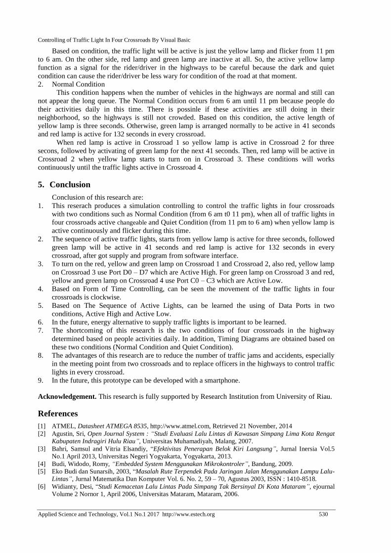
2. Normal Condition
This condition happens when the number of vehicles in the highways are normal and still can
not appear the long queue. The Normal Condition occurs from 6 am until 11 pm because people do
their activities daily in this time. There is possinle if these activities are still doing in their
neighborhood, so the highways is still not crowded. Based on this condition, the active length of
yellow lamp is three seconds. Otherwise, green lamp is arranged normally to be active in 41 seconds
and red lamp is active for 132 seconds in every crossroad.
When red lamp is active in Crossroad 1 so yellow lamp is active in Crossroad 2 for three
secons, followed by activating of green lamp for the next 41 seconds. Then, red lamp will be active in
Crossroad 2 when yellow lamp starts to turn on in Crossroad 3. These conditions will works
continuously until the traffic lights active in Crossroad 4.
5. Conclusion
Conclusion of this research are:
1. This reserach produces a simulation controlling to control the traffic lights in four crossroads
with two conditions such as Normal Condition (from 6 am t0 11 pm), when all of traffic lights in
four crossroads active changeable and Quiet Condition (from 11 pm to 6 am) when yellow lamp is
active continuously and flicker during this time.
2. The sequence of active traffic lights, starts from yellow lamp is active for three seconds, followed
green lamp will be active in 41 seconds and red lamp is active for 132 seconds in every
crossroad, after got supply and program from software interface.
3. To turn on the red, yellow and green lamp on Crossroad 1 and Crossroad 2, also red, yellow lamp
on Crossroad 3 use Port D0 – D7 which are Active High. For green lamp on Crossroad 3 and red,
yellow and green lamp on Crossroad 4 use Port C0 – C3 which are Active Low.
4. Based on Form of Time Controlling, can be seen the movement of the traffic lights in four
crossroads is clockwise.
5. Based on The Sequence of Active Lights, can be learned the using of Data Ports in two
conditions, Active High and Active Low.
6. In the future, energy alternative to supply traffic lights is important to be learned.
7. The shortcoming of this research is the two conditions of four crossroads in the highway
determined based on people activities daily. In addition, Timing Diagrams are obtained based on
these two conditions (Normal Condition and Quiet Condition).
8. The advantages of this research are to reduce the number of traffic jams and accidents, especially
in the meeting point from two crossroads and to replace officers in the highways to control traffic
lights in every crossroad.
9. In the future, this prototype can be developed with a smartphone.
Acknowledgement. This research is fully supported by Research Institution from University of Riau.
References
[1] ATMEL, Datasheet ATMEGA 8535, http://www.atmel.com, Retrieved 21 November, 2014
[2] Agustin, Sri, Open Journal System : “Studi Evaluasi Lalu Lintas di Kawasan Simpang Lima Kota Rengat
Kabupaten Indragiri Hulu Riau”, Universitas Muhamadiyah, Malang, 2007.
[3] Bahri, Samsul and Vitria Elsandiy, “Efektivitas Penerapan Belok Kiri Langsung”, Jurnal Inersia Vol.5
No.1 April 2013, Universitas Negeri Yogyakarta, Yogyakarta, 2013.
[4] Budi, Widodo, Romy, “Embedded System Menggunakan Mikrokontroler”, Bandung, 2009.
[5] Eko Budi dan Sunarsih, 2003, “Masalah Rute Terpendek Pada Jaringan Jalan Menggunakan Lampu Lalu-
Lintas”, Jurnal Matematika Dan Komputer Vol. 6. No. 2, 59 – 70, Agustus 2003, ISSN : 1410-8518.
[6] Widianty, Desi, “Studi Kemacetan Lalu Lintas Pada Simpang Tak Bersinyal Di Kota Mataram”, ejournal
Volume 2 Nornor 1, April 2006, Universitas Mataram, Mataram, 2006.

Controlling of Traffic Light In Four Crossroads By Visual Basic
Applied Science and Technology, Vol.1 No.1 2017 http://www.estech.org 531
[7] Prasetia, Rena, Catur Edi Widodo, “Teori Dan Praktek Interfacing Port Pararel Dan Port Serial Komputer
Dengan Visual Basic 6.0”, Andi Offset, Yogyakarta, 2004.
[8] Suhata, “Visual Basic Sebagai Pusat kendali Peralatan Kendali Elektronik”, PT.Elex Media Komputindo,
Jakarta, 2005.
[9] Pardede, Okthree Mahalya, “Evaluasi Kinerja Simpang Lima Giwangan Yogyakarta”, Universitas Atma
Jaya, Yogyakarta, 2009.
[10] Usman and Andi, “Teknik Antar Muka Pemrograman Mikrokontroler AT89S52”, Yogyakarta, 2008.
Copyright © 2022 FDOKUMEN