Analytical methods for calculating Continuous Symmetry Measures and the Chirality Measure
Upload
khangminh22Category
view
3download
0
University of Groningen
Controlling molecular chirality and motionvan Delden, Richard Andreas
IMPORTANT NOTE: You are advised to consult the publisher's version (publisher's PDF) if you wish to cite fromit. Please check the document version below.
Document VersionPublisher's PDF, also known as Version of record
Publication date:2002
Link to publication in University of Groningen/UMCG research database
Citation for published version (APA):van Delden, R. A. (2002). Controlling molecular chirality and motion. s.n.
CopyrightOther than for strictly personal use, it is not permitted to download or to forward/distribute the text or part of it without the consent of theauthor(s) and/or copyright holder(s), unless the work is under an open content license (like Creative Commons).
The publication may also be distributed here under the terms of Article 25fa of the Dutch Copyright Act, indicated by the “Taverne” license.More information can be found on the University of Groningen website: https://www.rug.nl/library/open-access/self-archiving-pure/taverne-amendment.
Take-down policyIf you believe that this document breaches copyright please contact us providing details, and we will remove access to the work immediatelyand investigate your claim.
Downloaded from the University of Groningen/UMCG research database (Pure): http://www.rug.nl/research/portal. For technical reasons thenumber of authors shown on this cover page is limited to 10 maximum.
Download date: 06-07-2022

Stellingen
behorende bij het proefschrift vanRichard van Delden
1. Het controleren van de chiraliteit van organische verbindingen vereist een zekerehandigheid.
Dit proefschrift.
2. De donor-acceptor gesubstitueerde moleculaire motor, zoals die in hoofdstuk 7 van ditproefschrift beschreven is, functioneert niet alleen als een motor op moleculair niveau,maar houdt zich bovendien aan de verkeersregels. Voor een verkeerslicht zal deze motorop basis van het absorptie spectrum voor rood en zelfs oranje licht stil blijven staanterwijl bij groen licht de motor zal gaan "rijden".
Dit proefschrift.
3. Het vergelijken van elegante synthetische strategieën en supramoleculaire concepten metkinderspeelgoed als respectievelijk LEGO en Meccano doet, hoewel illustratief, dewetenschappelijke inhoud van het beschreven onderzoek tekort.
Zie bijvoorbeeld: Stoddart et al., Chem. Soc. Rev. 1992, 215.Stoddart et al., Eur. J. Org. Chem. 2000, 1121.
4. In het licht van de bottom-up benadering in de nanotechnologie verrichten organischchemici het bodemonderzoek wat zal leiden tot een stevig fundament waaropdaadwerkelijk toepasbare nanotechnologische systemen gebouwd kunnen worden.
5. Hoewel de wetenschap in het algemeen poogt vooruitstrevend te zijn, wordt er buiten dewetenschap vaak sneller progressie geboekt dan binnen de wetenschap. Zo blijkt, bij hetvergelijken van dit proefschrift met het eerste proefschrift over chiroptische moleculaireschakelaars de in de tussenliggende periode geboekte vooruitgang vooral uit de in 1993geformuleerde stelling: "Gezien de immense populariteit van de schaatssport inNederland, is het onbegrijpelijk dat topschaatsers in ons land veelal moeten leven van eenminimum inkomen".
Ben de Lange, stelling 6 behorende bij het proefschrift Chiroptical Molecular Switches;Synthesis and Applications, Rijksuniversiteit Groningen, 1993.
6. De catalogi van de grote leveranciers van chemicaliën zijn als naslagwerken handiger danhet Handbook of Chemistry and Physics en worden derhalve ook vaker voor dit doelgebruikt.

7. Het door persbureau Reuters aanhalen van de publicatie van het eerste voorbeeld van eenmoleculaire motor aangedreven door licht met als auteurs twee Japanse en drieNederlandse wetenschappers als "Scientists from Germany, Denmark, and Japan alsopublished research..." zegt veel over de bekendheid van Nederland en Groningen in hetbijzonder in de rest van de wereld..
http://www.wired.com/news/medtech/0,1286,21698,00.htmlKoumura et al., Nature 1999, 401, 152.
8. Verbeelding mag dan belangrijker zijn dan kennis, maar in de wetenschap is eencombinatie van beide essentieel. Iemand met alleen verbeelding is een fantast terwijliemand met alleen kennis het best kan worden omschreven met het oer-Hollandse woordnerd.
Albert Einstein: "Imagination is more important than knowledge".
9. Het feit dat MS Word 97 en zelfs MS Word 2000 het woord nanotechnologie alsonbekend aanduiden en als vervangsuggestie het woord kanotechnologie geven zegt meerover de populariteit van de wetenschap dan over die van de kanosport.
10. Het groeiende aio-tekort leidt tot een devaluatie van de doctorstitel.
11. De typische Amerikaanse zin "I feel chemistry between us" verliest al zijn positievelading indien een chemicus deze van zijn of haar partner te horen krijgt.
12. Het klakkeloos overnemen van de ideeën van een professor is slecht voor de ontwikkelingvan een promovendus. Indien echter het Nederlandse volk zich bij de aankomendeparlementsverkiezingen klakkeloos laat leiden door de verbale vaardigheden van eenprofessor dan zou dit wel eens zeer onfortuynlijke consequenties kunnen hebben.
13. De teksten van Nederlandstalige (pop)muziek zijn gemiddeld minstens even goed als dievan Engelstalige (pop)muziek, maar lijden onder het feit dat er wel naar Nederlandseteksten geluisterd wordt terwijl menige Nederlander bij de Engelse variant slechts deklanken hoort.
14. De tijd die een chaoot kwijt is met het terugvinden van dingen is op zijn hoogst even langals de tijd die een geordend persoon kwijt is aan het ordenen. Het verschil zit in het feitdat een chaoot geen genoegen schept in het terugzoeken van dingen terwijl een geordendpersoon wel degelijk genoegen schept in het ordenen zelf.
In tegenstelling tot Harry Mulisch' De Ontdekking van de Hemel (eerste deel, hoofdstuk 11):"de orde, die hij [Max Delius] om zich heen had geschapen, leverde hen een extra jaar vanzijn leven op, dat anderen verspilden met zoeken.".

Controlling MolecularChirality and Motion
Richard Andreas van Delden

Cover illustration: M.C. Escher's "Spirals"© 2002 Cordon Art - Baarn - Holland. All rights reserved.

RIJKSUNIVERSITEIT GRONINGEN
Controlling MolecularChirality and Motion
Proefschrift
ter verkrijging van het doctoraat in deWiskunde en Natuurwetenschappenaan de Rijksuniversiteit Groningen
op gezag van deRector Magnificus, dr. D.F.J. Bosscher,
in het openbaar te verdedigen opvrijdag 26 april 2002
om 16.00 uur
door
Richard Andreas van Delden
geboren op 8 september 1974te Stadskanaal

Promotor: Prof. dr. B.L. Feringa
Beoordelingscommissie:
Prof. dr. D.J. BroerProf. dr. J.B.F.N. EngbertsProf. dr. J.C. Hummelen
Electronic version: ISBN 90-367-1609-8Printed version: ISBN 90-367-1600-4

Voorwoord
Hoewel de term chronologisch gezien onjuist is, mag dit stukje tekst, vanwege zijnprominente plaats in dit proefschrift voorwoord heten. Uiteraard is dit gedeelte van mijnproefschrift als laatste geschreven en ik wil dit voorwoord gebruiken om terugblikkendenkele mensen te bedanken. Want, als ieder ander, heb ik het beschreven werk natuurlijk nietalleen gedaan. Een groot aantal mensen is op verschillende gebieden belangrijk geweest voormij gedurende de afgelopen periode.Allereerst ben ik veel dank verschuldigd aan mijn promotor prof. dr. B.L. Feringa voor deruimte die hij mij heeft gegeven. Ruimte, in letterlijke zin in de vorm van een zuurkast en definanciële ruimte om een promotieonderzoek in zijn groep te doen en misschien welbelangrijker, ruimte in de figuurlijke zin: de ruimte om eigen ideeën te ontplooien en uit tevoeren. Deze vrijheid binnen het onderzoek heb ik zeer gewaardeerd. Daarnaast is zijn veelgeroemde, niet-aflatende ideeënstroom ook voor het onderzoek beschreven in dit proefschriftessentieel geweest. Hoewel niet al deze ideeën een uitwerking hebben gekregen in ditproefschrift, heeft een aantal hiervan toch geleid tot mooie resultaten.De leden van de beoordelingscommissie, prof. dr. D.J. Broer, prof. dr. J.B.F.N. Engberts enprof. dr. J.C Hummelen wil ik bedanken voor de zorgvuldige correctie van het manuscript.Een aantal mensen is voor mij onmisbaar geweest tijdens het onderzoek. Allereerst Marc vanGelder, vanwege de vele, niet altijd even gemakkelijke, chirale chromatografischescheidingen. Dit door hem uitgevoerde monnikenwerk is voor alle aspecten van hetonderzoek essentieel geweest en hoewel hij niet altijd even blij zal zijn geweest met weer eennieuwe te scheiden verbinding, denk ik dat we kunnen spreken van een zeer goedesamenwerking. Second, I would like to express my gratitude to Nagatoshi Koumura. I haveenjoyed the exciting experiments we have done together on the first-generation molecularmotor and your contributions to the discussions on the molecular motor research were ofgreat help to me. I also appreciate that I could occasionally make use of your incrediblesynthetic abilities. Verder ben ik dank verschuldigd aan Joost Hurenkamp die alshoofdvakstudent een deel van het synthetische werk in hoofdstuk 2 en een deel van het werkbeschreven in hoofdstuk 5 heeft uitgevoerd. Hoewel zijn onderzoek wat laat op gang kwam,denk ik dat we uiteindelijk toch een aantal mooie resultaten hebben behaald. Als laatste wil ikNina Huck bedanken, omdat zij als mijn voorganger genoeg open einden had overgelaten omop voort te borduren. Bovendien wil ik haar en Philips Research, Eindhoven bedanken voorde mogelijkheid om het in hoofdstuk 4 beschreven onderzoek daar uit te voeren.De mensen van de ondersteunende diensten, met name Jannes Hommes, Albert Kieviet enAuke Meetsma, ben ik dank verschuldigd voor het uitvoeren van elementanalyses,massaspectrometrie en kristalstructuurbepalingen. Naast Nagatoshi Koumura, wil ik deoverige leden en ex-leden van de subgroep 'Moleculaire Schakelaars' en met name Matthijster Wiel, Annemarie Schoevaars en Edzard Geertsema bedanken voor de discussies,suggesties en hulp die, hoewel niet altijd expliciet zichtbaar, zeker hebben bijgedragen aanhet onderzoek. Niek Buurma wil ik bedanken voor de hulp bij de kinetische beschouwingenin hoofdstuk 5 en 6. Finally, from a scientific point of view, I have to thank Alex Comely forthe correction of my written English in this manuscript and other publications.

Naast het wetenschappelijk aspect is natuurlijk ook de sociale omgeving op het lab endaarbuiten belangrijk geweest gedurende mijn promotieperiode. Hoewel alle bewoners vanhet lab daar op hun eigen manier aan hebben bijgedragen wil ik vooral Robert Naasz apartnoemen. Niet alleen omdat hij zeer nuttig is geweest als vraagbaak in de laatste fase van mijnpromotieperiode: ik kan het iedereen aanraden om een adviseur te hebben die anderhalvemaand eerder promoveert en op de hoogte is van alle regels en deadlines. Ook aan de talrijke,gezellige koffiepauzes samen bij Marc van Gelder, al dan niet in aanwezigheid van Marc, zalik altijd goede herinneringen houden. Ook Marc van Gelder wil ik hier nogmaals bedanken,voor alle gezelligheid. Ik wil Robert Naasz en Linda Lucas bedanken voor de prettigesamenwerking bij de organisatie van de werkweek naar Straatsburg. Een week waar we nogmeer dan een jaar plezier van hebben gehad. Daarnaast gaat mijn dank uit naar de volgendemensen (in alfabetische volgorde): Adri, Angel, Anke, Ate, Bouke, Casper, Diederik,Ferdinand, Franck, Gerlof, Inge, Irma, Jan, Jan, Jannes, Jean-Guy, Joke, Koumura, Lavinia,Maaike, Marco, Marten, Martin, Martin, Matthijs, Michel, Minze, Niek, Richard, Rienk, Rob,Robert, Roos en Ronald voor alle hulp en vooral voor de gezelligheid zowel binnen als buitenwerktijd. Zonder deze gezelligheid zou de afgelopen periode aanmerkelijk minder leuk enwaarschijnlijk als gevolg hiervan minder productief zijn geweest.Ik wil Casper Oosterhof en Robert Naasz ook bij voorbaat danken voor het feit dat zij tijdensmijn verdediging als paranimfen willen fungeren.Ik wil mijn familie, mijn ouders in het bijzonder, hartelijk danken, voor alles.Tot slot wil ik Mia bedanken, als mijn steun en toeverlaat in de afgelopen en hopelijk ook inde komende periode. Ik hoop dat dit jaar voor jou net zo onvergetelijk wordt als voor mij.


Contents
Chapter 1 Controlling Molecular Chirality and Motion1.1 Introduction 21.2 Controlling Product Chirality 21.3 Absolute Asymmetric Synthesis 41.3.1 Historic Perspective 41.3.2 Chiral Physical Force Fields 41.3.3 Photochemistry in Chiral Crystals 61.3.4 Circularly Polarized Light 71.4 Chiroptical Molecular Switches 111.4.1 Molecular Switches as Components of Nanotechnology's Toolbox 111.4.2 Basic Requirements of a Molecular Switch 131.5 Chiral Photobistable Systems and Their Use as Molecular Switches 141.5.1 Enantiomeric Switches Based on CPL 151.5.1.1 Axially Chiral Bicyclic Ketones 161.5.1.2 Intrinsically Chiral Sterically Overcrowded Alkenes 171.5.2 Pseudoenantiomeric Switches 201.5.3 Other Chiral Photoswitches 231.5.3.1 Chiral Diarylethylenes 231.5.3.2 Chiral Fulgides 251.5.3.3 Chiral Spiropyrans 261.5.3.4 Chiral Azobenzenes 271.5.4 Functional Molecular Switches 281.6 Controlling Molecular Motion 291.6.1 Controlled Molecular Translation 301.6.2 Controlled Molecular Rotation 301.6.3 Unidirectional Rotation in Nature 321.6.4 Chemically Driven Unidirectional Rotation 331.6.5 Light-Driven Unidirectional Rotation 341.7 Future Prospects and this Thesis 351.8 References 36
Chapter 2 Donor-Acceptor Substituted Chiroptical Molecular Switches2.1 Introduction 482.2 Donor-Acceptor Substituted Molecular Switches 492.2.1 Physical Properties and Switching Efficiency 512.2.2 Gated Photoswitching and Photoswitching of Luminescence 532.2.3 Drawbacks and Strategy 552.3 Synthetic Strategy 562.4 Photophysical Properties of New Donor-Acceptor Systems 622.4.1 n-Hexyl Functionalized Donor-Acceptor Switch 622.4.2 Rapid Screening of Switching Efficiencies 672.4.3 Simplified Donor- and Acceptor-Only Systems 692.5 Conclusion 712.6 Experimental Section 712.7 References and Notes 79

Chapter 3 Controlling Supramolecular Chirality by Photoswitching of Cholesteric Liquid Crystals3.1 Introduction 823.2 Photochromic Polymers 823.3 Liquid Crystals as Amplifiers of Chirality 843.3.1 Background 843.3.1.1 Smectic Liquid Crystals 863.3.1.2 Nematic Liquid Crystals 863.3.1.3 Cholesteric Liquid Crystals 863.4 Photocontrol of Liquid Crystalline Phases 873.4.1 Cholesteric Polymer Liquid Crystals 883.4.2 Cholesteric Low Molecular Weight Liquid Crystals 883.5 Donor-Acceptor Switches in LC Matrices 893.5.1 Liquid Crystalline Hosts 893.5.2 Dimethylamino Nitro Switch 903.5.3 Hexylmethylamino Nitro Switch 913.5.3.1 Compatibility 923.5.3.2 Chirality Aspects 923.5.3.3 Switching Efficiencies 933.6 Discussion and Conclusions 963.7 Experimental Section 983.8 References 100
Chapter 4 Controlling the Color of Cholesteric Liquid Crystals4.1 Introduction 1044.2 Optical Properties of Cholesteric Liquid Crystals 1044.3 Liquid Crystalline Displays 1064.3.1 Fundamental Features of Liquid Crystals Cells 1064.3.2 Colored Liquid Crystalline Displays 1084.3.2.1 Transmissive Mode Colored Liquid Crystal Cells 1084.3.2.2 Reflective Mode Colored Liquid Crystal Cells 1104.4 Photocontrollable Colored Cholesteric Phases 1114.5 Donor-Acceptor Switches in Polymerizable Liquid Crystals 1124.5.1 Dimethylamino Nitro Switch 1134.6 Hexylmethylamino Nitro Switch 1154.6.1 Photochemical Properties of Switchable Dopant 1154.6.2 Controlling the Color of Cholesteric Liquid Crystals 1154.7 Conclusion and Future Prospects 1204.8 Experimental Section 1224.9 References and Notes 122
Chapter 5 From Controlling Chirality to Controlling Rotation5.1 Introduction 1265.2 Extension of the Molecular Switching Movement 1265.3 Pyrrolidine Functionalized Chiroptical Molecular Switch 1285.3.1 Synthesis and Resolution 1295.3.2 Switching Selectivity 1295.3.3 Thermal Stability of the Distinct Diastereoisomers 1335.4 A Biphenanthrylidene as a Molecular Motor 1355.5 Conclusion 1395.6 Experimental Section 1405.7 References and Notes 141

Chapter 6 Unidirectional Rotation in a Liquid Crystalline Environment6.1 Introduction 1446.2 Comparison of the Molecular Motor and the Molecular Switch 1456.3 Molecular Motor in a Liquid Crystalline Matrix 1466.3.1 Stationary Properties of the Molecular Motor in a Liquid Crystalline Matrix 1466.3.2 Unidirectional Rotation in a Liquid Crystalline Environment 1476.3.3 Color Tuning in Motor Doped Liquid Crystalline Phases 1496.4 Liquid Crystals as a Probe for Molecular Chirality 1516.5 Conclusion 1546.6 Experimental Section 1556.7 References and Notes 156
Chapter 7 A Donor-Acceptor Substituted Molecular Motor: Unidirectional Rotation Driven byVisible Light
7.1 Introduction 1587.2 Second-Generation Molecular Motors 1587.3 Design of a Visible Light Driven Molecular Motor 1607.3.1 Synthesis and Characterization 1617.3.2 Photophysical Properties 1637.3.3 Four State Isomerization and Helix Inversion 1647.3.4 Visible Light Driven Unidirectionally Rotating Motor 1677.4 Discussion and Future Prospects 1687.4.1 Photophysics in Perspective 1687.4.2 A Proton as Accelerator 1717.4.3 Efficiency Considerations 1737.5 Conclusion 1747.6 Experimental Section 1757.7 References and Notes 177
Chapter 8 Color Indicators of Molecular Chirality Based on Doped Liquid Crystals8.1 Introduction 1808.2 Screening for Enantioselective Catalysts 1808.3 Liquid Crystals, Colors and Enantiomeric Excess 1858.3.1 Optical Properties of Doped Cholesteric Liquid Crystals 1858.3.2 In Perspective: Liquid Crystals as a Tool for Studies on Chirality 1868.4 Color Indicator of Enantiomeric Excess Based on Doped Liquid Crystals. 1868.4.1 Concept 1868.4.2 α-Phenylethylamine 1878.4.3 1-Phenylpropanol 1898.4.4 Visual Inspection of Enantiomeric Excess 1908.5 Different Aspects for Actual Color Screening 1928.6 Full Enantiomeric Excess Screening 1938.6.1 Concept and Implementation 1948.6.2 Methyl Ester of Phenyl Glycine 1948.7 Conclusions and Future Prospects 1978.8 Experimental Section 1988.9 References 200
Nederlandse Samenvatting 203


1con·trol \k n-'trÀl\ vt con·trolled; con·trol· ling [MEcontrollen, fr. MF contreroller, fr. contrerolle copy of an account, audit, fr. contre- counter- + rolle roll, account] 1 : to check, test or verify by evidence or experiments 2 a : to exercise restraining or directing influence over : REGULATE b : to have power over : RULE syn see CONDUCT % con·trol· la·ble \ -'trÀ-l -b l\ adj % con·trol·ment \ -'trÀl-m nt\ n Webster's New Collegiate Dictionary, G. & C. Merriam Co., 1979


1
Chapter 1
Controlling Molecular Chirality and Motion
In this introductory chapter a literature overview of the various reported methods to controlmolecular chirality and motion is given. Focussing on the approaches followed in theresearch described in this thesis, the principles and applicability of chiral molecular switchesis illustrated. In the second part of this chapter different aspects of molecular motion arediscussed with a focus on intramolecular rotation. Finally the main goals of the currentlypresented research are given.*
* This chapter is partly based on the following reviews: a) B.L. Feringa, R.A. van Delden, Angew.
Chem. Int. Ed. 1999, 38, 3418; b) B.L. Feringa, R.A. van Delden, N. Koumura, E.M. Geertsema,Chem. Rev. 2000, 100, 1789; c) B.L. Feringa, R.A. van Delden, M.K.J. ter Wiel in ChiropticalMolecular Switches, B.L. Feringa Ed., Wiley-VCH, Weinheim, 2001, Chapter 5, pp. 123-163.

Chapter 1
2
1.1 Introduction
Most confrontations with chirality (Greek, χειρ = hand) in daily life, like shaking hands ortightening a screw, go unnoticed. Although symmetry is generally associated with beauty alsoasymmetric or chiral shapes, for example a helix or spiral are appealing. In science, chiralityis a very important property, in particular in the light of the biomolecular homochiralityfound on earth. It is generally accepted that homochirality of its essential molecules is one ofthe most fundamental aspects of life on the earth.1 The sugars like deoxyribose and ribose inDNA and RNA that contain and transfer the genetic information are all right-handed2 and allproteins that are essential for the structure and chemical transformations in cells consists ofchiral α-amino acids with the same relative configuration. Without uniform chirality in themonomeric units that build the biopolymers, the enzymes that catalyze the chemicalconversions in the organism and the numerous chiral compounds that are involved inrecognition or information processing, like the hormones, current life forms could not exist.Supramolecular chirality and the information content associated with the DNA helix or the α-helix of proteins plays an essential role in the functioning of all known living organisms onearth.
As a result of the homochirality of biomolecules on the earth, chirality plays an essential rolein biochemical science. In numerous aspects of the functioning of organisms, chirality is adecisive factor. Not surprisingly, as a consequence, chirality also plays an important role inthe pharmaceutical industry. As is well known, due to the chirality present in the enzymes,receptors and genetic materials of organisms including humans, these organisms usually reactvery distinct to different enantiomers of a chiral drug via the phenomenon of diastereomericinteractions. Homochirality in nature has resulted in an ever increasing need forhomochirality in bioactive molecules used in drug formulations, flavors, fragrances, foodadditives and pesticides. This has resulted in severe restrictions in the production of thesebioactive molecules and nowadays a lot of enantiomerically pure chiral drugs are put on themarket. To give an indication of the importance, the worldwide sales of chiral drugs insingle-enantiomer dosage forms has been growing at an annual rate of more than 13% and inthe year 2000 the worldwide sale added up to 133 billion US dollars.3 This calls for anefficient means of controlling the chirality of bioactive molecules.
1.2 Controlling Product Chirality
There are basically three methods to obtain enantiomerically pure products, that is to controlthe chirality of a final product, in organic synthesis:
• Separation of enantiomers• Exploitation of the chiral pool• Asymmetric synthesis

Controlling Molecular Chirality and Motion
3
In industry, separation of enantiomers, via classical resolution of a racemate usingdiastereomeric crystal formation with chiral auxiliaries, is still the most widely used route toachieve the desired molecular chirality in the final product.4 The advantage of this method,that makes it useful in industry, is that its practicality is generally well established.5 A majordrawback of this method is that by definition half of the expensive chiral material isdiscarded, unless there is a possibility of recycling the undesired enantiomer. Kineticresolutions of racemates, either chemical or enzymatic, can offer an important alternativemethod.6
The abundant chiral compounds in nature, resulting from the biomolecular homochirality innumerous organic molecules from natural sources, constitute what is called the chiral pool.All these naturally occurring compounds can be used as starting material for organicsynthesis. In this way the chirality is already controlled at the initial state of a multistepsynthesis.7 The only requirements of the synthetic strategy are then to preserve this chiralityor to modify it in a stereospecific manner. Alternatively, compounds from the chiral pool canbe used as enantioselective agents, for example as chiral ligands in organic synthesis or as achiral resolving agent in a classical resolution.8 The drawback of this approach is againrelated to biomolecular homochirality. Since in nature usually only one enantiomer of acertain compound is available, in most cases only one of the enantiomers of the desiredproduct can readily be obtained. Despite the fact that it is possible to obtain a chiralcompound in high enantiomeric purity, a real control of the handedness is not easilyachieved.
A long time ago, direct asymmetric synthesis of chiral compounds was generally believed tobe possible only by biochemical methods. Indeed, methods employing enzymes, cell culturesor even living organism are numerous. Nowadays it is well known that organic synthesis cancomplement these biochemical methods. Using relatively simple chiral compounds (whichstill generally are obtained by resolution or from the chiral pool) as auxiliaries in organicsynthesis, either in stoechiometric or catalytic amounts, one can change enantiomericpathways towards the two enantiomers of a desired chiral product into diastereomericpathways. The interaction of the chiral auxiliary with the prochiral compound leads totransition states of different Gibbs energies. As a consequence, these reactions result in thepreferential formation of one product enantiomer over the other. If this Gibbs energydifference is high enough one can in this way obtain chiral compounds with highenantiomeric excess (ee). In the past decade the quest for new homochiral bioactivemolecules has evolved into approaches based on combinatorial chemistry and combinatorialcatalysis.9 Using these methodologies, large numbers (libraries) of chiral compounds aresynthesized simultaneously by automated systems. In case of combinatorial catalysis, anumber of potential catalyst or ligand systems are simultaneously tested for their activity andselectivity. Screening these large arrays requires fast and sophisticated methods. From thepoint of view of chirality, the bottleneck in these approaches is the screening forenantioselectivity of a certain catalyst under certain conditions.10 In Chapter 8 of this thesisan instant method for enantiomeric excess determination will be presented. This methodconstitutes a direct visual control (check) of chirality.

Chapter 1
4
Although asymmetric synthesis is by far the most elegant of the described ways to controlproduct chirality, still chiral compounds have to be used to transfer chirality to the desiredfinal products. As noted the initial chirality comes from resolution of racemates or from thechiral pool. Introduction of molecular chirality from scratch, without the use of chiralauxiliaries, reagents, or catalysts, would be the most elegant possible way of controllingchirality. This approach is called absolute asymmetric synthesis.
1.3 Absolute Asymmetric Synthesis
1.3.1 Historic PerspectiveThe formation of enantiomerically enriched products from achiral precursors without theintervention of pre-existing optical activity i.e. absolute asymmetric synthesis and theamplification of chirality is still a luring opportunity for many scientists. The fundamentalproblems of generation of asymmetry at the molecular level as well as the expression at thesupramolecular and macromolecular level are usually associated with the quest for molecularevolution and the origin of life.11 Despite the fact that 150 years have past since Louis Pasteurconducted his famous experiments on the resolution of tartaric acids,12,13 the origin ofchirality in biomolecules is still one of the great mysteries.1a,14
Several theories have been proposed which, on physical grounds, explain the chirality ofbiomolecules but attempts to mimic the terrestrial chemical composition at a prebiotic stageon a laboratory scale do not show any evolution of homochirality whatsoever.15 Nevertheless,despite a good mechanistic knowledge, many attempts were and are increasingly made toimitate nature’s ability to induce homochirality from scratch. Pasteur already tried to growchiral crystals in a magnetic field following Faraday’s discovery of magnetically-inducedoptical activity.16,17 The negative results did not discourage him from trying relatedexperiments, such as attempts to induce optical activity by performing reactions in acentrifuge or even to modify the optical activity of natural products that were produced byrotating plants. Although all these attempts failed to form enantiomerically enriched productsfrom achiral precursors, he stressed the essence of optical activity and moleculardissymmetry for life and beyond.
1.3.2 Chiral Physical Force FieldsNumerous attempts to induce absolute asymmetric synthesis using a chiral physical forcefield have been described.23 The most fundamental chiral force is the weak nuclear force,which is one of the four types of forces through which elementary particles interact. As aresult of parity violation in this weak nuclear force, electrons emitted from a radioactivenucleus are preferentially left-handed.18 Absolute asymmetric synthesis using thisfundamental chirality is in principle possible, however, it is still not supportedexperimentally. Even if experimental support is obtained effects are expected to be too smallfor any practical application.
Other artificially produced chiral force fields have also been applied to induce chirality fromscratch. A number of experiments in this area have proven to be irreproducible either due to

Controlling Molecular Chirality and Motion
5
fraudulent experiments or to a variety of irreproducible aggregation phenomena playing arole.19 Recently, a breakthrough example was reported that actually makes use of aggregationphenomena in the formation of helically shaped mesophases of tetraphenyl sulfonateporphyrins. A clear predominance of one helical sense of packing was observed depending onthe direction of a macroscopic vortex motion during the aggregation process, schematicallydepicted in Figure 1.1.20
Figure 1.1 Preferred chirality in helical packing of porphyrins induced by vortex motion.
Barron investigated chiral aspects of physical force fields in great detail and discriminatedbetween true and false chiral force field. Without going into detail on the differences (for thisthe reader is referred to the cited references19,23), only true chiral physical force fields arecapable of inducing absolute asymmetric synthesis under equilibrium conditions.21 Animportant candidate in this respect is the combination of linearly polarized light with amagnetic field parallel or antiparallel to its propagation direction. The chirality of thiscombination is shown experimentally in a difference in both the refractive index (MIDD;magnetic field induced dispersion difference) and absorption coefficient (MIAD; magneticfield induced absorption difference) of enantiomers in such a force field. Control of chiralitycan be exerted to a small extent. An experimental demonstration of the so-calledmagnetochiral anisotropy was performed by Rikken et al.22 When a racemic solution of achiral Cr(III)tris-oxalate complex was irradiated with linearly polarized or unpolarized lightparallel or antiparallel to a magnetic field, a wavelength dependent enantiomeric excess in therange of 10-2% was obtained. The most abundant stereoisomer is depending on the directionof the magnetic field relative to the propagation direction of the light.
Despite the great progress in asymmetric synthesis, there are only a few genuine absoluteasymmetric syntheses known today.19,23 Novel approaches based on the interplay ofmolecular biology, organic chemistry and supramolecular sciences have resulted in syntheticmolecules that show amplification, autocatalysis or self-replication and these systems are

Chapter 1
6
pertinent to the question how to amplify a small stereochemical bias rather than the actualformation of this bias.24 Only two successful approaches towards absolute asymmetricsynthesis under the influence of light are known using either photochemistry in chiral crystalsor applying circularly polarized light, which is a chiral force.
1.3.3 Photochemistry in Chiral CrystalsThe use of a chiral crystal field in topochemically controlled solid-state reactions offers thepossibility of absolute asymmetric synthesis. Asymmetric synthesis has been reported bydoping achiral compounds in a crystal of a chiral compound and using chiral inclusioncomplexes but these do not classify as absolute asymmetric syntheses.25,26 Chiral compoundsalways crystallize in chiral space groups but also a number of achiral compounds are knownto form chiral crystals. Most achiral molecules are known to adopt interconverting chiralconformations that could lead to a unique conformation upon crystallization. Green, Lahavand Rabinovich already noted that from a viewpoint of asymmetric synthesis, sincestereocontrol is exerted during crystallization in the chiral form, it is only necessary to lockthe chirality in a configurationally stable product by a subsequent solid-state reaction.27
Unfortunately, it is not easy to arrange achiral molecules in a chiral form in the crystal.Molecules with a C2-symmetry axis tend to crystallize in chiral structures according toJacques et al.28 but despite impressive work on crystal engineering,29 predictions on acorrelation between crystal symmetry and molecular structures are still hard to make. It wasshown however that it is possible to regulate chiral crystallization by crystal engineering.30
Asymmetric crystallization of achiral compounds is stimulated by autoseeding with the firstcrystal formed.
After Penzien and Schmidt reported the first absolute asymmetric transformation in a chiralcrystal,31 many examples of solid state photochemical reactions that use the chiral crystalenvironment of an otherwise achiral compound to induce an optically enriched product havebeen reported in recent years.19,32 A remarkable case was reported by Toda involvingphotocyclization of N,N-diisopropylphenyl-glyoxylamide 1.1 (Scheme 1.1).33 Due to twistingaround the CO-CO bond a helical conformation is found in the chiral crystal that is locked byphotocyclization to afford β-lactam 1.2 with 93% ee.
O
O
NN
O
ON
OH
O
hν
solid
1.1 1.2
Scheme 1.1 An example of absolute asymmetric synthesis employing the chiral crystalenvironment.

Controlling Molecular Chirality and Motion
7
The major drawbacks of the crystal field method, preventing it from becoming a generalmethod of absolute asymmetric synthesis, are: 1) the unpredictability of the crystallization ofthe achiral substrates, which as indicated can be circumvented by manual seeding and 2) thefact that achiral substrates seldom crystallize in chiral space groups.
1.3.4 Circularly Polarized LightCircularly polarized light (CPL) is chiral electromagnetic radiation and was shown to be ableto induce absolute asymmetric synthesis.34 The only basic requirement is that the moleculesto be converted should absorb visible or UV-light. Since circular dichroism (CD) arises froma difference in the absorption (∆ε) of right- and left-circularly polarized light by an opticallyactive molecule; right- and left-handed CPL should preferentially interact with oneenantiomer of substances exhibiting circular dichroism. In addition, starting from a moleculewith different chiral conformations, irradiation with CPL might preferentially convert one ofthe ground state conformers to an excited state with a certain chirality that can lead to apreferred formation of one enantiomer.
Three types of enantioselective conversions effected by CPL irradiations can be distinguished(Scheme 1.2):
A) Asymmetric photosynthesis; i.e. an enantioselective photochemical formation of anoptically active compound from a prochiral starting material.
B) Preferential photodestruction; i.e. in an irreversible process one of the enantiomers of aracemate is preferentially degraded and the other stereoisomer is enriched.
C) Photoresolution; i.e. a deracemization process of photochemically interconvertableenantiomers.
excess R+
degradation products of S
racemate
excess S+
degradation products of R
(l)-CPL
(r)-CPL
B
R product
achiral compound
S product
(l)-CPL
(r)-CPL
A
excess R
racemate
excess S
(l)-CPL
(r)-CPL
C
Scheme 1.2 Different ways of using circularly polarized light in absolute asymmetric synthesis

Chapter 1
8
A) Asymmetric PhotosynthesisAn early attempt to test the idea of using CPL as a means of performing absolute asymmetricsynthesis was an irradiation experiment of an asymmetrically substituted triphenylmethylradical but no unequivocal optical activity was observed.35 Suitable systems to prove theconcept of CPL controlled asymmetric synthesis are helicenes. These compounds are knownto have a strong CD effect and are produced by a photochemical ring closure and subsequentoxidation of a diarylethylene in the presence of iodine. Indeed, the groups of Kagan andCalvin independently succeeded in a CPL-induced enantioselective synthesis of helicenes.These compounds are structurally related to the molecular switches and motors described inthis thesis (Scheme 1.3). 36,37
H
H
H
H
CPL
CPL
1.3
1.4
1.5
oxidation
Scheme 1.3 Photosynthesis of hexahelicene using circularly polarized light.
When 1-(2-benzo[c]phenanthryl)-2-phenylethylene 1.3 or 1-(2-naphthyl)-2-(3-phenanthryl)-ethylene 1.4 were irradiated with CPL in the wavelength range of 310 - 410 nm opticallyenriched hexahelicene 1.5 was obtained via a dihydrohelicene intermediate. Note that 1.3 and1.4 exist in rapidly interconverting chiral conformers. The optical rotations of the synthesizedhelicene ([α]436) were 7.6 - 8.4° starting from 1.3 and 30.0 - 30.5° starting from 1.4,respectively (positive optical rotations were obtained with l-CPL). The optical purity waslower than 0.2% in all cases. Accordingly, 1-(2-naphthyl)-2-(2-benzo[c]phenanthryl)-ethylene, 1-(3-phenanthryl)-2-(2-benzo[c]phenanthryl)-ethylene and 1,2-bis-(2-benzo[c]phe-nanthryl)-ethylene under the same conditions gave optically active hepta-, octa- andnonahelicene. The photochemical reaction takes place from the lowest excited singlet state ofthe cis-alkene. Circularly polarized light will preferentially excite one of the ground stateconformers leading to a preferred chirality in the final product. For real application thisconcept is restricted to this type of compounds showing strong CD effects.
B) PhotodestructionIn the 19th century, Le Bel and Van ‘t Hoff recognized the potential use of right- and left-CPL in photochemical reactions for the production of a certain enantiomeric excess from aracemic substrate.38 Cotton was the first to test this idea by attempting enantiodifferentiating

Controlling Molecular Chirality and Motion
9
photolysis of an alkaline solution of copper tartrate.39 It was known that copper tartrateexhibits unequal absorptions for right- and left-handed CPL at the red end of the spectrum.However, no rotation was detected after photolysis, owing to insufficient energy of the lightemployed, as was later shown by Byk.40 Kuhn and coworkers succeeded in performing anenantiodifferentiating reaction with circularly polarized light in the UV region, namely thephotodestruction of the racemic dimethylamide of α-azidopropionic acid.41 In this firstunequivocal asymmetric photolysis, the obtained optical rotation could be correlated with theanisotropy factor of the substrate derived from CD experiments. Soon after this finding, astudy by Mitchell appeared, reporting optical rotation in the product after irradiation of thesesquiterpene humulene with CPL.42 Enantiodifferentiating photochemical reactionsemploying CPL have, however, not been extensively explored.
As photodestruction involves the preferential conversion of one of the enantiomers of aracemate, i.e. kinetic resolution, a high ee might be achieved provided the reaction is run tohigh conversions. Kagan et al., in accordance with theory, reported optical purities of 20%for camphor and 30% for trans-bicyclo[4,3,0]nonan-8-one, respectively, at 99%photodestruction of the racemates.43 These are among the highest stereoselectivities reportedso far but the very low yield of remaining optically active material is illustrative for thedisadvantages associated with this kinetic resolution method.
Although the obtained ee’s are considerably lower, important in this aspect is the asymmetricphotolysis of (R,S)-leucine using laser-induced circularly polarized UV light,44 Bonner andcoworkers obtained leucine with an ee of about 2% after irradiation at 212.8 nm of a racemicsample of the α-amino acid with a circularly polarized laser. This direct way of enriching anα-amino acid is of course of major importance in the study of the origin of biomolecularhomochirality. Two different amplification mechanisms for these small enantiomericexcesses have been reported. One concerns the amplification in polymerization of an α-amino acid.45 The other mechanism was actually illustrated for enantiomerically enrichedleucine obtained by CPL photodestruction.46 When the enriched α-amino acid is used as aninitial catalyst in an autocatalytic reaction where strong non-linear effects are observed,products of high enantiopurity can be synthesized. Considerable research has been performedon these autocatalytic reactions47 and it was already shown that starting from enantiomericexcesses as tiny as those obtained from CPL photodestruction considerable enantiomericexcesses could be obtained.
C) PhotoresolutionPhotoresolution comprises a mechanism by which enantio-differentiating reactions usingcircularly polarized light can operate in a reversible manner.48 For instance, irradiation ofracemic chromium oxalate solutions in water with CPL gradually resulted in an opticalenrichment without affecting the chromium oxalate contents.49 CPL selectively excites one ofthe two enantiomers of chromium oxalate and from this excited state racemization takesplace, the other enantiomer, which is hardly affected, will accumulate in solution until anequilibrium or photostationary state (PSS) is reached. Stevenson, Verdieck and Norden alsoreported a similar partial resolution of bidentate octahedral CrIII-complexes.50

Chapter 1
10
In general, in a photoresolution process irradiation of a racemate with (l)-CPL will cause theformation of an excess of the (R)-enantiomer whereas irradiation with (r)-CPL will lead to anexcess of the (S)-enantiomer (or the reverse enantioselectivity takes place). This means thattwo enantiomers are interconverted at a single wavelength by changing the handedness of thelight. When achiral -unpolarized or linearly polarized- light is used, irradiation of a mixtureof two enantiomers in any given ratio will lead to a racemic mixture due to identicalabsorption of both enantiomers, irrespective of the wavelengths. When employing (l)- or (r)-circularly polarized light, the selectivity that can be expected is governed by the Kuhnanisotropy factor g defined as the ratio of molar circular dichroism and extinction coefficient(g = ∆ε / ε ).51 The enantiomeric excess in the photostationary state (eePSS) is given byEquation (1). For most compounds the anisotropy factor g seldom exceeds 1% and thereforeee’s not higher than 0.5% are to be expected from CPL photoresolution. Notable exceptionsare for instance chiral lanthanide complexes that show g-values up to 3% and chiral bicyclicketones with anisotropy factors of about 1%.
εε
22
∆== geePSS (1.1)
The group of Schuster has studied a large variety of axially chiral (arylmethylene)cycloalkanes.52 These compounds exhibit axial chirality and irradiation will lead toisomerization of the olefinic bond, which results in simultaneous racemization of themolecule. Typically, irradiation of methyl ester (R)-1.6 with unpolarized light (254 nm)resulted in complete and selective racemization (Figure 1.2). Therefore it fulfils one of themain criteria for a photobistable compound to be suitable for reversible photoresolution. Withrelated compounds this requirement was not always fulfilled as considerablephotodecomposition accompanied photoracemization. Anisotropy factors could be enhancedfrom g251 = 7.5 × 10⁻⁵ for 1.6 to g361= 1 × 10⁻² for ketone 1.7 by tuning the excited stateinteractions between the chromophores via structural modifications. These systems bearing aketone chromophore exhibit high g-factors since the carbonyl n-π* transition is forbidden.Despite the fact that optically active 1.7 shows complete racemization in one minute and anenantiomeric excess of 5 × 10⁻³ based on the g-factor was calculated for the photostationarystate, no successful photoresolution was described. Photoisomerization andphotodecomposition were found to be competing processes in these systems. For axiallychiral bicyclo[3,2,1]octan-3-one 1.8 (g313=0.0502, eemax=2.5%) photoresolution was observedleading to an enantiomeric excess of 1.6%. However, photoresolution is rather slow and 47 hof irradiation are necessary to reach the photostationary state.53
Our interest in the control of chirality by circular polarized light stems from the challenge todevelop a chiroptical molecular switch based on CPL.54 The general concept is based onsterically overcrowded alkenes as the one 1.9 depicted in Figure 1.1, that have beenextensively studied in our group.55,56 Due to the steric hindrance around the central olefinicbond these molecules adopt a helical conformation. The intrinsic chirality in these inherentlydissymmetric alkenes is denoted M and P for left- (Minus) and right-handed (Plus) helices,respectively.57 Due to this configuration, g-values in the range of maximal 8.0 × 10⁻³ for 1.9

Controlling Molecular Chirality and Motion
11
(g257) were found, comparable to the structurally resembling the helicenes described above.The interconversion of the (P)- and (M)-enantiomers of these helical shaped inherentlydissymmetric alkenes with circularly polarized light was shown and enantiomeric excesses upto 0.07% were observed (vide infra).58
O OMeO
O O
S
1.7 1.8 1.91.6
Figure 1.2 Examples of compounds for which efficient photoresolution with circularlypolarized light is possible.
As such this photoresolution offers a way to reversibly control the chirality of a molecule byusing different forms of chiral light. As stated above for the real formation or synthesis ofchiral compounds this is not very useful because of the low enantiomeric excesses that can bereached. It can, however, be of high importance when looking at it from another point ofview. In a bistable molecular system, it is possible to exert control over the chirality and statein which the molecule is present. Chiral light can be used to switch the molecular systemfrom one handedness to the other and such a switching behavior on the molecular level mighthave potential, although limited, in developments towards molecular integrated systems oroptical data storage units.
1.4 Chiroptical Molecular Switches
1.4.1 Molecular Switches as Components of Nanotechnology's ToolboxIn modern day technology there is a constantly increasing demand for fast processing andhigh-density storage of information. Recent advances in information technology are reachedby what is called a top-down approach.59 In this approach, usually silicon-based electroniccomponents are miniaturized to smaller and smaller dimensions to allow more rapid dataprocessing and more dense data storage. The limits of miniaturization in such a top-downapproach are dependent on the limitations of the lithographic techniques used. It can beestimated that these limits will be reached at some point in the near future. An alternativeroute to devices and storage units of smaller dimensions is named the bottom-up approach.Instead of decreasing dimensions of known macroscopic entities, here the aim is to use thesmallest thinkable building blocks, molecules, or even atoms, and from this utter limit ofminiaturization build up materials that can fulfill the same functions as their macroscopiccounterparts. This approach calls for functional molecules as, for example, molecular motorsor switches that by assembly can form supramolecular materials that can function as actualdata storage units or as parts of molecular scale electronic circuitry. Considering the

Chapter 1
12
dimensions of a molecule it is save to predict that eventually devices, developed by thisbottom-up approach, would have dimensions in the nanometer (10-9 m) range. This sizeshould also be the approximate limit of the top-down approach, where already devices with80 nm features are presently known.60 Therefore both approaches are part of a field ofresearch that is named nanotechnology.
The bottom-up approach in nanotechnology requires multidisciplinary research to eventuallyresult in real supramolecular devices. Our target as organic chemists in the development ofmaterials for information storage and retrieval at the molecular level is the design andsynthesis of molecular structures with the basic characteristics of such a device.61 The use oforganic materials offers the advantage of easy fabrication, the possibility to shape organiccompounds into the desired structures by molecular engineering, the fine-tuning of a largevariety of physical properties by small changes in the structure, and the characterization ofsingle isolated structures (e.g. by single molecule spectroscopy) to allow the study offundamental problems.62 Disadvantages associated with stability and order compared toinorganic (solid state) materials can often be solved by structural modification. It is alsorelevant to mention recent advances in the construction of nanosize structures63 or patternedsurfaces64 with well-defined organization of several organic components, based on theprinciples of self-assembly.65
An essential electronic component is a simple switch that can differentiate between an on andan off state. A molecular counterpart would be necessary in what is called nanotechnology'stoolbox. This can be seen as a collection of molecular structures that can each perform acertain function, which eventually should be combined to really form supra- orsupermolecular devices. The basic requirement for a molecular counterpart of a switch isbistability. Bistability is the existence of two different forms of a molecule, which can beinterconverted by means of an external stimulus. In practice, this bistability can be based on avariety of properties of molecules like electron transfer, isomerization and difference incomplexation behavior whereas light, heat, pressure, magnetic or electric fields, pH change orchemical reactions can be used to achieve the interconversion, i.e. the actual switching, of thebistable states.66 Photoreversible or photochromic compounds,67 where the reversibleswitching process is based on photochemically induced interconversions, are particularlyattractive. Photochemical switching of nanoscale architectures,68 mechanical devices,69
catalysts,70 transport systems,71 sensors,72 surface properties of materials73 and target directeddelivery systems74 are only a few applications that can be envisioned. Next to this possibleswitching or triggering function which might offer intriguing prospects in the design of newphotonic materials, at itself a bistable molecular system already constitutes a potential binarydata storage system. Defining the two forms of the photochromic system as a 0 and a 1 statethis system constitutes one bit of information, provided that writing and reading-out arepossible. Also from the point of view of miniaturization in optical data storage aphotochromic molecular system is an interesting target. Another important advantage of thistype of systems is that light can be used for writing and processing information and,comparable to glass fiber technology, this would offer a highly increased speed compared toelectronic addressing and switching.

Controlling Molecular Chirality and Motion
13
In our approach towards useful molecular switch systems aiming for fast photoinducedprocessing of information, chiral organic compounds are applied. In addition to the commonreversible change in absorption spectra (color change) in photochromic materials and thepossibility to modulate other physicochemical properties like dipole moment or redoxpotential,75 the unique properties associated with different stereoisomers of such chiralphotoresponsive molecules can be exploited. Precise control of chirality at the molecular andmacroscopic level and in supramolecular assemblies is indispensable for the structure andproperties of many natural materials and essential to the functioning of biosystems (videsupra). The use of light to control chirality in a reversible manner might therefore offerintriguing prospects and a powerful principle for the design of molecular switches and newphotochromic materials. The left- (S or M) and right-handed (R or M) forms of a chiralcompound, as illustrated already for the olefinic compounds used in CPL photoresolution,can represent the two distinct states of opposite chirality in a molecular binary logic element.
1.4.2 Basic Requirements of a Molecular SwitchAs discussed above, the main requirement for a molecule to function as a switch isbistability.76 In the schematic representation below (Scheme 1.4) 0 and 1 represent the twodifferent forms of a bistable system and hν1 and hν2 refer to the different light stimuli(differing in either sign of circular polarization or wavelength of light) used to effect thereversible switching behavior for a photochromic molecule. A variety of photoreversiblecompounds including fulgides, azobenzenes, sterically overcrowded stilbene analogs,spiropyrans, diarylethenes, salicylideneimines, viologens, and azulenes have been studied.The photochromic processes involved are typically (cis-trans) isomerization,photocyclization, photoinduced electron transfer and keto-enol tautomerism (vide infra).77
0 1hν1
hν2
Scheme 1.4 Schematic representation of an optical switch.
Despite the fact that the inevitable condition of photochemical bistability is fulfilled in thesesystems, a number of requirements are essential for applications as molecular switching ortrigger elements. The most important are:
- High selectivity; especially at a molecular level high switching selectivity is essential.- Low fatigue; numerous write and erase cycles should be possible without
concomitant degradation.- Thermal stability; thermal interconversion of the isomers should not take place in a
large temperature range.- Easy detectability; both forms should be readily detectable.- Fast response times; fast switching cycles are essential.

Chapter 1
14
- High quantum yields; allowing fast and efficient switching.- Non-destructive read-out; the detection method should not interfere with or erase
the stored information.
Retention of the photochemical properties when the photochromic compound is incorporatedin e.g. a polymeric or liquid crystalline matrix, organized on a surface, or becomes part of asupramolecular assembly is also of considerable relevance. The various technicalrequirements to construct optical devices are an additional factor that can play a decisive rolewhere a multidisciplinary approach is essential for success.78
Fatigue resistance, thermal stability, fast response times and high quantum yields areproperties dependent on the molecular structure used and as such should be tuned for everytype of molecular system used. For the different photochromic molecular materials used sofar, UV-VIS spectroscopy is the most common detection technique.67 However, thistechnique that involves sampling at the absorption bands often leads to undesired side effectslike partial reversal of the photochromic process used to store the information.79 Efforts toavoid such problems80 resulted in the construction of light-switchable molecules in which thephotochromic event is accompanied by changes in other properties for instance, complexationof ions,81 refractive index,82 electrochemical behavior83 or conformational changes inpolymers.84 Also the modulation of the organization of large ensembles of molecules (andsimultaneous the physical properties) in gels,85 liquid crystals,86 and Langmuir-Blodgett-films87 represent means to avoid destructive read-out.
In a chiral approach towards molecular switches, the unique properties associated withstereoisomers of chiral photoresponsive molecules are exploited. A major advantage of chiraloptical switches is that non-destructive read-out is feasible by monitoring the optical rotationat wavelengths remote from the wavelengths used for switching. Chiroptical techniques offerthe attractive feature that the change in chirality of the photochromic system can be detected.Although the use of circular dichroism (CD) read-out is destructive unless the read-outwavelength is identical to the switching wavelength, optical rotatory dispersion (ORD)measurements can be performed readily outside the absorption region. It should be noted,however, that these techniques are generally employed on larger numbers of molecules (e.g.solution) rather than a single molecule. Furthermore, when the chiral photochromiccompounds are employed to control other (chiral) properties, such as, for instance, theorganization of a liquid crystalline phase non-destructive read-out is easily accomplished.The sensitivity towards changes in chirality of the organization in larger assemblies andconcomitant changes in physical properties associated with these events can be used in read-out by monitoring supramolecular chirality, although the actual storage entity here is amolecular assembly rather than a single molecule.
1.5 Chiral Photobistable Systems and Their Use As Molecular Switches
A number of different forms of chiral photochromism can be envisioned. The variety ofphotoswitching principles, summarized above, based on for example (cis-trans)

Controlling Molecular Chirality and Motion
15
isomerization, photocyclization, photoinduced electron transfer, and keto-enol tautomerismcan be exploited. In addition for every type of switching a variety of chiral organiccompounds are possible. This synthetic versatility allows a whole range of designed materialsto be synthesized.61a The use of circularly polarized light as a switching stimulus was alreadydiscussed above and is schematically shown in Scheme 1.5A. Most chiral photochromicmolecules known, however, employ unpolarized or linearly polarized light because oftheoretical boundaries of switching efficiencies using CPL. Two other types of switching canbe distinguished; i) switching of so-called pseudoenantiomers, where the switchingcompletely changes the chiral properties of the system (Scheme 1.5B), and ii) switching ofchiral molecules where the chirality of the systems itself does not change but whereswitching, for example distant from the actual chiral center, results in a geometrical change inthe molecules which automatically then has an effect on the chiral properties (Scheme1.5C).88
P M 'λ1
λ2
P MCPL
0-X* 1-X*λ1
λ2
A
B
C
Scheme 1.5 Schematic representation of different types of chiroptical molecular switches.
1.5.1 Enantiomeric Switches Based On CPLAs already stated above the switching efficiency of enantiomeric switches using CPL isseverely limited by the small values for the Kuhn anisotropy factor g. Nevertheless, these arethe only photochromic molecules reported that show absolute control of chirality. Startingfrom a racemic situation, chirality is induced by the influence of a true chiral physical force,circularly polarized light. Next to the general requirements already discussed in the previoussection, decisive factors for a successful molecular switch based on enantiomers are a)irradiation with CPL light should not cause any photodestruction b) the enantiomers shouldhave sufficiently high g-values and c) the quantum efficiency for photoracemization shouldbe high, as the rate of photoresolution is exponentially related to this quantity.89 Attempts todemonstrate the principle of a molecular switch based on CPL irradiation that were notsuccessful include an inherently dissymmetric fluorene derivative,88b atropisomeric bridgedbinaphthyls90 and 1,1’-binaphthylpyran.91 Inefficient photoracemization, low g-values andinsufficient sensitivity for detection are some of the problems encountered.

Chapter 1
16
Though limited in use CPL switches are interesting from the point of view of origin ofchirality. Furthermore, when combined with an amplification mechanism in which the smallenantiomeric excesses obtained by photoresolution are amplified to a macroscopic chiralproperty by, for example, liquid crystals or, as discussed above, via non-linear effects in anautocatalysis mechanism possible applications can be envisioned. The use of an amplificationmechanism based on an environment effect, for example with liquid crystals or polymers, isof more interest to our discussion here since the supramolecular system (switch and matrix) isstill a potential switch where the macroscopic chirality can directly be controlled by light.The main target of research on enantiomeric switches is the potential development of a liquidcrystal photo-trigger based on CPL. Liquid crystalline materials, as will be discussed in detailin Chapter 3 and following chapters, are extremely sensitive to chiral perturbations and assuch changes in LC films can reflect even tiny enantiomeric excesses of chiral dopants. Theexamples of CPL switches shown in Figure 1.2 were actually developed for this purpose.
1.5.1.1 Axially Chiral Bicyclic KetonesIn 1995, Schuster and coworkers reported the first reversible photoswitching of a racemicorganic material with CPL.92 In order to obtain high ee values, axially chiral bicyclic ketonese.g. 1.10 were selected as chiral photobistable materials to be used in particular as chiropticaltriggers for the control of liquid crystalline phases (Scheme 1.6).52. The absorption band ofthe substituted acrylic ester moiety in 1.10 has no overlap with that of the ketone group, andthe relatively rigid bicyclo[3,3,0]octane skeleton is used to link the chromophores in order toavoid averaging of the CD spectra by strong coupling of the transition moments of thechromophores. As a comparison, similar large CD effects were previously observed forinherently dissymmetric ketones.93 These features resulted in a g-value of about 1.0 × 10⁻².Irradiation of 1.10 with unpolarized light leads to efficient photoracemization byisomerization around the double bond (Scheme 1.6).
1.10
O
OMe
O
CPL
O
O
OMe
305 nm
Scheme 1.6 CPL switching of axially chiral bicyclic ketone.
A selective and efficient photoracemization of 1.10 occurs with a high quantum yield (Φrac)of 0.45 (out of the maximum quantum yield of 0.50 for such a resolution process).Furthermore, full fatigue resistance after 12.5 h of irradiation (λ > 305 nm) was observed.These favorable chiroptical and photochemical properties were essential for the successfuldemonstration of photoswitching of 1.10 by irradiation with circularly polarized light. Thephotostationary state is reached after 400 min of irradiation and an ee of 0.4% was measured.

Controlling Molecular Chirality and Motion
17
The enantioselectivity in this process is in agreement with the ee calculated on basis of gλ.Successful switching between enantiomeric forms is evident from the mirror image CDspectrum that is obtained when the handedness of the CPL is changed.
None of the described arylmethylene cycloalkenes (1.6, 1.7, 1.8, and 1.10) was capable ofactual phototriggering of a liquid crystal matrix. Doping of achiral (nematic) liquidcrystalline (LC) material with these chiral compounds in enantiomerically pure form resultedin macroscopically chiral (cholesteric) LC phases, that is the molecular chirality is amplified.Photoracemization causes the anticipated cholesteric to nematic phase transition. The reverseprocess, inducing chirality from an achiral racemic state, however was not observed, due toeither insufficient helical twisting power (that is insufficient chiral influence on the LC host)or low g-values for these photobistable dopants. Bicyclo[3,3,0]-octan-3-one 1.10 has a highg-value but photoresolution of this compound doped in a nematic LC material did not resultin a cholesteric phase due to a low helical twisting power. In an alternative approach, thephotoresolvable group was part of the liquid crystalline compound itself. For this purposeaxially chiral 1-benzylidene-4-{4-[4-alkylphenyl)ethynyl]phenyl]cyclohexanes were preparedbut again the anisotropy factor g proved to be too small.94 A more recent example involves asimilar approach using a mesogen modified analogue of bicyclic compound 1.8 (Figure 1.2)CPL switching of a liquid crystalline phase was accomplished but suffers from a strongdecrease in efficiency compared to solution.95 The pitch of the chiral liquid crystal obtained,which is a measure for its chirality, is larger by about a factor 2 when direct CPL irradiationis performed in the LC matrix compared to doping the LC material with enantiomericallyenriched compound at its photostationary state.
1.5.1.2 Intrinsically Chiral Sterically Overcrowded AlkenesThe switching process we envisioned involves the interconversion of the (P)- and (M)-enantiomers of helical shaped inherently dissymmetric alkenes. The possiblephotoisomerization steps, which also of course hold for the examples discussed above, are thefollowing: i) after irradiation with CPL one of the enantiomers ((P) or (M)) will be formed insmall excess when one starts with a racemate (M,P); ii) irradiation with light at onewavelength, but alternating (l)- and (r)-CPL, will result in a modulation between a (P)- and a(M)-helix; iii) the racemic mixture can be obtained again after irradiation with linearpolarized light LPL.
Out of a large number of sterically overcrowded chiral alkenes that were synthesized andresolved, helical shaped alkene 1.11 meets the requirements for a useful switch (Scheme1.7).54 The enantiomers of 1.11 are stable at ambient temperatures (∆Gk
rac = 108.4 kJ mol-1)and fatigue resistant. W. Jager showed that a stereospecific photoisomerization takes placethat reverses the helicity of the molecules. Irradiation of (P)-1.11 at 300 nm with unpolarizedlight resulted in rapid photoracemization without notable degradation and with a highquantum yield (Φrac=0.40 in n-hexane).

Chapter 1
18
O
S
(M)-1.11
O
S
r-CPL
l-CPL
(P)-1.11
Scheme 1.7 Successful CPL switch based on a sterically overcrowded alkene.
Furthermore, large CD absorptions and optical rotations, similar to those found for helicenes,are found which are useful for detection of the rather small change in chirality upon CPLirradiation. For practical purposes the photoresponsive system should exhibit sufficientlylarge g-values at wavelengths above 300 nm, since lower wavelength, high-energyirradiation, could lead to unwanted photochemical side reactions. The experimental g-valuefor 1.11 is -6.4 × 10⁻³ (313 nm), which indicates that an ee of 0.3% might be expected underideal conditions. Irradiation of (P,M)-1.11 with (l)-CPL indeed resulted inphotoderacemization. Successive irradiation for 30 min with (l)- and (r)-CPL at the samewavelength led to a modulation of the chirality as detected by CD measurements and nodeterioration of the CD signal was observed during 8 cycles. Switching occurs betweenphotostationary states with small excess of (P)- and (M)-helices and the ee = 0.07% and -0.07%, respectively. The ee values are smaller than anticipated but taken into account that thelight used in these experiments was 90% circular polarized at best and that the bandwidth was10 nm, ee’s not larger than 0.2% are realistic.
Interestingly, for this compounds it was proven by N. Huck that the concept of a CPLphototrigger for liquid crystal phase transition is indeed possible. Irradiation with (l)-CPL(313 nm) of racemic (P,M)-1.11 doped in a nematic LC host 4’-(pentyloxy)-4-biphenylcarbonitrile (M15) resulted in the formation of a negative cholesteric phase. Themolecular chirality controlled by circularly polarized light is amplified by the liquidcrystalline environment. Accordingly, irradiation with (r)-CPL (again 313 nm) also resultedin a cholesteric phase but of opposite positive screw sense. The amount of dopant needed toobtain a measurable chiral LC phase is relative large (20 weight%) as only a very small ee(0.07%) is expected from solution experiments. As a consequence the pitch of the cholestericphase, which is inversely proportional to both the enantiomeric excess and the concentrationof the dopant (Chapter 3), at lower concentrations is too large for direct determination.Irradiation of the cholesteric film with linear polarized light at 313 nm resulted again in acompensated nematic LC film, that is an LC phase that is achiral due to equal andcompensating negative and positive chiral perturbation (in case of two enantiomers thissimply implies racemic dopant). The two chiral influences ((l)- and (r)-CPL at the mostefficient wavelength stimulate the two extreme photostationary states. Actually, themacroscopic switching system is a multistate switch in which the cholesteric phases withintermediate pitches can be addressed by changing the irradiation time, intensity, wavelengthor quality of the circularly polarized light. A change between (l)-CPL and (r)-CPL modulates

Controlling Molecular Chirality and Motion
19
the chirality of the cholesteric phases whereas unpolarized or linearly polarized light resultsin an achiral LC phase (Scheme 1.8). It should be noted that in all cases the molecularchirality is amplified to a uniform homochiral liquid crystalline phase of a certainhandedness, even at low enantiomeric excesses where the two enantiomers of the dopantmaterial are present in comparable concentrations. The different enantiomeric excesses areonly reflected in the magnitude of the pitch of the cholesteric phase.
(+) cholesteric phase(-) cholesteric phase
Circularly polarized light
nematic phase
Unpolarized or linearlypolarized light
Scheme 1.8 Schematic representation of switching between different liquid crystalline phases.
In conclusion, there are a number of examples of chiroptical molecular systems in which thechirality is controlled solely by the chiral nature of the irradiation light. Besides the discussedlow molecular weight liquid crystalline examples also polymer systems whose handednesscan be switched by using left and right-handed CPL have recently been reported.96 For allthese systems, however, no future application is to be expected. Due to the theoreticallimitation of such a method and the necessity of chiral light, chiral photoresolution will mostprobably never lead to switching elements in future nanotechnological devices. Nevertheless,as emphasized repeatedly, from the point of view of fundamental research on the origin ofchirality this type of molecules are highly interesting.

Chapter 1
20
1.5.2 Pseudoenantiomeric SwitchesA way of circumventing the major limitations predicted and encountered in enantiomericswitches is by the use of pseudoenantiomeric molecules. Pseudoenantiomers13 are twoisomers that show close resemblance and exhibit opposite -mirror-image- chiral properties,yet are not real enantiomers. Pseudoenantiomers can differ in their physical properties andthis difference can be used for switching. Pertinent to our discussion here is the fact that thesemolecules exhibit different UV-VIS absorption behavior. This photochromism can beemployed in the same way as for the enantiomeric switches, but now a difference inabsorption at different wavelengths of achiral light causes the switching. When twopseudoenantiomers, which are actually diastereoisomers, differ in their extinction coefficientat a certain wavelength, irradiation at this wavelength will result in an accumulation of thepseudoenantiomer with lowest absorption. The physical background will be discussed in thenext chapter.
Inspired by the efficient switching of retinal in the human eye,97 our design ofpseudoenantiomeric chiroptical switches is again based on sterically overcrowded alkenes(Scheme 1.9).98 The molecules consist of an unsymmetrical upper part(tetrahydrophenanthrene or 2,3-dihydronaphtho(thio)pyran) connected via a double bond to asymmetric lower part (xanthene, thioxanthene, fluorene). The intrinsic helical chirality againoriginates from a distortion of the molecular framework leading to (M)- and (P)-helices. Sucha pseudoenantiomeric system is tetrastable (that is there are four stable forms) by itself,rather than bistable, which is necessary for switching applications. As seen from Scheme 1.9,a typical system consists of the four stereoisomers (P)-cis, (M)-cis, (P)-trans and (M)-trans.In order to function as a molecular switching element or data storage unit resolution has to beperformed to obtain either of the pseudoenantiomeric switching pairs ((M)-cis / (P)-trans or(P)-cis / (M)-trans). An asymmetric synthesis, providing an alternative approach towardsthese types of molecules, has recently been described.99 The major expected and encounteredfatigue in these systems is the racemization of the cis- and trans-isomers. This racemizationprocess involves a movement of the aromatic moieties of upper and lower halves through themean plane of the molecules. The steric bulk of the upper part inhibits fast racemization butthere is sufficient conformational flexibility in upper and lower halves to prevent excessivedistortion of the central olefinic bond. Again, these overcrowded alkenes show structuralresemblance to helicenes100 and feature both a cis- and a trans-stilbene chromophore in thesame molecule. A photochemically induced stilbene-type cis-trans isomerization101 results inreversal of the helicity while the molecular architecture prevents stilbene-likephotocyclization. Due to the mirror-image relation of the two pseudoenantiomers, such asystem forms a way to control molecular chirality merely by changing the wavelength of thelight employed.

Controlling Molecular Chirality and Motion
21
X
Y
R3 R2R1
(M)-cis-R2
X
Y
R1R3 R2
(P)-trans-R2
X
Y
R1R3 R2
X
Y
R1R2R3
(P)-cis-R2 (M)-trans-R2
λ1
λ2
λ1
λ2
Scheme 1.9 General scheme of a chiroptical molecular switch based on pseudoenantiomers of asterically overcrowded alkene.
As thermal stability is a major requirement for applicability of molecular switches, extensiveresearch has been performed on increasing the racemization barrier for these systems.88
Although at itself even a racemic mixture of all four molecular forms can function as amolecular switch where it is possible to selectively form cis- and trans-enrichedphotostationary states in this case the major advantage of the control of chirality is lost. It wasfound that the racemization barriers could be tuned over a range from approximately 50 toabove 125 kJ mol-1 by modification of the bridging atoms X and Y in the upper and lowerhalf of the inherently dissymmetric alkenes.55c For instance, the influence of the (hetero)atomX on the magnitude of the racemization barrier of the thioxanthenes (Y=S; Scheme 1.9) ispronounced. To illustrate this, going from oxygen to sulfur, the Gibbs energy of activation forthe racemization process increases from 91.2 to 120.9 kJ mol-1 with simultaneous change ofthe inter-atomic distance C2-C11 from 2.34Å to 2.75Å. The effect of enlarging this inter-atomic distance is that the naphthalene unit of the upper half is pushed towards thethioxanthene lower moiety and as a consequence the steric hindrance at the so-called fjordregion and the barrier for racemization are increased (Figure 1.3). To illustrate the influenceon the fatigue resistance for the oxygen-bridged (Y = O) compound the racemization processhas an half-life of about 10 min at 30°C and for the sulfur bridged compound (Y = S) at thesame temperature the half life is about 800 d. There is a delicate balance between groundstate distortion, due to twisting and folding, and helix inversion in this type of systems.102 Theability to tune the barriers for thermal and photochemical racemization and isomerizationprocesses, as illustrated, is essential in the construction of a stable chiropticalpseudoenantiomer switch. It also illustrates the ability in organic chemistry to tune thephysical properties of a functional molecular system by design and synthesis.

Chapter 1
22
X
YC2 C11
fjord region
Figure 1.3 Influence of hetero-atoms (X and Y) on the racemization rate of stericallyovercrowded alkenes.
The first chiroptical switching process was realized with thioxanthene-based alkenes (M)-cis-1.12 and (P)-trans-1.12 (Scheme 1.10). Irradiation of enantiomerically pure (M)-cis-1.12 inn-hexane solution at 300 nm resulted in a photostationary state consisting of 64% (M)-cis-1.12 and 36% (P)-trans-1.12 as a consequence of a stereospecific interconversion due todifferent UV absorption of (M)-cis- to (P)-trans-isomers.55b By using 250 nm wavelengthlight, a photostationary state of 68% (M)-cis-1.12 and 32% (P)-trans-1.12 was reached.Although this systems shows low selectivity, the difference in the pseudoenantiomeric excessof 8% reached here is far more efficient than can ever be reached for previously discussedenantiomeric systems based on CPL-induced switching. This 8% change produced asufficient change in the chiroptical properties for easy detection. Alternated irradiation at 250and 300 nm at a 3 s interval resulted in a photomodulation of the circular dichroism signals. Itshould be noted that after 20 switching cycles 10% racemization was observed due to arelatively low racemization barrier that was determined to be 110.9 kJ mol-1. The half-life ofthe racemization process is in this case about 6 min at 30°C explaining the observed behavior.
S
OMe
(M)-cis-1.12
S
OMe
(P)-trans-1.12
300 nm
250 nm
Scheme 1.10 The first chiroptical molecular switch based on a sterically overcrowded alkene.
In order to improve the stability towards racemization, to tune the wavelengths forphotoisomerization and to increase the stereoselectivity of the photochromic process theinitial design was adjusted. First, a benzo[a]thioxanthylidene moiety, which already proved tolead to increased racemization barriers, was introduced as upper half.103 In the lower half adimethylamino electron-donating substituent and a nitro electron-withdrawing substituentwere introduced (Scheme 1.11).104 This asymmetric substitution of the lower half results inrelatively large differences in the UV absorption characteristics of the two

Controlling Molecular Chirality and Motion
23
pseudoenantiomers that can be employed for switching. This molecular switch 1.13 iscapable of switching between a photostationary state of 90% (M)-cis-1.13 and 10% (P)-trans-1.13 using 435 nm light and 30% (M)-cis-1.13 and 70% (M)-trans-1.13 using 365 nm light inn-hexane solution. For 1.13 clear switching between pseudoenantiomers is observed and inthis way it is shown that molecular chirality can be controlled by changing only thewavelength of light used. The next chapter will deal in great detail with donor-acceptorsubstituted switches in general. This system has also been employed as a chiroptical trigger inliquid crystalline systems, which will be discussed in Chapter 3.105 Also switching of and inpolymeric matrices using similar systems has been reported.106
S
S
NO2Me2N
(M)-cis-1.13
S
S
NO2Me2N
(P)-trans-1.13
365 nm
435 nm
Scheme 1.11 Efficient chiroptical switching using a donor-acceptor substituted switch.
1.5.3 Other Chiral PhotoswitchesIn the discussed sterically overcrowded alkenes, switching implies reversal of the molecularhelicity and one might say reversal of molecular chirality. As such they are unique membersof the family of molecular switches. Most other examples involve an alternative approachwhere a chiral auxiliary and a photochromic unit are present in a switching system (Scheme1.5C). The photochromic unit allows switching and the auxiliary controls the chirality, inmost cases, switching merely results in a change in molecular geometry where the actualstereocenter is not influenced, during the photochromic event. Several chiral systems likediarylethylenes, fulgides, spiropyrans, azobenzenes, binaphthyls,90,91 tethered cyclooctene107
and bilirubin III 108 have been reported. Most research has been done on the first four types ofsystems and these will be discussed here.
1.5.3.1 Chiral DiarylethylenesPhotochromic diarylethylenes, which undergo a reversible photocyclization, are among themost promising photoswitches known today.109 A reversible pericyclic reaction can takeplace in these compounds as irradiation with UV light of the colorless (non-conjugated)open-form leads to the closed (colored) form which can undergo ring-opening again withvisible light (exemplified for compound 1.14 in Scheme 1.12). The introduction of 2-substituted hetero-arene moieties eliminated the low thermal stability of the dihydro-form,which is the main origin of the limited applicability of the reversible photocyclization ofstilbene derivatives. Bridging the central alkene bond, to prevent unwanted cis-transisomerization, is another key structural improvement.110 The groups of Irie and Lehn have

Chapter 1
24
developed a series of diarylethenes, which cover the whole visible spectrum, by tuning theconjugation length and by introduction of donor and acceptor substituents.111
The open form of a diarylethene compound consists of a dynamic system of helicalconformers. Inherent to the photocyclization process, the conrotatory ring closure112 byirradiation of a symmetric diarylethylene generates two chiral C2-symmetric closed forms(S,S and R,R). The resolution by chiral HPLC of a number of these chiral closed forms wasreported.113 Ring opening, however, yields the achiral open form and all the stereochemicalinformation is lost. By the introduction of an l- or d-menthyl moiety at the 2-position of thebenzo[b]thiophene ring in a diarylmaleimide-based switch 1.14a a diastereoselectivephotocyclization was accomplished (Scheme 1.12).113 Irradiation at 450 nm in toluene at40°C resulted in the formation of 1.14b with a diastereomeric excess (de) of 86.6%, wheresolvent polarity was found to play an important role. Upon photoexcitation a diarylethylenecompound can adopt two conformations, planar and twisted, and photocyclization onlyproceeds through the planar conformation.113 In the case of diarylethylene 1.14, containing amenthyl chiral auxiliary, there are two diastereomeric planar conformations leading to thetwo diastereomers of cyclic product 1.14b.
N
CN
O O
S SO
N
CN
O O
S SO
450 nm
> 570 nm
1.14a 1.14b
Scheme 1.12 Diastereoselective reversible photocyclization of a menthyl diarylethylenederivative.
The photochromic system might be used as a chiroptical switch system but faces theproblems of long irradiation times and high sensitivity to temperature and medium effects. Inother cases it was found that even if the diastereoselectivity is almost zero in thephotocyclization, the open and closed form show very distinct CD spectra.114 A bisimine-modified dithienylethylene, containing two (S)-α-phenylethylamine chiral auxiliary groups atthe 5-positions of the thiophene moieties, does not show any CD effects beyond 325 nm inthe open form but exhibits a distinct induced CD band at 575 nm after ring closure. It shouldbe noted that the diastereomeric excess here is only approximately 10%. These types ofsystems have also been used as phototriggers of LC phase transitions.115 Recently, Irie et al.reported a remarkable diastereoselectivity of 82% at low conversions making use of the chiralcrystals lattice environment induced by a α-phenylethylamine chiral auxiliary group.116 Evenhigher diastereomeric excesses of up to 98% were found for copper complexes of chiraloxazoline functionalized diarylethylenes.117

Controlling Molecular Chirality and Motion
25
1.5.3.2 Chiral FulgidesFollowing the discovery of the photochromic behavior of fulgides by Stobbe118 at thebeginning of the previous century there has been considerable interest in these molecules aspotential candidates for erasable and rewritable organic optical memory systems.119 Thebistability is based on the reversible photochemical conrotatory electrocyclization of the1,3,5-hexatriene moiety. A typical chiral example is the indolylfulgide 1.15.120 Thephotochromic reaction involves the open-colorless and conformational mobile trans-form (inequilibrium with the cis-form) and the closed-colored and rigid C-form (Scheme 1.13). Allthree isomers are chiral as a result of a stereogenic center in the closed C-form and a helicalconformation in the open (trans and cis) structures. Enantiotopomerization was demonstratedby dynamic NMR studies for the trans-form of a furylfulgide.121 Due to the presence of anisopropyl group the trans-cis isomerization is drastically reduced122 and the trans-isomercould be resolved by chiral HPLC.
O
O
N
O
405 nm
>580 nmO
O
N
O
N
O
O
O
UV
trans-1.15 1.15Ccis-1.15
Scheme 1.13 Photochromism of a chiral indolylfulgide.
Irradiation at 405 nm in toluene resulted in a photostationary state with a high excess of thecolored form (open : closed = 19 : 81) without formation of the cis-isomer. Irradiation withvisible light (>580 nm) led to the ring-opened form trans-1.15, exclusively. The switchingbetween the photostationary states was readily followed by circular dichroism. A majordrawback is the gradual photoracemization at 405 nm.
In a different approach binaphthol was introduced as a chiral auxiliary (Scheme 1.14).123
Diastereoselective photochromism was observed between the open (P)-trans-1.16 form andthe closed (9aS)-1.16C forms. In this case, the stereochemical features of the chiralphotochromic system are more complicated. At room temperature, the open form occurs astwo major conformers (α and β) in a 57 : 43 ratio in rapid equilibrium. Only the α-conformeradopts the right geometry for rapid photocyclization of the hexatriene moiety. Irradiation at366 nm generates a photostationary state with and a diastereomeric ratio of 95 : 5 for theclosed form whereas 14% of the open form is present. Switching back, by subsequentirradiation at 495 nm, quite inefficiently regenerates the open form as still 43% of the closedform is present.
The use of a fulgide as a chiral switch in a polymeric liquid crystal has been described.124
Although further improvements are required, the easy and non-destructive detection by thechange in optical rotation and the reasonable fatigue resistance (70% of signal after 300

Chapter 1
26
cycles) are important features of this diastereoselective photochromic system, makingfulgides attractive candidates to develop chiroptical switches.
O
O
O
O
N
O
O
O
O
N
366 nm
495 nmO
O
O
O
N
(P)-trans-1.16α
(P)-trans-1.16β
(9aS)-1.16C
Scheme 1.14 Chiral photoswitching of a binaphthol functionalized fulgide.
1.5.3.3 Chiral SpiropyransHirshberg proposed that the photochromism of spiropyrans could form the basis forphotochemical memory devices.125 These photoresponsive materials have found applicationas light filters in e.g. sunglasses and as optical recording media and numerous studies havebeen devoted to this class of photochromic compounds.126 The photochromic (andthermochromic) behavior is due to the interconversion of the closed spiropyran form and theopen zwitterionic merocyanine form (exemplified for 1.17 in Scheme 1.15).
N
NO2
O
> 530 nm
254 nm
O NO2
N
NO NO2
1.17
Scheme 1.15 A chiral optical switch based on a spiropyran.

Controlling Molecular Chirality and Motion
27
UV irradiation leads to the open form that reverts to the closed form either thermally or byirradiation with visible light. The spiro-carbon atom is a stereogenic center in the spiropyransbut as a consequence of the achiral nature of the merocyanine form the photochromic processwill always lead to racemization. When an additional chiral substituent was present,diastereoisomers of spiropyrans could be isolated but rapid epimerization of the spiropyranmoiety occurred.127 By the introduction of a stereogenic center at the 3-position, vicinal to thespiro-carbon in 1.17, photochemical switching of optical activity was accomplished (Scheme1.15).128 Upon irradiation with UV (254 nm) and visible light (>530 nm), a diastereomericratio of 1.6 : 1.0 was found with a change in CD absorption as monitored at 250 nm. Atemperature dependent CD was observed which was attributed to an inversion of thediastereomeric composition at low temperatures. Such effects might be exploited in dual-mode chiral response systems but in general these thermal effects will interfere with theactual switching and especially the read-out of these systems. Also a photochromic transitionmetal complex, based on η6-spirobenzopyran tricarbonyl chromium,129 and a failed attempt toform liquid crystalline chiral spiropyran have been reported.130 A lot of chiral super- andsupramolecular systems that employ spiropyran switches have been described where matrixeffects are controlled in, for example, bilayer membranes,131 PVC membranes,132 micelles,133
bilayers of clay,134 photochromic polymers135 and polymer liquid crystals.136
1.5.3.4 Chiral AzobenzenesAzobenzenes are perhaps the most extensively studied molecular switches.137 The switchingprocess is based on a simple cis-trans isomerization of a nitrogen-nitrogen double bond. Mostknown examples are achiral and suffer from the low thermal stability of the energetically lessfavorable cis-isomer, leading to thermal isomerization back to the trans-state. Examples ofchiral azobenzene-based systems are generally low molecular weight,138 polymer liquidcrystalline139 or polymeric systems140 where the chirality is either in the host material or inthe polymeric backbone. Some examples will be given in Chapter 3. These examplesgenerally employ the relatively large geometrical change of the molecule upon isomerizationto influence the chiral surroundings. This is especially apparent in liquid crystallinesurroundings where the elongated rod-like trans-isomers show high compatibility andisomerization to the bend cis-isomers generally has a dramatic effect on the packing of the(chiral) liquid crystal.
Of the large number of chiral azobenzene systems most chiral examples do not showdramatic changes in the molecular chirality since the cis-trans isomerization of theazobenzene unit is not associated with an intrinsic change in chirality. An example, studied incooperation with Rosini et al.,141 where switching of an azobenzene unit has a substantialeffect on the chirality, is shown in Scheme 1.16. Again, the changes are particularly reflectedin major changes in liquid crystalline surroundings. The system involves an azobenzenesubstituted binaphthol compound 1.18 in a liquid crystalline film. The switching selectivity isrelatively low in chloroform solution. Upon 402 nm irradiation, which was determined theideal wavelength for selective trans to cis isomerization, a photostationary state was foundwith 29% trans-trans-1.18, 49% trans-cis-1.18, and 22% cis-cis-1.18. Less than 47% of allphotoswitchable azobenzene moieties had switched from cis to trans. Back isomerizationemploying 466 nm light resulted in 56% of trans-trans-1.18, with still 40% trans-cis-1.18

Chapter 1
28
and 4% cis-cis-1.18 present. Despite this low selectivity, starting from the thermally stabletrans-trans-isomer 1.18, doped in a nematic liquid crystal E7 in 3 weight%, switching ofeither one or two of the azobenzene units at 402 nm resulted in a reversal of the handednessof the liquid crystal.
O
O
O
O
NN
NN
O
O
O
O
NN
NN
O
O
O
O
NN
NN
402 nm
466 nm
402 nm
466 nm
trans-trans-1.18 trans-cis-1.18 cis-cis-1.18
Scheme 1.16 A binaphthol-based chiral azobenzene switch.
Although in this case the intrinsic chirality of the binaphthol structure remains unchanged,apparently the steric demands of either trans-cis-1.18 or cis-cis-1.18 (present in respectively52 and 14% at the photostationary state) result in a change in the dihedral angle of thebinaphthol part, at least in liquid crystalline surroundings. This was substantiated by theabsence of these effects in a bridged system where the flexibility of the binaphthol-moietywas considerably decreased. Although thermal stability of this type of switches remains aproblem, the thermal back reaction might sometimes be exploited advantageously. In theabove system, for example, photochemical cis to trans isomerization at 466 nm only resultsin 59% of the trans-trans-1.18, where by simply heating the system full reversal to thisisomer takes place. Azobenzenes have been successfully exploited to photochemicallymodify organization in monolayers and thin films,142 aggregation and solubility,143 nonlinearoptical behavior,144 and conformation of a cyclic peptide,145 but also to constructphotoresponsive amphiphiles146 and membranes.147
1.5.4 Functional Molecular SwitchesA molecular switch itself constitutes a molecular equivalent of a macroscopic switch that canbe used to trigger a function or event. Throughout the text the application of molecularswitches as triggers for liquid crystalline phase transitions was illustrated. Other macroscopiceffects (functions) that can be switched include, for example, polymer chirality, eitheremploying doped or covalently attached switching units, or using polymer systems that areinherently photochromic.148 The switching of organic gels or the control of viscosityemploying photoresponsive gelators comprises other interesting functions.149 All the

Controlling Molecular Chirality and Motion
29
examples show the photocontrol of macroscopic material properties employingphotoswitchable functions like the ones described above.Molecular multifunctional systems form an interesting class of compounds that widen thescope of molecular switches in general. Next to the actual switching function, a lot ofdifferent functions can be envisioned. Due to the multifunctional nature of thesephotochromic systems the change in chirality triggers the modulation of a particular functionsuch as molecular recognition, fluorescence or motion. In most cases this is the result of achange in the geometry or electronic properties of the system. From the opposite point ofview, another important feature that can be introduced in multifunctional switch systems isgated response where a second stimulus is necessary for the actual switching process.150 Notonly is this important in data storage systems as a way to block the written information butone can also envision logic applications for these multifunctional systems. Chiropticalmolecular switch 1.13, for instance, proved to combine the possibility of photoswitching ofluminescence and gated response by acid-base stimuli as will be discussed in the nextchapter.
Photoresponsive host-guest systems based on azobenzene-substituted crown ethers have beenshown to be particularly effective in the control of molecular recognition by light, 151 due tothe large geometrical changes upon trans to cis isomerization.152 An azobenzene system wasalready employed in an approach towards photocontrol of chiral recognition in amembrane.153 A number of other photoactive receptor systems have been developed in recentyears. These include: a diarylethylene switch functionalized with two arylboronic acidmoieties for saccharide binding,154 photochromic nitro-spiropyrans bearing arylboronic acidgroups that allow photochemical control of the binding of sugars and diols,155 and aphotobistable fulgimide modified with the pyranoside binding protein concanavalin whichallows photochemically induced changes in association constants of α-D-mannopyranoside.156 The inclusion complexation of spiropyrans in cyclodextrins has alsobeen explored as a means to control the photochromic reaction.157 Results so far confirmedthe notion that the control of such complex functions is difficult to achieve and the efficiencyfalls behind that of biological control elements.158 Important to mention here, Willner et al.have reported a number of very elegant examples of biomimetic switches, photoswitchablebiomaterials and optobioelectronics, where functions such a recognition, catalysis andtransport can be controlled.159
1.6 Controlling Molecular Motion
Another important function that can be controlled by light is molecular motion. Controlledmovement of a system, especially controlled (unidirectional) rotation is essential for thedevelopment of nanomechanical devices. A large number of macroscopic devices make useof rotation behavior, think for example of car or jet engines or even something as simple as acan opener. In developing machinery on a molecular scale, which has to function asmolecular equivalent of these macroscopic entities, full control of movement and especiallyunidirectional rotation is essential. Although discussions on whether this type of molecularsystems will lead to nano-equivalents of cars or robots that will eventually be developed and

Chapter 1
30
function as macroscopic devices, nowadays lies in between actual science and science fiction.The research on controlled motion on a molecular level is extremely challenging. In thesenanotechnological pursuits for true molecular devices, a variety of different functions have tobe addressed on a molecular level.160 Next to molecular switches, molecular brakes,161
gears,162 turnstiles163 and muscles164 have, for example, been developed over the years. Allare examples of control over molecular action that is molecular geometry or molecularmovement.
1.6.1 Controlled Molecular TranslationOther examples of the control of molecular movement involve molecular machines based onredox-driven metal ion translocation165 and molecular shuttles based on linear pseudo-rotaxane or rotaxane or cyclic catenane systems, which have been extensively studied andreviewed.166 In the linear cases direction of movement is fully controlled by acid/base orredox stimuli and in principle could be extended to a full control of rotational movement incase of catenane-based systems, which work under the same stimuli. In the known exampleshowever, although there is full control over the position of one of the components of thecatenane where there are two defined stages (stations) in the molecule there is no control ondirectionality. The absence of control over the direction of rotation can be assigned to anabsence of chirality in all known systems. A way to circumvent these problems isintroduction of chiral centers in the catenane system making the competing pathwaysbetween the stations diastereomeric. Another approach might be the introduction of a thirdstation which independent of its nature results in a chiral catenane. The main requirementhere is to discriminate between three or more different interaction between -to use the samevocabulary- the train and the stations. For a detailed discussion on the enormous variety ofthese molecular shuttles, the reader is referred to the different reviews and referencestherein.166,167 Important to not, though, is that the developed catenane- and rotaxane-basedsystems are close to real nanotechnological application. A solid state, electronicallyaddressable single monolayer of [2]catenane in a molecular switching device was describedfor example.168 Two recently reported systems that should be mentioned here arepseudorotaxane-based systems that function as solid-state supramolecular machines.169 Oneof the systems is physically trapped in a rigid nanoporous optically transparent matrix; theother is tethered onto the surface of a silica film.
1.6.2 Controlled Molecular RotationThe major objective in designing a molecular motor is to generate controlled rotary motion,different from random Brownian thermal motions present in every molecular system.Although one might argue on the true definition of the term motor, in currentnanotechnological pursuits towards these types of systems and also in this thesis, a motor isdefined as a device that can convert any form of energy into controlled motion. Thiscontrolled motion should eventually be translated into any kind of work. Although drivingsome other function is theoretically possible in most existing molecular systems, this has notyet been fully established in most cases. In Chapter 6 of this thesis an example is given wherecontrolled motion is used to drive a cholesteric liquid crystalline phase transition.

Controlling Molecular Chirality and Motion
31
A key element in any macroscopic motor is the consumption of energy in the process ofcontrolling motion. If control of the direction of a full rotary motion in a molecular typemotor can be realized, a basic requirement for the construction of functioning molecularmachines might be fulfilled. In some primitive examples two rotational motions within amolecule are coupled due to steric hindrance170 and the concept of such so-called molecularpropellers was further exploited to develop the first molecular gear171 and later moreadvanced geared systems162 and a molecular turnstile.163 In these systems, no control on thespeed or direction of rotation is exerted, however. Rather these are examples of conformationinterconversions that result in hindered rotation around a single bond. In the chiropticalmolecular switches described above the actual switching process already involves a near 180°rotation around the central olefinic bond. This movement at itself is unidirectional sinceirradiation with a certain wavelength of light results in a preferred movement of one half ofthe molecule relative to the other and the direction is fully controlled by the chiral helicalshape of the initial state of the molecule. Of course, this is not a full rotational motion.
An approach towards a functional switch system where rotational motion can be controlledinvolves the control of the rotation around a single bond in a photoswitchable moleculemodified with a biaryl type rotor developed by A. Schoevaars (Scheme 1.17).172 Here, thesterically overcrowded alkene structure, which already proved to be efficient in switchingbetween two pseudoenantiomers was functionalized with a xylyl-moiety as a potential rotor.Photoisomerization between the cis-1.19 and trans-1.19 forms should cause a distinctdifference in rotation rate for the biaryl rotation because steric hindrance on the rotor iscompletely different for the two pseudoenantiomers. Dynamic NMR studies revealed barriersfor the biaryl rotation of ∆Gk = 4.54 and 4.71 kJ mol-1 for the cis- and trans-isomers,respectively. In contrast with expectation, but in agreement with semi-empirical calculations,the barrier for the trans-compound was higher than for the cis-compound. The observedisomerizations were attributed to distinct differences in the chiral conformations and stericeffects associated with folding in the molecules. Particularly, the methyl-groups of the xylylrotor meet severe steric hindrance of the CH2 groups of the upper half in trans-1.19, whereasthe nearly planar naphthalene moiety in cis-1.19 simply bends away during the rotaryprocess. The example suffers from a small difference in energy barriers and inefficientphotoswitching. Furthermore, there is no control over the direction of rotation, a conditio sinequa non for a molecular motor and the system can better be considered a molecular gear.
(M)-cis-1.19 (P)-trans-1.19
S
S
S
S
Scheme 1.17 Controlled intramolecular rotation in a chiroptical molecular switch.

Chapter 1
32
1.6.3 Unidirectional Rotation in NatureThe fascinating molecular motors in various biological systems offer a great source ofinspiration for research on the control of translational and rotary motion at the molecularlevel. Inspired by the intriguing linear kinesin, myosin,173 and RNA polymerase motors174 inliving organisms, the above-mentioned interlocked systems like catenanes and rotaxanes havebeen designed.175 Besides the bacterial flagellum rotor with a size of about 100 proteinmolecules,176 also F1-ATPase functions as a true molecular motor where ATP is synthesizedin a catalytic cycle, which is coupled to a rotary motion.177 F1-ATPase, or ATP synthaseconsists of a motor of approximately 1 nm radius (called the γ-subunit (Figure 1.4)) which isembedded in a stator part consisting of alternate α and β subunits. In living organisms, this F1
part is connected to the membrane-embedded proton-conducting unit F0 whereby in a rotarymotion proton flow over the membrane is coupled to the synthesis of ATP from ADP + P.The F1-ATPase itself is already a unidirectionally rotating motor as was shown by a veryillustrative example of direct observation of the rotational movement. In order to visualize therotation process a fluorescent actin filament was covalently attached to the γ-subunit of F1-ATPase, which was itself connected to a surface via a His-tag (Figure 1.4).178 By directfluorescent measurement it was established that all the rotors rotated in a clockwise fashionwhen observed from the static part.
Figure 1.4 Unidirectional rotation of the F1-ATPase motor shown by a fluorescent actinfilament.
These sophisticated examples of supramolecular (bio)motors and especially the inspiringdirect observation of rotation are a major incentive for the development of artificialunidirectionally rotating molecular counterparts. A molecular unidirectionally rotating systemwould be one of the prominent members of nanotechnology's toolbox. Two differentunidirectionally rotating molecular motors have thus far been developed, based on achemically and a photochemically driven system.

Controlling Molecular Chirality and Motion
33
1.6.4 Chemically Driven Unidirectional Molecular RotationKelly et al. showed that unidirectional rotary motion is possible on a molecular scale bysequential chemical conversions. The system is based on their efforts to develop a molecularratchet, where the rotation of a trypticene-based wheel was sterically hindered by a bendpawl.179 When the trypticene wheel is functionalized with an amino-substituent and a[4]helicene with a pending alcohol functionality serves as a pawl a unidirectional 120°rotation is possible which is fueled by phosgene and controlled by the intrinsic chirality of thecompound 1.20.180 This rotation involves 5 consecutive steps; a) phosgene fueled isocyanateformation, b) slight rotation, c) urethane formation, d) rotation involving an energy barrier inan irreversible manner and e) hydrolysis of the urethane bond, as depicted in Scheme 1.18.
O
HO
NH2
O
HO
NCO
O
HO
NCO
O
N
OOOO
HO
NH2 N
OO
O
a) b)
c)
d)e)
1.20
Scheme 1.18 A chemically driven unidirectional motor allowing 120° rotation.
Although this is the first and up to now the only example of a chemically drivenunidirectional rotating molecule, there are some major drawbacks to this system. First of all,the rotary motion still only leads to a third of a full unidirectional rotation. Second, twoseparate stimuli are needed to continue the process and even if extrapolation to full rotationwould be possible then six stimuli are needed, which cannot be introduced simultaneouslydue to their competing reactivity. A third drawback for any real application is the use of theextremely poisonous phosgene as a fuel. Although for any real application these drawbacksshould be overcome, the system proves the principle that unidirectional rotation can beaccomplished in a molecular system solely by controlling the its chirality.

Chapter 1
34
1.6.5 Light-Driven Unidirectional RotationIn our group, following extensive study on the thermal and photochemical isomerizationprocesses of biphenanthrylidenes,181 it was demonstrated that the intrinsic chirality associatedwith chiroptical molecular switches can be used to accomplish unidirectional rotarymotion.182,183 In this case light can be used as a fuel since the process involves isomerizationsimilar to the ones discussed above. With sterically overcrowded alkene (3R,3’R)-(P,P)-trans-1,1’,2,2’,3,3’,4,4’-octahydro-3,3’-dimethyl-4,4’-biphenanthrylidene 1.21, where thetwo methyl-substituents due to steric effects adopt an energetically favored axial orientation,it is possible to achieve unidirectional rotation by combining two energetically uphillphotochemically induced isomerization steps with two energetically down-hill helixinversions. In this way, a full light driven 360° rotation of one (rotor) half of the moleculerelative to the other (stator) half in a unidirectional fashion is induced (Scheme 1.19).184
(P,P)-trans-1.21diaxial methyl groups
> 280 nm
> 380 nm
> 280 nm
> 380 nm
∆ 20oC60oC
(M,M)-cis-1.21diequatorial methyl groups
(P,P)-cis-1.21diaxial methyl groups
(M,M)-trans-1.21diequatorial methyl groups
Scheme 1.19 Light-driven unidirectional molecular motor
The control elements that govern the unidirectional rotation are the helicity of theovercrowded alkene, the absolute configuration of the stereogenic centers185 and theconformational flexibility of the rings in the vicinity the central olefinic bond. The drivingforces in this rotary process are the photoinduced isomerizations, where by the nature of theprocess in both cases the methyl-substituents are forced to adopt an energetically unfavorableequatorial orientation. Helix inversion releases the energy in a unidirectional process to formthe stable isomers with axial methyl groups again. The direction of this rotation is controlledsolely by the configuration at the stereogenic centers. This first example of a unidirectionalmolecular motor, by the definition given above, allows controlled and repetitive 360°rotation. Drawbacks are the thermal energy required for helix inversion in case of the trans-

Controlling Molecular Chirality and Motion
35
isomer and the relatively high-energy irradiation used whereas the difficult functionalizationof this system makes it hard to tune its properties for future applications. This system and itsuse in liquid crystalline technology is the subject of Chapters 5 and 6. Improved systems havealready been developed in our group and are named second-generation motors.186 The basicconcept as well as an important member of this generation is the subject of Chapter 7.
1.7 Future Prospects and Contents of This Thesis
The different systems described here show that various methods and molecular structures canbe used to control molecular chirality in irreversible formation of chiral compounds but alsoin a reversible way by using chiral molecular switches. Chiroptical molecular switches wereshown to be prominent members of the family of photochromic materials. With thesesystems, full control of chirality can be exerted in a reversible manner between enantiomersusing circularly polarized light or between pseudoenantiomers using different wavelengths oflight. This control of molecular chirality and eventually supramolecular and supermolecularchirality will be the subject of the next three chapters. Although considerable and successfulefforts have already been made towards the improvement of the switching efficiency of thesetypes of systems there is still considerable room for improvement. This calls for a moredetailed knowledge on the photophysical processes involved. Starting from the successfuldonor-acceptor substituted chiroptical molecular switch, other donor-acceptor compounds aswell as simplified donor-only and acceptor-only systems have been synthesized. The researchinvolving the photophysics as well as the synthesis of this type of material is the subject ofChapter 2 of this thesis.
A major requirement for the systems mentioned to be useful in actual future application is theability to retain or even improve their function in supra- or super-molecular systems orsystems of larger dimension. Especially for light-driven systems where addressing a singlemolecule is theoretically limited because of the spatial limitation of light this is of extremeimportance. Creating supramolecular functional systems should also improve processabilityof these materials. On our way towards this goal, the behavior of the donor-acceptorsubstituted switches was investigated in liquid crystalline matrices. Liquid crystals, which arealready applied in electronic technologies, have the ability to host molecular guests and toamplify their chiral properties, making them extremely suitable as supramolecular host forchiroptical molecular systems. This approach is discussed in Chapter 3. With chiropticalmolecular switching it is also possible to use chiral liquid crystalline hosts that are alreadyknown to form colored liquid crystalline phases. The study of the effects of chiropticalswitching on a colored chiral LC host that in addition also has a possibility of locking theliquid crystal orientation by photopolymerization is the subject of Chapter 4.
Chapter 5 focuses on the control of molecular rotary motion in sterically overcrowdedalkenes. In the light of the research on chiroptical molecular switches the extension towardschiral molecular motors will be demonstrated. First, a new donor-acceptor substitutedsterically overcrowded alkene will be introduced. This system, apart from the intrinsic helicalstructure, incorporates a second chiral unit in the form of an enantiomerically pure

Chapter 1
36
pyrrolidine derivative. The different aspects arising from this additional stereogenic center onthe resolution, photochemistry, and relative stability are discussed. The remaining of thechapter focuses on the first-generation molecular motor, which was already introduced in thischapter. Here, an additional stereogenic center extends the possibility of a biphenanthrylidenesterically overcrowded alkene from chiroptical switching to unidirectional rotation.Chapter 6 deals with this light-driven unidirectional molecular motor in liquid crystallinematrices. The motor structure shows unexpected properties in liquid crystalline materials,which also for rotating molecular systems might form an ideal host. In Chapter 6 a firstexample is given where molecular rotation results in a macroscopic change in materialproperties of the bulk liquid crystalline matrix. As stated the molecular motor developed wasactually only a prototype of the system that might eventually reach application. In Chapter 7an improved type of motor is introduced in which major drawbacks, i.e. high thermal barriers,high-energy irradiation and difficult functionalization are reduced. The design, synthesis andproperties of a donor-acceptor substituted member of the so-called second-generation motorare discussed.
Chapter 8 deals with control of molecular chirality again but now in a completely differentdefinition of control. Where the chapters 2 to 4 deal with control in the sense of mastering achiral molecular structure, i.e. to exert control, here the major problem to be addressed is howto test or examine molecular chirality by experiment. As was briefly mentioned in thisintroductory chapter, especially in combinatorial approaches a direct test of molecularchirality will be essential. A liquid crystal-based method to assess chirality, which hasevolved from the research on the application of switch, and motor, systems in liquidcrystalline matrices has been developed. This method provides a simple color test for theenantiomeric excess of simple organic compounds.
1.8 References
1 a) F. Crick, Life Itself, McDonald & Co., London, 1981; b) M. Gardner, The AmbidextrousUniverse, 2nd Ed., C. Scribner, New York, Harmondsworth, UK, 1982.
2 For stereochemical definitions see: E.L. Eliel, S.H. Wilen, Stereochemistry of OrganicCompounds, Wiley, New York, 1994.
3 S.C. Stinson, Chem. Eng News; Chiral Pharmaceuticals, October 2000, 79.4 A.N. Collins, G.N. Sheldrake, J. Crosby Eds., Chirality in Industry II, Wiley, Chichester, 1997.5 J. Jacques, A. Collet, S.H. Wilen, Enantiomers Racemates and Resolution; Wiley, New York,
1981.6 H.B. Kagan, J.C. Fiaud, Topics in Stereochemistry, E.L. Eliel, S.H. Wilen, Eds., Wiley, New York,
1988, 18, 249.7 S. Hanessian, Total Synthesis of Natural Products: The 'Chiron' Approach; Pergamon Press,
Oxford, 1983.8 H.-U. Blaser, Chem. Rev. 1992, 92, 935.9 S.R. Wilson, A.W. Czarnik, Combinatorial Chemistry, Wiley, New York, 1997.10 M.T. Reetz, Angew. Chem. Int. Ed. 2001, 40, 284.11 a) M. Calvin, Chemical Evolution, Clarendon Press, Oxford, 1969; b) J. Chela-Flores, Chirality
1991, 3, 389; c) J.H. Brewster, J. Chem. Educ. 1986, 63, 667.12 L. Pasteur, Comp. Rend. Paris 1848, 26, 535.

Controlling Molecular Chirality and Motion
37
13 For stereochemical definitions, see: E.L. Eliel, S.H. Wilen, L.N. Mander, Stereochemistry ofOrganic Compounds, John Wiley & Sons, New York, 1994.
14 a) S.F. Mason, Nature 1984, 311, 19; b) W.A. Bonner, Top. Stereochem. 1988, 18, 1; c) Origins ofOptical Activity in Nature, D.C. Walker Ed., Elsevier, Amsterdam, 1979; d) G. Wald, Ann. N. Y.Acad. Sci. 1957, 69, 352; e) W.E. Elias, J. Chem. Educ. 1972, 49, 448; f) V.I. Goldanskii, V.V.Kuzmin, Nature 1991, 352, 114; g) A. Salam, J. Mol. Evolution 1991, 33, 105.
15 S.L. Miller, L.E. Orgel, The Origin of Life on the Earth, Prentice Hall, Englewood Cliffs, 1974.16 L. Pasteur, Bull. Soc. Chim. Fr. 1884, 41, 215.17 M. Faraday, Phil. Mag. 1846, 28, 294.18 For a discussion, see: R.A. Hegstrom, D.K. Kondepudi, Sci. Amer. 1990, 262, 98.19 See for a detailed discussion: B.L. Feringa, R.A. van Delden, Angew. Chem. Int. Ed. 1999, 38,
341820 a) J.M. Ribó, J. Crusats, F. Sagués, J. Claret, R. Rubires, Science 2001, 292, 2063; b) B.L. Feringa,
Science 2001, 292, 2021.21 a) L.D. Barron, Chem. Phys. Lett. 1987, 135, 1; b) L.D. Barron, Chem. Phys. Lett. 1994, 221, 311;
c) L.D. Barron, Chem. Soc. Rev. 1986, 15, 189; d) L.D. Barron, Science 1994, 266, 1491.22 a) G.L.J.A. Rikken, E. Raupach. Nature 2000, 405, 932. b) G.L.J.A. Rikken, E. Raupach, T. Roth,
Physica B 2001, 294, 1.23 For an alternative review, focussing on the physical aspects, see: M. Avalos, R. Babiano, P. Cintas,
J. Jiménez, J. C Palacios, L.D. Barron, Chem. Rev. 1998, 98, 2391.24 See for example: a) K. Soai, T. Shibata, I. Sato, Acc. Chem. Res. 2000, 33, 382; b) M. Avalos, R.
Babiano, P. Cintas, J.L. Jiménez, J.C. Palacios, Chem. Commun 2000, 887. And also reference 54.25 a) T. Fujiwara, N. Nauba, K. Hamada, F. Toda, K. Tanaka, J. Org. Chem. 1990, 55, 4532; b) S.
Akutsu, I. Miyahara, K. Hitotsu, H. Miyamoto, N. Maruyama, S. Kikuchi, F. Toda, Mol. Cryst.Liq. Cryst. 1996, 278, 87.
26 a) F. Toda, Acc. Chem. Res. 1995, 28, 480; b) F. Toda in Advances in Supramolecular Chemistryvol. 2, JAI Press Inc., 1992, 141; c) F. Toda, Synlett 1993, 303.
27 B.S. Green, M. Lahav, D. Rabinovich, Acc. Chem. Res. 1979, 12, 191.28 J. Jacques, A. Collet, S.H. Wilen, Enantiomers, Racemates and Resolutions, Wiley, New York,
1981.29 a) B.S. Green, M. Lahav, G.M.J. Schmidt, Mol. Cryst. Liq. Cryst. 1975, 29, 187; b) L. Addadi, M.
Lahav, J. Am. Chem. Soc. 1978, 100, 2838; c) B.S. Green, L. Haller, Science 1974, 185, 525; d) L.Addadi, J. van Mil, M. Lahav, J. Am. Chem. Soc. 1982, 104, 3422; e) L. Addadi, M. Lahav, PureAppl. Chem. 1979, 51, 1269.
30 L.-C. Wu, C.J. Cheer, G. Olovsson, J.R. Scheffer, J. Trotter, S.-L. Wang, F.-L. Liao, TetrahedronLett. 1997, 38, 3135.
31 K. Penzien, G.M.J. Schmidt, Angew. Chem. Int. Ed. Engl. 1969, 8, 608.32 See for example: a) M. Sakamoto, N. Sekine, H. Miyoshi, T. Mino, T. Fujita, J. Am. Chem. Soc.
2000, 122, 10210; b) L. Caswell, M.A. Garcia-Garibay, J.R. Scheffer, J. Trotter, J. Chem. Educ.1993, 70, 785; c) G. Kaupp, M. Haak, Angew. Chem., Int. Ed. Engl. 1993, 32, 694; d) M.Sakamoto, M. Takahashi, K. Kamiya, K. Yamaguchi, T. Fujita, S. Watanabe, J. Am. Chem. Soc.1996, 118, 10664.
33 F. Toda, M. Yagi, S. Soda, J. Chem. Soc., Chem. Commun. 1987, 1413.34 a) M. Shapiro, P. Brunner, J. Chem. Phys. 1991, 95, 8658; b) J. Shao, P. Hänggi, J. Chem. Phys.
1997, 107, 9935.35 G. Karagunis, G. Drikos, Naturwissenschaften 1933, 21, 607.36 a) A. Moradpour, J.F. Nicoud, G. Balavoine, H. Kagan, G. Tsoucaris, J. Am. Chem. Soc. 1971, 93,
2353; b) H. Kagan, A. Moradpour, J.F. Nicoud, G. Balavoine, R.H. Martin, J.P. Cosyn,Tetrahedron Lett. 1971, 27, 2479.
37 a) W.J. Bernstein, M. Calvin, O. Buchardt, J. Am. Chem. Soc. 1972, 94, 494; b) W.J. Bernstein, M.Calvin, Tetrahedron Lett. 1972, 22, 2195; c) W.J. Bernstein, M. Calvin, O. Buchardt, J. Am.Chem. Soc. 1973, 95, 527.

Chapter 1
38
38 a) J.A. Le Bell, Bull. Soc. Chim. Fr. 1874, 22, 337; b) J.H. van 't Hoff, Arch. Neerl. Sci. ExactesNat. 1874, 9, 445.
39 A. Cotton, Ann. Chim. Phys. 1896, 8, 360.40 A. Byk, Z. Phys. Chem. 1904, 49, 641.41 a) W. Kuhn, E. Braun, Naturwissenschaften 1929, 17, 227; b) W. Kuhn, E. Knopf,
Naturwissenschaften 1930, 18, 183.42 a) S. Mitchell, J. Chem. Soc. 1930, 1829; b) S. Mitchell, I.M. Dawson, J. Chem. Soc. 1944, 452.43 a) G. Balavoine, A. Moradpour, H.B. Kagan, J. Am. Chem. Soc. 1974, 96, 5152; b) H.B. Kagan,
J.C. Fiaud, Top. Stereochem. 1988, 18, 249.44 J.J. Flores, W.A. Bonner, G.A. Massey J. Am. Chem. Soc. 1977, 99, 3622.45 a) N.E. Blair, W.A. Bonner, Origins Life 1980, 10, 255; b) N.E. Blair, F.M. Dirbas, W.A. Bonner,
Tetrahedron 1981, 37, 27.46 Compare: T. Shibata, J. Yamamoto, N. Matsumoto, S. Yonekubo, S. Osanai, K. Soai, J. Am.
Chem. Soc. 1998, 120, 12157 and reference 44.47 K. Soai. T. Shibata, I. Sato, Acc. Chem. Rev. 2000, 33, 382.48 Y. Inoue, Chem. Rev. 1992, 92, 741.49 K.L. Stevenson, J.F. Verdieck, Mol. Photochem. 1969, 1, 271.50 a) K.L. Stevenson, J.F. Verdieck, J. Am. Chem. Soc. 1968, 90, 2974; b) B. Nordén, Acta Chem.
Scand. 1970, 24, 349.51 W. Kuhn, Trans. Faraday Soc. 1930, 26, 293.52 R.P. Lemieux, G.B. Schuster, J. Org. Chem. 1993, 58, 100.53 Y. Zhang, G.B. Schuster, J. Org. Chem. 1995, 60, 7192.54 N.P.M. Huck, W.F Jager, B. de Lange, B.L. Feringa, Science 1996, 273, 1686.55 a) B.L. Feringa, H. Wynberg, J. Am. Chem. Soc. 1977, 99, 602; b) B.L. Feringa, W.F. Jager, B. de
Lange, E.W. Meijer, J. Am. Chem. Soc. 1991, 113, 5468; c) B.L. Feringa, W.F. Jager, B. de Lange,Tetrahedron. Lett. 1992, 33, 2887; d) N.P.M. Huck, A. Meetsma, R. Zijlstra, B.L. FeringaTetrahedron Lett. 1995, 36, 9381.
56 For more recent metallo-based and metal complexating overcrowded alkenes, see: a) M.K.J. terWiel, A. Meetsma, B.L. Feringa, Tetrahedron 2002, 58, 2183; b) W.I. Smid, A.M. Schoevaars, W.Kruizinga, N. Veldman, W.J.J. Smeets, A.L. Spek, B.L. Feringa, Chem. Commun. 1996, 2265; c)A.M. Schoevaars, R. Hulst, B.L. Feringa, Tetrahedron Lett. 1994, 35, 9745.
57 For stereochemical definition see reference 2 and: R.S. Cahn, C.K. Ingold, V. Prelog, Angew.Chem., Int. Ed. Engl. 1966, 5, 385
58 N.P.M. Huck, Ph.D. Thesis, University of Groningen, 1997 and reference 5459 a) R.P. Feynman, in Miniaturization, H.D. Gilbert Ed., Reinhold, New York 1961; b) Special issue
Sci. Amer. sept. 2001, 70.60 Source: Bell Labs Innovations website http://www.bell-labs.com.61 a) B.L. Feringa, W.F. Jager, B. de Lange, Tetrahedron 1993, 49, 8267; b) Photoreactive Materials
for Ultrahigh Density Optical Memory, M. Irie Ed.; Elsevier; Amsterdam, 1994; c) V. Balzani, F.Scandola, Supramolecular Photochemistry; Ellis Horwood: New York, 1991.
62 a) J.-M. Lehn, J.K.M. Sanders, Angew. Chem., Int. Ed. Engl. 1995, 34, 2563; b) P.R. Ashton, G. R.Brown, W. Hayes, S. Menzer, D. Philp, J.F. Stoddart, D.J. Williams, Adv. Mater. 1996, 8, 564; c)Michl, J.; Sun, Y. P. ACS Symp. Ser. 1993, 527, 131.
63 a) S. Kawai, S.L. Gilat, J.-M. Lehn, J. Chem. Soc., Chem. Commun. 1994, 1011; b) M. Gómez-López, J.A. Preece, J.F. Stoddart, Nanotechnology 1996, 7, 183; c) Nanofabrication andBiosystems, Integrated Materials Science, Engineering and Biology; H.C. Hoch, L.W. Jelinshi,H.G. Craighead Eds., Cambridge University Press, Cambridge, 1996.
64 a) A. Ulman, An Introduction to Ultrathin Organic Films, from Langmuir-Blodgett to Self-Assembly; Academic Press: New York, 1991; b) A. Ulman, Chem. Rev. 1996, 96, 1533; c) A.E.Kaifer, Isr. J. Chem. 1996, 36, 389; d) A. Kumar, H.A. Biebuyck, A.L. Abbott, G.M. Whitesides,J. Am. Chem. Soc. 1992, 114, 9188; e) K.L. Prime, G.M. Whitesides, Science 1991, 252, 1164; f)M. Böltau, S. Walheim, J. Mlynek, G. Krausch, U. Steiner, Nature 1998, 391, 877; g) G.A. Ozin,

Controlling Molecular Chirality and Motion
39
Adv. Mater. 1992, 4, 612. h) H. Gesquière, S. De Feyter, F.C. de Schryfer, F. Schoonbeek, J. vanEsch, R.M. Kellogg, B.L. Feringa, Nanolett. 2001, 1, 201.
65 a) G.M. Whitesides, J.P. Mathias, C.T. Seto, Science 1991, 254, 1312; b) J.S. Lindsey, New. J.Chem. 1991, 15, 153; c) D.S. Lawrence, T. Jiang, M. Levett, Chem. Rev. 1995, 95, 2229; d) D.Philp, J.F. Stoddart, Angew. Chem., Int. Ed. Engl. 1996, 35, 1154; e) D.B. Amabilino, J.F.Stoddart, Chem. Rev. 1995, 95, 2725; f) H.W. Gibson, M.C. Bheda, P.T. Engen, Progr. Polym. Sci.1994, 19, 8434; g) G.M. Whitesides, J.P. Mathias, C.T. Seto, Science 1991, 254, 1312; h) D. Philp,J.F. Stoddart, Synlett. 1991, 445; i) G.M. Whitesides, E.E. Simanek, J.P. Mathias, C.T. Seto, D.N.Chin, M. Mammen, D.M. Gordon, Acc. Chem. Res. 1995, 28, 37; j) Frontiers in SupramolecularOrganic Chemistry and Photochemistry; H.J. Schneider, H. Dürr Eds., VCH, Weinheim, 1991.
66 F.L. Carter, H. Siatkowski, H.Wohltgen, Molecular Electronic Devices, Elsevier, Amsterdam,1988.
67 a) Photochromism, Molecules and Systems in Studies in Organic Chemistry 40, H. Dürr, H. Bouas,H. Laurent Eds, Elsevier, Amsterdam, 1990; b) Organic Photochromes, A.V. El’tsov Ed., PlenumPress, New York, 1990; c) Photochromism in Techniques of Chemistry, G.H. Brown Ed., Wiley-Interscience, New York, 1971, vol. 3; d) M.R. Wasielewski, Chem. Rev. 1992, 92, 435; e) D.Gostztola, M.P. Niemczyk, M.R. Wasielewski, J. Am. Chem. Soc. 1998, 120, 5118; f) M.P.Debreczeny, W.A. Svec, M.R. Wasielewski, Science, 1996, 274, 584.
68 a) D.M. Junger, D.V. McGrath, J. Chem. Soc., Chem. Commun. 1997, 857; b) D.-L. Yiang, T.Aida, Nature 1997, 388, 454; c) A. Archut, F. Vögtle, L. De Cola, G.C. Azzellini, V. Balzani, P.S.Ramanujam, R.H. Berg, Chem. Eur. J. 1998, 4, 699.
69 a) R.A. Bissel, E. Cordova, A.E. Kaifer, J.F. Stoddart, Nature 1994, 369, 133; b) J.F. Stoddart,P.L. Anelli, N. Spencer, J. Am. Chem. Soc. 1991, 113, 5131; c) P.R. Ashton, L. Perez-Garcia, J.F.Stoddart, A.J.P. White, D.J Williams, Angew. Chem., Int. Ed. Engl. 1995, 34, 571; c) J.F. Stoddart,A. Livoreil, C.O. Dietrich-Buchecker, J.-P. Sauvage, J. Am. Chem. Soc. 1994, 116, 9399; e) A.Livoreil, J.-P. Sauvage, N. Armaroli, V. Balzani, L. Flamigni, B. Ventura, J. Am. Chem. Soc. 1997,119, 12114; f) A. Credi, V. Balzani, S.J. Langford, J.F. Stoddart, J. Am. Chem. Soc. 1997, 119,2679; g) V. Martinez-Diaz, N. Spencer, J.F. Stoddart, Angew. Chem., Int. Ed. Engl. 1997, 36,1904; h) T.R. Kelly, M.C. Bowyer, K.V. Bhaskar, D. Bebbington, A. Garcia, F. Lang, M.H. Kim,M.P. Jette, J. Am. Chem. Soc. 1994, 116, 3657; i) T.C. Bedard, J.S. Moore, J. Am. Chem. Soc.1995, 117, 10662; j) T.R. Kelly, I. Tellitu, J.P. Sestelo, Angew. Chem., Int. Ed. Engl. 1997, 36,1866; k) F.G. Gatti, D.A. Leigh, S.A. Nepogodiev, A.M.Z. Slawin, S.J. Treat, J.K.Y. Wong, J. Am.Chem. Soc. 2001, 123, 5983; l) A.M. Brouwer, C. Frochot, F.G. Gatti, D.A. Leigh, L. Mottier, F.Paolucci, S. Roffia, G.W.H. Wurpel, Science 2001, 291, 2124; m) J.-P. Sauvage, Science 2001,291, 2105.
70 a) F. Würthner, J. Rebek Jr. Angew. Chem. Int. Ed. Engl. 1995, 34, 446; b) F. Würthner, J. RebekJr. J. Chem. Soc., Perkin Tr. 2 1995, 1727.
71 a) S. Shinkai, Pure & Appl. Chem. 1987, 59, 425; b) F. Vögtle, Supramolecular Chemistry, Wiley,New York, 1991, Chapter 7; c) I. Willner, Y. Eichen, S. Marx, Angew. Chem., Int. Ed. Engl. 1992,31, 1243.
72 a) R.A. Bissel, A.P. de Silva, H.Q.N. Gunaratne, P.L.M. Lynch, G.E.M. Maguire, K.R.A.S.Sandanayake, Chem. Soc. Rev. 1992, 21, 187; b) T.D. James, K.R.A.S. Sandanayake, S. Shinkai,Nature 1995, 374, 345; c) I. Willner, Acc. Chem. Res. 1997, 30, 347.
73 a) H. Tachibana, Y. Kawabata, H. Kozumi, E. Manda, M. Matsumoto, T. Nakamura, H. Niino, A.Yabe, J. Am. Chem. Soc. 1989, 111, 3080; b) H. Tachibana, R. Azumi, Y. Kawabata, M.Matsumoto, T. Nakamura, Chem. Lett. 1992, 173; c) I. Yamazaki, N. Ohta, Pure & Appl. Chem.1995, 67, 209; d) J. Tanida, Y. Ichicha, Appl. Opt. 1988, 27, 2926; e) R.C. Ahuja, H. Tachibana, J.Phys. Chem. 1995, 99, 9221; f) J. Maack, R.C. Ahuja, H. Tachibana, J. Phys. Chem. 1995, 99,9210; g) I. Willner, S. Marx, Y. Eichen, Angew. Chem., Int. Ed. Engl. 1992, 31, 2143; h) M.Lahav, K.T. Ranjit, E. Katz, I. Willner, J. Chem. Soc., Chem. Commun. 1997, 259.
74 a) Y. Sueishi, T. Nishimura, J. Phys. Org. Chem. 1995, 8, 335; b) T. Nagasaki, S. Tamagaki, K.Ogino, Chem, Lett. 1997, 717.

Chapter 1
40
75 a) I. Willner, S. Rubin, Angew. Chem., Int. Ed. Engl. 1996, 35, 367; b) Gómez-López, M.;Stoddart, J. F. Bull. Chim. Soc. Belg. 1997, 106, 491.
76 M. Emmelius, G. Pawlowski, H.W. Vollmann, Angew. Chem., Int. Ed. Engl. 1989, 28, 1445.77 Molecular Switches, Ed. B.L. Feringa, Wiley-VCH, Weinheim, 2001.78 W.J. Tomlinson, Appl. Opt. 1984, 23, 4609.79 H. Dürr, Angew. Chem., Int. Ed. Engl. 1989, 28, 413.80 a) M. Irie, M. Mohri, J. Org. Chem. 1988, 53, 803; b) M. Irie, K. Hayashi, Y. Nakamura, J. Org.
Chem. 1990, 55, 2592; c) J. Daub, S. Gierisch, Chem. Ber. 1989, 122, 69; d) H.G. Heller, A.P.Glaze, S.A. Harris, W. Johncock, S.N. Oliver, P.J. Strydom, J.W. Whittall, J. Chem. Soc. PerkinTr. 1 1985, 957; e) Y. Kurita, T. Tanaka, Y. Yokoyama, Chem. Lett. 1991, 1125.
81 S. Shinkai, T. Ogawa, Y. Jusano, O. Manabe, K. Kikukawa, T. Goto, T. Matsuda, J. Am. Chem.Soc. 1982, 104, 1960.
82 a) J.H. Wendorff, M. Eich, B. Reck, H. Ringsdorf, Macromol. Chem., Rapid Commun. 1987, 8, 59;b) T. Ikeda, S. Horiuchi, D.B. Karanjit, S. Kurihara, S. Tazuke, Macromolecules 1990, 23, 36.
83 a) J. Daub, C. Fischer, T. Knochel, H. Kunkely, K.M. Rapp, J. Salbeck, Angew. Chem., Int. Ed.Engl. 1989, 28, 1494; b) S. Ito, N. Morita, T. Asao, J. Org. Chem. 1996, 61, 5077; c) G.M.Tsivgoulis, J.-M. Lehn, Adv. Mater. 1997, 9, 39; d) N. Nakanishi, Y. Deguchi, T. Nakashima, K.Uchida, M. Irie, Chem. Lett. 1996, 817; e) L. Gobbi, P. Seiler, F. Diederich, Angew. Chem., Int.Ed. Engl. 1999, 38, 674.
84 H.W. Schmidt, Adv. Mater. 1989, 1, 940.85 a) S. Shinkai, K. Matsuo, A. Harada, O. Manabe, J. Chem. Soc. Perkin Tr. 2 1982, 1261; b) J.J.
Effing, J.C.T. Kwak, Angew. Chem., Int. Ed. Engl. 1995, 34, 2499.86 a) D. Kreysig, J. Stumpe in Selected Topics in Liquid Crystalline Research, H.D. Koswig Ed.,
VCH, Weinheim, 1990; b) T. Ikeda, O. Tsutsumi, Science 1995, 268, 1873.87 a) H. Tachibana, A. Goto, T. Nakamura, M. Matsumoto, E. Manda, H. Niino, A. Yabe, Y.
Kawabata, Thin Solid Films 1989, 179, 207; b) M. Sawodny, A. Schmidt, C. Urban, H. Ringsdorf,W. Knoll, Prog. Colloid.Polymer Sci. 1992, 89,165.
88 More than a decade of research on chiroptical molecular switches in our group is described in fourPh.D. theses: a) B. de Lange, Ph.D. Thesis, University of Groningen, 1993; b) W.F Jager, Ph.D.Thesis, University of Groningen, 1994; c) N.P.M. Huck, Ph.D. Thesis, University of Groningen,1997; d) A.M. Schoevaars, Ph.D. Thesis, University of Groningen, 1998.
89 K.L. Stevenson, J.F. Verdieck, Mol. Photochem. 1969, 1, 271.90 M. Zhang, G.B. Schuster, J. Phys. Chem. 1992, 96, 3063.91 K.S. Burnham, G.B. Schuster, J. Am. Chem. Soc. 1998, 120, 12619.92 M. Suarez, G.B. Schuster, J. Am. Chem. Soc. 1995, 117, 6732.93 a) C.A. Emeis, L. Oosterhoff, G. de Vries, Proc. R. Soc. London, Ser. A 1967, 297, 54; b) J.C.A.
Windhorst, J. Chem. Soc., Chem. Commun. 1976, 331; c) J.F. Nicoud, C. Eskenazi, H.B. Kagan, J.Org. Chem. 1977, 42, 4270.
94 Y. Zhang, G.B. Schuster, J. Org. Chem. 1994, 59, 1855.95 K.S. Burnham, G.B. Schuster, J. Am. Chem. Soc. 1999, 121, 10245.96 a) J. Li, G.B. Schuster, K.-S. Cheon, M.M. Green, J.V. Selinger J. Am. Chem. Soc. 2000, 122,
2603; b) G. Iftime, F.L. Labarthet, A. Nathansohn, P. Rochon J. Am. Chem. Soc. 2000, 122,12646; c) M. Ivanov, I. Naydenova, T. Todorov, L. Nikolova, T. Petrova, N. Tomova, V.Dragostinova, J. Mod. Opt. 2000, 47, 861.
97 See for example: a) N. Hampp, Chem. Rev. 2000, 100, 1755; b) G.J. Ashwell, Nature, 1990, 347,617; c) R.R. Birge, Biochim. Biophys. Acta 1990, 1016, 293. For examples actually employing thisbiochemical switch, see: a) A. Lewis, Y. Albeck, Z. Lange, J. Benchowski, G. Weizman, Science1997, 275, 1462; b) J. Tallent, Q.W. Song, Z. Li, J. Stuart, R.R. Birge, Opt. Lett. 1996, 21, 1339.
98 a) B. de Lange, W.F. Jager, B.L. Feringa, Mol. Cryst. Liq. Cryst. 1992, 216, 397; b) W.F. Jager, B.de Lange, B.L. Feringa, Mol. Cryst. Liq. Cryst. 1992, 216, 401; c) W.F. Jager, B. de Lange, A.M.Schoevaars, B.L. Feringa, Tetrahedron Asymmetry 1993, 4, 1481; d) B.L. Feringa, N.P.M. Huck,

Controlling Molecular Chirality and Motion
41
A.M. Schoevaars, Adv. Mater. 1996, 8, 681; e) B.L. Feringa, A.M. Schoevaars, W.F. Jager, B. deLange, N.P.M. Huck, Enantiomer 1996, 1, 325.
99 E.M. Geertsema, A. Meetsma, B.L. Feringa, Angew. Chem. Int. Ed. 1999, 38, 2738.100 a) W.H. Laarhoven, W.J.C. Prinsen, Top. Curr. Chem. 1984, 125, 63; b) H. Martin, Angew. Chem.,
Int. Ed. Engl. 1974, 13, 649; c) H. Wynberg, Acc. Chem. Res. 1971, 4, 65.101 N.J. Turro, Modern Molecular Photochemistry, University Science Books, Sausalito, 1991.102 a) J.F.D. Mills, S.C. Nyburg, J. Chem. Soc. 1963, 308; b) G. Shoham, S. Cohen, R.M. Suissa, I.
Agranat, Acta Cryst. 1990, C46, 1457; c) W.T. Borden, Chem. Rev. 1989, 89, 1095; d) H. Bock, H.Borrmann, Z. Havlas, H. Oberhammer, K. Ruppert, A. Simon, Angew. Chem., Int. Ed. Engl. 199130, 1678; e) J.S. Lee, S.C. Nyburg, Acta Cryst. 1985, C41, 560; f) A. Beck, R. Gompper, K.Polborn, H-U. Wagner, Angew. Chem., Int. Ed. Engl. 1993, 32, 1352.
103 B.L. Feringa, W.F. Jager, B. de Lange, J. Chem. Soc., Chem. Commun. 1993, 288.104 a) W.F. Jager, J.C. de Jong, B. de Lange, N.P.M. Huck, A. Meetsma, B.L. Feringa, Angew. Chem.,
Int. Ed. Engl. 1995, 34, 348; b) N.P.M. Huck, B.L. Feringa, J. Chem. Soc., Chem. Commun. 1995,1095.
105 B.L. Feringa, N.P.M. Huck, H.A. van Doren, J. Am. Chem. Soc. 1995, 117, 9929.106 M.L.C.M. Oosterling, A.M. Schoevaars, H.J. Haitema, B.L. Feringa, Isr. J. Chem. 1996, 36, 341.107 T. Sugimura, H. Shimizu, S. UmemotoH. Tsuneishi, T. Hakushi, Y. Inoue, A. Tai, Chem. Lett.
1998, 323.108 a) F. McDonagh, G. Agti, J. Am. Chem. Soc. 1995, 117, 4425. b) R.V. Person, B.R. Peterson, D.A.
Lightner, J. Am. Chem. Soc. 1994, 116, 42; c) A.F. McDonagh, L.A. Palma, F.R. Trull, D.A.Lightner, J. Am. Chem. Soc. 1982, 104, 6865; d) A.F. McDonagh, L.A. Palma, D.A. Lightner, J.Am. Chem. Soc. 1982, 104, 6867.
109 a) K.Uchida, M. Irie, Chem. Lett. 1995, 969; b) S.L. Gilat, S.H. Kawai, J.-M. Lehn, J. Chem. Soc.,Chem. Commun. 1993, 1439. c) M. Irie, K. Uchida, Bull Chem. Soc. Jpn. 1998, 71, 985; d) M. Iriein Chiroptical Molecular Switches, B.L. Feringa Ed., Wiley-VCH, Weinheim, 2001, pp. 37-62. e)M.Irie, Chem. Rev. 2000. 100, 1685.
110 M. Irie, S. Nakamura, J. Org. Chem. 1988, 53, 6136.111 a) S.L. Gilat, S.H. Kawai, J.-M. Lehn, Chem. Eur. J. 1995, 1, 275; b) M. Irie, K. Sakemura, M.
Okinaka, K. Uchida, J. Org. Chem. 1995, 60, 8305; c) G.M. Tsivgoulis, J.-M. Lehn, Chem. Eur. J.1996, 2, 1399; d) G.M. Tsivgoulis, J.-M. Lehn, Angew. Chem., Int. Ed. Engl. 1995, 34, 1119.
112 R.B. Woodward, R. Hoffmann, The Conservation of Orbital Symmetry, VCH, Weinheim, 1970.113 a) T. Yamaguchi, K. Uchida, M. Irie, J. Am. Chem. Soc. 1997, 119, 6066. b) T.Yamaguchi, Y.
Tanaka, H. Nakazumi, K. Uchida, T. Yamada, M. Irie, Enantiomer 2001, 6, 309.114 C. Denekamp, A.M. Schoevaars, B.L. Feringa, J. Chem. Soc. Perkin I, in press.115 C. Denekamp, B.L. Feringa, Adv. Mater. 1998, 10, 1080.116 K. Matsuda, S. Yamamoto, M. Irie Tetrahedron Lett. 2001, 42, 7291.117 E. Murguly, T.B. Norsten, N.R. Branda, Angew. Chem. Int. Ed. 2001, 40, 9.118 a) H. Stobbe, Chem. Ber. 1904, 37, 2232; b) H. Stobbe, Chem. Ber. 1905, 38, 3673.119 a) H.G. Heller, Chem. & Ind. 1978, 193; b) H.G. Heller, S. Oliver, J. Chem. Soc., Perkin Tr. 1
1981, 197; c) Y. Kurita, T. Goto, T. Inoue, M. Yokoyama, Y. Yokoyama, Chem. Lett. 1988, 1049;d) Y. Yokoyama, Y. Shimizu, S. Uchida, Y. Yokoyama, J. Chem. Soc., Chem. Commun. 1995,785.
120 Y. Yokoyama, S. Uchida, Y. Shimizu, Y. Yokoyama, Mol. Cryst. Liq. Cryst. 1997, 297.121 a) Y. Yokoyama, T. Iwai, Y. Yokoyama, Y. Kurita. Chem. Lett. 1994, 225; b) Y. Yokoyama, K.
Ogawa, T. Iwai, K. Shimazaki, Y. Kajihara, T. Goto, Y. Yokoyama, Y. Kurita, Bull. Chem. Soc.Jpn. 1996, 69, 1605.
122 Y. Yokoyama, Y. Shimizu, S. Uchida, Y. Yokoyama, J. Chem. Soc., Chem. Commun. 1995, 785.123 Y. Yokoyama, S. Uchida, Y. Yokoyama, Y. Sugawara, Y. Kurita, J. Am. Chem. Soc. 1996, 118,
3100.124 H. Ringsdorf, I. Cabrera, A. Dittrich, Angew. Chem., Int. Ed. Engl. 1991, 30, 76.125 a) Y. Hirshberg, J. Am. Chem. Soc. 1956, 78, 2304; b) Y. Hirshberg, New Scientist 1960, 7, 1243.

Chapter 1
42
126 R.C. Bertelson in Photochromism in Techniques in Chemistry, G.H. Brown Ed., Wiley-Interscience, New York, 1971, Vol. 3, Chapter 3.
127 A. Miyashita, EP 0640605 A1 [ Chem. Abstr. 1995, 122, 1660490a].128 a) L. Eggers, V. Buβ, Angew. Chem., Int. Ed. Engl. 1997, 36, 881; b) A. Miyashita, A. Iwamoto, T.
Kuwayama, H. Shitara, Y. Aoki, M. Hirano, H. Nohira, Chem. Lett. 1997, 965.129 A. Miyashita, A. Iwamoto, T. Kuwayama, H. Shitara, Y. Aoki, M. Hirano, H. Nohira, Chem. Lett.
1997, 965.130 L. Eggers, V. Buβ, Tetrahedron Asymmetry 1999, 10, 4485.131 a) T. Seki, K. Ichimura, J. Phys. Chem. 1990, 94, 3769; b) T. Seki, K. Ichimura, Macromolecules,
1990, 23, 31; c) T. Seki, K. Ichimura, E. Ando, Langmuir 1988, 4, 1068.132 a) T. Osa, J. Anzai, A. Ueno, J. Chem. Soc., Chem. Commun. 1984, 688; b) H.S. Blair, I. Pogue,
Polymer 1979, 20, 99.133 J. Sunamoto, K. Iwamoto, M. Akutagawa, N. Nagase, H. Kondo, J. Am. Chem. Soc. 1982, 104,
4904.134 H. Tomioka, T. Itoh, J. Chem. Soc., Chem. Commun. 1991, 532.135 a) O. Pieroni, A. Fissi, A. Viegi, D. Fabbri, F. Ciardelli, J. Am. Chem. Soc. 1992, 114, 2734; b) A.
Fissi, O. Pieroni, G. Ruggeri, F. Ciardelli, Macromolecules 1995, 28, 302; c) F. Ciardelli, D.Fabbri, O. Pieroni, A. Fissi, J. Am. Chem. Soc. 1989, 111, 3470; d) T.M. Cooper, K.A. Obermeier,L.V. Natarajan, R.L. Crane, Photochem. Photobiol. 1992, 55, 1; e) A. Fissi, O. Pieroni, F.Ciardelli, D. Fabbri, G. Ruggeri, K. Umezawa, Biopolymers 1993, 33, 1505.
136 a) I. Cabrera, V. Krongauz, H. Ringsdorf, Mol. Cryst. Liq. Cryst. 1988, 155, 221; b) I Cabrera, V.Krongauz, Macromolecules 1987, 20, 2713; c) I. Cabrera, V. Krongauz, Nature, 1987, 326, 582; d)I. Cabrera, V. Krongauz, H. Ringsdorf, Angew. Chem., Int. Ed. Engl. 1987, 26, 1178; e) K.Ichimura, A. Hosoki, K. Ozawa, Y. Suzuki, Polym. Bull. 1987, 17, 285.
137 a) Z. Sekkat, W. Knoll J. Opt. Soc Am. B 1995, 12, 1855; b) O. Watanabe, M. Tsuchimori, A.Okada, J. Mater. Chem. 1996, 6, 1487; c) C. Egami, Y. Suzuki, O. Sugihara, N. Okamoto, H.Fujimura, K. Nakagawa, H. Fujiwara, Appl. Phys. B 1997, 64, 471. d) C. Wang, H. Fei., Y. Yang,Z. Wei, Y. Qui, Y. Chen, Opt. Commun. 1999, 159, 58.
138 a) T. Ikeda, T. Sasaki, K. Ichimura, Nature 1993, 361, 428; b) T. Kusumoto, K. Sato, K. Ogino, T.Hiyama, S. Takehara, M. Osawa, K. Nakamura, Mol. Cryst. Liq. Cryst. 1993, 14, 727; c) M.Negishi, O. Tutsumi, T. Ikeda, T. Hiyama, J. Kawamura, M. Aizawa, S. Takehara, Chem. Lett.1996, 319; d) M. Negishi, K. Kanie, T. Ikeda, T. Hiyama, Chem. Lett. 1996, 583. e) T. Ikeda, O.Tsutsum, Science, 1995, 268, 1873.
139 a) S.R. Andrews, G. Williams, L. Läsker, J. Stumpe, Macromolecules 1995, 28, 8463; b) H.Akiyama, M. Momose, K. Ichimura, S. Yamamura, Macromolecules 1995, 28, 288; c) S. Tazuke,S. Horiuchi, T. Ikeda, D.B. Karanjit, S. Kurihara, Chem. Lett. 1988, 1679; d) S. Tazuke, T. Ikeda,H. Yamaguchi, Chem. Lett. 1988, 539; e) S. Tazuke, T. Ikeda, S. Kurihara, Chem. Lett. 1987, 911;f) T. Ikeda, O. Tsutsumi, Science 1995, 268, 1873; g) S. Hvilsted, F. Andruzzi, C.Kulinna, H.W.Siesler, P.S. Ramanujam, Macromolecules 1995, 28, 2172; h) O. Tsutsumi, T. Kitsunai, A.Kanazawa, T. Shiono, T. Ikeda, Macromolecules 1998, 31, 355; i) O. Tsutsumi, Y. Demachi, A.Kanazawa, T. Shiono, T. Ikeda, Y. Nagasa, J. Phys. Chem. B 1998, 102, 2869; j) A. Shishido, O.Tsutsumi, A. Kanazawa, T. Shiono, T. Ikeda, T. Tamai, J. Am. Chem. Soc. 1997, 119, 7791; k) Y.Wu, Y. Demachi, O. Tsutsumi, A. Kanazawa, T. Shiono, T. Ikeda, Macromolecules 1998, 31,1104; l) T. Öge, R. Zentel, Macromol. Chem. Phys. 1996, 197, 1805; m) M. Brehmer, R. Zentel,Macromol. Chem., Rapid Commun. 1995, 16, 659; n) M. Brehmer, R. Zentel, G. Wagenblast, K.Siemensmeyer, Macromol. Chem. Phys. 1994, 195, 1891.
140 a) M Goodman, M.L. Falxa, J. Am. Chem. Soc. 1967, 89, 3863; b) M. Goodman, A. Kossey, J. Am.Chem. Soc. 1966, 88, 5010; c) A. Ueno, J. Anzai, T. Osa, K. Takahashi, J. Am. Chem. Soc. 1981,103, 6410; d) A. Ueno, J. Anzai, T. Osa, K. Takahashi, Macromolecules 1980, 13, 460; e) A.Ueno, J. Anzai, Y. Kadoma, T. Osa, Bull. Chem. Soc. Jpn. 1979, 52, 549; f) A. Ueno, J. Anzai, Y.Kadoma, T. Osa, Bull. Chem. Soc. Jpn. 1977, 50, 2995; g) O. Pieroni, J.L. Houben, A. Fissi, P.Costantino, F. Ciardelli, J. Am. Chem. Soc. 1980, 102, 5913; h) J.L. Houben, A. Fissi, D. Bacciola,

Controlling Molecular Chirality and Motion
43
N. Rosato, O. Pieroni, F. Ciardelli, Int. J. Biol. Macromol. 1983, 5, 94. i) B.R. Malcolm, O.Pieroni, Biopolymers 1990, 29, 1121; j) A. Fissi, O. Pieroni, E. Balestreri, C. Amato,Macromolecules 1996, 29, 4680; k) M. Sisido, Y. Ishikawa, K. Itoh, S. Tazuke, Macromolecules1991, 24, 3993; l) M. Sisido, Y. Ishikawa, M. Harada, K. Itoh, Macromolecules 1991, 24, 3999;m) F. Ciardelli, O. Pieroni, A. Fissi, J.L. Houben, Biopolymers 1984, 23, 1423; n) M. Sato, T.Kinoshita, A. Takizawa, Y. Tsujita, Macromolecules 1988, 21, 1612; o) O. Pieroni, D. Fabbri, A.Fissi, F. Ciardelli, Macromol. Chem., Rapid Commun. 1988, 9, 637; p) A. Fissi, O. Pieroni, F.Ciardelli, Biopolymers 1987, 26, 1993; q) H. Yamamoto, A. Nishida, Macromolecules 1986, 19,943; r) H. Yamamoto, K. Ikeda, A. Nishida, Polym. Int. 1992, 27, 67. s) H. Yamamoto, A.Nishida, Polym. Int. 1991, 24,145.
141 T. Mecca, R.A. van Delden, C. Rosini, B.L. Feringa, 2002, manuscript in preparation.142 a) B.R. Malcolm, O. Pieroni, Biopolymers 1990, 29, 1121; b) H. Menzel, Macromol. Chem. Phys.
1994, 195, 3747; c) M. Higuchi, N. Minoura, T. Kinoshita, Colloid. Polym. Sci. 1995, 273, 1022;d) H. Menzel, B. Weichart, A. Schmidt, S. Paul, W. Knoll, J. Stumpe, T. Fischer, Langmuir, 1994,10, 1926.
143 O. Pieroni, A. Fissi, J.L. Houben, F. Ciardelli, J. Am. Chem. Soc. 1985, 107, 2990.144 F. Ciardelli, M. Aglietho, C. Carlini, E. Chiellini, R. Solaro, Pure Appl. Chem. 1982, 54, 521.145 L. Ulysse, J. Cubillos, J. Chmielewski, J. Am. Chem. Soc. 1995, 117, 8466.146 M. Higuchi, N. Nimoura, T. Kinoshita, Chem. Lett. 1994, 227.147 T. Kinoshita, Prog. Polym. Sci. 1995, 20, 527.148 a) O. Pieroni, A. Fissi, G. Popova, Prog. Polym. Sci. 1998, 23, 81; b) F. Ciardelli, O. Pieroni, A.
Fissi, C. Carlini, A. Altomare, Br. Polym. J. 1989, 21, 97; c) M. Irie, Adv. Polym. Sci. 1990, 94,27; d) Applied Photochromic Polymer Systems; C.B. McArdle, Ed.; Blackie: Glasgow, UK, 1992;e) F. Ciardelli, O. Pieroni, A. Fissi, J.L. Houben, Biopolymers 1984, 23, 1423; f) O. Pieroni, F.Ciardelli, Trends in Polym. Sci. 1995, 3, 282; g) T. Kinoshita, Prog. Polym. Sci. 1995, 20, 527; h)I. Willner, Acc. Chem. Res. 1997, 30, 347.
149 a) K. Murata, M. Aoki, T. Nishi, A. Ikeda, S. Shinkai, J. Chem. Soc., Chem. Commun. 1991, 1715.b) L.N. Lucas, J. van Esch, R.M. Kellogg, B.L. Feringa, Chem. Commun. 2001, 759; c) L.N.Lucas, Ph.D. Thesis, University of Groningen, 2001.
150 a) Z.F. Liu, A. Fujishima, A. Hashimoto, Nature 1990, 347, 658; b) T. Shimidzu, K. Honda, T.Iyoda, T. Saika, Tetrahedron Lett. 1989, 30, 5429; c) L. Gobbi, P. Seiler, F. Diederich, Angew.Chem., Int. Ed. Engl. 1999, 38, 674; d) H. Spreitzer, J. Daub, Chem. Eur. J. 1996, 2, 1150.
151 I. Willner, B. Willner in Bioorganic Photochemistry, Vol 2: Biological Applications ofPhotochemical Switches, H. Morrison Ed., Wiley, New York, 1993, p. 1-110.
152 a) S. Shinkai, O. Manabe, T. Nakaji, Y. Nishida, T. Ogawa, J. Am. Chem. Soc. 1980, 102, 5860; b)S. Shinkai, Y. Kusano, O. Manabe, T. Nakaji, T. Ogawa, Tetrahedron Lett. 1979, 20, 4569; c) S.Shinkai in Chiroptical Molecular Switches, B.L. Feringa Ed., Wiley-VCH, Weinheim, 2001, pp.281-307.
153 a) E. Yashima, J. Noguchi, Y. Okamoto, Macromolecules 1995, 28, 8368; b) Y. Okamoto, H.Sakamoto, K. Hatada, M. Irie, Chem. Lett. 1986, 983.
154 T.D. James, K.R.A.S. Sandanayake, S. Shinkai, Supramolecular Chem. 1995, 6, 141.155 a) M. Takeshita, K. Uchida, M. Irie, J. Chem. Soc., Chem. Commun. 1996, 1807; b) H. Shinmori,
M. Takeuchi, S. Shinkai, J. Chem. Soc., Perkin Trans. 2 1996, 1.156 I. Willner, S. Rubin, J. Wonner, F. Effenberger, P. Bäuerle, P. J. Am. Chem. Soc. 1992, 114, 3150.157 a) F. Hamada, I. Iti, I. Suzuki, T. Ota, A. Ueno, Macromol. Rapid Commun. 1994, 15, 531; b) F.
Hamada, K. Hoshi, Y. Higuchi, K. Murai, Y. Akagami, A. Ueno, J. Chem. Soc., Perkin Trans. 21996, 2567. c) F. Hamada, K. Hoshi, Y. Higuchi, K. Murai, Y. Akagami, A. Ueno, J. Chem. Soc.,Perkin Trans. 2 1996, 2567. d) F. Hamada, I. Iti, I. Suzuki, T. Ota, A. Ueno, Macromol. RapidCommun. 1994, 15, 531.
158 a) B.F. Erlanger, Annu. Rev. Biochem. 1976, 45, 267; b) W.R. Briggs, H.V. Rice, Annu. Rev. PlantPhysiol. 1972, 23, 293.

Chapter 1
44
159 For an overview, see: a) I. Willner, B. Willner in Chiroptical Molecular Switches, B.L. FeringaEd., Wiley-VCH, Weinheim, 2001, pp. 165-218; b) I. Willner, Acc. Chem. Res. 1997, 30, 347; c) I.Willner, B. Willner in Biological Applications of Photochemical Switches, BioorganicPhotochemistry, Vol 2, H. Morrison Ed., Wiley, New York, 1993, 1.
160 a) Sci Amer. Special Issue: Nanotech: the science of small gets down to business, september 2001.b) R.P. Feynman in Miniturization; H.D. Gilbert Ed.; Reinhold; New York, 1971; c) K.E Drexler,Nanosystems: Molecular Machinery, Manufecturing and Computation; Wiley; New York, 1992.d) R.D. Astumian, Sci. Amer., July 2001, 45.
161 T.R. Kelly, M.C. Bowyer, K.V. Baskar, D. Bebbington, A. Garcia, F.R. Lang, M.H. Kim, M.P.Jette, J. Am. Chem. Soc. 1994, 116, 3657.
162 a) A.M. Stevens, C.J. Richards Tetrahedron Lett. 1997, 38, 7805. b) J. Clayden, J.H. Pink. Angew.Chem. Int. Ed. Engl. 1998, 37, 1937.
163 T.C. Bedard, J.S. Moore, J. Am. Chem. Soc. 1995, 117, 10662.164 M.C. Jiménez, C. Dietrich-Buchecker, J.-P. Sauvage, Angew. Chem. Int. Ed. 2000, 39, 3284; see
also: B.L. Feringa, Nature 2000, 408, 151.165 V. Amendola, L. Fabbrizzi, C. Mangano, P. Pallavicini, Acc. Chem. Res. 2001, 34, 488.166 For reviews, see for example: a) V. Balzani, A. Credi, M. Raymo, J.F. Stoddart, Angew. Chem. Int.
Ed. 2000, 39, 3348.; b) A.R. Pease, J.O. Jeppesen, J.F. Stoddart, Y. Luo, C.P. Collier, J.R. Heath,Acc. Chem. Res. 2001, 34, 433; c) R. Ballardini, V. Balzani, A. Credi, M.T. Gandolfi, M. Venturi,Acc. Chem. Res. 2001, 34, 445; d) C.A. Schalley, K. Beizai, F. Vögtle, Acc. Chem. Res. 2001, 34,465; e) J.-P. Collin, C. Dietrich-Buchecker, P. Gaviña, M.C. Jiminez-Molero, J.-P. Sauvage, Acc.Chem. Res. 2001, 34, 477. f) Molecular Catenanes, Rotaxanes and Knots, Eds. J.-P. Sauvage, C.Dietrich-Buchecker, Wiley-VCH, Weinheim, 1999.
167 a) F.M. Raymo, J.F. Stoddart in Chiroptical Molecular Switches, B.L. Feringa Ed., Wiley-VCH,Weinheim, 2001, pp. 219-248; b) Molecular Machines and Motors, J.-P. Sauvage, V. AmendolaEds., Structure and Bonding Vol.99, Springer, Berlin, 2001.
168 C.P. Collier, G. Mattersteig, E.W. Wong, Y. Luo, K. Beverly, J. Sampaio, F.M. Raymo, J.F.Stoddart, J.R. Heath, Science 2000, 289,1172.
169 a) S. Chia, J. Cao, J.F. Stoddart, J.I. Zink, Angew. Chem. Int. Ed. 2001, 40, 2447; b) A.M.Brouwer, C. Frochot, F.G. Gatti, D.A. Leigh, L. Mottier, F. Paolucci, S. Roffia, Science 2001, 291,2124.
170 a) O.S. Akkerman, J. Coops, Recl. Trav. Chim. Pays-Bas 1967, 86, 755; b) O.S. Akkerman, Rec.Trav. Chim. Pays-Bas 1970, 89, 673.
171 F. Cozzi, A. Guenzi, C.A. Johnson, K. Mislow, W.D. Hounshell, J.F. Blount, J. Am. Chem. Soc.1981, 103, 957
172 A.M. Schoevaars, W. Kruizinga, R.W.J. Zijlstra, N. Veldman, A.L. Spek, B.L. Feringa, J. Org.Chem. 1997, 62, 4943.
173 For a discussion the the similar functioning of both motor proteins, see: R.D. Vale, R.A. MilliganScience 2000, 288, 88 and references therein.
174 H Yin, M. D. Wang, K. Svoboda, R. Landick, S.M. Block, J. Gelles, Science 1995, 270, 1653.175 a) J.-P.Sauvage, Acc. Chem. Res. 1998, 31, 611; b) V. Balzani, M. Gómez-López, J.F. Stoddart,
Acc. Chem. Res. 1998, 31, 405.176 H.C. Berg, R.A. Anderson, Nature 1973, 245, 380.177 J.E. Walker, Angew. Chem. Int. Ed. 1998, 37, 2308.178 H. Noji, R. Yasuda, M. Yoshida, K. Kinosita Jr., Nature 1997, 386, 299.179 a) T.R Kelly, I. Tellitu, J.P. Sestelo I, Angew. Chem., Int. Ed. Engl. 1997, 36, 1866; b) T.R. Kelly,
J.P. Sestelo, I. Tellitu, J. Org. Chem. 1998, 63, 3655.180 a) T.R Kelly, H. de Silva, R.A. Silva, Nature 1999, 401, 150; b) T.R Kelly, R.A. Silva, H. de
Silva, S. Jasmin, Y. Zhao, J. Am. Chem. Soc. 2000, 122, 6935; c) T.R Kelly, Acc. Chem. Res.2001, 34, 514.
181 a) N. Harada, A. Saito, N. Koumura, H. Uda, B. de Lange, W.F. Jager, H. Wynberg, B.L.Feringa,J. Am. Chem. Soc. 1997, 119, 7241; b) N. Harada, A. Saito, N. Koumura, D.C. Roe, W.F. Jager,

Controlling Molecular Chirality and Motion
45
R.W.J. Zijlstra, B. de Lange, B.L. Feringa, J. Am. Chem. Soc. 1997, 119, 7249; c) N. Harada, N.Koumura, B.L. Feringa, J. Am. Chem. Soc. 1997, 119, 7256; d) R.W.J. Zijlstra, W.F. Jager, B. deLange, P.T. van Duijnen, B.L. Feringa, H. Goto, A. Saito, N. Koumura, N. Harada, J. Org. Chem.1999, 64, 1667.
182 a) B.L. Feringa, N. Koumura, R.A. van Delden, M.K.J. ter Wiel, Appl. Phys A, in press; b) B.L.Feringa, Acc. Chem. Res. 2001, 34, 504.
183 For a discussion on both the chemically and photochemically driven motor: A.P. Davis, Nature1999, 401, 120.
184 N. Koumura, R.W.J. Zijlstra, R.A. van Delden, N. Harada, B.L. Feringa, Nature 1999, 401, 152.185 This configuration can be controlled by enantioselective synthesis: a) M.K.J.Ter Wiel, N.
Koumura, R.A.van Delden, A. Meetsma; N. Harada; B.L. Feringa, Chirality 2000, 12, 734; b)M.K.J. ter Wiel, N. Koumura, R.A.van Delden, A. Meetsma; N. Harada, B.L. Feringa, Chirality2001, 13, 336.
186 N. Koumura, E.M. Geertsema, A. Meetsma, B.L. Feringa, J. Am. Chem. Soc. 2000, 122, 12005.

46

47
Chapter 2
Donor-Acceptor Substituted Chiroptical Molecular Switches
This chapter deals with the synthesis and properties of chiroptical molecular switches basedon donor-acceptor substituted sterically overcrowded alkenes. Physical properties of thesephotochromic compounds are discussed and a number of new derivatives are presented.These include the most efficient overcrowded alkene based molecular switch developed thusfar, for which it is possible to control molecular chirality in a highly stereoselective manner.In addition, some simplified analogues are reported that were used to study the separateinfluences of the donor and the acceptor substituent. A novel synthetic approach to allowrapid construction of a variety of these donor-acceptor type systems is introduced. Thissynthetic methodology is based on a palladium-catalyzed aromatic substitution reaction on abromo-substituted sterically overcrowded alkene.

Chapter 2
48
2.1 Introduction
Chiroptical molecular switches based on two pseudoenantiomeric forms of an intrinsicallychiral helix-shaped sterically overcrowded alkene form a unique class of the different typesof chiral photochromic switches known today. They were introduced in the previous chapter.It is one of the few types of chiral switches where the chirality itself is switched uponphotoexcitation. Most other examples are based on structures in which the chiral part and theswitching unit are two separate entities. Here, switching itself does not influence the chiralityof the system but merely results in a geometrical change leading to a change in chiralproperties, i.e. optical rotation, circular dichroism, or chiral perturbation by a givencompound on its surroundings. In most examples of chiral photochromic compounds, theproperties of the two distinct states of a molecular switch are completely different. For mostcompounds in the switching event even chemical bonds are rearranged, leading to completelydifferent isomers. When light is used as a stimulus for both the forward and the reverseprocess, the totally different absorption spectra of the two isomers ensures high selectivity.Very illustrative in this case is the change in molecular structure upon photochemicalisomerization of a diarylethylene switch, starting from a hexatriene system in the open formto a cyclic hexadiene system in the closed form. In an extreme case, the dithienyl switchingunit is asymmetrically functionalized with an electron donating 2-benzo[1,3]dithiol-2-ylidenemethyl-group on the 2-position and an electron withdrawing dicyanovinyl-group onthe 2'-position as illustrated for 2.1 (Scheme 2.1).1 With this push-pull system it is possible touse remote wavelengths of light for switching (although due to the absence of a chiralinfluence no stereocontrol is possible).
S S
F
F
FF
F
F
CN
CN
S
S
F
F
FF
F
F
SS
CN
CN
S
S
365 nm
> 600 nm
open form 2.1 closed form 2.1(one isomer shown)
Scheme 2.1 A donor-acceptor substituted diarylethylene switch.
In the closed form, the two chromophores of opposite electron affinity are in full conjugationwhereas in the open form the conjugation between the two chromophores is absent. As aresult, the open form shows UV-VIS absorptions up to about 500 nm. Due to overlappingabsorptions of open and closed form apparent from the UV-VIS spectra, only wavelengths upto approximately 400 nm can be used for efficient forward switching. Upon photochemicalring closure a new UV-VIS band appears with a maximum around 800 nm as a result ofincreased conjugation length. This broad UV-VIS band with at least 200 nm half-width andranging up to approximately 1000 nm corresponding to near-infrared is clearly indicative of acharge transfer band. As a result, wavelengths up to at least 900 nm can be used to induce

Donor-Acceptor Substituted Chiroptical Molecular Switches
49
ring opening in the reverse photoisomerization process. It is superfluous to note thatirradiation with light of wavelengths this far outside the absorption range of the open formresults in an efficient reverse process.
As already mentioned in Chapter 1 our chiroptical molecular switches based on stericallyovercrowded alkenes use a stilbene-type cis-trans isomerization as the switching process.Closer investigation of the two stable forms of the molecule, which are named cis and transby virtue of the relative position of the upper half compared to an asymmetrically (mono- ordi-) functionalized lower half, show that both forms combine the properties of cis- and trans-stilbene. Forward and backwards switching involves a similar process and thus similarabsorption characteristics can be expected for the two states of the switch. Indeed, stericallyovercrowded alkenes bearing only electronically neutral substituents show inefficient if anyswitching behavior. Even the first reported chiroptical molecular switch, where the lower halfof the molecule was asymmetrically substituted with an electron-donating methoxy-substituent due to monosubstitution at the 2-position (compound 1.12, Scheme 1.10), resultedin a difference in diastereomeric excess of only 8% with the cis-isomer in excess in bothcases. It seems that for sterically overcrowded alkenes to function as efficient chiropticalmolecular switches, asymmetric donor-acceptor substitution is essential. For a differentsituation with molecular motors based on sterically overcrowded alkenes, see Chapter 5.
2.2 Donor-Acceptor Substituted Molecular Switches
The highly efficient switchable parent compound for all the donor-acceptor systemsdeveloped in our laboratories is the dimethylamine nitro-substituted chiroptical molecularswitch 2.2 (same as compound 1.13). With this molecular system (where the twoenantiomeric switch combinations ((M)-cis / (P)-trans and (P)-cis / (M)-trans) have to beresolved by chiral chromatographic techniques) switching between a photostationary state(PSS) of 90% (M)-cis-2.2 and 10% (P)-trans-2.2 using 435 nm light and 30% (M)-cis-2.2 and70% (P)-trans-2.2 using 365 nm light is possible in n-hexane solution (Scheme 2.2).2 Due tothe asymmetric donor-acceptor substitution in the lower half not only the switchingefficiencies of the system have dramatically increased compared to other stericallyovercrowded alkenes, but also charge transfer type bands appear in the UV-VIS spectra ofboth forms. There is the possibility of charge separation, most probably via the sulfur atom(in the lower half of 2.2) resulting in a considerable red shift in the absorption spectra. Thisbathochromic shift allows photoswitching at longer wavelengths, that is lower energies ofirradiation, which will increase the fatigue resistance and make the entire process moreenergetically efficient provided that quantum yields for switching remain the same. It waspossible to perform 80 switching cycles without deterioration or racemization. Thecomposition of the photostationary states, and as a consequence the excess of (M)- or (P)-helices is, however, strongly dependent on the medium (n-hexane was proven to be the bestsolvent for this system).

Chapter 2
50
S
S
NO2Me2N
(M)-cis-2.2
S
S
NO2Me2N
(P)-trans-2.2
365 nm
435 nm
Scheme 2.2 Donor-acceptor substituted chiroptical molecular switch 2.2 showing highstereoselectivity.
With this system molecular chirality can efficiently be controlled by changing only thewavelength of light used. A number of other donor-acceptor substituted systems based on thesame molecular skeleton, developed in our group include a compound similar to 2.2, whereonly the electron-donating substituent has changed from a dimethylamino- to a methoxy-substituent.3 Using Hammett substituent constants (either σp or σ+
P) as a measure for donorstrength, this means a decrease in the electron donating power by a factor of approximately2.2.4 Unfortunately, however, due to poor solubility, poor resolution and an observedhypsochromic shift of the UV-VIS spectra (which is in accordance with the anticipateddecreased donor-acceptor interaction) the switching selectivity was never measured. Adecreased switching selectivity can be expected, however.
S
S
NO2
(M)-cis-2.3
S
S
NO2
(P)-trans-2.3
313 nm
435 nmNMe2Me2N
Scheme 2.3 Alternative chiroptical molecular switch 2.3 with donor in upper half and acceptorin lower half of the molecule.
In a third system developed in our group, not the nature of the donor-acceptor substituentswas changed but rather the relative position of the two substituents. By introducing adimethylamino-substituent in the upper half of the molecule as present in compound 2.3 thedifference between the two isomers was expected to increase. In case of (M)-cis-2.3, wherethe donor and acceptor substituents are close together, a strong dipolar interaction betweenthe donor and acceptor moieties is expected. This possibility for this direct interaction isabsent in case of (P)-trans-2.3 and as a consequence switching would be more efficient. Thedifference between the two isomers has indeed increased, as observed from UV and CDabsorption spectra. Efficient photoisomerization was only observed in one direction stronglydepending on solvent polarity. In toluene, for example, a remarkable cis : trans ratio of 99 : 1was found for the photostationary state at 435 nm but switching to a state of excess trans-2.3was only possible in a highly polar solvent as dichloromethane and even then a trans : cis

Donor-Acceptor Substituted Chiroptical Molecular Switches
51
ratio of only 55 : 45 was achieved at 313 nm. To explain both the high selectivity inswitching for compound 2.2 as well as the high cis to trans efficiency for compound 2.3 acloser look at the photophysical processes involved in these systems is necessary.
2.2.1 Physical Properties and Switching EfficiencyIn a switching process, which is based on the difference in UV-VIS absorption of two statesof a molecular switch, the switching efficiency is linearly related to the ratio of the two UV-VIS absorptions by Equation 2.1. The ratio of the two extinction coefficients at a certainwavelength determines the ratio of the two switch states in a photostationary state. To put itin general terms, if at a certain wavelength one (cis) of the two forms (cis and trans) absorbsmore of the light, this monochromatic light will preferentially excite this (cis) form leading toa photostationary state where the other form (trans) is present in excess. A second propertydetermining the efficiency of the switching process is the ratio of the quantum yields (Φ) forinterconversion of the two forms. This quantum yield indicates the number of photons that isused for the actual isomerization of the system. When one of the two directions ofisomerization (cis→trans) is more efficient than the other (cis←trans) this will also lead to aphotostationary state where one of the isomers, in this case the trans-form, is present inexcess. From Equation 2.1 the possibility arises that these two effects will compensate.
transcis
cistrans
cis
transtrans
cis
→Φ→Φ
×=ε
ε][
][(2.1)
For a photochromic switch where different wavelengths of light are employed for switching,the ratio of the two, in our case cis and trans, stereoisomers should be strongly wavelengthdependent. At different wavelengths, the photoequilibrium should prefer either the cis- or thetrans-state. Quantum yields of isomerization, since they reflect the excited (transition) stateare expected to be largely wavelength independent, so unless different excited states can bereached by using different excitation wavelength, this quantum yield factor will never be theconclusive factor for reversible switching. As is well known from UV-VIS spectroscopy, theextinction coefficient of any given compound is extremely wavelength dependent. Also theratio of the two extinction coefficients of a photochromic switch is wavelength dependent andthis is the factor determining the switch efficiency. Asymmetric substitution of the molecularskeleton, as in the case of compound 2.2, results in subtle differences in the UV-VIS spectraof the two pseudoenantiomeric forms. These subtle differences are far smaller than for thediarylethylene example given above but can nevertheless be used for efficient switching.
Clearly visible from Figure 2.1, there are maximums in the ratio of extinction coefficients ofthe two pseudoenantiomers at 365 and 435 nm. According to equation 2.1 this implies thatthese wavelengths are the most ideal wavelengths for switching as was experimentallyconfirmed.

Chapter 2
52
250 300 350 400 4500
5
10
15
20
25
30
35
250 300 350 400
0
1
2
ε x
10-3 (
dm-3m
ol-1cm
-1)
wavelength (nm)
ε ci
s / ε
tran
s
wavelength (nm)
250 300 350 400
-50
-40
-30
-20
-10
0
10
20
30
40
50
∆ε
wavelength (nm)
Figure 2.1 UV-VIS (top) and CD (bottom) absorption spectra of donor-acceptor switch 2.2together with the ratio of the two extinction coefficients (εcis / ε trans, inset). The solid linescorrespond to (M)-cis-2.2 and the dashed graphs to (P)-trans-2.2.
Of utmost importance for chiroptical switching is the pseudoenantiomeric relationshipbetween the two isomers since we want to exploit the opposite chiral behavior. Thispseudoenantiomeric relation is most conveniently shown by the relative CD spectra of thetwo forms also depicted in Figure 2.1. The near mirror-image chiral properties, indicative of apseudoenantiomeric relationship are clearly visible. These two effects of designing amolecular systems with at the same time a maximal difference in UV absorption and minimaldeviation from mirror-image CD absorption are competitive and have to be balanced in orderto develop an efficient chiroptical molecular switch. An important characteristic of thesechiroptical switches is the possibility to execute the writing, reading and erasing cycle with asingle physical method. Apart from writing (UV-VIS) and reading (non-destructive by opticalrotary dispersion (ORD) remote from the switching wavelengths) these chiral photochromicmaterials might be employed for an EDRAW (Erasable Direct Read After Write) protocol.5

Donor-Acceptor Substituted Chiroptical Molecular Switches
53
In case of compound 2.3 the UV absorption shows similar subtle differences between the twoforms. Nevertheless, from CD spectroscopy it follows that while the cis-isomer shows CDbands which in magnitude resemble the ones found for compound 2.2, the trans-isomershows strongly decreased values for ∆ε.3 A second factor preventing it from becoming asuitable candidate for actual switching applications is the preference for the cis-isomerthroughout the entire wavelength spectrum and in almost any solvent. In this case apparentlythe quantum yield ratio is the predominant factor in the switching efficiency. Due tofavorable donor-acceptor interaction the excited state will predominantly show a cis-likegeometry leading to a cis-enriched ground state only slightly dependent on the wavelengthused for excitation. This assumption is supported by the fact that in more polar solventswhere intramolecular dipole interactions become less important the photostationary states areincreasingly shifted to the trans-isomer.
Although these major drawbacks associated with compound 2.3 will prevent it from being asuccessful chiroptical molecular switch, it can in principle be used in a write-once type ofprotocol where starting from the trans-state information is written very efficiently with up to99:1 diastereomeric ratio, in toluene solution in preference of the cis-state. In the cis-state thewritten information is stable to irradiation over a broad range of wavelengths since almost allinvestigated photostationary states had the cis-isomer as the major isomer. For data storageapplication this locking of information is of great importance but here the systems suffersfrom the fact that although the cis-form is relatively stable to irradiation, the trans-form willeventually also be converted to the cis-form thereby losing stored information.
2.2.2 Gated Photoswitching and Photoswitching of LuminescenceAs stated, locking of written information is absolutely essential for optical data storage; alocking and unlocking mechanism might even result in rewritable systems. This property iscalled gated response and implies the necessity of using a second external stimulus in order toallow switching in these types of molecules.6 A number of chemically gated systems, inwhich the photochromic event and for instance fluorescence, ion binding or electrochemicalproperties are mutually regulated, have been reported.7 N. Huck showed that donor-acceptorswitch 2.2 by the presence of a basic dimethylamino-substituent also allows gatedphotoswitching (Scheme 2.4).8 The photochemical isomerization process of both (M)-cis-2.2and (P)-trans-2.2 was effectively blocked by the addition of trifluoroacetic acid. Protonationof the dimethylamine donor unit changes the lower half of the molecule from a push-pulldonor-acceptor system to a pull-pull acceptor-acceptor system (nitro and ammonium cation).As a consequence, photoisomerization is completely blocked rather than that the absence of adonor-acceptor system leads to less efficient isomerization. It seems that in the excited stateof these molecules the cationic center acts as an energy drain allowing a fast additionalrelaxation pathway to compete with and completely block the photoisomerization. Thephotoisomerization behavior can be restored upon subsequent deprotonation by the additionof base e.g. triethylamine. This protonation-deprotonation protocol does not only lead togated response but also has an effect on the fluorescence of the molecule, leading to a dual-mode photoswitching of luminescence. This might be used as a, by definition destructive buthighly sensitive, read-out tool.

Chapter 2
54
435 nm 365 nm
acid
base
acid
base
X
S
S
NO2Me2N
(M)-cis-2.2
S
S
NO2Me2N
(P)-trans-2.2
S
S
NO2Me2HN
S
S
NO2Me2HN
Scheme 2.4 Blocking isomerization by protonation allowing gated photoswitching.
Photomodulation of emission between a relatively weak fluorescent state for (M)-cis-2.2 at528 nm and a relatively strong fluorescent state for (P)-trans-2.2 at 531 nm was shown uponswitching in n-hexane. The fluorescence was found to be highly solvent dependent.Protonation of these photochromic compounds resulted in complete quenching of theemission for both forms whereas after deprotonation fluorescence intensities were fullyrecovered.9 Combined, this allows for switching between three fluorescent states on (trans),dimmed (cis) and off (both protonated forms) by simultaneous use of light and acid/basestimuli. Remarkably, using time-resolved fluorescence spectroscopy and measuring circularlypolarized luminescence, it was found that the chirality of the fluorescent excited statesstrongly depends on the polarity of the solvent.10 In n-hexane, both (M)-cis-2.2 and (P)-trans-2.2 show the same sign of circularly polarized luminescence (glum = -4.2 × 10⁻⁴) while inbenzene circular polarization of luminescence is opposite for (M)-cis-2.2 (glum = +5.6 × 10⁻⁴)and (P)-trans-2.2 (glum = -7.8 × 10⁻⁴). This result can be explained by the existence of amutual trans-like luminescent excited state in n-hexane, where in benzene clearly a cis-likeand a trans-like excited state can be observed.
A change in fluorescence emission of the different forms involved in the photochromicsystem has been observed in a number of multifunctional switches. An on/off switching ofemission was found in the binaphthol-based indolylfulgide chiral photochromic system.11
Another interesting example concerns a paracyclophane substituted with two chiralcamphanic acid moieties. In this case the photochemical interconversion in one direction isaccompanied by circularly polarized chemiluminescence.12 Lehn et al. found strong emissionin the open form of a diarylethene-based switch whereas the closed form showed only weakfluorescence.13 It was expected that the use of the same type of protocol for compound 2.3should have large consequences. Protonation of the dimethylamino donor substituent again

Donor-Acceptor Substituted Chiroptical Molecular Switches
55
changes this group into an ammonium cation acceptor substituent leading to unfavorableacceptor-acceptor interactions in the cis-state which could result in more efficient switchingtoward the trans-isomer. However, again in this case protonation was shown to completelyprevent the isomerization process (Scheme 2.5).14 Nevertheless, this protonation allows theuse of this compound in a write-once switching protocol already implied above. The writteninformation can effectively be stored by protonation of the molecular data storage units.
435 nm 313 nm
acid
base
acid
base
X
S
S
NO2
(M)-cis-2.3
NMe2
S
S
NO2
(P)-trans-2.3
Me2N
S
S
NO2NHMe2
S
S
NO2Me2HN
Scheme 2.5 Blocking isomerization upon protonation for compound 2.3.
2.2.3 Drawbacks and StrategyPhotoresponsive system 2.2 fulfils several of the requirements for an efficient switch,formulated in the previous chapter. The reversibility during a large number of cycles remainsto be established. Another critical issue for application in any information storage system isthe response time. It was shown by using ultrafast laser spectroscopy that the cis-transisomerization in overcrowded alkenes takes place in microseconds and the isomerizationmechanism probably involves a strongly polar twisted phantom state.15 The actual observedswitching times merely reflect the time needed for full equilibration of the system to form thephotostationary state rather than the cis to trans isomerization itself. On the basis of availablephotochemical data it appears that high speed switching is precluded when the chiropticalswitches are incorporated in polymer matrices. For compound 2.2 going from n-hexanesolution to a PMMA polymer matrix necessary irradiation times increased by a factor of 100from about 30-60 sec in solution16 to about 1 h in the polymer film.17
The major drawback from a molecular point of view is the relatively low switching efficiencytowards the trans-side of the photoequilibrium. The strategy based on the asymmetric donor-acceptor substitution pattern proved to be efficient and the dialkylamine and nitro-

Chapter 2
56
substituents proved to be suitable for this purpose. Because of synthetic reasons and becauseof their relatively large electron-donating and withdrawing strengths, further improvement ofthis system would require subtle adjustments on the molecular system. A second drawback,which becomes of considerable importance especially when the molecule is used in a liquidcrystalline environment, is the low solubility of the compound in organic solvents and lowcompatibility in liquid crystalline matrices (Chapter 3). This low solubility leads to inefficientresolution and the low compatibility leads to severe limitations with respect to theapplicability of the system in organized matrices. In a novel design, merely in order toovercome this second drawback, one of the N-methyl groups is replaced by an n-hexyl groupand solubility and compatibility are expected to increase considerably for compound 2.4(Figure 2.2). Although subtle, this slight modification of the donor substituent also proved tohave an effect on the switching efficiency.
S
S
NO2N
(M)-cis-2.4
S
S
NO2N
(P)-trans-2.4
Figure 2.2 n-Hexyl functionalized donor-acceptor target molecule 2.4.
2.3 Synthetic Strategy
B. de Lange in our group developed a suitable and reasonably efficient synthesis of stericallyovercrowded alkenes.18 The crucial step in this synthesis is the formation of the central,sterically demanding, double bond. Where most commonly used olefinic bond formingreactions, like, for example, McMurry coupling reactions, Wittig type alkene formation andPeterson olefination failed to form these overcrowded structures, the diazo-thioketonecoupling method19 was successful. This approach is illustrated for compounds 2.4 in Scheme2.6. By connecting the upper (hydrazone) 2.5 and lower (thioketone) 2.6 halves, the stericconstraints are gradually increased via a sequence involving: i) 1,3-dipolar cycloaddition to afive-membered thiadiazoline intermediate, ii) nitrogen elimination to form a three-memberedepisulfide 2.7, and iii) sulfur extrusion to afford the desired alkene 2.4.20 Compound 2.4 wasobtained as a mixture of four stereoisomers: (M)-cis, (P)-cis, (M)-trans and (P)-trans. Thecis- and trans-isomers could be separated using flash column chromatography or HPLC andcomplete enantioresolution could be performed by chiral HPLC. The different isomers of 2.4were characterized by mass spectroscopy, 1H and 13C NMR and UV-VIS and CDspectroscopy (vide infra).

Donor-Acceptor Substituted Chiroptical Molecular Switches
57
N NO2
S
S
N NO2
S
S
S
N NO2
S
S
S
NNH2
S
N
N
N NO2
S
S
SN
N
+
- N2
2.5
2.6
2.7 2.4
a)
b)
Scheme 2.6 The diazo-thioketone coupling illustrated for compound 2.4: a) Ag2O, MgSO4,KOH/MeOH, CH2Cl2, -10 - 0°C, 85%, b) Cu, p-xylene, ∆, 79%.
The synthetic approach is based on the synthesis of the parent compound 2.2, which startedfrom (N,N)-dimethylaniline where the dimethylamine donor substituent is already present.The synthesis of compound 2.4 started with (N,N)-hexylmethylaniline 2.10, readily obtainedby a two stage reductive amination of caproic acid chloride (hexanoyl chloride) with N-methylaniline 2.8 (Scheme 2.7). From (N,N)-dialkylaniline 2.10, the synthesis of 2.4followed exactly the same 5 synthetic steps as for the synthesis of compound 2.2 to providethe desired donor-acceptor substituted thioketone lower half 2.6 used in the subsequentcoupling reaction. The upper half hydrazone 2.5 is the same as the one used for compound2.2. Although for the formation of 2.4, or any particular donor-acceptor switch, this syntheticstrategy is as efficient as any other strategy one can immediately see the shortcomings ofsuch a linear procedure when a variety of donor-acceptor substituted compounds has to besynthesized. It is therefore preferred to have a simple functionalization reaction late in thesynthetic route as to have a somewhat convergent scheme to allow the easy preparation of avariety (a small library) of different chiroptical molecular switches. Mainly because due tothe complicated nature of the exact photophysics involved in switching it is hard to predictbeforehand which particular donor-acceptor switch will show the desired properties. Ofcourse, an alternative strategy can be exploited using N-methylaniline as a startingcompound. In each stage of the synthesis one can introduce, for example, by reductiveamination with an aldehyde or acid, the desired functionality, such as a solubilizing group.This method has at least two major drawbacks; one is that the secondary amine moiety israther sensitive and might cause several side reactions. A second drawback is that in this caseonly one of the substituents on the nitrogen center can be functionalized to obtain the

Chapter 2
58
properties desired for a certain application. Therefore an alternative route using a palladium-catalyzed aromatic substitution reaction was investigated.
N NO2
S
S
N NO2
S
ON NO2
S
O
HO
N
SH
N
SCN
NN
O
HN
2.8 2.9 2.10
2.11 2.12
2.13 2.14
2.6
a) b)
c) d) e)
f)
g)
Scheme 2.7 Formation of thioketone 2.6 in a linear approach towards compound 2.4: a)hexanoyl chloride, 86%, b) BH3 / THF, ∆, 77%, c) KSCN, AcOH, Br2, 86%, d) Na2S, NaOH,EtOH, ∆, yield not determined, e) 2-chloro-5-nitro benzoic acid, KOH, EtOH, ∆, 94% (overtwo steps), f) polyphosphoric acid, 130°C, 56%, g) Lawesson's reagent, toluene, ∆, 73%.
The palladium-catalyzed amination of aryl halides has been extensively studied in recentyears. Especially Buchwald et al. have published numerous examples of successful arene-substitutions using different amines, aryl halides and palladium catalysts, by which the scopeof this reaction has been established.21 Previous attempts, however, to functionalize aromatichalides with amine-substituents in the synthesis of chiroptical molecular switches failed dueto low yields.22 In the literature since then several modifications of the general aminationreaction emerged rapidly, making it an even more versatile method. Especially the couplingof secondary amines to aromatic compounds bearing a bromo- or chloro-substituent providesgood results. These reactions include different types of aromatic compounds with bothelectron-donating as well as electron-withdrawing substituents and commonly employBINAP as a ligand and Pd2(dba)3 as a catalyst. The catalytic cycle where a Pd(0) species isproposed to be the active catalyst involves an oxidative addition of the aryl halide,23
coordination and deprotonation of the amine and finally reductive elimination24 of the N-arylproduct (Scheme 2.8).

Donor-Acceptor Substituted Chiroptical Molecular Switches
59
X
R
LnPd(0)
PdIILn
X
R
R'HN
R"
R
R'N
R"PdIILn
R
R'N
R"
Scheme 2.8 Catalytic cycle for Pd-catalyzed amination of arylhalides (adapted from ref. 21).
A retrosynthetic analysis of donor-acceptor substituted molecular switches bearing a nitroelectron acceptor substituent at the 7-position and a variable amino-based electron donatingsubstituent at the 2-position is shown in Scheme 2.9. Although several retrosyntheticpathways can be envisioned, the bromo-substituted compound 2.15 would be the idealsynthon. Introduction of the donor substituent in compound 2.15, that is the final stage of theswitch synthesis, would offer an elegant and direct way to a variety of donor-acceptorsubstituted switches. The amination of 2.15 proved to be successful for a number of aminedonors (Figure 2.3).
Br NO2
S
O
Br
N
R'
R"N
R'
R"NO2
S
O
N
R'
R"NO2
S
S
2.172.15 2.16
Br NO2
S
S
Scheme 2.9 Retrosynthetic analysis of a donor-acceptor switch synthesized via amination of anaryl halide.

Chapter 2
60
The introduction of the linear aliphatic secondary amine, n-hexylmethylamine providedcompound 2.4. Also a cyclic amine ((S)-2-methoxymethylpyrrolidine) and an aromaticsecondary amine (N-methylaniline) were introduced successfully leading to compounds 2.18(whose synthesis and switching properties are described in Chapter 5) and 2.19. Theswitching properties of the latter compound are described below. In the palladium catalyzedaminations Pd2(dba)3 was employed as the palladium source and BINAP as a ligand withtoluene as the solvent (Scheme 2.10). The yields are 58 - 100%.
N NO2
S
S
O
2.18
N NO2
S
S
2.19
NO2
S
S
2.20
N NO2
S
S
2.4
Figure 2.3 Novel molecular switches synthesized in one step from bromo compound 2.15.
Next to the possibility of amine substitution a whole range of coupling reactions starting fromaryl bromines are known. In an approach to develop a switchable molecular rotor (compound1.19, Chapter 1) a bromine-substituted lower half was already successfully used in a Suzukicoupling reaction. A Suzuki coupling, employing xylyl boronic acid was also successfullyperformed on compound 2.15 resulting directly in the new molecular rotor system 2.20 in67% yield (Figure 2.3, Scheme 2.10). The dynamic and photophysical properties of this rotorcompound are currently under investigation.

Donor-Acceptor Substituted Chiroptical Molecular Switches
61
Br NO2
S
S
2.15
N NO2
S
S
R'
R"
2.19 R' = phenyl; R" = methyl
2.4 R' = n-hexyl; R" = methyl
Br NO2
S
S
2.15
NO2
S
S2.20
a)
b)
Scheme 2.10 Functionalization reactions of bromo-substituted synthon 2.15, using palladiumcatalyzed amination: a) Pd2(dba)3, BINAP, NaOtBu, toluene, 80°C, yield: 2.4 quantitative,2.18: 58%, 2.19: 87% and b) Suzuki coupling: Pd(PPh3)4, DME, Ba(OH)2·8H2O, H2O, xylylboronic acid, 67%.
The synthesis of bromo-substituted overcrowded alkene 2.15 was performed via an approachsimilar to the one presented in Schemes 2.6 and 2.7. Starting from commercially available p-bromothiophenol (2.21) and 2-chloro-5-nitrobenzoic acid the lower half thioketone 2.23 wasobtained in three steps (Scheme 2.11). Via a diazo-thioketone coupling with the generallyused upper half hydrazone 2.5 the desired episulfide was formed which after desulfurizationresulted in compound 2.15.
Br NO2
S
O
NO2
S
O
HOBrBr
SH
2.21 2.22 2.16
Br NO2
S
S
2.23Br NO2
S
S
Br NO2
S
S
S
2.24 2.15
a) b)
c) d) e)
Scheme 2.11 Synthesis of bromo-substituted synthon 2.15: a) 2-chloro-5-nitro benzoic acid,NaHCO3, EtOH, ∆, b) sulfuric acid, 100°C, 95%, c) P2S5, toluene, ∆, 76%, d) Ag2O, MgSO4,KOH/MeOH, CH2Cl2, -10 - 0°C, 60%, e) Ph3P, toluene, ∆, 97%.

Chapter 2
62
In conclusion, using a late functionalization approach we now have direct synthetic access toa variety of donor-acceptor substituted switches by using different amines in the substitutionreaction. For one example it was shown that other functionalized switches could be directlysynthesized using the bromo-substituted synthon 2.15. The new functionalization methodallows the possibility of using enantiomerically pure 2.15 obtained by chiral HPLC resolutionas a chiral synthon and, provided light and high temperatures are excluded, in a single stepenantiomerically pure functionalized switches are obtained via the catalytic couplingreaction. HPLC resolution of both the cis- and trans-isomers of 2.15 was shown to be feasiblewhere an analytical Chiralcel OD column showed nearly baseline separated peaks uponelution with n-heptane : isopropanol 99.5 : 0.5. Irradiation of a mixture of the four isomers of2.15 did not lead to any change in UV-VIS absorption pattern while analysis of the diode-array signal obtained from the HPLC system showed substantial absorption differencesbetween cis- and trans-2.15. This indicates the absence of cis-trans isomerization. Thisfeature was also found for a similar fluoro-substituted chiroptical switch and can most likelybe assigned to the electronic nature of the halogen substituent. Note that in 2.15 two electron-acceptor substituents are present in the lower half. This means that 2.15 is a photostableresolvable synthon for a variety of different functionalized switches. Furthermore, thepresented method can be extended in several ways by employing different bromo-substitutedmolecular switches as synthons, which can bear a whole range of different substituents atdifferent positions and furthermore the position of the bromine might be varied. Of course, inall cases reaction conditions have to be optimized. In this way it should also be readilypossible to use a similar technique for a (combinatorial-like) synthesis of differentlysubstituted variants of the second-generation motors discussed in Chapter 7 of this thesis.
2.4 Photophysical Properties of New Donor-Acceptor Systems
2.4.1 n-Hexyl Functionalized Donor-Acceptor SwitchDonor-acceptor compound 2.4 was designed to increase the solubility without interferingwith the switching efficiency. The aim was to develop a novel helically shaped stericallyovercrowded alkene with improved liquid crystalline compatibility, where switching betweentwo pseudoenantiomeric forms was still efficient. Scheme 2.12 shows the envisionedswitching scheme of (M)-cis-2.4 and (P)-trans-2.4. After synthesis either via the linear aswell as the convergent route, separate crystallization of racemic cis-2.4 and trans-2.4 fromdichloromethane by slow evaporation under an n-hexane saturated atmosphere yieldedcrystals suitable for X-ray analysis (Figure 2.4). Both cis-2.4 and trans-2.4 crystallize in atriclinic unit cell, where both the (M)-enantiomer and the (P)-enantiomer are present in one
unit-cell of space group −1P . The X-ray structures for (M)-cis-2.4 and (P)-trans-2.4 are
depicted in Figure 2.4 where the carbon atoms of the molecular skeletons are numberedseparately for the upper and lower half for convenience.

Donor-Acceptor Substituted Chiroptical Molecular Switches
63
S
S
NO2N
(M)-cis-2.4
S
S
NO2N
(P)-trans-2.4
λ1
λ2
Scheme 2.12 Switching of an n-hexyl functionalized donor-acceptor switch.
The X-ray structure clearly shows the helical geometry for both pseudoenantiomers of thissystem. In the antifolded structure upper and lower halves of the molecule are tilted up anddown, respectively relative to the plane of the central double bond. The upper heterocyclicrings adopt a twisted boat conformation in both cases, which is comparable to parentcompound 2.2.
C2
C3C4
C5C6
C7
C8
C9C10
C11
C12
C13C14
C1’C2’
C3’C4’
C5’C6’
C7’ C8’C9’
C11’
C12’C13’
C14’C1’ C2’
C3’C4’
C5’C6’
C7’C8’
C9’C11’
C12’C13’
C14’
C2
C3C4
C5C6
C7
C8
C9C10
C11
C12C13
C14
Figure 2.4 ORTEP plot of X-ray structure of (M)-cis-2.4 (left) and (P)-trans-2.4 (right)obtained from racemic crystals (the unit cell contains both (M)- and (P)-enantiomers in eachcase of which only one enantiomer is shown).
The central double bond has a length of 1.347 Å for cis-2.4 and 1.357 Å for trans-2.4, valuescharacteristic for a normal olefinic bond and comparable to the value of 1.353 Å found forcis-2.2. The helical geometry is best described by the torsion angles in the vicinity of thecentral double bond. For (M)-cis-2.4 the dihedral angles C12-C4-C9'-C11' and C3-C4-C9'-C14' are -2.92° and -7.23°, respectively, clearly indicating substantial folding around thecentral double bond. For (M)-cis-2.2 these angles were determined to be 0.4° and -5.4°,respectively indicating significantly less folding in the structure. The values of (P)-trans-2.4were determined to be 0.55° and 6.65° for C12-C4-C9'-C14' and C3-C4-C9'-C11' with clearlyless folding than the cis-isomers. This is underlined by the angle of the upper half aromaticmoiety (C5-C14) relative to the lower half aromatic moiety directly adjacent to this upperhalf (the nitro-arene for the cis-isomer (C1'-C2'-C3'-C4'- C12'-C11') and the dialkylamine-

Chapter 2
64
arene (C5'-C6'-C7'-C8'- C14'-C13') for the trans-isomer) which was 49.4° for the trans-isomer and 54.4° for the cis-isomer. The folded structure of the lower halves for bothcompounds is reflected in the dihedral angles C9'-C14'-C13'-S and C9'-C11'-C12'-S whichwere determined to be -0.17° and -0.30° for (M)-cis-2.4 and -2.5° and 1.2° for (P)-trans-2.4.The trans-isomer therefore shows significantly larger folding although this is only slightlyreflected in the angles between the two aromatic rings in the bend lower half which weredetermined to be 138.4° for the cis-isomer and 138.1° for the trans-isomer. To graphicallyillustrate these differences the X-ray structures of (M)-cis-2.4 and (M)-trans-2.4 (the exactmirror image of the discussed structure of (P)-trans-2.4) were overlain (Figure 2.5). Althoughthere are subtle differences between the two forms, this is the first direct observation of thepseudoenantiomeric relationship of two forms of a chiroptical molecular switch based on asterically overcrowded alkene. The racemization barrier (∆Gk) for the (M)-trans-2.4 wasdetermined to be 118.4 kJ mol-1 in toluene solution at 80°C by CD spectroscopy. This valueis comparable though lower than the value found for trans-2.2, which was 122.2 kJ mol-1. Forthe cis-isomer in the same way a slightly higher racemization barrier of 124.6 kJ mol-1 wasdetermined.
(M)-cis-2.4
S
S
NO2N
(M)-trans-2.4
S
S
NO2N
Figure 2.5 Direct proof for a pseudoenantiomeric relationship based on overlain X-raystructures of (M)-cis-2.4 (black) and (M)-trans-2.4 (gray).
Due to the helical structure of compounds 2.4 strong CD effects in n-hexane solution areobserved for both isomers of the switching system (Figure 2.6 bottom). As expected thespectral features are similar to those of compound 2.2. The pseudoenantiomeric nature of the(M)-cis-2.4 and (P)-trans-2.4 isomers is clearly reflected in the CD spectra. In n-hexanesolution similar UV-VIS spectra for 2.2 and 2.4 are also found with a slight red shift for 2.4.Distinct differences between the absorptions of cis-2.4 and trans-2.4 are observed throughoutthe entire absorption spectra (Figure 2.6 top). The cis-isomer shows a distinct UV-VIS bandwith a maximum at 373 nm whereas the trans-isomer shows a less distinct broadened bandwith a shoulder at the high wavelength side without a clear maximum. This broadened bandfor the trans-isomers results in a bathochromic shift of the maximum wavelength. The cis-isomer shows absorption up to about 455 nm the long wavelength absorption band of thetrans-isomer is stretched to about 468 nm. This effect (which is also present in parent

Donor-Acceptor Substituted Chiroptical Molecular Switches
65
compound 2.2 but to a lesser extent) can be used for efficient switching since at wavelengthswhere only one of the forms of the bistable system shows absorption, theoretically switchingwith 100% efficiency should be possible.
250 300 350 400 450 5000
10
20
30
40
ε x
10-3 (
dm3 m
ol-1 c
m-1)
wavelength (nm)
250 300 350 400 450 500
-40
-30
-20
-10
0
10
20
30
40
∆ε
wavelength (nm)
Figure 2.6 UV-VIS (top) and CD spectra (bottom) of (M)-cis-2.4 and (P)-trans-2.4. The solidcurves correspond to (M)-cis-2.4 and the dashed curves to (P)-trans-2.4. Also depicted in thelower graph are the CD spectra obtained for the two photostationary states 465 nm (thin solidcurve) and 380 nm (thin dashed curve).
The actual factor that governs the switching efficiency is the ratio of extinction coefficientsplotted in Figure 2.7. It is immediately evident that the most efficient switching wavelengthsin n-hexane are 380 nm and about 455 nm. As noted, n-hexane was already shown to be themost efficient solvent for this type of systems. Furthermore, it should be emphasized thatupon increasing the irradiation wavelength the time to reach the photoequilibrium willincrease due to decreasing absorption.

Chapter 2
66
250 300 350 400 450 500
0.0
0.5
1.0
1.5
400 425 450 4750
1
2
3
4
5
ε ci
s / ε
tra
ns
wavelength (nm)
ε x
10-3 (
dm
3 mo
l-1 c
m-1)
wavelength (nm)
Figure 2.7 Ratio of extinction coefficients for the cis-and trans-form of compound 2.4 (solidcurve, the ratio found for compound 2.2 is given as a comparison (dashed curve)). The insetshows the red-end of the absorption spectrum for the cis- (solid) and trans- (dashed) form of2.4.
Switching experiments were mainly performed on resolved enantiomerically pure trans-isomers since HPLC resolution of trans-2.4 proved to be facilitated considerably compared tothe resolution of the cis-isomer. Actually using a Chiralcel OD column the first elutedfraction, when n-hexane or n-heptane / isopropanol mixtures are used as eluent, was assignedto be (P)-trans by 1H NMR spectroscopy and by comparing the CD spectrum of this fractionwith the CD spectra of the different isomers of compound 2.4. The chemical shift of the N-methyl protons (δ 2.27 ppm) clearly indicates the trans orientation, whereas for cis-2.4 the N-methyl proton absorptions are located at 3.02 ppm. Subsequently, (P)-cis-2.4 and (M)-cis-2.4were eluted followed by (M)-trans-2.4. Starting from either enantiomerically pure or racemictrans-2.4 in n-hexane solution irradiation at the most efficient wavelength of 380 nm resultedin the formation of a photostationary state consisting of 70% trans-2.4 and 30% cis-2.4. Thiscorresponds to an efficiency equal to that for the parent compound 2.2 for the transphotostationary state. Changing the wavelength of irradiation only had a decreasing effect onthe efficiency that is a decreased diastereomeric excess was obtained at the photostationarystates. Subsequent irradiation at 455 nm resulted in the formation of a photostationary stateconsisting of 95% cis-2.4 and 5% trans-2.4. This switching process is reversible and for threeconsecutive trans→cis→trans isomerizations no change in photoequilibria or fatigue wasobserved. Extrapolating the results found for compound 2.2 it can be assumed that also forthis compound repeated isomerizations would not be a problem.
Increasing the wavelength of irradiation to 460 nm and subsequently to 465 nm resulted ineven more efficient photostationary states of 97 : 3 and 98 : 2 diastereomeric ratio of cis-2.4to trans-2.4, respectively, as determined by HPLC. Considering the errors in HPLCdetermination, this system thus shows nearly quantitative switching to a cis photostationarystate, due to the fact that at the highest wavelength region only the trans-isomer shows UV-

Donor-Acceptor Substituted Chiroptical Molecular Switches
67
VIS absorption. Irradiation at the isosbestic point (304.5 nm) resulted in a nearpseudoracemic photostationary state of 51% cis-2.4 and 49% trans-2.4 indicating comparablequantum yields for the photoisomerization in both directions. With a switching efficiencytowards the trans-isomer at 380 nm (cis : trans ratio: 30 : 70) being equal to that of the parentdonor-acceptor compound 2.2 we have developed here the most efficient chiropticalmolecular switch thus far (Scheme 2.13).
S
S
NO2N
(M)-cis-2.4
S
S
NO2N
(P)-trans-2.4
380 nm
465 nm
30 : 70cis : trans 98 : 2
Scheme 2.13 Highly efficient chiroptical molecular switch 2.4.
The increased efficiency is caused by a slight bathochomic shift of the UV-VIS curve of thetrans-isomer relative to the cis-isomer (inset Figure 2.7). Although this is only a minor effectit allows irradiation at the red-edge of the spectrum to almost exclusively excite the trans-isomer resulting in a near quantitative switching to the cis photostationary state. The ratio ofthe two extinction coefficients is the determining factor here. Figure 2.7 shows a directcomparison of the ratio of the absorption of cis- and trans-isomers found for compound 2.225
and 2.4.
2.4.2 Rapid Screening of Switching EfficienciesThe development of a fast method for the synthesis of a variety of donor-acceptor switches oreven differently functionalized systems calls for a compatible fast screening process forswitching efficiencies. Where in the past, and illustrated for the previous example 2.4discussed in the previous paragraph, actual switching experiments were preceded by tediousand time-consuming preparative HPLC resolution steps this is not necessary in thedetermination of switching efficiencies. In some cases even actual switching experimentswere abandoned when resolution proved to be too difficult, but not even a separation of cis-and trans-isomers is required for efficiency measurements.
For compound 2.19, in which the donor substituent is a methylphenylamine and where theadditional phenyl chromophore might have considerable effect on the photochemicalbehavior, the switching efficiencies were determined without resolution. A UV-VISabsorption curve in n-hexane was determined for a mixture of the four stereoisomers (M)-cis,(P)-cis, (M)-trans and (P)-trans-2.19, in unknown ratios (a small detail is depicted in Figure2.8). In principle even contaminated samples can be used as long as the contamination is notphotoactive. This mixture was irradiated with 365 nm light (the wavelength here is chosen atrandom with the only requirement that the system actually absorbs at this wavelength)

Chapter 2
68
inducing two photoisomerization processes. Photoisomerizations between (M)-cis-2.19 and(P)-trans-2.19 as well as between (P)-cis-2.19 and (M)-trans-2.19 are simultaneouslyinduced. After a short irradiation period (5 min), a second UV-VIS spectrum is taken andfrom the ratio of the two one can immediately determine the most efficient wavelengths forswitching (here: 379 and 446 nm) as well as the isosbestic points (here: 343 (not shown) and398 nm) which are necessary to determine the relative ratios by HPLC diode array detection.It should be noted that since the depicted ratio is the ratio between the initial UV-VIS curveand the UV-VIS curve obtained after short irradiation, this cannot be quantitatively comparedto the ratios of extinction coefficients of two pseudoenantiomers as depicted in Figure 2.7. Itis clearly visible that the effect found for compound 2.4, where the absorption curve of one ofthe two switch forms has shifted to higher wavelength values, is absent here.
Subsequently the mixture was irradiated at 379 nm monitoring the UV-VIS spectra in time toensure full photoequilibration. Monitoring the photochemical process at either one of theisosbestic points by analytical HPLC (a Chiralcel OD column was used for 2.19 and n-heptane : isopropanol 95 : 5 as an eluent) gave a trans to cis ratio of 66 : 34 at thisphotostationary state. Cis- and trans-isomers of 2.19 are assigned by comparing UV-VISabsorptions with those of compounds 2.2 and 2.4. The fraction with the most distinctabsorption around 370 nm was assigned cis-2.19 whereas the fraction with the most red-shifted shoulder was assigned trans-2.19. Irradiation at 446 nm resulted in a secondphotostationary state with a cis : trans ratio of 95 : 5.
350 400 450 5000.00
0.25
0.50
0.75
1.00
1.25
0.00
0.25
0.50
0.75
1.00
1.25
rat
io
abso
rptio
n (a
.u.)
wavelength (nm)
N NO2
S
S
(cis)-2.19
Figure 2.8 UV-VIS absorption of compound 2.19 (mixture of four isomers in n-hexane; cis-2.19 depicted) without prior resolution or irradiation (solid) and after 5 min of irradiation at 365nm (dashed), plotted together with their ratio (abs(t0) / abs(t5)).
Although 2.19 constitutes a relatively efficient switch, the extra chromophore does not have asubstantial positive influence. It should be noted that the additional phenyl group has a largeinfluence on the HPLC separation of the four stereoisomers. Using again a Chiralcel ODcolumn with n-hexane : isopropanol as eluent, the order of elution has changed. First the twotrans-enantiomers are eluted and consecutively the two cis-enantiomers and near baseline

Donor-Acceptor Substituted Chiroptical Molecular Switches
69
separation of all four forms is achieved. An additional advantage of this type of system is thatits properties can be tuned by using differently substituted anilines in the coupling reaction.No resolution and chiroptical measurements were performed so far, however, if desired onecan still decide to revert to the original resolution and actual chiral switching.
2.4.3 Simplified Donor- and Acceptor-Only SystemsIn order to get information on the actual necessity that both an electron-donor and anelectron-acceptor moiety are present in the same molecule to induce efficient switching, theacceptor-only nitro-substituted and donor-only dimethylamine-substituted switches 2.26 and2.28, respectively, were synthesized using a linear synthetic approach (Scheme 2.14).
2.26
2.28
O2N
S
S
N
S
S
S
NNH2
2.5
N
S
S
2.25
O2N
S
S
2.27
Scheme 2.14 Simplified analogues of the donor-acceptor switches, acceptor-only compound2.26 and donor-only compound 2.28.
Using a similar rapid switching procedure as described in section 2.4.2, the relative switchingefficiencies of 2.26 and 2.28 in n-hexane were determined. Most efficient photoswitching foracceptor substituted switch 2.26 was observed upon irradiation at 324 and 402 nm. Thesewavelengths are considerably blue-shifted compared to the donor-acceptor switches due tothe absence of a charge transfer absorption band. At 324 nm a diastereomeric ratio of 55 : 45was observed in favor of the trans-isomer (assignment based on UV spectra) and at 402 nm adiastereomeric ratio of 77 : 23 was observed in favor of the cis-isomer (ratios weredetermined by HPLC analysis). For donor compound 2.28 most efficient switching was foundat 370 and 407 nm; again the optimized wavelengths for 2.28 are blue shifted compared tothose of the donor-acceptor compounds. At 370 nm a diastereomeric ratio of 67 : 33 wasobserved in favor of the cis-isomer. This was confirmed by NMR spectroscopy where cis-and trans-isomers can be easily assigned based on the differences in chemical shift of the N-methyl protons (2.25 ppm for cis-2.28 and 3.02 ppm for trans-2.28). Note that in the case of2.28, in the isomer that is assigned as cis the upper half of the molecule is on the same side asthe dimethylamine group in the lower half. As such it should be compared with the trans-

Chapter 2
70
isomers in the donor-acceptor systems presented earlier (compounds 2.2, 2.4, and 2.19). At407 nm a diastereomeric ratio of 72 : 28 was observed in favor of the trans-isomer.
250 300 350 400 4500.00
0.02
0.04
0.06
250 300 350 400 4500.0
0.1
0.2
0.3
0.4ab
sorp
tion
(a.u
.)
wavelength (nm)
abso
rptio
n (a
.u.)
wavelength (nm)
Figure 2.9 UV-VIS absorption spectra for acceptor switch 2.26 (left) and donor switch 2.28(right). Solid curves indicate the cis-isomers and dashed curves indicate trans-isomers obtainedfrom diode array PDA detection directly after chiral HPLC separation.
A first conclusion that can be drawn for both compounds 2.26 and 2.28 is that switchingselectivities are lower than for the donor-acceptor systems. For fair comparison compound2.2 should be used. Both for irradiation at shorter wavelength (which corresponds to transphotostationary states for compounds 2.2 and 2.26 and to a cis photostationary state forcompound 2.28) as well as irradiation at longer wavelengths, selectivities decreasedconsiderably. Scaling the UV-VIS absorption spectra of the cis- and trans-isomers of 2.26and 2.28 obtained directly from diode array detection after chiral HPLC separation byequalizing at the isosbestic points roughly give UV-VIS spectra in the HPLC eluentapproximated at equal concentration (Figure 2.9).
For the donor-acceptor switches 2.2 and 2.4 the far edge of the UV-VIS absorption of thetrans-isomers was red-shifted compared to the cis-isomers. This resulted in selectiveswitching towards the cis-isomers at 435 and 465 nm, respectively, for 2.2 and 2.4.Comparing the UV-VIS spectra of compounds 2.26 and 2.28 it is evident that this red-shift ofthe UV-VIS spectrum has to be attributed to the presence of the acceptor substituent, sincesimilar behavior is observed only for the acceptor substituted compound 2.26. Cis-2.26showed UV-VIS absorptions up to about 405 nm while for trans-2.26 the maximumabsorption wavelength was shown to be approximately 425 nm. For donor compound 2.28UV-VIS absorptions up to about 410 nm are observed for both cis- and trans-isomers.Differences in absorption around 365 nm (for 2.2, Figure 2.1) and 380 nm (for 2.4, Figure 2.6and 2.7) can mainly be assigned to the presence of the electron-donor substituent sincesimilar behavior is observed for the donor substituted compound 2.28 around 310 nm. Inaccordance with these observations, the acceptor-only compound 2.26 shows higherefficiency at the higher wavelength photostationary state (with a diastereomeric excess of54% compared to a value of 44% for 2.28). The donor-only compound 2.28 shows higher

Donor-Acceptor Substituted Chiroptical Molecular Switches
71
efficiency at the lower wavelength photostationary state (with a diastereomeric excess of 34%compared to a value of 10% found for 2.26). This leads to a careful conclusion that indeed acombination of both an electron-donor and an electron-acceptor substituent will lead toefficient reversible photoswitches. Since the lower wavelength photostationary state in thedonor-acceptor switches still leaves considerable room for enhanced selectivity, futureimprovements on the switching selectivities are most likely expected by varying theproperties of the donor substituent on the molecular skeleton. For this goal now a veryefficient synthetic strategy has been developed.
2.5 Conclusion
The newly designed donor-acceptor switch 2.4 proved to be the most efficient molecularswitch based on sterically overcrowded alkenes, developed thus far. Selectivities in thephotostationary states with cis-2.4 : trans-2.4 ratios of 30 : 70 (380 nm) and 98 : 2 (465 nm)are reached in n-hexane. Further improvement on the selectivity towards the transphotostationary state is still a main objective for further research. Studies on simplifieddonor- and acceptor-only systems 2.26 and 2.28 showed that this improvement should befocussed primarily on changing the donor properties of the molecular system. This can bedone efficiently in the synthetic route by a late amination step of a bromo-substitutedprecursor of the molecular switches also introduced in this chapter.
Essential in the further development towards actual molecular devices is the retention ofproperties in a larger array or organized environment. All aspects discussed in this chapter,although highly illustrative with respect to the molecular processes involved, relate tomeasurements in solution. Application requires a more processable medium where theproperties of the molecular system are retained or even amplified. Liquid crystalline hostmaterials already widely applied in display technology, offer one approach that will bediscussed in the following chapter.
2.6 Experimental Section
General Remarks1H NMR spectra were recorded on a Varian VXR-300 (300 MHz) or a Varian Unity Plus Varian-500(500 MHz). 13C NMR spectra were recorded on a Varian VXR-300 (75 MHz) or a Varian Unity PlusVarian-500 (125 MHz). Unless stated otherwise, 1H NMR data are obtained at 300 MHz and 13CNMR data are obtained at 75 MHz measurement, both in CDCl3. Chemical shifts are denoted in δ-unit(ppm) relative to CDCl3, and the NMR data of C2-symmetrical compounds are listed for half amolecule. The splitting patterns are designated as follows: s (singlet), d (doublet), t (triplet), q(quartet), m (multiplet) and b (broad) for 1H NMR. For 13C NMR the carbon atoms are assigned as t(primary carbon), d (secondary carbon), s (tertiary carbon) and q (quaternary carbon). CD spectrawere recorded on a JASCO J-715 spectropolarimeter and UV measurements were performed on aHewlett-Packard HP 8453 FT Spectrophotometer using UVASOL grade solvents (Merck). MSspectra were obtained with a Jeol JMS-600 spectrometer by Mr. A. Kieviet. Column chromatographywas performed on silica gel (Aldrich 60, 230-400 mesh). HPLC analyses were performed on a Waters

Chapter 2
72
HPLC system equipped of a 600E solvent delivery system and a 996 Photodiode Array Detector.Preparative HPLC was performed by Mr. M. van Gelder on a preparative Gilson HPLC systemconsisting of a 231XL sampling injector, a 306 (10SC) pump, an 811C dynamic mixer, a 805manometric module, with a 119 UV-VIS detector and a 202 fraction collector, using the (chiral)columns as mentioned. Elution speed was 1 ml min-1, unless stated otherwise. Elemental analyseswere performed in our microanalytical department by Mr. J. Hommes. X-ray diffractionmeasurements were performed by Drs. A. Meetsma in our laboratory employing a Bruker SMARTAPEX CCD diffractometer. If necessary, solvents were distilled and dried before use by standardmethods. Reagents and starting materials were used as obtained from Aldrich, Acros Chimica, Flukaor Merck.
Irradiation experiments.Irradiations were performed with an 150 W Oriel Xe-lamp attached to an Oriel monochromator or a180 W Oriel Hg-lamp adapted with a suitable Mercury line filter for 313, 365, 405 and 435 nmirradiations (typical bandwidth 10 nm). Photostationary states are ensured by monitoring compositionchanges in time by taking UV spectra at distinct intervals until no changes were observed. Ratios ofthe different forms of the molecular switches were determined by HPLC by monitoring at theisosbestic point or by NMR analysis. HPLC elution times and NMR details are denoted throughoutthe synthetic procedures.
2,3-Dihydro-1H-naphtho[2,1-b]thiopyran-1-one hydrazone (2.5).18 Starting for 2-thionaphthol, via3-(2-naphthylthio)-propiononitrile and 2,3-dihydro-1H-naphtho[2,1-b]thiopyran-1-one 2,3-dihydro-1H-naphtho[2,1-b]thiopyran-1-one hydrazone was synthesized. 1H NMR δ 2.87 (s, 4H), 5.43 (bs, 2H),7.31 (d, J = 8.4 Hz, 1H), 7.37 (ddd, J = 8.1, 7.0, 1.1 Hz, 1H), 7.46 (ddd, J= 8.8, 7.0, 1.5 Hz, 1H), 7.58(d, J = 8.4 Hz, 1H), 7.72 (dd, J = 8.1, 1.5 Hz, 1H), 8.65 (d, J = 8.8 Hz, 1H). 13C NMR δ 27.27 (t),30.31 (t), 124.93 (d), 126.37 (d), 126.46 (d), 126.66 (d), 127.59 (d), 127.85 (d), 129.60 (s), 131.39 (s),132.94 (s), 135.94 (s), 145.23 (s).
Hexanoyl chloride. To thionyl chloride (48 ml, 0.65 mol) was slowly added caproic acid (54 ml, 0.44mol). The mixture was refluxed for half an hour and the acid chloride was collected by distillation at151-153°C (55.0 g, 95%). 1H NMR δ 0.34 (t, J = 6.3 Hz, 3H), 0.71 (m, 4H), 1.12 (m, 2H), 1.62 (bt, J= 6.6 Hz, 2H), 2.78 (s, 3H), 6.74 (bd, J = 7.5 Hz, 2H), 6.84 (bt, J =7.5 Hz, 1H), 6.95 (bt, J = 7.5 Hz,2H). 13C NMR δ 13.06 (t), 21.58 (d), 24.37 (d), 30.62 (d), 33.13 (d), 36.29 (t), 121.22 (s), 126.53 (s),126.79 (s), 128.76 (s), 128,91 (s), 143.59 (q), 171.83 (q).
N-methylhexanoylaniline (2.9). To N-methylaniline 2.8 (32.2 ml, 300 mmol) was carefully addeddropwise hexanoyl chloride (20.0 g, 150 mmol). After complete addition the reaction mixture wasstirred for an additional hour and then diluted with water (200 ml). The product was extracted withwater and washed with 10% HCl solution and water. After drying with sodium sulfate andevaporation of the solvent, N-methylhexoylaniline 2.9 (26.2 g, 86%) was obtained. 1H NMR δ 0.34 (t,J = 6.3 Hz, 3H), 0.71 (m, 4H), 1.12 (m, 2H), 1.62 (bt, J = 6.6 Hz, 2H), 2.78 (s, 3H), 6.74 (bd, J = 7.5Hz, 2H), 6.84 (bt, J =7.5 Hz, 1H), 6.95 (bt, J = 7.5 Hz, 2H). 13C NMR δ 13.06 (t), 21.58 (d), 24.37(d), 30.62 (d), 33.13 (d), 36.29 (t), 121.22 (s), 126.53 (s), 126.79 (s), 128.76 (s), 128,91 (s), 143.59(q), 171.83 (q). HRMS calcd for C13H19NO: 205.14666, found: 205.14519.
N-Methylhexylaniline 2.10. At a constant temperature of 0°C, a solution of N-methylhexanoylaniline2.9 (6.16 g, 30 mmol) in THF (30 ml) was added to 1M BH3 in THF (50 ml) in 30 min. Aftercomplete addition the reaction mixture was slowly heated and refluxed for 1 h. Consecutively, the

Donor-Acceptor Substituted Chiroptical Molecular Switches
73
reaction mixture was cooled to room temperature and a 6M HCl solution (8 ml) was added dropwise.The THF was distilled off at atmospheric pressure and the residue was saturated with NaOH. Tripleextraction with ether (50 ml) yielded, after drying and evaporation of the solvent N-methylhexylaniline 2.10 (4.41 g, 77%) as an oil which was further purified by Kugelrohr distillation(60°C, 0.02 mmHg). 1H NMR δ 1.13 (bm, 3H), 1.54 (bs, 6H), 1.78 (bs, 2H), 3.11 (m, 3H), 3.46-3.52(m, 2H), 6.86-6.92 (m, 3H), 7.40-7.47 (m, 2H). 13C NMR δ 14.53 (t), 23.19 (d), 27.12 (d), 27.35 (d),38.65 (t), 53.28 (d) 112.56 (s), 116.30 (s), 129.57 (t), 149.83 (q). HRMS calcd for C13H21N:191.16739, found: 191.16777.
N-methylhexyl-4-thiocyanoaniline 2.11. A solution of KSCN (5.32 g, 55 mmol) N-methylhexylaniline 2.10 (5.00 g, 26.1 mmol) in acetic acid (50 ml) was cooled to 10°C. While stirringthis solution mechanically, a solution of Br2 (4.2 g, 26.2 mmol) in acetic acid (5 ml) was slowly addedkeeping the temperature of the mixture at 10°C. After the addition was complete the mixture waspoured into water (300 ml) and extracted with ether. After drying and evaporation N-methylhexyl-4-thiocyanoaniline 2.11 (5.57 g, 86%) was obtained. 1H NMR δ 0.94 (bm, 3H), 1.33 (bs, 6H), 1.57 (bs,2H), 2.95 (s, 3H), 3.29-3.34 (m, 2H), 6.64 (d, J = 8.7 Hz, 2H), 7.39 (d, J = 8.7 Hz, 2H). 13C NMR δ13.95 (t), 22.55 (d), 26.48 (d), 26.59 (d), 38.20 (t), 52.29 (d), 105.34 (q), 112.72 (s), 129.20 (q),134.51 (t), 150.54 (q). HRMS calcd for C14H20N2S: 248.13471, found: 248.13556.
4-(N-methylhexylamino)-thiophenol 2.12. To a solution of NaOH (3.3 g, 82.5 mmol) in dry ethanol(200 ml) under a N2 atmosphere, were added MgSO4 (3 g), Na2S·5H2O (15 g, 90 mmol) and N-methylhexyl-4-thiocyanoaniline 2.11 (16.8 g, 68 mmol). This mixture was refluxed for 4 h, filteredinto a solution of NH4Cl (9 g) in water (150 ml) and the resulting mixture was extracted twice withether (100 ml). After drying and evaporation of the solvent the obtained thiophenol was used in thenext step without purification and characterization due to the extreme oxidation sensitivity of thecompound.
2-({4-[N-methylhexylamino]phenyl}sulfanyl)-5-nitrobenzoic acid 2.13. The crude 4-(N-methylhexylamino)-thiophenol was added to a solution of KOH (3.6 g) in dry ethanol (150 ml)whereupon 2-chloro-5-nitro benzoic acid (13.8 g, 69 mmol) was added and the reaction mixture wasrefluxed for 24 h. After evaporation of approximately half of the solvent, the mixture was poured intowater (750 ml). The solid material was filtered and crystallized from ethanol to yield 7-(N-methylhexylamino)-thiophenoxy-2-nitrobenzoic acid 2.13 (24.8 g, 94% over two steps) as an orangesolid. m.p. > 302°C, 1H NMR δ 0.85-0.97 (m, 3H), 1.32 (m, 6H), 1.58-1.63 (m, 2H), 3.01 (s, 3H),3.37 (t, J = 7.5 Hz, 2H), 6.75 (d, J = 8.7 Hz, 2H), 6.97 (d, J = 9.3 Hz, 1H), 7.35 (d, J = 8.7 Hz, 2H),8.05 (dd, J = 9.0, 2.4 Hz, 1H), 8.95 (d, J = 2.7 Hz, 1H). 13C NMR δ 14.35 (t), 22.99 (d), 26.89 (d),27.06 (d), 31.93 (d), 38.66 (t), 52.90 (d), 113.38 (s), 125.63 (q): 127.36 (s), 133.04 (q), 134.06 (s),137.50 (s), 144.04 (q), 150.74 (q), 156.94 (q), 166.05 (q).
7-(N-methylhexylamino)-2-nitro-9H-thioxanthene-9-one 2.14. To polyphosphoric acid (100 ml) at50°C was added 7-(N-methylhexylamino)-thiophenoxy-2-nitrobenzoic acid 2.13 (8.2 g, 21.1 mmol).Under mechanical stirring, the mixture was heated at 130°C for 3 h and while hot poured into water (2l). The solid material was filtered and washed with water until the washings were neutral followed bywashing with hot toluene. After drying in vacuo 7-(N-methylhexylamino)-2-nitro-9H-thioxanthene-9-one 2.14 (4.36 g, 56%) was obtained as a brown solid. m.p. 135.7-136.1°C, 1H NMR δ 0.85 (m, 3H),1.32 (m, 6H), 1.59 (m, 2H), 3.01 (s, 3H), 3.37 (t, J = 7.2 Hz, 2H), 7.03 (dd, J = 8.7, 2.7 Hz, 1H), 7.32(d, J = 9.3 Hz, 1H), 7.55 (d, J = 9.3 Hz, 1H), 7.62 (d, J = 3.0 Hz, 1H), 8.20 (dd, J = 8.7, 2.7 Hz,1H),9.28 (d, J = 2.7 Hz,1H).13C NMR δ 14.31 (t), 22.94 (d), 26.87 (d), 27.03 (d), 38.05 (t), 52.78 (d),

Chapter 2
74
110.12 (s), 118.99 (s), 121.55 (q), 125.04 (s), 125.72 (s), 127.21 (s), 127.43 (s), 128.61 (q), 129.41(q), 144.88 (q), 145.51 (q), 148.90 (q), 178.67 (q). HRMS calcd for C20H22N2O3S2: 370.13509 found:370.13422.
7-(N-methylhexylamino)-2-nitro-9H-thioxanthene-9-thione 2.6. 7-(N-methylhexylamino)-2-nitro-9H-thioxanthene-9-one 2.14 (4 g, 10.8 mmol) and Lawesson's reagent (5.84 g, 14.4 mmol) weredissolved in dry toluene (100 ml). The reaction mixture was refluxed for 2 h during which period thecolor of the mixture turned deep purple. The mixture was concentrated and pure thioketone 2.6 (3.05g, 73%) was isolated as a purple solid after column chromatography with toluene (SiO2, Rf = 0.68).m.p. 130.5-130.8°C, 1H NMR δ 0.90 (m, 3H), 1.34 (m, 6H), 1.60 (m, 2H), 3.06 (s, 3H), 3.42 (t, J =7.5 Hz, 2H), 7.18 (dd, J = 9.0, 3.0 Hz, 1H), 7.44 (d, J = 9.0 Hz, 1H), 7.66 (d, J = 9.0 Hz, 1H), 8.17(d, J= 3.0 Hz, 1H), 8.27 (dd, J = 9.0, 2.7 Hz, 1H), 9.86 (d, J = 3.0 Hz, 1H). 13C NMR δ 14.31 (t),22.94 (d), 26.87 (d), 27.03 (d), 38.05 (t), 52.78 (d), 110.12 (s), 118.99 (s), 121.55 (q), 125.04 (s),125.72 (s), 127.21 (s), 127.43 (s), 128.61 (q), 129.41 (q), 144.88 (q), 145.51 (q), 148.90 (q), 178.67(q). HRMS calcd for C20H22N2O2S2: 386.11225 found: 386.11156.
Dispiro[1,2,3,4-tetrahydrophenanthrene-4,2’-thiirane-3’,9”-(7-N-hexylmethylamino)-2”-nitro))-9”H-thioxanthene 2.7. In a double Schlenck vessel, 2,3-dihydro-1H-naphtho[2,1-b]thiopyran-1-onehydrazone 2.5 (685 mg, 3 mmol) was dissolved in dry dichloromethane (75 ml) and MgSO4 (1 g) wasadded. This mixture was cooled to -10°C and subsequently Ag2O (1.1 g) and a saturated solution ofsaturated KOH in methanol (2.4 ml) were added. The mixture was allowed to warm to 0°C and itturned deep red at about -5°C. This deep red reaction mixture was filtered onto a deep green solutionof 7-(N-methylhexylamino)-2-nitro-9H-thioxanthene-9-thione 2.6 (500 mg, 1.29 mmol) indichloromethane (10 ml) upon which nitrogen evolution was visible and the green color rapidlydisappeared. The mixture was stirred for an additional hour and then the solvent was evaporated.After column chromatography (SiO2, CH2Cl2 : n-hexane 1:2, Rf = 0.38) to remove the byproducts 7-(N-methylhexylamino)-2-nitro-9H-thioxanthene-9-one (Rf = 0.26) and 2,3-dihydro-1H-benzo[f]thiochromen-1-one N-(2,3-dihydro-1H-benzo[f]thiochromen-1-ylidene)hydrazone, the azineproduct of two upper halves coupling together (Rf = 0.44), the episulfide 2.7 (640 mg, 85% relative tothe amount of thioketone used) was obtained as a solid cis : trans mixture in the ratio of 60:40 (asdetermined by NMR). The two isomers were not separated but, to a large extent, could be identifiedseparately by NMR. 1H NMR δ 0.92 (m, 3H, cis-nitro), 1.10 (m, 3H, trans-nitro), 1.26-1.41 (m, 6H,cis- and trans-nitro), 1.60 (m, 2H, cis- and trans-nitro), 2.04 (s, 3H, trans-nitro), 2.18-2.24 (m, 2H,trans-nitro), 2.43-2.79 (m, 4H, cis- and trans-nitro), 3.02 (s, 3H, cis-nitro), 3.35-3.43 (m, 2H, cis-nitro), 6.18-6.24 (m, 2H, trans-nitro), 6.71 (dd, J = 2.4, 8.4 Hz, 1H, cis-nitro), 6.85 (d, J = 8.7 Hz,1H, trans-nitro), 6.96 (d, J = 8.4 Hz, 1H, cis-nitro), 7.04 (m, 1H, cis- and trans-nitro), 7.23-7.64 (m,7H cis-nitro, 6H trans-nitro), 7.85 (m, 1H, cis-nitro), 8.11 (dd, J = 8.4, 2.1 Hz, 1H, trans-nitro), 8.86(d, J = 9 Hz, 1H, trans-nitro), 9.01 (m, 1H, cis-nitro). MS (EI): 584.8 [M+].
7-(N-methylhexylamino)-2-nitro-9-(1’,2’,3’,4’-tetrahydrophenanthrene-4’ylide)-9H-thioxanthene 2.4. Linear approach: Dispiro[1,2,3,4-tetrahydrophenanthrene-4,2’-thiirane-3’,9”-(7-N-hexylmethylamino)-2”-nitro))-9”H-thioxanthene 2.7 (550 mg, 0.94 mmol) was dissolved in p-xylene (50 ml) and Cu-bronze (3 g) was added. This mixture was refluxed for 24 h. The copper wasremoved by filtration over a short silica column which was washed with dichloromethane until thewashings were colorless. After flash chromatography (SiO2, n-hexane/CH2Cl2 2/1, Rf = 0.2)) a cis-trans mixture of 7-(N-methylhexylamino)-2-nitro-9-(1’,2’,3’,4’-tetrahydrophenanthrene-4’ylide)-9H-thioxanthene 2.4 (410 mg, 79%) was obtained as an orange solid. The remaining was starting materialwhich could be converted to the product by repeating the procedure. Convergent approach: A

Donor-Acceptor Substituted Chiroptical Molecular Switches
75
solution of BINAP (6 mg, 0.096 mmol) and Pd2(dba)3 (3 mg, 0.0025 mmol) in dry toluene (50 ml)was stirred for half an hour at r.t. and the solution turned from dark red to dark orange. After thisperiod NaOtBu (50 mg, 1.3 mmol) was added, followed by bromosubstituted alkene 2.5 (41 mg,0.079 mmol) and N-methylhexylamine (10 mg, 0.088 mmol). This solution was stirred overnight at90°C . After this period the reaction mixture was poured onto CH2Cl2 (50 ml) and filtered. Thesolvents were evaporated. The crude product was dissolved in a small amount of CH2Cl2 and purifiedusing column chromatography (SiO2; CH2Cl2 : n-hexane : NEt3 50 : 50 :1) to afford 2.4 as a orangesolid (46 mg, 87%).
Resolution was performed on a Chiralcel OD HPLC column (5 µm; 250 � 4.6 mm) for preparativeseparation using n-heptane : 2-propanol (90 : 10) for trans-2.4 (elution times: 5.46 min for (M)-trans-2.4 and 7.88 min for (P)-trans-2.4). For cis-2.4 n-heptane : 2-propanol (99 : 1) was used as eluent onthe same chiral column to give (M)-cis-2.4 after 10.46 min and (P)-cis-2.4 (again not used for theexperiments) after 12.67 min. For analytical HPLC the same column was used with n-heptane : 2-propanol (90 : 10) as an eluent: elution times were: (M)-trans-2.4: 7.88 min, (M)-cis-2.4: 5.68 min,(P)-cis-2.4: 6.10 min, (P)-trans-2.4: 7.88 min. m.p.cis-2.4 133.4-133.9°C, m.p.trans-2.4 140.0-140.4°C, 1HNMR trans-isomer: δ 0.83-0.90 (m, 5H), 1.16-1.29 (m, 6H), 2.27 (s, 3H), 2.65-2.72 (m, 2H), 3.51-3.55 (m, 2H), 3.60-3.66 (m, 2H), 5.89 (d, J = 2.7 Hz, 1H), 6.22 (dd, J = 8.4, 2.7 Hz, 1H), 7.09-7.28(m, 4H), 7.40 (d, J = 8.7 Hz, 1H), 7.47-7.64 (m, 2H), 7.71 (d, J = 8.7 Hz, 1H), 8.14 (dd, J = 2.7, 8.4Hz, 1H), 8.41 (d, J = 2.4 Hz, 1H). cis-isomer: δ 0.83-0.93 (m, 5H), 1.26-1.35 (m, 6H), 3.02 (s, 3H),3.28-3.45 (m, 2H), 3.51-3.66 (m, 2H), 3.82-3.89 (m, 2H), 6.70 (dd, J = 8.7, 2.7 Hz, 1H), 6.91 (d, J =2.7 Hz, 1H), 6.99 (bt, J = 6.9 Hz, 1H), 7.07 (bt, J = 6.9 Hz, 1H), 7.28 (d, J = 2.7 Hz, 1H,), 7.39-7.47(m, 4H), 7.55-7.62 (m, 3H). 13C NMR trans-isomer: δ 14.29 (t), 22.85 (d), 23.95 (d), 24.78 (d), 29.52(d), 29.86 (d), 30.20 (d), 31.73 (d), 32.09 (d), 37.98 (t), 52.75 (d), 111.91 (s), 111.78 (s), 117.33 (q),121.58 (s), 122.39 (s), 124.30 (s), 124.76 (s), 125.16 (s), 126.03 (s), 126.10 (s), 126.88 (s), 127.78 (s),128.11 (s), 131.58 (q), 132.99 (q), 134.00 (q), 134.37 (q), 135.10 (q), 135.36 (q), 136.66 (q), 137.43(q), 145.86 (q), 146.25 (q), 148.29 (q). cis-isomer: δ 14.29 (t), 22.85 (d), 24.93 (d), 25.07 (d), 29.66(d), 29.86 (d), 30.15 (d), 31.94 (d), 32.09 (d), 38.76 (t), 53.21 (d), 111.03 (s), 111.83 (s), 119.01 (q),120.90 (s), 123.66 (s), 124.35 (s), 124.64 (s), 126.02 (s), 126.15 (s), 126.69 (s), 128.15 (s), 128.22 (s),128.46 (s), 131.06 (q), 131.59 (q), 132.96 (q), 133.40 (q), 134.40 (q), 135.05 (q), 135.71 (q), 138.92(q), 144.44 (q), 145.21 (q), 148.72 (q).
trans-2.4: UV (n-hexane): λmax (ε) 258 (37703), 274 (31291), 320 (8246), 360 (6544), 410 (3548),(P)-trans-2.4 CD (n-hexane): λmax (∆ε) 255 (-33.9), 275 (+33.5), 326 (+6.8), 352 (-3.7). cis-2.4 UV (n-hexane): λmax (ε) 256 (39030), 275 (28778), 298 (14849), 356 (5137), (M)-cis-2.4 CD (n-hexane): λmax
(∆ε) 256 (+22.8), 280 (-30.5), 323 (-2.7), 362 (5.2).
The crystal structure determination of trans-2.4 was performed on a orange-red block of dimensions0.06 × 0.20 × 0.25 mm obtained after crystallization from n-hexane and dichloromethane. Data:Triclinic, P-1, a = 9.189(5) Å, b = 10.354(6) Å, c = 15.877(6) Å; V = 1374.5(12) Å3. Z = 2. T = 130K. The structure was solved to a final R index of 0.041 for 8588 unique reflections.
The crystal structure determination of cis-2.4 was performed on a irregular red block fragment ofdimensions 0.31 × 0.23 × 0.11 mm obtained after crystallization from n-hexane and dichloromethane.Data: Triclinic, P-1, a = 10.0842(5) Å, b = 11.4814(6) Å, c = 12.2991(6) Å; V = 1378.42(12) Å3. Z =2. T = 110 K. The structure was solved to a final R index of 0.0339 for 7026 unique reflections.

Chapter 2
76
HRMS calcd for C33H32N2O2S2: 552.19050, found: 552.19255, anal. calcd: C 71.71, H 5.84, N 5.07, S11.60, found: C 71.57, H 5.68, N 5.05, S 11.46.
2-[(4-Bromophenyl)sulfanyl]-5-nitrobenzoic acid 2.22 To a solution of NaHCO3 (10.8 g, 128mmol) in dry ethanol (200 ml) were added p-bromothiophenol (12 g, 64 mmol) and 2-chloro-5-nitrobenzoic acid (13.14 g, 64 mmol). The reaction mixture was refluxed for 24 h under a nitrogenatmosphere. After this period a 10% HCl solution (150 ml) was added, after which a precipitate wascollected by filtration, yielding crude 2.22 (27.4 g) as a yellow solid which was subsequently used inthe cyclization reaction to form 2.16.
2-Bromo-7-nitro-9H-thioxanthen-9-one 2.16. A suspension of 2.22 (27.4 g, crude) in sulfuric acid(400 ml) was stirred and heated at 100°C for 3 h. The suspension was then poured onto ice (500 g)and left overnight. Next the precipitate was filtered and washed with water (2 x 50 ml), concentratedNaHCO3 (2 x 100 ml) and ethanol (2 x 50 ml). The yellow solid was dried at 60°C under reducedpressure, yielding 2.16 (20.2 g, 95%). m.p. 288.1-290.5°C, 1H NMR : δ 7.46 (d, J = 8.4 Hz, 1H), 7.70(d, J = 8.8 Hz, 1H), 7.76 (dd , J = 8.4, 2.2 Hz , 1H), 8.39 (dd, J = 9.2, 2.6 Hz , 1H), 8.72 (d, J = 2.2Hz, 1H), 9.38 (d, J = 2.19 Hz, 1H). No 13C data available due to low solubility. HRMS calcd forC13H6BrNO3S: 334.92512, found: 334.92661.
2-Bromo-7-nitro-9H-thioxanthene-9-thione 2.23, A suspension of xanthone 2.16 (5.1 g, 15 mmol)and P2S5 (8 g, 36 mmol) in dry toluene (150 ml) was refluxed for 72 h. After this period additionalP2S5 (3 g, 14 mmol) was added and the suspension was refluxed for another 3 h. The solution wasthen allowed to cool to about 50°C and filtered. The flask was washed with hot toluene until thesolvent was no longer green. From the filtered solution the solvent was evaporated to leave a brownsolid. This solid was recrystallized from toluene to give dark brown crystals, yielding 2.23 (4.0 g,76%). m.p. 274.8-276.3°C, 1H NMR : δ 7.43 (d, J = 8.4 Hz, 1H), 7.66 (d, J = 8.8 Hz, 1H), 7.73 (dd, J= 8.4, 2.2 Hz , 1H), 8.34 (dd, J = 9.2, 2.6 Hz, 1H), 9.00 (d, J = 2.2 Hz, 1H), 9.68 (d, J = 2.6 Hz, 1H).No 13C data available due to low solubility. HRMS calcd for C13H6BrNO2S2: 350.90228, found:350.90238.
Dispiro[1,2,3,4-tetrahydrophenanthrene-4,2’-thiirane-3’,9”-7-bromo-2”-nitro))-9”H-thioxanthene 2.24. A stirred solution of hydrazone 2.5 (350 mg, 1.53 mmol) in dry CH2Cl2 (20 ml)was cooled to -20°C, whereupon MgSO4 (600 mg), Ag2O (531 g, 2.29 mmol) and a saturated solutionof KOH in dry MeOH (1.2 ml) were successively added and the mixture was stirred at thistemperature under a nitrogen atmosphere. After the solution turned deep red it was filtered intoanother ice-cooled bulb containing thioketone 2.23 (445 mg, 1.53 mmol) and the mixture was thenstirred for another 3 h while warming up to room temperature. The precipitated solid (excess 2.23)was filtered off and the solvent was evaporated. The product was purified by column chromatography(SiO2, CH2Cl2 : hexane 1:1), yielding 2.24 (510 mg, 60.1%) as a yellow powder and a mixture of cis-and trans-isomers. HRMS calcd for C26H16BrNO2S3: 550.95060 found: 550.95225.
7-Bromo-2-nitro-9-(1',2',3',4'-tetrahydrophenanthrene-4'ylidene)-9H-thioxanthene 2.15.Episulfide 2.24 (0.510 g, 0.92 mmol) was dissolved in toluene (50 ml). Triphenylphosphine (0.39 g,1.5 mmol) was added and the resulting solution was refluxed for 3 d. The solvent was evaporated andthe resulting orange solid was recrystallized from 96% EtOH to yield 2.15 as a mixture of isomers asa yellow powder (491 mg, 97%). 1H NMR : δ 2.30-2.40 (m, 3H), 3.45-3.64 (m, 8H), 6.53 (d, J = 1.8Hz, 1H), 6.87-7.16 (m, 10H), 7.32-7.71 (m, 22H), 8.14 (dd, J = 8.4, 2.2 Hz, 1H), 8.37 (d, J = 2.2 Hz,

Donor-Acceptor Substituted Chiroptical Molecular Switches
77
1H). MS (EI): 519 [M+]. HRMS calcd for C26H16BrNO2S2: 518.97853, found 518.97674, anal. calcd:C 60.24, H 3.11, N 2.70, S 12.37, found: C 60.33, H 3.05, N 2.86, S 12.69.
7-(N-methylphenyl-amino)-2-nitro-9-(1',2',3',4'-tetrahydrophenanthrene-4'ylidene)-9H-thioxanthene 2.19. A solution of BINAP (6 mg, 0.096 mmol) and Pd2(dba)3 (3 mg, 0.0025 mmol) indry toluene (50 ml) was stirred for half an hour at RT and the solution turned from dark red to darkorange. After this period NaOtBu (50 mg, 1.3 mmol) was added, followed by bromo-substitutedalkene 2.4 (41 mg, 0.079 mmol) and N-methylaniline (10 mg, 0.088 mmol). This solution was stirredovernight at 90°C . After this period the reaction mixture was poured into CH2Cl2 (50 ml) and filtered.The solvents were evaporated. The crude product was dissolved in a small amount of CH2Cl2 andpurified using column chromatography (SiO2, CH2Cl2 : n-hexane : NEt3 50 : 50 :1) to afford 2.19 (38mg, 87% yield) as a orange solid consisting of cis- and trans-isomers. 1H NMR : δ 2.15-2.35 (m, 2H),2.49 (s, 3H), 2.78-2.97 (m, 2H), 3.23 (t, J = 9.2 Hz, 2H), 3.32 (s, 3H), 3.40-3.64 (m, 2H), 6.16 (d, J =2.2 Hz, 1H), 6.27 (d, J = 8.4 Hz, 2H), 6.39 (dd, J = 5.9, 2.6 Hz, 1H), 6.78-7.20 (m, H), 7.28-7.72 (m,H), 8.11 (dd, J = 8.4, 2.2 Hz, 1H), 8.35 (d, J = 2.2 Hz, 1H). MS (EI): 544 [M+]
HPLC analysis yielded the relative ratios of the different enantiomers. Using a Chiralcel OD columnwith n-heptane : 2-propanol 95 : 5 as an eluent the elution times were 10.32 min for the first trans-isomer (the configuration was not assigned), 11.42 min for the second trans-isomer, 15.29 min for thefirst cis-isomer and 16.89 min for the second cis-enantiomer.
7-Xylyl-2-nitro-9-(1’,2’,3’,4’-tetrahydrophenanthrene-4’ylide)-9H-thioxanthene 2.20. Racemic7-bromo-2-nitro-9-(1',2',3',4'-tetrahydrophenanthrene-4'ylidene) -9H-thioxanthene 2.5 (40.0 mg, 77µmol) and palladium tetrakistriphenylphosphine (11.3 mg, 10 µmol) were dissolved in DME (5 ml)and stirred for 10 min to allow Pd complex formation. Subsequently, xylyl boronic acid (13 mg, 85µmol) and Ba(OH)2·8H2O (40 mg, 127 µmol) in water (5 ml) were added. The mixture was stirredand refluxed for 18 h and cooled to room temperature. The product was extracted twice with ether (10ml) and dichloromethane (10 ml) and the combined fractions were dried over magnesium sulphate.Evaporation of the solvents yielded crude 7-xylyl-2-nitro-9-(1’,2’,3’,4’-tetrahydrophenanthrene-4’ylide)-9H-thioxanthene 2.20 (28 mg, 67%) as a bright yellow solid. One trans-isomer was readilyseparated by chiral HPLC (Chiralcel OD, n-hexane : isopropanol 99 : 1, retention times: first transfraction: 15.4 min , overlapping cis fractions: 17.7 and 18.8 min, second trans fraction: 22.1 min).m.p.trans-2.20 278.0-279.8°C, trans-nitro-2.20: 1
+ 105 / ���� �V� �+�� ���� �V� �+�� ��������� �P� �+��
3.47-3.61 (m, 3H), 6.48-6.49 (d, J = 1.5 Hz, 1H), 6.64-6.67 (dd, J = 8.1, 1.8 Hz, 1H), 6.80-6.82 (d, J= 7.3 Hz, 1H), 6.89-6.91 (d, J = 7.3 Hz, 1H), 6.98-7.03 (t, J = 7.5 Hz, 1H), 7.11-7.21 (m, 2H), 7.32-7.35 (d, J = 8.8 Hz, 1H), 7.42-7.44 (d, J = 8.1 Hz, 1H), 7.58-7.61 (d, J = 8.4 Hz, 1H), 7.59-7.62 (d, J= 7.0 Hz, 1H), 7.68-7.70 (d, J = 8.4 Hz, 1H), 7.77-7.80 (d, J = 8.4 Hz, 1H), 8.18-8.22 (dd, J = 8.8,2.2 Hz, 1H), 8.43-8.44 (d, J = 2.2 Hz, 1H). No spectral information on pure cis-nitro-2.20 from the1H-NMR spectrum of a cis-trans mixture . The following signals can be assigned to the cis-2.20 /1.98 (s, 3H), 2.22 (s, 3H), 2.27-2.43 (m, 1H), 3.38-3.65 (m, 3H), 6.95-7.75 (m, 1H). Cis-trans mixture2.20: 13
&�105 / ���� �T�� ���� �T�� ���� �T�� ���� �T�� ���� �W�� ���� �W�� ���� �W�� ���� �W�� ����� �G��
121.7 (d), 122.4 (d), 123.3 (d), 124.0 (d), 124.3 (d), 124.5 (d), 124.7 (d), 125.97 (d), 126.01 (d), 126.6(d), 126.7 (d), 126.8 (d), 126.9 (d), 127.5 (d), 127.6 (d), 127.6 (d), 127.8 (d), 128.1 (d), 128.3 (d),128.4 (d), 128.5 (d), 129.3 (d), 130.7 (s), 131.4 (s), 131.6 (s), 131.9 (s), 132.0 (s), 132.2 (s), 132.97(s), 132.98 (s), 134.6 (s), 134.7 (s), 134.9 (s), 135.3 (s), 135.4 (s), 135.7 (s), 135.7 (s), 136.0 (s), 136.2(s), 136.7 (s), 137.2 (s), 138.5 (s), 140.10 (s), 140.13 (s), 140.2 (s), 140.4 (s), 142.7 (s), 144.8 (s),145.4 (s), 146.2 (s). Due to overlap in the region from 120 to 130 ppm, 7 signals out of 30 for tertiarycarbons are missing. Due to overlap in the region from 130 to 145, 2 signals out of 30 for quartenary

Chapter 2
78
are missing. HRMS calcd for C34H25NO2S2: 543.13265, found: 543.13191, anal. calcd: C 75.11, H4.45, N 2.58, found: C 74.81, H 4.33, N 2.62.
2-Nitro-9H-thioxanthene-9-thione 2.25. This compound was synthesized by Ben de Lange.18 Thecorresponding ketone can be synthesized in two steps from thiophenol.26 Thioketone 2.25 was readilyobtained by a P2S5 thioketone formation. 1
+ 105 / ���� �GGG� J = 8.4, 8.1, 1.1 Hz, 1H), 7.57 (dd, J =8.1, 1.1 Hz, 1H), 7.64-7.69 (m, 1H), 7.70 (d, J = 8.8 Hz, 1H), 8.35 (dd, J = 8.8, 2.2 Hz, 1H), 8.90 (dd,J = 8.4, 1.1 Hz, 1H), 9.75 (d, J = 2.2 Hz, 1H). HRMS calcd. for C13H7NO2S2: 272.992, found:272.991.
Dispiro[1,2,3,4-tetrahydrophenanthrene-4,2’-thiirane-3’,9”-2-nitro-9”H-thioxanthene In adouble Schlenck vessel 2,3-dihydro-1H-naphtho[2,1-b]thiopyran-1-one hydrazone 2.5 (1.75 g, 7.65mmol) was dissolved in dry dichloromethane (75 ml) and MgSO4 (2.5 g) was added. This mixture wascooled to -10°C and subsequently Ag2O (2.65 g) and saturated KOH in methanol (6 ml) were added.The mixture was allowed to warm to 0°C and it turned deep red at about -5°C. This deep red reactionmixture was filtered onto a deep green solution of 2-nitro-9H-thioxanthene-9-thione 2.25 (860 mg,3.15 mmol) in dichloromethane (10 ml) upon which nitrogen evolution was visible and the greencolor rapidly disappeared. The mixture was stirred for an additional hour and then the solvent wasevaporated. Washing the solid product with ethanol yielded the desired episulfide (625 mg, 42%) as ayellow solid; no further optimization nor resolution was performed.
2-Nitro-9-(1’,2’,3’,4’-tetrahydrophenanthrene-4’ylide)-9H-thioxanthene 2.26. Dispiro[1,2,3,4-tetrahydrophenanthrene-4,2’-thiirane-3’,9”-2-nitro))-9”H-thioxanthene (625 mg, 1.33 mmol) wasdissolved in p-xylene (50 ml) and Cu-bronze (3 g) was added. This mixture was refluxed for 24 h.The copper was filtered off over a short silica column which was washed with dichloromethane untilthe washings were colorless. Evaporation of the solvent yielded a cis-trans mixture of 7-nitro-9-(1’,2’,3’,4’-tetrahydrophenanthrene-4’ylide)-9H-thioxanthene 2.4 (410 mg, 79%). The cis- and trans-isomers were resolved by flash chromatography (SiO2, CH2Cl2 / n-hexane 1/2, Rf = 0.20 (trans), 0.13(cis)). trans-nitro: 1H NMR δ 3.50-3.66 (m, 4H), 6.52 (bd, J = 4.2 Hz, 2H), 6.81-6.88 (m, 1H), 7.02(bt, J = 7.8 Hz, 1H), 7.14 (bt, J = 7.8 Hz, 1H), 7.33 (d, J = 7.5 Hz, 1H), 7.42 (d, J = 8.7 Hz, 1H), 7.49(d, J = 8.4 Hz, 1H), 7.59 (d, J = 8.1 Hz, 1H), 7.58 (d, J = 8.7 Hz, 1H), 7.75 (d, J = 8.7 Hz, 1H), 8.18(dd, J = 8.4, 2.1 Hz, 1H), 8.43 (d, J = 2.1 Hz, 1H). cis-nitro: 1H NMR δ 3.00-3.12 (m, 2H), 3.42-8.78(m, 2H), 6.32 (d, J = 7.5 Hz, 1H), 6.87 (t, J = 7.5 Hz, 1H), 7.17 (d, J = 2.1 Hz, 1H), 7.20 (d, J = 7.5Hz, 1H), 7.51-7.62 (m, 8H), 8.02 (dd, J = 8.7 Hz, 1H). Due to extremely low solubility no 13C-NMRanalysis was performed. HRMS calcd for C26H17NO2S2: 439.07005 found: 439.06810, anal. calcd: C71.05, H 3.90, N 3.19, S 14.59, found: C 70.72, H 3.79, N 3.22, S 14.49. HPLC analysis yielded therelative ratio of the different enantiomers, using a Chiralcel OD column with n-heptane : 2-propanol(99 : 1) as an eluent. The elution times were 13.24 min for the first trans-isomer (the configuration isnot assigned), 16.44 min for the second trans-isomer, 18.43 min for the first cis-isomer and 22.91 minfor the second cis-isomer.
2-(N,N-dimethylamino)-9H-thioxanthene-9-thione (2.27). Thioketone 2.27 was prepared from thecorresponding ketone which was synthesized by J. de Jong.27 This synthesis is comparable to thesynthesis of compound 2.14 when N,N-dimethylaniline and 2-iodobenzoic acid are used instead ofN,N-methylhexylaniline and 2-chloro-5-nitrobenzoic acid. Ketone 2-(N,N-dimethylamino)-9H-thioxanthene-9-one (2.1 g, 8.4 mmol) was dissolved in dry toluene (100 ml) and Lawessons reagent(5.1 g, 12.5 mmol) was added. This solution was refluxed for 3 h. The mixture was concentration andpure thioketone 2.27 (1.2 g, 47%) was isolated pure as a purple solid after column chromatography

Donor-Acceptor Substituted Chiroptical Molecular Switches
79
with toluene (SiO2). 1H-NMR δ 3.04 (s, 3H), 7.10 (dd, J = 8.7, 2.2 Hz, 1H), 7.42 (m, 2H), 7.55 (m,
2H), 7.86 (d, 2.2 Hz, 1H), 8.64 (d, J = 8.7 Hz, 1H).
Dispiro[1,2,3,4-tetrahydrophenanthrene-4,2’-thiirane-3’,9”-(2-N,N-dimethylamino)-9”H-thioxanthene. In a double Schlenck vessel, 2,3-dihydro-1H-naphtho[2,1-b]thiopyran-1-onehydrazone 2.5 (171 mg, 260 µmol) was dissolved in dry dichloromethane (10 ml) and MgSO4 (250mg) was added. This mixture was cooled to -10°C and subsequently Ag2O (242 mg) and saturatedKOH in methanol (0.5 ml) were added. The mixture was allowed to warm to 0°C and it turned deepred at about -5°C. This deep red reaction mixture was filtered onto a deep green solution 2-(N,N-dimethylamino)-9H-thioxanthene-9-thione 2.27 (70 mg, 260 µmol) in dichloromethane (10 ml) uponwhich nitrogen evolution was visible and the green color rapidly disappeared. The mixture was stirredfor an additional hour and then the solvent was evaporated. After purification by columnchromatography (SiO2, dichloromethane / n-hexane 1 : 1, Rf = 0.5) the product was obtained as a solid(152 mg, 43%). No resolution was performed of the cis- and trans-isomers of dispiro[1,2,3,4-tetrahydrophenanthrene-4,2’-thiirane-3’,9”-(2-N,N-dimethylamino)-9”H-thioxanthene.
2--(N,N-dimethylamino)-9-(1’,2’,3’,4’-tetrahydrophenanthrene-4’ylide)-9H-thioxanthene 2.28.The total amount of dispiro[1,2,3,4-tetrahydrophenanthrene-4,2’-thiirane-3’,9”-(2-N,N-dimethylamino)-9”H-thioxanthene (152 mg, 320 µmol) was dissolved of p-xylene (25 ml). To thissolution triphenylphosphine (126 mg, 0.48 mmol) was added and this mixture was refluxed overnight.Evaporation of the solvent yielded a brown solid mixture of triphenylphosphine and 2-(N,N-dimethylamino)-9-(1’,2’,3’,4’-tetrahydrophenanthrene-4’ylide)-9H-thioxanthene 2.28 as a brownsolid. After flash chromatography (SiO2, CH2Cl2 / n-hexane 1/2, Rf = 0.18 (trans), Rf = 0.10 (cis)) thetrans-isomer was obtained pure. The cis and trans fractions combined to 133 mg (95%) of 2.28.Trans-2.28: 1H NMR δ 3.02 (s, 6H), 3.52-3.65 (m, 2H), 3.83-3.88 (m, 2H), 6.43 (dt, J = 7.5 Hz, 1H),6.54 (bd, J = 7.5 Hz, 1H), 6.71-6.76 (m, 2H), 6.98 (d, J = 2.4 Hz, 1H), 7.03 (d, J = 8.4 Hz, 1H), 7.13(t, J = 7.5 Hz, 1H), 7.32-7.48 (m, 2H), 7.57 (d, J = 8.4 Hz, 1H), 7.61 (d, J = 9.0 Hz, 1H), 7.71 (d, J =6.9 Hz, 1H), 7.75 (d, J = 6.9 Hz, 1H). Due to tailing on the column no pure cis material is obtained;some additional NMR signals for the mixture of cis and trans are highly indicative for the cis-configuration: 1H NMR δ 2.25 (s, 3H), 5.96 (d, J = 2.7 Hz, 1H), 6.24 (dd, J = 8.8, 2.7 Hz, 1H), therest of the absorptions strongly overlap with those of the trans-compound. HRMS calcd forC28H23NO2S2: 437.12719 found: 437.11021 HPLC analysis yielded the relative ratio of the differentenantiomers, using a Chiralcel OD column with n-heptane : 2-propanol 99 : 1 as an eluent the elutiontimes were 7.64 min for the first trans-isomer (the configuration was not assigned), and 9.15 min forthe first cis-isomer, 9.86 min for both the overlapping second trans- and cis-isomers.
2.7 References and Notes
1 S.L. Gilat, S. H. Kawai, J.-M. Lehn, Chem. Eur. J. 1995, 1, 2752 W.F. Jager, J.C. de Jong, B. de Lange, N.P.M. Huck, A. Meetsma, B.L. Feringa, Angew. Chem.,
Int. Ed. Engl. 1995, 34, 348.3 A.M. Schoevaars, Ph.D. Thesis, University of Groningen, 1998.4 H. Maskill, The Physical Basis of Organic Chemistry, Oxford Science Publications, New York,
1985.5 E.W. Meijer, B.L. Feringa, Mol. Cryst. Liq. Cryst. 1993, 234, 451.

Chapter 2
80
6 a) Z.F. Liu, A. Hashimoto, A. Fujishima, Nature 1990, 347, 658, b) T. Iyoda, T. Saika, K. Honda,T. Shimidzu, Tetrahedron Lett. 1989, 30, 5429, c) L. Gobbi, P. Seiler, F. Diederich, Angew.Chem., Int. Ed. Engl. 1999, 38, 674, d) H. Spreitzer, J. Daub, Chem. Eur. J. 1996, 2, 1150.
7 a) S.H. Kawai, S.L. Gilat, J.-M. Lehn, J. Chem. Soc. Chem. Commun., 1994, 1011, b) H. Spreitzer,J. Daub, Liebigs Ann. 1995, 1637, c) H. Görner, C. Fischer, J. Daub, J. Photochem. Photobiol., A.Chem. 1995, 85, 217, d) M. Irie, O. Miyatake, K. Uchida, J. Am. Chem. Soc. 1992, 114, 8715.
8 N.P.M. Huck, B.L. Feringa, J. Chem. Soc., Chem. Commun. 1995, 1095.9 Depending on the photostationary state a higher or lower emission is observed.10 R.A. van Delden, N.P.M. Huck, J.M. Warman, S.C.J. Meskers, H.P.J.M. Dekkers, B.L. Feringa, J.
Am. Chem. Soc., submitted for publication.11 T. Inada, S. Uchida, Y. Yokoyama, Chem. Lett. 1997, 321.12 H. Okamoto, H.P.J.M. Dekkers, K. Satake, M. Kimura, Chem. Commun. 1998, 1049.13 a) G.M. Tsivgoulis, J.-M. Lehn, Chem. Eur. J. 1996, 2, 1399, b) G.M. Tsivgoulis, J.-M. Lehn,
Angew. Chem., Int. Ed Engl. 1995, 34, 1119.14 R.A. van Delden, A.M. Schoevaars, B.L. Feringa, Mol. Cryst. Liq. Cryst. 2000, 344, 1.15 W. Schuddeboom, S.A. Jonker, J.M. Warman, M.P. de Haas, M.J.W. Vermeulen, W.F. Jager, B.
de Lange, B.L. Feringa, R.W. Fessenden, J. Am. Chem. Soc. 1993, 115, 3286.16 B.L. Feringa, W.F. Jager, B. de Lange, E.W. Meijer, J. Am. Chem. Soc. 1991, 113, 5468.17 reference 2: chapter 4.18 B. de Lange, Ph.D. Thesis, University of Groningen, 1993.19 a) D.H.R. Barton, B.J. Willis, J. Chem. Soc., Chem. Commun. 1970, 1225, b) R.M. Kellogg, J.
Buter, S. Wassenaar, J. Org. Chem. 1972, 37, 4045.20 a) B. de Lange, W.F. Jager, B.L. Feringa, Mol. Cryst. Liq. Cryst. 1992, 216, 397; b) W.F. Jager, B.
de Lange, B.L. Feringa, Mol. Cryst. Liq. Cryst. 1992, 216, 401.21 See for example: J.P Wolfe, S.L. Buchwald, J. Org. Chem. 2000, 65, 1144.22 A.M. Schoevaars, personal communication.23 J.F. Hartwig, F. Paul J. Am. Chem. Soc. 1995, 117, 5373.24 a) M.S. Driver, J.F. Hartwig J. Am. Chem. Soc. 1995, 117, 4708. b) M.S. Driver, J.F. Hartwig J.
Am. Chem. Soc. 1997, 119, 8232.25 N.P.M. Huck, PhD. Thesis, University of Groningen, 1997.26 E.D. Amstutz, C.R. Neumoyer, J. Am. Chem. Soc. 1947, 69, 1922.27 J.C. de Jong, internal communication.

81
Chapter 3
Controlling Supramolecular Chirality by Photoswitching of CholestericLiquid Crystals
In this chapter the use of the newly developed donor-acceptor switch, introduced in theprevious chapter, as a trigger for liquid crystalline phase transitions is described. A shortintroduction on liquid crystals is given and the importance of the control of supramolecularchirality is outlined. Donor-acceptor substituted switches are shown to induce a nematic tocholesteric phase transition. In the appropriate liquid crystalline hosts, photoswitching of thedopant is reflected in an inversion of the helical pitch of the cholesteric phase. The liquidcrystal matrix is shown to amplify the molecular chirality of a chiroptical molecular switch toa macroscopic chirality of a liquid crystal film.

Chapter 3
82
3.1 Introduction
The control of molecular chirality, as exerted by light in the chiroptical molecular switchsystems described in the previous chapter, is highly important from a fundamental point ofview. The research on these systems in solution forms the basis for the eventual developmentof applicable dense optical data storage systems and data processing units based on molecularlevel switching elements. As discussed in Chapter 2, one molecule is the equivalent of one bitof information, and accordingly a compact disc with the dimension that are used today fullycovered with these switchable systems, assuming 100% efficiency in switching, would resultin about 240 years of music, for example. Although this rough calculation gives an idea of thepower of nanotechnology in general, there are of course severe problems in the developmentof these systems. Next to the fact that 100% efficiency is not reached in our systems, themajor limitation in miniaturization of optical components is the dimension of light itself.Normally a light beam of minimal dimensions has a diameter equal to the wavelength. Thismeans that employing 380 nm light, which was shown in the previous chapter to switch thesystem to the trans state in case of compound 3.6 (Scheme 3.5; 2.4 in the previous chapter),the minimal area of the irradiation beam would at best be 900000 nm2, while the dimensionof compound 3.6 can be roughly estimated to be 1 nm2. This is one of the reasons thatamplification of this chiral switching event at the molecular level is a main topic of research.When the chiral response of a photochromic unit can be amplified by a response of a supra-or supermolecular systems of which this unit is a part then chiroptical switching would resultin an immediate macroscopic change of the material. Although the limitations in thedimensions of light still hold, this amplification of chirality will result in a more efficientprocess. Two other advantages of the use of chiroptical molecular switches in these systemsimmediately arise. All these systems offer the additional advantage of improvedprocessability compared to previously described applications of switches in solution and,furthermore, a matrix or supramolecular effect due to chiroptical switching would result in adirect application of the systems since now chiral macroscopic properties can be triggeredand controlled by light.
Different types of materials for amplification can be envisioned. Next to photochromic lowmolecular weight liquid crystals (LMW LC), which will be the main subject of this chapteralso photochromic polymers or polymer liquid crystal (PLC) are used for this purposewhereas some photoresponsive gels have also been reported.12 Although in Chapter 1 the useof the different chiral switches in these matrices was briefly mentioned, the subject will bediscussed in more detail in the next paragraphs.
3.2 Photochromic Polymers
Polymer-based photochromic systems have been studied extensively and are attractive inview of practical application because of the advantages of stability and processability. Anumber of reviews and chapters dealing with various aspects of photochromic polymers andphotoactive biomaterials have been published.3 Chiral photochromic peptides4 and polymers

Controlling Supramolecular Chirality by Photoswitching of Cholesteric Liquid Crystals
83
for holographic data storage and non-linear optics5 have been reviewed. Specificstereochemical effects in chiral photoresponsive polymers include chiral matrix effects on anachiral photochromic unit, photo-induced changes in the conformation or organization of achiral macromolecule and modulation of the chirality of the polymer by a chiroptical switch.6
Photochemical control of the chirality and organization of dynamic helical polymers has beenshown for peptides4 and chiral polyisocyanates.7 Achiral polyisocyanates are either racemicmixtures of (P)- and (M)-helices or they are composed of equal amounts of these oppositehelical segments in a long polymer chain. In the presence of chiral side groups, thepolyisocyanate chains become diastereomeric and a strong preference for one helical twistsense can already be observed when a small number of chiral side groups are incorporated.This high cooperativity results in amplification of chirality and is denoted the sergeants andsoldiers effect8. A polyisocyanate with an azobenzene photochromic group containing twostereogenic centers 3.1 has been prepared (Scheme 3.1).9 Irradiation of 3.1 at 365 nm resultsin trans-cis photoisomerization and a change in CD and ORD spectra indicating an inversionof the helical twist sense in the polymer chain, although the stereogenic centers do not changeupon photoisomerization (Scheme 3.1).
N
N
O
Cl
N
N
O
Cl
hν
∆
3.1
Scheme 3.1 Photocontrol of polyisocyanate chirality by achiral photoinduced cis-transisomerization.
Only few polymer systems have been described in which the switching unit itself is chiral.One example of a chiroptical switch is a chiral polyazulene where the bistability is based on aphotochemical 10π-electron cycloreversion of dihydroazulenes or the electron transferproperties of azulenes.10 An example from our group involves a polymer-bound stericallyovercrowded alkene 3.2 (Figure 3.1). Irradiation of thin films of this chiral photochromicpolymer results in distinct changes in the CD spectrum. This covalently bound system 3.2suffers from low diastereoselectivity in the switching process and longer irradiation times arerequired to reach the photostationary states. Photochemical switching of polymers doped withsterically overcrowded alkenes revealed that the thermal and photochemical stability wasretained in the polymer matrix. Kinetic studies, dielectric thermal analysis and dynamic

Chapter 3
84
mechanical analysis showed that the isomerization processes critically depend on themobility in the matrix.11
O
S
O O
CCCC
OO
x y
( )n
3.2
Figure 3.1 Polymer-bound chiroptical molecular switch (n = 1 - 5; x : y � ���� � �����
Next to relative stability and easy processability, the occurrence of a glass transitiontemperature (Tg) might offer another important advantage of using polymeric materials.Below Tg the segmental motion of the polymer chain is frozen and this effect might be usedto enhance the lifetime of the stored information in a switch system. For instance, in the caseof the structural variation induced by the trans-cis isomerization of azobenzenes, the cis-formcan be stabilized in the glassy state.12 In case of the sterically overcrowded alkenes the use ofpolymer matrices showed a large influence on the speed of the switching process, due to thehigh volume demand of the isomerization process where the sterically demanding upper halfhas to switch in an almost full semirotation. The restrictive polymer matrix slows down thisprocess to a large extent and for real application of the sterically overcrowded alkenes aschiroptical molecular switches it is better to use a more flexible liquid crystalline host toretain or amplify the molecular properties in a processable medium. Before the research onchiroptical switches doped in liquid crystalline matrices is discussed, liquid crystals need ageneral introduction.
3.3 Liquid Crystals as Amplifiers of Chirality
3.3.1 BackgroundLiquid crystalline (LC) materials form an intermediate state of matter between solid(crystalline) and liquid (isotropic) materials.13 As such they show some properties of both aliquid as well as a solid. The individual liquid crystalline moieties (mesogens) in an LCphase, which can be present as individual molecules or as units in, for example, polymericsystems, are ordered to a certain extent, either in their position and / or in their orientation,but not to such an extent that the material would solidify. The LC phase retains a certainliquid-like disorder and still shows flowing behavior although in most cases due to theordering the LC material is a very viscous and turbid substance. There are a lot of differentliquid crystalline phases known which differ in the degree as well as the kind of orientation.These substances show liquid crystallinity only over a limited temperature range. Below thisrange a liquid crystalline substance will show a crystalline (c) phase and above thistemperature an isotropic (i) liquid phase. For this reason the liquid crystalline phase is alsocalled an intermediate or mesomorphous phase (mesophase) but might also be found referredto as the fourth state of matter.14 Liquid crystalline materials are abundant in biological

Controlling Supramolecular Chirality by Photoswitching of Cholesteric Liquid Crystals
85
systems. Lipids forming the cell membranes and myelins, a lipid material surrounding andprotecting the nerves are liquid crystalline. Also in technology liquid crystals are veryabundant nowadays, the simplest watches and calculators make use of liquid crystallinedisplays (LCD's) and high-tech color applications in laptop computers and currently alsodesktop monitors and full-size television screens are readily available on the market. Theseelectronic applications will be discussed in more detail in the next chapter.
Liquid crystallinity was first observed for cholesteryl benzoate in 1888 by Reinitzer,15 anAustrian botanist who was puzzled by the apparent double melting point of this compound.Together with Lehman, a German physicist this mysterious behavior was further unraveled.Fascinated by this new fourth state of matter detailed research on liquid crystalline materialwas performed.16 Although different types of liquid crystalline phases are known thematerials that form liquid crystalline phases are all strongly anisotropic in shape. Liquidcrystalline molecules generally have either an elongated rod-like (calamatic) or disc-like(discotic) structure.17 This strong shape anisotropy is reflected in a strong anisotropy in theorganization of the macroscopic liquid crystalline phase and its physical properties. Severalclassifications of liquid crystalline phases can be made. Apart for the distinction betweencalamitic and discotic materials, classifications can be based on amphiphilic or non-amphiphilic, metal containing or non-metal containing and low molecular weight orpolymeric liquid crystals.18 The most generally used classification is based on the fact thatliquid crystalline phases are known based on pure compounds dependent on the temperatureas discussed above (thermotropic liquid crystals) and based on solvent-solute type systemswhere aggregates of molecules result in liquid crystallinity (lyotropic liquid crystals).19 Thediscussion here will focus on thermotropic liquid crystals that are calamatic, non-metalcontaining and non-amphiphilic. Low molecular weight systems are used in the presentedresearch but also polymeric systems will be discussed briefly.
solid liquidliquid crystal
temperature
smectic C nematic cholesteric
Figure 3.2 Molecular arrangement of liquid crystalline phases as intermediate state betweensolid and liquid.

Chapter 3
86
Calamatic thermotropic liquid crystals can be divided into different type of phases that differin the degree of orientational ordering. Dependent on this ordering three major types can bedistinguished: smectic, nematic and chiral nematic (or cholesteric) (Figure 3.2).
3.3.1.1 Smectic Liquid CrystalsSmectic liquid crystals, named after the Greek word σµεκτος (smectos meaning soap-like),were originally found for amphiphilic molecules. The name is now used for liquid crystallinephases where the individual molecules do not only show an orientational order but also apositional order; the molecules are organized in layers. These layers can slide relative to eachother leading to flow characteristics with high viscosity. A lot of different smectic phases areknown, distinguished by a letter and denoted as SA, SB, SC etc. The smectic C phase, wherethe molecules in the layered structure are tilted, can be chiral (SC
*) when it consists of chiralmesogenic molecules. In this chiral smectic C phase the director of the molecules displays ahelical propagation. This phase can exhibit ferroelectric properties and might be useful infuture applications using this property.
3.3.1.2 Nematic Liquid CrystalsNematic liquid crystals are named after the Greek word νεµατος (nematos meaning thread-like). The nematic phase is the simplest liquid crystalline phase that can be envisioned. Theindividual molecules do not show any positional order and only orientational order of thedirector of the individual mesogens is to some extent observed. The molecules can rotatealong the long molecular axis and can move freely, leading to flow characteristics with lowerviscosities than found for smectic phases.
pitch
Figure 3.3 Aligned chiral nematic or cholesteric liquid crystalline phase.
3.3.1.3 Cholesteric Liquid CrystalsThe nematic phase has a chiral counterpart called the chiral nematic or cholesteric phase,named after cholesterol derivatives for which this phase was first observed. In the cholestericLC phase, the molecules show the same ordering but the net director of the long axes of themesogenic molecules is twisted to a certain extent going through the LC sample, resulting ina helicoidal pattern in the material, as schematically illustrated for an aligned sample in

Controlling Supramolecular Chirality by Photoswitching of Cholesteric Liquid Crystals
87
Figure 3.3. This orientation is chiral and the chirality of a cholesteric LC material is indicatedby the sign and magnitude of the cholesteric pitch. This pitch is defined as the distance in thecholesteric matrix that is needed for the director of the molecule to rotate a full 360°. Thismeans that the larger the pitch the smaller the chiral information in the LC matrix. An infinitepitch would imply an achiral nematic LC phase.
Two types of cholesteric liquid crystals can be distinguished. Next to mesogenic moleculeswhich themselves are chiral (e.g. cholesteryl benzoate), doped cholesteric phases are known.Doping an achiral nematic liquid crystalline host with a chiral guest molecule results in theformation of a chiral nematic phase and this phenomenon offers the possibility ofamplification of molecular chirality, as desired for our chiroptical molecular switches.20 Ofcourse, the nature of the induced cholesteric phase is highly dependent on the properties ofthe chiral dopant; this is reflected both in the sign as well as the magnitude of the cholestericpitch. An important property here is the helical twisting power, a property intrinsic to everychiral compound, which indicates the ability of a chiral guest molecule to induce a cholestericphase. It reflects the amount of chiral dopant (in weight%) needed to reach a cholestericphase of a certain pitch.21 This cholesteric pitch (p) then is dependent on the concentration (cin weight%) of the dopant, the helical twisting power (β) of the dopant and the enantiomericexcess (ee) of the dopant (Equation 3.1).
eecp
××=
β1
(3.1)
The pitch is generally determined by the Grandjean-Cano technique,22 a method that requiresan aligned LC sample between a plane-convex lens and a flat surface as will be discussed insection 3.8. As such, for a doped LC matrix with two pseudoenantiomers of a chiropticalmolecular switch differing in their helical twisting powers, this pitch measurement offers anon-destructive - though laborious - read-out procedure. Cholesteric materials showinteresting optical properties when the pitch of the liquid crystal comes in the region of thewavelength of visible light (350 - 700 nm). The corresponding phases show bright colorreflections.
3.4 Photocontrol of Liquid Crystalline Phases
The reversible control of the anisotropic properties of liquid crystalline (LC) materials offersan attractive way to amplify the effects of molecular optical switches with the additionalbenefit of non-destructive read-out. Electronic modulation of the LC phases forms the basisfor current LC display technology.23 Photochemical switching of LC phases24 might providematerials with potential advantages for all-optical devices, enhanced speed of data processingand the possibility to modulate reflection and transmission with light.
Switching of a photoactive dopant in a liquid crystal can induce large changes in the LCphase, for instance in the case of an azobenzene as a result of the large configurational

Chapter 3
88
change upon photoisomerization. The trans-form is rod-like and therefore stabilizes the liquidcrystalline phase. The cis-form is bent and generally destabilizes the LC phase (Scheme3.2).25 This has been used for switching different -mostly achiral- liquid crystalline phases.Electro-optical switching has been reported for different phases where again in an achiralfashion the transmittance of a liquid crystalline layer can be modified reversibly by anapplied electric field. This is the way in which simple black-and-white calculator displayswork. Photomodulation of different LC phases, including smectic phases and ferroelectricliquid crystals,26,27 is known. For amplification of molecular chirality, photochemicallytunable doped cholesteric liquid crystals are the most attractive materials.
N
N
R1
R2
N
N
R2
R1
Scheme 3.2 Disruption of nematic liquid crystalline phase by trans to cis photoisomerization ofan azobenzene dopant.
Photochemically induced changes in the structure or stereochemistry of the chiral dopant canlead to significant changes in the organization of the LC phase. Irreversible light inducedconversion of cholesteric to nematic phases was achieved by photodecomposition of a chiralguest and by photoracemization.17,28 Some prototype systems for reversiblephotomanipulation of (colored) LC phases have been reported which employ cholestericpolymer liquid crystals (PLC) but also considerable effort, including the research reportedhere, is devoted to the use of low molecular weight (LMW) liquid crystals.29
3.4.1 Cholesteric Polymer Liquid CrystalsTazuke12,30 and Wendorff31 demonstrated the use of doped polymer liquid crystals withphotochromic guest molecules and polymers with covalently attached photochromic sidechains in the construction of optical data storage systems. Major improvements wereachieved by Ringsdorf 32 using copolymers of acrylates with LC side groups and thermallyirreversible photochromic fulgide side groups. A variety of new photochromic polymer liquidcrystals have been reported in recent years.33 A reversible change in optical rotation in acholesteric LC polymer by the photochromism of a dopant spiropyran was shown.34 Polymercholesteric liquid crystals have further been extensively studied for (color) LCD application(see Chapter 4).
3.4.2 Cholesteric Low Molecular Weight Liquid CrystalsThe use of the circularly polarized light switches as optical trigger for liquid crystalline phasetransitions was already discussed in Chapter 1. Photochromic compounds as chiral fulgides35
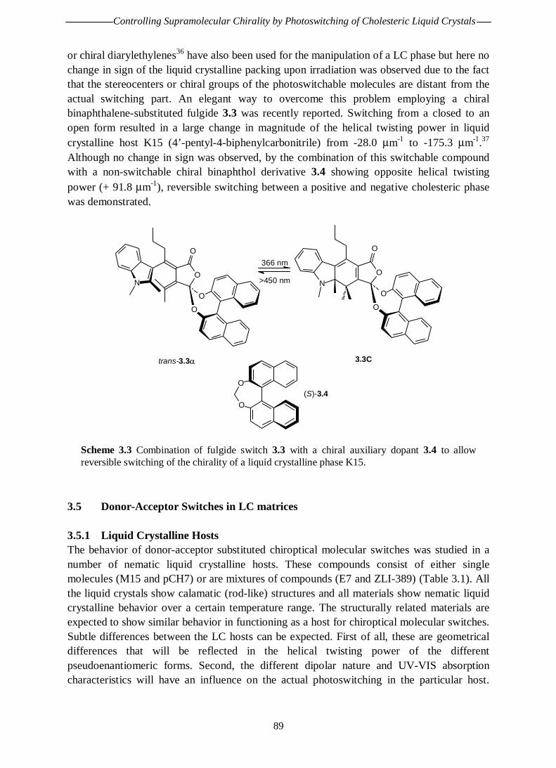
Controlling Supramolecular Chirality by Photoswitching of Cholesteric Liquid Crystals
89
or chiral diarylethylenes36 have also been used for the manipulation of a LC phase but here nochange in sign of the liquid crystalline packing upon irradiation was observed due to the factthat the stereocenters or chiral groups of the photoswitchable molecules are distant from theactual switching part. An elegant way to overcome this problem employing a chiralbinaphthalene-substituted fulgide 3.3 was recently reported. Switching from a closed to anopen form resulted in a large change in magnitude of the helical twisting power in liquidcrystalline host K15 (4’-pentyl-4-biphenylcarbonitrile) from -28.0 µm-1 to -175.3 µm-1.37
Although no change in sign was observed, by the combination of this switchable compoundwith a non-switchable chiral binaphthol derivative 3.4 showing opposite helical twistingpower (+ 91.8 µm-1), reversible switching between a positive and negative cholesteric phasewas demonstrated.
O
O
O
O
N
366 nm
>450 nmO
O
O
O
N
trans-3.3α 3.3C
O
O(S)-3.4
Scheme 3.3 Combination of fulgide switch 3.3 with a chiral auxiliary dopant 3.4 to allowreversible switching of the chirality of a liquid crystalline phase K15.
3.5 Donor-Acceptor Switches in LC matrices
3.5.1 Liquid Crystalline HostsThe behavior of donor-acceptor substituted chiroptical molecular switches was studied in anumber of nematic liquid crystalline hosts. These compounds consist of either singlemolecules (M15 and pCH7) or are mixtures of compounds (E7 and ZLI-389) (Table 3.1). Allthe liquid crystals show calamatic (rod-like) structures and all materials show nematic liquidcrystalline behavior over a certain temperature range. The structurally related materials areexpected to show similar behavior in functioning as a host for chiroptical molecular switches.Subtle differences between the LC hosts can be expected. First of all, these are geometricaldifferences that will be reflected in the helical twisting power of the differentpseudoenantiomeric forms. Second, the different dipolar nature and UV-VIS absorptioncharacteristics will have an influence on the actual photoswitching in the particular host.

Chapter 3
90
Additionally, different switching times can be anticipated depending on the viscosity of theLC host. However, this aspect was not investigated in detail.
Structure phasetransition*
Name
M15 H11C5O CN C 48 N 67 I4'-pentyloxy-4-
biphenylcarbonitrile
pCH7 H15C7 CN N 48 I4'-heptylcyclohexyl-4-
phenylcarbonitrile
ZLI-389
a.o.:
RO O
O
C5H11C -65 N 35 I
mixture of alkoxyphenyl pentylbenzoates
E7
a.o.:
H11C5 CN
CNH15C7
N 58 Imixture of 4'-substituted 4-
biphenylcarbonitriles
Table 3.1 Nematic liquid crystalline host materials and their structural features (* C =crystalline, N = nematic, I = isotropic; numbers indicate phase transition temperature in °C).
For any technological application, LC materials should, preferably, show liquid crystallinityat room temperature and over a broad temperature range. Of the liquid crystalline hosts inTable 3.1, only pCH7 and to a lesser extent ZLI-389 fulfil this requirement. M15 is onlyliquid crystalline at elevated temperatures.
3.5.2 Dimethylamino Nitro SwitchThe photochemical modulation of the helical screw sense and the pitch of a cholesteric phasewere realized with the combination of a nematic liquid crystalline host and donor-acceptorswitch 3.5 by N. Huck (Scheme 3.4).38
S
S
NO2N
(M)-cis-3.5
S
S
NO2N
(P)-trans-3.5
365 nm
435 nm
Scheme 3.4 Photochemical interconversion of parent donor-acceptor switch 3.5.

Controlling Supramolecular Chirality by Photoswitching of Cholesteric Liquid Crystals
91
For example, doping of liquid crystalline compound M15 (4’-(pentyloxy)-4-biphenylcarbonitrile) with (P)-trans-3.5 (2.4 weight%) converts the nematic phase into acholesteric phase. Irradiation at 365 nm or 435 nm of a thin film of this cholesteric phase ledto photostationary states with an excess of (M)-cis-3.5 or an excess of (P)-trans-3.5,comparable to the system in n-hexane solution. These two photostationary cholesteric phasesshow different pitches and opposite screw sense, as expected from the pseudoenantiomericrelationship of the two forms of the photoswitchable dopant (+8.5 Pm and -12.2 Pm,respectively). Different liquid crystals can be used as a host and the most important resultsare summarized in Table 3.2.39
LC Host β (M)-cis-3.5
(µm-1)β (P)-trans-3.5
(µm-1)cis : transPSS 435 nm
trans : cisPSS 365 nm
pitchPSS 435 nm
(2.4 weight%)
pitchPSS 365 nm
(2.4 weight%)
doping limit(weight%)
solution - - 90 : 10 70 : 30 − − −M15 - 3.4 + 5.6 88 : 12 75 : 25 - 12.2 µm + 8.5 µm 9
pCH7 - 5.5* + 3.7 80 : 20 70 : 30 - 10 µm + 36 µm 6ZLI-389 - 5.7 + 0.8 77 : 23 70 : 30 - 25 µm + 22 µm 8
Table 3.2 Properties of parent donor-acceptor switch in a variety of liquid crystals (* = valuecalculated from photostationary state ratios and pitches).
For 3.5 switching efficiencies in a liquid crystalline environment and in solution are more orless equal. It should be noted that the irradiation times have increased. Doping concentrationsare, however, limited for this particular system. When using a liquid crystal as a means ofread-out or just a host for a bistable switching system, this is of limited importance. However,when extending the concept to LCD applications this is an extremely important property. Inthe previous chapter a novel donor-acceptor switch bearing a hexyl chain (3.6) wasintroduced. Although improved switching behavior was found, compound 3.6 was initiallysynthesized to increase the compatibility of the chiroptical molecular switch in liquidcrystalline matrices. Another aspect is that improved compatibility is expected to increasehelical twisting powers.
3.5.3 Hexylmethylamino Nitro SwitchThe newly synthesized analogue of the donor-acceptor switches, 7-(N-methylhexylamino)-2-nitro-9-(1’,2’,3’,4’-tetrahydrophenanthrene-4’ylide)-9H-thioxanthene 3.6 (Scheme 3.5) wasalready introduced in the previous chapter where the photophysical properties in solutionwere discussed. Compatibility and switching efficiencies of this compound in liquidcrystalline surroundings were tested for a variety of LC materials. A material of choice forfurther improvement of the system is E7, a commercially applied mixture of differentbiphenylcarbonitrile-based mesogens which is liquid crystalline up to 58°C. This temperatureis also more or less the limit of applicability of these sterically overcrowded alkenes becauseof racemization interfering at elevated temperatures.

Chapter 3
92
S
S
NO2N
(M)-cis-3.6
S
S
NO2N
(P)-trans-3.6
380 nm
465 nm
Scheme 3.5 Switching of an n-hexyl functionalized donor-acceptor switch 3.6.
3.5.3.1 CompatibilityThe compatibility of compound 3.6 in various LC materials was tested by simply increasingits amount in the LC host material. For this purpose, a mixture of cis- and trans-3.6 was usedrather than one of the pure isomers because for any switching application the switchcompound will be present as a mixture. The given compatibility values are approximateconcentrations where the LC phase still is uniform, as seen through a polarizationmicroscope. Compatibilities in three different liquid crystalline hosts were tested and in twocases comparison with 3.5 was possible. In both these mesogenic hosts the compatibility ofthe switch system was improved.
LC Host phase transitions compatibilitycompound 3.6 (weight%)
phase transitionsdoped with 2.6 weight% 3.6
M15 C 53 N 68 I 17 C 47 N/N* 61 IpCH7 N 59 I 10 N/N* 52 I
ZLI-389 N 35 I - N/N* 34 IE7 N 58 I 25 N/N* 51 I
Table 3.3 Compatibility and phase transition temperature upon doping of donor-acceptorswitch 3.6 in different liquid crystals.
The observed increase in compatibility can be ascribed to the presence of a solubilizing n-hexyl tail. The phase transition temperatures are only effected to a small extent. In all casesthe transition temperatures are lowered by the addition of dopant. This effect can becompared to the lowering of a melting point of a solid by an impurity. Due to the use ofmixtures of cis- and trans-isomers rather than an enantiomerically pure form of compound3.6, (compensated) nematic textures were observed. Doping with enantiomerically pureswitch resulted in cholesteric textures, which is an essential aspect of this research.
3.5.3.2 Chirality AspectsIncreased compatibility was the initial goal with the development of 3.6. Preservation ofchiral properties and switching efficiency are also essential. These requirements werefulfilled in solution, as was discussed in the previous chapter, but preservation of the

Controlling Supramolecular Chirality by Photoswitching of Cholesteric Liquid Crystals
93
properties in a liquid crystal is crucial. In all tested nematic liquid crystalline hosts, acholesteric phase was readily induced by doping with either one of the enantiomerically pureforms of 3.5. In all cases the molecular chirality of the dopant was amplified to provide amacroscopic chirality of the liquid crystalline phase. The determining factor for this chiralinduction is the helical twisting power. The helical twisting powers of the different forms of3.6 were determined by pitch measurements using the Grandjean-Cano technique22 (seeExperimental Section) of known concentrations of two pseudoenantiomers of 3.6 in differentliquid crystalline hosts (Table 3.4).40
LC Host pitch upon dopingwith 2.6 weight%
(M)-cis-3.6
pitch upon dopingwith 2.6 weight%
(P)-trans-3.6
β (M)-cis-3.6 β (P)-trans-3.6
M15 - 4.8 µm + 4.1 µm - 8.1 µm-1 + 9.3 µm-1
pCH7 - 11.0 µm + 7.3 µm - 3.5 µm-1 + 5.3 µm-1
ZLI-389 - 25.6 µm + 9.6 µm - 3.5 µm-1 + 4.0 µm-1
E7 - 3.8 µm + 2.9 µm - 10.1 µm-1 + 13.5 µm-1
Table 3.4 Pitches and helical twisting powers of donor-acceptor switch 3.6 in different liquidcrystals.
Although there are differences found in the helical twisting powers for thepseudoenantiomers (P)-cis-3.6 and (M)-trans-3.6, in all cases the sign of the cholestericphase was opposite. This pseudoenantiomeric influence on the cholesteric packing can beused to generate a cholesteric matrix of which the screw sense can be switched under theinfluence of light. In the biphenyl-based LC hosts (M15 and E7) the highest helical twistingpowers were found and the differences between the two pseudoenantiomers were relativelysmall. It is striking that for all hosts tested the helical twisting power of the trans-isomer, inabsolute sense, is higher than that of the cis-isomer. This is probably due to different packingin the LC matrix, as is also reflected in the different β-values. Nevertheless, particularly inM15 or E7 host an efficient photoswitching of the chirality of the cholesteric phase should bepossible provided that photochemical switching is still possible in a liquid-crystalline matrix.
3.5.3.3 Switching EfficienciesThe switching efficiencies of 3.6 were tested in the different host materials employing 380nm and 435 nm light. The latter wavelength, though not the most efficient in solution, waschosen because in this case a high intensity mercury light source could be used, and becausefurther increasing the wavelength would result in longer switching times. It was alreadyknown that in the LC phase the switching time increases with approximately a factor of 3 incomparison with an isotropic solution.39 This was also observed for the present systems,although when spin-coated samples are used irradiation times dramatically decrease. This isprobably due to extinction of the LC layer being dependent on the layer thickness. The dataare summarized in Table 3.5.

Chapter 3
94
Host (M)-cis-3.6
PSS 435 nm
: (P)-trans-3.6
PSS 380 nm
pitchPSS 435 nm
(2.6 weight%)
pitchPSS 380 nm
(2.6 weight%)
n-hexane 73 : 27 30 : 70 − −M15 72 : 28 31 : 69 -12.0 µm + 10.1 µmpCH7 53 : 47 24 : 76 + 60.5 µm* + 12.1 µm*
ZLI-389 62 : 38 22 : 78 + 65.2 µm* + 13.8 µm*
E7 72 : 28 23 : 77 - 10.9 µm + 5.1 µm
Table 3.5 Switching cholesteric liquid crystalline phases, ratio determined by HPLC (* =calculated values).
Photoswitching of 3.6 is clearly still possible in a liquid crystal. The switching selectivitiesvary somewhat with the liquid crystalline host. In all cases, however, employing 435 and 380nm light, switching is possible between a photostationary state with excess cis-3.6 and aphotostationary state with excess trans-3.6. The change in pitch of the cholesteric phase forM15 and E7 nicely reflects the ratio of (M)-cis-3.6 and (P)-trans-3.6 in the photostationarystate. The (M)-cis-3.6 photostationary state results in a negative cholesteric pitch while the(P)-trans-3.6 photostationary state results in a positive cholesteric pitch. By changing theirradiation time (all samples were irradiated overnight to ensure complete photoequilibrium)or the irradiation wavelength, analogous to the solution experiments cholesteric phases withintermediate pitches, including a compensated nematic phase, are addressable. For the othertwo LC hosts pCH7 and ZLI-389, the pitches of the photostationary samples could not bedetermined. A calculation using the ratio at the photostationary state and the helical twistingpowers of the two pseudoenantiomers of 3.6 showed that pitches longer than 60 µm areexpected. Pitches of these dimensions cannot be measured with our technique. It should benoted that theoretically in both the pCH7 and ZLI-389 host all the pitches that can begenerated using the (M)-cis-3.6 / (P)-trans-3.6 switching system are of positive sign as aresult of a combination of low switching efficiencies and higher helical twisting powersobserved for the (P)-trans-isomer. Based on these observations the biphenyl-based liquidcrystals M15 and E7 are favored over pCH7 and ZLI-389 for any application in combinationwith 3.6.
Although in all cases the same irradiation wavelengths are used, the most efficientwavelengths for switching are strongly dependent on the environment. Further optimizationof the systems can be done in a trial and error fashion by just changing the wavelength andmonitoring the effect on the photostationary state. A more elegant way of optimizing thesystem requires detailed knowledge on the UV-VIS absorption characteristics of the chiraldopant. This knowledge can be obtained from experiments closely resembling the ones insolution discussed in the previous chapter. Due to scattering, however, UV-VIS experimentson liquid crystal samples are problematic. An approximate idea of the UV-VIS characteristicsof compound 3.6 in a liquid crystalline host can be obtained by experiments in the isotropicphase. For this purpose the most promising liquid crystalline host E7 was used. In anexperiment closely resembling the fast screening experiments discussed in the previous

Controlling Supramolecular Chirality by Photoswitching of Cholesteric Liquid Crystals
95
chapter, the change in UV-VIS absorption upon irradiation was monitored. For this purpose asample of racemic trans-3.6 in E7 in a 1 mm cuvet was heated at 60°C. At this temperatureE7 is isotropic and UV-VIS measurement were performed (Figure 3.4). For theseexperiments undoped isotropic E7, at the same temperature was used as a baseline. Note herethat the E7 host material shows strong absorption up to about 350 nm. The mixture wasirradiated at this temperature at 435 nm for 90 min in the spectrometer to allow substantialisomerization to take place and again a UV-VIS measurement was performed. Comparison ofthe two UV-VIS spectra and more specifically their ratio gives the most ideal wavelengths forswitching. In this case 492 nm and 378 nm were determined to be the most efficientwavelengths for switching.
Irradiation of the photostationary state mixture (obtained after 380 nm irradiation) with 378nm light did not result in a significant change and a photostationary state of 77 : 23 trans-3.6: cis-3.6 was proven the highest possible selectivity toward the trans-isomers. Irradiation firstat 470 nm resulted in a photostationary state of 87 : 13 cis-3.6 : trans-3.6 and prolongedirradiation at higher wavelengths (475, 480, 485 and 490 nm) did not result in a moreselective switching towards the cis-isomer. This can either be due to the small absorption atthese wavelengths leading to extremely slow formation of the photostationary state or to anunreliable ratio of the two UV-VIS absorption curves at higher wavelength where bothabsorptions approach zero.
380 400 420 440 460 480 5000.00
0.02
0.04
0.06
0.08
0.10
375 400 425 450 475 500
0.9
1.0
1.1
1.2
1.3
abso
rban
ce (
a.u.
)
wavelength (nm)
ratio
wavelength (nm)
Figure 3.4 UV-VIS absorption spectrum of racemic trans-3.6 (solid) in isotropic E7 at 60°Cand of the photostationary mixture obtained after 90 minutes of irradiation at 435 nm (dashed).The inset shows the ratio of the two curves.
Selective switching between cis and trans photostationary states of 3.6 has beendemonstrated in a liquid crystalline environment. This experiment was repeated forenantiomerically pure (P)-trans-3.6 doped at 2.6 weight% in E7. This cholesteric phase witha pitch of + 2.9 µm, was irradiated with 470 nm light overnight. This resulted in a

Chapter 3
96
photostationary cholesteric phase with a pitch of -5.5 µm and a 87 : 13 ratio of (M)-cis-3.6 :(P)-trans-3.6. This pitch is in accordance with the determined helical twisting powers andsubstantially lower than found after 435 nm irradiation (-10.9 µm, Table 3.5). Thephotostationary state with the trans-isomer in excess was shown to have a pitch of + 5.1 µm.In the switching of these doped cholesteric phases of opposite screw sense, first the pitchlength is increased to form a compensated nematic phase. Elongated irradiation result in apitch of opposite screw sense with a gradually decreasing length eventually resulting in thephotostationary state. By varying the irradiation time cholesteric phases with intermediatepitches can be induced. In this particular system of 2.6 weight% of 3.6 doped in E7 host,employing 380 nm light cholesteric phases with positive pitches of 5.1 µm and higher can beinduced. Employing 470 nm light, cholesteric phases with negative pitches of 5.5 µm andhigher can be induced. Depending on the irradiation times a large range of cholesteric pitch isreadily accessible, as schematically depicted in Scheme 3.6.
(+) cholesteric phaseexcess (P)-trans-3.6
pitch = + 5.1 µm
(-) cholesteric phaseexcess (M)-cis-3.6
pitch = - 5.5 µm
Compensated nematic phase
380 nm 380 nm
470 nm 470 nm
Scheme 3.6 Schematic representation of the switching of the chirality of a doped cholestericliquid crystal (E7).
3.6 Discussion and Conclusions
In this chapter it was shown that nematic liquid crystals form excellent hosts for the newlydeveloped chiroptical molecular switch 3.6. This compound shows improved compatibilitycompared to parent compound 3.5 in all investigated mesogenic hosts. Switching propertiesare maintained in liquid crystalline surroundings and switching selectivities comparable toexperiments in isotropic solution were found. The nature of the nematic host only has a minor

Controlling Supramolecular Chirality by Photoswitching of Cholesteric Liquid Crystals
97
effect on this selectivity. More dramatic differences between the host materials were found inthe chiral induction by 3.6, where large differences in helical twisting power are observed indifferent LC hosts. In all cases, however, the two pseudoenantiomeric forms of 3.6 ((M)-cis-3.6 and (P)-trans-3.6) induce cholesteric phases with pitches of opposite screw sense.Switching between cholesteric phases with opposite handedness was possible for the twobiphenyl-based LC hosts investigated (M15 and E7). Due to a combination of low switchingselectivity and a relatively large difference in helical twisting power for the twopseudoenantiomers in pCH7 and ZLI-389, in principle only the magnitude of the pitch butnot the sign of the cholesteric phase can be switched. No further research was done on thesetwo LC hosts. Upon 380 and 435 nm irradiation two photostationary states withcorresponding cholesteric phases of opposite screw sense are induced. By changingirradiation time and/or wavelength every intermediate state (including a compensated nematicphase) can be induced.
For E7, UV-VIS spectroscopy and photoisomerization experiments in the isotropic phaseshowed that employing higher wavelengths, irradiation would result in more selectiveswitching towards the cis-photostationary state. For a 2.6 weight% sample of 3.6 in E7,employing 380 and 470 nm pitches between -5.5 µm and + 5.1 µm could readily be induced.Switching selectivities are decreased only to a small extent compared to solution but moreefficient switching to the trans-photostationary state was found. The photostationary (M)-cis-3.6 : (P)-trans-3.6 ratio was determined to be 23 : 77 in E7, compared to 30 : 70 found in n-hexane solution. The switching selectivity towards the cis-photostationary state wasdecreased, a photostationary state ratio of 98 : 2 (M)-cis-3.6 : (P)-trans-3.6 was found in n-hexane. Most selective photoswitching in E7 employing 470 nm light resulted in a ratio of 87: 13. The exact reason for this decreased selectivity is not clear. It should be noted, that inChapter 2, by comparison of the systems 3.5 and 3.6 switching towards the cis-photostationary state at the red-end of the UV-VIS absorption of the switchable compoundswas shown to be highly sensitive to any perturbation. A change from a methyl to an n-hexyl-substituent had a dramatic effect on the switching selectivity. The presented results, however,show that a highly efficient photoswitching in a liquid crystalline host is possible usingbiphenyl-based mesogens. More important, the chiroptical molecular switch induces acholesteric LC phase and the chirality of this phase can be switched by photoirradiation. Thecontrol of molecular chirality of the switchable compound 3.6 is efficiently amplified to acontrol of supramolecular chirality of the screw sense of a macroscopic cholesteric phase.
Direct comparison of the results obtained for 3.6 and the results of photochemical switchingof the parent donor-acceptor switch 3.5 in LC matrices is difficult since for system 3.5 noswitching experiments were performed in E7. This E7 host is the most promising liquidcrystal matrix for future application of compound 3.6 both because of liquid crystallinity atroom temperature and the highly selective switching in this material. The only unequivocalconclusion that can be drawn by comparing results for compounds 3.5 and 3.6 is that thecompatibility has been improved. Improved switching of liquid crystalline phases is alsofound for compound 3.6, due to a combination of two effects: i) employing E7 compared tothe other LC hosts increased the helical twisting power of both (M)-cis-3.6 and (P)-cis-3.6,and ii) the UV-VIS absorption characteristics of the guest chiroptical molecular switch in this

Chapter 3
98
host material could be investigated in the isotropic state, these experiment indicated thatemploying higher wavelengths would result in more selective switching towards the cis-photostationary state as was experimentally shown. Where for compound 3.5 maximalswitching between LC samples of + 12.2 and - 8.5 µm was reported,39 for compound 3.6switching between LC samples of + 5.1 and - 5.5 µm was achieved. Further improvement ofboth doped systems should be possible by increasing the dopant concentration. In this respectcompound 3.6 is a more promising chiroptical molecular switch because of the increasedcompatibility. Preliminary experiments on a 3.6-doped sample of higher concentration willbriefly be discussed in the next chapter.
3.7 Experimental Sections
For general remarks and the synthesis of the hexylmethylamino donor-acceptor switch 3.6, seeSection 2.6.
MaterialsThe liquid crystalline materials M15 and ZLI-389 were purchased from Aldrich and Merck,respectively. E7 was received as a gift from Merck, Darmstadt. Nematic liquid crystal pCH7 wasprovided by Dr. V. Vill, Hamburg.
Preparation and Analysis of Liquid Crystalline SamplesThe liquid crystalline samples were prepared by weighing the appropriate amount of dopant guest andliquid crystalline host material that are fully mixed in solution. Upon slow evaporation of the solvent(both dichloromethane and toluene were used) a homogeneously doped liquid crystalline phase wasobtained at an appropriate temperature. Phase transition temperatures were determined by polarizationmicroscopy using an Olympus BX 60 microscope and a Linkam THMS 600 hotstage. Upon heating at5°C min-1 the clearing point of the liquid crystalline phase was monitored. Typical textures41 obtainedfor aligned (compensated) nematic phases and cholesteric phases are depicted in Figure 3.5. Thepictures are obtained between cross polarizers.
Figure 3.5 Schlieren texture42 of (compensated) nematic phase obtained for racemic cis-transmixture of 3.6 in pCH7 (left) and polygonal texture43 of orientated cholesteric liquid crystalobtained for (P)-trans-3.6 doped pCH7 (right).

Controlling Supramolecular Chirality by Photoswitching of Cholesteric Liquid Crystals
99
The pitch of the liquid crystalline phases and thus indirectly the helical twisting power of a chiraldopant were determined by the Grandjean-Cano technique.22 The distance between readily visibleGrandjean-Cano lines44 is a measure for the pitch of the aligned cholesteric material. A Grandjean-Cano texture can be obtained by alignment of a cholesteric liquid crystalline material on a polyimide-covered glass surface. For this purpose a glass surface (typically 6.25 cm2) was carefully cleaned withaqueous detergent and with organic solvent (2-propanol). This clean and dry surface was spin-coated(at approximately 3000 rpm for 1 min) with commercially available polyimide AL1051 (purchasedfrom JSR, Belgium). These coated glass surfaces were allowed to harden at 170°C in vacuum for atleast 3 h, but usually overnight. The surface was then linearly rubbed with a velvet cloth to induce aparallel-aligned pattern that could be detected visually and is necessary to induced plane-parallelalignment of the cholesteric LC phase. The LC material doped with the appropriate amount of dopantdissolved in toluene or dichloromethane (± 5 mg ml-1) was slowly poured onto this alignment layer.After evaporation of the solvent at room temperature (for the host materials that were liquidcrystalline at room temperature) or any other suitable temperature (for host materials liquid crystallineonly at higher temperatures) a suitable aligned LC film was obtained.
Figure 3.6 Grandjean-Cano texture as observed through crossed polarizers obtained for (P)-trans-3.6 in E7 (A) and contact method for sign determination: B) microscope picture obtaineddirectly after contact of ZLI-811 in E7 with known negative pitch with (M)-cis-3.6 in E7 wheremixing indicates joint negative helicity; C) microscope picture obtained directly after contact ofZLI-811 in E7 with known negative pitch with (P)-trans-3.6 in E7, clearly showing separatedLC phases indicate opposite pitch handedness.
The Grandjean-Cano texture was obtained by applying a plan-convex converging lens of knownradius (R = 25.119, 30.287, 40.388 or 50.481 mm; Linos Components; Radiometer) onto this liquidcrystalline covered surface. This confinement of the liquid crystalline material leads to concentricrings, the so-called Grandjean-Cano lines, when observed through a (polarization) microscope(Olympus BX 60 microscope) again equipped with a Linkam THMS 600 hot stage if necessary(Figure 3.6 A). The observed distances between these concentric rings by accounting for the radius ofthe plan-convex lens and the magnification of the microscope result in the pitch of the liquidcrystalline phase. The sign of the cholesteric phases was determined using a contact method wheremixing of the samples with a doped cholesteric liquid crystal of known negative screw sense,

Chapter 3
100
consisting of dopant ZLI-811, obtained from Merck in the appropriate liquid crystalline host, wastested. Two cholesteric phases of the same screw sense are known to show complete mixing uponcontact (Figure 3.6 B) whereas for two cholesteric phases of opposite screw sense a clear border isvisible through a microscope (Figure 3.6 C)
Irradiation ExperimentsIrradiation experiments were performed in a similar fashion as described in Chapter 2 at theappropriate wavelengths as given in the text and tables. The composition of the photostationary stateswas determined by HPLC using the same conditions as described already in Chapter 2 for the samedonor-acceptor substituted compound 3.6. Some overlap of the peaks of the liquid crystal materialswith the first or first and second eluted fractions of 3.6 occurs in most cases. By monitoring at anisosbestic point outside of the absorption range of all the liquid crystalline materials used (412 nm, orin some cases 343 nm) still accurate analysis is possible.
The change in cholesteric pitch upon irradiation was mostly determined by two pitch determinationsbefore and after irradiation. A change in the Grandjean-Cano pattern upon irradiation can also bedirectly observed by irradiation under the polarization microscope but this leads to dramaticallyincreased irradiation times and does not give a lot of additional information apart from the visualobservation that indeed the helical pitch gradually increases upon irradiation.
3.8 References
1 K. Murata, M. Aoki, T. Nishi, A. Ikeda, S. Shinkai, J. Chem. Soc., Chem. Commun. 1991, 1715.2 For an example of non-chiral photoswitchable gel: T.J. Effing, I.J. McLennan, J.C.T. Kwak, J.
Phys. Chem. 1994, 98, 2499.3 a) O. Pieroni, A. Fissi, G. Popova, Prog. Polym. Sci. 1998, 23, 81; b) F. Ciardelli, O. Pieroni, A.
Fissi, C. Carlini, A. Altomare, Br. Polym. J. 1989, 21, 97; c) M. Irie, Adv. Polym. Sci. 1990, 94,27; d) Applied Photochromic Polymer Systems; C.B. McArdle, Ed.; Blackie: Glasgow, UK, 1992;e) F. Ciardelli, O. Pieroni, A. Fissi, J.L. Houben, Biopolymers 1984, 23, 1423; f) O. Pieroni, F.Ciardelli, Trends in Polym. Sci. 1995, 3, 282; g) T. Kinoshita, Prog. Polym. Sci. 1995, 20, 527; h)I. Willner, Acc. Chem. Res. 1997, 30, 347.
4 F. Ciardelli, O. Pieroni in Chiroptical Molecular Switches, B.L. Feringa Ed., Wiley-VCH,Weinheim, 2001, Chapter 13, pp. 399-441.
5 J.A. Delaire, K. Nakatani, Chem. Rev. 2000, 100, 1817.6 For an extensive account of chiral optical switches: a) B.L. Feringa, R.A. van Delden, N.
Koumura, E.M. Geertsema, Chem. Rev. 2000, 100, 1789; b) B.L. Feringa, R.A. van Delden,M.K.J. ter Wiel in Chiroptical Molecular Switches, B.L. Feringa Ed., Wiley-VCH, Weinheim,2001, Chapter 5, pp. 123-163.
7 a) M.M. Green, J.-W. Park, T. Sato, A. Teramoto, S. Lifson, R.L.B. Selinger, J.V. Selinger,Angew. Chem. Int. Ed. 1999, 38, 3139; b) S. Lifson, C. Andreola, N.C. Peterson, M.M. Green, J.Am. Chem. Soc. 1989, 111, 8850.
8 M.M. Green, N.C. Peterson, T. Sato, A. Teramoto, R. Cook, S. Lifson, Science 1995, 268, 1860.9 G. Maxein, R. Zentel, Macromolecules 1995, 28, 8438.10 M. Porsch, G. Sigl-Seifert, J. Daub, Adv. Mater. 1997, 9, 635.11 A.M. Schoevaars, Ph.D. Thesis, University of Groningen, 1998.12 T. Ikeda, S. Horiuchi, D.B. Karanjit, S. Kurihara, S. Tazuke, Macromolecules 1990, 23, 36.13 a) Handbook of Liquid Crystals Vol 1, 2A, 2B and 3, D. Demus, J. Goodby, G.W. Gray, H.-W.
Spiess, V. Vill Ed., Wiley-VCH, Weinheim, 1998. b) D. Demus, Mol. Cryst. Liq. Cryst. 1988, 165,45.

Controlling Supramolecular Chirality by Photoswitching of Cholesteric Liquid Crystals
101
14 For the early development of liquid crystals, see: a) H. Kelker, Mol. Cryst. Liq. Cryst. 1973, 21, 1;b) H. Kelker, Mol. Cryst. Liq. Cryst. 1988, 165, 1.
15 F. Reinitzer, Monatsh. Chem. 1988, 9, 421; for an English translation, see: Liq. Cryst. 1989, 5, 17.16 V. Vill, Mol. Cryst. Liq. Cryst. 1992, 213, 67.17 D. Demus, Liq. Cryst. 1989, 5, 75.18 a) D.W. Bruce, J. Chem. Soc., Dalton Trans. 1993, 2983; b) A.M. Giroud-Godquin, P.M. Maitlis,
Angew. Chem. Int. Ed. Engl. 1991, 30, 375.19 C. Tschierske, Prog. Polym. Sci. 1996, 21, 775.20 a) G. Solladié, R.G. Zimmermann, Angew. Chem, Int. Ed. Engl. 1984, 23, 348. b) G. Gottarelli,
G.P. Spada, R. Bartsch, G. Solladié, R.G. Zimmermann, J. Org. Chem. 1986, 51, 589; b) G.Gottarelli, M.A. Osipov, G.P. Spada, J. Phys. Chem. 1991, 95, 3879; c) C. Rosini, G.P. Spada, G.Proni, S. Masiero, S. Scamuzzi, J. Am. Chem. Soc. 1997, 119, 506; d) C. Rosini, S. Scamuzzi, M.Pisani Focati, P. Salvadori, J. Org. Chem. 1995, 60, 8289; e) G. Gottarelli, M. Hibert, B. Samori,G. Solladié, G.P. Spada, R.G. Zimmermann, J. Am. Chem. Soc. 1983, 105, 7318. f) G. Gottarelli,G. Proni, G.P. Spada, D. Fabbri, S. Gladiali, C. Rosini, J. Org. Chem. 1996, 61, 2013. g) I. Rosati,C. Rosini, G.P. Spada, Chirality 1995, 7, 353.
21 a) H. Finkelmann, H. Stegemeyer, Ber. Bunsenges. Phys. Chem. 1978, 82, 1302; b) H.-G. Kuball,H. Bruning, T. Muller, O. Turk, A. Schonhofer, J. Mater. Chem. 1995, 5, 2167.
22 G. Heppke, F. Oestreicher, Mol. Cryst. Liq. Cryst. 1977, 41, 245.23 a) D. Kreysig, J. Stumpe, Selected Topics in Liquid Crystalline Research, H.D. Koswig Ed., VCH,
Weinheim, 1990; b) M. Freemantle, Chem. Eng. News 1996, 74 (50), 33; c) P.G. De Gennes,Angew. Chem, Int. Ed. Engl. 1992, 31, 842; d) Liquid Crystals: Applications and Uses, Vol. I-III,B. Bahadur Ed., World Scientific, Singapore, 1991; e) W.M. Gibbons, P.J. Shannon, S.-T. Sun,B.J. Swetlin, Nature 1991, 351, 49.
24 T. Ikeda, A. Kanazawa in Chiroptical Molecular Switches, B.L. Feringa Ed., Wiley-VCH,Weinheim, 2001, Chapter 12, pp. 363-397.
25 T. Ikeda, T. Sasaki, K. Ichimura, Nature 1993, 361, 428.26 T. Kusumoto, K. Sato, K. Ogino, T. Hiyama, S. Takehara, M. Osawa, K. Nakamura, Liq. Cryst.
1993, 14, 727.27 a) M. Negishi, O. Tsutsumi, T. Ikeda, T. Hiyama, J. Kawamura, M. Aizawa, S. Takehara, Chem.
Lett. 1996, 319; b) M. Negishi, K. Kanie, T. Ikeda, T. Hiyama, Chem. Lett. 1996, 583.28 a) R.P. Lemieux, G.B. Schuster, J. Org. Chem. 1993, 58, 100; b) C. Mioskowski, J. Bourguignon,
S. Candau, G. Solladie, Chem. Phys. Lett. 1976, 38, 456.29 N. Tamaoki, Adv. Mater. 2001, 13, 1135.30 a) T. Ikeda, S. Horiuchi, D.B. Karanjit, S. Kurihara, S. Tazuke, Chem. Lett. 1988, 1679; b) H.
Yamaguchi, T. Ikeda, S. Tazuke, Chem. Lett. 1988, 539; c) S. Tazuke, T. Ikeda, S. Kurihara,Chem. Lett. 1987, 911.
31 a) J.H. Wendorf, M. Eich, B. Reck, H. Ringsdorf, Macromol. Chem., Rapid. Commun. 1987, 8, 59;b) J.H. Wendorff, M. Eich, Macromol. Chem., Rapid Commun. 1987, 8, 467.
32 I. Cabrera, H. Ringsdorf, A. Dittrich, Angew. Chem, Int. Ed. Engl. 1991, 30, 76.33 a) T. Ikeda, O. Tsutsumi, Science 1995, 268, 1873; b) S. Hvilsted, F. Andruzzi, C. Kulinna, H.W.
Siesler, P.S. Ramanujam, Macromolecules 1995, 28, 2172; c) O. Tsutsumi, T. Kitsunai, A.Kanazawa, T. Shiono, T. Ikeda, Macromolecules 1998, 31, 355; d) O. Tsutsumi, Y. Demachi, A.Kanazawa, T. Shiono, T. Ikeda, Y. Nagasa, J. Phys. Chem. B 1998, 102, 2869; e) A. Shishido, O.Tsutsumi, A. Kanazawa, T. Shiono, T. Ikeda, N. Tamai, J. Am. Chem. Soc. 1997, 119, 7791; f) Y.Wu, Y. Demachi, O. Tsutsumi, A. Kanazawa, T. Shiono, T. Ikeda, Macromolecules 1998, 31,1104; g) H. Tokuhisa, M. Yokoyama, K. Kimura, J. Mater. Chem. 1998, 8, 889; h) A.Y.Bobrovsky, N.I. Boiko, V.P. Shibaev, Adv. Mater. 1999, 11, 1025.
34 K. Ichimura, A. Hosoki, K. Ozawa, Y. Suzuki, Polym. Bull. 1987, 17, 285.35 a) S.Z. Janicki, G.B. Schuster, J. Am. Chem. Soc. 1995, 117, 8524; b) Y. Yokoyama, T. Sagisaka,
Chem. Lett. 1997, 687.36 C. Denekamp, B.L. Feringa, Adv. Mater. 1998, 10, 1080.

Chapter 3
102
37 T. Sagisaka, Y. Yokoyama, Bull. Chem. Soc. Jpn. 2000, 73, 191.38 B.L. Feringa, N.P.M. Huck, H.A. van Doren, J. Am. Chem. Soc. 1995, 117, 9929.39 N.P.M. Huck, Ph.D. Thesis, University of Groningen, 1997.40 By definition, the relative enantiomers of (M)-cis-3.6 and (P)-trans-3.6 ((P)-cis-3.6 and (M)-trans-
3.6) have opposite helical twisting powers of the same magnitude.41 D. Demus, L. Richter, Textures of Liquid Crystals, VEB, Leipzig, 1978.42 a) G. Friedel, Ann. Physique 1922, 18, 273; b) J. Nehring, A. Saupe, J. Chem. Soc., Faraday
Trans. II 1972, 68, 1; c) A. Saupe, Mol. Cryst. Liq. Cryst. 1973, 21, 211.43 Y. Bouligand, Ann. Physique 1972, 33, 715.44 a) F. Grandjean, C.R. Hebd. Séan. Acad. Sci. 1921, 172, 71; b) R. Cano, Bull. Soc. Fr. Miner.
1968, 91, 20.

103
Chapter 4
Controlling the Color of Cholesteric Liquid Crystals
This chapter describes research into the doping of colored cholesteric liquid crystals withchiroptical molecular switches. Colored cholesteric phases can be applied in liquid crystaldisplay technology and the combination with the photoswitchable compounds described inprevious chapters might offer an all-optical liquid crystal display. First, in this chapter thebasic theory concerning colored cholesteric liquid crystals and color LCD's is discussed.Details on the tuning of cholesteric phases by light are presented and a locking mechanismbased on photopolymerization of the matrix is introduced.

Chapter 4
104
4.1 Introduction
In the previous chapter we showed that liquid crystals form excellent host materials for ourmolecular switches. These switch-doped cholesteric liquid crystals offer a processableswitching material, essential for any given application of these systems. In their cholestericpacking, the mesogenic host molecules also amplify the molecular chirality of the guestmaterial, in this case the chiroptical switch, in a macroscopic chiral helical packing. As suchthe liquid crystal chirality reflects the state of the chiral switch and this effect can be used in anon-destructive read-out procedure through cholesteric pitch determination. This is only oneadvantage of employing liquid crystals. Also, in all doped liquid crystals described in Chapter3, a liquid crystalline phase transition is induced by the chiral switchable dopant. Here thechiroptical molecular switch as a LC dopant functions as a trigger of a liquid crystal phasetransition. This holds for the initial doping, where a cholesteric phase is induced from anematic phase, which is a common feature for a large variety of chiral guest compounds.1 Ofmuch greater importance, though, is the change in handedness of the cholesteric phaseinduced by the switching process. A transition from a cholesteric phase with a certain screwsense, via a compensated nematic phase, to a cholesteric phase of opposite screw sense istriggered. 2 Upon irradiation at a suitable wavelength, cholesteric phases with intermediatepitches can be induced by varying irradiation time, wavelength, or intensity of the light. Thistriggering of a liquid crystalline phase opens opportunities to use this type of system for anoptically addressable liquid crystalline display, especially when considering the opticalproperties of cholesteric liquid crystals.
4.2 Optical Properties of Cholesteric Liquid Crystals
The molecular features of cholesteric liquid crystals have been discussed in Chapter 3.Cholesteric phases can be assigned by a helical packing of the mesogens with a certain signand a certain pitch.3 This pitch, the distance in a liquid crystal needed for the director of theindividual mesogens to rotate through a full 360 degrees, is a measure of the chirality of thesystem. It was shown in Chapter 3 that cholesteric phases can amplify the molecular chiralityof a switchable compound resulting in pitches in the micrometer range. When the pitch isfurther decreased to values that resemble the wavelengths of visible light, the correspondingcholesteric phases show unique optical properties as schematically depicted in Figure 4.1.4
These cholesteric phases, when illuminated with white light, reflect light of a certainwavelength dependent on the pitch of the LC phase. The reflected light is circularlypolarized: a right-handed cholesteric phase, as depicted in Figure 4.1, is known to reflectright-handed circularly polarized light (r-CPL) of a certain wavelength while left-handedcircularly polarized light (l-CPL) is transmitted.

Controlling the Color of Cholesteric Liquid Crystals
105
Right-handedcholestericphase
r-CPL
α
pitch
l-CPL
Figure 4.1 Schematic representation of a cholesteric phase and its optical properties.
A cholesteric LC layer of one pitch length thickness is depicted in Figure 4.1. The reflectionobserved is of a Bragg-type caused by the repetition of this helical packing.5 The wavelengthof the most important perpendicular reflection (λO) is given by Equation 4.1.
pn ×=⊥λ (4.1)
In this equation n is the average refractive index of the liquid crystalline sample and p is thecholesteric pitch. This wavelength of reflection is strongly angle dependent. With α being theangle of the incident light relative to the normal, this dependency is given by Equation 4.2,which reduces to equation 4.1 for α = 0°.
( )
××= −
npn
ααλ sinsincos 1 (4.2)
The interest in colored doped cholesteric phases in the current research on chiropticalmolecular switches is twofold. When chiroptical molecular switches can induce pitch lengthsresembling the dimensions of the wavelength of visible light, a direct color read-out ofwritten information is possible. On the other hand, direct color-tuning of the cholesteric phaseopens the opportunity to develop color liquid crystal displays addressable by light i.e. color

Chapter 4
106
pixel formation. In order to put the present research in perspective, a brief treatise on liquidcrystalline displays in general and colored liquid crystalline displays in particular isnecessary.
4.3 Liquid Crystalline Displays
Since the feasibility of liquid crystalline displays was proposed by Heilmeier in 1968,6 manyscientists have been engaged in improving the characteristics of such displays.7 This hasresulted in widely known black-and-white LCD's in for example calculators, wristwatches,and mobile phones and color LCD's in laptop computers, and photo and video cameras.Nowadays, desktop monitors and, at a higher price, even flat-screen televisions have becomereadily available to the general public.
4.3.1 Fundamental Features of Liquid Crystal CellsLiquid crystalline displays can be based on different aspects of liquid crystalline matrices.The first LCD to be used in the late 1960s was based on dynamic scattering of a nematicliquid crystalline material.8 This material is aligned between two electrodes in aperpendicular fashion (cf. the parallel alignment of a LC phase discussed in Chapter 3). Thealignment of the material results in a transparent relaxed state of this liquid crystal cell. Whena voltage is applied to this cell the ordered liquid crystalline phase is severely disturbedresulting in strong light scattering and a frosty appearance of the cell in this energized state.This rather primitive LC cell has several disadvantages, mainly contrast problems, anddifferent improved alternatives have been developed. An illustrative example of such animproved system is the twisted nematic (TN) LC cell that is the first type of LCD used forreal applications.9 The basic principle of a TN-LC cell is depicted below in Figure 4.2. Anematic liquid crystal is sandwiched between two perpendicularly oriented alignment layersto which transparent electrodes are attached. These alignment layers are in essence the sameas the rubbed polyimide-covered glass-surfaces discussed in the previous chapter. Thisperpendicular orientation forces the nematic material to adopt a helical packing resulting in a90° twist of the director of these molecules within the cell. Note that the obtained packingclosely resembles the cholesteric packing; the twist of the mesogens here corresponds to aquarter of a pitch in a cholesteric phase. This LC cell is covered with two polarizers orientedperpendicular to each other. Employing unpolarized backlight, the first polarizer onlytransmits linear polarized light. The polarization direction of this light follows the twistedstructure of the cell when transferring because the twisting pitch of the director of the twistedliquid crystal layer is relatively large compared to the wavelength of visible light. The 90°twist of the director of the LC material results in a 90° rotation of the polarization of the light.After passing the LC layer the light can therefore pass the second perpendicular polarizer andthe cell appears white in this case. When a voltage is applied to this system the LC moleculesare forced to twist their director perpendicular to the electrodes, parallel to the electric fieldapplied, due to the dipolar nature of the individual molecules. The plane of the polarized lightin this state is unaffected by the LC material. The linearly polarized light is thereforecompletely blocked by the second polarizer resulting in a black LC cell. Although also thistype of LC cell has some disadvantages, it is generally used in calculators and watches. Also

Controlling the Color of Cholesteric Liquid Crystals
107
super-twisted nematic (STN) cells are known where, instead of rotating the plane polarizedlight over 90°, twist angles of 180-270° are induced in a similar fashion to that illustratedabove for the TN-LC cell. 10
back light
off on
polarizer
electrodepolarizer
electrode
alignment layer
alignment layer
Figure 4.2 Principle of a twisted nematic liquid crystal cell.
In addition to the transmissive mode LCD's, reflective mode LCD's can be employed. Mostof the basic characteristics and properties of these two types of cells are the same. In principleall the described liquid crystal cells can also be used in a reflective mode where backlightingis not necessary but ambient light is used. This makes the LCD less energy consuming but italso has a dramatic effect on the brightness of the LCD and the requirements of the liquidcrystalline phase employed. The principle of a reflective mode LC cell,11 although there are alarge variety of other examples, can easily be explained for a TN LC cell, where thetransmissive analogue was depicted in Figure 4.2. The only necessary extension is a mirror(Figure 4.3).
back light
off off
incident light
reflected light
transmitted light
mirror
Figure 4.3 Reflective mode (right) versus transmissive mode (left) TN LC cell.

Chapter 4
108
The plane polarization of the incident light beam after passing the front polarizer (bottomFigure 4.3) is rotated through 90° and passes the back polarizer. The light is then reflected bythe back mirror where the plane polarization is unchanged. The reflected light passes the backpolarizer and, as with the inward pathway, the polarization is again rotated over 90° andallowed to pass the front polarizer leading to a white pixel for the viewer. Applying a voltageto this reflective mode TN cell has the same effect as for the transmissive analogue; thepolarization of the light is unaffected by the LC matrix, no light passes the back polarizer andmirror, and no light is reflected. This results in a black pixel for the viewer (analogous toFigure 4.2).
Major disadvantages of twisted nematic cells, whether in transmissive or reflective mode,arise when applying this concept to larger displays, where they suffer from contrastdeterioration and long switching times. Another major problem in early examples of LCD'slies in the addressing of the matrix rather than the material properties. An importantimprovement compared to the first systems is the use of thin-film transistors (TFT) to switchthe LC matrix.12 This so-called active matrix addressing can be applied to all electronicallyaddressable displays and is found in all laptop computers. Of course, for this type ofapplication full color displays are nowadays required.
4.3.2 Colored Liquid Crystal Displays
4.3.2.1 Transmissive Mode Colored Liquid Crystal CellsDifferent types of color liquid crystal displays that function in a transmissive mode have beendeveloped. Three types that will be discussed here are a birefringence mode, a twistednematic mode, and a host-guest liquid crystal cell.
Birefringence Mode Liquid Crystal CellsAlthough all known LCD's make use of the birefringence of the mesogenic molecules,birefringence mode LC cells, although hardly used, are based on the fact that when tiltedaligned liquid crystalline phases are employed, two different modes of light propagation existdue to anisotropy of the refractive index of the individual molecules.13 A perpendicularlyaligned nematic phase between crossed polarizers results in a dark LC cell. When a voltage isapplied the individual mesogenic molecules are tilted with respect to the electrodes resultingin a birefringent state. In this birefringent state the velocity and the pathway of the incidentlight is dependent on its polarization relative to the tilted individual mesogenic molecules.The different components of the light interfere with each other and as a result ellipticallypolarized light emerges from the liquid crystal. When applying a polarizer to this ellipticallypolarized light only some components of the spectrum, that is only some colors of light areallowed to pass. The color of the transmitted light is dependent on the tilt angle of themesogenic molecules, which in turn is dependent on the applied voltage. In this way a fullcolor LC cell can be developed.14 The system has severe restriction, however, when appliedto larger displays.

Controlling the Color of Cholesteric Liquid Crystals
109
Twisted Nematic Mode Liquid Crystal CellsAlthough the birefringence cell offers an elegant voltage dependent color display, the liquidcrystal cells most often used in LCD application use color filters as a means to display colors.The most widely used LCD's employ a TN-LC cell as depicted in Figure 4.2 or variationsbased on this concept in combination with colored subpixels to induce colored pixels (Figure4.4).15,16 In the RGB (red, green, blue) mode one pixel consists of three subpixels with a red,green and blue filter. The subpixels can individually be electronically addressed by an active-matrix TFT by a combination of column and row addressing lines where every subpixel hasits own transistor. In the relaxed state each subpixel rotates the plane-polarized light leadingto full transmission of light. This transmitted light falls on a colored polarizer leading to red,green or blue light. A fully relaxed pixel transmits the three basic colors resulting in anobservable white color. The entire visible spectrum, just like in every ordinary cathode raytube used in traditional televisions, can then be induced by activating combinations ofsubpixels. The fully activated state completely absorbs the incident light leading to a blackpixel. The mode of action can be inverted by using parallel placed polarizers: now activatedsubpixels are transmissive and relaxed subpixels fully absorb the incident light.
fluorescentbacklight
pixel
subpixel
liquid crystal
vertical polarizing filter horizontal polarizing filter
glass plate glass plate
subpixel electrode
column addressing line
row addressing line front plate
viewer
red green
blue
color filters
Figure 4.4 Operating mechanism of a standard color active-matrix TFT TN LCD.17
Host-Guest Liquid Crystal CellsAlthough the twisted nematic cells fulfill all requirements of a liquid crystalline display to anacceptable extent, as can readily be seen from any laptop computer, host-guest type cellsoffer an alternative approach.18 On a molecular basis these systems closely resemble thedoped cholesteric phases described in the previous chapter. Nematic LC hosts alignedbetween two electrodes are again used. As guest molecules (dopants) dichroic or pleochroicdye molecules are used.19 These molecules absorb light of a certain wavelength like any dyebut this absorption is anisotropic. They absorb more of a given color of light when thepolarization of the light is parallel to their optical axis than when it is perpendicular to thisaxis. The alignment of the nematic host molecules can be changed by applying a voltage asdiscussed before and this orientational change is followed by the guest material resulting in acolor change of the liquid crystal cell. A full color display can be obtained by combining

Chapter 4
110
three basic color dyes in a row (subtractive mode) or, as illustrated for the TN LC cell,parallel to each other (additive mode).
4.3.2.2 Reflective Mode Colored Liquid Crystal CellNext to applying the above examples of color LCD's in a reflective mode by employingmirrors, cholesteric liquid crystals can be used to generate colors in a reflective mode. Asdiscussed above cholesteric phases show unique light reflection properties when the pitchesare in the range of the wavelength of visible light. Although this is a different type ofreflection compared to reflective TN LC cells, these systems can also be used for LCDapplications. A pitch in the nanometer range can be obtained both by using chiral mesogensand by using nematic phases doped with chiral dopants. When such a LC phase is alignedbetween two electrodes a selective light reflection (color) is observed. Applying a voltagedisturbs the cholesteric packing and the color disappears. The pixel then becomes black whena black absorbing layer is applied underneath. When electronic switching between a coloredpixel and a dark pixel and electronic tuning of the pitch length is possible, the chiralproperties of the cholesteric material can be tuned to obtain all desired colors.20 Bycombining red, green and blue-colored cholesteric cells, as depicted in Figure 4.5, a full colorreflective display can be obtained.21 In the relaxed state as depicted all three basic colors arereflected resulting in a white display. By applying a voltage to either of the stacked three LCcells the cholesteric packing is disturbed and the whole visible spectrum can be generated.
blue green red
blue
green
red
Figure 4.5 Principle of a reflective full color cholesteric liquid crystalline display.
All the discussed devices, although already widely applied, make use of the so-called electro-optical response of a liquid crystalline material. The addressing of the cells or individual(sub)pixels in a LCD application is performed electronically in all cases by applying avoltage. A liquid crystalline matrix addressable by light could offer a useful alternativeconsidering the resolution, where pixel-sizes for a photo-addressable LCD are limited only bythe dimensions of light, and the speed of addressing, although relaxation of the mesogenichost molecules will be the rate determining factor for any application. Cholesteric liquidcrystals with photocontrollable pitches in the range of visible light also offer the advantage ofdirect color control rather than electronic control of the three basic spectral components.Where the currently used and discussed examples still have a switchable on and off state as a

Controlling the Color of Cholesteric Liquid Crystals
111
basis, full pitch control was already realized for chiroptical molecular switches doped inliquid crystals (as discussed in the previous chapter). The rest of this chapter will focus onphotoswitchable colored LC phases, which could in the future lead to full color LCDapplications.
4.4 Photocontrollable Colored Cholesteric Phases
The first observation of direct photochemical color control of a cholesteric liquid crystallinephase was made with a mixture of cholesteryl nonanoate and cholesteryl iodide, a mixturethat displays a cholesteric phase.22 Upon UV irradiation the cholesteryl iodide is decomposedin an irreversible process resulting in an observed shift of the wavelength of reflection from535 nm to about 630 nm (green to red). This wavelength of reflection was monitored at a 30°angle relative to the normal of the sample with an incident light beam at a 60° angle relativeto the normal. An early example of reversible color changes employs the photoisomerizationof azobenzene in a cholesteric mixture of cholesteryl nonanoate and cholesteryl chloride.Irradiation at 420 nm results in a maximal change in normal reflection from 610 nm in thecis-state to 560 nm in the trans-state.23 Also chiral switchable azobenzenes have been used asdopants to change the reflection wavelength properties of a cholesteric liquid crystal.24 Hereagain not the chiral unit itself is switched but merely the geometry of a chiral molecule ischanged upon switching. Maximum reflection shifts reported for these systems areapproximately 100 nm and are dependent on the exact composition of the cholesteric phase.There are relatively few examples of doped low molecular weight cholesteric liquid crystalsfor which the wavelength of reflection could be controlled by light irradiation. Beyond theazobenzene-doped examples, one example based on our chiroptical molecular switches isdiscussed below. Most of the literature examples employ cholesteric polymers.25,26
Polymer liquid crystals have an important advantage over low-molecular-weight systemsbecause stable storage of information is possible in the glassy state of the polymers where thehelical packing is maintained. This can be achieved either by cooling a polymeric liquidcrystalline system below the glass transition temperature27 or by employing(photo)polymerizable units in the liquid crystalline phase.28 A large variety of copolymerswith liquid crystalline properties and switching units, mainly based on menthyl-basedswitches29 or binaphthyl switches30 are described. An illustrative example for which nearlyevery wavelength within the visible spectral range could be achieved by irradiation, waspublished by van de Witte et al.31 A polyacrylate copolymer consisting of 33% ofphotoisomerizable (-)-2-arylidene-p-menthane-3-one substituted monomers 4.1 (Scheme 4.1)was mixed with E7 at 50 weight% to yield a cholesteric polymer-dispersed liquid crystal(PDLC).32 In the stable trans-state the helical twisting power of the chiral unit was 16.7 µm-1
(6.6. µm-1 for the polymer) while upon irradiation at 365 nm for 1 h this value was reduced to2.8 µm-1. For the PDLC with 50 weight% polymer the initial trans-state shows a reflectionwavelength of about 440 nm (blue-green color). Upon irradiation at 365 nm the reflection isbathochromically shifted to the red-end of the visible spectrum to approximately 720 nm(red) after only 4 min of irradiation. In this way, by varying the irradiation time, every color

Chapter 4
112
can be readily generated. It should be noted that a large quantity (50 weight%) of chiralcompound is used and this is rather a mixed system than a doped one. Nevertheless, at roomtemperature, these phase are stable for several months while heating results in regeneration ofthe initial color by thermal cis to trans back isomerization.
( )6 ( )6
OO
O
OO
CN
OO
O
OO
O
0.67 0.33
( )6 ( )6
OO
O
OO
CN
OO
O
OO
O
0.67 0.33
365 nm
4.1
Scheme 4.1 Cholesteric color control by photoisomerization of arylidene-p-methane-3-one unitin copolymer doped system 4.1.
4.5 Donor-Acceptor Switches in Polymerizable Liquid Crystals
Although the results obtained in E7 doped systems (Chapter 3) are promising improvementscompared to results with previously developed switch systems; the generation of colorsimplies pushing the limits of the low molecular weight system. E7 samples were preparedwith high dopant concentration of the n-hexylmethylamine-substituted donor-acceptor switch4.5 (discussed in the previous chapter and depicted in Scheme 4.2). Samples of 18.7 and 25.6weight% (P)-trans-4.5 proved to be stable enough to obtain Grandjean-Cano textures. Fromthe determined helical twisting power (β = + 13.5 µm-1) and the measured concentration,pitches of approximately 396 and 289 nm, respectively, are expected for these samples. Theseproperties might lead to colored LC phases, depending on the morphological influence ofsuch a high concentration of dopant. Pitch measurements, however, showed that the actualpitches obtained were + 2.8 and + 2.5 µm, respectively, for the 18.7 and 25.6 weight%samples. These results indicate non-linearity of the helical twisting power upon increasingconcentration. This might be caused by some kind of saturation of the cholesteric phasewhere increasing the concentration does not have an additional influence which, although notdirectly observed through a polarization microscope, might even lead to phase separation.These chiroptical molecular switch doped low molecular weight liquid crystals might further

Controlling the Color of Cholesteric Liquid Crystals
113
be improved to eventually form colored phases. For instance, the compatibility of the dopantscan be enhanced by structural modification or fine-tuning of the liquid crystalline host, butstability will certainly continue to be a severe problem.
To obtain LC phases stable enough for any given application, a different system has to beused. For two important reasons, the system of choice was a chiral polymerizable cholestericacrylate mixture (4.2 and 4.3) developed by Philips Research.33 First of all, due to thepresence of an achiral monoacrylate and a chiral diacrylate (Figure 4.6), this system has thepossibility to photopolymerize when a suitable photoinitiator is present. Thisphotopolymerization locks the cholesteric helix to generate a stable polymeric matrix with allthe optical properties of the initial liquid crystal matrix. This allows stable storage ofinformation. A second important property of this system is that due to the presence of a chiraldiacrylate the host liquid crystalline phase is already cholesteric. The exact properties aredependent on the ratio of the two components. For the present research a mixture of 40%chiral (S,S)-diacrylate 4.2 with 60% achiral monoacrylate 4.3 was used. This mixture forms agreen cholesteric phase with a maximum reflection wavelength of about 440 nm. Uponpolymerization the material shrinks slightly, thereby decreasing the reflection wavelength by5-15 nm depending on the amount of polymerization inhibitor used.
OO
O
O
OO
O
OO
OO
O
O
OO
O4.3
4.2
Figure 4.6 Photopolymerizable cholesteric mixture of monomeric acrylates 4.2 and 4.3.
An important result of using a cholesteric host is that upon doping with a chiroptical switchthe color of the LC phase only has to be influenced rather than fully induced. This mightreduce the relative amount of dopant needed. It should be noted that the chiral dopant, in thiscase a switch, should be able to compete with the chiral influence of the diacrylate and assuch should still show sufficiently large helical twisting power and compatibility.
4.5.1 Dimethylamine Nitro SwitchThe applicability of our chiroptical molecular switches in this mixture of monomericacrylates was first tested on the parent donor-acceptor switch 4.4 (Scheme 4.2) with adimethylamine electron donor and a nitro electron acceptor moiety by N Huck.34 Both (M)-
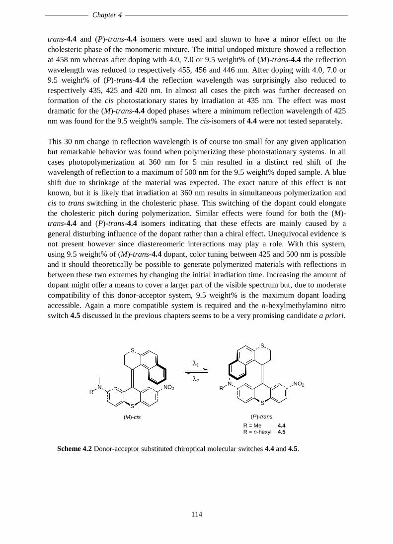
Chapter 4
114
trans-4.4 and (P)-trans-4.4 isomers were used and shown to have a minor effect on thecholesteric phase of the monomeric mixture. The initial undoped mixture showed a reflectionat 458 nm whereas after doping with 4.0, 7.0 or 9.5 weight% of (M)-trans-4.4 the reflectionwavelength was reduced to respectively 455, 456 and 446 nm. After doping with 4.0, 7.0 or9.5 weight% of (P)-trans-4.4 the reflection wavelength was surprisingly also reduced torespectively 435, 425 and 420 nm. In almost all cases the pitch was further decreased onformation of the cis photostationary states by irradiation at 435 nm. The effect was mostdramatic for the (M)-trans-4.4 doped phases where a minimum reflection wavelength of 425nm was found for the 9.5 weight% sample. The cis-isomers of 4.4 were not tested separately.
This 30 nm change in reflection wavelength is of course too small for any given applicationbut remarkable behavior was found when polymerizing these photostationary systems. In allcases photopolymerization at 360 nm for 5 min resulted in a distinct red shift of thewavelength of reflection to a maximum of 500 nm for the 9.5 weight% doped sample. A blueshift due to shrinkage of the material was expected. The exact nature of this effect is notknown, but it is likely that irradiation at 360 nm results in simultaneous polymerization andcis to trans switching in the cholesteric phase. This switching of the dopant could elongatethe cholesteric pitch during polymerization. Similar effects were found for both the (M)-trans-4.4 and (P)-trans-4.4 isomers indicating that these effects are mainly caused by ageneral disturbing influence of the dopant rather than a chiral effect. Unequivocal evidence isnot present however since diastereomeric interactions may play a role. With this system,using 9.5 weight% of (M)-trans-4.4 dopant, color tuning between 425 and 500 nm is possibleand it should theoretically be possible to generate polymerized materials with reflections inbetween these two extremes by changing the initial irradiation time. Increasing the amount ofdopant might offer a means to cover a larger part of the visible spectrum but, due to moderatecompatibility of this donor-acceptor system, 9.5 weight% is the maximum dopant loadingaccessible. Again a more compatible system is required and the n-hexylmethylamino nitroswitch 4.5 discussed in the previous chapters seems to be a very promising candidate a priori.
S
S
NO2NR
(M)-cis
S
S
NO2NR
(P)-trans
λ1
λ2
R = Me R = n-hexyl
4.44.5
Scheme 4.2 Donor-acceptor substituted chiroptical molecular switches 4.4 and 4.5.

Controlling the Color of Cholesteric Liquid Crystals
115
4.6 Hexylmethylamino Nitro Switch
4.6.1 Photochemical Properties of Switchable DopantA sample of 2.6 weight% of a racemic cis-trans mixture of 4.5 was tested in the same way aspresented in the previous chapter for a variety of low molecular weight nematic liquidcrystalline host materials. Here, in contrast to the other hosts, doping of a liquid crystallinemixture of 40% 4.2 and 60% 4.3 (forthwith denoted as 4.2/4.3) with racemic cis-transmixture of 4.5 resulted in a large decrease in the solid (C) to cholesteric (N*) phase transitiontemperature from 57°C to 40°C. This decrease in temperature was even more pronounced forsamples of higher concentration, where doped samples with 10 and 12.5 weight% ofenantiomerically pure (M)-trans-4.5 (vide infra) resulted in liquid crystallinity at roomtemperature. This is a very desirable feature of this system since for any LCD applicationliquid crystallinity at room temperature is an absolute requirement.
The switching selectivity for 4.5 was tested on samples of 4.2/4.3 doped with 2.6 weight% ofa racemic mixture of cis- and trans-isomers of 4.5. In a chiral environment such as thischolesteric liquid crystal matrix, the two photoisomerizations are no longer trulyenantiomeric pathways. The exact absorption characteristics of (M)- and (P)-trans-4.5 andalso of (M)- and (P)-cis-4.5 can be different in a chiral environment because ofdiastereomeric interactions. No attention was paid, however, to any effects concerning thisdiastereomeric relationship, which are expected to be small or negligible. The switchingselectivity in this cholesteric host resembled the selectivities found in other nematic liquidcrystalline hosts and in n-hexane solution (see Chapter 3). Upon 435 nm irradiation aphotostationary state was reached with a ratio cis-4.5 : trans-4.5 of 67 : 33. Irradiation at 380nm resulted in a photostationary state of 31% cis-4.5 and 69% trans-4.5. It should be notedthat also in this case these wavelengths are probably not the most efficient wavelengths forswitching.
4.6.2 Controlling the Color of Cholesteric Liquid CrystalsThe first requirement for donor-acceptor system 4.5 is an improved compatibility, comparedto compound 4.4, with the polymerizable liquid crystalline host 4.2/4.3. As described inChapter 3, a better compatibility was indeed found for low molecular weight liquid crystals.Next, compound 4.5 was tested in the cholesteric liquid crystalline acrylate mixture 4.2/4.3.In view of the similar chiral properties of 4.5 compared to the original donor-acceptor switch,(M)-trans-4.5 was used in all the following experiments. Samples were prepared withincreasing weight% of dopant (5 to 20 weight%). Stable samples were obtained with up to 15weight% dopant. The transmission characteristics of these samples were measured on alignedand spin-coated samples. The samples were aligned on a polyimide covered glass surfacefrom toluene solution and spin-coated. In this way, colored thin films of doped LC materialwere obtained, which were used for transmission measurements. The measured transmissioncurves were recalculated to show reflection characteristics.35 A schematic representation ofthe processes involved is depicted in Scheme 4.3.

Chapter 4
116
doping irradiation polymerization
acrylate 4.2/4.3
monomer
acrylate monomer+
(M)-trans-4.5
acrylate monomer+ PSS
(M)-trans-4.5 / (P)-cis-4.5
acrylate polymer+ PSS
(M)-trans-4.5 / (P)-cis-4.5
Scheme 4.3 Schematic representation of processes involved in cholesteric acrylate mixture4.2/4.3 doped with chiroptical molecular switch 4.5.
In all doped cases, the reflection wavelength was red-shifted compared to the undopedmixture. The red-shift increases with increasing concentration up to 12.5 weight% as depictedin Figure 4.7. For the 15 weight% sample the observed reflection wavelength was found tohave blue shifted by 49 nm relative to the 12.5 weight% sample, indicating some instability atthis higher concentration. This might be caused by phase separation but this was not visuallydetected.
400 500 600 7000
20
40
60
80
100
undoped
15 w%
12.5 w%
10 w%
5 w%
refle
ctio
n (%
)
wavelength (nm)
Figure 4.7 Influence of the concentration of dopant 4.5 in 4.2/4.3 on the reflection, wavelengthand intensity of aligned and spin-coated cholesteric phases.

Controlling the Color of Cholesteric Liquid Crystals
117
Switching experiments were performed on an aligned sample with 10 weight% dopant in thepresence of 1 weight% of photoinitiator (Irgacure 651) and 1 weight% of inhibitor (p-methoxyphenol) at 435 nm irradiation. At this wavelength no polymerization is initiated anda trans to cis isomerization of the chiral dopant is the only process observed. Thephotostationary state at this wavelength, determined at lower dopant concentration (2.6weight%), was found to consist of 67% cis and 33% trans (vide supra). Uponphotoisomerization the reflection band of the LC film was gradually shifted to shorterwavelength (Figure 4.8). Starting at a reflection wavelength of 596 nm, a blue shift of thereflection wavelength to 524 nm was observed at the photostationary state after 150 sec ofirradiation.
450 500 550 600 650 7000
20
40
60
80
100 increasing irradiation time
refle
ctio
n (%
)
wavelength (nm)
Figure 4.8 Color tuning by photoisomerization at 435 nm of 10 weight% of switchable dopant(M)-trans-4.5 in cholesteric host material 4.2/4.3, decreasing line thickness indicates increasingirradiation time (t = 0, 30, 60, 90, 120 and 150 sec).
For the 12.5 weight% sample this wavelength shift was more pronounced. Starting at areflection wavelength of 666 nm, under irradiation at 435 nm, a photostationary state wasreached with a reflection wavelength of 541 nm. This represents a blue shift of 125 nm(Figure 4.9). As already indicated in the previous chapter, however, this wavelength of 435nm is not the most efficient switching wavelength for compound 4.5. Indeed, when increasingthe irradiation wavelength using a 450 nm cut-off filter, the wavelength of reflection couldfurther be decreased to a value of 526 nm. This blue shift of 140 nm can also be induceddirectly by > 450 nm irradiation of the initial pure (M)-trans-4.5 doped film. The differencebetween 4.5 and 4.4 is striking, as for the parent compound 4.4, upon 435 nm irradiation(which for that compound is the most efficient wavelength) a maximum wavelength shift ofonly 24 nm is observed.

Chapter 4
118
500 550 600 650 700 7500
20
40
60
80
100 color control by irradiation
refle
ctio
n (%
)
wavelength (nm)
Figure 4.9 Change in reflection wavelength by photoisomerization at 435 nm (thin solid line)and subsequently 450 nm (dashed line) of 12.5 weight% of a thin LC film of switchable dopant4.5 in cholesteric host material 4.2/4.3 at its photostationary states.
Subsequent photopolymerization of the LC film at the photostationary state was effected by 5min irradiation at 365 nm in vacuo. At this wavelength cis to trans back isomerization isexpected to some extent. After the irradiation the liquid crystalline phase is polymerized anda rigid polymer matrix was obtained. The influence of the photopolymerization on theobserved reflection wavelengths is complicated. At low concentration (5 weight%)photopolymerization resulted in a red shift of the reflection band as also observed for theparent compound. The 10 and 12.5 weight% samples did not show this effect. At 10 weight%the cholesteric packing was apparently unaffected by the irradiation, while at 12.5 weight% aslight blue-shift, which is more or less a broadening effect was observed (Table 4.1).
Weight%(M)-trans-4.5
Reflectionwavelength
ReflectionwavelengthPSS 435 nm
ReflectionwavelengthPSS 450 nm
Reflection wavelengthafter photopolymerization
at 365 nm
5 564 nm 536 nm - 618 nm10 698 nm 536 nm - 538 nm
12.5 666 nm 541 nm 526 nm 518 nm15 617 nm - - -
Table 4.1 Influence of irradiation (photoisomerization and subsequent photopolymerization) on thereflection wavelength of the cholesteric LC phase (4.2/4.3)
For the 12.5 weight% sample, which is most promising for any color LC application, theeffect of the photopolymerization was also tested for the initially pure (M)-trans-4.5 dopedphase showing a 666 nm reflection in the monomeric state. Here, photopolymerization at 365nm changed the reflection wavelength to 632 nm, which can be explained by shrinkage of the

Controlling the Color of Cholesteric Liquid Crystals
119
material. This is also observed for undoped samples and caused by the fact that the polymeris of smaller dimensions than the monomer mixture. Combined with the photostationarymixture, which showed a reflection of 526 nm and gave a polymerized matrix with a 518 nmreflection, this system constitutes a "write and lock" mechanism for color information (Figure4.10). Although there is a small degree of cis to trans isomerization on thephotopolymerization process, the obtained polymeric phases in all cases reflect thephotostationary state of the chiral dopant. The polymerized phases are completely inert toprolonged irradiation and the photochemically written color information is locked. Startingfrom 12.5 weight% (M)-trans-4.5 in acrylate mixture 4.2/4.3, writing is done by irradiationwith 450 nm light and cholesteric phases with pitches between 666 nm and 526 nm can beinduced by varying the irradiation time. Color inspection (red to green) offers an easy read-out procedure. Further irradiation of this LC phase will result in a change in the (M)-trans-4.5to (P)-cis-4.5 ratio and consequent change in the wavelength of reflection (the color) of theLC film, as long as the 450 nm photostationary state is not reached. This monomeric state canbe considered a rewritable state. Upon photopolymerization, the LC matrix will harden andthe written information is locked. The polymerization process is accompanied by a slightchange in the chiral properties of the liquid crystalline phase. Polymerized cholesteric filmwith pitches between 632 nm and 518 nm can be obtained, dependent on the (M)-trans-4.5 :(P)-cis-4.5 ratio before photopolymerization. Again color inspection (orange to green) offersan easy read-out procedure which is now absolutely non-destructive. The information inlocked, there is no change in cholesteric pitch observed upon further irradiation.
500 600 700 8000
20
40
60
80
100locking information
color control
refle
ctio
n (
%)
wavelength (nm)
B
A
C
D
Figure 4.10 Color control to write information and photopolymerization as a lockingmechanism for a 12.5 weight% sample of (M)-trans-4.5 in 4.2/4.3. Wavelength of reflection atdifferent stages of the process: A) initial sample; B) photostationary state after 450 nmirradiation; C) polymerized sample after 365 nm irradiation of the initial sample (A); D)polymerized sample after 365 nm irradiation of the photostationary state (B).

Chapter 4
120
For a real switch system these one-direction experiments only constitute half the process,since controlled cis to trans isomerization should also be feasible. The photostationary stateupon irradiation at 380 nm was determined to be 69% (M)-trans-4.5 : 31% (P)-cis-4.5. Thereversibility of the process was also briefly tested. Irradiation at 365 nm of a 10 weight%sample of 4.5 in 4.2/4.3 leads to a competitive irradiation of the switchable dopant and thephotoinitiator for the polymerization process. In vacuo this resulted in polymerization and theobserved changes in reflection wavelength (vide supra). Atmospheric conditions preventpolymerization and irradiation under these conditions resulted in a red shift of the reflectionwavelength indicative of cis to trans back isomerization. This cis to trans switching wastested for the 10 weight% sample of 4.5 in 4.2/4.3 at the 435 nm photostationary state whichshowed a wavelength of reflection of 536 nm (vide supra). The resulting 365 nmphotostationary sample showed a reflection band at 551 nm, a blue shift of only 15 nm. Thisindicates low selectivity for the cis to trans photoisomerization step under these conditions.First of all it should be noted that the 365 nm used is not the most efficient wavelength forswitching. Furthermore, the observed low selectivity is most probably also caused by thecompeting effect of the photoinitiator since for the 2.6 weight% sample of 4.5 reasonableselectivities were found. Extrapolation of the results obtained for low concentration samplesat 380 nm, however, suggest that it should be possible to improve the reversibility by tuningthe exact composition of the LC matrices, especially by varying the amount and kind ofphotoinitiator, and the wavelengths employed for switching and polymerization.
4.7 Conclusion and Future Prospects
In summary, with an aligned and spin-coated sample of 12.5 weight% (M)-trans-4.5 doped ina cholesteric mixture of acrylates 4.2 and 4.3 (40 : 60), photocontrol of the reflection colorbetween red and green is possible. By varying the irradiation time and wavelength all phasesin between should be accessible. The written color information can be stored by subsequentphotopolymerization (Scheme 4.4). The wavelength range covers about one third of thewhole visible wavelength spectrum and as such a real LCD application is farfetched,especially when compared to the PDLC system of photoresponsive polymer 4.1, where thewhole visible spectrum can be generated upon irradiation.31 It should be noted, however, thatthe dopant loading in this system is 50 weight%, four times the amount used for the discussedchiroptical molecular switch 4.5. Due to compatibility problems, such a high dopant loadingis not possible for this system. PDLC systems are fundamentally different from the presentlow molecular weight systems, which the acrylate mixture 4.2/4.3 in the monomeric stateactually is.
Nevertheless, one can readily conceive some improvements for the present system. First ofall, the shrinkage of the material, which is dependent on the degree of polymerization, shouldbe reducible by varying the amount of initiator and inhibitor. This could lead to a broaderaddressable spectral region in the polymerized state. Another improvement that can beenvisioned is the use of a different photoinitiator that can be excited by wavelengths outsidethe absorption range of the switchable dopant. This might also have a dramatic effect on thereversibility of the photoswitching. Adjusting the relative amount of monoacrylate and chiral

Controlling the Color of Cholesteric Liquid Crystals
121
diacrylate should lead to further optimization. Also response times in the present system arestill far from response times required for any LCD application. As noted, for most LCDsystems, relaxation of the mesogenic host molecules is the rate-determining factor. In thepresented system, there is still considerable room for improvement in both the samplepreparation as well as the irradiation techniques applied. The results show however that pixelcolors can be tuned by photoirradiation of a chiroptical molecular switch doped in acholesteric liquid crystal.
photopolymerization
color control
photopolymerization
(RE)WRITABLE INFORMATION
STORED INFORMATION
Scheme 4.4 Schematic representation of color control and storage of information byphotopolymerization of a cholesteric liquid crystal.
Unfortunately, for donor-acceptor system 4.5, the two pseudoenantiomers have similareffects on the cholesteric phase. Both the film doped with pure (M)-trans-4.5, and the 435 or450 nm photostationary samples with (P)-cis-4.5 in excess, show red-shifted reflection curvescompared to undoped host. In an ideal situation the two pseudoenantiomers would showopposite effects on the chiral nature of the matrix where one pseudoenantiomer would inducea red and the other a blue shift of the reflection. The effects observed could in principle alsobe induced by an achiral photoswitch. Instead of focussing on improving all the aspects ofthis particular system under different conditions an improved photosensitive dopant for thistype of application was found. This new system will be the subject of the next two chapters.
Other applications for which the presented system could be used are reflective polarizers andlasers based on cholesteric liquid crystals. The color reflection of a cholesteric phase iscircularly polarized as discussed in the introduction. The polarization of the reflected light isdependent on the handedness of the cholesteric phase. As such, the presented system canfunction as a tunable reflector of circular polarized light at different wavelengths. This was

Chapter 4
122
already reported for a system based on a very similar acrylate mixture.36 Uponphotopolymerization, cholesteric filters of different wavelengths with an approximatebandwidth of about 50 nm could be obtained. Introduction of a gradient in the pitch of thecholesteric helix resulted in a polarization filter by which one of the two components ofcircularly polarized light was reflected over the entire visible spectrum.28b The othercomponent of the light is selectively transmitted. In principle, the LC system presented in thischapter is also useful in such an approach. Cholesteric materials have also been applied intunable mirrorless laser systems. The repetitive structure of a cholesteric phase allows for thepossibility of lasing without using external mirrors when a fluorescent dye is dissolved in thisphase.37 The wavelength of such a laser system is dependent on the fluorescent dye and onthe cholesteric pitch. An example has been published where the wavelength of a laser basedon a cholesteric liquid crystal could be tuned by mechanical modification of the LC phase.38
A phototunable cholesteric liquid crystal, as the one presented in this chapter might offer analternative approach towards phototunable laser sources.
4.8 Experimental Section
For general remarks, see Section 2.6. For preparation of aligned cholesteric phases, see Section 3.7.Spin-coating of the aligned phases was performed at 5 r.p.m. for 2 min resulting in thin LC films withhomogeneous colors. All experiments were performed at Philips Research, Eindhoven.
MaterialsThe cholesteric mixture of 4.2 and 4.3 as well as the photoinitiator (Irgacure 651) and inhibitor (p-methoxyphenol) were kindly provided by Philips Research and used without prior purification. Thesynthesis of chiroptical molecular switch 4.5 was presented in Chapter 2 and was resolved asdescribed there, using preparative chiral HPLC.
Reflection WavelengthsThe reflection wavelengths presented were measured as transmission curves as indicated in the text. APerkin Elmer Lambda 900 UV/VIS/NIR spectrometer was used. The incident light beam travelsthrough a depolarizer and a polarizer before it reaches the sample. After the sample the transmittedlight travels through a λ/4 plate to isolate the circularly polarized components and a second polarizedbefore being analyzed. From the transmission curves, reflection curves were calculated.35
Irradiation ExperimentsIrradiations were performed with a UV lamp equipped with a suitable interference filter (435 nm) orcut-off filter (>450 nm). For the photopolymerization a 365 nm light source was used (PhilipsPL10W/10).
4.9 References and Notes
1 G. Solladié, R.G. Zimmermann, Angew. Chem. Int. Ed. Engl. 1984, 23, 348.2 B.L. Feringa, R.A. van Delden, N. Koumura, E.M. Geertsema, Chem. Rev. 2000, 100, 1789 and
reference cited in Chapter 3.

Controlling the Color of Cholesteric Liquid Crystals
123
3 See for example: a) D. Dunmar, K. Toniyama in Handbook of Liquid Crystals Vol 1:Fundamentals, D. Demus, J. Goodby, G.W. Gray, H.-W. Spiess, V. Vill Ed., Wiley-VCH,Weinheim, 1998, pp. 215-239; b) G. Meier, in Applications of Liquid Crystals, Springer Verlag,Berlin-Heidelberg-New York, 1975, pp. 1-21; c) S. Chandrasekhar, Liquid Crystals, CambridgeUniversity Press, Cambridge, 1977.
4 Next to the references [3], see for example: a) E.B. Priestley in Introduction to Liquids Crystals,Ed. E.B. Priestley, P.J. Wojtowicz, P. Sheng, Plenum Press, New York, 1975, pp. 203-218; b) W.Elser, R.D. Ennulat in Advances in Liquid Crystals Vol. 2, Ed. G.H. Brown, Academic Press, NewYork, 1976, pp. 73-161 and references therein.
5 W.H. Bragg, W.L. Bragg, X-rays and Crystal Structure, G. Bell and Sons, London, 1915.6 G.H.Heilmeier, L.A. Barton, L.A. Zanoni, Appl. Phys. Lett. 1968, 13, 46.7 a) B. Bahadur, Mol. Cryst. Liq. Cryst. 1984, 109, 3; b) P.G. de Gennes, Angew. Chem. Int. Ed.
Engl. 1992, 31, 842; c) E. Kaneko, Liquid Crystal TV Displays: Principles and Applications ofLiquid Crystal Displays, KTK Scientific Publishers, Tokyo, 1987; d) L.A. Goodman inIntroduction to Liquids Crystals, Ed. E.B. Priestley, P.J. Wojtowicz, P. Sheng, Plenum Press, NewYork, 1975, pp. 241-273.
8 G.H. Heilmeier, L.A. Zanoni, L.A. Barton, Proc. IEEE 1968, 56, 1162.9 a) M. Schadt, W. Helfrich, Appl. Phys. Lett. 1971, 18, 127; b) D. de Rossi, J. Robert, J. Appl. Phys.
1978, 49, 1139; c) G. Bauer, Mol. Cryst. Liq. Cryst. 1981, 63, 45; L. Pohl, G. Weber, R.Eidenschink, Appl. Phys. Lett. 1981, 38, 497.
10 a) T.J. Scheffer, Japan Display '83 1983, 400; b) T.J. Scheffer, J. Nehring, Appl. Phys. Lett. 1984,45, 1021.
11 For an extensive account of reflective cells: S.-T. Wu, D.-K. Yang, Reflective Liquid CrystalDisplays, Wiley, Chichester, 2001.
12 Active vs. passive matrix in PC Computing 1993, 6, 197.13 a) G.H. Heilmeier, W. Helfrich, Appl. Phys. Lett. 1970, 16, 155; b) J.G. Grabmeier, W.F. Greubel,
H.H. Krüger, Mol. Cryst. Liq. Cryst. 1971, 15, 95.14 For early examples, see: a) T.J. Scheffer, J. Appl. Phys. 1973, 44, 4869; b) T.J. Scheffer in Non-
Emmisive Electronic Displays, Plenum Press, New York, 1975, pp 45-78; c) T. Uchida, C.Shishido, M. Wada, Mol. Cryst. Liq. Cryst. 1977, 39, 127.
15 For early examples, see: a) T.J. Scheffer, J. Appl. Phys. 1973, 44, 4799; b) I.A. Shanks, ElectronicLett. 1974, 10, 90.
16 S. Musa, Sci. Amer. 1997, 277, 124.17 Figure adaped from reference 16.18 a) G.H. Heilmeier, L.A. Zanoni, Appl. Phys. Lett. 1968, 13, 91; b) G.H. Heilmeier, J.A. Castellano,
L.A. Zanoni, Mol. Cryst. Liq. Cryst. 1969, 8, 293. For the most employed host-guest cell, see: D.L.White, G.N. Taylor, Appl. Phys. Lett. 1974, 45, 4718.
19 a) B. Bahadur, Liquid Crystals Application and Uses, World Scientific, Singapore, 1992, Vol. 3,Chapter 11; b) H.V. Ivashchenko, V.G. Rumyantsev, Mol. Cryst. Liq. Cryst. 1987, 150, 1.
20 See reference 6c, Chapter 3.21 a) F. Vicentini, L.-C. Chien Liq. Cryst. 1998, 24, 483; b) D. Davis, K. Kahn, X.-Y. Huang, J.W.
Doane, SID Intl. Symp. Digest. Tech. Papers 1998, 29, 901.22 a) W. Haas, J. Adams, J. Wysocki, Mol. Cryst. Liq. Cryst. 1969, 7, 371. b) J. Adams, W. Haas, J.
Electrochem. Soc. 1971, 118, 2026.23 E. Sackmann, J. Am. Chem. Soc. 1971, 93, 7088.24 H.-K. Lee, K. Doi, H. Harada, O. Tsutsumi, A. Kanazawa, T. Shioni, T. Ikeda, J. Phys. Chem. B.
2000, 104, 7023.25 N. Tamaoki, Adv. Mater. 2001, 13, 1135.26 see reference 21 and references therein.27 a) H. Finkelmann, J. Koldehoff, H. Ringsdorf, Angew. Chem. Int. Ed. Engl. 1978, 17, 935; b) S.-L.
Tseng, G.V. Laivins, D.G. Gray, Macromolecules 1982, 15, 1262; c) J. Watanabe, T. Nagasse, H.Itoh, T. Ishi, T. Satoh, Mol. Cryst. Liq. Cryst. 1988, 164, 135.

Chapter 4
124
28 a) M. Muller, R. Zentel, H. Keller, Adv. Mater. 1997, 9, 159; b) D.J. Broer, J. Lub, G.N. Mol,Nature 1995, 378, 467; c) P.J. Shannon, Macromolecules 1984, 17, 1873; d) T. Tsutsui, T. Tanaka,Polymer 1980, 21, 1351.
29 a) A.Y. Bobrovsky, N.I. Boiko, V.P. Shibaev, Liq. Cryst. 1998, 25, 393; b) A.Y. Bobrovsky, N.I.Boiko, V.P. Shibaev, Liq. Cryst. 1998, 25, 679; c) N.I. Boiko, A.Y. Bobrovsky, V.P. Shibaev, Mol.Cryst. Liq. Cryst. 1999, 332, 173; d) A.Y. Bobrovsky, N.I. Boiko, V.P. Shibaev, J. Opt. Technol.1999, 66, 574; e) P. van de Witte, J.C. Galan, J. Lub, Liq. Cryst. 1998, 24, 819.
30 a) A.Y. Bobrovsky, N.I. Boiko, V.P. Shibaev, J. Springer, Adv. Mater. 2000, 12, 16; b) F.Vicentini, J. Cho, L.-C. Chien, Liq. Cryst. 1998, 2, 483; c) S. Campbell, Y. Lin, U. Müller, L.-C.Chien, Chem. Mater. 1998, 10, 1652.
31 M. Brehmer, J. Lub, P. van de Witte, Adv. Mater. 1998, 10, 1438.32 D.A. Higgins, Adv. Mater. 2000, 12, 251.33 a) J. Lub, J.H. van der Veen, E. van Echten, Mol. Cryst. Liq. Cryst. 1996, 287, 205; b) J. Lub, J.H.
van der Veen, W. ten Hoeve, Recl. Trav. Chim. Pays-Bas 1996, 115, 321; c) R.A.M. Hikmet, J.Lub, A.J.W. Tol, Macromolecules 1995, 28, 3313; d) R.A.M. Hikmet, B.H. Zwerver, J. Lub,Macromolecules 1994, 27, 6722.
34 N.P.M. Huck, Ph.D Thesis, University of Groningen, 1997.35 Reflection (%) = 100 -%T; the LC material does not show absorption in the wavelength range
used.36 J. Lub, D.J. Broer, R.A.M. Hikmet, K.G.J. Nierop, Mol. Cryst. Liq. Cryst. 1995, 18, 31937 a) B. Taheri, A.F. Muñez, P. Palffy-Muhoray, R. Twieg, Mol. Cryst. Liq. Cryst. 2001, 358, 73; b)
E. Alvarez, M. He, A.F. Muñoz, P. Palffy-Muhoray, S.V. Serak, B. Taheri, R. Twieg, Mol. Cryst.Liq. Cryst. 2001, 369, 75.
38 H. Finkelmann, S.T. Kim, A. Muñoz, P. Palffy-Muhoray, B. Taheri, Adv. Mater. 2001, 13, 1069.

125
Chapter 5
From Controlling Chirality to Controlling Rotation
In this chapter the use of sterically overcrowded alkenes as unidirectionally rotatingmolecular motors is described. The work is an extension of the research on chiropticalmolecular switches and the most important features will be treated in this context. Theextension requires additional chiral information in the molecular structure to make thedifferent forms of the sterically overcrowded alkene diastereomeric. Apart from aninteresting pyrrolidine-functionalized donor-acceptor system, the first real example of aunidirectionally rotating motor is introduced.*
* Part of this chapter has been published: N. Koumura, R.W.J. Zijlstra, R.A. van Delden, N. Harada,
B.L. Feringa, Nature 1999, 401, 152.

Chapter 5
126
5.1 Introduction
In the previous chapters it was shown that sterically overcrowded alkenes could function aschiroptical molecular switches. In these systems molecular chirality can be controlled bylight. It was also demonstrated by employing liquid crystals as host compounds thatmacroscopic chirality could be controlled using chiroptical molecular switches as guestcompounds. These systems might have potential in future nanotechnological applicationssuch as optical data storage units or as true switching devices in optical data processing.Apart from these molecular switches which have one specific function, in approachestowards true nanoscale molecular devices a variety of different functions have to beaddressed at the molecular level.1 This requires delicate super- or supramolecularorganization of different molecular components each capable of performing a certainfunction. A variety of molecular, mechanical type, components have been developed,including, next to molecular switches, molecular counterparts of brakes,2 gears,3 turnstiles4
and muscles.5 A highly desirable addition to this so-called toolbox of nanotechnology is amolecular motor. In a molecular motor consumption of energy should result in controlledmotion. This motion could eventually enable a device to perform mechanical work. If controlof the direction of a full rotary motion in a molecular type motor can be realized, a basicrequirement for the construction of (supra)molecular machines might be fulfilled. In Chapter1 already some examples of molecular motors have been discussed. A chemically drivenmolecular motor that uses chemical energy to perform a 120° rotation has been developed byKelly et al.6 Simultaneously, in our group a light-driven molecular motor based on asterically overcrowded alkene was developed in which full 360° unidirectional rotation wasaccomplished. This chapter will elaborate on the step from molecular switching to molecularrotation for sterically overcrowded alkenes.
5.2 Extension of the Molecular Switching Movement
The chiroptical molecular switches already show a unidirectional rotation of about 105° asestimated from the X-ray structures discussed in Chapter 2. The direction of the movement issolely governed by the helicity in the initial state and the process is driven by light. In thedevelopment of molecular motors using sterically overcrowded alkenes as the basic structure,an extension of the switching movement is necessary and the light induced movement shouldcontinue in the same direction. Realizing that these sterically overcrowded alkenes consist offour stereoisomers, that is the pseudoenantiomeric forms that constitute the two switchingstages and their enantiomers, the possibility of full 360° rotation arises. For the n-hexylmethylamino nitro donor-acceptor switch 5.1, extensively discussed in the foregoingchapters, the possible processes are depicted in Scheme 5.1. Starting from enantiomericallypure (P)-trans-5.1, irradiation at 465 nm results in near quantitative formation of the (M)-cis-5.1 isomer. Since the cis-isomer does not absorb light at this wavelength, this isomerizationrepresents a unidirectional process.

From Controlling Chirality to Controlling Rotation
127
(M)-cis-5.1(P)-trans-5.1
465 nm
S
S
NO2N
S
S
NO2N
465 nm
(P)-cis-5.1(M)-trans-5.1
S
S
NO2N
S
S
NO2N
Scheme 5.1 Four states of a chiroptical molecular switch in theory combine to allow fullrotation.
Racemization by heating the solution results in a helix inversion forming (P)-cis-5.1eventually leading to a racemic state. This combination of irradiation and heating results in afull 180° rotation from (P)-trans-5.1 to (P)-cis-5.1, although an equal amount of (M)-cis-5.1will be present. Continuation of this movement for this system leads to a complicated mixtureof all stereoisomers, as irradiation of the cis-isomers ((M)-cis-5.1 and (P)-cis-5.1) at the mostefficient wavelength (380 nm) will result in both cis to trans as well as trans to cisisomerization. This will eventually lead to a racemic mixture of cis- and trans-isomers in a 30: 70 ratio, which was determined to be the photostationary state composition at thiswavelength (Chapter 2). Theoretically it will never be possible to make a unidirectionalmolecular motor when two enantiomeric states of one single compound are involved in theprocess. Nevertheless, this short reasoning shows that the four stages of the molecular switchmay combine to allow full rotary behavior. Although at specific wavelengths thephotoequilibrium can efficiently be shifted to one side, as illustrated for compound 5.1, cis-trans isomerization of the olefinic bond in these overcrowded alkenes is in principlereversible. Unidirectionality in rotation for a sterically overcrowded alkene should thereforebe controlled in the thermal helix inversion steps, which for compound 5.1 are part of aracemization process. To achieve this unidirectionality an additional chiral influence isessential to differentiate between the forward helix inversion pathway and the reverseprocess.

Chapter 5
128
5.3 Pyrrolidine Functionalized Chiroptical Molecular Switch
A possible candidate to function as a molecular motor is compound 5.2. This stericallyovercrowded alkene closely resembles the donor-acceptor substituted switch 5.1. Theintrinsically chiral structure is functionalized with an electron withdrawing nitro and anelectron donating amine substituent. The amine in this case is the proline derivative (S)-2-methoxymethylpyrrolidine. This chiral amine has been used as a chiral auxiliary inasymmetric synthesis.7 The additional stereogenic center in this molecular switch results infour distinct diastereomeric forms, rather than two diastereomeric pairs of enantiomers asfound for 5.1 (Scheme 5.2). As a result, the two photoequilibria are now different and also thehelix inversion steps are no longer true racemizations but rather pseudoracemizationprocesses. A difference in energy for the two separate cis- ((S)-(M)-cis-5.2 / (S)-(P)-cis-5.2)and trans- ((S)-(M)-trans-5.2 / (S)-(P)-trans-5.2) isomers of 5.2 can be anticipated. Due to therelatively large conformational freedom of the pyrrolidine moiety unfortunately nounequivocal data on this energy difference could be gained from computer calculations.
(S)-(M)-cis-5.2(S)-(P)-trans-5.2
S
S
NO2N
O
(S)-(P)-cis-5.2(S)-(M)-trans-5.2
N
O
S
S
NO2
N
O
S
S
NO2N
O
S
S
NO2
λ1
λ2
λ3
λ4
k1k2k3k4
Scheme 5.2 Four diastereoisomers of chiroptical switch 5.2 and their transformations.
Next to the possible unidirectionality of the pseudoracemization steps, compound 5.2 offerssome additional appealing features. The (S)-2-methoxymethylpyrrolidine substituent forexample, might be suitable for attachment of the chiroptical switch to peptide chains afterether hydrolysis, which might be an important step towards switchable biomaterials.8 Anotherfeature is that due to the diastereomeric relationship of all four forms of molecular switch 5.2

From Controlling Chirality to Controlling Rotation
129
chiral separation techniques are no longer essential in the resolution of these fourstereoisomers.
5.3.1 Synthesis and ResolutionThe synthesis of compound 5.2 was performed by J.H. Hurenkamp. A palladium-catalyzedamination of bromo-substituted switch 5.3 with (S)-2-methoxymethylpyrrolidine 5.4, asdiscussed in detail in Chapter 2, was used. The (S)-2-methoxymethylpyrrolidine wassynthesized according to a literature procedure starting from enantiomerically pure (S)-proline in a straightforward procedure with retention of chirality.7
Br NO2
S
S
5.3
N NO2
S
SO
; a)
5.2
NO
H5.4
Scheme 5.3 Functionalization reaction of bromo-substituted overcrowded alkene 5.3 to form5.2 involving a palladium catalyzed amination: a) Pd2(dba)3, BINAP, NaOtBu, toluene, 80°C,yield: 58%.
Chiroptical switch 5.2 was obtained as a mixture of the four diastereoisomers, as depicted inScheme 5.2. Resolution was performed by HPLC over an achiral silica column. Using agradient of n-heptane and dichloromethane as an eluent, the four diastereomers were readilyseparated with retention times of 16.9 min ((S)-(M)-cis-5.2); 17.4 min ((S)-(P)-cis-5.2); 18.2min ((S)-(P)-trans-5.2); 18.8 min ((S)-(M)-trans-5.2). It should be noted again that for thechiroptical switches discussed in Chapter 2, time-consuming and expensive chiral resolutionis necessary, whereas now achiral chromatography readily allows separation of the differentisomers. The accessibility of the enantiomerically pure forms is an important advantage ofcompound 5.2 over all the other chiroptical switches discussed.
5.3.2 Switching SelectivityDue to the diastereomeric relationship, the discussion on the switching selectivity ofcompound 5.2 is a little more complicated than for the other molecular switches. Since thetwo photoisomerizations here are no longer enantiomeric pathways they have to be analyzedseparately. For the pseudoenantiomeric couple (S)-(M)-cis-5.2 and (S)-(P)-trans-5.2 (Scheme5.4), UV-VIS and CD absorption curves were determined (Figure 5.1). The CD absorptioncurves indicate the respective (P)- and (M)-helicity with ∆ε-values comparable to the otherdonor-acceptor switches (e.g. compound 5.1). From the differences in the UV-VISabsorption, with values comparable to those of other donor-acceptor switches, the idealwavelengths for switching could be determined. Here 380 nm and 463 nm were the mostselective. Irradiation of an n-hexane solution of (S)-(M)-cis-5.2 with 380 nm light resulted ina photostationary state consisting of (S)-(P)-trans-5.2 and (S)-(M)-cis-5.2 in a ratio of 69 : 31,

Chapter 5
130
as determined by CD spectroscopy. Subsequent irradiation at 463 nm led to a photostationarystate with excess (S)-(M)-cis-5.2. The diastereomeric ratio (S)-(M)-cis-5.2 : (S)-(P)-trans-5.2was 96 : 4. This switching process was fully reversible. The selectivity of this switchingprocess is as expected comparable to other donor-acceptor systems. The CD spectra of thephotostationary states are also depicted in Figure 5.1. The absorption at longer wavelengthsfor the trans-isomer results in highly selective switching towards the cis photostationary state(irradiation at 463 nm), comparable to compound 5.1.
250 300 350 400 450 5000
10
20
30
ε x
103 (
dm3 m
ol-1cm
-1)
wavelength (nm)
250 300 350 400 450 500
-40
-30
-20
-10
0
10
20
30
40
∆ε
wavelength (nm)
Figure 5.1 UV-VIS and CD absorption spectra of the diastereoisomers (S)-(M)-cis-5.2 and (S)-(P)-trans-5.2 in n-hexane. The solid curves correspond to (S)-(M)-cis-5.2 and the dashed graphsto (S)-(P)-trans-5.2. The thin curves correspond to the photostationary states.

From Controlling Chirality to Controlling Rotation
131
(S)-(M)-cis-5.2 (S)-(P)-trans-5.2
S
S
NO2N
O
N
O
S
S
NO2
463 nm
380 nm
31 : 6996 : 4cis : trans:
Scheme 5.4 Selective switching between two diastereoisomers (S)-(M)-cis-5.2 and (S)-(P)-trans-5.2.
In a completely analogous way, the UV-VIS and CD absorptions of the otherpseudoenantiomeric couple: (S)-(P)-cis-5.2 and (S)-(M)-trans-5.2 were determined (Figure5.2 and Scheme 5.5). The most efficient switching wavelengths here, again derived from theratio of the two UV absorption curves, were 379 and 459 nm for the trans and the cisphotostationary state, respectively. Irradiation at 379 nm resulted in a photostationary stateconsisting of (S)-(M)-trans-5.2 and (S)-(P)-cis-5.2 in a 66 : 34 ratio. Irradiation at 459 nmresulted in the formation of a cis-enriched photostationary state with a ratio of (S)-(P)-cis-5.2: (S)-(M)-trans-5.2 of 95 : 5. Hence, switching selectivities as well as UV-VIS and CDabsorption characteristics are similar for the two diastereomeric bistable switching pairs. Thisis further illustrated in Figure 5.3 where both the UV-VIS as well as the CD absorptioncurves of the respective cis- and trans-isomers are directly compared.
34 : 6695 : 5
(S)-(P)-cis-5.2 (S)-(M)-trans-5.2
N
O
S
S
NO2 N
O
S
S
NO2
377 nm
459 nm
cis : trans:
Scheme 5.5 Selective switching between the other two diastereoisomers (S)-(P)-cis-5.2 and (S)-(M)-trans-5.2.

Chapter 5
132
250 300 350 400 450 5000
10
20
30
ε x
103 (
dm3 m
ol-1cm
-1)
wavelength (nm)
250 300 350 400 450 500
-40
-30
-20
-10
0
10
20
30
40
∆ε
wavelength (nm)
Figure 5.2 UV-VIS and CD absorption characteristics of the (S)-(P)-cis-5.2 and (S)-(M)-trans-5.2 diastereoisomers in n-hexane. The solid curves correspond to (S)-(P)-cis-5.2 and the dashedgraphs to (S)-(M)-trans-5.2. The thin curves correspond to the photostationary states.
Subtle differences in UV absorption result in the slightly different ideal switching wavelengthas well as the slightly different switching selectivity. Only small differences in CDabsorptions can be observed. The CD spectra of the cis- and trans-compounds of oppositehelicity are, however, still roughly mirror images. The major differences are found in the UVabsorption of the two isomers at lower wavelengths. These differences might be assigned todifferent geometries of the chiral amine-substituted aryl moiety absorbing in this region.

From Controlling Chirality to Controlling Rotation
133
250 300 350 400 450 5000
10
20
30
ε x
103 (
dm
3 mol
-1cm
-1)
wavelength (nm)
250 300 350 400 450 5000
10
20
30
ε x
103 (
dm
3 mol
-1cm
-1)
wavelength (nm)
250 300 350 400 450 500
-40
-30
-20
-10
0
10
20
30
40
∆ε
wavelength (nm)250 300 350 400 450 500
-40
-30
-20
-10
0
10
20
30
40
∆ε
wavelength (nm)
Figure 5.3 Comparison of UV-VIS and CD absorption characteristics of (S)-(M)-cis-5.2 and(S)-(P)-cis-5.2 (left) and (S)-(M)-trans-5.2 and (S)-(P)-trans-5.2 (right), respectively. Solidcurves correspond to both the (M)-enantiomers; dashed curves correspond to both the (P)-enantiomers.
5.3.3 Thermal Stability of the Distinct DiastereoisomersA small but significant effect of the additional stereogenic center in compound 5.2 wasobserved in the photophysical behavior of the four distinct diastereomers. A more importanteffect here, in the light of the development of molecular motors, is the influence of theadditional stereogenic center on the thermal stability of the different stereoisomers. Where inthe case of the donor-acceptor systems discussed in previous chapters, thermal stability wasdetermined by monitoring the racemization at elevated temperatures, in the present system5.2 one cannot speak of a true racemization. The thermally induced interconversion betweenthe diastereoisomers (S)-(M)-cis-5.2 and (S)-(P)-cis-5.2, and (S)-(M)-trans-5.2 and (S)-(P)-trans-5.2 was monitored in n-dodecane by CD spectroscopy. These pairs of diastereoisomersthat share the same (cis or trans) configuration but show opposite helical shape might becalled pseudoepimers.9 Solutions of enantiomerically pure (S)-(M)-cis-5.2 and (S)-(P)-trans-5.2 at known concentrations were heated for 10 h at 100°C. The change in CD absorption wasmonitored in time, as depicted in Figure 5.4.

Chapter 5
134
0 6000 12000 18000 24000 30000 36000
-40
-30
-20
-10
0
10
20
30
∆ε
time (s)
Figure 5.4 CD absorption rescaled to show molar values (∆ε) in time for heated samples of (S)-(M)-cis-5.2 (bottom) and (S)-(P)-trans-5.2 (top) at 100°C in n-dodecane.
Knowing the molar CD absorption of all four diastereoisomers in this solvent, which areidentical to the absorptions found in n-hexane, one can determine the equilibrium ratio of thetwo respective pseudoepimers. In case of (S)-(M)-cis-5.2, heating to equilibrium resulted in asteady state consisting of (S)-(M)-cis-5.2 and (S)-(P)-cis-5.2 in a 53.6 : 46.4 ratio. In case ofthe (S)-(P)-trans-5.2 solution a steady state of (S)-(P)-trans-5.2 and (S)-(M)-trans-5.2 in aratio of 47.5 : 52.5 was obtained. These steady state ratios are not 50 : 50 indicating that thereis indeed a small but significant energy difference between the two cis- and the two trans-forms of 5.2. These equilibrium ratios combined with the actual rate of thepseudoracemizations observed give the rate constants of all four separate pathways.10 Fromthese k-values, the Gibbs energy of activation of the four distinct pathways, which is anindication for the relative stability of the four isomers, can be determined. The calculatedvalues are depicted in Scheme 5.6.
Although the additional stereogenic center clearly has an effect on the relative stability of thedistinct isomers the effects are very small. It should be noted that both for the trans as well asthe cis-isomers (M)-helicity is preferred, however, no explanation for this behavior can begiven at this moment. It might seem unexpected that the energy difference between the twotrans-nitro isomers is in fact smaller than the difference for the two cis-nitro isomers. At firstinspection of the molecule it would seem that the influence of the stereogenic center of thepyrrolidine substituent, which is solely responsible for the observed energy differences, islarger when it is in close proximity to the sterically demanding upper arene part of themolecule. It was, however, previously observed that in these complicated helical structuresthe two hydrogens directly adjacent to the central double bond in the upper half of themolecule (explicitly depicted in Scheme 5.6) have a more substantial steric effect on thelower half as discussed in Chapter 1 for molecular rotor 1.19.11 Where the two hydrogens arerestricted to their respective axial and equatorial orientation, the naphthalene molecule can

From Controlling Chirality to Controlling Rotation
135
simply bend away thereby greatly reducing the steric effect exerted on the lower half of themolecule.
(S)-(M)-cis-5.2(S)-(P)-trans-5.2
S
S
NO2N
O
HH
(S)-(P)-cis-5.2(S)-(M)-trans-5.2
N
O
S
S
NO2
HH
N
O
S
S
NO2
HH
N
O
S
S
NO2
HH
k1 = 4.6 x 10⁻⁵ s-1
∆G1 = 123.0 kJ mol-1
k2 = 5.3 x 10⁻⁵ s-1
∆G2 = 122.6 kJ mol-1
k3 = 4.5 x 10⁻⁵
s-1
∆G3 = 123.0 kJ mol-1
k4 = 5.0 x 10⁻⁵
s-1
∆G4 = 122.8 kJ mol-1
Scheme 5.6 Thermal stabilities for the four distinct diastereoisomers of 5.2.
Although the energy differences shown in Scheme 5.6 are too small for any control on thedirectionality in these pseudoracemization processes, compound 5.2 has some advantageousproperties compared to previously discussed donor-acceptor switches. The improvedresolution properties of the system in combination with a high switching selectivity make thiscompound a potentially useful member of the chiroptical molecular switch family. Thesystem will, however, never function as a molecular motor. Based on the same principle ofchiral discrimination induced by an additional stereocenter in a sterically overcrowded alkenea molecular motor was however developed. A sterically overcrowded biphenanthrylidenebearing two stereocenters was proven to function as the first light-driven unidirectionalmolecular motor.
5.4 A Biphenanthrylidene as a Molecular Motor
The dimethyl-substituted biphenanthrylidene 5.5 is a sterically overcrowded alkene bearingtwo additional stereogenic centers. These biphenanthrylidenes,12 both with respect to theirphotochemistry as well as their chiral features, closely resemble the sterically overcrowdedalkenes used as chiroptical switches. Extensive research on these overcrowded alkenes hasbeen performed in our group in collaboration with the group of professor Harada.13 Thesesystems, like the molecular switches, due to the steric hindrance around the central doublebond adopt a helical geometry. For full assignment of the helices in this case both halves of

Chapter 5
136
the molecule have to be designated separately leading to (M,M)-, (P,P)- and (M,P)-isomers.For the unsubstituted biphenanthrylidenes already remarkable racemization behavior wasobserved where the cis-isomers where shown to racemize considerably faster than the trans-isomers.13b For the methyl-substituted compound (3R,3'R)-1,1',2,2',3,3',4,4'-octahydro-3,3'-dimethyl-4,4'-biphenanthrylidene 5.5 both stereogenic centers are of (R)-configuration.14 The(P,P)-trans-isomer was found to be the most stable form due to the trans-geometry and thepreferred axial orientation of both the methyl substituents. A chiral resolution and also astereoselective synthesis for these types of systems has been reported.15
Photoisomerization (> 280 nm) of the stable (P,P)-trans-isomer at room temperature insolution unexpectedly resulted in the irreversible formation of the (P,P)-cis-isomer, which isalso energetically stable due to the axial orientation of the two methyl substituents (Scheme5.7).16 Although trans-cis isomerization occurred, the helicity of the cis state formed was thesame as for the initial trans-state and the isomerization process was irreversible, bothobservations are in sharp contrast with our experience with other sterically overcrowdedalkenes. A similar photoisomerization of the (P,P)-cis-isomer, using the same wavelength oflight resulted in a reversible process to form the anticipated (M,M)-trans-isomer. Thephotostationary state consists of (P,P)-cis-5.5 : (M,M)-trans-5.5 in a ratio of 10 : 90. This(M,M)-trans-isomer is energetically less stable, by 36.0 kJ mol-1 compared to the (P,P)-trans-isomer, due to the forced equatorial orientations of the methyl groups. It was found (by NMRanalysis) to revert to the more stable (P,P)-trans-isomer in a unidirectional helix inversionstep upon heating.
(P,P)-trans-5.5diaxial methyl groups
> 280 nm > 280 nm
> 380 nm
(P,P)-cis-5.5diaxial methyl groups
(M,M)-trans-5.5diequatorial methyl groups
Scheme 5.7 Unexpected photochemistry of dimethyl-substituted biphenanthrylidene 5.5.
Close examination of the processes using MOPAC93-AM1 calculations17 revealed that thereason for the unexpected formation of (P,P)-cis-5.5 directly by photoisomerization of (P,P)-trans-5.5 most probably would be the existence of an energetically highly unfavorableintermediate. This intermediate would be less stable by 46.0 kJ mol-1 compared to the stable(P,P)-cis-isomer. It was proposed that this would be the expected (M,M)-cis-isomer of 5.5.Low temperature (-50°C) UV-VIS experiments during irradiation of (P,P)-trans-5.5 indeedrevealed the formation of a fourth form of this system (Figure 5.5). The UV-VIS absorptionswere bathochromically shifted and as a result the solution turned from colorless to yellow.Upon increase of the temperature to room temperature again the previously observedcolorless (P,P)-cis-isomer of 5.5 was formed.

From Controlling Chirality to Controlling Rotation
137
250 300 350 400 4500
2
4
6
8
10
ε x
10-3 d
m3 m
ol-1cm
-1
wavelength (nm)
Figure 5.5 UV-VIS spectra (n-hexane) of the three forms of motor 5.5 stable at roomtemperature (thin solid: (P,P)-trans-5.5; dashed: (P,P)-cis-5.5; dotted: (M,M)-trans-5.5) and theUV spectrum obtained from low temperature irradiation of (P,P)-trans-5.5: thick black.
Detailed low temperature irradiation experiments combined with CD and NMR studiesperformed in a joint effort with N. Koumura in our group fully established that this fourthstate was indeed the anticipated (M,M)-cis-isomer. A photostationary state consisting of(P,P)-trans-5.5 : (M,M)-cis-5.5 in a ratio of 5 : 95 was formed (at -50°C). The CD spectra ofthe four forms are depicted in Figure 5.6. The CD spectrum of (M,M)-cis-5.5 is mostillustrative for the chiral configuration since the Cotton effects are indicative of the (M,M)-helicity.
250 300 350 400 450
-300
-200
-100
0
100
200
300
∆ε
wavelength (nm)
Figure 5.6 CD spectra (n-hexane) of the four forms of motor 5.5 (thin solid: (P,P)-trans-5.5;thick solid: (M,M)-cis-5.5; dashed: (P,P)-cis-5.5; dotted: (M,M)-trans-5.5) at -50°C.

Chapter 5
138
The photoisomerization steps show remarkably high selectivity in switching to the cis-state,especially when we compare this hydrocarbon not containing any hetero-atom with theasymmetrically-substituted donor-acceptor switches such as 5.1 and 5.2 (vide supra). This isprobably due to a quantum yield effect in going to the state with equatorial methyl groupswhich is the case for both photoisomerization processes (P,P)-trans-5.5 to (M,M)-cis-5.5 and(P,P)-cis-5.5 to (M,M)-trans-5.5. It appears that the small differences in absorption (Figure5.5) can never account for this high selectivity. All the data together combine to a four stateswitch where all the states can separately be addressed using combined irradiation andheating or cooling (Scheme 5.8).
(P,P)-trans-5.5diaxial methyl groups
> 280 nm
> 380 nm
> 280 nm
> 380 nm
∆ 20oC60oC
(M,M)-cis-5.5diequatorial methyl groups
(P,P)-cis-5.5diaxial methyl groups
(M,M)-trans-5.5diequatorial methyl groups
Scheme 5.8 Four state molecular switch combining to unidirectional rotation.
Closer examination of the combined process reveals that the four discrete steps add up to afull 360° unidirectional rotation. Two photochemical energetically uphill trans-cisisomerizations, driving the rotary movement, are each followed by two irreversibleenergetically downhill thermal helix inversions, (M,M)-cis-5.5 to (P,P)-cis-5.5 and (M,M)-trans-5.5 to (P,P)-trans-5.5. The first thermal isomerization occurs readily at roomtemperature. The second helix inversion is induced by heating the system to 60°C. Therelease of internal energy of the system that takes place during helix inversion, to place themethyl substituents again in the more favorable axial orientation, ensures the unidirectionalityof the process. The direction of rotation is solely governed by the configuration of thestereogenic centers since this determines the axial or equatorial orientation of the methylgroups. Essential features of the rotating system are the olefinic bond, the helicity of theovercrowded alkene, the absolute configuration of the stereogenic centers and theconformational flexibility of the cyclohexyl-like rings. Due to the same wavelength used for

From Controlling Chirality to Controlling Rotation
139
both the photoisomerizations of (P,P)-trans-5.5 to (M,M)-cis-5.5 and of (P,P)-cis-5.5 to(M,M)-trans-5.5, a continuous unidirectional rotation can be induced by continuousirradiation at elevated temperature (above 60°C). As such this is the first example of a light-driven unidirectional molecular motor as illustrated in Figure 5.7. It should be noted here thatthis continuous rotation is not constant in speed, since the thermal and photoisomerizationsteps are discrete processes.
Figure 5.7 Continuous unidirectionally rotating molecular motor.
As already noted for the chiroptical molecular switches, for future application of theseunidirectionally rotating systems, preservation of the molecular properties in an organizedmedium is absolutely essential.18 Furthermore the unique dynamic (chiral) properties of therotating molecular system might allow photo-induced rotation to have an effect onmacroscopic properties. Studies on polymer systems employing molecular motors andmolecular motors assembled on a surface are already underway in our group. The researchpresented in the next chapter is focussing on liquid crystals as a host material because of theability to amplify molecular chirality together with the advantage of processability of a liquidcrystalline matrix as was discussed in Chapter 3 for the chiroptical molecular switches.
5.5 Conclusion
The step from molecular switches to molecular motors, based on sterically overcrowdedalkenes requires an extension of the cis-trans isomerization process to full rotation around thecentral olefinic bond. The combination of isomerization and racemization in case of thechiroptical molecular switches allows for such a full rotation, but the direction of rotation isnot controlled. Controlled rotation in these systems requires controlled unidirectional helixinversion rather than bidirectional racemization. The presence of a second chiral entity isessential. For pyrrolidine-substituted donor-acceptor switch 5.2, a pending stereogenic centerresulted in four different diastereoisomers. The differences between these diastereoisomers,however, were too small to allow unidirectional rotation even to some extent. Tiny energydifferences were observed for the different cis- and trans-isomers of 5.2. The additionalstereogenic center compared to related donor-acceptor substituted switches, however, had a

Chapter 5
140
large effect on the resolution of the different forms of this molecular switch. Due to theirdiastereomeric relationship all four possible structures were readily separated by achiralchromatographic techniques. Compound 5.2 proved to be a highly selective switch,comparable to other donor-acceptor systems developed earlier.
Unidirectional rotary behavior was found for the dimethyl-substituted biphenanthrylidene5.5. This is the first example of a light-driven molecular motor although almostsimultaneously a chemically driven (120°) unidirectional molecular rotation was describedfor a trypticene based molecular motor (see discussion in Chapter 1).6 The full 360° rotationwith motor 5.5 is solely governed by the configuration around two stereogenic centers in themolecule. The stereochemical control is dramatically larger than that for compound 5.2 dueto fact that the stereogenic center is part of the ring system in this sterically overcrowdedalkene. The large energy differences between an axial and an equatorial orientation of themethyl substituents directly adjacent to the stereogenic centers results in highly efficientunidirectional rotation. These results illustrate the delicate influences of chirality in thesesterically overcrowded systems. The properties of this molecular motor in liquid crystallinephases will be the subject of the next chapter. In Chapter 7 a different type of molecularmotor is described which is actually a combination of the two systems discussed in thischapter.
5.6 Experimental Section
For general remarks, details of photochemical experiments and photophysical measurements seeSection 2.6. The synthesis of bromo-substituted alkene 5.3 was described in Chapter 2. The synthesis,resolution and photochemical and thermal isomerization of 5.5 described elsewhere.13,19
(S)-2-methoxymethylpyrrolidine 5.4.7 Under exclusion of oxygen, LiAlH4 (14 g, 0.4 mol) andanhydrous THF (600 ml) were heated to reflux for 15 min. The heating mantle was switched off, (S)-proline (25 g, 0.25 mol) was added in small portions and the mixture was heated for 1 h at reflux.Excess LiAIH4 was decomposed by cautiously adding a solution of KOH (7 g) in H2O (28 ml). Afterstirring for 15 min the mixture was filtered through a large Büchner funnel and the remaining saltswere extracted with THF (200 ml) using soxlet apparatus. The combined organic filtrates wereconcentrated under reduced pressure at 30°C. Methyl formate (18 ml, 17 g, 0.28 mol) was added at0°C over a period of 1 h to the crude product and the mixture was stirred for 2 h. Excess methylformate was evaporated at 30°C in vacuo affording a dark oil which was taken up in CH2Cl2 (150 ml)and dried with Na2SO4. The mixture was filtered and concentrated under reduced pressure at 30°C.The procedure yielded 28.3 g (ca. 0.22 mol) of the crude N-formyl compound which was dissolved inanhydrous THF (350 ml). The solution was cooled to -60°C and MeI (18 ml, 0.26 mol) and then NaH(6.26 g, 0.26 mol) were added carefully. The solution was allowed to warm up to r.t. (H2 gas evolves),heated to reflux for 15 min, quenched by slow addition of 6 M HCl (20 ml) and filtered. THF wasevaporated under reduced pressure yielding a dark oil. A solution of KOH (40 g) in H2O (156 ml) wasadded to the crude product under vigorous stirring at r.t. and the mixture was heated at reflux for 5 h.(S)-2-Methoxymethylpyrrolidine was extracted in a 500 ml perforator over a period of 24 h withdiethylether. The organic layer was dried using Na2SO4, diethylether was evaporated and productpurified using bulb to bulb distillation (bp. 62°C/40Torr). The procedure yielded 10.56 g (37% overall

From Controlling Chirality to Controlling Rotation
141
yield) of 5.4 as a colorless liquid which was stored at -4°C. 1H NMR: δ 1.23-1.30 (m, 1H), 1.56-1.72(m, 3H), 2.44 (s, 1H), 2.71-2.87 (m, 2H), 3.11-3.21 (s, 3H); 13C NMR: δ 23.72(t) , 26.27(t) , 44.82(t) ,56.11(q) , 57.36(d) , 74.58(t).
7-((S)-2-methoxymethylpyrrolidine)-2-nitro-9-(1',2',3',4'-tetrahydrophenanthrene-4'ylidene)-9H-thioxanthene 5.2. BINAP (15 mg, 0.0225 mmol) and Pd2(DBA)3 (7.5 mg, 0.0063 mmol) weredissolved in dry toluene (50 ml). This solution was stirred for half an hour at r.t. whereupon it turnedfrom dark red to dark orange. After this period NaOt-Bu (125 mg, 1.3 mmol) was added, followed bybromo-substituted alkene 5.3 (100 mg, 0.19 mmol) and (S)-2-methoxymethylpyrrolidine 5.4 (50 mg,0.43 mmol). The mixture was stirred at 80°C for 2 d. After this period the reaction mixture waspoured into CH2Cl2 (50 ml) and filtered. The solvents were evaporated. The crude product wasdissolved in a small amount of CH2Cl2 and purified using column chromatography (SiO2; CH2Cl2 : n-hexane : NEt3 50 : 50 :1) to afford 5.2 as a red solid (60 mg, 58%). MS (EI): 552 [M+].
Resolution was performed by HPLC over an achiral silica column (Econosphere Silica; 5 µm; 250 �4.6 mm). The following gradient of n-heptane and dichloromethane was used as an eluent: 0-3 minpure n-heptane; 3-15 min gradient n-heptane : dichloromethane 100 : 0 to 0 : 100; 15-20 min puredichloromethane; 20-21 min gradient n-heptane : dichloromethane 0 : 100 to 100 : 0. The fourdiastereomers are readily separated with retention times of 16.9 min ((S)-(M)-cis-5.2); 17.4 min ((S)-(P)-cis-5.2); 18.2 min ((S)-(P)-trans-5.2); 18.8 min ((S)-(M)-trans-5.2.
1H NMR : (S)-(M)-cis-5.2 and (S)-(P)-cis-5.2: δ 1.92-2.06 (m, 8H), 2.24-2.31 (m, 2H), 3.08-3.26 (m,4H), 3.34 (s, 3H) , 3.38 (s, 3H), 3.43-3.58 (m, 8H), 3.76-3.88 (m, 3H), 3.90-3.98 (m, 1H), 6.59 (t, J =2.2 Hz, 1H) , 6.62 (t, J = 2.2 Hz, 1H), 6.87 (t, J = 2.6 Hz, 2H), 6.91-6.96 7.01-7.06 (m, 2H), 7.18-7.24(m, 2H), 7.28-7.59 (m, 14H); (S)-(M)-trans-5.2 and (S)-(P)-trans-5.2: δ 1.92-2.06 (m, 8H), 2.24-2.31(m, 2H), 3.08-3.26 (m, 4H), 3.17 (s, 3H) , 3.21 (s, 3H), 3.43-3.58 (m, 8H), 3.76-3.88 (m, 3H), 3.90-3.98(m, 1H), 5.77 (d, J = 2.2 Hz, 1H) , 5.87 (d, J = 2.2 Hz, 1H), 6.08 (dd, J = 8.4, 2.2 Hz, 1H), 6.14(dd, J = 8.4, 2.2 Hz, 1H), 7.01-7.16 (m, 6H), 7.47-7.60 (m, 8H), 7.67 (d, J = 8.4 Hz, 2H), 8.07-8.13(m, 2H), 8.34 (d, J = 2.2 Hz, 1H) , 8.39 (d, J = 2.2 Hz, 1H).
(S)-(M)-cis-5.2 UV (n-hexane): λmax (ε) 255 (18610), 273 (16686), 368 (3385); CD (n-hexane): λmax
(∆ε) 241 (-18.6), 256 (+22.6), 280 (-36.7), 326 (-1.6), 362 (+6.3). (S)-(P)-cis-5.2 UV (n-hexane): λmax
(ε) 257 (23552), 287 (13652), 369 (3058); CD (n-hexane): λmax (∆ε) 241 (+20.7), 255 (-24.2), 280 (-37.7), 326 (+1.8), 358 (-6.5). (S)-(M)-trans-5.2: UV (n-hexane): λmax (ε) 257 (20005), 271 (14895),312 (5942), 355 (2229), 398 (1681); CD (n-hexane): λmax (∆ε) 243 (0), 255 (+37.7), 275 (-37.4), 325(-7.3), 353 (+3.8). (S)-(P)-trans-5.2: UV (n-hexane): λmax (ε) 255 (17065), 275 (14981), 312 (6287),327 (3882), 362 (1618), 402 (1681); CD (n-hexane): λmax (∆ε) 242 (+4.4), 255 (-30.3), 275 (+28.9),325 (+5.7), 354 (-3.9).
5.7 References and Notes
1 a) Sci Amer. Special Issue: Nanotech: the science of small gets down to business, September 2001.b) R.P. Feynman in Miniturization; H.D. Gilbert Ed.; Reinhold; New York, 1971; c) K.E Drexler,Nanosystems: Molecular Machinery, Manufacturing and Computation; Wiley; New York, 1992.d) R.D. Astumian, Sci. Amer. July 2001, 45.
2 T.R. Kelly, M.C. Bowyer, J. Am. Chem. Soc. 1994, 116, 3657.

Chapter 5
142
3 a) A.M. Stevens, C.J. Richards, Tetrahedron Lett. 1997, 38, 7805. b) J. Clayden, J.H. Pink, Angew.Chem. Int. Ed. Engl. 1998, 37, 1937.
4 T.C. Bedard, J.S. Moore, J. Am. Chem. Soc. 1995, 117, 10662.5 M.C. Jiménez, C. Dietrich-Buchecker, J.-P. Sauvage, Angew. Chem. Int. Ed. 2000, 39, 3284.6 a) T.R Kelly, H. de Silva, R.A. Silva, Nature 1999, 401, 150; b) T.R Kelly, R.A. Silva, H. de
Silva, S. Jasmin, Y. Zhao, J. Am. Chem. Soc. 2000, 122, 6935; c) T.R Kelly, Acc. Chem. Res.2001, 34, 514.
7 D. Enders; M. Klatt, Synthesis 1996, 12, 1403.8 For an extensive account on biomolecular switches, see: I. Willner, B. Willner in Chiroptical
Molecular Switches, B.L. Feringa Ed., Wiley-VCH, Weinheim, 2001, Chapter 6, pp. 165-218.9 Based on the term pseudoenantiomers; for stereochemical definitions see: E.L. Eliel, S.H. Wilen,
Stereochemistry of Organic Compounds, Wiley, New York, 1994.10 The measured rate constant k for the process is a sum of the two individual rate constants of the
reversible helix inversion, for cis-5.2: (M)-cis-5.2 : (P)-cis-5.2 rate: k1; (P)-cis-5.2 : (M)-cis-5.2rate k2 then kmeasured = k1 + k2. The ratio of the two components at equilibrium [(M)-cis-5.2]/[(P)-cis-5.2] = K = k2 / k1 was determined separately resulting in two equations with two unknownparameters that can be solved. For a unimolecular reaction: ∆Gk = - RT ln (kh / kbT).
11 A.M. Schoevaars, W. Kruizinga, R.W.J. Zijlstra, N. Veldman, A.L. Spek, B.L. Feringa, J. Org.Chem. 1997, 62, 4943.
12 B.L. Feringa, H. Wynberg, J. Am. Chem. Soc. 1977, 99, 602.13 a) N. Harada, A. Saito, N. Koumura, H. Uda, B. de Lange, W.F. Jager, H. Wynberg, B.L.Feringa,
J. Am. Chem. Soc. 1997, 119, 7241; b) N. Harada, A. Saito, N. Koumura, D.C. Roe, W.F. Jager,R.W.J. Zijlstra, B. de Lange, B.L. Feringa, J. Am. Chem. Soc. 1997, 119, 7249; c) N. Harada, N.Koumura, B.L. Feringa, J. Am. Chem. Soc. 1997, 119, 7256; d) R.W.J. Zijlstra, W.F. Jager, B. deLange, P.T. van Duijnen, B.L. Feringa, H. Goto, A. Saito, N. Koumura, N. Harada, J. Org. Chem.1999, 64, 1667.
14 N. Koumura, N. Harada, Enantiomer 1998, 3, 25115 a) M.K.J.Ter Wiel, N. Koumura, R.A.van Delden, A. Meetsma, N. Harada, B.L. Feringa, Chirality
2000, 12, 734; b) M.K.J. ter Wiel, N. Koumura, R.A.van Delden, A. Meetsma, N. Harada, B.L.Feringa, Chirality 2001, 13, 336.
16 N. Koumura, N. Harada, Chem. Lett. 1998, 1151.17 Calculation performed by Dr. R.W.J. Zijlstra using MOPAC93-PM3, Fujitsu, Tokyo, 1993.18 See Chapter 3 and references therein.19 N. Koumura, R.W.J. Zijlstra, R.A. van Delden, N. Harada, B.L. Feringa, Nature 1999, 401, 152.

143
Chapter 6
Unidirectional Rotation in a Liquid Crystalline Environment
In this chapter the photophysical aspects of the unidirectionally rotary molecular motor,introduced in the previous chapter, in a liquid crystal environment are described. Liquidcrystals could function as hosts for this chiral molecular motor and amplify its chirality. It isdemonstrated that the chiral properties of the four different forms of this molecular motorallow color induction of the cholesteric phase as well as full color tuning by irradiation.*
* Part of this chapter is in press: R.A. van Delden, N. Koumura, N. Harada, B.L. Feringa, Proc. Nat.
Acad. Sci. 2002.

Chapter 6
144
6.1 Introduction
In the previous chapter a unidirectionally rotating motor 6.1 was introduced. This compoundon a molecular level functions as a motor since the energy of the irradiation light is used toexert a mechanical effect, i.e. a unidirectional rotation. Photon energy is converted intokinetic energy with a preferential direction. The next step towards any nanotechnologicalapplication of such a motor would be to actually drive some other function or event. AsGeorge M. Whitesides recently put it: "the age of nanofabrication is here, and the age ofnanoscience has dawned, but the age of nanotechnology--finding practical uses fornanostructures--has not really started yet".1 Whereas the synthesis or nanofabrication of thishydrocarbon compound was accomplished and its basic features (the nanoscience) in solutionwere proven to induce unidirectional rotation, any nanotechnological application remains tobe demonstrated. Combining the properties of our molecular motor 6.1 with liquid crystaltechnology might offer a step in the direction of real nanotechnology by this definition.
(P,P)-trans-6.1diaxial methyl groups
> 280 nm
> 380 nm
> 280 nm
> 380 nm
∆ 20oC60oC
(M,M)-cis-6.1diequatorial methyl groups
(P,P)-cis-6.1diaxial methyl groups
(M,M)-trans-6.1diequatorial methyl groups
Scheme 6.1 Unidirectional rotation of the molecular motor 6.1
The processes involved in the unidirectional rotation of compound 6.1, as they werediscussed in detail in the previous chapter, are depicted in Scheme 6.1. Two photo-inducedisomerization steps are combined with two thermal helix inversion steps to form a four-stagerotation. Both isomerizations force the methyl substituents next to the stereogenic centers toadopt an energetically unfavorable equatorial orientation. The thermal helix inversionsrelease the internal energy and the methyl substituents again adopt an axial orientation. It isimportant to note that in all four discrete steps, the photoisomerizations and the thermalisomerization steps, the helix of the molecule is inverted.

Unidirectional Rotation in a Liquid Crystalline Environment
145
As already noted for the chiroptical molecular switches, but also for future application of thisunidirectionally rotating motor 6.1, preservation of the molecular properties, as demonstratedin solution, in an organized medium is essential.2 Comparing the structural features of ourchiroptical molecular switches with motor 6.1, which are both sterically overcrowdedalkenes, shows a lot of resemblance. Both systems function under the influence of light,where a cis-trans isomerization is the key step. The stereochemistry of the systems is similar.Both systems are intrinsically chiral sterically overcrowded alkenes where photoinducedhelix inversion is essential. Since these unique (chiral) properties of the rotating molecularsystem resemble the features of the chiroptical switches, this might allow photoinducedrotation to have an effect on macroscopic properties. Studies on polymer systems employingmolecular motors and on molecular motors assembled on a surface are already underway inour group but the systems of choice for this research were again liquid crystals for severalreasons. Liquid crystalline matrices were shown to be excellent hosts for our chiropticalmolecular switches. In liquid crystalline surrounding the photochemical properties wereretained and the obtained doped LC materials could be aligned and processed. Moreimportant, the liquid crystal host in all cases functioned as an amplifier of molecular chirality.The dopant chirality was reflected in the chiral packing of the liquid crystalline host materialand chiroptical switching of the dopant resulted in switching of the macroscopic chiralproperties of the liquid crystal. The essence of the research described in this chapter is to seewhether the control of molecular rotation that can be exerted by light irradiation andgoverned by the configuration of two stereogenic centers can be amplified to full control ofmacroscopic (chiral) properties in a liquid crystalline phase thereby allowing indirectmacroscopic visualization of rotary motion.
6.2 Comparison of the Molecular Motor and the Molecular Switch
The first requirement of employing a liquid crystal to amplify the chiral clockwise orcounterclockwise unidirectional molecular rotation is that compound 6.1 is capable ofinducing chirality in a liquid crystalline phase. Next to M15 (4-methoxy-4'-biphenylcarbonitrile), again E7 (a mixture of different biphenylcarbonitrile-based mesogens)was chosen as a nematic LC host because of the useful properties of induced cholestericphases and the essential requirement of liquid crystallinity at room temperature and over abroad temperature range. The molecular structure and properties of the LC host materialswere discussed in Chapter 3. Helical twisting powers of the different forms should besufficiently large to allow formation of cholesteric phases at reasonably low dopant loading.3
An additional requirement is that the different cis- and trans-forms of the molecular motorshow different helical twisting power, since only then would a change in the geometry of themolecular system result in a macroscopic change in the cholesteric properties.
Comparing the motor system 6.1 to the donor-acceptor substituted molecular switches, wherehelical twisting powers in the range of 10 µm-1 and opposite in sign for the twopseudoenantiomers were found, the intrinsic helical structure of the molecular motor asevident from CD spectroscopy is far more pronounced. Therefore stronger inductive effectson the liquid crystalline matrix can be anticipated. In comparing the CD spectra of molecular

Chapter 6
146
motor (P,P)-trans-6.1 and molecular switch (P)-trans-6.2, the distinct circular dichroismbands for 6.1 are apparent (Figure 6.1). The larger ∆ε-values for 6.1 compared to 6.2 reflectthe double helix in this molecule. Helical twisting power and circular dichroism effects areboth related to the chirality of a compound but in general no relation is observed betweenthem due to two important reasons. Where CD depends on the properties of the ground andexcited states of the molecule, the helical twisting power is a consequence of the interactionof a chiral dopant with an anisotropic mesophase. A second important difference is that whilethe helical twisting power is intrinsic to a given chiral substance, the sign and magnitude ofan effect in circular dichroism is strongly dependent on the chosen transition. Nevertheless,despite these intrinsic differences Kuball et al. showed, for a series of structurally similarchiral amino-anthraquinones and amines, that there is a correlation between the twoproperties when the absorption band is well chosen.4 Since the two compounds comparedhere are also structurally related the molecular motor is expected to show high helicaltwisting power.
250 300 350 400
-150
-100
-50
0
50
100
150
∆ε
wavelength (nm)
(P )-trans-6.2
S
S
NO 2N
(P ,P )-tr ans-6.1
Figure 6.1 Comparison of circular dichroism spectra of (P,P)-trans-6.1 (black line) and (P)-trans-6.2 (dotted line).
6.3 Molecular Motor in a Liquid Crystalline Matrix
6.3.1 Stationary Properties of the Molecular Motor in a Liquid Crystalline MatrixInitial doping of nematic M15 with 3.4 weight% of enantiomerically pure (3R,3’R)-(P,P)-trans-6.1 resulted in a stable cholesteric phase. A distinct pitch of 390 nm was determined forthis sample by the Grandjean Cano technique.5 A corresponding helical twisting power (β) of+75 µm-1 was determined for (3R,3’R)-(P,P)-trans-6.1. This value is dramatically higher thanthe values found for chiroptical switch 6.2. For comparison the β-values for the stable cis-isomer (3R,3’R)-(P,P)-cis-6.1 and the unstable trans-isomer (3R,3’R)-(M,M)-trans-6.1 inM15 were measured. For (3R,3’R)-(P,P)-cis-6.1 a positive β-value of 8 µm-1 was foundwhich is in the same order of magnitude as the values for the chiroptical switches. For(3R,3’R)-(M,M)-trans-6.1 a negative β-value of -18 µm-1 was found, reflecting the helical

Unidirectional Rotation in a Liquid Crystalline Environment
147
structure and again higher than the values found for the chiroptical switches but substantiallylower than the value found for (3R,3’R)-(P,P)-trans-6.1. Furthermore, the β-values of the two(P,P)-stereoisomers were determined in the desired LC host E7 whereas the value for (M,M)-trans-6.1 could be calculated, vide infra. From the data given in Table 6.1 it is evident that(P,P)-trans-6.1 shows a high positive β-value and a large decrease in helical twisting poweris found going to (P,P)-cis-6.1 and (M,M)-trans-6.1. It should also be noted that (P,P)-cis-6.1shows positive β-values (right-handed cholesteric) and (M,M)-trans-6.1 shows negative β-values (left-handed cholesteric).
LC temperature (°C) (P,P)-trans-6.1(µm-1)
(P,P)-cis-6.1(µm-1)
(M,M)-trans-6.1(µm-1)
M15 50 + 75 + 8 - 18E7 20 + 69 + 12 - 5*
Table 6.1 Helical twisting powers (β-values) of three forms of the molecular motor 6.1 in twodifferent liquid crystalline hosts (M15 and E7). * = value calculated from HTP for mixtures ofknown composition.
For 6.1 sufficiently large helical twisting powers are found to efficiently induce cholestericphases for both mesogenic host compounds. The helical twisting of +69 and +75 µm-1 foundfor (P,P)-trans-6.1 in E7 and M15, respectively, open the opportunity of color generation ofthe cholesteric phase. The dramatic decrease in the helical twisting power going to the otherisomers is essential for generating light-induced macroscopic changes by unidirectionalrotation. This dramatically lowered helical twisting power found for the (P,P)-cis-isomer canbe explained by the more sphere-like geometry of this structure. Helical twisting powers aregenerally larger for dopants which structurally resemble the liquid crystalline host.6,7 Theopposite values for the helical twisting powers found for both (P,P)-isomers compared to the(M,M)-isomer is as expected and indicates that the helical structure is mainly responsible forthe induced cholesteric phase rather than the configuration at the stereogenic centers, whichare both (R) in all states of 6.1. The low helical twisting power found for the (M,M)-trans-isomer is not readily explained but must be due to a different packing of the mesogenicmolecules around this diastereomeric form compared to the (P,P)-trans-isomer, which is alsoapparent from the values in M15. It should be noted that the β-value of (M,M)-trans-6.1 in E7was obtained from an approximate calculation from the determined β-values for mixtures ofknown composition, therefore no unequivocal conclusions should be drawn from this value.
6.3.2 Unidirectional Rotation in an Liquid Crystalline EnvironmentIn order to test the rotary process in the more fixed liquid crystalline matrix, a drop-castedsample of E7 doped with 2.4 weight% of (P,P)-trans-6.1 was prepared. As in the case of n-hexane solution, when the (P,P)-trans-6.1 doped LC phase is irradiated at room temperaturewith the appropriate wavelength of light (> 280 nm) a trans to cis isomerization is inducedand as expected (M,M)-cis-6.1 is formed. This energetically unfavorable isomer at roomtemperature readily converts to (P,P)-cis-6.1, which was confirmed by HPLC analysis. Upon

Chapter 6
148
continued irradiation the (P,P)-cis-isomer is also photoisomerized to the corresponding(M,M)-trans-isomer which is stable at room temperature and can be detected by HPLC. Thetotal process in time was monitored by HPLC analysis as shown in Figure 6.2.
0 900 1800 2700 3600 4500 5400 6300 72000
10
20
30
40
50
60
70
80
90
100
%
time (s)
Figure 6.2 Percentage of the three detectable forms of 6.1 upon irradiation of a doped film of6.1 (2.4 weight%) in E7 at room temperature in time; (P,P)-trans-6.1 (�), (P,P)-cis-6.1 (�)and (M,M)-trans-6.1 (�) (analysis by HPLC).
The whole light-driven process is less efficient in a liquid crystal than in solution for threeimportant reasons; i) the absorption of the LC material reduces the amount of photons thatwill actually reach the photoisomerizable material, which is evident from the strongdependence of isomerization efficiency on substrate thickness. ii) due to the absorption of theLC material, the wavelength range that actually reaches the compound is > 340 nm whichcauses a shift in the two photoequilibria to the stable side ((P,P)-trans and (P,P)-cis). In thecase of the (P,P)-trans-6.1 to (M,M)-cis-6.1 photoisomerization this wavelength shift is notimportant for the entire process of rotation because of the fact that (M,M)-cis-6.1 is convertedfast to (P,P)-cis-6.1 resulting in a complete shift of the first photochemical equilibrium tocompletion. However, in the second photoisomerization step this will lead to an approximate30 : 70 mixture of (P,P)-cis-6.1 : (M,M)-trans-6.1, compared to a ratio of 10 : 90 in UV-transparent n-hexane solution. iii) the stability of energetically unstable (M,M)-cis-6.1 isincreased in a more rigid liquid crystalline matrix (vide infra).
Next, the doped LC phase, now consisting of (P,P)-trans-6.1, (P,P)-cis-6.1 and (M,M)-trans-6.1, was heated to 60°C for 4 h to allow helix inversion of the thermally unstable (M,M)-trans-6.1, finalizing the rotation cycle. Again testing the composition of the dopant by HPLCshowed that all the (M,M)-trans-6.1 had gone and an equal amount of (P,P)-trans-6.1appeared, indicating that indeed the expected energetically down-hill unidirectional helixinversion had taken place. It should be noted, however, that during the heating process the LCmaterial was in an isotropic stage and as a consequence the orientation is temporarily lost.

Unidirectional Rotation in a Liquid Crystalline Environment
149
Nevertheless, this completes the four-step unidirectional rotation showing that such a process,although less efficient than in solution, is indeed possible in a more rigid LC surroundings.
6.3.3. Color Tuning in a Motor Doped Liquid Crystalline PhaseFor any given application of this molecular motor system the findings that the photochemicalproperties are retained and amplification of chirality in a liquid crystalline matrix is possible.These are essential features for further applications of these molecular motors. Thedevelopment of a color tunable liquid crystal was already illustrated in detail for the donor-acceptor substituted molecular switches in Chapters 3 and 4. A consequence of the highhelical twisting power of (P,P)-trans-6.1 is that in order to reach a cholesteric phase with acertain pitch, compared to the molecular switches discussed in the previous chapters, in thepresent cases the concentration of dopant can be dramatically decreased. This opens thepossibility to generate cholesteric phases with pitch lengths in the range of the wavelength ofvisible light. These phases, as discussed in Chapter 4, are known to have useful opticalproperties. Certain wavelengths (colors) of light are selectively reflected, following Equation6.1.8
×
×××=
××= −−
neecn
npn
αβ
ααλ sinsincos
1sinsincos)( 11
(6.1)
For the color tuning, thin LC films comprising E7 doped with 6.16 weight% (3R,3’R)-(P,P)-trans-6.1, and spin-coated on linearly rubbed polyimide-covered glass plates were used. Thisresulted in a pitch of 234 nm. Measurements on the reflection wavelengths were performedby directly monitoring the reflection of the sample under an angle of 45°. The wavelengththat is reflected by this film was 357 nm. The normal reflection that can be calculated viaEquation 6.1 is 393 nm, which is confirmed by the violet color of the film.
350 400 450 500 550 600 6500
20
40
60
80
100
nor
ma
lize
d r
efle
ctio
n in
tens
ity(%
)
wavelength (nm)
Figure 6.3 Wavelength of reflection at different selected times of irradiation ranging from(dark to dashed to dotted) t = 0, 10, 40, 120 and 180 s.

Chapter 6
150
Upon irradiation of this film at λ > 280 nm a fast bathochromic shift of the reflectionwavelength occurred. Figure 6.3 shows selected reflection wavelength curve of this 6.16weight% sample in time upon irradiation at > 280 nm. The time dependent quantitativechange in reflection wavelength measured at a 45° angle is presented in Figure 6.4.
0 60 120 180350
400
450
500
550re
flect
ion
wav
elen
gth
(nm
)
time (s)
Figure 6.4 Wavelength of reflection at a 45° angle of a molecular motor doped LC phase (6.16weight% in E7) as a function of time starting from (P,P)-trans-6.1 upon irradiation with >280nm.
The change in reflection wavelength can be fully accounted for by the increase in the amountof both (P,P)-cis-6.1 and (M,M)-trans-6.1 together with a slight wavelength dependentchange in net refractive index (n) of the film as is also observed for undoped E7. As aconsequence a decrease in the net helical twisting power of the dopant occurs upon light-induced isomerization. The bathochromic shifts reflect the rather low β-values of (P,P)-cis-6.1 and (M,M)-trans-6.1. Accordingly the color of the film gradually and rapidly changesfrom violet to red as can be readily detected by visual inspection (Figure 6.5).
Figure 6.5 Colors of a molecular motor doped LC phase (6.16 weight% in E7) in time startingfrom pure (P,P)-trans-6.1 upon irradiation with > 280 nm light as taken from actualphotographs of the sample.
After heating the sample to 60°C at any time of irradiation the (M,M)-trans-6.1 dopant isconverted to (P,P)-trans-6.1 with a concomitant hypsochromic shift of the reflectionwavelength. Again during the heating process the LC material was in an isotropic stage and

Unidirectional Rotation in a Liquid Crystalline Environment
151
as a consequence the orientation is temporarily lost. Upon cooling the material reverts to thechiral nematic phase but in most cases the orientation, and thus the color of the material, isnot as pronounced as before heating. Considering that pure E7 is liquid crystalline up to 58°Cthis final helix inversion, although slower might also be induced in a cholesteric orientation.
6.4 Liquid Crystals as a Probe for Molecular Chirality
The results presented above indicate the possibility of using a LC material doped with ourmolecular motor 6.1 to induce colors. The color change is dependent on the irradiation time,but also irradiation intensity and irradiation wavelength changes should have a similar effect.The color of the LC phase can be controlled leading to all the wavelengths of the visiblespectrum required for LCD application. In comparison to the molecular switches, whereextensive research had to be performed in order to increase the compatibility of the systemsin a liquid crystalline surrounding, here, due to substantially higher helical twisting powers,the molecular motor 6.1 already at relatively low concentration is capable of inducing coloredcholesteric phases. Due to the low dopant concentration, at least when compared to thedonor-acceptor substituted switches, these colored LC phases are stable over a period ofhours. The color of the LC material at its turn can be used to test the chirality and in this casethe exact (chiral) nature of the dopant material. When HPLC is used to measure the exactratios of (P,P)-trans-6.1, (P,P)-cis-6.1 and (M,M)-trans-6.1 in time and one accounts for thefact that during every HPLC measurement all the (M,M)-cis-6.1 that is built up in thephotochemical process is fully converted to energetically favored (P,P)-cis-6.1, one can comeup with a quantitative kinetic model for all the steps, photochemically as well as thermally, inthe process. In this model, five steps with their respective rate constants have to be taken intoaccount. These include the two reversible photochemical steps and the thermal helixinversion step of (M,M)-cis-6.1 to (P,P)-cis-6.1. As stated before, the rate of the entirerotational process is highly dependent on the thickness of the LC sample. The relative rates ofthe photoisomerization steps are expected to be influenced only to a small extent. For ourcalculation we used the sample for which the ratio was determined by HPLC and the datashown in Figure 6.2 to verify the rate constants. The theoretical scheme used together withfive rate constants is depicted in Scheme 6.2.
(P,P)-trans-6.1 (M,M)-cis-6.1 (P,P)-cis-6.1 (M,M)-trans-6.1
k1
k -1
k2 k3
k -3
Scheme 6.2 Rotation scheme and rate constant used for a kinetic model.

Chapter 6
152
The total rate of the process can be measured from the decrease in the concentration of (P,P)-trans-6.1 as shown in Figure 6.2. In the presented HPLC experiment, however, time wasallowed for the full helix inversion of (M,M)-cis-6.1 to (P,P)-cis-6.1. Taking this intoaccount, in a trial and error fashion adjusting for the relative rate constants, where especiallythe rate of the photochemical steps are sensitive to the exact nature of the sample, gives arough approximation of the measured values for the relative ratios of the four forms.However, more thorough examination of the experimental curves, especially at the initialtime, shows a delay in the entire process. An explanation for the observed delay could be thatthe first couple of excitations of the molecules are needed to generate some space in the fixedLC surroundings and that repeated excitation would then induce the space-demandingisomerization step. Alternatively, one can also think of a temperature effect where the initialirradiation slightly rises the temperature of the material slowly increasing the isomerizationrate. Even without detailed knowledge on the exact reasons, one can account for this effect byintroducing a delay in all four photochemical steps. It can be assumed that the initial rateconstant in the first 90 seconds of this process is different (by a factor of 5 x 10⁵ for the firstisomerization, for example) from the final rate constant. Theory then accounts precisely forthe observed ratios of the three forms of the molecular rotor (Figure 6.6).
0 900 1800 2700 3600 4500 5400 6300 72000
10
20
30
40
50
60
70
80
90
100
0 900 1800 2700 3600 4500 5400 6300 72000
25
50
75
100
%
time (s)
(M,M)-cis-6.2(P,P)-cis-6.2
(M,M)-trans-6.2
(P,P)-trans-6.2%
time (s)
Figure 6.6 Correlation of calculated ratio (gray) with measured ratio (black) of the threedetectable forms of 6.1 upon irradiation of a doped film of 6.1 (2.4 weight%) in E7 in time;(P,P)-trans-6.1 (�), (P,P)-cis-6.1 (�) and (M,M)-trans-6.1 (�). Inset: Ratio of all four formscalculated from this kinetic model in case no analysis was performed during irradiation.

Unidirectional Rotation in a Liquid Crystalline Environment
153
The rate constants (defined according to Scheme 6.2) were fitted as k1 = 5.0 × 10⁻³ s-1; k-1 =4.3 × 10⁻² s-1; k2 = 8.0 × 10⁻⁴ s-1; k3 = 8.3 × 10⁻⁴ s-1 and k-3 = 1.9 × 10⁻³ s-1. As an inset the ratioof all four forms of the molecular motor in time, which would be the actual values when notime was given for reflection measurements or HPLC analyses are shown. This indicates anextreme example of a measurement itself interfering with the observation, that is the outcomeof the measurement. Since different aspects of the liquid crystalline matrix play an importantrole for these rate constants, no absolute molecular properties can be deduced. Someinformation on the two photoequilibria however can directly be calculated, since the ratio ofthe rate of the forward and back reaction in any unimolecular equilibrium equals the ratio ofthe concentrations of the initial and the final state. A photostationary state for the (P,P)-trans-6.1 to (M,M)-cis-6.1 isomerization can be calculated to consist of 10% of (P,P)-trans-6.1 and90% of (M,M)-cis-6.1 which is the same ratio as found from solution measurements. Acalculation on the second photoequilibrium gives a ratio of 30% (P,P)-cis-6.1 and 70%(M,M)-trans-6.1 as was also determined independently by HPLC analysis as indicated above.The rate constant for the helix inversion from (M,M)-cis-6.1 to (P,P)-cis-6.1 of 8.0 × 10⁻⁴ s-1
corresponds to a value for the Gibbs energy of activation (∆Gk) of 90.6 kJ mol-1 and a half-life of 866 s at room temperature. This shows that the thermally unstable (M,M)-cis-6.1 isdramatically more stable in a rigid liquid crystalline host compared to solution; a similarstabilization effect has also been reported, for example, for thermally unstable cis-azobenzenes where due to the rigidity of the environment thermal isomerization is sloweddown.9
0 600 1200 1800350
400
450
500
550
refle
ctio
n w
avel
engt
h (n
m)
time (s)
Figure 6.7 Calculated wavelength of reflection at a 45° angle of a molecular motor doped LCphase (6.16 weight% in E7) as a function of time starting from pure (P,P)-trans-6.1 uponirradiation with >280 nm light.

Chapter 6
154
Using the helical twisting powers determined for (P,P)-trans-6.1 and (P,P)-cis-6.1 andestimating the helical twisting power of (M,M)-trans-6.1 in E7 (which is -5 µm-1, the valuealso mentioned in Table 6.1), one can also calculate the change in pitch and correspondinglythe change in the wavelength of reflected light in time (Figure 6.7). The calculated curve for6.16 weight% of dopant nicely correlates in shape with the observed curve for a spin-coatedsample except for the time axis. It should be noted that the rate constants were estimated forthe drop-casted sample used in the initial HPLC experiments and due to the larger layerthickness the entire process but especially the photoisomerization is slowed down. This doesnot affect the equilibria but the lower intensity of light that actually reaches the sample has adramatic influence on the color tuning. This effect can however be accounted for by usingdifferent k-values adjusted to the other circumstances. With data and the correlation shownone can use a graph like the one in Figure 6.7 to deduce the ratio of the three forms of thechiral dopant and thus as a means to non-destructively read-out the states of the molecularmotor.
This type of experiment requires a strictly defined thickness of the liquid crystal sample andalso of the light intensity employed. In the presented experiments these properties were ofminor importance. Light intensity was more or less constant during all the experiments sincethe same irradiation equipment was used under the same experimental conditions. Two typesof liquid crystalline layers were employed, first for the ratio determination by HPLC analysis,samples generated by simple evaporation of solvent were used, and for the color tuning spin-coated samples were used. The thickness of the samples was not determined. In the presentcase therefore these kinetic consideration function as an illustration of a concept rather than aquantitative description. It should, however, be noted that for any LCD application the sameuniformity requirements hold. That is for the current LC doped system to function in an LCDapplication uniformity of LC layer thickness and light intensity is absolutely essential and inthat case a similar kinetic approach can lead to real quantitative data for the processes in theliquid crystalline film at hand. Considering the current state of LCD technology suchuniformity should be readily feasible.
6.5 Conclusion
The results presented in this chapter showed that unidirectional rotary motion could beperformed in a LC matrix, as is schematically illustrated in Figure 6.8. Furthermore, the light-driven motion in the dopant induces the motion of a large ensemble of rod-like moleculesduring the reorganization in the LC film. This indirectly allows visual observation of therotary motion. The high helical twisting power of (P,P)-trans-6.1 in combination with thelarge change in β going to the other stages makes it possible that the reflection wavelengthcan readily be tuned throughout the entire visible spectrum simply by changing the irradiationtime. These findings not only demonstrate that a macroscopic effect, i.e. a change of thephysical properties of a material (in the present case an LC film), can be induced by a rotarymolecular motor but also that color pixels in an LC film can be generated using thissupramolecular approach. The mechanism of the pitch increase in the LC phase and inparticular the intriguing question if the molecular motor indeed drives the unidirectional

Unidirectional Rotation in a Liquid Crystalline Environment
155
unwinding of the helical packing of several molecules in the LC matrix is a subject of furtherstudies.
Figure 6.8 Schematic representation of unidirectional rotation of the guest molecular motor6.1, the induced elongation of the pitch of the LC host matrix and the change in reflectionwavelength of the light.
6.6 Experimental Section
For general remarks, see Section 2.6. For details on the liquid-crystalline materials, the preparation ofaligned cholesteric phases and measurement of helical twisting powers, see Section 3.7. For all detailsconcerning compound 6.1, see Chapter 5.
Reflection WavelengthsReflection measurements were performed on a JASCO J715 Spectrophotometer equipped with afluorescence extension (a photomultiplier perpendicular to the direction of the light). Thisspectrophotometer was adapted to hold liquid crystalline covered glass plates in such a way that boththe incident light beam as well as the photomultiplier tube were at an angle of 45° to the surface.Actual color photographs of the aligned cholesteric structures were taken with a Minolta 404Si singlelens reflex camera perpendicular to the LC-covered surface.
Irradiation and AnalysisIrradiations were performed using the same method as presented in Chapter 2 employing a 180 WOriel Hg-lamp adapted with a Pyrex filter to obtain light with a wavelength longer than 280 nm.Ratios of the different forms of the molecular motor were determined using HPLC on a silica column(Econosphere Silica; 5 µm; 250 � 4.6 mm) and pure n-heptane as eluent. The three different formsthat are observable at room temperature ((P,P)-trans-6.1, (P,P)-cis-6.1 and (M,M)-trans-6.1) are

Chapter 6
156
readily separated, (tR ((M,M)-trans-6.1) = 11.0 min; tR ((P,P)-trans-6.1) = 11.5 min; tR ((P,P)-cis-6.1)= 12.2 min) from each other and the LC material which is only eluted when n-heptane/EtOH 95/5 isused as the eluent. The ratio of the three forms was checked at their isosbestic point at 305.9 nm (for(P,P)-trans-6.1 and (P,P)-cis-6.1) and 333.2 nm (for (M,M)-trans-6.1 and (P,P)-cis-6.1) by PDAdetection using a Waters 996 Diode Array Detector (DAD).
6.7 References and Notes
1 G.M. Whitesides, J.C. Love, Sci. Amer. sept. 2001, 33.2 See Chapter 3 and references therein.3 The helical twisting power (β) is defined as (p×ee×c)-1, with p = pitch; ee = enantiomeric excess
and c = concentration of the dopant in weight%, as discussed in detail in Chapter 3.4 H.-G. Kuball, H. Brüning, Chirality 1997, 9, 407.5 G. Heppke, F. Oestreicher, Mol. Cryst. Liq. Cryst. 1977, 41, 245.6 G. Solladié, R.G. Zimmermann, Angew. Chem. Int. Ed. Engl. 1984, 23, 348.7 a) G. Gottarelli, G.P. Spada, R. Bartsch, G. Solladié, R.G. Zimmermann, J. Org. Chem. 1986, 51,
589; b) G. Gottarelli, M.A. Osipov, G.P. Spada, J. Phys. Chem. 1991, 95, 3879; c) C. Rosini, G.P.Spada, G. Proni, S. Masiero, S. Scamuzzi, J. Am. Chem. Soc. 1997, 119, 506; d) C. Rosini, S.Scamuzzi, M. Pisani Focati, P. Salvadori, J. Org. Chem. 1995, 60, 8289; e) G. Gottarelli, M.Hibert, B. Samori, G. Solladié, G.P. Spada, R.G. Zimmermann, J. Am. Chem. Soc. 1983, 105,7318. f) G. Gottarelli, G. Proni, G.P. Spada, D. Fabbri, S. Gladiali, C. Rosini, J. Org. Chem. 1996,61, 2013. g) I. Rosati, C. Rosini, G.P. Spada, Chirality 1995, 7, 353.
8 D. Dunmar, K. Toniyama in Handbook of Liquid Crystals Vol 1: Fundamentals, D. Demus, J.Goodby, G.W. Gray, H.-W. Spiess, V. Vill Ed., Wiley-VCH, Weinheim, 1998, pp. 215-239.
9 See for an example: S. Morino, A. Kaiho, K. Ichimura, Appl. Phys. Lett. 1998, 73, 1317.

157
Chapter 7
A Donor-Acceptor Substituted Molecular Motor: Unidirectional RotationDriven by Visible Light
In this chapter the synthesis and physical properties of a newly designed unidirectionalrotary molecular motor are described. This donor-acceptor substituted molecular motor is amember of the second-generation molecular motor family. It combines the uniqueunidirectionality of the first-generation motor described in the previous chapter with thesynthetic versatility of the chiroptical molecular switches discussed in the first chapters ofthis thesis. This molecule is the first example of a motor that is driven by visible light.

Chapter 7
158
7.1 Introduction
The light-driven unidirectional molecular motor discussed in the previous two chaptersallowed for the first time the experimental demonstration of light-driven unidirectionalrotation at a molecular level and the control of a macroscopic effect in a liquid crystallineenvironment. Although this system efficiently yielded colored cholesteric liquid crystallinephases there are some major drawbacks associated with this so-called first-generationmolecular motor. The first drawback is the temperature requirements of the system where,although photon-energy is the driving force, heating to about 60°C is necessary to continuethe rotary motion. The second drawback immediately arises when thinking of possiblesolutions to this first drawback. The system as presented has little opportunities for structuralvariation, which is a drawback not only in attempts to decrease the racemization barrier butalso in other structural modifications of the system where, for example, covalent attachmentto polymer systems or organization on surfaces can be envisioned. Therefore a so-calledsecond-generation motor concept was developed.
The first-generation motor is based on a biphenanthrylidene system, which consists of twoidentical halves and is driven by two photochemical energetically uphill processes eachfollowed by an irreversible thermal helix inversion, which ensures unidirectionality.Effectively, the two identical halves in the molecule both perform the same function. Anessential question in the development of a more suitably modified motor system is whetherthe presence of only one of these rotor parts would suffice to induce unidirectional rotation.The other half of the molecule, comparable to the chiroptical molecular switches discussedalready in the first chapters of this thesis, could then be used for adjusting the molecularproperties by synthetic modifications.1 The goal in the studies on this second-generationmotor was to combine the design versatility of our chiroptical molecular switches2 with theunique rotational behavior of the first-generation molecular motor where one half, a chiral 2-methyl-2,3-dihydrothiopyran upper part, would induce a similar rotary behavior.
7.2 Second-Generation Molecular Motors
The first requirement to be fulfilled in this second-generation motor is that indeed a singlestereogenic center would suffice to induce light-driven unidirectional rotation. For the parentcompound 7.1, with a stereogenic center in the upper half of the molecule, this wasestablished by N. Koumura and E. Geertsema.3 Analogous to the first-generation molecularmotor, a strong preference for an axial conformation of the methyl group at the stereogeniccenter was established. This stereochemical feature is essential for unidirectional rotation. Forthis new type of motor 7.1 with distinct upper and lower halves, starting from the depictedenergetically stable isomer (2'R)-(M)-trans-7.1, by irradiation with 365 nm light a trans to cisisomerization was induced. This resulted in the corresponding energetically unstable isomer(2'R)-(P)-cis-7.1, completely analogous to the first-generation molecular motor discussed inthe previous chapter. Upon heating to 60°C, the unstable cis-form (2'R)-(P)-cis-7.1epimerizes to the stable (2'R)-(M)-cis-form. A second energetically uphill photoisomerization

A Donor-Acceptor Substituted Molecular Motor
159
step yields the unstable (2'R)-(P)-trans-form which upon heating also reverts to stable (2'R)-(M)-trans-7.1, completing a full 360° rotation in a counterclockwise sense relative to thelower half of the molecule.
S
S
MeO
S
S
MeO
S
S
MeO
365 nm
365 nm
∆∆
stable (2'R)-(M)-trans-7.1axial methyl group
unstable (2'R)-(P)-cis-7.1equatorial methyl group
unstable (2'R)-(P)-trans-7.1equatorial methyl group
stable (2'R)-(M)-cis-7.1axial methyl group
S
S
MeO
Scheme 7.1 First example of unidirectional rotation controlled by a single stereogenic center;the prototype of the second-generation motor.
This prototype of the second-generation motor shows that unidirectional rotation can becontrolled by one stereogenic center. The second objective of this new generation motors wasto be able to tune the properties by design and synthesis. The two distinct halves, the upperhalf being the rotating part and the lower, (thio)xanthene halve, the so-called stator allowsynthetic modifications comparable to those in the chiroptical molecular switches discussedin Chapters 1 and 2. In the lower half of this second-generation molecular motorfunctionalities can be introduced and in this way tuning of various properties is possible. Thefirst objective of the research was to decrease the barrier for the thermal helix inversion stepsto allow fast rotation at room temperature.
(2'R)-(M)-7.2
S
S
S
O S
(2'R)-(M)-7.3 (2'R)-(M)-7.4
Figure 7.1 Second-generation motor: unidirectional rotation controlled by a single stereogeniccenter and structural modifications that allow control of rotary behavior.

Chapter 7
160
For the chiroptical molecular switches already extensive research was performed to examinethe effect of the hetero-atoms in both upper and lower half of the molecule on theracemization barrier. The main objective in the case of the switches is preventing thisracemization under normal condition, while for the motors the lowering of the barrier forhelix inversion can be considered the opposite objective. Based on the experience with themolecular switches among others the depicted compounds 7.2, 7.3 and 7.4 were synthesizedin which, due to decreased dimensions of the hetero-atoms (O and CH2 compared to S), helixinversion was expected to be facilitated.4 Indeed, the Gibbs energy of activation (∆Gk) for thethermal steps decreased with decreasing hetero-atom size from 105.7 kJ mol-1 (for 7.2) to100.6 kJ mol-1 (for 7.3) and 91.6 kJ mol-1 (for 7.4), all at room temperature in n-hexanesolution. Changing the sulfur atom for an oxygen atom in the lower half resulted in adecrease in the half-life at room temperature by a factor of about 8. Correspondingly,changing from a sulfur to a carbon atom in the upper half decreased the half-life by a factorof about 320. This change resulted in a motor 7.4 with a half-life for thermal helix inversionof about 2400 s at room temperature. These examples clearly illustrate the potential forfunctionalization and tuning of the properties for this second-generation system.
7.3 Design of a Visible Light Driven Molecular Motor
The next objective in the design of these second-generation motors is a system that canfunction under the influence of visible light. For this purpose the absorption of the moleculeshave to be shifted from the UV region to the visible region to allow visible light absorption.For the chiroptical molecular switches based on sterically overcrowded alkenes it was alreadyshown that asymmetric donor-acceptor substitution not only resulted in improved switchingefficiency but also in a red shift in UV-VIS absorption. As a result of the presence of chargetransfer absorption bands, switching at visible and near-visible wavelengths is possible. Thiswas discussed in detail in Chapter 2. The molecular design of a second-generation motordriven by visible light is based on the same rotating upper part as present in the other second-generation motors i.e. a chiral 2-methyl-2,3-dihydrothiopyran upper part (Figure 7.2).
(2'R)-(M)-cis-7.7
S
S
N NO2
S
S
N NO2
(M)-cis-7.6(3R,3'R)-(P,P)-trans-7.5
Figure 7.2 Design of a donor-acceptor substituted second-generation motor 7.7 based on acombination of the first-generation motor 7.5 and a donor-acceptor substituted molecularswitch 7.6.

A Donor-Acceptor Substituted Molecular Motor
161
This upper half is combined with a donor-acceptor substituted 7-dimethylamino-2-nitro-9H-thioxanthene lower half as already used for the first successful donor-acceptor substitutedchiroptical molecular switch. With the donor-acceptor substituted sterically overcrowdedalkene 7.6 (2.2 in Chapter 2) efficient trans to cis isomerization is induced by visible (435nm) light irradiation. Therefore it is expected that the donor-acceptor substituted second-generation motor 7.7, depicted as one of its isomers in Figure 7.2, allows unidirectionalrotation controlled by a single stereogenic center using visible light. The concept iscomparable to that of the pyrrolidine-functionalized donor-acceptor switch presented inChapter 5.
7.3.1 Synthesis and CharacterizationAnalogous to chiroptical switch 7.6, the donor-acceptor substituted molecular motor 7.7 wasprepared by a diazo-thioketone coupling using the hydrazone of the upper half 7.8 and thethioketone lower half 7.9 as starting materials. This coupling yields the episulfide 7.10 of thetarget compounds in 33% (unoptimized) yield. By a desulfurization step using copper-bronzeepisulfide 7.10 is converted to the desired sterically overcrowded alkene 7.7 in 85% yield. InScheme 7.2, two ((2'R)-(M)-cis and (2'R)-(M)-trans) of the four stable isomers ((2'R)-(M)-cis,(2'R)-(M)-trans, (2'S)-(P)-cis and (2'S)-(P)-trans) of 7.7 are depicted.
(2'R)-(M)-cis-7.7
S
S
N NO2
S
S
N NO2
S
S
NH2N
+
S
N NO2
S
7.8
7.9
7.10
a) b)
(2'R)-(M)-trans-7.7
S
S
O2N N
Scheme 7.2 Synthesis of donor-acceptor motor 7.7; a) Ag2O, MgSO4, KOH/MeOH, CH2Cl2; -10 - 0°C; 33%; b) Cu, p-xylene; ∆; 85%.
Separation of the cis- and trans-isomers was readily achieved by a preferred crystallization ofthe cis-isomer of 7.7 from ethanol solution following purification of 7.7 by columnchromatography over silica gel. The remaining trans-isomer could subsequently also bepurified by precipitation from ethanol. In 1H NMR spectra the cis- and trans-isomers arereadily distinguished, especially by the chemical shift of the dimethylamine protons. Thesinglet signal of the dimethylamine protons for the stable trans-compound is observed at δ2.20 ppm and for the stable cis-compound at δ 3.05 ppm, due to shielding by the naphthyl-moiety in the upper half in trans-7.7. From the coupling constant of the doublet signal of themethyl substituent in the upper half the axial conformation of the methyl substituent could be

Chapter 7
162
assigned; for the two stable isomers of 7.7 with axial methyl substituent, the couplingconstants for H(2') and H(3') are 12.6 and 11.1 Hz for the trans- and cis-isomers,respectively. MOPAC calculations gave an average energy difference of 19.3 kJ mol-1
between the stable cis- and trans-isomers and their unstable counterparts.5 This relativestability of the isomers with the axial orientation of the methyl substituent is an essentialfeature for the functioning of this type of motors.
It was found that the crystals of the racemic cis-compound were suitable for X-ray analysis(Figure 7.3). The orthorhombic unit cell formed consisted of a single isomer (2'R)-(M)-cis-7.7and was of P212121 symmetry. In the structure of (2'R)-(M)-cis-7.7, depicted in Figure 7.3, thecarbon atoms of upper and lower half are numbered separately for convenience. The axialorientation of the methyl substituent (C15) is clearly confirmed. The dihedral angles C12-C4-C9'-C11' and C3-C4-C9'-C14' are 0.71° and -6.40°, respectively, surprisingly close to thevalues (-0.55° and -6.65°) determined for the corresponding dihedral angles for the trans-isomer rather than the cis-isomer of the donor-acceptor switch 7.6 discussed in Chapter 2.These values clearly indicate again substantial folding around the central double bond. Thedihedral angles C9'-C14'-C13'-S and C9'-C11'-C12'-S of 1.85° and 4.12°, respectively showthe folded nature of the lower half of the molecule. The dihedral angle between the two arylmoieties (C1'-C2'-C3'-C4'-C12'-C11' and C5'-C6'-C7'-C8'-C14'-C13') in the lower half was135.9°. The length of the central olefinic bond (C4-C9' = 1.355 Å) is of normal dimensions.
C2
C3C4
C5C6
C7 C8
C9
C10C11
C12C13 C14
C15
C1’C2’
C3’C4’
C5’
C6’
C7’
C8’
C9’C11’
C12’
C14’
C13’
Figure 7.3 ORTEP drawing of stable (2'R)-(M)-cis-7.7 obtained from racemic crystals whereboth enantiomers are present in the unit cell.
Enantioresolution of the racemic trans- and cis-isomers was achieved by chiral HPLC(Chiralcel OD heptane: 2-propanol = 9:1 and heptane : 2-propanol 99:1, respectively).Although the absolute configuration was not unequivocally determined, comparison of thecircular dichroism spectrum of the second eluted trans-fraction (vide infra) with the spectraof the parent chiroptical molecular switch 7.6 and taking into account the preferredpseudoaxial orientation of the methyl substituent, this isomer was assigned to be (2’R)-(M)-trans-7.7. For the cis-compound the isomer in the first eluted fraction was used for furtherexperiments and assigned to be (2'R)-(M)-cis-7.7.

A Donor-Acceptor Substituted Molecular Motor
163
7.3.2 Photophysical PropertiesEssential for the functioning of motor 7.7 under the influence of visible light is a red shift ofthe absorption of compound 7.7 compared to other second-generation molecular motors 7.1-7.4. The wavelength of maximum absorption observed for the latter four compounds liesaround 380 nm.4 The UV-VIS absorption spectra of the energetically stable forms of cis- andtrans-7.7 in chloroform solution are depicted in Figure 7.4.
250 300 350 400 450 5000
10
20
30
40
50
ε x
103 (
dm3 m
ol-1 c
m-1)
wavelength (nm)
Figure 7.4 UV-VIS absorption of stable cis-7.7 (solid) and trans-7.7 (dashed) in chloroform.
Figure 7.4 clearly shows absorption of both isomers of 7.7 up to about 500 nm implying thepossibility of excitation of these photoisomerizable compounds in the visible region of thespectrum. The CD curves of both stable isomers (2'R)-(M)-cis-7.7 and (2'R)-(M)-trans-7.7 inchloroform solution are shown in Figure 7.5. The depicted curves clearly illustrate the (M)-helicity of both isomers.6
250 300 350 400 450 500
-100
-50
0
50
100
∆ε
wavelength (nm)
Figure 7.5 CD spectra of (2'R)-(M)-cis-7.7 (solid) and (2'R)-(M)-trans-7.7 (dashed) inchloroform solution.

Chapter 7
164
7.3.3. Four State Isomerization and Helix InversionIrradiation of enantiomerically pure (2’R)-(M)-cis-7.7 in either CHCl3 or CDCl3 as solvents,at 5°C with visible light of 435 nm resulted in the formation of less stable (2’R)-(P)-trans-7.7(Figure 7.6). In this compound the methyl substituent is forced to adopt an equatorialorientation. In 1H NMR a shift of the dimethylamine proton from δ 3.05 to δ 2.25 ppm wasobserved indicative of cis to trans isomerization.7 The doublet observed for the methylsubstituent in the upper half of the molecule was shifted down-field from δ 0.86 to δ 1.06ppm which is caused by a deshielding effect of the lower half aryl moiety, indicating anequatorial orientation. A photostationary state with a ratio of 10 : 90 (2’R)-(M)-cis-7.7 :(2’R)-(P)-trans-7.7 was observed, as indicated both by HPLC and NMR analysis. The (M) to(P) reversal of helicity is readily observed using CD spectroscopy (Figure 7.6). Even thoughthe two isomers have a stereogenic center of identical configuration still apseudoenantiomeric relationship is observed by CD spectroscopy.
250 300 350 400 450 500
-150
-100
-50
0
50
100
150
∆ε
wavelength (nm)
S
S
NO2Me2N
S
S
NO2Me2N435 nm
stable (2'R)-(M)-cis-7.7axial methyl group
10 %
unstable (2'R)-(P)-trans-7.7equatorial methyl group
90 %
S
S
NO2Me2N
stable (2'R)-(M)-trans-7.7axial methyl group
50 Co
Figure 7.6 Change in CD absorption upon (2'R)-(M)-cis-7.7 (solid) to (2'R)-(P)-trans-7.7(dashed) isomerization by irradiation at 435 nm and thermal helix inversion to (2'R)-(M)-trans-7.7 (dotted).
Subsequently, this photostationary mixture was heated at 50°C and the CD signal at 274 nmwas monitored in time (Figure 7.7; solid line). A complete inversion of helicity of (2'R)-(P)-trans-7.7 was observed after only 20 min of heating, indicating the formation of the stable(2’R)-(M)-trans-7.7 with a negative major CD band (∆ε -113.4) at 279 nm as shown in Figure7.6 (dotted line). From the time transient together with the known CD spectra of both (2’R)-

A Donor-Acceptor Substituted Molecular Motor
165
(P)-trans-7.7 and (2’R)-(M)-trans-7.7 a rate constant of 6.90 × 10⁻³ s-1 for the process at thistemperature can be calculated. From this value8 both the half-life of the process (t½ = 1.01 ×10² s) and the Gibbs energy of activation (∆Gk = 92.7 kJ mol-1) could be calculated. Thisvalue is considerably lower than the value of 105.7 kJ mol-1 found for the unsubstitutedanalogue 7.2 (Figure 7.1), although the steric hindrance is expected to be similar for bothcompounds due to two bridging sulfur atoms in the lower and upper half. Strikingly, theobserved height of the thermal isomerization barrier is close to the barrier height for helixinversion of the fastest second-generation motor described thus far (7.4, Figure 7.1). In thecase of 7.4 the sulfur in the upper half was replaced with a carbon atom which resulted in adecrease of the barrier to 91.6 kJ mol-1. In the case of the donor-acceptor compounds 7.7described here electronic factors must play a role.
0 600 1200 1800 2400
-150
-100
-50
0
50
100
CD
(m
deg)
time (s)
Figure 7.7 Thermal helix inversion traces; change in CD signal monitored at 274 nm uponheating at 50°C. Black solid line: (2'R)-(P)-trans-7.7 : ��R)-(M)-trans-7.7; gray dotted line:(2'R)-(P)-cis-7.7 : ��R)-(M)-cis-7.7.
The ∆Gk-value of 92.7 kJ mol-1 is dramatically lower than the value of 122.2 kJ mol-1
determined for the parent donor-acceptor substituted switch trans-7.6. A slight decrease inthe barrier height for the helix inversion is generally observed when comparing the second-generation molecular motors with the corresponding molecular switches lacking the methylsubstituent in the upper half. For example, for 7.2 the helix inversion barrier was determinedto be 105.9 kJ mol-1 while for the corresponding molecular switch, which is identical exceptit lacks the methyl substituent in the upper halve, a barrier of 120.9 kJ mol-1 was determined.This difference can be assigned to the destabilizing effect of the equatorial methyl-substituenton the energetically unstable states and should also play a role here. The observed inversionof the CD signal going from (2'R)-(P)-trans-7.7 to (2'R)-(M)-trans-7.7 was accompanied by achange in 1H NMR absorption. The upper half methyl protons were shifted upfield to δ 0.74ppm indicative of an axial orientation, whereas the dimethylamine protons showed a signal atδ 2.20 ppm, clearly indicating the trans geometry. These results confirm that indeed astheoretically predicted (M)-trans-7.7 was formed.
Irradiation of (M)-trans-7.7 again with visible 435 nm light induced a second trans-cisisomerization resulting in the formation of energetically unfavorable (P)-cis-7.7. The

Chapter 7
166
equatorial orientation of the methyl substituent was confirmed by 1H NMR with a signal atδ 1.25 ppm for the methyl protons and the helix inversion by the change in CD absorption (toa positive ∆ε value of +75.9 at 274 nm, Figure 7.8). The dimethylamine protons showed a 1HNMR absorption at 3.07 ppm confirming the cis geometry. A photostationary state with a(M)-trans-7.7 : (P)-cis-7.7 ratio of 30 : 70 was observed in chloroform as evident both fromHPLC and NMR analysis.
250 300 350 400 450 500
-150
-100
-50
0
50
100
150
∆ε
wavelength (nm)
S
S
NO2Me2N
435 nm
stable (2'R)-(M)-cis-7.7axial methyl group
stable (2'R)-(M)-trans-7.7axial methyl group
30 %
50 Co
S
S
NO2Me2N
unstable (2'R)-(P)-cis-7.7equatorial methyl group
70 %
S
S
NO2Me2N
Figure 7.8 Change in CD absorption upon (2'R)-(M)-trans-7.7 (solid) to (2'R)-(P)-cis-7.7dashed) isomerization by irradiation at 435 nm and thermal helix inversion to (2'R)-(M)-cis-7.7(dotted).
Upon heating the mixture of (M)-trans-7.7 and (P)-cis-7.7 of the second photostationary statein chloroform to 50°C again, a clear helix inversion of (P)-cis-7.7 was visible in the CDspectrum (Figure 7.7) and 1H NMR analysis showed upfield shift of the absorption of theupper half methyl protons from 1.25 to 0.86 ppm which confirmed the expected energeticallydownhill thermal (P)-cis-7.7 to (M)-cis-7.7 isomerization. In the same manner as previouslydiscussed the rate constant, half-life, and Gibbs energy of activation were established to be4.95 × 10-3 s-1, 1.40 × 10² s, and 93.6 kJ mol-1. These values are close to the values for the(P)-trans-7.7 to (M)-trans-7.7 helix inversion.

A Donor-Acceptor Substituted Molecular Motor
167
7.3.4 Visible Light Driven Unidirectionally Rotating MotorThe four-stage rotation cycle of the donor-acceptor motor 7.7 is shown in Scheme 7.3.Analogous to the previously reported second-generation motors4 these four stages of themolecular process combine to a full 360° rotation of one half of the molecule relative to theother half in a counterclockwise fashion, dictated by the orientation of the methyl substituentat the stereogenic enter. The process is solely driven by two energetically uphillphotoisomerization processes induced by visible light of 435 nm wavelength, forcing themethyl substituent in the upper half of the molecule in an energetically unfavorable equatorialconformation. The release of internal energy is accomplished by a helix inversion step wherethe methyl substituent adopts the favorable axial conformation. These two energeticallydownhill processes ensure the unidirectionality of the entire process. The relatively lowefficiency observed for the second photoisomerization step (30 : 70 ratio) does not hinder thisrotary motion because the two thermal helix inversion step in a continuous rotation shift bothphotoequilibria to completion. Figure 7.9 shows the CD curves of the four states of molecularmotor 7.7.
S
S
NO2Me2N
S
S
NO2Me2N
S
S
NO2Me2N
S
S
NO2Me2N
435 nm
435 nm
∆∆
stable (2'R)-(M)-cis-7.7axial methyl group
unstable (2'R)-(P)-trans-7.7equatorial methyl group
unstable (2'R)-(P)-cis-7.7equatorial methyl group
stable (2'R)-(M)-trans-7.7axial methyl group
Scheme 7.3 Full rotational cycle for donor-acceptor motor 7.7.

Chapter 7
168
250 300 350 400 450 500
-150
-100
-50
0
50
100
150
∆εwavelength (nm)
Figure 7.9 CD spectra of the four different stages of the molecular motor 7.7� � ��R)-(M)-cis-7.7; ---- = (2'R)-(P)-trans-7.7 (photostationary state); ----- = (2'R)-(M)-trans-7.7 (heatedphotostationary state); ....... = (2'R)-(P)-cis-7.7 (second photostationary state).
7.4 Discussion and Future Prospects
7.4.1 Photophysics in PerspectiveWhen comparing this new unidirectionally rotating system 7.7 with the original molecularswitches, e.g. 7.6 (Figure 7.2) two striking differences are notable. First, the decrease of thebarrier for helix inversion, although expected to some extent from experience on relatedcompounds, which in this case was significantly larger than expected. Another surprisingaspect is the increase in switching efficiency at 435 nm when compared to the parentchiroptical molecular switch 7.6.
Of course the two photoisomerization steps can separately be treated and also used as aswitch process similar to chiroptical molecular switch 7.6. In chloroform, the firstphotoisomerization, from (2'R)-(M)-cis-7.7 to (2'R)-(P)-trans-7.7, at 435 nm resulted in aphotostationary state ratio of 10 : 90. The second photoisomerization (2'R)-(M)-trans-7.7 to(2'R)-(P)-cis-7.7 at the same wavelength resulted in a photostationary state ratio of 30 : 70.Both photoequilibria favor the unstable isomers ((2'R)-(P)-trans-7.7 or (2'R)-(P)-cis-7.7).Notably, depending on the initial state upon irradiation at the same single wavelength of 435nm either a trans- or a cis-isomer is preferred. A brief comparison with molecular switch 7.6is made here. Although detailed photophysical measurements were not performed with therelated molecular switch 7.6 in chloroform, 435 nm irradiation of 7.6 leads to aphotostationary state consisting of 82% cis-7.6 and 18% trans-7.6 as determined by HPLCanalysis. This is a lower selectivity than found in n-hexane solution, which is shown to be thebest solvent for this molecular switch. As discussed in Chapter 2, 435 nm irradiation in n-hexane solution leads to a photostationary state consisting of 90% cis-7.6 and 10% trans-7.6independent on which enantiomer is used. This switching selectivity of molecular switch 7.6is lower than the efficiency found for the (2'R)-(M)-cis-7.7 to (2'R)-(P)-trans-7.7isomerization of molecular motor 7.7. Remarkably, where the cis-isomer is preferred for 7.6

A Donor-Acceptor Substituted Molecular Motor
169
upon irradiation at this wavelength, for compound 7.7 starting from the stable cis-isomer thetrans-isomer is preferred. The selectivity found for the second photoequilibrium of molecularmotor 7.7 ((2'R)-(M)-trans-7.7 to (2'R)-(P)-cis-7.7) is lower than the selectivity found formolecular switch 7.6. Here, for both compounds the cis-isomer is present in excess in the 435nm photostationary state.
The two distinct photoisomerization processes will be discussed separately. The efficiency ofthe first switching process of (2'R)-(M)-cis-7.7 to (2'R)-(P)-trans-7.7 is believed to be causedby a difference in UV absorption of the two isomers. At 435 nm, the cis-isomer of themolecular switch 7.6 has a lower absorption than the trans-isomer leading to an excess of cis-7.6 in the photostationary state. As stated, upon irradiation of (M)-cis-7.7 a more efficientphotoisomerization takes place leading to a photostationary state with excess of unstable (P)-trans-7.7. Inspection of the calculated UV-VIS spectra for the enantiomerically pure forms(2'R)-(M)-cis-7.7 and (2'R)-(P)-trans-7.7 (Figure 7.10 left) and more importantly the ratio(Figure 7.11) shows that indeed at 435 nm, (M)-cis-7.7 has the highest absorption.
250 300 350 400 450 5000
10
20
30
40
50
250 300 350 400 450 5000
10
20
30
40
50
ε x
10-3 (
dm-3 m
ol-1 c
m-1)
wavelength (nm)
ε x
10-3 (
dm-3 m
ol-1 c
m-1)
wavelength (nm)
Figure 7.10 UV curves of the two photoisomerization processes for motor 7.7: left (2'R)-(M)-cis-7.7 (solid) and (2'R)-(P)-trans-7.7 (dashed); right (2'R)-(M)-trans-7.7 (solid) and (2'R)-(P)-cis-7.7 (dashed).
It follows from Figure 7.11, where the ratio of extinction coefficients ((M)-cis-7.7 / (P)-trans-7.7) is plotted that this wavelength of 435 nm is far from the most efficient wavelength forswitching which would be about 379 nm. Since the main objective was to generateunidirectional rotation with visible light this was not further investigated but nevertheless itcan be concluded that this system should show even higher selectivity for switching towardsunstable (P)-trans-7.7 at this wavelength. The ratio of both forms in a photostationary statedepends on two factors given in equation 7.1 and already discussed in Chapter 2.
transcis
cistrans
cis
transtrans
cis
→Φ→Φ
×=ε
ε][
][(7.1)
From the known ratio of the cis- and trans-isomer in the 435 nm photostationary state and theratio of extinction coefficients, a ratio of the quantum yield of interconversion between thetwo enantiomers can be estimated to be 6.8 in favor of the cis : trans interconversion. This

Chapter 7
170
significant preference is absent in the donor-acceptor substituted chiroptical molecularswitches.9 Therefore this high quantum yield ratio can be assigned to a preference of thissecond-generation motor system for the equatorial orientation of the methyl substituent in theexcited state. This is confirmed for other second-generation motors (e.g. 7.1) where, withoutdonor-acceptor substitution highly efficient isomerization towards the energeticallyunfavorable states was observed.3 Using the quantum yield ratio one can estimate the ratio ofcis and trans in the most efficient 379 nm photostationary state to be 95 : 5. Although for thedonor-acceptor switch presented in Chapter 2 higher efficiencies were found, it should benoted that this efficiency actually corresponds to the low wavelength switching band forwhich only a maximum trans : cis ratio of 70 : 30 was found for the donor-acceptorsubstituted chiroptical switches. Considering the large preference for the unstable statereflected in the quantum yield ratio switching back in the case of donor-acceptor motor 7.7would not be efficient. The equatorial position of the methyl substituent on the thermalstability of this overcrowded alkene 7.7 is essential in the rotary motion. The complicatedinfluence of the equatorial methyl substituent on the photochemical process, however,prevents compound 7.7 from being a selective reversible chiroptical molecular switch.
250 300 350 400 450
0
1
2
3
ε cis /
ε tr
ans
wavelength (nm)
Figure 7.11 Ratio of extinction coefficients determined from calculated UV curves for the fourenantiomerically pure (2'R)-forms of motor 7.7: solid line: ε(M)-cis-7.7 / ε(P)-trans-7.7; dashed line:ε(P)-cis-7.7 / ε(M)-trans-7.7: thin line.
Next, the photochemical isomerization of (2'R)-(M)-trans-7.7 to (2'R)-(P)-cis-7.7 isdiscussed. For this second photoisomerization a lower efficiency is observed, leading to aphotostationary state of 70% unstable (P)-cis-7.7 and 30% of stable (M)-trans-7.7. At 435nm, the absorbance of (M)-trans-7.7 is only slightly higher than that of (P)-cis-7.7 as evidentfrom Figure 7.10. For fair comparison also the ratio of extinction coefficients of cis overtrans is plotted in Figure 7.11. It should be noted that also here 435 nm is not the idealwavelength for switching. Higher wavelengths would be more appropriate this will lead toirradiation wavelengths that are even more in the visible region. Using a similar calculationas above the ratio of the quantum yields is about 1.9, which is considerably lower thandetermined for the first pseudoenantiomer pair, but still in favor of the unstable isomer (P)-cis-7.7. Again the maximum efficiency can be calculated at the most efficient wavelength

A Donor-Acceptor Substituted Molecular Motor
171
approximated to be about 490 nm. The 490 nm photostationary state would consist of (M)-trans-7.7 and (P)-cis-7.7 in a ratio of 22 : 78. Taking the same considerations (vide supra)into account also this bistable system will not be useful as a molecular switch.
As discussed above, the relatively low efficiency of the second isomerization process shouldnot have any influence on the rotational behavior. When using this type of compound as anactual motor simultaneous irradiation at 435 nm and heating to 50°C is necessary. Theunstable products of both photoequilibria will immediately react further to form their stablecounterparts and in this way both equilibria will be shifted to completion under theseconditions. Although true unidirectional rotary motion takes place, the actual mixtureobtained upon simultaneous irradiation at 435 nm and heating to 50°C is complicated as atthe same time, continuously stable starting material for the photoequilibria ((M)-cis-7.7 and(M)-trans-7.7) is formed. Data on the exact ratio of all four isomers in a bulk rotary motionrequires detailed kinetic knowledge (see also Chapter 5).
7.4.2 A Proton as AcceleratorAlthough yet unexplored, the asymmetric donor-acceptor substitution pattern in the lowerhalf of molecular motor 7.7, and as a consequence the presence of a dipole moment in themolecule, might offer the possibility of using an electric field to align this type of systems. Asecond important advantage of the donor-acceptor substitution pattern is the possibility toinfluence the behavior of the system by a second stimulus. As already demonstrated for thedonor-acceptor substituted molecular switch 7.6, protonation of the dimethylaminesubstituent is readily achieved using an acid like trifluoroacetic acid with a high pKa value(Chapter 2). Protonation of 7.6 allowed locking of the switching process which is a veryimportant property for information storage on a molecular level and simultaneously results inquenching of fluorescence.
As far as the fluorescence behavior of the donor-acceptor motor 7.7 is concerned, protonationwith trifluoroacetic acid (TFA) to form compound 7.11 (Scheme 7.4) has a similar effect asobserved for donor-acceptor switch 7.6. The unprotonated stable form (M)-trans-7.7 shows agreen fluorescence in n-hexane with a wavelength of maximum fluorescence of 527 nm(where the cis-form is hardly soluble in this solvent). This is comparable to the fluorescenceof parent compound 7.6. Also clearly visible solvatochromism is observed, the fluorescencein chloroform is orange. A bathochromic shift upon increasing solvent polarity to 710 nm for(M)-trans-7.7 and 705 nm for (P)-trans-7.7 in chloroform solution is seen with an expecteddecrease in intensity, common for charge transfer type fluorescence similar as was observedfor compound 7.6.10 The protonated motor 7.11 does not show any fluorescence in either n-hexane or chloroform solution.

Chapter 7
172
stable (2'R)-(M)-trans-7.7axial methyl group
S
S
O2N N
stable (2'R)-(M)-trans-7.11axial methyl group
S
S
O2N N
H
TFA
Scheme 7.4 Protonation of donor-acceptor motor 7.7 to form 7.11.
It might be interesting to investigate the fluorescence of the unprotonated motor 7.7 bycircularly polarized luminescence studies. This type of studies performed on molecularswitch 7.6 already showed a relatively strong circular polarization of the fluorescence and aremarkable solvent dependent chirality effect.11 It should be noted that at first sight thefluorescence is not changing upon photoisomerization of (M)-trans-7.7 by irradiation at 435nm, although this was not investigated in great detail. Unexpected and completely differentfrom the parent compound 7.6, irradiation of the protonated motor, starting from (M)-cis-7.11(Scheme 5.5) leads to a faster and more efficient isomerization process.
S
S
NO2N
S
S
NO2N
435 nm
stable (2'R)-(M)-cis-7.7axial methyl group
unstable (2'R)-(P)-trans-7.7equatorial methyl group
stable (2'R)-(M)-cis-7.11axial methyl group
unstable (2'R)-(P)-trans-7.11equatorial methyl group
TFA
435 nm
S
S
NO2N
H
S
S
NO2N
H
Scheme 7.5 Protonated molecular motor 7.11 vs. unprotonated molecular motor 7.7.
Only 420 s of irradiation of a 5.16 × 10⁻⁵ M chloroform solution of (M)-cis-7.11 with 435 nmlight are sufficient to fully reach the photostationary state with unstable (P)-trans-7.11 inexcess (95 : 5), as monitored by UV-VIS spectroscopy. In Figure 7.12 the photoisomerization

A Donor-Acceptor Substituted Molecular Motor
173
process is plotted in time. For the unprotonated compound 7.7 under identical conditions, anirradiation time of 720 s is necessary to reach the photostationary state and after 420 s only80% of the photostationary state is reached. Furthermore, the selectivity of thephotoisomerization has increased; where the unprotonated motor gives a photostationary statewith (M)-cis-7.7 : (P)-trans-7.7 in a ratio of 10 : 90, in the protonated case using 435 nm lightthis ratio (M)-cis-7.11 : (P)-trans-7.11 is 5 : 95. It should be noted that the UV-VISabsorption characteristics show substantial changes although no quantitative data wereobtained. Nevertheless, this result clearly illustrates the fact that the mechanism in thisenergetically uphill photoisomerization process forming the unstable isomers with the methylsubstituent in an equatorial position is completely different from that of the chiropticalmolecular switches functionalized with an amine substituent. For all investigated donor-acceptor substituted chiroptical molecular switches the isomerization process is completelyblocked upon protonation.
0 60 120 180 240 300 360 420 480 540 600 660 7200
20
40
60
80
100
% (
2'R
)-(P
)-tr
an
s-7.
7 o
r (2
'R)-
(P)-
tra
ns-
7.11
time (s)
Figure 7.12 Conversion versus time for photoisomerization of protonated motor 7.11 (solid)and unprotonated motor 7.7 (dashed).
The second step of the rotational cycle, that is the helix inversion going from unstable (P)-trans-7.11 to stable (P)-trans-7.11 was also monitored by UV-VIS spectroscopy for theprotonated structure. It was shown that this process indeed takes place and the Gibbs energywas established to be 101.1 kJ mol-1, a value substantially higher then for the unprotonatedcompound and more or less comparable to the value found for the parent molecular motorwithout donor-acceptor substituents. Although detailed analysis of all the processes involvedremains to be done these observations again clearly illustrate that electronic effects play animportant role in the process of helix inversion, as discussed above.
7.4.3 Efficiency ConsiderationsIn the system presented here as a result of donor-acceptor substitution in the molecule theabsorption spectrum of the compound has bathochromically shifted and this allowsisomerization and as a consequence unidirectional rotation with visible light of 435 nm. This

Chapter 7
174
corresponds to lower energy consumption since the photon energy is inversely proportional tothe wavelength of the light. Also in daily life, with environmental considerations taken intoaccount, not only the speed of a motor is important but also the energy required for rotation.With this design of a visible light driven molecular rotor we have reduced the energy requiredfor rotation to a considerable extent. Employing light of 280 nm, that is a photon energy ofmaximum 7.08 × 10⁻¹⁹ J (4.42 eV) in the case of the initially reported molecular motor nowlight of 435 nm and correspondingly a photon energy of 4.56 × 10⁻¹⁹ J (2.84 eV) is used, areduction of approximately 35%.
Preliminary MOPAC calculations on the four different forms of this rotating system can givea rough approximation on the actual efficiency of the motor. The energy differences can becalculated for the two pairs of stable and unstable cis and trans, where the heat of formationfor the four forms are determined to be 558.2 and 560.0 kJ for the two energetically stablestates (2'R)-(M)-cis-7.7 and (2'R)-(M)-trans-7.7, whereas values of 578.3 and 578.5 kJ arefound for the two energetically unstable states (2'R)-(P)-cis-7.7 and (2'R)-(P)-trans-7.7.These data can give an indication of the energy that can be harvested from one rotation. Thetwo energetically down-hill processes add up to a possible output of 38.6 kJ mol-1 the energyinput for the two photoexcitation steps is 549 kJ mol-1. The maximum efficiency of this motoris then 7.03%. This holds, of course, only provided that the systems has enough thermalenergy to allow thermal helix inversion and that quantum yield for the photoisomerizations is1. Although no data on the quantum yields are available for 7.7, the quantum yield ofisomerization of a chiroptical molecular switch of the same general structure but without anysubstituents was 0.29.12 Taking this more realistic value as the presumed quantum yield forthe present system the efficiency of the system is estimated to be 0.59%. It should, howeverbe noted here that the UV spectra of the two stable conformations show that in principle lightof lower energy up to approximately 470 nm can be applied so the input energy can bereduced to 508 kJ leading to an efficiency of 0.64%.
This value is so-called monochromatic efficiency, when one uses real solar light to drive themotor, the energy distribution as a function of the wavelength has to be taken into account.Considering that only wavelengths shorter than 470 nm are useful one can roughly say thatapproximately a third of the solar light spectrum can actually be used to induce rotary motion.From this useful wavelength range of approximately 280 to 470 nm irradiation at the highestwavelength is most efficient. At 300 nm irradiation the output of the rotary motion is still thesame but the input energy has increased to 800 kJ. Taking the average of these to extremes asthe actual input here gives an efficiency of 0.50% for this wavelength range and 0.17% totalsolar light energy conversion efficiency. This rough calculation indicates that there is stillconsiderable room for improvement in these molecular motor systems.
7.5 Conclusion
In conclusion, a new member of the second-generation of molecular motors was presented. Itwas proven that unidirectional rotation is possible and again, as in the other examples of thistype of motors the four-state process is driven by two energetically uphill isomerization

A Donor-Acceptor Substituted Molecular Motor
175
processes. The thermal barrier for helix inversion is remarkably low, leading to a relativelyfast rotation process. Liquid crystals as seen in the previous chapter might increase thestability of the unstable forms and act as an amplifier of the molecular chirality. Initialexperiments, however, showed that these compounds have relatively low helical twistingpowers. Due to this reason no additional switching experiments were performed in LCmatrices.
A major advantage of the second-generation motor systems is that the direction of rotation isgoverned solely by the configuration at the stereogenic center. In case of enantiomericallypure donor-acceptor switch 7.6 heating would lead to an unwanted racemization process forboth cis and trans compounds and time-consuming resolution steps are repeatedly necessarywhen measurements are performed at elevated temperatures. For molecular motor 7.7resolution of the (2'R)- and (2'S)-enantiomers results in two fractions of molecular motorswith opposite sense of rotary direction. Even upon heating the configuration at thestereogenic center remains unchanged and in this way a single resolution, or evenenantioselective synthesis,13 step is sufficient in all cases. This opposite direction of rotationfor the (2'R)- and (2'S)-isomers might open up the possibility to develop a similar systemwhere by a second stimulus, for example protonation / deprotonation one could control therotary direction also making use of the relative stabilities of an axial and equatorialsubstituent in the rotor part of the molecule.
The system presented here is the first example of unidirectional molecular rotation driven byvisible light. Due to the nature of the design, tuning the properties of this system for futureapplication is synthetically feasible. For example, a similar synthetic strategy can be used asdiscussed in Chapter 2 where different types of donor-acceptor substituted switches weresynthesized directly by a cross-coupling reaction on a bromo substituted synthon. Startingfrom a bromine derivative of the basic second-generation motor skeleton the possibility ofintroducing different donor substituents exists, thereby fine-tuning the molecular motorproperties.
7.6 Experimental Section
For general remarks, details of photochemical experiments and photophysical measurements seeSection 2.6.
2,3-Dihydro-2-methyl-1H-naphtho[2,1-b]thiopyran-1-one hydrazone 7.8. This compound wassynthesized by Dr. Koumura in a procedure closely resembling the procedures for the chiropticalmolecular switches described in Chapter 2.14 1H NMR (500 MHz, CDCl3) δ 8.41 (br d, J = 8.4 Hz,1H), 7.75 (br d, J = 8.1 Hz, 1H), 7.65 (d, J = 8.4 Hz, 1H), 7.49 (ddd, J = 8.4, 7.0, 1.5 Hz, 1H), 7.41(ddd, J = 8.1, 7.0, 1.1 Hz, 1H), 7.34 (d, J = 8.4 Hz, 1H), 3.54 (ddq, J = 9.9, 6.2, 7.0 Hz, 1H), 3.20(dd, J = 12.8, 6.2 Hz, 1H), 2.71 (dd, J = 12.8, 9.9 Hz, 1H), 1.33 (d, J = 7.0 Hz, 3H); 13C NMR (75MHz, CDCl3) δ 149.33, 135.72, 132.95, 132.09, 130.82, 127.98, 127.71, 126.69, 126.12, 125.90,125.13, 36.41, 34.00, 14.72; HRMS calcd for C14H14N2S 242.0878; found 242.0881.

Chapter 7
176
7-(N,N-dimethylamino)-2-nitro-9H-thioxanthene-9-thione 7.9. This compound, used extensively inthe synthesis of chiroptical molecular switches was synthesized by Dr. de Jong. 1H NMR δ 3.05 (s,6H), 7.36 (dd, J = 8.7, 2.9 Hz, 1H), 7.62 (d, J = 8.8 Hz, 1H), 7.94 (dd, J = 8.8, 2.9 Hz, 1H), 8.10 (d, J= 2.9 Hz, 1H), 8.30 (dd, J = 8.8, 2.6 Hz, 1H), 9.67 (d, J = 2.6 Hz, 1H). HRMS calcd for C15H12N2O2S316.034; found 316.035.15
N,N-dimethyl-9-(2-methyl-2,3-dihydro-1H-benzo[f]thiochromen-1-ylidene)-7-nitro-9H-thioxanthen-2-amine 7.7 Under a nitrogen atmosphere a solution of 2,3-dihydro-2-methyl-1H-naphtho[2,1-b]thiopyran-1-one hydrazone 7.8 (242 mg, 1 mmol) in dry dichloromethane (40 mL) wascooled to -10°C, whereupon MgSO4 (approximately 350 mg), Ag2O (350 mg, 2.02 mmol) and asaturated solution of KOH in methanol (0.8 mL) were added subsequently. The mixture was stirredwhile allowing to warm to 0°C whereupon the color of the mixture turned red. After stirring for 10min at 0°C, the deep red suspension was filtered into another ice-cooled bulb and the remainingresidue was washed with cold dichloromethane. To the deep red solution was added a solution of 1mmol (316 mg) of thioketone 7.9 in dichloromethane. Nitrogen evolution was observed and the redcolor of the solution slowly disappeared. The reaction mixture was stirred overnight and the reactiontemperature was allowed to raise to room temperature. The solvents were evaporated under reducedpressure to give the episulfide as a solid residue (170 mg, 0.33 mmol, 33%) that was used withoutfurther purification.
Under a nitrogen atmosphere Cu-bronze (0.95 g) was added to a stirred solution of 170 mg of crudeepisulfide (0.33 mmol) in p-xylene. After heating at reflux overnight, the reaction mixture wasallowed to cool to room temperature. The brown copper residue was removed by silica gel filtrationand washed with dichloromethane, and the solvents were evaporated under reduced pressure. Thecrude product which was purified by rapid flash column chromatography (SiO2, n-hexane : CH2Cl2 2 :1, Rf = 0.17) to give 135 mg (0.28 mmol, 85%) of the desired alkene as a cis / trans mixture.Crystallization from absolute ethanol first yielded crystals of cis-7.7 and further cooling of the motherliquid resulted in precipitation of trans-7.7. Solid material decomposes above 270°C, 1H NMR cis-7.7: δ 0.86 (d, , J = 6.9 Hz, 3H), 3.05 (s, 6H), 3.13 (dd, J = 12.6, 3.0 Hz, 1H), 3.57 (dt, J = 9.5, 3.9 Hz1H), 4.31 (m, 1H), 6.85 (bd, J= 8.4 Hz, 1H), 6.97 (t, J = 7.8 Hz, 2H), 7.08 (t, J = 8.4 Hz, 1H), 7.15 (d,J = 2.4 Hz, 1H), 7.35 (d, J = 8.7 Hz, 1H), 7.39-7.46 (m, 3H), 8.01 (bd, J = 8.4 Hz, 2H), 7.60 (d, J =8.7 Hz, 1H). trans-7.7: 1H NMR δ 0.74 (d, J = 6.9 Hz, 3H), 2.20 (s, 6H), 3.03 (dd, J = 11.1, 3.0 Hz,1H), 3.76 (m, 1H), 3.92 (m, 1H), 5.73 (bs, 1H), 6.14 (bd, J = 7.5 Hz, 1H), 6.92-7.21 (m, 3H), 7.34 (d,J = 8.4 Hz, 1H), 7.37-7.55 (m, 3H), 7.63 (d, J = 8.4 Hz, 1H), 8.05 (dd, J = 8.7, 2.1 Hz, 1H), 8.37 (d, J= 2.1 Hz, 1H). Due to solubility limitations for the stable cis-isomer and the small amounts ofunstable forms that are only generated in situ 13C NMR was only performed on the stable trans-isomer(2'R)-(M)-trans-7.7: 13C NMR δ 19.78 (t), 33.18 (s), 37.29 (d), 40.61 (t), 112.48 (s), 114.33 (s),119.07 (q), 121.71 (s), 122.94 (s), 124.52 (s), 124.86 (s), 125.87 (s), 126.37 (s), 127.09 (s), 127.37 (q),127,89 (s), 127.97 (s), 128.28 (s), 131.04 (q), 131.82 (q), 135.51 (q), 137.06 (q), 137.86 (q), 138.52(q), 141.72 (q), 146.31 (q), 146.77 (q), 149.75 (q).
Resolution was performed on a Chiralcel OD HPLC column for preparative separation using n-heptane : 2-propanol (90 : 10) for trans-7.7 (elution times: 6.02 min for (2'R)-(M)-trans-7.7 and 11.75min for (2'S)-(P)-trans-7.7 (not used in the experiments). For cis-7.7 n-heptane : 2-propanol (99 : 1)was used on the same chiral column to give (2'R)-(M)-cis-7.7 after 16.40 min and (2'S)-(P)-cis-7.7(again not used for the experiments) after 19.69 min. For analytical HPLC the same column was usedwith n-heptane : 2-propanol 90 : 10 as an eluent. Elution times were: (2'R)-(M)-trans-7.7: 6.02 min;(2'R)-(M)-cis-7.7: 6.73 min; (2'R)-(P)-cis-7.7: 6.80 min; (2'R)-(P)-trans-7.7: 8.97 min.

A Donor-Acceptor Substituted Molecular Motor
177
(2'R)-(M)-trans-7.7: UV (n-hexane): λmax(ε) 256.2 (40156), 273.6 (28547), 357.0 (5607); CD (n-hexane): λmax(∆ε) 255.6 (+ 102.7), 276.4 (-95.6), 326.8 (-15.6), 356.2 (+10.0). UV (CHCl3): λmax(ε)258 (43373), 273 (32167), 308 (15418), 360 (5633), 429 (2211); CD (CHCl3):�λmax(∆ε) 257 (+ 102.3),279 (-102.1), 327 (-18.3), 357 (+10.1).
(2'R)-(M)-cis-7.7: UV (CHCl3): λmax(ε) 257 (45067), 274 (35023), 366 (7136); 429 (2858). CD(CHCl3): λmax(∆ε) 259.2 (+ 66.9), 281.0 (-121.9), 327.2 (-12.4), 363.4 (+17.4).
The crystal structure determination of (3'R)-(M)-cis-7.6 was performed on a red platelet of dimensions0.52 × 0.44 × 0.33 mm obtained after crystallization from ethanol. Data: Orthorhombic P212121, a =7.7426(3) Å, b = 12.4048(5) Å, c = 24.2867(1) Å; V = 2388.36(16) Å3. Z = 4. T = 100 K. Thestructure was solved to a final R index of 0.0170 for 6379 unique reflections.
HRMS calcd for C29H24N2O2S2: 496.12792, found: 496.12798, anal. calcd: C 70.13, H 4.87, N 5.64, S12.91, found: C 69.70, H 4.76, N 5.59, S 12.86.
NMR details for the unstable isomers were obtained from photostationary states in deuteratedchloroform solution: unstable-trans-7.6: 1H NMR δ 1.06 (d, J = 6.9 Hz, 3H), 2.25 (s, 6H), 2.78-2.89(m, 1H), 3.37 (t, J = 11.6 Hz, 1H), 3.59 (bt, J = 8.8 Hz, 1H), 5.80 (d, J = 2.1 Hz, 1H,), 6.19 (dd, J=8.6, 2.1 Hz, 1H), 6.92-7.21 (m, 3H), 7.34 (d, J = 8.4 Hz, 1H), 7.37-7.55 (m, 3H), 7.63 (d, J = 8.4 Hz,1H), 8.12 (dd, J = 8.6, 2.1 Hz, 1H), 8.42 (d, J = 2.7 Hz, 1H); unstable-cis-7.6: 1H NMR δ 1.25 (d, J =6.9 Hz, 3H), 2.88 (m, 1H), 3.07 (s, 6H), 3.41 (m, 1H), 3.59 (dd, J = 7.2, 2.7 Hz, 1H), 6.96 (t, J = 7.2Hz, 1H), 7.08 (t, J = 6.9 Hz, 1H), 7.13 (d, J = 2.4 Hz, 1H), 7.29-7.77 (m, 9H).
7.7 References and Notes
1 N.P.M. Huck, B.L. Feringa, J. Chem. Soc., Chem. Commun. 1995, 1095.2 B.L. Feringa, R.A. van Delden, N. Koumura, E.M. Geertsema, Chem. Rev. 2000, 100, 1789.3 N. Koumura, E.M. Geertsema, A. Meetsma, B.L. Feringa, J. Am. Chem. Soc. 2000, 122, 12005.4 N. Koumura, E.M. Geertsema, B.L. Feringa, J. Am. Chem. Soc. 2002, accepted for publication.5 Calculation performed by Dr. Koumura using MOPAC93-PM3, Fujitsu, Tokyo, 1993.6 N. Harada; K.Nakanishi, Circular Dichroism Spectroscopy, Oxford University Press, 1983.7 Compare 1H NMR of compound 7.6: dimethyl amine proton cis-isomer δ 3.10 ppm; trans isomer:
δ 2.17 ppm; N.P.M. Huck PhD. Thesis, University of Groningen, 1997.8 For a unimolecular reaction: k = t½
-1 ln 2 and ∆Gk = - RT ln (kh / kbT)9 For the 365 nm irradiation of molecular switch 7.6 this quantum yield factor can be calculated for
the data presented in Chapter 2 and Formula 7.1; [cis-7.6] / [trans-7.6] = 30 / 70 and εtrans-7.6 / εcis-7.6
= 0.555 gives a quantum yield ratio Φtrans-cis / Φcis-trans of 1.5. A similar calculation at 435 nmresults in a quantum yield ratio of 4.5 but this value is very unreliable since both UV-VISabsorptions are very low at this wavelength.
10 a) M. Kasha in Fluorescence: Theory, Instrumentation and Practice, Ed. G.G. Guilbault, MarcelDekker, New York, 1967, pp. 204-208; b) F. Hirayama J. Chem. Phys. 1965, 42, 3163.
11 R.A. van Delden, N.P.M. Huck, J.J. Piet, J.M. Warman, S.C.J. Meskers, H.P.J.M. Dekkers, B.L.Feringa, J. Am. Chem. Soc submitted for publication.
12 W.F. Jager, Ph.D. Thesis, University of Groningen, 1994.

Chapter 7
178
13 a) M.K.J.Ter Wiel, N. Koumura, R.A.van Delden, A. Meetsma; N. Harada; B.L. Feringa, Chirality2000, 12, 734; b) M.K.J. ter Wiel, N. Koumura, R.A.van Delden, A. Meetsma; N. Harada, B.L.Feringa, Chirality 2001, 13, 336.
14 See reference 3, supplementary material and 4.15 W.F. Jager, J.C. de Jong, B. de Lange, N.P.M. Huck, A. Meetsma, B.L. Feringa, Angew. Chem.,
Int. Ed. Engl. 1995, 34, 348.

179
Chapter 8
Color Indicators of Molecular Chirality Based on Doped Liquid Crystals
In this chapter the development of a generally applicable method for controlling chirality inthe first definition of the verb, that is to test, check or verify by experiment, is presented. Themethod involves a color indicator for the determination of enantiomeric excess for simpleorganic molecules and is based on the optical properties of doped cholesteric liquid crystal.It is shown for two representative chiral organic molecules that simple functionalization witha so-called mesogenic unit allows direct color visualization of enantiomeric excess.Extension of the method to enantiomeric excess determination in the entire ee range as wellas assignment of the major enantiomer is illustrated for an α-amino acid derived analyte.The importance of this type of method in the light of combinatorial catalysis is discussed.*
* Part of this chapter has been published: a) R.A. van Delden, B.L. Feringa Angew. Chem. Int. Ed.
2001, 40, 3198; b) R.A. van Delden, B.L. Feringa, Chem. Commun. 2002, 174.

Chapter 8
180
8.1 Introduction
Color indicators are abundant in daily life and prominent examples are pregnancy tests, pHindicator paper and -though less familiar- color liquid crystal thermometers. Directvisualization of a certain property is a major advantage of these types of indicators whencompared to other monitoring techniques. A second advantage of using colors for indicationof a certain property is that the entire visible spectrum of light, ranging from approximately370 nanometer (violet color) to 740 nanometer (red color), can be used. In this way thewavelength of light and thus the color of the indicator can be used as a tool to quantify acertain property. From a chemical point of view, simple color tests for the detection ofbiological and chemical processes, concentrations of physiologically active substances orchanges in properties of materials are ubiquitous. The best known example would be thegenerally used universal pH indicator, where, just by looking at the color the acidity orbasicity of a solution can be determined with a reasonably high accuracy. This pH indicatorhas a distinct advantage when compared to traditional litmus paper where one can onlydiscriminate between an acidic and a basic solution without quantification. The accuracy ofsuch a visual read-out is dependent on the sensitivity of the human eye and as such is quitehigh, taken into account that in some regions of the visible spectrum even a wavelength shiftof less than a nanometer can be detected. The development of such an accurate and fast colorscreening method for enantiomeric excess is a major challenge, especially from the point ofview of screening for enantioselective catalysts in combinatorial catalysis approaches. 1
8.2 Screening for Enantioselective Catalysts
In the current pursuit of combinatorial approaches to new chiral drugs and enantioselectivecatalysts, direct visualization of molecular chirality would have considerable practicalimportance for rapid screening of libraries of non-racemic compounds.2 With the rapidlyincreasing role of combinatorial methods in chemistry and (bio-) catalysis there is an ever-growing need for fast screening processes for activity and selectivity. This is particularlyevident in the search for high enantioselectivity in asymmetric catalysis, which is often atime-consuming process.3 The research devoted to this problem can roughly be divided alongtwo major lines; one is focussed on increasing the speed of existing methodology whereas thesecond methodology concerns the development of new methods for screening forenantiomeric excess of products of asymmetric reactions. In this second approach, instead ofdirectly monitoring the enantiomeric excess of the product formed in a certain reaction, therelative activity of a certain catalyst towards the two enantiomers of a chiral substrate ismonitored. As such this methodology is generally restricted to kinetic resolutions. Bymonitoring the activity of a chiral catalyst towards the (R)- and the (S)-enantiomer of a chiralsubstrate separately, comparison of the two reaction rates can give an indication of theenantioselectivity of the catalyst.
Since the latter method involves screening for relative activity it does not require a chiralmonitoring or chiral screening technique and as a consequence a whole range of different

Color Indicators of Chirality Based on Doped Liquid Crystals
181
methods can be employed. Recently reported methods include the use of UV-VISspectroscopy,4 fluorescence spectroscopy,5 mass spectrometry6 and IR thermography7 in anelegant way. Two of these methods, VIS spectroscopy and fluorescence, already make use ofvisible light and as such can be considered color indicators. Three examples of such colorscreening for relative activity are depicted in Scheme 8.1. The examples show kineticresolutions where the reaction results in the liberation of either: (a) a VIS absorbingchromophore (p-nitro phenolate, absorption at 410 nm),4 (b) a fluorescent compound(umbelliferone)5 emitting at 460 nm (after excitation at 360 nm), or (c) a proton, resulting in achange in acidity of the reaction mixture that can be determined using a pH indicator (in thiscase again p-nitro phenolate) as a visual probe.8
H2O
cat.O
R
O
NO2
CH3
OHR
O
CH3
OR
O
NO2
CH3
+ + O NO2
O OO
OO
O OO
OO
O OO
OH
cat. +
O OO
O
O OHO
OO
O
O hydrolaseOO
OH
+ O
O
+ H
O NO2 HO NO2
A
(A)
(B)
(C)
Scheme 8.1 Examples of methods for screening relative activity of a catalyst in kineticresolutions using visible light.
The drawback of these methods is that they do not use different wavelengths (or color) oflight to quantify the obtained catalyst selectivity but instead monitor a change in intensity,either of visible light absorption or in fluorescence, at a single wavelength. Althoughtheoretically even a change in intensity of absorbance or fluorescence should be directlyvisible, visual quantification can never be accurate and for these techniques UV-VIS orfluorescence spectrometers are required. It should be noted, however, that this drawbackcould be circumvented when, like with pH indicator paper, a mixture of pH indicators wasused that show accurate color change upon acidity changes in the solution e.g. for the last

Chapter 8
182
example shown in Scheme 8.1. Although different pH indicators were used for visualizationof enzyme catalyzed reactions,9 no example of employing mixtures of indicators are known.A second drawback is that these methods are restricted to kinetic resolutions.
The first approach towards fast screening techniques for enantiomeric excess involves rapidand direct measurement of product enantiomeric excess. Traditional chiral chromatographicanalysis techniques, involving separation of enantiomers, are currently being miniaturized toallow rapid screening and, although enantiomer separation is still necessary, new methodslike parallel chiral capillary electrophoresis offer promising alternatives.10 One can also thinkof approaches using chiroptical techniques such as circular dichroism11 or optical rotation,when necessary in combination with chromatography or NMR spectroscopy using chiral shiftreagents12 as detection techniques for enantiomeric excess. A method for color detection ofenantiomeric excess can offer a welcome alternative to these time-consuming and expensivetechniques.
One example employs VIS spectroscopy following a concept closely related to the screeningfor relative activity discussed above.13 The method is applied on the well-studied diethylzincaddition to benzaldehyde leading to the formation of chiral 1-phenylpropanol. Theenantiomeric excess of this 1-phenylpropanol is determined by the rate of a second kineticresolution step using an alcohol dehydrogenase that shows a strong preference for the (S)-enantiomer. The rate of this enzymatic oxidation step, indicated by the amount of NADPHformed, is a direct measure for the amount of (S)-enantiomer present and an indirect methodfor the determination of the enantiomeric excess. The NADPH formed can be monitoredspectroscopically at 340 nm, slightly outside the visible wavelength spectrum in thisenzymatic method for the determination of enantiomeric excess (Scheme 8.2).
O
H Et2Zn+
OH
+
OH
alcohol dehydrogenase
NADP+
NADPH
O
cat.
OH
Scheme 8.2 Enzymatic method for the determination of enantiomeric excess.

Color Indicators of Chirality Based on Doped Liquid Crystals
183
A second example is based on visual recognition of chiral products as guests in color-producing host-molecules. Already color discrimination of metal cations,14 length of guestmolecules15 and anionic species16 using crown-ether type hosts have been described. Chiralvariants have been shown to discriminate between enantiomers on the basis of a colorchange.17 A recent example uses the chiral crown-ether depicted in Figure 8.1 to discriminatebetween the two enantiomers of an alanine-based amide.18 The (R)-enantiomer of the amideyields a purple-colored complex with a maximum absorption around 580 nm while the (S)-enantiomer shows hardly any complexation and the solution remains colorless. Since againonly a single wavelength of light is used this method is not suitable for quantification ofenantiomeric excesses and a second drawback is that a chiral auxiliary is necessary.
HOO
O
O
OO
O
O
OH
O
OO
O
O H2NN
O
NH2
Figure 8.1 Chiral phenolphtalein-derived receptors for color inspection of enantiomers.
To the best of our knowledge, only one method for screening for enantiomeric excess thatmakes use of different wavelengths of light reflecting different enantiomeric excesses isknown. This ingenious assay involves different fluorescence emission of enantiomers using amethod based on four synthetic steps including a parallel kinetic resolution and is used tovisualize enantiomeric excesses of α-amino acids.19 For this purpose Boc-protected aminoacids to be analyzed (the analytes) were covalently attached to an amine-functionalized glasssurface (Scheme 8.3). After a protection and a deprotection step the amino acids are allowedto react with two pseudoenantiomeric homologous fluorescent probes (fluoroprobes). Thesefluoroprobes, with pending proline groups, differ in their conjugation length resulting indifferent wavelengths (colors) of fluorescence, and in the stereochemistry of their prolineparts. Due to parallel kinetic resolution during this coupling reaction the enantiomeric excessof the analyte amino acid is translated to some extent to an excess of one fluoroprobe over theother. The ratio of fluorescence intensity of the two fluoroprobes, where the least conjugatedprobe emits at 568 nm (greenish) and the more conjugated probe emits at 676 nm (red) afterexcitation at two different wavelength of 532 and 635 nm, respectively, is a measure for theenantiomeric excess of the analyte. By use of an automated laser scanner microarrays of α-amino acids were tested and falsely colored pictures could be obtained.

Chapter 8
184
NH
OR
NH2
N
O
N
N
O
NHAc NHAc
OR
HN
NH
O
N
O
N
N
( )4( )4
NH2 NH2 NH2 NH2 NH
OR
HNBoc
NH2 NH2
OR
HNBoc
NH NH
OR
HNBoc
NHAc NHAc
OR
HNBoc
NH
NH
OR
NH2
NHAc NHAc
OR
NH2
NH
Scheme 8.3 An ingenious assay for screening enantiomeric excesses of different amino acidsmaking use of different wavelengths of fluorescence indicating different enantiomers ofanalyte.
The presented method has serious drawbacks when looking at its general applicability. Theobtained color pictures are as indicated falsely colored by comparing fluorescence intensitiesobtained after detailed fluorescence measurements using a fluorescence spectrophotometerand as such this is still no method for direct visualization of enantiomeric excess.Furthermore, three time-consuming synthetic steps are necessary, of which one relies on adelicate parallel kinetic resolution.
The goal of our research was to develop a more general method for enantiomeric excessdetermination using color indicators and we based our concept on doped cholesteric liquidcrystals. As already discussed in detail in previous chapters, cholesteric liquid crystals can beused to amplify molecular chirality. We showed that for both the chiroptical molecularswitches (Chapter 3 and 4) as well as the unidirectional molecular motor (Chapter 6) a liquidcrystalline matrix could translate molecular chirality to macroscopic chirality in the packingof mesogenic molecules in the cholesteric phase. In the case of the molecular motor it wasshown that doping an achiral nematic liquid crystal with only 6.16 weight% of chiral dopantit is possible to induce a photochemically tunable color in the liquid crystal. Cholestericliquid crystals in this case function as a tool for non-destructive (color) read-out of themolecular chirality. It is obvious that both types of sterically overcrowded alkenes have astrong helical shape, which results in special chiral features that are reflected in a liquidcrystal organization and are also apparent from their strong Cotton effects in circular

Color Indicators of Chirality Based on Doped Liquid Crystals
185
dichroism. The question was whether we could use a similar approach as we have used forthese specially designed molecules, to develop a color control of molecular chirality forsimple organic molecules.
8.3 Liquid Crystals, Colors and Enantiomeric Excess
8.3.1 Optical Properties of Doped Cholesteric Liquid CrystalsThe theoretical background regarding the optical properties of doped liquid crystals hasalready been described in detail in Chapter 3. The most important aspects will briefly besummarized here. Important for the present discussion, it should be noted that the pitch p of adoped cholesteric LC phase is dependent on: i) the concentration (c in weight%) of thedopant; ii) the helical twisting power (β) of the dopant and iii) the enantiomeric excess (ee) ofthe dopant (Equation 8.1).
eecppitch
××=
β1
)( (8.1)
For a given chiral substrate doped in a liquid crystalline (LC) matrix at a fixed concentration,the pitch is dependent only on the enantiomeric excess of the dopant. This property,therefore, might be used as a measure for the enantioselectivity of any catalytic reactiongenerating a suitable chiral dopant. This pitch is generally determined by the Grandjean-Canotechnique,20 a method that requires an aligned LC sample between a plane-convex lens and aflat surface. The pitch can then be obtained from distances between distinct lines as seenthrough a polarizing microscope. It is evident that for screening purposes this technique canhardly compete with other techniques due to laborious sample preparation. As discussed,cholesteric materials, however, show interesting optical properties when the pitch of theliquid crystal lies in the region of the wavelength of visible light. Aligned cholesteric samplesshow reflection at a specific wavelength (λ) dependent on the angle of the incident light (α)relative to the normal of the surface and the average refractive index of the material (n)(Equation 8.2).21
×
×××=
××= −−
neecn
npn
αβ
ααλ sinsincos
1sinsincos)( 11
(8.2)
Alignment of a cholesteric liquid crystal is readily induced when a solution of the liquidcrystalline material and the chiral dopant is drop-casted onto a unidirectionally rubbedpolyimide-covered glass plate, which can be prepared in advance. From Equation 8.2 it isapparent that at a fixed concentration, with a fixed chiral dopant with an intrinsic helicaltwisting power and a fixed liquid crystalline host material with a known average refractiveindex, the wavelength of reflection is solely (inversionally) proportional to the enantiomericexcess of a dopant indicating that theoretically doped cholesteric liquid crystals can be usedas color indicators for chirality.

Chapter 8
186
8.3.2 In Perspective: Liquid Crystals as a Tool for Studies on ChiralityThe use of liquid crystals as a tool in the study of molecular chirality has already extensivelybeen described.22 Studies of the dependence of helical twisting powers of chiral dopants onmolecular shape are known, 23 these studies correlate for example induced circular dichroismin liquid crystals (LCICD) with optical rotations in solution.24 Even the detection of chiralityby color has already been reported using cholesteric liquid crystals based on cholesterolderivatives. The color of cholesterol based chiral nematic liquid crystals consisting of amixture of cholesterol oleyl carbonate and cholesterol halides can be tuned by varying theratio of the two components.25 Shinkai et al. showed that these colored liquid crystals couldbe used to discriminate visually between two enantiomers of HCl salts of different methylesters of α-amino acids.26 This approach uses a cholesterol derivative functionalized with acrown-ether moiety (Figure 8.2). When different cations were added to mixtures of thiscrown-ether functionalized compound, cholesterol nonanoate and cholesterol chloride, thepitch of the liquid crystals was changed. When to this liquid crystalline sample differentenantiomers of an HCl salt of a methyl ester of an α-amino acid were added, in some cases,for example for the phenyl alanine methyl ester hydrochloride, opposite shifts in the pitchwere observed. For the D-enantiomer the helical twisting power was decreased and a red shiftin the wavelength of reflection (of 45 nm) was observed while for the L-enantiomer thehelical twisting power increased and a hypsochromic shift (of 19 nm) was observed. Thisconstitutes a color read-out of the configuration of the α-amino acid ester salt where the D-enantiomer doped LC phase shows a green (500 nm) reflection and the L-enantiomer dopedLC phase shows a bluish (440 nm) reflection, still using only about one sixth of the totalvisible spectrum. The authors do not mention anything on the enantiomeric excessdependency of the method.
O
O
OO
O
O
OO
NH3
H
O
O
Figure 8.2 A crown-ether functionalized cholesterol derivative as a tool for the color indicationof different enantiomers of α-amino acid ester salts.
8.4 Color Indicator of Enantiomeric Excess Based on Doped Liquid Crystals.
8.4.1 ConceptIn short, our design of a color test for chirality was based on the following considerations.First, as stated above, a screening technique with instant reading of enantiomeric excess bysimple color indication would be highly desirable. Second, in liquid crystalline (LC)materials a transition of a nematic to a chiral nematic (or cholesteric) phase, with a very large

Color Indicators of Chirality Based on Doped Liquid Crystals
187
sensitivity towards chiral perturbations, can be induced upon doping with suitable chiralguest compounds. When the helical twisting powers of dopant materials are sufficiently high,it is possible to generate colored cholesteric phases. The color of these phases can be a read-out for the chiral properties, including enantiomeric excess of the dopant. The major problemto overcome in the development of such a screening technique is that for common products ofenantioselective catalysis, helical twisting powers are negligible (no cholesteric phase can beinduced) or they are very small (only pitches in the range of µm can be obtained).
We reasoned that compounds that structurally resemble the LC material could be expected toshow high helical twisting powers as well as high compatibility.22,23 The present concept isbased on a simple one step functionalization of a simple chiral organic compound with anachiral mesogenic group in order to obtain derivatives that resemble the LC material and as aconsequence should possess high helical twisting powers and high compatibility (a mesogen,by definition, is a molecule showing liquid crystalline behavior). Two representativeexamples of simple chiral organic molecules were selected: 1-phenylethylamine 8.1 as arepresentative chiral amine which is, for example, used for classical resolution and as such isan interesting compound for enantiomeric excess screening,27 and 1-phenylpropanol 8.4 as arepresentative example of a chiral alcohol. This alcohol is especially interesting forenantiomeric excess screening, also in the light of combinatorial catalysis, since it is theproduct of the extensively studied catalytic 1,2-addition of diethylzinc to benzaldehyde (seealso the enzymatic method for determination of enantiomeric excess discussed above).28
Commercially available E7 was chosen as the liquid crystalline host material since it is liquidcrystalline at room temperature and as such easily applicable. E7 consists of a mixture of fourdifferent compounds with as a common structural motif a p-alkoxy- or alkyl-substitutedbiphenylcarbonitrile, frequent also in other nematic liquid crystalline materials. In order tostructurally resemble this material we designed a p-methoxy-substituted biphenyl moiety as amesogenic unit to be affixed to the chiral compound to be analyzed (Scheme 8.4). Thismesogenic unit has a suitable functional group for easy functionalization, essential for rapidscreening applications. The newly obtained molecules are expected to show both highcompatibility as well as high helical twisting power in a liquid crystalline matrix.
A
FG1 CB + O FG2
mesogenic unitchiral analyte
A
CBO link
chiral dopant for LC phase
Scheme 8.4 Concept for a color indicator for molecular chirality.
8.4.2 α-PhenylethylamineFor the screening of the enantiomeric excess of α-phenylethylamine, a mesogenic unit 8.2was designed and synthesized bearing an aldehyde functionality at the para-position of thebiphenyl system (Scheme 8.5). This aldehyde functionality allows simple functionalization ofthe amine to be analyzed by an imine formation. Imine 8.3 was prepared enantiomericallypure, starting from (S)-α-phenylethylamine 8.1 as well as in racemic form. As anticipated,

Chapter 8
188
enantiomerically pure (S)-imine 8.3 showed high compatibility with E7 (doping up to at least20 weight% was possible) and, more importantly, distinct cholesteric textures were readilyobtained.
CH3
H2NH + O
O
H
8.1 8.2 8.3
O
H
NH
H3C
Scheme 8.5 Functionalization of α-phenylethylamine with an aldehyde mesogenic unit.
The helical twisting power of the imine was determined using a Grandjean-Cano technique tobe -21.4 ± 0.9 µm-1. The negative sign was determined by a contact method with ZLI-811 (acommercially available Merck chiral dopant) doped E7 of known negative screw sense.Important to note is that also α-phenylethylamine 8.1 itself was tested as a dopant but nocholesteric texture was observed. In a concentration range from 10 to 19 weight% ofenantiomerically pure 8.3 doped in E7, liquid crystalline phases are obtained with colorsranging from red (approximately 700 nm) to violet (approximately 370 nm), thus coveringthe entire visible spectrum as anticipated by using the determined helical twisting power inEquation 8.5, taken that the average refractive index (n) of E7 doped with imine 8.3 isapproximately 1.62. This value is wavelength dependent, comparable to undoped E7 where,although data at the short wavelength region are not available, n is approximately 1.6 andshows a similar wavelength dependency. It should be realized that for full use of this methodfor color indication an enantiomerically pure sample should show violet light reflection. Thisis due to the fact that upon decreasing ee the pitch length of the cholesteric phase willincrease. A simple calculation using Equation 8.2 than shows that an 18.9 weight% sampleshould be useful for color indication of enantiomeric excess.
Doping of E7 with enantiomerically pure (S)-imine 8.3 in 18.9 weight% indeed gives rise tothe anticipated violet liquid crystalline layer. It should be emphasized that these alignedcolored LC layers were readily obtained by adding a drop of toluene solution of the doped E7material onto a pre-aligned polyimide cover glass surface. Upon slow evaporation of thesolvent at room temperature the cholesteric phase aligns spontaneously and the brightreflection colors appear. Measuring the reflection wavelength at an angle of 45°, where thewavelength is slightly different from the wavelength corresponding to the visually observedcolor perpendicular to the sample (following equation 8.2) shows a strong and narrowreflection at 360 nm. The refractive index of the sample is approximately the same as forundoped E7. Both refractive indices are wavelength dependent and both decrease uponincreasing wavelength. Next, samples of different enantiomeric excess ranging from 100 to50% (which is the theoretical limit for visualization, vide infra), were prepared and theirwavelength of reflection was measured (Figure 8.3).

Color Indicators of Chirality Based on Doped Liquid Crystals
189
400 500 600 7000
20
40
60
80
100
norm
aliz
ed r
efle
ctio
n in
tens
ity
wavelength (nm)
Figure 8.3 Reflection intensity versus wavelength of reflected light (α= 45°, normalized to100%) for E7 doped with imine (S)-8.3 (18.9 weight%). Decreasing line thickness indicatesdecreasing enantiomeric excesses of 100, 90, 80, 70, 60 and 50%, respectively.
It is apparent that upon decreasing enantiomeric excess the wavelength of reflection shiftsgradually to higher wavelength, as is theoretically predicted, reaching the red end of thevisible spectrum for 50% enantiomeric excess. This red shift is accompanied with linebroadening and although not visible in these normalized spectra, lowering in intensity of thesignal. This is the first proof that our concept works and cholesteric liquid crystals can beused as a color indicator for the enantiomeric excess of α-phenylethylamine after a simplederivatization with an aldehyde-functionalized mesogenic unit. Attempts of using the sameconcept for two less stereodifferentiating compounds, 2-amino butane and hexylethylaminethus far failed but it should be noted that only E7 was used as a host material and at first sightcompatibility seems to be the largest problem rather than a lack of stereodifferentiation.Making use of the wide variety of LC material available it seems however feasible that theseproblems can be overcome. Also the use of cholesteric host material might in some casesresolve the compatibility problems, provided that the analyte still shows sufficiently largehelical twisting power.
8.4.3 1-PhenylpropanolIn order to use the same type of concept for the screening of chiral alcohols, a slight changein the mesogenic unit is necessary. When changing the aldehyde functionality to an acidchloride in 8.5 again a simple functionalization reaction, in this case an ester formation, ispossible (Scheme 8.6). Enantiomerically pure (S)-ester 8.6, as obtained by chiral HPLCseparation of racemic ester, shows high compatibility with E7 and dopant concentrations of atleast 23 weight% could be obtained. The helical twisting power of this ester as determinedagain by a Grandjean-Cano measurement, in combination with a contact method to determinethe sign of the cholesteric phase, (β = -28.8 ± 0.7 µm-1) is significantly higher than that ofimine 8.3.

Chapter 8
190
HOH + O
O
Cl
O
O
O H
8.4 8.5 8.6
Scheme 8.6 Derivatization of 1-phenylpropanol with acid-chloride functionalized mesogenicunit 8.5.
Using the same reasoning as for imine 8.3 the desired concentration of ester 8.6 in E7 wascalculated to be 14.8 weight%. For an enantiomerically pure sample a 358 nm reflection anda violet color are observed. Again samples of different ee's were prepared and theirwavelength of reflection was measured (Figure 8.4). A similar red shift accompanied by aline broadening and intensity decrease as in the previous case is observed indicating that thesame concept holds for the ee-determination of 1-phenylpropanol 8.4.
400 500 600 7000
20
40
60
80
100
norm
aliz
ed r
efle
ctio
n in
tens
ity
wavelength (nm)
Figure 8.4 Light intensity versus wavelength of reflected light (α= 45°, normalized to 100%)for E7 doped with ester 8.6 (14.8 weight%). Decreasing line thickness indicates decreasingenantiomeric excesses of 100, 90, 80, 70, 60 and 50%, respectively.
8.4.4 Visual Inspection of Enantiomeric ExcessMeasurement of the reflection wavelengths, as described above for both mesogen-functionalized α-phenylethylamine and 1-phenylpropanol allows quantitative determinationof the enantiomeric excess using VIS absorption spectroscopy. A change in ee of only onepercent theoretically results in a readily detectable shift of at least 3.5 nm in the reflectedwavelength. The exact shift in wavelength is dependent on the enantiomeric excess of thedopant; for samples with high enantiomeric purity the shift in wavelength is smaller(typically 3.6 nm going from a sample of 100% ee to a sample of 99% ee) than for samples

Color Indicators of Chirality Based on Doped Liquid Crystals
191
with lower enantiomeric purity (typically 12.3 nm going from a sample of 50% ee to asample of 51% ee).
50 60 70 80 90 100350
400
450
500
550
600
650
700
λ (4
5o ) (n
m)
enantiomeric excess (%)
Figure 8.5 Wavelength of reflection versus enantiomeric excess for chiral imine 8.3 (closedsquares) and chiral ester 8.6 (open squares).
Figure 8.5 graphically summarizes the results and it is apparent that a graph like the onepresented can function as a calibration curve for the determination of the enantiomeric excessof samples of chiral imine 8.3 and ester 8.6 (and thus indirectly also of α-phenylethylamine8.1 and 1-phenylpropanol 8.4) of unknown enantiopurity. Although these results prove theprinciple of a color indicator for enantiomeric excess, still UV-VIS equipment is necessary toobtain the reflection curves and therefore in the way it is presented here the method still is nota direct visualization technique. Direct visualization is, however, readily possible for thesame samples on which the reflection measurements were performed. Figure 8.6 shows thecolor of the aligned liquid crystalline samples taken from actual photographs of samples bothdoped with chiral imine 8.3 and chiral ester 8.6 at different enantiomeric excesses. The fullvisible spectrum of light is presented for comparison.
Figure 8.6 Color of reflection [λ(0°)] of doped LC samples with different enantiomericexcesses for both imine 8.3 and ester 8.6. The colors shown are photographs of the aligned LCfilms taken perpendicular to the surface.

Chapter 8
192
The different wavelength shifts upon decrease in enantiomeric excess for imine 8.3 comparedto ester 8.6, apparent from both the visual inspection as well as from the detailed reflectionmeasurements, are due to different effects of the chiral dopant on the wavelength dependencyof the refractive index of the liquid crystalline material. The method can be calibrated forthese differences and as such, using a picture as the one presented in Figure 8.6 as acomparison, the enantiomeric excess of samples of α-phenylethylamine 8.1 and 1-phenylpropanol 8.4 can readily be detected visually. This method thus constitutes the firstreal example of a color indicator of enantiomeric excess.
8.5 Different Aspects for Actual Color Screening
The described method offers a new alternative screening technique for enantiomeric excess.The method requires only microgram quantities of analyte and no chiral auxiliaries. Althoughone functionalization step is required, both this functionalization as well as samplepreparation is relatively simple and fast. It is important to realize that the method as it isdescribed here does not discriminate between enantiomeric excess and concentration of achiral dopant, as implied by Equation 8.1. This does not have any consequences whendetecting an enantiomeric excess of a chemically pure chiral product. For direct screening incombinatorial arrays of enantioselective catalytic reactions, however, it offers a possibility ofsimultaneous screening for enantioselectivity and activity of a catalyst. Concentration ofdopant in this case corresponds to the amount of product and thus the conversion during thecatalytic reaction. The enantiomeric excess of the dopant is directly related to theenantioselectivity observed. The theoretically visualizable region of combined conversionand enantiomeric excess is graphically presented in Figure 8.7.
500 nm
450 nm
400 nm
350 nm
300 nm
250 nm
500 nm
450 nm
400 nm
350 nm
300 nm
250 nm
pitc
h (n
m)
conversion (%)enantiomeric excess (%)
100
8090
70
60
50
10090
8070
60
50
Figure 8.7 Simultaneous visualization of conversion and enantiomeric excess.

Color Indicators of Chirality Based on Doped Liquid Crystals
193
It should be noted here that although at first glance the lack of discrimination betweenenantiomeric excess and conversion might seem a serious drawback, from the point of viewof screening chiral catalyst it might offer a major advantage. For screening for so-called leadsor hot spots in a combinatorial approach of catalyst screening, it is not only desirable todiscard the catalyst and/or conditions that give low enantiomeric excesses but also to discardthose who give low conversion. In both cases the catalyst or conditions are no option forfurther research. In a direct screening in this way the colorless spots can be discarded and thecolored ones can be further analyzed. First of all, by visual inspection of the color where themost violet spots indicate the most suitable catalyst, both in activity as well asenantioselectivity. These leads can then be used for further studies, for example in reflectionwavelength measurement discussed above, as well as in further optimization studies.
For direct screening of reaction mixtures it is also important to realize that it is possible tocalibrate the present method for the presence of other chiral compounds in the reactionmixture, for example a chiral catalyst. A chiral catalyst should solely by the fact that it ischiral have some effect on the exact nature of the cholesteric phase. Under normal catalyticconditions these catalysts are only present in low concentrations since usually only a fewmole percent of catalyst are used. When comparing catalyst activity of different reactions themole percentage of catalyst is similar in all cases and it is easily possible to calibrate for theminor effect that this compound has on the actual color of the liquid crystalline phase.
8.6 Full Enantiomeric Excess Screening
Two limitations of the current method, as it is presented here, are: i) only enantiomericexcesses of fifty percent and higher can be visualized, and ii) since no chiral auxiliary is used,one cannot discriminate between different enantiomers of a chiral compound. As alreadymentioned above, monitoring enantiomeric excesses below fifty percent is not interesting forscreening for enantioselective catalysts. For laboratory purposes, however, an indication oflower selectivity might be desired. From theory it follows that increasing the concentration ofthe chiral dopant results in a blue shift of the reflection at a given enantiomeric excess. In thisway by increasing the concentration even enantiomeric excesses below fifty percent could bevisualized. It is important to realize, however, that increasing the concentration will result ininvisible ultraviolet reflections for the samples of highest enantiomeric excess. Theoreticallythe method can be adjusted in such a way that reflection at the red end of the visible spectrumindicates an enantiomeric excess that is half that of the violet end of the spectrum. Thus it ispossible, for example, to change the enantiomeric excess range from 100 - 50% to 50 - 25%and further when the doped liquid crystalline samples are still stable upon increasing theamount of dopant. The factor two in the screening range is a consequence of the fact that thewavelength at the red end of the spectrum is about double that of the violet end.

Chapter 8
194
8.6.1 Concept and ImplementationThe enantiomeric excess determination described above makes use of liquid crystals dopedonly with a chiral imine 8.3 or a chiral ester 8.6 of unknown ee being the analyte. The weightpercentage of analyte necessary could be calculated. This allowed direct visualization ofenantiomeric excesses of fifty percent and higher. By using enantiomerically pure samples ofour mesogen functionalized chiral imine 8.3 and chiral ester 8.6 as a chiral auxiliary one canbroaden the scope of the indicator to full enantiomeric excess determination as well as apossible measure for the most abundant enantiomer, which in the present method is onlypossible by examining the sense of chirality of the liquid crystalline matrix. This will beillustrated for a new chiral analyte based on the α-amino acid phenyl glycine but the samereasoning holds for chiral imine 8.3 and chiral ester 8.6.
Consider the case where instead of doping the liquid crystal with an appropriate amount ofanalyte, a mixture of enantiomerically pure chiral product for example of (S)-configuration,and analyte in a ratio of 3 : 1 (in the same total weight percentage) is used for enantiomericexcess determination. When the analyte is enantiomerically pure and also of the (S)-configuration, the same liquid crystalline phase would be obtained as the one for 100%enantiomerically pure sample described above, resulting in a violet color. But when now theanalyte -although enantiomerically pure- were of the (R)-configuration, the net enantiomericexcess of the dopant would be 50% and a red colored sample would be observed. In this way,employing enantiomerically pure compound as a chiral auxiliary, determination of the fullrange of enantiomeric excess values is possible. Taking into consideration that for racemicanalyte with this chiral auxiliary the net enantiomeric excess of the sample would be 75% onecan also determine the most abundant enantiomer. For every liquid crystalline sample thatshows a blue-shift in comparison to the racemic analyte the most abundant enantiomer hasthe same configuration as the chiral auxiliary, and vice versa. For the samples described forchiral imine 8.3 and chiral ester 8.6 of enantiomeric excesses of 50, 60, 70, 80, 90, and 100%,using this chiral auxiliary correspond to analytes of -100, -60, -20, 20, 60, and 100%enantiomeric excess (where negative ee's indicate the most abundant enantiomer being ofopposite configuration compared to the chiral auxiliary). As such the extension to the methodis already implied in the results presented above.
8.6.2 Methyl Ester of Phenyl GlycineA new analyte based on the methyl ester of α-amino acid phenyl glycine 8.7 was chosen as anew example to fully prove the concept. Of course a color indicator for enantiomericexcesses of α-amino acids would be very desirable since α-amino acids are, for example, thechiral building blocks of proteins and frequently used chiral synthons in pharmaceuticals. Toderivatize the α-amino acid methyl ester with a mesogenic unit our initially synthesizedmesogenic aldehyde 8.2 could be used (Scheme 8.7).

Color Indicators of Chirality Based on Doped Liquid Crystals
195
CO2Me
H2N H+ O
O
H
8.7 8.2 8.8
CO2Me
H
CO2Me
O
H
N
Scheme 8.7 Derivatization of methyl phenyl glycine with an aldehyde-functionalizedmesogenic unit.
The same rationale works, compound (S)-8.8 has a helical twisting power of + 16.0 µm-1
where again no cholesteric textures were observed for free analyte 8.7. Although at first sightthis positive helical twisting power found for the (S)-enantiomer was unexpected compared tothe negative values found both for (S)-imine 8.3 and (S)-ester 8.6, this opposite sign is duesolely to a change in priority of the different substituents at the stereogenic center, where inthis case the larger phenyl substituent has the second lowest priority. Increased compatibilityin E7 is also accomplished since doping up to 25 weight% is possible although it should benoted that doped samples here are considerably less stable in time compared to the onepresented for compounds 8.3 and 8.6. It was shown that already a sample of 18.5 weight% ofenantiomerically pure dopant resulted in a violet color and a wavelength of reflection of 337nm. This unexpected low concentration that is required can be attributed to a large effect ofthis dopant on the refractive index of the material which is estimated to be 1.3 compared tothe 1.6 for pure E7. Using this concentration of dopant again a color indicator ofenantiomeric excess can be developed for ee's higher than 50% and without any identificationof the major enantiomer (vide supra).
Now instead of adding the desired amount of 18.5 weight% of analyte to pure E7, E7 dopedwith 13.9 weight% of enantiomerically pure (S)-8.8 was used as a starting point. Whenaligned, this mixture has a yellowish color and a wavelength of reflection of 534 nm, which isapproximately the center of the visible spectrum. To this mixture an amount of 4.6 weight%of analyte of different enantiomeric excesses was added to obtain the desired 18.5 weight%of total dopant. For enantiomerically pure (S)-analyte the same sample is obtained asdescribed above, with a total 18.5 weight% of enantiomerically pure dopant, showing a violetcolor and a wavelength of reflection of 337 nm. Upon decreasing enantiomeric excess ofanalyte as expected a gradual red shift in the wavelength of reflection is observed (Figure8.8).
In case of racemic analyte the obtained doped LC sample has a net dopant ee of 75%, leadingto a yellowish color similar to the color of the starting mixture of E7 with 13.9 weight% ofchiral auxiliary with a reflection wavelength of 504 nm. Theoretically the pitch of bothsamples should be identical; the difference of 30 nm in reflection wavelength is due to thedecrease of average refractive index of the LC sample upon increasing dopant concentration,in accordance with the significantly lowered refractive index observed for all samples dopedwith 8.8 compared to pure E7. For all samples where the analyte is of the same configuration

Chapter 8
196
as the chiral auxiliary, in this case the (S)-configuration, the wavelength of reflection isshifted towards the violet end of the spectrum compared to the starting mixture or racemicanalyte. When next samples of analyte are used with different enantiomeric excesses but nowwith the (R)-enantiomer as the most abundant isomer present, the wavelength of reflection isfurther red-shifted to a measured value of 779 nm for enantiomerically pure (R)-analyte. Thenet enantiomeric excess of dopant is 50%, which corresponds to the theoretical limit of thiscolor indicator. Using the enantiomeric excess dependent reflection wavelength curvedepicted in Figure 8.8 as a calibration curve in this way again the unknown enantiomericexcess of an analyte can accurately be determined.
-100 -80 -60 -40 -20 0 20 40 60 80 100
300
400
500
600
700
800
λ (4
5o ) (n
m)
enantiomeric excess (%)
Figure 8.8 Full enantiomeric excess screening and determination of the most abundantenantiomers for chiral imine 8.8 (positive ee indicates (S)-8.8 as the major enantiomer; negativeee indicates (R)-8.8 as the major enantiomer).
The exact accuracy is wavelength and thus enantiomeric excess dependent but assuming thatthe effect of the refractive index is negligible in a short wavelength range the minimum andmaximum accuracy can be calculated. The minimum wavelength shift per percentageenantiomeric excess change (that is the wavelength shift going from 100% to 99% ee of (S)-analyte) is 0.8 nm. The maximum shift (going from 99% to 100% of (R)-analyte) is 7.7 nm.This accuracy is of course lower than the accuracy for the initial method and is solely due tothe fact that instead of indicating a change of 50% in ee over the total visible light spectrum,now a change of 200% in ee is indicated over the same wavelength range. The actual colorsobserved are summarized together with the wavelengths of reflection in Table 8.1. Thedifference in observed color and wavelength of reflection are due to the angle dependency ofthe wavelength of reflection.

Color Indicators of Chirality Based on Doped Liquid Crystals
197
ee analyte (%) net ee dopant (%) λ(45°) (nm) color
100 100 337 violet80 95 366 violet - blue60 90 396 blue40 85 434 blue - green20 80 468 green0 75 504 yellow
-20 70 544 yellow - orange-40 65 598 orange-60 60 644 red-80 55 714 deep red
-100 54 779 red glow
Table 8.1 Wavelengths of reflection and color of doped LC phases with different ee's of aminoacid derivative 8.8 (positive ee indicates (S)-8.8 as the major enantiomer; negative ee indicates(R)-8.8 as the major enantiomer).
8.7 Conclusions and Future Prospects
In this chapter it was shown that cholesteric liquid crystalline materials are highly effectivefor rapid visual screening of the enantiomeric excess of chiral compounds. The methodinvolves a single step derivatization with an appropriate achiral mesogenic unit followed bymixing with achiral nematic liquid crystalline material spreading on coated glass andassessment of the enantiomeric excess by color inspection. The main criterion for substratesto be amenable to analysis by this method is that the combination of the helical twistingpower and maximum dopant concentration (the compatibility of the derivative in a liquidcrystalline phase) results in pitches in the visible range. A change in helical twisting powergoing from one substrate to another, structurally related, substrate can be readily balanced bychanging the dopant concentration.
The major drawback of the presented method remains the necessity of a functionalizationstep. Although these functionalization reactions are performed readily and in quantitativeyield, a direct color screening of a product of asymmetric catalysis would be desirable. Forthis purpose research is currently focussed on the development of mesogens resemblingbenchmark substrates where standard catalytic reaction are performed on a designed substraterather than the simplest possible substrate generally applied. For example, in the discussedcatalytic diethylzinc addition to an aldehyde, benzaldehyde is generally used as a benchmarksubstrate. The initial choice of substrate however is fully ad random; when comparingcatalyst selectivity one might as well use a designed substrate as for example mesogenicaldehyde 8.2 as a benchmark substrate. Enantioselective diethylzinc addition on this substrateyield a mesogenic chiral compound that from same reasoning as used through this chaptercan be expected to show high helical twisting powers and thus can be suitable for direct colorscreening of catalyst selectivity. Although initial experiments using compound 8.2 gave

Chapter 8
198
chiral compounds with disappointingly low helical twisting power, structural modification iscurrently performed and could lead to a desired direct screening method in the near future.
The method as presented offers excellent perspectives for future application. A variety ofmesogenic units bearing suitable functional groups for coupling to the analyte can readily beprepared and a large number of nematic liquid crystalline materials are available syntheticallyor commercially. It should therefore be possible to "custom-design" these color indicators fornumerous chiral products. Considering the current level of liquid crystal technology, it is safeto predict that full automation, which is an essential requirement for use in for examplecombinatorial catalysis, of this method has outstanding prospects.29
8.8 Experimental Section
For general remarks, see Section 2.6. For preparation of aligned cholesteric phases and measurementof helical twisting powers, see Chapter 3. For the measurement on reflection wavelength, see Section6.6.
4'-Methoxy[1,1'-biphenyl]-4-carbaldehyde 8.2. Under a nitrogen atmosphere 13.7 g (74 mmol) ofp-bromobenzaldehyde was dissolved in 200 ml of toluene. To this solution was added 1.73 g (1.5mmol) Pd(PPh3)4 and 50 ml of a 2M Na2CO3 solution. Successively, 13.5 g (89 mmol) of p-methoxyphenyl boronic acid in 20 ml of toluene was added dropwise and the mixture was refluxedover night. After the reaction was complete the remaining boronic acid was oxidized by carefuladdition of 0.8 ml of 30% hydrogen peroxide solution after cooling of the reaction mixture. Themixture was then allowed to stir for one hour. The product was extracted with ether, washed withbrine and dried on sodium sulfate. The crude product was purified by chromatography on achromatotron (SiO2; n-hexane/dichloromethane 2/1; Rf = 0.2). After purification 4'-methoxy[1,1'-biphenyl]-4-carbaldehyde was obtained as a white solid (9.54 g, 61%). m.p. 109.6°C, 1H NMR δ 3.87(s, 3H), 7.01 (d, J = 8.7 Hz, 2H), 7.60 (d, J = 8.7 Hz, 2H), 7.72 (d, J = 8.1 Hz, 2H), 7.93 (d, J = 8.4Hz, 2H), 10.04 (3, 1H). 13C NMR δ 55.36 (t), 114.45 (s), 127.01 (s), 128.47 (s), 130.28 (s), 132.01 (q),134.63 (q), 146.74 (q), 160.07 (q), 191.84 (s). HRMS calcd for C14H12O2: 212.085, found: 212.084,anal. calcd: C 79.23, H 5.70, found: C 79.01, H 5.62.
4'-Methoxy[1,1'-biphenyl]-4-carboxylic acid. Under a nitrogen atmosphere 3.7 g (20 mmol) of p-bromobenzoic acid was dissolved in 75 ml of toluene. To this solution was added 530 mg (0.5 mmol)Pd(PPh3)4 and 15 ml of a 2M Na2CO3 solution. Successively, 3.69 g (24 mmol) of p-methoxyphenylboronic acid in 20 ml of toluene was added dropwise and the mixture was refluxed overnight. Afterthe reaction was complete the remaining boronic acid was oxidized by careful addition of 0.3 ml of30% hydrogen peroxide solution after cooling of the reaction mixture. The mixture was then allowedto stir for one hour. The reaction mixture was poured onto water and the solid acid (2.88 g, 63%) wascollected by filtration and due to its low solubility in any organic solvent used without purificationand characterization.
4'-Methoxy[1,1'-biphenyl]-4-carboxylic acid chloride 8.5. To 2.28 g (10 mmol) of 4'-methoxy[1,1'-biphenyl]-4-carboxylic acid was added an excess of SOCl2 (15 ml) and a few drops of DMF. Thissolution was refluxed for 3 h and the solvent was evaporated. The obtained solid material wasrecrystallized from pet. ether 80/110 yielding 1.61 g (6.5 mmol; 65%) of white crystalline 4'-

Color Indicators of Chirality Based on Doped Liquid Crystals
199
methoxy[1,1'-biphenyl]-4-carboxylic acid chloride. m.p. > 302°C, 1H NMR δ 3.88 (s, 1H), 7.02 (d, J= 9.0 Hz, 2H), 7.60 (d, J = 9.0 Hz, 2H), 7.69 (d, J = 8.4 Hz, 2H), 8.16 (d, J = 8.4 Hz, 2H).
N-[(4'-methoxy[1,1'-biphenyl]-4-yl)methylidene]-1-phenyl-1-ethanamine 8.3. Both racemic aswell as enantiomerically pure (S)-imine were prepared by the following procedure and subsequentlymixed in the appropriate ratios to obtain samples of the desired enantiomeric purity:
106 mg (0.5 mmol) of 4'-methoxy[1,1'-biphenyl]-4-carbaldehyde was dissolved in 5 ml ofdichloromethane. 250 mg of magnesium sulfate and 64 µl (60.2 g; 0.5 mmol) of α-phenylethylaminewere subsequently added and the mixture was stirred at room temperature overnight. After filtrationand removal of the solvent the desired imine was obtained in quantitative yield. m.p. 147.1-147.2°C,1H NMR δ 1.62 (d, J = 6.6 Hz, 3H), 3.87 (s, 3H), 4.57 (q, J = 6.6 Hz, 1H), 6.99 (d, J = 8.7 Hz, 2H),7.25-7.27 m, 1H), 7.36 (t, J = 7.8 Hz, 2H), 7.45 (d, J = 7.2 Hz, 2H), 7.57 (d, J = 8.7 Hz, 2H), 7.60 (d,J = 8.1 Hz, 2H), 7.81 (d, J = 8.1 Hz, 2H), 8.41 (s, 1H). 13C NMR δ 24.82 (t), 55.30 (t), 69.70 (s),114.24 (s), 126.59 (s) 126.67 (s), 126.76 (s) 128.12 (s), 128.37 (q), 128.65 (s), 132.88 (s), 134.74 (q),142.83 (q), 145.22 (q), 159.08 (q), 159.45 (s). HRMS calcd for C14H12O2: 315.16256, found:313.16231; anal. calcd: C 83.78, H 6.71, N 4.44, found: C 83.71, H 6.66, N 4.50. (S)-N-[(4'-methoxy[1,1'-biphenyl]-4-yl)methylidene]-1-phenyl-1-ethanamine: [α]D = + 119.6° (CHCl3) (S)-phenylethylamine: [α]D = - 39°(neat)).
1-Phenylpropyl-4'-methoxy[1,1'-biphenyl]-4-carboxylate 8.6. Both racemic as well as opticallypure (S)- and (R)-alcohol were prepared by the following procedure and subsequently mixed in theappropriate ratios to obtain samples of the desired enantiomeric purity:
345 mg (1.4 mmol) of 4'-methoxy[1,1'-biphenyl]-4-carboxylic acid chloride in 1 ml (5 fold excess) of1-phenylpropanol was refluxed overnight and the excess 1-phenylpropanol was removed byKugelrohr destillation to yield a quantative amount of 1-phenylpropyl-4'-methoxy[1,1'-biphenyl]-4-carboxylate. m.p. > 302°C, 1H NMR δ 0.98 (t, J=7.5 Hz, 3H), 1.92-2.15 (m, 2H), 3.87 (s, 3H), 5.94 (t,J=6.9 Hz, 1H), 7.00 (d, J=8.7 Hz, 2H), 7.29-7.45 (m, 5H), 7.57 (d, J=8.7 Hz, 2H), 7.63 (d, J=8.4 Hz,2H), 8.13 (d, J=8.4 Hz, 2H). 13C NMR δ 9.98 (t), 29.59 (d), 55.36 (t), 77.80 (s), 114.35 (s), 126.45 (s),127.80 (s), 128.35 (s), 128.41 (s), 130.14 (s), 132.44 (q), 136.75 (q), 139.90 (q), 140.68 (q), 145.21(q), 166.28 (q). HRMS calcd for C14H12O2: 346.15667, found: 346.15688; anal. calcd: C 79.74, H6.40, found: C 79.53, H 6.37.
Enantiomerically pure material could also very efficiently be obtained by chiral preparative HPLC ofthe racemic ester using a chiral Chiralcel OD column and n-heptane : isopropanol in a ratio of 90 to10 as eluent. Retention times were 5.76 min. for the (S)-enantiomer and 6.81 min. for the (R)-enantiomer.
(S)-1-Phenylpropyl 4'-methoxy[1,1'-biphenyl]-4-carboxylate: [α]D = + 100.7° (CHCl3)(cf (S)-1-phenylpropanol: [α]D = - 47° (n-hexane)).
Methyl phenyl glycine 8.7. 1.85 g (12.2 mmol) of both enantiomerically pure (S)- as well as racemicphenyl glycine were added to 75 ml of methanol. Through the suspensions that were obtained HCl gaswas bubbled until all the solid material was dissolved. The solutions were refluxed for 4 hrs. andsubsequently evaporated to dryness. The material was dissolved in CH2Cl2 and extracted with aconcentrated sodium carbonate solution. After drying over magnesium sulfate and evaporation of thesolvent compound 7 was obtained as an oily substance which solidified upon standing (1.2 g, 60%).

Chapter 8
200
1H NMR δ 1.90 (bs, 2H), 3.57 (s, 3H), 5.16 (s, 1H), 7.10-7.20 (m, 5H). 13C NMR δ 52.45 (t), 58.83(s), 126.95 (s), 127.90 (s), 128.89 (s), 140.48 (q), 174.58 (q). No mass data.
Methyl 2-{[(4'methoxy[1,1'-biphenyl]-4-yl)methylidene]amino}-2-phenyl acetate 8.8. Bothenantiomerically pure (S)- and racemic ester 7 (412.5 mg; 2.50 mmol) was added to a solution of 530mg (2.5 mmol) of mesogenic aldehyde 2 in 40 ml of dichloromethane. To this mixture was addedmagnesium sulfate and the solution was stirred at room temperature overnight. After filtration andevaporation of the solvent the desired imine 8 was obtained in quantitative yield. m.p. 161.4-161.6°C,1H NMR δ 3.71 (s, 3H), 3.80 (s, 3H), 6.94 (d, J = 8.7 Hz, 2H), 7.20-7.40 (m, 5H), 7.52 (d, J = 9.0 Hz,2H), 7.57 (d, J = 8.4 Hz, 2H), 7.84 (d, J = 8.4 Hz, 2H), 8.32 (s, 1H). 13C NMR δ 53.73 (t), 55.59 (t),76.84 (s), 114.58 (s), 126.95 (s) 128.10 (s), 128.36 (s), 128.47 (s), 129.44 (s), 129.94 (s), 132.95 (q),134.29 (q), 138.46 (q), 143.81 (q), 159.86 (q), 163.73 (s). HRMS calcd for C14H12O2: 359.15213,found: 359.15039; anal. calcd: C 76.86, H 5.89, N 3.90, found: C 76.60, H 5.82, N 4.02.
The enantiopurity of the product was checked using chiral HPLC (Chiralcel OD; n-heptane : 2-propanol 75 : 25, elution times: (R)-enantiomer 7.39 min, (S)-enantiomer 11.89 min). No opticalrotation test was performed. Enantiomerically pure compound could also be obtained by preparativeHPLC using these conditions.
8.9 References
1 a) S. Senkan, Angew. Chem. Int. Ed. 2001, 40, 312; b) T. Bein, Angew. Chem., Int. Ed. 1999, 38,323; c) R.H. Crabtree, Chem. Commun. 1999, 1611; d) B. Jandeleit, D.J. Schaefer, T.S. Powers,H.W. Turner, W.H. Weinberg, Angew. Chem. Int. Ed. 1999, 38, 2495; e) K.D. Shimizu, M.L.Snapper, A.H. Hoveyda, Chem. Eur. J. 1998, 4, 1885; f) C. Gennari, H.P. Nestler, U. Piarulli, B.Salom, Liebigs Ann. 1997, 637.
2 See for example: S.R Wilson, A.W. Czarnik, Combinatorial Chemistry, Wiley, New York, 1997.3 M.T. Reetz, Angew. Chem. Int. Ed. Engl. 2001, 40, 284.4 M.T. Reetz, A. Zonta, K. Schimossek, K. Liebeton, K.-E. Jaeger, Angew. Chem. Int. Ed. Engl.
1997, 36, 2830.5 G. Klein, J.-L. Reymond, Helv. Chim. Acta 1999, 82, 400.6 M.T. Reetz, M.H. Becker, H.-W. Klein, D. Stöckigt, Angew. Chem. Int. Ed. Engl. 1999, 38, 1758.7 M.T. Reetz, M.H. Becker, K.M. Kühling, A. Holzwarth Angew. Chem. Int. Ed. Engl. 1998, 37,
2647.8 L.E. Janes, A.C. Lowendahl, R.J. Kazlauskas, Chem. Eur. J. 1998, 4, 23249 F. Morís-Varas, A. Shah, J. Aikens, N.P. Nadkarni, J.D. Rozzell, D.C. Demirjian, Bioorg. Med.
Chem. 1999, 7, 2183.10 M.T. Reetz, K.M. Kühling, A. Deege, H. Hinrichs, D. Belder, Angew. Chem. Int. Ed. Engl. 2000,
39, 3891.11 a) K.L. Ding, A. Ishii, K. Mikami, Angew. Chem., Int. Ed. Engl. 1999, 38, 497. b) R. Angelaud, Y.
Matsumoto, T. Korenaga, K. Kudo, M. Senda, K. Mikami, Chirality 2000, 12, 544. c) M.T. Reetz,K.M. Kühling, H. Hinrichs, A. Deege, Chirality 2000, 12, 479.
12 H. Schröder, P. Neidig, G. Rossé, Angew. Chem., Int. Ed. Engl. 2000, 39, 3816.13 P. Abato, C.T. Seto, J. Am. Chem. Soc. 2001, 123, 9206.14 a) M. Inouye, K. Akamatsu, H. Nakazumi, J. Am. Chem. Soc. 1997, 119, 9160; b) J.S. Kim, O.J.
Shon, J.W. Ko, M.H. Cho, I.Y. Yu, J. Vicens, J. Org. Chem. 2000, 65, 2386; c) M. Tanaka, M.Nakamura, M.A.A. Salhin, T. Ikeda, K. Kamada, H. Ando, Y. Shibutani, K. Kimura, J. Org.Chem. 2001, 66, 1533.

Color Indicators of Chirality Based on Doped Liquid Crystals
201
15 K. Fuji, K. Tsubaki, K. Tanaka, N. Hayashi, T. Otsubo, T. Kinoshita, J. Am. Chem. Soc. 1999,121, 3807.
16 a) K. Niikura, A. Metzger, E.V. Anslyn, J. Am. Chem. Soc. 1998, 120, 8533; b) K. Niikura, A.P.Bisson, E.V. Anslyn, J. Chem. Soc., Perkin Trans. 2 1999, 1111; c) C.B. Black, B. Andrioletti,A.C. Try, C. Ruiperez, J.L. Sessler, J. Am. Chem. Soc. 1999, 121, 10438; d) H. Miyaji, W. Sato,J.L. Sessler, Angew. Chem., Int. Ed. 2000, 39, 1777; e) U. Lücking, D.M. Rudkevich, J. Rebek Jr.,Tetrahedron Lett. 2000, 41, 9547; f) H. Miyaji, J.L. Sessler, Angew. Chem., Int. Ed. 2001, 40, 154;g) R. Kato, S. Nishizawa, T. Hayashita, N. Teramae, Tetrahedron Lett. 2001, 42, 5053; h) D.H.Lee, K.H. Lee, J.-I. Hong, Org. Lett. 2001, 3, 5.
17 a) Y. Kubo, S. Maeda, S. Tokita, M. Kubo, Nature 1996, 382, 522; b) K. Naemura, Y. Tobe, T.Kaneda, Coord. Chem. Rev. 1996, 148, 199; c) K. Ogasahara, K. Hirose, Y. Tobe, K. Naemura, J.Chem. Soc., Perkin Trans. 1 1997, 3227; d) K. Hirose, K. Ogasahara, K. Nishioka, Y. Tobe, K.Naemura, J. Chem. Soc., Perkin Trans. 2 2000, 1984.
18 K. Tsubaki, M. Nuruzzaman, T. Kusumoto, N. Hayashi, W. Bin-Gui, K. Fuji, Org. Lett. 2001, 3,4071.
19 G.A. Korbel, G. Lalic, M.D. Shair, J. Am. Chem. Soc. 2001, 123, 361.20 G. Heppke, F. Oestreicher, Mol. Cryst. Liq. Cryst. 1977, 41, 245.21 D. Dunmar, K. Toniyama in Handbook of Liquid Crystals Vol 1: Fundamentals, D. Demus, J.
Goodby, G.W. Gray, H.-W. Spiess, V. Vill Ed., Wiley-VCH, Weinheim, 1998, pp. 215-239.22 G. Solladié, R.G. Zimmermann, Angew. Chem. Int. Ed. Engl. 1984, 23, 348.23 a) G. Gottarelli, G.P. Spada, R. Bartsch, G. Solladié, R.G. Zimmermann, J. Org. Chem. 1986, 51,
589; b) G. Gottarelli, M.A. Osipov, G.P. Spada, J. Phys. Chem. 1991, 95, 3879; c) C. Rosini, G.P.Spada, G. Proni, S. Masiero, S. Scamuzzi, J. Am. Chem. Soc. 1997, 119, 506; d) C. Rosini, S.Scamuzzi, M. Pisani Focati, P. Salvadori, J. Org. Chem. 1995, 60, 8289; e) G. Gottarelli, M.Hibert, B. Samori, G. Solladié, G.P. Spada, R.G. Zimmermann, J. Am. Chem. Soc. 1983, 105,7318. f) G. Gottarelli, G. Proni, G.P. Spada, D. Fabbri, S. Gladiali, C. Rosini, J. Org. Chem. 1996,61, 2013. g) I. Rosati, C. Rosini, G.P. Spada, Chirality 1995, 7, 353.
24 For an example, see: P.L. Rinaldi, M. Wilk, J. Org. Chem. 1983, 48, 2141.25 a) J. Adams, L. Leder, Chem. Phys. Lett. 1970, 6, 90; b) L.B. Leder, J. Chem. Phys. 1971, 55,
2649.26 T. Nishi, A. Ikeda, T. Matsuda, S. Shinkai, J. Chem. Soc. Chem. Commun. 1991, 339.27 J. Bálint, G. Egri, M. Czugler, J. Schindler, V. Kiss, Z. Juvancz, E. Fogassy, Tetrahedron Asymm.
2001, 12, 1511.28 K. Soai, S. Niwa, Chem. Rev. 1992, 92, 833.29 T.J. Sluckin, Contemporary Physics 2000, 41, 37.

202

203
Appendix: Nederlandse Samenvatting
Het Controleren van Moleculaire Chiraliteit en Beweging
Het onderzoek beschreven in dit proefschrift is gericht op verschillende aspecten vanmoleculaire chiraliteit. Voor de niet-chemici: de term moleculair komt natuurlijk van hetwoord molecuul. Een molecuul is per definitie het kleinste deeltje van een bepaald materiaaldat nog alle eigenschappen van dit materiaal bezit. Het begrip chiraliteit komt van hetGriekse woord cheir (χειρ) wat hand betekent. Een eenduidige definitie van chiraliteit gevenis nauwelijks mogelijk omdat (en misschien wel vandaar dat) deze term niet voorkomt in hetwoordenboek. Chiraliteit heeft te maken met de ruimtelijke structuur van een object.Wanneer een object op geen enkele manier door draaien omgezet kan worden in zijnspiegelbeeldvorm dan is dit object chiraal. Het standaardvoorbeeld van een chiraal object isde menselijke hand, hetgeen ook de etymologische oorsprong van het woord verklaart. Hetspiegelbeeld van een linkerhand is een rechterhand. Een linkerhand kan echter nooit zogedraaid worden dat het een rechterhand wordt (Figuur 1). Met andere woorden, handen zijnchirale objecten. Andere voorbeelden van chirale objecten in het dagelijks leven zijnbijvoorbeeld een schroef, een knoop in een stropdas en een schoen maar ook moleculen zijnvaak chiraal. Hoewel de term chiraliteit een relatief onbekend begrip is heeft een ieder weleens gehoord van linksdraaiend melkzuur, bijvoorbeeld in zogenaamde linksdraaiendeyoghurt. Melkzuur is een voorbeeld van een chiraal molecuul, er is ook een rechtsdraaiendevariant van melkzuur zoals te zien in Figuur 1.
Figuur 1 Chiraliteit, handen en moleculen.
Andere voorbeelden van chirale moleculen zijn bijvoorbeeld eiwitten en suikers. Beidespiegelbeeldvormen van een bepaald molecuul worden enantiomeren genoemd. Het links-dan wel rechtsdraaiend zijn van bijvoorbeeld yoghurt wordt geassocieerd met gezond enongezond en dit heeft een belangrijke oorzaak. Hoewel de twee spiegelbeeldvormen van eenchiraal molecuul ruimtelijk van structuur verschillen zijn ze wat hun eigenschappen betreftgelijk, zoals een linksdraaiende en een rechtdraaiende schroef ook niet van elkaar verschillen.Dus wat smeltpunt, kookpunt, gewicht, dichtheid enzovoort betreft zijn de tweespiegelbeeldvormen van een molecuul identiek. Toch is er een belangrijk verschil, een

204
verschil dat pas aan het licht komt wanneer er wordt gekeken naar de interactie van despiegelbeeldvormen van een chiraal molecuul met andere chirale invloeden of moleculen. Datkan weer uitgelegd worden aan de hand van onze handen. Het eigenlijke verschil tussen eenlinker- en een rechterhand komt bijvoorbeeld naar voren bij het handen schudden. Er is eenduidelijk verschil tussen het met de rechterhand schudden van andermans rechterhand (zoalste doen gebruikelijk) of het met de rechterhand schudden van andermans linkerhand. Zo gaathet ook met moleculen, enantiomeren van een bepaalde verbinding zullen verschillendeinteractie vertonen met andere chirale moleculen, zogenoemde diastereomere interacties.Bijna alle moleculen in het menselijk lichaam, zoals enzymen en DNA bijvoorbeeld, zijnchiraal omdat ze zijn opgebouwd uit chirale eiwitten en suikers. Het lichaam zal dan ookverschillend reageren op verschillende enantiomeren van een bepaalde stof zoals hetbovengenoemde melkzuur. Hierdoor kan de ene spiegelbeeldvorm (enantiomeer) van een stofgezond zijn en de andere ongezond. Dit is een enorm belangrijk aspect in de ontwikkelingvan bij voorbeeld medicijnen en pesticiden. Het controleren van, oftewel het uitoefenen vaneen invloed op, de moleculaire chiraliteit is hier essentieel.
linksdraaiende vorm rechtsdraaiende vorm
licht
S
S
NO2N
S
S
NO2N
Figuur 2 Chirale moleculaire schakelaar
In het onderzoek beschreven in dit proefschrift proberen we op een slimme manier gebruik temaken van moleculaire chiraliteit. Zo hebben we bijvoorbeeld chirale moleculaireschakelaars ontwikkeld. Deze moleculaire schakelaars functioneren in principe hetzelfde alsde macroscopische schakelaars die een ieder kent. De ontwikkelde moleculaire structurenkunnen in twee verschillende vormen (standen) voorkomen. Tussen deze standen kan wordengeschakeld met licht van verschillende golflengte. Het schakelen met licht noemen weoptisch schakelen en de ontwikkelde systemen noemen we chirale optische schakelaars ofwelchiroptische schakelaars. De twee standen van het molecuul komen overeen met de aan- enuit-stand. Op deze manier kan met licht een bepaalde functie aan- of uitgeschakeld worden.Bovendien kan het schakelbare systeem beschouwd worden als een binair element voor dataopslag. De aan- of uit-stand van het molecuul kan namelijk ook gedefinieerd worden als een0 en een 1 en op deze manier vormt het moleculaire systeem precies 1 bit aan informatie. Inde door ons ontwikkelde systemen is de chiraliteit van het molecuul essentieel voor hetvervullen van deze functies. Figuur 2 laat zien dat de twee vormen van de moleculaire

205
schakelaars bijna spiegelbeelden van elkaar zijn. De helix (schroefvormige) structuur van hetmolecuul klapt om van links- naar rechtsdraaiend en vice versa onder invloed van licht.Omdat beide vormen nog meer verschillen vertonen kunnen we echter niet, zoals bijmelkzuur, spreken van twee enantiomeren maar spreken we van twee pseudoenantiomeren.
De ontwikkelde systemen kunnen gebruikt worden voor data opslag in bijvoorbeeld plasticmaterialen en voor het aansturen van faseveranderingen in vloeibare kristallen (liquidcrystals). Dit laatste aspect is erg belangrijk voor eventuele toekomstige technologischeontwikkelingen van deze moleculaire systemen omdat vloeibare kristallen al veel gebruikworden in de elektronische industrie. Een ieder is bekend met de zogenaamde LCD (liquidcrystal display) schermen in bijvoorbeeld horloges, rekenmachines en laptop computers. Dechirale schakelaars zijn potentiële kandidaten om als onderdeel van door licht aangedrevenapparaten en machines op moleculair niveau te functioneren. Dit zou in de toekomst kunnenleiden tot miniatuur apparaten met een grootte in de orde van nanometers (10-9 m). Deontwikkeling van technologische systemen op nanometer schaal is een tak van onderzoek dieook wel de nanotechnologie genoemd word. De systemen ontwikkeld voor het begin van ditonderzoek waren zeer efficiënt op moleculaire schaal maar bleken bij verdere technologischeontwikkelingen ernstige tekortkomingen te hebben. Een belangrijke tekortkoming was dat hetschakelen in een vloeibaar kristal niet efficiënt genoeg was. Het doel van het onderzoek zoalsdat is beschreven in dit proefschrift was het verbeteren van onze chirale optische schakelaarsrichting nanotechnologische toepassingen en het uitbreiden van de functies van dezesystemen, hetgeen geleid heeft tot moleculaire motoren. Een uitgebreide introductie van hetonderzoek staat beschreven in Hoofdstuk 1.
Allereerst werd er een verbeterde variant van de moleculaire schakelaars gesynthetiseerd(bereid) om tot de gewenste eigenschappen in een vloeibaar kristal te komen. Het doel wasom zowel de schakeleigenschappen van de bestaande moleculen te behouden als deoplosbaarheid in vloeibare kristallen te verhogen om zo bij hogere concentraties een betertoepasbaar systeem te krijgen. Er werd een nieuw schakelsysteem (afgebeeld in Figuur 2)ontwikkeld met verbeterde schakeleigenschappen in een oplosmiddel. Om een beter beeld tekunnen vormen van de redenen voor deze verbetering werden vereenvoudigde varianten vanhet schakelsysteem gesynthetiseerd. Uit onderzoek aan deze systemen bleek dat deafzonderlijke groepen (substituenten) aan het molecuul elk een specifieke functie hebben endat een combinatie van twee verschillende substituenten (een elektrondonerende en eenelektronzuigende substituent) essentieel is voor selectief schakelen. De syntheses vanmoleculaire schakelaars zijn zeer tijdrovende bezigheden, waarbij meer dan tien afzonderlijkestappen nodig zijn om tot het gewenste molecuul te komen. Een nieuwe route naar dezeschakelsystemen werd ontwikkeld waarbij, uitgaande van een bepaalde bouwsteen, in éénstap verschillende moleculaire schakelaars kunnen worden gesynthetiseerd. Deze route werdgebruikt voor de ontwikkeling van drie nieuwe systemen, een nieuwe moleculaire schakelaardie echter geen verbeterde eigenschappen vertoonde, een moleculaire rotor die momenteelonderzocht wordt en een variant van een moleculaire schakelaar met een extra chirale groep.Ook werd aangetoond dat het nieuw ontwikkelde systeem zoals afgebeeld in Figuur 2 op eenefficiëntere manier gemaakt kon worden. Dit alles is terug te vinden in Hoofdstuk 2.

206
De eigenschappen van de verbeterde chirale schakelaar in vloeibaar kristallijne omgevingwerden getest. Er werd aangetoond dat de moleculaire schakelaar nog steeds efficiëntfunctioneert in een vloeibaar kristallijne omgeving. Bovendien is het systeem in staat om faseovergangen in het vloeibaar kristal te induceren. Door de chirale schakelaar toe te voegen aaneen niet chiraal (nematisch) vloeibaar kristal werd er een chiraal (cholesterisch) vloeibaarkristal gevormd met een helixvormige pakking van de individuele moleculen (Figuur 3). Dechiraliteit van dit vloeibaar kristal is afhankelijk van de stand van de schakelaar en kan metbehulp van licht efficiënt geschakeld worden. Dit staat beschreven in Hoofdstuk 3.
pitch
Figuur 3 Chirale vloeibaar kristallijne fase
Voor een eventuele LCD toepassing heeft het systeem echter nog steeds tekortkomingen.Hiervoor zijn namelijk gekleurde vloeibaar kristallijne fases noodzakelijk. De chiralevloeibaar kristallijne fases zoals die door de moleculaire schakelaars gegenereerd wordenkunnen in theorie verschillende kleuren reflecteren. De lengte ofwel pitch van deschroefvormige pakking (Figuur 3) is hier de doorslaggevende factor. Het is bekend dat degolflengte van het licht dat wordt gereflecteerd door een direct gerelateerd is aan de lengtevan de pitch in het vloeibaar kristallijne materiaal. In het in Hoofdstuk 3 beschrevenonderzoek werden pitches van micrometer dimensies bereikt wat veel te lang is invergelijking tot de golflengte van gekleurd licht (350 - 700 nanometer). Een oplossinghiervoor is het gebruik van een vloeibaar kristal dat van zichzelf al gekleurd is. In Hoofdstuk4 werd een groengekleurd vloeibaar kristal gebruikt. Die kleur wordt veroorzaakt doordat hetmateriaal zelf chiraal is. Door toevoeging van een paar procenten moleculaire schakelaar konde kleur van de vloeibaar kristallijne fase worden beïnvloed tot de vorming van eenoranjerode fase. Door met licht de moleculaire schakelaar te schakelen kon er afhankelijk vande bestralingstijd een oranje, een gele of een groene fase worden geïnduceerd. Hoewel verderschakelen naar blauwgekleurde fases nog niet mogelijk is laat dit onderzoek de basis zienvoor eventuele toekomstige LCD toepassingen van de moleculaire schakelaars. Een prettigebijkomstigheid van het vloeibaar kristallijne materiaal is dat, door bestralen met licht van een

207
andere golflengte, het materiaal gepolymeriseerd kon worden. Dat wil zeggen dat het van eenzachte, vloeibaar kristallijne toestand kon worden omgezet naar een harde, polymeretoestand. Dit biedt de mogelijkheid om de geschreven kleurinformatie te blokkeren en op diemanier op te slaan. Dit is een essentiële factor in optische data opslag systemen.
Het vervolg van dit proefschrift houdt zich bezig met het controleren van moleculairebeweging, of preciezer moleculaire rotatie. Wanneer een draaibeweging in een molecuulvolledig gecontroleerd zou kunnen worden dan kunnen we spreken van een moleculairemotor. Een motor is dan gedefinieerd als een systeem dat een willekeurige vorm van energieomzet in beweging. De basis voor de chirale schakelaars is een gecontroleerde rotatie van éénhelft van het molecuul ten opzicht van de andere helft. Dit is een rotatie over ongeveer 100°.Eigenlijk bestaat het systeem uit in totaal vier vormen in plaats van twee zoals hierbovenbeschreven. Door de moleculaire schakelprocessen te combineren met warmte geïnitieerdestappen kan een complete 360° draaiing worden geïnduceerd. In de bestaande systemen is erechter geen voorkeur voor een linksdraaiende of een rechtsdraaiende beweging omdat dezetwee processen enantiomere processen zijn. Indien een extra chirale groep in het molecuulwordt geïntroduceerd dan zou in er in theorie wel een voorkeur voor één van beidedraairichtingen kunnen bestaan. In Hoofdstuk 5 wordt allereerst een schakelbaar systeembeschreven met één extra chirale groep. Deze extra chirale groep heeft echter slechts eenbeperkte invloed. Hoewel dit systeem een aantal verbeterde eigenschappen heeft, kan menniet spreken van een moleculaire motor. Een ander systeem dat wel als zodanig functioneertis een verbinding die sterk lijkt op de beschreven schakelaars maar bestaat uit twee identiekehelften met elk een chiraal centrum (Figuur 4). In dit molecuul is de invloed van beide chiralecentra dusdanig dat er, onder invloed van licht, een rotatie specifiek in één richting plaatsvindt en we spreken dan ook van een licht-aangedreven moleculaire motor. Dit molecuul ishet eerste voorbeeld van een moleculaire motor waarbij de energie van het licht omgezetwordt in een gecontroleerde draaibeweging.
Figuur 4 Een moleculaire motor

208
Naast de uitbreiding van schakelen tot roteren biedt dit nieuwe systeem nog een anderbelangrijk voordeel beschreven in Hoofdstuk 6. Met dit systeem is het namelijk mogelijk omdirect gekleurde vloeibaar kristallijne fases te genereren. Door een relatief kleine hoeveelheidvan de moleculaire motor toe te voegen aan een vloeibaar kristal wordt een violette fasegegeneerd. De kleur van deze fase kan volledig naar rood worden verschoven door hetmateriaal te bestralen, waarbij, afhankelijk van de bestralingstijd, iedere kleur van deregenboog kan worden gegenereerd. De kleurverandering wordt geïnitieerd door het draaienvan de moleculaire motor. Dit biedt de mogelijkheid om dit systeem te gebruiken in LCDtechnologie, maar het is ook belangrijk dat het draaien van de motor in een vloeibaarkristallijne omgeving is aangetoond. Een nadeel van dit eerste voorbeeld van een moleculairemotor is dat relatief hoog energetisch licht en bovendien warmte nodig is voor een volledigerotatie. Een bij kamertemperatuur roterende motor, aangedreven door zonlicht, zou eengewenste verbetering zijn. Om deze verbetering te verwezenlijken moet het systeemaangepast worden om synthetische veranderingen mogelijk te maken. Een tweede generatiemotor systeem was al ontwikkeld waarbij de goede eigenschappen van de moleculaireschakelaars en de eerste moleculaire motor zijn gecombineerd. De draaibeweging in dezesystemen wordt gecontroleerd door slechts één chiraal centrum en synthetische variatie vanhet systeem is mogelijk. Dit tweede generatie ontwerp is gebruikt om een motor teontwikkelen die door zonlicht kan worden aangedreven. Dit systeem heeft een aantalwetenschappelijk interessante eigenschappen en staat beschreven in Hoofdstuk 7. Naast hetfeit dat inderdaad zonlicht gebruikt kan worden voor de aandrijving heeft dit systeem nog eenander voordeel. De rotatie is aanmerkelijk sneller dan bij andere moleculaire motoren endaardoor kan de motor bij lagere temperatuur functioneren.
Hoofdstuk 8, tot slot, behandelt een totaal ander aspect van het controleren van chiraliteit.Waar in de eerste zeven hoofdstukken controle in de zin van het beïnvloeden en ondercontrole hebben van chiraliteit het onderwerp van onderzoek was gaat het in dit laatstehoofdstuk om controle in de zin van verificatie van chiraliteit. Omdat chiraliteit zo enormbelangrijk is, bijvoorbeeld in de geneesmiddelenindustrie, is het ook essentieel om op eensnelle manier de chiraliteit van een bepaalde stof te bepalen. Geïnspireerd door de gekleurdevloeibare kristallen die konden worden geïnduceerd door de moleculaire schakelaars enmotors werd er een algemeen toepasbare methode ontwikkeld waarbij op basis van eensimpele kleurinspectie de chiraliteit van simpele moleculen kon worden bepaald. Chiraliteitwil in dit geval zeggen de verhouding tussen links- en rechtsdraaiende moleculen, dezogenaamde enantiomere overmaat. Deze kleurindicator voor enantiomere overmaat kantevens gebruikt worden om de meest voorkomende spiegelbeeldvorm te bepalen. Dechiraliteitstest kan worden toegepast voor het screenen van efficiënte synthesemethoden omchirale moleculen zuiver in handen te krijgen.
Samengevat behandelt dit proefschrift het controleren van moleculaire chiraliteit en bewegingin een zeer brede zin. In deze samenvatting zijn de verschillende aspecten van het onderzoekin summiere vorm de revue gepasseerd. Voor een uitgebreide behandeling van alleonderdelen van dit onderzoek wordt de lezer verwezen naar de rest van dit proefschrift.
Copyright © 2022 FDOKUMEN