Local and general anaesthesia do not influence outcome of transfemoral aortic valve implantation
G
J
Ca
Ha
b
a
ARRA
KTGGIF
1
lfamt
eooTttmp
i
1h
ARTICLE IN PRESS Model
JBE-2152; No. of Pages 8
Medical Engineering & Physics xxx (2012) xxx– xxx
Contents lists available at SciVerse ScienceDirect
Medical Engineering & Physics
jou rna l h omepa g e: www.elsev ier .com/ locate /medengphy
ontrolling horizontal deceleration during gait termination in transfemoralmputees: Measurements and simulations
elco G. van Keekena,∗, Aline H. Vrielingb, At L. Hofa,b, Klaas Postemab, Bert Ottena
Center for Human Movement Sciences, University Medical Center Groningen, University of Groningen, Groningen, The NetherlandsDepartment for Rehabilitation Medicine, University Medical Center Groningen, University of Groningen, Groningen, The Netherlands
r t i c l e i n f o
rticle history:eceived 16 August 2011eceived in revised form 5 July 2012ccepted 5 July 2012
eywords:ransfemoral prosthetic limbait terminationround reaction force
nverse dynamicsorward dynamics
a b s t r a c t
In this study we investigated how leading limb angles combined with active ankle moments of a soundankle or passive stiffness of a prosthetic ankle, influence the center of mass (CoM) velocity during the sin-gle limb support phase in gait termination. Also, we studied how the trailing limb velocity influences theCoM velocity during this phase. We analyzed force plate data from a group of experienced transfermoral(TF) amputee subjects using a prosthetic limb, and the outcome from a two-dimensional mathematicalforward dynamics model. We found that when leading with the sound limb, the subjects came almost toa full stop in the single limb support phase, without the use of the prosthetic limb. When leading withthe prosthetic limb, the CoM deceleration was less in a relatively short single limb support phase, with afast forward swing of the trailing sound limb. Slowing down the heavier trailing sound limb, compared tothe prosthetic limb, results in a relatively larger braking force at the end of the swing phase. The simula-tions showed that only narrow ranges of leading limb angle and ankle moments could be used to achieve
the same CoM velocities with the mathematical model as the average start and end velocities of theprosthetic limb user. We conclude that users of prosthetic limbs have a narrow range of options for thedynamics variables to achieve a target CoM velocity. The lack of active control in the passive prostheticankle prevents the TF amputee subjects from producing sufficient braking force when terminating gaitwith the prosthetic limb leading, forcing the subjects to use both limbs as a functional unit, in which thesound limb is mostly responsible for the gait termination.. Introduction
Successful gait termination with a transfemoral (TF) prostheticimb requires indirect control over a device with limited degrees ofreedom. With fewer muscles compared to able-bodied individu-ls, TF amputees have to be able to control the prosthetic limb byaking use of the limb properties and the environment in which
he limb is used.Gait termination studies in able-bodied subjects show that sev-
ral strategies are used to reduce the forward motion of the centerf mass (CoM). By placing the leading limb on the ground in frontf the body, a center of pressure (CoP) under the foot is formed.he ground reaction force (GRF) originating from this CoP is usedo decelerate the CoM. Also, by decreasing the push-off with therailing limb the forward motion is reduced [1–4]. During gait ter-
ination, the leading limb is for the most part responsible for the
Please cite this article in press as: van Keeken HG, et al. Controlling horizoMeasurements and simulations. Med Eng Phys (2012), http://dx.doi.org/10
roduction of the necessary braking force [3].Studies in prosthetic limb users show that the motion of the CoP
s directly related to the stiffness of the prosthetic ankle, the orien-
∗ Corresponding author. Tel.: +31 50 363 2719
350-4533/$ – see front matter © 2012 IPEM. Published by Elsevier Ltd. All rights reservettp://dx.doi.org/10.1016/j.medengphy.2012.07.002
© 2012 IPEM. Published by Elsevier Ltd. All rights reserved.
tation of the limb, the position of the foot and shaft and the type offoot that is used [5,6]. As a result of the absence of active control inthe ankle joint, a prosthetic limb produces less braking ground reac-tion force under the leading prosthetic limb in anterior–posteriordirection, compared to the force under the sound limb in a soundlimb leading situation [7]. To compensate for the limitations in theprosthetic foot and ankle, the leading prosthetic limb can be placedunder a different angle with the vertical at initial contact, to changethe position of the CoP, and therefore influence the CoM velocity.(The leading limb angle is defined as the angle between that limband the vertical.) When making a larger leading limb angle, whichresults in a more forward positioned foot, the CoM decelerates moreas a result of the more backward orientation of the GRF, comparedto when making a smaller leading limb angle.
In the current study, we investigated how combinations of lead-ing limb angles and internal active ankle moments of the soundankle or passive stiffness of the prosthetic ankle influence the CoMvelocity during the single limb support phase of the gait termina-
ntal deceleration during gait termination in transfemoral amputees:.1016/j.medengphy.2012.07.002
tion. Also, we considered if the trailing limb motion influences theCoM velocity during gait termination. Similar to gait initiation [8],we expect that when TF amputee subjects terminate gait with theirprosthetic limb leading, the duration of the single limb support
d.

ING Model
J
2 gineer
plmsoei
daatbcvpmlwtoptiiouiu
2
2
ttilwmlpatt
((2bkeTdo
2
oCstf
ARTICLEJBE-2152; No. of Pages 8
H.G. van Keeken et al. / Medical En
hase on the prosthetic limb is shorter compared to a sound limbeading condition. This strategy enables the TF amputee subjects to
ake use of the active muscle control possibilities in the trailingound limb as quickly as possible. However, it may have its effectn the CoM velocity, as the fast forward acceleration and decel-ration of the trailing sound limb toward the final stance positionnfluences the direction of the GRF.
In our study, we used a two-dimensional mathematical forwardynamics model based on Newton Euler and constraint equationsnd the gait termination data from a group of experienced TFmputee subjects using a prosthetic limb [7]. We divided the gaitermination process in a single and double limb support phase, inoth a prosthetic limb leading condition and a sound limb leadingondition. We compared the CoP position, the GRF and the CoMelocity of the TF amputee subjects during the single limb sup-ort phase with the outcome of the forward dynamics model. Theodel consisted of a leading limb, either a sound limb or prosthetic
imb, with an ankle joint, a trunk and a trailing limb. The two limbsere connected to the trunk via hip joints. The model enabled us
o inspect systematically the whole range of possible combinationsf leading limb angles, active ankle moments of a sound ankle orassive stiffness of a prosthetic ankle, and trailing limb accelera-ions. Testing for these parameters in human subjects, without thenterference of compensation strategies was not feasible; thereforet was decided to approach this problem in a theoretical way. Theutcome and insights we gained from this study can be used tonderstand how TF amputees can compensate for the limitations
n the active control of the CoP position during gait termination bysing different leading limb angles.
. Methods
.1. Subjects
For this study, TF amputee subjects were recruited by a pros-hetics workshop with clients in the three northern provinces ofhe Netherlands. Inclusion criteria for the amputee group were hav-ng a TF amputation for at least one year, daily use of a prostheticimb and the ability to walk with the prosthesis more than 50m
ithout walking aids. Amputees were excluded if they had anyedical condition affecting their mobility or balance, like neuro-
ogical, orthopedic or rheumatic disorders, otitis media, cognitiveroblems, severely impaired vision, reduced sensibility of the non-ffected limb, or the use of antipsychotic drugs, antidepressants orranquilizers. Furthermore, amputee subjects with pain or woundso the stump, and fitting problems of the prosthesis were excluded.
The study group consisted of seven TF amputee subjects (6/1m/f, absolute numbers); mean 44.0 years (SD 14.1); mean 81.4 kgSD 12.4); mean 1.83 m (SD 0.06); time since amputation mean10.7 months (SD 158.1); side of amputation 5/2 (l/r, absolute num-ers)). The TF amputee subjects used different types of prostheticnees, all supplied with a free movable knee: Teh Lin (3), comput-rized C-leg (1), Total knee (1), Otto Bock 3R60 (1) and Proteval (1).he following prosthetic feet were used by the subjects: C-walk (2),ynamic SACH (2) and Endolite (3). The subjects walked with theirwn shoes.
.2. Apparatus
The measurements were performed at the Motion Analysis Lab-ratory of the Center for Rehabilitation of the University Medical
Please cite this article in press as: van Keeken HG, et al. Controlling horizoMeasurements and simulations. Med Eng Phys (2012), http://dx.doi.org/10
enter Groningen. A force plate of 0.40 m × 0.60 m was used to mea-ure the three-dimensional forces and moments, which were usedo calculate the position of the CoP in the horizontal plane. Theorce plate data were sampled at 100 Hz. The gait termination was
PRESSing & Physics xxx (2012) xxx– xxx
recorded with two video cameras: one recording the coronal plane,the other the sagittal plane. The video frame rate was 25 Hz. Record-ing, synchronization and analysis of the force measurements andvideo registration was done with a custom-developed Gait Analy-sis System (GAS) based on LabView software. Synchronization wasdone by the hardware, using the same clock pulse.
2.3. Procedure
The subjects were instructed to terminate walking by step-ping with the leading limb on the force plate, followed by placingthe trailing limb next to the leading limb. The subjects performedrepeated runs, until the prosthetic limb and the sound limb wereboth used twice as leading limb in an adequate manner. The sub-jects performed at least three steps prior to the gait terminationstep, to achieve steady-state gait [9–11]. Adjustment of the steplength in order to hit the force plate was avoided by practicing thetask in advance to select an appropriate distance from the startingpoint to the force plate. The subjects were instructed to look at theend of the walkway instead of at the force plate.
The data were obtained in vertical (GRFz; CoPz),anterior–posterior (GRFy (breaking force); CoPy) and medio-lateral (GRFx; CoPx) direction. The CoM (CoMz; CoMy; CoMx) startvelocity (CoM velocity) and duration of the single limb supportphase (leading limb foot on the ground) and the double limbsupport phase were calculated from the force plate data (Fig. 2).
The gait termination process was divided in two phases. Thestart of the single limb support phase was defined as the momentthe leading limb was on the ground, the trailing foot was off theground and the maximal GRFz was reached. The video imageswere used to determine if the trailing foot was off the ground. Themoment of the transition from the single limb support phase to thedouble limb support phase was defined as the moment the CoPxreached the highest velocity when moving from under the singlelimb stance foot a point between the two feet. The end of the dou-ble limb support phase was defined as the moment the GRFy wasreduced to zero.
2.4. Outcome parameters
The force plate data of the group of TF amputee subjects wereused to calculate the final outcome parameters. The CoM accel-eration vector was directly calculated from Newton’s second law:m × �a = �W + �F , where m is the subject’s mass, �a is the CoM accel-eration, �W is the subject’s gravity vector and �F is the GRF vector.The instantaneous CoM velocity was obtained by integration of theacceleration.
The CoM velocity at the start of the single limb supportphase (CoM velocity1ft) and the double limb support phase (CoMvelocity2ft), the duration of gait termination process, the durationof the two phases (Duration1ft, Duration2ft) and the impulses usedin the two phases (Impulse1ft, Impulse2ft) were used to determinethe global differences in the sound limb and prosthetic limb lead-ing conditions. The trajectories of the CoMy velocity, the GRF andthe CoPy position during the one foot phase were compared to theoutcome of simulations with the mathematical model.
2.5. Statistical analysis
For each subject, individual means of the outcome parametersover the two trials for the leading and the two trials for the trailing
ntal deceleration during gait termination in transfemoral amputees:.1016/j.medengphy.2012.07.002
(prosthetic and sound) limb condition were calculated. A pairedtwo-sample Student’s t-test was used to determine the globaldifferences between the two conditions. The level of significancewas set to p ≤ 0.05.

ARTICLE IN PRESSG Model
JJBE-2152; No. of Pages 8
H.G. van Keeken et al. / Medical Engineering & Physics xxx (2012) xxx– xxx 3
Fa
2
iToitTeftw
te1tmvoejtws
ipooCdmvait
Table 1Ranges of the initial settings of the gait termination simulation.
Condition Sound limb leading Prosthetic limb leading
Leading limb angle 0.13–0.23 rad 0.18–0.28 rad7.45–13.18◦ 10.31–16.04◦
Ankle stiffness – 0–1a
Internal active ankle moment 19–69 N m –Trailing limb motion 0–1b 0–1b
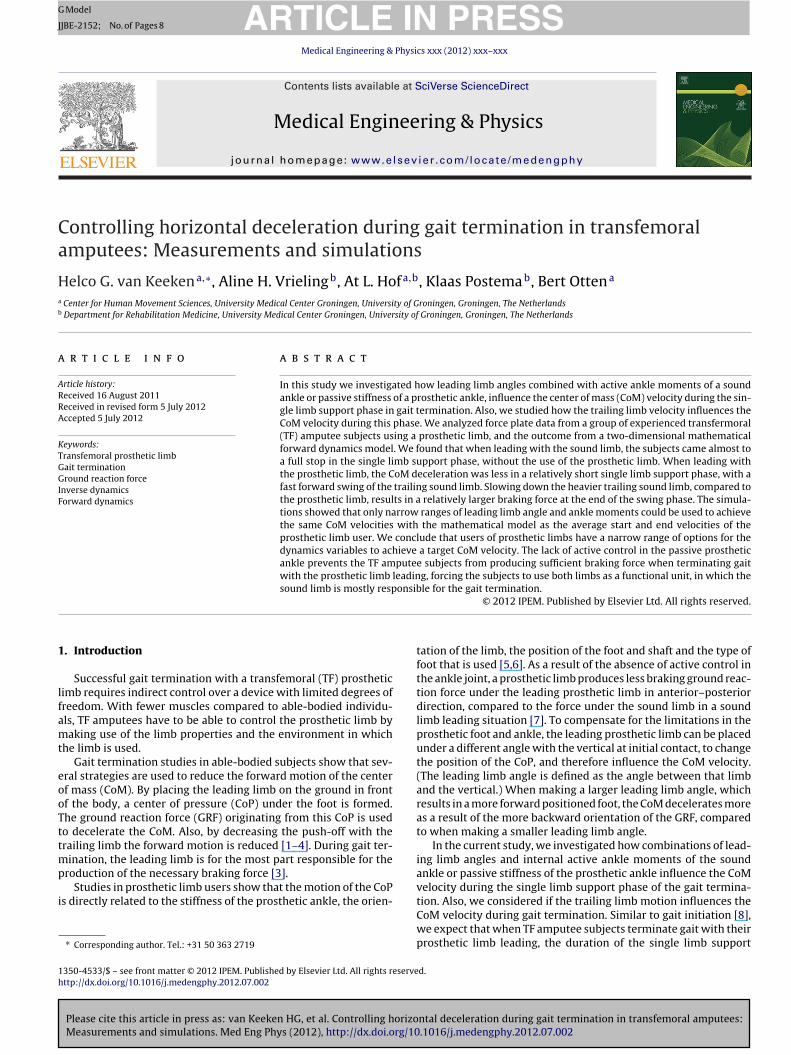
ig. 1. Gait termination model consisting of a leading limb and foot with ankle joint, trunk and a trailing limb.
.6. Mathematical model
A two-dimensional forward dynamics model was used tonspect the whole range of possible combinations, that may enableF amputee subjects to achieve the equal CoM velocities at the endf the single limb support phase during gait termination when vary-ng the leading limb angle and the internal active ankle moment ofhe sound ankle or passive stiffness of the prosthetic ankle (Fig. 1).he four elements model is based on Newton Euler constrainedquations with forward dynamics [12]. We used Euler integrationor the simulation steps (�t = 0.0001 s). Some additions were madeo simulate spring and damper limited joints and contact pointsith the external world.
The model consisted of a leading foot (length: 0.3 m, mass: 2 kg;he proximal and distal end point can form contact points with thexternal world), with an ankle joint, and limb (length: 1.0 m, mass:5 kg or 5 kg (respectively the sound limb and prosthetic limb)), arunk (length: 1.0 m, mass: 48 kg) and a trailing limb (length: 1.0 m,
ass: 15 kg or 5 kg). The two limbs were connected to the trunkia hip joints. The limbs could be set with the inertial propertiesf a prosthetic limb or a sound limb. The elements were mod-led as slender rods. Joints were simulated as frictionless pinpointoints. Elements were constrained by joint forces based on equatinghe acceleration of element endpoints. Internal and external forcesere passed on via the joint elements. Hip and ankle muscles were
imulated as torque engines in the joints.Input variables in the model were (1) the leading limb angle at
nitial contact, (2) the trailing limb motion during single limb sup-ort phase, and (3) the ankle stiffness or internal active momentf force of the ankle of respectively the leading prosthetic limbr the leading sound limb. The initial horizontal velocity of theoM at the start of the gait termination was set to 0.7 m/s. Mixedynamics, forward dynamics with some constraint or prescribedovement [12], were used to constrain the trunk element to the
Please cite this article in press as: van Keeken HG, et al. Controlling horizoMeasurements and simulations. Med Eng Phys (2012), http://dx.doi.org/10
ertical of the external world by using hip moments. The knownngular acceleration of the trunk was set to zero, keeping the trunkn the upright position. The velocity of the CoM was the result ofhe forces acting on the model, the inertial properties of the model
a 1: Maximal stiffness (=100 N m−1).b 1: Trailing limb is next to the leading limb at the end of the simulation, hanging
vertically.
and the internal moments produced by the model. A minimum jerkbell-shaped velocity curve [13] was defined for the angular veloc-ity of the trailing limb. The angular acceleration derived from thisangular velocity curve was scaled to the range the trailing limb wasallowed to move forward. When the scale value was 1, the trailinglimb ended hanging vertically next to the leading limb at the end ofthe single limb support phase. When it was 0, the trailing limb didnot move forward. When the leading limb was set as a prostheticlimb, the passive prosthetic ankle was limited in its range of motionby a spring (Cspring) and damper (Cdamper) system, creating a counter
torque (Tc) based on the joint angle (�) and joint angle velocity (�̇)when the ankle angle exceeds its limits (Eq. (1)).
Tc = Cspring × (�limit − �) − Cdamper × �̇ (1)
in which Cspring = 100 N m and Cdamper = 25 N s m.When the leading limb was set as a sound limb, the internal
active ankle moment (Tankle) was set to be the known in the externalmoments when the leading foot was in contact with the ground. Thesound ankle was set to produce a constant internal plantar flexionmoment of 54 N m.
Ground reaction forces (�FGRF ) were formed when the leadingfoot made contact with the floor of the external world. Ground reac-tion forces were calculated based on continuously checking for theintrusion of the heel and toe (�Xfooty,z
) into the floor (�Xfloory,z), which
has a modeled stiffness (Cstiffness) and damping (Cdamping) (Eq. (2)).
�FGRF = Cstiffness × (�Xfloory,z− (�Xfooty,z
)) − Cdamping
�(�Xfloory,z
− �Xfooty,z)
�t(2)
in which Cstiffness = 1 ×10⁵ N m−1 and Cdamping = 5 ×10³ N s m.The mathematical model was used to study the influence of the
leading limb angle at initial contact, the ankle properties (passivestiffness or internal active ankle moments) of the leading limb, andthe trailing limb motion during foot contact with the leading limbon the anterior–posterior CoM velocity. Combinations of settingswere investigated to study the influence of the ankle and limb prop-erties on the end velocity. Table 1 shows the ranges of the initialsettings.
The mathematical model was validated by examining the con-servation of energy and comparing the modeled external forceswith measured ground reaction forces of the TF amputee sub-jects. The mixed dynamics moments of force constraining the trunkelement were checked against unrealistic values by inspectingand comparing the calculated values with known maximal jointmoments of force in healthy subjects [14].
3. Results
ntal deceleration during gait termination in transfemoral amputees:.1016/j.medengphy.2012.07.002
3.1. Subjects
All subjects, except one, were able to come to a full stop in onegait termination cycle (both the leading and trailing limb placed on

ARTICLE ING Model
JJBE-2152; No. of Pages 8
4 H.G. van Keeken et al. / Medical Engineer
Table 2Gait termination: Averages and standard deviation of the velocity of the CoM (CoMvelocity) at the start (t = 0) of the single limb support phase (1ft) and double limbsupport phase (2ft), the gait termination duration (Duration; total = 1ft + 2ft) and thebraking impulse (impulse) in the sound limb leading and prosthetic limb leadingconditions (n = 6).
Condition Sound limb leading Prosthetic limb leading
CoM velocity1ft(t=0)(m/s) 0.72 (SD 0.12) 0.69 (SD 0.15)CoM velocity2ft(t=0)(m/s) 0.14 (SD 0.06)* 0.33 (SD 0.08)Durationtotal(s) 1.04 (SD 0.41) 1.02 (SD 0.31)Duration1ft(s) 0.58 (SD 0.15)* 0.32 (SD 0.08)Duration2ft(s) 0.46 (SD 0.43) 0.70 (SD 0.29)Impulsetotal(N s) 56.1 (SD 12.1) 54.5 (SD 14.1)Impulse (N s) 48.7 (SD 15.6)* 29.6 (SD 8.1)
tnscif
b(twpittvtpapilt
lDg
cb
3
tpw
tsfl
3
si
aal
1ft
Impulse2ft(N s) 7.3 (SD 6.6)* 24.9 (SD 9.7)
* Significant differences (p < 0.05) between the two leading limb conditions.
he ground). Although the CoMy velocity of the subject that couldot come to a full stop, was heavily reduced to almost zero, onemall step with his leading limb was made extra to come to theomplete full stop in both conditions. We could not find a convinc-ng biomechanical reason for this extra step. We excluded the datarom this subject from the analyses.
No significant differences were found in the velocity at theeginning of the gait termination process in the two conditionsTable 2). Also, the overall duration and the impulse used to comeo a full stop were almost equal. However, significant differencesere found when the gait termination process was divided in twohases. When the gait was terminated with the sound limb lead-
ng, the gait termination was almost completely executed duringhe single limb support phase (Fig. 2A). 85 percent (SD 14) of theotal impulse was generated in the first part of the process. Theelocity at the end of the single limb support phase was reducedo 20 percent. On average, the duration of the single limb supporthase and the double limb support phase were almost equal, but
large standard deviation was found for the double limb supporthase (Fig. 2A and B). Although CoMy velocity was already heav-
ly reduced for most subjects the moment they placed the trailingimb on the ground, the double limb support phase took quite longo come to a complete stop (Fig. 2B).
When terminating with the prosthetic limb, the average singleimb support phase took 33 percent (SD 8) of the total process time.uring this phase 55 percent (SD 10) of the total brake impulse wasenerated (Fig. 2D).
The data shows that our subjects use the CoP and the GRF toome to a complete stop with their CoM. Positive GRFy results inraking of the subjects.
.1.1. CoPIn the sound limb leading condition our subjects moved the CoP
o anterior under the foot in the first part of the single limb supporthase. During the double limb support phase, almost no CoP motionas found (Fig. 2A and B).
When leading with the prosthetic limb, the CoP moved slowlyo anterior during the single limb support phase. When the trailingound foot was placed on the ground the CoP continued movingorward, while transitioning the weight from the leading prostheticimb toward the sound limb (Fig. 2C and D).
.1.2. GRFIn the sound limb leading condition the GRF decreased as pre-
ented in Fig. 2B in 5 subjects. In one subject the GRFy decreased andncreased after the start of the single limb support phase (Fig. 2A).
Please cite this article in press as: van Keeken HG, et al. Controlling horizoMeasurements and simulations. Med Eng Phys (2012), http://dx.doi.org/10
In the prosthetic leading conditions the GRFy also decreasedfter the start of the single limb support phase, but was still highert the end of the single limb support phase. Compared to the soundimb leading condition a clear increase was found around the start
PRESSing & Physics xxx (2012) xxx– xxx
of the double limb support phase in the GRFy in four of the sixsubjects. This increase was found not only before but also after theweight shifting from leading limb to trailing limb (Fig. 2D).
3.1.3. CoMThe curved trajectory of the CoMy velocity in single limb sup-
port phase of the sound limb leading condition differed from therelatively more linear trajectory in the prosthetic limb condition.The CoMy velocity showed an larger decrease around the start ofthe double limb support phase (Fig. 2C and D).
3.2. Mathematical model
The CoMy velocity, the position of the CoP and the GRFy in themathematical model showed similarities with the measurements(Fig. 3).
3.2.1. Initial parametersThe average velocity of the TF amputee subjects at the begin-
ning of the single limb support phase (0.7 m/s) was used as an initialparameter for the mathematical model in both the sound limb lead-ing condition and prosthetic limb leading condition. The goal wasto achieve end velocities with the model, which were similar tothe average end velocity of the prosthetic limb group. In the soundlimb leading condition, the average end velocity was 0.14 m/s. Inthe prosthetic limb leading condition the average end velocity was0.33 m/s. These end velocities had to be reached in the same time asthe subjects used to reach these end velocities. The average dura-tion in the sound limb leading condition was 0.58 s and 0.32 s inthe prosthetic limb leading condition. To achieve the end velocityin the sound limb leading condition, we set the leading limb angleof the model at initial contact to 0.18 rad (10.31◦). The sound anklewas set to produce a constant internal plantar flexion moment of54 N m. In the prosthetic limb leading condition, we set the leadinglimb angle of the model at initial contact to 0.21 rad (12.03◦). Theprosthetic ankle of the model was set as a flexible ankle. In bothconditions, the velocity of the trailing limb was set in such a man-ner that the limb would be next to the stance limb at the end of thesingle limb support phase.
When simulating with the initial parameters, a clear decrease inthe CoMy velocity in the sound limb leading condition was found.In the prosthetic limb leading condition a plateau was found in theCoMy velocity halfway the single limb support phase. This plateauwas accompanied by a clear increase in the GRFy. The CoPy in thesound limb condition showed a gradual translation toward the toe,while in the prosthetic limb leading condition the CoPy rapidlyshifted from one position to another after the foot was flat on theground.
3.2.2. Combinations of settingsFig. 4 shows that only small areas can be found in which the cal-
culated end velocities of the model match the average end velocityof the group of TF amputee subjects. When chosen inadequate, thewrong combination of sound ankle moment and limb angle resultsin a CoM end velocity that differs substantially from the desiredend velocity, which was achieved by the TF amputee subjects. Theankle stiffness appears to have limited influence on the CoM endvelocity. The trailing limb motion seems only relevant for the CoMend velocity when the combination of the sound ankle moment
ntal deceleration during gait termination in transfemoral amputees:.1016/j.medengphy.2012.07.002
or ankle stiffness and the limb angle result in a CoM end velocitywhich is close to the average end velocity of the TF amputee sub-jects. This can be seen around the small areas in which the exactend velocity is found.

Please cite this article in press as: van Keeken HG, et al. Controlling horizontal deceleration during gait termination in transfemoral amputees:Measurements and simulations. Med Eng Phys (2012), http://dx.doi.org/10.1016/j.medengphy.2012.07.002
ARTICLE IN PRESSG Model
JJBE-2152; No. of Pages 8
H.G. van Keeken et al. / Medical Engineering & Physics xxx (2012) xxx– xxx 5
Fig. 2. Exemplary gait termination by TF amputee subjects in sound limb and prosthetic limb leading conditions, divided in single limb support phase (1ft) and double limbsupport phase (2ft). Vertical lines represent the start and end of a phase. (A) Sound limb leading, with a short double limb support phase and a deviating decrease and increasein the GRF just after the single limb support phase start. 1 subject produced this GRF pattern. (B) Sound limb leading, with a long double limb support phase, although theCoMy velocity is already heavily reduced at the start of the double limb support phase. 5 subjects produced similar GRF patterns. (C) Prosthetic limb leading, with GRFypeak after start double limb support phase. 4 subjects produced similar GRF patterns. (D) Prosthetic limb leading, with GRFy peak before start double limb support phase. 2subjects produced similar GRF patterns. CoPy: 0 = center of force plate; positive value indicates anterior position of the CoP (toward toe of foot).

ARTICLE IN PRESSG Model
JJBE-2152; No. of Pages 8
6 H.G. van Keeken et al. / Medical Engineering & Physics xxx (2012) xxx– xxx
time (s)
Vend: 0.14 | LA: 0.18 | AS: 0 | AM: 54 | VTL: 1
time (s)
Vend: 0.36 | LA: 0.2 | AS: 0 | AM: 0 | VTL: 1
A B
CoMy velocity
GRFy
CoPy position
velo
city (
m/s
)fo
rce (
N)
dis
tan
ce
(m
)
CoMy velocity
GRFy
CoPy position
0 0.1 0.2 0.3 0.4 0.5−0.5
0
0.5
1
0 0.1 0.2 0.3 0.4 0.5−400
−200
0
200
400
0 0.1 0.2 0.3 0.4 0.5
−0.2
0
0.2
0 0.05 0.1 0.15 0.2 0.25 0.3−0.5
0
0.5
1
0 0.05 0. 1 0.15 0. 2 0.25 0. 3−400
−200
0
200
400
0 0.05 0.1 0.15 0.2 0.25 0.3
−0.2
0
0.2
* *
**
Fig. 3. Results of the gait termination model during the single limb support phase, either leading with the sound limb (A) or with the prosthetic limb (B). Initial parameterswere used to achieve initial velocities and end velocities that were similar to the average velocities of the TF amputee subjects. Vend: end velocity (m/s); LA: leading limbangle (rad); AS: ankle stiffness (graduated scale from 0 to 1; 0: max. flexible, 1: max. stiff); AM: internal active ankle moment (N m); VTL: Trailing limb motion (graduateds angest ss andc on of
4
iiipljwtllcn
aCltrlCc
cale from 0 to 1; 0: no motion, 1: inversely related to leading limb). The sudden chhe ground, marked with �, are artifacts of the mathematically modeled floor stiffneontact. CoPy: 0 = center of modeled force plate; positive value indicates anterior positi
. Discussion and conclusion
Although it seemed that no differences in the sound limb lead-ng condition and prosthetic limb leading condition were foundn the global outcome values of the overall process (CoM veloc-ty, duration and impulse), clear differences were found when therocess was divided in the single limb support phase and double
imb support phase. When leading with the sound limb, the sub-ects came almost to a full stop in the single limb support phase,
ithout the use of the prosthetic limb. When leading with the pros-hetic limb, the CoM deceleration was less in a relatively short singleimb support phase, with a fast forward swing of the trailing soundimb. One possible reason for limiting the single limb support phasean be given: the active control possibilities in the sound limb areecessary for the gait termination.
For successful gait termination adequate CoP positioning andn associated backwards GRF are necessary. Anterior motion of theoP during the single limb support phase was found in both leading
imb conditions. When the leading sound limb was in contact withhe ground, with the foot flat on the ground, the CoP motion was the
Please cite this article in press as: van Keeken HG, et al. Controlling horizoMeasurements and simulations. Med Eng Phys (2012), http://dx.doi.org/10
esult of an internal active ankle plantar flexion moment. When theeading prosthetic limb was in contact with the ground the limitedoP motion under the prosthetic foot was the result of a passiveoupling between the foot and the changing limb angle during the
of the CoPy position and GRF at the transition of the heel contact to the foot flat on elasticity, and the flat shoe sole, causing a quick alternation between heel and toe
the CoP (toward toe of foot).
gait termination. The lack of active control in the passive prostheticankle prevents the TF amputee subjects from producing sufficientbraking force when terminating gait with the prosthetic limb lead-ing. A more forward placed CoP produces a more backward GRF,but in the TF amputee, CoP cannot be moved actively forward usingmuscular control. To compensate for this shortcoming, the leadingprosthetic foot can be placed more forward, resulting in a largerGRFy, which contributes to the production of the braking force.However, the simulations show that CoM velocity is very suscep-tible to foot placement. This finding shows that using this strategyfor accurate control is not very likely. Only narrow ranges of val-ues could be used to achieve the same CoM velocities with themathematical model as the average start and end velocities of theprosthetic limb user. These outcomes imply that a prosthetic limbuser does not have much freedom choosing the leading limb angle,the trailing limb motion and the ankle moment. Based on the simu-lations, it seems that TF amputee subjects have to make use of soundlimb depending strategies during gait termination. Instead of theleading limb being responsible for the necessary braking force asseen in healthy subjects, it is the sound limb, either as the leading
ntal deceleration during gait termination in transfemoral amputees:.1016/j.medengphy.2012.07.002
limb or trailing limb, which is mostly responsible for the necessarybraking force compensating for the shortcomings in the prostheticlimb. Also, it should be taken into account that not every limb angleis possible, as the CoP position and the resulting GRF are essential

ARTICLE IN PRESSG Model
JJBE-2152; No. of Pages 8
H.G. van Keeken et al. / Medical Engineering & Physics xxx (2012) xxx– xxx 7
0.120.14
0.16 0.180.2
0.220.24
10
20
30
40
50
60
70
0
0.5
1
trai
ling
limb
mot
ion
angle (rad)
moment (nm)
-
+
target velocity 0.14 m/s- 0.34 m/s
0.56 m/s
0.180.2
0.22 0.240.26
0.280.3
0
0.2
0.4
0.6
0.8
1
0
0.5
1
trai
ling
limb
mot
ion
angle (rad)
stiffness
-
+
+
-
target velocity 0.33 m/s
0.53 m/s
0.12 m/s
Sound limb leading
Prosthetic limb leading
<−0.11
−0.06
−0.01
0.04
0.09
0.14
0.19
0.24
0.29
0.34
>0.39m/s
marker range
<0.08
0.13
0.18
0.23
0.28
0.33
0.38
0.43
0.48
0.53
>0.58m/s
marker range
Fig. 4. Results of a gait termination model with several different parameters; Relation between the influence of the leading limb angle (rad), sound ankle moment (N m)or prosthetic ankle stiffness (graduated scale from 0 to 1; 0: max. flexible, 1: max. stiff) and trailing limb motion (graduated scale from 0 to 1; 0: no motion, 1: inverselyrelated to leading limb) and the anterior–posterior CoM velocity at the end of the gait termination. The calculated end velocities of the model that are equal to the averageend velocity of TF amputee subjects are visualized with black markers. The size of the markers indicates the magnitude of the correspondence with the average end velocityof the TF amputee subjects. The arrows show the direction of the change in velocity. The numbers at the end of the arrows show the range of the end velocity. Negativevelocity values represent motion in the backward direction. The initial anterior–posterior CoM velocity is set to 0.7 m/s, the end velocity to 0.14 m/s in the sound limb leadingcondition and 0.33 m/s in the prosthetic limb leading condition, and the duration of the single limb support phase is set to 0.58 s in the sound limb leading condition and0
fri
twttishsldl
isall
.32 s in the prosthetic limb leading condition.
or passive knee extension. Small changes in CoP placement mayesult in buckling of the knee, depending on the position of thenstantaneous knee axis.
This sound limb depending strategy has some consequences forhe gait termination process. In the short single limb support phasehen the prosthetic limb is leading, the relatively heavy sound
railing limb has to be moved forward. This influences the wayhe subjects can use the braking force to reduce the CoMy veloc-ty. Slowing down the trailing sound limb velocity at the end of itswing phase by producing adequate moments of force with bothips results in a relatively larger braking force, compared to whenlowing down the relatively light prosthetic limb in the sound limbeading condition. This relation explains the linear CoMy velocityecrease in the single limb support phase in the prosthetic limb
eading condition (Fig. 2C and D).It seems that the way the trailing sound limb is slowed down
s critical, but only when the leading prosthetic limb angle is cho-
Please cite this article in press as: van Keeken HG, et al. Controlling horizoMeasurements and simulations. Med Eng Phys (2012), http://dx.doi.org/10
en correctly and in accordance with the stiffness of the prostheticnkle as can be seen in Fig. 4. When the ankle is very stiff and theimb angle is large, the CoPy remains under the heel. Although thearge limb angle would contribute to a higher braking force, the
position of the CoP reduces this gain, since it remains under the heelfor quite some time. When using a flexible ankle and the same limbangle, the CoPy moves forward at the beginning of the stance phaseresulting in a larger braking force. For gait termination it seems thata flexible ankle or heel setting would be preferred as this settingincreases braking force. In contrast to gait termination, during gaitthis setting is counter productive, because CoMy velocity is lost dur-ing early stance phase, hindering forward progression. The settingsof the prosthetic ankle or heel should be different for gait termi-nation than for gait. Therefore, a well-balanced choice should bemade. The choice for the settings depends on the subjectÕs needs.
Some remarks and considerations should be given when inter-preting the outcome of the current study. In this study, we weremerely interested in specific underlying principals of gait ter-mination. Since no exact numerical correspondences were to beexpected, we decided that the models anthropometrics had tomatch those of a human being roughly. For simplicity reasons we
ntal deceleration during gait termination in transfemoral amputees:.1016/j.medengphy.2012.07.002
chose not to add moveable knee joints. Moveable knee joints havesome benefits during gait termination. A moveable knee joint hasits added value in the foot clearance process and can be used todecrease the impact of the GRF during heel strike. We realize that

ING Model
J
8 gineer
ttatucmsmrilttn
Absmstfl
bflfltOmw
ivbbvettpbtthirmas
ftptm
[
[
[
[13] Flash T, Hogan N. The coordination of arm movements: an experimentallyconfirmed mathematical model. J Neurosci 1985;5(July (7)):1688–703.
[14] Biewener Andrew A, Farley Claire T, Roberts Thomas J, Temaner Marco. Muscle
ARTICLEJBE-2152; No. of Pages 8
H.G. van Keeken et al. / Medical En
hese knee joints influence the CoM velocity. Already we showedhat the orientation of the GRF and the weight of the trailing limbre of importance for CoM velocity changes. Similar to this, the iner-ia of the limb, influenced by the orientation and position of thepper and lower part of the limb, has its effect on the CoM velocityhanges. The absences of the knee joints might explain some of theinor differences between the results of our model and the mea-
ured data of the TF amputee subjects. Although we did not useoveable knee joints, it is our opinion that the current findings are
elevant. Most of the prosthetic knees remain in full extension dur-ng the gait termination process, especially in the prosthetic leadingimb condition, but also in the prosthetic limb trailing condition. Inhis last condition, many times the limb does not flex as a result ofhe low angular velocity and the minimal use of the GRF which isot sufficient to create a flexion moment around the knee joint.
Also for the sake of simplicity, we did not add a trailing foot.dding a foot would probably enabled us to reproduce the quickraking force alteration around the beginning of the double limbupport phase. Based on our observations during the measure-ents and the consequences of the definition of the single limb
upport phase to double limb support phase transition, we assumehat the quick alteration is the result of the landing of the trailingoot and the moment in which the weight transition to the soundimb occurs.
In one subject the braking force decreased and increased at theeginning of the single limb support phase as a result of plantarexion of the stance ankle joint of the sound limb. This plantarexion was used to increase limb length to reach toe clearance ofhe trailing prosthetic limb at the beginning of its swing phase.bviously, this phenomenon was not found in the mathematicalodel because the plantar flexion strategy was not necessary ase did not include a trailing foot.
Because of the absence of the moveable knees and the trail-ng foot, we were not able to study their influence on the CoMelocity. It is likely that TF amputees make use of these possi-ilities to influence their CoM velocity. Similar to this, it shoulde taken into account that also the trunk influences the CoMelocity, and that TF amputees probably use their trunk to influ-nce the CoM velocity as well. We observed variation of therunk position when analyzing the video images. Four out ofhe six subjects showed a more backward trunk position in therosthetic limb leading condition. This strategy results is a moreackward positioned CoM, relative to the CoP position, which con-ributes to the deceleration of the CoM. In our mathematical model,he trunk is controlled to stay in vertical orientation using adequateip torques. A more advanced model should be used to study the
nfluence of these items. The current model is used to study theelation between the leading limb angles, the internal active ankleoments of the sound ankle or passive stiffness of the prosthetic
nkle, the trailing limb motion and the CoM velocity during theingle limb support phase of the gait termination.
During gait termination TF amputee subjects can compensateor the absence of voluntary muscle activity and joints in the pros-
Please cite this article in press as: van Keeken HG, et al. Controlling horizoMeasurements and simulations. Med Eng Phys (2012), http://dx.doi.org/10
hetic limb by influencing the CoP position and the GRF under theirrosthetic limb, and with their sound limb. Patients have to berained in such a manner that they learn how to produce the opti-
um of braking force with both of their limbs used as a functional
PRESSing & Physics xxx (2012) xxx– xxx
unit: using an adequate limb angle on the prosthetic side and usingthe capacities of the sound ankle. Because the duration of the totalgait termination process and the produced braking impulse do notdiffer when leading with the prosthetic limb or with the soundlimb, it seems that there is no reason to enforce a preferred lead-ing limb during gait termination. However, when terminating gaitwith the sound limb leading, the TF amputee subjects are able toreduce their CoMy velocity more quickly during the first part of theprocess. This gait termination strategy is the preferred strategy inthe experienced TF amputee subjects group.
Ethical approval
The medical ethics committee of the University Medical Cen-ter Groningen approved the study protocol (reference number2004.176). All subjects signed an informed consent before testing.
Acknowledgements
The authors wish to acknowledge the OIM Foundation, Beatrixo-ord Foundation and Anna Foundation for their financial support.
Conflict of interest
There is no conflict of interest related to this study.
References
[1] Crenna P, Cuong DM, Brénière Y. Motor programmes for the termination ofgait in humans: organisation and velocity-dependent adaptation. J Physiol2001;537(December (Pt 3)):1059–72.
[2] Tirosh O, Sparrow WA. Age and walking speed effects on muscle recruitmentin gait termination. Gait Posture 2005;21(April (3)):279–88.
[3] Bishop M, Brunt D, Pathare N, Patel B. The effect of velocity on the strategiesused during gait termination. Gait Posture 2004;20(October (2)):134–9.
[4] Stein RB, Hase K. Stopping and turning during human walking. Prog Brain Res1999;123:445–53.
[5] Kim KJ, Uchiyama E, Kitaoka HB, An KN. An in vitro study of individualankle muscle actions on the center of pressure. Gait Posture 2003;17(April(2)):125–31.
[6] Hansen AH, Childress DS, Knox EH. Prosthetic foot roll-over shapes withimplications for alignment of trans-tibial prostheses. Prosthet Orthot Int2000;24(December (3)):205–15.
[7] Vrieling AH, van Keeken HG, Schoppen T, Otten E, Halbertsma JPK, Hof AL,et al. Gait termination in lower limb amputees. Gait Posture 2008;27(January(1)):82–90.
[8] van Keeken Helco G, Vrieling Aline H, Hof At L, Halbertsma Jan PK, SchoppenTanneke, Postema Klaas, et al. Controlling propulsive forces in gait initiation intransfemoral amputees. J Biomech Eng 2008;130(February (1)):011002.
[9] Wearing SC, Urry S, Smeathers JE, Battistutta D. A comparison of gait initiationand termination methods for obtaining plantar foot pressures. Gait Posture1999;10(December (3)):255–63.
10] Jian Y, Winter DA, Ishac MG, Gilchrist L. Trajectory of the body GoG and CoPduring initiation and termination of gait. Gait Posture 1993;1:9–22.
11] Nissan M, Whittle MW. Initiation of gait in normal subjects: a preliminarystudy. J Biomed Eng 1990;12(March (2)):165–71.
12] Otten E. Inverse and forward dynamics: models of multi-body systems. PhilosTrans R Soc Lond B Biol Sci 2003;358(September (1437)):1493–500.
ntal deceleration during gait termination in transfemoral amputees:.1016/j.medengphy.2012.07.002
mechanical advantage of human walking and running: implications for energycost. J Appl Physiol 2004;97(December (6)):2266–74.
Copyright © 2022 FDOKUMEN