control system for the solar hot water collection ... - Cornell ECE
55
CONTROL SYSTEM FOR THE SOLAR HOT WATER COLLECTION ALTERNATIVE SYSTEM OF CORNELL UNIVERSITY SOLAR DECATHLON A Design Project Report Presented to the Engineering Division of the Graduate School of Cornell University in Partial Fulfillment of the Requirements for the Degree of Master of Engineering (Electrical) by Wei-jiunn Jang Project Advisor: Dr. Bruce R. Land Degree Date: May 2009
-
Upload
khangminh22 -
Category
Documents
-
view
3 -
download
0
Transcript of control system for the solar hot water collection ... - Cornell ECE
CONTROL SYSTEM FOR THE SOLAR HOT WATER
COLLECTION ALTERNATIVE SYSTEM OF
CORNELL UNIVERSITY SOLAR DECATHLON
A Design Project Report
Presented to the Engineering Division of the Graduate School
of Cornell University
in Partial Fulfillment of the Requirements for the Degree of
Master of Engineering (Electrical)
by
Wei-jiunn Jang
Project Advisor: Dr. Bruce R. Land
Degree Date: May 2009
2
Abstract
Master of Engineering Program
Cornell University
Design Project Report
Project Title: Control system for the solar hot water collection alternative system of
Cornell University Solar Decathlon
Author: Wei-jiunn Jang
Abstract: This project is a component of the Cornell University Solar Decathlon which is
dedicated to building a solar powered house to collect and save as much energy
as possible using various methods including solar hot water collection. In the
alternative system this project focuses on, solar hot water is collected in the
copper coil under the corrugated steel peripheral of the house. The goal is to
design a control system using microcontroller to control the pump and the
valves connected to the coil based on the temperature of the coils and the
hot/cold water tanks monitored using digital temperature sensors. There is a
computer interface for users to setup desired threshold temperature, and
control the pump and valves either automatically or manually. Atmel
ATmega644 microcontroller was used as the control unit for the project.
Report Approved by
Project Advisor: ______________________________ Date: _____________
3
Table of contents
Executive Summary ................................................................................................ 4
1. Introduction ..................................................................................................... 5
2. Design Requirements ....................................................................................... 8
3. Possible Solutions ........................................................................................... 10
3.1. Microcontroller ...................................................................................... 10
3.2. Temperature sensors ............................................................................... 11
3.3. User interface ......................................................................................... 12
3.4. Valves and pump actuating .................................................................... 13
3.5. Final project definition .......................................................................... 13
4. Design ............................................................................................................. 14
4.1. Input ....................................................................................................... 14
4.2. Output .................................................................................................... 17
4.3. Microcontroller (MCU).......................................................................... 19
5. Result.............................................................................................................. 26
6. Conclusion ...................................................................................................... 28
7. Reference ........................................................................................................ 29
8. Appendix ........................................................................................................ 30
4
Executive Summary
This project is the control system of the alternative system which uses copper
coils under the corrugated steel peripheral of the house to collect the heat from the sun.
The heated solution inside the coils will be pumped through the heat exchanger
connected to the hot water tank. Initially, the system was designed to have 6 or 8
different sections located on different positions of the wall; whenever the temperature
in any of the section is higher than the threshold temperature, the pump would start
pumping and the corresponding valves would open according. However, due to
construction delay and cost overruns, the hardware was modified and there was only
one section left to collect heat from the sun, and the valves for different section were
removed since there was only one route in the system.
The control system includes an ATmega644 MCU, two digital temperature
sensors, a TACO-007 pump, two electrical actuated valves for the heat sink, and a
computer-based user interface. The pump will be turned on and off based on the
current temperatures of the coils and the cold water tank, and the threshold
temperature set by the user. Through the user interface, the user is able to turn on and
off the pump manually and monitor the system status.
The outcome of the project was a success. All functionalities were implemented
and fully tested, and will be installed in the house during its construction.
5
1. Introduction
The Solar Decathlon is an international design-build competition hosted
biennially by the U.S. Department of Energy. Twenty college and university teams
compete to design, build and operate the most attractive, effective and
energy-efficient solar-powered house. Different parameters are being recorded during
the competition and used to evaluate the overall performance of every team. The solar
hot water collection is one of the main performance measures, and it consists of two
systems to maximize the efficiency.
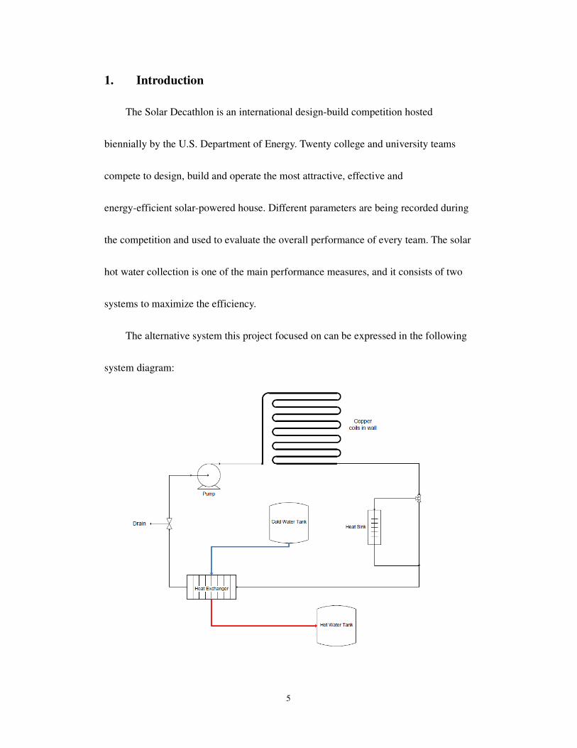
The alternative system this project focused on can be expressed in the following
system diagram:
6
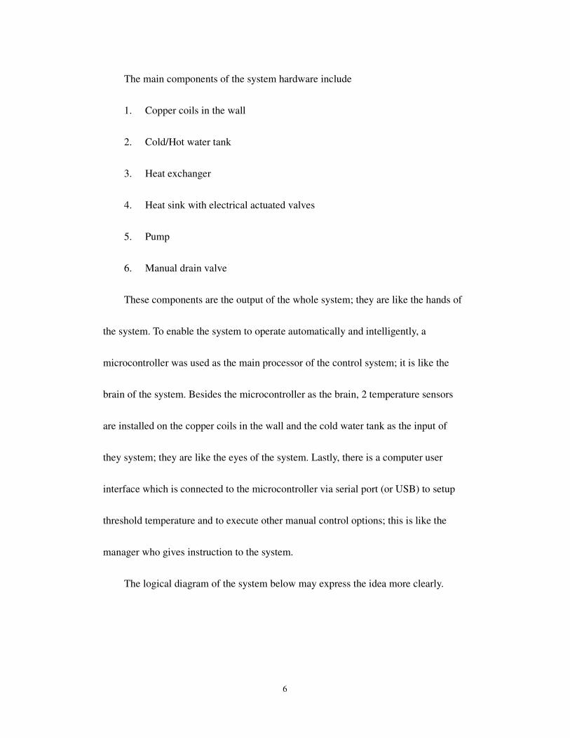
The main components of the system hardware include
1. Copper coils in the wall
2. Cold/Hot water tank
3. Heat exchanger
4. Heat sink with electrical actuated valves
5. Pump
6. Manual drain valve
These components are the output of the whole system; they are like the hands of
the system. To enable the system to operate automatically and intelligently, a
microcontroller was used as the main processor of the control system; it is like the
brain of the system. Besides the microcontroller as the brain, 2 temperature sensors
are installed on the copper coils in the wall and the cold water tank as the input of
they system; they are like the eyes of the system. Lastly, there is a computer user
interface which is connected to the microcontroller via serial port (or USB) to setup
threshold temperature and to execute other manual control options; this is like the
manager who gives instruction to the system.
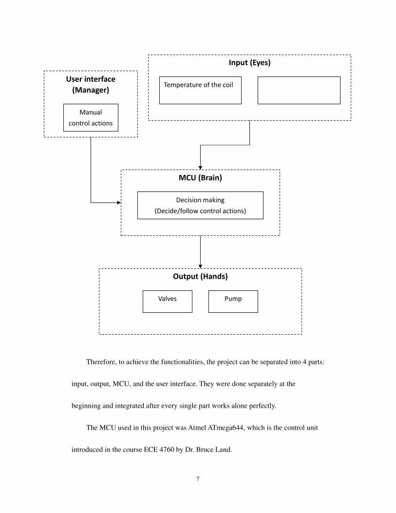
The logical diagram of the system below may express the idea more clearly.
7
Therefore, to achieve the functionalities, the project can be separated into 4 parts:
input, output, MCU, and the user interface. They were done separately at the
beginning and integrated after every single part works alone perfectly.
The MCU used in this project was Atmel ATmega644, which is the control unit
introduced in the course ECE 4760 by Dr. Bruce Land.
Temperature of the coil
Input (Eyes)
Decision making
(Decide/follow control actions)
MCU (Brain)
Output (Hands)
Pump Valves
Manual
control actions
User interface
(Manager)
8
2. Design Requirements
Since this project served as the control system of the alternative system in Solar
Decathlon, it would have to meet the requirements given by the solar thermal
sub-team of the Solar Decathlon Engineering Team. That is, the control system will be
depending on the hardware specifications.
Initially they were planning to install 6 or 8 sections of copper coils around the
peripherals of the house. However, due to construction delays and cost overruns, the
specifications have gone through several modifications during the course of the year.
For the initial hardware design, there would be either 6 or 8 sections, which meant
that the system would have to scan through 6 or 8 temperature sensors and turn on
different sets of valves based on its temperature. The solar thermal team finally settled
on only 1 section because of construction time and budget constraints. As a result, the
idea of valves was removed since there is no other section to select from. They also
added a heat sink route for safety reason to prevent overheating which also required a
set of valves. The general control logic they required stayed the same: the pump will
be turned on whenever the temperature reaches the threshold, and turned off when the
temperature drop close to the temperature of the cold water tank.
The general requirements of the control system are finalized as the following:
1. The system should automatically turn on the pump when the temperature of
9
the coil reaches the threshold temperature.
2. The system should automatically turn off the pump when the temperature of
the coils drops below “the temperature of the cold water tank plus 2
degree C”
3. The system should automatically turn on the valves that lead to the heat sink
when the temperature rises above 99 degree C.
4. User must be able to view the current status of the valves, pumps, and the
readings of different temperature sensors from the user interface.
5. User must be able to set the threshold temperature.
6. User must be able to control the valves and the pump manually regardless of
the current status and temperatures.
The final completed system also includes some minor functions which are not
stated above such as false input parameter prevention, Celsius/Fahrenheit conversion,
and temporary suspension of the control actions.
The biggest problem I encountered in doing this project is that the electrical
actuated valve needed for the heat sink route was very expensive and would have
exceeded the budget. At the end of this project, the business sub-team was still trying
to get the valves donated. Therefore, in this project, a fan was connected to the FET as
a substitute for the valve to test the control functionality.
10
3. Possible Solutions
To create the control system, I would have to choose a microcontroller (MCU), a
temperature sensor, and a form of user interface. The selection of the valves is
determined by the donation we could get, and the pump TACO 007 was previously
determined by the solar thermal team. The MCU will have to read the temperature
sensors and create a user interface, and the temperature sensor should better have a
digital output to avoid noise in analog signal which happens a lot especially when the
connection between the MCU and the sensors is long. The user interface must be easy
and straightforward. Everyone with or without electrical engineering background
knowledge should be able to operate the system through the interface even without a
user manual.
3.1. Microcontroller
The microcontroller Atmel ATmega644 used in the ECE4760 course turned out
to be to best choice for this project. It can be programmed in C, it is readily available
and there are plenty of resources about the MCU in the course website. Prototype
PCB and necessary components for the MCU are all readily available in the ECE4760
laboratory. Although I had never used the MCU when I started the project, I believed
that I would become more and more familiar with it since I was taking the course
starting at the same time.
11
3.2. Temperature sensors
As stated above, the temperature sensor should come with a digital output.
Handling analog signal involved noise problem which are not the main thing that this
project was focused on. Therefore, a digital output sensor would save me from
worrying about noise and analog to digital conversion.
The temperature I am dealing with in this project has a range of 15°C to nearly
100°C. Since the on and off threshold temperature are always differentiated by at least
30°C, it does not require a very high accuracy; therefore a ±2°C accuracy is
acceptable. The LM70 digital thermal sensor from National Semiconductor fit the
requirements very well. It has a resolution of 0.25°C, accuracy of ±2°C, and the
max/min temperature are -55°C /150°C. It comes with internal ADC, and
SPI/Microwire compatible interface. The ATmega644 microcontroller has a built-in
SPI bus, which makes it very easy to interact with the sensor. The package options are
LLP and SOIC. I chose SOIC because I would have to solder the IC on a breakout
board, and an IC with lead is much easier to handle. Luckily, National Semiconductor
provides a small number of free samples of these sensors so I ordered some samples
when I began to work on this project.
12
3.3. User interface
For the user interface of the control system, I initially pictured a system with a
keypad with a 2-lined LCD display by its side. The user could use the keypad to
choose from different control options and view the current status of the system. This
would be a compact interface because the user will be able to manipulate the system
without any external device; however, the input and output interface were both limited
because of the size of the keypad and the small LCD.
The other option which I decided to use was a computer interface with UART
communication to the MCU. I thought about this option when I was working on one
of the lab assignment of the ECE 4760 course. The MCU will work independently
without the computer, and whenever the user want to monitor or control the system,
he or she can simply connect the USB cable to a laptop and run the hyperterminal
program which is included as a default program in all the Windows XP operating
system. The USB cable is actually a USB/Serial dongle that goes to the serial port of
the MCU. With a laptop, the user will be able to operate the system more easily. After
the program and the connection are setup correctly according to the user manual, all
the temperature readings and the status can be seen in one screen without the need of
changing pages. The interface will explain itself so that the user can manipulate the
system without a user manual.
13
3.4. Valves and pump actuating
The choice of valves and pump was not under my control as they are determined
by other teams. I will be controlling the valve using FET and the pump using a solid
state relay. Both of the circuit will be isolated from the MCU using optoisolator to
prevent from spikes feedback to the MCU.
3.5. Final project definition
The definition of the final project is as following. The ATmega644 will be used
to receive the input data from the temperature sensors and decided necessary control
options to the output of valves and the pump. The LM70 digital thermal sensors will
be used to monitor the temperature of the coil and the cold water tank. A serial/USB
connection cable will be available by the control system for the user to connect a
laptop to interact with the system. The valves and pump are decided by other
sub-teams, and they will be controlled by the MCU using FET and solid state relay
and isolated using optoisolator. The project definition satisfies all the project
objectives. The next part of the report will focus on the detailed design of the project.
14
4. Design
The design of the control system can be divided into 3 parts: input, output, and
MCU. In the following part of the report, the software design and hardware
construction of each part will be discussed.
4.1. Input
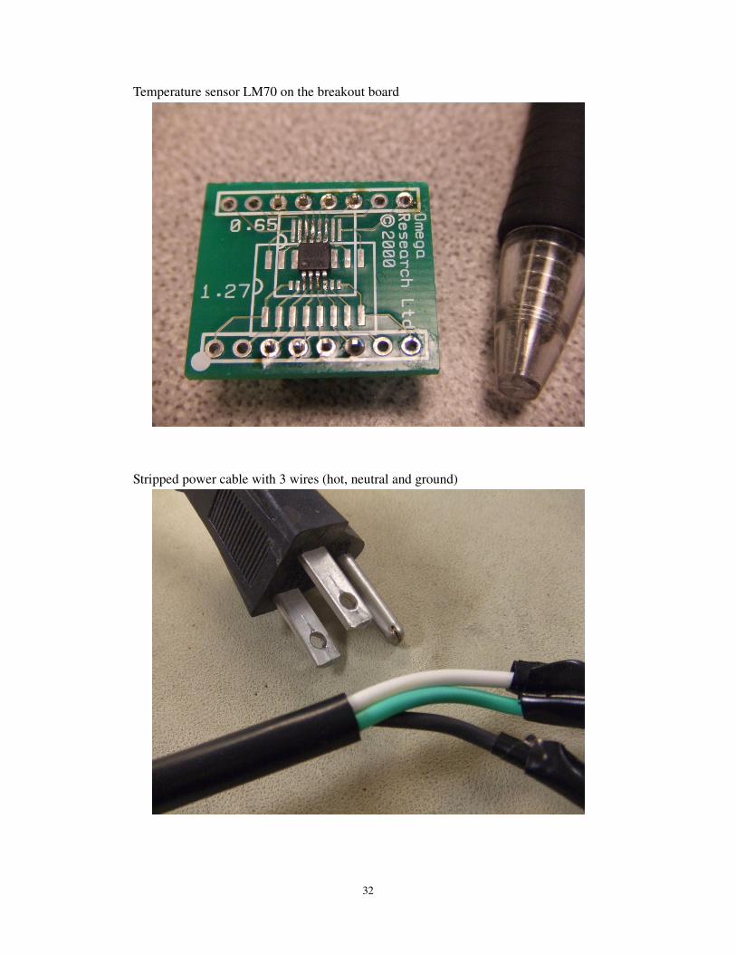
The input of the control system is the LM70 temperature sensors. The
dimension of the SOIC package is approximately 3 x 3 x 0.86 mm3; it is a surface
mount device with 8 leads. I first have to solder the IC on to a breakout board. It was
my first time to deal with a surface mount device and the very first one did take me a
while to finish. Luckily the soldering part looks successful and I could start testing the
sensor with the MCU.
The LM70 has a SPI/Microwire compatible interface. SPI is a three-wire,
synchronous, and serial protocol, and most of the AVR MCUs have a hardware
support for it. The three wires of SPI are master-in-slave-out, master-out-slave-in, and
clock. For the Microwire on LM70, it is actually a two-wire protocol: SI/O (serial
input/output) and clock. The principles are basically the same but Microwire use the
same wire for input and out. Besides the SI/O and clock on the chip, it also has a Chip
Select (inverted) pin for the master to select from different device. In this project I am

15
using 2 SPI-interfaced temperature sensors, so 2 pins (pin 3 and pin 4) from PORTB
of the MCU are respectively connected to the Chip Select pin on the two sensors. SPI
is essentially a synchronized serial protocol. When the master (in this case the MCU)
is ready to send data to the slave (the sensors), the program will put an 8-bit data into
the shift register SPDR. The transmission will then begin and the data from the master
will be shifted into the register in the slave, and vice versa. After the transmission is
completed, the data from the slave will be ready to read in the SPDR register. In the
LM70 temperature sensor, it will send a fixed format of data no matter what is
received from the MCU. Since it doesn’t do anything with the data it received, I don’t
even have to connect the master-out-slave-in pin to the sensor. Therefore in this
project, the MOSI pin (PORTB 5) was left unconnected to anything. The clock
(PORTB 7) and the chip select pin (PORTB 4) will enable the SPI transmission to
work correctly.
After setting up the connection, I had to figure out the necessary setting
parameter for the MCU to communicate with the sensor. There are 4 different
combinations of SPI data transmission modes. The clock can be set to either high or
low when SPI is idle; this can be selected by setting and clearing the CPOL (Clock
Polarity) bit in the control register. The data sampling can be set to occur either at the
trailing or the leading edge of clock; this can be determined by setting or clearing the
16
CPHA bit in the control register. Normally in the datasheets of the devices using SPI
interface, they would directly state its transmission mode; however, these datasheets
were sometimes too complicated. The easiest way to figure out its mode is to try all 4
different modes one by one. Luckily my first try worked and I found that the LM70
sensor has an idle clock of LOW and the sampling is taken place at the trailing edge
of the clock (CPOL =1 and CPHA = 1).
LM70 is a 10-bit temperature sensor so the data format is always 2 byte with a
sign bit (MSB), 10 data bits, and 5 unused bits. Every time the MCU samples data
from the sensor, it has to read 2 bytes back in order to get a complete data. The LSB
of the data is the resolution of the sensor, which is 0.25°C in this case. After getting
the 2 bytes, the MCU would do the calculation and store the result. I first used LED
on the STK500 (the development board for ATmega644) to display the temperature
reading and make sure it’s getting the right data. To calibrate a sensor, I had to find an
external sensor which was guaranteed to be more accurate than the device being
calibrated. I borrowed an electronic temperature sensor and measure the temperature
near the LM70, and it turned out that the reading was quite accurate with a difference
of less than 2°C under room temperature.
According to the datasheet, the LM70 sensor is measuring the temperature of
itself, that is, the temperature of the die. For the LM70, the best thermal path between
17
the die and the outside world is through its pins. It will also provide an accurate
measurement of the temperature of the printed circuit board on which it is mounted. I
tested the sensor under several different circumstances including room temperature,
the temperature of human body, and I also used electric soldering iron to raise the
surrounding temperature and see if the sensor works correctly in such condition. The
test went pretty well and demonstrated that the sensor is capable of reading a large
range of temperature with a fast response time.
4.2. Output
The output of the system includes two devices. The pump and the valves
connected to the heat sink. Since the valves were not readily available at the moment,
I started working on the pump first.
The pump used for the system is Taco 007 Cartridge Circulator. The minimum
fluid temperature is 4°C and the maximum is more than 100°C which is good enough
to fit the need of this project. The pump run on 110 volts, but it came with no power
cable or switch on it. The first thing I need was to open the cover of the power panel
and I found 2 wires and a screw that is used to connect the ground wire. Before trying
to “control” the pump, I had to make sure that the pump is working properly. To
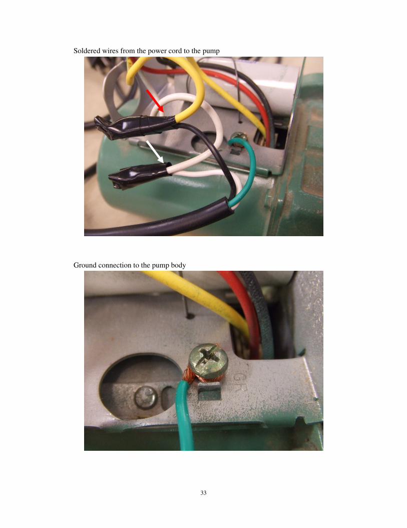
provide AC power to the pump, I used an old computer power cord and cut the female
18
end, and connect the wires respectively to the pump. The darkest wire inside is
connected to the hot power, the lightest wire is the neutral wire and the green wire is
connected to the ground. 110 volts could be harmful to human if not handled properly,
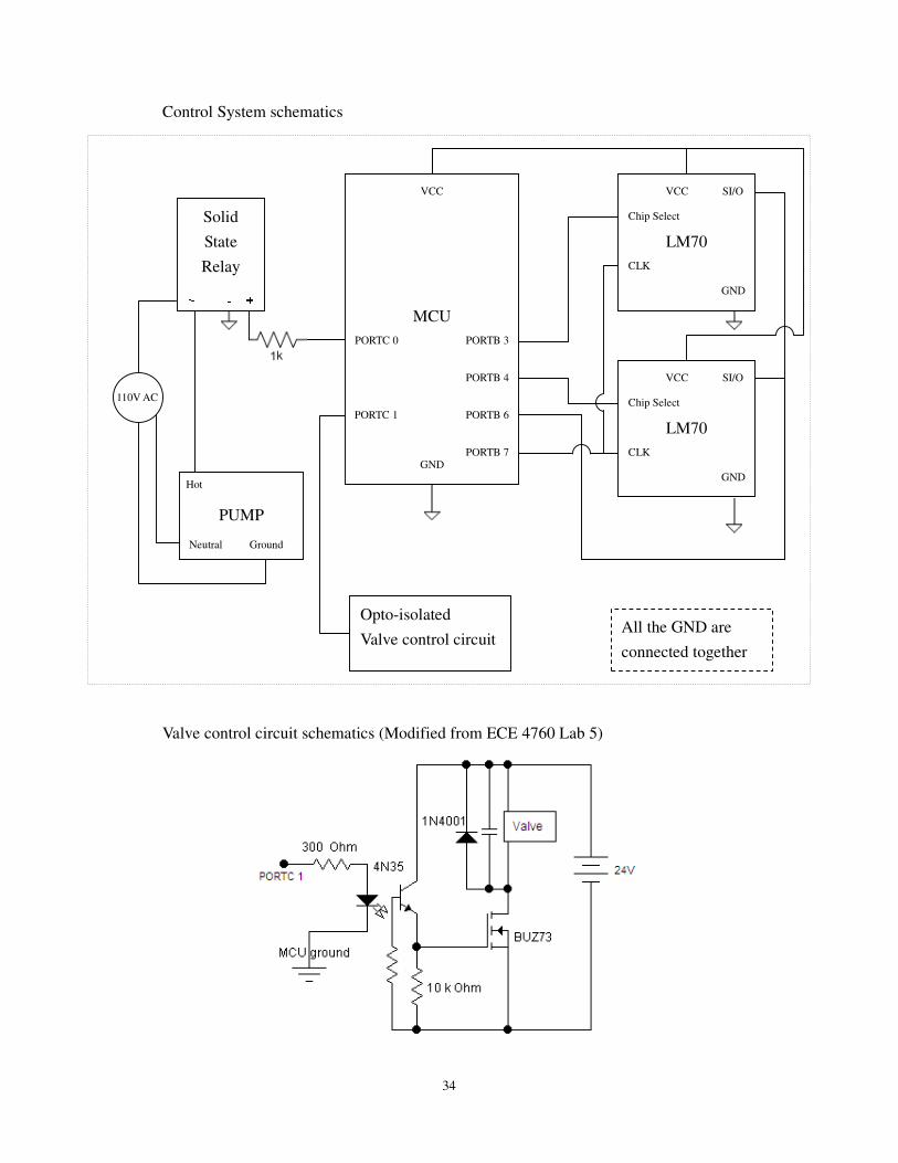
so I would have to make sure all the wires are connected without any mistake. The
wire inside the pump is insulated solid wire and the wire in the power cord is stranded
wire. They were soldered together with electrical tape wrapping around the
connection. After the 2 wires were connected properly and the ground was attached to
the screw on the pump surface, I tried to hook up the power cord to a single plug
instead of the extension cord in the laboratory. I did this because even if there had
been a connection problem between the wires, it would not affect other plugs in the
lab. The pump start to run and I removed the plug immediately because the bearings
inside the pump are water lubricated and the pump is not supposed to be run dry for
too long.
After making sure that the pump works, I started working on the control circuit
for the pump. A solid state relay is the best solution for the pump control issue. The
solid state I chose was Sharp S216S02 which is used in one of the previous year
project of ECE 4760. It has 4 pins; two of them should be connected in series to the
power wire of the 110 volts cable, and the other two should be connected to the MCU
for sending control signal. The circuit inside the solid state relay was opto-isolated,
19
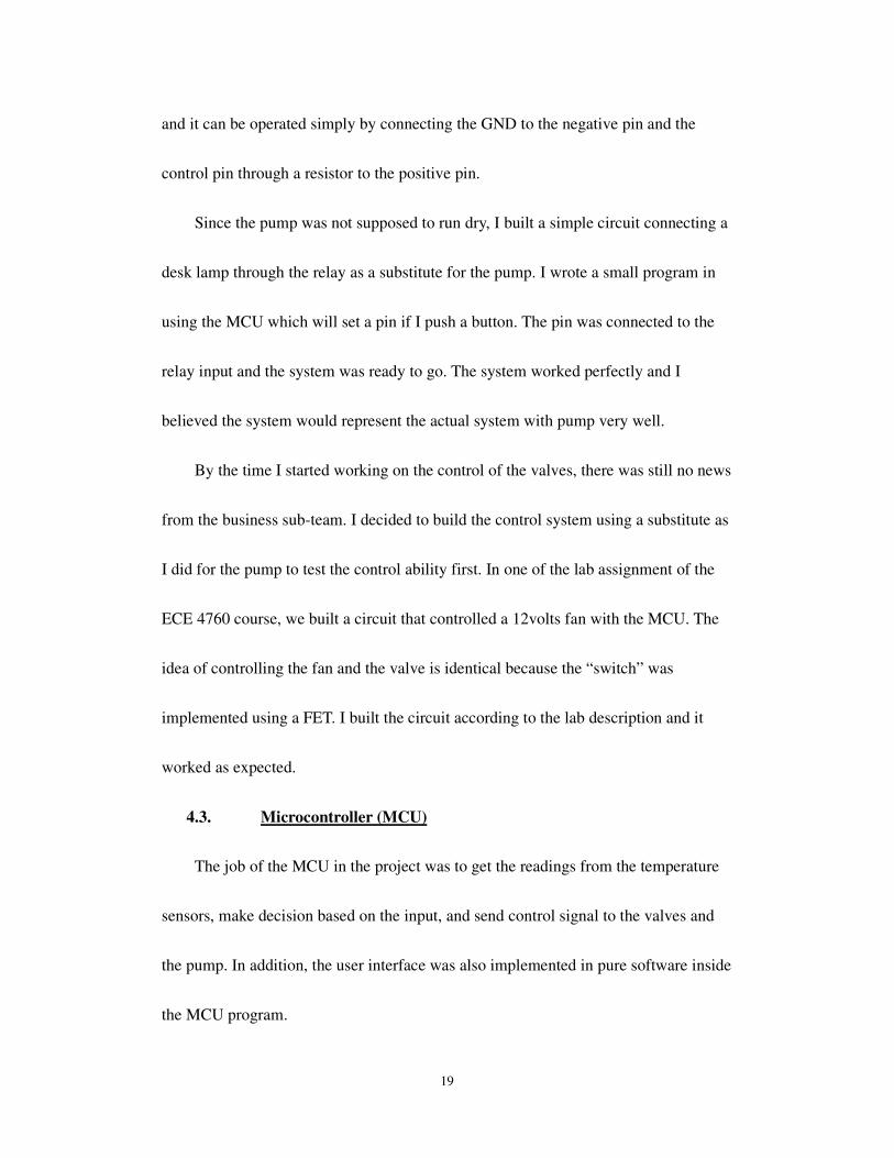
and it can be operated simply by connecting the GND to the negative pin and the
control pin through a resistor to the positive pin.
Since the pump was not supposed to run dry, I built a simple circuit connecting a
desk lamp through the relay as a substitute for the pump. I wrote a small program in
using the MCU which will set a pin if I push a button. The pin was connected to the
relay input and the system was ready to go. The system worked perfectly and I
believed the system would represent the actual system with pump very well.
By the time I started working on the control of the valves, there was still no news
from the business sub-team. I decided to build the control system using a substitute as
I did for the pump to test the control ability first. In one of the lab assignment of the
ECE 4760 course, we built a circuit that controlled a 12volts fan with the MCU. The
idea of controlling the fan and the valve is identical because the “switch” was
implemented using a FET. I built the circuit according to the lab description and it
worked as expected.
4.3. Microcontroller (MCU)
The job of the MCU in the project was to get the readings from the temperature
sensors, make decision based on the input, and send control signal to the valves and
the pump. In addition, the user interface was also implemented in pure software inside
the MCU program.

20
First of all, the MCU must be able to read from two sensors. The sensors worked
as the slaves in SPI communication and the MCU was the master. Through clearing
the Chip Select pin on the sensor chip, the MCU got to choose which sensor could
transmit data. The MCU is working as master in this program; therefore I can simply
use polling to read from the temperature sensor and no interrupt was needed for this
part. The temperature of the coil is increasing approximately at the maximum rate of
1°C per second. The resolution of the sensor was 0.25°C so the sampling rate has to
be at least 4Hz to record all the changes in temperature. A task in the program reading
the two temperature sensor was scheduled to run every 100 milliseconds, which is
equivalent to 10Hz. The data received was translated into degree Celsius and store in
variables with double data type.
After getting the temperature readings, the program compared the current
temperature of the coil to the threshold temperature. If the coil temperature is higher
than the threshold set by the user, it would set a pin which turns on the pump. If the
temperature drops below the temperature of the cold water tank plus 2°C, the pin will
be cleared so that the pump is shut down.
A finite state machine was used in the program to implement the menu-based
user interface. The program received input via UART from the laptop connected to
the MCU, processed the input message and did the necessary actions. In view of the
21
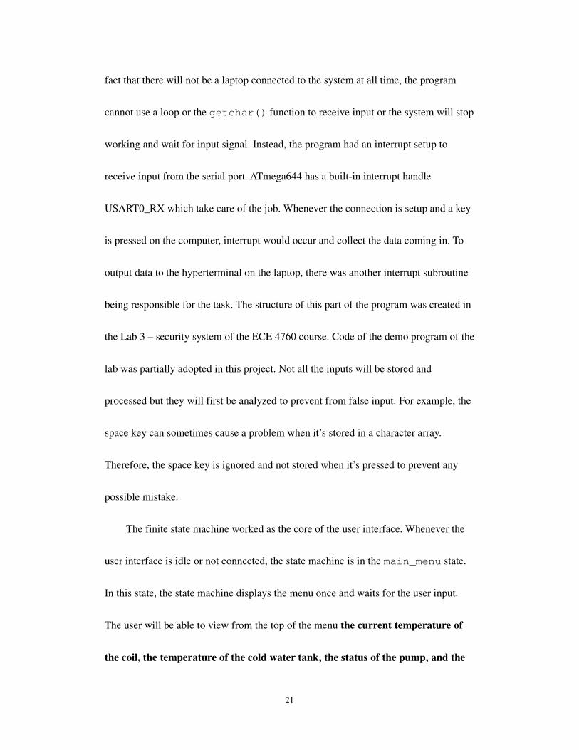
fact that there will not be a laptop connected to the system at all time, the program
cannot use a loop or the getchar() function to receive input or the system will stop
working and wait for input signal. Instead, the program had an interrupt setup to
receive input from the serial port. ATmega644 has a built-in interrupt handle
USART0_RX which take care of the job. Whenever the connection is setup and a key
is pressed on the computer, interrupt would occur and collect the data coming in. To
output data to the hyperterminal on the laptop, there was another interrupt subroutine
being responsible for the task. The structure of this part of the program was created in
the Lab 3 – security system of the ECE 4760 course. Code of the demo program of the
lab was partially adopted in this project. Not all the inputs will be stored and
processed but they will first be analyzed to prevent from false input. For example, the
space key can sometimes cause a problem when it’s stored in a character array.
Therefore, the space key is ignored and not stored when it’s pressed to prevent any
possible mistake.
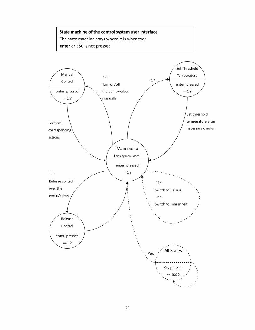
The finite state machine worked as the core of the user interface. Whenever the
user interface is idle or not connected, the state machine is in the main_menu state.
In this state, the state machine displays the menu once and waits for the user input.
The user will be able to view from the top of the menu the current temperature of
the coil, the temperature of the cold water tank, the status of the pump, and the
22
status of the valves. Different options are available to choose from by the user
including “Set Threshold Temperature”, “Manual Control”, “Release Control”,
“Switch to Celsius”, and “Switch to Fahrenheit”. Please refer to the appendix for the
image of the user interface. When I was testing the user interface, I found that the
menu can be messed up easily by intentionally sending a large amount of input to the
system while it’s printing on to the hyperterminal via interrupt. This situation occurs
due to the limit of transmission rate of UART. I believed it was necessary to have a
“Back to main menu” or “Refresh” key to restore the system back to normal and the
key should not go through the finite state machine. In the receive interrupt, I first
check the input character before storing it. As stated previously, if the key pressed is
space, then nothing will happen. If an ESC key is pressed, the program will then clear
the screen and force the state machine to go back to main_menu regardless of the
current state. Once the program leave the interrupt, the state machine will find itself in
the main_menu state and display the menu again. The ESC key is also used as the
initialization key to begin with when the laptop is connected to the MCU. The code of
the state machine was modified from my code of lab 3 in the ECE 4760 course. The
following state diagram gives a clear view of the state machine.
23
Main menu
(display menu once)
enter_pressed
==1 ?
Set Threshold
Temperature
enter_pressed
==1 ?
Manual
Control
enter_pressed
==1 ?
’1’
’4’
Switch to Celsius
’5’
Switch to Fahrenheit
’2’
Turn on/off
the pump/valves
manually
Perform
corresponding
actions
’3’
Release control
over the
pump/valves
Release
Control
enter_pressed
==1 ?
Set threshold
temperature after
necessary checks
All States
Key pressed
== ESC ?
Yes
State machine of the control system user interface
The state machine stays where it is whenever
enter or ESC is not pressed
24
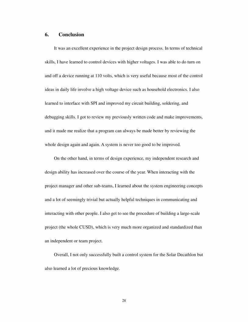
After implementing the functions on the MCU, I started working on the
hardware of it. Initially I was using a STK500 development board to write and test the
program. For the final device which is going to be installed in the house, the MCU is
installed on a more compact prototype board. The prototype board used is designed by
Dr. Bruce Land for the ECE 4760 course. Please refer to appendix for the schematics.
I tested the same program on the board upon its completion. There were 2 major
problems I ran into when I was trying to make the prototype board work. First of all,
the SPI bus on ATmega644 is hardware-determined on the pin 5, 6, and 7 on PORT B,
which happens to be the 3 pins that are used to program the MCU. When any of these
3 pins were driven by an external source during programming, the chip would not
program. Therefore I would have to remove the MISO wire at PORTB 6 whenever I
was programming the chip. This wasn’t a big problem because it was stated in the
prototype board description page. However, if I connect the wire back to PORTB 6
after the chip was programmed, the reading of the sensor was still sometimes
incorrect. This was because the programming cable may still affect the prototype
board because the power of the programmer (STK500) was still on. As a result, I had
to make sure that the programming cable is removed to ensure that the MCU receive
the correct data from the sensors.
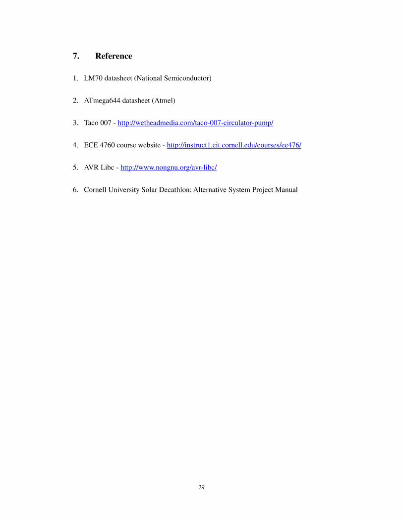
The other problem I had was a hardware problem of the prototype board. When I
25
was soldering header to the output pins on the board, I happened to solder a header
falsely into a hole which wasn’t designed for a header connection. It was a ground
connection and was simply used to connect the upper layer and the lower layer of the
board, and the size was smaller than other ones as well due to this reason. There
shouldn’t be any problem even though I inserted a pin to the ground hole. However, I
somehow destroyed the connection of the hole and made one of the ground pin
disconnected from the GND of the power source. That is, the ground that goes out
was not connected to the actual GND properly. I didn’t know this until I keep getting
incorrect data from the sensor. A few hours were spent on this problem and I went
through all the possible reasons but hardware. Finally I started checking the
connection on each pin and found that some of the pins were having a bad connection
including the GND. I made sure all the connection were good by desoldering the bad
ones and solder it again, but the bad connection on the ground continued to exist. I
realized that there’s a connection problem on the PCB rather than the soldered hole.
To fix the problem, I found out which one of the inner connection failed and soldered
a short wire on the bottom of the board to rebuild the connection. Detailed pictures are
included in the appendix.
After solving these problems, the prototype board worked as expected and the
system prototype was completed.
26
5. Result
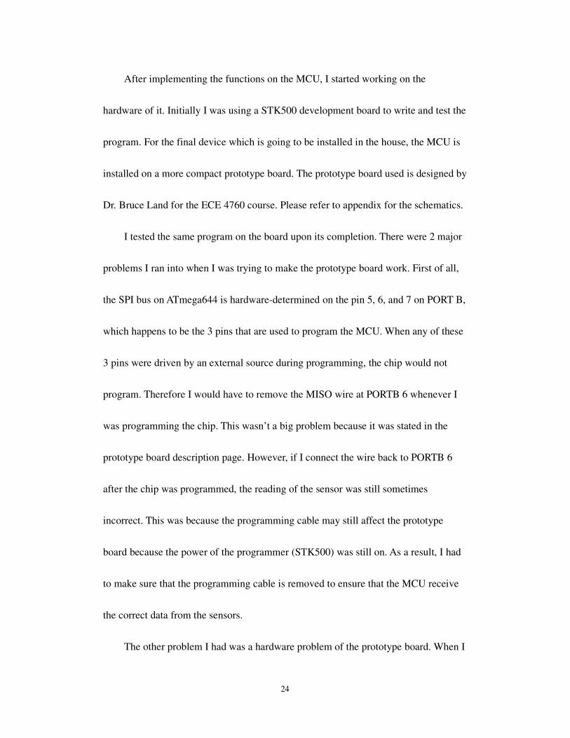
Overall, the results were quite successful. All the required functionalities were
implemented in software and hardware except for the electrical actuated valve. The
control system including the pump was fully tested upon completion of the project.
The user interface is simple and requires only a laptop with USB port and the
hyperterminal or other compatible programs. The control system along with the
hardware will be installed on to the house during its construction in May 2009.
The diagrams below show the user interface.
Setting threshold temperature
27
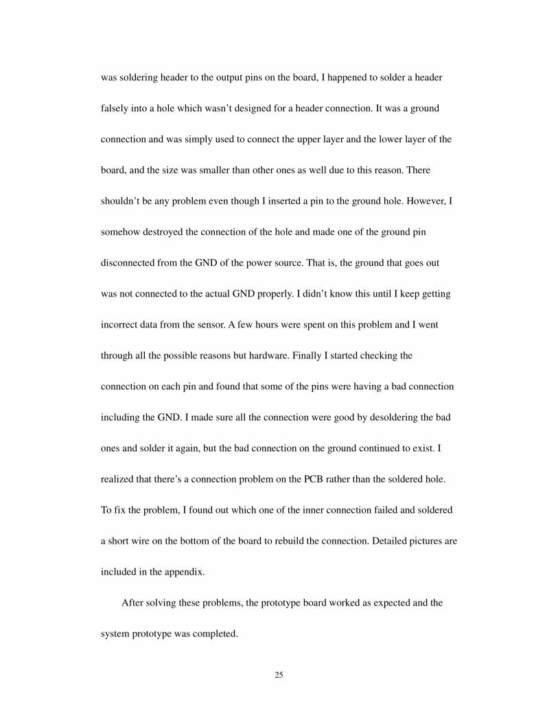
Manually controlling the pump
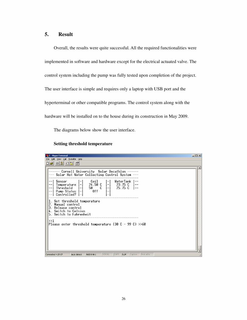
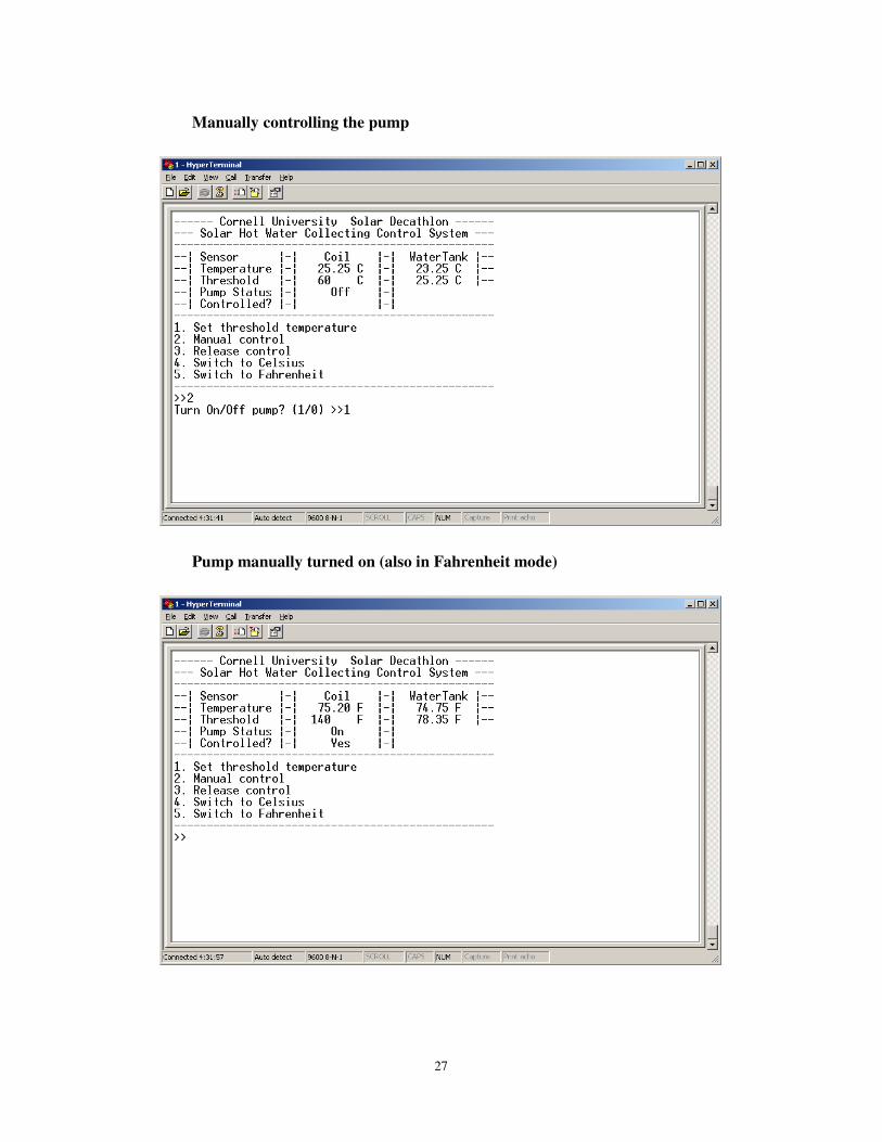
Pump manually turned on (also in Fahrenheit mode)
28
6. Conclusion
It was an excellent experience in the project design process. In terms of technical
skills, I have learned to control devices with higher voltages. I was able to do turn on
and off a device running at 110 volts, which is very useful because most of the control
ideas in daily life involve a high voltage device such as household electronics. I also
learned to interface with SPI and improved my circuit building, soldering, and
debugging skills. I got to review my previously written code and make improvements,
and it made me realize that a program can always be made better by reviewing the
whole design again and again. A system is never too good to be improved.
On the other hand, in terms of design experience, my independent research and
design ability has increased over the course of the year. When interacting with the
project manager and other sub-teams, I learned about the system engineering concepts
and a lot of seemingly trivial but actually helpful techniques in communicating and
interacting with other people. I also get to see the procedure of building a large-scale
project (the whole CUSD), which is very much more organized and standardized than
an independent or team project.
Overall, I not only successfully built a control system for the Solar Decathlon but
also learned a lot of precious knowledge.
29
7. Reference
1. LM70 datasheet (National Semiconductor)
2. ATmega644 datasheet (Atmel)
3. Taco 007 - http://wetheadmedia.com/taco-007-circulator-pump/
4. ECE 4760 course website - http://instruct1.cit.cornell.edu/courses/ee476/
5. AVR Libc - http://www.nongnu.org/avr-libc/
6. Cornell University Solar Decathlon: Alternative System Project Manual
30
8. Appendix
Hardware schematics and pictures
Prototype board schematics
Prototype board ground connection diagram 1
31
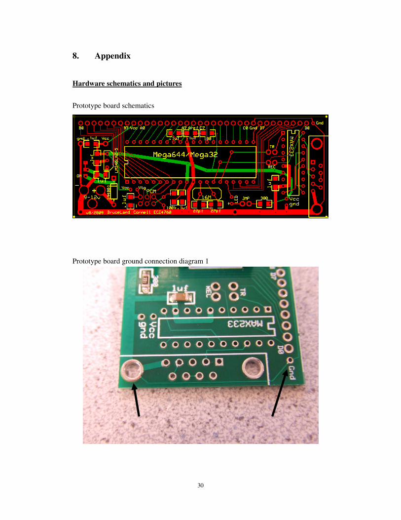
Prototype board ground connection diagram 2
The printed connection between of two holes was broken during the soldering
procedure. Therefore I had to set up the connection with wire.
Prototype board ground connection diagram 3
The two large holes were connected via the body of the D-sub connector.
32
Temperature sensor LM70 on the breakout board
Stripped power cable with 3 wires (hot, neutral and ground)
33
Soldered wires from the power cord to the pump
Ground connection to the pump body
34
Control System schematics
Valve control circuit schematics (Modified from ECE 4760 Lab 5)
LM70
VCC
GND
CLK
Chip Select
SI/O
LM70
VCC
GND
CLK
Chip Select
SI/O
Solid
State
Relay - + ~
PUMP
Hot
Neutral Ground
110V AC
MCU
PORTB 6
PORTB 7
PORTB 4
VCC
GND
PORTB 3 PORTC 0
PORTC 1
Opto-isolated
Valve control circuit All the GND are
connected together
35
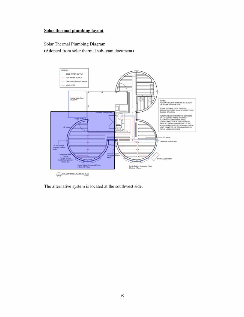
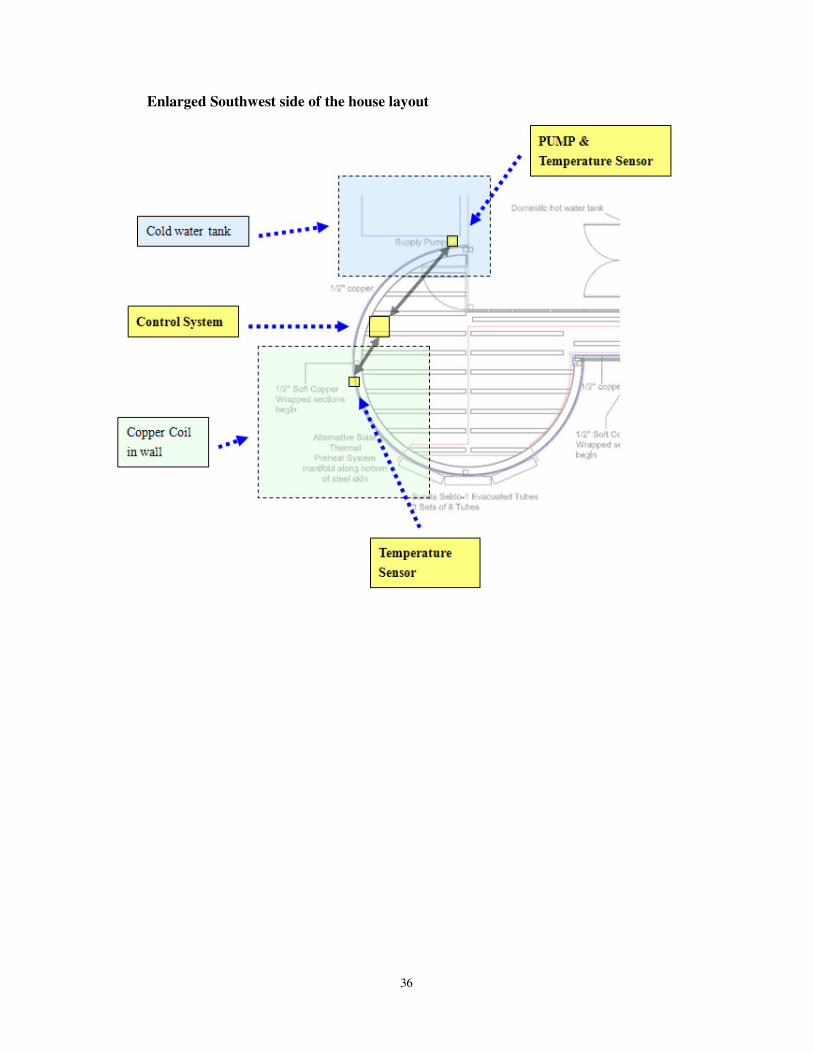
Solar thermal plumbing layout
Solar Thermal Plumbing Diagram
(Adopted from solar thermal sub-team document)
The alternative system is located at the southwest side.
36
Enlarged Southwest side of the house layout
37
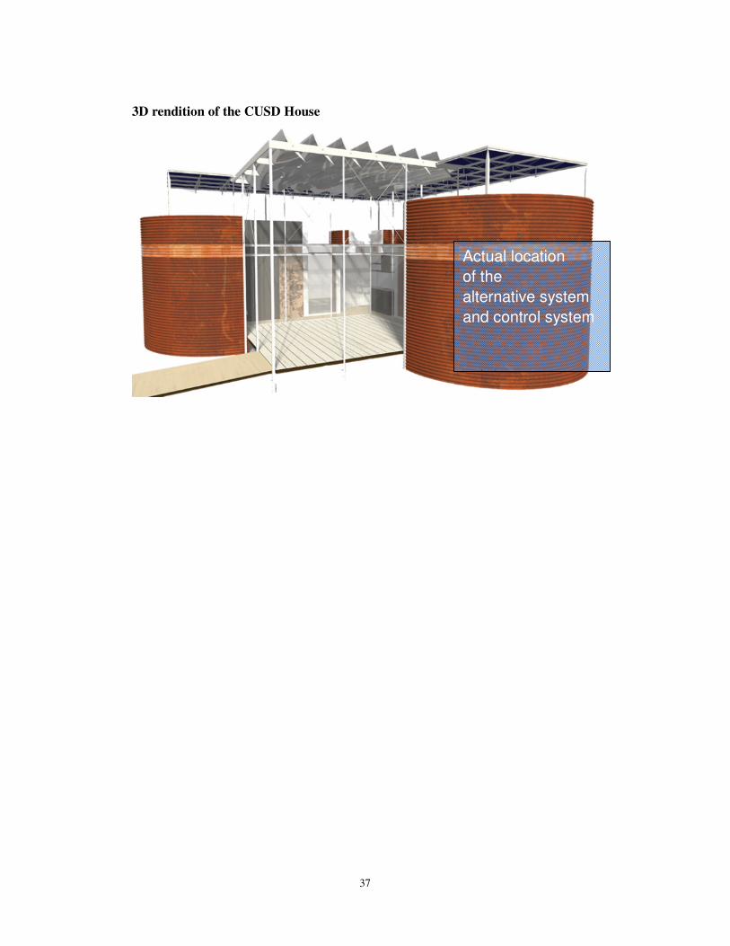
3D rendition of the CUSD House
Actual location
of the
alternative system
and control system
38
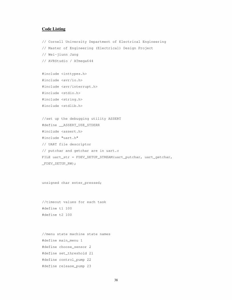
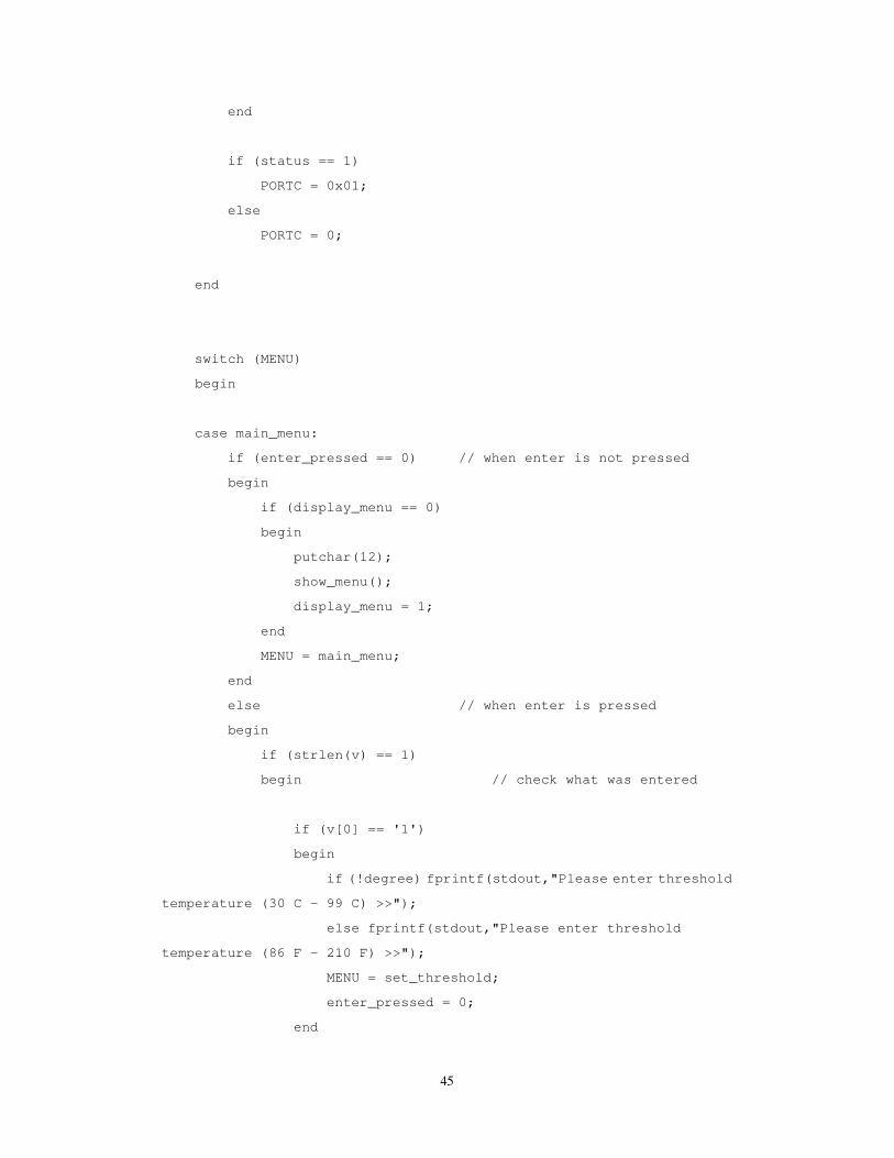
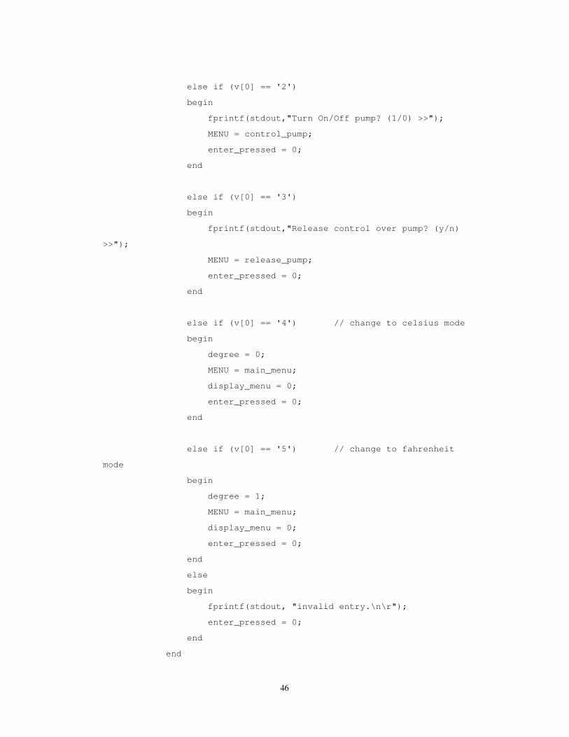
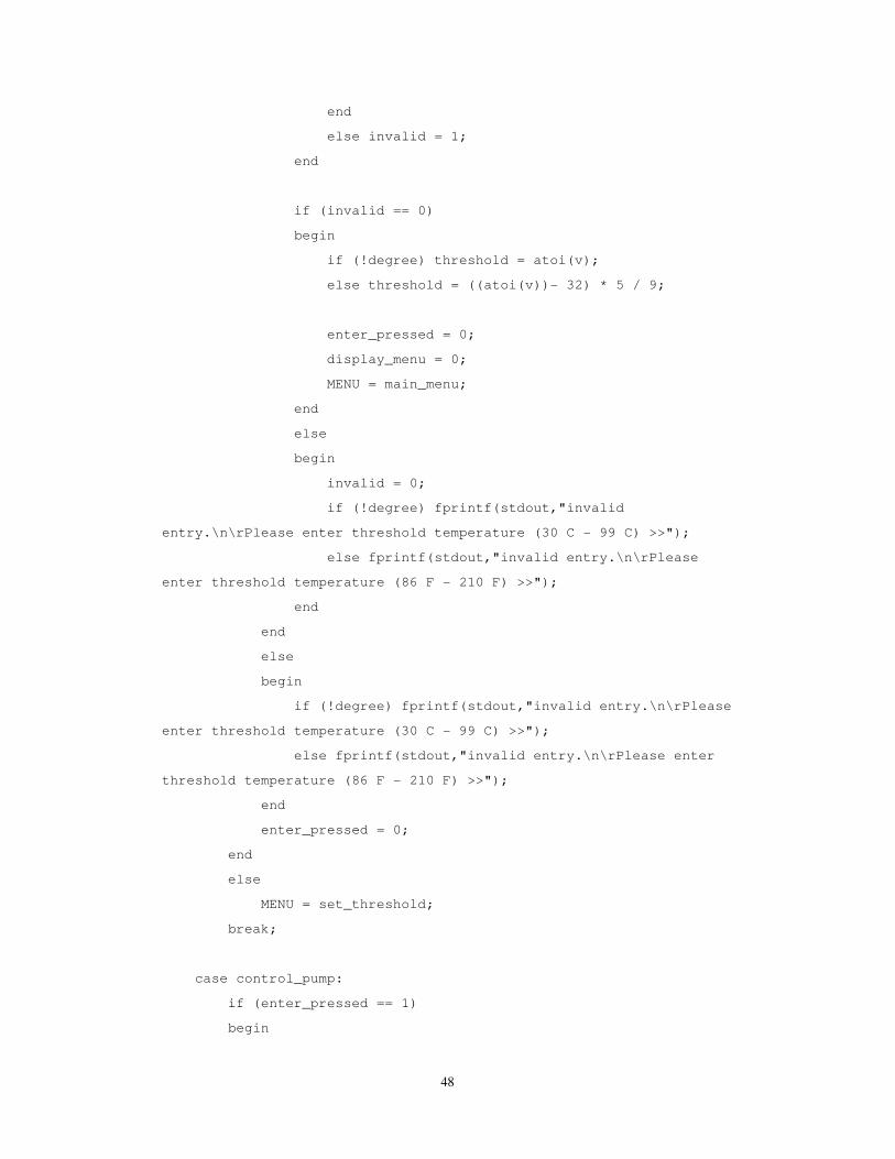
Code Listing
// Cornell University Department of Electrical Engineering
// Master of Engineering (Electrical) Design Project
// Wei-jiunn Jang
// AVRStudio / ATmega644
#include <inttypes.h>
#include <avr/io.h>
#include <avr/interrupt.h>
#include <stdio.h>
#include <string.h>
#include <stdlib.h>
//set up the debugging utility ASSERT
#define __ASSERT_USE_STDERR
#include <assert.h>
#include "uart.h"
// UART file descriptor
// putchar and getchar are in uart.c
FILE uart_str = FDEV_SETUP_STREAM(uart_putchar, uart_getchar,
_FDEV_SETUP_RW);
unsigned char enter_pressed;
//timeout values for each task
#define t1 100
#define t2 100
//menu state machine state names
#define main_menu 1
#define choose_sensor 2
#define set_threshold 21
#define control_pump 22
#define release_pump 23
39
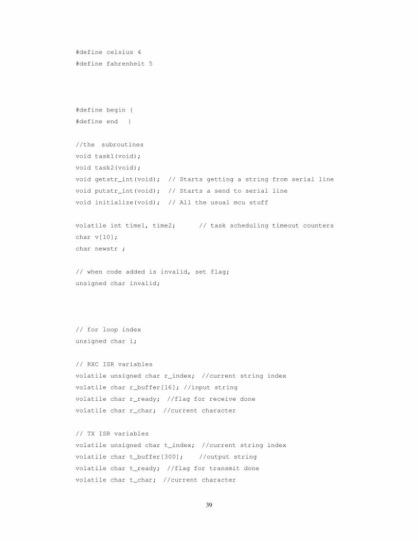
#define celsius 4
#define fahrenheit 5
#define begin {
#define end }
//the subroutines
void task1(void);
void task2(void);
void getstr_int(void); // Starts getting a string from serial line
void putstr_int(void); // Starts a send to serial line
void initialize(void); // All the usual mcu stuff
volatile int time1, time2; // task scheduling timeout counters
char v[10];
char newstr ;
// when code added is invalid, set flag;
unsigned char invalid;
// for loop index
unsigned char i;
// RXC ISR variables
volatile unsigned char r_index; //current string index
volatile char r_buffer[16]; //input string
volatile char r_ready; //flag for receive done
volatile char r_char; //current character
// TX ISR variables
volatile unsigned char t_index; //current string index
volatile char t_buffer[300]; //output string
volatile char t_ready; //flag for transmit done
volatile char t_char; //current character
40
// toggling LED variable
unsigned char LED;
// variables for main fuctions
unsigned char display_menu;
unsigned char MENU;
//display TIME and MENU subroutines
void show_menu(void);
// bit handling macros for i/o registers
#define READ(U, N) ((U) >> (N) & 1u)
#define SET(U, N) ((void)((U) |= 1u << (N)))
#define CLR(U, N) ((void)((U) &= ~(1u << (N))))
#define FLIP(U, N) ((void)((U) ^= 1u << (N)))
char Hbits, Lbits;
double temp[2];
int threshold;
char debug_led;
char status = 0;
char valve[4];
char force_status[4];
char force = 0;
// Celsius mode(0) or Fahrenheit(1)
char degree = 0;
#define set_temp 1
#define control 2
#define release 3
41
//**********************************************************
//timer 0 overflow ISR
ISR (TIMER0_COMPA_vect)
begin
//Decrement the times if they are not already zero
if (time1>0) --time1;
if (time2>0) --time2;
end
//**********************************************************
// UART character-ready ISR
// builds a sting and signals when the string is complete
// supports backspace
ISR (USART0_RX_vect)
begin
r_char = UDR0 ; //get a char
//build the input string
if (r_char != '\r') // Is the input a <enter>?
begin
if (r_char == '\b') // Is the input a backspace?
begin
if (r_index > 0)
begin
putchar('\b'); // backup
putchar(' '); // erase the character on the screen
putchar('\b'); // backup
--r_index ; // wipe a character from the string
end
end
else if (r_char == 27)
begin
42
MENU = main_menu;
display_menu = 0;
putchar(12);
end
else if (r_char == ' '); // ignore all the space
else
begin
UDR0 = r_char;
r_buffer[r_index++] = r_char ; // add a character to the string
end
end
else // Human pressed <enter>
begin
putchar('\n'); //use putchar to avoid overwrite
r_buffer[r_index] = 0x00; //zero terminate
r_ready = 1; //signal cmd processor
UCSR0B ^= (1<<RXCIE0) ; //stop rec ISR -- clear rxc
end
end
/**********************************************************/
//UART xmit-empty ISR
ISR (USART0_UDRE_vect)
begin
t_char = t_buffer[++t_index];
if (t_char == 0) // end of string?
begin
UCSR0B ^= (1<<UDRIE0) ; // kill isr -- clear tx enable
t_ready = 1; // transmit done
end
else UDR0 = t_char ; //send the char
end
//**********************************************************
//Entry point and task scheduler loop
int main(void)
begin
initialize();
43
while(1)
begin
if (time1==0){time1=t1; task1(); }
if (time2==0){time2=t2; task2(); }
end
end
//**********************************************************
//Task 1 input a string and print it
void task1(void)
begin
//print ad get another serial string
if (r_ready)
begin
enter_pressed = 1;
// read string which is now ready
sscanf(r_buffer,"%s",v);
if (r_buffer[0] == 0) v[0] = 0;
// set up procedure to get the next string input
// and read it using receive ISR
getstr_int();
end
end
//**********************************************************
//Task 2 print the meaasge and system time in seconds
void task2(void)
begin
// update sensor value
debug_led = debug_led ^ 1; // blink LED on the prototype board
(PORTD.2)
PORTD = (debug_led<<2);
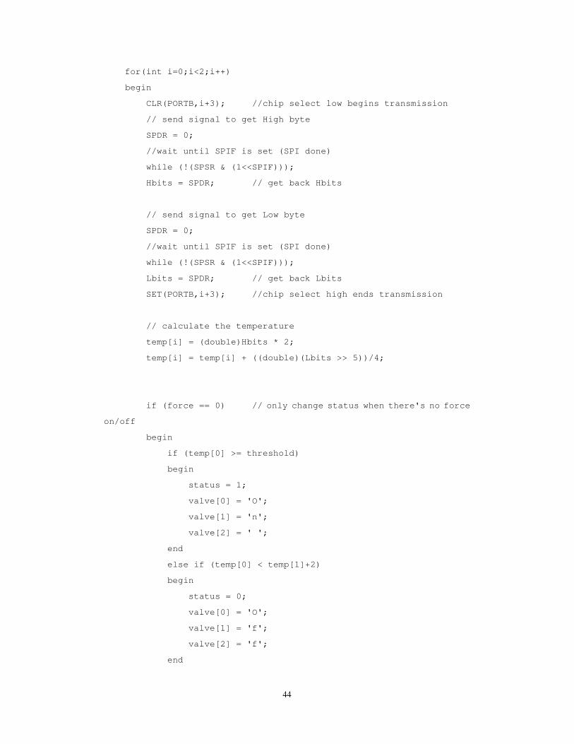
44
for(int i=0;i<2;i++)
begin
CLR(PORTB,i+3); //chip select low begins transmission
// send signal to get High byte
SPDR = 0;
//wait until SPIF is set (SPI done)
while (!(SPSR & (1<<SPIF)));
Hbits = SPDR; // get back Hbits
// send signal to get Low byte
SPDR = 0;
//wait until SPIF is set (SPI done)
while (!(SPSR & (1<<SPIF)));
Lbits = SPDR; // get back Lbits
SET(PORTB,i+3); //chip select high ends transmission
// calculate the temperature
temp[i] = (double)Hbits * 2;
temp[i] = temp[i] + ((double)(Lbits >> 5))/4;
if (force == 0) // only change status when there's no force
on/off
begin
if (temp[0] >= threshold)
begin
status = 1;
valve[0] = 'O';
valve[1] = 'n';
valve[2] = ' ';
end
else if (temp[0] < temp[1]+2)
begin
status = 0;
valve[0] = 'O';
valve[1] = 'f';
valve[2] = 'f';
end
45
end
if (status == 1)
PORTC = 0x01;
else
PORTC = 0;
end
switch (MENU)
begin
case main_menu:
if (enter_pressed == 0) // when enter is not pressed
begin
if (display_menu == 0)
begin
putchar(12);
show_menu();
display_menu = 1;
end
MENU = main_menu;
end
else // when enter is pressed
begin
if (strlen(v) == 1)
begin // check what was entered
if (v[0] == '1')
begin
if (!degree) fprintf(stdout,"Please enter threshold
temperature (30 C - 99 C) >>");
else fprintf(stdout,"Please enter threshold
temperature (86 F - 210 F) >>");
MENU = set_threshold;
enter_pressed = 0;
end
46
else if (v[0] == '2')
begin
fprintf(stdout,"Turn On/Off pump? (1/0) >>");
MENU = control_pump;
enter_pressed = 0;
end
else if (v[0] == '3')
begin
fprintf(stdout,"Release control over pump? (y/n)
>>");
MENU = release_pump;
enter_pressed = 0;
end
else if (v[0] == '4') // change to celsius mode
begin
degree = 0;
MENU = main_menu;
display_menu = 0;
enter_pressed = 0;
end
else if (v[0] == '5') // change to fahrenheit
mode
begin
degree = 1;
MENU = main_menu;
display_menu = 0;
enter_pressed = 0;
end
else
begin
fprintf(stdout, "invalid entry.\n\r");
enter_pressed = 0;
end
end

47
else
begin
fprintf(stdout, "invalid entry.\n\r");
enter_pressed = 0;
end
end
break;
case set_threshold:
if (enter_pressed == 1)
begin
// when addind a code, first check whether the length is 4
if (strlen(v) == 2 || strlen(v) == 3)
begin
if (!degree)
begin
if (atoi(v) >= 30 && atoi(v) <= 99)
begin
for(i=0;i<strlen(v);i++)
begin // then check whether they are
all numbers
if(v[i]<48 || v[i]>57 ) invalid = 1;
else invalid = 0;
end
end
else invalid = 1;
end
else
begin
if (atoi(v) >= 86 && atoi(v) <= 210)
begin
for(i=0;i<strlen(v);i++)
begin // then check whether they are
all numbers
if(v[i]<48 || v[i]>57 ) invalid = 1;
else invalid = 0;
end
48
end
else invalid = 1;
end
if (invalid == 0)
begin
if (!degree) threshold = atoi(v);
else threshold = ((atoi(v))- 32) * 5 / 9;
enter_pressed = 0;
display_menu = 0;
MENU = main_menu;
end
else
begin
invalid = 0;
if (!degree) fprintf(stdout,"invalid
entry.\n\rPlease enter threshold temperature (30 C - 99 C) >>");
else fprintf(stdout,"invalid entry.\n\rPlease
enter threshold temperature (86 F - 210 F) >>");
end
end
else
begin
if (!degree) fprintf(stdout,"invalid entry.\n\rPlease
enter threshold temperature (30 C - 99 C) >>");
else fprintf(stdout,"invalid entry.\n\rPlease enter
threshold temperature (86 F - 210 F) >>");
end
enter_pressed = 0;
end
else
MENU = set_threshold;
break;
case control_pump:
if (enter_pressed == 1)
begin
49
// when choosing sensor, should be 1 or 2
if (strlen(v) == 1)
begin
if (v[0]==48) //off
begin
MENU = main_menu;
display_menu = 0;
status = 0;
valve[0] = 'O';
valve[1] = 'f';
valve[2] = 'f';
force = 1;
force_status[0] = 'Y';
force_status[1] = 'e';
force_status[2] = 's';
end
else if (v[0]==49) //on
begin
MENU = main_menu;
display_menu = 0;
status = 1;
valve[0] = 'O';
valve[1] = 'n';
valve[2] = ' ';
force = 1;
force_status[0] = 'Y';
force_status[1] = 'e';
force_status[2] = 's';
end
else
fprintf(stdout, "invalid entry\n\rTurn On/Off Pump?
(1/0)");
end
else
fprintf(stdout, "invalid entry\n\rTurn On/Off Pump?
(1/0)");
enter_pressed = 0;
end
50
else
MENU = control_pump;
break;
case release_pump:
if (enter_pressed == 1)
begin
// when choosing sensor, should be 1 or 2
if (strlen(v) == 1)
begin
if (v[0] == 121) //yes
begin
MENU = main_menu;
display_menu = 0;
force = 0;
force_status[0] = ' ';
force_status[1] = ' ';
force_status[2] = ' ';
end
else if (v[0] == 110) //on
begin
MENU = main_menu;
display_menu = 0;
end
else
fprintf(stdout, "invalid entry\n\rRelease control over
pump? (y/n)\n\r>>");
end
else
fprintf(stdout, "invalid entry\n\rRelease control over
pump? (y/n)\n\r>>");
enter_pressed = 0;
end
else
MENU = release_pump;
break;
end
51
end
//**********************************************************
// Non-blocking keyboard input: initializes ISR-driven receive.
// This routine merely sets up the ISR, which then
//does all the work of getting a command.
void getstr_int(void)
begin
r_ready=0; // mark string as not ready
r_index=0; // reset index
// turn on receive ISR
UCSR0B |= (1<<RXCIE0) ;
end
//**********************************************************
// Nonblocking print: initializes ISR-driven transmit.
// This routine merely sets up the ISR, then
// sends one character, The ISR does all the work.
void putstr_int(void)
begin
t_ready=0; // mark transmitter as busy
t_index=0; // reset index
// see if there is actually a string
if (t_buffer[0]>0)
begin
// if so, send the first chararcter
putchar(t_buffer[0]);
// and turn on transmit (UDR empty) ISR
UCSR0B |= (1<<UDRIE0) ;
end
end
void show_menu(void)
begin
fprintf(stdout, "------ Cornell University Solar Decathlon
52
------\n\r");
fprintf(stdout, "--- Solar Hot Water Collecting Control System
---\n\r");
fprintf(stdout,
"-------------------------------------------------\n\r");
fprintf(stdout, "--| Sensor |-| Coil |-| WaterTank
|--\n\r");
if (!degree)
fprintf(stdout, "--| Temperature |-| %7.2f C |-| %7.2f C
|--\n\r",temp[0],temp[1]);
else
fprintf(stdout, "--| Temperature |-| %7.2f F |-| %7.2f F
|--\n\r",temp[0]*1.8+32,temp[1]*1.8+32);
if (!degree)
fprintf(stdout, "--| Threshold |-| %4d C |-| %7.2f C
|--\n\r",threshold,temp[1]+2);
else
begin
if( ((double)threshold*1.8+32) - (char)(threshold*1.8+32) > 0)
fprintf(stdout, "--| Threshold |-| %4d F |-| %7.2f F
|--\n\r",(char)(threshold*1.8+32)+1,(temp[1]+2)*1.8+32);
else
fprintf(stdout, "--| Threshold |-| %4d F |-| %7.2f F
|--\n\r",(char)(threshold*1.8+32),(temp[1]+2)*1.8+32);
end
fprintf(stdout, "--| Pump Status |-| %3s |-|\n\r",valve);
fprintf(stdout, "--| Controlled? |-| %3s
|-|\n\r",force_status);
fprintf(stdout,
"-------------------------------------------------\n\r");
sprintf(t_buffer, "1. Set threshold temperature\n\r2. Manual control
53
\n\r3. Release control\n\r4. Switch to Celsius\n\r5. Switch to
Fahrenheit\n\r-------------------------------------------------\n\r>>
");
newstr = 1;
if (t_ready && newstr)
begin
// make a string of system time (sec) and number from task 1
//sprintf(t_buffer,"%ld %d\n\r",time/1000, v) ;
// print it using transmit ISR
putstr_int();
// clear the string ready handshake from task 1
newstr = 0;
end
end
//**********************************************************
//Set it all up
void initialize(void)
begin
// init the UART -- uart_init() is in uart.c
uart_init();
stdout = stdin = stderr = &uart_str;
fprintf(stdout,"Starting ISR UART demo...\n\r");
putchar(12);
// set up timer 0
OCR0A = 249; // clear after 250 counts
TIMSK0 = (1<<OCIE0A) ; //turn on timer 0 cmp-match ISR
// turn on timer 0 clear on match
TCCR0A = (1<<WGM01) ;
54
// timer 0 prescalar to 64
TCCR0B = 3 ;
// init the task timers
time1=t1;
time2=t2;
// initialize the USRT handshake flags
r_ready=0; // initially, there is no input ready
t_ready=1; // initially, the transmitter is ready
// initialize main function variables
display_menu = 0;
MENU = main_menu;
enter_pressed = 0;
invalid = 0;
strcpy(force_status, " ");
strcpy(valve, "Off");
// output pin to pump controlling relay
DDRC = 0x01;
PORTC = 0;
// output pin debug_led
DDRD |= (1<<2) ; // LEDs
debug_led = 0x00;
// LM70 reading
//set up i/o data direction
//DDRB.4 = 1; //output chip select for DAC (notSYNC)
//DDRB.5 = 1; //output MOSI to ADC
//DDRB.6 = 0; //input MISO from ADC
//DDRB.7 = 1; //output SCLK
DDRB = (1<<DDB3) | (1<<DDB4) | (1<<DDB5) | (1<<DDB7) ;
// initialize notSYNC
SET(PORTB,4);
SET(PORTB,3);
//set up SPI
55
//bit 7 SPIE=0 no ISR
//bit 6 SPE=1 enable spi
//bit 5 DORD=0 msb first
//bit 4 MSTR=1 Mega32 is spi master
//bit 3 CPOL=1 clock polarity
//bit 2 CPHA=1 clock phase
//bit 1,0 rate sel=10 along with SPRC=1 sets clk to f/32 = 500 kHz
SPCR = (1<<SPE) | (1<<MSTR) | (1<<CPOL) | (1<<CPHA) | (1<<SPR1) ;
//SPCR SPCR = 0b01011110 ;
SPSR = (1<<SPI2X) ; //SPSR = 1;
// initialize threshold temperature to 50C
threshold = 50;
// turn in ISRs
// but note that UART ISRs are enabled when reading/writing
sei();
// start waiting for input
getstr_int();
end