Contra Costa Community College District
291
Contra Costa Community College District Security Design Guidelines March 2018
-
Upload
khangminh22 -
Category
Documents
-
view
0 -
download
0
Transcript of Contra Costa Community College District

Contra Costa Community College District
Security Design Guidelines
March 2018

1
DESIGN GUIDELINES
2
REQUEST FOR PROPOSAL
3
UNIT PRICING
4
SECURITY SYSTEM SPECIFICATIONS
5
PRODUCT INFORMATION
6
TYPICAL BLOCK DIAGRAMS
7
TYPICAL SECURITY SYSTEM
DETAIL DRAWINGS
8
SAMPLE SHOP DRAWINGS

Contra Costa Community College District
Security Design Guidelines
1.0 Revision Log
Date Version Description of Changes
March 7, 2012 B.2 Final Draft for Board Approval
1. Updates per 12/01/11 review meeting
March 1, 2018 B.3 Revised VSS Requirements and added ALPR
capability
Revised Security Device Requirements
Added additional Access Control System
Requirements (card reader override)
Added data requirements for Emergency
Notification System

Contra Costa Community College District
Security Design Guideline
1.0 OVERVIEW
Contra Costa Community College District plans to operate and maintain a consistent campus-wide
electronic security systems program throughout its multiple campuses: Contra Costa College, Diablo
Valley College, Los Medanos College. This also pertains to the District Office and the two satellite
campuses: San Ramon Valley Campus and the Brentwood Center. To assist with the design and
development of individual security projects, the following design guidelines were created.
Each new campus security project may include a blend of the following systems: Access Control and
Alarm Monitoring System (ACAMS), an Intrusion Detection System (IDS), and a Video Surveillance
System (VSS). Collectively the systems are an economical solution to provide security and safety
while maintaining convenience and flexibility. Contractors proposing on new Contra Costa
Community College District project must ensure that new security work utilizes the same software
versions that are currently operating on the Contra Costa Community College District server(s)
located at the District Office in Martinez, CA.
The standards are based around the following manufacturers:
• Access Control and Alarm Monitoring System: Software House CCURE 9000
• Intrusion Detection System: DSC PowerSeries
• Video Surveillance System: Salient Systems
This design guideline details the electronic security standards, system design criteria, implementation
guidelines, and coordination requirements. It is not intended as a substitution for construction
documents, but rather guides the engineer to design additions to the overall system during new and
renovation construction projects. Included with the guidelines are a sample RFP, unit pricing,
template construction technical specifications, typical product information, overall system topology
diagrams, typical details, and example shop drawings.
1.1 Scope
The scope of the guideline includes the following information:
A. Access Control and Alarm Monitoring Design Criteria
B. Intrusion Detection System Design Criteria
C. Video Surveillance Design Criteria
D. Electronic Security Device Application Matrix
E. Architectural, Structural, Electrical, Mechanical, Elevator, and
Telecommunication coordination and design requirements required to support the
physical access control and security system during implementation.
1.2 Application
Physical security plays a critical role in providing a safe environment for staff and students.
Security for the district consists of access control and alarm monitoring system (ACAMS),
intdusion detection, and video surveillance system, which mitigate theft, vandalism, and
general crimes of opportunity. Additionally the system automates the opening and closing of
the buildings on schedule, increasing the effective utilization of staff.

Contra Costa Community College District - Security Design Guidelines
Page 2 of 9
The guidelines and criteria herin apply to each campus within the Contra Costa Community
College District - Contra Costa College (CCC) located in San Pablo, Diablo Valley College
(DVC) located in Pleasant Hill, and Los Medanos College (LMC) located in Pittsburg, as
well as the District Office in Martinez. Even though the two satellite campuses: San Ramon
Valley Campus and the Brentwood Center do not have the same facility structure as the other
campuses, these guidelines and citeria shall apply to these locations.
1.3 Arrangement of Information
This document is arranged by design discipline. Best practice has the Architect and Design
Engineers reading this document, the electronic security device application matrix, and the
design coordination document, including related documents. The Design Team should study
the specific sections related to their discipline and review the other sections.
The district and colleges should review and utilize the sample RFP, unit pricing, template
construction technical specifications, typical product information, overall system topology
diagrams, typical details, and example shop drawings as a reference for each project
including electronic security systems.
1.4 Roles and Responsibilites
The successful design and implementation of any component of the electronic security
systems requires coordination with the following entities throughout the delivery process:
A. Facilities Planning - Staff such as campus project managers will engage end-
users in discussions regarding the security systems and operation, credential
issuance, and access privileges. Architects and other design consultants and their
agents shall not engage directly with end-users on system operational
requirements. The project managers will ensure that a project’s scope, schedule
and budget goals are achieved.
B. Building and Grounds - Manage and maintain doors and hardware, including
mechanically keyed hardware on each campus, connected to the electronic
physical security systems.
C. Police Services - Operate the electronic security systems on each campus and on
the district-wide level. Staff maintain credentials and control building access
schedules.
D. Information Techology and Research - Coordinate all aspects of the ACAMS,
intrusion, and video surveillance interfaces and connections with the LAN and/or
WAN.
E. User Groups - Facility users who will interact with the mechanically keyed,
ACAM’d and/or video surveilled facility. User group representatives will define
specific program requirements for the systems, beyond the minimum standard
deployed across all projects.

Contra Costa Community College District - Security Design Guidelines
Page 3 of 9
F. Security Design Engineer - Members of the design team who are designing the
electronic physical security systems shall have a thorough understanding,
knowledge and successful experience in designing similar systems in similar
applications. The design team members (whether part of the prime consultant’s
design team or an associated consultant) shall be approved by CCCD prior to
performing any design work. The Design Engineer shall provide services in
accordance with these standards. The Design Team shall verify that all
applicable portions of these standards are incorporated into the project’s design,
drawings, specification and final construction. Requests for variances from these
standards are to be submitted in writing to the campus project manager, and will
be scrutinized very carefully. Variances from any aspects of this physical access
controls and security management system design standard will only be allowed
with the explicit written consent of the District.
G. Security Systems Integrator
1. Integrator firms minimally provide the “parts and smarts” for the ACAMS
system. They may sell the parts to a C-10 electrician who then installs the parts
and wires them, and then the Integrator simply provides the programming of
those devices (smarts). Integrators may also install the entire system (parts,
smarts and wiring).
a) In order to ensure that an Integrator is able to provide the level of service
that the District requires, there are a number of qualifications that must be
met. The District may, at its discretion, make exceptions based on
demonstrated strengths in one area that outweigh a deficiency elsewhere.
b) Documentation demonstrating compliance with the following criteria must
be provided as a submittal prior to any work being done by the Integrator
2. Required Qualification Criteria:
a) Personnel must have successful experience and demonstrated knowledge,
skill and ability in working on a Software House ACAMS at the Global
level. Personnel must also reside in the District’s service area. Resumes of
the proposed Project Manager, General Foreman, and Lead Technician(s)
indicating role, years of experience, tenure, product certifications and
training, listing of similar projects the individual performed in the role
proposed for this project, along with client contact information for each shall
be reviewed by the District to ensure proposed personnel are qualified. In
addition, each proposed technician’s Software House Enterprise level
certification or other proof of factory training must be provided; this
requirement ensures that the manufacturer has certified that the technician is
trained in Enterprise level Software House ACAMS installations.
b) Integrator firms must be an authorized dealers for Software House, allowing
the firm to act as a reseller, installer, and warranty provider of the Software
House security system at the Enterprise Level. Certifications from Software
House for lower tiered product offerings are not acceptable. This
requirement ensures that the manufacturer has qualified the Integrator to
conduct business at the Enterprise level that is installed across the District.

Contra Costa Community College District - Security Design Guidelines
Page 4 of 9
2.0 ACCESS CONTROL AND ALARM MONITORING SYSTEM (ACAMS)
2.1 Overview
The District selected Software House as its access control system provider. All district
security projects must utilize this system to provide commonality in access card formats,
system monitoring/reporting capabilities, and District-wide programming standards.
Each campus will include a Software House system comprised of access control panels, card
readers, power supplies, access control cards, and interfaces to electrically controlled locking
hardware. The individual campus control panels connect to the Enterpise Software House
server software via the District LAN/WAN. The District IT department will provide and
support application servers and District workstations including video badging workstations.
The individual campus IT departements will support their respective security workstations.
Police Services will manage the security system software on both the District and campus
levels. Refer to the specific sections in the Design Specifications for recommendations
regarding specific security products.
The District requires card readers capable of reading proximity and iCLASS dual technology
access cards. All District security projects must utilize standardized control panels and a
commpon manufacturer for card readers to ensure commonality in system performance,
system monitoring/reporting capabilities, and District-wide programming standards. The
District uses standard 125KHz proximity access control cards. The design for new projects
should account for the use of 13.56 MHz “Smart” cards in the future. This will include
memory/storage capabilities to support future applications including logical access, biometric
templates, and debit card capabilities.
2.2 Application
A. ACAMS controls access into the buildings and select interior doors. Intrusion
alarm monitoring comprised of door contacts, motion detectors, and duress
buttons also monitored on the ACAMS system via integration with the IDS alarm
panels.
B. ACAMS electronic locks are used on doors that are deemed critical to security of
expensive assets subject to a high possibility of theft, confidential records, or
other areas of critical nature. These doors are typically locked at all times by the
ACAMS.
C. ACAMS locks may also be used on doors that are not deemed “critical”, but have
other operational requirements that make ACAMS a good solution, such as
building entrances. These doors are locked or unlocked based on a programmed
schedule
D. Doors specified to have electronic access control must tie into the College’s
existing Software House ACAMS. Create schedules to automate the opening and
closing of the building including unlocking doors, bypassing alarms and enabling
the auto operator at main entrances
E. No other security systems may be used in lieu of or in addition to the Software
House ACAMS.
F. Card readers and card readers with integrated keypads are generally not used at
the District at this time.
G. Interconnect ACAMS to auto operators for secure after hour’s operation

Contra Costa Community College District - Security Design Guidelines
Page 5 of 9
1. Interlock exterior ADA push plates (or motion sensor) with aux relay on local
lock power supply.
2. When door is locked exterior push plate (or motion sensor) is disabled
3. When door unlocked, even momentarily, ADA push plate (or motion sensor) is
enabled.
H. Security enclosures require tamper switches monitored by the ACAMS.
Supervision of power supplies and batteries is required.
I. Utilize stranded, plenum-jacketed cable and route on dedicated security J-
Hangers through the building’s accessible ceiling. Home run cable to nearest
security equipment hub typically located in telecommunications rooms. Do not
share conduits with fire alarm or telecommunications systems. Utilize plenum
jacketed cable when required.
J. Reference Specifications for additional application requirements.
2.3 ACAMS Door Typology
Table 2.3 lists standard ACAMS door typology used by the District. Each typology has an
identifying number used to indicate the door’s security function. All types include intrusion
monitoring. When programming ACAMS design with end-user groups, use the Districts
door typology as a starting point.
Door
Type Description How it Works
1
Card Reader Door with
Standard Proximity Reader (no
keypad)
Can be programmed to unlock/lock
on a schedule. When not scheduled
unlocked, a card or fob must be
presented to unlock the door. Door
includes capability to disable card
reader by using a push button or
other override device on opposite
side on interior of door. Activation
of the push button or override device
generates an alarm event and locks
the door.
2 ADA Card Reader Door with
Standard Proximity Reader
Uses a card reader, like “1”, but in
conjunction with an automatic door
operator.
3 Scheduled Unlock Door
Automatically locks or unlocks on a
schedule that has been programmed
into the ACAMS. Door includes
capability to lock the door by using
a push button or other override
device on opposite side on interior
of door. Activation of the push
button or override device generates
an alarm event and locks the door.
4 Monitored Door with
Authorized Exiting
Allows for egress without an alarm,
no re-entry through these doors,
typically no exterior trim on this
type.
4.1 Emergency Exit Door with
Local Alarm
Monitored like “4”, exiting through
this door will set off an audible
alarm near the door as well as at the
ACAMS and IDS.
4.2 Emergency Exit Door with
Local Alarm
Monitored like “4”, exiting through
this door will set off an alarm at the
ACAMS and IDS.

Contra Costa Community College District - Security Design Guidelines
Page 6 of 9
5
In/Out Standard Proximity
Reader with Door Management
Alarm
A card or fob must be presented to
use this door to exit or enter,
otherwise an audible alarm near the
door will sound.
6 Proximity Reader Sliding
Storefront
Card reader outside to enter,
momentary key switch inside to exit,
magnetic lock on the first sliding
panel.
Table 2.3: ACAMS Door Type Naming Convention
The District security standard shall provide card readers at the following locations:
Main perimeter entry/exit doors.
Exterior elevator hall call buttons
Other perimeter doors frequently used by staff
MDF, IDF, and data rooms
Lecture halls, laboratories, and rooms with high-value instructional technology
Staff administrative spaces including: Administrative Offices, Accounts Receiveable,
Financial Aid, Counseling, and Information Services Departments
Other rooms where staff handle or store cash and other assets
Smart classrooms and computer labs
Refer to the Electronic Security Device Matrix for additional security information.
2.4 Programming
A. The District, College CM, Design Engineer, and Contractor shall hold a meeting
prior to the completion of construction to discuss the programming criteria and
access to the District head end. Discuss the following topics
1. Door Names
2. Device Names
3. Alarm groups
4. Schedules and time codes
5. Action/responses from individual input points
6. Action response from card commands
7. Alarm groupings for programming and reporting
B. Contractor shall program and setup all system hardware such that no additional
programming other than entering new access cards, time codes, and adding doors
to existing access privilege groups is required
C. Program any Type 3, scheduled unlock doors which access the same space as a
Type 1 or 2, card reader door to unlock with when the space is switched to an
unlocked/disarmed state via card reader conditional comands.
D. Program the ACAMS software to make conditional commands a control panel
function instead of a server function. Conditional “if” statements shall have up to
eleven “then” commands.

Contra Costa Community College District - Security Design Guidelines
Page 7 of 9
2.5 Coordination
A. The ACAMS can interface many different disciplines making coordination
extremely important. Reference all other disciplines covered in these documents
and coordinate ACAMS requirements for each project. Attend design team
coordination meetings during design and hold a construction kick off meeting at
the start of construction.
B. Refer to Paragraph 5.0, Coordination below for additional information.
2.6 Commissioning and Closeout
A. Refer to Paragraph 6.0, Testing, below for additional information.
3.0 INTRUSION DETECTION SYSTEM (IDS)
3.1 IDS Overview
The District selected Digital Security Controls (DSC) as its IDS for integration with the
Software House access control system. The IDS is required to send security system alarms
and alarm events to District and Campus selected listed Central Alarm Monitoring Station
(CAMS). All security system devices monitored by the IDS are capable of being sent to the
CAMS and have secondary monitoring through the ACAMS.
Help/duress buttons located at the public interaction desks and cash transation counters are
wired directly to the IDS. The IDS system shall integrate to the ACAMS system to ensure
that activation of a help/duress button reports to the ACAMS and IDS. The IDS includes a
keypads located near main entry portals and also mounted on the cover of the control panel
located in the designated telecommunication room. The keypad will allow activation,
deactivation, and programming of the IDS system. Software integration will also allow the
ACAMS to arm and disarm alarm partitions through the use of specific credentials or through
the ACAMS workstation.
3.2 Application
Alarm initiating devices connected to the IDS are monitored via software thorugh the
ACAMS. Each security device is monitored through the ACAMS server and logged in the
software. The District security standard shall provide alarm devices at the following
locations:
Building perimeter consisting of all perimeter door contacts.
Building perimeter spaces with exterior glazing include motion sensors within the space.
Areas with assets and/or critical information consisting of alarm contacts on door to the
space and motion sensors
Duress buttons at cash transaction counters and other high-risk locations
3.3 Programming
Program the IDS to transmit help/duress button activations and forced door alarms to the
CAMS at all times (24hrs/7days). Other alarm monitoring devices such as motion detectors
and non-emergency exit-only doors will transmit alarms to the ACAMS when the IDS is
activated. All security alarms report to both systems (ACAMS & IDS) through software
integration. Review IDS schedules for each project with the campus project manager for
specific operational requirements.
Refer to the Electronic Security Device Matrix for additional security information.

Contra Costa Community College District - Security Design Guidelines
Page 8 of 9
3.4 Coordination
A. The IDS interfaces with different disciplines, including door hardware, electrical,
and campus IT, making coordination extremely important. Reference all other
disciplines covered in these documents and coordinate the IDS requirements for
each project. Attend design team coordination meetings during design and hold a
construction kick off meeting at the start of construction.
B. Refer to Paragraph 5.0, Coordination below for additional information.
3.5 Commissioning and Closeout
A. Refer to Paragraph 6.0, Testing, below for additional information.
4.0 VIDEO SURVEILLANCE SYSTEM (VSS)
4.1 VSS Overview
The Distrcit requires a video recording and viewing software platform which integrates with
the ACAMS via software interface. The District and individual campus security projects
must utilize a consistent system to provide commonality in recording and viewing formats,
along with District-wide programming standards. The video surveillance system will include
monitoring client workstations utilized by Police Services on each campus.
The District selected to use megapixel color cameras with vari-focal lens for both interior and
exterior locations. While current specifications reflect a few IP camera manufacturers, any
comparable performing PoE IP camera may be acceptable for use upon review by the District
and respective college campus IT department. Note that on typical new construction projects,
the telecommunication contractor will provide IT cabling. This ensures that all IT cabling
provided for the project falls under the certified IT structured cabling system. Please review
District and specific campus IT standards as they relate to the VSS..
The District and individual campus IT departments will provide and maintain the required
network video servers. These network videor servers will reside in a centralized
telecommunications or server room on each campus. The existing server capacity shall be
reviewed during the design and implementation of security cameras on every project.
4.2 Application
The District security standard advises to provide VSS cameras at the following locations:
Main entry/exit doors
Other perimeter doors including fire stairwell and exit-only doors
High traffic or high value interior locations and corridors
Refer to the Electronic Security Device Matrix for additional security information. Also note,
do not locate cameras to allow the viewing of staff or students within standard classrooms.
4.3 Coordination
A. The VSS interfaces heavily with the district and campus IT Department, making
coordination extremely important for a successful installation. All projects will
utilize existing central servers while large projects will require the installation of
additional storage to existing servers to support the processing and storage
requierments for the network video recorder software. The owner’s IT
department will provide the centrally located server.

Contra Costa Community College District - Security Design Guidelines
Page 9 of 9
B. Reference other disciplines covered in these documents and coordinate the IDS
requirements for each project. Attend design team coordination meetings during
design and hold a construction kick off meeting at the start of construction.
C. Refer to Paragraph 5.0, Coordination below for additional information.
4.4 Commissioning and Closeout
A. Refer to Paragraph 6.0, Testing, below for additional information.
5.0 COORDINATION This design guideline document identifies general information required for implementation of new
security work on any District facility. A significant amount of detailed coordination work is required
for a completely functional and operational installation at a new location. Following is a list of some
of the specific coordination activities required. Additional security coordination items are indicated
in the following Security Design Coordination document.
Coordinate with door and hardware specifier to ensure proper door preparation, voltages, and
divisions of work.
Electrical power locations for ACAMS and IDS control panels.
Coordination with local Authority Having Jurisdiction (AHJ) regarding building fire alarm
system interfaces, and local code requirements including Emergency Door releases and
intercoms.
6.0 TESTING The purpose of system commissioning and closeout is to ensure the security system operates properly
when it is needed most. Security systems are very complex from both equipment and programming
standpoints, and thorough testing is necessary to ensure correct operation prior to the building’s
occupancy.
The local security system integrator is required to perform 100% pre-functional testing of the
ACAMS, IDS, and VSS prior to requesting witnessing of final acceptance testing by the District or
their designated representative. The Contractor should be present and demonstrate the security
system functionality during the punch walk. Refer to individual specification sections for specific
testing/commissioning requirements. Refer to security system commissioning specification 28 08 00
for specific closeout procedures.

Notes
Card2
Reader
Sched
Electric
Lock
Entry
Intercom
Alarm
Contact
Arming
Station
Keypad3
Audible
Local
Alarm
Duress
Button
Motion
Detector
Fixed
Camera
Multi
Sensor
Camera
Site
Vehicle Entry Points
Pedestrian Entry Points
Staff & Student Lots
Student Assembly Areas
Critical Circulation Areas Trouble areas on campus
Building Perimeter
Main Perimeter Entry
Perimeter Entrance
Employee Entrance
Emergency Exit-Only
Perimeter Exit-Only Include request-to-exit
Util Ent. w/ Bldg Access
Util Ent. w/o Bldg Access
Rooms w/ Window
Loading Dock If applicable
Building Interior
Cashier/Cash Handling
Student/Staff Counters
High Value Asset Areas
Counseling Entrance
Telecom Rooms
Additional Interior
Tiered Lecture Halls
Staff Work Areas
Smart Classrooms Card reader on one door
Computer Labs Card reader on one door
Instructional Labs
Corridors Adjacent to High
Value / Sensitive Areas /
Labs
Access Control Alarm Monitoring CCTV
Electric Security Device Application
New Project Security System Standards
Security Device Matrix
1 of 2

Notes:
1. () Indicates an optional requirement. Determine requirements based on specific project requirements.
2. Card reader consists of magnetic door contacts, request-to-exit, and electrified locking hardware interface.
3. Alarm Arming Station Keypad only required if building/area does not have ACAMS present with alarm integration.
4. Where applicable, include Automated License Plate Recognition Camera at vehicle entry points.
Security Device Matrix
2 of 2

Contra Costa Community College District
Security Design Coordination
1.0 INTRODUCTION
1.1 Scope
The scope of this design guideline coordination document includes the following
information and should supplement the previous Security Design Guideline
segment:
A. Architectural, Structural, Electrical, Mechanical, Elevator, and
Telecommunication coordination and design requirements required to
support the physical access control and security system during
implementation.
1.2 Arrangement of Information
This document is arranged by design disciple. Best practice has the Architect
and Design Engineers reading the entire document and related items within the
security guidelines binder. The design team should review the specific sections
related to their discipline and how this affects their work.
2.0 ARCHITECTURAL
2.1 Equipment Rooms
A. Coordinate the locations of security equipment panels in telecommunications
rooms with the campus IT department, unless space constraints do not allow.
Wall mount panels to plywood backboard and coordinate space requirements
with telecommunication contractor with acceptance by campus IT
department. Verify at least one segment of 4’ wide x 8’ high plywood is
reserved in each typical telecommunication room for security equipment.
Depending on the magnitude of the project, some installations will require
more wall space.
B. Coordinate rack space for network security equipment. Take security
equipment into consideration when sizing the telecommunication rooms.
Some projects may require more rack space than others depending on the
quantity of security devices.
C. When space constrains do not allow for security equipment panels in the
telecommunication rooms, locate equipment in spaces suitable for low-
voltage equipment. Spaces shall be free from moisture, excess dust & dirt,
and secured from the general public. Equipment panels shall mount to
plywood backboard following the same requirements in telecommunication
rooms.
D. Typically telecommunication rooms and rooms with extremely critical
infrastructure receive a card reader and associated security hardware.
2.2 Doors and Hardware
A. Exterior Door ADA Interface Requirements

Contra Costa Community College District - Security Design Coordination
Page 2 of 8
1. The District is committed to providing access for our disabled community
and when appropriate will implement beyond code requirements. As an
example, auto operators at the major entries to each building may be
provided even if not required.
a) Operators shall be furnished with three-position rocker switches
(on/off/hold open).
b) Interlock the power assist’s push plate actuators with the ACAMS when
access control is required such that interior push plates unlock the door
before swinging the door open. Exterior push plate actuators will not
trigger the operator unless the door is in an unlocked state.
c) In some cases automatic sliding doors with motion sensors may be used
instead of push plate actuators. Interface the automatic sliding door’s
locking mechanism and motion sensor with the ACAMS.
B. Mechanical Override
1. Card reader doors must have mechanical lock mechanisms.
a) ACAMS electronic locks must have a manual override feature that
allows for access in the event of ACAMS downtime due to extended
power outages or other system failures.
b) Card reader doors must be keyed to the College’s master key system.
Only a high level master should have the capability to unlock card
reader doors.
c) Card reader doors must have capability to disable the card reader and
lock the door from the interior side using an electronic or mechanical
pushbutton. Disabling the card reader using either method above
generates an alarm event in the access control system and requires
electronic reset by the access control system.
2. This protocol facilitates emergency response, ease of use, departmental
control, protection of assets, lockout capability and the safety and security of
faculty, staff and students.
C. Application
1. All doors must have mechanical lock mechanisms with key access, unless
doors are exit only portals where no exterior trim exists.
a) Locked doors must be keyed to the College’s master key system.
b) ACAMS electronic locks must have a manual override feature that
allows for access in the event of ACAMS system downtime due to
extended power outages or other system failures.
2. This protocol facilitates emergency response, ease of use, departmental
control, protection of the District’s assets, and the safety and security of
faculty, staff and students. No exceptions to this protocol are allowed.

Contra Costa Community College District - Security Design Coordination
Page 3 of 8
2.3 Rated Doors and Frames
A. New Construction
1. Factory prepare fire rated assemblies for security devices by the
manufacturer prior to installation. Factory-prepared doors should be ready
for electrified locks via a transfer hinge and a factory-prepped cored chase
for wiring to the lock. No modifications to door or frame are allowed in the
field. Field modifications void rating and require replacement of the entire
rated assembly.
B. Renovation
1. Existing rated assemblies use a different modification approach. Utilize tape
wire around the edge of the door from the electrified hinge to the electrified
lockset instead of drilling through the door. Create a notch 3/4" wide by
1/4" deep around the edge of the door for the tape wire. Backfill notch and
conceal tape wire with additional wood to match original finish.
2. Coordinate color of security devices on walls and ceilings to best match the
mounting surface finish. Devices should not stand out. This applies to
security field devices such as card readers, request-to-exit sensors, contacts,
glass break sensors, and camera housings.
3.0 STRUCTURAL
3.1 New Construction
A. Seismic Bracing of Security Equipment Racks, in Telecommunications
Rooms
1. Equipment racks, possibly both floor-mounted and wall-mounted, will be
installed into Telecommunications Rooms.
2. The Structural Engineer shall be responsible to confirm the seismic bracing
designs (including structural calculations and details as required by the
Project), and provide recommendations as necessary.
3.2 Renovation
A. Floor Anchoring for Equipment Racks
1. Floor-standing equipment racks and cabinets shall be anchored to the
structural floor via devices pre-approved by DSA. Examples of such
devices include Hilti Kwik-Bolt 3. The structural engineer shall determine
the applicability of the anchoring device set in the floor system, including
minimum embedment depth.
B. Wall Anchoring for Equipment Racks and Cabinets
1. Wall-mounted equipment racks and cabinets shall be anchored to the wall
via fasteners pre-approved by Division of State Architect (DSA). Examples
of such fasteners include woods screws into plywood backboard and
expansion anchors into concrete wall.

Contra Costa Community College District - Security Design Coordination
Page 4 of 8
2. The structural engineer shall determine the applicability of the fasteners
depending upon the mounting substrate, including minimum embedment
depth.
C. Typical Fasteners
1. The Chart 3.1 is a guide to the fasteners generally approved for mounting
backboards, equipment, etc.
Wall Type Fastener Required
Concrete Wall TAPCON, 3/16" x 1¼" with 1" min embedment
CMU Wall TAPCON, 3/16" x 1¼" with 1" min embedment
Metal Stud Framed Wall, 1
Layer Gypsum
Into metal stud: no. 8 x 2" self-tapping metal screw
for metal studs
Into gypsum wallboard: Toggler toggle bolt BA
(3/16" x 24)
Wood Stud Framed Wall, 1
layer Drywall
Into wood stud: no. 8 x 2" wood screw
Into gypsum wallboard: Toggler toggle bolt BA
(3/16" x 24)
Plaster Wall Toggler toggle bolt BA (3/16" x 24)
Plywood Backboard no. 8 x 2" wood screw
Chart 3.1 - Approved Fasteners Chart
4.0 ELECTRICAL
4.1 Power Requirements
A. Security Equipment Hubs
1. Coordinate power at each wall-mounted security equipment hub location,
typically in the telecommunication rooms. Provide two 120 VAC, 20 amp
dedicated circuits to each security equipment hub location. Connections to
security equipment transformers or power supplies are hardwired unless a
receptacle is specifically indicated.
2. Network Video Recorders (NVR) require one 120 VAC, 20 amp dedicated
circuit. NVR’s are typically rack-mounted units. Verify load on new or
existing UPS power supplies can accommodate NVRs. If centralized UPS
power is not available, provide a rack-mount dedicated unit. Coordinate
exact power requirements and locations.
B. Locking Hardware
1. Review door locking hardware requirements on the latest door hardware
schedule. Verify if any hardware requires a local power supply or booster,
such as a Von Duprin PS 873, provided by the door hardware installer.
Power supplies are cabled no further than 25 feet from the electrified lock.
Provide hardwired 120 VAC to each lock power supply.
C. Field Devices
1. Coordinate power at field locations for remote security device power
supplies.

Contra Costa Community College District - Security Design Coordination
Page 5 of 8
a) Review site security requirements and provide a 120 VAC, 20 amp
circuit to each remote security power supply location. Security power
supplies used to power cameras, detection devices, or remote security
panels. Obtain locations from security Design Engineer.
b) Provide power to any vehicular gate operator system. These are
typically not provided by the security Design Engineer or Integrator but
may interface the ACAMS in several ways.
4.2 Pathways
A. Horizontal
1. Horizontal pathways consist of device boxes, conduit, j-hangers, and cable
tray used to home run the security cable from each device to the closest
telecommunication room. Security equipment typically requires a 4-square
device box installed on a wall or ceiling. Conduit is run from the device to
the closest accessible ceiling or directly into a cable tray when tray is
utilized. Dedicated security j-hangers are used in accessible ceilings to
support all security cable. Coordinate main j-hanger runs with other trades
to minimize interference issues. Pathways shall be concealed in walls and
accessible ceiling spaces wherever possible.
2. Site conduit for remote security devices such cameras shall be coordinated
with the security system Design Engineer, Civil Engineer, and
Telecommunication Engineer. Plan for conduits to run underground in a
joint trench into the closest telecommunications equipment room.
3. Elevator Demarcation: In some cases where card access is required on an
elevator, conduit is required between any elevator termination enclosures
and the ACAMS equipment panels. The elevator termination enclosure is
the termination point between the ACAMS and elevator controller. Refer to
article 6.0 for additional requirements.
B. Riser/Equipment Rooms
1. Security equipment hubs should utilize a 6” high x 6” deep x 4’ long screw
cover metallic raceway above security equipment hub locations. Sizing of
the raceway will vary from project to project. Provide EMT conduit from
the security equipment hub raceways to the low voltage cable trays within
the room or directly out of the room, to the nearest accessible ceiling for
security devices located on the same floor.
4.3 Fire Detection/Life Safety
A. Means of Egress
1. When required by code, provide output from the fire alarm system to any
ACAMS controlled door that falls in a path of egress. Connect the output
directly to the ACAMS panel that controls these specific doors. ACAMS
shall be programmed to unlock certain doors for egress in the event of a fire.
B. Magnetic Door Holders
1. Classrooms and instructional labs may have doors outfitted with hardware
that allows it to be held open.

Contra Costa Community College District - Security Design Coordination
Page 6 of 8
a) If the door is in a fire corridor, a magnetic door holder shall be tied into
the fire alarm system to release the door during a life/safety event.
b) If the door is not in a fire corridor, a mechanical door holder may be
used. However, mechanical door holders shall not be installed on doors
with ACAMS; in these instances, use a magnetic door holder tied to the
ACAMS (but not the fire alarm) system, or a door closer with an
electronic hold open.
C. Corridor Separation doors should be outfitted with hardware that allows the
doors to be held open.
1. If the corridor separation doors are not in a fire corridor, they can be
outfitted with a mechanical door holder.
a) The exception to this is if the doors are to be used to secure part of the
building off for operational purposes; in that case, magnetic door
holders must be used and tied into the ACAMS to release and secure the
corridor at the programmed time.
2. If the corridor separation doors are fire doors, the magnetic door holders
shall be tied into the fire alarm system.
a) If the doors are to be used to secure an area of the building off, then the
magnetic door holders must also be tied into the ACAMS to release at
the programmed time.
5.0 MECHANICAL
5.1 Equipment rooms
A. Security equipment generates heat and may require cooling depending on the
type of equipment. Wall-mount equipment such as access control panels and
power supplies don’t create as much heat as network video recorders.
Calculate heat load for security equipment and coordinate with
telecommunication engineer if equipment is located in a telecom room.
These rooms typically have some form of environmental cooling.
6.0 ELEVATOR
6.1 Applications
A. In-Cab Reader
1. When specific floors require restricted access, interface ACAMS to the
elevator controller to disable and enable specific floor select buttons.
Surface mount card reader in the elevator cab either above or below the floor
select buttons. Coordinate exact location with Owner and Design Team.
Coordinate card reader cable requirements for the traveler cable and
terminate cable to an elevator demarcation enclosure.
B. Hall-Call Reader

Contra Costa Community College District - Security Design Coordination
Page 7 of 8
1. When elevator access is restricted on a specific floor by the ACAMS, a card
reader shall be located adjacent to the elevator hall-call button. ACAMS
should interface the elevator controller to disable the call button. Coordinate
output from ACAMS to location of elevator demarcation enclosure.
C. Elevator Machine Room Connections
1. Cables from the elevator cab and controller do not terminate directly on
ACAMS control panels. The elevator contractor or electrical contractor
shall provide a demarcation enclosure with terminal strips for interface to
ACAMS. This enclosure is usually mounted in a coordinated accessible
space, just outside the elevator machine room. Conduit is required between
the enclosure and both the elevator controller and the ACAMS equipment
panels. Conduit sizing will vary depending on the level of ACAMS
integration on each project.
2. Provide demarcation terminal strip. Coordinate with the elevator contractor.
Terminate ACAMS cabling to one side of the terminal strip. The other side
of the terminal strip is used for the elevator controller interface wiring
terminated by the elevator contractor.
7.0 TELECOMMUNICATIONS
7.1 Network Connections
A. Connection to the District/Campus network is required at each ACAMS
security equipment hub for primary communications to the existing District
ACAMS server. This is typically a TCP/IP 10/100/1000 BASE-T
connection. Provide active network port and coordinate IP address to
security contractor.
B. Cameras will typically require one TCP/IP 10/100/1000 BASE-T connection
to communicate back to the District/Campus network. Provide active
network port with PoE for each camera location and coordinate IP addresses
with security contractor.
C. IDS panels require one TCP/IP 10/100/1000 BASE-T connection for
integration with the ACAMS server for local alarm monitoring. Coordinate
active network port and coordinate IP address to security contractor.
1. IDS panels may require a second TCP/IP address if the District migrates to
network based central station monitoring. Confirm network connections
based on current project requirements.
D. Classroom and spaces with no telephones require one TCP/IP 10/100 /1000
BASE-T connection for District Standard Emergeny Notification System.
Coordinate termination of TCP/IP connection with Emergency Notification
System provider.
7.2 Voice Connections
A. Intrusion alarm/detection panels (IDS) require an analog phone line to
communicate with an offsite central station. Provide an analog phone line to
security enclosure for the IDS communications for after hours alarm
monitoring.

Contra Costa Community College District - Security Design Coordination
Page 8 of 8
~End of Document~

Page 1 of 7
Contra Costa Community College District Security Design Guidelines
SECURITY SYSTEM REQUEST FOR PROPOSAL

Contra Costa Community College District – Security System Request for Proposal
Page 2 of 7
PART 1 - PROJECT OVERVIEW
As part of this [remodel/new construction] project, Contra Costa Community College District (CCCD) wishes to
incorporate their new District wide security system. This Request for Proposal document and associated bid form,
drawings, specifications, unit price sheet, base building work rules and general contractor insurance requirements are
provided to solicit a complete and competitive bid from authorized Software House dealers for this work.
SECURITY CONTRACTOR SELECTION PROCESS
1.01 Schedule of Events:
A. Date to be determined
RFP documents sent to selected bidders
B. Date to be determined
Mandatory pre-bid site walk General Contractor, (time to be determined) at the job site.
C. Date to be determined
Deadline for any final contractor requests for information (RFIs) needed to complete their response to the
RFP. Email RFIs to General Contractor and cc: [Respective campus PM contact information], all
questions must be in writing. CCCCD will provide responses to questions by the close of business on the
date to be determined.
D. Date to be determined
Contractors submit RFP responses by noon on date to be determined.
Bid Interviews may be held during the evaluation period. The bid interview schedule will be determined at a
later time.
E. Date to be determined
General Contractor [or CCCCD] to award security project to winning bidder
1.02 Bid Documents
A. RFP Document Date
B. Project schedule dated Project Date
C. Project drawings dated Project Date
D. Project specifications dated Document Date
E. Unit Price Sheet dated Document Date
F. Base Building work rules dated Document Date
G. General Contractor insurance requirements (Issued by General Contractor during Bid Walk)

Contra Costa Community College District – Security System Request for Proposal
Page 3 of 7
PART 2 - CONSTRUCTION SCHEDULE
2.01 Contractor is to coordinate with General Contractor and Contra Costa Community College District to meet construction
timelines for the project.
2.02 See attached Construction Schedule for project milestones and deadlines.
PART 3 - SPECIFIC REQUIREMENTS
3.01 Forms: Each proposal shall be made on the Bid Forms prepared by the Engineer and shall be submitted electronically via
email. Where sufficient space is not provided in the forms for a complete answer, supplemental sheets shall be used and
attached to the proposal.
3.02 Delivery of Proposals: Proposals shall be delivered electronically before time and date to be determined (fax is not
acceptable). It is the sole responsibility of the Bidder to see that their proposal is received in proper time. Any proposal
received after the scheduled closing time for receipt of Proposals shall not be considered.
3.03 Withdrawal: Any Bidder may withdraw his/her Proposal, either personally or by telegraphic or written request, at any time prior
to the scheduled closing time for receipt of Proposals.
3.04 Award or Rejection: The contract will be awarded to the best-qualified responsible Bidder complying with these instructions.
CCCCD reserves the right to reject any or all Proposals or to waive any formality or technicality in any Proposal in the interest of
CCCCD. No Bidder may withdraw his Proposal for a period of 30 days after the date of opening thereof.
3.05 Interpretation of Documents: If any person contemplating submitting a Proposal is in doubt as to the true meaning of any part of
the Contract Documents, they may submit to CCCCD/Engineer a written request for an interpretation or correction thereof. The
person submitting the request will be responsible for its prompt delivery. Any interpretation or correction of the documents will
be made only by Addendum duly issued and a copy of the Addendum will be faxed or delivered to each person receiving a set
of the Request for Proposal. Neither CCCCD nor the Engineer will be responsible for any other explanations or interpretations of
the technical specifications and drawings. The written interpretation by the Engineer or CCCCD shall be final.
3.06 Addenda: Any addenda issued during the time of preparation of the Proposal, shall be covered in the Proposal, and shall be
made a part of the Contract. Receipt of each addendum shall be acknowledged in the proposal.
PART 4 - PROPOSAL SUBMISSION
4.01 Submit proposal to each of the following people: To: General Contractor Contact Person
General Contractor (XXX) XXX-XXXX phone [email protected]
cc: Contra Costa Community College District Representative
Contra Costa Community College District [email protected]
[Name of Campus] District Representative (if applicable) Contra Costa Community College District [email protected]

Contra Costa Community College District – Security System Request for Proposal
Page 4 of 7
PART 5 - STIPULATED AMOUNTS
The Undersigned hereby proposes and agrees to provide a completely operational and functional security system for CCCCD
in accordance with the conditions and requirements outlined in this Request for Proposal for the following stipulated
amounts. A completely functional system includes all required equipment, materials, labor including programming and
training, software, coordination, submittals including detailed drawings and project management even if not specifically
detailed in bid documents.
The bidder is required to document in writing any exclusions, exceptions, or errors that may impact the projects
schedule or price. All security work is assumed to be included by the contractor. Failure to document any exclusions,
exceptions, or errors will result in the contractor providing the additional work at no additional cost to CCCCD.
Note: Prices quoted shall include all charges, i.e. permit fees, includes tax, shipping, job expenses, permits, overhead, and
profit, etc. All line items must be filled in.
5.01 Base Bid; Security System
Materials Labor Tax Total
Access Control System
Intrusion Detection System
Video Surveillance System
Total
Year 2 M/A
Year 3 M/A
Year 4 M/A

Contra Costa Community College District – Security System Request for Proposal
Page 5 of 7
5.02 Change Order Pricing
Change order pricing is for all work outside of the scope of the construction documents. This pricing shall be used
for change order pricing during this contract that is not covered under Unit Pricing. Change order pricing shall also be
valid for one year from the date of bid award.
Provide material and labor rates for the following:
Material Mark Up Project % Change Order %
Hourly Rates Normal Overtime Weekend Shift
Project Manager
Lead Forman
Installer
All change orders shall be performed on normal time. The contractor shall add crew to complete change orders if
required. Overtime work will be evaluated approved on a case-by-case basis by CCCCD.
PART 6 - SUPPLEMENTAL INFORMATION
6.01 Bill of Materials
A. Contractor shall attach a copy of the Bill of Materials for the project listing product description, model#, manufacturer
and quantity.
6.02 Project Team
A. Contractor shall attach a resume for each individual specified below.
Sales/Account Manager: _____________________________
Project Manager: ______________________________
Lead Forman: ______________________________
6.03 Certifications
Please attach a copy of the manufacturer’s certification or provide letter from manufacturer confirm that the
bidder is an authorized dealer of the specified products and the listed team members are certified in installation
and repair of the specified products.
Insurance
See attached insurance requirements and provide written proof of required coverage’s.
6.04 Specifications
The Undersigned hereby acknowledges receipt of the following Specification Sections:
Section 28 00 00, Section 28 05 13, Section 28 05 53, [Section 28 08 00, Section 28 13 00, Section 28 23 00, TBD]

Contra Costa Community College District – Security System Request for Proposal
Page 6 of 7
PART 7 - DRAWINGS
The Undersigned hereby acknowledges receipt of the following Drawings:
Drawing sheets:
Drawing sheets to be determined
ADDENDA
The Undersigned hereby acknowledges receipt of the following Addenda:
Addendum Number Dated
__________________________ ____________________
__________________________ ____________________
__________________________ ____________________
PART 8 - Exclusion, Exceptions, or Error
8.01 Document any exclusions, exceptions, or errors:
PART 9 - Value Engineering Ideas
9.01 The Contra Costa Community College District team is open to value engineering ideas that will save the Owner money and/or
improve the operation of the proposed security system installation. Please provide any recommendations for our review.

Contra Costa Community College District – Security System Request for Proposal
Page 7 of 7
PART 10 - THE PRECEDING PROPOSAL IS HEREBY RESPECTFULLY SUBMITTED BY
10.01 I understand that the Owner reserves the right to reject this bid, but that this bid shall remain open and not be withdrawn for a
period of thirty (30) days from the date prescribed for its opening.
10.02 If written notice of the acceptance of this bid is mailed or delivered to the undersigned at any time before it is withdrawn, the
undersigned will execute and deliver to the Owner Proof of Insurance coverage within five (5) days after notification of this bid.
10.03 Notice of Acceptance, or request for additional information, may be addressed to the undersigned at the addresses set forth
below.
10.04 The names of all persons interested in the foregoing bid as principals are:
Licensed in accordance with the governing country, state, local board, and with License Number
Sign Here:
Signature of Bidder
NOTE: If Bidder is a corporation or partnership, set forth the legal name of the corporation or partnership
together with the signature of the officer or officers authorized to sign contracts on behalf of the
corporation or partnership.
Business Address:
Telephone Number:
Date of Bid:

Security System Unit Pricing
Contra Costa Community College District
Security Design Guidelines
Security System Unit Pricing
Provide unit pricing to add or delete the following security system devices.
Include all labor, materials including wiring, conduit and back boxes, software,
programming, one-year warranty, and updating project As-Built drawings.
Reference project specifications for individual manufacturer, model number,
and device requirements. Do not include any hardware or software upgrades to
head-end equipment and assume sufficient spare capacity to support new work
on existing access control panels, network video recorders, PoE network
switches and security system power supplies:
Access Control System
1. One software license for “client” access control system workstation.
Cost to add:
Cost to delete:
2. One interior card reader door including card reader, request-to-exit device,
alarm contact(s), and interface to locking hardware. Do not include electric
locking hardware.
Cost to add:
Cost to delete:
3. One perimeter card reader door including card reader, request-to-exit
device, alarm contact(s), interface to locking hardware, and interface to
ADA actuator or automated door system. Do not include electric locking
hardware.
Cost to add:
Cost to delete:
4. One scheduled unlock door including request-to-exit device, alarm
contact(s), and interface to locking hardware. Do not include electric
locking hardware.

Contra Costa Community College District Security System Unit Pricing
2
Cost to add:
Cost to delete:
5. One door alarm contact(s) for security monitored door.
Cost to add:
Cost to delete:
6. One local door alarm management unit and alarm contact(s). Do not
include electric locking hardware.
Cost to add:
Cost to delete:
Intrusion Detection System
1. One wall-mounted alarm control keypad.
Cost to add:
Cost to delete:
2. One door alarm contact(s) for security monitored door.
Cost to add:
Cost to delete:
3. One wall/ceiling mounted motion detector.
Cost to add:
Cost to delete:
4. One under-counter duress (Help) button.
Cost to add:
Cost to delete:
Video Surveillance System
1. One interior fixed IP color camera, including software camera license.
Cost to add:
Cost to delete:
2. One exterior fixed IP color camera, including software camera license.
Cost to add:
Cost to delete:

Contra Costa Community College District Security System Unit Pricing
3
3. One interior multi-sensor IP color camera, including software camera
license.
Cost to add:
Cost to delete:
4. One exterior multi-sensor IP color camera, including software camera
license.
Cost to add:
Cost to delete:
Security System Training
1. 4 hours of on site user training
Cost to add:
Security System Programming
1. 4 hours on site programming.
Cost to add:
End of Document

Contra Costa Community College District
Security Design Guidelines
28 00 00 - 1 Basic Security Requirements
SECTION 28 00 00
BASIC SECURITY REQUIREMENTS
PART 1 - GENERAL
1.01 SUMMARY
A. This Section includes general administrative and procedural requirements for Division 28 and is
intended to supplement, not supersede, the requirements specified in Division 1.
B. The requirements described herein include the following:
1. References
2. Definitions
3. System Description
4. Submittals
5. Quality Assurance
6. Project Management and Coordination Services
7. Product Delivery, Storage, and Handling
8. Warranty
9. Maintenance
C. Products furnished and installed under another section:
1. 120V power
2. Conduit and junction boxes
3. Door hardware
4. Network Connections
D. Related Sections:
1. Consult other Sections, determine the extent and character of related work, and properly
coordinate work specified herein with that specified elsewhere to produce a complete and
operable installation.
2. Section 28 05 13 – Security System Cabling
3. Section 28 05 53 – Security System Labeling
4. Section 28 08 00 – Security System Acceptance Testing
5. Section 28 13 00 – Access Control and Alarm Monitoring System
6. Section 28 16 00 – Intrusion Detection System
7. Section 28 23 00 – Video Surveillance System
8. Earthwork: Include trenching, backfilling, boring and soil compaction as required for the
installation of underground conduit, in-grade pull boxes, vaults, and bollard foundations.
9. Selective Demolition: Nondestructive removal of materials and equipment for reuse or
salvage as indicated. Also dismantling electrical materials and equipment made obsolete
by these installations.

Contra Costa Community College District
Security Design Guidelines
28 00 00 - 2 Basic Security Requirements
10. Concrete Work: Include forming, steel bar reinforcing, cast-in- place concrete, finishing
and grouting as required for underground conduit encasement, pedestal foundations, and
curbs (also includes saw-cutting of existing slabs and grouting of conduits in saw-cut).
11. Miscellaneous Metal Work: Include fittings, brackets, backing, supports, rods, welding
and pipe as required for support and bracing of raceways, equipment enclosures, cameras,
and similar devices.
12. Miscellaneous Lumber and Framing Work: Include wood grounds, nailers, blocking,
fasteners, and anchorage for support of security materials and equipment.
13. Moisture Protection and Smoke Barrier Penetrations: Include membrane clamps, sheet
metal flashing, counter flashing, caulking and sealant as required for waterproofing of
conduit penetrations and sealing penetrations in or through fire walls, floors, ceiling slabs
and foundation walls. Tape and make vapor tight penetrations through vapor barriers at
slabs on grade.
14. Locking Hardware: Include interface to electronic hardware and door controllers on
security related doors.
15. Access Panels and Doors: Required in walls, ceilings, and floors to provide access to
security devices and equipment.
16. Painting: Include surface preparation, priming and finish coating as required for security
cabinets, exposed conduit, pull and junction boxes, and devices where indicated as field
painted in this Division. Refer to Division 9, Painting.
17. Elevators: Include interface to elevator floor and hall call on security related elevators.
1.02 REFERENCES
A. General
1. Codes, standards, and industry manuals/guidelines listed by reference, including revisions
by issuing authority, form a part of this specification section to extent indicated.
Consider such codes and/or standards a part of this Specification as though fully repeated
herein.
2. Standards listed are identified by issuing authority, authority abbreviation, designation
number, title or other designation established by issuing authority. Standards
subsequently referenced herein are referred to by issuing authority abbreviation and
standard designation.
3. Reference to codes, standards, specifications and recommendations of technical societies,
trade organizations and governmental agencies shall mean that latest edition of such
publications adopted and published prior to submittal of the bid unless otherwise
specifically stated.
B. Codes: Perform Work executed under this Section in accordance with applicable requirements of
the latest edition of governing codes, rules and regulations including but not limited to the
following minimum standards, whether statutory or not:
1. California Code of Regulations (CCR):
a. Title 8, “Industrial Relations”
1) Chapter 3.22, “California Occupational Safety And Health Regulations
(CAL/OSHA)”
b. Title 24, “California Building Standards Code”
1) Part 1, “California Building Standards Administrative Code”
2) Part 2, Volumes 1 and 2, “California Building Code” (CBC)

Contra Costa Community College District
Security Design Guidelines
28 00 00 - 3 Basic Security Requirements
3) Part 3, “California Electrical Code” (CEC)
4) Part 11, “California Green Building Standards Code” (CALGeen)”
2. National Fire Protection Agency (NFPA)
a. NFPA 70, “National Electrical Code” (NEC)
b. NFPA 75, “Protection Of Information Technology Equipment”
c. NFPA 255, “Standard Method of Test of Surface Burning Characteristics of
Building Materials”, 2006
3. National Fire Protection Agency (NFPA)
a. NFPA 70, “National Electrical Code” (NEC)
b. NFPA 75, “Protection of Information Technology Equipment”
c. NFPA 262, “Standard Method of Test for Flame Travel and Smoke of Wires and
Cables for Use in Air-Handling Spaces”, 2007
4. International Code Council
a. International Building Code (2009)
b. International Fire Code (2009)
5. National, State, Local and other binding building and fire codes
6. Code of Federal Regulations (CFR) Title 47 “Telecommunication”, Chapter I “Federal
Communications Commission (FCC)”:
a. Part 15, Radio Frequency Devices
C. Standards: Perform Work and furnish materials and equipment under Division 137xx in
accordance with the latest editions of the following standards as applicable:
1. Underwriter's Laboratories (UL): Applicable listing and ratings.
a. UL 294: Access Control System Units
b. UL 1076: Proprietary Burglar Alarm Units and Systems
c. UL 2044 Commercial Closed-Circuit Television Equipment
1.03 DEFINITIONS
A. The Definitions of Division 1 apply to the 28xxxx sections
B. In addition to those Definitions of Division 1, the following list of terms as used in this
specification defined as follows:
1. “Owner” : Contra Costa Community College District
2. “Engineer”: TEECOM Design Group
3. “Furnish”: To purchase, procure, acquire, and deliver complete with related accessories.
4. “Install”: To set in place, join, unite, fasten, link, attach, set up or otherwise connect
together and test before turning over to the Owner, parts, items, or equipment supplied by
contractor or others. Complete installation and make ready for regular operation.
5. “Provide”: To furnish, transport, install, erect, connect, test and turn over to the Owner,
complete and ready for regular operation.
6. “Connect”: To install required patch cords, equipment cords, cross-connect wire, etc. to
complete an electrical or optical circuit.
7. “As directed”: As directed or instructed by the Owner, or their authorized representative.

Contra Costa Community College District
Security Design Guidelines
28 00 00 - 4 Basic Security Requirements
8. “Cabling”: A combination of cables, wire, cords, and connecting hardware (e.g., cables,
conductor terminations, connectors, outlets, patch panels, blocks, and labeling).
9. “System”: The access control, video surveillance, and intrusion detection systems
10. “SEC”: Security Equipment Cabinet
11. “SJB”: Security Junction Box
12. “ACAMS”: Access Control & Alarm Monitoring System
13. “VSS”: Video Surveillance System
14. “IDS”: Intrusion Detection System
1.04 SYSTEM DESCRIPTION
A. Overview
1. The Owner intends to construct/renovate a single/multi-level building at Contra Costa
College / Diablo Valley College / Los Medanos College / District Office / San Ramon
Valley Campus / the Brentwood Center.
2. Security at the new facility will consist of [video surveillance, access control and alarm
monitoring, and intrusion detection systems].
3. The System will connect to the Owner’s existing Software House CCure 9000 headend
located at the District Office over the Owner’s local/wide area network.
4. Provide a high level of coordination services to ensure the proper installation and
functioning of the security system.
5. Coordinate the installation of the security system with other trades. This may include:
review of other’s subcontractor’s shop drawings, attendance at meetings, providing
samples for mockup, and preparation & distribution of written documentation.
6. Refer to Division 1 for detail building description.
B. Existing Conditions
1. [Perform a functional test of the existing security devices and provide a written list to the
Owner and Engineer of deficiencies prior to the commencement of work. Security work
not identified assumed as functional and contractor will repair at no additional cost to
the Owner.] (only include if reusing existing security equipment with new security work)
C. Base Bid Work
1. Access Control and Alarm Monitoring System (ACAMS)
a. The Owner requires an access control system to automate opening and closing
of the building, restrict access after hours by cardholder privileges, and monitor
specific spaces for intrusion.
b. The ACAMS consists of card readers, control panels, power supplies,
workstations, alarm monitoring devices, and interfaces to other security
equipment.
c. Refer to Section 28 13 00 for detailed description of system.
2. Intrusion Detection System (IDS)

Contra Costa Community College District
Security Design Guidelines
28 00 00 - 5 Basic Security Requirements
a. The IDS consists of keypads, control panels, duress buttons, alarm monitoring
devices, and interfaces to other security equipment.
b. The IDS will communicate with a remote, third-party central station for alarm
monitoring and contact Police Services during day-time operation and dispatch
of the local Police Department after hours.
c. Refer to Section 28 16 00 for detailed description of system.
3. Video Surveillance System (VSS)
a. The Owner requires a video surveillance to provide a photographic record of
access control transactions and alarm events, some real-time monitoring of the
facility, and integration with the access control and alarm monitoring system.
b. The VSS consists of a combination of analog and IP cameras, power supplies, IP
encoders, and network video recorders.
c. Refer to Section 28 23 00 for detailed description of system.
4. [The System includes integration with the Elevator conveying system to provide the
following:
a. Individual floor and/or hall call access control]
5. The System includes integration with the Fire/Life-Safety system to provide the
following:
a. Automatically release locks upon fire alarm activation for doors within the path
of egress
b. Disconnect power to magnetic door holders to automatically close doors after
business hours
1.05 SUBMITTALS
A. Submit required submittals to the General Contractor in the quantities and formats as required
under the general contract. In the absence of requirements, provide as described in the following
with reference to quantity and format.
B. Contractor Qualifications
1. Resumes of the Project Manager, General Foreman, and Lead Technician(s) indicating
role, years of experience, product certifications and training, listing of similar projects the
individual performed the role proposed for this project along with client contact
information for each.
2. Certification letters stating the Contractor is an authorized reseller, installer, and extended
warranty provider for the following systems:
a. Software House CCure 9000
b. Salient Systems
C. Product Data
1. Obtain written approval from the Engineer for the product data submittal prior to the
release of materials and equipment purchase order and prior to installation.
2. Quantity: Submit product data submittals as described in Division 1.
3. Format:
a. Minimum Format: Submit each product data submittal in an 8-1/2 x 11 inch
folder. Product data submittal shall be in a 3-ring binder (or similar). If in a 3-
ring binder, insert the submittal information the transparent front cover and
spine pockets.

Contra Costa Community College District
Security Design Guidelines
28 00 00 - 6 Basic Security Requirements
b. Clearly label the cover and spine of each submittal with the following
information:
1) Client Name
2) Project Name and Address
3) Project Submittal Number
4) Submittal Name (e.g., “Product Data Submittal for Video Surveillance
System”)
5) Specification Section Number (e.g., “Section 28 23 00”)
6) Date of Submittal Format: <month> <day>, <year> (e.g., “January 1,
2010”)
7) Contractor Name
c. Include a Table of Contents at the beginning of the submittal that lists materials
by article and paragraph number (e.g., “2.02-A Network Video Recorders”).
d. Include tabbed separators for improved navigation through the submittal.
4. Content:
a. Cover Letter: Product data submittals shall include a cover letter stating that the
submittal is in full compliance with the requirements of the Contract
Documents. Sign (and stamped, if applicable) cover letter and list items and
data submitted. Have the person who prepared the submittal sign the document
as well. Failure to comply with this requirement shall constitute grounds for
rejection of submittal.
b. Product Information: Product Data submittal shall consist of manufacturer's
technical data, product literature, "catalog cuts", data sheets, specifications, and
block wiring diagrams (if necessary). This data shall clearly describe the
product’s characteristics, physical and dimensional information, electrical
performance data, materials used in fabrication, material color & finish, and
other relevant information such as test data, typical usage examples, independent
test agency information, and storage requirements. Clearly indicate by arrows
or brackets precisely what is being submitted on and those optional accessories,
which are included and those which are excluded. At a minimum, include
products listed in the Division 28 specifications. Include relevant products that
will be installed, which are not listed in the specifications.
c. Re-submittals: Provide a cover letter with the re-submittal that lists the action
taken and revisions made to each product submittal in response to Submittal
Review Comments. No review shall take place for any re-submittal packages
that is not accompanied by this cover letter. Failure to include this cover letter
will constitute rejection of the re-submittal package.
D. Shop Drawings
1. Obtain written approval from the Engineer for the shop-drawings submittal prior to the
release of materials and equipment purchase order and prior to installation.
2. Quantity and Media: Submit shop-drawings as described in Division 1.
3. Format:
a. Produce shop drawings using AutoCAD, or other computer design application
that can save files to AutoCAD-compatible files.
b. Use the same size drawing sheet as the drawings of the Contract Documents.
c. Text: minimum of 3/32” high when plotted at full size.
d. Screen background information.

Contra Costa Community College District
Security Design Guidelines
28 00 00 - 7 Basic Security Requirements
e. Plot system components (devices, cable routes, etc.) and text at a sufficient line
weight to stand out against background information.
f. Scaling:
1) Scale floor plans at 1/8”=1’-0”
2) Scale enlarged room plans at 1/4”=1’-0”
3) Scale wall elevations at 1”=1’-0”
4. Content:
a. Submit shop drawings that represent proposed installation of security system.
b. Floor Plans: Scale floor plans at 1/8”=1’-0”. Floor plans shall show:
1) Locations and identifiers of security devices.
2) Size, quantity, location and proposed routes of security cabling.
3) Size, quantity, location, and routes of pathways (such as cable trays,
cable basket, conduits, cable hangers, and other cable support devices).
c. Point-to-Point Diagrams: Include wiring, points of connection and
interconnecting devices.
d. Schedules: Provide schedules for devices and control panels that show each
point ID with a description of the connected devices.
e. Block Diagram/Riser Diagram: Show the devices, conduit, wire types, and sizes
between them, including cabling interties between termination hardware.
f. Proposed mounting details
E. As-Built Drawings
1. Quantity and Media: Submit as-built drawings as described in Division 1 in both hard
copy and electronic formats.
2. Format:
a. Produce as-built drawings using AutoCAD, or other computer design
application that can save files to AutoCAD-compatible files.
b. Use the sheet size as the drawings of the Contract Documents, and use the
project title block.
c. Text: minimum of 3/32” high when plotted at full size.
d. Use symbols identical to the symbols shown on the Drawings.
e. Screen background information.
f. Plot system components (devices, cable routes, etc.) and text at a sufficient line
weight to stand out against background information.
3. Content:
a. Submit as-built drawings that fully represent actual installed conditions and that
incorporate modifications made during the course of construction.
b. Floor Plans: Scale floor plans at 1/8”=1’-0”. Floor plans shall show:
1) Locations and identifiers of security devices.
2) Size, quantity, location and proposed routes of security cabling.
3) Size, quantity, location, and routes of pathways (such as cable trays,
cable basket, conduits, cable hangers, and other cable support devices).
c. Point-to-Point Diagrams: Include wiring, points of connection and
interconnecting devices.
d. Schedules: Provide schedules for devices and control panels that show each
point ID with a description of the connected devices.

Contra Costa Community College District
Security Design Guidelines
28 00 00 - 8 Basic Security Requirements
e. Block Diagram/Riser Diagram: Show the devices, conduit, wire types, and sizes
between them, including cabling interties between termination hardware.
f. Custom mounting details
F. Operation and Maintenance (O&M) Manuals
1. Quantity: Submit quantity of O&M Manuals as described in Division 1 in both hard
copy and electronic formats.
2. Format:
a. Submit each O & M Manual in a white, 3-ring binder with front cover and spine
clear pockets for insertion of the project information.
b. Clearly label the cover of each O&M Manual with the following information:
1) Client Name
2) Project Name and Address
3) Manual Name (e.g., “Operation and Maintenance Manual for
Telecommunications Cabling System”)
4) Date of Submittal Format: <month> <day>, <year> (e.g., “January 1,
2010”)
5) Contractor Name
c. Include a Table of Contents at the beginning that lists the contents.
d. Include tabbed separators for improved navigation through the manual.
3. Content:
a. 11”x17” prints of as-built drawings, as described above
b. Manufacturer's original catalog information sheets for each component provided
under applicable Section (typically, this is similar to the accepted product data
submittal)
c. Warranty certificate from the manufacturer and the Contractor
d. Manufacturer’s instructions for system or component use
e. Instructions and requirements for maintenance and warranty issues
4. Contents shall include requirements and methods for maintaining installed products.
1.06 QUALITY ASSURANCE
A. General
1. Provide new and unused materials, equipment, and parts comprising the units specified
herein of current manufacturer and of highest grade.
2. Only use products and applications listed in this Division on the project
B. Substitutions
1. Conform to the general requirements and procedure outlined in Division 1 in the Request
For Substitution.
2. Where products are noted as "or equal", a product of equivalent design, construction, and
performance is considered. Include in the Product Data submittal: catalog cuts, product
information, and pertinent test data required to substantiate that the product is in fact
equivalent to that specified.
3. Only one substitution allowed for each product specified. Do not provide substituted
material, processes, or equipment without written authorization from the Engineer.

Contra Costa Community College District
Security Design Guidelines
28 00 00 - 9 Basic Security Requirements
Assumptions on the acceptability of a proposed substitution, prior to acceptance by the
Engineer, are at the sole risk of the Contractor.
4. The burden of proof rest with the Contractor that the substituted product is equivalent to
the specified product. When the Engineer accepts a substitution in writing, it is with the
understanding that the Contractor guarantees the substituted product, component, article,
or material to be equivalent to the one specified and dimensioned to fit within the
construction according to contract documents. Approved substitutions do not relieve the
Contractor of responsibilities for the proper execution of the Work, or from provisions of
the Specifications.
5. Manufacturers' names and model numbers used in conjunction with materials, processes
or equipment included in the Contract Documents are used to establish standards of
quality, utility and appearance. Materials, processes or equipment that, in the opinion of
the Engineer, are equivalent in quality, utility and appearance will be approved as
substitutions to that specified when “or equal” follows the manufacturers' names or
model number(s).
6. Whenever material, process or equipment is specified in accordance with a Federal
specification, an ASTM standard, an ANSI specification, UL rating or other association
standard, present an affidavit from the manufacturer certifying that the product complies
with the particular standard specification. When requested by the Engineer, submit
support test data to substantiate compliance at no additional cost.
7. Pay expenses, without additional charge to the Owner, in connection with substitution
materials, processes and equipment, including the effect of substitution on self,
subcontractor's or other Contractor's work.
C. Contractor Qualifications
1. A current, active, and valid and C7 or C10 California State Contractors License
2. Minimum five years experience in installation and service of access control, video
surveillance, and intrusion detection systems.
3. Minimum five completed projects similar to scope and cost.
4. Evidence of technicians qualified for the work in the form of current manufacturer’s
training certification
D. Materials
1. Materials, support hardware, equipment, parts comprising units, etc., shall be new,
unused, without defects and of current manufacturer, materials
2. Use specified products and applications, unless otherwise submitted and approved in
writing.
E. Regulatory Requirements
1. Work and materials shall conform to the latest rules of National Board of Fire
Underwriters wherever such standards have been established and shall conform to the
regulations of the State Fire Marshal, OSHA and the codes of the governing local
municipalities. Work under Division 28 shall confirm to the most stringent of the
applicable codes.
2. Provide the quality identified within these Specifications and Drawings when codes,
standards, regulations, etc. allow Work of lesser quality or extent. The Contract
Documents address the minimum requirements for construction.

Contra Costa Community College District
Security Design Guidelines
28 00 00 - 10 Basic Security Requirements
F. Drawings
1. Follow the general layout shown on the Drawings except where other work may conflict
with the Drawings.
2. Drawings for the Work within this Division are essentially diagrammatic within the
constraints of the symbology applied.
3. The Drawings do not fully represent the entire installation for the security system.
Drawings indicate the general route for the cables and the location of outlets. The
Drawings might not expressly show every conduit, sleeve, hanger, etc., but a complete
system is required.
4. Complete the details necessary for point-to-point design. This allows the Contractor to
achieve desired results applying their own procedures and methods. Submit shop
drawings for review prior to installation.
1.07 PROJECT MANAGEMENT AND COORDINATION SERVICES
A. Project Management and Coordination Services
1. Provide a project manager for the duration of the project to coordinate this Work with
other trades. Coordination services, procedures and documentation responsibility
include, but are not limited to, the items listed in this section.
2. Review of Shop Drawings Prepared by Other Subcontractors:
a. Obtain copies of shop drawings for equipment provided by others that require
telecommunication service connections or interface with Work.
b. Perform a thorough review of the shop drawings to confirm compliance with the
service requirements contained in the Division 28 contract documents.
Document discrepancies or deviations as follows:
1) Prepare memo summarizing the discrepancy
2) Submit a copy of the specific shop drawing, indicating via cloud, the
discrepancy
c. Prepare and maintain a shop drawing review log indicating the following
information:
1) Shop drawing number and brief description of the system/material
2) Date of the review
3) Name of the individual performing the review
4) Indication if follow-up coordination is required
3. Request for Information (RFI)
a. Thoroughly review the contract documents prior to the preparation and
submission of an RFI. If an RFI is submitted, attach 8 1/2" x 11" copies of
relevant documents to clarify the issue.
b. Submit RFIs with your recommended solution.
c. Prepare and maintain an RFI log using a Microsoft Excel spreadsheet indicating
the following information:
1) RFI number and brief summary of the issue.
2) Date of issuance and receipt of response.
4. Scheduling of Work
a. Prepare work schedules for each floor or building indicating the following
information:

Contra Costa Community College District
Security Design Guidelines
28 00 00 - 11 Basic Security Requirements
1) Cable Installation
2) SEC Build Out
3) Device Installation
4) Programming
5) Testing
6) Other tasks included under the alternate work section of these
specifications
B. Role of the Engineer
1. During the construction phase of the project, the Engineer will work with the Contractor
to provide interpretation and clarification of project contract documents, reply to (and
‘process’) relevant Requests for Information (RFIs), and act as an interface between the
Contractor and the Owner.
2. The Owner has retained the Engineer’s services to observe the Work for general
compliance with the Contract Documents and to ensure that the installation meets the
design intent of the system.
3. In general, the Engineer will participate during the construction phase as follows:
a. Review product data and shop drawings submittals for general compliance with
the contract drawings and specifications.
b. Review changes as they arise, and confirm that the proposed solutions maintain
the intended functionality of the system.
c. Interpret field problems for Owner, and translate between Owner and
Construction Team.
d. Review the testing procedures to confirm compliance with industry-accepted
practices.
C. Use of CAD Files
1. Should the Contractor need the Engineer’s CAD files to produce shop drawings and/or
as-built drawings, the Engineer requires the Contractor sign a CAD files release
agreement.
1.08 PRODUCT DELIVERY, STORAGE AND HANDLING
A. Delivery
1. Do not deliver security system components to the site until protected storage space is
available. Storage outdoors covered by rainproof material is not acceptable.
2. Replace equipment damaged during shipping and return to manufacturer at no cost to the
Owner.
B. Storage
1. Store materials in a clean, dry, ventilated space free from temperature extremes.
2. Maintain factory wrapping or provide a heavy canvas/plastic cover to protect units from
dirt, water, construction debris, and traffic.
3. Provide heat where required to prevent condensation or temperature related damage.
C. Handling
1. Handle in accordance with manufacturer's written instructions.

Contra Costa Community College District
Security Design Guidelines
28 00 00 - 12 Basic Security Requirements
2. Prevent internal component damage, breakage, denting and scoring. Do not install
damaged equipment. Replace damaged equipment and return equipment to
manufacturer.
1.09 WARRANTY
A. Provide the Security System as described in this specification with a one-year parts and service
warranty at no additional cost to the Owner.
B. Include in the warranty package, at a minimum, the following:
1. Software support agreement for the ACAMS and VSS
2. Software upgrades and patches
3. Labor to install software upgrades and patches necessary to maintain the latest version
4. Emergency service on regular working hour basis
5. Service by factory trained and employed service representatives of system manufacturer
C. Maintain regular service facilities and provide a qualified technician familiar with this work at the
site within four (4) hours of receipt of a notice of malfunction including weekends and holidays.
Provide material, devices equipment and personnel necessary for repairs. Install approved
temporary, alternate equipment if required by the Owner, complete and operational within twenty
four (24) hours after notification of a malfunction, at no additional cost.
D. Conduct warranty repairs and service at the job site unless in violation of manufacturer's warranty;
in the latter event, provide substitute systems, equipment and/or devices, acceptable to the Owner,
for the duration of such off-site repairs. Transport warranty substitute and/or test systems,
equipment, devices, material, parts and personnel to and from the job site at no additional cost.
1.10 MAINTENANCE
A. Extra Materials
1. Deliver extra materials to a secured location determined by the Owner.
2. Provide a complete Bill of Materials listing quantities, part numbers, and descriptions for
each device for the Owner to sign indicating receipt of equipment.
3. Provide new and unused spare parts in their original packing materials upon delivery.
B. Maintenance Service
1. For the first year of service, conduct quarterly system performance review meetings to
review system operation problems and/or defects that occurred during the preceding 3
months. During these performance review meetings, perform the following:
a. Visual checks and operational tests of the central processor, local processors,
monitors, keyboards, system printers, peripheral equipment, ACAMS
equipment, power supplies, and electrical and mechanical controls
b. Clean system equipment, including interior and exterior surfaces
c. Perform diagnostics on equipment
d. Check and calibrate each device
e. Run system software and correct diagnosed problems
f. Resolve previous outstanding problems
2. Provide software and firmware updates issued free of charge by the manufacturer.

Contra Costa Community College District
Security Design Guidelines
28 00 00 - 13 Basic Security Requirements
PART 2 - PRODUCTS
2.01 GENERAL
A. Material and equipment specified herein have been selected as the basis of acceptable quality and
performance and have been coordinated to function as components of the included systems. Where
a particular material, device, equipment or system is specified directly, the current manufacturer's
specification for same is a part of these specifications, as if completely elaborated herein.
B. Remove manufacturer identification marks from visible equipment.
C. Use standard, regularly manufactured, materials and equipment for this and/or other similar
systems, and not custom designed especially for this project. Provide systems and components
thoroughly tested and proven in actual use. Provide subsystems of one manufacturer.
2.02 TAMPER RESISTANT HARDWARE
A. Provide pinned-allen type hardware for exposed hardware in public spaces.
1. Provide hardware used in specialty metal surfaces that posses a similar finish color.
PART 3 - EXECUTION
3.01 EXAMINATION
A. Conditions: Verify existing conditions, which have been previously provided under other
sections, are acceptable for product installation in accordance with manufacturer's instructions.
B. Pathways: Verify that pathways and supporting devices, which have been previously provided
under other sections, are properly installed, and that temporary supports and devices have been
removed.
C. Field Measurements: Verify dimensions of pathways, including length of pathways. For
example, “True Tape” the conduits to verify cable distances.
3.02 FIELD QUALITY CONTROL
A. Staffing: Provide a qualified foreman who is in charge of the Work and who is present at the job
site at times Work is being performed. Perform the Work using skilled technicians under the
direction of the foreman. Supervise the work force executing the Work. Perform the installation
within the restraints of the construction schedule. Do not change the supervisor during the project
without prior written approval from the Owner.
B. Inspection: Perform inspection after installation. Keep areas of work accessible and notify code
authorities, or designated inspectors, of work completion released for inspection. Document
completion, and inspection as required.
3.03 INSTALLATION
A. Perform this work in accordance with acknowledged industry and professional standards and
practices and the procedures specified herein.

Contra Costa Community College District
Security Design Guidelines
28 00 00 - 14 Basic Security Requirements
B. Provide a complete, operating system. Include devices specified including basic components and
accessories, interconnecting wiring and other equipment and installation devices necessary for a
complete system as specified.
C. Manufacturer's Instructions:
1. Comply with manufacturer's product data, including product technical bulletins, product
catalog installation instructions, and product carton instructions for installation.
2. Maintain jobsite file of Material Safety Data Sheets (MSDS) for each product delivered
to jobsite.
D. Boxes, Panels, and Enclosures
1. Install boxes, panels, and enclosures square and plumb.
2. Set "flush mounted" units with the face of the cover, bezel or escutcheon in the same
plane as the surrounding finished surface.
3. Mount boxes, panels and trim so that there are no gaps, cracks or obvious lines between
the trim and the adjacent finished surface and ready them to receive final finish, as
applicable.
4. Install insulating terminations in signal circuit boxes, panels, wireways or enclosures.
E. Painting
1. Custom paint devices as indicated on the drawings.
3.04 REPAIR/RESTORATION
A. Replace or repair work completed by others that you deface or destroy, at not cost to the Owner.
B. Punch List:
1. Inspect installed work in conjunction with the General Contractor and develop a punch
list for items needing correction.
2. Provide punch list to Engineer for review prior to performing punch walk with the
Engineer.
C. Re-Installation:
1. Make changes to the system such that defects in workmanship are correct and cables and
the associated termination hardware passes the minimum test requirements.
2. Repair defects prior to system acceptance.
D. Painting: Repaint surfaces altered during installation of the security system to match previous
conditions.
3.05 CLEANING
A. Remove temporary coverings and protection of adjacent work areas. Remove unused products,
debris, spills, or other excess materials. Remove installation equipment.
B. Leave finished work and adjacent surfaces in neat, clean condition with no evidence of damage.
C. Repair or replace damaged installed products.
D. Legally dispose of debris.

Contra Costa Community College District
Security Design Guidelines
28 00 00 - 15 Basic Security Requirements
E. Clean installed products in accordance with manufacturer's instructions prior to Owner's
acceptance.
END OF SECTION

Contra Costa Community College District
Security Design Guidelines
28 05 13 - 1 Security System Cabling
SECTION 28 05 13
SECURITY SYSTEM CABLING
PART 1 - GENERAL
1.01 SUMMARY
A. General: Furnish engineering, labor, materials, apparatus, tools, equipment, transportation,
temporary construction and special or occasional services as required to make a complete working
security system installation, as described in these specifications.
B. Section Includes:
1. Wire and cable
2. Compression Seal BNC Connectors
C. Related Sections:
1. Consult other Sections, determine the extent and character of related work and properly
coordinate work specified herein with that specified elsewhere to produce a complete and
operable system.
2. Section 28 00 00 – Basic Security Requirements: includes general project requirements,
submittal formats, installation, and warranty requirements.
3. Section 28 05 53 – Security System Labeling: includes label types and formats.
4. Section 26 05 33 – Raceways: includes pathway types in different areas of the project.
1.02 SUBMITTALS
A. Product Data: Submit product information, including:
1. Cable Description and Use
2. Jacket Rating
3. Outside Diameter (of the overall wire or cable)
4. Manufacturer and Part Number
PART 2 - PRODUCTS
2.01 WIRE AND CABLE
A. General
1. Provide required wire and cable sized to allow for voltage drop on long runs and
effectively shielded as required to allow the routing of 12 & 24V power and video signal
cable in the same conduit without interference or signal noise.
2. Cable installed outdoors or in underground conduit must contain a PVC or Polyethylene
jacket to prevent water intrusion and compliant with the TIA-455-82B water infiltration
test.
3. Cables installed indoors to contain a plenum rated jacket (type CMP).

Contra Costa Community College District
Security Design Guidelines
28 05 13 - 2 Security System Cabling
B. Manufacturers:
1. West Penn
2. Belden
3. Or Equal
C. Access Control & Alarm Monitoring System
1. Plenum Jacketed Cable
a. #18/2 AWG unshielded: West Penn #25224B, door contact cable
b. #18/4 AWG unshielded: West Penn #25244B, REX and alarm device cable
c. #18/6 AWG shielded (overall): West Penn #253186B, card reader cable
d. #16/2 AWG unshielded: West Penn #25225B, lock power cable
e. #14/2 AWG unshielded: West Penn #25226B, lock power cable from local
power booster to exit device
f. #24/4 AWG shielded (overall): West Penn #D4854, RS-485 communications
cable
2. Water Blocked Cable
a. #18/2 AWG unshielded with Aquaseal tape: West Penn #AQC224, door contact
cable
b. #18/4 AWG unshielded with Aquaseal tape: West Penn #AQC244, REX and
alarm device cable
c. #18/6 AWG shielded (overall) with Aquaseal tape: West Penn # AQC3186, card
reader cable
d. #16/2 AWG unshielded with Aquaseal tape: West Penn #AQC225, lock power
cable
e. #14/2 AWG unshielded with Aquaseal tape: West Penn #AQC226, lock power
cable from local power booster to exit device
D. Intrusion Detection System
1. Plenum Jacketed Cable
a. #22/2 AWG unshielded: West Penn #25221B, door contact cable
b. #22/4 AWG unshielded: West Penn #25241B, keypad and alarm device cable
c. #18/2 AWG unshielded: West Penn #25224B, control panel power cable
E. Video Surveillance System
1. Cabling for IP cameras provided by Telecommunications contractor. Refer to Section 27
15 13 – Communications Horizontal Twisted Pair Cabling.
2. Provide minimum RG-59/U CCTV video coaxial cable between analog cameras and the
monitoring equipment, with the following features:
a. 95% percent copper braid
b. Foam dielectric
c. Solid copper core
d. 75 ohm characteristic impedance
e. Plenum jacket
3. Plenum Jacketed Cable
a. #RG-59/U coaxial: West Penn #25815, analog camera video cable

Contra Costa Community College District
Security Design Guidelines
28 05 13 - 3 Security System Cabling
b. #18/2 AWG unshielded: West Penn #25224B, power cable
c. #22/4 AWG 2 pair individually shielded (overall): West Penn #D25420, RS-422
communications cable for analog PTZ cameras
4. Water Blocked Cable
a. #RG-59/U coaxial with Aquaseal tape: West Penn #AQC815, analog camera
video cable
b. #18/2 AWG unshielded with Aquaseal tape: West Penn #AQC224, power cable
c. #22/4 AWG 2 pair individually shielded (overall) with Aquaseal tape: West
Penn #AQC430, RS-422 communications cable for analog PTZ cameras
2.02 MISCELLANEOUS COMPONENTS
A. Cable Ties
1. General
a. Provide Velco-style cable ties on security cabling within telecommunications
spaces and covered wireways.
b. Dress and bind cabling with cable ties every 24” minimum.
c. Width: 0.75 inches
d. Color: Black
2. Manufacturer:
a. Panduit #HLS-15-R-0 Black, 15 feet roll, cut to length
b. Or Equal
B. Compression Seal BNC (Bayonet Neill Concelman) Connectors
1. General
a. Suitable for use on RG-59/U coaxial cable for CCTV systems.
b. Compression seal connection
c. Capable of accepting cable with outside diameters between 0.195 - 0.245
inches. Twist-on or crimp-on style connectors are not permitted.
2. Manufacturer:
a. GEM Electronics #302-10CSTP compression seal BNC connector
b. Or Equal
PART 3 - EXECUTION
3.01 INSTALLATION
A. Label cables in accordance with Section 28 05 53 – Security System Labeling.
B. Horizontal Cable Installation and Routing
1. Provide wire and cable with a continuous, splice-free sheath for the entire length of run
between designated connections or terminations. Splices not permitted.
2. Place cables within designated pathways, such as cable tray, basketway, cable hangers,
etc. Do no fasten (such as with cable ties) or attach cables to other building infrastructure
(such as ducts, pipes, conduits, etc), other systems (such as ceiling support wires, wall
studs, etc), or to the outside of conduits, cable trays, or other non-approved pathway
systems.

Contra Costa Community College District
Security Design Guidelines
28 05 13 - 4 Security System Cabling
3. Place and suspend cables and conductors during installation and termination in a manner
to protect them from physical interference or damage. Place cables with no kinks, twists,
or impact damage to the sheath. Replace cables damaged during installation or
termination at no additional cost.
4. Route cables at 90-degree angles, allowing for bending radius, along corridors for ease of
access.
5. Do not exceed manufacturer's limits for pulling tension.
6. Do not use cable-pulling compounds for indoor installations.
7. Route cables under building infrastructure (such as ducts, pipes, conduits, etc) so the
installation results in easy accessibility to the cables in the future. Do not route cables
over building infrastructure.
8. Dress and secure coaxial cables to preclude stress and/or deformation.
9. Install shielded wiring or route in separate raceways as recommended by the
manufacturer's current requirements.
10. Place cables 6", minimum, away from power sources to reduce interference from EMI.
11. Do not run signal wire and cable in parallel to power (120VAC).
12. Make connections to screw-type barrier blocks with insulated crimp-type spade lugs.
Size lugs properly to assure high electrical integrity, i.e., low resistance connections.
13. Follow manufacturers recommended guidelines for installation.
14. When exiting the primary pathway (such as basketway or cable tray) to the work area,
exit via the top of the pathway. Secure the cables to the pathway using an approved cable
tie.
C. Cable Routing and Dressing within Telecommunication Rooms
1. Place cables within the overhead cable support and, when routing vertically, fasten the
cables onto wall-mounted vertical cable support every 24 inches on-center using cable
ties.
2. Only use Velcro type cable ties within the IDF.
3. Neatly bundle (dress cable longitudinally) and support security cables within overhead
cable runways.
4. Dress and bind cabling with cable ties every 12” minimum.
5. Provide 4 feet, minimum, sheathed cable slack – length not to exceed permanent link
maximum length requirement. Place the slack within the screw cover gutter wireways.
3.02 CABLE SUPPORT
A. Horizontal Support
1. Concrete and Metal construction (Above Ceiling)
a. Provide separate and dedicated cable support system for security cable runs.
Anchor cable support system to structural ceiling. Support and tie cables at a
maximum of 5-foot intervals.
2. Wood Construction (above ceiling and no ceiling)
a. Support cable utilizing appropriately sized drive rings or "D" rings.
b. Fasten rings to structural ceiling.

Contra Costa Community College District
Security Design Guidelines
28 05 13 - 5 Security System Cabling
c. Install drive rings at approximately 5 foot intervals.
d. Route cable through drive rings and cable tie at 10 foot intervals, or every other
drive.
B. Vertical Support
1. Riser Systems
a. Route cable through conduit in vertical riser systems.
b. Terminate conduit at each stacked closet in a lockable junction box. Refer to
Section 28 00 00 – Basic Security Requirements for minimum sizing of junction
boxes and equipment enclosures.
c. Fastened entire cable group to the inside of junction box at every other floor or
approximately every 24 feet.
d. Fasten cable in Junction box utilizing cable ties equipped with eyelets designed
to accept screws for fastening or approved equivalent method.
2. Vertical cable on floor space not in riser system
a. Route cable from below suspended ceiling devices to above ceiling when
possible.
1) Provide conduit and firestoppping for cable routed in fire rated wall
assemblies.
2) Provide conduit for cable routed from below ceiling devices to above
ceiling on concrete tilt up style walls.
b. Cable routed vertically from devices with no suspended ceiling.
1) Provide conduit stub from device junction box to 14 feet above finished
floor minimum.
END OF SECTION

Contra Costa Community College District
Security Design Guidelines
28 05 53 - 1 Security System Labeling
SECTION 28 05 53
SECURITY SYSTEM LABELING
PART 1 - GENERAL
1.01 SUMMARY
A. General: Furnish engineering, labor, materials, apparatus, tools, equipment, transportation,
temporary construction and special or occasional services as required to make a complete working
security system installation, as described in these specifications.
B. Section Includes:
1. Labeling of wire, cable, security devices, enclosures, and raceways.
C. Related Sections:
1. Consult other Sections, determine the extent and character of related work and properly
coordinate work specified herein with that specified elsewhere to produce a complete and
operable system.
2. Section 28 00 00 – Basic Security Requirements: includes general project requirements,
submittal formats, warranty, and installation requirements.
1.02 SUBMITTALS
A. Product Data: Submit the following:
1. Product information for components specified herein.
2. List of equipment (wire, cable, devices, enclosures, and raceways) and the corresponding
text for the label.
PART 2 - PRODUCTS
2.01 NAMEPLATES
A. Engraved, plastic laminated nameplates, signs, and instruction plates. Engrave stock melamine
plastic laminate 1/16 inch minimum thickness for signs up to 20 square inches, or 8 inches in
length; 1/8 inch thick for larger sizes. Use white letters for engraved nameplates and punch for
mechanical fasteners.
2.02 LABELS
A. Wire and Cable Labels:
1. General
a. Self-laminating adhesive laser labels.
b. Machine printable with a laser printer.
c. Cable size: 0.16 – 0.32” OD
d. Color: white with black lettering
2. Manufacturer:
a. Panduit #R100X125V1T, #R100X150V1T, and R100X225V1T wire marking
labels

Contra Costa Community College District
Security Design Guidelines
28 05 53 - 2 Security System Labeling
b. Brady #WML–211-295 and #WML-311-292 wire marking labels
c. Or Equal
B. Device Labels:
1. Self-laminating, type on tape, adhesive labels. Use Helvetica 12 pt text
PART 3 - EXECUTION
3.01 INSTALLATION
A. General Requirements
1. Label the security system components. The components include, but are not limited to,
the following:
a. Equipment Enclosures
b. Conduits
c. Security Devices
d. Batteries
e. Wires and Cables
f. Equipment Racks
g. Terminal Blocks
h. Relays
i. Patch panels, and the termination positions within the patch panels.
2. Labels to coincide with device IDs used on the record drawings.
3. Degrease and clean surfaces to receive nameplates and labels
4. Install nameplates parallel to equipment lines. Secure nameplates to equipment fronts
using machine screws.
B. Equipment Cabinets
1. Label SEC enclosures associated with the security system with a nameplate.
2. Mount label on exterior of door, centered horizontally, and positioned one-third of the
door height vertically from the top.
3. Example: Line 1: “SEC-01” (1/2 inch high letters)
Line 2: “Security Equipment Cabinet” (1/4 inch high letters)
C. Conduits
1. Write the destination for every conduit entering a junction box, SEC, and CEC enclosure,
or wireway using a black permanent ink marker next to the conduit inside the box.
2. Example: “To SEC-01”
D. Security Devices
1. Label devices associated with the security system with a permanent machine generated,
laminated, label. Use 12 point Helvetica text with a clear background. Use white or
black lettering depending upon the color of the device.
2. Label each device in a concealed location with the system point number and address.

Contra Costa Community College District
Security Design Guidelines
28 05 53 - 3 Security System Labeling
E. Batteries
1. Label power supply batteries with the month and year they were installed.
2. Example: “April 2012”
F. Wire and Cable
1. Identify wire and cable clearly with permanent machine-generated labels wrapped about
the full circumference within one (1) inch of each connection.
2. Indicate the cable ID designated on the associated field or shop drawings or run sheet, as
applies.
3. Assign wire or cable designations consistently throughout a given system; i.e., each wire
or cable to carry the same labeled designation over its entire run, regardless of
intermediate terminations.
4. Provide labels where wire and cable first enter and exit from conduit, junction or
distribution boxes; locate labels within six (6) inches of the point of exit.
5. Positional labels so they are clearly visible without the need to remove wire management
or other obstructions.
6. Label cables at both ends of a run and within pull and junction boxes using machine
generated wrap-around labels.
3.02 CABLE LABEL FORMAT
A. From Panel to Field Device
1. Line 1: Device Type and Device Number
2. Line 2: Panel ID – Port Number
3. Example: CR 001
PANEL 2 – CR5
4. Standard Device Types
a. CR = Card Reader
b. K = Camera
c. ET = Entry Telephone
d. R = Relay Output
e. A = Alarm Point
5. Standard Port #s
a. CR = Reader
b. M = Monitored Input
c. R = Relay Output
B. From Door Junction Box to Card Reader
1. Line 1: Device Type and Device Number
2. Line 2: Panel ID – Port Number
3. Example: CR 001
PANEL 4 – CR3

Contra Costa Community College District
Security Design Guidelines
28 05 53 - 4 Security System Labeling
C. Miscellaneous Examples:
1. From Door Junction Box to Door Contact
a. CR001
b. DC
2. From Door Junction Box to Rex Alarm
a. CR001
b. REX ALM
3. From Panel to Rex
a. CR001
b. REX PWR
c. 12 VDC
4. From Panel to Lock
a. CR001
b. LCK PWR
c. 24 VDC
D. Communications Cable
1. Line 1: Communication Type and Direction
2. Line 2: Panel ID
3. Example: RS-485 TO
PANEL 2
4. Typical Communication Types
a. RS-485
b. RS-232
c. RS-422
END OF SECTION

Contra Costa Community College District
Security Design Guidelines
28 08 00 - 1 Security System Acceptance Testing
SECTION 28 08 00
SECURITY SYSTEM ACCEPTANCE TESTING
PART 1 - GENERAL
1.01 SCOPE OF WORK
A. General: Furnish engineering, labor, materials, apparatus, tools, equipment, and transportation
required to thoroughly test the completed security system installation as described in these
specifications.
B. Base Bid Work
1. Full testing of a completed security system which includes:
a. Develop, submit, and obtain Engineer’s approval of security system Pre-
functional and Functional testing forms.
b. Complete 100% Pre-functional test of the security system. Submit Pre-functional
testing documentation reflecting that all security devices, cabling, locking
hardware, power, interfaces to other systems, IT switches, computer/servers and
other components required for a completely functional security system are
provided per project documents.
c. Complete 100% Functional test of the security system. Submit Functional testing
documentation reflecting that all security equipment, components, interfaces, and
programming are functioning correctly per project documents. Upon receiving
approval of functional testing documentation, schedule final acceptance testing
activities to be witnessed by Engineer and/or Owner.
d. Demonstrate 100% security system functionality to the Engineer and/or Owner.
Document testing activities and submit with final As-Built drawing.
C. Related Sections:
1. Section 28 00 00 – Basic Security Requirements
2. Section 28 05 13 – Security System Cabling
3. Section 28 05 53 – Security System Labeling
4. Section 28 08 00 – Security System Acceptance Testing
5. Section 28 13 00 – Access Control and Alarm Monitoring System
6. Section 28 16 00 – Intrusion Detection System
7. Section 28 23 00 – Video Surveillance System
1.02 SUMMARY OF SYSTEM COMMISSIONING ACTIVITIES
A. Overview
1. The purpose of system commissioning is to ensure the security system operates properly
when it is needed most. Security systems are very complex from both an equipment and
programming standpoint, and thorough testing is necessary to ensure correct operation.

Contra Costa Community College District
Security Design Guidelines
28 08 00 - 2 Security System Acceptance Testing
2. Perform testing activities after-hours or on weekends when the system is “quiet” and the
building is generally unoccupied. This will minimize the amount of irrelevant activity in
the system activity reports that will be used as a record of the pre and final test results.
B. Pre-Functional Test
1. Perform a 100% pre-functional test of system aspects to verify correct operation prior to
scheduling the final test. The pre-test will help to make the final test run smoothly when
demonstrating the system’s operation to the Owner and Engineer.
2. Document the results of the pre-test using the approved test forms and submit a copy to
the Engineer along with the system activity reports
C. Functional Test
1. Perform a 100% functional test of system aspects to verify correct operation prior to
scheduling the final test. The functional test will help to make the final test run smoothly
when demonstrating the system’s operation to the Owner and Engineer.
2. Document the results of the pre-test using approved test forms and submit a copy to the
Engineer along with the system activity reports prior to final acceptance test.
D. Final Acceptance Test
1. Perform a final test of the system in the presence of the Engineer and/or Owner to
demonstrate correct operation of the security system.
1.03 SUBMITTALS
A. Operation and Maintenance Manuals: Submit the following for review and comment at the
completion of the project:
1. Functional Design Manual: Includes a detailed explanation of the operation of the system.
2. Hardware Manual which includes:
a. Pictorial parts list and part numbers
b. Pictorial and schematic electrical drawings of wiring systems, including devices,
control panels, instrumentation and annunciators
c. Telephone numbers for the authorized parts and service distributors
d. Include service bulletins
3. Software Manual which includes:
a. Use of system and applications software
b. Initialization, start-up, and shut down procedures
c. Alarm Reports
4. Operator’s Manual which fully explains procedures and instructions for the operation of
the system and includes:
a. Computers and peripherals
b. System start up and shut down procedures
c. Use of system, command, and applications software
d. Recovery and restart procedures
e. Graphic alarm presentation
f. Use of report generator and generation of reports

Contra Costa Community College District
Security Design Guidelines
28 08 00 - 3 Security System Acceptance Testing
g. Data entry operator commands
h. Alarm messages and reprinting formats
i. System access requirements
5. Maintenance Manual which includes:
a. Instructions for routine maintenance listed for each component, and a multi-page
summary of component’s routine maintenance requirements.
b. Detailed instructions for repair of the security system.
c. A summary of the software licenses, including license numbers, quantity of
clients, summary of the software options provided and database capabilities.
d. A summary of the TCP/IP address used and which system component they are
associated with. Include the gateway address, subnet mask, DNS server, and
host name information.
6. Test Results Manual, which includes the document results of tests, required under this
Specification, organized by System, Floor, and Door.
7. Record Drawings Manual which includes 11”x17” prints of record drawings as described
below.
B. Record Drawings: Submit the following for review and comment at the completion of the project:
1. Drawings to fully represent installed conditions including actual locations of devices,
actual cable and terminal block numbering, and correct wire sizing as well as routing.
Record changes in the work during the course of construction on blue or black line prints.
2. Include drawings submitted as part of the Shop Drawing package, plus additional
information required to accurately document installed conditions.
3. Include the following additional information:
a. Device addresses & IP address information.
b. Settings for each camera (lens specs, mm setting, auto shutter setting, and other
available camera settings, etc.)
4. Final acceptance will not be made until the Engineer approves the record drawings.
1.04 QUALITY ASSURANCE
A. Provide a project manager to coordinate the security system commissioning work with other
trades.
PART 2 - PRODUCTS
2.01 NOT USED
PART 3 - EXECUTION
3.01 SCHEDULING
A. Coordinate security acceptance testing with the General Contractor, and provide specific
information on pre-test and final-testing activities to be entered into the overall project
construction schedule.

Contra Costa Community College District
Security Design Guidelines
28 08 00 - 4 Security System Acceptance Testing
3.02 TESTING REQUIREMENTS
A. Site Tests
1. Perform a 100% pretest of the system prior to final testing by the Engineer. Provide the
Engineer with a minimum of a 5 day notice prior to scheduling testing.
2. At the conclusion of the work on a floor, test the system on that floor to verify proper
operation and reporting of devices.
3. Work with the door hardware supplier to resolve electric hardware failures and door
alignment/closure problems.
4. At the completion of the work, test the entire system to verify proper operation. At a
minimum, include these tests:
a. Building Perimeter Test: Test doors, cameras, and devices related to
securing the perimeter of the building.
b. MDF/IDF Test: Test devices related to securing the MDF and
IDF rooms. Inspect system panels, power
supplies, and other related security equipment
located in these areas.
c. Access Control System Test: Test the software for correct programming and
setup. Test control and alarm communication
through both campus and District security
workstations. Verify correct integration with the
IDS and Video Surveillance Systems.
d. CCTV Recording System Test: Test the recording system for correct
programming, alarm recording, and event
retrieval. Verify correct integration with the
ACAMS and IDS system for alarm call-up. Test
and verify CCTV system viewable from
workstations.
e. Intrusion Detection System Test: Test the alarm dialer and duress stations for
correct programming and operation. Verify
correct arming/disarming functions from each
keypad and alarm partitioning. Verify integration
with ACAMS and Video Surveillance Systems.
f. CCTV Camera Test: Review cameras for proper coverage, video
quality, physical installation, etc.
g. Other Readers/Door Test: Test remaining card readers, scheduled unlock
doors, and exit-only doors not included in the
above tests.
h. Glass Break Test: Test the glass break detectors for correct
operation.
i. Motion Detector Test: Test the motion detectors for correct operation
and coverage.
j. Battery and UPS Load Test: Disconnect AC power to security system
equipment to verify battery operation functions
and system remains fully operational.
B. Test Preparation

Contra Costa Community College District
Security Design Guidelines
28 08 00 - 5 Security System Acceptance Testing
1. Provide device identification numbers that differ from or were not included on the
original contract drawing set.
2. Provide a complete systems point list.
3. Provide paper and toner for the printer so that an event log can be printed out and
attached to the test reports as verification of test sequence and systems response.
4. During testing, provide a minimum of three technicians familiar with the installation to
assist with the test. Stage the technicians as follows: one at the host, one at the device
being tested, and one runner responsible to furnishing tools, step ladders, etc.
5. Provide radios for use by the Engineer and Owner during testing.
6. Provide pre-programmed access cards for use during testing. Provide one card for each
access level.
3.03 TEST PROCEDURES
A. Refer to the test forms for testing procedures for each type of device/system.
3.04 DOCUMENTATION
A. Provide a full-sized blueline drawing containing a detailed wiring diagram (layout of
equipment/elevation, complete parts list, and a complete wiring diagram for each ACU & I/O
Board) for each SEC. Fold the diagram and place it inside a clear plastic pocket affixed to the
inside door of the SEC.
B. Provide a service log on the inside door of each SEC. Include columns for the following
information: date of service, description of work performed, service technician(s), service
company in the service log. Place the service log inside a separate clear plastic pocket affixed to
the inside door of the SEC.
3.05 DEMONSTRATION
A. On completion of the acceptance test, instruct the owner's representatives, at a time convenient to
them, in the operation and testing of the system.
B. Utilize the database for the project during training to give the users a project specific example to
learn from.
C. Provide a minimum of 12 (or more hours depending on scope and complexity of project) hours of
on-site training by a factory trained representatives. Maintain a sign in sheet with names and dates
of persons trained and forwarded to owner upon completion of training.
D. Provide for two Owner’s representatives to attend factory certification training (off-site) for both
the following systems:
1. Access Control System
2. Video Surveillance System
END OF SECTION

Contra Costa Community College District
Security Design Guidelines
28 13 00 - 1 Access Control and Alarm Monitoring System
SECTION 28 13 00
ACCESS CONTROL & ALARM MONITORING SYSTEM
PART 1 - GENERAL
1.01 SUMMARY
A. General: Furnish engineering, labor, materials, apparatus, tools, equipment, transportation,
temporary construction and special or occasional services as required to make a complete working
Access Control & Alarm Monitoring system installation, as described in these specifications.
B. Section Includes:
1. ACAMS client workstations
2. ACAMS control panels, input/output modules, and card readers
3. ACAMS power supplies
4. Alarm initiating devices, including: magnetic switch contacts, and request-to-exit sensors.
5. Interface to electric door hardware and ADA door operators
6. Interface to elevator controls
7. Interface to fire/life-safety system
8. Interface to security subsystems to allow bi-directional communication with one another
C. Products Installed But Not Supplied Under This Section:
1. Electric feed-through power transfer hinges
2. Electrified locking hardware cable and termination to transfer hinge and security system
D. Products Specified but Not Installed Under this Section:
1. Access control devices inside elevator cabs, including card readers, interface relays, and
reader modules.
E. Products Furnished and Installed Under another Section:
1. 120V power
2. Conduit, junction boxes, and (telecom cable trays, if included in project)
3. ADA door operators and push buttons
4. Fire/life-safety system interface relays
5. Electromagnetic door holders
6. Network connectivity for ACAMS devices via Owner’s local/wide area network
F. Related Sections:
1. Consult other Divisions, determine the extent and character of related work and properly
coordinate work specified herein with that specified elsewhere to produce a complete and
operable system.
2. Section 08 71 00 – Door Hardware: for wireless card reader with integrated locking
hardware product requirements.

Contra Costa Community College District
Security Design Guidelines
28 13 00 - 2 Access Control and Alarm Monitoring System
3. Section 28 00 00 – Basic Security Requirements: for submittal formats, warranty, general
product requirements, and installation requirements.
4. Section 28 05 13 – Security System Cabling: for cable requirements related to the
ACAMS.
5. Section 28 05 53 – Security System Labeling: for device labeling requirements.
6. Section 28 08 00 – Security System Acceptance Testing: for testing requirements.
7. Section 28 16 00 – Intrusion Detection: for interface requirement to the ACAMS.
8. Section 28 23 00 – Video Surveillance System: for interface requirement with the
ACAMS.
1.02 SYSTEM DESCRIPTION
A. Overview
1. The ACAMS is a distributed network of control panels connected to and programmed
from an existing host server and client workstations, one located at the District Office and
the others at each respective campus.
2. The ACAMS is utilized for electronically controlling access to students, delivery
personnel, and staff entrances to the building(s).
3. The ACAMS consists of an existing Software House CCURE 9000 server located at the
District Office in Martinez, existing client workstations, control panels, card readers,
battery powered wireless card readers with integrated locking hardware, wireless
interface modules and alarm initiating devices. The host server communicates with the
field panels via the Owner’s local/wide area network.
4. Card reader doors must tie into the existing District-wide host server. Develop schedules
to automate the opening and closing of the building(s), including unlocking doors,
bypassing alarms, and enabling ADA actuation devices.
5. Card readers used in classrooms and/or additional locations as identified by the college
must include emergency lockdown capability for shelter in place. The lockdown
capability will:
a. Disable the exterior reader and only allow excess via mechanical key only.
b. Notify Police Services via the access control system and/or the intrusion
detection system of emergency lockdown alarm event.
6. The ACAMS also provides secondary alarm monitoring and alarm partition control of the
IDS control panels through software integration.
B. Access Control & Alarm Monitoring System
1. Provide ACAMS interface software license for IDS control panels and program to enable
bidirectional alarm communication for alarm notification and partition arm/disarm
control.
2. Provide ACAMS interface software to VSS network video recorders to enable alarm
event recording and automatic call up of associated cameras upon alarm activation
(forced door, door held open, etc).
3. Provide ACAMS control panels located in the telecommunication rooms as indicated on
project drawings. Coordinate exact location of control panels with local IT department.
Panels support up to 16 card readers with locking control outputs and multiple general-
purpose input/output modules for automation.

Contra Costa Community College District
Security Design Guidelines
28 13 00 - 3 Access Control and Alarm Monitoring System
4. Provide proximity wireless card readers with integrated locking hardware. Wireless
readers are battery powered.
5. Provide wireless interface modules. Field determine the quantity and exact locations of
the wireless interface modules for full coverage of wireless card readers.
6. Provide wireless survey kit to verify wireless interface module placement.
7. Provide input and output modules in a lockable enclosure to support the project specific
security system requirements.
8. Provide multi-technology card readers with optical tampers on doors deemed critical to
the security of assets subject to a high possibility of theft, sensitive information, or other
areas of critical nature and doors with operational requirements such as building
entrances, as noted on the project drawings.
9. Provide alarm contacts and request-to-exit motion detectors for card reader controlled
doors. Include output from ACAMS to indicate alarm contact status to IDS.
10. Provide alarm contacts for non-card reader controller perimeter doors as indicated on
project drawings.
11. Provide local audible alarms at monitored emergency exit-only doors and special card
reader doors as indicated on project drawings. Local audible alarms to sound upon
alarm activation (forced door, door held open, etc). Provide monitoring of the keyswitch
and remote reset through the ACAMS.
12. Utilize IDS integration to monitor motion detector and duress alarms through the
ACAMS workstation.
13. Provide interface to ADA automatic/power assist door operator and corresponding
actuator push plates or optical motion detection actuators.
a. When door locked, exterior push plate/optical sensor is disabled
b. When door unlocked, even momentarily, push plate/optical sensor is enable.
c. Interior push plate/optical sensor unlocks door and triggers automatic door
operator at all times.
14. Provide 12/24VDC ACAMS device and lock power supplies as indicated on project
drawings with enclosure tamper switches.
15. Provide battery backup of system components and power supplies.
C. Elevator Interface (if required on project)
1. Passenger and/or freight elevator card readers to control access to floors based on
cardholder access levels after normal business hours and on weekends.
2. Provide card readers at elevator call stations as indicated on project drawings. Call
station card readers to activate call buttons and control access to elevator cab.
3. Provide interface relays between ACAMS and elevator controller.
4. Furnish card readers to elevator contractor for installation inside elevator cabs with
card access control.
5. Route security cabling from the ACAMS control panels to the security demarcation
enclosures located in/adjacent to the elevator machine room as indicated on the project
drawings.
6. Connections in the demarcation enclosure include landings, terminal blocks, and labels.

Contra Costa Community College District
Security Design Guidelines
28 13 00 - 4 Access Control and Alarm Monitoring System
7. Provide coordination during installation of card reader and cable terminations. Elevator
contractor responsible for elevator traveler cable, connection from elevator controller to
security demarcation enclosure, and installation of card readers within the elevator cabs.
D. Fire/Life-Safety System Interface (if required on project)
1. Coordinate with Fire/Life-Safety system contractor to automatically drop power from
stairwell, elevator lobby, and other doors within the path of egress upon alarm activation
of the Fire/Life-Safety system.
2. Coordinate with Fire/Life-Safety system contractor for scheduled release of
electromagnetic door holders on designated card reader doors as indicated on project
drawings. Provide ACAMS output modules as necessary to interface with Fire/Life-
Safety system.
3. Provide emergency door release pull stations with double pole, double throw contacts
located in elevator vestibule lobbies as indicated on project drawings. First set of
contacts to break power to electrified door hardware on adjacent card reader door.
Second set of contacts to connect with ACAMS. Provide ACAMS input modules as
necessary to monitor status of emergency door release pull stations.
E. Tamper Monitoring
1. Provide additional monitor input points for monitoring the following:
a. Tamper switches located within each security equipment enclosure and wireway
(use unsupervised inputs for this purpose).
b. Supervision of power supplies and batteries (use unsupervised inputs for this
purpose).
c. Tamper switches located within each door junction box.
1.03 SUBMITTALS
A. Contractor Qualifications: Submit certification letters for the manufacturer of the ACAMS.
B. Product Data: Submit product information for components specified herein.
C. Shop Drawings:
1. Device placement on floor plans
2. Point-to-Point Diagrams: Include wiring, points of connection and interconnecting
devices between the following:
a. ACAMS control panel
b. ACAMS card reader and input/output modules
c. ACAMS power supplies
d. Card Readers
e. Wireless Card Reader interface modules
f. Alarm contacts and request-to-exit sensors
g. Local audible alarms
h. Interface to electrified door hardware
i. Interface to ADA auto operators and actuators
j. Interface to fire/life-safety system
k. Interface to elevator controller
l. Hardwired interfaces to IDS

Contra Costa Community College District
Security Design Guidelines
28 13 00 - 5 Access Control and Alarm Monitoring System
m. Cable conductors (identify conductors on the point-to-point diagrams with the
same tag as the installed conductor)
3. Schedules: Provide schedules for ACAMS control panels that show each point ID with a
description of the connected devices.
4. Block Diagram/Riser Diagram: Show the ACAMS components, conduit, wire types, and
sizes between them, including cabling interties between termination hardware.
5. Custom mounting details
1.04 EXTRA MATERIALS
A. Provide 10% spare parts of total installed the following: (Round up to the next complete device)
1. Card Readers
2. Fuses (Place five (5) of each type of fuse inside each SEC and power supply housing).
3. Relays
PART 2 - PRODUCTS
2.01 MANUFACTURERS
A. Access Control & Alarm Monitoring System
1. Software House CCURE 9000 to match campus standards
2.02 ACAMS CONTROLLERS
A. General
1. An intelligent controller with integrated battery backup, database, and communication
ports that supports 16 card readers.
2. Supports multiple communication channels to which a variety of devices can connect.
3. Supports hardware modules used for additional memory and/or for future feature
enhancements.
4. Functions provided include:
a. Central control for attached devices and addressable modules
b. Makes decisions for access
c. Responds to monitor activity
d. Receives input to control its decision making
e. Reports activity to other devices
B. Features
1. Supports HID proximity, MIFARE, and DESFire card reader formats
2. Supports flash upgrades for firmware updates
3. Utilizes an onboard Ethernet NIC for TCP/IP communication, supporting IPv4 and IPv6
4. Global input/output and anti-passback functionality
5. Capable of utilizing keypad commands to activate/deactivate events
C. Supports RS-485 or RS-422connectivity to addressable modules:

Contra Costa Community College District
Security Design Guidelines
28 13 00 - 6 Access Control and Alarm Monitoring System
1. Input Module: Supports 8 Class A supervised input points
2. Output Module: Supports 8 Form C dry contact relays
3. Reader Interface Module: Supports 2 or 4 card readers with associated alarm contacts,
request-to-exit devices, and lock outputs
D. Manufacturer
1. Software House # iSTAR ULTRA 64MB control panel
a. Accessories
1) Software House # I8 input module
2) Software House # R8 output module
3) Software House # RM-4E reader interface module
4) Allegion PIM400-485; Panel Interface Module
2.03 EQUIPMENT ENCLOSURES
A. General
1. Provide enclosures with butt hinged and lockable door containing a lock kit (keyed alike
with other security enclosures on the project).
2. Provide perforated back panel for mounting control boards, relays, and terminal strips
with enclosure.
3. Provide slotted wiring duct for routing security cabling within enclosure.
4. One tamper switch for each enclosure
B. Security Equipment Cabinets
1. Type: NEMA type 1 enclosure
2. Size: 36” x 24” x 6” minimum
3. Finish: ANSI 61 gray polyester powder paint finish inside and out
4. Manufacturer:
a. Cooper B-Line # 36246-1PP with back panel and lock kit
b. Hoffman #A36N24M with #A36N24MPP back panel and #A612AR lock kit
c. Or Equal
C. Security Junction Boxes
1. Type: NEMA type 1 enclosure
2. Size: 12” x 12” x 6” minimum
3. Finish: ANSI 61 gray polyester powder paint finish inside and out
4. Manufacturer:
a. Cooper B-Line # 12126-1PP with back panel and lock kit
b. Hoffman # A12N126 with #A12N12PP back panel and # A612AR lock kit
c. Or Equal
D. Slotted Wiring Duct
1. Type: Lead-free PVC with narrow finger design

Contra Costa Community College District
Security Design Guidelines
28 13 00 - 7 Access Control and Alarm Monitoring System
2. Size: 1” x 1” minimum
3. Color: Light gray
4. Manufacturer:
a. Panduit # Type-F narrow slot wiring duct
b. Iboco # T1-1010 wiring duct
c. Or Equal
2.04 WIREWAYS
A. General:
1. Provide screw cover wireway sections with open top assembly as shown on Security
drawings.
2. Provide closure plates to secure end of wireway sections.
B. Screw Cover Gutter Wireways
1. Type: NEMA type 1 enclosure
2. Size: 4” x 4” x 48” minimum
3. Finish: ANSI 61 gray polyester powder paint finish inside and out
4. Manufacturer:
a. Copper B-Line # 4448-G-NK lay-in painted wireway without knockouts
b. Hoffman # F44T148GVP lay-in painted wireway without knockouts
c. Or Equal
5. Accessories:
a. Cooper B-Line # 44-E-NK closure plate without knockouts
b. Hoffman # A44GCPNK closure plate without knockouts
c. Or Equal
2.05 TERMINAL BLOCKS
A. General
1. Provide terminal blocks inside SEC for demarcation of elevator traveler and security
cabling.
2. Provide DIN rails and other mounting accessories for a complete installation.
B. Modular Terminal Strips
1. Push-in style bridging system that utilizes the IDC termination method
2. Feed through style, single level
3. Modular design
4. Capable of mounting on standard 35mm DIN rails
5. Manufacturer:
a. Phoenix Contact # QTC-1,5 terminal block
b. Weidmuller
c. Or Equal

Contra Costa Community College District
Security Design Guidelines
28 13 00 - 8 Access Control and Alarm Monitoring System
6. Accessories:
a. Phoenix Contact # NS-35/7,5 DIN rail
b. Weidmuller
c. Or Equal
2.06 CARD READERS
A. General
1. Presenting an access card to the reader initiates a single transmission to the ACAMS
controller.
2. Rugged, weatherized polycarbonate enclosure, designed to withstand an operating
temperatures of -22 to 120 degrees Fahrenheit (-30 to 65 degrees Celsius) and operating
humidity of 5-95% non-condensing.
3. Utilizes a Wiegand protocol for communication for compatibility with standard access
control systems.
4. Utilizes a multi-color LED and an audible sounder to indicate the status of the door.
5. Utilizes an internal tamper switch that will indicate an alarm condition if an unauthorized
attempt is made to disassemble the unit.
6. FCC and CE certified, and conform to the following ISO standards:
a. 15693 (CSN read-only)
b. 14443A (CSN read-only)
c. 14443B (CSN read-only)
7. Capable of reading the following frequencies and card formats:
a. 125kHz – HID, Indala, or AWID proximity
b. 13.56MHz – MyD, ISO 15693 CSN (MyD, ICODE, Tag-it), ISO 14443A CSN
(MIFARE, DESFire), ISO 14443B CSN, and US Government PIV
B. Manufacturer
1. HID # multiCLASS series
a. Wall mount: HID # RP40 multi-technology card reader
b. Wall mount with keypad: HID # RPK40 multi-technology card reader with
integrated keypad
c. Mullion style: HID # RP15 multi-technology card reader
2.07 ACCESS CARDS
A. General
1. Utilizes a graphics quality surface that supports direct-to-card printing.
2. Capable of being produced with holograms, ultra-violet fluorescent inks, or other anti-
counterfeiting features.
B. Manufacturer
1. HID ISOProx II proximity card, Corporate 1000 Program; verify card format with
College in writing prior to ordering.

Contra Costa Community College District
Security Design Guidelines
28 13 00 - 9 Access Control and Alarm Monitoring System
2.08 SECURITY SYSTEM PRINTERS
A. Badging System Printer
1. Features
a. Print Method: Dye-sublimation, resin thermal transfer
b. Resolution: Up to 300 dpi
c. Colors: Up to 16.7 million, 256 shades per pixel
d. Accept card thickness from 0.020 inches to 0.060 inches
e. Capable of utilizing custom watermarks for additional security
f. Includes Ethernet NIC option
2. Manufacturer
a. HID # DTC550 card printer
b. Zebra # P430i card printer
c. Magicard # Tango 2e card printer
d. Or Equal
2.09 ACAMS SECURITY WORKSTATION & COMPONENTS
A. ACAMS Security Workstation
1. Document the cost of this hardware at time of bid due to price reductions and
advancements in technology. Prior to placement of order, provide upgrades to the most
current model as requested by the Owner up to the cost of the specified product.
2. Provide complete prepackaged unit containing:
a. Processor: Intel Core i7 Quad Core 870 2.93GHz, 8M L3Cache
b. Memory: 4GB, 1333MHz FSB, DDR3 SDRAM, Non-ECC (2 DIMMS)
c. Video Card: Dual 512MB, dual monitor compatible for support for up to 4
monitors
d. Monitors: Two 22” widescreen monitors, 1920x1080 resolution, with digital
video inputs
e. Hard Drive: 250GB SATA, 7200 RPM and 8MB DataBurst Cache
f. OS: Microsoft Windows 7 Professional, or latest OS supported by manufacturer
g. Optical Drive: 16xDVD-RW
h. Network Adapter: Gigabit Ethernet NIC
3. Manufacturer
a. Dell # OptiPlex 980 series workstation
1) Dell # USB Multimedia Pro keyboard
2) Dell # USB optical mouse
b. Or Approved Equal
B. ACAMS Software
1. Include software licenses: Badging software license
2. Manufacturer
a. Software House # C-Cure 9000 client software
C. UPS:

Contra Costa Community College District
Security Design Guidelines
28 13 00 - 10 Access Control and Alarm Monitoring System
1. Provide one UPS for each workstation furnished.
2. APC or equal by BEST for backup of one CPU and two monitors. Connect UPS alarm
condition output relay to security system. Provide smart software interface with UPS and
operating system to facilitate automatic shut-down. Provide a separate UPS for each
required workstation.
2.10 MAGNETIC CONTACT SWITCHES
A. Wood, Steel, and Hollow Metal Doors
1. General
a. Mounting: Recessed
b. Contacts: Single Pole, Single Throw
c. Gap Distance: 0.5” maximum
2. Manufacturer
a. GE Security # 1078C 3/4” alarm contact switch
b. GRI
c. Or Equal
B. Local Audible Alarmed Doors
1. General
a. Mounting: Recessed
b. Contacts: Single Pole, Double Throw
c. Gap Distance: 0.5” maximum
2. Manufacturer
a. GE Security # 1076C 3/4" alarm contact switch
b. GRI
c. Or Equal
C. Overhead Roll-Up Doors
1. General
a. Mounting: Surface
b. Contacts: Single Pole, Single Throw
c. Gap Distance: 3.0” maximum
d. Wiring: Armor Cable, 12” minimum
2. Manufacturer
a. GE Security # 2205 floor mounted contact switch with 3’ armored cable lead
b. GRI
c. Or Equal
2.11 REQUEST-TO-EXIT MOTION SENSORS
A. General
1. Power: 12 or 24VDC, 35mA
2. Relay Output: 2 form “C” contacts
3. Adjustable relay latch time

Contra Costa Community College District
Security Design Guidelines
28 13 00 - 11 Access Control and Alarm Monitoring System
4. Programmable retrigger or non-retrigger mode
5. Programmable Fail Safe or Fail Secure Modes
6. Radio Frequency Interference (RFI) Immunity range from 26 to 1,000 MHz at 50 v/m
B. Manufacturer
1. Bosch #DS160 with TP160 trim plate
2. Honeywell #IS320WH with IS310WHTP trim plate
3. Or Equal
2.12 LOCAL AUDIBLE ALARMS
A. General
1. Panel operating voltage selectable 12 or 24VDC at 150mA.
2. Keyswitch operation using rim cylinder provided by Owner to match existing standard.
3. Utilizes 80 Db horn.
4. Input points for door switch, alarm shunt, door status, tamper switch, and key switch
override.
5. Output points for door propped alarm, intrusion alarm, door status, tamper switch, and
key switch override.
6. Timers for access period, warning period, and auto reset.
7. Tamper switch to detect the removal of the unit from the electrical back box.
B. Manufacturer
1. Designed Security # 4200 local alarm sounder
2. Or Equal
2.13 ACAMS POWER SUPPLIES
A. General
1. Provides a 120VAC to 12 and 24VDC output, fully supervised power supply to power
ACAMS field devices.
2. Utilizes 16 fused Class 2 rated power limited outputs.
3. Short circuit and thermal overload protection.
4. Integrated charger for sealed lead acid or gel type batteries.
5. Capable of providing a 10 amp supply current.
6. Supports a fire alarm disconnect to relay that individually selects any or all of the 16
outputs.
7. Enclosure with integrated tamper switch
B. Manufacturer
1. Altronix # MAXIM75 power supply
2. Or Equal

Contra Costa Community College District
Security Design Guidelines
28 13 00 - 12 Access Control and Alarm Monitoring System
2.14 BATTERIES
A. General:
1. Voltage: 12.00
2. Amps: 12.00
3. Chemistry: SLA or VRLA valve regulated
4. Termination: Spade protected terminals
B. Manufacturer:
1. Yuasa #RE12-12 sealed lead acid 12V 12Ah battery
2. Interstate Batteries #SLA1105 sealed lead acid 12V 12Ah battery
3. Or Equal
PART 3 - EXECUTION
3.01 INSTALLATION
A. ACAMS Control Panels
1. Place power supply and associated hardware in same location.
2. Install supervisory and end-of–line (EOL) resistors as required. Refer to Section 28 00
00 – Basic Security Requirements for EOL supervision requirements.
3. Connect power supply tamper switches to ACAMS for SEC hub monitoring.
B. Wireless Interface Module
1. Field determine best location for wireless card reader interface module. Locate module
above accessible ceiling, whenever possible to avoid damage to units.
2. Connect wireless interface module to ACAMS panel using the RS-485 data bus.
C. Remote Reader Modules
1. Locate remote reader module in accessible ceiling space unless otherwise noted on the
project drawings.
2. Power remove reader modules from power supply located at centralized security hub.
D. Four-State End-of-Line (EOL) Supervision
1. Provide designated resistors at device end of line per manufacturer’s EOL
recommendation to provide four-state supervision of security device and cabling.
2. Provide EOL supervision for alarm contacts, local alarm sounders, motion detectors,
help/duress buttons, and other designated security devices connected to the ACAMS and
IDS.
3. Provide the following states of supervision:
a. Contact closed = Secure
b. Contact open = Alarm
c. Short circuit = Line fault
d. Open circuit = Line fault

Contra Costa Community College District
Security Design Guidelines
28 13 00 - 13 Access Control and Alarm Monitoring System
E. Card Readers
1. Wire the card reader‘s multi-color LED to indicate the following status of the door.
a. Red status indicates the door is secure (locked).
b. Green status indicates the door is unsecured (unlocked).
c. Yellow status indicates the card reader is not functioning (off-line/trouble), is
processing a read request, or has denied access.
2. Utilize configuration card to enable optical tamper.
3. Wire the card reader’s optical tamper to spare input on the ACAMS reader module and
jumper ground wire from door contact to provide a Normally Closed circuit.
4. The card reader to produce an audible beep tone to indicate to the user:
a. The card was read and/or access was denied.
b. Door is being held open and needs to be closed.
F. Elevator Readers
1. Furnish card reader to elevator contractor for installation,
2. Coordinate the installation and termination of the card reader inside the cab and in the
elevator machine room.
3. Coordinate with elevator contractor to connect ACAMS output relays to elevator
controller. Install terminal blocks in security demarcation enclosure as indicated on
project drawings to separate security from elevator cabling.
G. Door Hardware
1. Route power to electrically controlled locks on life-safety doors through fire alarm output
to automatically unlock the door upon activation of Fire/Life-Safety system. Connect fire
alarm output to the disconnect relay on the associated 24VDC lock power supply.
2. Setup and conduct a door hardware coordination meeting.
3. Coordinate the installation and termination of the security cable with the installation of
the electric door hardware and transfer hinge.
4. Provide cable and terminate wires to delayed egress devices for monitoring activation of
delayed egress by the ACAMS system.
H. Door Contacts
1. Install on protected (secured) side of door.
2. Install 6” from leading edge at top of door.
I. Request-To Exit Motion Detectors
1. Mount motion detector on the secured (protected) side of door.
2. Install motion detector so that detection pattern is not obstructed by Exit Signs, light
fixtures and other objects that would interfere with proper operation.
3. Adjust relay hold time and pattern to properly detect valid exit and allow shunting of
door contact.
4. Adjust detection sensitivity to pulse.
5. Mask detector lens to provide a confined detection area limited to the door handle or
pushbar.

Contra Costa Community College District
Security Design Guidelines
28 13 00 - 14 Access Control and Alarm Monitoring System
6. Run wire inside structural tube steel frame into back of condulet for cage locations.
J. Local Alarm Sounders
1. Mount local alarm sounder as indicated on project drawings.
2. Install local, square, and plumb. Set flush-mounted units so that the face of the cover,
bezel, or escutcheon matches the surrounding finished surface.
3. Mount so that there are no gaps, cracks, or obvious lines between the trim and the
adjacent finished surface.
3.02 PROGRAMMING
A. Prior to the completion of construction, schedule and hold a meeting with the Owner to determine
the programming criteria. Discuss the following:
1. Door and device names
2. Access card levels and door groupings
3. Alarm priority levels
4. Alarm integration with IDS including arming and disarming protocol through the
ACAMS card readers (for example valid card disarms alarm partition while presenting
card two times arms alarm partition)
5. Schedules and time codes
6. Holidays and holiday types (priorities)
7. Action/responses from individual input points
8. Standard and custom (expanded) reports
9. Defining alarm messages and standard response messages applicable to site
10. Routing of alarm points to selected pagers
11. Routing of alarm points to operator’s workstations, printers, and history files
12. Coordinate implementation of graphics with Owner. Develop sample graphic complete
with icons and text. Alarms to appear on building floor plans depicting the nature and
location of alarms. Review and revise graphic layout as required by Owner.
13. System data base backup to external hard-drives
B. Document the results of the meeting and perform necessary programming to achieve the Owner’s
requests.
C. System Operation, Alarm and Reporting Function: Program door control panel tamper switches to
immediately reported as a separate “tamper” point to the system resulting in an alarm condition
displayed in both text and graphic form on the applicable workstation(s) and an alarm message
transmitted to the appropriate pager(s).
D. Receive CAD drawing files of floor plans and perform the following relative to system graphics:
1. Delete non-applicable drawing layers and details to arrive at simple floor plans of the
building as built.
2. Convert drawings to a graphic file format compatible with the Owner’s access control
and alarm monitoring system.
3. Load drawing files into the system.

Contra Costa Community College District
Security Design Guidelines
28 13 00 - 15 Access Control and Alarm Monitoring System
4. Apply new and predefined icons and other points on each graphic to indicate point and
control status.
5. Link graphic images to reader, monitor and control points.
E. Program routing of monitor and control points. Route activations and restore messages to one or
more of the following locations as directed by the Owner’s Representative:
1. One or more system workstations;
2. One or more system printers;
3. One or more alphanumeric pagers;
4. History files in addition to the above;
5. History files only.
F. Program the system such that reliance on a remote host for routine building operations, such as
scheduled door commands and conditional events, are minimized to the greatest extent possible
and decisions are made at the local building controller.
G. Program the system in a manner that minimizes the amount of time required for the users to make
updates and maintain the system on a daily basis especially updates that impact card holder record
updates. Nested programs, such as reader groupings used in access codes shall be used to the
greatest extent possible such that single actions are required to update an entire card data
population. If there is a question regarding the appropriate approach to programming, given the
flexibility of most systems, contact the Engineer prior to any initial programming
H. Complete other programming as required for system operation.
I. Program and setup the system such that no additional programming other than entering new access
cards is required. Include setup of available features of the software.
J. Use the point names provided on the system point schedule.
K. Perform 2 full system back-ups at completion of initial programming and deliver one copy to
owner with letter of Transmittal explaining information included in back-up and brief description
of recovery procedures. Label the second CD-ROM and store onsite. Perform back-ups on a
regular basis through the remainder of the project.
L. Customize menus with the assistance of the factory to “gray-out” features not used on project
(such as elevator control).
M. Perform field software changes after the initial programming session to "fine tune" operating
parameters and sequence of operations based on revised operating requirements.
3.03 TESTING
A. Commission ACAMS in accordance with Section 28 08 00.
END OF SECTION

Contra Costa Community College District
Security Design Guidelines
28 16 00 - 1 Intrusion Detection System
SECTION 28 16 00
INTRUSION DETECTION SYSTEM
PART 1 - GENERAL
1.01 SUMMARY
A. General: Furnish engineering, labor, materials, apparatus, tools, equipment, transportation,
temporary construction, and special or occasional services required to make a complete working
intrusion detection system installation as described in these specifications.
B. Section includes:
1. Intrusion Detection System, including digital communicator, keypad, and alarm devices.
2. Door contacts, glass break detectors, motion sensors
3. Duress alarm stations
4. Interfaces and connections between intrusion detection subsystems to allow
communication with one another
C. Products furnished and installed under another section:
1. 120V power
2. Network connectivity for IDS Panel via Owner’s local/wide area network
3. Phone line
D. Related sections:
1. Section 28 00 00 – Basic Security Requirements: for submittal format, warranty, general
product requirements, and installation requirements
2. Section 28 13 00 – ACAMS: for interface requirement to the intrusion detection system
3. Section 28 05 13 – Security System Cabling: for cable requirements related to the IDS
4. Section 28 05 53 – Security System Labeling: for device labeling requirements
5. Section 28 08 00 – Security System Acceptance Testing: for testing requirements
1.02 SYSTEM DESCRIPTION
A. Overview
1. The IDS is comprised of multiple areas that can be armed and disarmed independently of
each other [through IDS keypads or through integration with the ACAMS].
2. The IDS is utilized for after hours monitoring of the building(s), interior partitions and
alarm zones. The IDS will also be utilized for 24-hour monitoring of specific areas
which include but are not limited to duress buttons, glass breaks, etc.
3. Activation of the IDS dials a remote, third party central station to first contact Police
Services on campus during campus hours or dispatch the local [San Pablo/Pleasant
Hill/Pittsburg/other city] Police Department after hours.
4. The IDS integrate with the ACAMS through software to send alarm information for
secondary monitoring with the ACAMS and hardwired input points for remote
monitoring of ACAMS door alarm contact status.

Contra Costa Community College District
Security Design Guidelines
28 16 00 - 2 Intrusion Detection System
B. Intrusion Detection System
1. Provide an IDS control panel with integrated UL listed digital communicator shown on
the project drawings. Panels support up to 8 areas and 64 zones by use of addressable
input/output point modules.
2. Provide LCD command keypads as indicated on project drawings. Keypads allow for
system arming and disarming by authorized users.
3. Provide wireless back up alarm communicator.
4. Provide under counter duress buttons as indicated on project drawings. Program duress
alarm inputs as 24 hours zones.
5. Provide motion and glass break sensors as indicated on project drawings.
6. Provide alarm contacts on perimeter doors and operable windows as indicated on project
drawings. (if project does not include ACAMS or integration to existing ACAMS)
7. Provide local audible alarms on doors indicated on project drawings.
8. Provide double pole, double throw alarm contacts on doors with local alarm sounders.
Wire one contact to alarm sounder and wire the other contact to the IDS.
9. Provide 12VDC auxiliary power supply to support the field devices indicated on project
drawings.
10. Provide battery backup of IDS components and power supplies for a minimum of 24
hours in the event of a power failure or emergency.
C. Interface with ACAMS
1. Connect ACAMS alarm outputs to the IDS control panel. Provide expansion modules as
necessary to support the security devices shown on the project drawings.
2. Integrate IDS with ACAMS for alarm monitoring and alarm partition arming/disarming
through ACAMS workstation(s).
D. Tamper Monitoring
1. Provide additional monitor input points for monitoring the following:
a. Tamper switches located within each security equipment enclosure and wireway
(use unsupervised inputs for this purpose).
b. Supervision of power supplies and batteries (use unsupervised inputs for this
purpose).
1.03 SUBMITTALS
A. Product Data: Submit product information for the intrusion detection systems, including:
1. IDS control panel
2. Keypads
3. Cellular backup communicator
4. Duress buttons
5. Motion sensors
6. Glass break sensors
7. Alarm contacts

Contra Costa Community College District
Security Design Guidelines
28 16 00 - 3 Intrusion Detection System
8. Local audible alarms
9. Power supplies
10. Calculations for backup batteries
B. Shop Drawings: Submit shop drawings containing the following:
1. Device placement on floor plans
2. Point-to-Point Wiring Diagrams: Include wiring, points of connect, and interconnecting
devices between the following:
a. IDS control panel
b. IDS expansion modules and relays
c. Keypads
d. Motion sensors
e. Glass break sensors
f. Alarm contacts
g. Local audible alarms
h. Power supplies
i. Cable conductors (identify conductors on the point-to-point diagrams with the
same tag as the installed conductor)
3. Schedules: Provide schedules for the IDS control panel that show each alarm zone,
applicable area or partition, and a description of the connected device.
4. Custom mounting details
1.04 EXTRA MATERIALS
A. Provide 10%, of the total installed, spare parts for the following: (Round up to the next complete
device)
1. Motion sensors
2. Glass break sensors
3. Duress buttons
4. Alarm contacts
PART 2 - PRODUCTS
2.01 MANUFACTURERS
A. Intrusion Detection System
1. DSC to match campus standard
2.02 IDS CONTROL PANELS
A. General
1. Integrated UL listed digital communicator with phone line monitor (loop or ground start).
2. Supports up to 64 alarm zones and 8 programmable areas or partitions.
3. Capable of utilizing multiple telephone numbers, primary and duplicate paths with main
and alternate destinations.

Contra Costa Community College District
Security Design Guidelines
28 16 00 - 4 Intrusion Detection System
4. Capable of utilizing a dual phone line switcher to monitor 2 phone lines.
5. Capable of sending daily automatic test and status reports.
6. Supports supervised expansion and relay output modules.
7. Supports RS-232 connectivity to third party devices for automation.
8. Capable of utilizing an TCP/IP converter for Ethernet connectivity.
B. Manufacturer
1. DSC PowerSeries #PC1864 8-64 zone control panel
a. Accessories
1) DSC #PC5200 Power Supply Module
2) DSC #PC5204 Power Supply Module
b. Expansion modules
1) DSC # PC5100 Addressable Xone Expander
2) DSC # PC5108 8-Hardwire Xone Expander
3) DSC # PC 5208 Programmable Output Module
4) DSC # IT-100 Integration Module
5) Lantronix # UDS1100 w/ #500-163-R cable adapter
6) DSC #TL250GS Internet Alarm Communicator
c. Wireless back-up communication device
1) DSC #GS3060; Universal Wireless Alarm Communicator
2.03 IDS KEYPADS
A. General
1. 32-character display
2. Keys light on entry or key press
3. Back lighted multi-key touch pad
4. User controlled brightness and loudness
B. Provide the ability to display for each detection point:
1. Alarm
2. Trouble
3. Supervisory
4. Faulted
5. Custom text
C. System wide displays include:
1. Local system test
2. Sensor reset
3. Event log
D. Manufacturer
1. DSC #PK5500 64-Zone LCD Full-Message Keypad

Contra Costa Community College District
Security Design Guidelines
28 16 00 - 5 Intrusion Detection System
2.04 DURESS BUTTONS
A. General
1. Actuating lever, housing, and cover plate made of ABS fire-retardant plastic
2. Latching circuit with integrated LED
3. Contact: Normally Open or Normally Closed electrical loop, SPDT
4. Operating Voltage: 12VDC
B. Manufacturer:
1. GE Security # 3040 panic switch
2. Or Equal
2.05 MOTION SENSORS
A. General
1. Type: Passive infrared (PIR) detector with Fresnel type lens
2. Operating Voltage: 10-14VDC
3. Range: 35’ x 35’ minimum
4. Integrated tamper switch
B. Manufacturer
1. Wall mount
a. Bosch # ISM-BLP1 blue line PIR detector
b. Or Equal
2. Ceiling Mount
a. Bosch # DS938Z panoramic PIR detector
b. Or Equal
2.06 GLASS BREAK SENSORS
A. General
1. Type: Digital, utilizing DSP technology
2. Operating Voltage: 6-18 VDC
3. Range: 25’ maximum, omnidirectional
4. Integrated tamper switch
B. Manufacturer:
1. Honeywell # FG-1628T glass break sensor
2. Or Equal
2.07 MAGNETIC CONTACT SWITCHES
A. Wood, Steel, and Hallow Metal Doors
1. Mounting: Recessed

Contra Costa Community College District
Security Design Guidelines
28 16 00 - 6 Intrusion Detection System
2. Contacts: Single Pole, Single Throw
3. Gap Distance: 1.0” maximum
4. Manufacturer:
a. GE Security # 1078 1” alarm contact switch
b. Or Equal
B. Local Audible Alarmed Doors
1. Mounting: Recessed
2. Contacts: Double Pole, Double Throw
3. Gap Distance: 0.5” maximum
4. Manufacturer:
a. GE Security # 1076D alarm contact switch
b. Or Equal
C. Overhead Roll-Up Doors
1. Mounting: Surface
2. Contacts: Single Pole, Single Throw
3. Gap Distance: 3.0” maximum
4. Wiring: Armor Cable, 12” minimum
5. Manufacturer:
a. GE Security # 2205 floor mounted contact switch with 3’ armored cable lead
b. Or Equal
2.08 LOCAL AUDIBLE ALARMS
A. General
1. Panel operating voltage selectable 12 or 24VDC at 150mA.
2. Keyswitch operation using rim cylinder provided by Owner to match existing standard.
3. Utilizes 80 Db horn.
4. Input points for door switch, alarm shunt, door status, tamper switch, and key switch
override.
5. Output points for door propped alarm, intrusion alarm, door status, tamper switch, and
key switch override.
6. Timers for access period, warning period, and auto reset.
7. Tamper switch to detect the removal of the unit from the electrical back box.
B. Manufacturer
1. Designed Security # 4200 local alarm sounder
2. Or Equal
2.09 IDS POWER SUPPLIES
A. General

Contra Costa Community College District
Security Design Guidelines
28 16 00 - 7 Intrusion Detection System
1. Provides a 120VAC to 12/24VDC output, fully supervised power supply to power IDS
field devices.
2. Utilizes 16 PTC Class 2 rated power limited outputs.
3. Short circuit and thermal overload protection.
4. Integrated charger for sealed lead acid or gel type batteries.
5. Capable of providing 6 amp supply current.
B. Manufacturer
1. Altronix # AL600ULXPD16CB multi-output power supply/charger
2. Or Equal
PART 3 - EXECUTION
3.01 INSTALLATION
A. General
1. Follow manufacturers recommended guidelines for installation.
B. Components
1. IDS Control Panel
a. Utilize dedicated [or ACAMS] power supplies to power control panel and
associated expansion boards. Do not use plug-in transformers.
b. Place power supply and associated hardware in same location.
c. Install supervisory and end-of-line resistors on alarm initiating devices.
d. Coordinate installation of phone jack and network connection in IDS control
panel enclosure for communications to the contracted central station and
integration with the ACAMS.
2. Keypads
a. Mount keypads as indicated on project drawings.
3. Duress Buttons
a. Mount duress buttons under work desks as indicated on the project drawings.
b. Coordinate with architect and casework contractor to field determine exact
placement prior to installation.
4. Motion Sensors
a. Mount motion detectors as indicated on project drawings. Verify current
location to maximize coverage prior to installation.
b. Install motion detector so that detection pattern is not obstructed by exit signs,
light fixtures, and other objects that would interfere with proper operation.
5. Glass Break Sensors
a. Mount glass break detectors as indicated on drawing. Verify correct location to
maximize coverage prior to installation.
6. Door Position Contacts (if not installed with ACAMS)
a. Program input on IDS control panel to receive alarm output from ACAMS
indicating card reader door forced or door held-open alarm.
b. Install on protected (secured) side of door.

Contra Costa Community College District
Security Design Guidelines
28 16 00 - 8 Intrusion Detection System
c. Install 6” from leading edge at top of door.
3.02 PROGRAMMING
A. Prior to the completion of construction, schedule a meeting with the Owner to determine the
following programming criteria:
1. Zone or alarm point descriptions
2. User authority levels to arm/disarm areas or alarm partitions
3. Auto arm/disarm schedules
4. Arm/disarm requirements through the ACAMS using specific credentials.
5. Interface requirement with ACAMS
6. Central station response from individual alarm points
7. Central station password and call list information
B. Document the results of the meeting and perform necessary programming to achieve the Owner’s
requests. Program and setup the system such that no additional programming other than entering
new access codes is required.
3.03 TESTING
A. Commission the Intrusion Detection System in accordance with Section 28 08 00.
END OF SECTION

Contra Costa Community College District
Security Design Guidelines
28 23 00 - 1 Video Surveillance System
SECTION 13720
VIDEO SURVEILLANCE SYSTEM
PART 1 - GENERAL
1.01 SUMMARY
A. General: Provide engineering, labor, materials, apparatus, tools, equipment, transportation,
temporary construction, and special or occasional services as required to make a complete working
video surveillance system installation, as described in this specification.
B. Section Includes:
1. VSS Monitoring and Recording System
2. VSS Fixed, Multi-sensor, and PTZ IP cameras, lens, mounts, and housing
3. VSS Power supplies
4. Integration with ACAMS
5. Interfaces and connections between VSS subsystems to allow communication with one
another
C. Products Supplied But Not Installed Under This Section:
1. None
D. Products Installed But Not Supplied Under This Section:
1. None
E. Products Specified But Not Installed Under This Section:
1. None
F. Products Furnished and Installed Under another Section:
1. 120V power
2. Ethernet cable back to telecommunication for IP cameras
3. PoE switches in the telecommunications rooms for VSS connectivity via LAN/WAN
G. Related Sections:
1. Consult other Divisions, determine the extent and character of related work and properly
coordinate work specified herein with that specified elsewhere to produce a complete and
operable system.
2. Section 280000 Basic Security System Requirements: includes general project
requirements, submittal formats, installation, and warranty requirements.
3. Section 281300 Access Control & Alarm Monitoring System: includes product
information for video integration with the ACAMS.
4. Section 280513 Security System Cabling: includes product information for wire and cable
needed to support the video surveillance system.

Contra Costa Community College District
Security Design Guidelines
28 23 00 - 2 Video Surveillance System
5. Section 280553 Security System Labeling: includes label types and formats for security
devices.
6. Section 280800 Security Acceptance Testing: includes the integrating
testing/commissioning requirements for the video surveillance system.
1.02 DEFINITIONS
A. The Definitions of Division 1 apply to the 28 XX XX sections.
B. In addition to those Definitions of Division 1, the following list of terms as used in this
specification defined as follows:
1. “IP”: Internet Protocol
2. “NVR”: Network Video Recorder
3. “VMS”: Video Management System
4. “PTZ”: Pan-Tilt-Zoom
5. “NAS”: Network Attached Storage
6. “PoE”: Power-over-Ethernet
7. “VSS”: Video Surveillance System
1.03 SYSTEM DESCRIPTION
A. Overview
1. The VSS is a network of IP cameras connected to and managed through a video
management and recording server software and viewed on client workstations. The
recording servers are managed and provided by District / Campus IT on centrally located
servers.
2. The VSS consists of interior and exterior fixed and PTZ IP cameras, networked video
recorders, management software, and dedicated client video monitoring workstations.
3. Cameras will integrate with the ACAMS through software and TCP/IP communication for
alarm events which initiate video recording and tag video with specific alarms.
B. VSS Camera System - Base Bid
1. Provide VSS software and licenses capable of video motion detection and integration
capabilities with the ACAMS software for alarm interface.
2. Provide the appropriate number of video licenses for IP cameras connected to the VSS
video management system.
3. Coordinate installation of VSS camera licenses on centrally located network video
server(s) hardware provided by the Owner. Provide District / Campus IT the bandwidth
and storage requirements for cameras included under the project scope to ensure
appropriate resources are available.
4. Provide NVR client workstation software for monitoring and viewing capabilities in the
Police Services Office. Load client software on existing workstation located in the
security office.
5. Coordinate network connection between IP cameras and existing security workstation at
the Police Services Office with the District’s IT department prior to installation.

Contra Costa Community College District
Security Design Guidelines
28 23 00 - 3 Video Surveillance System
6. Coordinate one static IP network connection for each camera and/or IP video encoder.
7. Provide IP fixed VSS cameras as indicated on the floor plans.
8. Provide IP multi-sensor VSS cameras as indicated on the floor plans.
9. Provide IP PTZ VSS site camera as indicated on the floor plans.
10. Provide day/night cameras in outdoor locations with low light levels. Coordinate field of
view with exterior light sources to prevent poor image quality.
11. Provide VSS camera power supplies (if needed) for PTZ and exterior camera enclosures.
12. Provide software interface to the ACAMS for alarm call up of cameras and PTZ specific
presets on predefined alarm events.
C. Tamper Monitoring
1. Provide additional monitor input points for monitoring the following:
a. Tamper switches located within each security equipment enclosure and wire way
b. Supervision of power supplies and batteries
1.04 SUBMITTALS
A. Contractor Qualifications: Submit certifications for the manufacturers of the video surveillance
equipment.
B. Product Data: Submit product information for components specified herein.
C. Shop Drawings:
1. Device placement on floor plans.
2. Point-to-Point Diagrams: Include wiring, points of connection and interconnecting
devices between the following:
a. Video surveillance system, monitors, and recording equipment
b. Devices connected to the system
c. Miscellaneous control relays
d. Conductors (identify conductors on the point-to-point diagrams with the same
tag as the installed conductor)
3. Block Diagram/Riser Diagram: Show the video surveillance system components, conduit,
wire types, and sizes between them, including cabling interties between termination
hardware.
4. User interface graphics with icons and control buttons displayed.
5. Custom mounting details
1.05 EXTRA MATERIALS
A. Provide 10% spare parts of total installed the following: (Round up to the next complete device)
1. Fuses (Place five (5) of each type of fuse inside each power supply).
1.06 WARRANTY
A. Camera Systems

Contra Costa Community College District
Security Design Guidelines
28 23 00 - 4 Video Surveillance System
1. Provide a manufacturer’s warranty covering repair or replacement of defective parts for a
period of one year from the date of shipment from the factory
2. Cameras and support devices
a. Provide a manufacturer’s warranty covering repair or replacement of defective
parts for a period of one year from the date of shipment from the factory.
PART 2 - PRODUCTS
2.01 MANUFACTURERS
A. Video Surveillance System
1. Network Video Recorder Software
a. Salient Systems
2. IP Cameras
a. Sony
b. Axis Communications
c. Arecont Vision
d. Or Equal
3. Power Supplies
a. Altronix
b. Pelco
c. Or Equal
2.02 CAMERA SYSTEMS
A. General
1. Type: Color, solid-state CCD with DSP technology, unless otherwise noted
2. Power: 24 VAC/VDC,
3. Imager: 1/3 inch format, unless otherwise noted
4. Lens Mount: Accept a "CS" mount auto or manual-iris lens
5. Synch: Adjustable line lock for synchronizing camera to power line. No auxiliary sync
cable required.
6. Resolution: 640x480 minimum resolution (EIA RS-170), unless otherwise noted
7. Minimum Light Level: 0.1 fc imager illumination at full video, unless otherwise noted
8. Lens: Field determine, unless otherwise noted
9. Video transmission through IP or analog signals through IP encoder
B. Fixed IP Interior Dome Cameras
1. Complete prepackaged unit containing:
a. Minimum 1280x720 megapixel resolution for fixed cameras, with progressive
scan

Contra Costa Community College District
Security Design Guidelines
28 23 00 - 5 Video Surveillance System
b. Resolution: 30 frames per second at all resolutions
c. Video streaming: Simultaneous Motion JPEG and H.264
d. Auto iris, varifocal lens of 2.5-6mm
e. Security: IP address filtering and HTTPS encryption
f. Power over Ethernet (IEEE 802.3af), Class 1
g. Connectors:
1) Ethernet 10/100 BaseT, RJ-45
2) Terminal block for alarm inputs, output, and RS-485/422
3) Power - Mini DC
h. Dome housing
2. Manufacturer:
a. Axis #P33 Series network dome megapixel camera
b. Sony #SNCDH140 network dome megapixel camera
c. Arecont Vision #AV1355 network dome megapixel camera
d. Or Equal
3. Accessories:
a. Axis In-Ceiling Mount #5502-361 or Surface Mounting Plate #5502-401
b. Sony In-Ceiling Mount #YTICB45
c. Arecont Vision Surface Mounting Plate #MD-EBA
d. Or Equal
C. Exterior Fixed IP Mini-Dome Cameras
1. Complete prepackaged unit containing:
a. Superior 1.3 megapixel image sensor quality with progressive scan
b. Resolution: 12 frames per second at 1280x1024 and 30 frames per second at
640x480
c. Video streaming: Simultaneous Motion JPEG and MPEG-4
d. Auto iris, varifocal lens of 2.8-10mm
e. Security: IP address filtering and HTTPS encryption
f. Power over Ethernet (IEEE 802.3af), Class 1
g. Connectors:
1) Ethernet 10/100 BaseT, RJ-45
2) Terminal block for alarm inputs, output, and RS-485/422
3) Analog video, BNC composite output
4) Audio line output, mini-jack
h. Vandal resistant dome housing
i. Manufacturer:
1) Axis #P33 Series megapixel network mini-dome camera
2) Or Equal
j. Accessories:
1) Axis #5502-321 Pendant kit
2) Axis #5017-611 Wall Bracket
3) Axis #5017-641 Corner Bracket

Contra Costa Community College District
Security Design Guidelines
28 23 00 - 6 Video Surveillance System
4) Axis #5017-671 Pole Bracket
D. PTZ IP Dome Camera
1. Provide IP PTZ camera with appropriate mount to flush mount into roof soffit
2. Complete prepackaged unit containing:
a. 1/4” high-resolution color CCD camera & motorized zoom auto-iris lens
b. Resolution: Supports 1280x720 resolution at 30 frames per second
c. Resolution: 30 frames per second at all resolutions
d. High-speed pan and tilt that is stepper motor driven (belt-driven not acceptable).
e. Integral receiver/driver
f. Color
g. Integral 18X min optical zoom lens for exterior locations
h. Exterior cameras: wide dynamic range and auto day/night switching between
color and B/W
i. Motion JPEG and H.264 video compression
j. Integrated heater and blower for exterior locations
k. Power over Ethernet plus (IEEE 802.3at) compatible
l. Electronic Image Stabilizer
3. Provide seismic support of unit attached directly to roof soffit structure.
4. Manufacturer:
a. Sony #SNCRH164
b. Axis #P5534 Series
c. Or Equal
5. Accessories:
a. Sony #UNI#MB1 mounting bracket
b. Axis #T91A Mounting Accessories
c. Or Equal
E. Multi-sensor camera
1. Complete prepackaged unit containing:
a. Minimum resolution: (4) 1920 x1080
b. Video Compression format: H.264
c. Power over Ethernet (IEEE 802.3af, Class 2)
d. Frame Rate: 12.5 fps at H.264
e. Sensor: Four 1/2.8” progressive scan RGB CMOS sensors
f. Vandal Resistant Dome
2. Manufacturer, or equal:
a. Axis P3707-PE
3. Accessories, or equal:
a. AXIS T91D61 Wall Mount including weather shield
F. License plate capture camera
1. Integrated infrared imager for capture up to 50ft.

Contra Costa Community College District
Security Design Guidelines
28 23 00 - 7 Video Surveillance System
2. Housing: NEMA4 Compliant
3. IP Video Transmission
4. Manufacturers:
a. Inex-Tech ALPR Platform
b. ARH ParkIT
c. Hanwa with Arteco LPR Open Platform Application
2.03 VIDEO MANAGEMENT SOFTWARE
A. NVR Video Management Software
1. Video surveillance software must have software integration with ACAMS. Hard-wired
input/output alarms is not acceptable.
2. Include software licenses:
a. Camera licenses to support devices shown on project drawings
b. Client workstation licenses to support a minimum of 5 concurrent users
c. Internet Explorer client browser license
3. Manufacturer:
a. Salient Systems Complete View Enterprise (to match existing standard)
b. Salient Systems LPR Tracker
2.04 POWER SUPPLIES/BATTERY CHARGERS
A. VSS System Power Supplies
1. 120 VAC input to 24 VAC output, continuous current, fully supervised power supplies
for power to cameras.
2. Provide a separate fused connection to power supply per camera.
3. Exterior PTZ Camera
a. Pelco #WCS 1-4 NEMA4X/IP66 rated for outdoor use
b. AXIS #5000-001 24VAC Outdoor power supply
c. Altronix
d. Or Equal
2.05 VSS LIGHTNING PROTECTORS
A. Power Line Protectors
1. Provide on power lines serving exterior cameras.
2. Manufacturer:
a. PolyPhaser Corp #IS-SPTV
b. DITEK
c. Or Equal
B. PTZ Data Line Protectors
1. Provide on data lines serving exterior IP cameras.

Contra Costa Community College District
Security Design Guidelines
28 23 00 - 8 Video Surveillance System
2. Manufacturer:
a. PolyPhaser Corp #NX4-60-IG
b. DITEK
c. Or Equal
2.06 IP VIDEO ENCODER
A. General
1. Video Compression: Motion JPEG, MPEG-4 Part 2 (ISO/IEC 14496-3), Profiles: ASP
and SP
2. Resolution: 4CIF, 2CIFExp, 2CIF, QCI
3. Frame Rate: Up to 30/25 per channel
4. Pan/Tilt /Zoom control
5. Alarm and event management
6. Channels: 4 minimum
B. Blade Video Server
1. Hot-swappable
2. Built-in, universal power supply
3. Security: IP address filtering and HTTPS encryption
4. Manufacturer:
a. Axis #243Q blade video server
b. Or equal
C. Video Server Rack Enclosure
1. High density rack-mount solution
2. Capable of storing a minimum of 3 interchangeable and hot-swappable blade video
servers
3. Manufacturer:
a. Axis #291 1U video server rack
b. Or equal
PART 3 - EXECUTION
3.01 INSTALLATION
A. VSS Cameras
1. Provide outdoor housing and mounts for exterior cameras.
2. Field determine exact placement of cameras to ensure complete coverage.
3. Coordinate location with obstructions such as columns or exceedingly high shelving units
to avoid concealment opportunity.
4. Field determine fixed camera lens size to ensure complete coverage.

Contra Costa Community College District
Security Design Guidelines
28 23 00 - 9 Video Surveillance System
5. Route watertight flex from junction box to camera housing from below on exterior
cameras.
6. Provide 25 foot cable loop at PTZ location for relocating unit if required post installation
7. Coordinate Network Data Drop with Telecom contractor for each IP Camera.
8. Coordinate camera IP address with District IT staff.
B. VSS Power supplies
1. Do not combine with Access Control & Alarm Monitoring System power supplies.
C. Network Video Recorder Storage
1. Coordinate installation of additional camera licenses and programming of cameras on
owner provided network video server with District ITS
D. Surge Protection
1. Provide surge protection for video, power, and control cable on exterior cameras.
2. Provide protective device at the camera and encoder/recorder device.
3.02 PROGRAMMING
A. Coordinate a meeting with Owner’s IT representative to determine IP addresses and LAN/WAN
utilization of IP cameras and NVRs.
B. Prior to the completion of construction schedule a meeting with the Owner and the Engineer to
determine the programming criteria. Discuss the following:
1. Camera naming
2. PTZ Presets
3. Schedules and recording parameters including quality and frame rate (including video
motion detection)
4. ACAMS alarm and event integration requirements for workstation pop-ups and recording.
5. Video archiving schedule
6. Live viewing requirements
7. System data base backups
C. Document the results of the meeting and perform necessary programming to achieve the Owner’s
requests.
D. Setup and program the system such that no additional programming required.
E. Use the camera naming convention agreed upon at in the programming meeting when
programming point names into the system.
F. Perform a full system back-ups at completion of initial programming and deliver one copy to the
Owner with a Letter of Transmittal explaining information included in back-up and brief
description of recovery procedures.
G. Customize menus with the assistance of the factory to “gray-out” features not used on project (such
as elevator control).

Contra Costa Community College District
Security Design Guidelines
28 23 00 - 10 Video Surveillance System
H. Perform field software changes after the initial programming session to "fine tune" operating
parameters and sequence of operations based on revised operating requirements.
3.03 TESTING
A. Commission the video surveillance system in accordance with Section 280800.
END OF SECTION

Features That Make a Difference:
• Advanceddistributedarchitectureforenterprisescalability
• Maintainindependentcontrolateachremotelocation
• OptimizelocalperformancebylimitingWANtrafficandlatency
• Synchronizefulldatabaseacrossallservers
• Manageentireenterpriseacrossmultiplegeographicalareasfromonecentrallocation
• Monitoralarmsfrommultiplesitesononeworkstation
• Globalreportingforefficient,consolidateddatatracking
C•CURE 9000 EnterpriseTaking C•CURE 9000 further with advanced distributed architecture
C•CURE9000Enterpriseprovidesadvanceddistributedarchitectureforenterprisescalability.Whetheryourorganizationconsistsofafewfacilitiesthatarelocallydispersedormanythatspantheglobe,thissolutiongrowsasyourcompanygrows.
C•CURE9000EnterprisegivescorporatesecuritypersonnelandITmanagerscentralcontrolovertheentiresystem,whileeachlocalfacilitymaintainsindependentcontrolofitsindividualoperation.Italsoallowssystemadministratorsatthemainfacilitytoconfigureandmonitoralllocationsfromthatcentralsite.
Eachlocalservermaybepositionednearitsrelevantfieldhardwarewhichlimitstraffictothemainserverandoptimizesperformance.EachfacilitymaintainsalocalSQLdatabasewhichincreasessystemreliabilityasthereisnodependenceonthemasterdatabaseorWANconnectionfornormaloperations.
DatafromeachlocalserverissynchronizedwiththemainserverviatheWANtoensuredataconsistencythroughoutyourentireorganization.Alldatabaseinformation,includingcardholderandaccesscontrolinformation,issenttothecentralserver.Inaddition,whenupdatesaremadetothemainserver,thoseupdatesaredistributedtothelocalserverstoensurelocaldataiscurrent.
C•CURE9000Enterpriseallowssystemoperatorstosimultaneouslymonitoralarmsfrommultiplefacilitiesfromoneworkstation.Youcanmanageyourentireenterprisefromasingleclientprovidingonesourceofcriticalinformation.Additionally,youcancompileglobaljournalandauditreportsatthemainfacilityforefficient,consolidatedtrackingofpersonneloreventinformation.Thesereportscanbeusedforinternalinvestigationsortocomplywithcompanymandates.
A Ty c o I n t e r n a t i o n a l C o m p a n y
www.swhouse.com

FooTnoTe
Features
Advanced Distributed Architecture for Enterprise ScalabilityTheC•CURE9000Enterprisearchitecturesupportsamasterapplicationserver(MAS),andupto20satelliteapplicationservers(SAS)withoutlimitingsystemfunctionality.AllcommunicationisperformedacrossaWAN,whichallowsrealtimetwo-waycommunicationbetweentheMASandeachSAS.
Independent Control at Each Remote LocationEachSAScommunicatesdirectlywiththeMASbutisnotdependentontheMASforaccesscontrolintheareainwhichthelocalhardwareresides.Eachsatellitesystemadministratorhastotalcontroloverallaccesscontrolfieldhardwareandsysteminformationrelatedtohis/herrespectivelocation.ThisgivesregionalsystemadministratorsautonomouscontrolovertheirindividualregionsindependentoftheMASandcorporateWAN.Eachlocationretainsitsowndatabaseandhasfulllocalreliability.ThispreventsunnecessarysystemdowntimeshouldtheSASlosecommunicationwiththeMAS.
Optimize Local Performance ByconnectingaSAStoaLocalAreaNetwork(LAN)alongwithrelevantaccesscontrolhardware,localperformancemaybeoptimizedintheeventoflatencyfromtheWAN.TheSASmaycommunicatedirectlywiththehardwarethatispartofthatparticularLAN.ThereisnorelianceontheMASoranyotherSASforfunctionality.PlacementoftheSASwithinaLANcandecreasethetimeittakestotransmitdatatotherelevanthardwaresincethereisnodependenceontheWANforoperation.Muchlessbandwidthmayberequired,therebyincreasingefficiency.LocalperformanceisfurtheroptimizedsincetheMASperformssubstantialreportingforallSASs.ThisallowseachSAStoallocateadditionalresourcestoperformimportantaccesscontrolfunctions.
Synchronize Full Database Across All ServersAllaccesscontrolinformation,notjustcardholderdata,fromeachSASissynchronizedwiththeMAS.TheMASthendistributesanychangesreceivedfromeachSAS,sothatallserversareequippedandoperatingwithup-to-dateinformation.Thisisalldoneinrealtime.Consistentsynchronizationofeachlocaldatabasetothemasterdatabaseensuresdataconsistency.Thisprovidesinformationthatisnecessarytomakecertaintheorganizationissecureanditsemployeesarewellprotected.Synchronizationofafulldatabasealsogives
securitypersonneltheabilitytocompileglobalpersonnelandconfigurationreportsquicklyandefficiently.
Manage Entire Enterprise from One Central LocationSinceallcardholderandaccesscontrolfielddatacollectedfromeachSASissynchronizedandcommunicatedtotheMAS,youcanmanageandperformcentralmonitoringoperations.ViewingalldataacrossallSASsgivesyouafullviewofyourentireoperation.
Monitor Alarms from Multiple Sites on One WorkstationThepowerofC•CURE9000Enterpriseallowsyoutosimultaneouslymonitoralarmsinmultiplelocationsfromoneconvenientworkstation.Centralmonitoringofalarmsfrommultiplesitesmeansmoreflexibility.Operatorsmightsharetheresponsibilityofmonitoringvarioussitesduringdifferenttimeperiods.
Global Reporting for Efficient Consolidated Data TrackingWithC•CURE9000Enterprise’sglobalreportingfunctionality,youcanretrievepersonnel,configuration,hardware,journal,andauditdatafromallfacilitieswithintheorganization.Thisdatacanbeusedforavarietyofreasonssuchasinvestigatingunauthorizedentries,analyzinghardwarepositioningacrosstheorganization,andcomplyingwithspecificcompanymandates.YoucansavevaluabletimesearchingfordataandcompilingcriticalreportssinceallglobalinformationisreplicatedontheMASwhereyoucanquicklyrunreportsonpertinentinformation.

FooTnoTe
Features
C•CURE 9000 Enterprise System Capacities1, 2
iSTAR Edge
iSTAR Edge
iSTAR Pro iSTAR Pro iSTAR ProClient Workstation
Client Workstation C•CURE 9000 Master Application Server
Master SQL Database
Satellite Application Server w/database
Satellite Application Server w/database
Satellite Application Server w/database
Client Workstation
1 2 3 4 5
1 2 3 4 5 1 2 3 4 5
Master Application ServerMAS 1 MAS 2 MAS 3 MAS 4 MAS 5
GlobalPersonnelRecords 1,000 10,000 25,000 100,000 250,000
SimultaneousClients(admin,monitoringorweb) 5 5 5 10 10
BadgingClients 1 1 1 2 2
Satellite Application ServerSERIES L SERIES M SERIES N SERIES P SERIES Q SERIES R SERIES R
PLUSSERIES S
OnlineReaders 16 32 64 128 256 512 1,000 2,500+
OnlineInputs 64 128 256 512 1,024 2,500 5,000 10,000+
OnlineOutputs 64 128 256 512 1,024 2,500 5,000 10,000+
LocalPersonnelRecords 7,000 12,000 40,000 45,000 250,000 250,000 250,000 500,000
SimultaneousClients 5 5 5 10 10 10 10 10
BadgingClients 1 1 1 2 2 2 2 2
(1) Capacitiesshownaredefaultvalues.Additionalconnectionsmaybepurchasedseparately.(2) Additionalclientsandbadgingclientsmaybeaddedtoasystemlicense.SimultaneousclientconnectionsaretabulatedbyC•CURE9000Administration,AlarmMonitoring,andWebClientconnections.
C•CURE 9000 Enterprise Architecture Diagram

A Ty c o I n t e r n a t i o n a l C o m p a n y
www.swhouse.com
Thetrademarks,logos,andservicemarksdisplayedonthisdocumentareregisteredintheUnitedStates[orothercountries].AnymisuseofthetrademarksisstrictlyprohibitedandTycoInternationalLtd.Willaggressivelyenforceitsintellectualpropertyrightstothefullestextentofthelaw,includingpursuitofcriminalprosecutionwherevernecessary.AlltrademarksnotownedbyTycoInternationalLtd.arethepropertyoftheirrespectiveowners,andareusedwithpermissionorallowedunderapplicablelaws.
Productofferingsandspecificationsaresubjecttochangewithoutnotice.Actualproductsmayvaryfromphotos.Notallproductsincludeallfeatures.Availabilityvariesbyregion;contactyourregionalsalesmanager.©2011TycoInternationalLtd.anditsrespectivecompanies.Allrightsreserved.SH1085-DS-201102-R01-LT-EN
Related Products Approvals
C•CURE 9000 Master Application Server Minimum Hardware and Software Processor . . . . . . . . . . . . . . . Intel®Quad-CoreXeon(2.4GHzorgreater); Xeon5500SeriesorgreaterHardDiskDrives. . . . . . . . . . Dualdrives:primarydrive=250GB(9000 Runtime)secondarydrive=250GB (databackups)DriveSpeed . . . . . . . . . . . . . 15KRPMorgreaterMemory. . . . . . . . . . . . . . . . 8GBNetworkAdapterCard . . . . . 100/1000MB/secDVDDrive . . . . . . . . . . . . . . RequiredOperatingSystem . . . . . . . . Windows®Server2008R2Standardand Enterprise(64-bitonly)WebServer . . . . . . . . . . . . . IISv6.0orhigherforC•CURE9000WebClient, ifrequiredDatabase. . . . . . . . . . . . . . . SQLServer2008StandardandEnterprise (64-bitonly)VideoCard . . . . . . . . . . . . . . Dedicated256MBacceleratedvideocard
C•CURE 9000 Satellite Application Server Minimum Hardware and Software
ProcessorSeriesL-N . . . . . . . . . . . . . IntelPentiumDual-Coreorgreater(2.5GHz
orgreater)SeriesP-S . . . . . . . . . . . . . IntelQuad-CoreXeon(2.4GHzorgreater);
Xeon5500Seriesorgreater
Hard Disk DrivesSeriesL-N . . . . . . . . . . . . . Dualdrives:primarydrive=80GB(9000
Runtime);secondarydrive=80GB (databackups)Drivespeeds:7200RPMorgreater
SeriesP-S . . . . . . . . . . . . . Dualdrives:primarydrive=250GB(9000 Runtime);secondarydrive=250GB(databackups)Drivespeeds:10,000RPMorgreater
MemorySeriesL-N . . . . . . . . . . . . . 4GBSeriesP-S . . . . . . . . . . . . . 4GB4
NetworkAdapterCard. . . . 100/1000MB/secDVDDrive . . . . . . . . . . . . . RequiredOperatingSystem . . . . . . . Windows7Professional(32-and64-bit)
WindowsServer2008R2Standardand Enterprise(64-bit)
WindowsServer2008StandardandEnterprise (32-bit) WindowsServer2003StandardandEnterprise SP2(32-bit)
WindowsXPProfessionalSP3(32-bit)WebServer. . . . . . . . . . . . IISv6.0orhigherDatabase . . . . . . . . . . . . . . SQLServer2008R2Express,Standard,and
Enterprise(32-and64-bit);SQLServer2005 Express,Standard,andEnterprise(32-bit)
VideoCard . . . . . . . . . . . . Dedicated256MBacceleratedvideocard
C•CURE 9000 Client Workstation Minimum Hardware and Software
Processor . . . . . . . . . . . . . . . IntelPentiumDual-Coreorgreater(2.5GHzor greater)HardDiskDrive . . . . . . . . . . Single100GB;Drivespeed:7200RPMor greaterMemory. . . . . . . . . . . . . . . . 2GBNetworkAdapterCard . . . . . 100/1000MB/secDVDDrive . . . . . . . . . . . . . . RequiredOperatingSystem . . . . . . . . Windows7ProfessionalandEnterprise(32-bit) WindowsVistaBusinessandEnterprise(32-bit) Windows2003Standard(32-bit) Windows2003EnterpriseSP2(32-bit) WindowsXPProfessionalSP3(32-bit)VideoCard . . . . . . . . . . . . . . Dedicated256MBacceleratedvideocard
Supported LanguagesEnglish,Arabic,BrazilianPortuguese,Dutch,French,German,Italian,Polish,SimplifiedChinese,Spanish
In addition to the essential C•CURE 9000 features, C•CURE 9000 Enterprise offers these powerful features3:
- GlobalDatabaseSynchronization- GlobalAlarmandEventMonitoring- GlobalJournalandAuditReporting- GlobalConfigurationReporting- FullOperationatLocalSatellite
MaximumConcurrentSatelliteApplicationServersperMasterApplicationServer. . . . 20Authentication . . . . . . . . . . . . . . . . . . . . . .WindowsAuthentication onDomainandTrusted Domain
(3) RefertotheC•CURE9000SecurityandEventManagementdatasheetforessentialfeatures(4) 8GBrecommendedforWindowsProfessionalandWindowsServer2008R2(64-bit)
iSTARControllers
C•CURE9000SiteServer
C•CURE9000WebClient
C•CURE9000

Fully compatible with C•CURE 9000, C•CURE 800/8000, and other Software House hardware devices
A Ty c o I n t e r n a t i o n a l C o m p a n y
www.swhouse.com
Features That Make a Difference:
• NEW! C•CURE 9000 Enterprise provides advanced distributed architecture for enterprise scalability
• Control and monitor areas with anti-passback, Occupancy Restrictions, and N-man Rule
• Easily create your own custom personnel data fields to capture information specific to your company
• Enhance security by requiring operator confirmation before manual activation of events
• Trigger automatic changes in access rights based on threat levels with Dynamic Clearance Filters
• Control security objects directly from the monitoring station or from graphical CAD-based maps
• Dynamically change views, reorder columns, and modify and filter data from a single screen
• Easily drag and drop cameras directly to the interface
• Share a single database while retaining security and privacy of your own information
• Significantly enhance security with intrusion zones and keypad commands
• Remotely manage and monitor the system using C•CURE 9000 Web Client
• Access and leverage LDAP-compliant data sources
• Create a virtual hub of integrated applications with robust Software Development Kit (SDK)
• Supports the entire suite of iSTAR and apC controllers1, and SimplexGrinnell Ethernet ISC panels
• Integrates with American Dynamics solutions as well as other video systems
• FIPS 201 compliant
C•CURE 9000 v2.0Security and Event Management System
C•CURE 9000 is a powerful security and event management system that provides IT-standard tools and innovative distributed architecture. By leveraging .NET v3.5 technology, C•CURE 9000 offers native encryption and XML data transfer, making it one of the fastest, most secure systems in the industry.
C•CURE 9000 provides unsurpassed integration capabilities, advanced alarm routing, and remote access for system administration and monitoring via a light client. For extremely effective information management, C•CURE 9000 supports multiple layouts and monitoring station panes in the same windows. This enables you to focus on system activity, while another window displays your live video.
Integrate an unlimited number of security and business applications using the same GUI, navigation, driver interfaces, etc. with the C•CURE 9000 Kit (SDK). This kit is available through the “Software House Connected” platform integration program. The SDK provides the essential tools to develop hardware and software applications that communicate seamlessly with C•CURE 9000.
C•CURE 9000 provides advanced security with a built-in LDAP general connection. This allows a user to connect to many external data sources including industry-leading Microsoft Active Directory.
With C•CURE 9000 Web Client, you can manage personnel, display dynamic views, and monitor system activity directly from any PC with a web browser from anywhere in the world. C•CURE 9000 Web Client allows you to perform a wide range of tasks such as creating/modifying cardholders, and monitoring alarms/events while away from the workstation. Refer to the C•CURE 9000 Web Client data sheet on www.swhouse.com for more detailed information.
The new C•CURE 9000 Enterprise provides advanced distributed architecture for enterprise scalability. Whether your organization consists of a few facilities that are locally dispersed or many that span the globe, this solution grows as your company grows. Refer to the C•CURE 9000 Enterprise data sheet on www.swhouse.com for more detailed information.
(1) Minimum memory specification for apCs: 512k for apC/L and 1 MB for apC and apC/8X

Customizable Integrated Monitoring Station C•CURE 9000 offers preconfigured layouts or an empty palette for each administrator to customize. Drag and drop different viewers - some that represent objects like video tours and specific types of activities, live camera views, dynamic views of system activity, or configuration data, even the Windows Explorer bar to make navigation very easy.
The most powerful thing about the monitoring station is that each pane is live and interactive. With appropriate permissions, you can manipulate data fields and change views, navigate around maps, launch a video tour, perform quick searches and queries—all in real time, all from one interface.
Scalable, Editable Maps Import CAD (.dwg, .dxf) or raster files (.bmp, .jpg, etc.) and populate complex floor plans with your security objects. All original CAD layers are immediately visible or can be hidden for easy viewing. Create new layers, and drag and drop security objects such as cameras, tours, inputs/outputs, and more directly to your drawing with scalable icons. One-click magnification and tracking views provide the ability to manage and navigate around your floor plans. For expansion projects, easily update or replace your CAD drawings without having to add security icons again.
Control Areas and Monitor OccupancyEasily configure all areas across your facility to enforce anti-passback to prevent cardholders from passing their credentials to others to gain access to secured areas. You can further configure the system with time restrictions and to activate events such as sounding an alarm for anti-passback entry and exit violations.
Occupancy restrictions let you quickly define a maximum number of people, by role, that are permitted into a specified area. This type of control is essential in highly-classified areas such as those in government facilities or hospitals. An event can be triggered if the limit is violated. Similarly, a minimum occupancy level or N-man Rule limits access to an area based on a minimum required occupancy. For example, in order to grant access to a computer lab that stores highly classified data, a minimum of two people must present their credentials to unlock the door.
Intrusion Zones and Keypad Commands Enhance Security To enhance security, grouping inputs and doors into intrusion zones allows you to arm/disarm alarm inputs as well as lock/unlock groups of doors while displaying their current mode and status in a defined area. To enforce operator accountability and prevent misuse of the system, you can configure C•CURE 9000 to require the operator to verify his/her credentials before manual activating events.
Leveraging the intrusion zone feature, keypad commands give you the ability to remotely activate cameras, doors, and other events as well as trigger a duress call right from a reader key pad. Keypad commands can be configured to require card presentation and/or a PIN to validate the command.
Highly Secure Database PartitioningIndependent companies can share a single database while, at the same time, partitioning that database to maintain the security and privacy of their individual organization. Users can specify to which multiple partitions they share privileges - doors, clearances, etc. The partitioning of information includes everything from personnel to video and hardware configuration.
Exceptionally Reliable SecurityC•CURE 9000 provides FIPS 197-approved encrypted communication between the client and server, Microsoft Windows single sign-on, field-level audit, and authentication of historical log content feature a digital signature on each event. This allows administrators to detect additions, modifications, or deletions of data which is critical in order to maintain compliance with regulations, such as Sarbanes-Oxley, HIPAA, and 21-CFR Part 11. Distributed architecture and support for Microsoft SQL Server 2005 and 2008 provide powerful inherent data redundancy.
C•CURE 9000 addresses the U.S. Government’s HSPD-12 and, specifically, Federal Information Processing Standards (FIPS) 201. A key component of the FIPS 201 credentialing for
Features

Take a closer look
all government employees and contractors is the Cardholder Unique Identifier (CHUID). Support for extended card numbers allows users in government applications to comply with certain federal guidelines that require a multi-field CHUID. Additionally, C•CURE 9000 can be used in environments that use a Transportation Worker Identification Credential (TWIC) system to ensure individuals who pose a threat do not gain access to secure areas of the nation’s maritime transportation system.
Complete Flexibility and Scalability Answers the Evolving Needs of an EnterpriseC•CURE 9000 Enterprise gives corporate security personnel central control over the entire system, while each local facility maintains independent control of its individual operation. Its power gives system administrators at the main facility the ability to configure and monitor all locations from that single site. You can manage your entire enterprise from a central client providing one source of critical information.
Additionally, you can compile global journal and audit reports at the main facility for efficient, consolidated tracking of personnel or event information. These reports can be used for internal investigations or to comply with company mandates. Refer to the C•CURE 9000 Enterprise data sheet for further details.
Sophisticated Badging with C•CURE IDLeveraging a WYSIWYG badge designer, this solution offers superior control over color and easy manipulation of graphics. With a powerful Expression Builder, you can easily create expressions that simplify badge creation. Uncomplicated query features allow you to query a common field and then print those cards found by the query in one batch.
With the smart card enrollment solution, you can read and/or reprogram multiple smart card formats such as MIFARE® (1K & 4K cards), iCLASS®, and DESFire®. These cards can be programmed with a wide range of data depending on the protocol of each card type for critical security purposes and/or value add-ons such as vending, parking, etc. Refer to the C•CURE ID datasheet on www.swhouse.com for more detailed information.
Easily Migrate C•CURE 800/8000 DataThe optional C•CURE 9000 migration utility allows you to easily bring your important C•CURE 800/8000 data into C•CURE 9000. Data includes: cardholder information (including credentials and images), clearances, time specifications, readers, inputs, outputs, iSTAR and apC panels, doors, door groups, events, and actions.
C•CURE 9000 Enterprise Diagram
iSTAR Edge
iSTAR Edge
iSTAR Pro iSTAR Pro iSTAR ProClient Workstation
Client Workstation C•CURE 9000 Master Application Server
Master SQL Database
Satellite Application Server w/database
Satellite Application Server w/database
Satellite Application Server w/database
Client Workstation
1 2 3 4 5
1 2 3 4 5 1 2 3 4 5

A Ty c o I n t e r n a t i o n a l C o m p a n y
www.swhouse.com
The trademarks, logos, and service marks displayed on this document are registered in the United States [or other countries]. Any misuse of the trademarks is strictly prohibited and Tyco International Ltd. will aggressively enforce its intellectual property rights to the fullest extent of the law, including pursuit of criminal prosecution wherever necessary. All trademarks not owned by Tyco International Ltd. are the property of their respective owners, and are used with permission or allowed under applicable laws.
Product offerings and specifications are subject to change without notice. Actual products may vary from photos. Not all products include all features. Availability varies by region; contact your sales representative.© 2011 Tyco International Ltd. and its respective companies. All rights reserved. SH0032-DS-201101-R13-LT-EN
Related Products Approvals
C•CURE 9000 Server Recommended Hardware and SoftwareProcessor Series L-N. . . . . . . . . Intel® Pentium Dual-Core or greater (2.5 GHz or greater) Series P-S . . . . . . . . Intel Quad-Core Xeon (2.4 GHz or greater); Xeon Series 5500
or greater)Hard Disk Drives Series L-N. . . . . . . . . Dual drives: primary drive = 80 GB (9000 Runtime);
secondary drive = 80 GB (data backups) Drive speeds: 7200 RPM or greater
Series P-S . . . . . . . . Dual drives: primary drive = 250 GB (9000 Runtime) secondary drive = 250 GB (data backups) Drive speeds: 10,000 RPM or greater
Memory Series L-N. . . . . . . . . 4 GB Series P-S . . . . . . . . 4 GB7
Network Adapter Card 100/1000 MB/secDVD Drive . . . . . . . . . . Required
Operating System Series L-N. . . . . . . . . Windows 7 Professional and Enterprise (32- and 64-bit)8
Windows Server 2008 R2 Standard and Enterprise (64-bit)8 Windows Server 2008 Standard and Enterprise (32-bit) Windows Vista Business and Enterprise, SP1 or later (32-bit) Windows Server 2003 Standard and Enterprise, SP2 or later (32-bit) Windows XP Professional SP3 or later (32-bit)
Series P-S . . . . . . . . Windows Server 2008 R2 Standard and Enterprise (64-bit)8 Windows Server 2008 Standard and Enterprise (32-bit) Windows Server 2003 Standard and Enterprise, SP2 or later (32-bit)
Web Server . . . . . . . . . IIS v6.0 or higher
Database Series L-N. . . . . . . . . SQL Server 2005 and 2008 R2 Express (32-bit) Series P-S . . . . . . . . SQL Server 2005 and 2008 R2 Standard and
Enterprise (32-bit) Video Card . . . . . . . . Dedicated 256 MB accelerated video card9
C•CURE 9000 Client Workstation Recommended Hardware and SoftwareProcessor . . . . . . . . . . Intel Pentium Dual-Core or greater (2.5 GHz or greater) Hard Disk Drive . . . . . . 100 GB at 7200 RPM or greaterMemory. . . . . . . . . . . . 2 GBNetwork Adapter Card 100/1000 MB/secDVD Drive . . . . . . . . . . RequiredOperating System . . . . Windows 7 Professional and Enterprise (32-bit)8
Windows Vista Business and Enterprise, SP1 or later (32-bit) Windows Server 2003 Standard and Enterprise, SP2 or later (32-bit) Windows XP Professional, SP3 or later (32-bit)
Video Card . . . . . . . . . Dedicated 256 MB accelerated video card9
Supported LanguagesArabic, Brazilian Portuguese, Dutch, French, German, Italian, Polish, Simplified Chinese, Spanish
C•CURE 9000 Enterprise
C•CURE 9000SiteServer
C•CURE 9000Web Client iSTAR Controllers
Features Included with All C•CURE 9000 Series
- Activity Journal - Anti-Passback - Automated Import - CCTV Integration - Clearance Filters - Configuration Templates - Double Swipe - Elevator Support - Extended Card Number Support (Government Cards) - Field Level Auditing - Graphical Maps - Keypad Commands - Intrusion Zones - Manual Action Challenge - Multiple Card Support - Multiple Guard Station GUIs - Multiple Time Zones - N Man Rule - NetVue Integration with Intellex DVRs and VideoEdge NVRs - Notification by Email - Occupancy Restrictions - Partitioning - Personnel Views - Push Install of Clients - RM LCD Messages - Single Sign-On Authentication - Smart Card Program/Enrollment - System Backup of Database and Journals - User-Defined Fields
Options that Expand the Power of C•CURE 9000
- C•CURE 9000 Enterprise Server3
- Tools for In-Country Localization4
- Web Client - C•CURE Mobile5
- Built-in LDAP Connection - Migration Tool for Cardholder Data - "Software House Connected" Program Drivers6
- Integration with Wireless Access System
(2) Client License = single monitoring station application, administration application, or Web Client(3) See C•CURE 9000 Enterprise data sheet for more details(4) Included with Series S(5) C•CURE Mobile requires Windows Server 2003(6) Contact sales for a complete list of available "Software House Connected" program drivers(7) 8 GB recommended for for Windows 7 Professional and Windows Server 2008 R2 (64-bit)(8) Version 1.93 and higher(9) For multiple screen display or other display applications, additional video cards required
C•CURE 9000 System CapacitiesSERIES L SERIES M SERIES N SERIES P SERIES Q SERIES R SERIES R PLUS SERIES S
# of Online Readers 16 32 64 128 256 512 1,000 2,500+# of Online Inputs 64 128 256 512 1,024 2,500 5,000 10,000+# of Online Outputs 64 128 256 512 1,024 2,500 5,000 10,000+# of Credentials 7,000 12,000 40,000 45,000 250,000 250,000 250,000 500,000# of Simultaneous Clients2 (Admin., Monitoring, or Web) 5 5 5 10 10 10 10 10# Badging Clients 1 1 1 2 2 2 2 2
Note - Additional input/output capacity and additional clients and badging clients may be added to a system license.

A Ty c o I n t e r n a t i o n a l C o m p a n y
www.swhouse.com
Features That Make a Difference:
• ProvidesremoteaccesstoC•CURE9000fromvirtuallyanycomputerwithanInternetbrowser
• Managepersonnel,displaydynamicviews,monitorsystemactivityandgeneratereports
• Lock/unlockdoorsandactivateeventsusingmanualactions
• Easilycreateandsetupemailforsimplereportsofcardaccessactivityandoperatoractions
• Showjournalhistoryandaudittrailactivitythroughpre-configureddynamicviews
• Intuitiveicon-drivenuserinterface
• Easydeploymentandinstallation
• Shareasingledatabasewhileretainingsecurityandprivacyofdatathroughdatabasepartitioning
• Simplemanagementofaccess-levelpermissions
• 128-bitAESencryptionusingSSLforsecurecommunicationbetweenserverandclients
• Singlesign-onutilizesMicrosoft®WindowsAuthenticationtomaintainintegrityofITsecurity
• Upto10simultaneoususers
• BuiltusinglatestMicrosoftstandardsandplatforms
C•CURE 9000 Web ClientWeb Client User Interface
C•CURE9000WebClientprovidessimplicityandportabilityofyourC•CURE9000securityandeventmanagementsystembygivingyouremoteaccesstoC•CURE9000usinganInternetbrowser.WithC•CURE9000WebClientyoucanmanagepersonnelrecords,displaydynamicviewsofdoors,readers,inputs/outputs,andcontrollers,andmonitorsystemactivityfromwithinafacilityoranywhereintheworld.Youcanperformawide-rangeoftaskssuchascreating/modifyingcardholdersandmonitoringalarms/eventswhileawayfromyourworkstation.And,forapermanentlogofsystemactivity,youcanquicklyandeasilycreatereportsfromhistoricaljournalandaudittraildata.It’sasimpleandsecurewaytodeploy,monitor,andcontroltheC•CURE9000systemfromanylocation.
BuiltusingthelatestMicrosoft®standardtoolsandplatforms,C•CURE9000WebClientiseasytoadministerandnavigatewithanintuitivelayoutandclear,consistentnavigationpanes.Thereisnoneedtoinstalladditionalsoftware.
YoucanlogontotheWebClientusingthesameuniquelogon/passwordyouuseforC•CURE9000,whichreducesmanagementofuseraccounts.Youcanadd,delete,andmodifypersonnelrecords,clearances,andcredentials,aswellasenableanddisablecards.Validatingwhetheranindividualhasordoesnothaveaccesstoafacility,aparticularareawithinafacility,oraparticulardoorhasneverbeeneasier.
Tostreamlineproductivityandbalancebothresponsibilityandworkload,corporatesecurityadministratorscandisseminatecontroltoindividualdepartmentmanagers.Thisallowsthemtograntaccessinthephysicalareasforwhichtheyareresponsible.Themanagerscanassignorremoveaccessprivilegesforeachemployeetherebyeliminatingtheneedforinterventionbysecurityadministration.

A Ty c o I n t e r n a t i o n a l C o m p a n y
www.swhouse.com
Thetrademarks,logos,andservicemarksdisplayedonthisdocumentareregisteredintheUnitedStates[orothercountries].AnymisuseofthetrademarksisstrictlyprohibitedandTycoInternationalLtd.willaggressivelyenforceitsintellectualpropertyrightstothefullestextentofthelaw,includingpursuitofcriminalprosecutionwherevernecessary.AlltrademarksnotownedbyTycoInternationalLtd.arethepropertyoftheirrespectiveowners,andareusedwithpermissionorallowedunderapplicablelaws.
Productofferingsandspecificationsaresubjecttochangewithoutnotice.Actualproductsmayvaryfromphotos.Notallproductsincludeallfeatures.Availabilityvariesbyregion;contactyoursalesrepresentative.©2011TycoInternationalLtd.anditsrespectivecompanies.Allrightsreserved.SH0152-DS-201103-R03-LT-EN
Related Products Approvals
C•CURE 9000 Web Client Minimum System RequirementsSupportedBrowsers . . . . . . . MicrosoftInternetExplorer7and8 Mozilla®Firefox® Google™ChromeSupportedClientOperatingSystem. . . . . . . . . Windows7;WindowsVista; WindowsXPSP2;anyclientthatsupports Silverlight™3.0MicrosoftSilverlight........ Versionv3.0andhigher
C•CURE 9000 Server Minimum System RequirementsSupportedServerOperatingSystem. . . . . . . . . Windows7;WindowsServer2008; WindowsServer2003StandardSP2; WindowsXPSP2SupportedWebServer. . . . . MSIISv5.10,v6.0,v7.0C•CURE9000. . . . . . . . . . . . Version1.93andhigherMaximumSimultaneousClientConnectionstoServer. .Upto10(C•CURE9000licensemustinclude thesamenumberofsimultaneousWebClients)MaximumNumberofConfiguredUsers. . . . . . . . . . UnlimitedClienttoServerEncryption . . SSL,128-bitAESAuthentication . . . . . . . . . . . . SingleSign-onusingWindowsAuthenticationAuditTrail . . . . . . . . . . . . . . . UseractivitiesloggedincentralC•CURE9000 databaseDatabasePartitioning . . . . . . Yes
Ordering InformationC•CURE9000WebClientlicensesareincludedintheoverallC•CURE9000clientlicensecount–nospecialpartnumbersarerequired.ToorderadditionC•CURE9000clientlicensesusethepartnumberslistedbelow.
CC9000-ADDCLI. . . . . . . . . . OneadditionalC•CURE9000clientlicenseCC9000-ADD5CLI. . . . . . . . . FiveadditionalC•CURE9000clientlicenses
Personnel Management
Dynamic Views
Activity Viewer
C•CURE9000SiteServer
C•CURE9000Enterprise
iSTAREdgeC•CURE9000

D A T A s h e e T
C•CURE® IDIntuitive Badging Solution Features That Make a Difference:
Read and reprogram multiple smart card formats such as MIFARE® (1K & 4K cards), iCLASS®, and DESFire® for more secure badging
What You See Is What You Get (WYSIWYG) layout editor lets you design badges exactly the way they’ll appear
Intuitive graphical user interface (GUI) displays badge changes instantaneously
Design badge layout and edit cards in one convenient window
Expression Builder lets you easily add customized dynamic fields to badges
Choose from sample data templates for quick and easy badge design
Supports 1D or 2D barcodes for biometric data encoding; also supports magnetic stripe encoding
Access text and layout properties on both sides of badge for tremendous flexibility
Signature capture adds unique security characteristic to badge
Supports a variety of image formats (.bmp, .jpg, .tif, and .wmf) and automatically assigns a format to any unsupported, imported image
Easily import customized badge templates from C•CURE 800/8000 to C•CURE 9000
Software House C•CURE® ID is an intuitive, .NET based badging solution that provides high performance, cost-effective, and secure identification management. C•CURE ID allows you to read and/or reprogram multiple smart card formats with a wide range of vital personnel information for more stringent security protocols.
Access control cards can also be a powerful way to communicate your company’s message to employees and the public. C•CURE ID utilizes Microsoft® .NET guidelines for the GUI letting you create professional-looking badges.
C•CURE ID offers a WYSIWYG badge designer which provides complete control over color, graphics, text, and backgrounds on both sides of the credential. With a powerful Expression Builder, C•CURE ID lets you easily create expressions that simplify badge creation and organization.
In many instances a company can have hundreds, even thousands of employee and personnel records in its security system. The C•CURE ID query functions allow you to query a common field and then print those cards found in a single batch rather than one record at a time, making it faster and easier to manage your badges. Credentials can also be organized for sheet printing, facilitating the layout of a year book making it easier to manage a watch list or disallowed list.
For a complete badging solution, C•CURE ID provides a state-of-the-art, fully integrated photo imaging application that runs on C•CURE 9000 and C•CURE 800/8000.
C•CURE ID makes it easy to migrate from C•CURE 800/8000 to C•CURE 9000. Customized badge templates in C•CURE 800/8000 can be easily merged into a C•CURE 9000 system without losing valuable information and formatting.

s p e c I F I c A T I o n s
www.swhouse.com
Product offerings and specifications are subject to change without notice. Actual products may vary from photos. Not all products include all features. Availability varies by region; contact your sales representative. Certain product names mentioned herein may be trade names and/or registered trademarks of other companies.
© 2009 Tyco International Ltd. and its respective companies. All rights reserved. SH0034-DS-200908-R03-LT-EN
smart card enrollment and provisioningRead and reprogram multiple smart card formats such as MIFARE (1K and 4K cards), iCLASS, and DESFire. These cards can be programmed with a wide range of data depending on the protocol of each card type for critical security purposes and/or value add-ons such as vending, parking, etc. Using a USB based desktop encoder/decoder or the card encoding and decoding capabilities built into the printer lines of Fargo®, Magicard, or NiSCA printers, you can provision data onto a smart card or enroll data from the card into the C•CURE system. Those same printers can then be used to easily print cards in a specified layout.
With the powerful enrollment process, you can digitally store encrypted credentials onto the card for more stringent identity authentication and authorization.
pre and post processing of captured Images provides superior photosEasily control the iris and zoom of TWAIN compliant digital cameras before the image is captured ensuring you get exactly the photo you want.
Once the image is captured, the lighting, sharpness, and clarity of the image can easily be modified within C•CURE ID. The post-processing image settings can be saved within the application so that future captured images are uniform in those same settings.
Intuitive GUI of Badge Layout Editor The badge layout editor lets you construct and manipulate all aspects of the badge layout. Create and apply numerous badge layouts to individuals or groups of cardholders. All objects, images, and text can be moved, sized, rotated, and altered to meet your specific needs. Other effects can be achieved through “ghosting” and “transparency”.
Powerful Expression BuilderC•CURE ID offers an Expression Builder which allows you to easily meet specialized layout needs. Simply pick the fields and formats from a template list to build sophisticated expressions. Save layout time by importing data in one format and then transforming it to another format to suit your specific badge design. For example, if your personnel data imported from a human resources database appears in upper/lower case, you can use Expression Builder to easily change how you want the information displayed on the badge by selecting from a list of pre-configured formats.
C•CURE ID Client Workstation Recommended System Requirements1
CPU . . . . . . . . . . . . . . . . . . . 1.5 GHzMemory . . . . . . . . . . . . . . . . 1 GBVideo Card . . . . . . . . . . . . . . SVGA, 16 MB RAMResolution. . . . . . . . . . . . . . . 1024 x 768Operating System. . . . . . . . . Windows® XP ProfessionalQualified Printers . . . . . . . . . Magicard Rio 2e, Magicard Tango 2e, Fargo
DTC400e, Fargo DTC550, Fargo HDP5000, and NiSCA PR5350
The system should have enough USB ports to support keyboard, mouse, camera, signature capture tablets, and other input devices utilized in the station. Additionally, if a dedicated (1) video capture card (either the FlashBus® MV Lite or FlashBus MV Plus) is being utilized, the system should have the appropriate video ports available.

www.swhouse.com
Features That Make a Difference:
• Powerfulnetwork-readydoorcontrollerforupto32readers(16fromACMs)
• DedicatedDIPswitchallowsyoutogofrom“Promode”forusewithC•CURE800/8000andC•CURE9000to“Ultramode”forusewithC•CURE9000
• DualGigEnetworkportsforredundantnetworkoperation
• HardenedLinuxembeddedOSforimprovedsecurityandscalability
• EnableswirelesslockstocommunicatewithC•CURE9000providingafullyintegratedandmanagedlocksolution
• Includesglobalanti-passbackandadvancedpeer-to-peerclustering
• Nativeintrusionzonefunctionality
• Managesupto500,000cardholdersinlocalmemory
• Socketedrelaysimproveserviceability
• Dedicatedinputforfirealarminterlockoverridesdoorlocksduringfireconditions(Ultramodeonly)1
• Onboard256-bitAESnetworkencryption(Ultramodeonly)
• Rack-mountmodelsprovideflexibilityinmountingoptions
• FlexibleadapterplatetomountinexistingiSTARProenclosures
• Greatsolutionforenterpriseandgovernmentinstallations
iSTARUltraSEisapowerful,intelligentnetwork-readycontrollerthatsupportsupto32readers.WithastrongiSTARUltrafeatureset,theiSTARUltraSEprovidesanextralevelofcompatibility(“Promode”)toensureallSoftwareHousesystemscantakeadvantageofitsenhancedcapabilities.ThecontrollerfeaturesthesameGeneralControllerModule(GCM)asiSTARUltra,andoneortwoAccessControlModules(ACM)toaccommodatefieldwiringfromreaders,inputs,andoutputs.TheiSTARUltraSEACMsize,footprint,andconnectorsareidenticaltotheiSTARProACMallowingforaneasyupgradetotheiSTARUltraSE.
In“Promode”,iSTARUltraSEhasthefeaturesetoftheiSTARProprovidingcompatibilitywithC•CURE800/8000.In“Ultramode”,additionalhighendfeaturessuchasAESencryptionandASSAABLOYAperiowirelesslocksupportareenabled.Changingbetween“Promode”and“Ultramode”isaccomplishedviaadedicatedDIPswitchontheGCMboard.
iSTARUltraSEwasdesignedwithflexibilityandcompatibilityinmind.Whenyourprojectcallsforacontrollerwithasmallerfootprint,anupgradefromanearlierSoftwareHousecontroller,orwhentheprojectdoesnotrequiretheadditionalembeddedlockpowermanagementfeaturesofiSTARUltra,iSTARUltraSEgetsthejobdone.
Supports up to 32 ReadersiSTARUltraSEuniquelycombinessupportfortraditionalhardwiredaccesscontroldoorswithsupportforwirelesslocksets,
allinthesamecontroller.Upto32readersaresupportedbytheiSTARUltraSE,ofwhich16maycomefromtheI/OunitsoftheACM–therestcanbemadeupofIP-ACMEthernetDoorModulesand/orwirelesslocksetsanddevices.
iSTARUltraSEisidealforareasthatrequiremanyreadersincloseproximitytothepanel.Formoredistributedinstallations,iSTARUltraSEincludesupto16RS-485ports,allowingtheinstallertorunlongerdistancestoeachdoor.
Networking Strength and SecurityiSTARUltraSEincludestwoonboardgigabitnetworkportsforprimaryandsecondarycommunicationstothehost.AES256-bitFIPS140-2networkencryption,withcustomkeymanagementanddenial-of-serviceprotection,securesthecontrollerfrompotentialnetworkthreats.iSTARUltraSEsupportsbothstaticanddynamicIPaddresses,usingDHCPandDNStosimplifynetworkinstallation.Inaddition,thepowerfuliSTARConfigurationUtility(ICU)reducesstartuptimebyallowingyoutoviewonlinecontrollers,changeconfigurationparameters,anddownloadnewfirmwarefromasingleinterface.
iSTARUltraSEusesaGCMwhichincludesstandard2GBRAMand16GBSDcardformemory.Databasebackupsandallbufferedtransactionsarestoredtonon-volatileSDcardmemory.Areal-timeclockbatterykeepstheclockpoweredduringapowerfailure.
1AvailablewithC•CURE9000v2.50orhigher
iSTAR Ultra SE Special Edition iSTAR Ultra, Compatibility and Future-Proofingwith Pro Mode and Ultra Mode

Features
Ultra Mode vs Pro ModeiSTARUltraSEprovidestheultimatecompatibilitywiththeabilitytobeusedwithbothC•CURE800/8000andC•CURE9000systems.ForC•CURE800/8000systems,thecontrollerissetto“Promode”andwilloperateasaniSTARPro.ItcanclusterwithotheriSTARProsandevensupportsadial-upconnectionbacktotheC•CURE800/8000host.“Promode”isalsoveryusefulwhenupgradingiSTARhardwareaheadofaC•CURE9000upgrade–itallowsyoutoupgradethehardwarefirst,whilestillonthepreviousaccesscontrolsoftware.
ForC•CURE9000v2.50andgreater,youcansettheUltraSEto“Ultramode”totakeadvantageofadditionalhighendfeatures.Whenthecontrollerisin“Ultramode”,ithasallofthepowerfuliSTARUltrafeaturesincludingAESencryption,32-readerconnectivity,ASSAABLOYandSchlagewirelesslockintegration,andconfigurableinputcircuittypes.ItcanalsoclusterwithiSTARUltra,iSTAREdge,iSTAReX,oriSTARPro(non-encrypted).
Ensure Reliable Communication with Clusters iSTARUltraSEsupportspeer-to-peercommunicationsacrossclustersmeaningthatthecontrollerscommunicatewithoneanotherwithoutneedinghostintervention.Clustersareuser-definedgroupsofupto16controllersandcanbecreatedtoenhancesecuritybyseparatingawidelydispersedfacilityintodifferentcontrolledareas.Forexample,eventslinkinginputsononecontrollertooutputsonanothercontrollerwillstillbeactivewithoutthehost.
Local and Global Anti-Passback Provides Effective System-Wide SecurityAnti-passbackpreventscardholdersfrompassingtheircredentialsbacktoothersinordertogainaccesstosecured
areas.Globalanti-passbackiscriticalforensuringuncompromisedsecurityonalargescale.Buildinguponcluster-basedanti-passbackasdescribedabove,thecontrollersareabletosendananti-passbackviolationnoticetotheC•CUREserver.Tailgating,orfollowinganothercardholderintoasecuredareawithoutpresentingaseparatebadge,caneasilybeflaggedwithintheC•CUREmonitoringstation.
Rack Mount FlexibilityiSTARUltraSEisavailableinamodularrackmountconfiguration,reducingthespacerequirementsandcostsassociatedwithinstallingapanelonthewall.SeparateGCMandACMmodulescanbearrangedintheracktooptimizeyourserverroominstallation.Forexample,theGCMcanbemountedinthefrontofafour-postrack,whiletheACMandfieldwiringcanbelocatedintherearoftherack.FieldwiringontheACMiseasilyroutedthroughthetopand/orbottomoftheenclosure,withtheACMboardmountedfrontandcenterforconvenientservicing.
Keypad Commands Provide the Ultimate in ControliSTARUltraSEsupportscustomkeypadcommandswhichprovideapowerfulwaytoeasilyactivateeventsinC•CURE.Thesecommandsincludeanythingfromtriggeringaduresscallandsoundinganalarm,tolockingandunlockingdoorsdirectlyfromanRMreaderkeypad.Commandscanbeconfiguredtorequireacardpresentationand/oracardandPINtovalidatethecommand.Keypadcommandscanalsobeusedtoarmanddisarmintrusionzones.
Arm and Disarm Intrusion Zones to Enhance SecurityForyourmostcriticalareas,iSTARUltraSEfeaturesbuilt-inintrusionzonefunctionalityallowingyoutomonitorandrespondtointrusionalarmsquickly,withoutrelyingonathird-partyintrusionpanel.AnydoororinputontheiSTARUltraSE,includinginputsfromI8expansionmodules,canbeconfiguredaspartofanintrusionzone,eitherasa24/7monitoredinputsuchasaglassbreakdetector,orasacontrolledinputsuchasamotionsensorordoor.Zonescanbearmedanddisarmedusingacombinationofcardand/orPIN,and/orfromtheC•CURE800/8000orC•CURE9000.Entranceandexitdelays,bypass,andcustomtriggersandcommandsareallconfigurableperzonefortheutmostinflexibility.
Extended Card Formats, Multiple Credentials Enhance FlexibilityiSTARUltraSEsupportsextendedcardformatsofupto256withmultipledatafields,providingtheutmostinflexibilitywhenconfiguringcustomcardformats.Longercardnumbersandformatsoffergreaterprotectionagainstcardduplication,andareespeciallyvaluabletocustomerswhorequirecardnumbersthatexceed10digits.
Ultra Mode Pro Mode
Compatibility C•CURE9000,v2.50andabove
C•CURE800/8000v10.3,
C•CURE9000v2.30andabove
10/100/1GbEthernet,FullDuplex Yes Yes
DualNetworkPorts Yes Yes
AES256Encryption,FIPS197 Yes No
DialupSupport No Yes
SelectableInputCircuitTypes Yes No
Total#ofReadersSupported 32 16
#ofSupervisedInputsperACM 16 16
#ofRelayOutputsperACM 8 8
#WiegandReadersperACM 8 8
#RMReadersperACM 8 8
#I/OModulesperACM 16-I8&16-R8 8-I8&8-R8
SchlageWirelessLocksperGCM 32 16
AperioWirelessLocksperGCM 32 none
#Personnel,10clearances/per,5cards/per,longcard#s
500,000 500,000

Features
iSTAR Ultra SE and Wireless Lock System Layout
1 2 3 4 5
victor Application Server2
1 2 3 4 5
C•CURE 9000 Client
iSTAR Ultra SE Wall-Mount
Wireless Lock3 Wireless Lock3
Traditional Hard Wired DoorsUp to 16 Readers
Wireless Hub
Up to eight Aperio locks or 16 Schlage locks
Up to eight Aperio locks or 16 Schlage locks
Wireless Hub
Ethernet
RS-485
2TheC•CURE9000ServercomponentisnowcalledthevictorApplicationServer.3ASSAABLOYAperioorSchlageAD300orAD400butnotboth.
iSTARUltraSEallowsadministratorstoassignuptofiveactivecardspercardholderrecordratherthanhavingtocreateaseparaterecordforeachcard.Thissimplifiesthemanagementandmaintenanceofpersonnelrecords.Foradditionalflexibility,iSTARUltraSEcansupportupto128cardformatssystemwideandtencardformatsperreader.
Built-in Diagnostics to Easily Test and TroubleshootiSTARUltraSEincludesbothbuilt-inwebdiagnosticspagesandalocalLCDtotestandtroubleshootinputs,outputs,readerports,andlastcardread.Inaddition,viathenetwork,youcanretrievereal-timestatusanddiagnosticsof:
• controllertime/boottime• total/availablememory• connectionstatus• firmwareandOSversions• hardware(MAC)andIPaddresses• downloadedclearancesandcardholders
Fully Integrated and Managed Lock SolutionUtilizingiSTARUltraSE,wirelesslocksfromASSAABLOYorSchlagecommunicatewithC•CURE9000,providingafullyintegratedandmanagedlocksolution.Upto32ASSAABLOYAperioorSchlageAD300andAD400locksetscanbemanagedbyasingleiSTARUltraSE(inPromode-upto16Schlagelocks,noAperiosupport).Inadditiontotraditionallocksets,theAperiolinealsoincludescabinetanddatacenterlocks,allowingyoutoextendthebreadthofyouraccesscontrolsystemtonon-traditionalopenings.EachlocksetcommunicatesusingAES128-bitencryptedwirelesstechnologytoanawirelesshub,whichisthenconnectedtotheiSTARUltraSEwithasimpleRS-485communicationsbus.EachhubcanaccommodateuptoeightAperioor16Schlagewirelesslocks.
AllactivityandalarmsfromeachwirelessdevicearesenttotheiSTARUltraSEandthenuptotheC•CURE9000inrealtime,guaranteeingahighlevelofcontrolandvisibilityofdooractions.Besidesstandardcardaccesstransactions,eachdevicealsocommunicateslowbattery,tamper,andcommunicationsstatustothesystem.

www.swhouse.com
Related Products Approvals
© 2017 Tyco Security Products. All Rights Reserved. SH0396-DS-201702-R02-LT-ENTyco and the product names listed above are marks and/or registered marks. Unauthorized use is strictly prohibited.Product offerings and specifications are subject to change without notice. Actual products may vary from photos. Not all products include all features. Availability varies by region; contact your sales representative.
SpecificationsPhysicalDimensions(HxWxD)
Wall-Mount . . . . . . . . . . . . . . . 61.6x41.9x10.2cm(24.25x16.5x4.0in)RackMountGCM . . . . . . . . . 86x445x252mm(3.4x17.5x10in)
(2Urackheight)RackMountACM. . . . . . . . . . 175x445x125mm(6.9x17.5x4.9in)
(4Urackheight)GCMBoard. . . . . . . . . . . . . . 165x266x26mm(6.5x10.5x1.02in) ACMBoard . . . . . . . . . . . . . . 121x311x38mm(4.75x12.25x1.5in)
WeightWall-Mount . . . . . . . . . . . . . . . 10.6kg(23.3lbs)RackMountGCM . . . . . . . . . 4.3kg(9.5lbs)RackMountACM. . . . . . . . . . 4.1kg(9.0lbs)
EnclosureMaterial . . . . . . . . . . . . 16gaugecoldrolledsteel,withtamperswitch
EnvironmentalOperatingTemperature. . . . . . 0-50°C(32-122°F)OperatingRelativeHumidity. . 5-95%RHnon-condensingStorageTemperature. . . . . . . -20-60°C(-4-140°F)
ElectricalPowerRequirements,GCM. . . . . 12VDC+/-20%,0.5Aplusupto 1.5AperRS-485portPowerRequirements,EachACM. . . . . . . . . . . . . . . . . . 12VDC+/-20%,0.5Aforcoreboard; 1.5AperRS-485port; 0.8AperWiegand; 12VDC(Wiegand5Vmax,1.25Atotal); TotalACMcoreboardplusoutputsnotto exceed5A.PowerSupply(Optional)
PowerInput. . . . . . . . . . . . . . 90to240VAC,47to63Hz,1.7APowerOutput. . . . . . . . . . . . . 12VDCat5.0Amaximum
HeatDissipation . . . . . . . . . . . . . GCM:20.5BTU/hr,eachACM:20.5BTU/hrMemoryandRTCBackup. . . . . . CR2032lithiumbatteryprovidesRTCbackup; databaseandbufferedtransactionsstoredin non-volatilememory
System and NetworkCPU . . . . . . . . . . . . . . . . . . . . . . Freescalei.MX61GHzdualcoreCortex-A9SystemMemory . . . . . . . . . . . . . 2GBRAMSDStorage................. 16GBSDcardPrimaryNetworkPort . . . . . . . . . 10/100/1000Mbps,fullduplex,auto-negotiateSecondaryNetworkPort . . . . . . . 10/100/1000Mbps,fullduplex,auto-negotiateNetworkEncryption. . . . . . . . . . . OptionalAES256-bit,withcustomkey Management(Ultramodeonly);Promodedoes notsupportRSARC4encryptionIndicatorsandSwitches . . . . . . . LCDfordiagnostics,LEDsforpower,LAN activity,serialportactivity,outputstatus, encryption-enableswitch(Ultramodeonly),Ultra mode/PromodeswitchModemPortthruUSBModem. . SupportedonC•CURE800/8000, C•CURE9000v2.50(Promodeonly)
Memory Capacity4
Tenclearances,fivecards/person,40-digitcard. . . . . . . . . . 500,000cardholdersTransactionBufferSize . . . . . . . . 10,000minimum,500,000maximum
Inputs, GCMDedicatedInputs . . . . . . . . . . . . . Cabinettamper,ACfail,lowbattery
Distance, GCM to ACM. . . . . . . Upto1.83m(6ft)
Specifications for Wireless Lockset Support5
WirelessLocksetTechnologiesSupport. . . . . . . . . ASSAABLOYAperio(ultramodeonly), SchlageAD300&AD400,WASeries6GCMRS485PortstoConnectWirelessHubs. . . . . . . . 2(Ultramode),1(Promode,Schlageonly)Max#ofLocksetsperRS485Port . . . . . . . . . . . . . . 16Max#ofWirelessHubs/PIMsperRS485Port . . . . . . . . . . . . . . 15(Aperio);16(Schlage)Max#ofLocksetsperWirelessHub. . . . . . . . . . . . . 8(Aperio);16(Schlage)
Specifications per ACM Board7
ReadersNumberofReadersSupported,perACMBoard . . . . . . . . . . . . . . 8TypesofReadersSupported . . . . . . . . . . . . . . . . . . WiegandsignalingandRM(RS-485)ReaderTechnologiesSupported . . . . . . . . . . . . . . . . . . Multi-Technology,Proximity,SmartCard (incl.PIVII&TWIC),Wiegand,andMagnetic Stripe(RMonly)MaximumDataDistancetoDoor . . . . . . . . . . . . . RM:1,219m(4,000ft);Wiegand:150m(500ft)ReaderPowerStatusIndication . . On/offindicationperport,throughC•CURE9000RMBusCommunications......Eightports,RS-485halfduplex,twowire, plusoptionaltwowiresfordevicepower
InputsNumberofGeneralPurposeInputsperACM. . . . . . . . . . . . . . 16supervisedinputs,configurableEOLcircuit perinputwheninUltramodeAdditionalDedicatedInputs. . . . . Cabinettamper(standard);firealarminterlock, firealarmkeyswitchoverride, supervisionsupported(Ultramodeonly)8InputExpansion. . . . . . . . . . . . . . 64perACM(Promode);128perACM(Ultra mode)usingI8modulesonRMbus
OutputsNumberofRelayOutputsperACM. . . . . . . . . . . . . . . . . . . 8OutputRating,DryContact . . . . . 0to30VAC/DC,5AmaxOutputProtection . . . . . . . . . . . . Snubberandtranszorb(outputsuse socketedrelays)OutputExpansion. . . . . . . . . . . . 64perACM(Promode);128perACM (Ultramode)usingR8modulesonRMbus
RegulatoryAccessControl. . . . . . . . . . . . . . UL294,CSAC22.2No.205(Canada);BurglarAlarm . . . . . . . . . . . . . . . UL1076,ULc1076(Canada)CE. . . . . . . . . . . . . . . . . . . . . . . . EN55022(EMI),EN55024(EMC), EN60950-1(Safety)Safety . . . . . . . . . . . . . . . . . . . . . IEC60950-1EMI. . . . . . . . . . . . . . . . . . . . . . . FCCPart15ClassA,EN55022,ICES-003 (Canada),VCCIClassAITE(Japan),C-Tick (AS/NZSCISPR22-Australia/NewZealand)EMC. . . . . . . . . . . . . . . . . . . . . . EN55024,EN50130-4,IEC62599-2, EN61000-6-1Encryption . . . . . . . . . . . . . . . . . . FIPS197(Utramodeonly);Promodedoesnot supportRSARC4encryption
4Memoryallocationisdynamicandsharedbetweencardholders,eventstorage,andconfigurationinformation.5iSTARUltraSE(Ultramodeonly)supports32readers(ACMand/orwireless)totalofwhich16maycomefromACMs
6Only16SchlagePIMsandreadersaresupportedononeRS485portinPromode7UptotwoACMboardsperiSTARUltra8AvailablewithC•CURE9000v2.50orhigher
C•CURE 9000iSTAR Pro iSTAR Edge

D A T A s h e e T
Input/Output ModulesFeatures That Make a Difference: Provides cost-effective expansion of input and output capacity
Compatible with full range of Software House® iSTAR and apC access control panels
Locate modules up to 1,220 m (4,000 ft) away from controllers using flexible two-wire RS-485 RM bus
Reduces length of sensor and control wiring to save installation costs
I8 provides eight Class A supervised inputs
R8 provides eight Form C relay outputs
I8-CSI, configurable supervised input model, allows use of existing input wiring without changing end-of-line (EOL) resistors
Three status LEDs per input (red/yellow/green) and one per output enable quick diagnostics and troubleshooting
Small, modular size requires minimal panel space
Dedicated tamper input included on each module
Optional UL-listed enclosure available
The Software House I8, R8, and I8-CSI modules provide a flexible, cost-effective means to expand the input and output functionality of any iSTAR or apC access controller. Common applications include alarm monitoring and control and elevator control.
The I8 input module provides eight Class A supervised inputs. Three LEDs per input help the installer commission and troubleshoot each input circuit – red if the input is in alarm, green for normal, and yellow for a supervision error. LEDs may be turned off via a DIP switch setting.
The I8-CSI module enhances the functionality of the standard I8 module by supporting numerous supervised circuit types and EOL resistance values. This allows the I8-CSI to accommodate existing field wiring without changing EOL resistors. More than 20 different circuit types are supported. The circuit type is selected via a bank of DIP switches and applies to all eight inputs on the I8-CSI.
The R8 output module provides eight Form C dry contact relay outputs. A red status LED per output shows the state of the relay.
All modules feature a dedicated input for an external cabinet tamper switch and mount easily in the Software House RM-CAN or RM-DCM-CAN enclosure. The modules communicate with iSTAR or apC controllers via the two-wire RM bus that allows total wiring distances of up to 1,220 m (4,000 ft). Up to eight I8s and eight R8s can be connected to each apC, iSTAR eX, and iSTAR Pro eight-reader model; up to 16 of each module can be connected to the iSTAR Pro 16-reader model.
The modules are fully compatible with both C•CURE® 800/8000 and C•CURE 9000.

s p e c I F I c A T I O n s
Product offerings and specifications are subject to change without notice. Actual products may vary from photos. Not all products include all features. Availability varies by region; contact your sales representative. Certain product names mentioned herein may be trade names and/or registered trademarks of other companies.
© 2008 Tyco International Ltd. and its respective companies. All rights reserved. SH0146-DS-200903-R02-LT-EN
www.swhouse.com
(*) For plenum or underground applications, use Belden 89182 for one pair 22 AWG, 100 ohm 12.95 pf/ft. Note: Control, supervised, and unsupervised input cables must be shielded for FCC Class B operation.
GeneralDimensions (H x W) . . . . .11.0 x 15.0 cm (4.3 x 5.9 in)Environmental . . . . . . . . . . 0° to 50° C (32° to 122° F); 5 to 85% relative
humidity, non-condensingPower Input Voltage . . . . .12 VDC +/- 10%Tamper . . . . . . . . . . . . . . .Dedicated input for external tamper switchWeight. . . . . . . . . . . . . . . .0.23 kg (8 oz)Regulatory . . . . . . . . . . . . UL 294, UL 1076, FCC Part A
CE, EN 50133, ROHS
I8 Input ModulePower Requirements . . . .180 mA @ 12 VDCInputs . . . . . . . . . . . . . . . .Eight Class A supervisedLEDs per Input . . . . . . . . . Red (alarm), green (normal), and yellow
(supervision error)
I8-CSI Input ModulePower Requirements . . . .180 mA @ 12 VDCInputs . . . . . . . . . . . . . . . .Eight Class A supervised, configurable via DIP switchLEDs per Input . . . . . . . . . Red (alarm), green (normal) and yellow
(supervision error)Circuits Supported . . . . . . Single resistor: 1K, 5K, 10K
Double resistor: 1K, 5K, 10K, 1K/2K, 6.8K/18K, 200/10K Unsupervised: NO, NC
R8 Output ModulePower Requirements . . . .45 mA @ 12 VDC plus 32 mA per active relayOutputs. . . . . . . . . . . . . . .Eight Form C dry contact relaysLED per Output. . . . . . . . .Red (relay active)Relay Contact Ratings . . . 30 VDC, 2.0 A resistive
30 VDC, 1.0 A inductive 125 VAC, 4.0 A
Optional Metal Enclosures with Tamper Switch RM-DCM-CAN Dimensions. . . . . . . . . . .356 x 305 x 89 mm (14 x 12 x 3.5 in) Capacity . . . . . . . . . . . . .Up to four input or output modules
RM-CAN Dimensions. . . . . . . . . . .210 x 184 x 83 mm (8.25 x 7.25 x 3.25 in) Capacity . . . . . . . . . . . . .One input or output module
Model Numbers AS0073-000 . . . . . . . . . . .I8 input moduleAS0073-CSI . . . . . . . . . . .I8-CSI input moduleAS0074-000 . . . . . . . . . . .R8 output moduleRM-DCM-CAN . . . . . . . . .Large metal enclosure with tamper switchRM-CAN . . . . . . . . . . . . . .Small metal enclosure with tamper switch
Wiring SummarySignal From To Belden # Gauge # of Pairs Shielded Maximum Length
Comm(two-wire RS485) apC/iSTAR I8/R8 9841* 24 1 Yes 1,220 m
(4,000 ft)
Power apC/iSTAR I8/R8 9841* 24 1 No Based on voltage drop
Control Point R8 Strike, Siren, etc. 8442/8461 18 1 No Based on voltage drop
Supervised Input I8 REX or Door Contact 8442/8461 22/18 1 No 610 m (2,000 ft)
Wiring Configuration Diagram
I8 In
put M
odul
e C
onfig
urat
ion
R8
Out
put M
odul
e C
onfig
urat
ion
012 3
FE DC B A
4 56789
1
SW1
4
SOFTWARE HOUSEMADE IN USA
P9
P2
P3
P4
P8
P7
P6
P5
W1
TAMPERINPUT
P1
R8 OUTPUT MODULEAS-0074-000 REV.A
NO
NO
NO
NO
NO
NO
NO
NO
NC
NC
NC
NC
NC
NC
NC
NC
C
C
C
C
C
C
C
C
NOTE: All mounting holes are 1/8" dia.Max. component height 1/2".
2 3
1
2
3
1
2
3
1
2
3
1
2
3
12
3
12
3
12
3
12
3
I8-C
SI I
nput
Mod
ule
Con
figur
atio
n
PbPb-Free
P5
INE
1
P6
INF
1
P7
ING
1
P8
INH
1
P10 P9
GND GNDTS +D -D+12V
1 1
P4
IND
1
P3
INC
1
P2
INB
1
P1
INA
1
S1-1 ON = LED PowerS1-2 ON = Disable TamperS1-3 ON = Not UsedS1-4 ON = 485 Termination
DS4
DS25
DS3
DS2
DS2
7
Y1D
S26
DS1
DS24
DS23
DS22
S3
12
34
NO
DS21
DS20
DS7
DS6
DS5
DS10
DS9
DS8
DS13
DS12
DS11
S3
DS19
DS18
DS17
DS16
S2
12
34
ON
DS15
DS14
S2
S1
U3
FOR SWH STD 1K DUAL S2:3-4, S3:1-4 = OFF
SEE QUICKSTART DOC FOR OTHER SETTINGS
CYCLE POWER AFTER SETTING
1 2 3 4ON
S1
SW1
1
TYCOSOFTWARE HOUSE
ASSEMBLED IN USA
C COPYRIGHT 2007
"WARNING Damage may result from incorrectlywiring power terminals, input and output lines, andcentral-supervising station lines. Check allconnections before powering the unit."
0312–5008–01 Rev.18–CSI BOARD
®
Input Rating P912VDC 125mA
Refer to Quick Start Installation Guide,P/N UM-218, Rev B0, July 2008
Sample System Configuration: Combination Bus/Star Wiring Diagram
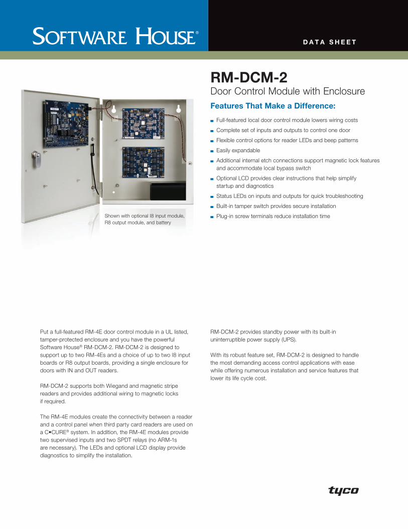
D A T A s h e e T
RM-DCM-2Door Control Module with EnclosureFeatures That Make a Difference:
Full-featured local door control module lowers wiring costs
Complete set of inputs and outputs to control one door
Flexible control options for reader LEDs and beep patterns
Easily expandable
Additional internal etch connections support magnetic lock features and accommodate local bypass switch
Optional LCD provides clear instructions that help simplify startup and diagnostics
Status LEDs on inputs and outputs for quick troubleshooting
Built-in tamper switch provides secure installation
Plug-in screw terminals reduce installation time
Put a full-featured RM-4E door control module in a UL listed, tamper-protected enclosure and you have the powerful Software House® RM-DCM-2. RM-DCM-2 is designed to support up to two RM-4Es and a choice of up to two I8 input boards or R8 output boards, providing a single enclosure for doors with IN and OUT readers.
RM-DCM-2 supports both Wiegand and magnetic stripe readers and provides additional wiring to magnetic locks if required.
The RM-4E modules create the connectivity between a reader and a control panel when third party card readers are used on a C•CURE® system. In addition, the RM-4E modules provide two supervised inputs and two SPDT relays (no ARM-1s are necessary). The LEDs and optional LCD display provide diagnostics to simplify the installation.
RM-DCM-2 provides standby power with its built-in uninterruptible power supply (UPS).
With its robust feature set, RM-DCM-2 is designed to handle the most demanding access control applications with ease while offering numerous installation and service features that lower its life cycle cost.
Shown with optional I8 input module, R8 output module, and battery

s p e C i F i C A T i o n s
PhysicalEnclosure Dimensions (H x W x D) . . 356 x 305 x 89 mm
(14 x 12 x 3.5 in) RM-4E Board-Only Dimensions (H x W) . . . . . . . . . . . . . 136 x 181 mm
(5.375 x 7.125 in) Weight (with 4Ah battery) . . . . . . . . .5.9 kg (11 lbs)Weight (without battery) . . . . . . . . . .4.5 kg (8 lbs)Construction . . . . . . . . . . . . . . . . . . . 20 AWG metal wall mounted locking
cabinet with tamper switch on doorEnvironmentalOperating and Storage Temperature . . . . . . . . . . . . . . . . . . . 0 ° to 50°C (32° to 122°F)
5 to 95% RH, non-condensing
ElectricalPower Requirements without Reader or Relays . . . . . . . . . +12 VDC +/- 5% or +24 VDC +/-10%,
280 mA maxPower Requirements, Maximum,with Reader and Relays . . . . . . . . . . +12 VDC +/- 5% or +24 VDC +/-10%,
550 mA maxOutput Relay Power Ratings . . . . . . .Up to 30 VAC/DC, 5A maximumReader LED Output Controls . . . . . .4.0 volts to 5.25 volts, 20mA maxPower Available for Reader . . . . . . . . 5 VDC +/- 10% or 12 VDC +/- 10%,
125mA max (at 5V or 12V)Optional Battery . . . . . . . . . . . . . . . . 12V/4Ah battery provides
nominal 4 hours backup timeRegulatoryUL 294CE, including EN50081-1, EN50130-4, EN50133FCC Part 15 Class ARoHS
CommunicationsCommunications Bus . . . . . . . . . . . . RM bus from iSTAR controller
or apC/8X panelCommunications Type . . . . . . . . . . .RS-485 half duplex, two-wireMaximum Distance . . . . . . . . . . . . . .1,219 m (4,000 ft)
Reader, Inputs & OutputsReader Ports . . . . . . . . . . . . . . . . . .OneReader Support . . . . . . . . . . . . . . . .Wiegand or magnetic stripeReader Control Lines Available . . . . .Red LED, green LED, yellow LED, beeperKeypad Support . . . . . . . . . . . . . . . . Terminals provided for external 3x4
matrix keypadSupervised Inputs . . . . . . . . . . . . . . .Two, double-resistorOutput Relays . . . . . . . . . . . . . . . . . .Two, Form C, dry contactTamper Input . . . . . . . . . . . . . . . . . .One
Indicators and Switches
Three status LEDs for each supervised inputLED on each relay outputLEDs for RS-485 transmit and receiveLED for power-onOptional LCD for diagnosticsEight position dipswitch for feature selection:
• Wiegand/magnetic stripe reader type• Tamper bypass• LED pattern• RM bus termination• Input LED disable
Mounting Specifications
Product offerings and specifications are subject to change without notice. Actual products may vary from photos. Not all products include all features. Availability varies by region; contact your sales representative. Certain product names mentioned herein may be trade names and/or registered trademarks of other companies.
©2008 Tyco International Ltd. and its respective companies. All rights reserved. SH0118-DS-200810-R02-LT-EN
www.swhouse.com
30.48 cm(12.00 in)
26.67 cm(10.50 in)
3.81 cm(1.50 in)
3.175 cm(1.25 in)
33.02 cm(13.00 in)
35.56 cm(14.00 in)

Type 1 Locking Hinge Cover Enclosure w/ Perforated PanelData Sheet
Construction• Covers and bodies are fabricated from code gauge steel
(see chart)• Includes panel grounding hardware kit• Cover has keyed quarter turn lock, two (2) keys are
included• Cover includes foam corner padding• Includes removable 16 gauge white perforated panel• Enclosure body has mounting holes on the back which are
accessible with or without the panel installed.• Cover is secured to the body with a continuous hinge on one
side and a flush latch on the opposite side
Finish• Wash and phosphate undercoat• ANSI 61 gray acrylic electro-coat finish
Accessories• Touch-up paint (84034)• Self-tapping screws (10168)
Application• Houses electrical and electronic controls and
instruments in an environment which does not requireoil, dust, or water tight specifications
• Protects against contact with enclosed equipment
Standards• UL 50 listed, Type 1• CSA C22.2 No. 40 certified, Type 1• Conforms to NEMA standard for Type 1• IEC 60529, IP30
Type
1 E
nclo
sure
s
Catalog Height x Depth x Length PerforatedNumber A x B x C Gauge Panel Size
in. mm in. mm in. mm
12126-1PP 12.00x12.00x6.00 305x305x152 16 1.4 10.25x10.25 260.3x260.3
16126-1PP 16.00x12.00x6.00 406x305x152 16 1.4 13.00x10.50 260.3x260.3
20166-1PP 20.00x16.00x6.00 508x406x152 16 1.4 17.00x14.50 431.8x368.3
24206-1PP 24.00x20.00x6.00 610x508x152 14 1.9 21.00x18.50 5333.4x469.9
36246-1PP 36.00x24.00x6.00 914x610x152 14 1.9 32.00x22.50 812.8x571.5
36306-1PP 36.00x30.00x6.00 914x762x152 14 1.9 32.00x28.50 812.8x723.9
Notes: Cooper B-Line can provide special sizes, finishes and other modifications. Consult the factory for your special requirements.
64
Type 1 Enclosures

Type 1 Locking Hinge Cover Enclosure w/ Perforated PanelIllustration Sheet
Type 1 Enclosures
Drawings for 12126-1PP
Drawings for 16126-1PP, 20166-1PP, 24206-1PP, 36246-1PP, 36306-1PP
key lock quar-ter turn latch
14 gauge panel(optional)
∅ .44mounting hole (2PL)
∅ .44 x .81mounting hole (2PL)
B-3.00
B-**
A-1.25
B-1.25
C-.44
B
C
A A (-*)
.375-16 collar stud and nut(omit center studs where “B”is less than 30)
1.06 if “A” is 24 or less1.25 if “A” is 30 or more
body stiffener(omit where “B” is less than 30)
perforated panel
door stiffener(omit where “B” is less than 30) Section X-X
.375-16 collar stud and nut(omit center studs where “A”is less than 30)
CL
CL
X
X
continuoushinge
perforatedpanel
perforated panel(see hole detaildetail below)
B
B-2.37
C-.50
B-1.12
C
CLAA-2.37
A-1.12
.50
1.50
weldnut(4PL)
∅ .25mountinghole (4PL)
key lock quarterturn latch
.250”
.125”Dia.
60°
.250”
Hole Detail16 Gauge
(.055 - .065) CRSPerforated Sheet
Type 1 Enclosures
65
Notes: Dimensions are in inches. Millimeters shown are for reference only. Data subject to change without notice.

For technical assistance in the U.S., call 866-405-6654 (outside the U.S., see inside back cover for directory)
ELECTRICAL SOLUTIONS
B2.Cable
Accessories
C1.Wiring
Duct
C3.Abrasion
Protection
C4.Cable
Management
D1.Terminals
D2.Power
Connectors
E1.LabelingSystems
E2.Labels
E3.Pre-Printed & Write-On
Markers
F.Index
B3.StainlessSteel Ties
C2.Surface
Raceway
E5.Lockout/Tagout
& SafetySolutions
B1.Cable Ties
A.System
Overview
D3.GroundingConnectors
E4.Permanent
Identification
Panduct ® Type F Narrow Slot Wiring Duct
• Narrow slot/finger design provides more slots to fit the spacing ofhigh-density terminal blocks and other hardware
• Material: Lead-free PVC
• UL recognized continuous use temperature: 122°F (50°C)
• UL 94 flammability rating of V-0
• Conforms with NFPA 79-2007 section 13.3.1 requirement for flame retardant material
• Provided with mounting holes
• Base and cover length is 6 feet
Part number shown for LG (Light Gray). For other color availability see color selection guide, page C1.48.Base and cover sold separately.*“H” dimension includes duct and cover.
W
H
.20 TYP [5.0]
.50 TYP [12.7]
Multiple slot restrictors present with2" and greater duct wall height.
To order cover with protective filmadd “-F” to part number. 6" covernot available with film.
BasePart Number
Duct Size (W x H)* Slot Width CoverPart Number
Std.Pkg.Qty.
BaseCtn.Qty.
CoverCtn.Qty.In. mm In. mm
F.5X.5LG6 0.69 x 0.60 17.5 x 15.2 0.20 5.0 C.5LG6 6 120 120
F.5X1LG6 0.69 x 1.06 17.5 x 26.9 0.20 5.0 C.5LG6 6 120 120
F.75X.75LG6 0.93 x 0.82 23.6 x 20.9 0.20 5.0 C.75LG6 6 120 120
F.75X1.5LG6 0.93 x 1.57 23.6 x 39.9 0.20 5.0 C.75LG6 6 120 120
F1X1LG6 1.26 x 1.13 32.0 x 28.7 0.20 5.0 C1LG6 6 120 120
F1X1.5LG6 1.26 x 1.62 32.0 x 41.1 0.20 5.0 C1LG6 6 120 120
F1X2LG6 1.26 x 2.12 32.0 x 53.8 0.20 5.0 C1LG6 6 120 120
F1X3LG6 1.26 x 3.12 32.0 x 79.2 0.20 5.0 C1LG6 6 120 120
F1X4LG6 1.26 x 4.10 32.0 x 104.1 0.20 5.0 C1LG6 6 60 120
F1.5X1LG6 1.75 x 1.12 44.5 x 28.4 0.20 5.0 C1.5LG6 6 120 120
F1.5X1.5LG6 1.75 x 1.62 44.5 x 41.1 0.20 5.0 C1.5LG6 6 120 120
F1.5X2LG6 1.75 x 2.12 44.5 x 53.8 0.20 5.0 C1.5LG6 6 120 120
F1.5X3LG6 1.75 x 3.12 44.5 x 79.2 0.20 5.0 C1.5LG6 6 120 120
F1.5X4LG6 1.75 x 4.10 44.5 x 104.1 0.20 5.0 C1.5LG6 6 60 120
F2X1LG6 2.25 x 1.12 57.2 x 28.4 0.20 5.0 C2LG6 6 120 120
F2X1.5LG6 2.25 x 1.62 57.2 x 41.1 0.20 5.0 C2LG6 6 120 120
F2X2LG6 2.25 x 2.12 57.2 x 53.8 0.20 5.0 C2LG6 6 120 120
F2X3LG6 2.25 x 3.12 57.2 x 79.2 0.20 5.0 C2LG6 6 60 120
F2X4LG6 2.25 x 4.10 57.2 x 104.1 0.20 5.0 C2LG6 6 60 120
F2X5LG6 2.25 x 5.10 57.2 x 129.5 0.20 5.0 C2LG6 6 60 120
F2.5X3LG6 2.75 x 3.12 69.9 x 79.2 0.20 5.0 C2.5LG6 6 120 120
F3X1LG6 3.25 x 1.12 82.6 x 28.4 0.20 5.0 C3LG6 6 120 120
F3X2LG6 3.25 x 2.12 82.6 x 53.8 0.20 5.0 C3LG6 6 120 120
F3X3LG6 3.25 x 3.12 82.6 x 79.2 0.20 5.0 C3LG6 6 60 120
F3X4LG6 3.25 x 4.10 82.6 x 104.1 0.20 5.0 C3LG6 6 60 120
F3X5LG6 3.25 x 5.10 82.6 x 129.5 0.20 5.0 C3LG6 6 60 120
F4X2LG6 4.25 x 2.12 108.0 x 53.8 0.20 5.0 C4LG6 6 60 120
F4X3LG6 4.25 x 3.12 108.0 x 79.2 0.20 5.0 C4LG6 6 60 120
F4X4LG6 4.25 x 4.10 108.0 x 104.1 0.20 5.0 C4LG6 6 60 120
F4X5LG6 4.25 x 5.10 108.0 x 129.5 0.20 5.0 C4LG6 6 60 120
F6X4LG6 6.25 x 4.15 158.8 x 105.4 0.20 5.0 C6LG6 6 60 120

Type 1 Screw Cover Wireway - Painted & GalvanizedData Sheet
Construction• Wireway body and cover are fabricated from code gauge steel
or galvanized steel, (see table)• Wireway body has mounting holes on the back• Wireway is available with or without knockouts on the top and
bottom sides• Wireway fittings have no knockouts, ends are available with or
without knockouts• Cover is secured to the body with plated screws• Keyhole slots are furnished on the wireway cover which allow
easy access to the inside without removing the screws• Flush and surface wireway covers are available• Wireway exceeding 72 inches in length has two overlapping
covers• Variety of fittings allow runs which can change direction,
junction and terminate• Standard wireway connectors (sold separately) have a unique
gate feature which can swing completely open allowing forcontinuous runs of wire and cable
• Universal connectors are also available for adapting to othermanufacturer’s wireway, (see table, page 16)
• Completely interchangeable with Type 1 Hinge Cover Wirewayand Fittings
Application• Houses runs of control and power cable• Used for cable and wire junction, distribution and
termination
Standards• UL 870 listed, Type 1• CSA C22.2 No. 26 certified, Type 1• Conforms to NEMA standard for Type 1• IEC 60529, IP30
Finish• Wash and phosphate undercoat or galvanized steel• ANSI 61 gray acrylic electrocoat finish
Accessories• Sealing devices• Touch-up paint• See Accessories section
Notes: Cooper B-Line can provide special sizes, finishes and other modifications. Consult the factory for your special requirements.
12
WirewayW
irewa
y

See page 14 for 8”x8” through 12”x12” wireway.
Type 1 Screw Cover Wireway - Painted & GalvanizedCatalog Number
Wireway Catalog Number Wireway Size KnockoutQuantity
Painted Galvanized Height x Depth x LengthA x B x C D
KO No KO KO No KO in. mm in. mm Gauge Top Bottom2212 G 2212 G NK 2212 GGV 2212 GGV NK 2.50x2.50x12.00 64x64x305 1.25 32 16 3 3
2218 G 2218 G NK 2218 GGV 2218 GGV NK 2.50x2.50x18.00 64x64x457 1.25 32 16 5 5
2224 G 2224 G NK 2224 GGV 2224 GGV NK 2.50x2.50x24.00 64x64x610 1.25 32 16 7 7
2236 G 2236 G NK 2236 GGV 2236 GGV NK 2.50x2.50x36.00 64x64x914 1.25 32 16 11 11
2248 G 2248 G NK 2248 GGV 2248 GGV NK 2.50x2.50x48.00 64x64x1219 1.25 32 16 15 15
2260 G 2260 G NK 2260 GGV 2260 GGV NK 2.50x2.50x60.00 64x64x1524 1.25 32 16 19 19
2272 G 2272 G NK 2272 GGV 2272 GGV NK 2.50x2.50x72.00 64x64x1829 1.25 32 16 23 23
22120 G 22120 G NK 22120 GGV 22120 GGV NK 2.50x2.50x120.00 64x64x3048 1.25 32 16 39 39
3312 G 3312 G NK 3312 GGV 3312 GGV NK 3.00x3.00x12.00 76x76x305 1.50 38 16 3 3
3318 G 3318 G NK 3318 GGV 3318 GGV NK 3.00x3.00x18.00 76x76x457 1.50 38 16 5 5
3324 G 3324 G NK 3324 GGV 3324 GGV NK 3.00x3.00x24.00 76x76x610 1.50 38 16 7 7
3336 G 3336 G NK 3336 GGV 3336 GGV NK 3.00x3.00x36.00 76x76x914 1.50 38 16 11 11
3348 G 3348 G NK 3348 GGV 3348 GGV NK 3.00x3.00x48.00 76x76x1219 1.50 38 16 15 15
3360 G 3360 G NK 3360 GGV 3360 GGV NK 3.00x3.00x60.00 76x76x1524 1.50 38 16 19 19
3372 G 3372 G NK 3372 GGV 3372 GGV NK 3.00x3.00x72.00 76x76x1829 1.50 38 16 23 23
33120 G 33120 G NK 33120 GGV 33120 GGV NK 3.00x3.00x120.00 76x76x3048 1.50 38 16 39 39
4412 G 4412 G NK 4412 GGV 4412 GGV NK 4.00x4.00x12.00 102x102x305 2.75 70 16 3 3
4418 G 4418 G NK 4418 GGV 4418 GGV NK 4.00x4.00x18.00 102x102x457 2.75 70 16 5 5
4424 G 4424 G NK 4424 GGV 4424 GGV NK 4.00x4.00x24.00 102x102x610 2.75 70 16 7 7
4436 G 4436 G NK 4436 GGV 4436 GGV NK 4.00x4.00x36.00 102x102x914 2.75 70 16 11 11
4448 G 4448 G NK 4448 GGV 4448 GGV NK 4.00x4.00x48.00 102x102x1219 2.75 70 16 15 15
4460 G 4460 G NK 4460 GGV 4460 GGV NK 4.00x4.00x60.00 102x102x1524 2.75 70 16 19 19
4472 G 4472 G NK 4472 GGV 4472 GGV NK 4.00x4.00x72.00 102x102x1829 2.75 70 16 23 23
44120 G 44120 G NK 44120 GGV 44120 GGV NK 4.00x4.00x120.00 102x102x3048 2.75 70 16 39 39
6412 G 6412 G NK 6412 GGV 6412 GGV NK 6.00x4.00x12.00 152x102x305 4.25 108 16 3 3
6418 G 6418 G NK 6418 GGV 6418 GGV NK 6.00x4.00x18.00 152x102x457 4.25 108 16 5 5
6424 G 6424 G NK 6424 GGV 6424 GGV NK 6.00x4.00x24.00 152x102x610 4.25 108 16 7 7
6436 G 6436 G NK 6436 GGV 6436 GGV NK 6.00x4.00x36.00 152x102x914 4.25 108 16 11 11
6448 G 6448 G NK 6448 GGV 6448 GGV NK 6.00x4.00x48.00 152x102x1219 4.25 108 16 15 15
6460 G 6460 G NK 6460 GGV 6460 GGV NK 6.00x4.00x60.00 152x102x1524 4.25 108 16 19 19
6472 G 6472 G NK 6472 GGV 6472 GGV NK 6.00x4.00x72.00 152x102x1829 4.25 108 16 23 23
64120 G 64120 G NK 64120 GGV 64120 GGV NK 6.00x4.00x120.00 152x102x3048 4.25 108 16 39 39
6612 G 6612 G NK 6612 GGV 6612 GGV NK 6.00x6.00x12.00 152x152x305 4.25 108 16 3 3
6618 G 6618 G NK 6618 GGV 6618 GGV NK 6.00x6.00x18.00 152x152x457 4.25 108 16 5 5
6624 G 6624 G NK 6624 GGV 6624 GGV NK 6.00x6.00x24.00 152x152x610 4.25 108 16 7 7
6636 G 6636 G NK 6636 GGV 6636 GGV NK 6.00x6.00x36.00 152x152x914 4.25 108 16 11 11
6648 G 6648 G NK 6648 GGV 6648 GGV NK 6.00x6.00x48.00 152x152x1219 4.25 108 16 15 15
6660 G 6660 G NK 6660 GGV 6660 GGV NK 6.00x6.00x60.00 152x152x1524 4.25 108 16 19 19
6672 G 6672 G NK 6672 GGV 6672 GGV NK 6.00x6.00x72.00 152x152x1829 4.25 108 16 23 23
66120 G 66120 G NK 66120 GGV 66120 GGV NK 6.00x6.00x120.00 152x152x3048 4.25 108 16 39 39
Wireway
13
Notes: Dimensions are in inches. Millimeters shown are for reference only. Data subject to change without notice.
Wireway

Type 1 Screw Cover Wireway - Painted & GalvanizedCatalog Number
Wireway Catalog Number Wireway Size KnockoutQuantity
Painted Galvanized Height x Depth x LengthA x B x C D
KO No KO KO No KO in. mm in. mm Gauge Top Bottom8812 G 8812 G NK 8812 GGV 8812 GGV NK 8.00x8.00x12.00 203x203x305 6.00 152 14 3 3
8818 G 8818 G NK 8818 GGV 8818 GGV NK 8.00x8.00x18.00 203x203x457 6.00 152 14 5 5
8824 G 8824 G NK 8824 GGV 8824 GGV NK 8.00x8.00x24.00 203x203x610 6.00 152 14 7 7
8836 G 8836 G NK 8836 GGV 8836 GGV NK 8.00x8.00x36.00 203x203x914 6.00 152 14 11 11
8848 G 8848 G NK 8848 GGV 8848 GGV NK 8.00x8.00x48.00 203x203x1219 6.00 152 14 15 15
8860 G 8860 G NK 8860 GGV 8860 GGV NK 8.00x8.00x60.00 203x203x1524 6.00 152 14 19 19
8872 G 8872 G NK 8872 GGV 8872 GGV NK 8.00x8.00x72.00 203x203x1829 6.00 152 14 23 23
88120 G 88120 G NK 88120 GGV 88120 GGV NK 8.00x8.00x120.00 203x203x3048 6.00 152 14 39 39
101012 G 101012 G NK 101012 GGV 101012 GGV NK 10.00x10.00x12.00 254x254x305 8.00 203 14 3 3
101024 G 101024 G NK 101024 GGV 101024 GGV NK 10.00x10.00x24.00 254x254x610 8.00 203 14 7 7
101036 G 101036 G NK 101036 GGV 101036 GGV NK 10.00x10.00x36.00 24x254x914 8.00 203 14 11 11
101048 G 101048 G NK 101048 GGV 101048 GGV NK 10.00x10.00x48.00 254x254x1219 8.00 203 14 15 15
101060 G 101060 G NK 101060 GGV 101060 GGV NK 10.00x10.00x60.00 254x254x1524 8.00 203 14 19 19
101072 G 101072 G NK 101072 GGV 101072 GGV NK 10.00x10.00x72.00 254x254x1829 8.00 203 14 23 23
1010120 G 1010120 G NK 1010120 GGV 1010120 GGV NK 10.00x10.00x120.00 254x254x3048 8.00 203 14 39 39
121212 G 121212 G NK 121212 GGV 121212 GGV NK 12.00x12.00x12.00 305x305x305 10.00 254 14 3 3
121224 G 121224 G NK 121224 GGV 121224 GGV NK 12.00x12.00x24.00 305x305x610 10.00 254 14 7 7
121236 G 121236 G NK 121236 GGV 121236 GGV NK 12.00x12.00x36.00 305x305x914 10.00 254 14 11 11
121248 G 121248 G NK 121248 GGV 121248 GGV NK 12.00x12.00x48.00 305x305x1219 10.00 254 14 15 15
121260 G 121260 G NK 121260 GGV 121260 GGV NK 12.00x12.00x60.00 305x3051524 10.00 254 14 19 19
121272 G 121272 G NK 121272 GGV 121272 GGV NK 12.00x12.00x72.00 305x305x1829 10.00 254 14 23 23
1212120 G 1212120 G NK 1212120 GGV 1212120 GGV NK 12.00x12.00x120.00 305x305x3048 10.00 254 14 39 39
14
Wireway
Notes: Dimensions are in inches. Millimeters shown are for reference only. Data subject to change without notice.
Wire
way

Type 1 Screw Cover Wireway Fittings - Painted & GalvanizedCatalog Number
Telescopic FittingCatalog Number A B1 B2 C
Painted Galvanized in. mm in. mm in. mm in. mm22 FTF 22 FTFGV 2.75 70 1.75 44 1.12 28 12.00 305
33 FTF 33 FTFGV 3.25 83 2.25 57 1.12 28 12.00 305
44 FTF 44 FTFGV 4.25 108 3.25 83 1.12 28 12.00 305
64 FTF 64 FTFGV 6.25 159 3.25 83 1.12 28 12.00 305
66 FTF 66 FTFGV 6.25 159 5.25 133 1.12 28 12.00 305
88 FTF 88 FTFGV 8.25 210 7.25 184 1.12 28 12.00 305
1010 FTF 1010 FTFGV 10.25 260 9.25 235 1.12 28 12.00 305
1212 FTF 1212 FTFGV 12.25 311 11.25 286 1.12 28 12.00 305
EndCatalog Number A B
KO No KO KO No KOPainted Galvanized in. mm in. mm
22 E 22 E NK 22 EGV 22 EGV NK 2.50 64 2.50 64
33 E 33 E NK 33 EGV 33 EGV NK 3.00 76 3.00 76
44 E 44 E NK 44 EGV 44 EGV NK 4.00 102 4.00 102
64 E 64 E NK 64 EGV 64 EGV NK 6.00 152 4.00 102
66 E 66 E NK 66 EGV 66 EGV NK 6.00 152 6.00 152
88 E 88 E NK 88 EGV 88 EGV NK 8.00 203 8.00 203
1010 E 1010 E NK 1010 EGV 1010 EGV NK 10.00 254 10.00 254
1212 E 1212 E NK 1212 EGV 1212 EGV NK 12.00 305 12.00 305
See drawing for KO sizes.
Wireway HangerCatalog Number G H J K
Painted Galvanized in. mm in. mm in. mm in. mm22 FH 22 FHGV 8.50 216 6.50 165 6.50 165 2.87 73
33 FH 33 FHGV 10.50 267 8.50 216 9.00 229 3.87 98
44 FH 44 FHGV 12.50 318 10.50 267 10.37 263 4.87 124
66 FH 66 FHGV 16.50 419 14.50 368 13.50 343 5.87 149
88 FH 88 FHGV 20.50 521 18.50 470 16.75 425 6.87 174
1010 FH* 1010 FHGV* 24.50 622 22.50 572 19.75 502 7.87 200
1212 FH* 1212 FHGV* 28.50 724 26.50 673 22.75 578 8.87 225
*Hangers are shipped welded in the top cover assembly position.
90° Elbow - Tee - CrossCatalog Number A B C
Painted Galvanized in. mm in. mm in. mm22 LTX 22 LTXGV 2.50 64 2.50 64 4.50 114
33 LTX 33 LTXGV 3.00 76 3.00 76 5.00 127
44 LTX 44 LTXGV 4.00 102 4.00 102 6.00 152
64 LTX 64 LTXGV 6.00 152 4.00 102 8.00 203
66 LTX 66 LTXGV 6.00 152 6.00 152 8.00 203
88 LTX 88 LTXGV 8.00 203 8.00 203 10.00 254
1010 LTX 1010 LTXGV 10.00 254 10.00 254 12.00 305
1212 LTX 1212 LTXGV 12.00 305 12.00 305 14.00 356
ConnectorCatalog Number A B
in. mm in. mm22 C 2.50 64 2.50 64
33 C 3.00 76 3.00 76
44 C 4.00 102 4.00 102
64 C 6.00 152 4.00 102
66 C 6.00 152 6.00 152
88 C 8.00 203 8.00 203
1010 C 10.00 254 10.00 254
1212 C 12.00 305 12.00 305
ReducerCatalog Number A1 B1 A2 B2 C
Painted Galvanized in. mm in. mm in. mm in. mm in. mm
2233 FR 2233 FRGV 2.50 64 2.50 64 3.00 76 3.00 76 6.00 152
3344 FR 3344 FRGV 3.00 76 3.00 76 4.00 102 4.00 102 8.00 203
4466 FR 4466 FRGV 4.00 102 4.00 102 6.00 152 6.00 152 10.00 254
6688 FR 6688 FRGV 6.00 152 6.00 152 8.00 203 8.00 203 12.00 305
881010 FR 881010 FRGV 8.00 203 8.00 203 10.00 254 10.00 254 12.00 305
10101212 FR 10101212 FRGV 10.00 254 10.00 254 12.00 305 12.00 305 16.00 406
Wireway End FlangeCatalog Number A B E F
Painted Galvanized in. mm in. mm in. mm in. mm22 GF 22 GFGV 2.50 64 2.50 64 4.00 102 4.00 102
33 GF 33 GFGV 3.00 76 3.00 76 4.50 114 4.50 114
44 GF 44 GFGV 4.00 102 4.00 102 5.50 140 5.50 140
64 GF 64 GFGV 6.00 152 4.00 102 7.50 191 5.50 140
66 GF 66 GFGV 6.00 152 6.00 152 7.50 191 7.50 191
88 GF 88 GFGV 8.00 203 8.00 203 9.50 241 9.50 241
1010 GF 1010 GFGV 10.00 254 10.00 254 11.50 292 11.50 292
1212 GF 1212 GFGV 12.00 305 12.00 305 13.50 343 13.50 343
90° ElbowCatalog Number A B C E F
Painted Galvanized in. mm in. mm in. mm in. mm in. mm
22 L COMBO 22 L COMBOGV 2.50 64 2.50 64 5.59 142 4.28 109 4.28 109
33 L COMBO 33 L COMBOGV 3.00 76 3.00 76 6.09 155 4.50 114 4.50 114
44 L COMBO 44 L COMBOGV 4.00 102 4.00 102 7.09 180 5.00 127 5.00 127
64 L COMBO 64 L COMBOGV 4.00 102 6.00 152 10.09 256 5.00 127 5.00 127
66 L COMBO 66 L COMBOGV 6.00 152 6.00 152 10.09 256 7.00 178 7.00 178
88 L COMBO 88 L COMBOGV 8.00 203 8.00 203 12.09 307 8.00 203 8.00 203
1010 L COMBO 1010 L COMBOGV 10.00 254 10.00 254 14.09 358 9.00 229 9.00 229
1212 L COMBO 1212 L COMBOGV 12.00 305 12.00 305 16.09 409 10.00 254 10.00 254
22 L SIDE 22 L SIDEGV 2.50 64 2.50 64 5.59 142 4.28 109 4.28 109
33 L SIDE 33 L SIDEGV 3.00 76 3.00 76 6.09 155 4.50 114 4.50 114
44 L SIDE 44 L SIDEGV 4.00 102 4.00 102 7.09 180 5.00 127 5.00 127
64 L SIDE 64 L SIDEGV 6.00 152 4.00 102 10.09 256 7.00 178 7.00 178
66 L SIDE 66 L SIDEGV 6.00 152 6.00 152 10.09 256 7.00 178 7.00 178
88 L SIDE 88 L SIDEGV 8.00 203 8.00 203 12.09 307 8.00 203 8.00 203
1010 L SIDE 1010 L SIDEGV 10.00 254 10.00 254 14.09 358 10.00 254 9.00 229
1212 L SIDE 1212 L SIDEGV 12.00 305 12.00 305 16.09 409 10.00 254 10.00 254
22 L SWEEP 22 L SWEEPGV 2.50 64 2.50 64 5.63 143 4.25 108 4.25 108
33 L SWEEP 33 L SWEEPGV 3.00 76 3.00 76 8.41 214 6.84 174 6.84 174
44 L SWEEP 44 L SWEEPGV 4.00 102 4.00 102 9.41 239 7.34 186 7.34 186
64 L SWEEP 64 L SWEEPGV 6.00 152 4.00 102 11.41 290 8.34 212 8.34 212
66 L SWEEP 66 L SWEEPGV 6.00 152 6.00 152 11.41 290 8.34 212 8.34 212
88 L SWEEP 88 L SWEEPGV 8.00 203 8.00 203 13.41 341 9.34 237 9.34 237
1010 L SWEEP 1010 L SWEEPGV 10.00 254 10.00 254 15.41 391 10.34 263 10.34 263
1212 L SWEEP 1212 L SWEEPGV 12.00 305 12.00 305 17.41 442 11.34 288 11.34 288
Wireway
15
Notes: Dimensions are in inches. Millimeters shown are for referenceonly. Data subject to change without notice.
Wireway

Type 1 Screw Cover Wireway Fittings - Painted & GalvanizedCatalog Number
45° ElbowCatalog Number A B E F
Painted Galvanized in. mm in. mm in. mm in. mm
2245 L COMBO 2245 L COMBOGV 2.50 64 2.50 64 1.72 44 1.72 44
3345 L COMBO 3345 L COMBOGV 3.00 76 3.00 76 2.56 65 2.56 65
4445 L COMBO 4445 L COMBOGV 4.00 102 4.00 102 2.75 70 2.75 70
6445 L COMBO 6445 L COMBOGV 4.00 102 6.00 153 2.75 70 2.75 70
6645 L COMBO 6645 L COMBOGV 6.00 153 6.00 153 3.18 81 3.18 81
8845 L COMBO 8845 L COMBOGV 8.00 203 8.00 203 3.62 92 3.62 92
101045 L COMBO 101045 L COMBOGV 10.00 254 10.00 254 4.06 103 4.06 103
121245 L COMBO 121245 L COMBOGV 12.00 305 12.00 305 4.50 114 4.50 114
2245 L SIDE 2245 L SIDEGV 2.50 64 2.50 64 1.97 50 1.97 50
3345 L SIDE 3345 L SIDEGV 3.00 76 3.00 76 2.56 65 2.56 65
4445 L SIDE 4445 L SIDEGV 4.00 102 4.00 102 2.75 70 2.75 70
6445 L SIDE 6445 L SIDEGV 6.00 153 4.00 102 3.18 81 3.18 81
6645 L SIDE 6645 L SIDEGV 6.00 153 6.00 153 3.18 81 3.18 81
8845 L SIDE 8845 L SIDEGV 8.00 203 8.00 203 3.62 92 3.62 92
101045 L SIDE 101045 L SIDEGV 10.00 254 10.00 254 4.06 103 4.06 103
121245 L SIDE 121245 L SIDEGV 12.00 305 12.00 305 4.50 114 4.50 114
TeeCatalog Number A B E F
Painted Galvanized in. mm in. mm in. mm in. mm22 T 22 TGV 2.50 64 2.50 64 4.25 108 4.25 108
33 T 33 TGV 3.00 76 3.00 76 4.50 114 4.50 114
44 T 44 TGV 4.00 102 4.00 102 5.00 127 5.00 127
64 T 64 TGV 6.00 153 4.00 102 7.00 178 7.00 178
66 T 66 TGV 6.00 153 6.00 153 7.00 178 7.00 178
88 T 88 TGV 8.00 203 8.00 203 8.00 203 8.00 203
1010 T 1010 TGV 10.00 254 10.00 254 9.00 229 9.00 229
1212 T 1212 TGV 12.00 305 12.00 305 10.00 254 10.00 254
CrossCatalog Number A B E F
Painted Galvanized in. mm in. mm in. mm in. mm22 X 22 XGV 2.50 64 2.50 64 4.25 108 4.25 108
33 X 33 XGV 3.00 76 3.00 76 5.62 143 5.62 143
44 X 44 XGV 4.00 102 4.00 102 6.12 155 6.12 155
64 X 64 XGV 6.00 152 4.00 152 7.12 181 7.12 181
66 X 66 XGV 6.00 152 6.00 152 7.12 181 7.12 181
88 X 88 XGV 8.00 203 8.00 203 8.12 206 8.12 206
1010 X 1010 XGV 10.00 254 10.00 254 9.12 232 9.12 232
1212 X 1212 XGV 12.00 305 12.00 305 10.12 257 10.12 25
Barrier Kit, 60” Bolt-OnCatalog Number Size Length H
in. mm in. mm in. mm22-12BK* 2.50x2.50 64x64 60.00 1524 1.88 48
33-12BK* 3.00x3.00 76x76 60.00 1524 2.25 57
44-12BK* 4.00x4.00 102x102 60.00 1524 3.00 76
66-12BK* 6.00x6.00 152x152 60.00 1524 4.50 114
88-12BK* 8.00x8.00 203x203 60.00 1524 6.00 152
1010-12BK* 10.00x10.00 254x254 60.00 1524 8.00 203
1212-12BK* 12.00x12.00 305x305 60.00 1524 10.50 267
*Not UL or CSA listed fitting.
Type 1 Wireway Competitor Adapters
Wireway Hoffman®1 Wiegmann®2 Square D®3 Unity®4 Electrical Box Austin®6Size
in. mm and Enclosures®5
2.5x2.5 64x64 22 CA 22 CA 22 CA 22 CA - 22 ACA
4x4 102x102 44 CA 44 CA 44 CA 44 CA 44 CA 44 ACA
6x6 152x152 66 CA 66 CA 66 CA 66 CA 66 CA 66 ACA
8x8 203x203 88 CA 88 CA 88 SCA 88 CA 88 CA 88 ACA
10x10 254x254 1010 CA 1010 CA 1010 SCA 1010 CA 1010 CA 1010 ACA
12x12 305x305 1212 CA 1212 CA 1212 SCA 1212 CA 1212 CA 1212 ACA
1. HOFFMAN® is the registered trademark of Hoffman Engineering Company, Anoka, Minnesota.2. WIEGMANN® is the registered trademark of Hubbell Incorporated, Orange, Connecticut.3. SQUARE D® is the registered trademark of Square D Company, Palatine, Illinois.4. UNITY® is the registered trademark of Unity Manufacturing, Garland, Texas.5. ELECTRICAL BOX AND ENCLOSURES® is the registered trademark of Electrical Box and
Enclosures, Alabaster, Alabama.6. AUSTIN® is the registered trademark of The Austin Co., Yadkinville, North Carolina.
16
Wireway
Notes: Dimensions are in inches. Millimeters shown are for reference only. Data subject to change without notice.
Wire
way

Type 1 Screw Cover Wireway - Painted & GalvanizedIllustration Sheet
90˚ Elbow
45˚ Elbow
Cross
Reducer Fitting
3.00(76) typ.
spacing
3.00(76) typ.
spacing
Tee
Wireway Side
3.00(76)
B 1.25(32)
1.56(40)
E F
J J JH HKnockout sizes:H = 3/4” or 1/2” conduitJ = 11/4” or 1” conduit
H
E
F
E
E
.75(19)
.75(19)
F F
E
F F
A2 A1
C
mounting holecover screw Wireway Front
C-4.00(102)
C
A D
Note: 2.50” x 2.50” wireway has 1/2” and 3/4” 2-way knockoutsonly, 3” (76 mm) from ends and 3” (76 mm) on center.Additional mounting holes are furnished when C dimensionis over 60.00" (1524 mm).
Wireway
17
Notes: Dimensions are in inches. Millimeters shown are for reference only. Data subject to change without notice.
Wireway

ConnectorSwing gate allowsfor continuous runsof wire and cable.
B
A
Barrier, Bolt-OnFor those installationsthat require separatedwiring compartments.
EndUsed to terminate wireway or fitting.2.50”x2.50” (64 mm x 64 mm) through8.00”x8.00” (203 mm x 203 mm) endshave a 1.50”-1.25” concentric 2-way KO.10.00” x 10.00” (254 mm x 254 mm) endsand larger have a 3.00”-2.50” concentric 2-way KO for terminating onpipe or conduit. Also available withoutKO.
B
A
Wireway End FlangeAllows for a secure connec-tion of wireway to an adjoin-ing enclosure or wall.
F
E
B
A
Telescopic FittingAdjustable length up to 10.00”(254 mm). Wraps around the twonear joining wireway lengths toachieve a continuous run.
C
A
B1
B2
ReducerA2 and B2 dimensions (see catalogtable), correspond to the large endopening. Used to reduce or enlargewireway runs.
C
A1
B1
Top Cover AssemblyFor those installations where thewireway cover must be removedfrom the top.*1010 FH & 1212 FHare shipped welded in the topcover assembly position.
Wireway Hangers
(shippedunassembled)*
J
K
G
K
G
∅ .25
∅ .45
H
Side Cover AssemblyFor those installations where thewireway cover must be removed from the side. *1010 FH &1212 FH are shipped welded inthe top cover assembly position.
Wireway SectionLengths from 12.00” (305 mm) to120.00” (3048 mm). Wirewayexceeding 72.00” (1829 mm) hastwo covers. Shown with KO’salso available without.
B
A
C
Type 1 Screw Cover Wireway - Painted & GalvanizedIllustration Sheet
60.00(1524)
H.875(22)
.875(22)
18
Wireway
Notes: Dimensions are in inches. Millimeters shown are for reference only. Data subject to change without notice.
Wire
way

Type 1 Screw Cover Wireway - Painted & GalvanizedIllustration Sheet
90° Elbow-Tee-CrossDesigned for left or right 90°turns or as a tee or cross byremoving closure plates.Includes two (2) closureplates and hardware.
Wireway 90˚ Elbows
Wireway 45˚ Elbows
Sweep ElbowSide cover design with a largerradius for 90° sweeping turns.
CrossSide cover and broad bodydesign to junction cable runin four directions.
A
B
TeeSide cover design where a “T”junction is necessary.
A
B
Side OpeningSimilar to the 90˚ side openingdesign except for a 45˚ turn.Excellent for combining two tomake a gradual sweeping 90˚turn.
A
B
Combo OpeningSimilar to the 90˚ elbowdesign except a 45˚ turn.Both inside and outsidecovers removable.
A
B
A
B
Side OpeningSide cover is removable to allowa continuous run on designswith 90˚ turns.
A
CC
B
Combo OpeningSpecially designed for remov-ing either the inside or outsidecover to allow a continuous runwith 90˚ turns.
B
A
CC
CC
A
B
Wireway
19
Notes: Dimensions are in inches. Millimeters shown are for reference only. Data subject to change without notice.
Wireway

PHOENIX CONTACT Inc., USA Page 1 / 9http://www.phoenixcon.com Jun 30, 2011
Extract from the onlinecatalog
QTC 1,5/ 1POrder No.: 3050073
http://eshop.phoenixcontact.de/phoenix/treeViewClick.do?UID=3050073
Commercial data
GTIN (EAN)
4 017918 975784
sales group A770
Pack 50 pcs.
Customs tariff 85369010
Catalog page information Page 316 (CL1-2011)
Product notes
WEEE/RoHS-compliant since:01/01/2003
http://www.download.phoenixcontact.comPlease note that the data givenhere has been taken from theonline catalog. For comprehensiveinformation and data, please referto the user documentation. TheGeneral Terms and Conditions ofUse apply to Internet downloads.
Technical data
General
Number of levels 1
Number of connections 2
Color gray
Insulating material PA
Inflammability class acc. to UL 94 V0
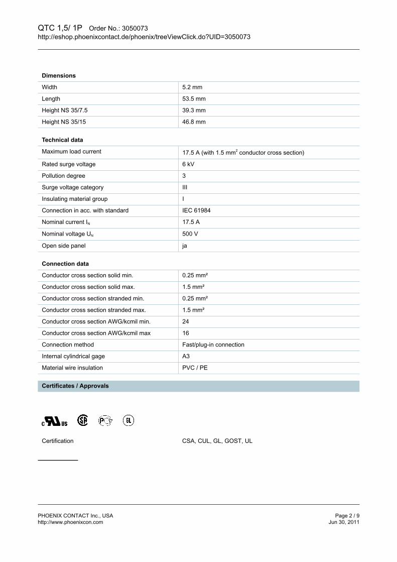
QTC 1,5/ 1P Order No.: 3050073http://eshop.phoenixcontact.de/phoenix/treeViewClick.do?UID=3050073
PHOENIX CONTACT Inc., USA Page 2 / 9http://www.phoenixcon.com Jun 30, 2011
Dimensions
Width 5.2 mm
Length 53.5 mm
Height NS 35/7.5 39.3 mm
Height NS 35/15 46.8 mm
Technical data
Maximum load current 17.5 A (with 1.5 mm2 conductor cross section)
Rated surge voltage 6 kV
Pollution degree 3
Surge voltage category III
Insulating material group I
Connection in acc. with standard IEC 61984
Nominal current IN 17.5 A
Nominal voltage UN 500 V
Open side panel ja
Connection data
Conductor cross section solid min. 0.25 mm²
Conductor cross section solid max. 1.5 mm²
Conductor cross section stranded min. 0.25 mm²
Conductor cross section stranded max. 1.5 mm²
Conductor cross section AWG/kcmil min. 24
Conductor cross section AWG/kcmil max 16
Connection method Fast/plug-in connection
Internal cylindrical gage A3
Material wire insulation PVC / PE
Certificates / Approvals
Certification CSA, CUL, GL, GOST, UL

QTC 1,5/ 1P Order No.: 3050073http://eshop.phoenixcontact.de/phoenix/treeViewClick.do?UID=3050073
PHOENIX CONTACT Inc., USA Page 3 / 9http://www.phoenixcon.com Jun 30, 2011
Accessories
Item Designation Description
Assembly
3206209 ATP-QTC Partition plate, Length: 64.4 mm, Width: 2 mm, Height: 46 mm,Color: gray
3206322 D-QTC 1,5/1P End cover, Length: 53.5 mm, Width: 2.2 mm, Height: 39.3 mm,Color: gray
Bridges
3030161 FBS 2-5 Plug-in bridge, Number of positions: 2, Color: red
3030174 FBS 3-5 Plug-in bridge, Number of positions: 3, Color: red
3030187 FBS 4-5 Plug-in bridge, Number of positions: 4, Color: red
3030190 FBS 5-5 Plug-in bridge, Number of positions: 5, Color: red
3030213 FBS 10-5 Plug-in bridge, Number of positions: 10, Color: red
3030226 FBS 20-5 Plug-in bridge, Number of positions: 20, Color: red
3038930 FBS 50-5 Plug-in bridge, Number of positions: 50, Color: red
Marking
3040588 PC Keying star, Length: 3 mm, Width: 3 mm, Height: 6 mm, Color: red
0818108 UC-TM 5 UniCard materials for labeling terminal blocks with a markergroove,96-section, can be labeled with BLUEMARK and CMS-P1-PLOTTER, color: white
0824581 UC-TM 5 CUS UniCard sheets, for labeling terminal blocks with a zack markerstrip groove, can be printed as per customer requirements
0818153 UC-TMF 5 UniCard materials for labeling terminal blocks using a flat markergroove, 96-section, can be labeled with BLUEMARK and CMS-P1-PLOTTER, color: white
0824638 UC-TMF 5 CUS UniCard sheets, for labeling terminal blocks with a flatzack marker sheet groove, can be printed as per customerrequirements
0828734 UCT-TM 5 UniCard materials for thermal transfer printer, for labeling terminalblocks with a marker groove, 72-section, can be labeled withTHERMOMARK CARD and BLUEMARK LED, color: white
0829595 UCT-TM 5 CUS Terminal block marking, can be labeled as per customerspecifications
0828744 UCT-TMF 5 UniCard materials for thermal transfer printer, for labeling terminalblocks with a horizontal marker groove, 72-section, can be labeledwith THERMOMARK CARD and BLUEMARK LED, color: white
0829658 UCT-TMF 5 CUS Terminal block marking, can be labeled as per customerspecifications

QTC 1,5/ 1P Order No.: 3050073http://eshop.phoenixcontact.de/phoenix/treeViewClick.do?UID=3050073
PHOENIX CONTACT Inc., USA Page 4 / 9http://www.phoenixcon.com Jun 30, 2011
1050004 ZB 5 :UNBEDRUCKT Zack strip, unprinted, 10-section, for individual labeling with M-PEN, ZB-T or CMS system, pack is sufficient for 100 terminalblocks, for a terminal width of 5.2 mm, color: White
Plug/Adapter
3030925 PAI-4 Test adapter, Color: gray
3036709 PS-4/E Test adapter, Color: red
3030983 PS-5 Test adapter, Color: red
Tools
1204517 SZF 1-0,6X3,5 Actuation tool, for ST terminal blocks, also suitable for use as abladed screwdriver, size: 0.6 x 3.5 x 100 mm, 2-component grip,with non-slip grip
Additional products
Item Designation Description
Plug/Adapter
3040258 SP 2,5/ 1 Connectors, Connection method: Spring-cage connection,Number of positions: 1, Cross section: 0.08 mm² - 4 mm²,AWG 28 - 12, Width: 5.2 mm, Height: 39 mm, Color: gray
3040698 SP 2,5/ 1 BU Connectors, Connection method: Spring-cage connection,Number of positions: 1, Cross section: 0.08 mm² - 4 mm²,AWG 28 - 12, Width: 5.2 mm, Height: 39 mm, Color: blue
3040708 SP 2,5/ 1 GNYE Connectors, Connection method: Spring-cage connection,Number of positions: 1, Cross section: 0.08 mm² - 4 mm²,AWG 28 - 12, Width: 5.2 mm, Height: 39 mm, Color: green-yellow
3040261 SP 2,5/ 2 Connectors, Connection method: Spring-cage connection,Number of positions: 2, Cross section: 0.08 mm² - 4 mm²,AWG 28 - 12, Width: 10.4 mm, Height: 39 mm, Color: gray
3040274 SP 2,5/ 3 Connectors, Connection method: Spring-cage connection,Number of positions: 3, Cross section: 0.08 mm² - 4 mm²,AWG 28 - 12, Width: 15.6 mm, Height: 39 mm, Color: gray
3040287 SP 2,5/ 4 Connectors, Connection method: Spring-cage connection,Number of positions: 4, Cross section: 0.08 mm² - 4 mm²,AWG 28 - 12, Width: 20.8 mm, Height: 39 mm, Color: gray
3040290 SP 2,5/ 5 Connectors, Connection method: Spring-cage connection,Number of positions: 5, Cross section: 0.08 mm² - 4 mm²,AWG 28 - 12, Width: 26 mm, Height: 39 mm, Color: gray
3040300 SP 2,5/ 6 Connectors, Connection method: Spring-cage connection,Number of positions: 6, Cross section: 0.08 mm² - 4 mm²,AWG 28 - 12, Width: 31.2 mm, Height: 39 mm, Color: gray
3040313 SP 2,5/ 7 Connectors, Connection method: Spring-cage connection,Number of positions: 7, Cross section: 0.08 mm² - 4 mm²,AWG 28 - 12, Width: 36.4 mm, Height: 39 mm, Color: gray

QTC 1,5/ 1P Order No.: 3050073http://eshop.phoenixcontact.de/phoenix/treeViewClick.do?UID=3050073
PHOENIX CONTACT Inc., USA Page 5 / 9http://www.phoenixcon.com Jun 30, 2011
3040326 SP 2,5/ 8 Connectors, Connection method: Spring-cage connection,Number of positions: 8, Cross section: 0.08 mm² - 4 mm²,AWG 28 - 12, Width: 41.6 mm, Height: 39 mm, Color: gray
3040339 SP 2,5/ 9 Connectors, Connection method: Spring-cage connection,Number of positions: 9, Cross section: 0.08 mm² - 4 mm²,AWG 28 - 12, Width: 46.8 mm, Height: 39 mm, Color: gray
3040342 SP 2,5/10 Connectors, Connection method: Spring-cage connection,Number of positions: 10, Cross section: 0.08 mm² - 4 mm²,AWG 28 - 12, Width: 52 mm, Height: 39 mm, Color: gray
3040355 SP 2,5/11 Connectors, Connection method: Spring-cage connection,Number of positions: 11, Cross section: 0.08 mm² - 4 mm²,AWG 28 - 12, Width: 57.2 mm, Height: 39 mm, Color: gray
3040368 SP 2,5/12 Connectors, Connection method: Spring-cage connection,Number of positions: 12, Cross section: 0.08 mm² - 4 mm²,AWG 28 - 12, Width: 62.4 mm, Height: 39 mm, Color: gray
3040371 SP 2,5/13 Connectors, Connection method: Spring-cage connection,Number of positions: 13, Cross section: 0.08 mm² - 4 mm²,AWG 28 - 12, Width: 67.6 mm, Height: 39 mm, Color: gray
3040384 SP 2,5/14 Connectors, Connection method: Spring-cage connection,Number of positions: 14, Cross section: 0.08 mm² - 4 mm²,AWG 28 - 12, Width: 72.8 mm, Height: 39 mm, Color: gray
3040397 SP 2,5/15 Connectors, Connection method: Spring-cage connection,Number of positions: 15, Cross section: 0.08 mm² - 4 mm²,AWG 28 - 12, Width: 78 mm, Height: 39 mm, Color: gray
3040106 SPB 2,5/ 1 Connectors, Connection method: Spring-cage connection,Number of positions: 1, Cross section: 0.08 mm² - 4 mm²,AWG 28 - 12, Width: 5.2 mm, Height: 39 mm, Color: gray
3040724 SPB 2,5/ 1 BU Connectors, Connection method: Spring-cage connection,Number of positions: 1, Cross section: 0.08 mm² - 4 mm²,AWG 28 - 12, Width: 5.2 mm, Height: 39 mm, Color: blue
3040711 SPB 2,5/ 1 GNYE Connectors, Connection method: Spring-cage connection,Number of positions: 1, Cross section: 0.08 mm² - 4 mm²,AWG 28 - 12, Width: 5.2 mm, Height: 39 mm, Color: green-yellow
3040119 SPB 2,5/ 2 Connectors, Connection method: Spring-cage connection,Number of positions: 2, Cross section: 0.08 mm² - 4 mm²,AWG 28 - 12, Width: 10.4 mm, Height: 39 mm, Color: gray
3040122 SPB 2,5/ 3 Connectors, Connection method: Spring-cage connection,Number of positions: 3, Cross section: 0.08 mm² - 4 mm²,AWG 28 - 12, Width: 15.6 mm, Height: 39 mm, Color: gray
3040135 SPB 2,5/ 4 Connectors, Connection method: Spring-cage connection,Number of positions: 4, Cross section: 0.08 mm² - 4 mm²,AWG 28 - 12, Width: 20.8 mm, Height: 39 mm, Color: gray
3040143 SPB 2,5/ 5 Connectors, Connection method: Spring-cage connection,Number of positions: 5, Cross section: 0.08 mm² - 4 mm²,AWG 28 - 12, Width: 26 mm, Height: 39 mm, Color: gray
3040151 SPB 2,5/ 6 Connectors, Connection method: Spring-cage connection,Number of positions: 6, Cross section: 0.08 mm² - 4 mm²,AWG 28 - 12, Width: 31.2 mm, Height: 39 mm, Color: gray

QTC 1,5/ 1P Order No.: 3050073http://eshop.phoenixcontact.de/phoenix/treeViewClick.do?UID=3050073
PHOENIX CONTACT Inc., USA Page 6 / 9http://www.phoenixcon.com Jun 30, 2011
3040164 SPB 2,5/ 7 Connectors, Connection method: Spring-cage connection,Number of positions: 7, Cross section: 0.08 mm² - 4 mm²,AWG 28 - 12, Width: 36.4 mm, Height: 39 mm, Color: gray
3040177 SPB 2,5/ 8 Connectors, Connection method: Spring-cage connection,Number of positions: 8, Cross section: 0.08 mm² - 4 mm²,AWG 28 - 12, Width: 41.6 mm, Height: 39 mm, Color: gray
3040180 SPB 2,5/ 9 Connectors, Connection method: Spring-cage connection,Number of positions: 9, Cross section: 0.08 mm² - 4 mm²,AWG 28 - 12, Width: 46.8 mm, Height: 39 mm, Color: gray
3040193 SPB 2,5/10 Connectors, Connection method: Spring-cage connection,Number of positions: 10, Cross section: 0.08 mm² - 4 mm²,AWG 28 - 12, Width: 52 mm, Height: 39 mm, Color: gray
3040203 SPB 2,5/11 Connectors, Connection method: Spring-cage connection,Number of positions: 11, Cross section: 0.08 mm² - 4 mm²,AWG 28 - 12, Width: 57.2 mm, Height: 39 mm, Color: gray
3040216 SPB 2,5/12 Connectors, Connection method: Spring-cage connection,Number of positions: 12, Cross section: 0.08 mm² - 4 mm²,AWG 28 - 12, Width: 62.4 mm, Height: 39 mm, Color: gray
3040229 SPB 2,5/13 Connectors, Connection method: Spring-cage connection,Number of positions: 13, Cross section: 0.08 mm² - 4 mm²,AWG 28 - 12, Width: 67.6 mm, Height: 39 mm, Color: gray
3040232 SPB 2,5/14 Connectors, Connection method: Spring-cage connection,Number of positions: 14, Cross section: 0.08 mm² - 4 mm²,AWG 28 - 12, Width: 72.8 mm, Height: 39 mm, Color: gray
3040245 SPB 2,5/15 Connectors, Connection method: Spring-cage connection,Number of positions: 15, Cross section: 0.08 mm² - 4 mm²,AWG 28 - 12, Width: 78 mm, Height: 39 mm, Color: gray
3040407 SPDB 2,5/ 1 Connectors, Connection method: Spring-cage connection,Number of positions: 1, Cross section: 0.08 mm² - 4 mm²,AWG 28 - 12, Width: 5.2 mm, Height: 39 mm, Color: gray
3040737 SPDB 2,5/ 1 BU Connectors, Connection method: Spring-cage connection,Number of positions: 1, Cross section: 0.08 mm² - 4 mm²,AWG 28 - 12, Width: 5.2 mm, Height: 39 mm, Color: blue
3040740 SPDB 2,5/ 1 GNYE Connectors, Connection method: Spring-cage connection,Number of positions: 1, Cross section: 0.08 mm² - 4 mm²,AWG 28 - 12, Width: 5.2 mm, Height: 39 mm, Color: green-yellow
3040410 SPDB 2,5/ 2 Connectors, Connection method: Spring-cage connection,Number of positions: 2, Cross section: 0.08 mm² - 4 mm²,AWG 28 - 12, Width: 10.4 mm, Height: 39 mm, Color: gray
3040423 SPDB 2,5/ 3 Connectors, Connection method: Spring-cage connection,Number of positions: 3, Cross section: 0.08 mm² - 4 mm²,AWG 28 - 12, Width: 15.6 mm, Height: 39 mm, Color: gray
3040436 SPDB 2,5/ 4 Connectors, Connection method: Spring-cage connection,Number of positions: 4, Cross section: 0.08 mm² - 4 mm²,AWG 28 - 12, Width: 20.8 mm, Height: 39 mm, Color: gray
3040449 SPDB 2,5/ 5 Connectors, Connection method: Spring-cage connection,Number of positions: 5, Cross section: 0.08 mm² - 4 mm²,AWG 28 - 12, Width: 26 mm, Height: 39 mm, Color: gray

QTC 1,5/ 1P Order No.: 3050073http://eshop.phoenixcontact.de/phoenix/treeViewClick.do?UID=3050073
PHOENIX CONTACT Inc., USA Page 7 / 9http://www.phoenixcon.com Jun 30, 2011
3040452 SPDB 2,5/ 6 Connectors, Connection method: Spring-cage connection,Number of positions: 6, Cross section: 0.08 mm² - 4 mm²,AWG 28 - 12, Width: 31.2 mm, Height: 39 mm, Color: gray
3040465 SPDB 2,5/ 7 Connectors, Connection method: Spring-cage connection,Number of positions: 7, Cross section: 0.08 mm² - 4 mm²,AWG 28 - 12, Width: 36.4 mm, Height: 39 mm, Color: gray
3040478 SPDB 2,5/ 8 Connectors, Connection method: Spring-cage connection,Number of positions: 8, Cross section: 0.08 mm² - 4 mm²,AWG 28 - 12, Width: 41.6 mm, Height: 39 mm, Color: gray
3040481 SPDB 2,5/ 9 Connectors, Connection method: Spring-cage connection,Number of positions: 9, Cross section: 0.08 mm² - 4 mm²,AWG 28 - 12, Width: 46.8 mm, Height: 39 mm, Color: gray
3040494 SPDB 2,5/10 Connectors, Connection method: Spring-cage connection,Number of positions: 10, Cross section: 0.08 mm² - 4 mm²,AWG 28 - 12, Width: 52 mm, Height: 39 mm, Color: gray
3040504 SPDB 2,5/11 Connectors, Connection method: Spring-cage connection,Number of positions: 11, Cross section: 0.08 mm² - 4 mm²,AWG 28 - 12, Width: 57.2 mm, Height: 39 mm, Color: gray
3040517 SPDB 2,5/12 Connectors, Connection method: Spring-cage connection,Number of positions: 12, Cross section: 0.08 mm² - 4 mm²,AWG 28 - 12, Width: 62.4 mm, Height: 39 mm, Color: gray
3040520 SPDB 2,5/13 Connectors, Connection method: Spring-cage connection,Number of positions: 13, Cross section: 0.08 mm² - 4 mm²,AWG 28 - 12, Width: 67.6 mm, Height: 39 mm, Color: gray
3040533 SPDB 2,5/14 Connectors, Connection method: Spring-cage connection,Number of positions: 14, Cross section: 0.08 mm² - 4 mm²,AWG 28 - 12, Width: 72.8 mm, Height: 39 mm, Color: gray
3040546 SPDB 2,5/15 Connectors, Connection method: Spring-cage connection,Number of positions: 15, Cross section: 0.08 mm² - 4 mm²,AWG 28 - 12, Width: 78 mm, Height: 39 mm, Color: gray
Diagrams/Drawings
Diagram
The figure shows the derating curve of theQTC 1,5/ 1P... terminal block in connectionwith the QP 1,5 connector

QTC 1,5/ 1P Order No.: 3050073http://eshop.phoenixcontact.de/phoenix/treeViewClick.do?UID=3050073
PHOENIX CONTACT Inc., USA Page 8 / 9http://www.phoenixcon.com Jun 30, 2011
Dimensioned drawing
Circuit diagram

QTC 1,5/ 1P Order No.: 3050073http://eshop.phoenixcontact.de/phoenix/treeViewClick.do?UID=3050073
PHOENIX CONTACT Inc., USA Page 9 / 9http://www.phoenixcon.com Jun 30, 2011
Address
PHOENIX CONTACT Inc., USA586 Fulling Mill RoadMiddletown, PA 17057,USAPhone (800) 888-7388Fax (717) 944-1625http://www.phoenixcon.com
© 2011 Phoenix ContactTechnical modifications reserved;

PHOENIX CONTACT Inc., USA Page 1 / 2http://www.phoenixcon.com Jun 30, 2011
Extract from the onlinecatalog
NS 35/ 7,5 WH PERF NZ3178S120A4Order No.: 0800925
http://eshop.phoenixcontact.de/phoenix/treeViewClick.do?UID=0800925
DIN rail, Width: 35 mm, Height: 7.5 mm
Commercial data
GTIN (EAN)
4 017918 254438
Note Made-to-order
sales group B202
Pack 1 m
Customs tariff 72166190
Product notes
WEEE/RoHS-compliant since:01/01/2003
http://www.download.phoenixcontact.comPlease note that the data givenhere has been taken from theonline catalog. For comprehensiveinformation and data, please referto the user documentation. TheGeneral Terms and Conditions ofUse apply to Internet downloads.

NS 35/ 7,5 WH PERF NZ3178S120A4 Order No.: 0800925http://eshop.phoenixcontact.de/phoenix/treeViewClick.do?UID=0800925
PHOENIX CONTACT Inc., USA Page 2 / 2http://www.phoenixcon.com Jun 30, 2011
Address
PHOENIX CONTACT Inc., USA586 Fulling Mill RoadMiddletown, PA 17057,USAPhone (800) 888-7388Fax (717) 944-1625http://www.phoenixcon.com
© 2011 Phoenix ContactTechnical modifications reserved;

The multiCLASS™ family of card readers is designed for customers upgrading their current card system from the most popular proximity technologies to iCLASS® credentials. With the RP40, RPK40 and RP15 readers, the customer has the ability to transition to smart cards over time while incorporating the use of multiple card technologies within a single building or across multiple facilities.
The multiCLASS reader line provides enhanced security through mutual authentication and data encryption. HID, Indala and other popular proximity technologies are supported by multiCLASS. Save on system configuration costs by keeping system upgrade simple. Whether reading proximity, iCLASS or multi-technology cards, identical user identification data formats are sent to the panel. Unlike competitor products, HID multiCLASS readers support all HID and Indala Proximity formats, including Corporate 1000, long and FlexSecur.
Only the multiCLASS family of products provides true iCLASS security, the ease of proximity technology, the power of smart cards and the confidence of choosing HID, the worldwide leader in access control.
Unique Read Selectionw Enable iCLASS, proximity or both technologies at the same time.w Multiple data outputs available when multi-technology card is presented depending on preference.w Configuration cards configure the reader to custom installation requirements.w Reads: 125 kHz – HID, Indala or AWID Proximity 13.56 MHz – iCLASS, ISO 15693 CSN (MyD, ICODE, Tag-it), ISO 14443A CSN (MIFARE® DESFire®), US Government PIV, ISO 14443B CSN, FeliCa™ IDm, CEPAS CAN or CSN
Seamless Upgradew Same HID and Indala Proximity reader features and format compatibilities.wMatching Reader and Credential formats for EM4102 and iCLASS.w Same wiring, power and interface as many popular proximity readers in the market today.w All Corporate 1000 formats can be migrated.w For additional security, our iCLASS Elite program is available with iCLASS credentials.w Wiegand or Clock-and-Data outputs easily interface with existing access control panels.wThe RPK40 combines a contactless card presentation with a personal identification number (PIN)
to support dual factor authentication of identity.wThe RP15 is a mullion form factor drop-in replacement for the HID MiniProx.
13.56 MHz Contactless and 125 kHz Proximity Card Readers • 6125, 6136, 6145
w Simple Migration – From the most popular proximity technologies to iCLASS®.
w GSA-approved – Included in the U.S. General Services Administration (GSA) FIPS 201 Approved Products List.
wDual Factor Authentication (RPK40 only) – Combine contactless card presentation with a PIN.
ACCESS upgrade.
multiCLASS ™ RP15, RP40 and RPK40 Readers
MULTI-TECHNOLOGy
TRANSITION SOLUTION
13.56 MHz Contactless

ACCESS experience. hidglobal.com
64-bit authentication keys are extremely secure. Readers and cards require matching keys to function. All RF data transmission between the card and reader is encrypted, using a secure algorithm. The key management system reduces the risk of compromised data or duplicated cards.
Custom keys provide the highest level of security, where cards and readers are uniquely matched to individual sites or customers, and are non-interchangeable. Combining Elite custom keys with our Corporate 1000 can offer companies a scalable solution that can be implemented in facilities worldwide.
Audio sounder provides various tone sequences to signify access granted, access denied, power up and diagnostics. Visually impaired cardholders can easily distinguish between access granted and access denied. A high-intensity light bar provides a clear visual status indication in red, green or amber, even in bright sunlight. (Note: Light bar will illuminate amber when a PIV/FIPS 201 card is read.)
Features
© 2010 HID Global Corporation. All rights reserved. HID, the HID logo, and iCLASS are trademarks or registered trademarks of HID Global in the U.S. and/or other countries. All other trademarks, service marks, and product or service names are trademarks or registered trademarks of their respective owners. Rev. 04/2010
RP40 multiCLASS™ Reader RPK40 multiCLASS™ Reader with Keypad
RP15 multiCLASS™ Mullion-mount Reader
*Model Number6125C (Wiegand)
6123C (Clock-and-Data)6124C (Transit)
6136C (Wiegand)6133C (Clock-and-Data)
6134C (Transit)
6145C (Wiegand)6143C (Clock-and-Data)
6144C (Transit)
**Read Range
iCLASS Card: 4.0 - 4.5” (10.2 - 11.4 cm) iCLASS Key/Tag: 1.0 - 2.0” (2.5 - 5.0 cm)
HID Prox ISO Card: 2.5 – 3.5” (6.5 - 9.0 cm) HID Prox Clamshell Card: 3.5 – 4.0” (9.0 - 10.0 cm)
HID Prox Keyfob/Tag: 1.0 – 2.25” (2.5 - 5.5 cm) Indala Proximity ISO Card: 1.5 – 2.0” (4.0 - 5.0 cm)
Indala Proximity Clamshell Card: 1.75 – 2.25” (4.5 - 5.5 cm) Indala Proximity Keyfob/Tag: 1.0 – 1.75” (2.5 - 4.5 cm)
iCLASS Card: 3.5 – 4.25” (9.0 - 11.0 cm)iCLASS Key/Tag: 1.0 – 1.5” (2.5 - 4.0 cm)
HID Prox ISO Card: 2.5 – 3.5” (6.5 - 9.0 cm) HID Prox Clamshell Card: 3.5 – 4.0” (9.0 - 10.0 cm)HID Prox Keyfob/Tag: 1.25 – 1.75” (3.2 - 4.5 cm)
Indala Proximity ISO Card: 1.5 – 2.0” (4.0 - 5.0 cm)Indala Proximity Clamshell Card: 1.75 – 2.25” (4.5 - 5.5 cm)
Indala Proximity Keyfob/Tag: 1.0 – 1.25” (2.5 - 3.2 cm)
iCLASS Card 3.0 - 3.25” (7.5 - 8.3 cm)iCLASS Key/Tag: 1.0 – 1.5” (2.5 - 4.0 cm)
HID Prox ISO Card: 2.5 – 3.5” (6.5 - 9.0 cm) HID Prox Clamshell Card: 3.5 – 4.0” (9.0 - 10.0 cm)HID Prox Keyfob/Tag: 1.25 – 1.75” (3.2 - 4.5 cm)
Indala Proximity ISO Card: 1.5 – 2.0” (4.0 - 5.0 cm)Indala Proximity Clamshell Card: 1.75 – 2.25” (4.5 - 5.5 cm)Indala Proximity Keyfob/Tag: 1.0 – 1.25” (2.5 - 3.2 cm)
Mounting
A three-part reader makes installation easier. Mounting plate attaches to U.S./EU/Asian back box, 52-60 mm screw hole spacing (vertical or horizontal), or to any flat surface. Reader body fits onto mounting plate. Cover fits over reader body,
secured with a screw. An auto-tuning circuit provides consistent read ranges on various mounting surfaces with
minimal reduction on metal surfaces.
Mounting plate attaches to U.S./EU/Asian back box, 52-60 mm screw holespacing (vertical or horizontal). Keypad
reader housing latches onto mounting plate, secured with a screw. An optional spacer can be used for surface mount installations. Mounting on metal can affect optimal read
range and we recommend the use of our spacer to maxi-mize read range.
Mounting plate attaches to mullion, door frame, U.S. single-gang J-box or any flat surface. (Reader will not cover junc-
tion box.) Reader body snaps onto mounting plate, secured with a screw. Identical mounting holes as the HID MiniProx.
Dimensions 3.3” x 4.8” x .95” (8.4 cm x 12.2 cm x 2.4 cm) 3.3” x 4.8” x 1.05” (8.4 cm x 12.2 cm x 2.7 cm) 6.1” x 1.9” x 0.9” (15.6 cm x 4.8 cm x 2.3 cm)
Weight 8.8 oz (249.5 g) 9.1 oz (258 g) 5.9 oz (166 g)
Power Supply 5 to 16 VDC. Linear supply recommended
*** Current Requirements 55 mA AVG, 141 mA PEAK @ 12 VDC 85 mA AVG, 169 mA PEAK @ 12 VDC 55 mA AVG, 114 mA PEAK @ 12 VDC
Operating Temperature -31º to 150º F (-35º to 65º C)
Operating Humidity 5% to 95% relative humidity non-condensing
Transmit Frequency 125 kHz and 13.56 MHz
Cable Distance Wiegand/Clock-and-Data Interface 500 ft (150 m) 22 AWG
Card Compatibility
125 kHz Proximity• HID or Indala proximity cards, keyfobs, and tags • AWID Credentials • EM4102 Credentials
13.56 MHz contactless smart cards• ISO 15693 - read only; 2k bit (256 Byte), 16k bit (2k Byte) and 32k bit (4k Byte) iCLASS Credentials, serial number
• ISO 14443A - read only; MIFARE and DESFire® (serial number) • ISO 14443B - read only; 2k bit (256 Byte), 2k bit (256 Byte), 16k bit (2k Byte) and 32k bit (4k Byte) iCLASS Credentials, serial number • FeliCa IDm, CEPAS CAN/CSN • US Government (PIV) ****
Certifications UL294/cUL (US), FCC Certification (US), IC (Canada), CE (EU), C-tick (Australia, New Zealand), SRRC (China), MIC (Korea), NCC (Taiwan), MIC ( Japan), iDA (Singapore), RoHS
Housing Material UL94 Polycarbonate
Environmental IP55
Family Model RP40N-6408-300, RP40D-6408-300,RP15N-6407-300, RP15D-6407-300, 6136AxN, 6136AxD and 6136AxA
Warranty Warrantied against defects in materials and workmanship for life. (See complete warranty policy for details.)
*Consult How to Order Guide for specific ordering instructions.**Dependent upon installation conditions*** Add 25 mA to AVG current when reader is populated with HID Prox module; add 40 mA to AVG current when reader is populated with Indala Prox module.**** iCLASS RPK40 Revision C readers are not currently approved for FIPS 201 functionality. See iCLASS RPK40 Revision B readers for US Government compliant readers.
Easily Interfaced The reader’s Wiegand output easily interfaces with most existing Wiegand protocol access control panels. The reader reads standard HID format data and will output data as encoded. When reading MIFARE® cards, the reader can be configured to output 26-bit, 32-bit, 34-bit, 37-bit, 40-bit, or 56-bit Wiegand formats, based on the card serial number.
Indoor/Outdoor Design Rugged, weatherized polycarbonate enclosure, designed to withstand harsh environments, provides reliable performance and resistance to vandalism. A tamper switch in reader housing facilitates the notification of a tamper alarm.
OptionsColors - Black or Gray Key Management - Standard or EliteSelectable Output Type (for MIFARE cards)Termination Options: 18” (46 cm) PigtailProgrammable LED/Beeper operation Accessory - Security Tool; 04-0001-03Prox - HID and AWID or IndalaTransit - Enable FeliCa IDm
Security
MKT-iCLASS_RP-SERIES_C_DS-EN
Elite Custom Keys
Audiovisual Indication
HID Global Offices:
Europe, Middle East & AfricaHaverhill Business Park Phoenix Road Haverhill, Suffolk CB9 7AE England Tel: +44 1440 714 850Fax: +44 1440 714 840
Asia Pacific19/F 625 King’s RoadNorth PointIsland EastHong KongTel: +852 3160 9800Fax: +852 3160 4809
CorporateNorth America 15370 Barranca PkwyIrvine, CA 92618 U.S.A.Tel: 1 800 237 7769 Tel: +1 949 732 2000Fax: +1 949 732 2360
Latin AmericaCircunvalación Ote. #201 B Despacho 2Col. Jardines del MoralLeon 37160, Gto. MexicoTel: +52 477 779 1492Fax: +52 477 779 1493

hidglobal.com
PHYSICAL ACCESS SOLUTIONS
ProxCard® II CardDurable, Value Priced Proximity Access Card
THE RF-PROGRAMMABLE PROXCARD® II PROXIMITY ACCESS CARD IS THE INDUSTRY CHOICE FOR A COST-EFFECTIVE SOLUTION TO PROXIMITY ACCESS CONTROL.
Proven, Reliable Technology – Offers extremely consistent read range. Unaffected by body shielding or variable environmental conditions, even when close to keys and coins.
Convenient To Use – Can fit into a wallet or purse. Use with a strap and clip as a photo ID badge.
Cross-reference – A cross-reference list correlating the external card number and the programmed ID number is provided for easy system administration.
Security – Offers over 137 billion unique codes. Long Life – Passive, no-battery design allows for an infinite
number of reads. Durability – Strong, flexible and resistant to cracking and
breaking. Companion Products– 1321 Photo pouch overlay
1324 PVC Direct print overlay
The RF-programmable ProxCard® II proximity access card is the industry choice for a cost-effective solution to proximity access control.
Features: Offers universal
compatibility with all HID proximity readers.
Provides durable packaging and consistent read range.
Provides an external number for easy identification and control.
Supports formats up to 85 bits, with over 137 billion codes.
Custom pre-printed artwork available.
A PVC overlay allows for on-site photo ID using most direct image printers.
Using HID’s ProxProgrammer®, card vendors can ship ProxCard II proximity cards, custom programmed to their customers’ requirements, from their own inventory. Enables smaller order quantities and overnight delivery. (Check with vendor for availablilty.)

SPECIFICATIONS
© 2011 HID Global Corporation. All rights reserved. HID, the HID logo, ProxCard logo are trademarks or registered trademarks of HID Global in the U.S. and/or other countries. All other trademarks, service marks and product or service names are trademarks or registered trademarks of their respective owners. 2012-05-14-hid-proxcardii-cards-ds-en
North America: +1 949 732 2000Toll Free: 1 800 237 7769 Europe, Middle East, Africa: +44 1440 714 850Asia Pacific: +852 3160 9800Latin America: +52 55 5081 1650
hidglobal.com
ProxCard® II Card
Base Part Number 1326
Typical Maximum* Read Range
ProxPoint® Plus reader-up to 3” (7.5 cm)MiniProx® reader-up to 5.5” (14 cm)
ThinLine® II reader-up to 5.5” (14 cm)ProxPro® reader-up to 8” (20 cm)
ProxPro® II reader-up to 9”(22.9 cm)Prox80™-up to 5.5” (14 cm)
MaxiProx® reader-up to 24” (60 cm)
Dimensions 2.135” x 3.385” x 0.075” MAX.(5.4 x 8.6 x 0.19 cm)
Operating Temperature -50° to 160° F (-45° to 70° C)
OptionsExternal card numbering
(inkjet only; no laser engraving)Custom artwork (text or graphics)
Weight 0.24 oz. (6.8 gm)
Warranty Lifetime
3.385"(8.6 cm)
0.075"(0.19 cm)
MAX.2.135"
(5.4 cm)MAX.
NOTES: *Dependent on local installation conditions.

The GE Interlogix 1078 Series Steel Door contacts are designed
specifically for use in the steel doors commonly found in
commercial building applications. The unique housing design
features a rugged unibody construction with flexible ribbed sides
for quick, secure installation without gluing. The magnet housing
isolates the magnet from the surrounding steel for maximum gap
distances, both make and break. Over seven models including:
Wide Gap, SPDT, DPDT, and Biased for High Security applications
make the 1078 Series the most widely used and comprehensive
line available.
On available models a terminal connection (T) makes installation
easier. Simply strip the wire, insert it into the terminal block and
tighten. The terminal accepts any wire size from 14 to 22 gauge,
and has a unique one piece design for added strength.
An optional Rare Earth Magnet is available. It is designed for use
in metal entry/exit doors with a channel in the top of the door. The
magnet eliminates the need to cut a mounting hole in the door
channel. The flexible magnet housing can be compressed
to accommodate a variety of channel widths for quick, easy
installation. Adhesive is recommended.
The contact contains a hermetically sealed magnetic reed switch.
The reed shall be potted in the contact housing with a
polyurethane based compound. Contact and magnet housing shall
snap-lock into a 3/4" or 1" dia. hole. Housings shall be molded of
flame retardant ABS plastic. Color of housings shall be off-white,
grey or mahogany brown. The magnet shall be made of Alnico V.
Rare Earth Magnet shall be made of neodymium iron boron.
Snap-lock insulation bushing for tight fit and maximum gap
in steel.
Both contact and magnet plastic housings are constructed of
one piece of thick-walled ABS plastic for maximum strength
and durability.
Steel Door Contact3/4” and 1” contacts
1078/1076 Series
www.GE-Interlogix.com
Standard Features
Fly leads and terminal options available
Designed specifically for use in steel doors
Special ribbed sides allow for easy installation
Rugged unibody construction for maximum durability and reliability
Terminal models available for easier installation
Regular, Wide Gap, SPDT, DPDT, and High Security models available
Rare Earth Magnet designed for steel door with top channel available
Model numbers
1076, 1076W, 1076C, 1076CW, 1076D, 1078, 1078W, 1078C, 1078CT, (R)1078, 1078CTW
Overview
GE Magnetic Contacts Product Information
Architecturaland Engineering Specifications
Designedfor use in Steel Doors
Optional 1840
Rare Earth Magnet
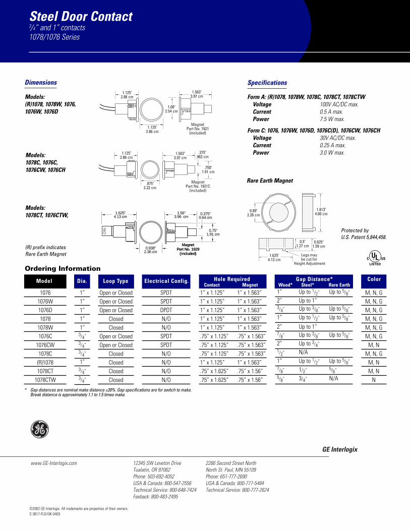
Steel Door Contact3/4” and 1” contacts1078/1076 Series
©2002 GE Interlogix. All trademarks are properties of their owners.C-3617-FLG10K-0403
GE Interlogix
www.GE-Interlogix.com 2266 Second Street NorthNorth St. Paul, MN 55109Phone: 651-777-2690USA & Canada: 800-777-5484Technical Service: 800-777-2624
12345 SW Leveton DriveTualatin, OR 97062Phone: 503-692-4052USA & Canada: 800-547-2556Technical Service: 800-648-7424Faxback: 800-483-2495
1.125"2.86 cm
1.125"2.86 cm
1.00"2.54 cm
MagnetPart No. 1921
(included)
1.563"3.97 cm
Dimensions Specifications
Form A: (R)1078, 1078W, 1078C, 1078CT, 1078CTWVoltage 100V AC/DC max.Current 0.5 A max.Power 7.5 W max.
Form C: 1076, 1076W, 1076D, 1076C(D), 1076CW, 1076CHVoltage 30V AC/DC max.Current 0.25 A max.Power 3.0 W max.
Ordering Information
Model Dia. Loop Type Electrical Config. Hole Required Gap Distance* Color
* Gap distances are nominal make distance ±20%. Gap specifications are for switch to make. Break distance is approximately 1.1 to 1.5 times make.
1”1”1”1”1”
3/4”
3/4”
3/4”
1”3/4”
3/4”
10761076W1076D1078
1078W1076C
1076CW1078C(R)10781078CT
1078CTW
Open or ClosedOpen or ClosedOpen or Closed
ClosedClosed
Open or ClosedOpen or Closed
ClosedClosedClosedClosed
SPDTSPDTDPDTN/ON/OSPDTSPDTN/ON/ON/ON/O
1” x 1.125” 1” x 1.563”1” x 1.125” 1” x 1.563”1” x 1.125” 1” x 1.563”1” x 1.125” 1” x 1.563”1” x 1.125” 1” x 1.563”.75” x 1.125” .75” x 1.563”.75” x 1.125” .75” x 1.563”.75” x 1.125” .75” x 1.563”1” x 1.125” 1” x 1.563”.75” x 1.625” .75” x 1.56”.75” x 1.625” .75” x 1.56”
Contact Magnet Wood* Steel* Rare Earth1” Up to 1/2” Up to 5/8”
2” Up to 1” 3/4” Up to 3/8” Up to 5/8”
1” Up to 1/2” Up to 5/8”
2” Up to 1” 7/8” Up to 3/8” Up to 5/8”
2” Up to 3/4”
1/2” N/A1” Up to 1/2” Up to 5/8”
7/8” 1/2” 5/8”
5/8” 3/4” N/A
1.125"2.86 cm
MagnetPart No. 1921C
(included)
.875"2.22 cm
1.563"3.97 cm
.375".962 cm
.750"1.91 cm
0.89"2.26 cm
1.813"4.60 cm
0.5"1.27 cm
0.625"1.59 cm
Legs may be cut for
Height Adjustment
1.625"4.13 cm
Models:(R)1078, 1078W, 1076,1076W, 1076D
Models:1078C, 1076C, 1076CW, 1076CH
Rare Earth Magnet
Protected by U.S. Patent 5,844,458.
(R) prefix indicates Rare Earth Magnet
M, N, GM, N, GM, N, GM, N, GM, N, GM, N, G
M, NM, N, G
M, NM, N
N
Models:1078CT, 1076CTW,
0.938"2.36 cm
1.625"4.13 cm
1.56"3.96 cm
MagnetPart No. 1929
(included)
0.375"0.64 cm
0.75"1.91 cm

e GE Security Product Data Sheet
www.GESecurity.com
2202 Series Overhead Door Magnetic ContactsSurface/floor mount contacts with armored cable
d
Overview
The GE Security 2202 Series overhead door magnetic contact is foruse in the rigorous environments of commercial and industrialinstallations.
The floor mount units are constructed with a low profile heavy castaluminum housing. The reed switch assembly is fully encased in GESecurity’s exclusive polyurethane potting material to preventdamage due to moisture or humidity. A wide operating gap distance ofup to 3 inches makes installation easy and helps prevent false alarmscaused by door movement or damaged and loose fitting doors.
The 2202 Series is available with a universal style magnet that allowsfor greater installation flexibility.
Standard Features
Wide 3-inch operating gapE
Fully sealed switchE
Form C unit availableE
Mounting hardwire includedE

2202 Series Overhead Door Magnetic ContactsSurface/floor mount contacts with armored cable
Specifications
Electrical, 2202Voltage: 100 VAC/DC max.l
Current: 0.5 A max.l
Power: 7.5 W max.l
Electrical, 2204Voltage: 30 VAC/DC max.l
Current: 0.25 A max.l
Power: 3.0 W max.l
Features, 2202Loop type: Closedl
Electrical configuration: Normally openl
Gap distance: Up to 3 in.l
Lead type: 18 in. flexible stainless steel cablel
Features, 2204Loop type: Open or closedl
Electrical configuration: SPDTl
Gap distance: Up to 3 in.l
Lead type: 18 in. flexible stainless steel cablel
Lead colors: Black - common; white - closed loop (N.O.); red - openloop (N.C.)
l
PhysicalDimensions, 2202A (LxWxD): 3.50 x 1.50 x 1.50 in. (89 x 38 x 38 mm)l
Dimensions, 2202AU and 2204AU (LxWxD): 3.125 x 2.125 x 0.81 in. (79x 54 x 21 mm)
l
Construction: Cast aluminuml
Color: Aluminuml
RegulatoryC-UL-USl
Related Diagram Ordering Information
Floor-mount magnetic contact for overhead doors,aluminum housing, 3 in. gap size, closed loop, includes18 in. stainless steel armored cable
2202A-L
Floor-mount magnetic contact for overhead doors,universal magnet, 3 in. gap size, closed loop, includes 18in. stainless steel armored cable
2202AU-L
Floor-mount magnetic contact for overhead doors,aluminum housing, 3 in. gap size, SPDT, includes 18 in.stainless steel armored cable
2204A-L
Floor-mount magnetic contact for overhead doors,universal magnet, 3 in. gap size, SPDT, includes 18 in.stainless steel armored cable
2204AU-L
g GE Security503-885-5700888-GE-SECURITY
(437-3287)faxback 800-483-2495email [email protected]
Asiatel 852-2907-8108fax 852-2142-5063
Australiatel +61-3-9259-4700fax +61-3-9259-4799
Europetel +44-113-238-1668fax +44-113-253-8121
Latin Americatel 305-267-4301fax 305-267-4300
As a company of innovation, GE Security reserves the right to change product specifications without notice. For the latest product specifications, visit GE Security online at www.GESecurity.com or contact your GE Security sales representative.IPS-2202 Series Overhead Door Magnetic Contacts-2005-07-20 02:17:38 Released : 20.07.2005

Intrusion Systems | DS160 Series High Performance Request‑to‑exit Detectors
The DS160 Series consists of the DS160 Detector (lightgray) and the DS161 Detector (black) specificallydesigned for Request-to-exit (REX) applications. Withfeatures such as timers, door monitor with sounder alert,and pointable coverage, the DS160 and DS161 have theflexibility to meet the most stringent REX requirements.The exclusive Sequential Logic Input (SLI) provides addedsecurity that is not offered in any other REX device.
Functions
Sequential Logic Input (SLI)The SLI terminal allows connection of a second device torequire sequential detection. This eliminates thepossibility that an object that is slid through the door orunderneath the door will activate the detector. This inputcan also be used to lock the sensor if motion is presentoutside the premises.
Door MonitorThe sensor can monitor a door contact to allow specialcontrol of the internal relay. For example, if the door isopened within the relay time period, the sensor can beprogrammed to halt the timer. If the door is not openedwithin a specific time period, the relay can beprogrammed to deactivate.
Sounder AlertAn integrated sounder can be programmed to activate ifthe door is left open too long. The sounder volume is fullyadjustable to 85 dB.
Keycard InputThe keycard input allows the sensor relay to be controlledfrom an external source, such as an access control systemor card reader.
DS160 Series High PerformanceRequest‑to‑exit Detectors
Door monitor with sounder alert
Sequential Logic Input (SLI)
Internal vertical pointability
Wrap-around coverage pattern with precise patterncontrol
Up to 64 second adjustable latch time
Selectable relay trigger mode
Selectable fail-safe or fail-secure modes
Adjustable sounder volume
Activation LED
www.boschsecurity.com

2 | DS160 Series High Performance Request‑to‑exit Detectors
Certifications and Approvals
Region Certification
Europe CE 89/336/EEC, EN55022: 1998 +A1:2000 +A2: 2003, EN50130-4: 1996+A1: 1998 +A2: 2003, EN61000-4-2:1995 +A1: 1998 +A2: 2001,EN61000-4-3: 2002 +A1: 2003,EN61000-4-4: 1995 +A1: 2000 +A2:2001, EN61000-4-5: 1995 +A1: 2001,EN61000-4-6: 1996 +A1: 2001 +A2:2001, EN61000-4-11:1994 +A1: 2001,EN60950-1: 2001
2004/108/EC; EN 50130-4:1996+A1:1998 +A2:2003; EN60950-1:2006
USA UL ALVY: Access Control Systems Units(UL294)
Europe Complies with EN50131‑1 Grade 2
Installation/Configuration Notes
ALARM WILLSOUND WHEN
DOOR ISOPENED
3 m(10 ft)
ALARM WILLSOUND WHEN
DOOR ISOPENED
1.2 m(4 ft)
Front ViewMounted on wall above door and mounted on ceiling .75 m(2.5 ft) in front of the door.
1.5 m(5 ft)
3 m
(10 ft)
Side ViewThe higher that you mount the unit, the larger thecoverage area. Do not mount the DS160/DS161 more than4.6 m (15 ft) above the floor.Side view of coverage pattern with the unit mounted at4.6 m (15 ft) above the floor with the lens pointed straightdown.
.75 m(2.5 ft)
1.5 m(5 ft)
Side ViewThe higher that you mount the unit, the larger thecoverage area. Do not mount the DS160/DS161 more than4.6 m (15 ft) above the floor.Side view of coverage pattern with the unit mounted at4.6 m (15 ft) above the floor with the lens pointed straightdown.

DS160 Series High Performance Request‑to‑exit Detectors | 3
Coverage InformationThe coverage (detection area) varies depending on themounting height above the floor, angle of the lens, andwhether the unit is mounted on a wall above the door oron the ceiling. The coverage is 2.4 m x 3 m (8 ft x 10 ft)The coverage patterns for the detector at a height of2.3 m (7.5 ft) are shown. The coverage pattern increasesor decreases with height and detector alignment.
Note When you mount the unit on the wall and thelens points straight down, some detectionzones point toward the wall and do notdetect movement.
The diagrams depict views of the coverage pattern withthe detector mounted at 2.3 m (7.5 ft) above the floorwith the lens pointed straight down. Zones that arepointed toward the wall are not shown.
Technical Specifications
Environmental
Operating Temperature: -29°C to +49°C (-20°F to +120°F)For UL Certificated installations, 0°C to +49°C(+32°F to +120°F)
Radio Frequency Inter-ference (RFI) Immunity:
No alarm or setup on critical frequencies in therange from 26 MHz to 1000 MHz at 50 V/m
Complies with Environmental Class II (EN50130-5)
Mechanical
Dimensions: 4.5 cm x 17.1cm x 4.4 cm(1.80 in. x 6.75 in. x 1.75 in.)
Material: High impact ABS plastic enclosure
Modes
Power Loss De-fault:
Programmable fail-safe or fail-secure modes.
Timer: Programmable reset accumulative or non-reset countingmode.
Electrical
Current Draw: 8 mA nominal standby current, 39 mA at 12 VDC inalarm
Voltage: 12 VAC or VDC to 30 VAC or VDC
Alarm Output: Two Form C relay contacts each rated 1 A at 30 VAC orVDC for resistive loads
Indicators: 1 activation LED
Relay LatchTime:
Adjustable from 0.5 sec to 64 sec.
Ordering Information
DS160 Request‑to‑exit DetectorLight gray enclosure. For use in request-to-exit (REX) applications. Provides 2.4 m x 3 m(8 ft x 10 ft) coverage, timers, door monitorwith sounder alert, and pointable coverage.
DS160
DS161 Request‑to‑exit DetectorBlack enclosure. For use in request-to-exit(REX) applications. Provides 2.4 m x 3 m (8ft x 10 ft) coverage, timers, door monitorwith sounder alert, and pointable coverage.
DS161
Accessories
TP160 Trim PlateA light gray trim plate used when mountingthe detector over a standard single-gang box.
TP160
TP161 Trim PlateA black trim plate used when mounting thesensor over a standard single-gang box.
TP161
www.boschsecurity.com

4 | DS160 Series High Performance Request‑to‑exit Detectors
Americas:Bosch Security Systems, Inc.130 Perinton ParkwayFairport, New York, 14450, USAPhone: +1 800 289 0096Fax: +1 585 223 [email protected]
Europe, Middle East, Africa:Bosch Security Systems B.V.P.O. Box 800025600 JB Eindhoven, The NetherlandsPhone: + 31 40 2577 284Fax: +31 40 2577 [email protected]
Asia-Pacific:Robert Bosch (SEA) Pte Ltd, Security Systems11 Bishan Street 21Singapore 573943Phone: +65 6258 5511Fax: +65 6571 [email protected]
Represented by
© Bosch Security Systems Inc. 2010 | Data subject to change without noticeT1138242827 | Cur: en-US, V14, 2 Dec 2010

Intrusion Systems | TP160 Trim Plate
A light gray trim plate used when mounting the detectorover a standard single-gang box.
Ordering Information
TP160 Trim PlateA light gray trim plate used when mountingthe detector over a standard single-gang box.
TP160
TP160 Trim Plate
www.boschsecurity.com

2 | TP160 Trim Plate
Americas:Bosch Security Systems, Inc.130 Perinton ParkwayFairport, New York, 14450, USAPhone: +1 800 289 0096Fax: +1 585 223 [email protected]
Europe, Middle East, Africa:Bosch Security Systems B.V.P.O. Box 800025600 JB Eindhoven, The NetherlandsPhone: + 31 40 2577 284Fax: +31 40 2577 [email protected]
Asia-Pacific:Robert Bosch (SEA) Pte Ltd, Security Systems11 Bishan Street 21Singapore 573943Phone: +65 6258 5511Fax: +65 6571 [email protected]
Represented by
© Bosch Security Systems Inc. 2010 | Data subject to change without noticeT1655525899 | Cur: en-US, V7, 2 Dec 2010

Intrusion Systems | TP161 Trim Plate
A black trim plate used when mounting the sensor over astandard single-gang box.
Ordering Information
TP161 Trim PlateA black trim plate used when mounting thesensor over a standard single-gang box.
TP161
TP161 Trim Plate
www.boschsecurity.com

2 | TP161 Trim Plate
Americas:Bosch Security Systems, Inc.130 Perinton ParkwayFairport, New York, 14450, USAPhone: +1 800 289 0096Fax: +1 585 223 [email protected]
Europe, Middle East, Africa:Bosch Security Systems B.V.P.O. Box 800025600 JB Eindhoven, The NetherlandsPhone: + 31 40 2577 284Fax: +31 40 2577 [email protected]
Asia-Pacific:Robert Bosch (SEA) Pte Ltd, Security Systems11 Bishan Street 21Singapore 573943Phone: +65 6258 5511Fax: +65 6571 [email protected]
Represented by
© Bosch Security Systems Inc. 2010 | Data subject to change without noticeT1655467915 | Cur: en-US, V7, 2 Dec 2010

The ES4200 is a multifunctional door
monitoring device that combines the best features
and functions of DSI’s door prop and exit alarm
product lines into one easy-to-use master unit. Field
selectable alarm timing, delay, and input/output options are sure
to make the NEW ES4200 the product of choice.
1402 Hawthorne St.Bastrop, TX 78602Voice: 1-800-272-3555 Fax: 512-321-9181E-mail: [email protected]
New!
E S 4 2 0 0 Series
FEATURES & BENEFITS• Aesthetically pleasing design
• Compatible with all access control systems
• Can be used as a stand-alone product
• Field selectable alarm timing and alarm delay option
• Field selectable high or low level sounder
• 12-24 VDC/VAC operation
• Easy installation
• Encourages employees to maintain access control procedures
• Reset/bypass keyswitch and remote input
• Visual status indicator
• Tamper resistant
• Incorporates form C output relays
• Supports door supervision
E S 4 2 0 0E S 4 2 0 0D o o r M a n a g e m e n t A l a r m

ELECTRICAL SPECIFICATIONS
Power: 12-24 VDC/VAC @ 250 mA
Local Control: Keyswitch for Unit Reset/Bypass
Control Input: N/O or N/C Alarm ShuntN/C Door ContactN/O Remote Reset/Bypass Voltage Sense Shunt
Control Output: N/O and N/C Door Contact StatusN/O and N/C Door Prop Alarm StatusN/O and N/C Intrusion/Tamper Alarm StatusN/O and N/C Bypass/Keyswitch StatusRemote LED
Adjustment: Auto Reset 0 sec. – 5 min. or Manual ResetAlarm Delay 0 sec. – 5 min. or InfiniteSilent Time 0 sec. – 90 min.
Audible Alarm: Field SelectableHigh – 103 dB@ 3 ft.Low – 96 dB@ 3 ft.
MECHANICAL SPECIFICATIONS
Dimensions: 2 Gang Plate with Standard Key 4.6”W x 4.5”H x 2.32”D
3 Gang Plate with Rim Hardware 6.4”W x 4.5”H x 2.32”D
Keyswitch: Double BittedRim Hardware with or without Cylinder
Finish: Painted – DSI Beige
1402 Hawthorne St.Bastrop, TX 78602Voice: 1-800-272-3555 Fax: 512-321-9181E-mail: [email protected]
PRODUCT DESCRIPTION
The ES4200 provides complete monitoring
of access control points by offering door prop/door
held and intrusion/door forced detection. These
alarms are designed to complement card reader and
access control systems and will interface with elec-
tronic locks, produce audible warnings and reduce
nuisance alarms by encouraging user compliance
with access control procedures.
7/02
ES4200 Doo r Management A la rm – Typ ica l App l i ca t i on

Maximal75Access Power Controller
Rev. DSMaximal75 - A19K
This unit distributes and switches power to access control systems and accessories. Unit converts a 115VAC 60Hz input into eight (8) 12VDC and eight (8) 24VDCindependently controlled fuse protected outputs. These Fail-Safe/Fail-Secure poweroutputs may be converted to dry form “C” contacts. The outputs are activated by an open collector sink or normally open (NO) dry trigger input from an Access Control System, Keypad, Push Button, REX PIR, etc. Units will route power to a variety of access control hardware devices including: Mag Locks, Electric Strikes, Magnetic Door Holders, etc. The FACP Interface enables Emergency Egress, AlarmMonitoring, or may be used to trigger other auxiliary devices. The fire alarmdisconnect feature is individually selectable for any or all of the sixteen (16) outputs. All interconnecting equipment must be UL Listed.
Overview
• 12VDC and 24VDC outputs.• Maximum output current: 19.2 amp total. Option P/S 1 P/S 2 A 12VDC @ 9.5 amp 24VDC @ 9.7 amp• 115VAC 60Hz, 10.0 amp input.• Input fuse ratings: AL1012ULXB 3.5 amp/250V. AL1024ULXB 10 amp/250V.• Power supply input options: a) Two (2) common power input for either ACM8 and lock power (factory installed). b) Two (2) isolated power inputs (external power supply is required), (current is determined by the power supply connected, not to exceed a maximum of 10 amp total).• Sixteen (16) Access Control System trigger inputs. Input options: a) Sixteen (16) normally open (NO) inputs. b) Sixteen (16) open collector inputs. c) Any combination of the above.• Sixteen (16) independently controlled outputs. Output options: a) Sixteen (16) Fail-Safe and/or Fail-Secure power outputs. b) Sixteen (16) form “C” 5 amp rated relay outputs. c) Any combination of the above. • Sixteen (16) auxiliary power outputs (unswitched) (outputs are rated 2.5 amp).• ACM8 boards main fuse is rated at 10 amp. Output fuses are rated @ 3.5 amp.• Red LEDs indicate outputs are triggered (relays energized).
• Fire Alarm disconnect (latching or non-latching) is individually selectable for any or all of the sixteen (16) outputs.• Fire Alarm disconnect input options: a) Normally open (NO) or normally closed (NC) dry contact input. b) Polarity reversal input from FACP signaling circuit.• Alarm output relay indicates that FACP input is triggered (form “C” contact rated @ 1 amp 28VDC).• Green LED indicates FACP disconnect is triggered.• Filtered and electronically regulated outputs (built-in power supply).• Built-in charger for sealed lead acid or gel type batteries.• Maximum charge current AL1012ULXB is 0.7 amp. AL1024ULXB is 3.6 amp.• Automatic switch over to stand-by battery when AC fails.• Zero voltage drop when unit switches over to battery backup (AC failure condition).• Thermal and short circuit protection with auto reset. • AC input and DC output LED indicators.• AC fail supervision (form “C” contact). • Low battery and battery presence supervision (form “C” contact).• Enclosure accommodates up to four (4) 12AH batteries.• Product weight: 40.65 lbs. • Shipping weight: 44.65 lbs.
Maximal75
Specifications

Enclosure Dimensions (approximate)26”H x 19”W x 6.25”D
AltronixCorp.-14058thStreet,Brooklyn,NY11220•718-567-8181•888-258-7669•altronix.com
18"18"
14.5"
14.5"
4.5"
4.5"
4.5"
4.5"
4.5"
18"
1.25"
1.5"4.0"6.5"1.5" 1.25"
1.5"
4.0"
10.0"
1.25"
2.75"7.25"
1.0"
1.5"
1.0"
1.0"
1.0"
1.25"
2.75"
1.5"
10"
Agency Approvals
UL Listed for Access Control System Units (UL 294).
CUL Listed - CSA Standard C22.2 No.205-M1983, Signal Equipment.
CSFMCalifornia State Fire Marshal Approved.

Data Sheet NP SERIES - NP 12-12
www.yuasabatteries.com NP
Reliability is your Security Utilizing the latest advance design Oxygen Recombination Technology, Yuasa have applied their 80 years experience in the lead acid battery field to produce the optimum design of Sealed Lead Acid batteries.
FEATURES Superb recovery from deep discharge. Electrolyte suspension system. Gas Recombination. Multipurpose: Float or Cyclic use. Usable in any orientation. Superior energy density. Lead calcium grids for extended life. Manufactured World wide. Application specific designs.
Terminals NP batteries are manufactured using a range of terminals which vary in size and type. Please refer to details as shown.
Operation in any Orientation The combination of sealed construction and Yuasa’s unique electrolyte suspension system allows operation in any orientation, with no loss of performance or fear of electrolyte leakage.
Valve Regulated Design The batteries are equipped with a simple, safe, low pressure venting system which releases excess gas and automatically reseals should there be a build up of gas within the battery due to severe overcharge. Note. On no account should the battery be charged in a sealed container.
Technical Features Sealed Construction Yuasa’s unique construction and sealing technique ensures no electrolyte leakage from case or terminals.
Electrolyte Suspension System All NP batteries utilize Yuasa’s unique electrolyte suspension system incorporating a microfine glass mat to retain the maximum amount of electrolyte in the cells. The electrolyte is retained in the separator material and there is no free electrolyte to escape from the cells. No gels or other contaminants are added.
Control of Gas Generation The design of Yuasa’s NP batteries incorporates the very latest oxygen recombination technology to effectively control the generation of gas during normal use.
Low Maintenance Operation Due to the perfectly sealed construction and the recombination of gasses within the cell, the battery is almost maintenance free.
General Specifications
Layout Terminals
Nominal Capacity (Ah) NP12-12
20hr to 1.75vpc 30ºC 12
10hr to 1.75vpc 20ºC 11.1 5hr to 1 .70vpc 20ºC 10 1 hr to 1 .60vpc 20ºC 7.2 Voltage 12
Energy Density (Wh.L.20hr) 1 04 Specific Energy (Wh.kg.20hr) 36 Int. Resistance (m.Ohms) 1 6 Maximum discharge (A) 75 Short Circuit current (A) 360
Dimensions (mm)
Length 151 Width 98 Height overall 97.5
Weight (Kg) 4.05 Terminal D Layout 4 Terminal Torque Nm -

Data Sheet NP SERIES - NP 12-12
Distributed by Yuasa Battery Inc. 2901 Montrose Ave
Laureldale, PA 19605 www.yuasabatteries.com
Registered number 1548820
Cat. No. NP 12-12 March 09
Lead Calcium Grids The heavy duty lead calcium alloy grids provide an extra margin of performance and life in both cyclic and float applications and give unparalleled recovery from deep discharge.
Long Cycle Service Life Depending upon the average depth of discharge, over a thousand discharge/charge cycles can be expected.
Float Service Life The expected service life is five years in float standby applications.
Separators The use of the special separator material provides a very efficient insulation between plates preventing inter-plate short circuits and prohibiting the shedding of active materials.
Long shelf Life The extremely low self discharge rate allows the battery to be stored for extended periods up to one year at normal ambient temperatures with no permanent loss of capacity.
Operating Temperature Range The batteries can be used over a broad temperature range permitting considerable flexibility in system design and location. Charge – 15°C to 50°C Discharge – 20°C to 60°C Storage – 20°C to 50°C (fully charged battery)

DATASHEET
AXIS P33 Series offers models from SVGA resolution up to 3 megapixel, including support for HDTV 720p and 1080p in compliance with the SMPTE standard in resolution, color representation and frame rate. All models provide day and night functionality with removable infrared-cut filter for increased light sensitivity.
The remote focus feature allows for convenient installation eliminating the need for hands-on focusing at the camera, and the remote zoom and pixel counter features ensure that the camera’s angle of view is optimized for the scene and pixel resolution.
AXIS P33 Network Cameras constitute a series of indoor and outdoor-ready fixed domes. These cameras are ideal for unobtrusive video surveillance in exposed areas such as airports, subways, retail stores, schools and university campuses.
AXIS P33 Network Camera SeriesFixed domes for any environment with remote focus and zoom.
> Superb video quality including HDTV 1080p
> Multiple H.264 video streams
> Remote focus and zoom
> Outdoor ready
> Digital PTZ and multi-view streaming
> P-Iris control
AXIS P33 Series provides multiple, individually configu-rable H.264 and Motion JPEG video streams. All AXIS P33 cameras offer digital pan/tilt/zoom, and the 3-megapixel AXIS P3346 models additionally provide multi-view streaming.
AXIS P3346 cameras offer the unique and revolutionary P-Iris control, which allows the cameras to precisely control the iris position to optimize depth of field and lens resolution for optimal image sharpness.
AXIS P33 Series ranges from indoor cameras to vandal-resistant outdoor models, supplied by standard Power over Ethernet (IEEE 802.3af). Weather-proof models operate in temperatures from -40 °C to 55 °C (-40 °F to 131 °F).

AXIS P33 Series is the perfect choice for a wide range of demanding video applications in outdoor and indoor environments. AXIS P33 Network Cameras are designed for professional video surveillance with easy and reliable installation in focus.
Fixed domes designed for efficient installation - indoors or outdoors
camera models include a smoked transparent cover as an alternative to the clear cover, for additional flexibility.
Easy installation with remote focus and zoomAXIS P33 Network Cameras offer unique installation capabilities with remote focus and zoom. The remote focus feature enables convenient focusing over the network, eliminating the need for hands-on fine-tuning at the camera. The remote zoom functionality ensures that the viewing angle is optimized for the area to be monitored.
Unique pixel counter featureThe unique pixel counter offered in Axis cameras allows the installer to easily verify that the camera installation fulfills any regulatory or specific customer requirements, for example, calculating the pixel resolution of the face of a person passing a doorway monitored by the camera.
Outdoor-ready installation for extreme temperatures The outdoor models of AXIS P33 Series are specially designed for reliable, vandal-resistant and weather- proof installation, with pre-installed heater and fan, and an integrated dehumidifying membrane eliminating any humidity caught in the camera casing during installation. These cameras come with a 5 m (16 ft.) Ethernet cable with a pre-mounted, specially designed gasket, enabling flush wall mounting and requiring no additional sealant. A weather shield is also included for effective protection against reflections from sunlight, or build-ups of rain or snow.
Mounting optionsAXIS P33 Series offers a wide range of optional kits for indoor and outdoor installations, for example, for mounting on a wall, pole or corner. The IP51-rated drop ceiling mount kit protects the camera from condensation and dust that may exist in the plenum space above the drop ceiling. Both indoor and outdoor
Unique pixel counter feature
AXIS P3343-VE /P3344-VEWeight: 1.6 kg (3.5 lb.) with weather shield
AXIS P3343/-V/P3344/-VAXIS P3343/P3344 weight: 450 g (1.0 lb.)AXIS P3343-V/P3344-V weight: 660 g (1.5 lb.)
AXIS P3346-VEWeight: 1.7 kg (3.7 lb.) with weather shield
AXIS P3346/-VAXIS P3346 weight: 490 g (1.1 lb.)AXIS P3346-V weight: 700 g (1.6 lb.)
∅ 96 mm (3.8’’)
96
mm
(3.8
’’)
148 mm (5.8’’)
117
mm
(4.6
")
123
mm
(4.8
")178 mm (7.0’’)
∅ 96 mm (3.8’’)
AXIS
P33
46: 1
01 m
m (4
.0’’)
AX
IS P
3346
-V: 1
04 m
m (4
.1’’)
148 mm (5.8’’)
∅ 96 mm (3.8’’)
∅ 96 mm (3.8’’)
178 mm (7.0’’)
110
mm
(4.3
")
119
mm
(4.7
")
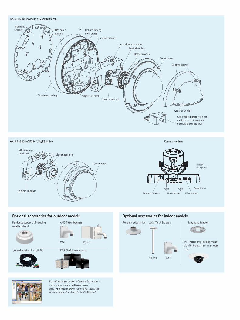
AXIS P3343-VE/P3344-VE/P3346-VE
AXIS P3343/-V/P3344/-V/P3346-V Camera module
Weather shield
Captive screws
Flat cable gaskets
Captive screws
Snap-in mount
Heater module
Motorized lens
Dome cover
Fan output connector
Camera moduleAluminum casing
Fan Dehumidifying membrane
Mounting bracket
Cable shield protection for cables routed through a conduit along the wall
Optional accessories for indoor modelsAXIS T91A Brackets
WallCeiling
Pendant adapter kit Mounting bracket
IP51-rated drop-ceiling mount kit with transparent or smoked cover
Optional accessories for outdoor modelsAXIS T91A Brackets
I/O audio cable, 5 m (16 ft.) AXIS T90A Illuminators
Wall Corner
Pendant adapter kit including weather shield
For information on AXIS Camera Station and video management software from Axis’ Application Development Partners, see www.axis.com/products/video/software/
Network connector LED indicators
Control button
Built-in microphone
I/O connector
Audioout
Audio in
Motorized lens
Camera module
Dome cover
SD memory card slot

©2011 Axis Communications AB. AXIS COMMUNICATIONS, AXIS, ETRAX, ARTPEC and VAPIX are registered trademarks or trademark applications of Axis AB in various jurisdictions. All other company names and products are trademarks or registered trademarks of their respective companies. We reserve the right to introduce modifications without notice.
Technical Specifications – AXIS P33 Network Camera Series
CameraModels AXIS P3343: SVGA, tamper-resistant, indoor
AXIS P3343-V: SVGA, vandal-resistant, indoorAXIS P3343-VE: SVGA, vandal-resistant, outdoorAXIS P3344: 1MP/HDTV 720p, tamper-resistant, indoorAXIS P3344-V: 1MP/HDTV 720p, vandal-resistant, indoorAXIS P3344-VE: 1MP/HDTV 720p, vandal-resistant, outdoorAXIS P3346: 3MP/HDTV 1080p, tamper-resistant, indoorAXIS P3346-V: 3MP/HDTV 1080p, vandal-resistant, indoorAXIS P3346-VE: 3MP/HDTV 1080p, vandal-resistant, outdoor
6mm or 12mm as suffix specifies lens option
Note: AXIS P3301/-V and AXIS P3304/-V are not part of AXIS P33 Series
Image sensor AXIS P3343/-V/-VE and AXIS P3344/-V/-VE: Progressive scan RGB CMOS 1/4” AXIS P3346/-V/-VE: Progressive scan RGB CMOS 1/3” (effective)
Lens Varifocal with remote zoom and focus, IR corrected, megapixel resolutionAXIS P3343/-V/-VE 6 mm: 2.5-6 mm, 72°-34° view*, F1.2, DC-irisAXIS P3343/-V/-VE 12 mm: 3.3-12 mm , 54°-17° view*, F1.4, DC-irisAXIS P3344/-V/-VE 6 mm: 2.5-6 mm, 87°-40° view*, F1.4, DC-irisAXIS P3344/-V/-VE 12 mm: 3.3-12 mm, 70°-20° view*, F1.6, DC-irisAXIS P3346/-V/-VE: 3-9 mm, 84°-30° view*, F1.2, P-Iris*horizontal angle of view
Day and night Automatically removable infrared-cut filter
Minimum illumination
AXIS P3343/-V/-VE 6 mm: Color: 0.2 lux, F1.2, B/W: 0.04 lux, F1.2AXIS P3343/-V/-VE 12 mm: Color: 0.3 lux, F1.4, B/W: 0.05 lux, F1.4AXIS P3344/-V/-VE 6 mm: Color: 0.3 lux, F1.4, B/W: 0.05 lux, F1.4AXIS P3344/-V/-VE 12 mm: Color: 0.4 lux, F1.6, B/W: 0.06 lux, F1.6AXIS P3346/-V/-VE: Color: 0.5 lux, F1.2, B/W: 0.08 lux, F1.2
Shutter time AXIS P3343/-V/-VE and AXIS P3344/-V/-VE: 1/25000 s to 1/6 sAXIS P3346/-V/-VE: 1/35500 s to 1/6 s
Camera angle adjustment
AXIS P3343/-V/-VE and AXIS P3344/-V/-VE: Pan 360°, tilt 170°, rotation 340°AXIS P3346/-V/-VE: Pan 360°, tilt 160°, rotation 340°
VideoVideo compression
H.264 (MPEG-4 Part 10/AVC) Motion JPEG
Resolutions AXIS P3343/-V/-VE: 800x600 to 160x90AXIS P3344/-V/-VE: 1280x800 to 160x90*AXIS P3346/-V/-VE: 2048x1536 to 160x90*1440x900 (1.3 MP) scaled resolution available via VAPIX®
Frame rateH.264
AXIS P3343/-V/-VE and AXIS P3344/-V/-VE: 30 fps in all resolutionsAXIS P3346/-V/-VE: 3MP mode: 20 fps in all resolutions,HDTV 1080p (1920x1080) and 2MP 4:3 (1600x1200) modes: 30 fps in all resolutions
Frame rate Motion JPEG
AXIS P3343/-V/-VE and AXIS P3344/-V/-VE: 30 fps in all resolutionsAXIS P3346/-V/-VE: 3MP mode: 20 fps in all resolutions,HDTV 1080p (1920x1080) and 2MP 4:3 (1600x1200) modes: 30 fps in all resolutions
Video streaming Multiple, individually configurable streams in H.264 and Motion JPEGControllable frame rate and bandwidthVBR/CBR H.264
Multi-view streaming
AXIS P3346/-V/-VE: Up to 8 individually cropped out view areas. When streaming 5 view areas in VGA resolution, the frame rate is 20 fps per stream in H.264/Motion JPEG (3 MP capture mode)Digital PTZ, preset positions, guard tour
Image settings Compression, color, brightness, sharpness, contrast, white balance, exposure control, exposure zones, backlight compensation, wide dynamic range - dynamic contrast, fine tuning of behavior at low lightRotation: 0°, 90°, 180°, 270°, including Corridor Format™Text and image overlay, privacy mask, mirroring of images
AudioAudio streaming Two-way
Audio compression
AAC LC 8/16 kHzG.711 PCM 8 kHzG.726 ADPCM 8 kHzConfigurable bit rate
Audio input/output
External microphone input or line input, line outputAXIS P3343/-V, AXIS P3344/-V and AXIS P3346/-V: Built-in microphone
NetworkSecurity Password protection, IP address filtering, digest authentication,
user access log, IEEE 802.1X** network access control, HTTPS** encryption
Supported protocols
IPv4/v6, HTTP, HTTPS**, QoS Layer 3 DiffServ, FTP, SMTP, Bonjour, UPnP, SNMPv1/v2c/v3(MIB-II), DNS, DynDNS, NTP, RTSP, RTP, TCP, UDP, IGMP, RTCP, ICMP, DHCP, ARP, SOCKS
System integrationApplication ProgrammingInterface
Open API for software integration, including the ONVIF specification available at www.onvif.org, as well as VAPIX® and AXIS Camera Application Platform from Axis Communications, specifications available at www.axis.comSupport for AXIS Video Hosting System (AVHS) with One-Click Camera connection
Intelligent video Video motion detection, active tampering alarm, audio detectionSupport for AXIS Camera Application Platform enablinginstallation of additional applications
Alarm triggers Intelligent video, external input
Alarm events File upload via FTP, HTTP and emailNotification via email, HTTP and TCPExternal output activationVideo and audio recording to local storagePre- and post-alarm video buffering
Installation aids in software
Remote zoom, remote focus, pixel counter
GeneralCasing Polycarbonate transparent cover
Aluminum inner camera module with encapsulated electronicsColor: white NCS S 1002-BAXIS P3343/P3344/P3346: Tamper-resistant polycarbonate casingAXIS P3343-V/P3344-V: 1000 kg (2200 lb.) impact-resistant aluminum casingAXIS P3346-V: IK10 impact-resistant aluminum casingAXIS P3343-VE/P3344-VE: IP66- and NEMA 4X-rated, 1000 kg (2200 lb.) impact-resistant aluminum casing with integrated dehumidifying membraneAXIS P3346-VE: IP66- and NEMA 4X-rated, IK10 impact-resistant aluminum casing with integrated dehumidifying membrane
Processor and memory
AXIS P3343/-V/-VE and AXIS P3344/-V/-VE: ARTPEC-3, 128 MB RAM, 128 MB FlashAXIS P3346/-V/-VE: ARTPEC-3, 256 MB RAM, 128 MB Flash
Power Power over Ethernet IEEE 802.3afAXIS P3343/-V, AXIS P3344/-V and AXIS P3346/-V: Class 2AXIS P3343-VE/P3344-VE/P3346-VE: Class 3
Connectors RJ-45 10BASE-T/100BASE-TX PoETerminal block for 1 alarm input and 1 output3.5 mm mic/line in, 3.5 mm line out
Local storage SD/SDHC memory card slot (card not included)
Operating conditions
AXIS P3343/-V, AXIS P3344/-V and AXIS P3346/-V: 0 °C to 50 °C (32 °F to 122 °F), humidity 15 - 85% RH (non-condensing)AXIS P3343-VE/P3344-VE/P3346-VE: -40 °C to 55 °C(-40 °F to 131 °F), humidity 15 - 100% RH (condensing)
Approvals EN 55022 Class B, EN 61000-3-2, EN 61000-3-3, EN 55024,FCC Part 15 Subpart B Class B, ICES-003 Class B,VCCI Class B, C-tick AS/NZS CISPR 22, EN 60950-1AXIS P3346-V: IEC 62262 IK10AXIS P3343-VE/P3344-VE.: IEC 60529 IP66, NEMA 250 Type 4XAXIS P3346-VE: IEC 60529 IP66, NEMA 250 Type 4X, IEC 62262 IK10
Included accessories
Mounting and connector kits, Installation Guide, CD with installation tools, recording software and User’s Manual, Windows decoder 1-user license, smoked transparent coverAXIS P3343-VE/P3344-VE/P3346-VE: mounting bracket, weather shield, cable shield, 5 m (16 ft.) network cable with pre-mounted gasket
* * This product includes software developed by the OpenSSL Project for use in the OpenSSL Toolkit. (www.openssl.org)
4349
3/EN
/R1/
1106
More information is available at www.axis.com

DATASHEET
AXIS Q6032 supports a wider picture with an extended D1 resolution of 752x480 in 60 Hz and 736x576 in 50 Hz. Videos in H.264 and Motion JPEG can be sent at full frame rate. Day and night functionality, progressive scan, 128x wide dynamic range and electronic image stabilization contribute to the camera's superb video quality.
The camera's tour recording functionality enables easy setup of an automatic tour using a device such as a joystick to record an operator's pan/tilt/zoom movements. With Active Gatekeeper, the camera can automatically move to a preset position upon motion detection in a pre-defined area, and track the detected object.
AXIS Q6032 PTZ Dome Network Camera offers 35x optical zoom and high-speed pan/tilt performance, enabling coverage of large indoor areas and great detail when zooming in. It is ideal for use in airports, train stations, stadiums and warehouses.
AXIS Q6032 PTZ Dome Network CameraAdvanced, high-speed indoor PTZ dome with 35x zoom.
> 35x optical zoom, day/night
> IP52-rated protection against dust and dripping water
> Extended D1 resolution, H.264
> Active Gatekeeper and tour recording
> Power over Ethernet Plus (IEEE 802.3at)
AXIS Q6032 offers easy and reliable installation. The IP52-rated camera provides protection against dust and dripping water, enabling video to be taken even when a sprinkler system is activated. Support for Power over Ethernet Plus (PoE+) also simplifies installation since only one cable is needed for carrying power, as well as video and PTZ controls.
When an optional multi-connector cable is used, AXIS Q6032 supports two-way audio, I/O ports for external devices and AC/DC power. The camera's SD/SDHC slot enables recordings to be stored locally.

Technical specifications – AXIS Q6032 PTZ Dome Network Camera
www.axis.com
©2011 Axis Communications AB. AXIS COMMUNICATIONS, AXIS, ARTPEC and VAPIX are registered trademarks or trademark applications of Axis AB in various jurisdictions. All other company names and products are trademarks or registered trademarks of their respective companies. We reserve the right to introduce modifications without notice.
4305
1/EN
/R1/
1106
CameraModels AXIS Q6032 60 Hz, AXIS Q6032 50 Hz
Image sensor 1/4” ExView HAD progressive scan CCD
Lens f 3.4 – 119 mm, F1.4 – 4.2, autofocus, automatic day/night, horizontal angle of view: 55.8° - 1.7°
Minimum illumination
Color: 0.5 lux at 30 IRE F1.4B/W: 0.008 lux at 30 IRE F1.4
Shutter time 1/30000 s to 0.5 s (60 Hz), 1/30000 s to 1.5 s (50 Hz)
Pan/tilt/zoom E-flip, 100 preset positionsPan: 360° endless, 0.05° – 450°/s, Tilt: 180°, 0.05° – 450°/s35x optical zoom and 12x digital zoom, total 420x zoom
Pan/tilt/zoom functionalities
Tour recording, guard tour, control queue On-screen directional indicator
VideoVideo compression
H.264 (MPEG-4 Part 10/AVC)Motion JPEG
Resolutions Extended D1 752x480 to 176x120 (60 Hz) Extended D1 736x576 to 176x144 (50 Hz)
Frame rate H.264: Up to 30/25 fps (60/50 Hz) in all resolutionsMotion JPEG: Up to 30/25 fps (60/50 Hz) in all resolutions
Video streaming Multiple, individually configurable streams in H.264 and Motion JPEGControllable frame rate and bandwidthVBR/CBR H.264
Image settings Wide Dynamic Range (WDR), Electronic Image Stabilization (EIS), manual shutter time, compression, color, brightness, sharpness, white balance, exposure control, exposure zones, rotation, backlight compensation, fine tuning of behavior at low light, text and image overlay, 3D privacy mask, image freeze on PTZ
AudioAudio streaming Two-way
Audio compression
AAC-LC 8/16 kHz, G.711 PCM 8 kHz, G.726 ADPCM 8 kHzConfigurable bit rate
Input/output Requires multi-connector cable (not included) for external microphone or line input, and line output
NetworkSecurity Password protection, IP address filtering, HTTPS encryption*,
IEEE 802.1X network access control*, digest authentication, user access log
Supported protocols
IPv4/v6, HTTP, HTTPS*, SSL/TLS*, QoS Layer 3 DiffServ, FTP, SMTP, Bonjour, UPnP, SNMPv1/v2c/v3 (MIB-II), DNS, DynDNS, NTP, RTSP, RTP, TCP, UDP, IGMP, RTCP, ICMP, DHCP, ARP, SOCKS
System integrationApplication ProgrammingInterface
Open API for software integration, including VAPIX® and AXIS Camera Application Platform from Axis Communications; specifications available at www.axis.comONVIF, specifications available at www.onvif.org AXIS Video Hosting System (AVHS) with One-Click Camera Connection
Intelligent video Video motion detection, audio detection, auto-tracking, Active Gatekeeper, AXIS Camera Application Platform
Alarm triggers Video motion detection, audio detection, auto-tracking, external input, PTZ preset, temperature, memory card full, AXIS Camera Application Platform
Alarm events File upload via FTP, HTTP and email Notification via email, HTTP and TCP External output, PTZ preset, guard tour, play audio clip, local storage Pre- and post-alarm video buffering
GeneralCasing IP52-rated, metal casing (aluminum), acrylic (PMMA) clear dome
Processors and memory
ARTPEC-3, 256 MB RAM, 128 MB Flash
Power Power over Ethernet Plus (PoE+) IEEE 802.3at, max. 30W 24-34 V DC, max. 19 W; 20-24 V AC, max. 27 VAAXIS T8123 High PoE Midspan 1-port included: 100-240 V AC
Connectors RJ-45 for 10BASE-T/100BASE-TX PoE Multi-connector (cable not included) for AC/DC power, 4 configurable alarm inputs/outputs, mic in, line mono input, line mono output to active speaker
Local storage SD/SDHC memory card slot (card is not included)
Operating conditions
0 °C to 50 °C (32 °F to 122 °F)Humidity 20 - 80% RH (non-condensing)
Approvals EN 55022 Class B, EN 61000-3-2, EN 61000-3-3, EN 61000-6-1, EN 61000-6-2, EN 55024, FCC Part 15 Subpart B Class B, ICES-003 Class B, VCCI Class B, C-tick AS/NZS CISPR 22, KCC Class BIP52 IEC 60529IEC 60721-4-3 Class 3K3, 3M3, EN/IEC 60068-2Midspan: EN 60950-1, GS, UL, cUL, CE, VCCI, CB, KCC, CSA, UL-AR
Weight Camera: 2.6 kg (5.7 lb.) Camera with drop-ceiling mount: 3.2 kg (7.1 lb.)
Included accessories
AXIS T8123 High PoE Midspan 1-port, mounting kit for hard and drop ceilings, clear and smoked dome cover, Installation Guide, CD with User's Manual, recording software, installation and management tools, Windows decoder 1-user license
More information at www.axis.com* This product includes software developed by the OpenSSL Project for use in the OpenSSL Toolkit. (www.openssl.org)
Dimensions
Hard ceiling mount Drop ceiling mount
Optional accessoriesAXIS T90A Illuminators
AXIS T91A Mounting Accessories
Wall Corner Ceiling Pendant kit
AXIS Camera Station and video management software from Axis’ Application Development Partners. For more information, see www.axis.com/products/video/software/
198 mm (7.8”)
221
mm
(8.7
”)
240
mm
(9.4
”)
248 mm (9.8”)102
mm
(4”)243
mm
(9.6
”)
AXIS T8310 Video Surveillance Control Board
Multi-connector cable for AC/DC power, I/Os and audio

AXIS P3707-PE Network CameraFlexible, 360° multisensor camera
AXIS P3707-PE Network Camera is an 8-megapixel multisensor fixed camera with four varifocal lenses that enableoverview and detailed surveillance. With one IP address, one network cable, PoE support, IP66 and IP67 ratings, thefour-camera-in-one unit provides a flexible, cost-effective solution for multidirectional surveillance in large indoor andoutdoor areas, and at the intersection of hallways and roads. Each camera head can be moved along a circular track. Thetilt angle and the field of view of each lens are adjustable, and each camera head can rotate to support Axis’ CorridorFormat. The specially designed clear cover, with no sharp edges, ensures undistorted views in all directions.
> 8 MP, 360° multisensor camera, one IP address
> Flexible positioning of four varifocal camera heads
> 1080p videos at 12.5/15 fps; 720p videos at 25/30 fps; quad view stream
> Axis’ Zipstream technology
Datasheet

AXIS P3707-PE Network Camera
CameraImage sensor 4 x 1/2.8” progressive scan RGB CMOS
Lens Varifocal, 2.8–6 mm, F2.04x1080p capture mode:Horizontal field of view: 108°–54°Vertical field of view: 57°–30°4xHDTV 720p capture mode:Horizontal field of view: 67°–36°Vertical field of view: 37°–20°Adjustable focus and zoom, fixed iris
Minimumillumination
Color: 0.3 lux, F2.0
Shutter time 720p: 1/28000 s to 2 s1080p: 1/22500 s to 2 s
VideoVideocompression
H.264 (MPEG-4 Part 10/AVC) Baseline, Main and High ProfilesMotion JPEG
Resolutions 4 x 1920x1080 (1080p) to 160x90Quad view 1920x1440 to 480x270
Frame rate 25/30 fps (50/60 Hz) with 720p capture mode12.5/15 fps (50/60 Hz) with 1080p capture mode
Video streaming Multiple, individually configurable streams in H.264 and MotionJPEGAxis Zipstream technology in H.264Controllable frame rate and bandwidthVBR/MBR H.264
Image settings Color, brightness, sharpness, contrast, white balance, exposurecontrol, exposure zone, fine tuning of behavior at low light,rotation: 0°, 90°, 180°, 270° including Corridor Format, text andimage overlay, privacy mask, Local contrast
Camera angleadjustment
Pan ±90°Tilt 28°-92°Rotate ±90°
NetworkIP address One IP address for all channels
Security Password protection, IP address filtering, HTTPSa encryption,IEEE 802.1Xa network access control, digest authentication, useraccess log, centralized certificate management
Supportedprotocols
IPv4/v6, HTTP, HTTPSa, SSL/TLSa, QoS Layer 3 DiffServ, FTP,CIFS/SMB, SMTP, Bonjour, UPnPTM, SNMP v1/v2c/v3 (MIB-II),DNS, DynDNS, NTP, RTSP, RTP, SFTP, TCP, UDP, IGMP, RTCP, ICMP,DHCP, ARP, SOCKS, SSH
System integrationApplicationProgrammingInterface
Open API for software integration, including VAPIX®and AXIS Camera Application Platform; specifications atwww.axis.comAXIS Video Hosting System (AVHS) with One-Click ConnectionONVIF® Profile S and ONVIF® Profile G, specification atwww.onvif.org
Analytics IncludedAXIS Video Motion Detection, active tampering alarmSupport for AXIS Camera Application Platform enablinginstallation of third-party applications, see www.axis.com/acap
Event triggers Analytics, edge storage events
Event actions Overlay text, pre- and post-alarm video buffering, videorecording to edge storage, SNMP trap
File upload: FTP, SFTP, HTTP, HTTPS network share and emailNotification: email, HTTP, HTTPS and TCP
Data streaming Event data
Built-ininstallation aids
Pixel counter
GeneralCasing IP66-, IP67-, NEMA 4X- and IK09-rated
Die-casted aluminum, polycarbonate dome
Sustainability PVC free
Memory 1 GB RAM, 256 MB Flash
Power Power over Ethernet (PoE) IEEE 802.3af/802.3at Type 1 Class 2Typical 4.8 W, max 5.5 W
Connectors RJ45 10BASE-T/100BASE-TX PoE
Storage Support for microSD/microSDHC/microSDXC cardSupport for SD card encryptionSupport for recording to network-attached storage (NAS)For SD card and NAS recommendations see www.axis.com
Operatingconditions
-30 °C to 60 °C (-22 °F to 140 °F)Humidity 10–100% RH (condensing)
Storageconditions
-40 °C to 65 °C (-40 °F to 149 °F)
Approvals EMCEN 55022 Class B, EN 61000-3-2, EN 61000-3-3, EN 55024,EN 61000-6-1, EN 61000-6-2, FCC Part 15 Subpart B Class A+B,ICES-003 Class B, VCCI Class B, RCM AS/NZS CISPR 22 Class B,KCC KN32 Class B, KN35, EN 50121-4, IEC 62236-4SafetyIEC/EN/UL 60950-1, IEC/EN/UL 60950-22EnvironmentIEC 60068-2-1, IEC 60068-2-2, IEC 60068-2-6, IEC 60068-2-14,IEC 60068-2-27, IEC/EN 62262 IK09, IEC/EN 60529 IP66/IP67,NEMA 250 Type 4X
Dimensions Diameter: ø 270 mm (10 5/8 in), Height: 91.5 mm (3 5/8 in)
Weight 2.2 kg (4.9 lb)
Includedaccessories
RJ45 mounting tool, Installation Guide, Windows decoder 1-userlicense
Optionalaccessories
AXIS T8415 Wireless Installation Tool, AXIS T94M02D PendantKit including weather shield, AXIS P3707-PE Clear Dome Kit,AXIS T91 Mounting Accessories, AXIS T8120 15 W Midspan1-portFor more accessories, see www.axis.com
Videomanagementsoftware
AXIS Camera Companion, AXIS Camera Station, Videomanagement software from Axis’ Application DevelopmentPartners available on www.axis.com/techsup/software
Languages English, German, French, Spanish, Italian, Russian, SimplifiedChinese, Japanese, Korean, Portuguese, Traditional Chinese
Warranty Axis 3-year warranty and AXIS Extended Warranty option, seewww.axis.com/warranty
a. This product includes software developed by the OpenSSL Project for use in theOpenSSL Toolkit. (www.openssl.org), and cryptographic software written by EricYoung ([email protected]).
Environmental responsibility:
www.axis.com/environmental-responsibility
www.axis.com
©2016 - 2017 Axis Communications AB. AXIS COMMUNICATIONS, AXIS, and VAPIX are registered trademarks or trademarkapplications of Axis AB in various jurisdictions. All other company names and products are trademarks or registeredtrademarks of their respective companies. We reserve the right to introduce modifications without notice.
1531
595/EN
/M2.2/02
2017

Complete
SALIENT SYSTEMS
Complete
SALIENT SYSTEMS
•
View Video Management Software

..-...... SALIENT SYSTEMS Salient Systems is a leading provider of network friendly video surveillance software and hybrid video management systems.

•
Secure your investment. Secure your world.
CompleteView Video Management Software contains everything you need to enable and optimize your
security system. CompleteView stands apart from traditional Video Management Systems by adding a
suite of features to reduce bandwidth impact on the IP network and facilitate system administration.
CompleteView comes in three editions: ONE, Pro and Enterprise. CompleteView ONE has the full power
of Pro and Enterprise editions but is designed for up to 25 cameras on a single server, at an attractive price.
CompleteView Pro is a fully expandable Video Management Software platform providing support for unlim
ited cameras, users and servers. CompleteView Enterprise provides the full feature set and additional com
ponents such as Active Directory support.
CompleteView protects your investment. As your needs change and grow, the software can scale from
ONE to Pro or Pro to Enterprise without losing your original investment. With support for analog and IP
cameras, fixed or PTZ and a number of access control platforms. CompleteView is just that: Complete.

With CompleteView enabling your enterprise you can monitor, maintain, and manage from anywhere at any point at any time .
• Users • Cameras • Servers • Configurations • Software Updates

Comprehensive and Flexible The Complete View suite of applications provides everything you need to manage your
single-server or multi-server enterprise video system from a single desktop, whether it's
local or remote. Powerful Client Applications such as Video Client, Alann Client, Web
Client and Mapping futerface are included.
Video Client provides powerfulliva video viewing features, access
to video recordings, maps and more. Access cameras across any
number of servers and allow unlimited clients to be active simulta
neously· to support multi-monitor display or populate a video wall.
Display cameras simultaneously. tile cameras in any configuration
or pr&<lefine views. Sequence switching between multi-camera
views and use Quick Review instant replay on any video source.
Alarm CIi..,t monitors only relevant security events to make the
best use of monitoring resources and reduces operator fatigue.
Video displays instantly on an event to catch the attention of the
security operator. Live and recorded video can be displayed at the
same time with full camera control.
Monitor video without installing software using CompleteView Web
Interface client. Web Client allows anyone from any location to
instantly monitor the security system. Allow first responders to
view video in an emergency, display video at configurable frame
rates and resolutions, drag and drop cameras to customize view layouts and view up to 16 cameras simultaneously.
Utilizing CompleteView's Mapping CIi.nt, security system operators and law enforcement personnel are able to view camera
placement on facility maps and see field of view infonnation assigned to each camera. Icons are overlaid on imported map files
so operators can gain an instant understanding of the security situation. Configurable cones show camera's field of view,
direction and alarm or motion activity. Additionally, system operators are able to view live video on any camera from the mapping
interface.
*Available in CompleteView Pro and Enterprise editions.
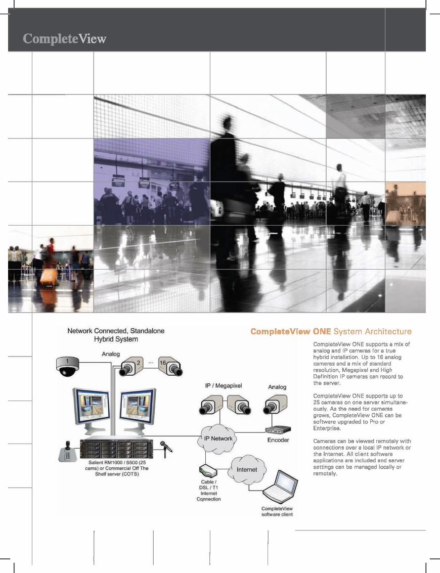
Network Connected, Standalone Hybrid System
SilliBnt RMlOOO I S500 (25 cams) or Commercial Off The
Shelf server (COTS)
IP I Megapixel
Internet Cqnnection
ComplataViaw ONE System Architecture
Analog
CompleteView software Client
CompleteView ONE supports a mix of analog end IP cameras for a true hybrid installation. Up to 16 analog cameras and a mix of standard resolution, Megapixel and High Definition IP cameras can record to the server.
CompleteView ONE supports up to 25 cameras on one server simultaneously. M the need for cameras grows, CompleteView ONE can be software upgraded to Pro or Enterprise.
Cameras can be viewed remotely with connections over a 10cailP network or the Internet. All client software applications are included and server settings can be managed locally or remotely.

Co Pro & Com ",,'TarY'l Architecture
With CompleteView Pro and Enterprise all sites and cameras can be viewed simultaneously by
security system operators, The software scales to any number of servers, clients and cameras
system-wide, A mix of standard resolution, megapixel and PTZ cameras are supported.
A unique component of CompleteView Pro and Enterprise is Admin Console which offers
multi-server management, Admin Console is used to manage all servers simultaneously, In the
event of a problem with storage, cameras, or servers, the administrator can instantly see and
proactively respond to troubleshoot issues, Administration and live viewing can be done from any
workstation on the local network, or, if enabled can be accessed over the Internet.
Site 1
Analog
Hybrid
IP I Megapixel
CompleteView Remote Server Admin istralion
(Admin Console)
Multi-Site, Campus System
Router (Internet
Coonection)
Site 2
IP I Megapixel
Commercial SeNe' (COTS). With CompieteView Enterp<'ise Software
IP Only
CompieleView CompleleView sottwam d ient software cli",,!
CompleteView easily scales
from a few cameras on
one server to thousands of
cameras on multiple servers.
A true hybrid system, CompleteView
supports virtually all leading IP
and analog cameras and encoder
manufacturers.

More Facts & Features Stable Recording Architecture · · CompleteView is built from the ground up using a unique recording
architecture. Many traditional Video Management Systems store all video, audio and associated meta data to a
database file. In a Video management System, a power outage, hardware failure or other unexpected interruption of
the applications can cause the database to become corrupted. If the repair fails, all video contained in the database
is lost. CompleteView separates the video and stores it in a flat file structure, outside of its database, avoiding the
potential of database corruption and long database rebuilds.
Alarm Console · · Designed to display live video for active alarm conditions. Display up to 4 live video
sources simultaneously, list up to 100 most recent alarms and do on-screen analysis of live video and archived
event video concurrently.
Automated Attendant · · The most advanced automatic control feature
in CompleteView. When motion occurs on a fixed camera, that camera can
automatically instruct a PTZ camera to move to a preset location. When motion
occurs on multiple fixed cameras those cameras can control multiple PTZ
cameras. The system has the ability to give 'high priority' status
to important locations so a PTZ camera can hold the view even if
motion is detected in lower priority locations. The flexibility of
Automated Attendant gives you security coverage in multiple
locations with multiple views.
Network Friendly . . CompleteView was designed to 'play nice in the IT world'. It doesn't interfere with
existing applications, out of band management tools, anti-virus software or firewalls. Special features have been
added to minimize the footprint of digital video on your network and reduce the bandwidth consumed by remote
users.
---CompleteView includes Dyn.mic Resolution SCli1ina, a powerful feature to manage bandwidth and network
resources. Video is always recorded at the preconfigured resolution on the CompleteView Server. If video is displayed
in the CompleteView Video Client at a small size, the CompleteView Server will send a lower resolution copy of the
video stream bandwidth is displayed at a I size on the COlmp,let,eView' Vi,deo
Client, video i at the higher high qu!,Ii1'/' dl"pl"y.

ActIve Directory Integration
CompleteView Enterprise supports Active Directory
users and groups which can be imported into
CompleteVlew and config ed with security system
specific permissions. AD I gration avoids duplicate
entry of user i f aoo nd support!; e single set of credentials for both network and security
SmartSearch . . Instantaneous retrieval of archived video from any
camera or server by time. date or motion events. Missing personal items.
equipment or corporate assets? Choose a date and time. highlight any
location in the cameras' view and let CompleteView do the rest. All motion in
the highlighted area will be identified for viewing. Slow the video down.
speed it up. see it frame by frame or create an AVI file for viewing on any PC.
Multi Compression Support: Motion JPEG, MPEG4" H.264 CompleteView's recording engine supports Motion JPEG.
MPEG4 and H.264 compression. Supported formats allow
for live view. recording and playback in all major
non-proprietary compression formats.
• Recording. Live View & Playback of Motion JPEG.
MPEG4 & H.264*
• Optionally transcode between compression formats for
reduced storage cost
• Supports native compression from IP Cameras without
transcoding
• Different compression formats can be used for recording
and live view
-svailable on all analog and aelect IP Cameraa
ComplateView Config Server
.-\ \
t .-.-
Config Server is an optionally installable component of CompleteView Pro and Enterprise which allows for centralized
storage of client configuration. Config Server allows users to log into any workstation or monitoring center and
maintain their configured views. camera access and other settings. For security operations with multiple monitoring
centers this can be an especially useful tool for scheduling guards at different stations. Security does not have to be
sacrificed in situations where a user without acx:ess to certain cameras needs to log into the security system from a
workstation configured to acx:ess normally unauthorized cameras and views.
Config Server also allows the administrators to centrally distribute new client software releases. When new versions
of CompleteView client applications become available. the administrator can push the new release to the Config
Server. The next time a client logs in. the user is prompted to upgrade with no further administrator intervention.

Dramatically lower your total cost of ownership. Complete View enables you
to implement a comprehensive video management strategy and cut the costs of
managing your enterprise.
IP or camera. & Ace •• Control •• CompleteView takes the complexity out of designing and implementing your surveillance system by supporting differing
camera technologies in a seamless manner. Enhance your security by integrating video and access control with a number
of supported access control products.
A true hybrid system with seamless integration of analog and IP technologies, CompleteView supports virtually all leading
Ip, analog and encoder manufacturers, allowing you to choose from a wide variety .
••• CompleteView can be delivered in three ways:
• Pre-installed on Salient Systems' purpose-built workstations and servers.
• Pre-installed on tier one industry standard platforms such as Dell. HP or other leading hardware vendors.
• Available as software only.
ll".a,.vInstallation • • •
Lower your manpower costs with CompleteView integrated systems pre-loaded with application software and
documentation. AIl intuitive user interiace guides users through set-up, log on and camera viewing. Full documentation
is shipped with each system or copy of software.
Pain Free ••• Camera licenses can be transferred from one system to another and replaced with identical units, different models, or
with a camera from a completely different manufacturer - all without extra license costs or penalties.
---.;;;i _ •. ~~-
&.~ \
~ ~ ---
I


Tripp Lite1111 West 35th Street
Chicago, IL 60609 USATelephone: +(773) 869 1234
E-mail: [email protected]
Model #: SU3000RTXL3USmartOnline 3kVA On-Line Double-Conversion UPS, 3U Rack/Tower, 110/120V NEMA outlets
Highlights
3000VA / 3kVA / 2400 watt on-line double-conversion 3U rack/tower UPS
110/120V +/-2% output at 50/60Hz, high efficiency economy mode option
Expandable runtime, Hot-swappable battery modules
USB, RS232 & EPO ports; support for SNMP/WEB card options
Front panel status LEDs with detailed load and battery metering
2 independently switchable output load banks
NEMA L5-30P input; L5-30R, 5-15/20R & 5-15R outlets
Description3000VA on-line, double-conversion UPS system for critical server, network and telecommunications equipment. 3U rackmount form factor with an
installed depth of 26 inches. Expandable battery runtime with optional BP72V15-2U (limit 1) and BP72V28RT-3U (multi-pack compatible) external
battery packs. Full time sine wave 110 or 120V output with +/-2% voltage regulation. Online, double-conversion Uninterruptible Power Supply (UPS)
actively converts raw incoming AC power to DC, then re-converts output back to completely regulated, filtered AC output. Operates continuously
without using battery power during brownouts to 65V and overvoltages to 150V. Highly efficient operation in optional economy mode saves BTU heat
output and energy costs. NEMA L5-30P input plug. NEMA 5-15, NEMA 5-15/20R and NEMA L5-30R output receptacles. Network-grade AC surge
and noise suppression. Zero transfer time between AC and battery operation. Network management interfaces support simultaneous
communications via USB port, DB9 serial port and SNMPWEBCARD slot. Built-in DB9 port offers both enhanced RS-232 enabled monitoring data,
plus contact closure monitoring ability. HID-compliant USB interface enables integration with built-in power management and auto shutdown
features of Windows and Mac OS X. Supports simultaneous detailed monitoring of equipment load levels, self-test data and utility power conditions
via all 3 network interfaces. Includes PowerAlert monitoring software and complete cabling. Emergency Power Off (EPO) interface. Integrated
two-bank PDU switching supports load shedding and remote reboot of connected equipment. 3-stage metered current monitoring and battery
charge status LEDs. LED display panel easily rotates for viewing in rackmount or tower configurations. Dataline surge suppression for dialup, DSL
or network Ethernet connection. Utility power and voltage regulation LEDs. Audible alarm. Self-test. Fault-tolerant auto-bypass mode. 4-post
rackmount accessories included; 2-9USTAND tower kit and 2POSTRMKITWM 2-post rackmount accessories available. Field-replaceable,
hot-swappable internal batteries and external battery packs. Attractive all-black color scheme. 2-year warranty and $250,000 connected equipment
insurance; extended warranty and service contracts available.
Package Includes
SU3000RTXL3U UPS SystemPowerAlert Software and CablingMounting hardware for 4 post rack enclosuresInstruction manual
Features
SmartOnline high performance UPS system is ideal for critical voice, data, medical and industrial network applicationsTrue on-line, double-conversion UPS provides perfectly regulated sine wave output within 2% of 110/120V (user selectable) under all usageconditions

conditionsMaintains continuous operation through blackouts, voltage fluctuations and surges with zero transfer timeHighly efficient operation in optional economy mode setting, saving BTU heat output and energy costsRemoves harmonic distortion, fast electrical impulses, frequency variations and other hard to solve power problems not addressed by otherUPS typesCorrects line voltage conditions as low as 65V and as high as 150V back to selectable 110/120V (+/-2%) valuesStandard internal battery set offers 14 minutes runtime at half load (1200W) and 5 minutes at full load (2400W)Expandable battery runtime with optional BP72V15-2U (limit 1) and BP72V28RT-3U (no limit) external battery packsCompact rackmount form factor installs using only 3 rack spaces (3U) with a maximum installed depth of 26 inchesShips with all mounting accessories for 4 post rackmount installationOptional 2POSTRMKITWM enables 2 post rackmount installation (not wallmount compatible)Optional 2-9USTAND accessory enables small-footprint upright tower placementFault tolerant electronic bypass maintains utility output during a variety of UPS fault conditionsNetwork interfaces support simultaneous communications via built-in USB, DB9 serial / contact-closure and SNMPWEBCARD slotHID compliant USB interface enables integration with built-in power management and auto shutdown features of Windows and Mac OS XIncluded PowerAlert UPS monitoring software supports safe unattended shutdown, monitoring and control via local connected servers, plusany number of additional servers over IPUPS interface supports on-battery, low-battery, power-restored, AC-voltage, DC-voltage, output current monitoring, battery charge current,battery capacity, AC line frequency, timed inverter shutoff, activate self-test, load bank output power control and remote reboot, UPSnominal voltage adjustment and UPS line to battery power voltage setpointsBuilt-in Emergency Power Off (EPO) interface with cableNEMA L5-30P input plug; NEMA 5-15/20R & L5-30R output receptaclesIntegrated 2 bank switched PDU enables remote outlet management for load shedding or remote reboot of individual load banks (eachbank has four outlets)Front panel LEDs offer current monitoring and battery charge level informationUPS ships fully assembled in full compliance with DOT regulations; no time consuming connection of internal batteries by user requiredSingle line TEL/DSL or network ethernet line surge suppression2 year manufacturer's product warranty, $250,000 Ultimate Lifetime Insurance
Specifications
OUTPUT
Output Volt AmpCapacity (VA)
3000
Output kVA capacity(kVA)
3
Output Watt Capacity(watts)
2400
Output kW capacity 2.4
Output power factor 0.8
Crest Factor 3:1
Nominal OutputVoltage(s) Supported
110V; 120V
Nominal Voltagedetails
120V default
Frequencycompatibility
50 / 60 Hz
Frequencycompatibility details
Output frequency matches input nominal on startup, defaults to 60 Hz on cold-start
Output voltageregulation (line mode)
+/- 2%
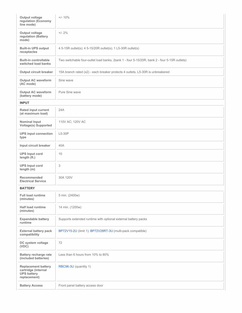
Output voltageregulation (Economyline mode)
+/- 10%
Output voltageregulation (Batterymode)
+/- 2%
Built-in UPS outputreceptacles
4 5-15R outlet(s); 4 5-15/20R outlet(s); 1 L5-30R outlet(s)
Built-in controllableswitched load banks
Two switchable four-outlet load banks, (bank 1 - four 5-15/20R, bank 2 - four 5-15R outlets)
Output circuit breaker 15A branch rated (x2) - each breaker protects 4 outlets, L5-30R is unbreakered
Output AC waveform(AC mode)
Sine wave
Output AC waveform(battery mode)
Pure Sine wave
INPUT
Rated input current(at maximum load)
24A
Nominal InputVoltage(s) Supported
110V AC; 120V AC
UPS input connectiontype
L5-30P
Input circuit breaker 40A
UPS Input cordlength (ft.)
10
UPS Input cordlength (m)
3
RecommendedElectrical Service
30A 120V
BATTERY
Full load runtime(minutes)
5 min. (2400w)
Half load runtime(minutes)
14 min. (1200w)
Expandable batteryruntime
Supports extended runtime with optional external battery packs
External battery packcompatibility
BP72V15-2U (limit 1); BP72V28RT-3U (multi-pack compatible)
DC system voltage(VDC)
72
Battery recharge rate(included batteries)
Less than 6 hours from 10% to 80%
Replacement batterycartridge (internalUPS batteryreplacement)
RBC96-3U (quantity 1)
Battery Access Front panel battery access door

Battery replacementdescription
Hot-swappable, user replaceable batteries
VOLTAGE REGULATION
Voltage regulationdescription
Online, double-conversion power conditioning
Overvoltagecorrection
2% output voltage regulation during overvoltages to 150
Undervoltagecorrection
2% output voltage regulation during undervoltages to 80
Severe undervoltagecorrection
2% output voltage regulation during undervoltages to 65 (under 70% load only)
LEDS ALARMS & SWITCHES
LED Indicators 14 LEDs indicate line power, online mode, economy/bypass mode, on-battery, overload, battery low, replace batteryand fault status information; 4-LED meter displays load and battery charge levels; LED panel rotates for viewing inrack/tower formats
Alarms Audible alarm indicates UPS startup, power-failure, low-battery, overload, UPS fault and remote shutdown conditions
Alarm canceloperation
Power-fail alarm can be silenced using alarm-cancel switch
Switches 2 switches control off/on power status and alarm-cancel/self-test operation
SURGE / NOISE SUPPRESSION
UPS AC suppressionjoule rating
510
UPS AC suppressionresponse time
Instantaneous
UPS Datalinesuppression
1 line TEL/DSL (1 in / 1 out); 10/100Base T Ethernet
EMI / RFI AC noisesuppression
Yes
PHYSICAL
Installation formfactors supportedwith includedaccessories
4 post 19 inch rackmount (mounting rail kit included)
Installation formfactors supportedwith optionalaccessories
2 post rackmount (2POSTRMKITWM); Tower (2-9USTAND)
Optional mountingaccessory notes
Wallmount installation not recommended
Primary form factor Rackmount
UPS / Power Moduledimensions inprimary form factor(height x width xdepth / inches)
5.2 x 17.8 x 26
UPS / Power Moduledimensions inprimary form factor(height x width xdepth / cm)
13.3 x 45.1 x 66

Installed wholesystem total rackspace height (rackspaces)
3U
Secondary form factor Tower (requires 2-9USTAND)
UPS / Power Moduleweight (lbs)
73.8
UPS / Power Moduleweight (kg)
33.5
UPS Shippingdimensions (height xwidth x depth / inches)
11.2 x 23 x 31.5
UPS Shippingdimensions (height xwidth x depth / cm)
28.6 x 58.4 x 80
Shipping weight (lbs) 112.4
Shipping weight (kg) 51
UPS housing material Steel
Cooling method Fan
ENVIRONMENTAL
OperatingTemperature Range
+32 to +104 degrees Fahrenheit / 0 to +40 degrees Celsius
Storage TemperatureRange
+5 to +122 degrees Fahrenheit / -15 to +50 degrees Celsius
Relative Humidity 0 to 95%, non-condensing
AC mode BTU / hr.(full load)
1112.7
AC economy modeBTU / hr. (full load)
520.9
Battery mode BTU /hr. (full load)
1219.3
AC economy modeefficiency rating(100% load)
94%
COMMUNICATIONS
Communicationsinterface
USB (HID enabled); DB9 Serial; Contact closure; EPO (emergency power off); Slot for SNMP/Web interface
Network monitoringport description
Supports detailed monitoring of UPS and site power conditions; DB9 port supports RS232 and contact closurecommunications
PowerAlert software Included
Communicationscable
USB and DB9 cabling included
WatchDogcompatibility
Supports Watchdog application, OS and hard-reboot restart options for remote applications
LINE / BATTERY TRANSFER
Transfer time No transfer time (0 ms.) in online, double-conversion mode

Low voltage transferto battery power(setpoint)
80V (100% load), 65V (
High voltage transferto battery power(setpoint)
150
SPECIAL FEATURES
Cold Start (startup inbattery mode duringa power failure)
Cold-start operation supported
High availability UPSfeatures
Automatic inverter bypass; Hot swappable batteries
Green & highefficiency features
High efficiency economy mode operation; Individually controllable load banks; Schedulable daily hours of economymode operation
CERTIFICATIONS
UPS Certifications Tested to UL1778 (USA); Tested to CSA (Canada); Tested to NOM (Mexico); Meets FCC Part 15 Category A (EMI)
WARRANTY
Product WarrantyPeriod (U.S., Canada& Puerto Rico)
2-year limited warranty
ConnectedEquipment Insurance(U.S., Canada &Puerto Rico)
$250,000 Ultimate Lifetime Insurance
Related ItemsOptional Products
Product Type Related Model Description Qty.
SNMP Accessories SNMPWEBCARD For remote monitoring and control via SNMP, Web, or Telnet. -
SNMP Accessories ENVIROSENSE Monitors temperature, humidity and contact-closure inputs. (RequiresSNMPWEBCARD or switched PDU.)
-
UPS Accessories RELAYIOCARD Programmable Relay I/O Card -
UPS Accessories MODBUSCARD For remote monitoring and control via MODBUS protocol -
Shutdown Cable Kits AS400CABLE KIT Power Management Tools - UPS Communication Cable Kit for Systemi / AS400 / iSeries Servers
-
Tower Stands 2-9USTAND Enables Tower Placement of Rackmount UPS Systems -
Rackmount/Wallmount Kits 2POSTRMKITHD Enables 2-Post Rackmount Installation of 3U and Larger UPS,Transformer and Battery Pack Components
-
External Battery Packs BP72V15-2U BP72V15-2U - External Battery Pack for UPS System -
External Battery Packs BP72V28RT-3U BP72V28RT-3U - External Battery Pack for UPS System -
Extended Warranties WEXT3-2200-3000 3-Year Extended Warranty - For Smart Line-Interactive and OnlineTower or Rack models, 2200-3000VA
-
Extended Warranties WEXT5-2200-3000 5-Year Extended Warranty - For Smart Line-Interactive and OnlineTower or Rack models, 2200-3000VA or less
-
Power Distribution PDUB30 Dual source Power Distribution Unit / PDU with Manual Transfer Switchenables Hot-swappable UPS Replacement in Critical NetworkApplications
-
Power Distribution PDU2430 Basic PDU / Power Distribution Unit - Safe, reliable power distributionfor critical networking equipment
-

Power Distribution PDUMV30 Metered 0U Vertical Rack PDU - Metered Power Distribution Unit forNetwork Applications
-
Power Distribution PDUMV30NET Switched, Metered PDU with Remote Monitoring - 0U VerticalRackmount Power Distribution Unit for Networks with IndividuallySwitchable Outlets, Current Metering, Remote Monitoring and Control
-
Power Distribution PDUMH30NET Switched, Metered PDU with Remote Monitoring - 2U RackmountPower Distribution Unit for Networks with Individually SwitchableOutlets, Current Metering, Remote Monitoring and Control
-
Power Distribution PDUMNV30 Monitored PDU / Power Distribution Unit supports real-time remotemonitoring of load level, voltage and frequency with options for remoteenvironmental and security monitoring
-
Power Cables P043-002 2-ft. 10AWG Heavy Duty Power Cord with 20 AMP Breaker, (NEMAL5-30P to NEMA L5-20R)
-
Power Distribution P044-06I 6-inch 12AWG Heavy Duty Power Adapter cord(NEMA-L5-20R to NEMA-5-20P)
-
Power Distribution P049-010 10-ft. 12AWG Heavy Duty Power cord(IEC-320-C19 to NEMA 5-20P)
-
More information, including related products, owner's manuals, and additional technical specifications, can be found online at
www.tripplite.com/en/products/model.cfm?txtModelID=3023.
Copyright © 2011 Tripp Lite. All rights reserved. All trademarks are the sole property of their respective owners. Tripp Lite has a policy of continuous
improvement. Specifications are subject to change without notice. Photos may differ slightly from final products.

PRODUCT SPECIFICATION
power solutions
C654 / REVISED 11-4-10
International StandardsOrganization Registered Firm;
ISO 9001 Quality System
WCS Series Power Supply
24 VAC POWER SUPPLY, OUTDOOR
Product Features
• 4 A or 20 A Capacities
• 1–4 Outputs
• Selectable Input Voltage
• 24 VAC Output or 28 VAC Output for Longer Wire Runs
• Meets NEMA Type 4X/IP66 Standards for Weatherproof Enclosure
• AC Power Indicator with Power On/Off Switch
• Compatible with Cameras, Domes, and Pan/Tilts
• WCS4-20B Has Class 2 Rated Outputs
Power supplies in the
WCS Series
offer a variety of configurationsfor powering up to four outdoor units from a single power source.
The power supplies provide 24 VAC output for 1–4 units, dependingon the model selected. To compensate for voltage losses over longwire runs, 28 VAC outputs are available on all models. The inputvoltage of all models is also selectable.
For integrated systems such as Spectra
®
and Esprit
®
, the powersupplies are capable of handling pan/tilt, heater, and bloweroperation in addition to the camera.
The
WCS1-4
has one fused output and is capable of handling up to4 A (100 VA) of total load. The WCS4-20 has four fused outputs andis capable of handling up to 20 A (480 VA) of total load. The
WCS4-20B
has four protected outputs with self-resetting circuitbreakers and is capable of handling up to 12 A (288 VA) of totalload. Fuses provide a greater degree of protection for the unitbecause they are faster acting and more precise. Circuit breakerswill self-reset when the fault is corrected, eliminating the need forreplacing fuses. However, the amount of current required to trip acircuit breaker can vary as much as 100 percent, depending ontemperature. In the fused models, the values of fuses can bechanged depending upon the specific current requirements of theequipment connected.
12.61 (32.03)11.98 (30.43)
3/4 INCH HOLESFOR CONDUIT
15.26(38.76)
5.06(12.85)
6.00(15.24)
14.26(36.22)
WCS4-20/WCS4-20B
NOTE: VALUES IN PARENTHESES ARE CENTIMETERS; ALL OTHERS ARE

Pelco, Inc. Worldwide Headquarters:
3500 Pelco Way, Clovis, California 93612-5699 USA
USA & Canada
Tel: (800) 289-9100 • FAX: (800) 289-9150
International
Tel: +1 (559) 292-1981 • FAX: +1 (559) 348-1120
www.pelco.com
TECHNICAL SPECIFICATIONS
MODELS
WCS1-4 Outdoor camera power supply, 100/120/240 VAC input. One 24/26/28 VAC output, total current capacity of 4 A (100 VA).
WCS4-20 Outdoor multiple camera power supply, 120/240 VAC input. Four fused 24/28 VAC outputs, total current capacity of 20 A (480 VA).
WCS4-20B Outdoor multiple camera power supply, 120/240 VAC input. Four protected 24/28 VAC outputs, total current capacity of 12 A (288 VA) with circuit breakers.
Product Capacity Chart
A partial list of compatible products and the number of units that may be powered by each power supply are listed below. Capacity is based on the VA rating of each product to be used with the power supply.
MECHANICAL
Cable Entry Hole plugs for 0.75-inch (1.9 cm) conduitLatch Stainless steel link-lock latch; can be secured
with padlock (not supplied)
ELECTRICAL
Input VoltageWCS1-4 100/120/240 VAC, 50/60 HzWCS4-20/WCS4-20B 120 or 240 VAC, 50/60 Hz
Output VoltageWCS1-4 24/26/28 VACWCS4-20, WCS4-20B 24/28 VAC
Required Input CurrentWCS1-4 1 AWCS4-20/WCS4-20B 4.40/2.30 A
Output Fuse RatingsWCS1-4 4 A*WCS4-20 8 A*
Output Circuit Breaker RatingsWCS4-20B 3A*
Input Connectors Screw-type barrier stripsOutput Connectors Screw-type barrier strips; WCS4-20B is
suitable for Class 2 wiringInput Wire Size 12–16 gauge solid wireOutput Wire Size
WCS1-4 16–20 gauge solid or stranded wireWCS4-20/-20B 16–22 gauge solid or stranded wire
GENERAL
Environment OutdoorOperating Range –50° to 122°F (–45.56° to 50°C)Construction AluminumFinish Gray polyester powder coatWeight Unit Shipping
WCS1-4 6.8 lb (3.1 kg) 8 lb (3.6 kg)WCS4-20/4-20B 16.2 lb (7.3 kg) 18 lb (8.1 kg)
*Individual output cannot exceed this rating, and the total of all outputs cannot exceed the overall rating of the power supply (refer to
Models
).
The following are the recommended maximum distances (transformer to load) and are calculated with a 10 percent voltage drop. (Ten percent is generally the maximum allowable voltage drop for AC-powered devices.) Distances are calculated in feet; values in parentheses are meters.
Recommended Wiring Distance Chart
CERTIFICATIONS/RATINGS
• CE• UL/cUL Listed• Meets NEMA Type 4X and IP66 standards
ProductPower Supply Model
WCS1-4 (100 VA)
WCS4-20(480 VA)
WCS4-20B(288 VA)
CCD Camera (12 VA max)Indoor Spectra (25 VA)Outdoor Spectra (70 VA)Outdoor DF5 (62 VA)Esprit (70 VA)
11111
44444
44444
Pelco, the Pelco logo, and other trademarks associated with Pelco products referredto in this publication are trademarks of Pelco, Inc. or its affiliates. All other
product names and services are the property of their respective companies.Product specifications and availability are subject to change without notice.
©Copyright 2010, Pelco, Inc. All rights reserved.
InputVoltage
Total VAConsumed
Wire Gauge
20 AWG(0.5 mm
2
)18 AWG(1.0 mm
2
)16 AWG(1.5 mm
2
)
24 VAC 255070
1135641
(34)(17)(12)
1809064
(55)(27)(19)
287143102
(87)(43)(31)
26 VAC 255070
1336649
(40)(20)(15)
21210578
(64)(32)(24)
337168124
(103)(51)(38)
28 VAC 255070
1557755
(47)(23)(17)
24612288
(75)(37)(27)
392195135
(119)(59)(41)
4.01 (10.3) 6.50
(16.5)
7.65 (19.4)
7.32 (18.8)
6.63 (16.8)
6.71 (17.0)
4.50 (11.4)
WCS1-4 POWER SUPPLY
NOTE: VALUES IN PARENTHESES ARE CENTIMETERS;ALL OTHERS ARE INCHES.

DITEK’s DP4P protects all the sensitive feeds to critical Pan/Tilt/Zoom cameras, not just the video cable. Simple to install, the DP4P protects 24 Volt power conductors, 5 Volt RS-422 data pairs, and video conductors – all in one compact package. With the lowest video let through voltage (and best surge protection) on the market, the DP4P provides ideal surge protection for today’s sensitive, sophisticated PTZ cameras. Three different DP4P models protect coaxial, twisted pair, or Balun video circuits. The DP4PBP includes passive Balun conversion.
Pan/Tilt/Zoom Camera Surge ProtectorGeneral Product Specifications
DTK-DP4P Series
DTK-DP4PDTK-DP4PBPDTK-DP4PTPV
One DITEK Center1720 Starkey RoadLargo, FL 33771
Document: SPS-100061-001 Rev 5 05-11©2011 DITEK Corp.
Specification Subject to Change
1-800-753-2345 Direct: 1-727-812-5000Technical Support: 1-888-472-6100
www.ditekcorp.com
Product Features
• Protects power, video and four dataconductors in one package
• 5 Amp, 24V circuit protects power feeds to camera, heater, blower, defroster
• Multi-stage, SAD technology, hybrid design provides the best possible protection
• Single point ground improves protection and speeds installation
• Protect standard Coax (DP4P), Balun(DP4P BP), or Twisted Pair (DP4PTPV)video connections
• Ten Year Limited Warranty
Product Selector
• Coax connected PTZ camera: DTK-DP4P• Balun connected PTZ camera: DTK-DP4PBP• Twisted pair video PTZ camera: DTK-DP4PTPV


DATASHEET
AXIS 243Q Blade Video Server enables high resolution, full frame rate video surveillance and remote monitoring in MPEG-4 or Motion JPEG on all four channels. The video encoder converts analog video into high quality, de-interlaced digital video, and can deliver the highest resolution, 4CIF, at 30/25 (NTSC/PAL) frames per second.
AXIS 243Q Blade Video Server in combination with Axis video encoder racks are specially made for applications involving a large number of cameras. Axis video encod-er rack offers flexibility and support for an expanding video surveillance system.
AXIS 243Q Blade Video Server is a high performance, four-channel video encoder blade enabling four analog cameras to be integrated into an IP-based video surveillance system. The video encoder is the ideal choice for casinos, airports, traffic surveillance and prisons — where the advantages of networked video are required as added benefits to analog surveillance systems.
AXIS 243Q Blade Video ServerFull frame rate, high-density video encoder.
> Full frame rate
> High-quality, de-interlaced video
> Simultaneous MPEG-4 and Motion JPEG
> Video motion detection and pre-/post-alarm buffer
> Support for PTZ and dome cameras
Offering high-resolution professional video surveillance and remote monitoring, the AXIS 243Q Blade offers a number of advanced features, such as video motion detection, active tampering alarm, and alarm buffering. Pre- and post-image alarm buffering secures images just before and after an alarm.
AXIS 243Q Blade Video Server connects to all leading brands of video analog pan/tilt/zoom (PTZ) cameras to allow for easy operation of these PTZ cameras across the IP network.

Technical specifications – AXIS 243Q Blade Video Server
www.axis.com
©2011 Axis Communications AB. AXIS COMMUNICATIONS, AXIS, ETRAX, ARTPEC and VAPIX are registered trademarks or trademark applications of Axis AB in various jurisdictions. All other company names and products are trademarks or registered trademarks of their respective companies. We reserve the right to introduce modifications without notice.
4221
2/EN
/R1/
1105
Video encoderModels AXIS 243Q Blade Video Server
Requires Axis video encoder rackVideo compression
MPEG-4 Part 2 (ISO/IEC 14496-2)Motion JPEG
Resolutions 704x576 to 160x120
Frame rate MPEG-4
Up to 30/25 (NTSC/PAL) per channel in all resolutions
Frame rate Motion JPEG
Up to 30/25 (NTSC/PAL) per channel in all resolutions
Video streaming Simultaneous MPEG-4 and Motion JPEGControllable frame rate and bandwidthVBR/CBR MPEG-4
Image settings Compression, colorRotation: 90°, 180°, 270°Aspect ratio correctionText and image overlayPrivacy maskDeinterlace filter
NetworkSecurity Password protection, IP address filtering, HTTPS encryption,
IEEE 802.1X network access controlSupported protocols
IPv4/v6, HTTP, HTTPS, QoS layer 3 DiffServ, FTP, SMTP, Bonjour, UPnP, SNMPv1/v2c/v3(MIB-II), DNS, DynDNS, NTP, RTSP, RTP, TCP, UDP, IGMP, RTCP, ICMP, DHCP, ARP, SOCKS
System integrationApplication Programming Interface
Open API for software integration, including VAPIX® from Axis Communications available at www.axis.com
Intelligent video Video motion detection, active tampering alarm
Alarm triggers Intelligent video, external inputs, video loss, on boot, PTZ preset
Alarm events File upload via FTP, HTTP and emailNotification via email, HTTP and TCPExternal output activation
Video buffer 9 MB pre- and post-alarm per channel
Pan/Tilt/Zoom Wide range of analog PTZ cameras supported (drivers available for download at www.axis.com)20 presets/camera, guard tour, PTZ control queueSupports Windows compatible joysticks
GeneralProcessor and memory
4x ETRAX 100LX, 4x ARTPEC-2, 4x 32 MB RAM, 4x 8 MB Flash
Power Powered from AXIS 291 1U Video Server Rack or AXIS Q7900 Rack
Connectors 4 analog composite video BNC input, NTSC/PAL auto-sensingRJ-45 10BASE-T/100BASE-TX Terminal block for 4 inputs, 4 outputs and RS-485 half duplex
Operating conditions
0 – 45 °C (32 – 113 °F)Humidity 20 – 80% RH (non-condensing)
Approvals EN 61000-6-1, EN 61000-6-2, EN 55024, EN 55022 Class B, EN 61000-3-2, EN 61000-3-3, FCC Part 15 Subpart B Class B, AS/NZS CISPR 22, ICES-003, VCCI Class B, ITE, ULEN 60950-1
Weight 270 g (0.6 lbs)
Included accessories
Installation Guide,CD with installation and management tools, software and User’s Manual, 1 Windows decoder user license
Dimensions
Optional accessories
Required hardware
More information is available at www.axis.com
AXIS Q7900 Rack AXIS 291 1U Video Server Rack
For information on AXIS Camera Station andvideo management software fromAxis’ Application Development Partners, seewww.axis.com/products/video/software/
AXIS T8310 Video Surveillance Control Board
129 mm (5.2’’)
30 m
m (1
.2’’)
229 m
m (9.3’
’)

DATASHEET
AXIS 291 1U Video Server Rack combines high reliability and functionality with quick, flexible and professional installation. The rack is designed to migrate from 4 to 18 analog cameras into high performance, IP-based, digital solutions, using only one Ethernet port.
AXIS 291 1U is designed for applications that need to be able to expand, not only by adding more channels, but also by using different types of cameras.
AXIS 291 1U Video Server Rack is a high-density solution for seamless and professional installation of video encoders. AXIS 291 1U is designed for expanding applications and is ideal for airports, hotels and train stations – premises where analog cameras are already installed.
AXIS 291 1U Video Server RackFull frame rate, high-density video encoder rack solution.
> High density
> 1U 19” industry standard rack
> 3 expansion slots for video encoder blades
> Built-in universal power supply
> Compatible with all Axis Blades
AXIS 291 1U is a 19” video encoder rack that holds up to 3 interchangeable and hot-swappable blades. Together with the video encoder blades, this rack provides MPEG-4 and Motion JPEG video at 25/30 frames per second at up to 4CIF resolution on all channels simultaneously. AXIS 291 1U can also provide H.264, dependent on the blade version.
The video encoder enables pan/tilt/zoom control over the network of all leading brands of analog video cameras on the market.

Technical specifications – AXIS 291 1U Video Server Rack
www.axis.com
©2011 Axis Communications AB. AXIS COMMUNICATIONS, AXIS, ETRAX, ARTPEC and VAPIX are registered trademarks or trademark applications of Axis AB in various jurisdictions. All other company names and products are trademarks or registered trademarks of their respective companies. We reserve the right to introduce modifications without notice.
4222
0/EN
/R1/
1105
291 1U Video encoder rackExpansion slots 3 slots for Axis video encoder blades
Casing Metal casing for standalone or rack mounting
Power 100 – 240 V AC, 1.9 A max 80 W (with 3x243Q)
Connectors Ethernet 10BASE-T/100BASE-TX/1000BASE-T, RJ-45 (Gigabit Ethernet) 3 terminal blocks: 4 alarm inputs 4 outputs RS-485/422 half-duplex
Operating conditions
0 – 45 ºC (32 – 113 ºF)Humidity 20 – 80% RH (non-condensing)
Approvals EN 55022 Class B, EN 61000-3-2, EN 61000-3-3, EN 55024,EN 61000-6-1, EN 61000-6-2, FCC Part 15 Subpart B Class B,VCCI Class B, AS/NZ CISPR 22, ICES-003, ITE, UL, cUL, EN 60950-1, CB-certificate, KTL
Weight 3.7 kg (8.2 lbs) excluding blades
Included accessories
Installation Guide, mounting kit, AC power cable
Compatible video encoder bladesBlade No. of channels Video compression* Frames per second
in max. resolutionExternal inputs/outputs PTZ support
AXIS Q74066
H.264 Multiple streams at 30/25 in D1 per channel 8
configurable •Motion JPEG
AXIS 243Q4
MPEG-4 30/25 in 4CIF per channel4/4 •
Motion JPEGAXIS 241Q
4MPEG-4 21/17 in 4CIF using 1 channel,
20/17 in CIF per channel using 4 channels4/4 •
Motion JPEG 30/25 in 4CIF using 1 channel,30/25 in CIF per channel using 4 channels
AXIS 240Q 4 Motion JPEG 6/5 in 4CIF per channel 4/4 •AXIS 241S
1MPEG-4 21/17 in 4CIF, 30/25 in 2CIF
4/4 •Motion JPEG 30/25 in 4CIF
Dimensions Dimensions
More information is available at www.axis.com
Back viewFront view
467 mm (18.4”)
483 mm (19.0”)
31 m
m (1
.2”)
44 m
m (1
.8”)
134 mm (5.3”)
263 mm (10.4”)
*H.264 is also known as MPEG-4 Part 10/AVC. In the table, MPEG-4 refers to MPEG-4 Part 2.

D S C P O W E R S E R I E S C O N T R O L PA N E L S v 4 . 2
DSC is a recognized leader in the design and manufacturing of reliable, feature-rich intrusion alarm control panels that easily integrate with an array of alarm communicators, verification modules and cabling solutions. From their clean unobtrusive look to their advanced technologies, DSC panels are a favorite of both users and installers.
ENHANCE YOUR CUSTOMERS’ EXPERIENCE WITH THE NEW, EASY-TO-INSTALL POWERSERIES™ V4.2 FROM DSC
New PowerSeries v4.2 control panels from DSC make installation easy, simple and fast. They feature template programming for new users and a programming interface that experts will be familiar with. This product also features independent end-of-line (EOL) configuration that makes installation faster than ever before. Each zone can be independently matched to a devices EOL configuration, reducing the time required to get a common EOL configuration across all devices.
PowerSeries v4.2 gives the user more control, thereby enhancing the functional experience. The user can Arm Away, Arm Stay or Disarm all partitions with just one operation.
If you’re worried about scalability, don’t be. PowerSeries v4.2 doubles the supported wireless zones on the PC1616 which allows up to 32 wireless zones.
PowerSeries v4.2 has been designed with commercial applications in mind. Featuring additional user codes, global arming and disarming, and scheduled auto arming and disarming, DSC control panels are the preferred choice of installers.
This product is RoHS compliant

D S C P O W E R S E R I E S C O N T R O L PA N E L S V 4 . 2
PowerSeries™ control panels have a proven reputation for providing the value and dependability
that security professionals expect. The modular design of PowerSeries control panels provides both versatility and flexibility in any application, from small residential to medium-sized commercial. Packed with features, they are easy to install, easy to program and easy to use.
For product informationwww.dsc.comProduct specifications and availability subject to change without notice. Certain product names mentioned herein may be trade names and/or registered trademarks of other companies.©2007 2007-12
Ordering Information:PC1616 PowerSeries 6-16 Zone Control PanelPC1832 PowerSeries 8-32 Zone Control PanelPC1864 PowerSeries 8-64 Zone Control Panel
New Features of the PowerSeries v4.2• Upto3TimesMoreUserCodes • PC1616increasesfrom32to48 • PC1832increasesfrom32to72 • PC1864increasesfrom32to95• DuressandSupervisoryCodeAttributes• TemplateProgramming• PC1616Supports32WirelessZones• AutoConnectPC-Link• AutomaticArm/Disarm• HolidaySchedules• ZoneBypassReportingCodes• GlobalAwayArmFunctionKey• GlobalStayArmFunctionKey• GlobalDisarmFunctionKey• IndependentZoneEndofLineConfiguration• 24HrNon-LatchingTamperZone• Identificationof1stZone-inAlarm• ScheduledDLSBatchUpload• TelephoneLineMonitored(TLM)TroublesReportingCode
sentviaT-Link
Configurable Features• EnableLatchingorNon-LatchingTroubles• UserOption[*][6]AccessiblebyallUsers• KeyswitchDisarmingDuringEntryDelay• KeyswitchArmsinAwayMode• AccessCodeRequiredforZoneBypass[*1],View
Troubles[*2]andAlarmMemory[*3]• MasterCodeBypassesHold-upZonesOnly• TroubleBeepsareSilent(ExcludingFire)• AccountCodeFollowsPhoneNumber• ResidentialDialDoesNotRequireHandshake
New PGMs• ZoneFollowerPGMSupportedbyall64Zones• TamperOutputTimer• Hold-UpOutput• BatteryTestOutput• AlternativeCommunicatorOutput• OpenAfterAlarm(AbortCode)• AwayArmedwithnoZoneBypassesStatusOutput
CP-01 CompliantAll PowerSeries control panels are compliant with the Security Industry Association (SIA) CP-01 standard. As more and more cities begin to incorporate this standard into their alarm ordinances for new installations, the occurrence of invalid alarm activations will be significantly reduced or eliminated.
SpecificationsPower Supply 16.5 VAC/40 VA @ 50/60 Hz
Current Draw (Panel) 110 mA (Nominal)
Auxiliary + Output 13.75 ± 5% Vdc/700 mA
Bell Output 13.75 ± 5% Vdc/700 mA
Operating Environment 32º to 120º F (0º to 49º C)
Relative Humidity 93%
Features PC1616 PC1832 PC1864
On-Board Zones 6 8 8
Hardwired Zones 16 (1 x PC5108) 32 (3 x PC5108) 64 (7 x PC5108)
Wireless Zones 32 32 32
Keypad Zone Support Yes Yes Yes
On-Board PGM Outputs
PGM 1 = 50 mAPGM 2 = 300 mA
PGM 1 = 50 mAPGM 2 = 300 mA
PGM 1, 3, 4 = 50 mAPGM 2 = 300 mA
PGM Expansion 8 x 50 mA (PC5208)4 x 500 mA (PC5204)
8 x 50 mA (PC5208)4 x 500 mA (PC5204)
8 x 50 mA (PC5208)4 x 500 mA (PC5204)
Keypads 8 8 8
Partitions 2 4 8
User Codes 47+ Master Codes 71+ Master Codes 94+ Master Codes
Event Buffer 500 Events 500 Events 500 Events
Battery Required 4 Ah / 7 Ah / 14 AHr 4 Ah / 7 Ah / 14 AHr 4 Ah / 7 Ah / 14 AHr
Bell Output 12 V / 700 mA (cont) 12 V / 700 mA (cont) 12 V / 700 mA (cont)
PowerSeries Features
P/N
300
0079
8 P
rinte
d in
Can
ada

Contact your DSC distributorwww.dsc.com
1-888-888-7838
Supported by PC1864, PC1832, PC1616, Power864™ and MAXSYS®
control panels via built-in PC-Link, or stand-alone mode for all other control panels
2-way, always-on IP communication
Works over local LAN/WAN network or the Internet
128-bit AES encryption (NIST approved)
Supports DHCP (dynamic IP addresses)
Reports events to 2 different receiver IP addresses
Polling and hardware substitution protection
Programmable heartbeat timer allows you to adjust the interval that the heartbeat signal is sent from the TL250 module to the central station IP receiver
Low network bandwidth requirements
Compatible with 10/100BaseT networks
4 on-board programmable inputs (expandable to 12 using PC5108 zone expander module)
2 programmable voltage outputs
Programmable through the panel keypad or T-Link Console software
Software upgrades via network
Download control panel via Internet with DLS2002SA software
UL AA High-Line Security and ULC Level 3/4/5 listed
T-Link TL250 Internet alarm communicators create fullysupervised security solutions between protectedpremises and central monitoring stations. The simple-to-
install modules save end-users money by taking advantage of
their existing networks to provide secure Internet
communications over a private network (LAN/WAN) or the
Internet, between the control panel and the Sur-Gard™ System
ll/III central station receivers. This method provides flexibility
and an always-on, two-way line of communication. The TL250
communication stream is small and requires only a limited
amount of network bandwidth. This ensures that the integrity
of the data being transferred never becomes compromised. To
reduce security risks, the TL250 utilizes
industry-leading, 128-bit AES encryption, polling and hardware
substitution protection.
tt
tt
Product Features:
tt
tt
tt
tt
tt
DSC T-LinkTM Internet Alarm Communicator TL250
t
t
t

Distributed by:For product informationwww.dsc.comProduct specifications and availability subject tochange without notice. Certain product namesmentioned herein may be trade names and/orregistered trademarks of other companies.©2007 2007•01
P/N
29
00
70
74
R0
03
Prin
ted
inC
anad
a
Value AddedTo ensure dependable and timely event notification, the TL250 iscapable of reporting to two different receiver IP addresses—aback-up feature that allows communication to continue in theevent one of the IP addresses is inaccessible. The TL250 can alsobe programmed to communicate events to two different e-mailaddresses. These e-mail addresses can be associated with apersonal computer, pager, enabled mobile phone or PDA.
FlexibilityProgramming the TL250 can be accomplished locally using thecontrol panel keypad or T-Link Console software over the IPnetwork connection made directly to TL250’s Ethernet port.
By interfacing to TL250’s four on-board programmable inputs, the unit can be configured to operate as a stand-alone communicator for interfacing existing third-party control equipment. Full two-way communication with the TL250 isachieved using the Sur-Gard System II or the Sur-Gard System IIIand its IP line card, the SG-DRL3-IP.
Secure CommunicationThe TL250 utilizes industry-leading 128-bit AES encryption, polling,hardware substitution protection, and application-specifichardware to help eliminate security risks.
Because the TL250 communication stream is minimal and drawsonly small amounts of network bandwidth, data transfer remainstimely and accurate.
DLS2002SA Download SoftwareSimple installation of the TL250 is assured throughutilization of the built-in PC-Link and T-Link Consolesoftware. Administration of accounts can beaccomplished over the Internet from anywhere in theworld using DLS2002SA download software—no othersoftware application is required.Software updates can be downloaded remotely fromany personal computer as the hardware platform of theTL250 features flash upgradeable memory.
CompatibilityThe TL250 is compatible with the following controlpanels via the built-in PC-Link:
• PC1864 PowerSeries 8-64 zone control panel• PC1832 PowerSeries 8-32 zone control panel• PC1616 PowerSeries 6-16 zone control panel• Power864 PC5020 (version 3.2 or higher)• MAXSYS PC4020 (version 3.31 or higher)
Direct trigger inputs of the TL250 can be controlled by outputs on any control panel.
Central station IP receivers:• Sur-Gard System lll with SG-DRL3-IP line card• Sur-Gard System ll
Specifications
Dimensions . . . . . . . . . . . . . . . . . . . . . . . . 3.25” x 5.25” (83 mm x 133 mm)
Input Voltage . . . . . . . . . . . . . . . . . . . . . .12 VDC
Current Draw . . . . . . . . . . . . . . . . . . . . . . 250 mA(275 mA with PGM or PC5108)
Operating Environment . . . . . . . . . . . . 32° to 120° F(0° to 49° C)
Relative Humidity . . . . . . . . . . . . . . . . . . 5% to 93%Ordering Information:TL250 . . . . . . . . . . . . . . . . . . . . . . . . . . . Internet Alarm CommunicatorPC5108 . . . . . . . . . . . . . . . . . . . . . . . . . . 8 Hardwire Zone Expander
DSC T-LinkTM Internet Alarm Communicator TL250
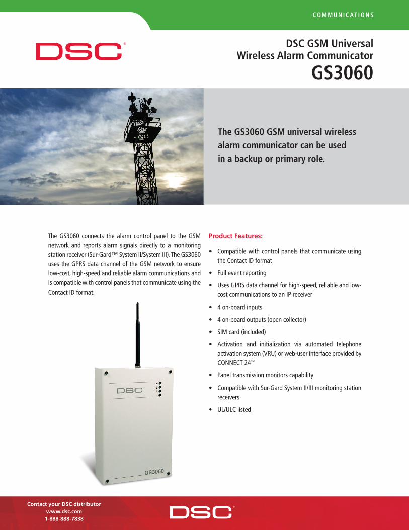
c o m m u n i c at i o n s
Dsc Gsm universal Wireless alarm communicator
Gs3060
Contact your DSC distributorwww.dsc.com1-888-888-7838
The GS3060 connects the alarm control panel to the GSM network and reports alarm signals directly to a monitoring station receiver (Sur-Gard™ System II/System III). The GS3060 uses the GPRS data channel of the GSM network to ensure low-cost, high-speed and reliable alarm communications and is compatible with control panels that communicate using the
Contact ID format.
Product Features:
• Compatiblewithcontrolpanelsthatcommunicateusingthe Contact ID format
• Fulleventreporting
• UsesGPRSdatachannelforhigh-speed,reliableandlow-cost communications to an IP receiver
• 4on-boardinputs
• 4on-boardoutputs(opencollector)
• SIMcard(included)
• Activation and initialization via automated telephoneactivationsystem(VRU)orweb-userinterfaceprovidedbyCONNECT24™
• Paneltransmissionmonitorscapability
• CompatiblewithSur-GardSystemII/IIImonitoringstationreceivers
• UL/ULClisted
the Gs3060 Gsm universal wireless alarm communicator can be used in a backup or primary role.

For product informationwww.dsc.comProduct specifications and availability subject to change without notice. Certain product names mentioned herein may be trade names and/or registered trademarks of other companies.©2008 2008-07
c o m m u n i c at i o n s
How it Works
The GS3060 is installed between the telephone connection of a control panel and telephone line. When used in a backup role, the communicator assesses the connection to the PSTN phone line, and if that has failed, it then connects to the GSM network to send an alarm signal to the monitoring station. In a primary role, the communicator simply sends the alarm transmission over the GSM network immediately.
Alarm signals are transmitted directly to the IP linecard of themonitoring station receiver (Sur-Gard System II/System III) without the need of clearinghouse involvement.
Activating & Initializing the Unit
Activating and initializing the GS3060 can be done using theautomated telephone activation system (VRU) or web-userinterfaceprovidedbyCONNECT24.Nospecialtoolsarerequired.
Advance Panel Transmission Monitoring
The GS3060 can intelligently monitor the panel transmission and switch over to the GSM network when the phone line is down. This function will occur for both traditional POTS and newer digital technologies (i.e. VoIP).
UL Listing
The GS3060 has been listed by UL for Residential Fire andBurglary and Commercial Burglary installations. The device has beeninvestigatedundertherequirementsofUL985,UL1023andUL1610standards.
Rate Plan
Cost-effective rate plans have been negotiated and are available through authorized master resellers. Contact your monitoringstationorvisitwww.connect24.comtofindamasterreseller.
specifications
Dimensions . . . . . . . . . . . . . . . . 814/16"x51/2" x 23/16" (225mmx138mmx55mm)
Input Voltage . . . . . . . . . . . . . . .13.8Vdc
Current Draw . . . . . . . . . . . . . . . (Jumper ON) . . . .700mA (JumperOFF) . . .100mA
Operating Environment . . . . . . . 40°to104°F (5°to40°C)
Weight . . . . . . . . . . . . . . . . . . . . 29oz (900g)
P/N
300
0079
3R0
01
Prin
ted
inC
anad
a
ordering information:
GS3060USA ....................................GSMUniversalWirelessAlarmCommunicator(U.S.Model/SIMCardIncluded)
GS3060 CDN ....................................GSMUniversalWirelessAlarmCommunicator(Canadian Model/SIM Card Included)

Modern, slim-line landscape keypad
Large, backlit keypad buttons
5 programmable function keys
Input/Output terminal can be programmed to operate as a zone input, programmable output or as a low temperature sensor
Individual FAP keys
Multiple door chime per zone
Adjustable backlight and keypad buzzer
Available in black or white bezels
Wire channel
Dual wall-mount and front cover tamper
Easy-to-install mounting hinge
Surface or single-gang box mount
PK5500 PK5516 PK5501 PK5508 RFK5500 RFK5516 RFK5501 RFK5508
PowerSeries high-quality, slim-profile keypads use advanced
plastics technology to achieve a clean, unobtrusive look that
homeowners welcome and installers will appreciate for their
easy programming and installation. The keypads feature an
input/output terminal that can be programmed to operate as
a zone input, programmable output or as a low temperature
sensor. The keypads also include adjustable backlit keys that
address low-light situations and five programmable keys for
simple one-button activation of system functions. PK5500/
RFK5500 64-zone full-message keypads support eight
languages, global partition status and full, 32-character
programmable phrases.
tt
tt
tt
D S C P O W E R S E R I E S ™ K E Y PA D S
tt
t
Features Common to all Keypads:
tt
t

P/N
3000
0364
R002
Prin
ted
inCa
nada
Distributed by:For product informationwww.dsc.comProduct specifications and availability subject tochange without notice. Certain product namesmentioned herein may be trade names and/orregistered trademarks of other companies.©2007 2007•02
Ordering Information:PK5500 . . . . . . . . . . . . . . . . . . . . . . 64-Zone Full-Message KeypadRFK5500 . . . . . . . . . . . . . . . . . . . . . Wireless 64-Zone Full-Message KeypadPK5501 . . . . . . . . . . . . . . . . . . . . . . 64-Zone LCD Picture ICON KeypadRFK5501 . . . . . . . . . . . . . . . . . . . . . Wireless 64-Zone LCD Picture ICON KeypadPK5516 . . . . . . . . . . . . . . . . . . . . . . 16-Zone LED KeypadRFK5516 . . . . . . . . . . . . . . . . . . . . . Wireless 16-Zone LED KeypadPK5508 . . . . . . . . . . . . . . . . . . . . . . 8-Zone LED KeypadRFK5508 . . . . . . . . . . . . . . . . . . . . . Wireless 8-Zone LED Keypad
D S C P O W E R S E R I E S ™ K E Y PA D S
Easy To UseTo simplify usage, the keypads feature five programmable keys for
easy one-button activation of system functions. The default tasks
assigned to the five function keys are stay arming, away arming,
door chime, smoke detector reset and quick exit. With the quick exit
function there’s no need to disarm and rearm the system every time
an occupant leaves the house or lets the dog out, for example.
Integrated Temperature Sensor The keypads’ integrated temperature sensor can be programmed
to activate when room temperature dips below 43° F (6° C) and
restores at 47° F (8° C). Built-in logic prevents the panel from
cycling in and out of alarm mode during minor temperature
fluctuations, helping to reduce false alarms.
FlexibilityRF versions of the keypads are available. They include all of the
same features as their hardwired equivalents and are able to
support 32 wireless zones and 16 wireless keys without taking
up a wireless zone slot.
CompatibilityThe keypads are compatible with all PowerSeries
control panels.
Specifications
Dimensions . . . . . . . . . . . . . . . . . . . . . . 6 1/16” x 4 7/16” x 13/16”(154 mm x 113 mm x 20.5 mm)
LCD Viewable Area . . . . . . . . . . . . . . . . 3 9/10” x 15/16"(99 mm x 24 mm)
Current Draw . . . . . . . . . . . . . . . . . . . . 125 mA (Max) . . . . . . . . . . . . . . . . . . . . . . . . . . . . . . .Voltage . . . . . . . . . . . . . . . . . . . . . . . . . 12 VDC Nominal
Operating Environment . . . . . . . . . . . . 32° to 120° F . . . . . . . . . . . . . . . . . . . . . . . . . . . . . . . (0° to 49° C)
Relative Humidity . . . . . . . . . . . . . . . . . 5 to 93%

S E N T R O LP R O D U C T I N F O R M A T I O N B U L L E T I N
3040 SERIESPANIC SWITCHModel numbers:3040, 3045, 3050, 3055
Model 3040 shown above;Model 3045 shown on right.
• Easy installation
• Latching LED and non-LEDmodels available
• 3050 and 3055 featureglowing LED for low lightvisibility
The Sentrol 3040 Series Panic Switch activates the
SPDT switch (SPST on the 3045 model) when the user
pulls the actuating lever. On the 3040 model, an
external LED lights and latches, indicating that the
alarm circuit has been activated. The lever is closed
first to rearm the alarm switch, then the latching LED
circuit is reset externally at the host panel. The 3045
model has no LED or latching circuit.
The 3050 and 3055 feature a glowing LED for low
light visibility. The LED glows green when powered up,
turns red upon activation. The 3050 contains a latching
LED, the 3055 is non-latching.
Applications
Mounted out of sight but within easy reach for manual
activation, such as under desks or counters in banks,
jewelry stores and other facilities where people or
property are at risk. The 3045 and 3055 models can be
used in residential installations when a panic switch is
needed. Models with the LED and latching circuit, can
be used as a panic switch in medical care facilities.
All models provide low-profile and reliable alarm
protection.
continued

©1999 Sentrol Certain of the items in the Product Information Bulletin are protected under one or more of the following patents: 4,210,888; 4,210,889; 4,213,110;4,371,856; 4,325,270; 4,336,518; 4,392,707; 4,456,897; 4,536,754; 4,525,018; 4,553,134; 4,943,791; 5,004,879; 5,155,460; D253,106; D255,030; D,262,618;D268,669; D273,783. Other patents pending.
C-3813-FG5k-0599
CORPORATE HEADQUARTERS Sentrol reserves the rightto change specifications
without notice.
©1999 Sentrol
12345 SW Leveton Dr., Tualatin, OR 97062Tel.: 503.692.4052 Fax: 503.691.7566http://www.sentrol.comU.S. & Canada: 800.547.2556Technical Service: 800.648.7424FaxBack: 800.483.2495SENTROL
Sentrol 3040 Series Panic SwitchArchitect and Engineering SpecificationsThe unit consists of a housing that contains the electricalcircuitry and magnetic reed contacts, a cover plate to protectthe internal electronics and an actuating lever with an AlnicoV magnet installed in a cradle in the lever. When the lever isfully closed, the magnet — in proximity to the reed —triggers the circuit. The alarm occurs when the actuatinglever is moved 20° to 45° past the fully closed position(approximately 1" from the fully closed position). On thelatching models, an LED on the unit flashes and latcheswhen the lever is opened. It can be reset only at thealarm panel.
The actuating lever, housing and cover plate are made ofABS fire-retardant plastic. Dimensions of the unit are 1.77"W x 2.90" L x 0.76" H (4.50 cm W x 7.37 cm L x 1.93 cmH). The unit has 12 feet of jacket lead. The device mountsto the surface with two No. 6 combo-head screws, 5/8" and1 1/4". Available in white.
Specifications:Model 3040, 3050, 3055Nominal Voltage ...................................... 12 V DC @ 6 mACurrent ................................................................. Max 8 mAOperational Voltage .................................. 7 V DC to 15 V DCTemperature Range .......... 0° to 110°F (-17.8°C to 43.3°C)Dimensions .............................. 1.77" W x 2.90" L x 0.76" H
(4.50 cm W x 7.37 cm L x 1.93 cm H)Weight ....................................................................... 1.5 oz.Housing Material ................................................ ABS plastic
Form C: 3040 onlyVoltage: ......................................................................... 30 VDC max.Current: ............................................... 0.25 A max.Power: ................................................................... 3 W max. 3040, 3050, 3055
(No LED on 3045)
Ordering Information
Model Latching ElectricalNumber LED Circuit Loop Type Configuration Color
3040 Red Yes Open or Closed SPDT White
3045 None No Closed SPST White
3050 Bi-color Yes Open or Closed SPDT White
3055 Bi-color No Open or Closed SPDT White
R
1.77"4.50 cm
0.76"1.93 cm
2.90"7.37 cm
Model 3045Temperature Range .......... -40° to 150°F (-40°C to 65.6°C)Dimensions ............................... 1.77" W x 2.90" L x 0.76" H
(4.50 cm W x 7.37 cm L x 1.93 cm H)Weight ........................................................................ 1.5 oz.Housing Material ................................................ ABS plastic
Form A: 3045 onlyVoltage: ........................................................ 100 V DC max.Current: ................................................................ 0.5 A max.Power: ................................................................. 7.5 W max.

Intrusion Systems | ISM‑BLP1 Blue Line PIR Detector
The ISM-BLP1 Detector uses a high-density (77 zone)Fresnel lens designed to produce sharply-focused imagesthroughout the field of view providing superior responseto intruders. Easy installation and flexible mountingoptions provide state-of-the-art detection.
Functions
Signal ProcessingFirst Step Processing (FSP) almost instantly responds tohuman targets without producing false alarms from othersources. FSP adjusts the detector's sensitivity based onsignal amplitude, polarity, slope, and timing. Thiseliminates the need for the installer to select thesensitivity level.
Test FeaturesThe externally-visible alarm LED can be disabled afterinstallation.
Draft and Insect ImmunityThe sealed optical chamber prevents drafts and insectsfrom affecting the detector.
Temperature CompensationThe detector adjusts its sensitivity so that it can identifyhuman intruders at critical temperatures.
Certifications and Approvals
Region Certification
Europe CE 2004/108/EC EMC Directive (standards:EN55022:2006; EN50130-4:1996+A1:1998 +A2:2003;EN60950-1:2006)
EN50131 EN 50131-1, TS 50131-2-2 August2004, EN 50130-4, EN 50130-5
Belgium INCERT B-509-0009/a
B-509-0009/b
Russia GOST IEC 60839-1-3-2001, IEC60839-2-2-2001, IEC 60839-2-6-2001,GOST 26342-84, GOST 27990-88
GOST 12997-84, GOST R 50009-2000,GOST R 51317.3.2-99, GOST R51317.3.3-99, GOST R MEK60065-2002
USA UL ANSR: Intrusion Detection Units (UL639),ANSR7: Intrusion Detection UnitsCertified for Canada (cULus)
Italy IMQ
France AFNOR NF, A2P (262262-00)
Sweden INTYG 05-132; SBSC larmklass 3, miljöklass 2
ISM‑BLP1 Blue Line PIR Detector 11 m x 11 m (35 ft x 35 ft) broad coverage
EN50131-2-2 Grade 2 compliant
First Step Processing (FSP)
Flexible mounting height from 2.3 m to 2.7 m (7.5 ftto 9 ft)
No range or height adjustments required
Installation-friendly two-piece design
Easy wiring access with plug-in terminals
Draft and insect immunity
Eight detection layers including optional look-downzone
Temperature compensation
www.boschsecurity.com

2 | ISM‑BLP1 Blue Line PIR Detector
Australia C-tick
Ukraine IEC 60839‑1‑3‑2001,IEC 60839‑2‑2‑2001,IEC 60839‑2‑6‑2001, GOST 26342‑84,GOST 27990‑88
Europe Complies with EN50131-2-2 Grade 2
Installation/Configuration Notes
Coverage Patterns
17.5 ft
17.5 ft
0 ft 0 m
0 ft
5.5 m
5.5 m
35 ft
0 m 11 m
1
Top View Broad: 11 m x 11 m (35 ft x 35 ft)
1 PIR coverage pattern
0 ft
0 ft 0 m
7.5 ft 2.3 m
35 ft
0 m 11 m
12
Side View Broad: 11 m x 11 m (35 ft x 35 ft)
1 PIR coverage pattern 2 Two look-down zones
MountingThe recommended mounting height is 2.3 m to 2.7 m(7.5 ft to 9 ft).
The detector can be mounted:
• On a flat wall (surface, semi-flush) with the optionalB335 Swivel-mount Bracket, or with the optional B328Gimbal-mount Bracket,
• In the junction of two perpendicular walls, or• On the ceiling with the optional B338 Ceiling-mount
Bracket.
Note The use of optional mounting brackets canreduce the detector's range and increase thedead zone areas.
Power ConsiderationsPower Limits
Input power must be provided by an Approved LimitedPower Source. All outputs must be connected to SELV(safety extra-low voltage) circuits only.
Standby Power
This detector has no internal standby battery. For ULListed product installations, 4 hr (40 mAh) of standby powermust be supplied by the control unit or by a UL Listedburglary power supply.
Parts Included
Quant. Component
1 Detector
1 Hardware pack
1 Literature pack
Technical Specifications
Environmental Considerations
Designed to comply with EN50131-2-2 Environmental Class II, SecurityGrade 2
Relative Humidity: 0 to 85%, non-condensing
Temperature (operating): -29°C to +49°C (-20°F to +120°F)For UL Listed product installations,0°C to +49°C (+32°F to +120°F)
Mechanical Properties
Color: White
Dimensions: 10.7 cm x 6.1 cm x 4.8 cm(4.2 in. x 2.4 in. x 1.9 in.)
Material: High-impact ABS plastic
Radio FrequencyInterference (RFI)Immunity
No alarm or setup on critical frequencies in therange from 26 MHz to 950 MHz at field strengthsless than 50 V/m.
Outputs
Digital Alarm: 5 V normally, grounded for 4 sec during alarm.
Relay: Solid state, supervised, Form A normally-closed (NC)contacts rated for 125 mA, 28 VDC, 3 W.
Tamper: Normally-closed (NC) contacts (with cover on) rated at28 VDC, 125 mA maximum.Connect tamper circuit to 24-hour protection circuit.
Power Requirements
Current (Alarm): 18 mA
Current (Standby): 10 mA maximum at 12 VDC
Voltage (Operating): 10 VDC to 14 VDC

ISM‑BLP1 Blue Line PIR Detector | 3
Ordering Information
ISM‑BLP1 Blue Line PIR DetectorProduces sharply-focused images throughoutthe field of view providing superior responseto intruders
ISM-BLP1
Accessories
ISM‑BLA1‑CC Blue Line Color CameraModule (NTSC format)NTSC format
ISM-BLA1-CC-N
ISM‑BLA1‑CC Blue Line Color CameraModule (PAL format)PAL format
ISM-BLA1-CC-P
ISM‑BLA1‑LM Blue Line Nightlight ModuleFits all Blue Line detectors
ISM-BLA1-LM
ISM‑BLA1‑SM Blue Line Sounder ModuleFits all Blue Line detectors
ISM-BLA1-SM
B328 Gimbal‑mount BracketMounts on a single-gang box and allows rota-tion of a detector. Wires are hidden inside.
B328
Swiveling B335-3 low-profile mountSwiveling, low-profile, plastic mount for wallmounting. The vertical swivel range is +10° to-20°, while the horizontal swivel range is±25°. Available in triple packs.
B335-3
B338 Universal Ceiling‑mount BracketSwiveling plastic mount for ceiling mounting.The vertical swivel range is +7° to -16°, whilethe horizontal swivel range is ±45°.
B338
www.boschsecurity.com

4 | ISM‑BLP1 Blue Line PIR Detector
Americas:Bosch Security Systems, Inc.130 Perinton ParkwayFairport, New York, 14450, USAPhone: +1 800 289 0096Fax: +1 585 223 [email protected]
Europe, Middle East, Africa:Bosch Security Systems B.V.P.O. Box 800025600 JB Eindhoven, The NetherlandsPhone: + 31 40 2577 284Fax: +31 40 2577 [email protected]
Asia-Pacific:Robert Bosch (SEA) Pte Ltd, Security Systems11 Bishan Street 21Singapore 573943Phone: +65 6258 5511Fax: +65 6571 [email protected]
Represented by
© Bosch Security Systems Inc. 2010 | Data subject to change without noticeT1245620363 | Cur: en-US, V18, 2 Dec 2010

Intrusion Systems | DS938Z and ZX938Z Series Panoramic PIR Detectors
These ceiling mount, 18 m (60 ft) panoramic PIR Detectorsuse Motion Analyzer II processing to reduce false alarms.The series consists of the:
• DS938Z Panoramic Detector• ZX938Z Panoramic Detector with POPITSeveral unique self-test features, including Motion Monitor,provide coverage integrity. Field replaceable mirroredoptics allow them to be mounted on ceilings from 2.5 m to6 m (8 ft to 18 ft) in height.
Functions
Motion Analyzer II ProcessingMotion Analyzer II uses multiple thresholds and timingwindows to analyze timing, amplitude, duration, andpolarity of signals to make an alarm decision. It will notalarm on extreme levels of thermal and illuminationdisturbances caused by heaters and air conditioners, hotand cold drafts, sunlight, lightning, and moving headlights.Provides three sensitivity settings.
PIR SupervisionPIR supervision provides trouble output in the event thatPIR circuitry fails.
Motion MonitorSwitch-selectable four or thirty day Motion Monitorsupervision timers provide the detector with the ability toverify that there is a clear view of the protection area andthat it has not been blocked.
Test FeaturesThree externally visible high output alarm LEDs visible fromany angle, flash to indicate trouble condition. Internal noisevoltage test pins provide precise pattern location andbackground disturbance evaluation using a standard analogmeter.
DS938Z and ZX938Z Series Panoramic PIRDetectors
Motion Analyzer II processing
Motion Monitor
Self-test supervision systems
Changeable mirrors
360° x 18 m (60 ft) diameter pattern
2.5 m to 6 m (8 ft to 18 ft) mounting height
www.boschsecurity.com

2 | DS938Z and ZX938Z Series Panoramic PIR Detectors
Certifications and Approvals
Region Certification
Europe CE DS938Z, DS938Z-CHI, and DS938Z-FRA:89/336/EEC, EN55022: 1998 +A1: 2000+A2: 2003, EN50130-4: 1996 +A1: 1998+A2: 2003, EN61000-4-2: 1995 +A1:1998 +A2: 2001, EN61000-4-3: 2002+A1: 2003, EN61000-4-4: 1995 +A1:2000 +A2: 2001, EN61000-4-5: 1995+A1: 2001, EN61000-4-6: 1996 +A1:2001 +A2: 2001, EN61000-4-11:1994+A1: 2001, EN60950-1: 2001 +A11:2004
Poland TECHOM DS938Z: 98/07 Klasy "C"
USA UL DS938Z: ANSR: Intrusion Detection Units(UL639)
ZX938Z: ANSR: Intrusion Detection Units(UL639)
China CCC DS938Z: 2002031901000002
DS938Z-CHI: 2004031901000036
Sweden INTYG DS938Z only: 04-683
These detectors have also been designed to meet the requirements of:
Europe DS938Z complies with EN50131‑1, Grade 2
France AFNOR NF, A2P
Installation/Configuration Notes
0 m9 m 9 m
0 ft
30 ft
30 ft
Top View360° x 18 m (60 ft) diameter
30 ft
0 ft
10 ft
9 m
0 m
3 m
30 ft
9 m
0 ft
0 m
AR8-13 Side View360° x 18 m (60 ft) diameter
0 ft30 ft 30 ft
0 ft
10 ft
15 ft
0 m9 m 9 m
0 m
3 m
4.5 m
AR13-18 Side View360° x 18 m (60 ft) diameter
Technical Specifications
Enclosure Design
Material: High impact ABS plastic enclosure
Dimensions: 8.4 cm x 13.3 cm(3.3 in. x 5.25 in.)
Environmental Considerations
Operating Temperature: -29°C to +49°C (-20°F to +120°F)For UL Listed Applications,0°C to + 49°C (+32°F to +120°F)
Radio Frequency Interfer-ence (RFI) Immunity:
No alarm or setup on critical frequencies in therange from 26 MHz to 950 MHz at 50 V/m.
DS938Z: Complies with Environmental Class II(EN50130-5)
Mounting
Height (recommended): 2.5 m to 6 m (8 ft to 18 ft)
Location: Mounts directly to ceiling or to standard oc-tagonal electrical box.
Internal Pointability: Coverage is adjustable ±10° horizontally, +2°to -18° vertically.
Outputs (DS models)
Alarm: Form C reed relay at 3.0 W, 125 mA at 28 VDC for resistiveloads
Tamper: Normally-closed. Contacts rated at 28 VDC, 125 mA maxi-mum.
Outputs (ZX model)
Alarm: Signal through POPEX data bus.
Tamper: Signal through POPEX data bus. Signaled as missing.
Trouble: Signal through POPEX data bus.

DS938Z and ZX938Z Series Panoramic PIR Detectors | 3
Power Requirements (DS models)
Current: 18 mA at 12 VDC
Voltage: 6 VDC to 15 VDC
Power Requirements (ZX model)
Current: < 0.5 mA nominal, 2 mA in alarm with LED enabled
Voltage: Power comes from two-wire POPEX bus.
Note: Do not leave Walk Test LEDs enabled.
Ordering Information
DS938Z Panoramic DetectorProvides Motion Analyzer II processing, mov-able mirrors, and 360° x 18 m (60 ft) diametercoverage.
DS938Z
DS938Z‑FRA Panoramic DetectorFor use in France. Provides Motion Analyzer IIprocessing, movable mirrors, and 360° x 18 m(60 ft) diameter coverage.
DS938Z-FRA
ZX938Z Panoramic DetectorProvides an internal POPIT, Motion Analyzer IIprocessing, movable mirrors, and 360° x 18 m(60 ft) diameter coverage.
ZX938Z
Accessories
AR13‑18‑3 Optical ModuleDesigned for 4 m (13 ft) to 6 m (18 ft) mountingheight. Shipped in packages of three.
AR13-18-3
TC6000 Test CordTest cord for connecting a compatible detec-tor’s test pins to a voltmeter. It is 4.6 m (15 ft)long.
TC6000
www.boschsecurity.com

4 | DS938Z and ZX938Z Series Panoramic PIR Detectors
Americas:Bosch Security Systems, Inc.130 Perinton ParkwayFairport, New York, 14450, USAPhone: +1 800 289 0096Fax: +1 585 223 [email protected]
Europe, Middle East, Africa:Bosch Security Systems B.V.P.O. Box 800025600 JB Eindhoven, The NetherlandsPhone: + 31 40 2577 284Fax: +31 40 2577 [email protected]
Asia-Pacific:Robert Bosch (SEA) Pte Ltd, Security Systems11 Bishan Street 21Singapore 573943Phone: +65 6258 5511Fax: +65 6571 [email protected]
Represented by
© Bosch Security Systems Inc. 2010 | Data subject to change without noticeT1170639243 | Cur: en-US, V12, 2 Jul 2010

The FG-1625 Glassbreak Detector uses the latest
technology to provide faster response and increased false
alarm immunity. The FG-1625 is specifically designed to
allow fast, easy installation, while the adjustable sensitivity
settings can compensate for the acoustics of any room.
Optimum operation can be quickly verified using the
FG-701 Glassbreak Simulator.
• FlexCore™ Signal Processor
The FlexCore Signal Processor is
an Application-Specific Integrated
Circuit (ASIC), which processes
sound data in parallel rather than
sequentially for faster, more
accurate detection decisions. The
combination of proven FlexGuard®
performance with the speed of
FlexCore processing provides
unmatched false alarm immunity
without compromising detection.
• Easy Installation and Setup
Honeywell’s patented technology
allows remote activation of Test
Mode (with simulator). The FG-1625
has a centered wire entry hole, 45°
terminal blocks and EOL terminals.
A hand-clap feature verifies that the
detector is functioning.
• Selectable Sensitivity
Two DIP switches on the FG-1625
make it easy to set the sensitivity to
match the acoustics of the room.
Four different sensitivity levels are
available, ranging from very low to
high. The range can then be
verified remotely with the FlexGuard
FG-701 Glassbreak Simulator.
• Mount the Detector Anywhere
Mounts on any wall, in the window
frame, or on the ceiling, with no
minimum range and a maximum
range of 25' (7.6m) to the glass.
• Covers All Glass Types
The FG-1625 works on all glass
types, including plate, tempered,
laminated, wired, film-coated and
sealed insulating glass.
• Multiple Domain Signal Analysis
The FG-1625 performs Multiple
Domain Signal Analysis in which
time, frequency and amplitude
characteristics are evaluated for
signal qualification. This enables
the detector to accurately
discriminate false alarms from
true glassbreak events.
• Enclosed PC Board
The PCB is protected from potential
damage during installation.
• Patented Remote Test Mode
The Patented Remote Test Mode
can enabled or disable the
indicator LEDs using the FG-701
Glassbreak Simulator. The unit
automatically resets from Test
Mode in five minutes.
• Mounting Locations
The FG-1625 can be mounted on
the ceiling, opposite wall, adjoining
wall or the same wall as the glass.
FEATURES
FG-1625/1625TGLASSBREAK DETECTOR

L/FG1625/D January 2007© 2007 Honeywell International Inc.
Honeywell Security & Custom Electronics Honeywell International Inc.PO Box 9035Syosset, NY 11791
www.honeywell.com
ORDERING FG-1625 Glassbreak DetectorFG-1625T Glassbreak Detector with Tamper
FG-1625/1625TGLASSBREAK DETECTOR
SPECIFICATIONS
Physical Dimensions
• White high impact ABS plastichousing
• 3 7/8" H x 2 2/5" W x 7/8" D(98mm x 62mm x 21.8mm)
Weight
• Product Only: 3.2oz (90g)• Pkgd Product: 4.1oz (116g)
Range
• 25' (7.6m) maximum,omnidirectional. Range isadjustable; no minimum range
Alarm Relay
• FG-1625: Form A, 125mA max,25VDC max
• FG-1625T: Form C, 125mA max,25VDC max
Tamper Switch (FG-1625T only)
• Combination cover/wall tamper25mA max, 24VDC max
Alarm Duration
• Five seconds (unaffected by alarmLED latching)
ESD Immunity
• 10kV discharges of either polarityto exposed surfaces
Power Requirements
• 6 - 18VDC, 12mA typical at12VDC; 22mA max (Latched LED)
• AC ripple: 4V peak-to-peak atnominal 12VDC
RFI Immunity
• 30V/m, 10MHz - 1000MHz
Operating Temperature
• 14° to 122° F (-10° to 50° C)• Storage: -4° to 122° F (-20° to 50° C)
Approvals and Listings
• FCC and IC verified• CE • C-Tick• UL Listed• ULC Listed
Glass Type/Thickness
Type* Minimum Maximum
Plate 3a 2.4mm (3/32") 10mm (3/8")
Tempered 3mm (1/8") 10mm (3/8")
Laminated 3mm (1/8") 14mm (9/16")
Wired 6mm (1/4") 6mm (1/4")
Coated 2,3b 3mm (1/8") 6.4mm (1/4")
Sealed 3mm (1/8") 6mm (1/4")
Insulating 1,3b (Maximum overall 7/16")
* Minimum size for all types is 28cm (11") square;glass must be framed in the wall or mounted in a barrier at least 0.9m (36") wide.
1 Protected only if both plates of the unit are broken.
2 Coated glass with security films, including filmsfor solar protection, up to 12mil. thick may beused. Film Technologies International, Inc.’sGLASS-GUARD® GGLL 1200 has beenevaluated with this product by UnderwritersLaboratories, Inc.
3 In compliance with Underwriters Laboratoriesof Canada’s Standard for Intrusion DetectionUnits (CAN/ULC-S306-M89):
a. Plate glass 3mm to 10mm can be used.b. ULC recognizes a maximum range for
protecting sealed insulated glass andcoated glass of 12.5ft. (3.8m).
Note: The FG-1625/1625T detectsshattering of framed glass by directimpact. It may not consistently detectbreakage by blows that only crackthe glass, by high velocity projectilessuch as bullets, or glass brokenwithout an impact.
Accessories Description
• FG-701 P/N 0-000-701-0Glassbreak Simulator
FlexGuard® GlassbreakSimulator/Tester
• The sound of breaking glass isdigitally simulated by the FG-701.The FG-701 is compatible fortesting all Honeywell glassbreakdetectors. Honeywell highlyrecommends testing glassbreakdetectors before final installation.

WARNING: The FG-701 Simulatorproduces extremely loud soundsand can be hazardous to hearingwhen used at close range. Neveroperate the FG-701 with it pointedtoward someone's head.
FG-701Glassbreak Simulator
This step is applicable toall FlexGuard®
Glassbreak Detectors
FEATURES
Digital audio produced glass-break sound
MANual and FLEX test modes
Sound activation of test modefor FG-1000 series detectors
Automatic turn-off to conservebattery life
This step is only applicable toFlexGuard® GlassbreakDetectors with ModelNumbers FG-1000or higher
OPERATING THE SIMULATOR
Model FG-1000 or higher glassbreak detectors must be activated fortesting.
To Activate the Model FG-1000 (or higher) Glassbreak Detector:
1. Install the glassbreak detector in an appropriate location (refer to thedetector's installation instructions).
2. Stand within 10' (3 m) of the detector.
3. Set the FG-701 switches to the ACTIVATE and MANual modes (seeFigure 1).
4. Aim the front speaker of the FG-701 Glassbreak Simulator at thedetector.
5. Press the red start button for the ACTIVATE sound.
Low battery voice announce-ment
Figure 1
Figure 2
Testing in FLEX mode:
1. Set the FG-701 switches to the TEST and FLEX modes. (See Figure 2.)
2. Press the red start button. The simulator will "click" on and start an eight-second armed period.
3. Position the FG-701 near the farthest point of the protected glass, andpoint the speaker directly at the glassbreak detector.
4. Generate a flex signal by carefully striking the glass with a cushionedtool. The FG-701 will respond by producing a burst of glass-breakaudio.
If both the flex and audio are received properly, the red alarm LED onthe detector will light.
Red StartButton
The green LED on FG-1000 series detectors will flash rapidly to indicate thedetector is in test mode.
Note: Pressing the red button again will deactivate the detector test mode.The FG-1000 series test mode also turns off automatically after ten minutes.
After the simulator is triggered by a flex signal, there is a one-second hold-off period during which the FG-701 will not retrigger. This prevents repeatedtriggering due to continued vibration of the glass.
Successfully triggering the simulator with a flex signal generates a new eight-second armed period. If you do not generate a flex signal within eightseconds, the simulator will automatically "click" off. Press the start buttonto re-arm the simulator.
The FG-701 may be turned off by either waiting for it to "click" off in FLEXmode, or by selecting MANual mode.
Red StartButton
OPERATING INSTRUCTIONS
Compatible with all FlexGuard®
glassbreak detectors
Testing in MANual mode:
If the glassbreak detector fails to signal an alarm when testing in the FLEXmode, switch the FG-701 to the MANual mode. This will enable you todetermine if the problem is flex or audio detection.
This step is applicable toall FlexGuard®
Glassbreak Detectors
Figure 3Red StartButton
Important: If window coverings are present, close them fullyand hold the FG-701 behind the window coverings for testing.
GlassbreakSimulator

Testing in the MANual Mode (Continued):
1. Set the FG-701 switches to the TEST and MANual modes. (SeeFigure 3.)
2. Position the FG-701 near the protected glass and point the speakerdirectly at the glassbreak detector. Watch the green LED on thedetector.
3. Press the red start button and the FG-701 will generate a burst of glass-break audio.
If the LED on the detector flashes, the range is acceptable for audio.If the LED does not flash, move the detector closer to the glass and tryagain. (On FG-1000 series detectors, the green LED will momentarilyturn off.)
BATTERY ANNOUNCEMENT
When the battery is low, the simulator sound will be interrupted by the word"BATTERY." The battery should then be replaced.
Use only 9V alkaline batteries. Do not use carbon-zinc or rechargeableNi-Cd batteries because they don't have sufficient peak power capacity.
Honeywell and FlexGuard are registered trademarks of Honeywell International, Inc.Copyright 2005 Honeywell.All Rights Reserved.
5-051-320-00 Rev C
PRODUCT SPECIFICATIONS
Temperature RangeOperating: 32o F to 122o F (0o C to +50o C)Storage: -4o F to +140o F (-20o C to +60o C)
Output Spectral Range:1.5 - 16 kHz
Estimated Battery Life:2500 operations (MANual mode)
Battery Type:9V Alkaline, Duracell MN1604 or equivalent
Output Level:Peak SPL of 102 dB at 1 meter, on axis
Dimensions:3.25" W x 6.3" H x 0.9" D (83 mm x 160 mm x 23 mm)
Weight:8 oz. (.23 kg)
TECHNICAL NOTES
When a pane of glass is broken by an impact, many variables affect thesound it produces. Depending on the type of glass, its size and thickness,type of mounting, the breaking instrument, and the force with which it isstruck, the sound it produces varies. In addition, the sounds will be modifiedby absorptive or reflective surfaces in the room where the glassbreakdetector is located.
While no simulator can account for all possible conditions, the soundproduced by the FG-701 is carefully designed to represent the more difficultcases. The sound is an enhanced digital recording of a small pane oftempered glass broken in a controlled environment. The output level of thesimulator is correlated with the original sound to insure an equivalentresponse in FlexGuard® detectors. In production, the acoustic output isfactory-calibrated to insure uniform performance.
Room characteristics greatly affect the apparent detection range indicatedby the simulator. In a room with hard walls, floor, and ceiling, the audio rangewill be much greater than in a room with absorbing surfaces such as carpetsand acoustic tiles. This is because hard surfaces reflect the sound back intothe room, reinforcing it at points far from the simulator. Actual glassbreaksound is affected in the same way as the simulator sound, since it has thesame frequency content and originates from the same location in the room.Thus the audio range achieved with the FG-701 is a good indication ofglassbreak detection range, independent of the room characteristics.
In FLEX mode, the low-frequency signal is generated by striking theprotected glass. If sufficient flex can be generated by a safe, non-breakingblow to the glass, there is good assurance that an actual break will bedetected.
Range indicated by the simulator should be considered the safe detectionrange for an individual detector. Because of component tolerances, itshould not be assumed that a substitute detector will work at the same range.If a detector is changed, the replacement should also be tested with the FG-701.
Approvals/listings:CEC-Tick
Customers in European Union countries are advised to disposeof this product, at the end of its useful life, as per applicable locallaws, regulations and procedures.
To obtain applicable EU compliance Declaration of Conformities for thisproduct, please refer to our Website,http://www.security.honeywell.com/hsce/international/index.html.
For any additional information regarding the compliance of this productto any EU specific requirements, please contact:
Quality Assurance Department,Honeywell Security & Custom Electronics,Newhouse Industrial EstateMotherwell,Lanarkshire ML1 5SB,Scotland,United Kingdom.Tel: +44(0)1698 738200Email: [email protected]

• 12VDC or 24VDC selectable outputs. • 6 amp supply current.• Class 2 Rated power limited outputs.• Sixteen (16) protected outputs.• Input 115VAC / 60Hz, 1.9 amp.• Input fuse rated @ 3.5 amp/250V.• Filtered and electronically regulated outputs.• Short circuit and thermal overload protection.• Built-in charger for sealed lead acid
or gel type batteries.• Maximum charge current .7 amp.• Automatic switch over to stand-by battery when
AC fails (zero voltage drop).• AC fail supervision (form "C" contacts). • Low battery supervision (form "C" contacts).
• Battery presence supervision (form “C” contacts).• AC input and DC output LED indicators.• Enclosure:
- Combination knockouts are 1/2” and 3/4”- Accommodates up to two (2) 12VDC/12AH batteries.
• Product weight: - AL600ULXPD16: 10.3 lbs.- AL600ULXPD16R: 8.7 lbs.- AL600ULXPD16CB: 10.3 lbs.- AL600ULXPD16CBR: 8.7 lbs.
• Shipping weight: - AL600ULXPD16: 10.3 lbs.- AL600ULXPD16R: 8.7 lbs.- AL600ULXPD16CB: 10.3 lbs.- AL600ULXPD16CBR: 8.7 lbs.
AL600ULXPD16(R), AL600ULXPD16CB(R)Multi-Output Power Supply/Charger
Rev. DSAL600ULXPD16 - B23F
Overview
Specifications
AL600ULXPD16 • Fuses are rated @ 3.5 amp/250V• Grey enclosure.AL600ULXPD16R • Red enclosure
AL600ULXPD16CB• PTCs are rated @ 2.5 amp.• Grey enclosure.AL600ULXPD16CBR • Red enclosure
• These multi-agency approved multi-output power supply/chargers convert a 115VAC/60Hz input to sixteen (16) Class 2 rated 12VDC or 24VDC power limited outputs.
Agency Approvals
CUL Listed - CSA Standard C22.2 No.205-M1983, Signal Equipment.
UL 294 UL Listed for Access Control System Units.
UL 1481 UL Listed Standard for Safety forFire Protective Signaling Systems.

Altronix Corp. - 140 58th Street, Brooklyn, NY 11220 • 718-567-8181 • 888-258-7669 • altronix.com
4.50"
4.50"
4.50"1.25"
2.13"
2.25"
3.38"
3.38"
1.25"
4.50" 1.50"4.50"1.50"
4.50" 1.50"4.50"1.50"
1.25"
1.25"
0.94"
0.88"
1.25"0.88" 9.88"
15.50"15.50"
4.50"
15.50"
12"
4.50"
Enclosure Dimensions15.5”H x 12”W x 4.5”D

Technical Data Sheet Plenum Communication Cables
PART NUMBER: 25224B DESCRIPTION: 18/2 Stranded bare copper conductors, unshielded with an overall jacket. NEC RATING: CMP, NEC Article 800 APPROVALS: (UL) C(UL) Listed or c(ETL)us Listed APPLICATION: Indoor within ducts, plenums, and other spaces used for environmental air for (Intercom Systems,
Security Systems, Sound, Audio, Background Music)
Construction Parameters: Conductor 18 AWG Bare Copper Stranding 7x26 Insulation Material PVC Insulation Thickness 0.008'' Nom. Number of Conductors 2 Shield None Drain None Jacket Material PVC Jacket Thickness 0.015'' Nom. Overall Cable Diameter 0.154'' Nom. Approximate Cable Weight 17 Lbs/1M' Nom. Flame Rating NFPA 262 Flame Test
Electrical & Environmental Properties: Temperature Rating -10°C To +60°C Operating Voltage 300 V RMS Max.Capacitance Between Conductors @ 1 KHz 30 pf/ft Nom. DC Resistance per Conductor @ 20deg C 6.2 Ohms/1M' Nom. Insulation Colors Black, Red Jacket Color Gray, Black, Brown, Orange, Green White, Yellow RoHS Compliant Yes
Mechanical Properties: Max. Recommended Pull Tension 42 lbs Min. Bend Radius (Install) 1.4” Specification Issue Date: 7/06 .
2833 West Chestnut Street Washington, PA 15301
Toll Free: (800) 245-4964 Fax: (724) 222-6420
www.westpenn-wpw.com
Standard Lengths are 1000ft. The Jacket is sequentially footmarked. The information presented here is, to the best of our knowledge, is true and accurate. However, since conditions of use are beyond our control, all recommendations or suggestions are presented without guarantee or responsibility on our part. We disclaim all liability in connection with the use of information contained herein or otherwise.
This document is the property of West Penn Wire. The information contained herein is considered Proprietary and not to be reproduced by any means Without written consent of West Penn Wire

Technical Data Sheet Plenum Communication Cables
PART NUMBER: 25244B DESCRIPTION: 18/4 Stranded bare copper conductors, unshielded with an overall jacket. NEC RATING: CMP, NEC Article 800 APPROVALS: (UL) C(UL) Listed or c(ETL)us Listed APPLICATION: Indoor within ducts, plenums, and other spaces used for environmental air for (Pro Audio, Intercom
Systems, Security Systems, Sound, Background Music)
Construction Parameters: Conductor 18 AWG Bare Copper Stranding 7x26 Insulation Material PVC Insulation Thickness 0.008'' Nom. Number of Conductors 4 Shield None Drain None Jacket Material PVC Jacket Thickness 0.015'' Nom. Overall Cable Diameter 0.180'' Nom. Approximate Cable Weight 32 Lbs/1M' Nom. Flame Rating NFPA 262 Flame Test
Electrical & Environmental Properties: Temperature Rating -10°C To +60°C Operating Voltage 300 V RMS Max.Capacitance Between Conductors @ 1 KHz 30 pf/ft Nom. DC Resistance per Conductor @ 20deg C 6.2 Ohms/1M' Nom. Insulation Colors Black, Red, White, Green Jacket Color Gray RoHS Compliant Yes
Mechanical Properties: Max. Recommended Pull Tension 84lbs Min. Bend Radius (Install) 1.9” Specification Issue Date: 7/06 .
2833 West Chestnut Street Washington, PA 15301
Toll Free: (800) 245-4964 Fax: (724) 222-6420
www.westpenn-wpw.com
Standard Lengths are 1000ft. The Jacket is sequentially footmarked. The information presented here is, to the best of our knowledge, is true and accurate. However, since conditions of use are beyond our control, all recommendations or suggestions are presented without guarantee or responsibility on our part. We disclaim all liability in connection with the use of information contained herein or otherwise.
This document is the property of West Penn Wire. The information contained herein is considered Proprietary and not to be reproduced by any means Without written consent of West Penn Wire

Technical Data Sheet Plenum Communication Cables
PART NUMBER: 253186B DESCRIPTION: 18/6 Stranded bare copper conductors, shielded with an overall jacket. RATING: CMP, NEC Article 800 APPROVALS: (UL) C(UL) Listed or c(ETL)us Listed APPLICATION: Indoor within ducts, plenums, and other spaces used for environmental air for (Intercom Systems,
Security Systems, Sound, Audio, Background Music)
Construction Parameters: Conductor 18 AWG Bare Copper Stranding 7x26 Insulation Material PVC Insulation Thickness 0.008'' Nom. Number of Conductors 6 Shield 100% Aluminum Polyester Foil Drain Stranded Tinned Copper Jacket Material PVC Jacket Thickness 0.015'' Nom. Overall Cable Diameter 0.221'' Nom. Approximate Cable Weight 50 Lbs/1M' Nom. Flame Rating NFPA 262 Flame Test
Electrical & Environmental Properties: Temperature Rating -10°C To +60°C Operating Voltage 300 V RMS Max.Capacitance Between Conductors @ 1 KHz 68 pf/ft Nom. Capacitance Between Conductors to Shield @ 1 KHz 122 pf/ft Nom. DC Resistance per Conductor @ 20deg C 6.2 Ohms/1M' Nom. Insulation Colors Black, Red, White, Green, Brown, Blue Jacket Color Gray RoHS Compliant Yes
Mechanical Properties: Max. Recommended Pull Tension 141 lbs Min. Bend Radius (Install) 2.25” Specification Issue Date: 7/06 .
2833 West Chestnut Street Washington, PA 15301
Toll Free: (800) 245-4964 Fax: (724) 222-6420
www.westpenn-wpw.com
Standard Lengths are 1000ft. The Jacket is sequentially footmarked. The information presented here is, to the best of our knowledge, is true and accurate. However, since conditions of use are beyond our control, all recommendations or suggestions are presented without guarantee or responsibility on our part. We disclaim all liability in connection with the use of information contained herein or otherwise.
This document is the property of West Penn Wire. The information contained herein is considered Proprietary and not to be reproduced by any means Without written consent of West Penn Wire

Technical Data Sheet Plenum Communication Cables
PART NUMBER: 25225B DESCRIPTION: 16/2 Stranded bare copper conductors, unshielded with an overall jacket. NEC RATING: CMP, NEC Article 800 APPROVALS: (UL) C(UL) Listed or c(ETL)us Listed APPLICATION: Indoor within ducts, plenums and other spaces used for environmental air for: (Intercom, Security, Sound, Audio, Background music)
Construction Parameters: Conductor 16 AWG Bare Copper Stranding 19x29 Insulation Material PVC Insulation Thickness 0.008'' Nom. Number of Conductors 2 Shield None Drain None Jacket Material PVC Jacket Thickness 0.015'' Nom. Overall Cable Diameter 0.176'' Nom. Approximate Cable Weight 25 Lbs/1M' Nom. Flame Rating NFPA 262 Flame Test
Electrical & Environmental Properties: Temperature Rating -10°C To +60°C Operating Voltage 300 V RMS Max.Capacitance Between Conductors @ 1 KHz 33 pf/ft Nom. DC Resistance per Conductor @ 20deg C 4.2 Ohms/1M' Nom. Insulation Colors Black, Red Jacket Color Gray, Black, Green RoHS Compliant Yes
Mechanical Properties: Max. Recommended Pull Tension 54 lbs Min. Bend Radius (Install) 1.8” Specification Issue Date: 7/06 .
2833 West Chestnut Street Washington, PA 15301
Toll Free: (800) 245-4964 Fax: (724) 222-6420
www.westpenn-wpw.com
Standard Lengths are 1000ft. The Jacket is sequentially footmarked. The information presented here is, to the best of our knowledge, is true and accurate. However, since conditions of use are beyond our control, all recommendations or suggestions are presented without guarantee or responsibility on our part. We disclaim all liability in connection with the use of information contained herein or otherwise.
This document is the property of West Penn Wire. The information contained herein is considered Proprietary and not to be reproduced by any means Without written consent of West Penn Wire

Technical Data Sheet Plenum Communication Cables
PART NUMBER: 25226B DESCRIPTION: 14/2 Stranded bare copper conductors, unshielded with an overall jacket. NEC RATING: CL2P, NEC Article 725 APPROVALS: (UL) or (ETL)us Listed APPLICATION: Indoor within ducts, plenums, and other spaces used for environmental air for (Intercom Systems,
Security Systems, Sound, Audio, Background Music)
Construction Parameters: Conductor 14 AWG Bare Copper Stranding 19x27 Insulation Material PVC Insulation Thickness 0.010'' Nom. Number of Conductors 2 Shield None Drain None Jacket Material PVC Jacket Thickness 0.015'' Nom. Overall Cable Diameter 0.218'' Nom. Approximate Cable Weight 36 Lbs/1M' Nom. Flame Rating NFPA 262 Flame Test
Electrical & Environmental Properties: Temperature Rating -10°C To +60°C Operating Voltage 150 V RMS Max.Capacitance Between Conductors @ 1 KHz 34 pf/ft Nom. DC Resistance per Conductor @ 20deg C 2.7 Ohms/1M' Nom. Insulation Colors Black, Red Jacket Color Gray, Black RoHS Compliant Yes
Mechanical Properties: Max. Recommended Pull Tension 84 lbs Min. Bend Radius (Install) 2.25” Specification Issue Date: 7/06 .
2833 West Chestnut Street Washington, PA 15301
Toll Free: (800) 245-4964 Fax: (724) 222-6420
www.westpenn-wpw.com
Standard Lengths are 1000ft. The Jacket is sequentially footmarked. The information presented here is, to the best of our knowledge, is true and accurate. However, since conditions of use are beyond our control, all recommendations or suggestions are presented without guarantee or responsibility on our part. We disclaim all liability in connection with the use of information contained herein or otherwise.
This document is the property of West Penn Wire. The information contained herein is considered Proprietary and not to be reproduced by any means Without written consent of West Penn Wire

Technical Data Sheet Data Grade RS-485 Cables
PART NUMBER: D4854 DESCRIPTION: 4 Pair 24 Awg. Stranded tinned copper conductors, shielded with an overall jacket. NEC RATING: CM, NEC Article 800 APPROVALS: (UL) Listed APPLICATION: Indoor data cable for: Computer Application, Low-Capacitance Data.
Construction Parameters: Conductor 24 AWG Tinned Copper Stranding 7x32 Insulation Material Polyolefin Insulation Thickness 0.035'' Nom. Number of Conductors 8 (4 pair) Shield 100% Aluminum Polyester Foil Drain Stranded Tinned Copper Jacket Material PVC Jacket Thickness 0.032'' Nom. Overall Cable Diameter 0.345'' Nom. Approximate Cable Weight 81 Lbs/1M' Nom. Flame Rating UL 1685
Electrical & Environmental Properties: Temperature Rating -20deg C to 60deg C Operating Voltage 300 V RMS Max.Capacitance Between Conductors @ 1 KHz 12.8 pf/ft Nom. Capacitance Between Conductors to Shield @ 1 KHz 23 pf/ft Nom. DC Resistance per Conductor @ 20deg C 24 Ohms/1M' Nom. Velocity of Propagation 66% Nom. Impedance 120Ω Nom Insulation Colors 1. Blue- White/Blue, 2. Orange-White/Orange, 3. Green-White/Green, 4. Brown- White/Brown Jacket Color Gray RoHS Compliant --
Mechanical Properties: Max. Recommended Pull Tension 110 lbs. Min. Bend Radius (Install) 3.4” Specification Issue Date: 7/06 .
2833 West Chestnut Street Washington, PA 15301
Toll Free: (800) 245-4964 Fax: (724) 222-6420
www.westpenn-wpw.com
Standard Lengths are 1000ft. The Jacket is sequentially footmarked. The information presented here is, to the best of our knowledge, is true and accurate. However, since conditions of use are beyond our control, all recommendations or suggestions are presented without guarantee or responsibility on our part. We disclaim all liability in connection with the use of information contained herein or otherwise.
This document is the property of West Penn Wire. The information contained herein is considered Proprietary and not to be reproduced by any means Without written consent of West Penn Wire

Technical Data Sheet Aquaseal® Communication Cables PART NUMBER: AQC224
2833 West Chestnut Street Washington, PA 15301
Toll Free: (800) 245-4964 Fax: (724) 222-6420
www.westpenn-wpw.com
DESCRIPTION: 18/2 Stranded bare copper conductors, unshielded with an Aquaseal tape and overall jacket. NEC RATING: CM or CL3, NEC Article 800 and 725 APPROVALS: (UL) C(UL) Listed, (ETL)us Listed APPLICATION: Materials suitable for outdoor use, and indoor trays, allows a variety of uses for (Intercom, Security,
Sound, Audio, Background music)
Construction Parameters: Conductor 18 AWG Bare Copper Stranding 7x26 Insulation Material PVC Insulation Thickness 0.010'' Nom. Number of Conductors 2 Shield N/A Drain N/A Water-Blocking Tape 2 ply water swellable tape Jacket Material Sunlight/Moisture Resistance PVC Jacket Thickness 0.025'' Nom. Overall Cable Diameter 0.194'' Nom. Approximate Cable Weight 37 Lbs/1M' Nom. Flame Rating UL 1685 Vertical Tray Electrical & Environmental Properties: Temperature Rating -20deg C to 60deg C Operating Voltage 300 V RMS Max.Capacitance Between Conductors @ 1 KHz 32pf/ft Nom. DC Resistance per Conductor @ 20deg C 6.2 Ohms/1M' Nom. Insulation Colors Black, Red Jacket Color Gray RoHS Compliant -- TIA455-82B Water Infiltration Test Compliant Yes UL 444 & 13 Compliant Yes
Mechanical Properties: Max. Recommended Pull Tension 42 lbs. Min. Bend Radius (Install) 1.9” Specification Issue Date: 7/06
Standard Lengths are 1000ft. The Jacket is sequentially footmarked. The information presented here is, to the best of our knowledge, is true and accurate. However, since conditions of use are beyond our control, all recommendations or suggestions are presented without guarantee or responsibility on our part. We disclaim all liability in connection with the use of information contained herein or otherwise.
.
This document is the property of West Penn Wire. The information contained herein is considered Proprietary and not to be reproduced by any means Without written consent of West Penn Wire

Technical Data Sheet Aquaseal® Fire-Alarm Cables PART NUMBER: AQ244 DESCRIPTION: 18/4 Stranded bare copper conductors, overall unshielded with Aquaseal tape and overall jacket. NEC RATING: FPL – PLTC, NEC Article 760 And 725 APPROVALS: (UL) or (ETL)us Listed- Direct Burial APPLICAT Materials suitable for outdoor use(direct burial), and indoor trays, allows a variety of uses for (Low voltage
industrial process control circuits, Power-Limited circuits, Power-Limited fire alarm circuits, Power-Limited tray cable PLTC)
Construction Parameters: Conductor 18 AWG Bare Copper Stranding 7x26 Insulation Material PVC with Nylon Insulation Thickness PVC 0.015'' Nom. Nylon .005” Nom. Number of Conductors 4 Shield None Drain None Water-Blocking Tape 2 Ply water swellable tape Jacket Material Sunlight/ Moisture Resistant PVC Jacket Thickness 0.040'' Nom. Overall Cable Diameter 0.327'' Nom. Approximate Cable Weight 64 Lbs/1M' Nom. Flame Rating UL 1685 Vertical Tray Electrical & Environmental Properties: Temperature Rating -20deg C to 60deg C Operating Voltage 300 V RMS Max.Capacitance Between Conductors @ 1 KHz 25 pf/ft Nom. DC Resistance per Conductor @ 20deg C 6.4 Ohms/1M' Nom. Insulation Colors Black, Red, Brown, Blue Jacket Color Black RoHS Compliant -- TIA455-82B Water Infiltration Test Compliant Yes UL 444 & 13 Compliant Yes
Mechanical Properties: Max. Recommended Pull Tension 98 lbs. Min. Bend Radius (Install) 3.2” Specification Issue Date: 7/06 .
2833 West Chestnut Street Washington, PA 15301
Toll Free: (800) 245-4964 Fax: (724) 222-6420
www.westpenn-wpw.com
Standard Lengths are 1000ft. The Jacket is sequentially footmarked. The information presented here is, to the best of our knowledge, is true and accurate. However, since conditions of use are beyond our control, all recommendations or suggestions are presented without guarantee or responsibility on our part. We disclaim all liability in connection with the use of information contained herein or otherwise.
This document is the property of West Penn Wire. The information contained herein is considered Proprietary and not to be reproduced by any means Without written consent of West Penn Wire

Technical Data Sheet Aquaseal® Communication Cables PART NUMBER: AQC3186
2833 West Chestnut Street Washington, PA 15301
Toll Free: (800) 245-4964 Fax: (724) 222-6420
www.westpenn-wpw.com
DESCRIPTION: 18/6 Stranded bare copper conductors, shielded with an Aquaseal tape and overall jacket. NEC RATING: CM or CL3, NEC Article 800 and 725 APPROVALS: (UL) C(UL) Listed, (ETL)us Listed APPLICATION: Materials suitable for outdoor use, and indoor trays, allows a variety of uses for (Intercom, Security,
Sound, Audio, Background music)
Construction Parameters: Conductor 18 AWG Bare Copper Stranding 7x26 Insulation Material PVC Insulation Thickness 0.010'' Nom. Number of Conductors 6 Shield 100% Aluminum Polyester Foil Drain Stranded Drain Wire Water-Blocking Tape 2 ply water swellable tape Jacket Material Sunlight/Moisture Resistance PVC Jacket Thickness 0.025'' Nom. Overall Cable Diameter 0.323'' Nom. Approximate Cable Weight 54 Lbs/1M' Nom. Flame Rating UL 1685 Vertical Tray Electrical & Environmental Properties: Temperature Rating -20deg C to 60deg C Operating Voltage 300 V RMS Max.Capacitance Between Conductors @ 1 KHz 68 pf/ft Nom. Capacitance Between Conductors to Shield @ 1 KHz 122 pf/ft Nom. DC Resistance per Conductor @ 20deg C 6.2 Ohms/1M' Nom. Insulation Colors Black, Red, White, Green, Brown, Blue Jacket Color Gray RoHS Compliant -- TIA455-82B Water Infiltration Test Compliant Yes UL 444 & 13 Compliant Yes
Mechanical Properties: Max. Recommended Pull Tension 141 lbs. Min. Bend Radius (Install) 3.2” Specification Issue Date: 7/06
Standard Lengths are 1000ft. The Jacket is sequentially footmarked. The information presented here is, to the best of our knowledge, is true and accurate. However, since conditions of use are beyond our control, all recommendations or suggestions are presented without guarantee or responsibility on our part. We disclaim all liability in connection with the use of information contained herein or otherwise.
.
This document is the property of West Penn Wire. The information contained herein is considered Proprietary and not to be reproduced by any means Without written consent of West Penn Wire

Technical Data Sheet Aquaseal® Communication Cables PART NUMBER: AQC225
2833 West Chestnut Street Washington, PA 15301
Toll Free: (800) 245-4964 Fax: (724) 222-6420
www.westpenn-wpw.com
DESCRIPTION: 16/2 Stranded bare copper conductors, unshielded with an Aquaseal tape and overall jacket. NEC RATING: CM or CL3, NEC Article 800 and 725 APPROVALS: (UL) C(UL) Listed, (ETL)us Listed APPLICATION: Materials suitable for outdoor use, and indoor trays, allows a variety of uses for (Intercom, Security,
Sound, Audio, Background music)
Construction Parameters: Conductor 16 AWG Bare Copper Stranding 19x29 Insulation Material PVC Insulation Thickness 0.010'' Nom. Number of Conductors 2 Shield None Drain None Water-Blocking Tape 2 ply water swellable tape Jacket Material Sunlight/Moisture Resistance PVC Jacket Thickness 0.025'' Nom. Overall Cable Diameter 0.228'' Nom. Approximate Cable Weight 48 Lbs/1M' Nom. Flame Rating UL 1685 Vertical Tray Electrical & Environmental Properties: Temperature Rating -20deg C to 60deg C Operating Voltage 300 V RMS Max.Capacitance Between Conductors @ 1 KHz 33 pf/ft Nom. DC Resistance per Conductor @ 20deg C 4.2 Ohms/1M' Nom. Insulation Colors Black, Red Jacket Color Gray RoHS Compliant -- TIA455-82B Water Infiltration Test Compliant Yes UL 444 & 13 Compliant Yes
Mechanical Properties: Max. Recommended Pull Tension 54 lbs. Min. Bend Radius (Install) 2.2” Specification Issue Date: 7/06
Standard Lengths are 1000ft. The Jacket is sequentially footmarked. The information presented here is, to the best of our knowledge, is true and accurate. However, since conditions of use are beyond our control, all recommendations or suggestions are presented without guarantee or responsibility on our part. We disclaim all liability in connection with the use of information contained herein or otherwise.
.
This document is the property of West Penn Wire. The information contained herein is considered Proprietary and not to be reproduced by any means Without written consent of West Penn Wire

Technical Data Sheet Aquaseal ® Fire-Alarm Cables PART NUMBER: AQ226
2833 West Chestnut Street Washington, PA 15301
Toll Free: (800) 245-4964 Fax: (724) 222-6420
www.westpenn-wpw.com
DESCRIPTION: 14/2 Stranded bare copper conductors, overall unshielded with Aquaseal tape and overall jacket. NEC RATING: FPL – PLTC, NEC Article 760 And 725 APPROVALS: (UL) or (ETL)us Listed – Direct Burial APPLICATION: Materials suitable for outdoor use (direct burial), and indoor trays, allows a variety of uses for (Low
voltage industrial process control circuits, Power-Limited circuits, Power-Limited fire alarm circuits, Power-Limited tray cable PLTC)
Construction Parameters: Conductor 14 AWG Bare Copper Stranding 19x27 Insulation Material PVC with Nylon Insulation Thickness PVC 0.015'' Nom. Nylon .005” Nom. Number of Conductors 2 (1 Pair) Shield None Drain None Water-Blocking Tape 2 Ply water swellable tape Jacket Material Sunlight/ Moisture Resistant PVC Jacket Thickness 0.040'' Nom. Overall Cable Diameter 0.310'' Nom. Approximate Cable Weight 59 Lbs/1M' Nom. Flame Rating UL 1685 Vertical Tray Electrical & Environmental Properties: Temperature Rating -20deg C to 60deg C Operating Voltage 300 V RMS Max.Capacitance Between Conductors @ 1 KHz 32 pf/ft Nom. DC Resistance per Conductor @ 20deg C 2.7 Ohms/1M' Nom. Insulation Colors Black, Red Jacket Color Black RoHS Compliant -- TIA455-82B Water Infiltration Test Compliant Yes UL 444 & 13 Compliant Yes
Mechanical Properties: Max. Recommended Pull Tension 84 lbs. Min. Bend Radius (Install) 2.7” Standard Lengths are 1000ft.
The Jacket is sequentially footmarked. The information presented here is, to the best of our knowledge, is true and accurate. However, since conditions of use are beyond our control, all recommendations or suggestions are presented without guarantee or responsibility on our part. We disclaim all liability in connection with the use of information contained herein or otherwise.
Specification Issue Date: 7/06 .
This document is the property of West Penn Wire. The information contained herein is considered Proprietary and not to be reproduced by any means Without written consent of West Penn Wire

Technical Data Sheet Plenum Communication Cables
PART NUMBER: 25221B DESCRIPTION: 22/2 Stranded bare copper conductors, unshielded with an overall jacket. NEC RATING: CMP, NEC Article 800 APPROVALS: (UL) C(UL) Listed or c(ETL)us Listed APPLICATION: Indoor within ducts, plenums, and other spaces used for environmental air for (Intercom Systems,
Security Systems, Sound, Audio, Background Music)
Construction Parameters: Conductor 22 AWG Bare Copper Stranding 7x30 Insulation Material PVC Insulation Thickness 0.007'' Nom. Number of Conductors 2 Shield None Drain None Jacket Material PVC Jacket Thickness 0.015'' Nom. Overall Cable Diameter 0.116'' Nom. Approximate Cable Weight 11 Lbs/1M' Nom. Flame Rating NFPA 262 Flame Test
Electrical & Environmental Properties: Temperature Rating -10°C To +60°C Operating Voltage 300 V RMS Max.Capacitance Between Conductors @ 1 KHz 27 pf/ft Nom. DC Resistance per Conductor @ 20deg C 10.5 Ohms/1M' Nom. Insulation Colors Black, Red Jacket Color Gray RoHS Compliant Yes
Mechanical Properties: Max. Recommended Pull Tension 24 lbs Min. Bend Radius (Install) 1.4” Specification Issue Date: 7/06 .
2833 West Chestnut Street Washington, PA 15301
Toll Free: (800) 245-4964 Fax: (724) 222-6420
www.westpenn-wpw.com
Standard Lengths are 1000ft. The Jacket is sequentially footmarked. The information presented here is, to the best of our knowledge, is true and accurate. However, since conditions of use are beyond our control, all recommendations or suggestions are presented without guarantee or responsibility on our part. We disclaim all liability in connection with the use of information contained herein or otherwise.
This document is the property of West Penn Wire. The information contained herein is considered Proprietary and not to be reproduced by any means Without written consent of West Penn Wire

Technical Data Sheet Plenum Communication Cables
PART NUMBER: 25241B DESCRIPTION: 22/4 Stranded bare copper conductors, unshielded with an overall jacket. NEC RATING: CMP, NEC Article 800 APPROVALS: (UL) C(UL) Listed or c(ETL)us Listed APPLICATION: Indoor within ducts, plenums, and other spaces used for environmental air for (Intercom Systems,
Security Systems, Sound, Audio, Background Music)
Construction Parameters: Conductor 22 AWG Bare Copper Stranding 7x30 Insulation Material PVC Insulation Thickness 0.007'' Nom. Number of Conductors 4 Shield None Drain None Jacket Material PVC Jacket Thickness 0.015'' Nom. Overall Cable Diameter 0.136'' Nom. Approximate Cable Weight 17 Lbs/1M' Nom. Flame Rating NFPA 262 Flame Test
Electrical & Environmental Properties: Temperature Rating -10°C To +60°C Operating Voltage 300 V RMS Max.Capacitance Between Conductors @ 1 KHz 25 pf/ft Nom. DC Resistance per Conductor @ 20deg C 16.1 Ohms/1M' Nom. Insulation Colors Black, Red, White, Green Jacket Color Gray RoHS Compliant Yes
Mechanical Properties: Max. Recommended Pull Tension 36 lbs Min. Bend Radius (Install) 1.4” Specification Issue Date: 7/06 .
2833 West Chestnut Street Washington, PA 15301
Toll Free: (800) 245-4964 Fax: (724) 222-6420
www.westpenn-wpw.com
Standard Lengths are 1000ft. The Jacket is sequentially footmarked. The information presented here is, to the best of our knowledge, is true and accurate. However, since conditions of use are beyond our control, all recommendations or suggestions are presented without guarantee or responsibility on our part. We disclaim all liability in connection with the use of information contained herein or otherwise.
This document is the property of West Penn Wire. The information contained herein is considered Proprietary and not to be reproduced by any means Without written consent of West Penn Wire

Technical Data Sheet RG59/U Type CCTV Coaxial Cable
PART NUMBER: 25815 DESCRIPTION: RG59/U – 1 Conductor 20AWG Solid, 95% Bare copper braid and an overall Flex Plenum Jacket. NEC RATING: CMP APPROVALS: (UL) C(UL) Listed or c(ETL)us Listed APPLICATION: Indoor within duct, plenum and other spaces used for environmental air for: CCTV
Construction Parameters: Conductor 20 AWG Bare Copper Stranding Solid Insulation Material Foam FEP – Teflon Insulation Thickness .138” Nom. Number of Conductors 1 Center Conductor Shield 95% BC Braid Jacket Material Flex Plenum PVC Overall Cable Diameter 0.207'' Nom. Approximate Cable Weight 30 Lbs/1M' Nom. Flame Rating UL NFPA262
Electrical & Environmental Properties: Temperature Rating -20deg C to 60deg C Max. Capacitance Between Conductors @ 1 KHz 16.2 pf/ft Nom. Velocity of Propagation 82% Nom. Impedance 75 ohms Nom. DC Resistance per Conductor @ 20deg C 10.1 Ohms/1M' Nom. Jacket Color Ivory RoHS Compliant Yes
Mechanical Properties: Max. Recommended Pull Tension 52 lbs. Min. Bend Radius (Install) 2.1”
Connectors and Accessories 75 ohm BNC Crimp CN-BM74-32 Crimp Tool: TL-104 Strip Tool: TL-121 1 Pc. Compression BNC 75 ohm CN-FS59BNCPL4 Comp. Tool: TL-SNSA Strip Tool: TL-CSST Compression RCA CN-FS59RCAPL4 Comp. Tool: TL-SNSA Strip Tool: TL-CSST Specification Issue Date: 7/06 .
2833 West Chestnut Street Washington, PA 15301
Toll Free: (800) 245-4964 Fax: (724) 222-6420
www.westpenn-wpw.com
Mhz db/100ft 1 .30 10 1.03 50 1.80 100 2.52 400 5.30 700 7.34 1000 8.76
Standard Lengths are 1000ft. The Jacket is sequentially footmarked. The information presented here is, to the best of our knowledge, is true and accurate. However, since conditions of use are beyond our control, all recommendations or suggestions are presented without guarantee or responsibility on our part. We disclaim all liability in connection with the use of information contained herein or otherwise.
This document is the property of West Penn Wire. The information contained herein is considered Proprietary and not to be reproduced by any means Without written consent of West Penn Wire

Technical Data Sheet Data Grade Cables PART NUMBER: D25420 DESCRIPTION: 2 Pair 22 Awg. Solid tinned copper conductors, individually shielded with an overall jacket. NEC RATING: CMP, NEC Article 800 APPROVALS: (UL)- C(UL) Listed or c(ETL)us Listed APPLICATION: Indoor data cable for: Control, Signaling, Electronic, Microprocessor Based.
Construction Parameters: Conductor 22 AWG Tinned Copper Stranding Solid Insulation Material Teflon Insulation Thickness 0.012'' Nom. Number of Conductors 4 Shield 100% Aluminum Polyester Foil Drain Stranded Tinned Copper Jacket Material Copolymer Jacket Thickness 0.015'' Nom. Overall Cable Diameter 0.185'' Nom. Approximate Cable Weight 24 Lbs/1M' Nom. Flame Rating NFPA 262 Flame Test Electrical & Environmental Properties: Temperature Rating -10deg C to 60deg C Operating Voltage 300 V RMS Max.Capacitance Between Conductors @ 1 KHz 15.5 pf/ft Nom. Capacitance Between Conductors to Shield @ 1 KHz 28 pf/ft Nom. DC Resistance per Conductor @ 20deg C 17.5 Ohms/1M' Nom. Velocity of Propagation 69% Nom. Impedance 100Ω Nom Insulation Colors 1. Black/Yellow, 2. Red/Green Jacket Color Gray Tint RoHS Compliant --
Mechanical Properties: Max. Recommended Pull Tension 56 lbs. Min. Bend Radius (Install) 1.8” Specification Issue Date: 7/06 .
2833 West Chestnut Street Washington, PA 15301
Toll Free: (800) 245-4964 Fax: (724) 222-6420
www.westpenn-wpw.com
Cold Environment Precautions: Due to the nature of PVC Compounds to become non-pliable when stored or handled in ambient temperatures of 32 deg. F or less, we recommend the following:
“Prior to installation, condition the cable for at least 24 hours at room temperature to provide the
best flex properties for ease of installation.”
Standard Lengths are 1000ft. The Jacket is sequentially footmarked. The information presented here is, to the best of our knowledge, is true and accurate. However, since conditions of use are beyond our control, all recommendations or suggestions are presented without guarantee or responsibility on our part. We disclaim all liability in connection with the use of information contained herein or otherwise.
This document is the property of West Penn Wire. The information contained herein is considered Proprietary and not to be reproduced by any means Without written consent of West Penn Wire

Technical Data Sheet- Indoor/Outdoor RG59/U Type CCTV Coaxial Cable
PART NUMBER: AQC815 DESCRIPTION: RG59/U – 1 Conductor 20AWG Solid, 95% Bare copper braid waterblocking tape and an overall
Sunlight Resistant PVC Jacket. NEC RATING: CM, CL2 APPROVALS: (UL) C(UL) Listed or c(ETL)us Listed APPLICATION: Indoor/Outdoor for: Security Cable - CCTV
Construction Parameters: Conductor 20 AWG Bare Copper Stranding Solid Insulation Material Gas Injected Polyethylene Insulation Thickness .142” Nom. Number of Conductors 1 Center Conductor Shield 95% Bare Copper Braid Waterblocking Tape 2 Ply Jacket Material Sunlight Resistant PVC Overall Cable Diameter 0.242'' Nom. Approximate Cable Weight 17 Lbs/1M' Nom. Flame Rating UL 1685
Electrical & Environmental Properties: Temperature Rating -20deg C to 60deg C Max.Capacitance Between Conductors @ 1 KHz 16.2 pf/ft Nom. Velocity of Propagation 82% Nom. Impedance 75 ohms Nom. DC Resistance per Conductor @ 20deg C 10.1 Ohms/1M' Nom. Jacket Color Black RoHS Compliant Yes
Mechanical Properties: Max. Recommended Pull Tension 41 lbs. Min. Bend Radius (Install) 2.5”
Connectors and Accessories 75 ohm BNC Crimp CN-BM74-32 Crimp Tool: TL-104 Strip Tool: TL-121 1 Pc. Compression BNC 75 ohm CN-CSBNC-59 Comp. Tool: TL-SNSA Strip Tool: TL-CSST Compression RCA CN-CSRCA-59 Comp. Tool: TL-SNSA Strip Tool: TL-CSST Specification Issue Date: 7/06 .
2833 West Chestnut Street Washington, PA 15301
Toll Free: (800) 245-4964 Fax: (724) 222-6420
www.westpenn-wpw.com
Mhz db/100ft 1 .5 10 .68 50 1.80 100 3.0 400 4.71 700 6.40 1000 7.80
Standard Lengths are 1000ft. The Jacket is sequentially footmarked. The information presented here is, to the best of our knowledge, is true and accurate. However, since conditions of use are beyond our control, all recommendations or suggestions are presented without guarantee or responsibility on our part. We disclaim all liability in connection with the use of information contained herein or otherwise.
This document is the property of West Penn Wire. The information contained herein is considered Proprietary and not to be reproduced by any means Without written consent of West Penn Wire


Technical Data Sheet Aquaseal® Communication Cables PART NUMBER: AQC430
2833 West Chestnut Street Washington, PA 15301
Toll Free: (800) 245-4964 Fax: (724) 222-6420
www.westpenn-wpw.com
DESCRIPTION: 2 Pair 22 Awg. Stranded bare copper conductors, individually shielded with an Aquaseal tape and
overall jacket. NEC RATING: CM or CL3, NEC Article 800 and 725 APPROVALS: (UL) C(UL) Listed, (ETL)us Listed APPLICATION: Materials suitable for outdoor use, and indoor trays, allows a variety of uses for (Intercom, Security,
Sound, Audio, Background music)
Construction Parameters: Conductor 22 AWG Bare Copper Stranding 7x30 Insulation Material PVC Insulation Thickness 0.010'' Nom. Number of Conductors 4 (2 Pair) Shield 100% Aluminum Polyester Foil Drain Stranded Tinned Copper Water-Blocking Tape 2 ply water swellable each pair Overall 2 Ply water swellable tape Jacket Material Sunlight/Moisture Resistance PVC Jacket Thickness 0.025'' Nom. Overall Cable Diameter 0.380'' Nom. Approximate Cable Weight 29 Lbs/1M' Nom. Flame Rating UL 1685 Vertical Tray Electrical & Environmental Properties: Temperature Rating -20deg C to 60deg C Operating Voltage 300 V RMS Max.Capacitance Between Conductors @ 1 KHz 55 pf/ft Nom. Capacitance Between Conductors to Shield @ 1 KHz 99 pf/ft Nom. DC Resistance per Conductor @ 20deg C 17 Ohms/1M' Nom. Insulation Colors Black, Red Jacket Color Gray RoHS Compliant -- TIA455-82B Water Infiltration Test Compliant Yes UL 444 & 13 Compliant Yes
Mechanical Properties: Max. Recommended Pull Tension 58 lbs. Min. Bend Radius (Install) 3.8” Standard Lengths are 1000ft.
The Jacket is sequentially footmarked. The information presented here is, to the best of our knowledge, is true and accurate. However, since conditions of use are beyond our control, all recommendations or suggestions are presented without guarantee or responsibility on our part. We disclaim all liability in connection with the use of information contained herein or otherwise.
Specification Issue Date: 7/06 .
This document is the property of West Penn Wire. The information contained herein is considered Proprietary and not to be reproduced by any means Without written consent of West Penn Wire

K e y F e a t u r e s B e n e f i t sSoft hook and loop material Reliability – Safe way to effectively bundle cables while maintaining
network data integrity by protecting against over-tensioning; minimal installation time; no tools required
Releasable design
Wide range of designs, sizes, and colors
Aesthetics – Allows design flexibility and provides a professional, finished appearance
Plenum rated styles UL listed cable ties can be safely applied in plenum or air handling spaces perNEC, Section 300-22 (C) and (D)
Comprehensive product offering Supports a wide range of applications; allows maximum installation flexibility
Scalability – Adjustable, releasable, and reusable to accommodate frequentmoves, adds, and changes (MACs) which supports evolving changes to equipment and cabling for future growth; supports rapid deployment
Hook and Loop Cable TiesThe comprehensive family of hook and loop cable tiesdelivers reliability by protecting against over-tensioning of high performance fiber and copper cables. These ties are adjustable, releasable, and reusable to effectively support frequent moves, adds, and changes (MACs).A wide range of designs, sizes, and colors provides flexibility and an aesthetically pleasing appearance.
TAK-TY ® Loop TiesSlot allows for pre-wrapping
of bundles
ULTRA-CINCH ™ TiesCinch ring provides extra strength
TAK-TY ® Strip TiesRolls perforated in convenient
6", 12" or 18" strips
TAK-TY ® RollsLengths: 15' and 75'
can be cut to any length
TAK-TY ® Cable Ties – Plenum-ratedUL Listed loop style
and strip style
ULTRA-CINCH ™ TiesGrommet styles for
mounting applications
TAK-TAPE ™ RollsGeneral purpose fastener
www.panduit .com
TAK-TY ® Stacked StripsEliminates cutting and staging
7" Strips (100 pieces)

Rack application Continuous rolls
HLS-15R10, HLS-15R6
Soft, premium material is safe to use on high performance cabling
Adjustable, releasable, and reusable up to hundreds of times
Broad selection of durable designs and sizes
Select ties are UL listed for use in plenum or air handling spaces(such as ceiling voids and under floor areas) per NEC, Section 300-22 (C) and (D); flammability rating: UL 94V-2
A full range of colors; see Color Chart on page 4
Overhead application Continuous rolls
HLS-15R6
Rack applicationX-Out for #10 Truss Head Screw
Loop Tie: HLT2I-X0
Underfloor (Plenum application)HLSP3S-X12 HLTP3I-X12
Part Number
Length WidthMax.
Bundle Dia.Min. Loop
Tensile Str.*Std.Pkg.Qty.
Std.Ctn.Qty.Ft. m In. mm In. mm Lbs. N
Continuous Rolls – 15' and 75' Lengths – Can be cut to desired length, eliminating wasteHLM-15R0 15 4.6 .330 8.4 Various Various 18 80 1 10
HLS-15R0 15 4.6 .750 19.1 Various Various 50 222 1 10
HLS-75R0 75 22.9 .750 19.1 Various Various 50 222 1 10
TAK-TY ® Hook & Loop Cable Ties
O r d e r i n g I n f o r m a t i o n
Available in eight colors
Convenient packaging (100 pcs.)HLB2S-CO
Part NumberLength Width
Max.Bundle Dia.
Min. Loop Tensile Str.*
Std.Pkg.Qty.
Std.Ctn.Qty.In. mm In. mm In. mm Lbs. N
Loop Ties – Slot allows for pre-wrapping of bundles; X-Out allows for use with #10 truss head screwHLT2I-X0 8.0 203 .500 12.7 1.91 49 40 178 10 100
HLT3I-X0 12.0 305 .500 12.7 3.18 81 40 178 10 100
UL Listed Loop Ties (Maroon) for plenum applicationsHLTP2I-X12 8.0 203 .500 12.7 1.91 49 40 178 10 100
HLTP3I-X12 12.0 305 .500 12.7 3.18 81 40 178 10 100
UL Listed Loop Ties (Black) for plenum applicationsHLTP2I-X0 8.0 203 .500 12.7 1.91 49 18 80 10 100HLTP3I-X0 12.0 305 .500 12.7 3.18 81 18 80 10 100
Strip Ties – Perforated in convenient 6", 12", and 18" stripsHLS1.5S-X0 6.0 152 .750 19.1 1.50 38 50 222 10 100
HLS3S-X0 12.0 305 .750 19.1 3.20 81 50 222 10 100
HLS5S-X0 18.0 457 .750 19.1 5.00 127 50 222 10 100
Stacked Strip Ties – Eliminates cutting ties to length and staging them for each job Rounded edges for installer safety - 100 pcs.
HLB2S-C0 7.0 178 .750 19.1 1.60 41 50 222 1 10
UL Listed Strip Ties (Maroon) for plenum applicationsHLSP1.5S-X12 6.0 152 .750 19.1 1.50 38 50 222 10 100
HLSP3S-X12 12.0 305 .750 19.1 3.20 81 50 222 10 100
HLSP5S-X12 18.0 457 .750 19.1 5.00 127 50 222 10 100
UL Listed Strip Ties (Black) for plenum applicationsHLSP1.5S-X0 6.0 152 .750 19.1 1.50 38 18 80 10 100HLSP3S-X0 12.0 305 .750 19.1 3.20 81 18 80 10 100HLSP5S-X0 18.0 457 .750 19.1 5.00 127 18 80 10 100
*Minimum 2'' overlap required to achieve loop tensile rating.

Part Number
Length WidthMax.
Bundle Dia.Min. Loop
Tensile Str.*Std.Pkg.Qty.
Std.Ctn.Qty.In. mm In. mm In. mm Lbs. N
Cinch TiesUCT3S-X0 12.0 305 .850 21.6 3.00 76 50 222 10 100
UCT5S-X0 18.0 457 .850 21.6 5.00 127 50 222 10 100
Cinch Ties – Center Mount Grommet (Bundle is centered over mounting point)UGCTC3S-X0 12.0 305 .850 21.6 3.00 76 50 222 10 100
UGCTC5S-X0 18.0 457 .850 21.6 5.00 127 50 222 10 100
Cinch Ties – End Mount Grommet (Bundle is offset from mounting point)UGCTE3S-X0 12.0 305 .850 21.6 3.00 76 50 222 10 100
UGCTE5S-X0 18.7 475 .850 21.6 5.00 127 50 222 10 100
Part Number Part Description
Std.Pkg.Qty.
Std.Ctn.Qty
Flat Head Screws for Grommet Cinch TiesUCTGS1224-X 12-24 UNC x 5/8mm (.625") flat head phillips screw. 10 100
UCTGSM5-X M5 x 16mm flat head phillips screw. 10 100
UCTGSM6-X M6 x 16mm flat head phillips screw. 10 100
Soft, premium material is safe to use on high performance cabling
Adjustable, releasable, and reusable multiple times
Unique material with hooks and loops on same side allows user to secure a greater range of bundle diameters, including smallerdiameter bundles
Low profile contoured cinch ring provides extra strength and bundletightness, while reducing overall bundle size
Grommet styles offer strength and assure reliable installations thatresist pullout when bundling and mounting cables within cabinet applications
Tapered tip facilitates easy, snag-free threading
A full range of colors; see Color Chart on page 4
Cinch tie on bundleUCT3S-X0
Cinch Tie mounted on rackUGCTC3S-X0
UGCTCBundle is centeredover mounting point
UGCTEBundle is offset from
mounting point
O r d e r i n g I n f o r m a t i o n
Cinch Tie mounted within cabinetUGCTC3S-X10
Three styles available in eight colors
ULTRA-CINCH ™ Hook & Loop Cable Ties
Note: 1/4" (6mm) diameter mounting hole on grommet style cinch ties.*Minimum 2" overlap required to achieve loop tensile rating.
Cinch Tie(UCT)
Cinch Tie – Center Mount Grommet(UGCTC)
Cinch Tie – End Mount Grommet (UGCTE)
D e s i g n S t y l e s

WORLDWIDE SUBSIDIARIES AND SALES OFFICES
For a copy of PANDUIT product warranties, log on to www.panduit.com/warranty
©2008 PANDUIT Corp.ALL RIGHTS RESERVED.
Printed in the U.S.A.Product Bulletin Number SA-CTCB34
3/2008
PANDUIT EUROPE LTD.London, [email protected]: 44.20.8601.7200
PANDUIT JAPANTokyo, [email protected]: 81.3.3767.7011
PANDUIT SINGAPORE PTE. LTD.Republic of [email protected]: 65.6305.7575
PANDUIT AUSTRALIA PTY. LTD.Victoria, [email protected]: 61.3.9794.9020
PANDUIT LATIN AMERICAJalisco, [email protected]: 52.333.777.6000
Contact Customer Service by email: [email protected] by phone: 800-777-3300 and reference CTCB34
Visit us at www.panduit.comFor more information
PANDUIT CANADAMarkham, [email protected]: 800.777.3300
*Minimum 2" overlap required to achieve loop tensile rating.
Strong, low profile flexible material; safe to use on high performance cabling
Adjustable, releasable, and reusable
Cost effective for general purpose bundling
Continuous rolls can be easily cut to size
Leaves no residue
Available in black color
TTS-35RX0
O r d e r i n g I n f o r m a t i o n
C o l o r C h a r t f o r H o o k a n d L o o p C a b l e T i e s
Convenient packaging
• For use with hook and loop cable ties• Unique cradle design provides maximum stability for cable bundle• Choice of adhesive backed or screw mount styles provides installer flexibility
• Reduces cable installation time up to 50%• Arranges 24 cables optimizing bundle size and improving installed appearance • Accommodates a wide range of data cable diameters
• Elastic, flexible tie; safe on network cables and installers• UL 94V-0 flammability rating meets telecommunication requirements• Releasable and reusable
R e l a t e d N e t w o r k B u n d l i n g P r o d u c t s
Cable Tie Mounts
Cable Bundle Organizing Tool
Elastomeric Cable Ties
Part NumberLength Width
Max.Bundle Dia.
Min. LoopTensile Str.* Packaging
Description
Std.Pkg.Qty.
Std.Ctn.Qty.Ft. m In. mm In. mm Lbs. N
TTS-20R0 20 6.1 .750 19.1 Various Various 40 178 One 20' roll in reusable plastic case. 1 10TTS-35R3-0 35 10.7 .750 19.1 Various Various 40 178 One package of three 35' rolls
shrink wrapped.1 8
TTS-35RX0 35 10.7 .750 19.1 Various Various 40 178 One package of ten 35' rolls shrinkwrapped; PANDUIT cutter included.
1 10
Black Red Orange Yellow Green Blue Gray White MaroonPart Prefix 0 2 3 4 5 6 8 10 12HLT, HLS, HLB, HLM • • • • • • • •HLTP, HLSP (Plenum) • •UCT, UGCTC, UGCTE • • • • • • • •TTS •
TAK-TAPE ™ Hook & Loop Cable Tie Rolls

Innovative design allows label to be moved after installation
Allows labels to rotate for visibility from any angle, and allows repositioning on the wire/cable to align legends for improved aesthetics
Labels can be easily repositioned once installed on the wire/cable to savetime and cost associated with relabeling; ideal for use in high density or spaceconstrained cable applications
Wrap-around wire/cable label
Perforated adhesive backed anchor Facilitates easy installation; prevents unintended movement in vertical or high vibration applications for superior performance
On-demand labeling solution Labels can be printed in the office using desktop thermal transfer printers or in the field using the PanTher™ LS8E or LS8EQ Hand-Held ThermalTransfer Printers; more cost effective than pre-printed solutions
Thermal transfer print technology Provides crisp, clear, and durable legends for a reliable, high performanceidentification solution
Permits labels to be installed on terminated wires/cables without disconnecting for increased productivity, performance, and cost savings
www.panduit .com
Turn-Tell ™ Labels
Turn-Tell™ Labels
“See the difference” with Turn-Tell™ Labels
Standard labels
K e y F e a t u r e s B e n e f i t s
Panduit innovative Turn-Tell™ Labels provide a unique identificationsolution to meet the application needs of data centers, industrialautomation, and other structured cabling infrastructures. These newpressure-sensitive, self-laminating labels improve visibility, placement,aesthetics, and flexibility of the labeling application. The labels areunique because they can rotate on the wire/cable after installation toallow visibility from any angle. In addition, they allow repositioning alongthe length of the cable which further improves ease of installation andflexibility in high density or space restrained applications. Installers willsave time and material by being able to reposition the label after pullingthe wire/cable and cutting it to final length for termination.
Offered in a wide range of sizes, the new Turn-Tell™ Labels are availablein P1™ Cassettes for the PanTher™ LS8E and LS8EQ Hand-HeldThermal Transfer Printers. They are also offered in computer printablerolls, ready to print on demand using Panduit® Easy-Mark™ LabelingSoftware and desktop thermal transfer printers.

WORLDWIDE SUBSIDIARIES AND SALES OFFICES
For a copy of Panduit product warranties, log on to www.panduit.com/warranty
©2010 Panduit Corp.ALL RIGHTS RESERVED.
Printed in the U.S.A.Product Bulletin Number SA-IDCB54
Replaces WW-IDCB548/2010
Turn-Tell ™ Labels
PANDUIT EUROPE LTD.London, [email protected]: 44.20.8601.7200
PANDUIT JAPANTokyo, [email protected]: 81.3.6863.6000
PANDUIT SINGAPORE PTE. LTD.Republic of [email protected]: 65.6305.7575
PANDUIT AUSTRALIA PTY. LTD.Victoria, [email protected]: 61.3.9794.9020
PANDUIT LATIN AMERICAJalisco, [email protected]: 52.33.3777.6000
Contact Customer Service by email: [email protected] by phone: 800-777-3300 and reference IDCB54
Visit us at www.panduit.comFor more information
PANDUIT CANADAMarkham, [email protected]: 800.777.3300
Once the label is completely applied to thecable, pinch lightly and rotate it in the samedirection as you wrapped it. This will breakthe label perforation and separate the labelfrom the anchor.
After the label is installed and detachedfrom the anchor, it is free to rotate and slideon the cable. The anchor can be used as astop to prevent unintended label movementin vertical or high vibration applications.
H o w I t W o r k s1. 2. 3.
4. 5.
Adhesive backedanchor
Remove the label from the liner by lifting itat the non-adhesive middle section.
Apply the top adhesive backed anchor sectionto the cable. For proper operation, the labelshould be applied squarely to the cable toavoid an uneven wrap.
Wrap the label around the cable repeatedlyuntil completely wrapped.
Part Number Part DescriptionWidth Length
Print-on Height
Cable Diameter Range
Std.Pkg.Qty.In. mm In. mm In. mm In. mm
Labels on Rolls for Use with Easy-Mark ™ Labeling Software and Desktop Thermal Transfer PrintersR100X075V1T White, 18-14 AWG wire/cable. 1.00 25.4 0.75 19.1 0.25 6.4 0.12 – 0.16 3.0 – 4.0 2500
R100X125V1T White, 12-10 AWG wire/cable. 1.00 25.4 1.25 31.8 0.38 9.7 0.16 – 0.22 4.1 – 5.6 2500
R100X150V1T* White, Cat 5/5e/6 cable. 1.00 25.4 1.50 38.1 0.50 12.7 0.22 – 0.28 5.6 – 7.1 2500
R100X225V1T* White, 8-4 AWG wire/cable. 1.00 25.4 2.25 57.2 0.75 19.1 0.28 – 0.39 7.1 – 9.9 2500
R100X400V1T White, 2 AWG – 250 MCMwire/cable.
1.00 25.4 4.00 101.6 1.00 25.4 0.39 – 0.95 9.9 – 24.1 1000
R200X225V1T White, 8-4 AWG wire/cable. 2.00 50.8 2.25 57.2 0.75 19.1 0.28 – 0.39 7.1 – 9.9 1000
R200X400V1T White, 2 AWG – 250 MCMwire/cable.
2.00 50.8 4.00 101.6 1.00 25.4 0.39 – 0.95 9.9 – 24.1 1000
*For other colors replace suffix V1T (White) with V2T (Blue), V3T (Green), V7T (Red), or V8T (Yellow).
P1 ™ Label Cassettes for Use with the PanTher ™ LS8E and LS8EQ Hand-Held Thermal Transfer PrintersR100X075V1C White print-on, 18-14 AWG
wire/cable, 150/cassette.1.00 25.4 0.75 19.1 0.25 6.4 0.12 – 0.16 3.1 – 4.1 1
R100X125V1C White print-on, 12-10 AWGwire/cable, 100/cassette.
1.00 25.4 1.25 31.8 0.38 9.7 0.16 – 0.22 4.1 – 5.6 1
R100X150V1C White print-on, Cat 5/5e/6cable, 100/cassette.
1.00 25.4 1.50 38.1 0.50 12.7 0.22 – 0.28 5.6 – 7.1 1
R100X225V1C White print-on, 8-4 AWGwire/cable, 75/cassette.
1.00 25.4 2.25 57.2 0.75 19.1 0.28 – 0.39 7.1 – 9.9 1

BLOCK DIAGRAM - ACAMS
SY0.10NONE
BK
AA
DRAWN BY
CHECKED BY
PROJECT NO
DATE
SCALE
SHEET NUMBER
COMMUNITY COLLEGE
ISSUANCE
KEY PLAN
SEAL AND SIGNATURE
CONSULTANT
GENERAL NOTES
SHEET TITLE
SECURITY DESIGN
10/2017
15002
--
NOT FOR CONSTRUCTION
REVISIONS
CONFIDENTIALITY
GUIDELINES
T E E C O Mwww.teecom.com
510 337 2800
1333 BroadwaySuite 601
Oakland, CA 94612
CONTRA COSTA
DISTRICT
SECURITY:
TELECOMMUNICATIONS:

BLOCK DIAGRAM - VSS
SY0.11NONE
RN
AG
DRAWN BY
CHECKED BY
PROJECT NO
DATE
SCALE
SHEET NUMBER
COMMUNITY COLLEGE
ISSUANCE
KEY PLAN
SEAL AND SIGNATURE
CONSULTANT
GENERAL NOTES
SHEET TITLE
SECURITY DESIGN
10/2017
15002
--
NOT FOR CONSTRUCTION
REVISIONS
CONFIDENTIALITY
GUIDELINES
T E E C O Mwww.teecom.com
510 337 2800
1333 BroadwaySuite 601
Oakland, CA 94612
CONTRA COSTA
DISTRICT
SECURITY:
TELECOM:

BLOCK DIAGRAM - IDS
SY0.12NONE
BK
AA
DRAWN BY
CHECKED BY
PROJECT NO
DATE
SCALE
SHEET NUMBER
COMMUNITY COLLEGE
ISSUANCE
KEY PLAN
SEAL AND SIGNATURE
CONSULTANT
GENERAL NOTES
SHEET TITLE
SECURITY DESIGN
10/2017
15002
--
NOT FOR CONSTRUCTION
REVISIONS
CONFIDENTIALITY
GUIDELINES
T E E C O Mwww.teecom.com
510 337 2800
1333 BroadwaySuite 601
Oakland, CA 94612
CONTRA COSTA
DISTRICT
SECURITY:
TELECOMMUNICATIONS:

NETWORK TOPOLOGY DIAGRAM
SY0.13NONE
BK
AA
DRAWN BY
CHECKED BY
PROJECT NO
DATE
SCALE
SHEET NUMBER
COMMUNITY COLLEGE
ISSUANCE
KEY PLAN
SEAL AND SIGNATURE
CONSULTANT
GENERAL NOTES
SHEET TITLE
SECURITY DESIGN
10/2017
15002
--
NOT FOR CONSTRUCTION
REVISIONS
CONFIDENTIALITY
GUIDELINES
T E E C O Mwww.teecom.com
510 337 2800
1333 BroadwaySuite 601
Oakland, CA 94612
CONTRA COSTA
DISTRICT