Construction Method Statement
11
50 Oakley Road, London N1 3LS Draft Construction Method Statement to Support Planning Application October 2017
-
Upload
khangminh22 -
Category
Documents
-
view
8 -
download
0
Transcript of Construction Method Statement

50OakleyRoad,LondonN13LSDraftConstructionMethodStatementtoSupportPlanningApplicationOctober2017

2
50OakleyRoad,LondonN13LSDraftConstructionMethodStatementtoSupportPlanningApplication
October2017
Contents
1.0Introduction 3
2.0SiteHistory 3
3.0SiteGeology 3
4.0ExistingStructure 4
5.0TheProposals 4
5.1TheDesignoftheBasement 4
5.2SequenceofConstructionfortheBasement 6
5.3ImpactoftheBasementontheRetainedStructureandAdjoiningBuildings 6
6.0Conclusion/References 6
AppendixA TheExistingSiteandBuilding–Location,Photo,Plansandsection 8
AppendixB BasementProposals–Plans,sectionandelevation 10
AppendixC SequenceofUnderpinningConstruction-Sections 11

3
1.0INTRODUCTION
2.0SITEHISTORY 3.0SITEGEOLOGY
Theownersof50OakleyRoadareproposingtocarryoutarefurbishmentofthisproperty.Theproposalsincludeanewsinglebasementlevelundertheexistinghouse.Paul ArcherDesign have been appointed as theArchitect and EngineersHRWhavebeenappointedastheConsultingStructuralEngineersfortheproject.Thisreporthasbeenpreparedtodescribethestructuralschemedesign,theoverallassumed sequence of construction of the basement, the impact of thebasementontheretainedstructures/adjacentproperties,andtheimpactofthebasementonsitetosupporttheplanningapplication.
The application site comprises of an end ofterraceproperty locatedon the southern sideofOakley Road. The area is mainly lateGeorgian/early Victorian and the predominantcharacterisresidential.Whilstthepropertyisnotstatutorilylisted, it is locallylistedL2939GradeCand the site and surrounding area is locatedwithin the East Canonbury Conservation Area(CA23).The house has two direct neighbours - a similarendof terracehouseatno.48andtheadjoiningterraceatno52.Thepropertyiscurrentlydividedintotwoseparatelyaccesseddwellings.The building has a stock brick façade set inFlemish bond with a stucco-facade to the lowerground floor front elevation. Windows to theuppergroundfloorhavepianonobileproportionswith stucco architrave and cornice, first andsecond-floor windows have stucco architraves.Thereisalight-wellandtieredgardentothefrontwithcast ironrailings. Therearofthehousehasbeen extended at lower ground floor level withroof terraces created. One window has beenadjustedinsizeandposition.
Theboreholeandtrialpitsrevealedgroundconditionsthat were consistent with geological records andknownhistoryof thearea. TheycomprisedofMadeGroundupto3.65mbelowgroundlevel,underlainbythe dense sandy gravel of the Hackney Gravelmember toadepthof7.5mfollowedbystiff LondonClayformationto17.5m.ThesitegeologyisanalysedindetailintheSASSiteInvestigationReport.The site investigation report can be made availableuponrequest

4
4.0EXISTINGSTRUCTURE 5.0THEPROPOSALS
The existing structure is a four-story semi-detached Victorian house with athree-storey side extension and a two-storey rear extension. The existingproperty issplit intotwowithaflatatthelowergroundflooraccessedviathesidepassage,themainhouseisaccessedviathemainfrontstaircase.Thesetwopropertiesareproposedtobecombined.AssurveyedbyScottDavidsonCharteredSurveyors,thestructurecomprisesofbrickmasonrywallsandsuspendedtimber floors to theupper levels,with thefloorjoistsspanningfront-to-back.Therearesomesteelbeamssupportingfloorjoistsover later structural alterations to createopenings in someof thewalls.There are some internal masonry walls. The foundations of the existingstructure are predominantly traditional corbelledbrick foundationswith somemassconcretespreadfoundationsundersomewalls.
Our proposal includes the conversion from twoself-contained units back to one dwelling as theproperty was originally built as shown in theattached Paul Archer Design and engineersHRWdrawings.Ouraimistocreateabetterconnectionfromtheliving spaces to the garden. The extension isdesigned as a contemporary addition and isclearly readable as such. The concept envisagesthe use of traditional materials combined withcarefully introduced modern elements. Usingglass as the principalmaterial at the rear of thehouse,allowsthenewstructuretobesubservientto the existing building and affords a largeamount of natural daylight through the rear oftheproperty.Weproposetoextendtotherearatlowergroundfloor level with a single storey partly glazedextension and to enable this we propose todemolish the existing extension and two storeyelements.Theuppergroundfloorelementwillbere-built to match the existing including the sashtimberwindow. Theexistingmetal railingtotheroof terrace will be replaced with a glassbalustrade at first floor. The roof to the newextensionwillbeplantedwithsedum.Anewbasementextensionisproposedwithinthefootprintoftheenlargeddwelling.Arooflightwillbeplaced in theexisting lightwell to the frontofthehouseandanewlightwellformedtotherear
The excavation to the garden will be limited to thearea adjacent to thehouse and theneighbour’s tree(T2)rootprotectionareawillretainitscurrentlevel.Allexistingtimbersashwindowswillbereplacedwithdouble glazed timber sash windows to match. Weproposeanewpair of gats to theproperty entrancetomatchtherailingstothefrontboundary.Thedoorand windows to the side access elevation will beremovedandinfilledwithbrickworktomatch.Anewrooflight is to be added to the side wing flat roof,concealed behind the existing parapet wall and wepropose two solar thermal panels to the main roof,andnewrooflightsabove thestairandbathroom,allhiddenbehindtheexistingparapetwall.5.1TheDesignoftheBasementThe nature of existing walls and footing,adjacent/adjoining properties, the ground conditionsand groundwater level mean that the proposedbasement can be constructed by carrying out massconcrete underpinning to the retained load bearingflank and party walls. The lateral loads onto theunderpinningdue to soil pressureswill be supportedbytemporaryshoringandpropping.Withintheunderpinningagroundbearingreinforcedconcrete structure will be constructed. This willconsist of RC slabs, RC retaining walls and internalwalls/columns. The structure will be designed toprovide lateral restraint to the underpinning in thepermanentcase.

5 withastairprovidingdirectaccesstothegarden.
A rooflight is proposed to the rear of theextension to allow more natural light into thebasementarea.Theheightofthebasementspaceis3m.The current lower ground floor level will belowered togivea ceilingheightof2.8mand thislevelwillcontinueouttothegarden.
StageA–Demolition
• Demolish the two-storey lower ground floorrearextension.
• Install temporary works to support themasonry above the three walls to bedemolishedfromthelowergroundfloortotheuppergroundfloor.
• Remove non-load bearing brick infill panelsand non-structural elements to allow accessforplant.
Insertlateralsupportsasnecessarytomaintainthe

6Thewallsabovewillbesupportedbysteelbeamsandcolumns,whichbearintotheRCstructureatbasementlevel.Reinforcedconcreteretainingwallswillbeconstructedaroundtheperimeterofthefrontandreargardens.DrawingssummarisingtheproposedbasementareincludedinAppendixB.5.2SequenceofConstructionfortheBasementTheconstructionsequenceisatypicalmethodofformingabasementbelowanexisting building. There is some complexity supporting the perimeterwalls inthe temporary case. The works require thorough and detailed structuralengineering consideration and the construction by a skilled contractorexperienced in such operations. We have developed our proposals to suitnormalconstructiontechniques.All deliveries/collections are to be co-ordinated with the contract manager,these will be unloaded/removed directly from the site, or into a suspendedparkingbay.Noon-siteparkingisavailable.Siteoperativesandvisitorswillbeencouraged to use public transport, or permits will be obtained for therestrictedonstreetparking.Wheelwashingfacilitiesarenotrequiredasnoconstructionvehiclewilldriveonoroffofthesite.All materials and plant will be stored within the confines of the site orsuspendedparkingbayforthedurationoftheworks.Alldeliveriestothesitewillbesuitablysizedandonvehiclessizedforaccesstothesurroundingroads.Where appropriate any hoarding that is required to secure the site will beerected within the site and adapted during the works, scaffolding whererequiredwillbesheetedtohelpcontaindustwithinthesite.
• Construct the strip foundation for the new load bearing wall for thelowergroundfloorextension,alongwithotherwalls.
• The building will be monitored for movements at all stages forconstruction.
5.3ImpactoftheBasementontheRetainedStructureandAdjoiningBuildings
The site office and welfare facilities will becontainedwithintheexistingbuilding,alongwithall plant andmaterial storage. The building andany hoarded areas will be maintained secureduring the working day and when the site isvacant.Areas of demolition will be damped down toreducethecreationofdustthusreducinganyriskof disturbance to the adjoining properties. Theproduction of dust, noise and vibration will bemonitoredduringtheworks,shouldhighlevelsofeach be caused the works will stop be assessedandmodifiedandrecommenced.All deliveries areunloadedwithin the suspendedparking bays to the front of the house, ifdeliveries affect the public footpath, suitablebarriers and signage will be provided whilstmovingmaterials. All skips are to bewithin thesuspendedparkingbaystothefrontofthehouse.The workers will be encouraged tomake use ofpublictransportduringtheworks.Allwastewillbesegregatedbeforebeingsenttoarecycling plant,where recycling is not possible itwillbesenttoalandfillsite.Below is a summary of the sequence for theconstructionofthebasement.Thevariousstagesare shown on the sequence of constructiondrawingsinAppendixC.6.0ConclusionTheengineeringrationaleandconstructionissuesassociated with the proposed alterations to thehouseandtheconstructionofthenewbasementhave been explored and summarised in thisreport. A structural scheme design has been
stability of the retained ground and adjacentproperties.
StageB–EnablingWorks
• Install thepermanent support structure (steelbeams)fortheuppergroundfloorlevelslabtoallow removal of the internal walls at lowergroundlevel.
• Providetemporaryproppingastheexcavationof the basement progresses to the basementslablevel.
StageC–Underpinning
• Underpin the existing foundations in 1msectionswithretainingwalls.
• Installthesteelframestore-supportthethreewallstobedemolishedfromthelowergroundfloortotheuppergroundfloor.
StageD–FormationofStructure
• On completion of the excavation, fix the slabreinforcement and pour the reinforcedconcrete ground-bearing basement slab thatforms the horizontal prop at the base of theexcavation.
• Remove the low level temporary propping totheretainingwallsoncethebasementfloorRCslabhassettoformthehorizontalpropatthebaseoftheexcavation.
• Remove the temporary works for the steelframes, fix the slab reinforcement and pourthe reinforced concrete lower ground floorsuspendedslabs.
• Remove thehigh level temporarypropping tothe retaining walls once the lower groundfloor. RC slab has set to form the horizontalpropatthetopoftheexcavation.

7The design and construction of the new basement level below the existinghouse requires normal underpinning, excavation and concrete constructiontechniquesusingacarefullyconsideredsequence.Whenexcavatingbasementsgroundmovementsneedtobeconsidered,bothfromtheeffectsofremovalofthe ground and transferring loads from the retained building into the newconstruction. Forworksof this nature, complex groundmovement analysis isnot warranted. With careful sequencing and temporary propping themovementsshouldbesmall.Due to the nature of the Victorian brickworkwith flexible limemortar, whenmovement occurs cracking may be focussed around areas of high stress.Providedtheworksarecarriedoutwithcare,thisislikelytobeminorinnatureandcanberepairedoncetheworksarecomplete.Theremaybesomeslightfinecrackstothefinishesinadjoiningpropertiesafterunderpinningiscarriedout.ThisshouldbewithinCategory1asdescribedinthegenerally accepted ‘Classification of visible damage to walls’, BRE Digest 251Assessmentofdamageinlow-risebuildings.i.e.slightfinecracksthatcaneasilybetreatedduringnormaldecoration.Wherecracksoccurinexposedbrickwork,themortarjointmayneedtobecutoutandre-pointed.
prepared along with a construction sequence todemonstrate that the proposals can be builtsafelybyacontractorwiththerightskillandcare.The Structural Engineer is to be retained forconsultationandwillundertakeregularinspectionof theworksas theyprogress toensure that theconstruction sequence is being adhered to, andanyamendmentscanbedesignedshouldtheyberequired.
ReferencesLondon Borough of Islington - Local ValidationRequirements.London Borough of Islington - Code of Practice forConstructionSites.ASUC Association of Specialist UnderpinningContractors-basementguidelines.Building Survey by Scott Davidson CharteredSurveyors.ExistingandProposeddrawingsbyPaulArcherDesignLtd.StructuralMethodStatementinSupportofaPlanningApplicationbyengineersHRWLtd.SASSiteInvestigationReportfor50OakleyRoad.Arboricultural Report for 50 Oakley Road by IndigoSurveysLtd.

8
AppendixA
TheExistingSiteandBuilding
ExistingFrontElevation ExistingRearElevation
9
ExistingSideElevation
ExistingRoof
ExistingRoofvoid
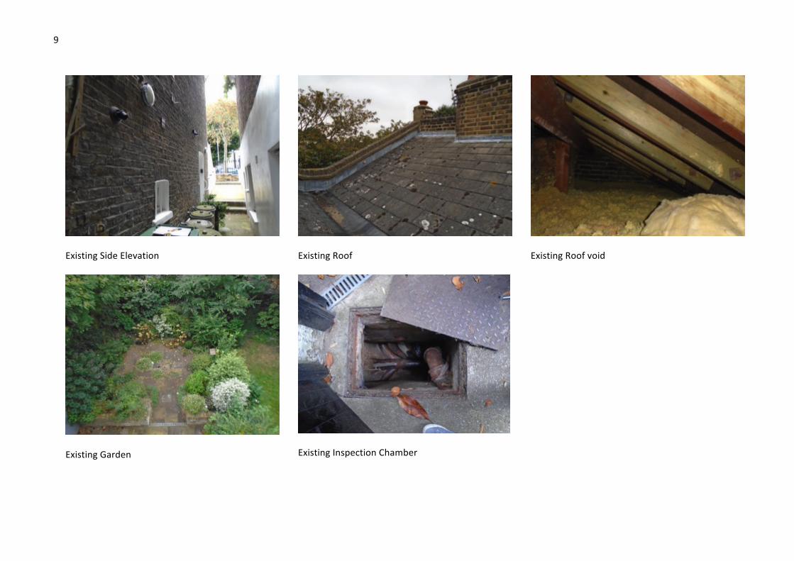
ExistingGarden
ExistingInspectionChamber

10
AppendixB
BasementProposals

11
AppendixC
SequenceofUnderpinningConstruction