Constant angular velocity of the wrist during the lifting of a sphere
11
Innovation Constant angular velocity of the wrist during the lifting of a sphere P. H. CHAPPELL*{, C. D. METCALF{{, J. H. BURRIDGE{, V. T. YULE{ and R. M. PICKERINGx {School of Electronics and Computer Science, University of Southampton, Highfield, Southampton SO17 1BJ, UK {School of Health Sciences, University of Southampton, Highfield, Southampton SO17 1BJ, UK xSchool of Medicine, University of Southampton, Highfield, Southampton SO17 1BJ, UK (Received 17 December 2009; revised 21 January 2010; accepted 29 January 2010) The primary objective of the experiments was to investigate the wrist motion of a person while they were carrying out a prehensile task from a clinical hand function test. A six- camera movement system was used to observe the wrist motion of 10 participants. A very light sphere and a heavy sphere were used in the experiments to study any mass effects. While seated at a table, a participant moved a sphere over a small obstacle using their dominant hand. The participants were observed to move their wrist at a constant angular velocity. This phenomenon has not been reported previously. Theoretically, the muscles of the wrist provide an impulse of force at the start of the rotation while the forearm maintains a constant vertical force on a sphere. Light–heavy mean differences for the velocities, absolute velocities, angles and times taken showed no significant differences (p ¼ 0.05). Keywords: Wrist; Movement; Constant velocity; Projectile; SHAP 1. Introduction Clinical gait analysis is an established method of quantify- ing the movement of the lower limbs and ambulatory patterns [1,2]. A common method used to capture data from gait is where reflective markers are located on the skin surface and a system of infrared cameras is used to determine the position and relative movement of limb segments. The extension of these techniques to the upper limb has not received the same attention due to the complexity of the anatomy and physiology where there is a wide range of different movement patterns [3–5]. Three-dimensional movement analysis has been applied to human research in a number of areas from rehabilitation to sports science. A trend developed recently in biomecha- nical research is to apply the principles established by the analysis of gait to the upper limb [6–11]. The motivation for using three-dimensional kinematic data originated from a desire to understand the biomechanical movements in- volved in prehensile tasks [12] and has evolved into developing an assessment for rehabilitation [4,13]. Under- standing the variability associated with a particular move- ment in unimpaired participants brings greater understanding of the limitations and compensatory me- chanisms involved in comparable movements by impaired participants. In addition, the current research trend is to concentrate on movements that are confined within defined and specific activities, whereby the movements generated by the upper limb are repetitive and constrained. In this paper are presented experimental results from an investigation into the movement of the wrist. These results have been obtained from kinematic data while a person *Corresponding author. Email: [email protected] Journal of Medical Engineering & Technology, Vol. 34, No. 4, May 2010, 274–284 Journal of Medical Engineering & Technology ISSN 0309-1902 print/ISSN 1464-522X online ª 2010 Informa UK Ltd. http://www.informaworld.com/journals DOI: 10.3109/03091901003663844 J Med Eng Technol Downloaded from informahealthcare.com by SOUTHAMPTON GENERAL HOSPITAL on 04/19/10 For personal use only.
Transcript of Constant angular velocity of the wrist during the lifting of a sphere

Innovation
Constant angular velocity of the wrist during the lifting of a sphere
P. H. CHAPPELL*{, C. D. METCALF{{, J. H. BURRIDGE{, V. T. YULE{ andR. M. PICKERINGx
{School of Electronics and Computer Science, University of Southampton, Highfield, Southampton SO171BJ, UK
{School of Health Sciences, University of Southampton, Highfield, Southampton SO17 1BJ, UKxSchool of Medicine, University of Southampton, Highfield, Southampton SO17 1BJ, UK
(Received 17 December 2009; revised 21 January 2010; accepted 29 January 2010)
The primary objective of the experiments was to investigate the wrist motion of a person
while they were carrying out a prehensile task from a clinical hand function test. A six-
camera movement system was used to observe the wrist motion of 10 participants. A very
light sphere and a heavy sphere were used in the experiments to study any mass effects.
While seated at a table, a participant moved a sphere over a small obstacle using their
dominant hand. The participants were observed to move their wrist at a constant angular
velocity. This phenomenon has not been reported previously. Theoretically, the muscles
of the wrist provide an impulse of force at the start of the rotation while the forearm
maintains a constant vertical force on a sphere. Light–heavy mean differences for the
velocities, absolute velocities, angles and times taken showed no significant differences
(p¼ 0.05).
Keywords: Wrist; Movement; Constant velocity; Projectile; SHAP
1. Introduction
Clinical gait analysis is an established method of quantify-
ing the movement of the lower limbs and ambulatory
patterns [1,2]. A common method used to capture data
from gait is where reflective markers are located on the skin
surface and a system of infrared cameras is used to
determine the position and relative movement of limb
segments. The extension of these techniques to the upper
limb has not received the same attention due to the
complexity of the anatomy and physiology where there is a
wide range of different movement patterns [3–5].
Three-dimensional movement analysis has been applied
to human research in a number of areas from rehabilitation
to sports science. A trend developed recently in biomecha-
nical research is to apply the principles established by the
analysis of gait to the upper limb [6–11]. The motivation for
using three-dimensional kinematic data originated from a
desire to understand the biomechanical movements in-
volved in prehensile tasks [12] and has evolved into
developing an assessment for rehabilitation [4,13]. Under-
standing the variability associated with a particular move-
ment in unimpaired participants brings greater
understanding of the limitations and compensatory me-
chanisms involved in comparable movements by impaired
participants. In addition, the current research trend is to
concentrate on movements that are confined within defined
and specific activities, whereby the movements generated by
the upper limb are repetitive and constrained.
In this paper are presented experimental results from an
investigation into the movement of the wrist. These results
have been obtained from kinematic data while a person
*Corresponding author. Email: [email protected]
Journal of Medical Engineering & Technology, Vol. 34, No. 4, May 2010, 274–284
Journal of Medical Engineering & TechnologyISSN 0309-1902 print/ISSN 1464-522X online ª 2010 Informa UK Ltd.
http://www.informaworld.com/journalsDOI: 10.3109/03091901003663844
J M
ed E
ng T
echn
ol D
ownl
oade
d fr
om in
form
ahea
lthca
re.c
om b
y SO
UT
HA
MPT
ON
GE
NE
RA
L H
OSP
ITA
L o
n 04
/19/
10Fo
r pe
rson
al u
se o
nly.
carried out a prehensile task from a clinical hand function
test. An objective of this research was to describe
unimpaired functional movement of the wrist. Each
participant completed a Southampton Hand Assessment
Procedure (SHAP) [14]. Reflective markers were placed on
the dominant upper limb of the participant, who was then
instructed to complete five SHAP abstract object tasks,
both light and heavyweight versions, while movements were
captured by a Vicon movement analysis system [15,16].
Movements of the wrist were studied for light and
heavyweight spherical, tripod, power, tip and extension
abstract object tasks. However this paper focuses on the
picking and placing of the spherical objects with different
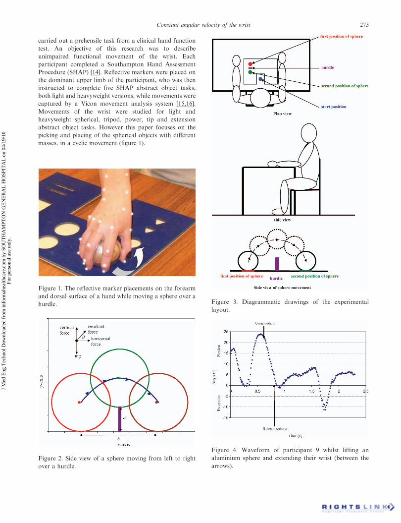
masses, in a cyclic movement (figure 1).
Figure 1. The reflective marker placements on the forearm
and dorsal surface of a hand while moving a sphere over a
hurdle.
Figure 2. Side view of a sphere moving from left to right
over a hurdle.
Figure 3. Diagrammatic drawings of the experimental
layout.
Figure 4. Waveform of participant 9 whilst lifting an
aluminium sphere and extending their wrist (between the
arrows).
Constant angular velocity of the wrist 275
J M
ed E
ng T
echn
ol D
ownl
oade
d fr
om in
form
ahea
lthca
re.c
om b
y SO
UT
HA
MPT
ON
GE
NE
RA
L H
OSP
ITA
L o
n 04
/19/
10Fo
r pe
rson
al u
se o
nly.
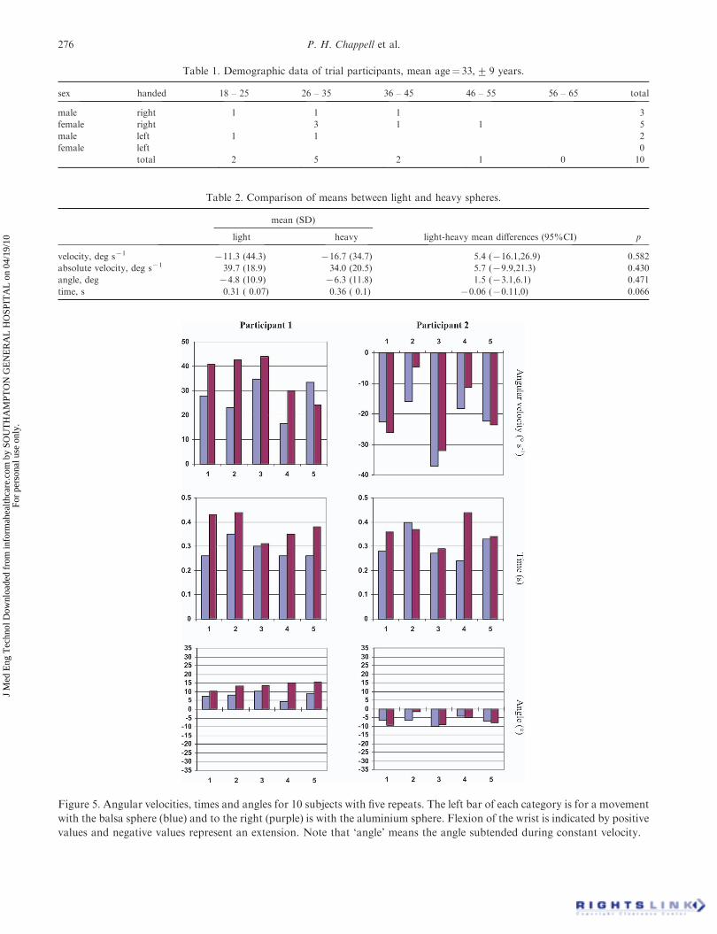
Table 1. Demographic data of trial participants, mean age¼ 33,+ 9 years.
sex handed 18 – 25 26 – 35 36 – 45 46 – 55 56 – 65 total
male right 1 1 1 3
female right 3 1 1 5
male left 1 1 2
female left 0
total 2 5 2 1 0 10
Table 2. Comparison of means between light and heavy spheres.
mean (SD)
light heavy light-heavy mean differences (95%CI) p
velocity, deg s71 711.3 (44.3) 716.7 (34.7) 5.4 (716.1,26.9) 0.582
absolute velocity, deg s71 39.7 (18.9) 34.0 (20.5) 5.7 (79.9,21.3) 0.430
angle, deg 74.8 (10.9) 76.3 (11.8) 1.5 (73.1,6.1) 0.471
time, s 0.31 ( 0.07) 0.36 ( 0.1) 70.06 (70.11,0) 0.066
Figure 5. Angular velocities, times and angles for 10 subjects with five repeats. The left bar of each category is for a movement
with the balsa sphere (blue) and to the right (purple) is with the aluminium sphere. Flexion of the wrist is indicated by positive
values and negative values represent an extension. Note that ‘angle’ means the angle subtended during constant velocity.
276 P. H. Chappell et al.
J M
ed E
ng T
echn
ol D
ownl
oade
d fr
om in
form
ahea
lthca
re.c
om b
y SO
UT
HA
MPT
ON
GE
NE
RA
L H
OSP
ITA
L o
n 04
/19/
10Fo
r pe
rson
al u
se o
nly.

There is evidence in the literature of the smooth
operation of the wrist. Results of captured time series,
from different experiments, show ramps of the wrist angle
which appear to be linear [17–21]. These waveforms
suggest that the wrist flexes and extends with a constant
angular velocity, but there have been no experimental or
theoretical reports of this phenomenon in the literature.
This paper presents a retrospective analysis of experimental
data to show for the first time that the wrist is moved with a
constant angular velocity.
2. Theory
A three-dimensional model of the movement of the wrist
and forearm is not presented in this paper. Instead, a two
dimensional theory is given for the forces on a sphere that is
moved in the prescribed manner shown in figure 1. From
this theory and the experimental results a movement
strategy can be inferred.
Consider a solid sphere that is held by a hand and
being moved over a hurdle shown in figure 2. Generally,
there will be forces and torques acting on the sphere
from the wrist and forearm. The fingers, thumb and
structures of the hand hold the sphere at the end of the
forearm. Also the sphere is subjected to the Earth’s
gravitational field. More simply, for a sphere to be lifted
from a surface and moved over the hurdle there will be
vertical, horizontal and gravitational forces shown in the
figure. This is a classical projectile problem where the
motion has a parabolic path. Using a rectangular set of
x–y axes, the horizontal and vertical motions are as
follows.
x ¼ ut cos y; ð1Þ
Figure 5b. (Continued).
Constant angular velocity of the wrist 277
J M
ed E
ng T
echn
ol D
ownl
oade
d fr
om in
form
ahea
lthca
re.c
om b
y SO
UT
HA
MPT
ON
GE
NE
RA
L H
OSP
ITA
L o
n 04
/19/
10Fo
r pe
rson
al u
se o
nly.

where u is the initial velocity at an angle y to the horizontal
x-axis and t is the time.
y ¼ ut sin y � 1
2gt2; ð2Þ
where g is the acceleration due to gravity. The maximum
altitude, a, is determined from these two equations, as:
a ¼ u2 sin 2 y2g
: ð3Þ
The horizontal distance travelled, b, is given by:
b ¼ u2 sin 2y2g
: ð4Þ
This analysis is applicable where an impulse force has been
applied by the upper limb to the projectile at the start and
no other external forces are applied during the motion.
3. Experiment
The main aim of the experiment was to obtain wave-
forms of the wrist angle and investigate common features
in them. A lightweight balsa sphere was used as it
effectively represents the holding of an object with
negligible mass. A heavyweight sphere, made from
aluminium, with the same dimensions as the balsa sphere
was also used.
A participant was seated at a table with their forearms
resting on the table surface (figure 3). The sphere and
hurdle were located in a form board on the table surface by
the assessor as shown in figure 3. Using their dominant
hand they were asked to carry out the following sequence of
movements.
(1) touch the table surface in front of them (start position
in the top drawing of figure 3);
(2) move to pick up the sphere (first position);
Figure 5c. (Continued).
278 P. H. Chappell et al.
J M
ed E
ng T
echn
ol D
ownl
oade
d fr
om in
form
ahea
lthca
re.c
om b
y SO
UT
HA
MPT
ON
GE
NE
RA
L H
OSP
ITA
L o
n 04
/19/
10Fo
r pe
rson
al u
se o
nly.

(3) take the sphere over a 30 mm hurdle and place it
down on the table surface (second position);
(4) return their hand to the start position; and
(5) place their forearm back on the table.
An assessor demonstrated the task to the participant and
then asked them to carry out the movement as quickly as
possible.
Ten unimpaired participants (mean age 33 years,+ 9
years) were recruited for the trial with the following
inclusion criteria:
. no history of musculoskeletal injury;
. no history of chronic pain in the dominant upper limb;
and
. no present discomfort in their dominant upper limb.
Ethical approval for the trial was granted by the School
of Health Professions & Rehabilitation Sciences Ethical
Committee (submission number PO4-1101) at the Uni-
versity of Southampton. The demographic data of the
participants is given in table 1.
A six-camera movement analysis system (Vicon 460) was
used to capture data at a sampling rate of 100 Hz. A total
of 26 hemispherical markers (3 mm) were placed on the
hand and wrist [15,16]. The captured data were analysed to
extract the flexion/extension angle of the wrist using
Matlab software (MathWorks, Natick, MA, USA) [16]. A
participant was asked to do five repeated movements for
the balsa and aluminium spheres.
4. Results
From a waveform (time series) of the angle of the wrist, a
ramp region was identified when a subject moved a sphere
over the hurdle (figure 4). The data from the wrist angles
were identified and cropped from the moment the spherical
object was lifted from the table surface to the moment it
Figure 5d. (Continued).
Constant angular velocity of the wrist 279
J M
ed E
ng T
echn
ol D
ownl
oade
d fr
om in
form
ahea
lthca
re.c
om b
y SO
UT
HA
MPT
ON
GE
NE
RA
L H
OSP
ITA
L o
n 04
/19/
10Fo
r pe
rson
al u
se o
nly.

was placed back on the table. An estimate of the slope
(angular velocity) of a waveform for these linear regions
was made using regression (mean r2 for the task using the
balsa sphere was 0.94 and that for the task using the
aluminium sphere was 0.90). These values are near to unity
which supports the hypothesis that the wrist movement is
carried out with constant velocity.
Figure 5 shows the estimated angular velocities, times
and angle for the 10 subjects. Six of the participants used
increasing extension in the movement, while two used
flexion and two a mixture of extension and flexion.
4.1. Comparison of means between light and heavy weight
spheres
In table 2 the means for each variable across the five repeats
under each condition have been calculated and compared
between the light and heavy spheres in paired t-tests. Light–
heavy mean differences are presented with 95% confidence
intervals in the third column and in the last column the p-
values show that the velocity, absolute velocity and angle
have no significant differences. There was a trend of
longer times to move the heavy sphere but this did not
quite reach statistical significance (p¼ 0.066). Similar
significance levels were obtained from non-parametric
Wilcoxon signed rank tests with time again nearly
reaching statistical significance (p¼ 0.059). Changes in
velocity per participant are shown in figure 6, where half
of the participants have higher mean velocities with the
heavy sphere and half lower. Four of the participants had
a higher absolute angular velocity while moving the heavy
sphere. Angular changes are shown in figure 7, where six
of the participants have a higher mean with the heavy
sphere. The trend of taking a longer time to move the
heavy sphere, as seen in table 2, is shown in figure 8,
where seven of the participants take a longer time, but
there is not strong enough evidence to achieve statistical
significance.
Figure 5e. (Continued).
280 P. H. Chappell et al.
J M
ed E
ng T
echn
ol D
ownl
oade
d fr
om in
form
ahea
lthca
re.c
om b
y SO
UT
HA
MPT
ON
GE
NE
RA
L H
OSP
ITA
L o
n 04
/19/
10Fo
r pe
rson
al u
se o
nly.

5. Discussion
Typically, the wrist was extended as a sphere was moved
over the hurdle (figure 9). During the lifting of the sphere
from the table surface to the top of the hurdle, the wrist
provides vertical movement and little horizontal move-
ment. The latter is provided by the forearm and shoulder.
For the sphere to land at the end position from the top of
the hurdle onto the table, the forearm is lowered while the
wrist extends, otherwise the sphere would continue to move
upwards. There is a coordinated movement of the wrist
maintaining a constant angular velocity with the rest of the
limb providing horizontal movement. The theory for a
projectile shown in figure 2 is ideal in that the sphere just
clears the top of the hurdle. So this presents the minimum
path required to carry out the task. Simulations of this
movement, using equations (1) and (2), showed that the
time taken to project a sphere over the hurdle is
considerably shorter than the experimental times. However,
applying a constant vertical force during the movement
with a smaller impulse of force at the start produced times
of about 350 ms, which are typical of the times taken by the
participants (figure 8). Adopting constant angular velocity
with a vertical force produces a smooth motion but the
origins of such smoothness are not clear [22]. Harris and
Wolpert propose that precision results in non-jerky move-
ment [23]. Minimizing a quadratic function of the vertical
force input and jerk (rate of change of acceleration) is
satisfied by a constant vertical force (see the Appendix).
While this analysis demonstrates a possible control strategy
for producing a constant force, it does not necessarily mean
that the physiological system implements this philosophy
[24].
During the movement the wrist is flexing or extending
but only through a small angle of 10.88 (balsa) and 11.78(aluminium) (figure 7). Hence the wrist supported by the
forearm can be considered as providing a constant vertical
Figure 6. Mean velocity changes per participant.
Figure 7. Mean angle changes per participant.
Figure 8. Mean time changes per participant.
Constant angular velocity of the wrist 281
J M
ed E
ng T
echn
ol D
ownl
oade
d fr
om in
form
ahea
lthca
re.c
om b
y SO
UT
HA
MPT
ON
GE
NE
RA
L H
OSP
ITA
L o
n 04
/19/
10Fo
r pe
rson
al u
se o
nly.

force. The sphere is also being rotated about the wrist but
as this is at a constant velocity there is no torque
component for this except an impulse at the start of the
movement. This control is a ‘bang-bang’ strategy where the
object is rapidly accelerated at the start of a movement, is
maintained at constant velocity and decelerated at the end
of the movement.
There was no significant difference between the angular
velocity developed during the lifting of the balsa sphere and
that during the lifting of the aluminium sphere. The
neuromuscular control system is therefore maintaining this
velocity when the object has negligible mass and when the
object has a significant mass (which is about the same mass
of a hand). A priori information about the distribution of
velocities is used by the central nervous system to achieve
targeted movement [24]. Rather than using force feedback
from the Golgi tendon organs, the wrist system appears to
favour the velocity loop provided by the Type Ia motor
neurones. The forearm, humerus and shoulder appear to be
using force control to provide a constant vertical force on
an object held in the hand.
During the movement of a sphere, there may be radial
and ulna deviation which is also carried out typically
with a constant velocity. However, this velocity is much
smaller than that for flexion and extension, or even zero
with a corresponding smaller angular movement. A
sphere is moved in the vertical plane with the participant
facing the direction of motion (plan view of figure 3) and
so the person is in a natural position to use flexion and
extension of their wrist. Any abduction or adduction of
the wrist results in a horizontal force on the sphere,
contributing little or no vertical force, since the hand is
in a position of pronation with the palm facing the
surface of the table.
6. Conclusions
For 10 normal participants, flexion and extension of the
wrist is achieved with constant angular velocity when lifting
a sphere. There were no significant differences between the
means of the angular velocities, absolute velocities, angles
or times while lifting a very lightweight sphere and a sphere
that had a significant mass. Theoretically the movement of
the object follows a classical projectile path with a constant
vertical force being maintained by the wrist and upper limb.
It is conjectured that the controller for the wrist uses
velocity feedback while the rest of a limb maintains a
constant vertical force.
Acknowledgements
The authors wish to thank the Life Sciences Interface
Forum at the University of Southampton for their financial
support of the research and the participants for their
enthusiasm and patience.
References
[1] Sutherland, D.H., 2002, The evolution of clinical gait analysis Part II.
Kinematics, Gait and Posture, 16, 159–179.
[2] Whittle, M.W., 1996, Clinical gait analysis: A review. Human
Movement Science, 15, 369–387.
Figure 9. Diagram showing the change in wrist angle, y, as a sphere is moved over the hurdle from positions 1 to 5. Included
are the forces on the sphere, torque about the wrist and principal axes.
282 P. H. Chappell et al.
J M
ed E
ng T
echn
ol D
ownl
oade
d fr
om in
form
ahea
lthca
re.c
om b
y SO
UT
HA
MPT
ON
GE
NE
RA
L H
OSP
ITA
L o
n 04
/19/
10Fo
r pe
rson
al u
se o
nly.

[3] van Andel, C.J., Wolterbeek, N., Doorenbosch, C.A.M., Veeger,
D.H.E.J., and Harlaar, J., 2008, Complete 3D kinematics of upper
extremity functional tasks. Gait and Posture, 27, 120–127.
[4] Murgia, A., Kyberd, P.J., Chappell, P.H. and Light, C.M.,
2004, Marker placement to describe the wrist movements during
activities of daily living in a cyclical task. Clinical Biomechanics, 19,
248–254.
[5] Murgia, A., 2005, A gait analysis approach to the study of upper limb
kinematics using activities of daily living. PhD thesis, University of
Reading, UK.
[6] Fowler, N.K. and Nicol, A.C., 1999, Measurement of external three-
dimensional interphalangeal loads applied during activities of daily
living. Clinical Biomechanics, 14, 646–652.
[7] Rau, G., Disselhorst-Klug, C. and Schmidt, R., 2000, Movement
biomechanics goes upwards: from the leg to the arm. Journal of
Biomechanics, 33, 1207–1216.
[8] Biryukova, E.V., Roby-Brami, A., Frolov, A.A. and Mokhtari, M.,
2000, Kinematics of human arm reconstructed from spatial tracking
system recordings. Journal of Biomechanics, 33, 985–995.
[9] Tocheri, M.W., Marzke, M.W., Liu, D., Bae, M., Jones, G.P.,
Williams, R.C. and Razdan, A., 2003, Functional capabilities of
modern and fossil hominid hands: three-dimensional analysis
of trapezia. American Journal of Physical Anthropology, 122, 101–
112.
[10] Leonard, L., Sirkett, D., Mullineux, G., Giddins, G.E.B. and Miles,
A.W., 2005, Development of an in-vivo method of wrist joint motion
analysis. Clinical Biomechanics, 20, 166–171.
[11] Su, F.-C., Chou, Y.L., Yang, C.S., Lin, G.T. and An, K.N., 2005,
Movement of finger joints induced by synergistic wrist motion.
Clinical Biomechanics, 20, 491–497.
[12] Rash, G.S., Belliappa, P.P., Wachowiak, M.P., Somia, N.N. and
Gupta, A., 1999, A demonstration of the validity of a 3-D video
motion analysis method for measuring finger flexion and extension.
Journal of Biomechanics, 32, 1337–1341.
[13] Fowler, N.K. and Nicol, A.C., 2001, A three-dimensional biomecha-
nical analysis of the index finger, incorporating measured loading data
for selected activities of daily living. Proceedings of the 18th International
Society of Biomechanics, Zurich, Switzerland, 8–13 July 2001.
[14] Light, C.M., Chappell, P.H. and Kyberd, P.J., 2002, Establishing a
standardized clinical assessment tool of pathologic and prosthetic
hand function: normative data, reliability, and validity. Archives of
Physical Medicine & Rehabilitation, 83, 776–783.
[15] Metcalf, C.D., Notley, S.V., Burridge, J.H., Chappell, P.H. and Yule,
V.T., 2008, Validation and application of a computational model for
wrist and hand movements using surface markers. IEEE Transactions
on Biomedical Engineering, 55, 1199–1210.
[16] Metcalf, C.D., 2008, The relationship between movement and function
of the wrist and hand: a clinically focused kinematic study. PhD thesis.
University of Southampton.
[17] Zedka, M. and Prochazka, A., 1997, Phasic activity in the human
erector spinae during repetitive hand movements. Journal of Physiol-
ogy, 504, 727–734.
[18] Collins, D.F., Cameron, T., Gillard, D.M. and Prochazka, A., 1998,
Muscular sense is attenuated when humans move. Journal of
Physiology, 508, 635–643.
[19] MacKinnon, C.D. and Rothwell, J.C., 2000, Time varying changes in
corticospinal excitability accompanying the triphasic EMG pattern in
humans. Journal of Physiology, 528, 633–645.
[20] Stinear, J.W. and Byblow, W.D., 2002, Disinhibition in the human
motor cortex is enhanced by synchronous upper limb movements.
Journal of Physiology, 543, 307–316.
[21] Milner, T.E. and Cloutier, C., 1998, Damping of the wrist joint during
voluntary movement. Experimental Brain Research, 122, 309–317.
[22] Sejnowski, T.J., 1998, Making smooth moves. Nature, 394, 725–726.
[23] Harris, C.M. and Wolpert, D.M., 1998, Signal-dependent noise
determines motor planning. Nature, 394, 780–784.
[24] Kording, K.P. and Wolpert, D.M., 2004, Bayesian integration in
sensorimotor learning. Nature, 427, 244–247.
[25] Barnett, S., 1984, Matrices in Control Theory. Krieger Publishing
Company, Malabar, FL, USA.
Appendix: Optimum control of the vertical force
A description of optimal control by defining a performance
index and Hamiltonian function using Pontryagin’s max-
imum principle can be found in textbooks (e.g. Appendix 4
in [25]).
The vertical equation of motion of a the sphere of mass,m is:
y:::¼ r
m� g; ð5Þ
where r is the vertical force (figure 2).
A quadratic performance index, J, combining the input
vertical force and jerk is
J ¼Z tf
0
e2 þ r2� �
dt; ð6Þ
where y:::is the jerk expressed as:
e ¼ Q y:::; ð7Þ
and Q is a constant.
The Hamiltonian function from these equations is:
H ¼ e2 þ r2� �
þ pr
m� g
� �; ð8Þ
where p is the Lagrange multiplier.
Equations (9) and (11) are the associated differential
equations, shown below.
p:¼ � @H
@e: ð9Þ
Differentiating equation (8) partially with respect to e:
p:¼ � 2e; ð10Þ
@H
@r¼ 0: ð11Þ
Differentiating equation (8) partially with respect to r:
2r þ p
m¼ 0: ð12Þ
Differentiating equation 12 with respect to time:
2 r: þ
p:
m¼ 0: ð13Þ
Constant angular velocity of the wrist 283
J M
ed E
ng T
echn
ol D
ownl
oade
d fr
om in
form
ahea
lthca
re.c
om b
y SO
UT
HA
MPT
ON
GE
NE
RA
L H
OSP
ITA
L o
n 04
/19/
10Fo
r pe
rson
al u
se o
nly.

Eliminating p from equations (10) and (13):
2 r: � 2e
m¼ 0: ð14Þ
Differentiating equation 5 with respect to time:
e ¼ Qr:
m: ð15Þ
Eliminating e from equations (14) and (15):
2 r: � 2Q
r:
m2¼ 0 ð16aÞ
or
r:
1 � Q
m2
� �¼ 0: ð16bÞ
This result implies that r is constant, for an arbitrary value
of m. An alternative solution is Q¼m2.
Minimizing a quadratic function of the vertical
force input and jerk is satisfied by a constant vertical force
input.
284 P. H. Chappell et al.
J M
ed E
ng T
echn
ol D
ownl
oade
d fr
om in
form
ahea
lthca
re.c
om b
y SO
UT
HA
MPT
ON
GE
NE
RA
L H
OSP
ITA
L o
n 04
/19/
10Fo
r pe
rson
al u
se o
nly.