Conservativity for a hierarchy of Euler and Venn reasoning ...
25
Conservativity for a hierarchy of Euler and Venn reasoning systems Koji Mineshima, Mitsuhiro Okada, and Ryo Takemura Department of Philosophy, Keio University, 2-15-45 Mita, Minato-ku, Tokyo 108-8345, Japan. {minesima,mitsu,takemura}@abelard.flet.keio.ac.jp Abstract This paper introduces a hierarchy of Euler and Venn diagrammatic reasoning systems in terms of their expressive powers in topological-relation-based formal- ization. At the bottom of the hierarchy is the Euler diagrammatic system intro- duced in Mineshima-Okada-Sato-Takemura [13, 12], which is expressive enough to characterize syllogistic reasoning in terms of unification and deletion rules. At the top of the hierarchy is a Venn diagrammatic system such as Swoboda-Allwein’s Euler/Venn diagrammatic system [23]. In order to understand the hierarchy uni- formly, we introduce an algebraic structure, which also provides another descrip- tion of our unification rule of Euler diagrams. We prove that each system S’ of the hierarchy is conservative over any lower system S with respect to validity—in the sense that S’ is an extension of S, and the semantic consequence relations of S and S’ are equivalent for diagrams of S. Furthermore, we prove that a region-based Venn diagrammatic system is conservative over our topological-relation-based Eu- ler diagrammatic system with respect to provability. 1 Introduction Euler diagrams were introduced by Euler (1768) [1] to represent logical relations among the terms of a syllogism by topological relations among circles. Given two Euler diagrams which represent the premises of a syllogism, the syllogistic inference can be naturally replaced by the task of manipulating the diagrams, in particular of unifying the diagrams and extracting information from them. For example, the well- known syllogism named “Barbara,” i.e., All A are B and All B are C; therefore All A are C, can be represented diagrammatically as in Fig. 1. Another well-known diagrammatic representation system for syllogistic reasoning is Venn diagrams. In Venn diagrams a novel syntactic device, namely shading, to represent emptiness plays a central role in place of the topological relations of Euler diagrams. Because of their expressive power and their uniformity in formalizing the manipulation of combining diagrams simply as the superposition of shadings, Venn diagrams have been very well studied. Cf. Venn-I, II systems of Shin [19], Spider 37
-
Upload
khangminh22 -
Category
Documents
-
view
0 -
download
0
Transcript of Conservativity for a hierarchy of Euler and Venn reasoning ...

Conservativity for a hierarchy ofEuler and Venn reasoning systems
Koji Mineshima, Mitsuhiro Okada, and Ryo Takemura
Department of Philosophy, Keio University,2-15-45 Mita, Minato-ku, Tokyo 108-8345, Japan.
{minesima,mitsu,takemura}@abelard.flet.keio.ac.jp
Abstract
This paper introduces a hierarchy of Euler and Venn diagrammatic reasoningsystems in terms of their expressive powers in topological-relation-based formal-ization. At the bottom of the hierarchy is the Euler diagrammatic system intro-duced in Mineshima-Okada-Sato-Takemura [13, 12], which is expressive enoughto characterize syllogistic reasoning in terms of unification and deletion rules. Atthe top of the hierarchy is a Venn diagrammatic system such as Swoboda-Allwein’sEuler/Venn diagrammatic system [23]. In order to understand the hierarchy uni-formly, we introduce an algebraic structure, which also provides another descrip-tion of our unification rule of Euler diagrams. We prove that each system S’ ofthe hierarchy is conservative over any lower system S with respect to validity—inthe sense that S’ is an extension of S, and the semantic consequence relations of Sand S’ are equivalent for diagrams of S. Furthermore, we prove that a region-basedVenn diagrammatic system is conservative over our topological-relation-based Eu-ler diagrammatic system with respect to provability.
1 Introduction
Euler diagrams were introduced by Euler (1768) [1] to represent logical relationsamong the terms of a syllogism by topological relations among circles. Given twoEuler diagrams which represent the premises of a syllogism, the syllogistic inferencecan be naturally replaced by the task of manipulating the diagrams, in particular ofunifying the diagrams and extracting information from them. For example, the well-known syllogism named “Barbara,” i.e.,All A areB and AllB areC; therefore AllAareC, can be represented diagrammatically as in Fig. 1.
Another well-known diagrammatic representation system for syllogistic reasoningis Venn diagrams. In Venn diagrams a novel syntactic device, namelyshading, torepresent emptiness plays a central role in place of the topological relations of Eulerdiagrams. Because of their expressive power and their uniformity in formalizing themanipulation of combining diagrams simply as the superposition of shadings, Venndiagrams have been very well studied. Cf. Venn-I, II systems of Shin [19], Spider
37

AB
D1 R
BC
D2
A
B
C
?
AC
E
Fig.1 Barbara with Euler diagrams
A B
Dv1 ?
B C
Dv2?
A B
CR
A B
C
A B
C?
A
CEv
Fig.2 Barbara with Venn diagrams
diagrams SD1 and SD2 of [9], [14], etc. For a recent survey, see [20]. However, thedevelopment of systems of Venn diagrams is obtained at the cost of clarity of Eulerdiagrams. As Venn [25] himself already pointed out, when more than three circlesare involved, Venn diagrams fail in their main purpose of affording intuitive and sen-sible illustration. (For some discussions on visual disadvantages of Venn diagrams,see [8, 5]. See also [18] for our cognitive psychological experiments comparing lin-guistic, Euler diagrammatic, and Venn diagrammatic representations.) Recently,Eulerdiagrams with shadingwere introduced to make up for the shortcoming of Venn dia-grams: E.g., Euler/Venn diagrams of [23, 24]; Spider diagrams ESD2 of [14] and SD3of [10]. However, their abstract syntax and semantics are still defined in terms of re-gions, where shaded regions of Venn diagrams are considered as “missing” regions.That is, the idea of theregion-basedEuler diagrams is essentially along the same lineas Venn diagrams.
We may point out the following complications of region-based formalization ofdiagrams:
1. In region-based diagrams, logical relations among circles are represented notsimply by topological relations, but by the use of shading or missing regions,which makes the translations of categorical sentences uncomfortably complex.For example,All A are B is expressed by a region-based diagram through atranslation to the statementThere is nothing which isA but notB as seen inDv
1
of Fig. 2.
2. The inference rule ofunification, which plays a central role in Euler diagram-matic reasoning, is defined by way of the superposition of Venn diagrams. Forexample, when we unify two region-based Euler diagrams as inD1 andD2 ofFig.1, they are first transformed into Venn diagramsDv
1 andDv2 of Fig.2, respec-
tively; then, by superposing the shaded regions ofDv1 andDv
2 , and by deletingthe circleB, the Venn diagramEv is obtained, which is transformed into theregion-based Euler diagramE . In this way, processes of deriving conclusions are
38

oftenmade complex, and hence less intuitive, in the region-based framework.
In contrast to the studies in the tradition of region-based diagrams, we proposed anovel approach in [13, 12] to formalize Euler diagrams in terms of topological relations.Our system has the following features and advantages:
1. Our diagrammatic syntax and semantics are defined in terms oftopological re-lations, inclusion and exclusion relations, between two diagrammatic objects.This formalization makes the translations of categorical sentences natural andintuitive. Furthermore, our formalization makes it possible to represent a dia-gram by a simple ordered (or graph-theoretical) structure.
2. Our unificationof two diagrams is formalized directly in terms of topologicalrelations without making a detour to Venn diagrams. Thus, it can directly cap-ture the inference process as illustrated in Fig. 1. We formalize the unificationin the style of Gentzen’s natural deduction, a well-known formalization of log-ical reasoning in symbolic logic, which is intended to be as close as possibleto actual reasoning (Gentzen [3]). This makes it possible to compare our Eulerdiagrammatic inference system directly with natural deduction system. Throughsuch comparison, we can apply well-developed proof-theoretical approaches todiagrammatic reasoning. See [13] for such proof-theoretical analyses.
From a perspective of proof-theory, the contrast between the standpoints of theregion-based framework and the topological-relation-based framework can be under-stood as follows: At the level of representation, the contrast is analogous to the onebetween disjunctive (dually, conjunctive) normal formulas and implicational formu-las; at the level of reasoning, the contrast is analogous to the one between resolutioncalculus style proofs and natural deduction style proofs.
From a perspective of cognitive psychology, our system is designed not just as analternative of usual linguistic/symbolic representations; we make the best use of ad-vantages of diagrammatic representations so that inherent definiteness or specificityof diagrams can be exploited in actual reasoning. See [18] for our experimental re-sult, which shows that our Euler diagrams are more effective than Venn diagrams orlinguistic representations in syllogism solving tasks.
We roughly review our topological-relation-based Euler diagrammatic representa-tion systemEUL in Section 2. (We also review our inference systemGDS in AppendixA.) AlthoughEUL is weaker in its expressive power than usual Venn diagrammatic sys-tems (e.g. Shin’s Venn-II [19], which is equivalent to the monadic first order logic inits expressive power),EUL is expressive enough to characterize basic logical reasoningsuch as syllogistic reasoning, see [12]. OurEUL-diagrams can be abstractly seen asalgebraic (or graph-theoretical) structure, where inclusion relations between diagram-matic objects are reflexive transitive ordering relations, and exclusion relations are ir-reflexive symmetric relations. Based on this observation, in Section 3, we introduceEUL-structure, which provides another description and a verification of our unificationrule of Appendix A. In Section 4, based on theEUL-structure, we introduce a hierarchyof Euler and Venn diagrammatic reasoning systems as seen in Fig. 3.The most elementary systemEUL considers only circles and points as diagrammaticobjects;EUL is extended by considering intersection regionsX ∩ Y , union regions
39

EUL
kEUL with ∩
3
3EUL with ∪k
EUL with ∩,∪6
EUL with ∩,∪,6
Venn
Fig.3 Hierarchy of Euler and Venn systems
X ∪ Y , and complement regionsX asdiagrammatic objects, respectively, as well aslinking of points; Venn diagrams can be put at the top of the hierarchy of these ex-tended systems. The algebraic structure thus obtained for Venn diagrams is essentiallythe directed acyclic graph of Swoboda-Allwein [23]. We prove that each systemS′
of the hierarchy is conservative over any lower systemS with respect to validity—in the sense thatS′ is an extension ofS, and the semantic consequence relations ofS andS′ are equivalent for diagrams ofS. Moreover, we prove that a region-basedVenn diagrammatic system is conservative over our topological-relation-based Eulerdiagrammatic system with respect to provability. We also give a procedure to transforma topological-relation-basedEUL-diagram through anEUL-structure to a semanticallyequivalent region-based Venn diagram.
2 A diagrammatic representation system (EUL) for Eu-ler circles and its set-theoretical semantics
In this section, we review our diagrammatic representation systemEUL of [13, 12].
2.1 Diagrammatic syntax ofEUL
The following definition of diagrams is slightly different from that of [13, 12] in that(1) we regard inclusion relation@ as reflexive in this paper; (2) we exclude fromEUL-diagrams only the empty diagram, on which no topological relation holds.
Definition 2.1 An EUL-diagram is a plane (R2) with a finite number, at least one, ofnamed simple closed curves(denoted byA, B,C, . . . ) andnamed points(denotedby a, b, c, . . . ), where each named simple closed curve or named point has a uniqueand distinct name.EUL-diagrams are denoted byD, E ,D1,D2, . . . .An EUL-diagram consisting of at most two objects is called aminimal diagram. Min-imal diagrams are denoted byα, β, γ, . . . .
In what follows, a named simple closed curve is called anamed circle. More-over, named circles and named points are collectively calledobjects, and denoted bys, t, u, . . . . We use a rectangle to represent a plane for anEUL-diagram.1
1Several Euler diagrammatic representation systems impose some additional conditions for well-formeddiagrams. E.g., at most two circles meet at a single point, no tangential meetings or concurrency etc. Cf.e.g., [22]. However, for simplicity of the definition, those are all considered to be well-formed inEUL.
40
We define the following binary topological relations between diagrammatic ob-jects2:
Definition 2.2 EUL-relations are the following binary relations between diagram-matic objects:
A @ B “the interior ofA is inside ofthe interior ofB,”
A ⊢⊣ B “the interior ofA is outside ofthe interior ofB,”
A ◃▹ B “there is an intersection between the interior ofA and the interior ofB,”
b @ A “b is inside ofthe interior ofA,”
b ⊢⊣ A “b is outside ofthe interior ofA,”
a ⊢⊣ b “a is outside ofb (i.e. a is not located at the point ofb).”
We call◃▹-relationcrossingrelation.EUL-relations⊢⊣ and◃▹ are symmetric, while@ is not. In this paper, we consider
@-relation as reflexive by allowings @ s for each objects.
Proposition 2.3 Let D be anEUL-diagram. For any distinct objectss and t of D,exactly one of theEUL-relationss @ t, t @ s, s ⊢⊣ t, s ◃▹ t holds.
Observe that, by Proposition 2.3, for a givenEUL-diagramD, the set ofEUL-relations holding onD is uniquely determined. We denote the set byrel(D). We alsodenote bypt(D) the set of named points ofD, by cr(D) the set of named circles ofD,and byob(D) the set of objects ofD.
Although in this section,ob(D) = pt(D) ∪ cr(D), in Section 4, diagrammatic ob-jects are extended, in addition to named circles and points, by introducing intersection,union, and complement regions respectively.
The following properties, as well as Proposition 2.3, characterizeEUL-diagrams.
Lemma 2.4 LetD be anEUL-diagram. Then for any objects (named circles or points)s, t, u ∈ ob(D), we have the following:
1. (Transitivity) If s @ t, t @ u ∈ rel(D), thens @ u ∈ rel(D).
2. (⊢⊣-downward closedness)If s ⊢⊣ t, u @ s ∈ rel(D), thenu ⊢⊣ t ∈ rel(D).
3. (Point determinacy)For any pointx ofD, exactly one ofx @ s andx ⊢⊣ s is inrel(D).
4. (Point minimality)For any pointx (≡ s) ofD, s @ x ∈ rel(D).
Equivalence betweenEUL-diagrams is defined as follows. (See [13] for a moredetailed explanation.)
Definition 2.5 When any two objects of the same name appear in different diagrams(planes), we identify them up to isomorphism. AnyEUL-diagramsD andE such thatob(D) = ob(E) aresyntactically equivalentwhenrel(D) = rel(E).
2We follow Gergonne [4] for our notations on topological relations@ and⊢⊣.
41

Example2.6 (Equivalence of diagrams)For example, diagramsD1, D2, D3, andD4 of Fig. 4 are equivalent sincerel(D1) = rel(D2) = rel(D3) = rel(D4) ={A ◃▹ B,A ◃▹ C,B ◃▹ C, a ⊢⊣ A, a @ B, a ⊢⊣ C}. In the description of a set ofrelations, we usually omit the reflexive relations @ s for each objects.
A B
•a
C
D1
A B
•a
C
D2
A B
•a
C
D3
A B
•aC
D4
A B
•a
C
D5
A B
•aC
D6
Fig.4 Equivalence ofEUL-diagrams.
On the other hand,D1 andD5 (resp. D1 andD6) are not equivalent since differentEUL-relations hold on them:A @ C holds onD5 in place ofA ◃▹ C of D1 (resp.C @ A andC @ B hold onD6 in place ofA ◃▹ C andC ◃▹ B of D1). Cf. Example4.5 and 4.7 of Section 4, whereD1,D2,D3, andD4 are distinguished.
Our equation of diagrams may be explained in terms of a kind of “continuous trans-formation (deformation)” of named circles, which does not change any of theEUL-relations in a diagram. (See [13] for an explanation.)
In what follows, the diagrams which are syntactically equivalent are identified, andthey are referred by a single name.
Remark 2.7 (Expressive power ofEUL) Our equation of diagrams in the basic sys-tem EUL may seem to be counterintuitive since seemingly distinctive diagramsD1,D2,D3,D4 of Example 2.6 are identified.3However, this slightly rough equa-tion makes the description of unification of diagrams much simpler; see Appendix A.Furthermore, it is shown thatEUL is expressive enough to characterize basic logicalreasoning such as syllogistic reasoning; see [12]. In Section 4, we consider some ex-tensions ofEUL, whereD1,D2,D3, andD4 are distinguished by regarding intersectionand union regions respectively as diagrammatic objects. See, in particular, Examples4.5 and 4.7. Note that, by introducing new diagrammatic objects in a representationsystem,EUL-relations for these new objects are augmented, so that the system be-comes more expressive. At the level of diagrammatic syntax, this means that morefine-grained distinctions between diagrams are made possible.
2.2 Set-theoretical semantics ofEUL
Our semantics is distinct from usual ones, e.g., [6, 8, 24, 10] in that diagrams areinterpreted in terms of binary relations. In order to interpret theEUL-relations@ and⊢⊣ uniformly as the subset relation and the disjointness relation, respectively, we regardeach point ofEUL as a special circle which does not contain, nor cross, any otherobjects.
3This is also pointed out in Fish-Flower [2] as an drawback of the relation-based approach.
42

Definition 2.8 A model M is a pair(U, I), whereU is a non-empty set (the domainof M ), andI is an interpretation function which assigns to each named circle or pointa non-empty subset ofU such thatI(a) is a singleton for any named pointa, andI(a) = I(b) for any pointsa, b of distinct names.
Note that we assign a non-empty set to each named circle. This condition is es-sential for our completeness. See the paragraph on the constraint for consistency inAppendix A and footnote 7 there.
Definition 2.9 Let D be anEUL-diagram. M = (U, I) is a model ofD, written asM |= D, if the following truth-conditions (1) and (2) hold: For all objectss, t of D,(1) I(s) ⊆ I(t) if s @ t holds onD, and (2) I(s) ∩ I(t) = ∅ if s ⊢⊣ t holds onD.
Note that whens is a named pointa, for somee ∈ U , I(a) = {e}, and the aboveI(a) ⊆ I(t) of (1) is equivalent toe ∈ I(t). Similarly, I(a) ∩ I(t) = ∅ of (2) isequivalent toe ∈ I(t).
Remark 2.10 (Semantic interpretation of◃▹-relation) By Definition 2.9, theEUL-relation ◃▹ does not contribute to the truth-condition ofEUL-diagrams. Informallyspeaking,s ◃▹ t may be understood asI(s) ∩ I(t) = ∅ or I(s) ∩ I(t) = ∅, which istrue in any model. Cf. also Remark 2.7.
Definition 2.11 An EUL-diagramE is a semantically valid consequenceof EUL-diagramsD1, . . . ,Dn, written asD1, . . . ,Dn |= E , when the following holds: For anymodelM , if M |= D1 and . . . andM |= Dn, thenM |= E .
See Appendix A and [13] for our Generalized Diagrammatic Syllogistic inferencesystemGDS, whose completeness holds with respect to the semantics of this section.
3 EUL-structure
In this section, we introduce an algebraic structure calledEUL-structure forEUL-diagrams.
Definition 3.1 An EUL-structure (D, p(D),@,⊢⊣) is a partially ordered structure,whereD is a set whose cardinality#D ≥ 1, andp(D) ⊆ D:
1. @ is a reflexive transitive ordering relation onD.
2. ⊢⊣ is an irreflexive symmetric relation onD.
3. (⊢⊣-downward closedness) For anys, t, u ∈ D, s ⊢⊣ t andt A u imply s ⊢⊣ u.
4. (Point determinacy) For anys ∈ D andx ∈ p(D), x @ s or x ⊢⊣ s.
5. (Point minimality) For anys ∈ D andx ∈ p(D) such thats ≡ x, not(s @ x).
43

Cf. Lemma 2.4. Observe that the above properties (i), (ii), and (iii) imply that,for any distinct pair of elements ofD, at most one of the relations@ and⊢⊣ holds (cf.Proposition 2.3); because if both of them hold, says @ t ands ⊢⊣ t, the property (iii)impliess ⊢⊣ s, which contradicts the irreflexivity of⊢⊣-relation.4
As seen in Section 2.1, given anEUL-diagramD, the setrel(D) of relations holdingon it is uniquely determined by Proposition 2.3.rel(D) can be regarded as anEUL-structure.
Proposition 3.2 Let D be anEUL-diagram. The set ofEUL-relations rel(D) givesrise to anEUL-structure(ob(D), pt(D),@,⊢⊣).
For example,rel(D1), rel(D5) andrel(D6) of Fig. 4 in Example 2.6 are expressedgraphically as follows: Here the ordering relations@ are expressed by→-edges.
A C B
a
6
rel(D1)
A
C
B
a
6
6
rel(D5)
A
C
B
a
6Y >
rel(D6)
Observe that there is no edge for◃▹-relation.Now we describe the unification rule of Definition A.1 of Appendix A in terms of
a graph-theoretical representation ofEUL-diagrams, which may assist with the under-standing and motivation of our unification rule.
Proposition 3.3 LetD be anEUL-diagram, andα be a minimal diagram. The set ofEUL-relations rel(D + α), which is obtained by unifyingD and α, gives rise to anEUL-structure.
Proof. In order to describe graphically the unification ofEUL-diagramsD andα, wefocus on the shared object ofD andα, sayA, and express theEUL-structure ofrel(D)as follows:
X
A
6
Z/z
6Y/y W
rel(D)
→-edgedenotes@-relation
⊢⊣-edge denotes⊢⊣-relation
No edge for◃▹-relation
“· · · ” denotes one of@,A,⊢⊣, ◃▹
The variablesX, Y, Z, W (resp.y, z) are representative circles (resp. points) which arepossibly related toA. When it makes no difference whether a possibly related objectis circle or point, we denote the object asY/y (instead of simply writings). Eachdotted line between objects expresses that there may be one of the relations@, A,⊢⊣, ◃▹between the objects. Note that there is no edge for each◃▹-relation, as seen betweenA andW . We omit the trivial transitive edgeZ → X to avoid notational complexity.In the following description of each unification rule forD andα, we give a graphical
4Notethat, by the properties (i)–(iii), anEUL-structure(D, p(D),@,⊢⊣) is anevent structureof Nielsen-Plotkin-Winskel [15].
44
representationof theEUL-structures ofrel(D) in the left-hand graph, andrel(D+α) inthe right-hand graph. We begin withU3-rule sinceU1 andU2 rules are rather untypicalcases:
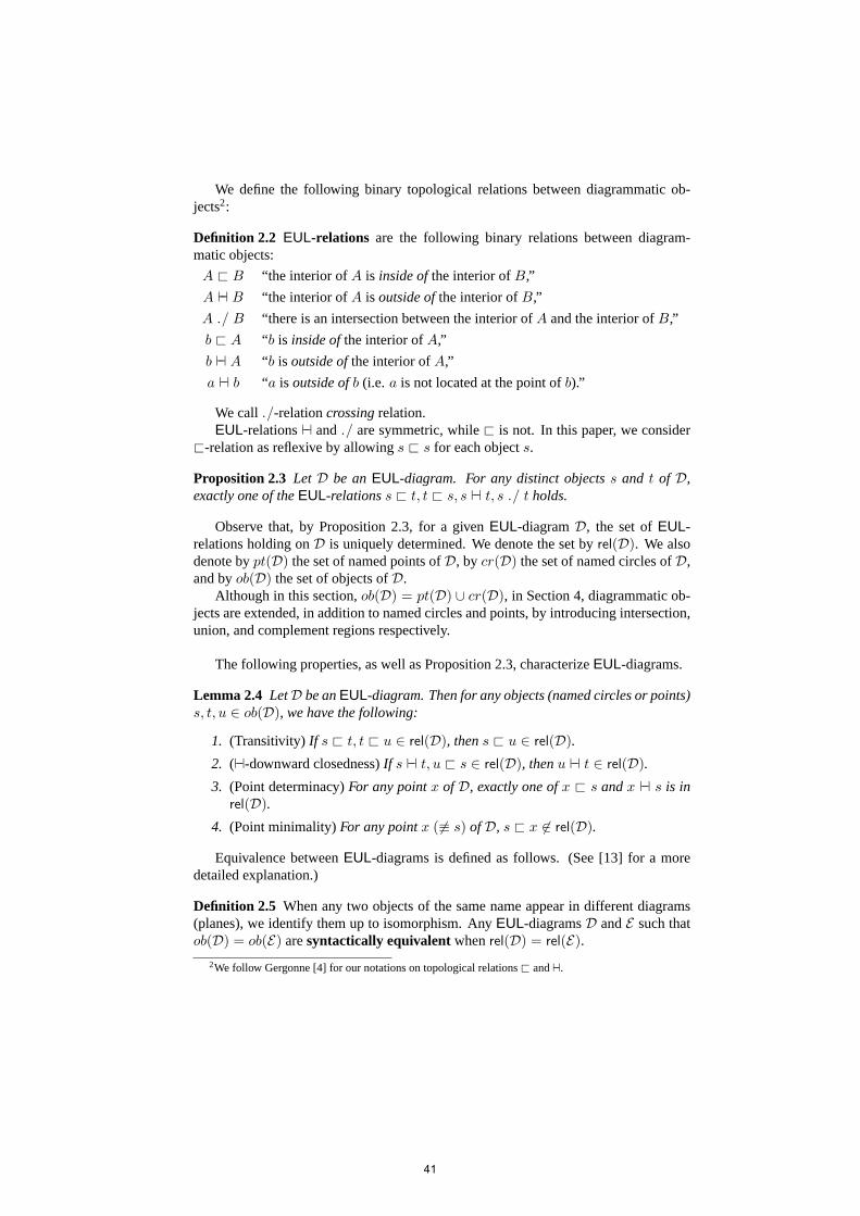
U3 Under the constraint ofU3-rule, there is no circleZ such thatZ @ A holds, andno circleW such thatA ◃▹ W holds, which is expressed by× in the graph ofrel(D). According toU3-rule of Definition A.1,rel(D+(b @ A)) is representedby the graph on the right.
X
A
6
×Z/z
6Y/y ×W
rel(D)
X
A
6
z
6Y/y
b
I
K
rel(D + (b @ A))
It is easily seen thatrel(D + (b @ A)) is anEUL-structure: I.e., the augmentededges do not violate the properties ofEUL-structure.
Note also that, without the constraint, i.e., if there is a circleZ or W as above,in order to preserve Point determinacy, we should fix a relation betweenb andZ (resp.W ) to @ or ⊢⊣. However, neither of them is sound with respect to ourformal semantics ofEUL.
U4 Under the constraint ofU4-rule, there is no circleX such thatA @ X holds, nocircleY such thatA ⊢⊣ Y holds, and no circleW such thatA ◃▹ W holds, whichis expressed by× in the graph ofrel(D). According toU4-rule of DefinitionA.1, rel(D + (b ⊢⊣ A)) is represented by the right hand graph below.
×X
A
Z/z
6×Y/y ×W
rel(D)
A
Z/z
6y
b
rel(D + (b ⊢⊣ A))
It is easily seen thatrel(D + (b ⊢⊣ A)) is anEUL-structure: I.e., the augmentededges do not violate the properties ofEUL-structure.
Without the constraint, i.e., if there is a circleX, Y or W as above, in orderto preserve Point determinacy, we should fix a relation betweenb andX (resp.Y,W ) to @ or ⊢⊣ in rel(D + (b ⊢⊣ A)). However, none of them is sound withrespect to our semantics ofEUL.
U5 Under the constraint ofU5-rule, there is no pointz such thatz @ B holds. Ac-cording toU5-rule of Definition A.1,rel(D + (A @ B)) is represented by theright hand graph below.
45

X
B
6
×Z/z
6Y/y W
rel(D)
X
B
6
Z
6Y/y W
A
K
I
rel(D + (A @ B))
Without the constraint, i.e., if there is a pointz as above, in order to preservePoint determinacy, we should fix a relation betweenz andA to@ or⊢⊣. However,none of them is sound with respect to our semantics ofEUL.
U6 Under the constraint ofU6-rule, there is no pointy such thaty ⊢⊣ A holds. Ac-cording toU6-rule of Definition A.1,rel(D + (A @ B)) is represented by theright hand graph below.
X
A
6
Z/z
6×Y/y W
rel(D)
X
A
6
Z/z
6Y W
B
��
rel(D + (A @ B))
Without the constraint, i.e., if there is a pointy as above, in order to preservePoint determinacy, we should fix a relation betweeny andB to@ or⊢⊣. However,none of them is sound with respect to our semantics ofEUL.
U7 Under the constraint ofU7-rule, there is no pointy such thaty ⊢⊣ A holds. Ac-cording toU7-rule of Definition A.1,rel(D + (A ⊢⊣ B)) is represented by theright hand graph below.
X
A
6
Z/z
6×Y/y W
rel(D)
X
A
6
Z/z
6Y W
B
rel(D + (A ⊢⊣ B))
Without the constraint, i.e., if there is a pointy as above, in order to preservePoint determinacy, we should fix a relation betweeny andB to@ or⊢⊣. However,none of them is sound with respect to our semantics ofEUL.
U8 Under the constraint ofU8-rule, there is no point inD. According toU8-rule ofDefinition A.1,rel(D + (A ◃▹ B)) is represented by the right hand graph below.
X
A
6
×Z/z
6×Y/y W
rel(D)
X
A
6
Z
6Y W
B
rel(D + (A ◃▹ B))
46

Without the constraint, i.e., if there is a pointy or z as above, in order to preservePoint determinacy, we should fix a relation betweeny (resp.z) andB to @ or⊢⊣.However, none of them is sound with respect to our semantics ofEUL.
U1 Under the constraint ofU1-rule, there is no pointy in D other thanb. Accordingto U1-rule, rel(D + (b @ A)) is represented by the right hand graph below.
X
b
6
×Y/y
rel(D)
X
b
6Y
�A
rel(D + (b @ A))
Without the constraint, i.e., if there is a pointy as above, in order to preservePoint determinacy, we should fix a relation betweeny andA to@ or⊢⊣. However,none of them is sound with respect to our semantics ofEUL.
U2 Under the constraint ofU2-rule, there is no pointy in D other thanb. Accordingto U2-rule, rel(D + (b ⊢⊣ A)) is represented by the right hand graph below.
X
b
6
×Y/y
rel(D)
X
b
6Y
A
rel(D + (b ⊢⊣ A))
Without the constraint, i.e., if there is a pointy as above, in order to preservePoint determinacy, we should fix a relation betweeny andA to@ or⊢⊣. However,none of them is sound with respect to our semantics ofEUL.
In U9, U10 rules of Definition A.1, the unified diagramsD andα share two cir-cles, which makes the graphical description ofrel(D) complicated. In order to avoidnotational complexity, we omit irrelevant objects and edges, which are retained afterthe application ofU9 andU10 rule, respectively.
U9 Under the constraint ofU9-rule, there is no objects such thats @ A ands ⊢⊣ Bhold onD, i.e., in the following description ofrel(D), the dotted line betweenY/y andA should not be→, and the dotted line betweenZ/z andB should notbe⊢⊣. According toU9-rule of Definition A.1,rel(D + (A @ B)) is representedby the right hand graph below.
X
B
6
Z/z
6A Y/y
rel(D)
X�
B
6
�
Z/z
6
�A - Y/y
rel(D + (A @ B))
47

Observe that, after the unification, some of the dotted lines ofrel(D) are fixed to→ or⊢⊣ in rel(D+(A @ B)) according to Definition A.1. We need to check thatrel(D + (A @ B)) is anEUL-structure; for example, if the dotted line betweenA andX in rel(D) is A ⊢⊣ X (or A ← X), after the application ofU9-rule,there are two incompatible edges⊢⊣ (resp.←) and→ betweenA andX, whichviolates the irreflexivity of the⊢⊣-relation of EUL-structure. It is shown that,because of our constraint forU9-rule, the dotted line betweenA andX is ◃▹(i.e., no edge) or→. Observe that, if we haveA ⊢⊣ X in rel(D), by the⊢⊣-downward closedness ofrel(D), we haveZ/z ⊢⊣ B in rel(D), which contradictsthe constraint. If we haveA ← X in rel(D), by the transitivity ofrel(D), wehaveA ← B in rel(D), which contradicts the presupposition ofU9-rule, i.e.,there is no edge betweenA andB in rel(D). Thus the dotted line betweenAandX should be◃▹ (i.e., no edge) or→, either of which is compatible with theedgeA → X in rel(D + (A @ B)). Similarly, it is shown that the other dottedlines of rel(D) are compatible with the edges ofrel(D + (A @ B)). Then it iseasily checked thatrel(D + (A @ B)) satisfies Definition 3.1, and hence it is anEUL-structure.
U10 Under the constraint ofU10-rule, there is no objects such thats @ A ands @ Bhold onD, i.e., in the following graph ofrel(D), the dotted line betweenZ ′/z′
andA (and also betweenZ/z andB) should not be→. According toU10-rule,rel(D + (A ⊢⊣ B)) is represented by by the right hand graph below.
B
Z ′/z′
6A
Z/z
6
rel(D)
B
Z ′/z′
6A
Z/z
6
rel(D + (A ⊢⊣ B))
We show that there are no incompatible edges inrel(D + (A ⊢⊣ B)). For thedotted line betweenZ/z andB, it is not→ by the constraint forU10-rule. Fur-thermore, assume to the contrary that we haveZ/z ← B in rel(D). Then, bythe transitivity ofrel(D), we haveA ← B in rel(D), which contradicts the pre-supposition ofU10-rule, i.e., there is no edge betweenA andB. Hence thedotted line betweenZ/z andB should be◃▹ (i.e., no edge) or⊢⊣, either of whichis compatible with the edgeZ/z ⊢⊣ B in rel(D + (A ⊢⊣ B)). Similarly, it isshown that the other two dotted lines ofrel(D) are compatible with the edges ofrel(D + (A ⊢⊣ B)). Then it is easily checked thatrel(D + (A ⊢⊣ B)) satisfiesDefinition 3.1, and hence it is anEUL-structure.
For a givenEUL-structure(D, p(D), @,⊢⊣), it can be shown that there is anEUL-diagramD such thatrel(D) is equivalent to(D, p(D),@,⊢⊣).
4 A hierarchy of EUL-diagrams and Venn diagrams
The representation systemEUL is extended by introducing new diagrammatic objects,intersection, union, and complement regions, respectively. Extended systems are strat-
48

ified in terms of their expressive powers.In what follows, we do not mention named points explicitly, since any named point
of EUL can be regarded as a special circle, which does not contain, nor cross, anyother objects. If we allow a point (as a special circle) to cross other circles, it amountsto adopting linking between points, although it is slightly restricted compared withusual linking as in Shin [19], among others.5
We first extendEUL by considering intersection regions as diagrammatic objects.Regionsof an EUL-diagram are defined recursively as usual, which are closed underintersection, union, and complement, provided that each is non-empty in a diagram.See, e.g., [10].
Definition 4.1 A non-empty regionr of anEUL-diagramD is anintersection regionwhen, for some{A1, . . . , An} ⊆ cr(D), r =
∩1≤i≤n in(Ai), wherein(Ai) is the
interior of circleAi. An EUL-diagrams with intersectionsD is an EUL-diagramwhere each intersection regionr =
∩1≤i≤n in(Ai) has the name⊓1≤i≤nAi, which is
sometimes denoted by⊓An for short. (In particular whenn = 1, ⊓A1 = A1.)
Note that, in anEUL-diagram with intersections, a region may have two names:For example, whenA @ B holds onD, circleA has another name,A ⊓B.
We define an algebraic structure forEUL-diagrams with intersections.
Definition 4.2 An EUL-structure with greatest lower bounds (glbs) (D, @,⊢⊣,⊓) is an EUL-structure, where for any subset{A1, . . . , An} ⊆ D such that¬∃1≤j,k≤n(Aj ⊢⊣ Ak holds onD), there is the greatest lower bound⊓1≤i≤nAi.
Although we regard named points as special named circles, the operation⊓ is notapplied to them.
Lemma 4.3 LetD be anEUL-diagram with intersections. The set of relationsrel(D)gives rise to anEUL-structure with glbs.
Lemma 4.4 (EUL ≺ EUL+⊓) Let (D, @,⊢⊣) be anEUL-structure. It is extended, byintroducing glbs, to anEUL-structure with glbs(D⊓, @,⊢⊣,⊓).
Proof. The domainD⊓ is defined as follows:
D⊓ := D ∪ {⊓1≤i≤nAi | ¬∃1≤j,k≤n(Aj ⊢⊣ Ak holds onD)}
@ and ⊢⊣ relations onD are preserved onD⊓ and they are extended for any⊓1≤i≤nAi ∈ D⊓ as follows: LetX, Y ∈ D⊓.
⊓An @ ⊓An
X @ ⊓An iff X @ Ai for all 1 ≤ i ≤ n⊓An @ X iff Ai @ X for some1 ≤ i ≤ nX ⊢⊣ Y iff X ⊓ Y ∈ D⊓
5We exclude a crossing relationc ◃▹ d between distinct named points, since it amounts toc = d or c = d(cf. Remark 2.10) but we always assumec = d in our framework.
49

It is immediate that thus constructed(D⊓,@,⊢⊣,⊓) is an EUL-structure, whichsatisfies Definition 3.1, and⊓An is the glb of Definition 4.2.
Seealso Example 4.17.WhenD is anEUL-diagram, we denoteD⊓ an EUL-diagram with intersections
whose algebraic structure is constructed from theEUL-structurerel(D) by Lemma4.4. We say that the diagramD⊓ is obtained from D.
By introducing intersection regions as diagrammatic objects,EUL with intersec-tions are more expressive than the basicEUL of Section 2.1. Let us see the followingexample.
Example 4.5 (EUL-diagrams with intersections) The three diagramsD1,D2, andD3 of Fig. 4 in Example 2.6, which are identified in the originalEUL, are distin-guished when they are regarded asEUL-diagrams with intersections. The differenceamong the three diagrams is more clearly seen by drawing theirEUL-structures withglbs. (Here, for reasons of simplicity, we omit the pointa and abbreviate⊢⊣-relation bystipulating thatX ⊢⊣ Y holds whenX ⊓ Y ∈ rel(D⊓).)
A B C
A⊓B
6 3A⊓C
k 3B⊓C
6k
A⊓B⊓C
k 63
rel(D⊓1 )
A C B
A⊓C63
B⊓C6k
A⊓B=A⊓B⊓C
k 3
rel(D⊓2 )
A B C
A⊓B
6 3A⊓C
k 3B⊓C
6k
rel(D⊓3 )
In a similar way as intersections, by considering union regions as diagrammaticobjects we have another extension ofEUL.
Definition 4.6 An EUL-diagrams with unions D is an EUL-diagram where eachunion regionr =
∪1≤i≤n in(Ai) has the name⊔1≤i≤nAi, provided that it is con-
nected.
EUL-structures with least upper bounds (lubs)for EUL-diagrams with unionsare defined in a similar way asEUL-structures with glbs.
EUL with unions is also more expressive thanEUL.
Example 4.7 (EUL-diagrams with unions) D1 andD4 of Fig. 4 in Example 2.6are distinguished when they are regarded asEUL-diagrams with unions. TheEUL-structures with lubs for these two diagrams are represented by the following differentstructures.
A⊔B⊔C
A⊔B
3A⊔C
6B⊔C
k
A
6 3
B
k 3
C
6k
rel(D⊔1 )
A⊔B=A⊔B⊔C
A⊔C
3B⊔C
k
A6
C
k 3B6
rel(D⊔4 )
50
Definition 4.8 An EUL-diagram with intersections and unions D is an EUL-diagram with intersections where union regions also have names.
Note that we only consider intersection (resp. union) regions of circles, and weexclude other regions such as(A ∩B) ∪ (C ∩D).
EUL-structure with glbs and lubs are defined by combiningEUL-structure withglbs andEUL-structure with lubs.
By considering the complement region of each circle as a diagrammatic object, wefurther introduceEUL-diagrams with intersections, unions, and complements.
Definition 4.9 An EUL-diagram with intersections, unions, and complementsD isanEUL-diagram with intersections and unions, where each complementA of a circleA, i.e., the exterior ofA, has the nameA.
EUL-structuresfor EUL-diagrams with∩,∪, aredefined as follows.
Definition 4.10 An EUL-structure with glbs, lubs, and complements(D, @,⊢⊣,⊓,⊔, ) is an EUL-structure with glbs and lubs(D, @,⊢⊣,⊓,⊔) where, for eachA ∈ D which is not of the form⊓Cj nor ⊔Cj (j ≥ 2), the complementA of A isdefinedin D.
Although we regard named points as special named circles, the operations⊓,⊔,and arenot applied to points.
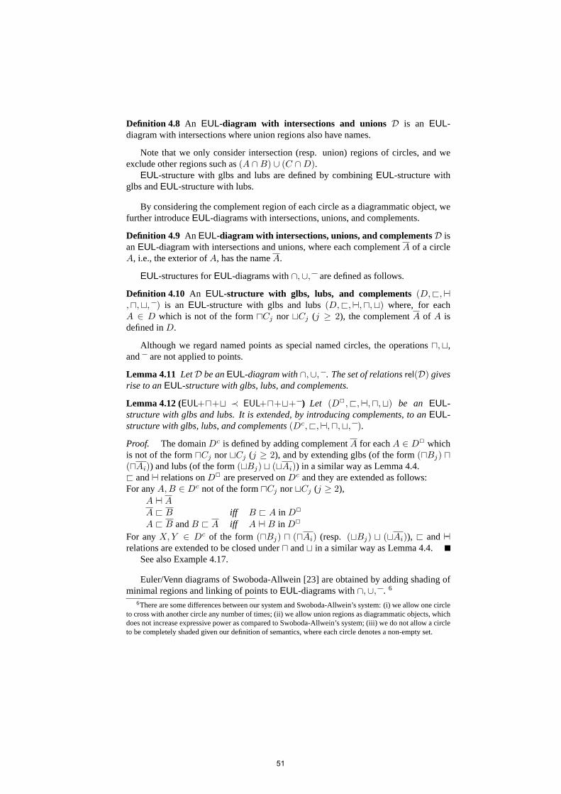
Lemma 4.11 LetD be anEUL-diagram with∩,∪, . The set of relationsrel(D) givesrise to anEUL-structure with glbs, lubs, and complements.
Lemma 4.12 (EUL+⊓+⊔ ≺ EUL+⊓+⊔+ ) Let (D2, @,⊢⊣,⊓,⊔) be an EUL-structure with glbs and lubs. It is extended, by introducing complements, to anEUL-structure with glbs, lubs, and complements(Dc,@,⊢⊣,⊓,⊔, ).
Proof. The domainDc is defined by adding complementA for eachA ∈ D2 whichis not of the form⊓Cj nor⊔Cj (j ≥ 2), and by extending glbs (of the form(⊓Bj) ⊓(⊓Ai)) and lubs (of the form(⊔Bj) ⊔ (⊔Ai)) in a similar way as Lemma 4.4.@ and⊢⊣ relations onD2 are preserved onDc and they are extended as follows:For anyA,B ∈ Dc not of the form⊓Cj nor⊔Cj (j ≥ 2),
A ⊢⊣ AA @ B iff B @ A in D2
A @ B andB @ A iff A ⊢⊣ B in D2
For anyX, Y ∈ Dc of the form (⊓Bj) ⊓ (⊓Ai) (resp. (⊔Bj) ⊔ (⊔Ai)), @ and⊢⊣relations are extended to be closed under⊓ and⊔ in a similar way as Lemma 4.4.
Seealso Example 4.17.
Euler/Venn diagrams of Swoboda-Allwein [23] are obtained by adding shading ofminimal regions and linking of points toEUL-diagrams with∩,∪, . 6
6Thereare some differences between our system and Swoboda-Allwein’s system: (i) we allow one circleto cross with another circle any number of times; (ii) we allow union regions as diagrammatic objects, whichdoes not increase expressive power as compared to Swoboda-Allwein’s system; (iii) we do not allow a circleto be completely shaded given our definition of semantics, where each circle denotes a non-empty set.
51

EUL-structuresfor Euler/Venn diagrams, which we callVenn-structures, are thedirected acyclic graphs DAGs of Swoboda-Allwein [23].
Lemma 4.13 (EUL+⊓+⊔+ ≺ Venn) Let (Dc, @,⊢⊣,⊓,⊔, ) be an EUL-structure with glbs, lubs, and complements. It is extended to a Venn-structureDv ofSwoboda-Allwein [23] by introducing shading and linking.
WhenD is anEUL-diagram, we denote byDv (resp. D⊓,D⊔,D2, Dc) an Eu-ler/Venn diagram (resp.EUL-diagram with intersections, unions, intersections andunions, intersections and unions and complements) whose algebraic structure is con-structed from theEUL-structurerel(D) by Lemma 4.4, 4.12, and 4.13. We say that thediagramDv (resp.D⊓,D⊔,D2, Dc) is obtained from D.
Various extensions ofEUL introduced so far can be summarized by the followingEUL-hierarchy:
EUL
kEUL with ∩
3
3EUL with ∪
kEUL with ∩,∪
6EUL with ∩,∪,
6Venn
Fig.5 EUL-hierarchy
Note that the semantics ofEUL of Section 2.2 is essentially the same as the seman-tics of Venn diagrams (e.g. [10, 19]), where the interpretation functionI of circles isnaturally extended to interpret regions:I(⊓Xi) =
∩I(Xi), I(⊔Xi) =
∪I(Xi), and
I(A) = U \ I(A). Note that the denotations of intersections, unions, and complementsare not assumed to be non-empty, while those of circles and points are non-empty.
Thus whenD∗ is a diagram obtained from anEUL-diagram D for ∗ ∈{⊓,⊔, 2, c, v}, D andD∗ are semantically equivalent since any relation ofD is pre-served inD∗ by constructions given in Lemmas 4.4, 4.12, and 4.13:
Lemma 4.14 LetD be anEUL-diagram. For each∗ ∈ {⊓,⊔, 2, c, v}, let D∗ be adiagram obtained fromD. For any modelM , M |= D∗ if and only ifM |= D.
Based on Lemma 4.14, it is shown that each system ofEUL-hierarchy is conser-vative over any lower system with respect to validity. We denote byD a sequence ofdiagramsD1, . . . ,Dn.
Proposition 4.15 (Semantic conservativity)LetS′ andS be any systems of theEUL-hierarchy such thatS′ is an extension ofS. LetD, E be diagrams ofS, andD∗, E∗ bediagrams ofS′ obtained fromD, E for ∗ ∈ {⊓,⊔, 2, c, v}. ThenD∗ |= E∗ iff D |= E .
52

In parallel to the extensions of representation systemEUL, we can obtain extendedinference systems ofGDS of Appendix A. It can be shown that each extended systemis a conservative extension of the most elementaryGDS with respect to provability. Inparticular, for Euler/Venn diagrammatic inference system of Swoboda-Allwein [24],we have the following conservativity theorem:
Theorem 4.16 (Conservativity) Let D and E be EUL-diagrams such thatD has amodel. IfEv is provable fromDv in Euler/Venn diagrammatic system, thenE is prov-able fromD in GDS.
Proof. Let Dv ⊢ Ev in Euler/Venn diagrammatic inference system. By soundness(cf. [24]) we have, for any modelM , M |= Dv ⇒M |= Ev. AssumeM |= D. Thenwe haveM |= Dv by Lemma 4.14. Thus we haveM |= Ev, that is,M |= E . Hence,by the completeness (Theorem A.2) ofGDS, we haveD ⊢ E in GDS.
Theconstructions of extensions ofEUL-structures given in Lemma 4.4, 4.12, and4.13 provide a procedure to transform anEUL-diagram to a Venn diagram. Let us seethe following example:
Example 4.17 Let D be an EUL-diagram such that rel(D) ={A ◃▹ B,A ⊢⊣ C, C @ B}. By transforming theEUL-structure rel(D) throughanEUL-structure with glbsrel(D)⊓, we obtain a Venn-structurerel(D)v. In rel(D)⊓
andrel(D)v below, we omit⊓ symbol and writeAB for A⊓B. In rel(D)v, we furtheromit lubs and⊢⊣-relation, and represent arrows by lines in a hierarchical structure.By extracting minimal unshaded regions (ABC, ABC, AB C, ABC, AB C) fromrel(D)v, we obtain a Venn diagramDv, which is semantically equivalent to the originalEUL-diagramD.
A B
C
D
EUL-diagram
A B
C=BC
AB
D⊓
EUL-diagramwith ∩A
C
B
Dv
Venn diagram
A
B
C6
rel(D)
B
AB6
3A C = BC
6
rel(D)⊓AB
=ABC
C =BC
=AC=AB=ABC
AB
=AB C
ABC A B C
AC =A AB B =B C BC A C
B A C
rel(D)v
In this paper, we introduced a hierarchy of Euler and Venn diagrammatic reasoningsystems in terms of their expressive powers in our topological-relation-based formal-ization. Because of the space limitation in this paper, we discuss our extensions ofEULmainly at the level of representation and semantics. This is why our conservativity re-sults for these systems (Proposition 4.15) are kept at the level of semantics. We leave
53
our explicit formalization of diagrammatic inference systems forEUL-diagrams withintersections, with unions, with complements, respectively, as future work.
References
[1] L. Euler, Lettresa une Princesse d’Allemagne sur Divers Sujets de Physique etde Philosophie, Saint-Petersbourg: De l’Academie des Sciences, 1768. (EnglishTranslation by H. Hunter, 1997,Letters of Euler to a German Princess on DifferentSubjects in Physics and Philosophy, Thoemmes Press, 1997.)
[2] A. Fish and J. Flower, Abstractions of Euler Diagrams, Electronic Notes in Theo-retical Computer Science, 134, 77-101, 2005.
[3] G. Gentzen, Investigations into logical deduction. In M. E. Szabo, ed.,The col-lected Papers of Gerhard Gentzen, 1969. (Originally published as Unter suchungenuber das logische Scliessen,Mathematische Zetischrift39 (1935): 176-210, 405-431.)
[4] J. D. Gergonne, Essai de dialectique rationelle,Annales de mathematiques pureset appliqees, 7, 189-228, 1817.
[5] J. Gil, J. Howse, E. Tulchinsky, Positive Semantics of Projections in Venn-EulerDiagrams,Journal of Visual Languages and Computing, 13(2), 197-227, 2002.
[6] E. Hammer,Logic and Visual Information, CSLI Publications, 1995.
[7] E. Hammer and N. Danner, Towards a model theory of diagrams, in G. Allwein andJ. Barwise, eds.,Working Papers on Diagrams and Logic, Bloomington: IndianaUniversity, 1993.
[8] E. Hammer and S.-J. Shin, Euler’s visual logic,History and Philosophy of Logic,19, 1-29, 1998.
[9] J. Howse, F. Molina, J. Taylor, SD2: A Sound and Complete Diagrammatic Rea-soning System,2000 IEEE International Symposium on Visual Languages, 127-134,2000.
[10] J. Howse, G. Stapleton, and J. Taylor, Spider Diagrams,LMS Journal of Compu-tation and Mathematics, Volume 8, 145-194, London Mathematical Society, 2005.
[11] B. Meyer, Diagrammatic evaluation of visual mathematical notations, inDia-grammatic Representation and Reasoning, P. Olivier, M. Anderson, and B. Meyer(Eds.), Springer, 261-277, 2001.
[12] K. Mineshima, M. Okada, Y. Sato, and R. Takemura, Diagrammatic ReasoningSystem with Euler Circles: Theory and Experiment Design,Diagrams 08, LNAI,Vol. 5223, Springer, 188-205, 2008.
[13] K. Mineshima, M. Okada, and R. Takemura, A Diagrammatic Reasoning Systemwith Euler Circles, 2009, to be submitted.
[14] F. Molina, Reasoning with extended Venn-Peirce diagrammatic systems, Ph. DThesis, University of Brighton, 2001.
54

[15] M. Nielsen, G. Plotkin, and G. Winskel, Petri Nets, Event Structures and Do-mains, Part I,Theoretical Computer Science, Vol. 13, No. 1, pages 85-108, 1980.
[16] C. S. Peirce,Collected Papers IV, Harvard University Press, 1897/1933.
[17] D. Prawitz,Natural Deduction, Almqvist & Wiksell, 1965 (Dover, 2006).
[18] Y. Sato, K. Mineshima, R. Takemura, and M. Okada, How can Euler diagramsimprove syllogistic reasoning?, poster presented at CogSci 2009, Amsterdam, at theVU University Amsterdam, July 29th to August 1st, 2009.
[19] S.-J. Shin,The Logical Status of Diagrams, Cambridge University Press, 1994.
[20] G. Stapleton, A survey of reasoning systems based on Euler diagrams,Euler2004, Electronic Notes in Theoretical Computer Science, 134(1), 127-151, 2005.
[21] G. Stapleton, J. Masthoff, J. Flower, A. Fish, and J. Southern, Automated Theo-rem Proving in Euler Diagram Systems,Journal of Automated Reasoning, volume39 , issue 4, 431-470, 2007.
[22] G. Stapleton, P. Rodgers, J. Howse, J. Taylor, Properties of Euler diagrams,ECE-ASST 7, 2-16, 2007.
[23] N. Swoboda and G. Allwein, Using DAG transformations to verify Euler/Vennhomogeneous and Euler/Venn FOL heterogeneous rules of inference,Software andSystem Modeling, 3(2), 136-149, 2004.
[24] N. Swoboda and G. Allwein, Heterogeneous reasoning with Euler/Venn diagramscontaining named constants and FOL,Euler Diagrams 2004, ENTCS, Volume 134,Elsevier, 153-187, 2005.
[25] J. Venn,Symbolic Logic, Macmillan, 1881.
A Diagrammatic inference systemGDS
In this section, we review Generalized Diagrammatic Syllogistic inference systemGDS of [13, 12], which consists of two inference rules:unificationanddeletion. Inorder to motivate our definition ofunification, let us consider the following question:Given the following diagramsD1,D2 andD3 of Fig.6, what diagrammatic informationonA,B andc can be obtained? (In what follows, in order to avoid notational complex-ity in a diagram, we express each named point, say•c, simply by its namec.) Fig. 6represents a way of solving the question.
In Fig. 6, at the first step, two diagramsD1 andD2 are unified to obtainD1 + D2,where pointc in D1 andD2 are identified, andB is added toD1 so thatc is inside ofB andB overlaps withA without any implication of a relationship betweenA andB.We formalize such cases, where two given diagrams share one object, byU1–U8 rulesof group (I) of Definition A.1. At the second step,D1 + D2 is combined with anotherdiagramD3 to obtain(D1 +D2) +D3. Note that the diagramsD1 +D2 andD3 sharetwo circlesA andB: A ◃▹ B holds onD1 + D2 andA @ B holds onD3. Sincethe semantic information ofA @ B onD3 is more accurate than that ofA ◃▹ B onD1 + D2, according to our semantics ofEUL (recall thatA ◃▹ B means just “true” in
55

A
c
D1
B
c
D2R
A
B
D3
A
c
B
D1 + D2R �
AB
c
(D1 + D2) + D3
Fig.6 Unification
BA A
c
D4 D5
Fig.7 Indeterminacy
Ca
B
D6
C B
D7
AB
D8
A B
D9
Fig.8 Inconsistency
our semantics), one keeps the relationA @ B in the unified diagram(D1 +D2) +D3.We formalize such cases, where two given diagrams share two objects, byU9–U10rules of group (II) of Definition A.1. Observe that the unified diagram(D1 +D2)+D3
of Fig. 6 represents the information of these diagramsD1,D2, andD3, that is, theirconjunction.
We impose two kinds of constraints on unification. One is theconstraint for de-terminacy, which blocks the disjunctive ambiguity with respect to locations of namedpoints. For example, two diagramsD4 andD5 in Fig. 7 are not permitted to be unifiedinto one diagram since the location of the pointc is not determined (it can be insideB or outsideB). The other is theconstraint for consistency, which blocks represent-ing inconsistent information in a single diagram. For example, the diagramsD6 andD7 (resp.D8 andD9) in Fig. 8 are not permitted to be unified since they contradicteach other. Recall that each circle is interpreted by non-empty set in our semantics ofDefinition 2.8, and henceD8 andD9 are also incompatible.7
We formalize our unification8 of two diagrams by restricting one of them to bea minimal diagram, except for one rule called thePoint Insertion-rule. Our com-pleteness (Theorem A.2) ensures that any diagramsD1, . . . ,Dn may be unified, underthe constraints for determinacy and consistency, into one diagram whose semantic in-formation is equivalent to the conjunction of that ofD1, . . . ,Dn. We give a formaldescription of inference rules in terms ofEUL-relations: Given a diagramD and aminimal diagramα, the set of relationsrel(D + α) for the unified diagramD + α isdefined. It is easily checked that the setrel(D + α) satisfies the properties of Lemma2.4 according to our constraints for determinacy and consistency, and hence locationsof points are determined in a unified diagram. (See also Section 3, where we give a
7 In place of our syntactic constraint, it is possible to allow unification of inconsistent diagrams such asD6 andD7 (resp. D8 andD9) by extendingGDS with an inference rule corresponding to the absurdityrule of Gentzen’s natural deduction system: We can infer any diagram from a pair of inconsistent diagrams.(For natural deduction systems, see, for example, [3, 17].) Such a rule is introduced in, for example, [10]for spider diagrams; [7] for Venn diagrams; [23, 24] for Euler/Venn diagrams. However, such a rule requireslinguistic symbol, say⊥, or some arbitrary convention to represent inconsistency, and hence we prefer oursyntactic constraint in our framework of a diagrammatic inference system.
8The following definition of inference rules ofGDS is slightly different from that of [13, 12] since weregard@-relation as reflexive relation in this paper.
56

graph-theoreticalrepresentation of unification.)For a better understanding of our unification rule, we also give a schematic dia-
grammatic representation and a concrete example of each rule. In the schematic rep-resentation of diagrams, to indicate the occurrence of some objects in a context on adiagram, we write the indicated objects explicitly and indicate the context by “dots” asin the diagram to the right below.9 For example, when we need to indicate onlyA andc on the left hand diagram, we could write it as shown on the right.
BF
A
E
D
c
b
Ac
Definition A.1 Axiom, unification, anddeletionof GDS are defined as follows.
Axiom:
A1: For any circlesA andB, any minimal diagram whereA ◃▹ B holds is an axiom.
A2: Any EUL-diagram which consists only of points is an axiom.
Unification: We denote byD+α the unified diagram ofD with a minimal diagramα.D+α is defined whenD andα share one or two objects. We distinguish the followingtwo cases: (I) WhenD andα share one object, they may be unified toD + α by rulesU1–U8 according to the shared object and the relation holding onα. Each rule of (I)has a constraint for determinacy. (II) WhenD andα share two circles, if the relationwhich holds onα also holds onD, D + α is D itself; otherwise, they may be unifiedtoD + α by rulesU9 or U10 according to the relation holding onα. Each rule of (II)has a constraint for consistency. Moreover, there is another unification rule called thePoint Insertion-rule (III).
(I) The caseD andα share one object:
U1: If b @ A holds onα andpt(D) = {b}, thenD andα may be unified to a diagramD + α such that the setrel(D + α) of relations holding on it is the following:
rel(D) ∪ {b @ A} ∪ {A ◃▹ X | X ∈ cr(D)}
U1 is applied as follows:
b
D R
A
b
αU1
A
b
D + α
C B
b
D1 R
A
b
D2U1C
b
B
A
D1 + D2
9Notethat the dots notation is used only for abbreviation of a given diagram. For a formal treatment ofsuch “backgrounds” in a diagram, see, for example, Meyer [11].
57

U2: If b ⊢⊣ A holds onα andpt(D) = {b}, thenD andα may be unified to a diagramD + α such that the setrel(D + α) of relations holding on it is the following:
rel(D) ∪ {b ⊢⊣ A} ∪ {A ◃▹ X | X ∈ cr(D)}
U2 is applied as follows:
b
D R
Ab
αU2
Ab
D + α
B
b
C
D1
B
b
C
A
D1 + D2
Ab
R U2 D2
U3: If b @ A holdsonα andA ∈ cr(D), and ifA @ X or A ⊢⊣ X holds for all circleX in D, thenD andα may be unified to a diagramD + α such that the set ofrelationsrel(D + α) is the following:
rel(D) ∪ {b @ X | A @ X ∈ rel(D)} ∪ {b ⊢⊣ X | A ⊢⊣ X ∈ rel(D)}∪ {b ⊢⊣ x | x ∈ pt(D)}
U3 is applied as follows:
A
D R
A
b
αU3
A
b
D + α
A
B
C
D1 R
A
b
U3 D2
A
b
B
C
D1 + D2
U4: If b ⊢⊣ A holds onα andA ∈ cr(D), and ifX @ A holds for all circleX in D,thenD andα may be unified to a diagramD + α such that the set of relationsrel(D + α) is the following:
rel(D) ∪ {b ⊢⊣ X | X @ A ∈ rel(D)} ∪ {b ⊢⊣ x | x ∈ pt(D)}
U4 is applied as follows:
A
D R
Ab
αU4
Ab
D + α
B
A
D1 R
Ab
D2U4
B
A
b
D1 + D2
58

U5: If A @ B holdson α andB ∈ cr(D), and if x ⊢⊣ B holds for allx ∈ pt(D),thenD andα may be unified to a diagramD + α such that the set of relationsrel(D + α) is the following:
rel(D) ∪ {A @ X | B @ X ∈ rel(D)}∪ {A ◃▹ X | X @ B or X ◃▹ B ∈ rel(D)}∪ {A ⊢⊣ X | X ⊢⊣ B ∈ rel(D)} ∪ {x ⊢⊣ A | x ∈ pt(D)}
U5 is applied as follows:
B
D R
A
B
αU5
A
B
D + α
C
B
EF
D1 R
A
B
U5 D2
A C
B
EF
D1 + D2
U6: If A @ B holdson α andA ∈ cr(D), and if x @ A holds for allx ∈ pt(D),thenD andα may be unified to a diagramD + α such that the set of relationsrel(D + α) is the following:
rel(D) ∪ {X @ B | X @ A ∈ rel(D)} ∪ {x @ B | x ∈ pt(D)}∪ {X ◃▹ B | A @ X or A ⊢⊣ X or A ◃▹ X ∈ rel(D)}
U6 is applied as follows:
A
D R
A
B
αU6
A
B
D + α
CA
E
D1 R
A
B
U6 D2
EC
A
B
D1 + D2
U7: If A ⊢⊣ B holds onα andA ∈ cr(D), and if x @ A holds for allx ∈ pt(D),thenD andα may be unified to a diagramD + α such that the set of relationsrel(D + α) is the following:
rel(D) ∪ {X ⊢⊣ B | X @ A ∈ rel(D)} ∪ {x ⊢⊣ B | x ∈ pt(D)}∪ {X ◃▹ B | A @ X or A ⊢⊣ X or A ◃▹ X ∈ rel(D)}
U7 is applied as follows:
A
D R
A B
αU7
A B
D + α
A
a
C
E
D1
A B
R U7 D2
A
a
C
E
B
D1 + D2
59

U8: If A ◃▹ B holds onα andA ∈ cr(D), and if pt(D) = ∅, thenD andα maybe unified to a diagramD + α such that the set of relationsrel(D + α) is thefollowing:
rel(D) ∪ {X ◃▹ B | X ∈ cr(D)}
U8 is applied as follows:
A
D R
A B
αU8
A B
D + α
C
AE
D1 R
A B
U8 D2
C
AE
B
D1 + D2
(II) WhenD andα sharetwo circles, they may be unified toD + α by the followingU9 andU10 rules.
U9: If A @ B holds onα andA ◃▹ B holds onD, and if there is no objects such thats @ A ands ⊢⊣ B hold onD, thenD andα may be unified to a diagramD + αsuch that the set of relationsrel(D + α) is the following:(rel(D) \ {Y ◃▹ X | Y @ A andB @ X ∈ rel(D)} \ {X ◃▹ Y | X @ A andY ⊢⊣ B ∈ rel(D)}
)∪ {Y @ X | Y @ A andB @ X ∈ rel(D)} ∪ {X ⊢⊣ Y | X @ A andY ⊢⊣ B ∈ rel(D)}
U9 is applied as follows:
A B
RD
A
B
U9α
AB
D + α
A BCE
D1 R
A
B
U9 D2
A
B
C
E
D1 + D2
U10: If A ⊢⊣ B holds onα andA ◃▹ B holds onD, and if there is no objects such thats @ A ands @ B hold onD, thenD andα may be unified to a diagramD + αsuch that the set of relationsrel(D + α) is the following:(rel(D)\{X ◃▹ Y | X @ A andY @ B ∈ rel(D)}
)∪{X ⊢⊣ Y | X @ A andY @ B ∈ rel(D)}
U10 is applied as follows:
A B
RD
A B
U10 α
A B
D + α
A B
C FE
U10D1 R
A B
D2
A
CE
B
F
D1 + D2
60
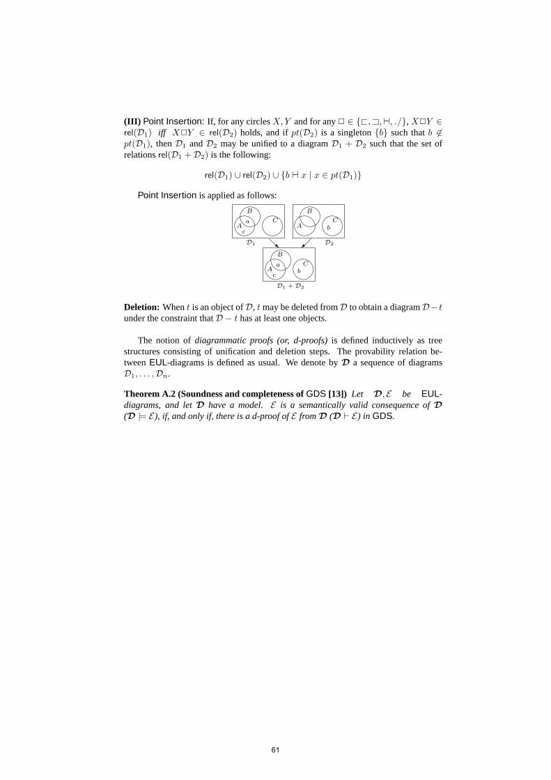
(III) Point Insertion: If, for any circlesX,Y and for any2 ∈ {@, A,⊢⊣, ◃▹}, X2Y ∈rel(D1) iff X2Y ∈ rel(D2) holds, and ifpt(D2) is a singleton{b} such thatb ∈pt(D1), thenD1 andD2 may be unified to a diagramD1 + D2 such that the set ofrelationsrel(D1 +D2) is the following:
rel(D1) ∪ rel(D2) ∪ {b ⊢⊣ x | x ∈ pt(D1)}
Point Insertion is applied as follows:
Aa
c
C
B
A bC
B
D1 D2R
Aa
cb
C
B
D1 + D2
Deletion: Whent is an object ofD, t may be deleted fromD to obtain a diagramD− tunder the constraint thatD − t has at least one objects.
The notion ofdiagrammatic proofs (or, d-proofs)is defined inductively as treestructures consisting of unification and deletion steps. The provability relation be-tweenEUL-diagrams is defined as usual. We denote byD a sequence of diagramsD1, . . . ,Dn.
Theorem A.2 (Soundness and completeness ofGDS [13]) Let D, E be EUL-diagrams, and letD have a model. E is a semantically valid consequence ofD(D |= E), if, and only if, there is a d-proof ofE fromD (D ⊢ E) in GDS.
61