Confocal Raman microscopy in 3-dimensional shape and composition determination of heterogeneous...
7
Confocal Raman microscopy in 3-dimensional shape and composition determination of heterogeneous systems M. Pastorczak a, * , M. Wiatrowski a , M. Kozanecki a , M. Lodzinski b , J. Ulanski a a Department of Molecular Physics, Technical University of Lodz, Zeromskiego street 116, 90-924 Lodz, Poland b Department of Mineralogy, Petrography and Geochemistry, AGH—University of Science and Technology, 30-059 Krakow, Poland Received 19 November 2004; accepted 2 December 2004 Available online 29 January 2005 Abstract Heterogeneous materials with special properties dedicated for specific applications attract a lot of interest due to the possibility of designing tailor-made products with strictly desirable properties. Wide range of new heterogeneous systems requires fast and non-destructive techniques for their characterization. The confocal 3D Raman micro-spectroscopy seems to be a powerful method for investigations of such materials. Its major advantage is a wide range of information simultaneously gained from the Raman spectra about the chemical structure, morphology, intermolecular interactions, internal stresses, etc. In this paper we focus our attention on the combination of two confocal Raman microscopy techniques: depth-profiling and mapping. Presented results show that such 3D Raman micro-spectroscopy allows to estimate shapes and sizes of distributed particles even for materials giving very weak Raman signal. q 2004 Elsevier B.V. All rights reserved. Keywords: Confocal Raman micro-spectroscopy; 3D mapping; Composites 1. Introduction Modern technologies make use of wide variety of heterogeneous materials (such as composites, blends, gels, alloys, etc.) with very specific properties, dedicated for special applications. This group of materials attracts so much interest due to the possibility of designing and making the products with strictly desirable chemical and physical properties (optical, electrical, magnetic, mechanical, thermal or chemical resistivity and many other) [1,2]. Most of these materials have specific architecture on the micro- or even nanometric level. Due to that for characterisation of these materials techniques providing the information on their structure with high spatial resolution are needed. Besides of many advantages and technical improvements commonly used techniques allowing to study materials at nanometric level, such as: Atomic Force Microscopy (AFM), Scanning Electron Microscopy (SEM), Secondary Ionic Mass Spectrometry (SIMS) have many limitations. For example, AFM and SEM allow only for investigation of surface morphology, with SIMS one can only characterise the chemical composition without any information on the supramolecular structure, etc. The confocal Raman micro- spectrometers, although it has spatial resolution only around 1 mm, seems to be good complementary method. The major advantage of Raman spectroscopy is a wide range of information simultaneously gained from the Raman spectra about the chemical structure, morphology, intermolecular interactions, internal stresses, etc. [3–5]. Using spatially resolved Raman techniques, such as mapping or depth- profiling one can characterise distribution of the components or stresses as well as the intermolecular interactions in multiphase systems [6,7]. Using special procedures it is possible to detect and to investigate particles even with nanometric size [8,9]. In this paper we describe the combination of two Raman techniques: depth-profiling and x–y mapping. The main goal of this work was to check the possibility of using the confocal Raman microscopy to produce 3D images; there- fore, the studies were performed on some chosen model 0022-2860/$ - see front matter q 2004 Elsevier B.V. All rights reserved. doi:10.1016/j.molstruc.2004.12.001 Journal of Molecular Structure 744–747 (2005) 997–1003 www.elsevier.com/locate/molstruc * Corresponding author. Tel.: C48 42 6313216; fax: C48 42 6313218. E-mail address: [email protected] (M. Pastorczak).
-
Upload
independent -
Category
Documents
-
view
0 -
download
0
Transcript of Confocal Raman microscopy in 3-dimensional shape and composition determination of heterogeneous...

Confocal Raman microscopy in 3-dimensional shape and composition
determination of heterogeneous systems
M. Pastorczaka,*, M. Wiatrowskia, M. Kozaneckia, M. Lodzinskib, J. Ulanskia
aDepartment of Molecular Physics, Technical University of Lodz, Zeromskiego street 116, 90-924 Lodz, PolandbDepartment of Mineralogy, Petrography and Geochemistry, AGH—University of Science and Technology, 30-059 Krakow, Poland
Received 19 November 2004; accepted 2 December 2004
Available online 29 January 2005
Abstract
Heterogeneous materials with special properties dedicated for specific applications attract a lot of interest due to the possibility of
designing tailor-made products with strictly desirable properties. Wide range of new heterogeneous systems requires fast and non-destructive
techniques for their characterization. The confocal 3D Raman micro-spectroscopy seems to be a powerful method for investigations of such
materials. Its major advantage is a wide range of information simultaneously gained from the Raman spectra about the chemical structure,
morphology, intermolecular interactions, internal stresses, etc. In this paper we focus our attention on the combination of two confocal
Raman microscopy techniques: depth-profiling and mapping. Presented results show that such 3D Raman micro-spectroscopy allows to
estimate shapes and sizes of distributed particles even for materials giving very weak Raman signal.
q 2004 Elsevier B.V. All rights reserved.
Keywords: Confocal Raman micro-spectroscopy; 3D mapping; Composites
1. Introduction
Modern technologies make use of wide variety of
heterogeneous materials (such as composites, blends, gels,
alloys, etc.) with very specific properties, dedicated for
special applications. This group of materials attracts so much
interest due to the possibility of designing and making the
products with strictly desirable chemical and physical
properties (optical, electrical, magnetic, mechanical,
thermal or chemical resistivity and many other) [1,2]. Most
of these materials have specific architecture on the micro- or
even nanometric level. Due to that for characterisation of
these materials techniques providing the information on their
structure with high spatial resolution are needed. Besides of
many advantages and technical improvements commonly
used techniques allowing to study materials at nanometric
level, such as: Atomic Force Microscopy (AFM), Scanning
Electron Microscopy (SEM), Secondary Ionic Mass
0022-2860/$ - see front matter q 2004 Elsevier B.V. All rights reserved.
doi:10.1016/j.molstruc.2004.12.001
* Corresponding author. Tel.: C48 42 6313216; fax: C48 42 6313218.
E-mail address: [email protected] (M. Pastorczak).
Spectrometry (SIMS) have many limitations. For example,
AFM and SEM allow only for investigation of surface
morphology, with SIMS one can only characterise the
chemical composition without any information on the
supramolecular structure, etc. The confocal Raman micro-
spectrometers, although it has spatial resolution only around
1 mm, seems to be good complementary method. The major
advantage of Raman spectroscopy is a wide range of
information simultaneously gained from the Raman spectra
about the chemical structure, morphology, intermolecular
interactions, internal stresses, etc. [3–5]. Using spatially
resolved Raman techniques, such as mapping or depth-
profiling one can characterise distribution of the components
or stresses as well as the intermolecular interactions in
multiphase systems [6,7]. Using special procedures it is
possible to detect and to investigate particles even with
nanometric size [8,9].
In this paper we describe the combination of two Raman
techniques: depth-profiling and x–y mapping. The main goal
of this work was to check the possibility of using the
confocal Raman microscopy to produce 3D images; there-
fore, the studies were performed on some chosen model
Journal of Molecular Structure 744–747 (2005) 997–1003
www.elsevier.com/locate/molstruc

M. Pastorczak et al. / Journal of Molecular Structure 744–747 (2005) 997–1003998
heterogeneous systems: natural minerals (rock with
different inclusions) and synthetic polymer composites.
2. Experimental
2.1. Materials
The polystyrene/micro-diamonds composite (PS/C) was
studied as a model organic/inorganic system. It was
prepared by compressing the commercial atactic PS
(MwZ149,000) with synthetic monocrystalline diamond
particles (average diameter ca. 1 mm and the purity 99.9%)
from Sigma-Aldrich Co. After compression-moulding at a
temperature of 170 8C the sample was conditioned for 5 min
at 60 8C.
A second studied heterogeneous material was natural
beryl (emerald) with an inclusion. This sample originates
from Izumrudnyje Kopii mine in Russia.
2.2. Techniques
All the spectra were collected using the Jobin-Yvon
Raman spectrometer T64000 equipped with the Olympus
Fig. 1. 3D Raman mapping technique as a combination of Raman depth-profilin
confocal microscope and motorized x–y table. The 514.5 nm
Ar line (LEXEL 95 ion laser) was used as the excitation
light. To approach the best spatial resolution the measure-
ments were performed using 100! microscope objective
(NA 0.9) and confocal pinhole of 0.1 mm width. The laser
power and the time of sample excitation were adjusted to
obtain high quality Raman spectra, enabling creation of the
spectral maps. Calibration of the confocal system was
checked by performing the depth-profile for silicon wafer
(peak 521 cmK1). The obtained results (full width at half
maximum (FWHM) of the depth-profileZ2.5 mm) are
comparable with the data given in literature, e.g. published
by Hajatdoost [10,11].
2.3. Methodology
3D Raman mapping applied in our studies is a
combination of two known Raman techniques: depth-
profiling and x–y mapping. In the depth-profiling method
the Raman spectra are collected point-by-point along the
z-axis (normal to the surface of the sample). Raman
mapping consists in scanning (point-by-point) some
selected area of the sample in the x–y plane. In both
techniques the Raman spectra should be collected in
g method (bottom scheme) and Raman mapping method (upper scheme).

M. Pastorczak et al. / Journal of Molecular Structure 744–747 (2005) 997–1003 999
properly chosen range of wavelengths covering the selected
band characteristic for the component of interest. Depth-
profiles are obtained by integration of intensity of selected
Raman band. Marking borders in FWHM of selected peaks
is an usual procedure in creating spectral x–y maps. 3D
Raman mapping as a combination of depth-profiling and
mapping allows for creation of a 3D spectral view of the
sample, as it is shown schematically in Fig. 1.
3. Results and discussion
The PS/C composite was chosen as a model system for
its high optical transparency and strong intensity of
characteristic Raman peaks: 1332 cmK1 for diamond and
1002 cmK1 for polystyrene. Raman spectra of this system
were collected with 0.25 mm step in x and y directions and
0.5 mm step along the z-axis. The maps were prepared for
both the characteristic diamond peak and the characteristic
polystyrene peak as shown in insets Fig. 2. In Fig. 3a,
showing the 2D map of the sample surface, one can notice
the area corresponding to the micro-diamonds which shapes
are very similar to those visible by optical microscopy
(compare Fig. 2). We have found, that the diameter of the
micro-diamonds estimated using this Raman map, will be
compatible with the optical microscopy pictures and with
the information provided by Sigma-Aldrich Co. (ca. 1 mm),
Fig. 2. Microphotograph of the polystyrene/micro-diamond composite from opti
by arrows.
when we assume, that the grain boundary is situated in the
place where the diamond peak intensity fall down to 25% of
its maximum value.
Analysis of the maps corresponding to the planes below
the surface (Fig. 3b1–e1) shows that the diamond peak
intensity decreases down to 25% for map acquired for 2 mm
depths. It allows estimating the sizes of particular diamond
grains to be ca. 1–1.5 mm, which is in agreement with the
in-plane sizes estimated from the x–y map shown in
Fig. 3a1. The ‘negative’ maps based on the 1002 cmK1
polystyrene peak also reflect correctly the shape of the
diamond particles. For the depth 2 mm (map corresponds to
the plane under the diamond grain), the x–y map of
polystyrene peak is uniform (see Fig. 3e2), which means
that the presence of diamond grain above the confocal plane
does not interfere the Raman signal of the polystyrene
matrix below the grain.
Fig. 4 presents a micro-photography of the second
investigated object, the natural inclusion in the beryl crystal.
Using Raman micro-spectrometry it was found that the
inclusion contains methane and carbon dioxide—see inset
in Fig. 4. The 3D Raman mapping technique was used in
order to determine a distribution of these two substances in
the inclusion. The inclusion was mapped with the x–y table
step of 1.5 mm and such 2D Raman maps were collected at
different depths, with 3 mm step along the z-axis, starting at
1 mm below the sample surface. So large x, y and z steps
cal microscopy; inset—Raman spectra from different places, as indicated

Fig. 3. Raman maps of the polystyrene/micro-diamond composite made basing on the diamond peak (1332 cmK1)—column 1 and the polystyrene peak
(1002 cmK1)—column 2. Maps a–e in each column are obtained at every 0.5 mm along z-axis starting from the sample surface.
M. Pastorczak et al. / Journal of Molecular Structure 744–747 (2005) 997–10031000

Fig. 4. Microphotograph of the studied inclusion in the beryl crystal from the optical microscopy. Inset—Raman spectra obtained from different places, as
indicated by arrows.
M. Pastorczak et al. / Journal of Molecular Structure 744–747 (2005) 997–1003 1001
were chosen because of relatively big size of inclusions. The
Raman maps created basing on the 1070 cmK1 beryl peak
(Fig. 5a1–e1), 1352 cmK1 carbon dioxide peak (maps
5a2–e2) and 2917 cmK1 methane peak (maps 5a3–e3)
reflect spatial distribution of each compound. An absence of
the CO2 and CH4 peaks in the maps 5e2 and e3,
respectively, suggests that at this depth (13 mm) there is
no more the inclusion. Fig. 5a3–e3 shows that the methane
is placed only in the bubble well visible (bottom part of the
inclusion) on the microphotography—see Fig. 4.
Contrary to methane, carbon dioxide fulfils the whole
inclusion. Obtained results prove that the investigated
inclusion is two phases and it contains liquid CO2 which
is in thermodynamical equilibrium with the mixture of
gases: CO2 and CH4.
A series of the Raman maps 5a1–e1 presents the spatial
distribution of intensity of the characteristic ‘matrix’ (beryl)
peak at 1070 cmK1. Not surprisingly the ‘matrix’ peak
intensity is the lowest in the area of the presence of the
inclusion.
It is necessary to note that although the shape of the
inclusion is not perfectly imaged by the 3D Raman maps
shown in Fig. 5, it would be possible to get more precise
results by using smaller in-plane x–y steps and the in-depth
z-step; however, it is time-consuming procedure in a case of
such relatively large objects. Another reason of the different
shape of the inclusion determined by the confocal Raman
spectroscopy can be the differences of refraction indexes
between environment (here air), matrix (here beryl) and the
inclusion. Due to such differences the focusing plane of the
excitation light (it means the real depth from which
the Raman spectra is taken) is shifted up or down comparing
to the depth determined by the microscope stage shift along
the z-axis [12]. As studies for PS/C composite shows,
for very small objects, focusing plane shift is smaller then
the depth resolution and the size estimation error is
negligible. In studies of the inclusion in emerald when
diameter of the inclusion is equal ca. 10 mm, the refraction
index of the material in the inclusion plays an important role
and it makes precise analysis of the Raman maps difficult.
Moreover, precise determination of the refractive indexes of
several phases in inclusion requires quantitative character-
ization of the composition and internal pressure. Contrary to
the laminates, where the suitable corrections can be
successfully done [12,13], for the objects with irregular
shape corrections and simultaneous analysis are very
difficult.
4. Conclusions
Presented results have shown that the confocal micro-
Raman spectroscopy is very powerful method for 3D
mapping of heterogeneous systems. For both natural and
synthetic materials the 3D Raman mapping allows to
estimate shapes and sizes of distributed particles in a proper
way without any special sample preparation. This is true for
the ‘positive’ as well as the ‘negative’ images, which means
that e.g. in a case of inclusions giving very weak Raman
signal their shapes and distribution may be determined by
making 3D map with peak characteristic for the matrix.
The estimation of the grain sizes along z-axis causes
problems due to an effect of refractive phenomena.
Similarly to the depth profiling studies of laminates, the
results from 3D Raman mapping require suitable correc-
tions for refraction. Nevertheless, for objects of a few
micrometers the influence of refraction is negligible. For
bigger objects with irregular shapes suitable corrections can
be difficult to introduce.
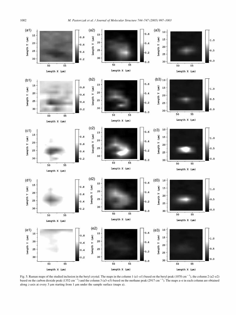
Fig. 5. Raman maps of the studied inclusion in the beryl crystal. The maps in the column 1 (a1–e1) based on the beryl peak (1070 cmK1), the column 2 (a2–e2)
based on the carbon dioxide peak (1352 cmK1) and the column 3 (a3–e3) based on the methane peak (2917 cmK1). The maps a–e in each column are obtained
along z-axis at every 3 mm starting from 1 mm under the sample surface (maps a).
M. Pastorczak et al. / Journal of Molecular Structure 744–747 (2005) 997–10031002

M. Pastorczak et al. / Journal of Molecular Structure 744–747 (2005) 997–1003 1003
Acknowledgements
This work was supported by KBN project No. 3 T08A 018
26 (Poland) and was done in a frame of the 6FP NoE project
NANOFUN-POLY, contract No. NMP3-CT-2004-500361.
References
[1] M.F. Ashby, Y.J.M. Brechet, Acta Mater. 51 (2003) 5801–5821.
[2] T.R. Jackson, H. Liu, N.M. Patrikalakis, E.M. Sachs, M.J. Cima,
Mater. Des. 20 (1999) 63–75.
[3] M. Clayburn, A. Luget, K.P.J. Williams, Raman Microscopy and
Imaging of Polymers, ACS Symposium Series 598 41, 1995 (Chapter 3).
[4] P. Smidt, M.R. Fernandez, J.M. Pastor, Polymer 38 (9) (1997)
2067–2075.
[5] J. Parthenios, D.G. Katerelos, G.C. Psarras, C. Galiotis, Eng. Fract.
Mech. 69 (2002) 1067–1087.
[6] C. Krafft, et al., Vib. Spectrosc. 32 (2003) 75–83.
[7] W. Schrof, E. Beck, R. Koniger, W. Reich, R. Schwalm, Prog. Org.
Coat. 35 (1999) 197–204.
[8] W.X. Sun, Z.X. Shen, Ultramicroscopy 94 (2003) 237–244.
[9] M.S. Anderson, S.D. Gaimari, J. Struct. Biol. 142 (2003) 364–368.
[10] S. Hajatdoost, J. Yarwood, Appl. Spectrosc. 50 (5) (1996) 558.
[11] S. Hajatdoost, M. Olsthoorn, J. Yarwood, Appl. Spectrosc. 51 (1997)
12.
[12] N.J. Everall, Appl. Spectrosc. 54 (10) (2000) 1515–1520.
[13] H. Reinecke, S.J. Spells, J. Sacristan, J. Yarwood, C. Mijangos, Appl.
Spectrosc. 55 (2001) 12.