
Confidence in smart token proximity: Relay attacks revisited
33
Confidence in Smart Token Proximity: Relay Attacks Revisited G.P. Hancke a , K.E. Mayes a , K. Markantonakis a a ISG Smart Card Centre Royal Holloway, University of London Egham TW20 0EX, UK Abstract Contactless and contact smart card systems use the physical constraints of the communication channel to implicitly prove the proximity of a token. These systems, however, are potentially vulnerable to an attack where the attacker relays communication between the reader and a token. Relay attacks are not new but are often not considered a major threat, like eavesdropping or skimming attacks, even though they arguably pose an equivalent secu- rity risk. In this paper we discuss the feasibility of implementing passive and active relay attacks against smart tokens and the possible security im- plications if an attacker succeeds. Finally, we evaluate the effectiveness of time-out constraints, distance bounding and the use of a additional verifica- tion techniques for making systems relay-resistant and explain the challenges still facing these mechanisms. Key words: Relay attack, RFID, smart card, token, contactless, near-field communication 1. Introduction Smart tokens are often used for the purpose of proximity identification in secure systems. Contactless tokens use near-field communication, usually limiting the operating range of most readers to less than 10 cm and con- tact tokens, as the name suggests, have to physically touch the reader. If Email address: [email protected] (G.P. Hancke) Preprint submitted to Computers & Security August 19, 2008
-
Upload
independent -
Category
Documents
-
view
1 -
download
0
Transcript of Confidence in smart token proximity: Relay attacks revisited

Confidence in Smart Token Proximity:
Relay Attacks Revisited
G.P. Hanckea, K.E. Mayesa, K. Markantonakisa
aISG Smart Card Centre
Royal Holloway, University of London
Egham TW20 0EX, UK
Abstract
Contactless and contact smart card systems use the physical constraints ofthe communication channel to implicitly prove the proximity of a token.These systems, however, are potentially vulnerable to an attack where theattacker relays communication between the reader and a token. Relay attacksare not new but are often not considered a major threat, like eavesdroppingor skimming attacks, even though they arguably pose an equivalent secu-rity risk. In this paper we discuss the feasibility of implementing passiveand active relay attacks against smart tokens and the possible security im-plications if an attacker succeeds. Finally, we evaluate the effectiveness oftime-out constraints, distance bounding and the use of a additional verifica-tion techniques for making systems relay-resistant and explain the challengesstill facing these mechanisms.
Key words:Relay attack, RFID, smart card, token, contactless, near-fieldcommunication
1. Introduction
Smart tokens are often used for the purpose of proximity identificationin secure systems. Contactless tokens use near-field communication, usuallylimiting the operating range of most readers to less than 10 cm and con-tact tokens, as the name suggests, have to physically touch the reader. If
Email address: [email protected] (G.P. Hancke)
Preprint submitted to Computers & Security August 19, 2008

the reader successfully communicates with a token it is therefore assumedthat the token is close physical proximity. Using only these physical charac-teristic of the communication channel, however, is not suitable for securelyproving the proximity of a token. An attacker can use a proxy-token andproxy-reader to relay the communication between a legitimate reader andtoken over a greater distance than intended, thereby tricking the reader intobelieving that the real token is in close proximity. A successful relay attacktherefore allows an attacker to temporarily possess a ‘virtual clone’ of a to-ken, thereby allowing him to gain the associated benefits.
Relay attacks are not a new concept. The attack scenario was alreadyproposed in the 1970s [1] and more recently relay attacks, known in thiscontext as ‘wormhole’ attacks, have also become a recognised threat in wire-less network security [2]. The possibility of relay attacks have been discussedbriefly in security surveys and threat frameworks concerning Radio FrequencyIDentification (RFID), e.g. [3, 4], but at the same time there are several ex-amples, including comprehensive industrial and government guidelines, ofsurvey publications that do not take relay attacks into account, e.g. [5, 6, 7].The reason for failing to consider relaying as a threat could be that securityexperts tend to treat this attack as a mixture of conventional man-in-the-middle and skimming attacks, which can be prevented with application layerauthentication or physical security mechanisms. Relay attacks, however, arenot that easy to defend against and even though physical mechanisms, suchas the shielding of contactless tokens, could prevent certain attack scenar-ios, any application layer security is effectively circumvented. As a result, itis irrelevant whether the system implements secure authentication and en-cryption mechanisms. To our knowledge the only cryptographic mechanismconsidered to be suitable for preventing relay attacks are distance-boundingprotocols, which will detect the additional delay introduced by the attacker.These protocols are, however, not implemented in current systems and ex-isting time-out constraints imposed on the communication between a readerand token has been shown to be ineffective in detecting this extra attackdelay. The attack could be made more difficult by implementing ‘two factor’authentication, although this method cannot prevent the attack entirely andis considered impractical in certain systems.
This paper serves as an overview of the recent academic work related torelay attacks, detailing both our own work and that of other researchers,
2

which highlight the practical feasibility and security implications of these at-tacks. Our primary motivations are to emphasise the challenges this attackposes to proximity identification and to assist system engineers to fully un-derstand the risks and attack techniques when selecting or upgrading smartcard technologies. In Section 2 we discuss active and passive relay attacks,first elaborating on the logical attacks before examining the feasibility ofpractically implementing these against current systems in Section 3. Sec-tion 4 considers the security implications and presents possible exploitationscenarios. Finally, in Section 5 we describe some of the countermeasuresproposed and comment on their effectiveness.
2. Relay attacks
In 1976, Conway [1] first proposed the Grand Master Chess problem,which described how a person who does not know the rules of chess couldplay against two grand masters by challenging both of them to a postal game.The player would then simply forward the move received from one grand mas-ter to the other, effectively making them play against one another. A relayattack, or ‘mafia fraud’ as it was first referred to by Desmedt et al. [8], isan extension of this scenario to security protocols. For example, an attackercan circumvent an authentication protocol by simply relaying a challenge toa legitimate prover, who will provide him with the correct response, whichcan then be relayed back to the verifier. It does not matter what applicationlayer protocols or security algorithms are used as the attacker just relays allthe application layer data, thereby ensuring that both the verifier and theprover always receive the data they expect.
Figure 1: Basic relay attack setup
To execute a relay attack the attacker needs two devices, which act as atoken and a reader respectively. These devices are connected via a suitable
3

communication channel in order to relay information over a greater distance.For example, the basic relay setup for attacking a contactless system is shownin Figure 1. The proxy-reader is used to communicate with the real token,while the proxy-token is placed near the real reader. Any information trans-mitted by the reader is received by the proxy-token and relayed to the proxy-reader, which will transmit the information to the token. The token assumesthat it is communicating with the reader and responds accordingly. The to-ken’s response is then relayed back to the proxy-token, which will transmitthe information to the reader. The intention of the attacker is to ensure thatthe reader is unable to distinguish between the real token and the proxy. Ifhe succeeds the reader will assume that the token and its associated ownerare in close proximity and grant access to the attacker.
A simple attack against a system implementing application layer crypto-graphic mechanisms could be illustrated using the example of a a door accesscontrol system using smart tokens. The door reader and the token share asecret key K and the reader authenticate the token presented before unlock-ing the door. An attacker sets up a relay attack and approaches the door,where the reader challenges him by asking his ‘token’ to encrypt a challengeC. The attacker forwards C to an accomplice with access to a legitimate to-ken, for example a token in the pocket of an employee having his lunch in anearby cafeteria. The accomplice challenges the legitimate token and learnsthe correct response EK {C}, which be sends back to the attacker standingat the door. As the attacker’s ‘token’ responds with the correct answer thereader assumes that the legitimate token is present and unlocks the doorfor the attacker to gain access. If the reader wanted to read some furtheraccess conditions off the token, e.g. EK {Read Sector AC}, the attacker andhis accomplice relays information in the same way and the attacker’s ‘to-ken’ would be able to respond with the expected EK {AC’s content}. Theattacker never needs to know the plaintext data or the key K as long as heand his accomplice can continue relaying the respective messages between thereader and the legitimate token. It does therefore not matter if the data isencrypted using the Advanced Encryption Standard AES with a 256-bit key,or a weak proprietary cipher with a 32-bit key as the resultant ciphertext ofeither can be relayed just as easily. The success of the attacker is thereforeindependent of the application layer protocol and encryption algorithm usedand as a result application layer cryptographic mechanisms are ineffective atpreventing relay attacks.
4

Relay attacks can be classified as either passive or active. When execut-ing a passive relay attack the attacker does not modify the data in transit.To be successful, the attacker only needs to relay the communication be-tween the token and the reader for the duration of the transaction. Thepassive attack is limited when compared to conventional man-in-the-middleattacks, since the attacker cannot modify or access any data he relays unlessfurther flaws exist in the protocols or algorithms used. Despite this limita-tion, relay attacks still pose a threat to systems that provide privileges andservices if it simply manages to perform a successful authentication sequencewith the token presented. For example, an access control system will opena door and a vending machine will dispense an item if presented with whatit perceives to be a valid token in close proximity. A relay attack setup is,however, also an ideal platform for executing a ‘real-time’ man-in-the-middleattack. During this active relay attack the adversary could also exploit anexisting weakness in the security mechanisms of the system to modify thetransaction data. Memory and logic tokens recommended for high-volumeclosed payment and access control systems are probably more vulnerablethan high security micro-controller tokens, as they implement limited secu-rity mechanisms due to resource and cost constraints. For example, if atoken only implements an authentication function but the subsequent datais not encrypted the attacker could relay the authentication exchange andthen modify the data that follows.
3. Practical Implementation
The theoretical principles of a relay attack is quite simple but the at-tacker must still overcome timing restrictions and the practical engineeringchallenges of relaying signals between the participants. Relay attacks, how-ever, are practically feasible against contactless and contact tokens as ex-ample demonstrations in 2005 [10] and 2007 [9] showed. There are severalfactors that aid relay attacks in the contactless environment. One of theperceived benefits of contactless technology is convenience for the customer.Contactless tokens do not have to be oriented correctly and inserted intoreaders like contact cards and the time it takes the customer to performan action is therefore reduced. To preserve this time advantage contactlesssystems rarely require further user interaction, such as entering a Personal
5

Identification Number (PIN), when processing a transaction. It is also a pos-sibility that an attacker could also activate a contactless token while still inthe victim’s pocket, wallet or bag by using a modified reader with a largeroperating range [21]. The attacker does, therefore, not need to convince thevictim to hand over his token for a period of time, or to insert it into aproxy-reader and enter a PIN, as would be the likely case for a relay attackagainst contact tokens. The contactless operation also makes the construc-tion of the proxy-token easier. People often scan their wallet, purse or bagcontaining the token, which means that an attacker never needs to reveal hishardware. In an attack on a contact token the attacker has to take out hisproxy-token in order to insert it into a reader, for example at a point-of-saleterminal in the presence of a vendor, so it has to closely resemble a real card.We describe our implementation of a contactless relay attack in Section 3.1followed by a brief overview of the attack against contact cards describedin [9] in Section 3.2.
3.1. Contactless Systems
An attacker can choose a number of different approaches to implementan attack depending on his skill and resources. The attacker can implementhis own custom hardware for the contactless proxy token and reader or al-ternatively use existing hardware. Hancke [11] and Kasper [12] have bothdescribed hardware designs capable of performing a relay attack against ISO14443A [13] systems. Alternatively, an attacker could also implement an opensource reader and token design such as the OpenPCD and OpenPICC [14]and modify the hardware and software as required. If an attacker does nothave the engineering skills to build hardware he could also use existing Near-Field Communication (NFC) devices when these become available. The ISO18092, or the Near Field Communication – Interface and Protocol (NFCIP),standard [15] allows for active devices, such as cellphones, to communicatewith ISO 14443 contactless devices. Such a NFC device can act as either acontactless reader or a token and should already contain additional commu-nication channels suitable for relaying information, e.g. Wi-Fi. Even thoughthe deployment of NFC devices is currently limited, they could provide anattacker with an ideal hardware platform for executing his relay attack. Apossible relay attack setup using modified NFC devices has been proposedby Kfir et al. [16], although the attack was not practically implement anddemonstrated. Most of the existing relay attack implementations focus onISO 14443A systems as this is the predominant standard used in most secu-
6

rity sensitive applications, such as e-passports and credit cards. The relayattack scenarios does, however, apply to all tokens and it is conceivable thatattackers in the future could develop attack hardware for other RFID stan-dards, such as ISO 15693 [17], ISO 18000 [18] and Electronic Product CodeClass-1 Generation 2 [19].
Figure 2: Example of attack implementation against a contactless system
For our relay attack investigation, we successfully reimplemented a proxy-token and a proxy-reader suitable for executing a relay attack against ISO14443A tokens, as shown in Figure 2, based on concepts introduced in [11, 12].Our main design consideration was to minimise the delay the hardware in-troduced when relaying the communication. The majority of the attackhardware was implemented with off-the-shelf components and publicly avail-able reference designs, which were slightly modified. The necessary hardwareparts were easily obtainable and the cost of the whole system was under $230,with main costs being an RFID reader for the proxy-reader and RF links forthe relay channel. The proxy-token and proxy-reader hardware is shown inFigure 3.
Proxy-Reader: The main component of the proxy-reader is an RFID readerwe purchased for approximately $70. The reader is build around a contact-less reader integrated circuit (IC) connected to an 8-bit micro-controller. Itis therefore an ideal development platform since all radio frequency (RF) andcommunication components are already implemented while the functioningof the reader can easily be reconfigured by simply reprogramming the micro-
7

(a) Proxy-Reader (b) Proxy-Token
Figure 3: Hardware for contactless relay attack
controller. To implement the proxy-reader we configured the reader to actonly as a high-frequency radio front-end. The reader IC was placed in anoperating mode where data supplied on a specified input pin would be mod-ulated onto the 13.56 MHz carrier. In this configuration, the IC modulatesthe signal on a specified pin onto the carrier using 100% amplitude mod-ulation. The Modified Miller encoded data, specified for reader-to-tokencommunication in ISO 14443A, can therefore be modulated onto the carrierby connecting the input data stream to this pin. In this mode the IC alsodemodulates the response from the token and outputs the recovered Manch-ester encoded data, used for token-to-reader communication in ISO 14443A,on a specified pin. In order to interface to the relay communication channelsthe proxy-reader also performs some basic signal processing of the ModifiedMiller and the Manchester encoded data. These processing operations aredescribed in more detail later when discussing the communication channels.
The proxy-reader’s operating range is determined by the distance overwhich it can power the token, and its ability to receive the token’s answer.This range is dependent on the transmitted power in addition to the diam-eter of the antenna used [20]. Although our demonstration simply used thestandard operating range of our reader, the attacker would ideally want toextend the operating range to avoid detection. The attacker might thereforeimplement an extended range skimming attack, as already described in by
8

Kirschenbaum et al. [21], in addition to a relay attack. In this case, the RFinterface would need to be modified to achieve the required operating range.The only part of the unit that needs to be covert is the antenna as it needsto be close to the victim for a short period without being noticed. The cre-ativeness of the implementation is left to the attacker, but an antenna couldbe built into a briefcase, clothes, etc.
Proxy-Token: The proxy-token is basically an ISO 14443 high frequency(HF) interface, which demodulates the received communication and load-modulates the desired response onto the reader’s carrier. The interface, whichis partly based on a circuit design described in [22, pp 276–278], is imple-mented using only discrete components and basic logic ICs. For example,the sub-carrier required for load-modulating the response is generated witha binary counter and the readers communication is recovered using a simpleenvelope detector and threshold comparator. The proxy-token also incorpo-rates an adjustable delay to align the response received from the proxy-readerwith the start of a bit period defined by the real reader. The significanceof the expected bit start times and the response timing is discussed in Sec-tion 5.1. In order to interface to the relay communication channels the proxy-reader also performs some basic signal processing of the Modified Miller andthe Manchester encoded data. These processing operations are described inmore detail later when discussing the communication channels.
The cost of the proxy-token is dependent on the actual way it is im-plemented. An attacker could implement the design on a printed circuitboard, for approximately $70, or choose a simpler and cheaper method suchas prototype strip board. The attacker does not need to extend the token’soperating range as the device can be held in close proximity to the reader.The attacker also does not need to have a proxy-token resembling the realtoken as it is acceptable in contactless transactions to hold a wallet or a bagagainst the reader. Unlike real tokens, the proxy-token does not need to bepowered by the reader and can have its own power supply thereby furthersimplifying the design.
Relay Channel: The communication channel relays the data using shortrange RF communication. For this purpose we purchased two wireless audiovisual (AV) channels from eBay with an advertised range of approximately30–100 m at a cost of approximately $35 each. One channel was used to
9

send data from the proxy-token to the proxy-reader and the second channelwas used to send data from the proxy-reader to the proxy-token. The com-munication channel potentially causes the largest time delay in the system.The advantage of the AV channels were that they could transmit the Modi-fied Miller and Manchester encoded data as received from the proxy devices,thereby eliminating the extra processing requirements and delay needed todecode, buffer and retransmit the data. The AV channels were also more re-liable and easier to use than the RF components originally described in [10].Only basic signal processing functions were required to interface the chan-nels to the communication channels and all functions were implemented usingonly discrete components. The input signal had to be scaled down and theoutput signal passed through a comparator to correct the signal shape andlevel-shift the data signal to the voltage level required by the proxy devices’logic.
3.2. Contact Systems
Drimer and Murdoch demonstrated a relay attack on an EMV [23] con-tact payment system in the United Kingdom called “Chip and PIN” [9].The card holder is presented with a fake terminal for PIN entry that is con-nected to the attacker’s laptop. This laptop then communicates wirelesslywith another laptop inside a backpack of an accomplice in a shop elsewhere,which is connected to a fake card that is inserted into a real point-of-sale(POS) terminal. Once both real and fake cards are inserted, the transactiondata can be relayed between the real terminal and card, and authorized bythe cardholder through entry of the correct PIN. Since the card holder hasno feedback about the transaction, apart from information displayed on theproxy-reader, it could be possible for the attacker to authorise a transac-tion of any amount. For example, the attacker could be purchasing a $200product while the cardholder thinks that he is authorising payment for a$2 cup a coffee, purchased from the attacker’s accomplice. To be successfulthe attackers require a counterfeit terminal (proxy-reader), counterfeit card(proxy-token) and a suitable relay channel. To make our paper self-containedwe briefly discuss the practical implementation of these three components,as shown in Figure 4, although we recommend that the reader refers to theoriginal publication for a more detailed explanation.
Counterfeit card: The authors modified a genuine Chip & PIN card byconnecting wires to the reverse side of the card’s contact pads. The counter-
10

Figure 4: Example of attack implementation against a contact system as described in [9]
feit card was then connected to an FPGA development board that bufferedthe transaction data and translated the data between the ISO 7816 and RS-232 protocols. The total cost of the card was approximately $160.
Counterfeit terminal: The authors purchased a ’Chip & Pin’ payment ter-minal from eBay with enough internal space to fit the hardware required forthe attack. All the original internal hardware, except the keypad and liquidcrystal display (LCD) screen were removed, and replaced with a smart cardreader, which was connected to the existing card slot, and a small form-factorfield programmable gate array (FPGA) development board. The modifiedterminal could record keypad strokes, display content on the LCD screen andinteract with an inserted contact card, and as a result it appeared to behavelike a real terminal. The total cost of the terminal was approximately $300.
Relay Channel: The counterfeit terminal and card were controlled by sep-arate laptops via USB and RS-232 interfaces respectively, using custom con-trol software. The laptops communicated via Transmission control Protocol(TCP) over 802.11b wireless, although the authors state that in principlethis could be Global System for Mobile (GSM) or another wireless protocol.
11

One of the complications of this attack is that it requires careful coordi-nation by the fraudsters in order to make sure that both cards are insertedinto the respective terminals at about the same time. The attacker must haveaccess to the token for the full duration of his interaction with the reader.Some additional synchronization is therefore needed between the attackersto present the proxy-token to a reader at the time when a suitable tokenhas been inserted into the proxy-reader. With contact cards, there is also achance that the merchant may notice that something is not right with thecard, or even be required to handle it. The contact card attack does, however,demonstrate that current systems, even those used in security sensitive en-vironments such as banking, do not have the necessary mechanisms in placeto prevent relay attacks.
4. Security Implications
There are several ways in which an attacker can benefit from a relayattack. It should be noted that this section presents simple, worst-case sce-narios to illustrate how relay attacks might be used to circumvent securitymeasures. These scenarios could in some cases be prevented by current se-curity mechanisms.
4.1. Passive Attack
In general, a relay attack is seen as an attack by a fraudulent third partyagainst an honest service provide, or merchant, and a token holder. In thisscenario, the attacker can masquerade as the real holder by making a proxy-token act as a virtual clone of a legitimate token. As a result, the attackercould circumvent the security of several systems, e.g. payment and accesscontrol. We have already presented on such case in Section 2 where an at-tacker, who wants to gain entry to a building, simply identifies an authorizedtoken holder, possibly out to lunch, and activates his token while anotherattacker opens the required door. The relay attack might, however, also beused in attacks that do not involve a third party attacker.
A relay attack can also be utilized by a fraudulent merchant. A fraud-ulent merchant can set up the proxy-token at the reader supplied by theacquirer (likely to be his bank). His accomplice then wanders around outsidewith a proxy-reader and conducts payment transactions with the tokens of
12

unwitting victims. This attack could go unnoticed if the merchant conductstransactions, of small value, with several victims. The victims are unlikelyto notice a single fraudulent transaction once they check their statements,since a sandwich or newspaper purchased from a specific merchant is notalways easy to remember. Similarly, the token issuer or system operator can-not easily distinguish this attack from the regular activity on the merchant’saccount. However, these activities can be traced back to the merchant if theoperator, bank or customer does happen to identify fraudulent transactionsand sufficient punitive measures, such as the loss of their ability to acceptcard payments, might discourage merchants to execute such attacks. Themerchant can also have several proxy-readers sending information to a singleproxy-token. This allows the merchant to have multiple ‘readers’ withoutpurchasing additional hardware from the acquirer, possibly circumventingexpensive licensing agreements.
With token resources, like processing ability and memory size, increasingmulti-application tokens are becoming more popular. A token, for example,might be required to act as both a credit/debit and a transport card withreaders located in stores, or at underground rail stations. In this system, afraudulent merchant could possibly set up a fake top-up reader to act as aproxy-reader, which then selectively relays communication to the transportauthority and the debit card readers. Alternatively, it might be possible tocovertly attach a small loop antenna onto the transport authority’s reader,which acts as the antenna of a contactless proxy-reader relaying informationto the debit card reader. A person wishing to top-up his travel purse firstenters the amount he wishes to add. After payment he then presents his cardto the reader for the credit to be loaded. Using the relay setup it might bepossible for the merchant to also charge the debit card during the time thatthe card is touched to the reader. The holder is unlikely to notice the extratime taken for the debit card transaction, since both transactions can be con-ducted before he takes the card away. This attack could possibly be detectedif the travel and payment systems look for simultaneous transactions but thatwould require collaboration between the two operators. In this example bothapplications are related to payment schemes, which are generally thought tobe monitored for fraud by operators who might also make some effort toensure that their equipment is tamper resistant, maintained and installedcorrectly. However, multi-application tokens potentially contain applicationsthat require a varying degree of security. In addition, a merchant does not
13
necessarily have a incentive, or the skill, to regularly examine or maintaintheir equipment, e.g. while a customer scans his employee ID as part of asimple loyalty scheme at the coffee house next to his place of work attack-ers are gaining access to his office/building. In some case an extra vigilantcustomer could become suspicious but, as is noted in [9], it is unreasonableto expect that the token holder recognises illegitimate equipment, especiallywhen there are so many different readers in use. For example, in June 2008there was 157 VISA-approved point-of-sales terminals offered by 41 differentvendors [24].
A fraudulent holder can also benefit from a relay attack by setting upthe attack using a proxy-reader close to his own token. He then createsseveral proxy-tokens that all communicate with the proxy-reader. Each ofthe proxy-tokens now acts as a virtual clone of the original. Theoretically,this allows several ‘holders’ to share the same valuable token. For example,if one owner is issued with a yearly public transport pass he can issue proxy-tokens to some of his friends. Everyone can then use the same transporttoken, assuming that they do not travel in such a way that will alert back-end fraud detection measures to block the token. Another advantage theowner can gain by implementing an ‘attack’ against his own token is theability to control the communication. The owner can therefore implementan active relay attack and selectively modify the communication. This canpossible allow the attacker to exploit further vulnerabilities in the securityprotocols of the smart token system.
4.2. Active Attack
A number of systems still use older, or legacy, smart token technology.Some of these tokens implement proprietary cryptographic algorithms to pro-vide security services such as authentication and encryption. In certain cases,integrity checking is also implemented using basic error detection mechanismssuch as parity checking and Cyclic Redundancy Codes (CRC). Such systemscould be vulnerable to an active relay attack because of weaknesses in thesecurity mechanisms.
For example, if the data is encrypted using a stream cipher, which com-bines the cipher stream and plaintext in a linear way, inverting a ciphertextbit leads to the corresponding plaintext bit also being inverted. An attackercan therefore change bits in the plaintext by changing the corresponding bits
14

in the ciphertext. Extra cryptographic mechanisms must therefore be imple-mented to prevent data tampering as measures designed primarily to detectbit errors are not sufficient, i.e. CRC and parity bits can simply be modifiedin the same way to match the new data. This is not a new attack and hasalready been used against other protocols, such as Wireless Equivalent Pro-tocol (WEP) [25].
Figure 5: Modifying data bits between the token and reader
To execute this attack an attacker would require some knowledge aboutthe communication sequence, individual frame formats, the parity bit andthe CRC polynomial. Contactless system communication tend to repeatthe same communication sequence during each transaction, e.g. for a travelscheme the reader might authenticate the token, read the current balanceand then subtract the fare value and repeat this process each time a token ispresented. As a result of these predictable exchanges, a system that does notensure that every transaction with the same token yields different ciphertextfor all messages exchanged could therefore fall prey to selective replay attacks.In the travel scheme example the attacker could just relay the authentica-tion sequence and then replace the current balance response with a replayed
15

response from an earlier exchange, thereby making the reader believe thatthe token has more credit than is the case. In most cases, it is relativelyeasy to identify different commands even though some frames are encrypted.This is possible because most commands have a recognisable format, whichcan be obtained from a token’s data sheet, example code provided by thetoken manufacturer or industry standards. This is useful for an attacker whowants to execute an active relay attack since he can try to figure out whenthe system is transmitting data of interest by means of simple traffic analy-sis. Next the attacker requires some knowledge about the plaintext format,which is usually not publicly published and probably differs from one sys-tem to the next. The attacker could, however, perform some trial-and-errortesting to see whether a single modified bit has any effect on the system.In simple systems, an attacker might need to modify only one or two bitsto change the date his pass expires or to charge his token with more creditthan what he payed for. If an attacker already knows the full plaintext, theattack becomes even simpler. In this case he can simply XOR the knownplaintext with the ciphertext to obtain the cipher stream and then ‘encrypt’an entire new message using the resultant cipher stream. Figure 5 shows howthe transmitted data frame is constructed and Table 1 shows an example ofhow the attacker could possibly change the encrypted data without beingdetected by a parity check.
Bits Original Cipher Transmitted Attack Received De-cipheredPlaintext Stream Ciphertext Pattern Ciphertext Plaintext
0 0 1 1 0 1 01 0 1 1 0 1 02 1 0 1 0 1 13 0 1 1 0 1 04 0 0 0 0 0 05 0 0 0 0 0 06 0 1 1 0 1 07 0 0 0 1 1 1P 0 1 1 1 0 1
Table 1: Modifying an encrypted value, with odd parity checking, from ‘4’ to ‘132’.
16

After deciding which bits to invert in the plaintext, the attacker needs tocalculate which integrity checking bits to change. If an even number of bitsin a byte is changed the parity bit is kept the same. If an odd number ofbits is changed the parity bit should also be changed. The CRC also needsto be changed to correspond to the new data. To do this the attacker createsa bit mask equal in length to the data block, containing only ‘0’s, for whichhe calculates the CRC. The attacker then sets the bits corresponding to theplaintext bits that are to be inverted equal to ‘1’ and again calculates theCRC. The two CRC values are XORed together and the result is appendedto the bit mask. The attacker then flips all the bits in the relayed frame thatcorresponds to a ‘1’ in the bit mask. If an attacker knows the plaintext theattack is much simpler. He recovers the relevant cipher stream, by XORingthe plaintext and the ciphertext, and then creates a new message by XORinghis plaintext to the cipher stream.
An example of a token that seems vulnerable to this attack is the MifareClassic product supplied by NXP [26, 27]. This ISO 14443A compliant prod-uct was introduced in the 1990s and is still used in numerous access controland closed payment systems today [28]. It is basic memory token with a fewsimple commands to manipulate stored data such as read, write, incrementand decrement. Authentication and encryption services are implementedusing a proprietary cipher, Crypto1, with a 48-bit key. A number of publi-cations have recently described security vulnerabilities with regards to thisproduct, e.g. [29, 30], mainly focusing on weaknesses identified after the theCrypto1 cipher was reverse engineered [31]. However, since integrity checkingis provided using a CRC, parity bits and bit counting the attacker could altertransactions in real time without any knowledge about the encryption algo-rithm or the secret key material [11]. In theory this attack is very powerfulbut we were also interested to know whether it is practical and affordable forattackers. To investigate this we implemented this active attack in almostthe identical way to the passive attack hardware described in Section 3.1,although the relay communication channel is replaced with a $200 FPGAdevelopment board. In our test system, a Mifare Classic 1K token and anoff-the-shelf reader with a simple user interface for accessing the token, wecan successfully change chosen plaintext bits without being detected. Fornow we choose to withhold further details about our implementation of thisattack as this vulnerability potentially affects a widely deployed product andeven though the token appears to exhibit a vulnerability it does not neces-
17

sarily mean that every system using these tokens is vulnerable. The decisionto draw attention to this attack now is to ensure that it is considered bydesigners looking to upgrade Mifare Classic card systems. Systems could bedesigned to provide additional measures to prevent bit modification. Possi-ble solutions would be to calculate a Messagce Authentication Code (MAC)and store it on the token along with the data, i.e. data||MACK(data), or toencrypt the data with a block-cipher and to store resultant ciphertext on thetoken.
5. Relay Resistant Mechanisms
Protecting a system against a passive relay attack is difficult because ofthe fact that it largely negates application layer cryptography. Additionalsecurity measures are therefore needed to supplement existing authenticationor encryption mechanisms. In this section we discuss the merits of solutionsthat have been proposed to detect and prevent relay attacks. We focus onthree types of countermeasure:
• Timing Constraints: The attacker’s hardware needs time to relay databetween the reader and token and the attacker’s response is there-fore delayed when compared to an authentic response. Implementingtime-outs would therefore appear to be a feasible solution to preventan attacker’s ‘late’ response from being accepted. Timing constraintsare already defined for communication in the ISO 14443 standard andreaders often have the capability to also implement a time-out on thetoken’s response. The timing constraints in the standards, however, arerarely enforced in readers we observed. Setting a time-out on responsedata is also not an effective countermeasure as the delay introducedby the relay hardware is much less than the typical time-out values,e.g. the attack hardware in Section 3.1 only caused a 20–35 µsdelay.Setting time-outs that would detect such a small delay is not practicaleither because the variation in the time taken by the token to generatea response is likely to be larger than the time-out and legitimate re-sponses would be at a risk of being rejected. Further details concerningthis countermeasure are given in Section 5.1.
• Distance Bounding: Distance-bounding protocols determine an up-per bound for the physical distance between two communicating par-
18

ties based on the Round-Trip-Time (RTT) of cryptographic challenge-response pairs. The format of the challenge-response pairs are specifi-cally designed to allow for an accurate time measurement, e.g. choosinga response that takes a predictable or constant time to calculate. Toachieve an accurate and trusted distance-bound the protocol needs tobe run over a special communication channel since it has been shownthat conventional channels introduce timing uncertainty that can possi-bly obscure the delay introduced by a relay attack. Distance-boundingwould therefore require modified tokens and/or readers that would in-crease the total system cost. Distance-bounding has been practicallyimplemented in a contact system but suitable contactless channels arestill a work in progress with current proposals raising security or practi-cal concerns. Further details concerning this countermeasure are givenin Section 5.2.
• Additional Verification: Relay attacks could be detected or discouragedif additional checking procedures were performed. The token couldstore a photo of the real token holder that is verified by a human op-erator, or the token’s holder could be requested to enter an additionalpassword or PIN when conducting a transaction. A simple check bya service provider to make sure the the customer is not using a proxydevice could also discourage relay attacks. All of these countermea-sures, however, complicate the transaction process for the user and/orthe service provider. Extra checks also increases the transaction time,which in certain applications is not feasible. When interacting witha reader the token holder could use an additional trusted device tomonitor the transaction being conducted with his token. As a result,the holder can ensure that his token is only used in the way intended.This would, however, mean that each holder is issued with an extrahardware devices and would require that the holder is knowledgeableenough to spot any suspicious transactions. Further details concerningthis countermeasure are given in Section 5.3.
5.1. Timing Constraints
Practically relaying communication takes additional time and as a resultan attacker’s response is delayed compared to an authentic response. Stricttiming constraints, such as response time-outs, would therefore appear to bea feasible solution for detecting attacks. Unfortunately, timing constraints
19

are not enforced, with systems accepting responses not adhering to require-ments, and if timeouts are strictly enforced these can possibly be bypassedby an attacker. For example, let us consider the timing requirements thatthe ISO 14443A standard specifies for communication [13].
Timing constraints during the selection and configuration of the tokenis described in ISO 14443 – Part 3. The reader periodically polls for newtokens using the Request Type A (REQA) command. The minimum timebetween the start bits of two consecutive REQA commands is specified as7000/fcarrier ≈ 500 µs. The token must therefore be able to respond to theREQA command with an Answer to Request Type A (ATQA) within 5 msafter first receiving an unmodulated carrier. This requirement, however, doesnot impose an upper bound on the attack delay, since there is nothing link-ing a specific REQA to an ATQA. The attacker can simply wait until hehas determined the token’s response and then answer any of the subsequentREQA commands. The standard also specifies a Frame Delay Time (FDT)used to ensure bit synchronization. FDT is specified as (n · 128 + 84) /fcarrier
if the last data bit sent by the reader was ‘1’ and (n · 128 + 20) /fcarrier if thelast data bit sent was ‘0’. FDT is calculated using n = 9 for REQA andSELECT commands, and n ≥ 9 for all other commands. The proxy-tokenmust therefore ensure that the start bit of the response is aligned to a validFDT value. For n = 9 the reader will expect the token’s response to startafter 91 µs, or 86 µs, depending on the last data bit sent by the reader.This potentially complicates the attack as the real token will only respond atthose times, since it thinks that it is speaking to a real reader, which meansthat the attacker has minimal time to relay the response. However, in ourtest system the value of n did not really matter as the reader accepted theresponse as long as the data was aligned to the required bit grid. For theattack to succeed the total response time of the proxy-token, which is therelay delay plus the time taken by the token to respond, therefore has tobe set to a multiple of 9.44 µs using the adjustable delay. More informa-tion about this experiment and possible reasons for this behaviour is givenin [11]. The same conclusion was also drawn by Kasper [12], who deter-mined experimentally that the reader he used accepted responses startingduring a time slice of 2.5 µs every 9.44 µs. Even if the n condition was en-forced, the attacker could gather the token’s information, such as the valuesof the token’s ATQA and UID, in advance and respond at the expected time.
20

After the token has been selected and the communication parameters con-figured all data exchanges should comply to the timing constraints definedin ISO 14443 – Part 4. The Frame Waiting Time (FWT) specifies the timewithin which a token shall start its response after the end of the reader’sdata. FWT is defined as (256 · 16/fcarrier) × 2FWI , where FWI is a valuefrom 0 (FWT = 300 µs) to 14 (FWT = 5 s) with a default of 4 (FWT =4.8 ms). The value of the Frame Waiting Integer FWI is defined by thetoken in the ATS (Answer To Select) response. If implemented, the FrameWaiting Time defines an upper bound on the relay delay, so in the defaultcase an attacker would need to relay the required data in 4.8 ms. Althoughimplemented timeouts place constraints on the attacker’s hardware it doesnot prevent the attack, and the timeout values are quite long when consider-ing the capabilities of current communication systems. Our attack hardwareand the setups discussed in [10, 12] only introduced round-trip delays in theregion of 20–35 µs. We therefore believe that it is feasible for an attackerwith the necessary resources to implement a relay attack that operates withinthe 4.8 ms limit. As with the other timing constraints the attacker can alsocircumvent the shorter timeouts for the REQA and SELECT commands bygetting the token’s responses earlier. These values can then be stored in theproxy-token and sent to the reader when required without any delay. Finally,we must also considered the possibility that an attacker could alter data be-fore relaying it back to the reader. For example, an attacker could modifythe FWI value transmitted by the token to the maximum value, forcing thereader to implement a 5 second timeout and allowing himself adequate timeto relay subsequent data.
Apart from timing constraints specified in the relevant standards thecontactless system itself might implement response timeouts. In our testcase, the reader’s configuration software did allow for a timeout condition tobe set for communication between the reader and the token. For the REQA
and SELECT commands the timeout could be set from 300 µs to 76.2 ms,with a default value of 4.8 ms. For any further communication the timeoutcould be set from 300 µs to 19.7 s, with a default value of 230 ms. Thesetiming measures are vulnerable in the same ways mentioned in the previousparagraph. In contact systems the timing constraint are just as tolerantto high latency. In [9] the authors state that they could add an additional3 s delay to the base time their hardware took to relay communication andstill succeed with their attack. Even short, high-resolution, timeouts do not
21

provide an acceptable solution as variability in the processing time taken togenerate a response could lead to inaccuracies, e.g. if the token takes 100 ms± 1% the 1 ms uncertainty possible allows enough time for relaying, whileit is possible that an attacker can gain a timing advantage by overclocking atoken and receiving a response early, as demonstrated in [32]. As a result wemust conclude that the specified timeouts and timing constraints currentlydefined in current standards or hardware cannot provide adequate protectionagainst relay attacks.
5.2. Distance Bounding
Distance-bounding protocols determine an upper bound for the physicaldistance between two communicating parties based on the Round-Trip-Time(RTT) of cryptographic challenge-response pairs. This distance can then beused as a cryptographic proof of proximity. Secure distance-bounding proto-cols are meant to detect any extra delay in the prover’s expected response.These protocols, if implemented correctly, can therefore be an effective wayto prevent relay attacks. Brands and Chaum [33] first described distance-bounding protocols in 1993 and several new protocols have been proposedsince, e.g. [34, 35, 36]. The design of distance-bounding protocols is beyondthe scope of this paper but to give the reader an indication of how theseprotocols function we briefly discuss the protocol by Brands and Chaum,as shown in Figure 6. For a more detailed overview of different distance-bounding protocols please see [11, Chpt 5]
In the setup stage the verifier and the prover both generate a random bitstring of length l, which serves as the response string M and the challengeC, respectively. Making the prover calculate the responses R based on aresponse string M and the challenges C, forces the prover to wait until hereceived the challenge before transmitting his response. The protocol furtherprevents distance fraud by specifying that the prover commits to the stringM before the exchange phase starts. This prevents the prover from sending arandom bit Ri before receiving Ci, and then retrospectively claiming duringthe verification stage that he used Mi = Ci⊕Ri. The verifier then transmitsone challenge bit Ci at a time (for alli = 1, . . . , n), to which the proverresponds immediately with Ri = Ci ⊕ Mi. The verifier times the round-trip delay ∆ti between sending each bit Ci and receiving the correspondingresponse bit Ri. During verification the prover reveals M and transmits adigital signature, or message authentication code, of the two bit strings C andR. This allows the verifier to check whether the prover received the challenge
22

A B(Prover) (Verifier)
NA ∈ {0, 1}l NB ∈ {0, 1}l
M ← NA C ← NB
commit(M)−−−−−−−−−−−−−−−−−−−−−→
for i = 1 to l do: timed bit exchange
Ri ← Ci ⊕Mi
Ci←−−−−−−−−−−−−−−−−−−−−−Ri−−−−−−−−−−−−−−−−−−−−−→
}
∆ti
m← R1|C1| . . . |Rl|Cl open(M), (m)signA−−−−−−−−−−−−−→
Figure 6: Brands-Chaum distance-bounding protocol
bits it sent. This prevents an attacker from sending guessed challenges C ′
i
to the prover and recovering M , from the received responses by calculatingM = C ′ ⊕R, and subsequently using the recovered response string once theverifier starts the exchange stage. For this attack to succeed the attackerwould therefore need to guess all of C correctly. The verifier also checks thatMi = Ci ⊕ Ri for i = 1 to l, thus confirming that the prover sent the rightresponse and used the string M he committed to.
Even if the cryptographic part of a distance-bounding protocol is securethe design should also take into consideration the practical aspects of theprover calculating the response and the communication channel. In general,distance-bounding protocols will use short data formats, e.g. single bits, andsimple response calculations, e.g. XOR and 1-bit lookup, to achieve moresecure and accurate timing information. Proposals requiring the prover toperform excessive computation upon receipt of the challenge to generate theresponse could yield unreliable timing information due to variability in theprocessing time. Such proposals are basically an authentication protocol witha tight timeout constraint, and therefore susceptible to similar weaknesses asnormal timeouts. .
Time-of-flight distance-bounding protocols are dependent on time mea-surements made at the physical layer of the communication channel to ac-curately calculate the distance between the prover and verifier. This meansthat the security of the distance bound depends not only on the cryptographic
23

protocol itself but also on the practical implementation and the physical at-tributes of the communication channel. The communication channel used forthe exchange must, therefore, not introduce any latency that the attacker canexploit to circumvent the physical distance bound. Clulow et al. [37] showhow an attacker can gain a timing advantage by exploiting the time allowedby the verifier for the transmission of redundant data, such as framing anderror correction, at the packet level of the communication layer. For example,if a challenge is followed by a CRC the attacker does not wait until he receivesthe entire data packet before forwarding it to the proxy-reader. Instead theattacker only forwards the challenge the moment is has been received, andthe proxy-reader calculates and appends the CRC before sending it to thetoken. Assuming the proxy-reader can calculate the CRC in time tx and thereader takes time ty to transmit the CRC the distance bound will not detectthe attack if the communication is relayed to the proxy-reader and back inless than ty − tx. Hancke et al. [32] also demonstrated how the attacker canachieve similar timing benefits at the physical level, i.e. by exploiting timedelays in the coding and modulation stages of RF transceivers. Both thesepapers illustrate that systems planning to use distance-bounding protocolsmust implement special low-latency channels as conventional communica-tion channels are designed for reliable data transfer and therefore featureredundancy and timing tolerances, which introduces timing uncertainty foran attacker to exploit.
Considering these weaknesses, the implementation of a suitable distance-bounding channel for contactless tokens is a technical challenge. Currently,there are two basic ideas proposed in literature. The first approach is to workwith the current communication channel principles and try to add distance-bounding functionality. There are two proposals tailored to the HF contact-less environment where the verifier directly samples the modulated carrier,which results in the prover’s response being recovered without performingtraditional demodulation and decoding, thus reducing communication chan-nel latency. In the proposal by Munilla, et al. [35], the reader transmits aperiodic sequence of pulses that are 100% amplitude-shift key (ASK) mod-ulated onto the carrier. The pulses act as synchronization bits with theperiods in between, when the carrier is off, referred to as slots. In some slots,the reader will switch on the carrier for a short period of time to indicatethat it wants a response. The token knows when to expect these requestsand preemptively switches its impedance to indicate the answer. When the
24

reader then switches on the carrier, the envelope of the signal rises imme-diately to a level that indicates the token’s answer state. The reader timesfrom the point when it switches on the carrier until the token’s response canbe determined. To determine the token’s response, the reader continiouslysamples the envelope of the carrier until it finishes rising and becomes stable.The time it takes until the two levels can be reliably distinguished, and thedifference between the envelope amplitude for the two states, depends on thedistance between the token and the reader. The authors state that the timingresolution of the channel is less than 1 µs. For this proposal to be secure thetoken would need to be protected against a proxy-reader transmitting a weakcarrier, which appears to the token to be ‘off’, to probe the state of the loadearly. Another practical drawback is that the carrier is switched off regularly,which means that the token has no source of power for long periods of time.A proposal by Reid, et al. assumes that the token will reply after a fixed timetwait [36]. In practice the token waits for a pre-determined number of cyclesof the 13.56 MHz carrier, which would synchronise its response to an accu-racy of 1/13.56 MHz = 75 ns. The reader then make a distance-boundingestimate based on the difference between the time it expected the response,twait, and when the actual time that the response was detected. The systemtries to determine the exact moment that the amplitude of the carrier is firstmodulated by sampling the peaks of the HF carrier and comparing the lat-est sample to a threshold calculated from the eight previous samples. Theresolution of the system is once again dependent on the distance betweenthe token and the reader, with the authors stating that a 300 ns resolutionwas obtained when the token and the reader were 4–5 cm apart. A possiblevulnerability is the authors’ stated assumption that the token should be pro-tected against overclocking, which is not always feasible. Both contact andcontactless tokens receive their clock signals from the reader so an attackercould use a proxy-reader to provide a token with higher frequency clock. Asdemonstrated in [32], this could cause the token to process data at a fasterrate, which shortens the token’s wait time twait and therefore causes the tokento respond earlier than expected. As the attacker learns the response earlierhe has time to relay this response to the proxy-token, which can now replythe reader at the expected time.
The second approach advocates that a new channel is implemented usinga crude Ultra-Wideband (UWB) pulse channel [34]. Making the bit periodas short as possible would limit the attacks, although this requirement might
25
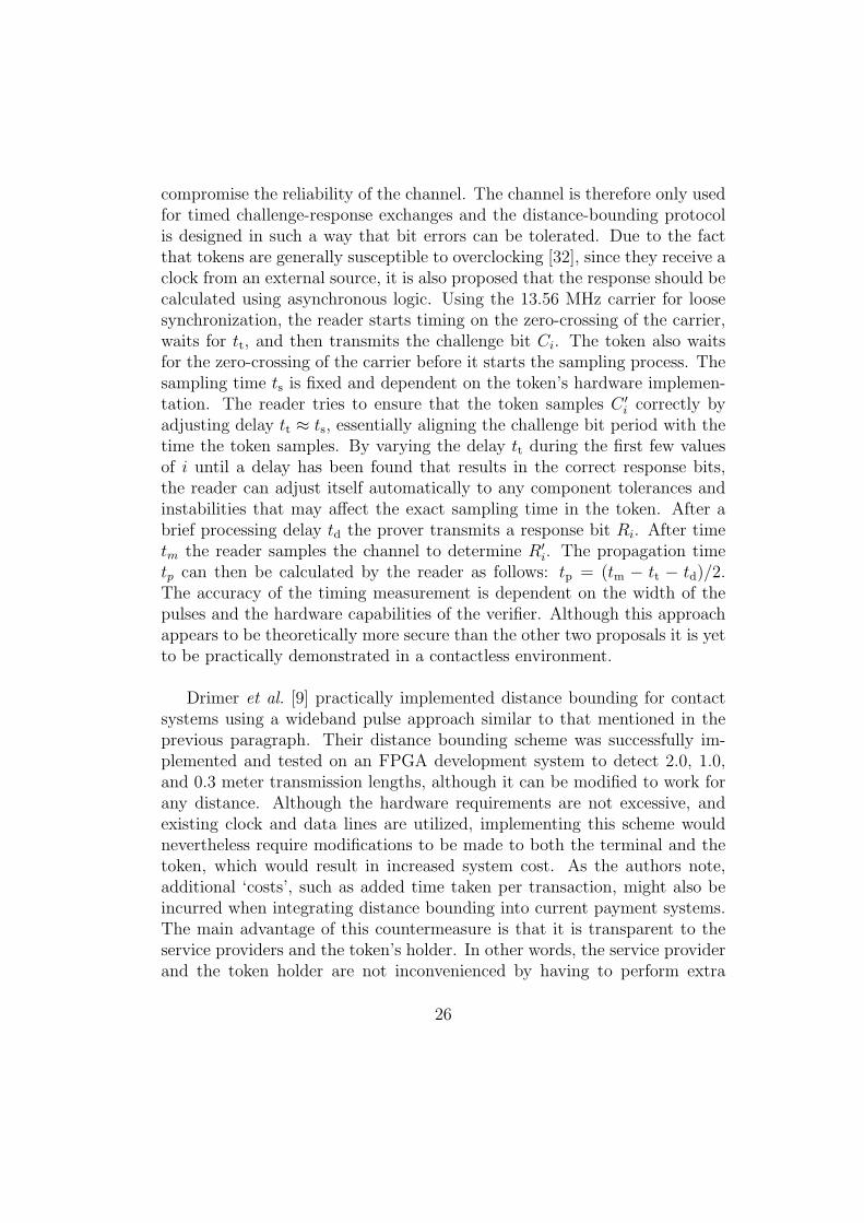
compromise the reliability of the channel. The channel is therefore only usedfor timed challenge-response exchanges and the distance-bounding protocolis designed in such a way that bit errors can be tolerated. Due to the factthat tokens are generally susceptible to overclocking [32], since they receive aclock from an external source, it is also proposed that the response should becalculated using asynchronous logic. Using the 13.56 MHz carrier for loosesynchronization, the reader starts timing on the zero-crossing of the carrier,waits for tt, and then transmits the challenge bit Ci. The token also waitsfor the zero-crossing of the carrier before it starts the sampling process. Thesampling time ts is fixed and dependent on the token’s hardware implemen-tation. The reader tries to ensure that the token samples C ′
i correctly byadjusting delay tt ≈ ts, essentially aligning the challenge bit period with thetime the token samples. By varying the delay tt during the first few valuesof i until a delay has been found that results in the correct response bits,the reader can adjust itself automatically to any component tolerances andinstabilities that may affect the exact sampling time in the token. After abrief processing delay td the prover transmits a response bit Ri. After timetm the reader samples the channel to determine R′
i. The propagation timetp can then be calculated by the reader as follows: tp = (tm − tt − td)/2.The accuracy of the timing measurement is dependent on the width of thepulses and the hardware capabilities of the verifier. Although this approachappears to be theoretically more secure than the other two proposals it is yetto be practically demonstrated in a contactless environment.
Drimer et al. [9] practically implemented distance bounding for contactsystems using a wideband pulse approach similar to that mentioned in theprevious paragraph. Their distance bounding scheme was successfully im-plemented and tested on an FPGA development system to detect 2.0, 1.0,and 0.3 meter transmission lengths, although it can be modified to work forany distance. Although the hardware requirements are not excessive, andexisting clock and data lines are utilized, implementing this scheme wouldnevertheless require modifications to be made to both the terminal and thetoken, which would result in increased system cost. As the authors note,additional ‘costs’, such as added time taken per transaction, might also beincurred when integrating distance bounding into current payment systems.The main advantage of this countermeasure is that it is transparent to theservice providers and the token’s holder. In other words, the service providerand the token holder are not inconvenienced by having to perform extra
26

duties related to security as the distance-bounding procedure is handled au-tomatically by the reader and token.
5.3. Additional Verification Procedures
In certain cases, relay attacks could be detected if additional procedureswere incorporated into token transactions. Systems that require additionalverification of the holder, either through human validation or by implement-ing ‘two factor’ authentication (2FA), could therefore limit the success ofthis attack. An attacker, for example, would struggle to execute the attackagainst RFID enabled e-passports since the photo read from his ‘passport’does not resemble him. Simple physical checks on the ‘token’ presented wouldalso force the attacker to construct a proxy-token that not only functions likea real token but also looks like one. Unfortunately these measures are notalways practical. A benefit often attributed to contactless systems is speed.Asking a queue of travelers to enter their PINs, or checking a photo stored ontheir token, adds unwanted delay, so additional verification is not a reason-able mechanism in such systems. 2FA is a more favourable solution for accesscontrol systems, and should already be implemented to prevent unauthorisedaccess with stolen or lost tokens. It must, however, be said that a second au-thentication factor does not necessarily prevent the attack, as illustrated bythe attack implementation described in Section 3.2, but does complicate theattack procedure. Another of the perceived benefits of contactless systemsis convenience. Contactless payment systems expect the customer to quicklyhold a wallet, or purse, to a reader and operators asking to inspect the tokencould potentially irritate a customer and again cause delays for other tokenholders. Even in contact payment systems the attacker tends to keep controlover his token at all times, and the merchant might even look away to allowthe customer to enter his PIN [9].
Another method that has been proposed is that the legitimate holdershould verify that his token is used in an approved way, e.g. checking whetherthe amount awaiting authorisation is as expected, with the aid of an addi-tional device. One example of this approach is the use of an electronic attor-ney as described in [38]. The electronic attorney is an additional hardwaredevice owned by the token holder that would act as an intermediary betweenthe token and reader. The device would provide a trusted interface that dis-plays details of the transactions between the legitimate token and reader tothe token holder. In this case the token holder does not have to solely rely
27

on information displayed by the reader so he can verify that the merchant’sreader and his token are acting in an honest way. An extra trusted deviceoffers several advantages, especially in payment systems, but could in turnlead to increased costs and operating complexity and possible inconvenienceto the customer.
6. Conclusion
Smart tokens are often used in proximity identification systems. Thesesystems assume that the token is in close proximity to the reader if it isauthenticated because of the perceived physical limitations of the commu-nication channel. A relay attack exploits this assumption and allows anattacker to temporarily possess a ‘virtual clone’ of a legitimate token, whichenables him to gain access to associated benefits. Even thought the basicattack theory was first proposed several decades ago and ‘worm holes’ area recognised security threat in wireless networks, few threat models, or op-erational guidelines, for contact and contactless smart tokens take it intoaccount. This paper provides a detailed overview of relay attacks with re-gards to smart tokens during which we highlight their practical feasibilityand provide examples of how current systems are potentially vulnerable. Wehope that this paper will help the reader to recognise the threat posed by re-lay attacks and understand the challenges related to preventing or detectingthese attacks.
The theory of passive and active relay attacks are explained and someexamples of practical relay attacks that have been demonstrated are exam-ined in further detail. A description is given of an attack that we successfullyimplemented and demonstrated against an ISO 14443A contactless systemusing guidelines in public literature and easily obtainable hardware. A sim-ilar demonstration concerning contact tokens, as presented in [9], is alsobriefly discussed. We also present some exploitation scenarios for relay at-tacks against current systems, including a novel attack against NXP’s MifareClassic tokens. This active relay attack, which we successfully implementedagainst a test system, allows an attacker to potentially circumvent system se-curity without any key recovery or knowledge of the Mifare Classic’s Crypto1algorithm. The motivation for highlighting the attack at this time, is to en-sure that it is considered during evaluation and migration planning of current
28

smart card systems.
A relay attack is difficult to defend against as it successfully circumventsapplication layer security mechanisms. We examine a number of counter-measures that have been proposed. Timing constraints are shown to beineffectual and although two factor authentication can be used in certainsystems it nullifies some key advantages of smart token systems, such asspeed and convenience. Distance bounding and allowing the token’s holderto monitor transaction details using a trusted interface may provide betterprotection but both solutions could add significant cost and/or complexityto existing systems. As a result of these current disadvantages there are stillfuture scope for research on appropriate security mechanisms.
References
[1] J.H. Conway. On Numbers and Games. Academic Press, 1976.
[2] Y.C. Hu, A. Perrig and D.B. Johnson. Wormhole attacks in wirelessnetworks. IEEE Journal on Selected Areas in Communications (JSAC),pp 370–380, 2006.
[3] A. Juels. RFID Security and Privacy: A Research Survey. IEEE Journalon Selected Areas in Communications, Vol. 24, Issue 2, pp 381–394,February 2006.
[4] P. Rotter. A Framework for Assessing RFID System Security and Pri-vacy Risks. IEEE Pervasive Computing Magazine, Vol. 7, Issue 2, pp70–77, April 2008.
[5] C.M. Roberts. Radio Frequency Identification (RFID). Elsevier JournalComputers & Security, Vol. 25, Issue 1, pp 18–26, February 2006.
[6] Bundesamt fur Sicherheit in der Informationstechnik. Security Aspectsand Prospective Applications of RFID Systems. October 2004. http:
//www.bsi.bund.de
[7] NIST: Special Publication 800-98. Guidance for Securing Radio Fre-quency Identification (RFID) Systems. April 2007. http://csrc.nist.gov/
29

[8] Y. Desmedt, C. Goutier and S. Bengio. Special Uses and Abuses ofthe Fiat-Shamir Passport Protocol. Advances in Cryptology (CRYPTO),Springer-Verlag LNCS 293, pp 21, 1987.
[9] S. Drimer and S.J. Murdoch. Keep Your Enemies Close: DistanceBounding Against Smartcard Relay Attacks. Proceeding USENIX Se-curity Symposium, pp 87–102, August 2007.
[10] G.P. Hancke. A practical relay attack on ISO 14443 proximity cards.http://www.rfidblog.org.uk/hancke-rfidrelay.pdf
[11] G.P. Hancke. Security of Proximity Identification Systems. PhD Disser-tation, University of Cambridge, February 2008.
[12] T. Kasper. Embedded Security Analysis of RFID Devices. Diploma The-sis, Ruhr-University Bochum,July 2006.
[13] ISO/IEC 14443. Identification cards – Contactless integrated circuitcards – Proximity cards.
[14] OpenPCD Project. http://www.openpcd.org
[15] ISO/IEC 18092. Information technology – Telecommunications and in-formation exchange between systems – Near Field Communication – In-terface and Protocol (NFCIP-1).
[16] Z. Kfir and A. Wool. Picking virtual pockets using relay attacks on con-tactless smartcard systems.Proceedings of IEEE/CreateNet SecureComm, pp 47–58, 2005.
[17] ISO/IEC 15693. Identification cards – Contactless integrated circuitcards – Vicinity cards.
[18] ISO/IEC 18000. ISO/IEC 18000 Information Technology AIDCTechniques-RFID for Item Management – Air Interface.
[19] EPC Class-1 Generation-2 UHF RFID Conformance RequirementsSpecification v. 1.0.2
30

[20] Texas Instruments. HF Antenna Design Notes, Technical ApplicationReport.http://www.ti.com/rfid/docs/manuals/appNotes/
HFAntennaDesignNotes.pdf
[21] I. Kirschenbaum and A. Wool. How to Build a Low-Cost, Extended-Range RFID Skimmer. Proceedings of 15th USENIX Security Sympo-sium, pp 43–57, August 2006.
[22] K. Finkenzeller. RFID Handbook: Radio-frequency identification funda-mentals and applications.2nd Edition, Wiley, 1999.
[23] EMV Integrated Circuit Card Specifications for Payment Systems, v4.1.June 2007.http://www.emvco.com/
[24] VISA Internation Service Association. Approved PIN entry de-vices, June 2008. http://partnernetwork.visa.com/dv/pin/
pedapprovallist.jsp
[25] N. Borisov, I. Goldberg and D. Wagner. Intercepting Mobile Communi-cations: The Insecurity of 802.11. Proceedings of Seventh Annual Inter-national Conference on Mobile Computing and Networking,pp 180–189, July 2001.
[26] NXP Semiconductor. Mifare Standard Card IC MF1 IC S50 FunctionalSpecification.http://www.nxp.com/acrobat_download/other/identification/
m001051.pdf
[27] NXP Semiconductor. Mifare Standard Card IC MF1 IC S70 FunctionalSpecification.http://www.nxp.com/acrobat_download/other/identification/
m043531.pdf
[28] Mifare.net. http://mifare.net/
[29] N.T. Courtois, K. Nohl and S. O’Neil.Algebraic Attacks on the Crypto-1 Stream Cipher in MiFare Classic and Oyster Cards. Cryptology
31

ePrint Archive: Report 2008/166, April 2008.http://eprint.iacr.org/2008/166
[30] Security Flaw in Mifare Classic. Radboud University Nijmegen, March2008.http://www.ru.nl/english/general/radboud_university/vm/
security_flaw_in/
[31] K. Nohl, D. Evans, Starbug and H. Plotz. Reverse-Engineering a Crypto-graphic RFID Tag. Proceedings of the 17th Usenix Security Symposium,August 2008.
[32] G.P Hancke and M.G. Kuhn. Attacks on Time-of-Flight DistanceBounding Channels. Proceedings of the First ACM Conference on Wire-less Network Security (WISEC’08), pp194–202, March 2008.
[33] S. Brands and D. Chaum. Distance Bounding Protocols. Advances inCryptology, EUROCYPT ’93, Springer-Verlag LNCS 765, pp 344–359,May 1993.
[34] G.P Hancke and M.G. Kuhn. An RFID distance bounding protocol. Pro-ceedings of IEEE/CreateNetSecureComm, pp 67–73, September 2005.
[35] J. Munilla, A. Ortiz and A. Peinado. Distance Bounding Protocols withVoid Challenges for RFID.Proceedings of Workshop on RFID Security (RFIDSec), pp 15–26, July2006.
[36] J. Reid, J.M.G Nieto, T. Tang and B. Senadji. Detecting Relay Attackswith Timing-Based Protocols. Proceeding 2nd ACM Symposium on In-formation, Computer and Communications Security, pp 204–213, March2007.
[37] J. Clulow, G.P. Hancke, M.G. Kuhn, T. Moore. So Near and Yet SoFar: Distance-Bounding Attacks in Wireless Networks. European Work-shop on Security and Privacy in Ad-Hoc and Sensor Networks (ESAS),Springer-Verlag LNCS 4357, pp 83–97, September 2006.
32

[38] R.J. Anderson, and M. Bond. The Man-in-the-Middle Defense. Pre-sented at Security Protocols Workshop, March 2006. http://www.cl.cam.ac.uk/~rja14/Papers/Man-in-the-Middle-Defence.pdf
33