![arXiv:2006.03884v2 [cond-mat.soft] 2 Oct 2020](https://static.fdokumen.com/doc/165x107/6336e213d63e7c7901058e51/arxiv200603884v2-cond-matsoft-2-oct-2020.jpg)
Cond 3310 - Carl Roth
58
OPERATING MANUAL ba75803e08 10/2017 Cond 3310 CONDUCTIVITY METER
-
Upload
khangminh22 -
Category
Documents
-
view
0 -
download
0
Transcript of Cond 3310 - Carl Roth

OPERATING MANUALba75803e08 10/2017
Cond 3310
CONDUCTIVITY METER

Cond 3310
Copyright © 2017 Xylem Analytics Germany GmbHPrinted in Germany.
2 ba75803e08 10/2017

Cond 3310 Contents
Cond 3310 - Contents
1 Overview . . . . . . . . . . . . . . . . . . . . . . . . . . . . . . . . . . . . . 61.1 Keypad . . . . . . . . . . . . . . . . . . . . . . . . . . . . . . . . . . . . . . . 71.2 Display . . . . . . . . . . . . . . . . . . . . . . . . . . . . . . . . . . . . . . . 81.3 Connectors . . . . . . . . . . . . . . . . . . . . . . . . . . . . . . . . . . . . 9
2 Safety . . . . . . . . . . . . . . . . . . . . . . . . . . . . . . . . . . . . . . . 102.1 Authorized use . . . . . . . . . . . . . . . . . . . . . . . . . . . . . . . . 112.2 General safety instructions . . . . . . . . . . . . . . . . . . . . . . . 11
3 Commissioning. . . . . . . . . . . . . . . . . . . . . . . . . . . . . . . 133.1 Scope of delivery. . . . . . . . . . . . . . . . . . . . . . . . . . . . . . . 133.2 Initial commissioning . . . . . . . . . . . . . . . . . . . . . . . . . . . . 13
3.2.1 Inserting the batteries. . . . . . . . . . . . . . . . . . . . . 133.2.2 Switching on the meter. . . . . . . . . . . . . . . . . . . . 143.2.3 Setting the date and time . . . . . . . . . . . . . . . . . . 14
4 Operation. . . . . . . . . . . . . . . . . . . . . . . . . . . . . . . . . . . . 154.1 Switching on the meter . . . . . . . . . . . . . . . . . . . . . . . . . . 154.2 General operating principles . . . . . . . . . . . . . . . . . . . . . . 16
4.2.1 Operating modes . . . . . . . . . . . . . . . . . . . . . . . . 164.2.2 Navigation . . . . . . . . . . . . . . . . . . . . . . . . . . . . . 164.2.3 Navigation example 1:Setting the language. . . . 184.2.4 Example 2 on navigation: Setting the date and
time . . . . . . . . . . . . . . . . . . . . . . . . . . . . . . . . 204.3 Sensor-independent settings . . . . . . . . . . . . . . . . . . . . . 23
4.3.1 System . . . . . . . . . . . . . . . . . . . . . . . . . . . . . . . . 234.3.2 Data storage. . . . . . . . . . . . . . . . . . . . . . . . . . . . 244.3.3 Automatic Stability control . . . . . . . . . . . . . . . . . 24
4.4 Conductivity. . . . . . . . . . . . . . . . . . . . . . . . . . . . . . . . . . . 264.4.1 General information . . . . . . . . . . . . . . . . . . . . . . 264.4.2 Measuring . . . . . . . . . . . . . . . . . . . . . . . . . . . . . 274.4.3 Temperature compensation . . . . . . . . . . . . . . . . 284.4.4 Settings for conductivity measuring cells . . . . . . 294.4.5 Determining the cell constant (calibration in
control standard) . . . . . . . . . . . . . . . . . . . . . . . . 324.4.6 Displaying calibration records . . . . . . . . . . . . . . 34
4.5 Data memory. . . . . . . . . . . . . . . . . . . . . . . . . . . . . . . . . . 354.5.1 Manual storage . . . . . . . . . . . . . . . . . . . . . . . . . 364.5.2 Automatic storing at intervals . . . . . . . . . . . . 38
3ba75803e08 10/2017

Contents Cond 3310
4.5.3 Displaying and editing the measurement data memory. . . . . . . . . . . . . . . . . . . . . . . . . . . . . . . . 40
4.5.4 Erasing the measurement data memory. . . . . . . 424.6 Transmitting data (USB interface) . . . . . . . . . . . . . . . . . . 42
4.6.1 Options for data transmission . . . . . . . . . . . . . . . 424.6.2 Connecting a PC . . . . . . . . . . . . . . . . . . . . . . . . 43
4.7 MultiLab Importer. . . . . . . . . . . . . . . . . . . . . . . . . . . . . . . 444.8 Reset . . . . . . . . . . . . . . . . . . . . . . . . . . . . . . . . . . . . . . . . 44
4.8.1 Resetting the measurement settings . . . . . . . . . 444.8.2 Resetting the system settings. . . . . . . . . . . . . . . 45
5 Maintenance, cleaning, disposal . . . . . . . . . . . . . . . . . 465.1 Maintenance . . . . . . . . . . . . . . . . . . . . . . . . . . . . . . . . . . 46
5.1.1 Replacing the batteries . . . . . . . . . . . . . . . . . . . . 465.2 Cleaning. . . . . . . . . . . . . . . . . . . . . . . . . . . . . . . . . . . . . . 475.3 Packing . . . . . . . . . . . . . . . . . . . . . . . . . . . . . . . . . . . . . . 475.4 Disposal . . . . . . . . . . . . . . . . . . . . . . . . . . . . . . . . . . . . . . 47
6 What to do if... . . . . . . . . . . . . . . . . . . . . . . . . . . . . . . . . 48
7 Technical data . . . . . . . . . . . . . . . . . . . . . . . . . . . . . . . . 497.1 General data . . . . . . . . . . . . . . . . . . . . . . . . . . . . . . . . . . 497.2 Measuring ranges, resolution, accuracy . . . . . . . . . . . . . 50
8 Lists . . . . . . . . . . . . . . . . . . . . . . . . . . . . . . . . . . . . . . . . 52
9 Firmware update . . . . . . . . . . . . . . . . . . . . . . . . . . . . . . 54
4 ba75803e08 10/2017

Cond 3310 Contents
5ba75803e08 10/2017

Overview Cond 3310
1 Overview
The Cond 3310 compact precision conductivity meter enables you to perform conductivity measurements quickly and reliably.
The Cond 3310 provides the maximum degree of operating comfort, reliability and measuring certainty for all applications.The proven procedures for determining or adjusting the cell constant support your work with the conductivity meter.
1 Keypad
2 Display
3 Connectors
1
2
3
6 ba75803e08 10/2017

Cond 3310 Overview
1.1 Keypad
In this operating manual, keys are indicated by brackets <..> . The key symbol (e.g. <ENTER>) generally indicates a short keystroke (under 2 sec) in this operating manual. A long keystroke (approx. 2 sec) is indicated by the underscore behind the key symbol (e.g. <ENTER_>).
<F1>:<F1_>:<F2>:
<F1>/[Menu]: Opens the menu for measurement settings<F1_>/[Menu]: Opens the menu for system settings
<On/Off>: Switches the meter on or off
<M>: Selects the measured parameter
<CAL>: <CAL_>:
Calls up the calibration procedure Displays the calibration data
<STO>: Saves a measured value manually
<RCL>: Displays the manually stored measured values
<>: Increments values, scrolls
<>: Decrements values, scrolls
<ENTER>: <ENTER_>:
Opens the menu for measurement settings / confirms entriesOpens the menu for system settings
<AR> Freezes the measured value (HOLD function)Switches the AutoRead measurement on or off
F1
CAL
STO
RCL
E N T E R
AR
7ba75803e08 10/2017

Overview Cond 3310
1.2 Display
Function displayindicators
1 Status information
2 Measured value (with unit)
3 Measured parameter
4 Sensor symbol (calibration evaluation, calibration interval)
5 Measured temperature (with unit)
6 Status line
7 Softkeys and date + time
3
2
4
5
6
7
1HOLD AR
25.01417
°C
µS/cm
[Tr25][nLF][ 0.475 1/cm]
ϰ
22.09.200808:00Menu USB output
Error An error occurred during calibration
AR Stability control (AutoRead) is active
HOLD Measured value is frozen (<AR> key)
Batteries are almost empty
8 ba75803e08 10/2017

Cond 3310 Overview
1.3 Connectors
CautionOnly connect measuring cells to the meter that cannot return any voltages or currents that are not allowed (> SELV and > current circuit with current limiting). Almost all customary measuring cells fulfill these conditions.
1 Conductivity measuring cell
2 USB B (device) interface
3 Service interface
3 1 2
9ba75803e08 10/2017

Safety Cond 3310
2 Safety
This operating manual contains basic instructions that you must follow during the commissioning, operation and maintenance of the meter. Consequently, all responsible personnel must read this operating man-ual before working with the meter. The operating manual must always be available within the vicinity of the meter.
Target group The meter was developed for work in the field and in the laboratory.Thus, we assume that, as a result of their professional training and experience, the operators will know the necessary safety precautions to take when handling chemicals.
Safety instructions Safety instructions in this operating manual are indicated by the warn-ing symbol (triangle) in the left column. The signal word (e.g. "Caution") indicates the level of danger:
Warningindicates instructions that must be followed precisely in order to avoid possibly great dangers to personnel.
Cautionindicates instructions that must be followed precisely in order to avoid the possibility of slight injuries or damage to the instrument or the environment.
Further notesNoteindicates notes that draw your attention to special features.
Noteindicates cross-references to other documents, e.g. operating manu-als.
10 ba75803e08 10/2017

Cond 3310 Safety
2.1 Authorized use
Authorized use of the meter consists exclusively of the measurement of conductivity, resistivity, salinity, TDS (total dissolved solids) and tem-perature in a laboratory or field environment. The technical specifications as given in chapter 7 TECHNICAL DATA must be observed. Only the operation and running of the meter according to the instructions given in this operating manual is authorized. Any other use is considered unauthorized.
2.2 General safety instructions
This meter is constructed and tested in compliance with the IEC 1010 safety regulations for electronic measuring instruments. It left the factory in a safe and secure technical condition.
Function andoperational safety
The smooth functioning and operational safety of the meter can only be guaranteed if the generally applicable safety measures and the specific safety instructions in this operating manual are followed during opera-tion.
The smooth functioning and operational safety of the meter can only be guaranteed under the environmental conditions that are specified in chapter 7 TECHNICAL DATA.
If the meter was transported from a cold environment to a warm envi-ronment, the formation of condensate can lead to the faulty functioning of the meter. In this event, wait until the temperature of the meter reaches room temperature before putting the meter back into opera-tion.
CautionThe meter is only allowed to be opened by authorized personnel.
11ba75803e08 10/2017

Safety Cond 3310
Safe operation If safe operation is no longer possible, the meter must be taken out of service and secured against inadvertent operation!Safe operation is no longer possible if the meter:
has been damaged in transport
has been stored under adverse conditions for a lengthy period of time
is visibly damaged
no longer operates as described in this manual.
If you are in any doubt, please contact the supplier of the meter.
Obligations of thepurchaser
The purchaser of this meter must ensure that the following laws and guidelines are observed when using dangerous substances:
EEC directives for protective labor legislation
National protective labor legislation
Safety regulations
Safety datasheets of the chemical manufacturers.
CautionIn addition to the safety instructions mentioned here, also follow the safety instructions of the sensors used.The operating manuals of the sensors are available on the sup-plied CD and on the Internet under www.WTW.com.
12 ba75803e08 10/2017

Cond 3310 Commissioning
3 Commissioning
3.1 Scope of delivery
Conductivity meter Cond 3310
4 batteries 1.5 V Mignon type AA
USB cable
Short instructions
CD-ROM with
– USB drivers
– detailed operating manual
– Software MultiLab Importer
3.2 Initial commissioning
Perform the following activities:
Insert the supplied batteries
Switching on the meter
Set the date and time
3.2.1 Inserting the batteries
1 Unscrew the screws (1) on the underside of the meter.
2
1
13ba75803e08 10/2017

Commissioning Cond 3310
CautionMake sure that the poles of the batteries are positioned correctly.The ± signs on the batteries must correspond to the ± signs in the battery compartment.
NoteAlternatively, you can also use Ni-MH rechargeable batteries (type Mignon AA). In order to charge the batteries, an external charging device is required.
3.2.2 Switching on the meter
NoteThe meter has an energy saving feature to avoid unnecessary battery depletion. The energy saving feature switches off the meter if no key is pressed during the adjusted interval. (How to set the switch-off interval, see sec-tion 4.3.1).
3.2.3 Setting the date and time
2 Open the battery compartment (2) on the underside of the meter.
3 Place four batteries (type Mignon AA) in the battery compart-ment.
4 Close the battery compartment.
1 Press the <On/Off> key.The meter performs a self-test. The display shows the manufacturer's logo while the self-test is being performed.Subsequently, the meter switches to the measuring mode (measured value display).
1 See section 4.2.4
14 ba75803e08 10/2017

Cond 3310 Operation
4 Operation
4.1 Switching on the meter
Switching on Press the <On/Off> key.The meter performs a self-test. The display shows the manufacturer's logo while the self-test is being performed.The measured value display appears.
Switching off Press the <On/Off> key.
Automatic switch-offfunction
The instrument has an automatic switch-off function in order to save the batteries (see section 4.3.1). The automatic switch-off function switches off the meter if no key is pressed for an adjustable period.
The automatic switch-off function is not active
if the communication cable is connected
if the Automatic data storage function is active, or with automatic data transmission
Display illumination The meter automatically switches off the display illumination if no key is pressed for 30 seconds. The illumination is switched on with the next keystroke again.
You can also generally switch the display illumination on or off (see section 4.3.1).
ϰ1417µS/cm
25.0 °C[Tr25][nLF][0.475 1/cm]
15.03.201410:00MenuMenu USB output
15ba75803e08 10/2017

Operation Cond 3310
4.2 General operating principles
This section contains basic information on the operation of the Cond 3310.
Operating elements,display
An overview of the operating elements and the display is given in sec-tion 1.1 and section 1.2.
Operating modes,navigation
An overview of the operating modes and navigation of the Cond 3310 is given in section 4.2.1 and section 4.2.2.
4.2.1 Operating modes
The instrument has the following operating modes:
MeasuringThe measurement data of the connected sensor are shown in the measured value display
CalibrationThe course of a calibration with calibration information, functions and settings is displayed
Storing in memoryThe meter stores the measurement data manually or automatically
Transmitting dataThe meter transmits measurement data and calibration records to the USB interface automatically or manually.
SettingThe system menu or a sensor menu with submenus, settings and functions is displayed
4.2.2 Navigation
Measured value display In the measured value display, you can
open the menu for calibration and measurement settings with <F1> (short keystroke)
Open the Storage & config menu with the sensor-independent set-tings with <F1_> (long keystroke, approx. 2 s).
Change the display in the measurement window by pressing <M> (e.g. conductivity −> resistivity −> −> −> ).
Menus and dialogs The menus for settings and dialogs in procedures contain further sub-elements. The selection is made with the <><> keys. The current selection is displayed with a frame.
Submenus
16 ba75803e08 10/2017

Cond 3310 Operation
The name of the submenu is displayed at the upper edge of the frame. Submenus are opened by confirming with <ENTER>. Exam-ple:
SettingsSettings are indicated by a colon. The current setting is displayed on the right-hand side. The setting mode is opened with <ENTER>. Subsequently, the setting can be changed with <><> and <ENTER>. Example:
FunctionsFunctions are designated by the name of the function. They are immediately carried out by confirming with <ENTER>. Example: Display the Calibration record function.
General
Interface
ClockService information
Reset
System
15.03.201410:00Back
Language: Deutsch Beep: OffIllumination: On
Contrast: 48 %
Switchoff time: 30 min
General
15.03.201410:00Back
17ba75803e08 10/2017

Operation Cond 3310
Messages Information is marked by the i symbol. It cannot be selected. Example:
NoteThe principles of navigation are explained in the two following sections by reference of examples:
Setting the language (section 4.2.3)
Setting the date and time (see section 4.2.4).
4.2.3 Navigation example 1:Setting the language
Calibration recordCalibration data storage
Calibration interval: 150 d
ϰ
15.03.201410:00
Back
1 Press the <On/Off> key.The measured value display appears.The instrument is in the measuring mode.
Measuring cell
Temp. comp. (TC)TDS factor 1.00
Stability control On
Temperature unit °C
i ϰ = 1413 µS/cm
ϰ
15.03.201410:00
Back
18 ba75803e08 10/2017

Cond 3310 Operation
2 Using <F1_>/[Menu], open the Storage & config menu.The instrument is in the setting mode.
3 Select the System submenu with <><>. The current selection is displayed with a frame.
4 Open the System submenu with <ENTER>.
ϰ1417µS/cm
25.0 °C[Tr25][nLF][ 0.475 1/cm]
15.03.201410:00Menu USB output
SystemData storage
Storage & config
15.03.201410:00Back
GeneralInterface
Clock
Service informationReset
System
15.03.201410:00
Back
19ba75803e08 10/2017

Operation Cond 3310
4.2.4 Example 2 on navigation: Setting the date and time
The meter has a clock with a date function. The date and time are indi-cated in the status line of the measured value display. When storing measured values and calibrating, the current date and time are automatically stored as well.
5 Select the General submenu with <><>. The current selection is displayed with a frame.
6 Open the General submenu with <ENTER>.
7 Open the setting mode for the Language with <ENTER>.
8 Select the required language with <><>.
9 Confirm the setting with <ENTER>. The meter switches to the measuring mode.The selected language is active.
Language: Deutsch
Beep: OffIllumination: On
Contrast: 48 %
Switchoff time: 30 min
General
15.03.201410:00Back
Language: Deutsch
Beep: OffIllumination: On
Contrast: 48 %
Switchoff time: 30 min
General
15.03.201410:00Back
20 ba75803e08 10/2017

Cond 3310 Operation
The correct setting of the date and time and date format is important for the following functions and displays:
Current date and time
Calibration date
Identification of stored measured values.
Therefore, check the time at regular intervals.
NoteThe date and time are reset to default after a fall of the supply voltage (empty batteries).
Setting the date, timeand date format
The date format can be switched from the display of day, month, year (dd.mm.yyyy) to the display of month, day, year (mm/dd/yyyy or mm.dd.yyyy).
1 In the measured value display:Using <F1_>/[Menu], open the Storage & config menu.The instrument is in the setting mode.
2 Select and confirm the System / Clock menu with <><> and <ENTER>.The setting menu for the date and time opens up.
3 Select and confirm the Time menu with <><> and <ENTER>.The hours are highlighted.
4 Change and confirm the setting with <><> and <ENTER>.The minutes are highlighted.
5 Change and confirm the setting with <><> and <ENTER>.The seconds are highlighted.
Date format: dd.mm.yyyy
Date: 15.03.2014Time: 14:53:40
Clock
15.03.201410:00Back
21ba75803e08 10/2017

Operation Cond 3310
6 Change and confirm the setting with <><> and <ENTER>.The time is set.
7 If necessary, set the Date and Date format. The setting is made similarly to that of the time.
8 To make further settings, switch to the next higher menu level with [Back]<F1>.orSwitch to the measured value display with <M>. The instrument is in the measuring mode.
22 ba75803e08 10/2017

Cond 3310 Operation
4.3 Sensor-independent settings
The Storage & config menu comprises the following settings:
System (see section 4.3.1).
Data storage (see section 4.3.2)
4.3.1 System
Overview The following sensor-independent meter characteristics can be adjusted in the Storage & config/System menu:
Menu language
Beep on keystroke
Illumination
Display contrast
Interval of the automatic switch-off function
Data interface
Clock and date function
Reset of all sensor-independent system settings to the default con-dition
Settings To open the Storage & config menu, press the <F1_>[Menu] key in the measured value display. After completing the settings, switch to the measured value display with <M>.
Menu item Setting Explanation
System / General / Language
DeutschEnglish(more)
Selects the menu lan-guage
System / General / Beep
OnOff
Switches on/off the beep on keystroke
System / General / Illu-mination
AutoOnOff
Switches the display illumi-nation on/off
System / General / Contrast
0 ... 100 % Changes the display con-trast
System / General / Switchoff time
10 min ... 24 h Adjusts the switch-off time
System / Interface / Baud rate
1200, 2400, 4800, 9600, 19200
Baud rate of the data inter-face
23ba75803e08 10/2017

Operation Cond 3310
4.3.2 Data storage
This menu contains all functions to display, edit and erase stored mea-sured values and calibration records.
NoteDetailed information on the memory functions of the Cond 3310 is given in section 4.5.
4.3.3 Automatic Stability control
The function, automatic Stability control (AutoRead) continually checks the stability of the measurement signal. The stability has a considerable impact on the reproducibility of measured values.
You can activate or switch off the automatic Stability control function (see section 4.4.4).
The measured parameter flashes on the display
as soon as the measured value is outside the stability range
when you switch over between the measured parameters with <M>.
when the automatic Stability control is switched off.
System / Interface / Output format
ASCIICSV
Output format for data transmissionFor details, see section 4.6
System / Interface / Decimal separator
Dot (xx.x)Comma (xx,x)
Decimal separator
System / Interface / Output header
Output of a header for Out-put format: CSV
System / Clock TimeDatumDate format
Settings of time and date. For details, see section 4.2.4
System / Service infor-mation
Hardware version and soft-ware version of the meter are displayed.
System / Reset - Resets the system settings to the default values. For details, see section 4.8.2
Menu item Setting Explanation
24 ba75803e08 10/2017

Cond 3310 Operation
25ba75803e08 10/2017

Operation Cond 3310
4.4 Conductivity
4.4.1 General information
You can measure the following parameters:
Conductivity
Specific resistance
Salinity
Total dissolved solids (TDS)
AttentionWhen a grounded PC is connected, measurements cannot be per-formed in grounded media as incorrect values would result.The USB interface is not galvanically isolated.
Temperaturemeasurement
The conductivity measuring cells TetraCon 325, KLE 325, LR 325/01 and LR 325/001 have an integrated temperature sensor.
Preparatory activities Perform the following preparatory activities when you want to measure:
NoteThe selection of the measuring cell and the setting of the cell constant is done in the measurement settings menu for conductivity (see section 4.4.4). The cell constant to be set must either be taken from the oper-ating manual of the measuring cell or is printed on the measuring cell.
1 Connect a conductivity measuring cell to the measuring instru-ment. The conductivity measuring screen is displayed.
2 Check whether the Measuring cell and cell constant settings are suitable for the connected conductivity measuring cell. If necessary, correct the settings.
26 ba75803e08 10/2017

Cond 3310 Operation
4.4.2 Measuring
You can carry out conductivity measurements as follows:
Selecting thedisplayed
measured parameter
You can switch between the following displays with <M>:
Conductivity [μS/cm] / [mS/cm]
Resistivity [Ω·cm] / [kΩ·cm] / [MΩ·cm]
Salinity SaL [ ]
Total dissolved solids TDS [mg/l] / [g/l]
The factor to calculate the total dissolved solids is set to 1.00 in the fac-tory. You can adjust this factor to meet your requirements in the range 0.40 ... 1.00. The factor is set in the Measurement menu for the param-eter, TDS.
Stability control(AutoRead )
The stability control function (AutoRead) continually checks the stability of the measurement signal. The stability has a considerable impact on the reproducibility of measured values.
The measured parameter flashes on the display
as soon as the measured value is outside the stability range
when the automatic Stability control is switched off.
You can start the Stability control manually at any time, irrespective of the setting for automatic Stability control (see page 24) in the Measure-ment menu.
1 Perform the preparatory activities according to section 4.4.1.
2 Immerse the conductivity measuring cell in the test sample.
ϰ1417µS/cm
25.0 °C[Tr25][nLF][ 0.475 1/cm]
15.03.201410:00Menu USB output
1 Freeze the measured value with <AR>.The [HOLD] status indicator is displayed.The HOLD function is active.
27ba75803e08 10/2017

Operation Cond 3310
Criteria for a stablemeasured value
The Stability control function checks whether the measured values are stable within the monitored time interval.
The minimum duration until a measured value is assessed as stable is the monitored time interval. The actual duration is mostly longer.
4.4.3 Temperature compensation
The calculation of the temperature compensation is based on the pre-set reference temperature, 20 °C or 25 °C. It appears on the display as Tr20 or Tr25.
You can select one of the following temperature compensation meth-ods:
2 Using <ENTER>, activate the Stability control function manu-ally.The [AR] status indicator appears while the measured value is assessed as not stable. A progress bar is displayed and the display of the measured parameter flashes.The [HOLD][AR] status indicator appears as soon as a stable measured value is recognized.
NoteYou can prematurely terminate the Stability control function manually with <ENTER> at any time. If the Stability control function is prema-turely terminated, the current measurement data are output to the interface without the AutoRead info.
3 Using <ENTER>, start a further measurement with stability control.orRelease the frozen measured value again with <AR> or <M>.The [AR] status display disappears. The display switches back to the previous indication.
Measured parameter
Time interval Stability in the time interval
Conductivity ϰ 10 seconds Δ : better than 1.0% of mea-sured value
Temperature 15 seconds Δ : better than 0.5 °C
28 ba75803e08 10/2017

Cond 3310 Operation
Nonlinear temperature compensation (nLF) according to EN 27 888
Linear temperature compensation (Lin) with adjustable coeffi-cient in the range 0.000 ... 10.000 %/K
No temperature compensation (off)
NoteThe reference temperature and temperature compensation are set in the Measurement menu for the parameter, conductivity (see section 4.4.4).
Application tips Select the following temperature compensations given in the table according to the respective test sample:
4.4.4 Settings for conductivity measuring cells
Overview The following settings are possible for conductivity measuring cells:
Calibration record (display)
Calibration interval
Measuring cell/cell constant
Reference temperature
Temperature compensation
TDS factor
Unit of the temperature
Automatic Stability control
Test sample Temperature compensation Display indica-tor
Natural water (ground water, surface water, drinking water)
nLF according to EN 27 888
nLF
Ultrapure water nLF according to EN 27 888
nLF
Other aqueous solu-tions
Lin Set linear temperature coefficient0.000 ... 10.000 %/K
Lin
Salinity (seawater) Automatic nLF according to IOT (International Oceano-graphic Tables)
Sal, nLF
29ba75803e08 10/2017

Operation Cond 3310
Settings The settings are made in the Measurement menu for the measured parameter, conductivity. To open the settings, display the required parameter in the measured value display and press the <F1>/[menu] or <ENTER> key. After completing the settings, switch to the measured value display with <M>.
Menu item Possible setting
Explanation
Calibration / Calibration record
- Displays the calibration record of the last calibration.
Calibration / Calibra-tion data storage
- Displays the last calibration records.
Calibration / Calibration interval
1 ... 999 d Calibration interval for the measuring cell (in days).The meter reminds you to cali-brate regularly by the flashing sensor symbol in the measur-ing screen.
Measurement / Measuring cell / Type
Measuring cell used
Cal Measuring cells the cell con-stant of which is determined by calibration in the KCL control standard solution.Calibration ranges:0.450 to 0.500 cm-1 and 0.800 to 0.880 cm-1
The currently valid cell con-stant is displayed in the status line.
LR 325/01 Measuring cell LR 325/01, nominal cell constant 0.100 cm-1.The cell constant can be adjusted in the range from 0.090 to 0.110 cm-1.
LR 325/001 Measuring cell LR 325/001, nominal cell constant 0.010 cm-1.The cell constant is perma-nently set.
30 ba75803e08 10/2017

Cond 3310 Operation
man Any measuring cells with freely adjustable cell con-stants.
Measurement / Measuring cell / Cell const. man
0.250 ... 25.000 cm-1
Display and setting option of the cell constant of any mea-suring cells (man).
Measurement / Measuring cell / Cell const. LR 325/01
0.090 to 0.110 cm-1
Display and setting options for the cell constant of the mea-suring cell LR 325/01.
Measurement / Temp. comp. (TC) / Method
nLFLinOff
Procedure for temperature compensation (see section 4.4.3).
This setting is only available for the measured parameters, ϰ and ρ.
Measurement / Temp. comp. (TC) / Linear coeff.
0,000 ... 10,000 %/K
Coefficient of the linear tem-perature compensation.
This setting is only available when the linear temperature compensation is set.
Measurement / Temp. comp. (TC) / Reference temp.
20 °C25 °C
Reference temperature
This setting is only available for the measured parameters, ϰ and ρ.
Measurement / TDS factor
0.40 ... 1.00 Factor for TDS value
Measurement / Stability control
On / Off Switches on or off the auto-matic stability control during measurement (see section 4.3.3)
Menu item Possible setting
Explanation
31ba75803e08 10/2017

Operation Cond 3310
4.4.5 Determining the cell constant (calibration in control standard)
Why determine the cellconstant?
Aging slightly changes the cell constant, e.g. due to coatings. As a result, an inexact measured value is displayed. The original character-istics of the cell can often be restored by cleaning the cell. Calibration determines the current value of the cell constant and stores this value in the meter.Thus, you should calibrate at regular intervals (we recommend: every 6 months).
Procedure You can determine the actual cell constant of the conductivity measur-ing cell by calibrating with the control standard in the following ranges:
The cell constant is determined in the control standard, 0.01 mol/l KCl. Cell constants outside the ranges quoted above cannot be calibrated.
Stability control(AutoRead)
In calibration, the Stability control function (AutoRead) is automatically activated.
Display calibration dataand output to interface
You can have the data of the last calibration displayed (see section 4.4.6). Subsequently, you can transmit the displayed calibration data to the interface, e.g. to a PC, with the <F2>/[USB output] key.
NoteThe calibration record is automatically transmitted to the interface after
Measurement / Temperature unit
°C °F
Temperature unit,degrees Celsius or degrees Fahrenheit.All temperature values are dis-played with the selected unit.
Reset - Resets all sensor settings to the delivery condition (see section 4.8.1).
Menu item Possible setting
Explanation
0.450 ... 0.500 cm-1 (e.g. TetraCon 325, nominal cell constant 0.475 cm-1)
0.800 ... 0.880 cm-1
(e.g. KLE 325 with a nominal cell constant of 0.840 cm-1)
In the default condition, the calibrated cell constant of the meter is set to 0.475 cm-1 (conductivity sensor TetraCon 325).
32 ba75803e08 10/2017

Cond 3310 Operation
calibrating.
Sample record:
Calibration evaluation After calibration, the meter automatically evaluates the current status of the calibration. The evaluation appears on the display and in the cali-bration record.
Determining the cellconstant
For this calibration procedure, the Measuring cell setting must be set to cal in the Measurement menu. Proceed as follows to determine the cell constant:
Cond 3310Ser. no. 08502113
CALIBRATION Cond15.03.2014 16:13:33
Cell constant 0.479 1/cm 25.0 °C
Temperature Sensor+++
Display Calibration record
Cell constant [cm-1]
+++ within the ranges0.450 ... 0.500 cm-1
or0.800 ... 0.880 cm-1
Error Error outside the ranges0.450 ... 0.500 cm-1
or0.800 ... 0.880 cm-1
Eliminate the error according to chapter 6 WHAT TO DO IF...
1 Connect a conductivity measuring cell to the measuring instru-ment.
2 In the measured value display, select the conductivity parame-ter with <M>.
3 Start the calibration with <CAL>.The cell constant that was calibrated last is displayed.
33ba75803e08 10/2017

Operation Cond 3310
4.4.6 Displaying calibration records
The calibration data can be displayed and then output to the interface.
Displaying thecalibration record
The calibration record of the last calibration is to be found under the menu item, Calibration / Calibration record. To open it in the measured value display, press the <CAL_> key.
The calibration records of the last calibration procedures are available in the <F1>/[Menu] / Calibration / Calibration data storage and <F1_>/[Menu] / Storage & config/Data storage / Calibration data storage menu.
4 Immerse the conductivity measuring cell in the control standard solution, 0.01 mol/l KCI.
5 Start the measurement with <ENTER>.The [AR] status indicator is displayed. The measured parame-ter flashes.
6 Wait for the end of the AutoRead measurement or accept the calibration value with <ENTER>.The calibration record is displayed and output to the interface.
7 Using <F1>/[Continue] or <ENTER>, switch to the measured value display.
ϰ0.479 1/cm
25.1 °C
15.03.201410:00
34 ba75803e08 10/2017

Cond 3310 Operation
Example
4.5 Data memory
You can transmit measured values (datasets) to the data memory:
Manual memory (see section 4.5.1)
Menu item Setting/func-tion
Explanation
Calibration / Calibration data stor-age / Display
or
Data storage / Calibration data stor-age / Display
- Displays the calibration record.
Further options: Scroll through the cali-
bration records with <><>.
Output the displayed calibration record to the interface with <F2>/[USB output].
Quit the display with <F1>/[Back] or <ENTER>.
Switch directly to the measured value display with <M>.
Calibration / Calibration data stor-age / Output to USBor
Data storage / Calibration data stor-age / Output to USB
- Outputs the calibration records to the interface.
Cond 3310Ser. no. 08502113
CALIBRATION Cond15.03.2014 16:13:33
Cell constant 0.479 1/cm 25.0 °C
Temperature Sensor+++
35ba75803e08 10/2017

Operation Cond 3310
Automatic storing at intervals (see section 4.5.2)
Each data storing process transmits the current dataset to the interface at the same time.
Measurement dataset A complete dataset consists of:
ID number
Date/time
Measured value of the connected sensor
Measured temperature value of the connected sensor
AutoRead info: AR appears with the measured value if the AutoRead criterion was met while storing (stable measured value). Otherwise, the AR display is missing.
Calibration evaluation: +++, ++, +, -, or no evaluation
Memory locations The Cond 3310 meter has two measurement data memories. The mea-sured values recorded either manually or automatic are stored sepa-rately in individual measurement data memories.
4.5.1 Manual storage
You can store a measurement dataset to the data memory as follows. The dataset is at the same time output to the interface:
Data memory Maximum number of datasets
Manual data storage 500
Automatic data storage 5000
1 Press the <STO> key shortly.The menu for manual data storage appears.
36 ba75803e08 10/2017

Cond 3310 Operation
If the memory is full The following window appears if all 500 storage locations are occupied:
You have the following options:
To erase the entire memory, confirm Yes.
To cancel the storing process and switch to the measured value dis-play, confirm No. Then you can e.g. store the data from the memory to a PC (see section 4.5.3) and subsequently erase the memory (see section 4.5.4).
2 If necessary, change and confirm the ID number (1 ... 10000) with <><> and <ENTER>.The dataset is stored. The meter switches to the measured value display.
15.03.2014 07:00:00ϰ 1415 µS/cm 24.8 °C AR +++
ID number: 1
Continue
Manual data storage 4 von 500
15.03.201410:00
Back
Data storage full. Erase?
Yes
No
Warning
15.03.201410:00
Back
37ba75803e08 10/2017

Operation Cond 3310
4.5.2 Automatic storing at intervals
The storing interval (Interval) determines the time interval between automatic data storing processes. Each data storing process transmits the current dataset to the interface at the same time.
Configuring theautomatic memory
function
Settings You can configure the automatic data storing function with the following settings:
1 Press the <STO_> key.The menu for automatic data storing appears.
Specified entire storing duration
Max. available storing dura-tion
Graphical display of the memory usage
ID number 1Interval 30 s
Duration 180 min
Continue 0d03h00min
0 1d17h33min
Automatic data storage
15.03.201410:00
Back
Menu item Possible set-ting
Explanation
ID number 1 ... 10000 ID number for the dataset series.
38 ba75803e08 10/2017

Cond 3310 Operation
Starting the automaticstoring function
To start the automatic storing function, select Continue with <><> and confirm with <ENTER>. The meter switches to the measured value display.
The active automatic data storing function can be recognized by the progress bar in the status line. The progress bar indicates the remain-ing storing duration.
NoteIf the automatic storing function is activated, only the following keys are active: Softkeys, <M>, <STO_> and <On/Off>. The other keys and the automatic switch-off function are deactivated.
Interval 1 s, 5 s, 10 s, 30 s, 1 min, 5 min, 10 min, 15 min, 30 min, 60 min
Storing interval.
The lower limit of the stor-ing interval can be restricted by the number of free memory locations.The upper limit is restricted by the storing duration.
Duration 1 min ... x min Storing duration.Specifies after which time the automatic data storing should be terminated.
The lower limit of the stor-ing duration is restricted by the storing interval.The upper limit is restricted by the number of free memory locations.
Menu item Possible set-ting
Explanation
ϰ1417µS/cm
25.0 °C
0d03h00min[Tr25][nLF][ 0.475 1/cm]
15.03.201410:00
Remaining storing duration
Graphical display of the storing duration
Eco mode USB output
39ba75803e08 10/2017

Operation Cond 3310
Energy saving mode([Eco mode])
If the automatic storing function is active, the meter provides an energy saving mode ([Eco mode]) to avoid unnecessary energy consumption. The energy saving mode switches off functions of the meter that are not required for the automatic storing of measurement data (such as the display). By pressing any key the energy saving mode is switched off again.
Terminating theautomatic memory
function prematurely
Proceed as follows to switch off the automatic data storing function before the adjusted storing duration has expired:
4.5.3 Displaying and editing the measurement data memory
The contents of the manual or automatic measurement data memory can be shown on the display.
Each of the measurement data memories has a function to erase the entire contents.
The contents of the manual or automatic measurement data memory can be shown on the display and output to the interface.
Editing the data memory The memory is edited in the menu, Storage & config/ Data storage. To open the Storage & config menu, press the <F1_>/[Menu] key in the measured value display.Open the manual or automatic storage directly with the <RCL> or <RCL_> key.
1 Press the <STO_> key.The following window appears.
2 Using <><>, select Yes and confirm with <ENTER>.The meter switches to the measured value display.The automatic data storing function is terminated.
Stop automatic storage?
YesNo
Warning
15.03.201410:00
Back
40 ba75803e08 10/2017

Cond 3310 Operation
NoteThe settings are explained here using the manual data memory as an example. The same settings and functions are available for the auto-matic data memory.
Settings
Display presentation ofa dataset
Menu item Setting/func-tion
Explanation
Data storage / Manual data storage / Display
- Displays all measurement datasets page by page.
Further options: Scroll through the data-
sets with <><>.
Output the displayed dataset to the interface with <F2>/[USB output].
Quit the display with <F1>/[Back].
Data storage / Manual data storage / Erase
- Erases the entire manual measurement data mem-ory.
Note:All calibration data remain stored when this action is performed.
Data storage / Manual data storage / Output to USB
- Outputs all stored mea-surement data to the inter-face.
Manual data storage 3 of 64
15.03.2014 07:00:00 ID number: 1
ϰ 1415 µS/cm 25.1 °C AR +++
C = 0.475 1/cm, Tref 25, nLF
15.03.201410:00
Back
41ba75803e08 10/2017

Operation Cond 3310
Example
Quitting the display To quit the display of stored measurement datasets, you have the fol-lowing options:
Switch directly to the measured value display with <M>.
Quit the display and move to the next higher menu level with <F1>/[Back].
4.5.4 Erasing the measurement data memory
How to erase the measurement data memory is described in section 4.5.3 DISPLAYING AND EDITING THE MEASUREMENT DATA MEMORY.
4.6 Transmitting data (USB interface)
4.6.1 Options for data transmission
Via the USB interface you can transmit data to a PC. The following table shows which data are transmitted to the interface in which way:
15.03.2014 09:27:20Cond 3310 Ser. No. 12345678
ID number 1ϰ 99.8 µS/cm 25.0 °C AR +++________________________________________
15.03.2014 09:56:24Cond 3310 Ser. No. 12345678
ID number 1ϰ 99.9 µS/cm 25.0 °C AR +++________________________________________
Data Control Operation / descriptionCurrent mea-sured valuesof all connected measuring cells
Manual With <F2>/[USB output].
Simultaneously with every manual storing process (see section 4.5.1).
Automatic, at intervals
With <F2_>/[USB output]. Then you can set the trans-mission interval.
Simultaneously with every automatic storing process (see section 4.5.2).
42 ba75803e08 10/2017

Cond 3310 Operation
NoteThe following rule applies: With the exception of the menus, shortly pressing the <F2>/[USB output] key generally outputs the display con-tents to the interface (displayed measured values, measurement data-sets, calibration records).
4.6.2 Connecting a PC
Connect the Cond 3310 to the PC via the USB interface.
AttentionThe USB interface is not galvanically isolated. When a grounded PC is connected, measurements cannot be per-formed in grounded media as incorrect values would result.
Installation of the USBdriver on the PC
System requirements of the PC for installation of the USB driver:
PC with USB port and CD-ROM drive
Microsoft Windows (for details, see enclosed installation CD, Driver directory)
Stored measured values
Manual Displayed dataset with <F2>/[USB output] after calling up from the memory.
All datasets with the Output to USB function.
For details, see section 4.5.3.Calibration records
Manual Calibration record with <F2>/[USB output].
For details, see section 4.6.Automatic At the end of a calibration
procedure.
1 Insert the supplied installation CD in the CD drive of your PC.
2 Install the driver from the CD.Follow the Windows installation instructions as necessary.
3 Connect the Cond 3310 to the PC via the USB interface.The meter is listed as a virtual COM interface among the con-nections in the Windows instrument manager.
43ba75803e08 10/2017

Operation Cond 3310
4.7 MultiLab Importer
With the aid of the MultiLab Importer software, you can record and eval-uate measurement data with a PC.
4.8 Reset
You can reset (initialize) all sensor settings and sensor-independent settings separately from each other.
4.8.1 Resetting the measurement settings
NoteThe calibration data are reset to the default settings together with the measuring parameters. Recalibrate after performing a reset.
The following settings for conductivity measurements are reset to the default settings with the Reset function:
More detailed information can be found in the MultiLab Importer operating manual.
Setting Default settings
Cal. interval 150 d
Measured parameter ϰ
Cell constant (c) calibrated: 0.475 cm-1
adjusted: 0.475 cm-1
calibrated: cm-1
adjusted:
Temperature compensation nLF
Reference temperature 25 °C
Temperature coefficient (TC) of the linear temperature compen-sation
2.000 %/K
TDS factor 1.00
Stability control On
Temperature unit °C
44 ba75803e08 10/2017

Cond 3310 Operation
The sensor settings are reset under the Reset menu item in the menu for calibration and measurement settings. To open the settings, acti-vate the relevant measuring window in the measured value display and press the <F1>/[Menu] key shortly.
4.8.2 Resetting the system settings
The following system settings can be reset to the default status:
The system settings are reset in the menu, Storage & config / System / Reset. To open the Storage & config menu, press the <F1_>/[Menu] key in the measured value display.
Setting Default settings
Language English
Beep On
Baud rate 4800 Baud
Output format ASCII
Contrast 50 %
Illumination Auto
Switchoff time 1 h
45ba75803e08 10/2017

Maintenance, cleaning, disposal Cond 3310
5 Maintenance, cleaning, disposal
5.1 Maintenance
The only maintenance activity required is replacing the batteries.
NoteSee the relevant operating manuals of the measuring cells for instruc-tions on maintenance.
5.1.1 Replacing the batteries
CautionMake sure that the poles of the batteries are positioned correctly.The ± signs on the batteries must correspond to the ± signs in the battery compartment.
NoteAlternatively, you can also use Ni-MH rechargeable batteries (type Mignon AA). In order to charge the batteries, an external charging device is required.
1 Unscrew the screws (1) on the underside of the meter.
2 Open the battery compartment (2) on the underside of the meter.
3 Remove the batteries from the battery compartment.
2
1
46 ba75803e08 10/2017

Cond 3310 Maintenance, cleaning, disposal
5.2 Cleaning
Occasionally wipe the outside of the measuring instrument with a damp, lint-free cloth. Disinfect the housing with isopropanol as required.
CautionThe housing is made of synthetic material (ABS). Thus, avoid con-tact with acetone or similar detergents that contain solvents. Re-move any splashes immediately.
5.3 Packing
This meter is sent out in a protective transport packing. We recommend: Keep the packing material. The original packing pro-tects the meter against damage during transport.
5.4 Disposal
NoteThis meter contains batteries. Batteries that have been removed may only be disposed of at a recycling facility set up for this purpose or via the retail outlet. It is illegal to dispose of it in household refuse.
4 Place four batteries (type Mignon AA) in the battery compart-ment.
5 Close the battery compartment.
47ba75803e08 10/2017

What to do if... Cond 3310
48 ba75803e08 10/2017
6 What to do if...
Error messageOFL, UFL
Error message,Error
Sensor symbol flashes
Display
Meter does not react tokeystroke
You want to know whichsoftware
version is in the meter
Cause Remedy
– Measured value outside the measuring range
– Use suitable measuring cell
Cause Remedy
– Measuring cell contaminated – Clean cell and replace it if necessary
– Calibration solution not suitable – Check the calibration solu-tions
– Measuring cell not connected – Connect the measuring cell
Cause Remedy
– Cleaning interval expired – Recalibrate the measuring system
Cause Remedy
– Batteries almost empty – Replace the batteries (see section 5.1 MAINTENANCE)
Cause Remedy
– Operating condition undefined or EMC load unallowed
– Processor reset:Press the <ENTER> and <On/Off> key simultane-ously
Cause Remedy
– E.g., a question by the service department
– Switch on the meter.Open the menu, <F1_>[Menu] / Storage & config / System / Service information. The instrument data are displayed.

Cond 3310 Technical data
7 Technical data
7.1 General data
Dimensions Approx. 180 x 80 x 55 mm
Weight Approx. 0.4 kg
Mechanical structure Type of protection IP 67
Electrical safety Protective class III
Test certificates CE
Ambientconditions
Storage - 25 °C ... + 65 °C
Operation -10 °C ... + 55 °C
Admissible relative humidity
Yearly mean: < 75 %30 days/year: 95 %Other days: 85 %
Power supply
Batteries 4 x 1.5 V alkali-manganese batteries, type AA
Rechargeable batteries
4 x 1.2 V NiMH rechargeable batteries, type AA (no charging function)
Operational life Up to 800 h without / 100 h with illumination
USB interface Type USB 1.1USB B (device), data output
Baud rate Adjustable: 1200, 2400, 4800, 9600, 19200 Baud
Data bits 8
Stop bits 2
Parity None
Handshake RTS/CTS
Cable length Max. 3 m
Guidelinesand norms used
EMC EC directive 2004/108/ECEN 61326-1EN 61000-3-2EN 61000-3-3FCC Class A
Meter safety EC directive 2006/95/ECEN 61010-1
IP protection class EN 60529
49ba75803e08 10/2017

Technical data Cond 3310
7.2 Measuring ranges, resolution, accuracy
Measuring ranges, resolution(depending on the sen-sor)
Variable Measuring range Resolution
ϰ[µS/cm] 0.000 ... 1.999*0.00 ... 19.99**0.0 ... 199.9200 ... 1999
0.0010.010.11
ϰ [mS/cm] 2.00 ... 19.9920.0 ... 199.9200 ... 1000
0.010.11
ρ (Resistivity) [Ohm*cm]
1.000 ... 1.9992.00 ... 19.9920.0 ... 199.9200 ... 1999
0.0010.010.11
ρ (Resistivity) [kOhm*cm]
2.00 ... 19.9920.0 ... 199.9200 ... 1999
0.010.11
ρ (Resistivity) [MOhm*cm]
2.00 ... 19.99**20.0 ... 199.9*
0.010.1
SAL 0.0 ... 70.0according to the IOT table
0.1
TDS 0 ... 1999 mg/l2.00 ... 19.99 g/l20.0 ... 199.9 g/l
10.010.1
T [°C] -5.0 ... +105.0 0.1
T [°F] +23.0 ... +221.0 0.1
* only possible with cells of the cell constant, 0.010 cm-1
** only possible with cells of the cell constant, 0.010 cm-1 or 0.090 ... 0.110 cm-1
Cell constants Cell constant C Values
To be calibrated 0.450 ... 0.500 cm-1
0.800 ... 0.880 cm-1
Adjustable 0.010 cm-1 (fixed)0.090 ... 0.110 cm-1
0.250 ... 25.000 cm-1
50 ba75803e08 10/2017
Cond 3310 Technical data
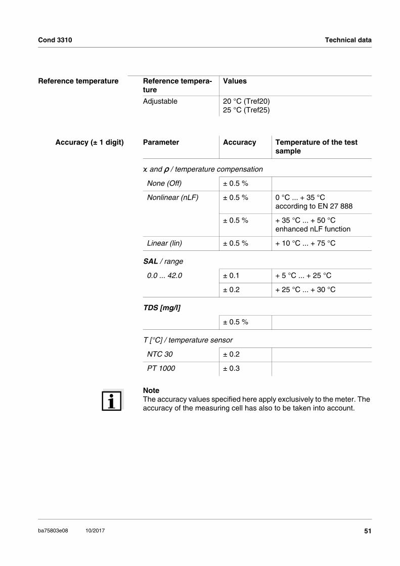
NoteThe accuracy values specified here apply exclusively to the meter. The accuracy of the measuring cell has also to be taken into account.
Reference temperature Reference tempera-ture
Values
Adjustable 20 °C (Tref20)25 °C (Tref25)
Accuracy (± 1 digit) Parameter Accuracy Temperature of the test sample
ϰ and ρ / temperature compensation
None (Off) ± 0.5 %
Nonlinear (nLF) ± 0.5 % 0 °C ... + 35 °Caccording to EN 27 888
± 0.5 % + 35 °C ... + 50 °Cenhanced nLF function
Linear (lin) ± 0.5 % + 10 °C ... + 75 °C
SAL / range
0.0 ... 42.0 ± 0.1 + 5 °C ... + 25 °C
± 0.2 + 25 °C ... + 30 °C
TDS [mg/l]
± 0.5 %
T [°C] / temperature sensor
NTC 30 ± 0.2
PT 1000 ± 0.3
51ba75803e08 10/2017

Lists Cond 3310
8 Lists
This chapter provides additional information and orientation aids.
Specialist terms The glossary briefly explains the meaning of the specialist terms. How-ever, terms that should already be familiar to the target group are not described here.
Index The index will help you to find the topics that you are looking for.
Glossary
Adjusting To manipulate a measuring system so that the relevant value (e.g. the displayed value) differs as little as possible from the correct value or a value that is regarded as correct, or that the difference remains within the tolerance.
AutoRange Name of the automatic selection of the measuring range.
Calibration Comparing the value from a measuring system (e.g. the displayed value) to the correct value or a value that is regarded as correct. Often, this expression is also used when the measuring system is adjusted at the same time (see adjusting).
Cell constant, k Characteristic quantity of a conductivity measuring cell, depending on the geometry.
Conductivity Short form of the expression, specific electrical conductivity. It corresponds to the reciprocal value of the resistivity. It is a measured value of the ability of a substance to conduct an electric current. In water analysis, the electrical conductivity is a dimension for the ionized substances in a solution.
Measured parameter The measured parameter is the physical dimension determined by measuring, e.g. pH, conductivity or D.O. concentration.
Measured value The measured value is the special value of a measured parameter to be determined. It is given as a combination of the numerical value and unit (e. g. 3 m; 0.5 s; 5.2 A; 373.15 K).
Molality Molality is the quantity (in Mol) of a dissolved substance in 1000 g solvent.
52 ba75803e08 10/2017

Cond 3310 Lists
Reference tempera-ture
Fixed temperature value to compare temperature-dependent measured values. For conductivity measurements, the measured value is converted to a conductivity value at a reference temperature of 20 °C or 25 °C.
Reset Restoring the original condition of all settings of a measuring system.
Resistance Short name for the specific electrolytic resistance. It corresponds to the reciprocal value of the electrical conductivity.
Resolution Smallest difference between two measured values that can be displayed by a meter.
Salinity The absolute salinity SA of seawater corresponds to the relationship of the mass of dissolved salts to the mass of the solution (in g/Kg). In practice, this dimension cannot be measured directly. Therefore, the practical salinity according to IOT is used for oceanographic monitoring. It is determined by measuring the electrical conductivity.
Salt content General designation for the quantity of salt dissolved in water.
Stability control Function to control the measured value stability.
Standard solution The standard solution is a solution where the measured value is known by definition. It is used to calibrate a measuring system.
Temperature coeffi-cient
Value of the slope of a linear temperature function.
Temperature compen-sation
Name of a function that considers the temperature influence on the measurement and converts it accordingly. Depending on the measured parameter to be determined, the temperature compensation functions in different ways. For conductimetric measurements, the measured value is converted to a defined reference temperature. For potentiometric measurements, the slope value is adjusted to the temperature of the test sample but the measured value is not converted.
Temperature function Name of a mathematical function expressing the temperature behavior of a test sample, a sensor or part of a sensor.
Test sample Designation of the test sample ready to be measured. Normally, a test sample is made by processing the original sample. The test sample and original sample are identical if the test sample was not processed.
α
TRef=
Meas*
1
1 + � (T - )* TRef
53ba75803e08 10/2017

Firmware update Cond 3310
54 ba75803e08 10/2017
9 Firmware update
General information Available firmware updates are provided on the Internet.With the "Firmware Update " program and a PC you can update the firmware of the Cond 3310 to the newest version.
For the update you have to connect the meter to a PC.
For the update via the USB interface, the following is required:
a free USB interface (virtual COM port) on the PC
the driver for the USB interface (on the enclosed CD-ROM)
the USB cable (included in the scope of delivery of the Cond 3310).
Program installation
Program start
Firmware update
After switching the meter off and on you can check whether the meter has taken over the new software version (see page 48).
1 Install the downloaded firmware update on a PC.
An update folder is created in the Windows start menu. If an update folder already exists for the meter (or meter type), the new data is displayed there.
2 In the windows start menu, open the update folder and start the firmware update program.
3 Using the USB interface cable, connect the Cond 3310 to a USB interface (virtual COM port) of the PC.
4 Switch on the Cond 3310.
5 In the firmware update program, start the update process with OK.
6 Follow the instructions of the firmware update program.During the programming process, a corresponding message and a progress bar (in %) are displayed. The programming process takes approx. three minutes. A ter-minatory message is displayed after a successful programming process. The firmware update is completed.
7 Disconnect the Cond 3310 from the PC. The Cond 3310 is ready for operation again.

Cond 3310 Lists
Index
AAuthorized use . . . . . . . . . . . . . . . . . . . . . . 11Automatic switch-off function . . . . . . . . . . . 15AutoRead
pH . . . . . . . . . . . . . . . . . . . . . . . . . . . . 27
BBattery compartment . . . . . . . . . . . . . . 14, 46
CCalibration . . . . . . . . . . . . . . . . . . . . . . . . . 32Calibration evaluation . . . . . . . . . . . . . . . . 33Calibration records . . . . . . . . . . . . . . . . . . . 34Cell constant . . . . . . . . . . . . . . . . . . . . . . . 32Connecting a PC . . . . . . . . . . . . . . . . . . . . 43Connectors . . . . . . . . . . . . . . . . . . . . . . . . . . 9Control standard . . . . . . . . . . . . . . . . . . . . 32Copyright . . . . . . . . . . . . . . . . . . . . . . . . . . . 2
DDataset . . . . . . . . . . . . . . . . . . . . . . . . . . . . 36Date and time . . . . . . . . . . . . . . . . . . . . . . . 20Default settings
Measured parameter . . . . . . . . . . . . . . 44System settings . . . . . . . . . . . . . . . . . . 45
Display . . . . . . . . . . . . . . . . . . . . . . . . . . . . . 8
EEnergy saving feature . . . . . . . . . . . . . . . . 14Energy saving mode . . . . . . . . . . . . . . . . . 40
FFirmware update . . . . . . . . . . . . . . . . . . . . 54
IInitial commissioning . . . . . . . . . . . . . . 13, 14Initialize . . . . . . . . . . . . . . . . . . . . . . . . . . . 44
KKeys . . . . . . . . . . . . . . . . . . . . . . . . . . . . . . . 7
MMeasured value display . . . . . . . . . . . . . . . 16Measurement data memory
Edit . . . . . . . . . . . . . . . . . . . . . . . . . . . . 40Erase . . . . . . . . . . . . . . . . . . . . . . . . . . 40Memory locations . . . . . . . . . . . . . . . . . 36
Measurement dataset . . . . . . . . . . . . . . . . 36Measuring . . . . . . . . . . . . . . . . . . . . . . . . . 27Menu for calibration and measurement settings
. . . . . . . . . . . . . . . . . . . . . . . . . . . . . . . 30Menus (navigation) . . . . . . . . . . . . . . . . . . 16Messages . . . . . . . . . . . . . . . . . . . . . . . . . 18
OOperational safety . . . . . . . . . . . . . . . . . . . 11
PPrecautions . . . . . . . . . . . . . . . . . . . . . . . . 10Print . . . . . . . . . . . . . . . . . . . . . . . . . . . . . . 42
RReset . . . . . . . . . . . . . . . . . . . . . . . . . . . . . 44
SSafety . . . . . . . . . . . . . . . . . . . . . . . . . . . . . 10Scope of delivery . . . . . . . . . . . . . . . . . . . . 13Setting the date . . . . . . . . . . . . . . . . . . . . . 14Setting the time . . . . . . . . . . . . . . . . . . . . . 14Stability control
Automatic . . . . . . . . . . . . . . . . . . . . . . . 24Storing in memory . . . . . . . . . . . . . . . . . . . 35
At intervals . . . . . . . . . . . . . . . . . . . . . . 38Automatic . . . . . . . . . . . . . . . . . . . . . . . 38Manual . . . . . . . . . . . . . . . . . . . . . . . . . 36
Storing interval . . . . . . . . . . . . . . . . . . . . . . 38
TTemperature compensation . . . . . . . . . . . . 28Temperature measurement . . . . . . . . . . . . 26Transmitting data . . . . . . . . . . . . . . . . . . . . 42Transmitting measured values . . . . . . . . . . 42
55ba75803e08 10/2017

Lists Cond 3310
56 ba75803e08 10/2017


What can Xylem do for you?
We're a global team unified in a common purpose: creating innovative solutions to
meet our world's water needs. Developing new technologies that will improve the way
water is used, conserved, and re-used in the future is central to our work. We move,
treat, analyze, and return water to the environment, and we help people use water
efficiently, in their homes, buildings, factories and farms. In more than 150 countries, we
have strong, long-standing relationships with customers who know us for our powerful
combination of leading product brands and applications expertise, backed by a legacy
of innovation.
Xylem Analytics Germany GmbH
Dr.-Karl-Slevogt-Str. 1
82362 Weilheim
Germany
Xylem Analytics Germany
Sales GmbH & Co. KG
WTW
Dr.-Karl-Slevogt-Str. 1
82362 Weilheim
Germany
Tel.:
Fax:
Internet:
+49 881 183-325
+49 881 183-414
www.WTW.com
Service address:
®
For more information on how Xylem can help you, go to xyleminc.com.


![arXiv:1401.4247v1 [cond-mat.other] 17 Jan 2014](https://static.fdokumen.com/doc/165x107/631c8832c2fddc4819080932/arxiv14014247v1-cond-matother-17-jan-2014.jpg)
![arXiv:2105.05506v1 [cond-mat.soft] 12 May 2021](https://static.fdokumen.com/doc/165x107/633ce6518750369e5d0f7040/arxiv210505506v1-cond-matsoft-12-may-2021.jpg)


![arXiv:2112.09608v1 [cond-mat.soft] 17 Dec 2021](https://static.fdokumen.com/doc/165x107/6335841bd2b728420307f38f/arxiv211209608v1-cond-matsoft-17-dec-2021.jpg)

