Computational Design of Transforming Pop-up Books
14
Computational Design of Transforming Pop-up Books NAN XIAO and ZHE ZHU TNList, Tsinghua University and RALPH R. MARTIN Cardiff University and KUN XU and JIA-MING LU and SHI-MIN HU TNList, Tsinghua University We present the first computational tool to help ordinary users create trans- forming pop-up books. In each transforming pop-up, when the user pulls a tab, an initial flat 2D pattern, i.e. a 2D shape with a superimposed picture, such as an airplane, turns into a new 2D pattern, such as a robot, standing up from the page. Given the two 2D patterns, our approach automatically computes a 3D pop-up mechanism that transforms one pattern into the oth- er; it also outputs a design blueprint, allowing the user to easily make the final model. We also present a theoretical analysis of basic transformation mechanisms; combining these basic mechanisms allows more flexibility of final designs. Using our approach, inexperienced users can create models in a short time; previously, even experienced artists often took weeks to man- ually create them. We demonstrate our method on a variety of real world examples. Categories and Subject Descriptors: I.3.5 [Computer Graphics]: Com- putational Geometry and Object Modeling—Geometric algorithms, lan- guages, and systems Additional Key Words and Phrases: paper art, pop-up, transforming pop-up, mechanism design 1. INTRODUCTION Most youngsters of today are familiar with Transformers toys pro- duced by Takara and Hasbro, in which a toy can change shape, for example from a plane into a robot, via a combination of mecha- nisms. Youngsters of an earlier generation were perhaps more fa- miliar with pop-up books—when their pages were opened, objects such as castles or animals would pop up from the page. More re- cently, these two ideas were brought together in such publications as Reinhart’s best-selling book [2013], which contains sophisticat- ed examples of transforming pop-ups. When the user pulls a tab, an initial flat 2D pattern, i.e. a 2D shape with a superimposed pic- ture, turns into a new 2D pattern, standing up from the page. We illustrate one of Reinhart’s transforming pop-ups in Figure 1. Creating such a book is a big challenge even for experienced pa- per artist-engineers. Designing the necessary mechanisms to create the desired effects, without interference, can take even a talented professional many weeks of trial and error. Typically, the designer first creates an initial pop-up from a combination of mechanisms to transform between the two desired patterns, and then adjusts the patterns to fit the pop-up. An iterative process of adjusting the pop- up and the 2D patterns then follows until satisfactory, aesthetically pleasing results are achieved. Researchers have already considered automating the design pro- cess for pop-up books [Li et al. 2010; Li et al. 2011; Le et al. (a) Car form, before transformation (b) Robot form, after transformation Fig. 1. Transforming pop-up by Matthew Reinhart, showing car and robot forms of the Hornet Transformer. 2014]. However, the kind of pop-ups so far considered depict only one meaningful object: an arbitrary flat design turns into the de- sired object. In contrast, transforming pop-ups depict two different meaningful objects, and a transformation between them. Due to this intrinsic difference, existing automated pop-up design approaches cannot be directly applied to the design of transforming pop-ups. This paper considers automating the design of transforming pop- ups. We first study the principles of assembling a transforming pop- up. We discuss several basic mechanisms and types of linkages for combining them. We then show how a transforming pop-up can be easily composited by combining appropriate mechanisms via these linkages. Our main contribution, apart from the discussion of suitable mechanisms and linkages is a fully automatic algorithm for creat- ing a transforming pop-up that approximately transforms one user- provided pattern into another. An optimization based approach at- tempts to match the user given patterns in the initial and final s- tates as well as possible, while at the same time ensuring as a hard constraint that interference between parts of the pop-up cannot oc- cur. After optimization, the pop-up is painted with color textures. Finally, a construction template is generated, allowing the user to fabricate the pop-up. 2. RELATED WORK 2.1 Computational pop-ups There are several kinds of pop-up art, such as V-style pop-ups [Li et al. 2011], multi-style pop-ups [Ruiz et al. 2014], sliceform pop- ups [Le-Nguyen et al. 2013] and transforming pop-ups [Glassner 2002b]. They can be classified into two categories: one-state pop- ups, and two-state pop-ups [Glassner 2002b]. [Li et al. 2011; Ruiz et al. 2014; Le-Nguyen et al. 2013; Mitani and Suzuki 2004; Mi- tani et al. 2003] consider one-state pop-ups: their transformation ACM Transactions on Graphics, Vol. VV, No. N, Article XXX, Publication date: Month YYYY.
-
Upload
khangminh22 -
Category
Documents
-
view
1 -
download
0
Transcript of Computational Design of Transforming Pop-up Books
Computational Design of Transforming Pop-up BooksNAN XIAO and ZHE ZHUTNList, Tsinghua UniversityandRALPH R. MARTINCardiff UniversityandKUN XU and JIA-MING LU and SHI-MIN HUTNList, Tsinghua University
We present the first computational tool to help ordinary users create trans-forming pop-up books. In each transforming pop-up, when the user pulls atab, an initial flat 2D pattern, i.e. a 2D shape with a superimposed picture,such as an airplane, turns into a new 2D pattern, such as a robot, standingup from the page. Given the two 2D patterns, our approach automaticallycomputes a 3D pop-up mechanism that transforms one pattern into the oth-er; it also outputs a design blueprint, allowing the user to easily make thefinal model. We also present a theoretical analysis of basic transformationmechanisms; combining these basic mechanisms allows more flexibility offinal designs. Using our approach, inexperienced users can create models ina short time; previously, even experienced artists often took weeks to man-ually create them. We demonstrate our method on a variety of real worldexamples.
Categories and Subject Descriptors: I.3.5 [Computer Graphics]: Com-putational Geometry and Object Modeling—Geometric algorithms, lan-guages, and systems
Additional Key Words and Phrases: paper art, pop-up, transforming pop-up,mechanism design
1. INTRODUCTION
Most youngsters of today are familiar with Transformers toys pro-duced by Takara and Hasbro, in which a toy can change shape, forexample from a plane into a robot, via a combination of mecha-nisms. Youngsters of an earlier generation were perhaps more fa-miliar with pop-up books—when their pages were opened, objectssuch as castles or animals would pop up from the page. More re-cently, these two ideas were brought together in such publicationsas Reinhart’s best-selling book [2013], which contains sophisticat-ed examples of transforming pop-ups. When the user pulls a tab,an initial flat 2D pattern, i.e. a 2D shape with a superimposed pic-ture, turns into a new 2D pattern, standing up from the page. Weillustrate one of Reinhart’s transforming pop-ups in Figure 1.
Creating such a book is a big challenge even for experienced pa-per artist-engineers. Designing the necessary mechanisms to createthe desired effects, without interference, can take even a talentedprofessional many weeks of trial and error. Typically, the designerfirst creates an initial pop-up from a combination of mechanismsto transform between the two desired patterns, and then adjusts thepatterns to fit the pop-up. An iterative process of adjusting the pop-up and the 2D patterns then follows until satisfactory, aestheticallypleasing results are achieved.
Researchers have already considered automating the design pro-cess for pop-up books [Li et al. 2010; Li et al. 2011; Le et al.
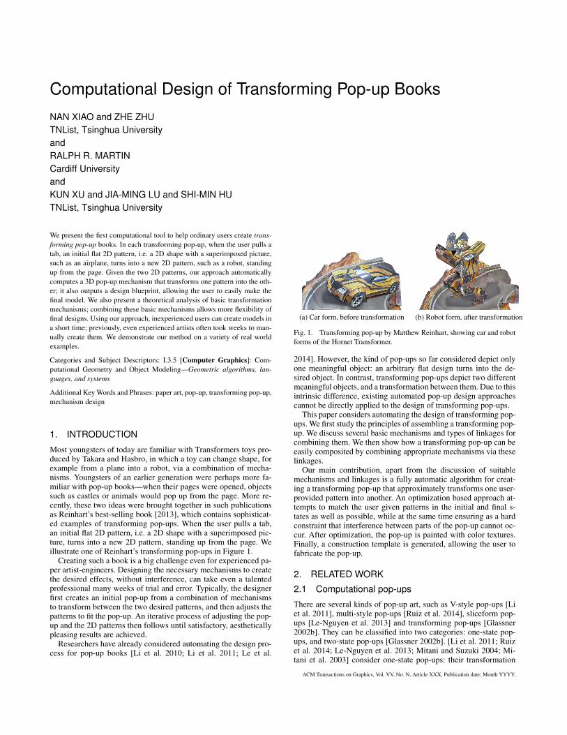
(a) Car form, before transformation (b) Robot form, after transformation
Fig. 1. Transforming pop-up by Matthew Reinhart, showing car and robotforms of the Hornet Transformer.
2014]. However, the kind of pop-ups so far considered depict onlyone meaningful object: an arbitrary flat design turns into the de-sired object. In contrast, transforming pop-ups depict two differentmeaningful objects, and a transformation between them. Due to thisintrinsic difference, existing automated pop-up design approachescannot be directly applied to the design of transforming pop-ups.
This paper considers automating the design of transforming pop-ups. We first study the principles of assembling a transforming pop-up. We discuss several basic mechanisms and types of linkages forcombining them. We then show how a transforming pop-up can beeasily composited by combining appropriate mechanisms via theselinkages.
Our main contribution, apart from the discussion of suitablemechanisms and linkages is a fully automatic algorithm for creat-ing a transforming pop-up that approximately transforms one user-provided pattern into another. An optimization based approach at-tempts to match the user given patterns in the initial and final s-tates as well as possible, while at the same time ensuring as a hardconstraint that interference between parts of the pop-up cannot oc-cur. After optimization, the pop-up is painted with color textures.Finally, a construction template is generated, allowing the user tofabricate the pop-up.
2. RELATED WORK
2.1 Computational pop-ups
There are several kinds of pop-up art, such as V-style pop-ups [Liet al. 2011], multi-style pop-ups [Ruiz et al. 2014], sliceform pop-ups [Le-Nguyen et al. 2013] and transforming pop-ups [Glassner2002b]. They can be classified into two categories: one-state pop-ups, and two-state pop-ups [Glassner 2002b]. [Li et al. 2011; Ruizet al. 2014; Le-Nguyen et al. 2013; Mitani and Suzuki 2004; Mi-tani et al. 2003] consider one-state pop-ups: their transformation
ACM Transactions on Graphics, Vol. VV, No. N, Article XXX, Publication date: Month YYYY.
2 • Xiao et al.
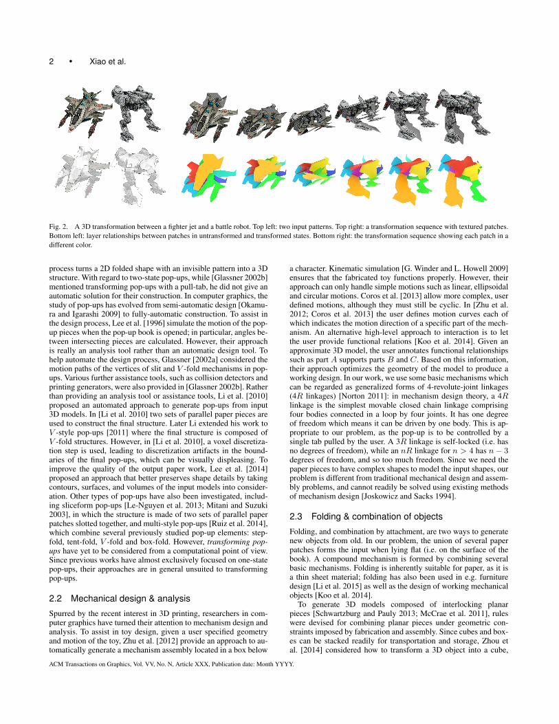
Fig. 2. A 3D transformation between a fighter jet and a battle robot. Top left: two input patterns. Top right: a transformation sequence with textured patches.Bottom left: layer relationships between patches in untransformed and transformed states. Bottom right: the transformation sequence showing each patch in adifferent color.
process turns a 2D folded shape with an invisible pattern into a 3Dstructure. With regard to two-state pop-ups, while [Glassner 2002b]mentioned transforming pop-ups with a pull-tab, he did not give anautomatic solution for their construction. In computer graphics, thestudy of pop-ups has evolved from semi-automatic design [Okamu-ra and Igarashi 2009] to fully-automatic construction. To assist inthe design process, Lee et al. [1996] simulate the motion of the pop-up pieces when the pop-up book is opened; in particular, angles be-tween intersecting pieces are calculated. However, their approachis really an analysis tool rather than an automatic design tool. Tohelp automate the design process, Glassner [2002a] considered themotion paths of the vertices of slit and V -fold mechanisms in pop-ups. Various further assistance tools, such as collision detectors andprinting generators, were also provided in [Glassner 2002b]. Ratherthan providing an analysis tool or assistance tools, Li et al. [2010]proposed an automated approach to generate pop-ups from input3D models. In [Li et al. 2010] two sets of parallel paper pieces areused to construct the final structure. Later Li extended his work toV -style pop-ups [2011] where the final structure is composed ofV -fold structures. However, in [Li et al. 2010], a voxel discretiza-tion step is used, leading to discretization artifacts in the bound-aries of the final pop-ups, which can be visually displeasing. Toimprove the quality of the output paper work, Lee et al. [2014]proposed an approach that better preserves shape details by takingcontours, surfaces, and volumes of the input models into consider-ation. Other types of pop-ups have also been investigated, includ-ing sliceform pop-ups [Le-Nguyen et al. 2013; Mitani and Suzuki2003], in which the structure is made of two sets of parallel paperpatches slotted together, and multi-style pop-ups [Ruiz et al. 2014],which combine several previously studied pop-up elements: step-fold, tent-fold, V -fold and box-fold. However, transforming pop-ups have yet to be considered from a computational point of view.Since previous works have almost exclusively focused on one-statepop-ups, their approaches are in general unsuited to transformingpop-ups.
2.2 Mechanical design & analysis
Spurred by the recent interest in 3D printing, researchers in com-puter graphics have turned their attention to mechanism design andanalysis. To assist in toy design, given a user specified geometryand motion of the toy, Zhu et al. [2012] provide an approach to au-tomatically generate a mechanism assembly located in a box below
a character. Kinematic simulation [G. Winder and L. Howell 2009]ensures that the fabricated toy functions properly. However, theirapproach can only handle simple motions such as linear, ellipsoidaland circular motions. Coros et al. [2013] allow more complex, userdefined motions, although they must still be cyclic. In [Zhu et al.2012; Coros et al. 2013] the user defines motion curves each ofwhich indicates the motion direction of a specific part of the mech-anism. An alternative high-level approach to interaction is to letthe user provide functional relations [Koo et al. 2014]. Given anapproximate 3D model, the user annotates functional relationshipssuch as part A supports parts B and C. Based on this information,their approach optimizes the geometry of the model to produce aworking design. In our work, we use some basic mechanisms whichcan be regarded as generalized forms of 4-revolute-joint linkages(4R linkages) [Norton 2011]: in mechanism design theory, a 4Rlinkage is the simplest movable closed chain linkage comprisingfour bodies connected in a loop by four joints. It has one degreeof freedom which means it can be driven by one body. This is ap-propriate to our problem, as the pop-up is to be controlled by asingle tab pulled by the user. A 3R linkage is self-locked (i.e. hasno degrees of freedom), while an nR linkage for n > 4 has n − 3degrees of freedom, and so too much freedom. Since we need thepaper pieces to have complex shapes to model the input shapes, ourproblem is different from traditional mechanical design and assem-bly problems, and cannot readily be solved using existing methodsof mechanism design [Joskowicz and Sacks 1994].
2.3 Folding & combination of objects
Folding, and combination by attachment, are two ways to generatenew objects from old. In our problem, the union of several paperpatches forms the input when lying flat (i.e. on the surface of thebook). A compound mechanism is formed by combining severalbasic mechanisms. Folding is inherently suitable for paper, as it isa thin sheet material; folding has also been used in e.g. furnituredesign [Li et al. 2015] as well as the design of working mechanicalobjects [Koo et al. 2014].
To generate 3D models composed of interlocking planarpieces [Schwartzburg and Pauly 2013; McCrae et al. 2011], ruleswere devised for combining planar pieces under geometric con-straints imposed by fabrication and assembly. Since cubes and box-es can be stacked readily for transportation and storage, Zhou etal. [2014] considered how to transform a 3D object into a cube,
ACM Transactions on Graphics, Vol. VV, No. N, Article XXX, Publication date: Month YYYY.
Computational Design of Transforming Pop-up Books • 3
by defining several types of joints between voxels and searching avoxel-tree to find a folding sequence. Inspired by their work, we de-fine our own types of joints as well as a tree structure of joints. Weobtain our final result by searching a tree to optimize the mecha-nism. Another popular method is to define a connection graph [Xinet al. 2011] but this approach is unsuited to our case as it focuseson 3D models.
3. TRANSFORMING POP-UP
The problem to be solved is as follows. A pattern is a 2D shapewith a texture (i.e. coloring). Given two patterns as input, we wishto compute a mechanism that can smoothly perform 3D transforma-tion between one pattern and the other. We also wish to automat-ically generate a blueprint, so that a user can fabricate the trans-forming pop-up by gluing and assembling printed pieces of paper.
The key components of a transforming pop-up are patches,hinges, and slits. Specifically:
A patch is a planar polygon. Physically, it is a piece of paper,whose two sides can be differently textured (i.e. coloured with adrawing). A number of patches are used together to depict a pattern.
A hinge is a shared axis along which two patches are joined, andabout which they can rotate relative to one another.
A slit is a straight line cut in the interior of a patch, of infinitesi-mal width. Another patch can pass through such a slit.
A linkage is the coupling between two elements elements of amechanism that transfers the movement between them.
Following [Li et al. 2011], we regard paper as a rigid materialthat can rotate around hinges, and assume for simplicity that it haszero thickness and weight.
From a mechanical view, a transforming pop-up is composed ofseveral basic mechanisms and other functional elements, which to-gether we call basic elements. These basic elements are linked to-gether using a few predefined types of linkage. When users pull atab, the pop-up turns from an initial flat 2D pattern to new erect 2Dpattern through 3D transformation. The transformation is driven bythe tab, and is transferred to the whole pop-up through the linkages.We refer to the initial state and the final state of the pop-up as theuntransformed state and the transformed state, respectively.
We now turn to consider the basic mechanisms used in Sec-tion 3.1, and functional elements in Section 3.2, as well as the link-ages in Section 3.3. We then introduce geometric parameters, andthe parameter space of the transforming pop-up, used for reasoningabout the mechanisms in Section 3.4. We discuss their use in thedesign optimization algorithm in Section 4.
3.1 Basic Mechanisms
We use three basic mechanisms based on the 4R linkage, a fun-damental closed loop mechanism [Norton 2011] with 4 hinges andone degree of freedom. We now describe each in turn.
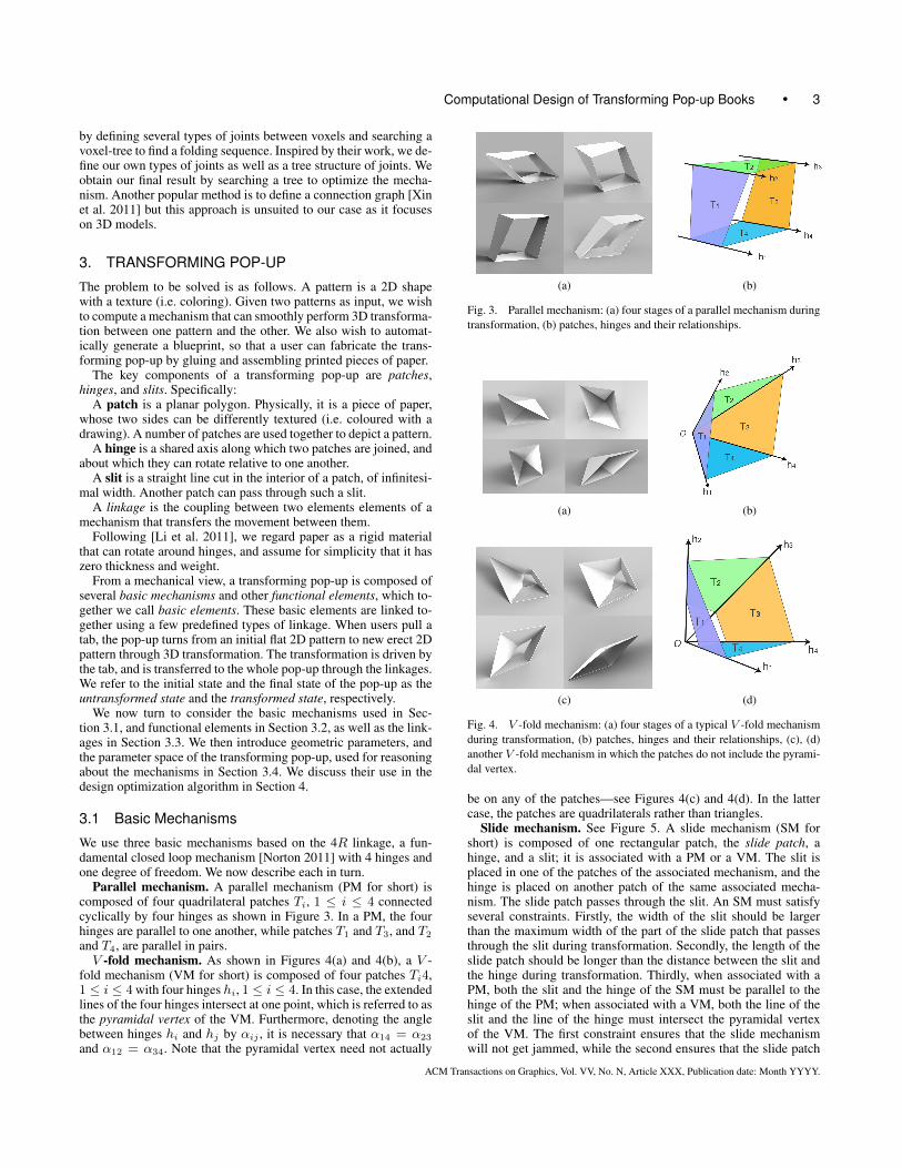
Parallel mechanism. A parallel mechanism (PM for short) iscomposed of four quadrilateral patches Ti, 1 ≤ i ≤ 4 connectedcyclically by four hinges as shown in Figure 3. In a PM, the fourhinges are parallel to one another, while patches T1 and T3, and T2
and T4, are parallel in pairs.V -fold mechanism. As shown in Figures 4(a) and 4(b), a V -
fold mechanism (VM for short) is composed of four patches Ti4,1 ≤ i ≤ 4 with four hinges hi, 1 ≤ i ≤ 4. In this case, the extendedlines of the four hinges intersect at one point, which is referred to asthe pyramidal vertex of the VM. Furthermore, denoting the anglebetween hinges hi and hj by αij , it is necessary that α14 = α23
and α12 = α34. Note that the pyramidal vertex need not actually
(a) (b)
Fig. 3. Parallel mechanism: (a) four stages of a parallel mechanism duringtransformation, (b) patches, hinges and their relationships.
(a) (b)
(c) (d)
Fig. 4. V -fold mechanism: (a) four stages of a typical V -fold mechanismduring transformation, (b) patches, hinges and their relationships, (c), (d)another V -fold mechanism in which the patches do not include the pyrami-dal vertex.
be on any of the patches—see Figures 4(c) and 4(d). In the lattercase, the patches are quadrilaterals rather than triangles.
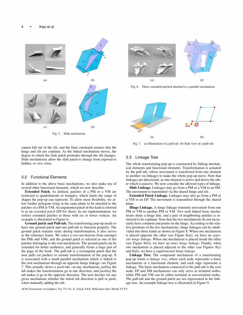
Slide mechanism. See Figure 5. A slide mechanism (SM forshort) is composed of one rectangular patch, the slide patch, ahinge, and a slit; it is associated with a PM or a VM. The slit isplaced in one of the patches of the associated mechanism, and thehinge is placed on another patch of the same associated mecha-nism. The slide patch passes through the slit. An SM must satisfyseveral constraints. Firstly, the width of the slit should be largerthan the maximum width of the part of the slide patch that passesthrough the slit during transformation. Secondly, the length of theslide patch should be longer than the distance between the slit andthe hinge during transformation. Thirdly, when associated with aPM, both the slit and the hinge of the SM must be parallel to thehinge of the PM; when associated with a VM, both the line of theslit and the line of the hinge must intersect the pyramidal vertexof the VM. The first constraint ensures that the slide mechanismwill not get jammed, while the second ensures that the slide patch
ACM Transactions on Graphics, Vol. VV, No. N, Article XXX, Publication date: Month YYYY.
4 • Xiao et al.
(a) (b)
(c) (d)
Fig. 5. Slide mechanism
cannot fall out of the slit, and the final constraint ensures that thehinge and slit are coplanar. As the linked mechanism moves, thedegree to which the slide patch protrudes through the slit changes.Slide mechanisms allow the slide patch to change from exposed tohidden, or vice versa.
3.2 Functional Elements
In addition to the above basic mechanisms, we also make use ofseveral other functional elements, which we now describe.
Extended Patch. As defined, patches of a PM or a VM arerestricted to quadrilaterals or triangles, which limits the range ofshapes the pop-up can represent. To allow more flexibility, we al-low further polygons lying in the same plane to be attached to thepatches of a PM or VM. An augmented patch of this kind is referredto as an extended patch (EP for short). In our implementation, werestrict extended patches to those with six or fewer vertices. Anexample is illustrated in Figure 6.
Ground patch and Pull-tab. The transforming pop-up needs tohave one ground patch and one pull-tab to function properly. Theground patch remains static during transformation; it also servesas the reference frame. We select a root mechanism from amongstthe PMs and VMs, and the ground patch is selected as one of thepatches belonging to the root mechanism. The ground patch can beextended for better aesthetics, and generally forms a large part ofthe page of the book. The pull-tab is a rectangular patch that theuser pulls (or pushes) to actuate transformation of the pop-up. Itis associated with a small parallel mechanism which is linked tothe root mechanism through an opposite hinge linkage: see Figure7. This actually shows a push-tab—in any mechanism, pulling thetab makes the transformation go in one direction, and pushing thetab makes it go in the opposite direction. The user decides for anygiven mechanism whether the initial tab direction is pull or push,when manually adding the tab.
(a) (b)
Fig. 6. Three extended patched attached to a parallel mechanism.
(a) (b)
Fig. 7. (a) Illustration of a pull-tab. (b) Side view of a pull-tab.
3.3 Linkage Tree
The whole transforming pop-up is constructed by linking mechan-ical elements and functional elements. Transformation is actuatedby the pull-tab, whose movement is transferred from one elementto another via linkages to make the whole pop-up move. Note thatlinkages are directional, as one element is active and drives the oth-er which is passive. We now consider the allowed types of linkage.
Slide Linkage. Linkages may go from a PM or a VM to an SM.The movement is transmitted via the shared hinge and slit.
Extended Patch Linkage. Linkages may also go from a PM ora VM to an EP. The movement is transmitted through the sharedplane.
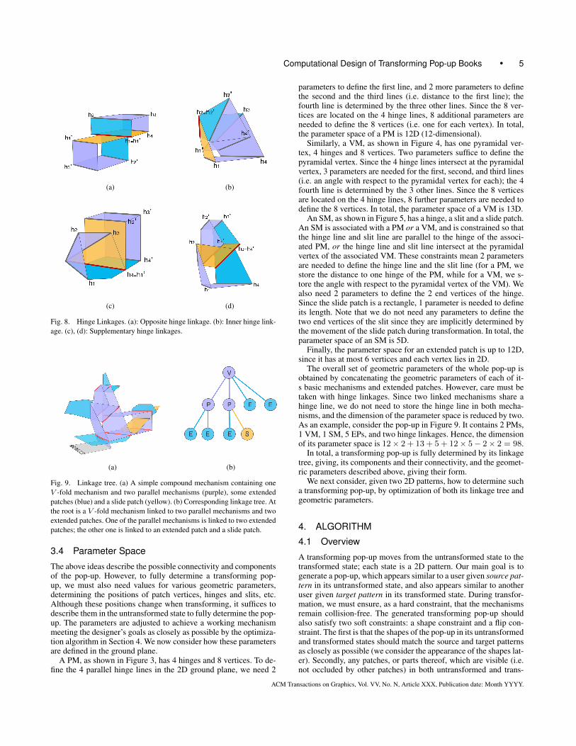
Hinge Linkage. A hinge linkage transmits movement from onePM or VM to another PM or VM. Two such linked basic mecha-nisms share a hinge line, and a pair of neighboring patches is re-stricted to be coplanar. Note that the two mechanisms do not neces-sarily have common end points on the hinge. According to the rela-tive positions of the two mechanisms, hinge linkages can be subdi-vided into three kinds as shown in Figure 8. When one mechanismis placed opposite the other (see Figure 8(a)), we have an oppo-site hinge linkage. When one mechanism is placed inside the other(see Figure 8(b)), we have an inner hinge linkage. Finally, whenone mechanism is placed adjacent to the other (see Figures 8(c)and 8(d)), we have a supplemental hinge linkage.
Linkage Tree. The compound mechanism of a transformingpop-up forms a linkage tree, where each node represents a basicmechanism or a functional element, and each edge represents alinkage. The basic mechanism connected to the pull-tab is the rootnode. EP and SM mechanisms can only serve as terminal nodes,while PM and VM can be either terminal or non-terminal nodes.The pull-tab and the ground patch are not represented in the link-age tree. An example linkage tree is illustrated in Figure 9.
ACM Transactions on Graphics, Vol. VV, No. N, Article XXX, Publication date: Month YYYY.
Computational Design of Transforming Pop-up Books • 5
(a) (b)
(c) (d)
Fig. 8. Hinge Linkages. (a): Opposite hinge linkage. (b): Inner hinge link-age. (c), (d): Supplementary hinge linkages.
(a) (b)
Fig. 9. Linkage tree. (a) A simple compound mechanism containing oneV -fold mechanism and two parallel mechanisms (purple), some extendedpatches (blue) and a slide patch (yellow). (b) Corresponding linkage tree. Atthe root is a V -fold mechanism linked to two parallel mechanisms and twoextended patches. One of the parallel mechanisms is linked to two extendedpatches; the other one is linked to an extended patch and a slide patch.
3.4 Parameter Space
The above ideas describe the possible connectivity and componentsof the pop-up. However, to fully determine a transforming pop-up, we must also need values for various geometric parameters,determining the positions of patch vertices, hinges and slits, etc.Although these positions change when transforming, it suffices todescribe them in the untransformed state to fully determine the pop-up. The parameters are adjusted to achieve a working mechanismmeeting the designer’s goals as closely as possible by the optimiza-tion algorithm in Section 4. We now consider how these parametersare defined in the ground plane.
A PM, as shown in Figure 3, has 4 hinges and 8 vertices. To de-fine the 4 parallel hinge lines in the 2D ground plane, we need 2
parameters to define the first line, and 2 more parameters to definethe second and the third lines (i.e. distance to the first line); thefourth line is determined by the three other lines. Since the 8 ver-tices are located on the 4 hinge lines, 8 additional parameters areneeded to define the 8 vertices (i.e. one for each vertex). In total,the parameter space of a PM is 12D (12-dimensional).
Similarly, a VM, as shown in Figure 4, has one pyramidal ver-tex, 4 hinges and 8 vertices. Two parameters suffice to define thepyramidal vertex. Since the 4 hinge lines intersect at the pyramidalvertex, 3 parameters are needed for the first, second, and third lines(i.e. an angle with respect to the pyramidal vertex for each); the 4fourth line is determined by the 3 other lines. Since the 8 verticesare located on the 4 hinge lines, 8 further parameters are needed todefine the 8 vertices. In total, the parameter space of a VM is 13D.
An SM, as shown in Figure 5, has a hinge, a slit and a slide patch.An SM is associated with a PM or a VM, and is constrained so thatthe hinge line and slit line are parallel to the hinge of the associ-ated PM, or the hinge line and slit line intersect at the pyramidalvertex of the associated VM. These constraints mean 2 parametersare needed to define the hinge line and the slit line (for a PM, westore the distance to one hinge of the PM, while for a VM, we s-tore the angle with respect to the pyramidal vertex of the VM). Wealso need 2 parameters to define the 2 end vertices of the hinge.Since the slide patch is a rectangle, 1 parameter is needed to defineits length. Note that we do not need any parameters to define thetwo end vertices of the slit since they are implicitly determined bythe movement of the slide patch during transformation. In total, theparameter space of an SM is 5D.
Finally, the parameter space for an extended patch is up to 12D,since it has at most 6 vertices and each vertex lies in 2D.
The overall set of geometric parameters of the whole pop-up isobtained by concatenating the geometric parameters of each of it-s basic mechanisms and extended patches. However, care must betaken with hinge linkages. Since two linked mechanisms share ahinge line, we do not need to store the hinge line in both mecha-nisms, and the dimension of the parameter space is reduced by two.As an example, consider the pop-up in Figure 9. It contains 2 PMs,1 VM, 1 SM, 5 EPs, and two hinge linkages. Hence, the dimensionof its parameter space is 12× 2 + 13 + 5 + 12× 5− 2× 2 = 98.
In total, a transforming pop-up is fully determined by its linkagetree, giving, its components and their connectivity, and the geomet-ric parameters described above, giving their form.
We next consider, given two 2D patterns, how to determine sucha transforming pop-up, by optimization of both its linkage tree andgeometric parameters.
4. ALGORITHM
4.1 Overview
A transforming pop-up moves from the untransformed state to thetransformed state; each state is a 2D pattern. Our main goal is togenerate a pop-up, which appears similar to a user given source pat-tern in its untransformed state, and also appears similar to anotheruser given target pattern in its transformed state. During transfor-mation, we must ensure, as a hard constraint, that the mechanismsremain collision-free. The generated transforming pop-up shouldalso satisfy two soft constraints: a shape constraint and a flip con-straint. The first is that the shapes of the pop-up in its untransformedand transformed states should match the source and target patternsas closely as possible (we consider the appearance of the shapes lat-er). Secondly, any patches, or parts thereof, which are visible (i.e.not occluded by other patches) in both untransformed and trans-
ACM Transactions on Graphics, Vol. VV, No. N, Article XXX, Publication date: Month YYYY.
6 • Xiao et al.
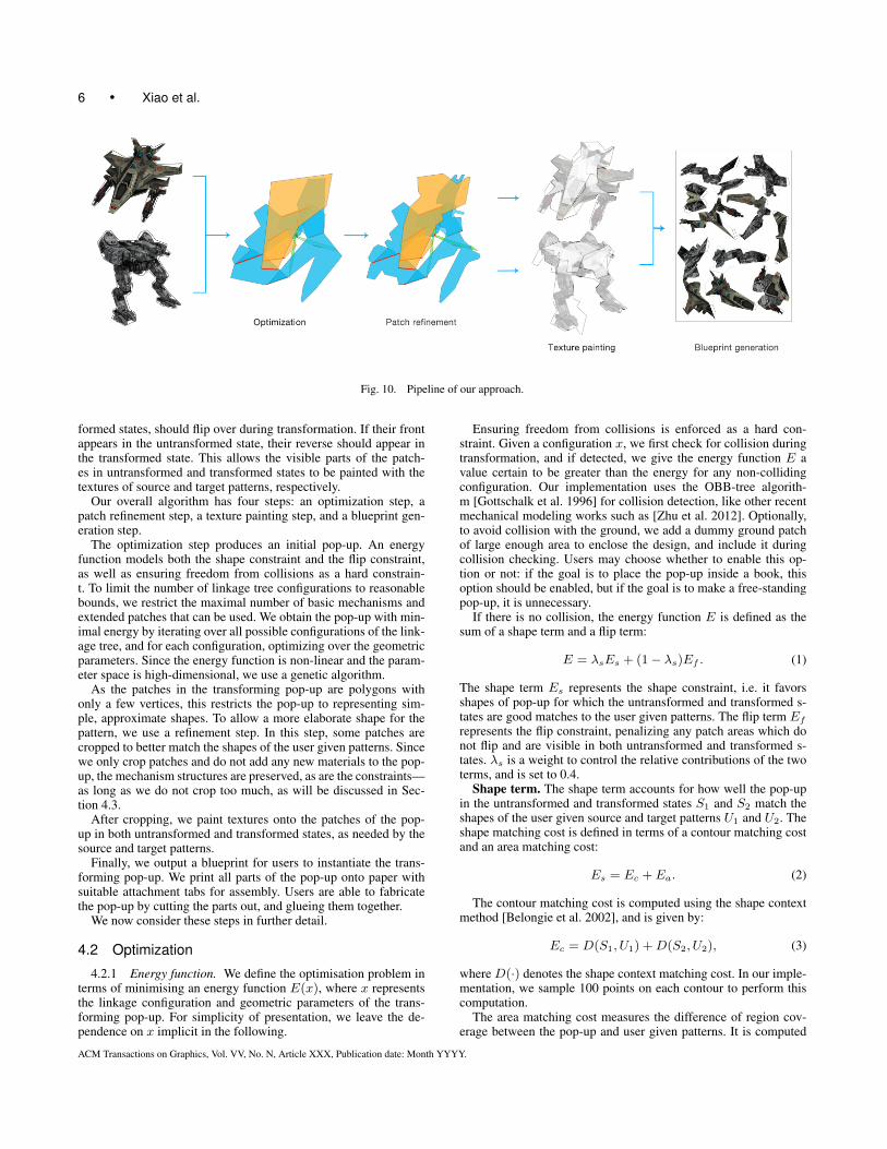
Fig. 10. Pipeline of our approach.
formed states, should flip over during transformation. If their frontappears in the untransformed state, their reverse should appear inthe transformed state. This allows the visible parts of the patch-es in untransformed and transformed states to be painted with thetextures of source and target patterns, respectively.
Our overall algorithm has four steps: an optimization step, apatch refinement step, a texture painting step, and a blueprint gen-eration step.
The optimization step produces an initial pop-up. An energyfunction models both the shape constraint and the flip constraint,as well as ensuring freedom from collisions as a hard constrain-t. To limit the number of linkage tree configurations to reasonablebounds, we restrict the maximal number of basic mechanisms andextended patches that can be used. We obtain the pop-up with min-imal energy by iterating over all possible configurations of the link-age tree, and for each configuration, optimizing over the geometricparameters. Since the energy function is non-linear and the param-eter space is high-dimensional, we use a genetic algorithm.
As the patches in the transforming pop-up are polygons withonly a few vertices, this restricts the pop-up to representing sim-ple, approximate shapes. To allow a more elaborate shape for thepattern, we use a refinement step. In this step, some patches arecropped to better match the shapes of the user given patterns. Sincewe only crop patches and do not add any new materials to the pop-up, the mechanism structures are preserved, as are the constraints—as long as we do not crop too much, as will be discussed in Sec-tion 4.3.
After cropping, we paint textures onto the patches of the pop-up in both untransformed and transformed states, as needed by thesource and target patterns.
Finally, we output a blueprint for users to instantiate the trans-forming pop-up. We print all parts of the pop-up onto paper withsuitable attachment tabs for assembly. Users are able to fabricatethe pop-up by cutting the parts out, and glueing them together.
We now consider these steps in further detail.
4.2 Optimization
4.2.1 Energy function. We define the optimisation problem interms of minimising an energy function E(x), where x representsthe linkage configuration and geometric parameters of the trans-forming pop-up. For simplicity of presentation, we leave the de-pendence on x implicit in the following.
Ensuring freedom from collisions is enforced as a hard con-straint. Given a configuration x, we first check for collision duringtransformation, and if detected, we give the energy function E avalue certain to be greater than the energy for any non-collidingconfiguration. Our implementation uses the OBB-tree algorith-m [Gottschalk et al. 1996] for collision detection, like other recentmechanical modeling works such as [Zhu et al. 2012]. Optionally,to avoid collision with the ground, we add a dummy ground patchof large enough area to enclose the design, and include it duringcollision checking. Users may choose whether to enable this op-tion or not: if the goal is to place the pop-up inside a book, thisoption should be enabled, but if the goal is to make a free-standingpop-up, it is unnecessary.
If there is no collision, the energy function E is defined as thesum of a shape term and a flip term:
E = λsEs + (1− λs)Ef . (1)
The shape term Es represents the shape constraint, i.e. it favorsshapes of pop-up for which the untransformed and transformed s-tates are good matches to the user given patterns. The flip term Ef
represents the flip constraint, penalizing any patch areas which donot flip and are visible in both untransformed and transformed s-tates. λs is a weight to control the relative contributions of the twoterms, and is set to 0.4.
Shape term. The shape term accounts for how well the pop-upin the untransformed and transformed states S1 and S2 match theshapes of the user given source and target patterns U1 and U2. Theshape matching cost is defined in terms of a contour matching costand an area matching cost:
Es = Ec +Ea. (2)
The contour matching cost is computed using the shape contextmethod [Belongie et al. 2002], and is given by:
Ec = D(S1, U1) +D(S2, U2), (3)
where D(·) denotes the shape context matching cost. In our imple-mentation, we sample 100 points on each contour to perform thiscomputation.
The area matching cost measures the difference of region cov-erage between the pop-up and user given patterns. It is computed
ACM Transactions on Graphics, Vol. VV, No. N, Article XXX, Publication date: Month YYYY.
Computational Design of Transforming Pop-up Books • 7
as:
Ea =∑i=1,2
λa‖Si \ Ui‖+ (1− λa)‖Ui \ Si‖, (4)
where \ is the set difference operator, ‖ · ‖ denotes the normalizedarea of a region, i.e. its area divided by the sum of the areas of allpatches, and λa is a relative weight. Si \Ui are redundant regions,i.e. regions covered by the pop-up but not covered by the user givenpattern. Ui \ Si are unrepresented regions, i.e. regions covered bythe user given pattern but not covered by the pop-up. Redundantregions are relatively unimportant, since the later patch refinemen-t step can crop them. However, unrepresented regions will showthe ground patch as they will not be included in the transformingpop-up. Hence, in our implementation, we set λa = 0.1 to morestrongly penalize unrepresented regions.
Flip term. Since visible regions in untransformed and trans-formed states are painted with source and target pattern texturesrespectively, to avoid conflicts in texture painting, we should min-imise regions which are visible in both untransformed and trans-formed states which do not show different sides of the paper. Theflip term is simply defined as the sum of the areas of all regionswhich violate this constraint (again normalized as in Equation 4):
Ef =∑i
‖Ri‖, (5)
where Ri is any region of a patch which is visible from the sameside in both states.
4.2.2 Energy minimization. We first describe our basic ap-proach to solving the minimization problem, then discuss how itcan be modified to achieve greater performance.
Basic approach. To minimize the energy function defined in E-quation 1 we iterate over all possible configurations for a linkagetree, up to a certain maximum size. To limit the number of con-figurations to reasonable bounds we restrict the maximal numberof basic mechanisms and extended patches that can be used. Weobserve that transforming pop-ups made by artists [Reinhart 2013]generally contain 3 or 4 mechanisms, so we restrict the number ofbasic mechanisms to 5 or fewer. The number of extended patchesis restricted to 12 or fewer—more would lead to pup-ups which areharder to construct with smaller pieces, and also which are morefragile, as well as leading to a more time-consuming optimizationproblem.
Simulation of the mechanism during optimization is driven bythe pull-tab. One patch of the mechanism connected to the pull-tab makes an angle with the pull-tab that varies smoothly from 0◦
to 180◦ as the mechanism operates. We can compute the angles atother hinges from simple geometric considerations. Since the ener-gy function is highly non-linear, we use a genetic algorithm (GA)to optimize the geometric parameters. The fitness function for aconfiguration x is given by −E(x). The parameters are each en-coded using integers constrained to lie in an appropriate range. Theinitial population is generated at random. Mutation is performed byadding a normally distributed value to each parameter in the indi-vidual. Single point crossover and tournament selection are used.In our implementation, we run the GA 10 times, each time for 50generations, and a population of 1000 individuals, with a crossoverprobability of 0.4 and mutation probability of 0.3.
Acceleration. Due to the high dimensionality of the parameterspace, directly using a GA to solve the above problem is time con-suming, taking tens of hours to generate reasonable output. Our ini-tial experiments showed that the GA after a few generations obtain-s an adequate global structure for the whole mechanism, but takes
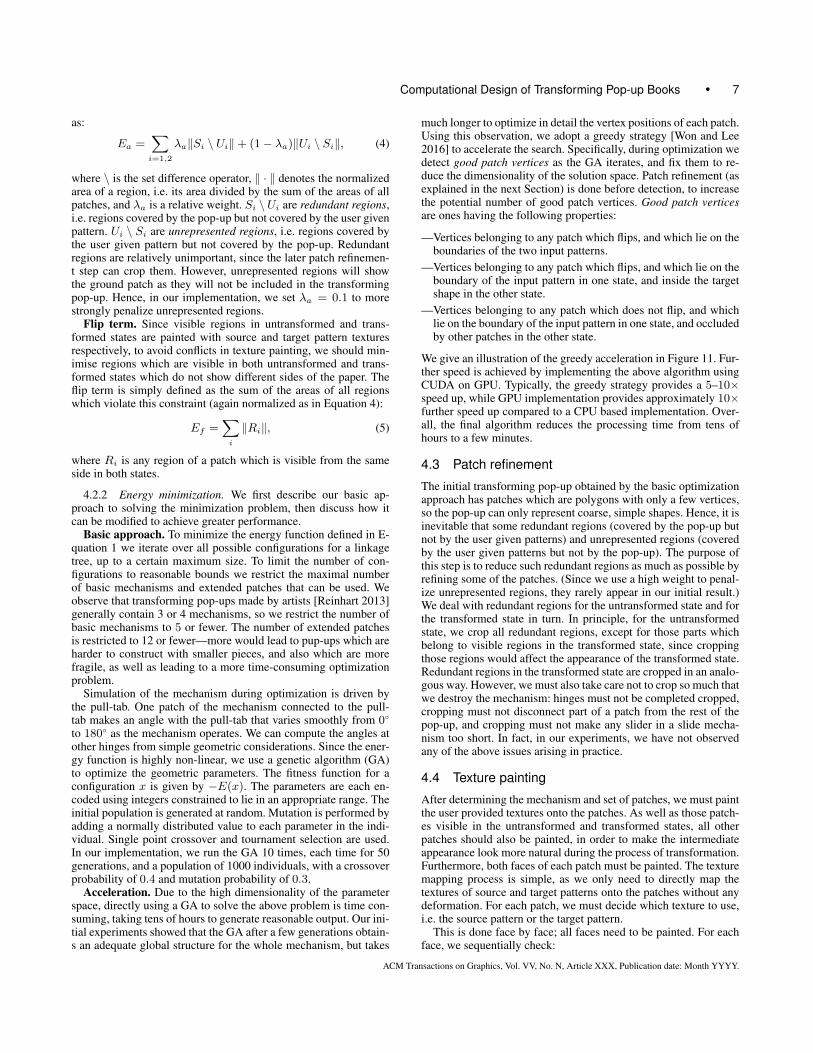
much longer to optimize in detail the vertex positions of each patch.Using this observation, we adopt a greedy strategy [Won and Lee2016] to accelerate the search. Specifically, during optimization wedetect good patch vertices as the GA iterates, and fix them to re-duce the dimensionality of the solution space. Patch refinement (asexplained in the next Section) is done before detection, to increasethe potential number of good patch vertices. Good patch verticesare ones having the following properties:
—Vertices belonging to any patch which flips, and which lie on theboundaries of the two input patterns.
—Vertices belonging to any patch which flips, and which lie on theboundary of the input pattern in one state, and inside the targetshape in the other state.
—Vertices belonging to any patch which does not flip, and whichlie on the boundary of the input pattern in one state, and occludedby other patches in the other state.
We give an illustration of the greedy acceleration in Figure 11. Fur-ther speed is achieved by implementing the above algorithm usingCUDA on GPU. Typically, the greedy strategy provides a 5–10×speed up, while GPU implementation provides approximately 10×further speed up compared to a CPU based implementation. Over-all, the final algorithm reduces the processing time from tens ofhours to a few minutes.
4.3 Patch refinement
The initial transforming pop-up obtained by the basic optimizationapproach has patches which are polygons with only a few vertices,so the pop-up can only represent coarse, simple shapes. Hence, it isinevitable that some redundant regions (covered by the pop-up butnot by the user given patterns) and unrepresented regions (coveredby the user given patterns but not by the pop-up). The purpose ofthis step is to reduce such redundant regions as much as possible byrefining some of the patches. (Since we use a high weight to penal-ize unrepresented regions, they rarely appear in our initial result.)We deal with redundant regions for the untransformed state and forthe transformed state in turn. In principle, for the untransformedstate, we crop all redundant regions, except for those parts whichbelong to visible regions in the transformed state, since croppingthose regions would affect the appearance of the transformed state.Redundant regions in the transformed state are cropped in an analo-gous way. However, we must also take care not to crop so much thatwe destroy the mechanism: hinges must not be completed cropped,cropping must not disconnect part of a patch from the rest of thepop-up, and cropping must not make any slider in a slide mecha-nism too short. In fact, in our experiments, we have not observedany of the above issues arising in practice.
4.4 Texture painting
After determining the mechanism and set of patches, we must paintthe user provided textures onto the patches. As well as those patch-es visible in the untransformed and transformed states, all otherpatches should also be painted, in order to make the intermediateappearance look more natural during the process of transformation.Furthermore, both faces of each patch must be painted. The texturemapping process is simple, as we only need to directly map thetextures of source and target patterns onto the patches without anydeformation. For each patch, we must decide which texture to use,i.e. the source pattern or the target pattern.
This is done face by face; all faces need to be painted. For eachface, we sequentially check:
ACM Transactions on Graphics, Vol. VV, No. N, Article XXX, Publication date: Month YYYY.
8 • Xiao et al.
(a) (b) (c)
Fig. 11. Greedy acceleration. (a) is an intermediate result by running brute force GA. By a patch refinement step we can get the result in (b). Note that someof the boundary vertices can be fixed in this step. Then by the proposed greedy acceleration strategy, we can get the final result in (c).
—If the face is visible (or partially visible) in both states. The partsonly visible in the untransformed or transformed state are paintedusing source or target pattern respectively. Any conflicting parts(i.e. visible in both states) and parts invisible in both states arepainted using the source pattern.
—If the face is only visible (or partially visible) in one state (un-transformed or transformed), the whole face is painted using on-ly one texture (source or target pattern respectively).
—Otherwise (i.e. the face is invisible in both states), the whole faceis painted using the source pattern.
Care must be taken for redundant regions and unrepresentedregions. We fill any redundant regions with the average color ofsource and target patterns, to ensure the consistency with the tex-ture inside the pattern. Unrepresented regions become a part of theground patch and are not included in the transformation of the pop-up, but are still painted using mapped textures from source or targetpatterns.
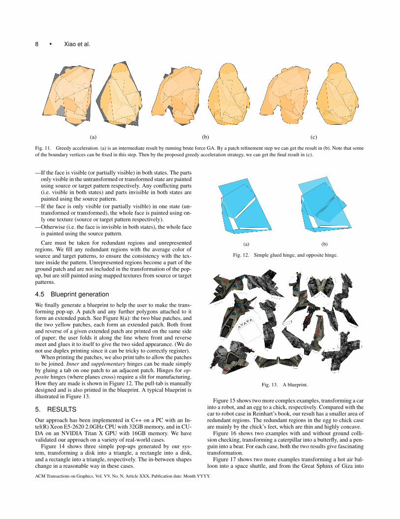
4.5 Blueprint generation
We finally generate a blueprint to help the user to make the trans-forming pop-up. A patch and any further polygons attached to itform an extended patch. See Figure 8(a): the two blue patches, andthe two yellow patches, each form an extended patch. Both frontand reverse of a given extended patch are printed on the same sideof paper; the user folds it along the line where front and reversemeet and glues it to itself to give the two sided appearance. (We donot use duplex printing since it can be tricky to correctly register).
When printing the patches, we also print tabs to allow the patchesto be joined. Inner and supplementary hinges can be made simplyby gluing a tab on one patch to an adjacent patch. Hinges for op-posite hinges (where planes cross) require a slit for manufacturing.How they are made is shown in Figure 12. The pull-tab is manuallydesigned and is also printed in the blueprint. A typical blueprint isillustrated in Figure 13.
5. RESULTS
Our approach has been implemented in C++ on a PC with an In-tel(R) Xeon E5-2620 2.0GHz CPU with 32GB memory, and in CU-DA on an NVIDIA Titan X GPU with 16GB memory. We havevalidated our approach on a variety of real-world cases.
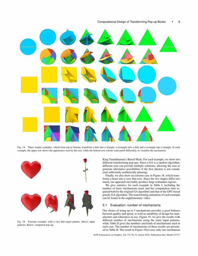
Figure 14 shows three simple pop-ups generated by our sys-tem, transforming a disk into a triangle, a rectangle into a disk,and a rectangle into a triangle, respectively. The in-between shapeschange in a reasonable way in these cases.
(a) (b)
Fig. 12. Simple glued hinge, and opposite hinge.
Fig. 13. A blueprint.
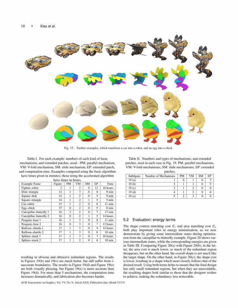
Figure 15 shows two more complex examples, transforming a carinto a robot, and an egg to a chick, respectively. Compared with thecar to robot case in Reinhart’s book, our result has a smaller area ofredundant regions. The redundant regions in the egg to chick caseare mainly by the chick’s feet, which are thin and highly concave.
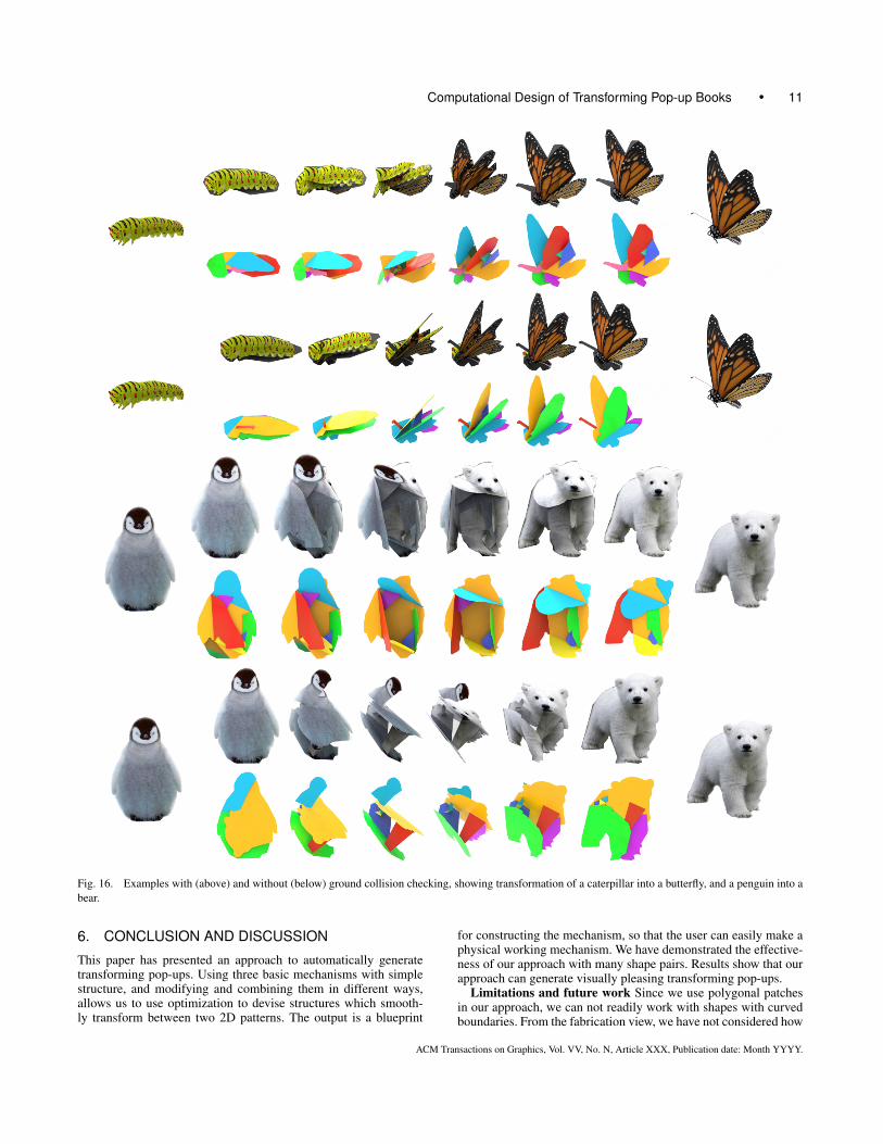
Figure 16 shows two examples with and without ground colli-sion checking, transforming a caterpillar into a butterfly, and a pen-guin into a bear. For each case, both the two results give fascinatingtransformation.
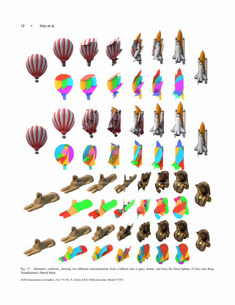
Figure 17 shows two more examples transforming a hot air bal-loon into a space shuttle, and from the Great Sphinx of Giza into
ACM Transactions on Graphics, Vol. VV, No. N, Article XXX, Publication date: Month YYYY.
Computational Design of Transforming Pop-up Books • 9
Fig. 14. Three simple examples, which from top to bottom, transform a disk into a triangle, a rectangle into a disk and a rectangle into a triangle. In eachexample, the upper row shows the appearance seen by the user, while the bottom row colours each patch differently, to visualize the mechanism.
Fig. 18. Extreme example, with a very thin target pattern. Above: inputpatterns. Below: computed pop-up.
King Tutankhamun’s Burial Mask. For each example, we show twodifferent transforming pop-ups. Since a GA is a random algorithm,different runs can provide multiple solutions, allowing the user togenerate alternative possibilities if the first attemot is not consid-ered sufficiently aesthetically pleasing.
Finally, we also show an extreme case in Figure 18, which trans-forms a heart into a very thin rose. Since the two shapes differ twomuch, our approach inevitably produce large redundant regions.
We give statistics for each example in Table I, including thenumber of basic mechanisms used, and the computation time re-quired both by the original GA algorithm and that of the GPU basedgreedy GA algorithm. The transforming animation of each examplecan be found in the supplementary video.
5.1 Evaluation: number of mechanisms
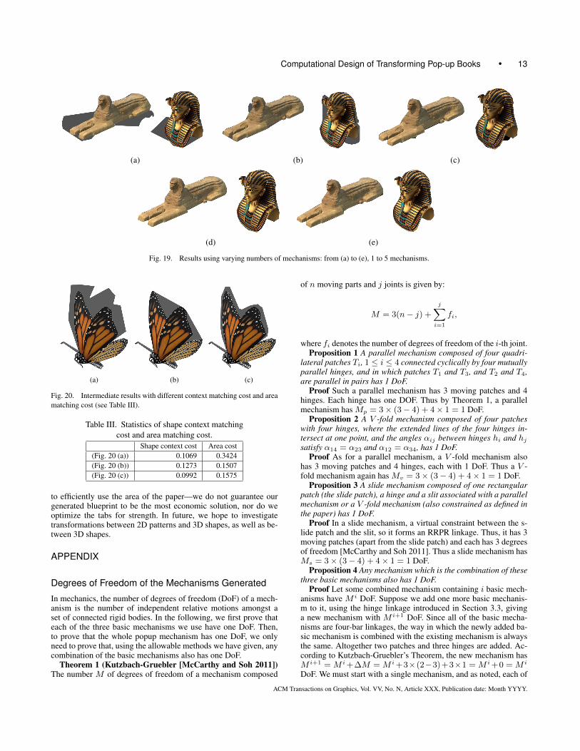
Our choice of using up to 5 mechanisms provides a good balancebetween quality and speed, as well as suitability of design for man-ufacture and robustness in use. Figure 19, we give the results withdifferent number of mechanisms using the same input patterns,while Table II gives the numbers and kinds of mechanisms used ineach case. The number of mechanisms of these results are present-ed in Table II. The result in Figure 19(a) uses only one mechanism
ACM Transactions on Graphics, Vol. VV, No. N, Article XXX, Publication date: Month YYYY.
10 • Xiao et al.
Fig. 15. Further examples, which transform a car into a robot, and an egg into a chick.
Table I. For each example: numbers of each kind of basicmechanisms, and extended patches, used—PM: parallel mechanism,VM: V-fold mechanism, SM: slide mechanism, EP: extended patch,
and computation time. Examples computed using the basic algorithmhave times given in minutes; those using the accelerated algorithm
have times in hours.Example Name Figure PM VM SM EP TimeFighter–robot 2 1 2 0 12 16 hoursDisk–triangle 14 1 3 0 8 9 minSquare–disk 14 1 2 0 5 9 minSquare–triangle 14 1 2 1 5 5 minCar–robot 15 1 2 0 6 11 minEgg–chick 15 0 2 0 5 8 minCaterpillar–butterfly 1 16 3 2 0 7 17 minCaterpillar–butterfly 2 16 0 2 1 5 14 hoursPenguin–bear 1 16 1 3 0 8 11 minPenguin–bear 2 16 0 3 0 7 13 hoursBalloon–shuttle 1 17 1 3 0 9 14 hoursBalloon–shuttle 2 17 1 3 0 8 10 minSphinx–mask 1 17 1 3 0 7 16 hoursSphinx–mask 2 17 1 2 0 6 10 min
resulting in obvious and obtrusive redundant regions. The resultsin Figures 19(b) and 19(c) are much better, but still suffer from i-naccurate boundaries. The results in Figure 19(d) and Figure 19(e)are both visually pleasing, but Figure 19(e) is more accurate thanFigure 19(d). For more than 5 mechanisms, the computation timeincreases dramatically, and fabrication also becomes harder.
Table II. Numbers and types of mechanisms, and extendedpatches, used in each case in Fig. 19. PM: parallel mechanisms,VM: V-fold mechanisms, SM: slide mechanisms, EP: extended
patches.Subfigure Number of Mechanisms PM VM SM EP19 (a) 1 0 1 0 319 (b) 2 1 1 0 519 (c) 3 1 2 0 019 (d) 4 1 3 0 019 (e) 5 2 3 0 0
5.2 Evaluation: energy terms
The shape context matching cost Ec and area matching cost Ea
both play important roles in energy minimization, as we nowdemonstrate by giving some intermediate states during optimisa-tion from the caterpillar-to-butterfly example. Figure 20 shows var-ious intermediate states, while the corresponding energies are givenin Table III. Comparing Figure 20(a) with Figure 20(b), in the lat-ter, the area cost is much lower, so much of the redundant regiondisappears, but on the other hand, the overall shape is not much likethe target shape. On the other hand, in Figure 20(c), the shape costis lower, resulting in a shape which more closely follows that of thedesired result. Using both terms helps to ensure that the final designhas only small redundant regions, but when they are unavoidable,the resulting shapes look similar to those that the designer wishesto achieve, making the redundancy less noticeable.
ACM Transactions on Graphics, Vol. VV, No. N, Article XXX, Publication date: Month YYYY.
Computational Design of Transforming Pop-up Books • 11
Fig. 16. Examples with (above) and without (below) ground collision checking, showing transformation of a caterpillar into a butterfly, and a penguin into abear.
6. CONCLUSION AND DISCUSSION
This paper has presented an approach to automatically generatetransforming pop-ups. Using three basic mechanisms with simplestructure, and modifying and combining them in different ways,allows us to use optimization to devise structures which smooth-ly transform between two 2D patterns. The output is a blueprint
for constructing the mechanism, so that the user can easily make aphysical working mechanism. We have demonstrated the effective-ness of our approach with many shape pairs. Results show that ourapproach can generate visually pleasing transforming pop-ups.
Limitations and future work Since we use polygonal patchesin our approach, we can not readily work with shapes with curvedboundaries. From the fabrication view, we have not considered how
ACM Transactions on Graphics, Vol. VV, No. N, Article XXX, Publication date: Month YYYY.
12 • Xiao et al.
Fig. 17. Alternative solutions, showing two different transformations from a balloon into a space shuttle, and from the Great Sphinx of Giza into KingTutankhamun’s Burial Mask.
ACM Transactions on Graphics, Vol. VV, No. N, Article XXX, Publication date: Month YYYY.
Computational Design of Transforming Pop-up Books • 13
(a) (b) (c)
(d) (e)
Fig. 19. Results using varying numbers of mechanisms: from (a) to (e), 1 to 5 mechanisms.
(a) (b) (c)
Fig. 20. Intermediate results with different context matching cost and areamatching cost (see Table III).
Table III. Statistics of shape context matchingcost and area matching cost.
Shape context cost Area cost(Fig. 20 (a)) 0.1069 0.3424(Fig. 20 (b)) 0.1273 0.1507(Fig. 20 (c)) 0.0992 0.1575
to efficiently use the area of the paper—we do not guarantee ourgenerated blueprint to be the most economic solution, nor do weoptimize the tabs for strength. In future, we hope to investigatetransformations between 2D patterns and 3D shapes, as well as be-tween 3D shapes.
APPENDIX
Degrees of Freedom of the Mechanisms Generated
In mechanics, the number of degrees of freedom (DoF) of a mech-anism is the number of independent relative motions amongst aset of connected rigid bodies. In the following, we first prove thateach of the three basic mechanisms we use have one DoF. Then,to prove that the whole popup mechanism has one DoF, we onlyneed to prove that, using the allowable methods we have given, anycombination of the basic mechanisms also has one DoF.
Theorem 1 (Kutzbach-Gruebler [McCarthy and Soh 2011])The number M of degrees of freedom of a mechanism composed
of n moving parts and j joints is given by:
M = 3(n− j) +
j∑i=1
fi,
where fi denotes the number of degrees of freedom of the i-th joint.Proposition 1 A parallel mechanism composed of four quadri-
lateral patches Ti, 1 ≤ i ≤ 4 connected cyclically by four mutuallyparallel hinges, and in which patches T1 and T3, and T2 and T4,are parallel in pairs has 1 DoF.
Proof Such a parallel mechanism has 3 moving patches and 4hinges. Each hinge has one DOF. Thus by Theorem 1, a parallelmechanism has Mp = 3× (3− 4) + 4× 1 = 1 DoF.
Proposition 2 A V -fold mechanism composed of four patcheswith four hinges, where the extended lines of the four hinges in-tersect at one point, and the angles αij between hinges hi and hj
satisfy α14 = α23 and α12 = α34, has 1 DoF.Proof As for a parallel mechanism, a V -fold mechanism also
has 3 moving patches and 4 hinges, each with 1 DoF. Thus a V -fold mechanism again has Mv = 3× (3− 4) + 4× 1 = 1 DoF.
Proposition 3 A slide mechanism composed of one rectangularpatch (the slide patch), a hinge and a slit associated with a parallelmechanism or a V -fold mechanism (also constrained as defined inthe paper) has 1 DoF.
Proof In a slide mechanism, a virtual constraint between the s-lide patch and the slit, so it forms an RRPR linkage. Thus, it has 3moving patches (apart from the slide patch) and each has 3 degreesof freedom [McCarthy and Soh 2011]. Thus a slide mechanism hasMs = 3× (3− 4) + 4× 1 = 1 DoF.
Proposition 4 Any mechanism which is the combination of thesethree basic mechanisms also has 1 DoF.
Proof Let some combined mechanism containing i basic mech-anisms have M i DoF. Suppose we add one more basic mechanis-m to it, using the hinge linkage introduced in Section 3.3, givinga new mechanism with M i+1 DoF. Since all of the basic mecha-nisms are four-bar linkages, the way in which the newly added ba-sic mechanism is combined with the existing mechanism is alwaysthe same. Altogether two patches and three hinges are added. Ac-cording to Kutzbach-Gruebler’s Theorem, the new mechanism hasM i+1 = M i +∆M = M i +3×(2−3)+3×1 = M i +0 = M i
DoF. We must start with a single mechanism, and as noted, each of
ACM Transactions on Graphics, Vol. VV, No. N, Article XXX, Publication date: Month YYYY.
14 • Xiao et al.
the single mechanisms has 1 DoF. Thus, by induction, a mechanismformed from any number of basic mechanisms has 1 DoF.
REFERENCES
BELONGIE, S., MALIK, J., AND PUZICHA, J. 2002. Shape matching andobject recognition using shape contexts. IEEE Trans. Pattern Anal. Mach.Intell. 24, 4 (Apr.), 509–522.
COROS, S., THOMASZEWSKI, B., NORIS, G., SUEDA, S., FORBERG, M.,SUMNER, R. W., MATUSIK, W., AND BICKEL, B. 2013. Computationaldesign of mechanical characters. ACM Trans. Graph. 32, 4 (July), 83:1–83:12.
G. WINDER, BRIAN ANDP. MAGLEBY, S. AND L. HOWELL, L. 2009.Kinematic representations of pop-up paper mechanisms. Journal ofMechanisms and Robotics 1, 2.
GLASSNER, A. 2002a. Interactive pop-up card design, part 1. IEEE Com-put. Graph. Appl 20, 1, 79–86.
GLASSNER, A. 2002b. Interactive pop-up card design, part 2. IEEE Com-put. Graph. Appl 20, 2, 74–85.
GOTTSCHALK, S., LIN, M. C., AND MANOCHA, D. 1996. Obbtree: Ahierarchical structure for rapid interference detection. In Proceedings ofSIGGRAPH 96. Annual Conference Series. 171–180.
JOSKOWICZ, L. AND SACKS, E. 1994. Configuration space computationfor mechanism design. In In Proceedings of IEEE International Confer-ence on Robotics and Automation. 1080–1087.
KOO, B., LI, W., YAO, J., AGRAWALA, M., AND MITRA, N. J. 2014.Creating works-like prototypes of mechanical objects. ACM Trans.Graph. 33, 6 (Nov.), 217:1–217:9.
LE, S. N., LEOW, S.-J., LE-NGUYEN, T.-V., RUIZ, C., AND LOW, K.-L.2014. Surface and contour-preserving origamic architecture paper pop-ups. IEEE Trans. Vis. Comput. Graph. 20, 2 (Feb.), 276–288.
LE-NGUYEN, T., LOW, K., JR., C. R. R., AND LE, S. N. 2013. Automaticpaper sliceform design from 3d solid models. IEEE Trans. Vis. Comput.Graph. 19, 11, 1795–1807.
LEE, Y., TOR, S., AND SOO, E. 1996. Mathematical modelling and simu-lation of pop-up books. Computers & Graphics 20, 1, 21 – 31.
LI, H., HU, R., ALHASHIM, I., AND ZHANG, H. 2015. Foldabilizing fur-niture. ACM Trans. Graph. 34, 4 (July), 90:1–90:12.
LI, X.-Y., JU, T., GU, Y., AND HU, S.-M. 2011. A geometric study ofv-style pop-ups: Theories and algorithms. ACM Trans. Graph. 30, 4,98:1–10.
LI, X.-Y., SHEN, C.-H., HUANG, S.-S., JU, T., AND HU, S.-M. 2010.Popup: automatic paper architectures from 3d models. ACM Trans.Graph. 29, 4, 111:1–9.
MCCARTHY, J. M. AND SOH, G. S. 2011. Geometric Design of Linkages.Vol. 11. Springer-Verlag New York.
MCCRAE, J., SINGH, K., AND MITRA, N. J. 2011. Slices: A shape-proxybased on planar sections. ACM Trans. Graph. 30, 6 (Dec.), 168:1–168:12.
MITANI, J. AND SUZUKI, H. 2003. Computer aided design for 180-degreeflat fold origamic architecture with lattice-type cross sections. Journal ofGraphic Science of Japan 37, 3, 3–8.
MITANI, J. AND SUZUKI, H. 2004. Computer aided design for origamicarchitecture models with polygonal representation. In Proceedings of theComputer Graphics International. 93–99.
MITANI, J., SUZUKI, H., AND UNO, H. 2003. Computer aided design fororigamic architecture models with voxel data structure. Transactions ofInformation Processing Society of Japan 44, 5, 1372–1379.
NORTON, R. L. 2011. Design of Machinery. McGraw-Hill Education; 5edition (March 30, 2011).
OKAMURA, S. AND IGARASHI, T. 2009. An interface for assisting thedesign and production of pop-up card. Lecture Notes in Computer Sci-ence 5531, 2, 68–78.
REINHART, M. 2013. Transformers: The Ultimate Pop-up Universe. LBKids; Pop edition.
RUIZ, C. R., LE, S. N., YU, J., AND LOW, K.-L. 2014. Multi-style paperpop-up designs from 3d models. Computer Graphics Forum 33, 2, 487–496.
SCHWARTZBURG, Y. AND PAULY, M. 2013. Fabrication-aware design withintersecting planar pieces. Comput. Graph. Forum 32, 2, 317–326.
WON, J. AND LEE, J. 2016. Shadow theatre: Discovering human motionfrom a sequence of silhouettes. ACM Trans. Graph. 35, 4 (July), 147:1–147:12.
XIN, S., LAI, C.-F., FU, C.-W., WONG, T.-T., HE, Y., AND COHEN-OR,D. 2011. Making burr puzzles from 3d models. ACM Trans. Graph. 30, 4(July), 97:1–97:8.
ZHOU, Y., SUEDA, S., MATUSIK, W., AND SHAMIR, A. 2014. Boxeliza-tion: Folding 3d objects into boxes. ACM Trans. Graph. 33, 4 (July),71:1–71:8.
ZHU, L., XU, W., SNYDER, J., LIU, Y., WANG, G., AND GUO, B. 2012.Motion-guided mechanical toy modeling. ACM Trans. Graph. 31, 6(Nov.), 127:1–127:10.
ACM Transactions on Graphics, Vol. VV, No. N, Article XXX, Publication date: Month YYYY.