Compressibility and hydraulic conductivity of clayey soil mixed with calcium bentonite for slurry...
9
Research paper Compressibility and hydraulic conductivity of clayey soil mixed with calcium bentonite for slurry wall backfill: Initial assessment R.-D. Fan a , Y.J. Du a,b, ⁎, Krishna R. Reddy c , S.Y. Liu a , Y.L. Yang a a Institute of Geotechnical Engineering, Southeast University, Nanjing 210096, China b Key Laboratory of Geotechnical and Underground Engineering, Tongji University, Shanghai 200092, China c Department of Civil and Materials Engineering, University of Illinois at Chicago, IL 60607, USA abstract article info Article history: Received 12 June 2014 Received in revised form 15 July 2014 Accepted 24 July 2014 Available online xxxx Keywords: Backfill Bentonite Compression Cutoff wall Hydraulic conductivity Soil–bentonite Soil–bentonite vertical cutoff walls, consisting of a sandy soil mixed with Na-bentonite as backfill, are used extensively as engineered barriers for contaminant containment. However, suitable sandy soil and Na-bentonite may not be available at some sites. Consequently, locally available clayey soil and Ca-bentonite may be considered as an alternative backfill. The use of clayey soil/Ca-bentonite backfill may be advantageous to achieve relatively low hydraulic conductivity, which has equivalent performance as that of conventional sandy soil/Na-bentonite backfills. However, studies on the compressibility and hydraulic conductivity of these clayey soil–bentonite backfills are very limited. This paper presents a comprehensive laboratory investigation on the compressibility and hydraulic conductivity of clayey soil/Ca-bentonite backfill through a series of oedometer tests. Kaolin is used as the control clayey soil and it is amended with different contents of Ca-bentonite, 0 (kaolin alone), 5, 10, and 15% (by dry weight basis), to prepare the clayey soil/Ca-bentonite backfills. The initial water contents for the backfills are selected to be 0.75, 1.0, 1.25, and 1.50 times their corre- sponding liquid limits. The results reveal that the backfills exhibit a noticeable inverse ‘S’ shaped e-log(σ′) compression curves attributed to the existence of the remolded yield stress (σ′ yr ). The compressibility, in terms of σ′ yr and the compression index (C c ), is significantly affected by the initial water content and bentonite content. The void ratio at an effective vertical compression stress of 1 kPa (denoted as e 1 ) is a useful characteristic parameter to uniquely correlate with C c for the clayey soil/Ca-bentonite backfills in this study as well as for sandy soil/Na-bentonite and sandy soil–clay backfills that are reported in previous published studies. Unique relation- ships are also found between the σ′ yr , initial void ratio (e 0 ), e 1 , and the void ratio at liquid limit (e L ). The hydraulic conductivity of the clayey soil/Ca-bentonite backfills is significantly reduced by the bentonite content; generally to less than 10 -9 m/s. An empirical method based on the framework of Kozeny–Carman equation is proposed to predict the hydraulic conductivity of the clayey soil/Ca-bentonite backfills, and the predicted hydraulic conduc- tivity values using these methods are found to fall in the range of 1/3 to 3 times those obtained from the oedometer tests. The proposed method is shown to estimate the hydraulic conductivity for both the clayey soil/Ca-bentonite backfills in this study and the sandy soil–bentonite backfills from published study with reason- able accuracy. Additional research is warranted to prepare the backfills to simulate typical field practice (e.g., use of tap water) and at workable initial water contents (based on the slump testing). © 2014 Elsevier B.V. All rights reserved. 1. Introduction Improper past disposal practices and accidental spills at numerous sites worldwide have resulted in the contamination of the subsurface soils and groundwater with high amounts of heavy metals and organic pollutants (Du et al., 2013, 2014a,b; Hu et al., 2010; Xue et al., 2013). Soil–bentonite vertical cutoff walls installed with the slurry trenching technology are widely used as in-situ barriers to control the subsurface migration of contaminated groundwater in the United States, Canada and Japan (Evans et al., 1995; Sharma and Reddy, 2004). In the United States, soil–bentonite vertical cutoff walls are often preferred because they possess relatively low hydraulic conductivity (typically ranges from 10 -9 to 10 -11 m/s) and are generally cost-effective (Evans et al., 1995; Sharma and Reddy, 2004). The effects of the fines content (FC), bentonite content (BC), grada- tion of sand, and other amendment content (e.g. zeolite and activated carbon) on the compressibility and hydraulic conductivity (k) of sandy soil/Na-bentonite (hereinafter referred to sandy SB) and/or sand/clay Applied Clay Science xxx (2014) xxx–xxx ⁎ Corresponding author at: Institute of Geotechnical Engineering, Southeast University, Nanjing 210096, China. Tel.: +86 25 83793729; fax: +86 25 83795086. E-mail addresses: [email protected] (R.-D. Fan), [email protected] (Y.J. Du), [email protected] (K.R. Reddy), [email protected] (S.Y. Liu), [email protected] (Y.L. Yang). CLAY-03109; No of Pages 9 http://dx.doi.org/10.1016/j.clay.2014.07.026 0169-1317/© 2014 Elsevier B.V. All rights reserved. Contents lists available at ScienceDirect Applied Clay Science journal homepage: www.elsevier.com/locate/clay Please cite this article as: Fan, R.-D., et al., Compressibility and hydraulic conductivity of clayey soil mixed with calcium bentonite for slurry wall backfill: Initial assessment, Appl. Clay Sci. (2014), http://dx.doi.org/10.1016/j.clay.2014.07.026
Transcript of Compressibility and hydraulic conductivity of clayey soil mixed with calcium bentonite for slurry...
Applied Clay Science xxx (2014) xxx–xxx
CLAY-03109; No of Pages 9
Contents lists available at ScienceDirect
Applied Clay Science
j ourna l homepage: www.e lsev ie r .com/ locate /c lay
Research paper
Compressibility and hydraulic conductivity of clayey soil mixed withcalcium bentonite for slurry wall backfill: Initial assessment
R.-D. Fan a, Y.J. Du a,b,⁎, Krishna R. Reddy c, S.Y. Liu a, Y.L. Yang a
a Institute of Geotechnical Engineering, Southeast University, Nanjing 210096, Chinab Key Laboratory of Geotechnical and Underground Engineering, Tongji University, Shanghai 200092, Chinac Department of Civil and Materials Engineering, University of Illinois at Chicago, IL 60607, USA
⁎ Corresponding author at: Institute of Geotechnical EnNanjing 210096, China. Tel.: +86 25 83793729; fax: +86
E-mail addresses: [email protected] (R.-D. Fan), [email protected] (K.R. Reddy), [email protected] (S.Y. Liu),(Y.L. Yang).
http://dx.doi.org/10.1016/j.clay.2014.07.0260169-1317/© 2014 Elsevier B.V. All rights reserved.
Please cite this article as: Fan, R.-D., et al., Cobackfill: Initial assessment, Appl. Clay Sci. (2
a b s t r a c t
a r t i c l e i n f oArticle history:Received 12 June 2014Received in revised form 15 July 2014Accepted 24 July 2014Available online xxxx
Keywords:BackfillBentoniteCompressionCutoff wallHydraulic conductivitySoil–bentonite
Soil–bentonite vertical cutoff walls, consisting of a sandy soil mixed with Na-bentonite as backfill, are usedextensively as engineered barriers for contaminant containment. However, suitable sandy soil andNa-bentonite may not be available at some sites. Consequently, locally available clayey soil and Ca-bentonitemay be considered as an alternative backfill. The use of clayey soil/Ca-bentonite backfill may be advantageousto achieve relatively low hydraulic conductivity, which has equivalent performance as that of conventionalsandy soil/Na-bentonite backfills. However, studies on the compressibility and hydraulic conductivity of theseclayey soil–bentonite backfills are very limited. This paper presents a comprehensive laboratory investigationon the compressibility and hydraulic conductivity of clayey soil/Ca-bentonite backfill through a series ofoedometer tests. Kaolin is used as the control clayey soil and it is amended with different contents ofCa-bentonite, 0 (kaolin alone), 5, 10, and 15% (by dry weight basis), to prepare the clayey soil/Ca-bentonitebackfills. The initial water contents for the backfills are selected to be 0.75, 1.0, 1.25, and 1.50 times their corre-sponding liquid limits. The results reveal that the backfills exhibit a noticeable inverse ‘S’ shaped e-log(σ′)compression curves attributed to the existence of the remolded yield stress (σ′yr). The compressibility, interms of σ′yr and the compression index (Cc), is significantly affected by the initial water content and bentonitecontent. The void ratio at an effective vertical compression stress of 1 kPa (denoted as e1) is a useful characteristicparameter to uniquely correlate with Cc for the clayey soil/Ca-bentonite backfills in this study as well as for sandysoil/Na-bentonite and sandy soil–clay backfills that are reported in previous published studies. Unique relation-ships are also found between the σ′yr, initial void ratio (e0), e1, and the void ratio at liquid limit (eL). The hydraulicconductivity of the clayey soil/Ca-bentonite backfills is significantly reduced by the bentonite content; generallyto less than 10−9 m/s. An empirical method based on the framework of Kozeny–Carman equation is proposed topredict the hydraulic conductivity of the clayey soil/Ca-bentonite backfills, and the predicted hydraulic conduc-tivity values using these methods are found to fall in the range of 1/3 to 3 times those obtained from theoedometer tests. The proposed method is shown to estimate the hydraulic conductivity for both the clayeysoil/Ca-bentonite backfills in this study and the sandy soil–bentonite backfills from published studywith reason-able accuracy. Additional research is warranted to prepare the backfills to simulate typical field practice (e.g., useof tap water) and at workable initial water contents (based on the slump testing).
© 2014 Elsevier B.V. All rights reserved.
1. Introduction
Improper past disposal practices and accidental spills at numeroussites worldwide have resulted in the contamination of the subsurfacesoils and groundwater with high amounts of heavy metals and organicpollutants (Du et al., 2013, 2014a,b; Hu et al., 2010; Xue et al., 2013).
gineering, Southeast University,25 [email protected] (Y.J. Du),[email protected]
mpressibility and hydraulic co014), http://dx.doi.org/10.101
Soil–bentonite vertical cutoff walls installed with the slurry trenchingtechnology are widely used as in-situ barriers to control the subsurfacemigration of contaminated groundwater in the United States, Canadaand Japan (Evans et al., 1995; Sharma and Reddy, 2004). In the UnitedStates, soil–bentonite vertical cutoff walls are often preferred becausethey possess relatively low hydraulic conductivity (typically rangesfrom 10−9 to 10−11 m/s) and are generally cost-effective (Evans et al.,1995; Sharma and Reddy, 2004).
The effects of the fines content (FC), bentonite content (BC), grada-tion of sand, and other amendment content (e.g. zeolite and activatedcarbon) on the compressibility and hydraulic conductivity (k) of sandysoil/Na-bentonite (hereinafter referred to sandy SB) and/or sand/clay
nductivity of clayey soil mixed with calcium bentonite for slurry wall6/j.clay.2014.07.026
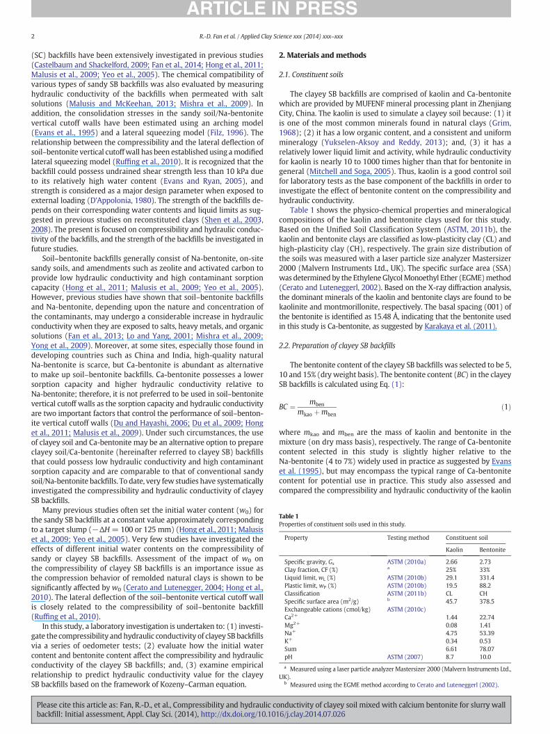
Table 1Properties of constituent soils used in this study.
Property Testing method Constituent soil
Kaolin Bentonite
Specific gravity, Gs ASTM (2010a) 2.66 2.73Clay fraction, CF (%) a 25% 33%Liquid limit, wL (%) ASTM (2010b) 29.1 331.4Plastic limit, wP (%) ASTM (2010b) 19.5 88.2Classification ASTM (2011b) CL CHSpecific surface area (m2/g) b 45.7 378.5Exchangeable cations (cmol/kg) ASTM (2010c)Ca2+ 1.44 22.74Mg2+ 0.08 1.41Na+ 4.75 53.39K+ 0.34 0.53Sum 6.61 78.07pH ASTM (2007) 8.7 10.0
a Measured using a laser particle analyzer Mastersizer 2000 (Malvern Instruments Ltd.,UK).
b Measured using the EGME method according to Cerato and Luteneggerl (2002).
2 R.-D. Fan et al. / Applied Clay Science xxx (2014) xxx–xxx
(SC) backfills have been extensively investigated in previous studies(Castelbaum and Shackelford, 2009; Fan et al., 2014; Hong et al., 2011;Malusis et al., 2009; Yeo et al., 2005). The chemical compatibility ofvarious types of sandy SB backfills was also evaluated by measuringhydraulic conductivity of the backfills when permeated with saltsolutions (Malusis and McKeehan, 2013; Mishra et al., 2009). Inaddition, the consolidation stresses in the sandy soil/Na-bentonitevertical cutoff walls have been estimated using an arching model(Evans et al., 1995) and a lateral squeezing model (Filz, 1996). Therelationship between the compressibility and the lateral deflection ofsoil–bentonite vertical cutoffwall has been established using amodifiedlateral squeezing model (Ruffing et al., 2010). It is recognized that thebackfill could possess undrained shear strength less than 10 kPa dueto its relatively high water content (Evans and Ryan, 2005), andstrength is considered as a major design parameter when exposed toexternal loading (D'Appolonia, 1980). The strength of the backfills de-pends on their corresponding water contents and liquid limits as sug-gested in previous studies on reconstituted clays (Shen et al., 2003,2008). The present is focused on compressibility and hydraulic conduc-tivity of the backfills, and the strength of the backfills be investigated infuture studies.
Soil–bentonite backfills generally consist of Na-bentonite, on-sitesandy soils, and amendments such as zeolite and activated carbon toprovide low hydraulic conductivity and high contaminant sorptioncapacity (Hong et al., 2011; Malusis et al., 2009; Yeo et al., 2005).However, previous studies have shown that soil–bentonite backfillsand Na-bentonite, depending upon the nature and concentration ofthe contaminants, may undergo a considerable increase in hydraulicconductivity when they are exposed to salts, heavy metals, and organicsolutions (Fan et al., 2013; Lo and Yang, 2001; Mishra et al., 2009;Yong et al., 2009). Moreover, at some sites, especially those found indeveloping countries such as China and India, high-quality naturalNa-bentonite is scarce, but Ca-bentonite is abundant as alternativeto make up soil–bentonite backfills. Ca-bentonite possesses a lowersorption capacity and higher hydraulic conductivity relative toNa-bentonite; therefore, it is not preferred to be used in soil–bentonitevertical cutoff walls as the sorption capacity and hydraulic conductivityare two important factors that control the performance of soil–benton-ite vertical cutoff walls (Du and Hayashi, 2006; Du et al., 2009; Honget al., 2011; Malusis et al., 2009). Under such circumstances, the useof clayey soil and Ca-bentonite may be an alternative option to prepareclayey soil/Ca-bentonite (hereinafter referred to clayey SB) backfillsthat could possess low hydraulic conductivity and high contaminantsorption capacity and are comparable to that of conventional sandysoil/Na-bentonite backfills. To date, very few studies have systematicallyinvestigated the compressibility and hydraulic conductivity of clayeySB backfills.
Many previous studies often set the initial water content (w0) forthe sandy SB backfills at a constant value approximately correspondingto a target slump (−ΔH=100 or 125 mm) (Hong et al., 2011; Malusiset al., 2009; Yeo et al., 2005). Very few studies have investigated theeffects of different initial water contents on the compressibility ofsandy or clayey SB backfills. Assessment of the impact of w0 onthe compressibility of clayey SB backfills is an importance issue asthe compression behavior of remolded natural clays is shown to besignificantly affected by w0 (Cerato and Lutenegger, 2004; Hong et al.,2010). The lateral deflection of the soil–bentonite vertical cutoff wallis closely related to the compressibility of soil–bentonite backfill(Ruffing et al., 2010).
In this study, a laboratory investigation is undertaken to: (1) investi-gate the compressibility andhydraulic conductivity of clayey SB backfillsvia a series of oedometer tests; (2) evaluate how the initial watercontent and bentonite content affect the compressibility and hydraulicconductivity of the clayey SB backfills; and, (3) examine empiricalrelationship to predict hydraulic conductivity value for the clayeySB backfills based on the framework of Kozeny–Carman equation.
Please cite this article as: Fan, R.-D., et al., Compressibility and hydraulic cobackfill: Initial assessment, Appl. Clay Sci. (2014), http://dx.doi.org/10.101
2. Materials and methods
2.1. Constituent soils
The clayey SB backfills are comprised of kaolin and Ca-bentonitewhich are provided by MUFENF mineral processing plant in ZhenjiangCity, China. The kaolin is used to simulate a clayey soil because: (1) itis one of the most common minerals found in natural clays (Grim,1968); (2) it has a low organic content, and a consistent and uniformmineralogy (Yukselen-Aksoy and Reddy, 2013); and, (3) it has arelatively lower liquid limit and activity, while hydraulic conductivityfor kaolin is nearly 10 to 1000 times higher than that for bentonite ingeneral (Mitchell and Soga, 2005). Thus, kaolin is a good control soilfor laboratory tests as the base component of the backfills in order toinvestigate the effect of bentonite content on the compressibility andhydraulic conductivity.
Table 1 shows the physico-chemical properties and mineralogicalcompositions of the kaolin and bentonite clays used for this study.Based on the Unified Soil Classification System (ASTM, 2011b), thekaolin and bentonite clays are classified as low-plasticity clay (CL) andhigh-plasticity clay (CH), respectively. The grain size distribution ofthe soils was measured with a laser particle size analyzer Mastersizer2000 (Malvern Instruments Ltd., UK). The specific surface area (SSA)was determined by the EthyleneGlycolMonoethyl Ether (EGME)method(Cerato and Luteneggerl, 2002). Based on the X-ray diffraction analysis,the dominant minerals of the kaolin and bentonite clays are found to bekaolinite and montmorillonite, respectively. The basal spacing (001) ofthe bentonite is identified as 15.48 Å, indicating that the bentonite usedin this study is Ca-bentonite, as suggested by Karakaya et al. (2011).
2.2. Preparation of clayey SB backfills
The bentonite content of the clayey SB backfills was selected to be 5,10 and 15% (dry weight basis). The bentonite content (BC) in the clayeySB backfills is calculated using Eq. (1):
BC ¼ mben
mkao þmbenð1Þ
where mkao and mben are the mass of kaolin and bentonite in themixture (on dry mass basis), respectively. The range of Ca-bentonitecontent selected in this study is slightly higher relative to theNa-bentonite (4 to 7%) widely used in practice as suggested by Evanset al. (1995), but may encompass the typical range of Ca-bentonitecontent for potential use in practice. This study also assessed andcompared the compressibility and hydraulic conductivity of the kaolin
nductivity of clayey soil mixed with calcium bentonite for slurry wall6/j.clay.2014.07.026

Table 3Initial water content (w0) and ratio of initial water content to liquid limit (w0/wL) forkaolin specimen and kaolin–bentonite backfills tested in this study.
Specimen IDa w0 (%) w0/wL Specimen IDa w0 (%) w0/wL
B0LL0.75 20.9 0.72 B0LL1.25 35.3 1.22B0LL1.00 27.6 0.95 B0LL1.50 45.0 1.55B5LL0.75V1 31.3 0.71 B5LL1.25V1 53.7 1.22B5LL0.75V2 31.6 0.72 B5LL1.25V2 53.2 1.21B5LL1.00V1 43.0 0.98 B5LL1.50V1 63.5 1.45B5LL1.00V2 41.8 0.95 B5LL1.50V2 64.3 1.46B10LL0.75V1 37.6 0.70 B10LL1.25V1 65.0 1.22B10LL0.75V2 38.7 0.73 B10LL1.25V2 64.2 1.20B10LL1.00V1 51.1 0.96 B10LL1.50V1 78.5 1.47B10LL1.00V2 52.3 0.98 B10LL1.50V2 77.8 1.46B15LL0.75V1 47.1 0.76 B15LL1.25V1 78.9 1.28B15LL0.75V2 46.5 0.75 B15LL1.25V2 77.0 1.25B15LL1.00V1 62.7 1.02 B15LL1.50V1 94.4 1.53B15LL1.00V2 62.7 1.02 B15LL1.50V2 92.1 1.49
a BiLLjVk denotes a specimenwith bentonite content of i%, initial water content (w0) ofj times the liquid limit (wL), and identical specimen number of kth.
3R.-D. Fan et al. / Applied Clay Science xxx (2014) xxx–xxx
specimens to the clayey SB backfills. The values of bentonite content,specific gravity, liquid limit and plastic limit of the various backfillsprepared are summarized in Table 2.
The backfills were prepared by thoroughly mixing a predeterminedmass of air-dried kaolin and bentonite clays with a predeterminedvolume of distilled water for 10 min using a paddle mixer. The initialwater contents for the backfills and kaolin specimens were selectedto be 0.75, 1.00, 1.25, and 1.50 times their corresponding liquid limitsto study the effects of initial water content on compressibility andhydraulic conductivity of the backfills. However, the practical rangeof water content for field applications should be selected basedon the workability considerations as determined by slump testing(Evans et al., 1995).
A predetermined mass of the kaolin or clayey SB backfill withpredetermined initial water content was placed in a conventionalconsolidation ring that was 61.8 mm in diameter and 20 mm in height.The entrapped air bubbles were minimized by tapping the ring andbackfill at regular time intervals. Then, the specimens were immersedin distilled water for 48 h to achieve full saturation.
In each case, two identical specimenswere prepared under the sameconditions for the clayey SB backfills and one specimen was preparedfor the kaolin alone. The symbol “BiLLjVk” denotes a specimen with BCof i%, w0 of j times the liquid limit and the identical specimen numberof kth. For example, specimen ID “B5LL1.25V2” denotes a specimencontaining 5% bentonite with initial water content of 1.25 timesthe liquid limit and is the second of the specimens prepared withthese variables. In addition, a third identical specimen was preparedand then sacrificed for the measurement of the initial water contentimmediately after saturation soaking step. The measured values of w0
and w0/wL for each specimen are summarized in Table 3.
2.3. Testing methods
The oedometer tests were conducted as per ASTM D 2435 (ASTM,2011a), except that the initial loading on the specimens was kept at3.125 kPa. This relatively low loading was chosen to avoid squeezingthe soil from the gap that exists between the specimen ring and porousdisks (Fan et al., 2014; Hong et al., 2010). The loadingwas then doubledfor each incremental step until a maximum loading of 1600 kPa wasreached. The duration of each loading was 24 h.
At a given average effective vertical compression stress (σ′ave),defined as the mean value of two successive load increments, thehydraulic conductivity for each load incrementwas estimated followingTerzaghi's one-dimensional consolidation theory, as expressed by:
k ¼ cvmvγw ð2Þ
where k is the hydraulic conductivity (m/s), cv is the coefficientof consolidation (m2/s) determined using the Taylor (square-root-of-time) method in this study, mv is the coefficient of volume change(kPa−1), and γw is the unit weight of water (kN/m3). This method todetermine k value is extensively accepted (Chai et al., 2004;Horpibulsuk et al., 2007; Mishra et al., 2011; Sivapullaiah et al., 2000;Watabe et al., 2011; Yong et al., 2009). The method is likely to underes-timate k value of clayey soils (Chapuis, 2012), but it is used in thisstudy for relative comparison of hydraulic conductivity of various clayeysoil/Ca-bentonite backfills and kaolin specimens.
Table 2Types and properties of kaolin–bentonite backfills.
Property Testing method Bentonite content (%)
5 10 15
Specific gravity, Gs ASTM (2010a) 2.66 2.67 2.67Liquid limit, wL (%) ASTM (2010b) 43.9 53.3 61.7Plastic limit, wP (%) ASTM (2010b) 22.9 25.9 29.3
Please cite this article as: Fan, R.-D., et al., Compressibility and hydraulic cobackfill: Initial assessment, Appl. Clay Sci. (2014), http://dx.doi.org/10.101
3. Results and discussion
The results of the compressibility and hydraulic conductivity for theclayey SB backfills and, where possible, the comparison of the results inthis study with those for the sandy SB and SC backfills reported inprevious studies (Baxter, 2000; Fan et al., 2014; Hong et al., 2011;Malusis et al., 2009; Yeo et al., 2005) are presented and discussed inthe following sections. The sandy SB backfills amended with zeolitesand activated carbons reported by Hong et al. (2011) and Malusiset al. (2009) are categorized as sandy SB backfills, as the zeolites andactivated carbons used have limited effects on the compressibility orhydraulic conductivity of the sandy SB backfills.
3.1. Compression curves
Fig. 1 (a to d) shows the void ratio (e)—effective vertical compres-sion stress (σ′) compression curves on semi-logarithm scale for theclayey SB backfills and kaolin specimens with w0 of 0.75 to 1.50 timestheir corresponding liquid limits. Three characteristic parametersfor the e-log(σ′) compression curves are defined, including theremolded yield stress (σ′yr) originally proposed by Hong et al. (2012),void ratio at σ′ = 1 kPa (denoted by e1) and compression index (Cc),as illustrated in Fig. 2. The σ′yr shown in Fig. 2 is defined as the stressat the intersection point of the linear portions of e-log(σ′) compressioncurve at pre- and post-yield states. The e1 is obtained by extendingthe linear portion of the e-log(σ′) compression curve at the post-yieldstate; therefore, the point at σ′ of 1 kPa and e1 (i.e., (1, e1)) representsthe origin of the extended linear portion of the e-log(σ′) compressioncurve at the post-yield state. The e1 values for the sandy soil/Na-bentonite and sand/clay backfills reported in previous studies(Fan et al., 2014; Hong et al., 2011; Yeo et al., 2005) are also estimatedusing this method. The Cc values are determined from the linear portionof the e-log(σ′) compression curve at the post-yield state, as shownin Fig. 2.
Previous studies suggest that the initial water content and liquidlimit are twomajor factors that control the compressibility of remoldedclays (Hong et al., 2012; Terzaghi et al., 1996). In this study, the effectsof initial void ratio (e0) and void ratio at liquid limit (eL) on σ′yr and e1are described using a dimensionless parameter e0x × eL
y (x and y aredimensionless parameters). The x and y values are obtained by fittingthe derived values of σ′yr or e1, within considered bentonite contentand initialwater content, to their corresponding e0x× eL
yusing amultipleregression analysis when the correlation coefficient (R) reaches themaximum. The results of multiple regression analysis show that σ′yr
nductivity of clayey soil mixed with calcium bentonite for slurry wall6/j.clay.2014.07.026
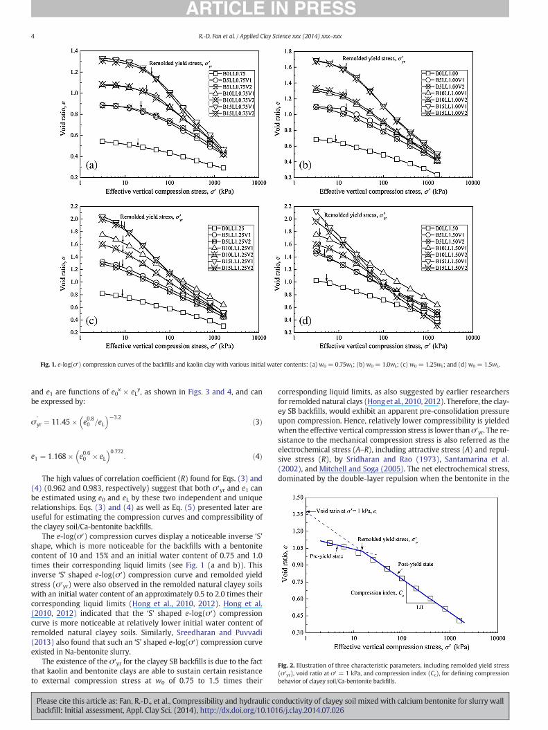
Fig. 1. e-log(σ′) compression curves of the backfills and kaolin clay with various initial water contents: (a) w0 = 0.75wL; (b) w0 = 1.0wL; (c) w0 = 1.25wL; and (d) w0 = 1.5wL.
Fig. 2. Illustration of three characteristic parameters, including remolded yield stress(σ′yr), void ratio at σ′ = 1 kPa, and compression index (Cc), for defining compressionbehavior of clayey soil/Ca-bentonite backfills.
4 R.-D. Fan et al. / Applied Clay Science xxx (2014) xxx–xxx
and e1 are functions of e0x × eLy, as shown in Figs. 3 and 4, and can
be expressed by:
σ0
yr ¼ 11:45� e0:80 =eL� �−3:2 ð3Þ
e1 ¼ 1:168� e0:60 � eL� �0:772
: ð4Þ
The high values of correlation coefficient (R) found for Eqs. (3) and(4) (0.962 and 0.983, respectively) suggest that both σ′yr and e1 canbe estimated using e0 and eL by these two independent and uniquerelationships. Eqs. (3) and (4) as well as Eq. (5) presented later areuseful for estimating the compression curves and compressibility ofthe clayey soil/Ca-bentonite backfills.
The e-log(σ′) compression curves display a noticeable inverse ‘S’shape, which is more noticeable for the backfills with a bentonitecontent of 10 and 15% and an initial water content of 0.75 and 1.0times their corresponding liquid limits (see Fig. 1 (a and b)). Thisinverse ‘S’ shaped e-log(σ′) compression curve and remolded yieldstress (σ′yr) were also observed in the remolded natural clayey soilswith an initial water content of an approximately 0.5 to 2.0 times theircorresponding liquid limits (Hong et al., 2010, 2012). Hong et al.(2010, 2012) indicated that the ‘S’ shaped e-log(σ′) compressioncurve is more noticeable at relatively lower initial water content ofremolded natural clayey soils. Similarly, Sreedharan and Puvvadi(2013) also found that such an ‘S’ shaped e-log(σ′) compression curveexisted in Na-bentonite slurry.
The existence of the σ′yr for the clayey SB backfills is due to the factthat kaolin and bentonite clays are able to sustain certain resistanceto external compression stress at w0 of 0.75 to 1.5 times their
Please cite this article as: Fan, R.-D., et al., Compressibility and hydraulic cobackfill: Initial assessment, Appl. Clay Sci. (2014), http://dx.doi.org/10.101
corresponding liquid limits, as also suggested by earlier researchersfor remolded natural clays (Hong et al., 2010, 2012). Therefore, the clay-ey SB backfills, would exhibit an apparent pre-consolidation pressureupon compression. Hence, relatively lower compressibility is yieldedwhen the effective vertical compression stress is lower thanσ′yr. The re-sistance to the mechanical compression stress is also referred as theelectrochemical stress (A–R), including attractive stress (A) and repul-sive stress (R), by Sridharan and Rao (1973), Santamarina et al.(2002), and Mitchell and Soga (2005). The net electrochemical stress,dominated by the double-layer repulsion when the bentonite in the
nductivity of clayey soil mixed with calcium bentonite for slurry wall6/j.clay.2014.07.026
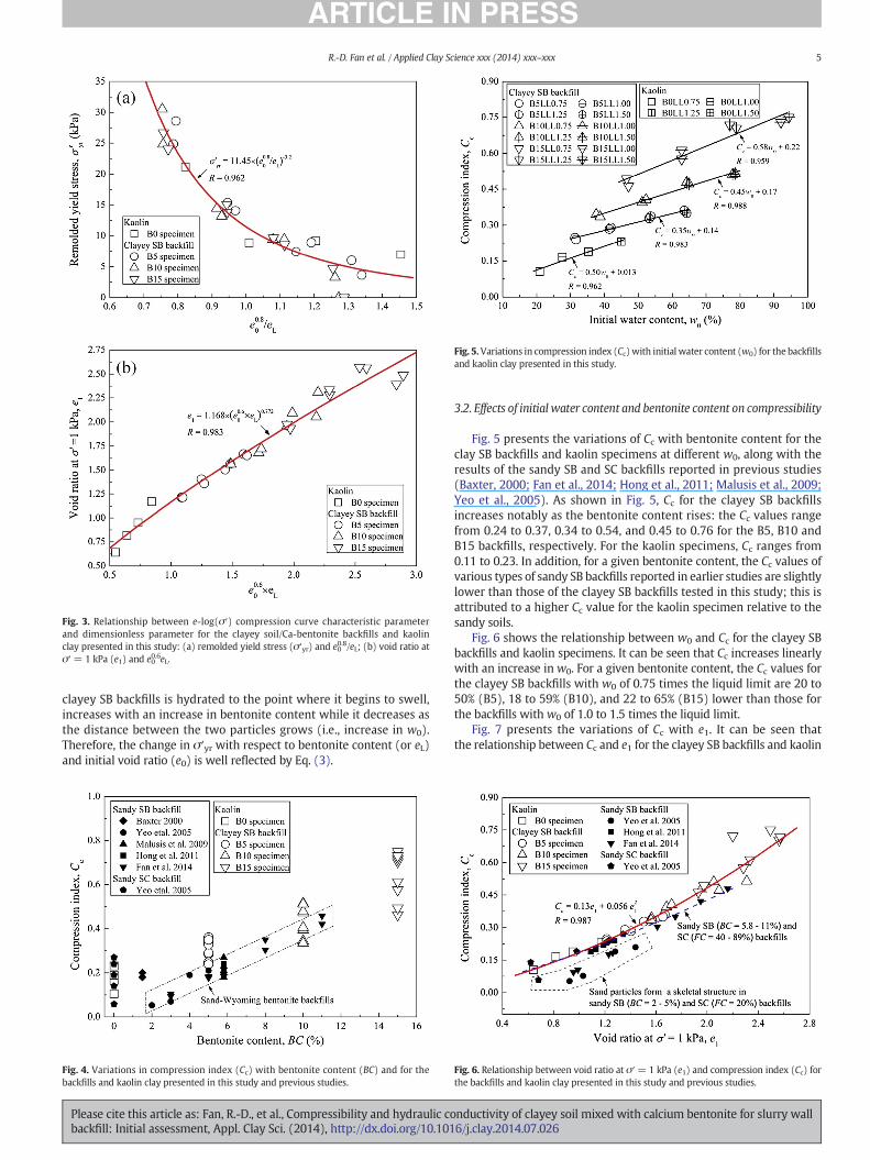
Fig. 3. Relationship between e-log(σ′) compression curve characteristic parameterand dimensionless parameter for the clayey soil/Ca-bentonite backfills and kaolinclay presented in this study: (a) remolded yield stress (σ′yr) and e0
0.8/eL; (b) void ratio atσ′ = 1 kPa (e1) and e0
0.6eL.
Fig. 5.Variations in compression index (Cc)with initial water content (w0) for the backfillsand kaolin clay presented in this study.
5R.-D. Fan et al. / Applied Clay Science xxx (2014) xxx–xxx
clayey SB backfills is hydrated to the point where it begins to swell,increases with an increase in bentonite content while it decreases asthe distance between the two particles grows (i.e., increase in w0).Therefore, the change in σ′yr with respect to bentonite content (or eL)and initial void ratio (e0) is well reflected by Eq. (3).
Fig. 4. Variations in compression index (Cc) with bentonite content (BC) and for thebackfills and kaolin clay presented in this study and previous studies.
Please cite this article as: Fan, R.-D., et al., Compressibility and hydraulic cobackfill: Initial assessment, Appl. Clay Sci. (2014), http://dx.doi.org/10.101
3.2. Effects of initial water content and bentonite content on compressibility
Fig. 5 presents the variations of Cc with bentonite content for theclay SB backfills and kaolin specimens at different w0, along with theresults of the sandy SB and SC backfills reported in previous studies(Baxter, 2000; Fan et al., 2014; Hong et al., 2011; Malusis et al., 2009;Yeo et al., 2005). As shown in Fig. 5, Cc for the clayey SB backfillsincreases notably as the bentonite content rises: the Cc values rangefrom 0.24 to 0.37, 0.34 to 0.54, and 0.45 to 0.76 for the B5, B10 andB15 backfills, respectively. For the kaolin specimens, Cc ranges from0.11 to 0.23. In addition, for a given bentonite content, the Cc values ofvarious types of sandy SB backfills reported in earlier studies are slightlylower than those of the clayey SB backfills tested in this study; this isattributed to a higher Cc value for the kaolin specimen relative to thesandy soils.
Fig. 6 shows the relationship between w0 and Cc for the clayey SBbackfills and kaolin specimens. It can be seen that Cc increases linearlywith an increase in w0. For a given bentonite content, the Cc values forthe clayey SB backfills with w0 of 0.75 times the liquid limit are 20 to50% (B5), 18 to 59% (B10), and 22 to 65% (B15) lower than those forthe backfills with w0 of 1.0 to 1.5 times the liquid limit.
Fig. 7 presents the variations of Cc with e1. It can be seen thatthe relationship between Cc and e1 for the clayey SB backfills and kaolin
Fig. 6. Relationship between void ratio at σ′= 1 kPa (e1) and compression index (Cc) forthe backfills and kaolin clay presented in this study and previous studies.
nductivity of clayey soil mixed with calcium bentonite for slurry wall6/j.clay.2014.07.026
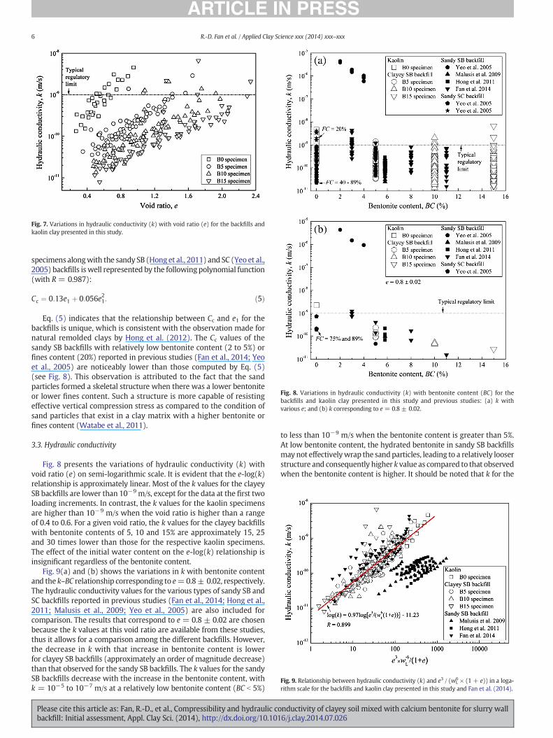
Fig. 7. Variations in hydraulic conductivity (k) with void ratio (e) for the backfills andkaolin clay presented in this study.
Fig. 8. Variations in hydraulic conductivity (k) with bentonite content (BC) for thebackfills and kaolin clay presented in this study and previous studies: (a) k withvarious e; and (b) k corresponding to e = 0.8 ± 0.02.
Fig. 9. Relationship between hydraulic conductivity (k) and e3 / (wL6 × (1 + e)) in a loga-
rithm scale for the backfills and kaolin clay presented in this study and Fan et al. (2014).
6 R.-D. Fan et al. / Applied Clay Science xxx (2014) xxx–xxx
specimens alongwith the sandy SB (Hong et al., 2011) and SC (Yeo et al.,2005) backfills is well represented by the following polynomial function(with R = 0.987):
Cc ¼ 0:13e1 þ 0:056e21: ð5Þ
Eq. (5) indicates that the relationship between Cc and e1 for thebackfills is unique, which is consistent with the observation made fornatural remolded clays by Hong et al. (2012). The Cc values of thesandy SB backfills with relatively low bentonite content (2 to 5%) orfines content (20%) reported in previous studies (Fan et al., 2014; Yeoet al., 2005) are noticeably lower than those computed by Eq. (5)(see Fig. 8). This observation is attributed to the fact that the sandparticles formed a skeletal structure when there was a lower bentoniteor lower fines content. Such a structure is more capable of resistingeffective vertical compression stress as compared to the condition ofsand particles that exist in a clay matrix with a higher bentonite orfines content (Watabe et al., 2011).
3.3. Hydraulic conductivity
Fig. 8 presents the variations of hydraulic conductivity (k) withvoid ratio (e) on semi-logarithmic scale. It is evident that the e-log(k)relationship is approximately linear. Most of the k values for the clayeySB backfills are lower than 10−9 m/s, except for the data at the first twoloading increments. In contrast, the k values for the kaolin specimensare higher than 10−9 m/s when the void ratio is higher than a rangeof 0.4 to 0.6. For a given void ratio, the k values for the clayey backfillswith bentonite contents of 5, 10 and 15% are approximately 15, 25and 30 times lower than those for the respective kaolin specimens.The effect of the initial water content on the e-log(k) relationship isinsignificant regardless of the bentonite content.
Fig. 9(a) and (b) shows the variations in k with bentonite contentand the k–BC relationship corresponding to e=0.8± 0.02, respectively.The hydraulic conductivity values for the various types of sandy SB andSC backfills reported in previous studies (Fan et al., 2014; Hong et al.,2011; Malusis et al., 2009; Yeo et al., 2005) are also included forcomparison. The results that correspond to e = 0.8 ± 0.02 are chosenbecause the k values at this void ratio are available from these studies,thus it allows for a comparison among the different backfills. However,the decrease in k with that increase in bentonite content is lowerfor clayey SB backfills (approximately an order of magnitude decrease)than that observed for the sandy SB backfills. The k values for the sandySB backfills decrease with the increase in the bentonite content, withk = 10−5 to 10−7 m/s at a relatively low bentonite content (BC b 5%)
Please cite this article as: Fan, R.-D., et al., Compressibility and hydraulic cobackfill: Initial assessment, Appl. Clay Sci. (2014), http://dx.doi.org/10.101
to less than 10−9 m/s when the bentonite content is greater than 5%.At low bentonite content, the hydrated bentonite in sandy SB backfillsmay not effectivelywrap the sandparticles, leading to a relatively looserstructure and consequently higher k value as compared to that observedwhen the bentonite content is higher. It should be noted that k for the
nductivity of clayey soil mixed with calcium bentonite for slurry wall6/j.clay.2014.07.026

Fig. 10. Relationship between the hydraulic conductivity (k) evaluated from theoedometer tests and the predicted hydraulic conductivity (kP) using Eq. (8).
7R.-D. Fan et al. / Applied Clay Science xxx (2014) xxx–xxx
clayey SB backfills containing 5% Ca-bentonite is nearly the same asthat of the sandy soil/Na-bentonite backfills with bentonite contentof 5% and 5.8% reported by Fan et al. (2014) and Hong et al. (2011),respectively. This leads to the conclusion that the clayey soil/Ca-bentonite backfill has the potential to be an effective alternativeto the conventional sandy soil/Na-bentonite backfill.
3.4. Predictive method for k
Several methods have been reported in published literaturefor predicting hydraulic conductivity of clays, and most of them areoriginated from Kozeny–Carman (KC) equation, Taylor (1948)'s method(e.g., Ma et al., 2014; Xu et al., 2012) and Nagaraj's method (Nagaraj andMiura, 2001). In this study, an empirical equation is assessed to predictthe k of the clayey SB backfills based also on the framework of KC equa-tion. The KC equation has been used to predict hydraulic conductivityfor most saturated soils including sandy soils and natural clays(Chapuis and Aubertin, 2003; Sanzeni et al., 2013; Shen and Xu, 2011).The KC equation is commonly used to estimate hydraulic conductivityand it is expressed by:
k ¼ Csγw
μw� e3
SSA2 1þ eð Þ ð6Þ
where Cs is the shape coefficient that reflects the pore shape and tortuos-ity of the channels, γw is the unit weight of water, μw is the dynamicviscosity of water, SSA is the specific surface area, and e is the voidratio. SSA values for the sandy SB or SC backfills are not available inprevious studies including Malusis et al. (2009) and Hong et al. (2011).Sanzeni et al. (2013) suggested that an inaccurate SSA value could leadto a significant discrepancy in the predicted k of clayey soils. To addressthese issues, it is proposed to replace the SSA in the original KC equationby a function ofwL in this study. This approach offers several advantages:(1) wL is a basic soil parameter that is easily determined using conven-tional laboratory testing methods; and (2) wL can be used to estimateSSA using various relationships, if needed (Chapuis and Aubertin, 2003).
Initially it is attempted to linearly fit log(k) estimated from theoedometer tests to a dimensionless parameter log[e3 / (wL
n × (1 + e))](n value varies from 1 to 8) using the Least-Square-Root method.The results show that n value of 6 yields a “besting fitting” conditionwhere the correlation coefficient (R) reaches the maximum whilethe standard deviation is the lowest. As a result, the log(k) of allclayey SB backfills as well as kaolin specimens can be described by log[e3 / (wL
6 × (1 + e))] using a unique linear function, as expressed bythe following equation with R value of 0.934:
log kð Þ ¼ 0:97 loge3
w6L 1þ eð Þ
" #−11:29 ð7Þ
where wL is in %. An attempt is also made to correlate log[e3 /(wL
6 × (1 + e))] to log(k) for the clayey SB backfills, kaolin specimensand sandy SB backfills reported by Fan et al. (2014), and the obtainedlog[e3 / (wL
n × (1 + e))] − log(k) relationship (R = 0.899) isexpressed by:
log kð Þ ¼ 0:97 loge3
w6L 1þ eð Þ
" #−11:23: ð8Þ
Since Eqs. (7) and (8) are very similar to each other, it is concludedthat Eq. (8) is capable of predicting k of the clayey SB backfills, kaolinspecimen, and the sandy SB backfills reported by Fan et al. (2014);whereas the data from Malusis et al. (2009) and Hong et al. (2011)were not included in this regression.
The predicted hydraulic conductivity (kp) values using Eq. (8) iscompared with those estimated from the oedometer tests, as shown
Please cite this article as: Fan, R.-D., et al., Compressibility and hydraulic cobackfill: Initial assessment, Appl. Clay Sci. (2014), http://dx.doi.org/10.101
in Fig. 10. Fig. 10 shows that the kp values are generally in the range of1/3 to 3 times the k measured during the oedometer tests, except forthe results of the first two loading increments. Therefore, it is concludedthat the proposedmethod (see Eq. (8)) is reasonably suitable to predictk for the clayey SB backfills with bentonite content that ranges from 5 to15%. In addition, the proposed method can also be used to predict the kof the sandy SB backfills reported by Fan et al. (2014); whereas it fails topredict k for the sandy SB backfills reported by Hong et al. (2011) andMalusis et al. (2009), as shown in Fig. 9.
Further study is needed to investigate a better approach that willaccurately predict hydraulic conductivity of not only the clayey SBbackfills and kaolin specimens presented in this study, but also thesandy SB backfills reported in previous studies.
4. Study limitations/future studies
In this study, the clayey soil/Ca-bentonite backfills were preparedwith initial water contents at 0.75, 1.00, 1.25, and 1.50 times theircorresponding liquid limits using distilled water and then they weresubjected to the oedometer tests. Based on the slump tests conductedsubsequently, the selected initial water contents are found unsuitableto yield the target slump (−ΔH= 100–150mm). Therefore, additionaltesting is warranted with the backfills prepared at other initial watercontents thatmeet theworkability requirement based on slump testing.In addition, the clayey soil/Ca-bentonite backfills in this study wereprepared by using distilled water, which deviates from the typicalfield practice. Hong et al. (2011) suggested blending sandy soil withhydrated Na-bentonite slurry to simulate typical field conditions.Hence, additional testing is recommended with the backfills preparedby replicating the typical field practice. Furthermore, k values in thisstudy are estimated indirectly based on the oedometer test results.Direct measurement of k of the backfills, based on either the rigid-wallpermeameter or the flexible-wall permeameter tests, is recommended.On-going additional research is aimed at addressing all of theselimitations.
5. Conclusions
Soil backfills that consist of sandy soil and Na-bentonite arecommonly used for vertical cut-off walls to control seepage andcontaminant migration. However, such materials may not be easilyavailable in some areas. This study investigates the soil backfills thatare prepared using clayey soil and Ca-bentonite (materials that arecommonly available in certain areas, especially in developing countriessuch as China and India). The clayey soil/Ca-bentonite backfills were
nductivity of clayey soil mixed with calcium bentonite for slurry wall6/j.clay.2014.07.026
8 R.-D. Fan et al. / Applied Clay Science xxx (2014) xxx–xxx
prepared using kaolin as clayey soil and Ca-bentonite as bentonite,and they were evaluated for the compressibility based on a series ofoedometer tests and also hydraulic conductivity based on its estimationestimated using the Terzaghi's one-dimensional consolidationtheory. The test results were compared with those for the sandy soil/Na-bentonite and also limited sand/clay backfills reported in previousstudies. The following conclusions can be drawn:
1. The compression curves of the clayey soil/Ca-bentonite backfills andkaolin specimens exhibited a noticeable inverse ‘S’ shape that isattributed to the existence of the remoldedyield stress (σ′yr). Theσ′yrand void ratio atσ′= 1kPa (denoted as e1) had unique relationshipswith the initial void ratio (e0) and void ratio at liquid limit (eL) givenby: σ′yr = 11.45 × (e00.8 / eL)−3.2 and e1 = 1.168 × (e00.6 × eL)0.772.
2. The compressibility of the clayey soil/Ca-bentonite backfills wassignificantly affected by the initial water content and bentonitecontent. The compression index (Cc) obtained from this studyand previous studies had a unique relationship with e1 givenby: Cc = 0.13e1 + 0.056e12.
3. The hydraulic conductivity values for the clayey soil/Ca-bentonitebackfills were significantly affected by the bentonite content in therange of 5 to 15%. Most of the hydraulic conductivity values for thebackfills presented in this study are lower than 10−9m/s. The resultsdemonstrate that clayey soil/Ca-bentonite backfills can be applied inthe construction of soil–bentonite vertical cutoff walls.
4. Two empirical equations, namely the Sivapullaiah et al.'s (2000)method and the newly proposed method based on the frameworkof Kozeny–Carman equation, were applied to predict the hydraulicconductivity values for the clayey soil/Ca-bentonite backfills. Theresults indicate that the predicted hydraulic conductivity valuesusing the two proposed equations were within a range of 1/3 to 3times those obtained from the oedometer tests. The proposed newmethod is better suited to estimate the hydraulic conductivity valuesfor both clayey soil/Ca-bentonite backfills in this study and sandysoil/Na-bentonite backfills reported by previous studies.
Acknowledgments
The authors are grateful for the financial support of the NationalNatural Science Foundation of China (Grant Nos. 51278100 and41330641), Natural Science Foundation of Jiangsu Province(BK2012022), Key Laboratory of Geotechnical and UndergroundEngineering Foundation (Tongji University) (Grant No. KLE-TJGE-B1202) and Scientific Research Foundation of Graduate School ofSoutheast University (Grant No. YBJJ1343).
References
ASTM, 2007. Standard Test Method for pH of Soils. D 4972 American Society for Testingand Materials, Philadelphia.
ASTM, 2010a. Standard Test Methods for Specific Gravity of Soil Solids by WaterPycnometer. D 854 American Society for Testing and Materials, Philadelphia.
ASTM, 2010b. Standard Test Methods for Liquid Limit, Plastic Limit, and Plasticity Index ofSoils. D 4318 American Society for Testing and Materials, Philadelphia.
ASTM, 2010c. Standard Test Method for Measuring the Exchange Complex and CationExchange Capacity of Inorganic Fine-Grained Soils. D 7503 American Society forTesting and Materials, Philadelphia.
ASTM, 2011a. Standard Test Methods for One-dimensional Consolidation Properties ofSoils Using Incremental Loading. D 2435 American Society for Testing and Materials,Philadelphia.
ASTM, 2011b. Standard Practice for Classification of Soils for Engineering Purposes(Unified Soil Classification System). D 2487 American Society for Testing andMaterials, Philadelphia.
Baxter, D.Y., 2000. Mechanical Behavior of Soil–bentonite Cutoff Walls. PhD DissertationVirginia Polytechnic Institute and State University, Blacksburg, Virginia, USA.
Castelbaum, D.,Shackelford, C.D., 2009. Hydraulic conductivity of bentonite slurry mixedsands. J. Geotech. Geoenviron. Eng. ASCE 135, 1941–1956.
Cerato, A.,Lutenegger, A., 2004. Determining intrinsic compressibility of fine-grained soils.J. Geotech. Geoenviron. Eng. ASCE 130 (8), 872–877.
Cerato, A.B.,Luteneggerl, A.J., 2002. Determination of surface area of fine-grained soils bythe ethylene glycol monoethyl ether (EGME) method. Geotech. Test. J. ASTM 25 (3),315–321.
Please cite this article as: Fan, R.-D., et al., Compressibility and hydraulic cobackfill: Initial assessment, Appl. Clay Sci. (2014), http://dx.doi.org/10.101
Chai, J., Miura, N., Zhu, H., 2004. Compression and consolidation characteristics ofstructured natural clay. Can. Geotech. J. 41 (6), 1250–1258.
Chapuis, R.P., 2012. Predicting the saturated hydraulic conductivity of soils: a review. Bull.Eng. Geol. Environ. 71 (3), 401–434.
Chapuis, R.P., Aubertin, M., 2003. On the use of the Kozeny–Carman equation to predictthe hydraulic conductivity of soils. Can. Geotech. J. 40 (3), 616–628.
D'Appolonia, D.J., 1980. Soil–bentonite slurry trench cutoffs. J. Geotech. Eng. Div. 106 (4),399–417.
Du, Y.J., Hayashi, S., 2006. A study on sorption properties of Cd2+ on Ariake clay forevaluating its potential use as a landfill barrier material. Appl. Clay Sci. 32 (1–2),14–24.
Du, Y.J., Shen, S.L., Liu, S.Y., Hayashi, S., 2009. Contaminant mitigating performance ofChinese standard municipal solid waste landfill liner systems. Geotext. Geomembr.27 (3), 232–239.
Du, Y.J.,Wei, M.L., Jin, F.,Liu, Z.B., 2013. Stress–strain relation and strength characteristicsof cement treated zinc-contaminated clay. Eng. Geol. 167, 20–26.
Du, Y.J., Jiang, N.J., Liu, S.Y., Jin, F., Singh, D.N., Puppala, A.J., 2014a. Engineering propertiesand microstructural characteristics of cement-stabilized zinc-contaminated kaolin.Can. Geotech. J. 51 (3), 289–302.
Du, Y.J.,Wei, M.L., Reddy, K.R., Liu, Z.P., Jin, F., 2014b. Effect of acid rain pH on leachingbehavior of cement stabilized lead-contaminated soil. J. Hazard. Mater. 271, 131–140.
Evans, J.C.,Ryan, C., 2005. Time-dependent strength behavior of soil-bentonite slurry wallbackfill. GeoFrontiers 2005:Waste Containment and Remediation. In: Alshawabkeh, A.,Benson, C.H., Culligan, P.J., Evans, J.C., Gross, B.A., Narejo, D., Reddy, K.R., Shackelford,C.D., Zornberg, J.G. (Eds.), ASCE GSP 142. ASCE, Reston, VA, pp. 1–9.
Evans, J.C., Costa, M.J., Cooley, B., 1995. The state-of-stress in soil–bentonite slurrytrench cutoff walls. In: Acar, Y.N., Daniel, D.E. (Eds.), Geoenvironment 2000:Characterization, Containment, Remediation, and Performance in EnvironmentalGeotechnicsASCE GSP. 46. ASCE, Reston, VA, pp. 1173–1191.
Fan, R.D., Du, Y.J., Chen, Z.B., Liu, S.Y., 2013. Compressibility and permeabilitycharacteristics of lead contaminated soil–bentonite vertical cutoff wall backfills.Chin. J. Geochem. Eng. 35 (5), 841–848.
Fan, R.D.,Du, Y.J., Liu, S.Y.,Chen, Z.B., 2014. Compressibility and hydraulic conductivity ofsand/clay–bentonite backfills. In: Reddy, K.R., Shen, S.J. (Eds.), Geo-Shanghai 2014:Geoenvironmental EngineeringASCE GSP. 241. ASCE, Reston, VA, pp. 21–30.
Filz, G.M., 1996. Consolidation stresses in soil–bentonite backfilled trenches. Proceedingsof the 2nd International Congress on Environmental Geotechnics, pp. 497–502(Osaka, Japan).
Grim, R.E., 1968. Clay Mineralogy, 2nd ed. McGraw Hill, New York.Hong, Z.S.,Yin, J.,Cui, Y.J., 2010. Compression behaviour of reconstituted soils at high initial
water contents. Geotechnique 60 (9), 691–700.Hong, C.S.,Shackelford, C.D.,Malusis, M.A., 2011. Consolidation and hydraulic conductivity
of zeolite amended soil–bentonite backfills. J. Geotech. Geoenviron. Eng. ASCE 138(1), 15–25.
Hong, Z.S.,Zeng, L.L.,Cui, Y.J.,Cai, Y.Q.,Lin, C., 2012. Compression behaviour of natural andreconstituted clays. Geotechnique 62 (4), 291–301.
Horpibulsuk, S., Shibuya, S., Fuenkajorn, K., Katkan, W., 2007. Assessment of engineeringproperties of Bangkok clay. Can. Geotech. J. 44 (2), 173–187.
Hu, L.,Wu, X.,Liu, Y.,Meegoda, J.N.,Gao, S., 2010. Physical modeling of air flow during airsparging remediation. Environ. Sci. Technol. 44 (10), 3883–3888.
Karakaya, M.Ç.,Karakaya, N.,Bakır, S., 2011. Some properties and potential applications ofthe Na- and Ca-bentonites of ordu (N.E. Turkey). Appl. Clay Sci. 54 (2), 159–165.
Lo, I.M.C.,Yang, X., 2001. Use of organoclay as secondary containment for gasoline storagetanks. J. Environ. Eng. 127 (2), 154–161.
Ma, L., Xu, Y.S., Shen, S.L., Sun, W.J., 2014. Evaluation of the hydraulic conductivity ofaquifers with piles. Hydrogeol. J. 22 (2), 371–382.
Malusis, M.A.,McKeehan, M.D., 2013. Chemical compatibility of model soil–bentonitebackfill containing multiswellable bentonite. J. Geotech. Geoenviron. Eng. ASCE 139(2), 189–198.
Malusis, M.A.,Barben, E.J.,Evans, J.C., 2009. Hydraulic conductivity and compressibility ofsoil–bentonite backfill amended with activated carbon. J. Geotech. Geoenviron. Eng.ASCE 135 (5), 664–672.
Mishra, A.K., Ohtsubo, M., Li, L.Y., Higashi, T., Park, J., 2009. Effect of salt of variousconcentrations on liquid limit, and hydraulic conductivity of different soil–bentonitemixtures. Environ. Geol. 57 (5), 1145–1153.
Mishra, A.K., Ohtsubo, M., Li, L., Higashi, T., 2011. Controlling factors of the swelling ofvarious bentonites and their correlations with the hydraulic conductivity ofsoil–bentonite mixtures. Appl. Clay Sci. 52 (1–2), 78–84.
Mitchell, J.K., Soga, K., 2005. Fundamentals of Soil Behavior, 3rd ed. John Wiley and SonsInc., New York.
Nagaraj, T.S.,Miura, N., 2001. Soft Clay Behaviour: Analysis and Assessment. A. A BalkemaPublishers, The Netherlands.
Ruffing, D.G., Evans, J.C.,Malusis, M.A., 2010. Prediction of earth pressures in soil–bentonite cutoff walls. In: Fratta, D.O., Puppala, A.J., Muhunthan, B. (Eds.),GeoFlorida 2010: Advances in Analysis, Modeling and DesignASCE GSP. 199.ASCE, pp. 2416–2425.
Santamarina, J.C.,Klein, K.A., Palomino, A.,Guimaraes, M.S., 2002. Micro-scale aspects ofchemical–mechanical coupling: interparticle forces and fabric. In: Di Maio, C.,Hueckel, T., Loret, B. (Eds.), Chemo-mechanical Coupling in Clays: FromNano-structure to Engineering Applications. A.A. Balkema Publishers, TheNetherlands, pp. 47–64.
Sanzeni, A., Colleselli, F.,Grazioli, D., 2013. Specific surface and hydraulic conductivity offine-grained soils. J. Geotech. Geoenviron. Eng. ASCE 139 (10), 1828–1832.
Sharma, H.D.,Reddy, K.R., 2004. Geoenvironmental Engineering: Site Remediation, WasteContainment, and Emerging Waste Management Technologies. John Wiley and SonsInc., New York.
nductivity of clayey soil mixed with calcium bentonite for slurry wall6/j.clay.2014.07.026

9R.-D. Fan et al. / Applied Clay Science xxx (2014) xxx–xxx
Shen, S.L.,Miura, N.,Koga, H., 2003. Interaction mechanism between deep mixing columnand surrounding clay during installation. Can. Geotech. J. 40 (2), 293–307.
Shen, S.L.,Han, J.,Du, Y.J., 2008. Deep mixing induced property changes in surroundingsensitive marine clays. J. Geotech. Geoenviron. Eng. ASCE 134 (6), 845–853.
Shen, S.L.,Xu, Y.S., 2011. Numerical evaluation of land subsidence induced by groundwa-ter pumping in Shanghai. Canadian Geotechnical Journal 48 (9), 1378–1392.
Sivapullaiah, P., Sridharan, A., Stalin, V., 2000. Hydraulic conductivity of bentonite–sandmixtures. Can. Geotech. J. 37 (2), 406–413.
Sreedharan, V.,Puvvadi, S., 2013. Compressibility behaviour of bentonite and organicallymodified bentonite slurry. Geotechnique 63 (10), 876–879.
Sridharan, A.,Rao, G.V., 1973. Mechanisms controlling volume change of saturated claysand the role of the effective stress concept. Geotechnique 23 (3), 359–382.
Taylor, D.W., 1948. Fundamentals of Soil Mechanics. John Wiley & Sons Inc., New York.Terzaghi, K., Peck, R.B.,Mesri, G., 1996. Soil Mechanics in Engineering Practice, 3rd ed.
Wiley-Interscience, Inc., New York.Watabe, Y., Yamada, K., Saitoh, K., 2011. Hydraulic conductivity and compressibility of
mixtures of Nagoya clay with sand or bentonite. Geotechnique 61 (3), 211–219.
Please cite this article as: Fan, R.-D., et al., Compressibility and hydraulic cobackfill: Initial assessment, Appl. Clay Sci. (2014), http://dx.doi.org/10.101
Xu, Y.S.,Ma, L., Shen, S.L., Sun, W.J., 2012. Evaluation of land subsidence by consideringunderground structures that penetrate the aquifers of Shanghai, China. Hydrogeol.J. 20 (8), 1623–1634.
Xue, Q., Li, J.S., Liu, L., 2013. Experimental study on anti-seepage grout made of leachatecontaminated clay in landfill. Appl. Clay Sci. 80–81, 438–442.
Yeo, S.-S.,Shackelford, C.D.,Evans, J.C., 2005. Consolidation and hydraulic conductivity ofnine model soil–bentonite backfills. J. Geotech. Geoenviron. Eng. ASCE 131 (10),1189–1198.
Yong, R.N.,Ouhadi, V.R.,Goodarzi, A.R., 2009. Effect of Cu2+ ions and buffering capacity onsmectite microstructure and performance. J. Geotech. Geoenviron. Eng. ASCE 135(12), 1981–1985.
Yukselen-Aksoy, Y.,Reddy, K.R., 2013. Electrokinetic delivery and activation of persulfatefor oxidation of PCBs in clayey soils. J. Geotech. Geoenviron. Eng. ASCE 139 (1),175–184.
nductivity of clayey soil mixed with calcium bentonite for slurry wall6/j.clay.2014.07.026


![Anomalous compressibility effects and superconductivity of EuFe[subscript 2]As[subscript 2] under high pressures](https://static.fdokumen.com/doc/165x107/6317be2e65e4a6af370f19d2/anomalous-compressibility-effects-and-superconductivity-of-eufesubscript-2assubscript.jpg)