Component-based robotic engineering (Part I) [Tutorial
12
IEEE ROBOTICS AND AUTOMATION MAGAZINE, VOL. XX, NO. 4, DECEMBER 2009 1 Component-based Robotic Engineering Part I: Reusable building blocks Davide Brugali, Member, IEEE and Patrizia Scandurra Abstract— This article is the first of a two-part series intended as an introduction to Component-based Software Engineering (CBSE) in Robotics. In Part I, we regard a component as a piece of software that implements robotic functionality (e.g. path planning). The focus is on design principles and implementation guidelines that enable the development of reusable and maintainable software building blocks, which can be assembled to build robotic applications. In Part II, we will discuss the role of software components as architectural units of large, possibly distributed, software- intensive robotic systems. The focus is on technologies to manage the heterogeneity of hardware, computational, and communica- tion resources and on design techniques to assemble components into systems. Index Terms—Software Engineering, Reuse, Architecture, Component. I. I NTRODUCTION Software for autonomous robotics systems is typically em- bedded, concurrent, real-time, distributed, and data intensive and must guarantee system properties, such as safety, reliabil- ity, and fault tolerance. Software requirements of robotic control applications are similar, to a large extent, to those of software systems in other domains, such as avionics, automotive, factory automation, telecommunication, and even large scale information systems. In these domains, it can be observed a strong move toward the application of software engineering principles to significantly reduce the effort to develop new software applications by promoting the systematic and routine use of existing solutions in the development of new systems. Component-Based Software Engineering (CBSE) [1], [2] is an approach that has arisen in the software engineering community in the last decade (see Sidebar: An historical overview of software reuse). It aims to shift the emphasis in system-building from traditional requirement analysis, system design and implementation to composing software systems from a mixture of reusable off-the-shelf and custom-built components. Such an approach improves software development by reduc- ing the amount of code that has to be written by the application designer. In particular, reusing previously-existing software components greatly reduces time to test new applications. When a component is used in a large number of systems by different developers, the knowledge about the component D. Brugali and P. Scandurra are with the Department of Computer Science and Mathematics, Universita’ degli Studi di Bergamo, Dalmine, Italy e-mail: {davide.brugali, patrizia.scandurra}@unibg.it. Manuscript received xxx xx, 2009; revised xxx xx, 2009. usage, robustness and efficiency is available in the user com- munity. As such, software reuse promotes the development of maintainable, reliable, and affordable software systems. In Robotics there is a pressing need to regard the con- struction of new software applications as the composition of reusable building blocks [3]. Software reuse allows researchers to more easily keep up the pace of robotics research, since they do not have to constantly re-write each other’s code. For example, experts in motion planning could experiment new path planning algorithms for a mobile robot relying on obstacle avoidance and self-localization functionalities encapsulated in components off-the-shelf. Reuse of consolidated and shared components allows different teams to test their algorithms on common benchmarks in order to assess performance objec- tively. Nevertheless, software reuse and component-based devel- opment are not yet state-of-the-practice software develop- ment approaches in robotics. Today, most robotic research and development is still based on custom designed software architectures invented from scratch each time. Many valuable robotic applications are monolithic systems that have been developed to solve a specific class of problems. As a result, a huge corpus of software applications, which implement the entire spectrum of robot functionality, algorithms, and control paradigms, are potentially available in robotic research laboratories. Unfortunately, they are often not reusable even in slightly different application scenarios because they are tight to specific robot hardware, processing platforms, and communication infrastructures and because the assumptions and constraints about tasks and operational environments are hidden and hard coded in the software implementation. This situation is alleviated by an emerging consciousness in the robotic community of the role that software plays in the construction of effective, reliable, safe, and economically feasible robotic systems. During the last very few years many ideas from software engineering (modularity, informa- tion hiding, distributed middleware) have progressively been introduced in the construction of robotic software systems, to simplify their development, and to improve their quality as documented in [4] and [5]. The aim of this paper is to contribute to raise awareness of the great potential offered by state-of-the-art software en- gineering techniques and methods to develop complex robotic systems. The paper is structured as follows. Section II analyzes the factors that enable software reuse, such as portability, interoperability, and flexibility of software systems.
-
Upload
mundusphd-interzones -
Category
Documents
-
view
4 -
download
0
Transcript of Component-based robotic engineering (Part I) [Tutorial
IEEE ROBOTICS AND AUTOMATION MAGAZINE, VOL. XX, NO. 4, DECEMBER 2009 1
Component-based Robotic EngineeringPart I: Reusable building blocks
Davide Brugali, Member, IEEE and Patrizia Scandurra
Abstract— This article is the first of a two-part series intendedas an introduction to Component-based Software Engineering(CBSE) in Robotics.
In Part I, we regard a component as a piece of software thatimplements robotic functionality (e.g. path planning). The focusis on design principles and implementation guidelines that enablethe development of reusable and maintainable software buildingblocks, which can be assembled to build robotic applications.
In Part II, we will discuss the role of software componentsas architectural units of large, possibly distributed, software-intensive robotic systems. The focus is on technologies to managethe heterogeneity of hardware, computational, and communica-tion resources and on design techniques to assemble componentsinto systems.
Index Terms—Software Engineering, Reuse, Architecture,Component.
I. INTRODUCTION
Software for autonomous robotics systems is typically em-bedded, concurrent, real-time, distributed, and data intensiveand must guarantee system properties, such as safety, reliabil-ity, and fault tolerance.
Software requirements of robotic control applications aresimilar, to a large extent, to those of software systems in otherdomains, such as avionics, automotive, factory automation,telecommunication, and even large scale information systems.In these domains, it can be observed a strong move toward theapplication of software engineering principles to significantlyreduce the effort to develop new software applications bypromoting the systematic and routine use of existing solutionsin the development of new systems.
Component-Based Software Engineering (CBSE) [1], [2]is an approach that has arisen in the software engineeringcommunity in the last decade (see Sidebar: An historicaloverview of software reuse). It aims to shift the emphasis insystem-building from traditional requirement analysis, systemdesign and implementation to composing software systemsfrom a mixture of reusable off-the-shelf and custom-builtcomponents.
Such an approach improves software development by reduc-ing the amount of code that has to be written by the applicationdesigner. In particular, reusing previously-existing softwarecomponents greatly reduces time to test new applications.When a component is used in a large number of systemsby different developers, the knowledge about the component
D. Brugali and P. Scandurra are with the Department of Computer Scienceand Mathematics, Universita’ degli Studi di Bergamo, Dalmine, Italy e-mail:{davide.brugali, patrizia.scandurra}@unibg.it.
Manuscript received xxx xx, 2009; revised xxx xx, 2009.
usage, robustness and efficiency is available in the user com-munity. As such, software reuse promotes the development ofmaintainable, reliable, and affordable software systems.
In Robotics there is a pressing need to regard the con-struction of new software applications as the composition ofreusable building blocks [3]. Software reuse allows researchersto more easily keep up the pace of robotics research, sincethey do not have to constantly re-write each other’s code. Forexample, experts in motion planning could experiment newpath planning algorithms for a mobile robot relying on obstacleavoidance and self-localization functionalities encapsulated incomponents off-the-shelf. Reuse of consolidated and sharedcomponents allows different teams to test their algorithms oncommon benchmarks in order to assess performance objec-tively.
Nevertheless, software reuse and component-based devel-opment are not yet state-of-the-practice software develop-ment approaches in robotics. Today, most robotic researchand development is still based on custom designed softwarearchitectures invented from scratch each time. Many valuablerobotic applications are monolithic systems that have beendeveloped to solve a specific class of problems. As a result,a huge corpus of software applications, which implementthe entire spectrum of robot functionality, algorithms, andcontrol paradigms, are potentially available in robotic researchlaboratories.
Unfortunately, they are often not reusable even in slightlydifferent application scenarios because they are tight to specificrobot hardware, processing platforms, and communicationinfrastructures and because the assumptions and constraintsabout tasks and operational environments are hidden and hardcoded in the software implementation.
This situation is alleviated by an emerging consciousnessin the robotic community of the role that software plays inthe construction of effective, reliable, safe, and economicallyfeasible robotic systems. During the last very few yearsmany ideas from software engineering (modularity, informa-tion hiding, distributed middleware) have progressively beenintroduced in the construction of robotic software systems, tosimplify their development, and to improve their quality asdocumented in [4] and [5].
The aim of this paper is to contribute to raise awarenessof the great potential offered by state-of-the-art software en-gineering techniques and methods to develop complex roboticsystems.
The paper is structured as follows. Section II analyzesthe factors that enable software reuse, such as portability,interoperability, and flexibility of software systems.

IEEE ROBOTICS AND AUTOMATION MAGAZINE, VOL. XX, NO. 4, DECEMBER 2009 2
Section III introduces the concept of software componentas unit of encapsulation of robotic functionality that can becomposed as building block of various robotic system, presentsa working example that will be used throughout the paper,and illustrates the fundamental design principle of CBSE,i.e the separation of component specification and componentimplementation.
Section IV presents the key ingredients of a componentspecification, i.e. interfaces and contract, and discusses somesoftware engineering priciples to design the specification ofreusable components.
Finally, Section V illustrates techniques to implement com-ponent specifications and, in particular, the concept of Com-ponent Framework as a mean to enhance robotic systemsflexibility.
II. REUSABLE SOFTWARE BUILDING BLOCKS
Within software engineering, a software architecture istypically defined as: ”the structure or structures of the system,which comprise software components, the externally visibleproperties of those components, and the relationships amongthem” [6]. Here components are units of implementation andrepresent a code-based way of considering the system. Thus, arobot software architecture describes the decomposition of therobot control system into a collection of software components,the encapsulation of functionality and control activities intocomponents, and the flow of data and control informationamong components. The design or selection of the softwarearchitecture takes specifically into account non-functionalrequirements of a robotic software system (maintainability,portability, interoperability, scalability, etc.) that is those -ilitiesthat characterize software quality and enable software reuse.
As an example, figure 1 depicts the CLARAty [7] controlarchitecture that partition robot capabilities into two hierarchi-cal layers: the Decision Layer and the Functional Layer. Eachlayer groups software components that implements specificalgorithms, such as those for task planning, navigation, loco-motion, pose estimation, sensor processing, and motor control.
The mapping of robot functionality to components, thatis, how algorithms, data structures, synchronization and com-munication mechanisms are packaged together, is a crucialdesign step as it greatly influences the reusability of thosefunctionality.
Ideally, components embedding common robot functionalityshould be reusable in different robot control systems andapplication scenarios, and thus they should not be bounded tospecific robotic hardware, software development technologies,or control paradigms. For example, a fully reusable componentimplementing a mobile robot navigation algorithm should bedesigned without implicit assumptions about the operationalsetting (e.g. stand alone application or distributed system),the possible use (e.g. map building or object tracking), therobot morphology (e.g. size and shape), and even its kinematicstructure (e.g. number and type of wheels).
In reality, designing reusable components consists in findingthe best trade-off between being too specific (less reusable)and too generic (less valuable). Three aspects of a reusable
Fig. 1. The CLARAty architecture
component are equally important: quality, technical reusabilityand functional reusability.
The quality of a robotic software component is typicallyexpressed in terms of its computational performance (e.g. thetime required to process a video frame), efficiency (e.g. theamount of memory used to build a probabilistic roadmap),or reliability (e.g. the probability of returning a sensor mea-sure when needed). Quality can be assessed here and now,provided that adequate metrics and benchmarks are available(e.g a standard reference image for testing different edgedetection algorithms or different implementations of the samealgorithm).
Technical reusability of a robotic software component ismainly concerned with its degree of usability and interoper-ability. The source code of a software component is not usableif it is not properly documented or if the cost of its exploitation(e.g. integration with the rest of the system) is too high. Insome cases, it is more convenient to design and build the com-ponent from scratch. Interoperability is the ability of two ormore systems or components to exchange information and touse the information that has been exchanged. Interoperabilitywith third-party systems can be achieved by designing well-defined component interfaces, protocols, and data exchangeformats, by clearly separating component interface and im-plementation, and possibly by conforming the component’sspecification to existing standards.
From a functional point of view, reusable componentscan be classified with respect to application domains intotwo broad categories (see Figure 2) horizontal and verticalcomponents. The term domain is used to denote or groupa set of systems (e.g. mobile robots, humanoid robots) orapplications (service robotics, space robotics, etc.) that ex-hibit similar characteristics or fulfill similar requirements.Horizontal components provide functionality to a variety ofapplications that may implement totally different use cases.Typical horizontal components provide system services suchas interfacing to hardware devices, providing computational orcommunication services, or implementing mathematic func-

IEEE ROBOTICS AND AUTOMATION MAGAZINE, VOL. XX, NO. 4, DECEMBER 2009 3
Fig. 2. The scope of reuse: horizontal vs. vertical components
tions. Vertical components capture a company, organization,or research community know-how in specific functional areas,such as kinematics, motion planning, deliberative control andaddress the requirements of target application domains, suchas service robotics, space robotics, or humanoid robotics. Ithas been reported [8] that vertical components contribute themost to reuse up to 65% of any application, while horizontalcomponents typically no more than 20%. Functional reusabil-ity requires insight into the future and a clear understandingof how robotic systems integrating reusable components willbe likely to evolve.
The three reusability aspects described above are equallyimportant [9]. The highest-quality component will never bereused if the function it offers is useless. The most neededcomponent will never be reused if it is unreliable, slow, hard tounderstand. The highest-quality and most needed componentwill never be reused if the interface is not compatible.
III. COMPONENT-BASED SOFTWARE ENGINEERING
Out of the multiple definitions for software components wecan find in literature, in this tutorial we adopt the one givenin [2] as it illustrates the key factors that enable componentreusability: “A software component is a unit of compositionwith contractually specified interfaces and explicit contextdependencies only. A software component can be deployedindependently and is subject to composition by third parties”.
In this paper we illustrate design principles that mostlyrefer to the concepts expressed in the first sentence of thisdefinition, i.e.e contractually specified interfaces and explicitcontext dependencies. The second part of this tutorial willaddress issues related to the components composition anddeployment.
Thus, in the rest of this paper, we regard components asimplementation software units, which developers can reuse todevelop a variety of different applications more quickly thanwriting all of the code from scratch for each application. Wewill refer to Object Oriented Technology (see Sidebar), whichis not a necessary paradigm to implement components but themost convenient one.
Fig. 3 shows the key ingredients to realize software com-ponents.
A software component comes with a well-defined compo-nent specification, which is an abstraction from the details(data structures and operations) of its (possibly many) imple-mentations.
Fig. 3. A component’s key ingredients
A component specification explicitly declares which func-tionality (provided interfaces) are offered to its clients1, thepublic obligations (contracts) with its clients in the form ofvarious kinds of constraints (e.g. preconditions, postconditions,invariants) on how to access the functionality, and the de-pendencies (required interfaces)to the functionality that aredelegated to other components.
A component implementation, on the other hand, defineshow the component supports those features and obligations interms of a collaborative structure of realizing objects (classinstances) and algorithms implementing the functionality de-clared in the component specification.
Separating component specification from its implementationis desirable for achieving modular, interoperable, and exten-sible software and to allow independent evolution of clientand provider components. If client code depends only onthe interfaces to a component and not on the component’simplementation, a different implementation can be substitutedwithout affecting client code. Furthermore, the client codecontinues to work correctly if the component implementationis upgraded to support an extended specification.
CBSE defines a set of principles that help software devel-oper to design components that are effectively reusable. Weillustrate and exemplify them in the following sections.
A. A working example
Motion planning for autonomous mobile manipulators isa robot functionality that is realized by an integrated set ofalgorithms, such as collision checking, configuration sampling,and path planning. Several implementations of these algo-rithms are available as open source software library (see forexample, MPKit [10] and MSL [11]). In the context of theEU project BRICS (http://www.best-of-robotics.org), we arecurrently contributing to the design of software componentsthat offer a reusable environment to embed the most prominentmotion planning algorithms found in literature [12]. In this pa-per, we take some of our recent results to exemplify the designprinciples illustrated in the following sections. In particular, we
1We refer here to the term client to denote code invoking an operation onsome component, not necessarily in a distributed environment.

IEEE ROBOTICS AND AUTOMATION MAGAZINE, VOL. XX, NO. 4, DECEMBER 2009 4
Fig. 4. Motion planning components interconnected by means of providedand required interfaces. A complete circle (a.k.a lollipop) represents aninterface that the component provides. A half circle (a.k.a. sockets) representsan interface that the component requires. In both cases, the interface’s nameis placed near the interface symbol itself. A dependency arrow comes out ofthe requiring socket towards the provider’s lollipop
refer to the design of four major components (see Figure 4),i.e. Cartesian Space, Configuration Space, Collision Checker,and Path Planner.
Component Cartesian Space encapsulates the data struc-tures that store the geometric representation of the robot and itssurrounding environment. It provides information about objectshapes and positions and geometric elaboration services, suchas compute the relative position of two objects.
Component Configuration Space encapsulates the datastructures that define a robot’s configuration space and pro-vides services such as sampling robot configurations, interpo-lating between two configurations, and measuring the distancebetween two configurations.
Component Collision Checker checks if a given configura-tion is obstacle-free. It requires access to the information thatdefine shape and position of every object in the environment.In the example depicted in Figure 4, these information areprovided by Component Cartesian Space.
Component Path Planner computes a robot path betweena start and an end robot configuration. Typical path planningalgorithms, such as Probabilistic Roadmaps [13], sample therobot configuration space and check if a given configuration isobstacle free. For this purpose, in Figure 4, the Path Plannercomponent uses the services provided by the ConfigurationSpace and the Collision Checker components.
IV. COMPONENT SPECIFICATION
The specification of a software component is the key to itssuccessful use as a part in a larger piece of software. In thissection, we introduce interface design concepts and guidelines[14] first and then discuss some relevant aspects related tointerface contracts.
Interfaces are the external visible parts of the componentsand components interact with each other through interfaces.Interfaces support the information hiding and protect clientcode from changes in the component implementation. A givencomponent may implement more than one interface and an in-terface may be implemented by a number of different compo-nents. For example, interface CollisionCkecking could
be implemented by different components, each one embeddinga specific algorithm and specific internal representations ofobstacles and robots (see [15] for a comprehensive overviewof collision checking libraries).
A. Provided and required interfaces
A component has one or more provided and/or requiredinterfaces. The provided interfaces of a component are theset of interfaces realized by the component. They representthe contractually specified functionality that the componentoffers to their clients. The required interfaces, instead, specifyfunctionality and resources that the component needs in orderto perform its own functions and fulfill its own obligationsto its clients. A required interface of a component denotesan explicit context2 dependency, that is a usage relationshipbetween the component’s implementation and the implemen-tation of those components implementing the correspondingprovided interfaces.
Components are interconnected to build systems by wiringtogether their required and provided interfaces.
The diagram in Figure 4 shows provided and requiredinterfaces of each component using the UML ball-and-socket notation. In particular, the Path Planner pro-vides the PathPlanning interface and requires theConfigurationSampling and CollisionCheckinginterfaces. This means that the Path Planner is able toplan robot paths provided that it is interconnected to twocomponents, which are responsible for sampling valid robotconfigurations and checking if a given configuration is colli-sion free.
B. Service interfaces and data interfaces
Interfaces can be classified in data interfaces and ser-vice interfaces. Data interface expose state information ofcomponents and make it available to its clients. Data inter-faces typically contain getter/setter operations for retrievingor set values of attributes. For example (see Figure 4), inter-face SpaceBrowsing provides access to the internal stateof component Cartesian Space and returns informationabout shape and position of objects located in the robotoperational environment.
Data interfaces may also specify attributes as abstract prop-erties implying that the realizing component should explicitlymaintain information corresponding to the type and multiplic-ity of the attribute and facilitate retrieval and modificationof that information. If an interface declares an attribute,this does not necessarily mean that the realizing componentwill necessarily have such an attribute in its implementation(i.e., the attribute value may be computed by an algorithmwhen the get operation is invoked), only that it will ap-pear so to external observers. This is the case of interfaceConfigurationSampling which defines operations thatreturn a valid robot configuration, i.e. a configuration defined
2A context of use exists for each single component and contains its con-nections, its containment, the allocation on hardware and software resources,the usage profile, and the perceived functional and non-functional propertiesin the actual environment.
IEEE ROBOTICS AND AUTOMATION MAGAZINE, VOL. XX, NO. 4, DECEMBER 2009 5
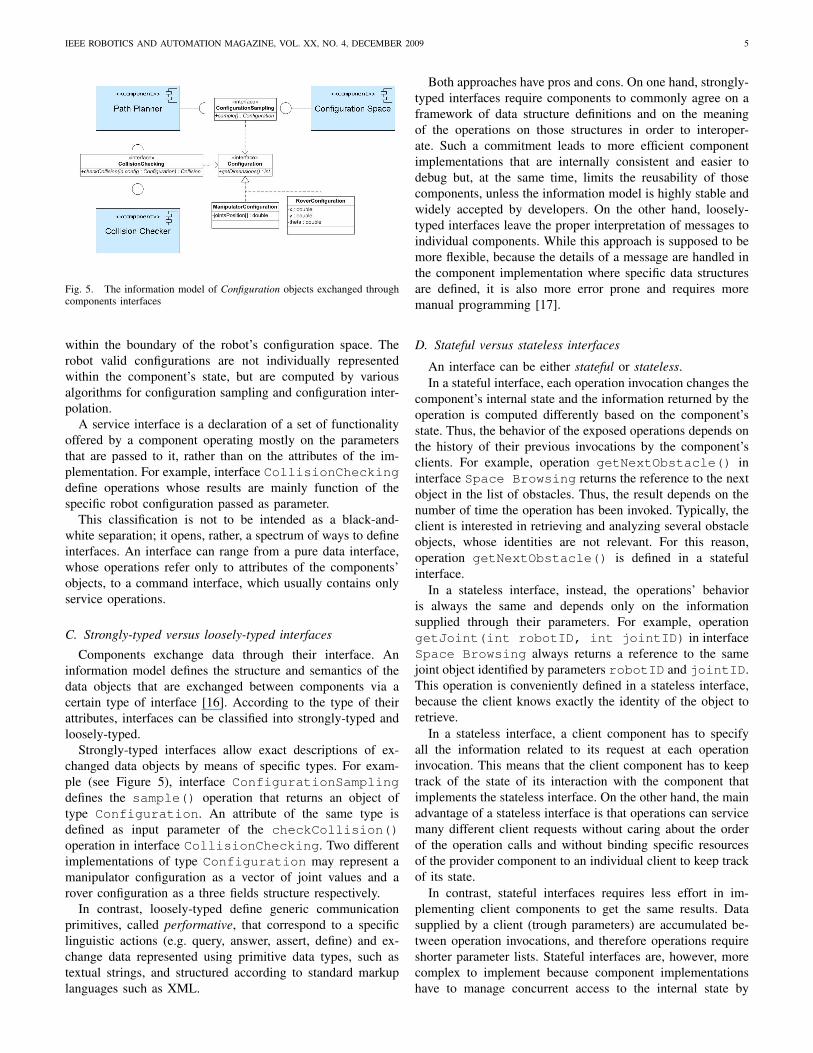
Fig. 5. The information model of Configuration objects exchanged throughcomponents interfaces
within the boundary of the robot’s configuration space. Therobot valid configurations are not individually representedwithin the component’s state, but are computed by variousalgorithms for configuration sampling and configuration inter-polation.
A service interface is a declaration of a set of functionalityoffered by a component operating mostly on the parametersthat are passed to it, rather than on the attributes of the im-plementation. For example, interface CollisionCheckingdefine operations whose results are mainly function of thespecific robot configuration passed as parameter.
This classification is not to be intended as a black-and-white separation; it opens, rather, a spectrum of ways to defineinterfaces. An interface can range from a pure data interface,whose operations refer only to attributes of the components’objects, to a command interface, which usually contains onlyservice operations.
C. Strongly-typed versus loosely-typed interfaces
Components exchange data through their interface. Aninformation model defines the structure and semantics of thedata objects that are exchanged between components via acertain type of interface [16]. According to the type of theirattributes, interfaces can be classified into strongly-typed andloosely-typed.
Strongly-typed interfaces allow exact descriptions of ex-changed data objects by means of specific types. For exam-ple (see Figure 5), interface ConfigurationSamplingdefines the sample() operation that returns an object oftype Configuration. An attribute of the same type isdefined as input parameter of the checkCollision()operation in interface CollisionChecking. Two differentimplementations of type Configuration may represent amanipulator configuration as a vector of joint values and arover configuration as a three fields structure respectively.
In contrast, loosely-typed define generic communicationprimitives, called performative, that correspond to a specificlinguistic actions (e.g. query, answer, assert, define) and ex-change data represented using primitive data types, such astextual strings, and structured according to standard markuplanguages such as XML.
Both approaches have pros and cons. On one hand, strongly-typed interfaces require components to commonly agree on aframework of data structure definitions and on the meaningof the operations on those structures in order to interoper-ate. Such a commitment leads to more efficient componentimplementations that are internally consistent and easier todebug but, at the same time, limits the reusability of thosecomponents, unless the information model is highly stable andwidely accepted by developers. On the other hand, loosely-typed interfaces leave the proper interpretation of messages toindividual components. While this approach is supposed to bemore flexible, because the details of a message are handled inthe component implementation where specific data structuresare defined, it is also more error prone and requires moremanual programming [17].
D. Stateful versus stateless interfaces
An interface can be either stateful or stateless.In a stateful interface, each operation invocation changes the
component’s internal state and the information returned by theoperation is computed differently based on the component’sstate. Thus, the behavior of the exposed operations depends onthe history of their previous invocations by the component’sclients. For example, operation getNextObstacle() ininterface Space Browsing returns the reference to the nextobject in the list of obstacles. Thus, the result depends on thenumber of time the operation has been invoked. Typically, theclient is interested in retrieving and analyzing several obstacleobjects, whose identities are not relevant. For this reason,operation getNextObstacle() is defined in a statefulinterface.
In a stateless interface, instead, the operations’ behavioris always the same and depends only on the informationsupplied through their parameters. For example, operationgetJoint(int robotID, int jointID) in interfaceSpace Browsing always returns a reference to the samejoint object identified by parameters robotID and jointID.This operation is conveniently defined in a stateless interface,because the client knows exactly the identity of the object toretrieve.
In a stateless interface, a client component has to specifyall the information related to its request at each operationinvocation. This means that the client component has to keeptrack of the state of its interaction with the component thatimplements the stateless interface. On the other hand, the mainadvantage of a stateless interface is that operations can servicemany different client requests without caring about the orderof the operation calls and without binding specific resourcesof the provider component to an individual client to keep trackof its state.
In contrast, stateful interfaces requires less effort in im-plementing client components to get the same results. Datasupplied by a client (trough parameters) are accumulated be-tween operation invocations, and therefore operations requireshorter parameter lists. Stateful interfaces are, however, morecomplex to implement because component implementationshave to manage concurrent access to the internal state by
IEEE ROBOTICS AND AUTOMATION MAGAZINE, VOL. XX, NO. 4, DECEMBER 2009 6
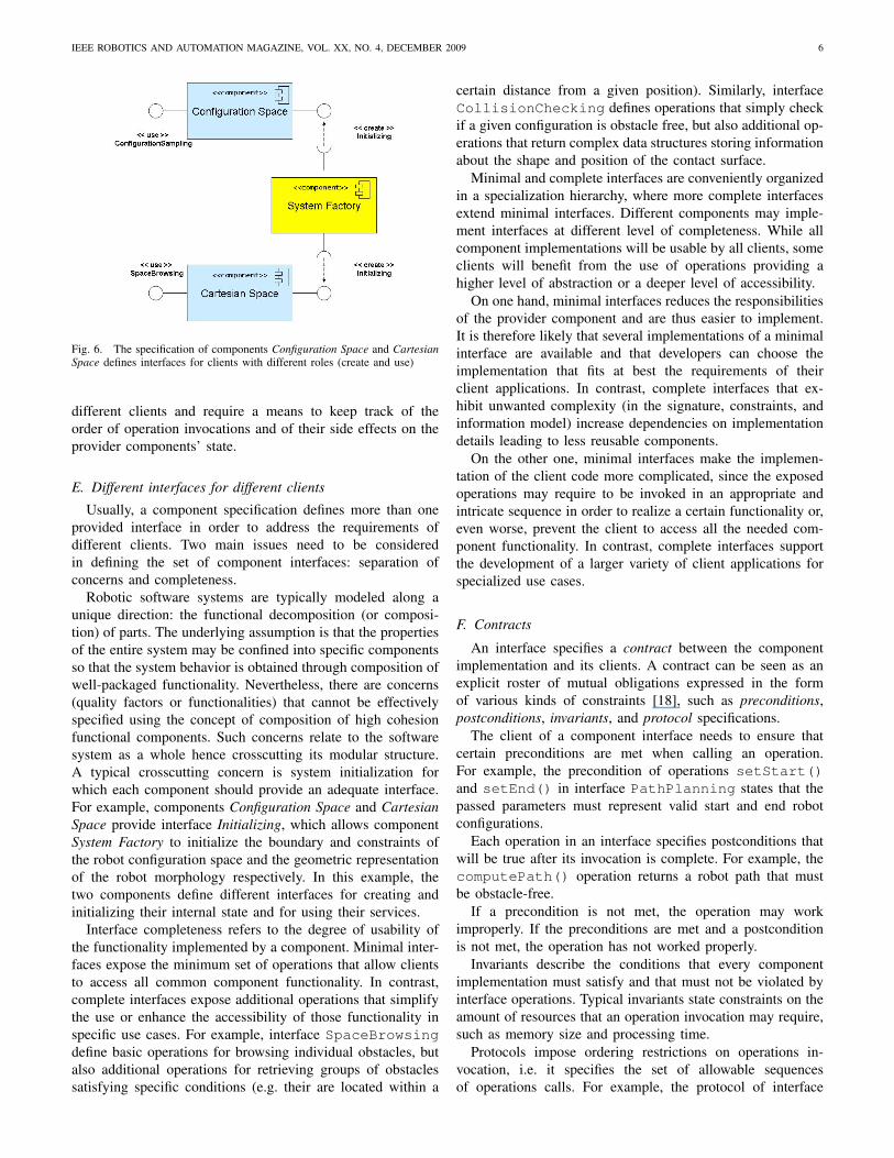
Fig. 6. The specification of components Configuration Space and CartesianSpace defines interfaces for clients with different roles (create and use)
different clients and require a means to keep track of theorder of operation invocations and of their side effects on theprovider components’ state.
E. Different interfaces for different clients
Usually, a component specification defines more than oneprovided interface in order to address the requirements ofdifferent clients. Two main issues need to be consideredin defining the set of component interfaces: separation ofconcerns and completeness.
Robotic software systems are typically modeled along aunique direction: the functional decomposition (or composi-tion) of parts. The underlying assumption is that the propertiesof the entire system may be confined into specific componentsso that the system behavior is obtained through composition ofwell-packaged functionality. Nevertheless, there are concerns(quality factors or functionalities) that cannot be effectivelyspecified using the concept of composition of high cohesionfunctional components. Such concerns relate to the softwaresystem as a whole hence crosscutting its modular structure.A typical crosscutting concern is system initialization forwhich each component should provide an adequate interface.For example, components Configuration Space and CartesianSpace provide interface Initializing, which allows componentSystem Factory to initialize the boundary and constraints ofthe robot configuration space and the geometric representationof the robot morphology respectively. In this example, thetwo components define different interfaces for creating andinitializing their internal state and for using their services.
Interface completeness refers to the degree of usability ofthe functionality implemented by a component. Minimal inter-faces expose the minimum set of operations that allow clientsto access all common component functionality. In contrast,complete interfaces expose additional operations that simplifythe use or enhance the accessibility of those functionality inspecific use cases. For example, interface SpaceBrowsingdefine basic operations for browsing individual obstacles, butalso additional operations for retrieving groups of obstaclessatisfying specific conditions (e.g. their are located within a
certain distance from a given position). Similarly, interfaceCollisionChecking defines operations that simply checkif a given configuration is obstacle free, but also additional op-erations that return complex data structures storing informationabout the shape and position of the contact surface.
Minimal and complete interfaces are conveniently organizedin a specialization hierarchy, where more complete interfacesextend minimal interfaces. Different components may imple-ment interfaces at different level of completeness. While allcomponent implementations will be usable by all clients, someclients will benefit from the use of operations providing ahigher level of abstraction or a deeper level of accessibility.
On one hand, minimal interfaces reduces the responsibilitiesof the provider component and are thus easier to implement.It is therefore likely that several implementations of a minimalinterface are available and that developers can choose theimplementation that fits at best the requirements of theirclient applications. In contrast, complete interfaces that ex-hibit unwanted complexity (in the signature, constraints, andinformation model) increase dependencies on implementationdetails leading to less reusable components.
On the other one, minimal interfaces make the implemen-tation of the client code more complicated, since the exposedoperations may require to be invoked in an appropriate andintricate sequence in order to realize a certain functionality or,even worse, prevent the client to access all the needed com-ponent functionality. In contrast, complete interfaces supportthe development of a larger variety of client applications forspecialized use cases.
F. Contracts
An interface specifies a contract between the componentimplementation and its clients. A contract can be seen as anexplicit roster of mutual obligations expressed in the formof various kinds of constraints [18], such as preconditions,postconditions, invariants, and protocol specifications.
The client of a component interface needs to ensure thatcertain preconditions are met when calling an operation.For example, the precondition of operations setStart()and setEnd() in interface PathPlanning states that thepassed parameters must represent valid start and end robotconfigurations.
Each operation in an interface specifies postconditions thatwill be true after its invocation is complete. For example, thecomputePath() operation returns a robot path that mustbe obstacle-free.
If a precondition is not met, the operation may workimproperly. If the preconditions are met and a postconditionis not met, the operation has not worked properly.
Invariants describe the conditions that every componentimplementation must satisfy and that must not be violated byinterface operations. Typical invariants state constraints on theamount of resources that an operation invocation may require,such as memory size and processing time.
Protocols impose ordering restrictions on operations in-vocation, i.e. it specifies the set of allowable sequencesof operations calls. For example, the protocol of interface

IEEE ROBOTICS AND AUTOMATION MAGAZINE, VOL. XX, NO. 4, DECEMBER 2009 7
Fig. 7. Flexibility among different realization of the same interface (lefthand side) and flexibility within a component framework (right hand side)
PathPlanning states that operation computePath()can be invoked only when operations setStart() andsetEnd() have been executed correctly. The protocol canalso show the callbacks that an interface may create, eventsthat are generated, or observers that are called.
V. COMPONENT IMPLEMENTATION
Separation of component specification and implementationenables reuse of software components embedding commonrobotic functionality. If, for a given application domain, acoherent set of required interfaces can be defined that specifythe most frequently used robot services and capabilities, andif applications in that domain are designed around thoseinterfaces, then every component implementing compatibleprovided interfaces has the potentiality to be reused in thoseapplications.
The various implementations of a component may differ innon-functional characteristics (i.e. performance, maintainabil-ity, documentation quality, reliability), realizing technology(e.g. the description of the geometric space may be storedin a relational database or as collection of XML files) andeven programming language (when components are build ona middleware or multi-language run-time infrastructure).
A clear separation of component specification and im-plementation grants component developers the flexibility toimprove the software quality of their components withoutaffecting the implementation of the applications that integratethem. At the same time, application developer have the flex-ibility to chose the components that best meet the qualityrequirements of their systems. Flexibility (see left hand side ofFigure 7) requires components specifications to be stable for agiven domain (i.e. interfaces are standard or widely acceptedin the developers community) and variability in applicationrequirements to be embedded in component implementations.In this context, flexibility enhances component reuse in thesense that a given component implementation can be used asa black box to build different component systems provided thatit meets their application requirements.
Component reuse can be further enhanced if commonalitiesamong different implementations of the same component spec-ification are identified and properly exploited. Here stabilitycan be defined as a component’s resilience to changes in the
original requirements specification [19] and refers to the inter-nal representation of a component, which is seen as a white box(see right hand side of Figure 7). The basic assumption is thatvertical components (see Section II) encapsulate functionalitythat are typically implemented around common entities andmechanisms, which are core aspects within the domain (e.g.the concepts of Path and Configuration) and can be representedas stable data structures and operations. Those aspects of acomponent implementation that are more likely to be affectedby the evolution of the application domain (e.g. ) represent itsvariation points.
In the following, we introduce the concept of componentframework as a technique to clearly separate stable andvariable aspects of a component implementation and illustratevariability implementation techniques that reduce the effortof developing new implementations of the same componentspecification.
A. Component Framework
A component framework is a skeleton of a component im-plementation that can be specialized by a component developerto produce custom components.
A component framework captures commonalities amongdifferent implementations of similar components and pointsof variability to express the differences. As such a componentframework represents a family of component implementa-tions, which share domain-specific properties and differ forapplication-specific requirements. A component framework isstable if new concrete components can be derived from itsdesign and built on its data structures and operations withoutchanging them.
Frameworks have acquired popularity in object-orientedprogramming [20]. Here, the interpretation of ”framework”ranges from structures of classes of cooperating objects whichprovide, through extension, reusable basic designs for a familyof similar applications (Johnson and Foot 1988), to the morerestrictive view [21] of complete high level modules which,through customization, directly result in specific applicationsfor a certain domain.
Frequently, the two views of framework, referred to as whitebox and black box approaches to reuse, may be simultaneouslypresent in one framework [22]. In fact, features, which arelikely to be common to most component implementations, canbe offered and therefore reused as black boxes with minorchanges. On the other hand, the class library accompanyingthe framework usually provides base classes (seen as whiteboxes) that can be specialized, by adding subclasses as needed,and easily integrated with the rest of the framework.
An intriguing relationship exists between frameworks, de-sign patterns, and pattern languages (see sidebar A). In apioneering paper [23] Johnson argues that patterns documentframeworks and help to ensure the correct use of frameworkfunctionalities. We take a more radical position: a patternlanguage – the organized collection of patterns for a certain ap-plication domain – in our view generates the framework which,thereafter, offers the elements for the pattern implementations,and it accompanies the framework through its life.
IEEE ROBOTICS AND AUTOMATION MAGAZINE, VOL. XX, NO. 4, DECEMBER 2009 8
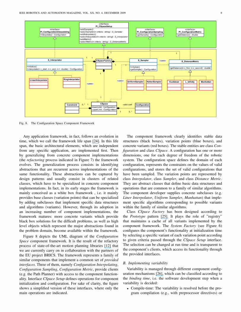
Fig. 8. The Configuration Space Component Framework
Any application framework, in fact, follows an evolution intime, which we call the framework life span [24]. In this lifespan, the basic architectural elements, which are independentfrom any specific application, are implemented first. Thenby generalizing from concrete component implementations(the refactoring process indicated in Figure 7) the frameworkevolves. The generalization process consists in identifyingabstractions that are recurrent across implementations of thesame functionality. These abstractions can be captured bydesign patterns and usually consist in clusters of relatedclasses, which have to be specialized in concrete componentimplementations. In fact, in its early stages the framework ismainly conceived as a white box framework , i.e. it mainlyprovides base classes (variation points) that can be specializedby adding subclasses that implement specific data structuresand algorithms (variants). However, through its adoption inan increasing number of component implementations, theframework matures: more concrete variants which provideblack box solutions for the difficult problems, as well as highlevel objects which represent the major abstractions found inthe problem domain, become available within the framework.
Figure 8 depicts the UML diagram of the ConfigurationSpace component framework. It is the result of the refactoryprocess of state-of-the-art motion planning libraries [12] thatwe are currently carry on in collaboration with the partners ofthe EU project BRICS. The framework represents a family ofsimilar components that implement a common set of providedinterfaces. Three of them, namely Configuration Interpolating,Configuration Sampling, Configuration Metric, provide clients(e.g. the Path Planner) with access to the component function-ality. Interface CSpace Setup defines operations for componentinitialization and configuration. For sake of clarity, the figureshows a simplified version of these interfaces, where only themain operations are indicated.
The component framework clearly identifies stable datastructures (black boxes), variation points (blue boxes), andconcrete variants (red boxes). The stable entities are class Con-figuration and class CSpace. A configuration has one or moredimensions, one for each degree of freedom of the roboticsystem. The configuration space defines the domain of eachconfiguration, represents the constraints on the values of validconfigurations, and stores the set of valid configurations thathave been sampled. The variation points are represented byclass Interpolator, class Sampler, and class Distance Metric.They are abstract classes that define basic data structures andoperations that are common to a family of similar algorithms.The component developer supplies concrete subclasses (e.g.Liner Interpolator, Uniform Sampler, Manhattan) that imple-ment specific algorithms corresponding to possible variantswithin the family of similar algorithms.
Class CSpace Factory has been designed according tothe Prototype pattern [25]. It plays the role of ”registry”that maintains a cache of all variants implemented by thecomponent framework. The System Factory (see Figure 6)configures the component’s functionality at initialization timeby selecting a specific variant of each variation point accordingto given criteria passed through the CSpace Setup interface.The selection can be changed at run time and is transparent tothe component’s clients, which access its functionality throughthe provided interfaces.
B. Implementing variabilityVariability is managed through different component config-
uration mechanisms [26], which can be classified according tothe binding time, i.e. the software development step when avariability is decided:
• Compile-time: The variability is resolved before the pro-gram compilation (e.g., with preprocessor directives) or
IEEE ROBOTICS AND AUTOMATION MAGAZINE, VOL. XX, NO. 4, DECEMBER 2009 9
at compile time. Mechanisms that typically causes thevariability to be resolved at compile-time are: inheritance,aggregation, parametrization, and conditional compila-tion.
• Link-time: The variability is resolved during moduleor library linking (e.g., selecting different libraries withdifferent versions of the exported operations).
• Run-time : The variability is resolved during programexecution. An example of late-binding techniques is Re-flection.
1) Inheritance and extension: Object inheritance is used toassign base functionality to superclasses and extensions to sub-classes. Subclasses may introduce new attributes, operations,or overwrite or wrap existing ones.
Inheritance may be used to provide variants by separatingvariabilities into derived subclasses. However this means thatthe growing number of different variants implies a growingnumber of subclasses, which in many cases leads to complexinheritance hierarchies.
2) Aggregation and delegation: Aggregation is an object-oriented technique that enables an (aggregate) object to containother objects. Aggregation may be done by value or byreference. By value means that the lifetimes of the whole andthe part objects are exactly the same; they are born and dieat the same time. By reference de-couples the lifetimes of thetwo objects. The whole may not have a part, or it may havea different part at different times. Different wholes may sharethe same part. De-allocating the whole will not automaticallyde-allocate the part.
The whole can delegate the part to provide some function-ality by forwarding to the part requests it can normally notsatisfy. Variability can be handled by putting the standardor mandatory functionality in the delegating object and thevariant functionality in the delegated object. This techniqueworks well with optional features, but gets worse when thenumber of variants grows significantly requiring additionaldelegation classes.
3) Parameterization: Parametric types, templates, and pre-compiler macros are used when unbound parameters or macroexpressions can be inserted in the code and later instantiatedwith the actual parameter or by expanding the macro. Theidea of parameterized programming is to to represent reusablesoftware as a library of parameterized components. Compo-nent behavior is determined by the values parameters are setto.
Parameterization avoids code replication by centralizingcode decision around a set of variables. A typical usage is tomake structured data types (stacks, queues, lists, etc.) flexibleand working for any kind of data by allowing setting the datatype through a parameter. However, the major drawback isthat parameterization strictly depends on the particular selectedprogramming language.
4) Conditional compilation: Macro definitions given asparameters to the compiler, ifdefs statements, and recentcontext-aware programming languages [27] may be used atcompile-time to select between different implementations inthe code and therefore lead to different variants of a com-ponent. Code segments may be included or excluded from a
program compilation. Directives mark the varying locationsin the code. The makefiles mechanism is also another way toperform a sequence of compilations and linkages at link-timedepending on the makefile parameters.
One benefit of this technique is the encapsulation of multipleimplementations in a single module. The desired functionalityis selected by defining the appropriate conditional symbols. Onthe other hand conditional directives do not support recursionor any other kind of looping which makes difficult to enableadvanced code selection schema. Moreover, following thedecisions related to a conditional code selection is also noteasy. A solution to that is to interrelate directives hierarchicallywith a central include file as a decision unit at the top of thehierarchy.
5) Dynamic Link Libraries: Static libraries contain a setof functions that can be linked to an application after it hasbeen compiled and loaded in the same memory space. Thesignatures of the functions are known to the compiled codeand therefore they must remain unchanged. The implementa-tions though can change by selecting different libraries andthus providing some kind of variability support. In contrast,Dynamic link libraries, like Microsoft ActiveX controls, canbe combined with several executables in the same system atloading time trough configuration files.
6) Reflection: Reflection is the ability of a program toobserve and modify its own structure and behavior. Reflectionrelates strongly to metaprogramming where objects in higherlevels of abstraction (metalevels) are established to represententities like operating systems, programming languages, pro-cessors, object models, etc. Reflection enables access to suchmetaobjects and therefore allows architecting flexible systems.Reflection is an appealing run-time variation mechanism.Reflection can be, for example, combined with the standardJava dynamic class loading in order to load modules unknownuntil runtime, depending on the deployment context and invokeoperations on these modules. However, reflective programs aredifficult to understand, to debug and to maintain.
VI. CONCLUSION
In this first of a two-parts tutorial on Component-BasedRobotic Engineering we have illustrated the fundamental con-cepts and design guidelines for the development of softwarebuilding blocks that embed reusable robot functionality. Thefocus was on the design of individual components, on theseparation of component specification and component imple-mentation, and on the techniques that maximize componentinteroperability and flexibility. In the second part of thistutorial, we will discuss techniques to assemble componentsinto large and distributed component systems and methods toderive concrete applications from a common base of domainspecific reusable components.
APPENDIX ASIDEBAR: A HISTORICAL OVERVIEW OF SOFTWARE REUSE
Software reuse is the use of existing software to constructnew software [28]. Software reuse practice takes typically twodifferent forms:

IEEE ROBOTICS AND AUTOMATION MAGAZINE, VOL. XX, NO. 4, DECEMBER 2009 10
• opportunistic: the software engineer reuses pieces ofsoftware that fit the current problem.
• systematic: the research and development team puts ex-plicit effort (i.e. invests) in developing software buildingblocks that meet the requirements of a family of similarapplications, fit into an higher level architecture, and thuscan be reuse to solve a larger class of problems.
Systematic reuse is generally recognized as a key technol-ogy for improving software productivity and quality.
Systematic software reuse was introduced along the firstCOBOL compiler almost fifty years ago, when the concept oflibraries was developed. The libraries allowed collections ofprecompiled, reusable subroutines to be linked into a program.The vision of the COBOL team was that in the course of afew years, standard libraries would be developed for differentapplication domains, allowing developers to write high-levelprograms that reused most of the logic and functionalityavailable in the libraries. This, however, has not happened; theonly domain where library-based reuse has been successful isnumerical analysis, where a large number of FORTRAN and Clibraries are available and are used in many projects. The mainreason for the failure of library-based reuse is the difficulty ofencapsulating high-level functionality in subroutines. Subrou-tine libraries suffer from the division of procedural code anddata which make up a program.
The advent of object-oriented languages, starting with Sim-ula in 1967 [29] and gaining popularity with the developmentof Smalltalk [30] in the eighties, introduced a new techniquefor reuse: the class library. Object-oriented programs are seenas structures of objects, which encapsulate state and behaviorand communicate with messages; the behavior of the wholesystem is the result of the interactions and collaborationsbetween the objects. The developer implements classes, whichare descriptions of the state and behavior for a number ofsimilar objects, and creates objects as instances of the classes.
The class library approach, however, has not been muchmore successful than the subroutine libraries; most of thesuccessful class libraries consist of simple container or col-lection classes which are object-oriented implementations ofbasic data structures. The failure of class-library reuse ispartly due to the fact that class libraries commonly restrictspolymorphism to work on objects which are specializations ofa class supplied with that library, and that each library providesa different, incompatible version of this top-level class.
As software systems continued to grow in size and com-plexity, the importance of design and architecture increased.Software architecture development has shifted attention fromcode reuse to design reuse, by giving more importance to thefundamental role that patterns of relationships between theelements of an architecture have in any design. In contrast tothe class libraries approach, the structure of interconnectionsbetween classes is reused, not the classes themselves.
While a large number of general methods and notationshave been developed for creating and documenting designs andarchitectures, such as the OMG Unified Modeling Language(UML) [xx], systematic reuse of concrete architectures anddesigns has been possible only with the introduction of De-sign Patterns [25], Architectural Styles [31], and Application
Frameworks [32] in the middle Nineties.Design Patterns are textual and graphical descriptions of
reusable design solutions to recurrent design problems inspecific application context. Design Patterns document notonly the design, but also the development knowledge andexpertise that lead to that design. The whole set of patterns fora specific application domain (e.g. Factory Automation [33]),together with their structuring principles represented by thenetwork of connections among individual patterns, is calleda Pattern Language, and is a design method for the domainwhich accompanies the software life cycle from the analysisto the final implementation.
Architectural Styles describe families of architectural de-signs that share a set of common assumptions. An architecturalstyle provides a specialized component vocabulary (e.g. theterms Client, Server, Application Server, etc.), a connectorvocabulary (e.g. pipes, data stream, etc.) and a set of rulesto build specific topology using components and connectors.
An Application Framework is an integrated set of reusableand extendible software artifacts for a specific applicationdomain. It consists of both reusable code and reusable de-sign. This means that applications which are built using theframework are never designed and implemented from scratch;instead, the framework design and implementation are used asa starting point.
More recently, in addition to Component Based SoftwareEngineering (CBSE) [2], Software Product Lines (SPL) [34],and Model-Driven Engineering (MDE) [35] have been pro-posed as new software development approaches that relievethe application developer from most of the burden of designingand implementing entire applications.
A SPL is a set of applications (products) that share many(structural, behavioral, etc.) commonalities and together ad-dress a particular domain. Each new application is buildfrom the SPL repository of common software assets (e.g.requirements specification, architectural and design models,software components). The core of a SPL is the productline architecture that supports the variations reflected in theproducts and prescribes how software components can beassembled to derive individual products.
MDE tools simplify and automate many activities associatedwith developing, optimizing, and deploying complex softwaresystems. Developers use domain-specific modeling languagesto build models that capture the structure, behavior, andrelevant properties of their component-based systems. A newapplication is developed by reusing these models, customizingthem according to specific application requirements, and semi-automatically generating source code using transformationengines and generators.
APPENDIX BSIDEBAR: OBJECT ORIENTED PROGRAMMING
Object Oriented Programming (OOP) consists of techniquesand mechanisms to be used in structuring models and programcode after the entities (objects) found in the problem domain.OOP is based on the concept of object as program unit,which encapsulates both data and algorithms. This concept

IEEE ROBOTICS AND AUTOMATION MAGAZINE, VOL. XX, NO. 4, DECEMBER 2009 11
Fig. 9. A class diagram in UML
distinguishes the object-oriented programming paradigm frompure procedural and functional paradigms. The code thataccesses and modifies given data is confined to one locationin the program and not spread, uncontrollably, throughoutthe program. The key ingredient of an object definition areidentity, state, interface, and behavior.
Take, for example, a library of path planning algorithms. Anobject called shortest path (its identity) could describean obstacle-free robot path by means of attributes like thestart and end robot configuration (its internal state); itcould implement some operations like appendPathLeg()(its interface) that can be invoked by other objects (e.g. apath planner) and perform some computation (its behavior)like updating the end configuration.
Objects with similar properties belong to the same class. Inthe previous example, class Robot Path defines a familyof path objects that differ from each others in terms of theirspecific initial and end configurations, via points, and path legsconnecting intermediate configurations. In other words, a classdefines the common type of a set of objects, while an objectis an instance of a specific class.
Figure 9 depicts the classes of this example according to thegraphical notation of the Unified Modeling Language (UML).
OOP supports reuse of software objects by offering fourbasic techniques.
• Composition, which consists in constructing new classesaround objects of existing classes. For example, classRobot Path encapsulates two instances of classConfiguration and has the responsibility to instanti-ate and initialize them correctly.
• Parametric polymorphism, often called generic program-ming, which consists in writing a function or a classgenerically with respect the type of the values it han-dles. For example, the implementation of class List isgeneric with regards to the implementation of the listelements. Thus, it can be reused in class Robot Pathto implement a collection of Navigable Leg objects.
• Subtyping, which consists in defining a new class assubtype of an existing one. In the example of Figure 9,instances of class Geometric Curve can be substi-tuted by instances of class Motion Behavior withoutaffecting client’s code because both classes are subtypesof interface Navigable Leg.
• Inheritance, which consists of deriving new classes asspecializations of existing classes and therefore reusingexisting code. For example, class Segment extendsclass Geometric Curve by reusing the same datastructures (e.g. curvilinear x) but re-implementingsome operations in a more efficient way (e.g. calculatingthe curve length).
OOP is claimed to promote reuse by supporting the or-ganization of complex data structures into hierarchies of ab-straction. However, object-oriented programming suffers fromsome well known shortcomings. In particular, implementationinheritance creates a tight coupling between base and derivedclasses, which makes the evolution of the base classes difficult(the fragile base class problem). Every simple modification(e.g. changing the parameters of an operation) to the base classmay cause semantic inconsistencies in the derived classes. Inaddition, a subclass cannot be understood without knowinghow the inherited methods are implemented in its superclass.
These and others shortcomings of OOP have lead to the in-troduction of Component-based Software Engineering, whichspecifically promotes the separation of component specifica-tion and component implementation.
ACKNOWLEDGMENT
The authors would like to thank Herman Bruyninckx, StefanChristen, Angelo Gargantini, Edmund Milke, Walter Nowak,Alexej Zakharov, and Azamat Shakhimardanov for their valu-able comments.
The research leading to these results has received fundingfrom the European Community’s Seventh Framework Pro-gramme (FP7/2007-2013) under grant agreement no. FP7-ICT-231940-BRICS (Best Practice in Robotics).
REFERENCES
[1] G. T. Heineman and W. T. Councill, Component-Based Software Engi-neering: Putting the Pieces Together (ACM Press). Addison-WesleyProfessional, June 2001.
[2] C. Szyperski, Component Software: Beyond Object-Oriented Program-ming. Addison-Wesley Professional;, 2002.
[3] A. Shakhimardanov, H. Bruyninckx, K. Nilsson, and E. Prassler. Whitepaper: The use of reuse of hardware and software componentsin robot development. [Online]. Available: http://www.robot-standards.org/index.php?id=19
[4] D. Brugali, Ed., Software Engineering for Experimental Robotics, ser.Springer Tracts in Advanced Robotics. Berlin / Heidelberg: Springer- Verlag, April 2007, vol. 30.
[5] D. Brugali and E. Prassler, “Software engineering for robotics,” SpecialIssue of the IEEE Robotics and Automation Magazine, March 2009.
[6] L. Bass, P. Clements, and R. Kazman, Software Architecture in Practice.Addison Wesley, 1999.
[7] I. A. Nesnas, “The claraty project: Coping with hardware and softwareheterogeneity,” in Software Engineering for Experimental Robotics, ser.Springer Tracts in Advanced Robotics, D. Brugali, Ed. Berlin /Heidelberg: Springer - Verlag, April 2007, vol. 30.
[8] J. Poulin, Measuring Software Reuse: Principles, Practices, and Eco-nomic Models. Addison-Wesley Professional, 1996.
IEEE ROBOTICS AND AUTOMATION MAGAZINE, VOL. XX, NO. 4, DECEMBER 2009 12
[9] M. Ezran, M. Moriso, and C. Tully, Practical Software Reuse - theessential guide. ESSI Surprise Project book, 1998.
[10] J.-C. Latombe, F. Schwarzer, and M. Saha. Mpk - motion planning kit.[Online]. Available: http://robotics.stanford.edu/ mitul/mpk/
[11] S. LaValle, P. Cheng, J. Kuffner, S. Lindemann, A. Manohar, B. Tovar,L. Yang, and A. Yershova. Msl - motion strategy library. [Online].Available: http://msl.cs.uiuc.edu/msl/
[12] E. Milke, S. Christen, E. Prassler, and W. Nowak, “Towards harmoniza-tion and refactoring of mobile manipulation algorithms,” in Proceedingsof the ICAR 2009 14th International Conference on Advanced Robotics,Munich, Germany, June 22 - 26 2009.
[13] G. Sanchez and J. Latombe, “A single-query bi-directional probabilisticroadmap planner with lazy collision checking,” in Int. Symposium onRobotics Research (ISRR), 2001.
[14] K. Pugh, Interface Oriented Design. The Pragmatic Programmers LLC.,2006.
[15] M. Reggiani, M. Mazzoli, and S. Caselli., “An experimental evaluationof collision detection packages for robot motion planning,” in Pro-ceecings of the IEEE/RSJ Int. Conf. on Intelligent Robots and Systems,2002.
[16] J. G. Wijnstra, “Components, interfaces and information models withina platform architecture,” in GCSE, ser. Lecture Notes in ComputerScience, J. Bosch, Ed., vol. 2186. Springer, 2001, pp. 25–35.
[17] A. Tost. (2005, September) Loosely typed versus strongly typedweb services. IBM. [Online]. Available: http://www.ibm.com/developerworks/webservices/library/ws-loosevstrong.html
[18] B. Meyer, Object-Oriented Software Construction. Prentice Hall, 1997.[19] F. M.E. and A. A., “An introduction to software stability,” Communica-
tions of the ACM, vol. 44, no. 9, September 2001.[20] J. O. Coplien and D. Schmidt, “Frameworks and components,” in Pattern
Languages of Program Design. Addison-Wesley, 1995, pp. 1–5.[21] H. Schmid, “Creating the architecture of a manufacturing framework
by design patterns,” in Proceedings of OOPSLA95. SIGPLAN, ACM,1995.
[22] R. Johnson and B. Foote, “Designing reusable classes,” Journal ofObject-Oriented Programming, vol. 1, pp. 22–35, 1988.
[23] R. Johnson, “Documenting frameworks using patterns,” in Proceedingsof OOPSLA 92, Vancouver, B. C., Canada, October 1992.
[24] D. Brugali, G. Menga, and A. Aarsten, “The framework life span,”Communications of the ACM, vol. 40, no. 10, pp. 65–68, October 1997.
[25] E. Gamma, R. Helm, R. Johnson, and J. Vlissides, Design Patterns:Elements of Reusable Object-Oriented Software. Addison-Wesley,Longman, Reading, MA, 1995.
[26] M. Anastasopoulos and C. Gacek, “Implementing product line variabil-ities,” May 2001.
[27] M. Rosemann and J. Recker, “Context-aware process design exploringthe extrinsic drivers for process flexibility,” in BPMDS, ser. CEURWorkshop Proceedings, G. Regev, P. Soffer, and R. Schmidt, Eds., vol.236. CEUR-WS.org, 2006.
[28] W. Frakes and K. Kang, “Software reuse research: status and future,”Software Engineering, IEEE Transactions on, vol. 31, no. 7, pp. 529–536, July 2005.
[29] O. Dahl, B. Myhrhaug, and K. Nygaard, “Simula information: Commonbase language.” Norwegian Computing Center, Oslo, Tech. Rep., 1970.
[30] A.Goldberg and D. Robson, Smalltalk80: The language and its imple-mentation. Addison-Wesley, 1983.
[31] P. Clements, F. Bachmann, L. Bass, D. Garlan, J. Ivers, R. Little,R. Nord, and J. Stafford, Documenting Software Architectures: Viewsand Beyond. Addison Wesley, 2003.
[32] M. Fayad, R.J, and D.S., “Object-oriented application frameworks,”Communications of the ACM, vol. 40, no. 10, October 1997.
[33] D. Brugali and G. Menga, “Architectural models for global automationsystems,” IEEE Transactions on Robotics and Automation, vol. 18, no. 4,pp. 487–493, August 2002.
[34] P. Clements and L. Northrop, Software Product Lines: Practices andPatterns. Addison-Wesley, 2002.
[35] D. C. Schmidt, “Guest editor’s introduction: Model-driven engineering,”Computer, vol. 39, no. 2, pp. 25–31, Feb. 2006, printed.