Comparison of Sutures and Devices Used in Closure ...
141
Grand Valley State University ScholarWorks@GVSU Masters eses Graduate Research and Creative Practice 4-2015 Comparison of Sutures and Devices Used in Closure Following Partial Nephrectomy Suturing Bikal Paka Grand Valley State University Follow this and additional works at: hp://scholarworks.gvsu.edu/theses Part of the Engineering Commons is esis is brought to you for free and open access by the Graduate Research and Creative Practice at ScholarWorks@GVSU. It has been accepted for inclusion in Masters eses by an authorized administrator of ScholarWorks@GVSU. For more information, please contact [email protected]. Recommended Citation Paka, Bikal, "Comparison of Sutures and Devices Used in Closure Following Partial Nephrectomy Suturing" (2015). Masters eses. 772. hp://scholarworks.gvsu.edu/theses/772
-
Upload
khangminh22 -
Category
Documents
-
view
0 -
download
0
Transcript of Comparison of Sutures and Devices Used in Closure ...

Grand Valley State UniversityScholarWorks@GVSU
Masters Theses Graduate Research and Creative Practice
4-2015
Comparison of Sutures and Devices Used inClosure Following Partial Nephrectomy SuturingBikal PakaGrand Valley State University
Follow this and additional works at: http://scholarworks.gvsu.edu/theses
Part of the Engineering Commons
This Thesis is brought to you for free and open access by the Graduate Research and Creative Practice at ScholarWorks@GVSU. It has been acceptedfor inclusion in Masters Theses by an authorized administrator of ScholarWorks@GVSU. For more information, please [email protected].
Recommended CitationPaka, Bikal, "Comparison of Sutures and Devices Used in Closure Following Partial Nephrectomy Suturing" (2015). Masters Theses.772.http://scholarworks.gvsu.edu/theses/772

Comparison of Sutures and Devices Used in Closure Following Partial Nephrectomy Suturing
Bikal Paka
A Thesis Submitted to the Graduate Faculty of
GRAND VALLEY STATE UNIVERSITY
In
Partial Fulfillment of the Requirements
For the Degree of
Master of Science in Engineering
Padnos College of Engineering and Computing
April 2015

3
Dedication
This thesis is dedicated to my mother and father. In addition, I will also like to dedicate to those
who have assisted me along the way for the completion of my thesis.

4
Acknowledgements
This thesis appears in its current form due to the assistance and guidance of several people. I
would therefore like to offer my sincere thanks to all of them.
I would like to thank Grand Valley State University and Spectrum Health System for providing
the financial assistance to carry out this research. I am grateful to Department of Biomedical
Engineering, for providing me opportunity to conduct this research
I heartily thank my supervisors, Dr. Robert Bossemeyer for all the time spent working with me,
and for patient and encouraging guidance.
I am eternally grateful to Dr. Brian Lane for the guidance and the preparation of specimens in
this research. I would like to express my deep thanks to Dr. Mouafak Tourojman for his support
in preparation of specimens during experiment.
I would like to express my deep thanks to Dr. Samhita Rhodes, for her support to complete this
research.
I sincerely thank Miss Sabrina for her regular support and research coordination. My
appreciation goes to Mr. Jerry Smart for all precious suggestions regarding experimental device
design I would like to thank Spectrum Health for helping me in statistical analysis of data. I
would like to thank Mr. Ruchir Gupta, Miss. Anisa Tuladhar and Mr. Ravi Bhatta for their
continuous support during the research.

5
Abstract
Laparoscopic partial nephrectomy (LPN) is an effective surgical procedure to remove a small
renal tumor, while preserving the remainder of the kidney. However, it is a technically
challenging procedure to maintain hemostatic condition on the kidney during LPN suturing.
Three different experiments were conducted to explore the characteristics and limitations of the
current mechanism for tissue approximation during LPN procedures.
During the first experiment, a standard suture anchor Hem-o-lok device, a standard stop knot,
and three prototype devices were compared to each other based on the amount of tension that
could be placed on a suture before there was a tear in renal tissue. The renal remnant of a
standardized defect in porcine kidneys without an intact renal capsule was sutured using Vicryl
2-0 suture and different suture anchors. The approximate mean tensions at which the renal
parenchymal tissue failed using these tested anchors was knots (2.7N ± 0.53N), Prototype 2(4.0
N± 1.6N), Hem-o-lok (5.4 N±0.72N), Prototype 1(5.6 N±0.75N), and Prototype 3(6.0 N±3.39N).
Even with a small number of tests (8 for most configurations), there are significant differences at
the 95% confidence level. Statistical analysis of the data, however, indicates that there is no
significant difference between anchors Hem-o-lok, Prototype 1 and Prototype 3 with a
significance level of 0.05.
The second experiment was conducted to determine if different types and sizes of absorbable
suture used in partial nephrectomy can sustain a tension of 4N over a 21 day period, which is
necessary to achieve hemostasis in the perfused kidney. The results indicate that the sutures
commonly used in LPN, i.e. Vicryl 2-0 and Vicryl 3-0 do not break within the 21 day expected
life and that failure of other sutures tested before 7 days is commonly due to knot slippage

6
The final experiment measured and compared the holding strength of a common technique used
in LPN surgery to provide anchoring of a suture, a Hem-o-lok device backstopped with a
LAPRA-TY. Suture types Vicryl, Monocryl, Chromic, Stratafix and V-Loc were tested in
common sizes. The results show that the holding strength of clips (Hem-o-Lok backstopped by
LAPRA-TY) for Vicryl 4-0 sutures is the lowest of all types and sizes tested at a mean value of
4.2 N±1.36N and maximum for V-Loc 2-0 sutures at the mean value of 15.9 N±2.58N. The clips
hold maximum tension for suture sizes “1” and “0”, whereas minimum tension for suture size 4-
0. This experiment indicates that the holding ability of these clips support the application of
suture tension greater than 5.5N thought to be necessary for adequate hemostasis following LPN.
However, suture types Vicryl 3-0 and Vicryl 4-0 may not be able to maintain hemostatic
condition during LPN when used with this anchor method.

7
Table of Contents
Dedication .......................................................................................................................................3
Acknowledgements ........................................................................................................................4
Abstract ...........................................................................................................................................5
Table of Figures............................................................................................................................10
Table of Tables .............................................................................................................................14
Introduction ..................................................................................................................................17
Background ..................................................................................................................................18
Experiment 1: Comparison between Prototype suture anchors and conventional suture
anchors…………………………………………………………………………………………..28
Background/Literature review ........................................................................................... ........28
Methodology ..............................................................................................................................31
Result ..........................................................................................................................................38
Discussion ..................................................................................................................................40
Experiment 2: Analysis of time required for absorbable sutures with a given tension
expected to support ......................................................................................................................43
Background/Literature review ....................................................................................................43
Methodology ..............................................................................................................................44
Result ..........................................................................................................................................50
Discussion ..................................................................................................................................51

8
Experiment 3: Investigation on holding strength of a Hem-o-lok backstopped by Lapra-Ty
clip on various suture types and sizes…………………………………………………………53
Background/Literature review ....................................................................................................53
Methodology ..............................................................................................................................56
Result ..........................................................................................................................................59
1. Comparison of holding strength of clips on different suture types for each suture size…...60
2. Comparison of holding strength of clips on different suture sizes for each suture type. .......65
3. Comparison of time at which clips starts to slip from suture size 2-0 ...................................71
4. Comparison of holding strength clips for barbed suture, i.e. toward and against barb ..........76
Discussion ..................................................................................................................................77
Conclusion ....................................................................................................................................80
Topics for additional research ....................................................................................................82
Appendices ....................................................................................................................................83
Appendix A: JMP ANOVA Instructions steps an description ...................................................84
Appendix B: Statistical analysis for comparison between Prototype suture anchors and
conventional suture anchors .......................................................................................................89
Appendix C: Procedure for comparison between Prototype suture anchors and conventional
suture anchors .............................................................................................................................92
Appendix D: Suture life test data ...............................................................................................96
Appendix E: Holding strength of Sutures just before LAPRA-TY slippage .............................97
Appendix F: Holding strength of clips on different suture types for each suture size ...............99

9
Appendix G: Holding strength of clips on different suture sizes for each suture type………109
Appendix H: Comparison of time at which clips starts to slip from suture size 2-0………...117
Appendix I: Holding strength of clips with its placement towards and against barb ……….120
Appendix J: Graphical representation of holding strengths………………………………….125
Bibliography…………………………………………………………………………………...137

10
Table of Figures
Figure 1: Surgical clips: a. Hem-o-lok clip b. LAPRA-TY clip 19
Figure 2: Continuous suturing technique 20
Figure 3: Knot types 21
Figure4: Sliding-clip renorrhaphy using Hem-o-clip and LAPRA-TY 22
Figure 5: Suturing techniques 24
Figure 6: Barbed sutures 27
Figure 7: Holding strength using clips Hem-o-clip and LAPRA-TY 29
Figure 8: Prototype clips type 30
Figure 9: MTS Mini-Bionix 32
Figure 10: DFG with MTS mini Bionix 33
Figure 11: Calibration of DFG and MTS Mini Bionix 33
Figure 12: Defect on kidney creating Procedure 34
Figure 13: Comparison of prototype clip and Hem-o-lok 35
Figure 14: Design of revolving kidney holder 35
Figure 15: Revolving holder with MTS Mini Bionix and DFG 36
Figure 16: Tension holding strength of renal tissue 37
Figure 17: Block diagram of data recording process 38
Figure 18: Mean failure force for suture anchors 39
Figure 19: Hook support structure design 45
Figure 20: Hooks and spring balance 46
Figure 21: Hem-o-Lok and knots with a lower hook 47
Figure 22: Figure “8” knot 48
Figure 23: Experimental setup for tensile strength analysis of absorbable suture 49

11
Figure 24: median sutures duration of failure 50
Figure 25: Mean LAPRA-TY holding strength 55
Figure 26: Application of clips on suture 57
Figure 27: Holding strength of Hem-o-lok back stopped by LAPRA-TY 58
Figure 28: Mean holding strength of clips on different suture types 61
Figure 29: Mean holding strength of clips on different suture sizes 66
Figure 30: Comparison of time at which clips starts to slip from suture size 2-0 72
Figure 31: Total slippage time of clips on sutures 73
Figure 32: Recorded tension for sutures of size 2-0 74
Figure 33: Holding strength for Vicryl 2-0 sutures 75
Figure 34: Holding strength for Monocryl 2-0 sutures 75
Figure 35: LAPRA-TY clips on barbed sutures: 76
Figure 36: Comparison of clips on barbed sutures (towards and against) 77
Figure B1: Box plot of tensions recorded for anchors 89
Figure B2: Normality plot of Studentized Residual of tensions recorded for anchors 90
Figure F1: Box plot for sutures of size “1” 99
Figure F2: Normal quantile plot for suture size “1” 100
Figure F3: Box plot for sutures of size “0” 101
Figure F4: Normal quantile plot for suture size “0” 101
Figure F5: Box plot for sutures of size “2-0” 103
Figure F6: Normal quantile plot for suture size “2-0” 103
Figure F7: Box plot for sutures of size “3-0” 105
Figure F8: Normal quantile plot for suture size “3-0” 105
Figure F9: Box plot for sutures of size “4-0” 107

12
Figure F10: Normal quantile plot for suture size “4-0” 107
Figure G1: Normal quantile plot for Vicryl sutures 110
Figure G2: Normal quantile plot for Monocryl sutures 111
Figure G3: Normal Quantile plot for Chromic sutures 112
Figure G4: Normal Quantile plot for Stratafix sutures 104
Figure G5: Normal Quantile plot for V-Loc sutures 105
Figure H1: Normal Quantile plot of tension holding time of clips before slippage 117
Figure H2: Normal Quantile plot of studentized residual obtain from holding time 118
Figure J1: Holding strength for Monocryl 1 sutures 125
Figure J2: Holding strength for Monocryl 0 sutures 125
Figure J3: Holding strength for Monocryl 2-0 sutures 126
Figure J4: Holding strength for Monocryl 3-0 sutures 126
Figure J5: Holding strength for Monocryl 4-0 sutures 127
Figure J6: Holding strength for Vicryl 1 sutures 127
Figure J7: Holding strength for Vicryl 0 sutures 128
Figure J8: Holding strength for Vicryl 2-0 sutures 128
Figure J9: Holding strength for Vicryl 3-0 sutures 129
Figure J10: Holding strength for Vicryl 4-0 sutures 129
Figure J11: Holding strength for Chromic 1 sutures 130
Figure J12: Holding strength for Chromic 0sutures 130
Figure J13: Holding strength for Chromic 2-0 sutures 131
Figure J14: Holding strength for Chromic 3-0 sutures 131
Figure J15: Holding strength for Chromic 4-0 sutures 132
Figure J16: Holding strength for Stratafix 0 sutures 132

13
Figure J17: Holding strength for Stratafix 2 sutures 133
Figure J18: Holding strength for Stratafix 3 sutures 133
Figure J19: Holding strength for Stratafix 4 sutures 134
Figure J20: Holding strength for V-Loc 0 suture 134
Figure J21: Holding strength for V-Loc 2-0 sutures 135
Figure J22: Holding strength for V-Loc 3-0 sutures 135
Figure J23: Holding strength for V-Loc 4-0 suture 136

14
Table of Tables
Table 1: Comparison of mean tension value between different anchors 40
Table 2: suture failure before seven days 52
Table 3: suture failure before 21 days 52
Table 4: Post hoc test for suture size 1 62
Table 5: Post hoc test for suture size 0 62
Table 6: Post hoc test for suture size 2-0 63
Table 7: Post hoc test for suture size 3-0 64
Table 8: Post hoc test for suture size 4-0 65
Table 9: Post hoc test for Vicryl sutures 67
Table 10: Post hoc test for Monocryl sutures 68
Table 11: Post hoc test for Chromic sutures 69
Table 12: Post hoc test for Stratafix sutures 70
Table 13: Post hoc test for V-Loc sutures 70
Table 14: Post hoc test for clips tension holding time for sutures size 2-0 73
Table D1: Suture life test data 96
Table E1: Holding strength of Sutures just before LAPRA-TY slippage 97
Table F1: Shapiro-Wilk W test for suture size “1” 100
Table F2: Levene’s test for suture size “1” 100
Table F3: Welch’s test for suture size “1” 100
Table F4: Shapiro-Wilk W test for suture size “0” 102
Table F5: Levene’s test for suture size “0” 102
Table F6: Welch’s test for suture size “0” 102
Table F7: Shapiro-Wilk W test for suture size “2-0” 107

15
Table F8: Levene’s test for suture size “2-0” 107
Table F9: ANOVA test for suture size “2-0” 107
Table F10: Shapiro-Wilk W test for suture size “3-0” 106
Table F11: Levene’s test for suture size “3-0” 106
Table F12: Welch’s test for suture size “3-0” 106
Table F13: Shapiro-Wilk W test for suture size “4-0” 108
Table F14: Levene’s test for suture size “4-0” 108
Table F15: Welch’s test for suture size “4-0” 108
Table G1: Shapiro-Wilk W test for Vicryl sutures 110
Table G2: Levene’s test for Vicryl sutures 110
Table G3: Welch’s test for Vicryl sutures 111
Table G4: Shapiro-Wilk W test for Monocryl sutures 111
Table G5: Levene’s test for Monocryl sutures 112
Table G6: Welch’s test for Monocryl sutures 112
Table G7: Shapiro-Wilk W test for Chromic sutures 112
Table G8: Levene’s test for Chromic sutures 113
Table G9: ANOVA test for Chromic sutures 113
Table G10: Shapiro-Wilk W test for Stratafix sutures 114
Table G11: Levene’s test for Stratafix sutures 114
Table G12: ANOVA test for Stratafix sutures 115
Table G13: Shapiro-Wilk W test for V-Loc sutures 115
Table G14: Levene’s test for V-Loc sutures 116
Table G15: ANOVA test for V-Loc sutures 116
Table H1: Shapiro-Wilk W test for tension holding time of clips before slippage 117

16
Table H2: Shapiro-Wilk W test of studentized residual data obtained for tension holding time of
clips before slippage for sutures size 2-0 118
Table H3: Levene’s test for tension holding time of clips before slippage 118
Table H4: ANOVA test for tension holding time of clips before slippage 119
Table I1: Data analysis of V-Loc 2-0 sutures 120
Table I2: Wilcoxon Signed Rank test for V-Loc 3-0 sutures 120
Table I3: Data analysis of V-Loc 2-0 sutures 121
Table I4: Wilcoxon Signed Rank test for V-Loc 3-0 sutures 122
Table I5: Data analysis of Stratafix 2-0 sutures 123
Table I6: Wilcoxon Signed Rank test for Stratafix 2-0 suture 123
17
Introduction
Radical nephrectomy is the traditional treatment choice for solid renal tumors in which the entire
kidney and surrounding fat are removed during surgery1. Partial nephrectomy is the preferred
current practice for removal of small renal tumors and for patients who have a risk of kidney
failure if one of the kidneys is removed. The benefit of partial nephrectomy when compared to
radical nephrectomy is the preservation of as much of the kidney as possible to prevent
subsequent problems such as kidney failure2. Partial nephrectomy is a less invasive surgery, has
a favorable cosmetic result and has a faster recovery period when compared to traditional
Radical nephrectomy3. Laparoscopic partial nephrectomy (LPN) was first described in 1993. It is
a safe and effective way to remove renal tumors while preserving the remainder of the kidney. It
has become the preferred method of treatment in certain renal diseases, including small,
peripheral tumors4. However, during LPN intracorporeal suturing for hemostasis, renal
parenchymal repair, and closure of the pelvicalyceal under the constraint of warm ischemia time
(WIT) are considered most technically challenging and time-consuming steps5.
Similarly, post-operative bleeding and urine leakage are the main complications of partial
nephrectomy6. These challenges have limited the procedure to the most experienced laparoscopic
surgeons preventing mainstream application. Numerous factors could generate complications.
Investigation of those factors is scant. It is therefore logical to begin with a study of those
variables which are known to have changed measurably during the procedure and could change
further post-operatively. A major factor in the control of bleeding, urine leakage and
parenchymal tissue tear is the closing system6, 4. While some small, peripheral tumors have been
removed without the aid of sutures, the vast majority of surgeries involve a sutured closing

18
system. The term ‘closing system’ is introduced here to underscore that the suture is not an
isolated device which completes the function. Rather, it is one of a number of elements which
must perform satisfactorily for the purpose to be served.
Background
Partial nephrectomy is technically more challenging than radical nephrectomy; therefore, it
requires proper techniques. Despite various surgical techniques to prevent postoperative adverse
events after nephron surgery, the complications associated with it are as follows: 7.4% of
persistent urine leak, 4.9% of dialysis, and 2.8% of acute and delayed bleeding7. A secure
reconstruction technique is required for a high risk patient with large or centrally located
tumors. Improvement in renal imaging and detection of small incidental masses has allowed
widespread application of laparoscopy in renal cancer surgery7. However, laparoscopic partial
nephrectomy (LPN) cannot be widely performed due to difficulty in obtaining hemostatic
condition and achieving satisfactory renal parenchymal repair. In fact, if the defect is too large to
be repaired, open partial nephrectomy (OPN) is also difficult to perform due to the excessive
tensile force involved, which destroys the remaining renal parenchyma7. During traditional
methods of closing the parenchymal defect, the power of cinching the suture down on the renal
parenchyma is limited because of the “cheese slicing” effect, i.e. damage to tissue caused by
pulling force applied on it through suture of knot tying8. To overcome this problem, several
techniques were developed to enhance closure strength of renal parenchyma using clips.
LAPRA-TY and Hem-o-lok clips are currently in practice8. The figure 1 shows a Hem-o-lok and
a LAPRA-TY clip.

19
Figure 1: Surgical clips: A. Hem-o-lok clip B. LAPRA-TY clip
The major issue related to partial nephrectomy is the tearing of the parenchymal tissue while
placing tension on the suture to achieve hemostatic condition6. Research has shown that both
tension angle and tension applied are major factors that determine renal parenchymal tissue
damage; however, there is still not enough experimental data to conclude the result4. The
tangential forces applied on parenchymal tissue during suturing results in a “cheese-wiring”
effect, so great care must be taken to minimize tissue damage8. Research performed on the
relationship between tension angle and tissue damage during suturing has shown that force
applied near normal direction has greater magnitudes before failure in comparison to the force
applied parallel to the surface of the kidney4. The ability of the tissue and suture anchor to
support applied tension can be improved significantly by increasing the angle of the applied
force relative to the organ surface. For angles between 0° and 90° the tension necessary to cause
failure increases rapidly with the angle when the kidney is without connective membrane tissue.
The force usually needed for closure is generally applied at an angle near zero4; finding the angle
where tissue can bear maximum tension force helps to make a suturing process with minimum
damage to the kidney. There is still limited documentation to determine the angles where tissue
bears maximum and minimum tension. Further research on finding the relation between suture
tension angle and tissue damage would contribute to understanding suture closing techniques for
proper closure of renal tissue4.
20
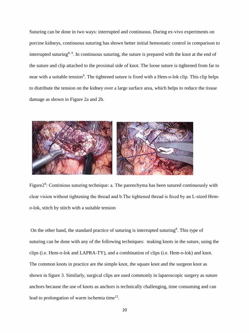
Suturing can be done in two ways: interrupted and continuous. During ex-vivo experiments on
porcine kidneys, continuous suturing has shown better initial hemostatic control in comparison to
interrupted suturing8, 9. In continuous suturing, the suture is prepared with the knot at the end of
the suture and clip attached to the proximal side of knot. The loose suture is tightened from far to
near with a suitable tension9. The tightened suture is fixed with a Hem-o-lok clip. This clip helps
to distribute the tension on the kidney over a large surface area, which helps to reduce the tissue
damage as shown in Figure 2a and 2b.
Figure29: Continious suturing technique: a. The parenchyma has been sutured continuously with
clear vision without tightening the thread and b.The tightened thread is fixed by an L-sized Hem-
o-lok, stitch by stitch with a suitable tension
On the other hand, the standard practice of suturing is interrupted suturing8. This type of
suturing can be done with any of the following techniques: making knots in the suture, using the
clips (i.e. Hem-o-lok and LAPRA-TY), and a combination of clips (i.e. Hem-o-lok) and knot.
The common knots in practice are the simple knot, the square knot and the surgeon knot as
shown in figure 3. Similarly, surgical clips are used commonly in laparoscopic surgery as suture
anchors because the use of knots as anchors is technically challenging, time consuming and can
lead to prolongation of warm ischemia time12.

21
Figure 3: Knot types: a. square knot, b. simple knot and c. surgeon knot
During partial nephrectomy suturing with a Hem-o-lok clip backstopped by LAPRA-TY, the
tension will be applied on the tissue against the Hem-o-lok clip. This clip helps to distribute the
tension on the kidney over a large surface area, which helps to reduce the tissue damage. This
process also helps to readjust the applied tension by sliding a clip towards the damage renal
tissue in order to maintain hemostatic condition, i.e. stoppage of the blood leakage 10. The
locking mechanism of LAPRA-TY clips helps to secure the applied tension on renal tissue using
a particular suture. This is a standard procedure of partial nephrectomy suturing 10, 11.
During robotic partial nephrectomy (RPN), the method of choice for renorrhaphy is now the
sliding-clip technique because it gives the console surgeon precise control over the closure 8.
This is achieved either using two Hem-O-Lok clips or using both LAPRA-TY and Hem-o-lok
clips. Using two Hem-o-lok clips is the best technique because they slide smoothly and have the
lowest risk of renal violation due to their larger footprint8, 12. The process for sliding-clip
renorrhaphy for renal partial nephrectomy is as follows: LAPRA-TY clips and Hem-o-lok clips
will be placed above a knot tied at the end of the suture and the assistant places a second Hem-O-

22
Lok clip on the loose end of the suture after the suture has been placed through the opposite ends
of the renal parenchyma13. The clip is applied so that the suture is in the center of the jaws of the
clip because this helps it to slide smoothly14. A robotic needle driver with jaws slightly open
helps to slide the Hem-o-Lok clip down the suture towards the kidney until tightly opposed to the
renal parenchyma. This allows tension adjustment but does not definitively lock the suture in
position8. Tension adjustment against the renal parenchyma using Hem-o-clip helps in
preventing blood leakage after suturing, which is also known as hemostatic condition11. Finally,
a LAPRA-TY clip is placed to secure the closure as shown in Figure 4.
Figure 4: Sliding-clip renorrhaphy using Hem-o-clip and LAPRA-TY
The critical step during partial nephrectomy is to maintain hemostatic condition, i.e. the arrest of
bleeding from the kidney. Renal hemostatic condition depends on the strength of the renal
capsule and suturing techniques during partial nephrectomy15. There are three patterns of
interrupted suturing techniques like simple suturing, horizontal mattress suturing and vertical
mattress suturing as shown in figure 5.
Hem-o-clip with
LAPRA-TY

23
Simple suture17
Also known as an interrupted suturing. It is simple, and relatively easy to place
In this type of suturing individual stitches aren't connected, which keeps the wound
together even if one suture fails.
Horizontal Mattress 17
Helps to spreads tension along the wound edge so minimize the tension
Ideal for holding together fragile skin as well as skin under high tension such as the
distant edges.
The procedure of suturing in this technique is such that margin of 1 cm should be
maintained in both sides of the wound and the tension should not be applied in suture to
reduce the error.
Vertical Mattress 17
Provides closure for both deep and superficial layers
The disadvantage of this suturing is poor vertical alignment of edges which may cause
tissue damage
The procedure of suturing in this technique is such that a margin of 1 cm should be
maintained in both sides of the wound and the distance between the upper and lower
bites of vertical suture should remain at a half cm.
The current clinical practice for suturing depends on preference of the surgeon. In some cases,
surgeons prefer knot-tying as it is less expensive compared to using surgical clips. However,
surgical clips are replacing the practice of making knots after suturing as tying a knot is more

24
time consuming and difficult1. Surgeons have the impression that one suture technique is
superior to the others for the proper closure of wounds and maintaining hemostatic condition
after partial nephrectomy. However, experimental data to support these techniques are still
lacking16.
Figure 516: Suturing techniques: A. simple suturing, B. Horizontal suturing, C. vertical suturing
Suture is a piece of thread-like material used to stitch tissues and hold the wound together until
healing takes place. It holds the wound tissue together in good apposition until the natural
healing process is sufficiently well established to make the support from the suture material
unnecessary. The size of the suture is defined by its numbers, i.e. 5,2,1,0, 2-0, 3-0.4-0, 5-0, 6-0,
7-0, 8-0, 9-0 and 10-018. The size and its use are described as follows: 18 Suture 5 is largest and
the size 10-0 is the smallest suture. The larger sutures are commonly used for repair of tendons
or other high tension structures in large orthopedic. The smallest size suture is used in delicate
surgeries like ophthalmic surgery18.
There are different types of sutures; the two most important properties are Absorbable Vs Non-
Absorbable and Braided vs. Non-Braided. Absorbable sutures break down over time in the body.
The amount of time for sutures to break down in the body depends on a few factors such as
suture type, size and the location it is placed. Examples of absorbable suture include Monocryl,

25
Vicryl, Chromic, and PDS. On the other hand, non- absorbable suture, when used on the skin
will be removed, and when used in the body, will be retained inside the tissue. The examples of
non-absorbable sutures are as follows: Nylon (Ethilon), Gortex and Silk. Similarly, another
important property of suture is braided and non- braided. Braided sutures have a number of
strands woven together like a string. Examples of braided sutures are: Silk, Vicryl and
Ethibond18. Non-Braided or Monofilament Sutures have a single strand such as Monocryl, PDS,
and Ethilon Nylon. Monofilament sutures incite less tissue reaction and exhibit less tissue drag,
resulting in less tissue tearing because of their smooth surfaces. However, monofilament sutures
are less flexible and, are more difficult to tie in a knot as well as have inferior knot security
because of their tendency to loosen when compared with multifilament sutures. Ideally, one
chooses monofilament sutures in situations where lesser tissue trauma and lower risk of infection
are paramount in tissue healing19. Suture materials should be chosen based on their physical and
biological properties, assessment of local conditions in the particular wound, and the healing rate
of different tissues. However, suture selection has often been governed by training, experience,
economics, and personal preferences rather than by scientific facts19. There are many types of
suture which are commonly used in the field of health sector such as PDS (polydioxanone), Plain
Gut, Vicryl, Chromic, Polyglycolide etc.
1 Chromic sutures are absorbable and monofilament made from either beef serosa or sheep
submucosa. They are most commonly used in OB-GYN surgery and facial plastic or oral
surgery. They lose their tensile strength from 21 days and are completely absorbed in 90
days. The color of this suture is brown or blue dyed18, 19.
2 PDS (polydioxanone) is an absorbable monofilament suture with clear or violet color. The
tensile strength of PDS Size 3-0 and larger is 80% at 2 weeks, 70% at 4 weeks, and 60% at 6
weeks. This suture will completely absorb in 183-238 days. PDS is a long lasting absorbable
26
monofilament suture for soft tissue approximation; it is commonly used to approximate
fascia in open abdominal cases 18, 19.
3 Vicryl is a braided absorbable suture which has tensile strength of 75% at 2 weeks, 50% at 3
weeks and 25% at 4 weeks. This suture will completely absorb within 56-70 days. Vicryl
suture is either violet or white. It is one of the most common sutures used in all surgical
services to approximate soft tissue18, 19.
4 Plain catgut is monofilament absorbable suture and maintains strength for at least 7 days. It
has very high knot-pull tensile strength and good knot security due to special excellent
handling features. The color of this suture is straw. It is not recommended for incisions that
require sustaining the tissues for a prolonged period of time 18, 19.
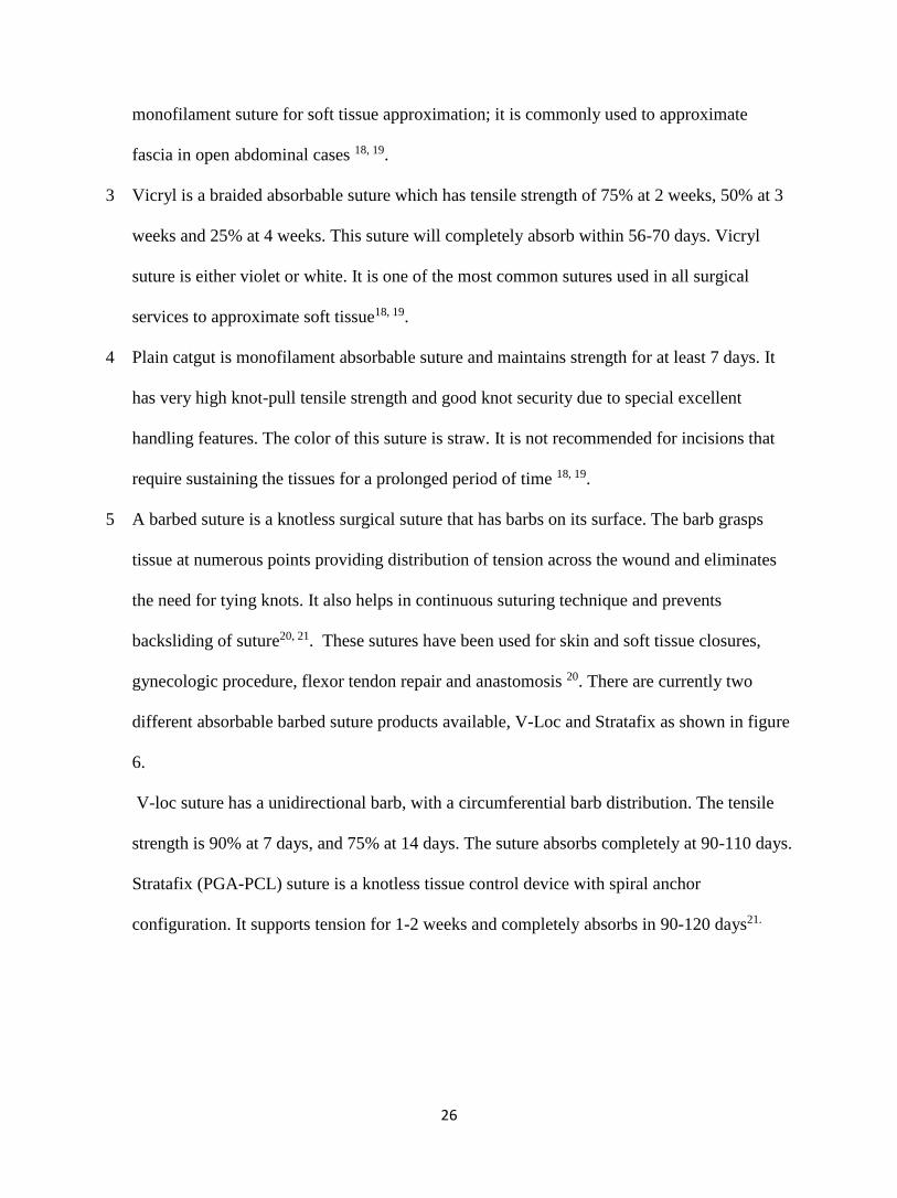
5 A barbed suture is a knotless surgical suture that has barbs on its surface. The barb grasps
tissue at numerous points providing distribution of tension across the wound and eliminates
the need for tying knots. It also helps in continuous suturing technique and prevents
backsliding of suture20, 21. These sutures have been used for skin and soft tissue closures,
gynecologic procedure, flexor tendon repair and anastomosis 20. There are currently two
different absorbable barbed suture products available, V-Loc and Stratafix as shown in figure
6.
V-loc suture has a unidirectional barb, with a circumferential barb distribution. The tensile
strength is 90% at 7 days, and 75% at 14 days. The suture absorbs completely at 90-110 days.
Stratafix (PGA-PCL) suture is a knotless tissue control device with spiral anchor
configuration. It supports tension for 1-2 weeks and completely absorbs in 90-120 days21.

27
Figure 6: Barbed sutures: a. V-Loc b. Stratafix
The purpose of this Master’s thesis is to determine the most secure mechanism for tissue
approximation. There are three different experiments which are as follows: 1. to compare
prototype suture anchors designed by Dr. Brian Lane from Spectrum Health, with standard
anchors (knots and Hem-o-lok) to determine the most secure mechanism for tissue
approximation with suture anchoring technique, 2. To analyze the time require for absorbable
sutures with a given tension expected to support in a controlled temperature. 3. To investigate
the holding strength of Hem-o-lok clip backstopped by LAPRA-TY clip on various suture types
and sizes

28
Experiment 1: Comparison between Prototype suture anchors and conventional suture
anchors
Background/Literature review
Failure in suture anchors is common and generally occurs in two situations: 1. Insufficient
holding strength of anchor causing slippage of suture 2. Tear of renal parenchymal tissue while
applying tension during suturing. This experiment was to compare Prototype suture clips with
conventional suture anchors, i.e. knot without clips and Hem-o-lok clips. The comparison was
based on the amount of force required for the renal parenchymal tissue to tear using those
anchors.
Simon et al. have examined the force required to cause a suture to tear through tissue in frequently used
configurations (simple, vertical mattress, and horizontal mattress formats) 16. However, this experiment
did not address the relation between the measured force and the closing force. Nor did that study consider
the use of surgical clips to terminate simple sutures which is common in laparoscopic procedures.
The other experiment conducted by Simon Kimm used tensometer to determine the amount of
tension necessary to dislodge each of the five different clips from Vicryl suture with an without
intervening pledget11. The clips investigated were LAPRA-TY, Hem-o-lok, Endoclip II Weck
and novel suture clip. The results have shown that Endoclip II Weck and novel suture clips
required significantly greater tension to dislodge than the Hem-o-lok and LAPRA-TY11.
One of the experiments has shown that the holding strength of a single Hem-o-lok clip is more
resistant to cause capsular violation, but less resistant to slippage when compared with a single

29
LAPRA-TY clip10. However, when two Hem-o-lok clips are placed in one in front of another,
the force needed to slip off the suture exceeds that of one LAPRA-TY clip. Similarly, this
experiment shows the use of Hem-o-clip minimizes the renal tissue damage compared to
LAPRA-TY. Figure 7 shows the holding strength and tissue violation force for the LAPRA-TY
and Hem-o-lok clips. The locking mechanism of LAPRA-TY clips helps to ensure closure of a
tissue using a particular suture10.
Figure 710: Holding strength using clips Hem-o-clip and LAPRA-TY
Three different types of prototype clips, i.e. Prototype 1, Prototype 2 and Prototype 3, were
designed by Dr. Brian Lane, MD PhD, who specializes in Urology. Dr. Lane was participated in
this research for preparation of specimens. The size and number of aperture for Prototype clips
designed were varied to test different configurations for closure with more than one suture per
clip in response to renal tissue damage. The goal was to design a clip with a more optimal
surface area to reduce the tissue damage during partial nephrectomy suturing. The Prototype

30
clips were different from each other in shape and size. The approximate area of clips Prototype 1,
Prototype 2 and Prototype 3 were 50 mm2, 138 mm2 and 160 mm2 respectively. Both Prototype 1
and Prototype 2 consist of two apertures and slots as shown in figure 8. The slots extend from
respective ones of the pair of apertures towards the perimeter of the plate. The slots formed a
channel from the perimeter to the respective apertures and, the suture slides through a slot into an
aperture during suturing. Hence, double sutures should apply for each clip type, i.e. Prototype 1
and Prototype 2. Further, the Prototype 3 consists of single aperture and slot.
Figure 8: Prototype clips type
The maximum tension holding capability of an anchor is the amount of tension that can be
applied on the suture without tissue damage. The prototype clips are not designed to secure the
tension on the suture to maintain hemostatic condition, so a knot or LAPRA-TY clip is required
to backstop the anchor. Failure in suture anchor generally occurs either with insufficient holding
strength of anchor causing slippage of suture or with tearing of renal parenchymal tissue while
applying tension during suturing8.

31
The objective of this experiment was as follows: 1. To compare prototype anchors (clips) with
conventional anchors, i.e. Hem-o-lok anchor 2.To determine the effectiveness of the prototype
clips to bolster the suturing so that associated suture strands are less prone to ripping, tearing, or
slicing through the tissue adjacent a wound, incision and void. The analysis was based on the
clip’s size and design. 3. To determine the amount of force that can be applied safely using the
suture anchors which helps to prevent postoperative complications including hemorrhage.
Methodology
This experiment was a comparison of prototype suture anchors (clips) with conventional suture
anchors, i.e. knot and Hem-o-clips. The comparison was based on the amount of force required
for the renal parenchymal tissue to tear using those anchors. This experiment helped to conclude
the effectiveness of prototype anchors developed by Dr. Lane as this design was designed to
reduce the tearing of the real parenchymal tissue and to increase the tension holding capability of
kidney for a hemostatic condition. The kidney samples for a test was came from plants
processing agriculturally raised pork. The quality of kidney was preserved by ice during the
storage interval.
To apply the tension on renal tissue, an automated material testing system (MTS Mini-Bionix)
was used with the Wagner FDV-10 digital force gauge (DFG). The MTS Mini-Bionix controlled
the velocity and an acceleration of tension applied on the suture and the DFG measured the force
applied on the suture. The DFG is an electronic force gage with an accuracy of ±0.3% ± 1 least
significant digit. The MTS Mini-Bionix is a machine used to test peel, tear, shear, tensile,
compression, and flex/bend of a material. In this experiment this machine was used to apply
tension to an attached suture with control on acceleration and velocity. Movement of the

32
crosshead of this machine determines the amount of tension applied on sutures. The figure 9
shows the MTS Mini-Bionix.
Figure 9: MTS Mini-Bionix
To measure the force applied, the clamping jaw was removed from the MTS and the Wagner
DFG was attached to the Mini-Bionix ram as shown in figure 10. Station manager software was
used to control the MTS ram speed. Travel speed of the ram was adjusted to a constant 1 cm per
second to minimize the effect of acceleration during tension on renal tissue.

33
Figure 10: DFG with MTS mini Bionix
The calibration of DFG was completed by hanging laboratory masses from the force gauge and
verifying the displayed value. The displacement of the MTS Mini-Bionix was calibrated by the
ruler. Figure 11 shows the calibration of DFG and MTS Mini-Bionix.
Figure 11: Calibration of DFG and MTS Mini Bionix

34
The kidney samples for a test came from plants processing agriculturally raised pork. The quality
of kidney was preserved with ice during the storage of approximately 5 hours. During an
experiment, an approximately 4 cm diameter by 2 cm deep defect was created on the porcine
kidney representing the removal of a tumor using techniques regularly employed in laparoscopic
partial nephrectomy (LPN) surgeries as shown in figure 12. Similarly, a channel was created at
the two ends of the kidney which helped to pass the sutures towards the DFG hook without
interfering with tissue during an experiment. The surgeon sutured the void using Vicryl 2-0
sutures and the clips. The slippage of clips was secured with a knot for all clips.
Figure 12: Defect on kidney creating Procedure
During the experiment, two sutures were applied at 1 cm margin from the wound for all different
type of anchors to make identical suturing condition with Prototype 1 and Prototype 2. The
experiment was performed with double Hem-o-lok clips, double Prototype 3 clips and double
knots with a distance between the sutures of 0.8 cm. This distance between sutures is the same as
a distance between the apertures in Prototype 1 and Prototype 2 clips. Figure 13 shows the
prototype clip and Hem-o-lok clips applied on a porcine kidney.

35
Figure 13: Comparison of prototype clip and Hem-o-lok clips
The revolving holder was designed to position the kidney during an experiment as shown in
figure 14. The sampled kidney was positioned in the revolving kidney holder attached with
medical leucoplast (medical tape) and latex free self -adherent wrap. The positioned kidney
could revolve in different angles and could fix using a locking system on a design.
Figure 14: Design of revolving kidney holder

36
The holder was positioned at vertical plane to represent the suturing force applied on sutured
tissue similar to the suturing force applied during a surgery. The tail of the sutures were
connected and attached to a Wagner force gauge (WFG) for tension measurement. The revolving
holder with MTS Mini Bionix and DFG is shown in figure 15.
Figure 15: Revolving holder with MTS Mini Bionix and DFG
Suture was pulled with the help of a MTS Mini Bionix machine at a speed of 1 cm per second.
The applied tension was directly recorded on a laptop interfaced to the WFG using a Matlab
program. Failure tension data was obtained by continuing to increase the force on the suture until
the tissue damage occurred which resulted in rapid decrease in applied suture tension as shown
in figure 16. The procedure was also visually recorded by a high-definition web camera as shown
in experimental setup figure 1522.

37
Figure 16: Tension holding strength of renal tissue
Force measured by the DFG was recorded in the computer using a Matlab program to record and
post process tension data23. The program included a graphical user interface, which provided
START/STOP control with feedback and real-time graphing of force recorded by DFG23. The
Matlab program for post-process tension data eliminated the need of for hand-written calculation
as the program collected force measurement directly in an Excel sheet23. Digital force gauge with
the MTS Mini-Bionix test station and station manager software enabled force measurement. The
figure 17 shows the block diagram of data recording procedure for this experiment.

38
Figure 17: Block diagram of data recording process
Result
The tension at which renal parenchyma tissue failed during an experiment was recorded. The
total number of samples for this experiment was 30. The mean failure tensions for suture anchors
were knots (2.7N ± 0.53N), Prototype 2(4.0 N± 1.6N), Hem-o-lok (5.4 N+0.72N), Prototype
1(5.6 N±0.75N), and Prototype 3(6.0 N±3.39N). The normality of tissue failure tension recorded
for five different anchors was analyzed using Shapiro Wilk test24, 25. The p-value of this test was
0.3228 which is greater than significance level indicating that the Studentized Residual of
collected data is normally distributed. Levene’s test was used to test the equality of the variance
for tension data collected for different anchors. Data collected from this experiment has the weak
evidence of normal distribution, hence, Levene’s test was chosen for variance test. The data
collected for different anchors has unequal variance, as a p value is 0.0154, which is less than
significance level, i.e. 0.2, for Levene’s test.

39
Welch’s test was used to compare the anchors from each other with condition of unequal
variance and normally distributed studentized residual24, 25, 26. The p-value of Welch’s test was
0.0039, which is less than 0.05. The Welch’s test provided a significant evidence of difference in
mean tension recorded for five different anchors. Figure 18 shows the mean value and S.D of
tension data for each anchor type with significant difference between a standard stop knot with
anchors Hem-o-lok, Prototype 1 and Prototype3.
Figure 18: Mean failure force for suture anchors
Multiple comparisons were performed to determine the relationship between five suture anchors
using Tukey's HSD test as shown in table 1. The anchors Prototype 1, Prototype 3 and Hem-o-
lok were significantly different from anchor knot, as the p value is less than 0.05. The anchors
Prototype 3, Prototype 1 and Hem-o-lok were not significantly different from each other. The
tension at which renal tissue failed using knots as anchor was significantly different from the
other four anchors, as it failed at tension 2.73 N. During partial nephrectomy suturing, the
surgeon rarely anchors the suture with knots without additional clips.

40
Table 1: Comparison of mean tension value between different anchors (pairwise comparison
Tukey’s HSD at the confidence level 95%)
Discussion
The Tukey’s HSD test at the confidence level 95% had shown no significant difference in
maximum tension holding capability between the anchors Prototype 1, Prototype 3 and Hem-o-
lok. However, those anchors were significantly different from knots. Prototype 2 was neither
significantly different nor similar to other anchors. This implies that the amount of tension
required tearing the tissue during partial nephrectomy suturing increases with increase in clip
area. In addition, the mean tension for tissue failure with only knot as an anchor was smaller than
other anchors. Furthermore, the configuration of knot as an anchor is significantly different in
maximum tension holding capability with the confidence level of 95% from the anchors
Prototype 1, Prototype 3 and Hem-o-lok anchors. During an experiment, the suturing of renal
tissue using knot as an anchor failed on average at a tension of 2.7 N. The minimum surface area
of knot while suture was pulled against tissue caused this failure. Hence, it is not recommended
to use only a knot as an anchor during partial nephrectomy suturing. The condition of renal tissue

41
suturing failure was tissue tear for all anchor types. There was no slippage of knots applied on
anchors. The approximate mean tensions at which the renal parenchymal tissue failed using
anchors were knots (2.7N), Prototype 2(4.0 N), Hem-o-lok (5.4 N), Prototype 1(5.6 N), and
Prototype 3(6.0 N) at the 95% confidence level.
The experimental condition, i.e. suturing kidney with different clips as anchor backstopped by a
knot closely mimicked the clinical scenario of suturing during partial nephrectomy. This
condition was compared with the knot as only anchor without the clips. The experiment has
shown that anchors larger than a knot improves the tension holding capacity of renal tissue
suturing. The tension required tearing tissue using Prototype 1, Prototype 2, Hem-o-lok and
Prototype 3 were more than that of knot. In addition, our findings are consistent with tensions
measured by Endres (2013)8 in a previous experiment to control bleeding during both perfused
and non-perfused condition of kidney.
NU-KNIT is soft, pliable weave designed to hold a suture and its appropriate placement on
delicate tissue. An experiment was also performed to analyze the efficacy NU-KNIT to increase
the amount of tension required to tear the renal tissue throughout suturing. However, there was
not enough samples size to conclude the efficacy of NU-KNIT. The renal capsule is a tough
fibrous layer surrounding the kidney and is covered in a thick layer of perinephric adipose
tissue. It provides some protection from trauma and damage to a kidney. This experiment has
shown that the tension required tearing the renal parenchymal tissue increases when capsule is
included during suturing. The additional tension can be applied during suturing to maintain
hemostatic condition in the presence of the renal capsule.

42
Limitations of this experiment are as follows: 1. Variation in tension required to tear renal
parenchymal tissue was due to variation of suturing depth and margin. Once the pressure on the
tissue was dispersed by anchors, the defining factor for tissue tearing was the cutting action of
the suture. The properties of renal tissue varied in depth within a kidney; we found that the
tension required to tear the outer cortex tissue is less than inner medulla tissue. 2. Variation in
amount of capsule in the kidney samples was another limitation. The tension required to tear
renal tissue with capsule was more than the tissue without capsule. 3. Preservation of tissue due
to variable amount of storage time of the sample kidney. 4. Small number of samples limited the
statistical relevance of the tests.

43
Experiment 2: Analysis of time required for absorbable sutures with a given tension
expected to support
Background/Literature review
Manufacturers of suture routinely test suture material for tensile strength as part of quality
control procedures. Several independent comparisons of sutures have been performed to
determine the suture strength. Some in vitro and animal studies have shown that pH and bacterial
activity can affect selected suture products 27, 28. A few researchers have conducted in vitro and
animal tests of sutures to quantify tensile strength at selected durations of exposure to
environments simulating in vivo conditions 27. All have used tensile testing at predetermined
time intervals to estimate life expectancy. Results from these studies are reported as absolute
tensile strength of the sutures. None of these studies have measured and reported the time to
failure at the tension necessary to achieve hemostasis in the perfused kidney.
During suturing, suture type should be chosen based on its physical and biological properties,
assessment of local conditions in a wound, and the healing rate of tissue29. Normally body tissue
heals within 21 days of a surgery. Therefore, it is very necessary for a suture to hold the tension
on it for at least 21 days after surgery to maintain homeostatic conditions and to prevent the risk
of re-surgery. Absorbable suture materials tend to degrade with time and lose its tensile strength
within 60 days, as it will be absorbed by the body. For a partial nephrectomy, the experiment
conducted by GVSU master’s student Don Endres had shown that the tension required for a
homeostasis condition is 3.42 +/- 0.7 N during hyper-tension conditions and 3.2 ± 0.7 N during
normal condition. This research helped to understand the tension required for homeostasis during

44
systolic blood pressure representing both normal blood pressure and hypertensive cases4, 23. The
purpose of this experiment is to analyze the tensile strength of different absorbable sutures used
in partial nephrectomy while maintaining similar conditions to the body, i.e. control of
temperature and suture tension. This experiment simulates the in-vivo condition with
temperature was controlled with the help of saline water, a temperature controlled heater and a
circulating pump.
The purpose of this experiment is to analyze the ability of different absorbable sutures to
maintain 4.0 N of tension over a period of time required for healing. During partial nephrectomy
the amount of tension required to achieve hemostasis in the perfused kidney is 4.0 N 4, 23. This
experiment maintains the in-vivo simulated condition with control of temperature. The result of
this experiment will help to explain lifespan of absorbable sutures being used in LPN required
for healing defected renal parenchyma tissue after surgery. Further, it also helps to compare
breakage time for different types and sizes of sutures. This experiment simulates the in-vivo
condition where temperature was controlled with the help of saline water, a temperature
controlled heater and a circulating pump.
Methodology
During this experiment a 4ft x 2ft x 1 inch glass tank was used with a suture support frame
designed with PVC rod pipe as shown in figure 19. Each suture was attached to a spring balance
to apply tension of 4.0 N for simulation of hemostasis in the perfused kidney 4. The tank was
filled with saline solution submerging entire the suture. The spring balances were left dry to
reduce the corrosive effect of the saline on the spring element during the experimental period. A

45
heater was placed inside the tank to keep the temperature of the solution at approximately 37
degrees and a recirculation system was used to match the temperature throughout the tank. The
temperature of the water was maintained by using a sensor with a feedback system30.
Figure 19: Hook support structure design
During the experiment the spring balance iron hook was replaced by the hook designed by
makerbot machine to prevent the iron hook from rusting. The modified hook helped to anchor
the suture with the Hem-o-lok clip and knot at 4.0 N of tension. The Hem-o-lok clip helped to
apply the amount of tension required, whereas the knot prevented the slippage of applied tension.
Two different kinds of polymer hooks were designed as shown in figure 20. The bottom hook
was anchored to a tank base rod, whereas the upper hook was designed for use with a spring
balance. Further, the hooks with small, 0.05 cm diameter holes in the base provided a place to
anchor the suture with the Hem-o-lok and knot. The spring balance helped to detect applied

46
tension on suture which was adjusted by pulling the spring. The spring balance was connected to
an upper PVC rod of a tank with the help of upper hook using a bolt and nut system. The system
was adjusted by loosening or tightening the nut to change the height of the spring. The change in
height of a spring balance helped to adjust the tension on the suture. After setting tension of 4N,
lid of the tank was closed to reduce the rate of water loss from evaporation.
Figure 20: Hooks and spring balance: a. spring balance b. Lower hook design c. upper hook
design.
Tension was applied on sutures with the help of designed hooks, spring balances, Hem-o-lok
clips, figure ‘8’ knots and the tank arrangement. Both ends of suture were anchored on the hooks
with the help of Hem-o-lok clips and knots of the figure ‘8’ type. The knots helped to prevent
suture from slippage. The number of figure ‘8’ knots required to prevent the suture from slipping
depended on the suture thickness. The thinner sutures required more knots, whereas for thicker

47
sutures even single knots helped to prevent slippage. Figure 21 shows the Hem-o-Lok and knots
with a designed lower anchor.
Figure 21: Hem-o-Lok and knots with a lower hook
The steps to make a Figure ‘8’ knot are as follows32:
One end of a suture was taken and folded over itself, but was left space between the end
of the suture and the rest of it, forming a bight.
The end was twisted over the suture itself, which formed a small loop. Finally, placed the
end of the suture was placed into the loop and tightened as shown in figure 22.

48
Figure 22: Figure “8” knot
The knots were used to prevent the slippage of the Hem-o-lok clip. The distance between two
hooks was adjusted to 12 cm to apply 4.0 N tensions on the suture with the help of the spring
balance. Further, the lower hooks were wrapped with steel wire to increase the density of hooks
more than density of saline water. The higher density hooks were easy to hook on to the tank
base rod inside the saline water. The sutures used for this experiment were as follows: Vicryl 0,
Vicryl 2-0, Vicryl 3-0, Vicryl 4-0, Vicryl 5-0 (negative control), Chromic 0, Chromic 2-0,
Chromic 3-0, Chromic 4-0, PDS 1(positive control),PGA-PCL 3-0, PGA-PCL 2-0 and PDO
Stratafix
The sutures were submerged inside the 0.9% saline water, applied 4.0 N tension and were
monitored with the help of a web cam which captures images of the experimental setup at an
interval of 15 minutes. The monitoring system was used to determine the time of suture failure.
Software to save webcam image save software was downloaded in a laptop and the Microsoft
Life cam webcam was connected to the computer. A Google drive folder was used to store the
images recorded by the software22. Finally, the Google drive folder was used to send the images
to the Google drive online. The experimental setup is shown in figure 23.When a suture fails the
following steps were taken:

49
1. All of the sutures fragments and Hem-o-lok clips were taken out of the tank using long
forceps without disturbing other sutures.
2. The piece of the failed suture was laid out on a table and a picture was taken with all of
the suture fragments lined up.
3. The pieces of the failed suture were examined for the breakage point and this point was
noted in a data collection spreadsheet.
4. The suture fragments and the Hem-o-lok clips were placed in an envelope labeled with
the date and time of the failure, hanger number and name of the suture.
5. Webcam images taken just prior to failure the one taken just after failure were included in
a folder.
Figure 23: Experimental setup for tensile strength analysis of absorbable suture

50
Result
Due to the large variance and not symmetrical distribution in the experimental results, the
duration of tension holding time was calculated with the help of the median calculation rather
than mean. During median analysis the effect of outliers is comparatively less than mean. The
negative control had a median duration of 6.5 minutes. The positive control had a median
duration of more than 120 days. Besides the Vicryl 5-0 all other sutures had a median duration of
21 days or more than 21 days. The Chromic 2-0 and Chromic 0 had a median duration of more
than 120 days. Figure 24 shows the median sutures duration of failure.
Figure 24: median sutures duration of failure
0
500
1000
1500
2000
2500
3000
Ten
sio
n D
ura
tio
n (
hr)
Suture Types
Median suture duration

51
Discussion
Tables 2 and 3 show the individual suture failures before 7 days and the 21 days respectively.
The visual observation of an experiment and failed suture indicates that the suture failed before 7
days are due to slippage of knots from Hem-o-lok clips. And the sutures that failed during 21
days are due to suture breakage. We can conclude from the analysis that the commonly used
LPN sutures Vicryl 2-0 and Vicryl 3-0 do not break within 21 days while continuous supporting
a tension of 4N. On the contrary, we found that the suture that failed before 7 days are commonly
due to knot slippage. Therefore, multiple knots should be applied while using the Vicryl sutures.
This experiment shows that the sutures currently in practice for LPN hold 4-0 N tension for at-
least 21 day with proper anchor to prevent slippage. However, sutures Vicryl 5-0, Vicryl 4-0 and
Vicryl 2-0 with minimum number of knots, i.e. 3-4 knots may not hold 4.0 N tension due to
slippage The LAPRA-TY clip helps to prevent the slippage of tension applied during LPN
suturing. The LAPRA-TY clip used to backstop the 4.0 N tensions applied on sutures. However,
the clip did not hold the tension for all suture types. Hence, the clip was replaced by the figure
“8” knot to backstop the tension applied on sutures with hem-o-lok clip. The LAPRA-TY
anchor also helps to prevent the slippage of suture; however, according to the manufacturer, it
should be used only for the specific sizes of Vicryl sutures.

52
Suture failure before seven days
Vicryl 4-0 1 min knot slippage through Hem-o-lok
Vicryl 5-0 4 min knot slippage through Hem-o-lok
Vicryl 5-0 5 min knot slippage through Hem-o-lok
Vicryl 5-0 8 min knot slippage through Hem-o-lok
Vicryl 5-0 1 hr 34 min knot slippage through Hem-o-lok
Vicryl 2-0 5 days 18 hr 30 min knot slippage through Hem-o-lok
Table 2: suture failure before seven days
Suture failure before 21 days
PGA-PCL 2-0 19 days 1 hr 34 min breakage near upper knot
PGA-PCL 2-0 20 days 13 hrs 19 min breakage near upper knot
PGA-PCL 3-0 20 days 18 hrs 30 min breakage near middle of suture
PGA-PCL 3-0 20 days 7 hrs 29 min breakage near lower knot
chromic 4-0 20 days 7 hrs 16 minutes breakage near middle of suture
Vicryl 3-0 20 days 9 hrs 41 minutes breakage near lower knot
Table 3: suture failure before 21 days

53
Experiment 3: Investigation on holding strength of a Hem-o-lok backstopped by Lapra-Ty
clip on various suture types and sizes
Background/Literature review
LAPRA-TY clips are commonly used in laparoscopic surgery as suture anchors because the knot
as an anchor is technically challenging, time consuming and can lead to prolongation of warm
ischemia time 9, 12. Warm ischemia is the time in which the kidney remains at physiological
temperature during absence of blood supply due to clamping of the renal hilar 12, 33. During
partial nephrectomy for larger and deeper tumors, the 30-minute cutoff is the accepted safe limit;
time beyond this may cause irreversible kidney damage due to absence of blood flow 34. Many
laparoscopic surgeons use a LAPRA-TY clip as a substitute for knot tying to improve efficiency
during partial nephrectomy surgery 35, 36. The manufacturer of LAPRA-TY clip states that the
product is intended “for use with single strands of coated Vicryl (polyglactin 910) suture coated
with polyglactin 370 and calcium stearate dyed (violet) braided synthetic absorbable sutures
(sizes 2-0, 3-0, and 4-0)37.” However, some laparoscopic surgeons are applying LAPRA-TY
clips to monofilament suture during vesicourethral anastomosis during laparoscopic radical
prostatectomy. A vesicourethral anastomosis is the most challenging and time-consuming step of
radical prostatectomy37. It is a process of connecting the bladder neck with the membranous
urethra. The experiment on holding strength of LAPRA-TY and Hem-o-lok clips for different
sutures helps to find the tension at which the clip starts to slip from the suture.
Robot-assisted partial nephrectomy (RAPN) is an emerging technique for minimally invasive
nephron-sparing surgery that may facilitate the technical challenges of sutured renorrhaphy38.

54
Barbed suture is a technology that has been used for RAPN as it increases efficiency, decreases
warm ischemia time, and creates a non-significant reduction in overall procedure time 20, 21. The
barb grasps tissue at numerous points providing distribution of tension across the wound and
eliminates the need for tying knots211. However, when faced with newer barbed sutures, many
surgeons are initially skeptical with regard to the strength of the knotless, barbed suture lines as
compared with traditional knotted, smooth suture lines21. There are limited reports regarding the
holding strength of Hem-o-lok clips backstopped with LAPRA-TY anchors for barb suture.
In an experiment conducted by Kyle J. Weld, LAPRA-TY holding strength and displacement
were determined with 0, 2-0, 3-0, and 4-0 Vicryl, Monocryl, and Polydioxanone suture (PDS)
using an automated materials testing system37. Material Testing System(MTS) or Automated
Materials Testing System (AMTS) help to evaluate the mechanical properties of materials and
components using tension, compression, flexure, fatigue, impact, torsion and hardness tests.
AMTS recorded raw data and computed the load over time. The holding strength was defined as
the maximum load recorded at the instant just before failure (detachment of suture from LAPRA-
TY when the load was applied at a constant speed of 12 mm/min on the suture against LAPRA-
TY) 37. Displacement was defined as the distance traveled by the AMTS arm until the failure.
The experiment showed that the holding strength for 0 Vicryl and Monocryl was significantly
greater than for 0 PDS, for 2-0 Vicryl was significantly greater than for 2-0 Monocryl and PDS,
and for 3-0 Vicryl was significantly greater than for 3-0 Monocryl and PDS23. The figure 25
shows the result of an experiment conducted by Kyle J. Weld37.

55
Figure 2537: Mean LAPRA-TY holding strength
The experiment conducted by Jesse Sammon described the clinical study of barbed suture for
renorrhaphy during RAPN in human patients and compared perioperative outcomes to RAPN
with polyglactin suture. The result had shown that the barbed suture simplifies the renorrhaphy
technique during RAPN and improves efficiency, allowing for reduced warm ischemia times20.
During LPN suturing, the holding strength of tissue is defined as the maximum load recorded at
the instant just before tissue failure. In this experiment, the holding strength is defined as the
maximum tension recorded at the instant just before the LAPRA-TY slippage. The use of
LAPRA-TY is common during laparoscopic surgery because the use of knots as anchors is
technically challenging and time consuming. LAPRA-TY slippage could cause loosening of the
suture, inadequate tissue approximation, and potentially urinary extravasations39, 40. The purpose
of this experiment is to analyze the tension holding capability of Hem-o-lok backstopped by
LAPRA-TY anchor for different sutures: Vicryl, Monocryl, and Chromic, Vloc and Stratafix.
From the first experiment, we found that the amount of the tension that can be applied safely

56
without observable tissue damage in renal parenchyma tissue during suturing was approximately
5 N using Hem-o-lok anchors with knots as backstop. This experiment helps to find whether the
Hem-o-Lok clip backstopped by LAPRA-TY hold the tension of at least 5 N for a variety of
suture types and sizes.
Methodology
The holding strength of LAPRA-TY anchor for different sutures like Vicryl, Monocryl,
Chromic, V-Loc and Stratafix was tested using mechanical testing system, MTS Mini Bionix and
Wagner FDV (digital force gauge). The Digital Force Gage is an electronic force gage with
Accuracy ±0.3% ± 1 least significant digit (LSD). Suture tension can be estimated using a
Wagner FDV-10 digital force gauge (DFG) with a 10 pound (0 to 44 Newton) load cell in place
with 0.1 N resolutions. Calibration was done by hanging laboratory masses from the force gauge
and verifying the display value with graphs recorded from Matlab program. Matlab was used to
record tension with time applied to suture. Similarly, the MTS Mini-Bionix machine was used to
control the effect of acceleration and velocity during an experiment. Movement of crosshead of
this machine determines the amount of tension applied on sutures. To measure the force applied,
the clamping jaw was removed from the MTS and the Wagner DFG was attached to the Mini-
Bionix ram. Station manager software was used to control the MTS ram speed.
During this experiment the length of the suture and the position of the LAPRA-TY clip were
made constant. The length of the suture was 14 cm and a LAPRA-TY clip was applied exactly 1
cm from the end of a suture as a back stop of a Hem-o-lok clip with the help of a LAPRA-TY
clip. The suture and LAPRA-TY were submerged in sterile saline just before testing to simulate

57
clinical conditions, i.e. suture passing through healthy tissue. The procedure of clip application
on suture is shown in figure 26.
Figure 26: Application of clips on suture
The opposite end of the suture was threaded through a 2-mm hole in a specially designed slab
before securing it to the clamp design which was attached to digital force gauge (DFG). The
clamp design helped to clamp the suture without slippage and to connect suture with DFG as
shown in figure 27. During the calibration of a clamp, the suture was marked at the edge of
clamp. Tension was applied on suture until it broke or LAPRA-TY slipped with the help of MTS
Mini Bionix. The sutures were either slipped or broke without slippage from the clamp. The
DFG applied the load on the suture with the help of MTS Mini Bionix. The 2-mm hole allowed
the suture to easily slide through the plate but restrained the Hem-o-lok and LAPRA-TY at a
fixed position under the slab designed while the load was applied upward on the suture. The
constant load was applied at a speed of 12 mm/min.

58
Figure 27: Holding strength of Hem-o-lok back stopped by LAPRA-TY
The applied tension was directly recorded on a laptop as Wagner DFG will interface with the
computer so that the force is logged to a file by a Matlab program running on the computer23.
The increasing tension on the suture will be acquired continuously by the program until the
LAPRA-TY slips or suture breaks. This force appears as a sudden sharp decrease on tension
recorded by the DFG. USB to serial converter was used as an interface between DFG and
computer. Force from DFG was recorded in the computer using Matlab Software. The program
includes real-time graphing of force recorded by DFG. Digital force gauge with the MTS Mini-
Bionix test station and station manager software enables force measurement. Visual recording of
the suture failure will record by the help of high definition web camera. This helps careful
review of the suture failure with the applied tension.

59
The holding strength in this experiment is defined as the maximum load recorded at the instant
just before LAPRA-TY slippage. The holding strength of LAPRA-TY clips was recorded for 23
different types of sutures, i.e. Vicryl(1,0, 2-0, 3-0, 4-0), Monocryl(1,0, 2-0, 3-0, 4-0), Chromic(
1,0, 2-0, 3-0, 4-0), V-Loc(0, 2-0, 3-0, 4-0) and Stratafix(0, 2, 3, 4). The manufacturer provided
tensile strength size, which was used for the Stratafix suture to compare to other sutures. The
number of samples for each suture size and type is 7.
Result
The mean holding strength of sutures was determined during post-experiment processing using
the Excel software. The holding strength in this experiment is defined as the maximum load
recorded at the instant just before LAPRA-TY slippage. The holding strength of clips (Hem-o-
lok backstopped by LAPRA-TY clip) was analyzed in two different ways as follows: 1.
Comparison of holding strength of clips on different suture types for each suture size. For
example, for suture size 2-0 the sutures Vicryl 2-0, Monocryl 2-0, Chromic 2-0, V-Loc 2-0 and
Stratafix 2 were compared with each other.
2. Comparison of holding strength of clips on different suture sizes for each suture type. For
example, for suture type Vicryl the sutures Vicryl 1, Vicryl 0, Vicryl 1-0, Vicryl 2-0, Vicryl 3-0
and Vicryl 4-0 were compared with each other.
Four different investigations which were conducted in this experiment are listed below:
1. Comparison of holding strength of clips on different suture types for each suture size
2. Comparison of holding strength of clips on different suture sizes for each suture type.
3. Comparison of clips holding time before slippage for suture size 2-0

60
4. Comparison of holding strength clips for barbed suture, i.e. toward and against barb
1. Comparison of holding strength of clips on different suture types for each suture size
The holding strength of clips (LAPRA-TY clip backstopped by Hem-o-lok clip) was compared
from one type to another within the suture size. The sutures Vicryl, Monocryl, Chromic, Stratafix
and V-Loc were compared from each other within suture sizes 0, 2-0, 3-0 and 4-0. The suture
size 1 does not have type Stratafix and V-Loc. The figure 28 shows the mean holding strength of
clips for different suture types within each suture size.
JMP software was used to analyze the ANOVA test and post- hoc test. The steps to perform the
analysis using JMP software is shown in appendix A. The ANOVA test was used to determine
the significant difference between the mean of sutures. Tukey's HSD test was performed to
determine significant difference of each suture from other sutures. Tukey's HSD test is a post-
hoc test; it is performed after an analysis of variance (ANOVA) test26. Tukey’s HSD test
calculates a new critical value that can be used to evaluate whether differences between any two
pairs of means are significant. The post hoc test table shows the higher mean in positive level
and a lower mean in negative level. The difference in the table shows difference between mean
in positive and negative level.
The lower and upper confidence level (CL) shows the range of value where difference of mean
calculated exists. The p-value shows the significance level between the means. If the p value is
less than 0.05 the means are significantly different else no difference.

61
Figure 28: Mean holding strength of clips on different suture types for each suture size
a. Sutures 1
The Shapiro-Wilk W test showed that the holding strength of sutures of size 1 is normally
distributed (p = 0.64>0.05). Whereas, the Levene's test showed that the sutures of size 1 have
unequal variance (p = 0.1551 < 0.2). Welch’s test on suture tensions revealed a significant effect
related to tension (p < 0.0006).
The Tukey’s HSD test was used to determine significant difference of each suture type from
other sutures type as shown in table 4. The post hoc test showed that the holding strength of
Monocryl 1 and Chromic 1 are significantly higher than the holding strength of Vicryl 1.

62
Table 4: Post hoc test for suture size 1 (pairwise comparison Tukey’s HSD with confidence
interval 95%)
b. Suture 0
The Shapiro-Wilk W test showed that the holding strength of sutures of size 0 is not normally
distributed (p = 0.0272<0.05). Hence, the normality was checked by obtaining the studentized
residual. The Shapiro-Wilk W test of studentized residual showed the holding strength of sutures
size 0 normally distributed (p=0.0842>0.05). The Levene's test showed that the sutures of size 0
have unequal variance (p = 0.0787 > 0.2). The Welch’s test on suture tensions revealed
significant effect related to tension (p < 0.0001).
The Tukey’s HSD test was used to determine significant difference of each suture type from
other sutures type as shown in table 5. The post hoc test showed that the holding strength of
Monocryl -0, Chromic-0, V-Loc 0 and Stratafix 0 are significantly greater than Vicryl-0.
Table 5: Post hoc test for suture size 0 (pairwise comparison Tukey’s HSD with confidence
interval 95%)

63
c. Sutures 2-0
The Shapiro-Wilk W test showed that the holding strength of sutures of size 2-0 is normally
distributed (p = 0.3670), whereas, the Levene's test showed that the sutures of size 2-0 have
equal variance (p = 0.2293 > 0.2). An analysis of variance on suture tension revealed significant
effect related to tension (p < 0.0001)
The Tukey’s HSD test was used to determine significant difference of each suture type from
other sutures type as shown in table 6. The post hoc test showed that the holding strength of Vloc
2-0, Stratafix 2 and Chromic 2-0 are significantly greater than the holding strength of Vicryl 2-0,
Stratafix 2 and Vloc 2-0 are significantly greater than Monocryl 2-0, and Vloc 2-0 is
significantly greater than Chromic 2-0.
Table 6: Post hoc test for suture size 2-0 (pairwise comparison Tukey’s HSD with confidence
interval 95%)
d. Sutures 3-0
The Shapiro-Wilk W test showed that the holding strength of sutures of size 3-0 is normally
distributed (p = 0.0574). Whereas, the Levene's test showed that the sutures of size 3-0 have

64
unequal variance (p = 0.0143 < 0.2). Welch’s test on suture tensions revealed significant effect
related to tension (p < 0.0001).
The Tukey’s HSD test was used to determine significant difference of each suture type from
other sutures type as shown in table 7. The post hoc test showed that the holding strength of Vloc
3-0, Stratafix 3, Monocryl 3-0 and Chromic 3-0 are significantly greater than the holding
strength of Vicryl 3-0, Stratafix 3 is a significantly greater than Monocryl 3-0 and Chromic 3-0,
and Vloc 3-0 is significantly greater than Monocryl 3-0 and Chromic 3-0.
Table 7: Post hoc test for suture size 3-0 (pairwise comparison Tukey’s HSD with confidence
interval 95%
e. Sutures 4-0
The Shapiro-Wilk W test showed that the holding strength of sutures of size 4-0 is normally
distributed (p = 0.0972). Whereas, the Levene's test showed that the sutures of size 4-0 have
equal variance (p = 0.5437 > 0.2). An analysis of variance on suture tensions significant effect
related to tension (p < 0.0001).
The Tukey’s HSD test was used to determine significant difference of each suture type from
other sutures type as shown in table 8. The post hoc test showed that the holding strength of Vloc

65
4-0 is significantly greater than Stratafix 4, Monocryl 4-0, Vicryl 4-0 and Chromic 4-0 and,
Chromic 4-0 and Monocryl 4-0 are significantly greater than the holding strength of Vicryl 4-0.
Table 8: Post hoc test for suture size 4-0 (pairwise comparison Tukey’s HSD with confidence
interval 95%
2. Comparison of holding strength of clips on different suture sizes for each suture type.
The holding strength of clips (LAPRA-TY clip backstopped by Hem-o-lok clip) was compared
from one size to another within the suture type. This analysis helps to compare the suture sizes
within the suture type. The suture sizes 0, 1, 2-0, 3-0 and 4-0 were compared from each other
within suture types, i.e. Vicryl, Chromic, Monocryl, Stratafix and V-Loc. The suture type V-Loc
and Stratafix does not have size 1. The figure 29 shows the mean holding strength of clips for
different suture sizes within each suture size.
JMP software was used to analyze the ANOVA test and post- hoc test. The steps to perform the
analysis using JMP software is shown in appendix A. The ANOVA test was used to determine

66
the significant difference between the mean of sutures. Tukey's HSD test was performed to
determine significant difference of each suture from other sutures. Tukey's HSD test is a post-
hoc test; it is performed after an analysis of variance (ANOVA) test. Tukey’s HSD test calculates
a new critical value that can be used to evaluate whether differences between any two pairs of
means are significant. The post hoc test table shows the higher mean in positive level and a lower
mean in negative level. The difference in the table shows difference between mean in positive
and negative level.
The lower and upper confidence level (CL) shows the range of value where difference of mean
calculated exists. The p-value shows the significance level between the means. If the p value is
less than 0.05 the means are significantly different else no difference.
Figure 29: Mean holding strength of clips on different suture sizes for each suture type

67
a. Vicryl
The Shapiro-Wilk W test showed that the holding strength of Hem-o-Lok clip backstopped by
LAPRA-TY clip for Vicryl sutures were normally distributed (p = 0.1570>0.05). Whereas, the
Levene's test showed that the Vicryl sutures have unequal variance (p = 0.1158 < 0.2). With a
condition of unequal variance, the Welch’s test on suture tensions revealed a significant effect
related to tension (p < 0.0001).
The Tukey’s HSD test was used to determine significant difference of each suture size from
other suture sizes as shown in table 9. The post hoc test showed that the holding strength for
Vicryl 1 is significantly higher than the holding strength for Vicryl 4-0, Vicryl 3-0 and Vicryl 2-
0. Vicryl 0 is significantly higher than Vicryl 4-0 and Vicryl 3-0.
Table 9: Post hoc test for Vicryl sutures (pairwise comparison Tukey’s HSD with confidence
interval 95%)
b. Monocryl
The Shapiro-Wilk W test showed that the holding strength of Hem-o-Lok clip backstopped by
LAPRA-TY clip for Monocryl sutures were normally distributed (p = 0.1041>0.05). Whereas,
the Levene's test showed that the Vicryl sutures have unequal variance (p = 0.0399 < 0.2). With a

68
condition of unequal variance, the Welch’s test on suture tensions revealed a significant effect
related to tension (p < 0.0001).
The Tukey’s HSD test was used to determine significant difference of each suture size from
other suture sizes as shown in table 10. The post hoc test showed that the holding strength for
Monocryl 0 is significantly higher than the holding strength for Monocryl 4-0, Monocryl 3-0,
Monocryl 2-0 and Monocryl 1. The Monocryl 1 is significantly higher than Monocryl 4-0,
Monocryl 3-0 and Monocryl 2-0.
Table 10: Post hoc test for Monocryl sutures (pairwise comparison Tukey’s HSD with
confidence interval 95%)
c. Chromic
The Shapiro-Wilk W test showed that the holding strength of Hem-o-Lok clip backstopped by
LAPRA-TY clip for Chromic sutures were normally distributed (p = 0.5722>0.05). The Levene's
test showed that the Chromic sutures have equal variance (p = 0.7692 > 0.2). With a condition of
equal variance, the ANOVA test on suture tensions revealed a significant effect related to tension
(p < 0.0001).
The Tukey’s HSD test was used to determine significant difference of each suture size from
other suture sizes as shown in table 11. The post hoc test showed that the holding strength for

69
Chromic 1, Chromic 0 and Chromic 2-0 are significantly higher than the holding strength for
Chromic 4-0 and Chromic 3-0.
Table 11: Post hoc test for Chromic sutures (pairwise comparison Tukey’s HSD with confidence
interval 95%)
d. Stratafix
The Shapiro-Wilk W test showed that the holding strength of Hem-o-Lok clip backstopped by
LAPRA-TY clip for Stratafix sutures were normally distributed (p = 0.7024>0.05). Whereas, the
Levene's test showed that the Stratafix sutures have equal variance (p = 0.5396 > 0.2). With a
condition of equal variance, the ANOVA test on suture tensions revealed a significant effect
related to tension (p < 0.0001).
The Tukey’s HSD test was used to determine significant difference of each suture size from
other suture sizes as shown in table 12.The post hoc test showed that the holding strength for
Stratafix 0, Stratafix 2 and Stratafix 3 is significantly higher than the holding strength for
Stratafix 4.

70
Table 12: Post hoc test for Stratafix sutures (pairwise comparison Tukey’s HSD with confidence
interval 95%)
e. V-Loc
The Shapiro-Wilk W test showed that the holding strength of Hem-o-Lok clip backstopped by
LAPRA-TY clip for V-Loc sutures were normally distributed (p = 0.1190>0.05). Whereas, the
Levene's test showed that the V-Loc sutures have equal variance (p = 0.0921 < 0.2). With a
condition of unequal variance, the Welch’s test on suture tensions revealed a significant effect
related to tension (p = 0.0097).
The Tukey’s HSD test was used to determine significant difference of each suture size from
other suture sizes as shown in table 13. The post hoc test showed that the holding strength for V-
Loc 2-0 and V-Loc 3-0 are significantly higher than the holding strength for V-Loc 4-0.
Table 13: Post hoc test for V-loc sutures (pairwise comparison Tukey’s HSD with confidence
interval 95%)

71
3. Comparison of time at which clips starts to slip from suture size 2-0
The tension holding time of LAPRA-TY clip with Hem-o-lok clip before slippage was analyzed
for sutures of size 2-0 as shown in figure 30. The suture of size 2-0 is more common in use
during partial nephrectomy suturing. This analysis with reference figure 32 helps to determine
the characteristics of sutures based on their stretch. The approximate mean time(s), at which the
clips (LAPRA-TY and Hem-o-lok) start to slip were Vicryl 2-0 (23 s), Chromic 2-0(24 s),
Stratafix 2 (90 s), Monocryl 2-0(106 s), and V-Loc 2-0(111 s).
JMP software was used to analyze the ANOVA test and post- hoc test. The steps to perform the
analysis using JMP software is shown in appendix A. The ANOVA test was used to determine
the significant difference between the mean of sutures. Tukey's HSD test was performed to
determine significant difference of each suture from other sutures. Tukey's HSD test is a post-
hoc test; it is performed after an analysis of variance (ANOVA) test. Tukey’s HSD test calculates
a new critical value that can be used to evaluate whether differences between any two pairs of
means are significant. The post hoc test table shows the higher mean in positive level and a lower
mean in negative level. The difference in the table shows difference between mean in positive
and negative level.
The lower and upper confidence level (CL) shows the range of value where difference of mean
calculated exists. The p-value shows the significance level between the means. If the p value is
less than 0.05 the means are significantly different else no difference.

72
Figure 30: Comparison of time at which clips starts to slip from suture size 2-0
The Shapiro-Wilk W test showed that the tension holding time of Hem-o-Lok clip backstopped
by LAPRA-TY clip before slippage for sutures Vicryl, Monocryl, Chromic, Stratafix and V-Loc
were not normally distributed (p < 0.0002<0.05). Hence, the studentized residual data were
obtained. The p-value of this test was 0.1932 which is greater than 0.05 indicating that the
Studentized Residual of collected data is normally distributed. The Levene's test showed that
the holding time of sutures have equal variance (p = 0.2492 > 0.2). With a condition of equal
variance and normal distribution, the ANOVA test on suture tensions revealed a significant
effect related to tension (p < 0.0001).
The post hoc test showed that the holding time for V-Loc 2-0 is significantly higher than the
holding strength for Vicryl 2-0, Stratafix 2 and Chromic 2-0. The sutures Monocryl 2-0 and
Stratafix have significantly higher holding time than Vicryl 2-0 and Chromic 2-0.

73
Table 14: Post hoc test for Comparison of time at which clips starts to slip from suture size 2-0
(pairwise comparison Tukey’s HSD with confidence interval 95%)
The figure 31 shows the total slippage time of sutures Monocryl, Vicryl, Chromic, V-Loc and
Stratafix. From the experiment, we found that Monocryl suture required the maximum amount
of time to slip LAPRA-TY completely from a 1 cm long suture tail.
Figure 31: Total slippage time of clips on sutures

74
Figure 32 shows approximate pattern of tension recorded as holding strength of LAPRA-TY
with Hem-o-lok for sutures Vicryl, Monocryl, Chromic, V-loc and Stratafix of size 2-0. The
marker shows the maximum holding strength recorded before the clips slippage.
Figure 32: Recorded tensions for sutures of size 2-0
Figure 33 and Figure 34 shows the holding strength recorded for Vicryl 2-0 and Monocryl 2-0
sutures. The graph of each suture has an approximate pattern similar to other sutures only within
the same suture size and type. The similarity of pattern only within the same suture size and type
implies that the variation in characteristics of sutures with size and type. The Monocryl sutures
stretch more than Vicryl suture in reference to figure 30. The figure 30 the time at which the
clips starts to slip for Monocryl 2-0 is higher than Vicryl 2-0. In addition, the graph of
Monocryl 2-0 sutures holding strength shows two outliers. Appendix ‘J’ shows the overall

75
graphs of the data collected during AN experiment “Holding strength of Hem-o-lok backstopped
by a LAPRA-TY clip for different sutures”.
Figure 33: Holding strength for Vicryl 2-0 sutures
Figure 34: Holding strength for Monocryl 2-0 sutures

76
4. Comparison of holding strength clips for barbed suture, i.e. toward and against barb
A barbed suture is a type of knotless surgical suture that has barbs on its surface. While
suturing tissue, these barbs penetrate inside the tissue and lock them into place, eliminating the
need for knots to tie the suture. The Clips on barbed sutures can be applied in two methods, i.e.
clips forcing against the barbed direction and with the barbed direction. Figure 35 shows the
direction of clips force on barbed suture.
Figure 35: LAPRA-TY clips on barbed sutures: A. LAPRA-TY clip against barb B. LAPRA-TY
clip towards barb
The holding strength of LAPRA-TY for barb sutures was analyzed based on the placement of
LAPRA-TY on suture, i.e. LAPRA-TY towards the barb or against the barb as shown in figure

77
35. The comparison was made for 3 different kinds of barb sutures, i.e. V-Loc 2-0, V-Loc 3-0
and Stratafix 3-0 as shown in figure 36. The Wilcoxon Signed Rank Test revealed that there is no
significant difference between holding strength of LAPRA-TY towards and against barb with a
significance level 0.05. Appendix ‘I’ shows the statistical for comparison of barbed sutures
against and towards barb.
Figure 36: Comparison of clips on barbed sutures (towards and against)
Discussion
The holding tension in this experiment was defined as the maximum load recorded at the instant
just before LAPRA-TY starts to slip. During this experiment, the Stratafix suture sizes were
tensile strength sizes (0, 2, 3 and 4). The holding strength of clips (Hem-o-lok clip backstopped
by LAPRA-TY clip) for different suture types were compared to each other based on suture
types on each size of suture. There was a significant difference in holding strength of clips for

78
different suture types within each size, i.e. suture 1(p=0.0006), suture 0(p<0.0001), suture 2-
0(p<0.0001), suture 3-0(p<0.0001) and suture 4-0(p<0.0001). The confidence level for this test
was 95%. For all suture sizes holding strength of LAPRA-TY was minimum for Vicryl sutures
and maximum for V-Loc sutures. The post hoc test showed that only the holding strength of V-
Loc 4-0 is significantly greater than Stratafix 4, with a p value <0.0001 and confidence level
95%. In reference to the porcine kidney experiment, the tissue tears at tension on average of
about 5.5 N using a standard clipping technique of Hem-o-lok clip with a knot backstop. This
experiment shows that the holding tension of a Hem-o-lok backstopped by a LAPRA-TY
supports the application of tension greater than 5.5 N except for sutures, Vicryl 3-0 and Vicryl 4-
0.
In addition, the holding strength of clips for different suture sizes were compared to each other
based on suture types on each size of suture. There was a significant difference in holding
strength of clips for different suture types within each size, i.e. Vicryl (p=0.0005), Monocryl
(p<0.0001), Chromic (p<0.0001), Stratafix (p<0.0001) and V-Loc (p=0.0097). The significance
level for this test was 0.05. The post hoc test showed that the holding strength of clips for sutures
size “1” and size “0” are significantly higher than other suture sizes. The holding strength of
clips for sutures size “1” and size “0” are not significantly different from each other at 95%
confidence level. The suture size “4-0” holds the minimum tension for all the suture types.
The suture of size 2-0 is more common in use during partial nephrectomy suturing. The
approximate mean time(s), at which the clips (LAPRA-TY and Hem-o-lok) started to slip were
Vicryl 2-0 (23 s), Chromic 2-0(24 s), Stratafix 2 (90 s), Monocryl 2-0(106 s), and V-Loc 2-0(111
s). The mean tension holding time for Vicryl 2-0 and Chromic 2-0 was significantly smaller than
Monocryl 2-0 and V-Loc 2-0 with a p value <0.0001 at significance level of 0.05. The holding
strength of V-Loc 2-0 is also significantly higher than Stratafix 2 suture. The result

79
corresponding to sutures holding strength graphs from appendix “J” implies that Monocryl and
V-Loc sutures stretch more than Vicryl and Chromic sutures.
The analysis of LAPRA-TY position on barbed sutures, i.e. toward and against barb, showed that
there is no difference in Clips position for sutures V-Loc 2-0, V-Loc 3-0 and Stratafix 2-0 with a
confidence level 95%. The investigation on holding strength of Hem-o-lok backstop by LAPRA-
TY for different sutures showed that the holding strength of barbed sutures are comparatively
higher than Vicryl sutures for all sutures sizes. The result of this research implies that the holding
strength of Hem-o-lok backstopped by LAPRA-TY for barbed sutures is more than Vicryl
sutures for all sizes. However, the benefit of increased holding tension using barbed sutures must
be weighed against the added cost of these products.
Limitations of this experiment are as follows: First, experiment without tissue model limited
simulation of clinical application. Secondly, during an experiment to record holding strength of
Hem-o-lok backstopped with LAPRA-TY, load was applied perpendicular to the slab designed
to maximize consistency of trials. However, during in-vivo, suturing load is applied tangential to
the tissue.

80
Conclusion
The approximate mean tensions at which the renal parenchymal tissue failed using anchors were
knots (2.7N ± 0.53N), Prototype 2(4.0 N± 1.6N), Hem-o-lok (5.4 N+0.72N), Prototype 1(5.6
N±0.75N), and Prototype 3(6.0 N±3.39N). The tension required to tear renal parenchyma tissues
using the anchors Prototype 1 and Prototype 3 were not statistically different to that of Hem-o-
lok clips with a significance level of 0.05. The anchor Prototype 2 failed at a lower tension in
comparison to Prototype 1 and Prototype 3 at the confidence level 95%. The amount of tension
holding capability of anchors Prototype 1 and Prototype 3 is similar to anchor Hem-o-lok. The
amount of tension required to tear renal parenchyma tissue using a knot as an anchor was only
2.7N on average, far less than is necessary for hemostasis. For this reason, a simple knot is not
used as an anchor during partial nephrectomy suturing.
During experiment 2, the sutures that failed before 7 days under the condition of 4N applied
tension were due to slippage of the knots from Hem-o-lok clip .The sutures that failed during 21
days were due to suture breakage. The sutures commonly used in LPN, i.e. Vicryl 2-0 and Vicryl
3-0 are able to hold a tension of 4.0 N for more than 21 days. Multiple knots should be applied
behind the Hem-o-lok clip while using the Vicryl sutures since knot slippage through the closed
Hem-o-Lok is a common mode of failure.
Finally, from experiment 3, we can conclude that the Hem-o-clip backstopped with a LAPRA-
TY clip holds maximum tension for suture sizes “1” and “0” and holds minimum tension for
suture size 4-0. The holding tension of a Hem-o-lok backstopped with a LAPRA-TY supports
the application of tension greater than 5.5 N except for sutures, Vicryl 3-0 and Vicryl 4-0. Hence,
the sutures Vicryl(1,0,2-0), Monocryl(1,0,2-0,3-0,4-0), Chromic(1,0,2-0,3-0,4-0), Stratafix(0,2-

81
0,3-0,4-0) and V-Loc(0,2-0,3-0,4-0) should perform adequately when Hem-o-Lok and LAPRA-
TY are properly applied during LPN surgery. The application of clips towards or against the barb
on barbed sutures does not appear to affect the holding strength of barbed sutures. In addition,
Vicryl sutures have the lowest holding tension capability, despite the fact that the manufacturer
specifies that LAPRA-TY’s should only be used with Vicryl sutures.
82
Topics for additional research
This research exposed a number of future works in the field of partial nephrectomy suturing.
This experiment has shown that the holding strength of renal parenchyma tissue is similar while
suturing with clips Hem-o-lok, Prototype 1 and Prototype 3. Additional research can be done
including the factors like: depth of suture and margin during suturing made, applying tension on
tissue at an angle close to the clinical condition, storage time between harvest and test, amount of
capsule on test kidney and larger sample that may further reveal the holding strength of anchors
based on their sizes and structure.
The holding strength of Hem-o-lok clip backstopped by LAPRA-TY clip is higher for V-Loc
sutures and lower for Vicryl sutures. Including tissue model may help to simulate the clinical
condition and may provide further information about holding strength of tissue and clips together
for different sutures. In addition, further study on holding strength of clips can be done including
the directions of tension apply on clips simulating in vivo suturing technique.

83
Appendices

84
Appendix A: JMP ANOVA Instructions steps an description
Boxplot to check normality:
Graph Graph Builder
Click on boxplot in top graphs
Put independent variable on horizontal axis, dependent variable on vertical axis
ANOVA:
Analyze Fit Y by X
Put independent and dependent variables in corresponding boxes
Right click on OneWay box at top and select Means/Anova
Right click on OneWay box at top and click Means and Std Dev to get sample means and
standard deviations
Other normality check:
Analyze Fit Y by X Display Options Box Plots
Analyze Fit Model
Right click at top of Fit Model results and select Save Columns Studentized Residuals
Analyze Distribution Put Studentized Residuals in and submit
Right click at top of results and select Normal Quantile Plot; Also go to Display Options
and select Customize Summary Statistics, check skewness and kurtosis
The skewness and kurtosis values should be between -2 and 2
Right click at top of results, select Continuous Fit Normal
Right click on Fitted Normal bar and select Goodness of Fit
The Shapiro Wilk p-value should be greater than 0.05 for normality assumption to be
met

85
Check Equal Variances:
Analyze Fit Y by X
Right-click at top of ANOVA results and select Unequal Variances
Use the Levene p-value; if greater than .20, equal variance assumption is met
Welch’s Test:
Welch’s test is used when equal variance assumption is violated, but normality
assumption is met
The Welch’s test p-value is output when the Unequal Variances option is selected
If Welch’s p-value is less than .05, there is significant evidence that at least one mean
measured outcome is significant
Post-Hoc:
Use Tukey’s post-hoc to control experiment-wise error
Analyze Fit Y by X
Right click at top of results and select Means/Anova
Right click again and select Compare Means Each Pair Tukey HSD

86
Analysis
a. Box Plot
Before doing any statistical analysis it is necessary to understand the data type. Box plot helps to
determine the normal distribution and the variance of data. It is a standardized way of displaying
the distribution of data based on the five number summaries: minimum, first quartile, median,
third quartile, and maximum. In the simplest box plot the central rectangle spans the first quartile
to the third quartile (the interquartile range or IQR). A segment inside the rectangle shows the
median of the data and "whiskers" above and below the box show the locations of the minimum
and maximum.
b. Normality check
The graph normal quantile plot helps to visualize the normality of data. The Shapiro Wilk test
helps to detect the normality of data at the significance level 0.05. The Shapiro Wilk p-value
should be greater than 0.05 for normality assumption to be met. Similarly, the skewness and
kurtosis is between -2 and 2 so the studentized residual is normally plot.
c. Studentized residual
When the data does not show the normal distribution, the alternative to check normality is to
obtain studentized residual. A residual is the difference between a predicted value and the
observed value. A studentized residual is the result of dividing the residual by the standard error

87
of the residual. The adjustment accounts for different variances in the residuals. The variances of
residuals for different values of the input field are not the same. To account for these differences,
the residual values are divided by the standard error for the residuals. This adjustment is called
studentizing. It allows for a standardized comparison among the residuals
d. ANOVA
The one-way analysis of variance (ANOVA) determines the significant difference between the
mean of three or more independent (unrelated) groups. The assumptions of one-way ANOVA are
as follow:
The populations from which the samples were obtained must be normally or
approximately normally distributed.
The samples must be independent.
The variances of the populations must be equal.
During a statistical analysis if the assumption normal distribution of populations from which the
samples were obtained is not met, following two options can be taken (1) transforming data
using various algorithms to reshape the non normal distribution into normal distribution or (2)
choosing the non-parametric Kruskal-Wallis H Test which does not require the assumption of
normality. On the other hand, if the equal variance of the population for each anchor type
assumption fails, there are two tests that can be applied, i.e. (1) Welch or (2) Brown and Forsythe
test.
Alternatively, we can also run a Kruskal-Wallis H Test. For most situations it has been shown
that the Welch tests as best option. In Welch’s test p-value is output when the Unequal Variances

88
option is selected. If Welch’s p-value is less than .05, there is significant evidence that at least
one mean measured outcome is significant, i.e. significant evidence that at least one of the mean
from measured outcome is significant
e. Post hoc test (Tukey’s HSD)
The ANOVA test was used to determine the significant difference between the mean of sutures.
Multiple comparison procedures are designed to make multiple mean comparisons while
controlling the experiment wise error rate. Tukey's HSD test was performed as multiple
comparison tests, to determine significant difference of each suture from other sutures. Tukey's
HSD test is a post-hoc test; it is performed after an analysis of variance (ANOVA) test. Tukey’s
HSD test calculates a new critical value that can be used to evaluate whether differences between
any two pairs of means are significant.
The post hoc test table shows the higher mean in positive level and a lower mean in negative
level. The difference in the table shows difference between mean in positive and negative level.
The lower and upper confidence level (CL) shows the range of value where difference of mean
calculated exists. The p-value shows the significance level between the means. If the p value is
less than 0.05 the means are significantly different else no difference.

89
Appendix B: Statistical analysis for comparison between Prototype suture anchors and
conventional suture anchors
The five box plots shown below corresponds to each anchor type, irregularity of box plots obtain
from failure tension data for each anchor shows unequal variance. In a box plot, mid segment
indicates normality of the data. Box plot shown below indicates that the data obtain from anchors
Hem-o-lok, knot and Prototype 1 have nearly normal distribution characteristics. In contrast,
tension data obtain from anchors Prototype 2 and Prototype 3 have a characteristic far from
normal distribution.
Figure B1: Box plot of tensions recorded for anchors
Studentized residual
The data obtained from the experiment was not normally distributed so the data was transformed
into studentized residual to analyze the normal distribution of data. The graph below shows the
normal plot of the studentized residual because from Shapiro Wilk test the p value is 0.3228. The

90
Shapiro Wilk p-value should be greater than 0.05 for normality assumption to be met. Similarly,
the skewness and kurtosis is between -2 and 2 so the studentized residual is normally plot.
Figure B2: Normality plot of Studentized Residual of tensions recorded for anchors
Levene's test is used to test the equality of the variance. It is an alternative to the Bartlett test.
The Levene test is less sensitive than the Bartlett test . If data has the strong evidence of
normality, or nearly normal distribution, then Bartlett's test has better performance. If the
Levine’s p-value is greater than .20, equal variance assumption is met. Levene's test shown the p
value is 0.0154 which is less than 0.2 so; we can say that the data we collected for different
anchors has unequal variance.
From the Levene's test and Studentized residual analysis, it was found that the equal variance
assumption is violated, but normality assumption is met. Thus, Welch’s test was conducted to

91
analyze the ANOVA29. In Welch’s test p-value is output when the Unequal Variances option is
selected. If Welch’s p-value is less than .05, there is significant evidence that at least one mean
measured outcome is significant. From our test we found the p value is less than 0.05, i.e.
0.0039. So we can say that there is significant evidence that at least one of the mean from
measured outcome is significant
Since, the Welch’s test was significant; Tukey's HSD test was performed to determine
significant difference between suture anchors. Tukey's HSD test is a post-hoc test; it is
performed after an analysis of variance (ANOVA) test30. The anchors Prototype 1, Prototype 3
and Hem-o-lok were significantly different from anchor knot, as the p value is less than 0.05.
The anchors Prototype 3, Prototype 1 and Hem-o-lok were not significantly different from each
other.
Table B1: Mean tensions at which renal tissue tear using anchors knots, Hem-o-lok, Prototype 1,
Prototype 2 and Prototype

92
Appendix C: Procedure for comparison between Prototype suture anchors and
conventional suture anchors
1. Verify power source for MTS Mini Bionix, Wagner force gauge (WFG), CPU and
monitor.
2. Verify power switch on pump unit is in ‘ON’ position.
3. Verify all three E-stop buttons of MTS Mini Bionix are PULLED OUT.
4. Turn ‘ON’ power to I/O controller (white switch on back of the control box of MTS Mini
Bionix.
5. Turn ‘ON’ CPU and monitor.
6. Logon as Administrator.
7. Open control station software (station manager software).
8. Open file name lpn practice.cfg
9. The manufacturer recommends bringing equipment up to temperature before testing by
exercising the unit. Use the ‘function generator’ function to move the cylinder up and
down.
Reset ‘locks’ with button on screen, if necessary.
Start pump with buttons on screen. Click two bars, wait a second, then click three
bars. (Two stages: 2 bars = low, 3 bars = normal. Run on normal.)
Set the target point in limit either 0mm or 100mm and also set the time to reach
target, i.e. 10 second
Start signal generator with button on screen, the cylinder move based on the given
target value

93
10. Turn ‘ON’ WFG and make sure the RS232 is turned ‘ON ’ and unit is set on kilogram for
calibration
11. Position the Webcam in proper position
12. Calibration of WFG
Verify WFG is connected to Laptop with USB\Serial converter
Start the Matlab and run the code “startstoprecrddataGUIforwagner”
For calibration measure the 2 kilogram, 1 kilogram, 500 gram, 200 gram and 100
gram weight calibrator simultaneously in WFG.
Run Matlab code ‘StandardizeDirectoryNames’ to make file and directory name
consistent in format.
Run Matlab code ‘SortFiles2Directories_r2’ to group files by test.
Run the Matlab code ‘d_ConvertASCII2xls’1 to generate Excel spreadsheet files.
Verify the weight calibration with both excel file and the graph obtain from
Matlab coding.
13. Calibration of MTS Mini Bionix
Set the position of the Webcam and length measurement scale.
Make sure reset is not active and position the cylinder at zero position
Target the cylinder at 100 mm in the control station software
Start the Webcam recording
Start the MTS Mini Bionix
Stop the web cam when cylinder reaches to target.
The webcam record the experiment at 30 frames per second, verify the speed of
the piston for individual second with 30 frames for 10 seconds finally compare
the speed of piston at 10 second

94
14. Take out a kidney from the cooler and place it in a tray to create defects
15. Create a defect on two poles of first side of kidney using scalpel, blade, coin, forceps and
scissor
16. Create a channel towards the pole to minimize the interference of medical bandage
during experiment.
17. If necessary rinse the bio-fluid with the tab water.
18. In one of the defect two Hem-o-lok clips should use for suturing and in another defect
one of the three prototype clip should use. During the process of test 2-0 Vicryl suture
should use.
19. During suturing procedure the margin during suturing should be in between 0.5 cm to 1
cm from the defect created.
20. Suture with Hem-o-lok should prepare before suturing action
21. After completion of one of the two configuration of suturing the kidney sample should
place on the rotating device holder where latex free medical bandage and medical tape
are used for positioning the kidney sample.
22. Kidney sample should wrap on the holder with the help of bandage leaving space for the
defect. After positioning the kidney medical tape can be used to secure the position.
23. The free end of the suture configuration should attach to the WFG hook with the help of
the knot made in suture
24. Finally, configuration of WFG, MTS Mini Bionix and web cam should recheck and
should run the Matlab code “startstoprecrddataGUIforwagner”
25. Start the web cam and the MTS Mini Bionix.

95
26. After completion of two suturing configuration test, similarly two defects on opposite
side of the kidney should made and the test should be done using two remaining
prototype clips
27. In total 8 tear-out tests on each of 4 suture configurations (one configuration using Hem-
o-lok clips on 2 parallel sutures, and the other configurations using 3 prototype clips that
employ parallel sutures) should be done

96
Appendix D: Suture life test data
Table D1: Suture life test data

97
Appendix E: Holding strength of Sutures just before LAPRA-TY slippage
Holding strength of Sutures just before LAPRA-TY slippage
S.N Suture Types Mean Tension S.D Num of samples
1 Vicryl 0 7.6 2.15 8
2 Vicryl 1 8.89 1.23 8
3 Vicryl 2-0 5.71 1.19 7
4 Vicryl 3-0 4.39 0.92 7
5 Vicryl 4-0 4.26 1.36 7
6 Monocryl 0 16.49 1.59 7
7 Monocryl 1 12.63 2.78 6
8 Monocryl 2-0 8.39 1.14 7
9 Monocryl 3-0 8.43 1.14 7
10 Monocryl 4-0 7.61 1.38 7
11 Chromic 0 12.98 1.43 6
12 Chromic 1 13.13 1.55 7
13 Chromic 2-0 11.3 2.72 7
14 Chromic 3-0 8.2 1.54 7
15 Chromic 4-0 7.7 1.75 7
16 Vloc 0 14.71 4.1 7
17 Vloc 2-0 15.93 2.58 7
18 Vloc 3-0 15.36 3.34 7
19 Vloc 4-0 11.86 1.19 7
20 Stratafix 0 15.07 2.87 7

98
21 Stratafix 2 13.8 1.56 7
22 Stratafix 3 12.27 3.01 7
23 Stratafix 4 5.64 2.59 7
Table E1: Holding strength of Sutures just before LAPRA-TY slippage

99
Appendix F: Holding strength of clips on different suture types for each suture size
The normality test of tension recorded for different sutures were analyzed using Shapiro Wilk
test. The p-value greater than 0.05 indicate normal distribution of data obtain. Levene’s test was
used to test the equality of the variance, where p value greater than 0.2 is consider as
homogeneity in variance. Welch’s test was used as ANOVA test for a condition of unequal
variance and normal distribution of data. Welch’s test provided a significant evidence of
difference in mean tension recorded for different sutures. The p value less than 0.05 indicated the
significant difference in mean tension for sutures. The ANOVA tests followed by Tukey HSD
post hoc analysis were conducted on sutures Vicryl, Monocryl, Chromic, Stratafix and V-Loc
based on suture sizes. The results were shown below:
a. Suture size “1”
Figure F1: Box plot for sutures of size “1”

100
Figure F2: Normal quantile plot for suture size “1”
Table F1: Shapiro-Wilk W test for suture size “1”
Table F2 Levene’s test for suture “1”
Table F3: Welch’s test for suture size “1”

101
b. Suture size “0”
Figure F3: Box plot for sutures of size “0”
Figure F4: Normal quantile plot for suture size “0”
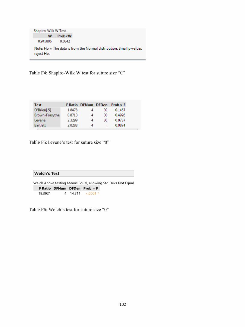
102
Table F4: Shapiro-Wilk W test for suture size “0”
Table F5:Levene’s test for suture size “0”
Table F6: Welch’s test for suture size “0”

103
c. Suture size 2-0
Figure F5: Box plot for sutures of size “2-0”
Figure F6: Normal quantile plot for suture size “2-0”

104
Table F7: Shapiro-Wilk W test for suture size “2-0”
Table F8: Levene’s test for suture size 2-0
Levene’s test show equal variance
Table F9: ANOVA test for suture size “2-0”

105
d. Suture size 3-0
Figure F7: Box plot for sutures of size “3-0”
Figure F8: Normal quantile plot for suture size “3-0”

106
Table F10: Shapiro-Wilk W test for suture size “3-0”
Table F11: Levene’s test for size 3-0 sutures
Table F12: Welch’s test for suture size “3-0”

107
e. Suture size “4-0”
Figure F9: Box plot for sutures of size “4-0”
Figure F10: Normal quantile plot for suture size “4-0”

108
Table F13: Shapiro-Wilk W test for suture size “4-0”
Table F14: Levene’s test for size 4-0
Table F15: Welch’stest for suture size “4-0”

109
Appendix G: Holding strength of clips on different suture sizes for each suture type
The normality test of tension recorded for different sutures were analyzed using Shapiro Wilk
test. The p-value greater than 0.05 indicate normal distribution of data obtain. During an
analysis, if the data obtained from the experiment was not normally distributed, the data was
transformed into studentized residual to analyze the normal distribution of data. A residual is the
difference between a predicted value and the observed value. A studentized residual is the result
of dividing the residual by the standard error of the residual. The adjustment accounts for
different variances in the residuals. The variances of residuals for different values of the input
field are not the same. To account for these differences, the residual values are divided by the
standard error for the residuals. This adjustment is called studentizing. It allows for a
standardized comparison among the residuals. Significance in normality test for studentized
residual data achieves the requirement of normal distribution of data.
Levene’s test was used to test the equality of the variance, where p value greater than 0.2 is
consider as homogeneity in variance. For a condition of unequal variance, Welch’s test was used
as ANOVA test for a condition of unequal variance and normal distribution of data. Welch’s test
provided a significant evidence of difference in mean tension recorded for different sutures. The
p value less than 0.05 indicated the significant difference in mean tension for sutures. The
ANOVA tests followed by Tukey HSD post hoc analysis were conducted on sutures Vicryl,
Monocryl, Chromic, Stratafix and V-Loc based on suture Types. The results were shown below:

110
a. Vicryl Sutures
Figure G1: Normal quantile plot for Vicryl sutures
Table G1: Shapiro-Wilk W test for Vicryl sutures
Table G2: Levene’s test for Vicryl sutures

111
Table G3: Welch’s test for Vicryl sutures
b. Monocryl Sutures
Figure G2: Normal Quantile plot for Monocryl sutures
Table G4: Shapiro-Wilk W test for Monocryl sutures

112
Table G5: Levene’s test for Monocryl sutures
Table G6: Welch’s test for Monocryl sutures
c. Chromic Sutures
Figure G3: Normal Quantile plot for Chromic sutures
Table G7: Shapiro-Wilk W test for Chromic sutures

113
Table G8: Levene’s test for Chromic sutures
Table G9: ANOVA test for Chromic sutures

114
d. Stratafix Sutures
Figure G4: Normal Quantile plot for Stratafix sutures
Table G10: Shapiro-Wilk W test for Stratafix sutures
Table G11: Levene’s test for Stratafix sutures

115
Table G12: ANOVA test for Stratafix sutures
e. V-Loc Sutures
Figure G5: Normal Quantile plot for V-Loc sutures
Table G13: Shapiro-Wilk W test for V-Loc sutures

116
Table G14: Levene’s test for V-Loc sutures
Table G15: Welch’s test for V-Loc suture

117
Appendix H: Comparison of time at which clips starts to slip from suture size 2-0
Figure H1: Normal Quantile plot of tension holding time of clips before slippage for sutures size
2-0
Table H1: Shapiro-Wilk W test for tension holding time of clips before slippage for sutures size
2-0

118
Figure H2: Normal Quantile plot of studentized residual obtain from tension holding time
Table H2: Shapiro-Wilk W test of studentized residual data obtained for tension holding time of
clips before slippage for sutures size 2-0
Table H3: Levene’s test for tension holding time of clips before slippage for sutures size 2-0

119
Table H4: ANOVA test for tension holding time of clips before slippage for sutures size 2-0

120
Appendix I: Holding strength of clips with its placement towards and against barb
1. Comparison of holding strength of LAPRA-TY with its placement towards and against barb
for V-Loc 2-0 suture (towards and against barb)
Table I1: Data analysis of V-Loc 2-0 sutures
Conditions:
Since the sample size is so small (n=7) we need to use a non-parametric alternative to the paired
t-test. The skewness of .5846 is between -1.0 and 1.0 so lack of symmetry is not an issue, thus
we can use the Wilcoxon Signed Rank Test to compare medians.
Table I2: Wilcoxon Signed Rank test for V-Loc 2-0 sutures

121
Wilcoxon Signed Rank:
The p-value of .2188 is not significant. There is not a statistically significant difference between
the median strength of suture between the two directions (toward and against) for Vloc2.
2. Comparison of holding strength of LAPRA-TY with its placement towards and against barb
for V-Loc 3-0 suture (towards and against barb)
Moments
N 7 Sum Weights 7
Mean -2.9142857 Sum Observations -20.4
Std Deviation 4.87627883 Variance 23.7780952
Skewness 0.72770556 Kurtosis -0.8344105
Uncorrected SS 202.12 Corrected SS 142.668571
Coeff Variation -167.32329 Std Error Mean 1.84306016
Table I3: Data analysis for V-Loc 3-0 sutures
Conditions:

122
Since the sample size is so small (n=7) we need to use a non-parametric alternative to the paired
t-test. The skewness of .7277 is between -1.0 and 1.0 so lack of symmetry is not an issue, thus
we can use the Wilcoxon Signed Rank Test to compare medians.
Tests for Location: Mu0=0
Test Statistic p Value
Student's t t -1.58122 Pr> |t| 0.1649
Sign M -1.5 Pr>= |M| 0.4531
Signed Rank S -9 Pr>= |S| 0.1563
Table I4: Wilcoxon Signed Rank test for V-Loc 3-0 sutures
Wilcoxon Signed Rank Test:
The p-value of .1563 is not significant. There is not a statistically significant difference between
the median strength of suture between the two directions (toward and against) for Vloc3.
3. Comparison of holding strength of LAPRA-TY with its placement towards and against barb
for Stratafix 2-0 suture (towards and against barb)

123
Moments
N 7 Sum Weights 7
Mean 0.27142857 Sum Observations 1.9
Std Deviation 2.28743982 Variance 5.23238095
Skewness 0.36076071 Kurtosis -1.3278339
Uncorrected SS 31.91 Corrected SS 31.3942857
Coeff Variation 842.740988 Std Error Mean 0.86457099
Table I5: Data analysis for Stratafix 2-0 sutures
Conditions:
Since the sample size is so small (n=7) we need to use a non-parametric alternative to the paired
t-test. The skewness of .3608 is between -1.0 and 1.0 so lack of symmetry is not an issue, thus
we can use the Wilcoxon Signed Rank Test to compare medians.
Tests for Location: Mu0=0
Test Statistic p Value
Student's t t 0.313946 Pr> |t| 0.7642
Sign M 0 Pr>= |M| 1.0000
Signed Rank S 0.5 Pr>= |S| 1.0000
Table I6: Wilcoxon Signed Rank test for Stratafix 2-0 sutures

124
Wilcoxon Signed Rank Test:
The p-value of 1.00 is not significant. There is not a statistically significant difference between
the median strength of suture between the two directions (toward and against) for Stratafix2.

125
Appendix J: Graphical representation of holding strengths
Figure J1: Holding strength for Monocryl 1 sutures
Figure J2: Holding strength for Monocryl 0 sutures

126
Figure J3: Holding strength for Monocryl 2-0 sutures
Figure J4: Holding strength for Monocryl 3-0 sutures

127
Figure J5: Holding strength for Monocryl 4-0 sutures
Figure J6: Holding strength for Vicryl 1 sutures

128
Figure J7: Holding strength for Vicryl 0 sutures
Figure J8: Holding strength for Vicryl 2-0 sutures

129
Figure J9: Holding strength for Vicryl 3-0 sutures
Figure J10: Holding strength for Vicryl 4-0 sutures

130
Figure J11: Holding strength for Chromic 1 sutures
Figure J12: Holding strength for Chromic 0 sutures

131
Figure J13: Holding strength for Chromic 2-0 sutures
Figure J14: Holding strength for Chromic 3-0 sutures

132
Figure J15: Holding strength for Chromic 4-0 sutures
Figure J16: Holding strength for Stratafix 0 sutures

133
Figure J17: Holding strength for Stratafix 2 sutures
Figure J18: Holding strength for Stratafix 3 sutures

134
Figure J19: Holding strength for Stratafix 4 sutures
Figure J20: Holding strength for V-Loc 0 sutures

135
Figure J21: Holding strength for V-Loc 2-0 sutures
Figure J22: Holding strength for V-Loc 3-0 suture

136
Figure J23: Holding strength for V-Loc 4-0 sutures

137
Bibliography
1. Fracchia JA, Glickman LI, Javit D, et al. Contemporary management of small renal
tumors. J Community Support Oncol 2014.;2(6):112-221.
2. Bhat S. Role of surgery in advanced/metastatic renal cell carcinoma. Indian J Urol
2010;26(2):167–176.
3. Jared RB, Mohamad EA. Laparoendoscopic single-site surgery in urology. TherAdvUrol
2009; 1(5): 259–266.
4. Endres DM, Bossemeyer RW, Tobert CM, Baer WH, Lane BR. Investigation of the
closing forces Involved in re-approximation of the renal remnant following partial
nephrectomy. Urol 2014; 84 (4):971-975.
5. Shang JW, Ma X, Zhang X, Li HZ, Shi TP.Comparison of two different renorrhaphy
techniques in retroperitoneal laparoscopic partial nephrectomy for complex tumor. Chin
Med J 2013;126 (24):4629-4632
6. Breda A, Finelli A, Janetschek G, Porpiglia F, MontorsiF.Complications of Laparoscopic
Surgery for Renal Masses: Prevention, Management, and Comparison with the Open.
EurUrol 2009; 55(4): 836–850.
7. Park DS, Jang WK. Secure reconstruction technique after partial nephrectomy
irrespective of tumor size and location. IntBraz J Urol 2009;35(4):416-26.
8. Ghani KR, Anderson C. Closing the deal: Renorrhapy during Laparoscopic and robotic
Partial nephrectomy. BJU Int 2011;108(1):2-4.
9. Makiyama K, Nakaigawa N, Miyoshi Y, Murakami T, Yao M, Kubota Y .Improvement
on parenchymal suturing technique in laparoscopic partial nephrectomy. Int J Urol 2008;
15(9): 854–855
http://www.ncbi.nlm.nih.gov/pubmed/?term=Glickman%20LI%5BAuthor%5D&cauthor=true&cauthor_uid=24999499
http://www.ncbi.nlm.nih.gov/pubmed/?term=Porpiglia%20F%5BAuthor%5D&cauthor=true&cauthor_uid=19168276

138
10. Tarin T, Kimm S, Chung B, Shinghal R, Reese J. Comparison of holding strength of
suture anchors on human renal capsule. J Endourol 2010; 24(3): 293-297.
11. Ames CD, Perrone JM, Frisella AJ, Morrissey K, Landman J. Comparison of holding
strength of suture anchors for hepatic and renal parenchyma. J Endourol. 2005
;19(10):1221-1225.
12. Fernando P. Secin “Importance and Limits of Ischemia in Renal Partial Surgery:
Experimental and Clinical Research. AdvUrol 2008;102461
13. Ghani KR, Trinh QD, Sammon J, Jeong W, Dabaja A, Menon M. Robot-assisted
urological surgery: Current status and future perspectives. Arab J Urol.2012;10(1):17–22
14. Benway BM1, Wang AJ, Cabello JM, Bhayani SB. Robotic Partial Nephrectomy with
Sliding-Clip Renorrhaphy: Technique and Outcomes.EurUrol 2009;55(3): 592–599
15. Bernardo NO, Gill IS. Laparoscopic partial nephrectomy: current status Arch. EspUrol
2002;55(7):868-880
16. Simon J, Finter F, Ignatius A, Meilinger M, Dürselen L. Maximum tensile force of
different suture techniques in reconstruction of the renal remnant after nephron-sparing
surgery. SurgEndosc 2011;25(2):503-507.
17. Zuber TJ. The Mattress Sutures:Vertical,Horizontal, and Corner Stitch. Am Fam
Physician 2002;66(12):2231-2236.
18. Surgical Instrument Pictures[Internet];[cited 2015 March].Available
from:http://www.surgical-instrument-pictures.com/suture.html
19. Kudur MH, Pai SB, Sripathi H, PrabhuS.Sutures and suturing techniques in skin closure.
Indian J DermatolVenereolLeprol 2009;75(4):425-434.
http://www.ncbi.nlm.nih.gov/pubmed/?term=Frisella%20AJ%5BAuthor%5D&cauthor=true&cauthor_uid=16359220
http://www.ncbi.nlm.nih.gov/pubmed/?term=Morrissey%20K%5BAuthor%5D&cauthor=true&cauthor_uid=16359220
http://www.ncbi.nlm.nih.gov/pubmed/?term=Bernardo%20NO%5BAuthor%5D&cauthor=true&cauthor_uid=12380320

139
20. Sammon J, Petros F, Sukumar S, Bhandari A, Kaul S, Menon M, Rogers C. Barbed
Suture for Renorrhaphy During Robot-Assisted Partial Nephrectomy J
Endourol. 2011;25(3): 529-533.
21. Jeon SH, JungS , Son HS, Kimm SY, Chung BI. The unidirectional barbed suture for
renorrhaphy during laparoscopic partial nephrectomy: Stanford experience. J
LaparoendoscAdvSurg Tech A .2013;23(6):521-525
22. Microsoft Hardware.LifeCam Studio[Internet] United states;2015[cited 2015 March
].Available from: http://www.microsoft.com/hardware/en-us/p/lifecam-studio#overview
23. Endres DM. Investigation of the closing forces involved in re-approximation of the renal
remnant following partial nephrectomy. Grand Rapids: Grand Valley State University;
2013 April
24. Laerd Statistics[Internet]: One-Way ANOVA 2013[cited 2015 March 2] Available
from: https://statistics.laerd.com/statistical-guides/one-way-anovastatistical-guide-3.php
25. Ghasemi A, Zahediasl S. Normality Tests for Statistical Analysis: A Guide for Non-
Statisticians. EndocrinolMetab2012;10(2):486-489.
26. Handbook of biological statistics[Internet].McDonald JH: One-way ANOVA
2014;[cited2015March].Availablefrom:http://bcs.bedfordstmartins.com/resdoc5e/RES5e_
ch11_s10003.html#RES5e_ch11_p0070
27. Chung E, McPherson N, Grant A,” Tensile Strength of Absorbable Suture Materials: In
Vitro Analysis of the Effects of pH and Bacteria. Journal of Surgical Education
2009;66(4):208-211.

140
28. Greenberg CB, Davidson EB, Bellmer DD, Morton RJ, Payton ME .Evaluation of the
tensile strengths of four monofilament absorbable suture materials after immersion in
canine urine with or without bacteria. Am J Vet Res 2004; 65(6): 847-853.
29. Monnet E.New suture materials offer more options for wound closures[Internet];2002
Oct 01[cited 2015 March], Available from: http://veterinarynews.dvm360.com/new-
suture-materials-offer-more-options-wound-closures
30. Aquarium Answers. Aquarium Heaters; Review, Size, Heater Information[Internet];
[cited 2015 March].Available from: http://www.aquarium-pond-
answers.com/2007/01/aquarium-heaters-preset-vs-non-preset.html
31. Makiyama K, Nakaigawa N, Miyoshi Y, Murakami T, Yao M, Kubota Y.Improvement
on parenchymal suturing technique in laparoscopic partial nephrectomy. Int J
Urol 2008;15(9):854–855
32. Todd Gunson,DermNet NZ. Suturing techniques[Internet];2014[cited 2015
March].Available from: http://www.dermnetnz.org/procedures/suturing.html
33. Koo HJ, Lee DH, Kim IY. Renal hilar control during laparoscopic partial nephrectomy:
to clamp or not to clamp. J Endourol. 2010;24(8):1283-1287.
34. Park DS, Jang WK.Secure reconstruction technique after partial nephrectomy irrespective
of tumor size and location. Int Braz J Urol. 2009;35(4):416-26
35. Masumori N1, Itoh N, Takahashi S, Kitamura H, Nishida S, Tsukamoto T .New
technique with combination of felt, Hem-o-lok and LAPRA-TY for suturing the renal
parenchyma in laparoscopic partial nephrectomy. Int J Urol 2012;19(3):273-276.
http://www.ncbi.nlm.nih.gov/pubmed/?term=Davidson%20EB%5BAuthor%5D&cauthor=true&cauthor_uid=15198227
http://www.ncbi.nlm.nih.gov/pubmed/?term=Nakaigawa%20N%5BAuthor%5D&cauthor=true&cauthor_uid=18786208

141
36. Orvieto MA1, Lotan T, Lyon MB, Zorn KC, Mikhail AA, Rapp DE, Brendler
CB, Shalhav AL Assessment of the LapraTy Clip forFacilitating Reconstructive
Laparoscopic Surgery in a Porcine Model. Urology. 2007;69(3):582-585
37. Weld KJ, Arzola J, Montiglio C, Bush AC, Cespedes RD.LAPRA-TY holding strength
andslippage with various suture types and sizes. Urology 2008;71(1):32-35
38. Gorin MA, Ramanathan R, Leveillee RJ. Laparoscopic Techniques Applied to Open
Surgery: Sliding-clip Renorrhaphy. Urology 2010;77 (3):751-753
39. Canales BK, Lynch AC, Fernandes E, Anderson JK, RamaniAP.Novel Technique of
Knotless Hemostatic Renal Parenchymal Suture Repair During Laparoscopic Partial
Nephrectomy. Urology 2007;70(2):358-359.
40. Miller M, Anderson JK, Pearle MS, Cadeddu JA .Resorbable Clip migration in the
collecting system after Laparoscopic Partial Nephrectomy. Urology 2006; 67(4):845
http://www.ncbi.nlm.nih.gov/pubmed/?term=Brendler%20CB%5BAuthor%5D&cauthor=true&cauthor_uid=17382183
http://www.ncbi.nlm.nih.gov/pubmed/?term=Brendler%20CB%5BAuthor%5D&cauthor=true&cauthor_uid=17382183
http://www.ncbi.nlm.nih.gov/pubmed/?term=Montiglio%20C%5BAuthor%5D&cauthor=true&cauthor_uid=18242360
http://www.ncbi.nlm.nih.gov/pubmed/?term=Cespedes%20RD%5BAuthor%5D&cauthor=true&cauthor_uid=18242360
http://www.ncbi.nlm.nih.gov/pubmed/?term=Fernandes%20E%5BAuthor%5D&cauthor=true&cauthor_uid=17826508
http://www.ncbi.nlm.nih.gov/pubmed/?term=Anderson%20JK%5BAuthor%5D&cauthor=true&cauthor_uid=17826508