Comparison of performance of Ni–Mo/γ-alumina catalyst in ...
12
Vol.:(0123456789) 1 3 Petroleum Science (2019) 16:645–656 https://doi.org/10.1007/s12182-019-0319-5 ORIGINAL PAPER Comparison of performance of Ni–Mo/γ‑alumina catalyst in HDS and HDN reactions of main distillate fractions Babak Behnejad 1 · Majid Abdouss 1 · Ahmad Tavasoli 2 Received: 6 May 2018 / Published online: 29 April 2019 © The Author(s) 2019 Abstract A bimetallic nickel–molybdenum catalyst supported on γ-alumina was synthesized by the two-step incipient wetness impreg- nation technique. The activity of the prepared Ni–Mo/γ-alumina catalyst was evaluated in a down flow fixed-bed micro- reactor. In this way, hydrodesulfurization (HDS) and hydrodenitrogenation (HDN) reactions of the main distillate fractions of crude oil were assessed. XRD, SEM, TPR, ICP-OES, BET–BJH and nitrogen adsorption/desorption methods were used for characterizing the synthesized Ni–Mo/γ-alumina catalyst. The active metals with Ni/Mo mass ratio of 0.23 and total metal of 13.7 wt% were loaded on the support, similar to the commercial industrial catalyst. The performance tests were conducted at 3.0 MPa (for light naphtha and heavy naphtha) and at 4.5 MPa (for kerosene and gas oil). The results revealed that the total sulfur conversion of the light naphtha, heavy naphtha, kerosene and gas oil fractions was 98.3%, 95%, 91.7% and 90.1% (after 24 h), respectively. Keywords HDS · HDN · Ni–Mo/γ-alumina · Gas oil · Kerosene · Naphtha 1 Introduction In refineries, crude oil is distilled to various fractions, in which the main distillate fractions including light naphtha, heavy naphtha, kerosene and gas oil are very valuable (Jarul- lah et al. 2011; Prins 2001; Qian et al. 2013). There are serious regulations, especially in Europe and USA, which limit the impurities in the main petroleum fractions. These fractions contain various sulfur and nitrogen compounds that should be removed to help reaching a clean environ- ment (Bassi et al. 2015; González-Cortés et al. 2006; Ling et al. 2009; Rong et al. 2014). Hydrodesulfurization (HDS) and hydrodenitrogenation (HDN) have been widely used for removing sulfur and nitrogen compounds from liquid phases (Faro and dos Santos 2006; Furimsky and Massoth 2005; Gao et al. 2011; Gutiérrez et al. 2014; Huirache-Acuña et al. 2012; Ledoux and Djellouli 1990; Mendoza-Nieto et al. 2015; Prins 2001; Qian et al. 2013; Soghrati et al. 2012; Sundaramurthy et al. 2006; Zepeda et al. 2016; Zhao et al. 2004). For obtaining high-quality gasoline and enhancing the research octane number (RON) of light naphtha and heavy naphtha streams, refiners usually utilize isomeriza- tion and catalytic reforming units (Eijsbouts et al. 2013), respectively. The catalysts used in the mentioned units are very sensitive to common impurities such as sulfur, nitrogen, oxygen and metal contents in the relevant feedstock. Sulfur compounds in transportation fuels are converted to SO x by combustion, and SO x is a major source of acid rain and air pollution (Ho and McConnachie 2011; Fan et al. 2011). HDS and HDN are hydrotreating processes in which the reaction between feedstock and hydrogen occurs over a catalyst. Due to the importance of HDS and HDN processes and also economical–environmental issues associated with it, tremendous efforts have been devoted to the development of novel catalysts with high yields. NiMo and CoMo cata- lysts on various supports are among the most studied cata- lysts (Zdražil 2003; Yamamoto et al. 2007; Vonortas and Papayannakos 2014; Bui et al. 2015; Klimov et al. 2016; Liu et al. 2016; Zepeda et al. 2016; Escobar et al. 2017; Hajjar et al. 2017a, b; Maximov et al. 2017; Xu et al. 2017; Zhou et al. 2017). Edited by Xiu-Qin Zhu * Majid Abdouss [email protected] 1 Department of Chemistry, Amirkabir University of Technology, Tehran, Iran 2 School of Chemistry, College of Science, University of Tehran, Tehran, Iran
-
Upload
khangminh22 -
Category
Documents
-
view
2 -
download
0
Transcript of Comparison of performance of Ni–Mo/γ-alumina catalyst in ...

Vol.:(0123456789)1 3
Petroleum Science (2019) 16:645–656 https://doi.org/10.1007/s12182-019-0319-5
ORIGINAL PAPER
Comparison of performance of Ni–Mo/γ‑alumina catalyst in HDS and HDN reactions of main distillate fractions
Babak Behnejad1 · Majid Abdouss1 · Ahmad Tavasoli2
Received: 6 May 2018 / Published online: 29 April 2019 © The Author(s) 2019
AbstractA bimetallic nickel–molybdenum catalyst supported on γ-alumina was synthesized by the two-step incipient wetness impreg-nation technique. The activity of the prepared Ni–Mo/γ-alumina catalyst was evaluated in a down flow fixed-bed micro-reactor. In this way, hydrodesulfurization (HDS) and hydrodenitrogenation (HDN) reactions of the main distillate fractions of crude oil were assessed. XRD, SEM, TPR, ICP-OES, BET–BJH and nitrogen adsorption/desorption methods were used for characterizing the synthesized Ni–Mo/γ-alumina catalyst. The active metals with Ni/Mo mass ratio of 0.23 and total metal of 13.7 wt% were loaded on the support, similar to the commercial industrial catalyst. The performance tests were conducted at 3.0 MPa (for light naphtha and heavy naphtha) and at 4.5 MPa (for kerosene and gas oil). The results revealed that the total sulfur conversion of the light naphtha, heavy naphtha, kerosene and gas oil fractions was 98.3%, 95%, 91.7% and 90.1% (after 24 h), respectively.
Keywords HDS · HDN · Ni–Mo/γ-alumina · Gas oil · Kerosene · Naphtha
1 Introduction
In refineries, crude oil is distilled to various fractions, in which the main distillate fractions including light naphtha, heavy naphtha, kerosene and gas oil are very valuable (Jarul-lah et al. 2011; Prins 2001; Qian et al. 2013). There are serious regulations, especially in Europe and USA, which limit the impurities in the main petroleum fractions. These fractions contain various sulfur and nitrogen compounds that should be removed to help reaching a clean environ-ment (Bassi et al. 2015; González-Cortés et al. 2006; Ling et al. 2009; Rong et al. 2014). Hydrodesulfurization (HDS) and hydrodenitrogenation (HDN) have been widely used for removing sulfur and nitrogen compounds from liquid phases (Faro and dos Santos 2006; Furimsky and Massoth 2005; Gao et al. 2011; Gutiérrez et al. 2014; Huirache-Acuña et al.
2012; Ledoux and Djellouli 1990; Mendoza-Nieto et al. 2015; Prins 2001; Qian et al. 2013; Soghrati et al. 2012; Sundaramurthy et al. 2006; Zepeda et al. 2016; Zhao et al. 2004). For obtaining high-quality gasoline and enhancing the research octane number (RON) of light naphtha and heavy naphtha streams, refiners usually utilize isomeriza-tion and catalytic reforming units (Eijsbouts et al. 2013), respectively. The catalysts used in the mentioned units are very sensitive to common impurities such as sulfur, nitrogen, oxygen and metal contents in the relevant feedstock. Sulfur compounds in transportation fuels are converted to SOx by combustion, and SOx is a major source of acid rain and air pollution (Ho and McConnachie 2011; Fan et al. 2011).
HDS and HDN are hydrotreating processes in which the reaction between feedstock and hydrogen occurs over a catalyst. Due to the importance of HDS and HDN processes and also economical–environmental issues associated with it, tremendous efforts have been devoted to the development of novel catalysts with high yields. NiMo and CoMo cata-lysts on various supports are among the most studied cata-lysts (Zdražil 2003; Yamamoto et al. 2007; Vonortas and Papayannakos 2014; Bui et al. 2015; Klimov et al. 2016; Liu et al. 2016; Zepeda et al. 2016; Escobar et al. 2017; Hajjar et al. 2017a, b; Maximov et al. 2017; Xu et al. 2017; Zhou et al. 2017).
Edited by Xiu-Qin Zhu
* Majid Abdouss [email protected]
1 Department of Chemistry, Amirkabir University of Technology, Tehran, Iran
2 School of Chemistry, College of Science, University of Tehran, Tehran, Iran
646 Petroleum Science (2019) 16:645–656
1 3
As mentioned, a wide range of catalysts has been used for HDS and HDN of various liquid phases. In general, a single feedstock has been used for evaluating the HDS and HDN activity of the catalysts. Tawara et al. have under-taken catalysis for deep HDS of kerosene using Ni–Mo/Al2O3, which performed better than conventional catalysts (i.e., NiO, CoO and MoO3) (Tawara et al. 2000). It is also reported that nickel clusters supported on ZnO nanowires and gamma alumina are highly active for HDS of gaso-line and kerosene (Gupta et al. 2016). Song reviewed new approaches to clean gasoline, diesel fuel and jet fuel (Song 2003). Sundaramurthy et al. (2006) studied HDN and HDS of different gas oils over phosphorus-doped NiMo/γ-Al2O3 carbides catalysts. Miller et al. (2000) have used MoS2 cata-lyst for HDS of fluid catalytic cracking (FCC) naphtha, and it was shown that MoS2 catalyst performs better on a silica support compared with alumina. Shan et al. (2015) have uti-lized NiW catalysts for selective HDS of FCC naphtha, and it was reported that better dispersion of W enables modifi-cation of the active phase which results in higher selective HDS. Also, various graphene-supported catalysts have been used for HDS of naphtha (Hajjar et al. 2015, 2016, 2017a, b). MoS2 supported over graphene was used for HDS of naphtha for which a simultaneous chemical exfoliation method was followed for preparing the catalyst by which high conversion was obtained (Hajjar et al. 2015). Co–Mo supported over graphene oxide has been used for performing the naphtha HDS reaction in which metallic phases were impregnated onto the support via the hydrothermal and wetness impreg-nation method (Hajjar et al. 2017a, b). It is reported that con-versions of 95%–100% have been obtained on naphtha feed (Hajjar et al. 2017a, b). However, the performance of the reported catalysts has been evaluated only on one feed type (i.e., Naphtha), which limits the commerciality of the cata-lysts. Actually, most of the works on hydrotreating (HDT) of the liquid feedstock were mainly focused on only one feed type. However, Vozka et al. (2017) have studied the catalyst performance on a mixture of some distillates.
For commercializing the catalysts, it is necessary to develop catalysts which are effective in HDS and HDN on different fractions. Thus, in this study, the Ni–Mo/γ-alumina catalyst was synthesized and also HDS and HDN reactions on the main distillate fractions including light naphtha (L.N.), heavy naphtha (H.N.), kerosene (Kero.) and gas oil (G.O.) were studied and compared.
2 Experimental
2.1 Materials
Analy t ica l g rade n icke l n i t ra te hexahydra te (Ni(NO3)2·6H2O), ammonium heptamolybdate tetrahydrate
((NH4)6Mo7O24·4H2O) and dimethyl disulfide (DMDS) were supplied by Merck Chemical Co.; analytical grade H2 and deionized water (DI) were used throughout the experiments.
2.2 Catalyst preparation
The Ni/Mo atomic ratio was considered according to the specifications of the industrial catalysts. For preparing the catalysts, nickel nitrate hexahydrate (Ni(NO3)2·6H2O) and ammonium heptamolybda te te t rahydra te ((NH4)6Mo7O24·4H2O) were used. The two-step incipient wetness impregnation method was used in which the Ni and Mo salts were added to the γ-alumina support. In the first step, incipient wetness impregnation was carried out on the support with ammonium heptamolybdate tetrahydrate aque-ous solution and then it was dried in the air at 120 °C for 4 h (by using a temperature-programmed electric furnace at the rate of 1 °C/min). In the second step, nickel nitrate hexahydrate aqueous solution was used and dried similar to step 1. The calcination step was in air to 550 °C (with a rate of 2 °C/min) and kept at this temperature for 5 h.
2.3 Catalyst characterization methods
2.3.1 ICP‑OES
As the metal loading has a determining effect on the overall performance of the hydrotreating catalysts, it is essential to obtain optimum metal loading and control it. To determine metal loading, inductively coupled plasma-optical emission (ICP-OES) spectrometry was used (Perkin Elmer, Optima 8000 Dual view System).
2.3.2 BET surface area measurements/BJH pore size distributions
Surface properties such as surface area, pore volume and an average diameter of pores of the calcined catalysts are of great importance and have a direct effect on HDS and HDN activities, so they should be investigated thoroughly. The ASAP-2010 V2 Micromeritics system (Micromeritics Instrument Corp., Norcross, GA, USA) was used to study the surface properties. The samples were degassed at 200 °C for 4 h at a vacuum of 50 mTorr, and their Brunauer, Emmett and Teller (BET) area, pore volume and pore diameter were determined.
2.3.3 X‑ray diffraction
X-ray diffraction (XRD) patterns of the sample were col-lected employing a Bruker D8 Advance powder diffractom-eter with a copper anode X-ray tube (operating conditions, 40 kV and 40 mA) and a Si(Li) solid-state detector (Sol-X)
647Petroleum Science (2019) 16:645–656
1 3
was set to discriminate the Cu-Kα radiation. Data scans were performed in the 2θ range of 5°–80° with a step size of 0.020° and a counting time of 3 s/step.
2.3.4 Temperature‑programmed reduction (TPR)
The H2-TPR profile of the synthesized Ni–Mo/γ-alumina catalyst was recorded to study the reducibility of the cata-lyst. First, 0.05 g of the sample was purged under a helium atmosphere at 140 °C. Next, using a stream composed of 5% H2 in Ar with a flow rate of 40 ml/min, the temperature-pro-grammed reduction (TPR) of each sample was performed for which the Micromeritics TPD-TPR 2900 analyzer equipped with a thermal conductivity detector (TCD), heating at a linearly programmed rate of 10 °C/min up to 1000 °C, was employed.
2.3.5 Scanning electron microscopy (SEM)
SEM images are taken from the sample surface. A Seron Technologies AIS2100 SEM was used to obtain micrographs with different magnifications.
2.3.6 CO chemisorption
The active surface properties were determined by volumet-ric CO chemisorption using a Micromeritics ASAP 2010 instrument. Two hundred milligrams of catalyst was loaded into a U-shaped quartz reactor and evacuated at 120 °C for 60 min. The catalyst was reduced in flowing H2 to 330 °C
(heating rate 10 °C/min) with a hold time of 2 h. Then, it was evacuated at 330 °C for 60 min and then cooled down to 40 °C. The adsorption isotherms were measured at 40 °C by determining the adsorbed amount of CO.
2.3.7 Experimental outline and reaction testing
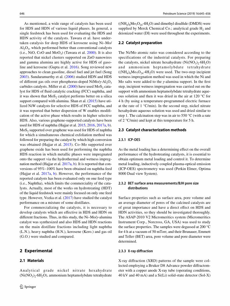
The HDS and HDN reactions were conducted in a continu-ous down flow fixed-bed stainless steel reactor. The sche-matic illustration of the experimental reactor setup is shown in Fig. 1.
The inner diameter and length of the reactor were 10 mm and 450 mm, respectively. Feed (liquid phase) was injected into the reactor by an HPLC pump (KNAUER K-501). The Brooks 5850 mass flow controller (MFC) was used to inject H2 into the reactor. The desired pressure of the reaction sys-tem was adjusted by the backpressure valve. The required heat for the reaction was supplied with an adjustable elec-trical heater. The reaction zone temperature was monitored and controlled by a temperature indicator controller (TIC WEST 3400).
Typically, 1 g of the synthesized catalyst was loaded into the reactor. The catalyst was loaded into the central segment of the reactor between two layers of carborundum filler and glass beads. After loading the catalyst into the reactor, a leak test of all connections and piping of the setup system was carried out using nitrogen gas. In the next step, sweeping nitrogen gas was switched to hydrogen gas and the pressure was reduced to the required level.
H2
MFCMFC
N2
Gas
Liquid
Feed
Water coolerSeparator
Reactor
Back-pressurevalve
TIC
Pump
Reactionzone
Fig. 1 Schematic illustration of the experimental reactor setup

648 Petroleum Science (2019) 16:645–656
1 3
Prior to the reaction, for providing Ni–Mo-S phases, all fresh catalysts were sulfided by injecting dimethyl disulfide (DMDS) as a sulfiding agent and the catalysts were con-verted to activated states (sulfide). The sulfiding procedure took place in two steps: lower and higher temperature. The operating conditions during sulfiding steps such as liquid hourly space velocity (LHSV), H2/HC ratio and required time are presented in Table 1. In the first step, the reaction zone temperature was increased up to 220 °C with a heating rate of 30 °C/h. In this step, DMDS was injected for 4 h. In the second step, the reaction zone temperature was increased to 330 °C at a heating rate of 30 °C/h. The operating condi-tions of this step were similar to the first step. In this step, DMDS was injected for 12 h.
After sulfiding the catalyst, all of the main distillate frac-tions of crude oil including light naphtha, heavy naphtha, kerosene and gas oil were fed into the reactor separately. The operating conditions such as temperature, pressure, LHSV and H2/HC ratio were adjusted to perform HDS and HDN reactions for each petroleum fraction according to a typical range of hydroprocessing unit operating conditions (Eijs-bouts et al. 2013).
The reaction conditions in HDS and HDN reactions are presented in Table 2. After achieving steady-state condi-tions, liquid samples were collected and total sulfur, mer-captans and total nitrogen were measured. Actually, prior to final experiments, in order to find the duration to reach the steady states, some experiments were performed and it was found that there is no significant fluctuation in HDT activity of the catalysts.
3 Results and discussion
3.1 Characterization overview
The nitrogen adsorption/desorption isotherm of the syn-thesized catalyst is shown in Fig. 2.
As it can be observed in Fig. 2, a Type 4 isotherm was obtained for the synthesized Ni–Mo/γ-alumina, which is characteristic of mesoporous materials, indicating that the sample was composed of pores in the range of 2–50 nm. In addition, by considering pore size distribution curve in Fig. 3, there is a peak at 6.4 nm (64 Å) for pore width,
Table 1 Sulfiding conditions prior to HDS and HDN processes
Parameter Sulfiding conditions
Sulfiding (first step) Sulfiding (second step)
Temperature, °C 220 330Pressure, MPa 3.5 3.5LHSV, h−1 3 3H2/HC, NL/L 115 115Time, h 4 12
Table 2 Reaction conditions in HDS and HDN process
Parameter Sample
Gas oil Kero. H.N. L.N.
Temperature, °C 350 305 290 280Pressure, MPa 4.5 4.5 3.0 3.0LHSV, h−1 1.1 2.5 3.3 4H2/HC, NL/L 150 130 100 75
0 0.2 0.4 0.6 0.8 1.0
2
4
6
8
10
12
14
g/lom
m ,debrosda ytitnauQ
Relative pressure (P/P0)
Fig. 2 Nitrogen adsorption/desorption isotherm for the synthesized Ni–Mo/γ-alumina catalyst
20 40 60 200 4001000
0.2
0.4
0.6
0.8
1.0
1.2
1.4
1.6
1.864.80431
emulov
erop)w(gold/
Vd
Pore width, Ångstrom
Fig. 3 Pore size distribution for the synthesized Ni–Mo/γ-alumina catalyst

649Petroleum Science (2019) 16:645–656
1 3
in agreement with Fig. 2, confirming that a mesoporous material has been prepared.
As shown in Table 3, the specific surface area and pore volume of the synthesized catalyst are 224.4 m2/g and 0.52 cm3/g, respectively.
Metal loading over the alumina support was determined using ICP-OES analysis. According to the results which are shown in Table 4, the Ni/Mo mass ratio of 0.23 and the total loading of 13.7 wt% for the prepared catalyst are close to that of the industrial catalyst.
SEM images of the synthesized Ni–Mo/γ-alumina are shown in Fig. 4 with different magnifications (the left-side image scale bar is 50 µm and the right-side 5 µm).
XRD patterns of the synthesized Ni–Mo/γ-alumina and γ-alumina support are shown in Fig. 5. In the XRD pattern of γ-alumina, the peaks at 2θ of 37.17°, 46.99° and 66.82° are observed corresponding to (3 1 1), (4 0 0) and (4 4 0) planes, respectively (Wang et al. 2004; Wang and Ozkan 2005). By adding molybdenum and nickel oxide to the alu-mina support, the intensity of the peaks related to alumina was decreased and peaks corresponding to the MoO3 phase (JCPDS 00-005-0508) emerged. Peaks at 2θ of 23.41°, 25.7° and 27.1° are related to (1 1 0), (0 4 0) and (0 2 1) planes of the MoO3 phase. However, due to the low amount of nickel (i.e., less than 3.5 wt%) in the synthesized catalyst, which has been determined by ICP analysis, no apparent peak was observed for nickel-based phases.
It can be observed that the synthesized catalyst has weak peaks in the XRD pattern which indicates the small metal particle sizes and high dispersion of Ni and Mo metals. Increase in the dispersion of Ni and Mo metals leads to the formation of more active sites and the adsorption of more hydrogen which enhanced the activity and stability of the catalyst.
The TPR curve of the synthesized Ni–Mo/γ-alumina is shown in Fig. 6, where two main peaks are observed. In Fig. 6, the right side of the diagram along with the red line indicated the temperature and the H2 consumption is shown on the left side. The first reduction occurred in the range of 400–500 °C, which can be related to the reduction of oxide forms of molybdenum, Mo+6, and nickel to different oxide states such as Mo+4 (Bunch and Ozkan 2002; Wang et al. 2015; Purón et al. 2017). Another reduction can be observed over 700 °C, which might be due to the reduc-tion of molybdenum oxide (Mo+4) to metallic molybdenum (Mo0) (Bunch and Ozkan 2002; Wang et al. 2015; Purón et al. 2017). For comparison, the TPR curve of the industrial
Table 3 BET surface area, pore volume and average pore diameter of the catalysts
Catalyst Characteristics
BET area, m2/g Pore vol-ume, cm3/g
Average pore size, nm
Synthesized catalyst 224.39 0.52 6.57Industrial catalyst 216.53 0.54 6.51
Table 4 Metal precursors in their oxide phase
Catalyst Characteristics
ICP Ni/Mo, mass ratio
ICP total metal loading, wt%
Synthesized catalyst 0.23 13.7Industrial catalyst 0.24 14.1
Fig. 4 SEM images of the synthesized Ni–Mo/γ-alumina with different magnifications

650 Petroleum Science (2019) 16:645–656
1 3
catalyst is also provided. It can be observed that the same shape was obtained for both curves, indicating the formation of oxides with the same oxidation state.
The active surface adsorption properties were deter-mined by volumetric CO chemisorption. The amount of chemisorbed CO for the synthesized and industrial catalysts was 274.4 and 262.3 μmol/g, respectively. The Mo disper-sion is obtained from the CO uptakes and the known metal concentration in the samples, assuming a chemisorption stoichiometry of CO/metal = 1:1. The calculated dispersion for the synthesized and industrial catalysts was 14% and 13.2%, respectively. It shows that the accessibility of the active phase for the synthesized catalyst is higher than the industrial catalyst.
3.2 Catalyst activity (evaluation of HDS and HDN reactions)
The specific gravities of the main distillate fractions (feed-stock) are shown in Table 5. Also, total sulfur (T.S.), R-SH compounds (mercaptans) and total nitrogen (T.N.) of the feedstock are shown in Table 6. In addition, the physical properties of gas oil and kerosene (feedstock) are shown in Table 7.
Research octane number (RON) and Reid vapor pressure (RVP) in heavy naphtha and light naphtha (feedstock) are presented in Table 8. Furthermore, the ASTM D-86 of the feedstock of the main distillate fractions is shown in Fig. 7. By using the ASTM D-86 method, which was performed in a batch distillation system at atmospheric pressure, the boiling range of the petroleum fraction was determined.
For light naphtha and heavy naphtha fractions, PONA (paraffins, olefins, naphthenes and aromatics) of the feed-stock and products of each catalyst (after 24 h) are shown in Figs. 8 and 9, respectively. Considering the fact that no significant changes were observed in these figures, it can be stated that a little hydrogenation reaction occurred under these conditions.
20 30 40 50 60 70 80
37.17 (311) 46.99 (400)
66.82 (440)
23.41 (110)
25.7 (040)
27.1 (021)37.66 (311)
46.19 (400)
67.24 (440)
Diffraction angle (2θ), degree
.u.a ,ytisnetnI
MoO3
100
200
300
400
500
600
700-aluminaγ
-aluminaγ
γNi–Mo/ -alumina
Fig. 5 XRD patterns of γ-alumina (gray) and the synthesized Ni–Mo/γ-alumina catalyst (red)
50 70 9040 60 80 1000
0.05
0.10
0.15
0.20
0.25
(a) Synthesized catalyst
H2
.u.a,noitpmusno
C
0
200
400
600
800
1000
1200
50 70 9040 60 80 1000
0.05
0.10
0.15
0.20
0.25
Time, min
0
200
400
600
800
1000
1200
(b) Industrial catalyst
C°,erutarepmeT
H2
.u.a,noitpmusno
C
C°,erutarepmeT
Time, min
Temperature, °CH2 Consumption
Temperature, °CH2 Consumption
Fig. 6 TPR curve of the a synthesized and b industrial Ni–Mo/γ-alumina catalysts
Table 5 Specific gravity of the main distillate fractions (feedstock)
Analysis Sample
Gas oil Kerosene Heavy naphtha
Light naphtha
Test method
Specific gravity at 15 °C
0.8530 0.8010 0.7435 0.6505 ASTM D 4052

651Petroleum Science (2019) 16:645–656
1 3
In these figures, it can be observed that for both frac-tions (light and heavy naphtha), olefins and aromatics com-pounds were decreased, whereas paraffins and naphthenes were increased.
Light naphtha, heavy naphtha, kerosene and gas oil were fed to the reactor separately. After steady-state con-ditions were achieved, liquid samples were collected and total sulfur, mercaptans and total nitrogen were measured for both the industrial and synthesized catalysts during a 240-h operating test.
For calculating the catalytic conversion of the fractions, Eq. 1 is used:
where Xi shows T.S., R-SH and T.N. conversions (%), ci0 corresponds to T.S., R-SH and T.N. concentration in the feedstock (ppm) and ci is T.S., R-SH and T.N. concentra-tion in the products (ppm).
The catalysts performance versus time on stream (TOS) for different fractions is depicted in Figs. 10, 11, 12 and 13. Total nitrogen in treated light naphtha and heavy
(1)Xi =
(
ci0 − ci
ci0
)
× 100,
Table 6 T.S., R-SH and T.N. of the main distillate fractions (feed-stock)
Sample Test
T.S., ppm R-SH, ppm T.N., ppm
Gas oil 12,400 33.5 212Kero. 2300 37.8 20H.N. 280 51.4 3.5L.N. 92 75 0.5Test method ASTM D 5453 ASTM D 3227 ASTM D 4629
Table 7 Physical properties of gas oil and kerosene (feedstock)
Analysis Sample Test method
Gas oil Kerosene
Total aromatic, vol% 24.5 16 ASTM D 1319Flash point, °C 88 50 ASTM D 93Water content, ppm 310 24 ASTM D 6304Aniline point, °C 70 – ASTM D 611Cetane index 51 – ASTM D 976Smoke point, mm – 24 ASTM D 1322Freezing point, °C – – 45 ASTM D 2386
Table 8 RON and RVP of heavy and light naphtha
Analysis Sample Test method
Heavy naphtha Light naphtha
RON 45.6 69.3 ASTM D 2699RVP, MPa – 0.075 ASTM D 323
0
40
80
120
160
200
240
280
320
360
400
0 20 40 60 80 100
Tem
pera
ture
, °C
Volume, %
L.N.H.N.KeroseneGas oil
Fig. 7 ASTM D-86 of the feedstock of the main distillate fractions
87.3
0.4
10.1
1.9
87.4
0.2
10.4
1.7
87.5
0.3
10.3
1.6
0
20
40
60
80
100
Paraffins Olefins Naphthenes Aromatics
Volu
me,
%
PONA
L.N. FeedProduct (Synthesized catalyst)Product (Industrial catalyst)
Fig. 8 PONA of light naphtha in feedstock and product of all cata-lysts
64.5
0.6
21.4
12.5
64.8
0.4
21.712.2
64.6
0.5
21.5
12.3
0
20
40
60
80
100
Paraffins Olefins Naphthenes Aromatics
Volu
me,
%
PONA
H.N. FeedProduct (Synthesized catalyst)Product (Industrial catalyst)
Fig. 9 PONA of heavy naphtha in feedstock and product of all cata-lysts

652 Petroleum Science (2019) 16:645–656
1 3
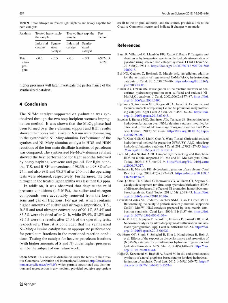
naphtha for both catalysts is presented in Table 9. The final amount of the nitrogen compounds in the treated feed is suitable for the relevant downstream process units (i.e., light naphtha for the isomerization unit and treated heavy naphtha for the catalytic reforming unit) (Hsu and Robin-son 2017).
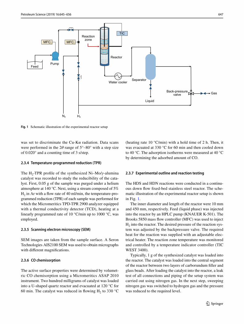
It can be observed that the synthesized catalyst has shown the highest activity in removing T.S. and R-SH in light naph-tha fraction. T.S. and R-SH conversions for light naphtha were 98.3% and 98.8% after 24 h and also 98% and 98.5% after 240 h of operating test, respectively. Such a high activ-ity compared with other fractions is attributed to the type of impurities in the light naphtha fraction. With respect to the T.S. conversion, it can be stated that the synthesized catalyst had a relatively high and acceptable performance on heavy naphtha and kerosene, respectively; however, it had the lowest activity for gas oil, which is due to the larger and more complex molecular structure of the sulfur compounds in the gas oil fraction. The highest activity in terms of R-SH
conversion was obtained for light naphtha followed by heavy naphtha, kerosene and gas oil.
In removing the nitrogen compounds from these frac-tions which is essential for producing a clean fuel, the best performance was obtained for light naphtha in which after 240 h of the operating test, more nitrogen compounds were removed. Considering the fact that gas oil contained the highest amount of T.N. before hydrotreating, 82.5% of its nitrogen compounds were removed at the end of 240-h run-ning time.
Comparing the results obtained for the industrial and syn-thesized catalysts (the operating conditions were the same for each petroleum fraction) shows that the prepared cata-lyst performance is slightly better than that of the industrial catalyst which can be attributed to the smaller particle sizes and higher metal dispersion as confirmed by CO chemisorp-tion tests.
Overall, it can be concluded that the synthesized Ni–Mo/γ-alumina at the mentioned reaction conditions is
Fig. 10 Conversion of the T.S. and R-SH compounds vs. time on stream for light naphtha (reaction conditions: T = 280 °C, P = 3.0 MPa, LHSV = 4 h−1 and H2/HC = 75 NL/L)
80
85
90
95
100
0 24 48 72 96 120 144 168 192 216 240 264
Con
vers
ion,
%
Total sulfur
Synthesized catalystIndustrial catalyst
80
85
90
95
100
0 24 48 72 96 120 144 168 192 216 240 264
Con
vers
ion,
%
Time on stream, h
R-SH
Fig. 11 Conversion of the T.S. and R-SH compounds vs. time on stream for heavy naphtha (reaction conditions: T = 290 °C, P = 3.0 MPa, LHSV = 3.3 h−1 and H2/HC = 100 NL/L)
80
85
90
95
100
0 24 48 72 96 120 144 168 192 216 240 264
Con
vers
ion,
%
Total sulfur
Synthesized catalystIndustrial catalyst
80
85
90
95
100
0 24 48 72 96 120 144 168 192 216 240 264
Con
vers
ion,
%
Time on stream, h
R-SH
653Petroleum Science (2019) 16:645–656
1 3
appropriate for the lighter fractions such as light naphtha and heavy naphtha that contain a lower amount of sulfur and nitrogen impurities. Due to limitations, we were not
able to test the catalyst (especially for the heavier petroleum fractions with higher S and N contents) at higher pressures. For the heavier petroleum fractions, testing the catalyst at
Fig. 12 Conversion of the T.S., T.N. and R-SH compounds vs. time on stream for kerosene (reaction conditions: T = 305 °C, P = 4.5 MPa, LHSV = 2.5 h−1 and H2/HC = 130 NL/L)
80
85
90
95
100
0 24 48 72 96 120 144 168 192 216 240 264
Con
vers
ion,
%
Total sulfur
70
80
90
100
0 24 48 72 96 120 144 168 192 216 240 264
Con
vers
ion,
%
Total nitrogen
70
80
90
100
0 24 48 72 96 120 144 168 192 216 240 264
Con
vers
ion,
%
R-SH
Time on stream, h
Synthesized catalystIndustrial catalyst
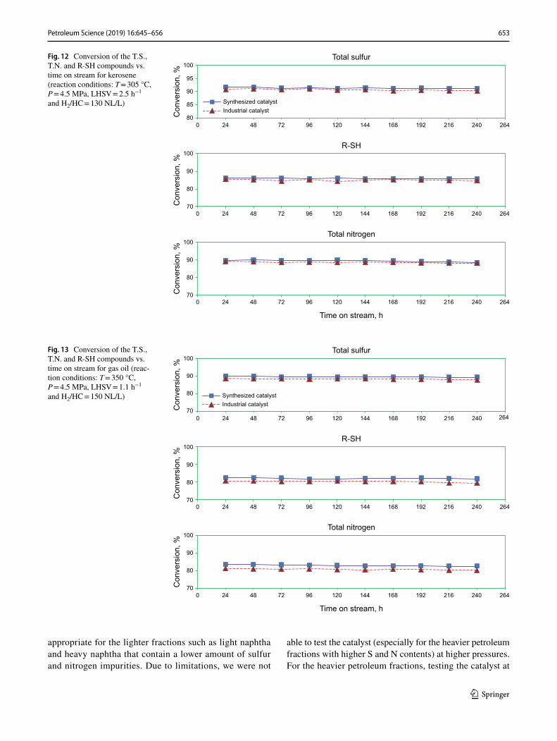
Fig. 13 Conversion of the T.S., T.N. and R-SH compounds vs. time on stream for gas oil (reac-tion conditions: T = 350 °C, P = 4.5 MPa, LHSV = 1.1 h−1 and H2/HC = 150 NL/L)
70
80
90
100
0 24 48 72 96 120 144 168 192 216 240 264
Con
vers
ion,
%
Total sulfur
70
80
90
100
0 24 48 72 96 120 144 168 192 216 240 264
Con
vers
ion,
%
70
80
90
100
0 24 48 72 96 120 144 168 192 216 240 264
Con
vers
ion,
%
Time on stream, h
Total nitrogen
R-SH
Synthesized catalystIndustrial catalyst
654 Petroleum Science (2019) 16:645–656
1 3
higher pressures will later investigate the performance of the synthesized catalyst.
4 Conclusion
The Ni/Mo catalyst supported on γ-alumina was syn-thesized through the two-step incipient wetness impreg-nation method. It was shown that the MoO3 phase had been formed over the γ-alumina support and BET results showed that pores with a size of 6.4 nm were dominating in the synthesized Ni–Mo/γ-alumina. Performance of the synthesized Ni–Mo/γ-alumina catalyst in HDS and HDN reactions of the four main distillate fractions of petroleum was compared. The synthesized Ni–Mo/γ-alumina catalyst showed the best performance for light naphtha followed by heavy naphtha, kerosene and gas oil. For light naph-tha, T.S. and R-SH conversions of 98.3% and 98.8% after 24 h and also 98% and 98.5% after 240 h of the operating tests were obtained, respectively. Furthermore, the total nitrogen in the treated light naphtha was less than 0.3 ppm.
In addition, it was observed that despite the mild pressure conditions (4.5 MPa), the sulfur and nitrogen compounds were acceptably removed from the kero-sene and gas oil fractions. For gas oil, which contains higher amounts of sulfur and nitrogen impurities, T.S., R-SH and total nitrogen conversions of 90.1%, 82.4% and 83.5% were obtained after 24 h, while 89.4%, 81.8% and 82.5% were the results after 240 h of the operating tests, respectively. Thus, it is concluded that the synthesized Ni–Mo/γ-alumina catalyst has an appropriate performance for petroleum fractions in the mentioned reaction condi-tions. Testing the catalyst for heavier petroleum fractions (with higher amounts of S and N) under higher pressures will be the subject of our future work.
Open Access This article is distributed under the terms of the Crea-tive Commons Attribution 4.0 International License (http://creat iveco mmons .org/licen ses/by/4.0/), which permits unrestricted use, distribu-tion, and reproduction in any medium, provided you give appropriate
credit to the original author(s) and the source, provide a link to the Creative Commons license, and indicate if changes were made.
References
Bassi R, Villarroel M, Llambías FJG, Camú E, Baeza P. Tungsten and rhenium as hydrogenation agents in the hydrodenitrogenation of pyridine using stacked bed catalyst systems. J Chil Chem Soc. 2015;60(2):2931–4. https ://doi.org/10.4067/S0717 -97072 01500 02000 15.
Bui NQ, Geantet C, Berhault G. Maleic acid, an efficient additive for the activation of regenerated CoMo/Al2O3 hydrotreating catalysts. J Catal. 2015;330:374–86. https ://doi.org/10.1016/j.jcat.2015.07.031.
Bunch AY, Ozkan US. Investigation of the reaction network of ben-zofuran hydrodeoxygenation over sulfided and reduced Ni–Mo/Al2O3 catalysts. J Catal. 2002;206(2):177–87. https ://doi.org/10.1006/jcat.2001.3490.
Eijsbouts S, Anderson GH, Bergwerff JA, Jacobi S. Economic and technical impacts of replacing Co and Ni promotion in hydrotreat-ing catalysts. Appl Catal A Gen. 2013;458:169–82. https ://doi.org/10.1016/j.apcat a.2013.03.043.
Escobar J, Barrera MC, Gutiérrez AW, Terrazas JE. Benzothiophene hydrodesulfurization over NiMo/alumina catalysts modified by citric acid. Effect of addition stage of organic modifier. Fuel Pro-cess Technol. 2017;156:33–42. https ://doi.org/10.1016/j.fupro c.2016.09.028.
Fan Y, Xiao H, Shi G, Liu H, Qian Y, Wang T, et al. Citric acid-assisted hydrothermal method for preparing NiW/USY–Al2O3 ultradeep hydrodesulfurization catalysts. J Catal. 2011;279(1):27–35. https ://doi.org/10.1016/j.jcat.2010.12.014.
Faro AC, dos Santos ACB. Cumene hydrocracking and thiophene HDS on niobia-supported Ni, Mo and Ni–Mo catalysts. Catal Today. 2006;118(3–4):402–9. https ://doi.org/10.1016/j.catto d.2006.07.027.
Furimsky E, Massoth FE. Hydrodenitrogenation of petroleum. Catal Rev Sci Eng. 2005;47(3):297–489. https ://doi.org/10.1081/CR-20005 7492.
Gao Q, Ofosu TNK, Ma S-G, Komvokis VG, Williams CT, Segawa K. Catalyst development for ultra-deep hydrodesulfurization (HDS) of dibenzothiophenes. I: effects of Ni promotion in molybdenum-based catalysts. Catal Today. 2011;164(1):538–43. https ://doi.org/10.1016/j.catto d.2010.10.016.
González-Cortés SL, Rodulfo-Baechler SMA, Xiao T, Green MLH. Rationalizing the catalytic performance of γ-alumina-supported Co(Ni)–Mo(W) HDS catalysts prepared by urea-matrix com-bustion synthesis. Catal Lett. 2006;111(1):57–66. https ://doi.org/10.1007/s1056 2-006-0130-y.
Gupta M, He J, Nguyen T, Petzold F, Fonseca D, Jasinski JB, et al. Nanowire catalysts for ultra-deep hydro-desulfurization and aro-matic hydrogenation. Appl Catal B. 2016;180:246–54. https ://doi.org/10.1016/j.apcat b.2015.06.029.
Gutiérrez OY, Singh S, Schachtl E, Kim J, Kondratieva E, Hein J, et al. Effects of the support on the performance and promotion of (Ni)MoS2 catalysts for simultaneous hydrodenitrogenation and hydrodesulfurization. ACS Catal. 2014;4(5):1487–99. https ://doi.org/10.1021/cs500 034d.
Hajjar Z, Kazemeini M, Rashidi A, Bazmi M. In situ and simultaneous synthesis of a novel graphene-based catalyst for deep hydrodesul-furization of naphtha. Catal Lett. 2015;145(9):1660–72. https ://doi.org/10.1007/s1056 2-015-1563-y.
Table 9 Total nitrogen in treated light naphtha and heavy naphtha for both catalysts
Analysis Treated heavy naph-tha sample
Treated light naphtha sample
Test method
Industrial catalyst
Synthe-sized catalyst
Industrial catalyst
Synthe-sized catalyst
Total nitro-gen, ppm
< 0.5 < 0.5 < 0.3 < 0.3 ASTM D 4629
655Petroleum Science (2019) 16:645–656
1 3
Hajjar Z, Kazemeini M, Rashidi A, Bazmi M. Graphene based cata-lysts for deep hydrodesulfurization of naphtha and diesel fuels: a physiochemical study. Fuel. 2016;165:468–76. https ://doi.org/10.1016/j.fuel.2015.10.040.
Hajjar Z, Kazemeini M, Rashidi A, Soltanali S. Optimizing param-eters affecting synthesis of a novel Co–Mo/GO catalyst in a naphtha HDS reaction utilizing D-optimal experimental design method. J Taiwan Inst Chem Eng. 2017a;78:566–75. https ://doi.org/10.1016/j.jtice .2017.06.048.
Hajjar Z, Kazemeini M, Rashidi A, Soltanali S, Bahadoran F. Naphtha HDS over Co–Mo/graphene catalyst synthesized through the spray pyrolysis technique. J Anal Appl Pyrolysis. 2017b;123:144–51. https ://doi.org/10.1016/j.jaap.2016.12.013.
Ho TC, McConnachie JM. Ultra-deep hydrodesulfurization on MoS2 and Co0.1MoS2: intrinsic versus environmental factors. J Catal. 2011;277(1):117–22. https ://doi.org/10.1016/j.jcat.2010.10.017.
Hsu CS, Robinson PR. Springer handbook of petroleum technology. New York: Springer; 2017. https ://doi.org/10.1007/978-3-319-49347 -3.
Huirache-Acuña R, Pawelec B, Loricera CV, Rivera-Muñoz EM, Nava R, Torres B, et al. Comparison of the morphology and HDS activ-ity of ternary Ni(Co)–Mo–W catalysts supported on Al-HMS and Al-SBA-16 substrates. Appl Catal B Environ. 2012;125:473–85. https ://doi.org/10.1016/j.apcat b.2012.05.034.
Jarullah AT, Mujtaba IM, Wood AS. Improvement of the middle distil-late yields during crude oil hydrotreatment in a trickle-bed reactor. Energy Fuels. 2011;25(2):773–81. https ://doi.org/10.1021/ef101 327d.
Klimov OV, Nadeina KA, Dik PP, Koryakina GI, Pereyma VY, Kaza-kov MO, et al. CoNiMo/Al2O3 catalysts for deep hydrotreatment of vacuum gasoil. Catal Today. 2016;271:56–63. https ://doi.org/10.1016/j.catto d.2015.11.004.
Ledoux MJ, Djellouli B. Comparative hydrodenitrogenation activity of molybdenum, CoMo and NiMo alumina-supported catalysts. Appl Catal A Gen. 1990;67(1):81–91. https ://doi.org/10.1016/S0166 -9834(00)84433 -4.
Ling T-R, Wan B-Z, Lin H-P, Mou C-Y. Desulfurization of vacuum gasoil by MCM-41 supported molybdenum—nickel catalysts. Ind Eng Chem Res. 2009;48(4):1797–803. https ://doi.org/10.1021/ie801 4389.
Liu H, Li Y, Yin C, Wu Y, Chai Y, Dong D, et al. One-pot synthesis of ordered mesoporous NiMo–Al2O3 catalysts for dibenzothiophene hydrodesulfurization. Appl Catal B Environ. 2016;198:493–507. https ://doi.org/10.1016/j.apcat b.2016.06.004.
Maximov NM, Tomina NN, Solmanov PS, Pimerzin AA. Co–Mo/Al2O3 and Ni–W/Al2O3 catalysts: potential and prospects for use in hydrotreating of light cycle oil from catalytic cracking. Russ J Appl Chem. 2017;90(4):574–81. https ://doi.org/10.1134/S1070 42721 70401 39.
Mendoza-Nieto JA, Robles-Méndez F, Klimova TE. Support effect on the catalytic performance of trimetallic NiMoW catalysts pre-pared with citric acid in HDS of dibenzothiophenes. Catal Today. 2015;250:47–59. https ://doi.org/10.1016/j.catto d.2014.05.002.
Miller JT, Reagan WJ, Kaduk JA, Marshall CL, Kropf AJ. Selective hydrodesulfurization of FCC naphtha with supported MoS2 cata-lysts: the role of cobalt. J Catal. 2000;193(1):123–31. https ://doi.org/10.1006/jcat.2000.2873.
Prins R. Catalytic hydrodenitrogenation. Adv Catal. 2001;46:399–464. https ://doi.org/10.1016/S0360 -0564(02)46025 -7.
Purón H, Pinilla JL, Montoya de la Fuente JA, Millán M. Effect of metal loading in NiMo/Al2O3 catalysts on Maya vacuum residue hydrocracking. Energy Fuels. 2017;31(5):4843–50. https ://doi.org/10.1021/acs.energ yfuel s.7b001 04.
Qian EW, Abe S, Kagawa Y, Ikeda H. Hydrodenitrogenation of por-phyrin on Ni–Mo based catalysts. Chin J Catal Dalian Inst Chem
Phys Chin Acad Sci. 2013;34(1):152–8. https ://doi.org/10.1016/S1872 -2067(11)60514 -7.
Rong G, Benxian S, Xiangchen F, Jin S, Chong P, Xiaoli C. Study of the relationship between the microstructure of the active phase and HDS performance of sulfided Ni–Mo catalysts: effect of metal loading. China Pet Process Petrochem Technol. 2014;16(2):12–9 (in Chinese).
Shan S, Yuan P, Han W, Shi G, Bao X. Supported NiW catalysts with tunable size and morphology of active phases for highly selective hydrodesulfurization of fluid catalytic cracking naphtha. J Catal. 2015;330:288–301. https ://doi.org/10.1016/j.jcat.2015.06.019.
Soghrati E, Kazemeini M, Rashidi AM, Jozani KJ. Preparation and characterization of Co–Mo catalyst supported on CNT coated cordierite monoliths utilized for naphtha HDS process. Proc Eng. 2012;42:1484–92. https ://doi.org/10.1016/j.proen g.2012.07.541.
Song C. An overview of new approaches to deep desulfurization for ultra-clean gasoline, diesel fuel and jet fuel. Catal Today. 2003;86:211–63. https ://doi.org/10.1016/S0920 -5861(03)00412 -7.
Sundaramurthy V, Dalai A, Adjaye J. HDN and HDS of different gas oils derived from Athabasca bitumen over phosphorus-doped NiMo/γ–Al2O3 carbides. Appl Catal B Environ. 2006;68(1–2):38–48. https ://doi.org/10.1016/j.apcat b.2006.07.014.
Tawara K, Imai J, Iwanami H. Ultra-deep hydrodesulfurization of kero-sene for fuel cell system (part 1). J Jpn Pet Inst. 2000;43(2):105–13. https ://doi.org/10.1627/jpi19 58.43.105.
Vonortas A, Papayannakos N. Kinetic study of the hydrodesulfuriza-tion of a heavy gasoil in the presence of free fatty acids using a CoMo/γ–Al2O3 catalyst. Ind Eng Chem Res. 2014;53(23):9646–52. https ://doi.org/10.1021/ie500 6492.
Vozka P, Orazgaliyeva D, Šimáček P, Blažek J, Kilaz G. Activity comparison of Ni–Mo/Al2O3 and Ni–Mo/TiO2 catalysts in hydro-processing of middle petroleum distillates and their blend with rapeseed oil. Fuel Process Technol. 2017;167:684–94. https ://doi.org/10.1016/j.fupro c.2017.08.019.
Wang H, Xiao B, Cheng X, Wang C, Zhao L, Zhu Y, et al. NiMo cata-lysts supported on graphene-modified mesoporous TiO2 toward highly efficient hydrodesulfurization of dibenzothiophene. Appl Catal A Gen. 2015;502:157–65. https ://doi.org/10.1016/j.apcat a.2015.05.028.
Wang X, Li G, Ozkan US. Hydrogenation of hexanal over sulfided Ni–Mo/γ–Al2O3 catalysts. J Mol Catal A: Chem. 2004;217(1):219–29. https ://doi.org/10.1016/j.molca ta.2004.03.037.
Wang X, Ozkan US. Effect of pre-treatment conditions on the perfor-mance of sulfided Ni–Mo/γ–Al2O3 catalysts for hydrogenation of linear aldehydes. J Mol Catal A: Chem. 2005;232(1–2):101–12. https ://doi.org/10.1016/j.molca ta.2005.01.037.
Xu J, Huang T, Fan Y. Highly efficient NiMo/SiO2–Al2O3 hydrodesul-furization catalyst prepared from gemini surfactant-dispersed Mo precursor. Appl Catal B Environ. 2017;203:839–50. https ://doi.org/10.1016/j.apcat b.2016.10.078.
Yamamoto T, Kubota T, Okamoto Y. Effect of phosphorus addition on the active sites of a Co–Mo/Al2O3 catalyst for the hydrodesul-furization of thiophene. Appl Catal A Gen. 2007;328(2):219–25. https ://doi.org/10.1016/j.apcat a.2007.06.020.
Zdražil M. MgO-supported Mo, CoMo and NiMo sulfide hydrotreat-ing catalysts. Catal Today. 2003;86(1–4):151–71. https ://doi.org/10.1016/S0920 -5861(03)00409 -7.
Zepeda TA, Pawelec B, Obeso-Estrella R, de Díaz León JN, Fuentes S, Alonso-Núñez G, et al. Competitive HDS and HDN reactions over NiMoS/HMS–Al catalysts: diminishing of the inhibition of HDS reaction by support modification with P. Appl Catal B Environ. 2016;180:569–79. https ://doi.org/10.1016/j.apcat b.2015.07.013.
Zhao Y, Kukula P, Prins R. Investigation of the mechanism of the hydrodenitrogenation of n-hexylamines over sulfided

656 Petroleum Science (2019) 16:645–656
1 3
NiMo/γ–Al2O3. J Catal. 2004;221(2):441–54. https ://doi.org/10.1016/j.jcat.2003.09.010.
Zhou W, Liu M, Zhou Y, Wei Q, Zhang Q, Ding S, et al. 4,6-Dime-thyldibenzothiophene hydrodesulfurization on nickel-modified
USY-supported NiMoS catalysts: effects of modification method. Energy Fuels. 2017;31(7):7445–55. https ://doi.org/10.1021/acs.energ yfuel s.7b011 13.