Comparison of hot-air and low-radiant pew heating systems on the distribution and transport of...
8
Original article Comparison of hot-air and low-radiant pew heating systems on the distribution and transport of gaseous air pollutants in the mountain church of Rocca Pietore from artwork conservation points of view La ´szlo ´ Bencs a,b, * , Zoya Spolnik a , Dionne Limpens-Neilen c , Henk L. Schellen c , Bernhard A.H.G. Ju ¨tte d,1 , Rene ´ Van Grieken a a Department of Chemistry, Micro and Trace Analysis Centre, University of Antwerp, Campus Drie Eiken, Universiteitsplein 1, B-2610 Antwerp, Belgium b Research Institute for Solid State Physics and Optics, Hungarian Academy of Sciences, P.O. Box 49, H-1525 Budapest, Hungary c Department of Architecture, Building and Planning, Technical University of Eindhoven, P.O. Box 513, 5600 MB Eindhoven, The Netherlands d The Netherlands Institute for Cultural Heritage, Gabrie ¨l Metsustraat 8, P.O. Box 76709, 1070 KA Amsterdam, The Netherlands Received 19 November 2006; accepted 17 May 2007 Abstract The concentrations of CO 2 , CO, formaldehyde (H 2 CO) and water vapour were simultaneously monitored in various sections of a mountain church situated in the village of Rocca Pietore in the Italian Alps. The performance of a conventional, hot-air heating system and a novel design for heating the church, consisting of low-temperature heating elements, such as electrically heated pews and carpets, were compared for the supply, transport and removal of gases, the deposition and/or transformation of which may affect the preservation of displayed works of art. Experiments with sulphur hexafluoride (SF 6 ) tracer-gas showed a considerable influx of external air through the hot air carrier ducts of the old heating system, and also the leakage of the internal air mostly via the apertures of the doors. The ventilation rates for the total volume of the church with the hot-air heating system (on for 1.5 h), the new heating system (on for 2 h), and without heating were calculated to be 0.25, 0.18, and 0.13 h 1 , respectively. Without heating, a nearly homogeneous distribution of gases has been observed along both the horizontal and the vertical cross-sections of the church. Immediately after switching on the hot-air heating system, the levels of CO 2 and water vapour showed a sharp increase. After turning this system off, the levels of gases showed a slow fall and they developed a highly non- homogeneous spatial distribution indoors for many hours. In the upper region of the church, being airtight, higher concentrations of the pollut- ants could be detected. The low levels of CO and H 2 CO, mostly originating from incense burning during services, were correlated to that of CO 2 . The hot-air heating system has been proved to present a potential deterioration risk to artworks, as it increases the supply, transport and deposition probability of air pollutants. On the other hand, the novel, symmetrical heating system eliminates these undesirable effects, thus its application is advantageous to all churches involved in the preservation of works of art. Ó 2007 Elsevier Masson SAS. All rights reserved. Keywords: Heating of churches; Low-temperature radiant elements; Electrically heated benches and carpets; Indoor and outdoor air pollution; Sulphur hexafluoride tracer gas; Leakage; Ventilation rate; Preservation of artworks; Conservation 1. Introduction Dry deposition of aerosols and gaseous air pollutants (e.g., acid-forming species [1e3], ozone [4] and formaldehyde (H 2 CO) [5]) has been shown to cause a potential deterioration risk on artworks; most of them also being sensitive to changes in the indoor microclimate (e.g., variations in temperature and * Corresponding author. Research Institute for Solid State Physics and Op- tics, Hungarian Academy of Sciences, P.O. Box 49, Konkony-Thege Miklo ´s u ´t 29e33, H-1525 Budapest, Hungary. Tel.: þ36 1 392 2222x1684; fax: þ36 1 392 2223. E-mail addresses: [email protected], [email protected] (L. Bencs). 1 Retired. Home address: Langegracht 52, 3601 AK Maarssen, The Netherlands. 1296-2074/$ - see front matter Ó 2007 Elsevier Masson SAS. All rights reserved. doi:10.1016/j.culher.2007.05.001 Journal of Cultural Heritage 8 (2007) 264e271 http://france.elsevier.com/direct/CULHER/
-
Upload
independent -
Category
Documents
-
view
4 -
download
0
Transcript of Comparison of hot-air and low-radiant pew heating systems on the distribution and transport of...
Original article
Journal of Cultural Heritage 8 (2007) 264e271http://france.elsevier.com/direct/CULHER/
Comparison of hot-air and low-radiant pew heating systems on thedistribution and transport of gaseous air pollutants in the mountainchurch of Rocca Pietore from artwork conservation points of view
Laszlo Bencs a,b,*, Zoya Spolnik a, Dionne Limpens-Neilen c, Henk L. Schellen c,Bernhard A.H.G. Jutte d,1, Rene Van Grieken a
a Department of Chemistry, Micro and Trace Analysis Centre, University of Antwerp, Campus Drie Eiken, Universiteitsplein 1, B-2610 Antwerp, Belgiumb Research Institute for Solid State Physics and Optics, Hungarian Academy of Sciences, P.O. Box 49, H-1525 Budapest, Hungary
c Department of Architecture, Building and Planning, Technical University of Eindhoven, P.O. Box 513, 5600 MB Eindhoven, The Netherlandsd The Netherlands Institute for Cultural Heritage, Gabriel Metsustraat 8, P.O. Box 76709, 1070 KA Amsterdam, The Netherlands
Received 19 November 2006; accepted 17 May 2007
Abstract
The concentrations of CO2, CO, formaldehyde (H2CO) and water vapour were simultaneously monitored in various sections of a mountainchurch situated in the village of Rocca Pietore in the Italian Alps. The performance of a conventional, hot-air heating system and a novel designfor heating the church, consisting of low-temperature heating elements, such as electrically heated pews and carpets, were compared for thesupply, transport and removal of gases, the deposition and/or transformation of which may affect the preservation of displayed works of art.Experiments with sulphur hexafluoride (SF6) tracer-gas showed a considerable influx of external air through the hot air carrier ducts of theold heating system, and also the leakage of the internal air mostly via the apertures of the doors. The ventilation rates for the total volumeof the church with the hot-air heating system (on for 1.5 h), the new heating system (on for 2 h), and without heating were calculated to be0.25, 0.18, and 0.13 h�1, respectively. Without heating, a nearly homogeneous distribution of gases has been observed along both thehorizontal and the vertical cross-sections of the church. Immediately after switching on the hot-air heating system, the levels of CO2 and watervapour showed a sharp increase. After turning this system off, the levels of gases showed a slow fall and they developed a highly non-homogeneous spatial distribution indoors for many hours. In the upper region of the church, being airtight, higher concentrations of the pollut-ants could be detected. The low levels of CO and H2CO, mostly originating from incense burning during services, were correlated to that of CO2.The hot-air heating system has been proved to present a potential deterioration risk to artworks, as it increases the supply, transport anddeposition probability of air pollutants. On the other hand, the novel, symmetrical heating system eliminates these undesirable effects, thusits application is advantageous to all churches involved in the preservation of works of art.� 2007 Elsevier Masson SAS. All rights reserved.
Keywords: Heating of churches; Low-temperature radiant elements; Electrically heated benches and carpets; Indoor and outdoor air pollution; Sulphur hexafluoride
tracer gas; Leakage; Ventilation rate; Preservation of artworks; Conservation
* Corresponding author. Research Institute for Solid State Physics and Op-
tics, Hungarian Academy of Sciences, P.O. Box 49, Konkony-Thege Miklos
ut 29e33, H-1525 Budapest, Hungary. Tel.: þ36 1 392 2222x1684; fax:
þ36 1 392 2223.
E-mail addresses: [email protected], [email protected] (L. Bencs).1 Retired. Home address: Langegracht 52, 3601 AK Maarssen, The
Netherlands.
1296-2074/$ - see front matter � 2007 Elsevier Masson SAS. All rights reserve
doi:10.1016/j.culher.2007.05.001
1. Introduction
Dry deposition of aerosols and gaseous air pollutants (e.g.,acid-forming species [1e3], ozone [4] and formaldehyde(H2CO) [5]) has been shown to cause a potential deteriorationrisk on artworks; most of them also being sensitive to changesin the indoor microclimate (e.g., variations in temperature and
d.

265L. Bencs et al. / Journal of Cultural Heritage 8 (2007) 264e271
humidity [6]). Studies on mountain churches [7e9] haveshown that deliquescent salts (e.g., mirabilite, natrite, and ni-tronatrite), present in masonry, plasters and frescoes, canadsorb water vapour, thus they can dissolve/re-crystallizeaccording to the variation in the equilibrium relative humidity.Incense and candle burning release high amounts of blacksmoke, which is particularly responsible for the blackeningof paintings, decorations and textiles [10]. Incense burning isalso an emission source of several organic compounds, suchas H2CO [11] and polycyclic aromatic hydrocarbons [12].For these reasons, the indoor microclimate and air pollutionhave received an increasing attention for recent years inchurches [3,7e15,24e28] and museums [1,2,16e23] display-ing historical artworks.
The outlined preservation problems can be more manifestin mountain churches, where the displayed artworks are oftenexposed to sharply changing microclimates [10]. This is partlydue to the long, cold season, when condensation and/or freez-ing can occur in the underlying masonry in combination withthe dew-point on the surface [6], and partly, to the usage ofhot-air heating systems for human comfort during services[10].
A good example of these extreme conditions and the sub-ject of this study is the small church of Rocca Pietore locatedin the Italian Alps at 1143 m height above the average sealevel. It contains some works of art; the most valuable isa wooden, carved and painted triptych by Ruprecht Potschdating from 1518. Initially, the church was installed witha hot-air heating system using diesel oil, popular for its fastresponse and low maintenance cost. For economic reasons,this heating system is occasionally used, generally, for shortperiods (1e2 h), such as weekend and other special services(e.g., marriage or funeral). With the heating system on, thehot air blows in from two, square-shaped (60 cm � 60 cm)grid diffusers fitted on the northern wall of the nave and theleft lateral chapel, both at 4 m above the floor level. Thisasymmetric arrangement of the heating inlets together withthe fast response of the system causes large temperature andpressure gradients indoors [10]. Therefore, a faster transport,and a higher probability of adsorption and deposition of airpollutants could be expected, resulting in an increasingdamage risk to works of art.
To study the properties of a heating system on artworks,some important building characteristics have to be determined,such as the ventilation and infiltration rates, and the air-exchange via various apertures (doors, windows, etc.) [24],as well as the level and transport of indoor and outdoor airpollutants.
In a previous study, size-segregated and bulk aerosol sam-ples were collected at various locations inside the church, aswell as outdoors for comparison, and subjected to energydispersive X-ray fluorescence spectrometry and electron probemicroanalysis [25]. It was concluded that the hot-air heatingsystem affected the generation, transport, and deposition ofaerosols indoors. Some harmful gaseous pollutants (SO2,NO2 and O3) were also monitored by the application ofpassive diffusive sampling. However, this method yields
only weekly averaged concentration of gases, due to therelatively long (6e8 days) sampling period required. Thus,only could a limited data be derived on the fast spatial andtemporal changes in the distribution of gaseous pollutantsinside the church, for which certainly a higher temporal reso-lution is required.
In the present study, the results of three field surveys arereported, which were conducted in November 2002, January2003 and 2004 in the church of Rocca Pietore in the frame-work of a multi-disciplinary research project, called ‘‘FriendlyHeating’’. The primary aim was to make a comparison be-tween the newly installed electrical bench heating systemand the conventional, hot-air heating systems with respect tothe spatial and temporal changes in the distribution of gaseousair pollutants, such as CO2, CO, H2CO and water vapour in theindoor air of the church. Moreover, sulphur hexafluoride (SF6)was used as a tracer-gas to determine some importanttransport/ventilation characteristics of the building.
2. Experimental
2.1. Description of the church and the heating systems
The church was built in the 15th century with massive stonewalls. It is 25 m long and 17 m wide at the position of the twoside-chapels (8 m at the nave) and 16 m high (9 m at thevaulted ceiling) [10]. The church has a total volume of around1500 m3. Its ground plan is depicted in Fig. 1.
The conventional, hot-air heating system, further onreferred to as ‘‘old’’, uses an air-heat exchanger and a fanfor the re-circulation system of the warm air inside the church.It is installed in a small, separate room (Fig. 1, point G), nextto the left side-chapel and the nave, with a door and a smallwindow to the outside. This system has a total heating capacityof 85 kW without any control, thus running with maximumpower when it is switched on. Recirculation is achieved by
Fig. 1. Ground plan of the church; with the sampling locations. A, SW corner
of the nave; B, middle of the nave at 1 m, 4 m and 7.5 m heights, respectively;
C, NE corner of the nave; D, middle of left side-chapel; F, outer side of the
balcony at 4.8 m). Doors: E1, main entrance; E2, side entrance; E3, door to
the bell-tower; E4, door to the vestry; E5, door to the heating system from out-
side. G, room of the hot-air heating system; I1 and I2, inlet grills; R, return
grill at the floor.

266 L. Bencs et al. / Journal of Cultural Heritage 8 (2007) 264e271
a single grill (1 m � 1 m) located on the floor of the left side-chapel below the inlet grid.
The new heating system incorporates electrically heatedpews with some low-temperature heating elements mountedunder the pews and their back-boards and, moreover, someelectrically heated carpets being laid around the altar, all ofthem providing localized heating conditions. The arrangementof this system is symmetrical to the longitudinal axis of thechurch. This is also an important condition to avoid the possi-ble occurrence of temperature gradients, which may causeunwanted circulation of the internal air, and thus leads to re-suspension and/or deposition of pollutants, as well as toa higher ingress of outdoor pollutants into the building.
2.2. Instrumentation
A Bruel & Kjær (Nærum, Denmark) Model 1302 Multi-gasanalyser with infrared photo-acoustic detection was appliedfor the monitoring of the concentrations of some gaseous com-ponents of the air (CO2, CO, H2CO, and water vapour) and ofSF6 tracer-gas. The analyser was equipped with a six-channelsample-splitter, which made possible the quasi-simultaneousmonitoring of gases at six diverse locations. Every measure-ment cycle consisted of 2 min of gas sampling and analysisfor each channel, resulting in a total cycle of 12 min. Fordata collection, the B&K software was run on a laptop com-puter [24]. The configuration of the B&K analyser was set ac-cording to the manufacturer’s recommendation. The indoor airtemperature (Tin) and air pressure ( pair) were measured dailyat the sampling site and the set-up of the B&K analyser wasupdated accordingly. Tin was determined with a Brennan-type thermometer, and it was also checked with a radiationthermometer. The pair was measured with a Chamonix Model705070 (Kasper & Richter) altitude/barometer calibrated be-fore each sampling campaign in Antwerp, Belgium, accordingto the accurate daily weather data.
2.3. Measurement and evaluation procedures
To measure the spatial distribution of gases indoors, theends of the sampling tubes of the analyser were fitted in sixdiverse locations at 1 m height from the floor and 1 m distancefrom the wall, if not indicated otherwise (Fig. 1), i.e., A, south-western (SW) corner of the nave at the right of the back door;B, middle of the nave at 1 m, 4 m and 7.5 m heights, respec-tively; C, north-eastern (NE) corner of the nave near thedoor of the bell-tower; D, middle of the left side-chapel.The sampling tube used at point B(1m) was replaced occasion-ally to point F, i.e., at the outer side of the balcony at 4.8 mfrom the ground floor and 1 m from the left wall of the church.During the experiments, all the doors and entrances of thechurch were kept closed, if not stated otherwise.
The experiments were performed with the usage of eitherthe old heating system as used formerly in the church (onfor 1.5 h), or with the new heating system (on for 2 h), or with-out heating. Traces of the chemically ‘‘inert’’ SF6 gas wasreleased from a gas cylinder either at the middle of the nave
near point B(1m), or at the room of the hot-air heating system(Fig. 1, point G), or outside, near the main and side entrances,in a parallel direction with the doors, i.e., not to force the gasdirectly through the apertures of the doors. Then, the level ofSF6 was monitored at the sampling points selected as above.The amount of gas released inside was regulated to get around0.5e2 ppm maximum concentration at each measurementlocation after complete mixing. Obviously, a considerablyhigher amount of gas was released outside, i.e., around100 ppm local concentration, to obtain detectable signalsindoors. For outside release of SF6, a relatively wind-calmperiod was selected, when the wind-speed was fluctuatingbetween 0.5 and 0.8 m s�1, i.e., it did not affect significantlythe mixing of the tracer with the ambient air. The uncertaintyin the concentration measurement was around 3% at 1 ppmSF6 level, while it was around 5% for CO2, CO, H2CO andwater vapour.
The ventilation rate of the church under different heatingconditions was calculated from fittings to the exponentialdecay part of the SF6 concentration curves. For this purpose,the Matlab program was used with an exponential fitting,minimizing the least squared differences of measurementand regression points.
3. Results and discussion
3.1. Experiments with the tracer-gas
3.1.1. Supply, transport and removal of SF6 under inactiveand working heating
Transient signals of SF6 with steep leading edge and expo-nentially decreasing falling edge (decay) were observed for allthe measurement points, according to a relatively fast supply/transport/mixing indoors, and a slow removal of the gas fromthe church, irrespective of the season/campaign (Fig. 2). With-out heating, a fairly slow mixing of SF6 was observed, i.e.,w0.5 h to reach the same level at each measurement point.Under this condition, the gas transport mainly occurred byconcentration diffusion at quite low Tin, ranging between
0.0
0.4
0.8
1.2
1.6
2.0
2.4
9:00
10:00
11:00
12:00
13:00
14:00
15:00
16:00
17:00
Time
Co
ncen
tratio
n o
f S
F6 (p
pm
)
Dashed lines: no heating
Heating on
Heating off
SW corner of naveleft side-chapelNE corner of navenave ceiling (7.5 m)nave middle (4 m)nave middle (1 m)
Fig. 2. Variation of the SF6 tracer-gas level with the hot-air heating system on
(continual lines) and without heating (dashed lines) during the autumn
campaign.
267L. Bencs et al. / Journal of Cultural Heritage 8 (2007) 264e271
9e11 �C and 5e7 �C during the autumn and winter cam-paigns, respectively.
With the old heating system on, the mixing of SF6 indoorswas found to be faster (w15 min) and more complete, dueto the forced convective flow of the hot air from the grids ofthe heating system, which also exhibited a faster removal ofthe gas from the church, as manifest by a steeper decay of thetransients (Fig. 2). The decrease of SF6 level was more empha-sized at the corners of the nave (points A and C), which areclose to the entrances/doors. The concentration of SF6 at themiddle of the nave [B(1m)] followed that of at the cornersof the nave. However, a delayed decrease in the SF6 levelhas been observed at the two upper points of the nave, andthe left chapel (point D). The formers can be attributed tothe airtight upper parts of the church. The loss of the tracer-gas (i.e., the air-exchange with outdoors) mainly occursthrough the lower sections of the building (e.g., doors). Atthe left side-chapel, however, recirculation of gases by theold heating system can be expected, which makes the levelsof gases similar to that at point B(1m).
A different pattern of the decay curves was found with noheating. The corner of the nave at the bell-tower (point C)only reached the same SF6 concentration in a considerablylonger time than the other points. This can be attributed totwo effects: (1) a faster removal of SF6 from this sectionthrough the slits at the door of the bell-tower, and at the sideentrance (E2 in Fig. 1) (i.e., natural convection by draught),and (2) a slower transport rate of gases to the front part ofthe nave. It is also noted that point F near the organ showeda very similar characteristic as the middle of the nave at thesame height [i.e., B(4m)].
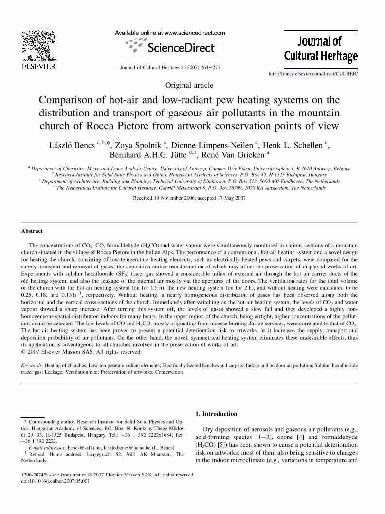
With the new heating system on, the mixing of SF6 wasfound to be complete indoors without any significant concen-tration difference, indicating the lack of large pressure andtemperature gradients, a shortcoming observed during theoperation of the old heating system. Switching the new heatingsystem on and off had a negligible impact on the decay curves(Fig. 3). It can be concluded that the supply, mixing andremoval of the tracer gas take place with a similar transport
0.00
0.15
0.30
0.45
0.60
0.75
0.90
7:00
9:01
11:02
13:03
15:04
17:04
19:05
21:06
23:07
Time
Co
ncen
tratio
n o
f S
F6 (p
pm
) SW corner of naveleft side-chapelNE corner of navenave ceiling (7.5 m)nave middle (4 m)nave middle (1 m)
Heating off
Heating off
Heating on
Dashed lines: idle heating
and no service
Service for 50 min.
with ~20 people
Service
Heating
on
Fig. 3. Variation of the SF6 concentration with the new heating system (con-
tinual lines) and without heating (dashed lines) during the winter campaign
in 2003.
mechanism (mostly concentration diffusion) with the novelheating system on as well as without heating.
3.1.2. Indooreoutdoor air-exchange and leakage of thechurch
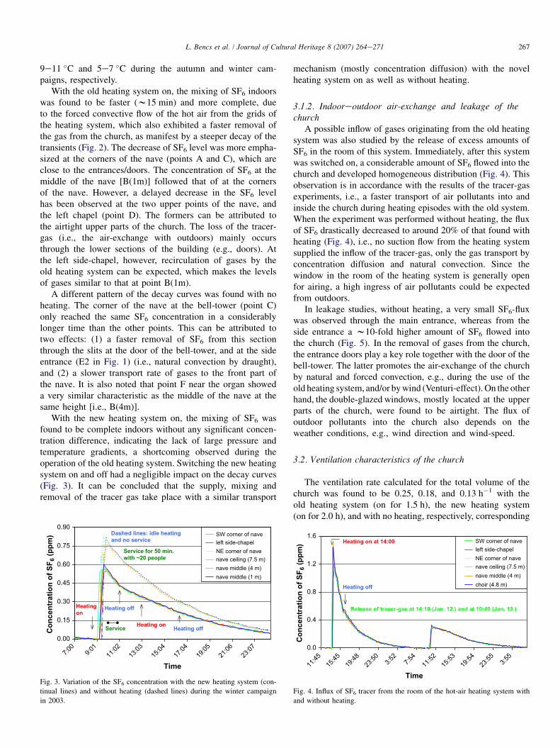
A possible inflow of gases originating from the old heatingsystem was also studied by the release of excess amounts ofSF6 in the room of this system. Immediately, after this systemwas switched on, a considerable amount of SF6 flowed into thechurch and developed homogeneous distribution (Fig. 4). Thisobservation is in accordance with the results of the tracer-gasexperiments, i.e., a faster transport of air pollutants into andinside the church during heating episodes with the old system.When the experiment was performed without heating, the fluxof SF6 drastically decreased to around 20% of that found withheating (Fig. 4), i.e., no suction flow from the heating systemsupplied the inflow of the tracer-gas, only the gas transport byconcentration diffusion and natural convection. Since thewindow in the room of the heating system is generally openfor airing, a high ingress of air pollutants could be expectedfrom outdoors.
In leakage studies, without heating, a very small SF6-fluxwas observed through the main entrance, whereas from theside entrance a w10-fold higher amount of SF6 flowed intothe church (Fig. 5). In the removal of gases from the church,the entrance doors play a key role together with the door of thebell-tower. The latter promotes the air-exchange of the churchby natural and forced convection, e.g., during the use of theold heating system, and/or by wind (Venturi-effect). On the otherhand, the double-glazed windows, mostly located at the upperparts of the church, were found to be airtight. The flux ofoutdoor pollutants into the church also depends on theweather conditions, e.g., wind direction and wind-speed.
3.2. Ventilation characteristics of the church
The ventilation rate calculated for the total volume of thechurch was found to be 0.25, 0.18, and 0.13 h�1 with theold heating system (on for 1.5 h), the new heating system(on for 2.0 h), and with no heating, respectively, corresponding
0.0
0.4
0.8
1.2
1.6
11:45
15:45
19:48
23:50 3:5
27:5
411
:5215
:5319
:5423
:55 3:55
Time
Co
nc
en
tratio
n o
f S
F6 (p
pm
)
SW corner of naveleft side-chapelNE corner of navenave ceiling (7.5 m)nave middle (4 m)choir (4.8 m)
Heating on at 14:00
Heating off
Release of tracer-gas at 14:10 (Jan. 12.) and at 10:40 (Jan. 13.)
Fig. 4. Influx of SF6 tracer from the room of the hot-air heating system with
and without heating.

268 L. Bencs et al. / Journal of Cultural Heritage 8 (2007) 264e271
to average residence times of 4, 5.6 and 7.7 h for SF6, respec-tively. Since aerosols with small aerodynamic diameter(<1 mm) tend to show transport characteristics similar togases, these data therefore could fairly well approximate theirresidence time indoors. These data, together with the localpollutant concentrations and deposition velocities, can beused to establish pollutant deposition rates on artworks, whichis important from the damage risk assessment point of view.
The air-exchange rate of the church without heating is ina fairly good agreement with the values found for churcheswith plastered stone vaults in the Netherlands (0.08e0.12 h�1) [24] and in Cracow, Poland (0.17 h�1) [26]. It wasalso observed that continuous heating of the church duringtwo subsequent services on the same day, and the openingand closing the entrance doors by the visitors before and afterthe service, could considerably increase the ventilation rate,i.e., up to 0.4 h�1. During the cold season, this higher air-exchange with outdoors can provide a faster cooling of thechurch interior, which, combined with the subsequent use ofthe hot-air heating system, could increase the damage riskon artworks.
3.3. Distribution and transport of gaseous air pollutantsindoors
3.3.1. Carbon dioxideVariation of CO2 concentration was studied indoors in the
empty church (Fig. 6) and during service with some 20 people(Figs. 7, 8) to give a clue about the leakage of the hot-air heat-ing system, as experienced above. Without heating andservice, the concentration of CO2 was fluctuating between490 and 620 ppm, mainly due to a long service at the previousday and presence of few members (2e3) of the research team(Fig. 6). Certainly, the CO2 concentration decreased during theevening hours, when the church was empty. However, itsharply increased when the heating system was switched on.The spatial distribution of CO2 without heating was near ho-mogeneous. The decrease of CO2 concentration was of similardegree at each monitoring point, except for points C andB(1m), both showing a slightly sharper fall. On the other
-0.02
0.00
0.02
0.04
0.06
0.08
0.10
0.12
9:41
11:37
13:37
15:38
17:38
19:39
21:39
23:39 1:4
03:4
05:4
07:4
09:4
0
Time
Co
ncen
tratio
n o
f S
F6 (p
pm
)
SW corner of naveleft side-chapelNE corner of navenave ceiling (7.5 m)nave middle (4 m)choir (4.8 m)
Release of SF6 at the main entrance
Release of SF6 at the side-entrance
Fig. 5. Influx of SF6 tracer-gas from outside the church through the entrance
doors of the church without heating.
hand, with the working old heating system (empty church),a sharp increase can be observed at each point, due to the in-gress of some CO2 from the old heating system. The upperlevels of the nave showed a delayed decrease in CO2 levelafter the heating was switched off.
During service an entirely diverse pattern was observed forCO2. In the presence of some 20 people and with heating,a sharp increase in the CO2 concentration was found witha peak of w900 ppm (Fig. 7). The fairly sharper increase ofCO2 level at the left chapel (point D) compared to those atthe other sites is due to that it is the nearest location to the grids,indicating that the heating system plays an important role in thesupply of CO2 originating from the diesel-oil combustion. Onthe other hand, without heating, less increased CO2 peakshave been observed, purely due to the breathing of people pres-ent during service (Fig. 7). During such long services, when thechurch was fully loaded with people (up to some 200 person-sdtypical for a celebration service at Christmas) and the oldheating system was on, the level of CO2 ranged from 1200 to1700 ppm. These levels are over the limit value specified inASHRAE guideline (1000 ppm) [29]. Therefore, they can af-fect the comfort of church visitors joining for longer periods
480
515
550
585
620
7:18
13:19
19:18 1:1
87:1
813
:2219
:22 1:22
7:22
Time
Co
ncen
tratio
n o
f C
O2 (p
pm
) SW corner of naveleft side-chapelNE corner of navenave ceiling (7.5 m)nave middle (4 m)nave middle (1 m)
Heating on at 9.55 a.m.
Heating off at 11:25 a.m.
Ingress of external pollution
Fig. 6. Variation of the CO2 concentration with the hot-air heating system on in
the empty church.
500
550
600
650
700
750
800
850
900
10:39
12:40
14:40
16:41
18:41
20:42
22:43 0:4
32:4
34:4
36:4
4
Time
Co
ncen
tratio
n o
f C
O2 (p
pm
)
SW corner of naveleft side-chapelNE corner of navenave ceiling (7.5 m)nave middle (4 m)choir (4.8 m)
Service
Heating on
Heating offDashed lines: no heating
Service for 40 min with ~20 people
Fig. 7. Variation of the CO2 concentration with the hot-air heating on (contin-
ual lines) and without heating (dashed lines) during service with some 20
people.
269L. Bencs et al. / Journal of Cultural Heritage 8 (2007) 264e271
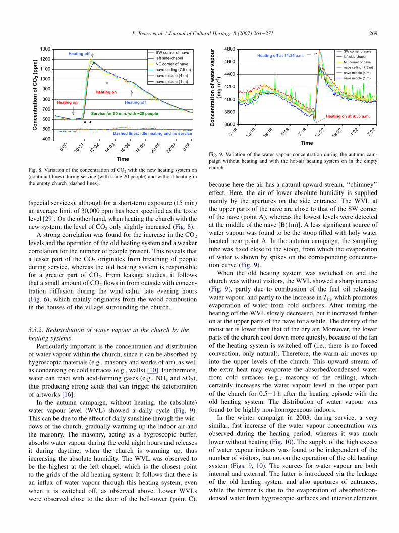
(special services), although for a short-term exposure (15 min)an average limit of 30,000 ppm has been specified as the toxiclevel [29]. On the other hand, when heating the church with thenew system, the level of CO2 only slightly increased (Fig. 8).
A strong correlation was found for the increase in the CO2
levels and the operation of the old heating system and a weakercorrelation for the number of people present. This reveals thata lesser part of the CO2 originates from breathing of peopleduring service, whereas the old heating system is responsiblefor a greater part of CO2. From leakage studies, it followsthat a small amount of CO2 flows in from outside with concen-tration diffusion during the wind-calm, late evening hours(Fig. 6), which mainly originates from the wood combustionin the houses of the village surrounding the church.
3.3.2. Redistribution of water vapour in the church by theheating systems
Particularly important is the concentration and distributionof water vapour within the church, since it can be absorbed byhygroscopic materials (e.g., masonry and works of art), as wellas condensing on cold surfaces (e.g., walls) [10]. Furthermore,water can react with acid-forming gases (e.g., NOx and SO2),thus producing strong acids that can trigger the deteriorationof artworks [16].
In the autumn campaign, without heating, the (absolute)water vapour level (WVL) showed a daily cycle (Fig. 9).This can be due to the effect of daily sunshine through the win-dows of the church, gradually warming up the indoor air andthe masonry. The masonry, acting as a hygroscopic buffer,absorbs water vapour during the cold night hours and releasesit during daytime, when the church is warming up, thusincreasing the absolute humidity. The WVL was observed tobe the highest at the left chapel, which is the closest pointto the grids of the old heating system. It follows that there isan influx of water vapour through this heating system, evenwhen it is switched off, as observed above. Lower WVLswere observed close to the door of the bell-tower (point C),
400
500
600
700
800
900
1000
1100
1200
1300
8:00
10:01
12:02
14:03
16:04
18:05
20:06
22:07 0:0
8
Time
Co
ncen
tratio
n o
f C
O2 (p
pm
)
SW corner of naveleft side-chapelNE corner of navenave ceiling (7.5 m)nave middle (4 m)nave middle (1 m)
Heating off
Heating on
Heating off
Dashed lines: idle heating and no service
Service for 50 min. with ~20 people
Heating on
Fig. 8. Variation of the concentration of CO2 with the new heating system on
(continual lines) during service (with some 20 people) and without heating in
the empty church (dashed lines).
because here the air has a natural upward stream, ‘‘chimney’’effect. Here, the air of lower absolute humidity is suppliedmainly by the apertures on the side entrance. The WVL atthe upper parts of the nave are close to that of the SW cornerof the nave (point A), whereas the lowest levels were detectedat the middle of the nave [B(1m)]. A less significant source ofwater vapour was found to be the stoop filled with holy waterlocated near point A. In the autumn campaign, the samplingtube was fixed close to the stoop, from which the evaporationof water is shown by spikes on the corresponding concentra-tion curve (Fig. 9).When the old heating system was switched on and thechurch was without visitors, the WVL showed a sharp increase(Fig. 9), partly due to combustion of the fuel oil releasingwater vapour, and partly to the increase in Tin, which promotesevaporation of water from cold surfaces. After turning theheating off the WVL slowly decreased, but it increased furtheron at the upper parts of the nave for a while. The density of themoist air is lower than that of the dry air. Moreover, the lowerparts of the church cool down more quickly, because of the fanof the heating system is switched off (i.e., there is no forcedconvection, only natural). Therefore, the warm air moves upinto the upper levels of the church. This upward stream ofthe extra heat may evaporate the absorbed/condensed waterfrom cold surfaces (e.g., masonry of the ceiling), whichcertainly increases the water vapour level in the upper partof the church for 0.5e1 h after the heating episode with theold heating system. The distribution of water vapour wasfound to be highly non-homogeneous indoors.
In the winter campaign in 2003, during service, a verysimilar, fast increase of the water vapour concentration wasobserved during the heating period, whereas it was muchlower without heating (Fig. 10). The supply of the high excessof water vapour indoors was found to be independent of thenumber of visitors, but not on the operation of the old heatingsystem (Figs. 9, 10). The sources for water vapour are bothinternal and external. The latter is introduced via the leakageof the old heating system and also apertures of entrances,while the former is due to the evaporation of absorbed/con-densed water from hygroscopic surfaces and interior elements
3600
3800
4000
4200
4400
4600
4800
7:18
13:19
19:18 1:1
87:1
813
:2219
:22 1:22
7:22
Time
Co
ncen
tratio
n o
f w
ater vap
ou
r
(m
g m
-3)
SW corner of naveleft side-chapelNE corner of navenave ceiling (7.5 m)nave middle (4 m)nave middle (1 m)
Heating on at 9:55 a.m.
Heating off at 11:25 a.m.
Fig. 9. Variation of the water vapour concentration during the autumn cam-
paign without heating and with the hot-air heating system on in the empty
church.

270 L. Bencs et al. / Journal of Cultural Heritage 8 (2007) 264e271
(e.g., wooden benches). Also, a significant source of outdoormoisture has been reported to be people fully loading thechurch during longer services on the main feasts [10].
When the new heating system was switched on (emptychurch), the WVL slowly and slightly increased, whereas itdecreased after switching the heating off (Fig. 11). Duringthe service, a modest increase of the WVL was observed forthe whole heating period. The WVL considerably increasedonly at the middle of the nave [point B(1m)], i.e., near theheated pews, whereas at the other monitoring locations theincrease is less manifest. This is a very important characteris-tic of the new heating system, i.e., it keeps the moisture mainlylocalized at the benches. With this heating system on, how-ever, the supply of water vapour indoors was found to beslightly dependent on the number of visitors entering forservice. The source of this water is external (rainwater,snow, etc.) brought into the church by people entering forthe service with wet clothes, shoes, hair, etc. During heating,this moisture could be released via evaporation/melting, thusincreasing the water vapour content indoors.
3.3.3. Sources and variations in the CO and H2CO levelsOnly very low amounts of CO and H2CO were detected in-
doors, i.e., up to 1.1 and 0.15 ppm with the old system, and 0.2
2500
3000
3500
4000
4500
9:53
11:52
13:52
15:53
17:53
19:54
21:54
23:55 1:5
53:5
55:5
67:5
6
Time
Co
ncen
tratio
n o
f w
ater vap
ou
r
(m
g m
-3)
SW corner of naveleft side-chapelNE corner of navenave ceiling (7.5 m)nave middle (4 m)choir (4.8 m)
Heating on
Heating off
Heating off
Dashed lines: no heating
Service for 40 min with ~20 people
Fig. 10. Variation of the water vapour level with the old heating system on
(continual lines) and without heating (dashed lines) during services.
2500
2650
2800
2950
3100
3250
3400
8:12
10:13
12:14
14:15
16:16
18:17
20:18
22:19 0:2
0
Time
Co
ncen
tratio
n o
f w
ater vap
ou
r
(m
g m
-3)
Heating off
Heating on
Heating off
Dashed lines: idle heating and no service
Service for 50 min with ~20 people
Heating on
SW corner of naveleft side-chapelNE corner of navenave ceiling (7.5 m)nave middle (4 m)nave middle (1 m)
Fig. 11. Variation of the water vapour level with the new heating system on
(continual lines) and without heating (dashed lines).
and 0.02 ppm with the new heating system, respectively. Theirlevels were correlated with those of CO2 and water vapourduring services that utilized longer heating periods with thehot-air heating system, and/or incense burning. This impliesthat they originate from, or at least are re-suspended by thehot-air heating system. Incense burning is a source of H2COand CO [11]. Also, for H2CO, the furniture of churches, i.e.,plywood, particleboard and adhesives for wall-clothing, wasreported as emission sources [30], of which effects howeverwere found to be negligibly small in the church of RoccaPietore.
The transition metal oxide (e.g., Mn, Fe, Cu, and Ti)induced decomposition of H2CO [30] is of importance fromconservation points of view, if a possible interaction ofH2CO with metal oxide based paintings is considered. In thechurch of Rocca Pietore, the displayed mural paintings mayprovide a surface for these reactions to take place. Therefore,the effects of incense/candle burning, as the main sources ofH2CO, should also be more serious on the displayed artworksthan previously observed [10].
Without heating, the concentration of CO was correlatedwith that of H2CO. The presence of these pollutants indoorsoccasionally showed correlation with the usage of conven-tional wood heating in the houses of the village during themorning and evening hours, similarly as observed for CO2.Certainly, their ingress into the church is strongly dependenton the weather conditions (wind direction and speed, etc.).
4. Conclusions
Due to the forced convection of hot air during the operationof the conventional heating system and the induced high-temperature gradients, remaining in the church after theheating period, an increased ventilation and transport of gas-eous air pollutants take place in the indoor air of the church.A considerable influx of external air through this heatingsystem during heating and a lower influx during its inactivestate were also observed. Leakage of either internal or externalair was found with and without heating, respectively, mostlyvia the apertures of the doors.
The hot-air heating system is a potential source of gaseouspollutants, which partly originate from outside. This heatingsystem also promotes the deposition probability of gaseousair pollutants as well as aerosols, thus presents an increaseddamage risk to artworks. Controlled ventilation of thesechurches after each heating period using proper air/humid-ity-exchangers and filters is of importance for the removal ofair-pollutants, which is advantageous from a conservationpoint of view.
The results clearly demonstrate that with the new, symmet-rical heating system, comprising low-temperature radiantheating elements, the shortcomings of the hot-air heatingsystem (e.g. the large pressure and temperature gradients,emission of water vapour and CO2, and re-suspension of airpollutants) can be eliminated, or at least drastically reduced.These features yield a significantly lower transport of pollut-ants, thus lower probability of deposition and chemical

271L. Bencs et al. / Journal of Cultural Heritage 8 (2007) 264e271
reactions on artworks. Moreover, the new system keeps theheat and the moisture localized at and around the benches,thus less evaporation of absorbed water could be expected.These are all important advantages of the novel heating systemover conventional systems, especially from the viewpoint ofconservation. Thus its installation and usage can be recom-mended in churches displaying monumental works of art.
Acknowledgements
Support from the European Commission through theproject called ‘‘Friendly Heating’’ (Contract No.: EVK4-CT-2001-00067) is gratefully acknowledged. The authors ex-press their gratitude to Don Attilio De Zaiacomo, the parishpriest in Rocca Pietore, for his assistance during the studiesin the church. One of the authors (L.B.) thanks the supportof the Hungarian Scientific Research Fund (OTKA) underthe project of F67647.
References
[1] P. Brimblecombe, The composition of museum atmospheres, Atmos.
Environ. 24B (1990) 1e8.
[2] M.W.M. Hisham, D. Grosjean, Air-pollution in southern California
museumsdIndoor and outdoor levels of nitrogen dioxide, peroxyacetyl
nitrate, nitric acid and chlorinated hydrocarbons, Environ. Sci. Technol.
25 (1991) 857e862.
[3] F. De Santis, I. Allegrini, M.C. Fazio, D. Pasella, Characterization of
indoor air quality in the Church of San Luigi dei Francesi, Rome, Italy,
Int. J. Environ. Anal. Chem. 64 (1996) 71e81.
[4] D. Grosjean, P.M. Whitmore, G.R. Cass, J.R. Druzik, Ozone fading of
triphenylmethane colorantsdreaction-products and mechanisms,
Environ. Sci. Technol. 23 (1989) 1164e1167.
[5] M.R. Raychaudhuri, P. Brimblecombe, Formaldehyde oxidation and lead
corrosion, Stud. Conserv. 45 (2000) 226e232.
[6] D. Camuffo, Microclimate for Cultural Heritage, Elsevier, Amsterdam,
1998.
[7] A. Arnold, Determination of mineral salts from monuments, Stud.
Conserv. 29 (1983) 129e138.
[8] A. Arnold, K. Zehnder, Salt weathering on monuments, in: F. Zezza
(Ed.), The Conservation of Monuments in the Mediterranean Basin.
Grafo, Bari, 1990, pp. 31e58.
[9] A. Arnold, K. Zehnder, Monitoring wall paintings affected by soluble
salts, in: S. Cather (Ed.), The Conservation of Wall Paintings. Paul Getty
Trust, Thien Wah Press, Singapore, 1991, pp. 103e135.
[10] D. Camuffo, G. Sturaro, A. Valentino, M. Camuffo, The conservation of
artworks and hot air heating systems in churches: Are they compatible?
The case of Rocca Pietore, Italian Alps, Stud. Conserv. 44 (1999) 209e216.
[11] S.S.H. Ho, J.Z. Yu, Concentrations of formaldehyde and other carbonyls
in environments affected by incense burning, J. Environ. Monit. 4 (2002)
728e733.
[12] C.K. Huynh, H. Savolainen, T. Vu-Duc, M. Guillemin, F. Iselin, Impact
of thermal proofing of a church on its indoor air-qualitydthe combustion
of candles and incense as a source of pollution, Sci. Total Environ. 102
(1991) 241e251.
[13] S. Janhall, P. Molnar, M. Hallquist, Vertical distribution of air pollutants
at the Gustavii Cathedral in Goteborg, Sweden, Atmos. Environ. 37
(2003) 209e217.
[14] G.C. Fang, C.N. Chang, Y.S. Wu, C.J. Yang, S.C. Chang, I.L. Yang,
Suspended particulate variations and mass size distributions of incense
burning at Tzu Yun Yen temple in Taiwan, Taichung, Sci. Total Environ.
299 (2002) 79e87.
[15] Z. Spolnik, A. Worobiec, J. Injuk, D. Neilen, H. Schellen, R. Van
Grieken, Chemical characterization of airborne particles in St. Martinus
Cathedral in Weert, The Netherlands, Microchim. Acta 145 (2004)
223e227.
[16] D. Camuffo, P. Brimblecombe, R. Van Grieken, H.J. Busse, G. Sturaro,
A. Valentino, A. Bernardi, N. Blades, D. Shooter, L. De Bock,
K. Gysels, M. Wieser, O. Kim, Indoor air quality at the Correr Museum,
Venice, Italy, Sci. Total Environ. 236 (1999) 135e152.
[17] G. Sturaro, D. Camuffo, P. Brimblecombe, R. Van Grieken, H.J. Busse,
A. Bernardi, A. Valentino, N. Blades, K. Gysels, F. Deutsch,
M. Wieser, S. Buczolits, Multidisciplinary environmental monitoring at
the Kunsthistorisches Museum, Vienna, J. Trace Microprobe Techn. 21
(2003) 273e294.
[18] P. Brimblecombe, N. Blades, D. Camuffo, G. Sturaro, A. Valentino,
K. Gysels, R. Van Grieken, H.J. Busse, O. Kim, U. Ulrych,
M. Wieser, The indoor environment of a modern museum building,
the Sainsbury Centre for Visual Arts, Norwich, UK, Indoor Air 9
(1999) 146e164.
[19] K. Gysels, F. Deutsch, R. Van Grieken, Characterisation of particulate
matter in the Royal Museum of Fine Arts, Antwerp, Belgium, Atmos.
Environ. 36 (2002) 4103e4113.
[20] L.A. De Bock, R.E. Van Grieken, D. Camuffo, G.W. Grime, Microanal-
ysis of museum aerosols to elucidate the soiling of paintings: Case of the
Correr Museum, Venice, Italy, Environ. Sci. Technol. 30 (1996)
3341e3350.
[21] D. Camuffo, R. Van Grieken, H.J. Busse, G. Sturaro, A. Valentino,
A. Bernardi, N. Blades, D. Shooter, K. Gysels, F. Deutsch, M. Wieser,
O. Kim, U. Ulrych, Environmental monitoring in four European
museums, Atmos. Environ. 35 (2001) S127eS140.
[22] F. De Santis, V. Di Palo, I. Allegrini, Determination of some atmospheric
pollutants inside a museumdrelationship with the concentration outside,
Sci. Total Environ. 127 (1992) 211e223.
[23] J. Injuk, J. Osan, R. Van Grieken, K. Tsuji, Airborne particles in the
Miyagi Museum of Art in Sendai, Japan, studied by electron probe
X-ray microanalysis and energy dispersive X-ray fluorescence analysis,
Anal. Sci. 18 (2002) 561e566.
[24] H.L. Schellen, Heating Monumental ChurchesdIndoor Climate and
Preservation of Cultural Heritage, PhD thesis, Technical University of
Eindhoven, The Netherlands, 2002.
[25] Z. Spolnik, L. Bencs, A. Worobiec, V. Kontozova, R. Van Grieken,
Application of EDXRF and thin window EPMA for the investigation
of the influence of hot air heating on the generation and deposition of
particulate matter, Microchim. Acta 149 (2005) 79e85.
[26] L. Samek, A. De Maeyer-Worobiec, Z. Spolnik, L. Bencs, V. Kontozova,
L. Bratasz, R. Koz1owski, R. Van Grieken, Impact of electric overhead
radiant heating on the indoor environment of historic churches, J. Cult.
Herit. (2007) accepted.
[27] Z. Spolnik, A. Worobiec, L. Samek, L. Bencs, K. Belikov, R. Van
Grieken, Influence of different types of heating systems on particulate
air pollutant deposition: The case of churches situated in a cold climate,
J. Cult. Herit. 8 (2007) 7e12.
[28] D. Limpens-Neilen, Bench Heating in Monumental ChurchesdThermal
Performance of a Prototype, PhD thesis, Technical University of Eind-
hoven, The Netherlands, 2006.
[29] American Society of Heating, Refrigerating and Air-conditioning
Engineers Inc. (ASHRAE), Ventilation for Acceptable Indoor Air
Quality, ASHRAE 62e2001.
[30] Y. Sekine, Oxidative decomposition of formaldehyde by metal oxides at
room temperature, Atmos. Environ. 36 (2002) 5543e5547.