Comparative Analysis of GPS Azimuth and Derived Azimuth for the Establishment of Project Controls
18
TS 6D – Engineering Application of GNSS Page 1 of 18 Dimal, Matthew Oliver Ralp L. and Balicanta, Louie P. Comparative Analysis of GPS Azimuth and Astronomic Azimuth for the Establishment of Project Controls 7 th FIG Regional Conference Spatial Data Serving People: Land Governance and the Environment – Building the Capacity Hanoi, Vietnam, 19-22 October 2009 Comparative Analysis of GPS Azimuth and Derived Azimuth for the Establishment of Project Controls Matthew Oliver Ralp L. DIMAL and Louie P. BALICANTA, Philippines Keywords: Azimuth, Astronomic Observations, GPS SUMMARY The azimuths obtained from astronomic observation and GPS survey were evaluated to show significant differences. Astronomic observation was used in azimuth determination for old surveys in the Philippines, but is gradually being replaced by the use of the GPS, because of its rapid measuring capability and weather independency. However, GPS provides a different type of azimuth as compared to astronomic observation. The relationship and precision of both techniques were tested on various baselines located in different parts of the country. Nine baselines in five cities from around the Philippine Archipelago were chosen as test sites to compare the difference between the measured GPS azimuth and astronomic azimuth. Dual frequency GPS receivers were used to measure geodetic azimuth using static GPS technique while the astronomic observations made use of series of solar observations using a Wilde T2 theodolite. The differences in measured azimuth were analyzed and evaluated using the standards of project control accuracy in the Philippines. The results derived from the two methods yielded comparative difference of amounts less than 15 seconds in all test sites, the minimum requirement of PE for tertiary project controls. This means that in the establishment of project controls of at least tertiary control requirements, azimuth from GPS and astronomic observations may be used or interchanged.
-
Upload
philippines -
Category
Documents
-
view
6 -
download
0
Transcript of Comparative Analysis of GPS Azimuth and Derived Azimuth for the Establishment of Project Controls
TS 6D – Engineering Application of GNSS Page 1 of 18 Dimal, Matthew Oliver Ralp L. and Balicanta, Louie P. Comparative Analysis of GPS Azimuth and Astronomic Azimuth for the Establishment of Project Controls 7th FIG Regional Conference Spatial Data Serving People: Land Governance and the Environment – Building the Capacity Hanoi, Vietnam, 19-22 October 2009
Comparative Analysis of GPS Azimuth and Derived Azimuth for the Establishment of Project Controls
Matthew Oliver Ralp L. DIMAL and Louie P. BALICANTA, Philippines
Keywords: Azimuth, Astronomic Observations, GPS SUMMARY The azimuths obtained from astronomic observation and GPS survey were evaluated to show significant differences. Astronomic observation was used in azimuth determination for old surveys in the Philippines, but is gradually being replaced by the use of the GPS, because of its rapid measuring capability and weather independency. However, GPS provides a different type of azimuth as compared to astronomic observation. The relationship and precision of both techniques were tested on various baselines located in different parts of the country. Nine baselines in five cities from around the Philippine Archipelago were chosen as test sites to compare the difference between the measured GPS azimuth and astronomic azimuth. Dual frequency GPS receivers were used to measure geodetic azimuth using static GPS technique while the astronomic observations made use of series of solar observations using a Wilde T2 theodolite. The differences in measured azimuth were analyzed and evaluated using the standards of project control accuracy in the Philippines. The results derived from the two methods yielded comparative difference of amounts less than 15 seconds in all test sites, the minimum requirement of PE for tertiary project controls. This means that in the establishment of project controls of at least tertiary control requirements, azimuth from GPS and astronomic observations may be used or interchanged.
TS 6D – Engineering Application of GNSS Page 2 of 18 Dimal, Matthew Oliver Ralp L. and Balicanta, Louie P. Comparative Analysis of GPS Azimuth and Astronomic Azimuth for the Establishment of Project Controls 7th FIG Regional Conference Spatial Data Serving People: Land Governance and the Environment – Building the Capacity Hanoi, Vietnam, 19-22 October 2009
Comparative Analysis of GPS Azimuth and Derived Azimuth for the Establishment of Project Controls
Matthew Oliver Ralp L. DIMAL and Louie P. BALICANTA, Philippines
1. INTRODUCTION Azimuth is one of the basic and important information in field surveying, which form the basis for orienting different navigation systems (Davis, Foote, Anderson, & Mikhail, 1981). For surveyors and engineers, the information provides important data required for all kinds of land surveys from cadastral-property survey, mapping, and various construction and development projects. Prior to the advent of electronic and sophisticated surveying instruments, azimuths were traditionally obtained from the observation of different celestial bodies. The most popular celestial bodies being observed were the sun during the day, and Polaris or the North Star during the night (Mueller, 1969). Other celestial bodies have also been used; however, the unique characteristics of the sun and Polaris for places on the northern hemisphere made them the more popular choice in astronomic observation. With astronomic observation, an optical surveying instrument is utilized to observe the position of the celestial body, which may be use to determine the line’s direction called astronomic azimuth. This method was widely used in the establishment of old Philippine geodetic control networks established through triangulation and trilateration (Allman, 1991). However, in recent years, the use of astronomic observations in surveying became less, due partly to the multitude of problems in observing celestial objects, and due to the apparent shift of the industry towards GPS (Lennartz-Johansen & Ellegaard, 2002). Global Positioning System or GPS is a breakthrough in the field of surveying. This technology is independent from the method of sighting, as compared to a theodolite or total station, which are highly dependent on intervisibility between stations. Using information transmitted form orbiting satellites, geographical information like coordinates and azimuth may be derived by an observer using a GPS receiver. Modern geodetic control networks are now using this technology. In the Philippines, the National Mapping and Resource Information Authority (NAMRIA) has used GPS technology in establishing control stations for the Philippine Reference System of 1992 or PRS92 (Department of Environment and Natural Resources, 1994). Since PRS92 uses an ellipsoidal model such as the Clarke Spheroid of 1866, the derived azimuth from the use of GPS is geodetic azimuth. Survey grade GPS units are very expensive, yet the technology is very popular among local surveyors because of its efficiency and of its ability to give fast accurate results. Since the astronomic observation-derived azimuth and GPS derived-geodetic azimuth are from different systems and references, the question among surveyors arises as to the equivalence or similarity of the two azimuths. The need for a comparative analysis between the azimuth obtained from GPS and astronomic observation has risen for various reasons.
TS 6D – Engineering Application of GNSS Page 3 of 18 Dimal, Matthew Oliver Ralp L. and Balicanta, Louie P. Comparative Analysis of GPS Azimuth and Astronomic Azimuth for the Establishment of Project Controls 7th FIG Regional Conference Spatial Data Serving People: Land Governance and the Environment – Building the Capacity Hanoi, Vietnam, 19-22 October 2009
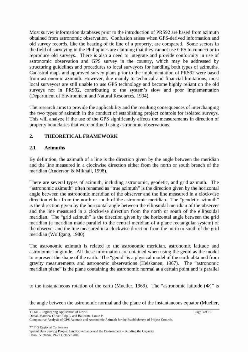
Most survey information databases prior to the introduction of PRS92 are based from azimuth obtained from astronomic observation. Confusion arises when GPS-derived information and old survey records, like the bearing of tie line of a property, are compared. Some sectors in the field of surveying in the Philippines are claiming that they cannot use GPS to connect or to reproduce old surveys. There is also a need to integrate and provide conformity in use of astronomic observation and GPS survey in the country, which may be addressed by structuring guidelines and procedures to local surveyors for handling both types of azimuths. Cadastral maps and approved survey plans prior to the implementation of PRS92 were based from astronomic azimuth. However, due mainly to technical and financial limitations, most local surveyors are still unable to use GPS technology and become highly reliant on the old surveys not in PRS92, contributing to the system’s slow and poor implementation (Department of Environment and Natural Resources, 1994). The research aims to provide the applicability and the resulting consequences of interchanging the two types of azimuth in the conduct of establishing project controls for isolated surveys. This will analyze if the use of the GPS significantly affects the measurements in direction of property boundaries that were outlined using astronomic observations. 2. THEORETICAL FRAMEWORK 2.1 Azimuths By definition, the azimuth of a line is the direction given by the angle between the meridian and the line measured in a clockwise direction either from the north or south branch of the meridian (Anderson & Mikhail, 1998). There are several types of azimuth, including astronomic, geodetic, and grid azimuth. The “astronomic azimuth” often renamed as “true azimuth” is the direction given by the horizontal angle between the astronomic meridian of the observer and the line measured in a clockwise direction either from the north or south of the astronomic meridian. The “geodetic azimuth” is the direction given by the horizontal angle between the ellipsoidal meridian of the observer and the line measured in a clockwise direction from the north or south of the ellipsoidal meridian. The “grid azimuth” is the direction given by the horizontal angle between the grid meridian (a meridian made parallel to the central meridian of a plane rectangular system) of the observer and the line measured in a clockwise direction from the north or south of the grid meridian (Wolfgang, 1980). The astronomic azimuth is related to the astronomic meridian, astronomic latitude and astronomic longitude. All these information are obtained when using the geoid as the model to represent the shape of the earth. The “geoid” is a physical model of the earth obtained from gravity measurements and astronomic observations (Heiskanen, 1967). The “astronomic meridian plane” is the plane containing the astronomic normal at a certain point and is parallel
to the instantaneous rotation of the earth (Mueller, 1969). The “astronomic latitude ( )” is
the angle between the astronomic normal and the plane of the instantaneous equator (Mueller,
TS 6D – Engineering Application of GNSS Page 4 of 18 Dimal, Matthew Oliver Ralp L. and Balicanta, Louie P. Comparative Analysis of GPS Azimuth and Astronomic Azimuth for the Establishment of Project Controls 7th FIG Regional Conference Spatial Data Serving People: Land Governance and the Environment – Building the Capacity Hanoi, Vietnam, 19-22 October 2009
1969). The “astronomic longitude (Λ)” is the angle between the designated zero meridian, the Greenwich mean astronomic meridian, and that of the meridian of a certain point measured in the plane of the instantaneous equator (Mueller 1969).
Figure 2.1: The Geoid and the Ellipsoid
The geodetic azimuth is related to the geodetic meridian, geodetic latitude and geodetic longitude. With these parameters, the earth is represented in a mathematical model as an ellipsoid. There are several ellipsoidal models including the World Geodetic System of 1984 (WGS84) used by the GPS, and the Clarke Spheroid of 1866 used in the Philippines. The “geodetic meridian plane” is the plane containing the geodetic normal at a certain point
and is parallel to the rotational axis of the earth. The “geodetic latitude ( )” is the angle
between the geodetic normal and the geodetic equator. The “geodetic longitude ( )” is the
angle between the designated zero meridian, or the Greenwich meridian, and the meridian containing a certain point measured in the plane of the geodetic equator. (Mueller, 1969) As it is more convenient to do positioning on a rectangular XY coordinate system, an earth model is projected on a plane that fits the location being mapped. This process is called map projection (Wolfgang, 1980). There are different map projections, and in the Philippines the Transverse Mercator projection is used. In doing the projection, a central meridian is being chosen and is considered as the true meridian. All other meridians are made parallel to this central meridian and are called “grid meridians”. As discussed, grid azimuths are referred from the grid meridian containing the observer. 2.2 Astronomic Observation The primary method of obtaining the astronomic azimuth used in this research is the Method of Azimuth Determination at any Hour Angle or MADHA. The celestial sphere is used as the primary model in astronomic observation, where the earth is made the center of the sphere and other celestial objects are of the infinite distance from the earth. Position and direction of celestial objects are defined by different celestial coordinate systems. MADHA is derived
TS 6D – Engineering Application of GNSS Page 5 of 18 Dimal, Matthew Oliver Ralp L. and Balicanta, Louie P. Comparative Analysis of GPS Azimuth and Astronomic Azimuth for the Establishment of Project Controls 7th FIG Regional Conference Spatial Data Serving People: Land Governance and the Environment – Building the Capacity Hanoi, Vietnam, 19-22 October 2009
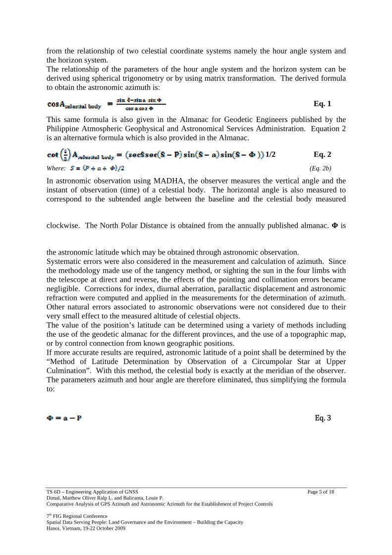
from the relationship of two celestial coordinate systems namely the hour angle system and the horizon system. The relationship of the parameters of the hour angle system and the horizon system can be derived using spherical trigonometry or by using matrix transformation. The derived formula to obtain the astronomic azimuth is:
Eq. 1
This same formula is also given in the Almanac for Geodetic Engineers published by the Philippine Atmospheric Geophysical and Astronomical Services Administration. Equation 2 is an alternative formula which is also provided in the Almanac.
1/2 Eq. 2
Where: (Eq. 2b)
In astronomic observation using MADHA, the observer measures the vertical angle and the instant of observation (time) of a celestial body. The horizontal angle is also measured to correspond to the subtended angle between the baseline and the celestial body measured
clockwise. The North Polar Distance is obtained from the annually published almanac. is
the astronomic latitude which may be obtained through astronomic observation. Systematic errors were also considered in the measurement and calculation of azimuth. Since the methodology made use of the tangency method, or sighting the sun in the four limbs with the telescope at direct and reverse, the effects of the pointing and collimation errors became negligible. Corrections for index, diurnal aberration, parallactic displacement and astronomic refraction were computed and applied in the measurements for the determination of azimuth. Other natural errors associated to astronomic observations were not considered due to their very small effect to the measured altitude of celestial objects. The value of the position’s latitude can be determined using a variety of methods including the use of the geodetic almanac for the different provinces, and the use of a topographic map, or by control connection from known geographic positions. If more accurate results are required, astronomic latitude of a point shall be determined by the “Method of Latitude Determination by Observation of a Circumpolar Star at Upper Culmination”. With this method, the celestial body is exactly at the meridian of the observer. The parameters azimuth and hour angle are therefore eliminated, thus simplifying the formula to:
Eq. 3
TS 6D – Engineering Application of GNSS Page 6 of 18 Dimal, Matthew Oliver Ralp L. and Balicanta, Louie P. Comparative Analysis of GPS Azimuth and Astronomic Azimuth for the Establishment of Project Controls 7th FIG Regional Conference Spatial Data Serving People: Land Governance and the Environment – Building the Capacity Hanoi, Vietnam, 19-22 October 2009
2.3 GPS Observation The basic principle of the GPS is the use of positioning satellites to determine the position of a receiver located on the surface of the earth. There are more than twenty four NAVSTAR satellites orbiting around the earth. At least four (4) satellites are needed to obtain a relatively accurate receiver position similar to the principle of resection. Accuracy is measured in terms of the “Dilution of Precision”. This dilution of precision has several levels; the highest is the Geometric Dilution of Precision (GDOP) which considers the errors in the x, y, z and time. The lower the DOP or GDOP the higher the accuracy of the obtained measurement. This is similar to the concept of the strength of figure in triangulation networks. The accuracy of the GPS measurement is further improved by performing differential GPS survey wherein two or more survey grade GPS receivers simultaneously observe the same set of satellites. (Leick, 2004) Relative or differential static GPS survey shall be used as the primary method in the
determination of the geodetic azimuth ( ). Two GPS receivers located on stations where is needed shall be observed simultaneously. Appropriate processing software should obtain
the WGS84 geographic coordinates: geocentric latitude and longitude ( ) of both stations. Since these coordinates are based from the WGS84 datum, there is a need to convert these to PRS92 horizontal datum having geographic coordinates: geodetic latitude and
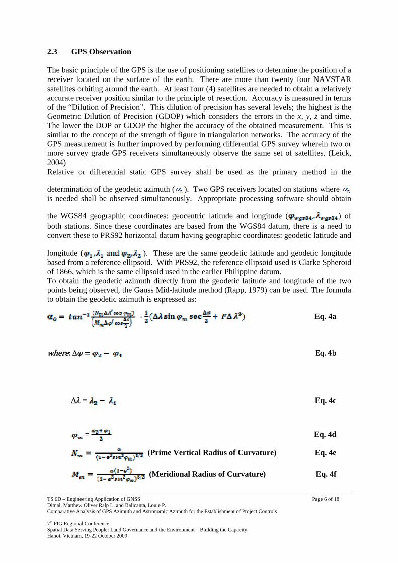
longitude ( ). These are the same geodetic latitude and geodetic longitude based from a reference ellipsoid. With PRS92, the reference ellipsoid used is Clarke Spheroid of 1866, which is the same ellipsoid used in the earlier Philippine datum. To obtain the geodetic azimuth directly from the geodetic latitude and longitude of the two points being observed, the Gauss Mid-latitude method (Rapp, 1979) can be used. The formula to obtain the geodetic azimuth is expressed as:
- Eq. 4a
where: Δ Eq. 4b
Δ = Eq. 4c
= Eq. 4d
(Prime Vertical Radius of Curvature) Eq. 4e
(Meridional Radius of Curvature) Eq. 4f
TS 6D – Engineering Application of GNSS Page 7 of 18 Dimal, Matthew Oliver Ralp L. and Balicanta, Louie P. Comparative Analysis of GPS Azimuth and Astronomic Azimuth for the Establishment of Project Controls 7th FIG Regional Conference Spatial Data Serving People: Land Governance and the Environment – Building the Capacity Hanoi, Vietnam, 19-22 October 2009
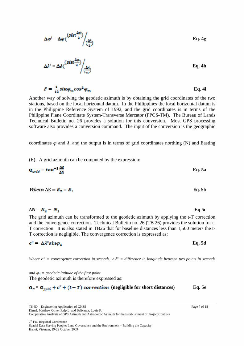
= Eq. 4g
= Eq. 4h
Eq. 4i
Another way of solving the geodetic azimuth is by obtaining the grid coordinates of the two stations, based on the local horizontal datum. In the Philippines the local horizontal datum is in the Philippine Reference System of 1992, and the grid coordinates is in terms of the Philippine Plane Coordinate System-Transverse Mercator (PPCS-TM). The Bureau of Lands Technical Bulletin no. 26 provides a solution for this conversion. Most GPS processing software also provides a conversion command. The input of the conversion is the geographic
coordinates and , and the output is in terms of grid coordinates northing (N) and Easting
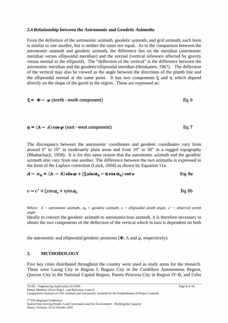
(E). A grid azimuth can be computed by the expression:
= Eq. 5a
Where: ΔE Eq. 5b
ΔN = Eq 5c The grid azimuth can be transformed to the geodetic azimuth by applying the t-T correction and the convergence correction. Technical Bulletin no. 26 (TB 26) provides the solution for t-T correction. It is also stated in TB26 that for baseline distances less than 1,500 meters the t-T correction is negligible. The convergence correction is expressed as:
Eq. 5d
Where c” = convergence correction in seconds, Δ ” = difference in longitude between two points in seconds
and = geodetic latitude of the first point The geodetic azimuth is therefore expressed as:
= (negligible for short distances) Eq. 5e
TS 6D – Engineering Application of GNSS Page 8 of 18 Dimal, Matthew Oliver Ralp L. and Balicanta, Louie P. Comparative Analysis of GPS Azimuth and Astronomic Azimuth for the Establishment of Project Controls 7th FIG Regional Conference Spatial Data Serving People: Land Governance and the Environment – Building the Capacity Hanoi, Vietnam, 19-22 October 2009
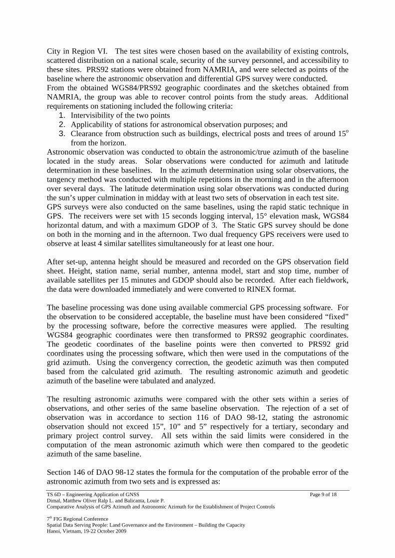
2.4 Relationship between the Astronomic and Geodetic Azimuths From the definition of the astronomic azimuth, geodetic azimuth, and grid azimuth, each form is similar to one another, but is neither the same nor equal. As to the comparison between the astronomic azimuth and geodetic azimuth, the difference lies on the meridian (astronomic meridian versus ellipsoidal meridian) and the normal (vertical reference affected by gravity versus normal to the ellipsoid). The “deflection of the vertical” is the difference between the astronomic meridian and the geodetic/ellipsoidal meridian (Heiskanen, 1967). The deflection of the vertical may also be viewed as the angle between the directions of the plumb line and the ellipsoidal normal at the same point. It has two components ξ and η which depend directly on the shape of the geoid in the region. These are expressed as:
north ‐ south component Eq. 6
east ‐ west component Eq. 7
The discrepancy between the astronomic coordinates and geodetic coordinates vary from around 0” to 10” in moderately plain areas and from 10” to 30” in a rugged topography (Bhattacharji, 1958). It is for this same reason that the astronomic azimuth and the geodetic azimuth also vary from one another. The difference between the two azimuths is expressed in the form of the Laplace correction (Leick, 2004) as shown by Equation 11a.
Eq. 8a
υ υ’ ξcos ηsin Eq. 8b
Where: A = astronomic azimuth, = geodetic azimuth, υ = ellipsoidal zenith angle, υ’ = observed zenith angle Ideally to convert the geodetic azimuth to astronomic/true azimuth, it is therefore necessary to obtain the two components of the deflection of the vertical which in turn is dependent on both
the astronomic and ellipsoidal/geodetic positions ( , Λ and , respectively).
3. METHODOLOGY Five key cities distributed throughout the country were used as study areas for the research. These were Laoag City in Region I, Baguio City in the Cordillera Autonomous Region, Quezon City in the National Capital Region, Puerto Princesa City in Region IV-B, and Cebu
TS 6D – Engineering Application of GNSS Page 9 of 18 Dimal, Matthew Oliver Ralp L. and Balicanta, Louie P. Comparative Analysis of GPS Azimuth and Astronomic Azimuth for the Establishment of Project Controls 7th FIG Regional Conference Spatial Data Serving People: Land Governance and the Environment – Building the Capacity Hanoi, Vietnam, 19-22 October 2009
City in Region VI. The test sites were chosen based on the availability of existing controls, scattered distribution on a national scale, security of the survey personnel, and accessibility to these sites. PRS92 stations were obtained from NAMRIA, and were selected as points of the baseline where the astronomic observation and differential GPS survey were conducted. From the obtained WGS84/PRS92 geographic coordinates and the sketches obtained from NAMRIA, the group was able to recover control points from the study areas. Additional requirements on stationing included the following criteria:
1. Intervisibility of the two points 2. Applicability of stations for astronomical observation purposes; and 3. Clearance from obstruction such as buildings, electrical posts and trees of around 15o
from the horizon. Astronomic observation was conducted to obtain the astronomic/true azimuth of the baseline located in the study areas. Solar observations were conducted for azimuth and latitude determination in these baselines. In the azimuth determination using solar observations, the tangency method was conducted with multiple repetitions in the morning and in the afternoon over several days. The latitude determination using solar observations was conducted during the sun’s upper culmination in midday with at least two sets of observation in each test site. GPS surveys were also conducted on the same baselines, using the rapid static technique in GPS. The receivers were set with 15 seconds logging interval, 15° elevation mask, WGS84 horizontal datum, and with a maximum GDOP of 3. The Static GPS survey should be done on both in the morning and in the afternoon. Two dual frequency GPS receivers were used to observe at least 4 similar satellites simultaneously for at least one hour. After set-up, antenna height should be measured and recorded on the GPS observation field sheet. Height, station name, serial number, antenna model, start and stop time, number of available satellites per 15 minutes and GDOP should also be recorded. After each fieldwork, the data were downloaded immediately and were converted to RINEX format. The baseline processing was done using available commercial GPS processing software. For the observation to be considered acceptable, the baseline must have been considered “fixed” by the processing software, before the corrective measures were applied. The resulting WGS84 geographic coordinates were then transformed to PRS92 geographic coordinates. The geodetic coordinates of the baseline points were then converted to PRS92 grid coordinates using the processing software, which then were used in the computations of the grid azimuth. Using the convergency correction, the geodetic azimuth was then computed based from the calculated grid azimuth. The resulting astronomic azimuth and geodetic azimuth of the baseline were tabulated and analyzed. The resulting astronomic azimuths were compared with the other sets within a series of observations, and other series of the same baseline observation. The rejection of a set of observation was in accordance to section 116 of DAO 98-12, stating the astronomic observation should not exceed 15”, 10” and 5” respectively for a tertiary, secondary and primary project control survey. All sets within the said limits were considered in the computation of the mean astronomic azimuth which were then compared to the geodetic azimuth of the same baseline. Section 146 of DAO 98-12 states the formula for the computation of the probable error of the astronomic azimuth from two sets and is expressed as:
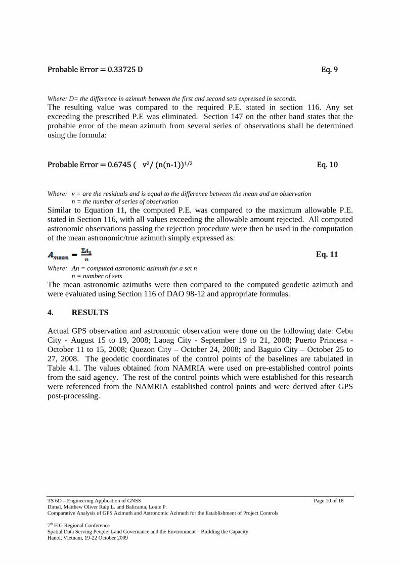
TS 6D – Engineering Application of GNSS Page 10 of 18 Dimal, Matthew Oliver Ralp L. and Balicanta, Louie P. Comparative Analysis of GPS Azimuth and Astronomic Azimuth for the Establishment of Project Controls 7th FIG Regional Conference Spatial Data Serving People: Land Governance and the Environment – Building the Capacity Hanoi, Vietnam, 19-22 October 2009
Probable Error 0.33725 D Eq. 9
Where: D= the difference in azimuth between the first and second sets expressed in seconds. The resulting value was compared to the required P.E. stated in section 116. Any set exceeding the prescribed P.E was eliminated. Section 147 on the other hand states that the probable error of the mean azimuth from several series of observations shall be determined using the formula:
Probable Error 0.6745 �v2/ n n‐1 1/2 Eq. 10
Where: v = are the residuals and is equal to the difference between the mean and an observation n = the number of series of observation Similar to Equation 11, the computed P.E. was compared to the maximum allowable P.E. stated in Section 116, with all values exceeding the allowable amount rejected. All computed astronomic observations passing the rejection procedure were then be used in the computation of the mean astronomic/true azimuth simply expressed as:
Eq. 11
Where: An = computed astronomic azimuth for a set n n = number of sets The mean astronomic azimuths were then compared to the computed geodetic azimuth and were evaluated using Section 116 of DAO 98-12 and appropriate formulas. 4. RESULTS Actual GPS observation and astronomic observation were done on the following date: Cebu City - August 15 to 19, 2008; Laoag City - September 19 to 21, 2008; Puerto Princesa - October 11 to 15, 2008; Quezon City – October 24, 2008; and Baguio City – October 25 to 27, 2008. The geodetic coordinates of the control points of the baselines are tabulated in Table 4.1. The values obtained from NAMRIA were used on pre-established control points from the said agency. The rest of the control points which were established for this research were referenced from the NAMRIA established control points and were derived after GPS post-processing.
TS 6D – Engineering Application of GNSS Page 11 of 18 Dimal, Matthew Oliver Ralp L. and Balicanta, Louie P. Comparative Analysis of GPS Azimuth and Astronomic Azimuth for the Establishment of Project Controls 7th FIG Regional Conference Spatial Data Serving People: Land Governance and the Environment – Building the Capacity Hanoi, Vietnam, 19-22 October 2009
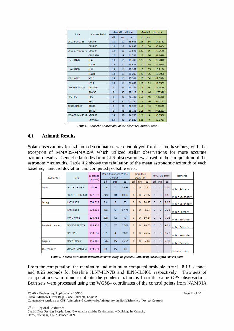
Table 4.1 Geodetic Coordinates of the Baseline Control Points
4.1 Azimuth Results Solar observations for azimuth determination were employed for the nine baselines, with the exception of MMA39-MMA39A which utilized stellar observations for more accurate azimuth results. Geodetic latitudes from GPS observation was used in the computation of the astronomic azimuths. Table 4.2 shows the tabulation of the mean astronomic azimuth of each baseline, standard deviation and computed probable error.
Table 4.1: Mean astronomic azimuth obtained using the geodetic latitude of the occupied control point
From the computation, the maximum and minimum computed probable error is 8.13 seconds and 0.25 seconds for baseline ILN7-ILN7B and ILN6-ILN6B respectively. Two sets of computations were done to obtain the geodetic azimuths from the same GPS observations. Both sets were processed using the WGS84 coordinates of the control points from NAMRIA
TS 6D – Engineering Application of GNSS Page 12 of 18 Dimal, Matthew Oliver Ralp L. and Balicanta, Louie P. Comparative Analysis of GPS Azimuth and Astronomic Azimuth for the Establishment of Project Controls 7th FIG Regional Conference Spatial Data Serving People: Land Governance and the Environment – Building the Capacity Hanoi, Vietnam, 19-22 October 2009
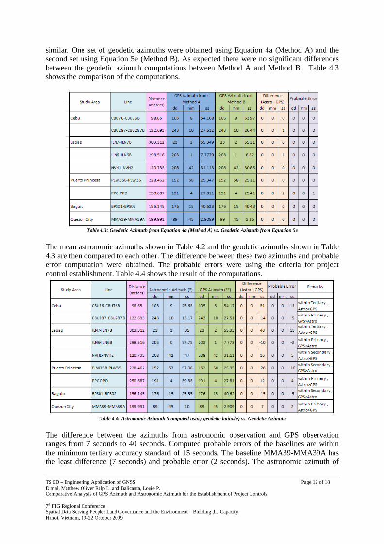
similar. One set of geodetic azimuths were obtained using Equation 4a (Method A) and the second set using Equation 5e (Method B). As expected there were no significant differences between the geodetic azimuth computations between Method A and Method B. Table 4.3 shows the comparison of the computations.
Table 4.3: Geodetic Azimuth from Equation 4a (Method A) vs. Geodetic Azimuth from Equation 5e
The mean astronomic azimuths shown in Table 4.2 and the geodetic azimuths shown in Table 4.3 are then compared to each other. The difference between these two azimuths and probable error computation were obtained. The probable errors were using the criteria for project control establishment. Table 4.4 shows the result of the computations.
Table 4.4: Astronomic Azimuth (computed using geodetic latitude) vs. Geodetic Azimuth
The difference between the azimuths from astronomic observation and GPS observation ranges from 7 seconds to 40 seconds. Computed probable errors of the baselines are within the minimum tertiary accuracy standard of 15 seconds. The baseline MMA39-MMA39A has the least difference (7 seconds) and probable error (2 seconds). The astronomic azimuth of
TS 6D – Engineering Application of GNSS Page 13 of 18 Dimal, Matthew Oliver Ralp L. and Balicanta, Louie P. Comparative Analysis of GPS Azimuth and Astronomic Azimuth for the Establishment of Project Controls 7th FIG Regional Conference Spatial Data Serving People: Land Governance and the Environment – Building the Capacity Hanoi, Vietnam, 19-22 October 2009
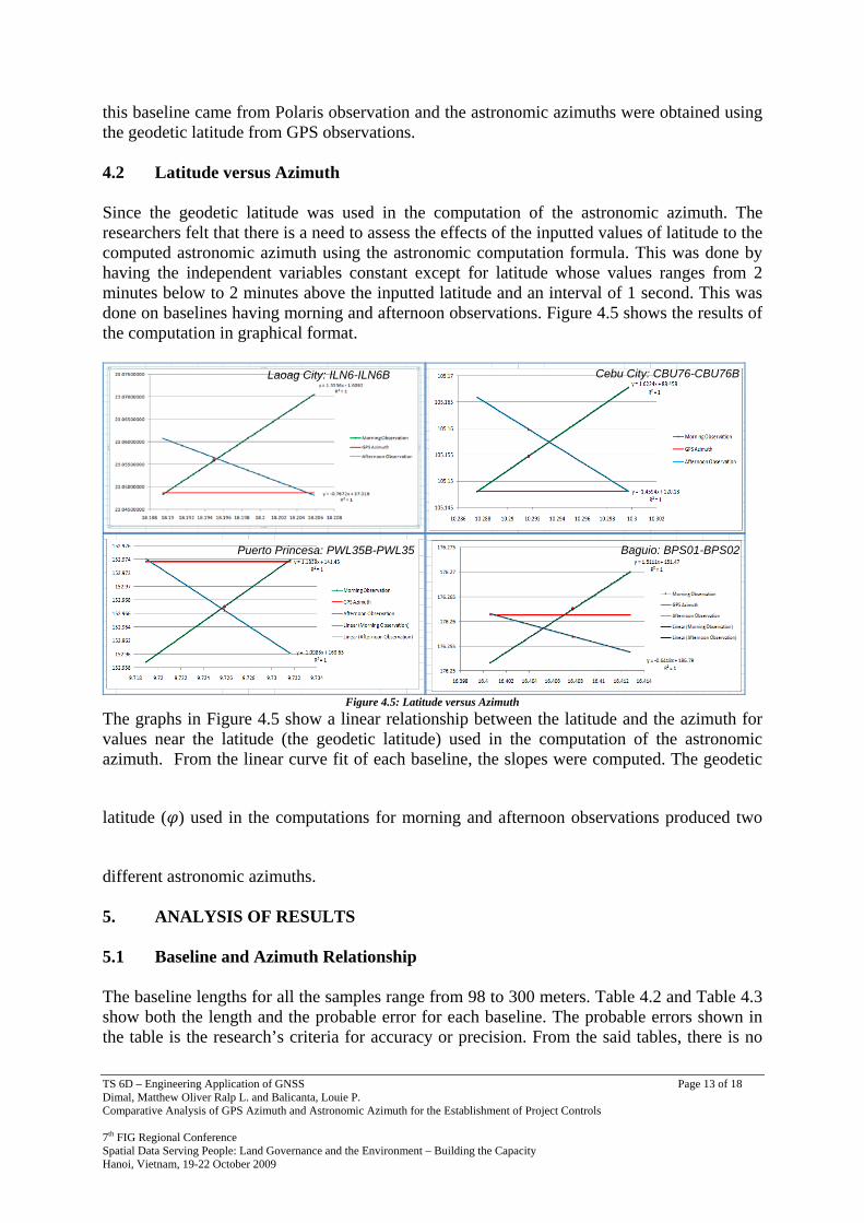
this baseline came from Polaris observation and the astronomic azimuths were obtained using the geodetic latitude from GPS observations. 4.2 Latitude versus Azimuth Since the geodetic latitude was used in the computation of the astronomic azimuth. The researchers felt that there is a need to assess the effects of the inputted values of latitude to the computed astronomic azimuth using the astronomic computation formula. This was done by having the independent variables constant except for latitude whose values ranges from 2 minutes below to 2 minutes above the inputted latitude and an interval of 1 second. This was done on baselines having morning and afternoon observations. Figure 4.5 shows the results of the computation in graphical format.
Figure 4.5: Latitude versus Azimuth
The graphs in Figure 4.5 show a linear relationship between the latitude and the azimuth for values near the latitude (the geodetic latitude) used in the computation of the astronomic azimuth. From the linear curve fit of each baseline, the slopes were computed. The geodetic
latitude ( ) used in the computations for morning and afternoon observations produced two
different astronomic azimuths. 5. ANALYSIS OF RESULTS 5.1 Baseline and Azimuth Relationship The baseline lengths for all the samples range from 98 to 300 meters. Table 4.2 and Table 4.3 show both the length and the probable error for each baseline. The probable errors shown in the table is the research’s criteria for accuracy or precision. From the said tables, there is no
Puerto Princesa: PWL35B-PWL35 Baguio: BPS01-BPS02
Laoag City: ILN6-ILN6B Cebu City: CBU76-CBU76B
TS 6D – Engineering Application of GNSS Page 14 of 18 Dimal, Matthew Oliver Ralp L. and Balicanta, Louie P. Comparative Analysis of GPS Azimuth and Astronomic Azimuth for the Establishment of Project Controls 7th FIG Regional Conference Spatial Data Serving People: Land Governance and the Environment – Building the Capacity Hanoi, Vietnam, 19-22 October 2009
indication that the length of the baseline affect the value of the probable error as longer baseline length that not always have smaller value for the computed probable error when compared to shorter baselines. The result of Chang and Tsai’s research (2006) also shows similar observation. In their research three baselines of distance: 300 meters, 6,900 meters and 18,300 meters were used as samples. It was also observed that no increase in accuracy was obtained for longer baselines. The precision of measurement for both astronomic and GPS survey does not depend on the length of the baselines. 5.2 Analysis of the Latitude The graphs in Figure 4.5 show that the latitude and azimuth baselines exhibited a linear relationship for latitude values ranging from 2 minutes above and below the inputted latitude. All the graphs show a similar pattern that is: an increase in latitude constitutes an increase in azimuth for morning observation and an increase in latitude for afternoon observation constitute a decrease in azimuth. There is also a one is to one relationship between the two as one value of latitude provides a single resulting azimuth within the given range of values. The initial latitudes used in the solar computation are the geodetic latitudes obtained from GPS observations. These latitudes were used in the computation of astronomic azimuths from morning and afternoon solar observation. The resulting azimuth obtained shows a difference between the computed azimuths. The differences are minimal and within the criteria as shown in Table 4.2 but these are differences nonetheless. Figure 4.5 shows the two linear curves that represent morning and afternoon data intersecting at a specific point. This intersection point, if one would interpret the graphs, describe a single value of latitude for both morning and afternoon observation and would result to a single value of resulting azimuth. Given that the other parameters expressed in Equation 2 (altitude, North Polar Distance and horizontal angle) which are being observed using the geoid as the physical model, one could assume that the latitude obtained from the intersection is the astronomic latitude. This hypothesis should be validated in future researches. 5.3 Comparison and Analysis between Geodetic and Astronomic Azimuths 5.3.1. Astronomic Azimuths The result of the astronomic observation from Table 4.2 shows that that standard deviation ranges from 7.18 to 30.24 seconds. The computed probable errors passed the criteria for at least tertiary project control accuracy. It was expected that results from Polaris observation would yield a probable error passing the requirement for primary project control and this was shown by the result of MMA39-MMA39A baseline. However, it is important to note that several baselines that were observed using solar observation also passed the primary project control accuracy requirements. 5.3.2 Geodetic Azimuths Geodetic azimuths from GPS observation was obtained by using the Gauss Mid-latitude method expressed by Equation 4a and by converting the grid azimuth to geodetic azimuth expressed in Equation 5e. The resulting geodetic azimuths using the two methods did not vary.
TS 6D – Engineering Application of GNSS Page 15 of 18 Dimal, Matthew Oliver Ralp L. and Balicanta, Louie P. Comparative Analysis of GPS Azimuth and Astronomic Azimuth for the Establishment of Project Controls 7th FIG Regional Conference Spatial Data Serving People: Land Governance and the Environment – Building the Capacity Hanoi, Vietnam, 19-22 October 2009
5.3.3. Astronomic Azimuths versus Geodetic Azimuths It is expected that the astronomic azimuth and the geodetic azimuths would have a difference. The discussion from Equation 8a indicates that this difference is inherent because of the effect of the deflection of the vertical. Table 4.4 shows that the difference between the two azimuths. Two baselines fall within the tertiary project control accuracy, three baselines within secondary and four baselines within the primary. Precision in the astronomic observation is not indicative to the closeness of the astronomic azimuth to GPS azimuth as CBU76-CBU76B which has a probable error of 2.19 seconds in the astronomic computation yields a difference within tertiary when compared to the geodetic azimuth. The obtained difference between the astronomic and geodetic azimuths is larger compared to the results obtained from a related research that showed a difference better than 1 second (Chang & Tsai, 2006). The disparity can be attributed to the type of equipment and the baselines used in the two researches. Chang and Tsai used established baselines whose astronomic azimuths were observed and measured periodically using high precision gyroscope. This research used baselines established measured only during the scheduled time of the fieldwork and the equipment used was a Wild T2 theodolite. However, the result showed that for project control network establishment, the resulting azimuth obtained using GPS survey or traditional astronomic observation can be used interchangeably. 6. CONCLUSIONS This research aimed to determine the effect and significance of interchanging astronomic azimuth from solar observation with geodetic azimuth measured from the GPS. Variables that may cause variations in the computed azimuth were also evaluated to show any consequence in the computations. The variability in the length of the baselines for project controls was checked. The results showed the length to have no detectable effect on the precision of the observations on either method. The computed and measured latitude used in the computations from the astronomic observations was found to have a significant effect. Any error in the derived or assumed latitude of the place of observation will cause a linear increase of inaccuracy of the computed azimuth. An alternative method to minimize the error introduced by assumed latitude had been suggested with the use of a pair of solar observations conducted one in the morning and one in the afternoon. Preliminary results from this research showed positive reduction of errors, though this conclusion needs further validation. In assessing the applicability of solar observations in contemporary usage, the research also found some interesting results. The Philippine geodetic engineers’ manual, DAO 98-12, had only considered solar observation to be used in tertiary project control surveys. The probable errors computed from the results of the fieldwork have shown that the azimuths from solar observations may consistently attain primary project control accuracy with carefully and systematically executed fieldwork and application of appropriate corrections. The research also noted some factors that may minimize the usability of solar observations in surveying applications, which included weather conditions, forest canopy, and urban built-up. To counter some of these concerns, a revised manual in conducting solar observations had been forwarded to the authorities for evaluation and comments.
TS 6D – Engineering Application of GNSS Page 16 of 18 Dimal, Matthew Oliver Ralp L. and Balicanta, Louie P. Comparative Analysis of GPS Azimuth and Astronomic Azimuth for the Establishment of Project Controls 7th FIG Regional Conference Spatial Data Serving People: Land Governance and the Environment – Building the Capacity Hanoi, Vietnam, 19-22 October 2009
In the determination of geodetic azimuth from GPS observation, a comparison of results, between those of logged coordinates with unreferenced solution and those of predetermined positions with referenced solutions, had been analyzed. It was observed that no significant effect in measured geodetic azimuth exists, and that unreferenced solutions may be used in the determination of geodetic azimuth with no apparent difference from referenced solutions. But for position or grid coordinates, GPS derived positions from the referenced and from the unreferenced solutions had very different outcome. In the computation of geodetic azimuth, a difference of 2” was observed on one baseline, 1” for two baselines, and the rest with no apparent difference. For project controls of primary, secondary and tertiary precision requirements the use of the geodetic latitude in the determination of the astronomic azimuth was determined to be sufficient at least for areas with flat topography. The geodetic azimuths and astronomic azimuths as shown in the study proved to be within the criteria of project controls. Results from related studies from other countries have also yielded similar results (Chang & Tsai, 2006; Yilmaz & Karaali, 2006). This concludes that for practical purposes or at least for project controls, the two azimuths can be used interchangeably. An analysis on the methodologies of astronomic observation and GPS survey showed several advantages and disadvantages of each of the methods:
a. The disadvantage of astronomic observation lies on its too much dependency on weather condition. A clear sky in daytime observation for solar observation and clear sky in night time for Polaris observation is needed. This is true if the parameter needed is astronomic latitude, astronomic longitude or astronomic azimuth. Consideration of the terrestrial lighting should be considered when performing astronomic observation during night time. Minimal lighting within the vicinity is required so that stars and star pattern would be visible.
b. Expertise on the use of the instrument is also a major consideration and since the astronomic observation uses an optical instrument where majority of the task is performed by the instrument man and with limited time consideration this again becomes the weakness of astronomic observation compared to GPS observation.
c. GPS observation on the other hand provides a faster way of obtaining azimuth. The use of GPS seems more advantageous being weather independent and with minimal user intervention.
7. RECOMMENDATIONS More local studies analyzing the consequences of the use of the GPS in property surveys should be conducted to increase local understanding and awareness of the technology, and its proper use in the practice of surveying. Other factors that were not considered but may contribute to the difference the derived azimuths, like the ruggedness of terrain, variability in geologic attributes and proximity of the location to the coastlines, should also be analyzed. Its application in geodetic surveys should also be checked. Due to the extensiveness and complexities of requirements needed in geodetic applications, further research should be conducted to ensure the seamless transition of the national positional framework from mainly using astronomic observations towards using GPS techniques. The determination of the Laplace correction from an extensive research would be required in fulfilling this requirement.
TS 6D – Engineering Application of GNSS Page 17 of 18 Dimal, Matthew Oliver Ralp L. and Balicanta, Louie P. Comparative Analysis of GPS Azimuth and Astronomic Azimuth for the Establishment of Project Controls 7th FIG Regional Conference Spatial Data Serving People: Land Governance and the Environment – Building the Capacity Hanoi, Vietnam, 19-22 October 2009
The proposed field procedures inscribed in the generated revised manual should be reviewed and evaluated further, to update current practices in land surveying. New techniques in solar observations and GPS surveys as consequence of the findings in this research should also be validated by further studies.
TS 6D – Engineering Application of GNSS Page 18 of 18 Dimal, Matthew Oliver Ralp L. and Balicanta, Louie P. Comparative Analysis of GPS Azimuth and Astronomic Azimuth for the Establishment of Project Controls 7th FIG Regional Conference Spatial Data Serving People: Land Governance and the Environment – Building the Capacity Hanoi, Vietnam, 19-22 October 2009
8. REFERENCES Allman, J. (1991). An Analysis of the Primary Triangulation Network of the Philippines
Internal Report. Quezon City: SAGRIC Intl Pty Ltd. Anderson, J., & Mikhail, E. (1998). Surveying Theory and Practice Seventh Edition. New
York: McGraw-Hill Companies, Inc. Bhattacharji, J. C. (1958). Comments on `Azimuth Determination without Circle
Readings' by R. K. C. Johns. Bulletin Géodésique , 32 (4), 52-55. Chang, C., & Tsai, W. (2006). Evaluation of a GPS-Based Approach for Rapid and
Precise Determination of Geodetic/Astronomical Azimuth. Journal of Surveying Engineering , 149-154.
Davis, R., Foote, F., Anderson, J., & Mikhail, E. (1981). Surveying Theory and Practice (6th ed.). New York: McGraw-Hill International.
Department of Environment and Natural Resources. (1994). Implementing Guidelines in the Adoption of the Philippine Reference System 1992 for Land Surveys in the Philippines. DENR Administrative Order.
Heiskanen, W. H. (1967). Physical Geodesy. San Francisco: WH Freeman and Company. Leick, A. (2004). GPS Satellite Surveying. John Wiley and Sons. Lennartz-Johansen, H., & Ellegaard, S. (2002). Analyzing Europe's Largest Suspension
Bridge. FIG XXII International Congress. Washington D.C. Mueller, I. I. (1969). Spherical and Practical Astronomy as Applied to Geodesy. New
York, New York, United States of America: Frederick Ungar Publishing Co. Rapp, R. H. (1979). Geometric Geodesy. Columbus, Ohio: Ohio State University. Wolfgang, T. (1980). Geodesy: An Introduction. Berlin: Walter de Gruyter & Co. Yilmaz, N., & Karaali, C. (2006). Positioning with Astronomic and Geodetic Method.
XXIII FIG Congrees. Munich, Germany. CONTACTS Mr. Matthew Oliver Ralp L. Dimal University of the Philippines Dept. of Geodetic Engineering, University of the Philippines, Diliman Quezon City PHILIPPINES Tel. + 632 981 8500 3126 Fax + 632 920 8924 Email: [email protected] Web site: http://dge.upd.edu.ph/ Mr. Louie P. Balicanta University of the Philippines Dept. of Geodetic Engineering, University of the Philippines, Diliman Quezon City PHILIPPINES Tel. + 632 981 8500 3126 Fax + 632 920 8924 Email: [email protected] Web site: http://dge.upd.edu.ph/