Cooperative Inter-vehicle Communication Protocol Dedicated to Intelligent Transport Systems
Upload
khangminh22Category
view
0download
0
Communication protocol User's Manual
AE/AEK series Communication protocol
*Note:The specifications are subject to change without notice.
■ I2C Bus Interface Option
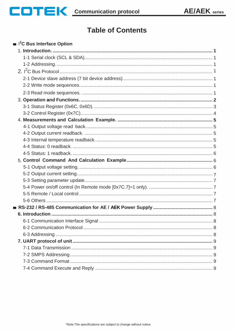
Table of Contents
1. Introduction. ......................................................................................................................... 1
1-1 Serial clock (SCL & SDA). ................................................................................................ 1
1-2 Addressing. ...................................................................................................................... 1
2. I2C Bus Protocol .................................................................................................................... 1
2-1 Device slave address (7 bit device address). ................................................................... 1
2-2 Write mode sequences. .................................................................................................... 1
2-3 Read mode sequences. ................................................................................................... 1
3. Operation and Functions. .................................................................................................... 2
3-1 Status Register (0x6C, 0x6D). .......................................................................................... 3
3-2 Control Register (0x7C). ................................................................................................... 4
4. Measurements and Calculation Example. ........................................................................ 5
4-1 Output voltage read back. ............................................................................................... 5
4-2 Output current readback. ................................................................................................. 5
4-3 Internal temperature readback. ........................................................................................ 5
4-4 Status: 0 readback. .......................................................................................................... 5
4-5 Status: 1 readback. .......................................................................................................... 6
5. Control Command And Calculation Example ................................................................. 6
5-1 Output voltage setting. ..................................................................................................... 6
5-2 Output current setting. ...................................................................................................... 7
5-3 Setting parameter update. ................................................................................................ 7
5-4 Power on/off control (In Remote mode [0x7C.7]=1 only). ................................................ 7
5-5 Remote / Local control ..................................................................................................... 7
5-6 Others .............................................................................................................................. 7
■ RS-232 / RS-485 Communication for AE / AEK Power Supply ............................................. 8
6. Introduction .......................................................................................................................... 8
6-1 Communication Interface Signal ...................................................................................... 8
6-2 Communication Protocol .................................................................................................. 8
6-3 Addressing ....................................................................................................................... 8
7. UART protocol of unit .......................................................................................................... 9
7-1 Data Transmission ........................................................................................................... 9
7-2 SMPS Addressing ............................................................................................................ 9
7-3 Command Format ............................................................................................................ 9
7-4 Command Execute and Reply ......................................................................................... 9
AE/AEK series Communication protocol
*Note:The specifications are subject to change without notice.
8. Commands. ........................................................................................................................... 10
8-1 Command set. .................................................................................................................. 10
8-2 Command descriptions. ................................................................................................... 10
8-2-1 Data Transmission. ................................................................................................. 11
8-2-2 Global Power ON / OFF Control. ............................................................................ 11
8-2-3 Global Control O/P Voltage Setting. ........................................................................ 11
8-2-4 Global Control O/P Current Setting. ........................................................................ 11
8-2-5 Power ON / OFF / Query ........................................................................................ 12
8-2-6 Output Voltage Setting. ........................................................................................... 12
8-2-7 Output Current Setting. ........................................................................................... 12
8-2-8 Voltage setting Query ............................................................................................. 12
8-2-9 Current setting Query .............................................................................................. 12
8-2-10 Output Voltage Query ........................................................................................... 12
8-2-11 Output Current Query ............................................................................................ 13
8-2-12 Internal Temperature query .................................................................................. 13
8-2-13 Control mode Select / Query ................................................................................. 13
8-2-14 Device Status Query ............................................................................................. 13
8-2-15 Device Information Query ..................................................................................... 15
8-2-16 Query rated voltage and rated current. ................................................................. 15
8-2-17 Device Name Query .............................................................................................. 15
8-2-18 Device Identify ...................................................................................................... 15
■ Attention ................................................................................................... 16
AE/AEK series Communication protocol
REV. B3 18/06/19
1 *Note:The specifications are subject to change without notice.
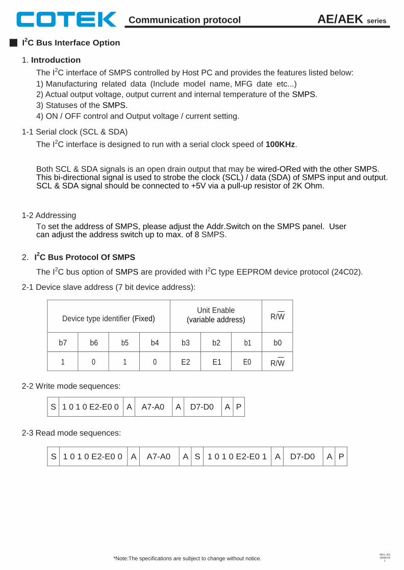
I2C Bus Interface Option
1. Introduction
The I2C interface of SMPS controlled by Host PC and provides the features listed below:
1) Manufacturing related data (Include model name, MFG date etc...)
2) Actual output voltage, output current and internal temperature of the SMPS.
3) Statuses of the SMPS.
4) ON / OFF control and Output voltage / current setting.
1-1 Serial clock (SCL & SDA)
The I2C interface is designed to run with a serial clock speed of 100KHz.
Both SCL & SDA signals is an open drain output that may be wired-ORed with the other SMPS. This bi-directional signal is used to strobe the clock (SCL) / data (SDA) of SMPS input and output. SCL & SDA signal should be connected to +5V via a pull-up resistor of 2K Ohm.
1-2 Addressing
To set the address of SMPS, please adjust the Addr.Switch on the SMPS panel. User can adjust the address switch up to max. of 8 SMPS.
2. I
2C Bus Protocol Of SMPS
The I2C bus option of SMPS are provided with I2C type EEPROM device protocol (24C02).
2-1 Device slave address (7 bit device address):
Device type identifier (Fixed) Unit Enable
(variable address)
R/W
b7 b6 b5 b4 b3 b2 b1 b0
1 0 1 0 E2 E1 E0
R/W
2-2 Write mode sequences:
S 1 0 1 0 E2-E0 0 A A7-A0 A D7-D0 A P
2-3 Read mode sequences:
S 1 0 1 0 E2-E0 0 A A7-A0 A S 1 0 1 0 E2-E0 1 A D7-D0 A P
AE/AEK series Communication protocol
REV. B3 18/06/19
2 *Note:The specifications are subject to change without notice.
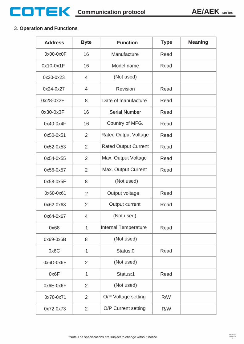
3. Operation and Functions
Address Byte Function Type Meaning
0x00-0x0F 16 Manufacture Read
0x10-0x1F 16 Model name Read
0x20-0x23 4 (Not used)
0x24-0x27 4 Revision Read
0x28-0x2F 8 Date of manufacture Read
0x30-0x3F 16 Serial Number Read
0x40-0x4F 16 Country of MFG. Read
0x50-0x51 2 Rated Output Voltage Read
0x52-0x53 2 Rated Output Current Read
0x54-0x55 2 Max. Output Voltage Read
0x56-0x57 2 Max. Output Current Read
0x58-0x5F 8 (Not used)
0x60-0x61 2 Output voltage Read
0x62-0x63 2 Output current Read
0x64-0x67 4 (Not used)
0x68 1 Internal Temperature Read
0x69-0x6B 8 (Not used)
0x6C 1 Status:0 Read
0x6D-0x6E 2 (Not used)
0x6F 1 Status:1 Read
0x6E-0x6F 2 (Not used)
0x70-0x71 2 O/P Voltage setting R/W
0x72-0x73 2 O/P Current setting R/W
AE/AEK series Communication protocol
REV. B3 18/06/19
3 *Note:The specifications are subject to change without notice.
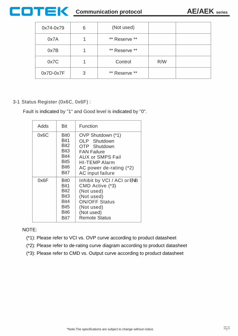
0x74-0x79 6 (Not used)
0x7A 1 ** Reserve **
0x7B 1 ** Reserve **
0x7C 1 Control R/W
0x7D-0x7F 3 ** Reserve **
3-1 Status Register (0x6C, 0x6F) :
Fault is indicated by "1" and Good level is indicated by "0".
Adds Bit Function
0x6C Bit0 Bit1
OVP Shutdown (*1)
OLP Shutdown OTP Shutdown FAN Failure AUX or SMPS Fail HI-TEMP Alarm AC power de-rating (*2) AC input failure
Bit2 Bit3 Bit4 Bit5 Bit6 Bit7
0x6F Bit0 Bit1
Inhibit by VCI / ACI or ENB CMD Active (*3) (Not used) (Not used) ON/OFF Status (Not used) (Not used) Remote Status
Bit2 Bit3 Bit4 Bit5 Bit6 Bit7
NOTE:
(*1): Please refer to VCI vs. OVP curve according to product datasheet
(*2): Please refer to de-rating curve diagram according to product datasheet
(*3): Please refer to CMD vs. Output curve according to product datasheet
AE/AEK series Communication protocol
REV. B3 18/06/19
4 *Note:The specifications are subject to change without notice.
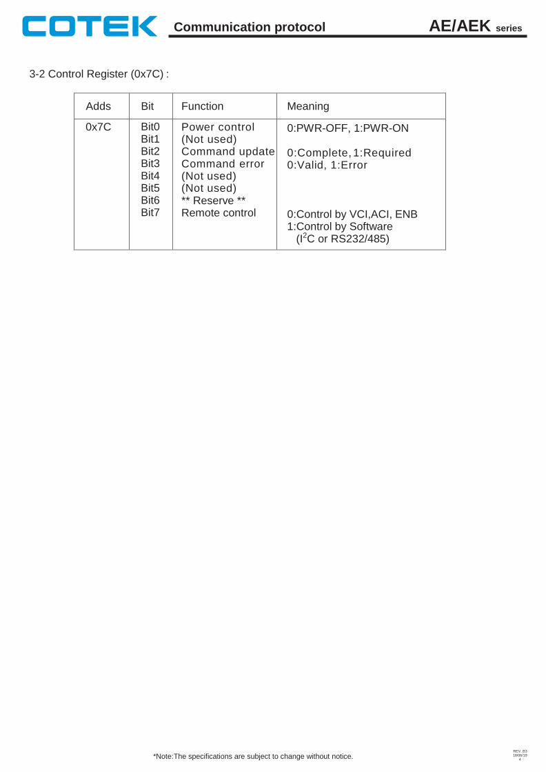
3-2 Control Register (0x7C) :
Adds Bit Function Meaning
0x7C Bit0 Bit1 Bit2 Bit3 Bit4 Bit5 Bit6 Bit7
Power control (Not used) Command update Command error (Not used) (Not used) ** Reserve ** Remote control
0:PWR-OFF, 1:PWR-ON
0:Complete, 1:Required 0:Valid, 1:Error
0:Control by VCI,ACI, ENB 1:Control by Software
(I2C or RS232/485)
AE/AEK series Communication protocol
REV. B3 18/06/19
5 *Note:The specifications are subject to change without notice.
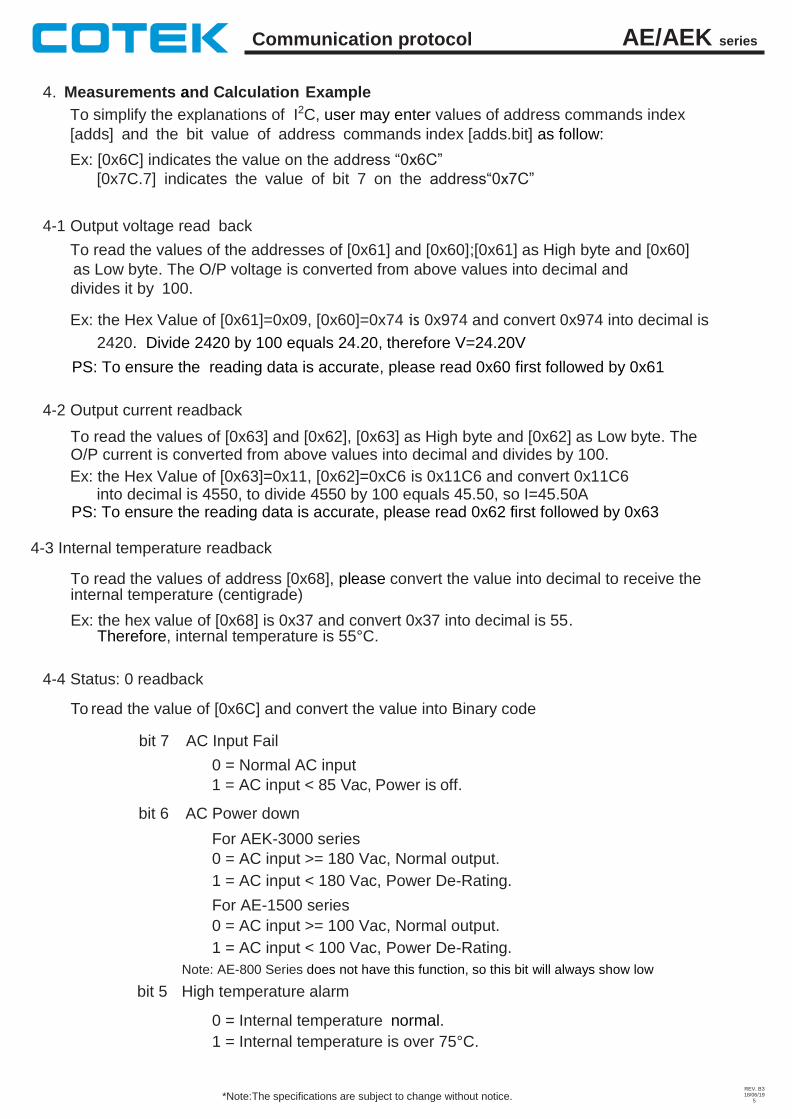
4. Measurements and Calculation Example
To simplify the explanations of I2C, user may enter values of address commands index
[adds] and the bit value of address commands index [adds.bit] as follow:
Ex: [0x6C] indicates the value on the address “0x6C”
[0x7C.7] indicates the value of bit 7 on the address“0x7C”
4-1 Output voltage read back
To read the values of the addresses of [0x61] and [0x60];[0x61] as High byte and [0x60]
as Low byte. The O/P voltage is converted from above values into decimal and
divides it by 100.
Ex: the Hex Value of [0x61]=0x09, [0x60]=0x74 is 0x974 and convert 0x974 into decimal is
2420. Divide 2420 by 100 equals 24.20, therefore V=24.20V
PS: To ensure the reading data is accurate, please read 0x60 first followed by 0x61
4-2 Output current readback
To read the values of [0x63] and [0x62], [0x63] as High byte and [0x62] as Low byte. The O/P current is converted from above values into decimal and divides by 100.
Ex: the Hex Value of [0x63]=0x11, [0x62]=0xC6 is 0x11C6 and convert 0x11C6 into decimal is 4550, to divide 4550 by 100 equals 45.50, so I=45.50A
PS: To ensure the reading data is accurate, please read 0x62 first followed by 0x63
4-3 Internal temperature readback
To read the values of address [0x68], please convert the value into decimal to receive the internal temperature (centigrade)
Ex: the hex value of [0x68] is 0x37 and convert 0x37 into decimal is 55. Therefore, internal temperature is 55°C.
4-4 Status: 0 readback
To read the value of [0x6C] and convert the value into Binary code
bit 7 AC Input Fail
0 = Normal AC input
1 = AC input < 85 Vac, Power is off.
bit 6 AC Power down
For AEK-3000 series
0 = AC input >= 180 Vac, Normal output.
1 = AC input < 180 Vac, Power De-Rating.
For AE-1500 series
0 = AC input >= 100 Vac, Normal output.
1 = AC input < 100 Vac, Power De-Rating.
Note: AE-800 Series does not have this function, so this bit will always show low
bit 5 High temperature alarm
0 = Internal temperature normal.
1 = Internal temperature is over 75°C.
AE/AEK series Communication protocol
REV. B3 18/06/19
6 *Note:The specifications are subject to change without notice.
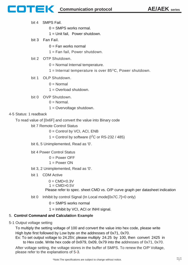
bit 4 SMPS Fail.
0 = SMPS works normal.
1 = Unit fail,
bit 3 Fan Fail.
Power shutdown.
0 = Fan works normal
1 = Fan fail, Power shutdown.
bit 2 OTP Shutdown.
0 = Normal Internal temperature.
1 = Internal temperature is over 85OC, Power shutdown.
bit 1 OLP Shutdown.
0 = Normal
1 = Overload shutdown.
bit 0 OVP Shutdown.
0 = Normal.
1 = Overvoltage shutdown.
4-5 Status: 1 readback
To read value of [0x6F] and convert the value into Binary code
bit 7 Remote Control Status
0 = Control by VCI, ACI, ENB
1 = Control by software (I2C or RS-232 / 485)
bit 6, 5 Unimplemented, Read as '0'.
bit 4 Power Control Status
0 = Power OFF
1 = Power ON
bit 3, 2 Unimplemented, Read as '0'.
bit 1 CDM Active
0 = CMD<0.3V 1 = CMD>0.5V
Please refer to spec. sheet CMD vs. O/P curve graph per datasheet indication
bit 0 Inhibit by control Signal (In Local mode[0x7C.7]=0 only)
0 = SMPS works normal
1 = Inhibit by VCI, ACI or INHI signal.
5. Control Command and Calculation Example
5-1 Output voltage setting
To multiply the setting voltage of 100 and convert the value into hex code, please write
High byte first followed by Low byte on the addresses of 0x71, 0x70.
Ex: To set output voltage to 24.25V, please multiply 24.25 by 100, then convert 2425 in
to Hex code. Write hex code of 0x979, 0x09, 0x79 into the addresses of 0x71, 0x70.
After voltage setting, the voltage stores in the buffer of SMPS. To renew the O/P Voltage, please refer to the explanations of 5-3.
AE/AEK series Communication protocol
REV. B3 18/06/19
7 *Note:The specifications are subject to change without notice.
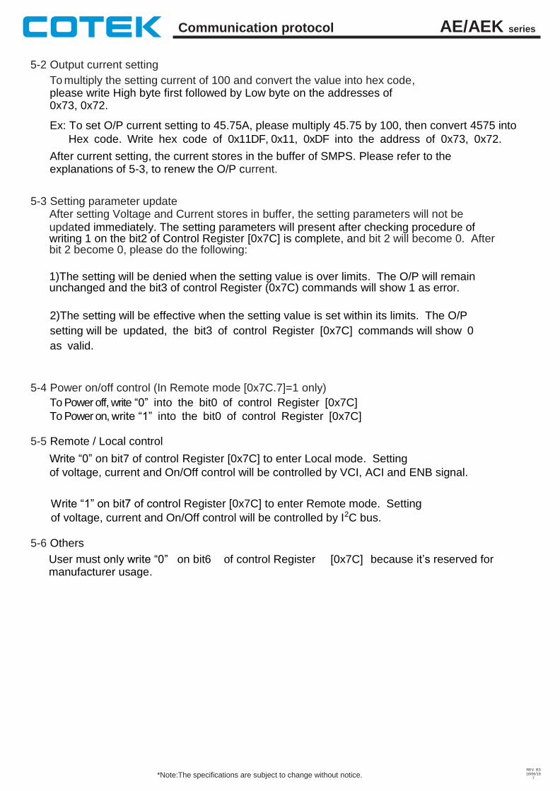
5-2 Output current setting
To multiply the setting current of 100 and convert the value into hex code, please write High byte first followed by Low byte on the addresses of 0x73, 0x72.
Ex: To set O/P current setting to 45.75A, please multiply 45.75 by 100, then convert 4575 into
Hex code. Write hex code of 0x11DF, 0x11, 0xDF into the address of 0x73, 0x72.
After current setting, the current stores in the buffer of SMPS. Please refer to the explanations of 5-3, to renew the O/P current.
5-3 Setting parameter update After setting Voltage and Current stores in buffer, the setting parameters will not be updated immediately. The setting parameters will present after checking procedure of writing 1 on the bit2 of Control Register [0x7C] is complete, and bit 2 will become 0. After bit 2 become 0, please do the following:
1)The setting will be denied when the setting value is over limits. The O/P will remain unchanged and the bit3 of control Register (0x7C) commands will show 1 as error.
2)The setting will be effective when the setting value is set within its limits. The O/P
setting will be updated, the bit3 of control Register [0x7C] commands will show 0
as valid.
5-4 Power on/off control (In Remote mode [0x7C.7]=1 only)
To Power off, write “0” into the bit0 of control Register [0x7C]
To Power on, write “1” into the bit0 of control Register [0x7C]
5-5 Remote / Local control
Write “0” on bit7 of control Register [0x7C] to enter Local mode. Setting
of voltage, current and On/Off control will be controlled by VCI, ACI and ENB signal.
Write “1” on bit7 of control Register [0x7C] to enter Remote mode. Setting
of voltage, current and On/Off control will be controlled by I2C bus.
5-6 Others
User must only write “0” manufacturer usage.
on bit6 of control Register [0x7C] because it’s reserved for
AE/AEK series Communication protocol
REV. B3 18/06/19
8 *Note:The specifications are subject to change without notice.
RS-232 / RS-485 Communication for AE / AEK Power Supply
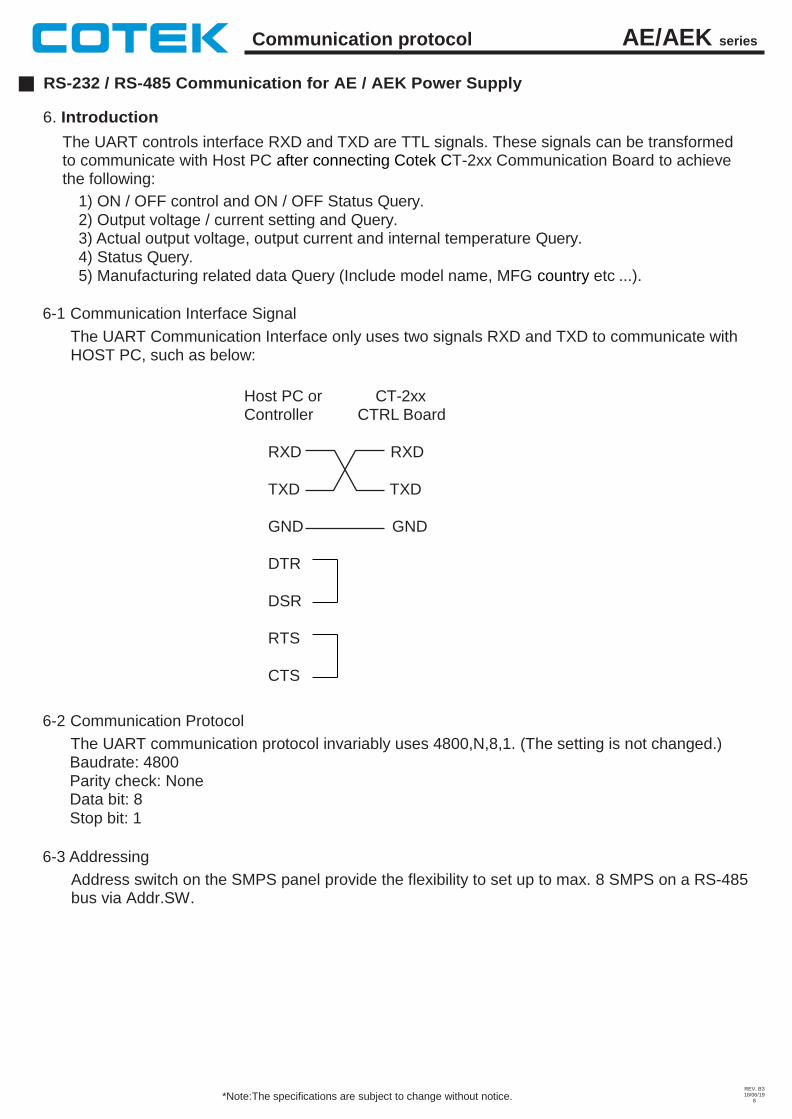
6. Introduction
The UART controls interface RXD and TXD are TTL signals. These signals can be transformed to communicate with Host PC after connecting Cotek CT-2xx Communication Board to achieve the following:
1) ON / OFF control and ON / OFF Status Query. 2) Output voltage / current setting and Query. 3) Actual output voltage, output current and internal temperature Query. 4) Status Query. 5) Manufacturing related data Query (Include model name, MFG country etc ...).
6-1 Communication Interface Signal
The UART Communication Interface only uses two signals RXD and TXD to communicate with HOST PC, such as below:
Host PC or CT-2xx Controller CTRL Board
RXD RXD
TXD TXD
GND GND
DTR
DSR
RTS
CTS
6-2 Communication Protocol
The UART communication protocol invariably uses 4800,N,8,1. (The setting is not changed.) Baudrate: 4800 Parity check: None Data bit: 8
Stop bit: 1
6-3 Addressing
Address switch on the SMPS panel provide the flexibility to set up to max. 8 SMPS on a RS-485 bus via Addr.SW.
AE/AEK series Communication protocol
REV. B3 18/06/19
9 *Note:The specifications are subject to change without notice.
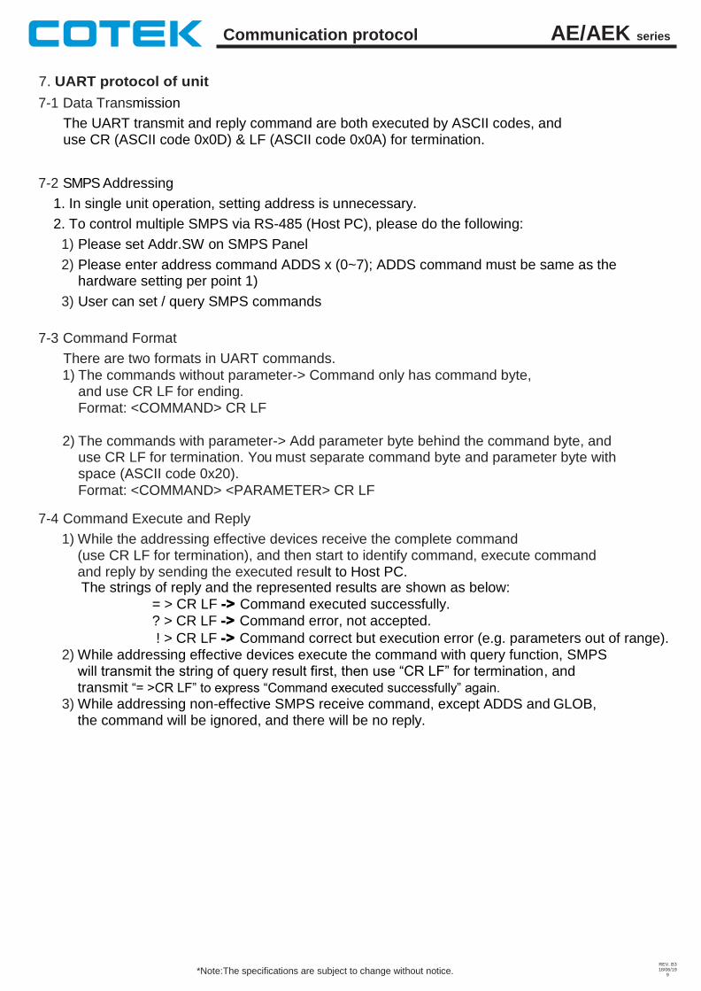
7. UART protocol of unit
7-1 Data Transmission
The UART transmit and reply command are both executed by ASCII codes, and use CR (ASCII code 0x0D) & LF (ASCII code 0x0A) for termination.
7-2 SMPS Addressing
1. In single unit operation, setting address is unnecessary.
2. To control multiple SMPS via RS-485 (Host PC), please do the following:
1) Please set Addr.SW on SMPS Panel
2) Please enter address command ADDS x (0~7); ADDS command must be same as the hardware setting per point 1)
3) User can set / query SMPS commands
7-3 Command Format
There are two formats in UART commands.
1) The commands without parameter-> Command only has command byte, and use CR LF for ending. Format: <COMMAND> CR LF
2) The commands with parameter-> Add parameter byte behind the command byte, and use CR LF for termination. You must separate command byte and parameter byte with space (ASCII code 0x20).
Format: <COMMAND> <PARAMETER> CR LF
7-4 Command Execute and Reply
1) While the addressing effective devices receive the complete command (use CR LF for termination), and then start to identify command, execute command and reply by sending the executed result to Host PC. The strings of reply and the represented results are shown as below:
= > CR LF -> Command executed successfully.
? > CR LF -> Command error, not accepted.
! > CR LF -> Command correct but execution error (e.g. parameters out of range). 2) While addressing effective devices execute the command with query function, SMPS
will transmit the string of query result first, then use “CR LF” for termination, and transmit “= >CR LF” to express “Command executed successfully” again.
3) While addressing non-effective SMPS receive command, except ADDS and GLOB, the command will be ignored, and there will be no reply.
AE/AEK series Communication protocol
REV. B3 18/06/19
10 *Note:The specifications are subject to change without notice.
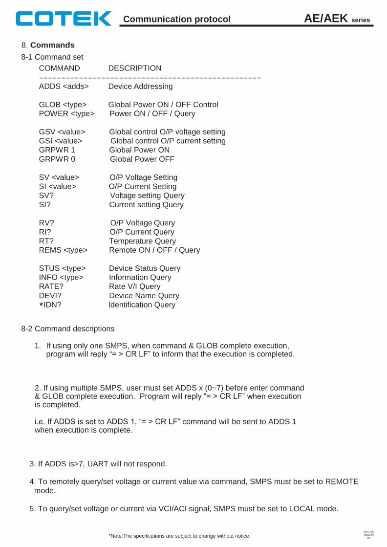
8. Commands
8-1 Command set
COMMAND DESCRIPTION
--------------------------------------------------
ADDS <adds> Device Addressing
GLOB <type> Global Power ON / OFF Control POWER <type> Power ON / OFF / Query
GSV <value> Global control O/P voltage setting GSI <value> Global control O/P current setting GRPWR 1 Global Power ON
GRPWR 0 Global Power OFF
SV <value> O/P Voltage Setting SI <value> O/P Current Setting SV? Voltage setting Query SI? Current setting Query
RV? O/P Voltage Query RI? O/P Current Query RT? Temperature Query REMS <type> Remote ON / OFF / Query
STUS <type> Device Status Query INFO <type> Information Query RATE? Rate V/I Query
DEVI? Device Name Query *IDN? Identification Query
8-2 Command descriptions
1. If using only one SMPS, when command & GLOB complete execution, program will reply “= > CR LF” to inform that the execution is completed.
2. If using multiple SMPS, user must set ADDS x (0~7) before enter command & GLOB complete execution. Program will reply “= > CR LF” when execution is completed.
i.e. If ADDS is set to ADDS 1, “= > CR LF” command will be sent to ADDS 1 when execution is complete.
3. If ADDS is>7, UART will not respond.
4. To remotely query/set voltage or current value via command, SMPS must be set to REMOTE mode.
5. To query/set voltage or current via VCI/ACI signal, SMPS must be set to LOCAL mode.
AE/AEK series Communication protocol
REV. B3 18/06/19
11 *Note:The specifications are subject to change without notice.
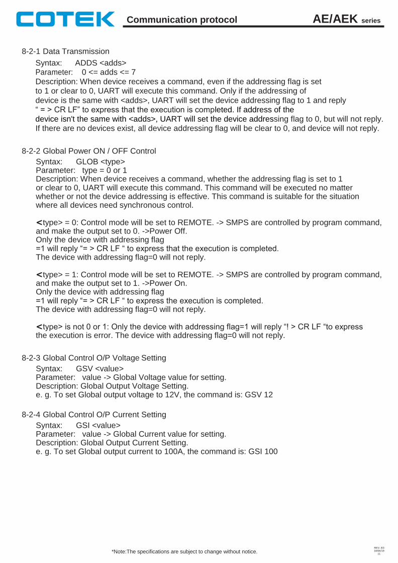
8-2-1 Data Transmission
Syntax: ADDS <adds> Parameter: 0 <= adds <= 7 Description: When device receives a command, even if the addressing flag is set to 1 or clear to 0, UART will execute this command. Only if the addressing of
device is the same with <adds>, UART will set the device addressing flag to 1 and reply “ = > CR LF” to express that the execution is completed. If address of the device isn't the same with <adds>, UART will set the device addressing flag to 0, but will not reply. If there are no devices exist, all device addressing flag will be clear to 0, and device will not reply.
8-2-2 Global Power ON / OFF Control
Syntax: GLOB <type> Parameter: type = 0 or 1 Description: When device receives a command, whether the addressing flag is set to 1 or clear to 0, UART will execute this command. This command will be executed no matter whether or not the device addressing is effective. This command is suitable for the situation where all devices need synchronous control.
<type> = 0: Control mode will be set to REMOTE. -> SMPS are controlled by program command, and make the output set to 0. ->Power Off. Only the device with addressing flag =1 will reply “= > CR LF “ to express that the execution is completed. The device with addressing flag=0 will not reply.
<type> = 1: Control mode will be set to REMOTE. -> SMPS are controlled by program command, and make the output set to 1. ->Power On. Only the device with addressing flag =1 will reply “= > CR LF “ to express the execution is completed. The device with addressing flag=0 will not reply.
<type> is not 0 or 1: Only the device with addressing flag=1 will reply “! > CR LF “to express the execution is error. The device with addressing flag=0 will not reply.
8-2-3 Global Control O/P Voltage Setting
Syntax: GSV <value> Parameter: value -> Global Voltage value for setting. Description: Global Output Voltage Setting. e. g. To set Global output voltage to 12V, the command is: GSV 12
8-2-4 Global Control O/P Current Setting
Syntax: GSI <value> Parameter: value -> Global Current value for setting. Description: Global Output Current Setting. e. g. To set Global output current to 100A, the command is: GSI 100
AE/AEK series Communication protocol
REV. B3 18/06/19
12 *Note:The specifications are subject to change without notice.
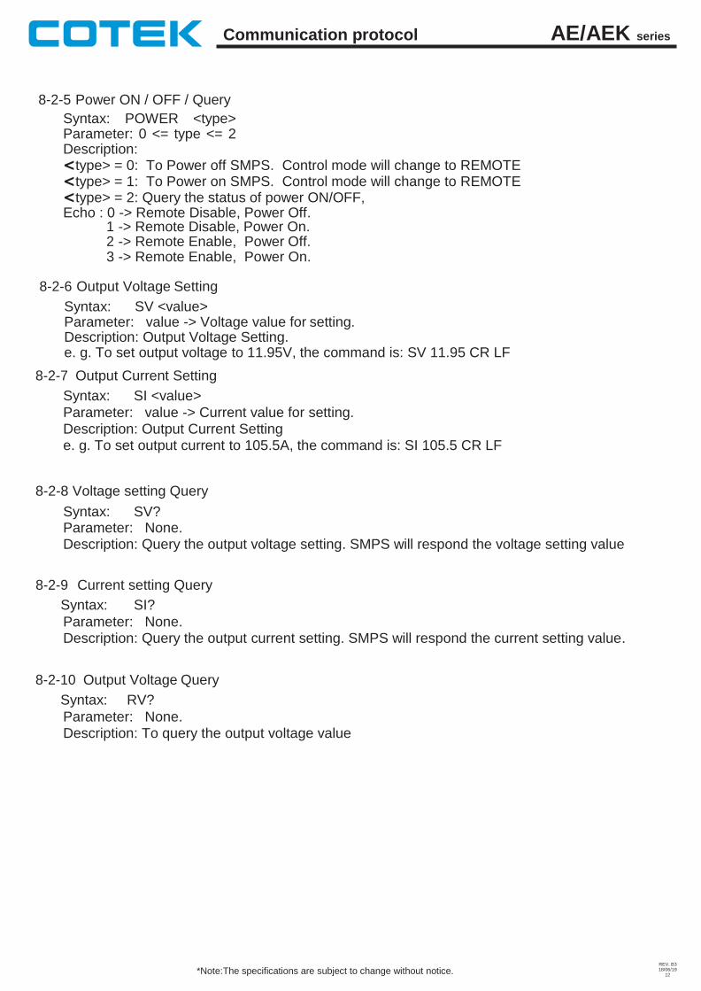
8-2-5 Power ON / OFF / Query
Syntax: POWER <type> Parameter: 0 <= type <= 2 Description: <type> = 0: To Power off SMPS. Control mode will change to REMOTE <type> = 1: To Power on SMPS. Control mode will change to REMOTE <type> = 2: Query the status of power ON/OFF, Echo : 0 -> Remote Disable, Power Off.
1 -> Remote Disable, Power On. 2 -> Remote Enable, 3 -> Remote Enable,
8-2-6 Output Voltage Setting
Syntax: SV <value>
Power Off. Power On.
Parameter: value -> Voltage value for setting. Description: Output Voltage Setting. e. g. To set output voltage to 11.95V, the command is: SV 11.95 CR LF
8-2-7 Output Current Setting
Syntax: SI <value>
Parameter: value -> Current value for setting. Description: Output Current Setting e. g. To set output current to 105.5A, the command is: SI 105.5 CR LF
8-2-8 Voltage setting Query
Syntax: SV? Parameter: None. Description: Query the output voltage setting. SMPS will respond the voltage setting value
8-2-9 Current setting Query
Syntax: SI?
Parameter: None. Description: Query the output current setting. SMPS will respond the current setting value.
8-2-10 Output Voltage Query
Syntax: RV?
Parameter: None. Description: To query the output voltage value
AE/AEK series Communication protocol
REV. B3 18/06/19
13 *Note:The specifications are subject to change without notice.
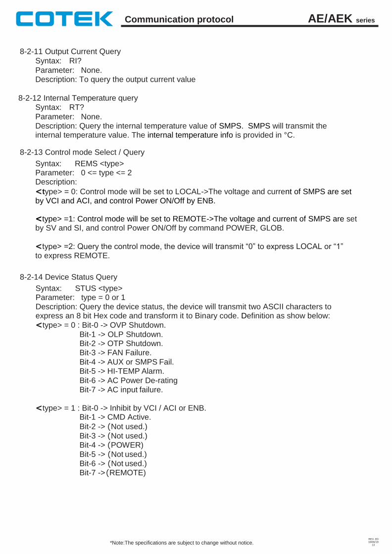
8-2-11 Output Current Query
Syntax: RI?
Parameter: None. Description: To query the output current value
8-2-12 Internal Temperature query Syntax: RT?
Parameter: None. Description: Query the internal temperature value of SMPS. SMPS will transmit the internal temperature value. The internal temperature info is provided in °C.
8-2-13 Control mode Select / Query
Syntax: REMS <type> Parameter: 0 <= type <= 2 Description:
<type> = 0: Control mode will be set to LOCAL->The voltage and current of SMPS are set by VCI and ACI, and control Power ON/Off by ENB.
<type> =1: Control mode will be set to REMOTE->The voltage and current of SMPS are set by SV and SI, and control Power ON/Off by command POWER, GLOB.
<type> =2: Query the control mode, the device will transmit “0” to express LOCAL or “1” to express REMOTE.
8-2-14 Device Status Query
Syntax: STUS <type> Parameter: type = 0 or 1 Description: Query the device status, the device will transmit two ASCII characters to express an 8 bit Hex code and transform it to Binary code. Definition as show below:
<type> = 0 : Bit-0 -> OVP Shutdown.
Bit-1 -> OLP Shutdown. Bit-2 -> OTP Shutdown. Bit-3 -> FAN Failure.
Bit-4 -> AUX or SMPS Fail. Bit-5 -> HI-TEMP Alarm.
Bit-6 -> AC Power De-rating Bit-7 -> AC input failure.
<type> = 1 : Bit-0 -> Inhibit by VCI / ACI or ENB. Bit-1 -> CMD Active.
Bit-2 -> (Not used.)
Bit-3 -> (Not used.) Bit-4 -> (POWER) Bit-5 -> (Not used.) Bit-6 -> (Not used.) Bit-7 -> (REMOTE)
AE/AEK series Communication protocol
REV. B3 18/06/19
14 *Note:The specifications are subject to change without notice.
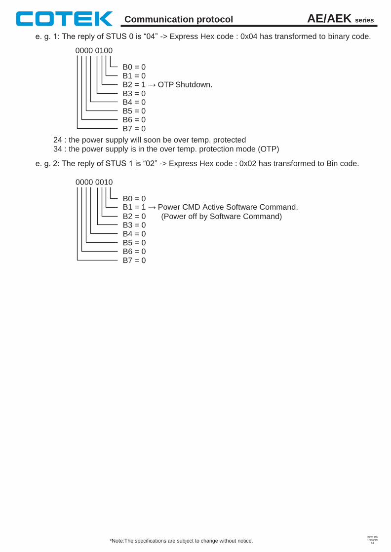
e. g. 1: The reply of STUS 0 is “04” -> Express Hex code : 0x04 has transformed to binary code.
0000 0100
B0 = 0 B1 = 0 B2 = 1 → OTP Shutdown. B3 = 0 B4 = 0 B5 = 0 B6 = 0 B7 = 0
24 : the power supply will soon be over temp. protected 34 : the power supply is in the over temp. protection mode (OTP)
e. g. 2: The reply of STUS 1 is “02” -> Express Hex code : 0x02 has transformed to Bin code.
0000 0010
B0 = 0 B1 = 1 → Power CMD Active Software Command.
B2 = 0 B3 = 0 B4 = 0 B5 = 0 B6 = 0 B7 = 0
(Power off by Software Command)
AE/AEK series Communication protocol
REV. B3 18/06/19
15 *Note:The specifications are subject to change without notice.
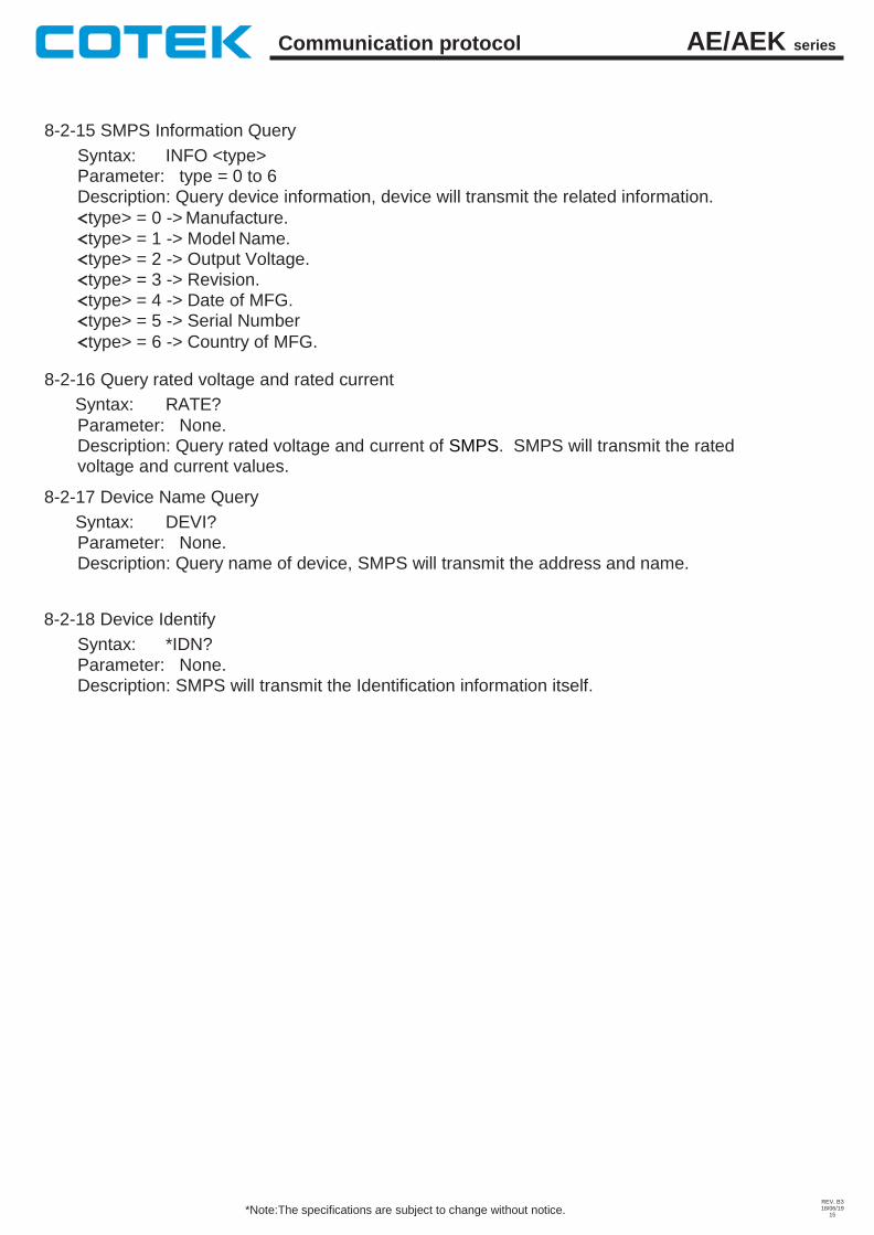
8-2-15 SMPS Information Query
Syntax: INFO <type> Parameter: type = 0 to 6 Description: Query device information, device will transmit the related information.
<type> = 0 -> Manufacture.
<type> = 1 -> Model Name. <type> = 2 -> Output Voltage. <type> = 3 -> Revision. <type> = 4 -> Date of MFG. <type> = 5 -> Serial Number
<type> = 6 -> Country of MFG.
8-2-16 Query rated voltage and rated current
Syntax: RATE?
Parameter: None. Description: Query rated voltage and current of SMPS. SMPS will transmit the rated voltage and current values.
8-2-17 Device Name Query
Syntax: DEVI? Parameter: None. Description: Query name of device, SMPS will transmit the address and name.
8-2-18 Device Identify
Syntax: *IDN? Parameter: None. Description: SMPS will transmit the Identification information itself.
AE/AEK series Communication protocol
REV. B3 18/06/19
16 *Note:The specifications are subject to change without notice.
Attention
When use RS232 / 485 to control AE/AEK series SMPS, user must follow the rules as stated below.
A: Before entering the power-on command (POWER 1, GLOB 1), it is recommended to set / check the voltage and current value in advance before power on. After receiving the response from SMPS, user may then assign power-on command.
B: All characters of RS232/485 must be transmitted completely between 400ms according CR LF (0D0A). Transmitting the characters over the time range stated, system will ignore the command.
C: After shut down power input, controller board power will remain in the RAM for a while. When close the power of EUT, all setting commands will return to initial value when output voltage drop (or set) to 0V. At this time, the status resumes to LOCAL MODE.
D: The communication board controls up to 8 SMPS (ADDS0-7) max. Please check the SMPS Address set is not conflicted when connecting multiple SMPS simultaneously.
E: To set/query multiple SMPS in remote mode via protocol, user must assign the address of each SMPS by entering command ADDS x (x=0~7); otherwise, the SMPS will not be able to set/query. If customer uses only one SMPS, it will not be necessary to set address

AE/AEK series Communication protocol
REV. B3 18/06/19
17 *Note:The specifications are subject to change without notice.
Copyright © 2022 FDOKUMEN