columnas
17
Clean Columns Help: 1) You must Enable Macros in order for the spreadsheet "Clean Columns" to wo If the buttons on the worksheets don't work the Macros are not enabled. If you are not prompted as to whether or not you want to enable macros wh First, Excel's macro security may be too high. To correct this, select " The "Security" form will open. Choose the "Medium" or "Low" setting on th If the program still does not work, the second reason macros may not work as a virus and remove or disable them from the file. If this happens, th administrator for help in correcting these problems. 2) If you are getting errors while running Clean Columns such as "Path not F Set the Error Trapping Option in Excel's Visual Basic Editor to "Break on To do this go to the "Tools" menu, select "Macro" then "Visual Basic Edi You can also use Alt-F11 to open the window. Select "Tools" from the menu bar at the top, then select "Options". The Go to the "General" tab. Select "Break on Unhandled Errors" from the "Er
Transcript of columnas
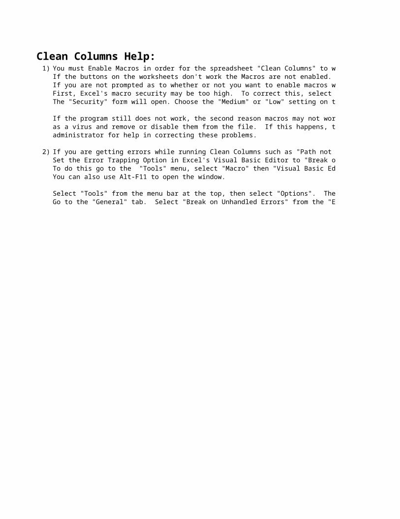
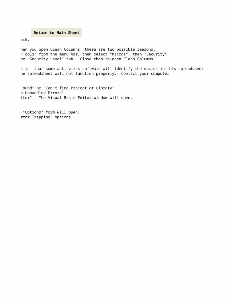
Clean Columns Help:1) You must Enable Macros in order for the spreadsheet "Clean Columns" to work.
If the buttons on the worksheets don't work the Macros are not enabled.If you are not prompted as to whether or not you want to enable macros when you open Clean Columns, there are two possible reasons.First, Excel's macro security may be too high. To correct this, select "Tools" from the menu bar, then select "Macros", then "Security". The "Security" form will open. Choose the "Medium" or "Low" setting on the "Security Level" tab. Close then re-open Clean Columns.
If the program still does not work, the second reason macros may not work is that some anti-virus software will identify the macros in this spreadsheetas a virus and remove or disable them from the file. If this happens, the spreadsheet will not function properly. Contact your computeradministrator for help in correcting these problems.
2) If you are getting errors while running Clean Columns such as "Path not Found" or "Can't find Project or Library"Set the Error Trapping Option in Excel's Visual Basic Editor to "Break on Unhandled Errors"To do this go to the "Tools" menu, select "Macro" then "Visual Basic Editor". The Visual Basic Editor window will open.You can also use Alt-F11 to open the window.
Select "Tools" from the menu bar at the top, then select "Options". The "Options" form will open.Go to the "General" tab. Select "Break on Unhandled Errors" from the "Error Trapping" options.
You must Enable Macros in order for the spreadsheet "Clean Columns" to work.
If you are not prompted as to whether or not you want to enable macros when you open Clean Columns, there are two possible reasons.First, Excel's macro security may be too high. To correct this, select "Tools" from the menu bar, then select "Macros", then "Security". The "Security" form will open. Choose the "Medium" or "Low" setting on the "Security Level" tab. Close then re-open Clean Columns.
If the program still does not work, the second reason macros may not work is that some anti-virus software will identify the macros in this spreadsheetas a virus and remove or disable them from the file. If this happens, the spreadsheet will not function properly. Contact your computer
If you are getting errors while running Clean Columns such as "Path not Found" or "Can't find Project or Library"Set the Error Trapping Option in Excel's Visual Basic Editor to "Break on Unhandled Errors"To do this go to the "Tools" menu, select "Macro" then "Visual Basic Editor". The Visual Basic Editor window will open.
Select "Tools" from the menu bar at the top, then select "Options". The "Options" form will open.Go to the "General" tab. Select "Break on Unhandled Errors" from the "Error Trapping" options.
Return to Main Sheet

Clean Columns V13.1Least weight is not least cost.
Least weight is not least cost.Least weight is not least cost.
The Steel Solutions® Center is your gateway to powerful tools, facts and project solutions.
Calcualtions are based on AISC 2005 Specification, Design Guide #13, and Design Guide #4 2nd Edition.
Talk to your favorite fabricator, or consult chapter 3 of Design Guide 13 for more information on the cost of stiffener and doubler plates.
This spreadsheet has been prepared in accordance with information made available to the American Institute of Steel Construction, Inc., AISC Marketing, LLC, and the Steel Solutions Center, LLC at the time of its preparation. While it is believed to be accurate, it has not been prepared for conventional use as an engineering or construction document and should not be used or relied upon for any specific application without competent professional examination and verification of its accuracy, suitability and applicability by a licensed engineer, architect or other professional. AISC, AISCM, and SSC disclaim any liability arising from information provided by others or from the unauthorized use of the information contained in this spreadsheet.
Clean Columns calculates the lightest column section required to eliminate sti...
Enter Now
Com m ents? Q uestions? Visit us online at www.aisc.org/ASKAISC or contact us at solutions@ aisc.org or toll free at 866.ASK.AISC
What's New in Version 13.1?
Trademarks licensed from AISC
Clean Columns V13.1Least weight is not least cost.
Least weight is not least cost.Least weight is not least cost.
Center is your gateway to powerful tools, facts and project solutions.
Specification, Design Guide #13, and Design Guide #4 2nd Edition.
Talk to your favorite fabricator, or consult chapter 3 of Design Guide 13 for more information on the cost of stiffener and doubler plates.
This spreadsheet has been prepared in accordance with information made available to the American Institute of Steel Construction, Inc., AISC Marketing, LLC, and the Steel Solutions Center, LLC at the time of its preparation. While it is believed to be accurate, it has not been prepared for conventional use as an engineering or construction document and should not be used or relied upon for any specific application without competent professional examination and verification of its accuracy, suitability and applicability by a licensed engineer, architect or other professional. AISC, AISCM, and SSC disclaim any liability arising from information provided by others or from the unauthorized use of the information contained in
What's New in Version 13.1?
Project: Any Steel Project
Client: Best Architect Ever
Engineer: JRE
Remarks: Interior Columns: Lines B, C, and E
1) Summary of Assumptions:
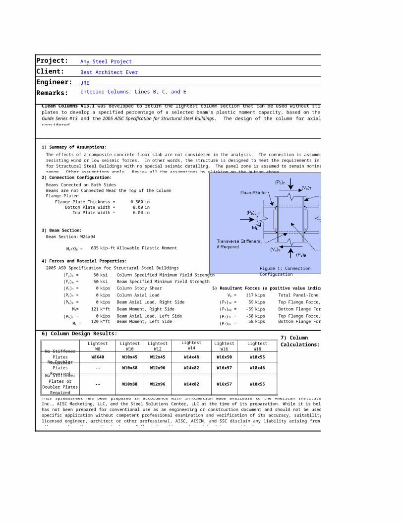
2) Connection Configuration:Beams Conected on Both SidesBeams are not Connected Near the Top of the Column 0.00 inFlange-Plated
Flange Plate Thickness = 0.500 inBottom Plate Width = 8.00 in
Top Plate Width = 6.00 in
3) Beam Section:Beam Section: W24x94
635 kip-ft Allowable Plastic Moment
4) Forces and Material Properties:2005 ASD Specification for Structural Steel Buildings
50 ksi Column Specified Minimum Yield Strength50 ksi Beam Specified Minimum Yield Strength0 kips Column Story Shear 5) Resultant Forces (a positive value indicates compression)0 kips Column Axial Load 117 kips Total Panel-Zone Shear Force0 kips Beam Axial Load, Right Side 59 kips Top Flange Force, Right Side
121 k*ft Beam Moment, Right Side -59 kips Bottom Flange Force, Right Side0 kips Beam Axial Load, Left Side -58 kips Top Flange Force, Left Side
120 k*ft Beam Moment, Left Side 58 kips Bottom Flange Force, Left Side
6) Column Design Results:Lightest Lightest Lightest Lightest Lightest Lightest
W8 W10 W12 W14 W16 W18W8X40 W10x45 W12x45 W14x48 W16x50 W18x55
-- W10x88 W12x96 W14x82 W16x57 W18x46
-- W10x88 W12x96 W14x82 W16x57 W18x55
Clean Columns V13.1 was developed to return the lightest column section that can be used without stiffeners and/or doubler plates to develop a specified percentage of a selected beam's plastic moment capacity, based on the criteria in AISC Design Guide Series #13 and the 2005 AISC Specification for Structural Steel Buildings. The design of the column for axial load capacity is not considered.
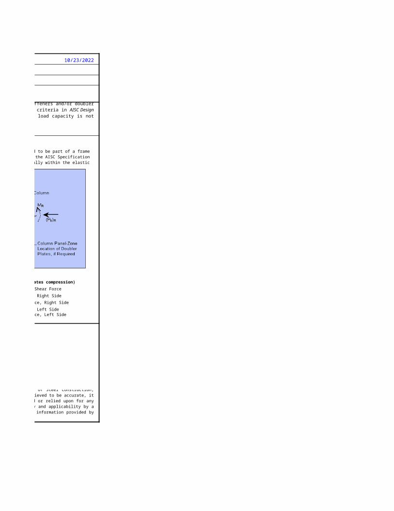
The effects of a composite concrete floor slab are not considered in the analysis. The connection is assumed to be part of a frame resisting wind or low seismic forces. In other words, the structure is designed to meet the requirements in the AISC Specification for Structural Steel Buildings with no special seismic detailing. The panel zone is assumed to remain nominally within the elastic range. Other assumptions apply. Review all the assumptions by clicking on the button above.
(Fy)c =(Fy)b =(Vs)T =(Pc)T = Vp =(Pb)R = (Pf)TR =
MR= (Pf)BR =
No Stiffener Plates RequiredNo Doubler Plates RequiredNo Stiffener Plates or
Doubler Plates Required
This spreadsheet has been prepared in accordance with information made available to the American Institute of Steel Construction, Inc., AISC Marketing, LLC, and the Steel Solutions Center, LLC at the time of its preparation. While it is believed to be accurate, it has not been prepared for conventional use as an engineering or construction document and should not be used or relied upon for any specific application without competent professional examination and verification of its accuracy, suitability and applicability by a licensed engineer, architect or other professional. AISC, AISCM, and SSC disclaim any liability arising from information provided by others or from the unauthorized use of the information contained in this spreadsheet.
Figure 1: Connection Configuration
(Pb)L =ML =
Mp/Wb =
(Pf)TL =(Pf)BL =
7) Column Calculations:
10/23/2022
Best Architect Ever
JREInterior Columns: Lines B, C, and E
5) Resultant Forces (a positive value indicates compression)Total Panel-Zone Shear ForceTop Flange Force, Right SideBottom Flange Force, Right SideTop Flange Force, Left SideBottom Flange Force, Left Side
was developed to return the lightest column section that can be used without stiffeners and/or doubler plates to develop a specified percentage of a selected beam's plastic moment capacity, based on the criteria in AISC Design
. The design of the column for axial load capacity is not
The effects of a composite concrete floor slab are not considered in the analysis. The connection is assumed to be part of a frame resisting wind or low seismic forces. In other words, the structure is designed to meet the requirements in the AISC Specification for Structural Steel Buildings with no special seismic detailing. The panel zone is assumed to remain nominally within the elastic
This spreadsheet has been prepared in accordance with information made available to the American Institute of Steel Construction, Inc., AISC Marketing, LLC, and the Steel Solutions Center, LLC at the time of its preparation. While it is believed to be accurate, it has not been prepared for conventional use as an engineering or construction document and should not be used or relied upon for any specific application without competent professional examination and verification of its accuracy, suitability and applicability by a licensed engineer, architect or other professional. AISC, AISCM, and SSC disclaim any liability arising from information provided by
Figure 1: Connection Configuration
7) Column Calculations:
Project: Any Steel Project 10/23/2022
Client: Best Architect Ever
Engineer: JRE
Remarks: Interior Columns: Lines B, C, and E
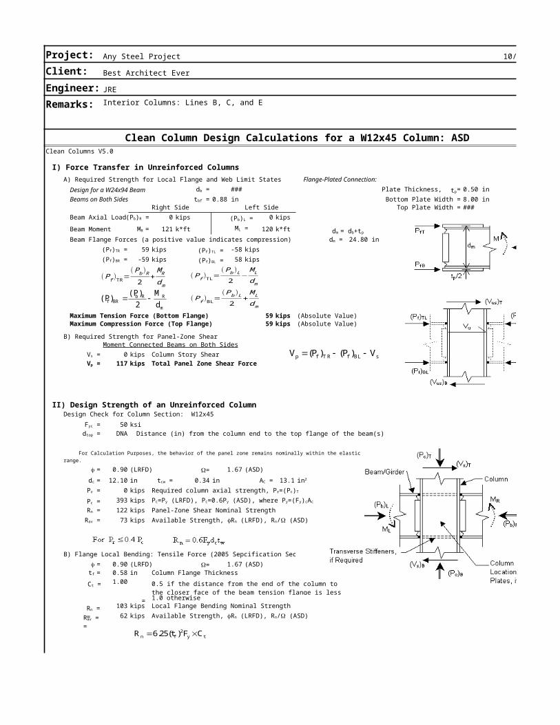
Clean Column Design Calculations for a W12x45 Column: ASDClean Columns V5.0
I) Force Transfer in Unreinforced ColumnsA) Required Strength for Local Flange and Web Limit States Flange-Plated Connection:
Design for a W24x94 Beam ### Plate Thickness, = 0.50 inBeams on Both Sides 0.88 in Bottom Plate Width = 8.00 in
Right Side Left Side Top Plate Width = ###Beam Axial Load 0 kips 0 kipsBeam Moment 121 k*ft 120 k*ftBeam Flange Forces (a positive value indicates compression) 24.80 in
59 kips -58 kips-59 kips 58 kips
1 Maximum Tension Force (Bottom Flange) 59 kips (Absolute Value)0 Maximum Compression Force (Top Flange) 59 kips (Absolute Value)
B) Required Strength for Panel-Zone ShearMoment Connected Beams on Both Sides
0 kips Column Story Shear117 kips Total Panel Zone Shear Force
Design Check for Column Section: W12x4550 ksiDNA Distance (in) from the column end to the top flange of the beam(s)
DNA Distance (in) from the column end to the bottom flange of the beam(s)
0.90 (LRFD) 1.67 (ASD)12.10 in 0.34 in 13.1
0 kips393 kips122 kips Panel-Zone Shear Nominal Strength73 kips
B) Flange Local Bending: Tensile Force (2005 Sepcification Sec 10.90 (LRFD) 1.67 (ASD)0.58 in Column Flange Thickness1.00
= 1.0 otherwise103 kips Local Flange Bending Nominal Strength62 kips
See Eq. 3.20 of Design Guide #4, 2nd Edition for Extended End Plates
db =tbf =
(Pb)R =MR =
dm = (Pf)TR =(Pf)BR =
Vs =Vp =
II) Design Strength of an Unreinforced Column
Fyc =dtop =dbot =A) Web PanelZone Shear (2005 Specification Section J10.6)
For Calculation Purposes, the behavior of the panel zone remains nominally within the elastic range.
f = W=dc = tcw = AC = in2
Pr = Required column axial strength, Pr=(Pc)T
Pc = Pc=Py (LRFD), Pc=0.6Py (ASD), where Py=(Fy)cAc
Rn =Rav = Available Strength, fRn (LRFD), Rn/W (ASD)
f = W=tf =
0.5 if the distance from the end of the column to the closer face of the beam tension flange is less than 10tf
Available Strength, fRn (LRFD), Rn/W (ASD)
(Pf)TR=(Pb)R2
+MRdm
(Pf)TL=(Pb )L2
−MLdm
m
RRbBRf d
M2)(P)(P (Pf)BL=
(Pb)L2
+MLdm
(Pf)TL =(Pf)BL =
(Pb)L =ML =
sBLfT Rfp V)P()(PV
dm = db+tp
tp
Ct =
Rn = =Rav = =
2n f y tR 6.25(t)F C

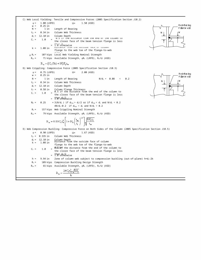
C) Web Local Yielding: Tensile and Compressive Forces (2005 Specification Section J10.2)1.00 (LRFD) 1.50 (ASD)
w = 0.25 inN = 1 in Length of Bearing
0.34 in Column Web Thickness12.10 in Column Depth1.0 =
= 1.0 otherwisek = 1.08 in
107 kips Local Web Yielding Nominal Strength71 kips
See Eq. 3.24 of Design Guide #4, 2nd Edition for Extended End PlatesD) Web Crippling: Compressive Force (2005 Specification Section J10.3)
0.75 (LRFD) 2.00 (ASD)w = 0.25 inN = 1 in Length of Bearing 0.08 < 0.2
0.34 in Column Web Thickness12.10 in Column Depth0.58 in Column Flange Thickness1.0 =
= 1.0 otherwise0.25 =
157 kips Web Crippling Nominal Strength79 kips
E) Web Compression Buckling: Compressive Force on Both Sides of the Column (2005 Specification Section J10.5)0.90 (LRFD) 1.67 (ASD)0.335 in Column Web Thickness12.10 in Column Depth
k = 1.08 in
1.0 =
= 1.0 otherwiseh = 9.94 in
109 kips Compression Buckling Design Strength65 kips
f = W=
tw =dc =Ct = 0.5 if the distance from the end of the column to
the closer face of the beam tension flange is less than dc
Distance from the outside face of column flange to the web toe of the flange-to-web filletRn =
Rav = Available Strength, fRn (LRFD), Rn/W (ASD)
f = W=
N/dc =tw =dc =tf =Ct = 0.5 if the distance from the end of the column to
the closer face of the beam tension flange is less than dc/2
Nd = 3(N/dc ) if dtop > dc/2 or if dtop < dc and N/dc < 0.24N/dc-0.2 if dtop < dc and N/dc > 0.2
Rn =Rav = Available Strength, fRn (LRFD), Rn/W (ASD)
f = W=tw =dc = Distance from the outside face of column
flange to the web toe of the flange-to-web filletCt = 0.5 if the distance from the end of the column to the closer face of the beam tension flange is less than dc/2
Zone of column web subject to compression buckling (out-of-plane) h=dc-2kRn =Rav = Available Strength, fRn (LRFD), Rn/W (ASD)
WN
Reinforcing Fillet W eld
f
WN
Reinforcing Fillet W eld
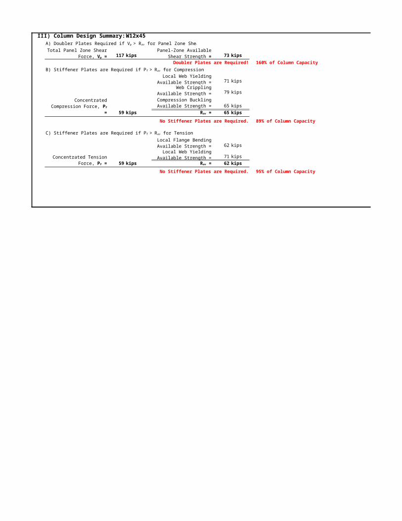
W12x45
117 kips 73 kipsDoubler Plates are Required! 160% of Column Capacity
71 kips
79 kips
65 kips59 kips 65 kips
No Stiffener Plates are Required. 89% of Column Capacity
62 kips
71 kips59 kips 62 kips
No Stiffener Plates are Required. 95% of Column Capacity
III) Column Design Summary:A) Doubler Plates Required if Vp > Rav for Panel Zone ShearTotal Panel Zone Shear
Force, Vp =Panel-Zone Available
Shear Strength =
B) Stiffener Plates are Required if Pf > Rav for CompressionLocal Web Yielding
Available Strength =Web Crippling
Available Strength =Concentrated
Compression Force, Pf =
Compression Buckling Available Strength =
Rav =
C) Stiffener Plates are Required if Pf > Rav for TensionLocal Flange Bending Available Strength =
Concentrated Tension Force, Pf =
Local Web Yielding Available Strength =
Rav =
10/23/2022
Best Architect Ever
JREInterior Columns: Lines B, C, and E
Clean Column Design Calculations for a W12x45 Column: ASD

WN
Reinforcing Fillet W eld
WN
Reinforcing Fillet W eld

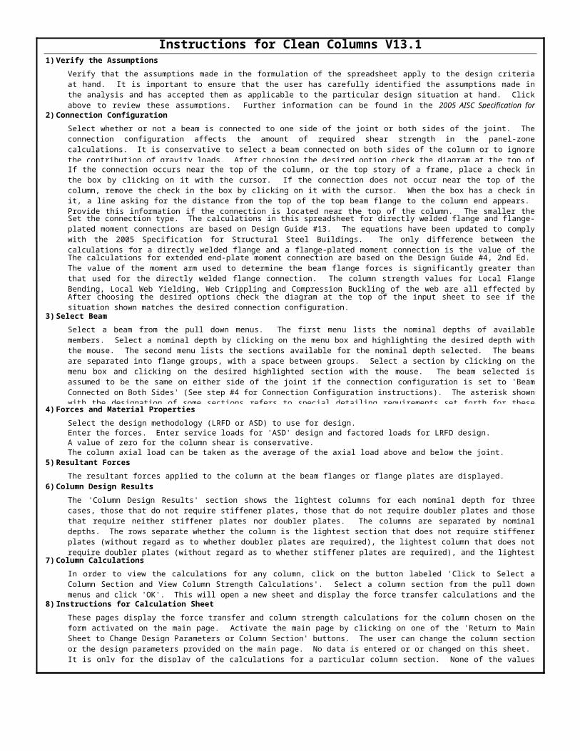
Instructions for Clean Columns V13.11)Verify the Assumptions
2)Connection Configuration
3)Select Beam
4)Forces and Material PropertiesSelect the design methodology (LRFD or ASD) to use for design.Enter the forces. Enter service loads for 'ASD' design and factored loads for LRFD design.A value of zero for the column shear is conservative.The column axial load can be taken as the average of the axial load above and below the joint.
5)Resultant ForcesThe resultant forces applied to the column at the beam flanges or flange plates are displayed.
6)Column Design Results
7)Column Calculations
8)Instructions for Calculation Sheet
Verify that the assumptions made in the formulation of the spreadsheet apply to the design criteria at hand. It is important to ensure that the user has carefully identified the assumptions made in the analysis and has accepted them as applicable to the particular design situation at hand. Click above to review these assumptions. Further information can be found in the 2005 AISC Specification for Structural Steel Buildings, Design Guide #13, and Design Guide #4, 2nd Ed.Select whether or not a beam is connected to one side of the joint or both sides of the joint. The connection configuration affects the amount of required shear strength in the panel-zone calculations. It is conservative to select a beam connected on both sides of the column or to ignore the contribution of gravity loads. After choosing the desired option check the diagram at the top of the page to see if the situation shown matches the desired connection configuration. If the connection occurs near the top of the column, or the top story of a frame, place a check in the box by clicking on it with the cursor. If the connection does not occur near the top of the column, remove the check in the box by clicking on it with the cursor. When the box has a check in it, a line asking for the distance from the top of the top beam flange to the column end appears. Provide this information if the connection is located near the top of the column. The smaller the Set the connection type. The calculations in this spreadsheet for directly welded flange and flange-plated moment connections are based on Design Guide #13. The equations have been updated to comply with the 2005 Specification for Structural Steel Buildings. The only difference between the calculations for a directly welded flange and a flange-plated moment connection is the value of the The calculations for extended end-plate moment connection are based on the Design Guide #4, 2nd Ed. The value of the moment arm used to determine the beam flange forces is significantly greater than that used for the directly welded flange connection. The column strength values for Local Flange Bending, Local Web Yielding, Web Crippling and Compression Buckling of the web are all effected by After choosing the desired options check the diagram at the top of the input sheet to see if the situation shown matches the desired connection configuration.
Select a beam from the pull down menus. The first menu lists the nominal depths of available members. Select a nominal depth by clicking on the menu box and highlighting the desired depth with the mouse. The second menu lists the sections available for the nominal depth selected. The beams are separated into flange groups, with a space between groups. Select a section by clicking on the menu box and clicking on the desired highlighted section with the mouse. The beam selected is assumed to be the same on either side of the joint if the connection configuration is set to 'Beam Connected on Both Sides' (See step #4 for Connection Configuration instructions). The asterisk shown with the designation of some sections refers to special detailing requirements set forth for these members in the AISC manuals. These sections are mainly intended for use as columns.
The 'Column Design Results' section shows the lightest columns for each nominal depth for three cases, those that do not require stiffener plates, those that do not require doubler plates and those that require neither stiffener plates nor doubler plates. The columns are separated by nominal depths. The rows separate whether the column is the lightest section that does not require stiffener plates (without regard as to whether doubler plates are required), the lightest column that does not require doubler plates (without regard as to whether stiffener plates are required), and the lightest
In order to view the calculations for any column, click on the button labeled 'Click to Select a Column Section and View Column Strength Calculations'. Select a column section from the pull down menus and click 'OK'. This will open a new sheet and display the force transfer calculations and the
These pages display the force transfer and column strength calculations for the column chosen on the form activated on the main page. Activate the main page by clicking on one of the 'Return to Main Sheet to Change Design Parameters or Column Section' buttons. The user can change the column section or the design parameters provided on the main page. No data is entered or or changed on this sheet. It is only for the display of the calculations for a particular column section. None of the values can be changed on this sheet, only viewed and printed.
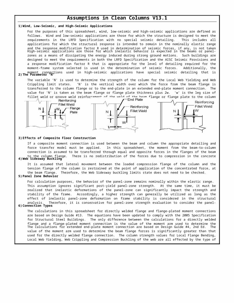
Assumptions in Clean Columns V13.11)Wind, Low-Seismic, and High-Seismic Applications
2)The Parameter "N"
3)Effects of Composite Floor Construction
4)Web Sidesway Buckling
5)Panel Zone Behavior
6)Connection Types
For the purposes of this spreadsheet, wind, low-seismic and high-seismic applications are defined as follows. Wind and low-seismic applications are those for which the structure is designed to meet the requirements in the LRFD Specification with no special seismic detailing. This includes all applications for which the structural response is intended to remain in the nominally elastic range and the response modification factor R used in determination of seismic forces, if any, is not taken High-seismic applications are those for which inelastic behavior is expected in the beams or panel-zones as a means of dissipating the energy induced during strong ground motions. Such buildings are designed to meet the requirements in both the LRFD Specification and the AISC Seismic Provisions and a response modification factor R that is appropriate for the level of detailing required for the moment-frame system selected is used in the determination of seismic forces. Additionally, the moment connections used in high-seismic applications have special seismic detailing that is
The variable 'N' is used to determine the strength of the column for the Local Web Yielding and Web Crippling limit states. 'N' is the vertical width over which the force from the beam flange is transferred to the column flange or to the end-plate in an extended end-plate moment connection. The value for 'N' is taken as the beam flange or flange plate thickness plus 2w. 'w' is the leg size of fillet weld or groove weld reinforcement of the weld of the beam flange or flange plate to the column
If a composite moment connection is used between the beam and column the appropriate detailing and force transfer model must be applied. In this spreadsheet, the moment from the beam-to-column connection is assumed to be transferred through equal and opposite forces in the flanges of the beam to the column flange. There is no redistribution of the forces due to compression in the concrete
It is assumed that lateral movement between the loaded compression flange of the column and the tension flange of the column is restrained at the point of application of the concentrated force, at the beam flange. Therefore, the Web Sidesway buckling limits state does not need to be checked.
For calculation purposes, the behavior of the panel-zone remains nominally within the elastic range. This assumption ignores significant post-yield panel-zone strength. At the same time, it must be realized that inelastic deformations of the panel-zone can significantly impact the strength and stability of the frame. Accordingly, a higher strength can generally be utilized as long as the effect of inelastic panel-zone deformation on frame stability is considered in the structural analysis. Therefore, it is conservative for panel-zone strength evaluation to consider the panel-
The calculations in this spreadsheet for directly welded flange and flange-plated moment connections are based on Design Guide #13. The equations have been updated to comply with the 2005 Specification for Structural Steel Buildings. The only difference between the calculations for a directly welded flange and a flange-plated moment connection is the value of the moment arm used to determine the The calculations for extended end-plate moment connection are based on Design Guide #4, 2nd Ed. The value of the moment arm used to determine the beam flange forces is significantly greater than that used for the directly welded flange connection. The column strength values for Local Flange Bending, Local Web Yielding, Web Crippling and Compression Buckling of the web are all effected by the type of
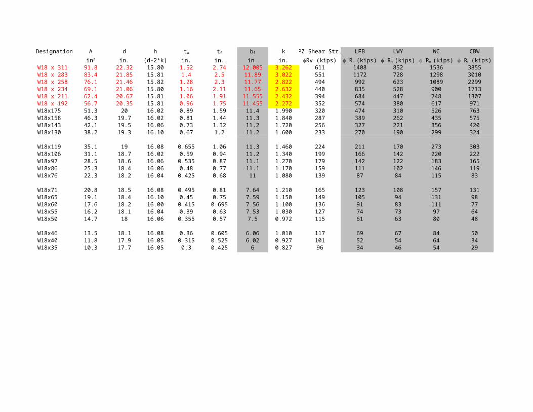
Designation A d h k PZ Shear Str. LFB LWY WC CBWin. (d-2*k) in. in. in. in.
W18 x 311 91.8 22.32 15.80 1.52 2.74 12.005 3.262 611 1408 852 1536 3855W18 x 283 83.4 21.85 15.81 1.4 2.5 11.89 3.022 551 1172 728 1298 3010W18 x 258 76.1 21.46 15.82 1.28 2.3 11.77 2.822 494 992 623 1089 2299W18 x 234 69.1 21.06 15.80 1.16 2.11 11.65 2.632 440 835 528 900 1713W18 x 211 62.4 20.67 15.81 1.06 1.91 11.555 2.432 394 684 447 748 1307W18 x 192 56.7 20.35 15.81 0.96 1.75 11.455 2.272 352 574 380 617 971W18x175 51.3 20 16.02 0.89 1.59 11.4 1.990 320 474 310 526 763W18x158 46.3 19.7 16.02 0.81 1.44 11.3 1.840 287 389 262 435 575W18x143 42.1 19.5 16.06 0.73 1.32 11.2 1.720 256 327 221 356 420W18x130 38.2 19.3 16.10 0.67 1.2 11.2 1.600 233 270 190 299 324
W18x119 35.1 19 16.08 0.655 1.06 11.3 1.460 224 211 170 273 303W18x106 31.1 18.7 16.02 0.59 0.94 11.2 1.340 199 166 142 220 222W18x97 28.5 18.6 16.06 0.535 0.87 11.1 1.270 179 142 122 183 165W18x86 25.3 18.4 16.06 0.48 0.77 11.1 1.170 159 111 102 146 119W18x76 22.3 18.2 16.04 0.425 0.68 11 1.080 139 87 84 115 83
W18x71 20.8 18.5 16.08 0.495 0.81 7.64 1.210 165 123 108 157 131W18x65 19.1 18.4 16.10 0.45 0.75 7.59 1.150 149 105 94 131 98W18x60 17.6 18.2 16.00 0.415 0.695 7.56 1.100 136 91 83 111 77W18x55 16.2 18.1 16.04 0.39 0.63 7.53 1.030 127 74 73 97 64W18x50 14.7 18 16.06 0.355 0.57 7.5 0.972 115 61 63 80 48
W18x46 13.5 18.1 16.08 0.36 0.605 6.06 1.010 117 69 67 84 50W18x40 11.8 17.9 16.05 0.315 0.525 6.02 0.927 101 52 54 64 34W18x35 10.3 17.7 16.05 0.3 0.425 6 0.827 96 34 46 54 29
tw tf bf
in2 fRv (kips) f Rn (kips) f Rn (kips) f Rn (kips) f Rn (kips)