Code of Practice For Avoiding Danger From Underground ...
51
Code of Practice For Avoiding Danger From Underground Services
-
Upload
khangminh22 -
Category
Documents
-
view
1 -
download
0
Transcript of Code of Practice For Avoiding Danger From Underground ...
Code of PracticeFor Avoiding Danger From Underground Services
HSA UNDERGROUND COVER 5/24/16 10:54 AM Page 2

Our vision: Healthy, safe andproductive lives.
HSA UNDERGROUND COVER 5/24/16 10:54 AM Page 3
Table of Contents
Originally published in January 2010 by the Health and Safety Authority, updated in May 2016, The Metropolitan Building,James Joyce Street, Dublin 1. ©All rights reserved. No part of this publication may be reproduced, stored in a retrieval system,or transmitted in any form or by any means, electronic, mechanical, photocopying, recording or otherwise, without the priorpermission of the Health and Safety Authority.
Foreword 4
1.0 Introduction 51.1 Background 51.2 Status of the Code of Practice 51.3 Scope of the Code of Practice 5
2.0 General 62.1 Introduction 62.2 Electricity cables 62.3 Gas pipes 62.4 Water pipes and sewers 72.5 Telecommunications cables 72.6 Accumulation of gases 7
3.0 Role of the client 83.1 Introduction 83.2 Information from clients 83.3 Other duties that may apply 9
4.0 Design process roles 94.1 Definition of designer 94.2 Project supervisor design process 94.3 Use of plans during design 94.4 Underground services and building work 104.5 Underground services in paths and roadways 10
5.0 Construction stage roles 115.1 Project supervisor construction stage 115.2 The contractor 115.3 Utility/service providers 115.4 Employees 12
6.0 Safe system of work 136.1 Introduction 136.2 Basic elements 136.3 Employees 136.4 Procedures 14
7.0 Use of plans in the preparation of projects 157.1 Introduction 157.2 Emergency works 157.3 Availability of plans from utility/service providers 157.4 Use and limitation of plans 15
8.0 Cable - and pipe-locating devices 178.1 Position of services 178.2 Types of locating devices 178.3 Locating the service 18
1
Code of Practice for Avoiding Danger from Underground Services
2
9.0 Safe digging practices 199.1 Excavating 199.2 Damaged services 199.3 Identification of services 209.4 Support to exposed services 219.5 Back-filling 219.6 Burial of existing services 219.7 Protection against burns 219.8 Insulated digging tools 21
10.0 Safe systems of work for trenchless methods 22
11.0 New housing developments 23
12.0 Installation of new services near existing services 24
13.0 Demolition sites 25
14.0 Training and instruction 2614.1 Introduction 2614.2 Provision of information and instruction 2614.3 Training for supervisors and operatives 2614.4 Site-based direct managers/supervisors 2714.5 Role of the project supervisor construction stage in training 2714.6 Construction Skills Certification Scheme 28
Appendices 29
Appendix 1 Electricity cables 30Plans 30Cable-locating devices 30Safe digging practices 30Recommended standards for new underground electricity cable installations 33on new developments and in existing roads and streetsColour marking and strength specification of ducts for underground electricity cables 33
Appendix 2 Gas pipelines 36A.2.1 General requirements 36A.2.2 Transmission pipelines 36A.2.3 Distribution pipelines 38A.2.4 Requirements common to both transmission and distribution pipelines 38A.2.5 In the event of damage to a gas pipeline 41
Appendix 3 Water pipes and sewers 42
Appendix 4 Telecommunications cables 43Pre-planned work 43Cable-locating devices 43Safe digging practices 43
Appendix 5 Suggested job aid for workers on a safe system of work for digging 45
Appendix 6 Summary of IS 370:2007 47
Appendix 7 Useful contacts 48
Table of Contents continued
3
4
Foreword
The Health and Safety Authority, with the consent of Mr Gerald Nash TD, Minister of State for Business andEmployment, publishes this amended Code of Practice, titled “Code of Practice for Avoiding Danger fromUnderground Services”, in accordance with Section 60 of the Safety, Health and Welfare at Work Act 2005 (No.10 of 2005).
The aim of the code of practice is to improve the level of safety with which excavation work, and other workinvolving underground services, is carried out. In particular, it aims to reduce the incidence of damage tounderground services and in doing so to minimise risk to personnel who are involved in this work.
The code of practice provides practical guidance as to the observance of Part 5 of the Safety, Health and Welfareat Work (Construction) Regulations 2013 (SI No. 291 of 2013) which, inter alia, requires that adequate precautionsare taken in any excavation, shaft, earthwork, underground works or tunnel to avoid risk to persons at workarising from possible underground dangers. Such dangers include underground cables or other distributionsystems, the circulation of fluids and the presence of pockets of gas, and appropriate investigations to locatethem must be undertaken before excavation begins. The Code of Practice also provides practical guidance as tothe observance of Sections 19 and 20 of the Safety, Health and Welfare at Work Act 2005 in respect of relevantexcavation work.
This amended code of practice comes into effect on Monday 30th May, 2016, and replaces the “Code of Practicefor Avoiding Danger from Underground Services” issued by the Authority on 11 January, 2010. Notice of the issueof this amended code of practice, and revocation of the 2010 code of practice, was published in the Iris Oifigiúilon Friday 27th May, 2016.
As regards the use of codes of practice in criminal proceedings, section 61 of the Safety, Health and Welfare atWork Act 2005 provides as follows:
61.– (1) Where in proceedings for an offence under this Act relating to an alleged contravention of anyrequirement or prohibition imposed by or under a relevant statutory provision being a provision forwhich a code of practice had been published or approved by the Authority under section 60 at the timeof the alleged contravention, [subsection (2) shall have effect with respect to that code of practice inrelation to those proceedings.
(2) (a) Where a code of practice referred to in subsection (1) appears to the court to give practical guidanceas to the observance of the requirement or prohibition alleged to have been contravened, the codeof practice shall be admissible in evidence.
(2) (b) Where it is proved that any act or omission of the defendant alleged to constitute thecontravention—
(i) is a failure to observe a code of practice referred to in subsection (1), or
(ii) is a compliance with that code of practice, then such failure or compliance is admissible inevidence.
(3) A document bearing the seal of the Authority and purporting to be a code of practice or part of a codeof practice published or approved of by the Authority under this section shall be admissible as evidencein any proceedings under this Act.
Dr. Marie DaltonSecretary to the BoardHealth and Safety Authority
Code of Practice for Avoiding Danger from Underground Services
1.0 Introduction
1.1 Background
This Code of Practice (COP) replaces the Code of Practice for Avoiding Danger from Underground Services issuedby the Authority in 2010 and is the result of a joint initiative between the Health and Safety Authority,Construction Industry Federation, Irish Congress of Trade Unions, key utility companies/service providers andlocal authorities that are involved in the provision and maintenance of vital underground services. This COPtakes into account legislative changes in the Safety, Health and Welfare at Work Act 2005 and the Safety, Healthand Welfare at Work (Construction) Regulations 2013.
The aim of this COP is to improve the level of safety with which excavation work is carried out. In particular, itaims to reduce the incidence of damage to underground services and in doing so to minimise risk to personnelwho carry out this work.
1.2 Status of the Code of Practice
This COP is published by the Health and Safety Authority under Section 60 of the Safety, Health and Welfare atWork Act 2005 and with the consent of the Minister of State at the Department of Jobs, Enterprise andInnovation.
This COP is intended to provide practical guidance to utility/service providers, clients, designers, planners, projectsupervisors (both design process and construction stage), contractors, safety representatives and any personnelwho are involved in work where there is a risk from underground services.
A failure to observe any part of this COP will not in itself render a person liable to civil or criminal proceedings.However, where the COP gives practical guidance on the observance of any of the relevant statutory provisions,compliance or non-compliance with those provisions may be admissible as evidence in criminal proceedings. Therequirements of this COP are without prejudice to the general obligations placed on employers and others bythe current Safety, Health and Welfare at Work Act, Construction Regulations and other associated occupationalsafety, health and welfare legislation.
1.3 Scope of the Code of Practice
This COP gives recommendations and practical guidance on how to carry out excavation work safely in thevicinity of underground services. In this context ’excavation’ means any work that involves penetrating theground at or below surface level.
Excavation carried out in the vicinity of underground services includes work associated with a new or existingbuilding that may involve the risk of damaging underground services. It encompasses all excavation work carriedout on roadways, streets, footpaths and other open areas where there is a likelihood of buried undergroundservices.
This COP also contains guidance on how to prevent future damage to services that are currently being installed.
5
2.0 General
2.1 Introduction
Electricity cables, gas pipes, water pipes and sewers, if damaged, may pose a direct danger to personnel whoare working on the site. Damaged telecommunications cables may also be hazardous, although direct risk ofpersonal injury is rare.
If an electricity cable, telecommunications cable, gas pipeline or water main suffers any impact or anydamage, however slight, the incident must be reported to the network operator without any unduedelay. Refer to Appendix 5, item 12.
2.2 Electricity cables
Injuries that result from damage to live electricity cables are usually caused by the explosive effects of arcingcurrent and by any associated fire or flames that may follow when the sheath of a cable and the conductorinsulation are penetrated by a sharp object such as the point of a tool, or when a cable is crushed severelyenough to cause internal contact between the sheathing and one or more of the conductors. Typically, thiscauses severe and potentially fatal burns to the hands, face and body.
Some high-voltage electricity cables (e.g. 38kV and higher voltage) are filled with oil and, if damaged, the oilmay auto-ignite and create an explosion or fire. Injuries may also be caused by the explosive effects of cablematerials being vaporised by large currents. There is also a risk of electric shock when underground services aredamaged.
Incidents may also arise from cables that have been damaged, but have not been reported to the relevantutility/service provider and, therefore, have not been repaired. In such circumstances nearby services such asplastic gas pipes may be at risk from damaged live electricity cables, which could create explosions or increasethe risk of fire.
2.3 Gas pipes
Damage to gas pipes can cause leaks and may lead to high-pressure gas being released, with associated flyingdebris, noise, fires or explosions. There are two types of damage:
• Damage that causes an immediate leak following a pipe rupture. Those most likely to be at risk are thepersonnel carrying out the work and others in the immediate vicinity.
• Damage that causes a leak some time after the event. For example, damage to a pipe wrapping or surfacemay occur while work is being carried out and this damage may lead to a leak at a later date. Damage mayalso occur after the work has been carried out. For example, poor reinstatement may leave a pipeinadequately supported or subjected to unequal forces. Those most likely to be at risk are members of thepublic.
Refer to Section 10 and Appendix 2 for requirements.
Code of Practice for Avoiding Danger from Underground Services
6
7
2.4 Water pipes and sewers
While damaged water pipes are less likely to cause an injury, a jet of water emanating from a high-pressure maincould injure people or damage adjacent underground services. In addition, a water leak from an undergroundpipe could wash away subsoil, thereby reducing support for adjacent services, roads and structures. There is alsoa risk of flooding trenches or low-lying areas such as nearby basements.
Sewers are generally gravity fed, but some sewage is pumped at pressure. While the main risk to peopleassociated with damage to sewers is the possibility of contamination, these pipes may also emit gases such asmethane or hydrogen sulphide. At certain concentrations, methane may be flammable.
Water mains and sewers require ongoing maintenance to ensure that they function effectively; clear accessshould always be maintained to pipes, especially near flanges, valves, manholes etc. The laying of gas pipes orelectricity cables in parallel above or in immediate proximity to a water main or sewer substantially increasesthe risk of injury to the crews who may have to carry out subsequent maintenance tasks.
2.5 Telecommunications cables
Although damage to telecommunications cables may be very expensive, generally there is no direct risk ofpersonal injury. However, damage to cables can pose a risk to the general population served by these cables. Abreakdown in service can result in isolation from essential services such as fire brigade, ambulance and gardaí.Therefore, it is imperative that all precautions necessary are taken to avoid damaging telecommunicationscables. If damage does occur, it must be communicated to the utility/service provider without delay. In case ofdamage to a fibre optic cable, it is advised that an individual should never look into either end of a severed fibreoptic cable as laser light might damage eyesight.
2.6 Accumulation of gases
Flammable and toxic gases from sewers and other services may enter and accumulate in service ducts,particularly if ducts have been damaged. Such gases may also accumulate in chambers and manholes and maypose a risk to personnel who are carrying out work in these areas. The gas may also be transported in these ductsto nearby structures where the risk of explosion may be even greater.
Where entry into a confined space is necessary, the requirements identified in the Confined Space Codeof Practice must be complied with.
3.0 Role of the client
3.1 Introduction
Clients play a very important role when it comes to safety and health on construction projects. The Safety,Health and Welfare at Work (Construction) Regulations 2013 define a ‘client’ as a person for whom a project iscarried out.
The Construction Regulations place duties on the client. Clients must make assessments and only appointcompetent designers or contractors for the works. If the construction project involves more than one contractor,has a particular risk or will last longer than 30days/500 person days they must appoint a competent projectsupervisor design process (PSDP) and a competent project supervisor construction stage (PSCS). Projectsupervisors co-ordinate the management of health and safety with regard to the design and construction of theproject.
Clients have a legal duty to be reasonably satisfied that the appointed project supervisors to carry out the workare competent to do so and will dedicate sufficient resources to the project to comply with their legal safetyobligations.
3.2 Information from clients
Clients or their agents have a duty to pass on any relevant information relating to underground services thatmay be in their possession to the PSDP or the PSCS. This information should be as up to date as possible. Theclient should also make available a copy of any Safety File that is relevant to the construction work that is aboutto be undertaken.
3.3 Other duties that may apply
In accordance with Section 15 of the Safety, Health and Welfare at Work Act 2005, it is the duty of each person(or company) who has control to any extent of any place of work, or any part of a place of work, to take suchmeasures as are reasonable for them to take to ensure, so far as is reasonably practicable, that the place of workis safe and without risk to health. In certain cases, this provision may be applicable to clients who commissionprojects that will involve carrying out excavation work near underground services.
Section 17 of the 2005 Act specifies duties to be complied with by persons who commission or procureconstruction work. Such persons must appoint in writing a competent person or persons to ensure, so far as isreasonably practicable, that the project is designed and is capable of being constructed to be safe and withoutrisk to health.
Code of Practice for Avoiding Danger from Underground Services
8
4.0 Design process roles
4.1 Definition of designer
’Design’ covers the preparation of drawings, design details, specifications and bills of quantities. A ’designer’ isdefined as any person who is involved in such work.
4.2 Project supervisor design process
All designers’ work should be co-ordinated by a project supervisor for the design process (PSDP). The PSDP hasa duty to prepare and provide to the project supervisor for the construction stage (PSCS) a preliminary safetyand health plan if the project is expected to last more than 30 days or 500 person days, or if it contains a‘particular risk’, as defined in the Safety, Health and Welfare at Work (Construction) Regulations 2013. Onesuch ‘particular risk’ is working near high-voltage power lines (i.e. voltages greater than 1.0 kV), includingoverhead lines and underground cables.
The preliminary safety and health plan must contain an overall description of the project, its proposed timescaleand appropriate information relating to other work on the site. It must also specify any work related to theproject that will involve ‘particular risks’.
Unforeseen circumstances may arise during the execution of the project and may result in a design change.This may in turn have safety, health and welfare implications. The PSDP has a duty to co-ordinate the designersin relation to the safety, health and welfare implications of any change in the original design.
The PSDP must prepare a Safety File for the project and present it to the client when the project is complete.
Where new services are being laid it is important that they do not prevent access to existing services. Anyrisk to crews carrying out maintenance on the existing services caused by the laying of new services mustbe identified at an early stage and minimised as far as is reasonably practicable.
The Principles of Prevention must be applied at all stages of the design process.
4.3 Use of plans during design
Where possible, the designers should obtain up-to-date maps and records of all potentially hazardousunderground services in order to allow them to consider, at the design stage, the risks posed by those services.Plans and maps should be made available to prospective contractors at tender stage or contract negotiationstage. Before beginning any work on a site, the contractor should be satisfied that the drawings suppliedcontain the most up-to-date information available for the area in which the works are to be carried out.
9
4.4 Underground services and building work
4.4.1 Relocating underground services some distance away from the proposed construction site may provide areasonably practicable means of avoiding the risk of causing damage to these services. Any request for therelocation of services should allow for sufficient time for the relevant utility/service providers to evaluate suchproposals and carry out their work.
Buildings and other permanent structures should not be erected over underground services because this maycreate additional risks for construction workers and could prevent future access to those services. If it is notpossible to avoid erecting a structure over an underground service, arrangements should be made with therelevant utility/service provider to relocate the service if this is practicable.
4.4.2 Other options to relocating the services may include:
• Repositioning structures or parts of structures to ensure that contact with underground services is avoidedwhile the work is being carried out.
• Arranging for the supply contained within the underground services to be disconnected during the work.
• If neither of these options is practicable, then choosing methods to avoid contact, such as using groundbeams to protect the service(s), may present a reasonably practicable option.
4.4.3 Designers should take into account any ancillary work that may be required, including the erection ofperimeter fencing and walls or the construction of roadways. Early identification and planning are essential ifrisks are to be controlled.
4.4.4 Where new services such as electrical or gas supplies are being installed, it may be possible to reduce risksby not installing or commissioning these services until other ground works and installation works have beencompleted.
4.5 Underground services in paths and roadways
4.5. The options facing designers who are planning a new service in a roadway may be more limited. In orderto select a route that avoids contact with existing services, it is important to have access to the most up-to-dateinformation about those services. One option is to choose a route that has a low density of undergroundservices. For example, a cable television duct might be routed at the side of a road, if that site has a reducedcable density. Designers of gas pipelines should also be aware of the requirements contained in IS 328:2003Code of Practice for Gas Transmission Pipelines; IS 265:2000 Installation of Gas Service Pipes and I.S.329:2003+A1:2009 Code of Practice for Gas Distribution Mains.
4.5.2 Having reduced the risks to a level as low as is reasonably practicable by design, information should beprovided by the designer(s) about the risks that remain. In most cases the best way of informing those physicallyexcavating in the vicinity of underground services is by providing the information on drawings, ensuring thatthe information given is the best available.
Code of Practice for Avoiding Danger from Underground Services
10
5.0 Construction stage roles
5.1 Project supervisor construction stage
The role of a project supervisor construction stage (PSCS) is to co-ordinate the project from a health and safetyperspective. The PSCS must also develop the safety and health plan, which should outline how the managementof the safety, health and welfare of on-site personnel is to be achieved. In addition, the PSCS must facilitate safeaccess to the site and co-ordinate the overall implementation of safe working procedures.
5.2 The contractor
All contractors on site must co-operate with the PSCS to allow the PSCS to comply with his or her statutoryobligations and all contractors have a duty to co-operate with each other on issues concerning health andsafety. The contractor must also supply accurate information in a timely fashion to the PSCS to allow for thepreparation of the Safety File.
Contractors must carry out a site-specific risk assessment. They should also ensure that their employees haveadequate training and that any plant or machinery is, so far as is reasonably practicable, safe and does not posea risk to health. Contractors should also put in place measures to ensure that the health and safety of personnelemployed by them will not be adversely affected by the work being carried out.
Sections 6 to 13 of this COP set out practical measures for protecting the safety, health and welfare of employeesand non-employees while excavation work is being carried out in the vicinity of underground services.
5.3 Utility/service providers
All undertakings that have underground services should ensure that their records and maps are maintained asaccurately as possible. They should make these records readily available to designers and contractors, asappropriate (see Section 7.3).
In circumstances where a utility/service provider is asked to provide permanent services for a buildingdevelopment, that company will be acting in the role of contractor. Therefore, while it is on site, it will berequired to comply with any directions given by the PSCS. However, in circumstances where the provision ofservices is physically separated and demarcated from the site, then the utility company may assume the role ofclient for the purposes of the Safety, Health and Welfare at Work (Construction) Regulations 2013.
The utility/service providers should make all reasonable efforts to facilitate clients, designers and contractors tomanage the safety risks arising from work activities close to underground services.
11
5.4 Employees
Safe systems of work must always be adhered to. All workers on site must take reasonable care to protect theirown safety and the safety of others who might be affected by their actions. They must not engage in anybehaviour likely to endanger health and safety on site. They should report without delay any defects in thesafety and health regime that might endanger anyone in the workplace.
Employees must also attend training and assessments as might reasonably be prescribed by their employerswith regard to health and safety and they must not misrepresent the level of training which they have attended.
Code of Practice for Avoiding Danger from Underground Services
12
6.0 Safe system of work
6.1 Introduction
Underground utility networks are a common feature in both rural and urban areas and their presence shouldbe assumed until proved otherwise. The guidance given in this COP aims to minimise the risk involved in workthat may expose persons to inadvertent contact with underground networks. It sets out a safe system of workthat is based on obtaining as much information as possible about buried services before excavation or otherground penetration work begins and using that information to ensure that the work is carried out safely.
6.2 Basic elements
In the context of this COP, a safe system of work is defined as having three basic elements:
• Plans: Plans or other suitable information about all buried services in the area should be obtained beforeexcavation work begins (see Section 4 and Section 7.4). This material should be passed on as early as isreasonably practicable by the designer through the project supervisors to the contractor who is tenderingfor, or is negotiating the carrying out of, the works.
Plans that were used at the design stage and at the tendering stage may be out of date by the timeexcavation work begins. Therefore, before beginning any such work, the contractor should check that theplans supplied are the most up to date available.
Account should also be taken of possible indications of the existence of underground services such as thepresence of houses or other buildings, lamp posts, illuminated traffic signs, pit covers or evidence ofreinstated trenches. However, the absence of such indicators does not necessarily mean that undergroundservices do not exist.
• Locators: Suitable cable- and pipe-locating devices should be used in conjunction with any available plansto determine as accurately as possible the position of metallic underground services in or near the proposedwork area. It should be noted, however, that these devices do not detect plastic pipes (see Section 8).
• Safe digging practices: Excavation work should be carried out carefully and should follow recognised safedigging practices (see Section 9).
These key elements – plans, locators and safe digging practices – complement each other and all three shouldbe used when working near buried services. Using one element alone is not enough.
6.3 Employees
Employees should receive adequate instruction and training in the above procedures (see Section 14). Asuggested job aid for workers’ information is set out in Appendix 5. It is particularly important that anyone whois using a locator should have received thorough training in the use and limitations of that particular type ormodel of device. Most manufacturers will provide such training, and employers should ensure that this isadequate for their employees’ needs.
13
Under the Safety, Health and Welfare at Work (Construction) Regulations 2013 persons carrying outcertain named tasks – including locating underground services, signing, lighting and guarding on roadsand assisting in the implementation of health and safety at roadworks – are required to be in possessionof a relevant and valid Construction Skills Certification Scheme (CSCS) card. Training and instructionrequirements are dealt with in Section 14.
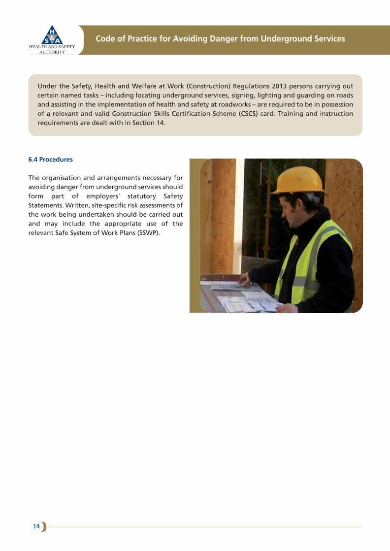
6.4 Procedures
The organisation and arrangements necessary foravoiding danger from underground services shouldform part of employers’ statutory SafetyStatements. Written, site-specific risk assessments ofthe work being undertaken should be carried outand may include the appropriate use of therelevant Safe System of Work Plans (SSWP).
Code of Practice for Avoiding Danger from Underground Services
14
7.0 Use of plans in the preparation of projects
7.1 Introduction
Up-to-date plans of all potentially hazardous underground services in the area should be obtained beforeexcavation work begins. Where possible, providers of all relevant underground services should be consulted. Itshould be noted that there may be more than one service provider in a particular catchment area for certaintypes of utility. For example, while most electricity cables under roads and other public areas are owned by ESBNetworks, many electricity cables are the property of local authorities and are used for providing services suchas public lighting, traffic lights and so on.
7.2 Emergency works
In the case of emergency* works it may not be possible to obtain all requisite up-to-date plans prior tobeginning excavation work. In such situations, all other aspects of safe digging practice should be compliedwith (see Section 9) and the work should be carried out in the same manner as if there were undergroundservices on the site.
7.3 Availability of plans from utility/service providers
7.3.1 Utility/service providers should make available either up-to-date, readable plans that show the recordedline and depth (where known) of all underground services in the proposed work area, or they should provideother suitable information that achieves the same objective. The inclusion of a symbol key will generally benecessary to help the recipient understand the plans.
7.3.2 Utility/service providers should do everything that is reasonably practicable to ensure that such informationis made available to enquirers. They are likely to receive many routine applications for information and theyshould consider how best to make this information available at short notice. In cases where utility/serviceproviders have reservations about releasing copies of plans for commercial or security reasons, they should offeran alternative method of co-operation. For example, they might send a representative to the site tocommunicate the requisite information to designated contractor personnel only.
7.4 Use and limitation of plans
Plans vary in scale, content and style and adequate instruction and training in how to read and interpret themshould be given to anyone who needs to use them.
–––––––––––––––––––––––––––––––* If the question arises in criminal or civil proceedings as to whether works were emergency works, it is for theperson alleging that they were to prove that this was the case. Clients and contractors should not use‘emergency’ work as an excuse to justify a failure to plan properly when starting work without plans or othersuitable information about underground services in the area.
15
Plans may give an indication of the location, configuration and number of underground services on a particularsite. However, they are rarely drawn accurately to scale and, even if they claim to be accurate, they should notbe relied upon in order to obtain accurate distance measurements. Errors may have been made during draftingor the scale may have been altered during reproduction, particularly if the original data was obtained from amicrofiche slide or a digital map. Accuracy may be further limited because:
• Use of low-scale maps may not give a reasonable indication of location or configuration of undergroundservices. Where possible use 1:500 in preference to 1:1000.
• The position of reference points (e.g. the kerb line) may have changed since the plans were prepared.
• The re-grading of a particular surface area may mean that the depths shown on the plan are no longercorrect.
• Fixtures such as cables may have been moved without the knowledge of the utility/service provider.
• In many cases service connections are not marked.
• Services that appear as straight lines on a map may, in fact, be laid out in a snake-like formation; excessivelylong cables may have been laid in horizontal loops outside substations and switch rooms.
• Plans may show spare ducts.
• The routes of older services in particular may not have been recorded and so the absence of records shouldnever be taken as proof that the area in question is free of underground services.
To determine the actual position of services and the depth of these services on site, safe digging practicesmust be used at all times. Such practices include the use of detection equipment and the hand diggingof trial holes as required. See Section 9.
Code of Practice for Avoiding Danger from Underground Services
16
8.0 Cable- and pipe-locating devices
8.1 Position of services
The position of any services in or near the proposed work area should be pinpointed as accurately as possibleby means of a locating device. This device should be used in conjunction with plans and other relevantinformation (see Section 8.2) as a guide to the possible location of services and to help interpret the signal.
8.2 Types of locating devices
The main types of locator available are:
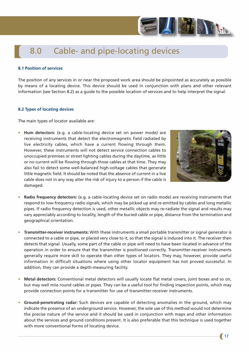
• Hum detectors: (e.g. a cable-locating device set on power mode) arereceiving instruments that detect the electromagnetic field radiated bylive electricity cables, which have a current flowing through them.However, these instruments will not detect service connection cables tounoccupied premises or street lighting cables during the daytime, as littleor no current will be flowing through those cables at that time. They mayalso fail to detect some well-balanced high-voltage cables that generatelittle magnetic field. It should be noted that the absence of current in a livecable does not in any way alter the risk of injury to a person if the cable isdamaged.
• Radio frequency detectors: (e.g. a cable-locating device set on radio mode) are receiving instruments thatrespond to low-frequency radio signals, which may be picked up and re-emitted by cables and long metallicpipes. If radio frequency detection is used, other metallic objects may re-radiate the signal and results mayvary appreciably according to locality, length of the buried cable or pipe, distance from the termination andgeographical orientation.
• Transmitter-receiver instruments: With these instruments a small portable transmitter or signal generator isconnected to a cable or pipe, or placed very close to it, so that the signal is induced into it. The receiver thendetects that signal. Usually, some part of the cable or pipe will need to have been located in advance of theoperation in order to ensure that the transmitter is positioned correctly. Transmitter-receiver instrumentsgenerally require more skill to operate than other types of locators. They may, however, provide usefulinformation in difficult situations where using other locator equipment has not proved successful. Inaddition, they can provide a depth-measuring facility.
• Metal detectors: Conventional metal detectors will usually locate flat metal covers, joint boxes and so on,but may well miss round cables or pipes. They can be a useful tool for finding inspection points, which mayprovide connection points for a transmitter for use of transmitter-receiver instruments.
• Ground-penetrating radar: Such devices are capable of detecting anomalies in the ground, which mayindicate the presence of an underground service. However, the sole use of this method would not determinethe precise nature of the service and it should be used in conjunction with maps and other informationabout the services and ground conditions present. It is also preferable that this technique is used togetherwith more conventional forms of locating device.
17
Most commercially available instruments use more than one of these techniques and may also include a depth-measuring facility.
8.3 Locating the service
The degree of confidence with which buried services may be detected depends on a number of factors such asthe characteristics of the devices being used; the type and depth of the service; the magnitude of any electriccurrent carried by the service cable; the effects of other cables and metal pipes close by; and the training, skill,hearing and experience of the operator.
A locator may not be able to distinguish between cables or pipes running close together and may representthem as a single signal. If two cables or pipes are sited one above the other, it may not detect the lower one.For that reason, frequent and repeated use of the locator should be made during the course of the work.
A locator may not detect plastic pipes or other non-metallic ducts and services unless:
• A metallic tracer wire has been laid with the pipe, which enables a signal transmitter-receiver to be used.Plastic gas, water, sewage pipes and fibre optic cables are the most likely type of non-metallic services to beencountered and some of these may have been laid with metallic tracer wires.
• A small signal transmitter is inserted into and then pushed along the pipe. This is a sophisticated techniqueand is not likely to be appropriate for many sites.
A locating device should always be used in accordance with the manufacturer’s instructions, including beingcalibrated at regular intervals and not being used outside the specified date. A locating device should bechecked regularly and maintained in good working order.
The line of any identified services should be noted and marked with waterproof crayon, chalk or paint on pavedsurfaces. Any residual markings should be erased after excavation, as far as possible.
On grassed or unsurfaced areas, wooden pegs should be used. Steel pins, spikes or long pegs, which coulddamage services laid at shallow depth, should not be used.
Under the Safety, Health and Welfare at Work (Construction) Regulations 2013, persons carrying out thetask of locating underground services are required to be in possession of a Construction Skills CertificationScheme (CSCS) card. This is dealt with in more detail in Section 14.6.
Code of Practice for Avoiding Danger from Underground Services
18
9.0 Safe digging practices
9.1 Excavating
Once plans and a locator device have been used to determine the position of underground services, excavationmay proceed. This work should be carried out carefully, following recognised safe digging practices.
Trial holes should be dug using hand tools to confirm the position of any buried services. Special care shouldbe taken when digging above or close to the assumed lines of any such services. Hand-held power tools are themain source of danger to personnel and they should not be used too close to underground services. (SeeAppendices 1 and 2 for advice on appropriate safety margins for electricity cables and gas pipelines respectively.)
Hand tools, incorrectly used, are a common cause of accidents. However, if they are used carefully and if theapproximate position of services has been determined through the use of plans and locators, these tools mayprovide a satisfactory method for exposing underground services. Every effort should be made to excavatealongside the service rather than directly above it. Final exposure of the service by horizontal digging isrecommended as the force applied to hand tools may be controlled more effectively.
In particular:
• Spades and shovels should be used rather than other tools. They should not be thrown, or spiked into theground. Rather, they should be eased in with gentle foot pressure.
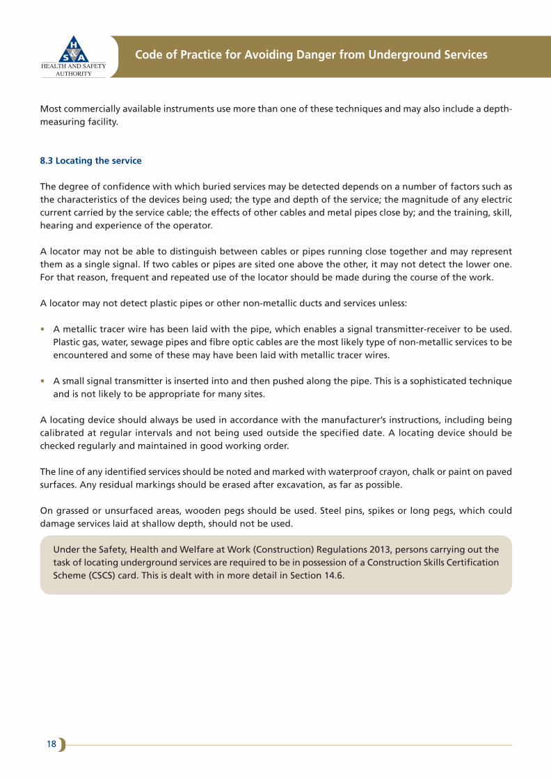
• Picks, pins or forks may be used with care to free lumps of stone and othermaterials and to break up hard layers.
• Picks should not be used in soft clay or other soft soils in areas close to buriedservices.
Particular care should be taken in cases where gas leak search techniques, suchas barholing, are used. Refer to Bord Gáis guidance material for advice. Similarprecautions should apply when piles or earth rods are being driven into theground.
Alternative excavation methods such as hydro or air digging tools and vacuumexcavation may be used in certain circumstances. However, a detailed, site-specific risk assessment will need to be carried out first to estimate the specificrisks associated with the use of these techniques, such as the presence of gas,spark ignition and injuries from ejected soil.
9.2 Damaged services
If an underground service suffers damage, no matter how slight, the utility/service provider should be informedimmediately.
19
In the case of electricity cables, gas pipes, fibre optic telecommunications cables or high-pressure water mains,arrangements should be made to keep personnel well clear of the area until the damage has been repaired orotherwise made safe by the utility/service provider.
9.3 Identification of services
Failure to identify underground services correctly can cause accidents. Correct identification may prove difficultas the utility/service providers may have used a wide variety of materials and colours over a number of years. Itis important to remember that colours may appear differently under poor or artificial lighting. In addition,ducts may well contain any one of a number of services, irrespective of the type or colour of the duct.
Some services are very similar in appearance and the following approaches should be adopted until such timeas their identity has been positively confirmed:
• The housing for some water pipes and a significant proportion of electricity cables and telecommunicationscables are made from black plastic. If a black plastic-covered service is encountered, it should be assumed tobe a live electricity cable until proved otherwise. A small percentage of directly buried electricity cables arered in colour, these should not be mistaken for red-coloured electricity cable ducting.
• Iron and steel water pipes may look very similar to gas pipes. Therefore, if any iron or steel pipe is uncovered,it should be handled as if it is a gas pipe.
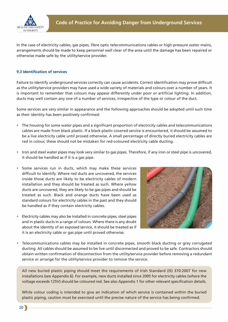
• Some services run in ducts, which may make these servicesdifficult to identify. Where red ducts are uncovered, the servicesinside those ducts are likely to be electricity cables of moderninstallation and they should be treated as such. Where yellowducts are uncovered, they are likely to be gas pipes and should betreated as such. Black and orange ducts have been used asstandard colours for electricity cables in the past and they shouldbe handled as if they contain electricity cables.
• Electricity cables may also be installed in concrete pipes, steel pipesand in plastic ducts in a range of colours. Where there is any doubtabout the identity of an exposed service, it should be treated as ifit is an electricity cable or gas pipe until proved otherwise.
• Telecommunications cables may be installed in concrete pipes, smooth black ducting or grey corrugatedducting. All cables should be assumed to be live until disconnected and proved to be safe. Contractors shouldobtain written confirmation of disconnection from the utility/service provider before removing a redundantservice or arrange for the utility/service provider to remove the service.
All new buried plastic piping should meet the requirements of Irish Standard (IS) 370:2007 for newinstallations (see Appendix 6). For example, new ducts installed since 2005 for electricity cables (where thevoltage exceeds 125V) should be coloured red. See also Appendix 1 for other relevant specification details.
While colour coding is intended to give an indication of which service is contained within the buriedplastic piping, caution must be exercised until the precise nature of the service has being confirmed.
Code of Practice for Avoiding Danger from Underground Services
20
9.4 Support to exposed services
Services uncovered in an excavation may need to be supported and should never be used as handholds orfootholds by personnel when climbing out of an excavation.
9.5 Back-filling
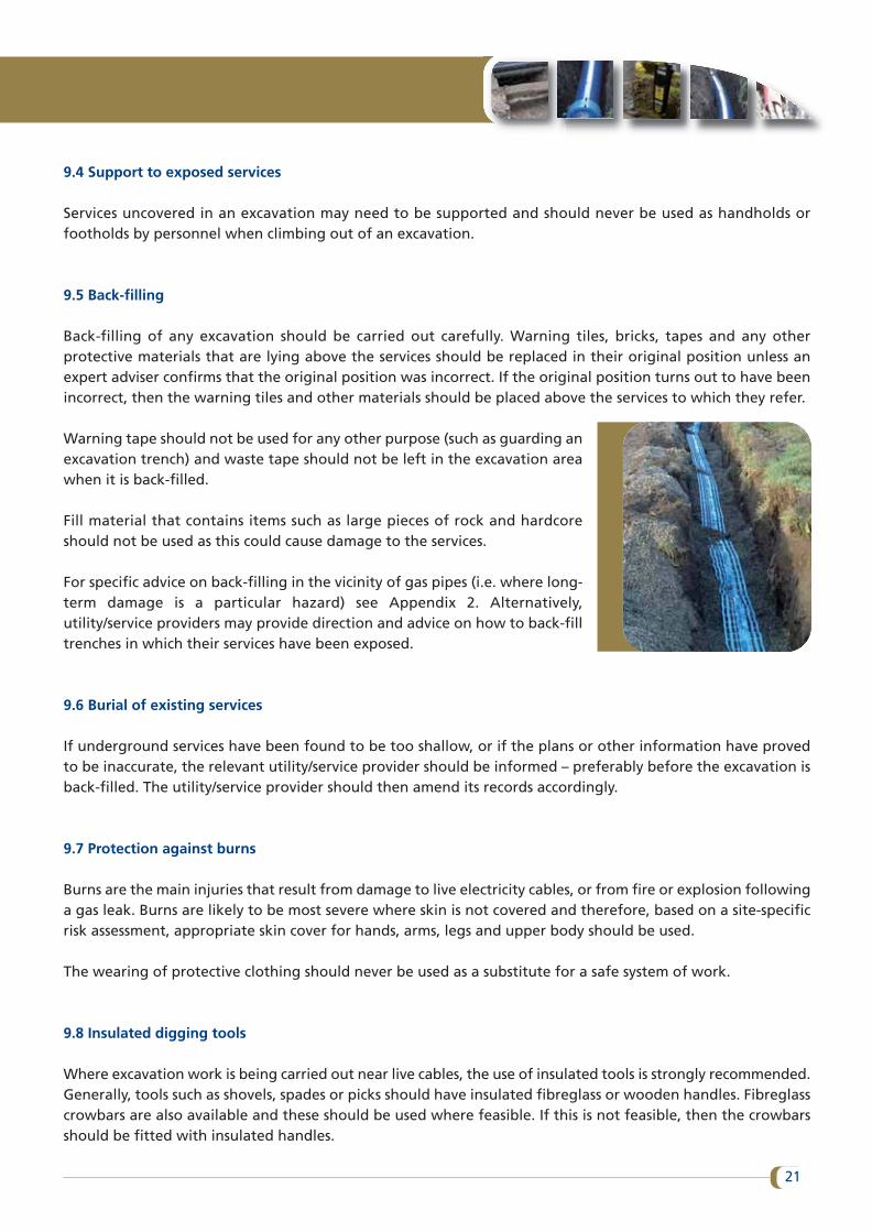
Back-filling of any excavation should be carried out carefully. Warning tiles, bricks, tapes and any otherprotective materials that are lying above the services should be replaced in their original position unless anexpert adviser confirms that the original position was incorrect. If the original position turns out to have beenincorrect, then the warning tiles and other materials should be placed above the services to which they refer.
Warning tape should not be used for any other purpose (such as guarding anexcavation trench) and waste tape should not be left in the excavation areawhen it is back-filled.
Fill material that contains items such as large pieces of rock and hardcoreshould not be used as this could cause damage to the services.
For specific advice on back-filling in the vicinity of gas pipes (i.e. where long-term damage is a particular hazard) see Appendix 2. Alternatively,utility/service providers may provide direction and advice on how to back-filltrenches in which their services have been exposed.
9.6 Burial of existing services
If underground services have been found to be too shallow, or if the plans or other information have provedto be inaccurate, the relevant utility/service provider should be informed – preferably before the excavation isback-filled. The utility/service provider should then amend its records accordingly.
9.7 Protection against burns
Burns are the main injuries that result from damage to live electricity cables, or from fire or explosion followinga gas leak. Burns are likely to be most severe where skin is not covered and therefore, based on a site-specificrisk assessment, appropriate skin cover for hands, arms, legs and upper body should be used.
The wearing of protective clothing should never be used as a substitute for a safe system of work.
9.8 Insulated digging tools
Where excavation work is being carried out near live cables, the use of insulated tools is strongly recommended.Generally, tools such as shovels, spades or picks should have insulated fibreglass or wooden handles. Fibreglasscrowbars are also available and these should be used where feasible. If this is not feasible, then the crowbarsshould be fitted with insulated handles.
21
10.0 Safe systems of work for trenchless methods
Increasingly, trenchless methods are being used for the laying or renovation of underground pipes and cables,particularly in cases where it is necessary to avoid disturbing surface areas. The most widely used techniques areimpact-moling, pipe-bursting and auger-boring. Care should be taken when using trenchless methods to avoidcolliding with, and thereby damaging, other services. With moling and pipe-bursting it is also important not towork too close to other services as displaced soil may escape into nearby pipes or ducts.
As moling takes place underground, the actual path taken is unseen and not guaranteed, the pertinent risksassociated with moling must be taken into account at both the design and construction stages. Possible damageusing trenchless methods includes damage to structures and damage to other services.
Consideration must be given to the location of all services present and may involve appropriateconsultation with the relevant utility/service providers. Competent planning, organisation andimplementation will be required before and during trenchless works. The recommendations for safedigging practices outlined in Section 9 must be referred to.
Plans, locators and trial holes should be used to determine the position of existing services. The path of theequipment to be used should then be calculated accordingly. In order to avoid danger and allow sufficientclearance for the maintenance of existing services, the general guideline is that the minimum clearance betweenadjacent services should be either 300mm or one and a half times the diameter of the pipe being laid, whicheveris the greater. For electricity cables, gas mains, telecommunications cables and water mains, clearances formaintenance work should be a minimum 300mm in all directions. Trenchless methods (moling/directionaldrilling) must not take place within ten metres of a gas pipeline unless the gas network operator has beenconsulted.
In certain circumstances, clearances may need to be varied. Therefore, contractors should take into accountfactors such as the construction of adjacent plant; ground conditions; bore diameter; the accuracy and reliabilityof the technique/equipment being used; and whether the other plant is parallel or crossing the proposed line.In addition, the requirements of nearby utility/service providers may need to be taken into account.
Moles are prone to deflection from their planned course and, if there are existing services in the vicinity, amole-tracking device should be used. Where trenchless methods are being used, all equipment which iselectrically bonded to the mole should be earthed at all times in case the equipment strikes a power cable andthis causes it to become live. As an additional precaution, an equipotential mat can be used for the operatorto stand on.
The use of no-dig technology carries its own risks. Several recorded examples exist where, unknown tothe installing contractor, a new service such as a gas main had been pushed through a sewer pipe,resulting in a blockage in the sewer pipe. The subsequent use of clearing techniques such as jettingmachines by the sewer maintenance teams put these crews at risk when they unknowingly cut throughthe gas pipe.
Code of Practice for Avoiding Danger from Underground Services
22

11.0 New housing developments
Underground services that are located within the confines of partly completed new housing developments areespecially prone to damage from the numerous site operations that may need to be carried out.
The construction of a single trench may help to control the position and separation of underground services.Where services are laid on a partly developed site, special arrangements may be required for their temporaryprotection at vehicle/plant crossing points.
Close liaison should be maintained between the developers, their contractors and the utility/service providers.A marked-up plan of the estate, showing the up-to-date position of underground services (including anyvariations from planned routes) should be kept on site and referred to in advance of carrying out excavationsor other ground penetration works.
23
12.0 Installation of new services near existing services
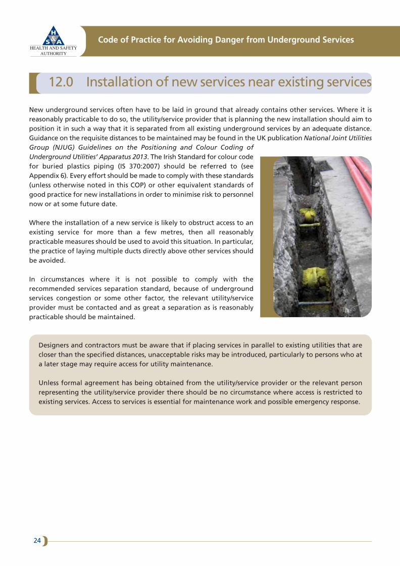
New underground services often have to be laid in ground that already contains other services. Where it isreasonably practicable to do so, the utility/service provider that is planning the new installation should aim toposition it in such a way that it is separated from all existing underground services by an adequate distance.Guidance on the requisite distances to be maintained may be found in the UK publication National Joint UtilitiesGroup (NJUG) Guidelines on the Positioning and Colour Coding ofUnderground Utilities’ Apparatus 2013. The Irish Standard for colour codefor buried plastics piping (IS 370:2007) should be referred to (seeAppendix 6). Every effort should be made to comply with these standards(unless otherwise noted in this COP) or other equivalent standards ofgood practice for new installations in order to minimise risk to personnelnow or at some future date.
Where the installation of a new service is likely to obstruct access to anexisting service for more than a few metres, then all reasonablypracticable measures should be used to avoid this situation. In particular,the practice of laying multiple ducts directly above other services shouldbe avoided.
In circumstances where it is not possible to comply with therecommended services separation standard, because of undergroundservices congestion or some other factor, the relevant utility/serviceprovider must be contacted and as great a separation as is reasonablypracticable should be maintained.
Designers and contractors must be aware that if placing services in parallel to existing utilities that arecloser than the specified distances, unacceptable risks may be introduced, particularly to persons who ata later stage may require access for utility maintenance.
Unless formal agreement has being obtained from the utility/service provider or the relevant personrepresenting the utility/service provider there should be no circumstance where access is restricted toexisting services. Access to services is essential for maintenance work and possible emergency response.
Code of Practice for Avoiding Danger from Underground Services
24
13.0 Demolition sites
Special difficulties may arise in the case of service terminations in a derelict property or on a demolition site.
Contractors who plan to engage in demolition work have a duty to give adequate notice to the relevant gas,electricity and water authorities of their intention to carry out this work. Demolition should not begin until therelevant authorities have confirmed in writing that the supply has been disconnected or some other appropriatesafeguarding action has been taken.
As noted in Section 4, there is an onus on the PSDP who is co-ordinating the design team to identify hazardsassociated with the existing environment, including known hazardous underground services.
Underground services on industrial or commercial sites may be the property of the site occupier. A contractorwho is planning to demolish buildings or plant on such a site should contact the site occupier or the site ownerto ensure that all relevant services are isolated before demolition work begins.
Even where supplies have been disconnected, contractors should be aware that:
• Services that run through a site may not be providing a service to that site.
• Bottle-ended or pot-ended cables must be treated as live unless confirmed otherwise.
• Some services may not have been recorded on the original plans and, consequently, may not have beenidentified or disconnected.
25
14.0 Training and instruction
14.1 Introduction
Digging close to underground services is potentially dangerous. Both the workers and the supervisors who areinvolved in this activity need an appropriate level of knowledge, skills and experience in order to ensure thatthe work is carried out safely. Anyone who does not possess these attributes should work under the closesupervision of someone who does have the requisite experience and competencies.
14.2 Provision of information and instruction
Prior to work commencing on site all employees/operatives must be given appropriate information andinstruction, through induction, toolbox talks or other equivalent means of communication. The information andinstruction provided may include all or some of the following, as appropriate:
• Completion and communication of a relevant Safe System of Work Plan.
• Site-specific risk assessments.
• Operating procedures.
• Permits to work procedures.
• Relevant drawings, maps and other related information.
14.3 Training for supervisors and operatives
In accordance with the Safety, Health and Welfare at Work (Construction) Regulations 2013, operatives mustsatisfactorily complete the one-day Safe Pass safety awareness programme. However, this is an introductorycourse in construction safety and does not in itself provide sufficient training in relation to the hazards and risksinvolved in digging close to underground services.
Personnel* who are involved in either the supervision or carrying out of excavations in the vicinity of hazardousunderground services should be appropriately trained in one or more of the following areas, as required:
• Planning of the work.
• Legislation.
–––––––––––––––––––––––––––––––
* These include workers who manually work on excavations in streets, utility/service provider employees whomanually work on excavations and those directly supervising these workers. Excavator drivers may be excludedif they received sufficient relevant training on an excavator driving course. However, if they are involved inexcavation outside the excavator, they should receive the stipulated training.
Code of Practice for Avoiding Danger from Underground Services
26
• Risk assessment.
• Liaison with utility/service providers.
• Use of plans and drawings from the various utility/service providers.
• Appropriate use of cable- and pipe-locating devices.
• Location of underground services (CSCS, see Section 14.6.1).
• Identification of services.
• Safe digging practices.
• Personal protective devices.
Refresher training will be required periodically depending on the work being carried out by personnel.Employees should not refuse reasonable offers of training; they should co-operate with their employersregarding training and they should make relevant documentation demonstrating receipt of training availablefor inspection as appropriate.
14.4 Site-based direct managers/supervisors
Those involved in direct management and supervision of site-based work require relevant competencies todeliver safety standards on site. They will need health and safety training in order to:
• Assess and prioritise the risks on a particular project.
• Design safe systems of work that are appropriate to specific site conditions.
• Prepare clear, simple safety method statements that can be used and understood by site workers.
• Check that suitable personal protective clothing and appropriate equipment has been provided and is beingused correctly.
14.5 Role of the project supervisor construction stage in training
As part of their duty to co-ordinate site safety, the PSCSs must have a system in place for checking that on-siteoperatives have been appropriately trained, even if those operatives are not their employees. The PSCS shouldhave a system in place for ensuring that all craft and general construction workers on site have an up-to-dateSafe Pass card and appropriate Construction Skills Certification Scheme (CSCS) cards where required.
27
14.6 Construction Skills Certification Scheme
The Construction Skills Certification Scheme (CSCS) is managed by the Further Education and Training Authority,SOLAS. This scheme is backed up by legislation, in particular Schedule 5 of the Safety, Health and Welfare atWork (Construction) Regulations 2013. The regulations list tasks which are common to the construction industry.If a task is listed in the schedule then you must hold a CSCS card to carry out that task on a construction project.Some of the common CSCS tasks in relation to avoiding dangers from underground services are set out in thesections below.
A large number of underground services are located under roads (including footways, cycle tracks, roadwaysetc.). Carrying out construction work on or near a roadway brings additional hazards, the most obvious beinglive traffic. The Safety, Health and Welfare at Work (Construction) Regulations 2013 (SI No. 291 of 2013) setsout the CSCS training requirements in regards to protecting workers and the public when working on roads.
For further information on the CSCS, contact SOLAS Tel: + 353 (0) 1 53302500 or Email: [email protected].
14.6.1 Locating of underground services (CSCS): The 2013 regulations require persons carrying out the task oflocating underground services to be in possession of a CSCS card. Contractors must ensure that undergroundservices are located before excavation begins. This task and the methods involved are dealt with in detail inSection 8.
14.6.2 Signing, lighting and guarding (CSCS): Where any construction work which obstructs the roadway (partof the road where vehicles travel) or where pedestrians, people with disabilities or cyclists are diverted on tothe roadway due to construction work, there must be on that site at all times when road signing, lighting andguarding is being installed, modified or removed, at least one person who has been issued with a validconstruction skills registration card relating to signing, lighting and guarding on roads. In general this relatesto works which interfere with the roadway traffic. Furthermore, the works both on and off the roadway mustalso be supervised by a competent person who has been issued with a valid construction skills registration cardrelating to signing, lighting and guarding on roads.
14.6.3 Assisting in the implementation of health and safety at roadworks (CSCS): When construction works onroads are in progress you must have a person on site who has been issued with a valid construction skillsregistration card relating to ‘assisting health and safety at roadworks’, where the person possessing a validsigning, lighting and guarding CSCS is not present. In general this relates to work which does not interfere withthe roadway traffic.
Code of Practice for Avoiding Danger from Underground Services
28
29
Appendices
Appendix 1: Electricity Cables
Appendix 2: Gas Pipelines
Appendix 3: Water Pipes and sewers
Appendix 4: Telecommunications cables
Appendix 5: Suggested job aid for workers on a safe system of work for digging
Appendix 6: Summary of ISO 370:2007
Appendix 7: Useful contacts
Appendices 1 to 4 give advice on matters relating to each of the five main types ofunderground services (gas, electricity, water and telecommunications). This is additionalinformation and should be read and used in conjunction with the advice contained in themain text.
Appendix 1: Electricity cables
Plans
A1.1 The electricity service providers should be consulted wherever possible and all relevant plans obtained.(Note: While most electricity cables are owned by ESB Networks, many underground cables are the property oflocal authorities and are used for the provision of services such as public lighting, traffic lights and so on. Otherunderground cables may be the property of public bodies or private companies.)
A1.2 The representation of underground cables on plans may vary depending on the density of theunderground networks (i.e. the number of cables running in close proximity), the scale of the plans and localhistorical recording conventions. Advice for interpretation should be sought from the issuing office. It shouldbe noted that low/medium-voltage cables and high-voltage cables may be shown on separate plans.
Cable-locating devices
A1.3 While hum detectors (e.g. cable-locating devices set on power mode) are the easiest devices to use, theydo not respond to unloaded or direct current cables. Furthermore, they may fail to detect lightly loaded low-voltage cables (such as those used for street lighting) and well-balanced high-voltage cables. A locator with aradio frequency detection mode may detect these cables and, therefore, should be used for additional back-up checks.
In some situations it may be possible to use a generator (genny) to induce a traceable signal on to a cable andthis signal can then be used to trace the position/depth of the cable at locations remote from the genny usinga cable detector.
A1.4 Even where a locating device does not give a positive reading, there may still be cables present and thesemay still be live.
A1.5 If a cable that is recorded on a plan cannot be located, appropriate assistance or advice should be sought.If digging has to start before such assistance or advice has been obtained, extreme care should be taken.
Safe digging practices
A1.6 In the vast majority of cases there will be no permanent surface markers or other visible signs to indicatethe presence of a buried cable. Even if no cables are shown on plans or detected by a locator, a close watchshould be kept for any signs that might indicate their presence.
A1.7 Underground cables are normally laid in trenches between 400mm and one metre deep. However, depthsshould never be assumed. Cables are often found just below the surface. As a result, therefore, even shallowexcavations may present a source of danger. This factor should always be borne in mind, particularly if theground has been disturbed or if there are cellars or other structures such as bridges in the area, which mayhave prevented cables being laid at standard depths.
Code of Practice for Avoiding Danger from Underground Services
30
A1.8 Cables may have been laid in any of a number of different ways – directly in the ground with a bed orsurround of fine soil or sand; in earthenware or concrete pipes; in pitch-filled cast iron formers; or in plastic pipesor ducts. Occasionally they may be encased in steel pipes, or a covering of tiles, bricks, slabs, timber boards orcoloured plastic marker tape may be laid above them. However, such coverings may have been disturbed andmoved subsequently and should not be relied upon to give an accurate indication of cable position. Thesefactors further emphasise the importance of using safe digging practices.
A1.9 During digging work, a careful watch should be kept for evidence of cables and repeat checks should bemade with a locator to determine more precisely the position of any cable. Note: a cable should be consideredpositively located only after it has been safely exposed. Even then, digging should proceed with care, as theremay be other cables, particularly high-voltage cables, nearby or lower down.
A1.10 Occasionally, cables are terminated in the ground by means of a seal or some other form of externalmechanical protection. These pot-ended or bottle-ended cables should always be treated as live and shouldnot be assumed to be abandoned or disused. They may be difficult to detect with locators even when live.
A1.11 When joints on electricity cables are encountered, they should be treated with extreme care. The jointsmay be enclosed in cast iron, earthenware or plastic casings. They need proper support and should never bedisturbed, except following consultation and agreement with the utility/service provider.
A1.12 The use of hand-held power tools to break up paved surfaces often leads to accidents. Where practicable,such power tools should not be used within 500mm of the indicated line of a cable buried in or below a hardsurface. Where power tools have been used to break away the surface from the indicated line of the cable, itshould then be positively located by careful hand digging under the hard surface. The material under the hardsurface should be removed gradually until the cable is exposed. If the cable is not exposed, then it must beassumed to be embedded in the hard surface. Where possible, a cable locator should be used as a depth guidedown the side of the excavation.
The 500mm safety margin may be reduced:
• Where congestion of buried cables renders it impracticable.
• Where surface obstructions limit the space available; but only if the line of the cable has been positivelyidentified by plans and confirmed by a locator.
Because it may be difficult to confirm depth, hand-held power tools should never be used over the cable unlesseither:
• The cable has already been exposed by digging under the surface to be broken out and is at a safe depth(at least 300mm) below the bottom of the hard surface material.
or• Physical precautions have been taken to prevent the tool striking the cable. Advice on the safe use of hand
tools is given in Section 9.
A1.13 Excavating close to electricity cables buried in concrete is dangerous. For this reason alone electricitycables should not be buried in concrete and the utility/service providers should ensure that their employeesand contractors are aware that this practice is unacceptable.
31
A1.14 Using mechanical means to break up concrete can cause damage to cables. If the cable is live, anyonepresent is likely to be injured.
A1.15 Alternative routes should be carefully considered as a means of avoiding cables that are buried inconcrete.
A1.16 Where it is necessary to break away or disturb the concrete in which a cable is embedded, theutility/service provider should be asked to disconnect it from the supply, or an alternative safe method ofexcavation should be agreed with the utility/service provider before excavation work begins. It is important tonote that the use of powered hand tools close to cables is likely to represent the greatest risk of injury.
A1.17 Where a buried cable has been disconnected from the supply to allow for safe excavation, it is essentialthat liaison should be maintained between the parties involved to ensure that the work has been completedand that workers have cleared the site before the cable is reconnected.
A1.18 Where mechanical excavators are being used in an area likely to be in the vicinity of underground cables,the work should be arranged in such a way as to ensure that damage to cables is avoided. In addition, allpersonnel should be kept well clear of the excavator bucket while digging work is going on.
Drivers should be instructed to remain in the cab if a cable is struck. If the driver has to leave the cab, he or sheshould jump clear of the machine, rather than climb down, to avoid the risk of electrocution. A designatedperson should be assigned to guard the excavator and ensure that no person enters the area or touches eitherthe excavator or the cable until the utility/service provider has made the damaged cable safe.
A1.19 The most common injuries resulting from cable accidents are flash burns, splatter burns from moltenmetal or ignited oil and electrical burns. Burns are likely to be most severe where skin is not covered andtherefore, based on a site-specific risk assessment, appropriate skin cover for hands, arms, legs and upper bodyshould be used.
A1.20 Accidents sometimes occur after underground cables have been exposed. Cables should not be used ashandholds or footholds by anyone climbing in and out of the trench. Where a cable that is exposed for morethan one metre crosses a trench, support should be provided. If the exposed length is less than one metre,support should still be considered if joints have been exposed or if the cable appears otherwise vulnerable todamage. If advice or help is needed, the cable service provider should be contacted.
Suitable precautions should be taken to prevent damage from ongoing work in the excavation area (e.g. by useof physical means such as timber boards or sand bags). Cables that are lying at the bottom of an excavation areashould be protected by nail-free wooden planks, troughing or some other suitable means. Care should be takennot to use materials or equipment that could damage or penetrate the outer sheath of the cables. Cables shouldnot be moved aside unless the operation is supervised by the utility/service provider. Precautions should betaken to prevent access to exposed cables by children or other unauthorised personnel.
A1.21 Hard or sharp materials, such as pieces of rock, large stones, hard-core or surplus concrete, should not betipped into open cable trenches. Advice on back-filling cable trenches should be obtained from the cable serviceprovider. As a general rule, all exposed cables should be back-filled with a 75mm minimum surround ofcompacted sand. Disturbed tiles and bricks should be replaced and new yellow-coloured warning tape shouldbe placed above the excavated area.
Code of Practice for Avoiding Danger from Underground Services
32
A1.22 Any damage to an electricity cable should be reported immediately to the cable service provider andwork should not be undertaken in the vicinity of a damaged cable until the service provider has investigatedits condition. (Some cables may automatically ‘trip out’ when damaged, but these may be re-energised at anytime unless the cable service provider is notified of the damage.)
Recommended standards for new underground electricity cable installations on new developments and inexisting roads and streets
A1.23 Buried electricity cables may be laid either directly in the ground or they may be installed in impact-resistant ducts or pipes. As a general guideline, new cables should be installed at depths of approximately450mm in footpaths and driveways and at greater depths of approximately 600mm when installed in roadcarriageways or grassed areas. However, local conditions may dictate that these depths vary, particularly wherepipes and cables cross, or where underground structures or other obstructions are crossed. Depths may alsovary at entrances to buildings, beside street furniture and at underground link disconnection boxes. Deviationfrom the recommended standards outlined above should only occur if local conditions make complianceimpracticable. If cables are buried at shallower depths than those recommended, then this should be noted onthe record drawings.
The clearance in all directions between underground electricity cables and other services should beapproximately 300mm. With the exception of crossing points, services should not be laid above electricity cables.This is because, following installation, continuous access will be required for the repair of faults or theinstallation of new service connections. These connections are usually jointed live in the case of low-voltagemains cables.
While there is no agreed industry standard in Ireland governing the relative lateral positioning of services infootpaths, general guidance may be found in the UK publication National Joint Utilities Group (NJUG)Guidelines on the Positioning and Colour Coding of Underground Utilities’ Apparatus 2013. Efforts should bemade to comply with this standard, or other equivalent standards of good practice in relation to the positioningof new installations.
Colour marking and strength specification of ducts for underground electricity cables
A1.24 All new underground ducts laid for the installation of electricity cables of 125V or greater must be REDin compliance with IS 370:2007 (see Appendix 6) and must carry the warning: DANGER ELECTRICITY CABLES.They must also conform to the deformation and impact resistance requirements and all other requirements asset out in the ‘Material Specification’ (see Section A1.25).
33
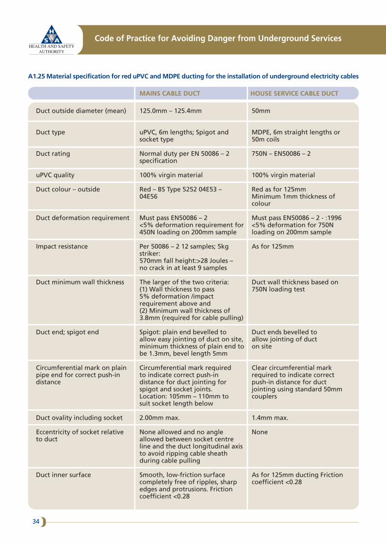
A1.25 Material specification for red uPVC and MDPE ducting for the installation of underground electricity cables
Code of Practice for Avoiding Danger from Underground Services
34
Duct outside diameter (mean)
Duct type
Duct rating
uPVC quality
Duct colour – outside
Duct deformation requirement
Impact resistance
Duct minimum wall thickness
Duct end; spigot end
Circumferential mark on plainpipe end for correct push-indistance
Duct ovality including socket
Eccentricity of socket relative to duct
Duct inner surface
125.0mm – 125.4mm
uPVC, 6m lengths; Spigot andsocket type
Normal duty per EN 50086 – 2specification
100% virgin material
Red – BS Type 5252 04E53 – 04E56
Must pass EN50086 – 2<5% deformation requirement for450N loading on 200mm sample
Per 50086 – 2 12 samples; 5kgstriker:570mm fall height:>28 Joules – no crack in at least 9 samples
The larger of the two criteria: (1) Wall thickness to pass 5% deformation /impactrequirement above and(2) Minimum wall thickness of3.8mm (required for cable pulling)
Spigot: plain end bevelled toallow easy jointing of duct on site,minimum thickness of plain end tobe 1.3mm, bevel length 5mm
Circumferential mark required to indicate correct push-indistance for duct jointing forspigot and socket joints.Location: 105mm – 110mm to suit socket length below
2.00mm max.
None allowed and no angleallowed between socket centreline and the duct longitudinal axisto avoid ripping cable sheathduring cable pulling
Smooth, low-friction surfacecompletely free of ripples, sharpedges and protrusions. Frictioncoefficient <0.28
50mm
MDPE, 6m straight lengths or50m coils
750N – EN50086 – 2
100% virgin material
Red as for 125mmMinimum 1mm thickness ofcolour
Must pass EN50086 – 2 - :1996<5% deformation for 750Nloading on 200mm sample
As for 125mm
Duct wall thickness based on750N loading test
Duct ends bevelled to allow jointing of duct on site
Clear circumferential markrequired to indicate correctpush-in distance for ductjointing using standard 50mmcouplers
1.4mm max.
None
As for 125mm ducting Frictioncoefficient <0.28
MAINS CABLE DUCT HOUSE SERVICE CABLE DUCT
35
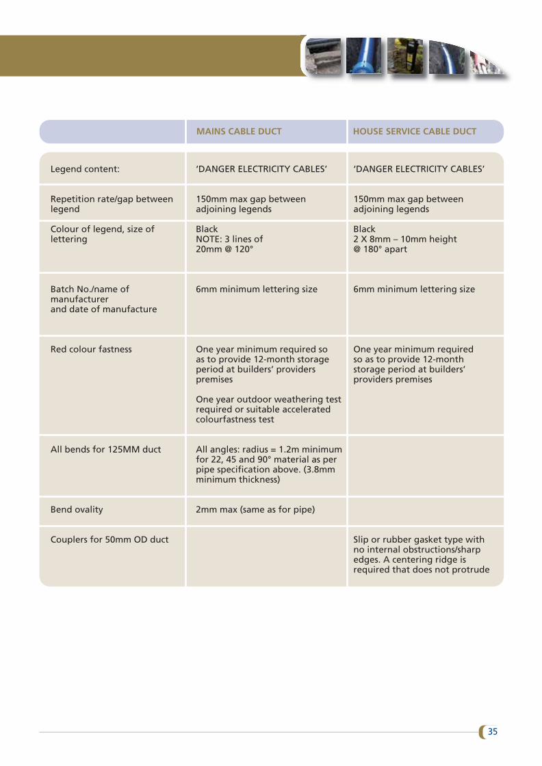
Legend content:
Repetition rate/gap betweenlegend
Colour of legend, size oflettering
Batch No./name ofmanufacturerand date of manufacture
Red colour fastness
All bends for 125MM duct
Bend ovality
Couplers for 50mm OD duct
‘DANGER ELECTRICITY CABLES’
150mm max gap betweenadjoining legends
BlackNOTE: 3 lines of20mm @ 120°
6mm minimum lettering size
One year minimum required so as to provide 12-month storageperiod at builders’ providerspremises
One year outdoor weathering testrequired or suitable acceleratedcolourfastness test
All angles: radius = 1.2m minimumfor 22, 45 and 90° material as perpipe specification above. (3.8mmminimum thickness)
2mm max (same as for pipe)
‘DANGER ELECTRICITY CABLES’
150mm max gap betweenadjoining legends
Black2 X 8mm – 10mm height@ 180° apart
6mm minimum lettering size
One year minimum requiredso as to provide 12-monthstorage period at builders’ providers premises
Slip or rubber gasket type withno internal obstructions/sharpedges. A centering ridge isrequired that does not protrude
MAINS CABLE DUCT HOUSE SERVICE CABLE DUCT
Appendix 2: Gas pipelines
A.2.1 General requirements
Natural gas, which is highly flammable, is transported in a network of polyethylene and steel pipes at pressuresup to 85 bar. Damage to a gas main may result in large volumes of gas escaping into the atmosphere in anuncontrolled manner. Even if there is no smell of gas, any damage to a gas pipe should be reported, regardlessof how minor the damage might appear. An immediate repair may prevent an accident at a later stage due toa stress failure at the location of the original minor damage.
Most underground gas pipes are the property of gas transmission or distribution companies. One notableexception to this is private ‘metered’ estates, which may have gas piped to users from a bulk liquefied petroleumgas (LPG) tank. In such cases, the service provider should be able to supply the requisite information. Estates thatcomprise privately owned dwellings do not normally have a site owner or manager. In such circumstancesinformation may be obtained from the LPG supplier, whose name and telephone number (manned twenty-four hours each day) should be displayed in the bulk storage vessel compound. The risks associated with leakingLPG are even greater than those associated with leaking natural gas as it is heavier than air and does notdisperse as readily. In addition, it can travel great distances below ground level before accumulating at lowlevels.
All personnel who are involved in carrying out work near underground gas plant should observe the specificrequirements set out by the gas network operator. Network operator staff or representatives must have accessto underground and above-ground plant at all times. Unauthorised repairs to gas pipes must not be made. Ifthere is any doubt about the need to carry out repairs, the advice of the relevant gas network operator companyshould be sought.
Natural gas pipeline infrastructure in Ireland may be categorised as transmission pipeline or distributionpipeline.
A.2.2 Transmission pipelines
See Section A.2.4 for requirements common to both transmission and distribution pipelines:
Transmission pipelines operate at internal pressures between 7 bar and 85 bar. They are the primary spinepipelines that transfer gas throughout the country. They are constructed from steel with a black or concretecoating and may have marker posts at intervals along their length, particularly at field boundaries and roadcrossings.
• Transmission gas pipelines are generally between 150mm and 1000mm in diameter and coated in yellowand/or encased in black wrapping.
If a transmission main is identified within ten metres of any intended excavations (including vertical boring),then work must not proceed until the gas network operator has been consulted. See greater distancerequirements in relation to special operations in Section A.2.2.7.
Code of Practice for Avoiding Danger from Underground Services
36
The network operator should be consulted before commencement of excavation works within ten metres of anylarge pressure reduction plant, i.e. above-ground gas installation (AGI) or district regulator installation (DRI),as shown on the map records.
Gas Networks Ireland: ‘Dial Before You Dig’ enquiries: 1850 427 747.
A.2.2.1 Locating the transmission pipeline: The gas network operator should arrange for locating and markingout of the pipeline as well as for the supervision of the digging of any trial holes necessary to confirm theposition of the pipeline.
A.2.2.2 Orientation and location: Where a new service is to cross either above or below an existing transmissiongas pipeline, the normal minimum distance between the outside of the pipeline and the service to be installedshould be 600mm.
In special circumstances this distance may be reduced at the discretion of the network operator’s engineer. Atsuch crossings both the pipeline and the new service should be suitably supported to prevent any futuresettlement and the back-fill should be packed and consolidated to the satisfaction of the network operator’sengineer (see Section A2.2.6).
As a general rule, no new service should be laid parallel to an existing transmission gas pipeline. However, inspecial circumstances (e.g. motorways) a new service may be laid parallel to an existing pipeline provided thatthere is adequate clearance (normally 600mm) between them and provided that the service is not laid in paralleleither directly above or below the existing pipeline.
A.2.2.3 Cathodic protection: Transmission gas pipelines are cathodically protected. Where a new service is to belaid and similarly protected, the network operator (once notified) is obliged to carry out interaction tests todetermine whether its system is adversely affected.
A.2.2.4 Pressure testing: Hydraulic testing of other installations (e.g. high-pressure water mains) should nottake place within eight metres of an existing transmission gas pipeline unless precautions have been taken tomitigate the effects of a possible burst. These precautions may include the use of pre-installation tested pipe,sleeving, barriers etc. as agreed with the gas network operator’s engineer.
A.2.2.5 Excavation: Where it is necessary to excavate below a transmission gas pipeline, the pipeline mustduring all stages of the operation be supported to the satisfaction of the gas network operator’s engineer. Oncompletion, permanent supports should, if necessary, be constructed to avoid future settlement.
Mechanical excavation by powered tools is not permitted within a distance of three metres and the use ofhand-held power-assisted tools should not be permitted within 1.5 metres of a transmission gas pipeline orassociated equipment. Consideration may be given to a relaxation of these limits provided that prior notice ofthe excavating methods to be used is given to the network operator and the safeguards to be employed areagreed between all parties.
To avoid damage during construction work, exposed gas pipelines must be protected as directed by the networkoperator’s engineer.
37
A.2.2.6 Back-filling: Parties responsible for the new works should give the gas network operator at least forty-eight hours notice of their intention to back-fill under, over or near an existing transmission pipeline. The gasnetwork operator’s representative must be in attendance during all back-filling operations and advise on thesuitability and degree of consolidation of back-fill material around the pipeline. Any damage to the coating ofthe transmission gas pipeline, even if minor in extent, must be brought to the notice of the gas networkoperator so that any necessary repairs may be carried out before back-filling is completed. The gas networkoperator must make repairs as efficiently and as quickly as practicable.
A.2.2.7 Special operations: Explosives must not be used within 400 metres of gas transmission pipelines (30metres for distribution pipelines), without prior consultation with the gas network operator.
Piling and/or demolition works; the gas network operator must be consulted before any piling is carried outwithin 15 metres of an existing gas pipeline.
A.2.3 Distribution pipelines
Distribution pipelines operate at internal pressures less than 7 bar. They transmit gas at medium pressure (morethan 100 mbar and less than 7 bar) or low pressure (less than or equal to 100 mbar) and are mainly constructedfrom polyethylene (PE).
The pipeline is predominantly yellow in colour, but may have brown or black stripes. Mains gas pipelines usuallyrun parallel to property in the footpath, grass verge or road and range in size from 63mm to 315mm diameter.Service gas pipelines are connected to mains and run to a meter position at the property and range in size from20mm to 63mm diameter.
Note: There is a limited use of steel pipes in areas like bridges or where only shallow depths can be achievedGas Network Ireland: ‘Dial Before You Dig’ enquiries: 1850 427 747.
A.2.4 Requirements common to both transmission and distribution pipelinesRequirements under A.2.2 take precedence in the vicinity of transmission pipelines.
A safe system of work must always be followed – refer to Section 6.
Work involving piling, demolition, directional drilling, use of explosives or hot works may require specialprecautions to be taken.
A.2.4.1 Planning and obtaining utility maps: It is imperative that early contact is made with the gas networkoperator to obtain a gas network map and that this is made available to operatives on site for the duration ofany works. The responsible person should ensure that operatives on site understand the map and are continuallyinformed of any updates.
A.2.4.2 Identifying distribution mains and services: Where the presence of gas mains which operate at pressuresgreater than 7 bar is indicated (i.e. a transmission pipeline), the gas network operator must be consulted beforework begins.
Code of Practice for Avoiding Danger from Underground Services
38
The depth of cover from gas distribution mains laid in a roadway is normally 750mm. For those laid in a footwayit is normally 600mm. The depth of cover for gas service connections is normally 450mm in both roadways andfootpaths. However, at entry points to buildings, the depth of cover for a service connection may be 375mm.It is important to note that these depths are merely a guide and pipes may be found at shallower levels. Forexample, pipes such as those passing over cellars or in the vicinity of bridge structures may have been laid atshallower levels, or the depth of cover may have been reduced after the pipe was installed due to other workssuch as road alterations being carried out in the area.
Polyethylene mains may have been inserted into redundant cast iron or ductile iron gas mains. Marker tilesmay have been used above gas pipes, for example where they have been laid at a shallow depth in bridgestructures or above cellars.
Polyethylene mains may have a coloured plastic marker tape above them. The presence of gas plant may alsobe indicated by valve boxes and marker posts. Marker posts/plates are sometimes used to indicate the positionand size of valves or siphons on gas mains. However, such markers may have been disturbed and should not berelied upon as an accurate indicator of pipe position.
Plans do not normally show the position of service connections. Their existence should be assumed and it maybe possible to estimate the probable line of the service connection pipe from the gas meter boxes/cabinets,house entry points, service risers and gas valve covers, or from the point of entry to the premises. Older buildingsmay have no visible signs of a service, as the service may run directly into the building underground, with themeter fitted internally. In these cases a check should be made inside the building to identify the service routeto the meter position.
A.2.4.3 Safe digging practices and avoidance of pipeline impact:
(i) Excavations near gas pipelines: Where gas pipes cross, or are parallel and close to excavations, changes inback-fill may cause differential ground settlement and increased stress in the pipe. Where pipes are parallel andclose to excavations, the degree of risk depends on the depth of the excavation, the distance of the pipe fromthe excavation and the type of soil. If an excavation is likely to affect support for a gas pipe, the gas networkoperator should be consulted. If gas pipeline or gas plant relocation is necessary, the gas network operatorshould be contacted to arrange diversion before work begins.
The network operator should be consulted before commencement of excavation works within ten metres of anylarge pressure reduction plant, i.e. above-ground gas installation (AGI) or district regulator installation (DRI),as shown on the map records.
(ii) Pipe locators: Before excavation, locator devices that use radio frequency detection or transmitter-receivertechnology should be used to help locate metallic gas pipes. However, it should be noted that the majority ofdistribution gas pipelines are made of polyethylene and cannot be traced by such devices. This factor furtherreinforces the importance of using plans and safe digging practices.
(iii) Road construction work: If road construction work is being carried out close to the top of a gas pipe, thegas network operator should be consulted to give guidance on specific precautions to be taken.
(iv) Mechanical excavators: Mechanical excavators pose the highest risk and should not be used within threemetres of a gas transmission pipeline or within 0.5 metres of a gas distribution pipeline.
39
Gas pipes may have projections such as valve housings, siphons and stand pipes and these will not be shown onthe plans. In order to allow for these projections, mechanical excavators should not be used within the distancesidentified above.
(v) Hand-held power tools: Hand-held power tools may damage buried gas pipes and they should be used withcare until the exact position of an underground pipe has been determined. They should not be permitted within1.5 metres of a transmission gas pipeline or associated equipment.
(vi) Hand digging: Plastic gas pipes should be located by hand digging before mechanical excavation begins. Itmay also be necessary to use this method to locate metallic pipes if their position has not already beendetermined by a pipe-locating device. The use of hand digging is particularly important for service connectionpipes, which will not be marked on plans. The recommended method is to dig a trial trench along the road nearthe kerb, or on the footpath, where the depth of the service connection pipes is likely to be at its shallowest.Once the position and depth of the pipes have been determined, work may proceed.
(vii) Special operations: Explosives must not be used within 400 metres of a gas transmission pipeline (30 metresfor a distribution pipeline), without prior consultation with the gas network operator.
Piling and/or demolition works; the gas network operator must be consulted before any piling is carried outwithin 15 metres of an existing gas pipeline.
(viii) Crossing points: In cases where heavy plant and other machinery may have to cross the line of a gas pipeduring construction work, the number of crossing points should be kept to a minimum. These points should beclearly indicated and crossings at other positions along the line of the pipe should be prevented. Where the pipeis not adequately protected by an existing road, crossing points should be suitably reinforced with sleepers,steel plates or a specially constructed reinforced concrete raft. The gas network operator will advise on thetype of reinforcement necessary.
(ix) Hot work: If hot work, such as welding or laying hot bitumen, is to be carried out adjacent to gas pipes orinstallations and there is any risk of that work affecting the integrity of a pipe or pipe surface, the gas networkoperator should be consulted. Gas pipelines, their protective coating and above-ground plant must be protectedagainst damage by heat transfer, sparks or naked flames.
(x) Uncovering a gas pipe during excavation: If a gas pipe with a damaged wrapping is uncovered duringexcavation work, the gas network operator should be informed so that repairs may be carried out to preventfuture corrosion and leakage.
Pipe restraints or thrust blocks close to gas mains should never be removed.
(xi) Positioning of structures in the vicinity of gas pipelines: Manholes, chambers or other structures should notbe built over, around or under a gas pipeline or gas plant. Work should not be carried out that results in areduction of cover or other protective measures without prior consultation with the gas network operator.
(xii) Use of concrete or other hard material: Concrete or other hard material should never be placed or leftunder or near any gas pipe as this could cause pipe fracture at a later date. Concrete back-fill or slabbing shouldnot be used within 300mm of a gas pipe or associated connections.
Code of Practice for Avoiding Danger from Underground Services
40
(xiii) Back-filling distribution pipelines after excavation work: If a gas pipe is uncovered during excavationwork, the back-fill should be adequately compacted, particularly beneath the pipe itself. This measure isdesigned to prevent any settlement that could subsequently damage the pipe. The back-fill should comprise finematerial or sand and should not contain stones, bricks, lumps of concrete etc. It should be suitably compactedto give comparable support and protection to that provided before excavation. Power compaction should nottake place until a 200mm cover of selected fine-fill is in place.
Any protective measures, such as marker tape or marker tiles, should be reinstated.
A.2.5 In the event of damage to a gas pipeline
In the event of damage to a gas pipeline, work should cease immediately and the following precautionarymeasures should be taken:
• Do not turn any electrical switches on or off (e.g. ignition switches).
• Do not operate any plant or equipment.
• Move people away from and upwind of the affected area.
• Restrict employee and public access to the affected area.
•• Prevent smoking, the use of naked flames, the use of mobile phones and other ignition sources in the vicinityof the leak.
• Report the leak/damage immediately to the gas network operator emergency number.
• Provide accurate information on your location and the nature of the incident.
• Do not attempt to repair the damage.
• Do not cover up a damaged main or service pipeline, this may lead to the gas travelling through ducts,sewers, chambers or voids and potentially building up inside a premises or confined space.
• Do not turn off any gas valves in the road or footpath (you may be causing further problems by doing so).
• Assist the gas network operator emergency personnel as required to safeguard life and property.
It is critical that any damage to gas pipelines, even if the pipe does not appear to be leaking, is reported to thegas network operator.
Gas Networks Ireland Emergency Number: 1850 20 50 50.
41
Appendix 3: Water pipes and sewers
The appropriate records office should be contacted and the location of all sewers, water mains, kiosks, metersand wiring/cable ducting should be determined before any excavation work begins. The location of mains ondrawings should be taken as approximate. In general, if there is a sewer or water main (diameter greater thanor equal to 300mm) in the vicinity, then the appropriate service provider engineer should be contacted in orderto co-ordinate the excavation work.
Mains runs must be marked out before excavation begins.
During excavation, in addition to the safe digging practices previously outlined in this COP, the followingprecautions should be taken:
• If a water main spans a road cutting or similar excavation, then the main must be adequately braced so thatno movement takes place.
• If a pipe anchor is exposed, then excavation must cease and the appropriate engineer must be contacted.
• Fittings (ferrules, air valves and so on) should not be interfered with.
• Excavation in the vicinity of mains must be carried out by hand in order to avoid damage to the pipe.
If the pipe in question is a high-pressure trunk main, then the following additional precautions must be adheredto:
• No personnel should be positioned inside the trench while the mechanical excavator is operating, in case ahigh-pressure break occurs.
• Continuous inspections are essential in order to determine whether the next excavation level is clear.
• If any leak is discovered, then the service provider must be contacted immediately and the area sealed offto keep it safe and to prevent members of the public from gaining access.
In relation to the installation of new services, in particular gas or electricity services near existing water or sewermains, the following additional precautions are recommended:
• No new service should be laid above or along the length of an existing water main or sewer.
• Where the new services have to cross a water main or sewer this should be done at right angles as far as isreasonably practical.
• New installations should always avoid blocking access to valves, flanges etc., where subsequent maintenancemay be required.
• Where a new service is likely to limit access for future maintenance to the service, contact with the relevantlocal authority should be made in advance of the works.
Code of Practice for Avoiding Danger from Underground Services
42
Appendix 4: Telecommunications cables
Pre-planned work
A4.1 The cable providers should be consulted wherever possible and all relevant plans obtained. (Note: Whilemost telecommunications cables are owned by Eir, many underground cables are the property of localauthorities or private companies.)
A4.2 The representation of underground cables on plans may vary depending on the density of theunderground networks (i.e. the number of cables running in close proximity), the scale of the plans and localhistorical recording conventions. Advice for interpretation should be sought from the issuing office.
Cable-locating devices
A4.3 While using cable-locating devices to locate underground telecommunications cables you must understandthe limitations of each operating mode and the need to use both power and radio modes to locate theunderground service.
A4.4 Even where a cable-locating device does not give a positive reading, there may still be cables present.Cable-locating devices will not detect fibre optic cables.
A4.5 If a cable that is recorded on a plan cannot be located, appropriate assistance or advice should be sought.If digging has to start before such assistance or advice has been obtained, extra care should be taken to avoiddamaging the cable.
Safe digging practices
A4.6 In the vast majority of cases there will be no permanent surface markers to indicate the presence of aburied cable. Frequently, however, the presence of marked communications manhole covers or other streetfurniture will indicate the presence and general run of telecommunications cables. Even if no cables are shownon plans or detected by a cable-locating device, a close watch should be kept during excavation for any signsthat might indicate their presence.
A4.7 Underground telecommunications cables are normally laid at adequate and sufficient depth in trenchesbut depths should never be assumed. Cables must not be laid just below the surface.
If in doubt the network provider should be contacted.
A4.8 Cables may have been laid in any of a number of different ways. In urban areas steel wire armouredtelecommunications cable can be found buried directly in the ground or in ducting of various colours rangingin size from 25 to 100mm, Telecommunications cable may also be found in earthenware or concrete pipes.Occasionally they may be encased in steel pipes. Coloured plastic marker tape may be laid above the ducting.
43
A4.9 During digging work, a careful watch should be kept for evidence of cables and repeat checks should bemade with a cable-locating device to determine more precisely the position of any cable.
A4.10 Any damage to a telecommunications cable should be reported immediately to the cable service provider.No work which involves back-filling around the damaged cable should be undertaken until the service providerhas investigated its condition and carried out any required repairs.
A4.11 Recommended standards for new underground telecommunications cable installations on newdevelopments and in existing roads and streets are to be adhered to. However, local conditions may dictate thatthese depths vary, particularly where pipes and cables cross or where underground structures or otherobstructions are crossed. The clearance in all directions between underground telecommunications duct andother services should be approximately 300mm. With the exception of crossing points, services should not belaid above telecommunications duct. This is because, following installation, continuous access will be requiredfor the repair of faults.
A4.12 While there is no agreed industry standard in Ireland governing the relative lateral positioning of servicesin footpaths, general guidance may be found in the UK publication National Joint Utilities Group (NJUG)Guidelines on the Positioning and Colour Coding of Underground Utilities’ Apparatus 2013. Efforts should bemade to comply with this standard, or other equivalent standards of good practice in relation to the positioningof new installations.
Code of Practice for Avoiding Danger from Underground Services
44
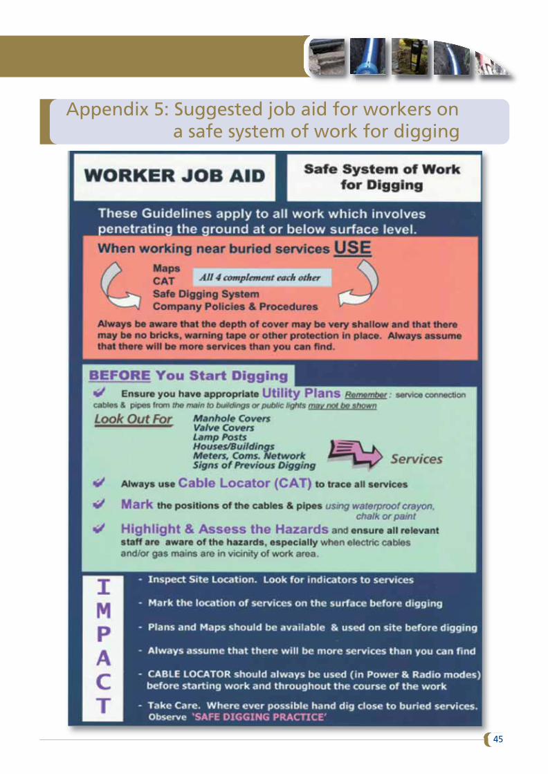
Appendix 5: Suggested job aid for workers ona safe system of work for digging
45
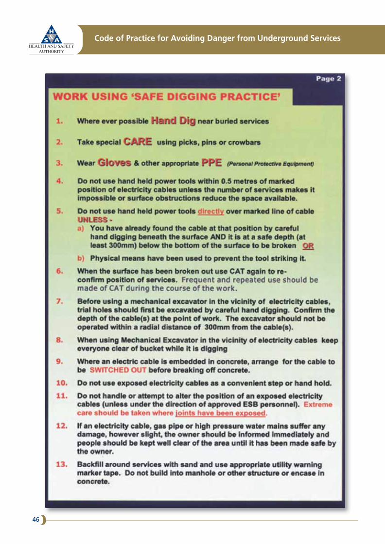
Code of Practice for Avoiding Danger from Underground Services
46
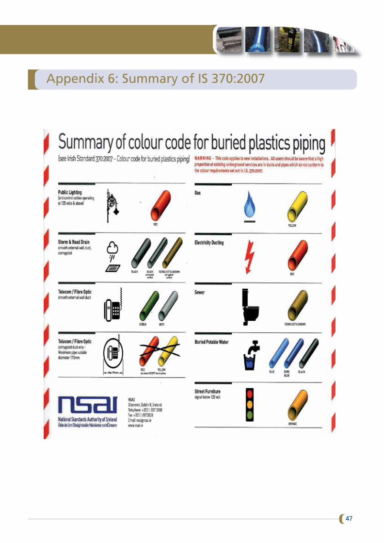
Appendix 6: Summary of IS 370:2007
47
Appendix 7: Useful contacts
ESB Networks
For all emergencies, including any damage to underground electricity cables or plant, call 1850 372 999 (or ifyou are phoning from outside Republic of Ireland 00 353 21 2382410).
For other ESB Networks queries, including general queries in relation to underground electricity cables,overhead lines, new connections etc., call 1850 372 757, email: [email protected] or see area office addresses at:www.esb.ie/esbnetworks.
For all ESB Networks map records (underground cables, overhead lines and other plant):
(a) Write to Central Site, ESB Networks, St Margarets Road, Finglas, Dublin 11.(b) Send a fax to 01 638 8169.(c) Email: [email protected](d) Register for access to electronic map records (make arrangements via (a) or (c) above).
All map requests should include the following information: (i) a site map/area map with geographic reference,(ii) a return postal address and (iii) a telephone contact number.
Map records that have been requested as set out above will be delivered by post. Allow up to ten days fordelivery.
ESB Networks provides a range of safety material, such as booklets, posters, cab stickers and DVDs addressingthe issue of electrical safety. This material is free and may be obtained by calling 1850 372 757 or by emailrequest to: [email protected]. Some of this material is also available for free download from:www.esb.ie/esbnetworks.
Gas Networks Ireland
24 Hour Emergency Service: 1850 20 50 50
Gas Networks Ireland ‘Dial Before You Dig’: 1850 427 747
Gas Networks Ireland Transmission Enquiries: 021 453 4562
Email: [email protected]
EIR
‘Click Before You Dig’
http://support.eir.ie/article/clickbeforeyoudig
Eir Home: 1800 773 729
Code of Practice for Avoiding Danger from Underground Services
48
ISBN 978-1-84496-226-6 HSA0447
Healthy, safe
and productive
lives
HEALTH AND SAFETYAUTHORITY
Tel. 1890 289 389
International callers00353 1 6147000Fax. (01) 6147020
www.hsa.ie
HSA UNDERGROUND COVER 5/24/16 10:54 AM Page 1