Cloud Computing for Optimization: Foundations, Applications ...
468
Studies in Big Data 39 Bhabani Shankar Prasad Mishra Himansu Das Satchidananda Dehuri Alok Kumar Jagadev Editors Cloud Computing for Optimization: Foundations, Applications, and Challenges
-
Upload
khangminh22 -
Category
Documents
-
view
7 -
download
0
Transcript of Cloud Computing for Optimization: Foundations, Applications ...

Studies in Big Data 39
Bhabani Shankar Prasad MishraHimansu DasSatchidananda DehuriAlok Kumar Jagadev Editors
Cloud Computing for Optimization: Foundations, Applications, and Challenges

Studies in Big Data
Volume 39
Series editor
Janusz Kacprzyk, Polish Academy of Sciences, Warsaw, Polande-mail: [email protected]
The series “Studies in Big Data” (SBD) publishes new developments and advancesin the various areas of Big Data- quickly and with a high quality. The intent is tocover the theory, research, development, and applications of Big Data, as embeddedin the fields of engineering, computer science, physics, economics and life sciences.The books of the series refer to the analysis and understanding of large, complex,and/or distributed data sets generated from recent digital sources coming fromsensors or other physical instruments as well as simulations, crowd sourcing, socialnetworks or other internet transactions, such as emails or video click streams andother. The series contains monographs, lecture notes and edited volumes in BigData spanning the areas of computational intelligence incl. neural networks,evolutionary computation, soft computing, fuzzy systems, as well as artificialintelligence, data mining, modern statistics and Operations research, as well asself-organizing systems. Of particular value to both the contributors and thereadership are the short publication timeframe and the world-wide distribution,which enable both wide and rapid dissemination of research output.
More information about this series at http://www.springer.com/series/11970

Bhabani Shankar Prasad MishraHimansu Das • Satchidananda DehuriAlok Kumar JagadevEditors
Cloud Computingfor Optimization:Foundations, Applications,and Challenges
123

EditorsBhabani Shankar Prasad MishraSchool of Computer EngineeringKIIT UniversityBhubaneswar, OdishaIndia
Himansu DasSchool of Computer EngineeringKIIT UniversityBhubaneswar, OdishaIndia
Satchidananda DehuriDepartment of Informationand Communication Technology
Fakir Mohan UniversityBalasore, OdishaIndia
Alok Kumar JagadevSchool of Computer EngineeringKIIT UniversityBhubaneswar, OdishaIndia
ISSN 2197-6503 ISSN 2197-6511 (electronic)Studies in Big DataISBN 978-3-319-73675-4 ISBN 978-3-319-73676-1 (eBook)https://doi.org/10.1007/978-3-319-73676-1
Library of Congress Control Number: 2017962978
© Springer International Publishing AG, part of Springer Nature 2018, corrected publication 2018This work is subject to copyright. All rights are reserved by the Publisher, whether the whole or partof the material is concerned, specifically the rights of translation, reprinting, reuse of illustrations,recitation, broadcasting, reproduction on microfilms or in any other physical way, and transmissionor information storage and retrieval, electronic adaptation, computer software, or by similar or dissimilarmethodology now known or hereafter developed.The use of general descriptive names, registered names, trademarks, service marks, etc. in thispublication does not imply, even in the absence of a specific statement, that such names are exempt fromthe relevant protective laws and regulations and therefore free for general use.The publisher, the authors and the editors are safe to assume that the advice and information in thisbook are believed to be true and accurate at the date of publication. Neither the publisher nor theauthors or the editors give a warranty, express or implied, with respect to the material contained herein orfor any errors or omissions that may have been made. The publisher remains neutral with regard tojurisdictional claims in published maps and institutional affiliations.
Printed on acid-free paper
This Springer imprint is published by the registered company Springer International Publishing AG partof Springer NatureThe registered company address is: Gewerbestrasse 11, 6330 Cham, Switzerland

Bhabani Shankar Prasad Mishra dedicatesthis work to his parents: Gouri PrasadMishra and Swarnalata Kar, wife:Dr. Subhashree Mishra and kids: PunyeshMishra and Anwesh Mishra.
Himansu Das dedicates this work to his wifeSwagatika Das for her love andencouragement and also to his parents—Jogendra Das and Suprava Das, for theirendless support and guidance.
Satchidananda Dehuri dedicates this work tohis wife: Dr. Lopamudra Pradhan, and kids:Rishna Dehuri and Khushyansei Dehuri, alsohis mother: Kuntala Dehuri, who has alwaysbeen there for him.
Alok Kumar Jagadev dedicates this work tohis wife and kids.

Preface
A computing utility has been a dream of computer scientists, engineers, andindustry luminaries for several decades. With a utility model of computing, anapplication can start small and grow to be big enough overnight. This democrati-zation of computing means that any application has the potential to scale. Hence, anemerging area in the name of cloud computing has become a significant technologytrend in current era. It refers to applications and services that run on a distributednetwork using virtualized resources and accessed by common internet protocols andnetworking standards. It is distinguished by the notion that resources are virtual andlimitless and that details of the physical systems on which software runs areabstracted from the user. Moreover, cost saving, access to greater computingresources, high availability, and scalability are the key features of cloud whichattracted people. Cloud provides subscription-based access to infrastructure(resources, storage), platforms, and applications. It provides services in the form ofIaaS (Infrastructure as a Service), PaaS (Platform as a Service), and SaaS (Softwareas a Service).
The purpose of this volume entitled “Cloud Computing for Optimization:Foundations, Applications, and Challenges” is to make the interested readers/researchers about the practice of using a network of remote servers hosted on theinternet to store, manage, and process data, rather than local server or a personalcomputer while solving highly complex nonlinear optimization problem. In addi-tion, this volume also magnetizes and sensitizes the readers and researchers in thearea of cloud computing by presenting the recent advances in the fields of cloud,and also the tools and techniques.
To achieve the objectives, this book includes sixteen chapters contributed bypromising authors.
In Chap. 1, Nayak et al. have highlighted a detail survey on the applicability ofnature-inspired algorithms in various cloud computing problems. Additionally,some future research directions of cloud computing and other applications areas arealso discussed. Nowadays, many organizations are using cloud computing suc-cessfully in their domain of interest, and thereby popularity is growing; so becauseof this, there has been a significant increase in the consumption of resource by
vii

different data centers. Hence, urgent attention is required to develop optimizationtechniques for saving resource consumption without compromising the perfor-mance. These solutions would not only help in reducing the excessive resourceallocation but would also reduce the costs without much compromise on SLAviolations thereby benefitting the cloud service providers.
In Chap. 2, authors discuss the optimization of resource allocation so as toprovide cost benefits to the cloud service users and providers. Radhakrishnan andSaravanan in Chap. 3 illustrate the resource allocation in cloud IaaS. How tooptimize the VM instances allocation strategy using the novel ANN model has beenpresented. Further, several issues in implementing the resource allocation are alsodiscussed. Cloud federation has become a consolidated paradigm in which set ofcooperative service providers share their unused computing resources with othermembers of federation to gain some extra revenue.
Chapter 4 gives emphasis on different approaches for cloud federation formationbased on game theory and also highlights the importance of trust (soft security) infederated cloud environment. Different models for cloud federation formation usingcoalition game and the role of a cloud service broker in cloud federation are alsopresented in this chapter. The major components of resource management systemsare resource provisioning and scheduling; in Chap. 5, author discusses the essentialperceptions behind the cloud resource provisioning strategies. Then, the author hasproposed QoS parameters based resource provisioning strategies for workflowapplications in cloud computing environment.
Ritesh in Chap. 6 presents consolidation in cloud environment using optimiza-tion techniques. Author has highlighted that in cloud computing, moving large sizeVM from one data center to other data center over wide area network is challengingtask. In Chap. 7, Rao et al. describe different issues and the performances over thevirtual machine migration in cloud computing environment. Specifically, authorsmake the reader to learn about the architectural design of working and storagestructures of a key virtualization technology, VMware.
In Chap. 8, Dash et al. present a survey on the various frameworks to developSLA-based security metrics in addition to different security attributes and possiblethreats in cloud. Along the line in Chap. 9, to maintain security and privacy at cloudsystem, Sengupta presents a dimension reduction based intrusion detection systemon a cloud server. Deshpande et al. in Chap. 10 have discussed methods andtechnologies that form the digital guardians of our connected world. In addition, itadapts a case study based approach to understand the current scenario and bestpractices with respect to cloud security. Cook et al. in Chap. 11 pursue two mainworks: i) analyze the different components of cloud computing and IoT andii) present security and privacy problems that these systems face. Developingcloud-based IDS that can capture suspicious activity or threats and prevent attacksand data leakage from both the inside and outside the cloud is the topic of interest inChap. 13.
In Chap. 12, Chakrabarty et al. have proposed a hybrid model of IoT infras-tructure to overcome some of the issues of existing infrastructure. This model willbe able to transfer data reliably and systematically with low latency, less bandwidth,
viii Preface

heterogeneity, and maintaining the Quality of Service (QoS) befittingly.In Chap. 14, Barik et al. discuss the concept of edge-assisted cloud computingand its relation to Fog-of-things. Further, they have also proposed application-specific architectures GeoFog and Fog2Fog that are flexible and user orientated.In Chap. 15, Limbasiya and Das present a secure smart vehicle cloud computingsystem for smart cities which is useful to identify the vehicle user in establishing acommunication session to share a remarkable information. In Chap. 16, Sahoo et al.have presented various techniques related to cloud-based transcoding systemincluding video transcoding architecture and performance metrics to quantify cloudtranscoding system.
Topics presented in each chapter of this book are unique to this book and arebased on unpublished work of contributed authors. In editing this book, weattempted to bring into the discussion all the new trends, experiments, and productsthat have made cloud computing such a dynamic area. We believe the book is readyto serve as a reference for larger audience such as system architects, practitioners,developers, and researchers.
Bhubaneswar, Odisha, India Bhabani Shankar Prasad MishraBhubaneswar, Odisha, India Himansu DasBalasore, Odisha, India Satchidananda DehuriBhubaneswar, Odisha, India Alok Kumar Jagadev
Preface ix

Acknowledgements
The making of this edited book was like a journey that we had undertaken forseveral months. We wish to express our heartfelt gratitude to our families, friends,colleagues, and well-wishers for their constant support throughout this journey. Weexpress our gratitude to all the chapter contributors, who allowed us to quote theirremarks and work in this book.
We thank Santwana Sagnika for helping us in the process of compilation of thisedited volume.
We wish to acknowledge and appreciate Mrs. Varsha Prabakaran, ProjectCo-ordinator, Book Production of Springer and her entire team of associates whoproficiently guided us through the entire process of publication.
Finally, we offer our gratitude and prayer to the Almighty for giving us wisdomand guidance throughout our lives.
xi

Contents
1 Nature Inspired Optimizations in Cloud Computing:Applications and Challenges . . . . . . . . . . . . . . . . . . . . . . . . . . . . . . 1Janmenjoy Nayak, Bighnaraj Naik, A. K Jena, Rabindra K. Barikand Himansu Das
2 Resource Allocation in Cloud Computing Using OptimizationTechniques . . . . . . . . . . . . . . . . . . . . . . . . . . . . . . . . . . . . . . . . . . . 27Gopal Kirshna Shyam and Ila Chandrakar
3 Energy Aware Resource Allocation Model for IaaSOptimization . . . . . . . . . . . . . . . . . . . . . . . . . . . . . . . . . . . . . . . . . . 51A. Radhakrishnan and K. Saravanan
4 A Game Theoretic Model for Cloud Federation . . . . . . . . . . . . . . . 73Benay Kumar Ray, Sunirmal Khatua and Sarbani Roy
5 Resource Provisioning Strategy for Scientific Workflows in CloudComputing Environment . . . . . . . . . . . . . . . . . . . . . . . . . . . . . . . . . 99Rajni Aron
6 Consolidation in Cloud Environment Using OptimizationTechniques . . . . . . . . . . . . . . . . . . . . . . . . . . . . . . . . . . . . . . . . . . . 123Ritesh Patel
7 Virtual Machine Migration in Cloud Computing Performance,Issues and Optimization Methods . . . . . . . . . . . . . . . . . . . . . . . . . . 153Preethi P. S. Rao, R. D. Kaustubh, Mydhili K. Nairand S. Kumaraswamy
8 Frameworks to Develop SLA Based Security Metrics in CloudEnvironment . . . . . . . . . . . . . . . . . . . . . . . . . . . . . . . . . . . . . . . . . . 187Satya Ranjan Dash, Alo Sen, Pranab Kumar Bharimallaand Bhabani Shankar Prasad Mishra
xiii

9 Security and Privacy at Cloud System . . . . . . . . . . . . . . . . . . . . . . 207Nandita Sengupta
10 Optimization of Security as an Enabler for CloudServices and Applications . . . . . . . . . . . . . . . . . . . . . . . . . . . . . . . . 235Varun M. Deshpande, Mydhili K. Nair and Ayush Bihani
11 Internet of Cloud: Security and Privacy Issues . . . . . . . . . . . . . . . . 271Allan Cook, Michael Robinson, Mohamed Amine Ferrag,Leandros A. Maglaras, Ying He, Kevin Jones and Helge Janicke
12 A Novel Extended-Cloud Based Approach forInternet of Things . . . . . . . . . . . . . . . . . . . . . . . . . . . . . . . . . . . . . . 303Amitabha Chakrabarty, Tasnia Ashrafi Heya, Md. Arshad Hossain,Sayed Erfan Arefin and Kowshik Dipta Das Joy
13 Data Sources and Datasets for Cloud Intrusion DetectionModeling and Evaluation . . . . . . . . . . . . . . . . . . . . . . . . . . . . . . . . 333Abdulaziz Aldribi, Issa Traore and Belaid Moa
14 Fog Assisted Cloud Computing in Era of Big Data andInternet-of-Things: Systems, Architectures, and Applications . . . . . 367Rabindra K. Barik, Harishchandra Dubey, Chinmaya Misra,Debanjan Borthakur, Nicholas Constant, Sapana Ashok Sasane,Rakesh K. Lenka, Bhabani Shankar Prasad Mishra, Himansu Dasand Kunal Mankodiya
15 Secure Smart Vehicle Cloud Computing System forSmart Cities . . . . . . . . . . . . . . . . . . . . . . . . . . . . . . . . . . . . . . . . . . 395Trupil Limbasiya and Debasis Das
16 Video Transcoding Services in Cloud ComputingEnvironment . . . . . . . . . . . . . . . . . . . . . . . . . . . . . . . . . . . . . . . . . . 417Sampa Sahoo, Bibhudatta Sahoo and Ashok Kumar Turuk
17 Vehicular Clouds: A Survey and Future Directions . . . . . . . . . . . . 435Aida Ghazizadeh and Stephan Olariu
Erratum to: Secure Smart Vehicle Cloud Computing Systemfor Smart Cities . . . . . . . . . . . . . . . . . . . . . . . . . . . . . . . . . . . . . . . . . . . E1Trupil Limbasiya and Debasis Das
xiv Contents

Chapter 1Nature Inspired Optimizations in CloudComputing: Applications and Challenges
Janmenjoy Nayak, Bighnaraj Naik, A. K Jena,Rabindra K. Barik and Himansu Das
Abstract Cloud computing is an emerging area of research and is useful for all levelof users from end users to top business companies. There are several research areas ofcloud computing including load balancing, cost management, workflow schedulingetc., which has been the current research interest of researchers. To deal with suchproblems, some conventional methods are developed, which are not so effective.Since, last decade the use of nature inspired optimization in cloud computing is amajor area of concern. In this chapter, a detailed (yet brief) survey report on theapplicability of nature inspired algorithms in various cloud computing problemsis highlighted. The chapter aims at providing a detailed knowledge about natureinspired optimization algorithms and their use in the above mentioned problems ofcloud computing. Some future research directions of cloud computing and otherapplication areas are also discussed.
Keywords Cloud computing · Nature inspired optimization · Load balancingWork flow scheduling · Cost optimization
J. Nayak (B)Department of Computer Science and Engineering, Sri Sivani Collegeof Engineering, Srikakulam AP-532402, Indiae-mail: [email protected]
B. NaikDepartment of Computer Applications, Veer Surendra Sai Universityof Technology, Burla, Sambalpur 768018, Odisha, Indiae-mail: [email protected]
A. K. Jena · H. DasSchool of Computer Engineering, KIIT University, Bhubaneswar, Odisha, Indiae-mail: [email protected]
H. Dase-mail: [email protected]
R. K. BarikSchool of Computer Applications, KIIT University, Bhubaneswar, Odisha, Indiae-mail: [email protected]
© Springer International Publishing AG, part of Springer Nature 2018B. S. P. Mishra et al. (eds.), Cloud Computing for Optimization:Foundations, Applications, and Challenges, Studies in Big Data 39,https://doi.org/10.1007/978-3-319-73676-1_1
1

2 J. Nayak et al.
1.1 Introduction
With the satisfaction of some constraints, choosing the best solution among theavailable solution for solving a problem is optimization. Every optimization prob-lem is either minimization or maximization depending on the nature of the problem.In our real lives also, optimization is there at almost everywhere. While solvingengineering problems, the main objective of any form of optimization is to make ahealthy balance in between exploration and exploitation. The key elements of anyoptimization are constraints (obstacles), design variable and objective function (heartof optimization). There are various types of optimization algorithms depending onthe number of objective functions, types of objective functions, types of constraints,variable types and nature of optimization. Based on these criteria the optimizationmay be single objective/multiobjective/multobjective with pareto optimal solutions,local/global, smooth/non smooth, stochastic/deterministic, continuous/discrete, con-strained/unconstrained etc. The type of optimization may be varied, but for solvingany complex engineering problem it is very difficult to choose the exact optimizationmethod, which is suitable for that particular problem. With the successive growthof science and technology, the real life optimization problems are becoming morecomplex in nature. The earlier developed traditional optimization algorithms fail toexplicate the exact and real solution of the nonlinear and non differential problemsin large search space. The basic limitations to these algorithms are that they sufferfrom early convergence, use of complicated stochastic functions and higher orderderivatives in solving the equations. During last few decades, some popular optimiza-tion algorithms have already proved their effectiveness in resolving different real lifeproblems. In 1992, John Holland and Goldberg (1989) developed the most popularevolutionary algorithm called Genetic algorithm (GA). In comparison to the gradientsearch based methods, this algorithm performs better at local optima and having veryless chance to trap at local minima positions. Then in 1995, Kennedy and Eberhartdeveloped a stochastic swarm inspired technique called PSO. It is one of the popularstochastic and heuristic based search method on till date. Several variants of suchcategory physical, chemical and nature based algorithms are introduced during thelast decade. Although they have been used to resolve variety of complex problems,but still they suffers from some major issues such as convergence criteria, when theyare being single handedly applied. This is due to the extensive use of controllingparameters such as population size, environmental conditions, no. of iterations etc.Therefore, such variations have been developed by integrating some modificationsin the parameters or leading any form of hybridization of the algorithms to exploretheir capability to resolve complex problems. As, any major change in the parameterselection may change the functional aspects of the whole algorithm, so hybridizationis not the exact solution to solve these complex problems.
The applicability of nature inspired optimization algorithms have been a recentinterest among the researchers of various research community. The main reasonbehind the success rate of nature inspired and swarm based algorithms are havingthe capability to solve the NP-hard problems. To resolve the real life problems, some

1 Nature Inspired Optimizations in Cloud Computing: Applications and Challenges 3
of the earlier developed optimization techniques fails and the solutions of many reallife problems have been obtained by heat and trail methods. So, this is the basis for theresearchers to focus towards the development of some competitive optimization algo-rithms, which are efficient to resolve the complex problems.We all are surrounded bya beautiful scenario called nature and now-a-days most of the algorithms are naturedinspired algorithms,which are developedwith the concepts of nature. Nature is one ofthe amazing creations of God and has always been a great source of inspiration for allof us.Moreover, some biological systems are also responsible for the development ofnovel optimization algorithms. So, most of the nature inspired algorithms are basedon biological processes or the behavior of some of the nature’s creation (animals orinsects). Among the biological inspired algorithms, swarm based algorithms draw aspecial attention due to their larger applicability in various applications. Such algo-rithms are inspired by collective nature or behavior of some swarms such as bees,birds, frogs, fishes etc. Various examples of swarm based algorithmsmay be PSO [1],CS [2], Bat inspired algorithm (BA) [3], Bacteria foraging algorithm (BFA) [4], ABCoptimization [5], BCO [6], Wolf Search (WS) [7], Cat Swarm Optimization (CSO)[8], Firefly Algorithm (FA) [9], Monkey Search Algorithm (MSA) [10] etc. Thereare also some algorithms such as Atmosphere cloudmodel [11], Biogeography basedalgorithm [12], Brain storm optimization [13], Differential evolution algorithm [14],Japanese tree frogs calling [15], Flower pollination algorithm [16], Great salmon run[17], Group search optimizer [18], Human-Inspired Algorithm [19], Invasive weedoptimization [20], Paddy Field Algorithm [21], Queen-bee evolution [22], Termitecolony optimization [23] etc. which are nature inspired, bio inspired but not swarmbased. The concept behind all the swarm based algorithms is the collective behaviorand coordination among the swarm elements in an open environment. The advantageof using swarm based algorithms relies on information sharing between numerousagents, for which self organization, co-evolution and learning throughout the itera-tions possibly helps to provide high efficiency [24]. In fact, each of the individualswarm behaves and acts in a collective manner so that, the processes such as for-aging, reproduction, task allocation among themselves etc. is easier. Based on thelocally obtained information among each other, the necessary decisions are taken ina decentralized manner.
Since last two decades, the use of internet has become very popular among alllevels of users starting from business to automation industry at some cheaper price.More storage, access and processing of data with a vast utility makes the internetmore successful, which in turn responsible for the evolvement of a new era calledcloud computing. Cloud computing is basically dealt with hosting and delivering theservices over the network. Cloud services are more popular and demanding due totheir flexibility towards the use of resources as per user’s choice. Today, most of themajor IT industries are effectively using the cloud services to fulfill their require-ments for reshaping their business. Although the research of cloud computing ison hype, but some of its past issues are not yet resolved and some new issues arearising. Issues like provision of automated service, migration of virtual machines,server consolidation, effective management of energy, traffic management etc. needsurgent attention. However, some problems such as task scheduling, load balancing,

4 J. Nayak et al.
job/flow scheduling, resource optimization, resource allocation etc. are being solvedby various researchers with the use of optimization algorithms. Most of them haveused the nature inspired optimization techniques for efficiently solving those prob-lems. In this chapter, a detailed survey has been elucidated on the use of natureinspired optimization algorithms in different problems of cloud computing with theobservations, analytical discussions and suggestions for better improvement in theuse of resources.
The remainder of this chapter is organized as follows. Section1.2 providesthe overview of cloud computing and its architecture. Section1.3 describes vari-ous research challenges of cloud computing. Section1.4 discuses on analysis ofbroad areas of research on cloud computing using different optimization techniques,Sect. 1.5 focuses on future research challenges on cloud computing and finallySect. 1.6 concludes the chapter.
1.2 Cloud Computing: An Overview
Now-a-day’s cloud computing is an emerging technology used for hosting and deliv-ering cloud services over the internet throughout the globe and provides solution fordeploying on demand services to satisfy the requirement of service provider and theend users based on service level agreement (SLA). It is used both in commercial andscientific applications. Cloud computing allow users to access large amount of com-puting power services in virtualized environment. It provides on-demand, dynamic,scalable, flexible services to the end users on pay-as-you-use basis. Cloud providers[25] such asGoogle,Amazon,Microsoft etc. established their data centers for hostingcloud computing applications throughout the globe. These services [28] are calledInfrastructure as a service (IaaS), Platform as a service (PaaS), and Software as aService (SaaS). This cloud services are provided for different functionalities suchas computing services, network services, storage services etc. to the end user byemploying Service level Aggrements(SLA).
Many researchers have defined the cloud computingwith their own aspects. Buyyaet al. [25] have explained cloud computing as “It is a distributed and parallel comput-ing environment which consist of a huge collection of virtualized and inter-connectedcomputing resources that are dynamically presented and provisioned as one or moreunified computing resources based on SLA”.
TheNational Institute of Standards and Technology (NIST) [29] defined the cloudcomputing as “it is a pay-per-use model for enabling convenient, on-demand com-puting resource access to a common pool of computing resources that can be dynami-cally released and provisioned with service provider effort or negligible managementeffort”.

1 Nature Inspired Optimizations in Cloud Computing: Applications and Challenges 5
1.2.1 Layered Architecture of Cloud Computing
The cloud computing services are broadly classified based on the abstraction level ofability and service provided by the service provider. This abstraction level can alsorepresented as layered architecture in cloud environment. The layered architecture[27] of cloud computing can be represented by four layers such as data center layer,platform layer, infrastructure layer and application layer.
1.2.1.1 Datacenter Layer
This layer is accountable for managing physical resources such as servers, switches,routers, power supply, and cooling system etc. in the data center of the cloud environ-ment. All the resources are available and managed in data centers in a large numbersto provide services to the end user. The data center consists of large number ofphysical servers, connected through high speed devices such as router and switches.
1.2.1.2 Infrastructure Layer
It is a virtualization layer where physical resources are partitioned into set of vir-tual resources through different virtualization technologies such as Xen, KVM andVMware. This layer is the core of the cloud environment where cloud resources aredynamically provisioned using different virtualization technologies.
1.2.1.3 Platform Layer
This layer consists of application software and operating system. The objective ofthis layer is to deploy applications on directly on the virtual machines.
1.2.1.4 Application Layer
This layer consists of different actual cloud services which are used by cloud users.These applications provide services to the end user as per their requirements.
1.2.2 Cloud Business Model
Cloud computing environment deploys service oriented business model to satisfythe customer requirements. It means physical resources are delivered as services on

6 J. Nayak et al.
demand basis to the end user. This section focuses on services provided by the cloudproviders and are classified into three types according to the abstraction level andservice level.
1.2.2.1 Infrastructure as a Service (IaaS):
IaaS provides on demand physical resources such as CPU, storage, memory, etc. interms of virtualized resources like virtual machines. Each virtual machine has its owncomputing capability to do certain operations as per the user requirements. Cloudinfrastructure employs on-demand service provisioning of servers in terms of virtualmachines. Example of IaaS providers are EC2, GoGrid etc.
1.2.2.2 Platform as a Service (PaaS):
It provides an environment on which the developer will create and deploy applica-tions. This offers high level of abstraction tomake the cloud environment more easilyaccessible by the programmer. Example of PaaS providers are Google AppEngine,Microsoft Azure etc.
1.2.2.3 Software as a Service (SaaS):
It provides on demand services or applications over Internet to the end users. Thismodel of delivering of services is called Software as a Service (SaaS). Itwill eliminatethe overhead of software maintenance and simplifies the development process of endusers. Example of PaaS providers are Rackspace, salesfource.com etc.
1.2.3 Types of Cloud
There are different types of clouds available in cloud environment.
1.2.3.1 Public Cloud
The public clouds are operated and owned by the organizations that provide cloudservices to the customers as pay-as-you-use model. In public cloud, users can eas-ily access the services and computing resources throughout the globe publicly. Allthe users share the same computing resources with limited design, security protec-tions, and availability resources. All the services are managed and controlled by thecloud providers. The services are delivered to the customer through I internet froma third party service provider. The vendors of public cloud providers are Google,
1 Nature Inspired Optimizations in Cloud Computing: Applications and Challenges 7
Amazon, Salesforce, Microsoft, etc. The infrastructure of the public cloud provideris Rackspace, Amazon, Gogrid, Terramark etc.
1.2.3.2 Private Cloud
The private clouds are exclusively allow services to be accessible for a single enter-prise only. As it is private in nature, it is more secured than public cloud. In privatecloud, only authorized organization can access and use the computing resources andservices. Private clouds are hosted within its own data center or externally with acloud provider which provides a more standardized process of its privacy and scal-ability. This private cloud may be advisable for organizations that does not favora public cloud due to common allotment of physical resources. These services areprovided and managed by the organization itself. The vendors of the private cloudproviders are Vmware, IBM, Oracle, HP etc. The infrastructure of the private cloudproviders are Vmware, Eucalyptus, IBM, etc.
1.2.3.3 Hybrid Cloud
This Cloud is a hybridization of both private and public cloud models. In hybridcloud, critical and secure services are provided by the private cloud and other servicesare provided by the public clouds. Hybrid cloud provides on-demand, dynamicallyprovisioned resources to the end users. It also combines the services provided frompublic and private Clouds. Example of hybrid cloud is ERP in private cloud andemails on public cloud.
1.2.3.4 Community Cloud
The community cloud distributes and manages infrastructure between numerousorganizations between specific communities by internally, externally or by a thirdparty and hosted externally or internally. These types of cloud is specifically designedfor specific community of people to serve the end-users requirements.
1.2.4 Research Challenges in Cloud Environments
Most of the works of grid computing [26, 30–33] concepts such as virtualization,resource allocation, scheduling, service discovery, scalability and on-demand serviceare ported to cloud computing. Now, the biggest challenges of these concepts aretask scheduling [35], resource allocation [37], and energy efficient scheduling [34],etc. in large scale environments [36]. Here this section focuses on aforesaid conceptsand its current research directions.

8 J. Nayak et al.
1.2.4.1 Task Scheduling
Scheduling of task [35] with existing resources is one of the emerging research direc-tion for research community. There are two types of applications used in cloud likeindependent tasks called Bag-of-tasks or interconnected independent tasks calledworkflows. Workflow scheduling can be either deterministic or non-deterministic.Deterministic means execution path can be determined in advance by a directedacyclic graph (DAG) but in non-deterministic algorithm execution path is determineddynamically. The workflow scheduling is a NP-Complete problem which deals withdifferent factors such as dynamicity, heterogeneity, elasticity, quality of services,analysis of large volume of data etc. In this scheduling, it is difficult to find the globaloptimum solution. In cloud computing environment makespan, cost, elasticity, andenergy consumption etc. are most important factor to determine the quality of ser-vices. In commercial cloud, applications are categorized into single service orientedor workflow oriented. One of themost important problem in cloud is task-to-resourcemapping. This problem has three folds: selection of virtual machines, determinationof best resource provisioning algorithm for virtual machines, scheduling of task onvirtual machines.
1.2.4.2 Resource Allocation
The cloud computing environment provides infinite number of computing resourcesto the cloud users so that they can dynamically increase or decrease their resourceuses according to their demands. In resource allocation model having two basicobjectives as cloud provider wants to maximize their revenue by achieving highresource utilizationwhile clouduserswants tominimize their expenseswhilemeetingtheir requirements. The main objective of the resource allocation [37] in a cloudenvironment is to dynamically allocate VM resources among the users on demandbasis without exceeding their resources capabilities and expense prices. When acloud provider allocates resource to multiple users, they proportionally occupy cloudprovider capacity and increase the expense.When a cloud provider allocates resourceto multiple users, they proportionally occupy cloud provider capacity and increasethe expense. The goal is to assign each user to a require resource in order tomaximizethe resource utilization and minimize the total expense.
1.2.4.3 Cloud Federation
One of themajor challenges in cloud computing environment is scalability.When onecloud is not enough to provide services to the users or demand exceeds the maximumcapacity of the single cloud provider, then to achieve user level satisfaction, we gofor cloud federation [38]. To achieve scalability and user level satisfaction cloudfederation is required. The basic objective of cloud federation is to provide dynamic-on-demand users request to achieve quality of services. The cloud federation consists
1 Nature Inspired Optimizations in Cloud Computing: Applications and Challenges 9
of several cloud providers joined by themselves by mutual collaboration amongthemselves or service level agreement. The cloud providers in the federation havingexcess resource capacity can share their resources with other members of federation.
1.2.4.4 VM Consolidation
The VM consolidation [39] is used to improve the dynamic utilization of physicalresources to reduce energy consumption by dynamically reallocating VMs using livemigration technologies. VM consolidation tries to pack the active VMs in the min-imum number of physical servers with the goal of energy saving and maximizationof server resource utilization. Cloud computing architectures take advantage of vir-tualization technologies to implement the VM consolidation concept. Virtualizationis the most emerging technology that reduces energy consumption of datacentersby detaching the virtual machines from the physical servers and allowing them tobe positioned on the physical servers where energy consumption can be improved.Cloud providers try to reduce their operational costs of the data centers by increas-ing the number of customers by increasing the number of VMs but within limitednumber of physical servers, and also sinking power consumptions of the data center.VMs should be distributed among the minimum number of physical servers sucha way that the utilization of each physical server is also maximized. As a result,consolidation provides the higher efficiencies with less number of machines thoseare switched on which leads to the less energy consumption in the data centers.
1.2.4.5 Energy Efficient Scheduling
Scheduling in cloud computing environment is a problem of assigning tasks to a par-ticular machine to complete their work based on Service Level Agreements. Energyaware task scheduling is a process of assigning tasks to a machine in such a way thatminimum energy is used. This minimization can be achieved by implementing theproblem in various scheduling algorithms in-order to get the best result.
In cloud computing the service consumers can access the required resources with-out being present physically in the working location based on pay which means theypay for the amount of resources they use by signing SLA with the cloud serviceprovider. Now-a-days, energy costs increases as the data center resource manage-ment cost are increased rapidly while maintaining high service level performance.In datacenters, the quantity of energy consumption by a server is varied dynami-cally depending on its current workloads. The power consumption of a computingserver is specified by its number of processors are currently working and that powerconsumption of that processor is estimated mainly by its CPU utilization. In datacenters carbon dioxides emissions are increasing day by day due to the high energyconsumptions and massive carbon footprints are incurred due to huge amount ofelectricity consumed for the power supply and cooling the several servers those arehosted in those data centers.

10 J. Nayak et al.
The main objective is to minimize energy consumption in cloud data centers byperforming energy-aware task scheduling [34]. Minimizing the energy utilization ofcloud data centers is a challenging issue because of its large dynamic computingapplications requirements. So, there is a need of suitable green cloud computingenvironment that not only minimize energy consumption in cloud data centers, butalso reduces the operational costs in terms of energy consumption without violatingSLA policy in cloud data centers.
1.3 Emerging Research Areas of Cloud Computing
There are several earlier and newly evolved research areas of cloud computing. Everytime the researchers are developing some highly efficient techniques to handle thereal life problems of cloud scenario. This section highlights with some importantresearch areas in which the use of nature inspired optimization algorithms can berealized.
1.3.1 Energy Optimization
In any cloud scenario, energy optimization is a challenging task as the data centersmust have to utilize the resources in an efficientmanner. In order tomanage the powerconsumption, it is essential to find out the list of power providers and the way tomanage the usage. In reality, energy is being used for maintaining the working statusof any computing facilities. So, the inefficient utilization may be helpful to originatethe waste of power. Most of the researchers use the dynamic reduction technique inthe number of clusters to handle such problem.Also, through virtualization techniquethe target may be achieved by VM migration. Energy optimization can be achievedin various ways. First, the operation of different physical machines may be optimizedby automatically changing the frequency and voltage through the dynamic voltageand frequency scaling technique. The main intend of such technique is to optimizethe power and alleviate the heat generated from processors. Second, the method ofpower capping is used in the data centers, which helps to budget the power at systemlevel. Besides that, this technique is useful for individual allocation of power to eachserver in the configured cluster, which is called power shifting. In this technique,preference is given to systems having high priority for more power rather than thesystems having low priority. Another important recent development for saving thepower is C-states systems [40], which are outfitted with processors. By using thistechnique, the fallow components of idle systems are turned off to better utilize thepower. Although, this technique is good for long time use systems like personallaptops, but it has the limitation like deep sleep. Deep sleep is a mode, where the

1 Nature Inspired Optimizations in Cloud Computing: Applications and Challenges 11
Table 1.1 Literatures of nature inspired algorithms in energy optimization
Developed strategy Optimizationalgorithm
Purpose Year Reference
– Multi objective PSO Identification ofpower models ofenterprise servers
2014 [41]
Smart VMoverprovision
Mixed integer linearprogramming
Solving the energyefficiency problem
2017 [42]
– Convex predictiveoptimization
Energy efficientresource utilization
2017 [43]
Dynamic backlightscaling optimization
– Minimization ofenergy consumption
2014 [44]
– Generic optimization Cost optimality 2014 [45]
– Improved PSO Optimization ofenergy in virtual datacenters
2013 [46]
– SLA basedoptimization
Minimization ofenergy cost
2012 [47]
– Immune Clonaloptimization
Energy efficiency 2014 [48]
– PSO Virtual machineallocation
2014 [49]
ACO-VM placement ACO Effective use ofphysical resources
2014 [50]
processors cannot move forward by sticking at some point and requires long time toactivate. Moreover, system’s kernel failure is also another problem associated withdeep sleep. Apart from these techniques, some other techniques are developed forsuitable optimization of energy and are listed in Table1.1.
1.3.2 Load Balancing
In any cloud scenario, the total execution time of the tasks must be reduced for betterperformance. Virtual machines (VM) are known as the processing units of clouds.For business purpose, execution of tasks by VM is faster and run parallel. As a result,problems occur in scheduling of tasks within the existing resources. All the resourcesmust be fully utilized by the scheduler for efficient scheduling. One or multiple VMsare assigned to more than one task for parallel completion. In such scenario, thescheduler must be ensured that all the VMs are assigned to equal tasks and the loadis equivalent for all; rather some VMs have more load and some are in idle state.So, all the loads must be distributed/assigned equally to all VMs and scheduler isresponsible for that. The main objective of load balancing algorithms is to ensure the

12 J. Nayak et al.
maximum use of available resources along with the improvement in response timeof client’s offered application. Also, the algorithms are useful for rapid executionof applications during the variability of workload in runtime [51]. Finding in bothhomogeneous and heterogeneous environments, load balancing algorithms are oftwo types such as: static and dynamic. If the variation is low at node, then staticmethod is applicable. If the load will vary time to time like cloud environments, thenthese methods are not suitable. So, dynamic algorithms are more preferable thanstatic methods with an extra overhead of cost factor. Specifically in heterogeneousenvironments, dynamic algorithms are more preferable. For dynamic load balancing,a number of nature inspired basedmethods are proposed and remain successful.Manyauthors have studied the literatures of load balancing algorithms in various aspects(Table1.2).
Babu and Krishna [59] have proposed a novel dynamic load balancing techniquebased on honey bee mating optimization algorithm. Their main aim is to achievemaximum throughput as well as maintaining suitable balance in loads across theVMs. They claim that, their method is also useful for minimization in waiting timeof the tasks while those wait in the queue. With the combination of ant colony opti-mization, Nishant et al. [60] has developed one method for the effective distributionof loads among the nodes. The developed method is helpful for both under loadedand over loaded nodes in efficient load distribution. Apart from these some otherload balancing methods based on nature inspired optimization are developed and arelisted in Table1.3.
Table 1.2 Literatures survey articles of load balancing algorithms
Authors Main Focus Area of Survey Year Reference
Ghomi et al. Hadoop Map Reduce load balancingcategoryNatural Phenomena-based loadbalancing categoryAgent-based load balancing categoryGeneral load balancing categoryApplication-oriented categoryNetwork-aware categoryWorkflow specific category
2017 [52]
Milani and Navimipour Various ParametersAdvantages & Disadvantages
2016 [53]
Mesbahi and Rahmani Design metrics with pros and cons 2016 [54]
Kanakala et al. Metrics such as throughput, speed,complexity
2015 [55, 56]
Ivanisenko and Radivilova Distributed environmentEfficiency factors
2015 [57]
Farrag and Mahmoud Intelligent cloud computing algorithms 2015 [58]

1 Nature Inspired Optimizations in Cloud Computing: Applications and Challenges 13
Table 1.3 Load balancing techniques based on nature inspired optimizations
Algorithm Objective Advantages Reference
GA Minimization selfadaptation of loaddistribution
Cost effective [61]
PSO Minimization of executiontime
Best solution for VMmigration
[62]
GA Minimization of makespan
Improved performancethan traditional hillclimbing methods
[63]
ABC Minimization of makespan
Better efficiency thanother scheduling
[64]
Improved PSO Minimization of responsetime
Avoidance of local optimaand better than GA
[65]
ACO Minimization of executiontime
Better efficiency in makespan
[66]
PSO and Cuckoo Search Minimization of makespan
Better performance thantraditional methods
[67]
GA Minimization of VMs Minimization of makespan
[68]
PSO Better resource allocation Efficiency in allocatingVMs
[69]
PSO Load balancing with VM Efficient VM migration [70]
GA Efficient task scheduling Better resource utilization [71]
ACO Efficient Load distribution Better efficiency [72]
ACO Load balancing at datacenter
Efficiency in performance [73]
ACO Balancing total load Minimization in makespan
[74]
PSO Task scheduling betweenoverloaded and underloaded VMs
Better resource utilization [75]
BCO Efficient load balancing inVMs
Better utilization andperformance
[76]
Compare and Balance Load balancing in server Efficiency in responsetime
[77]
PSO System load balancing Reduce down time [78]
Multi Particle SwarmOptimization
Minimization of taskoverhead
Better resource utilization [79]
ACO and PSO Scheduling of VMs Better performance thanonly PSO and ACO
[80]
Orthogonal TaguchiBased-Cat SwarmOptimization
Minimization of executiontime
Better system utilization [81]

14 J. Nayak et al.
1.3.3 Task Scheduling
Since its inception, cloud computing has drastically reduced the financial andmainte-nance cost for various application deployment. Due to the property of high scalability,clients are not bothering about any resource or respective revenue loss [82, 83]. ByVMs, several systems connected over the internet can easily use the resources at anyof the remote place systems. One of the major objective of cloud computing is toincrease or generate the revenue as much as possible at both sides i.e. cloud providerand clients. Task scheduling has been a important aspect in cloud computing, asineffective task scheduling may lead to huge revenue loss, degradation in the perfor-mance etc. So, the scheduling algorithms must be effective one to efficiently handlethe problems such as use of response time, resource utilization, make span, cost ofdata communication etc. Zhu and Liu [84] have developed one multidimensionalbased cloud computing framework with genetic algorithm for efficient task schedul-ing. They considered the metrics such as completion time of tasks and economicneeds of the clients for improvement in efficiency in task scheduling. As comparedto traditional genetic algorithms, their performance result is very good in terms ofefficiency. Performance comparison with energy aware task scheduling and two dif-ferent optimization techniques like GA and CRO is conducted by Wu et al. [85].From their simulation results, they claim for better utilization of make span in caseof CRO algorithm as compared to GA. In a hetero generous environment, Tao et al.[86] have developed one model for handling the task scheduling problem with GAand case library, Pareto solution based hybrid method. Both make span and energyconsumption are taken into consideration and after the successful simulation study,they are able to minimize the both with optimized resource utilization. As comparedto other algorithms, they claim that their hybrid method performs well for solving thetask scheduling problem in a heterogeneous environment. Li et al. [87] have proposedone ant colony algorithm based task scheduling algorithm for minimizing the makespan for a given set of tasks. Their proposed method is able to handle all types of taskscheduling problem irrespective to the size and also, outperforms some other methodlike FCFS. Apart from these works, some other nature inspired methods [88–95] aredeveloped for handing the task scheduling problem in the cloud environment.
1.3.4 Work Flow Scheduling
Proper scheduling of work flow is very much necessary for effectively managing theinter-dependent tasks with efficient resource utilization. Work flow is nothing but thecompletion of number of activities required to complete a task. There may be variouscomponents of workflow like data, programs, reports, sequencing etc. The structureto work with such components is any process, data aggregation, data segmentationand distribution/redistribution. As compared to job scheduling, work flow schedulingis more popular due to its efficiency in determining the optimal solution in an effi-

1 Nature Inspired Optimizations in Cloud Computing: Applications and Challenges 15
cient way for dealing with complex applications by considering different constraintsamong the tasks. Most of the researchers use directed acyclic graph to represent theworkflow scheduling. It is very important to consider the computation cost and com-pletion time while scheduling the work flow in any cloud scenario. If the work flowis to be computed manually by any IT staff, then some proper background knowl-edge is required for right execution [96]. For the cloud environment, it is essential tomeet the optimization criteria of work flow scheduling to accomplish the proficientwork flow management system. With the existing computing resources, the workflowmanagement system identifies, control and executes the work flows. The execu-tion order of work flows are handled by computational logic representation. For theproblems like process optimization, well management of process, system integra-tion, re-scheduling, improvement in maintainability etc., the work flowmanagementsystem may be developed [97]. For effective cost optimization, a number of natureinspired based or soft computing based approaches (table4) are developed in thecloud environment. Both the single objective and multi objective algorithms are ableto tackle the cost optimization problem. The optimization criteriasmay bemakespan,availiability, budget allocation, service level agreement, reliability control, waitingtime etc.
1.4 Analysis and Discussion
Cloud computing is a vast area of research havingmultiple subfields.Various researchareas within the vicinity of cloud computing are discussed in the previous sectionand some new areas such as resource scheduling, software deployment, networkinfrastructure optimization, web service composition etc. are also at the bloomingstage. Also, some other close related areas of cloud computing like grid computing,virtualization, utility computing and smart computing are the interest of differentresearchers. Among the other related areas, task scheduling, load balancing, energyoptimization, workflow scheduling [98–110] are the most frequently applied andsolved research issues. Based on the keyword search in Google scholar, it is foundthat most of the problems related to load balancing and task scheduling are solvedduring the last decade. An analysis on the number of published research article isconducted and may be realized in Fig. 1.1.
In the above discussed three areas, the use of nature inspired algorithms is alsofrequent for all applications. It is found that compared to other algorithms the use ofPSO & ACO is more in all applications. For example, PSO has been frequently usedin solving the load balancing problem in any homogeneous or heterogeneous cloudenvironments as compared to other algorithms. At the same time after PSO, ACOhas been applied for effective optimization of problems like task scheduling andwork flow scheduling. However, some other algorithms like cat swarm optimization,bee colony optimization, honey bee optimization, chemical reaction optimization,genetic algorithm etc. are also used to solve various problems of cloud computing.A typical comparative analysis may be realized in Figs. 1.2, 1.3, 1.4 and 1.5.

16 J. Nayak et al.
Fig. 1.1 Number of research articles published in major areas of cloud computing
Fig. 1.2 Applications of PSO in various research areas of cloud computing
Fig. 1.3 Applications ofACO in various researchareas of cloud computing

1 Nature Inspired Optimizations in Cloud Computing: Applications and Challenges 17
Fig. 1.4 Applications of GA in various research areas of cloud computing
Fig. 1.5 Comparative analysis of algorithms in various research areas of cloud computing
In Figs. 1.2 and 1.3, the application of PSO and ACO algorithms are visualized indifferent research areas of cloud computing. The PSO algorithm is mostly applied inthe area of load balancing with its various advanced versions such as improved PSO,modified PSO, Pareto based PSO, fuzzy PSO etc. But, for solving the schedulingproblem in cloud, ACO based techniques are mostly proposed as compared to others.In Fig. 1.4, the case of ever popular algorithm called GA has been analyzed andfound mostly in the problem of load balancing. Also, the success rate of GA in costoptimization is more as compared to others. Moreover, it is observed that other thana single optimization, now-a-days more focus is paid in hybrid algorithms for betterresults.
In Fig. 1.5, an overall comparison is made in between all algorithms in consider-ation to major applications of cloud computing. It can be analyzed that, other thanGA, PSO and ACO, some other nature inspired algorithms are frequently used incloud environment.
Figure1.6 analyzes the development of different load balancing techniques and itmay be concluded that, the ratio of development using nature inspired algorithms is

18 J. Nayak et al.
Fig. 1.6 Analysis of various load balancing techniques
Fig. 1.7 Types of nature inspired algorithms in solving cloud computing problems
more than other methods i.e. agent based techniques, FCFS based methods, roundrobin, random allocation, LJF and others.
So, the applicability of nature inspired optimization algorithms is quite importantin all respect of cloud computing scenario. In both static and dynamic environments,these algorithms can cope with the structure of the problem and produces effectivesolution with marginal errors for further improvements. Moreover, a brief analysisis demonstrated by distinguishing the type of nature inspired algorithms for cloudcomputing in Fig. 1.7. From the literatures, it is conveyed that most of the cloud com-puting research are based on swarm based algorithms other than evolutionary based,physical and chemical based optimizations. The reason behind this, is swarm basedalgorithms are capable of handling nonlinearity, producing more chance at globaloptima, less error rate, good convergence and less complexity. The algorithms suchas cuckoo search, firefly optimizations are multiobjective type techniques and haveless chance to trap at local optima solutions. On the other side, in evolutionary basedoptimizations e.g. GA, due to crossover and mutation operations, the complexity ismore. Also, evolutionary algorithms are stochastic in nature means random variablesare used in these techniques and after every run, new different solution will be gen-erated. In swarm based algorithms, there is no any central controller to control thebehaviour of swarm members in the population and only through some behavioralaspects, they communicate with each other. Also, swarm based algorithms are more

1 Nature Inspired Optimizations in Cloud Computing: Applications and Challenges 19
scalable than evolutionary algorithms. Other than these two, some other techniquessuch asCRO [111, 112], biogeography based optimization [113], big bang big crunchalgorithm [114], intelligent water drop algorithm [115], simulated annealing [116]etc. are also applied to solve different issues of cloud computing.
1.5 Further Research Challenges
Undoubtly, cloud computing is an important emerging area of research and it isattractive to all level of users starting from one end user to large business or soft-ware industry peoples. Despite this fact, it is found still there are some issues to beaddressed in different domains. Some of the research challenges with future direc-tions are discussed by Zhang et al. [117]. For any type of digital service delivery,resources are to be used effectively. The service of cloud computing is totally basedon internet and for delivering any service, the users have to fully rely on internetconnection. None of the any cloud service provider can assure for full phase service,as they may fall at any moment. Although, demanding a service level agreement is anoptional way, but still some more ways to be find out for effective solution. Anotherkey factor of cloud computing is effective way of scheduling of resources. Alwaysit is the prime responsibility of service provider to apportion and de-apportion ofresources with the satisfaction of service level objectives and decreasing the cost.But achieving this goal is not an easy task and for massive demands, it becomes verydifficult to map to QoS level. Security and privacy issues are always been an impor-tant deal to cloud computing. Any of the cloud infrastructures may not fully ensurefor complete secure communication. However, some of the risk based approaches areproposed to deal such challenges and further research is required to reach at com-plete assurance level. Balancing loads across the data center is another importantarea of concern. Some research has been developed for dealing with above problemwith virtual machine migration and upto certain extent those are successful. For eg.,Xen [118] has proposed one live based virtual machine migration technique with avery short downtime in a range of 10ms to 1s. For maximum utilization of resourceand minimum consumption of energy, most of the developers use the server consol-idation approach. To deal with the optimality mode of server consolidation, manyheuristic based approaches [119–121] are developed. Due to server consolidation,the performance of applications must not be hampered and there must be a quickresponse for any congestion(if occurs). Apart from these issues, some other impor-tant research challenges such as effective management of energy, data security withmore confidentiality, avoiding the network traffic by analyzing the demands, dealingwith storage and capability to maintain consistency etc. are evolving day by day andadvance research is needed to tackle all these problems.

20 J. Nayak et al.
1.6 Conclusion
Since last two decades, nature-inspired optimizations are quite popular for theircapability to produce promising solutions for diversified applications. However, itdoes not sense that there is no need to focus urgent attention as they are in infancystage. In this chapter, the applicability of nature inspired optimization algorithmsare surveyed for different research areas of cloud computing. Applications such asload balancing, task scheduling, workflow scheduling, cost optimization etc. haveremained the main focus for this survey. Also, the type and nature of various natureinspired algorithms are analysed in various perspectives. It is found that, there hasbeen a frequent use of PSO and ACO for solving almost all types of problems incloud computing. Other than some of the conventional methods of cloud computing,nature inspired algorithms are robust, scalable and effective to use.
However, realizing the reality, it can be concluded that still there is a long way togo for such algorithms. These algorithms are quite efficient in producing the optimalsolutions, but some significant gap among the theory and practice may still found.Research challenges like meticulous mathematical analysis, analysis of convergenceto get optimality condition, suitable tradeoff between exploration and exploitation,accurate tuning of algorithmic parameters etc. are yet to be solved. Apart from these,some recently developed nature inspired algorithms such asmulti verse optimization,lion optimization, whale optimization, dragonfly optimization, virus colony searchoptimization, elephant herding optimization, social spider optimization, social emo-tional optimization, moth search algorithm, intelligent water drop algorithm, krillherd algorithm, wind driven optimization, kidney inspired algorithm, bird swarmalgorithm, ant lion optimization, salp swarm algorithm, flower pollination algorithm,grey wolf optimization, intrusive tumor growth optimization etc. are yet to be appliedand may be the future concern.
Appendix
GA: Genetic algorithm
ABC: Artificial bee colony
PSO: Particle swarm optimization
DE: Differential evolution
ACO: Ant colony optimization
CRO: Chemical reaction optimization
BCO: Bee colony optimization

1 Nature Inspired Optimizations in Cloud Computing: Applications and Challenges 21
CSO: Cat swarm optimization
FCFS: First come fist serve
LJF: Longest job first
References
1. J. Kennedy, Russell Eberhart, Particle swarm optimization. Proc. IEEE Int. Conf. NeuralNetworks 4, 1942–1948 (1995)
2. X.S. Yang, S. Deb, Cuckoo search via Lvy flights, in World Congress on Nature and Biolog-ically Inspired Computing (NaBIC 2009) (IEEE, 2009), pp. 210–214
3. X.S. Yang, A new meta-heuristic bat-inspired algorithm, Nature Inspired Cooperative Strate-gies for Optimization (NICSO 2010), p. 6574
4. K.M. Passino, Biomimicry of bacterial foraging for distributed optimization and control. IEEEControl Syst. 22(3), 52–67 (2002)
5. D. Karaboga, B. Basturk, A powerful and efficient algorithm for numerical function optimiza-tion: artificial bee colony (ABC) algorithm. J. Global Optim. 39(3), 459–471 (2007)
6. D. Teodorovi, M. DellOrco, Bee colony optimizationa cooperative learning approach to com-plex transportation problems, inAdvanced OR and AI Methods in Transportation: Proceedingsof 16th MiniEURO Conference and 10th Meeting of EWGT (13–16 September 2005) Poznan:Publishing House of the Polish Operational and System Research (2005), pp. 51–60
7. R. Tang, S. Fong, X.S. Yang, S. Deb,Wolf search algorithmwith ephemeral memory, in IEEESeventh International Conference on Digital Information Management (ICDIM) (2012), pp.165–172
8. S.C. Chu, P.W. Tsai, J.S. Pan, Cat swarm optimization, in PRICAI 2006: Trends in artificialintelligence (Springer Berlin Heidelberg, 2006), pp. 854–858
9. X.S. Yang, Firefly algorithm, stochastic test functions and design optimization. Int. J. Bio-Inspired Comput. 2(2), 78–84 (2010)
10. A.Mucherino, O. Seref, Monkey search: a novel metaheuristic search for global optimization.Data Min. Syst. Anal. Optim. Biomed. 953(1), 162–173, AIP Publishing (2007)
11. G.W. Yan, Z.J. Hao, A novel optimization algorithm based on atmosphere clouds model. Int.J. Comput. Intell. Appl. 1(2 (01)) (2013)
12. D. Simon, Biogeography-based optimization. IEEE Trans. Evolut. Comput. 12(6), 702–713(2008)
13. Y. Shi, An optimization algorithm based on brainstorming process, Emerging Research onSwarm Intelligence and Algorithm Optimization (2014)
14. R. Storn,K. Price,Differential evolution a simple and efficient heuristic for global optimizationover continuous spaces. J. Global Optim. 11(4), 341–359 (1997)
15. H. Hernndez, C. Blum, Distributed graph coloring: an approach based on the calling behaviorof Japanese tree frogs. Swarm Intell. 6(2), 117–150 (2012)
16. X.S. Yang, Flower pollination algorithm for global optimization, in Unconventional compu-tation and natural computation (Springer Berlin Heidelberg, 2012), pp. 240–249
17. A. Mozaffari, A. Fathi, S. Behzadipour, The great salmon run: a novel bio-inspired algorithmfor artificial system design and optimization. Int. J. Bio-Inspired Comput. 4(5), 286–301(2012)
18. S. He, Q.H. Wu, J.R. Saunders, Group search optimizer: an optimization algorithm inspiredby animal searching behavior. IEEE Trans. Evolut. Comput. 13(5), 973–990 (2009)

22 J. Nayak et al.
19. L.M. Zhang, C. Dahlmann, Y. Zhang, Human-inspired algorithms for continuous functionoptimization, in IEEE International Conference on Intelligent Computing and IntelligentSystems, ICIS 2009, Vol. 1 (2009), pp. 318–321
20. A.R. Mehrabian, C. Lucas, A novel numerical optimization algorithm inspired from weedcolonization. Ecolo. Inf. 1(4), 355–366 (2006)
21. U. Premaratne, J. Samarabandu, T. Sidhu,A newbiologically inspired optimization algorithm,in International Conference on Industrial and Information Systems (ICIIS) (IEEE, 2009), pp.279–284
22. S.H. Jung, Queen-bee evolution for genetic algorithms. Electron. Lett. 39(6) (2003)23. R. Hedayatzadeh, F.A. Salmassi, M. Keshtgari, R. Akbari, K. Ziarati, Termite colony opti-
mization: A novel approach for optimizing continuous problems, in 18th Iranian Conferenceon In Electrical Engineering (ICEE) (IEEE, 2010), pp. 553–558
24. I. FisterJr, X.S. Yang, I. Fister, J. Brest, D. Fister, A brief review of nature-inspired algorithmsfor optimization (2013). arXiv preprint arXiv:1307.4186
25. R. Buyya, C.S. Yeo, S. Venugopal, J. Broberg, I. Brandic, Cloud computing and emerging ITplatforms: Vision, hype, and reality for delivering computing as the 5th utility. Future Gener.Comput. Syst. 25(6), 599–616 (2009)
26. I. Foster, Y. Zhao, I. Raicu, S. Lu. Cloud computing and grid computing 360-degree compared.in Grid Computing Environments Workshop, IEEE, GCE’08 (2008), pp. 1–10
27. Q. Zhang, L. Cheng, R. Boutaba, Cloud computing: state-of-the-art and research challenges.J. Internet Serv. Appl. 1(1), 7–18 (2010)
28. M. Armbrust, A. Fox, R. Griffith, A.D. Joseph, R. Katz, A. Konwinski, G. Lee et al., A viewof cloud computing. Commun. ACM 53(4), 50–58 (2010)
29. P. Mell, T. Grance, The NIST definition of cloud computing. National Institute of Standardsand Technology, Information Technology Laboratory, Technical Report Version 15, (2009)
30. H. Das, G.S. Panda, B. Muduli, P.K. Rath. The complex network analysis of power grid: acase study of the West Bengal power network. in Intelligent Computing, Networking, andInformatics (Springer, New Delhi, 2014), pp. 17–29
31. Das, Himansu, S.K. Mishra, D.S. Roy, The topological structure of the Odisha power grid: acomplex network analysis. IJMCA 1(1), 012–016 (2013)
32. Das, Himansu, D.S. Roy, A grid computing service for power system monitoring. Int. J.Comput. Appl. 62(20) (2013)
33. H. Das, A.K. Jena, P.K. Rath, B. Muduli, S.R. Das. Grid computing-based performance anal-ysis of power system: a graph theoretic approach. in Intelligent Computing, Communicationand Devices (Springer, New Delhi, 2015), pp. 259–266
34. I. Kar, R.N Ramakant Parida, H. Das, Energy aware scheduling using genetic algorithm incloud data centers. in IEEE International Conference on Electrical, Electronics, and Opti-mization Techniques (ICEEOT) (2016), pp. 3545–3550
35. Sarkhel, Preeta, H. Das, L.K.Vashishtha. Task-SchedulingAlgorithms in Cloud Environment.in Computational Intelligence in Data Mining (Springer, Singapore, 2017), pp. 553–562
36. C.R. Panigrahi, M. Tiwary, B. Pati, H. Das, Big Data and Cyber Foraging: Future Scope andChallenges. in Techniques and Environments for Big Data Analysis (Springer InternationalPublishing, 2016), pp. 75–100
37. X. Xin, H. Yu, A game theory approach to fair and efficient resource allocation in cloudcomputing. Math. Probl. Eng. 2014, 1–14 (2014)
38. L. Mashayekhy, M.M. Nejad, D. Grosu, Cloud federations in the sky: Formation game andmechanism. IEEE Trans. Cloud Comput. 3(1), 14–27 (2015)
39. A. Corradi, M. Fanelli, L. Foschini, VM consolidation: A real case based on openstack cloud.Future Gener. Comput. Syst. 32, 118–127 (2014)
40. S. Nedevschi, L. Popa, G. Iannaccone, S. Ratnasamy, D.Wetherall, Reducing network energyconsumption via sleeping and rate-adaptation, in NSDI, Vol. 8 (2008), p. 323336
41. P. Arroba et al., Server power modeling for run-time energy optimization of cloud computingfacilities. Energy Procedia 62, 401–410 (2014)

1 Nature Inspired Optimizations in Cloud Computing: Applications and Challenges 23
42. M.A. Sharkh, A. Shami, An evergreen cloud: Optimizing energy efficiency in heterogeneouscloud computing architectures. Veh. Commun. 9(11), 199–210 (2017)
43. D.-M. Bui et al., Energy efficiency for cloud computing system based on predictive optimiza-tion. J. Parallel Distrib. Comput. 102, 103–114 (2017)
44. Chun-Han Lin, Pi-Cheng Hsiu, Cheng-Kang Hsieh, Dynamic backlight scaling optimization:a cloud-based energy-saving service for mobile streaming applications. IEEE Trans. Comput.63(2), 335–348 (2014)
45. M. Ferrara, E. Fabrizio, J. Virgone, M. Filippi, A simulation-based optimization method forcost-optimal analysis of nearly zero energy buildings. Energy Build. 84, 442–457 (2014)
46. S. Wang, Z. Liu, Z. Zheng, Q. Sun, F. Yang, Particle swarm optimization for energy-awarevirtual machine placement optimization in virtualized data centers, in IEEE InternationalConference on Parallel and Distributed Systems (ICPADS) (2013), pp. 102–109
47. H. Goudarzi, M. Ghasemazar, M. Pedram, IEEE 12th IEEE/ACM International Symposiumon SLA-based optimization of power and migration cost in cloud computing (Cloud and GridComputing (CCGrid), In Cluster, 2012), pp. 172–179
48. W. Shu, W. Wang, Y. Wang, A novel energy-efficient resource allocation algorithm based onimmune clonal optimization for green cloud computing. EURASIP J. Wirel. Commun. Netw.1 (2014)
49. A.P. Xiong, C.-X. Xu, Energy efficient multiresource allocation of virtual machine based onPSO in cloud data center. Math. Probl. Eng. (2014)
50. X.F. Liu, Z.H. Zhan, K.J. Du,W.N. Chen, Energy aware virtualmachine placement schedulingin cloud computing based on ant colony optimization approach. in Proceedings of the 2014ACM Annual Conference on Genetic and Evolutionary Computation (2014), pp. 41–48
51. D.L. Eager, E.D. Lazowska, J. Zahorjan, Adaptive load sharing in homogeneous 647 dis-tributed systems. IEEE Trans. Softw. Eng. 12(5), 662675
52. E.J. Ghomi, A.M. Rahmani, N.N. Qader, Load-balancing Algorithms in Cloud Computing:A Survey. J. Netw. Comput. Appl. 88, 50–71 (2017)
53. A.S. Milani, N.J. Navimipour, Load balancing mechanisms and techniques in the cloud envi-ronments: systematic literature review and future trends. J. Netw. Comput. Appl. 71, 8698(2016)
54. M. Mesbahi, A.M. Rahmani, Load balancing in cloud computing: a state of the art survey.Int. J. Mod. Educ. Comput. Sci. 8(3) (2016)
55. V.R.T. Kanakala, V.K. Reddy, Performance analysis of load balancing techniques in cloudcomputing environment. TELKOMNIKA Indones. J. Electr. Eng. 13(3), 568573 (2015a)
56. V.R.T. Kanakala, V.K. Reddy, Performance analysis of load balancing techniques in cloudcomputing environment. TELKOMNIKA Indones. J. Electr. Eng. 13(3), 568573 (2015b)
57. I.N. Ivanisenko, T.A. Radivilova, Survey of major load balancing algorithms in distributedsystem. in IEEE Information Technologies in Innovation Business Conference (ITIB) (2015),pp. 89–92
58. A.A.S. Farrag, S.A. Mahmoud, Intelligent Cloud Algorithms for Load Balancing problems:A Survey. IEEE in Proceedings of the Seventh International Conference on Intelligent Com-puting and Information Systems (ICICIS ’J 5) (2015), pp. 210–216
59. L.D. Dhinesh Babu, P. Venkata Krishna, Honey bee behavior inspired load balancing of tasksin cloud computing environments. Appl. Soft Comput. 13(5), 2292–2303 (2013)
60. K. Nishant, P. Sharma, V. Krishna, C. Gupta, K.P. Singh, R. Rastogi, Load balancing of nodesin cloud using ant colony optimization. in IEEE UKSim 14th International Conference onComputer Modelling and Simulation (UKSim) (2012), pp. 3–8
61. J. Gu, J. Hu, T. Zhao, G. Sun, A new resource scheduling strategy based on genetic algorithmin cloud computing environment. JCP J. Comput. 7(1), 42–52 (2012)
62. F. Ramezani, J. Lu, F.K. Hussain, Task-based system load balancing in cloud computing usingparticle swarm optimization. Int. J. Parallel Progm. Int. J. Parallel Program. 42(5), 739–754(2013)
63. K. Dasgupta, B. Mandai, P. Dutta, J.K. Mandai, S. Dam, A Genetic Algorithm (GA) basedload balancing strategy for cloud computing. Int. Conf. Comput. Intell. Model. Tech. Appl.10, 340–347 (2013)

24 J. Nayak et al.
64. B.K. Ruekaew, W. Kimpan, Virtual machine scheduling management on cloud computingusing artificial bee colony, in Proceedings of the International MultiConference of Engineersand Computer Scientists, vol. 1 (2014)
65. H. Yuan, C. Li, M. Du, Optimal virtual machine resources scheduling based on improvedparticle swarm optimization in cloud computing. JSW J. Softw. 9(3), 705–708 (2014)
66. M.A. Tawfeek,A. EI-Sisi, A.E.Keshk, F.A. Torkey, Cloud task scheduling based on ant colonyoptimization, in 2013 8th International Conference on Computer Engineering & Systems(ICCES), vol. 12, no. 2 (2015), pp. 64–69
67. A. Al - maamari, F.A. Omara, Task scheduling using hybrid algorithm in cloud computingenvironments. IOSR J. Comput. Eng. 17(3), 96–106 (2015)
68. S. Dam, G. Mandal, K. Dasgupta, P. Dutta, Genetic algorithm and gravitational emulationbased hybrid load balancing strategy in cloud computing. in IEEE Third International Confer-ence on 2015 Computer, Communication, Control and Information Technology (C3it) (2015),pp. 1–7
69. T.S. Ashwin, S.G. Domanal, R.M. Guddeti, A Novel Bio-Inspired Load Balancing Of VirtualMachines In Cloud Environment. in IEEE International Conference On Cloud Computing InEmerging Markets (Ccem) (2014), pp. 1–4
70. S. Aslanzadeh, Z. Chaczko, Load balancing optimization in cloud computing: applyingendocrine-particle swarm optimization. in 2015 IEEE International Conference On Elec-tro/Information Technology (Eit) (2015), pp. 165–169
71. T. Wang, Z. Liu, Y. Chen, Y. Xu, X. Dai, Load balancing task scheduling based on geneticalgorithm in cloud computing, in IEEE 12th International Conference On Dependable. Auto-nomic And Secure Computing (Dasc) (2014), pp. 146–152
72. Z. Zhang, X. Zhang, A load balancing mechanism based on ant colony and complex networktheory in open cloud computing federation. in 2010 IEEE 2nd International Conference On2010 May 30 IEEE Industrial Mechatronics And Automation (Icima), Vol. 2, pp. 240–243
73. E. Gupta, V. Deshpande, A technique based on ant colony optimization for load balancing incloud data center. in 2014 IEEE International Conference On Information Technology (Icit)(2014), pp. 12–17
74. R. Kaur, N. Ghumman, Hybrid improved max min ant algorithm for load balancing in cloud.in International Conference On Communication, Computing and Systems (IEEE Icccs2014)
75. K. Pan, J. Chen, Load balancing in cloud computing environment based on an improved parti-cle swarm optimization. in 2015 6th IEEE International Conference On Software EngineeringAnd Service Science (Icsess) (2015), pp. 595–598
76. K.R. Babu, A.A. Joy, P. Samuel, Load balancing of tasks in cloud computing environmentbased on bee colony algorithm. in 2015 IEEE Fifth International Conference On AdvancesIn Computing And Communications (Icacc) (2015), pp. 89–93
77. R. Achar, P.S. Thilagam, N. Soans, P.V. Vikyath, S. Rao, A.M. Vijeth, Load balancing incloud based on live migration of virtual machines. in 2013 Annual IEEE India Conference(Indicon) (2013), pp. 1–5
78. F. Ramezani, J. Lu, F.K. Hussain, Task-based system load balancing in cloud computing usingparticle swarm optimization. Int. J. Parallel Program. 42(5), 739–754 (2014)
79. S. Mohanty, P.K. Patra, S. Mohapatra, M. Ray, MPSO: A Novel Meta-Heuristics for LoadBalancing in Cloud Computing. Int. J. Appl. Evolut. Comput. (IJAEC) 8(1), 1–25 (2017)
80. K.M. Cho, P.W. Tsai, C.W. Tsai, C.S. Yang, A hybrid meta-heuristic algorithm for VMscheduling with load balancing in cloud computing. Neural Comput. Appl. 26(6), 1297–1309(2015)
81. D. Gabi, A.S. Ismail, A. Zainal, Z. Zakaria, Solving task scheduling problem in cloud com-puting environment using orthogonal Taguchi-Cat algorithm. Int. J. Electr. Comput. Eng.(IJECE) 7(3) (2017)
82. M.G. Avram, Advantages and challenges of adopting cloud computing from an enterpriseperspective. Procedia Technol. 12, 529534 (2014)
83. M.D. Assuno, A. Costanzo, R. Buyya, A cost-benefit analysis of using cloud computing toextend the capacity of clusters. Clust. Comput. 13(3), 335347 (2010)

1 Nature Inspired Optimizations in Cloud Computing: Applications and Challenges 25
84. Y. Zhu, P. Liu, Multi-dimensional constrained cloud computing task scheduling mechanismbased on genetic algorithm. Int. J. Online Eng. 9, 1518 (2013)
85. L. Wu, Y.J. Wang, C.K. Yan, Performance comparison of energy-aware task scheduling withGA and CRO algorithms in cloud environment, in Applied Mechanics and Materials (2014),p. 204208
86. F. Taoa, L.Z. Ying Fengb, T.W. Liaoc, CLPS-GA: A case library and Pareto solution-basedhybrid genetic algorithm for energy-aware cloud service scheduling. Appl. Soft Comput. 19,264279 (2014)
87. K. Li, G. Xu, G. Zhao, Y. Dong, D. Wang, Cloud task scheduling based on load balancing antcolony optimization. in 2011 IEEE Sixth Annual Chinagrid Conference (ChinaGrid) (2011),pp. 3–9
88. S. Xue et al., An ACO-LB algorithm for task scheduling in the cloud environment. J. Softw.9(2), 466473 (2014)
89. S. Xue, J. Zhang, X. Xu, An improved algorithm based on ACO for cloud service PDTsscheduling. Adv. Inf. Sci. Serv. Sci. 4(18), 340348 (2012)
90. S. Kaur, A. Verma, An efficient approach to genetic algorithm for task scheduling in cloudcomputing environment. Int. J. Inf. Technol. Comput. Sci. 10, 7479 (2012)
91. Z. Yang et al., Optimized task scheduling and resource allocation in cloud computing usingPSO based fitness function. Inf. Technol. J. 12(23), 70907095 (2013)
92. S. Zhan, H. Huo, Improved PSO-based task scheduling algorithm in cloud computing. J. Inf.Comput. Sci. 9(13), 38213829 (2012)
93. K. Kaur, N. Kaur, K. Kaur,A Novel Context and Load-Aware Family Genetic Algorithm BasedTask Scheduling in Cloud Computing, Data Engineering and Intelligent Computing (Springer,Singapore, 2018), pp. 521–531
94. H.B. Alla, S.B. Alla, A. Ezzati, A. Mouhsen, A novel architecture with dynamic queuesbased on fuzzy logic and particle swarm optimization algorithm for task scheduling in cloudcomputing. inAdvances in Ubiquitous Networking 2 (Springer, Singapore, 2017) pp. 205–217
95. K.R. Kumari, P. Sengottuvelan, J. Shanthini, A hybrid approach of genetic algorithm andmulti objective PSO task scheduling in cloud computing. Asian J. Res. Soc. Sci. Humanit.7(3), 1260–1271 (2017)
96. W.-J. Wang, Y.-S. Chang, W.-T. Lo, Y.K. Lee, Adaptive scheduling for parallel tasks withQoS satisfaction for hybrid cloud environments. J. Supercomput. 66(2), 129 (2013)
97. E.N. Alkhanak, S.P. Lee, R. Rezaei, R.M. Parizi, Cost optimization approaches for scientificworkflow scheduling in cloud and grid computing: A review, classifications, and open issues.J. Syst. Softw. 113, 1–26 (2016)
98. W.N. Chen, J. Zhang, A set-based discrete PSO for cloud workflow scheduling with user-definedQoS constraints. in 2012 IEEE International Conference on Systems, Man, and Cyber-netics (SMC) (2012), pp. 773–778
99. Z. Wu, Z. Ni, L. Gu, X. Liu, A revised discrete particle swarm optimization for cloud work-flow scheduling. in 2010 IEEE International Conference on Computational Intelligence andSecurity (CIS) (2010), pp. 184–188
100. S. Pandey, L. Wu, S.M. Guru, R. Buyya, A particle swarm optimization-based heuristic forscheduling workflow applications in cloud computing environments. in 2010 24th IEEE inter-national conference on Advanced information networking and applications (AINA) (2010),pp. 400–407
101. Z. Wu, X. Liu, Z. Ni, D. Yuan, Y. Yang, A market-oriented hierarchical scheduling strategyin cloud workflow systems. J. Supercomput. 1–38 (2013)
102. C. Wei-Neng, J. Zhang, An ant colony optimization approach to a grid workflow schedul-ing problem with various QoS requirements. in IEEE Transactions on Systems, Man, andCybernetics, Part C (Applications and Reviews), Vol. 39, No. 1 (2009), pp. 29–43
103. H. Liu, D.Xu,H.K.Miao, Ant colony optimization based service flow schedulingwith variousQoS requirements in cloud computing. in IEEE 2011 First ACIS International Symposium onSoftware and Network Engineering (SSNE), pp. 53–58

26 J. Nayak et al.
104. J. Yu, R. Buyya, Scheduling scientific workflow applications with deadline and budget con-straints using genetic algorithms. Sci. Program. 14, 217–230 (2006)
105. A.K. Talukder, M. Kirley, R. Buyya, Multiobjective differential evolution for schedulingworkflow applications on global grids. Concurr. Comput. Pract. Exp. 21(13), 1742–1756(2009)
106. S. Pandey, L. Wu, S.M. Guru, R. Buyya, A particle swarm optimization-based heuristicfor scheduling workflow applications in cloud computing environments. in IEEE 2010 24thIEEE international conference on Advanced information networking and applications (AINA)(2010), pp. 400–407
107. H.B. Alla, S.B. Alla, A. Ezzati, A. Mouhsen, A novel architecture with dynamic queuesbased on fuzzy logic and particle swarm optimization algorithm for task scheduling in cloudcomputing. inAdvances in Ubiquitous Networking 2 (Springer, Singapore, 2017), pp. 205–217
108. B.Kumar,M.Kalra, P. Singh,Discrete binary cat swarmoptimization for schedulingworkflowapplications in cloud systems. in 3rd International Conference on Computational Intelligenceand Communication Technology (CICT) (IEEE, 2017), pp. 1–6
109. S. Prathibha, B. Latha, G. Suamthi, Particle swarm optimization based workflow schedulingfor medical applications in cloud. Biomed. Res. 1(1) (2017)
110. D. Gabi, A.S. Ismail, A. Zainal, Z. Zakaria, Solving Task Scheduling Problem in CloudComputing Environment Using Orthogonal Taguchi-Cat Algorithm. Int. J. Electr. Comput.Eng. (IJECE) 7(3) (2017)
111. Y. Xu, K. Li, L. He, L. Zhang, K. Li, A hybrid chemical reaction optimization scheme fortask scheduling on heterogeneous computing systems. IEEE Trans. parallel Distribut. Syst.26(12), 3208–3222 (2015)
112. Y. Jiang, Z. Shao, Y. Guo, A DAG scheduling scheme on heterogeneous computing systemsusing tuple-based chemical reaction optimization. Sci. World J. (2014)
113. S.S. Kim, J.H. Byeon, H. Yu, H. Liu, Biogeography-based optimization for optimal jobscheduling in cloud computing. Appl. Math. Comput. 247, 266–280 (2014)
114. V. Kumari, M. Kalra, S. Singh, Independent task scheduling in cloud environment usingBig Bang-Big Crunch approach. in 2nd International Conference on Recent Advances inEngineering and Computational Sciences (RAECS) (IEEE, 2015), pp. 1–4
115. S. Selvarani, G. Sadhasivam, An intelligent water drop algorithm for optimizing task schedul-ing in grid environment. Int. Arab J. Inf. Technol. 13(6) (2016)
116. G. Guo-Ning, H. Ting-Lei, Genetic simulated annealing algorithm for task scheduling basedon cloud computing environment, in Proceedings of International Conference on IntelligentComputing and Integrated Systems (2010), pp. 60–63
117. Q. Zhang, L. Cheng, R. Boutaba, Cloud computing: state-of-the-art and research challenges.J. Internet Serv. Appl. 1(1), 7–18 (2010)
118. XenSource Inc, Xen, www.xensource.com119. F. Farahnakian, A. Ashraf, T. Pahikkala, P. Liljeberg, J. Plosila, I. Porres, H. Tenhunen, Using
ant colony system to consolidate VMs for green cloud computing. IEEE Trans. Serv. Comput.8(2), 187–198 (2015)
120. S.E. Dashti, A.M. Rahmani, Dynamic VMs placement for energy efficiency by PSO in cloudcomputing. J. Exp. Theor. Artif. Intell. 28, 97–112 (2016)
121. F. Farahnakian, A. Ashraf, P. Liljeberg, T. Pahikkala, J. Plosila, I. Porres, H. Tenhunen,Energy-aware dynamic VM consolidation in cloud data centers using ant colony system. inCloud Computing (CLOUD) (2014), pp. 104–111

Chapter 2Resource Allocation in Cloud ComputingUsing Optimization Techniques
Gopal Kirshna Shyam and Ila Chandrakar
2.1 Introduction
The aim of cloud computing is to provide utility based IT services by interconnectinga huge number of computers through a real-time communication network such as theInternet. Since many organizations are using cloud computing which are workingin various fields, its popularity is growing. So, because of this popularity, there hasbeen a significant increase in the consumption of resources by different data centreswhich are using cloud applications [1–4]. Hence, there is a need to discuss opti-mization techniques and solutions which will save resource consumption but therewill not be much compromise on the performance. These solutions would not onlyhelp in reducing the excessive resource allocation, but would also reduce the costswithout much compromise on SLA violations, thereby benefitting the Cloud serviceproviders. In this chapter, we discuss on the optimization of resource allocation soas to provide cost benefits to the Cloud service users and Cloud service providers.
2.2 Resource Allocation Using Meta-HeuristicOptimization Techniques
Cloud computing offers various resource allocation services like computation, stor-age etc. in a virtualized environment [5]. The virtual machine in Cloud allocatesthe job and schedules it efficiently. The key issues in using cloud is task schedul-
G. K. Shyam (B) · I. ChandrakarSchool of Computing and Information Technology, REVA University,Bengaluru 560 064, Indiae-mail: [email protected]
I. Chandrakare-mail: [email protected]
© Springer International Publishing AG, part of Springer Nature 2018B. S. P. Mishra et al. (eds.), Cloud Computing for Optimization:Foundations, Applications, and Challenges, Studies in Big Data 39,https://doi.org/10.1007/978-3-319-73676-1_2
27

28 G. K. Shyam and I. Chandrakar
ing and resources utilization. Scheduling allocates different types of jobs using theexisting resources. Scheduling is decided based on the feedback of the Quality ofServices (QoS), which handles the different tasks in the job allocation [6]. Therefore,in order to schedule the tasks, numerous heuristic techniques exist such as ParticleSwarm Optimization (PSO), Genetic Algorithms (GA), Ant Colony OptimizationAlgorithms (ACO), Artificial Bee Colony Algorithms (ABC), is used to solve thetask scheduling and resource problems. This section shall discuss algorithm to solvetask scheduling and resource allocation problem inCloud computing. The algorithmsaim at providing better efficient scheduling mechanism which increases the perfor-mance and efficiency of the system by minimizing the execution time (makespan),execution cost, deadline etc.
2.2.1 Particle Swarm Optimization (PSO)
PSO is a swarm based meta-heuristic algorithm simulating the nature such as a flockof insects, bird’s gesture or schooling of fish to discover the optimal solutions. Algo-rithm 1 provides PSO algorithm aimed at reducing the cost function. It is an universaloptimization algorithm, where the optimized results for multi-dimensional searchescan be made to appear as a point or surface. The fitness values examine the parti-cles. In PSO, swarm is considered as population and participants like insects, birdsor fishes generated by random velocities and situations are considered as particles[1]. The algorithm is easy to implement and it contains only few parameters formodification [2].
To minimize the usage of energy in Cloud data center, energy efficient virtualmachine allocation algorithm is suggested through the PSO technique and the energyefficient multi-resource allocation model. This algorithm can escape dropping intolocal optima, which is very commonly found in traditional algorithms [3].
Another technique known as Position Balanced Parallel Particle Swarm Opti-mization (PBPPSO) algorithm is given for allocation of resources in IaaS Cloud [7].It discovers the resource optimizations for the group of jobs with less make span andlesser cost.
2.2.2 Genetic Algorithms (GA)
GA is a probabilistic optimization algorithm imitating the progression of naturalevolution. The biological evolution process in chromosomes is the idea behind GA,which is survival of the fittest. An advantage of Genetic Algorithm (GA) is to resolvethe problem of resource allocation and recommend a newmodel to enhance the resultof the decision making process.
An objective of GA algorithm, that we have discussed here is discovering trade-off solutions between completion time of tasks and system energy consumption. It is

2 Resource Allocation in Cloud Computing Using Optimization Techniques 29
Algorithm 1 Pseudo-code for PSO
Inputs: size of the problem, size of the population;Output: Optimized solution;Description:population = θ
s_g_optimal = θ
for (i = 1 to size_of_population) doS_velocity = Random_Velocity();S_position = RandomPosition(size_of_population);s_g_optimal = s_position ;if Cost(S_s_best) <= Cost(S_g_best)S_g_optimal = (S_s_best);endendwhile: StopCondition () dofor each p ε population doS_velocity = UpdateVelocity(S_velocity, S_s_best, S_s_best);S_position = UpdatePosition(S_position, S_velocity);if Cost(S_position) <= Cost(S_s_best)s_s_best = s_position;if Cost(S_s_best) < = Cost(S_g_best)s_g_optimal = S_g_optimal;endendendendreturn P_g_best
applicable for Cloud computing data centers that perform joint allocation of networkand computational resources. The algorithm allows to explore solutions space and tosearch for the optimal solution in an efficient manner. It is scalable as well as energyefficient and is based on a model developed to capture specifics of the data centernetwork topology and device power consumption.
2.2.3 Ant Colony Optimization Algorithms (ACO)
An ant colony framework for adaptive resource allocation in Cloud computing envi-ronments is done by hosting the applications with specified QoS necessities asa response time and throughput. It minimizes the usage of energy of data centerresources by making an allowance for the dynamic workloads of servers by meansof various ant agents. The issue of VM placement is expressed as a multi-objectivecombinatorial optimization problem, whose core goal is to optimize concurrentlytotal resource wastage and energy consumption.

30 G. K. Shyam and I. Chandrakar
Algorithm 2 Pseudo-code for Ant Colony optimization
Inputs: An instance P of a CO problem model P=S, f , ω;Output: P_best;Description:InitializePheromoneValues (T);P_best = null;while (terminations conditions not met) doS_iter = θ ;for ( j = 1 to n ) doS = ConstructSolution (T)if (s is a valid solution) thenP_g_best = (P_p_best)s = LocalSearch = s optional;if (f(s) < f_best or (P_best=null) ) then P_best = S ;s_iter = s_iter ∪ sendendApplyPheromoneUpdate (T, S_iter, P_best );endreturn P_best;
2.2.4 Cooperative Game Based Resource Allocation
The work in Ref. [8] proposed a scheme for bargaining cooperation based resourceby making use of game theory approach to achieve energy consumption, cost andresource utilization requirements. The scheme is evaluated based on parameters likebargaining steps, job submission, job execution and expected payoffs.
To achieve the above mentioned requirement, a cooperation based resource bar-gaining game is shown in Fig. 2.1. The sequence of bargaining when combined givesrise to four cases. The cases are with respect to the following: (i) resources are avail-able and jobs aremore, (ii) resources are available and jobs are less, (iii) resources arenot available and jobs are more, and (iii) resources are not available and jobs are less.The payoff matrix is constructed for cooperative game such that the parties involvedget computational credits and none of them lose to another by a huge margin. Theequilibrium is obtained by maximizing the payoffs for each of the cases so that: (i)SU can submit, and (ii) SP can execute as many jobs as possible.
2.2.5 Description of Cooperative Game
Here we are considering that SU and SP are competing fairly to acquire resourcesi.e. they are cooperating each other since resources are limited in the CDC. Thethree factors to be taken into consideration for game are set of players SUs and SPs,strategies of each players and utility of each player.

2 Resource Allocation in Cloud Computing Using Optimization Techniques 31
Fig. 2.1 Resourcebargaining game
In Fig. 2.1, SU starts resource bargaining game by stating the price that it can pay(p), required resource (R), expected start time of the job (est), duration of execution(dur), number of jobs to be submitted (NJ(S)). The SP initially bargains with increas-ing price (P(I)), a different expected start time of the job (est’), and states the numberof jobs it can execute (NJ(E)). In the subsequent steps, it provides attractive offers toSUs, with decrease cost (p(D)) and increased number of jobs (NJ(I)). It also offersto increase the price if numbers of jobs are not increased (NJ(I*)). The offers alsoconsiders cost if decreased energy consumption (E(D*)) and increased resource uti-lization (RU(I*)) are taken into account. The SP offers to lock the resources when SPcommits, but penalizes themwhen they cancel the order after committing. These bar-gaining steps are limited for cooperative bargaining while for non-cooperative game(since SUs and SPs are selfish and look to fulfill their own needs), the bargainingsteps increases drastically.
A payoff matrix algorithm is discussed in Algorithm 3.
2.2.6 Nash Equilibrium in a Cooperative Game
To identify Nash equilibria on a payoff matrix, rule goes as follows: if, in the pay-off pair of the cell, the first payoff number is the maximum of the column of thecell and if the second number is the maximum of the row of the cell - then the cellshows aNash equilibrium.This rule can be applied to a 3x3matrix shown inTable2.1.Nomenclature used in Table2.1 are as follows: LCJ (lesser cost job_submission), ICJ(increased cost job_submission), LCJE (lesser cost job execution), ICJE (increasedcost job execution), DEJ (decreased energy job_submission), IEJ (increased energy

32 G. K. Shyam and I. Chandrakar
Algorithm 3 Payoffs Algorithm
Inputs: priority of SU and SP;Output: number of job submissions by SU and successful offers by SP;Description:
IF1 (p(D) or p(I) is prioritized by SP and SU)find job submissions by SUfind successful job offers by SPend IF1IF2 (p(D) or p(I) prioritized by SP OR (p(D) or p(I) is prioritized by SP AND RU(D) or RU(I)is prioritized by SU)find job submissions by SUfind successful job offers by SPend IF2IF3 (E(D) or E(I) is prioritized by SP AND p(D) or p(I) is prioritized by SU) AND SU prioritizeeither RU(D) or RU(I))find job submissions by SUfind successful job offers by SPend IF3IF4 (RU(D) or RU(I) is prioritized by SP AND SU prioritize either p(D) or p(I)) OR (SP andSU prioritize either RU(D) or RU(I))OR (SP prioritize either RU(D) or RU(I)AND SU prioritizeeither E(D) or E(I))find job submissions by SUfind successful job offers by SPend IF4
Table 2.1 Payoff matrix for different strategies of playersService Providers
Cost Energy ResourceUtility
Cost LCJE (ICJE)
LCJ (ICJ)
DEJE (IEJE)
DEJ (IEJ)
LRUJE (HRUJ)
LRUJ (HRUJ)
Users
Energy LCJE (ICJE)
DEJ (IEJ)
DEJE (IEJE)
DEJ (IEJE)
LRUJE (HRUJE)
DEJ (IEJ)
Ser vice
ResourceUtility
LCJE (ICJE)
LRUJ (HRUJE)
DEJE (IEJE)
LRUJ (HRUJE
LRUJE (HRUJE)
LRUJE (HRUJE)
job_submission), DEJE (decreased energy job execution), IEJE (increased energyjob execution), LRUJ (lesser resource utilized jobs), HRUJ (higher resource utilizedjobs), LRUJE (lesser resource utilized job execution), HRUJE (higher resource uti-lized job execution). So, the actual mechanics of finding equilibrium cells is: search-ing for the maximum of a column and then checking whether the second member of

2 Resource Allocation in Cloud Computing Using Optimization Techniques 33
the pair is themaximumof the row.Aftermeeting these conditions, the cell representsa Nash equilibrium.
2.2.7 Non-cooperation Based Resource Bargaining
The sequence diagram shown in Fig. 2.1, is applicable to non-cooperative bargainingwhen the number of bargaining steps are increased to a large value. Each of theentities, namely SU and SP become selfish and fail to arrive at common goals. Payoffmatrix constructed in such case reveals that there is a large difference between jobsubmissions and job executions. Nash equilibrium is obtained when SU decides notto accept services (from SP) above a certain expected value, and SP decides notto offer any services (to SU) below a certain expected value. Expected values arepayoffs in terms of cost, energy consumption and resource utilization.
2.2.8 Non-cooperative Game Based Resource Allocation
In Cloud computing, the resources are normally available as VMs that appear astraditional servers. The consideration taken by us is that a data centre of Cloud hasa large number of requests, and each request requires for multidimensional resourcelike CPU, memory, disk, network bandwidths etc. and this will be taken care by aVM. Analogously, each PM has a capacity across each of these dimensions.
Recently, game theory are used to solve different resource competition problems inCloud computing. Kwok et al. [9] studied a non-cooperative game in a hierarchicalGrid computing, in which the machines are selfishness. Kong et al. [10] studiedthe mechanism design on stochastic virtual resource allocation, in which the valuefunction of a VM is a private information. Auction based [11] methods are such thatresources are held by incentive providers and the users act strategically to maximizetheir utilities.
2.2.9 Resource Allocation Using Uncertainty Principleof Game Theory
Resource management is a significant issue in Cloud computing, as the on-demandresource allocation needs to be offered to cloud consumers. The different approacheson resource management in Cloud computing are:
1. Game Theoretic Resources Management in Cloud.Nowadays, game theory is used to solve different resource allocation problems inCloud computing. A study on non-cooperative games for the load balancing and

34 G. K. Shyam and I. Chandrakar
virtual machine placement problem is discussed [12]. They focus on the existenceof Nash equilibrium and care little about the solution for an optimal allocationstrategy. A method for the distributed resource allocation problem in federatedCloud which studies both noncooperative and cooperative games [13]. It showsthat the cooperative allocation game has a stronger motivation for providers tocontribute resources.
2. Fair Resources Allocation.One of the big challenge for resource allocation in Clouds is the coordination ofresource sharing. Fair allocation for hadoop is used in many works which dividesresources as fixed-size partitions, or slots [14]. Another fair technique is the max-min fairness, which tries to maximize the minimum resource each user received.This approach can be enhanced by providing a weighted max-min fairness modelto support some policies which considers different factors, like priority, reserva-tion, and deadline [15]. Some approaches have recently been proposed to quantifyfairness [16].But, most of them considers the fairness of single type resource allocation prob-lem. The fair allocation problem for multiple types of resources allocation hasbeen studied in [17]. In this work, they present fairness approach for dominantresource, which considers the problem by computing the dominant share of eachuser. [18] extends the DRF approach by leveraging a technical framework andstudied the indivisibilities allocation. They proved that this mechanism satisfiesthree properties of fairness. But their work also has some drawbacks because donot consider resource wastage. Our work makes use of DRF approach to measurethe fairness of resource allocation, as well as exploiting a way to improve theresource utilization for greater optimization.
3. Efficient Resource Allocation.For a Cloud having number of heterogeneous physical servers in data cen-tre, achieving efficient resource consumption is another interesting direction ofresource allocation [19, 20]. A method of the resource allocation for a hetero-geneous mix of workloads and presentation of a system to manage data cen-tre for increasing the resource consumption of servers has been discussed [21].Maximization of resource utilization and optimal execution efficiency has beenproposed by a novel scheme DOPS [22]. A study of the efficiency of resourceallocation of MapReduce Clouds is discussed [23]. They propose a spatiotem-poral trade-off technique to scale MapReduce clusters dynamically to improveenergy consumption while simultaneously improving performance.
Reference [24] shows a resource aware multiple job scheduling technique forMapReduce that improves resource utilization while meeting completion time goals.Reference [25] presents a resource allocation system that uses user-assigned prioritiesto offer different service levels and adjusts resource allocations dynamically to fitthe requirements.
Although some existing researches study on the trade-off between fairness andefficiency [26], some of them consider the case for multiple types of resources allo-cation in Cloud. Developing a framework to address the fairness efficiency trade-off

2 Resource Allocation in Cloud Computing Using Optimization Techniques 35
with multiple resources is discussed [27]. The limitation of this approach is that thecharacterization of the parameters is not done which otherwise, could have ensuredthe fairness properties being satisfied.
2.3 Game Theory Based Concurrent and CooperativeNegotiation of Resource Cost in Cloud ComputingEnvironment Using Agents
Agent technology is proclaimed to be a flexible promising solution for networkresource management and QoS (Quality of Service) control. Cloud computing usingsuch technologywill be helpful in designingmechanisms for: (i) analyzing consumerjob’s resource requirements, (ii) reducing service negotiation time by providing coop-erative environment in case of consumers and providers having potential conflictinginterests, where consumers prefer availing best resources at minimum cost for jobexecution and providerswish efficient utilization of resourceswith amaximumprofit,and (iii) ensuring successful delivery of services. This section presents an agent-basedscheme for the entities namely, consumers, brokers and service providers, where eachentity comprises of an agency with set of agents and database. The scheme worksin following steps: (i) broker agency communicates with resource provider agencyto receive the updates of resource availability and cost, (ii) consumer agency uponreceiving the job resource requirements communicates to broker agency concurrentlyfor execution of several jobs, (iii) broker agency plays a cooperative game concur-rently with consumer agencies for resource cost negotiation and payoffs, and (iv)broker agency attempts to provide the best services to the consumer agencies bycommunicating to resource provider agency. Some of the advantages of concurrentand cooperative resource cost negotiation scheme are as follows:
• Helping consumer agent determine the best framework for each individual needbased on a number of factors. This includes proenhanced visioning assistanceand budget guidance, as well as identifying selection and integration of disparateservices across multiple brokers.
• Cost-effective resources and infrastructure advantages, including the ability tonegotiate.
• Time efficient resource cost analysis and negotiation for different combinations.• Enhanced security, allows organizations to develop a customized solution whichbalances security and the cost benefits.
• Assurance that there will be no disruption on upgradation, repair, and maintenanceactivities.
• Cooperative negotiations leading to long term relations between consumers, bro-kers and service providers.
The computational grid design with a distributed resource management scheme isintroduced in [5], that uses rational agents for managing the servers sharing reliableresources. The automated multiparty negotiation algorithm used by these agents are

36 G. K. Shyam and I. Chandrakar
motivated by economic value (e.g., revenue) of the strategies employed. In this case,the cooperation is formed to share the resource to process the computing tasks frommultiple computing grids, such that the cost is minimized. The concept of virtualorganization in computational grid is introduced in [28]. The agent-based servicecomposition scheme [29, 30] decentralizes decision making, limited knowledge,and considers rationality of agents for cooperation.
Reference [31] presents a simple game theory approach to propose a cooperativeresource management in Cloud computing systems. It involves simple negotiationprocess, wherein service users and service providers negotiate to achieve Nash equi-librium. Reference [32] discusses the support for single composite service request,considering a centralized approach. Coalition formation among agents has also beendiscussed. The coalitions solely emerge through interactions, but number of inter-actions are not defined. Message handling is very complicated because of a lot ofdependencies among the agents. The work given in [33] better fits in for Grid com-puting scenario. It considers off-line, clairoyant scheduling with no preemption ontime-sharing processors. Further, it presents the interest of collaboration betweenindependent parties.
Research carried out in [34] presents the first work on truthful online auctiondesign in Cloud computingwhere users with heterogeneous demands come and leaveon the fly. The nature and dynamics of user’s demand in Cloud markets necessitatesdesigning onlinemechanisms [35]. But, such onlinemechanismsmake no discussionabout future demands. To bolster many-to-many consumer-to-Cloud negotiations,[29] devises a novel interaction protocol and a novel negotiation strategy that ischaracterized by adaptive concession rate (ACR) andminimally sufficient concession(MSC). Game theory has been applied to study different issues in utility computing(e.g., grid and pervasive computing) [14, 15]. For example, in [14], a schedulingalgorithm to guarantee QoS constraints in an open Cloud computing framework ismodeled as a game. The assignment of tasks to the available resources is obtainedfrom Nash equilibrium.
The agreement settlement among Internet service providers (ISP) is studied usingcooperative game theory [16]. The Shapley value is applied for the fair profit sharingwhich motivates any selfish ISP to apply the routing and connection management toachieve Nash equilibrium among all ISPs.
We discuss cooperative resource cost negotiation scheme expediting flexible pric-ing of Cloud services that adopts many-to-many negotiation model for negotiat-ing resource cost between consumers and providers. Since a Cloud service may bedynamically composed using multiple types of Cloud resources, external resourcebrokers can help in bargainingmultiple types ofCloud resourceswithmultiple groupsof Cloud providers offering several types of computational resources. The resourcecost negotiation environment for the proposed scheme is shown in Fig. 2.2. It consistsof resource consumer agency (RCAg), resource broker agency (RBAg), and resourceprovider agency (RPAg) and ICSP (IaaS Cloud service provider). RBAg interactswith RPAg to obtain information about resources in ICSP. RPAg is bounded to ICSP.RCAg submits job to RBAg, and a resource cost negotiation takes place betweenthese agencies.
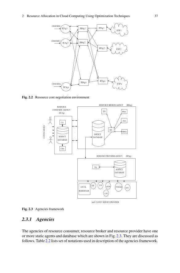
2 Resource Allocation in Cloud Computing Using Optimization Techniques 37
Fig. 2.2 Resource cost negotiation environment
Fig. 2.3 Agencies framework
2.3.1 Agencies
The agencies of resource consumer, resource broker and resource provider have oneor more static agents and database which are shown in Fig. 2.3. They are discussed asfollows. Table2.2 lists set of notations used in description of the agencies framework.

38 G. K. Shyam and I. Chandrakar
Table 2.2 List of notations Notations Meaning
RCAg Resource consumer agency
RBAg Resource broker agency
RPAg Resource provider agency
CA Consumer agent
BA Broker agent
QA Query agent
PA Provider agent
MMA Matchmaker agent
JAA Job Allocation agent
CNA Consumer negotiation agent
BNA Broker negotiation agent
ICSP IaaS Cloud service provider
CNG Cooperative negotiation game
M Mappers
R Reducers
VM Virtual machines
Resource consumer agency (RCAg): It involves agency database and two agents,namely, consumer agent (CA) and consumer negotiation agent (CNA). RCAg func-tions are designed to act on behalf of resource consumers. The significance of agencydatabase and agents are presented as follows.
Agency database: It provides detailed information about several brokers in the Cloudmarket and maintains history of consumer(s) and broker(s) interactions. The agentsuse the database to pass messages among themselves and to know the frequency ofapplication(s) usage by consumer(s). The database facilitates in deciding the offeredprice for resource cost negotiation and the payoffs. Further, consumer’s services areupdated to the database at regular intervals.
Consumer agent (CA): The functions of agent are: (i) receiving and mapping con-sumer requirements (workload) to available RBAg, (ii) selecting the best RBAg (interms of the quality and cost), and (iii) receiving and handling the virtualized servicefrom RBAg to consumers.
The workload received by CA is a set of several jobs. Jobs can require VMsfrom several combinations, such as small, medium and large as shown in Table2.3.The specifications of small, medium, and large VMs are same as in Amazon EC2.Algorithm 4 illustrates concurrent analysis of user’s job resource requirements byRBAg from several RCAg(s). It proceeds in two phases, a distributed ‘map’ oper-ation followed by a distributed ‘reduce’ operation. At each phase a configurablenumber of M ‘mapper’ processors and R ‘reducer’ processors are assigned to workon the problem, by CA and BA respectively. In the map phase each mapper reads
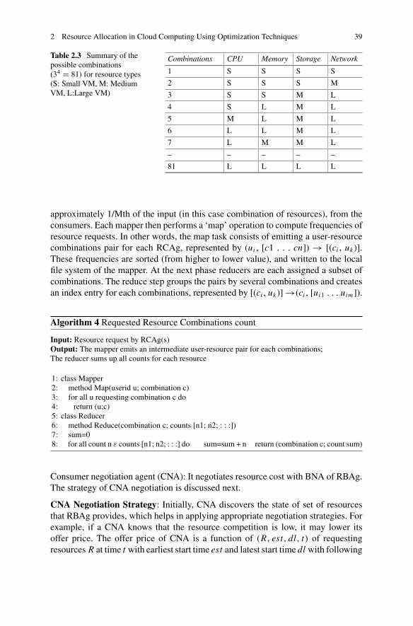
2 Resource Allocation in Cloud Computing Using Optimization Techniques 39
Table 2.3 Summary of thepossible combinations(34 = 81) for resource types(S: Small VM, M: MediumVM, L:Large VM)
Combinations CPU Memory Storage Network
1 S S S S
2 S S S M
3 S S M L
4 S L M L
5 M L M L
6 L L M L
7 L M M L
– – – – –
81 L L L L
approximately 1/Mth of the input (in this case combination of resources), from theconsumers. Each mapper then performs a ‘map’ operation to compute frequencies ofresource requests. In other words, the map task consists of emitting a user-resourcecombinations pair for each RCAg, represented by (ui , [c1 . . . cn]) → [(ci , uk)].These frequencies are sorted (from higher to lower value), and written to the localfile system of the mapper. At the next phase reducers are each assigned a subset ofcombinations. The reduce step groups the pairs by several combinations and createsan index entry for each combinations, represented by [(ci , uk)] →(ci , [ui1 . . . uim]).
Algorithm 4 Requested Resource Combinations count
Input: Resource request by RCAg(s)Output: The mapper emits an intermediate user-resource pair for each combinations;The reducer sums up all counts for each resource
1: class Mapper2: method Map(userid u; combination c)3: for all u requesting combination c do4: return (u;c)5: class Reducer6: method Reduce(combination c; counts [n1; n2; : : :])7: sum=08: for all count n ε counts [n1; n2; : : :] do sum=sum + n return (combination c; count sum)
Consumer negotiation agent (CNA): It negotiates resource cost with BNA of RBAg.The strategy of CNA negotiation is discussed next.
CNA Negotiation Strategy: Initially, CNA discovers the state of set of resourcesthat RBAg provides, which helps in applying appropriate negotiation strategies. Forexample, if a CNA knows that the resource competition is low, it may lower itsoffer price. The offer price of CNA is a function of (R, est, dl, t) of requestingresources R at time t with earliest start time est and latest start time dl with following

40 G. K. Shyam and I. Chandrakar
considerations. Firstly, the deadline: theCNAlowers the offer pricewhen the deadlineapproaches. Secondly, the cost of resource R: intuitively, a CNA has to offer morefor a resource with a higher cost. Thirdly, the demand to supply ratio of a resourceR: higher the ratio, higher will be the offered price for the resource.
Resource Broker Agency (RBAg): RBAg consists of an agency database, a queryagent (QA), a broker agent (BA), a broker negotiation agent (BNA), a matchmakeragent (MMA), and a job allocation agent (JAA). Their responsibilities are explainedas follows.
Agency database: It maintains the information about several RCAgs which use itsservices, and a history of consumer(s) and broker(s) interactions. The agents usethis database to pass messages among themselves. The database aids in decidingthe offered price for resource cost negotiation and the payoffs. The updates regard-ing broker’s services are added to the database at regular time intervals. Further,agency database of an RBAg contains information about availability of resourcesfrom multiple RPAgs, which facilitates in providing virtualized service(s) to RCAg.
Query agent (QA): It responds to the queries of CA and the responses are updatedin agency database instantly.
Broker agent (BA): It controls and coordinates activities of an RBAg. This agenttriggers JAA,MMA, and BNA. It manages the availability and usability of resources.BA runs on several machines, manages all the jobs, and decides whether to provisionnewVM from reserved resources or send request to ICSP for extra resources. The BAperforms following tasks: (i) predicting future incoming workloads based on historyof most frequent / least frequent accessed applications from agency database, (ii)provisioningnecessaryVMs in advance fromICSPwhenever required, (iii) allocatingjobs to VMs, (iv) releasing idle VMs (which do not have jobs running on them), and(v) dynamically allocating VMs for un-allocated jobs through PA (of RPAg).
Broker negotiation agent (BNA): It performs resource price negotiations. Initial pay-offs are decided for consumers based on the adopted strategy. Successive payoffs aredecided on the basis of cooperative/non-cooperative nature of consumers involved.
Job allocation agent (JAA): JAA is assigned a job by BA, which is decomposedinto parallelizable subjobs as presented in [36]. JAA requests MMA to discovercorresponding resources for job scheduling.
Matchmaker agent (MMA): MMA discovers and recommends resources for jobscheduling as follows: (i) MMA interacts with BA to obtain the statistical statusinformation of each available resource, (ii) resources are sorted in a descendingorder of their reliability, and (iii) MMA chooses resource with higher reliabilityvalue based on less failure history of VMs.
All virtual resources (reserved or dynamically allocated) are provisioned fromICSPs (via RPAg). This helps to pre-configure all the necessary VMs images to runconsumer jobs.All the incoming jobs are enqueued.Algorithm5presents the resourceproposals sent and received by CA. Algorithm 6 presents role of BA in processingjobs. Owing to space constraints, the algorithms are made self explanatory.
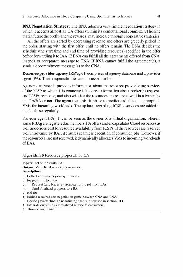
2 Resource Allocation in Cloud Computing Using Optimization Techniques 41
BNA Negotiation Strategy: The BNA adopts a very simple negotiation strategy inwhich it accepts almost all CA offers (within its computational complexity) hopingthat in future the profit (and the rewards)may increase through cooperative strategies.
All the offers are sorted by decreasing revenue and offers are greedily picked inthe order, starting with the first offer, until no offers remain. The BNA decides theschedule (the start time and end time of providing resources) specified in the offerbefore forwarding it to JAA. If BNA can fulfill all the agreements offered from CNA,it sends an acceptance message to CNA. If BNA cannot fulfill the agreement(s), itsends a decommitment message(s) to the CNA.
Resource provider agency (RPAg): It comprises of agency database and a provideragent (PA). Their responsibilities are discussed further.
Agency database: It provides information about the resource provisioning servicesof the ICSP to which it is connected. It stores information about broker(s) requestsand ICSPs response, and also whether the resources are reserved well in advance bythe CA/BA or not. The agent uses this database to predict and allocate appropriateVMs for incoming workloads. The updates regarding ICSP’s services are added tothe database regularly.
Provider agent (PA): It can be seen as the owner of a virtual organization, whereinsomeRBAgare registered asmembers. PAoffers and encapsulatesCloud resources aswell as decides cost for resource availability from ICSPs. If the resources are reservedwell in advance by BAs, it ensures seamless execution of consumer jobs. However, ifthe resource(s) are not reserved, it dynamically allocatesVMs to incomingworkloadsof BAs.
Algorithm 5 Resource proposals by CA
Inputs: set of jobs with CA;Output: Virtualized service to consumers;Description:1: Collect consumer’s job requirements2: for job (i = 1 to n) do3: Request (and Receive) proposal for ith job from BAs4: Send Finalized proposal to a BA5: end for6: Initiate resource cost negotiation game between CNA and BNA7: Decide payoffs through negotiating agents, discussed in section III.C8: Integrate outputs as a virtualized service to consumers9: Throw error, if any

42 G. K. Shyam and I. Chandrakar
Algorithm 6 Job processing by BA
Inputs: Finalized proposal from CAs;Output: Instantiation of a proposal processing by (BA or PA)Description:1: if (Reserved resource for ith job in BA) then2: Send ith job to ICSP for execution3: else4: send ith job resource requirements to PA5: process execution of ith job dynamically
2.3.2 Cooperative Resource Cost Negotiation Game
We proceed to model the RCAg-RBAg resource cost negotiation as a cooperativegame. The consumer’s budget to amass resources is limited. Also, the resources vitalfor an application to run are limited in the data center (DC) of an ICSP acquired byRBAg. Hence cooperative resource cost negotiation between RCAg and RBAg isneeded for achieving better payoffs. The RBAg offers services and receives compen-sation from the CA. The cooperative negotiation game considered consists of threefactors: (i) set of players, i.e., CNA from RCAg and BNA from RBAg, (ii) strategiesfor each player, and (iii) payoff for each player.
Let RCAg’s total resource cost (that it can pay to RBAg) be referred to as theoffered price of cooperating and deceiving CNA (negotiating on behalf of RCAg)denoted by OPCNA and ncOPCNA, respectively, where ncOPCNA < OPCNA. Also, letthe RBAg’s total cost be specified as the offered price of cooperating and deceivingBNA(negotiating on behalf ofRBAg) denoted byOPBNA and ncOPBNA, respectively,where ncOPBNA < OPBNA. If RBAg decides not to allow expected quality of services(refer to expected quality of service as Q), it saves cost but it risks the violation ofSLAs which may result in even greater costs in terms of penalty. This encouragesRBAg to play a cooperative resource cost game.
The RCAg’s experience (on services received from RBAg) could be quantified interms of satisfaction, where a service delivered on expected lines, i.e., of quality Q,results in satisfaction s(Q). On the other hand, if the service delivered is not on theexpected lines, i.e., of quality Q′, the satisfaction is s(Q′), where s(Q′) < s(Q).
The interactions between CNA andBNA could be recursive in resource cost nego-tiation. In such relationships, the players do not seek the immediate maximizationof payoffs but instead the long-run optimal solution. Such situations are modeled ingame theory by repeated game models.
Let us consider the RCAg-RBAg interactionmodel as an infinite horizon repeatedgame, since the RCAg may keep requesting RBAg for the particular service, but thenumber of such requests are not known well in advance.
A repeated game makes it possible for the players to condition their negotiationmoves on the complete previous history of the various stages, by employing strategiesthat define appropriate actions for each round. In our scheme, the harsh trigger

2 Resource Allocation in Cloud Computing Using Optimization Techniques 43
strategy is used by the CNA, such that if the CNA is not satisfied in one of thestages (i.e., the RBAg does not provide the service as promised in SLAs), the CNAmay punish BNA by leaving the relationship forever in the next stage (e.g., stopinteracting with the specific RBAg for subsequent requests of the particular service).Given such a strategy, the BNA has stronger incentives to cooperate and providethe service promised, since it faces the threat of losing its consumers from RCAg.Another popular strategy used in this scheme is for a player to mimic the actionsof his opponent, giving him the incentive to play cooperatively. This way the playerwill be rewarded with a similar replicating behaviour. We refer to this as a tit-for-tatstrategy.
We employ the harsh strategy as a viable strategy for the CNA and the tit-for-tatstrategy as a feasible strategy for the BNA. In addition, we define two more probablestrategies for the CNA and one more desirable strategy for the BNA. For the CNAwedefine: (a) the deceive-and-exit strategy, and (b) the deceive-and-joinback strategy,and for the BNA we define the deceive-and-join-back strategy. The deceive-and-exitstrategy is defined so as to allow the CNA to employ non-cooperative behaviour.With this strategy, the CNA leaves after deceiving from cooperation, i.e., does notcontinue interaction with the particular BNA, in order to avoid any punishment fordeceiving. The deceive-and-join-back strategy is defined to capture a case where theBNAdeceives and joins back in the subsequent rounds. It is a cooperative strategy thatprovides the opportunity to the BNA to join back and cooperate with CNA, withoutpenalising it heavily. The discount factor is taken into account while employing thestrategies.
2.3.3 Payoffs Calculation
We present several cases for payoff calculations.
• Case 1: CNA playing the harsh strategy. BNA could either play the tit-for-tat strategy, i.e., cooperate in the current round, or play the deceive-and-join-back strategy. If the BNA cooperates, then: CPVBNA
c = |OPCNA−OPBNA|1−d f . If the
BNA deceives, then: CPVBNAnc = OPCNA − ncOPBNA + d f.0
1−d f . For the BNA to bemotivated for cooperation, CPV in case of cooperation must be greater thanCPV in case of non-cooperation. Thus, CPVBNA
c > CPVCN Anc = OPCNA−OPBNA
1−d f >
OPCNA − ncOPBNA + d f.01−d f . If the CNA plays harsh strategy, the BNA is moti-
vated to cooperate, when d f > OPBNA−ncOPBNAOPCNA−ncOPBNA
.
• Case 2: CNA playing the deceive-and-exit strategy. Considering BNAs possi-ble strategies, it could either cooperate or deceive in the current round. If BNAcooperates then: CPVBNA
c = ncOPCNA − OPBNA + d f.01−d f . If BNA deceives then:
CPVBNAnc = NCOPCNA − ncOPBNA + d f.0
1−d f . If CNA plays deceive-and-exit strat-
egy, BNA is not motivated to cooperate since CPVBNAnc > CPVBNA
c .

44 G. K. Shyam and I. Chandrakar
Table 2.4 Limits of cooperation by CNA and BNA
Cooperation strategies Punishment strategies
BNA (d f )BN Ac > OPBNA−ncOPBNA
OPCNA−ncOPBNA(d f )BN A
pun > OPBNA−ncOPBNAOPCNA−OPBNA
CNA (d f )CN Ac > OPCNA−ncOPCNA
OPBNA−ncOPCNA(d f )CN A
pun > OPCNA−ncOPCNAOPBNA−ncOPBNA
• Case 3: BNA playing tit-for-tat strategy. If CNA cooperates then: CPV SUc =
|OPSP−OPSU |1−d f . CPVCN A
c = |OPBNA−OPCN A|1−d f . If the CNA deceives then: CPVCN A
nc =OPBNA − ncOPCNA + d f.0
1−d f . For the CNA to be motivated for cooperation, CPV incase of cooperationmust be preferable than CPV in case of non-cooperation. Thus,CPVCN A
c > CPVCN Anc = OPBNA−OPCNA
1−d f > OPBNA − ncOPCNA + d f.01−d f . If the BNA
cooperates, the CNA is motivated to cooperate when: d f >OPCNA−ncOPCNAOPBNA−ncOPBNA
.
• Case 4: BNA playing the deceive-and-joinback strategy. Considering CNAspossible strategies, it could either cooperate or deceive in the current round.If CNA cooperates then: CPVCN A
c = s(Q′) − OPCNA + d f.01−d f . If CNA deceives
then:CPVCN Anc = s(Q′) − ncOPCNA + d f.0
1−d f . If BNA plays deceive-and-joinback
strategy, BNA is not motivated to cooperate since CPVCN Anc > CPVCN A
c .
The cooperation limits for each player (BNA and CNA), with several strategiesused by an opponent, are summarized in Table2.4.
2.3.4 Agents Interaction
The interaction of agents in game is discussed. Agents in RCAg, RBAg, and RPAgcooperatively work together to discover suitable VMs with optimal cost for serviceexecution of jobs. The sequence of operations in the proposed scheme are as follows:
1. CA sends job execution request (alongwith job requirements) toMMAofRBAg.2. BA communicates to JAA of RBAg about job requirements.3. JAA informs MMA to recommend specified number of suitable VMs.4. MMAsearches logs and discovers suitableVMs thatmeet job requirements (logs
hold resource history containing details of each used VMs).5. MMA sorts them in descending order of required resource.6. MMA recommends expected number of VMs to JAA.7. JAA informs BA to decide optimal cost of VMs.8. BA triggers BNA to play a cooperative negotiation gamewith CNAs to negotiate
resource cost.9. CNA and BNA play cooperative resource cost negotiation game.

2 Resource Allocation in Cloud Computing Using Optimization Techniques 45
10. BNA returns cost of each VMs (satisfiable to both negotiating agents) to JAA.11. JAA schedules jobs to RPAg, and receives result from them after execution.12. JAA sends job results to CAs.
2.4 Simulation
We have used JADE simulator to test the operational effectiveness of the work.This section describes the simulation model, performance parameters and simulationprocedure.
2.4.1 Simulation Model
The simulated Cloud environment consists of RCAg, RBAg, RPAg and ICSPs. Thebehavior of ICSPs considered is similar to that ofAmazonEC2, andMicrosoft Azure,discussed in [37]. The values of simulation parameters are presented in Table2.5. The
Table 2.5 Simulationparameters
Symbol Values
RCAg [50–100] nodes
RBAg [250–500] nodes
RPAg [250–750] nodes
ICSP 4 nodes
Mappers 10 nodes
Reducers 5 nodes
No. of resource types per BA [10–25] applications
Quantity of resources per BA [10, 50] VMs
Unit cost of a resource [10, 100]$
No. of resource types per CA [1, 10] VMs
VMs per ICSPs [25, 400] nodes
Processor’s speed [2, 4] Mghz
Processor’s memory [4, 8] GB
Jobs [50, 500] applications
Jobs Arrival rate [5–100] jobs/milliseconds
Payoffs [0–90]$
Jdeadline [60, 150] sec./job
Max_negotiations [2,10] iterations
Consumers [10, 250]
Buffered resource [100, 200] VMs

46 G. K. Shyam and I. Chandrakar
Table 2.6 Payoffs for different simulation sets
Strategies Simulation set 1 Simulation set 2 Simulation set 3
User leaves (0, 0) (0, 0) (0, 0)
One defects, onecooperates
(4, 1) (100, 1) (90, 10)
Both defect (2, 2) (40, 40) (50, 50)
Both cooperate (3, 3) (60, 60) (60, 60)
topology and setting of individual clusters are derived from the grid test-bed DAS-2.The experimental workload (tasks stream) is generated by using Lublin-Feitelsonmodel, which is derived from the workload logs of real supercomputers.
The implementation of the CNA-BNA interactive negotiation game is based on apublicly available Matlab implementation of the Iterated Prisoner’s Dilemma Game[38], which has been extended to include all existing and proposed strategies exam-ined in Algorithm 3. We use simple numbers as payoffs to get scores for differentstrategy combinations. These numbers follow the relationships of the payoffs, asdescribed in general case in the repeated game models. The payoffs for the differentsimulation sets are summarized in Table2.6.
2.4.2 Simulation Procedure
Simulation procedure is as follows.
1. Deploy RCAg, RBAg and RPAg to create the Cloud environment2. Concurrent job submission is done by RBAg for resource analysis3. Employ MMA to find the eligible VMs and then recommend required number of
VMs4. Employ BNA to play concurrent negotiation game with CNAs for negotiating
resource price5. Employ JAA to schedule user jobs to RPAg, collect results from RPAg and send-
back to CAs6. Compute performance parameters.
2.5 Results
This section presents the results of the proposed scheme obtained during the simu-lation.
Analysis of waiting time, negotiation time, and execution time: To examinethe effects of resource requirements on response time, we enlarge the workload’s

2 Resource Allocation in Cloud Computing Using Optimization Techniques 47
Fig. 2.4 Response timeversus resource requirement,when VMs = 200
Fig. 2.5 Response time vsresource requirement, whenVMs = 400
resource requirement from 200 to 400 VMs. The results are shown in Figs. 2.4and 2.5 respectively. Comparing with auction model, [35] is effective in reducingcommunication-related costs. However, our simulation results indicate that, its nego-tiation time increases significantly when resource requirement increases to higherlevels. By examining the logs, we found that re-negotiation occurs more frequentlythan before, that is, [35] can not efficiently finish the trading for all resource require-ments. Based on the above simulation results, we can say that the proposed methodis effective in reducing the negotiation time.
Analysis of payoffs: Figures2.6 and 2.7 illustrate payoff analysis for CNA and BNArespectively. The most profitable strategy for CNA and BNA is Tit-for-Tat strategyfor all payoffs except for the payoff received from the combination with the CNA’sdeceive-and-exit strategy. However, the difference between the payoffs received bythe BNA from playing either the Tit-for-Tat strategy or the deceive-and-join-backstrategy, in combination with the CNA deceive-and-exit strategy, is negligible. Also,the combination of the two most profitable strategies in the same game profile offersthe highest cumulative payoffs to both players.

48 G. K. Shyam and I. Chandrakar
Fig. 2.6 CNA payoffsversus BNA strategies
Deceive-and-ExitHarsh-Trigger
Deceive-and-Joinback
Fig. 2.7 BNA payoffsversus BNA strategies Harsh-Trigger
Deceive-and-ExitDeceive-and-Joinback
2.6 Summary
Cloud computing is, no doubt, an emerging trend in ICT domain. Resource allocationis an important aspect for improving the performance of large-scale Cloud applica-tions. Moreover, performance evaluation of different workload models catering todifferent applications is the need of the hour. Resource allocation techniques andalgorithms in Cloud environment under different configurations and requirementsare needed. Obviously, there is still lack of tools for enabling developers to comparedifferent resource allocation strategies regarding both computing servers and userworkloads. To fill this gap in tools for evaluation and modeling of Cloud environ-ments and applications, this chapter discusses different optimization techniques forresource allocation in Cloud computing environment.

2 Resource Allocation in Cloud Computing Using Optimization Techniques 49
References
1. J. Kennedy, Particle swarm optimization, in Encyclopedia of Machine Learning (Springer, US,2010), pp. 760–766
2. Y. Shi, R. Eberhart, A modified particle swarm optimizer, in IEEE International Conferenceon Evolutionary Computation Proceedings of World Congress on Computational Intelligence(Anchorage, AK, 1998), pp. 69–73
3. X. An-Ping, X. Chun-Xiang, Energy efficientmultiresource allocation of virtual machine basedon PSO in Cloud data center. Math. Probl. Eng. 8–15 (2014)
4. S.E. Dashti, A.M. Rahmani. Dynamic VMs placement for energy efficiency by PSO in Cloudcomputing. J. Exp. Theor. Artif. Intell. 1–16 (2015)
5. A.S. Banu, W. Helen, Scheduling deadline constrained task in hybrid IaaS cloud using cuckoodriven particle swarm optimization. Indian J. Sci. Tech. 8(16), 6 (2015)
6. Y. Qiu, P. Marbach, Bandwidth allocation in ad hoc networks: a price-based approach. Proc.IEEE INFOCOM 2(3), 797–807 (2013)
7. R.S. Mohana, A position balanced parallel particle swarm optimization method for resourceallocation in cloud. Indian J. Sci. Tech. 8(S3), 182–8 (2015)
8. P. Ghosh, K. Basu, S.K. Das, A game theory based pricing strategy to support single/multiclassjob allocation schemes for bandwidth-constrained distributed computing system. IEEE Trans.Parallel Distrib. Syst. 18(4), 289–306 (2010)
9. Y. Kwok, K. Hwang, S. Song, Selfish grids: game theoretic modeling andNAS/PAS benchmarkevaluation. IEEE Trans. Parallel Distrib. Syst. 18(5), 621–636 (2007)
10. Z. Kong, C. Xu, M. Guo, Mechanism design for stochastic virtual resource allocation in non-cooperative Cloud systems, in Proceedings of 2011 IEEE International Conference on CloudComputing, Cloud (2011), pp. 614–621
11. U. Kant, D. Grosu, Auction-based resource allocation protocols in grids, in Proceedings of16th International Conference on Parallel and Distributed Computing and Systems, ICPDCS(2004), pp. 20–27
12. S. Caton, O. Rana, Towards autonomic management for cloud services based upon volunteeredresources. Concurr. Comput. Pract. Experi. 24(9), 992–1014 (2012)
13. J. Espadas, A. Molina, G. Jimnez, M. Molina, D. Concha, A tenant-based resource allocationmodel for scaling software-as-a-service applications over cloud computing infrastructures.Future Gener. Comput. Syst. 29(1), 273–286 (2013)
14. J. Bi, Z. Zhu, R. Tian, Q. Wang, Dynamic provisioning modeling for virtualized multi-tierapplications in Cloud data center, in Proceedings of the 3rd IEEE International Conference onCloud Computing (Cloud ’10) (2010), pp. 370–377
15. D.C. Vanderster, N.J. Dimopoulos, R. Parra-Hernandez, R.J. Sobie, Resource allocation oncomputational grids using a utility model and the knapsack problem. Future Gener. Comput.Syst. 25(1), 35–50 (2009)
16. D. Ye, J. Chen, Non-cooperative games onmultidimensional resource allocation. Future Gener.Comput. Syst. 29(6), 1345–1352 (2013)
17. M. Hassan, B. Song, E.N. Huh, Game-based distributed resource allocation in horizontaldynamic Cloud federation plat- form, in Algorithms and Architectures for Parallel Processing.Lecture Notes in Computer Science (Springer, Berlin, 2011), pp. 194–205
18. Scheduling in Hadoop (2012), https://www.Cloudera.com/blog/tag/scheduling19. C.A. Waldspurger, Lottery and Stride Scheduling: Flexible Proportional-Share Resource Man-
agement, Massachusetts Institute of Technology (1995)20. T. Lan, D. Kao, M. Chiang, A. Sabharwal, An axiomatic theory of fairness in network resource
allocation, in Proceedings of the Annual Joint Conference of the IEEE Computer and Commu-nications Societies (2010), pp. 1–9
21. D.C. Parkes, A.D. Procaccia, N. Shah, Beyond dominant resource fairness: extensions, limita-tions, and indivisibilities, inProceedings of the 13th ACMConference on Electronic Commerce(Valencia, Spain, 2012), pp. 808–825

50 G. K. Shyam and I. Chandrakar
22. X. Wang, X. Liu, L. Fan, X. Jia, A decentralized virtual machine migration approach of datacenters for cloud computing. Math. Prob. Eng. Article ID 878542, 10 (2013)
23. D.C. Erdil, Autonomic cloud resource sharing for inter cloud federations. Future Gener. Com-put. Syst. 29(7), 1700–1708 (2013)
24. M. Steinder, I. Whalley, D. Carrera, I. Gaweda, D. Chess, Server virtualization in autonomicmanagement of heterogeneous workloads, in Proceedings of the 10th IFIP/IEEE InternationalSymposium on Integrated Network Management (2007), pp. 139–148
25. S. Di, C.L.Wang,Dynamic optimization ofmultiattribute resource allocation in self-organizingclouds. IEEE Trans. Parallel Distrib. Syst. 24(3), 464–478 (2013)
26. M. Cardosa, A. Singh, H. Pucha, A. Chandra, Exploiting spatio-temporal tradeoffs for energy-aware MapReduce in the cloud. IEEE Trans. Comput. 61(12), 1737–1751 (2012)
27. T. Sandholm, K. Lai, MapReduce optimization using regulated dynamic prioritization, in Pro-ceedings of the 11th International JointConference onMeasurement andModelingofComputerSystems (Seattle, Wash, USA, 2009), pp. 299–310
28. A. Ghodsi, M. Zaharia, B. Hindman, A. Konwinski, S. Shenker, I. Stoica, Dominant resourcefairness: fair allocation of multiple resource types, in Proceedings of the 8th USENIX Con-ference on Networked Systems Design and Implementation (Boston, Mass, USA, 2011),pp. 24–28
29. K.M. Sim, Agent-based cloud computing. Trans. Serv. Comput. IEEE 5(4), 564–577 (2012)30. K.M. Sim, Complex and concurrent negotiations for multiple interrelated e-markets. Trans.
Syst. Man Cybern. IEEE 43(1), 230–245 (2013)31. G.K. Shyam, S.S. Manvi, Co-operation based game theoretic approach for resource bargaining
in cloud computing environment, in International Conference on Advances in Computing,Communications and Informatics (ICACCI) (2015), pp. 374–380
32. I. Uller, R. Kowalczyk, P. Braun, Towards agent-based coalition formation for service com-position, in Proceedings of the IEEE/WIC/ACM International Conference on Intelligent AgentTechnology (IAT) (2006), pp. 73–80
33. F. Pascual, K. Rzadca, D. Trystram, Cooperation in multi-organization scheduling, in Proceed-ings of International Euro-Par Conference (2007)
34. Hong Zhang, et al., A framework for truthful online auctions in cloud computing with hetero-geneous user demands, in Proceedings of International Conference on Computer Communi-cations (IEEE, Turin, Italy, 2013), pp. 1510–1518
35. Lena Mashayekhy, et al., An online mechanism for resource allocation and pricing in clouds.Trans. Comput. IEEE. https://doi.org/10.1109/TC.2015.2444843
36. Tony T. Tran et al., Decomposition methods for the parallel machine scheduling problem withsetups. J. Comput. Springer 28(1), 83–95 (2015)
37. IaaS providers, http://www.tomsitpro.com/articles/iaas-providers,1-1560.html. Accessed 24March 2016
38. G. Taylor, Iterated Prisoner’sDilemma inMATLAB:Archive for the “GameTheory”, Category(2007), https://maths.straylight.co.uk/archives/category/game-theory

Chapter 3Energy Aware Resource Allocation Modelfor IaaS Optimization
A. Radhakrishnan and K. Saravanan
Abstract This chapter illustrates the resource allocation in cloud IaaS. We detailhow to optimize the VM instances allocation strategy using the novel ANN model.This chapter narrates the functionality and workflow of the system using the NFRLPand EARA algorithms. Further, several issues in implementing the resource alloca-tion are also detailed. This chapter illustrates how the artificial neural network andgenetic algorithm techniques are used in IaaS frame work to efficiently allocate theresources for VMs.
Keywords IaaS optimization · Energy efficiency · Resource allocation · ANN
3.1 Introduction
Cloud computing is a new computing paradigm, which offers computing resourcesfor solving complex IT related problems in fast and low cost under pay per usage basisthrough internet. These features attract the industries and individuals to load theircomputation and data in cloud environment that significantly reduces infrastructuresetup and maintenance cost. Cloud provides its services in three fundamental modelsnamely SaaS, PaaS and IaaS. Among the three service models, IaaS is called asfoundation of cloud computing because of its resource provisioning capability to allother cloud servicemodels. Since all cloud services are depends on IaaS for resources,resource allocation is an important activity in IaaS to provide better cloud service.In IaaS service model, the entire computing environment is provided as a resourceto service requests in the form of Virtual Machines (VMs). The VMs are created as
A. Radhakrishnan (B)Department of Information Technology, Anna University Collegeof Engineering, Nagercoil 629004, Tamilnadu, Indiae-mail: [email protected]
K. SaravananDepartment of Computer Science and Engineering, Anna UniversityRegional Campus, Tirunelveli 627007, Tamilnadu, Indiae-mail: [email protected]
© Springer International Publishing AG, part of Springer Nature 2018B. S. P. Mishra et al. (eds.), Cloud Computing for Optimization:Foundations, Applications, and Challenges, Studies in Big Data 39,https://doi.org/10.1007/978-3-319-73676-1_3
51

52 A. Radhakrishnan and K. Saravanan
machine instances in cloud data centers servers, which could work as a dedicatedcomputer system to consumers. The cloud data centers are located in geographicallydifferent locations with high configuration servers and interconnected together toshare their workload.
In cloud environment, both consumer and providers are much interested parties toaugment their profits, particularly the providers are much concern about maintainingtrust and Service Level Agreements (SLA) in front of loyal consumers. The violationof SLA brings down the trust worthiness about cloud provider [1]. For instance, oneof the prime factors for SLA violation is resource failure during service consumption.The efficient and strategic resource allocation in IaaS greatly supports the providerto deliver failure free resource to consumers and handle more number of servicerequests without any hitch. It also facilitates the consumers to complete their task ontime with low rental cost. This chapter discusses the optimized resource allocationmodel in IaaS aimed to fulfill the expectation of both consumer and provider aswell as elevate the cloud service in high altitude. In the novel approach, the resourceallocation in IaaS is takes place based on the energy level of resources in present aswell as near future. It helps the provider to provide reliable and trustworthy resourcesto service requests. The energy aware resource allocation model utilizes geneticallyweight optimized Artificial Neural Network (ANN) to predict the near future energylevel of resources in cloud data centers. Typically, the initial weight factors in ANNare assigned randomly during learning, whereas the projected model possess geneticalgorithm to optimize the initial weights of ANN. The genetically optimized weightenriches the ANN to improve its prediction accuracy. As per the novel strategy, theresources present and near future energy level are taken in to account for allocatinga resource to service request. The resources found to be heavily loaded in nearfuture never to be targeted for allocation. This feature supports the resource managerin cloud to distribute the workloads in balanced manner as well as minimize themigration of VMs that occurs due to hefty workload. The minimization of VMsmigration automatically improves the performance of data centers.
In clouddata centers,workloadof eachphysical server ismost reliable substance tomeasure their energy level. In the energy based resource allocationmodel, theANN isassociated with each computing servers that could predicts its near future workloadbased on their recent past workloads. This powerful ANN extends great supportto the resource allocator to identify the reliable resource for service requests. Thenovel model encompasses the algorithms of Near Future Resource Load Prediction(NFRLP) and Energy Aware Resource Allocation (EARA), which implements thestrategic approach of resource allocation for IaaS service requests. It certainly allaysthe fear of cloud consumers about the failure of resources in mid of the computationand makes the cloud service as trustable and reliable service.
Cloud computing is spreading from private enterprises to public sectors as it meetsthe agility expected by both sectors. The reason behind the rapid adaptation of cloudcomputing is its features of service delivery mechanism such as ubiquitous, scalableand elastic. A typical cloud computing framework consists of four major areas thatis depicted in Fig. 3.1.

3 Energy Aware Resource Allocation Model for IaaS Optimization 53
Fig. 3.1 Typical cloud computing framework
The application layer in the frame work consists of two different type of appli-cation specifically native cloud application that is developed to be working in cloudplatform. Another application is ported in cloud, which were originally developedin licensed software and ported into cloud environment. The middle layer of thecloud framework is called platform layer that offers common framework model forbuilding application. The major services of this layer are data service, workflow,authorization/authentication and multitenancy support.
The bottom layer is infrastructure layer that contains the most basic informa-tion technology resources with service capability. It delivers the whole infrastruc-ture requirements such as hardware, software and other associated resources for thedevelopment and execution of cloud applications. The cloud framework also containsmanagement layer to monitor and manage the cloud environment activities. The coremanagement activities are analysis and administration across the layers, metering,pricing and billing capabilities.
In the cloud computing framework, the bottom most infrastructure layer is play-ing a vital support to the top layers by providing required IT resources. Since alllayers are completely depends on infrastructure layer for its service, infrastructureservice is called as foundation of cloud computing. Any refinement and revampin infrastructure layer activities reflects in entire cloud computing service so thatthis chapter mainly focuses on infrastructure service especially revamping its primeresponsibility of resource provisioning. The introduction about the core functional-ities of infrastructure layer and the methodologies used for revamping its resourceprovisioning is as follows.
3.1.1 Introduction About IaaS Service Framework
The service architecture of IaaS is shown in Fig. 3.2, which consist of four importantcompartments namely cloud computing system with virtualization, cloud storagesystem, content delivery network and IT infrastructure.

54 A. Radhakrishnan and K. Saravanan
Fig. 3.2 IaaS service framework
The IaaS platform utilizes virtualization as their prime technique that providesillusion on hardware. This enables portability of high level functions and sharingor aggregation of physical resources. Virtualization can be applied to all aspects ofcomputing systems such as storage, memory, processor, and networks. This featureallow multiple guest OS to run simultaneously on a single system so that a sys-tem in cloud environment is able to handle multiple service requests. The popularvirtualization techniques currently used in IaaS framework is VMware, XEN andKVM.
The virtualization technique supports IaaS model to deliver VMs as a resourceto service requests. The VMs are created on cloud data center servers as machineinstances that could act as an independent computer system. A hypervisor or virtualmachine monitor is a software that could create and run VMs on physical server.A machine a hypervisor runs one or more VMs is called host machine, each VMsare called guest machines. The VMs can be classified into different types such assmall, medium and high according to their capability in terms of processor, memoryand bandwidth. Allocating reliable resource to VMs is a challenging and responsibletask of IaaS framework because it avoids VMs failure and frequent migration. Thestrategic allocation of resources to VMs leads cloud service as a trustworthy andreliable service to all walks of cloud consumers. This chapter illustrates how theartificial neural network and genetic algorithm techniques are used in IaaS framework to efficiently allocate the resources for VMs.
3.1.2 Overview of Artificial Neural Network and GeneticAlgorithm
TheANN is a computation system inspired by the structure, processingmethodologyand learning ability of a biological brain. The ANN is mainly used for predictionprocess through its learning capability. The important component in this systemis the structure of information processing. It is build by large number of highlyinterconnected processing elements known as neurons, which are working togetherto solve any specific problem.ANNattempts to imitate theway a human brainworks.

3 Energy Aware Resource Allocation Model for IaaS Optimization 55
Fig. 3.3 Generic structure of artificial neural network
The ANN architecture consists of three core layers, which are input layer, outputlayer and hidden layer of neurons. The generic architecture of ANN is depicted inthe Fig. 3.3.
In ANN architecture, the layers are well connected with each others. The inputlayer units are connected to the hidden layer units, and the hidden layer units areconnected to the output layer units. The input layer represents the information whichis fed into the ANN as input. The hidden neurons functions are identified by theactivities of the input neurons and the connecting weights between input and hiddenunit. Similarly, the role of the output unit depends on the activity of the neuronsin the hidden unit and the weights assigned between the hidden and output unit. InANN, the hidden neurons are free to construct their own representation of the input.Each node in ANN has the same node function. The node function is a compositeof the weighted sum and a differential nonlinear activation function. The nonlinearactivation function is any one of the following namely, logistic, hyperbolic tangent,and identity. They were used to transform the incoming signal into an output signal.
The learning process in ANN is a result of modification of the network weightswith the learning algorithms at some extent. The main objective of learning is tofind a set of weight matrices that would applied to the network to map any input tocorrect output. The popular learning paradigms are namely supervised, unsupervisedand reinforcement learning. There are several classes of ANN, which are classifiedaccording to their learning mechanisms. The arrangements of neurons into layersand the pattern of connecting within and in-between layers are generally called asthe types of neural networks. The most fundamental classification of ANN falls intothree categories namely single layer feed forward network, multi layer feed forwardnetwork and recurrent network.
The term Genetic algorithm (GA) was initially introduced as a probabilis-tic optimization algorithm. The GA is a family of computational model influ-enced by natural progression. The original idea came from the biological evolu-tion process in chromosomes. The GA exploits the idea of the survival of fittestwhere best solutions are recombined with each other to form better solutions.
56 A. Radhakrishnan and K. Saravanan
There are three basic processes in GA, which are selection, crossover and muta-tion. Selection is a process for choosing a pair of chromosomes which are fitted forsurvival. The crossover operation performs the exchange of genes between two indi-vidual chromosomes for reproducing.Mutation process refers to arbitrarily changingthe chromosomes. In GA, set of individual number named as population. Each indi-vidual denotes the life form of chromosome. There is a fitness function to determineshow fit each individual for survival and select the fitted individuals from the popula-tion to reproduce. The two selected chromosomes performs crossover and split again,followed bymutation that produce two new individuals. The process is repeated untilbest individual is good enough. The term fitness in GA measures the goodness of achromosome, how well the chromosome fits to solve the problem.
In the energy aware resource allocation approach for VMs, the ANN mechanismutilizes GA for optimizing its initial weights matrices. This kind of weight optimiza-tion increases the accuracy of ANN prediction. The subsequent section illustratesthe existing resource allocation methodologies in IaaS framework followed by thefunctionality and utilization of energy aware resources allocation technique usingANN with GA.
3.2 Existing Resource Allocation Methodologies in IaaSFramework
Resource allocation is the process of assigning cloud resources to the requiredcloud applications; inefficient allocation will lead to resource contention, scarcity ofresources and resource fragmentation. The complexity of finding an optimal resourceallocation is high in huge system such as data centers and grid. Since the resourceavailability and demand are dynamic and scalable, variousmethods for resource allo-cation in cloud should be followed. The researchers found different type of resourceallocation strategies in cloud, but the prime focus of all are, cloud must provide QoSguaranteed computing environment to the end user.
The resource allocation strategies are based on policy, execution time of applica-tions, utility function, Gossip protocol, hardware resource dependency, auction andSLA. Kuo and Kuan [2] has proposed the most fit-processor policy for resource allo-cation. This policy assigns the job to the cluster, which produces a leftover processordistribution. The fit policy requires a search process to determine the target cluster,which leads to high time complexity. The work done by Shin and Akkan [3] cre-ates decentralized user and virtual resource management for IaaS through new layercalled domain layer. Based on role based access control, the virtualized resourcesare allocated to users through domain layer. Li et al. [4] has proposed task executiontime and preemptable scheduling for resource allocation. It avoids resource con-tention and increases the resource utilization by using different modes of renting.Themajor problem of this approach is that estimating the execution time of a job. Theadvanced reservation based resource allocation strategy for distributed environment

3 Energy Aware Resource Allocation Model for IaaS Optimization 57
is proposed by Melendez and Majumdar [5]. It is based on any scheduling criteriafor assigning a job to resource in heterogeneous environment subjected to advancedreservation of resource. The work done by Kumar et al. [6], have assigned a virtualmachine to a job based on the cost and speed of available VMs in IaaS. It allows theuser to select the VMs according to their budget level.
Zhen et al. [7] have proposed stochastic approximation method to model andanalyze the QoS performance of virtual resources. This approach enforces the VMsto report their credentials truthfully, based on that the virtual resources would beallocated to the requests. Wuhib and Stadler [8] have suggested a Gossip-basedprotocol for resource allocation in cloud. This protocol implements a distributedcloud resources allocation scheme, which assigns the applications that have timedependent memory demands and dynamically increases a global utility function.The work given by Niyato et al. [9] has proposed Gossip based co-operative VMswith VMs allocation. In which, cost is reduced by sharing the available resources tothe VMs. The co-operative formations of organization are based on network gam-ing approach so that none of the organization will be deviated. The work proposedby Nguyen et al. [10] considers the utility function to assess the application fulfill-ment in resource allocation. The utility function computes the workload of enter-prise online applications and CPU-intensive application then resources could beallocated to applications accordingly. Weisong et al. [11] has proposed job optimiza-tion scheduler for resource allocation. The jobs are classified by scheduler based ontheir hardware resource dependency such as CPU, memory, network bandwidth andI/O. Afterward, the scheduler detect the parallel jobs of different category, basedon the category resources are allocated. Xiaoyi et al. [12] have analyzed adaptiveresource co-allocation approachbasedonCPUconsumption amount.Gradient climb-ing approach is used to determine the actual CPU share that each VM occupies ona system and its optimizing level. It mainly focuses on CPU and memory resourcesfor co-allocation and does not consider the dynamic nature of resource request.
The auction based resource allocation strategy is proposed by Wei et al. [13].This methodology is based on seal based biding, where the cloud provider collectsthe entire sealed bid from users and determine the price. The resource is distributedto the users based on highest bidder. This strategy does not enlarge the profit dueto its truth telling property under severe constraints. The main objective of thisresource allocation strategy is to increase the profits of both cloud consumer andprovider by balancing the resource supply and demand according to market level.Xindong et al. [14] has introduced market based resource allocation strategy usingequilibrium theory. It determines the number of fractions can be used in one VM andcan adjust dynamically according to the varied resource requirement of workload.The proposed market economy system balances the resource supply and demandin the market system. Uthaya and Saravanan [15] defined Kalman filter predictionmodel for predicting resource demand in both reservation and on-demand pricing.
The nature of the application is also considered for resource allocation in cloud.Tram and John [16] has designed a virtual infrastructure allocation strategy for work-flow based application, where resources are allocated based on the workflow rep-resentation of the application. The application logic is interpreted and exploited to
58 A. Radhakrishnan and K. Saravanan
produce execution schedule estimation. Xiong et al. [17] has designed a databasereplicas allocation strategy in cloud, in which the resource allocation module sep-arates into two levels. The first level optimally divides the resources among theprocess and the second level expands database replicas based on learned predictedmodel. In cloud, SLA must be ensured during service to sustain the trust over cloudcomputing. Hence, various resource allocation strategies are suggested by the primeconsideration of SLA. The work done by Linlin et al. [18] has focused on SLAdriven user based QoS parameters to maximize the profit of SaaS provider, whichmap the customer request into infrastructure parameters and policies. This approachmaximizes the cost by optimizing the resource allocation within a VM.Ma et al. [19]has proposed a framework for resource management for SaaS provider to effectivelycontrol the SLA of their users. It mainly concentrates on SaaS provider profit andconsiderably reduces the resource wastage and SLA violation.
The aforementioned various resource allocation strategies are the results of intenseanalysis by researchers in cloud domain. All the resource allocation strategies aredesigned to consider one or more prime parameters such as policy, SLA, auction,execution time, hardware dependency and utility function. The main objectives ofall allocation strategies are providing failure free and optimized resource allocationfor cloud consumers, through which the cloud service should be made as affordableand trustworthy service to all kind of consumers. The highlighted resource allocationstrategy of this chapter is illustrated in the remaining sections.
3.3 The IaaS Cloud Architecture with Energy AwareResource Allocation Model
The IaaS architecture for cloud computing service is depicted in the followingFig. 3.4, which encompass various functional components along with the energyaware resource allocation methodology for handling service requests. The clouddata center consists of number of high configuration servers to handle the requests.It requires a mechanism to equally distribute the load across the data center serversin order to meet QoS expectation of consumers from different locations. The elasticservice of IaaS leads very hard to implement load balancing due to the reasons of (i)The provider must deliver enough resources to hold peak time resource usage, (ii)The service should grow depends on the development of resource consumption, (iii)The service provider should be able to predict the growth of resource consumptionwell in advance and strategic planningmust bemade tomeet the requests. These com-plexities are one of the major hindrances for the growth of IaaS service. The energyaware resource allocation strategy lends support to address these issues effectively.
The computing hosts in the cloud hub is called as data center servers, which are thefoundation of cloud as it renders all kind of resources to cloud services. In the abovearchitecture, the genetically weight optimized ANN is attached with each computinghosts to predicts their near future availability when it required [20, 21]. It helps thecloud resource allocator to provide reliable computing resources to consumers.

3 Energy Aware Resource Allocation Model for IaaS Optimization 59
Fig. 3.4 The IaaS cloud architecture with resource allocation model
3.3.1 Architectural Components and Its Functionalities
The architecture contains a variety of functional components and their functionalitiesare well defined in sequences (Fig. 3.5) to handle the service request. The majorarchitectural components as well as their functionalities are described as follows.
Request Receiving and Authentication Unit: This unit receives the IaaS servicerequest from the users. The user authentication is examined and authorized basedon cloud security strategy which is either third party or internal authentication. Ifthe authentication of the user is valid, then the request is forwarded to resourceavailability checking unit.
ResourceAvailabilityCheckingUnit: It keeps the availability details of resourcesin the cloud hub. The authenticated requests are evaluated by this unit. If the hub isable to provide resource for a request then it triggers resource selection unit, other-wise request is readdressed to some other cloud hub. This unit is updated by resourceallocation and deallocation unit.
Resource Selection Unit: This unit selects a suitable host for resource allocationwith the support of activating genetically weight optimized ANN attached in allcomputing hosts to predict their near future load. Finally, it chooses a suitable hostwhose present and near future load is adequate compared with all other computingnodes. The ANN of a host is activated if its current load exceeds mid of its capacityduring selection.
Resource Load Prediction Process: It is fabricated by genetically weight opti-mized trained ANN that is attached with all computing hosts. It takes recent pastloads of computing host from queue data structure to predict its near future load.The prediction process is initiated by resource selection unit. The predicted near

60 A. Radhakrishnan and K. Saravanan
Fig. 3.5 Sequence diagram of architecture activities
future load is reported to internal cloud admin and resource selection unit for furtherprocess.
Resource Allocation and Reallocation Unit: It allocates the requested resourceto aspirants based on the resource identity obtained from resource selection unit. Thisactivity reflects in accounting unit for metering the service as well as resource avail-ability unit for availability update. It also takes care about reallocation of resourcesafter usage is over.
Accounting and Price Fixing Unit: This unit is responsible for accounting theresource usage details such as how long the resource was consumed. The usagecharges also calculated based on the metering and pricing policies of the provider.The invoice of the payment voucher is sent to the cloud user to enable payment.
3.3.2 Workflow of Architecture
1. The IaaS requester log on by valid authentication and submit their request details.2. The requested resources availability is checked in cloud hub database.3. If availability exits then assess the current load of working hosts as well as its nearfuture load if necessary by ANN for host identification.4. The current and predicted load of each host is brought to the attention of hubadministrator as well as resource selection unit for VMs creation.5. Resource selection unit calls decision making algorithm for identifying suitablehost by providing dynamic and static parameters such as resources predicted load,requested type of resource and user category details.

3 Energy Aware Resource Allocation Model for IaaS Optimization 61
6. Decision making process is done by EARA algorithms that identifies targetedphysical host for virtual machine creation with requested resource capability andnotifies the same to resource selection unit.7. The created virtualmachine is allocated to customer, the update ismade on resourceavailability database and accounting unit.8. Customer received requested resource as virtual machine instance, after usagerelinquish request send to the cloud.9. Revoke allocated virtual machine from customer and notify to accounting unit andresource availability units.10. The cost of resource usage is informed to customer to make payment.
3.3.3 The Genetically Weight Optimized ANN Model forLoad Prediction
The ANN model of near future workload prediction for cloud data center host isdepicted in Fig. 3.6. The ANN must be trained with substantial amount of databecause the trained model only directs the network to behave in response to theexternal stimulus or initiate activities on its own. The training and testing datasetare collected from the load traces of grid workstation node, which is available inthe URL http://people.cs.uchicago.edu/~lyang/load/, herein mystere10000.data fileis selected for training and testing. The 200 samples of host load were sequentiallytaken to form experimental dataset.
The ANNmodel is build with 5 input nodes, 5 hidden nodes and one output node.The hosts recent past five seconds loads from tn to tn−4 are given as input to predictthe load at tn+1 s. The recent past loads are kept in queue data structure associatedwith each physical host in cloud data center. In ANN prediction model, the initialweights between the units are optimized by genetic algorithm. Typically the initialweights are given as random. For optimizing initial weights of ANN, optimizationstarts at the multiple random points of initial weights, the weights are encoded intochromosome format of symbol strings. Each chromosome is evaluated by fitnessfunction based on mean square error value in ANN training. Once this has beendone, all the chromosomes are operated by the selection, crossover and mutation of
Fig. 3.6 ANN model forhosts near future loadprediction
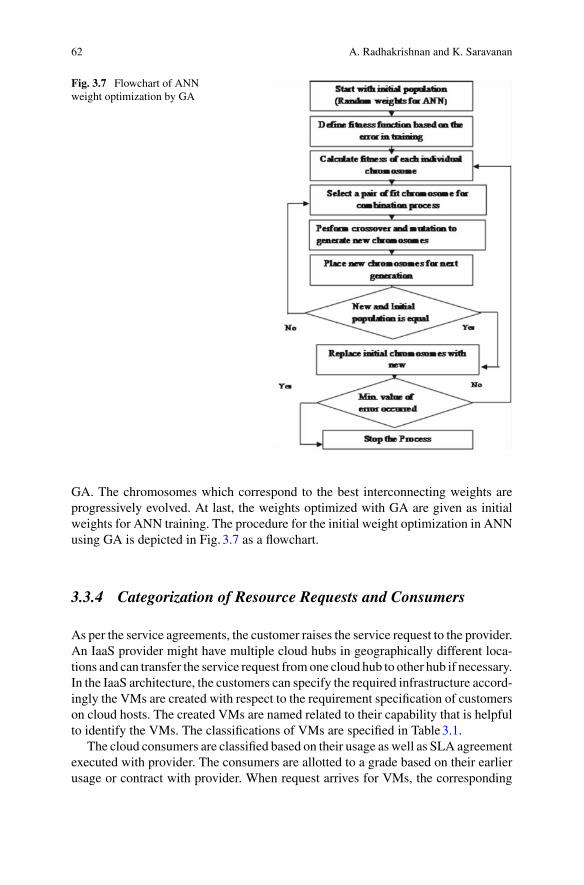
62 A. Radhakrishnan and K. Saravanan
Fig. 3.7 Flowchart of ANNweight optimization by GA
GA. The chromosomes which correspond to the best interconnecting weights areprogressively evolved. At last, the weights optimized with GA are given as initialweights for ANN training. The procedure for the initial weight optimization in ANNusing GA is depicted in Fig. 3.7 as a flowchart.
3.3.4 Categorization of Resource Requests and Consumers
As per the service agreements, the customer raises the service request to the provider.An IaaS provider might have multiple cloud hubs in geographically different loca-tions and can transfer the service request fromone cloud hub to other hub if necessary.In the IaaS architecture, the customers can specify the required infrastructure accord-ingly the VMs are created with respect to the requirement specification of customerson cloud hosts. The created VMs are named related to their capability that is helpfulto identify the VMs. The classifications of VMs are specified in Table3.1.
The cloud consumers are classified based on their usage as well as SLA agreementexecuted with provider. The consumers are allotted to a grade based on their earlierusage or contract with provider. When request arrives for VMs, the corresponding

3 Energy Aware Resource Allocation Model for IaaS Optimization 63
Table 3.1 Resource classification
Sl. no Customer request specification Virtual machine category
1 Requested resource is more than 2.5 GHz CPU and/orRAM size is more than 3 GB
High
2 Requested CPU capability is in-between 1.5 and 2.5GHzand/or in-between 1.5 and 3 GB RAM size
Standard
3 Requested CPU power is less than 1.5GHz and/or RAMsize is less than 1.5 GB
Small
Table 3.2 Categorization of consumer
Sl. no Type of customer Grade
1 Consumers with contract A
2 More than hundred hours usage B
3 Less than hundred hours usage C
grade of the requested customer is obtained from cloud database. The taxonomy ofcloud customer is denoted in Table3.2.
The host identification process to launch the requested VMs utilizes consumergrade and virtual machine category as key parameters for decision making. Thepreference is given to loyal and long term customers during resource allocation. Theproviders are much careful in avoiding SLA violation and providing trustworthyservice to their consumers.
3.3.5 Energy Aware Resource Allocation Algorithm in IaaSCloud
The main objective of the proposed algorithms Energy Aware Resource Allocation(EARA)andNearFutureResourceLoadPrediction (NFRLP) are to efficiently handleIaaS service requests in terms of trust and cost worthy. The algorithm EARA isdeveloped to receive the required resource specification from consumers and thenchoose an appropriate physical host in data center to create a virtual machine withrequired resource capability. The NFRLP extends support to EARA, which classifiesthe hosts of cloud hub into three categories such as heavy, medium and low accordingto their current and predicted load level in near future. The heavily loaded hosts arenever considered for resource allocation [22]. Also, the algorithm EARA accordspreference to loyal customers in resource allocation, which are presented in Figs. 3.8and 3.9 respectively.
The algorithm EARA consists of two sun functions, NFRLP (N) and Host-Class(Load, Host-Id). The sub function NFRLP (N) is used to predict the near future load

64 A. Radhakrishnan and K. Saravanan
Fig. 3.8 Pseudo code of Energy Aware Resource Allocation algorithm (EARA)
of each physical host. The parameter N specifies how long past load are taken intoaccount for prediction process. The function Host-Class (Load, Host-Id) performsthe categorization of hosts according to their load specified by parameter load. Thephysical hosts in the cloud hub are having its identity that is represented by parameterHost-Id. The pseudo code of the algorithm NFRLP is given in Fig. 3.9.
The proposed algorithms are developed to identify the right resources for IaaSrequests after ensuring their energy level in present as well as near future. To reducethe overhead, the ANN mechanism for load prediction is activated when the currentload of resources are above their average level. It gives the new dimension in resourceallocation strategy in cloud environment. The pseudo codes of the algorithms areconverted into JAVA code while implementing cloud environment.

3 Energy Aware Resource Allocation Model for IaaS Optimization 65
Fig. 3.9 Pseudo code of near future load prediction algorithm
3.4 Implementation Results of Proposed Methodologyin Cloud Environment
The implementation of the IaaS architecture with energy aware resource allocationstrategy is done as two parts. The first part contains the implementation and per-formance evaluation of genetically weight optimized various ANNs and the secondpart contains the implementation and performance comparison of novel resourceallocation strategy in IaaS cloud environment.
3.4.1 Experimental Setup and Prediction PerformanceResults of ANN
The training of ANN is required sizeable amount of data, the dataset for trainingand testing is collected from load traces of grid workstation node that can be foundin the URL in http://people.cs.uchicago.edu/~lyang/load/. The 200 samples of hostload were taken successively to run the experimental setup. The transformation ofidentified dataset for neural network training is specified in Table3.3.
The training model of ANN possesses 5 input nodes, 5 hidden nodes and oneoutput node. The identified 200 load samples are further split into training, valida-tion and testing purposes. The experiment is conducted in MATLAB environment,the implemented MATLAB program is converted into JAVA code using MATLABBuilder JA tool for the evaluation in cloud environment. The prediction performanceis evaluated by parameters such as CPU time taken for training that is used to mea-sure efficiency, and Mean Absolute Error (MAE) that is used to measure accuracy.

66 A. Radhakrishnan and K. Saravanan
Table 3.3 ANN training dataset model
Input value1 Up to Input value m Output value
Load (1) .. Load (m) Load (m+1)
Load (2) .. Load (m+1) Load (m+2)
.. .. .. ..
Load (t−2) .. Load (t−m−1) Load (t−1)
Load (t−1) .. Load (t−m) Load (t)
Table 3.4 Prediction performance result comparisons
ANNmodels
Parameters
Standard way of optimized weight Genetically optimized weight
MAE R-Square CPU time(s)
MAE R-Square CPU time(s)
BPNN 0.037 0.949 8 0.01 0.962 6
ELNN 0.023 0.971 6 0.006 0.984 3
JNN 0.002 0.995 5 0.0005 0.996 2
The R-Square value is used to measure the successful fitting between targets andpredicted. The R-Square value closer to one indicates a better fit of prediction.
The prediction performance comparison between standard weight and geneticallyweight optimized three neural networks namely Back Propagation Neural Network(BPNN), Elman Neural Network (ELNN) and Jordon Neural Network (JNN) isshown in Table3.4. In standard weight optimization, JNN possess high accuracy ofprediction among three neural networks. The R-Square value of JNN is near to oneand the time taken by the CPU is 5 s to predict the given load samples, which is lesscompared with the other two neural networks.
The evaluation parameters in Table3.4 shows that the genetic optimization ofweight increases the performance of all neural networks compared with standardweight optimization. The performance of ELNNand JNN are very close in predictionbut comparing theCPU time taken, JNN took only two seconds to predict the samples.The time taken is drastically decreased by genetically optimized weights. Hence, thecloud architecture for IaaS service management affixes genetically weight optimizedJNN for its computing host near future load prediction. The reasons behind theselection of JNN among other neural network are its prediction accuracy and timetaken for prediction.

3 Energy Aware Resource Allocation Model for IaaS Optimization 67
3.4.2 Experimental Setup and Performance Results ofEnergy Aware Resource Allocation Strategy in CloudEnvironment
Cloud architecture setup is made in CloudAnalyst toolkit that provides simulationenvironment for IaaS cloud computing service. It also facilitates to customize thefunctionality of core IaaS system components such as data centers, VMs creation,resource allocation policies and requestmaking pattern.CloudAnalyst is another sim-ulation tool from cloudbus.org for modeling and analysis of the large scale cloud datacenter environment. This simulation is used to measure the statistical measurementof response time of simulated applications, usage patterns of applications, time takenby data centers for servicing user requests and cost of the application. The Cloud-Analyst simulation environment splits the data centers in the earth into six regions.In experimental setup, three data centers and seven user hubs are configured. Eachdata center and user base is having unique identifier and located in different regions.The position of user bases (UB) and data centers (DC) in simulation environmentis shown in following Fig. 3.10 where the user bases which are distance from datacenters are getting network latency compared with user bases near to data centers.
In simulation screen, the data centers are not exists in the region of user bases 1,3 and 7 therefore the requests of these user bases are sent to data centers in anotherregions. It increases the network latency that reflects in response time of consumerapplication in these user bases. The three data centers are made to serve the consumerrequests irrespective of regions. The physical hosts in data centers are configuredwithLinux OS, X86 architecture, 8 GB RAM, 1terabyte storage, 4 cores and 1 G.Bit/s
Fig. 3.10 User bases and data centers in simulation environment
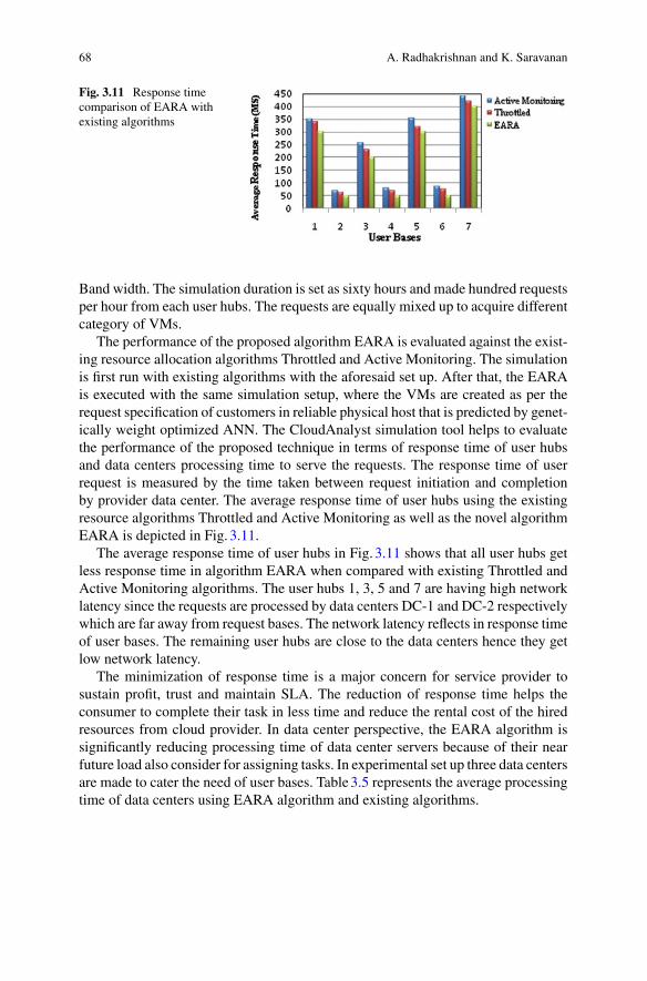
68 A. Radhakrishnan and K. Saravanan
Fig. 3.11 Response timecomparison of EARA withexisting algorithms
Band width. The simulation duration is set as sixty hours and made hundred requestsper hour from each user hubs. The requests are equally mixed up to acquire differentcategory of VMs.
The performance of the proposed algorithm EARA is evaluated against the exist-ing resource allocation algorithms Throttled and Active Monitoring. The simulationis first run with existing algorithms with the aforesaid set up. After that, the EARAis executed with the same simulation setup, where the VMs are created as per therequest specification of customers in reliable physical host that is predicted by genet-ically weight optimized ANN. The CloudAnalyst simulation tool helps to evaluatethe performance of the proposed technique in terms of response time of user hubsand data centers processing time to serve the requests. The response time of userrequest is measured by the time taken between request initiation and completionby provider data center. The average response time of user hubs using the existingresource algorithms Throttled and Active Monitoring as well as the novel algorithmEARA is depicted in Fig. 3.11.
The average response time of user hubs in Fig. 3.11 shows that all user hubs getless response time in algorithm EARA when compared with existing Throttled andActive Monitoring algorithms. The user hubs 1, 3, 5 and 7 are having high networklatency since the requests are processed by data centers DC-1 and DC-2 respectivelywhich are far away from request bases. The network latency reflects in response timeof user bases. The remaining user hubs are close to the data centers hence they getlow network latency.
The minimization of response time is a major concern for service provider tosustain profit, trust and maintain SLA. The reduction of response time helps theconsumer to complete their task in less time and reduce the rental cost of the hiredresources from cloud provider. In data center perspective, the EARA algorithm issignificantly reducing processing time of data center servers because of their nearfuture load also consider for assigning tasks. In experimental set up three data centersare made to cater the need of user bases. Table3.5 represents the average processingtime of data centers using EARA algorithm and existing algorithms.
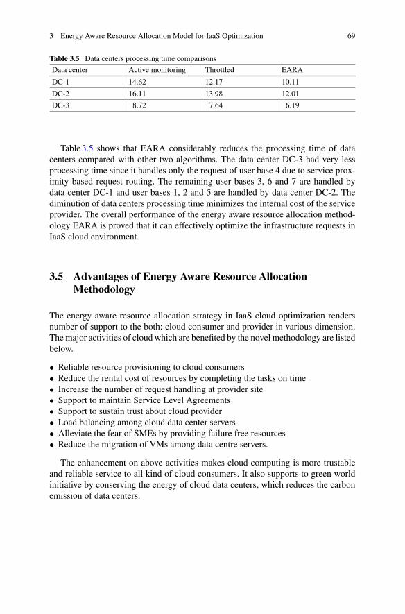
3 Energy Aware Resource Allocation Model for IaaS Optimization 69
Table 3.5 Data centers processing time comparisons
Data center Active monitoring Throttled EARA
DC-1 14.62 12.17 10.11
DC-2 16.11 13.98 12.01
DC-3 8.72 7.64 6.19
Table3.5 shows that EARA considerably reduces the processing time of datacenters compared with other two algorithms. The data center DC-3 had very lessprocessing time since it handles only the request of user base 4 due to service prox-imity based request routing. The remaining user bases 3, 6 and 7 are handled bydata center DC-1 and user bases 1, 2 and 5 are handled by data center DC-2. Thediminution of data centers processing time minimizes the internal cost of the serviceprovider. The overall performance of the energy aware resource allocation method-ology EARA is proved that it can effectively optimize the infrastructure requests inIaaS cloud environment.
3.5 Advantages of Energy Aware Resource AllocationMethodology
The energy aware resource allocation strategy in IaaS cloud optimization rendersnumber of support to the both: cloud consumer and provider in various dimension.Themajor activities of cloud which are benefited by the novel methodology are listedbelow.
• Reliable resource provisioning to cloud consumers• Reduce the rental cost of resources by completing the tasks on time• Increase the number of request handling at provider site• Support to maintain Service Level Agreements• Support to sustain trust about cloud provider• Load balancing among cloud data center servers• Alleviate the fear of SMEs by providing failure free resources• Reduce the migration of VMs among data centre servers.
The enhancement on above activities makes cloud computing is more trustableand reliable service to all kind of cloud consumers. It also supports to green worldinitiative by conserving the energy of cloud data centers, which reduces the carbonemission of data centers.
70 A. Radhakrishnan and K. Saravanan
3.6 Conclusion
The cloud computing offers many IT related service options to large and small ITbusiness companies and individuals. It opens up the world of computing to a broadrange of uses and increases the ease of use by giving access through internet. Thecloud services are basically classified into three major categories namely SaaS, PaaSand IaaS. These services greatly cut off consumers infrastructure setup cost andmain-tenance cost by loading their computation and data in cloud environment. Among allcloud service, IaaS is called as foundation of cloud service because resources for allservicemodels are obtained from IaaS. The performance of all the services are highlydepends on IaaS. In spite of lot of benefits provided by cloud, the cloud consumersespecially the Small andMedium Enterprises (SMEs) are worried to utilize the cloudservice due to the standing issues of trust and getting reliable resource for their com-putation. The SMEs are playing vital role for the key success of any technologicaldevelopment, currently SMEs are stay away from cloud business. Since IaaS cloudservice can allay these kinds of issues, this projected methodology was concentratedon enriching IaaS service internal activities to mitigate the standing issue of reliableresource provisioning and maintaining trust.
The IaaS cloud service provides VMs as resource to consumers. The providedVMs can act as dedicated computer systems to customers to cater their needs. TheVMs are created on physical host of cloud provider data centers. The reliable hostselection for launching VMs as per the requirements of consumers is a challengingtask for service provider. The deficient selection of hosts for VMs creation leadsVMsfailure in middle of the computation or deprived the performance of VMs due to theheavy workload of physical host. In the energy aware resource allocation approach,the physical hosts selection for VMs creation is based on their current and near futureavailability. The availability of computing host is measured by its workload. The loadprediction process is fabricated bygeneticallyweight optimizedANN.TheANN loadprediction model is trained and validated by the real load samples of grid workstationnode. The future load prediction of a computing host is based on its recent past loadhistory. The load prediction mechanism is embedded in the algorithm EARA, whichfacilitates the VMs creation process to identify the reliable physical host for VMscreation. The reliable host selection improves the performance of VMs and avoidsVMs failure during service. The performance of EARA is validated in CloudAnalysttool. The results demonstrates that the response time of consumer applications andprocessing time of provider data centers are decreased immensely by using EARAcompared with existing methodologies in cloud environment.
References
1. K. Saravanan,M. Rajaram, An exploratory study of cloud service level agreements - state of theart review. KSII Trans. Internet Inform. Syst. 9(3), 843–871 (2015). https://doi.org/10.3837/tiis.2015.03.001. ISSN 1976-7277.IF0.561

3 Energy Aware Resource Allocation Model for IaaS Optimization 71
2. H. Kuo-Chan, L. Kuan-Po, Processor allocation policies for reducing resource fragmentationin multi cluster grid and cloud environments (IEEE, 2010), pp. 971–976
3. D. Shin, H. Akkan, Domain-based virtualized resource management in cloud computing, in2010 6th International Conference on Collaborative Computing: Networking, Applicationsand Work-sharing (CollaborateCom) (IEEE, 2010), pp. 1–6
4. J. Li, M. Qiu, J.W. Niu, Y. Chen, Z. Ming, Adaptive resource allocation for preemptable jobsin cloud systems, in 2010 10th International Conference on Intelligent Systems Design andApplications (ISDA) (IEEE, 2010), pp. 31–36
5. J.O. Melendez, S. Majumdar, Matchmaking with limited knowledge of resources on cloudsand grids, in 2010 International Symposium on Performance Evaluation of Computer andTelecommunication Systems (SPECTS) Ottawa, ON (2010), pp. 102–110
6. K. Kumar, J. Feng, Y. Nimmagadda, Y.H. Lu, Resource allocation for real-time tasks usingcloud computing, in 2011 Proceedings of 20th International Conference on Computer Com-munications and Networks (ICCCN) (IEEE, 2011), pp. 1–7
7. K. Zhen, Z.X. Cheng, G. Minyi, Mechanism design for stochastic virtual resource allocationin non cooperative cloud systems, in IEEE 4th International Conference on Cloud Computing(2011), pp. 614–621
8. F. Wuhib, R. Stadler, Distributed monitoring and resource management for large cloud envi-ronments, in 2011 IFIP/IEEE International Symposium on Integrated Network Management(IM) (IEEE, 2011), pp. 970–975
9. D. Niyato, K. Zhu, P. Wang, Cooperative virtual machine management for multi-organizationcloud computing environment, in Proceedings of the 5th International ICST Conference onPerformance Evaluation Methodologies and Tools (ICST (Institute for Computer Sciences,Social-Informatics and Telecommunications Engineering), 2011), pp. 528–537
10. H. Nguyen Van, F. Dang Tran, J.M. Menaud, Autonomic virtual resource management forservice hosting platforms, inProceedings of the 2009 ICSEWorkshop on Software EngineeringChallenges of Cloud Computing (IEEE Computer Society, 2009), pp. 1–8
11. H.Weisong, T. Chao, L. Xiaowei, Q. Hongwei, Z. Li, L. Huaming,Multiple job optimization inMapReduce for heterogeneous workloads, in IEEE 6th International Conference on Semantics,Knowledge and Grids (2010), pp. 35–140
12. L. Xiaoyi, L. Jian, Z. Li, X. Zhiwei, Vega ling cloud: a resource single leasing point system tosupport heterogeneous application modes on shared infrastructure (IEEE, 2011), pp. 99–106
13. L.Wei-Yu, L.GuanYu, L.Hung-Yu,Dynamic auctionmechanism for cloud resource allocation,in IEEE/ACM 10th International Conference on Cluster, Cloud and Grid Computing (2010),pp. 591–592
14. Y. Xindong, X. Xianghua, W. Jian, Y. Dongjin, RAS-M: Resource allocation strategy based onmarket mechanism in cloud computing (IEEE, 2009), pp. 256–263
15. M. Uthayabanu, K. Saravanan, Optimizing the cost for resource subscription policy in IaaScloud. Int. J. Eng. Trends Technol. (IJETT), Seventh Sense Res. Group 6(5), 296 (2014)
16. T.H. Tram, M. John, Virtual resource allocations distribution on a cloud infrastructure (IEEE,2010), pp. 612–617
17. P. Xiong, Y. Chi, S. Zhu, H.J. Moon, C. Pu, H. Hacigm, Intelligent management of virtual-ized resources for database systems in cloud environment, in 2011 IEEE 27th InternationalConference on Data Engineering (ICDE) (IEEE, 2011), pp. 87–98
18. W. Linlin, K.G. Saurabh, R. Buyya, SLA–based resource allocation for SaaS provides in cloudcomputing environments. IEEE. 195–204 (2011)
19. R.T. Ma, D.M. Chiu, J.C. Lui, V. Misra, D. Rubenstein, On resource management for cloudusers: a generalized kelly mechanism approach. Electr. Eng. Tech. Rep. (2010)
20. A. Radhakrishnan, V. Kavitha, Energy conservation in cloud data centers byminimizing virtualmachines migration through artificial neural network. Comput. Springer–Verlag Wien, 98,1185–1202 (2016)
21. A. Radhakrishnan, V. Kavitha, Proficient decision making on virtual machine allocation incloud environment. Int. Arab. J. Inf. Technol. 14 (2017)
22. S. Vinothina, R. Sridaran, G. Padmavathi, A survey on resource allocation strategies in cloud.Int. J. Adv. Comput. Sci. Appl. 3, 98–104 (2012)

Chapter 4A Game Theoretic Model for CloudFederation
Benay Kumar Ray, Sunirmal Khatua and Sarbani Roy
Abstract Cloud federation has become a consolidated paradigm in which set ofcooperative service providers share their unused computing resources with othermembers of the federation to gain some extra revenue. Due to increase in conscious-ness about cloud computing, demand for cloud services among cloud users haveincreased, thus making it hard for any single cloud service provider to cope up withcloud users demands and satisfying the promised quality of service. Hence, the cloudfederation overcomes the limitation of each cloud service provider for maintainingtheir individual cloud resources. This chapter emphasizes on different approaches forcloud federation formation based on game theory and also highlights the importanceof trust (soft security) in federated cloud environment. Different models for cloudfederation formation using coalition game and the role of a cloud service broker incloud federation are presented in this chapter.
4.1 Introduction
In recent years, Cloud computing has emerged as a new computing paradigm, wheredifferent cloud services like Infrastructure as a Service (IaaS), Software as a Service(SaaS), Platform as a Service (PaaS) are provision on-demand. The on demandprovisioning of computing resources has attracted many big organization and led torapid increase in cloud market due to their cost benefit. Moreover, with the increasein consciousness and growth in the cloud, requirement for computing resourceshas increased in such a way that, single service provider available resources become
B. K. Ray (B) · S. RoyDepartment of CSE, Jadavpur University, Kolkata, Indiae-mail: [email protected]
S. Roye-mail: [email protected]
S. KhatuaDepartment of CSE, University of Calcutta, Kolkata, Indiae-mail: [email protected]
© Springer International Publishing AG, part of Springer Nature 2018B. S. P. Mishra et al. (eds.), Cloud Computing for Optimization:Foundations, Applications, and Challenges, Studies in Big Data 39,https://doi.org/10.1007/978-3-319-73676-1_4
73

74 B. K. Ray et al.
insufficient to dealt with cloud users resources requests. Therefore, not able to delivercloud services with committed QoS. This necessitates service providers to reshapetheir business plan in order to deliver uninterrupted cloud service to cloud users byincreasing their resource scaling capabilities and availability (uptime) of resources.Hence federated cloud offers a practical platform to service provider for deliveringuninterrupted cloud service to cloud users.
Cloud federation is a paradigm where the cloud environments of two or moreservice providers can collaborate and share their unused computing resources withothermember service providers to obtain someextra revenue. In federation user appli-cations need to be provider independent so that they can be easily migrated acrossmultiple cloud service providerswithin the federation. In addition to this, the security,privacy and independence of the members of federation should be preserved to moti-vate cloud providers to take part in federation. Cloud federation provides substantialadvantages to service providers and cloud users. Cloud federation enables serviceproviders to earn some extra revenue by sharing their idle or underutilized com-puting resources. Second, cloud federation also allow service providers to increasetheir geographic space and allow to overcome unexpected rise in resources (virtualmachine) request without having to invest in new infrastructure. Third, cloud userscan avoid vendor lockin scenarios if their associated cloud service providers supportmore than one federations standards.
Cloud broker plays an important role in forming the cloud federation. A cloudbroker is amiddleware that provides cloud services to cloud users butmay not provideany of its own computing resources. Cloud federation introduces new avenues ofresearch based on the assistance it receives from the cloud broker, such as:
• Formation and management of the cloud federation.• determining the number of computing resources, each cloud service providershould contribute within the federation and how the profits can be shared amongthe member of federation.
• Standardizing andmonitoring theQoS and promised SLA among the cloud serviceproviders within the federation.
• Providing a single unified view to the applications and cloud users.• Formation and management of Trust of the cloud service providers for ensuringsecurity of sensitive data and computation within the federation.
Forming cloud federation among different cloud service providers and sharing rev-enue among them are often complicated acts; so cloud broker helps different cloudservice providers to work in federation.
Recently, popularity of game theory has considerably increased in the researchfield of cloud computing. This chapter will focus on a broker based cloud federationframework using game theory. We present the formation of cloud federation as acooperative (coalition) game where different service providers collaborate to form afederation to cope up with fluctuation of users resources demands. The frameworkcalculate the profit of every member service providers of federation based on theircontribution of resources in federation and help them to gain highest profit whilebeing part of federation. The cloud broker determines the individual satisfaction

4 A Game Theoretic Model for Cloud Federation 75
level of each CSP in a federation and based on that the existing federations aremerged or split. It produces a stable federation partition where not a single serviceproviders get better incentives in a different federation. Cloud broker is responsiblefor managing cloud federation, allocation of resources to cloud service users, servicelevel monitoring etc. If these service providers can collaborate to form a federationthen the available computing resources of these service providers can be combinedto maximize their profit by using idle resources and support more cloud users. Oneof the main problems for service providers to take part in federation is the absenceof trust between different service providers taking part in federation. Moreover, toguarantee the committedQoS and security of critical and sensitive data of cloud users,it is necessary to evaluate the trust of service providers and then form federation.The framework maintains the trust of each CSPs and the cloud broker selects trustedcloud service providers based on their individual QoS parameters like performance,scalability, availability. Cloud broker also combined services of more than one cloudservice providers and provides an combined framework to the service providersor cloud users. This framework provides immense advantage to both cloud usersand as well as service providers as cloud broker provides a single entry point tomultiple heterogeneous cloud environments. Our focus is on laying emphasis ondifferent approaches for cloud federation formation based on game theory and alsohighlighting the importance of trust (soft security) in federated environment.
The chapter is organized as follows. The Sect. 4.2 presents the role of cloud brokerin cloud ecosystem. Section4.3 provides brief overview of cooperative game theory.A game theoretical model for cloud federation formation is discussed in Sect. 4.4followed by discussion of different framework based on coalition game theory.Section4.5 discusses about the importance of trust in cloud federation. Section4.6concludes this chapter.
4.2 Role of a Cloud Broker in the Cloud Ecosystem
A cloud broker is a middleware that provides cloud services to cloud users but maynot provide any of its own computing resources. Due to increase in cloud comput-ing demands, the need for some expert to provide the optimal cloud offerings forenterprise business and technical requirements is also increasing. The provisioningtask becomes more complicated in a heterogeneous cloud environment. Cloud ser-vice broker plays an important role by leveraging specialize expertise to provisioncloud services in such a heterogeneous environment. In order to deliver reliable ser-vices, cloud service broker should be trusted and should have sound knowledge ofthe available cloud market. Trusted cloud service broker will make cloud servicemore secure to select and manage complicated cloud services, in federated cloudenvironments. A cloud service broker help cloud users by clearly defining technicaland business needs while cautiously assessing the security policies, infrastructurecapabilities and unique differentiating features provided by every service providers.Thus cloud broker provides a brokerage services to the cloud user’s. The importantcharacteristics of cloud service brokers are:

76 B. K. Ray et al.
• It is a middleware between cloud service providers and cloud users.• It does not provide cloud service of its own.• Manages relationships between cloud service providers and cloud users.• Provide single platform to deal with heterogeneous cloud providers.• Cloud service broker provision resources optimally and add some value to inter-action.
Increase in consciousness and growth in the cloud market, resulted in increaseof variety of heterogeneous cloud services, thus increasing the need for specializedexpertise (cloud service broker). As the demands of cloud service increases and num-ber of service provider and infrastructure increases, the complexity service offeredby cloud market also increases. Due to increase in complexity of cloud market, usershave to manage many different heterogeneous services in terms of cloud interfaces,type of instances and price schema. For example, virtual machine instances are char-acterized, based on their configuration (number of core, memory, storage, computeunit) and each virtual machine provided by different service providers are of differentquality as it these service providers provides service with different quality. In thisscenario, the problem for cloud user was to select, best cloud service provider, whocan deliver good quality service at low price. The cloud service broker’s help cloudusers to save their time by analyzing best negotiated services from different serviceproviders and availing the cloud users with information about the best quality ser-vices at negotiated price. After analyzing best negotiated service, the broker providesthe cloud users with a short list of selected service providers.
Based on above discussion, cloud brokering procedure will be essential to over-come variety of heterogeneous cloud services, for example, choosing computingresources for task at negotiated price, management of Service Level Agreement,monitoring of service for SLA violation. Ray et al. [1] in their work, proposed (a)broker based cloud service provider selection architecture and (b) game theory basedSLA negotiation framework is proposed. The objective of cloud service broker wasto determine a most suitable cloud provider, who can deliver good quality serviceat low price to cloud user and negotiating SLA on behalf of both cloud providersand cloud users and determine optimal value for price and quality for both cloudproviders and cloud users. Their service broker architecture is given in Fig. 4.1.
In the proposed architecture, as shown in Fig. 4.1 [1], the service broker is con-sidered as third party between cloud provider and cloud user. Their service brokerassists cloud user to select the most suitable provider who will provide cloud servicebased on negotiation on parameters like price and quality. The working principleof the architecture is describe as follows, (a) Client submit task and SLA templateto Resource Request Requirement (RRR), (b) Forward resource request to RequestAnalyzer (RA), (c) RA check for similar task in history, (d) If task matched then itscorresponding resource details are forward to Resource selection module otherwisetask information is forward to Service Provider Broker (SPB) module, (e) SPB sub-mit the details of matched resource with task to Execution TimeAnalyzer module, (f)Execution TimeAnalyzermodule, after analyzing time t for task on different selectedresource, submitted to RAmodule, (g) RA forward cloud user SLA template to SLA

4 A Game Theoretic Model for Cloud Federation 77
Fig. 4.1 Cloud brokerarchitecture
negotiationmodule and ask initial offered value (price and quality) to execute task forestimated time t from SPB module (consist of different service providers), (h) bestvalues for chargeable price and quality of service of service providers are submittedto resource selection module and (i) History module is updated.
Cloud service broker can deliver different categories of services. Cloud servicebroker are categorized based on functionality provided by them.As stated byNationalInstitute of Standards and Technology [NIST], (2011) cloud service brokers are ofthree different categories and are differentiated based on their functionality. They arediscussed below:
Service Aggregation: service broker unites many heterogeneous cloud services intoone or more new services. The cloud service broker offer data integration andguarantee secure movement of critical data among users and service providers.
Service Intermediation: Cloud service broker upgrade a cloud service by enhanc-ing some particular capacity and deliver value-added services to cloud users.The capability enhancement includes access and identity management, securityenhancements, etc.
Service Arbitrage: Service arbitrage and service aggregation are almost similar,but the only difference is, that the combined cloud services not stable. Servicearbitrage means a cloud service broker is flexible to pick cloud services frommultitude of cloud services.

78 B. K. Ray et al.
Cloud service broker plays anmajor part in forming the federation. A cloud brokeraggregates and integrates cloud service providers and managed their services frommultiple providers through a single entry point. Cloud brokering establishes rela-tionships with multiple cloud service providers. Forming cloud federation betweenmultiple private and public clouds and sharing revenue are often complicated acts;so cloud broker helps different cloud service providers to work in federations. Cloudfederation introduces new avenues of research based on the assistance it receivesfrom the cloud service broker. Some of them are, (a) Formation and management ofcloud at federation level, (b) Management of resources at cloud provider level and(c) Standardizing and monitoring the QoS and promised SLA.
Cloud broker can make profit from aggregating all types of services frommultiplecloud providers and delivering that service to users and thus easily include their ownvalue-added services into the overall solution. Users of cloud broker gain substantialamount of benefit by continuously outsourcing their IT needs while cloud brokerable to manage the complexity, cost and risk of using cloud services. Currently manycloud users, beyond selecting the cloud service providers, are looking for trusted thirdparty (cloud broker) for monitoring, managing of cloud services provided by cloudproviders. In addition to strategic and technical challenges, commonly associatedwith migration of application workload to other cloud, the cloud providers also needsupport over post-deployment, so that they may maximize their return from theirinvestment. For instance, it is very essential to obtain suitable service broker suchthat it can guide a user to understand the technical and business aspects of cloud.
4.3 Overview of Cooperative Game Theory
Game theory is the branch of mathematics which dealt with the study of strategicdecisionmaking. Specifically, determines strategies for dealingwith situationswherethe outcome of one players choice of action depends on the actions of other players.The cloud federation formation framework is modeled based on problem of a coop-erative game. In cooperative game, a group of players can take a set of joint actions.These groups of rational players are referred to as coalition and enforce a cooperativebehavior. The outcome of a cooperative game will be specified by which coalitionsforms, and the combine action that group takes. Cooperative game theory examinescondition where set of players can cooperate to create value by joining coalitions.
In coalition game two important components are the players and the coalitionvalue. Let currently set of rational players be indicated by ξ = [1,m] who interactwith each other to form cooperative group (coalition) and try to improve their pay-off in the coalition game. In a coalition game coalition F ⊆ ξ represents group ofplayer cooperative with each other and act as a single entity in a given game. Onthe other hand the coalition value u(payoff), is defined as the utility of a coalitionin a cooperative game. Again, based on the considered definition of coalition value,different properties of a coalition game can be defined. Therefore a coalition game

4 A Game Theoretic Model for Cloud Federation 79
can be defined by the pair (ξ, u). The mathematical model of the Coalition Game isgiven by:
Definition: A coalition F in any subset of ξ . The set of all coalitions is denoted by2ξ . A coalition game is mapping u : 2ξ → R such that u(∅) = 0. For any coalitionF ⊆ ξ , the number u(F) is called the worth of F.
In general, a coalition value can be of three different types:
Characteristic form: The characteristic form is the most popular form of coalitionvalue in game theory and it was first introduced by Neumann [2]. The value ofcoalition in characteristic form depends on each players of coalition, i.e., the valueor utility of any coalition F ⊆ ξ is not relied on the coalitions formed betweenthe players which are not the part of F.
Partition form: Any coalitionF ⊆ ξ are in partition form if utility of coalition gameis dependent on the coalitions formed by the members in ξ\F and as well asmembers of F. The concept of the partition form was introduced by Thrall andLucas [3].
Graph form: In coalition game, the value of gamemay be strongly affected if mem-bers of coalition may communicate through pairwise links in a graph. Thereforein such coalition game, the value of game is considered in graph form becausea different game value can be determined for each different graph structure. Thecharacteristic form and the partition form are not suitable to determine the valueof a coalition F, as they are not dependent on the connection between the mem-bers of coalition. The concept of modeling interconnection graph within coalitiongame was first introduced by Myerson [4].
In any coalition game, the value of any coalition denotes the total utility obtainedby a coalition. The payoff of a player, denotes the total utility obtained by an indi-vidual player. Based on how payoff is divided among the members of coalition, thecoalition game can either be with non-transferable utility or with transferable utility.In transferable utility game the total utility obtained by any coalition F can be sharedin any way among the players of coalition F. For an example, in transferable utilitygame, if the value represents an amount of money, it can be distributed in any wayamong the coalition members. Based on property of transferable utility, the totalutility obtained can be distributed in any order among the players of coalition (usingsome fairness rule). The amount of utility that an each players of coalition obtainedfrom the sharing of total utility u(F) comprise the players payoff and is representedby y j . The vector y ∈ R
F with each element y j being the payoff of players j ∈ F
constitutes a payoff allocation.Coalition game with transferable utility is a popular and accepted method, there
exist a number of circumstances, where the value of coalition cannot be assigneda single real number or there exists a rigid restriction on the utility division. Thesetypes of coalitional games are known as game with non-transferable utility. Theconcept was known using basis of non-cooperative strategic games according toAumann and Peleg [5]. In a game of non-transferable utility, the payoff received byeach player of coalition F depends on the joint action taken by the players of that

80 B. K. Ray et al.
coalition. In game theory literature most aspect of coalition game theory are studiedin characteristic form with non-transferable utility or transferable utility. For thesetypes of coalition game, different game properties and solution concepts are defined.Some of the properties of a game in characteristic form with transferable utility areprovided below:
• Superadditive: The subset of two disjoint coalition will have an incentive tocooperate only when profit obtained in case of cooperation are greater than theprofit obtained alone according to Drechsel [6].
F1 ∩ F2 = ∅ ⇒ u(F1 ∪ F2) ≥ u(F1) + u(F2)
• Monotone: A cooperative game (ξ, u) in characteristic form is monotone if forall F1, F2 ∈ 2ξ .
F1 ⊆ F2 = u(F1) ≤ u(F2)
• Symmetric: A coalition game (ξ, u) is symmetry if the coalition value u(F1) onlybased on the number of players in the coalitions F1 according to Gilles [7]. Hencethere is some function f : ξ → R such that u(F1) = f (|F|) for all F1 subset ξ .
• Constant-sum: A cooperative game (ξ, u) is constant sum if for every coalitionF1 subset ξ is
u(F1) + u(ξ \ F1) = u(ξ)
• Simple: A cooperative game (ξ, u) is simple if, for each coalition F1 subset of ξ
we have either u(F1) = 0 or u(F1) = 1.
4.3.1 Classification of Coalitional Game Theory
Based on the properties, coalitional game can be mapped into three different groups.The three different types of coalition game are (i) Canonical coalitional games, (ii)Coalition formation games and (iv) Coalitional graph games.
4.3.1.1 Canonical Coalitional Games
Canonical coalitional games refer to the group ofmost popular type of coalition game,which is well studied in cooperative game theory. These groups of coalition game arewidely used, thoroughly formalized, well understood and its solution concepts areclear. To classify the game in canonical form, the game must satisfy the followingproperties:
1. The value of the game must be in characteristic form or the value may be mappedto this form through some assumptions. The characteristic form will either be ofthe transferable utility form or non-transferable utility form.

4 A Game Theoretic Model for Cloud Federation 81
2. The game follows a superadditive property. Increasing the number of participatingplayers in the coalition will not decrease its value, i.e. no group of players willworsen off while joining the coalition. That is, cooperation among members ofcoalition will always be beneficial.
3 Proper study is needed to divide utility and gain among the members of coalitionin a fair manner, so that grand coalition (coalition of all the players) can bestabilized.
The motive of canonical game is to examine the stability of grand coalition undercertain payoff allocation rule. Hence assessing the total profit that the grand coalitioncan obtained and fair payoff division is also another important key objective ofcanonical game. In game theory, various methods and broad range of concepts areavailable for solving canonical game.Almost all the solution concepts,which are usedfor solving canonical game, satisfy all the properties and key objective of canonicalgame. Thus the solution concepts which are used for finding solution of canonicalgame are (i) The core, (ii) the Shapley value and (iii) the nucleolus.
The Core
The existing game theoretical literature considers the core as the most importantconcept for solving a canonical coalitional game. In canonical coalitional game thecore defines the set of payoff allocations which assured that not a single player ina group will have an incentive to join new coalition F ⊆ ξ while leaving the grandcoalition ξ . Therefore the main idea of the core in canonical games is to distributethe payoff to players that will stabilize the grand coalition. It is to be noted thatin canonical game, the grand coalition will help to generate maximum payoff dueto superadditivity. Though mathematically, the core definition is different for bothtransferable utility and non- transferable utility game, the important concept of coreis applied to both. The core of a canonical coalitional game (ξ, u) in a characteristicform with transferable utility game is defined as follows:
coreTu = {y :∑
i∈ξ
y j = u(ξ)} and {∑
i=F
y j ≥ u(F)∀F ⊆ ξ}
Therefore, the core denotes the set of payoff allocation where none of the coalitionF ⊆ ξ has benefit to leave grand coalition and form other coalition F and reject theallocated payoff to the players. The concept of core guarantee that deviation fromgrand coalition does not occur due to the reason that in the core any allocated payoffy, guarantees at least u(F) amount of utility for every single coalition F ⊂ ξ . Notethat, for an NTU game, an analogous definition of the core can be used according toSaad et al. [8].
At any instance, in canonical coalition game, solution of grand coalition will bestable and optimal, only if obtained payoff allocation lies in the core. This highlightsthe important of core in solution concept. However, the core of a coalitional gamesuffers from several drawbacks, such as (a) In canonical coalition game if the coreis empty, there does not exist payoff allocation that can stabilize grand coalition,
82 B. K. Ray et al.
(b) If there exists a payoff allocation that can stabilize the grand coalition, then thecore will be a vast set and providing a fair payoff allocation from this set will bea complicated task. So to avoid this type of problem, there exists many classes ofcanonical coalitional games where the core is non-empty and based on this class ofgame respective properties may be derived. More detailed explanation can be foundin [8].
The Shapley Value
To deal with the drawback of the core, the Shapley value is used as a solutionconcept for canonical coalition game. Shapley value deals with the concept of value.Shapley provides a unique approach to assign unique payoff vector (value) to eachgame in coalition form given by (ξ, u). Let φ j (u) denote the payoff provided toplayer j by the Shapley value φ with characteristic function u. Therefore, φ(u) =(φ1(u), φ1(u), . . . , φn(u)) is the value function that is assigned to each possiblecharacteristic function of a n-person game. According to Shapley, there exist a uniquemapping, Shapley value φ(u) from the space of all coalition games to R
ξ .Alternative definition of Shapley value considers the order of each player joining
in grand coalition. In coalition game, if a player randomly joins the grand coalition,the allocated payoff (calculated based on Shapley value) to player j ∈ ξ is said to bethe expected marginal contribution to player j . Thus based on this interpretation forany canonical coalition game with transferable utility game (ξ, u), the payoff φ j (u)
assigned to each player j ∈ ξ of Shapley value φ(u) can be given as:
φ j (u) =∑
F⊆ξ\{ j}
|F|!(ξ − |F| − 1)!ξ ! [u(F ∪ { j}) − u(F)]
From above equation, u(F ∪ { j}) − u(F) denotes the marginal distribution of eachplayer j ∈ F. The weight before u(F ∪ { j}) − u(F) denotes the probability of player
j facing the F, while joining in random order. Therefore from|F|!(ξ − |F| − 1)!
ξ ! it
can be noted that in coalition F the players can be positioned at the start of orderingin |F|! ways and the remaining players can be positioned at the end of an ordering in
(ξ − |F| − 1)ways. The probability of occurrence of such order is|F|!(ξ − |F| − 1)!
ξ !and the finally calculated value φ j (u) denotes the expected marginal contribution ofplayer j . The Shapley value is mostly used, but the problem of using this solutionconcept is that the complexity of finding the solution by Shapley value will increaseas the numbers of players increases.
The Nucleolus
Other than core and Shapley value, solution concept used for n-person canonicalcoalition game is nucleolus. The solution concept of nucleolus was introduced bySchmeidler [9]. Nucleolus as a solution concept in cooperative canonical coalitionalgame (ξ, u), provides a payoff allocation that reduces the dissatisfaction of playersin coalition from obtained allocation. Thus nucleolus help to find imputation y,

4 A Game Theoretic Model for Cloud Federation 83
that minimize the maximum dissatisfaction. For a given coalition F, the measure ofdissatisfaction of an imputation y for F is defined as the excess and is given by:
e(y, F) = u(F) −∑
j∈Fy j
Itmeasures the excess bywhich coalitionF falls short of its potential in the imputationy. Thus, this is one of the main reasons behind the concept of nucleolus.
4.3.1.2 Coalition Formation Games (CFG)
In many cooperative scenario, cooperation among the members may accompaniedwith an extra hidden cost, and hence limit from getting advantage of this cooperation.Thus formation of grand coalition may not be always guaranteed. In this type ofscenario, using of canonical coalitional games for modeling the cooperative behaviorbetween theplayers is not preferred. InCFGcost of cooperation andnetwork structureplay a vital role. Some important characteristics of a coalition formation game arediscussed below:
1. Coalition formation game is non-superadditive in nature and grand coalition for-mation is not guaranteed. This due to the reason that, though coalition formationbrings profit to its members, the profits of member are limited to the cost ofcoalition formation.
2. The coalition formation game can be in characteristic form or in partition form.3. The CFG important aim is to study the coalitional network structure. From coali-
tional structure, the question which can be answered are (j) what is the size ofoptimal coalition, (ii) which coalition will form and (iii) how structures charac-teristics, can be assess and many other.
In contrast to canonical game finding solution to coalition formation game ismuchmore difficult. This is because in many coalition game problems, coalition formationbear an extra cost for an information exchange process and negotiation process, thusreducing the overall profit obtained from coalition formation. In coalition formationgame, finding solution in presence of coalition structure by using previous solutionconcept is not easy and need significant changes in their definition. But even aftersignificant change in definition, finding solution of game is not straightforward andcan be complicated. Therefore it will be quite challenging to find optimal coalitionstructure and characterizing their formation. In case of coalition formation game noformal and unified solution concepts exist unlike canonical coalition game. Thereforeinmany researchworks, dealingwith coalition formation game, the solution conceptswhich are defined are specific to the problem.
In this type of coalition game, the most important part is to determine the coali-tion partition that is appropriate to the respective game. The respective coalitionstructure of the game in transferable utility, helps to maximize the total payoff ofthe game and in non-transferable utility game, the coalition structure is found with
84 B. K. Ray et al.
Pareto optimal payoff distribution. For finding this type of solution a centralizedapproach is used and such approaches are mostly NP-complete as has been shown[10] and [11]. The problem is NP-complete because, finding optimal coalition par-tition (which provide highest payoff) required continuous iteration over all coalitionpartitions of player in ξ . If players in ξ increases then number of coalition partitionin set ξ also increases exponentially [12]. In order to avoid complexity of centralizedapproach, in many practical application it was observed that the process of coalitionformation takes place in a distributed manner. In distributed process, players canmake their own decision to join or leave current coalition. Hence the demand fordistributed approach and complexity of the centralized approach has requirementfor huge development in the coalition formation. The objective of this requirementis to find low complexity centralized approach and distributed algorithm for coali-tion formation. The different approaches used for distributed coalition formationare (i) Markov chain-based methods, (ii) heuristic methods, (iii) set theory basedmethods and (iv) method that use negotiation technique or bargaining theory fromeconomics. Again it is noted that, there are two approaches for coalition formation,fully reversible and partially reversible [13]. In coalition formation game, with fullyreversible approach, players can leave or join particular coalition with no limitationwhereas in partially reversible approach, players are not allowed to leave coalitionafter coalition formation. Though fully reversible approach is flexible and practical,forming such an approach is complicated. In case of partial reversible approach, itis easy to construct but their practicality is limited, because players are not allowedto leave from current coalition and join new coalition thus breaking the agreement.Depending on the type of application, most favorable approach can be selected.
4.3.1.3 Coalitional Graph Games (CGG)
Overview of two types of cooperative coalition game (a) canonical game and (b)coalition formation game are discussed above. The utility or value of coalition forthese games is not depended on the internal connection of players within the coali-tion. But in many coalition games, the impact of interconnection or communicationbetween the players can be reflected on the characteristic function and outcome ofthe game. The interconnection between the players can be captured by graph. Thisgraph helps to determine connectivity of the players among each other in coalition.Therefore some of the properties that differentiate CGG from others are discussedbelow:
1. The cooperative coalitional graph game can be of type transferable utility ornon-transferable utility and the value of the game may depend on internal inter-connection between players within the coalition.
2. The internal structures of playerwithin the coalition have great impact on outcomeand characteristics of the game.

4 A Game Theoretic Model for Cloud Federation 85
The main objective of CGG are given below:
1. Study the properties like stability, efficiency, etc. of the formed directed or undi-rected network graph. If network graph is provided for some coalition game, thenanalyzing properties like efficiency and stability is the only goal of the game.
2. Coalitional graph games are a suitable tool for the gameswhere hierarchy governsthe interactions between the players.
In [4] Myerson et al. first proposed the idea of coalitional graph game, through thegraph function form for transferable utility games. In their work, Myerson et al. triedto define fair solution for the game, starting from canonical coalitional game withtransferable utility and in presence of undirected graph (interconnects the players)in the game. Afterwards these fair solution proposed by Myerson et al. was definedas Myerson value. Myerson et al. work, motivated the future work significantly, andmany new approaches was developed for coalition graph game and one of them isnetwork formation games. Network formation game is a mixture of two game, CGGand non-cooperative games. The main aim of Network formation game is to studythe interactions between the players in a group that wants to form a graph. The moredetails literature can be found in [4, 8].
4.4 Coalition Game in Cloud Federation Formation
Coalition games have huge applicationwithin cloud federation. For instance, in cloudfederation cooperation always required between different cloud service providers.Cooperation helps cloud service providers to maximize the use of idle resource andincrease their profit. This section presents three different models of cloud federationformation. Ray et al. [14] in their work proposed a cloud federation framework basedon satisfaction level. Mashayekhy et al. have also model cloud federation formationproblem using coalitional game theory. Their model let the cloud service providersto decide of its own, to form a federation and obtaining the highest gross profit [15].The author of [16] have present trust based cloud federation formation model basedon hedonic coalition game theory. The different models are discussed as follows:
4.4.1 Cloud Federation Formation Based on SatisfactionLevel
Theobjective of thework byRay et al. in [14]was tofindbest federation for individualcloud service provider. The criterion for selecting most suitable federation is, on thebasis of two important Quality of Service (QoS) attributes price and availability.Availability a is stated as the uptime of the cloud service. Price p on the other handis the amount paid by cloud user for using the cloud service. It is assumed that cloudservice provider with high availability will have higher price. Thus relation between

86 B. K. Ray et al.
Fig. 4.2 Broker based cloudfederation architecture
availability and price is given by pi = ρ ∗ ai where a = {a1, . . . , an} denotes theavailability, p = {p1, . . . , pn} denotes the price of ξ number of players and ρ isconsidered as the proportionality constant and its value represent the price of cloudservice provider with availability 1. It has been assumed that cloud service providerwith same availability will have same price.
Cloud brokers are identified as the key component for federation. The role andresponsibility of the service broker is to find the best federation from a set of federa-tions. Ray et al. [14] describes, broker based cloud federation formation framework.The cloud federation framework are divided into twomodule (a) FederationView and(b) Cloud View (see Fig. 4.2). The detail discussion of each component of individualmodule is discussed below.
Cloud View
• Service Provider Broker (SPB): manage a set of service providers and cloudfederation.
• Federation: Federation are formed among different service providers. Each feder-ation consist its own broker coordinator and heterogeneous set instance of differentcloud service providers.
Federation View
• Broker Coordinator (BC): handles all the resource requests by user on behalf offederation and provide each and every update to SPB.
• Virtual machine instance type (V MITIx ): retain information of homogeneoustypes of instances of different cloud service provider of particular federationwhereI = {Ia, . . . , Iy} denotes different instance types.
• Sub Broker Coordinator (SBC): keep details of all instances in V MITIx . It alsohandles all the request received from BC.
A coalition game with transferable utility is used to form federation among differentservice providers. Here a set of rational player is denoted by ξ and u is the value of thegame, i.e., the total profit achieved by member of cloud service providers in a federa-tion. Here players are referred as cloud service providers. Broker coordinatormanagethe cooperation among the members of cloud service providers in federation, based

4 A Game Theoretic Model for Cloud Federation 87
on optimal arrangement order α = {ESPi
j | j = [1, z] and SPi ∈ ξ}. Therefore cloudusers requests are processed based on arrangement order of cloud service providersin α. Again, availability of V MITIx (service of resource) of cloud service providersin federation is achieved by cooperation among them. When, unavailability of eachcloud service providers will have effect on overall availability of federation. Thusbased on conditional probability, probability of availability of V MITIx in federationf d j is given by:
AVMITxf d j
(α) = 1 −ξ∏
i=1
uSPi
Ix
Each instance type I SPi
x are differentiated according to amount of compute unitCuSPi
Ix
amount of storagemSPi
Ix, amount ofmemory sSP
i
Ixand specific number of coresCoSP
i
Ix.
The cost incurred by instance type I SPi
x of cloud service providers are given by:
cSPi
Ix = CoSPi
Ix · pc + CuSPi
Ix · pcu + mSPi
Ix · pm + sSPi
Ix · psIn these equation pc denotes the cost of single core, pcu is the cost of each computeunit, pm is the cost of one GB of memory and ps is the cost of one GB of storage.The cost of federation is formulated based on the availability of each V MITIx infederation. Therefore the total cost of federation f d j will be define as the sum ofcost of all instances I SP
i
x of all the service providers in federation and is given by:
C f d j (α) =∑
Ix∈I
ξ∑
i=1
i−1∏
k=1
uSPk
Ix · aSPi
Ix · cSPi
Ix (4.1)
In this equation aSPi
Ixrepresent the availability of cloud providers SPi of Ix types of
instance. The chargeable price for each instance depends on the availability providedby federation. Hence that is defined as follows:
Pf d j (α) =∑
Ix∈IρSPi
Ix (α) · C f d j (α) (4.2)
The characteristic function (payoff) of federation is model based on total profitobtained by group of cloud service provider in federation. That is, payoff uα( f d j ) isthe difference between the revenue Pf d j (α) received by cloud users and costC f d j (α)
incurred by cloud federation. Process of Shapley value is used for fair allocation ofpayoff among the members of federation in this coalition game. The payoff of cloudfederation is given by:
uα( f d j ) = Pf d j (α) − C f d j (α) (4.3)

88 B. K. Ray et al.
To form federation they introduce the concept of satisfaction level. The differentmeasured satisfaction levels are (i) sat SP
i( f d j ) denotes the satisfaction level of SPi
in federation f d j , (ii) sat SPi(I (SPi )) denotes the satisfaction level of single service
provider in federation or satisfaction level of service provider without being in anyfederation and (iii) sat ( f d j ) denotes the satisfaction level of federation. The valueof satisfaction level sat SP
i( f d j ) and sat SP
i(I (SPi )) are calculated based on cloud
providers two QoS parameters, availability and profit and satisfaction level sat ( f d j )
is determined based on payoff value and availability of federation. The satisfactionlevel are model based on idea describe in [14].
The Coalition (federation) formation algorithm follows a distributed approach.It is assumed that at any instant of time any cloud service providers may mergenew federation or split from existing federation. At each time period SPB checksfor available of each type of instances for every federation. If available resource(virtual machine) is below certain threshold value, then BC of those federation areinformed by SPB. BC on being informed it request to join with new federation orcloud service providers. Based on satisfaction level, some set of preference rulesare defined over possible federation (coalition) partition. The preference rule are (i)a cloud service providers merge with new federation only if, its satisfaction levelmaximizes during formation of federation otherwise service provider will leave thefederation (ii) federation will collaborate with other providers, if its satisfaction levelincreases in newly formed federation.
4.4.2 Merge and Split Based Cloud Federation Formation
Mashayekhy et al. [15] proposed themodel for the problemof cloud federation forma-tion based on hedonic coalition game.According to their proposedmodel every singleservice provider form federation to serve users’ virtualmachine requests. Theirmodelmaximize the overall profit obtained by federation by delivering required request tocloud users. Further their proposed model consider group of service providers andgroup of cloud users that submits their requirements about different types of virtualmachine instances. Out of this group of service providers a subset of this group willbe selected as a federation to serve the required virtual machine request of users.
A hedonic game with additional properties of fairness and stability has beenchosen as a model for the proposed game, with well-defined preference relations.Further their proposed model enables the formation of a federation yielding thehighest total profit. Merge and split operations are performed on cloud federations inorder to form a federation serving the user with his requested resources. Accordingto Mashayekhy et al. every service providers obtain its discrete profit based on itsmarket share. Their cloud federation model provides a stable federation structure,i.e., not single service providers, will get extra benefit to join with new federation orsplit from an existing federation to join with new federation.

4 A Game Theoretic Model for Cloud Federation 89
4.4.2.1 Proposed Model
Their system model is comprised of (a) group of service providers, (b) a cloudbroker, and (c) cloud users. In their model broker is considered as the trusted thirdparty entrusted with 1. receiving requests, 2. executing CFFM, 3. receiving payment,and 4. profit division. A set of cloud providers serve resources requests of cloudusers. Each VM instance are characterized by their total cores, size of memory, andstorage. A specific capacity is reserved by a cloud provider for private users, and thebalance virtual machine load is contributed to the federation according to currentload conditions.
A user request is consists of the number instances of different virtual machinetypes. The broker receives the request, and charges a user based on the virtualmachineinstances types apportioned to him, who finally pays an amount that is free of theservice provider providing the virtual machine instances.
4.4.2.2 IP-CFPM
The problem of federation formation with the objective of profit maximization isformulated as an integer program, called IP-CFPM. The total profit is determinedby the weighted sum of the profits per VM instance, the weights being the numberof allocated virtual machine instances of different types, which are the decisionvariables here and are constrained to be integers. The constraints ensure that theresources (cores, memory and storage) delivered by a service providers taking part infederation formation process are less than their respective total amounts of resources.A separate constraint ensures that every single provider at least provide one virtualmachine in federation.
4.4.2.3 Game Formulation
The cloud federation game is a coalitional game that models federations amongdifferent service providers. A cloud federation game is defined based on the conceptof coalitional game (I, u) with transferable utility. Every single service provider inI (set of service providers) is considered to be player of the game, and u is theutility function, of the federation F ⊂ I . In this game, profit is considered as thecharacteristic function i.e., if federation is formed then profit is considered as theutility of the game otherwise the utility is 0 if no federation can be formed. Theircloud federation game satisfies twomain properties (a)Fairnessmeans a fair divisionof the profit achieved by a federation by dividing the total profit among the membersof federation and (b) Stability means a federation should be stable, providing noincentives to the participating cloud providers to leave the federation.

90 B. K. Ray et al.
4.4.2.4 Profit Division
The system employs a fair profit distribution among the member of federation basedon the share of the service providers. The author have used normalized Banzhaf valuefor distribution of profit among the members of federation. The normalized Banzhafvalue ensures that the member of federation which contributes more resources infederation obtain higher profit. The main idea of Banzhaf value technique is todivide the payoff for the grand federation that takes into consideration the powerof the players and represents the average marginal contribution of provider Ci overall possible federations containing Ci . Although computing the Banzhaf value for agame isNP-hard, some of the possible federations are checked by iteratively applyingthe merge and split rules and their values are estimated. These checked values areused to define an estimated Banzhaf value.
4.4.2.5 Cloud Federation Formation Framework
The salient features of their proposed model are:
1. Players are partitioned into disjoint sets.2. The formed federation partition consist of the single federation to deliver the
service to the corresponding requests of the users.3. The remaining service providers are free to take part in federation formationwith
other service providers to service the requests of the users, without affectingthe decision of the other service providers participating in the correspondingfederation.
4. The preference relation for the hedonic game is based on the characteristic func-tion, which is in turn based on profit.
5. A CSP prefers a federation over another if the characteristic function for thatfederation with respect to that CSP higher than that for the other, i.e. if it yieldsmore profit.
6. The merge comparison relations and split comparison relations are defined forservice provider.
7. The merge comparison compares the merged federation to its two constituentsand is valid only if all CSPs prefer the merged federation to the constituents.
8. The split comparison compares two disjoint federations to their merged formand is valid if any CSP prefers the constituents to the merged form.
9. Two rules - Merge Rule and Split Rule are defined based on these comparisons.10. According to merge rule two federations will merge to form a new federation if
total profit of new federation increases.11. According to the split rule a federation will splits if there is present atleast one
subfederation that achieves identical profit with respect to its constituent serviceproviders.
12. A split may lead to decrease in the profit of the other sub-federations.

4 A Game Theoretic Model for Cloud Federation 91
4.4.2.6 Algorithm CFFM
The CFFM mechanism is carry out by a broker and uses merge and split rulesdiscussed previously. The CFFM algorithm takes users request as input. From aninitial federation structure consisting of singleton federations a final federation isobtained by repeatedly solving IP-CFPM and applying the merge and split rules intwo procedures - MergeFederations() and SplitFederation(). The proposed algorithmconverges to a federation partition consisting of only single federation and producesan individually stable federation. CFFM avoids performing an extensive search onthe set of federation by employing the merge and split procedures.
4.4.3 Trust Based Federation
The trust-based model of cloud federation formation, called DEBT (Discovery,Establishment, and Bootstrapping Trust, Wahab et al. [16]) aims to address theproblem of credibility assignment to different cloud service providers in the sce-nario where it is uncertain that they will adhere to their commitments detailed inthe clauses of official contracts such as SLAs. The malicious agents (here, otherproviders) may collude to give false information regarding the trustworthiness of aprovider. Their purpose is to artificially raise or lower a provider’s face value. Also, inthe situation where there is no past interaction between two providers, it is importantto assign initial trust values. This is called trust bootstrapping. The DEBT frame-work provides a stepwise guide for services to build trust relationships starting fromdiscovering services and collecting feedback, down to bootstrapping new servicesand aggregating feedback in a collusion-resistant manner. Here trust is modeled asa private relationship between each pair of services rather than a global absolutevalue that can be referenced by all services. Based on DEBT it is possible to designa trust-based hedonic coalitional game with nontransferable utility that aims to findthe coalition partition that minimizes the number of malicious members.
4.4.3.1 System Model
Since services may be either truthful or collusive in judging the other services, eachpair of services (Fi , F j ) has a belief in credibility, Cr(Fi → F j ) = n,Cr(F j →Fi ) = m, also called a credibility score, that represents each services accuracy levelin judging the other services, where n and m are two decimal numbers. Each ser-vice Fi develops a measure of belief in the trustworthiness of another provider F j ,
referred to as belie fF j
Fi(T ) and a belief in its maliciousness, denoted by belie f
F j
Fi(M)
before forming a coalition. These belief measures are based on a satisfaction metricwhich is the ratio of the number of satisfactory experiences to the total number ofexperiences. Thus, these measures depend on past history between the two services.
92 B. K. Ray et al.
The community formation is designed as a hedonic coalition game, which results ina coalition structure or partition. It is a set of non-empty coalitions that partitions theexisting set of services into mutually exclusive and exhaustive subsets. The utilityof service Fi in a certain coalition Ck is obtained by summing up Fi ’s beliefs intrustworthiness in Ck’s members. This utility is given by
UFi (Ck) =∑
F j∈Ck
belie fF j
Fi(T )
4.4.3.2 Attack Model
There are two situationswhenattacks are likely: (1) during trust establishment (2) dur-ing and after communities formation. During trust establishment, collusion attacksmay take place between services to mislead the results. During and after communi-ties formation, passive malicious services may misbehave to save their resources andgain illegal advantage over the other services. Two major attack types are considered
• Collusion Attacks: Such attacks occur when several malignant services collab-orate together to give misleading judgments either to increase the trust score ofsome services (i.e., a promoting attack) or to decrease the trust score of some otherservices (i.e., a slandering attack).
• Passive Attacks: Such attacks occur when passive malicious services cheat abouttheir available resources and/or QoS potential during communities formation inorder to increase their chances of being grouped into powerful communities. Aftercommunities are formed, these malicious services would renege on their agree-mentswith both services and clients by benefiting from the other services resources(e.g., physical computing infrastructure) and refraining from sharing their ownresources to dedicate them for their own workload.
4.4.4 DEBT Framework
DEBT (Discovery, Establishment, and Bootstrapping Trust) framework presents astep by step guide for services to build trust relationships beginning from discoveringservices and collecting feedback, down to bootstrapping new services and aggregat-ing feedback in a collusion-resistant manner. The brief description is provided below.
4.4.4.1 Service Discovery
DEBT incorporates a discovery algorithm that allows services to inquire about eachother from their direct neighbors is proposed to collect judgments for the purposeof establishing trust. The algorithm capitalizes on the concept of tagging in online

4 A Game Theoretic Model for Cloud Federation 93
social networks (e.g., Facebook, LinkedIn) to explore the direct neighbors of a certainservice. The basic idea is to keep tagging or nominating intermediate services untilidentifying all the reachable direct neighbors of the intended service. The algorithmis a variation of the Breadth-First Search (BFS) strategy in graph theory.
4.4.4.2 Trust Establishment
During the trust establishment process, services may collude with each other andprovide dishonest judgments, generating false trust results. Moreover, these servicesusually tend to refrain from revealing their opinions due to a lack of incentives fordoing so, which leads to meaningless or biased computations of the aggregate trustvalue.
In recognition of these problems, theDEBT system includes an aggregationmodelfor the collected judgments that is able to overcome the collusion attacks even whenattackers are the majority and an incentive model for the services to motivate themto participate in the trust establishment process. An aggregation technique based onthe Dempster-Shafer theory of evidence which takes into account the existence ofcolluding services is used. The performance of the aggregation technique dependsheavily on the credibility scores assigned to the services. The proposed aggregationtechnique overcomes the collusion attacks even when attackers are the majority ifand only if (1) the credibility values are between 0 and 1, and (2) the credibilityscores of the trustworthy raters are higher than those of colluding ones. Thus, theauthenticity of this metric is essential to the trust establishment process and should beprotected. Therefore, the credibility metric should be updated continuously to ensurethat truthful services always hold higher credibility scores than those of colludingones.
4.4.4.3 Trust Bootstrapping
Trust bootstrapping is assessing trust, i.e. allocating initial trust values for newlydeployed Web services, in the absence of historical information about the pastbehavior of newcomers. The bootstrapping mechanism is based on the concept ofendorsement in online social networks that is resilient to white-washing. Each ser-vice maintains a dataset that records its previous interactions with several serviceshaving different functional and non-functional specifications. Whenever a requestfrom service i to bootstrap a new service j is received, the services that are interestedin the request train a decision tree classifier on their datasets to predict an initial trustvalue for j. The decision tree classifier analyzes services training dataset that con-tains properties and specifications for some existing services (e.g., providers name,deployment country, etc.) and learns the patterns of the data by pairing each set ofinputs with the expected output (e.g., the judgment on the services).

94 B. K. Ray et al.
4.4.5 Trust-Based Hedonic Coalitional Game
4.4.5.1 Game Formulation
In the proposed game the players are the services that seek to form multi-cloudcommunities. The objective is to form trusted communities wherein the number ofmalicious members is minimal. The proposed coalitional game is a non-cohesivegame and utility of the game is non-transferable. It is hedonic in nature, with apreference relation defined as follows:
PFi (C) =
⎧⎪⎨
⎪⎩
−∞, if a ∈ C and belief aFi
(T ) < belie f aFi
(M),
0, if C ∈ hFi (t),
UFi (C), otherwise
(4.4)
where hFi (t) represents the history set of service Fi at time t , consisting of all thecoalitions it has joined and left at any time t ′ < t .
4.4.5.2 Hedonic Coalition Formation Algorithm
The system relies on a distributed hedonic coalition formation algorithm that enablesservices to make decisions about which coalitions to join so that the number ofmalicious services is minimized in the final coalition structure. The algorithm takesas input an initial partition of services at a certain time t and outputs the final coalitionpartition. The algorithm converges to a final coalition partition consisting of a numberof disjoint coalitions which is Nash-stable as well as individually stable.
4.5 Role of Trust in Forming Cloud Federation
In above sections, following are discussed: (1) the importance of formation of cloudfederation by different cloud service providers (2) different technique based on gametheory for cloud federation formation (3) role of broker in cloud federation formation.But above of all these topics discussion about importance of trust or soft securityin cloud federation formation is important. Formation of cloud federation by cloudservice providers has various advantages, but though has various challenges to over-come like allocation of optimum resource, interoperablity service issue, migration ofresource, establishing trust between cloud service providers in federation. Absenceof trust between cloud service providers in federation, establish the major problemsfor cloud service providers in adoption of federation. To guarantee committed QoSand security of critical data of cloud users, it will be necessary to assess and buildtrust between multitudes of cloud providers. Again in federation, image of instancesor partial data objects are migrated from one cloud service provider to other and

4 A Game Theoretic Model for Cloud Federation 95
hence there is matter of concern for privacy and security of cloud user’s. Thus inorder to guarantee, privacy and security of data of cloud user on new cloud provider’splatform, it is necessary to identify trusted service provider. Thus evaluating trustof each participating cloud service providers in federation is identified as essentialcondition to participate in Cloud federation according to Kanwal et al. [17]. Trust isan important issue for cloud federation. The issues which need to be taken care offare as follows:
1. Defining specification of security policy for cloud federation.2. Defining techniques to manage and implement security policies for cloud feder-
ation.3. Some security measure must be present to guarantee the security of the informa-
tion. The considered security measures are (a) Encryption of data integrity, (b)access controls, (c) confidentiality of the data and (d) availability of data.
4. Determining reliable cloud service supplied by different providers.
The trustworthiness of cloud service providers can be determined based on theirreputation and reliability. The reputation can be defined based on the opinions ofcloud users, cloud broker and other cloud service providers, whereas reliability ofparticular cloud service providers is measured through observation obtained by thecloud user while using the service according to Zant et al. [18]. In cloud federationevery security system may depend on the trust of different cloud service providersin federation [19]. A very basic security problem faced by cloud service providers infederation is the service which is delivered to cloud user is trusted or reliable. Thus totackle this problem there is a need to develop trust based securitymechanism in cloudfederation. In case of soft security one service provider in federation may not trustany other member of same federation initially but if some securitymechanism is usedto select cloud service providers in federation then every member of federation maytrust on each other as trustworthiness of each cloud service providers, have alreadybeen verified. If suppose, there are no security mechanism available for selectingservice providers then no service provider will have belief on service delivered byother cloud service providers in federation, because there is no trust between them.Therefore if some security mechanism is provided then these service providers willsurely trust each other in federation, thus increasing overall Quality of deliveredservices. The trust of cloud service provider can be obtain based on defined set ofrules in security system.
Though considerable amount of work over the last few years have been done ontrust evaluation and establishment in cloud computing, the issue of trust evaluationin cloud federation is important challenge to overcome. Some of the works done onthis respect are discussed below:
Mashayekhy et al. [20] in their work, have proposed data protection frameworkfor cloud federation. Their framework considers the data privacy and security restric-tions as well as minimizes the cost of outsource computing resources to the serviceproviderswhich aremember of federation. They have proposed two conflict graph forrestricting privacy of data (1) one graph denotes the conflicts among virtual machineand (2) second graph represents the conflicts among virtual machine. An integer
96 B. K. Ray et al.
program is used to formulate the problem of data protection in cloud federation. Anextensive experimental analysis is performed and obtained result is compared withthe optimal result.
Kanwal et al. in [17] have also proposed the security model to guarantee thesecurity of critical data of cloud users. Thus proposed protocol will help each cloudservice providers to determine the trustworthiness of each cloud providers beforetaking part in federation to share their resources in reliable and trusted way. Themain objective the author was to establish two-way trust between home and foreigncloud service providers. They have formulated trust value based on service levelagreement of provider and feedback obtained from registered cloud users. Based onthis two parameters final value of trust is formulated and this trust score is consideredas the overall level of trustworthiness of each cloud service providers. On gettingtrust score, the credentials of trust are interchanged between home and foreign cloudservice providers. The credentials are (a) aggregated trust value, (b) service levelagreement of service providers and (c) their Level of Trust.
In [21] Messina et al. dealt with problem of measurement of trust of cloud serviceproviders in cloud federation environment. They have proposed their model as anextension of RRAF model [22]. The RRAF model is used widely with the advance-ment ofmulti-dimensional approach. This new approach of RRAFmodel solvemanyreliability issue, which originally exists in cloud computing. Their trust model iden-tify trusted service provider based on (a) measuring of reputation, is obtained basedon recommendation made by other cloud service provider and user and (b) evalu-ation of services delivered in the past. This technique helps cloud users to make afine grained evaluation of cloud services, which are delivered in the past by serviceproviders.
4.6 Conclusion
With the advent of cloud computing technology, it has become utmost importance toextract benefits out of idle or underutilized resources maintained by different cloudservice providers to yield more revenue. This requirement has led to the birth of theconcept of cloud federation. This chapter deals with how the concept of cooperativegame theory can be applied in forming the cloud federation. It also discusses differ-ent framework of cloud federation formation based on coalition game theory wheredifferent cloud service providers form a cooperative group based on some preferencerule and examines the benefit of a cloud service broker in cloud federation. Establish-ing trust between cloud service providers is necessary, so this chapter presents somebrief theoretical idea about the importance of trust in cloud federation and discussessome existing problem and its solution.

4 A Game Theoretic Model for Cloud Federation 97
References
1. B.K. Ray, S. Khatua, S. Roy, Negotiation based service brokering using game theory, Appli-cations and Innovations in Mobile Computing (AIMoC) (Kolkata, 2014), pp. 1–8
2. L.J. Neumann, O. Morgenstern, Theory of Games and Economic Behavior (Princeton Univer-sity Press, Princeton, 1947)
3. R.M. Thrall, W.F. Lucas, Nperson games in partition function form. Naval Research LogisticsQuarterly 10(1), 281–298 (1963)
4. R.B. Myerson, Graphs and cooperation in games. Math. Oper. Res. 2(3), 225–229 (1977)5. R.J. Aumann, B. Peleg, Von Neumann-Morgenstern solutions to cooperative games without
side payments. Bull. Am. Math. Soc. 66(3), 173–179 (1960)6. J. Drechsel, Selected Topics in Cooperative Game Theory, Cooperative Lot Sizin Games in
Supply Chains (Springer, Berlin, 2010), pp. 5–397. R.P. Gilles, The Cooperative Game Theory of Networks and Hierarchies, vol. 44 (Springer
Science and Business Media, Berlin, 2010)8. W. Saad, Z. Han, M. Debbah, A. Hjorungnes, T. Basar, Coalitional game theory for communi-
cation networks. Signal Process. Mag. IEEE 26(5), 77–97 (2009)9. D. Schmeidler, The nucleolus of a characteristic function game. SIAM J. Appl. Math. 17(6),
1163–1170 (1969)10. K.R. Apt, A.Witzel, A generic approach to coalition formation. Int. Game Theory Rev. 11(03),
347–367 (2009)11. T. Arnold, U. Schwalbe, Dynamic coalition formation and the core. J. Econ. Behav. Organ.
49(3), 363–380 (2002)12. T. Sandholm, K. Larson, M. Andersson, O. Shehory, F. Tohm, Coalition structure generation
with worst case guarantees. Artif. Intell. 111(1), 209–238 (1999)13. D. Ray, A Game-Theoretic Perspective on Coalition Formation (Oxford University Press,
Oxford, 2007)14. B.K. Ray, S. Khatua, S. Roy, Cloud Federation Formation Using Coalitional Game Theory,
Distributed Computing and Internet Technology (Springer International Publishing, Berlin,2015), pp. 345–350
15. L.Mashayekhy, D. Grosu, A coalitional game-basedmechanism for forming cloud federations,in Proceedings of the 2012 IEEE/ACM Fifth International Conference on Utility and CloudComputing (IEEE Computer Society, 2012), pp. 223–227
16. O.A.Wahab, J. Bentahar, H. Otrok, A.Mourad, Towards trustworthymulti-cloud services com-munities: a trust based hedonic coalitional game, IEEE Transactions on Services Computing(2016)
17. A. Kanwal, R. Masood, M.A. Shibli, Evaluation and establishment of trust in cloud federation,in Proceedings of the 8th International Conference on Ubiquitous Information Managementand Communication (ACM, 2014), p. 12
18. B.E. Zant, N.E. Zant, N.E. Kadhi, M. Gagnaire, Security of cloud federation, in 2013 Inter-national Conference on Cloud Computing and Big Data (CloudCom-Asia) (IEEE, 2013), pp.335–339
19. J.Ma,M.A.Orgun, Trustmanagement and trust theory revision. IEEETrans. Syst.ManCybern.Part A: Syst. Hum. 36(3), 451–460 (2006)
20. L. Mashayekhy, M.M. Nejad, D. Grosu, A framework for data protection in cloud federations.in 2014 43rd International Conference on Parallel Processing (ICPP), (IEEE, 2014), pp. 283–290
21. F. Messina, G. Pappalardo, D. Rosaci, C. Santoro, G.M. Sarn, A trust model for competitivecloud federations. Complex, Intelligent, and Software Intensive Systems (CISIS) (2014), pp.469–474
22. S. Garruzzo, D. Rosaci, The roles of reliability and reputation in competitive multi agent sys-tems. inOn theMove toMeaningful Internet Systems:OTM2010 (Springer, Berlin, Heidelberg,2010), pp. 326–339

Chapter 5Resource Provisioning Strategy for ScientificWorkflows in Cloud Computing Environment
Rajni Aron
Abstract Cloud computing has emerged as a computing paradigm to solve large-scale problems. The main intent of Cloud computing is to provide inexpensive com-puting resources on a pay-as-you-go basis, which is promptly gainingmomentumas asubstitute for traditional information technology (IT)-basedorganizations.Therefore,the increased utilization of Clouds makes successful execution of scientific applica-tions a vital research area. As more and more users have started to store and processtheir real-time data in Cloud environments, resource provisioning and schedulingof huge Data processing jobs becomes a key element of consideration for efficientexecution of scientific applications. The base of any real-time system is a resource,and to manage the resources to handle workflow applications in Cloud computingenvironment is a very tedious task. An inefficient resource management system canhave a direct negative effect on performance and cost and indirect effect on function-ality of the system. Indeed, some functions provided by the system may become tooexpensive or may be avoided due to poor performance. Thus, Cloud computing facesthe challenge of resource management, especially with respect to choosing resourceprovisioning strategies and suitable algorithms for particular applications. The majorcomponents of resourcemanagement systems are resource provisioning and schedul-ing. If any system is able to fulfill the requirements of these two components, theexecution of scientific workflow applications will become much easier. This chapterdiscusses the fundamental concepts supporting Cloud computing and resource man-agement system terms and the relationship between them. It reflects the essentialperceptions behind the Cloud resource provisioning strategies. The chapter also iden-tifies requirements based on user’s applications associated with handling real-timedata. A model for resource provisioning based on user’s requirements to maximizeefficiency and analysis of scientific workflows is also proposed. QoS parameter (s)based resource provisioning strategy has been proposed for workflow applicationsin cloud computing environment. Validation of resource provisioning strategies ispresented in this book chapter.
R. Aron (B)Lovely Professional University, Phagwara, Indiae-mail: [email protected]
© Springer International Publishing AG, part of Springer Nature 2018B. S. P. Mishra et al. (eds.), Cloud Computing for Optimization:Foundations, Applications, and Challenges, Studies in Big Data 39,https://doi.org/10.1007/978-3-319-73676-1_5
99
100 R. Aron
5.1 Introduction
The concept of Cloud computing gives us an illusion of availability of infinite com-puting resources on demand. The emerging trends in this field have up tomuch extenteliminated advance commitments related to provisioning by cloud users [30]. Thesmaller companies in this field now can start small and increase h/w resources asand when the need arises. It provides the users ability to pay-per-use of computingresources even on a short-term basis. Any application here comes with three require-ments: computation, storage and network. Resources here are virtualized in order togive the illusion of infinite capacity as well as to hide the implementation of howthey are multiplexed and shared [15].
The basis of distinguishing between various utility computing offerings basicallylies on the level of abstraction presented to the programmer and the level of manage-ment of resources. Whenever a demand for a service varies with time or the demandis unknown in advance, utility computing is preferred to run a private cloud. Thereare mainly five critical obstacles to the growth of cloud computing such as
1. Bottlenecks in Data Transfer,2. Performance Unpredictability3. Scalable Storage,4. Occurrence of Bugs in Large Distribution Systems and5. Quick Scaling On Demand.
If we concentrate on the second obstacle i.e. Performance Unpredictability, it canbe resolved through:
i. Improved VM supportii. Provisioning of VMs
Taking view of the above observations and analyzing the current public utility com-puting likeAmazonWeb Service, GoogleAppEngine andMicrosoft Azure, resourceprovisioning and scheduling has become important research area in a cloud comput-ing environment [29].
Workflow and bag of tasks are the two main categories of applications usuallyconsidered for execution in a cloud environment. Bag of tasks consists of a num-ber of independent tasks whereas workflow is a combination of several mutuallydependent tasks. Bag of tasks having negligible inter-task dependencies are almostexpected to get a predictable performance under some suitably chosen provisioningpolicy. The picture is not exactly same in case of workflows driven mostly by inter-task dependency. Vast use of Clouds by scientific workflows has come up with manychallenging issues related to execution performance. Execution performance of sci-entific workflows get influenced by task dependency which might lead to massiveinter-task communication involving heavy data traffic.
The traditional way to evaluate the performance of a workflow system is to recordand compare the execution time. Our work which focuses mainly on workflows
5 Resource Provisioning Strategy for Scientific Workflows … 101
and being well aware with inter task dependency has taken count of the total datamovement too. In a cloud computing environment having a limited bandwidth guidedby the Internet, reduction in the total data movement leads to the reduced executiontime too.
In [17], the cost is only computed according to the BTUs. However, data and com-munications represent other costs, such as storage and communication, that should betaken into account. In a cloud computing environment providing a limited bandwidthbased on the Internet, reduction in the total data movement leads to the reduced exe-cution time correspondingly [29]. Furthermore, it leads to the reduced cost of datatransfer. We focused on resource capacity in terms of bandwidth for execution ofscientific applications. We proposed a resource provisioning model and provision-ing strategy considering data transfer and data storage impact on VM provisioningstrategies. The main contribution of the work are thus:
• To show need resource provisioning strategies to handle large volume data jobs.• To proposed model for resource provisioning in Cloud Computing Environment.• QoSparameter based resource provisioning strategy for scientificworkflowswhichhave more data dependencies.
Themotivation of ourwork stems from the challenges inmanaging and an efficientutilization of the resources in cloud computing environment. In real life situations,there are many constraints including (i) satisfying user’s requirements in terms ofQoS parameters (ii) minimizing consumption of resources for workflow applicationby choosing appropriate strategy and (iii) minimizing the time for execution of anapplication by meeting the deadline requirements which will be submitted by thecloud user. The main intent of this work is to provision the resources along withachieving the practical constraints mentioned above. This paper presents resourceprovisioning model and resource provisioning policy. By implementing the modelitself, actual provisioning and scheduling of resources can be well anticipated.
The rest of paper is organized as follows. Relationship between cloud comput-ing and resource management systems along with resource provisioning’s require-ments is presented in Sect. 5.2. Section5.3 discusses related work in the area ofresource provisioning policies and communication effect on data intensive work-flows. Cloud resource provisioning model is proposed in Sect. 5.4. Section5.5explains our assumptions and the problem we address in this paper. In Sect. 5.6, weproposed PCH based hyper-heuristic resource provisioning strategies. We presentthe existing different strategies, which are evaluated in Sect. 5.7. The experimentalset up is described in Sect. 5.8 and the results are further discussed in same section.Section5.9 concludes with our paper and future work plans.

102 R. Aron
5.2 Relationship Between Cloud Computing and ResourceManagement Systems
Cloud computing is an elaborate and complex distributed computing paradigm pro-viding an easy to use, on-demand network access to a shared pool of configurablecomputing resources involving networks, servers, storage, applications and servicesthat can be dynamically provisioned and released with least management effort aswell as service providers interaction. This cloud model can be visualized as an amal-gamation of five essential characteristics and three servicemodels. Cloud Computingservices offerings can broadly be put into three major categories: Infrastructure-as-a-Service (IaaS), Platform-as-a-Service (PaaS) and Software-as-a-Service (SaaS).Cloud Computing is primarily concerned about sharing of the resources. Any appli-cation in this paradigm comes with three requirements: computation, storage andnetwork. Resources here are virtualized giving us an illusion of infinite capacity aswell as hiding the implementation of their multiplexing and sharing [3]. In Cloudcomputing, huge volumes of data is distributed over dynamic and geographicallyremote sites probably all over the world. In case of an application running on a sitenot holding the required data, reliable and efficient data management facilities arerequired to take care of the requiredmovements across variousmachine [8]. The termresource management system is used for managing large number of resources hav-ing resource provisioning policies and scheduling procedure. Cloud resource man-agement systems as a research area has captivated the attention of many researchorganizations, academia and industries world-wide. Efficient resource managementis a key component to run scientific applications and to attain high performance inDistributed environments such as grid and clouds. So, resource provisioning andscheduling has become an important issue in cloud resource management. To handlecloud resource management systems efficiently, it is required to design provisioningstrategy in an efficient and effective way. Most operations are still largely dependenton experience based cloud user decisions. With the explosive growth of computeintensive applications, it is essential that real time information which is of use to thebusiness, industry and scientific community can be extracted to deliver better insightsby using appropriate resource provisioning strategy. In the cloud, a large number ofresources are distributed over dynamic and geographically remote sites probably allover the world [3]. The main aim of Cloud computing is to provide facility of ondemand resource provisioning for compute and data intensive applications. In caseof an application running on a site not holding the required data, reliable and efficientresource management facilities are required to take care of the required movementacross various machines.

5 Resource Provisioning Strategy for Scientific Workflows … 103
5.2.1 Resource Provisioning for Scientific Workflows
5.2.1.1 Definition
Deployment of a cloud involves an efficient and effective management of geograph-ically distributed, heterogeneous and dynamically available resources [3]. Cloudplatforms host various independent applications on a shared pool of resources withthe ability to provide computing capabilities to them as per their demand. This ispossible due to the concept of virtualization which creates an emulation of hard-ware or software environment that appears to a user as a complete instance of thatenvironment. Virtualization actually serves the purpose of supporting the dynamicsharing of data center infrastructure between cloud hosted applications [20]. In thecontext of Cloud computing, resource management can be explained as the processof allocating computing, storage and networking resources to a set of applicationsin a manner that intends to fulfil the performance objectives of the applications, thedata center providers and the cloud resource users. It henceforth deals with all theissues and procedures involved in locating a required capability, arranging of its use,monitoring the use as well as ensuring the efficiency of use under the assigned billingmodel. Cloud Resource Management needs to meet QoS (Quality of Service) agree-ment within the constraints of SLAs (Service Level Agreements) without expectingany cooperation from the resources being managed as none of the resource is typ-ically dedicated to a specific virtual organization. Cloud providers’ main aim liesin fulfilling consumers QoS requirements while minimizing their operational coststhrough a well-planned and strategic resource management policy.
5.2.1.2 Requirement of Resource Provisioning Strategies
1. Efficient: Effective Resource Provisioning should work towards minimizing theoverheads of scientific workflows in clouds. There should be an efficient man-agement of cloud resources to handle scientific workflows jobs. Scheduling toois required to be very efficient and based on fair policies.
2. Efficient Resource Usage: Wastage of the valued resources should be reducedthrough employing wise provisioning and scheduling strategies. Scientific work-flows applicationswaiting for some events should bemade to release the resourcesnot being used currently and be granted dynamically to the other jobs needingthem.
3. Fair Allocation: There should be fair provisioning of resources and the amountof resources allocated to individual users should be independent of the numberof scientific workflows jobs executed by the user.
4. Adaptability and Scalability: The scheduler should be adaptive and should totallybe in tune with the resources that can be allocated to and released by the jobs thusensuring an efficient scientific workflows execution anyhow.

104 R. Aron
5. Predictable Performance: Every application should be ensured about a certainlevel of guaranteed performance in terms of cost, time or several other conceivableparameters that exist within the cloud environment.
5.2.1.3 Types of Resource Provisioning
In this section, types of Resource Provisioning in cloud resource management sys-tems have been discussed.
• Virtual Machine (VM) Provisioning: VM Provisioning is allocation of virtualmachines (VM) to particular task for execution of an application. In VirtualMachine (VM) Provisioning, provider will configure Virtual Machine (VM) asper the requirement of application. Authors have proposed Virtual Machine (VM)strategies for compute intensive applications [16].
• Static Provisioning: In Static Resource Provisioning, all resourceswill be allocatedin advance before starting the execution of application [11].
• Dynamic Provisioning: In Dynamic Resource Provisioning, provider will allocatethe resources and then user releases the resources immediately after the executionof application [34].
5.3 Related Work
In this section, we have highlighted some points of the existing research papersrelated to resource provisioning in cloud computing. A large amount of work hasbeen reported in concern with various provisioning strategies and their performancefor IaaS Clouds. We can put these work broadly in two categories.
5.3.1 Provisioning Policies
Jiyuan Shi et al. [31] designed an elastic resource provisioning and task schedulingmechanism to perform scientific workflow jobs in cloud. The intent of their work isto handle as many high-priority workflow jobs as possible under budget and deadlineconstraints. Villegas et al. designed SkyMark, an evaluation framework that enablesthe generation, submission and monitoring of complex workloads to IaaS clouds[34]. The provisioning and allocation policies for IaaS clouds have been presentedin this work. They have calculated cost and performance of provisioning policies.The concept of data storage and data transfer have not been considered in this work.
Maciej Malawski et al. have considered resource provisioning for scientific work-flow ensembles on IaaS clouds [26]. They have considered both static and dynamicresource provisioning approach to handle scientific workflow. The proposed algo-

5 Resource Provisioning Strategy for Scientific Workflows … 105
rithms assumed that all workflow data is stored in Cloud storage systems such asAmazon S3 and the intermediate node transfer times are included in task run times.They have not considered data storage and transfer cost.
In [10], a provisioning technique that automatically adapts to workload changesaccording to applications has been presented for facilitating the adaptivemanagementof system. They have used queuing network systemmodel and workload informationto supply intelligent input about system requirements to an application provisioner.The author have given emphasize on workload pattern and resource demand insteaddata transfer between workflow tasks and resource utilization.
Lin, Cui et al. presented SHEFT workflow scheduling algorithm to schedule aworkflow elastically on a Cloud computing environment [24]. They have used a taskprioritizing, resource Selection method for scheduling of applications. In cloud com-puting environment, the number of resources can not be automatically determined onthe demand of the size of a workflow and resources assigned to a workflow usuallyare not released until the workflow completes an execution. It leads a long executionduration and many resources might become idle for a long time during workflowexecution which leads to a waste of resources and budgets. Data transfer time andcost between workflow has not been considered.
Wu. Zhangjun et al. [35] presented a market oriented hierarchical schedulingstrategy for cloud workflow systems. They have used transaction intensive workflowfor scheduling. They have considered the problem of workflow systems in termsof QoS constraint based scheduling and general service oriented scheduling insteadof application specific scheduling. They didn’t considered the communication timebetween workflow.
Srinivasan et al. [32] presented one approach forVMprovisioningwhich does helpto cleanup tasks added to workflow. There is one limitation of the proposed approachis disk usage. It would not be scalable for large scale workflow applications as eachVM will run hundred jobs and in result the machine will run out of disk space.
R.N Calheiros et al. [9] have enhanced IC-PCP(EIPR) algorithm for workflowapplication execution by meeting deadline and budget constraints. They have takeninto consideration the behavior of Cloud resources during the scheduling processand also applies replication of tasks to increase the chance of meeting applicationdeadlines. Data storage has not been considered to give optimum result to user.
Zhou, A. et al. [36] developed a scheduling system calledDyna by usingA*-basedinstance configuration method for performance dynamics. They have consideredthe problem of minimizing the cost of WaaS (Workflow as a Service) providersvia satisfying individual workflows. They have not designed any algorithm to runscientific application. Only one framework has been developed.
Abinaya and Harris [2] proposed an approach for provisioning of resources whileconsidering QoS parameters. They focused to keep balance load on machine andincrease resource utilization. They didn’t consider workflow application with datastorage and data transfer parameters.

106 R. Aron
5.3.2 The Role of Communication and Data Transferin the Execution of Scientific Workflows
The works in [21, 23] have emphasized on the storage system that can be used tocommunicate data within a scientific workflow running on cloud. Juve et al. haveemphasized on the storage system that can be used to communicate data within a sci-entific workflow running on cloud. They have considered three different applicationsnamed as Montage (Astronomy application), Broadband (Seismology Application)and Epigenome(bioinformatic application) to run different storage systems such asS3, NFS, PVFS2 and GlusterFS. In this work, only a shared storage system withmultiple nodes was used to communicate data between workflow tasks. In result,S3 storage system is useful for memory intensive application; GlusterFS is usefulfor other I/O intensive (Montage) and CPU-intensive (Epigenome) application. Theruntime of the applications tested improvedwhen resources are added. The run-timesreported in experiment do not include the time required to boot and configure. Theyhave considered the size of input output files are constant. Resources are all pro-visioned at the same time and file transfer, provisioning overhead are assumed tobe independent of the storage system [23]. In [21], the time required to provisionand configure the VMs has not been considered. In [17], the cost is only computedaccording to the BTUs. However, data and communications represent other costs,such as storage and communication, that should be taken into account.
Juve et al. have studied the performance of three different workflows namedas Montage, Epigenome and Broadband on Amazon EC2 [22]. In this work, theyhave used a single node to run a workflow. In this paper, some points have beenhighlighted such as the provisioning resources onEC2, the trade-off between cost andperformance, the trade-off between storage cost and transfer cost. The comparisonof cost of running scientific workflow applications in the cloud using Amazon’s EC2and NCSA’s Abe cluster has also been done. In result, cost of data transfer is higherin comparison to acquiring resources to execute workflow tasks and storage costs.They have not considered communication between workflow tasks in a Cloud.
Bittencourt et al. [4] focussed on workflow scheduling problem and used PathClustering Heuristic (PCH) [5] to schedule workflow application. They have notconsidered available bandwidth for provisioning of the resources. Although manyresource provisioning strategies and scheduling algorithms for clouds have beenproposed for BOTs and workflows [16, 27, 34] even analyzing the impact of VMprovisioning, none have addressed the importance of the provisioning strategiesconsidering network and storage issues for the case of workflows. For BoTs testshave shownadependencybetween the twowhich impacts both themakespangain andthe paid cost. In [11], stochastic programming based resource provisioning algorithmhas been proposed for cloud. They have considered the over provisioning and underprovisioning of resources and tried to minimize the cost. They have not consideredthe bandwidth constraints at the time of provisioning.
Line et al. [25] have studied the effect of bandwidth at the time of task scheduling.They have designed an algorithm for scheduling of task on the VM. The major

5 Resource Provisioning Strategy for Scientific Workflows … 107
drawback is that they have studied the effect of bandwidth only for independenttasks not for workflows. We have considered the workflow application to study theeffect of bandwidth at the time of resource provisioning.
5.3.3 Our Contribution
Our contribution in this paper is twofold. Firstly, we have defined a Cloud resourceprovisioning model for cloud resource management systems in which a ResourceProvisioning (RP)manager has been incorporated. Themain aimof theRPmanager isto determine some strategies leading to an efficient, comprehensive and performancedriven VM provisioning strategy for a Cloud environment and finding the relativebenefits of increasing the network bandwidth in case of data dependency amongtasks in the execution of scientific workflow and then we get the provisioned set ofresources from the total available resources in the cloud. Secondly, the final decisionsabout mapping and execution of the job to the corresponding resource is done byusing the proposed PCH resource provisioning algorithm. It should be noted that wehave considered the cost (BTU) and makespan of the application’s execution as theuser’s and resource provider’s functions respectively which are components of anyreal-life based problems.
The main contribution of this paper is the development of a resource provisioningmodel that enables the execution of an application according to the users require-ments. To achieve this, firstly, we generate the workload on the basis of actual experi-ment on schlouder. Techniques used in the traditional distributed computing systemshave not been very successful in producing efficient and effective results to man-age the resources. Our proposed implementation of hyper-heuristic based resourceprovisioning algorithm minimizes the cost and makespan simultaneously.
5.4 Resource Provisioning Model
We have proposed a resource provisioning model where resource providers give thefacility of resource provisioning to the user for optimum results and better servicesand avoid violations of the service level guarantees. The main intent of this model isto reduce cost and time of workflow applications by considering communication timeand data storage space too. The implementation of this model enables the user to ana-lyze customer requirements and define processes that contribute to the achievementof a product or service that is acceptable to their resource consumers.
Figure5.1 shows the resource provisioning in the model. The model executes therequests as follows:
• In resource provisioningmodel, first of all user tries to access the resources throughcloud portal. User will submit task’s requirements for execution of application.

108 R. Aron
Fig. 5.1 Cloud resourceprovisioning model
• Onceworkflowapplication is submitted, itwill be given toworkflowanalyzer to getto know specification of workflow.Workflow analyzer takes the information aboutresources from resource information unit and consult with resource provisioningmanager.
• Workflow analyzer then collects the information of available resources from theResource Information Unit (RIU). RIU contains the whole information about theresource providers resources. Resource information unit will keep track the statusof resources and monitoring of resources.
• Resource ProvisioningManager (RPM) takes the information fromworkflow ana-lyzer.After studying the various parameterswhich the user has demanded,managerchecks for provisioning strategy. The selection of resources is made on the basisof workflow application’s requirements.
• RPMprovisions the requested resources to the user for the execution of applicationin the cloud computing environment only if the requested resources are capable tothe complete the application’s executionprocess on time as per user’s requirements.
• If the requested resources are not available in the current time according to theresource provisioning to satisfy user’s requirements then the resource provisioningunit asks user to resubmit specifications for application’s execution.
• After provisioning of the resources, job is submitted through the job scheduler.After completion of application’s execution; the result is then sent back to theresource provisioning manager. Finally, the user collects the result. Thus, thisframework exhibits how resource provisioning can be done in the cloud envi-ronment. A resource provisioning algorithm has been identified as a part of thismodel.

5 Resource Provisioning Strategy for Scientific Workflows … 109
5.5 Problem Statement
The complexity of resource provisioning model is to find ingredient resources forcorresponding application. Any distributed computing environment including eitherGrid or Cloud needs to satisfy scalability, management and performance demands.Scientific applications require huge amount of data for processing. The cost and timeof data transfer and data storage in clouds play an important role to run any scientificapplication. Scientificworkflows run on the cloud infrastructure,which is operated byvirtual machines in cloud providers’ data centers and each VM has a limited resourcecapacity. Resource capacity constraint plays major role in the VM provisioning onthe task. So, there is a need to exploit resource capacity in terms of Bandwidth toimprove the performance of the application. In this model, provisioning problemhas been considered from both client and resource provider perspectives. We haveconsidered cost and makespan criteria to check the performance of proposed model.
To consider this problem, a scientific workflow application is represented as adirected acyclic graph (DAG) in which graph nodes represent tasks and graph edgesrepresent data dependencies among the tasks. In a workflow, an entry task does nothave any parent task and an exit task does not have any child task. In addition, a childtask cannot be executed until all of its parent tasks have completed.
Thus, even though the problem can be solved by using exhaustive search meth-ods, the complexity of generating the schedule becomes very high. The over-all finish/completion time of an application is usually called the schedule lengthor makespan. So, the objective of provisioning techniques is to minimize themakespan and cost of scientific application by proper allocation of the resourcesto the tasks considering resource capacity constraint. Let us assume workflow W(T, E) consisting of a set of tasks. To consider this problem, we have taken aset of tasks T = {t1, t2, t3, ..........tm} and a set of dependencies among the tasks,E = {< t1, t2 >,< t3, t4 > .......... < tx , ty >, tm} where tx is the parent task of ty .V = {v1, v2, v3..........vn} is the set of active virtual machines, connected throughnetwork links. Each resource vi ∈ V has a set of links L = {liv1 .....livk }, 1 ≤ k ≤ n,where li j ∈ R+ is the available bandwidth in the link between resource vi and v j . Theexternal bandwidth is usually lower than the internal bandwidth, which is commonconfiguration in real environments. For problem formulation; few assumptions havebeen considered as follows:
1. First, we assume that task have unique id with known durations.2. Users submit their application through a local resource management system,
which requires users to specify a maximum runtime.3. Second, tasks are not preemptable, i,e the migration of a running tasks is not
possible and jobs can not be suspended to run another job.
The problem is the provisioning of VM to tasks so that the makespan Tmakespan isminimized. The total execution time can be calculated as:
minimizeTmakespan = maxEFT (t) (5.1)

110 R. Aron
minimize(Tmakespan) subject to, Total Cost ≤ Budget. Where B is the user givenconstraint on cost. Estimated Finish Time EFT (ti , vn) represent the estimated finishtime of task ti on the resource vn .
EFT (ti , vn) = EST (ti , vn) + win (5.2)
EST (ti , vn) ={T ime(vn), i f i = 0
max(T ime(vn), STi ) otherwise(5.3)
where STi = max∀t_m∈pred(t_i)(EST (t_m, r_n) + w_mn + c_mi) EST (ti , vn) rep-resent the earliest start time possible for the task i in the resource n at a given schedule.T ime(vn) is the time when the resource n is available to execute the task i.
Let us consider ti be the task size and p is the processing capacity of resource.
eiv = tip
(5.4)
di j = datai jlr,s
(5.5)
eiv represents the computation time of the task ti on the resource v.di j represents the communication time between task ti and t j using the link l betweenresource r and s. sc(i) is the set of immediate successor of task ti . pred(i) is the setof immediate predecessors of task ti . eiv and di j are used to calculate the prioritiesto the tasks.
Pri ={eiv, i f sc(i) = 0
eiv + max∀ j∈sc(i)(di j + Pr j ), otherwise(5.6)
5.6 PCH Based Hyper-heuristic Resource ProvisioningStrategy
A hyper-heuristic employs at a higher-level of abstraction to stipulate a low-levelheuristic. Low-level heuristic could be applied at any given time, depending uponthe characteristics of the region of solution space currently under exploration [7]. Thework presented in this paper is based on the four low-level heuristics as discussed in[6, 12]. The procedure of hyper-heuristic is split into two parts: heuristic selection andheuristic acceptance. Heuristics selection method is very simple to select the low-level heuristics. Heuristics acceptance can be further segregate into deterministicand non-deterministic. In the proposed algorithm, we have used tabu search [18] asheuristic selection method and Path Clustering Heuristic [5] as heuristic acceptance.
5 Resource Provisioning Strategy for Scientific Workflows … 111
Path Clustering Heuristic algorithm is used to design the initial plan for VMProvisioning. For each task, a priority based on execution time and transfer timesis computed. Tasks are the ordered descending by their priority rank. Tabu searchis used for low-level heuristic selection with feasible solution for provisioning ofresources in cloud environment. For workflow application’s execution, best heuristicis found and then the procedure is repeated until all tasks have been scheduled. Inthis section, we have discussed solution which will be used to solve the problem.
5.6.1 The Proposed Algorithm
The proposed algorithm first initially schedule the number of jobs using path cluster-ing heuristic. An efficient resource provisioning strategy has been designed with thetask allocation using PCH as heuristic information. SCHIaaS broker works on thebehalf of the users for all the details related to VM creation, destruction and numberof VM allocated to that application. The main task of broker is to bind the task toparticular VM. The selection of the job for rescheduling and the resource are directlyinfluenced by the available bandwidth in the communication channels.
In this section, we present the pseudo code of PCH-based hyper-heuristic forresource provisioning in the Cloud environment. Initial schedule is a partial solu-tion and is represented as a heuristic (e.g., select, move, swap, drop) or a sequenceof heuristics. A low-level heuristic is any heuristic which is operated upon by thehyper-heuristic. Low-level heuristics can be simple or complex and are implementedas follows: (1) task selection and scheduling: the heuristics select task from theunscheduled list and schedule it in to the best available resource. (2) Try for the bestcombination of all tasks and resources until the best combination is found. (3) Movetask ti from its current resource/schedule. (4) Swap tasks: select the tasks randomlywhich can swap. (5) Remove a randomly selected task from task list already sched-uled [28]. This is the only heuristic which will move the search into an unfeasibleregion because any task may be unscheduled.Wemake sure that the search can moveback into its feasible region by un-scheduling job that has other valid resources sothat it can move into the next iteration. The low- level heuristics are then appliedso as to find an optimal solution of the problem instance. The objective of PCH isto find the best low-level heuristic that generates the best solution for resource pro-visioning problem. The selection process of low-level heuristic in hyper-heuristicstops after a pre-defined number of iterations. We set a fixed number of iterations tokeep the computation time low. The particle rejects the new solution if it is poorerthan the current solution. The pseudo code of PCH-based hyper-heuristic is given inAlgorithm 1.
• Task list and a random feasible solution is initialized. Then, resource list is obtainedfrom resource provisioning unit after provisioning of users requests.
• The task to choose best heuristic from low-level heuristics is started.

112 R. Aron
Algorithm *KwDataA DAG G=(T,E) with task execution time and communication. A set V of V VMs withcost of executing tasks and available Budget B.KwResultA DAG schedule S of G onto V
initialize Resource list[Number of Resources]initialize tasklist[Number of Tasks]Initialize a random feasible solutiontasklist= get task to schedule()resourcelist= get available resources()
Whilethere are unscheduled tasks in the queueForevery resource is in resource list
get the next task from queueCalculate the priorities of taskIfPCHcost < Budget
compute Estimated Finish Time EFT (ti , vn) and EST (ti , vn) of task ti on the resourcevnschedule the job on the resource on the basis of finishing time
select the best heuristic from non tabu listinitialize the heuristic list h[h1,h2,h3...hn]boundary= F_current
For m = 0 → m = ki= selectheuristic(h_c)
IfFi < Fcurrent
ApplyhcFcurrent = Fi
addh_cintothetabulistuntil terminating condition satisfied
Repeat the every step until terminating condition is not satisfiedPCH based Hyperheuristic Resource Provisioning Strategy
• The value of boundary is set with current feasible solution for accepting the bestheuristic from non tabu list. It calls each heuristic which is not tabu.
• Path Clustering Heuristic [5] acceptance criteria has been used in this algorithm.After the selection of heuristic, its solution is compared with current solution.
• If the solution is less than the boundary value, then the heuristic is accepted forresource scheduling.

5 Resource Provisioning Strategy for Scientific Workflows … 113
• After heuristic selection, heuristic will assign each job to resource from the queueof unscheduled jobs.
• The process of provisioning of resources to tasks is performed till there are nounscheduled task in the queue.
5.7 Existing VM Provisioning Strategies
VM provisioning deals with: allocation of VMs, reuse of existing running VMs,renting a new VM for a new task or when execution time of the task exceeds theremaining Billing Time Unit (BTU) of the available VM.
In this section, we describe VM provisioning strategies used in the experiments.
• As Soon As Possible (ASAP) minimizes the walltime, regardless of renting cost,by deploying a VM for each job that could not be serviced immediately by alreadyprovisioned VMs, or when the boot time exceeds the wait time for one VM tobecome available.
• As Full As Possible (AFAP) aims at utilizing the BTU as much as possible, henceminimizing the number of rented resources by delaying the execution of the sub-mitted jobs.
Both strategies that tend to allocate VMs are better suited for tasks with largerdata dependencies and file sizes. On the other hand these give larger idle times whichdo not provide cost efficiency.
5.8 Performance Evaluation and Discussion
SimSchlouder allows to simulate Schlouder with SCHIaaS. SCHIaaS allows to sim-ulate IaaS with SimGrid. SimGrid implements hypervisor level functionalities (e.g.start and stop VMs) [1]. SCHIaaS implements cloud level functionalities (e.g. runand terminate instances). It also supports main VM management functions: run, ter-minate, suspend, resume and describe instances; description of available resources;image and instance types management; automatic VM placement on the clusters (ina round-robin way); boot and other VM life-cycle processes; cloud storage man-agement. The SimSchlouder has been used for the evaluation due to the followingreasons:
• It supports main cloud broker management functions for scientific computation.• The type of application can be Bag-of-Tasks and workflows execution;• Extensible provisioning and scheduling policies.• There is no limit on the number of application jobs that can be simulated.• Application Tasks can be heterogeneous and they can be CPU or I/O intensive.

114 R. Aron
The experimental setup for cloud resource provisioning model is considered asAmazon on demand instances with one BTU = 3, 600s. Communication cost iscalculated in terms of GB. The default execution time of simulator is considered tobe the one for the small instance. Transfer times are computed based on a store andforward model.
5.8.1 Performance Evaluation Criteria
The main aim of the evaluation is to check the validity of the proposed PCH basedhyper-heuristic resource provisioning strategy. To do so, we have implementedresource provisioning model and the aforementioned proposed provisioning algo-rithms in a SimSchlouder. We have defined the performance evaluation criteria toevaluate the performance of strategy. Two matrices, namely makespan and cost isfinalized for evaluating the performance of the proposed work. The former indicatesthe total execution time whereas the latter indicates the cost per hour resource thatis consumed by the users for the execution of their applications. The makespan andcost are measured in seconds and BTU respectively.
5.8.2 Results
In this section, we present the results of our experiments for data intensive tasks. Sci-entific workflows are both data and computation intensive, with data up to hundredsof gigabytes exchanged between tasks. A key challenge here is to allocate tasks onspecific cloud instances in order to ensure a minimum amount of data is transferredbetween dependent tasks. An analytical model is used for calculation of runtimeby using Feitelsons results [13] Montage workflow ideally suit to this situation asapprox 99% of its execution consists data transfer [33].
Montage is a workflow used in astronomical image processing. Its size variesaccording to the dimension of the studied sky region. In our tests we have used aversion with 24 tasks. In general, a workflow application is represented as a directedacyclic graph (DAG) in which graph nodes represent tasks and graph edges representdata dependencies among the tasks on the nodes. The workflow dependencies arequite intermingled and data dependencies may exist across more than one level. Thistype of workflow makes it particularly interesting for locality aware data intensivescheduling. At the same time presence of a large number of parallel tasks makes it agood candidate for studying the efficiency of parallel VM provisioning policies.
MapReduce is a model first implemented in Hadoop which aims at processinglarge amount of data by splitting it into smaller parallel tasks. We depict a version inwhich there are two sequential map phases. Its original use and the large (variable)amount of parallel tasks it can hold makes it useful in the study of various parallelVM provisioning policies for data intensive tasks and in showing their benefits.

5 Resource Provisioning Strategy for Scientific Workflows … 115
The number of tasks on each allocated VM is defined by the used provisioning andallocation policies.
CSTEM, an acronym for Coupled Structural-Thermal-Electromagnetic Analysisand Tailoring of Graded Composite Structures, is a finite element-based computerprogram developed for the NASA Lewis Research Center [19]. CSTEMwas dividedinto 15 separate tasks. Its relatively sequential nature with a few parallel tasks andseveral final tasks makes it a good candidate for studying the limits of the parallelVM provisioning policies against the OneVMperTask and a particular case of Start-ParExceed in which all tasks of a workflow with a single initial task are scheduledon the same VM.
Our main aim is to make an inexpensive strategy for application’s executionin Cloud computing environment. In [29], we have investigated the effect of bothstrategiesASAPandAFAPon increasing the size of files;weproposed a new resourceprovisioning model and PCH based Hyperheuristic Resource Provisioning Strategyin this paper.
Two types of experiments have been performed to check the validity of the pro-posed work. In the first case, we have checked the result on makespan and cost byvaryingfile sizes of scientificworkflowapplications. Secondcase represents the resultby varying number of resources for the execution of scientific workflow applications.An average of fifty runs has been used in order to guarantee statistical correctness.The simulation results have been presented using SimSchlouder discrete event sim-ulation so as to test the performance of hyper-heuristic based resource provisioningstrategy. In addition, a comparison of makespan and cost of the proposed algorithmwith existing provisioning strategies such as ASAP and AFAP has been presented. Inorder to evaluate the performance of the proposed approach, the effects of differentnumber of applications have been investigated.
Thus, minimization of bothmakespan and cost of an applicationmay conflict witheach other depending on the price of the resources. Themost important characteristicapplicable to real-world scenarios is that how each algorithm responds to differentheterogeneity of applications and resources.
5.8.2.1 Test Case I: Effect on Makespan
In this case, the effect on makespan under three resource provisioning strategies. Itcan be seen from figure that as we have increased the file sizes of montage applica-tion, PCH based hyper-heuristic resource provisioning strategy gives less makespanin comparison to both strategies ASAP and AFAP. From ratio 0.25, makespan isincreasing at very high rate under ASAP in comparison to AFAP. We are gettinghigher makespan under ASAP but there is a gradual decrease in under AFAP (cf.Fig. 5.2a). The reason of growth in the makespan is the simultaneous execution ofall tasks and consumption of more power with limited bandwidth that the platformis providing. ASAP although being costly gives efficient output due to parallelismof VM employed and asynchronous data transfer contributing to parallel disk andnetwork I/O. PCH based hyper-heuristic resource provisioning strategy gives bet-

116 R. Aron
Fig. 5.2 Effect on makespan for data intensive workflows
ter result due to optimal decision as communication increases between files. Theproposed strategy tries to use less number of VMs to make best utilization of theresources as per the user’s requirements. This strategy tries to schedule dependentjob on the same machine. At initial stage, workload analyze will analyze the require-ments. The maximum communication among the dependent jobs are within singleVM; we are getting less makespan.
Mapreduce is data intensive application (consisting of parallel tasks) and anincrease in the file size results into the increase in makespan (cf. Fig. 5.2). Makespanfor execution of mapreduce application under the proposed resource provisioningstrategy is increase at initial stage when communication is increased. After ratio0.25, makespan is decreasing. The reason is that PCH based hyper-heuristic resourceprovisioning startegy is meta resource provisioning strategy when communication iszero; this strategy tries to start more number of VMs to reduce waiting time but laterrealize communication is increasing then tries to schedule further jobs on the samealready running machines. Whenever there is balance between communication andcomputation, the proposed strategy and AFAP starts give same results. On one hand,ASAP provisions a new VM for job, as long as it predicts that the resulting gain inperformance will overcome the communication time penalty. ASAP gives result inopposite to other two strategies.
CSTEM workflow application consists of parallel and sequential tasks. For exe-cution of CSTEM workflow, as we increase the file size, the makespan is noticeablystable under both strategies PCH based hyper-heuristic resource provisioning strat-egy and ASAP. Makespan is decreasing under PCHHRP and AFAP as shown in(cf. Fig. 5.2) At ratio 0.25 onwards, AFAP performs more well in comparison toPCH based hyper-heuristic resource provisioing strategy and ASAP. For CSTEM
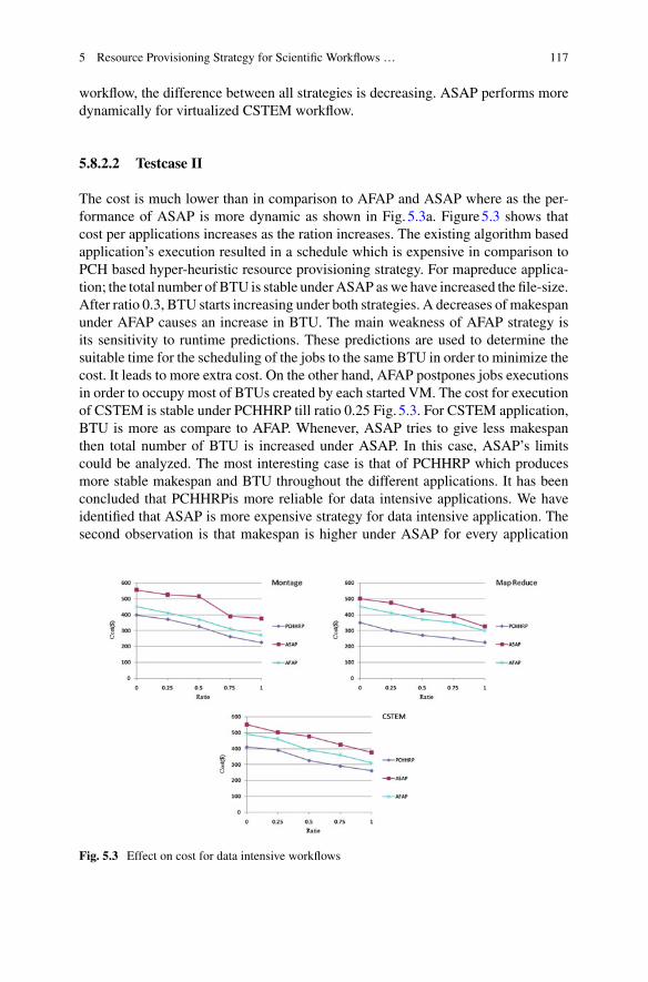
5 Resource Provisioning Strategy for Scientific Workflows … 117
workflow, the difference between all strategies is decreasing. ASAP performs moredynamically for virtualized CSTEM workflow.
5.8.2.2 Testcase II
The cost is much lower than in comparison to AFAP and ASAP where as the per-formance of ASAP is more dynamic as shown in Fig. 5.3a. Figure5.3 shows thatcost per applications increases as the ration increases. The existing algorithm basedapplication’s execution resulted in a schedule which is expensive in comparison toPCH based hyper-heuristic resource provisioning strategy. For mapreduce applica-tion; the total number of BTU is stable underASAP aswe have increased the file-size.After ratio 0.3, BTU starts increasing under both strategies. A decreases of makespanunder AFAP causes an increase in BTU. The main weakness of AFAP strategy isits sensitivity to runtime predictions. These predictions are used to determine thesuitable time for the scheduling of the jobs to the same BTU in order to minimize thecost. It leads to more extra cost. On the other hand, AFAP postpones jobs executionsin order to occupy most of BTUs created by each started VM. The cost for executionof CSTEM is stable under PCHHRP till ratio 0.25 Fig. 5.3. For CSTEM application,BTU is more as compare to AFAP. Whenever, ASAP tries to give less makespanthen total number of BTU is increased under ASAP. In this case, ASAP’s limitscould be analyzed. The most interesting case is that of PCHHRP which producesmore stable makespan and BTU throughout the different applications. It has beenconcluded that PCHHRPis more reliable for data intensive applications. We haveidentified that ASAP is more expensive strategy for data intensive application. Thesecond observation is that makespan is higher under ASAP for every application
Fig. 5.3 Effect on cost for data intensive workflows

118 R. Aron
as file size increases. As we have increased the file-sizes; the makespan for bothpolicies is increasing but makespan under AFAP is increasing at very slow rate incomparison to ASAP. ASAP’s efficiency is well analyzed in the presence of paralleltasks. Result demonstrated the structure of workflow, the task execution times andfile-size. Depending on what user seeks (faster executions and more savings) differ-ent combinations need to be used. The exception of this point seems to be the caseof sequential application.
5.8.3 Effect of Resources
In this case, we have shown the effect of number of resources on data intensiveworkflows. The results depict that by increasing the number of resources, the totalexecution time increases thus decreasing the performance of the cloud. PCHHRPand AFAP perform better when the number of resources is less in comparison to thenumber of jobs. As shown in Fig. 5.4, makespan increases at high rate under ASAPin comparison to PCHHRP and AFAP. For montage scientific workflows, ASAPincreases makespan at high speed but for CSTEM workflow applications, makespanis less as CSTEM workflow application is combination of parallel and sequentialtasks. In this experiments, we kept the file sizes same and increased the number ofresource to observe the behavior of resource provisioning strategies.
The same trend we can observe in the Fig. 5.5 the effect on cost as we kept samenumber of jobs. If there aremore number of resources then cost increases for both dataintensive workflows montage and CSTEM. For mapreduce workflow applications,cost increases at very less speed. The cost of application execution using PCHHRP is
Fig. 5.4 Effect of resources on makespan for data intensive workflows

5 Resource Provisioning Strategy for Scientific Workflows … 119
Fig. 5.5 Effect of resources on cost for data intensive workflows
much less in comparison to the execution cost using existing provisioning strategy.Asthe cost variations within the cloud resources are not significant so the cost benefits ofonly 6–9% were noticed. However, more benefits can be anticipated if the variationsare higher. Thus PCHHRP outperforms all the existing provisioning strategies whenthe application execution cost is high, which is an important case for a large-scalecloud computing environment.
PCHHRP performs better among all three resource provisioning strategies. Asfull as possible is always better and more economical than the other strategy ASAP.Due to denser job packs (VM internal) coupled with less communication partners(across VMs) the communication overhead is lower. These systems are not set upwith high performance interconnects and too much uncertainty is present in theseallocations. This is why larger number of resources will always be worse, unless youare in a dedicated high performance network (Infiniband or similar). This observationindicates that our strategy gives an equally good performance in comparison to thatgiven by other strategy.
Based on the observations, we concluded that a meta strategy could be expectedto play a major role for execution of data intensive workflows. In cloud computing,the main goal of the providers is to minimize the makespan whereas the goal of theuser is to minimize the cost for applications.
5.9 Conclusions and Future Directions
Resource provisioning model is presented for the execution of scientific workflowsin cloud computing. We have considered different types of application mix of com-putation and data intensive application. Communication time can be consider at the

120 R. Aron
selection time of resource provisioning strategy. This paper mainly focuses on theresource provisioning problems for data intensive workflows in the cloud comput-ing environment. Result demonstrated the structure of workflow, the task executiontimes and filesize. Depending on what user seeks (faster executions and more sav-ings) different combinations need to be used. QoS based resource provisioning strat-egy is proposed. The experimental results show that the PCH based hyper-heuristicresource provisioning strategy outperforms the existing provisioning strategies in allthe cases. The proposed strategy not only minimizes cost but it also minimizes themakespan. A cloud is dynamic and diverse, which is rendered by various applicationsand resources. All this raises various theoretical and technical questions. In future,we’ll consider data storage that is also one another important aspect for the executionof scientific application in Cloud environment.
References
1. Schiaas (2015), http://schiaas.gforge.inria.fr/simschlouder.html2. R. Abinaya, P. Harris, A Novel Resource Provisioning Approach for Virtualized Environment
(2016)3. M. Armbrust, A. Fox, R. Griffith, A.D. Joseph, R.H. Katz, A. Konwinski, G. Lee, D.A. Pat-
terson, A. Rabkin, I. Stoica et al., Above the clouds: a Berkeley view of cloud computing(2009)
4. L. Bittencourt, E. Madeira, HCOC: a cost optimization algorithm for workflow scheduling inhybrid clouds. J. Int. Serv. Appl. 2, 207–227 (2011), https://dx.doi.org/10.1007/s13174-011-0032-0, https://dx.doi.org/10.1007/s13174-011-0032-0
5. L.F. Bittencourt, E.R.M. Madeira, A performance-oriented adaptive scheduler for dependenttasks on grids. Concurr. Comput. Pract. Exper. 20(9), 1029–1049 (2008), https://dx.doi.org/10.1002/cpe.v20:9
6. E. Burke, G. Kendall, D.L. Silva, R. OBrien, E. Soubeiga, An ant algorithm hyperheuristicfor the project presentation scheduling problem, in 2005 IEEE Congress on EvolutionaryComputation, vol. 3 (IEEE, 2005), pp. 2263–2270
7. E.K. Burke, M. Gendreau, G. Hyde, G. Kendall, G. Ochoa, E. O zcan, R. Qu, Hyperheuristics:a survey of the state of the art. J. Oper. Res. Soc. 64(12), 1695–1724 (2013)
8. R. Buyya, C.S. Yeo, S. Venugopal, J. Broberg, I. Brandic, Cloud computing and emerging itplatforms: vision, hype, and reality for delivering computing as the 5th utility. Future Gener.Comput. Syst. 25(6), 599–616 (2009)
9. R.N. Calheiros, R. Buyya, Meeting deadlines of scientific workflows in public clouds withtasks replication. IEEE Trans. Parallel Distrib. Syst. 25(7), 1787–1796 (2014)
10. R.N. Calheiros, R. Ranjan, R. Buyya, Virtual machine provisioning based on analytical perfor-mance and qos in cloud computing environments, in 2011 International Conference on ParallelProcessing (ICPP) (IEEE, 2011), pp. 295–304
11. S. Chaisiri, B.S. Lee,D.Niyato,Optimization of resource provisioning cost in cloud computing.IEEE Trans. Serv. Comput. 5(2), 164–177 (2012)
12. P. Cowling, G. Kendall, L. Han, An investigation of a hyperheuristic genetic algorithm appliedto a trainer scheduling problem, in Proceedings of the 2002 Congress on Evolutionary Com-putation, 2002. CEC02, vol. 2 (IEEE, 2002), pp. 1185–1190
13. D.G. Feitelson,WorkloadModeling forComputer SystemsPerformance evaluation (CambridgeUniversity Press, Cambridge, 2015)
14. I. Foster, Y. Zhao, I. Raicu, S. Lu, Cloud computing and grid computing 360-degree compared,in Grid Computing Environments Workshop, 2008. GCE08 (IEEE, 2008), p. 110

5 Resource Provisioning Strategy for Scientific Workflows … 121
15. A. Fox, R. Griffith, A. Joseph, R. Katz, A. Konwinski, G. Lee, D. Patterson, A. Rabkin, I.Stoica, Above the clouds: a Berkeley view of cloud computing. Dept. Electr. Eng. Comput.Sci. Univ. California Berkeley, Rep. UCB/EECS 28(13), 2009 (2009)
16. M. Frincu, S. Genaud, J. Gossa, Comparing provisioning and scheduling strategies for work-flows on clouds, inWorkshop Proceedings of 28th IEEE International Parallel and DistributedProcessing Symposium (IEEE, 2013), pp. 2101–2110
17. S. Genaud, J. Gossa, Cost-wait trade-offs in client-side resource provisioning with elasticclouds, in 4th IEEE International Conference on Cloud Computing (CLOUD 2011) (IEEE,2011)
18. F. Glover, Tabu search-part i. ORSA J. Comput. 1(3), 190–206 (1989)19. M.A. Iverson, F. O zguner, G.J. Follen, Parallelizing existing applications in a distributed
heterogeneous environment, in 4TH Heterogeneous Computing Workshop HCW95 (Citeseer,1995)
20. B. Jennings, R. Stadler, Resource management in clouds: survey and research challenges. J.Netw. Syst. Manag. 23(3), 567–619 (2015)
21. G. Juve, E. Deelman, G.B. Berriman, B.P. Berman, P. Maechling, An evaluation of the costand performance of scientific workflows on amazon ec2. J. Grid Comput. 10(1), 521 (2012)
22. G. Juve, E. Deelman, K. Vahi, G. Mehta, B. Berriman, B.P. Berman, P. Maechling, Scientificworkflowapplications on amazon ec2, in 2009 5th IEEE InternationalConference onE-ScienceWorkshops (IEEE, 2009), pp. 59–66
23. G. Juve, E. Deelman, K. Vahi, G. Mehta, B. Berriman, B.P. Berman, P. Maechling, Datasharing options for scientific workflows on amazon ec2, in Proceedings of the 2010 ACM/IEEEInternational Conference for High Performance Computing, Networking, Storage and Analysis(IEEE Computer Society, 2010), p. 19
24. C. Lin, S. Lu, Scheduling scientific workflows elastically for cloud computing, in 2011 IEEEInternational Conference on Cloud Computing (CLOUD) (IEEE, 2011), pp. 746–747
25. W. Lin, C. Liang, J.Z. Wang, R. Buyya, Bandwidth-aware divisible task scheduling for cloudcomputing. Softw. Pract. Exper. 44(2), 163–174 (2014)
26. M. Malawski, G. Juve, E. Deelman, J. Nabrzyski, Cost-and deadline-constrained provisioningfor scientific workflow ensembles in IAAS clouds, in Proceedings of the International Con-ference on High Performance Computing, Networking, Storage and Analysis (IEEE ComputerSociety Press, 2012), p. 22
27. E. Michon, J. Gossa, S. Genaud, Free elasticity and free CPU power for scientific workloadson IaaS Clouds, in 18th IEEE International Conference on Parallel and Distributed Systems(IEEE, Singapour, Singapore, 2012), http://hal.inria.fr/hal-00733155
28. I. Chana, Rajni, Bacterial foraging based hyper-heuristic for resource scheduling in grid com-puting. Future Gener. Comput. Syst. 29(3), 751–762 (2013)
29. A. Rajni, An empirical study of vm provisioning strategies on IAAS cloud, in 2016 IEEE18th International Conference on High Performance Computing and Communications (IEEE,2016)
30. J. Sen, Security and privacy issues in cloud computing, in Architectures and Protocols forSecure Information Technology Infrastructures (2013), p. 145
31. J. Shi, J. Luo, F. Dong, J. Zhang, J. Zhang, Elastic resource provisioning for scientific workflowscheduling in cloud under budget and deadline constraints. Cluster Comput. 19(1), 167182(2016)
32. S. Srinivasan, G. Juve, R.F. Da Silva, K. Vahi, E. Deelman, A cleanup algorithm for implement-ing storage constraints in scientific workflow executions, in 2014 9th Workshop on Workflowsin Support of Large-Scale Science (WORKS) (IEEE, 2014), pp. 41–49
33. C. Szabo, Q.Z. Sheng, T. Kroeger, Y. Zhang, J. Yu, Science in the cloud: Allocation andexecution of data-intensive scientific workflows. J. Grid Comput. 120 (2013)
34. D. Villegas, A. Antoniou, S.M. Sadjadi, A. Iosup, An analysis of provisioning and allocationpolicies for infrastructure-as-a-service clouds, in 2012 12th IEEE/ACM International Sympo-sium on Cluster, Cloud and Grid Computing (CCGrid) (IEEE, 2012), pp. 612–619

122 R. Aron
35. Z. Wu, X. Liu, Z. Ni, D. Yuan, Y. Yang, A market-oriented hierarchical scheduling strategy incloud workflow systems. J. Supercomput. 63(1), 256–293 (2013)
36. A. Zhou, B. He, C. Liu, Monetary cost optimizations for hosting workflow-as-a-service inIAAS clouds (2013)

Chapter 6Consolidation in Cloud EnvironmentUsing Optimization Techniques
Ritesh Patel
Abstract The services offered by cloud computing and its usage are increasing day-by-day. Due to the elasticity characteristic of cloud computing, many organizationsare now moving their services on cloud data centers. A cloud disaster recoveryrequires migration of a VM from one data center to another without disconnectingthe user. Live VM migration is a key concept to transfer VM without disruptingservices. Server consolidation and scheduled maintenance are added advantages ofit. In cloud computing, moving large size of VM from one data center to other datacenter over a wide area network is a challenging task.
Keywords Live Virtual Machine(VM) migration · Virtualization · Networkprotocol stack · Cloud data center
6.1 Introduction
Process migration was hot topic in virtual computer systems since 1980s. Researchcommunity got some success to carry our process migration for the few category ofapplications. Milojicic [22] gave a survey and problems associated with processmigration. Major problem is the residual dependencies that a migrated processhas with operating system. Examples of residual dependencies include open filedescriptors, shared memory segments with other processes and other local resources.Research community gradually comeupwith newsolution: instated of process,wholeoperating system can bemigrated. To achieve this hardware visualization is required.
Increase of bandwidth at end user has increased demand to perform operations on-line Indeed, it increases the requirement of efficient resource management in the datacenter. Many big players of Cloud Service providers such as Google, Amazon andMicrosoft, are providing cloud solutions in terms of product or in terms of services
R. Patel (B)Computer Engineering Department, C.S. Patel Institute of Technology,CHARUSAT, Anand 388421, Gujarat, Indiae-mail: [email protected]
© Springer International Publishing AG, part of Springer Nature 2018B. S. P. Mishra et al. (eds.), Cloud Computing for Optimization:Foundations, Applications, and Challenges, Studies in Big Data 39,https://doi.org/10.1007/978-3-319-73676-1_6
123

124 R. Patel
[39]. Amazon [4] and Microsoft [21] are providing services through portal. Otherorganizations can create their private cloud using product based solutions like VMware, Xen and Microsoft hypervisor. Users may demand their services for Compute,Storage, Networking solutions and much more. Cloud providers are providing theseservices through Data Center where all the hardware elements are virtualized andmade available to users based on their need. Cloud providers are able to providethese services through any one of three levels of Virtualization.
Hardware virtualization [19] is a powerful platform for making clear separationbetween real hardware and operating system. Applications and resources can beloaded in that operating system. It facilitates to virtualize CPU, RAM, SecondaryStorage and Network. Multiple OS can be run simultaneously using hardware visu-alization.Migrating entire operating system instances [33] across distinct physicalhosts provides ease of manageability for administrators of data centers.
6.2 Virtualization
Virtualization forms strong foundation for cloud computing. It separates strong tieup between operating system and computer hardware by purring separate thin layerof virtualization. There are three levels of virtualization exists (i) Application virtu-alization, (ii) OS virtualization and (iii) Hardware virtualization.
1. Application Virtualization where same application can be executed on differentOS platform by introducing virtual execution environment.
2. Operating System Virtualization where functionality of operating system isabstracted into container and it can be easily ported on different machine.
3. Hardware Virtualizationwhere components of computers are virtualized to runmultiple operating system.
6.3 Virtual Machine Migration
Virtual machine migration is a key feature of virtualization. It enables a easier man-agement of large variety of tasks.Advantages of Live Migration [14] are:
1. Reduce power consumption using VM consolidation.2. Improve reliability with business continuity and disaster recovery.3. Efficiently manage IT infrastructure using single management console.4. Exploitation of resource locality for performance and resource sharing.5. Simplified system administration and mobile computing for instance as used by
commuters from office to home.

6 Consolidation in Cloud Environment … 125
6.3.1 Live VM Migration
Moving a running virtual machine between different physical machines withoutdisconnecting the client or user application is known as live VMmigration. But, it isobvious that, user may not access application for some duration of time dependingon the type of migration. But that duration is negligible with respect to featuresprovided. Live migration is a key feature [24] of virtualization. It enables a largevariety of management tasks to manage very easily.
There are two approaches to live VM migration. (1) Managed migration (2) SelfMigration. As shown in Fig. 6.1, in managed migration, VM controller is responsibleto monitor and migrate VM on targeted host. While in self migration, migration stub[11] on host would transfer VM to the targeted host. Migration stub is responsible tofind out suitable host for migration and carry out task related to migration.In eitherof above approach do not require to modify guest OS to support live VM migration.Major advantage of manged migration is it allows various heuristics to be applied atcentral controller which reduces implementation complexity.
Migrating an virtual machine involves to transfer of in-memory state and diskstate. Several research problems are identified and solved to perform an efficienttransfer of VM. Depending on whether VM migration suspends user processes, it iscategorized under Cold and Live migration, as shown in Fig. 6.2. In cold migration,VM is shut down at source host and restart in targeted host. The user would lose theconnection. In live migration, VM is continuously transferred to targeted host whilethe user is accessing data. Further live migration in divided into two types, Seamlessmigration and Non-seamless migration. In seamless migration, user would not getdisturbed while migration is going on, and non-seamless migration, user processeswould be suspended at source host and resumed at the targeted host [5, 29].
Fig. 6.1 Approaches of VM migration

126 R. Patel
Fig. 6.2 Types of VM migration
In cold migration, VM is shut down at source host and started in targeted host.The user would lose the connection as well as current computing. In live migration,VM is continuously transferred to targeted host while the user is accessing data. Thiskind of scenario is suitable to applications which has characteristics like busty withsmall duration of time. Examples includes web traffic.
Live migration in divided into two types, Seamless Migration and Non-seamlessMigration. In seamless migration, user would not get disturbed while migration isgoing on, and non-seamless migration, user processes would be suspended at sourcehost and resumed at the targeted host [5, 29]. Differences among these migration are(i) downtime suffered by user (ii) whether user need to take some action to continueoperation or not.
Seamless live VM Migration [31] is carried as illustrated in Fig. 6.3:
1. Phase i: Pre-Migration: Selection of VM to be transferred and Host on which VMwill be shifted will be carried out here.
2. Phase ii: Resource Reservation: Resources like primary and secondary storage,network bandwidth allocation, CPU Cores, on the destination are reserved.
3. Phase iii: Iterative Copy: In-memory image VM is treated as sequential blocks.One by one block is transferred to the destination host in a number of iterations.VM is not stopped yet on the source host. Blockswhich aremodified in the currentiteration will be transferred in the next iteration on the destination host. Numberof iterations determine the efficiency of the migration process.

6 Consolidation in Cloud Environment … 127
Fig. 6.3 Live migration steps
4. Phase iv: Pause-and-Copy: Once the number of modified pages reaches to thebelow threshold in particular iteration, VM is suspended at source, then CPUstate and other remaining modified memory blocks are transferred to target host.
5. Phase v: Post-migration: Device drivers are mapped to the new VM. To informnew network attachment, it advertises MAC addresses using the ARP unsolicitedmessage which changes the network binding of MAC address to layer 2 devicesand mapping of MAC to IP address in hosts in the network.
In pre-copy migration, phase-iii will be iterated until it reaches to some thresholdvalue. In post-copy migration, phase-v performed after phase-ii, means users will beconnected to targeted host first and required pages are transferred using page faultat remote location and rest pages are transferred in single iteration.
Pause-and-Copy is an example of non-seamless migration. It is considered thesimplestmigration technique.But it leads to higher downtime aswell as servicewouldnot be available for that duration of time. It involves stopping current VM, copyingto target host and restarting VM at target host. Network also plays important roleto transfer VM if network transfer is involved. As compared to Live VM migration,stop and copy takes less time of VM transfer as it does not need to support the currentconnections. This approach is easy to implement and control. Disadvantages is thatusers suffers from unavailability of VM during VM transfer. Even if migration iscarried out over WAN, VM would not be available until DNS gets updated. Non-seamless migration is out of scope of thesis work so it is not discussed further.
Depending on the writable workload on the VM, current hypervisors performlive VM migration from milliseconds to few seconds. VMware [23] a proprietarysolution and KVM [18] open source solution facilitates with live VM migration.
128 R. Patel
The advantages of Live VM migration are as follows:
1. Migrating VM moves residual application and all its dependencies which existwith the OS. No need to detach applications and its dependencies.
2. VM is migrated with network credentials, application level restarts or reconnectis not required at the targeted host.
3. Easy administration of virtual machine in clustered and non-clustered environ-ment.
4. Facilitates efficient use of hardware.5. Preventive maintenance can be scheduled without disturbing user.6. Server consolidation becomes easy.7. User access time can be improved by using follow-the-sun [31] scenario.
LiveMigration time ismostly affectedby the (1)VMmemory size (2)Rate ofmod-ification of blocks in subsequent iteration (3) Application workload on VM whichincreases rate of modification of blocks (4) Current network bandwidth between thesource and destination servers (5) Hardware configuration of the source and desti-nation servers (6) Amount of buffer allocated to the transport layer of hypervisor.
6.3.2 Properties of the Live VM Migration
Followings are the properties of the VM migration over LAN as well as WAN [12]
• Continuous operation: The VM should continue to provides services while trans-ferring its in-memory and local storage.
• Consistency: File system is remain consistent after VM migration on destinationmachine.
• Minimum service disruption: Migration should not significantly degrade theperformance of services running in the VM.
• Transparency: Treatment of services running inside the virtual machine shouldbe same as the OS is running on hardware. The VM’s open network connectionsremain alive, even after an IP address change, and new connections are seamlesslyredirected to the new IP address at the destination.
6.3.3 Performance Metrics
The following are the metric parameter [17] to evaluate any live VM migrationmethod.
1. Preparation Time: Time between initiating migration process and transferring theVMs processor state to the target node, during which the VM continues to executeand dirty its memory.
6 Consolidation in Cloud Environment … 129
2. Down Time: It is time that VMwould not be available to the user. It is also knownas non-availability time. At the end of migration, user VM is paused and all thepages are migrated to target host. This time the VM is not available to the user. Itis also known as pause time.
3. Pages Transferred: VM image is divided into a number of blocks called pages [?].VM image is transferred by picking up one page by page. So, a unit of transferis pages. There is a trade-off between size of the page and dirtied pages. If thepage size is larger than the possibility of a number of dirtied pages will be lessand vice versa.
4. Resume Time: It is pause time caused by reconnection to the target host.5. Total Migration Time: Total time taken by host machines to migrate VM from
source host to target host. Total time is very important because it affects the releaseof resources on source node.
6. Performance Degradation: When Virtual machine is migrated from one host toanother, the application would suffer a little bit pause time.
By literature survey and various experiments, it could conclude that totalmigrationtime heavily depends on the network throughput and reaction of congestion controlalgorithm. Following are the other parameters which also affect the performance oflive VM migration.
1. Total size of VM.2. Size and Number of pages of VM.3. Dirtying rate while VM migration takes place.4. Currently available network bandwidth.5. Current Network Traffic.6. Congestion Control Algorithm at transport layer.7. The buffer allocated to application at Socket Layer (both at sender and receiver
side).8. Queuing mechanism at intermediate node/switch/router.9. Network utilization during live VM migration.10. Ingress and Outgress data traffic.
Server consolidation is one of the requirements of the data center to make energyefficient [1]. VM Migration is a key concept in server consolidation where heavilyloaded and lightly loadedVMs aremigrated to another host tomeet the SLAviolationand efficient energy consumption required in the data center. VM migration is alsoperformed across data centers to perform disaster recovery, pre-planed data centermaintenance and migrating VM as closer to users to solve the problem of responsetime [31].
6.3.4 Applications of Live VM Migration
According to need, VM can be migration within LAN andWAN network. Followingare the applications within datacenter.

130 R. Patel
• Server Consolidation [27]: Aggregating VMs on single host is known as serverconsolidation. Using live VM migration multiple VM can be transferred to singlehost to utilize resources fully.
• Energy Conservation [27]: In host, 70% of energy is consumed by non computingelements. To conserve energy, VMs running on underutilized node are transferredto other host and under utilized hosts are shuted down. Reducing resources withoutaffecting application performance
• Avoiding SLA Violations: In case of requirement of performance, VM can beshifted to under utilized host to avoid SLA.
• Service Load Balancing [27]: Quick instances can be created by copying in-memory copy of VM.
Following are the needs to perform VM transfer across Data Center
• Fog Computing [6, 30, 32, 38]: Cloud computing is characterized as a group ofPCs and bunch of servers associated together over the Internet to form a client-server system. Today, the large number of ventures and substantial associations arestarting to receive the Internet of Things, the requirement for a lot of informationto be collected at the center node for the further processing. Fog Computing is aframework in which certain application procedures are managed over infrastruc-ture and it is overseen at the edge of the system by a gadget. It is, basically, a centerlayer between the cloud and the equipment to empower more proficient informa-tion handling, investigation and capacity, which is accomplished by diminishingthe measure of information which should be transported to the cloud.
• Follow the Sun: User applications can be brought near to user geographic area toreduce latency.
• Disaster Recovery The capability to relocate a virtual machine (VM) form onephysical host to other physical host can fundamentally help an organization toenhance business reliability. It also facilitates to perform server hardware mainte-nance without affecting users.
• Hybrid Cloud Computing: Private data center is integrated with public cloud. VMcan be migrated from public to private to cut the billing cost. Same way VM canbe transferred to private to public to carry maintenance of private cloud withoutworrying of service availability.
6.3.5 Four Decision Pillars of Migration
1. When to Migrate: It deals with requirement of the migration. Where VM need tobe migrated or not. There are many approaches and each approach have pros andcons. Simplest approach is to manual VM migration where each VM is pickedup manually ans transferred to other data center. Its good for small data centerwherein time consuming in larger data center.
6 Consolidation in Cloud Environment … 131
a. Autob. Manualc. SemiAuto / Semi Manuald. Host Over loading Detectione. Host Under loading Detectionf. heuristics
i. An adaptive Utilization Thresholdii. Local Regressioniii. Robust Local Regression
2. What to Migrate: It deals with proactive VM migration, where it has statistics ofall VMs and applies some heuristics to decide the order of VM migration. It isalso possible to transfer more than one VMs simultaneously.
a. VM Selectioni. The minimum Migration Time Policyii. The Random Choice Policyiii. The Maximum Correlation Policy
3. How toMigrate: Its a reactive kind ofVMmigration,where decisions ofmigrationis made during in transit VM scenario.
a. Compression Algorithmb. Network aware migration
4. Where to Migrate
a. Within same Data Center: This would transfer VM using LANmostly usinginfiniband switches.
b. Outside Data Center (Other data center): This involves transferring datafrom one data center to other data center using WAN. Root challenges areof high latency and higher downtime observed by user.
c. VM Placement: It deals with in which host this VMmust be placed efficientwork. It also requires heuristics to decide best combination of host and VMcombination.i. An adaptive Utilization Thresholdii. Local Regressioniii. Robust Local Regression.
6.4 VM Consolidation
VM consolidation is one of the requirements of the data center to make energyefficient [1]. VM Migration is a key concept in VM consolidation where heavilyloaded and lightly loadedVMs aremigrated to another host tomeet the SLAviolationand efficient energy consumption required in the data center. VM migration is also
132 R. Patel
performed across data centers to perform disaster recovery, pre-planed data centermaintenance and migrating VM as closer to users to solve the problem of responsetime [31].
VM Consolidation is technique to reduce the number of active PMs by consol-idating multiple underloaded VMs into one physical machines. VM consolidationincludes
• VM Selection• VM Placements
Following are the advantages of VM consolidation
• Reduce the amount of active physical machine,• Reduce the data center footprints,• Indirectly reduce power consumption,• Energy conservation
6.4.1 VM Selection
VM selection refers to selecting VM for themigration to different host. VM selectioncan be initiated either by host over-load detection OR host under-load detection.
VM can be selected from one of the approaches:
• Minimum Utilization: The VMs with the lowest CPU utilization are selected forthe migration.
• Maximum Utilization: The VMs with the highest CPU utilization are selected.This approach is very useful to meet SLA.
• MinimumMigration time: The VMs with the lowest calculated migration time areselected. Lowest migration time is calculated using current size of VM and currentload on VM.
6.4.2 VM Placement
After VM is being selected for migration, it required to find the suitable host for themigration is known as VM placement. Once the VM is running and migrated to otherhost then it is known as VM placement.Following are the approaches of VM placement:
• Power Saving based approach• Application based approach• Service Level agreement based Approach

6 Consolidation in Cloud Environment … 133
Many algorithms are proposed for efficient VMPlacement like first fit, single dimen-sional best fit, volume based best fit, dot product based fit, constraint based approach,bin packing problem, stochastic integer programming, genetic algorithm, networkaware etc.
6.5 Components of Live VMMigration
Virtual machine live migration facilitates to move a virtual machine running onone physical host to another host without disturbing application availability. Livemigration catches aVM’s totalmemory state and the condition of all its processor coreare collected and send it to memory space on destination host. The destination hostthen loads the processor cores and resumes VMs execution. All virtualization toolsoffer live VM migration: VMware offers vMotion, Microsoft offers Live Migrationin Hyper-V, and Citrix Systems offers XenMotion.
Live Migration over WAN has some issues. First, because of the high-latencycharacteristic of links in the WAN, VM migration takes longer time. Second, aftermigration the VM will be allocated new IP address, seamless application reconnectis require.
Following are the components of live VM migration:
1. Need for the migration2. Selection of VM to be migrated3. Selection of host on which VM is to be migrated4. Allocating resources at destination machine5. Migrating CPU State6. Migrating in-memory image7. Migrating disk pages8. Migrating network
• Redirecting network to destination machine• Redirecting clients to destination machine
9. Modeling VM Migration
• Cost of VM Migration.
6.5.1 Need of Live VM Migration
Live migration of VM allows transferring a VM between physical nodes withoutinterruption and with a very short downtime. However, Live VM migration nega-tively impacts performance of application performance running inside VM duringmigration. Requirement are framed either within or outside data center migration.

134 R. Patel
As we have seen the previous section that Within Data Center Energy Conser-vation,Server consolidation, Mitigating SLA violations and Service Load Balancingare the major need of VM migration.
ServerConsolidation and energy conservation are co-relatedwith each other. Loadon the server changes based on the customer location of geographic boundary. Asservers would not be heavily loaded during night hours, thoseVMcould be combinedand put on single host.
The benefits of server grouping together include higher efficiency, reducing powerand cooling costs, and the flexibility to move workloads between physical servers.
As we have seen the previous section that Across Data Center Fog Computing,Follow the Sun, Disaster Recovery and hybrid cloud computing are the major appli-cation areas.
Availability of computational resources and network resources during migrationare also real time issues [10] to have control over live VMmigration. Processor shareof VM depends on the scheduling policy of operating system. To estimate accuratetime required to transfer pages of in-memory VM, bandwidth should be constant.Fixed bandwidth of 100Mbps is taken for consideration and probabilistic based LRUpolicy is used to evaluate work.
In fact, frequentVMmigrationwould lead to increase of overhead [34]. Therefore,it is necessary to define heuristics very carefully such that it should avoid frequentVM migration. Bing wei combined heuristics of energy optimized and workloadadaptive modeling for migration. Workload characteristics are analyzed to avoid theunnecessary migration. Even in case of decrease of workload, it avoids to migrationVM.
6.5.2 Selection of VM to be Migrated
Selection ofVMcan be based on average post-migrationCPU, load on the destinationPM, cost of the migration, and expected load distribution in the system after themigration.
Energy guided migration [34] model selects the best VM by considering VM’scurrent memory and utilization of CPU [13].
S. Zaman and D. Grosu [40] suggested auction based VM selection policy. Twostrategies are suggested, Push and Pull. In push method, an overloaded physicalmachine acts as a seller. PM constitutes actioned parameters PM communicates thisinformation to other using multicasting protocol. The underloaded PM acts as abuyers. The buyers may bid on one, several, or all auctioned VMs. The seller selectsthe best host from the bids.
In pull strategy, underutilized PM acts as seller and advertises free resources. Theother PMs, mostly overutilized, in the system are potential resource buyers that bidwith for the resources. The seller decides which bid it accepts and initiates the VMmigration.

6 Consolidation in Cloud Environment … 135
6.5.3 Selection of Host on Which VM is to be Migrated
Workload adaptive model [34] selects the best migrating target physical server withthe lowest power consumption. In addition, it determines the suitable migrationmoment in terms of both the performance and the trend of workload.
6.5.4 Migrating In-Memory Image
In this section modeling in-memory image and predicting of migration time mathe-matically are discussed..
F. Checconi, T. Cucinotta, andM. Stein [10] presented technique for livemigrationof real-time virtualized machines. The achievement of research is very low andpredictable down times, as well as the availability of guaranteed resources duringthe migration process.
Total time for the migration is calculated by
t f =(P + H
bd
) K∑k=1
nk + td (6.1)
where nk is number of pages in kth iteration, P is page size in Bytes, H is overheadof bytes, bd is constant bandwidth available during migration and td is downtimeobserved by user.
Downtime td is expressed as
td =(P + H
bd
)nk+1 (6.2)
where k + 1 is last iteration of themigration duringwhich all the pages in kth iterationis dirtied.
As per Eqs. 6.1 and 6.2, total migration time and downtime is inversely proposalto the bandwidth available during migration.
Assumption: Bandwidth of fixed size 50Mbps.FutureWork: Different policies can be developed and tested for reordering page
to be transferred. To reduce the migration time
• Derive heuristics which reduces time by reducing dirty rate.• Perform testing on different values of bandwidth.• Derive heuristics which rearranges pages to be transferred in each iteration [10].
C.Clark,K. Fraser, S.Hand [11] presented thatmigrating theVM’s fromone physicalhost to targeted host can be can be accomplished by any one of three approaches.Approaches are assessed based on the requirements of minimizing both downtimeand total migration time. The downtime is the period during which the service is

136 R. Patel
unavailable to user due to pause time of VM instance. This period will be obasedas service interruption by client. The migration time is the duration between whenmigration is initiated and client gets reconnected with VM on targeted host.
Push migration VM continues to destination server and pages are pushed by theserver agent to the destination server. Pull migration has two parallel transmission.First its normal transmission and second is pulling (page on demand) transmission.Either on any types of migration, network migration remains challenging task.
6.5.5 Migrating Disk Pages
Following are the classification approaches of migrating disk pages
1. Replica based2. Pull mode3. Push mode4. Hybrid mode
S. Al-Kiswany, D. Subhraveti, P. Sarkar, and M. Ripeanu [3] presentedVMFlockMS, a migration service optimized for cross-datacenter transfer. Authorssuggested two approaches to reduce migration time and minimize pause time causedby migration. First, VM deduplication: Multiple copies of VM is deployed is active-passivemode. Once the active copy is unavailable then one of the passice copy of VMwill be made active. Second, Accelerated Instantiation: It crates partial set of databased the access patterns observed in last few moments. Evaluation of VMFlocksshows that it can reduce the data volumes to be transferred over the network to aslow as 3% of the original VM size.
Method: Duplicate VM Image is kept on multiple data center. Data are copiedfrequently. Its not migration its about VM Duplication
Thought: VM Duplication is solution here. Disadvantages are resource wastageand lower down efficiency of network bandwidth.
K. Haselhorst, M. Schmidt, R. Schwarzkopf, N. Fallenbeck, and B. Freisleben[16] suggested replica based solution. Write on both the site. Multiple copies of VMare kept at multiple sites. Read operation is carried out from any one copy but writeoperation is performedonall the duplicated sites. For this purpose, a novelmechanismbased on distributed replicated block devices (DRBD) has been presented that allowsfor synchronous writes on the source and the destination host.
Issue: Synchronization of VM storage for live VM over WAN. Main Challenge:writable part need to be synchronized.
B. Nicolae and F. Cappello [25] suggested to use active push prioritized prefetchstrategy. It uses combination of pre-copy and post-copy to performmigration. It startswith pre-copy but end with post copy.
Challenge: Disk storage transfer under high I/O intensive workload.K.Haselhorst,M. Schmidt, R. Schwarzkopf,N. Fallenbeck, andB. Freisleben pre-
sented VM migration over WAN, targeting to synchronize the storage on the source
6 Consolidation in Cloud Environment … 137
and destination before transferring control to the destination. They have introducestwo issues:
• The same disk content may change repeatedly. This lead to frequent write ondestination server. This, increases migration time.
• Rate of change of disk content is higher than the data rate of copying it to destina-tion. Thus migration becomes impossible and it could have a negative impact onperformance of application.
Problem addressed: When to transfer phase from pre-copy to post-copy.It uses least frequently access policy during post-copy transfer. It uses sequen-
tial packet transfer in post-copy phase. Along with this it uses hybrid active push-prioritized prefetch strategy. Performance of live migration reach to 10x faster, con-sumed to 5x less bandwidth and resulted in high I/O throughput.
J. Zheng, T. S. E. Ng, and K. Sripanidkulchai [42] presented Workload awarescheduling of transfer of chunk. Also size of chunk depends on workload of VM.The benefits of scheduling increases as the available network bandwidth decreases,as image seize gets larger and as I/O rate gets increase. Authors validated resultswith five representative applications.
6.5.6 Migrating over Network
Live migration can be carried out differently in LAN and WAN.
• Local area network redirection: In LAN environment, migrating VM wouldcarry its local IP address with it. There will not be a problem of transport layerconnection reset. Only Layer 2 redirection is sufficient. Layer 2 redirection com-promise with drop of in-flight packet which are occurring at last iteration of migra-tion. To ensure about the network remapping of layer 2, ARP advertisement is sentin the network to assign new IP address and its corresponding MAC address.
• Wide area network redirection: VM migration over WAN is similar to LANbut VM migration over WAN possesses different challenges which are elaboratedbelow.
There are some issues while dealing with WAN VM migration are as follows:
1. High latency: VMmigration gets high latency while VM ismigrating from sourcehost to destination.
2. Network reconnect because of change in IP address.3. Higher application workload (I/O intensive workload).4. It Slow downs performance of multiple VM transfer.
Higher latency lead to lower data transfer rate. If data transfer rate is lower than theVM dirty rate, VM migration becomes endless process. It continuously involves totransfer pages whichwill bemodified again and again. It is recommended that Higherbandwidth should be available during the transfer of VM or at least last iteration

138 R. Patel
Fig. 6.4 CloudNet:VPN Proxy Based Migration
going on. Layer 3 redirection would break connection. Layer 3 redirection changesthe layer 3 addressing facility. So it would reset application layer connection, networkapplications need to be restarted. To mitigate this issue Mobile IP [7] is a solutionwhere a node on the home network (the home agent) forwards packets destined forthe client (mobile node) in terms of care-of address on the foreign network.
VPN Proxy based method [37] To lower down downtime and migration time, [37]have suggested CloudNet, a VPN based proxy mechanism to overcome problem ofWAN migration. Figure6.4 shows a pair of VPCs, cloud 1 and cloud 2, that spanmultiple cloud data centers, but present a unified pool of resources to each enterprisesites. A VPN controller is responsible for the remapping of the VM to cloud site.It uses further MPLS based VPN to increase naming abstraction. Dynamic VPNreconfiguration deploy and move resources between cloud data centers. Figure6.4shows a pair of VPCs that span multiple cloud data centers, but present a unifiedpool of resources to each enterprise.
J. Cao, L. Zhang, J. Yang, and S. K. Das [9] solved the problem of connectionmigration at transport layer level by a secure token negotiated at connection estab-lishment time. That token will be subsequently used during connection migration toidentify the legitimate session of TCP.
DNS updates are suggested in Dynamic DNS as a means of relocating hosts aftera move. In WANVMmigration, the migrated VM gets a new IP address. Temporarynetwork redirection scheme [12] provided solution by combining IP tunneling [28]with Dynamic DNS [35].
Dynamic Rate-Limiting for Migration Traffic [11]
The downtime suffered by user can be reduced by increasing the bandwidth limit[11] with lower and upper bound. Bandwidth can be adapted dynamically duringeach precopy iteration as well. Fixed bandwidth could be allocated to first precopyround then subsequently, bandwidth could be increased as iteration is progressing.Bandwidth limit could be derived from the previous iteration’s dirtying rate.
TCP Freeze [8]
M. V. Bicakci and T. Kunz [8] have proposed a cross-layer feasibility for vir-tual machine live migration between various subnets. The live migration processis straightforward to the correspondent hosts, and this is accomplished by having the

6 Consolidation in Cloud Environment … 139
Fig. 6.5 TCP freeze: initial topology
old host of the moved virtual machine act as a proxy server at Layer 3. Further TCPfreeze mechanism is used to stop the in-transit packets.
Features of TCP Freeze
1. Guest Operating system is aware of live Migration process.2. TCP Freeze is used to stop further generation of in-transit packets.3. Ip-in-IP tunnel is set from source host to destination host to prevent from recon-
nection for existing connection.
Once the virtual machine is live migrated, it will have two IP addresses: IPaddress on the new subnet, and IP from old subnet(by means of the IP-in-IP burrowfrom the source have). Figure6.5 shows initial topology before migration take place.Figures6.5 portray the means taken when a virtual machine is relocated more thanonce between various hosts. In Fig. 6.5, the virtual machine is running on Host 1,with an IP address of 111.123.10.10.A customer, C1, has a dynamic association withHost 1.
As can be found in Fig. 6.6, the virtual machine is then moved to Host 2, which ison another subnet. The new IP address of the virtual machine is 111.123.20.20. Thispoint of time all the connection to VM a would get disrupted. Subsequently, Ip-in-Iptunnel is created for this connection tonewly created IP subnet address.111.123.20.10.
New client C2 wants to get connected to VM, but this time using the virtualmachine’s new IP address 111.123.20.20.

140 R. Patel
Fig. 6.6 TCP freeze: network topology after migration to network-1
Finally, the virtual machine is migrated to Host 3, as can be seen in Fig. 6.7. In thiscase, two tunnels will be created at VM running of host 3. Firt tunnel is created fromHost 1 to host 2 to support in-flight data of client c1 and second tunnel is createdfrom host 2 to host 3 to support in-flight data of client 2. Noe if either C1 or C2 resetsthe connections, tunnel is no longer available. It identifies VM with newly allocatedIP address i.e. 111.123.30.20. Any further connection of client will be connected to11.123.30.20.
VM Turntable [31]
The ability to move live VMs over a other long distanced data center addresses theissues [31] of many key serious case situations, particularly when user should not beaware about migration.
For a wide area migration of VM must have short downtime in spite of RTT.This is particularly valid for data center with hundreds or a huge number of virtualmachines arranged for a hypothetical selection of VM to be transferred. Uponmigra-tion, the system endpoints be consistently adjusted to the new environment, with noearlier understanding, ans should also implement different addressing scheme thanthe original environment. The adjustment of the endpoints must happen transparentlywith respect to end users. Much of the time, the new environment must be thoughtto keep equal or better access than the source environment required by the virtualmachine (Fig. 6.8)

6 Consolidation in Cloud Environment … 141
Fig. 6.7 TCP freeze: network topology after migration to network-2
VM Shadow [15]
VM Shadow considers virtual desktops and gaming application servers that requiredto bemoved closest to the client.VMShadow is a framework to consequently upgradethe area and execution of area delicate virtual desktops in the cloud. VMShadow con-tinuously performs fingerprinting of aVM’s system activity aswell as geo-location ofother data center to conclude best VM-Datacenter pair for each clients. VM Shadowutilizes WAN-based live movement and another system association relocation con-vention to guarantee that theVM relocation and resulting changes to theVM’s systemdeliver are transparent to end-clients.
Transparent VM migration is achieved in two phase. In the first phase, it iden-tifies VM to be migrated and data center where the VM is placed. In second phaseit performs transparent VM and connection migration across geo-location withoutdisturbing current connection.
Given a multiple cloud with L locations and N VMs, the shadowing algorithmaccomplish following steps. In step 1 of algorithm, it identifies good candidates tomove from current data center to other data center based on location sensitive ranksof all VM. Threshold is defined to make decision whether VM need to be migratedfirst or not. It also counts the resources availability at other cloud sites. In step 2, itdetermines other data center for transferring VM based on the geo-location of eachVMwith respect to data center. It identifies k closet cloud sites by geographic distanceand determines network distance by observing delay of user with each of k sites. All

142 R. Patel
Fig. 6.8 VM turntable IP tunneling
selected k sites are ranked by their network distance. In step 3, cost-benefit analysisis carried out for the selection of VM and corresponding data center. Cost countsoverhead to transfer in-memory and disk image of VM. Benefit(B) is calculated byfollowing formula.
B = w1.(l1 − l2) + w2.(l1 − l2) ∗ 100
l1
where w1 and w2 are weights, l1 and l2 denotes the absolute latency increase ordecrease seen by the VM due to a move and the second term is the percentagelatency decrease. Percentage increase or decrease should not be considered alone totake decision [12]. Suppose l1 is of 1 unit and l2 is 2 unit. Then percentage increase ofbandwidth is 100%. In other casewhere l1 is 50 units and l2 is 75 units then percentageincrease is only 50%. Above formula counts percentage increase/decrease and alsobenefits of absolute value as well. Weighted are associated to increase or decrease

6 Consolidation in Cloud Environment … 143
preference over relative or absolute increase/decrease. Suggested value of w1 = 0:6and w2 = 0:4 are 0.6 and 0.4 respectively.
Further it formulates cost-benefit trade-off by Integer Linear Program optimiza-tion. At last, it transfers VM to the selected data center. Simple rank based greedyapproach is used to transfer VM one by one.
Transparent VM and Connection Migration
In the first phase, VMShadow attempts to optimize the performance of locationsensitive VMs by moving them closer to their users, it is mandatory that migrationshould be transparent to user. In the second phase, nested hypervisor is used torelocate the VM easily in new data center without affecting application connection.Xen-blanket [36] provides nesting of hypervisor. That prevents VM from disruptionof services due to change in network address. As shown in Fig. 6.9 one more layeradded to the Xen hypervisor known as xen-blanket. Xen-blanket layer provides userlevel machine monitoring. Xen hypervisor facilitates service provider level machinemonitoring.
Live WAN Migration Over WAN:
Live migration of VM inWAN has more issues than LANmigration. There is limitedwork done on migration over the wide area. VM shadow performs following pointsto carry out transparent VM migration over WAN (Fig. 6.10).
Fig. 6.9 Xen Blanket Architecture

144 R. Patel
Fig. 6.10 Each VM containing two Logical Interfaces
Redirecting Network to New Location of VM:
There exists two solutions as specified below:
1. Network layer solution- IP Tunneling, VM Turntable.2. Transport layer solution TCB(Transmission control block) change MobiSocket.3. Application layer solution -Dynamic DNS.
Z. Pan, Y. Dong, Y. Chen, L. Zhang, and Z. Zhang [26] presented CompSC, a solutionof hardware state migration that achieves live migration support on pass-throughnetwork devices.
MobiSocket-Transport Layer Solution
The problems associate of other approaches are non-transparent end-to-end operationof TCP session, as well as the requirement of new infrastructure entities (the middleagent) and triangle overhead. TCP Control Block(TCB) maintains connection stateof each client. It contains information about connection sate, associated processesand state associated with state transition of connection. It usually maintained perconnection basis. The MobiSocket updates new IP address with old IP address inTCB. In this sense only the TCP at the MH is affected, while at the CH the TCPsession is not disturbed. Working procedure of MobiSocket:
Consider that TCPconnection is goingonbetweenMobile host andCorrespondenthost. Types of message exchanges are mentioned in Fig. 6.11.
MSOCKS [20]: InMSOCKS, Transport LayerMobility is presented that permits notonly change the connection to the network, but additionally to control which organizeinterfaces are utilized for the various types of information leaving the network. Hereclient is having multiple NIC card is assumed. They have implemented transportlayer connectivity using split-connection proxy architecture and TCP splice is usedto split connection proxy that provides end-to-end semantics.
The architecture of MSOCKS is give in Fig. 6.12. As shown in architecture, theMSOCKS architecture consists of three pieces: A user levelMSOCKSproxy runningin proxy server, kernel level MSOCKS proxy running in proxy server and MSOCKSlibrary running in Mobile Node. No modification required in correspondent host.
Disadvantage: Proxy server is required and mobile node need to be modified.TCP Redirection TCP-R [14] is an extension of TCP which maintains application

6 Consolidation in Cloud Environment … 145
Fig. 6.11 Message exchange of Mobisocket between MH and CH
Fig. 6.12 MSOCKS architecture
level connection in case of change of IP address at network layer. It is backwardcompatible to TCP. It provides the efficient and secure support for mobility. Alsoit does not require intermediate entity to perform further action. Only sender andreceiver is modified. In mobile computing environment, IP changes very frequentlyas users move from one region to other region. “Continuous Operation” is the centerheart of TCP redirection. When mobile node moves from one location to anotherlocation it follows reconnection procedure. It devices that steps into “ContinuousOperations” and “Compensative Operation”.

146 R. Patel
Fig. 6.13 TCP-R state transition diagram
Figure6.13 represents TCP-R state transition diagram. Mobile node is in ESTDstate whenever it is communication with correspondent host. When mobile nodemoves to other region it sends RD_REQ request and goes to RD_SENT state. Uponreceiving RD_REQ, correspondent host goes to RD_RCVD state and it also sendsAT_REQ request. Either of the side sending of REQ ensures that they have receivedall in-transit packets.
6.6 Modeling VMMigration
Modeling Performance Degradation
Performance degradation due to migration and downtime experienced by userdepends on the application’s behavior [33]. If behavior of application is frequentwrite, then it lead to updation of pages frequently, it forces to have a higher numberof iteration for VMmigration. Time required to complete the migration [?] for sharedstorage area network is defined as
Tm j = Mj
Bj(6.3)
where Mj is the amount of memory used by V Mj , and Bj is the available net-work bandwidth. keeping in the ming that Bj is constant bandwidth available duringmigration.

6 Consolidation in Cloud Environment … 147
It is also found that during migration CPU cycles of source and destination hostsare utilized to the migration process. The total performance degradation by V Mj isdefined as Pdj
Pd j = 0.1X∫ t0+Tm j
t0
u j (t)dt, (6.4)
where, t0 is the time when the migration starts, u j (t) is the CPU utilization by V Mj .It is also concluded that number of VM migration should be avoided to reduce
the SLA violations.
6.7 Modeling Downtime, Number of Pages Transferred,Network Utilization
Analytic performance modeling [2] of live VM migration is derived in terms down-time, total number of pages transferred and network utilization for uniform dirtyingrate.
Downtime observed by user can be modeled as Tdwon
Tdown = P(n + 1) ∗ τ = Ps ∗ τ ∗ pn+1 (6.5)
where τ is time required to transmit a page of VM over the network, Ps is the numberof memory pages of VM, pi is network utilization during i t h iteration of migration,n is iteration number during which pages are migrated before downtime, so n + 1is the final iteration for which user observes downtime and P(i) is number of pagescopied during iteration i .
Total migration is sum of rime required in pre-copy and time required duringdowntime. Pre-copy itself is iterative in nature. It is modeled as Tpre−copy
Tpre−copy =n∑
i=0
T (i) =n∑
i=0
Ps ∗ τ ∗ Pi = Ps ∗ τ ∗ 1 − pn+1
1 − p(6.6)
Total migration time Ttotal is
Ttotal = Tpre−copy + Tdown (6.7)
Ttotal = Ps ∗ τ ∗ 1 − pn+2
1 − p(6.8)
Total number of pages migrated during migration PTotalMig is
TtotalMig = Ps ∗(1 − pn+1
1 − p+ α
)(6.9)

148 R. Patel
Gain(G) as the ratio between the downtime without live migration and with livemigration.
G = Ps ∗ τ
Tdown= Ps ∗ τ
Ps ∗ τ ∗ Pn+1= 1
Pn+1(6.10)
The utilization of network Unet is defined as
Unet = p − pn+2 + α(1 − p)
1 − Pn+2(6.11)
where α is the representation of uniform dirtying rate of VM. α < 1. Most programsunder VM exhibits principle of locality reference. It means probability of accessingpage is very frequent. Those pages are called Hot pages. In the first iteration of VMit copies all the number of pages of VM. Second iteration onwards it copies only thepages which are dirtied. There are two different situations. First, all the dirtied pageswill be transferred in multiple iterations. Second, all dirtied pages are transferredwith downtime without any more iterations. In the first situation total downtime,total pages transferred, Gain and network utilization are modeled as
Deffective = Dnh(1 − β) + Dh ∗ β (6.12)
pef f e = Deffective ∗ τ (6.13)
Tdown = Ps ∗ τ ∗ Pn+1e f f (6.14)
PTotalMig = Ps ∗(1 − Pn+1
e f f
1 − Pef f
)+ α (6.15)
G = 1
Pn+1e f f
(6.16)
Unet = Pef f − pn+2e f f + α(1 − pef f )
1 − Pn+2e f f
(6.17)
In the second situation total downtime, total pages transferred, Gain and networkutilization are modeled as
pnh = Dnh ∗ τ (6.18)
Tdown = Ps ∗ τ ∗ [(1 − β) ∗ pn+1nh + β] (6.19)
PTotalMig = Ps ∗[(1 − β)
(1 − pn+1
nh
1 − pnh
)+ (α + β)
](6.20)

6 Consolidation in Cloud Environment … 149
G = 1
(1 − β) ∗ pn+1nh + β
(6.21)
Unet = (1 − β)(pnh − pn+2nh ) + (α + β)(1 − pnh)
(1 − β)(pnh − pn+2nh ) + (β)(1 − pnh)
(6.22)
References
1. R.W. Ahmad, A. Gani, S.H.A. Hamid, M. Shiraz, A. Yousafzai, F. Xia, A survey on virtualmachine migration and server consolidation frameworks for cloud data centers. J. Netw. Com-put. Appl. 52, 11–25 (2015)
2. A. Aldhalaan, D.A. Menasc, Analytic performance modeling and optimization of live vmmigration, in EPEW, vol. 8168, Lecture Notes in Computer Science, ed. by M.S. Balsamo,W.J. Knottenbelt, A. Marin (Springer, Berlin, 2013), pp. 28–42
3. S. Al-Kiswany, D. Subhraveti, P. Sarkar, M. Ripeanu, Vm Flock: virtual machine co-migrationfor the cloud, in HPDC ed. by A.B. Maccabe, D. Thain (ACM, 2011), pp. 159-170
4. Amazon: Amazon elastic compute cloud (2010), Disponvel online em http://aws.amazon.com/ec2/
5. A. Bejleri, O. Shurdi, A. Xhuvani, I. Tafa, E. Kajo, The performance between XEN-HVM,XEN-PV and open-VZ during live-migration. Int. J. Adv. Comput. Sci. Appl. (IJACSA) 2(9)(2011)
6. P. Bellavista, A. Zanni, Feasibility of fog computing deployment based on docker container-ization over raspberrypi, in ICDCN (ACM, 2017), p. 16
7. A. Beloglazov, R. Buyya, Optimal online deterministic algorithms and adaptive heuristics forenergy and performance efficient dynamic consolidation of virtual machines in cloud datacenters. Concurr. Comput. Pract. Exp. 24(13), 1397–1420 (2012)
8. M.V. Bicakci, T. Kunz, Tcp-freeze: beneficial for virtual machine livemigrationwith ip addresschange?, in IWCMC (IEEE, 2012), pp. 136–141
9. J. Cao, L. Zhang, J. Yang, S.K.Das, A reliablemobile agent communication protocol, in ICDCS(IEEE Computer Society, 2004), pp. 468–475
10. F. Checconi, T. Cucinotta, M. Stein, Real-time issues in live migration of virtual machines.European conference on parallel processing (Springer, Berlin, 2009), pp. 454–466
11. C. Clark, K. Fraser, S. Hand, J.G. Hansen, E. Jul, C. Limpach, I. Pratt, A. Warfield, Livemigration of virtual machines, in NSDI ed. by A. Vahdat, D. Wetherall (USENIX, 2005)
12. A. Feldmann, R. Bradford, E. Kotsovinos, H. Schioberg, Livewide-area migration of virtualmachines including local persistent state, inVEE’07 (ACM, SanDiego, California, USA, 2007)
13. M. Forsman, A. Glad, L. Lundberg, D. Ilie, Algorithms for automated live migration of virtualmachines. J. Syst. Softw. 101, 110–126 (2015)
14. D. Funato, K. Yasuda, H. Tokuda, Tcp-r: Tcp mobility support for continuous operation, inICNP (IEEE Computer Society, 1997), p. 229
15. T. Guo, V. Gopalakrishnan, K.K. Ramakrishnan, P.J. Shenoy, A. Venkataramani, S. Lee,Vmshadow: optimizing the performance of latency-sensitive virtual desktops in distributedclouds, inMMSys ed. by R. Zimmermann (ACM, 2014), pp. 103-114
16. K. Haselhorst, M. Schmidt, R. Schwarzkopf, N. Fallenbeck, B. Freisleben, Effcient storagesynchronization for live migration in cloud infrastructures, in PDP ed. by Y. Cotronis, M.Danelutto, G.A. Papadopoulos (IEEE Computer Society, 2011), pp. 511-518
17. M.R. Hines, U. Deshpande, K. Gopalan, Post-copy live migration of virtual machines. Op.Syst. Rev. 43(3), 14–26 (2009)
18. A. Kivity, Y. Kamay, D. Laor, U. Lublin, A. Liguori, in Proceedings of the 2007 Ottawa LinuxSymposium (OLS- 07, Kvm: the linux virtual machine monitor (2007)
150 R. Patel
19. H. Liu, C.-Z. Xu, H. Jin, J. Gong, X. Liao, Performance and energy modeling for live migrationof virtual machines, in HPDC ed. by A.B. Maccabe, D. Thain (ACM, 2011), pp. 171–182
20. D. A. Maltz, P. Bhagwat, Msocks: an architecture for transport layer mobility, in INFOCOM(IEEE, 1998), pp. 1037–1045
21. Microsoft: Windows azure platform (2010), Disponvel online em http://www.microsoft.com/windowsazure/
22. D.S. Milojicic, F. Douglis, Y. Paindaveine, R. Wheeler, S. Zhou, Process migration. ACMComput. Surv. 32(3), 241–299 (2000)
23. M. Nelson, B.-H. Lim, G. Hutchins, Fast transparent migration for virtual machines, USENIXannual technical conference, General Track, (USENIX, Berkeley, 2005) pp. 391–394
24. B.Nicolae, F.Cappello,Ahybrid local storage transfer scheme for livemigration of i/o intensiveworkloads, inHPDC ed. by D.H.J. Epema, T. Kielmann, M. Ripeanu (ACM, 2012), pp. 85–96
25. B.Nicolae, F.Cappello, Towards effcient livemigration of i/o intensiveworkloads: a transparentstorage transfer proposal (2011)
26. Z. Pan, Y. Dong, Y. Chen, L. Zhang, Z. Zhang, Compsc: live migration with pass-throughdevices, in VEE ed. by S. Hand, D.D. Silva (ACM, 2012), pp. 109–120,
27. P.D.Patel,M.Karamta,M.D.Bhavsar,M.B.Potdar, Live virtualmachinemigra- tion techniquesin cloud computing: a survey. Int. J. Comput. Appl. 86(4), 18–21 (2014)
28. C. Perkins, Ip encapsulation within ip (1996)29. K. Rybina, A. Patni, A. Schill, Analysing the migration time of live migration of multiple
virtual machines, in CLOSER, ed. by M. Helfert, F. Desprez, D. Ferguson, F. Leymann, V.M.Muoz (SciTePress, Portugal, 2014), pp. 590–597
30. H. Shi, N. Chen, R. Deters, Combining mobile and fog computing: using coap to link mobiledevice clouds with fog computing, in DSDIS (IEEE, 2015), pp. 564–571
31. F. Travostino, P. Daspit, L. Gommans, C. Jog, C.D. Laat, J. Mambretti, I. Monga, B.V.Oudenaarde, S. Raghunath, P. Wang, Seamless live migration of virtual machines over theMAN/WAN. Future Gener. Comput. Syst. 22(8), 901–907 (2006)
32. B. Varghese, N. Wang, D.S. Nikolopoulos, R. Buyya, Feasibility of fog computing, in ICDCN(ACM, 2017), p. 16
33. W. Voorsluys, J. Broberg, S. Venugopal, R. Buyya, Cost of virtual machine live migrationin clouds: A performance evaluation, in CloudCom, vol. 5931, Lecture Notes in ComputerScience, ed. by M.G. Jaatun, G. Zhao, C. Rong (Springer, Berlin, 2009), pp. 254–265
34. B. Wei, A novel energy optimized and workload adaptive modeling for live migration. Int. J.Mach. Learn. Comput. 2(2), 162 (2012)
35. B.Wellington, Secure dns dynamic update rfc 3007 (2000)36. D.Williams, H. Jamjoom,H.Weatherspoon, The xen-blanket: Virtualize once, run everywhere,
inProceedings of the 7thACMEuropeanConference onComputer Systems, EuroSys ’12 (ACM,NewYork), pp. 113–126
37. T. Wood, K.K. Ramakrishnan, P.J. Shenoy, J.E. van der Merwe, J. Hwang, G. Liu, L. Chau-fournier, Cloudnet: Dynamic pooling of cloud resources by live wan migration of virtualmachines. IEEE/ACM Trans. Netw. 23(5), 1568–1583 (2015)
38. M. Yannuzzi, R.A. Milito, R. Serral-Graci, D. Montero, M. Nemirovsky, Key ingredients inan iot recipe: Fog computing, cloud computing, and more fog computing, in CAMAD (IEEE,2014), pp. 325–329
39. J.-S. Yih, Y.-H. Liu, Data center hosting services governance portal and google map-basedcollaborations, in Web Information Systems Engineering - WISE 2009, vol. 5802, LectureNotes in Computer Science, ed. by G. Vossen, D.D.E. Long, J.X. Yu (Springer, Berlin, 2009),pp. 455–462
40. S. Zaman, D. Grosu, Combinatorial auction-based mechanisms for vm pro- visioning andallocation in clouds, in CCGRID (IEEE Computer Society, 2012), pp. 729–734

6 Consolidation in Cloud Environment … 151
41. Y. Zhang, S.K. Dao, A persistent connection model for mobile and distributed systems, inICCCN (IEEE, 1995), p. 300
42. J. Zheng, T.S.E. Ng, K. Sripanidkulchai, Workload-aware live storage migration for clouds, inACM Sigplan Notices, vol. 46 (ACM, 2011), pp. 133–144

Chapter 7Virtual Machine Migration in CloudComputing Performance, Issuesand Optimization Methods
Preethi P. S. Rao, R. D. Kaustubh, Mydhili K. Nair and S. Kumaraswamy
Abstract This chapter tries to broaden the reader’s perspective on Virtualizationand how it works at the heart of Cloud Computing. Advantageous features of vir-tualization such as cost effectiveness, portability, security etc. can be manipulatedto effectively provide cloud services to users. Virtualization can create an image ofpersonal servers while in reality storing, processing and manipulation of data is doneon a few physical servers present at the data centres of cloud service providers. Wefurther focus on need for virtualization in the following topics: migrate workloadsas needs change, protect apps from server failure, maximising uptime, consolida-tion and resource optimization. That done, we want the reader to learn about thearchitectural design of working and storage structures of a key virtualization tech-nology, VMWare) elaborating on their functionalities, how performance goals aremet, reduction of complexity and increasing reliability, security.
Keywords Virtualization · Big data · Cloud computing · VM Migration ·Optimization · vSphere
7.1 Introduction to Cloud Computing and Virtualization
This chapter tries to broaden the reader’s perspective on Virtualization and how itworks at the heart of Cloud Computing. Advantageous features of virtualizationsuch as cost effectiveness, portability, security etc. can be manipulated to effectivelyprovide cloud services to users.
P. P. S. Rao (B) · R. D. Kaustubh · M. K. Nair · S. KumaraswamyM S Ramaiah Institute of Technology, Bengaluru, Indiae-mail: [email protected]
M. K. Naire-mail: [email protected]
P. P. S. Rao · R. D. Kaustubh · M. K. Nair · S. KumaraswamyGlobal Academy of Technology, Bengaluru, India
© Springer International Publishing AG, part of Springer Nature 2018B. S. P. Mishra et al. (eds.), Cloud Computing for Optimization:Foundations, Applications, and Challenges, Studies in Big Data 39,https://doi.org/10.1007/978-3-319-73676-1_7
153

154 P. P. S. Rao et al.
7.1.1 Cloud Computing
It can be described as a technique of accessing storage and data processing serversremotely to overcome the drawbacks of local computation.
7.1.2 Virtualization
Virtualization can create an image of personal servers while in reality storing, pro-cessing and manipulation of data is done on a few physical servers present at the datacenters of cloud service providers.
7.1.3 Case Study: Benefits of Virtualization Reaped by SportsTherapy, New York (a Health Care Provider)
Sports Therapy of New York, a health provider having 24 locations across the city,saw the advantage of virtualization when it was able to overcome the loss of moneyand time caused by repeated failure and large downtime of physical servers (Bigelov,2011). The warranties of the physical servers bought in 2005 had expired, and werecausing around 24–30h of downtime for each crash. They selected VMware forserver virtualization, and currently, 12 VirtualMachines (VMs) are hosted on 3 phys-ical servers. Future vision is to get 10 desktop virtualization using VMware vision.This lead to growth in reliability and increased availability, thereby overcoming therequirement of high maintenance for the small-scale organization.
7.2 Introduction to VM and Its Role in ResourceManagement
According to Popek and Goldberg [7], a Virtual Machine is an efficient, isolated,duplicate of a real computer machine. Here, a physical computers resources areshared among different virtual environments, which are then presented to the users.
The physical resources of server include memory, CPU, disk and network. VMshelp in making efficient use of physical resources of servers in the cloud. TheseVMs are typically used in data centres, where they can be copied, moved, reassignedamong the host physical servers to optimize the utilization of the current underly-ing hardware. VMs provide partitioning (running multiple VMs in single server),isolation (VM is isolated from other VMs on same server), hardware independence(running VMs without modification on any server).

7 Virtual Machine Migration in Cloud Computing Performance, Issues … 155
Fig. 7.1 Example of VM setup
Hypervisor or Virtual machine monitor (VMM) is required to run VMs. Resourcesharing among the VMs, keeping track of the state of VMs, hardware resource emu-lation etc., is done by the hypervisor. Load balancing, solving resource contentionamong VMs, unifying multiple OSes and fault tolerance are other functions of thehypervisor. In a typical data center, just 5–15% (on an average) of the physical serversare in use, but use up all the available resources, including high electricity cost (airconditioning needed to cool down the servers). With the use of virtualization, datacenters can aim at around 70–80% resource utilization, resulting in greater ROI(Return On Investment).
7.2.1 Typical VMs Setup
Figure7.1 shows a block diagram shows set up of two ESXi hosts managed byVMWare vSphere tool discussed at the end of this chapter. ESXi host is installedin two physical machines (PM) with IP address: 10.0.2.70 and 10.0.1.68. On top ofthat, VM1 and VM2 are installed on the first host and a single VM is installed in thesecond physical host. This is an example to show usage of multiple VMs on a singlehost. These multiple VMs share the resources of the physical machine (PM).
7.2.2 Case Study on the Motley Fool
The Motley Fool is a company providing online financial services and is based inAlexandria, VA, USA. Traditional data centers proved to be frustrating due to lowefficiency, high power consumption, less available space, and difficulty in scaling up.They decided to move to VMware vCentre and are currently about 75% virtualized,with 200VMs running on10physical hosts. This lead to 33% less power consumptionof servers, gain in space and improvement in flexibility.

156 P. P. S. Rao et al.
7.3 VM Performance Overhead in Cloud Data Centers
Many companies are opting for pay-as-use model in the cloud services, where theusers pay only for the specific amount of resources that they use. Investing hugeamount of money in indigenous computer infrastructure is costly, especially forsmall-scale companies.
There exists SLA (Service Level Agreement) between the users and the cloud ser-vice providers, detailing the resources needed at peak and non-peak hours, acceptabledowntime period etc. Overcommitting the cloud resources can end up in violatingthe SLA, whereas loss of revenue occurs in case of underutilization. In order to bal-ance the two, the data centers opt for dynamic resource management while providingcloud based services [1].
In the data centers, multiple VMs are installed on each physical hardware, whichhelps in providing efficient services to the users. Virtualization based approach incloud centres has advantages, such as - generation of less heat, reduced hardware cost,easy backup, faster recovery, reduced carbon footprint, and operational efficiency.
The performance overhead factors, reasons and solutions of VMs used in datacentres are discussed below. Performance overhead might be caused due to VMmigration, snapshotting of VMs, and resource isolation of VMs.
7.3.1 VM Migration
Migration means moving a VM from one host to the other. The host can be in thesame or different physical server [4]. VM migration is done under the followingconditions [6]:
7.3.1.1 Avoiding Server Sprawls
Server sprawls is an event whenmanyVMs are under-utilized but are taking upmuchmore resources than needed for their workload. By migrating the VMs to other host,the administrator can make better resource optimization. This is also called serverconsolidation, where the VMs are all brought together onto fewer machines, and thefree hosts can be shut down to save electricity costs.
7.3.1.2 Balancing of the Load
Load on the VMs have to be evenly distributed. Sometimes, specific VMs may havesevere load, whereas other VMs may be idle. In such a scenario, applications and theVM itself may be moved from one physical server to the other using VM migration.

7 Virtual Machine Migration in Cloud Computing Performance, Issues … 157
Fig. 7.2 Types of migrations
7.3.1.3 Avoiding Hotspots
Hotspotmeans the conditionwhere theVMdoes not have sufficient resources to fulfilthe SLA requirements. To remove hotspot, the resources can be provided locally bythe same physical machine. Migration of VMs can also be done to remove/mitigatethe hotspot.
7.3.2 Types of Migration
Figure7.2 shows two types of migrations: live (hot) and non-live (cold). In livemigration, the source VM is kept running, and migration is done simultaneously. Innon-live, the user can feel the interruption while the VM is being migrated. Servicewill be down until the migration is complete. This non-live migration can be done forthe non-essential services of the cloud, where the continuous working of applicationis not necessary.
7.3.2.1 Live Migration
The live migration has two components in it:
1. The control is transferred to the destination of the migration.2. The data is then transferred to the required destination.
Algorithm for live migration
1. The hypervisor will mark all pages as dirty.2. Algorithm will then start transferring the dirty pages iteratively across the net-
work till either the remaining pages are under certain threshold or the maximumiterations are exhausted.
3. The pages at the source are marked as clean.

158 P. P. S. Rao et al.
4. Since the migration is live, the source VM will be working during the migration.Hence, previously clean pages may be marked dirty again by the hypervisor, andwill need to be transferred to the destination again.
5. The VM is then suspended and remaining pages are transferred completely. TheVM will now resume its functionality at the destination.
Pre-copy
In this approach, pages are transferred continuously without suspension of sourceVM. Once sufficient pages are transferred, VM gets suspended at the source and theremaining state is transferred to the target physical machine.
Post-copy
As described above, the goal of pre-copy is to keep the service downtime as small aspossible, achieving through minimizing the copying of VM state. In this pre-copy,throughmultiple iterations, thememory state is transferred, followedby the processorstate. In contrast, post-copy method does exactly the opposite: the processor state iscopied and sent to the target host, followed by transferring the memory state.
Advantage of post-copy over pre-copy is that in pre-copy, if the workload iswrite-extensive, more pages are dirtied and have to be retransmitted. This leads tothe increase in VM downtime.
Algorithm for Post-copy
1. The processor state is copied first from source to the target.2. VM at the target is started.3. VM memory pages are actively pushed to the target.4. Concurrently, thememory pages that the target faults andwhich are not yet pushed
are demand-paged to the source through the network.
7.3.2.2 Non-live Migration (Cold Migration)
Its also known as suspend-and-copy. The VM is turned off or suspended till themigration completes.
Two Cases of Cold Migration:
1. If a suspended VM is migrated, then the compatibility issues of the CPU must bemet in the new host. This is needed to enable the running of suspended VM andresume executing the instructions from the new destination when the migrationis complete.
2. If a turned off VM is migrated, then CPU compatibility checks are not needed.
In cold migration, the virtual machines can be migrated to different data-store aswell. Generally, the configurations files, the log files, BIOS files and suspend filesare all moved to the destination storage area. The associated disk files can be movedto the destination host situated in the other data-store as well. The main advantageof cold migration is that the setup (host and the destination) need not have sharedmemory.
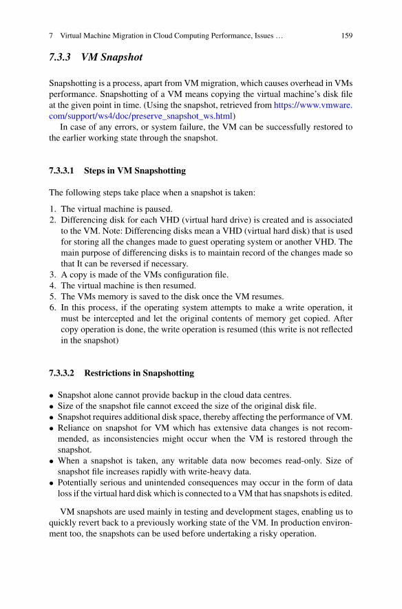
7 Virtual Machine Migration in Cloud Computing Performance, Issues … 159
7.3.3 VM Snapshot
Snapshotting is a process, apart from VMmigration, which causes overhead in VMsperformance. Snapshotting of a VM means copying the virtual machine’s disk fileat the given point in time. (Using the snapshot, retrieved from https://www.vmware.com/support/ws4/doc/preserve_snapshot_ws.html)
In case of any errors, or system failure, the VM can be successfully restored tothe earlier working state through the snapshot.
7.3.3.1 Steps in VM Snapshotting
The following steps take place when a snapshot is taken:
1. The virtual machine is paused.2. Differencing disk for each VHD (virtual hard drive) is created and is associated
to the VM. Note: Differencing disks mean a VHD (virtual hard disk) that is usedfor storing all the changes made to guest operating system or another VHD. Themain purpose of differencing disks is to maintain record of the changes made sothat It can be reversed if necessary.
3. A copy is made of the VMs configuration file.4. The virtual machine is then resumed.5. The VMs memory is saved to the disk once the VM resumes.6. In this process, if the operating system attempts to make a write operation, it
must be intercepted and let the original contents of memory get copied. Aftercopy operation is done, the write operation is resumed (this write is not reflectedin the snapshot)
7.3.3.2 Restrictions in Snapshotting
• Snapshot alone cannot provide backup in the cloud data centres.• Size of the snapshot file cannot exceed the size of the original disk file.• Snapshot requires additional disk space, thereby affecting the performance of VM.• Reliance on snapshot for VM which has extensive data changes is not recom-mended, as inconsistencies might occur when the VM is restored through thesnapshot.
• When a snapshot is taken, any writable data now becomes read-only. Size ofsnapshot file increases rapidly with write-heavy data.
• Potentially serious and unintended consequences may occur in the form of dataloss if the virtual hard disk which is connected to a VM that has snapshots is edited.
VM snapshots are used mainly in testing and development stages, enabling us toquickly revert back to a previously working state of the VM. In production environ-ment too, the snapshots can be used before undertaking a risky operation.

160 P. P. S. Rao et al.
7.3.3.3 Deleting a Snapshot
When a snapshot is deleted, the saved state file and the configuration files are imme-diately deleted, and the snapshot entry is removed from the user interface.
7.3.3.4 Types of Deletion
1. If a snapshot which has no other snapshot referencing it is deleted, then all thefiles associated with the snapshot get deleted.
2. If a snapshot with only one descendent (snapshot which references the currentsnapshot) is deleted, then the snapshot differencing disks will be merged togetherand the configuration along with saved state files will be deleted.
3. A snapshot may have two descendants dependent on it (two or more snapshotreferencing to the current snapshot). Deleting the snapshot in such a case willresult in deletion of the configuration and the saved state files - but the differencingdisks wont be merged till the number of descendants is one.
7.3.4 Shared Cloud Network and Contention Issues
• SAN - Storage Area NetworkThis is a type of network which provides access to block level data storage andis used to enhance the performance and speed of accessibility of storage devices,like tape and disk arrays. Typically, the amount of data which can be accessed bya server is limited by the storage attached to it. Instead, a common storage utilityis made accessible to multiple different types of servers. SAN provides high speeddata transfer between storage and the servers which use the data.In SAN, the applications servers need not store all relevant data. Instead, they canbe optimized for running their own applications. The shared space storage ensuresthe peak storage of individual servers is met easily. The physical machines usethe LAN to communicate with the storage, hence potentially causing performanceissues and creating bandwidth.
• Storage QoSStorage QoS (Quality of Service) includes bandwidth, latency and queue depth.Here, queue depth refers to the number of operations waiting to be executed tothe disks. Storage QoS options differ from vendor to vendor, and third-party offerthem too. In the shared network system, a spike in usage from one user can causedecrease in performance in other users of the same network. This is called “noisyneighbour effect”.Using performance monitoring tools, the storage administrator can analyse theminimum IOPS (input output per second) required by a typical VM. These IOPScan then be reserved for each VM to avoid contention by the storage QoS. Thismethod can also be used to put a limit to the maximum bandwidth usage per VM,

7 Virtual Machine Migration in Cloud Computing Performance, Issues … 161
applicable for the high-demand VMs. This way, resource contention can be man-aged.Also, reduction in number of VMs sharing common storage is needed to avoidperformance degradation. Bottleneck needs to be identified using performancemonitoring, and this can give the exact cause of the problem.
• Virtual switchVirtual switch will enable one VM to communicate with another. This is morethan just forwarding packets of data. These switches can monitor data packetsbefore forwarding them. This helps in moving and migrating VMs from one hostto another and in expanding server virtualization. Functionality of switches alsoinclude maintenance of a table of MAC address to port. This is used to forwardthe frames from the ports to the correct destination.
7.4 Optimization in VMMigration
7.4.1 Optimizing VM Migration in Networking
Networking in virtualization brings together globally placed entities into a singlesoftware controlled unit. This embodies various software and hardware resourcesand their functionalities to form a virtual network [11, 14])
Some approaches of optimization are:
1. De-duplication
2. Throttling
De-duplication
Pre-copy is a popular method in migration where pages are migrated and copied ontothe target system one after the other. Once a threshold number of pages are migratedto the destination, the state of the VM is suspended on the host and is completelymigrated.
This approach obviously shows the disadvantage of having to transfer duplicatedata thereby leading to an increase in:
1. Migration Time.2. Down Time (time for which the hosts have to be suspended).
In the event of repeated updation of a page on the host machine during pre -copy,the copies of the updates have to also be stored repeatedly on the destinationmachine.This leads to excess memory usage in the host as well as destination.
The graph in Fig. 7.3 clearly shows the relative improvement for different chunksizes when original disk access method was replaced. For 128 bytes it went down tojust 6% and for 512, 4096 and 16384 bytes it went down to 10, 6 and 2% respectively.

162 P. P. S. Rao et al.
Fig. 7.3 Graph showing chunk size versus relative improvement for disk access [10]
Fig. 7.4 Steps in hash based deduplication (From left to right)
De-duplication deals with this drawback by comparing data blocks/pages to iden-tify duplicates and erase redundancy during migration. It employs hash based de-duplication where the data blocks are fed to a hash function which compares themagainst the entries in a hash table. If similarity is found the count of occurrence forthat block is incremented and it is marked as redundant. If a unique block is foundit is added to the hash table. Thus it now only contains non redundant data and onlythese aremigrated. This leads to efficient storagemanagement and reducedmigrationtime.
In the Fig. 7.4, the memory is divided into small chunks and each is allotted aunique ID. They are compared to find duplicates and these are removed and replacedby pointers to the actual chunks. Thus only the dissimilar chunks remain and themigration process is accelerated. Data blocks/chunks in de-duplication can be:
1. Fixed sized: Memory is divided into fixed sized blocks. This makes it fastand simple. But smaller blocks require more processing to be done to achievede-duplication whereas large blocks require less processing but efficiency de-duplication decreases with increase in size.
2. Variable sized: Takes care of disadvantages of de-duplication of fixed sizedblocks but CPU overhead increases in trying to determine the size and boundaryof each block.

7 Virtual Machine Migration in Cloud Computing Performance, Issues … 163
Throttling
The network may sometimes experience an overload in migrations if all of them aretriggered at the same time. In these situations, it is necessary to throttle the flow ofVMs on a network. Here, throttling means controlling the number of VMs travellingtowards a destination host away from a source host.
One way to achieve throttling to restrict the bandwidth available for the VMs.A maximum upper limit can be set that will signify the upper boundary of usablenetwork bandwidth for a VM.
Bandwidth can also be allocated according to the conflicts arising between dif-ferent VMs migrating at the same time. Some can get a greater bandwidth comparedto others instead of having fixed bandwidth boundaries for all.
• Transfer ThrottleAssume that the pages are being updated continuously at the host machine. Thesepages are marked dirty and should hence be updated on the destination machine.These dirty pages are transferred on the net bandwidth allotted to the VM. Therewriting rates of each of the pages on the destination machine is then measured.If this sum is more than the allotted bandwidth, the transfer of pages that remainon the source are throttled.
• Increasing redundancy to increase network throughputBringing redundancy in network components such as the NIC can prevent stop-pages due to component failure in the network. A physical NIC can be assignedto each virtual server. This prevents any interference between VMs running on thesame physical machine.NICs can also be connected to their switches. In case of NIC or switch failure,each server can directly connect to the backbone network. [13]Example: In VMware, a virtual dual switch can be configured to act as an interfaceon a pair of NICs.
7.4.2 Optimization in Application Performance
• Write throttlingSometimes, during migration, rate at which applications create dirty pages on thehost can be faster than the allotted bandwidth of migration. This has to be curbedto have a stable synchronization effect between the source and destination. In thecase of “the number of dirty pages exceeding a limit”, the kernel interrupts theapplication and stops it from creating more dirty pages. It then waits for the dirtypages to be “cleaned” at the destination. This process is write throttling.
• Optimization through resource managementApplication performance can be optimized by predicting their performance for agiven allocation scheme of resources. This prediction can also be used for resourcemanagement in an environment where number of applications have increasedrapidly and the number of resources remain the same.

164 P. P. S. Rao et al.
Conventionally, each application would have a dedicated set of resources that itcan use without having to share. But with growing number of applications on dif-ferent VMs, resources must be optimally timed and shared across the network ofVMs.Traditionally, multiple VMs would work on similar applications and demand for asingle type of resource by all VMs had the potential to create serious bottlenecks.An approach to optimizing application performance can be - allocating differentapplications to different VMs. That way all resources can be used uniformly acrossVMs without having to send demand for a single resource at the host by all VMs.
• Dynamic write throttlingIt is a technique that overcomes the drawbacks of currently deployed static sizedbuffers. In case of an event of congestion detection, the clients buffers are to bedynamically throttled.This ensures that the rate at which the client’s buffer is being written at is slowedand an event of bursty traffic (very high bandwidth usage for a short time period)is avoided to optimize networking conditions and application performance on thehost as well as destination increases.
• Rate LimitingRate limiting deals with restricting to and fro traffic between applications runningon VMs either present on their source machines or destination machines.Some Network Interface Cards on host machines supports hardware that limitrate of input and output of buffer queues. With increasing server consolidation(resources provided by the server are optimally used to have less number ofservers), the need to have rate limiting hardware is important to protect serversfrom uncontrollable, congestion-causing, traffic.
7.4.3 Power Optimization
Withvirtualization itwas possible formany applications to be runon a limited numberof servers. This drastically reduced the number of hardware resources required.Furthermore, the possibility of being able to migrate applications from one physicalmachine to another leads to optimal load balancing, and while one physical machinecan run more than one application, the other physical machines can be put to sleepthereby conserving power.
Virtualization and VM migration also reduces the memory power (constitutesup to 19% of the total machine power) consumed.
Clients usually have complex SLAs and cloud service providers, in order to meetthem, must overprovision resources. Heavy usage of resources leads to high opera-tional costs of servers in datacenters. The electrical energy consumed and thus theemission of carbon increases.
Optimal provisioning of resources is the solution to reducing the negative impactsand keeping up with the SLAs of the clients [11].

7 Virtual Machine Migration in Cloud Computing Performance, Issues … 165
This is a difficult job as applications requested by the clients along with the SLAsthey provide suffer from tremendous diversity.
Dynamic Voltage Frequency Scaling(DVFS) Algorithm
It is an algorithm developed to optimize energy consumption in cloud data centers.The frequency of operation of the processor is adjusted based on the current need.
Thermal design point/Thermal design power is the amount of heat dissipated bya computer system. It is measured in Watts. Now, power is a product of amount offlow of current in an electrical unit per unit time and the potential across it (voltage).Thus, a watt = amps * volts, where the current is measured in amps and the voltageis measured in volts [12].
This equation makes the power be directly proportional to the voltage under aconstant amperage. Hence adjusting the voltage can directly influence the amount ofpower dissipated. DVFS algorithm is used to adjust the MIPS (million instructionsper second) frequency and optimize the electrical energy dissipation by fluctuatingthe potential (voltage) as per requirement on the selected machine.
The DVFS works by selecting an appropriate Virtual Machine and adjusts thefrequency. The operation of the VM is then adjusted to the required clock frequencyinstead of the original frequency it is required to run on.
Input: The algorithm takes the VM that is victimized and the frequency that isrequired to be set as the input.
Output: The output of the algorithm is consumption of energy that is optimized. Itis measured in Watts.
Case Study for Power Optimization
Data centres use 40–60% of additional power for maintaining a cool environment forthe servers. Some cloud service providers hence sought to bring down this energyexpenditure by setting up their data centres in places with a cold climate.
1. Facebook: Lulea, in Sweden, has a Facebook data center 70 miles south of theArctic Circle. Since it is located very close to the Arctic Circle, the climate isquite cold and the energy requirement for cooling was largely mitigated.
2. Google: The DeepMind AI (Artificial Intelligence) unit was put in charge byGoogle to optimize its power usage. Thismethodwas cited to reduce the electricityused in cooling by as much as 40
3. Microsoft: The idea of having underwater data centers is being explored atMicrosoft.
7.4.4 Storage Optimization
The concept of virtual storage can be described as - Storage in form of uniformmemory chunks are present on various physical machines either locally or remotely.

166 P. P. S. Rao et al.
Virtualization helps in accumulating these chunks together to form a picture of con-tiguous memory for the benefit of the clients. Thus a client does not have to whollyrely on the constricted memory available on the local physical machine it is runningon [9].
You can pick one the below two steps to optimize virtual hard disk storage:
1. The hardware used to store the virtualized hard disk must have a high through-put and good performance. A SAN (Storage Area Network) or SCSI disk (SmallComputer System Interface) can be used. SCSI allows a computer to be interfacedwith peripheral such as tape drives, CDS, disk drives, printers, etc. and this allowsa fast and flexible data transfer rates. A SAN provides access to storage devicesthat are either present locally or remotely by forming a network of these devices. Itovercomes the limitation of a LAN network that is usually incapable of accessingdevices located outside its reach.
2. Although having fragmented chunks of memory is an advantage over large con-tiguous chunks, a periodic fragmentation is necessary especially in a dynamicallygrowing VHD(Virtual Hard Disk) environment. This is because the virtual mem-ory dynamically becomes larger and the amount of fragmentation increases with it.This makes it harder to keep track of each of the fragment and also the concept ofcontiguous memory becomes harder to achieve.
Storage Migration - Optimization and Best Practices
This concept dealswithmigrating the virtual hard disks of aVMwhile being availablefor usage by the VM.
Steps in Migrating a VHD:
1. The read-write operations begin and end at the source VHD all through themigra-tion process.
2. The new or modified contents are then copied later to the destination VHD.3. Any dirty or outstanding pages are committed at the destination after checking
with the source VHD.4. Complete synchronization of the source and the destination takes place and
switching of VM takes over from old VHD to the new one at the destination.5. The VHD is deleted at the source.
Best Practices
1. Knowing the form of the data in the VHD that is being migrated is importantalong with form it will take after migration on the destination machine.
2. Prior to moving the data, its extraction, deduplication and transformation has tobe done.
3. Guidelines for migration must be followed so that the VHD is migrated in aprecise and orderly manner.
4. Accuracy of the data can be checked through various validation tests.5. Review and verification of the data should follow migration.6. All the steps from the start of migration to its end must be documented.

7 Virtual Machine Migration in Cloud Computing Performance, Issues … 167
7.4.5 Cost Minimization Algorithm
The cost minimization algorithm can be formulated as,
Min Cp∑
j
[x j P0j + P p
j
∑
i
φi j ]Te +∑
i
∑
j
zi j costmi + Te
∑
i
f ci λi∑
j
ai j e−(cpj φi jμi j−αi jλi )R
ci
(7.1)
where, x j ≥ ∑i αi j ,∀ j
φi j ≥ yi j ((αi jλi−ln
hciRci
)
μi j C Pj
),∀i, j∑
i φi j ≤ 1,∀ j∑j yi jmi ≤ Cm
j ,∀ j∑j ai j = 1,∀i
yi j ≥ αi j , yi j ≤ 1 + αi j − ε,∀i, jzi, j ≥ yi j − y p
i j ,∀i, j
andx j ∈ 0, 1, yi j ∈ 0, 1, zi j ∈ 0, 1,∀i, jφi j ≥ 0, αi, j ≥ 0,∀i, j
The algorithm consists of 3 steps (Table7.1):
• Sorting of Clients and dynamic assignment of resources: Client’s status con-sideration from the previous timestamp as well as resource demand estimation fornext decision time period determines the sorting of clients. The result is used increation of VMs on the available servers. But this may lead to under-utilization ofservers and uncompetitive sharing of resources.Min Cp
∑j [(P0
j + P pj )φi j ]Te + ∑
j zi j costmi + Te f ci λi
∑j ai j e
−(cpj φi jμi j−αi jλi )Rci
subject to:φi j ≥ yi j ((αi jλi−ln hci /R
ci )/μi jC
pj ),∀ j
φi j ≤ 1 − φpj ,∀ j
yi jmi ≤ (1 − φmj )Cm
j ,∀ j
The above formula describes the minimization of the cost for the client that waschosen after the sorting process.
Algorithm 1: Dynamic Programming Resource AssignmentInputs: Cp, Te, costmi , λi , f ci ,C p
j , Rci , μi j , P0
j , Ppj φ
pj , φ
mj ,Cm
j ,C pj , h
ci and mi
Outputs: φi j , αi j (i is constant in this algorithm)ga = granularity of alpha;for(j=1 to number of servers)for(αi j = 1/ga to 1)φi j = optimal resource shares based on KKT conditionsC( j, αi j ) = CpTe(P0
j + P pj )αi j + zi j costmi + Te f ci αi jλi exp(−(C p
j φi jμi j −

168 P. P. S. Rao et al.
Table 7.1 Variables used in the algorithm [8]
Symbol Definition
λi Predicted average request rate of the i th client
Rci , f ci Contract target response time and penalty values for each request in the SLA contract
hci Hard constraint on the possible percentage of violation of the response timeconstraint in the SLA contract
μi j Average service rate of requests of the i th client on a unit processing capacity of j thserver
mi Required memory for the i th client
C pj ,C
mj Total processing and memory capacities of the j th server
costmi Migration cost of the i th client
P0j , P
pj Constant and dynamic (in terms of utilization) power consumption of the j th server
operation
Te Duration of the decision epoch in seconds
Cp Cost of energy consumption
y pi j Pseudo Boolean parameter to show that if the i th client is assigned to the j th serverin previous epoch (1) or not (0)
x j A pseudo-Boolean integer variable to determine if the j th server is ON (1) or OFF (0)
yi j Pseudo Boolean parameter to show that if the i th client is assigned to the j th server(1) or not (0)
αi j Portion of the i th client’s requests served by the j th server
φi j Portion of processing resources of the j th server that is allocated to the i th client
αi jλi )Rci )
EndEndX = ga, and Y=number of serversFor (j= 1 to Y)For (x=1 to X )D[x,y] = infinity; // Auxiliary XxY matrix used for DPFor (z=1 to x )D[x,y] = min(D[x,y], D[x-1,y-z]+C(j, z/ga))D[x,y] = min(D[x,y], D[x-1, y])EndEndBack Track to find best α′
i j s and φ′i j s to minimize the cost.
• Resource adjustment: It is done to minimize cost of servers that are runningapplications for multiple clients.

7 Virtual Machine Migration in Cloud Computing Performance, Issues … 169
Min CpPpj
∑i∈I j φi j + ∑
i∈I j fci αi jλi e
−(C pj φi jμi j−αi jλi )Rc
i
subject to:φi j ≥ yi j ((αi jλi − ln hci /R
ci )/μi jC
pj ),∀i ∈ I j∑
i∈I j φi j ≤ 1
where, I j is used to represent the Virtual Machines on the server numbered j.• Dynamic resource arrangement: Resources are allocated as and when data isfed for computation. This way client requests are serviced and disadvantages likeunderutilization of resources is taken care of by turning off the servers that areunderutilized. This reduces costs such as energy cost due to an idling server.Theminimum cost is found through an iterativemethodwhichmakes use of resultsacquired in the previous steps.
1. A threshold is set to compare the extent of utilization of each server. If anyserver falls under this or is unable to satisfy the threshold value it is deemed asunderutilized and turned off.
2. Threshold can be set to a value such as 153. After a server is turned off, the total cost is calculated.4. This is compared with the least total cost that was globally calculated. If turning
off the server caused any significant changes in the cost, the state is kept as it is.5. Else the move to turn off the server is undone.6. This is carried on until the last server showing low utilization is identified.7. The removed VMS are then reassigned to other running servers.
7.5 Issues, Goals and Challenges
7.5.1 Issues and Challenges
7.5.1.1 Big VM Migration
In recent times, IaaS (infrastructure as a service) clouds are providingVMswith hugeamount of memory. Amazon EC2 (elastic cloud compute), for example, providesVM of the size of 2TB [2]. These types of large memory sizes are needed for bigdata analysis. Hence, VM migration becomes difficult because of the huge memoryinvolved.
The destination host would require large amount of free space for migration. Evenin cloud infrastructure, large amount of free space is hard to come by. Reserving hostswith large memory size for future migration is not cost effective.
Two issues come up while migrating large VMs:
• Migration time: The migration time is an important issue in migrating large sizedVMs. This migration time is directly proportional to the size of the VM to bemigrated. Hence, larger the size, more the migration time.

170 P. P. S. Rao et al.
This issue can be tackled in two ways:
1. Using high speed interconnections: 25, 50, or even 100Gigabyte Ethernet. Thisensures the VM is migrated on faster connections, hence will save the migrationtime.
2. Parallelizing VM migration: Different portions of the data which are unre-lated to each other can be migrated simultaneously to the destination though thenetwork. This saves time and large VM migration can be achieved.
• Destination host: The destination host having large amount of free space mustbe available for migration. Having huge free memory hosts reserved all the timefor future migration is costly even in the cloud infrastructure. In case large sizedVMs cannot be migrated, then it will result in downtime of services and big dataanalysis is disrupted.
7.5.1.2 Inter VM Migration
The VMs use hypervisor to access system resources, whereas the host machine canaccess it directly. There exists isolation constraint between VMs, which results ina VM not knowing the existence of another VM on the same host. Communicationthroughput of the VMs running on the same host will be limited by this isolationconstraint. Isolation among VMs of the same physical host is necessary from thesecurity perspective. At the same time, enforcing this isolation will lead to degrada-tion in performance, as explained below. Hence, a balance between the two is neededfor effective and secure VM inter-communication.
When two processes residing in the same physical host, but different VMs,want to exchange data among themselves, it is an example of IVMC (Inter VirtualMachine Communication). The traditional mechanism for communication betweenVMs located on same host is using their VNI (virtual network interface).
Therefore, communication between VMs is done via standard network interface,as if the VMs dont share the same physical host. This brings in unnecessary overheadand degrades performance of both the VMs. Now, the data being shared has to beencapsulated, given an address, transmitted and verified through the network as wellas the virtualization layer.
Problem with this is that it ends up using too much of CPU and low throughputof network because the network data-path is completely traversed.
This overhead is reduced by using shared memory channel, which is used tocommunicate between the VMs located on the same host. Shared memory techniquehas the following challenges:
1. Providing Security: The guest as well as the host can access shared memory.The data which is intended for a VM may be altered or maliciously interceptedby another VM. Therefore, information leakage has to be contained, so that theshared communication buffer is not exploited by malicious VM.

7 Virtual Machine Migration in Cloud Computing Performance, Issues … 171
2. Migration: To perform load balancing,VMsmaybemigrated fromone host to theother. Even when his happens, the communication between the VMs, includingthe one being migrated, has to continue.
Other challenges include transparency issues, migration support, data integrity,security, and denial of service.
7.5.2 Goals
7.5.2.1 Energy Management
Data centres are huge and have large operational costs. Along with this, electricityconsumption is extremely high too. Thousands of servers exists in one data-centreand they need centralized AC (Air-Conditioning) to keep their temperatures down.
Each servers heats up while being switched on. Cooling systems are needed forproper working of the data centres. Hence, electricity is consumed by these coolingsystems, and carbon footprint increases due to this. Management of energy is neededin data centres from an economical as well as environmental viewpoint.
Green IT
This is a type of optimization in which the goal is to reduce the carbon footprintassociated with the IT (Information Technology) industry. Its aim is to reduce illeffects of IT on the environment by planning, designing, operating, manufacturing,and disposing of computers and their components safely. Decrease in the usage ofhazardousmaterials, increasing efficiency of energy, increasing the products lifetime,and reusing the components can be effective in moving towards Green IT.
PUE (power usage effectiveness): This metric is defined as the ratio between theenergy consumed during the process of computing over total energy (including cool-ing) being consumed for the data centre operations.
In data centres of Google and Facebook, this ratio is close to 1 (other data centreshave PUE ratio close to 2).
It is possible to bring down PUE ratio to less than 1 by reusing wasted energy.Heat produced is proportional to the I/O operations (input/output) being down bythe servers. The heat which is thus generated can be used to places where heat isrequired. According to McKinsey report, energy consumption was $11.5billion in2010 and has doubled in 2015.
Static Power Consumption (SPC)
This is the power consumed by the components of the system. It is independent ofthe usage scenarios and clock rates. This depends on the type of transistors and thequality of the processors used in the servers. SPC is caused by the leaking of currentby the active circuits.

172 P. P. S. Rao et al.
This can be prevented in the following ways:
1. SVR (Supply Voltage Reduction): the supplied voltage itself is reduced. Thiswill ensure server components (like CPU, and cache etc.) have longer life.
2. Reducing size of the circuits: This is done by making circuits with fewer tran-sistors. Also, the reduction or cut in power supply to the idle components of thecircuit will reduce power consumption.
3. Cooling technology: There is less resistance to electricity in lower temperatures.And lower degradation of the chips used. Power leakages can be minimizedbecause the circuits work faster (due to low resistance of electricity).
7.5.2.2 Fault Tolerance
Fault tolerance is among the key issues yet to be fully addressed in the cloud comput-ing industry. It deals with all the techniques and needed to let a system tolerate errors,software faults, and prevent total system failure. Improved performance, increasedefficiency, better reliability, reduced costs and failure recovery are the advantages ofimplementing failure recovery in cloud computing.
On different VMs,multiple instances of the applicationmay be running. If a servergoes down, then there is a need for the implementation of automatic fault tolerancetechniques to reduce downtime and recover quickly.
Fault Tolerance Metrics:
Throughput - it is the number of completed tasks by the system. In every system, thethroughput should be high.Response time -This is the time taken to reply and respond to the input/query by theprocess. Minimum response time is required for high performance.Scalability - The performance of the algorithm of fault tolerance must not be affectedby the addition of the nodes/VMs/host machines. Adverse effect on the performancedue to scalability of nodes must be prevented.Performance -Measures the efficiency of the system. This performance metrics hasto be increased while keeping the cost down.Availability -The reliability of a resource is directly dependent on its degree of avail-ability. It is the situation where for any epoch of time, the resource must be function-ing.
Types of Fault Tolerance techniques:
• Reactive Fault Tolerance:These policies are applicable after the failure effectively occurs. They help inlimiting the effects of application execution failure.
– Checkpoint/Restart: Task is made to restart from the recently saved check-point when it fails. This avoids restarting the task from the beginning, ensuringeffective fault tolerance for long running application.

7 Virtual Machine Migration in Cloud Computing Performance, Issues … 173
– Replication: Multiple copies of the same application is made to run on differentVMs and hosts. This ensures that even if one copy fails, other copies of the sameapplication are running smoothly and the application is not affected.
– Job Migration: If a task fails, it has to be migrated to another VM, or anotherhost.
– Retry and Resubmission: A task is made to retry on the same resource ofthe cloud when it has failed. This is one of the simplest techniques of faulttolerance. Resubmission is when a failed task at runtime is resubmitted to thesame/different resource of the cloud service.
– User-defined fault handling: The user (client or the system administrator) givesthe specific solution to the particular task failure.
• Proactive fault tolerance techniques:Here, the policies are such that errors, failures and faults are avoided before theyoccur. Prediction and prevention is initiated on suspected components which mayfail in the future. Policies like preemptive migration, software rejuvenation etc.are based on this technique and are introduced below.
– Software Rejuvenation: In this, the system is designed for periodic restarts.Each time the systems gets a fresh start.
– Preemptive Migration: Here, the system and the application is continuouslychecked and analyzed to give a feedback response to decide when to preemp-tively migrate the application from one VM to the other.
7.5.2.3 Load Balancing
Distribution of work and allocation of resources among servers in the cloud datacentre is known as Load Balancing. This balancing of load helps in achieving higherperformance and simultaneously reducing the operational costs. Energy considera-tions and constraints are fulfilled as well, and helps in overall reduction of energyand power consumption [3].
Goals of Load Balancing
1. Reduction of costs: Operational costs of servers reduces due to load balancingas the load is evenly distributed among the servers. This ensures servers work ataround 80% efficiency workload whereas underutilized servers can be switchedoff.
2. Flexible and scalable: The data centre can be expanded and changes can be madeinside the servers and clusters.
Algorithms for Load Balancing
1. Task Scheduling: This algorithm consists of two steps. First step is to map tasksto VMs and next is to map VMs to the host physical machines. Utilization ofresources is high using this algorithm.

174 P. P. S. Rao et al.
2. Round Robin: This algorithm assigns processes to the multiple processors, andeach processor is allowed to work for a specified time quanta, after which thecontrol switches over to the next processor.
Examples of Load Balancing Technologies
1. Cloud service providers like Google, Amazon Web Services (AWS), Rackspaceand Microsoft Azure provide load balancing technology to their clients.
2. Elastic Load Balancer is provided by AWS for their EC2 instances. It managesthe traffic and the workload in their servers.
3. Google Compute Engine is the load balancer provided byGoogle. It is responsiblefor dividing the network traffic among its VMs and servers.
4. Traffic Manager is the name of the balancer by Microsoft Azure. Across multipledata centers, the traffic is distributed by Traffic Manager.
5. Rackspace has its Cloud Load Balancer which is responsible for managing theservers for the distribution of workload.
7.5.2.4 Server Consolidation
The main goal of server consolidation is to avoid server sprawls. Server sprawlsoccur when many under-utilized VMs run on the cloud platform leading to highenergy consumption. In this technique the number of active PMs is minimized. Thisis achieved by migrating the VMs in the under-utilized, lightly loaded PMs to otheractive PMs, so that the lightly loaded PMs can be switched off to save energy.
7.5.2.5 Hot Spot Mitigation
‘Hot Spots’ are created in PMs if the VMs associated with them are not havingsufficient resources to run dynamic changes in traffic load of the applications hostedin them. To mitigate such hot-spots, it is required to migrate VMs from PMs withhot-spots to other PMs where the required amount of resources to run the hostedapplication causing the hot-spot is available.
7.6 Case Study: vSphere 6.0 Cold Migration
One of the authors belongs to Dept. of CSE, Global Academy of Technology (GAT).vSphere 6.0 lab is setup in GAT premises through VMware IT Academy of VMWareand ICT Academy, Chennai. Evaluation copy of vSphere and ESXi software is usedto demonstrate the creation of VMs and cold migration of VMs.

7 Virtual Machine Migration in Cloud Computing Performance, Issues … 175
7.6.1 Screenshots of vSphere Client with VMs Creationand Snapshotting
Figure7.5 shows usage of vSphere Client, physical host on which EXSi operatingsystem is installed is connected and the console of the VMs running in that physicalhost can be viewed. The vSphere Client helps the administrator gain access to theESXi physical hosts as well as the VMs installed on top of them, and gives a GUI(graphical user interface) to the administrator.
The Fig. 7.6 shows two VMs, named vm_win7_70_1 and vm_win7_70_2, arepowered on in the physical host (with IP address 10.0.2.70) and are simultaneouslyrunning. These VMs share resources of the physical host machine to carry out theapplications in the VMs.
Figure7.7 shows VMWare vSphere web client, where new VMs can be created indifferent connected physical hosts, snapshots of any VM of any connected physicalhost can be taken, and also, migration of VM from one physical machine to theother (to manage workload) can be done. In this figure, a cluster with two physical
Fig. 7.5 VM installed on a physical host
Fig. 7.6 2 VMs on a single physical host

176 P. P. S. Rao et al.
Fig. 7.7 Option to create new VM
machines is present, and 3 VMs are installed on them. Right clicking on the nameof cluster gives options in which a new VM can be easily added by specifying the IPaddress of the physical host on which the VM needs to be placed.
In Fig. 7.8, it can be seen that by right clicking on any of the VMs, and on clicking“all vRealize Orchestrator plugin Actions” , we get various options like “migratevirtual machine with vMotion”, “remove all, excess, old snapshot”, “shut down anddelete virtual machine”. One host IP address is 10.0.2.70 and the VMs placed onit are named: vm_68_2 , vm_win7_70_1 and vm_win7_70_2. Other physical hostwith ESXi has IP address of 10.0.1.68 and the VM placed on it is named: vm_68_1.
7.6.2 Screenshots of ESXi Hosts
This Fig. 7.9 shows the display on the monitor of the physical host of IP address10.0.2.70.A total of 16 GB of memory space is allocated to this ESXi from the

7 Virtual Machine Migration in Cloud Computing Performance, Issues … 177
Fig. 7.8 Various options on a VM
Fig. 7.9 Display on the monitor of the physical host
physical hosts memory. Using vSphere Client, VMs can be created on this ESXihost.
The Fig. 7.10 shows the host with IP address of 10.0.1.68. Memory of 16 GB isallocated to this ESXi host from the physical machine. VMs on top of this ESXi hostcan be created by specifying this IP address while using VMWare Web Client by theadministrator.
Figure7.11 shows the interface of the vSphere Client. On the left, there arethe details of the VMs installed on the physical host with IP address 10.0.2.70.VMs vm_68-2, vm_win7_70_1 and vm_win7_70_2 are installed in the ESXi host.

178 P. P. S. Rao et al.
Fig. 7.10 Host with IP address of 10.0.1.68
Fig. 7.11 Interface of the vSphere client
vm_68_2 is in the powered off state, while the other two VMs are in the runningstate (indicated by green colour). On the task bar located on the top, various optionsexists like “resource allocation” , “performance” , “events”, “console” and “per-mission”. Situated below, the recent tasks specify the state and actions done by theadministrator. Here, name, power state, start and end time of the task etc. can beviewed.

7 Virtual Machine Migration in Cloud Computing Performance, Issues … 179
Fig. 7.12 Cluster setup before cold migration
Fig. 7.13 Determining the migration type
7.6.3 Screenshots of Cold Migration Using vSphere 6.0 WebClient
The Fig. 7.12 shows the setup of the cluster before cold migration. ESXi server isinstalled on topof twophysical hosts, and fourVMsare installed.Hostwith IP address10.0.0.11 has just one VM named vm_11_3 on it, whereas host with IP address10.0.2.70 has three VMs, named: vm_11_1, vm_win7_70_1 and vm_win7_70_2.
TheFig. 7.13 shows thefirst step in coldmigrationwhich is to determine themigra-tion type involving storage and compute resource. Three options, namely, changing

180 P. P. S. Rao et al.
Fig. 7.14 Computing resources
Fig. 7.15 Selecting destination storage
the compute resource alone, changing the storage alone, and changing both, areavailable.
This Fig. 7.14 shows the second step, which is to compute resources. Here, thedestination of theVM to bemigrated is selected. In this example, 10.0.0.11 is selectedas the destination host.
The Fig. 7.15 shows the third step which is, selecting the destination storage forthe migrating VM. Format of virtual disk can be elected, along with storage policy.In this case study, datastore1 is selected as the destination storage.
The Fig. 7.16 shows the fourth step which is to select the network destination.

7 Virtual Machine Migration in Cloud Computing Performance, Issues … 181
Fig. 7.16 Selecting the network destination
Fig. 7.17 Verifying the information about the migration type
The Fig. 7.17 shows the last step, which is to verify the information about themigration type, VM to be migrated, host, storage, and disk format. Clicking finishwill start the migration process.
This Fig. 7.18 shows the setup after cold migration is performed. The VM namedvm_11_1 which was on host IP address 10.0.2.70 has now been migrated to the otherhost with IP address 10.0.0.11.

182 P. P. S. Rao et al.
Fig. 7.18 Setup after cold migration
7.7 Optimization in Tool
Networking in virtualization brings together globally placed entities into a singlesoftware controlled unit. This embodies various software and hardware resourcesand their functionalities to form a virtual network.
Below a few tips for optimizing networking in virtualization are discussed andoptimization strategies in some example VMs are also listed.
1. Have a Separation Between VM Network and the Management Network
Management network, here, refers to the group of servers and hosts providingresources and functionalities to the VMs.
Traditionally, a server communicates with the VMs through an interface. This isalso, however, used for managing the VMs. Congestion is easily formed when thecommunication traffic increases even a little.
Thus a separate management network can be configured to reduce the overheadof the network and enhance its performance.
How to Achieve this for ESXi Server?
Locate the Configuration menu and choose Networking � Add Networking. You’llhave the option to choose between 2 network types.
1. Choose the network type, Virtual Machine, for VM generated traffic.2. Choose the network type,VMKernel, for vSphere related traffic and for bandwidth
over utilizing services, such as vMotion or iSCSI traffic (Fig. 7.19).

7 Virtual Machine Migration in Cloud Computing Performance, Issues … 183
Fig. 7.19 System configuration menu
2. Have Redundancy in Management Networks
Since failure of a NIC(Network Interface Card) can cause the network to fail, havingredundant network interface cards can brace us for such situations.
How to Have Redundancy?
On the Configuration Panel go to Networking � Management vSwitch properties.Here select a new physical network card to be connected to vSwitch.
3. Changing Network Properties for Better Utilization of Bandwidth BetweenVMs
A VM is capable of using up the entire bandwidth available. This will hinder theperformance of all other entities present on the network. The concept of packetshaping/traffic shaping can be used to achieve this. It involves regulating the trafficby setting an upper limit for the usable bandwidth or the density of packets travellingin unit time etc.
How to Achieve this for All the VMs?
The option of Traffic Shaping can be found under Properties of VirtualSwitch.
4. Simplifying the Network Topology
Introducing changes to the topology often leads to degradation in the performance.A simple solution is to revert the network settings to default.
How to Revert to Default?
Locate the option to restore the VMWare to default on the ESXi host panel. Thisresets all the characteristics of the network to initial mode of operation.
Caution: Resetting drops all the changes made and boots the server anew(Fig. 7.20).

184 P. P. S. Rao et al.
Fig. 7.20 Dialog box to confirm the changes made to host’s management network
5. Using a Pass Through Card Instead of Having Dedicated Servers
VMs requiring the entire bandwidth must ideally be allotted a dedicated server thatopposes the whole idea of virtualization. A solution for this is to have a pass throughcard. This approach allows a VM to access a physical NIC directly, bypassing thehypervisor. Thus a dedicated network board is possible for the bandwidth consumingVM.
How to Configure a Pass Through Card?
On the Configuration menu choose Configure Pass Through. Here, choose the net-work card to act as a pass through card and further assign this to the VM.
References
1. A. Beloglazov, J. Abawajy, R. Buyya, Energy-aware resource allocation heuristics for efficientmanagement of data centers for cloud computing. Future Gener. Comput. Syst. 28(5), 755–768(2012)
2. M. Suetake, H. Kizu, K. Kourai, Split migration of large memory virtual machines, in Pro-ceedings of the 7th ACM SIGOPS Asia-Pacific Workshop on Systems (ACM, New York, 2016)
3. A. Bhadani, S. Chaudhary, Performance evaluation of web servers using central load balancingpolicy over virtual machines on cloud, in Proceedings of the Third Annual ACM BangaloreConference (ACM, New York, 2010)
4. V. Shrivastava et al., Application-aware virtual machine migration in data centers, in INFO-COM, 2011 Proceedings IEEE (IEEE, New York, 2011)
5. A. Beloglazov, R. Buyya, Energy efficient allocation of virtual machines in cloud data centers,in 2010 10th IEEE/ACM International Conference on Cluster, Cloud and Grid Computing(CCGrid) (IEEE, New York, 2010)
6. M. Mishra et al., Dynamic resource management using virtual machine migrations. IEEECommun. Mag. 50(9) (2012)
7. J. Smith, R. Nair, The architecture of virtual machines. Comput. IEEE Comput. Soc. 38(5),3238 (2005). https://doi.org/10.1109/MC.2005.173

7 Virtual Machine Migration in Cloud Computing Performance, Issues … 185
8. H. Goudarzi, M. Ghasemazar, M. Pedram, SLA-based optimization of power and migrationcost in cloud computing, in 2012 12th IEEE/ACM International Symposium on Cluster, Cloudand Grid Computing (CCGrid) (IEEE, New York, 2012)
9. Y. Du, H. Yu, G. Shi, J. Chen, W. Zheng, Micro wiper: efficient memory propagation in livemigration of virtual machines, in 2010 39th International Conference on Parallel Processing(San Diego, CA, 2010), pp. 141–149. https://doi.org/10.1109/ICPP.2010.23
10. C. Constantinescu, J. Pieper, T. Li, Block size optimization in de-duplication systems, in DataCompression Conference. Snowbird, UT (2009), pp. 442–442. https://doi.org/10.1109/DCC.2009.51
11. M. Anan, N. Nasser, A. Ahmed, A. Alfuqaha, Optimization of power and migration cost invirtualized data centers, in IEEEWireless Communications and Networking Conference. Doha2016 (2016), pp. 1–5. https://doi.org/10.1109/WCNC.2016.7564869
12. A. Paulin Florence,V. Shanthi, C.B. Sunil Simon,EnergyConservationUsingDynamicVoltageFrequency Scaling for Computational Cloud, vol. 2016, Article ID 9328070 (The ScientificWorld Journal, 2016), p. 13. https://doi.org/10.1155/2016/9328070
13. M.K. Nair, C. Bhosle, V. Gopalakrishna, Net mobile-Cop: A hybrid intelli-agent framework tomanage networks, in Proceedings of IEEE International Conference on Intelligent and Multi-Agents (IAMA09), 21–23 July, Chennai (2009), pp. 1–8
14. M.K. Nair, V. Gopalakrishna, Agent based web services with RuleML for network Mgt, inProceedings of IEEE International Conference on Networks and Communications (NetCoM09), 27–29 Dec, Chennai, India (2009) pp. 214–219
15. Using the VM Snapshot, Accessed from https://www.vmware.com/support/ws4/doc/reserve_snapshot_ws.html 2. Understanding VM Snapshots in ESXi, Accessed from https://kb.vmware.com/selfservice/microsites/search.do?language=en_US&cmd=displayKC&externalId=1015180
16. S. Bigelov, Case Study on Server Virtualization, Accessed from http://searchdatacenter.techtarget.com/tip/Server-virtualization-software-refresh-cycles-go-hand-in-hand (For casestudy 1.3 topic number)
17. Shivanshu, Resource Management in Cloud, http://www.ninjaducks.in/thesis/mainch1.html18. D. Dias, Resource Management in VMWare, Accessed from http://techgenix.com/getting-
started-resource-management-vmware-vsphere/ (2013)19. B. Tholeti, Hypervisor, Virtualization and the Cloud, Accessed from https://www.ibm.com/
developerworks/cloud/library/cl-hypervisorcompare/ (2013)20. S. Bigelov, Case Study on Improving Efficiency Through Server Virtualization of Com-
pany Motley Fool, Accessed from http://searchdatacenter.techtarget.com/tip/Improving-IT-efficiency-with-server-virtualization-technology (2011)
21. Case Studies on Benefits of Virtualization, Accessed from https://searchdatacenter.techtarget.com/feature/Case-studies-show-the-benefits-of-virtualization (2011)
22. https://www.cl.cam.ac.uk/research/srg/netos/papers/2005-migration-nsdi-pre.pdf23. Mishra, Das, Kulkarni, Sahoo, Dynamic Resource Management using VM Migration (2012),
https://ieeexplore.ieee.org/document/629570924. J. Vincent, Google Data Centre Energy Bills, Accessed from https://www.theverge.com/2016/
7/21/12246258/google-deepmind-ai-data-center-cooling25. Kaur, Rani, VM Migration in Cloud Computing, Accessed from https://www.sersc.org/
journals/IJGDC/vol8_no5/33.pdf (2015)26. J. Vincent, Facebook’s Data Centre, Accessed from https://www.theverge.com/2016/9/29/
13103982/facebook-arctic-data-center-sweden-photos (2016)

Chapter 8Frameworks to Develop SLA Based SecurityMetrics in Cloud Environment
Satya Ranjan Dash, Alo Sen, Pranab Kumar Bharimallaand Bhabani Shankar Prasad Mishra
Abstract Cloud computing, the growing technologywhichmost of the small aswellas large organizations adopt to maintain IT as it is a very cost effective organizationshould consider the business risk associated with cloud computing all of which arestill not resolved. The risk can be categorized in several issues like privacy, security,legal risks. To solve these types of severe risks, organization might make and developSLA for the establishment of an agreement between the customer and the cloudproviders. This chapter provides a survey on the various frameworks to develop SLAbased security metrics. Various security attributes and possible threats are havingalso been discussed in this chapter.
Keywords Cloud computing · Security metric · Service level agreement (SLA) ·Cloud-hosted application SLA (A-SLA) · SLA-tree
8.1 Introduction
Cloud computing is one of the most emerging technology now a days and grabbingpopularity day by day because of reduction in cost of investment as well as consump-tion of energy of the shared computing resources like software, servers, networkingand storage. Though it enables efficient use of IT resources and increases flexibil-ity to expand the new infrastructures quickly [1], it also has many security risks tothe business that have to resolve effectively. These types of risks include handling
S. R. Dash (B) · A. Sen · P. K. Bharimalla · B. S. P. MishraKIIT University, Bhubaneswar, Indiae-mail: [email protected]
A. Sene-mail: [email protected]
P. K. Bharimallae-mail: [email protected]
B. S. P. Mishrae-mail: [email protected]
© Springer International Publishing AG, part of Springer Nature 2018B. S. P. Mishra et al. (eds.), Cloud Computing for Optimization:Foundations, Applications, and Challenges, Studies in Big Data 39,https://doi.org/10.1007/978-3-319-73676-1_8
187

188 S. R. Dash et al.
of access to privileged user, to ensure legal compliance, to ensure segregation ofdata, to maintain recovery of data and no assurance of guarantee of cloud serviceproviders for long term viability [2]. For this reason, cloud customers should adoptsome techniques to improve and measure their data security in the cloud. Cloudproviders should make their data security metrics using a Service Level Agreement(SLA). SLA can be distinct as an concurrence among cloud providers and aloudcustomers to manage and control the service. Thus, SLA metrics help to assess ser-vice level between them and take a part in improving services [3]. But there are noactual standard format to prepare SLA. Different cloud service providers use theirown format to prepare it, thus it leads to a huge risk to have faith on the servicefrom the viewpoint of customers [4]. To solve this issue CSA provide STAR Reposi-tory to be included for different security issues and common rule within SLA STAR[5]. However, secure SLA should be provide to the customers so that they can havefaith on Cloud Services. Many researchers proposed various security mechanismsfor cloud services agreement, but a novel secure approach was introduced partiallyover FP7-ICT project SPECS [6] team for automatic management of secure SLA anddeploying automatic secure mechanisms proposed by [7] and SPECS project [6].
This chapter has four sections which includes introduction and conclusion. 2ndSection covers some basic concepts of cloud computing, 3rd section describes servicelevel agreement and Sect. 4 describes the security metric with the list of securityattributes and threats as well as the list of different frameworks to develop SLAbased security metrics in a cloud environment [8].
8.1.1 Cloud Computing Characteristics
• Self on demand service: Cloud providers enables the provisioning of cloudresources on demand whenever they are required. The resources are self pro-visioned without much human intervention, and the client will be charged as perthe usages.
• Ubiquitous access of network: Cloud services can be accessed everywhere thoughstandard terminals like laptops, desktops, mobile handsets, PDAs etc. with Internetconnectivity.
• Easy to use: The Internet based interface offered by the cloud providers is muchsimpler than APIs, so user can easily use cloud environment.
• Business model: Cloud is a standard business model as it is pay for use of resourceor service.
• Elastic: The illusion of infinite computing resources is provide by the cloudproviders to their consumers. As a result, consumers expect to get resources inany quantity at any time from the cloud.
• Customizable: In a multi-tenant cloud environment all the resources rented fromthe cloud must be customizable. Customization means to allow the users fordeploying special virtual appliances and to give root access to the virtual cloudservers. Other cloud service models (PaaS and SaaS) provide less flexibility thus

8 Frameworks to Develop SLA Based Security Metrics … 189
not suited for general-purpose computing, but provide limited level of customiza-tion [9].
• Location independent resource pooling: The cloud providers dynamically assignthe virtual resources according to the consumer demand irrespective of the location.
8.1.2 Cloud Computing Deployment Models
• Public cloud: Public cloud environment service is available to the general pub-lic over Internet. The providers other consumers share the computing resources.Public cloud is a pure cloud computing model.
• Private cloud: Private cloud environment is solely operated by small or large orga-nizations where they want to keep their services, application programs, own datain cloud by taking the responsibility for security of their data.
They implement firewall behind their cloud environment and enable pooling andsharing of resources among various departments, applications, etc. The main advan-tage behind this cloud is compliance, security and QoS.
• Community cloud: As the name suggests, community cloud environment is sharedby multiple organizations. The third party suppliers provide the necessary com-puting infrastructures, or it may be provided inside.
• Hybrid cloud: Hybrid cloud atmosphere is a combination of two or more clouds.Many organizations prefer hybrid cloud by using public cloud for general com-puting purpose where the data of the customers are kept within other types ofthe cloud model. It enables portability of data application by balancing the loadbetween clouds [10].
8.1.3 Cloud Computing Solutions
• Infrastructure as a service: This service provides virtualmachines, some abstractedhardware, and operating system on the Internet.
• Software as a service: This is software on the Internet through which customerscan rent full applications without purchasing and installing the software on theirown computer [11].
• Platform as a service: Cloud providers provide a platform of developed environ-ment as a service where users can run their application.
• Storage as a service: In this service, it provides database like services. Users arecharged based upon their usage e.g., gigabyte per month.
• Desktop as a service: In this service, desktop environment is provisioned as aterminal or within a browser.

190 S. R. Dash et al.
8.2 Service Level Agreement (SLA)
A SLA is agreed upon agreement between two parties, namely cloud environmentproviders and customers, which provide the guarantees of a service [12]. This guar-antee includes the list of transactions need to be executed with the best procedureof execution. SLA had been defined as the what without considering the how. SLAtells the different types of service, customer should get with respect to informationsecurity though SLA do not specify by what procedure the service levels will beachieved. It also provides a common understanding between two parties on prior-ities, responsibilities, services, guarantees and warranties. In a cloud environment,when customers submit their vital information to the cloud service providers, thenthey don’t bother about the storing and processing of their information. So, SLAis needed by the cloud providers to convince people to access their services andguarantees about their information security.
Following are the types of SLAs:
1. Cloud Infrastructure based SLA (I-SLA): Cloud providers offer this type of SLAto the cloud customers to give assurance for the level of quality of the cloudcomputing resources like performance of the server, speed of network, availabilityof resources, storage capacity etc.
2. Cloud-hosted Application SLA (A-SLA): This type of SLA gives assurance overthe quality level for the deployed software applications on a cloud environment.
Actually, cloud customers sometimes offer such type of assurance to the softwareend user in classify to give promise to the excellence of different type of services likethe response time of the software and data freshness. Figure8.1 illustrates differentSLA parties in the cloud environment.
8.2.1 SLA Life Cycle
A standard SLA life cycle has been proposed by Roja (Fig. 8.2) [13]:
Fig. 8.1 Different SLAs in cloud environment

8 Frameworks to Develop SLA Based Security Metrics … 191
Fig. 8.2 SLA life cycle process [13]
8.2.2 Features of SLAs
SLA has the following characteristics:
• SLA format should be properly maintained so that it will be easier for a consumerto understand the details of the available services by a cloud provider.
• Explanation about the level of performance.
– Description about monitoring of system parameter and report.– Penalties for the violation of rules or in the case of unable to provide all therequirements to the consumer.
There are many functional, as well as non-functional necessities which should befulfilled to meet the expectation of the customers. All the requirements can be clas-sified under different services provided by the cloud providers. Figure8.3 classifiesthe cloud services.
As per the non-functional requirements there are many things to be considered.The most vital criteria are quality of service i.e. availability of the desired serviceon time. This is the assurance for the customers about the probability of the cloudservices perfectly. Cloud customers can use the service or the resources and pay as perusages. Sometimes they have a need to scale up or down for some specific resources.So, there should be some assurance over the degree of scalability by which cloudcustomers can utilize the resource properly. There should be an accurate method forservice billing. In the cloud environment, customers are willing to pay as per theiruse of services.

192 S. R. Dash et al.
Fig. 8.3 Classification for requirements in different cloud service
So, a monthly or an annual billing system is not suitable for the service. It isalso not possible to calculate the cost, according to the reservation method. So, anefficient billing method should be maintained like the billing for storage service canbe made by depending on the size of data and duration of usage of the service.
Cloud environment deals with many virtual machines for each individual server.As a need, customers should get a flexible access over the VMs to get the ser-vice smoothly with a little effort of managing the configuration themselves. Securemedium should be used to accumulate the data on the server and between the dura-tion of transferring of data between customers and cloud providers. Security featuresshould be assured by cloud providers so that organizations will to invest on cloudenvironments rather than switching to spend on operating their own data centers.
8.3 Security Metrics
Security metrics are measured quantitatively in organization for providing securityoperations [14]. It helps the organizations to take decisions related to different typesof security including the architecture of security to control structure for effectiveand efficient operations [15]. Security metrics are valuable to the stakeholders andmanagerial level of IT [16]. Sometimes, security operations demand high level ofexpenditures to them. NIST [8] divides security metrics according to their charac-teristics into three different types:

8 Frameworks to Develop SLA Based Security Metrics … 193
1. Implementation metrics: These types of metrics are for demonstrating theadvancement in implementation of different programs for information security,controls of security and different procedures and policies [4].
2. Effectiveness/efficiency metrics: These types of metrics are for monitoringwhether the program-level process and security controls of system level havebeen implemented properly and operating as expected and achieving the desiredoutcomes [4].
3. Impact metrics: These types of metrics are for articulating information securityimpact on target of organization [4].
Security metrics can also be decomposed according to their uses. The user groupcan be divided into quality assurance, strategic support and tactical oversight [16].Table8.1 demonstrate different security attributes and threats in cloud environment.
Kaiping [18], anticipated a new safe group allotment structure for public cloud.The structure ensures that, no insightful data is showing to cloud supplier and invader.It combines proxy signature, improved TGDH, alternative re-encryption to form arobust security protocol layer.
Diffie–hellman (CDH) [19] problem in Random Oracle Model. Islander et al.in 2011 proposed a mechanism for implementing authentication policies in cloudcomputing and theydefineddifferent levels of policy consistency constraints.Authorspropose a Two-Phase rationale Committed protocol to provide a explanation whichis customized version of essential Two-Phase Commit protocols [20].
8.4 Frameworks for Developing SLA Oriented SecurityMetrics
The SLA parameters are driven by metrics and metrics define the way to measurecloud service parameters and specify values of measurable parameters [9].
At first, we have tried to identify the various parameters necessary for SLA indifferent cloud environment like IaaS, PaaS, SaaS, Storage as a service and param-eters for all the users for all types of cloud which are general parameters. Table8.2illustrates list of parameters needed in SLA for different services in the cloud envi-ronment.
We have surveyed the list of frameworks associated with SLA.
1. Goal Question Metric (GQM): In GQM (Fig. 8.4), evaluation is carried outin a top-down manner. This approach first formulated Basili. GQM defines adimension of replica on three levels [10].

194 S. R. Dash et al.
Table 8.1 List of security attributes and threats in cloud environment
Serial no Security attributes Description Threats
1 Accountability This attribute keep track of thesecurity actions andresponsibilities [8]
• Ambiguous ownership fordata protection• Loss of business• Audit difficulty• Regularity and legal issues• Difficult bug detection• Difficult intruder detection
2 Confidentiality This attribute protect thesensitive information from theunauthorized users [17]
• Identify theft• Unauthorized modification• Data theft• Malware attacks• Requirement of datasegregation• illegal access• Data loss• Eavesdropping• Insecure data storage• Inadequate authorizationand authentication• Cloud provider espionage• Phishing attack• Insecure interfaces and APIs
3 Integrity This attribute deals withcompleteness, accuracy andinformation validation withrespect to businessrequirements and goals [17]
• Identify theft• Unauthorized modification• Data theft• Malware attacks• Data segregation notsufficient• Unauthorized access• Inconsistent data• Authorization andauthentication is inadequate• Insecure interfaces and APIs
4 Availability This attribute deals with theinformation to be fetched andaccessible later when it isnecessary by the businessprocedure as in the prospect[17]. Though, this informationis not accessible to theunauthorized users
• Unauthorized modification• Malware attacks• DOS/DDOS• Lack of data segregation• Unauthorized access• Data loss• Loss of business• Inadequate authorizationand authentication• Service disruption

8 Frameworks to Develop SLA Based Security Metrics … 195
Table 8.2 List of parameters needed in SLA for different services in the cloud environment
SLA for environment Parameters
IaaS • Capacity of VM CPU• Size of VM cache memory• Ready time for VM• Size of data• Maximum VM per user• Minimum VM per user• Time to add one VM• Time to deallocate one VM• Maximum VMs run per server• Service availability• Time for completion and receiving process
PaaS • Integration with other platforms• Degree of scalability• Pay as per use of the service• Servers and browsers• Accessibility
SaaS • Ability of operation in each case• Usage of user interface• Degree of scalability• Availability of software• Flexibility to use
Storage as a Service • Availability of data storage location• Degree of scalability for updating storage area• Capacity of storage area• Cost of storage• Privacy and security• Information about the backup of data• Availability of recovery in case of failure• System throughput• Network bandwidth• Management of data
For all types of users • Detail description of monitoring the system• Description about the billing• Privacy and security• Information of networking system• Clarification of support and service• The standard policy should be followed
• Conceptual Level (Goal): An objective is defined for a particular entity forseveral reason, with value to many excellence models, from many points ofvision and with respect to a particular environment.
• Operational Level (Question): A put of questions is basically used todescribe the way the appraisal or the accomplishment of a particular goalis going to be performed based on some depicting form.

196 S. R. Dash et al.
Fig. 8.4 Approach in GQM
• Quantitative Level (METRIC): A set of related and connected informationwith each and each query in order to respond it in a computable and quanti-tative way. The data can be short or long or may be objective or subjective.
2. Electronic Bill Presentment and Payment (EBPP): The framework identifiessecurity threats using STRIDE model, which is basically derived from acronymfor following six threat category:- (i) Spoofing identity, (ii) Tampering withData, (iii) Repudiation, (iv) Information Disclosure, (v) Denial of Service, and(vi) Elevation of Privilege.In this model, to measure the levels of security, the architectures componentsand the threats are combined together [21].
3. Policy BasedMetrics: This framework is specified in NIST SP800-53 andNIST800-53 to measure and monitor overall IT security [21, 22].
4. Security Metric Identification Framework: The framework provides a sys-tematic method for the identification and development of a security metric suitefor software [23].
5. Risk Based Proactive Security Configuration Manager (ROCONA): Thisframework is to measure proactive security configuration within a network. Itidentifies, formulate, and validate the risk factors which severely affect the net-work security [24].
6. Security Performance Framework (SPF): The proposed Framework (SPF)is used for the measurement and monitoring of whole Information Technologysafety performance in an association using NIST SP800-80 procedures [21].
7. Control Objectives for Information and Related Technology (COBIT): Theproposed framework is a place of open papers for the declaration of sound ITauthority in an association. COBIT covers assurance, absolute governance andmanage over IT [25] & [26].
8. WebServiceLevel Agreement framework (WSLA): The proposed frameworkis developed to monitor and enforce SLA in service oriented architecture (SOA)for web services [27].

8 Frameworks to Develop SLA Based Security Metrics … 197
9. Framework of Service Level Agreements in the Cloud Bank Model(CBSLA): Cloud Bank model includes the following: (i) Resource Consumer,(ii) Cloud-Bank (CB) (iii) Cloud-Consumer-Agency (CCA), (iv) Physical layer(v) Virtual layer, (vi) Cloud-Resource-Agency (CRA) and (vii) ResourceProvider. The CBSLA is proposed to capture the SLAs in Cloud Bank envi-ronment [28].
10. Framework for Consumer-Centric SLA: The author planned an end-to-endstructure for consumer-centric SLA supervision of cloud-hosted databases. TheSLAdocument is clearly defined by the terms of goals specific for the applicationrequirements with some constraints [29].
11. Collaboration-BasedCloudComputing SecurityManagement Framework:The framework is based on the improvement and for the support of associationbetween cloud stakeholders to expand a cloud security measurement and imple-mentation framework including all of their requirements. The framework hasbeen implemented by align FISMA customary with the cloud replica and usingcollaboration between the stakeholders [30].
12. SLA-Tree: It is a framework to support efficiently SLA-based earnings tiltingdecision in cloud computing. SLA-tree ismostly used to reply professionally twoimportant questions about the possible earnings modify between queries in thebuffer. SLA-tree can be used for capacity planning, dispatching and scheduling,etc. [31].
13. Framework for SLA Assurance: This trust model framework addresses theissues of real-time QoS appraisal. The structure contains two modules that isreputation assessment module and transaction risk assessment module. Struc-ture to deal with the real-time QoS appraisal problem. The framework/structureconsists of two modules specifically, standing appraisal module and transac-tion risk assessment module. The authors have worked on trust-based design todecide pre interaction andmatter risk-based design to determine post-interactionof QOS estimation for assessment building [32].
14. SMICloud Framework: This is a method to determine the excellence and pri-oritize cloud services. Such a structure makes considerable contact and willcreate competitive atmosphere between Cloud providers to convince their Ser-vice Level Agreement (SLA) and get better their quality of service(QoS). TheSMI framework provide a perfect vision of QoS required by the consumers forthe selection of a Cloud service provider based on: responsibility, quickness,service declaration, performance, price, privacy, safety and usability. The SMI-Cloud structure provide various features such as choice of services based onQoS parameters and position of services on past client experience and quality ofservices. It is a tool for assessment, planned to evaluate Cloud services in termsof KPI parameters and client necessities [33].

198 S. R. Dash et al.
Fig. 8.5 secSLA life cycle by [34]
15. secSLA: The research on a secure SLA was proposed by SPECS (SecurePro-visioning of cloud services based on SLA management) team for FP7 Project.This is a novel mechanism to reduce the possibility of damages with an auto-matic remedy by continuous monitoring of secSLAs that detect the violationoccurred in any time and react to it for that agreement by [34]. Figures8.5 and8.6 illustrates the life cycle of secSLA with remedy.
16. Security SLA: MUSA, the successor team of SPECS had proposed the samedesign for secure SLA design but for multi-cloud environment defined the wholeprocess of step-by-step design of secure SLA [35] in the following Figs. 8.7and 8.8.In our survey paper, we had discussed about 17 different SLA based frameworkthat should be provided by the cloud providers. Users had no choice to interactdirectly for defining their requirements for preventing themselves from differentsecurity issues arise in cloud service and they can have a trust on the servicethey are getting from cloud service providers. Now we will illustrate anotherframework (USRAF) that is basically user-centric.
17. USRAF: This is a cloud security architectural framework proposed by [19],where user will set the goals, parameters, rules and resources to increase theirsecurity requirement. User send the service request to the cloud service providersby determining four factors to get their required security.Then, cloud service providers identify the requirements and provide the serviceto the cloud customers according to customer’s choice. Figure8.9 illustrates thesecurity procedure.Table8.3 illustrates the stages of the security metric frameworks and illustratesthe comparative study between the different security metric frameworks fordeveloping SLA oriented security metrics in the cloud environment.

8 Frameworks to Develop SLA Based Security Metrics … 199
Fig. 8.6 Remediation flow by secSLA by [34]
Fig. 8.7 MUSA Security-by-design cloud application development process by [35]
Fig. 8.8 MUSA security-by-design cloud application development process by [35]

200 S. R. Dash et al.
Fig. 8.9 Security procedure for USRAF by [19]
8.5 Comparative Analysis
Wehave discussed 16 different frameworks to recognize SLA based security metrics.Now, in this section we have done a comparative analysis of those frameworks[36] agreed that the same information security threats are also vulnerable to cloudcomputing as the traditional computing. But, cloud security alliance argues that newsecurity threats are challenged to the cloud computing depends on its deploymentover an organization [37]. To identify manageable number of security metrics amongmany proposedmetrics, there is a need of proper identification of ametric framework[38]. The study shows that researches have identified a large number of securitymetrics among which all are not related to cloud computing security treats [39].They should have been proposed an efficient model to derive such security metrics.Goal definition are crucial for creating security metrics framework [10], withoutwhich, it is unclear on what metrics to be used and how you interpret it.
Each one of the recognized frameworks have their individual limitations. Experi-ments have also revealed that bottom-up structuremay not generate improvedmetricsas here exist also many thing exclusivity to watch. We observed that NIST SP800-[4]. SANS security metrics strategy [40] and GQM [32], all are measured to be basedon top-down approach. But, they also cannot obtain all criteria of a suitable frame-work. Among them, GOM fulfills most of the criteria.
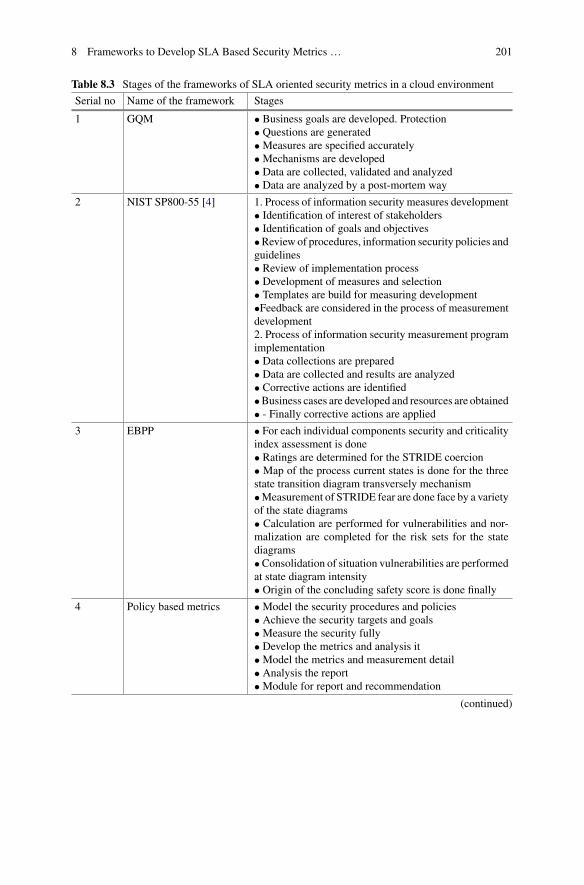
8 Frameworks to Develop SLA Based Security Metrics … 201
Table 8.3 Stages of the frameworks of SLA oriented security metrics in a cloud environment
Serial no Name of the framework Stages
1 GQM • Business goals are developed. Protection• Questions are generated•Measures are specified accurately•Mechanisms are developed• Data are collected, validated and analyzed• Data are analyzed by a post-mortem way
2 NIST SP800-55 [4] 1. Process of information security measures development• Identification of interest of stakeholders• Identification of goals and objectives•Review of procedures, information security policies andguidelines• Review of implementation process• Development of measures and selection• Templates are build for measuring development•Feedback are considered in the process of measurementdevelopment2. Process of information security measurement programimplementation• Data collections are prepared• Data are collected and results are analyzed• Corrective actions are identified•Business cases are developed and resources are obtained• - Finally corrective actions are applied
3 EBPP • For each individual components security and criticalityindex assessment is done• Ratings are determined for the STRIDE coercion• Map of the process current states is done for the threestate transition diagram transversely mechanism•Measurement of STRIDE fear are done face by a varietyof the state diagrams• Calculation are performed for vulnerabilities and nor-malization are completed for the risk sets for the statediagrams•Consolidation of situation vulnerabilities are performedat state diagram intensity• Origin of the concluding safety score is done finally
4 Policy based metrics •Model the security procedures and policies• Achieve the security targets and goals•Measure the security fully• Develop the metrics and analysis it•Model the metrics and measurement detail• Analysis the report•Module for report and recommendation
(continued)

202 S. R. Dash et al.
Table 8.3 (continued)
Serial no Name of the framework Stages
5 Security metricidentification framework
• Security metrics requirements are specified• Vulnerabilities are identified• Software characteristics are identified• OO models are analyzed• Security metrics are analyzed• Security metrics are categorized• Security metric measures are specified fully•Metric development process are designed• Security metrics are designed• Finalization of metric suite
6 ROCONA • Analysis of traffic• Analysis of service risk• Analysis of policy risk• Calculation of threat portability are performed• Analysis of risk impact•Measure the system risk• and finally, security attain and recommendations
7 SANS security metricsguideline [36]
• Defining goals and objectives of the metrics program• Decide the metrics to be generated• Define a plan for generating the metrics• Setup targets and benchmarks• Outline a plan to report the metrics• Generate an implementation map and start execution,and Set up a proper program evaluation and alterationcycle
8 SPF This Framework follows 2 approaches:• Control-specific approach:- This approach chose a con-trol depending upon the metric for a better design of orga-nization chart which will represent the entire family in abetter way• The cross-cutting approach:- This approach mainlybased on security routine based on one or more than onebeing or group of control. Group of control are usedmainly to analyze, develop and collection of matrices
9 COBIT The framework is developed by the basic principle toprovide the required information for the organizations toachieve objectives for business while managinginvestment and resources for IT department
10 WSLA The framework is composed of a set of concepts and aXML language. Following are services of WSLA:•Measurement Service• Condition Evaluation Service•Management Service
(continued)

8 Frameworks to Develop SLA Based Security Metrics … 203
Table 8.3 (continued)
Serial no Name of the framework Stages
11 CBSLA Cloud Bank model forms the cloud economic architec-ture of the market. From the local cloud, the bank storestransaction resource related to market. Then the guidanceinformation is provided to the consumers after analyzingthe resources effectivelyLife cycle of CBSLA:• Initial Specification• Activation/Execution•Monitor SLA Performance•Modification• Termination
12 Framework forconsumer-centric SLA
• The framework inspect the database workload continu-ously• Keep track the execution of the application-based SLA• Assesses the state of the act policy and takes dealingswhen required
13 Collaboration-basedcloud computing securitymanagement framework
• Aligning NIST-FISMA standard with the cloud model- Service Security Categorization(SSC)- Security Control Selection(SCS)- Security Controls Implementation(SCI)- Security Controls Assessment(SCA)- Service Authorization(SA)- Monitoring the Effectiveness of Security Con-trols(MESC)• Security automation
14 SLA-tree • Converting delay to slack• Structured the slack tree S+• Querying the slack tree S+• Structured and query the tardiness tree S
15 Framework for SLAassurance
• For pre-interaction of qos assessment:- Reputation assessment methodology- Fuzzy logic-based approach• For pre-interaction of qos assessment:- Transactional risk assessment approach- Evaluating cost due to service level filth- Evaluating cost due to non-dependable criteria
16 SMICloud Framework • Hierarchical organization for cloud services based onSMI KPIs• calculation of comparative weights of each QoS andservice• comparative value-based weights for position Cloudservices aggregation of comparative standing for eachSMI attribute
17 secSLA • Preparation• Negotiation• Implementation•Monitoring• Remediation(followed by re-negotiation)

204 S. R. Dash et al.
• GQM framework measures the object for which an organization should define thegoals for measurement related to business goal. It helps to find the security metricswhich are relevant to cloud computing.
• NIST SP800-55 is also an goal based approach. But it is suitable to produce themetrics for selected customers. This framework is having no global acceptancebecause this model is specially used by USA government organizations.
• EBPP framework is developed for a specific system and has no global acceptance.• Framework for policy based matrices is totally depended on organizational policesand it is made by US NIST guidelines.
• Security metric identification framework is a newly proposed framework is con-sidered complicated for practical uses.
• ROCONA framework is proposed for a explicit purpose to determine the securitypattern in a network. It is not validated for academic or industrial purpose.
• SANS security metrics guideline is a general framework developed for intendedcustomers. This is also an goal based approach. There is no full documentationavailable for this proposed model.
• SPF framework is totally depended on organizational polices and it is made by USNIST guidelines.
• COBIT structure is extra paying attention on industry and it ensure that its functionare enabling industries in planned and industry objectives while rationally runningIT risks [8].
• As cloud is engineering structural design, we thus believe the COBIT struc-ture is further suitable than other accessible protection frameworks. COBIT is ameasurement-driven structure which offers numerous metrics to determine severalindustrial processes as well as metrics for evaluating SLA and security routine.We have also studied that the COBIT framework describes approximately 340metrics, even though not all of the metrics described in the COBIT structure areapplicable in cloud computing [34]. SecSLA uses detection and have remedy forthe vulnerability occurred in agreement and have measurement level to measurethe fulfillment of agreed Security Level Objectives which can be used in currentCloud service trends.
8.6 Conclusion
Cloud Computingmodel will gradually change the landscape of IT industry. Though,There are several benefits provided by the Cloud environment, A efficient model orframework for SLA metric for security is needed which can assure the QOS neededby the consumers. In this chapter, we have surveyed various structure suitable forSLA in cloud computing. We have explained the detail stages of those frameworksso that it will be easier for the new researchers to do research on the field of SLA andmake more suitable and flexible framework for SLA security metric in the upcomingyear.

8 Frameworks to Develop SLA Based Security Metrics … 205
References
1. R. Barga et al. Cloud computing architecture and application programming: DISC’09 tutorial,half day, in ACM Sigact News 40.2 (22 Sept 2009), pp. 94–95
2. B.R. Kandukuri, A. Rakshit, Cloud security issues, in IEEE International Conference on Ser-vices Computing, SCC’09 (IEEE, 2009)
3. I.S. Hayes, Metrics for IT outsourcing services level agreements (2004), www.Clarity-consulting.com/metricsarticle.Htm
4. E. Chew et al., Performance measurement guide for information security. Special Publication(NIST SP)-800-55 Rev 1 (2008)
5. J. Huang, D.M. Nicol, Trust mechanisms for cloud computing. J. Cloud Comput. Adv. Syst.Appl. 2(1), 9 (2013)
6. V. Casola et al., SLA-based secure cloud application development. Scalable Comput. Pract.Exp. 17(4), 271–284 (2016)
7. M. Rak et al., Security as a service using a SLA-based approach via SPECS, in 2013 IEEE 5thInternational Conference on Cloud Computing Technology and Science (CloudCom) (IEEE,2013), pp. 1–6
8. J. Feng, Yu. Chen, Pu. Liu, Bridging the missing link of cloud data storage security in AWS,in Consumer Communications and Networking Conference (Ksons) (2010), pp. 1–2
9. M. Alhamad, T. Dillon, E. Chang, Conceptual SLA framework for cloud computing, in 20104th IEEE International Conference on Digital Ecosystems and Technologies (DEST) (IEEE,2010), pp. 606–610
10. R. Van Solingen et al., Goal Question Metric (GQM) approach, in Encyclopedia of SoftwareEngineering, ed. by J.J. Marciniak (Wiley Interscience, New York, 2002). Online version
11. G.B. Tanna et al., Information assurance metric development framework for electronic billpresentment and payment systems using transaction and workflow analysis. Decis. SupportSyst. 41(1), 242–261 (2005)
12. DeChaves, S.Aparecida,C.B.Westphall, F.R. Lamin, SLAperspective in securitymanagementfor cloud computing, in 2010 Sixth International Conference on Networking and Services(ICNS) (IEEE, 2010)
13. M.A.T. Rojas et al., Inclusion of security requirements in SLA lifecycle management for cloudcomputing, in IEEE2ndWorkshoponEvolvingSecurity andPrivacyRequirementsEngineering(ESPRE) (IEEE, 2015), pp. 7–12
14. T. Klaus, Security metrics-replacing fear, uncertainty, and doubt (2008), pp. 62–6315. W. Jansen, Directions Research in Security Metrics (Diane Publishing, 2010)16. E. Kahraman, Evaluating IT security performance with quantifiable metrics, Master’s thesis,
DSV SU/KTH (2005)17. J. Wei et al., Managing security in a cloud environment, in Proceedings were Encapsulated
ACM 2009 Workshop On Cloud Computing Security (K ACM, 2009), pp. 91–9618. Kaiping Xue, Peilin Hong, A dynamic secure group sharing framework in public cloud com-
puting. IEEE Trans. Cloud Comput. 2(4), 459–470 (2014)19. V.R. Thakare, K.J. Singh, Users’ Security Requirements Architectural Framework (USRAF)
for emerging markets in cloud computing, in 2015 IEEE International Conference on CloudComputing in Emerging Markets (CCEM) (IEEE, 2015), pp. 74–80
20. A. Aieh et al., Deoxyribonucleic acid (DNA) for a shared secret key cryptosystem with Diffie–Hellman key sharing technique, in 2015 Third International Conference on Computer, Com-munication, Control and Information Technology (C3IT) (IEEE, 2015), pp. 1–6
21. C. Martin, M. Refai, A policy-based metrics framework for information security performancemeasurement, in 2nd IEEE/IFIP International Workshop on Business-Driven IT Management,2007. BDIM’07 (IEEE, 2007), pp. 94–101
22. C. Martin, M. Refai, Service-Oriented Approach to Visualize IT Security PerformanceMetricsTrust Management (2007), pp. 403–406

206 S. R. Dash et al.
23. S. Chandra, R.A. Khan, Software security metric identification framework (SSM), in Proceed-ings of the International Conference on Advances in Computing, Communication and Control(ACM, 2009), pp. 725–731
24. E. Al-Shaer, L. Khan,M.S. Ahmed, A comprehensive objective network security metric frame-work for proactive security configuration, inProceedings of the 4th Annual Workshop on CyberSecurity and Information Intelligence Research: Developing Strategies toMeet the Cyber Secu-rity and Information Intelligence Challenges Ahead (ACM, 2008), p. 42
25. B. Von Solms, Information security governance: COBIT or ISO 17799 or both? Comput. Secur.24(2), 99–104 (2005)
26. A. Da Veiga, J.H.P. Eloff, An information security governance framework. Inf. Syst. Manag.24(4), 361–372 (2007)
27. H. Ludwig et al., Web service level agreement (WSLA) language specification, IBM Corpora-tion (2003), pp. 815–824
28. F. Zhu, H. Li, J. Lu, A service level agreement framework of cloud computing based onthe Cloud Bank model, in 2012 IEEE International Conference on Computer Science andAutomation Engineering (CSAE) (IEEE, 2012), pp. 255–259
29. L. Zhao, S. Sherif, L. Anna, A framework for consumer-centric SLA management of cloud-hosted databases. IEEE Trans. Serv. Comput. 8(4), 534–549 (2015)
30. M. Almorsy, J. Grundy, A.S. Ibrahim, Collaboration-based cloud computing security man-agement framework, in 2011 IEEE International Conference on Cloud Computing (CLOUD)(IEEE, 2011) pp. 364–371
31. Y. Chi et al., SLA-tree: a framework for efficiently supporting SLA-based decisions in cloudcomputing, in Proceedings were incompletely International L4th Conference On ExtendingDatabase Technology (K ACM, 2011), pp. 129–140
32. A.M. Hammadi, O. Hussain, A framework for SLA assurance in cloud computing, in 2012 26thInternational Conference on Advanced Information Networking and Applications Workshops(WAINA) (IEEE, 2012), pp. 393–398
33. S.K. Garg, S. Versteeg, R. Buyya, A framework for ranking of cloud computing services. Futur.Gener. Comput. Syst. 29(4), 1012–1023 (2013)
34. R. Trapero et al., A novel approach to manage cloud security SLA incidents. Futur. Gener.Comput. Syst. 72, 193–205 (2017)
35. V. Casola et al., Security-by-design in clouds: a security-SLA based methodology to buildsecure cloud applications. Procedia Comput. Sci. 97, 53–62 (2016)
36. C.P. Pfleeger, S.L. Pfleeger, Security in Computing. Prentice Hall Professional Technical Ref-erence (2002)
37. T. Jena, Disaster recovery services in intercloud using genetic algorithm load balancer. Int. J.Electr. Comput. Eng. 6(4), 18–28 (2016)
38. A. Aich, A. Sen, S.R. Dash, A survey on cloud environment security risk and remedy, in 2015International Conference on Computational Intelligence and Networks (CINE) (IEEE, 2015),pp. 192–193
39. M. K. Iskander et al., Enforcing policy and data consistency of cloud transactions, in 2011 31stInternational Conference on Distributed Computing Systems Workshops (ICDCSW) (IEEE,2011), pp. 253–262
40. S.C. Payne, A guide to security metrics. SANS Institute Information Security Reading Room(2006)
Chapter 9Security and Privacy at Cloud System
Nandita Sengupta
Abstract This chapter is focused to provide security mechanism for complete cloudsystem by implementing encryption and intrusion detection system. Hybrid encryp-tion is applied on data at cloud client level so that data in medium will be safeas well as data will be stored in cloud server in safe mode. Data in server will beaccessible only to the authorized users which have the decryption key. Computationfor decryption becomes challenging and difficult in case of hybrid encryption. Thesecond phase of security will be applied in cloud server by implementing intrusiondetection system which will detect the anomaly traffic towards server and block theunauthorized and unauthenticated traffic. Dimension reduction techniques are alsofocused in this chapter to make the efficient intrusion detection system.
Keywords Artificial neural network · Cloud system · Dimension reduction ·Hybrid encryption · Machine learning techniques · Security · Support vectormachine
9.1 Introduction
Use of electronic data is increasing day by day in individual level as well as in cor-porate world. Various aspects of such data need to be considered for its effective use.Maintaining data is very important research work in computer science world. Main-taining data refers the processes like, cleaning, storing, providing security, accessing.Daily transaction data is generated in large amountwhich are not required to be storedas it is. Cleaning, i.e., preprocessing of data is very vital for efficient utilization ofdata. Cleaning data refers removal of noise, removal of redundant data, and prepa-ration of data in required format. After cleaning, data is stored for future use inthe form of data warehouse or in big data form. Large size of space is required tostore such huge amount of data. Cloud system provides such storage to store data.
N. Sengupta (B)Department of IT, University College of Bahrain, P O Box 55040, Manama, Bahraine-mail: [email protected]
© Springer International Publishing AG, part of Springer Nature 2018B. S. P. Mishra et al. (eds.), Cloud Computing for Optimization:Foundations, Applications, and Challenges, Studies in Big Data 39,https://doi.org/10.1007/978-3-319-73676-1_9
207

208 N. Sengupta
Cloud system has become popular very recently because of various advantages ofusing cloud. Users can use infrastructure, i.e. storage, RAM, etc. in IaaS model ofcloud. They can use different types of software in SaaS model of cloud. They can usereadymade platform in PaaSmodel of cloud.Without buying hardware and software,people can use those based on pay-per-use model as agreed through Service LevelAgreement between cloud service provider and cloud consumer. There are manyreasons to use cloud system even though many challenges are faced while usingcloud. There are some challenges in using cloud, like uninterrupted high bandwidthinternet connection, security, downtime, service quality etc. Out of these challenges,most critical issue is to maintain security in cloud system. Security of cloud includessecurity of data in client, in server as well as when data is inmedium. Cloud client canaccess data in safe mode from cloud server if cloud security is maintained. Thoughmany researchers from Computer Science field are working on divergent aspect ofcloud security, it needs continuous effort formaintaining privacy of data of cloud con-sumers. Cloud security refers to the security which is maintained at all cloud actorslevel, like cloud consumer level, cloud service provider level, cloud broker level,cloud audit level and also when data at the medium. Both encryption and IntrusionDetection System play an important role in maintaining security in cloud. Designingcomputationally complex encryption technique for data at transmission medium andefficient real time Intrusion Detection System (IDS) at cloud consumer site, cloudservice provider site contribute a lot in cloud security system. In this chapter, hybridencryption and IDS have been strengthened for improvement of security of cloudsystem. Hybrid encryption algorithm is proposed for protection of data in mediumand in cloud service provider. Classifier plays an important role in IDS. Designing ofIDS is proposed where the performance of two classifiers, based on machine learn-ing techniques, have been compared. Hybrid technique of encryption is consisting ofthree phases. In the first phase, simplest transposition technique, rail fence, will beapplied on plain text. One key, which is known as rail key, will be considered for thistransposition technique. In the second phase, Vernam Cipher substitution techniquewill be applied on cipher text developed from the first phase of hybrid encryption.Another key will be considered for this substitution technique. In the third phase,each digit of cipher text, achieved from the result of second phase, will be comple-mented. Once the encrypted message reaches cloud server side, the data will remainprotected by implementing IDS at server side. Real life data is too big to handlewhere time is very important for effective performance of IDS. Data preprocessingis a mandatory step before applying any machine learning technique as a classifier.Data Preprocessing refers the processes involving data conversion, data reduction,removal of noise, removal of inconsistency, removal of incompleteness. Applicationof data preprocessing is very much necessary to develop an efficient intrusion detec-tion system. IDS at cloud server will analyze the traffic in real time and if it findsthe traffic as intruder, same will be notified immediately to the administrator, so thatthe attack can be blocked. Artificial Neural Network has been applied to determinethe traffic for IDS. As a second method, support vector machine has been appliedto determine any abnormal traffic. Learning system will be generated to identify thetraffic. Intruder will be detected by analyzing the attributes of the traffic. Here, in this

9 Security and Privacy at Cloud System 209
chapter, raw data refers to the data about network traffic. Normally, network traffichas many attributes and only some of the attributes will be required to determinethe traffic. Values of some of the attributes can be ignored to determine the traffic.In data preprocessing stage, these attributes are identified and unimportant attributesare known as redundant attributes. In the analysis, redundant attributes are identifiedbefore applying to IDS, which makes the IDS efficient. Section9.2 explains cloudsystem and its challenges, Sect. 9.3 describes hybrid encryption, Sect. 9.4 delineatesintrusion detection system, Sect. 9.5 demonstrates experimental results, and Sect. 9.6concludes the chapter and expresses future work.
9.2 Cloud System
Cloud provides many advantages through different models of cloud system. Thereare three types of model used in cloud worldwide. Infrastructure as a Service (IaaS)provides different types of infrastructure, like RAM, Hard Disk, Processing Power.Software as a Service (SaaS) provides accessibility of different types of software toits clients. Platform as a Service (PaaS) provides readymade platform to its clients.With affordable cost and resources, computation is achievable by using clouds [1–7].Service Level Agreement (SLA) is signed between cloud service provider and cloudclient. Depending on the usage, amount is determined which needs to be paid bycloud client to the service provider. Popularity of cloud is increasing day by dayamong the individuals and corporates. One of the challenges of using cloud systemis to have uninterrupted internet connection which is another research area wherecontinuous improvement is taking place. As there is a remarkable improvement incommunication, use of cloud is increasing. Continuous research work is required toprovide complete solution for security of cloud computing [8–20]. TheNational Insti-tute of Standard and Technology has framed a clear roadmap for cloud security. Inany of the deployment model, private cloud, public cloud, community cloud, hybridcloud, NIST has encouraged to implement security at its highest level. Five commonactors are involved in cloud system, cloud consumer, cloud provider, cloud auditor,cloud broker, cloud medium. Though in this chapter, security at cloud consumer,at cloud medium and at cloud server are focused, but cloud security also involvessecurity at cloud auditor and at cloud broker level. The objective of maintainingsecurity refers maintaining confidentiality, availability, integrity, accountability. Toprotect the cloud system, some countermeasures should be taken like, authentication,identification, intrusion monitoring detection prevention, authorization, access con-trol, cryptography, auditing. In this chapter, some countermeasures are explained indetail with proposed model, like cryptography, intrusion monitoring, detection andprevention.

210 N. Sengupta
9.3 Encryption
Encryption is a technique which is used for converting plain text into cipher text.Encryption technique is developed in such a way that the encryption computationbecomes very difficult. Time complexity and computation complexity should be toodifficult for decryption to provide robust cloud, security of data and system [21–23].If such difficult encryption [24–27] is applied before the data leaves cloud client,data will be secured in medium as well as in server. To make encryption difficult,encryption with three phases is proposed for client data. There are lots of substitutiontechniques and transposition techniques are used for encryption. In the first phase,transposition technique, rail fence is applied on plain text. In the second phase,Vernam Cipher is applied on the cipher text achieved from the first phase. In the thirdphase, each digit is complemented achieved from the second phase.
9.3.1 Rail Fence
Rail fence is one of the effective transposition techniques used in encryption. Somesorts of permutation is applied in this technique.Rail fence is also called zigzag cipher.Rail key is considered tomake the computation difficult. Depth of zigzag varies basedon the rail key. Suppose the plain text is “security is the biggest challenge for cloudcomputing”. Consider rail key is 4, i.e., depth of zigzag is 4 and also considersthe blank spaces for plain text. Cipher text derived from the given plain text is asSTTGCNRDUEIY HIG HEGO U PTCR SEBETALEFCOCMIGUI SL LON. It’sexplained diagrammatically in Fig. 9.1.
9.3.2 Vernam Cipher
In Vernam Cipher, plain text first gets converted into bit stream for each of thecharacter. One key is considered which also gets converted into its bit stream. Thencipher text is formed applying XOR operation with plain text and the key. In thischapter, in the second phase of encryption, Vernam Cipher will be used on the ciphertextwhich is achieved from the first phase of encryption, i.e., after applying rail fence.
Fig. 9.1 Rail fenceencryption with rail key 4

9 Security and Privacy at Cloud System 211
Fig. 9.2 Flowchart for applying Vernam Cipher
In normalVernamCipher, only one time thisXORoperation is done.But hereVernamCipher will be achieved after applying XOR operation with 3 different keys. This isapplied to make the Vernam Cipher difficult from the general one. Computation timewill be 3 times of the general Vernam Cipher. This proposed method is explainedthrough flowchart in Fig. 9.2.
9.3.3 Digital Computation
This is the third phase of the encryptionmethod proposed in this chapter. Thismethodwill be applied after getting cipher text from the second phase. Cipher text of secondphase will be plain text for this phase of encryption. Each of the letters of plaintext will be converted into corresponding bit stream, if they are not already in bitform. Each bit of this plain text will be complemented as cipher text. This method isexplained through flowchart in Fig. 9.3.
9.3.4 Algorithm for Applying Encryption
Step 1: Take input as plain text dataStep 2: Apply Rail fence encryption algorithmStep 2.1: Take input as rail key (n) where n > 1Step 2.2: Consider blank spaces in the plain textStep 2.3: Take the letter from plain text and write in the first row of zigzag railStep 2.4: Take next letter from plain text and write in the second row of zigzag railStep 2.5: Repeat the same n times for coming down via the rail from left corner ofzigzag

212 N. Sengupta
Fig. 9.3 3rd phase of hybridencryption with simpledigital computation
Step 2.6: Repeat the same (n − 1) times for going up via the rail from zero depth ofzigzag to right corner of zigzag.Step 2.7: Repeat the above steps from 2.3 to 2.6 until entire plain text gets overStep 2.8: Write the letters in order from the first row for developing cipher textStep 3: Consider cipher text developed from rail fence as plain text for VernamCipherStep 3.1: Consider ASCII codes for each charactersStep 3.2: Convert each letter of plain text into bit streamsStep 3.3: Consider m = 1Step 3.4: Consider a keyStep 3.5: Repeat the key and make the length of the key as same as plain textStep 3.6: Convert the entire length of key into equivalent bit streamsStep 3.7: Apply XOR operation for each bit of plain text with each bit of keyStep 3.8: Result of XOR operation will be the cipher text developed from VernamCipher from m number of keyStep 3.9: m = m + 1Step 3.10: Repeat above steps from Step 3.4 to Step 3.9 till m < 4Step 4: Consider cipher Text developed from Vernam Cipher as plain text for digitalcomputationStep 4.1: Each bit of this plain text will be complemented and the result will be ofset of 8 bit streams.Step 5: Each set of 8 bit streams to be converted into the corresponding charactersas assumed in Step 3.1.

9 Security and Privacy at Cloud System 213
9.4 Intrusion Detection System
The correct IDS [28–40] monitors the traffic, applies detection method on the traf-fic to identify any suspicious traffic. Mainly two types of detection techniques areused, misuse detection and anomaly detection. In misuse detection technique, pat-terns are generated from past records. IDS checks the pattern of new traffic with thepattern stored in database. If the pattern of new traffic matches with the pattern ofanomaly traffic stored in the database, IDS generates the alarm for the administra-tor. In anomaly detection technique, IDS tries to identify the traffic which behavesdifferently than the normal traffic. IDS generates the alarms, quality and quantity ofthese alarms are very sensitive issue. Too many false alarms or missing alarms arenot desired, in such cases IDS fails and system administrator looses the trust. Mis-use detection model are not able to find the new attack. Anomaly detection modelalso finds difficulty in learning new attack and it generates many false alarm due toaddition of new components in the network. Therefore, its very difficult to design afixed IDS model. Dynamic design of IDS is the only choice to reduce false alarm.Different statistical models are used in IDS. Only through experience, learning canbe more accurate. There are various types of IDSs, Network based IDS (NIDS) [41]which monitors entire network on which it is loaded, Protocol based IDS (PIDS)detects the traffic based on the protocol, Host based IDS (HIDS) [42] is loaded onthe host which needs to be protected from attack traffic. Here, in this chapter, HIDSand PIDS are referred for cloud security. IDS has two components, IDS Sensor andIDS Manager. IDS Sensor identifies the traffic as normal or anomaly by classifi-cation. Different types of classifiers are used in IDS classification. Performance ofclassifiers depends on system data, noise, number of attributes, etc. Different typesof classifiers, artificial neural network, support vector machine, genetic algorithm,rough set theory, etc. are used in IDS. IDS Manager informs the administrator aboutanomaly traffic. In this chapter, it is proposed to implement IDS at cloud server torestrict the accessing of data. Artificial Neural Network and Support VectorMachinesare used as classifier to classify the traffic. Data preprocessing is required to makethe classification technique efficient.
9.4.1 Data Preprocessing
Data preprocessing means preparing system into the form which is easier for classi-fication. Real life data can have noise, missing value. It can have the combination ofdiscrete data and continuous data. Many classification techniques do not take bothtypes of data. In that case, one type of data needs to be converted. Most impor-tantly, real life data size is too big for quick processing. Classification for IDS shouldwork in real time. Here, efficiency is considered in terms of accuracy and in termsof time, i.e., classification techniques should work quickly to produce the result.If it delivers its output with higher computation time, result may not be useful for

214 N. Sengupta
the system even though it produces the result with high accuracy. For classifica-tion, study of attributes, i.e., determination of importance of attributes is an essentialpart of data preprocessing. In an object, attributes are classified in two broad cat-egories, conditional and decisional. Decisional attribute means which specify theclassification and conditional attributes are those which determine the value of deci-sion attributes. Some conditional attributes do not participate in classification. i.e.,removal of such attributes does not affect the result of classification. Such attributesare known as redundant attributes. Sometimes, some objects are repetitive in thedata set and in that case, repetitive objects should be removed before computation/training of classification. Therefore, preprocessing of data refers noise removal, con-version of data, removal of redundant attributes, and removal of repetitive objects.Here, in this chapter, for identifying redundant attributes, Rough Set Theory (RST) isused. Feature extraction is another method by which important attributes are identi-fied and redundant attributes are removed for classification. Data reduction refers todimension/attribute reduction and object/instance reduction of an information table.In this chapter, both reduction methods have been addressed to efficiently handle thehuge data sets. Dimensionality reduction [43–47] compromises between selection ofmost predictive features for class-outcome and rejection of irrelevant features withminimal information loss. In addition, large database contains redundant objectsor instances which increase system overhead and dominating the important objectsresults wrong prediction. Hence attribute and instance reduction is essential to reducecomplexity of the system and increasing scope of accurate prediction.
In the chapter, two approaches of dimensionality reduction are presented whilehandling both discrete and continuous domain data sets. First, real valued NSL KDDnetwork traffic data is discretized and then rough set theory (RST) is applied forattribute reduction using discernibility matrix and attribute dependency concepts.In the second approach, information loss due to discretization has been avoidedby extending Fuzzy-RoughQuickReduct (FRQR) algorithm [48], which is appliedon continuous domain data set. Genetic algorithm (GA) is integrated with FRQRto select optimum number of attributes from the continuous domain data set. Theproposed algorithm (Fuzzy-Rough-GA)generatesminimal attribute set, called reduct[49] consisting of information that classifies data more accurately compared to theFRQR algorithm.
Rough Set Theory (RST) has ability to deal with vague data sets and discoverknowledge by processing large volume of data, has been applied in the chapter asa data mining tool for dimension reduction. Since RST cannot handle continuousdata, efficient way of discretization has been focused in the work with the objectiveof minimum information loss while maintaining consistency in a comprehensiveway. Two different discretization approaches have been proposed here to achieve thediscretizationwithminimum loss and primarily applied onNSL-KDDnetwork trafficdata set. To retain important attributes, classification accuracy using Support VectorMachine is evaluated before and after reduction of attributes. One attribute has beenreduced at a time and the effect on classification accuracy is observed in terms ofpercentage of error. The result of classification considering 34 continuous attributeshas been shown in “confusion matrix” [50] and using “error rate”. If change in error

9 Security and Privacy at Cloud System 215
rate is more than 1% for consecutive two attributes, that attribute is considered as animportant attribute and so retained.
Instance reduction has been tackled here by extending the concept of simulatedannealing fuzzy clustering (SAFC) algorithm [51] with RST. First SAFC algorithmis modified to partition the objects with respect to individual attribute. Most signifi-cant cluster for each attribute is evaluated using attribute dependency concept of RSTand thus less informative objects are removed to reduce instances in the informationtable. Finally, non-redundant andmost informative instances are retained and reductsusing the reduced instances are obtained. Classification accuracy of reduced data setis compared with the original NSL-KDD data set, demonstrating effectiveness ofdata reduction methods.
Dimension Reduction Using RST
Before illustrating the proposed algorithms, concepts of Rough set theory (RST)used in the algorithms are presented briefly in this subsection.
Preliminaries of RST
Information system is a data table consisting of objects and attributes with values.Formally, the table is represented as a set of tuple (U, A, Va) where U is the nonemptyset of objects, A is a nonempty set of attributes and Va is the value of attribute a (aεA)such that a: U → Va. The set of attributes A is divided into two subsets, namelyconditional set of attributes (C), representing features of the objects and decision setof attributes (D), representing class label of the objects.
Indiscernibility Relation
The Indiscernibility relation is denoted by IND(P) states that two objects x and y areequivalent if and only if they have the same attribute values with respect to attributeset PεA, as defined by Eq. (9.1).
IND(P) = {(x, y)εU | ∀aεP, a(x) = a(y)} (9.1)
Indiscernibility relation IND(P) is referred as P-indiscernibility relation and the classof indiscernible objects is denoted by [x]P. The partition of U, determined by IND(P)is denoted as U/IND(P) or U/P.
Lower Approximation
Lower approximation of a set X with respect to attribute set R (R´X) is the set of allobjects, which are certainly or unambiguously elements of set X, as defined usingEq. (9.2).
R (́X ) = {xεU, [x]R ⊆ X } (9.2)

216 N. Sengupta
Fig. 9.4 Diagrammaticalrepresentation of rough set
Upper Approximation
Upper approximation of a set X with respect to attribute set R (R` (X)) is the unionof all equivalence classes in [x]R, which have non-empty intersection with set X. Itis the set of objects, possibly members of the set X, defined using Eq. (9.3).
R (̀X ) = {xεU, [x]R ∩ X �= φ} (9.3)
Boundary Region
The boundary region of set X consists of those objects which are neither be ruledin nor ruled out of the set X. It is represented as the difference of upper and lowerapproximation of the set X.
Rough Set
The rough set (RS) [52–55] is represented by the tuple (R (́X),R` (X)) consisting oflower and upper approximation of the set X, as shown in Fig. 9.4.
Positive Region
The positive region of a set X contains all objects that are certainly belongs to set X,defined in Eq. (9.4).
POSR(D) =⋃
X εU/D
R (́X ) (9.4)
where POSR(D) is a positive region of the partition U/D with respect to R, the set ofall elements of U that can be uniquely classified by means of attribute R.
Attribute Dependency
An important issue in data analysis is discovering dependencies between theattributes. A set of attributes D depends totally on a set of conditional attributesR, where the attributes of R uniquely determine the attributes of D. D depends on Rto a degree k is denoted as R ⇒k D and defined using Eq. (9.5).

9 Security and Privacy at Cloud System 217
k = γ (R,D) = ΣNi=1|R´Di||U | = |POSR(D)|
|U | (9.5)
where POSRD is called a positive region of the partition U/Dwith respect to attributeset R and N is the number of labels of attribute set D. If k = 1, D depends totally onR, and if k < 1, D depends partially (to degree k) on R. k = 0 indicates the positiveregion of the partition U/D with respect to R is empty or D doesn’t depend on R. Thehigher the dependency, the more significant the attribute is.
Reduct Using Discernibility Matrix
In the information system is there any attribute or set of attributes which are moreimportant to the knowledge than other attributes. If so, is it possible to remove thoseless important attributes from an information system preserving its properties? Thereis a minimal subset of attributes which can fully characterize the knowledge of theinformation system as the whole set of attributes and maintains partition of data.Such an attribute set is called a reduct.
In Rough Set Theory (RST) reduct is the minimum attribute set that retains theindiscernibility relation as defined by the entire attribute set. For dimensionalityreduction of information system, reduct is generated using two different approachesof RST. First, the concept of discernibility matrix [56, 57], introduced by Skrowron[58] is applied for computation of reduct.
The discernibility matrix is defined as follows: Given a decision system DS= (U,A, C, D), where U is the universe of discourse and A is the total number of attributes.The system consists of two types of attributes namely conditional attributes (C) anddecision attributes (D) so that A = C ∪ D. Let the universe U = x1, x2, . . . , xn, thenthe discernibility matrix M = (mij) is a |U | × |U | matrix, in which the element mij
for an object pair (xi, xj) is obtained by Eq. (9.6).
mij = {aεC : a(xi) �= a(xj) ∧ (dεD, d(xi) �= d(xj))}, i, j = 1, 2, . . . , n (9.6)
where mij is the set of attributes classifies objects xi and xj into different decisionclass labels using partition U/D. The physical meaning of the matrix element mij isthat objects xi and xj can be distinguished by any attribute inmij. The pair (xi, xj) canbe discerned if mij �= 0. A discernibility matrix M is symmetric, i.e., mij = mji, andmii = ϕ. Therefore, it is sufficient to consider only the lower triangle or the uppertriangle of the matrix.
Consider an information systemofTable9.1 consisting of 10 objects, 5 conditionalattributes, namely a, b, c, d, e and one decision attribute, say f.
Discernibility matrix of the Information System (Table9.1) is shown in Table9.2and corresponding discernibility function f(s) has been derived as shown.

218 N. Sengupta
Table 9.1 An information system
Objects Attributes (A)
Conditional Decision
a b c d e
O1 1 2 0 1 1 CLASS1
O2 1 2 0 1 1 CLASS1
O3 2 0 0 1 0 CLASS2
O4 0 0 1 2 1 CLASS3
O5 2 1 0 2 1 CLASS2
O6 0 0 1 2 2 CLASS1
O7 2 0 0 1 0 CLASS2
O8 0 1 2 2 1 CLASS3
O8 2 1 0 2 2 CLASS1
O10 2 0 0 1 0 CLASS2
Table 9.2 Discernibility matrix using Table9.1
O1 O2 O3 O4 O5 O6 O7 O8 O9 O10
O1 − − − − − − − − − −O2 − − − − − − − − − −O3 a,b,e a,b,e − − − − − − − −O4 a,b,c,d a,b,c,d a,b,d,e − − − − − − −O5 a,b,d a,b,d − a,b,c − − − − − −O6 − − a,c,d,e e a,b,c,e − − − −O7 a,b,e a,b,e − a,c,d,e − a,c,d,e − − − −O8 a,b,c,d a,b,c,d,e a,b,c,d,e a,c b,c,e a,b,c,d,e − − −O9 − − b,d,e a,b,c,e e − b,d,e a,c,e − −O10 a,b,e a,b,e − a,c,d,e − a,c,d,e − a,b,c,d,e b,d,e −
f (s) = (a ∨ b ∨ e) ∧ (a ∨ b ∨ e) ∧ (a ∨ b ∨ c ∨ d) ∧ (a ∨ b ∨ c ∨ d) ∧ (a ∨c ∨ d ∨ e) ∧ (a ∨ b ∨ d) ∧ (a ∨ b ∨ d) ∧ (a ∨ b ∨ c) ∧ (a ∨ c ∨ d ∨ e) ∧ (e) ∧(a ∨ b ∨ c ∨ e) ∧ (a ∨ b ∨ e) ∧ (a ∨ b ∨ e) ∧ (a ∨ c ∨ d ∨ e) ∧ (a ∨ c ∨ d ∨ e) ∧(a ∨ b ∨ c ∨ d) ∧ (a ∨ b ∨ c ∨ d) ∧ (a ∨ b ∨ c ∨ d ∨ e) ∧ (a ∨ c) ∧ (b ∨ c∨ e) ∧ (a ∨ b ∨ c ∨ d ∨ e) ∧ (b ∨ d ∨ e) ∧ (a ∨ b ∨ c ∨ e) ∧ (e) ∧ (b ∨ d ∨ e) ∧(a ∨ c ∨ e) ∧ (a ∨ b ∨ e) ∧ (a ∨ b ∨ e) ∧ (a ∨ c ∨ d ∨ e) ∧ (a ∨ c ∨ d ∨ e) ∧(a ∨ b ∨ c ∨ d ∨ e) ∧ (b ∨ d ∨ e)
Equivalent terms (elements connected by logical “OR” operation) are removedand discernibility function becomes:

9 Security and Privacy at Cloud System 219
f (s) = (a ∨ b ∨ e) ∧ (a ∨ b ∨ c ∨ d) ∧ (a ∨ c ∨ d ∨ e) ∧ (a ∨ b ∨ d) ∧ (a ∨ b ∨c) ∧ (a ∨ b ∨ c ∨ d ∨ e) ∧ (e) ∧ (a ∨ b ∨ c ∨ e) ∧ (a ∨ c) ∧ (b ∨ c ∨ e) ∧ (b ∨d ∨ e) ∧ (a ∨ c ∨ e)
Next absorption law is applied on f(s), which specifies that if one term is a puresubset of another term and connected with Boolean “AND” operation then the termwith minimum number of variables is sustained. By applying the absorption law,discernibility function is derived as:
f (s) = (e) ∧ (a ∨ c) ∧ (a ∨ b ∨ d)
Finally, expansion law algorithm is applied to retain attributes which are morefrequently appearing in partitions compared to other attributes. AND operation isapplied on attributes having highest frequency and so selected because they playimportant role in classification, compared to others which appear less frequently.Less frequently attributes are not rejected but apply OR operation to select any ofthem. Finally apply AND operation on each of the OR term so that any of them maybelong to different reducts by applying distributive law.
Following steps are executed to apply expansion law.Step 1: Find the attributes appearing most frequently (at least twice).Step 2: Apply “AND” operation on the terms having such attributes and “OR” oper-ation on the rest.Step 3: Apply the connective “AND” between the “OR” terms and the term if con-sisting of such attribute then eliminate.Step 4: Combine the terms obtained from Step 2 and Step 3 using “AND” operation.
For the example, most frequent attribute is a, based on which following deriva-tions are obtained.From Step 2: (a ∧ e)From Step 3: c ∧ (b ∨ d)
From Step 4: (a ∧ e) ∧ (c ∧ (b ∨ d))
so, f (s) = (a ∧ e) ∧ (c ∧ (b ∨ d)) = (a ∧ e) ∧ ((c ∧ b) ∨ (c ∧ d)) = (a ∧ e ∧ c∧ d) ∨ (a ∧ e ∧ c ∧ d) Therefore, reducts are {a, e, c, b} and {a, e, c, d}.
Reduct Using Attribute Dependency
The algorithm for attribute selection or dimensionality reduction has been proposedbased on the attribute dependency concept of RST and implemented using tree datastructure. Initially, the set of all conditional attributes is mapped at the root node ofthe tree. Gradually one by one the attributes are removed from the set and dependencyof remaining attributes is evaluated. If dependency remains same to that of the rootnode then there is a possibility of reduct in the reduced set of attributes and the pathis extended otherwise, the path is aborted.
Algorithm Reduct
Step1: Indiscernibility of the set of conditional attributes (C) and decision attributes(D) are evaluated using Eq. (9.1).Step 2: POSC (D) is evaluated using Eq. (9.4).

220 N. Sengupta
Fig. 9.5 Illustratingalgorithm reduct
Table 9.3 Information system with 13 objects
Objects Conditional attributes Decision attributes
U a b c d e f
1 2 1 1 1 1 3
2 2 1 1 0 1 3
3 2 2 1 1 1 3
4 1 1 1 0 0 3
5 1 1 1 1 0 3
6 2 1 1 2 1 2
7 2 2 1 2 1 2
8 3 2 1 2 1 2
9 3 2 2 2 1 1
10 3 3 2 2 1 1
11 3 3 2 1 1 1
12 3 2 2 1 1 1
13 3 0 2 1 1 1
Step 3: Dependency for the root node γ (C,D) is calculated using Eq. (9.5).Step 4: One by one attributes are removed from C and dependency for the set con-sisting of remaining attributes is evaluated using Eq. (9.5).Step 5: If the dependency is same as that of the root node then go to step 6, else abortthe path.Step 6: Repeat Step 3 to Step 5 until height of the tree is equal to |C|.
Figure9.5 narrates the reduct generation procedure considering information sys-tem of Table9.3, which consists of conditional attributes {’a’, ’b’, ’c’, ’d’} anddecision attributes {’e’, ’f’}.The domain of the conditional attributes are:-
a → {1, 2, 3}; b → {0, 1, 2, 3}; c → {1, 2}; d → {0, 1, 2}; e → {0, 1}; f → {1, 2, 3}

9 Security and Privacy at Cloud System 221
Discretization is the process by which continuous variables or data get convertedinto discrete form. Most of the real-life data sets contain continuous variables needto be discretized to obtain qualitative data instead of quantitative. Advantage of dis-cretization is many fold, it increases learning accuracy and processing speed whileproducing results in more compact and concise form. Discrete attributes are inter-pretable, understandable and easier to use and elaborate. But process of discretiza-tion is associated with few negative effects in data analysis. Existing methods ofdiscretization are source of information loss resulting inconsistency in data, due towhich classification accuracy gets affected. There are different discretization meth-odswhich can be applied, like cut generationmethod, center spread encodingmethod,machine learning based method.
From machine learning point of view, two different discretization processes areproposed here. Optimized Equal Width Interval (OEWI), an unsupervised methodand Split and Merge Interval (SMI), a supervised method have been presented inthe work. It must be observed that discretization leads to some information loss andmay result in inconsistent rules. So, by discretization process strategies have beenadopted to minimize number of inconsistencies that may arise after discretization.Both these discretization schemes handle inconsistency in data as illustrated below.
Optimized Equal Width Interval (OEWI)
The Optimized Equal Width Interval discretization is an unsupervised method thatdivides the range of conditional attributes into equal width (w) bins, as given inEq. (9.6).
w = (vmax − vmin)/k (9.7)
where k is any positive integer denoting number of bins, vmax and vmin representmaximum and minimum value of the attribute (feature) in continuous domain.
Thus, the continuous data is mapped to one of the bins based on their spatialdistributionwhere the intervals havewidthwand the cut points are at vmin + w, vmin +2w, . . . , vmin + kw.
However, since the size of each bin is fixed, the number of inconsistent rulesgenerated due to discretization depends on the value of k. To minimize the numberof inconsistent rules, Particle SwarmOptimization (PSO) technique has been invokedin OEWI method to optimize number of bins (k).
Particle Swarm Optimization(PSO)
Particle swarm optimization uses a population of particles where it is assumed thateach particle is a potential solution. The system is initialized with a population ofrandom solutions and searches for optima, according to some fitness function. Par-ticles are updated over generations where particles “fly” through the N-dimensionalproblem search space towards the current better-performing particles. Each parti-cle remembers its own best position Xpbest (the function was fittest), and searchesglobally best value, Xgbest .

222 N. Sengupta
Fig. 9.6 Particle Swarm optimization
At each iteration, the particle velocity vectorsV and position vectorsX are updatedaccording to Eqs. 9.7 and 9.8 respectively. Factor c1 and c2 are empirically deter-mined and used to establish a balance between exploration and convergence.
Vi = w ∗ vi + c1 ∗ rand(.) ∗ (Xpbest − Xi) + c2 ∗ rand(.) ∗ (Xgbest − Xi) (9.8)
Xi(t + 1) = Xi(t) + Vi (9.9)
where Vi,Xi,Xpbest and Xgbest are N-dimensional vectors and the parameter w is theinertia weight, a suitable selection of w provides a balance between global and localexploration.
After each candidate solution is generated in the intermediate course of PSO,inconsistencies present in the data set are evaluated as fitness function of PSO whichis optimized. Therefore, after Equal width optimization process, optimized numberof inconsistent rules are formed.
Figures9.6 and 9.7 explains the concept of PSO and the flow of control of theOEWI Discretization process is shown by the flowchart.
Split and Merge Interval (SMI)
In this scheme, each attribute is considered individually while discretized. Say, xis the minimum difference between attribute values that differentiates two distinctclasses (normal and anomaly). However, there is no specific range of the valuestaken by the attributes, which creates problem due to the heterogeneous nature ofdata distribution of different attributes. Homogeneity is achieved by dividing eachattribute value with maximum of modulus values obtained while considering all
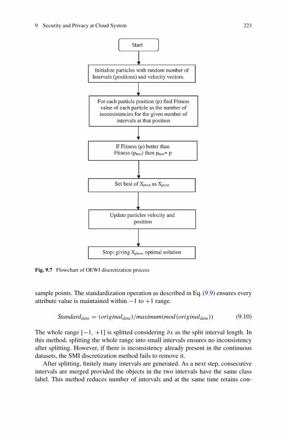
9 Security and Privacy at Cloud System 223
Fig. 9.7 Flowchart of OEWI discretization process
sample points. The standardization operation as described in Eq. (9.9) ensures everyattribute value is maintained within −1 to +1 range.
Standarddata = (originaldata)/maximum(mod(originaldata)) (9.10)
The whole range [−1, +1] is splitted considering ∂x as the split interval length. Inthis method, splitting the whole range into small intervals ensures no inconsistencyafter splitting. However, if there is inconsistency already present in the continuousdatasets, the SMI discretization method fails to remove it.
After splitting, finitely many intervals are generated. As a next step, consecutiveintervals are merged provided the objects in the two intervals have the same classlabel. This method reduces number of intervals and at the same time retains con-

224 N. Sengupta
Fig. 9.8 The SMI process determine the intervals
sistency in the dataset as intervals are merged only when they belong to the sameclass. It must be noted that after Split and Merge processes (see Fig. 9.8), the inter-vals possibly are of different length. SMI discretization process is more adaptable tonon-uniform data distribution and orientation. It partitions the whole data range ofeach attribute into distinct and disjoint intervals and thus maintaining consistency.
The intervals are represented as [−1,K1∂v], [K1∂v,K2∂v], . . . , [K(n − 1)∂v,K(n)∂v]whereK1 < K2 < K3 < K(n − 1) < K(n) and K(n) = 1/∂v, the last inter-val.
The following theorem proves that the Split and Merge Interval Discretizationprocess always preserves consistency in the data set.Theorem I. Split and Merge Interval Discretization process preserves consistency.The prove follows in two steps, considering first the Split phase and then theMergingphase.
(i) Consistency is preserved after Splitting
Proof. Assume, after splitting an attribute with values x1 and x2 (x1 �= x2) lie inthe same interval but in different class labels. Also assume that the interval length is∂v, denoting minimum difference in attribute values that differentiates two differentclass labels.
Therefore,|x1 − x2| = ∂x ≤ ∂vNow if x1 and x2 have two different class labels thenminimumdistance separating
two class labels is ∂x as ∂x ≤ ∂v. But we assume that v is the minimum separatingdistance. Therefore, assumption is incorrect and there are no distinct attribute valuesbelonging to the same interval but with different class labels. Therefore, it is provedthat consistency is preserved after splitting.
(ii) Consistency is preserved after Merging
Proof. In themerging phase consecutive intervals are merged if and only if their classlabel is same. Before merging (i.e. after splitting phase) consistency is preserved andthe merging process itself preserves consistency by merging only the consecutiveintervals with same class label. Therefore, consistency is maintained after merging.To illustrate the method, consider Table9.4 with one attribute and two class labels.
For the given sample dataset, it has been observed that the minimum differencebetween attribute value that separates two classes (‘Normal’, ‘Anomaly’) is 0.10

9 Security and Privacy at Cloud System 225
Table 9.4 Illustration of SMI method
Attribute value Class Attribute value Class
0.04 Normal 0.48 Normal
0.1 Normal 0.55 Normal
0.15 Normal 0.66 Anomaly
0.20 Normal 0.70 Anomaly
0.30 Anomaly 0.85 Normal
0.35 Anomaly 1.0 Normal
Table 9.5 Output of splitting process
Range of attributevalues
Class Range of attributevalues
Class
0.0–0.1 Normal 0.5–0.6 Normal
0.1–0.2 Normal 0.6–0.7 Anomaly
0.2–0.3 Normal 0.7–0.8 Anomaly
0.3–0.4 Anomaly 0.8–0.9 Normal
0.4–0.5 Normal 0.9–1.0 Normal
Table 9.6 Output of the merge Process
Merged Range Class
0.0–0.3 Normal
0.3–0.4 Anomaly
0.4–0.6 Normal
0.6–0.8 Anomaly
0.8–1.0 Normal
(0.30–0.20). After splitting, the result is summarized in Table9.5 that demonstratespreservation of consistency in the dataset.
Now in themerging phase, consecutive intervals aremerged provided correspond-ing class labels are same. The merged intervals along with class labels are given inTable9.6, demonstrating consistency in the dataset after merging.
9.4.2 Artificial Neural Network
Artificial Neural Network (ANN) [59, 60] classifies the object based on patternmatching. For many real life complex applications, ANN works very efficiently.ANN has many characteristics. It considers some instances based on the attribute

226 N. Sengupta
values, as its training data. It takes long time for training. In the learning data, therecan be noise. Here, rules are generated based on pattern of the objects. ANN learnsthe system before classification. There are three types of learning, supervised learn-ing, unsupervised learning, reinforcement learning. In supervised learning, beforeclassifying the objects, classifier has set of inputs and the targeted outputs. Classi-fier algorithm works through the iterations. In each iteration, classifier classifies theobjects and finds the difference between the targeted output and actual output. Afterevery iteration, classifier decides to change its parameters/algorithms/rules to reducethe difference between the targeted output and the actual output. In unsupervisedlearning, targeted output is not available for the set of inputs. In such type of learn-ing, classifier tries to learn the system as and when it receives the set of inputs andfinds the output. In reinforcement learning, classifier uses some kind of feedback onevery iteration. If it achieves the reward, the classifier strengthens its algorithms/rulesin the same manner so that it achieves the desired accuracy within a short period oftime. There can be various designs of ANN, like perceptrons, linear units, sigmoidunits. Training ofmultilayer ANNs involves a lot of complexity like hypothesis spacesearch, representing units and moreover the learning part. Perceptron is one type ofANNwhich provides the output as 1 or−1. Based on the inputs, linear combinationsof the same are calculated and the sum is derived. Basically, perceptron separates theobjects with the concept of a hyperplane. Some objects lie on one side of the hyper-plane based on the output of the perceptron, like +1. Some objects lie on anotherside of the hyperplane for which the output of perceptron is −1. As the output ofperceptron is either +1 or −1, perceptron can represent many Boolean functions.Perceptron rule and delta rule yield some acceptable results in learning. Perceptronrule works successfully when the objects are linearly separable. When the objectsare not linearly separable, perceptron rule fails. In that case, delta rule works. ANNfollows supervised learning for classification. ANN takes the inputs, assumes weightfor each inputs and forms the output. In each iteration, it calculates the output andfinds the difference between the targeted output and actual output. If the output isfar from the desired output, ANN model changes the weights and recalculates theoutput. Iteration processes repeat till it achieves the desired output. ANN model isshown in Fig. 9.9.
ANN classifier assumes the values of weights and finds the output as mentionedin Eq. (9.8).
output =n∑
i=1
Iiwi (9.11)
Algorithm for applying ANN is given as follows.
Step 1: Take inputs after dimension reduction and take desired accuracy, targetedoutput, OutputStep 2: Assume weights for each inputStep 3: Calculate actual Output applying Eq. (9.8)

9 Security and Privacy at Cloud System 227
Fig. 9.9 ANN classification
Step 4: Calculate the difference between actual output and targeted outputStep 5: If desire accuracy is not achieved, change weights and repeat step 3 to step5, else declare the accuracy.
9.4.3 Support Vector Machine
Support Vector Machine (SVM) [61–65] is an efficient classification method whichuses hyperplane for classifying the objects. Though SVM performs very well inbinary classification and regression problem, SVM has many challenges. Selectingparameters, pre processing of data, limiting use of SVM are a few of those. Forclassifying single dimensional objects, a point is required to classify. For classify-ing two dimensional objects, a straight line is required to classify those objects. Forthree dimensional objects, a plane is required to classify the objects. For n dimen-sional objects, n−1 dimensional hyperplane is required to classify those objects.Classification through SVM is shown in Fig. 9.10 for 2 dimensional objects.
The objective of SVM classification is to find out the optimum hyperplane whichclassifies the objects.Margin is defined as double the distance between the hyperplaneand the closest point. The optimized hyperplane will be achieved when the value ofmargin is maximum. SVM will be efficient when number of attributes will be less.Though inFig. 9.10, a straight line is shownwhich divides the objects into two classes.For twodimensional objects, separating line equationwill be normal equationof a line(y = mx + c). But in reality, objects are with multi dimensions. In multidimensionalcases, straight line equation cannot be considered as a separating line. In that case we

228 N. Sengupta
Fig. 9.10 SVMclassification of two types ofobjects
Fig. 9.11 Hyperplaneshowing the classificationsof multidimensional objects
need to consider the equation of a hyperplane (WTX = 0) for separating the objects.The method of determining hyperplane for classifying multidimensional objects isshown in Fig. 9.11.
Consider the objects a, b, c, d, e for one class and f, g, h, j are the objects of anotherclass. These objects are considered as training objects. There can be infinite numberof hyperplanes which can classify these objects into two classes. But the objective isto determine the optimal hyperplanewhere themarginwill be themaximum. Supposepp is the hyperplane which classifies those training objects and in this case, margin= 2Xfk. Now consider another hyperplane qq which also classifies those objectsinto two classes and the margin = 2Xam, which is higher than 2Xfk (clear from thedrawing). So, qq is the better hyperplane than pp but optimum hyperplane needs tobe determined.
Algorithm for Implementing SVM
Step 1: Get the training datasetStep 2: Find two hyperplanes so that between these two hyperplanes no training datapoint should be there
9 Security and Privacy at Cloud System 229
Step 3: Displace these two hyperplanes in opposite direction upto the level wherethe distance between two hyperplanes become maximumStep 4: Distance between these two hyperplanes will be the margin for optimumhyperplaneStep 5: Hyperplane passing through the mid point of the distance between these twohyperplanes will be the optimal hyperplane.
Different models of SVM have been designed by the researchers to improve inperformance of classification. Twin Support Vector Machines are proposed by someresearchers where objects are classified by using two hyperplanes. Computation costhas been reduced in such cases. Algorithms for parallel randomized support vectormachine and parallel randomized support vector regression works very well for thecases of linearly non separable objects and linearly non separable regression prob-lems. Incremental learning support vector machine uses hyper distance for learning.It uses less number of training samples as historical data is used for learning. It takesless time for training and provides better classification accuracy. One of the objectiveof SVM is to reduce the complexity of the decision function of SVM which can bedecreased by reducing the number of training vectors. ClusterSVM provides a bettermodel where similar types of objects are clustered and the distance from the centerpoint of cluster to the hyperplane is measured to determine the hyperplane. As inreal life IDS, time is very important, clusterSVM can yield better result. MulticlassSVM is also very useful for application of multiple classification. As in IDS, dif-ferent types of attacks can be there, multiclass SVM can also be useful. SmoothSVM is another type of SVM where kernel function needs to be designed accord-ingly. Manifold proximal SVM is another classification which takes out maximumgeometrical information from inside data. Boosting support vector machine is aneffective classification method. In such method, dimension of data is reduced to helpin training and in classification accuracy. This chapter tried to focus this boostedSVM for application in server IDS.
9.4.4 Classification Parameters
Confusion Matrix or table of confusion provides information about actual and pre-dicted classification achieved by a classification system. Actual values are writtencolumn wise and predicted values are written as row wise. Confusion matrix inTable9.7 gives the indication how actual and predicted are represented.
9.5 Experimental Results
In proposed IDS, NSL-KDD 2009 Intrusion Detection System data set [66] hasbeen considered for experimental analysis for phase three implementation. DARPAnetwork traffic data has been analyzed for SVM. Total 11850 objects have been

230 N. Sengupta
Table 9.7 Confusion matrix
Actual value (p) Actual value (n) Total
Predicted value (p’) True positive(a) False positive(b) P’
Predicted value (n’) False negative(c) True negative(d) N’
Total P N
Table 9.8 Confusion matrix
Anomaly Normal Sum
Anomaly 9591 107 9698
Normal 491 1661 2152
Sum 10082 1768 11850
considered which have 41 conditional attributes and 1 decision attributes. Out of 41attributes, 34 attributes are continuous and 7 are discrete. 34 continuous attributeshave been applied for SVM and found out the confusion matrix as in Table9.8.
Error rate is found as 5.05% applying SVM. For same set of data, by applyingANN, error rate is found as 6.67%. As SVM provides better classification result thanANN, SVM is proposed for implementation of IDS at cloud server.
9.6 Conclusions and Future Work
Security is one of the biggest challenges in cloud system. This chapter has beenfocused to provide the mechanism to overcome the above mentioned challenge ofcloud system. Maintaining complete security system of cloud has been discussed inthe chapter. Complex encryption has been suggested for implementation in the clientcloud system so that data becomes secured before leaving the cloud client. Data willremain secure in the medium as well as in the cloud server. Practically, in the serverlevel, two tier architecture of security has been applied, first is encryption and sec-ond is implementing IDS at cloud server level. Robust IDS with SVM classificationtechnique is applied in server level so that it can protect the server data from anyunauthorized access. In the section of SVM, various models of SVM are discussedwith their merits and demerits. Cloud system provides storage place for various typesof data. Single classification method or a particular model of SVM cannot yield bestresult of IDS for cloud server because of heterogeneous nature of data. Here, in thechapter, SVM is suggested for classification of traffic in nature. In future, for differentgroups of data or for different locations of cloud server can involve any SVMmodelwhich suits that environment most. Different deployment models, different businesscases should be taken as an experiment for identifying classification model. In a nut-shell, future work can be done for implementing powerful IDS with more efficiency.
9 Security and Privacy at Cloud System 231
In this chapter, only some countermeasures for cloud security is discussed, cryp-tography, intrusion monitoring detection and prevention. Other measures for cloudsecurity, like, identification, authentication, authorization, access control, auditingare not explained. These areas need more research work in future. Future continuousresearch work can bring the solutions for security of cloud.
References
1. J. Xiong, X. Liu, Z. Yao, J. Ma, Q. Li, K. Geng, S.P. Chen, A secure data self-destructingscheme in cloud computing. IEEE Trans. Cloud Comput. 2(4), 448–458 (2014)
2. N. Sengupta, Designing encryption and IDS for cloud security. in The second InternationalConference on Internet of Things, Data and Cloud Computing (ICC 2017), Cambridge city,Churchill College, University of Cambridge, United Kingdom, 22–23 March 2017
3. M. Ficco, M. Rak, Stealthy Denial of service strategy in cloud computing. IEEE Trans. CloudComput. 3(1), 80–94 (2015)
4. D. Talia, P. Trunfio, F. Marozzo, Data Analysis in the Cloud: Models, Techniquesand Applications (Elsevier Science Publishers B.V. Amsterdam, The Netherlands, 2015).ISBN:0128028815 9780128028810
5. C.A. Chen, M. Won, R. Stoleru, G.G. Xie, Energy-efficient fault-tolerant data storage andprocessing in mobile cloud. IEEE Trans. Cloud Comput. 3(1), 28–41 (2015)
6. T. Erl, R. Puttini, Z. Mahmood, Cloud Computing:Concepts, Technology and Architecture(Prentice Hall, Englewood Cliffs)
7. D. Zissis, D. Lekkas, Addressing cloud computing security issues. Futur. Gener. Comput. Syst.ELSEVIER Int. J. Grid Comput. eScience 28, 583–592 (2012)
8. S. Thakur, G.J. Breslin, A robust reputation management mechanism in federated cloud. IEEETrans. Cloud Comput. PP(99), 1 (2017)
9. Z. Zhang, M. Dong, L. Zhu, Z. Guan, R. Chen, R. Xu, K. Ota, Achieving privacy-friendlystorage and secure statistics for smart meter data on outsourced clouds. IEEE Trans. CloudComput. PP(99), 1 (2017)
10. J. Baek, H.Q. Vu, K.J. Liu, X. Huang, Y. Xiang, A secure cloud computing based frameworkfor big data information management of smart grid. IEEE Trans. Cloud Comput. 3(2), 233–244(2015)
11. S. Jiang, X. Zhu, L. Guo, J. liu, Publicly verifiable boolean query over outsourced encrypteddata. IEEE Trans. Cloud Comput. PP(99), 1 (2017)
12. M.K. SIM, Agent-based approaches for intelligent intercloud resource allocation. IEEE Trans.Cloud Comput. PP(99), 1 (2016)
13. K. Hashizume, G.D. Rosado, F.E. Medina, B.E. Fernandez, An analysis of security issues forcloud computing. J. Internet Serv. Appl. 4, 5 (2013). https://doi.org/10.1186/1869-0238-4-5
14. P.R. Padhy, R.M. Patra, C.S. Satapathy, Cloud computing: security issues and research chal-lenges. IRACST Int. J. Comput. Sci. Inf. Technol. Secur. 1(2) (2011)
15. P. Schoo, V. Fusenig, V. Souza, M. Melo, P. Murray, H. Debar, H. Medhioub, D. Zeghlache,Challenges for cloud networking security. HP Laboratories
16. H. Liu, B. He, X. Liao, H. Jin, Towards declarative and data-centric virtual machine imagemanagement in IaaS clouds. IEEE Trans. Cloud Comput. PP(99), 1 (2017)
17. P. Jamshidi, A. Ahmad, C. Pahl, Cloud migration research: a systematic review. IEEE Trans.Cloud Comput. 1(2), 142–157 (2013)
18. Y. Zhang, X. Liao, H. Jin, G. Min, Resisting skew-accumulation for time-stepped applicationsin the cloud via exploiting parallelism. IEEE Trans. Cloud Comput. 3(1), 54–65 (2015)
19. K. Hashizume, G.D. Rosado, F.E. Medina, B.E. Fernandez, An analysis of security issues forcloud computing. J. Internet Serv. Appl. 4(5) (2013). https://doi.org/10.1186/1869-0238-4-5

232 N. Sengupta
20. N. vurukonda, T.B. Rao, A study on data storage security issues in cloud computing. in 2ndInternational Conference on Intelligent Computing, Communication & Convergence (ICCC-2016), vol. 92 (Elsevier Procedia Computer Science, 2016), pp. 128–135
21. N.P. Smart, Algorithms, key size and parameters report, European Union Agency for Networkand Information Security, 2014
22. T.Olufon, E.-A.C. Campbell, S. Hole, K. Radhakrishnan,A. Sedigh,Mitigating external threatsin wireless local area networks. Int. J. Commun. Netw. Inf. Secur. (IJCNIS) 6(3), 200 (2014)
23. F. Ayoub, K. Singh, Cryptographic techniques and network security. IEE Proc. F Commun.Radar Signal Process. 131(7) (2008)
24. U. Somani, K. Lakhani, M. Mundra, Implementing digital signature with rsa encryption algo-rithm to enhance the data security of cloud in cloud computing. in 1st International Conferenceon Parallel, Distributed and Grid Computing (PDGC - 2010) (2010)
25. T. Cusick, P. Stanica, Cryptographic Boolean Functions and Applications (Elsevier). eBookISBN: 9780128111307
26. M. Abdalla, X. Boyen, C. Chevalier, D. Pointcheval, Distributed public-key cryptography fromweak secrets, in Public Key Cryptography PKC 2009, ed. by S. Jarecki, G. Tsudik. PKC 2009.Lecture Notes in Computer Science, vol. 5443 (Springer, Berlin, 2009)
27. U. Somani, K. Lakhani, M. Mundra, Implementing digital signature with rsa encryption algo-rithm to enhance the data security of cloud in cloud computing. in 1st International Conferenceon Parallel, Distributed and Grid Computing (PDGC - 2010) (2010)
28. N. Sengupta, Intrusion detection system for cloud computing. inMiddle East and North AfricaConference for Public Administration Research, Bahrain, 23–24 April 2014
29. D.E. Denning, An intrusion-detection model. IEEE Trans. Softw. Eng. SE–13(2), 222–232(1987)
30. Aydin, EhsanAmiri E., Keshavarz, H., Mohamadi, E., Moradzadeh, H. : Intrusion detectionsystems in manet: a review. in Elsevier, International Conference on Innovation, Managementand Technology Research, Malaysia, 22–23 Sept 2013
31. S. Roschke, C. Feng, C. Meinel, Intrusion detection in the cloud, dependable, autonomic andsecure computing, in DASC09, Eighth IEEE International Conference (2009), pp. 729–734.E-ISBN: 978-1-4244-5421-1
32. Y. Mehmood, U. Habiba, M.A. Shibli, R. Masood, Intrusion detection system in cloud com-puting: challenges and opportunities. in 2nd National Conference on Information Assurance(NCIA) (2013)
33. A. Patel, M. Taghavia, K. Bakhtiyaria, J.C. Jnior, An intrusion detection and prevention systemin cloud computing: a systematic review. J. Netw. Comput. Appl. 36(1), 2541 p (2013)
34. X. Ren, Intrusion detection method using protocol classification and rough set based supportvector machine. Comput. Inf. Sci. 2(4), 100–108 (2009)
35. Z. Yu, J.J.P. Tsai, Intrusion Detection, A Machine Learning Approach, vol. 3 (Imperial CollegePress, London, 2011). ISBN-13: 978-1848164475
36. R.P. Patil, Y. Sharma, M. Kshirasagar, Performance analysis of intrusion detection systemsimplemented using hybrid machine learning techniques. Int. J. Comput. Appl. (0975–8887)133(8) (2016)
37. A.M. Aydin, H.A. Zaim, G.K. Ceylan, A hybrid intrusion detection system design for computernetwork security. Comput. Electr. Eng. 35, 517–526 (2009). Elsevier
38. D.Anderson, T. Lunt,H. Javitz,A. Tamaru,A.Valdes. Safeguard final report:Detecting unusualprogram behavior using the NIDES statistical component, Technical report, Computer ScienceLaboratory, SRI International, Menlo Park, CA, 1993
39. Lianying, L. Fengyu, A Swarm-intelligence-based intrusion detection technique. IJCSNS Int.J. Comput. Sci. Netw. Secur. 6(7B) (2006)
40. S. Owais, V. Snasel, P. Kromer, A. Abraham, Survey: Using genetic algorithm approach inintrusion detection systems techniques. in CISIM 2008 (IEEE, 2008), pp. 300–307
41. P. LaRoche, N.A. ZincirHeywood, 802.11 network intrusion detection using genetic program-ming. in Proceeding GECCO ’05 Proceedings of the 2005 workshops on Genetic and evolu-tionary computation (2005), pp. 170–171

9 Security and Privacy at Cloud System 233
42. Y. LIN, Y. ZHANG, OU Yang-Jia, : The design and implementation of host-based intrusiondetection system. Third International Symposium on Intelligent Information Technology andSecurity Informatics, 2010
43. R.W. Swiniarski, Rough sets methods in feature reduction and classification. Int. J. Appl. Math.Comput. Sci. 11(3), 565–582 (2001)
44. Y. Zhao, F. Luo, S.K.M. Wong, Y.Y. Yao, A general definition of an attribute reduct. in Pro-ceedings of Rough Sets and Knowledge Technology, Second International Conference, RSKT2007, LNAI 4481 (2007), pp. 101–108
45. L. Cuijuan, L. Yuanyuan, Q. Qin Yankai, Research on anomaly intrusion detection based onrough set attribute reduction. in The 2nd International Conference on Computer Applicationand System Modeling (Atlantis Press, Paris, France, 2012)
46. M. Sammany, T. Medhat, Dimensionality reduction using rough set approach for two neuralnetworks-based applications. in Proceedings of the international conference on Rough Setsand Intelligent Systems Paradigms (Springer, Berlin, 2007), pp. 639–647
47. R. Jensen, Q. Shen, Computational Intelligence and Feature Selection: Rough and FuzzyApproaches (Wiley-IEEE Press, Oxford, 2008)
48. J.R. Anaraki, M. Eftekhari, Improving Fuzzy-rough quick reduct for feature selection. in IEEE19th Iranian Conference on Electrical Engineering (ICEE) (2011), pp. 1–6
49. P.E. Ephzibah, B. Sarojini, E.J. Sheela, A study on the analysis of genetic algorithms withvarious classification techniques for feature selection. Int. J. Comput. Appl. 8(8), 33 (2010)
50. B. Zadrozny, Learning and evaluating classifiers under sample selection bias. in InternationalConference on Machine Learning ICML’04 (2004)
51. Y.X. Wang, G. Whitwell, M.J. Garibaldi, The application of a simulated annealing fuzzy clus-tering algorithm for cancer diagnosis. in Proceedings of IEEE 4th International Conferenceon Intelligent Systems Design and Application, Budapest, Hungary, 26–28 August 2004, pp.467–472
52. R.C. Chen, K.F. Cheng, C.F. Hsieh, Using rough set and support vector machine for networkintrusion detection. Int. J. Netw. Secur. Appl. (IJNSA) 1(1) (2009)
53. Z. Pawlak, Rough Sets Theoretical Aspects of Reasoning about Data, vol. 229 (Kluwer Aca-demic Publishers, Boston, 1991)
54. Z. Pawlak, Rough set theory and its applications to data analysis. Cybern. Syst. 29, 661–688(1998)
55. N. Sengupta, J. Sen, J. Sil, M. Saha, Designing of on line intrusion detection system usingrough set theory and Q learning algorithm. Neurocomputing (Elsevier Journal) 111, 161–168(2013)
56. Y. Yao, Discernibility matrix simplification for constructing attribute reducts. Inf. Sci. 179(5),867–882 (2009)
57. Y. Zhao, Y. Yao, F. Luo, Data analysis based on discernibility and indiscernibility. Inf. Sci.177, 4959–4976 (2007). Elsevier Inc
58. A. Skowron, C. Rauszer, The discernibility matrices and functions in information systems,in Intelligent Decision Support-Handbook of Applications and Advances of the Rough SetsTheory, ed. by R. Slowinski (Springer, Dordrecht, 1991), pp. 331–362
59. H. Li, Q. Zhang, J. Deng, B.Z. Xu, A preference-based multiobjective evolutionary approachfor sparse optimization. IEEE Trans. Neural Netw. Learn. Syst. PP(99), 1–16 (2017)
60. J. Faigi, A.G. Hollinger, Autonomous data collection using a self-organizing map. IEEE Trans.Neural Netw. Learn. Syst. PP(99), 1–13 (2017)
61. A.N. Alias, M.H.N. Radzi, Fingerprint classification using support vector machine. in 2016Fifth ICT International Student Project Conference (ICT-ISPC), 27–28 May 2016
62. S.K.M. Varma, K.K.N. Rao, K.K. Raju, S.P.G. Varma, Pixel-based classification using supportvector machine classifier. in 2016 IEEE 6th International Conference on Advanced Computing(IACC), 27–28 Feb 2016
63. H.A. Sung, S. Mukkamala, Identifying important features for intrusion detection using supportvector machines and neural networks. in Proceedings of International Symposium on Applica-tions and the Internet (SAINT 2003) (2003), pp. 209–217

234 N. Sengupta
64. S.S. Keerthi, S.K. Shevade, C. Bhattacharyya, K.R.K. Murthy, A fast iterative nearest pointalgorithm for support vector machine classifier design. IEEE Trans. Neural Netw. 11, 124–136(2000)
65. C. Cortes, V.N. Vapnik, Support vector network. Mach. Learn. 20, 273–297 (1995)66. Nsl-kdd data set for network-based intrusion detection systems (2009), http://nsl.cs.unb.ca/
NSL-KDD/

Chapter 10Optimization of Security as an Enablerfor Cloud Services and Applications
Varun M. Deshpande, Mydhili K. Nair and Ayush Bihani
Abstract The advent of cloud computing has created a paradigm shift in how peo-ple around the world communicate and do business. Its inbuilt characteristics haveempowered companies to build cutting edge solutions that bring us all together thanwe ever were before. Cloud computing provides avenues to use storage and comput-ing resources in metered basis to provide optimized virtual infrastructure for serviceproviders to prosper. Service providers can concentrate on building technology ratherthan worrying about the infrastructure and the platform for service hosting or servermaintenance. Amount of information being shared and exchanged by users is grow-ing exponentially by the passing of each hour. People around the globe have openlyembraced the era of information technology, and almost unknowingly, it has becomean essential part of everyday life. In this context, securing our digital life by enablingcloud applications to perform at its fullest is of prime importance. Security engineer-ing community is continuously optimizing security standards, tools and practicesto achieve this. This chapter throws light into such methods and technologies thatform the Digital Guardians of our Connected World! In any discussion related tooptimization of Cloud Security, it is important to recognize the current market andresearch trends. This chapter adopts a case study based approach to understand thecurrent scenario and best practices with respect to Cloud Security. We discuss theoverall security objectives and challenges that developers and cloud service vendorsface during life cycle of Cloud software applications. Topics related to Cloud soft-ware quality assurance including cloud penetration testing are dealt with religiously
V. M. Deshpande (B)Department of CSE, Jain University, Bangalore, Indiae-mail: [email protected]
M. K. Nair · A. BihaniDepartment of ISE, MSRIT, Bangalore, Indiae-mail: [email protected]
A. Bihanie-mail: [email protected]
© Springer International Publishing AG, part of Springer Nature 2018B. S. P. Mishra et al. (eds.), Cloud Computing for Optimization:Foundations, Applications, and Challenges, Studies in Big Data 39,https://doi.org/10.1007/978-3-319-73676-1_10
235

236 V. M. Deshpande et al.
in the chapter. We then propose certain tools and techniques which would help anydeveloper or cloud security enthusiast to understand how to secure any application tomake it cloud ready. This is very important; especially, with the growing complexityof web application threats. Hence, we have dedicated a section of this chapter toidentify and mitigate security loopholes in the applications in a smart and focusedmanner.
Keywords Cloud security optimizationsSecurity standards and recommendations · Cloud penetration testingTools and techniques for assessment and mitigation of security issuesSecurity in big data (Hadoop) · Trusted computing and identity managementEfficient security operations management · Open forums and certifications
10.1 Introduction
This chapter is designed for a Cloud Security Enthusiast having solid foundationof Cloud Architecture and Models, having basic background about web applicationsecurity, digital privacy and security management. On completion of reading, thereader would be able to appreciate and understand through case studies, the Securityand Privacy aspects of Cloud Computing, Big Data and Trusted Computing and howto optimize the same in real world scenario. The reader would be equipped withknowledge of usage of Tools, Standards and Methodologies to ensure Security isused smartly to enable of Cloud applications to perform at its best potential. Whenwe discuss the optimization of cloud technologies in providing better engineeringsolutions to real world problems and requirements; it is important to understandthe security implications of the same. As cloud computing evolves and amount ofdata being handled increase exponentially, the necessity to understand the securityconcerns and bring out innovative solutions to these concerns is riper than ever. Itis up to the able hands of the security engineering community to stay ahead andrespond to the new threats to the fresh requirements of cloud architecture. Thissection deals with understanding the security requirements, design considerations,risks and challenges of a cloud based systems by means of strategically selected casestudies - Amazon Web Services and Microsoft Azure.
10.1.1 Current Scenario of Cloud Applications and Security
Cloud technology involves orchestration of several services at difference levels ofabstraction, such as infrastructure, platform and software. The service orchestrationin turn provides the necessary environment for the service provider to host theirapplications etc. without having to worry about underlying architecture as well asmaintenance of quality of service. Question comes in ones mind- as to what is the

10 Optimization of Security as an Enabler for Cloud Services … 237
level of importance and relevance of Security in this service stack and where does itfit in? This chapter throws light on just that topic. With case study based approach,we try to postulate the title of the chapter and convey to the reader as how securitycan play a pivotal role in enabling cloud applications to reach its fullest potential.
Drawing parallel with real world, where a lot of funds are allocated to securinga building, locality or a state; similarly, we have been seeing a notable amount toIT budget being allocated for securing the computing elements of any organization.Security can never be an afterthought, rather it needs to be in built at every level ofsystem. As per report produced by SANS in 2016 top business drivers for securityspending in the IT industry were protection of sensitive data, regulatory complianceand reducing incidents and breaches.
10.1.2 Case Study: Amazon Web Services (AWS)
Amazon started the Amazon Web Services platform [1] in 2006 to provide servicesfor otherweb sites and applications.AWSoffers a host of on-demand services over thecloud. Primary components of AWS include Amazon Elastic Compute Cloud (EC2)which forms the virtualization and computation core of AWS and other is AmazonSimple Storage System (S3) which handles the scalable storage unit of AWS. Alongwith these, AWS now offering over 70 unique Cloud computing services such asAmazon Aurora, Amazon VPC etc. These can be availed on the fly on a meteredbasis or highly competitive rates. This is one of the reasons for its growing popularityin the business (Fig. 10.1).
Fig. 10.1 Services provided by AWS

238 V. M. Deshpande et al.
AWS has helped many organizations solve their challenges through web services.We will discuss two such case studies involving Avira (A Company that providesIT Security Solutions) and Alert Logic (An Amazon partner company that providessecurity-as-a-service).
Avira Avira offers a several IR security solutions that help its customers who arehome users to large enterprises. Meaning each of the projects would require a cus-tomized deployment environment. Their local data center was simply not equippedto handle high amount of data. Also, the effort that would need to be put in to handle ahuge user base would not allow the project to be launched within the required time tomarket. Now, Avira choose to work with AWS team to host more that 10 of their topprojects on AWS. Each of these projects are isolated using Amazon Virtual PrivateCloud (Amazon VPC). One of the main benefits that was highlighted during this pro-cess was that Avira engineers could spend most of their energies in building cuttingedge products instead of worry about their hosting and maintenance. Lot of moneywas saved by Avira for not having to procure new hardware and other resources tomaintain it.
Alert Logic Alert Logic has built their business providing security monitoringsolutions for web and business applications. They have built a new vulnerabilityand configuration management solution called Cloud Insight. Cloud Insight helps itscustomers by identifying potential security threats and remediates them in real time.Instead of hosting this service on their own which is very costly or a small growingorganization like itself, they used AWS platform features and services such as AWSCloudTrail. By doing so, Alert Logic estimate that they have saved over $1 Millionin capital expenses and close to 6 months of development time!
10.1.3 Case Study: Microsoft Azure (MA)
Microsoft Azure [2] is a holistic collection of integrated cloud services stack whichdevelopers and IP professionals can use to build, deploy and manage cloud basedapplications via their global grid of data centers. Azure provides the flexibility tobuild anddeployweb applicationswhere ever the developerwants using anypreferredtools, applications and frameworks of choice (Fig. 10.2).
Fig. 10.2 Services provided by MA

10 Optimization of Security as an Enabler for Cloud Services … 239
The case studies chosen to explain the benefits ofMicrosoftAzure areOneHorizonGroup, a media and cable company from United Kingdom and Daman, a healthinsurance company from United Arab Emirates.
One Horizon Group a telecommunications startup company that needed a cost-effective cloud platform for hosting theirVoIP service called Smart Packet. They usedMicrosoft Azure cloud for both software development and hosting of their solution.They could complete the product releasewithout having to invest on highly expensivecomputing resources. This helped them to gain competitive advantage over othersand provide aggressive rates. They also reduced operation costs and enhanced theirproduct security. All this was possible only because of evolution and optimizationof cloud computing services.
Daman is a healthcare company in the Middle East based in United Arab Emi-rates. The problem that they were facing is to use the data available to find creativesolutions for getting business insights for managing growing healthcare costs. Theyneeded to use decision making algorithms based on behavior monitoring, qualita-tive analyzing, cost control mechanisms and fraud detection. To achieve this, theyessentially migrated their 3TB data warehouse from Sybase IQ to Microsoft SQLServer 2016 with Column store indexes facility provided by Microsoft Azure. Withthis they could 5-fold improvement in the performance and avoided $250,000 annualexpenses and in turn strengthened data security and better change management.
Note: Figures taken from AWS and MA website for illustration and educationalpurpose only
10.2 Cloud Computing Security Objectives, Challenges
Security and Privacy has always been an essential factor in discussion related to com-puting. Security has always been regarded as one of non-functional requirements ofa system such as reliability, maintainability etc. making it hard to measure. Providingtoo much security to applications may adversely affect quality of service parameterslike response time, cost etc. However, providing less security may lead to securitybreaches of the cloud services which affect the reputation and mean time to recovery.Hence, planning smartly and providing an optimized security plays a great role inenabling the cloud applications to successfully function as designed and meet all thedesired quality of servicemetrics. In this section, we discuss about such objective andchallenges. Also Security Policy Implementation and challenges in virtual securitymanagement using VMWare ESX server case study as dealt with in the section.
Consider a scenario where a company is considering to move their products andinformation to cloud. Then, security of the organizations critical information in acloud environment maintained by cloud service provider is of principal concern.Especially, when the data is being kept in geographically distributed cloud envi-ronments which are not under direct control of the company. In order to provideconfidence to the companies and developers, the cloud service providers adhere tostrict set of security requirement and objectives. This section [3] talks about such

240 V. M. Deshpande et al.
requirements, design constraints of secure cloud systems.Wealso cover topics relatedto challenges in policy implementation as well as go over case study of Virtualizationsecurity management using VMWare ESX server as example.
10.2.1 Requirements of Secure Cloud System
Security is a non-functional requirement.Hence, the principle requirement of a securecloud based system is that we mitigate any known vulnerabilities in the system andmake sure that system performance is not compromised when it is under externalmalicious attack. This requirement is not same as security functionality requirementsuch as identification, authentication and authorization. However, it speaks about theresilience factor of the cloud system that we are building.
The key factors that are required to be exhibited by the secure cloud system are:
• Dependability Software system needs to be dependable even during hostile con-ditions
• Trustworthiness Ability of not to be compromised by malicious programs andvulnerability injection
• ResilientRecover from any damage done gracefully and recover to full operationalability and to secure itself from further attacks. Performing thiswith as less damageas possible as well as in as less time as possible.
• Availability and Fail Safe Ensure that there is always a fail-safe state functional-ity which can be used when there are no other options available. This ensures thatsystem is not compromised and up and running all the time. To achieve the abovesaid nonfunctional requirements, organization must follow good secure develop-ment practices and life cycle. During project execution, utmost importance shouldbe given to security during the execution of the project to avoid possible secu-rity lapses in the end. While there are several tools and techniques to design, anddevelop efficient cloud programs, special attention needs to be given to belowaspects:
• Sensitive Data handling and Input validation Some data generated during com-puting are sensitive. Revealing of which could be harmful to the users. And leakingsuch information could mean facing litigations and legal actions for the serviceproviders. For example, storing account critical information such as passwords,account recovery questions etc. in clear text/unencrypted manner in the database;storing the credit card details and other financial information in unencrypted for-mat. Sending these parameters via URLs as parameters for easy access. Thesekinds of activities should be taken care of very carefully.
• Code practices and Language Options Reverse engineering is quite possibleto trace back some loopholes present in the system and hackers can use it toexploit the low hanging fruits to gain more information on the system. This canbe used to design more sophisticated exploits later. Hence using secure memorymanagement via language options are necessary. For example, Java and C# have
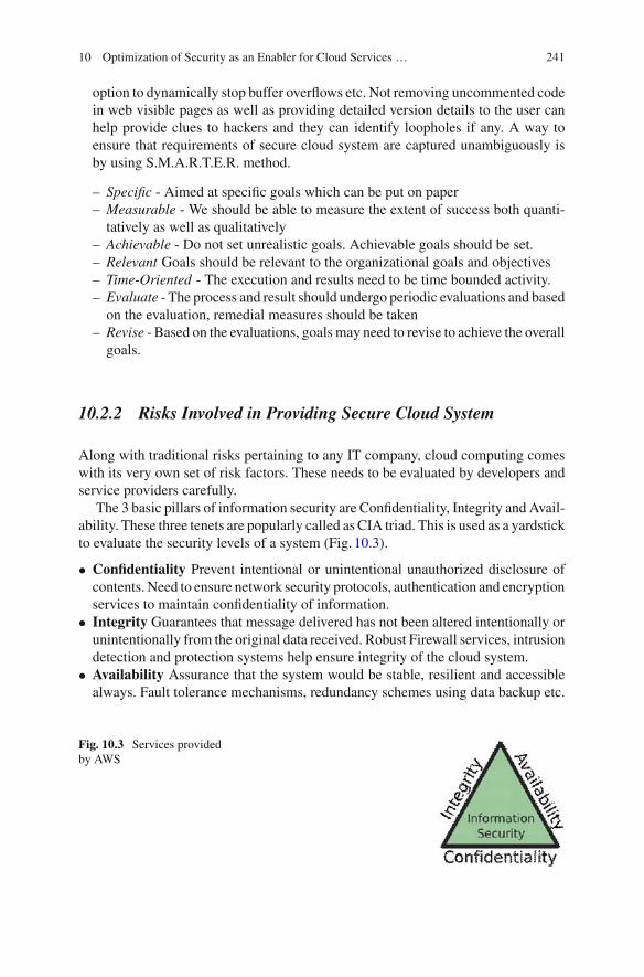
10 Optimization of Security as an Enabler for Cloud Services … 241
option to dynamically stop buffer overflows etc. Not removing uncommented codein web visible pages as well as providing detailed version details to the user canhelp provide clues to hackers and they can identify loopholes if any. A way toensure that requirements of secure cloud system are captured unambiguously isby using S.M.A.R.T.E.R. method.
– Specific - Aimed at specific goals which can be put on paper– Measurable - We should be able to measure the extent of success both quanti-tatively as well as qualitatively
– Achievable - Do not set unrealistic goals. Achievable goals should be set.– Relevant Goals should be relevant to the organizational goals and objectives– Time-Oriented - The execution and results need to be time bounded activity.– Evaluate - The process and result should undergo periodic evaluations and basedon the evaluation, remedial measures should be taken
– Revise - Based on the evaluations, goals may need to revise to achieve the overallgoals.
10.2.2 Risks Involved in Providing Secure Cloud System
Along with traditional risks pertaining to any IT company, cloud computing comeswith its very own set of risk factors. These needs to be evaluated by developers andservice providers carefully.
The 3 basic pillars of information security are Confidentiality, Integrity and Avail-ability. These three tenets are popularly called as CIA triad. This is used as a yardstickto evaluate the security levels of a system (Fig. 10.3).
• Confidentiality Prevent intentional or unintentional unauthorized disclosure ofcontents. Need to ensure network security protocols, authentication and encryptionservices to maintain confidentiality of information.
• Integrity Guarantees that message delivered has not been altered intentionally orunintentionally from the original data received. Robust Firewall services, intrusiondetection and protection systems help ensure integrity of the cloud system.
• Availability Assurance that the system would be stable, resilient and accessiblealways. Fault tolerance mechanisms, redundancy schemes using data backup etc.
Fig. 10.3 Services providedby AWS

242 V. M. Deshpande et al.
ensure high availability of the cloud system. Apart from CIA triad, user iden-tification and authentication, authorization and accountability and privacy formimportant concepts which will result as risks if not handled properly.
• Privacy and Legal Compliance RisksWith billions of users using cloud serviceson a regular basis, privacy and compliance becomes a high risk area and a pitfallfor any organization using cloud computing. Identity theft resulting in privacybreach can cause lot of issues for enterprise as well as end users. We will look atprivacy holistically in Sect. 10.5 of this chapter.
• Common Threats and Vulnerabilities Common threats to both cloud and tra-ditional computing include eavesdropping, fraud, theft, denial of service, logonabuse, network intrusion etc.
10.2.2.1 Case Studies on Recent Security Breaches
Recent days have seen a high increase in security breaches being reported [4]. Thesereaches may cause downtime for the services. This costs the organizations lot ofmoney due to loss of confidential information which eventually tarnishes their rep-utation. Cloud computing is one of the most valuable innovations for business, pro-viding cheap, virtual services. The past decade has seen increasing use of cloudinfrastructure to store data and provide services with major businesses and technol-ogy companies shifting to the cloud. The cloud also provides the ability to scale upor down to respond quickly to changing market conditions. Due to this, many orga-nizations are hesitant to fully leverage the cloud, citing concerns about compliance,data loss, and unauthorized access with major security breaches having taking placein the past. Technology giants Yahoo, Dropbox, Adobe security were compromisedand found millions of users credentials including private mails, passwords, and userprofile data exposed.
There have been 5,754 data breaches between November 2005 and November2015 that have exposed 856,548,312 records. Malicious attacks have gone from200,000 a year in 2006 to 200,000 attacks a day. Major multinationals, governmentorganizations have been at the end site of the hack. We highlight some of the recentincidents to give you an insight.
Yahoo announced in Sep 2016 that over 500 million accounts were compro-mised and had sensitive information stolen since 2014- over 2 years. The hackerhad gained access to personally identifiable information and digital identities of theaffected users. The first announced breach, reported in September 2016, had occurredsometime in late 2014, and affected over 500 million Yahoo! user accounts. A sep-arate data breach, occurring earlier around August 2013, was reported in December2016, and affected over 1 billion user accounts. The security lapse responsible for thehack were forged cookies to bypass security protections and access users accountswithout a password.
Sony Pictures - The Sony breach began with a series of phishing attacks tar-geted at Sony employees. These phishing attacks worked by convincing employeesto download malicious email attachments or visit websites that would introduce mal-

10 Optimization of Security as an Enabler for Cloud Services … 243
ware to their systems. This type of attack used social engineering, where phishingemails appeared to be from someone the employees knew, thus tricking them intotrusting its source. Hackers then used Sony employee login credentials to breachSony’s network. Over 100 terabytes of data was stolen and monetary damages areestimated to be over $100 million.
MySpace - A social media behemoth before Facebookwas the target of hackers in2016 with more than 360 million emails and passwords of users being leaked online.This incident threw light at how weak passwords can be cracked easily through bruteforce attacks. The hacker responsible for this hack found a users password in theMyspace dump and allegedly used it to log into different accounts even though thepasswords were hashed with SHA1 algorithm, which is easy to crack. Major numberof hacked users had passwords such as password1, abc213, etc. which are vulnerableto brute force attack.
Dropbox - A huge cache of personal data from Dropbox that contains the user-names and passwords of nearly 70 million account holders had been discoveredonline. The information, believed to have been stolen in a hack that occurred severalyears ago, includes the passwords and email addresses of 68.7 million users of thecloud storage service. The credentials were stolen in a hack that occurred in 2012when hackers used stolen employee login details to access a document containing theemail address and passwords of users. The many reason for such hacks were largelyattributed due to weak passwords set by the users which are often easy to brute forcewith sophisticated software. Poor security by employees of the company risked dataof millions of users.
Home Depot - A security breach that attacked Home Depot’s payment terminalsaffected 56 million credit and debit card numbers. The Ponemon institute estimateda loss of $194 per customer record compromised due to re-issuance costs and anyresulting credit card fraud. Hackers first gained access to Home Depot’s systemsthrough stolen vendor login credentials. Once the credentials were compromised,they installed malware on Home Depot’s payment systems that allowed them tocollect consumer credit and debit card data.
10.2.3 Security Architecture Design Considerations
With all the various advantages that cloud computing brings to the table such asdecreasing costs and time required to deploy new projects to market; cloud securitywill always remain to be a major concern. The security of the cloud system is heavilybased on its security architecture. A security architecture of a cloud system is acohesive reproducible design process which has holistic plan to address all securityrequirements and provides specifications on what security controls should be appliedin which area.

244 V. M. Deshpande et al.
A variety of parameters play their role in the performance and implementationof cloud security architecture. Factors related to compliance, security managementand administration, controls and security awareness form the main considerationconstraints for security architecture design.
Information needs to be efficiently classified to demonstrate companys commit-ment towards data security, identify the critical data units and to devise appropriatesecurity measures to protect it. Information can be classified as public/sensitive/private/confidential data and provide data access to employees accordingly.
Secure execution environments is a critical design consideration for effectivecloud platform utilization. In cloud atmosphere, applications need to be executedon distributed environment. When they interact with outside computing resources oreven sensitive data, the computing needs to be done is a secure environment. Hence itis imperative for service provider to provide the developers with secure environmentsto communicate between cloud, sensitive data and client resources.
One of the advantages of cloud computing to developers or young companiesis that the responsibility of providing the secure execution environment is with theservice provider and not with themselves.
Cloud service providers need to be careful when developer code with potentiallyunsafe programming languages like C, C++ which have poor memory managementcapabilities. In these cases, they must perform some more compile time and runtimevalidations so that the coder executed does not unintentionally harm other computingresources hosted on the cloud.
CIA Triad must strictly follow in this regards so that the confidentiality, integrityand availability of the services are not compromised. Virtual private networks (VPN)are an important tool to provide secure cloud communications. It is one of themethodsto ensure secure cloud environment for communications. Secure remote access tocomputing resources can be provided using remote access VPN. Network to networkconnections can be provided using network-network VPN.
VPN tunneling can be used to encapsulate data from one network to another byadditional headers for security (Figs. 10.4 and 10.5).
Encryption is a key design consideration for secure communications and the infor-mation that gets exchanged between the computing resources needs to be encrypted.
Fig. 10.4 Services provided by AWS

10 Optimization of Security as an Enabler for Cloud Services … 245
Fig. 10.5 Services provided by AWS
The server calls and communications needs to be analyzed for possible malwareinjections etc. In this chapter, we wont go in detail about the public and private keyencryption and how it works. However, for the record we would like to highlightthe usage of digital certificates, LDAP services, time stamping for creating a securedesign for cloud architecture.
10.2.4 Cloud Computing Security Challenges
Some of the challenges faced by cloud based organizations can be broadly classifiedinto: Security policy implementation, Computer intrusion, detection and response(discussed later in the chapter) and visualization management.
Security policy implementation forms the most challenging task in cloud com-puting for service provider. The policies include high level management policieswhich are mostly business oriented and lack technical specifications. The lowerlevel policies are more specific such as regulatory policies which are related to com-pliance to standards, informative policies which are educating internal and externalstakeholders of the company and advisory policies which are not mandatory to fol-low like regulation, however advisable to be followed to uphold the company definedself-standard.
Virtualization management - Virtualization describes a technology in whichapplication, guest operating system or data storage is abstracted away from the trueunderlying hardware or software. The software emulates the hardware from a fullyblown operating system such as Linux, windows or a specifically designed operatingsystem such as VMWare ESX running on the virtual machine. It has allowed orga-nizations to scale their operations with increased stability for resource fulfillment.Virtualization is now a critical part of cloud computing forming the backbone ofthe infrastructure as a service (IaaS) which begs the question of security risks ofvirtualization.

246 V. M. Deshpande et al.
10.2.4.1 Case Study: VMWare ESX Server - Challenges inVirtualization Security Management
Some of the Security Challenges and risks involved especially with Virtualizationare discussed below.
Isolation: One of the key issues in virtualization is isolation. Isolation will guar-antee that one application in one VM cannot see applications running in a differentVM, or that some process running in one VM cannot affect the other VMs runningin the same machine. If this security assumption is broken, then an attacker can haveaccess to other VMs in the same machine or even to the host machine. That is whyit must be carefully configured and maintained.
Guest Attack: There can be some external or internal factors that can compro-mise isolation as mis-implementation/configuration or some bug in the virtualizationsoftware. A dangerous attack can be made if isolation between the host and the VMsis compromised. That attack is called VM escape and happens when a program canbypass the virtualmachine layer from inside aVMand get access to the hostmachine.The host machine is the root of all the VMs, and so if a program escapes from thevirtual machines privileges it will get root, allowing it to control all the VMs and thetraffic between them.
Remote Management Vulnerabilities: Many VM environments have manage-ment consoles that allow administrator to manage the virtual machines throughHTTP/HTTPS protocol. Older versions of VMs using HTTP stand at a greater risk ofattack such as XSS and SQL injection remotely. If the attacker gains root privilegesto the machine, allowing him to have access to the host, he can gain access to all theguests running.
Denial of Service: In virtual machine architecture, resources as CPU, memory,disk and network are shared between the host and the guests. The guest machine canimpose a denial of service to others guest which would eventually affect the hostresources. When other guests request for any resource from the host, they are deniedas the resources are fully occupied by the suspicious guest. In order to prevent DOSattacks, the host allocates maximum possible resource that can be used a by guest toeach of its guests.
Case Study: VMWare ESXHypervisors (Hosts) act as an abstraction between the underlying hardware and
the guest machines running and hence is a sensitive piece of computer software.VMWare ESX [5] represents the forefront of efforts with respect to hypervisors andsecurity which is thoroughly examined by security researchers.
VMWare ESX being one of the most common used hypervisor reported more vul-nerability compared to its counterswith having reported 26 vulnerabilities (Fig. 10.6).
The common vulnerability scoring system is used as a metric to determine thesecurity lapse of a system. The figure below shows the ESX CVSS severity analysisfrom 2003 to 2009 (Fig. 10.7).
ESX reported 7 incidents with high vulnerability. Out of these vulnerabilities 60%were exploited over a network and 40% locally. Most High Severity attacks are HostPrivilege Escalation exploitable by network. These are possible because the newer
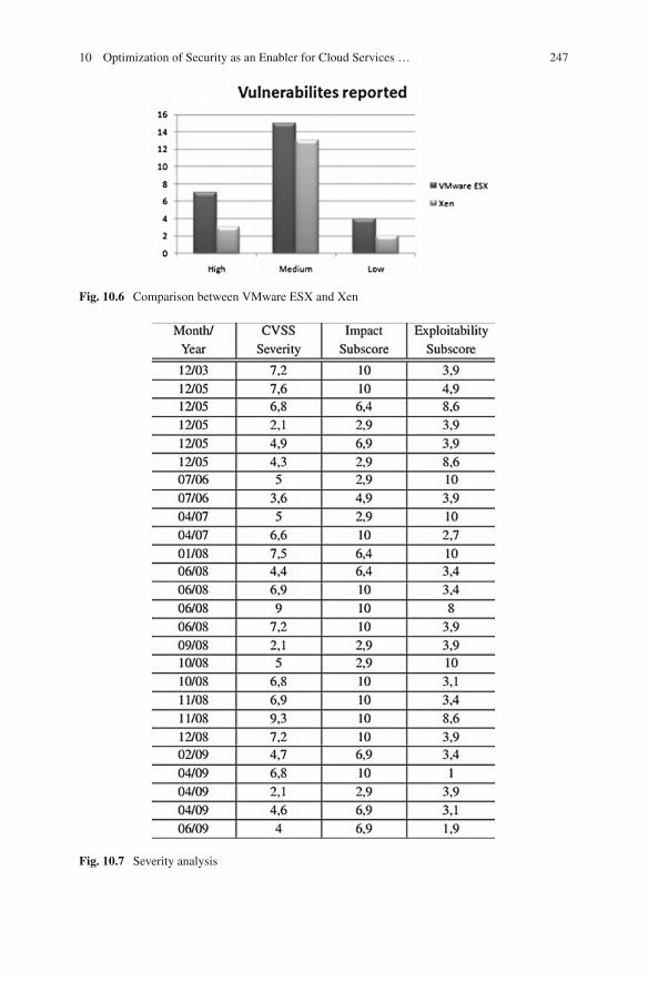
10 Optimization of Security as an Enabler for Cloud Services … 247
Fig. 10.6 Comparison between VMware ESX and Xen
Fig. 10.7 Severity analysis

248 V. M. Deshpande et al.
versions of ESX have a web server to use the client vSphere to management theserver and so have a new door for attacks. For the same reason, can do XSS attacksagainst the ESX.
Note: Figures are taken from Internet for Illustration and educational purposeonly.
10.3 Cloud Security as an Enabler for Cloud Applications:Standards and Tools for Implementation
In this section [3], we look at security elements of open standards for Cloud applica-tions such as Organization for the Advancement of Structured Information Standards(OASIS), Open Web Application Security Project (OWASP) and Open Grid Forum(OGF) and deal with latest recommendations for implementingWeb Service Security(WSS), Cross Enterprise Privacy, and Cyber-Security. The reader also is introducedto expert groups and task forces such as Computer Security and Incident ResponseTeam (CSIRT) available in case of security incidents or activities and how to interactwith them. In the same section, we dwell in detail on the Cloud Software Secu-rity Quality assurance aspects including the 3 stages of Pre-Testing. We look at theassessment methodologies and techniques for covering Cloud Penetration Testingusing tools such as Visual Trace.
Cloud applications can flourish when they are empowered with necessary designand tools which help them in delivering the best in class quality of services. Cloudsecurity is one of the main elements that enable the developers to concentrate ondeveloping applications the meet the product requirements. To make this happen,standards need to be put in place and the process must be such that the guidelinesneed to be followed at each level of development cycle. In real world is not an idealone. Hence, we need to prepare for incidents which happen andwe need to respond toit. Tools that help in testing the assuring the security quality of software is availableto the product delivery teams to use it and develop high quality products.
10.3.1 Standards, Guidelines and Forums
In this section, we look at some of the standard which are setup to help the developercommunity to use security as an enabler for their applications. Although there areseveral such standards and guidelines available, there is still no clearwinner orwidelyaccepted standard or 3rd party certifications that cloud security providers can affirm.We are highlighting some of the notable standards and guidelines with respect tosecurity.

10 Optimization of Security as an Enabler for Cloud Services … 249
International Organizations and Standardizations (ISO) - ISO has publishedseveral series of standards pertaining to information system security andweb servicesinteroperability that are very relevant for cloud security. ISO 27001-27006
TheOrganization for the advancement of Structured Information Standards(OASIS) - OASIS is a standard that develops standards for security, e-commerce andweb services. OASIS have created cloud related standards on SOA models, securityaccess, data/import and export, identity management etc.
Open Grid Forum (OGF) - OGF is an international organization committed tothe development and adoption of standards for applied distributed computing tech-nologies. A sub group has been created named as Open Cloud Computing Interface(OCCI) to develop open standard APIs for Infrastructure as a service (IaaS) provid-ing virtualization address management features. These can be used by developers toreduce possibility of vendor lock-in, develop new cloud applications, provide morecloud service options etc.
The Open Web Application Security Project (OWASP) - OWASP is an opensource web community that has spent lot of time and dedicated its efforts to enhanceapplication software community. It is one of those communities that entire securityindustry look up to for directions and best practices. OWASP provides standardsand recommendations for cloud system security as well as application security on aregular periodic basis.
10.3.2 Incident Response Teams
For the cloud computing industry, it is critical to have incident response teams. Thisneeds to be created using group of experts at the service provider side and well asfrom cloud user front. Network monitoring and management considerations havebeen discussed by Dr. Mydhili et al. [6]. Incident response teams are responsible formonitoring the network for any unexpected events as well as maintaining intrusiondetection systems.
• Computer Security and Incident Response Team (CSIRT) - In a cloud basedorganization, creating a computer security and incident response team is requiredfor following activities:Analysis of any anomaly notificationImmediate response to an incident if analysis warrants itEscalating the issue based on the priority and severityProviding timely resolution for the issue and following up with post incidentactivities and remedial activities
• NIST Special Publication 800-61 - NIST stands for National Institute of Stan-dards and Technology. In 2004, NIST Special Publication 800-61 published aguide named as Computer Security Incident Handling Guide, Recommendationsof National Institute of Standards and Technology. This guide described incidentresponse life cycle as below:

250 V. M. Deshpande et al.
– Preparation involves securing the computing arena and making sure that thereare no further intrusions.Also, risk assessment needs to be doneduring this phaseto establish incident response capabilities. NIST recommendations include userawareness training to secure networks, implementation of patch management,malicious code prevention framework etc. to be set up in the system.
– Detection and Analysis In the heat of the incident, detecting the actual rootcause and source of the issue might not be possible or practical to search forin the available time. The next best thing would be to analyze the anomalies ininput data etc. and deviation from regular system behavior. This can be achievedthrough analyzing the system logs for anomalous events and correlating it withevents that occurred which resulted in current state of the system. Once the issueis detected, it needs to be immediately escalated to concerned teams and higherups to get their inputs on the matter. Each of the incidents needs to be reported tochief security officer, chief information officer, legal department, system ownerand public affairs team.
– Containment, eradication and recovery Once issue is detected, it is of highestpriority to prevent the spread of the issue to any other components of the system.In some cases, the incident response teams carefully trace the hackers activityin case it will help them identify the intention of the attack and the identity ofthe attacker. This can be traced by looking at host IP address of the attacker,email or account details etc. Next steps involve the cleaning activity of systemwherever the attackers traces are found. In many cases, even the files which aresuspicious, are replaced using data backup.
– Post incident activity - After the incident is closed, a thorough analysis of eachsteps taken and time lines needs to done diligently. All parties involved need tobe transparent and come up with the shortcomings, learnings and kudos for theincident response team. It is like a retrospective meeting at end of a sprint inAgile/Scrum model of application development.
10.3.3 Cloud Application Security Testing
NIST in 2001 provided certain security principles which can use used a postulatewhile developing any cloud applications. This was called NIST 33 Security princi-ples. The principles address each step of software life cycle, from design to end oflife of a product. Some of the highlights of these principles are:
• Principle 1 - Establish a sound security policy as the foundation for design• Principle 2 Treat security as an integral part of overall system design• Principle 3 Clearly delineate the physical and logical security boundaries governedby associated security policies.
• Principle 6 - Assume external systems are insecure• Principle 16 Implement layered security; ensure there is n single point of vulner-ability

10 Optimization of Security as an Enabler for Cloud Services … 251
• Principle 20 Isolate public access systems frommission critical resources like dataetc.
• Principle 25 Minimize the system elements to be trusted• Principle 26 Implement least privilege• Principle 33 Use unique identities to ensure accountability
Above principles show a guiding light for cloud application security testing toensure that the cloud applications are built the right (secured) way to achieve itsgoals.
Secure cloud software testing involves number of activities and techniques suchas source code analysis, fault injection, dynamic code analysis, fuzz testing, vulner-ability scanning, black box testing and penetration testing. Although there are noindustry wide security quality assurance terminologies, ISO 9126 standard provideslist of software quality standards and definitions. As per the standard, some of theattributes that need to be addressed are functionality, reliability, usability, efficiency,maintainability and portability testing.
Security testing should analyze the security properties of the software as it interactswith internal components of the system aswell as external systems such as humans orother systems. SOAR Software Security Assurance State-of-the-art Report providesa guideline that each of the product security team should adhere to.
• Behavior of software should be predictable• Should expose no vulnerabilities or weakness• Secure exception handling and fail safe mechanisms• Does not violate any security constraints• Does not support reverse engineering
10.3.3.1 Cloud Penetration Testing
Cloud Penetration Testing is a methodology that is used to find the level of securityof systems network security by simulating an attack from proxy malicious source. Itis done at 3 levels:
• Level 1 High level assessment• Level 2 Network valuation• Level 3 Penetration test
Penetration testing is usually conducted without knowledge of the system specificdetails. So that the intruders are not influenced by the knowledge of system archi-tecture and neglect possible issue. Penetration testing involves 3 steps - Preparation,execution and delivery.
Preparation Non-disclosure agreement is signed for legal protection of tester.Execution Penetration testing is executed and potential vulnerabilities identified.

252 V. M. Deshpande et al.
DeliveryResults of the penetration testing alongwith recommendations are formallycommunicated to the organization.
Some of the testing tools and techniques used for penetration testing are -Visual traceroute is a free diagnostic tool that displays the path the Internet packetstake across IP networks to reach a specific destination on a network. The programrequires a domain name that is the site to which the route is traced. An IP addresscan be used for the same.
For every trace a report identifying the approximate geophysical location of eachhop and visualizing the route on a map is generated. This report helps in detectingbottlenecks, quickly track down the problem and isolate it.
Visual Trace provides a graphical interface to trace routes where the underlyingcommands used to trace routes are ping and tracert.
Use of visual trace in cloud:
• Improve troubleshooting• Restore network visibility• Connect user to apps and services
Visual Route: includes integrated traceroute, ping tests ad reverse DNS and WhoIslook up.Smart WhoIs this tool can be used to get host of information about the target suchas IP address, hostname, domain name, country etc. SamSpade Tool used to tracethe spammers. Apart from these port scanning tools, vulnerability scanning tool,password crackers can be used for penetration testing. Some of the well-knownpassword cracking tools are - Brutus, WebCracker, Obi wan, Burp Intruder.
10.4 Web Application Security: Security OptimizationTechniques
In this section [3], we concentrate on Web Application Security Optimization Tech-niques and Big Data Security. We understand several men in the middle attacks(MITM) attacks such as SQL Injections, Buffer Overflows, Cross Site Scriptingusing Burp Suite tool. We discuss how to mitigate these risks by adopting OWASPweb security recommendations and best practices taking practical examples.
10.4.1 Understanding Web Threats and Vulnerabilities UsingMan in Middle Attacks
Using internet comes with the baggage of threats and vulnerabilities. Man in middleattacks are one such class of web based attack where in a malicious entity interceptscommunication channel between any two entities.While doing so, he canmanipulate

10 Optimization of Security as an Enabler for Cloud Services … 253
Fig. 10.8 Example for SQLinjection
the messages being exchanged giving rise to vulnerabilities. SQL Injections: is aninjection attack, where the input is not properly checked before execution. Attackercan make use of this vulnerability by embedding some SQL commands along withinput.When this is executed at server sidewithout performing proper validation of theinput, the attacker can get control over the database server and cause serious damageincluding deleting the whole database. To ensure that SQL injections are stopped,the input needs to be parameterized and validated before execution. Also, certainaccess restrictions should be kept so that unintentional database query execution areavoided (Fig. 10.8).
Cross Site Scripting (XSS): When the user input such as url redirect is notproperly before execution, it can result in cross site scripting. Attackers can exploitXSS by generating malicious URLs and tricking users to click on them. By clickingon the links, attackers client side scripting language like javascript and VBScript,and it gets executed in victims browser.Example: URL http://xyz.com/users.php?register=<script>alert(Hacked!)</script>This vulnerability can be largely avoided if the inputs are properly validated andthey fall into expected set of inputs. Developers should not rely just on client sidevalidation. They should treat all inputs as malicious and verify the correctness ofinput before executing them.

254 V. M. Deshpande et al.
10.4.2 Tools for Simulating and Preventing MITM Attacks:Case Study - Burp Suite
Burp Suite [7] is an integrated Java based platform for performing security testson web applications. It is an interception proxy which speeds up the entire testingprocess, from initial mapping and analysis of a web applications attack surface,through to finding and exploiting security vulnerabilities. It allows users to integratecapabilities of various tools present tofindvulnerabilities such asXSS,SQL injection,configuration in cookie issues etc. faster and in an efficient manner. Burp suite is avaluable tool to detect security concerns and help organizations to rectify any bugsand optimize their code. The key components of burp are:
• Proxy -Acts as an intermediary HTTP/S server between the clients requesting fordata and servers providing the data.
• Scanner - Performs vulnerability scans of web applications.• Spider -A crawler for navigating to different links.• Intruder - Performs powerful customized attacks to find and exploit unusual vul-nerabilities.
• Repeater - A simple tool that can be used to manually test an application to modifyrequests to the server, resend them, and observe the results.
• Sequencer - A tool for testing the randomness of session tokens and data beingcached that can be unpredictable.
• Decoder - A decoder helps to change and recognize the format of a data. It is usedto transforms encoded data to raw data and from raw data to encoded and hashedforms.
• Extender - Burp suite allows the use of extensions to extend burps functionalityfor solving complex vulnerabilities.
Configuring Burp suite - The primary requirement of burp suite is a browser(Ex: Chrome, Firefox, Edge, Safari) which receives all the incoming traffic from theinternet and establishes connection to servers on the internet. To allow burp suite toread the incoming/outgoing traffic from a web browser, a proxy server is required.
The proxy settings for the web browser is the same as the proxy setting used inburp suite. This is to make sure burp reads all the traffic through the proxy serverbefore it reaches the browser. If the default proxy in burp suite is 127.0.0.1/8080which is localhost, the browser must also be configured to use a proxy server withaddress 127.0.0.1/8080.
Working with HTTPS traffic requires additional settings since HTTPS is a securelayer HTTP protocol for secure communication which does not allow traffic to besnooped. A proxy on the other hand is a man in the middle agent which interceptstraffic, hence HTTPS traffic cannot be intercepted. To overcome this circumstance,burp provides a downloadable certificate through the link http://burp/.cert adding itas a trusted interface.
Defining target - Sitemap and scope: A sitemap is a visualization of the entirefile structure of the website. It logs all the requests made by the browser. In order to

10 Optimization of Security as an Enabler for Cloud Services … 255
Fig. 10.9 Burp suite
concentrate only on the website we are testing, the address of the website is addedto the target. This causes burp to log those requests made on the testing website(Fig. 10.9).
Using Burp Suite - Activating Burps spider will crawl the linked content on theweb application, going down a depth of 5 links down by default, but these optionscan be configured under the Spider tab. As you interact with the web application, allthe requests and responses will be logged under the Proxy tab. Each HTTP requestmade by your browser is displayed in the Intercept tab. You can view each message,and edit it if required. The “Forward” button is used to send the request on to thedestination web server. If at any time there are intercepted messages pending, youwill need to forward these for your browser to complete loading the pages it is waitingfor.
Spidering the application - The spider tool is used to get a complete list ofURLs and parameters for each site. The tool considers each page that was manuallyvisited and goes through every link it finds in the testing scope. A better spider canbe obtained by visiting more links manually as it gives the spider a large coveragearea (Fig. 10.10).
Scanning Applications for Bugs
To find any sort of vulnerabilities in an application, all the links and URLs present inthe application must be exploited. The Scanner tool gives a fine-grained control overwhich items get scanned, and gives immediate feedback and results for each scanneditem picking out key security vulnerabilities. Burp gives a dashboard view of all thekey vulnerabilities in order of their severity so that the tester can focus on the critical

256 V. M. Deshpande et al.
Fig. 10.10 Spidering using Burp suite
issues quickly. Three types of scans can be performed on an application, namelyactive scan, passive scan and user directed scans. Burp can be used to perform:
• Passive scanning of all requests and responses made through Burp Proxy, to iden-tify shortcomings such as insecure use of SSL, and cross-domain exposure. Thislets us safely find bugs without sending any additional requests to the application.
• Active scanning of all in-scope requests passing through Burp Proxy. This lets youuse your browser to walk Burp Scanner through the interesting parts of the appli-cation’s functionality that you want to actively scan. Burp Scanner will then sendnumerous additional requests to the target application, to identify vulnerabilitiessuch as SQL injection, cross-site scripting and file path traversal.
• User-directed scanning of selected requests. Burp suite allows to select specificrequests within any of the Burp Suite tools, and send these for active or passivescanning. This usage is ideal when you are manually testing individual parts of anapplication’s functionality (Fig. 10.11).
Using the Intruder
Burp Intruder is a tool for automating customized attacks against web applications,to identify and exploit all kinds of security vulnerabilities and perform semi-targetedfuzzing. It is used against parameter of HTTP requests such as password and user-name. The intruder has four panels namely target, positions, payloads and options.Target: This panel is used to specify the target host (the URL), the port to use forthe connection.Positions: The type of attack to be performed on the target. There are various typesof attacks such as pitchfork attack, cluster attack, battering ram attack and sniperattack.Payloads: This is used to configure one or more sets of payloads, which will be

10 Optimization of Security as an Enabler for Cloud Services … 257
Fig. 10.11 Example of scanner output
placed into payload positions during the attack.Options: This is used to configure numerous other options affecting the attack.
While examining the requests, Burp uses the symbol to highlight potential injec-tion points. The potential area is given a payload, a list of data which is substitutedindividually in the field each made through a separate request. This can be used tocrack passwords with a list of commonly used passwords or perform a SQL injectionto exploit further vulnerabilities.
10.4.3 OWASP Recommendations for Web ApplicationSecurity Action Plan
Several projects taken up byOWASP [8] have yielded high results in terms of industryreach and acceptance as a de-facto recommendations. Some of the major contribu-tions of OWASP include OWASP Top Ten Project. This is an informed list of cloudand web application vulnerabilities that developer community needs to be highlyvigilant on. The last published list was in 2013.
• A1 Injection.• A2 Broken Authentication and Session Management.• A3 Cross-Site Scripting (XSS).• A4 Insecure Direct Object References.

258 V. M. Deshpande et al.
• A5 Security Misconfiguration.• A6 Sensitive Data Exposure.• A7 Missing Function Level Access Control.• A8 Cross-Site Request Forgery (CSRF).• A9 Using Components with known Vulnerabilities.• A10 Un validated redirects and Forwards.
OWASP Development Guide is another guideline which can be used for cloudapplication security. These guidelines provide description to developers on how tomake web applications self-defensive in case of intrusion by malicious elements. Itis categorized into 3 sections namely Best Practices that should be part of the webapplication. Secure patterns which form optional security features that can be used asguides and lastly Anti-patterns which are the patterns in the program which increasevulnerabilities (which needs to be avoided). Some of the topics addressed byOWASPdevelopment guide include secure coding principles, threat risk modelling, sessionmanagement, phishing, buffer overflows etc.
OWASP Code Review Guide Security Code review is a process of auditingthe code methodically to assess the security quality of the program. This OWASPguide identifies the phases of code review as Discovery, Transactional analysis, posttransactional analysis, procedure peer review, reporting and presentation, laying thegroundwork. In a secure code review, developers need to ensure to review for inputvalidation, secure code design, information leakage and improper error handling,direct object reference, resource usage, API usage, best practice violation, weaksession management, using HTTP Get query string.
OWASP Testing Guide- provides detailed testing techniques for security testing.Some of the aspects included in OWASP testing guide are manual inspections andreviews, threat modelling, code review, penetration testing. It also mandates some ofthe common security test that needs to be conducted to evaluate security controls ofthe system. They are as follows:
• Authentication and access control• Input validation and encoding• Encryption• User and session management• Error and exception handling• Audition and logging.
All above guidelines and recommendations provide the developer and securitycommunity a sense of action plan to execute upon during the product developmentlife cycle.

10 Optimization of Security as an Enabler for Cloud Services … 259
10.4.4 Big Data and Security
Cloud computing has been modelled by its characteristics like rapid elasticity,resource pooling capabilities, broad network access. While, Big data characterizesitself by its handling of huge volume of data, high velocity of computation and vari-ety of data itself i.e., broad network access, elasticity and scalability. These commoncharacteristics make Big data and cloud computing perfect partners in helping eachother achieves their goals. Cloud computing plays a role of enabler with respect toBig data.
With the adoption of newer technologies, the baggage of operating challengesincluding security comes to the forefront of IT managers. Organizations are in a rushto adopt Big Data into their Business and data analytics without having understoodcomplete implications of doing so. There is no question that Big data driven analyticshelps gather a lot of user data. This makes it easier to make data driven decisionsusing new generation analytics. However, it brings along with it security implica-tions related to the data lake that gets created soon after adoption of data analyticscapabilities. Therefore, it is essential to consider data security and ensure that it isbuilt in in the design; before scaling up the Big data initiatives. This section dealswith understanding how HortonWorks is addressing these issues and helping orga-nizations in order to reap full value of advanced analytics without exposing businessto security risks.
10.4.4.1 Case Study: How HortonWorks Data Platform is SolvingHadoop Security Concerns
About HortonWorks (https://hortonworks.com):HortonWorks is a Big Data softwarecompany that develops and supports Apache Hadoop, for distributed procession oflarge data sets across computer clusters.
Hadoop is the de-facto standard framework used in the world of Big Data. Hadooppowered data lake can help provide a solid base for launching new generation ofdata analytics. However, it is very important to understand and consider securityconcerns before scaling up the Hadoop initiate. It is a widely accepted among leadingcompanies in all industries that data is the new driver of competitive advantage.
To provide effective protection against security and data governance issues, Hor-tonWorks (HW) has adopted 5 pillars based holistic approach [9]:
• Administration - Central management and consistent security to set policy acrossentire cluster.
• Authentication and perimeter security Authenticate users and system• Authorization Provisioning access to data and provide access to what user can do• Audit Maintain a record of data access of what a user did/accessed at what time.
Data protection Protect data stored andwhich is being transported across clustersusing encryption over the wire.

260 V. M. Deshpande et al.
Fig. 10.12 HortonWorks data platform 2.3
GivenfiguredescribesHortonWorksDataPlatform2.3 architecturewhich includesmain components Hadoop Distributed System (HDFS), YARN (Data Operating Sys-tem), Security, Operations and Governance and Integration. As part of Hadoop Secu-rity, Apache Ranger, Apache Knox and Kerberos form the core components forenhancing security (Fig. 10.12).
Apache Ranger is a tool to enhance the productivity of the security administra-tions that reducing anomalous errors by helping them to define clear security policyand apply them to all the applicable components in the Hadoop stack from a central-ized location. Currently, other commercially applicable solutions provide only par-tial support to security administrator. Hence using Apache Ranger helps the securityadministrators by providing centralized platform for security policy administrationwith respect to authentication, authorization, and auditing and data protection viaencryption.
Apache Knox is a gateway that ensures perimeter wide security for HortonWorkscustomers. Using this solution, enterprises customers can extend the Hadoop RESTAPIS to new users easily with confidence and meeting the compliance standards.
ApacheKnox is a pluggable framework and a newRESTAPI service can be addedand configure easily into the service stack. It provides single, simple point of accessfor a cluster. Its central controls ensure consistency across one or more clusters. Itcan be integrated with existing systems such as LDAP, AD, SSO to simplify identifymaintenance.
Current vendors fail to provide a comprehensive solution in this area. Hence Knoxis a market differentiator and can be adopted with high confidence.
With all these and more security features, HortonWorks provides a holistic solu-tion with respect to administration, authentication, perimeter security, authorization,audit and data protection.

10 Optimization of Security as an Enabler for Cloud Services … 261
Another product developed by HortonWorks Apache Metron [10] can be usedto identify anomalies and other issues in real time cyber security telemetry data inBig data context. Metron helps security operations professionals to identify issuesin cybersecurity analytics. It can take in inputs from multiple sources and types ofdata, analyze and provide results. It has capabilities of log aggregation, advancedbehavioral analytics and data enrichment.
Note: Figures are taken from Internet for Illustration and educational purposeonly
10.5 Digital Privacy and Trusted Computing
Digital privacy and data security are an inseparable part of a successful securityarchitecture. Current section [11] deals with Digital Privacy and Trusted Computing.Users online activity along with their accounts created on various service providerwebsites form their digital identity.We discuss businessmodels used by cloud serviceproviders which adopt data monetization for profit using case study of Facebook.There are even chances of ones digital identity being stolen by use of personallyidentifiable information (PII). Identity theft resulting from data/privacy breach isa serious cause of concern. Hence Digital Identity Management has become morerelevant than ever before in this era driven by information exchange.
Data privacy breaches have been taking place time to time alarming the orga-nizations, consumers and security researchers. We have already highlighted suchprivacy and security breaches earlier in the chapter with examples. This brings tocenter stage, the point that no one is immune to data security concerns and it needs tobe addressed with all seriousness. We discuss this in detail in the context of trustedcomputing and cloud solutions for social networking.
10.5.1 Business Models of Cloud Service Providers: CaseStudy: Google, Facebook
When we are dealing with cloud service providers especially with SaaS model, acomplete end-to-end user experience is provided by the service provider and theend user is given a simple client interface such as a desktop/mobile application or abrowser to access the services. Some examples that come under this servicemodel aresocial networking websites such as Facebook, Google Plus. Social networking hasreunited countless friends and families who were separated by time and space. Theyinclude e-mail/messenger service providers such as Google, Yahoo. Email serviceshelp us to send and receive mails to and from anyone in the world via our email id.
Both Google and Facebook rely heavily on advertisements and in being adver-tisement platforms for generating revenue. The user generated data becomes their

262 V. M. Deshpande et al.
input for providing specific tailor made advertisements to the end users. Now, thatGoogle, via google chrome has a browser product, they can piece in information ofusers online activity and build a digital identity out of it. They can provide contextualadvertisements based on users search history, websites that he or she visited, prod-ucts that he or she bought etc. Similarly, Facebook tries to analyze user preferenceswith respect to the content which he viewed, his friends interest, are he is residing,profession, age, gender, relationship status etc. to provide customized yet automatedadvertisements that are too hard to resist for the end users. And hence, these twogiants have could get hold of market share and become big players in the businessarea. The user feels that the he is getting the service free of charge, but the serviceproviders are making money via advertisements based on user data. So, essentially,users are paying the service providers back with their self-generated content andonline activity.
10.5.2 Advent of Social Networking, Data Sharing Policiesand Concerns
In many instances, SaaS service providers provide service to end users at free ofcost to attract more number of users of the service. Social networking companiesand email service providers rely hugely on personalized advertisements to monetize.This is how they can sustain and make profit of a free service that they provideto millions of customers online who use their services extensively. E-commercewebsites make their earnings from commission it gets when an online purchase ismade using their platform. In any case, service providers who provide free SaaSservices have a lot riding upon the number of users using their platform. Also, theamount of information that is being shared, content created or amount of businesstransactions that happen online via their services have impact on their revenue.
As the service providers state the end user license agreement policies and the datasharing policies, the users are left with no choice but to agree to it if they want to usethe service. By the mere urge and want to use the service, users agree to the termsbased on the product reputation and peer recommendations. Concern with respect todata sharing policy is that the service providers have huge level of control over howthey are going to use the user data. They can share it with 3rd party, advertisers dataanalytics companies etc. When some of these data are aggregated, and used usingBig data analytics, they can be correlated and can reveal great deal of informationabout a person and his preferences. This can, in best can scenario lead to targetedadvertisement, and in worst case: identity theft and fraud. There are laws governingthe use of these data and regulations on what data can be stored and used. Still, theyare vague and in many cases, technically incorrect and having legal loopholes. Manya times, the privacy policy breach is found after the fact when the damage is alreadydone.

10 Optimization of Security as an Enabler for Cloud Services … 263
10.5.3 Towards Trusted Computing
End users are generally exhibit different kind of personas (traits). Few people areearly adopters of new service, technologies. A bulk of users waits for the review fortechnical people and then decide whether to use the product or not. Some segmentare very technical critics who use the product to understand the pros and cons of theproduct and then decide whether to use of exit from the product. The main bindingforce which ensure that the people who started using the product to stay engagedwiththe product is the factor called asTrust. Trust is very important to ensure that customeris retained and engaged. Hence, the service provider needs to have a vested interest inensuring that the customers trust the product and service provider. This is possible byproviding a holistic user engagement starting from first point to contact/sale to afterclosure of the contract. The data security policy and the EULA details need to be astransparent as possible. A clear and open channel of communication and a smoothuser experience goes a long way in gaining end users trust. Several ongoing workstowards providing trustable software solutions for secure cloud based applicationsare underway currently giving the consumer the center stage of trusted computing.Allowing customer to define certain terms of engagement with service provider [12],selecting the best service for the user based on quality of service requirements such aslevel of data security and privacy [13]. Proposal of framework for privacy preservingadvertisement framework for social networking [14] are some of ongoing researchworks in this area. All of which aimed at moving towards trusted computing.
10.6 Efficient Security Operations and Management forSecuring Cloud Data Centers
Discussion of cloud security is incomplete without security operations and man-agement. This section is dedicated for this topic in context of optimal practices forsecuring the clouddata centers.Aprocess oriented approach formanagingday-to-dayactivities of a security of an organization is critical for its sustainability. Establishingeffective communications channels for managing security incidents, and implemen-tation of security and access controls form the basic framework of security operationsmanagement of an organization.
One of the important responsibilities of security operations team is to identifyand define what components need to be protected and what it needs to be protectedfrom. It also involves predictive analysis of high risk areas which needs more atten-tion. Another important aspect with respect to security operations is the Businesscontingency plan. They are designed to ensure that we are prepared for unexpectedcircumstances. As any organization grows, the need for having disaster recoveryplans and fail safe mechanisms using redundancy schemes increases.
In this section [15], we talk about how security can be efficientlymanaged in clouddata centers adhering to legal requirements. Security management is very important

264 V. M. Deshpande et al.
because it form the first line of defense against the attackers, without which theunderlying security loses context.
Traditionally, physical security has always been kept away from IT paradigm.However, the industry trend is hinting at convergence of IT security and physicalsecurity aspects. It is important for an IT security manager to understand all theaspects of physical security and employ efficient methodologies to secure the ITresources including the cloud data centers. This chapter introduces the reader tophysical security related topics and provides insights on how to efficientlymanage thesecurity operations to secure cloud data center and thereby enable cloud applications.
10.6.1 Security Operations Management
Security operations and management deals with management of security day to daybasis of security functions. It is the management of ground level tasks includingsetting up and implementing security controls, managing security incidents. Topdownapproach ofmanagement is enforcedwhere each of the details can bemonitoredby the higher ups to ensure swift decisions are made.
Security Administration - Communications and Reporting are two of the mostimportant tasks that arise in a security operations department. This is because, theresponsibility of providing the right measurements and metrics indicating the per-formance of the services provided by company rests with security operations team.Administration in an organization with respect to security operations is often drivenby key performancemetrics. Thesemetrics such asmeasuring the set S.M.A.R.T.E.Rgoals (Refer Sect. 10.1) provide insights on how the overall performance is faring.
Few examples of the key performance indicators as percentage and number ofresolved intrusion incidents measured in a periodic scale (month/quarter/year), per-centage and number of blocked attacks from outside through firewall capabilities ofthe system, percentage and number of total machines in the organization of cloudcluster where OS patches are successfully installed and antivirus and other securityfeatures working as designed etc. It is a part of responsibility of security administra-tors to ensure that security telemetry data are captured and it is part of the design ofthe cloud system.
Change management is yet another important task which falls in the purviewof security administration. It essentially involves carefully assessing the changesdone to the system and ensuring the all the risk factors are manages and mitigatedbefore the release to make sure that there is no negative impact due to change. Thisis required to maintain the availability of servers and to ensure that there are nosecurity backdoors or loopholes created due to unintended misconfigurations duringdeployment of changes such as patches, updates or new feature implementations.Service Oriented framework is a preferred design paradigm in information technol-ogy as per Dr. Mydhili et al. [16]. Information Technology Infrastructure Library(ITIL) is a well-known service oriented framework for service delivery in IT sector.
10 Optimization of Security as an Enabler for Cloud Services … 265
It provides recommendations of best practices for change management. The changemanagement steps involve
• Describe Describe the change being done in the system and which are all thetouchpoints for the same. This involves steps Record (the change), Accept (acceptor reject if the changes are required and valid) and classify (if it is a patch, softwareupdate, new features etc.)
• Prepare Prepare for deployment of change. This step involves Plan (plan forverifying) and Approve (Approve the validity and correctness of changes)
• Execute Ensure to have a pre-production environment which replicates produc-tion environment to execute the changes done. Build (generate the deployable filesand configurations) and Test in the pre-production environments. Maintaining thehealth of these environments to mimic production settings is a separate challengeall together and something which most of the companies struggle with. Having anefficient response system which proactively updates all the pre-production envi-ronments post production deployment is key for ensuring smooth functioning ofthe system.
• Check Checking the changes with a set of validation test cases which are regularlymaintained and updated is a crucial step in changemanagement and administration.Automation needs to be built to evaluate the system for overall functionality ofthe system.
We mentioned earlier that security administration is usually enforced top downfrom the organization. While security administration is important, we also need toensure that the administrators and managers and utilizing their privileges to see oversecurity operations in an acceptablemanner. Companies need to formulate acceptableuse constraints and enforce it on to all the employees in order to comply with varioussecurity operations administrative management standards. Some examples related tothis:
• dont store, share confidential information to unauthorized personnel• dont access or misuse information resources where there is no specific job require-ment.
• Security principles that help in avoiding abuse of administrative power includelimiting authority and separation of duty.
Management Practices and Accountability - Management practices and enforcingaccountability controls can help in efficient security operations management. Someof the management practices:
• creating user groups for providing controls to computing resources.• Restricting access and privileges for remote access to consoles• Use automation for regularly patching the employee OS and have onto virus andfirewalls installed in them.
• centrally control the software installations done on each machine via endpointmanagement.
266 V. M. Deshpande et al.
10.6.2 Business Contingency Planning
Uncertainty of life extends to the binary world of cloud as well. In this regard, it ishighly recommended as well as mandated to have a solid Business continuity plan(BCP) as well as disaster recovery plan (DRP). These are by extremely importantto formulate and implement and mandated as per compliance standards. BCP andDRP involves formulation of process that ensure that business critical computationalresources are safeguarded from major system and network failures.
Cloud providers need to address few concerns such as data backup operationduring service interruptions, capabilities for remote execution of business-criticalprocesses at alternate site, ensuring reliability of the alternate systems, automatingall decision-making processes to remove human dependency during emergency.
An effective BCP andDRP addresses all the cloud resources being utilized includ-ing LAN, WAN servers, telecommunication links, workstations and work spaces,applications and data. BCP needs to be tested on a frequent basis and upgradedwhenever needed. Top level management have a big role to play in this regard. Theyneed to be face of the organization to the employees and all other stakeholders. Theyneed to provide all necessary resources to team to recover to a manageable stateas soon as possible. When any incident occurs, the BCP team takes the followingsteps: Scope and plan initiation, business impact assessment, business continuityplan development, plan approval and implementation. During the business impactassessment, the issues are prioritized based on cost and downtime. Based on this,resources are allocated to mitigate it.
10.6.3 Physical Security
Drawing parallel to the real-world scenario, to live peacefully with calm mind, oneneeds a place that can be called home. It needs to be secured by doors, windows andlocks. The perimeter of the house needs to have some amount of protection. No oneshould be allowed more access than they require to interact with us. These charac-teristics of physical security are applicable to the binary world of cloud computersas well.
The cloud data centers including the computer equipment, communication andtechnical equipment, storage media, company assets and records needs to be wellprotected. An initial physical vulnerability assessment must be done of the area.The buildings, computing resources and peripherals, documents and records needto be safe guarded. Physical location of the site also needs to be decided based onenvironmental and neighboring construction and landscape factors.
Entry controls in form or building access control systems,man traps and providingemployee badges as entry pass, use of biometric features, having security guards inall the entry, exit and business critical locations form the 2nd line of defense.

10 Optimization of Security as an Enabler for Cloud Services … 267
Even if the physical security is breached, there should be efficient ways to detectthe intrusion and take appropriate measures. Some of the examples of such toolsand techniques are use of closed circuit television (CCTV), burglar alarm systems,temperature monitoring, motion sensors etc. These needs to be followed to meetcompliance standards. COBIT and ISO 27002 are the industry accepted standards inthis area.
10.6.4 Forensics Analysis and Compliance
Wehave highlighted inmultiple sections in this chapter that a data breach or evidenceof noncompliance is found usually after the fact. Hence, to gather the evidence, foren-sic analysis is very important. Forensics basically involves collection of evidence,examining it, and analyzing it to provide report on the incident.
Forensic evidence is usually used during legal proceedings to find level of confor-mance with said standards. Evidence acquisition is very important step in forensicanalysis. It can be classified as host based evidence that can be found on the hostmachine and network based evidence that can be collected from network based sys-tem such as IDS or firewall.
While working with a live system to collect data, capturing system contentsbecomes very crucial in evidence collection. CPU activity and running processescan be traced from task manager in windows and ps command in Unix system. Net-work connections can be documented using netstat and arp command. Open filescan be found using lsof command in Unix. In Windows, a host of forensic activi-ties can be done using System internal tools which can be downloaded from www.sysinternals.com. Likewise, there are several other tools that can be used to exam-ine file system for hidden data, alternate data streams, deleted data, encrypted andcompressed data.
10.7 Parting Words and Useful Information
This section is reserved for our concluding message as well as providing an insightinto current and future research trends in cloud security. We discuss the most impor-tant questions (related to security) to consider for any organizations before switchto cloud. Through this chapter, we want to encourage cloud researchers and profes-sionals to think about security from a holistic perspective, understand the variousissues and incorporate smart ways to tackle them. We want all stakeholders to useoptimized securitymodels, tools and techniques to enable cloud services and applica-tions. We share some useful details on how researchers and academicians can benefitby joining hands in the cloud security community by joining open forums such asCloud Security Alliance (OCA), Open Cloud Consortium (OCC). For a professionalaspiring to create a career in Cloud Security, we provide key information on acquir-
268 V. M. Deshpande et al.
ing industry recognized certifications such as Certified Cloud Security Professional(CCSP) and Certificate of Cloud Security Knowledge (CCSK) and how he can applythe knowledge in create a positive impact in the organization.
10.7.1 Questions to Consider Before Shifting to Cloud
The in-built characteristics of Cloud computing such as rapid scalability, meteredusage and fail safemake it very tempting to switch to cloudwithout a second thought.However, a reasonable thought needs to be given to ascertain if migrating to cloudis the best idea for the company or specific project. We earlier provided brief casestudies on companies that adopted cloud technology and became successful.
To introspect what services should be moved to cloud, the various factors needto be considered. Such as cost to shift to cloud. Cloud expenses include storagecharges, computational changes, bandwidth consumption etc. We also need to assessif the cloud provider can meet the quality of service that is required for hosting theproduct. Another important factor that needs to be considered is if the clouds alternateenvironment in case of outage, is reliable or not.
In cases where companies to be use cloud optimally to make best use of availableresources, theymay choose to use cloud for data backup and computational resourcesonly during the peak seasons. Interoperable cloud providers are always preferredover others. This means that cloud applications can be built in such a way that thedeveloper can choose from which cloud provider, it can be executed.
10.7.2 Getting Involved in Open Forums and UsefulCertification Programs
As researchers, academicians, security professionals or cloud security enthusiastswe need to continuously improve our knowledge base and if possible contribute tothe research community. One of the open forums Cloud Security Alliance (OCA)[17] works to promote the best practices for providing security assurance withincloud computing, and provide education on the uses of cloud computing to helpsecure all other forms of cloud computing. They also offer a certification program -Certificate of Cloud Security Knowledge (CCSK)which helps security professionalsdemonstrate their level of knowledge and get recognized in global platform. OpenCommons Consortium (OCC) [18] formerly known as Open Cloud Consortium is anon-government organization which helps inmaintaining and operating cloud infras-tructure to support scientific, medical health care and environmental research. Theyare supported by universities around theworld. They also take care of preparing refer-ence implementations and standards for cloud. Cloud Security Professional (CCSP)[19] and related certifications are leading certification body for cloud security in the

10 Optimization of Security as an Enabler for Cloud Services … 269
world. They offer several other certifications such as CISSP for Information security,SSCP Systems security, HCISSP Healthcare security etc. We recommend that thereader evaluates these forums and certifications as it would help them to move toleadership positions in security career.
10.7.3 Concluding Remarks and Research Trends
Topic of the chapter reads as Optimization of Security as an Enabler for CloudServices and Applications. The aim of the chapter was to show how cloud servicesand applications can to be enabled to perform and fair better by optimizing the cloudsecurity. This chapter is designed to help users to understand security in a holisticperspective and how managing security will help them develop great products.
To start with, we discussed via case studies about benefits of adopting cloud com-puting. Later, we understood the security requirements, challenges and objectives of asecure cloud system.We discussed in detail about available standards and guidelinesfor ensuring cloud security. We learnt how Cloud application security testing, inci-dent response team provide use with tools and processes us to mitigate any securityrelated issues.
Web applications are the most vulnerable of the all the cloud based services.We took examples of tools and case studies and showed how to prevent from suchvulnerabilities. Big data securitywas also coveredwith example ofHortonWorks dataplatform. Digital privacy issues and concerns were discussed and we recommendedthe community to move towards open standards and certification of service providersfor conformance of data security policies.
We then moved to security operations management and how it plays a role increating environment for developers to perform at their best and make sure cloudapplications are not affected even in case of emergencies and unscheduled outages.
In the end, we gave call of duty to all the researchers and professionals to take upcertifications based on their interests and join hand with open forums to contributetowards cloud security community.
Security has always been a silent unsung hero that ensures the high availability ofthe servers. Providing too much security to applications may hinder the performanceparameters and response time of the service. However, reducing the minimal amountof security couldmean a detrimental blow for cloud service and application. Hence, itis only wise for us to continuously optimize the methods and techniques of providingcloud security to enable cloud applications to perform to their fullest of potential.
References
1. Amazon Web Services, https://aws.amazon.com/ec2/2. Microsoft Azure, https://azure.microsoft.com3. R.L. Krutz, R.D. Vines, Cloud Security- A Comprehensive Guide to Secure Cloud Computing
(2013) (Primary Reference Book for section 2, 3, 4)

270 V. M. Deshpande et al.
4. Privacy Breaches, https://www.opswat.com/blog/8-largest-data-breaches-all-time5. VMWare ESX, http://www.vmware.com/products/esxi-and-esx.html6. M.K. Nair, V. Gopalakrishna, Cloud-cop: putting network admin on cloud nine, in Proceedings
of IEEE International Conference on Internet Multimedia Services Architecture and Applica-tions, Bangalore (IMSAA’09), 09–11 Dec, India (2009), pp. 1–6
7. Burp Suite, https://portswigger.net/burp/8. OWASP Recommendations, https://www.owasp.org/index.php/Main_Page9. A HortonWorks White Paper, Solving Hadoop Security. A Holistic Approach to Secure Data
Lake (2015)10. Apache Metron Project, https://hortonworks.com/apache/metron/11. S. Pearson, G. Yee, Privacy and Security for Cloud Computing. Computer Communications
and Networks (2013). ISBN: 978-1-4471-4188-412. V.M. Deshpande, Dr. M.K. Nair, B. Sowndararajan, Customer driven SLA in cloud based
systems, in Proceedings of International Conference of Emerging Computations and Informa-tion Technologies, SIT, Tumkur, Karnataka (India), 22–23 November 2013 (Elsevier, 2013),pp. 508–518, http://www.elsevierst.com/ConferenceBookdetail.php?pid=35. ISBN: 978-93-5107-176-1
13. V.M. Deshpande, Dr. M.K. Nair, Anveshana search for the right service, in Proceedings ofInternational Conference of Convergence of Technology, Pune, Maharastra (India) (IEEE,2014). ISBN 978-1-4799-3759-2
14. V.M. Deshpande, Dr. M.K. Nair, A novel framework for privacy preserving ad-free social net-working, in Proceedings of 2017 2nd International Conference for Convergence in Technology(I2CT) (2017). ISBN: 978-1-5090-4307-1
15. M. Rhodes-Ousley, The Complete Reference: Information Security (2013) (Primary ReferenceBook for section 6)
16. M.K. Nair, S.M. Kakaraddi, K.M. Ramnarayan, V. Gopalakrishna, Agent with rule engine: theGlue for web service oriented computing applied to network management system, in Proceed-ings of IEEE International Conference on Services Computing (SCC 09), 22–25 Sep 2009,Bangalore, India (2009), pp. 528–531
17. Cloud Security Alliance (OCA), https://cloudsecurityalliance.org/18. Open Commons Consortium (OCC), http://occ-data.org/19. Cloud Security Professional (CCSP), https://www.isc2.org/ccsp/default.aspx

Chapter 11Internet of Cloud: Security and PrivacyIssues
Allan Cook, Michael Robinson, Mohamed Amine Ferrag,Leandros A. Maglaras, Ying He, Kevin Jones and Helge Janicke
Abstract The synergy between Cloud and IoT has emerged largely due to the Cloudhaving attributes which directly benefit IoT and enable its continued growth. IoTadoptingCloud services has brought new security challenges. In this book chapter,wepursue two main goals: (1) to analyse the different components of Cloud computingand IoT and (2) to present security and privacy problems that these systems face. Wethoroughly investigate current security and privacy preservation solutions that existin this area, with an eye on the Industrial Internet of Things, discuss open issues andpropose future directions.
Keywords Internet of cloud · Cloud computing · Security · AuthenticationIntrusion detection · Privacy
11.1 An Introduction to Cloud Technologies
According to forecasts from Cisco Systems, by 2020 the Internet will consist ofover 50 billion connected devices, including, sensors, actuators, GPS- and mobile-enabled devices, and further innovations in smart technologies, although this forecastis disputed [53]. New projections talk about 20–30 billion connected devices whichis again a huge number [20]. These revolutionary devices are predicted to integrateto form hybrid networks based upon concepts such as the Internet of Things (IoT),Smart Grids, sensor networks etc., to deliver newways of living and working. Under-pinning such operating models will be ’cloud computing’ technology that enables
A. Cook · L. A. Maglaras (B) · Y. He · H. JanickeDe Montfort University, School of Computer Scienceand Informatics, Leicester, UKe-mail: [email protected]
M. Robinson · K. JonesAirbus Group Innovations, Newport, Leicester, UK
M. A. FerragDepartment of Computer Science, Guelma University, Guelma, Algeria
© Springer International Publishing AG, part of Springer Nature 2018B. S. P. Mishra et al. (eds.), Cloud Computing for Optimization:Foundations, Applications, and Challenges, Studies in Big Data 39,https://doi.org/10.1007/978-3-319-73676-1_11
271

272 A. Cook et al.
convenient, on-demand, and scalable network access to a pool of configurable com-puting resources. This remote access to high levels of processing power and storageprovides a complementary platform onwhich to augment the low-power, low-storagecharacteristics of IoT devices, providing an integrated environment to provide ubiq-uitous capabilities to end users.
Cloud computing further offers a range of attractive benefits to organisationswish-ing to optimise their IT resources, such as increases in efficiency and organisationalability, reduced time to market (TTM), and a better balance between capital expen-diture (capex) versus operational expenditure (opex) [30]. However, to achieve suchreturns on investment, organisations require a clear understanding of cloud tech-nologies to drive their strategy, and in particular, the issues surrounding security andprivacy. This chapter introduces the reader to cloud computing technologies in gen-eral, then proceeds to explain the emerging Internet of Cloud (IoC) before discussingthe security and authentication issues of IoT and finally exploring the issues relatedto the preservation of privacy in the IoC.
11.1.1 A Definition of Cloud Computing
Cloud computing is a technological and operationalmodel for ubiquitous, on-demandnetwork access to a shared pool of configurable infrastructure, processing, storageand application services that can be provisioned and released for use with minimalsystem management effort or service provider interaction [48]. Many of the tech-nologies that underpin cloud computing environments are not new, as they compriseexisting virtualisation, processing and storage capabilities that have existed for manyyears. It is the operatingmodel that surrounds the use of these technologies that deliv-ers the revolutionary services, where ownership of physical resources rests with oneparty, and the service users are billed for their use [12].
As such, it is necessary to consider the essential characteristics, service modelsand deployment models of cloud computing.
11.1.2 Characteristics of Cloud Computing
Cloud computing environments comprise five essential characteristics; On-demandself-service, broad network access, resource pooling, rapid elasticity, and measuredservice [48]. We shall now review each of these in turn.
• On-demand Self-service: In cloud environments, a consumer can request anddeploy processing and storage capabilities, such as server capacity and storagespace, through the use of automated provisioning services that require no nego-tiation with the cloud provider [48]. This allows connected devices to remotelyexploit such resources and extend their processing capabilities as necessary.

11 Internet of Cloud: Security and Privacy Issues 273
• Broad Network Access: The services of a cloud are made available over thenetwork using thick or thin clients, allowing devices using different operatingsystems and platforms to access common capabilities [48].
• Resource Pooling: The computing resources of a cloud service are pooled into amodel to serve multiple consumers, with different physical and virtual resourcesdynamically assigned and reassigned according to demand requirements, irrespec-tive of their geography. The customer is typically unaware of the exact location ofthe provided resources, although they may be able to define high-level constraintssuch as country or data centre [48].
• Rapid Elasticity: Elasticity is the ability of a cloud provider to scale up or downdependent upon consumer demand, allocating or freeing resources as necessary.To the consumer, the capabilities provided often appear to be unlimited.
• Measured Service: In cloudmodels, consumers pay for the services they use, so itis necessary to monitor, control and report upon the consumption of the infrastruc-ture. This allows usage to be optimised, and provides a transparent understandingto both the provider and consumer [48].
11.1.3 Cloud Service Models
There are various levels of service model available to consumers when they adoptcloud services, eachwith their own operating paradigm, offering software, platforms,or infrastructure as a service.
• Software as a Service (SaaS): In this model, the consumer uses the provider’sapplications that run on the cloud infrastructure. The consumer accesses theseapplications without any knowledge of the underlying infrastructure, and doesnot request or provision any associated services. They provision and consumeapplication resources, typically against an agreed service level agreement (SLA)that determine performance, and the cloud provider scales the infrastructure tomeet its obligations [48].
• Platformas a Service (PaaS): In a PaaS environment, consumers deploy their own(or their acquired) applications, services, libraries or tools, which they control. Thecloud provider’s role is to provision and maintain sufficient computing, networkand storage resources tomeet the agreedSLAs for the consumer-deployed elements[48].
• Infrastructure as a Service(IaaS): This service model allows consumers to pro-vision processing, network and storage resources as necessary, onto which theycan deploy whichever applications and services the require. The consumer doesnot control the underlying hardware infrastructure, but can determine the technicaldetail of what is deployed, such as operating systems etc. [48].
• Cloud Deployment Models: The provision of SaaS, PaaS or IaaS is dependentupon the cloud provider’s business model. Similarly, the scope of the cloud itself,whether private, community, public, or hybridmix of these three, allows consumers
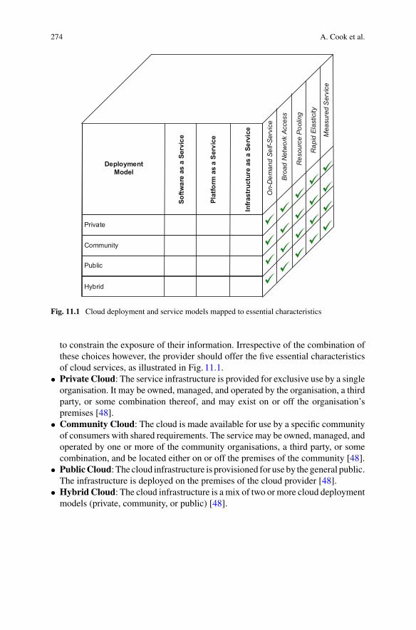
274 A. Cook et al.
Private
Community
Public
Hybrid
On-
Dem
and
Self-
Serv
ice
Broa
d N
etw
ork
Acce
ss
Res
ourc
e Po
olin
g
Rap
id E
last
icity
Mea
sure
d S
ervi
ce
Softw
are
as a
Ser
vice
Plat
form
as
a Se
rvic
e
Infra
stru
ctur
e as
a S
ervi
ce
DeploymentModel
Fig. 11.1 Cloud deployment and service models mapped to essential characteristics
to constrain the exposure of their information. Irrespective of the combination ofthese choices however, the provider should offer the five essential characteristicsof cloud services, as illustrated in Fig. 11.1.
• Private Cloud: The service infrastructure is provided for exclusive use by a singleorganisation. It may be owned, managed, and operated by the organisation, a thirdparty, or some combination thereof, and may exist on or off the organisation’spremises [48].
• Community Cloud: The cloud is made available for use by a specific communityof consumers with shared requirements. The service may be owned, managed, andoperated by one or more of the community organisations, a third party, or somecombination, and be located either on or off the premises of the community [48].
• PublicCloud: The cloud infrastructure is provisioned for use by the general public.The infrastructure is deployed on the premises of the cloud provider [48].
• Hybrid Cloud: The cloud infrastructure is a mix of two or more cloud deploymentmodels (private, community, or public) [48].

11 Internet of Cloud: Security and Privacy Issues 275
11.1.4 Enabling Technologies
Aspreviously discussed, cloud services are basedupon a common set of underpinningenabling technologies that were developed before cloud computing emerged as abusiness model. We shall now consider a key subset of these technologies in thecontext of their operation within a cloud.
• Virtualisation: Virtualisation is the ability to deploy multiple host operating envi-ronments on one physical device. Typically, operating systems are encapsulatedwithin a ‘virtual machine’ (VM), a number of which are deployed onto a singlephysical server (a ‘real machine’). A ‘hypervisor’ that abstracts the VMs from thereal machine, accessing hardware components of the server as required by eachVM. Hypervisors also allow VMs to be redeployed to other real machines, per-mitting them to be reallocated to servers with greater or lesser processing capacityas required by the consumers demands [16].
• Storage: Storage within cloud environment can be characterised as either file- orblock-based services, or data management comprising record-, column- or object-based services. These typically reside on a storage area network (SAN) that pro-vides a persistence platform that underpins a data centre. For file- or block-basedservices, the cloud ensures that sufficient capacity is provided to support the elas-ticity of the service, expanding or contracting as required. Record-, column- orobject-based services, however, focus on database persistence and the performanceof the data used by applications.As data expandswithin a large database it becomesnecessary to optimise the storage based on frequency of access and location of con-sumers. Data within the cloud can be easily replicated to provide temporary copiesin caches etc. that improve performance, as well as reducing the impact of backupservices on production data. Similarly, where multiple data centres are used, theselocal caches can be optimised to focus on the datasets most frequently accessedin each location. The underlying file system elastically supports these replicas ofdata, expanding and contracting as necessary to support performance SLAs [27].
• Monitoring and Provisioning: The ability of a cloud provider to automaticallyprovision services is an key element of its offering. Automated provisioning istypically based on a catalogue, from which consumers can select the extension orcontraction of a service over which they have decided to maintain control. Thenature of the service they maintain control of is dependent upon the service modelthey operate within (SaaS, PaaS, IaaS). Similarly, for the cloud provider, theyrequire the ability to modify the execution environment in line with agreed SLAs,with or without human intervention. The provisioning is typically managed by aservice orchestration layer that interacts with the monitoring service to determinethe levels of performance of cloud elements in line with SLAs, and coordinatesthe manipulation of the infrastructure, deploying and redeploying resources asnecessary tomaintain a balanced and cost-efficient use of the available architecture[39].
• Billing: Given the differing service and deployment models that cloud providerscan offer, the billing service must be integrated with the monitoring and

276 A. Cook et al.
provisioning to ensure accurate accounting of consumption. The billing services,in some cases, support both prepay and postpay models, requiring the billing ser-vice to decrement or accrue respectively. The service must also only account forconsumption as it occurs, and be cognisant of the elasticity of deployment andrelease. As the nature of the cloud service provided to consumers may differ, thebilling service must support multiple, and in many cases, complex pricing modelsto ensure accurate accounting [19].
Cloud computing is based on a mix of technologies brought together in differingservice and deployment models to provide cost-effective utilisation of IT resources.The ubiquity of access to these resources allows low-power, low-storage capacityIoT devices to extend their capabilities by leveraging these services on-demand. Thisintegration of IoT and cloud into the Internet of Cloud (IoC) provides opportunitiesto provide a revolution in the use and exploitation of smart devices.
11.2 Internet of Things (IoT) and Internet of Cloud (IoC)
The Internet of Things is a term that has rapidly risen to the forefront of the IT world,promising exciting opportunities and the ability to leverage the power of the internetto enhance the world we live in. The concept itself is not a new one however, and itis arguable that Nikola Tesla predicted the rise of IoT back in 1926 when he stated:
When wireless is perfectly applied the whole earth will be converted into a huge brain...andthe instruments through which we shall be able to do this will be amazingly simple comparedwith our present telephone [36].
What Tesla had predicted was the Internet of Things (IoT), which today has beendefined as the pervasive presence in the environment of a variety of things, whichthrough wireless and wired connections and unique addressing schemes are ableto interact with each other and cooperate with other things to create new applica-tions/services and reach common goals [76]. Put more simply, things are anythingand everything around us that are internet connected and are able to send, receiveor communicate information either to humans or to other things. There are threeprimary methods in which things communicate. Firstly, a sensor can communicatemachine to machine (M2M). Examples here include a sensor feeding data to anactuator which opens a door when movement is detected. Secondly, communica-tion can be Human to Machine (H2M), such as a sensor which can detect humanvoice commands. Finally, machine to human (M2H) communication provides thedelivery of useful information in an understandable form such as a display or audioannouncement.When considering the number of things in our world, and the numberof potential combinations of connecting them, the only limit for thinking up valuableuse cases is our own imagination. Some well established use cases for the IoT are asfollows:

11 Internet of Cloud: Security and Privacy Issues 277
• Healthcare: The use of sensors and the internet to monitor the medical variablesof human beings and perform analyses on them. A real world example is NHSEngland’s Diabetes Digital Coach Test Bed [51], which trialled the use of mobilehealth self-management tools (wearable sensors and supporting software). Thistrial leveraged the IoT to realise a number of benefits. Firstly it enabled peoplewith diabetes to self-manage their condition through the provision of real timedata and alerts based upon the data from their sensors. Secondly, the sensors wereable to notify healthcare professionals if there was a dangerous condition that wasnot being corrected by the patient. Thirdly, the data from the sensors could beaggregated to provide a population-wide view of the health status of people withdiabetes.
• SmartCities: The use of connected sensors to improve city life and create an urbaninformation system [34]. For example, detecting the amount of waste in containersto schedule a pick-up or the use of sensors to detect city-wide availability of parkingand direct drivers to an available space [59]. This has the potential to not only savecitizens frustration, but also to reduce congestion, pollution and fuel consumption.
• Smart Buildings: Both places of business and people’s homes can benefit fromthe rise of the IoT. Buildings consume 33% of world energy [76], and there is realpotential for the IoT to bring this usage down. Sensors can turn off lights when theyare not needed, and appliances remotely switched off. Heating can be optimisedbased upon sensors detecting occupancy and weather conditions. Aggregations ofthis data can be used by energy providers to plan and optimise their operations.
• Smart Transport: The connecting of multiple transport related things. For exam-ple, sensors in roadways and vehicles to provide a full view of traffic flow anddynamically alter traffic light sequences, speed limits, information signs or satel-lite navigation systems to suggest quicker routes.
• Smart Industry: Intelligent tracking of goods and components, smart factoriesand innovative retail concepts such as Amazon Go [2], which offer a checkout-lessexperience for customers.
A summary of IoT projects around the world ranked by application domain isprovided in Fig. 11.2. As the graphic shows, the most active domains for IoT (as ofQ3 2016) are connected industry and smart cities. However, all of the domains areshowing an upward trend that is likely to continue into the future as new and inno-vative use cases are developed and the value of IoT becomes increasingly apparentto actors in each domain [6].
11.2.1 IoT Technologies
Behind the things whichmake up the IoT are a number of essential core technologies.The literature identifies five overall technologies as follows: [41]:
• RadioFrequency Identification (RFID): PassiveRFID chips have no battery, andprovide information to a reader when it is placed in proximity of the chip. Active

278 A. Cook et al.
Fig. 11.2 IoT projects by category
RFID chips can initiate communication, and output information in response to achange in its environment (e.g. changes in temperature or pressure).
• Wireless Sensor Networks (WSN): Wireless sensor networks are defined as col-lections of stand-alone devices which, typically, have one or more sensors (e.g.temperature, light level), some limited processing capability and a wireless inter-face allowing communication with a base station [29].
• Middleware: Middleware sits between the things and the raw data they generate toprovide interoperability between things and developers who code the applicationsfor interesting use cases. It provides a level of abstraction, allowing developers towork with sensors without having to know the specifics of their implementation.
• Cloud Computing: The cloud provides the seemingly limitless storage and pro-cessing power necessary for IoT use cases to become a reality.
• IoT Applications: The software that provides end users with a useful product -e.g. A smartphone app through which a driver can find and reserve a free parkingspace.
The focus of this section is on the cloud aspect of IoT technology, in particular howcloud computing and the IoT have found what appears to be a mutually beneficialrelationship and led to the term Internet of Cloud (IoC).
11.2.2 Internet of Cloud (IoC)
The synergy between the cloud and the IoT has emerged largely due to the cloudhaving attributes which directly benefit the IoT and enable its continued growth.In the IoT’s infancy, things either had some local computing resources (storage,

11 Internet of Cloud: Security and Privacy Issues 279
processing) to produce a useful result, or they sent their data to a mainframe whichhad the necessary computing resources to process the data and generate an output. Ineffect, the “brain” as Tesla envisioned in 1926 was either highly distributed amongstthe things, or it was centrally located with the things simply acting as sensors. Bothof these approaches have disadvantages. The mainframe’s weaknesses are that it isexpensive to maintain and presents a central point of failure. The highly distributedapproach whereby things communicate and perform some local computation pro-vides better resilience to failure, but increases the cost of each thing in the network.This additional cost is both financial (the cost of equipping each thing with suit-able resources and replacing failed things) and logistical (including such resourcesrequired the thing to be physically larger and consume more power). As use casesbecome more advanced, and the goals more complex, the demand for more complexcomputation has only increased.
The IoT is not only expanding in its need for more demanding computationresources. Gartner has predicted that the number of internet connected deviceswill reach 20.8 billion by 2020 [26], suggesting that the IoT is not only expand-ing in computational complexity, but also in the sheer amount of data that needs tobe processed. In effect, the IoT generates big data [58], which places the demandfor smaller and cheaper things directly into competition with the demand for morecomputing resources. Traditional approaches to the IoT cannot satisfy both demands -either the things become more expensive and complex, or limits on their computa-tion resource needs are imposed. However, the cloud presents a solution with thepotential to satisfy both demands.
11.2.3 Cloud as a Solution
The rise of cloud computing has provided an alternative solution, presenting the IoTwith a virtually limitless source of computing power, easily accessible via the internet,with better resilience and at a lower cost than utilising a mainframe or includingcomputing resources at the thing level. The cloud allows IoT developers to be freedfrom the constraints of limited resources, and enables the use case to be realised atreduced cost. In effect, things only require the bare minimum of hardware to performtheir function (e.g. sense something, actuate something) and to communicate withthe cloud. The cloud performs all computation and communicates back the result tothe things. This pairing of cloud computing and the IoT has led to the term Internet ofCloud (IoC), and numerous literature reviews of this new paradigm are available [9,17].

280 A. Cook et al.
11.2.4 Sensor-Clouds
Cloud infrastructure is not only valuable for taking on the burden of heavy compu-tation and storage, it has also been identified as valuable in forming what are knownas Sensor-Clouds [1]. In traditional sensor networks, the deployed sensors providedata for one purpose - to fulfil the purchaser’s use case. Unfortunately, this leads toan element of wastage, since the data being collected could be useful for other pur-poses but is not readily accessible by other organisations or third party developers.For example, if a local council deployed sensors to measure traffic flow in the citycentre, a third party may wish to access the sensor data to improve their satellitenavigation system and direct travellers away from congested roads. Sensor-Cloudsaddress this scenario by making the sensor data available to multiple parties in thecloud. In effect, they offer what could be termed sensors as a service. This scenariobrings a number of benefits. Firstly it allows developers of IoT applications to avoidthe burden of manually deploying sensors and focus upon developing interesting usecases through the use of existing sensor networks. Secondly, sensor owners suchthe local council can recoup some of the cost of deployment and maintenance bycharging these third parties to access the data.
A Sensor-Cloud can be visualised in three layers [1]. At the lowest layer, physicalsensors around the world upload their data in a standardised format to the Sensor-Cloud. This standardisation of data allows users of the service to use the data withoutconcern over differences in areas such as protocols and formatting. At the secondlayer, the Sensor-Cloud allows users to create virtualised groups of sensors for use intheir applications. These virtual sensors are based upon service templates, which aredefined by the sensor owners. At the top layer, application developers can plug thesevirtual sensors into their applications. This three layer architecture for Sensor-Cloudsis shown in Fig. 11.3.
11.2.5 Ongoing Challenges
It has been noted that the cloud brings some valuable attributes to the IoT, but it isnot a perfect solution which can solve all of the IoT’s problems. In fact, the use ofthe cloud can present some new and interesting challenges as follows [17]:
• Security and Privacy: Cloud security is a well documented challenge, but thepairing between cloud and the IoT presents additional concerns. For example,when considering the sensitive nature of some use cases such as smart health,additional caremust be taken to ensure that confidentially, integrity and availabilityof data is not violated. Confidentiality breaches could result in personal health databeing stolen, integrity breaches could be fatal if data is tampered with and a lackof availability could fail to alert to a life threatening condition.
• Addressing: If Gartner’s predictions on the rapid growth of the IoT are correct,IPv4 will quickly become inadequate to address all of the things. IPv6 has the

11 Internet of Cloud: Security and Privacy Issues 281
Fig. 11.3 Sensor-cloud layers
potential to address this concern, but it is not yet widely adopted. It has beenproposed that an efficient naming and identity management system is required todynamically assign and manage unique identity for an ever increasing number ofthings [37].
• Latency and Bandwidth: The cloud may provide limitless computing resources,but it cannot necessarily ensure low latency or unlimited bandwidth since thisrelies upon the public internet which is outside of the cloud provider’s control.This challenge has led to the rise of what is termed “fog computing”, where com-puting resources are placed as close to the things as possible in order to act as anintermediary. This intermediary can quickly service time critical processing thatis latency sensitive whilst forwarding on non-time critical data for cloud process-ing [8].
• Interoperability: Due to the high number of things from multiple vendors, cloudcomputing alone cannot solve the issue of interoperability. The IoT would benefitfrom standards which describe a common format for both handling and commu-nicating data.

282 A. Cook et al.
11.2.6 Japan Case Study
While the concept of Internet of Cloud and Sensor-Clouds can seem abstract, it hasbeen implemented in some very valuable use cases. One such use case was in theaftermath of the 2011 tsunami in Japan, which led to the second-largest nuclearemergency since Chernobyl. With a lack of reliable government information on theradiation threat, private individuals and organisations donated hundreds of Geigercounters to the affected region. As standalone devices, the use of these counters waslimited, and researchers began to investigate methods to link the devices together andmake the information available to all. The cloud provided the necessary infrastructureand agility to quickly connect each sensor, and a Sensor-Cloud of around 1000radiation sensors was formed. This Sensor-Cloud provided emergency services withessential information regarding radiation levels, and the same data was leveragedto produce a smart phone app for local citizens to monitor radiation levels in theirarea [74]. The project, today known as Safecast [62], has grown beyond the initialuse case and is now a global network of radiation sensors, allowing the public toaccess, contribute and use the sensor data through an API.
This use case highlights how valuable the Internet of Cloud can be not only for itsability to provide the necessary computing resources but also for the speed at whichsuch resources can be provisioned - in this case rapidly providing the back end fora potentially life saving service. As stated in the previous subsection the pairingbetween cloud and the IoT presents additional concerns in terms of security andprivacy. However, for these services to be adopted they must be trusted. Therefore,we must now consider the security and privacy implications of such integration.
11.3 Security and Authentication Issues
IoT ecosystem creates a world of interconnected thing, covering a variety of appli-cation and systems, such as smart city systems, smart home systems, vehicular net-works, industrial control systems as well as the interactions among them [28]. Cloudcomputing is a technology that is configured to enable access to a shared pool ofresource including servers, data storage, services and application [3]. It has becomean important component of the IoT as it provides various capabilities to manage sys-tems, servers and application and performs necessary data analytics and aggregation.
It is undeniable that IoT provides benefits and convenience to our everyday life,however, many of the IoT components (e.g. low cost digital devices and industrialsystems) are developed with little to no consideration of security [35, 38, 63]. Asuccessful exploit can propagate within the IoT ecosystem that could render the lossof sensitive information, interruption of the business functionalities, and the damageto critical infrastructure.
We have already seen the security concerns of the cloud services. These includebut are not limited to malware injection (malicious code injected into cloud and run
11 Internet of Cloud: Security and Privacy Issues 283
as SaaS), vulnerable application programming interfaces (API), abuse of data andcloud service, insider threats and the newly emerging Man In Cloud Attack [32].Cloud involves both service providers and consumers; therefore, cloud security is ashared responsibility between the two.
Security issues are still yet to be solved for IoT and Cloud respectively. IoTadopting Cloud services could complicate this situation and raise more securityconcerns. This section focuses on the security issues on IoT adopting Cloud servicesand makes recommendations to address those issues.
11.3.1 Data Sharing/Management Issues of IoT Cloud
Within a cloud context, nomatter public, private or hybrid, data securitymanagementinvolves secure data storage, secure data transmission and secure access to the data.During transmission, the Transport Layer Security (TLS) cryptography is widelyused to prevent against threats. During processing, the cloud service provided appliesisolation between different consumers. The isolation [80] is applied at different levelssuch as operations system, virtual machine or hardware. The secure access to datasometimes depends on the isolation level. It may sometimes separate completelyfrom other resources or may have shared infrastructures and softwares that relyon access control policies. Within an IoT context, one of the benefits is open datasharing among different things. If the data is isolated as is currently offered in thecloud services, open wide data aggregation and analytics would become impossible.A balance needs to be found between data protection and sharing.
There is existing work such as Information Flow Control (IFC) [4, 54] definingand managing the requirements for data isolation and sharing. People can specifyto what extent they want to share or protect their data. Other work is related todata encryption, encrypting the things before uploading to the cloud. This wouldlimit the users access to the data, which again affects the IoT’s data sharing andanalytical capability. There are some solutions to analyse encrypted data. However,this approach is not mature to be applied in practice at this stage [31, 50].
11.3.2 Access Control and Identity Management
Within a cloud context, access control rules are strictly enforced. The serviceproviders use authentication and authorisation services to grant privileges to theconsumers to access storage or files. Within an IoT context, there are interactionsbetween different devices that are owned by different people. Access control is usu-ally leveraged through device identity management and configuration [46]. Existingidentity management includes identity encoding and encryption [77].
When IoT uses Cloud services, access control involves the interactions amongthe applications and cloud resources. Policies and mechanism need to be flexibly
284 A. Cook et al.
defined to accommodate the needs of both and resolve the conflicts of differentparties. There is existingwork ongrouping the IoTdevices to enable commonpolicies[64]. However, cares need to be taken to ensure the flexibly defined policies do notintroduce vulnerabilities to the system.
11.3.3 Complexity (Scale of the IoT)
One of the benefits of Cloud service adoption is the reduction of cost through elas-tically resource scaling mechanisms. The increase of IoT devices, data volume, andvariety has become a burden for the Cloud. The failure to coordinate and scale the“things” will impact the availability of the data. Security mechanism will bring extraburden that can impact the performance of IoT Cloud [60, 80].
Logging is an important aspect of security as it provides a view of the currentstate of the system. Logging within the Cloud is centralised and it is an aggregationof the logs from different components such as software applications and operation[68]. IoT logging tends to decentralise it among different components. There aresome existing work on logging centralisation (e.g. design analytics tools to collectand correlate decentralised logs from “things” [57]) and decentralisation (e.g. enablelogging to capture information in a data-centric manner [56]). A balance needs to befound between logging centralisation and decentralisation.
11.3.4 Protection of Different Parties
IoT Cloud raise security concerns to both service providers and consumers. Cloudservice providers used to apply access control to protect data and resources. Now,the “things” can directly interact with the providers. Attacks can be easily launchedby compromised “things”. We have already seen some real world exploits of smarthome applications, that are designed with poor security considerations [61].
From the consumers’ perspective, “things” needs to be validated before it can beconnected. If the “things” are determined to be compromised or malicious, alerts willbe sent either in a human readable or machine-readable format. The determinationcan be based on reputation, trustworthy network node evaluation [52, 85] and so on.
11.3.5 Compliance and Legal Issues
Cloud demonstrated compliance using contract through service-level agreement(SLA). A typical method to assess compliance is through auditing. Within thearea of Cloud, Massonet has proposed a framework that can generate auditing logs

11 Internet of Cloud: Security and Privacy Issues 285
demonstrating that they are compliant with the related policies/regulations [47].There are also frameworks designed in the area of IoT to demonstrate complianceusing auditing logs.
IoT tends to be decentralised in isolated physical locations. The centralisation ofcloud allows the data to flow across geographic boundaries, which has raised legaland law concerns of the data across national borders. There are some existing workon constrain data flow geographically by applying legal and management principlesto the data [66]. Again this will have an negative impact on data sharing capabilityof IoT and Cloud.
11.3.6 Cloud Decentralisation
An emerging trend is the Cloud decentralisation in order to accommodate the IoTand big data analytics. Typical method is decentralised computing such as Fog com-puting [8] and grid computing [25]. Cloud decentralisation helps reduce the typicalCloud attacks such as denial of service (DoS) attack; it also raises new security con-cerns. Instead of targeting on the Cloud services, the attacks are directed to individualservice providers and consumers. There is on-going research in securing the decen-tralised Cloud through coordinating the communication of things to things, thingsto clouds and clouds to clouds [67, 68]. Finally cloud decentralization can providemore flexible management.
Following the trend of decentralized cloud deployment, security mechanisms thatmust be developed for the IoC may also be decentralized. This deployment can havemultiple advantages and in this context Intrusion Detection Systems for the IoC areanalyzed on Sect. 11.3.7.
11.3.7 Intrusion Detection Systems
Intrusion detection systems (IDS) can be classified into centralized intrusion detec-tion systems (CIDS) and distributed intrusion detection systems (DIDS) by the wayin which their components are distributed. In a CIDS the analysis of the data isperformed in some fixed locations without considering the number of hosts beingmonitored [40], while a DIDS is composed of several IDS over large networks whosedata analysis is performed in a number of locations proportional to the number ofhosts. There are numerous advantages of a DIDS compared to a CIDS. A DIDS ishighly scalable and can provide gradual degradation of service, easy extensibilityand scalability [14].
Novel intrusion detection Systems (IDS) must be implemented that need to beefficient both in terms of accuracy, complexity and communication overhead, falsealarm rate and time among others. IDSs that have been developed for other systems,e.g. Industrial Control Systems [15, 45], wireless sensor networks [11], or cloud
286 A. Cook et al.
environments [49] can be used as a basis for developing new detection systems forthe IoC area. Adaptivity of the IDS on changes in the network topology, which willbe a frequent situation for an IoC, is an aspect that needs to be addressed when newIDS are going to be designed [70].
11.4 Privacy Preserving Schemes for IoC
In this subsection, we review the privacy preserving schemes for IoC. Based on theclassification of authentication and privacy preserving schemes in our three recentsurveys [22–24], the privacy preserving schemes for IoC can be classified accord-ing to networks models and privacy models. The summary of privacy preservingschemes for IoC are published in 2014, 2015, and 2016, as presented in Tables11.1,11.2, and 11.3, respectively. In addition, Fig. 11.4 shows the classification of privacypreservation models for IoC.
Cao et al. [13] defined and solved the problem of multi-keyword ranked searchover encrypted cloud data while preserving strict systemwise privacy in the cloud-computing paradigm. Specifically, the authors proposed a preserving scheme, calledMRSE, using the secure inner product computation. The MRSE scheme is efficientin terms of the time cost of building index and the time cost of query. Worku etal. [81] proposed a privacy-preserving public auditing protocol in order to providethe integrity assurance efficiently with strong evidence that unfaithful server cannotpass the verification process unless it indeed keeps the correct data intact. Wanget al. [78] proposed a brand new idea for achieving multi-keyword (conjunctivekeywords) fuzzy search. Different from existing multi-keyword search schemes, thescheme [78] eliminates the requirement of a predefined keyword dictionary. Basedon locality-sensitive hashing and Bloom filters, the scheme [78] is efficient in term ofthe Bloomfilter generation time for a single file.Wang et al. [10] a privacy-preservingpublic auditingmechanism, calledOruta, to verify the integrity of shared datawithoutretrieving the entire data. Oruta uses ring signatures [7] to construct homomorphicauthenticators. In addition, Oruta can achieving following properties: (1) PublicAuditing, (2) Correctness, (3) Unforgeability, and (4) Identity Privacy. Yuan and Yu[33] proposed the first secure and practical multi-party the back-propagation neuralnetwork learning scheme over arbitrarily partitioned data. Based on two phases,namely, (1) privacy preserving multi-party neural network learning, and (2) securescalar product and addition with Cloud, the scheme [33] can support the multi-party scenario and efficient in terms of collaborative learning and communicationcost compared to both schemes in [73] and [5]. Sun et al. [72] proposed an ideato build the search index based on the vector space model and adopt the cosinesimilarity measure in the Cloud supporting similarity-based ranking. Based on thevector space model, the scheme [72] is efficient in term of time cost for generatingencrypted query. Dong et al. [18] considered four parties in a network, namely, thedata owner, the data consumer, the cloud server, and the private key generator. Then,

11 Internet of Cloud: Security and Privacy Issues 287
Table11.1
Summaryof
privacypreserving
schemes
forIoC(Publishedin
2014)
Scheme
System
model
Privacymodel
Goals
Mainph
ases
Performances(+)and
limita
tions
(-)
Cao
etal.[13
]Aclouddatahosting
serviceinvolvingthree
differententities,nam
ely,
thedataow
ner,thedata
user,and
thecloudserver
Dataprivacy
Indexprivacy
Keywordprivacy
Achieving
the
multi-keyw
ordranked
search
with
privacy-preserving
-Se
tup
-BuildIndex
-Trapdoor
-Query
+Efficientinterm
ofthe
timecostof
build
ing
index
+Efficientinterm
ofthe
timecostof
query
+Resistanceto
theknow
nciphertext
modeland
know
nbackground
model
-Noconsiderationfor
checking
theintegrity
oftherank
order
Worku
etal.[81
]Three
differententities,
including,
cloudserver,
user,and
thirdparty
auditor
-Userprivacy
Achieving
public
verifia
bility,storage
correctness,batch
auditin
g,blockless
verification,andprivacy
preserving
KeyGen
SigG
enProofG
enVerifyP
roof
+Efficientinterm
auditor
andserver
computatio
noverhead
comparedto
the
schemein
[79]
+Secure
intherandom
oraclemodel
-Nothreatmodel
presented
Wangetal.[78
]Three
differententities,
including,
dataow
ner,
cloudserver,and
user
-Filecontentp
rivacy
-Indexprivacy
-Userqueryprivacy
Supportm
ulti-keyw
ord
fuzzysearch
-KeyGen
-IndexEnc
-Query
Enc
-BuildIndex
-Trapdoor
-Search
+Efficientinterm
ofthe
Bloom
filtergeneratio
ntim
eforasing
lefile
+Multi-keyw
ordfuzzy
search
+Resistanceto
theknow
nciphertext
modeland
know
nbackground
model
-Nocomparisonwith
relatedschemes (c
ontin
ued)

288 A. Cook et al.
Table11.1
(contin
ued)
Scheme
System
model
Privacymodel
Goals
Mainph
ases
Performances(+)and
limita
tions
(-)
Wangetal.[10
]Three
parties:thecloud
server,a
groupof
users
andapu
blicverifie
r
-Identityprivacy
Achieving
follo
wing
properties:(1)Pu
blic
Auditing,(2)
Correctness,
(3)Unforgeability,and
(4)IdentityPrivacy.
-KeyGen
-RingS
ign
-RingV
erify
+Efficientinterm
sof
signaturegeneratio
nand
commun
icationcost
+Efficientinterm
ofauditin
gtim
e+Efficientinterm
sof
privacyandbatch
auditin
gwith
incorrect
proofs
-Traceability
isno
tconsidered
YuanandYu[33]
Three
major
parties:a
trustedauthority
(TA),the
participatingparties(data
owner)andthecloud
servers(orcloud)
-Multi-party
privacy-preserving
Protectin
geach
participant’s
private
datasetand
interm
ediate
results
generateddu
ring
theback-propagatio
nneuralnetworklearning
process
-PrivacyPreserving
Multi-PartyNeural
Network
Learning
-Secure
Scalar
Product
andAdd
ition
with
Cloud
+Efficientinterm
sof
collaborativ
elearning
and
commun
icationcost
comparedto
both
schemes
in[73]
and[5]
+Su
pportthe
multi-party
scenario
+Scalable,efficientand
secure
-Doesno
tallo
wmultip
arty
colla
borativ
elearning
with
outthe
help
ofTA
(contin
ued)

11 Internet of Cloud: Security and Privacy Issues 289
Table11.1
(contin
ued)
Scheme
System
model
Privacymodel
Goals
Mainph
ases
Performances(+)and
limita
tions
(-)
Sunetal.[72
]Three
entities:thedata
owner,thedatauser,and
thecloudserver
-Search
privacy
-Indexconfi
dentiality-
Query
confi
dentiality
-Query
unlin
kability
-Keywordprivacy
Achieving
high
efficiency
andfunctio
nality(suchas
expressive/usable
queries)
-Se
tup
-GenIndex
-GenQuery
-SimEvaluation
+Efficientinterm
oftim
ecostforgeneratin
gencryptedquery
+Helpusersensure
the
authentic
ityof
the
returned
search
results
inthemulti-keyw
ordranked
encryp
tedtext
search
scenario
-Traceability
isno
tconsidered
Dongetal.[18
]Fo
urpartiesin
anetwork:
thedataow
ner,thedata
consum
er,the
cloud
server,and
theprivatekey
generator
-Backw
ardsecrecy
-Userprivacy
Achieving
fine-grained
access
control
-Sy
stem
initialization
-Encryption
-Key
generatio
nand
distributio
n-Decryption
+Efficientinterm
sof
compu
tatio
ncomplexity,
commun
icationcost,and
costof
revocatio
noperation
+Fu
llycollu
sion
secure
+Useraccess
privilege
confi
dentiality
-Adversary’smodelis
limite
d
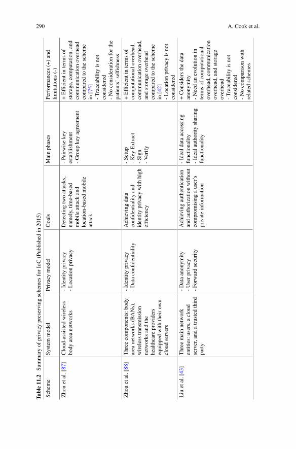
290 A. Cook et al.
Table11.2
Summaryof
privacypreserving
schemes
forIoC(Publishedin
2015)
Scheme
System
model
Privacymodel
Goals
Mainph
ases
Performances(+)and
limita
tions
(-)
Zhouetal.[87
]Cloud
-assistedwireless
body
area
networks
-Identityprivacy
-Locationprivacy
Detectin
gtwoattacks,
namely,tim
e-based
mob
ileattack
and
locatio
n-basedmob
ileattack
-Pairwisekey
establishm
ent
-Group
keyagreem
ent
+Efficientinterm
sof
storage,computatio
n,and
commun
icationoverhead
comparedto
thescheme
in[75]
-Traceability
isno
tconsidered
-Noconsiderationforthe
patie
nts’selfishness
Zhouetal.[88
]Three
components:body
area
networks
(BANs),
wirelesstransm
ission
networks
andthe
healthcare
providers
equipp
edwith
theirow
ncloudservers
-Identityprivacy
-Dataconfi
dentiality
Achieving
data
confi
dentialityand
identityprivacywith
high
effic
iency
-Se
tup
-Key
Extract
-Sign
-Verify
+Efficientinterm
sof
computatio
nalo
verhead,
communicationoverhead,
andstorageoverhead
comparedto
thescheme
in[42]
-Locationprivacyisnot
considered
Liu
etal.[43
]Three
mainnetwork
entities:users,aclou
dserver,and
atrustedthird
party
-Dataanonym
ity-Userprivacy
-Fo
rwardsecurity
Achieving
authentic
ation
andauthorizationwith
out
comprom
isingauser’s
privateinform
ation
-Ideald
ataaccessing
functio
nality
-Idealauthority
sharing
functio
nality
+Considersthedata
anonym
ity-Needan
evolutionin
term
sof
compu
tatio
nal
overhead,com
munication
overhead,and
storage
overhead
-Traceability
isno
tconsidered
-Nocomparisonwith
relatedschemes

11 Internet of Cloud: Security and Privacy Issues 291
Table11.3
Summaryof
privacypreserving
schemes
forIoC(Publishedin
2016)
Scheme
System
model
Privacymodel
Goals
Mainph
ases
Performances(+)and
limita
tions
(-)
Xiaetal.[83
]Fo
urdifferenttypes
ofentities:theim
ageow
ner,
imageuser,cloud
server
and
watermarkcertificatio
nauthority
-Dataprivacy
Protectin
gtheprivacyof
imagedatain
content-based
imageretrievalo
utsourcing
applications
againsta
curiou
scloudserver
andthe
dishonestq
uery
users
-KeyGen
-IndexG
en-Im
gEnc
+Privacyof
imagecontent
+Privacyof
imagefeatures
+Privacyof
trapdoors
+Leakage
ofsimila
rity
inform
ation
+Efficientinterm
oftim
econsum
ptionof
thetrapdoor
generatio
n-The
proposed
watermarking
methodcannot
beregarded
asavery
robust
one
Xiaetal.[84
]Three
differenttypes
ofentities:theim
ageow
ner,
imageuser
andcloudserver
-Im
ageprivacy
The
plaintextd
ataneedsto
bekept
unknow
nto
thecloud
server
-The
generatio
nof
unen-
cryptedindex
-The
indexencryptio
n
+The
privacyof
theim
age
+The
privacyof
theim
age
features
+The
privacyof
the
trapdoors
+The
leakageof
the
simila
rity
inform
ation
+Efficientinfour
term
s,namely,(1)tim
econsum
ption
oftheindexconstructio
n,(2)
timeconsum
ptionof
the
trapdoor
generatio
n,(3)tim
econsum
ptionof
thesearch
operation,
and(4)storage
consum
ptionof
theindex
-The
featureextractio
nin
encryp
tedim
age
(contin
ued)

292 A. Cook et al.
Table11.3
(contin
ued)
Scheme
System
model
Privacymodel
Goals
Mainph
ases
Performances(+)and
limita
tions
(-)
Pasupu
letietal.[55
]Con
sistingof
threemain
entities,includ
ing,
data
owner,cloudservice
provider,and
authorized
users
-IndexPrivacy
-Dataprivacy
Proposingan
efficient
andsecure
privacy-preserving
approach
with
follo
wing
goals:privacypreserving,
indexprivacy,anddata
integrity
-Key
generatio
n-Indexcreatio
n-Privacy-preserving
-Trapdoorgeneratio
n-Rankedkeyw
ordsearch
-Datadecryp
tion
+Detectthe
modificatio
nsor
deletio
nsof
dataand
maintaintheconsistency
ofdata
+Efficientinterm
sof
computatio
ncostand
commun
icationcost
-Dyn
amicdataup
dates
Xiaetal.[82
]Con
sistingof
threemain
entities,includ
ing,
data
owner,datauser
and
cloudserver
-Indexconfi
dentiality
-Query
confi
dentiality
-Trapdoorunlin
kability
-Keywordprivacy
Supportin
gmulti-keyw
ordranked
search
anddynamic
operationon
the
documentcollection
-IndexConstruction
-Search
Process
+The
search
precisionon
differentp
rivacy
level
+The
efficiencyof
index
constructio
n,trapdoor
generatio
n,search,and
update
-The
userskeep
thesame
secure
keyfortrapdoor
generatio
n-Locationprivacyand
identityprivacyarenot
considered
(contin
ued)

11 Internet of Cloud: Security and Privacy Issues 293
Table11.3
(contin
ued)
Scheme
System
model
Privacymodel
Goals
Mainph
ases
Performances(+)and
limita
tions
(-)
Song
etal.[69
]Con
sistingof
threemain
entities,includ
ing,
data
owner,authorized
data
user,and
cloudserver
-Dataprivacy
-Query
privacy
Providingthefull-text
retrievalserviceswith
privacy-preserving
-Docum
entp
rocessing
-Indexstructureand
maintenance
mechanism
-Fu
ll-text
retrieval
algorithm
over
encrypted
data
+The
indexspacecost
+Tim
ecostforinserting
anewdocument
+Query
effic
iencywith
differentn
umberof
documents
+Query
precisionwith
differentn
umberof
documents
-Traceability
isno
tconsidered
Zhu
etal.[89
]Fo
urparts:trusted
authority,locationbased
services
(LBS)
provider,
LBSuser,and
cloud
server
-Locationprivacy
Providing
privacy-preserving
LBS
dataanduser’slocatio
ninform
ationwith
accurateLBSforusers.
-Sy
stem
initialization
-Cloud
server
data
creatio
n-Privacy-preserving
locatio
nbasedservices
+The
user
querylocatio
nisprivacy-preserving
intheproposed
EPQ
scheme
+The
proposed
EPQ
schemecanachieve
confi
dentialL
BSdata
+The
authentic
ationof
theLBSqueryrequest
andresponse
are
achieved
intheproposed
EPQ
scheme
+Efficientinterm
ofcompu
tatio
ncomplexity
comparedwith
theFINE
scheme[65]
-Traceability
isno
tconsidered
(contin
ued)

294 A. Cook et al.
Table11.3
(contin
ued)
Scheme
System
model
Privacymodel
Goals
Mainph
ases
Performances(+)and
limita
tions
(-)
Lyuetal.[44
]Fo
urparts:social
network,
dataow
ner,
mem
bers,and
cloud
storageserver
-Dataprivacy
Providingthe
fine-grainedaccess
control
-Sy
stem
initiation
-Privacy-preserving
data
constructio
n-Interested
data
acqu
isition
-Dyn
amicattribute
managem
ent
+Dataconfi
dentiality
+Fine-grained
access
control
+Collusion
attacks
resistant
+Efficientinterm
sof
commun
icationoverhead
andcomputatio
ncost
comparedto
thescheme
in[71]
-Locationprivacyand
identityprivacyarenot
considered
Yuetal.[86
]Fo
urparts,key
distributio
ncenter,cloud
user,cloud
server
and
thirdpartyauditor
-Dataprivacy
Form
alizethesecurity
modelof
zero
know
ledge
privacyagainstthe
third
partyauditor
-Se
tup
-Extract
-TagG
en
+Perfectd
ataprivacy
preserving
+Efficientinterm
sof
costsregarding
computatio
n,communicationand
storage
-Nocomparisonwith
relatedschemes

11 Internet of Cloud: Security and Privacy Issues 295
Identity privacy
Privacy preservationmodels for IoC
User privacy
Data privacy
Forward security
Data anonymity
Keyword privacy
Search privacy
Query unlinkability
Location privacy
Index privacy
User query privacy
File content privacy
Backward secrecy
Fig. 11.4 Classification of privacy preservation models for IoC
the authors [18] proposed an idea that the cloud can learn nothing about a user’sprivacy or access structure, as such the scheme is fully collusion resistant.
To resilient to both time-based and location-based mobile attacks, Zhou et al.[87] proposed a secure and privacy-preserving key management scheme for cloud-assisted wireless body area networks. Based on the body’s symmetric structure withthe underlying Blom’s symmetric key establishment mechanism, the scheme [87]is efficient in terms of storage, computation, and communication overhead com-pared to the scheme in [75], but the traceability is not considered. Zhou et al. [88]proposed a patient self-controllable and multilevel privacy-preserving cooperativeauthentication scheme, called PSMPA, to realize three levels of security and pri-vacy requirement in distributed m-healthcare cloud computing system which mainlyconsists of the following five algorithms: Setup, Key Extraction, Sign, Verify andTranscript Simulation Generation. Based on an attribute based designated verifiersignature scheme, PSMPA is efficient in terms of computational overhead, com-munication overhead, and storage overhead compared to the scheme in [42], butthe location privacy is not considered. Therefore, Liu et al. [43] proposed a sharedauthority based privacy-preserving authentication protocol, named, SAPA, for thecloud data storage, which realizes authentication and authorization without compro-mising a user’s private information. SAPA protocol [43] applied ciphertext-policyattribute based access control to realize that a user can reliably access its own datafields. In addition, SAPA protocol [43] adopt the proxy re-encryption to provide tempauthorized data sharing among multiple users.
Xia et al. [83] proposed an idea to protect the privacy of image data in content-based Image retrieval outsourcing applications against a curious cloud server and thedishonest query users. Specifically, the idea is the first work that proposes a search-able encryption scheme, considering the dishonest query users who may distributethe retrieved images to those who are unauthorized. Similarly to the scheme [83],

296 A. Cook et al.
Xia et al. [84] proposed an idea which the secure k-nearest neighbor algorithm isemployed to protect the feature vectors in order to enable the cloud server to rank thesearch results very efficiently without the additional communication burdens. Basedon the pre-filter tables, the scheme [84] is efficient in four terms, namely, (1) timeconsumption of the index construction, (2) time consumption of the trapdoor gener-ation, (3) time consumption of the search operation, and (4) storage consumption ofthe index. Pasupuleti et al. [55] proposed an efficient and secure privacy-preservingapproach using the probabilistic public key encryption technique to reduce computa-tional overhead on owners while encryption and decryption process without leakingany information about the plaintext. Based on the idea of integrity verification, thescheme [55] can detect the modifications or deletions of data and maintain the con-sistency of data, also is efficient in terms of computation cost and communicationcost. Therefore, Xia et al. [82] proposed two secure search schemes, namely, (1) thebasic dynamic multi-keyword ranked search scheme in the known ciphertext model,and (2) the enhanced dynamic multi-keyword ranked search scheme in the knownbackground model. Based on the searchable encryption scheme, the idea in [82]can supports both the accurate multi-keyword ranked search and flexible dynamicoperation on document collection. Song et al. [69] defined and solved the problemof full-text retrieval over encrypted cloud data in the cloud computing paradigm.Based on a hierarchical Bloom filter tree index, the scheme [69] can protect userquery privacy. Zhu et al. [89] proposed a privacy-preserving location based servicesquery scheme in outsourced cloud, called EPQ, for smart phone. EPQ scheme canachieve confidential location-based services (LBS) data and is efficient in term ofcomputation complexity compared with the FINE scheme [65].
Lyu et al. [44] design an efficient and secure data sharing scheme, named DASS.Based on multi-attribute granularity for social applications, DASS can supportsearchable encryption over data, and is efficient in terms of communication over-head and computation cost compared to the scheme in [71], but location privacy andidentity privacy are not considered. Yu et al. [86] investigated a new primitive calledidentity-based remote data integrity checking for secure cloud storage. In addition,the scheme [86] showed that it achieves soundness and perfect data privacy. In arecent work, Ferrag and Ahmim in [21] proposed an efficient secure routing schemebased on searchable encryption with vehicle proxy re-encryption, called ESSPR, forachieving privacy preservation of message in vehicular peer-to-peer social network.
11.5 Summary
The synergy between the cloud and the IoT has emerged largely due to the cloudhaving attributes which directly benefit the IoT and enable its continued growth. IoTadopting Cloud services has brought new security challenges.We have identified keysecurity issues in data management, access control and identity management, com-plexity and scale, the protections of different parties, compliance and legal issues, aswell as the emerging Cloud decentralisation trend. There is existing work addressing

11 Internet of Cloud: Security and Privacy Issues 297
these issues, however future work should primarily focus on the balance betweencentralisation and decentralisation, data security and sharing as well as associatedpolicy issues.
Regarding privacy preservation, it is not a problem that can be treated in isolationfor a system, but interdependencies among different users and platforms must bealso analyzed. Also the combination of privacy metrics can help improve the levelof privacy by combining the positive aspects of different methods while keeping thetotal cost, in terms of storage, computation and delay, relatively low.
References
1. A. Alamri, W.S. Ansari, M.M. Hassan, M.S. Hossain, A. Alelaiwi, M.A. Hossain, A surveyon sensor-cloud: architecture, applications, and approaches. Int. J. Distrib. Sens. Netw. 9(2),917923 (2013). https://doi.org/10.1155/2013/917923
2. Amazon: Amazon go. Online (2017), https://www.amazon.com/b?node=160085890113. M. Armbrust, A. Fox, R. Griffith, A.D. Joseph, R. Katz, A. Konwinski, G. Lee, D. Patterson,
A. Rabkin, I. Stoica et al., A view of cloud computing. Commun. ACM 53(4), 50–58 (2010)4. J. Bacon, D. Eyers, T.F.M. Pasquier, J. Singh, I. Papagiannis, P. Pietzuch, Information flow
control for secure cloud computing. IEEE Trans. Netw. Serv. Manag. 11(1), 76–89 (2014)5. A. Bansal, T. Chen, S. Zhong, Privacy preserving Back-propagation neural network learning
over arbitrarily partitioned data. Neural Comput. Appl. 20(1), 143–150 (2011)6. J. Bartje, The top 10 iot application areas - based on real iot projects (2016), https://iot-analytics.
com/top-10-iot-project-application-areas-q3-2016/7. D. Boneh, C. Gentry, B. Lynn, H. Shacham, Aggregate and Verifiably Encrypted Signatures
from Bilinear Maps, Intenational Conference on the Theory Applications of CryptographicTechnology (Springer, Berlin, Heidelberg, 2003), pp. 416–432
8. F. Bonomi, R. Milito, J. Zhu, S. Addepalli, Fog computing and its role in the internet of things,in Proceedings of the First Edition of the MCC Workshop on Mobile Cloud Computing (ACM,2012), pp. 13–16
9. A. Botta, W. de Donato, V. Persico, A. Pescap, Integration of cloud computing and internet ofthings: a survey. Future Gener. Comput. Syst. 56, 684–700 (2016), http://www.sciencedirect.com/science/article/pii/S0167739X15003015
10. W. Boyang, L. Baochun, L. Hui, Oruta: privacy-preserving public auditing for shared data inthe cloud. IEEE Trans. Cloud Comput. 2(1), 43–56 (2014)
11. I. Butun, S.D. Morgera, R. Sankar, A survey of intrusion detection systems in wireless sensornetworks. IEEE Commun. Surv. Tutor. 16(1), 266–282 (2014)
12. B.V., I.N.: CompTIA Cloud Essentials Certification Study Guide (Exam CLO-001) (McGraw-Hill, New York, 2014)
13. N. Cao, C. Wang, M. Li, K. Ren, W. Lou, Privacy-preserving multi-keyword ranked searchover encrypted cloud data. IEEE Trans. Parallel Distrib. Syst. 25(1), 222–233 (2014)
14. M. Crosbie, E.H. Spafford, Active defense of a computer system using autonomous agents(1995)
15. T. Cruz, L. Rosa, J. Proença, L. Maglaras, M. Aubigny, L. Lev, J. Jiang, P. Simões, A cyberse-curity detection framework for supervisory control and data acquisition systems. IEEE Trans.Ind. Inf. 12(6), 2236–2246 (2016)
16. J. Daniels, Server virtualization architecture and implementation. Crossroads 16(1), 8–12(2009)
17. M. Díaz, C. Martín, B. Rubio, State-of-the-art, challenges, and open issues in the integration ofinternet of things and cloud computing. J. Netw. Comput. Appl. 67(C), 99–117 (2016). https://doi.org/10.1016/j.jnca.2016.01.010

298 A. Cook et al.
18. X. Dong, J. Yu, Y. Luo, Y. Chen, G. Xue, M. Li, Achieving an effective, scalable and privacy-preserving data sharing service in cloud computing. Comput. Secur. 42, 151–164 (2014)
19. E. Elmroth, F.G. Marquez, D. Henriksson, D.P. Ferrera, Accounting and billing for federatedcloud infrastructures, inEighth International Conference on Grid and Cooperative Computing,2009 GCC’09 (IEEE, 2009), pp. 268–275
20. A. Ericsson, Ericssonmobility report: On the pulse of the networked society. Ericsson, Sweden,Technical Report EAB-14 61078 (2015)
21. M.A. Ferrag, A. Ahmim, Esspr: an efficient secure routing scheme based on searchable encryp-tion with vehicle proxy re-encryption for vehicular peer-to-peer social network. Telecommun.Syst. 1–23 (2017). https://doi.org/10.1007/s11235-017-0299-y
22. M.A. Ferrag, L. Maglaras, A. Ahmim, Privacy-preserving schemes for ad hoc social networks:a survey. IEEE Commun. Surv. Tutor. 19(4), 3015–3045 (2017)
23. M.A. Ferrag, L.A. Maglaras, H. Janicke, J. Jiang, A Survey on Privacy-preserving Schemesfor Smart Grid Communications (2016), arXiv:1611.07722
24. M.A. Ferrag, L.A. Maglaras, H. Janicke, J. Jiang, Authentication Protocols for Internet ofThings: A Comprehensive Survey (2016), arXiv:1612.07206
25. I. Foster, Y. Zhao, I. Raicu, S. Lu, Cloud computing and grid computing 360-degree compared,in Grid Computing Environments Workshop, 2008. GCE’08 (IEEE, 2008), pp. 1–10
26. Gartner, Inc: Gartner says 6.4 billion connected “things” will be in use in 2016, up 30 percentfrom 2015 (2015), http://www.gartner.com/newsroom/id/3165317
27. R.L. Grossman, Y. Gu, M. Sabala, W. Zhang, Compute and storage clouds using wide areahigh performance networks. Future Gener. Comput. Syst. 25(2), 179–183 (2009)
28. J. Gubbi, R. Buyya, S. Marusic, M. Palaniswami, Internet of things (iot): a vision, architecturalelements, and future directions. Future Gener. Comput. Syst. 29(7), 1645–1660 (2013)
29. C. Guy, Wireless Sensor Networks, in Sixth International Symposium on Instrumentation andControl Technology: Signal Analysis, Measurement Theory, Photo-Electronic Technology, andArtificial Intelligence, ed. by J. Fang, Z. Wang, (eds.) SPIE-International society for opticalengineering, vol. 6357 (2006), pp. 63571I–63571I–4. https://doi.org/10.1117/12.716964
30. K.K. Hausman, S.L. Cook, T. Sampaio, Cloud Essentials: CompTIA Authorized Coursewarefor Exam CLO-001 (Wiley, New York, 2013)
31. D. Hrestak, S. Picek, Homomorphic encryption in the cloud, in 2014 37th International Con-vention on Information and Communication Technology, Electronics and Microelectronics(MIPRO) (IEEE, 2014), pp. 1400–1404
32. M. Jensen, J. Schwenk,N.Gruschka, L.L. Iacono,On technical security issues in cloud comput-ing. in IEEE International Conference on Cloud Computing, 2009. CLOUD’09 (IEEE, 2009),pp. 109–116
33. J. Yuan, S. Yu, Privacy preserving back-propagation neural network learning made practicalwith cloud computing. IEEE Trans. Parallel Distrib. Syst. 25(1), 212–221 (2014)
34. J. Jin, J. Gubbi, S. Marusic, M. Palaniswami, An information framework for creating a smartcity through internet of things. IEEE Internet Things J. 1(2), 112–121 (2014)
35. Q. Jing, A.V. Vasilakos, J. Wan, J. Lu, D. Qiu, Security of the internet of things: perspectivesand challenges. Wirel. Netw. 20(8), 2481–2501 (2014)
36. J.B. Kennedy, When woman is boss: an interview with nikola tesla, in Colliers (1926)37. R. Khan, S.U. Khan, R. Zaheer, S. Khan, Future internet: the internet of things architecture,
possible applications and key challenges, in 2012 10th International Conference on Frontiersof Information Technology (FIT) (IEEE, 2012), pp. 257–260
38. M.T. Khorshed, A.S. Ali, S.A. Wasimi, A survey on gaps, threat remediation challenges andsome thoughts for proactive attack detection in cloud computing. Future Gener. Comput. Syst.28(6), 833–851 (2012)
39. J.Kirschnick, J.M.A.Calero, L.Wilcock,N. Edwards, Toward an architecture for the automatedprovisioning of cloud services. IEEE Commun. Mag. 48(12), 124–131 (2010)
40. S. Kumar, Classification and detection of computer intrusions. Ph.D. thesis, Purdue University(1995)

11 Internet of Cloud: Security and Privacy Issues 299
41. I. Lee, K. Lee, The internet of things (iot): applications, investments, and challenges for enter-prises. Bus. Horiz. 58(4), 431–440 (2015), http://www.sciencedirect.com/science/article/pii/S0007681315000373
42. Li, M., Yu, S., Ren, K., Lou, W.: Securing personal health records in cloud computing: patient-centric andfine-grained data access control inmulti-owner settings, in International Conferenceon Security and. Privacy in Communication Systems (Springer, Berlin, Heidelberg, 2010), pp.89–106, http://link.springer.com/10.1007/978-3-642-16161-2_6
43. H. Liu, H.Ning, Q.Xiong, L.T. Yang, Shared authority based privacy-preserving authenticationprotocol in cloud computing. IEEE Trans. Parallel Distrib. Syst. 26(1), 241–251 (2015)
44. C. Lyu, S.F. Sun, Y. Zhang, A. Pande, H. Lu, D. Gu, Privacy-preserving data sharing schemeover cloud for social applications. J. Netw. Comput. Appl. 74, 44–55 (2016)
45. L.A. Maglaras, J. Jiang, T.J. Cruz, Combining ensemble methods and social network metricsfor improving accuracy of ocsvm on intrusion detection in scada systems. J. Inf. Secur. Appl.30, 15–26 (2016)
46. P. Mahalle, S. Babar, N.R. Prasad, R. Prasad, Identity management framework towards internetof things (iot): Roadmap and key challenges, in International Conference on Network Securityand Applications (Springer, 2010), pp. 430–439
47. P. Massonet, S. Naqvi, C. Ponsard, J. Latanicki, B. Rochwerger, M. Villari, A monitoring andaudit logging architecture for data location compliance in federated cloud infrastructures, in2011 IEEE International Symposium on Parallel and Distributed Processing Workshops andPhd Forum (IPDPSW) (IEEE, 2011), pp. 1510–1517
48. P. Mell, T. Grance et al., The NIST Definition of Cloud Computing (2011)49. C. Modi, D. Patel, B. Borisaniya, H. Patel, A. Patel, M. Rajarajan, A survey of intrusion
detection techniques in cloud. J. Netw. Comput. Appl. 36(1), 42–57 (2013)50. M. Naehrig, K. Lauter, V. Vaikuntanathan, Can homomorphic encryption be practical? in
Proceedings of the 3rd ACM Workshop on Cloud Computing Security Workshop (ACM, 2011),pp. 113–124
51. NHS England: Digital diabetes coach (2015), https://www.england.nhs.uk/ourwork/innovation/test-beds/diabetes-digital-coach/
52. M. Nitti, R. Girau, L. Atzori, Trustworthiness management in the social internet of things.IEEE Trans. Knowl. Data Eng. 26(5), 1253–1266 (2014)
53. A. Nordrum, Popular internet of things forecast of 50 billion devices by 2020 is out-dated. IEEE Spectrum, http://spectrum.ieee.org/tech-talk/telecom/internet/popular-internet-of-things-forecast-of-50-billiondevices-by-2020-is-outdated. Accessed 18 2016
54. T.F.M. Pasquier, J. Singh, J. Bacon, Clouds of things need information flow control withhardware roots of trust, in 2015 IEEE 7th International Conference on Cloud ComputingTechnology and Science (CloudCom) (IEEE, 2015), pp. 467–470
55. S.K. Pasupuleti, S.Ramalingam,R.Buyya,Anefficient and secure privacy-preserving approachfor outsourced data of resource constrained mobile devices in cloud computing. J. Netw. Com-put. Appl. 64, 12–22 (2016)
56. A. Rabkin, M. Arye, S. Sen, V.S. Pai, M.J. Freedman, Making every bit count in wide-areaanalytics, in HotOS (2013), p. 6
57. A. Rabkin, R.H. Katz, Chukwa: a system for reliable large-scale log collection. LISA 10, 1–15(2010)
58. B.B.P. Rao, P. Saluia, N. Sharma,A.Mittal, S.V. Sharma, Cloud computing for internet of things& sensing based applications, in 2012 Sixth International Conference on Sensing Technology(ICST) (2012), pp. 374–380
59. Rico, J., Sancho, J., Cendon, B., Camus, M.: Parking easier by using context informationof a smart city: enabling fast search and management of parking resources, in 2013 27thInternational Conference on Advanced Information Networking and Applications Workshops(2013), pp. 1380–1385
60. J.W. Rittinghouse, J.F. Ransome, Cloud computing: Implementation, Management, and Secu-rity (CRC press, Boca Raton, 2016)

300 A. Cook et al.
61. R.J. Robles, T.h. Kim, D. Cook, S. Das, A review on security in smart home development. Int.J. Adv. Sci. Technol. 15 (2010)
62. SafeCast Project: Safecast project website (2017), http://safecast.jp/en/63. P. Samarati, S.D.C. di Vimercati, S. Murugesan, I. Bojanova, Cloud Security: Issues and Con-
cerns (Wiley, New York, 2016)64. R.M. Savola, H. Abie, Metrics-driven security objective decomposition for an e-health appli-
cation with adaptive security management, in Proceedings of the International Workshop onAdaptive Security (ACM, 2013), p. 6
65. J. Shao, R. Lu, X. Lin, FINE: A fine-grained privacy-preserving location-based service frame-work for mobile devices, in IEEE INFOCOM 2014 - IEEE Conference on Computer Commu-nications (IEEE, 2016), pp. 244–252
66. J. Singh, J. Bacon, J. Crowcroft, A.Madhavapeddy, T. Pasquier,W.K.Hon,C.Millard, Regionalclouds: technical considerations, University of Cambridge, Computer Laboratory, TechnicalReport (2014)
67. J. Singh, J. Bacon, D. Eyers, Policy enforcement within emerging distributed, event-basedsystems, in Proceedings of the 8th ACM International Conference on Distributed Event-BasedSystems (ACM, 2014), pp. 246–255
68. J. Singh, T. Pasquier, J. Bacon, H. Ko, D. Eyers, Twenty security considerations for cloud-supported internet of things. IEEE Internet Things J. 3(3), 269–284 (2016)
69. W. Song, B. Wang, Q. Wang, Z. Peng, W. Lou, Y. Cui, A privacy-preserved full-text retrievalalgorithm over encrypted data for cloud storage applications. J. Parallel Distrib. Comput. 99,14–27 (2017)
70. B. Stewart, L. Rosa, L.A. Maglaras, T.J. Cruz, M.A. Ferrag, P. Simoes, H. Janicke, A novelintrusion detection mechanism for scada systems that automatically adapts to changes in net-work topology (2017)
71. J. Sun, X. Zhu, Y. Fang, A privacy-preserving scheme for online social networks with efficientrevocation, in 2010 Proceedings IEEE INFOCOM (IEEE, 2010), pp. 1–9
72. W. Sun, B. Wang, N. Cao, M. Li, W. Lou, Y.T. Hou, H. Li, Verifiable privacy-preserving multi-keyword text search in the cloud supporting similarity-based ranking. IEEE Trans. ParallelDistrib. Syst. 25(11), 3025–3035 (2014)
73. T. Chen, S. Zhong: Privacy-preserving backpropagation neural network learning. IEEE Trans.Neural Netw. 20(10), 1554–1564 (2009)
74. University of Southampton, Southampton researchers develop new tool to provide radi-ation monitoring in Japan (2013), http://www.southampton.ac.uk/news/2013/05/radiation-monitoring-in-japan.page
75. K. Venkatasubramanian, A. Banerjee, S. Gupta, PSKA: usable and secure key agreementscheme for body area networks. IEEE Trans. Inf. Technol. Biomed. 14(1), 60–68 (2010)
76. O. Vermesan, IERC Cluster Book 2016, Innovation and Deployment. European Research Clus-ter on the Internet of Things, IoT Digital Value Chain Connecting Research (2016)
77. O. Vermesan, P. Friess, P. Guillemin, S. Gusmeroli, H. Sundmaeker, A. Bassi, I.S. Jubert,M. Mazura, M. Harrison, M. Eisenhauer et al., Internet of things strategic research roadmap.Internet Things-Global Technol. Soc. Trends 1, 9–52 (2011)
78. B. Wang, S. Yu, W. Lou, Y.T. Hou, Privacy-preserving multi-keyword fuzzy search overencrypted data in the cloud, in IEEE INFOCOM 2014 - IEEE Conference on Computer Com-munications (IEEE, 2014), pp. 2112–2120
79. C. Wang, S.S. Chow, Q. Wang, K. Ren, W. Lou, Privacy-preserving public auditing for securecloud storage. IEEE Trans. Comput. 62(2), 362–375 (2013)
80. L. Wei, H. Zhu, Z. Cao, X. Dong, W. Jia, Y. Chen, A.V. Vasilakos, Security and privacy forstorage and computation in cloud computing. Inf. Sci. 258, 371–386 (2014)
81. S.G. Worku, C. Xu, J. Zhao, X. He, Secure and efficient privacy-preserving public auditingscheme for cloud storage. Comput. Electr. Eng. 40(5), 1703–1713 (2014)
82. Z. Xia, X.Wang, X. Sun, Q.Wang, A secure and dynamicmulti-keyword ranked search schemeover encrypted cloud data. IEEE Trans. Parallel Distrib. Syst. 27(2), 340–352 (2016)

11 Internet of Cloud: Security and Privacy Issues 301
83. Z. Xia, X. Wang, L. Zhang, Z. Qin, X. Sun, K. Ren, A privacy-preserving and copy-deterrencecontent-based image retrieval scheme in cloud computing. IEEE Trans. Inf. Forensics Secur.11(11), 2594–2608 (2016)
84. Z. Xia, N.N. Xiong, A.V. Vasilakos, X. Sun, EPCBIR: An efficient and privacy-preservingcontent-based image retrieval scheme in cloud computing. Inf. Sci. (Ny). 387, 195–204 (2017)
85. Z. Yan, P. Zhang, A.V. Vasilakos, A survey on trust management for internet of things. J. Netw.Comput. Appl. 42, 120–134 (2014)
86. Y. Yu, M.H. Au, G. Ateniese, X. Huang, W. Susilo, Y. Dai, G. Min, Identity-based remotedata integrity checking with perfect data privacy preserving for cloud storage. IEEE Trans. Inf.Forensics Secur. 12(4), 767–778 (2017)
87. J. Zhou, Z. Cao, X. Dong, N. Xiong, A.V. Vasilakos, 4S: a secure and privacy-preservingkey management scheme for cloud-assisted wireless body area network in m-healthcare socialnetworks. Inf. Sci. (Ny). 314, 255–276 (2015)
88. J. Zhou, X. Lin, X. Dong, Z. Cao, PSMPA: patient self-controllable and multi-level privacy-preserving cooperative authentication in distributedm-healthcare cloud computing system.IEEE Trans. Parallel Distrib. Syst. 26(6), 1693–1703 (2015)
89. H.Zhu,R.Lu,C.Huang,L.Chen,H.Li,An efficient privacy-preserving location-based servicesquery scheme in outsourced cloud. IEEE Trans. Veh. Technol. 65(9), 7729–7739 (2016)

Chapter 12A Novel Extended-Cloud Based Approachfor Internet of Things
Amitabha Chakrabarty, Tasnia Ashrafi Heya, Md. Arshad Hossain,Sayed Erfan Arefin and Kowshik Dipta Das Joy
Abstract The Internet of Things(IoT) is the future Internet evolution towards anetwork of interconnected smart objects such as computers, smart phones, smartwatches, smart televisions, smart cars and many more. It is a matter of concern thatour current infrastructure may not be able to handle large amount of data efficientlyinvolving the growing number of smart IoT devices. As a solution, in this paper wecame up with proposing a hybrid model of IoT infrastructure, as compared to theexisting infrastructure to overcome its challenges.Our proposed infrastructurewill bea collaboration of Fog computing combined with intelligent use of Service OrientedArchitecture(SOA) which will be serving as a machine to machine communicationprotocol. This model will be able to transfer data reliably and systematically with lowlatency, less bandwidth, heterogeneity and maintaining the Quality of Service(QoS)befittingly.
12.1 Introduction
Timeline of Internet is not that much old, it has been around to people for somedecades. Internet has been serving to community of people, making life much easier.
First four authors contributed equally to this chapter
A. Chakrabarty (B) · T. A. Heya · Md. A. Hossain · S. E. Arefin · K. D. D. JoyDepartment of Computer Science and Engineering, BRAC University,66 Mohakhali C/A, Dhaka 1212, Bangladeshe-mail: [email protected]
T. A. Heyae-mail: [email protected]
M. A. Hossaine-mail: [email protected]
S. E. Arefine-mail: [email protected]
K. D. D. Joye-mail: [email protected]
© Springer International Publishing AG, part of Springer Nature 2018B. S. P. Mishra et al. (eds.), Cloud Computing for Optimization:Foundations, Applications, and Challenges, Studies in Big Data 39,https://doi.org/10.1007/978-3-319-73676-1_12
303

304 A. Chakrabarty et al.
Before the birth of Internet, travelling or sending letters across the ocean or next tohome were the paths to transfer information. Internet has taken a truly revolutionarystep in this regard.With emerging time, Internet has become amuchmore complexedsystem and is gradually extending to Things. Things with Internet creates a digitalfabric and with the birth of the concept of Internet of Things (IoT), communicationtechnology has involved things where things can share feelings with other thingsbecause they are uniquely addressable. Moreover, they are able to make successfulmedia of information across of the globe producing prosperous communication linkamong humans, objects and other systems.
Data processing with lots of information remotely, seems to become problematicas information growth is exponential relative to time. According to recent statisticsin 2016, number of devices outstretched 22.9 billion which will range over trillionin number within 20201 and as an outcome, more than quintillions of data will betransmitted through the network. Our present infrastructure is inadequate to have ahold on this much amount of data transaction in a disciplined manner and may endup with a clutter communication system.
Fog computing is a geo-distributed computing systemwhich let applications oper-ate as close as possible to enormous data from machine to machine communication,coming out of individuals, processes and things. Fog computing is actually an exten-sion of cloud computing that generates automated replies with desired values atthe edge of the network but its adaptability and geographically closest accessibilitydiffers it from typical cloud computing. Because of these features, fog computingensures mobility support, location awareness and low latency enhancing the Qualityof Service(QoS) which are the requirements of IoT along with real-time interpreta-tion of big data and distributed compact accumulation of data and processing unlikecloud computing [1]. Moving all data from IoT to the cloud for computation woulddemand gigantic amount of bandwidth. Volume, assortment, and velocity of hugedata that the IoT generates are not aimed by the present cloud infrastructures [2].Exchanging information via network through Internet without any human collabora-tions or machine associations, is the supremacy of IoT which incorporates elements,for example, versatility support, extensive variety of geo-distribution, availability ofwireless support and expansive number of nodes takes Fog computing to a superiorstage for a particular number of IoT services [3].
Considering the ad-hoc network, the communication between different nodes in aparticular network and resolving their next destination network are confined within aspecific local groupwhere all nodes are defined in two categories, (i) smaller sizewithlow popularity and (ii) with many local contacts and higher popularity and to dividebandwidth in equal parts the traffic through each node can be routed assuming threediverse circumstances, (i) Nodes that are in transmission mode, (ii) Nodes in relaymode and (iii) Nodes that are in receive mode, where each nodes transmit one floweach time and carries trafficwithinmaximumsupportable traffic [4]. Though, locationawareness with less bandwidth, low latency and geo-distribution is one of the centernecessity of IoT which is not by any stretch of the imagination conceivable to handlethrough conventional data communication with cloud by taking after this structure

12 A Novel Extended-Cloud Based Approach for Internet of Things 305
as it is extremely tedious for vast data, causes issue of bandwidth at remote spots,depending servers are placed which causes lagged response time and versatility [5].
On grounds of having a significant ramification, cloud computing is an anarchicaltechnology as it has a few issues in regards to service-level agreements (SLA) withsecurity and energy efficiency. Uncertainty of availability of utilization in need,inducing unauthorized application parts and getting victimized by various securityissues are themajor downsides of Software as a Service (SaaS), Platform as a Service(PaaS) and Infrastructure as a Service (IaaS), which are three relevant conveyancemodels of Cloud Computing [6–8]. Trust administration principle in the agent basedSOA level (third level) of Fog computing model of our proposed infrastructure [9]is a convincing solution for these obstacles.
An infrastructure which is composed of Fog computing converging with activeMachine-to-Machine(M2M) communication corresponding with the combination ofthe service composition model and Agent based composition which are based uponService Oriented Architecture(SOA) is proposed for a better approach towards datacomputation in case of IoT. This model will have the capacity to exchange datadependably and efficiently with low latency, less bandwidth, heterogeneity in leastmeasure of time maintaining the Quality of Service(QoS).
12.2 Proposed Infrastructure
Fog computing uses several layers of nodes based on its usage. In the context of ourproposed infrastructure as shown in the Fig. 12.1, we have put better performanceutilization of the concept of fog computing by dividing it into four layers.
All the devices reside in the lowest layer of our Infrastructure. These are allconsumer devices which can be cellphone, desktop, home thermostat and so on.From now on these devices will addressed as End Device. These end devices may ormay not have any built-in intelligence, it can be a simple low powered sensor. Enddevices communicate with the next two following layers which are ad-dressed as theMiddleWare. Devices that are involved with it in the same geographical location, canbe designated as the regions. Our lower one of the Middle Layer utilizes the Servicecomposition model. It is based on Service Oriented Architecture using a very lightweight model that suites devices with lower resources. By sending service request,end point devices communicate with Service Oriented Architecture model (SOA).
For large scale or complex service composition we have the upper middleware.This layer utilizes the SOA using agents, so that services can be composed intelli-gently if a service compositionwas not possible by the lowermiddleware the re-questwould be passed to the upper middleware.
If the agents do not have required information and simple services to composea service it will request to the Cloud service. Cloud services will provide simpleservices and the information or metadata of a complex service that indicates therequired simple service which are to be used to compose a complex service.

306 A. Chakrabarty et al.
Fig. 12.1 IoT infrastructure model with FOG implementation
12.3 Literature Review
Before we dive into explaining what the proposed infrastructure does to validate thebenefits that comes with it, we need to know about the concepts that it is built uponwith and the significance that these concepts has on the proposed infrastructure. Abrief explanation of each of the concepts that made this infrastructure possible isgiven below.
12.3.1 Fog Computing
CISCOs recent idea of Fog computing is to empower applications of billions of IoTdevices to run from the edge of the network [10]. Fog computing extends cloud andcloud services to the edge of the network. Fog provides data, computations, storageand service applications to the end users similarly as Cloud computing but faster andin real-time as everything is done on the edges close to the end devices [11]. Fogcomputing is a developing technology that is fundamentally made to provide supportfor IoT. Fog is a distributed computing model, transporting centralized data storage,

12 A Novel Extended-Cloud Based Approach for Internet of Things 307
Fig. 12.2 Traditional cloud computing model versus Fog computing model
processing and applications to the edge of the network, locally hosted near the enddevices [12]. This reduces the traffic as a result of low usage of band-width, reduceslatency and increase the Quality of Service (QoS) (Fig. 12.2).
12.3.2 Real Life Implementation of Fog in IoT
Now industrial protocols are being used instead of IP for machine to connect withcontroller which will bring about billions of new IoT devices. Rapid data analyzationis the main reason for Fog computation making a substantial extension of cloudcomputing producing services and applications for enhancing data management andanalytics [13]. The fundamentals of cloud such as, data computation, data storage,establishing network with the end-devices and data centers are interrelated by Fogcomputing. Fog operation is less time consuming as it processes data at particularaccess points rather than sending data over the main cloud and as a result demandfor bandwidth falls creating faster response time and scalability for servers [14].
Internet of Things can interrelate customary devices with physical addresses.Control Packet Switches helps to assemble PCs and information delivery with pro-ficiency by its built frameworks. As an example, the usages of this advancement areempowered by remote sensors placed to measure temperature, humidity, or differentgases in the building atmosphere [15, 16]. During this situation, data can be tradedamid all sensors in a location and their analysis can be consolidated to generateunfailing estimations for a smart building. Low latency and context awareness ofFog provides localization by its nodes where cloud provides centralization. Both ofthese are needed for big data and analytics. Fog collects data from grid sensors anddevices from edges which needs real-time processing related with protection [17].

308 A. Chakrabarty et al.
12.3.3 End Device Communication
At the very lowest part of each infrastructure lies the end devices with users. Heredevices become both constructor and client of data and within these devices, eachone of these will learn and acquire knowledge to solve everyday life complicationsdirectly with the data acquired, which forms the foundation2 of IoT. Now, connectingall the devices that are connected would create much more data. This vast volumeof data processing becomes much more critical for existing technologies. Multipledata streams [18] can generate anyplace around the world, which is reachable viathe Internet if it is made public, which in fact can possess a security threat alongwith an imminent chance of clogging the network [19]. Therefore, data streamshave to be administered efficiently providing real-time monitoring. This is where theMachine-to-Machine (M2M) protocols come into play.M2Mdenotes direct commu-nication between devices using specific simple and light communication protocolsfor both wireless and wired devices. Thus, M2M has a major play in IoT using smartcommunication orientation objects, as they are easily reachable and manageable[20]. From the beginning of working with IoT and M2M, the devices that are usedfor this purpose are usually low powered, short ranged and interconnected and withpredefined functions and purpose. Therefore, general Internet protocols could not beused for these devices. This introduced some new protocols MQTT, CoAP, OMALWM2M and many more, keeping in mind of the devices low energy consumptionreducing the payload to keep these running for a long time [21]. These protocols gen-erally depend on message passing for the use of MQTT (Message Queue TelemetryPort) various REST APIs used in CoAP (Constrained Application Protocol) andOMA LWM2M (Open Mobile Alliance Light Weight M2M). For each device to beidentified in the network, each has different sets of configurations in their metadata.it saves name, model, hardware type, version and timestamp locally to the sensorvalues creating metadata for devices [22]. A preliminary configuration of the deviceand its endpoints is set up by an API with JSON file containing the static description[23]. This API gets the configuration file via GET request and the configuration ofthe device for the API must have certain attributes to be recognized such as,
• Name - Name of the device.• Id - Unique identification of the device.• Value - Gives the reading or value of the hardware.• Location - Location can be designated by GPS co-ordinates.• Protocol - Type of request.• Gateway-in - URI to a device connected with the sensor.• Gateway-out - URI to a device connected with the actuator.
Then the configuration of the endpoint for the API to be recognized has theattributes as below:
• Name - Name of the endpoint.• Password - Unique password of the endpoint.• Token - non-cryptographic token for unique identification.

12 A Novel Extended-Cloud Based Approach for Internet of Things 309
Through this API, the devices manage a constant connection with the higherlayer of Fog nodes and requests necessary services for real time problem solving.This huge amount of data generated from these devices may need to be transferredto other devices or even data processing may take place in the second layer of fogcomputation model. With this, the second layer of our fog computing model worksas a middleware in real time for the devices by which a M2M protocol is alwaysworking for the end devices to provide proper services.
12.3.4 Service Oriented Architecture (SOA)
For a proficient distributed architecture, the primary concern becomes the commu-nication process of the end devices between themselves and to the upper layer. Theway devices are going to communicate is a challenging matter. This is where a mid-dleware is required by creating nodes which will convey the services to the up-perlayers of the Fog architecture. A middleware is what connects different componentsor software to enable multiple processes running on one or more devices to interactacross a network.
Now as we know, in Internet of Things these Things can be anything such ashuman, car, watch, household things, vehicles etc. Here the entity which is basicallythe end device, the focus of interactive experience by clients and it involves amediumthat can monitor the activities of these entities. For this monitoring purpose, thesoftware or medium that is used, is called resource that can also control and giveinformation to the entity. A service provides a standardized interface which offers allrequired functionalities to interactwith the entities as the resource is highly dependenton the entity. The services represent the functionality of a device by accessing itsresources. As a result, each device may have a different type of service. Therefore,the link between a service and a resource needs to be in such a way that will provideinteroperable and automated machine-readable representations [24]. As described inM2M communication portion each entity as in each device can have some propertiessuch as, domain value, location and temporal values which also can have several subvalues for each of these properties [25]. Location can be global or Local. For theselocation values a kind of URI (Uniform Resource Identifier) named URN (UniformResource Name) is used and for distinguishing each IoT service nodes individuallyname or id is applied [26]. On the other hand, resources represent these entities indigital forms. The resources are specified by access interface by an interface typewhich is a set of instances used in distributed technologies, for example, REST,SOAP, RPC.
This way a fully service model can provide functionality to a IoT structure. Thus,as it is the service based approach so far for the IoT context, Service OrientedArchitecture (SOA) is used as a designing approach to create schemes built fromindependent services and in which application components offer services to othercomponents by a communications protocol over a network. The principles are inde-

310 A. Chakrabarty et al.
pendent of any business, product or technology [27]. The aptitude of SOA is enablingagile service via open standards.
For the nodes that are not at the end but is in a lower level of the fog architecturesmiddleware the composite model is implemented based on the Service OrientedArchitecture. Not all distributed software architecture supports a network of het-erogeneous devices so the solution is to a middle layer application that can handleheterogeneous devices running different services on different platforms, which pro-vides a dynamic distributed system assuring flexibility and interoperability alongwith improving robustness, reliability, availability and scalability if existing SOAlack proper settings of non-functional requirements. This distributed service compo-sitionmodel is used for improvised data acquisition which will convert basic existingheterogeneous devices into better software units along with complex functionality.This functionality is added with corresponding Quality of Service (QoS) featuresfollowing the soft-real time restrictions by the most appropriate sampling time ofspecific services.
Services of IoT can be represented by five-tuple. We can show them with thisdefinition:I oT Servicei =< I di , Psi , I pi , I ri , Ati >
Here, I di= Identification, Psi= Purpose, I pi=Provided Interface, I ri= RequiredInterface, Ati= Attributes. This equation characterizes IoT services from rest of theservices on the network [28]. Here each IoT service needs to be identified (I di )uniquely with an Id or name, has a purpose (Psi ) such as, giving a value of currenttemperature, provided (I pi ) and required (I ri ) interface of same API such as RESTAPI using JSON and attributes (Ati ) as values.
The operation of an IoT service can be either simple or composite. Simple oper-ation defines a service which does not depend on other services for having fullresources. On the contrary, composite services are depended on other services.More-over, IoT services can act as both provider and consumer using different interfacescreating a systematic synchronized mechanism and services may use parametersbased on its configuration when it acts as a provider.
12.3.5 Agent Based SOA
For the nodes in the upper middleware we use the agent based compositions to makecomplex compositions. The agent based model does not need to be light-weight, asa result these nodes have high resources and computation capabilities.
An agent based model signifies that, the interactions by this model is done byautonomous agents which can be a single entity or a collection of agent workingtogether to assess the system. The goal of agents is to serve a particular purpose withthe collective knowledge of each group of agents where each group is following apredefined rule. Due to recent researches with ontology to make machines representhuman like knowledge, agent based model got a significant amount of interest invarious sectors of science and business. Thus, in this model services are managed

12 A Novel Extended-Cloud Based Approach for Internet of Things 311
by agents to determine which services should be selected when its requested. Thischoice is determined autonomously by learning the priority of the services requestedby the end devices [29].
An agent based composition needs to have three actors, service provider, businessprocess manager and users to make autonomous agents cooperate to attain its goals.These agents also must have the capability to do certain activities such as, buildingworkflows, make web services and monitor performance. This architecture is builtupon with Society of Agents and made up with two components [30]:
1. Component Manager: This is in charge of interacting and communicate with webservices via API in case of this model, JSON messages within the agent societyand vice versa providing flexible services based on some rules given by the usesas required through the interface.
2. WorkflowManager: The goal is to support clients to build theworkflows, composeweb services and monitor their execution. As this is a complex activity its doneby two processes [31]:
• Predefined workflow: From previous communications many other templatesare generated. Therefore, when a user makes a new communication process,they can get help from these templates by using them directly. Here the work-flow manager works by matching services, which is possible be-cause ofcommon background knowledge of the agents based on shared ontology.
• Dynamic workflow: Another alternative process of making a new communi-cating process is by using dynamic workflow where new workflow is createdbased on user requirements and compose available atomic services, with thehelp of a planner [32]. After its creation, it replaces the failed or deprecatedor unavailable web services.
Local names and the credentials are the main factors for the Trust Managementprinciples. These structures avoid central based system and works as a distributedsystemwhichunlocks theway to build peer-peer networkswith eachnode responsiblefor security as it provides proper credentials to access other nodes resources.
Local names and the tokens for each request are the main aspects for the TrustManagement Principle. The Fog model work as a distributed system building peerto peer network with each node responsible for security as it checks and providesproper credentials to access another nodes resources. The authorization is very criticaland important as it helps building up the trusted network without a central controlfollowing least privilege [33].
12.3.6 Cloud Service
The cloud services hold a number of resources that a cloud-service provider dis-tributes to clients over the network. this context now has become known as theCloud. Features of cloud services consist of autonomy and elasticity. Meaning, the

312 A. Chakrabarty et al.
clients can use services on an on-demand basis and terminate them if desired, scaleit on demand and maintain data redundancy and backups [34].
Usage of cloud services has become limited to some common cloud services3,such as, SaaS, PaaS and IaaS. SaaS is a software delivery model where applicationsare given by a service provider and made available to clients in the method of webservices [35], for example, G Suite, Microsoft Office 365, Send Grid etc. PaaS offersthe platform as in, the OS and related services [36]. Which helps users to deploy anduse operating system level services without investing in the infrastructure involved.Examples include Microsoft Azure, Amazon Web Services, Elastic Beanstalk etc.IaaS involves having full access to the components used to support operations, whichincludes storage, servers, networking modules etc. which are made accessible toclients over the Internet [37] such as, Amazon Web Services, IBM Bluemix andMicrosoft Azure.
Apart from this, there are some other form of services too. For example, BaaSknown as the Backend as a service and FaaS is defined Function as a service etc.Therefore, we have the main Cloud in the top or the fourth layer of the infrastructurewhere each cloud services are kept. Here these services are ready to receiving datafrom Fog nodes, summaries are collected, analyzed on IoT data and data from othersources to generate business insights and depending on these insights new applicationrules can be conveyed to the fog nodes [38].
12.4 Workflow of the Infrastructure
In the Fig. 12.3, the workflow of the infrastructure is described with some sampleservice requests and responds. Here we have end devices D1, D2, D3, D4, D5 and D6where D1, D2, D3 and D4 is in region 1 an D5 and D6 is in region 2. Moreover, hereA and B represents two cloud services. At first D5 requested for the service A to thelower middleware or SOA. SOA is regionally dependent and does not consume a lotof power like network servers. SOA is used to listen constantly for service requestsfrom end devices. When a request is found, it is parsed and service results and valuesare searched locally. End devices can request two types of services, simple serviceand complex service. If the service requested is a simple service, SOA fetches allthe values and starts preparing JSON reply. When a complex service is requested,SOA composes the simple services under this complex service and for each of simpleservice found, it fetches the details. Now as it got a request of A, it is searched locallybut could not find it.
Things start changing when a service is not found in SOA. It is not particularlypossible to take care of all the services by a low powered device like SOA. End pointdevices may request an infinite number of services. So, when a requested service isnot found, it makes a new request to its parent which is Service based Agent (3rdlayer of our model) or simply known as Agent. After getting reply from agent if theservice is present in Agent database, SOA updates its storage for serving that requestin future. Agent society consists of Reply Agent, Fellow Agent and Update Agent.

12 A Novel Extended-Cloud Based Approach for Internet of Things 313
Fig. 12.3 Sample workflow of the infrastructure
For implementation purpose, we have put Reply Agent and Fellow Agent together inChecker Agent. When a SOA request is found, checker agent parses it and forwardsit to the reply agent. Reply agent works just like SOA, searches for that particularrequest locally. If it finds with in it, then it gives back all the requested value to theSOA. One major distinguishes between SOA and Reply agent server is, Reply agentdoes not compose any service when requested but SOA does.
Therefore, now Reply agent searches for A and same as SOA it failed to retrieveit. As some service may not be available to Reply Agent, it calls fellow agent whichresides in the same server as Reply Agent does. Fellow agent has got an IP table ofother Agent Servers and the main server. Thus, it requests its fellow agent in region 1butwith another failed attempt it requests themain cloud.HereDNSService redirectsto the Cloud service that is requested and provides A to the upper middleware. NowA is stored locally by the Reply Agent and again relied to lower middleware andalso stored there. Finally, service A is sent to the End device. This is what we calla worst-case scenario where the middleware does not have the required service andthe Cloud is requested. But now as D6 now requests for the same service A lowermiddleware or SOA directly replies with the service thus giving us the best-casescenario.
In this exact same way, in region 1 when D1 requests for B we have our worstcase again and for D2 the best case is seen. Furthermore, when D4 requests for A, therequest goes to the lower middleware then to the upper but this time Fellow Agent

314 A. Chakrabarty et al.
retrieves A from the upper middleware in region 2 and replies step by step to D4storing the service along the way to both upper and lower middleware in region 1.Thus, as same as before when D3 requests for service A, is gets replied directly bythe lower middleware.
12.5 Implementation
12.5.1 Methodology
At first, we need to find out a service that can be composed using another serviceparts which can be created in two ways -
1. Using our own custom services. For example, a service that collects environmentdata and gives that to users who are registered for it. Here, the environment datacan be called environment data as a service (EdaaS) which is composed of somecore services such as:
• Temperature. (Temperature as a service - TaaS),• Humidity (Humidity as a service - HaaS),• Wind Flow (Wind flow as a service - WFaaS) and• Air quality (Air quality as a service - AQaaS)
2. Using the existing services to compose a service which is required by the user.Then we have to create modules using JAVA and Cloud technologies in order tomimic our infrastructure. Here we chose JAVA for our implementation purpose.We could also use other languages for like PHP and C++ if necessary.
Finally, after that we have to set up a test environment to run a prototype of the modeland get results for a number of devices from different test cases. The preferred testcases are,
• Different types of devices asking for same service request from the same region.• Different types of devices asking for same service request from different regions.• Different types of devices asking for different service requests from the sameregion.
• Different types of devices asking for different service requests from differentregions.
Here, we have to have support for homogenous devices. That is why for thedevices, we can implement each with VMs of Windows or Linux mimicking anyenvironments. Moreover, we can use two actual single board devices like Arduinoand Raspberry Pi or three android based devices. Therefore, the variation will notcontain all same type of devices.
12 A Novel Extended-Cloud Based Approach for Internet of Things 315
Some of the possible outcomes of the test case that we can expect here are -
1. When a device request for a service for the first time in a region, the service isprovided by climbing up to the cloud services and then getting the results andrespond with the composed service. Which can be considered the worst case inour infrastructure.
2. Once, a service has been composed, the upper and lower part of the middlewareknows how to compose that. Now devices requesting the same service or otherservices which has common simple services can be composed without climbingto the cloud services.
3. For the best case, it can be considered that, a second device requesting for thesame service which can be composed directly at the lower part of the middle layerand respond to the device directly.
A note to remember here is that, for VMs to work with the context DifferentRegions, we will be provisioning VMs in different data centers situated in differentregions. So, even if it is a virtual machine, it is provisioned in different geo-positionsor regions of the world. This makes sure that, even if the VMs are using differentStorage Area Networks (SAN) of some other region, the actual VMs location staysthe same as it states in the VMs provisioning configuration.
Finally, to summarize, to make the infrastructure work properly we need to imple-ment it in a large-scale environment. However, to prove that this infrastructure canreduce the usage of traffic and improves QoS, we can just simulate the infrastructurein the cloud by provisioning virtual machines in different geographically availabledata centers by assigning the VMs to represent different layers of the infrastructureand then simulate the requests and responds with cloud services. Here we will beusing the public network so that we can recreate the real situation of the networkusability instead using the clouds internal private network or any Virtual networks.After that, we are going to monitor and record the data usage of the virtual networkinterface card assigned to each of the VM to get the exact volume of the data transferand then finally compare it with the traditional approach of the cloud services tovalidate our proposal.
12.5.2 Creating the Prototype Model
We can either use existing cloud services from any cloud service provider likeMicrosoft Azure or Amazon AWS or we can create our own cloud services in orderto implement our infrastructure and then test it out. But we cannot use the currentcloud service only to implement our infrastructure because there are a lot of layersthat needs to be implemented physically to test out our infrastructure. If we createour own cloud service, we can leverage the Clouds potential and add an extra layerin this case a virtual machine, which will enable us to mimic the hardware that donot need to be physically present but exist in the cloud.

316 A. Chakrabarty et al.
Fig. 12.4 Deployed virtual machines for test run of our infrastructure
In our Experimental setup, end devices, SOAArchitecture andAgent basedArchi-tecture have been represented using Virtual Machines (VM). For this purpose, wehave chosenMicrosoftAzure as an implementation structure. Azure datacentersweresituated in different geographical positions, this is really efficient and convenient toperform some test runs. Initially we planned to use two different geographical posi-tions: North Central US, South Central US and Central US. The VMs representedthe SOA, Agent based SOA and machines which were in the same geographicallyavailable data centers. The main cloud service could be deployed in any region.
Given Fig. 12.4 shows the deployed infrastructure in Azure usingVMs in differentlayer. In the Fig. 12.4, SCUSL1M1, SCUSL1M2 and SCUSL1M3 are VMs whichrepresent the layer 1 (End devices) in the South-Central US region and NCUSL1M1belongs to layer 1 in the North Central US region. Next, in the second layer (SOA),SCUSL2M1 and SCUSL2M2 are in the South-Central US region and NCUSL2M1belongs to the North Central US region. In the third layer (Agent based SOA),SCUSL3M1 is in the South-Central US region and NCUSL3M1 is in the NorthCentral US region. Finally, CUSMAIN is the main cloud server (Fig. 12.4).
12.5.3 Technical Properties of the Infrastructure
Asmentioned before in this paper, our infrastructure has four layers from end devicestomain cloud server. In case of implementation, communication between these layerswas established with different algorithm and pseudocodes as the structure and mech-anism of each layer follows different approaches. But the request of data requested

12 A Novel Extended-Cloud Based Approach for Internet of Things 317
by any of the VM and response of that requested data replied by any server arerepresented through a JSON format. Request format is uniform for any request fromany layer and response format is also uniform for every reply in any layer.
Request JSON format:{“REQ”:“authentication”:{“USERID”:“user.name”,“password”:“password123”},“token”:“2b2c5f9e6655ce42740584f4c25c85b6”,“ser-vice”:{“name”:“environment”,“components”:“temperature,humidity”}}}
Response JSON format:{“’RES”:{“Token”:“2b2c5f9e6655ce42740584f4c25c85b6”,“C.Service”:{“Service-Name”:“environment”,“provider”:“metro”},“B.Service”:{“ServiceName”:[“temperature”,“humidity”],“value”:[“32”,“55”],“optionalParameters”:“protocol”:[“http”,“http”],“url”:[“http://www.example.com/temperature”,“http://www.example.com/humidity”

318 A. Chakrabarty et al.
],“ttl”:[“500”,“500”],“timestamp”:[“2016-10-08 08:26:27”,“2016-10-08 08:26:27”]}}}}
In our implementation process, we have defined services in two phases: Simpleand Complex. Complex services are combined with several basic or simple services.For example, from our JSON format we can observe that “environment” is a complexservice which consists simple services such as “temperature” and “humidity”. Therecan be many independent simple services as well which are not generalized in aparticular complex service. The main advantage of this generalization of simpleservices as a specific complex service is, there can be plenty of simple services withsame name but different category or mechanism for instance “temperature” can beof many categories such as environment, food, room, water and many more. So, ifa machine wants to request for environment temperature, it is easier to fetch thedata value from the server as a complex service called “environment” which consiststemperature.
12.6 Pseudocodes
To Implement our proposed infrastructure, at first, we built some algorithms forlayer to layer communications for each layer and applied them in datadog in orderto generate graphs to compare the results. Datadog provides monitoring as a serviceand to use that we need to integrate datadog agents in azure VMs which sends metricof the azure VMs to the datadog dashboard. But datadog agents can have delay up to2min to send the data to datadog dashboard which may cause a bit delay in thegenerated graphs.
12.6.1 Communication from End Devices to SOA
In our communication from End devices to SOA algorithm, SOA is always listeningfor incoming requests from end devices. When a request for service is received

12 A Novel Extended-Cloud Based Approach for Internet of Things 319
its saved as a String serviceName. Then it searches for the values of the complexservices. Next, for each basic services of the complex service, it tries to retrieve allthe components or parameters of the basic services of that service. Otherwise, if thequery result was null, that means the serviceName does not belongs to any complexservice but it can be an independent simple service and therefore it searches for thatservice in the simple services and if the result is null, that means SOA layer does notconsist this data, so, it will send an http request to an Agent in next layer which isthe third layer (Agent based SOA) of our infrastructure or else if found it will sendthe value to the device. The algorithm is given as follows:
Pseudocode 1. SOA
/* SOA data fetch, wait for request from M2M, Received request */valueresult ← getComplexServiceValues(serviceName)if valueresult not null thenReply valueresult to device
getComplexServiceValues(serviceName):
result ← query for basic services of serviceNameCall getSimpleServiceValues(serviceName)
getSimpleServiceValues(serviceName):
result ← query for values of serviceNameif result is null thenvalue ← serviceValue from agent based on that regionelsevalue ← serviceValueReturn value
12.6.2 Communication from SOA to Agent Based SOA
Wehave divided ourAgent based SOA in three parts, ReplyAgent, UpdateAgent andFellow Agent. Prioritizing the services based on how frequently they are requested,success rate and up time, the agents decides as anArtificial Intelligent, which servicesshould be served at the first place. AReplyAgent always keeps listening requests sentfrom layer two(SOA) and an Update Agent also keeps updating the simple servicesthrough HTTP request based on priorities.
In our communication from layer two (SOA) to layer three (agent based SOA)algorithm, a reply Agent of layer three is always listening for incoming requests fromlayer two as mentioned before it works as same as the layer two SOA. An updateAgent also continuously updates simple service values via HTTP request based onprioritywhere priority is fixed depending on request or update countswhich increasedevery time a service is requested.

320 A. Chakrabarty et al.
The fellow agent is called when an agent based SOA receives null after queryingin database. This agent goes through the lookup table for IP of nearby agents andrequest for the service value from those agents. The used algorithm is described asfollows:
Pseudocode 2. ReplyAgent/* Agent based SOA data fetch, wait for request from SOA, Received request */Call getComplexServiceValues(serviceName)Call increaseUpdateCount(serviceName);Call increasePriority(serviceName);valueresult ← getComplexServiceValues(serviceName)if valueresult not null thenReply valueresult to device
increaseUpdateCount(String serviceName):Increase and update update_count of serviceName by 1 in Database
getComplexServiceValues(serviceName) and getSimple-ServiceValues(service-Name) is same as explained in SOA
Pseudocode 3. UpdateAgent/* Update Agent always runs updateTable() in the background */updateTable():result ← query for all complex service by priorityfor the size of resultCall UpdateComponents(serviceName)
UpdateComponents(serviceName):Make threads to send http request and get new value from CloudCall updateValues(serviceName, newValue)
updateValues(serviceName, serviceValue):Update simple service value to serviceValue of the serviceName
increasePriority(String serviceName):Increase priority count of serviceName
Pseudocode 4. fellowAgent/* Agent based SOA data fetch, wait for request from SOA, Received request */ip = ip of other agents from lookup tableGet serviceName value from fellow agent

12 A Novel Extended-Cloud Based Approach for Internet of Things 321
12.6.3 Communication from Third Layer to Main Server
When second and third layer is unable to fetch the requested service or data, then agentsends an http request to the main server. After getting the request from third layer, themain server call the getComplexServiceValues(String serviceName) method whichfollows exactly similar algorithm described in the communication from End deviceto SOA alongwith the getSimpleServiceValues(String service-Name) using themaincloud server(main_server database) except the method named ttlCount(String servi-ceName, String timestamp) and the main server wont need to send any http request.
12.6.4 Traditional Cloud Computing
Figure12.5 shows the deployed present infrastructure in Azure using VM. Amongthe VMs, in the first layer end devices TSCUSMACHINE1, TSCUSMACHINE2and TSCUSMACHINE3 are situated in the South-Central US region and TNCUS-MACHINE1 is in the North Central US region. Finally, TCUSMAIN is the maincloud server.
In case of implementing present computing infrastructure, it is a server clientmodel where each client request hits the server and the server sends a reply accord-ingly. Therefore, here the main server directly gets the request from end devicesin same JSON format described before. Afterwards, the main server fetch servicefrom the traditional_main_server database and send reply to the end devices throughJSON response format.
Fig. 12.5 Deployed VMs in Azure for traditional cloud computing infrastructure

322 A. Chakrabarty et al.
12.7 Result
12.7.1 Result Graphs for Each VMs
Wemade a small-scale experiment to monitor the network usage of each of the VMsfor our infrastructure by requesting and responding with JSON generating up to afew hundreds of kilobytes. We have to considered that for a large-scale deploymentthe network traffic will exceed by millions and network needs to be adjusted to copeup to deliver terabytes of data.
12.7.2 Result Graph of South Central US
The graphs below show the network usage of VMs of South Central US which wereinvolved with the test environment while the experiment was conducted (Table12.1).
For a trial within the first layer, request for the same service was sent fromevery device, SCUSL1M1 at 2:31:40am (Fig. 12.6), SCUSL1M2 at 2:36:00am,SCUSL1M3 at 2:36:00am. In the Fig. 12.6 we can see a spike in the network curveof 249kb at 2:31:40am. This curve indicates the request that was sent. For the othersmall curves, those are the network usage of the VM that were being conducted forupdate and other purposes which in this case, we are ignoring by acknowledgingthose as noise. The previous network spike curves are also being excluded as westarted recording the network activity from 2:30:00am and this is applicable for allthe graphs for our proposed model. Initially, VM of the second layer SCUSL2M1received the request but it did not have the service. So, request of the service was sentto SCUSL3M1 at 2:31:00am (Fig. 12.7) in the third layer. When the service was noteven found in the third layer it was sent to the main server CUSMAIN at 2:30:40am(Fig. 12.8). Later, from the main server the result was saved and sent back to the
Table 12.1 VM information
VM name Layer Location
SCUSL1M1 Layer 1 South Central US
SCUSL1M2
SCUSL1M3
SCUSL2M1 Layer 2
SCUSL2M2
SCUSL3M1 Layer 3
NCUSL1M1 Layer 1 North Central US
NCUSL2M1 Layer 2
NCUSL3M1 Layer 3

12 A Novel Extended-Cloud Based Approach for Internet of Things 323
Fig. 12.6 SCUSL1M1
Fig. 12.7 SCUSL2M1
third layer and after that in the second layer. A note to remember here, we can seesome difference in seconds in the network graph, this occurred due to the differencein regional placement of the VMs in Microsoft Azure.
We can observe from SCUSL2M1 (Fig. 12.7) and SCUSL3M1 (Fig. 12.8) whereonly request from SCUSL1M1 at 2:31:40am was sent as we see a network spike butnot from the other two devices as the result was already saved in the second layerwhile processing for SCUSL2M1. In the main server, request received and requested

324 A. Chakrabarty et al.
Fig. 12.8 SCUSL3M1
at 2:36:00amwas not sent fromSCUSL1M2 and SCUSL1M3but fromNorthCentralwhere NCUSL1M1 requested for a service.
12.7.3 Result Comparison
As mentioned before, two experiments were conducted in two different test en-vironments. Among them, one represented our proposed infrastructure and the otherone represented the conventional infrastructure. For the sake of computing the datatransactions between the VMs and main cloud server and comparing our proposedand present infrastructure, same service was re-quested from four end-devices ofdifferent regions as mentioned before.
After finishing the data processing, our result was projected through differentgraphs. Figure12.9 shows the results of the conventional infrastructure where fourdevices have requested for services where first three requests are for the same serviceand fourth request is for different service in between 3:33:00am to 3:38:00am. If wenotice on the graph, we can observe that the total amount of data both received (darkerblue) and sent (light blue), shows a constant data consumption.
On the contrary, Figs. 12.10 and 12.11 symbolizes our infrastructure where thesame scenario was imposed, in between 2:31:00am to 2:36:00am where we can seein the received data graph (Fig. 12.10) two request was received and sent (Fig. 12.11)to the second layer during that time. As indicated before, from the kilobyte/timegraph we can see that there is a big drop of data consumption in the middle bothwhile receiving and sending data. This data was recorded in at most 15 s interval,
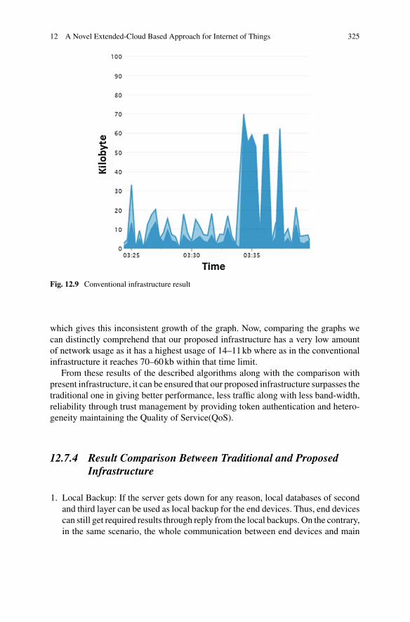
12 A Novel Extended-Cloud Based Approach for Internet of Things 325
Fig. 12.9 Conventional infrastructure result
which gives this inconsistent growth of the graph. Now, comparing the graphs wecan distinctly comprehend that our proposed infrastructure has a very low amountof network usage as it has a highest usage of 14–11kb where as in the conventionalinfrastructure it reaches 70–60kb within that time limit.
From these results of the described algorithms along with the comparison withpresent infrastructure, it can be ensured that our proposed infrastructure surpasses thetraditional one in giving better performance, less traffic along with less band-width,reliability through trust management by providing token authentication and hetero-geneity maintaining the Quality of Service(QoS).
12.7.4 Result Comparison Between Traditional and ProposedInfrastructure
1. Local Backup: If the server gets down for any reason, local databases of secondand third layer can be used as local backup for the end devices. Thus, end devicescan still get required results through reply from the local backups. On the contrary,in the same scenario, the whole communication between end devices and main

326 A. Chakrabarty et al.
Fig. 12.10 Fog model’s total received data
server gets interjected in the traditional infrastructure because of the lacking oflocal backup.
2. Less Bandwidth and Traffic: Less bandwidth and less traffic can be assured in ourproposed infrastructure as all the request are restricted to the distributed locallyupdated local backups (second and third layer) instead of requesting the mainserver again and again for the same service.
3. Data Redundancy and latency: Form the result of TCUSMAIN, we can see thatfor the same service x request the main server had to fetch and reply thrice toTCUSMACHINE1 and TCUSMACHINE2 (Fig. 12.9). This increases the latencyof the infrastructure. In other hand, the proposed infrastructure gives less latency

12 A Novel Extended-Cloud Based Approach for Internet of Things 327
Fig. 12.11 Fog model’s total sent data
since in case of the second request for service x by SCUSL1M2, the responsedirectly came from layer two instead of themain server (Fig. 12.10) and therefore,we can say that all of the requests are not handled by the main server, instead,was handled by layer 1 and layer 2.
12.7.5 Efficiency of Our Infrastructure
In the graph (Fig. 12.12) given below, we plotted the amount of data consumed byeach layer of the infrastructure for each request. In our implementation,we re-questedfor two types of services (x and y) as 6 requests in total. We can observe the increaseof request leads to lower data consumption eventually. For experimental purpose, we

328 A. Chakrabarty et al.
Fig. 12.12 Data consumption versus request graph
Table 12.2 Data consumption
Requests x1 x2 y3 y4 x5 y6
SCUSL1M1 In/out 192.28/153.31
148.3/203.53
SCUSL1M2 In/out 452.01/370.7
251.35/277.32
247.65/274.5
232.05/274.45
SCUSL2M1 In/out 256.6/208.29
249.22/95.9
356.48/98.43
144.56/91
144.84/90.79
144.41/90.94
SCUSL3M1 In/out 122.94/115.41
97.34/54.03
202.83/256.38
96.61/56.63
10.1/0.56 12.33/ 11.2
CUSMAIN In/out 202.34/221.4
0/ 10 82.66/39.24
12/ 11 0/ 15 19/ 0
Total 1472.57 1329.2 1387.95 940.45 783.44 784.38
generated only 6 requests but in future when 20 billion devices will be involved withthe IoT infrastructure, the number of data consumption will get lower because theLayer 3 Agents will get more intelligent with the passage of time (Table12.2).

12 A Novel Extended-Cloud Based Approach for Internet of Things 329
12.8 Conclusion
Traditional approach deals with direct communication to the cloud in order to workwith IoT devices which inefficient as we have already discussed. Our infrastructurerelies on Fog computing model where nodes neighboring to the IoT devices are usedfor calculating and providing data to the local nodes. Our infrastructure supportsa light weighted SOA which will be running in the fog nodes, that will provideservices to the IoT devices locally as the second layer of our distributed model.For complex service compositions, the third layer will be providing agent basedservices as artificial intelligence where the more devices will be involved with ourinfrastructure, the more mature the agents of the third layer will become over thetime. In addition, monitoring the traffic of the cloud channels, data is periodicallysynced with the cloud where the period is determined by the agent. Moreover, thethird layer can implement miniature versions of services like stream analytics, busservices, machine learning andmanymore as services. That makes our infrastructuremore flexible, proficient and versatile from the ongoing researches regarding fogcomputing and IoT.
Some other benefits of using this model will be, firstly, working as local backupof second layer can maintain the data transactions even if the main server gets downwhich results in no data loss or jeopardized data communication. Secondly, busi-nesses can grow based on the infrastructure. For example, big companies whichneeds to serve IoT services to their clients can deploy second, third layer devicesand they can provide other companies to use their nodes for their services based onsome business model. This way users can get their services easily and this will alsoopen up new opportunities for companies to grow. It can be deployed on the cur-rent growing infrastructure without changing the way devices work at present withaddition of trust management, low latency, less bandwidth preserving the Quality ofService(QoS).
References
1. Stojmenovic, S. Wen, The fog computing paradigm: scenarios and security issues, in 2014Federated Conference on Computer Science and Information Systems, Warsaw, 2014, pp. 1–8.https://doi.org/10.15439/2014F503
2. Cisco, Fog Computing and the Internet of Things: Extend the Cloud to Where the Things Are(2015)
3. N.N. Khan, Fog computing: a better solution for IoT. Int. J. Eng. Tech. Res. 3(2), 298–300(2015)
4. B. Azimdoost, H.R. Sadjadpour, J.J. Garcia-Luna-Aceves, Capacity of wire-less networks withsocial behavior. IEEE Trans. Wirel. Commun. 12(1), 60–69 (2013). https://doi.org/10.1109/TWC.2012.121112.111581
5. D. Christin, A. Reinhardt, P.S. Mogre, R. Steinmetz, Wireless sensor networks and the internetof things: selected challenges, in Proceedings of the 8th GI/ITG KuVS Fach-gesprch Drahtlosesensornetze, 2009, pp. 31–34

330 A. Chakrabarty et al.
6. P.R. Jaiswal, A.W. Rohankar, Infrastructure as a service: security issues in cloud computing.Int. J. Comput. Sci. Mob. Comput. 3(3), 707–711 (2014)
7. N.S. Patel, B.S. Rekha, Software as a Service (SaaS): security issues and solutions. Int. J.Comput. Eng. Res. 4(6), 68–71 (2014)
8. S. Subashini, V. Kavitha, A survey on security issues in service delivery models of cloudcomputing. J. Netw. Comput. Appl. 34(1), 1–11 (2011). https://doi.org/10.1016/j.jnca.2010.07.006
9. T. Devi, R. Ganesan, Platform-as-a-Service (PaaS):model and security issues. TELKOMNIKAIndones. J. Electr. Eng. 15(1), 151–161 (2015)
10. F. Bonomi, Connected vehicles, the internet of things, and fog computing, in The Eighth ACMInternational Workshop on Vehicular Inter-Networking (VANET), Las Vegas, USA, 2011
11. S. Sanjeev, S. Thusu, A survey of fog computing and its applications. Int. J. Adv. Res. IdeasInnov. Technol. 3(2), (2017)
12. N. Patel, FOG computing and its real-time applications. Int. J. Emerg. Technol. Adv. Eng. 5(6),(2015)
13. T.H. Luan, L. Gao, Z. Li, Y. Xiang, G. Wei, L. Sun, Fog computing: focusing on mobile usersat the edge (2015), arXiv:1502.01815
14. F. Al-Doghman, Z. Chaczko, A.R. Ajayan, R. Klempous, A review on Fog Computing tech-nology, in 2016 IEEE International Conference on Systems, Man, and Cybernetics (SMC),Budapest, 2016, pp. 001525–001530. https://doi.org/10.1109/SMC.2016.7844455
15. I. Stojmenovic, Fog computing: a cloud to the ground support for smart things and machine-to-machine networks, in 2014 Australasian Telecommunication Networks and ApplicationsConference (ATNAC), Southbank, VIC, pp. 117–122 (2014). https://doi.org/10.1109/ATNAC.2014.7020884
16. K.P. Birman, R. van Renesse, W. Vogels, Spinglass: secure and scalable communication toolsformission-critical computing, inDARPA Information Survivability Conference and ExpositionII, 2001. DISCEX ’01. Proceedings, vol. 2, Anaheim, CA, 2001, pp. 85–99. https://doi.org/10.1109/DISCEX.2001.932161
17. F. Bonomi, R. Milito, J. Zhu, S. Addepalli, Fog computing and its role in the internet of things,in Proceedings of the first edition of the MCC workshop on Mobile cloud computing, ACM,Aug 2012, pp. 13-16
18. Y. Qin, N. Falkner, S. Dustdar, H.Wang,When things matter: a data-centric view of the internetof things, in CoRR, 2014, arXiv:1407.2704
19. G. Fortino, W. Russo, Towards a cloud-assisted and agent-oriented architecture for the internetof things, in WOA@ AI* IA 25 Nov 2013, pp. 60-65
20. T. Xue, L. Qiu, X. Li, Resource allocation, for massive M2M communications in SCMAnetwork, in IEEE 84th Vehicular Technology Conference (VTC-Fall), Montreal, QC, Canada,2016, pp. 1–5. https://doi.org/10.1109/VTCFall.2016.7881198
21. M. Shanmugasundaram, M2M/ Iot protocols: an introduction. Happiest minds, 3 Feb 2016,http://www.happiestminds.com/blogs/m2m-iot-protocols-an-introduction/
22. F.H. Bijarbooneh, W. Du, E.C.H. Ngai, X. Fu, J. Liu, Cloud-assisted data fusion and sensorselection for internet of things. IEEE Internet Things J. 3(3), 257–268 (2016). https://doi.org/10.1109/JIOT.2015.2502182
23. S.K. Datta, C. Bonnet, N. Nikaein, An IoT gateway centric architecture to provide novel M2Mservices, in 2014 IEEE World Forum on Internet of Things (WF-IoT), Seoul, 2014, pp. 514–519.https://doi.org/10.1109/WF-IoT.2014.6803221
24. Microsoft, 2014, Chap. 1: Service Oriented Architecture (SOA), http://Msdn.microsoft.com.Retrieved on May 30, 2014
25. S.K. Datta, C. Bonnet, Smart M2M gateway based architecture for M2M device and Endpointmanagement, in 2014 IEEE International Conference on, Internet of Things (iThings), andIEEE Green Computing and Communications (GreenCom), and IEEE Cyber, Physical andSocial Computing (CPSCom), 2014, pp. 61–68
26. R. Garcia-Castro, C. Hill, O. Corcho, SemserGrid4Env Deliverable D4.3 v2 Sensor networkontology suite (2011)

12 A Novel Extended-Cloud Based Approach for Internet of Things 331
27. E. Newcomer, G. Lomow, Understanding SOA with Web Services (Independent TechnologyGuides) (Addison-Wesley Professional, Reading, 2004)
28. S. Rodrguez-Valenzuela, J.A. Holgado-Terriza, J.M. Gutirrez-Guerrero, J.L. Muros-Cobos,Distributed service-based approach for sensor data fusion in IoT environments. Sensors 14(10),19200–19228 (2014). https://doi.org/10.3390/s141019200
29. W. Shen, Q. Hao, H.J. Yoon, D.H. Norrie, Applications of agent-based systems in intelligentmanufacturing: an updated review. Adv. Eng. Inform. 20(4), 415–431 (2006). https://doi.org/10.1016/j.aei.2006.05.004. ISSN 1474-0346
30. A. Poggi, M. Tomaiuolo, P. Turci, An agent-based service oriented architecture, in WOA, Sept2007, pp. 157–165
31. M. Koskimies, Composing services in SOA: workflow design, usage and patterns, in Researchseminar on Service-Oriented Software Engineering, Oct 2006, http://www.cs.helsinki.fi/u/thruokol/opetus/2006/sose/pa-pers/koskimies_workflows.pdf
32. C. Lin, A reference architecture for scientific workflow management systems and the VIEWSOA solution. IEEE Trans. Serv. Comput. 2(1), 79–92 (2009). https://doi.org/10.1109/TSC.2009.4
33. A.M. Khan, A.Mishra, R. Agarwal, Security framework based onQoS and net-working for ser-vice oriented architecture, in 2016 3rd International Conference on Computing for SustainableGlobal Development (INDIACom), New Delhi, 2016, pp. 1106–1109
34. N.K. Pandey, S. Chaudhary, N.K. Joshi, Resource allocation strategies used in cloud com-puting: a critical analysis, in 2016 2nd International Conference on Communication Controland Intelligent Systems (CCIS), Mathura, India, 2016, pp. 213–216. https://doi.org/10.1109/CCIntelS.2016.7878233
35. L. Wu, S.K. Garg, R. Buyya, Service level agreement(SLA) based SaaS cloud managementsystem, in 2015 IEEE 21st International Conference on Parallel and Distributed Systems(ICPADS), Melbourne, VIC, 2015, pp. 440–447. https://doi.org/10.1109/ICPADS.2015.62
36. D. Gesvindr, B. Buhnova, Architectural tactics for the design of efficient PaaS cloud applica-tions, in 2016 13th Working IEEE/IFIP Conference on Software Architecture (WICSA), Venice,2016, pp. 158–167. https://doi.org/10.1109/WICSA.2016.42
37. Y. Govindaraju, H. Duran-Limon, A QoS and energy aware load balancing and resource allo-cation framework for IaaS cloud providers, in 2016 IEEE/ACM 9th International Conferenceon Utility and Cloud Computing (UCC), Shanghai, China, 2016, pp. 410–415
38. C.F.Lai,D.Y.Song,R.H.Hwang,Y.X.Lai,AQoS-aware, streaming service over fog computinginfrastructures, in Digital Media Industry Academic Forum (DMIAF). Santorini, pp. 94–98(2016). https://doi.org/10.1109/DMIAF.2016.7574909

Chapter 13Data Sources and Datasets for CloudIntrusion Detection Modeling and Evaluation
Abdulaziz Aldribi, Issa Traore and Belaid Moa
Abstract Over the past few years cloud computing has skyrocketed in popularitywithin the IT industry. Shifting towards cloud computing is attracting not only indus-try but also government and academia. However, given their stringent privacy andsecurity policies, this shift is still hindered by many security concerns related to thecloud computing features, namely shared resources, virtualization andmulti-tenancy.These security concerns vary from privacy threats and lack of transparency to intru-sions from within and outside the cloud infrastructure. Therefore, to overcome theseconcerns and establish a strong trust in cloud computing, there is a need to developadequate security mechanisms for effectively handling the threats faced in the cloud.Intrusion Detection Systems (IDSs) represent an important part of such mechanisms.Developing cloud based IDS that can capture suspicious activity or threats, and pre-vent attacks and data leakage from both inside and outside the cloud environment isparamount. One of the most significant hurdles for developing such cloud IDS is thelack of publicly available datasets collected from a real cloud computing environ-ment. In this chapter, we discuss specific requirements and characteristics of cloudIDS in the light of traditional IDS. We then introduce the first public dataset of itskind for cloud intrusion detection. The dataset consists of several terabytes of data,involving normal activities and multiple attack scenarios, collected over multipleperiods of time in a real cloud environment. This is an important step for the industryand academia towards developing and evaluating realistic intrusion models for cloudcomputing.
A. Aldribi (B) · I. TraoreThe Department of Electrical and Computer Engineering, University of Victoria,Victoria, BC, Canadae-mail: [email protected]
B. MoaCompute Canada-WestGrid, University Systems, University of Victoria,Victoria, BC, Canada
© Springer International Publishing AG, part of Springer Nature 2018B. S. P. Mishra et al. (eds.), Cloud Computing for Optimization:Foundations, Applications, and Challenges, Studies in Big Data 39,https://doi.org/10.1007/978-3-319-73676-1_13
333

334 A. Aldribi et al.
13.1 Introduction
Since the 1990s to recent days the internet has changed the computing world in adramatic way. It has evolved from the concept of parallel computing to distributedcomputing, to grid computing and recently to cloud computing. Although the ideaof cloud computing has been around for quite some time, it is an emerging field ofcomputer science.Cloud computing has becomeone of the popular terms in academiaand IT industry. The two main characteristics of cloud computing are: on demandservice, and flexible cost model that allows users to pay according to their needs.Cloud is just like water, electric, and gas utilities that can be charged according to theamount used. It integrates and offers several shared computational resources to usersas a service on demand. Furthermore, the cloud model offers enticing features suchas greater scalability, cost reduction, and flexibility. It can provide various levels ofservices and enable the completion of different tasks over the Internet. These featuresand services enabled the cloud to gain tremendous popularity in IT.
This growing popularity, however, comes with an increasing level of concernover the security of the cloud computing infrastructure. Shared resources, virtual-ization and multi-tenancy, which are the essential components of cloud computing,provide a number of advantages for increasing resource utilization, and on demandelasticity and scalability. However, they raise many security and privacy concernsthat affect and delay the wide adoption of the cloud. Compared to the traditional ITsystems, cloud computing introduces new and different security challenges that varyfrom privacy threats and lack of transparency to increasing likelihood of remote andinside attacks. Furthermore, these concerns are exacerbated by the fact that there isoften some uncertainty or lack of transparency about the type of security measuresimplemented by the cloud service provider to protect the information, as well asthe effectiveness of such measures. Moreover, since cloud computing relies on theInternet to operate, the security problems that exist in the Internet are not only foundbut are also amplified in the cloud. Likewise, all existing threats and vulnerabilitiesfaced by traditional computer networks apply to cloud-based infrastructures.
To overcome these concerns and establish a strong trust in cloud computing, thereis a dire need for effective security monitoring and defense systems adequate for thecloud. While traditional IDS can address some of the cloud security threats, they areseverely limited not only by the specificity of some of the threats involved but alsoby the regulatory, legal, and architectural considerations unique to cloud computing.Therefore, several research proposals have been recently published on developingcloud-specific intrusion detection systems, also referred to as cloud IDS. Developingsuch systems, however, is very challenging as cloud IDS researchers are faced withone of the greatest hurdles: the lack of publicly available datasets collected from a realcloud computing environment. Most existing projects and works on cloud IDS useproprietary datasets, which they do not share with others. Sometimes the closenessof such datasets is justified by privacy concerns. However, this makes it difficult forother researchers to leverage or replicate the published results, hindering advancesin cloud IDS development. Furthermore, some of the datasets used in cloud IDS
13 Data Sources and Datasets for Cloud Intrusion … 335
development are synthetic datasets, which obviously miss important characteristicsof real-world cloud environments.
In this chapter, we describe the ISOT Cloud Intrusion Dataset (ISOT-CID), whichto our knowledge is the first publicly available dataset of its kind. The dataset wascollected in a production cloud environment, and involves multiple attack scenarios,covering both remote and inside attacks, and attacks originating from within thecloud. It has a mixture of both normal and intrusive activities, and is labeled. Itcontains diverse logs and data sources that will enable the development of diverseintrusion data models, feature sets and analysis models. The dataset was collectedover many days and involves several hours of attack data, culminating into a fewterabytes. It is large and diverse enough to accommodate various effectiveness andscalability studies.
The remainder of this chapter is organized as follows. Section13.2 presents thecurrent cloud computing models and architectures. Section13.3 discusses cloudsecurity threats and monitoring for the cloud. Section13.4 outlines the evaluationapproaches used in the literature and the underlying datasets. A particular empha-sis is placed on the publicly available datasets. Section13.5 presents our dataset bydescribing the data collection environment and procedures. The involved attack sce-narios are discussed in Sect. 13.6, and the main characteristics and components ofthe ISOT-CIDwill be presented in Sect. 13.7. Finally, the conclusion and future workare presented in Sect. 13.8.
13.2 Cloud Computing Models and Architectures
13.2.1 Cloud Computing Characteristics
The idea of cloud computing can be traced back to 1969. In fact, Leonard Klein-rock [8], one of the chief scientists of the original Advanced Research ProjectsAgency Network (ARPANET) project that seeded the Internet, envisioned the spreadof ‘computer utilities’, similar to that of the electric and telephone utilities. Nowa-days, cloud computing has become a trend in IT, and is able to move computingand data away from desktop, portable PCs and dedicated remote servers into a largenumber of distributed and shared computers. By doing so, the customers do not needto own the hardware or the infrastructure required to offer their services. They freethemselves from dealing with the infrastructure, its installation and maintenance,and focus on developing their services on a shared infrastructure offered by anotherparty in a pay-as-you-use manner. This paradigm also solves the limitations in stor-age, memory, computing power and software on desktops and portable PCs.
In cloud computing, data, applications or any other services are accessed by usersthrough a browser or a terminal regardless of the device used and its location. Akey characteristic of the cloud is its large scale. From the customer perspective, thecloud is of unlimited resources and should be ready to satisfy their computational

336 A. Aldribi et al.
needs no matter how big they are. Therefore, cloud providers have a very largenumber of servers to accommodate user requests. The other key characteristic ofcloud computing is virtualization, which allows the cloud to achieve its agility andflexibility by “segmenting” the shared resources and running any operating systemon them. This makes it easy for the cloud customers to offer their heterogenousservices on the virtualized infrastructure without worrying about the specificity ofthe underlying hardware.
13.2.2 Cloud Computing Architecture
Looking at the literature, there is no standardized or universal cloud architecturereference model available. The cloud computing industry and academia are workingin parallel to define and standardize reference models, frameworks and architecturesfor cloud computing [16]. Therefore, cloud reference models are in the developmentstage, and are expected to stay that way as long as the cloud computing models areevolving. According to [44], Forrester Research was able to count more than 75different parties working on cloud standards in 2010. Today, the number of industryand academia involved has clearly increased significantly. From the literature, how-ever, cloud computing architectures are better classified by service and deploymentmodels. In the next section most common cloud computing service and deploymentmodels are discussed.
13.2.3 Cloud Computing Service Models
Cloud service models try to classify “anything” providers offer as a service (XaaS),where X means any service (e.g., infrastructure, software, storage). Cloud servicemodels are typically classified as: Infrastructure as a Service (IaaS), Platform asa Service (PaaS) and Software as a Service (SaaS). These three models (depictedin Fig. 13.1) are the basis of all services provided by cloud computing. In IaaS, thecustomers get access to the infrastructure to run and manage their own operating sys-tems and applications. However, they do not control the underlying infrastructure,and can typically only launch virtual machines with pre-specified flavors and oper-ating systems. PaaS provides a computing environment on the cloud infrastructureto the customers to create and control their own applications by using programminglanguages and runtime tools offered and supported by the PaaS provider. The cus-tomers do not, however, manage or control the operating systems or the underlyingcloud infrastructure. In SaaS, vendor offers an instance of a software application as aservice accessible via an Internet browser The service provider hosts the software on

13 Data Sources and Datasets for Cloud Intrusion … 337
Fig. 13.1 Cloud ComputingService and Deploymentmodels
the SaaS environment so that the customers do not have to install, maintain and runthe software on their own resources. By doing so, the customers are only concernedwith using it and, therefore, benefit from reduced software purchases by on demandpricing.
It is worth emphasizing that there are other proposed cloud service models includ-ing Storage as a Service, Hardware as a Service, Data as a Service, and Security asa Service.
13.2.4 Cloud Computing Deployment Models
Based on the NIST definition framework [29], there are four main cloud computingdeployment models. These models are classified as public, private, community, andhybrid deployments as shown in Fig. 13.1.
In a public cloud, the pool of resources owned by the cloud provider are availableto and shared among all the customers. They can rent parts of the resources andcan typically scale their resource consumption according to their demands [34, 40].Since multiple customers are sharing the resources, the major challenges facing thepublic cloud are security, regulatory compliance and Quality of Service (QoS) [5].A private cloud, also known as internal cloud, is a dedicated cloud serving only theusers within a single organization. It relies on internal data centers of an organizationnot made available to the general public, whereby all resources are reserved to theorganization’s private use. Although the private clouds are more expensive, they aremore secure than the public clouds [3, 49, 52]. Moreover, the compliance and QoSare under the control of the organization [21, 53]. A hybrid cloud is a combinationof public and private clouds, and tries to address their limitations while maintainingtheir features [37, 46]. The main purpose of a hybrid cloud is usually to provide

338 A. Aldribi et al.
extra resources in cases of high demands, for instance, to enable migrating somecomputation tasks from a private to a public cloud [51, 53]. A community cloud issimilar to a private cloudwith the particular characteristic of being shared bymultipleorganizations, usually belonging to a specific community [2, 34, 46].
13.3 Cloud Security Issues and Monitoring
13.3.1 Context
Security concerns are inherent in cloud computing and are delaying its adoption.In fact, when customers move their information to a cloud infrastructure owned byanother party, there is a high risk of losing full control over their data as well as apotential leakage of their private information as the resources are not only owned bysomeone else but also shared with many unknown users. Moreover, when runninga data processing service on the cloud (via IaaS or PaaS), the provider can obtainfull control on the processes belonging to the service and, therefore, compromise itsintegrity [20].
Since the cloud computing system relies on the Internet to operate, the securityproblems that affect the Internet can be not only found but are also amplified in thecloud computing environments. Moreover, given that the cloud computing leveragesthe existing IT infrastructure, operating systems and applications, it is susceptible tothe traditional IT attacks aswell. In fact, almost all existing attacks could target cloud-based infrastructure. Moreover, cloud computing systems may face new securityissues as they combinemanynew technologies that lead to newexploits such as, cross-virtual machines exploits, and inter-processes and cross-application vulnerabilityattacks [17].
There are many academic institutions, research organizations, cloud vendors andproduct development enterprises working on different cloud computing securityissues and their solutions. From the literature, these issues are classified into variouscategories based on different perspectives. For example, D. Högberg [18] pointed outthat the cloud computing security issues can be divided into two broad categories:security issues faced by cloud providers including Saas, Paas and Iaas providers, andsecurity issues faced by their customers. ENISA, which developed a comprehensivedetailed research in cloud computing security, classified these issues into three cat-egories: Organizational, Technical and Legal. The Cloud Security Alliance (CSA)identified 15 areas of concerns and grouped them into three general areas: Com-pliance, Legal, Security and Privacy Issues [1]. V. Amandeep and K. Sakshi [43]classified the cloud computing security issues based on the delivery and deploy-ment model of the cloud. Other researchers categorized security issues based on thedifferent layers involved in a cloud infrastructure, which are application level, net-work level, virtualization level, data storage level, authentication and access control

13 Data Sources and Datasets for Cloud Intrusion … 339
level, trust level, compliance level, and audit and regulations level [31]. Some of thesecurity issues from the above classification will be highlighted next.
13.3.2 Cloud Security Issues Based on Different Layers
13.3.2.1 Virtualization Level Security Issues
Virtualization is a core technology in cloud computing and an essential element fora cloud to achieve its characteristics, especially scalability, location independence,and resource pooling. In a virtual environment, multiple Operating Systems (OSs)run at the same time on a single host computer using a hypervisor (also called VirtualMachine Monitor (VMM)) [38], and physical servers contain multiple virtualizedservers on which several virtual machine instances may be running [26, 31].
A major function of the virtualization layer is to ensure that different VirtualMachine (VM) instances running on a same physical machine are logically but fullyisolated from each other. However, the isolation technologies that the current VMMsoffer are not perfect, especially with the full access and control the administratorshave on host and guest operating systems. This leads to many security issues relatedto virtualization [50].
In cloud computing, there are mainly three types of virtualization: OS level vir-tualization, application-based virtualization, and hypervisor-based virtualization. Inthe OS level virtualization, a hosting OS can run multiple guest OSs and has vis-ibility of and control over each guest OS. In such a configuration, if an attackercompromises the host OS, the entire guest OSs could be controlled by that attacker.Bluepill, SubVirt, and DKSM are some well-known attacks for such a configurationand it is still an open problem to prevent such threats [31]. In the application basedvirtualization, virtualization is only enabled at the top layer of the host OS, and eachVM has its specific guest OS and related applications. This kind of virtualizationalso suffers from the same vulnerabilities as in the traditional OS case.
Hypervisor or virtualmachinemonitor (VMM) is viewedas anyother code embed-ded on the host OS. Furthermore, this code is available at boot time of the host OSto control multiple guest OSs. As with any other code, it can harbour vulnerabilitiesthat attackers can exploit.
Also, cross VM side-channel attacks and denial of service attack (DoS) attackscan be performed by the attacker.
However, as mentioned earlier, vulnerabilities in a hypervisor allow a malicioususer to gain access and control of the legitimate user’s virtualmachine. Furthermore, ashared resource environment introduces unexpected side channel and covert channelattacks. An attacker if successful in neighboring a target can then use variousmethodsfor intercepting data being sent and received from the other resource [31].
The cloud can also be overloaded when trying to serve a huge number of requests,which can ultimately lead toDoS or distributed denial of service (DDoS). This type ofattacks usually floods the cloudwithmany large number of requests via zombies. The
340 A. Aldribi et al.
DoS attack against BitBucket.org is an excellent example. This attack suspended thisweb site over 19 hours during a DoS attack on the Amazon Cloud infrastructure [30].
According to [25], if a hacking tool is installed on a virtual machine, the othervirtual machines and hypervisors can also be attacked. Hsin-Yi et al. [41] infer thatVMhopping is a reasonable threat in cloud computing since it has been shown that anattacker can obtain or determine the IP address using standard customer capabilities.Moreover, because several VMs can run at the same time on the same host, all ofthem could become victim VMs. VM hopping is thus a crucial vulnerability for PaaSand IaaS infrastructures.
13.3.2.2 Data Storage Level Security Issues
The security of data on the cloud computing is another important research topic[45, 52]. One of the cloud computing principles is to move and store data in thecloud. Once the data is stored in the cloud, the full control of the data is transferredfrom the data owner to the hands of cloud computing providers. In addition, thedata is moving from a single, private and dedicated tenant to a shared multi-tenantenvironment where untrusted users can harbor their VMs. Gaining access to privatedata in such a shared environment can be very catastrophic if the data storage is notdone securely and properly. Therefore, according to [34], data stored in the cloudneeds policies for physical, logical and personnel access control.
When the data resides on the cloud and is served from there only, there is a potentialsecurity risk that it might not be available, especially when needed the most.
The data security risks on the cloud are rising as the number of parties, devicesand applications involved in the cloud infrastructure increases. In the literature, datastored in cloud, data leaks, data remanence, data availability, data location, dataprivacy and data breaches are examples for data security risks that are still openchallenges.
For instance, confidentiality is one of the most difficult aspects of data to guar-antee in cloud computing. Compared to the traditional computing, an enterprise hasno control over storage and transmission of data once it is in the cloud. Therefore, toensure that the data will not be able to accessed by unauthorized party, proper encryp-tion techniques should be applied [21]. However, increased number of encryptionand decryption operations reduces the application performance and increases theconsumption of cloud computing resources [9].
In IaaS, variety of users can access computing resources from a single physi-cal infrastructure. To achieve a proper confidentiality level, it is required to isolateresources among the multiple users and ensure that no user can view the state ofthe other users’ resources [41]. Moreover, since PaaS relies on IaaS virtualization,protecting the state of the resources used by a user from the rest of users is also asecurity challenge in PaaS.
There are a lot of challenges in a public cloud computing environment to ensuredata confidentiality. There are several reasons for that, for example, the needs forelasticity, performance, and fault tolerance lead to massive data duplication and

13 Data Sources and Datasets for Cloud Intrusion … 341
require aggressive data caching, which in turn increase the number of targets thatcould be targeted by data theft [43].
Given all of the security issues and risks we outlined above, it is clear that cloudsecurity monitoring is of paramount importance to both cloud service provider andcloud service customer. The next section is dedicated to this topic.
13.3.3 Cloud Security Monitoring
Since security is the most significant obstacles to the widespread adoption of cloudcomputing, there is a dire need for a proper monitoring system to gauge the securityon the cloud. This need has attracted many researchers and cloud providers who aretrying to develop security monitoring systems that can capture suspicious activityor threats, and prevent attacks and data leakage from both inside and outside of thecloud infrastructure.
Due to an increase in the amount of organized crime and insider threats, proac-tive security monitoring is crucial nowadays [13]. Moreover, to design an effectivesecurity monitoring system, a variety of aspects should be taken into account suchas: previous knowledge of threats and their specifications in the new environment,handling a large number of incidents, cooperation among interested parties and theirprivacy concerns, product limitations, just to name a few.
In the literature, there is much research conducted to apply security monitor-ing systems to cloud computing. These systems are deployed in public and privatecloud platforms and at different layers, and have different properties but each mainlyfocuses on a subset of security protection types and security risk mitigations.
Although researchers have approached the cloud security monitoring from differ-ent perspectives, the most common challenge faced in implementing real monitoringsystems is the availability of dataset collected from real cloud computing environ-ments. The importance of the availability of such dataset clearly appears when devel-oping newcloud securitymonitoring systems or evaluating the existing ones.Our firstattempt to address this challenge is to introduce the ISOT Cloud Intrusion Dataset(ISOT-CID), which to our knowledge is the first publicly available dataset of its kind.
13.4 State of the Art in Cloud IDS Evaluation
Cloud computing introduces a new era of integration of heterogeneous data in varyingformats and from diverse sources and operating systems. This requires an improvedunderstanding of the concept of a cloud dataset and its related concepts, such asthe formats and the sources of data. By reviewing cloud intrusion datasets in theliterature, there is a floating confusion about what can really be counted as a clouddataset. This raises the need to define what a real cloud dataset is, since, not onlythere is no or limited publicly available cloud dataset available for researchers, but

342 A. Aldribi et al.
most of the datasets that are mentioned in the literature for cloud computing are notsuitable and do not reflect the real cloud environment. These deficiencies are themain reasons why there is no effective real cloud intrusion detection datasets yet.
We define the cloud intrusion detection datasets as data collected from real cloudcomputing environments and gathered from either one or different data sources.The dataset may comprise one or more data formats, and can contain strings ofcharacters, numbers, binary or any combination of them.
This section will briefly present the available works on cloud IDS datasets anddiscus the insufficiency and limitation arisingwhen adopting them to develop, deployor evaluate cloud IDSs.
13.4.1 Cloud Intrusion Detection Dataset (CIDD)
Kholidy and Baiardi [22] introduced a Cloud Intrusion Detection Dataset (CIDD),which is based on theDefenseAdvancedResearch Project Agency (DARPA) dataset.The DARPA dataset was collected from a simulated network for an air force baseconnected to the Internet. This dataset contains simulated user activities and injectsattacks at well defined points, and then gathers tcpdumps, process and filesysteminformation. CIDD was built by assigning users to different VMs according to theirlogin session times and the applications that they ran. Using this method, CIDDwas created by extracting and correlating user audits from DARPA dataset, and waspresented to be a dataset for cloud computing.
13.4.2 Cloud Storage Datasets
Drago et al. [12] collected network traffic related to personal cloud storage servicenamely Dropbox. They gathered TCP flows with the commands executed by theDropbox clients from two university campuses and two Points of Presence (POP) intwo different European countries during 42 successive days. The analyzed datasetprovides a better understanding for the use of cloud storage in different environments,which have different user habits and access to technology.
13.4.3 Cloud Intrusion Detection Datasets (CIDD)
Moorthy andRajeswari [32] used the samenameCIDDfor their dataset as [22] but thedatasets are different in content. They simulated the cloud environment by settingup a cloudstack environment using two machines: one running the managementservices and the other running a kernel-based virtual machine KVM hypervisor.The CIDD was collected based on the traffic, which flow to/from specific ports that

13 Data Sources and Datasets for Cloud Intrusion … 343
were opened for communications in the simulated cloud. The malicious traffic wasgenerated based on attack signatures that are prepared manually and scored using acommon vulnerability scoring system. A systematic approach was used to generateCIDD based on profiling intrusions, protocols, or lower level network entities.
13.4.4 Denial of Service Attack Dataset
Another work on the generation of cloud intrusion dataset is the work done byKumaret al. [24] as a part of developing their DoS attack IDS. They stimulated IaaS cloudenvironment using the open source cloud platform Eucalyptus. They launched 15normal VMs, 1 target VM and 3 malicious VMs. The normal VMs are used togenerate normal traffic while the malicious VMs are used to perform 7 different DoSattacks on the target VM. The attacks were run using 4 different scenarios, including1 scenario depicting normal activities, and 3 different attack scenarios. The trafficbetween each VM was captured but was limited to 4 IP-header fields (i.e. source,destination, transferred bytes and protocol type) without any information about thepayload. Although this work collected different internal traffics between VMs, thepublished data does not contain the raw data but, instead, it contains the data obtainedafter transformation and feature extraction [23, 42].
13.4.5 Limitation and Deficiencies of Current Datasets
The cloud intrusion datasets described above have limitations and deficiencies thathinder their adoption for a broad range of cloud intrusion detection investigations.The most significant limitation is that they were not collected from a real cloudenvironment, which is heterogeneous in nature. Therefore, there is a lack of certaindata types that need to be collected from specific sources in the cloud environment.For example, some datasets are limited to network traffic traces that are only collectedfrom the host side, and do not include any data collected at the hypervisor level,instance’s OS level or internal network traffic. This affects the richness of the datasetsand their size, hindering their use in training and testing a wide range of cloud IDSmodels. Moreover, current datasets do not reflect cloud IDS characteristics becausethey were either collected organically to evaluate the performance of a cloud serviceor were transformed and adjusted to be suitable for cloud IDSs. Furthermore, theydo not include some attack types that are new and specific to the cloud computingenvironment. But most importantly, these datasets are not publicly available forresearchers to access and use to build, evaluate and compare cloud IDSs.
To overcome these limitations and deficiencies, and help the cloud security com-munity in its effort to build practical IDSs, we opted to collect and share a real

344 A. Aldribi et al.
cloud dataset called ISOT-CID. This dataset, which was collected from an Open-Stack cloud production environment, is publicly accessible and available for cloudsecurity researchers. ISOT-CID is described next.
13.5 ISOT-CID Collection Environment and Procedure
13.5.1 Overview
The analysis and assessment of cloud system based on data collected during pro-duction provide valuable information on actual cloud behaviour, and can be used toidentify normal behaviours from intrusions, quantify security measures, and performquantitative evaluations and verifications for the IDS analytical models. Therefore, itis not surprising that the availability of cloud dataset has gained increasing momen-tum within cloud IDS community, and can help in providing the empirical basis forresearching and developing effective models for cloud IDS.
To this date, there is a lack of a cloud IDS dataset that is collected from a realproduction cloud environment, publicly available and rich enough to satisfy theneeds of the cloud security community. The reason for this lack is that collectinga real cloud intrusion dataset is a burdensome task and there are many challengesand barriers associated with it. Privacy is one of the foremost of these challengesas cloud environments are built upon sharing resources among many users and anyattempt to collect data on the cloud could reveal private information about the users,their instances and their data. For a cloud provider, protecting the users’s privacyis important and revealing some of the data collected on the cloud to researchers isnot negotiable. Moreover, most of the cloud systems are commercial by nature, andopening their closed infrastructures for external parties could sabotage their businessby breaching privacy agreements they have with their customers. The damage caneven be worse if the data collected revealed a silent breach in the provider’s cloudenvironment.
In addition to privacy, the cloud has many different layers such as hypervisors,networks and guest hosts with different OS environments as well as many compo-nents, and collecting real data from these heterogeneous sources is difficult and canincrease the complexity of the data correlation for the cloud IDS. The final challengeworth emphasizing is the data size. When collecting data on the cloud you have to beready for enormous amount of data that will be gathered from different computingresources (more than 8TB for ISOT-CID dataset).
We were able to tackle these challenges and difficulties, and collect a real cloudcomputing dataset to be the first of its kind and paving the way for cloud securitycommunities for more research and finding.
The ISOT cloud intrusion detection dataset is an aggregation of different data col-lected from a production cloud computing environment and gathered from a varietyof cloud layers, including guest hosts, hypervisors and networks, and comprising

13 Data Sources and Datasets for Cloud Intrusion … 345
data with different data formats and from multiple data sources like memory, CPU,system and network traffic. It contains different attack traces likemasquerade attacks,denial of service, stealth attacks, anomalous user behaviour and data attacks fromoutside and inside the cloud.
The purpose of ISOT-CID is the embodiment of a real cloud dataset for researchersso that they can build, evaluate and compare their works. It is designed to servedifferent and broad IDS models developments and evaluations. Moreover, ISOT-CID is essentially “raw” and has not been transformed, manipulated or altered. Itis structured and prepared for the cloud security community, and is available fordownloading through ISOTwebsite alongwith the documentation andmetadata files,which explain its production and use in order to ensure an unambiguous meaning ofthe data.
13.5.2 Target Network Architecture
13.5.2.1 OpenStack-Based Production Cloud Environment
The dataset was collected through Compute Canada, a non-profit organizationsthat serves the computational needs of the Canadian researchers (see https://www.computecanada.ca for more details). To address the needs of the non High Perfor-mance Computing researchers, Compute Canada recently bought two cloud environ-ments: one in the east (east cloud) located at the University of Sherbrooke, and theother in the west (west cloud) hosted at the University of Victoria. With more than16000 virtual cores and 1.5 PB of storage, the west cloud is the largest academiccloud in Canada dedicated to all Canadian researchers and their collaborators.
The dataset was collected on the west cloud, which is based on OpenStack. Withmore than 600 supporting companies, OpenStack is becoming the de facto platformfor public and private cloud deployments. It allows the cloud providers to controllarge pools of resources, including compute, storage and network. OpenStack hasa modular architecture composed of many components, each one is usually a fullproject on its own with a large development team behind it. Currently, OpenStackhas the following main components:
• Nova: It is a service that runs on the compute nodes (i.e. hypervisors also calledNova-compute) and manages the instances on them, and on the controller nodesto provide the scheduling and the API functionalities (Nova-api, Nova-schedulerand Nova-conductor).
• Keystone: This is the identity management service for OpenStack, which controlsthe authentication and authorization of the OpenStack users.
• Neutron: This service manages the network services in Openstack. It allows theproviders to virtualize all the network elements, including routers, subnets, ports,etc.
• Glance: A dedicated service for storing and managing images and snapshots.

346 A. Aldribi et al.
• Horizon: This is the dashboard of OpenStack. It provides a web-based interfaceto OpenStack.
• Ceilometer: This service is the main monitoring service for OpenStack. It offersmany statistics that allow both users and administrators to monitor their resources.
• Heat: This service allows the user to write recipes for deploying and orchestratingtheir virtual environments.
• Cinder: The service that manages the block storage on OpenStack. Cinder isdesigned to support different kinds of backend storage including Ceph. Usingit, users can create and attach storage volumes to their instances.
• Swift: The cloud object service that allows users to store and retrieve their objectssimilar to Dropbox.
In addition to the dashboard web interface, OpenStack offers two other inter-faces to manage the resources: a command line interface and a programming API.The communication between differentOpenStack services is asynchronously orches-trated using RabbitMq.
The west cloud architecture is show in Fig. 13.2. The services Horizon, Key-stone, Glance and RabbitMq are running on 3 controller nodes (Nefos1, Nefos2, andNefos3) designed in a HA (high-availability) configuration. Two high-bandwidthnodes (Neut1 an Neut2) are dedicated to the Neutron service. All the rest of computenodes are hypervisors that are running Nova Compute service. The back end storageused by Cinder is Ceph.
13.5.2.2 ISOT-CID Collection Environment
The ISOT-CID project aims at setting up a real production cloud environment tocollect the necessary data from all three cloud layers (i.e.,VMs, Hypervisors andNetwork traffic). Our lab environment for performing this collection processes con-sists of two separated environments, namely ISOT-lab environment and ISOT-cloudenvironment.
The ISOT-lab environment contains the server that receives the forwarded datasetfromdifferent sources and stores it in a secureway. The ISOT-cloud environment runson the west cloud. The ISOT-cloud environment has all the three sources involved inthe dataset generation (i.e.,VMs, Hypervisors and Network traffic), and is composedof two hypervisor nodes and 10 instances launched in three different cloud zonesnamed as A, B and C (Fig. 13.3 depict the ISOT-cloud environment).
The instances located in these zones are organized as follows: 5 instances launchedin zone A, 4 instances launched in zone B, and 1 instance launched in zone C(instances specifications and hypervisors specifications are shown in Table13.1 andTable13.2).
All these instances are accessible from outside world through one public VLAN(namely VLAN3337), except one instance, isotvm_in, that is hidden under a privateinternal network and only accessible from specific instances via the internal router.We designed the cloud environment that way on the belief that generating a real

13 Data Sources and Datasets for Cloud Intrusion … 347
Nefos2
Keystone, Horizon, Nova-
api, Cinder, RabbitMq,
Glance
Nefos3
Keystone, Horizon, Nova-
api, Cinder, RabbitMq,
Glance
Nefos1
Keystone, Horizon, Nova-
api, Cinder, RabbitMq,
Glance
Neut1 Neut2
Ceph backend
Load-Balanced Neutron Configuration
High-Availability Configuration
10 GB network
Nova Compute Nodes
Virtual Load Balancer
Outside
Fig. 13.2 Compute Canada West Cloud OpenStack deployment architecture
cloud computing dataset needs to consist of heterogeneous data sources (i.e. VMs,Hypervisors and Network traffic) to represent the real cloud environment. The ISOT-cloud network topology is depicted in Fig. 13.3.
13.5.3 Data Collection Procedure
The ISOT-CID project started as a response to our need to build and develop practicalcloud IDSs. This need was then amplified by not finding any source for real clouddatasets, and ignited a formal data collection procedure structured as follows:

348 A. Aldribi et al.
Zone C
Zone AZone B
ten_
du
olc_
tos
i
internal_net
VLAN3337
Fig. 13.3 ISOT-CID project environment
Table 13.1 Instances specifications
VM Number VM’s OS Specification Zone
VM 1 Centos RAM: 6 GB Disk:0 GB VCPUs: 4
C
VM 2 Centos RAM: 7.5 GB Disk:20 GB VCPUs: 2
A
VM 3 Debian RAM: 7.5 GB Disk:20 GB VCPUs: 2
A
VM 4 Windows Server12 RAM: 7.5 GB Disk:20 GB VCPUs: 2
A
VM 5 Ubuntu RAM: 7.5 GB Disk:20 GB VCPUs: 2
A
VM 6 Centos RAM: 7.5 GB Disk:20 GB VCPUs: 2
A
VM 7 Ubuntu RAM: 7.5 GB Disk:20 GB VCPUs: 2
B
VM 8 Ubuntu RAM: 7.5 GB Disk:20 GB VCPUs: 2
B
VM 9 Windows Server12 RAM: 7.5 GB Disk:20 GB VCPUs: 2
B
VM 10 Centos RAM: 7.5 GB Disk:20 GB VCPUs: 2
B

13 Data Sources and Datasets for Cloud Intrusion … 349
Table 13.2 Hypervisors specifications
ID OS Specification
A Centos RAM: 125 GB CPU: 32cores Clock Speed: 2.00GHZ
B Centos RAM: 125 GB CPU: 32cores Clock Speed: 2.00GHZ
C Centos RAM: 264 GB CPU: 55cores Clock Speed: 2.40GHZ
1. Elicitation of the requirements related to the data collection targeted to cloudIDSs.
2. Official agreement between ISOT lab and Compute Canada to approve the ISOT-cloud environment on the Compute Canada West Cloud and obtain the realdatasets thereafter. The agreement took few months to be finalized and approved.
3. Designing and setting up the appropriate ISOT-cloud environment for the datacollection.
4. Setting up and configuring the ISOT-lab environment.5. Designing and implementing the data collection agents.6. Collecting the data for normal and attack scenarios.7. Finalizing the data collection.8. Publishing the data via a secure webserver on the ISOT-lab environment.
In addition to using syslog as our main logging mechanism, we designed andwrote agents for collecting specialized data syslog does or can not include. Sincewe intended to collect heavy data (e.g. memory and tcp dumps), we deployed threetypes of agents:
• Light weight agents that run very often (every ∼5s) and use minimal resources onthe targeted machines.
• Medium weight agents that run less often (every ∼60s) but collect large amountof data.
• Heavy weight agents that are intensive, run even less often (every 120s), andcollect an even larger amount of data.
The specialized collector agentswere implemented as shell and powershell scripts,and ran in the background at specific times during normal and attack periods. The timeinterval for the data collection in different agents can be adjusted to avoid missing theattack period. The data gathered at the agent level is either forwarded to the syslogdaemon, or lz4 compressed and transferred directly to the logging server using scp.The type of data collected by the agents is described in Sect. 13.7. Figure13.4 showsthe general architecture of the logging platform.
After verifying and validating the collector agent scripts, we embedded them intoand ran them simultaneously on the ISOT-cloud machines. The body of each script is

350 A. Aldribi et al.
ISOT - Lab
VM 2
Instance
VM 7
Instance
VM 8
Instance
VM 10
Instance
VM 9
Instance
Hypervisor B
Light weight agent sends the data to the syslog daemon.Windows machine also sends it to logging server using scp
Medium weight agent sends the data to the logging server using scp
Syslog daemon
Heavy weight agentsends the data to the logging server using scp
VM 4
Instance
VM 5
Instance
VM 6
Instance
Hypervisor A
VM 3
Instance
Fig. 13.4 ISOT-CID collection elements
different according to the targeted source, but in general they are very similar as theycollect information from the same data sources except for the hypervisor agents thatcollect extra data and more detailed traces. The main pseudo code for the collectoragents is shown in Algorithm.
Algorithm 1 Light weight agentssend anything printed to stdout and stderr to the syslogWhileTrue get information about all the processesget the CPU and disk utilization reportget virtual memory statisticsget information about network connectionsget the list of open filestcpdump the light weight network trafficsleep 5skill tcpdump
When the collector agents are invoked during collection processes, they extractand collect the required data from low level logs in all specified sources. The collectedbinary logs by the agents are forwarded through a secure channel to a dedicated logrepository server in the ISOT-lab for data storage and future processing. Furthermore,

13 Data Sources and Datasets for Cloud Intrusion … 351
thedata collected fromeach source is sorted chronologically on the server. Figure13.4briefly describes the collection processes.
The collector agents can be classified and mapped into the three cloud layers(instances, hypervisors and networks) as follows: Instance-based agents, Hypervisor-based agents and Network-based agents into the three cloud stack layers. The goalof each agent is to collect specific type of real time data that is relevant to theenvironment in which it resides as described next.
• Host-based agent: The host-based agent is installed on each VM in ISOT-cloudenvironment. The agent’s responsibility is to collect runtime information from theVM’s data sources such as, operating system and network, and forward them tothe log server in the ISOT-lab.
• Hypervisor-based agent: The hypervisor-based agent runs on each hypervisor inISOT-cloud environment. Its main responsibility is to collect runtime informationfrom the hypervisor data sources and forward them to the log server.
• Network-based agent: The network-based agent also runs on each hypervisor andcollects runtime data from the hypervisor network traffic and forward them to thelog server.
By spreading the agents between all cloud stack layers we were able to build a richcloud dataset. We collected different data types by targeting a variety of data sources.These data sources are: system calls, cpu utilization, windows events log, memorydumps and tcp dumps.
ISOT-CID collection was performed over several months for the VM instances,and several days and time slots for the Hypervisors and the Network traffics (moredetails will be provided when describing the attack scenarios).
13.6 Attack Scenarios
As discussed previously in Sect. 13.5.2, the aim of our cloud environment setup is toobtain a rich cloud dataset by gathering different data types from variety of sources.Moreover, to amplify its richness andmake it comprehensive, we performedmultipletypes of attacks that are ranked as the top threats in cloud computing. All the tracesof these attacks were collected from all the previously specified data sources. Thisis essential as cloud IDS researchers/developers need a cloud dataset that coversdifferent attack scenarios in advance so that they can effectively and productively gothrough the development and evaluation cycles.
In addition, there are twomajor categories of users in cloud computing: the insiderswho have some sort of access to the cloud infrastructure, and the outsiders whoare not. Both of this kind of users are included in our ISOT-CID attack scenarios.Likewise, the ISOT-CID attacks are divided into inside and outside attacks that areperformed by an insider and outsider attackers, respectively. The inside attacks were

352 A. Aldribi et al.
originated from within the ISOT-cloud environment and targeted either the internalcloud infrastructure or the outside world. In our case, we opted for two scenarios:
1. The attacks are performed by a malicious insider who has high privileges (e.g.root access) on the hypervisor nodes in our ISOT-cloud environment.
2. The attacks are originated from an instance inside the ISOT-cloud environment.This instance could be either compromised or used on purpose as a bot to attackother instances in the ISOT-cloud environment or the outside world.
The outside attacks are defined as the attacks that target the ISOT- cloud environ-ment from the outside world. In the outside attacks, in addition to the daily attacksthat were performed by stranger attackers, we carried out different masqueradesand DoS attack scenarios from outside world targeting ISOT-cloud instances. Attacktypes and scenarios are discussed next.
13.6.1 Inside Attack Scenarios
Most cloud vendors provide little to no information about their policies regardingrecruitment procedures, the level of privileges assigned to their employees, and thelegal actions that could be taken against the malicious insiders. This lack of trans-parency can encourage the insiders, especially employees, to carry out theirmaliciousactivities, and to even have escalated privileges that they are not supposed to have.With these privileges and the knowledge about the resources to attack, an employeecan easily gain access to confidential data [31]. In most cases, this can even go unde-tected as the insider activities often bypass the provider firewall or IDS. Moreover,current data protection mechanisms, such as encryption, have failed to prevent theinside data theft attacks [39]. Therefore, it is not surprising that the number of databreaches by malicious insiders have been increasing [4] and malicious insiders areranked as the 3rd top threat in cloud computing [19].
In the inside attack scenarios we performed, multiple attacks were run by mali-cious insider, a user having root access to the ISOT-cloud hypervisors. These attacksviolate confidentiality, privacy, integrity and protection of cloud user’s data. We dis-cuss below the different categories of inside attacks enacted.
13.6.1.1 Revealing User’s Credentials
Two different techniques were used to attack the ISOT-cloud environment and revealuser’s credentials. The summary of the first attack scenario as follows:
Step 1 Scan the running instances and their associated disks.Step 2 Extract the names of the instances from their libvirt.xml specifications.Step 3 Focus on a single instance, and locate and mount its disk.Step 4 Copy the password and shadow files, and the .ssh folder.

13 Data Sources and Datasets for Cloud Intrusion … 353
Step 5 Copy the private key to the attacker workstation.Step 6 Finally, compromise the ISOT instance using the copied private key.
The second inside attack was performed by a root privileged user to get memory andstrace dumps. These dumps were obtained using gcore and strace, respectively. Asshown in [11], once the memory dumps are available, the inside attacker can extractuser credential and private information, including passwords in clear text.
13.6.1.2 Extracting User’s Confidential Data
Following the same steps as above, once the inside attacker hasmounted the instance’sdisk he can search, copy, delete and change any user’s data, similar to copying the.ssh folder above.
13.6.1.3 Back Door and Trojan Horse
In this scenario, the inside attacker shutdown the instance using virsh tools, mountedits disk using guestfish tools, and created Trojan horse for ls and ps. He also added anattractive script called psb that runs a malicious code when executed (this is a kindof back door to access the machine later on).
The other inside attack scenarios that we performed were carried out from com-promised ISOT-cloud instances. After two instances were compromised, the insideattacker configured one of them to be a stepping stone, which potentially could bepart of a botnet. Although this stepping stone was setup by an insider attacker, itcould have been launched by the owner of the instance himself.
13.6.1.4 Compromised Instance and Introductory Botnet Activities
These attacks are carried out from an inside attacker who is either aiming at com-promising an instance and using it for his malicious activities, or owning an instancethat behaved as a normal instance for a while but it then turns out to be part of abotnet.1 Once the attackers compromise an instance, they start attacking the neigh-boring instances. The summary of the attack scenario for this step is as follows:
Step 1 After a successful access to an instance VM8 from a previous outside attack(see Sect. 13.6.2), the attacker started to discover the internal network bysearching local IP information and scanning the subnet. A few VMs withopen ports were then discovered.
1In our particular scenario, the botnet command and control (C&C) server is hosted remotely,outside the cloud and only one bot is in the cloud.

354 A. Aldribi et al.
Step 2 A file was transferred via scp from the attacker machine to the compromisedinstance VM8. The file was used as a password dictionary.
Step 3 The attacker installed hydra on VM8 and launched internal network scansusing nmap. The machines discovered were then subjected to brute-forceattacks using the passworddictionaryfile.Oneof these attackswas successfulagainst the instance VM5.
Step 4 A quick ssh login into the internal host VM5 from VM8 was logged.Step 5 Finally, the attacker installed hping3 on VM8 and ran several failed DoS
attempts against VM4.
13.6.2 Outside Attack Scenarios
As we previously emphasized, the cloud is becoming an attractive target to outsidedata hunters. Having a centralized environment for virtual machines and data is ahacker’s dream that is becoming true with the widespread adoption of cloud com-puting. Many attack attempts are made every single second to access instances andexploit any vulnerabilities within cloud.We can easily see that in our ISOT-CID; out-side attackers are performing many different masquerade and DoS attacks attempts.Just within few months of operations, the Compute Canada’s West cloud detected 5compromised instances, most of which had weak passwords that the outsider attack-ers cracked using brute-force attacks. Moreover, at least one of these instances wascompromised within one hour of its deployment.
In the outside attack scenarios, we performedmultiple attacks against ISOT-cloudenvironment to breach the confidentiality, privacy, integrity, protection and availabil-ity of cloud user’s data by performing masquerade and DoS attacks. Moreover, oncethe instance is compromised, it is leveraged to attack other instances from within thecloud environment, executing the inside attack scenarios that were outlined above.
13.6.2.1 Masquerade Attack
Masquerade attacks are very challenging in cloud computing as they can escapedetection because any related trace can be buried in the massive amounts of datagenerated from user audits and activities across cloud environments. A masqueraderis an insider or outsider attacker who steals the legitimate user credentials and usesthem to authenticate as a legal user. This allows the attacker to fool the systemand get access to its abundant resources illegally. In ISOT-CID attack scenarios, weperformed differentmasquerade attacks launched from the outside. As an illustration,we outline the steps of one of these masquerade attacks below:
Step 1 Scanning subnet of the VMs using nmap scanner.Step 2 Password dictionary attack against VM8 using Ncrack scan leading to
credential discovery.

13 Data Sources and Datasets for Cloud Intrusion … 355
Step 3 SSH login to VM8 using the cracked credentials.Step 4 Running ifconfig to display network IP address info/range, local IP address
determined.Step 5 Nmap scan (against internal network) from VM8 to uncover a few hosts
with open ports.Step 6 Transferring a file using scp from the attack host to VM8 (to be used as
password dictionary).Step 7 Installing hydra on VM8.Step 8 Internal network scanning using nmap to discover 10 IP addresses (4 hosts
up).Step 9 Cracking the password using hydra against one of the internal machines
VM5.Step 10 SSH login to VM5 using the cracked password to check the ssh connection.Step 11 Setting up hping3 on VM8 after checking that it was not previously
installed.Step 12 Launching nmap scan against VM4 to discover a host with 2 open ports.
13.6.2.2 Denial of Service (DoS) Attack
The second attack scenario performed from the outside against ISOT-cloud environ-ment is Denial of service (DoS) attack. In a DoS attack, the attacker overloads thetargeted victim’s system or service with huge number of requests consuming largeamounts of system resources and leaving the system or the service unavailable. Notonly that, in a cloud environment DoS attacks can render the whole cloud infras-tructure unusable. In fact, two instances running on the same hypervisor are usuallysharing the physical resources of the node. If one of them is subject to a DoS attack,the effect of this attack leaks into the second instance. In addition, consuming hugeresources leads to an expensive bill that the victim will need to pay. As opposed tothe cloud being a target for DoS attacks, many malicious users are leveraging the“unlimited” amount of resources in the cloud to launch massive outside DoS attacks.It is worth mentioning that, in cloud computing paradigm, DoS attacks were markedby the Cloud Security Alliance as the first of seven top threats [6]. The reader shouldalso keep in mind that DoS attacks are the most common attacks on the Internet, andare hard to detect as distinguishing between DoS attack traffic and legitimate systemunavailability is an open problem. In ISOT-CID, we designed and launched threetypes of DoS attacks. We performed the most common DoS attack, which targetsthe transport layer, and exploits the flaws in TCP three-way handshake procedures,called the TCP SYN attack. We used the open source hping3 tool [36] to createa SYN flood attack. The first TCP SYN attack was performed on a compromisedinstance inside ISOT-cloud environment against another virtual machine in anotherISOT-cloud zone. The attack flooded the instance with TCP SYN packets consumingits resources, hindering its use, and causing it to crash.

356 A. Aldribi et al.
The second attack was performed from an outside machine against an instanceinside the ISOT-cloud environment. The last attack was performed from a com-promised instance inside ISOT-cloud environment against the logging server in theISOT-lab. The 1st and 2nd DoS attack scenarios were the last attack steps from the1st attack scenario, which we explained before. (The full and detailed attack scenar-ios are available for interested readers along with ISOT-CID documentations). Tocomplete the 1st attack round, we add the following DoS attacks:
Step 1 From VM8, an unsuccessful syn flood DoS attack was launched againstVM4.
Step 2 Another syn floodDoS attack against VM4 from the attackermachine causedVM4 to crash and we had to reboot it.
The 1st attack round for inside and outside attacks are depicted in Fig. 13.5.
Zone A
VLAN3337
6-Transfer
4- SSH login
2-Dictionary attack
3-Password found
8-Password found
9-DoS attack
10-DoS attack1- Scanning
internal_net
7-Dictionary attack
en_
du
olc_
tos
i
5-Scanning Compromised VM
Zone B
Fig. 13.5 1st attack round for inside and outside attacks

13 Data Sources and Datasets for Cloud Intrusion … 357
Scenario
12016-12-09
Time AM / PST
- Scanning subnet VM 8-10- Dictionary attack against ssh VM 8
- SSH login to VM 8- Scanning subnet VM 7-10
VM 8- Install hydra - Nmap scan against VM 5- Successful dictionaryattack against VM 5
- Install hping3- Nmap scan against VM 4- DoS against VM 4
- DoS against VM 4
9:37 9:41 9:42 9:45 10:06 10:37 10:48 11:01 11;07
- Scan target VM 8- Bruteforce attack against VM 8- Attack failed
- Launch password cracking using ncrack againstVM 8
- Found credentials
- Launch a reverse shell attack using ncat against VM 8- Attack failed
- Stealing private key from VM 8- Failed attempt to login into VM8using Metasploit
ssh_login_pubkey module
- Launch bruteforce attack against VM 8- Using Metasploit ssh_login module- Found credentials
2
2016-12-15
9:18 9:389:37 9:42 10:2810:1810:029:37 10:25
Inside Attack
Outside Attack
Fig. 13.6 Summary of the first and second attack scenarios for inside and outside attacks
13.6.3 Attack Time and Locations
In designing our ISOT-CID attack scenarios, we chose different attack times anddistinct attacker’s geographical locations. The attacks were divided into 4 rounds,averaging for 1 hour for each round, and spread over 4 different days. Moreover,the attackers performed and completed the attack scenarios from two different con-tinents, precisely Europe and North America. The data collected during these timeswere labeled as a malicious traffic and the remaining as a normal traffic. Figure13.6summarizes the first and second attack scenarios for inside and outside attacks.
13.7 Collected Data
13.7.1 System Calls
A system call is a mechanism by which a user-space application requests a servicefrom the kernel space of the OS [7, 15, 48]. Although every OS (like *nix andWindows) has its own specific system calls that are accessed via dedicated APIs, allof them follow the same bidirectional process in the sense that all requests from auser-level application to the OS are delivered by a system call interface to the kernel

358 A. Aldribi et al.
before they are executed on hardware. This allows the kernel to run the code on behalfof the user in the privileged space and get the information requested by the user viarestricted system calls [7]. Furthermore, each one of these system calls has a uniquenumber that is written in the kernel’s system call table to identify them. Examplesof system calls for OS (like *nix and WinX) are fork, pipe, read, CreateProcess andReadFile. In ISOT-CID collection process, we collected the system calls from bothhypervisors and instances. Theyprovide useful information, like opened and accessedfiles, execution time stamps and the count of each system call number executed bythe application. This information reflects every activity occurring inside the instancesand hypervisors, and the communication between them. In fact, when a guest OSinitiates a system call to access the host resources, the hypervisor intercepts andinterprets it into the corresponding system call supported by the host OS. By doingso, the hypervisor has full control over the host OS resources like CPU, memory,persistent storage, I/O devices, and the network, and each VM access to any of theseresources is accounted for.
13.7.2 Network Traffic
Network traffic is the main mechanism for exchanging information between com-puters. It is defined as a sequence of packets traveling between two communicationendpoints known as source and destination. Each packet consists of a transport layerheader, a network layer header, a data-link layer header and a payload representingthe actual data exchanged [14]. These network packets can provide rich statisticsthat is essential for developing network security tools. In a cloud computing infras-tructure such as OpenStack, the network traffic travels through different networkpoints. In our case, the outside traffic first arrives via the entry and top-rack switchesto dedicated network nodes, called neutron nodes, and then travels to the hypervi-sor on the compute nodes passing through our internal physical switches. Finally,the hypervisor delivers the traffic to the designated instance. With this OpenStacknetworking configuration, we have three different network flows: external, internaland local traffic. The external traffic is between the virtual machine and an outsidemachine (an “instance-outside” traffic). The internal traffic is between the computenode and another compute node (“hypervisor-hypervisor” traffic). The local trafficis between two instances on the same Compute node (“instance-instance” traffic).In ISOT-CID, we were able to collect all of these three different traffics from bothhypervisors and instances. By setting the network interface into promiscuous mode,we were able to collect all the network traffic that passes through all the networkinterfaces on the hypervisors and instances (except for the special network inter-faces not involved in our network traffic). The utility TCPdump was used to capturethe network traffic [27] on*nix OSs and Netsh on winX OS, and stored in packetcapture (pcap) format. We performed two kinds of network traffic data collections:the network traffic without payload on both hypervisors and instances, and the full
13 Data Sources and Datasets for Cloud Intrusion … 359
network traffic on the hypervisors only (the interested readers can find more detailsin ISOT-CID documentations).
13.7.3 Memory Dump
Memory dump is a procedure by which the contents of a physical memory, rep-resenting the internal states of the system, are printed out or written to a storagedrive. Memory dumps are usually generated when a crash occurred or during debug-ging [28]. They are very helpful to pin point the source of a crash, to debug systemerrors and performance issues, to obtain information about the running programs andthe overall state of a system, to detect any intrusion or attack, to locate deleted ortemporary information, and to carry out malware and forensic investigation.
Unfortunately memory dumps capture sensitive information, like passwords,encryption keys, and the contents of a private document, which can be very harmfulif it ends up in the hand’s of an attacker [11]. The ISOT-CID contains memory dumpfiles that were collected using gcore command on the processes of the instances run-ning of the ISOT-cloud hypervisors. The memory dumps collected resulted in largeamount of data as each instance had around 7.5GB of memory.
13.7.4 Event Logs
On any computer system, there is a specific auditing or event log service used tocapture any predefined events, such as error reports, system alerts, and diagnosticmessages that happen during the daily operation of the system. This event log serviceusually runs in background and listens to event sent by processes running on the localor remote system [33].
13.7.4.1 Windows Event Logs
In WinX OS, an event is defined as a notification posted to the user and raised by ahardware, software, or system component [10]. The event log service is responsiblefor logging and organizing these events in WinX OS. There are three types of eventlogs stored on Windows machine: Security, System and Application event logs. Ingeneral, security logs record events related to sensitive components of the system,such as the authentication component, as well as events related to resource usage,such asfile operations andprocess invocations. The system log contains events loggedby the system components, for example, driver failures and hardware issues. Finally,the application events can be triggered by any application as long as it implementsthe event API. The developer can generate events by calling the proper Windowsevent API. Windows event logs are not only useful in diagnosing problems, but also

360 A. Aldribi et al.
crucial in monitoring activities on a system. ISOT-CID includes all of these eventlog files types from the two windows instances that run in different zones and havebeen involved in the attack scenarios.
13.7.4.2 Unix Logs
Messages, notifications and events generated by *nix subsystems and services areusually logged as text under /var/log in specific files. Each process can virtually logits messages into a dedicated file. For example, sshd logs its authentication eventsinto /var/log/auth.log and kernel messages are sent to /var/log/messages. This ofcourse leads to unmanageable large amounts of log files, especially when dealingwith many machines. To avoid that, we installed and configured rsyslog on the *nixmachines to collect the logs in a central and secured location on the ISOT log server.Our scripts use the logger command to send the collected information to the rsyslogdaemons, which in turn forwards them to the ISOT lab logging server.
13.7.5 Resource Utilization
One of themain functions of the operating system is the scheduling of the resources toserve all the running processes [35]. Scheduling CPU is the most important schedul-ing function of the OS as without it only a single program can use the CPU from startto finish and the rest of processes will starve [47]. When no task is requesting CPU,the processor becomes idle. By summing up the idle times during a given numberof CPU ticks, one can deduce the overall CPU utilization. There are two types ofCPU utilization, user CPU utilization and system CPU utilization. Both presentingthe percentage of time spent performing user and system tasks, respectively. Analyz-ing the CPU utilization during different states, especially over long periods of time,allows for building a profile for the system. This profile can be enhanced by collect-ing other statistics, such as disk utilization. By monitoring the usage of resourcesone can build a baseline profile that characterizes the normal behavior of the system.Any deviation from such a baseline profile can be detected and subjected to furtherinvestigation. ISOT-CID provides different information about the usage of resourceson all instances and hypervisors. This information was collected using commandslike ps and iostat.
ISOT-CID also contains more information about memory and disk IO in its doc-umentations. Figures13.7 and 13.8 illustrate some excerpts from ISOT-CID.

13 Data Sources and Datasets for Cloud Intrusion … 361
Fig. 13.7 Excerpt from the dataset: sample virtual memory statistics and the CPU and disk utiliza-tion for one of the hypervisors

362 A. Aldribi et al.
Fig. 13.8 Excerpt from the dataset: sample open files, network connections and TCPdump tracesfor an hypervisor

13 Data Sources and Datasets for Cloud Intrusion … 363
13.7.6 Excerpt From the Dataset
This section provides snapshots from the dataset that was collected from one hyper-visor during one attack scenario. Fig. 13.7 shows collected data about virtual memorystatistics and the CPU and disk utilization.
Figure13.8 provides information about the list of open files, network connectionsand the collected TCPdump for the lightweight network traffic.
13.8 Conclusion and Future Work
IDSs are by nature inherently pattern recognition systems. The design and evaluationof such systems require appropriate datasets. It is a fact that cloud computing facesseveral of the same security threats as conventional computing networks and devices.But, cloud computing also involves several new threat vectors due to the specificityof its underlying architecture and operation. This calls for new datasets that wouldadequately capture the characteristics of the threat landscape faced by cloud com-puting. ISOT-CID is an initial response toward addressing such need. Although,undoubtedly, there are several limitations in the dataset, we believe that it will proveuseful for academia and industry in developing effective cloud intrusion detectionsystems. Our future work will consist of strengthening and extending the datasetby covering more threat vectors and attack scenarios. The current dataset includesonly introductory botnet traces. In the future, we will extend and diversify the cloudtraces by involving more instances and different botnet architectures. We are alsoworking, in parallel, in developing new intrusion detection models that will leveragethe richness of the dataset for effective protection.
Acknowledgements Wewould like to express our gratitude and appreciation forQassimUniversityand the Ministry of Education of the Kingdom of Saudi Arabia for sponsoring this work. Also thisgratitude goes to Compute Canada and the University of Victoria, especially Kim Lewall, RyanEnge and Eric Kolb, for given us this opportunity.
References
1. C.S.Alliance, Sampling of issueswe are addressing (2009), https://www.cloudsecurityalliance.org/issues.html#ediscovery. Accessed 3 Feb 2017
2. F.M. Aymerich, G. Fenu, S. Surcis, An approach to a cloud computing network, in FirstInternational Conference on the Applications of Digital Information and Web Technologies,2008. ICADIWT 2008 (IEEE, New York, 2008), pp. 113–118
3. L.D. Babu, P.V. Krishna, A.M. Zayan, V. Panda, An analysis of security related issues in cloudcomputing, in International Conference on Contemporary Computing (Springer, Berlin, 2011),pp. 180–190

364 A. Aldribi et al.
4. W. Baker, M. Goudie, A. Hutton, C. Hylender, J. Niemantsverdriet, C. Novak, D. Ostertag, C.Porter, M. Rosen, B. Sartin, et al., Verizon 2010 Data Breach Investigations Report. VerizonBusiness (2010)
5. T. Berners-Lee, R. Fielding, L. Masinter, Std66 rfc3986: Uniform resource identifier (uri)generic syntax. ietf full standard rfc (2005)
6. G.Brunette, R.Mogull et al., SecurityGuidance forCritical Areas of Focus inCloudComputingv2. 1 (Cloud Security Alliance, 2009), pp. 1–76
7. I. Burguera, U. Zurutuza, S. Nadjm-Tehrani, Crowdroid: behavior-based malware detectionsystem for android, in Proceedings of the 1st ACM Workshop on Security and Privacy inSmartphones and Mobile Devices (ACM, 2011), pp. 15–26
8. R. Buyya, C.S. Yeo, S. Venugopal, Market-oriented cloud computing: vision, hype, and realityfor delivering it services as computing utilities, in 10th IEEE International Conference on HighPerformance Computing and Communications, 2008. HPCC’08 (IEEE, 2008), pp. 5–13
9. N.S. Chauhan, A. Saxena, Energy analysis of security for cloud application, in 2011 AnnualIEEE India Conference (INDICON), (IEEE, 2011), pp. 1–6
10. M. Corporation, Windows event log service (2011), https://technet.microsoft.com/en-us/library/dd315601(v=ws.10).aspx. Accessed 3 Feb 2017
11. S. Davidoff, Cleartext Passwords in Linux Memory (Massachusetts Institute of Technology,Massachusetts, 2008), pp. 1–13
12. I. Drago,M.Mellia,M.M.Munafo, A. Sperotto, R. Sadre, A. Pras, Inside dropbox: understand-ing personal cloud storage services, in Proceedings of the 2012 ACM Conference on InternetMeasurement Conference (ACM, 2012), pp. 481–494
13. C. Fry,M.Nystrom, SecurityMonitoring: ProvenMethods for IncidentDetection onEnterpriseNetworks (O’Reilly Media, Sebastopol, 2009)
14. F. Fuentes, D.C. Kar, Ethereal versus tcpdump: a comparative study on packet sniffing toolsfor educational purpose. J. Comput. Sci. Coll. 20(4), 169–176 (2005)
15. J. Guo, S.L. Johnson, Intrusion detection using system call monitors on a bayesian network,U.S. Patent Application 11/677,059, 21 Feb 2007
16. M. Hamdaqa, L. Tahvildari, Cloud computing uncovered: a research landscape. Adv. Comput.86, 41–85 (2012)
17. S. Hanna, A security analysis of cloud computing. Cloud Comput. J. (2009)18. D. Högberg, An Applied Evaluation and Assessment of Cloud Computing Platforms (2012)19. D. Hubbard, M. Sutton et al., Top Threats to Cloud Computing v1. 0 (Cloud Security Alliance,
2010)20. M. Jensen, J. Schwenk, J.M. Bohli, N. Gruschka, L.L. Iacono, Security prospects through
cloud computing by adopting multiple clouds, in IEEE International Conference on CloudComputing (CLOUD), 2011 (IEEE, 2011), pp. 565–572
21. P.J. Kaur, S. Kaushal, Security concerns in cloud computing, inHigh Performance Architectureand Grid Computing (Springer, 2011) pp. 103–112
22. H.A. Kholidy, F. Baiardi, Cidd: A cloud intrusion detection dataset for cloud computing andmasquerade attacks, in Ninth International Conference on Information Technology: New Gen-erations (ITNG) (IEEE, 2012), pp. 397–402
23. R. Kumar, S.P. Lal, A. Sharma (2016), https://github.com/uspscims/cloudsecurity. Accessed3 Feb 2017
24. R. Kumar, S.P. Lal, A. Sharma, Detecting denial of service attacks in the cloud, inDependable,Autonomic and Secure Computing, 14th International Conference on Pervasive Intelligenceand Computing, 2nd International Conference on Big Data Intelligence and Computing andCyber Science and Technology Congress (DASC/PiCom/DataCom/CyberSciTech), 2016 IEEE14th International Conference (IEEE, 2016), pp. 309–316
25. H. Lee, J. Kim, Y. Lee, D. Won, Security issues and threats according to the attribute of cloudcomputing, in Computer Applications for Security, Control and System Engineering (Springer,2012), pp. 101–108
26. H. Li, X. Tian, W. Wei, C. Sun, A deep understanding of cloud computing security, in NetworkComputing and Information Security (Springer, 2012), pp. 98–105

13 Data Sources and Datasets for Cloud Intrusion … 365
27. J. Liebeherr, M.E. Zarki, Mastering Networks: An Internet Lab Manual (Addison-WesleyLongman Publishing Co., Inc., Boston, 2003)
28. A.Mehta, Process and apparatus for collecting a data structure of a memory dump into a logicaltable, US Patent 5,999,933, 7 December 1999
29. P. Mell, T. Grance, Effectively and Securely Using the Cloud Computing Paradigm. NIST,Information Technology Laboratory pp, 2009), pp. 304–311
30. C. Metz, Ddos Attack Rains Down on Amazon Cloud. The Register (2009)31. C. Modi, D. Patel, B. Borisaniya, A. Patel, M. Rajarajan, A survey on security issues and
solutions at different layers of cloud computing. J. Supercomput. 63(2), 561–592 (2013)32. M. Moorthy, M. Rajeswari, Virtual host based intrusion detection system for cloud. Int. J. Eng.
Technol. 0975–4024 (2013)33. J.D. Murray, Windows NT Event Logging (O’Reilly & Associates, Inc., 1998)34. C. Rong, S.T. Nguyen, M.G. Jaatun, Beyond lightning: a survey on security challenges in cloud
computing. Comput. Electr. Eng. 39(1), 47–54 (2013)35. F. Sabrina, C.D. Nguyen, S. Jha, D. Platt, F. Safaei, Processing resource scheduling in pro-
grammable networks. Comput. Commun. 28(6), 676–687 (2005)36. S. Sanfilippo, Hping3 (8)-Linux Man Page (2005)37. N. Sénica, C. Teixeira, J.S. Pinto, Cloud computing: a platform of services for services, in
International Conference on ENTERprise Information Systems (Springer, Berlin, 2011), pp.91–100
38. M.K. Srinivasan, K. Sarukesi, P. Rodrigues, M.S. Manoj, P. Revathy, State-of-the-art cloudcomputing security taxonomies: a classification of security challenges in the present cloudcomputing environment, in Proceedings of the International Conference on Advances in Com-puting, Communications and Informatics (ACM, New York, 2012), pp. 470–476
39. S.J. Stolfo, M.B. Salem, A.D. Keromytis, Fog computing: mitigating insider data theft attacksin the cloud, in 2012 IEEE Symposium on Security and Privacy Workshops (SPW) (IEEE, NewYork, 2012), pp. 125–128
40. H. Takabi, J.B. Joshi, G.J. Ahn, Security and privacy challenges in cloud computing environ-ments. IEEE Secur. Priv. 8(6), 24–31 (2010)
41. H.Y. Tsai, M. Siebenhaar, A. Miede, Y. Huang, R. Steinmetz, Threat as a service?: virtualiza-tion’s impact on cloud security. IT Prof. 14(1), 32–37 (2012)
42. Uspscims: (2016), https://github.com/uspscims/cloudsecurity43. A. Verma, S. Kaushal, Cloud computing security issues and challenges: a survey, in Interna-
tional Conference on Advances in Computing and Communications (Springer, Berlin, 2011),pp. 445–454
44. C. Wang, S. Balaouras, L.C.: Q&a: Demystifying cloud security. an empowered report: gettingpast cloud security fear mongering. Technical report, Forrester Research, Inc (2010)
45. L. Wang, J. Shen, H. Jin, Research on cloud computing security. Telecommun. Sci. 26(6),67–70 (2010)
46. M. Waschke, Cloud Standards: Agreements that Hold Together Clouds (Apress, New York,2012)
47. R.K. Yadav, A.K. Mishra, N. Prakash, H. Sharma, An improved round robin scheduling algo-rithm for CPU scheduling. Int. J. Comput. Sci. Eng. 2(04), 1064–1066 (2010)
48. R.V. Yampolskiy, V. Govindaraju, Behavioural biometrics: a survey and classification. Int. J.Biom. 1(1), 81–113 (2008)
49. Z. Yandong, Z. Yongsheng, Cloud computing and cloud security challenges, in 2012 Inter-national Symposium on Information Technology in Medicine and Education (ITME), vol. 2(IEEE, New York, 2012), pp. 1084–1088
50. P. You, Y. Peng,W. Liu, S. Xue, Security issues and solutions in cloud computing, in 2012 32ndInternational Conference on Distributed Computing Systems Workshops (ICDCSW) (IEEE,New York, 2012), pp. 573–577
51. S. Zhang, S. Zhang, X. Chen, X. Huo, Cloud computing research and development trend,in Second International Conference on Future Networks, 2010. ICFN’10 (IEEE, New York,2010), pp. 93–97

366 A. Aldribi et al.
52. Q. Zhang, L. Cheng, R. Boutaba, Cloud computing: state-of-the-art and research challenges.J. Int. Serv. Appl. 1(1), 7–18 (2010)
53. W. Zhao, An initial review of cloud computing services research development, in 2010 Interna-tional Conference on Multimedia Information Networking and Security (MINES) (IEEE, NewYork, 2010), pp. 324–328

Chapter 14Fog Assisted Cloud Computing in Era of BigData and Internet-of-Things: Systems,Architectures, and Applications
Rabindra K. Barik, Harishchandra Dubey, Chinmaya Misra,Debanjan Borthakur, Nicholas Constant, Sapana Ashok Sasane,Rakesh K. Lenka, Bhabani Shankar Prasad Mishra,Himansu Das and Kunal Mankodiya
R. K. Barik (B) · C. Misra · B. S. P. Mishra · H. DasKIIT University, Bhubaneswar, Odisha, Indiae-mail: [email protected]
C. Misrae-mail: [email protected]
B. S. P. Mishrae-mail: [email protected]
H. Dase-mail: [email protected]
H. DubeyCenter for Robust Speech Systems, University of Texas at Dallas, Dallas,Texas TX-75080, USAe-mail: [email protected]
D. Borthakur · N. Constant · K. MankodiyaWearable Biosensing Lab, University of Rhode Island, Kingston,Rhode Island RI-02881, USAe-mail: [email protected]
N. Constante-mail: [email protected]
K. Mankodiyae-mail: [email protected]
S. A. SasaneSavitribai Phule Pune University, Pune, Indiae-mail: [email protected]
R. K. LenkaIIIT Bhubaneswar, Bhubaneswar, Indiae-mail: [email protected]
© Springer International Publishing AG, part of Springer Nature 2018B. S. P. Mishra et al. (eds.), Cloud Computing for Optimization:Foundations, Applications, and Challenges, Studies in Big Data 39,https://doi.org/10.1007/978-3-319-73676-1_14
367
368 R. K. Barik et al.
Abstract This book chapter discusses the concept of edge-assisted cloud comput-ing and its relation to the emerging domain of “Fog-of-things (FoT)”. Such systemsemploy low-power embedded computers to provide local computation close to clientsor cloud. The discussed architectures cover applications in medical, healthcare, well-ness and fitness monitoring, geo-information processing, mineral resource manage-ment, etc. Cloud computing can get assistance by transferring some of the processingand decision making to the edge either close to client layer or cloud backend. Fogof Things refers to an amalgamation of multiple fog nodes that could communicatewith each other with the Internet of Things. The clouds act as the final destination forheavy-weight processing, long-term storage and analysis. We propose application-specific architectures GeoFog and Fog2Fog that are flexible and user-orientated. Thefog devices act as intermediate intelligent nodes in such systems where these coulddecide if further processing is required or not. The preliminary data analysis, signalfiltering, data cleaning, feature extraction could be implemented on edge computerleading to a reduction of computational load in the cloud. In several practical cases,such as tele healthcare of patients with Parkinson’s disease, edge computing maydecide not to proceed for data transmission to cloud (Barik et al., in 5th IEEE GlobalConference on Signal and Information Processing 2017, IEEE, 2017) [4]. Towardsthe end of this research paper, we cover the idea of translating machine learningsuch as clustering, decoding deep neural network models etc. on fog devices thatcould lead to scalable inferences. Fog2Fog communication is discussed with respectto analytical models for power savings. The book chapter concludes by interestingcase studies on real world situations and practical data. Future pointers to researchdirections, challenges and strategies to manage these are discussed as well. We sum-marize case studies employing proposed architectures in various application areas.The use of edge devices for processing offloads the cloud leading to an enhancedefficiency and performance.
Keywords Big data · Edge computing · Fog computing · Cyber-physicalsystems · Cloud computing · Smart health · Geoinformation systems · Informationsystems
14.1 Introduction
Cloud GIS framework facilitated sharing and exchange of geospatial data belongingto various stakeholders. It created an environment that enabled wide variety of usersto retrieve, access and disseminate geospatial data along with associated meta datain a secure manner [31]. It has the functionality for decision making, storage forvarious data types, fetching data and maps as per user’s demand, querying, superim-posing and analyzing the data and generating final reports (maps) to administratorsand planners[63]. CloudGIS framework has leveraged for environmental monitoring,natural resource management, healthcare, land use and urban planning, watershed,marine and coastal management [32]. There are numerous emerging applications of

14 Fog Assisted Cloud Computing in Era of BigData and Internet-of-Things … 369
CloudGIS framework. CloudGIS has the ability to integrate and analyze heteroge-neous thematic layers along with their attribute information to create and visualizealternative planning scenarios. User friendly CloudGIS has made Geospatial Infor-mation Systems (GISs) a preferred platform for planning in global, regional, nationaland local level using various analyzes and modeling functionalities. CloudGIS inte-grates common geospatial database operations such as query formation, statisticalcomputations and overlay analysis with unique visualization functionalities [32].These features distinguish CloudGIS from other spatial decision support systems. Itis a widely used tool in public and private sector for explaining events, predictingoutcomes and designing strategies [70].
Geospatial data contains informative temporal and geospatial distributions [48].In traditional setup of CloudGIS framework, we send the data to cloud server wherethese are processed and analyzed.This scheme takes largeprocessing timeand requirehigh Internet bandwidth. Fog computing overcomes this problem by providing localcomputation near the clients or cloud. Fog computing enhances the CloudGIS byreducing latency at increased throughput. Fog devices such as Intel Edition andRaspberry Pi etc. provides low-power gateway that can increase throughput andreduces latency near the edge of geospatial clients. In addition, it reduces the cloudstorage for geospatial big data. Also, the required transmission power needed tosend the data to cloud is reduced as now we send the analysis results to cloud ratherthan data. This leads to improvement in overall efficiency. Fog devices can act as agateway between clients such as mobile phones [7, 12].
The increasing use of wearables in smart telehealth system led to generation ofhuge medical big data. Cloud and fog services leverage these data for assisting clin-ical procedures. IoT Healthcare has been benefited from this large pool of generateddata. It suggests that the use of low-resource machine learning on Fog devices whichkept close to wearables for smart telehealth. For traditional telecare systems, thesignal processing and machine learning modules are deployed in cloud that processphysiological data. This book chapter also presents a Fog architecture that relied onunsupervised machine learning big data analysis for discovering patterns in physio-logical data.
So both geospatial and medical data was processed at the edge using of fogdevices and finally has stored at the cloud layer. The present book chapter has madethe following contributions:
• It gives the detail concepts and architectural framework of about the edge, cloudand fog computing;
• It presents the big data concept in the field of geospatial and medical applications;• It discusses about management of services, optimization, security and privacy infog computing as well as edge computing environment;
• There are two case studies i.e. malaria disease management and telemonitoring ofpatients with Parkinson’s diseases have been elaborated with the use of differentfog assisted cloud architecture;

370 R. K. Barik et al.
14.2 Edge Assisted Cloud Computing
14.2.1 Cloud and Edge
Data are gradually produced and processed at the edge of the network. Same workshave been done before in micro data center and cloudlet. Cloud backend does notefficiently handle the processing of big data that is generated at the edge. Edgecomputing allows for more edge devices or sensors to interface with the cloud inlarger scale [34, 62]. Since the cloud computing environments are not efficient foredge data due to throughput and latency need. The data has to be transferred to cloudand processing being done there. The analysis is later to be communicated to theedges. In light of these facts, we need another layer of computational nodes referredas Fog computing to tackle local processing and inference at reduced latency andincreases throughput [55].
In the edge computing concept, the things are both data producers and/or con-sumers. Both play important roles. At the network edge, the nodes perform compu-tational tasks as well as request service from the cloud. Edge computers store datatemporarily, perform computations and in this way translate some of the analysisfrom cloud to edge node. In addition, it reduced latency, transmission power andincrease throughput. The design of edge nodes and their arrangement is decided bythe application requirements such as remote telecare of patients with Parkinson’sdisease [23, 28, 52]. The edge computing paradigm manages the computations nearsensor nodes such as wearables, smart watches [21, 64]. Edge computing offers sev-eral advantages over cloud processing. It assists the cloud backend, in a way that it iscomplementary analysis happens at edges and cloud such as preliminary diagnosisof diseases at edge and long-term decision making in cloud backend.
For example, a smart mobile is the edge between the cloud layer and body things,a gateway in a smart home is the edge between the cloud and home things, a microdata center and a cloudlet is the edge between the cloud and a mobile device. Fromthese point of view, the edge computing is the exchangeable with fog computing.But edge is focused more towards the things side where fog computing is mainlyfocusing on the infrastructure side [3, 57, 62].
14.2.2 Cloud Computing
Cloud facilitates on-demand resources and facilities over the web. It possesses ade-quate storage and computational infrastructure for data analysis and visualization.Cloud computing provided a transition from desktop to cloud servers. Various webprocessing architectures have created in an open environment with shared assets[70]. It was facilitated by four distinct types of service model, i.e., infrastructureas a service (IaaS), platform as a service (PaaS), software as a service (SaaS) anddatabase as a service (DaaS). These four types of service models are depicted in

14 Fog Assisted Cloud Computing in Era of BigData and Internet-of-Things … 371
Fig. 14.1 The characteristics of cloud computing service models
Fig. 14.1. IaaS model includes virtual machines (VM) and storage area for storing ofdata. IaaS balances the computational load in cloud computing. Users could accessthe software and/or install those through VM. Users have access to hard system vaiIaaS model. This way the end users have online access to hardware platform as pertheir needs [14]. PaaS ensures availability of programming models via web. It haspossibility of execution of these program for addressing the user’s need. It ensuresthat web apps could be used without installation or download of any software [9,44]. SaaS service model allows software deployment in a way that users could runapplications without installing those on their system. However, this model is limitedto a set of services [1, 47]. A more flexible model, DaaS provide its users accessto a database without software installation or hardware setup or configuration. Allof the administrative and maintenance tasks are handled by the service providers.Customers can have control over the database depending on the service providers[15, 42]. All the above discussed models were used for various application areas.Particularly SaaS and DaaS model are dedicated for geospatial applications. Analy-sis and storage of geospatial data requires a robust framework. Such system workson top of PaaS service model in CloudGIS framework. It is a robust platform usingthat organizations interrelate with technologies, tools and expertise to nurture deedsfor producing, handling and using geographical statistics and data.
It deploys a unique instance, multi tenant design that permits more than oneclient to contribute assets without disrupting each other. This integrated hosted ser-vice method helps installing patches and application advancements for users’ trans-parency.Another characteristic is embrace of geospatial web services and as an estab-lished architectural methodology in engineering [46]. Many cloud platforms uncoverthe applications statistics and functionalities via geospatial web services [30]. Thesepermit clients to query or update different types of cloud services and applications.

372 R. K. Barik et al.
Fig. 14.2 Systems view ofCloudGIS framework withthree categories of clients(thick, thin and mobile). Ithas client-tier layer,application-tier layer dividedinto different web servicesand data-tier layer withgeospatial and meta-datastorage [29]
It is a tool that assimilates software cloud with enterprise SOA infrastructure [58].Figure14.2 shows the system architecture for CloudGIS framework [29].
The client tier layer consists of three types of clients i.e. thin, thick and mobileclients. These three types of clients have the main function to visualization function-ality for geospatial information. Mobile clients are users operating through mobiledevices. The users those are working on web browsers are defined to be thin clients.In thin clients, users do not require any additional software for the operation. Thickclients are the users processing or visualizing the geospatial data in standalone systemwhere it requires additional software for full phase operation [38]. The applicationtier comprises the main geospatial services executed by servers. It is an intermediateamongst the different clients and providers. Dedicated server for each applicationis operated for services such as Web Map Service (WMS), Web Coverage Service(WCS),Web Feature Service (WFS),Web Catalog Service (CSW) andWeb Process-ing Service (WPS) /emphetc. [58]. Dedicated application server is responsible forrequests to and from clients. In addition, services include three types of applicationsnamely catalog, data servers and processing servers. Catalog servers are employedto search the meta information regarding the stored spatial data. It is an importantcomponents for controlling geospatial information in cloud. The catalog service hasimplementation of a standard publish-find-bind model. This model is defined byOGC web service architecture. Data server deals with the WMS, WCS and WFS[17]. Processing server offers geospatial processes that allow different clients tosmear in WPS standard geospatial data [66]. Detail explanation of every processdone by client request, forward the desire processing service with input of severalfactors, specifies and provides definite region in leaping box and feedbacks with

14 Fog Assisted Cloud Computing in Era of BigData and Internet-of-Things … 373
composite standards. Data tier layer has spatial data long with related information.System utilizes the layer to store, recover, manipulate and update the geospatial datafor further analysis. Data can be stored in different open source DBMS packages,simple file system or international organizations (e.g., Bhuvan, USGS, Open StreetMap, Google) [67]. The system architecture of CloudGIS shows that geospatial dataare one of the key components in data layer for the handling geospatial analysis[61]. The widespread use of cloud for geospatial data storage and analysis lead togeneration of large amount of data from different areas [69]. This gives rise to thegeospatial big data discussed in next section.
14.2.3 Fog Computing
Cloud computing paradigm has the limitation as most of the cloud data centers aregeographically centralized. These data centers are not located near the proximity ofusers or devices. Consequently, latency-sensitive and real time computation servicerequests by the distant cloud data centers has often suffer large network conges-tion, round trip delay and degraded service quality. Edge computing is an emergingtechnology for resolving these issues [53]. Edge computing provide the computationnodes near the edge, i.e., close to the clients. It enables the desired data process-ing at the edge network that consists of edge devices, end devices and edge server[37]. Devices are the smart objects, mobile phones whereas routers, bridges, wire-less access points are the employed as edge servers. These components functionco-operatively for supporting the capability of edge computation [62]. This para-digm ensures fast response to computational demands and after computation, theanalysis report could be transferred to cloud backend. Edge computing is not asso-ciated with any kind of cloud services model and communicate more often with enddevices. Various combination of edge and cloud computing lead to emergence of sev-eral computational paradigms such as mobile cloud computing (MCC), mobile edgecomputing (MEC) [57], Fog computing. These are considered the budding exten-sion of edge and cloud computing as shown in Fig. 14.3 [56]. Cisco proposed Fogcomputing in 2012 [20] as a paradigm that decentralizes the computations towardsusers so that quality of service be improved [59]. Fog computing do not requirecomputational resources from cloud data centers [60]. In this way, data storage andcomputation are brought closer to the users leading to reduced latencies as comparedto communication overheads with remote cloud servers [71]. It refers to a computingparadigm that uses interface kept close to the devices that acquire data. It introducesthe facility of local processing leading to reduction in data size, lower latency, highthroughput and thus power efficient systems. Fog computing has successfully appliedin smart cities [35] and healthcare [28].
Fog devices are embedded computers such as Intel Edison and Raspberry Pi thatacts a gateway between cloud and mobile clients [5]. From the above discussions,we can see that it requires an efficient, reliable and scalable Fog computing basedGIS framework for sharing and analysis of geospatial and medical big data across

374 R. K. Barik et al.
Fig. 14.3 Different schemes ofmobile cloud computing, edge computing, Fog and cloud computing[53]
Fig. 14.4 Fog computing is as an intermediate layer between edge computing layer and cloudlayer. The Fog computer layer has enhanced the efficiency by providing computing near the edgecomputing devices. This framework is verymuch useful for geospatial application, healthcare, smartcity, smart grid and smart home etc. [23]
the web. Fog computing is a novel idea that helps to increase throughput and reducelatency at the edge of the client with respect to cloud computing environment (SeeFig. 14.4).
14 Fog Assisted Cloud Computing in Era of BigData and Internet-of-Things … 375
14.2.4 Geospatial and Medical Big Data
As Big data from geospatial and medical domains is increasing in terms of variety,size it demands new architectures for efficient analysis. It includes large data setswhose sizes is beyond the ability of commonly used software tools. It requires specialtools to acquire, curate, manage, and process big data in realistic time frames [2, 26].Big data is generated in multiple forms. Most of the big data is semi-structured,quasi-structured or unstructured, that makes the processing challenging. Big data ifprocessed in an efficient manner helps in finding useful analytics related to diseaseprevention, crime or businesses etc. The data size is increasing at an exponentialrate as a result of increased use of wearable and mobile devices, radio-frequencyidentification (RFID) readers, and remote sensing. Geospatial data has always bigdata with the combination of remote sensing, GIS and GPS data [48]. In these days,big data analytics for geospatial systems is receiving attention. Geospatial big datausually refer to datasets beyond the processing capability of traditional infrastructures[51].
Geospatial data are categorized into raster, vector and graph data. Raster includegeospatial images obtained from satellites, security cameras and aerial vehicles. Theraster data are utilized by government agencies for analysis, prediction and decisionmaking. Feature extraction, change detection and pattern mining are some examplesof analyzing raster data. Vector consist of points, lines and polygons features. Forexample, in Google maps, the various temples, bus stops and churches are markedwith points data whereas lines and polygons correspond to the road networks. Spatialcorrection, pattern analysis and hot spot detection is usually done using vector data.Graph appears in form of road networks. Here, an edge represents a road segmentand a node denotes an intersection or a landmark.
Due to diversity of health related ailments and variety of treatments and outcomesin health sector, there are numerous health care data have generated. That gives riseto the concept of medical big data. Electronic health records, clinical registries,biometric data, patient-reported data, medical imaging and different administrativeclaim record are the main sources for medical big data. Medical big data have severaltypical features that are different from big data from other disciplines. These data areoften hard to access and investigators in the medical area are aware of risks relatedto data privacy and access [49].
Big data poses some challenges for data analysis with cloud computing. Relia-bility, manageability and low cost are the key factors that make cloud computinguseful for data processing. However, the security and privacy are the main concernsfor processing sensitive data. Particularly in health geo-informatics applications withsensitive data, we require secure processing [36]. For minimizing privacy and secu-rity threats, the data should be utilized as per the user’s context for limited amountof data access within the model. After processing the data should be transferred tothe next level for final processing of data analysis. That will benefit the data securityand privacy.

376 R. K. Barik et al.
14.3 Performance Criterion
14.3.1 Management of Services
In consideration of management service at edge and fog network, it has argued thatthere are different kinds of features such as isolation, extensibility, differentiation andreliability should assure. Every services in edge and fog network, it has to be executewith proper priority of services. For example, in health care system, heart failuredetection has the higher order priority as compared with other services [37, 64].
14.3.2 Optimization
Edge computing leads to improved latency, power efficient, at high throughput andreasonable quality of service. These attributes make edge computing an attractivealternative for efficient analysis of big data. Initially, businesses would require invest-ment to augment cloud with edge computing and optimize it for a given application.The data collection, processing and transfer could be optimized for a given applica-tion.While some general purpose architectures can be built, the optimization for eachapplication have to be done separately. It is important to note that in era of edge andfog computing, we assist the cloud computing by employing edge computers. We donot intend to replace cloud by edge or Fog computers as cloud is still required forlong-term contextual storage and analysis [21, 57]. Latency is an important aspectsof cloud based systems. For some applications such as remotemonitoring of patients,it is more important than other. For improved latency, the data analysis should beperformed To decrease the latency, the workload should better to finish in the nearestlayer which has enough calculation ability to the things at the edge, cloud and fognetwork. From the point of view with respect to latency, high bandwidth reducesthe transmission time, particularly for large data set. It has to be correctly decidethe workload allocation in each and every layer, it needs to consider the bandwidthusage information and computation capability in the layers to keep away from delayand competition [37, 62].
14.4 Case Study I: Malaria Disease Management
14.4.1 Health GIS
For medical solutions, sharing patient’s private data, preparing it further analysishave been challenging partly due to heterogeneous nature of data and also their geo-graphical distributions. It lead to confluence of geo-information system and health-

14 Fog Assisted Cloud Computing in Era of BigData and Internet-of-Things … 377
care solutions into health GIS paradigm. Occurrence and spread of diseases such asMalaria, Chikungunya is correlated to geographical boundaries and related to timerelated factors. So, during few months of an year and for certain regions of a stateor country these are more important than others. In past, Cloud computing has facil-itated a means of data collection, process, monitoring and managements of diseaseinformation through web interface [65]. However, interoperability, integrating vari-ous heterogeneous data remains challenges in cloud-based health GIS systems. Theproblem can be tackled in different ways. With the emergence of fog computing,it is possible to have dedicate fog nodes are handling heterogeneity, scalability andinteroperability issues. The cloud would still be the final destination of metadataand/or processing results [33].
From the different literature reviews, it is summarized that, it requires an effi-cient, reliable and scalable fog computing based framework for enhanced analysisof geospatial big data. We proposed the FogGIS framework and associated methodssuch as compression techniques, overlay analysis, energy saving strategies, scala-bility issues [50], various time analysis and comparative study. We considered thegeospatial data of malaria vector borne disease positive maps of Maharastra, Indiafrom 2011 to 2014 for performing a case study.
14.4.2 Malaria Vector Borne Disease Positive Mapsof Maharastra, India
Maharashtra is a state in the western region of India. It is also the second mostpopulous state and third largest by area. It is bordered by the Arabian sea to the west,Karnataka to the south Gujarat and the Union territory of Dadra and Nagar Haveli tothe northwest, Telangana to the southeast,Madhya Pradesh to the north, Chhattisgarhto the east and Goa to the southwest. It spans over an area of 307,731km2 or 9.84%of the total geographical area of India. In total, it has 41000 villages and 378 urbancities. It has one of the highest levels of urbanization among all Indian states.
The secondary health data positive cases of malaria and number of death dueto malaria are collected from the National Vector Borne Disease Control Program(NVBDCP), New Delhi. Climatic data includes all the surface parameters like tem-perature, rainfall, humidity, wind speed etc. are collected from the National DataCentre (NDC) and India Meteorological Department (IMD), Pune, India.
The inputs of positive cases and the deaths (number of persons) were fed in Quan-tum GIS software and region wise maps with district boundaries were generated. Itincludes incidence of malaria with the interval of 2011–2014 to see the trend andpattern of the incidence of Malaria in Maharashtra and finally find out the trend withthe help of linear regression equation: y = a + bx where b value shows the rate ofchange per decade thus the trend of malaria from 2011 2014 generated in the formof Map. The creation of geospatial database are significant and tedious assignmentwhere efficacy in system development and implementation. Integrated geo-health

378 R. K. Barik et al.
database creation include stages such as inputs of data on geo-health data and relatednon-geo-health attributes data, its authentication by connecting with same set of data.Geospatial database delivers a platform in that organizations interrelate with tech-nologies to nurture actions for spending, handling and generating geo-health data.The development of geo-health database supports in various administrative and polit-ical levels through these decision-making functions. Quantum GIS 2.14.3 is the OSGIS software selected to examine the competences w.r.t. creation of geospatial data-base. The procedure model of geo-health database creation is recurring or frequent innature and each operation improves the study and strategy steps through assessmentand testing of a complete component. In complete component, Quantum GIS hasset up an malaria geo-health database by the help of political map of India. QGISis also used for integrated geo-health database creation. After geo-health databasedesigned, the next step is to propose the model for better analysis of geo-health data.
14.4.3 Proposed Architecture
This section describes various components of the proposed GeoFog4Health frame-work anddiscusses themethods implemented in it. It has discussed the hardware, soft-ware and methods used for compression of geospatial big data. It has been employedIntel Edison and Raspberry Pi as fog computing device in proposed GeoFog4Healthframework [5]. Intel Edison is powered by a rechargeable lithium battery and con-tains dual-core, dual-threaded 500MHz Intel Atom CPU along with a 100MHz IntelQuark micro controller. It possesses 1GB memory with 4GB flash storage and sup-ports IEEE 802.11 a,b,g,n standards. It connects toWIFI and has been usedUbiLinuxoperating system for running compression utilities. Raspberry Pi B Platforms havebeen used. Raspberry Pi has consisted of a 900MHz 32-bit quad-core ARM Cortex-A7 CPU with 1GB RAM. For WiFI connectivity in Raspberry Pi, it has been usedWIFI dongle of Realtek RTL8188CUS chip set. In the proposed framework, it hasbeen used both Intel Edison and Raspberry Pi in every fog node for better efficiencyin time analysis that will be discuss in later section.
Figure14.5 has shown the proposed GeoFog4Health framework, it has catego-rized into four layers as cloud layer, fog layer, intermediate fog Layer and client-tierlayer. The cloud layer is mainly focused on overall storage and analysis of geo-health data. In cloud layer, it has been implemented to add GeoSpark [72] for realtime geospatial big data processing on the top of the Hadoop Ecosystem. The foglayer works as middle tier between client-tier layer and intermediate fog Layer. It hasbeen experimentally validated that the fog layer is characterized by low power con-sumption, reduced storage requirement and overlay analysis capabilities. In fog layer,all fog nodes have been developed with Intel Edison and Raspberry Pi processor forprocessing of geo-health data. The additional intermediate fog layer has been addedbetween fog layer and cloud layer for load overhead in fog layer. Thus, intermediatefog layer has been used for refinement of processing and storing of geo-health datain cloud storage area. In client-tier, the categories of users have been further divided

14 Fog Assisted Cloud Computing in Era of BigData and Internet-of-Things … 379
Fig. 14.5 Conceptual diagramof the proposedGeoFog4Health architecturewith four layers (client-tier layer, fog layer, intermediate fog layer and cloud layer [6])
into thick clients, thin clients and mobile clients environment respectively. Process-ing and analysis of geo-health data can be possible within these three environments.In the proposed framework, the processing of every fog node, it is found that lots ofenergy has been realized and it should be properly managed. It also experiments thedifferent overlay analysis and lossless compression techniques in GeoFog4Healthframework.
14.4.4 Energy Efficiency
In this section, the analytical model has introduced for the energy saving manage-ment of intermediate fog layer in GeoFog4Health. The proposed framework hasinvestigated the energy saving management using finite buffer batch service buffer-ing system with change over time and multiple vacations. It has been studied that theoverall message delay in the uplink channel and performance of mean number of fognode data packets in the buffer, buffering delay and probability of blocking in the foglayer. Lots of energy has been required for handling heavy traffic of fog node datafrom fog and intermediate fog layer. With vacation mode operation, intermediatefog layer node does not listen to the node of fog layer continuously but it alternatesthe active state and the vacation state. It has considered a finite buffer batch servicebuffering system with multiple vacation and changeover time.
Let, it has been assumed a and b as the threshold values of activating the interme-diate fog layer service and service capacity, respectively. Whenever the intermediatefog layer node finished all its work, it goes to vacation, an internal timer that is

380 R. K. Barik et al.
exponentially distributed with parameter θ is then started and the intermediate foglayer node awakes to check the buffer content of the fog layer. When upon awakingthe intermediate fog layer finds that there are still less than j (0 ≤ j ≤ a − 2) dataframes, it goes to vacation again. If the number of data frames in the buffer of thefog layer is a − 1 either at a service completion epoch or at a vacation terminationpoint, the intermediate fog layer service will wait for some more time that is calledchangeover time. The change over time is exponentially distributed with parameterγ . If there is an arrival during the change over time, the intermediate fog layer servicewill start immediately, otherwise, it will go for a vacation period. If after a vacationperiod, the intermediate fog layer finds a non-empty buffer, it serves all data framespresent at that point and also all new data frames that arrive while the intermediatefog layer service is working, until the buffer becomes empty again at the fog layerend and the whole procedure is repeated.
14.4.4.1 Analytical Model
It has been considered aMarkov chain with the state space {(i, j)|0 ≤ i ≤ N , j = 0,1⋃
(a − 1, 2)} where i gives the buffer size and j represents the state of the server.The process is in the state (i, 0) if there are i data frames waiting in the buffer andthe server is in sleep mode. It is in state (i, 1) if there are i data frames waiting inthe base station buffer and the mobile station service unit is busy and it is in state(a − 1, 2) if there are a − 1 data frames in the buffer and the server is waiting in thesystem. Using probabilistic argument at steady state, we obtain the following systemof equations
βP0,0 = αP0,1, (14.1)
βPi,0 = βPi−1,0 + αPi,1, 1 ≤ i ≤ a − 2, (14.2)
(β + θ)Pa−1,0 = βPa−2,0 + γ Pa−1,2, (14.3)
(β + θ)Pi,0 = βPi−1,0, a ≤ i ≤ N − 1, (14.4)
θ PN ,0 = βPN−1,0, (14.5)
(β + α)P0,1 = βPa−1,2 + α
b∑
s=a
Ps,1 + θ
b∑
s=a
Ps,0, (14.6)
(β + α)Pi,1 = βPi−1,1 + θ Pi+b,0 + αPi+b,1, 1 ≤ i ≤ N − b, (14.7)
Using normalization conditionN∑
i=0Pi,0 +
N∑
i=0Pi,1 + Pa−1,2 = 1we recursively solved
the equations.

14 Fog Assisted Cloud Computing in Era of BigData and Internet-of-Things … 381
14.4.4.2 Performance Measures
The state probabilities of the incoming job request at arrival times are known, wecan find out various performance measuring parameters like average number of jobrequests in the buffer Lq , average time spending in the bufferWq and the probability ofblocking (PBL). They are given by Lq = ∑N
i=1 i Pi,0 + ∑Ni=1 i Pi,1 + (a − 1)Pa−1,2.
The probability of blocking is given byPBL = PN ,0 + PN ,1. The average time spend-ing in the buffer using Little’s rule is Wq = Lq/β
′, where β ′ = β(1 − PBL) is theeffective arrival rate.
14.4.5 Results and Discussions
14.4.5.1 Data Compression and Overlay Analysis
In the present research, it has beenused awell knownpopular compression algorithmsfor reduction of the malaria geo-health data size. The concept of compression in geo-health data have been used in several areas like in network andmobileGIS frameworkfor minimization of their data size [16, 43, 73]. Present study, it has been translatedthe various compression techniques frommobile platform to the proposed framework[55]. After completion of compressed resultant geospatial data at fog layer, it latertransmits to the cloud layer. The cloud layer has stored the compressed data ordecompressed the data before processing, analyzing and visualizing the resultantone. Presently, we are using lossless compression techniques such as .rar, .gzip, .zip,Various lossless compression techniques has been applied at fog Layer and the resulthas shown in Table14.1. In this section, data analysis particularly overlay analysisis performed for malaria vector borne disease positive maps of Maharastra, India.Overlay analysis is one of the important data analysis in that, it has superimposevarious geospatial data in a common platform for better analysis of raster and vectorgeospatial data. It has been found that 2 number of shape files related to malariainformation mapping are overlaying with google satellite layer. In the present study,it has been used the malaria death mapping data of Maharastra from 2011–2014; hasbeen processing in GeoFog4Health. The overlay analysis of various vector data andraster data of particular area has been performed. Initially, the developed datasets have
Table 14.1 Result of compression in proposed framework using malaria geo-health data
Geo-health data Original data size(MB)
.rar compressedsize (MB)
.gzip compressedsize (MB)
.zip compressedsize (MB)
India boundary 2.96 2.5 2.2 1.2
Death mapping 0.98 0.55 0.41 0.32

382 R. K. Barik et al.
Fig. 14.6 Integrated geo-health database of Malaria
Fig. 14.7 Overlay operation on thin client environment in qgis cloud [39]
been opened with Quantum GIS; desktop based GIS analysis tools, and performedsome join operations [8].
The desired overlay operation has been done with standalone application, areknown as thick client operation that has been shown in Fig. 14.6. In Fig. 14.6, it hasbeen visualized with OpenStreet maps and the two shape files are invoked in oneplatform on Quantum GIS desktop environment. In Quantum GIS, plugin named asQGISCloud has been installed. The said plugin has the capability of storing various

14 Fog Assisted Cloud Computing in Era of BigData and Internet-of-Things … 383
Fig. 14.8 Overlay operationon mobile client environmentin qgis cloud [40]
raster and vector data set in cloud database for further overlay analysis.After storingin cloud database, it also generates the mobile and thin client link for visualizationof both vector and raster data set. Figures14.7 and 14.8 shows the overlay analysison thin and mobile client respectively. It observes that the overlay analysis is a usefultechnique for visualization of geo-health data. In GeoFog4Health, it has been usedRaspberry Pi in every Fog Node for better efficiency in time analysis. In the proposedframework, during the processing of every fog node consumes so many energy andcost. Thus, it is found that lots of energy has been realized and it should be properlymanagement. So the next section describes the better strategy for energy efficiencyand management in GeoFog4Health.

384 R. K. Barik et al.
Fig. 14.9 Performance comparison between CloudGIS andGeoFog4Health framework using inteledition and raspberry Pi
14.4.5.2 Analysis of Computation Time
We used Intel Edition and Raspberry Pi as fog device in proposed GeoFog4Healtharchitecture. Running time of Intel Edison is greater time than that of RaspberryPi. Intel Edison has been produced the processing time of order of NLog(N) whereN defines the size of dataset. It has found that Raspberry Pi has completed thedesire process almost two times faster than that of Intel Edison with scale up tolarger than 125 or more data sets. The main network has been designed in eachframework between the client-tier layer and the cloud layer. It is assumed that themean arrival rate of transmitted data would be once per minute assuming that the fognode can place in the locations where only a small number of devices in that areaexist. The average waiting time for each and every fog node has been calculated byLittle’s Law [41]. It has been used malaria positive information geospatial data forthe different test of bench-marking experiment. It has also calculated the average loadof memory, CPU, processing time in percentage and average power consumption inwatt. Figure14.9 shows the various performance comparison between cloud GIS andGeoFog4Health framework using Intel Edition and Raspberry Pi processor. From thecomparison analysis, it has been shown that while running one set at a instant of time,the average waiting time for Cloud GIS framework is 189:45 s, the average waitingtime for GeoFog4Health framework with Intel Edition processor is 73:57 s where aswith Raspberry Pi processor has around 10:20 seconds. It has also experimented that

14 Fog Assisted Cloud Computing in Era of BigData and Internet-of-Things … 385
the service rate with Raspberry Pi is one third of Intel Edition in GeoFog4Healthframework. It is found that the proposed framework with Raspberry Pi has beenconsuming 199mW = s where as GeoFog4Health framework with Intel Edition has522mW = s when both these frameworks are in active state.
14.4.5.3 Comparative Analysis of Cloud GIS and ProposedArchitecture
Both Cloud GIS andGeoFog4Health framework have specific meaning for a servicerange with in the cloud computing environment and client-tiers that provide themutual benefit to each other and interdependent services that leads to the greaterstorage capacity, control and communication possible anyplace with in the specifiedrange [18]. Table14.2 outlines the comparison characteristics of Cloud GIS andFogGIS framework [6].
Table 14.2 Comparison of Cloud GIS and FogGIS architecture
Characteristics Cloud GIS FogGIS
Bandwidthrequirementsand internetconnectivity
It requires clients to have networkconnectivity through entire realm ofservices, bandwidth required dependson total amount of geospatial databeing processed
It operates autonomously with orwithout Internet, the data and/orresults are synced later when Internetbecome available. Thus, it is moreflexible scheme.
Size At cloud layer, processing has donewith large amount of geospatial dataat a time and each typically containstens of thousands of integrated servers
At fog layer, a fog node in eachlocation can be small or as required tomeet another fog node for customer orclient demands.
Operation It operates in facilities andenvironments selected by the specificdomain with well trained technicalexperts
In FogGIS framework theenvironments primarily decided bythe customer’s requirements.
Deployment It requires highly sophisticated andsuitable strategically planning fordeployment
It requires minimal planning fordeployment but challenges is toconnect with one fog node to otherintermediate fog node.
Server locations It requires centralized server in asmall number of big data centersdistributed environment
It often requires distributed servers inmany locations and over largegeographical areas, closer to usersalong with fog-to-fog range orcloud-to-thing range. Distributed fognodes and systems has beencontrolled either in centralized ordistributed manners depending uponthe clients/fog node.

386 R. K. Barik et al.
14.5 Case Study II: Telemonitoring of Patients withParkinson’s Disease
14.5.1 Telemonitoring of Patients with Parkinson’s Disease
Telehealth monitoring is very effective for the speech language pathology, and smartdevices can be effective in such situations. Several signs indicate the relationship ofdysarthria, speech prosody and acoustic features. Patients with Parkinson’s diseaseare always accompanied by dysarthria. Characterized by the monotony of speech,variable rate, reduced stress, imprecise consonants and breathy and harsh voice. Itsuggested that excessive F0 variation and range in speakers with severe dysarthriaexist. Another important acoustic feature for dysarthria is the amplitude of the speechuttered by the patients with Parkinson’s disease. It also mentioned about reducedvocal intensity in hypokinetic dysarthria in Parkinson disease. For assisting to thepatients, it presents a Fog Computing architecture, SmartFog (see Fig. 14.10) thatrelied on unsupervised clustering for discovering patterns in pathological speechdata obtained from patients with Parkinson’s disease(PD). The patients with PD usesmartwatch while performing speech exercises at home. The speech data were routedinto the Fog computer via a nearby tablet/smart phone [24].
14.5.2 Proposed Architecture: SmartFog
The Fog computer extracts loudness and fundamental frequency features for quan-tifying pathological speech. The speech features were normalized and processedwith k-means clustering. When we see an abnormal change in features, results areuploaded to the cloud. In other situations data is only processed locally. In this way,Fog device could perform “smart” decision on when to upload the data to cloud com-puting layer for storing. It developed two prototype using Intel Edison and RaspberryPi. Both of the prototypes were used for comparative analysis on computation time.Both systems were tested on real world pathological speech data from telemonitor-ing of patients with Parkinson’s disease. The increasing use of wearables in smart
Fig. 14.10 Proposed SmartFog architecture for enhanced analytics in wearable internet of medicalthings. It is developed and evaluated for telehealth application

14 Fog Assisted Cloud Computing in Era of BigData and Internet-of-Things … 387
telehealth system led to generation of huge medical big data [23, 25, 49]. The tele-health services leverage these data for assisting clinical procedures. It also suggestedto use of low-resource machine learning on Fog devices kept close to the wearablefor smart telehealth [13, 22, 27].
That is why in the present book chapter, it discussed the development and imple-mentation of a smartfog framework. This developed framework helps mitigate theamount of data processed at the cloud layer. It is also playing as the role of orchestra-tor in the process of data acquisition, conditioning, analysis and short-term storage.Finally, it compared the results of benchmarking experiments to those of realisticpayloads to explore limitations in scale. Edge computing refers to the enabling tech-nologies which allow computation to be performed at the edge of the network. Fordownstream data and upstream data, it utilized the cloud services and IoT servicessimultaneously. In this case, it defined edge as any computing and network resourcesalong with the path between cloud data centers and data sources.
14.5.3 Fog-Based Machine Learning
14.5.3.1 Clinical Feature Extraction
Feature engineering is the initial step in any machine learning analysis. It is theprocess of proper selection of data metric to input as features into a machine learningalgorithm. InK-means clustering analysis, the selection of features that are capable ofcapturing the variability of the data are essential for the algorithm to find the groupsbased on similarity. The subjects were patients with Parkinson’s disease and thefeatures chosenwere the average fundamental frequency (F0) andAverage amplitudeof the speech utterance. Speech data from the patients with Parkinson’s diseasewere collected. For analysis 164 speech samples were considered.These samplescomprised of sound files with utterances as a short /a/, a long /a/, a normal then highpitched /a/ ,a normal then low pitched /a/ and phrases. The feature extraction is donewith the help of Praat scripting language [11]. For pitch, the algorithm performs anacoustic periodicity detection on the basis of an accurate auto correlation method.For calculating the intensity the values in the sound are first squared, then convolvedwith a Gaussian analysis window. The intensity is calculated in decibels.
14.5.3.2 K-Means Clustering
K-means clustering is a type of unsupervised learning, that is used for exploratorydata analysis of no labeled data [10]. K-means is a method of vector quantizationand is quite extensively used in data mining. The main goal of this algorithm is tofind groups in the data, the number of groups represented by the variable K. Thisalgorithm works iteratively to assign each data point to one of K groups based on thefeatures that are provided. The input to the algorithm are the features and the value

388 R. K. Barik et al.
of K. K centroids are initially randomly selected, then the algorithm iterates untilconvergence. This algorithm aims to minimize the squared error function J. wherechosen distance measure is Euclidean distance between the data point and clustercenter. Feature Engineering is an essential part in this algorithm. Authors in [45],uses optimized K-means, that clusters the statistical properties such as variance ofthe probability density functions of the clusters extracted features. In [54] the authorshave used clustering on database containing feature vectors extracted from Malaydigits utterances. The features extracted in [54] were the Mel Frequency CepstralCoefficients (MFCC). In our work we have chosen average fundamental frequencyand average intensity as features extracted from the speechfiles for applyingK-meansclustering.
14.5.4 Results and Discussions
14.5.4.1 K-Means Clustering Plot
For our analysis we have chosen speakers with 164 speech samples with utterancesthat are a short /a/, a long /a/, a normal then high pitched /a/,a normal then low pitched/a/ and phrases. The features chosen are average fundamental frequency and intensity.Feature extraction is done using praat [11] an acoustic analysis software and usingpraat scripts that uses standard algorithms to extract pitch and intensity mentionedin the discussion above. The results are shown in the the form of plots.The k-meansclustering analysis is done on python programming language. The plots below showthe Clusters of the speech data samples used in the analysis.Different colors representdifferent mutually exclusive groups. The analysis is done with 2, 3 and 4 number ofclusters, i.e. the value of k chosen as 2 and 3 and 4 respectively. Figure14.11a showsthe K-means clustering plot for two clusters shown with different colors.The pythonscript is run on Raspberry Pi and Intel Edison to generate the results. Figure14.11bdisplays the k-means cluster plot for 4 clusters designated with four different colorsin a 3D plot.Each observation belongs to the cluster with the nearest mean in k-meansclustering.We have used k-means for feature learning performed in the fog device.
Fig. 14.11 K-means clustering plot

14 Fog Assisted Cloud Computing in Era of BigData and Internet-of-Things … 389
Fig. 14.12 A comparison of intel edison and raspberry pi
Figure14.11c shows the k-means clustering plot for three clusters with differentcolors in 3D.
14.5.4.2 Performance Comparison
The Raspberry Pi provides a low-cost computing terminal. The Edison is a deeplyembedded IoT computingmodule. There is a difference of processor speed and powerconsumption in Edison and Raspberry Pi. The Machine Learning algorithms wererun on both of the devices and their Run time, average CPU usage andMemory usagehave been calculated.
The Fig. 14.12 shows comparison of Intel Edison and raspberry Pi fog devices.The ideal system will minimize run time, maximize CPU usage, and use a modestamount of memory. The raspberry Pi either outperformed or matched the Edison ineach of these criterion. The raspberry Pi was not capable of generating a graphicaloutput for this type of analysis in a real-time response threshold of 200ms. How ever,without a need for complex graphics, the raspberry Pi was able to reach the thresholdclocking in at 160ms.
14.6 Conclusions
In this book chapter, we developed and validated GeoFog, Fog2Fog architecturesfor application-specific case studies. Intel Edison processor and Raspberry Pi wereused as Fog processors in fog computing layers. Fog nodes not only reduce storage

390 R. K. Barik et al.
requirements but also results in efficient transmission at improved throughput andlatency. Fog of things is collection of all nodes between client layer and cloud. Theedge computing done on fog nodes creates an assistive layer in scalable cloud com-puting. With increasing use of wearables and internet-connected sensors, enormousamount of data is being generated. Clean and curating such data for extraction ofuseful features can be easily done on fog nodes. The cloud could be reserved forlong-term analysis.
In this study, we proposed and validated a Fog-basedGIS framework for enhancedanalysis of geo-health data. Fog devices reduced the storage requirements, transmis-sion power leading to overall efficiency. Fog computing enhances the data analysis byincreasing the throughput and reducing the latency. Geo-health data ofmalaria vectorborne disease positivemaps ofMaharashtra state in India was used for case study.Weanalyzed the energy saving and cost analysis for proposed GeoFog4Health architec-ture. Further, the comparison of computation time showed the efficacy of proposedFog architecture over Cloud GIS for enhanced analysis of geo-health data. Thus, thefog devices add edge intelligence in geo-health data analysis by introducing localprocessing within cloud computing environments.
Fog computing emphasizes proximity to end-users unlike cloud computing alongwith local resource pooling, reduction in latency, better quality of service and bet-ter user experiences. This paper relied on Fog computer for low-resource machinelearning. As a use case, we employed K-means clustering on clinical speech dataobtained from patients with Parkinson’s disease (PD). Proposed Smart-Fog archi-tecture can be useful for health problems like speech disorders and clinical speechprocessing in real time as discussed in this paper.Fog computing reduced the onusof dependence on Cloud services with availability of big data.There will be moreaspects of this proposed architecture that can be investigated in future.We can expectFog architecture to be crucial in shaping the way big data handling and processinghappens in near future.
Acknowledgements This material is based upon work supported by the National Science Foun-dation under Grant No. (#1652538). Any opinions, findings, and conclusions or recommendationsexpressed in this material are those of the author(s) and do not necessarily reflect the views of theNational Science Foundation.
References
1. A. Amiri, Application placement and backup service in computer clustering in software as aservice (SaaS) networks. Comput. Oper. Res. 69, 48–55 (2016)
2. J. Andreu-Perez, C.C. Poon, R.D. Merrifield, S.T. Wong, G.Z. Yang, Big data for health. IEEEJ. Biomed. Health Inf. 19(4), 1193–1208 (2015)
3. R. Barik, H. Dubey, R.K. Lenka, K. Mankodiya, T. Pratik, S. Sharma, Mistgis: Optimizinggeospatial data analysis using mist computing. in International Conference on ComputingAnalytics and Networking (ICCAN 2017) (Springer, 2017)

14 Fog Assisted Cloud Computing in Era of BigData and Internet-of-Things … 391
4. R. Barik, H. Dubey, K. Mankodiya, Soa-fog: Secure service-oriented edge computing archi-tecture for smart health big data analytics. in 5th IEEE Global Conference on Signal andInformation Processing 2017 (IEEE, 2017), p. 15
5. R.K. Barik, H. Dubey, A.B. Samaddar, R.D. Gupta, P.K. Ray, FogGIS: Fog computing forgeospatial big data analytics. arXiv preprint http://arxiv.org/abs/1701.02601arXiv:1701.02601(2016)
6. R. Barik, H.Dubey, S. Sasane, R.K. Lenka, C.Misra, N. Simha,K.Mankodiya, Fog computing-based enhanced geohealth big data analysis. in 2017 International Conference on IntelligentComputing and Control, I2C2 (IEEE, 2017)
7. R. Barik, R.K. Lenka, H. Dubey, N.R. Simha, K. Mankodiya, Fog computing based SDIframework for mineral resources information infrastructure management in india. in 2017International Conference on Intelligent Computing and Control, I2C2 (IEEE, 2017)
8. R. Barik, A. Samaddar, R. Gupta, Investigations into the efficacy of open source GIS software.Map World Forum (2009)
9. S. Bera, S. Misra, J.J. Rodrigues, Cloud computing applications for smart grid: A survey. IEEETrans. Parallel Distribut. Syst. 26(5), 1477–1494 (2015)
10. C.M.Bishop,Neural Networks for Pattern Recognition (Oxford university press, Oxford, 1995)11. P. Boersma, D. Weenink, Praat-a System for Doing Phonetics by Computer [Computer Soft-
ware] (Institute of Phonetic Sciences, University of Amsterdam, The Netherlands, 2003)12. F. Bonomi, R. Milito, J. Zhu, S. Addepalli, Fog computing and its role in the internet of things.
in Proceedings of the First Edition of the MCCWorkshop on Mobile Cloud Computing (ACM,2012), p. 13–16
13. D. Borthakur, H. Dubey, N. Constant, L. Mahler, K. Mankodiya, Smart fog: Fog computingframework for unsupervised clustering analytics in wearable internet of things. in 5th IEEEGlobal Conference on Signal and Information Processing 2017 (IEEE, 2017), p. 15
14. A. Botta, W. De Donato, V. Persico, A. Pescape, Integration of cloud computing and internetof things: a survey. Future Gener. Comput. Syst. 56, 684–700 (2016)
15. H.T. Chang, T.H. Lin, A database as a service for the healthcare system to store physiologicalsignal data. PloS one 11(12), e0168935 (2016)
16. F. Chen, H. Ren, Comparison of vector data compression algorithms in mobile gis. in 2010 3rdIEEE International Conference on Computer Science and Information Technology (ICCSIT),vol. 1, (IEEE, 2010), p. 613–617
17. Z. Chen, N. Chen, C. Yang, L. Di, Cloud computing enabled web processing service for earthobservation data processing. IEEE J. Sel. Top. Appl. Earth Obs. Remote Sens. 5(6), 1637–1649(2012)
18. M. Chiang, T. Zhang, Fog and iot: An overview of research opportunities. IEEE Internet ThingsJ. 3(6), 854–864 (2016)
19. N. Constant, D. Borthakur, M. Abtahi, H. Dubey, K. Mankodiya, Fog-assisted wIoT: Asmart fog gateway for end-to-end analytics in wearable internet of things. arXiv preprintarXiv:1701.08680 (2017)
20. A.V. Dastjerdi, H. Gupta, R.N. Calheiros, S.K. Ghosh, R. Buyya, Fog computing: Principles,architectures, and applications. arXiv preprint arXiv:1601.02752 (2016)
21. S. Dey, A. Mukherjee, Robotic slam: a review from fog computing and mobile edge comput-ing perspective. in Adjunct Proceedings of the 13th International Conference on Mobile andUbiquitous Systems: Computing Networking and Services (ACM, 2016), p. 153–158
22. H. Dubey, N. Constant, K. Mankodiya, RESPIRE: A spectral kurtosis-based method to extractrespiration rate from wearable ppg signals. in 2nd IEEE/ACM International Conference onConnected Health: Applications, Systems and Engineering Technologies (CHASE) (IEEE,Philadelphia, USA, 2017)
23. H. Dubey, N. Constant, A. Monteiro, M. Abtahi, D. Borthakur, L. Mahler, Y. Sun, Q. Yang,K. Mankodiya, Fog computing in medical internet-of-things: Architecture, implementation,and applications. in Handbook of Large-Scale Distributed Computing in Smart Healthcare(Springer International Publishing AG, 2017)
392 R. K. Barik et al.
24. H. Dubey, J.C. Goldberg, K. Mankodiya, L. Mahler, A multi-smartwatch system for assessingspeech characteristics of people with dysarthria in group settings. in 2014 IEEE 16th Inter-national Conference on e-Health Networking, Applications and Services (Healthcom) (IEEE,2015)
25. H.Dubey, R.Kumaresan,K.Mankodiya, Harmonic sum-basedmethod for heart rate estimationusing ppg signals affected with motion artifacts. J. Ambient Intell. Hum. Comput. (2016)
26. H. Dubey, M.R. Mehl, K. Mankodiya, BigEAR: Inferring the ambient and emotional corre-lates from smartphone-based acoustic big data. in IEEE International Workshop on Big DataAnalytics for Smart and Connected Health (IEEE, Washington DC, USA, 2016)
27. H. Dubey, A. Monteiro, L. Mahler, U. Akbar, Y. Sun, Q. Yang, K. Mankodiya, FogCare:fog-assisted internet of things for smart telemedicine. Future Gener. Comput. Syst. (2016)
28. H. Dubey, J. Yang, N. Constant, A.M. Amiri, Q. Yang, K. Makodiya, Fog data: Enhancingtelehealth big data through fog computing. in Proceedings of the ASE BigData and SocialIn-formatics 2015 (ACM, 2015), p. 14
29. K. Evangelidis, K. Ntouros, S. Makridis, C. Papatheodorou, Geospatial services in the cloud.Comput. Geosci. 63, 116–122 (2014)
30. S. Fang, Y. Zhu, L. Xu, J. Zhang, P. Zhou, K. Luo, J. Yang, An integrated system for landresources supervision based on the iot and cloud computing. Enterprise Inf. Syst. 11(1), 105–121 (2017)
31. J. Georis-Creuseveau, C. Claramunt, F. Gourmelon, A modelling framework for the study ofspatial data infrastructures applied to coastal management and planning. Int. J. Geogr. Inf. Sci.31(1), 122–138 (2017)
32. G. Giuliani, P. Lacroix, Y. Guigoz, R. Roncella, L. Bigagli, M. Santoro, P. Mazzetti, S. Nativi,N. Ray, A. Lehmann, Bringing GEOSS services into practice: A capacity building resource onspatial data infrastructures (SDI). Trans. GIS 21, 811–824 (2016)
33. C. Granell, O.B. Fernandez, L. Daz, Geospatial information infrastructures to address spatialneeds in health: collaboration, challenges and opportunities. Future Gener. Comput. Syst. 31,213–222 (2014)
34. N. Gupta, R.K. Lenka, R.K. Barik, H. Dubey, Fair: A hadoop-based hybrid model for facultyinformation retrieval system. in 2017 International Conference on Intelligent Computing andControl (I2C217), IEEE, June 23–24, 2017 (IEEE, Coimbatore, India, 2017), p. 16
35. G.P. Hancke, G.P. Hancke Jr. et al., The role of advanced sensing in smart cities. Sensors 13(1),393–425 (2012)
36. L. He, P. Yue, L. Di, M. Zhang, L. Hu, Adding geospatial data provenance into SDIa service-oriented approach. IEEE J. Sel. Top. Appl. Earth Obs. Remote Sens. 8(2), 926–936 (2015)
37. T. Higashino, Edge computing for cooperative real-time controls using geospatial big data. inSmart Sensors and Systems (Springer, 2017), p. 441–466
38. http://boundlessgeo.com/products/opengeo-suite/. Accessed 27th Jan 201739. http://qgiscloud.com/rabindrabarik2016/malaria?mobile=false. Accessed 27th Jan 201740. http://qgiscloud.com/rabindrabarik2016/malaria?mobile=true. Accessed 27th Jan 201741. https://www.isixsigma.com/dictionary/littles-law/. Accessed 12th Jan 201742. A. Jain, N.Mahajan, Introduction to database as a service. in The CloudDBA-Oracle (Springer,
2017), p. 11–2243. H. Ji, Y. Wang, The research on the compression algorithms for vector data. in International
Conference on Multimedia Technology (ICMT), 2010 (IEEE, 2010), p. 1444. B. Joshi, B. Joshi, K. Rani, Mitigating data segregation and privacy issues in cloud computing.
inProceedings of International Conference onCommunication andNetworks (Springer, 2017),p. 175–182
45. H.A.Kadhim, L.Woo, S. Dlay, Novel algorithm for speech segregation by optimized kmeans ofstatistical properties of clustered features. in 2015 IEEE International Conference on Progressin Informatics and Computing (PIC) (IEEE, 2015), p. 286–291
46. Z. Khan, D. Ludlow, R. McClatchey, A. Anjum, An architecture for integrated intelligence inurban management using cloud computing. J. Cloud Comput. Adv. Syst. Appl. 1(1), 1 (2012)
14 Fog Assisted Cloud Computing in Era of BigData and Internet-of-Things … 393
47. S.H.Kim, S.Y. Jang,K.H.Yang,Analysis of the determinants of software-as-a-service adoptionin small businesses: Risks, benefits, and organizational and environmental factors. J. Small Bus.Manag. (2016)
48. J.G. Lee, M. Kang, Geospatial big data: challenges and opportunities. Big Data Res. 2(2),74–81 (2015)
49. C.H. Lee, H.J. Yoon, Medical big data: promise and challenges. Kidney Res. Clin. Pract. 36(1),3 (2017)
50. R.K. Lenka, R.K. Barik, N. Gupta, S.M. Ali, A. Rath, H. Dubey, Comparative analysis ofspatialhadoop and geospark for geospatial big data analytics. in 2nd International Conferenceon Contemporary Computing and Informatics (IC3I 2016) (IEEE, 2016)
51. Y. Ma, H. Wu, L. Wang, B. Huang, R. Ranjan, A. Zomaya, W. Jie, Remote sensing big datacomputing: challenges and opportunities. Future Gener. Comput. Syst. 51, 47–60 (2015)
52. L. Mahler, H. Dubey, C. Goldberg, K. Mankodiya, Use of smartwatch technology for peoplewith dysarthria. in In theProceedings of theMotor SpeechConference (MadonnaRehabilitationHospital, 2016)
53. R. Mahmud, R. Buyya, Fog computing: A taxonomy, survey and future directions. arXivpreprint http://arxiv.org/abs/1611.05539arXiv:1611.05539 (2016)
54. S. Majeed, H. Husain, S. Samad, A. Hussain, Hierarchical k-means algorithm applied onisolated malay digit speech recognition. Int. Proc. Comput. Sci. Inf. Technol. 34, 33–37 (2012)
55. A. Monteiro, H. Dubey, L. Mahler, Q. Yang, K. Mankodiya, Fit: A fog computing device forspeech tele-treatments. in 2nd IEEE International Conference on Smart Computing (SMART-COMP 2016) (IEEE, At Missouri, USA, 2016)
56. A. Munir, P. Kansakar, S.U. Khan, Ifciot: integrated fog cloud iot architectural paradigmfor future internet of things. arXiv preprint http://arxiv.org/abs/1701.08474arXiv:1701.08474(2017)
57. S. Nunna, K. Ganesan, Mobile edge computing. in Health 4.0: How Virtualization and BigData are Revolutionizing Healthcare (Springer, 2017), p. 187–203
58. S.S. Patra, R. Barik, Dynamic dedicated server allocation for service oriented multi-agent dataintensive architecture in biomedical and geospatial cloud. in Cloud Technology: Concepts,Methodologies, Tools, and Applications (IGI Global, 2015), p. 2262–2273
59. S. Sareen, S.K.Gupta, S.K. Sood,An intelligent and secure system for predicting andpreventingzika virus outbreak using fog computing. Enterprise Inf. Syst. 121 (2017)
60. S. Sarkar, S. Chatterjee, S. Misra, Assessment of the suitability of fog computing in the contextof internet of things. IEEE Trans. Cloud Comput. (2015)
61. B. Schaffer, B. Baranski, T. Foerster, Towards spatial data infrastructures in the clouds. inGeospatial Thinking (Springer, 2010), p. 399–418
62. W. Shi, J. Cao, Q. Zhang, Y. Li, L. Xu, Edge computing: vision and challenges. IEEE InternetThings J. 3(5), 637–646 (2016)
63. J. Smith, W. Mackaness, A. Kealy, I. Williamson, Spatial data infrastructure requirements formobile location based journey planning. Trans. GIS 8(1), 23–44 (2004)
64. X. Sun, N. Ansari, EdgeIoT: mobile edge computing for the internet of things. IEEE Commun.Mag. 54(12), 22–29 (2016)
65. B. Vanmeulebrouk, U. Rivett, A. Ricketts, M. Loudon, Open source gis for hiv/aids manage-ment. Int. J. Health Geogr. 7(1), 53 (2008)
66. X. Wang, H. Zhang, J. Zhao, Q. Lin, Y. Zhou, J. Li, An interactive web-based analysis frame-work for remote sensing cloud computing. ISPRS Ann. Photogramm. Remote Sens. Spat. Inf.Sci. 4, W2 (2015)
67. B. Wu, X. Wu, J. Huang, Geospatial data services within cloud computing environment. in2010 International Conference on Audio Language and Image Processing (ICALIP) (IEEE,2010), p. 1577–1584
68. C.P. Yang, Geospatial cloud computing and big data (2017). https://doi.org/10.1016/j.compenvurbsys.2016.05.001
69. C. Yang, R. Raskin, M. Goodchild, M. Gahegan, Geospatial cyberinfrastructure: past, presentand future. Comput. Environ. Urban Syst. 34(4), 264–277 (2010)

394 R. K. Barik et al.
70. C.Yang,Q.Huang, Z. Li, K. Liu, F.Hu, Big data and cloud computing: innovation opportunitiesand challenges. Int. J. Digit. Earth 10(1), 13–53 (2017)
71. S. Yi, C. Li, Q. Li, A survey of fog computing: concepts, applications and issues. inProceedingsof the 2015 Workshop on Mobile Big Data (ACM, 2015), p. 37–42
72. J. Yu, J. Wu, M. Sarwat, Geospark: A cluster computing framework for processing largescalespatial data. in Proceedings of the 23rd SIGSPATIAL International Conference on Advancesin Geographic Information Systems (ACM, 2015), p. 70
73. H. Zhu, C.P. Yang, Data compression for network GIS. in Encyclopedia of GIS (Springer,2008), p. 209–213

Chapter 15Secure Smart Vehicle Cloud ComputingSystem for Smart Cities
Trupil Limbasiya and Debasis Das
Abstract We acquire or provide most of the services with the help of the Inter-net in the fast-growing world. We should deploy various kinds of systems globallyso that other users can practice the same effortlessly, and use storage frameworkto provide conveniences world-wide effectively. Nowadays, we practice vehicularcommunication technology to exchange diversified data for varied intentions, whichhelps vehicle operators in diversified manners such as traffic awareness, weatherconditions, road assistance, automatic toll payment system, etc. In this chapter, weconverse about data transmission through vehicular ad-hoc networks, cloud comput-ing in the vehicular technology. After that, we survey of different schemes related tosecure routing and geo-location details of vehicles. We illustrate concerning securitydemands, possible attacks, and challenges in the vehicular cloud computing (VCC)architecture. Conclusively, we suggest a new identification scheme to get access ofthe VCC system from the user end, which can be secured against varied attacks.Moreover, we do analysis of the suggested system to determine security worthinessand measure total required time to execute the phases.
Keywords Attack · Authentication · Cloud computing · VANET
The original version of this chapter was revised: Missed out author corrections have been incorpo-rated. The erratum to this chapter is available athttps://doi.org/10.1007/978-3-319-73676-1_18
T. LimbasiyaBITS Pilani - K.K. Birla Goa Campus, Goa, Indiae-mail: [email protected]
D. Das (B)K. K. Birla Goa Campus, Goa, Indiae-mail: [email protected]
© Springer International Publishing AG, part of Springer Nature 2018B. S. P. Mishra et al. (eds.), Cloud Computing for Optimization:Foundations, Applications, and Challenges, Studies in Big Data 39,https://doi.org/10.1007/978-3-319-73676-1_15
395

396 T. Limbasiya and D. Das
15.1 Introduction
We use different advanced applications to make easy and better experience of avail-able serviceswith the help of network systems in themodern society. For this purpose,we should employ high-configured hardware for designing concepts, software forvarious operations, and networkwith respect to the transmission channel in the devel-opment of advanced systems. We should arrange these requirements in such a wayso that it can run efficiently in different environments. Otherwise, there is wastageof various infrastructures (buildings, hardware devices, network components, andsoftware computations). Customers ask to provide a network system, which canaccomplish the communication functionality among several computing devices fora limited time. This kind of network arrangement is known as the ad-hoc network,which is flexible, infrastructure-less, for a specific purpose, within a specified range,for mobile devices. It can be worthwhile to military applications, rescue, vehicularsystems, home networking, finding surroundings, and much more. A wireless ad hocnetwork (WANET) is a distributed kind of complicated radio framework. This typeof network is structured for a short duration of time because it does not depend on apre-planned infrastructure, and each node co-operates in a direction by forwardingpackets to other nodes. Therefore, the selection of an upcoming forwarding node isperiodically focused on the network link up. A mobile ad hoc network (MANET) isa subcategory of WANET, especially for portable appliances. It is helpful to deliversignificant data-grams through single hop or multi-hop communication systems. Itcan be applicable to personal area networks, civilian environment, emergency cir-cumstances. However, there are some concerns such as packet loss, regularly dis-connections, limited power resources, fixed communication bandwidth, varied linkcapacity, broadcast nature, mobility, frequent range updating.
Wedo have different famous applications of theVANETs,which help us in variouscircumstances. To better enhancement of ad-hoc facility in the field of vehicular tech-nology, scientists introduced the concept of the vehicular ad-hoc network (VANET),which is focused on the vehicular technology to fulfill available opportunities in thefast-growing world. In the current decade, there is an attention on VANET, and it isa collection of passing vehicular data in a radio network that implements the infor-mation communication technology (ICT) to accommodate state-of-the-art servicesregarding the vehicle traffic and position based upon the vehicle cloud manage-ment. Presently, VANET gained notable attention due to the opportunity of investingnovel and agreeable explications in the fields of current status, moving details, trafficresponse, street safety, and Intelligent Transportation Systems (ITS).
Figure15.1 shows the general structure of vehicular cloud computing connectionsof various kinds of information sharing links. Vehicles are connected with othervehicles as well as infrastructures to carry out significant packets at appropriate endswithin a reasonable period to make out it affective in the vehicular cloud technologyinfrastructure.
Cloud computing is an enumerating archetype, where many computing devicesare linked in the public or private interfaces, to contrive scalable foundation for

15 Secure Smart Vehicle Cloud Computing … 397
Fig. 15.1 The vehicular cloud computing framework for smart society
administrative intention, data and file storage in a dynamic manner. Some of thetypical advantages of cloud computing are flexibility, reduced cost, increased stor-age, expeditious deployment, green computing, rapid data availability, updated soft-ware accessibility, advanced versatility, etc. Clouds carry out enormous interestsfor both individuals and businesses. Clouds promote in financial profits, outsourc-ing mechanisms, everywhere anytime accessibility, equipment sharing, on-demandscalability, and co-operation adaptability. Clouds depreciate between the demand foruser engagement by masking technical specifications such as permissions, softwareupgrades, and maintenance from its consumers. Additionally, clouds could extendbetter security protections against various attacks over public working environments.However, there are some drawbacks such as data recovery, data protection, manage-ment strength, data availability in certain circumstances. There are some impressions(e.g. parallel data computation, extraordinary need of responsive applications, virtu-alized IT infrastructure, large desktop applications, etc.), which motivate us towardscloud usage in the fast-growing technology world. There are three types of cloudnamely private, public, and hybrid.
1. Public CloudPublic clouds are controlled by third bodies; they deliver the higher economies ofscale to clients, as the infrastructure expenses are shared between various levels ofcustomers. They deliver services to every customer at reduced cost, pay-as-you-go to plan, etc. All consumers distribute the equivalent infrastructure equipmentswith certain configurations, security features, and availability variances. Theseare maintained by the cloud service providers. One of the advantages of a publiccloud is that it may be larger than an enterprise cloud.

398 T. Limbasiya and D. Das
2. Private CloudPrivate clouds are formulated for a single enterprise. The primary intent is to workout data protection obstacles and extend higher command, which are not presentin a public cloud.
3. Hybrid CloudThis type of cloud is designed to combine both public and private clouds at a timeso that customers can avail different kinds of services in a secure manner alongwith effective management.
We use various kind of cloud servicemodels, which can be helpful to avail/providedifferent facilities to customers in numerous ways. They are categorized based ontheir effective characteristics. We have listed six types of cloud models, which areavailable on the technology world.
1. Business Process as a Service (BPaaS)A primary objective of BPaaS is to contrive services to other companies forbusiness collaboration. It connects business processmanagement alongwithmorethan one features to a cloud deployment system. One industry can provide dataprocesses to other companies for specific reasons.
2. Communications as a Service (CaaS)A communication is the most imperative segment of any device or human lifein the today’s digital world. To fulfill requirements of consumers, CaaS permitsto interact with others as a portion of the communication system. Skype is anexample of CaaS.
3. Database as a Service (DBaaS)It is a platform to accomplish database-related functionality. There are differentcloud providers, which offer database services to various levels of customers toprovide/avail their services. Some third party industries avail this type of facilityfor numerous intentions.
4. Infrastructure as a Service (IaaS)It is a facility for outsourcing the infrastructure of a network in the interest tothe enterprise customers regarding numerous intentions. The infrastructure ismanaged on the Internet and by the third party industries for computing variousoperations in a legitimate fashion. There are different IaaS providers, which helpto the organizations in availing related conveniences to provide a sufficient levelof duties within a reasonable time without any incidents.
5. Platform as a Service (PaaS)A main purpose of PaaS is to allow functionality of any applications at anymachines without installing certain programs. A user can access an applicationthrough any computing system, which will redirect to a server and users can availservices of the particular application directly. Before this, a company has to deployan application on the cloud server else customers cannot acquire the specifiedneeds. Online programming languages and development tools are examples of aPaaS, which are available to the customers through the cloud scenario.
15 Secure Smart Vehicle Cloud Computing … 399
6. Software as a Service (SaaS)It is on-demand software applications, which can be accessed from a consumervia the Internet. Most of the web browser focused services are instances of SaaS.We can consider Hotmail, Facebook, LinkedIn, etc. as an example of SaaS.
We use the concept of wireless technology from last four and half decades, withfew omissions. Researchers came up with an emergent research arena vehiculartechnology from the past one and half decade, which effects inmultiple computerizedpolicies for different intentions. The thought of cloud computing lighted from theunderstanding of computing infrastructure establishment physically at one place andother organizations may obtain their usefulness (to hire the infrastructure to run theirsystems) from several places at a time with varied benefits. This dominant plan hasbeen recommended because of a high-speed Internet, relatively low-cost, advancesin parallel and shared computing and distributed databases, virtualization, etc. Oneof the key interests of cloud computing is scalable accessibility to computing devicesand information technology (IT) services [1].
There are several vehicular cloud computing services such as accident warnings,vehicle maintenance, intelligent parking controlling, road situation awareness, safetyapplications, traffic management, etc. The vehicular cloud computing (VCC) is aninnovative model, which provides a facility to vehicles for interacting and collab-orating to compute the data, understand insight into the environment, generate theoutcomes and more commonly distribute resources. Eltoweissy et al. [2] presentedthe vehicular cloud idea, which supports the on-board devices in participating vehi-cles. Sometimes, vehicle users park their vehicles for long durations, and others arestuck in overcrowded transportation and progress moderately by modifying theirlocation in the wireless networks. Ultimately, our vehicles consume vital time inthe street and may face wavering positions periodically. In this circumstance, thevehicles will support local authorities for fixing traffic occurrences within a limitedperiod, which is not achievable by themunicipal traffic administrative system centerssimply due to the shortage of enough computational supports. We consider that thevehicles may be proficient of determining difficulties in many circumstances thatmay need an countless time for a converged system.
Chapter organization: In Sect. 15.2, we present a brief discussion on differentvehicular protocols of vehicle data transmission, secure routing, geo-positing ofvehicles, and vehicular cloud computing to address related attack vulnerabilities. InSect. 15.3, we explain about security needs, possible attacks, and challenges in thevehicular cloud computing schemes. In Sect. 15.4, we suggest a verification schemeto get access to the VCC system legitimately. In Sect. 15.5, we do security analysisof the suggested model to identify the security level against multiple attacks. Finally,we conclude our chapter in Sect. 15.6. References are at the end.

400 T. Limbasiya and D. Das
15.2 Literature Survey
The theory of co-operative collision avoidance (CCA) is performed using the routinglayer as well as medium access control (mac) to classify collision avoidance in thevehicle emergency circumstances. Authors [3] practiced this kind of outline forhighway traffic protection in the V2V technology. A warning message distributioncan be preceded rapidly in case of V2V communication rather thanV2I transmission.An optical wireless communication V2V transmission scheme [4] operates a specificCMOS image sensor for acknowledging to light energy fluctuations and an outputcircuit with the help of an LED transmitter and a camera receiver.
Now, we discuss regarding the secure routing protocols in the vehicular tech-nology world. There are different kind of routing etiquettes such as topology-based, broadcast-based, geography-based, cluster-based, and traffic-aware. Thesealgorithms work on their own characteristics to achieve better performance in thespecific circumstances.
Topology-based algorithms transmit or forward data-grams using existing trans-mission connections. There are some standard etiquettes such as AODV, PRAODV,PRAODV-M,ADOV+PGB,DSR, PFQ-AODV [5–9]. Authors practiced various sce-narios to execute their thoughts. Scientists [10] designed a new trust model to reducetrust bias and to maximize the routing administration. They conducted a comparablestudyof their recommended routing etiquette against the non-trust based andbayesiantrust-based routing etiquettes. The effects illustrated that the proposed protocol wascapable to deal with selfish operations and was flexible against trust-based attacks.Moreover, it can effectively trade off packet overhead and delay for a meaningfulgain as the performance ratio.
An etiquette [11] was recommended to transfer the data packets through thequickest path amongst the verified vehicles. Transferring the data in a very associatedpathwith a limited connection is a dilemma,whichmagnifies the system achievementand decides the authorized vehicles in this system. The experiment outcomes havebeen reviewed for better secure path routing protocol, anchor-based street, greedytraffic-aware routing, path length, average end-to-end delay, traffic-aware routing,and network gap encounter.
Researchers [12] came up with a new etiquette, which enables high-resolutionrobust localization based on the vehicle sites. Communication systems related to thevehicle work in the wireless networks for better functionality implementation in thescheme. But, we should take care of some constraints such as cost-effective oper-ations, information alteration, correct position, false location, etc. Scientists [13]proposed SeRLOC skeleton focused on a one-way hash function and symmetrickey, which can resist against remarkable preservation vulnerabilities (sybil attackand wormhole attack) in different circumstances. There are some drawbacks suchas advanced keys distribution, public and private keys generation, execution speed,maintenance of keys, storage, protection of the private key, etc. A new ring signaturepolicy has been implemented to succeed over multiple concerns. In this method,three users (the supervisors, the deployers, and the clients) play an important role in

15 Secure Smart Vehicle Cloud Computing … 401
carrying out a complete model. Ring signature algorithm fulfils anonymity, decen-tralization, integrity, originality, and privacy [14].
Yan et al. [15] suggested secure vehicle position frameworks, which enable secu-rity peculiarities (availability, confidentiality, and integrity). They discussed differentpaths to make simpler integrity, to improve the existence, and to offer cryptographicschemes. Sun et al. [16] advised an identity-based vehicular data defending thescheme without using certificates to preserve the privacy of the vehicle users in cer-tain states. They also examined other security demands (authenticity, confidentiality,non-repudiation, and information reliability) in the proposed model. This arrange-ment has been performed to defeat data location disclose offenses.
Wu et al. [17] suggested a framework focused on position of vehicles. The mix-ture of ad-hoc networks and RSU infrastructures comprise present probabilistic RSUamendment etiquette practices effective localization to predict the number and posi-tion of nearest RSUs. A routing switch framework is used to ensure quality of service(QoS) in different network connectivity and deployment adumbrations. The execu-tion of hybrid routing system is assessed under both practical and really test basedexperiments. They also discussed an administration of opportunistic routing, prac-ticing a carry-and-forward scheme to work out the forwarding disruption difficultyin VANETs. Scientists [18] found two types of vehicle management mapping attacksand suggested a new-vehicle management scheme to preserve privacy related to apresent position on the vehicle. They also described the scenario for the adversaryto realize the practical outcome of the proposed model.
Cloud computing frameworks facilitate organizations to commute cost of out-sourcing computations on-interest. There may be concerns related to user or dataauthentication, information confirmation, data privacy, data availability, etc. How-ever, there are significant benefits (cost savings, reliability, less environmentalimpact), which lead to the acceptance of cloud computing in the highly expandingtechnology world. Hence, most of the industries have accepted cloud services in theirday-to-day businesses. Authors [19] introduced a trusted cloud computing platform,which enables IaaS contributors to present secure services during the initializationstage.
We should consider technical concerns such that browser-based authentication atcloud end, future browser enhancements, cloud malware injection, metadata spoof-ing, flooding, etc. [20]. Wang et al. [21] recommended an auditing system to obtainthe privacy of public cloud database, which combines the theory of the homomorphicauthenticator focused on asymmetric key along with random masking. This modelmainly enables two demands, which are as the followings: (1) the cloud databaseaudit process can be implementedwithout the local data and extra computing resourcerequirements by the third party auditor. (2) A system would not be affected (in termsof additional exposures about private details) during the execution of cloud dataaudit procedures. A third party auditor can conduct numerous auditing engagementsconcurrently by using the bilinear aggregate signature method.
Scientists [22] proposed a privacy-preserving public auditing etiquette, whichenables public data auditing, no additional impediment to the cloud server, quickexecution. As we know, users can ask for the stored data (at the cloud end) anytime

402 T. Limbasiya and D. Das
due to different goals and hence, there is always a requirement of parallel computing.The batch auditing scheme can satisfy it, and it has been achieved in the proposedprotocol.
A new threshold reputation-based scheme [23] is proposed, and it is focused uponthe population dynamics efficiently to counter the node compromise attacks, stimu-late the cooperation with intermediate nodes, increase vehicular nodes attention andunderstand the truth of maintaining the probability of conveying data-grams for cred-its. This etiquette is intended to determine the dilemma of withstanding layer-addingattack. The vehicle privacy is quite preserved from both (the transportation managerand cloud) ends. Ultimately, formal security proofs and the extensive simulationshave been explained the effectiveness in their proposed system in opposing the com-plicated attacks and potency in different parameters, e.g. high delivery ratio, specialreliability, and moderate average delay in cloud-assisted vehicular delay tolerantnetworks.
15.3 Security Discussion in the Vehicular Cloud Computing
The vehicular cloud computing is a vast system and is not an easy architecture tohandle simply. However, it is highly helpful for different types of vehicle-relatedservices easily in the today’s technology enabled universe. This kind of system com-municates in the public environment during their packet transmission stages andvehicles distribute significant information with other vehicles or infrastructure unitsfor the specific intention. Hence, the data comes in the picture and data regardingcare should be taken by the concerned authority else there are opportunities to attack-ers for disturbing various natures of connected systems efficiently. Consequently, weexplain different security needs, security challenges, and security attacks in the vehic-ular cloud computing. Figure15.2 describes various needs, attacks, and challengesin terms of vehicular cloud security in the present world.
15.3.1 Security Requirements
We know that a system has to fulfill security requirements else a system or users maybe exposed, and an attacker can avail advantages on the same, which leads to seri-ous trouble for various appliances and/or humans throughout the technology world.We illustrate essential needs of security (authentication, accountability, availability,confidentiality, integrity, privacy) into the real-time systems. Figure15.2 indicates asecurity taxonomy (needs, attacks, and challenges) of the vehicular cloud computing.
In our day to day life, we use vehicle communication sessions for numerousintentions as mentioned earlier. Here, we consider an example of the toll plaza andtoll plazas aremostly found on national highways and bridges andwe spend an ampleamount of time over a queue for paying a tax there. Consequently, there is a wastage

15 Secure Smart Vehicle Cloud Computing … 403
Fig.15.2
The
vehicularclou
dcompu
tingsecurity
taxo
nomy

404 T. Limbasiya and D. Das
of money by using unnecessary fuel. Furthermore, the mobility of vehicles getsinterrupted by this method, which takes a higher travel period, more consumption offuel and pollution level gets increased near to that region, etc. Themethods frequentlyused by enterprises and technology-enabled organizations are the automatic paymentsystems, which provide multiple superiorities rather than traditional methodology inthe vehicular systems.
1. AccountabilityEvery person whoworks with an information system should have specific respon-sibilities for information assurance. An individual is engaged with the particularinformation security management system and he/she is responsible for the same.Person’s duties can be measurable by a concerned authority. The security goalthat generates the requirement for actions of an entity to be traced uniquely tothat entity, and it supports non-repudiation, restriction, fault isolation, intrusiondetection and prevention, and after-action recovery and legal action.
2. AuthenticationAuthenticity is the property of holding genuine and being able to be validatedas well as trusted. Authentication is a method in which the credentials providedby users are checked with the credentials stored in a database (either on a localoperating system or at an authentication server). If credentials match, the pro-cess is completed and the user is granted authorization for access. Vehicles havebeen identified as the basis of their unique identity number, which is directly con-nected to their individual bank account. A matter related to financing comes fromthe picture and hence, people worry on the same. Therefore, there is a need ofproper level authentication during communication between vehicle and paymentcollection arrangement.
3. AvailabilityIt means that a system should ensure timely and reliable access of facility anduse of resources to customers. Availability of information refers to ensure thatauthorized parties should be able to access the data when needed. Informationonly has value if the right people can access it at the right time. This feature ofthe automatic payment system ensures that the details and information about thevehicle will be available to affiliated authority in case of any need or verification.
4. ConfidentialityA system should preserve details about authorized clients, access, and ownedinformation. Data has extraordinary value especially in today’s world. There isalways a requirement of cryptography so that only authorized device/person canunderstand the meaningful data. Here, there is a need to compute details concern-ing bank accounts of users. All the confidential data provided by the customershould be taken care by the related authority.
5. IntegrityA certain level of security should be present in the information computation torestrict unauthorized modification or disruption of the communicated data in thepublicmedium. Integrity is related to the data into the system/human. Informationonly has value if and only if it is correct at the requiredmoment. The system should

15 Secure Smart Vehicle Cloud Computing … 405
include similar functionality, which ensures the customers that the informationwill not be leaked and will not be manipulated by any unauthorized person(s).
6. PrivacyPrivacy refers to information shared with visiting sites, how that information isused, what information has been shared with whom, or if that information is usedto track users or not. A term often used to describe an individual’s anonymityand how safe they feel at a location, about personal activities, regarding privatedetails, etc. Most of the present web-related services share their clients’ data withothers. But, Systems should provide a certain level of assurance related to sharingusers’ confidential data and privacy.
15.3.2 Security Attacks
An attack is an interference in a legitimate facility, that can affect the vital infor-mation/data from the customers and/or system elements. The attack is a spitefulexercise, which can be performed to collapse the software and/or hardware segmentsof an arrangement. It can influence pertinent data of either a server or a client or both.In this manner, private data to the server or customer can be divulged or familiar toothers. There are numerous attacks, which can disturb vehicle operators or vehiclecloud computing framework.
1. Denial of ServiceDenial of service (DoS) is a one type of attack, which can be practiced by amoderate knowledgeable people to disturb various levels of computing facility,which can be availed by different systemusers. Themain intention ofDoS attack isto keep busy computing servers with fake service requests by malicious attackers.Hence, authorized users may not gain particular services at appropriate time andthen, an user might not obtain needed facility during emergency circumstance(s).For example, a vehicle user is interested in knowing the traffic status of preciseroad network, but he/she may not receive proper packets containing fruitful datawithin a limited time. Then, an user may lose his/her valuable time.
2. ImpersonationAn attacker can impersonate a legal road side unit (RSU) infrastructure to othervehicle users if he/she has some information from previous conversations asbeing long time same range sharing vehicle user. The vehicle customer regularlyupdates its stored information when the RSUs do not update data frequently,therefore, resynchronization can be transpired. Hence, the vehicular cloud storageis not updated as per current status. If the RSU is not protected, there is anopportunity of a server impersonation; if a vehicle operator is not secured, thena user impersonation attack can happen in the VCC system. Thus, an attackercan acquire the stored private data. A primary conception behind this attack is totarget upcoming vehicle transactions (regarding significant information) to availa facility without the knowledge of valid vehicle users and/or RSUs. This type of

406 T. Limbasiya and D. Das
attack also acts in silence mode; therefore, it is not easy to capture the identity ofa malicious vehicle customer.
3. InsiderAn insider attack is a one kind of malicious activity implemented on numerousnetworks or computer systems by illegal objects or legal objects those are alreadyavailable within the same range of the vehicle(s). An attacker can gain the accessto restricted information or confidential data when this attack is performed ina vehicle span or VCC system. An insider attack is typical in any computersystem or network because anyone might or might not be the truthful in advancetechnology world. An authorized officer can misuse related user credentials fordifferent objectives.
4. ModificationAmodification is hard to identify in the VCC. The main objective behind a mod-ification attack is to alter transferred data. A User/RSU sends a packet to otherRSUs/users; at that moment, an attacker tracks packets, transforms the messageinformation, and retransmits the changed information to the RSU/user. Thus,the RSU will not receive correct packet data. In other words, the attacker keepsrecording of earlier vehicle communication transactions. After words, when thecertified vehicle users access a system/network, the attacker changes communica-tion requests from the users and re-sends reformed packets to RSUs/VCC. Thus,legal users will not be capable to contact the system/network.
5. MasqueradeA masquerade attack is one kind of attack that practices an invalid identity ofthe vehicle user. Such an attack can be prosecuted over an insecure verificationprocessing.Masquerade attacks are performed by utilizing known pass-codes andlogin credentials of original vehicle users. A masquerade attack can depend uponthe prominence of the users. When the communication medium is not dominantin verification schemes, an attacker can proceed for this type of attack to identifysignificant information effortlessly that is passed in the public communicatingchannel.
6. Parallel SessionWhen more than one login request from different vehicle customers are receivedconcurrently for the same users/RSUs, at that moment, the occurrence of a paral-lel session attack transpiring will arise. Such a parallel session attack is practicedto similar communication transactions, methods and tasks. In these advance tech-nology systems, computations are frequently executed in an identical way due tolimited time availability. Therefore, a parallel session attack can be performed inthe vast technologyworld easily.A simple objective of the attacker is a disturbanceduring significant vehicle transactions.
7. PlaintextAn attacker will choose some portion of normal text. A plaintext is concomitant inpublic-key cryptosystem especially. Awell-known plaintext attack is linear crypt-analysis against block and stream ciphers. Its principal objective is to obtain dataand to reduce performance ratio of the VCC system. The plaintext attack is per-formed by an attacker if the relevant information is transferred in a simple form.

15 Secure Smart Vehicle Cloud Computing … 407
In other words, secure cryptographic functions are not in use during the authen-tication mathematical calculations. Therefore, an adversary can be succeeded toget meaning of the transmitted texts easily.
8. ReplayA replay attack is practiced by an attacker to stop/delay the transmitted packetsthrough a public communication channel so that a request (to get some service)made by a legitimate vehicle operator may not be available to the recipient endto proceed with further step(s). There is a situation, where a delay of significantinformation may disturb the system/human at the extreme level. Consider that avehicle is at the toll-plaza (enabled with the automatic toll payment system) andthe system is unable to receive the request for payment from the vehicle operatorend due to some attack, then there is no use of the automatic toll payment system,which requires more time to complete the payment process.
9. Session Key DisclosureThis type of attack can be applied to the system when an attacker has knowledgeof required credentials to compute a session key for establishing a transaction ses-sion. There is another situation, where an attacker can calculate needed parame-ters to enumerate a session key for creating a transaction circumstance for furtherstep(s). Assume that, some vehicle user (acting as an adversary) has computedsome other user’s session key to do transaction for different facility. This kindof situation can happen to the case of same secret key has been practiced in thesystem from the server end. Hence, he/she can avail different level of servicesbehalf of a targeted vehicle operator without his/her knowledge.
15.3.3 Security Challenges
Here, we explain different present challenges during the vehicular cloud computingsystem. Vehicle nodes share their present position after every specified interval.Vehicle operators may get issues regarding denial of service, user authentication,data verification at the receiver end.
1. Network AvailabilityA vehicle user is interested in getting some information (e.g. petrol bank) withinthe particular range of kilometers. However, all vehicles have limited networkrange. Due to this, he/she must request to other vehicle users for assisting on thesame. Other vehicle customers might reply to the requester; a vehicle user willreceive more responses from different vehicle operators. At the same moment,a vehicle (original sender) may fail to fulfill normal operations to be alive inthe network due to high traffic of ripostes. There may be a concern regardinghigh mobility because vehicles are always in moving situation. Hence, a vehiclemay fall into the dead circumstance sometimes due to lack of required significantinformation. At the end, a vehicle user cannot avail needed information in areasonable period.

408 T. Limbasiya and D. Das
2. User AuthenticationWe consider the similar scenario (Sect. 15.3.1.1) to clarify a need for user authen-tication in the vehicular networks. A vehicle operator requested to provide infor-mation about nearby public facilities and various vehicle users may reply withdifferent information based upon their knowledge. A vehicle (original sender)has to verify the source of the data because a user may have received informationfrom numerous vehicles. There is a possibility that a vehicle user may act asan adversary in the present network. Attackers have an opportunity to distributeincorrect data among several vehicle consumers. There is another point for arequirement on the user authentication system in the vehicular ad-hoc networks.Consider that there is a network of some vehicle operators presently and anothervehicle (not belongs to a current network) is going to join a present network. Atthe same time, existing vehicle users must verify that a newmember is authorizedto communicate to other group members or not. Because, members of a presentnetwork may share various information with their group members in the future,and a new member can also distribute it in a malicious manner, which leads tovarious problems in the future. Hence, there is a demand of user authenticationin the system of vehicular ad-hoc networks.
3. Information ValidationHere, vehicles share various kind of facts with other vehicle users in case ofdemand from a precise user(s). However, they can distribute required informationthrough a common communication channel. The adversary has also access to apublic transmission medium, and he/she can modify a message (which is sentby a legitimate user to an original sender as a reply) or create a bogus responsebased on available information of normal vehicle consumers. Vehicles are locatedat varied places and there is a probability of dissimilar information from manyusers additionally even though they are legal users. A vehicle (original sender)must confirm the originality and correctness of the received information fromnumerous vehicles.
4. Delivery RatioAdelivery of packets to the particular recipient party should bewithin a reasonabletime else a sender cannot have access for requested facility at appropriate time andis not able to perform certain step(s) to accomplish other procedures. Considerthat, a vehicle user is interested in informing the situation regarding weather aswell as road of particular place to future (few hours) visiting vehicle users so thatthey can use alternative route to reach the destination without any concerns. Here,the concept of multi-hop communication comes into the picture. Due to somereason(s), a packet is delivered to future (few hours) visiting vehicle users afterreaching very close to that place. Hence, data should be available at appropriaterecipient within a reasonable time else it is meaningless.
5. Key AgreementThe key agreement is a concept, which is practiced to provide mutual verifica-tion at the both ends (sender and receiver). Generally, we believe that a server(which is used to authenticate users) is always genuine. However, there are someconditions in which an attacker can create fake server and tries to establish

15 Secure Smart Vehicle Cloud Computing … 409
communication sessions with original users on the system. In this circumstance,a legal user may be trapped of an adversary and transfer important credentials toan attacker due to considering a legitimate server communication. By using thetheory of key management, the sender verifies to the recipient, and the receiverauthenticates the sender. In the vehicular technology, we use infra-structurelessnetwork as per characteristics of ad-hoc networks. Consequently, there is arequirement of mutual authentication between the receiver(s) and the sender(s).To provide mutual authentication, both (sender and receiver) have to compute dif-ferent required operations as per designed scheme and have to establish a samesession key within a reasonable time. This session key is valid up to a limitedduration. It is not an easy deal to provide mutual authentication facility to vehicleoperators during their communication sessions in the vehicular ad-hoc network.
6. LocalizationVehicles are in moving situation generally so that we should consider dynamicnature of the vehicles in the system. Thus, there is a need to know the current posi-tion about a specific vehicle at different periods to provide better facility to users.Consider that a vehicle user is traveling from one station to other stations, andhe/she is interested in knowing about his/her availability time to the destination orsharing his/her present location detail with family members due to awareness oflocality. We can assume another circumstance of the medical vehicles (carrying apatient from home to the hospital). Here, staff members (present at hospital) areinterested to know current position or reaching time of a patient traveling throughthe medical vehicle so that they can arrange medical components accordingly inthe emergency case.
15.4 Proposed Model for Vehicle User Identification
In this section, we suggest an authentication scheme to verify legitimacy of a vehicleuser. If a receiver verifies a vehicle user correctly, then both (sender and recipient)can communicate with each other to share significant information in the vehicularad-hoc networks. In this framework, we design three phases (initialization, login andauthentication) systematically,which have been practiced in themost of identificationmodel generally. Table15.1 shows used different notations, which can be helpful tounderstand the recommended design in the vehicular technology. Table15.2 statesan initialization phase, Table15.3 dictates a login phase and Table15.4 presents anauthentication phase to understand a suggested identification model clearly.
15.4.1 Initialization Phase
This procedure is a one-time exercise for Vi, which should be completed. The ini-tialization phase includes the following steps:
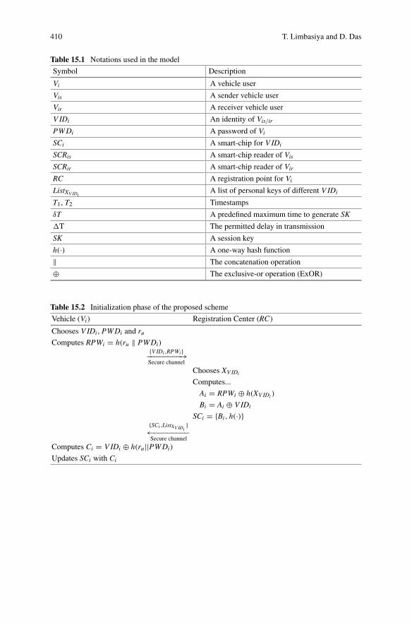
410 T. Limbasiya and D. Das
Table 15.1 Notations used in the model
Symbol Description
Vi A vehicle user
Vis A sender vehicle user
Vir A receiver vehicle user
V IDi An identity of Vis/irPWDi A password of ViSCi A smart-chip for V IDi
SCRis A smart-chip reader of VisSCRir A smart-chip reader of VirRC A registration point for ViListXV IDi
A list of personal keys of different V IDi
T1, T2 Timestamps
δT A predefined maximum time to generate SK
�T The permitted delay in transmission
SK A session key
h(·) A one-way hash function
‖ The concatenation operation
⊕ The exclusive-or operation (ExOR)
Table 15.2 Initialization phase of the proposed scheme
Vehicle (Vi) Registration Center (RC)
Chooses V IDi , PWDi and ruComputes RPWi = h(ru ‖ PWDi)
{V IDi,RPWi}−−−−−−−−→Secure channel
Chooses XVIDi
Computes...
Ai = RPWi ⊕ h(XVIDi )
Bi = Ai ⊕ V IDi
SCi = {Bi, h(·)}{SCi,ListXV IDi
}←−−−−−−−−Secure channel
Computes Ci = V IDi ⊕ h(ru||PWDi)
Updates SCi with Ci

15 Secure Smart Vehicle Cloud Computing … 411
Table 15.3 Login phase of the proposed scheme
Sender (Vi) Smart-chip Reader (SCRis)
Inserts V IDi and PWDi{V IDi,PWDi}−−−−−−−−→Secure channel
Retrieves Bi,Ci from SCi
Computes...
Di = Bi ⊕ Ci ⊕ (V IDi||T1){V IDi,Di,T1}−−−−−−−→Open channel
Table 15.4 Authentication phase of the proposed scheme
Smart-chip Reader (SCRis) Smart-chip Reader (SCRir){V IDi,Di,T1}−−−−−−−→Open channel
Checks T2 − T1 ≤ �T
Computes...
h′(XVIDi ) = (V IDi||T1) ⊕ Di
h′(XVIDi )
?= h(XVIDi )
SKS?= SKR
1. Vi chooses V IDi as per vehicle identity number allocated by the respected author-ity and selects PWDi as well as ru (a random number) freely.
2. Vi computes RPWi = h(ru||PWDi).3. Vi sends V IDi,RPWi to RC.4. After receiving it, RC generates a personal key (XVIDi ) for V IDi and computes
Ai = RPWi ⊕ h(XVIDi ) plus Bi = Ai ⊕ V IDi.5. RC saves credentials (Bi, h(·)) into SCi and installs it along with ListXVIDi
into aparticular vehicle.
6. Vi calculates Ci = V IDi ⊕ h(ru||PWDi) and updates SCi with Ci and RPWi.
15.4.2 Login Phase
This phase is performed between Vi and SCRis. They perform the following steps toget login into the system as well as to proceed further in order to communicate withother vehicles:
1. Vi enters V IDi and PWDi.2. SCRis extracts Bi,Ci from SCi. Then, it calculates Di = V IDi ⊕ Bi ⊕ Ci ⊕ T1
and transmits {V IDi,Di,T1} to the receiver.

412 T. Limbasiya and D. Das
15.4.3 Authentication Phase
An authentication phase is practiced to check the sender (SCRis) before starting acommunication at the recipient end. The receiver (SCRir) performs subsequent stepsas the followings:
1. SCRir receives V IDi,Di,T1 and checks a validity of a verification request byperforming a timestamp validation. If it is valid, then proceeds to next step elseit drops a request immediately.
2. SCRir computes h′(XVIDi ) = V IDi ⊕ Di and matches with h(XVIDi ). If both are
same, then the receiver starts a communication session. Otherwise Vi terminatesa request directly.
3. SCRir computes a session key, SKR = V IDi ⊕ Di ⊕ T1 ⊕ T3. SCRis computes asession key, SKS = V IDi ⊕ Di ⊕ T1 ⊕ T3. Where, T3 = �T + δT .
15.5 Security Analysis
We do analysis of the proposed model in terms of security after considering certainsuppositions, and these assumptions have been practiced by multiple researchers[24, 25] in order to measure the security level of different authentication schemes.
1. Impersonation AttackAn impersonation attack can be applied if an attacker (A ) has some significantdata of earlier packet transmissions as well as basic information (an identity)about a targeted person. Finally,A can impersonate either receivers or senders ifhe/she can manipulate these data and is able to put into effect at receiver/senderends, then we can consider that there is an opportunity to apply an impersonationattack into the scheme. SCRis transfers some parameters (V IDi,Di,T1) to SCRir
for verification. However,A does not have knowledge of ru, Ai and PWDi. As aresult,A cannotmanipulate any data of a packet request. Therefore, the suggestedmodel is secured against an impersonation attack.
2. Insider AttackIt is an attack, which can be applied by an internal user (he/she belongs to thesame organization.) of the system and internal person acts as an attacker (A ). So,he/she knows an identity of a user. At that point, he/she does not have familiaritywith some credentials (PWDi, ru). In this case, s/he should guess one parameterat a time, which is a guessed password (PWD′
i). But, A does not know ru cor-rectly, and it is difficult to apply an attack with two guessed parameters withina polynomial period. In this way, the proposed scheme can withstand against aninsider attack.
3. Modification AttackIn order to apply a modification attack, an attacker should able to update thetransmitted credentials (from SCRis to SCRir) according to his/herwish and should

15 Secure Smart Vehicle Cloud Computing … 413
be succeeded to pass the verification test.A cannot able tomodify the transmittedrequest by using V IDi,Di and T1 in the advised system. To update Di, A needsBi,Ci,RPWi, which are not accessible to A easily in a reasonable duration. Asa consequence, the recommended mechanism is protected against a modificationattack.
4. Masquerade AttackIn this attack, an attacker uses an identity of other users to obtain unautho-rized/authorized access to the system. For this action, he/she should be awareof PWDi and should get access of other user’s vehicle physically. We assumethatA makes use of guessed password (PWD′
i) but, it is difficult to get physicalaccess to a vehicle without knowledge of an original vehicle owner for an attacker.Now,A cannot proceed further to execute certain steps in order to be successful.Consequently, the suggested system is secured against a masquerade attack.
5. Parallel Session AttackA parallel session attack is applied to the system to get rights of authorized userwhen an original user tries to obtain services of the system for some intention(s).At that time, an attacker (A ) intercepts a message request ({V IDi,Di,T1}) andredirects it towards its end. After that, A updates credential(s) and forwardsto allow permission for getting different kind of services illegally. However, averification test will not be passed at SCRir end if A has done any modification,and a session will be terminated automatically. If a session key is not computed,then there is no chance to establish a communication session in the proposedmethod. Therefore, the advised system can withstand against a parallel sessionattack.
6. Plaintext AttackSCRis does not transmit any value in the simple form so that, it is not usefulup to some extends, and we use the concept of time-stamp. Here, it is difficultto retrieve any credential without having proper knowledge of other parameters.In order to understand Di, A should have knowledge of Bi and Ci but A doesnot know these credentials. As a result, a plaintext attack is not feasible in theproposed model.
7. Replay AttackWe practice the concept of time-stamp in the system in order to keep securecommunication. If A tries to change T1, then he/she requires some amount oftime to process this operation. Thus, A will fail at the recipient end to clear theverification process (T2 − T1 ≤ �T ). SCRir terminates a session straightaway if atime-stamp test fails. In this manner, the suggested scheme can withstand againsta replay attack.
15.6 Conclusion
We describe concerning various type of wireless ad-hoc networks and their numer-ous applications in the smart city concept. Afterwords, we deliberate for the cloud

414 T. Limbasiya and D. Das
computing systems along with their various level of applications. We discuss dif-ferent schemes regarding V2V communication, vehicular cloud computing, securerouting, geo-graphic position of vehicles in the vehicular ad-hoc networks. Then,we explain about essential security requirements, possible security attacks, varioussecurity challenges in the vehicular technology. Finally, we design a scheme, whichis useful to identify the vehicle user in establishing a communication session to shareremarkable information. Furthermore, we discuss the security analysis of the samescheme to recognize the security level.
Acknowledgements We are grateful to the anonymous reviewers for their noteworthy time andeffort in suggesting their exceptional views on the chapter in the review process. In addition, we arethankful to editors for the handling of this book. This work is partially supported by Early CareerResearch Award from Science and Engineering Research Board (SERB), Department of Scienceand Technology(DST), Govt. of India, New Delhi, India (Project Number: ECR/2015/000256).
References
1. S. Olariu, I. Khalil, M. Abuelela, Taking VANET to the clouds. Int. J. Pervasive Comput.Commun. 7(1), 7–21 (2011)
2. M. Eltoweissy, S. Olariu, M. Younis, Towards autonomous vehicular clouds, in InternationalConference on Ad Hoc Networks (Springer, Berlin, Heidelberg, 2010), pp. 1–16
3. S. Biswas, R. Tatchikou, F. Dion, Vehicle-to-vehicle wireless communication protocols forenhancing highway traffic safety. IEEE Commun. Mag. 44(1), 74–82 (2006)
4. I. Takai, T. Harada, M. Andoh, K. Yasutomi, K. Kagawa, S. Kawahito, Optical vehicle-to-vehicle communication system using LED transmitter and camera receiver. IEEE Photonics J.6(5), 1–14 (2014)
5. C. Perkins, E. Belding-Royer, S. Das, Ad hoc on-demand distance vector (AODV) routing (No.RFC 3561) (2003)
6. V. Namboodiri,M.Agarwal, L. Gao, A study on the feasibility ofmobile gateways for vehicularad-hoc networks, in Proceedings of the 1st ACM International Workshop on Vehicular Ad HocNetworks (2004), pp. 66–75
7. V. Naumov, R. Baumann, T. Gross, An evaluation of inter-vehicle ad hoc networks based onrealistic vehicular traces, in Proceedings of the 7th ACM International Symposium on MobileAd Hoc Networking and Computing (2006), pp. 108–119
8. S.K. Dhurandher, S. Misra, M.S. Obaidat, M. Gupta, K. Diwakar, P. Gupta, Efficient angularroutingprotocol for inter-vehicular communication in vehicular adhocnetworks. IETCommun.4(7), 826–836 (2010)
9. C.Wu, S.Ohzahata, T.Kato, Flexible, portable, and practicable solution for routing inVANETs:a fuzzy constraint Q-learning approach. IEEE Trans. Veh. Technol. 62(9), 4251–4263 (2013)
10. R. Chen, F. Bao, M. Chang, J.H. Cho, Dynamic trust management for delay tolerant networksand its application to secure routing. IEEE Trans. Parallel Distrib. Syst. 25(5), 1200–1210(2014)
11. S.K. Bhoi, P.M. Khilar, SIR: a secure and intelligent routing protocol for vehicular ad hocnetwork. IET Netw. 4(3), 185–194 (2014)
12. S. Capkun, J.P. Hubaux, Secure positioning in wireless networks. IEEE J. Sel. Areas Commun.24(2), 221–232 (2006)
13. X. Lin, X. Sun, P.H. Ho, X. Shen, GSIS: a secure and privacy-preserving protocol for vehicularcommunications. IEEE Trans. Veh. Technol. 56(6), 3442–3456 (2007)

15 Secure Smart Vehicle Cloud Computing … 415
14. C. Zhang, R. Lu, X. Lin, P.H. Ho, X. Shen, An efficient identity-based batch verificationscheme for vehicular sensor networks, in The 27th Conference on Computer Communications,INFOCOM 2008 (IEEE, 2008), pp. 246–250
15. Gongjun Yan, Stephan Olariu, Michele C. Weigle, Providing location security in vehicular AdHoc networks. IEEE Wirel. Commun. 16(6), 48–53 (2009)
16. J. Sun, C. Zhang, Y. Zhang, Y. Fang, An identity-based security system for user privacy invehicular ad hoc networks. IEEE Trans. Parallel Distrib. Syst. 21(9), 1227–1239 (2010)
17. D. Wu, Y. Zhang, L. Bao, A.C. Regan, Location-based crowdsourcing for vehicular commu-nication in hybrid networks. IEEE Trans. Intell. Transp. Syst. 14(2), 837–846 (2013)
18. J. Kang, R. Yu, X. Huang, M. Jonsson, H. Bogucka, S. Gjessing, Y. Zhang, Location privacyattacks and defenses in cloud-enabled internet of vehicles. IEEEWirel. Commun. 23(5), 52–59(2016)
19. N. Santos, K.P. Gummadi, R. Rodrigues, Towards trusted cloud computing. HotCloud 9(9), 3(2009)
20. M. Jensen, J. Schwenk, N. Gruschka, L.L. Iacono, On technical security issues in cloud com-puting, in IEEE International Conference on Cloud Computing, 2009. CLOUD’09 (2009),pp. 109–116
21. C.Wang, Q.Wang, K. Ren,W. Lou, Privacy-preserving public auditing for data storage securityin cloud computing, in Proceedings of the IEEE INFOCOM (2010), pp. 1–9
22. C. Wang, S.S. Chow, Q. Wang, K. Ren, W. Lou, Privacy-preserving public auditing for securecloud storage. IEEE Trans. Comput. 62(2), 362–375 (2013)
23. J. Zhou, X. Dong, Z. Cao, A.V. Vasilakos, Secure and privacy preserving protocol for cloud-based vehicular DTNs. IEEE Trans. Inf. Forensics Secur. 10(6), 1299–1314 (2015)
24. R. Madhusudhan, R.C. Mittal, Dynamic ID-based remote user password authenticationschemes using smart cards: a review. J. Netw. Comput. Appl. 35(4), 1235–1248 (2012)
25. T. Limbasiya, N. Doshi, An analytical study of biometric based remote user authenticationschemes using smart cards. Comput. Electr. Eng. 59, 305–321 (2017)

Chapter 16Video Transcoding Services in CloudComputing Environment
Sampa Sahoo, Bibhudatta Sahoo and Ashok Kumar Turuk
Abstract Nowadays, online video consumption is an outstanding source of info-tainment. Current social media era allows people to communicate with others aroundthe world via Facebook, LinkedIn, YouTube and other platforms by sharing/sendingphotos, videos over the Internet. The proliferation of viewing platforms, file formats,and streaming technologies generate the need for video transcoding. The transcod-ing process ensures that video content can be consumed from any networks anddevices, but it is a time-consuming, computation-intensive method and requires highstorage capacity. The rise of video distribution and consumption makes the videoservice providers face unpredictable CAPEX and OPEX, for delivering more videosacross multi-screens and networks. A cloud-based transcoding is used to overcomethe limitations with on-premise video transcoding. The virtually unlimited resourcesof the cloud transcoding solution allow video service providers to pay as they usetoday, with the assurance of providing online support to handle unpredictable needswith lower cost. This chapter is designed to discuss various techniques related tocloud-based transcoding system. Various sections in this chapter also present thecloud-based video transcoding architecture, and performance metrics used to quan-tify cloud transcoding system.
16.1 Introduction
The Internet is now an important part of entertainment media, i.e., a user can watcha video of their choice or watch live events or matches through the Internet. The vol-ume of media assets is increasing rapidly due to the growth of on-line viewing, social
S. Sahoo (B) · B. Sahoo · A. K. TurukNIT Rourkela, Rourkela 769008, Indiae-mail: [email protected]
B. Sahooe-mail: [email protected]
A. K. Turuke-mail: [email protected]
© Springer International Publishing AG, part of Springer Nature 2018B. S. P. Mishra et al. (eds.), Cloud Computing for Optimization:Foundations, Applications, and Challenges, Studies in Big Data 39,https://doi.org/10.1007/978-3-319-73676-1_16
417

418 S. Sahoo et al.
media and mobile outlets. Current social media era allows people to communicatewith others around the world via Facebook, LinkedIn, YouTube and other platformsby sharing/sending photos, videos over the internet. The variation in video quality,file sizes, and compression codecs makes the job of media professionals critical tomaintaining it. Growth in other technologies like internet connectivity, increase inbandwidth put additional pressure. More recently, a significant new data modalityhas emerged due to unstructured data from video and images. A plethora of videosgenerated by digital devices demands attention in the current Big Data market. Thevideo uploading rate of most popular online video archiving systems YouTube isaround 100 video per minute. In recent time, one of the research challenges is anal-ysis and processing of video data to support anytime anywhere viewing irrespectiveof devices, networks, etc. [1]. Video service providers use broadcast-quality videostreaming services to reach local and worldwide audiences irrespective of networksand devices. Streaming is the process of fragmenting the video files into smallerpieces and delivered it to the destination. Streaming use buffering technology to col-lect several packets before the file being played. For example, Imagine a glass filledwith water with a hole at the bottom, then there is a constant stream of water drainageas long as there is enough water in the glass. The streaming technology applies toboth live streams and progressive downloads for audio and video on demand. Stream-ing can be done at the streaming server or by renting streaming service provided bystreaming service providers who can host the video on the cloud. Streaming servicecan be rented on an hourly or monthly basis, i.e., the user needs to pay only for theresources consumed.
Cloud computing is used to provide ubiquitous, on-demand network access suchthat user can access computing resources anywhere and at any time through theInternet. It is built on the base of distributed computing, grid computing, and virtu-alization, which delivers the on-demand computing resources over the Internet on apay-for-use basis. Users can access the resources without considering the installationdetails and use it as required with paying only for the used units. The cloud servicemodel can be Software as a service (SaaS), Platform as a service (PaaS), Infrastruc-ture as a service (IaaS). SaaS is a subscription model to access software runningon Service Providers servers. Few examples of SaaS applications are Google Apps,Box, Dropbox. PaaS provides a computing platform for development and deploy-ment ofweb applicationswithout buying andmaintaining software and infrastructurerequired for it. Examples of PaaS include Google App Engine, Microsoft Azure Ser-vices, Force.com, etc. Infrastructure resources like storage, network, andmemory aredelivered as on-demand service in the IaaS cloud service model. Examples of IaaSproviders are Amazon Web Services, Rackspace, etc. [2–6]. A virtualization tech-nique used by cloud computing allows splitting of coarse-grained physical resourcesinto fine-grained virtual resources to be allocated on-demand [7]. The cloud-basedvideo delivery architecture allows storage and distribution of single, high quality,high bitrate video files in multiple formats without the expense of purchasing andmaintaining own infrastructure [8]. In Video-on-Demand (VoD) cloud, the contentprovider rent resources (e.g. storage and bandwidth) from the cloud provider. Theresources can be rescaled based on fluctuating demands of the user to satisfy some

16 Video Transcoding Services in Cloud Computing Environment 419
Quality of Service (QoS) (e.g. video start-up delay). There are several advantages ofmoving video streaming services to the cloud and are listed as follows:
(i) The company converts upfront capital expenditure (CAPEX) to operatingexpense (OPEX). Cloud eliminates the massive capital investment for on-premise hardware (e.g. servers, storage arrays, networks) and software. It alsoputs an end to investment for continuously expanding andupgradingon-premiseinfrastructures.
(ii) In the cloud, a user pays as they go for processing intensive services suchas encoding (transcoding), asset management and storage of video streaming.The payment can be paid on a transaction basis, monthly subscription or as anannual fee. For example, a file-based video content can be transcoded on anhourly, pay-as-you-go basis in the Amazon Web Services (AWS) marketplace.
(iii) To build a massively scalable encoding on-premise platform with support forlatest devices and players is costly and not trivial. But, the infrastructure neededfor this can be upgraded by the cloud provider without the knowledge of uservery easily and with less effort.
(iv) A user can work from anywhere in the world at any time.(v) The time-consuming uploads, downloads or inefficient bandwidth use is elim-
inated and thus making cloud time-efficient.(vi) The cloud offers flexibility and scalability. On-premise scaling-up/down of
resources is not hassle free sometimes. As resources can’t be added on the flycontent providers, need to start thewhole process of buying andmaintaining thenew resources. Whereas in the cloud, the addition of new resources is simpleand quick as the user only need to change its requirement details. The cloudservice provider will accordingly either reduce or add resources for the userand charge for the same.
(vii) Whether Video delivery is on-demand or live streaming cloud ensures highquality and stability.
Different video streaming services used in practice are storage, transcoding, con-tent delivery. This study mainly focuses on video transcoding service. The Ciscowhite paper [9] discusses why and how the cloud can support video delivery to mul-tiscreen, i.e., more devices. London Olympic, 2012 is considered as a milestone thattakes traditional viewing to a new level, i.e., shifting towards connected devices liketablets, smartphones, etc. for anytime anywhere viewing. The challenge lies in cre-ating an effective multiscreen offer with the consideration of a different combinationof devices, networks, service platforms, etc. The cloud architecture used for bothhomogeneous and heterogeneous environments could reduce the potential cost from36 percent to 13 percent compared to traditional video architecture. One of the waysto manage the cost of multiscreen access is to allow a temporary bandwidth increasefor premium consumers, who are ready to pay extra for the better experience. Theparadigm shift will also help video service providers to reduce CAPEX/OPEX aswell as coping with the growth of online video industry. According to statistics pre-sented in [10], 462 million active Internet users are there in India, which is 34.8%of the whole population and 13.5% of the world Internet users. Despite a significant
420 S. Sahoo et al.
percentage of Internet users, the average connection speed in India is 3.6Mbps, thelowest in the Asia-Pacific region. The average peak connection speed is also thelowest in India with 26.1Mbps. In Asia-Pacific region, South Korea has the high-est average connection speed, i.e., 27Mbps, and average peak connection speed inSingapore is the highest with 157.3Mbps [11]. From the report we can see thatcountry-wise, there is variation in Internet speed. So, a single format of a video forall will not be sufficient. The advancement of mobile devices, tablets, PC supportmultiple formats, and it adds additional challenges to the video service providers. So,there is a need of video format conversion that will satisfy the demand for the varioususer devices and network. The format conversion process is known as transcoding.
An online video consumed by a user on multiple screens, such as digital TVs,smartphones, and tablets, need to be conveyed in a device suitable format. Videocontent providers require many formats of a single video file to provide service tousers with varying need. It is practically impossible to prepare a video in all for-mats as it requires large content storages. There is also continuous development inthe field of coding and encoding technology, codecs, etc. So, there is a need for asolution that will convert a video into the required format with less effort and cost[12, 13]. The conversion of video from one digital format to another format termedas transcoding. Video transcoding method helps video content providers to generateall the possible formats of a single video [14]. To provide such a transcoding capa-bility, video content providers need enormous computing powers and storage space.Video service providers want their videos to look good and playable irrespective ofdevices or platforms. The proliferation of video distribution and consumption makesthe video service providers to face unpredictable CAPEX and OPEX, to deliver morevideos across multi-screens. Video transcoding solution requires enormous comput-ing power andmust deal with issues related to cost, scalability, video quality, deliveryflexibility, and ubiquity. Cloud computing has emerged as a front-runner to give asolution to time-consuming and resource-aware transcoding process.
Video transcoding was initially employed to reduce the video file size, but nowthe priority has changed, i.e., transcoding is not only used to reduce the file size butalso make the video viewable across platforms, enable HTTP streaming and adap-tive bitrate delivery. Transcoding may results degradation in video quality. So, it isdesirable to start with a high-quality mezzanine file and carefully do the transcod-ing based on specific target formats and content types. Transcoding a large, high-definition video to a diverse set of screen sizes, bit rates, and quality requires a lot oftime, computation, storage capacity. To overcome the difficulty associated with thetranscoding process content providers are using the cloud services. The cumbersometranscoding is simple, take less time and pocket-friendly in the cloud as comparedto in-house process. A user only needs to specify its requirements and subscribe theservices provided by the cloud which is only a single click away. The rest of the task,i.e., resource allocation and time-consuming transcoding process will be performedin the background. Finally, the user is charged only for the resources consumedwithout much overhead. Before discussing transcoding in the cloud further first, wepresent various terms used in video transcoding in next Sect. 16.1.1.
16 Video Transcoding Services in Cloud Computing Environment 421
16.1.1 Terms in Video Transcoding
A video consists of video sequences where each video sequence consists of Groupof Pictures (GOPs). Each GOP has several video frames. Usually, transcoding isperformed at GOP level or frame level. Few more terms related to video transcodingare
(i) Codec: The method used by a system to determine the amount of changebetween frames is called a codec. Codec stands for Compressor-Decompressor,and it either encode or decodes the video.
(ii) Bitrate (Data rate): It is the amount of data that is used for each second of video(Kbps,Mbps, etc.). Bit rate can be constant (CBR), i.e., the same amount of dataevery second or variable (VBR), i.e., the amount of data is adjusted dependingon changes between frames.
(iii) Resolution: Resolution is the actual size of the video (1 frame) measured inpixels. For example 1920×1080 resolution = 2,073,600 pixels. Let each pixeluses 24 RGB color bit, then the size of one frame is 2,073,600×24 = 0.25MB(1 MB = 8388608bit).
(iv) Frame rate: Number of frames shown every second is known as frame rate.Popular frame rates are 24 fps, 30 fps, 50/60 fps, etc. If 1 frame size is 0.25MBthen bandwidth (data rate) requirement of a video@60fps is 15MB/s, whereas@24fps is 6MB/s.
From the above calculation, we can see that even a video with few frames needa significant amount of bandwidth. For a movie or long duration video, it will beeven more. A video is also demanding a substantial amount of storage. Differentways to deal with massive storage and bandwidth requirements are: buy and useinfrastructure or convert video into a format (transcode) thatwill consume less storageand bandwidth. As transcoding is time-consuming and computationally intensive,cloud-based video conversion is preferable to reduce a provider’s expense.
16.2 Video Transcoding Process
Transcoding (Encoding) is the process of changing the input video file from one for-mat to another for video delivery to different programs and devices without losingoriginality [15]. Transcoding is commonly used as an umbrella term that covers somedigital media tasks, such as transrating, trans-sizing [16]. Transcoding is typically thechange of codec, bitrate or resolution. The change of bitrates, i.e., 5Mbps to 3Mbpsor 1.8Mbps, etc. are known as transrating, and change of resolution (video framesize), i.e., 1080p–720p is referred as trans-sizing. Transcoding involves followingtwo steps: first decoding is done to convert input video file to uncompressed formatand after that re-encoding is done to generate data format supported by the user’sdevice [17]. Screen size 1080p racking up the pixel dimensions to 1920×1080 for

422 S. Sahoo et al.
Fig. 16.1 TranscodingProcess
full high definition. Here p is for progressive scanning, meaning each line is drawn insequence upon screen refresh. 3Mbps represents bit rate. Figure16.1 shows that howtranscoding will generate different formats. The encoded video file can be deliveredon-demand or live. The video file can be transferred entirely before playing it (down-loading) or stream to the user device. Video content delivery depends on the distancebetween user location and media server containing the requested file. If the distanceis less content delivery is fast, but if distance is more user experience choppiness,loading lag, poor quality. The advantage of transcoding in the cloud is lower cost,virtually unlimited scalability, and elasticity to counter peak demand in real-time.The cloud transcoding solution allows video service providers to pay-as-you-use,with the assurance of providing online support to handle unpredictable needs [18,19]. Video transcoding service in cloud uses popular cloud servicemodel that includeSoftware as a Service (SaaS), Platform as a Service (PaaS), Infrastructure as a Service(IaaS), and hybrid model [20].
Video service providers want their videos to look good and playback irrespectiveof devices or platforms. The proliferation of video distribution and consumptionmakes the video service providers to face unpredictable CAPEX and OPEX, todeliver more videos across multi-screens (smartphones, PCs, TVs, tablets, etc.) andnetwork (2/3/4G,mobile, broadcast, etc.). Encoding is not just compression; it meanshaving to choose and accelerating, not declining as the number of renditions areneeded to support the diversity of user devices and networks. The encoding solutions,whether in-house infrastructure, the third party need to deal with cost, scalability,video quality, delivery flexibility, and ubiquity issues. One of the solution to solvethese problems is cloud-based transcoding. The advantage of transcoding in thecloud is lower cost, virtually unlimited scalability, and elasticity to counter peakdemand in real-time. The cloud transcoding solution allows video service providersto pay as they use today, with the assurance of providing online support to handleunpredictable needs [21]. Operators, service providers, and content providers see thebenefits of using standard servers in the cloud and want to move away from specialappliances or dedicated hardware. Pushing video to the cloud, in real-time requiresa high-speed, highly available network. The selection of cloud for any applicationdepends on following primary requirements: bandwidth, storage, cost, security, andaccessibility. The total bandwidth required for a video stream varies depending onthe number of frames or images being captured per second as well as the quality ofthe images being captured. The availability and affordability of bandwidth are not

16 Video Transcoding Services in Cloud Computing Environment 423
consistent from city to city, country to country. Bandwidth and storage requirementcalculation is an essential step in the planning or design of any cloud-based videodelivery system.
16.3 Cloud-Based Video Transcoding Architecture
The system architecture of the cloud-based video transcoding service adopted from[13, 19, 22, 23] is shown in Fig. 16.2. The architecture consists of many componentslike a streaming service provider, a video repository, splitter, transcode manager,transcodingVMs (Servers), videomerger and caching storage. The streaming serviceproviders like YouTube, Netflix accepts user’s request and checks if required videois present in video repository or not. If the video is present in its desired format, thenstarts streaming the video. However, if the coveted video is in another format thanthe one requested by the user, online transcoding is done using cloud resources. Theservice provider charged according to the amount of resource reserved in clouds.For online transcoding first, the video is split into several segments, or chunks byvideo splitter. The video segments are mapped to transcoding VMs by the transcodemanager to be transcoded independently. The video segments can be of equal size,an equal number of frames, equal number of GOPs, equal-size with an odd numberof intraframes or different size with an equal number of intraframes [24, 25].
Fig. 16.2 Cloud-basedTranscoding Architecture
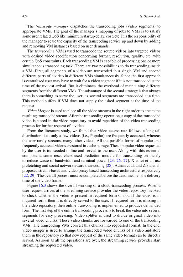
424 S. Sahoo et al.
The transcode manager dispatches the transcoding jobs (video segments) toappropriate VMs. The goal of the manager’s mapping of jobs to VMs is to satisfysome user related QoS likeminimum startup delay, cost, etc. It is the responsibility ofthe manager to scale the capacity of the transcoding service up and down by addingand removing VM instances based on user demands.
The transcoding VM is used to transcode the source videos into targeted videoswith desired video specification concerning format, resolution, quality, etc. withcertain QoS constraints. Each transcoding VM is capable of processing one or moresimultaneous transcoding task. There are two possibilities to do transcoding insidea VM. First, all segments of a video are transcoded in a single VM and seconddifferent parts of a video in different VMs simultaneously. Since the first approachis centralized user may have to wait for a video segment if it is not transcoded at thetime of the request arrival. But it eliminates the overhead of maintaining differentsegments from the different VMs. The advantage of the second strategy is that alwaysthere is something to serve the user, as several segments are transcoded at a time.This method suffers if VM does not supply the asked segment at the time of therequest.
Video Merger is used to place all the video streams in the right order to create theresulting transcoded stream.After the transcoding operation, a copy of the transcodedvideo is stored in the video repository to avoid repetition of the video transcodingprocess for further request of a video.
From the literature study, we found that video access rate follows a long taildistribution, i.e., only a few videos (i.e., Popular) are frequently accessed, whereasthe user rarely streams, many other videos. All the possible forms of popular andfrequently accessedvideos are stored in cache storage.Theunpopular video requestedby the user is transcoded online and served to the user. Along with this essentialcomponent, some researchers used prediction module for transcoding on the flyto reduce waste of bandwidth and terminal power [23, 26, 27]. Xiaofei et al. useprefetching and social network aware transcoding [28]. Adnan et al. and Zixia et al.proposed stream-based and video proxy based transcoding architecture respectively[22, 29]. The overall process must be completed before the deadline, i.e., the deliverytime of the video frame.
Figure16.3 shows the overall working of a cloud-transcoding process. When auser request arrives at the streaming service provider the video repository invokedto check whether the video is present in required form or not. If the video is ininquired form, then it is directly served to the user. If required form is missing inthe video repository, then online transcoding is implemented to produce demandedform. The first step of the online transcoding process is to break the video into severalsegments for easy processing. Video splitter is used to divide original video intoseveral video chunks. These video chunks are forwarded to one of the transcodingVMs. The transcoding VMs convert this chunks into requested format. In the end,video merger is used to arrange the transcoded video chunks of a video and storethem in the repository so that new request of the same video format can be directlyserved. As soon as all the operations are over, the streaming service provider startstreaming the requested video.

16 Video Transcoding Services in Cloud Computing Environment 425
Fig. 16.3 Working of Cloud-based Transcoding Process
Table 16.1 Time in different phases of a transcoding process
Time Definition
Reach Time (RT) Time for a request to reach from user to the streaming server
Check Time (CT) Time spent by the streaming server to check video repository forrequired video format
Split Time (ST) Time to split the original video into several video chunks
Transcode Time (TT) Time to transcode video segments into requested format
Merging Time (MT) Time for arranging and storing transcoded segments of a video
Response Time (RT) Time to give response to user by the streaming service provider
Table16.1 shows time for different phases of online video transcoding process,starting from user request reach to a streaming service provider to response sent bythe service provider. Let D be the deadline of a frame to be delivered then total timetaken to transcode a frame must be less than or equal to D as shown in Eq.16.1.
RT + CT + ST + T T + MT + RT ≤ D (16.1)

426 S. Sahoo et al.
16.4 Video Transcoding Techniques in Cloud
The cumbersome transcoding is simple, take less time and pocket-friendly in thecloud as compared to in-house process. A user only needs to specify its requirementsand subscribe the services providedby the cloudwhich is only a single click away.Therest of the task, i.e., resource allocation and time-consuming transcoding process willbe performed in the background. Finally, the user is charged only for the resourcesconsumed without much overhead. Following are different transcoding techniquesin the cloud.
A. Pre-transcoding: One of the ways to deal with the video transcoding problem ispre-stored multi-version videos. This process stores various transcoded versionsof each video to serve all user’s requests and different types of client devices. Themain drawback of this approach is the usage of large storage and computationresources. Even though pre-transcoding is a widely usedmethod in VoD industry,but it induces a high cost. The increase in cost is due to provisioning and upgra-dations of fast-growing transcoding infrastructure, storage overhead to maintainall versions of all videos. It becomes cost prohibitive for small and medium sizestreaming service providers. The explosive growth of video streaming demandson a broad diversity of the client devices makes it ineffective [13, 30].
B. On-demand Transcoding: On-demand/real-time/online video transcoding per-forms conversion only when a particular format is not present in the storage.This method reduces the expenses of storage as it eliminates the need to storeall versions. The on-demand resource reservation in the cloud makes the videotranscoding process simpler and less costly. A leading content delivery networkprovider Akamai uses on-demand transcoding. Along with all the advantages,some challenges associated with this method are over/under-provisioning ofcloud resources. The reserved resources must be future ready. Transcoder per-forms on-demand transcoding only for the segment that is not present in storagebut requested by the user [30]. A QoS and cost aware on-demand transcoding ofvideo streams using cloud resources presented in [13] with the aim ofminimizingincurred cost of stream providers. Both on-demand and pre-transcoding are doneto reduce the transcoding overhead. Pre-transcoding of video based on popularitybased prediction is done into specific formats and resolution when the transcod-ing request falls (e.g. at night). A user is given several choices if its requiredformat is not in local storage. If a user disagrees with the options, on-demandtranscoding is done to generate user-specified form [26]. In [19] QoS-awareonline video transcoding in the cloud is presented. Akamai advocates transcod-ing of multiple files in parallel for a fast turnaround time. Akamai the leadingcontent delivery network (CDN) service provider of media and software distri-bution, uses stream packaging feature to detect the set of stream formats requiredby the user device and do the formatting and packaging of video streams at thenetwork edge servers on-demand. The computation at edge server eliminatesthe shortcomings of pre-transcoding and centralized server transcoding process

16 Video Transcoding Services in Cloud Computing Environment 427
as it reduces additional storage cost and content management overhead [31].Transcoding improves throughput (bandwidth) while preserving quality.
C. Partial Transcoding: In partial transcoding, some segments of a video are con-verted to other formats and stored in cloud storage. Based on the user viewingpattern rest segments of a video is transcoded on-demand. The purpose of doingso is to reduce operational cost, i.e., transcoding cost plus storage cost. Anotherapproach is to store multiple versions of a popular segment and only one highestquality version for unpopular segments. If a user request for a segment that is notin the cloud storage, do the transcoding in real-time. Authors in [32] proposedpartial transcoding scheme for content management in media cloud. Initially, apartial subset of video contents in different bitrates is stored in local storage thatcan be directly consumed. If the user specified format is not present in local stor-age, then online transcoding is done. The purpose of this approach is to reducelong-run overall cost. In [30] partial transcoding proposed based on user viewingpattern.
D. In-network Transcoding: Here, transcoding service can be placed on nodesinside the network, i.e., the introduction of a transcoding service into a networkinfrastructure. But, it requires routers that support this service processing. Fur-ther service placement of routers requires redesigning of the underlying networkarchitecture. Thus, the practical implementation of this is not applicable to theexisting network architecture [30].
E. Bit-rate Reduction Transcoding: A bitrate is the number of bits processedper unit time i.e. usually bits per second. The data rate for a video file is thebitrate. Example: bit rate of a standard definition DVD is 6 megabits per second(mbps) whereas video for phones is in kilobits per second (kbps). As the highrate video demands high network bandwidth, the video stream bit rate is reducedto ensure smooth streaming. This process is also known as transrating. Videosegmentation is used to perform bit rate reduction transcoding in a distributedcomputing environment. The distributed transcoder do transcoding of differentsegments parallelly on several machines to speed-up transcoding process [25].Cloud computing is an extension of distributed computing so the parallel bit-rate reduction transcoder can be implemented with or without any modification.This paper [13] introduces bit-rate, spatial and temporal resolution reductiontranscoding techniques.Video data at 1920×1080 pixels, 60 frames per second means original framesize is 1920×1080 pixels and each pixel is sampled 60 times per second. Spatialresolution ascertains information related to each frame and temporal resolutiondefines the change between frames represented by frames per second. Example1080HD is a case of spatial resolution or containing more pixels, but 720HD isa case of temporal resolution or containing more frames per second. Based onthe reduction in the temporal or spatial domain following type of transcoding arepossible.
F. Spatial-Resolution Reduction Transcoding: The spatial resolution indicatesthe encoded dimension size of a video. In spatial resolution reduction transcodingmacro-blocks of an original video are removed or combined without
428 S. Sahoo et al.
sacrificing the video quality. Spatial resolution reduction transcoding produces anoutput video with a smaller resolution, but with same frame rate than the originalvideo. In [24] spatial resolution reduction transcoding implemented in multi-core distributed system. Since the spatial resolution reduction method reducesthe resolution, the transcoder has to deal with less number of bits. Since a virtualmachine (VM) can have multiple cores, this process can be extended to the cloudenvironment.
G. Temporal-Resolution Reduction Transcoding: In a temporal resolution,transcoding frames are dropped to support frame rate of the client device andreduce the required transcoding time. To reduce the transcoding time a temporalresolution reduction transcoding is used for the cloud environment in [22]. Herethe transcoder drops a small proportion of video frames from a video segment ofcontinuous video content delivery to the user.
H. Scalable Transcoding: Scalable coding consists of a base layer (minimum bit-rate) and several enhanced layers (gradually increase the bit rate). Depending onthe link capability of the user device one or more enhanced layer delivered alongwith a base layer. There is always something to play (i.e., base layer). In [28]an adaptive video streaming is proposed that can adjust the streaming flow withscalable video coding technique based on the feedback of link quality. This paperalso discusses the advantage of this method like an efficient use of bandwidth.The video encoding strategy presented in Zencoder a cloud-based video encodingservice, white paper [33] maintain a base format (e.g. MP4) that is playableon a broad range of devices. Then decide the number and type of renditions.For example, short duration (e.g. 1 min) videos can be easily downloadable, soonly a few versions are sufficient. But long duration videos like movies cant bedownloadable in a single go so need extra attention. As the user always expecta high-quality video, many renditions are required that can be used according toavailable network bandwidth and the user device.
Video transcoding can be performed in the client device or on-premise architec-ture or in any third party architecture like a cloud. The compute intensive and time-consuming transcoding job suffers from low processing power and energy sourcesof the client device (e.g. smart phone). So, it is not feasible to perform transcod-ing on client devices [13]. The in-house architecture suffers from scalability issues.Let there is infrastructure for a particular rendition sets. After sometimes a new setof renditions is required. To satisfy the new demand, the process of buying hard-ware and installing software will be time-consuming, cumbersome and costly. Thisprocess may also suffer from over/under-provisioning of resources which will havean adverse impact on the companys investment. Apart from economic inefficiency,there is also wastage of resources as most of the time servers are in an idle state[13, 19, 27]. Forecasting transcoding capacity is difficult due to the proliferationof delivery options, the unpredictability of the volume of video assets, a signifi-cant lead time required to acquire and prepare the necessary infrastructure [18]. Toovercome the difficulties of in-house infrastructure to deal with the flash crowd,over/under-provisioning of resources, video service providers can look into cloud

16 Video Transcoding Services in Cloud Computing Environment 429
technology. The scalable cloud architecture allows on-demand resource reservationwith less maintenance and cost. The compute intensive and time-consuming videotranscoding can use on-demand cloud resources to reduce the expenses of videoservice providers [13, 19].
16.5 Performance Metrics
Performance metrics determined the benefit/lack of system designs. These are themetrics used to evaluate the working of a system in all conditions (favourable orunfavourable). The following section discusses various performance metrics used byresearchers to assess their cloud transcoding system and listed in Table16.2.
(i) Encoding Delay (Transcoding Time): It is the total time used to convert avideo from one format to another.
(ii) Prefetching Delay: This is the time used to pre-fetch video segments for auser based on his/her social network service activity.
(iii) Watching (Click-to-playDelay): This is a time towait for a user from clickinga video link to the first streaming arrival.
(iv) TranscodingRate/Speed: It is the number of transcoding operation completedper unit time.
(v) Number of streams with Jitter (Transcoding Jitter): It is the measure ofstreams with jitter where jitter is the time difference in stream inter-arrivaltime.
(vi) Number of dropped frames: It is the count of frames being dropped to avoiddeadline violation.
(vii) Queue waiting time: Waiting time of a stream in the queue to be encoded isknown as queue waiting time.
(viii) Launch Latency: It is the time between the opening of a VM and its becomeready to provide service.
(ix) End-to-End Delay: The end-to-end delay is the time between streamingprovider starts to deliver streaming media to the time a user device startsplaying it.
(x) Utilization Rate: It is defined as the ratio between used transcoding capacitiesto the total transcoding capacity of the system.Lower utilization rate indicatesthe larger idle time of the transcoding system.
(xi) Average Response Time: It is the difference between the time of transcodingrequest to the time of first transcoding response of the system.
(xii) Operational Cost: The overall operational cost is the combination of storage,computing and transcoding cost. The storage and computing cost is adoptedfrom Amazon S3 and Amazon EC2 On-Demand instances respectively [32].
(xiii) VM Provisioning Cost (Cost): It is the cost to acquire resources in the cloudfor transcoding process. To reduce the VM provisioning cost, the number ofservers required to transcoding process should also be minimized [23].

430 S. Sahoo et al.
Table 16.2 Performance metrics
Sl.No. Reference no. Performance metrics Environment Transcodingtool
1. [27] [2015] Cost Cloud Own Set-up
2. [22] [2013] Transcoding rate, Numberof streams with Jitter,Queue waiting time
Cloud Python withsimpyframework
3. [34] [2016] Launch latency, End-to-EndDelay, Utilization Rate,Average Response Time
Cloud ffmpeg andHi-cloud withWindows server2008 operatingsystem andAmazon EC2
4. [32] [2015] Operational Cost (storagecost + computing cost +transcoding cost)
Cloud Own setup
5. [29] [2011] Transcoding Speed,Transcoding Jitters
Cloud Own set-up
6. [23] [2013] VM Provisioning Cost Cloud Python withSimpyframework
7. [26] [2012] Average CPU Utilization,Cache Hit Rate, DataTransfer Rate
Cloud ffmpeg
8. [13] [2016] Average startup delay,Average deadline miss-rate,Cost
Cloud Cloudsim
9. [28] [2013] Pre-fetching delay,Watching delay, Encodingdelay
Cloud U-cloud serveroffered byKorean Telecomand JAVA basedserverapplication
10. [19] [2017] Transcoding time, TargetedVideo Chunk Size
Cloud Python, ffmpeg
11. [35] [2014] Energy Cloud Own set-up
12. [30] [2017] Storage and TranscodingCost, Average Delay(startup)
Cloud Own set-up
(xiv) Average CPU Utilization: It measures how efficiently CPU is utilized fortranscoding process.
(xv) CacheHitRate: If the requested transcoded video is present in cache storage itis a hit. The cache hit rate indicates the ratio between a hit and total transcodedvideo request.

16 Video Transcoding Services in Cloud Computing Environment 431
(xvi) Data Transfer Rate: Data Transfer Rate represents the transfer speed of thetranscoded videos from the cloud to the user with the aim of saving user’senergy consumption in retrieving the requested videos [26].
(xvii) Average Startup Delay: It is the delay occurred at the beginning of a videostream and represents the delay in receiving the first transcoded video stream[13].
(xviii) Average Deadline Miss-Rate: This delay occurs when a transcoding taskmisses its presentation deadline during streaming of a video [13].
(xix) Targeted Video Chunk Size: The average video chunk size influences thecloud resources, i.e., the number of CPU cores, so it should be carefullyselected [19].
The study shows that transcoding time, i.e., the time taken by the system totranscode a video from one format to another format is an important metric. Otherparameters used by researchers are transcoding rate/speed, i.e., the number of videotranscoding per time unit. Some researchers used end-to-end delay (time differ-ence between service requests in response), cost, etc. Operational cost, i.e., the costused to acquire cloud resources such as storage, transcoding is also used by severalresearchers.
16.6 Conclusion
Initially, video transcoding performed to reduce file size, but now the perception haschanged. Now transcoding is considered as a facility that provides options to choose.The options are picked tomake the video viewable across platforms, devices, and net-works. The cloud transcoding solution allows video service providers to pay as theyuse, with the assurance of providing online support to handle unpredictable needs,i.e., flash crowd. This paper discusses various aspects of performing a transcodingoperation in cloud starting from why to shift the transcoding process to the cloud, togeneral architecture andmetrics used to evaluate a cloud transcoding system.The sys-tem model designed for cloud-based video transcoding must consider the constraint,i.e., the online transcoding must be completed before the deadline of the frame.Future studies can be carried out to design and simulate a cloud-based transcodingmodel such that it willmeet the constraint with less overhead. The overhead reductionmay be concerning cost, scheduling, and provisioning of cloud resources, energy,response time, transcoding time, etc.

432 S. Sahoo et al.
References
1. https://content.pivotal.io/blog/large-scale-video-analytics-on-hadoop2. S. Sahoo, S. Nawaz, S.K. Mishra, B. Sahoo, Execution of real time task on cloud environment,
in 2015 Annual IEEE India Conference (INDICON) (New Delhi, 2015), pp. 1–5, https://doi.org/10.1109/INDICON.2015.7443778
3. S.K. Mishra, R. Deswal, S. Sahoo, B. Sahoo, Improving energy consumption in cloud, in 2015Annual IEEE India Conference (INDICON, New Delhi, 2015), pp. 1–6, https://doi.org/10.1109/INDICON.2015.7443710
4. S.K. Mishra, B.Sahoo, K.S. Sahoo, S.K. Jena, Metaheuristic approaches to task consolidationproblem in the cloud, in Resource Management and Efficiency in Cloud Computing Environ-ments (IGI Global, 2017), pp. 168–189, https://doi.org/10.4018/978-1-5225-1721-4.ch007
5. S. Sahoo, B. Sahoo, A.K. Turuk, S.K. Mishra, Real time task execution in cloud using mapre-duce framework, in Resource Management and Efficiency in Cloud Computing Environments(IGI Global, 2017), pp. 190–209, https://doi.org/10.4018/978-1-5225-1721-4.ch008
6. S.K. Mishra, P.P. Parida, S. Sahoo, B. Sahoo, S.K. Jena, Improving energy usage in cloudcomputing using DVFS, in International Conference on Advanced Computing and IntelligentEngineering (ICACIE) (2016), http://hdl.handle.net/2080/2598
7. https://www.ericsson.com/res/thecompany/docs/publications/ericssonreview/2010/cloudcomputing.pdf
8. Kontron Whitepaper, Video optimization in the cloud (2014)9. http://www.cisco.com/c/dam/en_us/about/ac79/docs/sp/Streaming_Under_the_Clouds.pdf10. http://www.internetlivestats.com/internet-users/india/11. https://www.akamai.com/uk/en/our-thinking/state-of-the-internet-report/state-of-the-
internet-connectivity-visualization.jsp12. S. Ko, S. Park, H. Han, Design analysis for real-time video transcoding on cloud systems, in
Proceedings of the 28th Annual ACM Symposium on Applied Computing (SAC ’13) (ACM,New York, 2013), pp. 1610–1615, https://doi.org/10.1145/2480362.2480663
13. X. Li, M.A. Salehi, M. Bayoumi, R. Buyya, CVSS: A cost-efficient and QoS-aware videostreaming using cloud services, in 2016 16th IEEE/ACM International Symposium on Cluster,Cloud andGridComputing (CCGrid) (Cartagena, 2016), pp. 106–115, https://doi.org/10.1109/CCGrid.2016.49
14. S. Sahoo, I. Parida, S.K.Mishra, B. Sahoo, A.K. Turuk, Resource allocation for video transcod-ing in themultimedia cloud, in International Conference on AdvancedComputing, Networking,and Informatics (ICACNI) (2017), http://hdl.handle.net/2080/2722
15. S. Sahoo, B. Sahoo, A.K. Turuk, An analysis of video transcoding in multi-core cloud envi-ronment. in International Conference on Distributed Computing and Networking (ICDCN)(2017), http://hdl.handle.net/2080/2643
16. https://www.wowza.com/blog/what-is-transcoding-and-why-its-critical-for-streaming(2015)
17. http://coconut.co/video-transcoding18. http://download.sorensonmedia.com/PdfDownloads/LowRes/whitepaper.pdf (2011)19. L. Wei, J. Cai, C.H. Foh, B. He, QoS-aware resource allocation for video transcoding in
clouds. IEEE Trans. Circuits Syst. Video Technol. 27(1), 49–61 (2017), https://doi.org/10.1109/TCSVT.2016.2589621
20. http://www.streamingmedia.com/Articles/Editorial/Featured-Articles/Buyers-Guide-to-Cloud-Based-Video-Encoding-and-Transcoding-2015-102483.aspx
21. http://download.sorensonmedia.com/PdfDownloads/LowRes/whitepaper.pdf (2011)22. A. Ashraf, F. Jokhio, T. Deneke, S. Lafond, I. Porres, J. Lilius, Stream-based admission control
and scheduling for video transcoding in cloud computing, in 2013 13th IEEE/ACM Interna-tional Symposium on Cluster, Cloud, and Grid Computing, Delft, (2013), pp. 482–489, https://doi.org/10.1109/CCGrid.2013.21
16 Video Transcoding Services in Cloud Computing Environment 433
23. F. Jokhio, A. Ashraf, S. Lafond, I. Porres, J. Lilius, Prediction-based dynamic resource alloca-tion for video transcoding in cloud computing, in 2013 21st Euromicro International Confer-ence on Parallel, Distributed, and Network-Based Processing, (Belfast, 2013), pp. 254–261,https://doi.org/10.1109/PDP.2013.44
24. F. Jokhio, T. Deneke, S. Lafond, J. Lilius, Analysis of video segmentation for spatial resolutionreduction video transcoding, in 2011 International Symposium on Intelligent Signal Processingand Communications Systems (ISPACS) (Chiang Mai, 2011), pp. 1–6, https://doi.org/10.1109/ISPACS.2011.6146194
25. F. Jokhio, T. Deneke, S. Lafond, J. Lilius, Bit rate reduction video transcoding with distributedcomputing, in 2012 20th Euromicro International Conference on Parallel, Distributed andNetwork-based Processing (Garching, 2012), pp. 206–212, https://doi.org/10.1109/PDP.2012.59
26. Z. Li, Y. Huang, G. Liu, F. Wang, Z. L. Zhang, Y. Dai. Cloud transcoder: bridging the formatand resolution gap between internet videos and mobile devices, in Proceedings of the 22ndinternational workshop on Network andOperating System Support for Digital Audio and Video(NOSSDAV ’12), (ACM, New York), pp. 33–38, https://doi.org/10.1145/2229087.2229097
27. A. Alasaad, K. Shafiee, H.M. Behairy, V.C.M. Leung, Innovative schemes for resource alloca-tion in the cloud for media streaming applications. IEEE Trans. Parallel Distrib. Syst. 26(4),1021–1033 (2015), https://doi.org/10.1109/TPDS.2014.2316827
28. X.Wang,M. Chen, T.T. Kwon, L. Yang, V.C.M. Leung, AMES-cloud: a framework of adaptivemobile video streaming and efficient social video sharing in the clouds. IEEE Trans. Multimed.15(4), 811–820 (2013), https://doi.org/10.1109/TMM.2013.2239630
29. Z. Huang, C. Mei, L.E. Li, T. Woo, CloudStream: delivering high-quality streaming videosthrough a cloud-based SVC proxy, in 2011 Proceedings IEEE INFOCOM (Shanghai, 2011),pp. 201–205, https://doi.org/10.1109/INFCOM.2011.5935009
30. H. Zhao, Q. Zheng,W. Zhang, B. Du, H. Li, A segment-based storage and transcoding trade-offstrategy for multi-version VoD systems in the cloud. IEEE Trans. Multimed. 19(1), 149–159(2017), https://doi.org/10.1109/TMM.2016.2612123
31. https://www.akamai.com/us/en/multimedia/documents/content/streaming-toward-televisions-future-4k-video-white-paper.pdf
32. G. Gao,W. Zhang, Y.Wen, Z.Wang,W. Zhu, Towards cost-efficient video transcoding inmediacloud: insights learned from user viewing patterns. IEEE Trans. Multimed. 17(8), 1286–1296(2015), https://doi.org/10.1109/TMM.2015.2438713
33. https://www.brightcove.com/en/blog/2013/08/new-whitepaper-architecting-a-video-encoding-strategy-designed-for-growth
34. K.B. Chen, H.Y. Chang, Complexity of cloud-based transcoding platform for scalable andeffective video streaming services, in Multimedia Tools and Applications (2016), pp. 1–18,https://doi.org/10.1007/s11042-016-3247-z
35. W. Zhang, Y.Wen, H.H. Chen, Toward transcoding as a service: energy-efficient offloading pol-icy for green mobile cloud. IEEE Netw. 28(6), 67–73 (2014), https://doi.org/10.1109/MNET.2014.6963807

Chapter 17Vehicular Clouds: A Survey and FutureDirections
Aida Ghazizadeh and Stephan Olariu
Abstract Vehicular clouds have become an active area of research with tens ofpapers written and a large number of documented applications. We feel this is a goodmoment to summarize the main research trends in the area of vehicular clouds andto map out various research challenges and possible applications. With this in mind,the primary objective of this chapter is to present a survey of the state of the art invehicular clouds, of the current research topics and future directions. We will takea critical look at the various vehicular cloud models proposed in the literature andtheir applications.
Keywords Vehicular clouds · Intelligent transportation systems · Cloudcomputing
17.1 Introduction and Motivation
It is intuitively clear that, in order to be effective, Intelligent Transportation Systemsshould acknowledge and employ the most recent technologies specially in the realmof networks and communications. Back in the 1980s, visionaries predicted that theability to network vehicles together would be a game changer, redefining the fashionwe use our vehicles and roads and provide safer and more efficient transportationmeans which eventually leads to the creation of the smart cities of the future [64].This idea has inspired scientists to extend the concept of Mobile Ad-hoc Networks(MANET) to roads, highways and parking lots and create the new notion of vehicularnetworks. Vehicular Network uses many forms of communication such as Vehicle-to-Vehicle (V2V) and Vehicle-to-Infrastructure (V2I) communications in order toenhance the drivers’ awareness of impending traffic conditions. In particular, it hasbeen shown that if the drivers are given advance notification of traffic events, they can
A. Ghazizadeh (B) · S. OlariuDepartment of Computer Science, Old Dominion University, Norfolk, VA, USAe-mail: [email protected]
© Springer International Publishing AG, part of Springer Nature 2018B. S. P. Mishra et al. (eds.), Cloud Computing for Optimization:Foundations, Applications, and Challenges, Studies in Big Data 39,https://doi.org/10.1007/978-3-319-73676-1_17
435

436 A. Ghazizadeh and S. Olariu
make informed decisions that either prevent congestion from occurring or contributeto mitigating its effects [71, 82, 85, 86].
Not surprisingly, in the past two decades, there has been an increasing interest invehicular networking and its countless possible applications and services. To supportvehicular networking and to promote its integration with Intelligent TransportationSystems, the US Federal Communications Commission (FCC) has allocated 75MHzof spectrum in the 5.850–5.925GHz band for the sole benefit of Dedicated ShortRange Communications (DSRC) [79].
The research community was quick to notice that the allocated DSRC spectrumwas excessive for the current designed transportation applications [64]. The excessavailable bandwidth can be used for launching third-party applications such as vehic-ular peer-to-peer communication, video and content delivery, vehicle entertainment,safety, travel and commercial applications.
It has been noticed [68] that under present-day state of the practice, the vehicleson our roads and city streets are mere spectators that witness traffic-related eventswithout being able to participate in the mitigation of their effect. Recently, it hasbeen shown that in such situations the vehicles have the potential to cooperate withvarious authorities to solve problems that otherwise would either take an inordinateamount of time to solve (e.g. routing traffic around congested areas) or could not besolved for lack for adequate resources [82, 86].
Back in 2010. Abuelela and Olariu [1] called on the vehicular networking com-munity to “take vehicular networks to the clouds” to use the vehicular resourcesavailable to improve safety, increase efficiency and help the economy. That call toaction has led to an explosion in the number of papers that dealt with various aspectsand applications of vehicular cloud computing. Indeed, it is fair to say that in recentyears, vehicular clouds have become an active area of research with a large numberof documented applications [68, 84].
The concept of vehicular cloud and its possible applications are recent and so aremany challenges and obstacles in the realm of research and implementation [89].The main goal of this chapter is to provide a critical review of recent research invehicular clouds.
At this point, we feel it is appropriate to give the reader a synopsis of the chapter.Section17.2 offers a brief review of cloud computing and cloud services that hasmotivated the vision of vehicular clouds. Next, in Sect. 17.3 we offer a brief intro-duction to Mobile Clouds and review their main components and characteristics.Section17.4 introduces the earliest models of vehicular clouds and discusses someof their attributes. Section17.5 introduces generic system assumptions about VCsincluding a description of the vehicular model, a quick review of virtualization andvirtual machine migration as well as a discussion about the merits of static anddynamic VCs. Next, Sect. 17.6 offers a generic look at a generic VC architecture.Finally, Sect. 17.11 offers concluding remarks and maps out directions for futureinvestigations.

17 Vehicular Clouds: A Survey and Future Directions 437
17.2 Cloud Computing
Professor McCarthy, an MIT computer scientist and cognitive scientist, was thefirst to suggest the idea of utility computing in 1961. He envisioned that in futurecomputing power and applications may one day be organized as public utility andcould be sold through a utility business model, like water or electricity. “Computingmay someday be organized as a public utility just as the telephone system is a publicutility. Each subscriber needs to pay only for the capacity he actually uses, but hehas access to all programming languages characteristic of a very large system”Professor McCarthy said at MIT’s centennial celebration in 1961.
Cloud computing (CC) is a catchy metaphor for utility computing implementedthrough the provisioning of various types of hosted services over the Internet [11].Indeed, it has been argued [4] that CC was inspired by the concept of utility com-puting and was enabled by the availability of infrastructure providers whose surpluscomputational resources and storage that can be rented out to users. In this context, auser may purchase the amount of compute services they need at the moment. As theirIT needs grow and as their services and customer base expand, the users will be inthe market for more and more cloud services and more diversified computational andstorage resources. This helps users to not worry about over-acquiring of resourcesand services that might not meet their needs in future and protects them from beingobligated to pay for what they don’t use. As a result, the underlying business modelof CC is the familiar pay-as-you-go model of metered services, where a user paysfor whatever he/she uses and no more, and where additional demand for service canbe met in real time [11, 56, 57].
The term “Cloud” started to gain popularity when Google’s CEO Eric Schmidtintroduced the term Cloud Computing at an industry conference in 2006. Weekslater, Amazon used the term Cloud when launching Amazon Elastic Compute Cloud(EC2). Jumping on the bandwagon, the National Institute of Standards [62] definedCC as “A model for enabling convenient, on-demand network access to a shared poolof configurable computing resources (e.g., networks, servers, storage, applications,and services) that can be rapidly provisioned and released with minimal managementeffort or service provider interaction”.
The past decade has witnessed the amazing success of CC, a paradigm shiftadopted by information technology (IT) companies with a large installed infrastruc-ture base that often goes under-utilized [11, 13, 16, 56, 90]. The unmistakable appealof CC is that it provides scalable access to computing resources and to a multitudeof IT services. Not surprisingly, CC and cloud IT services have seen and continueto see a phenomenal adoption rate around the world [63]. In order to achieve almostunbounded scalability, availability and security, CC requires substantial architecturalsupport ranging from virtualization, to server consolidation, to file system support,to memory hierarchy design [16, 19, 56]. With the help of distributed and paral-lel computing, virtualization and high-speed Internet that is available for affordableprices, users easily can rent softwares and infrastructures required for their business[39, 56].

438 A. Ghazizadeh and S. Olariu
17.2.1 A Review of Cloud Services
CC has been associated with hosted services over the past decade. The idea that ITand specialized services and storage and computational resources are available ondemand creates the opportunity for business to invest inwhat they need at themomentand acquire more services as their business grow. Similarly, software developers caneasily test their applications and develop their ideas on platforms that are offered byCC.
There are many benefits and opportunities that are provided by CC, including thefollowings:
• It provides the illusion that infinite computing and storage resources and servicesare available therefore it helps users to save time on planning ahead and alsoreduces any potential risks of acquiring excess services.
• It reduces the upfront financial commitments and unnecessary investments for theusers and companies and it helps businesses to begin their plans as small as theywant and develop and expand it as the number of their customers grow and as theirneeds escalate.
• It allows users to purchase computing, storage and IT services and resources ona short-term basis, for example for months, days or hours. It also gives users theability to release these resources as needed, therefore providing more flexibilityand also encouraging conservancy.
There are three basic types of conventional cloud services:Infrastructure as a Service (IaaS): Here the cloud provider offers its customerscomputing, network and storage resources. A good example is Amazon Web Ser-vices (AWS), where Amazon provides its customers computing resources throughits Elastic Compute Cloud (EC2) service and storage service through both SimpleStorage Service (S3) and Elastic Book Store (EBS) [2];Platform as a Service (PaaS): PaaS solutions are development platforms for whichthe development tool itself is hosted in the cloud and accessed through a browser.With PaaS, developers can build web applications without installing any tools ontheir computers and then deploy those applications without any specialized systemsadministration skills. Google AppEngine [35] and Microsoft Azure [58] are goodexamples of this category;Software as a Service (SaaS): With SaaS a provider licenses an application tocustomers as a service on demand, through a subscription, in a “pay-as-you-go”model. This allow customers to use expensive software that their applications require,without the hassle of installing andmaintaining that software. GoogleAppEngine andIBM [45] are good examples of this category.

17 Vehicular Clouds: A Survey and Future Directions 439
17.3 Mobile Cloud Computing
Mobile phones and other mobile devices have become an integral part of our lives.The daily time used onmobile phones and the average daily Internet usage formobiledevices have increased drastically in the recent years. Nowadays consumers demandsophisticated applications, unlimited storage and computing power, however themobile devices do not have powerful storage and computational power (e.g., CPUand memory) and they provide limited resources.
CC offers users advantages such as servers, networks, storage, platforms andapplications at a low cost. These advantages can be used in mobile devices andallow mobile users to not compromise the service quality and rich experience thatthey desire. Mobile Cloud Computing (MCC) is an integration of CC in the mobiledevices and mobile environments [6]. In MCC, the data processing and storage aremoved from mobile devices to powerful centralized computing platforms in thecloud. The MCC users can then access these data and the storage services over thewireless connection based on native thin clients or web browsers.
The Mobile Cloud Computing Forum defined MCC as “An infrastructure whereboth the data storage and data processing happen outside of the mobile device.Mobile cloud applications move the computing power and data storage away frommobile phones and into the cloud, bringing applications and MC to not just smart-phone users but a much broader range of mobile subscribers”.
InMCCmobile devices such as smartphones, laptops or personal digital assistants(PDA) are connected to the network through the help of base stations, transceiverstations, access points or satellites. Mobile user’s requests and information are deliv-ered to the cloud through the Internet. The mobile network operators can provideauthentication, authorization and accounting services for the data that is stored inthe databases. Cloud controllers then process the request and information and pro-vide users with the corresponding and requested cloud services. Monitoring andcalculating the functions of the system will guarantee that the QoS of the system ismaintained until the task is completed.
For a useful survey of MCC the readers are referred to [21] where importantapplications are discussed (Fig. 17.1).
17.4 Vehicular Clouds – How It All Started
In 2010, inspired by the success and promise of conventional clouds, a number ofpapers have introduced the concept of aVehicular Cloud, (VC, for short), a non-trivialextension, along several dimensions, of the conventional CC paradigm. VCs weremotivated by understanding that the current and future vehicles are equipped withpowerful computers, transceivers and sensing devices. These resources are usuallyunderutilized and employing them in a meaningful way has compelling economicaland environmental impacts.Arguably, thefirst researchers that introduced the concept

440 A. Ghazizadeh and S. Olariu
Fig. 17.1 Illustrating a possible MCC architecture
of a VC were Eltoweissy et al. [24], Olariu et al. [66, 67]. Their early papers definedvarious possible versions of VCs, their various applications and research challenges.Specifically, autonomous clouds, a precursor of VCs, were proposed for the first timeby Olariu et al. [66] where they also provided an overview of a number of importantapplications and research challenges. Later, Florin et al. [25] have extended the VCmodel of Eltoweissy et al. [24] to accommodate the computational needs of militarydeployments and tactical missions.
The insight that led to VC was that by providing financial opportunities andencouragements, the drivers and owners of vehicles can rent their excess computa-tional and storage resources to customers. This approach is similar to the approachof large companies and corporations that rent out their excess resources in exchangefor financial benefits. For example, Arif et al. [3] suggested that in the near future airtravelers will park and plug their vehicles in airport long-term parking lots. In returnfor free parking and other perks, they will allow their vehicles to participate, duringtheir absence, in the airport-run datacenter.
A number of researchers have pointed out that even under current state of thepractice, many implementations of VCs are both technologically feasible and eco-nomically viable [44, 66, 67, 84]. Given their large array of applications, it is reason-able to expect that, once adopted, VCs will be the next paradigm shift, with a lastingtechnological and societal impact [68]. It is somewhat surprising that, in spite of agood deal of theoretical papers, no credible implementation attempts of VCs havebeen reported in the literature. The only notable exceptions are the work of Lu et al.[54] and Florin et al. [26].
One of the fundamental ways in which VCs differ from conventional clouds isthe ownership of resources. In VCs, the ownership of the computational resourcesis scattered over several owners as opposed to a single owner as is the case ofconventional clouds run by companies such asAmazon,Google and IBM.Acorollaryof this is that the resources of the VC are highly dynamic. As vehicles enter the VC,

17 Vehicular Clouds: A Survey and Future Directions 441
new resources become available while others depart, often unexpectedly, creatinga volatile environment where the task of reasoning about job completion becomesvery challenging.
Gu et al. [36] published a survey paper where they reviewed key issues in VCmostly concerning its architecture, inherent features, service taxonomy and potentialapplications.More recently,Whaiduzzaman et al. [84] offered an updated perspectiveof various research topics in VCs.
Arif et al. [3] were the first to look at the feasibility of datacenters running on topof the vehicles parked at a major airport. Given time-varying arrival and departurerates, they proposed a stochastic model predicting occupancy in the parking lot.Specifically, they provided a closed form for distribution of parking lot occupancy asa function of time, for the variance and number of vehicles. In addition to analyticalresults, they have obtained a series of empirical results that confirm the accuracy oftheir analytical derivations and the feasibility of these datacenters.
Further motivation for investigating VCs and their applications was provided byOlariu et al. [68] where it was suggested that VCs are the next paradigm shift, takingvehicular networks to the next level of relevance and innovation. The authors of[68] have also hinted to an entire array of possible applications of VCs. Since thepublication of [68], numerous papers have shown how VCs can enhance the solutionto many problems of interest in security and privacy, reliability and availability,intelligent transportation systems and the like. Some of these recent papers will besummarized in this chapter.
17.5 Vehicular Clouds – Generic System Assumptions
The objective of this section is to provide an overview of the assumptions aboutthe capabilities of vehicles, virtualization, VMmigration and data replication strate-gies necessary to support the execution of a large variety of user jobs. A high-leveldescription of a possible VC architecture will be presented in Sect. 17.6.
17.5.1 The Vehicle Model
The past decade has seen significant advances and growing interest in vehicular net-works and Intelligent Transportation Systems (ITS) with its array of potential appli-cations. The improved availability of wireless Internet in vehicles has encouraged theappearance of innovative applications and services related to traffic management androad traffic safety [64, 87]. At the same time, we have witnessed an unmistakabletrend towards development of smart vehicles and making our cities safer and thetransportation experience more enjoyable and more comfortable [73].

442 A. Ghazizadeh and S. Olariu
Fig. 17.2 Illustrating avirtualization model for VCs
Guest VM
VMM
Guest OS
User job
Vehicle hardware
A typical vehicle is usually equipped with several devices and capabilities suchas sensing devices and transceivers, GPS, tracking devices, camera and powerfulon-board computers and storage [76].
As will be discussed later in the chapter, we assume that, as illustrated in Fig. 17.2,each vehicle has a virtualizable on-board computer and has been pre-loaded with asuitable Virtual Machine Monitor (VMM). Because of their sophisticated computecapabilities and ample storage, our vehicles are good candidates for servers in aWarehouse-Scale Computer [10].
It is reasonable to assume that in the case of static VCs, the vehicles in the parkinglot are plugged into a standard power outlet (to save their battery power) and areprovided Ethernet connection to the datacenter.
17.5.2 Virtualization, the Workhorse of VCs
The Virtual Machine (VM) abstraction is one of the pillars of conventional CC[16, 39, 56]. The same concept remains fundamental in VC. While the type ofservice provided by the VC is largely immaterial, to fix the ideas, in the followingdiscussion we assume that the VC offers IaaS cloud services. It is well known that inIaaS, the users can acquire virtualized computing resources. They are able to choosean operating system and receive a VM with an installed instance of their desiredOS. As illustrated in Fig. 17.2, the VC offers the user a virtualized instance of thedesired hardware platform and operating system bundled as a VM and guest OS. Forfault-tolerance purposes, each user job is assigned to multiple cars. When the VMrunning the user job on a vehicle terminates execution, the result is uploaded to thedatacenter.

17 Vehicular Clouds: A Survey and Future Directions 443
As discussed in Sect. 17.5.1, we assume that each vehicle has a virtualizable on-board computer similar, but not necessarily identical, to the Intel Itanium, AMDAthlon or Opteron lines of processors. Vehicles are assumed to have been pre-loadedwith aVMMin charge ofmapping between the guestVMand the host car’s resources.Naturally, to increase system performance, VM consolidation is essential [11, 12,39]. EvaluatingVC performancemetrics under various VMconsolidation disciplinesis an interesting and worthwhile research topic and is being addressed by one of theauthors of this chapter [89].
However, there are some contexts where the main concern is system dependabil-ity and availability only, and not system performance [30]. In those contexts it isacceptable to assume that each vehicle in the VC runs at most one VM.
It is important to distinguish between vehicle residency times in the VC and VMlifetime. For this purpose, it is useful to remember that VMs are associated with userjobs while vehicle residency times reflect the amount of time vehicles spend in theVC. We say that a vehicle leaves prematurely when it departs the VC before the VMthat it is hosting has terminated execution.
17.5.3 VM Migration and Data Replication
Once a vehicle is ready to leave the VC, a number of actions need to be undertaken.First and foremost, if the vehicle is hosting a guest VM, the VM and all intermediatedata stored by the departing vehicle must be migrated to an available vehicle in theVC. There are several known strategies for VM migration [9, 48, 49, 72].
In spite of its fundamental importance, somewhat surprisingly, only a few authorsaddressed VM migration in VCs such as Baron et al. [9], Refaat et al. [72] andFlorin et al. [26]. For the purpose of this chapter we are not suggesting any specificmigration discipline, although the topic is very important and impacts reliability,system availability and job duration time [89].
Inspired by the data replication strategies adopted by the Google File System(GFS) [33] and the Google record storage system Bigtable [17], in support of relia-bility, dependability and availability, the datacenter will mandate data replication formulti-stage user applications, such as MapReduce.
As an example, at the end of the Map stage the intermediate result, in the form ofa set of key-value pairs will be stored by a number of vehicles in the VC. Likewise,when a VM belonging to a multi-stage user job has to be migrated, it will go (if atall possible) to one of the vehicles that stores relevant intermediate data for that job.
17.5.4 Static and Dynamic VCs
In their seminal papers Eltoweissy et al. [66] and Olariu et al. [67] have arguedthat in the near future, vehicles have the ability to use their computing resources in

444 A. Ghazizadeh and S. Olariu
a cooperative manner to self-organize into VCs to solve a large number of crucialproblems. While stationary and static VC may mimic the behavior of a conventionalCC, we should remember that vehicles do not have an absolute static nature and theyare involved in several dynamic situations and also unexpected circumstances suchas accidents and traffic congestions.
VCs are still in their infancy and likewise the myriad potential applications andnovel research challenges facing the VC research community. While a good numberof papers were written about various flavors of VCs, there are virtually no studiesconcerning the practical feasibility of VCs. As alreadymentioned, a number of recentpapers proposed VCs built on top of moving vehicles interconnected by some formof wireless communication fabric; some other authors consider a mix of movingand stationary vehicles. However, as pointed out by Florin et al. [26] their extensivesimulations have shown that VCs based on wireless communications (as are, perforce, all those inherent to moving vehicles) do not appear to be able to supportdata-intensive applications effectively. It is our hope that this negative result mightserve as a wakeup call to the VC community.
One of the significant research challenges in the realm of VCs is to identifyconditions under which dynamic VCs can support data-intensive applications. Suchapplications, with stringent data processing requirements might not be efficientlysupported by ephemeralVCs, that is to say, VCswhere the residency time of vehiclesin the cloud is too short for supporting VC setup and VM migration. Similarly, VCimplementations with bandwidth-constricted interconnection topologies are not theperfect choice for applications that consume or produce a large amount of data andtherefore need to be running for an extended amount of time.
17.6 A High-Level Definition of a VC Architecture
The main goal of this section is to present a bird-eye’s view of a possible VC archi-tecture, similar to the one proposed by Florin et al. [26].
Throughout this chapter we deal with a datacenter supported either by a staticVC built on top of vehicles parked in a adequately large parking lot, or else by adynamic VC involving vehicles in a MVC (see Florin et al. [25]) or, perhaps, movingvehicles in the downtown area of a Smart City where they have full-time connectivity[37, 69, 80]. We assume that a sufficient number of vehicles participate in the VCthat it is always possible to find one or more vehicles that can be assigned to anincoming user job.
The participating vehicles share their computational and storage resources tocreate a VC-based datacenter that then helps companies and corporations to makethemost out of their underutilized resourced andpotentially save thousands of dollars.
Conceptually, the architecture of the VC is almost identical to the architectureof a conventional cloud [11, 16, 56], with the important difference that the VC isfar more dynamic than a conventional cloud. As an illustration, assume that the VCoffers only IaaS cloud services. Recall that in IaaS, the users request a hardware

17 Vehicular Clouds: A Survey and Future Directions 445
platform and specify their preferred OS support. Referring back to Fig. 17.2, the VCoffers a virtualized version of an OS based on user preferences and then the assignedjobs can run on the provided VM and guest OS on top of the vehicles. To reducethe rate of unsuccessful jobs and improve reliability, each job is assigned to severalvehicles. When the VM running the user job in a specific vehicle finishes executionand the job is done, then the result is uploaded to the datacenter. In this scenario, thedatacenter waits for the prescribed number of instances of the user job to terminateand makes a final determination by using, for example, a quorum-based algorithmor voting mechanism [74, 83, 91, 92].
We suspect that the datacenter is equipped with a system that identifies idle vehi-cles in the VC. In the simplest form, this can be implemented by assigning a statusbit to each vehicle in the VC. Upon joining the VC, the status bit is set to available.Upon receiving a job, the datacenter updates the bit to unavailable. For purposes offault-tolerance, the datacenter is able to assign multiple vehicles to a user job; thisassignment utilizes some criteria based on locality. Upon a vehicle departure, thedatacenter notifies all other vehicles assigned to the same job.
When a vehicle enters the VC, it will initiate communication with the ResourceManager component of the datacenter manager. We assume that the drivers of thevehicle will select an available parking spot at random. The Resource Manageridentifies and keeps track of the location of the vehicle. Finally, the Job Scheduleridentifies and picks the available vehicles for the assignment of jobs.
To get an idea of the type of processing that is going on, consider a user jobsubmitted for execution by the datacenter and refer to Fig. 17.3 that offers a functionalview of the datacenter manager module. The requirements of the submitted user job,in terms of the hardware platform that needs to be emulated, the requested OS andthe user-specified input data are evaluated by the Job Admission daemon. If theserequirements can be met by the datacenter, the job is admitted and gets inserted intoa queue of jobs awaiting execution. Otherwise, the job is rejected. It would be ofinterest to mimic the Amazon AWS paradigm offering support for different typesof jobs, described by the quality and quantity of system resources they need. To thebest of our knowledge, this approach has not been reported on yet.
Once the job makes it to the front of the queue, control passes to the VirtualizationAgent that bundles the resources specified by the user job into a VM, specific OS,and the input data to the VM. Finally, the Virtualization Agent passes control to theJob Scheduler that identifies one vehicle (or a group of vehicles) on which the job isto be executed.
Figure17.4 presents the logical view of the communication structure of the dat-acenter. This communication structure is, conceptually, very similar to that of astandard datacenter (see Barroso et al. [11]). The analogy is better understood if oneassumes a static VC involving the vehicles in a parking lot. Indeed, one can think of avehicle in the parking lot as a server in a rack of servers. Accordingly, the parking lotis partitioned logically into clusters of parking spots, regions of clusters and so on.The communication in each cluster is under the control of a switch called the ClusterController. Similarly, the communication in a region is under the control of a switchcalled a Region Controller. Referring to Fig. 17.4, the parking lot is partitioned into
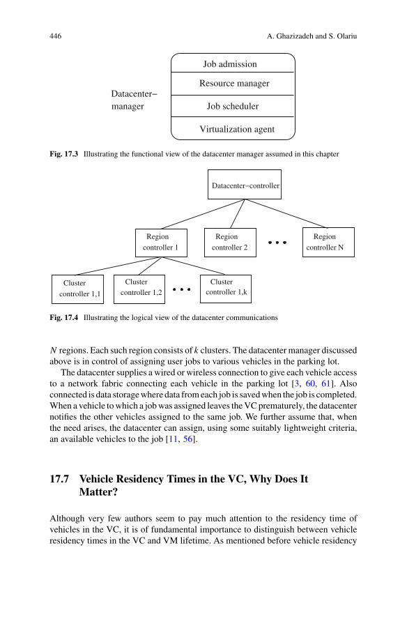
446 A. Ghazizadeh and S. Olariu
Job admission
Job scheduler
Virtualization agent
Resource manager
managerDatacenter−
Fig. 17.3 Illustrating the functional view of the datacenter manager assumed in this chapter
controller 1 controller 2
Region RegionRegion
Datacenter−controller
Cluster Cluster
controller 1,1 controller 1,2
controller N
Clustercontroller 1,k
Fig. 17.4 Illustrating the logical view of the datacenter communications
N regions. Each such region consists of k clusters. The datacenter manager discussedabove is in control of assigning user jobs to various vehicles in the parking lot.
The datacenter supplies a wired or wireless connection to give each vehicle accessto a network fabric connecting each vehicle in the parking lot [3, 60, 61]. Alsoconnected is data storagewhere data fromeach job is savedwhen the job is completed.When a vehicle towhich a jobwas assigned leaves theVCprematurely, the datacenternotifies the other vehicles assigned to the same job. We further assume that, whenthe need arises, the datacenter can assign, using some suitably lightweight criteria,an available vehicles to the job [11, 56].
17.7 Vehicle Residency Times in the VC, Why Does ItMatter?
Although very few authors seem to pay much attention to the residency time ofvehicles in the VC, it is of fundamental importance to distinguish between vehicleresidency times in the VC and VM lifetime. As mentioned before vehicle residency

17 Vehicular Clouds: A Survey and Future Directions 447
time shows the amount of time a vehicle spends in the VC. If a vehicle leaves the VCbefore finishing the job, meaning the VM that is running the job has not terminated,then we can say that the vehicle has left prematurely.
The VC literature is full of papers discussing fanciful VCmodels implemented ontop of moving vehicles and supported by ubiquitous and pervasive roadside infras-tructure. Those authors do not seem to be concernedwith the obvious fact thatmovingvehicles’ residency times in the VC may, indeed, be very short-lived and thereforeso is their contribution to the amount of useful work performed. Worse yet, should avehicle running a VM leave the VC prematurely the amount of work performed bythat vehicle may be lost. Unless, of course, special precautions are being taken. Suchprecautionary measures involve either some flavor of checkpointing [23, 77] or elseenforcing some form of redundant job assignment [30–32]. Both approaches haveconsequences in terms of overhead and impact the mean time to failure [32] and jobcompletion time [28].
While such supporting infrastructure may well be available in the Smart Cities[34, 52], of the future, it does not exist today. This state of affairs is casting along shadow of doubt on the feasibility of those VC models and is apt to discreditthe entire VC concept. Similarly, zero-infrastructure VCs built on top of movingvehicle are utterly unrealistic since the DSRC-mandated V2V transmission range[75], combined with the limited bandwidth inherent to wireless communications,does not permit VM migration and/or data offloading in case vehicles exit the VC.
As a general comment, we note that for tractability reasons, to a first approx-imation, vehicular residency times in the VC are considered to be independent,exponentially distributed random variables with a common parameter.
17.7.1 A Taxonomy of Residency Times
Given the importance of residency times, it is useful to offer a more general look atVCs in terms of the assumed vehicular residency times in the VC.
• Long residency times: At one end of the spectrum, we find VCs characterizedby long vehicular residency times. These can be further partitioned depending onwhether or not the vehicles are assumed to be parked or mobile. For example,Arif et al. [3] and other researchers have assumed a VC is developed using thevehicles in the long-term parking lot of an international airport where residencytimes are days or maybe even weeks [32]. Intuitively, it is clear that the users ofsuch a parking lot may share their transportation plans with the datacenter at theairport and so the residency times become almost deterministic.As another example of a VC characterized by long and stable vehicular residencytimes consider a plant that operates 24 hours a day, seven days a week. The patronsof the parking lot are working at the plant in eight-hour shifts, that creates a poolof vehicles that can serve as the substructure for a datacenter. We assume thatthe vehicles in the parking lot are plugged into a standard power outlet and areprovided Ethernet connection to the datacenter.

448 A. Ghazizadeh and S. Olariu
Recently, Florin et al. [25] proposedMilitary Vehicular Clouds (MVC) an instanceof VCs with (relatively) long vehicular residency times. In their vision, a MVCcomprises either parked military vehicles or vehicles that move in formation sothat, for all practical purposes, the distance between adjacent vehicles remainsthe same. This controlled mobility regimen applies to military units deployedin support of a tactical mission. The vehicles participating in the MVC have awireless connection to a Mobile Access Point (MAP) which may be connectedto a center of command and control. There are two major differences betweenMVCs and conventional clouds. First, unlike conventional clouds that are mostlypublic, MVCs are private, catering to the special needs of the military. Second,because of mobility and of the fact that military vehicles join and leave the MVCin ways that best support the tactical mission at hand, the MVCs are characterizedby unpredictable availability of compute resources.
• Medium residency times: Some VCs are characterized by shorter vehicle resi-dency times. Such is the case, for example, of VCs build on top of the vehiclesin the parking lot of a shopping mall. Observe that the vehicular residency timesat the mall are correlated with the average time a standard American spends atthe shopping mall in one visit. While vehicle residency times at shopping mallsare not directly available, there is a profusion of data concerning shopping patternstatistics – see, for example, [6, 40, 46, 47]. This statistical data indicates that,during normal business hours, when the datacenter services are required, the shop-ping center parking lot contains a sufficient number of vehicles which makes thetask of finding available vehicles, for job assignment, feasible. Also, according tothese statistics, the average American shopper spends about two hours per visit atthe shopping mall. Of course, the exact residency time of any one individual is arandom variable and so any form of reasoning here must be probabilistic. One ofthe challenges in these types of VCs is to identify the types of cloud services thatcan be offered.Yet another instance of a VC characterized by medium vehicular residency timesare VCs set up in a Smart City [89] where the vehicles have connectivity throughpre-deployed infrastructure provided by the municipality. In such a scenario,whether the vehicle are parked or mobile, as long as they reside within the SmartCity (as the vast majority do) they participate in the VC without interruption ofservice [80].The challenge facing the implementation of a datacenter built on medium resi-dency vehicles is to maintain high availability and reliability in the face of thedynamically changing resources.
• Short residency times: Finally, one can conceive of instances of VCs involvingvehicles with a short residency times. These are vehicles that happen to be inan area that offers free Internet connectivity, such a gas stations or restaurants athighway interchanges, where they can be assigned jobs to process. The vehicleswill process their jobs while moving (and not being connected) and will uploadtheir results at the next interchange.As in the case of medium residency times, VC involving short-term vehicularresidency times are very challenging to deal with and, to the best or our knowledge,

17 Vehicular Clouds: A Survey and Future Directions 449
no papers in the literature have reported on promoting high system availability andreliability in the face of the dynamically changing resources.
17.8 Services Supported by VCs
In [68] Olariu et al. have introduced three types of services that will be made possiblebyVCs: Network as a Service (NaaS), Storage as a Service (STaaS), and Cooperationas a Service (CaaS). Since then, other services were proposed. These services willbe discussed briefly in Sects. 17.8.1–17.8.6 below.
17.8.1 Network as a Service (NaaS)
It is clear that, at the moment, not every vehicle on the road has Internet connection.Therefore the vehicles that have access to Internet can share their excess Internetwith other drivers that request it. Many drivers have limited or unlimited Internetconnection through 3G or 4G cellular network and these resources can be under-utilized because, for example, not all drivers are constantly downloading from theInternet. A driver that wants to share the Internet connectivity will advertise it to allthe vehicles nearby. Considering the fact that the vehicles are moving on the samedirection and with relative speeds, this system can be viewed as a traditional VANET,constructed of a set of static access points and mobile nodes that are moving at lowspeeds.
For example in Fig. 17.5, vehicle a, and c have 4G and vehicle d has WiFi con-nectivity through an access point. Vehicles a, d and c broadcast packets and informother drivers about their intention to share their networks. If any vehicle is interestedto rent these Internet services, the requests will be sent to a selected vehicle with astable Internet connection. There are several factors such as reliability of the network,expected connection time, and speed of the network that should be considered forselecting a candidate.
17.8.2 Storage as a Service (STaaS)
Many vehicles have plenty of on-board storage resources and capabilities, howeverthere are also some vehicles that need extra storage for running complex applications.In addition parked vehicles in the shoppingmalls or any large ormedium-size parkinglot can rent out their storage resources to the management of such places. Anotherexample is using this excess storage in backup purpose, peer-to-peer applicationsand various types of content such as multimedia contents that are larger in size andrequire more storage support. STaaS in VCs has limitations related to mobility of the

450 A. Ghazizadeh and S. Olariu
Fig. 17.5 Example of Naas Service in VCs
vehicles. The vehicles are not static forever; hence the users are able to use storageresources for an extended period of time. This limitation is an obstacle against rentingstorage as a service in VCs.
17.8.3 Cooperation as a Service (CaaS)
Mousannif et al. [59] have introduced Cooperation as a Service, as a new architec-ture that extends the two types of services in VCs, Network as a Service (NaaS) andStorage as a Service (SaaS). It aims to provide vehicles with a set of services for free,and without the need for increased roadside infrastructure. Vehicular networks canbe help in many situations to improve the safety of transportation, decrease trafficcongestion, and provide accident warnings, road condition and weather information,parking availability and advertisement [64]. ITS and available 3G and 4G networkscan be useful for offering these services. In CaaS, which can be considered as anew form of community service, drivers can obtain a set of services using minimalroadside infrastructure. If no infrastructure is available, these vehicles can take advan-tage of V2V communication. V2V communications are made possible via DSRC orWAVE (Wireless Access in a Vehicular Environment) [79].
CaaS uses a hybrid publish/subscribe mechanism where the driver (or subscriber)informs the system about his wish to acquire a service and the vehicles/drivers thathave subscribed to the same service will cooperate to provide the driver with thenecessary information regarding the service, by publishing this information in thenetwork. An example of a cooperative vehicular safety application is the ElectronicBrake Warning (EBW) application. When a vehicle breaks sharply, it broadcastsan event-based message, alerting the surrounding vehicles of the braking incident.This information is especially useful in situations that the view of the break light isblocked and it will allow drivers to take necessary precautions. Another example isthe Vehicle Stability Warning (VSW) application. In VSW, preceding vehicles alertfollowing vehicles of upcoming potential hazardous conditions such as icy or slippery
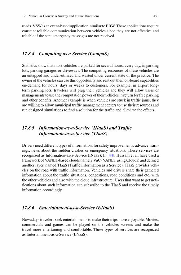
17 Vehicular Clouds: A Survey and Future Directions 451
roads.VSWis an event-based application, similar toEBW.These applications requireconstant reliable communication between vehicles since they are not effective andreliable if the sent emergency messages are not received.
17.8.4 Computing as a Service (CompaS)
Statistics show that most vehicles are parked for several hours, every day, in parkinglots, parking garages or driveways. The computing resources of these vehicles arean untapped and under-utilized and wasted under current state of the practice. Theowner of the vehicles can use this opportunity and rent out their on-board capabilitieson-demand for hours, days or weeks to customers. For example, in airport long-term parking lots, travelers will plug their vehicles and they will allow users ormanagements to use the computation power of their vehicles in return for free parkingand other benefits. Another example is when vehicles are stuck in traffic jams, theyare willing to allow municipal traffic management centers to use their resources andrun designed simulations to find a solution for the traffic and alleviate the effects.
17.8.5 Information-as-a-Service (INaaS) and TrafficInformation-as-a-Service (TIaaS)
Drivers need different types of information, for safety improvements, advance warn-ings, news about the sudden crashes or emergency situations. These services arerecognized as Information-as-a-Service (INaaS). In [44], Hussain et al. have used aframework ofVANET-based clouds namelyVuC (VANETusingClouds) and definedanother layer, named TIaaS (Traffic Information as a Service). TIaaS provides vehi-cles on the road with traffic information. Vehicles and drivers share their gatheredinformation about the traffic situations, congestions, road conditions and etc. withthe other vehicles and also with the cloud infrastructure. Users that want to get noti-fications about such information can subscribe to the TIaaS and receive the timelyinformation accordingly.
17.8.6 Entertainment-as-a-Service (ENaaS)
Nowadays travelers seek entertainments to make their trips more enjoyable. Movies,commercials and games can be played on the vehicles screens and make thetravel more entertaining and comfortable. These types of services are recognizedas Entertainment-as-a-Service (ENaaS).

452 A. Ghazizadeh and S. Olariu
17.9 Applications of VC
The major objective of this section is to offer an overview of a number of VCapplications. Many others, that were discussed in [68] will not be mentioned here.
17.9.1 Security and Privacy in VCs
When users are allowed to share pools of resources in a shared network, securityand privacy questions and issues arise. In the past few years, many researchers havesuggested solutions for such issues.
The first authors to investigate security and privacy issues in VC were Yan et al.[87] and Yan et al. [88]. They have shown that many of the insecurities found in con-ventional CC carry over to VCs. In addition, several VC-specific security challengeswere identified and also preliminarily solutions were proposed. They have catego-rized the main targets of attacks into attacks related to confidentiality, integrity andavailability. Examples for such attacks are finding the identities of users, personaland sensitive data, code and documents stored on the VC. Such attacks can be done inmany ways, for example attackers pretend to be the user that is requesting the serviceor they can discover a bug or flaw in the system and get access to the sensitive andhidden data that they normally don’t have the permission or access to. Yan et al. haveargued that the security authentication in VC is challenging due to the mobile natureof the moving vehicles. Specially, authentication of messages with location contextis not easy since the location of the vehicles is changing with time. Another vulner-ability area in VC is that often because of the legal reasons, the vehicle identity andinformation is pinned to its owner’s identity. However most VC applications use thelocation information of the vehicle and tracking the location of the vehicle violatesthe owner’s privacy. Pseudonymization has been suggested as a possible solution. Inthis approach the vehicle’s identity is replaced by a pseudonym to protect the driver’sprivacy.
Huang et al. [43] have proposed a vehicular cloud computing system called PTVCfor improving privacy and trust based verification communication. The purpose ofthis system is to provide a better solution for selection of credible and trustwor-thy vehicles for forming a VC. The proposed PTVC scheme is composed of afew stages: system setup, privacy-preserving trust-based vehicle selection proto-col, privacy-preserving verifiable computing protocol and trust management. In thisscheme, a trust authority is responsible for execution and maintenance the the wholesystem and it generates public and private keys for vehicles and road side units (RSU).When a vehicle wants to join or form a VC, it will try to find the nearest availablevehicles with the highest reputation. Participating vehicles that want to transfer datawithout worrying about leaking privacy, should first encrypt their data, which is donewith the help of privacy preserving verifiable computing protocols. Each participat-ing vehicle will receive feedbacks on the performance and participation which then

17 Vehicular Clouds: A Survey and Future Directions 453
helps in determining the reputation value of the vehicle. The authors have concludedthat the security analysis showed that this proposed scheme is practical and effectiveagainst various security attacks. This system can identify the untrustworthy vehiclesand blocks them from entering the VC.
17.9.2 Disaster Management Using VCs
The importance of emergency response systems and disaster management systemscannot be diminished due to the sudden nature of disasters and the damage, lossand destruction that it brings to human lives and as well as properties. In the pastdecade we have been seen many disasters such as the Earthquake in Haiti, in 2010that caused over 200,000 deaths, left two million homeless and three million in needof emergency assistance.
At the time of disaster, VCs plays a very important role in helping with remov-ing people from disastrous and damaged areas and transfer them to safe areas andtherefore save many lives and also valuables including information. Raw et al. [70]proposed an Intelligent Vehicular Cloud Disaster Management System (IVCDMS)model and have analyzed the intelligent disaster management through VC networkcommunicationmodes with the existing hybrid communication protocols. The archi-tecture of this system consists of three interacting service layers named vehicularcloud infrastructure as a service, intelligence layer service and system interface ser-vice. The smart interface service helps in transportation of data from one place toanother and it acquires data from various sources such as roadside units, smart cellphones, social network etc. The VC infrastructure as a service provides base plat-form and environment for the IVCDMS. The intelligence layer service provides thenecessary computational models, algorithms and simulations; both stochastic anddeterministic that then provides the emergency responses strategies by processingthe available data from various resources.
Raw et al. [70] have implemented the communication V-P (vehicle-to-pedestrian)protocol which uses cellular phones and wireless network to improve the safetyof travelers, pedestrians and drivers. This protocol helps drivers and pedestrians toget informed of one another and have enough time to take proper action and avoidprobable accidents and hazards.
17.9.3 VC Data Collection for Traffic Management
VCs can help the ITS community by improving the traffic and accident informationsharing. Chaqfeh et al. [18] have proposed an on-demand and pull-based data collec-tion model for better information sharing between vehicles. When a vehicle wants toget information about a specific rout, it will create a route request (RREQ) messagethat contains details about the destination and the route that the vehicle is interested

454 A. Ghazizadeh and S. Olariu
to get more information about. The requesting vehicle then broadcasts this messageto its neighbors. The RREQ message is the re-routed to vehicles in the identifieddestination. The vehicles at the destination that receive the RREW message thenpublish their sensor data and gathered traffic information to the network by forminga dynamic VC. Finally a vehicle is selected as the broker to collect the informationand transfer and communicate it with the infrastructure. Chaqfeh et al. [18] haveshowed via simulation that their VC-based approach can effectively support ITSwith real-time data, even with not too many participating vehicles and concludedthat the participation of small number of vehicles in a dynamic VC is enough fordata transferring and data collection. However, these authors have ignored funda-mental VC problems including whether VMs will be set up and how system failurescan be handled in case vehicles leave the VC unexpectedly.
17.9.4 Sharing Real-Time Visual Traffic Information via VCs
With advances in technology, vehicles are equipped with more sophisticated sensingdevices such as cameras and these features give vehicles the ability to act as mobilesensors that provide useful traffic information.
With advances in technology, vehicles are having better quality and improvedcameras and sensing deviceswhich can be used to collect traffic and road information.
Users can send or receive accurate and up-to-dated information about the road ortraffic conditions by using vehicular cloud services. Kwak et al. [51] have presentedan architecture for a possible collaborative traffic image-sharing systemwhich allowsdrivers in the VC to report and share visual traffic information called NaviTweets.NaviTweets are selected and transformed into an informative snapshot summary ofthe route. This will provide reliable information about various details of the roadcondition, traffic, congestion, weather and any data that is useful for drivers and isbeneficial for enhancing the safety and speed of the transportation.
Figure17.6 illustrates an example case for using this system. Assume that DriverA want to get to a destination and does not know which route to take. He has twooptions, Route 1 and Route 2 and there is not enough available information regardingthe safety of the road on the application that he is using. He decides to subscribe tothe NaviTweets service to receive other driver’s opinions about the road. Driver Bthat is driving on Route 1 posts a picture, via the VC, about an accident that occurredand resulted in congestion. Driver C that is driving on Route 2 sends a tweet aboutthe slippery bridge and he indicates that there is no traffic on that road. The VCdiscards the older tweets from previous drivers and keeps the most up-to-date tweetsregarding a rout. Driver A then receives a summary of each road and plans his routeaccordingly.

17 Vehicular Clouds: A Survey and Future Directions 455
Fig. 17.6 Example scenario of the proposed architecture
17.10 Future Challenges for VCs
The main goal of this section is to point out a few important challenges for the VC.
17.10.1 A Large-Scale Implementation of VCs
As already mentioned in this chapter, to the best of the authors’ knowledge, no large-scale implementation of Vcs has been reported in the literature. We are aware oftwo attempts at addressing this challenge: one is purely simulation-based and wasreported in [26]. The other is a recent testbed that we discuss below.
Researchers often desire convenient, cost-effective and reconfigurable testingenvironments. Developing and testing VC applications is challenging and expen-sive. One solution to this problem is creating miniature testbeds using robots insteadof real vehicles. Recently, this approach was explored by Lu et al. [54] who haveattempted to build a VC testbed with different types of mobile robots. Their testbedis constructed from robot vehicles on mini cloud, network, remote cloud and man-agement servers. The VC-bots can be managed and controlled with the help of auser interface (UI) that was built using java. Using this interface, users can see andtrack vehicles on a map. The interface is a graph-based model that shows straightroads as edges and intersections as nodes. The width of an edge shows the widthof the road and the position or coordinate of each node, shows the location of theintersection. Parking lots and open spaces are shown as special nodes connected tothe road network. Users can move the robot vehicles from one location to another,using the UI. An advantage of this design is the configurable map and road network.
The testbed contains 19 robot vehicles of four types: VC-trucks, VC-van, VC-sedan, and VC compacts. The types of robot vehicles vary in sensing devices, com-

456 A. Ghazizadeh and S. Olariu
puting resources, and battery life and an independent WiFi network was used forthe purpose of the robot vehicle management. Each robot vehicle is equipped withWiFi interface and also LTE modem, or the purpose of better network connectionand in case the robot is out of the range of the WiFi network. In addition, severalWiFi routers are deployed as roadside units (RSU).
In this testbed, the cloud resources contain robot vehicles on board mini cloudand remote cloud in the data center. The remote cloud consists of Linux serversmanaged by OpenStack and provides a cloudmanagement user interface, centralizedcontrol and storage. A Kernel-based Virtual Machine (KVM) was installed on therobot vehicles to provide basic virtualization environment. Users can create virtualmachines (VM)or import existingVMimages intomini cloud, and run their programsand applications on these virtual machines. Live migration is also allowed from arobot vehicle to another.
The testbed of Lu et al. [54] is a work-in-progress and proof-of-concept prototypefor VC-bots, an evolving platform for testing vehicular network andVC applications.To the best of our knowledge this is the first time researchers have implemented atestbed for VCs and it is a proof that this area of research should be explored andstudied further.
17.10.2 Promoting Reliability and Availability in VCs
It has been pointed out repeatedly [16, 39, 56] that the huge success of CC was due,to a large extent, to the extremely system reliability and availability of datacenters.For example, Amazon and Google are striving to make customer experience moreenjoyable by insisting on extremely high system availability under all imaginableconditions [11, 19].
However, as mentioned before, the dynamically changing availability of computeresources due to vehicles joining and leaving the VC unexpectedly leads to a volatilecomputing environment where promoting system reliability and availability is quitechallenging. Yet, it is clear that if VCs are to see an adoption rate and success similarto CCs, reliability and availability issues must be addressed in VCs.
To understand this issue better, assume that a job is assigned to a vehicle currentlyin the VC. If the vehicle remains in the VC until the job completes, all is well.Difficulties arise when the vehicle leaves the VC before job completion. In thiscase, unless special precautionary measures are taken, the work is lost and the jobmust be restarted, taking chances on another vehicle, and so on, until eventually thejob is completed. Clearly, losing the entire work of a vehicle, in case of a prematuredeparture, must bemitigated. One possible method is to use checkpointing, a strategyoriginally proposed in databases [23, 77]. This strategy requires making regularbackups of the job’s state, and storing them in a separate location. In the event avehicle leaves before job completion, the job can be restarted, on a new vehicle,using the last backup. While this seems simple and intuitive, checkpointing is not

17 Vehicular Clouds: A Survey and Future Directions 457
implemented efficiently in VCs. In fact, Ghazizadeh [30] has found that, in VCs,most checkpoints remain unused and introduce a very large overhead.
Alternatively, reliability and availability can be enhanced, as it is often done inconventional CCs, by employing various forms of redundant job assignment strate-gies [11, 15, 16, 20, 22, 50, 55, 65]. Indeed, the volatility of resources in VCssuggests employing job assignment strategies wherein each user job is assigned to,and executed by, two or more vehicles in the VC [32].
A well-known yardstick for assessing reliability of a system is the Mean Time toFailure (MTTF), defined as the expectation of the time until the occurrence of the nextsystem failure [5, 7, 8, 14]. Related to MTTF is the Mean Time To Repair (MTTR)that quantifies the expected time until the system is operational again. Barlow andProschan [8] defined system availability as the long-term probability that the systemis operating at a specified time. Thus, the availability of a system can be expressedin terms of MTTF and MTTR as (see also [39], p. 34)
AVAIL = MTTF
MTTF + MTTR. (17.1)
It is intuitively clear that the longer and more predictable the vehicle residencytimes in the VC, the easier it is to ensure system reliability and availability. Recently,Ghazizadeh et al. [32] have studied redundancy-based job assignment strategies andhave derived analytical expressions for the corresponding MTTF. Similarly Florinet al. [25] have looked at the problem of reasoning about the reliability of MVCs.Building on the results in [32] Florin et al. have developed an analytic model forestimating the job completion time in VCs assuming a redundant job assignmentstrategy.
Florin et al. [27] has studied the reliability of VCs with short vehicular residencytimes, as is the case of shopping mall parking lots or the short-term parking lotof a large airport. They showed how to enhance system reliability and availabilityin these types of VCs through redundancy-based job assignment strategies. Theyoffered a theoretical prediction of the corporate MTTF and availability offered bythese strategies in terms of the MTTF of individual vehicles and of the MTTR. Tothe best of the authors’ knowledge, this is the first paper that is looking at evaluatingthe MTTF and availability in VCs built on top of vehicles with a short residencytime. Extensive simulations using data from shopping mall statistics [40–42] haveconfirmed the accuracy of our analytical predictions.
17.10.3 Big Data in VCs
Oneof the significant research challenges inVCs is to identify conditions underwhichVCs can support Big Data applications. It is apparent that Big Data applications, withstringent data processing requirements, cannot be supported by ephemeral VCs,
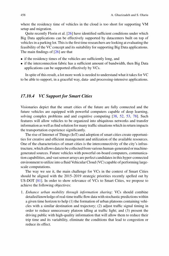
458 A. Ghazizadeh and S. Olariu
where the residency time of vehicles in the cloud is too short for supporting VMsetup and migration.
Quite recently Florin et al. [26] have identified sufficient conditions under whichBig Data applications can be effectively supported by datacenters built on top ofvehicles in a parking lot. This is the first time researchers are looking at evaluating thefeasibility of the VC concept and its suitability for supporting Big Data applications.The main findings of [26] are that
• if the residency times of the vehicles are sufficiently long, and• if the interconnection fabric has a sufficient amount of bandwidth, then Big Dataapplications can be supported effectively by VCs.
In spite of this result, a lot more work is needed to understand what it takes for VCto be able to support, in a graceful way, data- and processing-intensive applications.
17.10.4 VC Support for Smart Cities
Visionaries depict that the smart cities of the future are fully connected and thefuture vehicles are equipped with powerful computers capable of deep learning,solving complex problems and and cognitive computing [38, 52, 53, 78]. Suchfeatures will allow vehicles to be organized into ubiquitous networks and transferinformation aswell as find solution formany traffic situationswhich in return impactsthe transportation experience significantly.
The rise of Internet of Things (IoT) and adoption of smart cities create opportuni-ties for creative and efficient management and utilization of the available resources.One of the characteristics of smart cities is the interconnectivity of the city’s infras-tructure,which allowsdata to be collected fromvarious human-generatedormachine-generated sources. Future vehicles with powerful on-board computers, communica-tion capabilities, and vast sensor arrays are perfect candidates in this hyper-connectedenvironment to utilize into a fluid Vehicular Cloud (VC) capable of performing large-scale computations.
The way we see it, the main challenge for VCs in the context of Smart Citiesshould be aligned with the 2015–2019 strategic priorities recently spelled out byUS-DOT [81]. In order to show relevance of VCs to Smart Cities, we propose toachieve the following objectives:
1. Enhance urban mobility through information sharing: VCs should combinedetailed knowledge of real-time trafficflowdatawith stochastic predictionswithina given time horizon to help (1) the formation of urban platoons containing vehi-cles with a similar destination and trajectory; (2) adjust traffic signal timing inorder to reduce unnecessary platoon idling at traffic light; and (3) present thedriving public with high-quality information that will allow them to reduce theirtrip time and its variability, eliminate the conditions that lead to congestion orreduce its effect.

17 Vehicular Clouds: A Survey and Future Directions 459
2. Avoid congestion of key transportation corridors through cooperative navigationsystems: Congestion-avoidance techniques that become possible in SC environ-ments will be supplemented by route guidance strategies to reduce unnecessaryidling and will limit environmental impact of urban transportation.
3. Handling non-recurring congestion: VCs will explore strategies to efficientlydissipate congestion, by a combination of traffic light retiming and route guidanceto avoid more traffic buildup in congested areas.
4. Demonstrate and evaluate VCs: We will build a small-scale prototype for VCs.The evaluation of the traffic light retiming will be conducted in VCs throughsimulation. Several traffic simulation systems described in [29] will be evaluatedbefore deciding on the right manner to simulate a platoon-aware system.
17.11 Concluding Remarks and Directions for FutureWork
A few years ago, inspired by the success and emergence of CC, researchers haveproposed Vehicular Cloud Computing (VCC) which is assumed to be a non-trivialextension of the conventional Cloud Computing (CC) paradigm. VCCwas first moti-vated by understating the fact that the current and future smart vehicles are assem-bled with powerful computational and storage resources and several transceivers andsensing devices. These resources in vehicles are chronically underutilized and canbe rented out to users or shared to solve traffic and safety related problems or used inmany different means and applications. In this work, we briefly discussed the con-ventional Cloud Computing as well as the Mobile Cloud Computing. We providedan overview of the Vehicular Cloud Computing. We studied the details of the archi-tecture and services provided by VCs. In addition we reviewed the recent researchesand potential future applications. We also looked at some of the challenges of VCsand discussed possible solutions.
With the rise of Internet of things (IoT) and intelligent transportation systems (ITS)our cities, roads and vehicles are getting smarter and information and communicationtechnologies are improving and becomingmore advanced. Such features create greatopportunity to not only create a safe, secure and comfortable journey for travelersbut also provide the most efficient and least expensive solutions which is the purposeof Vehicular Cloud Computing. A concerted effort among industry, academia, auto-industry and the government is needed for new researches and implementations ofVCs. Once adopted VCC will be the next paradigm shift with impressive impacts oneconomy, environment, safety and transportation.

460 A. Ghazizadeh and S. Olariu
References
1. M. Abuelela, S. Olariu, Taking VANET to the clouds, in Proceedings of the ACM MoMM(Paris, France, 2010)
2. Amazon Inc, Amazon web services (2010), http://aws.amazon.com3. S.Arif, S.Olariu, J.Wang,G.Yan,W.Yang, I.Khalil, Datacenter at the airport: Reasoning about
time-dependent parking lot occupancy. IEEE Trans. Parallel Distrib. Syst. 23(11), 2067–2080(2012)
4. M. Armbrust, A. Fox, R. Griffith, A.D. Joseph, R.H. Katz, A. Konwinski, G. Lee, D.A. Patter-son, A. Rabkin, I. Stoica, M. Zaharia, Above the clouds: a berkeley view of cloud computing.Technical Report No. UCB/EECS-2009-28 (U.C. Berkeley, 2009)
5. A. Avizienis, J.-C. Laprie, B. Randell, C. Landwehr, Basic concepts and taxonomy of depend-able and secure computing. IEEE Trans. Dependable Secur. Comput. 1(1), 1–23 (2004)
6. K. Bachman, Study; teens still big mall shoppers (2017), http://www.adweek.com/news/advertising-branding/study-teens-still-big-mallshoppers-112487. Accessed 18 Jan 2017
7. R.F. Barlow, F. Proschan, Mathematical Theory of Reliability (Wiley, New York, 1967). 3-rdprinting
8. R.F. Barlow, F. Proschan, Statistical Theory of Reliability and Life Testing Probability Models(Holt, Rinehart and Winston, New York, 1975)
9. B. Baron,M. Campista, P. Spathis, L.H. Costa,M. Dias de Amonim, O.C. Duarte, G. Pujolle, Y.Viniotis, Virtualizing vehicular node resources: feasibility study of virtual machine migration.Veh. Commun. 4, 39–46 (2016)
10. L.A. Barroso, U. Hölzle, The Datacenter as a Computer: An Introduction to the Design ofWarehouse-Scale Machines (Morgan & Claypool, San Rafael, California, 2009)
11. L.A. Barroso, J. Clidaras, U. Hölzle, The Datacenter as a Computer: An Introduction to theDesign of Warehouse-Scale Machines, 2nd edn. (Morgan & Claypool, San Rafael, California,2013)
12. A. Beloglazov, J. Abawajy, R. Buyya, Energy-efficient resource allocation heuristics for effi-cient management of datacenters for cloud computing. Future Gener. Comput. Syst. 28, 755–768 (2012)
13. A. Bento, R. Bento, Cloud computing: a new phase in information technology management. J.Inf. Technol. Manag. 22(1), 39–46 (2011)
14. B. Bergman, On reliability theory and its applications. Scandinavian J. Stat. 12, 1–41 (1985)15. D. Bhagavathi, P.J. Looges, S. Olariu, J.L. Schwing, A fast selection algorithms on meshes
with multiple broadcasting. IEEE Trans. Parallel Distrib. Syst. 5(7), 772–778 (1994)16. R. Buyya, C. Vecchiola, S. Thamarai Selvi, Mastering Cloud Computing: Foundations and
Applications Programming (Morgan Kaufman, Elsevier, 2013)17. F. Chang, J. Dean, S. Ghemawat,W.C. Hsieh, D.A.Wallach,M. Burrows, T. Chandra, A. Fikes,
R.E. Gruber, Bigtable: a distributed storage system for structured data, in Proceedings 7-thUSENIX Symposium on Operating Systems Design and Implementation, (OSDI06) (Seattle,Washington, 2006)
18. M. Chaqfeh, N. Mohamed, I. Jawhar, J. Wu, Vehicular cloud data collection for intelligenttransportation systems, in Smart Cloud Networks & Systems (SCNS) (IEEE, 2016), pp. 1–6
19. G. DeCandia, D. Hastorun, M. Jampani, G. Kakulapati, A. Lakshman, A. Pilchin, S. Siva-subramanian, P. Vosshall, W. Vogels, Dynamo: amazons highly available key-value store, inProceedings of 23-th ACM Symposium on Operating Systems Principles, (SOSP07) (Stevenson,Washington, 2007)
20. J. Deng, S.-H. Huang, Y. Han, J. Deng, Fault tolerant and reliable computation in cloud com-puting, in 2010 IEEE GLOBECOM Workshops (GC Wkshps) (2010), pp. 1601–1605
21. H.T. Dinh, C. Lee, D. Niyato, P. Wang, A survey of mobile cloud computing: architecture,applications, and approaches. Wirel. Commun. Mobile Comput. 13(18), 1587–1611 (2013)
22. I. Egwutuoha, S. Chen, D. Levy, B. Selic, A fault tolerance framework for high performancecomputing in cloud, in 2012 12th IEEE/ACM International Symposium on Cluster, Cloud andGrid Computing (CCGrid) (2012), pp. 709–710

17 Vehicular Clouds: A Survey and Future Directions 461
23. R. Elmasri, S.B.Navathe,Fundamentls of Database System, 6th edn. (Addison-Wesley, Boston,2011)
24. M. Eltoweissy, S. Olariu, M. Younis, Towards autonomous vehicular clouds, in Proceedingsof AdHocNets’2010 (Victoria, BC, Canada, 2010)
25. R. Florin, P. Ghazizadeh, A.G. Zadeh, S. Olariu, Enhancing dependability through redundancyin military vehicular clouds, in Proceedings of IEEE MILCOM’2015 (Tampa, Florida, 2015)
26. R. Florin, S. Abolghasemi, A.G. Zadeh, S. Olariu, Big Data in the parking lot, in Big DataManagement and Procesing, chapter 21 ed. by K.-C. Li, H. Jiang, A. Zomaya (Taylor andFrancis, Boca Raton, Florida, 2017), pp. 425–449
27. R. Florin, A.G. Zadeh, P. Ghazizadeh, S. Olariu, Promoting reliability and availability in vehic-ular clouds. IEEE Trans. Cloud Comput. submitted (2017)
28. R. Florin, P. Ghazizadeh, A.G. Zadeh, S. El-Tawab, S. Olariu, Reasoning about job completiontime in vehicular clouds. IEEE Trans. Intell. Transp. Syst. 18 (2017)
29. D. Gettman, L. Head, Surrogate safety measures from traffic simulation models (2003), http://www.fhwa.dot.gov/publications/research/safety/03050/03050.pd
30. P. Ghazizadeh, Resource allocation in vehicular cloud computing. Ph.D. Thesis, Old DominionUniversity (2014)
31. P. Ghazizadeh, S. Olariu, A.G. Zadeh, S. El-Tawab, Towards fault-tolerant job assignment invehicular cloud, in Proceecings IEEE SCC (2015), pp. 17–24
32. P. Ghazizadeh, R. Florin, A.G. Zadeh, S. Olariu, Reasoning about the mean time to failure invehicular clouds. IEEE Trans. Intell. Transp. Syst. 17(3), 751–761 (2016)
33. A.S. Ghemawat, H. Gobioff, S.-T. Leung, The Google file system, in Proceedings of 19-thACM Symposium on Operating Systems Principles, (SOSP03) (Bolton Landing, NY, 2003),pp. 29–43
34. D.V. Gibson, G. Kozmetsky, R.W.E. Smilor, The Technopolis Phenomenon: Smart Cities, FactSystems, Global Networks (Rowman and Littlefield, 8705 Bollman Place, Savage, MD, 1992)
35. Google, Inc. Google app engine (2010), http://code.google.com/appengine/36. L.Gu,D.Zeng, S.Guo,Vehicular cloud computing: a survey, inProceedings of IEEE Globecom
Workshops (2013), pp. 403–40737. C. Harrison, I.A. Donnelly, The theory of smart cities, in Proceedings of the 55th Annual
Meeting of the International Society for the Systems Sciences, (ISSS’2011), Hull, U.K. (2011)38. D. Hatch, Singapore strives to become ’The Smartest City’: Singapore is using data to redefine
what it means to be a 21st-century metropolis (2013)39. J.L. Hennessy, D.A. Patterson,Computer Architecture a Quantitative Approach (MorganKauf-
man, Elsevier, 2012)40. H. Hu, C.R. Jasper, Men and women: a comparison of shopping mall behavor. J. Shopp. Center
Res. 11(1/2), 113–123 (2004)41. H. Hu, C.R. Jasper, Consumer shopping experience in the mall: Conceptualization and mea-
surement, in Academy of Marketing Science Annual Conference Proceedings (Coral Gables,Florida, 2007)
42. H. Hu, C.R. Jasper, A qualitative study of mall shoping behaviors of mature consumers. J.Shopp. Center Res. 14(1), 17–38 (2007)
43. C. Huang, R. Lu, H. Zhu, H. Hu, X. Lin, PTVC: achieving privacy-preserving trust-based veri-fiable vehicular cloud computing, in Proceedings of IEEE Global Communications Conference(GLOBECOM’2016) (IEEE, 2016), pp. 1–6
44. R. Hussain, F. Abbas, J. Son, H. Oh, TIaaS: secure cloud-assisted traffic information dissem-ination in vehicular ad hoc networks, in 2013 13th IEEE/ACM International Symposium onCluster, Cloud and Grid Computing (CCGrid) (2013), pp. 178–17
45. IBM Inc, IBM smart cloud (2010), http://www.ibm.com/cloud-computing46. JCDecaux, The mall phenomenon (2017), http://www.jcdecauxna.com/sites/default/files/
assets/mall/documents/studies/mallphenomenon.pdf. Accessed 18 Jan 201747. JCDecaux, Teen marketplace (2017), http://www.jcdecauxna.com/sites/default/files/assets/
mall/documents/studies/TeensFact.pdf. Accessed 18 Jan 2017

462 A. Ghazizadeh and S. Olariu
48. D. Kapil, E.S. Pilli, R. Joshi, Live virtual machine migration techniques: Survey and researchchallenges, in Proceedings of 3rd International IEEE Advance Computing Conference (IACC)(Ghaziabad, India, 2013)
49. P. Kaur, R.A. Virtual machine migration in cloud computing. Int. J. Grid Distrib. Comput. 8(5),337–342 (2015)
50. S. Y. Ko, I. Hoque, B. Cho, I. Gupta, Making cloud intermediate data fault-tolerant, in Pro-ceedings of the 1st ACM Symposium on Cloud Computing, SoCC ’10 (ACM, New York, NY,USA, 2010), pp. 181–192
51. D. Kwak, R. Liu, D. Kim, B. Nath, L. Iftode, Seeing is believing: sharing real-time visual trafficinformation via vehicular clouds. IEEE Access 4, 3617–3631 (2016)
52. K. Lakakis, K. Kyriakou, Creating and intelligent transportation system for smart cities: perfor-mance evaluation of spatial-temporal algorithms for traffic prediction, in Proceedings of 14-thInternational Conference on Environmental Science and Technology (Rhodes, Greece, 2015)
53. T. Litman, Autonomous vehicle implementation predictions: implications for transport plan-ning. Presented at the 2015 Transportation Research Board Annual Meeting (2015)
54. D. Lu, Z. Li, D. Huang, X. Lu, Y. Deng, A. Chowdhary, B. Li, Vc-bots: a vehicular cloudcomputing testbed with mobile robots, in Proceedings of First International Workshop onInternet of Vehicles and Vehicles of Internet (ACM, 2016), pp. 31–36
55. S. Malik, F. Huet, Adaptive fault tolerance in real time cloud computing, in 2011 IEEE WorldCongress on Services (SERVICES) (2011), pp. 280–287
56. D.C. Marinescu, Cloud Computing, Theory and Applications (Morgan Kaufman, Elsevier,2013)
57. D.C. Marinescu, A. Paya, J.P. Morrison, S. Olariu, An approach for scaling cloud resourcemanagement. Clust. Comput. 20(1), 909–924 (2017)
58. Microsoft Corporation, Windows azure (2010), http://www.microsoft.com/windowazure/59. H. Moussanif, I. Khalil, S. Olariu, Cooperation as a service in VANET: implementation and
simulation results. Mob. Inf. Syst. 8(2), 153–172 (2012)60. K. Nakano, S. Olariu, Randomized leader election protocols in radio networks with no collision
detection, in International Symposium on Algorithms and Computation, (ISAAC’2000) (2000),pp. 362–373
61. K. Nakano, S. Olariu, J.L. Schwing, Broadcast-efficient protocols for mobile radio networks.IEEE Trans. Parallel Distrib. Syst. 10(12), 1276–1289 (1999)
62. National Institute of Standards and Technology (NIST), NIST definition of cloud computing(2009), http://csrc.nist.gov/groups/SNS/cloud-computing/cloud-def-v15.doc
63. National Institute of Standards and Technology (NIST), DRAFT cloud computing synopsisand recommendationsdefinition of cloud computing (2011), http://csrc.nist.gov/publications/drafts/800-146/Draft-NIST-SP800-146.pdf
64. S. Olariu, M.C.Weigle (eds.) Vehicular Networks: From Theory to Practice (CRC Press/Taylor& Francis, 2009)
65. S. Olariu, M. Eltoweissy, M. Younis, ANSWER: AutoNomouS netWorked sEnsoR system. J.Parallel Distrib. Comput. 67, 114–126 (2007)
66. S. Olariu, M. Eltoweissy, M. Younis, Towards autonomous vehicular clouds. ICST Trans. Mob.Commun. Appl. 11(7–9), 1–11 (2011)
67. S. Olariu, I. Khalil, M. Abuelela, Taking VANET to the clouds. Int. J. Pervasive Comput.Commun. 7(1), 7–21 (2011)
68. S. Olariu, T. Hristov, G. Yan, The next paradigm shift: from vehicular networks to vehicularclouds, in Mobile Ad Hoc Networking Cutting Edge Directions, ed. by S. Basagni, et al. (Wileyand Sons, New York, 2013), pp. 645–700
69. P. Olson, Why Google’s Waze is trading user data with local governments (2014), http://www.forbes.com/sites/parmyolson/2014/07/07/why-google-waze-helps-local-governments-track-its-users/
70. R.S. Raw,A.Kumar,A.Kadam,N. Singh, et al., Analysis ofmessage propagation for intelligentdisaster management through vehicular cloud network, in Proceedings of Second InternationalConference on Information and Communication Technology for Competitive Strategies (ACM,2016), p. 46

17 Vehicular Clouds: A Survey and Future Directions 463
71. D. Rawat, D. Treeumnuk, D. Popescu, M. Abuelela, S. Olariu, Challenges and perspectives inthe implementation of NOTICE architecture for vehicular communications, in Proceedings ofthe International Workshop on Mobile Vehicular Networks (MoVeNet) (Atlanta, GA, 2008)
72. T.K. Refaat, B. Kantarci, H.T. Mouftah, Virtual machine migration and management for vehic-ular clouds. Veh. Commun. 4, 47–56 (2016)
73. R. Roess, E. Prassas, W. McShane, Traffic Engineering, 4th edn. (Pearson, Boston, 2011)74. L. F. Sarmenta, Sabotage-tolerance mechanisms for volunteer computing systems. Future
Gener. Comput. Syst. 18(4), 561 – 572 (2002). Best papers from Symposium on Cluster Com-puting and the Grid (CCGrid2001)
75. SIRIT-Technologies, DSRC technology and the DSRC industry consortium (dic) proto-type team.White Paper (2005), http://www.itsdocs.fhwa.dot.gov/research_docs/pdf/45DSRC-white-paper.pdf
76. Texas Transportation Institute, 2012 urban mobility report (2013), http://mobility.tamu.edu/ums/
77. S. Toueg, O. Babaoglu, On the optimum checkpoint selection problem. SIAMJ. Comput. 13(3),630–649 (1984)
78. A.M. Townsend, Smart Cities: Big Data, Civic Hackers, and the Quest for a New Utopia (W.W. Norton, New York, NY, 2013)
79. US Department of Transportation. Standard Specification for Telecommunications and Infor-mation Exchange Between Roadside and Vehicle Systems - 5 GHz Band Dedicated ShortRange Communications (DSRC) Medium Access Control (MAC) and Physical Layer (PHY)Specifications. ASTM E2213-03 (2003)
80. USDOT, The smart/connected city and its implications for connected transportation (2014)81. USDOT, 2015–2019 Strategic Plan Intelligent Transportation Systems (ITS) (2015), http://
www.its.dot.gov/strategicplan.pdf82. X.Wang, S. El-Tawab,A.Alhafdhi,M.Almalag, S.Olariu, Toward probabilistic data collection
in the NOTICE architecture. IEEE Trans. Intell. Transp. Syst. 17(12), 3354–3363 (2016)83. K.Watanabe, M. Fukushi, S. Horiguchi, Expected-credibility-based job scheduling for reliable
volunteer computing. IEICE Trans. Inf. Syst. 93(2), 306–314 (2010)84. M. Whaiduzzaman, M. Sookhak, A. Gani, R. Buyya, A survey of vehicular cloud computing.
J. Netw. Comput. Appl. 40, 325–344 (2014)85. G. Yan, S. Olariu, M.C. Weigle, M. Abuelela, SmartParking: A secure and intelligent parking
system using NOTICE, in Proceedings of the International IEEE Conference on IntelligentTransportation Systems (Beijing, China, 2008), pp. 569–574
86. G. Yan, S. Olariu, D. Popescu, NOTICE: an architecture for the notification of traffic incidents.IEEE Intell. Transp. Syst. Mag. 4(4), 6–16 (2012)
87. G. Yan,W.D., S. Olariu, M.C.Weigle, Security challenges in vehicular cloud computing. IEEETrans. Intell. Transp. Syst. 4(1), 6–16 (2013)
88. G. Yan, S. Olariu, J. Wang, S. Arif, Towards providing scalable and robust privacy in vehicularnetworks. IEEE Trans. Parallel Distrib. Syst. 25(7), 1896–1906 (2014)
89. A.G. Zadeh, Virtual machine managent in vehicular clouds. PhD Thesis, Department of Com-puter Science, Old Dominion University (2018)
90. Q. Zhang, L. Cheng, R. Boutaba, Cloud computing: state-of-the-art and research challenges.J. Internet Serv. Appl. 1(1), 7–18 (2010)
91. Y.A. Zuev, On the estimation of efficiency of voting procedures. Theory Prob. Appl. 42(1),73–81 (1998)
92. Y. Zuev, S. Ivanov, The voting as a way to increase the decision reliability. J. Franklin Inst.336(2), 361–378 (1999)

Erratum to: Secure Smart Vehicle CloudComputing System for Smart Cities
Trupil Limbasiya and Debasis Das
Erratum to:Chapter 15 in: B. S. P. Mishra et al. (eds.),Cloud Computing for Optimization: Foundations,Applications, and Challenges, Studies in Big Data 39,https://doi.org/10.1007/978-3-319-73676-1_15
The original version of the book was inadvertently published without incorporatingthe author corrections in Chapter 15, which have to be now incorporated. Theerratum chapter and the book have been updated with the changes.
The updated online version of this chapter can be found athttps://doi.org/10.1007/978-3-319-73676-1_15
© Springer International Publishing AG, part of Springer Nature 2018B. S. P. Mishra et al. (eds.), Cloud Computing for Optimization:Foundations, Applications, and Challenges, Studies in Big Data 39,https://doi.org/10.1007/978-3-319-73676-1_18
E1