CLASS: SS 2 THIRD TERM: E-LEARNING NOTES - Goodwill ...
90
This material is NOT the property of Goodwill Group of Schools but has been adopted by the school management as additional teaching aid for teachers and students. Please this material should not be commercialized in any form without prior formal engagement with school management. This material was developed for the use of teachers and students of the Goodwill Group of Schools. All financial commitment has been duly fulfilled by the school management. It is prohibited therefore to commercialize this document in any form without prior formal discussion with the management. CLASS: SS 2 SUBJECT: PHYSICS THIRD TERM: E-LEARNING NOTES THIRD TERM SCHEME OF WORK WEEK TOPIC THEME: WAVES-MOTION WITHOUT MATERIAL TRANSFER 1. Revision/Production and Propagation of Waves: (a) Production of mechanical waves (b) Graphical representation of wave (c) Terms as applied to waves (d) Relationship between f, T and λ (e) Simple solved problems on f, T and λ 2. Types of waves&Wave equation ( y = Asin(ωt – k) 3. Properties of Waves: (a)Reflection of waves (i)laws of reflection (b)Superposition of waves(i)Two waves in thesame direction (progressive wave) (ii)Two waves in oppositedirection(standing or stationary waves)(c)Refractionof waves: laws of refraction. 4. Light waves:(a)Sources of light (b)Light and matter (c)Transmission of light (d)Reflectionof light at(i)Plane mirror surfaces(ii)Curved mirrors(e)Formation of images by (i)Plane mirrors (ii)Curved mirrors (f)Laws of reflection (g)Parabolic mirror as application of reflection of light on curved surfaces. 5. Light waves: (a)Refraction of light through (i)Rectangular glass block (ii)Triangular prism(b) Laws refraction (c)Critical angle and total internal reflection (d)Angle ofdeviation(e)Sun’s energy and the radiation to the earth (f)Refraction of light through: (i)Converging lenses(ii)Diverging lenses. Dispersion of white light and colour mixing. 6. Application of lenses: (a)Human Eye (i) The human Eye (ii) Defects of vision (iii) Correction of defects. 7. MID – TERM BREAK 8. Application of lenses (contd):(b) The Camera (c) Comparing the human eye with the camera(d)Simple and compound microscope (e) Telescope (f)Simple periscope (g)filmprojector
-
Upload
khangminh22 -
Category
Documents
-
view
0 -
download
0
Transcript of CLASS: SS 2 THIRD TERM: E-LEARNING NOTES - Goodwill ...
This material is NOT the property of Goodwill Group of Schools but has been adopted by the school management as
additional teaching aid for teachers and students. Please this material should not be commercialized in any form without
prior formal engagement with school management. This material was developed for the use of teachers and students of the
Goodwill Group of Schools. All financial commitment has been duly fulfilled by the school management. It is prohibited
therefore to commercialize this document in any form without prior formal discussion with the management.
CLASS: SS 2 SUBJECT: PHYSICS
THIRD TERM: E-LEARNING NOTES
THIRD TERM SCHEME OF WORK
WEEK TOPIC
THEME: WAVES-MOTION WITHOUT MATERIAL TRANSFER
1. Revision/Production and Propagation of Waves: (a) Production of mechanical waves (b)
Graphical representation of wave (c) Terms as applied to waves (d) Relationship between
f, T and λ (e) Simple solved problems on f, T and λ
2. Types of waves&Wave equation ( y = Asin(ωt – k𝒙)
3. Properties of Waves: (a)Reflection of waves (i)laws of reflection (b)Superposition of waves(i)Two waves in thesame direction (progressive wave) (ii)Two waves in oppositedirection(standing or stationary waves)(c)Refractionof waves: laws of refraction.
4. Light waves:(a)Sources of light (b)Light and matter (c)Transmission of light (d)Reflectionof light at(i)Plane mirror surfaces(ii)Curved mirrors(e)Formation of images by (i)Plane mirrors (ii)Curved mirrors (f)Laws of reflection (g)Parabolic mirror as application of reflection of light on curved surfaces.
5. Light waves: (a)Refraction of light through (i)Rectangular glass block (ii)Triangular prism(b) Laws refraction (c)Critical angle and total internal reflection (d)Angle ofdeviation(e)Sun’s energy and the radiation to the earth (f)Refraction of light through: (i)Converging lenses(ii)Diverging lenses. Dispersion of white light and colour mixing.
6. Application of lenses: (a)Human Eye (i) The human Eye (ii) Defects of vision (iii) Correction of defects.
7. MID – TERM BREAK
8. Application of lenses (contd):(b) The Camera (c) Comparing the human eye with the camera(d)Simple and compound microscope (e) Telescope (f)Simple periscope (g)filmprojector
This material is NOT the property of Goodwill Group of Schools but has been adopted by the school management as
additional teaching aid for teachers and students. Please this material should not be commercialized in any form without
prior formal engagement with school management. This material was developed for the use of teachers and students of the
Goodwill Group of Schools. All financial commitment has been duly fulfilled by the school management. It is prohibited
therefore to commercialize this document in any form without prior formal discussion with the management.
9. Sound Waves: (a) Sources of sound (b)Transformation of sound (c)Noise and music(d)Pitch, loudness andquality(e)Forced vibration (i)Resonance (ii)Harmonics and overtones (f)Speed of sound in (i)Solid (ii)Liquid (iii)Air (g)Velocityof sound; its measurement (h)Stationary waves.
10. Application of sound waves:(a)Wind instruments:(i)Clarinet (ii)Flute (iii)Saxophone (iv)Trumpet(b)Stringed instruments:(i)Guitar (ii)Sonometer (iii)Piano (c)Percussioninstruments (i)Drum(ii)Bell(iii)The talking drum (d)Echoes and their applications(e)Hearing Aids. Doppler Effect.
11. Revision
12. Exams
WEEK 1: DATE:…………….
SUBJECT: PHYSICS
This material is NOT the property of Goodwill Group of Schools but has been adopted by the school management as
additional teaching aid for teachers and students. Please this material should not be commercialized in any form without
prior formal engagement with school management. This material was developed for the use of teachers and students of the
Goodwill Group of Schools. All financial commitment has been duly fulfilled by the school management. It is prohibited
therefore to commercialize this document in any form without prior formal discussion with the management.
CLASS: SS 2:
TOPIC: REVISION &PRODUCTION AND PROPAGATION OF WAVES
CONTENTS
a. Revision
b. Production of mechanical waves
c. Graphical representation of wave
d. Terms as applied to waves
e. Relationship between f, T and λ
f. Simple solved problems on f, T and λ
Sub topic 1:Production of mechanical waves
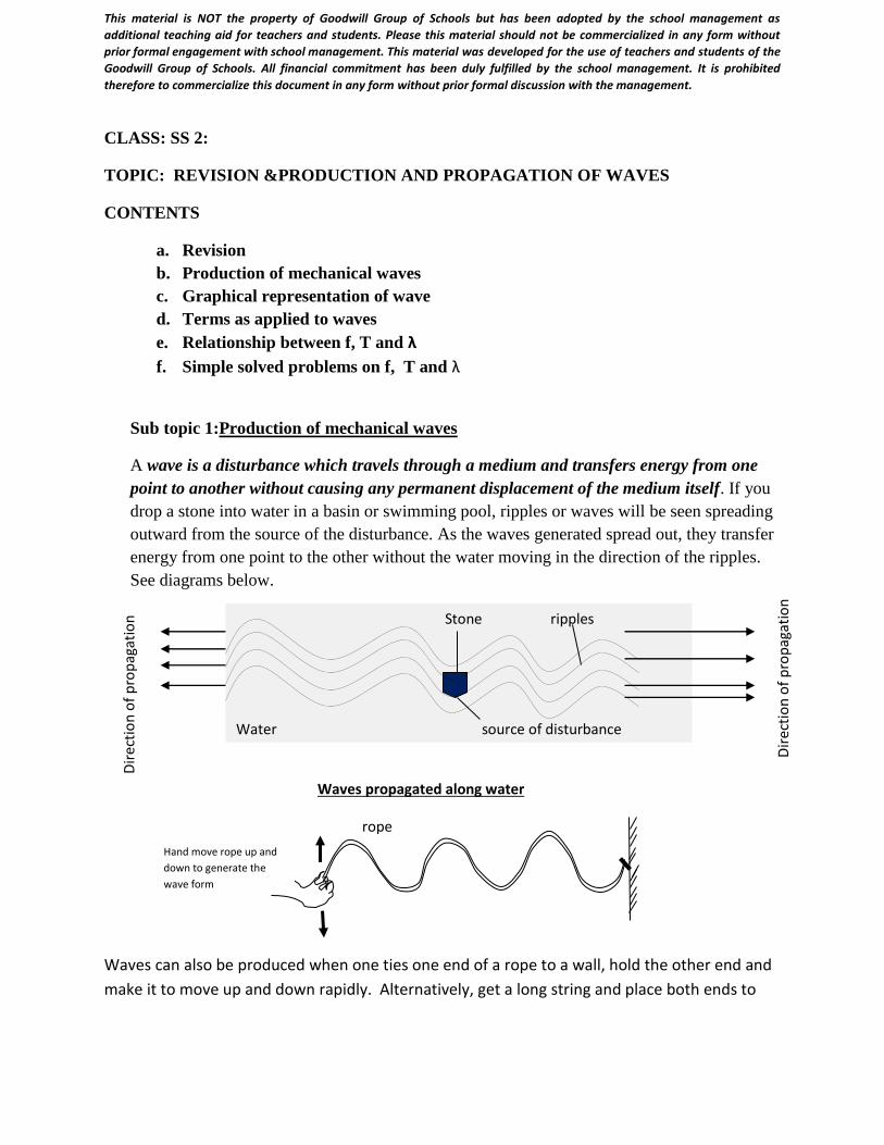
A wave is a disturbance which travels through a medium and transfers energy from one
point to another without causing any permanent displacement of the medium itself. If you
drop a stone into water in a basin or swimming pool, ripples or waves will be seen spreading
outward from the source of the disturbance. As the waves generated spread out, they transfer
energy from one point to the other without the water moving in the direction of the ripples.
See diagrams below.
Waves can also be produced when one ties one end of a rope to a wall, hold the other end and
make it to move up and down rapidly. Alternatively, get a long string and place both ends to
Stone ripples
Water source of disturbance
Dir
ecti
on
of
pro
pag
atio
n
Dir
ecti
on
of
pro
pag
atio
n
Waves propagated along water
rope
Hand move rope up and
down to generate the
wave form
This material is NOT the property of Goodwill Group of Schools but has been adopted by the school management as
additional teaching aid for teachers and students. Please this material should not be commercialized in any form without
prior formal engagement with school management. This material was developed for the use of teachers and students of the
Goodwill Group of Schools. All financial commitment has been duly fulfilled by the school management. It is prohibited
therefore to commercialize this document in any form without prior formal discussion with the management.
two fixed points as shown below. Pluck the string i.e pull it either vertically downward or
upward and release it. A wave will be generated.
Class activity
1. Educator should use ripple tank to produce plane and circular waves or a large bowl
containing water could be used as alternative
2. Educator should guide the students as they produce mechanical waves using a rope or a
suitable string.
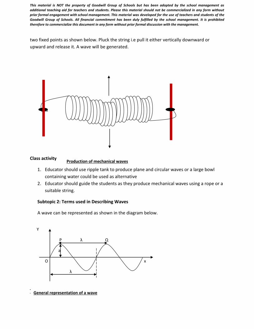
Subtopic 2: Terms used in Describing Waves
A wave can be represented as shown in the diagram below.
Terms as applied to wave motion
Production of mechanical waves
Y
P λ Q
a
O x
λ
General representation of a wave
This material is NOT the property of Goodwill Group of Schools but has been adopted by the school management as
additional teaching aid for teachers and students. Please this material should not be commercialized in any form without
prior formal engagement with school management. This material was developed for the use of teachers and students of the
Goodwill Group of Schools. All financial commitment has been duly fulfilled by the school management. It is prohibited
therefore to commercialize this document in any form without prior formal discussion with the management.
a. Crest: This is a region of maximum upward displacement of the particles of the
medium.
b. Trough: This is a region of maximum downward displacement of the particles of the
medium
c. Phase: The particles of a wave are said to be in phase when they are at the same
vertical distance from their mean position and are moving in the same direction.
d. Amplitude (a): It is the maximum displacement of the particles as measured from the
mean position.
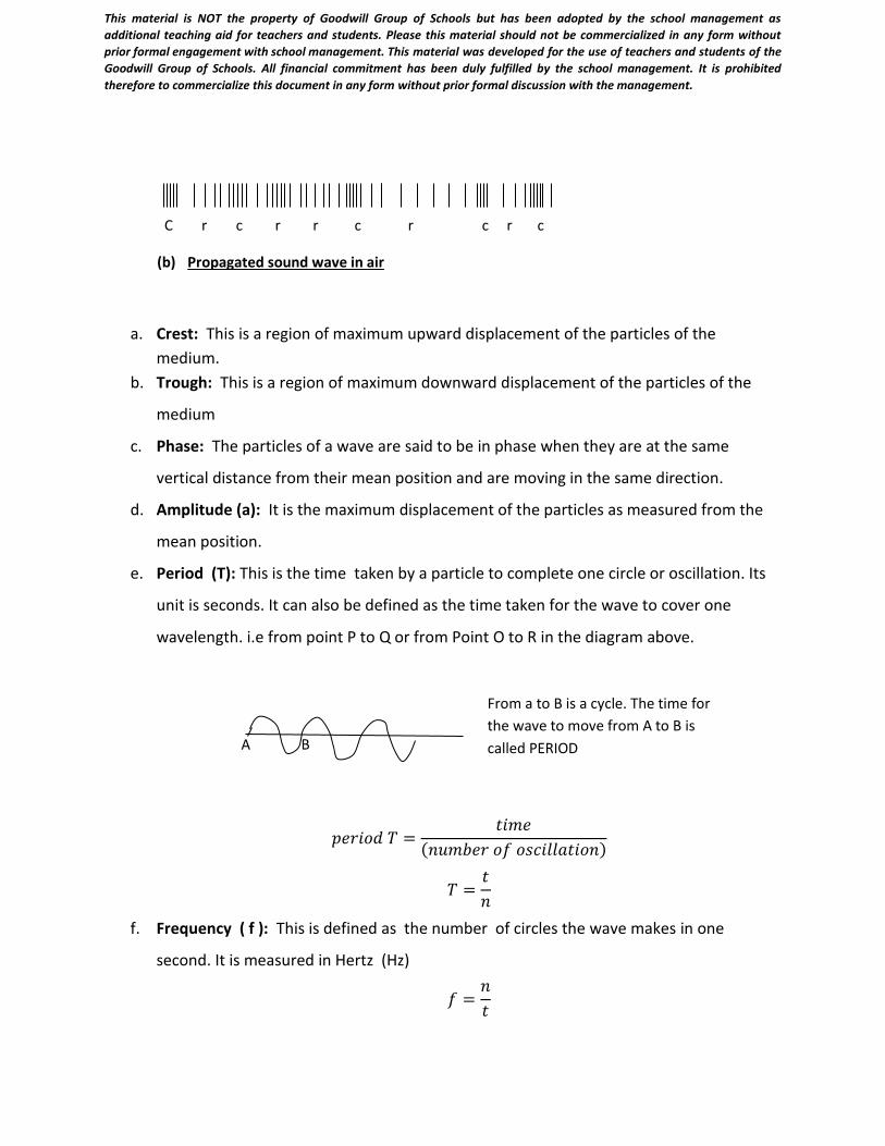
e. Period (T): This is the time taken by a particle to complete one circle or oscillation. Its
unit is seconds. It can also be defined as the time taken for the wave to cover one
wavelength. i.e from point P to Q or from Point O to R in the diagram above.
𝑝𝑒𝑟𝑖𝑜𝑑 𝑇 =𝑡𝑖𝑚𝑒
(𝑛𝑢𝑚𝑏𝑒𝑟 𝑜𝑓 𝑜𝑠𝑐𝑖𝑙𝑙𝑎𝑡𝑖𝑜𝑛)
𝑇 =𝑡
𝑛
f. Frequency ( f ): This is defined as the number of circles the wave makes in one
second. It is measured in Hertz (Hz)
𝑓 =𝑛
𝑡
C r c r r c r c r c
(b) Propagated sound wave in air
B A
From a to B is a cycle. The time for
the wave to move from A to B is
called PERIOD
This material is NOT the property of Goodwill Group of Schools but has been adopted by the school management as
additional teaching aid for teachers and students. Please this material should not be commercialized in any form without
prior formal engagement with school management. This material was developed for the use of teachers and students of the
Goodwill Group of Schools. All financial commitment has been duly fulfilled by the school management. It is prohibited
therefore to commercialize this document in any form without prior formal discussion with the management.
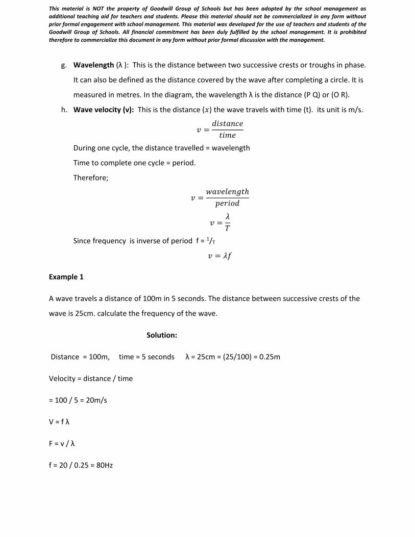
g. Wavelength (λ ): This is the distance between two successive crests or troughs in phase.
It can also be defined as the distance covered by the wave after completing a circle. It is
measured in metres. In the diagram, the wavelength λ is the distance (P Q) or (O R).
h. Wave velocity (v): This is the distance (𝑥) the wave travels with time (t). its unit is m/s.
𝑣 =𝑑𝑖𝑠𝑡𝑎𝑛𝑐𝑒
𝑡𝑖𝑚𝑒
During one cycle, the distance travelled = wavelength
Time to complete one cycle = period.
Therefore;
𝑣 =𝑤𝑎𝑣𝑒𝑙𝑒𝑛𝑔𝑡ℎ
𝑝𝑒𝑟𝑖𝑜𝑑
𝑣 =𝜆
𝑇
Since frequency is inverse of period f = 1/T
𝑣 = 𝜆𝑓
Example 1
A wave travels a distance of 100m in 5 seconds. The distance between successive crests of the
wave is 25cm. calculate the frequency of the wave.
Solution:
Distance = 100m, time = 5 seconds λ = 25cm = (25/100) = 0.25m
Velocity = distance / time
= 100 / 5 = 20m/s
V = f λ
F = v / λ
f = 20 / 0.25 = 80Hz
This material is NOT the property of Goodwill Group of Schools but has been adopted by the school management as
additional teaching aid for teachers and students. Please this material should not be commercialized in any form without
prior formal engagement with school management. This material was developed for the use of teachers and students of the
Goodwill Group of Schools. All financial commitment has been duly fulfilled by the school management. It is prohibited
therefore to commercialize this document in any form without prior formal discussion with the management.
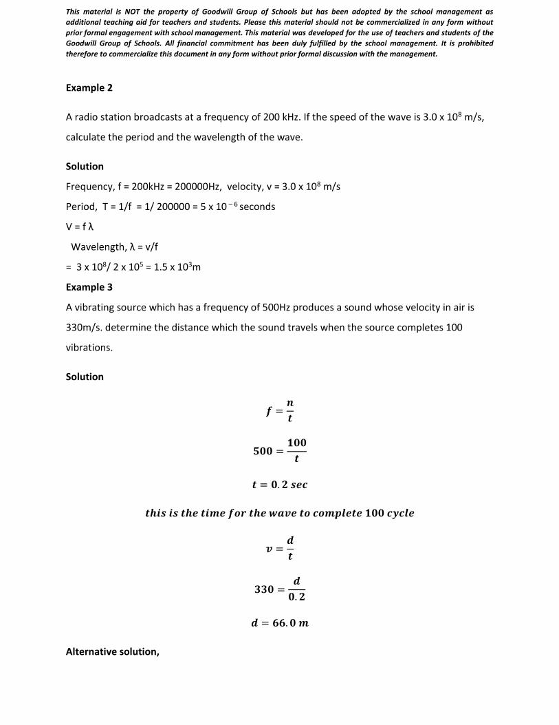
Example 2
A radio station broadcasts at a frequency of 200 kHz. If the speed of the wave is 3.0 x 10⁸ m/s,
calculate the period and the wavelength of the wave.
Solution
Frequency, f = 200kHz = 200000Hz, velocity, v = 3.0 x 10⁸ m/s
Period, T = 1/f = 1/ 200000 = 5 x 10 – 6 seconds
V = f λ
Wavelength, λ = v/f
= 3 x 10⁸/ 2 x 105 = 1.5 x 10³m
Example 3
A vibrating source which has a frequency of 500Hz produces a sound whose velocity in air is
330m/s. determine the distance which the sound travels when the source completes 100
vibrations.
Solution
𝒇 =𝒏
𝒕
𝟓𝟎𝟎 =𝟏𝟎𝟎
𝒕
𝒕 = 𝟎. 𝟐 𝒔𝒆𝒄
𝒕𝒉𝒊𝒔 𝒊𝒔 𝒕𝒉𝒆 𝒕𝒊𝒎𝒆 𝒇𝒐𝒓 𝒕𝒉𝒆 𝒘𝒂𝒗𝒆 𝒕𝒐 𝒄𝒐𝒎𝒑𝒍𝒆𝒕𝒆 𝟏𝟎𝟎 𝒄𝒚𝒄𝒍𝒆
𝒗 =𝒅
𝒕
𝟑𝟑𝟎 =𝒅
𝟎. 𝟐
𝒅 = 𝟔𝟔. 𝟎 𝒎
Alternative solution,
This material is NOT the property of Goodwill Group of Schools but has been adopted by the school management as
additional teaching aid for teachers and students. Please this material should not be commercialized in any form without
prior formal engagement with school management. This material was developed for the use of teachers and students of the
Goodwill Group of Schools. All financial commitment has been duly fulfilled by the school management. It is prohibited
therefore to commercialize this document in any form without prior formal discussion with the management.
Frequency f = 500Hz or 500 circles per second.
If the source makes 500 circles in a second, then it will take the source (100/500) seconds to
make 100 circles = 0.2s
Speed (v) = distance (s) / time (t)
Therefore s = v t = 330 x 0.2 = 66m
Evaluation
1. Define wave and represent its motion by a diagram
2. Calculate the frequency of a wave if its period is 0.25s
3. Five circles are formed in 2s, what is the period of the wave?
Weekend assignment
1. Reading assignment: Read on transverse and longitudinal
2. What is wave motion?
Objectives
1. Which of the following
statements about wave is/are correct?
i. A wavefront is a line which contains
all particles whose vibrations are in
phase.
ii. The direction of propagation of a
wave is the line drawn parallel to
the wavefront.
iii. A wavefront is a circle which is
common to all particles that are to
be in the same state
of disturbance.
(A) I only (B) ii only (C) I, ii and iii
(D) I and ii only (E) ii and iii only.
2. A stone is dropped into the middle
of a pool of water. Which of the
following statements is/are correct?
i. Spherical waves are set up in the
water.
ii. The water moves outwards to the
sides of the pool.
iii. Energy is transmitted outwards
from the center of disturbance.
(A) I only (B) ii only (C) iii only
(D) I and iii only (E) ii and iii only.
3. The S.I units of frequency, period
and amplitude of a wave are
respectively
(A) hertz, second and centimeter.
(B) second, meter and hertz
This material is NOT the property of Goodwill Group of Schools but has been adopted by the school management as additional teaching aid
for teachers and students. Please this material should not be commercialized in any form without prior formal engagement with school
management. This material was developed for the use of teachers and students of the Goodwill Group of Schools. All financial commitment
has been duly fulfilled by the school management. It is prohibited therefore to commercialize this document in any form without prior formal
discussion with the management.
(C) meter, hertz and second
(D) hertz, second and meter
4. The period of a wave is 0.02second.
Calculate its wavelength if its speed
is 330m/s.
(A) 6.6m (B) 5.0m (C) 4.0m
(D) 3.3m (E) 2.0m
. 5. The distance between two points in
phase on a progressive wave is 5cm.
If the speed of the wave is 0.020m/s.
Calculate its period.
(A) 4.00s (B) 2.50s
(C) 0.25s (D) 0.04s
6. A periodic pulse travels a distance
of 20.0m in 1.00s. If the frequency
is 2.0 x 10³Hz, calculate the
wavelength.
(A) 1.0 x 10⁻³m (B) 1.0 x 10⁻²m
(C) 2.0 x 10⁻²m (D) 1.0 x 10²Hz
WEEK 2: DATE:…………….
SUBJECT: PHYSICS
CLASS: SS 2
TOPIC: WAVES ( CONT’D)
CONTENTS
1. Types of waves
2. Wave equation ( y = Asin(ωt – k𝒙)
Sub topic 1: Types of waves
Waves can be classified under Transverse waves and Longitudinalwaves. If the direction of
propagation of the particles of the wave is perpendicular to the direction of vibration of the
medium, the wave is transverse. Examples of transverse waves are, water waves and waves
produced by plucking a string. If we consider material medium, waves can be classified under
This material is NOT the property of Goodwill Group of Schools but has been adopted by the school management as
additional teaching aid for teachers and students. Please this material should not be commercialized in any form without
prior formal engagement with school management. This material was developed for the use of teachers and students of the
Goodwill Group of Schools. All financial commitment has been duly fulfilled by the school management. It is prohibited
therefore to commercialize this document in any form without prior formal discussion with the management.
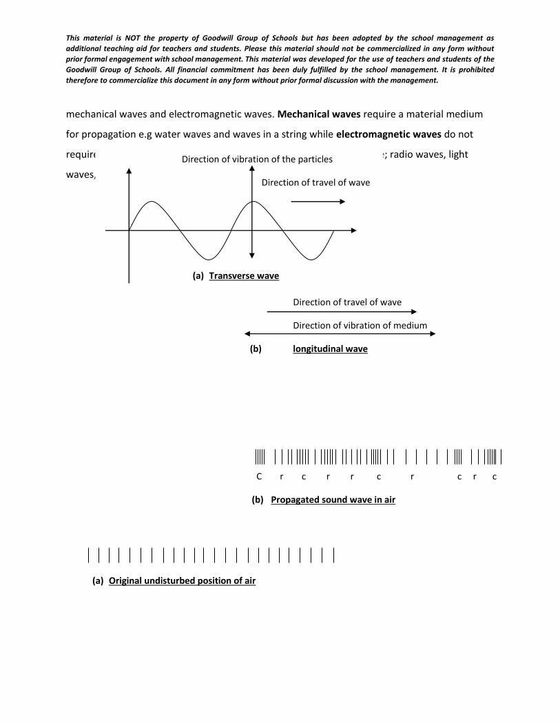
mechanical waves and electromagnetic waves. Mechanical waves require a material medium
for propagation e.g water waves and waves in a string while electromagnetic waves do not
require material medium for propagation. Examples of these waves are; radio waves, light
waves, x-rays e.t.c.
(a) Original undisturbed position of air
Direction of travel of wave
Direction of vibration of medium
(b) longitudinal wave
Direction of vibration of the particles
Direction of travel of wave
(a) Transverse wave
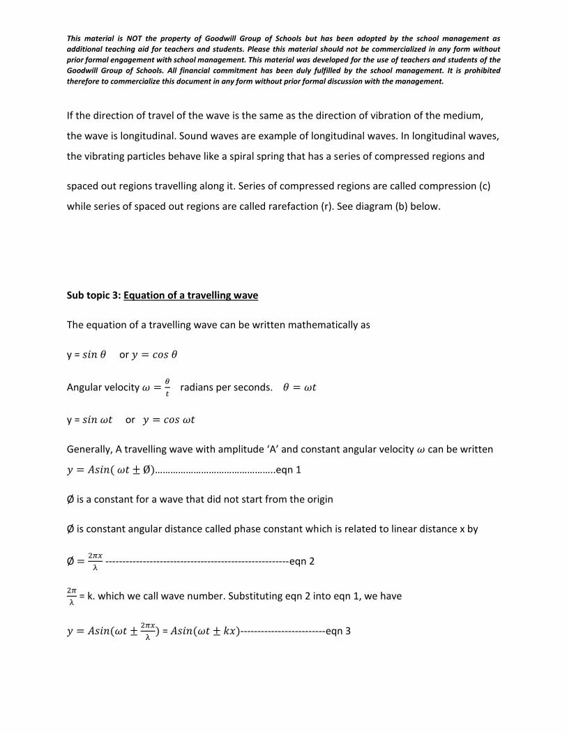
C r c r r c r c r c
(b) Propagated sound wave in air
This material is NOT the property of Goodwill Group of Schools but has been adopted by the school management as
additional teaching aid for teachers and students. Please this material should not be commercialized in any form without
prior formal engagement with school management. This material was developed for the use of teachers and students of the
Goodwill Group of Schools. All financial commitment has been duly fulfilled by the school management. It is prohibited
therefore to commercialize this document in any form without prior formal discussion with the management.
If the direction of travel of the wave is the same as the direction of vibration of the medium,
the wave is longitudinal. Sound waves are example of longitudinal waves. In longitudinal waves,
the vibrating particles behave like a spiral spring that has a series of compressed regions and
spaced out regions travelling along it. Series of compressed regions are called compression (c)
while series of spaced out regions are called rarefaction (r). See diagram (b) below.
Sub topic 3: Equation of a travelling wave
The equation of a travelling wave can be written mathematically as
y = 𝑠𝑖𝑛 𝜃 or 𝑦 = 𝑐𝑜𝑠 𝜃
Angular velocity 𝜔 =𝜃
𝑡 radians per seconds. 𝜃 = 𝜔𝑡
y = 𝑠𝑖𝑛 𝜔𝑡 or 𝑦 = 𝑐𝑜𝑠 𝜔𝑡
Generally, A travelling wave with amplitude ‘A’ and constant angular velocity 𝜔 can be written
𝑦 = 𝐴𝑠𝑖𝑛( 𝜔𝑡 ± Ø)………………………………………..eqn 1
Ø is a constant for a wave that did not start from the origin
Ø is constant angular distance called phase constant which is related to linear distance x by
Ø =2𝜋𝑥
λ ------------------------------------------------------eqn 2
2𝜋
λ = k. which we call wave number. Substituting eqn 2 into eqn 1, we have
𝑦 = 𝐴𝑠𝑖𝑛(𝜔𝑡 ±2𝜋𝑥
λ) = 𝐴𝑠𝑖𝑛(𝜔𝑡 ± 𝑘𝑥)-------------------------eqn 3
This material is NOT the property of Goodwill Group of Schools but has been adopted by the school management as
additional teaching aid for teachers and students. Please this material should not be commercialized in any form without
prior formal engagement with school management. This material was developed for the use of teachers and students of the
Goodwill Group of Schools. All financial commitment has been duly fulfilled by the school management. It is prohibited
therefore to commercialize this document in any form without prior formal discussion with the management.
If we substitute 𝜔 =2𝜋
𝑇 and 𝑘 =
2𝜋
λ into eqn 3, it becomes
𝑦 = 𝐴𝑠𝑖𝑛 (2𝜋𝑡
T±
2𝜋𝑥
λ)
Or 𝑦 = 𝐴𝑠𝑖𝑛2𝜋 (𝑡
T±
𝑥
λ)---------------------------------------------eqn 4
Or 𝑦 = 𝐴 sin2𝜋
λ(
λt
T± 𝑥)----------------------------------------------eqn 5
Recall that v = f λ
λ = vt, therefore eqn 5 becomes
𝑦 = 𝐴 sin2𝜋
λ(𝑣𝑡 ± 𝑥)--------------------------------------------------eqn 6
+ 𝑓𝑜𝑟 𝑤ℎ𝑒𝑛 𝑡ℎ𝑒 𝑤𝑎𝑣𝑒 𝑖𝑠 𝑝𝑟𝑜𝑝𝑎𝑔𝑎𝑡𝑖ng in the negative x-direction
− 𝑓𝑜𝑟 𝑤ℎ𝑒𝑛 𝑡ℎ𝑒 𝑤𝑎𝑣𝑒 𝑖𝑠 𝑝𝑟𝑜𝑝𝑎𝑔𝑎𝑡𝑖𝑛𝑔 𝑖𝑛 𝑡ℎ𝑒 positive x- direction
Solved problems
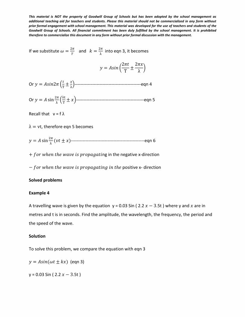
Example 4
A travelling wave is given by the equation y = 0.03 Sin ( 2.2 𝑥 − 3.5t ) where y and 𝑥 are in
metres and t is in seconds. Find the amplitude, the wavelength, the frequency, the period and
the speed of the wave.
Solution
To solve this problem, we compare the equation with eqn 3
𝑦 = 𝐴𝑠𝑖𝑛(𝜔𝑡 ± 𝑘𝑥) (eqn 3)
y = 0.03 Sin ( 2.2 𝑥 − 3.5t )
This material is NOT the property of Goodwill Group of Schools but has been adopted by the school management as
additional teaching aid for teachers and students. Please this material should not be commercialized in any form without
prior formal engagement with school management. This material was developed for the use of teachers and students of the
Goodwill Group of Schools. All financial commitment has been duly fulfilled by the school management. It is prohibited
therefore to commercialize this document in any form without prior formal discussion with the management.
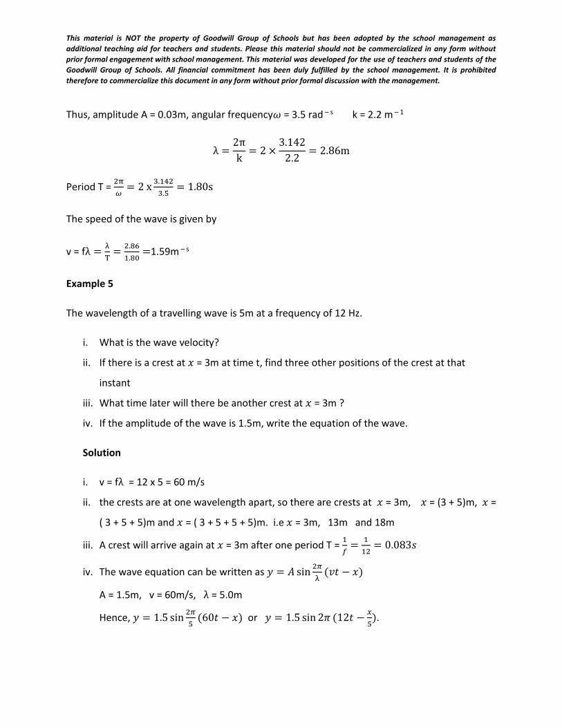
Thus, amplitude A = 0.03m, angular frequency𝜔 = 3.5 rad – s k = 2.2 m – 1
λ =2π
k= 2 ×
3.142
2.2= 2.86m
Period T = 2π
𝜔= 2 x
3.142
3.5= 1.80s
The speed of the wave is given by
v = fλ =λ
T=
2.86
1.80=1.59m – s
Example 5
The wavelength of a travelling wave is 5m at a frequency of 12 Hz.
i. What is the wave velocity?
ii. If there is a crest at 𝑥 = 3m at time t, find three other positions of the crest at that
instant
iii. What time later will there be another crest at 𝑥 = 3m ?
iv. If the amplitude of the wave is 1.5m, write the equation of the wave.
Solution
i. v = fλ = 12 x 5 = 60 m/s
ii. the crests are at one wavelength apart, so there are crests at 𝑥 = 3m, 𝑥 = (3 + 5)m, 𝑥 =
( 3 + 5 + 5)m and 𝑥 = ( 3 + 5 + 5 + 5)m. i.e 𝑥 = 3m, 13m and 18m
iii. A crest will arrive again at 𝑥 = 3m after one period T = 1
𝑓=
1
12= 0.083𝑠
iv. The wave equation can be written as 𝑦 = 𝐴 sin2𝜋
λ(𝑣𝑡 − 𝑥)
A = 1.5m, v = 60m/s, λ = 5.0m
Hence, 𝑦 = 1.5 sin2𝜋
5(60𝑡 − 𝑥) or 𝑦 = 1.5 sin 2𝜋 (12𝑡 −
𝑥
5).
This material is NOT the property of Goodwill Group of Schools but has been adopted by the school management as
additional teaching aid for teachers and students. Please this material should not be commercialized in any form without
prior formal engagement with school management. This material was developed for the use of teachers and students of the
Goodwill Group of Schools. All financial commitment has been duly fulfilled by the school management. It is prohibited
therefore to commercialize this document in any form without prior formal discussion with the management.
Weekend assignment
1. Differentiate between transverse and longitudinal waves with examples
2. Mention 5 terms associated with waves and explain them
3. The equation of a wave is given as 𝑦 = 0.5sin (3𝜋𝑥 + 50𝜋𝑡). Where x and y are in
metres and t is in seconds. Find (a) The amplitude (b) the wave number k and (c) the
wavelength of the wave.
4. A wave covers 30cm in 5s, if the distance between a crest and its neighbouring
trough is 1.5cm, (a) What is the wavelength? (b) How many circles can be formed in
15s?
5. The equation, y = Asin2𝜋/𝜆(vt –x) represents a wave train in which y is the vertical
displacement of a particle at distance X from the origin in the medium through which
the wave is travelling. Explain, with the aid of a diagram, what A and λ represent.
6. The equation y = asin(wt-kx) represents a plane wave travelling in a medium along
the
x-direction, y being the displacement at the point x at time t.
i. Given that x is in meters and t is in seconds, state the units of k and w.
ii. What physical quantity does w/k represent? Justify your answer.
iii. State whether the wave is travelling in the positive or negative x-direction.
7. The equation, y = 5sin(3x – 4t), where y is in millimeters, x is in meters and t in
seconds
represents a wave motion. Determine the i. frequency ii. Period iii. Speed of the
wave.
Objectives
1. Which of the following is not a
property of longitudinal waves?
(A) Compression (B) Reflection
(C) Refraction (D) polarization
(E) Diffraction.
3. When the direction of vibration of
the particles of a medium is
perpendicular to the direction of
travel of a wave, the wave
transmitted is known as
(A) sound wave (B) transverse
wave
(C) longitudinal wave
(D) stationary wave
(E) mechanical wave.
4. Which of the following are
This material is NOT the property of Goodwill Group of Schools but has been adopted by the school management as
additional teaching aid for teachers and students. Please this material should not be commercialized in any form without
prior formal engagement with school management. This material was developed for the use of teachers and students of the
Goodwill Group of Schools. All financial commitment has been duly fulfilled by the school management. It is prohibited
therefore to commercialize this document in any form without prior formal discussion with the management.
longitudinal waves?
i. Ripples on the surface of water
ii. waves produced by a tuning fork
vibrating in air.
iii. light waves.
iv. waves produced by flute.
(A) I and ii only (B) I and iii only
(C) ii and iii only (D) ii and iv only
(E) iii and iv only.
8. Which of the following are
transverse wave?
i. Ripples on water
ii. sound waves in air.
iii. light waves from the sun.
(A) ii only (B) I and ii only
(C) ii and iii only
(D) I and iii only
(E) I, ii and iii
9. Which of the following wave
characteristics can be used to
distinguish a transverse wave from a
longitudinal wave?
(A) Reflection (B) Refraction
(C) Diffraction (D) Polarization
(E) interference.
10. Which of the following is not a
mechanical wave?
(A) wave propagated in stretched
string.
(B) Waves in closed pipes
(C) Radio waves
(D) Water waves
(E) sound waves.
11. Which of the following statements
about a progressive mechanical wave
is correct?
(A) it can be plane polarized.
(B) its energy is localized at specific
points of its profile.
(C) it does not require material
medium for its propagation.
(D) its frequency remains constant
as it travels between different
media.
12. .
13. In a wave, the maximum
displacement of particles from their
equilibrium positions is called
(A) frequency (B) Amplitude
(C) Period (D) wavelength
(E) Wave velocity.
14. The amplitude of a wave is the
(A) distance travelled by the wave in
a complete cycle of its motion.
(B) maximum displacement of the
wave particle from the
equilibrium position.
(C) separation of two adjacent
particles vibrating in phase.
(D) distance between two
This material is NOT the property of Goodwill Group of Schools but has been adopted by the school management as
additional teaching aid for teachers and students. Please this material should not be commercialized in any form without
prior formal engagement with school management. This material was developed for the use of teachers and students of the
Goodwill Group of Schools. All financial commitment has been duly fulfilled by the school management. It is prohibited
therefore to commercialize this document in any form without prior formal discussion with the management.
successive troughs of the wave.
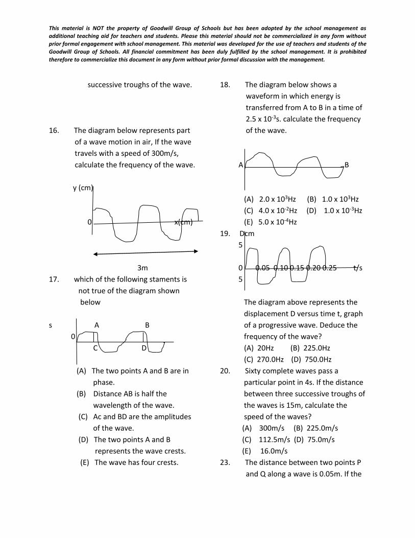
16. The diagram below represents part
of a wave motion in air, If the wave
travels with a speed of 300m/s,
calculate the frequency of the wave.
y (cm)
0 x(cm)
3m
17. which of the following staments is
not true of the diagram shown
below
s A B
0
C D
(A) The two points A and B are in
phase.
(B) Distance AB is half the
wavelength of the wave.
(C) Ac and BD are the amplitudes
of the wave.
(D) The two points A and B
represents the wave crests.
(E) The wave has four crests.
18. The diagram below shows a
waveform in which energy is
transferred from A to B in a time of
2.5 x 10⁻³s. calculate the frequency
of the wave.
A B
(A) 2.0 x 10³Hz (B) 1.0 x 10³Hz
(C) 4.0 x 10⁻²Hz (D) 1.0 x 10⁻³Hz
(E) 5.0 x 10⁻⁴Hz
19. Dcm
5
0 0.05 0.10 0.15 0.20 0.25 t/s
5
The diagram above represents the
displacement D versus time t, graph
of a progressive wave. Deduce the
frequency of the wave?
(A) 20Hz (B) 225.0Hz
(C) 270.0Hz (D) 750.0Hz
20. Sixty complete waves pass a
particular point in 4s. If the distance
between three successive troughs of
the waves is 15m, calculate the
speed of the waves?
(A) 300m/s (B) 225.0m/s
(C) 112.5m/s (D) 75.0m/s
(E) 16.0m/s
23. The distance between two points P
and Q along a wave is 0.05m. If the
This material is NOT the property of Goodwill Group of Schools but has been adopted by the school management as
additional teaching aid for teachers and students. Please this material should not be commercialized in any form without
prior formal engagement with school management. This material was developed for the use of teachers and students of the
Goodwill Group of Schools. All financial commitment has been duly fulfilled by the school management. It is prohibited
therefore to commercialize this document in any form without prior formal discussion with the management.
wave length of the wave is 0.10m,
determine the angle between P and
Q in radians.
(𝐴) 0.1 𝜋 (B) 𝜋
(𝐶) 2 𝜋(𝐷) 10 𝜋
24. A progressive wave has a
wavelength of 50cm. Calculate the
phase difference between two
points at a distance of 20cm apart.
(𝐴) 10/3 𝜋 (B) 5/2𝜋
(𝐶) 4/5𝜋(𝐷) 2/3 𝜋
(𝐷) 𝜋/3
2526. The change of the direction of a
wavefront because of a change in
the velocity of the wave in another
medium is called
(A) refraction (B) reflection
(C) diffraction (D) interference
27. In which of the following is a
stationary wave produced?
i. A vibrating tuning fork held near
the end of a resonate tube closed
at the end.
ii. A string tightly stretched between
two points and plucked at its
middle.
iii. The prongs of a tuning fork
vibrating in air
(A) I only (B) ii only
(C) I and ii only
28. Two identical waves travelling in
the same direction are
superimposed,
what should be the phase difference
between the waves for maximum
destructive interference to occur?
(A) 200 (B) 450 (C) 1800
(D) 2250 (E) 2700
29. Water waves are generated by
dropping stones at regular intervals
at a point in a pool of water. The
first crest reaches another point, 8m
away in 4s. If the distance between
two successive crests is 0.5m, the
frequency of the wave is
(A) 2Hz (B) 4Hz (C) 8Hz
(D) 16Hz
30. In the wave equation
y = Eosin(200t- 𝜋x), Eo represents
the
(A) amplitude (B) frequency
(C) period (D) wavelenght
WEEK 3
DATE:…………….
This material is NOT the property of Goodwill Group of Schools but has been adopted by the school management as
additional teaching aid for teachers and students. Please this material should not be commercialized in any form without
prior formal engagement with school management. This material was developed for the use of teachers and students of the
Goodwill Group of Schools. All financial commitment has been duly fulfilled by the school management. It is prohibited
therefore to commercialize this document in any form without prior formal discussion with the management.
SUBJECT: PHYSICS
CLASS: SS 2
TOPIC: PROPERTIES OF WAVES
CONTENTS
1. Reflection and refractionof waves
2. . Interference, diffraction and polarization of waves
3. Progressive and stationary waves
Subtopic 1: Reflection and Refraction of waves
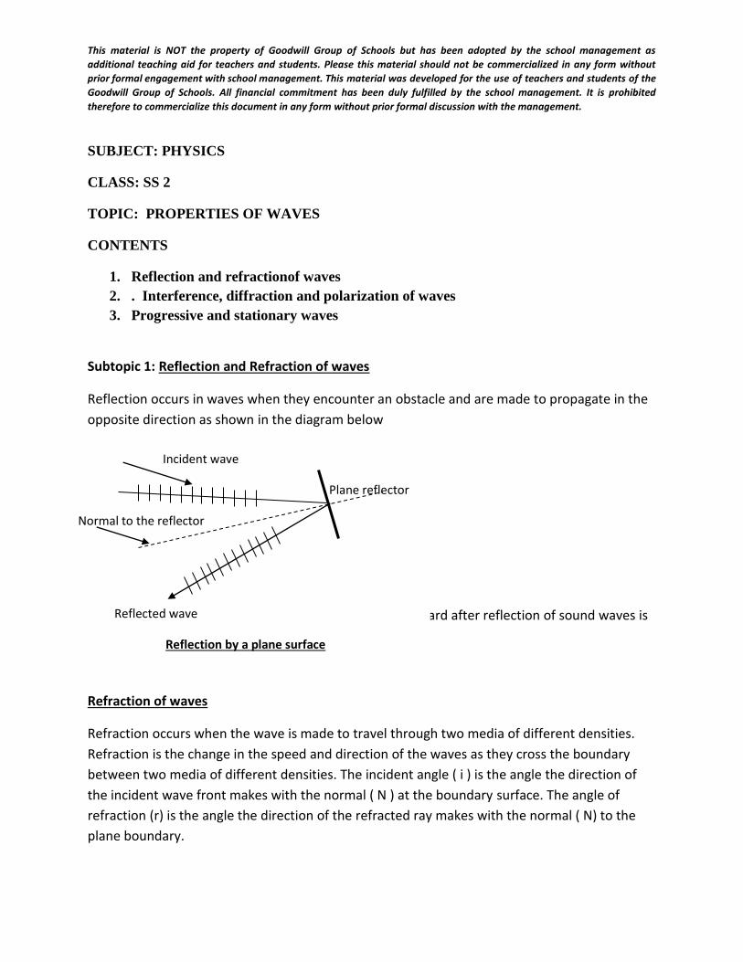
Reflection occurs in waves when they encounter an obstacle and are made to propagate in the
opposite direction as shown in the diagram below
Reflection also occurs in sound and light waves. Sound heard after reflection of sound waves is
called an echo.
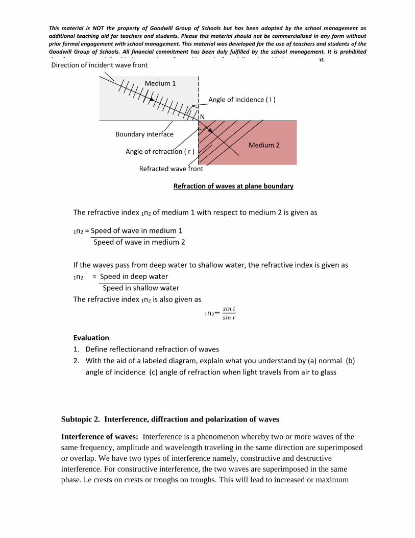
Refraction of waves
Refraction occurs when the wave is made to travel through two media of different densities.
Refraction is the change in the speed and direction of the waves as they cross the boundary
between two media of different densities. The incident angle ( i ) is the angle the direction of
the incident wave front makes with the normal ( N ) at the boundary surface. The angle of
refraction (r) is the angle the direction of the refracted ray makes with the normal ( N) to the
plane boundary.
Incident wave
Plane reflector
Normal to the reflector
Reflected wave
Reflection by a plane surface
This material is NOT the property of Goodwill Group of Schools but has been adopted by the school management as
additional teaching aid for teachers and students. Please this material should not be commercialized in any form without
prior formal engagement with school management. This material was developed for the use of teachers and students of the
Goodwill Group of Schools. All financial commitment has been duly fulfilled by the school management. It is prohibited
therefore to commercialize this document in any form without prior formal discussion with the management.
The refractive index 1n2 of medium 1 with respect to medium 2 is given as
1n2 = Speed of wave in medium 1
Speed of wave in medium 2
If the waves pass from deep water to shallow water, the refractive index is given as
1n2 = Speed in deep water
Speed in shallow water
The refractive index 1n2 is also given as
1n2=𝑠𝑖𝑛 𝑖
𝑠𝑖𝑛 𝑟
Evaluation
1. Define reflectionand refraction of waves
2. With the aid of a labeled diagram, explain what you understand by (a) normal (b)
angle of incidence (c) angle of refraction when light travels from air to glass
Subtopic 2. Interference, diffraction and polarization of waves
Interference of waves: Interference is a phenomenon whereby two or more waves of the
same frequency, amplitude and wavelength traveling in the same direction are superimposed
or overlap. We have two types of interference namely, constructive and destructive
interference. For constructive interference, the two waves are superimposed in the same
phase. i.e crests on crests or troughs on troughs. This will lead to increased or maximum
Direction of incident wave front
Angle of incidence ( I )
N
Boundary interface
Angle of refraction ( r )
Refracted wave front
Refraction of waves at plane boundary
Medium 1
Medium 2
This material is NOT the property of Goodwill Group of Schools but has been adopted by the school management as
additional teaching aid for teachers and students. Please this material should not be commercialized in any form without
prior formal engagement with school management. This material was developed for the use of teachers and students of the
Goodwill Group of Schools. All financial commitment has been duly fulfilled by the school management. It is prohibited
therefore to commercialize this document in any form without prior formal discussion with the management.
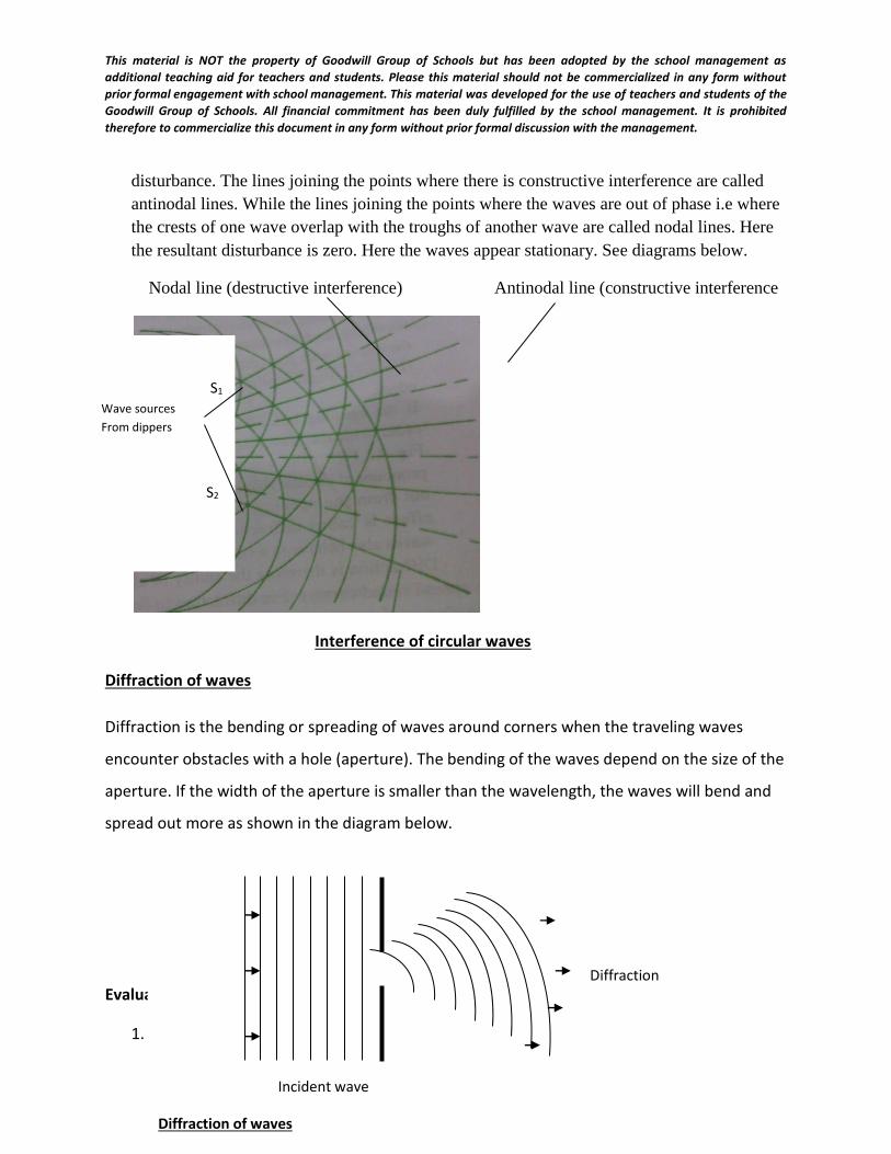
disturbance. The lines joining the points where there is constructive interference are called
antinodal lines. While the lines joining the points where the waves are out of phase i.e where
the crests of one wave overlap with the troughs of another wave are called nodal lines. Here
the resultant disturbance is zero. Here the waves appear stationary. See diagrams below.
Nodal line (destructive interference) Antinodal line (constructive interference
Interference of circular waves
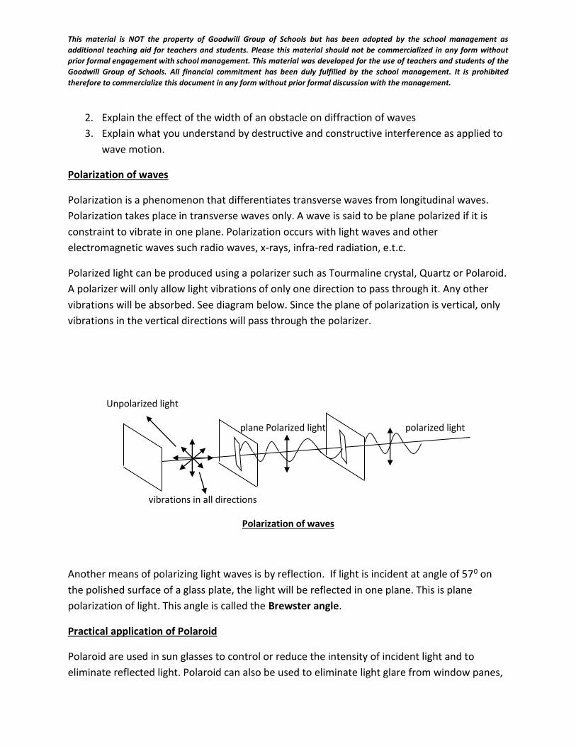
Diffraction of waves
Diffraction is the bending or spreading of waves around corners when the traveling waves
encounter obstacles with a hole (aperture). The bending of the waves depend on the size of the
aperture. If the width of the aperture is smaller than the wavelength, the waves will bend and
spread out more as shown in the diagram below.
Evaluation
1. Define the following terms: (i) Diffraction (ii) interference of waves
Diffraction
Incident wave
Diffraction of waves
S1 Wave sources
From dippers
S2
This material is NOT the property of Goodwill Group of Schools but has been adopted by the school management as
additional teaching aid for teachers and students. Please this material should not be commercialized in any form without
prior formal engagement with school management. This material was developed for the use of teachers and students of the
Goodwill Group of Schools. All financial commitment has been duly fulfilled by the school management. It is prohibited
therefore to commercialize this document in any form without prior formal discussion with the management.
2. Explain the effect of the width of an obstacle on diffraction of waves
3. Explain what you understand by destructive and constructive interference as applied to
wave motion.
Polarization of waves
Polarization is a phenomenon that differentiates transverse waves from longitudinal waves.
Polarization takes place in transverse waves only. A wave is said to be plane polarized if it is
constraint to vibrate in one plane. Polarization occurs with light waves and other
electromagnetic waves such radio waves, x-rays, infra-red radiation, e.t.c.
Polarized light can be produced using a polarizer such as Tourmaline crystal, Quartz or Polaroid.
A polarizer will only allow light vibrations of only one direction to pass through it. Any other
vibrations will be absorbed. See diagram below. Since the plane of polarization is vertical, only
vibrations in the vertical directions will pass through the polarizer.
Another means of polarizing light waves is by reflection. If light is incident at angle of 570 on
the polished surface of a glass plate, the light will be reflected in one plane. This is plane
polarization of light. This angle is called the Brewster angle.
Practical application of Polaroid
Polaroid are used in sun glasses to control or reduce the intensity of incident light and to
eliminate reflected light. Polaroid can also be used to eliminate light glare from window panes,
Unpolarized light
plane Polarized light polarized light
vibrations in all directions
Polarization of waves
This material is NOT the property of Goodwill Group of Schools but has been adopted by the school management as
additional teaching aid for teachers and students. Please this material should not be commercialized in any form without
prior formal engagement with school management. This material was developed for the use of teachers and students of the
Goodwill Group of Schools. All financial commitment has been duly fulfilled by the school management. It is prohibited
therefore to commercialize this document in any form without prior formal discussion with the management.
glass doors, polished table top, also how chemical substance polarize light has also been used in
salt analysis e.t.c.
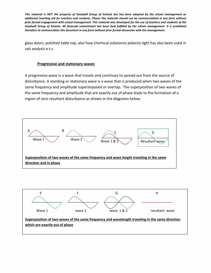
Progressive and stationary waves
A progressive wave is a wave that travels and continues to spread out from the source of
disturbance. A standing or stationary wave is a wave that is produced when two waves of the
same frequency and amplitude superimposed or overlap. The superposition of two waves of
the same frequency and amplitude that are exactly out of phase leads to the formation of a
region of zero resultant disturbance as shown in the diagrams below.
Superposition of two waves of the same frequency and wave length traveling in the same
direction and in phase
A
Wave 1
B
Wave 2
C
Wave 1 & 2
D
Resultant wave
E F G H
Wave 1 wave 2 wave 1 & 2 resultant wave
Superposition of two waves of the same frequency and wavelength traveling in the same direction
which are exactly out of phase
This material is NOT the property of Goodwill Group of Schools but has been adopted by the school management as
additional teaching aid for teachers and students. Please this material should not be commercialized in any form without
prior formal engagement with school management. This material was developed for the use of teachers and students of the
Goodwill Group of Schools. All financial commitment has been duly fulfilled by the school management. It is prohibited
therefore to commercialize this document in any form without prior formal discussion with the management.
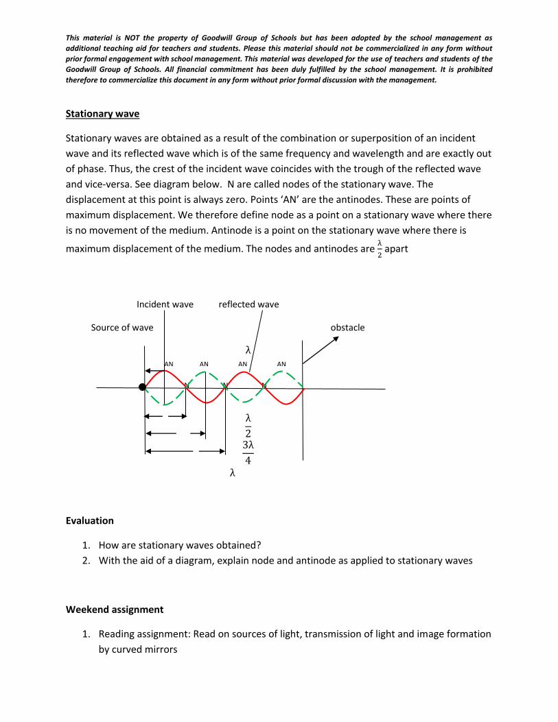
Stationary wave
Stationary waves are obtained as a result of the combination or superposition of an incident
wave and its reflected wave which is of the same frequency and wavelength and are exactly out
of phase. Thus, the crest of the incident wave coincides with the trough of the reflected wave
and vice-versa. See diagram below. N are called nodes of the stationary wave. The
displacement at this point is always zero. Points ‘AN’ are the antinodes. These are points of
maximum displacement. We therefore define node as a point on a stationary wave where there
is no movement of the medium. Antinode is a point on the stationary wave where there is
maximum displacement of the medium. The nodes and antinodes are λ
2 apart
Evaluation
1. How are stationary waves obtained?
2. With the aid of a diagram, explain node and antinode as applied to stationary waves
Weekend assignment
1. Reading assignment: Read on sources of light, transmission of light and image formation
by curved mirrors
Incident wave reflected wave
Source of wave obstacle
λ
4
N N N
λ
2
3λ
4
λ
Stationary wave
AN AN AN AN
This material is NOT the property of Goodwill Group of Schools but has been adopted by the school management as
additional teaching aid for teachers and students. Please this material should not be commercialized in any form without
prior formal engagement with school management. This material was developed for the use of teachers and students of the
Goodwill Group of Schools. All financial commitment has been duly fulfilled by the school management. It is prohibited
therefore to commercialize this document in any form without prior formal discussion with the management.
2. Distinguish between progressive and stationary waves. What is the distance between
two nodes and between a node and an antinode in terms of the wavelength of the
wave?
3. What is plane polarized wave? How can plane polarized light be produced and
detected?
WEEK 4:
DATE:…………….
SUBJECT: PHYSICS
CLASS: SS11
TOPIC: LIGHT WAVES
CONTENTS
1. Sources of light
2. Transmission of light
3. Reflection of light
4. Formation of images by plane and curved mirrors
Sub topic 1: Sources of light
Light has a number of sources. Some are man-made while others are natural. Examples of man
made sources of light include: light from candles and light from electric bulbs. Natural sources of
light are; the sun, stars, glow-worms, e.t.c. these sources of light can be grouped into luminous
and non luminous sources. Luminous bodies or objects generate and emit light by themselves.
E.g stars, sun electric lamps e.t.c. Non luminous objects or bodies depend on man-made or
natural sources. E.g the moon.
Sub topic 2: Transmission of light
Light is an example of electromagnetic waves because it does not require a material medium for
propagation. Some materials allow light to pass through them easily while others do not.
Materials that allow light to pass through them so that objects can be seen are called transparent
This material is NOT the property of Goodwill Group of Schools but has been adopted by the school management as
additional teaching aid for teachers and students. Please this material should not be commercialized in any form without
prior formal engagement with school management. This material was developed for the use of teachers and students of the
Goodwill Group of Schools. All financial commitment has been duly fulfilled by the school management. It is prohibited
therefore to commercialize this document in any form without prior formal discussion with the management.
materials. E.g glass and water. Non transparent bodies that allows small amount of light to pass
through them such that objects are not seen clearly are called translucent materials or bodies.
Examples of such bodies are, frosted glass or tinted glass. Those that will not allow light to pass
through them at all are called opaque bodies. Example is wood.
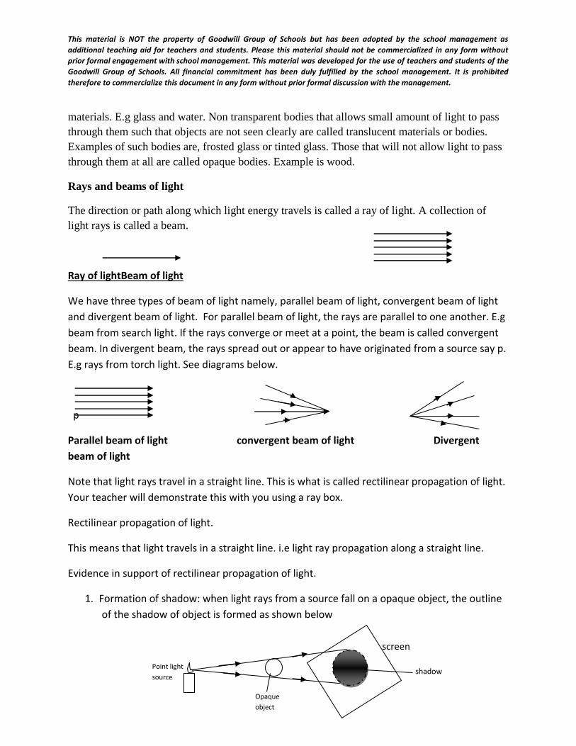
Rays and beams of light
The direction or path along which light energy travels is called a ray of light. A collection of
light rays is called a beam.
Ray of lightBeam of light
We have three types of beam of light namely, parallel beam of light, convergent beam of light
and divergent beam of light. For parallel beam of light, the rays are parallel to one another. E.g
beam from search light. If the rays converge or meet at a point, the beam is called convergent
beam. In divergent beam, the rays spread out or appear to have originated from a source say p.
E.g rays from torch light. See diagrams below.
p
Parallel beam of light convergent beam of light Divergent
beam of light
Note that light rays travel in a straight line. This is what is called rectilinear propagation of light.
Your teacher will demonstrate this with you using a ray box.
Rectilinear propagation of light.
This means that light travels in a straight line. i.e light ray propagation along a straight line.
Evidence in support of rectilinear propagation of light.
1. Formation of shadow: when light rays from a source fall on a opaque object, the outline
of the shadow of object is formed as shown below
Point light
source
screen
shadow
Opaque
object
This material is NOT the property of Goodwill Group of Schools but has been adopted by the school management as
additional teaching aid for teachers and students. Please this material should not be commercialized in any form without
prior formal engagement with school management. This material was developed for the use of teachers and students of the
Goodwill Group of Schools. All financial commitment has been duly fulfilled by the school management. It is prohibited
therefore to commercialize this document in any form without prior formal discussion with the management.
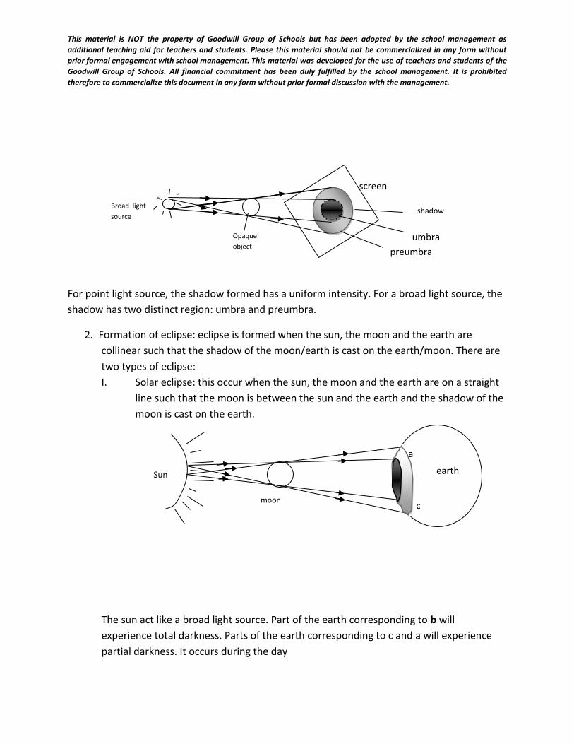
For point light source, the shadow formed has a uniform intensity. For a broad light source, the
shadow has two distinct region: umbra and preumbra.
2. Formation of eclipse: eclipse is formed when the sun, the moon and the earth are
collinear such that the shadow of the moon/earth is cast on the earth/moon. There are
two types of eclipse:
I. Solar eclipse: this occur when the sun, the moon and the earth are on a straight
line such that the moon is between the sun and the earth and the shadow of the
moon is cast on the earth.
The sun act like a broad light source. Part of the earth corresponding to b will
experience total darkness. Parts of the earth corresponding to c and a will experience
partial darkness. It occurs during the day
Broad light
source
screen
shadow
Opaque
object umbra
preumbra
a
b
c
Sun earth
moon
This material is NOT the property of Goodwill Group of Schools but has been adopted by the school management as
additional teaching aid for teachers and students. Please this material should not be commercialized in any form without
prior formal engagement with school management. This material was developed for the use of teachers and students of the
Goodwill Group of Schools. All financial commitment has been duly fulfilled by the school management. It is prohibited
therefore to commercialize this document in any form without prior formal discussion with the management.
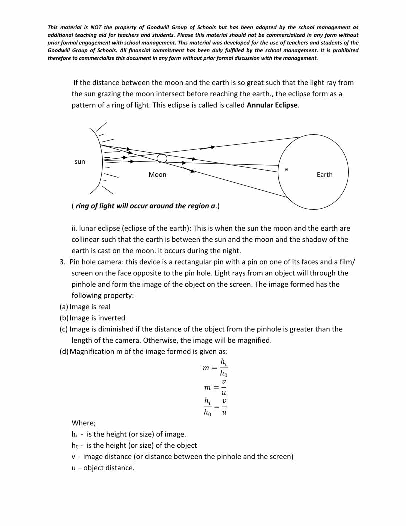
If the distance between the moon and the earth is so great such that the light ray from
the sun grazing the moon intersect before reaching the earth., the eclipse form as a
pattern of a ring of light. This eclipse is called is called Annular Eclipse.
( ring of light will occur around the region a.)
ii. lunar eclipse (eclipse of the earth): This is when the sun the moon and the earth are
collinear such that the earth is between the sun and the moon and the shadow of the
earth is cast on the moon. it occurs during the night.
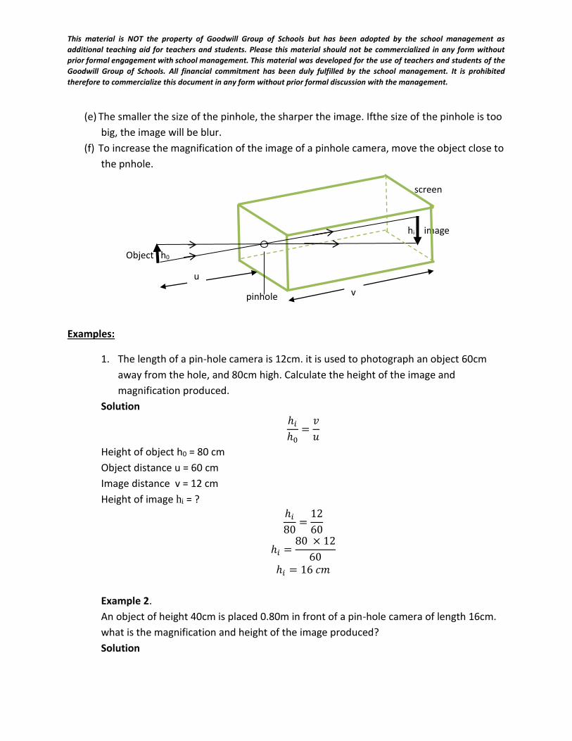
3. Pin hole camera: this device is a rectangular pin with a pin on one of its faces and a film/
screen on the face opposite to the pin hole. Light rays from an object will through the
pinhole and form the image of the object on the screen. The image formed has the
following property:
(a) Image is real
(b) Image is inverted
(c) Image is diminished if the distance of the object from the pinhole is greater than the
length of the camera. Otherwise, the image will be magnified.
(d) Magnification m of the image formed is given as:
𝑚 =ℎ𝑖
ℎ0
𝑚 =𝑣
𝑢
ℎ𝑖
ℎ0=
𝑣
𝑢
Where;
hi - is the height (or size) of image.
h0 - is the height (or size) of the object
v - image distance (or distance between the pinhole and the screen)
u – object distance.
Earth a
sun
Moon
This material is NOT the property of Goodwill Group of Schools but has been adopted by the school management as
additional teaching aid for teachers and students. Please this material should not be commercialized in any form without
prior formal engagement with school management. This material was developed for the use of teachers and students of the
Goodwill Group of Schools. All financial commitment has been duly fulfilled by the school management. It is prohibited
therefore to commercialize this document in any form without prior formal discussion with the management.
(e) The smaller the size of the pinhole, the sharper the image. Ifthe size of the pinhole is too
big, the image will be blur.
(f) To increase the magnification of the image of a pinhole camera, move the object close to
the pnhole.
Examples:
1. The length of a pin-hole camera is 12cm. it is used to photograph an object 60cm
away from the hole, and 80cm high. Calculate the height of the image and
magnification produced.
Solution
ℎ𝑖
ℎ0=
𝑣
𝑢
Height of object h0 = 80 cm
Object distance u = 60 cm
Image distance v = 12 cm
Height of image hi = ?
ℎ𝑖
80=
12
60
ℎ𝑖 =80 × 12
60
ℎ𝑖 = 16 𝑐𝑚
Example 2.
An object of height 40cm is placed 0.80m in front of a pin-hole camera of length 16cm.
what is the magnification and height of the image produced?
Solution
screen
pinhole
Object h0
hi image
v
u
This material is NOT the property of Goodwill Group of Schools but has been adopted by the school management as
additional teaching aid for teachers and students. Please this material should not be commercialized in any form without
prior formal engagement with school management. This material was developed for the use of teachers and students of the
Goodwill Group of Schools. All financial commitment has been duly fulfilled by the school management. It is prohibited
therefore to commercialize this document in any form without prior formal discussion with the management.
ℎ𝑖
ℎ0=
𝑣
𝑢
Height of object h0 = 40 cm
Object distance u = 0.8 m = 80 cm
Image distance v = 16 cm
Height of image hi = ?
Magnification m = ?
ℎ𝑖
40=
16
80
ℎ𝑖 =40 × 16
80
ℎ𝑖 = 8 𝑐𝑚
Evaluation
1. The distance between the pinhole and the screen of a pinhole camera is 12.5 cm and the
plate is 20 cm long. T what minimum distance from the pinhole must a 1.8 m tall man
stand if a full-length photo is required?
2. A body of height 6 cm and it is placed 40 cm in front of pinhole camera 16 cm in length.
What is the height of the image?
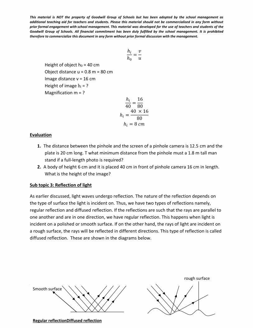
Sub topic 3: Reflection of light
As earlier discussed, light waves undergo reflection. The nature of the reflection depends on
the type of surface the light is incident on. Thus, we have two types of reflections namely,
regular reflection and diffused reflection. If the reflections are such that the rays are parallel to
one another and are in one direction, we have regular reflection. This happens when light is
incident on a polished or smooth surface. If on the other hand, the rays of light are incident on
a rough surface, the rays will be reflected in different directions. This type of reflection is called
diffused reflection. These are shown in the diagrams below.
Laws of reflection of light
There are two laws of reflection. These are
rough surface
Smooth surface
Regular reflectionDiffused reflection
This material is NOT the property of Goodwill Group of Schools but has been adopted by the school management as
additional teaching aid for teachers and students. Please this material should not be commercialized in any form without
prior formal engagement with school management. This material was developed for the use of teachers and students of the
Goodwill Group of Schools. All financial commitment has been duly fulfilled by the school management. It is prohibited
therefore to commercialize this document in any form without prior formal discussion with the management.
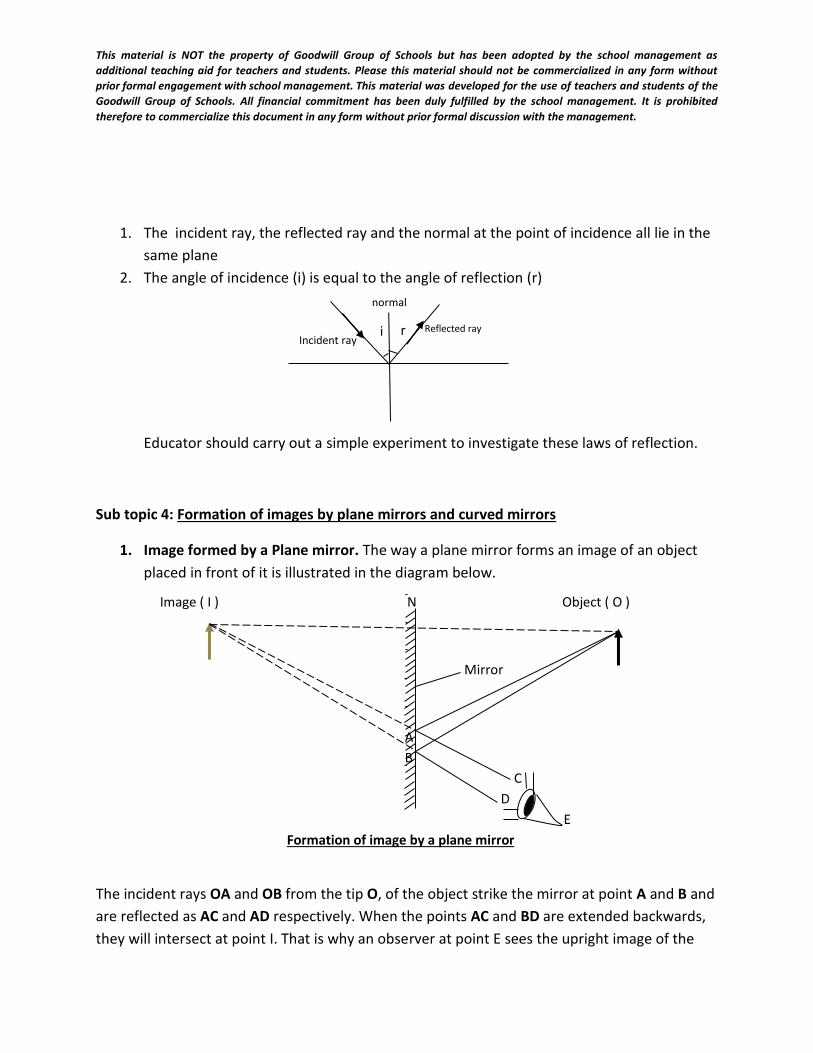
1. The incident ray, the reflected ray and the normal at the point of incidence all lie in the
same plane
2. The angle of incidence (i) is equal to the angle of reflection (r)
Educator should carry out a simple experiment to investigate these laws of reflection.
Sub topic 4: Formation of images by plane mirrors and curved mirrors
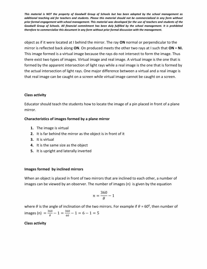
1. Image formed by a Plane mirror. The way a plane mirror forms an image of an object
placed in front of it is illustrated in the diagram below.
The incident rays OA and OB from the tip O, of the object strike the mirror at point A and B and
are reflected as AC and AD respectively. When the points AC and BD are extended backwards,
they will intersect at point I. That is why an observer at point E sees the upright image of the
Image ( I ) N Object ( O )
Mirror
A
B
C
D
E
Formation of image by a plane mirror
Incident ray Reflected ray
normal
i r
This material is NOT the property of Goodwill Group of Schools but has been adopted by the school management as
additional teaching aid for teachers and students. Please this material should not be commercialized in any form without
prior formal engagement with school management. This material was developed for the use of teachers and students of the
Goodwill Group of Schools. All financial commitment has been duly fulfilled by the school management. It is prohibited
therefore to commercialize this document in any form without prior formal discussion with the management.
object as if it were located at I behind the mirror. The ray ON normal or perpendicular to the
mirror is reflected back along ON. On produced meets the other two rays at I such that ON = NI.
This image formed is a virtual image because the rays do not intersect to form the image. Thus
there exist two types of images. Virtual image and real image. A virtual image is the one that is
formed by the apparent intersection of light rays while a real image is the one that is formed by
the actual intersection of light rays. One major difference between a virtual and a real image is
that real image can be caught on a screen while virtual image cannot be caught on a screen.
Class activity
Educator should teach the students how to locate the image of a pin placed in front of a plane
mirror.
Characteristics of images formed by a plane mirror
1. The image is virtual
2. It is far behind the mirror as the object is in front of it
3. It is virtual
4. It is the same size as the object
5. It is upright and laterally inverted
Images formed by inclined mirrors
When an object is placed in front of two mirrors that are inclined to each other, a number of
images can be viewed by an observer. The number of images (n) is given by the equation
𝑛 =360
𝜃− 1
where 𝜃 is the angle of inclination of the two mirrors. For example if 𝜃 = 600, then number of
images (n) =360
𝜃− 1 =
360
60− 1 = 6 − 1 = 5
Class activity
This material is NOT the property of Goodwill Group of Schools but has been adopted by the school management as
additional teaching aid for teachers and students. Please this material should not be commercialized in any form without
prior formal engagement with school management. This material was developed for the use of teachers and students of the
Goodwill Group of Schools. All financial commitment has been duly fulfilled by the school management. It is prohibited
therefore to commercialize this document in any form without prior formal discussion with the management.
Place a pin in front of two mirrors inclined at an angle of 450. View and record down the images
formed. Repeat the experiment for two other angles ( 600, 900). Test your result using the
formula method. What do you notice?
Evaluation
1. Mention 4 sources of light you know
2. What do you understand by rectilinear propagation of light?
3. Differentiate between virtual and real image
4. Give 4 characteristics of images formed by a plane mirror
Applications/uses of plane mirror
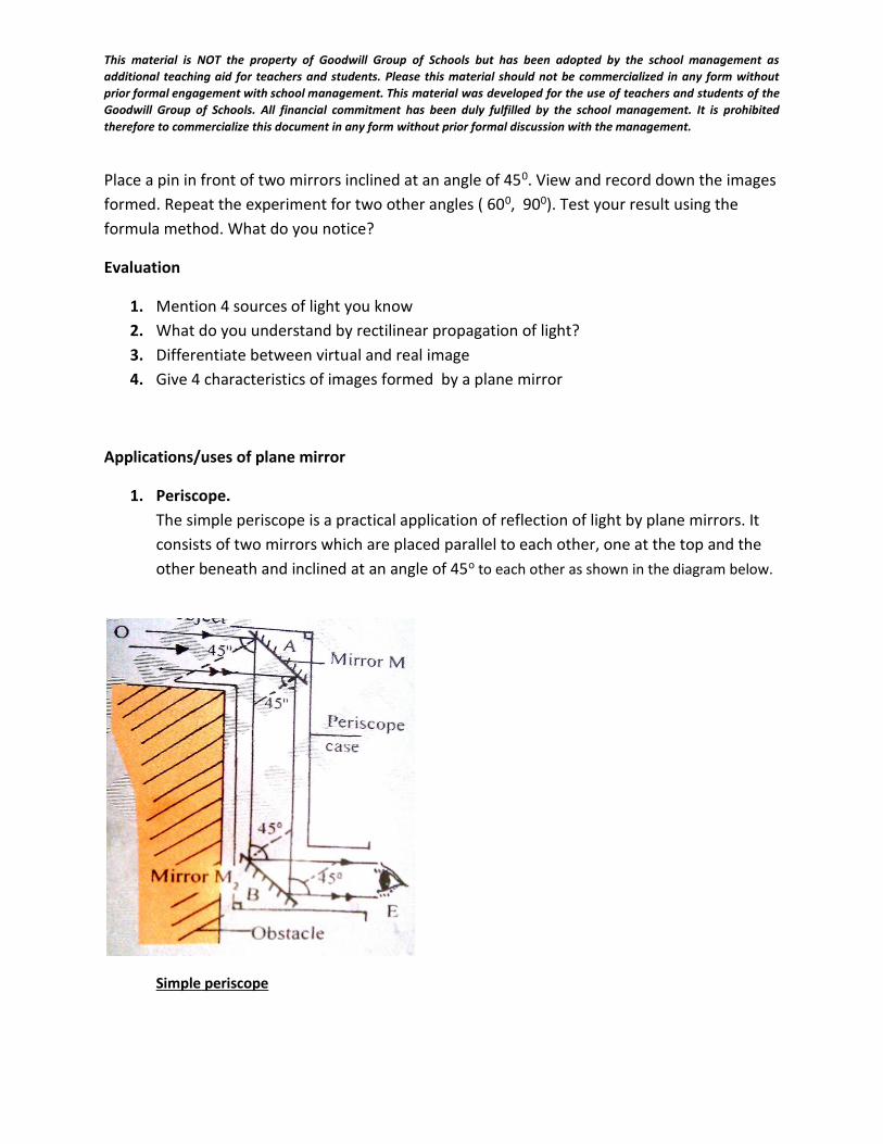
1. Periscope.
The simple periscope is a practical application of reflection of light by plane mirrors. It
consists of two mirrors which are placed parallel to each other, one at the top and the
other beneath and inclined at an angle of 45o to each other as shown in the diagram below.
Simple periscope
This material is NOT the property of Goodwill Group of Schools but has been adopted by the school management as
additional teaching aid for teachers and students. Please this material should not be commercialized in any form without
prior formal engagement with school management. This material was developed for the use of teachers and students of the
Goodwill Group of Schools. All financial commitment has been duly fulfilled by the school management. It is prohibited
therefore to commercialize this document in any form without prior formal discussion with the management.
Parallel rays from an object ‘O’ strike mirror ‘A’ at an angle of 45o and are reflected
perpendicularly through an angle of 45o (law of reflection) to mirror B. As the rays strike
mirror ‘B’, they again get reflected through the same angle of 45o. Thus, an observer at point ‘E’
can see the object ‘O’ clearly. The simple periscope is used in warfare especially in sea or water.
It is also used for looking over barriers. The periscope produces multiple images. This is a
disadvantage. Modern periscope uses a triangular glass prism with refractive angle 900 instead
of plane mirrors.
2. Kaleidoscope: This is a toy in which multiple images are formed by two plane mirrors inclined at
angle 600. The mirrors are fixed between at one end of a tube and colour paper are placed
there. The image of the paper viewed through the other end of the tube are seen symmetrically
in a circle. By shaking the tube, different pattern can be seen each time.
3. Sextant: optical instrument used for the measurement of angular distance between any
two objects. The operation of the sextant depends upon superimposition of the images of
the two objects whose distance is being measured. This is achieved by means of an
optical system consisting of a telescope and two mirrors, one fixed and one movable.
4. It is used in supermarkets to display multiple images of items.
5. it used for dressing mirrors.
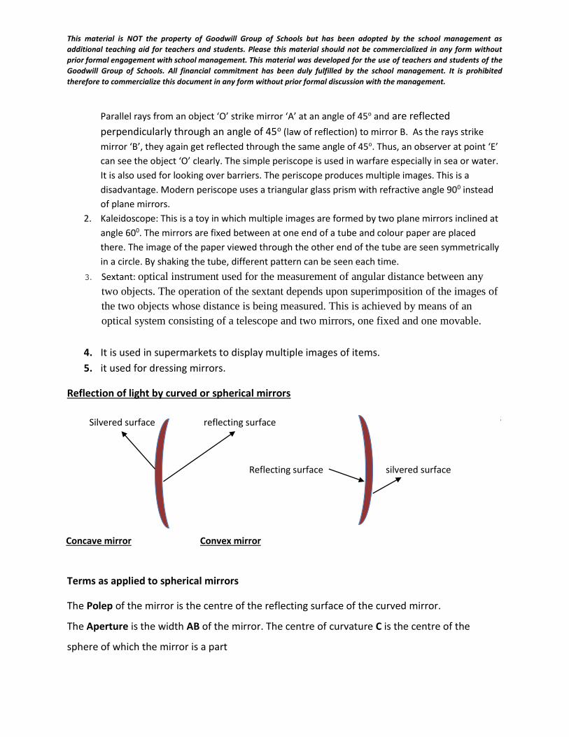
Reflection of light by curved or spherical mirrors
Apart from plane mirrors, curved or spherical mirrors also reflect light rays. There are two types
of spherical mirrors. They are convex mirror and concave mirror. If the reflecting surface is
curved inside, the mirror is concave mirror or converging mirror. If the reflecting surface is
curved outward, it is called convex or diverging mirror. Ask your teacher to show you these
spherical mirrors.
Terms as applied to spherical mirrors
The Polep of the mirror is the centre of the reflecting surface of the curved mirror.
The Aperture is the width AB of the mirror. The centre of curvature C is the centre of the
sphere of which the mirror is a part
Silvered surface reflecting surface
Reflecting surface silvered surface
Concave mirror Convex mirror
This material is NOT the property of Goodwill Group of Schools but has been adopted by the school management as
additional teaching aid for teachers and students. Please this material should not be commercialized in any form without
prior formal engagement with school management. This material was developed for the use of teachers and students of the
Goodwill Group of Schools. All financial commitment has been duly fulfilled by the school management. It is prohibited
therefore to commercialize this document in any form without prior formal discussion with the management.
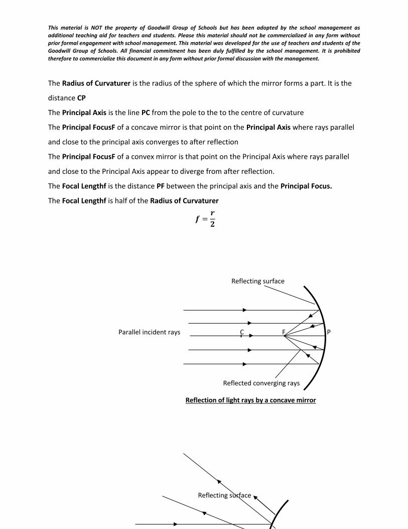
The Radius of Curvaturer is the radius of the sphere of which the mirror forms a part. It is the
distance CP
The Principal Axis is the line PC from the pole to the to the centre of curvature
The Principal FocusF of a concave mirror is that point on the Principal Axis where rays parallel
and close to the principal axis converges to after reflection
The Principal FocusF of a convex mirror is that point on the Principal Axis where rays parallel
and close to the Principal Axis appear to diverge from after reflection.
The Focal Lengthf is the distance PF between the principal axis and the Principal Focus.
The Focal Lengthf is half of the Radius of Curvaturer
𝒇 =𝒓
𝟐
Reflecting surface
Reflecting surface
Parallel incident rays C F P
Reflected converging rays
Reflection of light rays by a concave mirror
This material is NOT the property of Goodwill Group of Schools but has been adopted by the school management as
additional teaching aid for teachers and students. Please this material should not be commercialized in any form without
prior formal engagement with school management. This material was developed for the use of teachers and students of the
Goodwill Group of Schools. All financial commitment has been duly fulfilled by the school management. It is prohibited
therefore to commercialize this document in any form without prior formal discussion with the management.
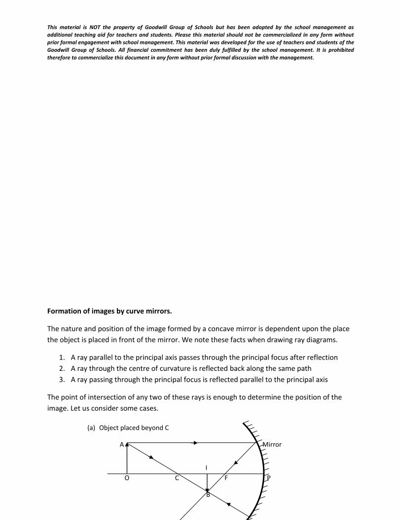
Formation of images by curve mirrors.
The nature and position of the image formed by a concave mirror is dependent upon the place
the object is placed in front of the mirror. We note these facts when drawing ray diagrams.
1. A ray parallel to the principal axis passes through the principal focus after reflection
2. A ray through the centre of curvature is reflected back along the same path
3. A ray passing through the principal focus is reflected parallel to the principal axis
The point of intersection of any two of these rays is enough to determine the position of the
image. Let us consider some cases.
Object placed beyond C
(a) Object placed beyond C
A Mirror
O C F P
B
I
This material is NOT the property of Goodwill Group of Schools but has been adopted by the school management as
additional teaching aid for teachers and students. Please this material should not be commercialized in any form without
prior formal engagement with school management. This material was developed for the use of teachers and students of the
Goodwill Group of Schools. All financial commitment has been duly fulfilled by the school management. It is prohibited
therefore to commercialize this document in any form without prior formal discussion with the management.
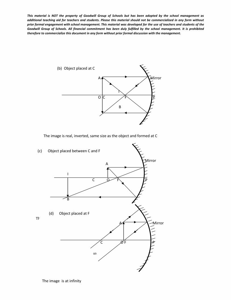
(b) Object placed at C
A Mirror
O C F P
B
The image is real, inverted, same size as the object and formed at C
I
(c) Object placed between C and F
Mirror
C O F P
B
The image is real, inverted, enlarged and formed beyond C
I
A
(d) Object placed at F
A Mirror
C O F P
The image is at infinity
∞
This material is NOT the property of Goodwill Group of Schools but has been adopted by the school management as
additional teaching aid for teachers and students. Please this material should not be commercialized in any form without
prior formal engagement with school management. This material was developed for the use of teachers and students of the
Goodwill Group of Schools. All financial commitment has been duly fulfilled by the school management. It is prohibited
therefore to commercialize this document in any form without prior formal discussion with the management.
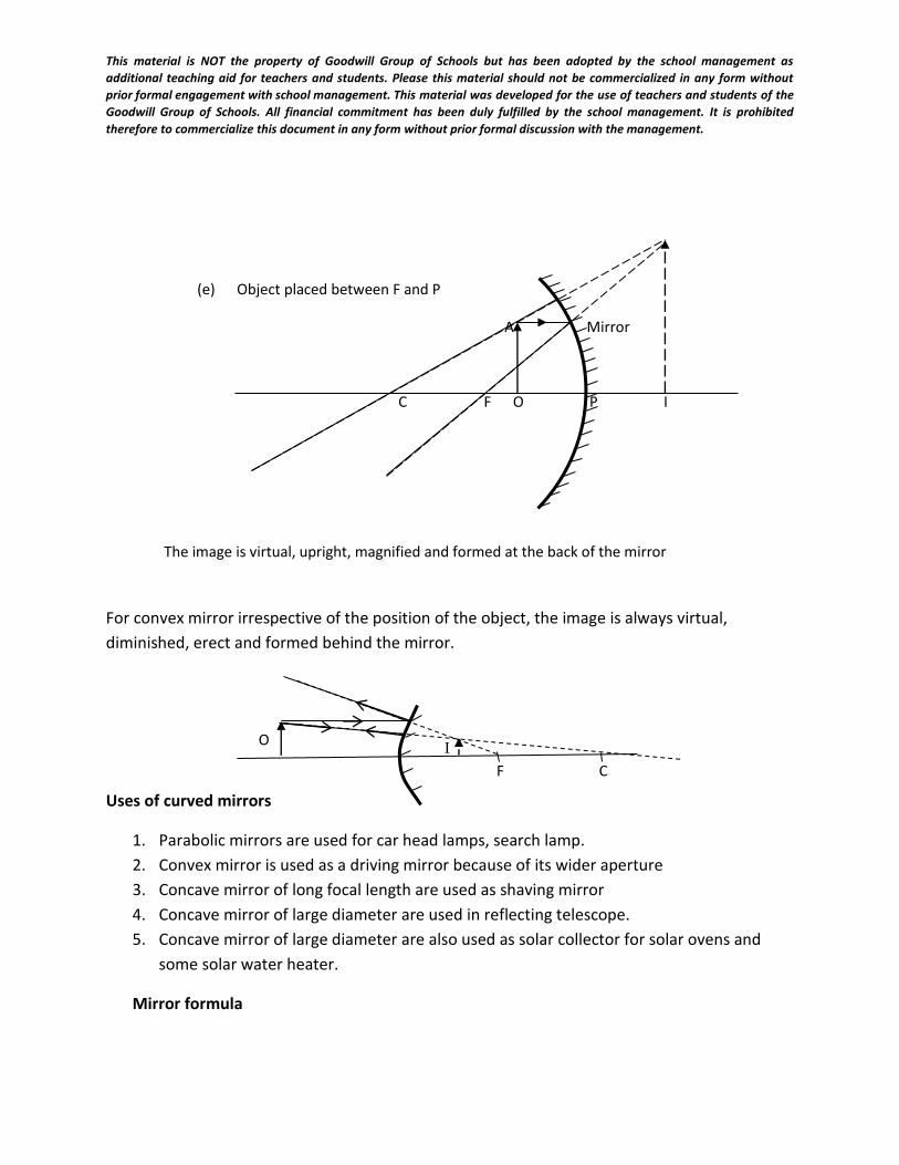
For convex mirror irrespective of the position of the object, the image is always virtual,
diminished, erect and formed behind the mirror.
Uses of curved mirrors
1. Parabolic mirrors are used for car head lamps, search lamp.
2. Convex mirror is used as a driving mirror because of its wider aperture
3. Concave mirror of long focal length are used as shaving mirror
4. Concave mirror of large diameter are used in reflecting telescope.
5. Concave mirror of large diameter are also used as solar collector for solar ovens and
some solar water heater.
Mirror formula
(e) Object placed between F and P
A Mirror
C F O P I
The image is virtual, upright, magnified and formed at the back of the mirror
F C
I O
This material is NOT the property of Goodwill Group of Schools but has been adopted by the school management as
additional teaching aid for teachers and students. Please this material should not be commercialized in any form without
prior formal engagement with school management. This material was developed for the use of teachers and students of the
Goodwill Group of Schools. All financial commitment has been duly fulfilled by the school management. It is prohibited
therefore to commercialize this document in any form without prior formal discussion with the management.
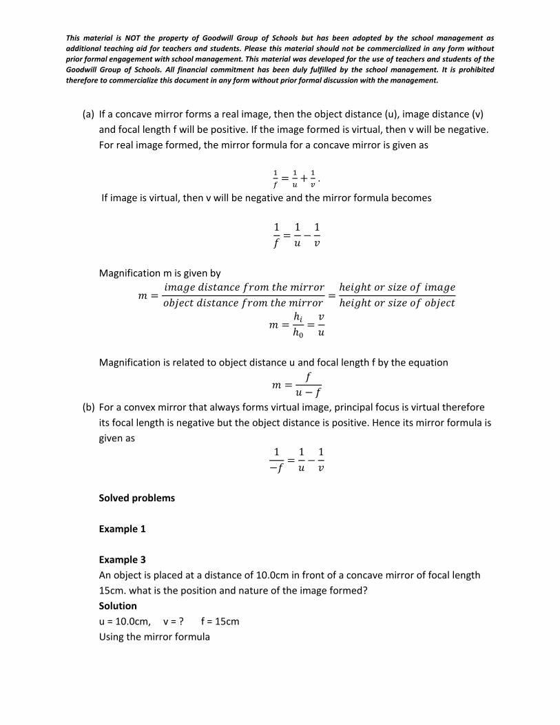
(a) If a concave mirror forms a real image, then the object distance (u), image distance (v)
and focal length f will be positive. If the image formed is virtual, then v will be negative.
For real image formed, the mirror formula for a concave mirror is given as
1
𝑓=
1
𝑢+
1
𝑣 .
If image is virtual, then v will be negative and the mirror formula becomes
1
𝑓=
1
𝑢−
1
𝑣
Magnification m is given by
𝑚 = 𝑖𝑚𝑎𝑔𝑒 𝑑𝑖𝑠𝑡𝑎𝑛𝑐𝑒 𝑓𝑟𝑜𝑚 𝑡ℎ𝑒 𝑚𝑖𝑟𝑟𝑜𝑟
𝑜𝑏𝑗𝑒𝑐𝑡 𝑑𝑖𝑠𝑡𝑎𝑛𝑐𝑒 𝑓𝑟𝑜𝑚 𝑡ℎ𝑒 𝑚𝑖𝑟𝑟𝑜𝑟=
ℎ𝑒𝑖𝑔ℎ𝑡 𝑜𝑟 𝑠𝑖𝑧𝑒 𝑜𝑓 𝑖𝑚𝑎𝑔𝑒
ℎ𝑒𝑖𝑔ℎ𝑡 𝑜𝑟 𝑠𝑖𝑧𝑒 𝑜𝑓 𝑜𝑏𝑗𝑒𝑐𝑡
𝑚 =ℎ𝑖
ℎ0=
𝑣
𝑢
Magnification is related to object distance u and focal length f by the equation
𝑚 =𝑓
𝑢 − 𝑓
(b) For a convex mirror that always forms virtual image, principal focus is virtual therefore
its focal length is negative but the object distance is positive. Hence its mirror formula is
given as
1
−𝑓=
1
𝑢−
1
𝑣
Solved problems
Example 1
Example 3
An object is placed at a distance of 10.0cm in front of a concave mirror of focal length
15cm. what is the position and nature of the image formed?
Solution
u = 10.0cm, v = ? f = 15cm
Using the mirror formula
This material is NOT the property of Goodwill Group of Schools but has been adopted by the school management as
additional teaching aid for teachers and students. Please this material should not be commercialized in any form without
prior formal engagement with school management. This material was developed for the use of teachers and students of the
Goodwill Group of Schools. All financial commitment has been duly fulfilled by the school management. It is prohibited
therefore to commercialize this document in any form without prior formal discussion with the management.
1
𝑓=
1
𝑢+
1
𝑣 ,
1
15=
1
10+
1
𝑣
1
𝑣=
1
15−
1
10
1
𝑣= −
1
30
v = - 30cm
Therefore the image is formed 30cm behind the mirror and it is virtual since v is
negative
Example 4
A converging mirror forms an image which is twice the size of the object. Given that the
focal length of the mirror is 5cm, calculate the object distance and the image distance.
Solution
Magnification m = 2, f = 5cm, u = ? v = ?
m = v/u
2 = v/u
V =2u
Considering the mirror formula
1
𝑓=
1
𝑢+
1
𝑣
1
𝑓=
1
𝑢+
1
2𝑢
1
5=
1
𝑢+
1
2𝑢
This material is NOT the property of Goodwill Group of Schools but has been adopted by the school management as
additional teaching aid for teachers and students. Please this material should not be commercialized in any form without
prior formal engagement with school management. This material was developed for the use of teachers and students of the
Goodwill Group of Schools. All financial commitment has been duly fulfilled by the school management. It is prohibited
therefore to commercialize this document in any form without prior formal discussion with the management.
1
5=
3
2𝑢
2u = 15
u = 7.5cm
since v = 2u
v = 2 x 7.5 = 15cm
Example 5
An object is placed 30cm from a concave mirror of focal length 15cm. find the linear
magnification of the image produced
Solution
Object distance u = 30cm, focal length f = 15cm
Applying the mirror formula,
1
𝑓=
1
𝑢+
1
𝑣
1
15=
1
𝑢+
1
30
1
𝑢=
1
15+
1
30=
2 − 1
30=
1
30
u = 30cm
magnification m = 𝑣
𝑢=
30
30= 1.0𝑐𝑚
Note: Educator should carry out an experiment to determine the focal length of a
concave mirror with the students
This material is NOT the property of Goodwill Group of Schools but has been adopted by the school management as
additional teaching aid for teachers and students. Please this material should not be commercialized in any form without
prior formal engagement with school management. This material was developed for the use of teachers and students of the
Goodwill Group of Schools. All financial commitment has been duly fulfilled by the school management. It is prohibited
therefore to commercialize this document in any form without prior formal discussion with the management.
Evaluation:
1. Define these terms as applied to curved mirror. Radius of curvature, centre of
curvature, pole, focal length and principal focus of a concave mirror
2. Differentiate between convergent and divergent beam
3. Differentiate between concave and convex mirror
4. Draw the ray diagram of an object placed between C and P and explain its
characteristics
Week end assignment:
1. Draw a ray diagram of an object placed in front of a convex mirror and explain the
characteristics of the image formed.
2. An object of height 3cm is placed 10cm in front of a concave mirror of focal length 5cm.
using scale diagram, determine the position, height, nature of magnification of the
image that will be produced.
3. State one advantage and one disadvantage of using a convex mirror as a driving mirror
4. Explain the term parallax as applied to optics. Describe the method of non-parallax to
locate the position of an image in a plane mirror.
5. With a labeled diagram, describe the mode of operation of a pin-hole camera. Comment
on the effects of the size of the pin-hole on the image formed by the camera.
Objectives
1. The image of an optical pin placed at the principal focus of a concave mirror will be
formedbetween the principal focus and the pole
a. at the centre of curvature
b. between the principal focus and the centre of curvature
c. at infinity
d.
2. A man 1.8m tall stands 3m away from a pin hole camera. If the distance between the pin
hole and the screen of the camera is 0.3m, calculate the height of the image of the man
produced by the camera.
A 0.18m B. 0.50m C. 1.62m D. 18.00m
3. The image in a pin-hole camera is always
This material is NOT the property of Goodwill Group of Schools but has been adopted by the school management as
additional teaching aid for teachers and students. Please this material should not be commercialized in any form without
prior formal engagement with school management. This material was developed for the use of teachers and students of the
Goodwill Group of Schools. All financial commitment has been duly fulfilled by the school management. It is prohibited
therefore to commercialize this document in any form without prior formal discussion with the management.
A. Diminished B. enlarged
B. C. upright D. inverted
4. Which of the following statement is/are correct about the image formed by a plane
mirror?
i. The magnification produced is 1
ii. The image distance is the same as the object distance.
iii. The image is real.
iv. The image is laterally inverted.
A i only B. ii only C. iii only D. i and iii only
5. An image which can be formed on the screen is said to be
A. real B. virtual C.blurred D.inverted
. An object is placed between two mirrors which are inclined at an angle of 1200 and facing each
other. Determine the number of images observed in the two mirrors.
A. 1 B. 2 C 3 D. 4
8. A concave mirror of radius of curvature 20cm has a pin placed at 15cm from the pole. What
will be the magnification of the image produced?
A. 4.00 B. 2.00 C.1.33 D.1.50
9. A parallel beam of light is to be obtained from the headlamp of a car. At which of the
following positions should the source of light be placed from the pole of its spherical mirror?
A. At the focal point
B. At the centre of curvature
C. Beyond the centre of curvature
D. Between the focal point and the pole
WEEK 5:
DATE:…………….
SUBJECT: PHYSICS
CLASS: SS11
TOPIC: REFRACTION OF LIGHT WAVES
CONTENTS
1. Refraction of light through rectangular glass block and triangular glass prism
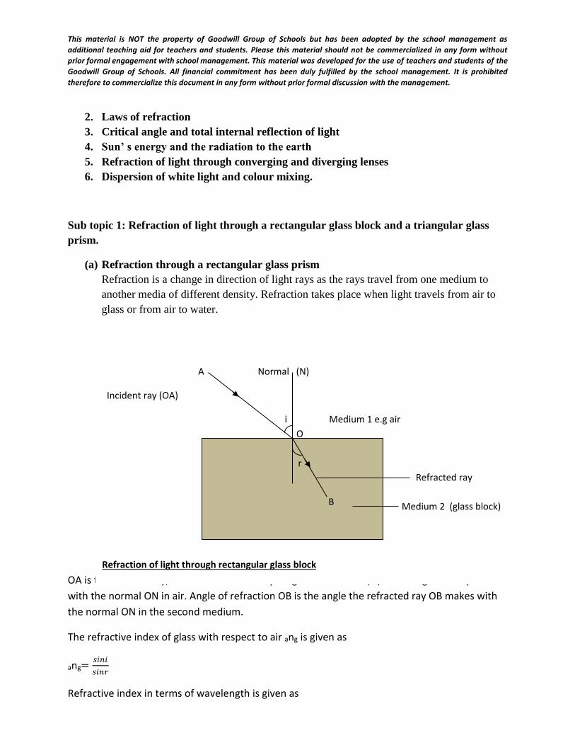
This material is NOT the property of Goodwill Group of Schools but has been adopted by the school management as
additional teaching aid for teachers and students. Please this material should not be commercialized in any form without
prior formal engagement with school management. This material was developed for the use of teachers and students of the
Goodwill Group of Schools. All financial commitment has been duly fulfilled by the school management. It is prohibited
therefore to commercialize this document in any form without prior formal discussion with the management.
2. Laws of refraction
3. Critical angle and total internal reflection of light
4. Sun’ s energy and the radiation to the earth
5. Refraction of light through converging and diverging lenses
6. Dispersion of white light and colour mixing.
Sub topic 1: Refraction of light through a rectangular glass block and a triangular glass
prism.
(a) Refraction through a rectangular glass prism
Refraction is a change in direction of light rays as the rays travel from one medium to
another media of different density. Refraction takes place when light travels from air to
glass or from air to water.
OA is the incident ray, OB is the refracted ray. Angle of incidence ( i ) is the angle the ray makes
with the normal ON in air. Angle of refraction OB is the angle the refracted ray OB makes with
the normal ON in the second medium.
The refractive index of glass with respect to air ang is given as
ang=𝑠𝑖𝑛𝑖
𝑠𝑖𝑛𝑟
Refractive index in terms of wavelength is given as
A Normal (N)
Incident ray (OA)
i Medium 1 e.g air
O
Refracted ray
Medium 2 (glass block)
Refraction of light through rectangular glass block
r
B
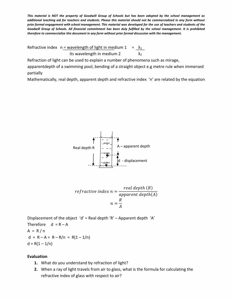
This material is NOT the property of Goodwill Group of Schools but has been adopted by the school management as
additional teaching aid for teachers and students. Please this material should not be commercialized in any form without
prior formal engagement with school management. This material was developed for the use of teachers and students of the
Goodwill Group of Schools. All financial commitment has been duly fulfilled by the school management. It is prohibited
therefore to commercialize this document in any form without prior formal discussion with the management.
Refractive index n = wavelength of light in medium 1 = λ1
its wavelength in medium 2 λ2
Refraction of light can be used to explain a number of phenomena such as mirage,
apparentdepth of a swimming pool, bending of a straight object e.g metre rule when immersed
partially
Mathematically, real depth, apparent depth and refractive index ‘n’ are related by the equation
𝑟𝑒𝑓𝑟𝑎𝑐𝑡𝑖𝑣𝑒 𝑖𝑛𝑑𝑒𝑥 𝑛 =𝑟𝑒𝑎𝑙 𝑑𝑒𝑝𝑡ℎ (𝑅)
𝑎𝑝𝑝𝑎𝑟𝑒𝑛𝑡 𝑑𝑒𝑝𝑡ℎ(𝐴)
𝑛 =𝑅
𝐴
Displacement of the object ‘d’ = Real depth ‘R’ – Apparent depth ‘A’
Therefore d = R – A
A = R / n
d = R – A = R – R/n = R(1 – 1/n)
d = R(1 – 1/n)
Evaluation
1. What do you understand by refraction of light?
2. When a ray of light travels from air to glass, what is the formula for calculating the
refractive index of glass with respect to air?
water
image
object d - displacement
A – apparent depth Real depth R
This material is NOT the property of Goodwill Group of Schools but has been adopted by the school management as
additional teaching aid for teachers and students. Please this material should not be commercialized in any form without
prior formal engagement with school management. This material was developed for the use of teachers and students of the
Goodwill Group of Schools. All financial commitment has been duly fulfilled by the school management. It is prohibited
therefore to commercialize this document in any form without prior formal discussion with the management.
Sub topic 2: Laws of refraction
We have two laws of refraction. They are,
1. The incident ray, the refracted ray and the normal at the point of incidence all lie in the
same plane
2. The ratio of the sine of angle of incidence to the sine of angle of refraction is constant
for a given pair of media.
The second law is known as Snell’s law of refraction. Refractive index can also be written as
ang=𝑣𝑒𝑙𝑜𝑐𝑖𝑡𝑦 𝑜𝑓 𝑙𝑖𝑔ℎ𝑡 𝑖𝑛 𝑎𝑖𝑟
𝑣𝑒𝑙𝑜𝑐𝑖𝑡𝑦 𝑜𝑓 𝑙𝑖𝑔ℎ𝑡 𝑖𝑛 𝑔𝑙𝑎𝑠𝑠
ang=𝑣𝑎
𝑣𝑔
Where ang is refractive index of glass with respect to air.
Educator should verify Snell’s law in the laboratory with the students using a rectangular
glass block.
Example 1
A fish appears to be 2m below the surface of a pond when viewed directly from above. How
far below the surface of the pond is the fish? (Refractive index of water = 1.33)
Solution
Apparent depth = 2m, refractive index n = 1.33
Using the formula: refractive index n = real depth / apparent depth,
Real depth = refractive index x apparent depth = 1.33 x 2 = 2.66m
Example 2
The wavelength of red light in air is 7 x 10 -7m. (a) What is its wavelength in a glass of
refractive index 1.5 (b) What is its speed in the glass. (speed of light in air is 3 x 10⁸m/s)
Solution
Wavelength of red light λR = 7 x 10 – 7m. Wavelength in glass = λ . Refractive index = n =
1.5
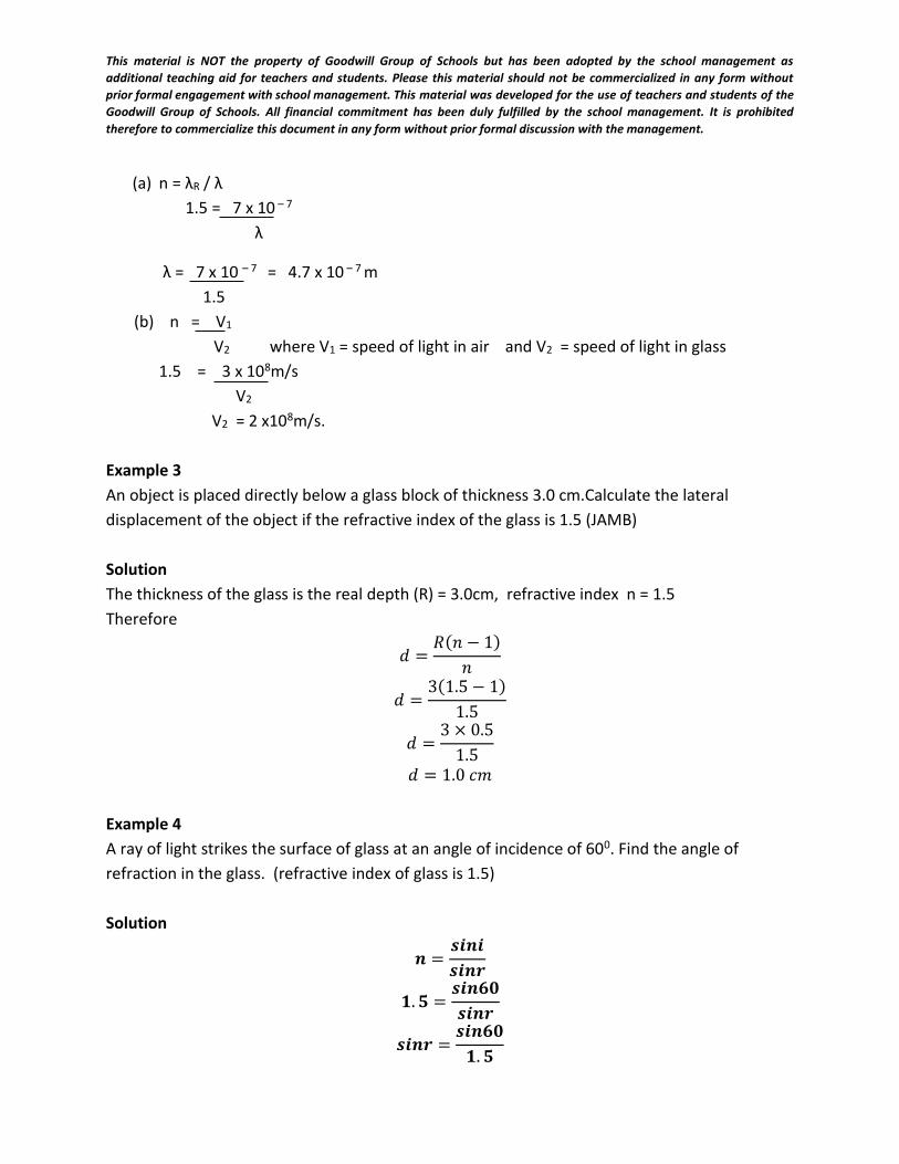
This material is NOT the property of Goodwill Group of Schools but has been adopted by the school management as
additional teaching aid for teachers and students. Please this material should not be commercialized in any form without
prior formal engagement with school management. This material was developed for the use of teachers and students of the
Goodwill Group of Schools. All financial commitment has been duly fulfilled by the school management. It is prohibited
therefore to commercialize this document in any form without prior formal discussion with the management.
(a) n = λR / λ
1.5 = 7 x 10 – 7
λ
λ = 7 x 10 – 7 = 4.7 x 10 – 7 m
1.5
(b) n = V1
V2 where V1 = speed of light in air and V2 = speed of light in glass
1.5 = 3 x 10⁸m/s
V2
V2 = 2 x10⁸m/s.
Example 3
An object is placed directly below a glass block of thickness 3.0 cm.Calculate the lateral
displacement of the object if the refractive index of the glass is 1.5 (JAMB)
Solution
The thickness of the glass is the real depth (R) = 3.0cm, refractive index n = 1.5
Therefore
𝑑 =𝑅(𝑛 − 1)
𝑛
𝑑 =3(1.5 − 1)
1.5
𝑑 =3 × 0.5
1.5
𝑑 = 1.0 𝑐𝑚
Example 4
A ray of light strikes the surface of glass at an angle of incidence of 600. Find the angle of
refraction in the glass. (refractive index of glass is 1.5)
Solution
𝒏 =𝒔𝒊𝒏𝒊
𝒔𝒊𝒏𝒓
𝟏. 𝟓 =𝒔𝒊𝒏𝟔𝟎
𝒔𝒊𝒏𝒓
𝒔𝒊𝒏𝒓 =𝒔𝒊𝒏𝟔𝟎
𝟏. 𝟓
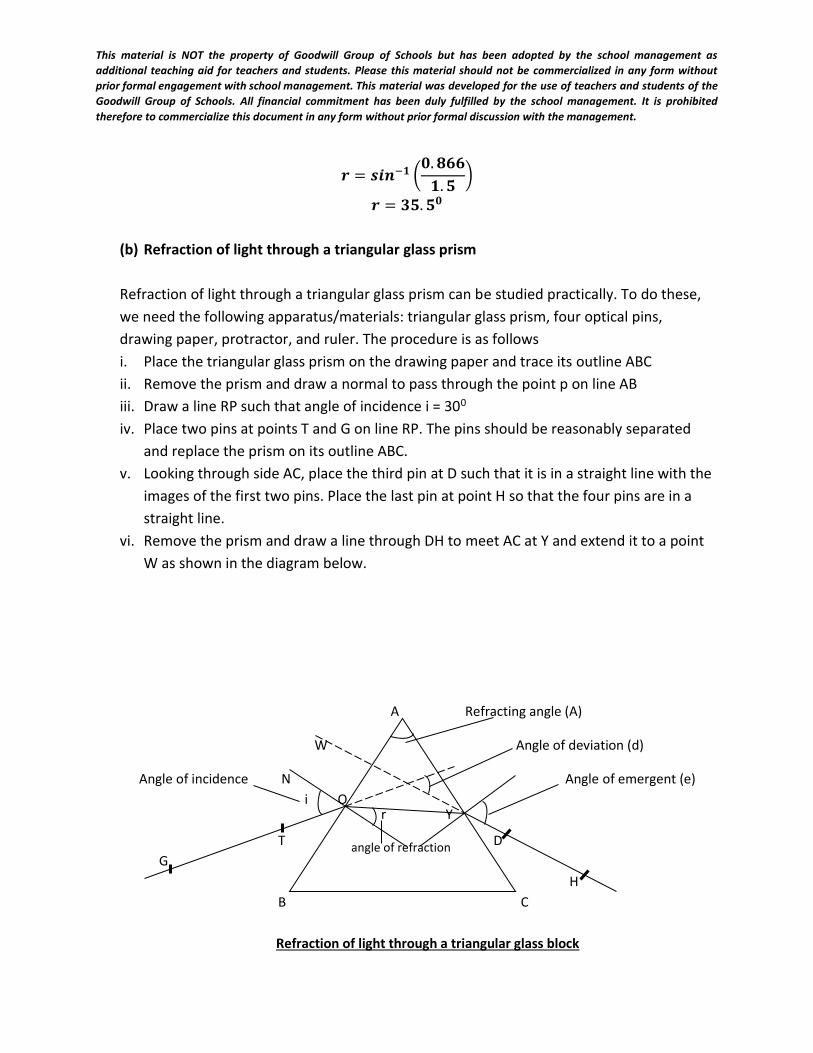
This material is NOT the property of Goodwill Group of Schools but has been adopted by the school management as
additional teaching aid for teachers and students. Please this material should not be commercialized in any form without
prior formal engagement with school management. This material was developed for the use of teachers and students of the
Goodwill Group of Schools. All financial commitment has been duly fulfilled by the school management. It is prohibited
therefore to commercialize this document in any form without prior formal discussion with the management.
𝒓 = 𝒔𝒊𝒏−𝟏 (𝟎. 𝟖𝟔𝟔
𝟏. 𝟓)
𝒓 = 𝟑𝟓. 𝟓𝟎
(b) Refraction of light through a triangular glass prism
Refraction of light through a triangular glass prism can be studied practically. To do these,
we need the following apparatus/materials: triangular glass prism, four optical pins,
drawing paper, protractor, and ruler. The procedure is as follows
i. Place the triangular glass prism on the drawing paper and trace its outline ABC
ii. Remove the prism and draw a normal to pass through the point p on line AB
iii. Draw a line RP such that angle of incidence i = 300
iv. Place two pins at points T and G on line RP. The pins should be reasonably separated
and replace the prism on its outline ABC.
v. Looking through side AC, place the third pin at D such that it is in a straight line with the
images of the first two pins. Place the last pin at point H so that the four pins are in a
straight line.
vi. Remove the prism and draw a line through DH to meet AC at Y and extend it to a point
W as shown in the diagram below.
A Refracting angle (A)
W Angle of deviation (d)
Angle of incidence N Angle of emergent (e)
i O
T D
G
H
B C
Refraction of light through a triangular glass block
r Y
angle of refraction
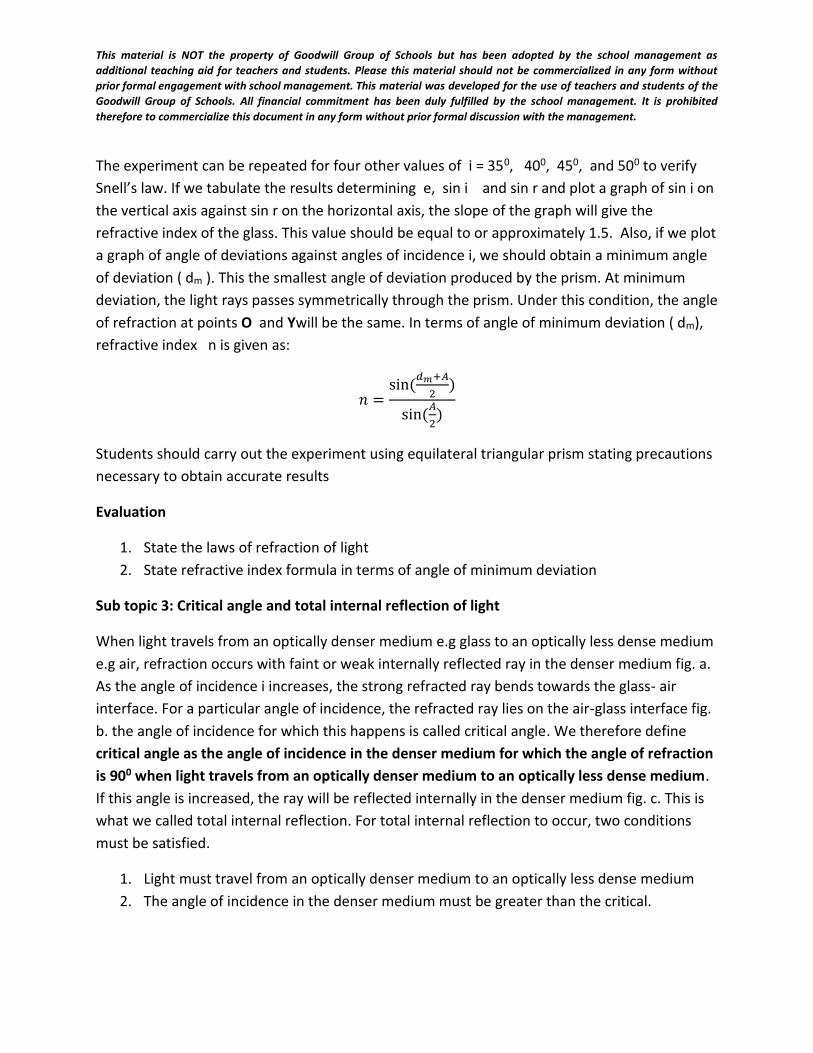
This material is NOT the property of Goodwill Group of Schools but has been adopted by the school management as
additional teaching aid for teachers and students. Please this material should not be commercialized in any form without
prior formal engagement with school management. This material was developed for the use of teachers and students of the
Goodwill Group of Schools. All financial commitment has been duly fulfilled by the school management. It is prohibited
therefore to commercialize this document in any form without prior formal discussion with the management.
The experiment can be repeated for four other values of i = 350, 400, 450, and 500 to verify
Snell’s law. If we tabulate the results determining e, sin i and sin r and plot a graph of sin i on
the vertical axis against sin r on the horizontal axis, the slope of the graph will give the
refractive index of the glass. This value should be equal to or approximately 1.5. Also, if we plot
a graph of angle of deviations against angles of incidence i, we should obtain a minimum angle
of deviation ( dm ). This the smallest angle of deviation produced by the prism. At minimum
deviation, the light rays passes symmetrically through the prism. Under this condition, the angle
of refraction at points O and Ywill be the same. In terms of angle of minimum deviation ( dm),
refractive index n is given as:
𝑛 =sin (
𝑑𝑚+𝐴
2)
sin(𝐴
2)
Students should carry out the experiment using equilateral triangular prism stating precautions
necessary to obtain accurate results
Evaluation
1. State the laws of refraction of light
2. State refractive index formula in terms of angle of minimum deviation
Sub topic 3: Critical angle and total internal reflection of light
When light travels from an optically denser medium e.g glass to an optically less dense medium
e.g air, refraction occurs with faint or weak internally reflected ray in the denser medium fig. a.
As the angle of incidence i increases, the strong refracted ray bends towards the glass- air
interface. For a particular angle of incidence, the refracted ray lies on the air-glass interface fig.
b. the angle of incidence for which this happens is called critical angle. We therefore define
critical angle as the angle of incidence in the denser medium for which the angle of refraction
is 900 when light travels from an optically denser medium to an optically less dense medium.
If this angle is increased, the ray will be reflected internally in the denser medium fig. c. This is
what we called total internal reflection. For total internal reflection to occur, two conditions
must be satisfied.
1. Light must travel from an optically denser medium to an optically less dense medium
2. The angle of incidence in the denser medium must be greater than the critical.
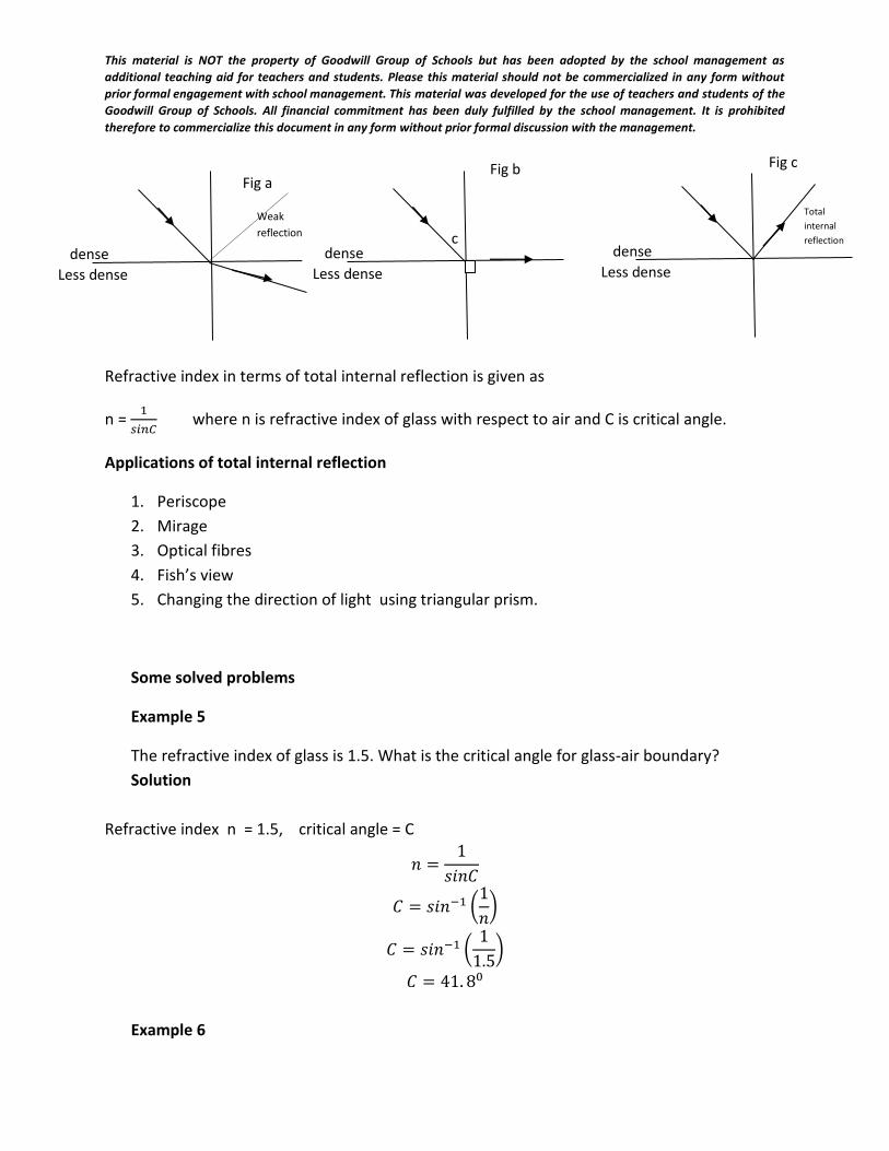
This material is NOT the property of Goodwill Group of Schools but has been adopted by the school management as
additional teaching aid for teachers and students. Please this material should not be commercialized in any form without
prior formal engagement with school management. This material was developed for the use of teachers and students of the
Goodwill Group of Schools. All financial commitment has been duly fulfilled by the school management. It is prohibited
therefore to commercialize this document in any form without prior formal discussion with the management.
Refractive index in terms of total internal reflection is given as
n = 1
𝑠𝑖𝑛𝐶 where n is refractive index of glass with respect to air and C is critical angle.
Applications of total internal reflection
1. Periscope
2. Mirage
3. Optical fibres
4. Fish’s view
5. Changing the direction of light using triangular prism.
Some solved problems
Example 5
The refractive index of glass is 1.5. What is the critical angle for glass-air boundary?
Solution
Refractive index n = 1.5, critical angle = C
𝑛 =1
𝑠𝑖𝑛𝐶
𝐶 = 𝑠𝑖𝑛−1 (1
𝑛)
𝐶 = 𝑠𝑖𝑛−1 (1
1.5)
𝐶 = 41. 80
Example 6
Less dense
dense c
Less dense
dense Less dense
dense
Total
internal
reflection
Weak
reflection
Fig a Fig b Fig c
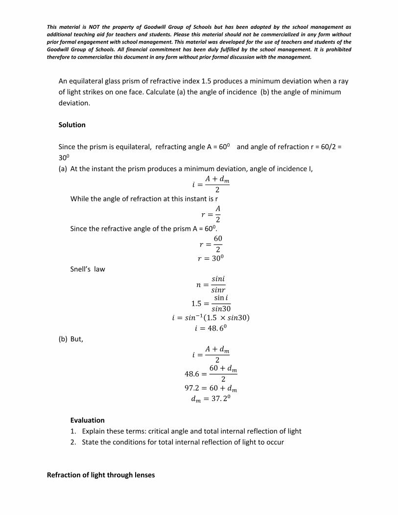
This material is NOT the property of Goodwill Group of Schools but has been adopted by the school management as
additional teaching aid for teachers and students. Please this material should not be commercialized in any form without
prior formal engagement with school management. This material was developed for the use of teachers and students of the
Goodwill Group of Schools. All financial commitment has been duly fulfilled by the school management. It is prohibited
therefore to commercialize this document in any form without prior formal discussion with the management.
An equilateral glass prism of refractive index 1.5 produces a minimum deviation when a ray
of light strikes on one face. Calculate (a) the angle of incidence (b) the angle of minimum
deviation.
Solution
Since the prism is equilateral, refracting angle A = 600 and angle of refraction r = 60/2 =
300
(a) At the instant the prism produces a minimum deviation, angle of incidence I,
𝑖 =𝐴 + 𝑑𝑚
2
While the angle of refraction at this instant is r
𝑟 =𝐴
2
Since the refractive angle of the prism A = 600.
𝑟 =60
2
𝑟 = 300
Snell’s law
𝑛 =𝑠𝑖𝑛𝑖
𝑠𝑖𝑛𝑟
1.5 =sin 𝑖
𝑠𝑖𝑛30
𝑖 = 𝑠𝑖𝑛−1(1.5 × 𝑠𝑖𝑛30)
𝑖 = 48. 60
(b) But,
𝑖 =𝐴 + 𝑑𝑚
2
48.6 =60 + 𝑑𝑚
2
97.2 = 60 + 𝑑𝑚
𝑑𝑚 = 37. 20
Evaluation
1. Explain these terms: critical angle and total internal reflection of light
2. State the conditions for total internal reflection of light to occur
Refraction of light through lenses
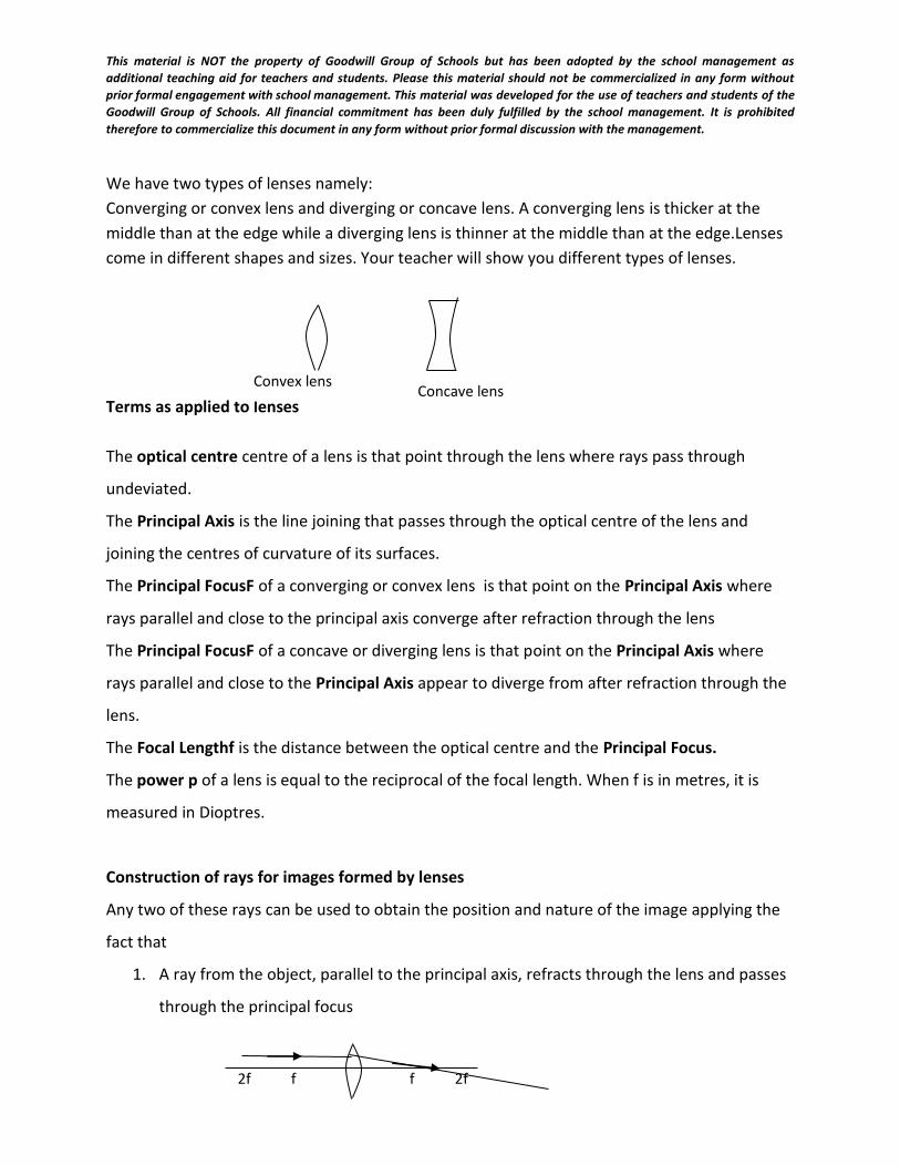
This material is NOT the property of Goodwill Group of Schools but has been adopted by the school management as
additional teaching aid for teachers and students. Please this material should not be commercialized in any form without
prior formal engagement with school management. This material was developed for the use of teachers and students of the
Goodwill Group of Schools. All financial commitment has been duly fulfilled by the school management. It is prohibited
therefore to commercialize this document in any form without prior formal discussion with the management.
We have two types of lenses namely:
Converging or convex lens and diverging or concave lens. A converging lens is thicker at the
middle than at the edge while a diverging lens is thinner at the middle than at the edge.Lenses
come in different shapes and sizes. Your teacher will show you different types of lenses.
Terms as applied to lenses
The optical centre centre of a lens is that point through the lens where rays pass through
undeviated.
The Principal Axis is the line joining that passes through the optical centre of the lens and
joining the centres of curvature of its surfaces.
The Principal FocusF of a converging or convex lens is that point on the Principal Axis where
rays parallel and close to the principal axis converge after refraction through the lens
The Principal FocusF of a concave or diverging lens is that point on the Principal Axis where
rays parallel and close to the Principal Axis appear to diverge from after refraction through the
lens.
The Focal Lengthf is the distance between the optical centre and the Principal Focus.
The power p of a lens is equal to the reciprocal of the focal length. When f is in metres, it is
measured in Dioptres.
Construction of rays for images formed by lenses
Any two of these rays can be used to obtain the position and nature of the image applying the
fact that
1. A ray from the object, parallel to the principal axis, refracts through the lens and passes
through the principal focus
Convex lens Concave lens
2f f f 2f
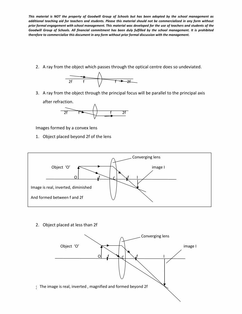
This material is NOT the property of Goodwill Group of Schools but has been adopted by the school management as
additional teaching aid for teachers and students. Please this material should not be commercialized in any form without
prior formal engagement with school management. This material was developed for the use of teachers and students of the
Goodwill Group of Schools. All financial commitment has been duly fulfilled by the school management. It is prohibited
therefore to commercialize this document in any form without prior formal discussion with the management.
2. A ray from the object which passes through the optical centre does so undeviated.
3. A ray from the object through the principal focus will be parallel to the principal axis
after refraction.
Images formed by a convex lens
1. Object placed beyond 2f of the lens
2. Object placed at less than 2f
3. Object placed at 2f
Converging lens
Object ‘O’ image I
O f f I
Image is real, inverted, diminished
And formed between f and 2f
C
Converging lens
Object ‘O’ image I
O f f I
The image is real, inverted , magnified and formed beyond 2f
C
2f f f 2f
2f f f 2f
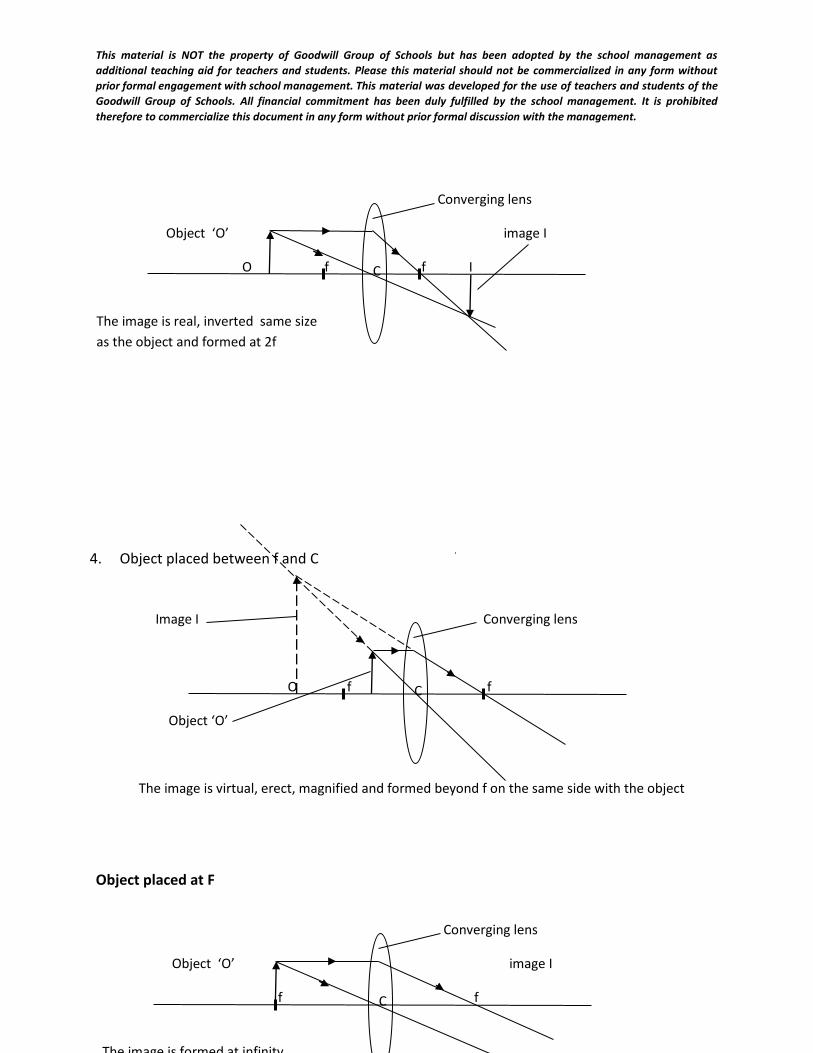
This material is NOT the property of Goodwill Group of Schools but has been adopted by the school management as
additional teaching aid for teachers and students. Please this material should not be commercialized in any form without
prior formal engagement with school management. This material was developed for the use of teachers and students of the
Goodwill Group of Schools. All financial commitment has been duly fulfilled by the school management. It is prohibited
therefore to commercialize this document in any form without prior formal discussion with the management.
4. Object placed between f and C
Object placed at F
Converging lens
Object ‘O’ image I
O f f I
The image is real, inverted same size
as the object and formed at 2f
C
Image I Converging lens
O f f
Object ‘O’
The image is virtual, erect, magnified and formed beyond f on the same side with the object
C
Converging lens
Object ‘O’ image I
f f
The image is formed at infinity
C
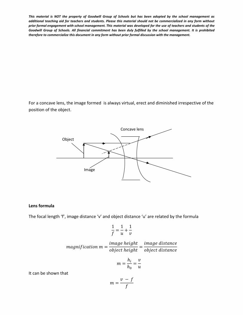
This material is NOT the property of Goodwill Group of Schools but has been adopted by the school management as
additional teaching aid for teachers and students. Please this material should not be commercialized in any form without
prior formal engagement with school management. This material was developed for the use of teachers and students of the
Goodwill Group of Schools. All financial commitment has been duly fulfilled by the school management. It is prohibited
therefore to commercialize this document in any form without prior formal discussion with the management.
For a concave lens, the image formed is always virtual, erect and diminished irrespective of the
position of the object.
Lens formula
The focal length ‘f’, image distance ‘v’ and object distance ‘u’ are related by the formula
1
𝑓=
1
𝑢+
1
𝑣
𝑚𝑎𝑔𝑛𝑖𝑓𝑖𝑐𝑎𝑡𝑖𝑜𝑛 𝑚 =𝑖𝑚𝑎𝑔𝑒 ℎ𝑒𝑖𝑔ℎ𝑡
𝑜𝑏𝑗𝑒𝑐𝑡 ℎ𝑒𝑖𝑔ℎ𝑡=
𝑖𝑚𝑎𝑔𝑒 𝑑𝑖𝑠𝑡𝑎𝑛𝑐𝑒
𝑜𝑏𝑗𝑒𝑐𝑡 𝑑𝑖𝑠𝑡𝑎𝑛𝑐𝑒
𝑚 =ℎ𝑖
ℎ0=
𝑣
𝑢
It can be shown that
𝑚 =𝑣 − 𝑓
𝑓
Concave lens
Object
Image
This material is NOT the property of Goodwill Group of Schools but has been adopted by the school management as
additional teaching aid for teachers and students. Please this material should not be commercialized in any form without
prior formal engagement with school management. This material was developed for the use of teachers and students of the
Goodwill Group of Schools. All financial commitment has been duly fulfilled by the school management. It is prohibited
therefore to commercialize this document in any form without prior formal discussion with the management.
Sign conventions for lenses
1. Focal length for convex or converging lens is positive
2. Focal length for concave or diverging lens is negative
3. For virtual image or erected image, v is negative
4. For real or inverted image, v is positive.
Solved problems
Example 1
A diverging lens has a focal length of 15.0cm. an object 1.5cm high is positioned 30cm in front
of the lens. Find (a) the image distance (b) the height of the image and (c) the magnification
Solution
f = - 15cm (diverging lens), object distance u = 30cm, height of object ho = 1.5cm, image
distance v=? height of image hi =?
Using the lens formula:
1
𝑓=
1
𝑢+
1
𝑣
−1
15=
1
30+
1
𝑣
1
𝑣=
−1
15−
1
30= −
3
30
𝑣 = −30
3= −10𝑐𝑚
( this minus sign means the image formed is virtual and erect)
(b) Magnification m =hi
ho=
v
u
hi
1.5=
10
30,
hi × 30 = 1.5 × 10
This material is NOT the property of Goodwill Group of Schools but has been adopted by the school management as
additional teaching aid for teachers and students. Please this material should not be commercialized in any form without
prior formal engagement with school management. This material was developed for the use of teachers and students of the
Goodwill Group of Schools. All financial commitment has been duly fulfilled by the school management. It is prohibited
therefore to commercialize this document in any form without prior formal discussion with the management.
hi = 1.5 ×10
30
hi = 0.5cm
Example 2
The image of a pin formed by a diverging lens of focal length 10cm is 5cm from the lens.
Calculate the distance of the pin from the lens ( SSCE)
Solution
image distance v = - 5.0cm, object distance u = ? Focal length f = - 10cm (diverging lens)
Using the lens formula
1
𝑓=
1
𝑢+
1
𝑣
1
−𝑓=
1
𝑢−
1
𝑣
1
−10=
1
𝑢−
1
5
1
𝑢=
1
5−
1
10=
1
10
u = 10cm.
Example 3
A real image of an object formed by a converging lens of focal length 15cm is three times the
size of the object. What is the distance of the object from the lens. (SSCE)
Solution
Using the formula
m = 𝑓
𝑢−𝑓
m = 3, f = 15cm, u = ?
3 =15
𝑢−15
15 = 3(𝑢 − 15) = 3𝑢 − 45
3𝑢 = 45 + 15
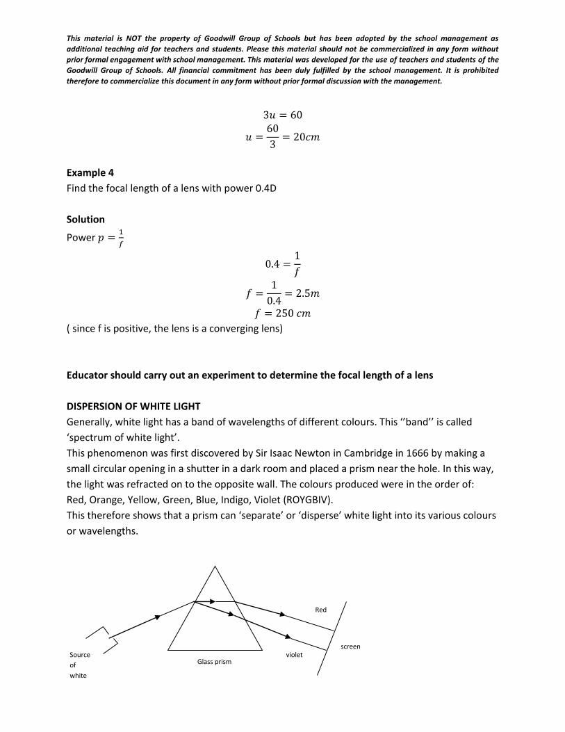
This material is NOT the property of Goodwill Group of Schools but has been adopted by the school management as
additional teaching aid for teachers and students. Please this material should not be commercialized in any form without
prior formal engagement with school management. This material was developed for the use of teachers and students of the
Goodwill Group of Schools. All financial commitment has been duly fulfilled by the school management. It is prohibited
therefore to commercialize this document in any form without prior formal discussion with the management.
3𝑢 = 60
𝑢 =60
3= 20𝑐𝑚
Example 4
Find the focal length of a lens with power 0.4D
Solution
Power 𝑝 =1
𝑓
0.4 =1
𝑓
𝑓 =1
0.4= 2.5𝑚
𝑓 = 250 𝑐𝑚
( since f is positive, the lens is a converging lens)
Educator should carry out an experiment to determine the focal length of a lens
DISPERSION OF WHITE LIGHT
Generally, white light has a band of wavelengths of different colours. This ‘’band’’ is called
‘spectrum of white light’.
This phenomenon was first discovered by Sir Isaac Newton in Cambridge in 1666 by making a
small circular opening in a shutter in a dark room and placed a prism near the hole. In this way,
the light was refracted on to the opposite wall. The colours produced were in the order of:
Red, Orange, Yellow, Green, Blue, Indigo, Violet (ROYGBIV).
This therefore shows that a prism can ‘separate’ or ‘disperse’ white light into its various colours
or wavelengths.
E
Red
violet screen
Glass prism Source
of
white
light
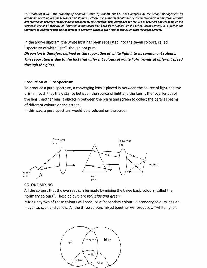
This material is NOT the property of Goodwill Group of Schools but has been adopted by the school management as
additional teaching aid for teachers and students. Please this material should not be commercialized in any form without
prior formal engagement with school management. This material was developed for the use of teachers and students of the
Goodwill Group of Schools. All financial commitment has been duly fulfilled by the school management. It is prohibited
therefore to commercialize this document in any form without prior formal discussion with the management.
In the above diagram, the white light has been separated into the seven colours, called
‘’spectrum of white light’’, though not pure.
Dispersion is therefore defined as the separation of white light into its component colours.
This separation is due to the fact that different colours of white light travels at different speed
through the glass.
Production of Pure Spectrum
To produce a pure spectrum, a converging lens is placed in between the source of light and the
prism in such that the distance between the source of light and the lens is the focal length of
the lens. Another lens is placed in between the prism and screen to collect the parallel beams
of different colours on the screen.
In this way, a pure spectrum would be produced on the screen.
COLOUR MIXING
All the colours that the eye sees can be made by mixing the three basic colours, called the
‘’primary colours’’. These colours are red, blue and green.
Mixing any two of these colours will produce a ‘’secondary colour’’. Secondary colours include
magenta, cyan and yellow. All the three colours mixed together will produce a ‘’white light’’.
Narrow
split
Converging
lens
Glass
prism
Converging
lens
screen
red blue magenta
white
cyan yellow
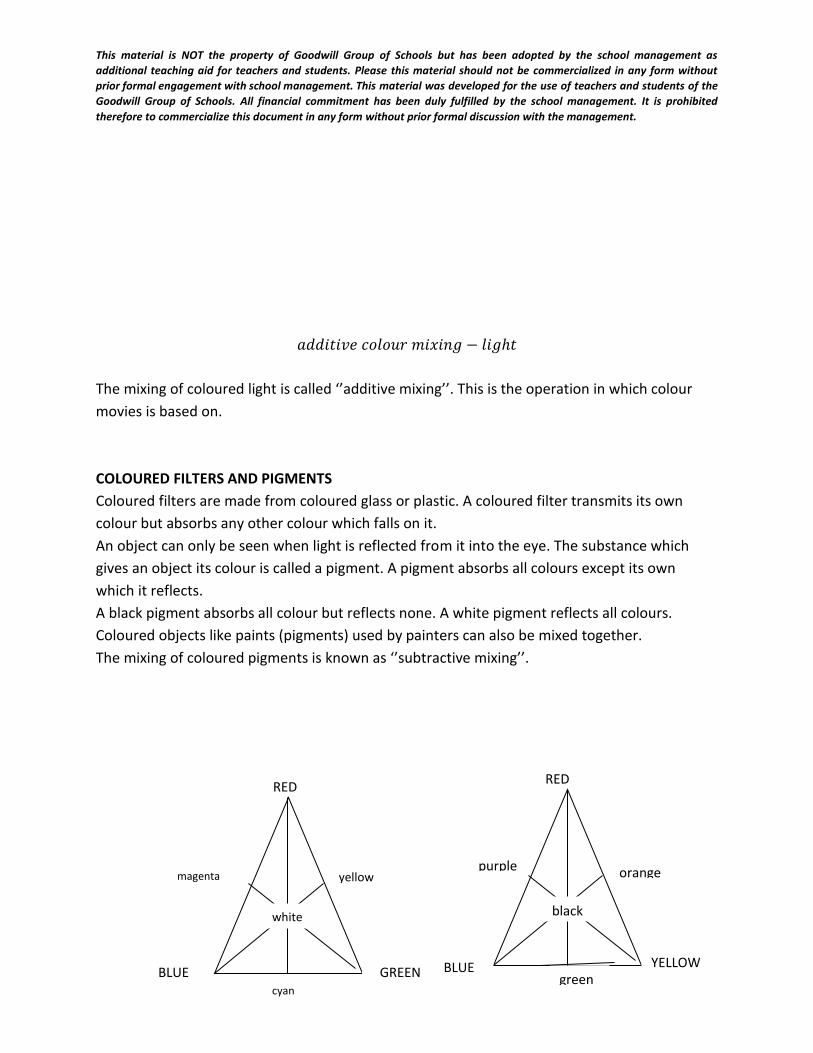
This material is NOT the property of Goodwill Group of Schools but has been adopted by the school management as
additional teaching aid for teachers and students. Please this material should not be commercialized in any form without
prior formal engagement with school management. This material was developed for the use of teachers and students of the
Goodwill Group of Schools. All financial commitment has been duly fulfilled by the school management. It is prohibited
therefore to commercialize this document in any form without prior formal discussion with the management.
𝑎𝑑𝑑𝑖𝑡𝑖𝑣𝑒 𝑐𝑜𝑙𝑜𝑢𝑟 𝑚𝑖𝑥𝑖𝑛𝑔 − 𝑙𝑖𝑔ℎ𝑡
The mixing of coloured light is called ‘’additive mixing’’. This is the operation in which colour
movies is based on.
COLOURED FILTERS AND PIGMENTS
Coloured filters are made from coloured glass or plastic. A coloured filter transmits its own
colour but absorbs any other colour which falls on it.
An object can only be seen when light is reflected from it into the eye. The substance which
gives an object its colour is called a pigment. A pigment absorbs all colours except its own
which it reflects.
A black pigment absorbs all colour but reflects none. A white pigment reflects all colours.
Coloured objects like paints (pigments) used by painters can also be mixed together.
The mixing of coloured pigments is known as ‘’subtractive mixing’’.
RED RED
GREEN BLUE BLUE YELLOW
orange
green
purple yellow
cyan
magenta
white black
This material is NOT the property of Goodwill Group of Schools but has been adopted by the school management as
additional teaching aid for teachers and students. Please this material should not be commercialized in any form without
prior formal engagement with school management. This material was developed for the use of teachers and students of the
Goodwill Group of Schools. All financial commitment has been duly fulfilled by the school management. It is prohibited
therefore to commercialize this document in any form without prior formal discussion with the management.
𝑎𝑑𝑑𝑖𝑡𝑖𝑣𝑒 𝑐𝑜𝑙𝑜𝑢𝑟 𝑚𝑖𝑥𝑖𝑛𝑔 − 𝑙𝑖𝑔ℎ𝑡𝑠𝑠𝑢𝑏𝑡𝑟𝑎𝑐𝑡𝑖𝑣𝑒 𝑐𝑜𝑙𝑜𝑢𝑟 𝑚𝑖𝑥𝑖𝑛𝑔 − 𝑝𝑎𝑖𝑛𝑡𝑠
In the additive colour mixing,
Red + Blue + Green = White
Also, Red + Cyan = White
Blue + Yellow = White
Green + Magenta = White
Since the colours which add together to produce white light are complementary colours, then,
Red is complementary to Cyan
Blue is complementary to Yellow
Green is complementary to Magenta.
Weekend assignment:
Objectives .
1. A converging lens of focal length 15cm forms a virtual image at a point 10cm from the lens.
Calculate the distance of the object from the lens.
A. 10.00cm B. 6.00cm C. 5.00cm D. 1.50cm
2. In a compound microscope, the image formed by the objective lens is at a distance of 3.0cm
from the eye lens. If the final image is at 25.0cm from the eye lens, calculate the focal length of
the eye lens.
A. 0.3cm B. 2.7cm C. 3.4cm D. 8.3cm
3. Which of the following conditions is necessary for the occurrence of total internal reflection of
light?
A. Light must travel from an optically less dense to a denser medium
B. The angle of incidence must be equal to the critical angle
C. The angle of incidence must be greater than the critical angle.
D. The angle of refraction must be 900
4. A converging lens produces an image four times as large as an object placed 25cm from the
lens.
Calculate its focal length.
A. 100cm B. 33cm C. 29cm D. 20cm
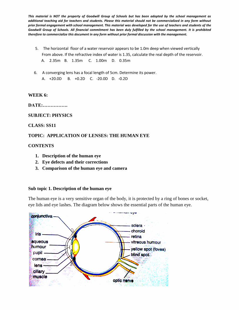
This material is NOT the property of Goodwill Group of Schools but has been adopted by the school management as
additional teaching aid for teachers and students. Please this material should not be commercialized in any form without
prior formal engagement with school management. This material was developed for the use of teachers and students of the
Goodwill Group of Schools. All financial commitment has been duly fulfilled by the school management. It is prohibited
therefore to commercialize this document in any form without prior formal discussion with the management.
5. The horizontal floor of a water reservoir appears to be 1.0m deep when viewed vertically
From above. If the refractive index of water is 1.35, calculate the real depth of the reservoir.
A. 2.35m B. 1.35m C. 1.00m D. 0.35m
6. A converging lens has a focal length of 5cm. Determine its power.
A. +20.0D B. +0.2D C. -20.0D D. -0.2D
WEEK 6:
DATE:…………….
SUBJECT: PHYSICS
CLASS: SS11
TOPIC: APPLICATION OF LENSES: THE HUMAN EYE
CONTENTS
1. Description of the human eye
2. Eye defects and their corrections
3. Comparison of the human eye and camera
Sub topic 1. Description of the human eye
The human eye is a very sensitive organ of the body, it is protected by a ring of bones or socket,
eye lids and eye lashes. The diagram below shows the essential parts of the human eye.
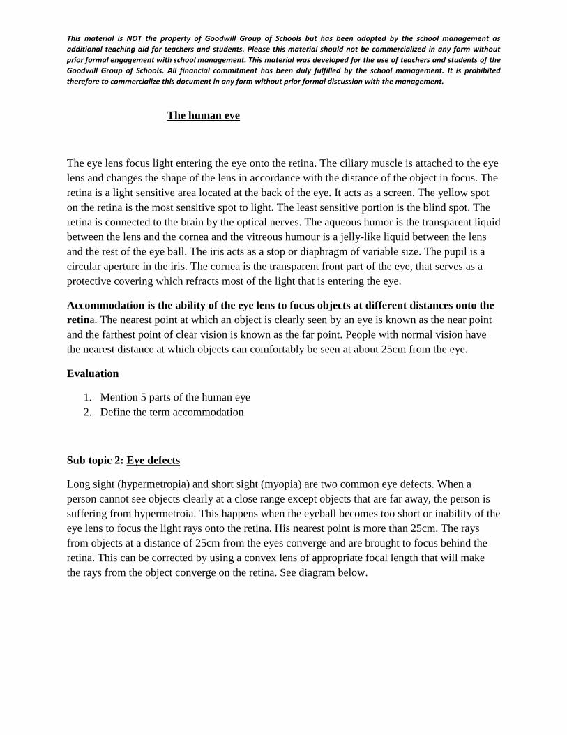
This material is NOT the property of Goodwill Group of Schools but has been adopted by the school management as
additional teaching aid for teachers and students. Please this material should not be commercialized in any form without
prior formal engagement with school management. This material was developed for the use of teachers and students of the
Goodwill Group of Schools. All financial commitment has been duly fulfilled by the school management. It is prohibited
therefore to commercialize this document in any form without prior formal discussion with the management.
The human eye
The eye lens focus light entering the eye onto the retina. The ciliary muscle is attached to the eye
lens and changes the shape of the lens in accordance with the distance of the object in focus. The
retina is a light sensitive area located at the back of the eye. It acts as a screen. The yellow spot
on the retina is the most sensitive spot to light. The least sensitive portion is the blind spot. The
retina is connected to the brain by the optical nerves. The aqueous humor is the transparent liquid
between the lens and the cornea and the vitreous humour is a jelly-like liquid between the lens
and the rest of the eye ball. The iris acts as a stop or diaphragm of variable size. The pupil is a
circular aperture in the iris. The cornea is the transparent front part of the eye, that serves as a
protective covering which refracts most of the light that is entering the eye.
Accommodation is the ability of the eye lens to focus objects at different distances onto the
retina. The nearest point at which an object is clearly seen by an eye is known as the near point
and the farthest point of clear vision is known as the far point. People with normal vision have
the nearest distance at which objects can comfortably be seen at about 25cm from the eye.
Evaluation
1. Mention 5 parts of the human eye
2. Define the term accommodation
Sub topic 2: Eye defects
Long sight (hypermetropia) and short sight (myopia) are two common eye defects. When a
person cannot see objects clearly at a close range except objects that are far away, the person is
suffering from hypermetroia. This happens when the eyeball becomes too short or inability of the
eye lens to focus the light rays onto the retina. His nearest point is more than 25cm. The rays
from objects at a distance of 25cm from the eyes converge and are brought to focus behind the
retina. This can be corrected by using a convex lens of appropriate focal length that will make
the rays from the object converge on the retina. See diagram below.
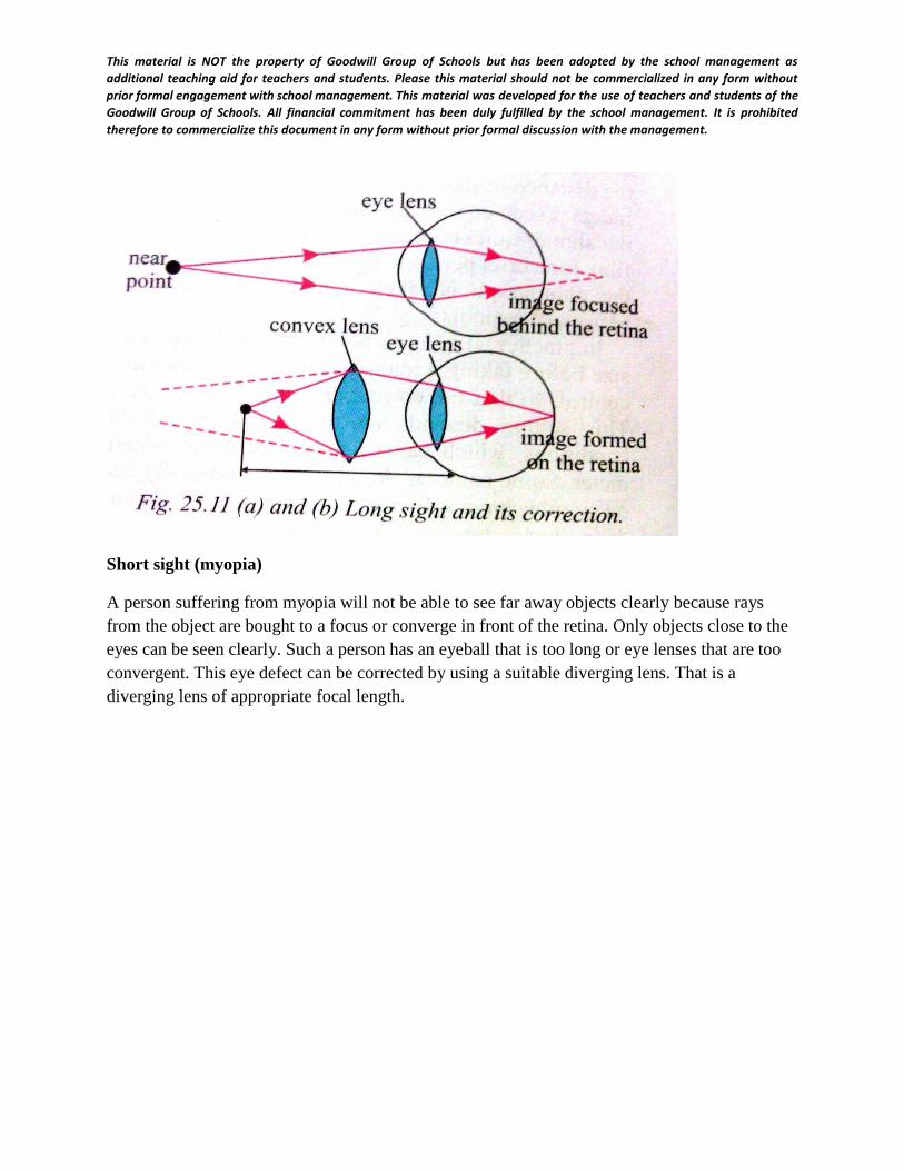
This material is NOT the property of Goodwill Group of Schools but has been adopted by the school management as
additional teaching aid for teachers and students. Please this material should not be commercialized in any form without
prior formal engagement with school management. This material was developed for the use of teachers and students of the
Goodwill Group of Schools. All financial commitment has been duly fulfilled by the school management. It is prohibited
therefore to commercialize this document in any form without prior formal discussion with the management.
Short sight (myopia)
A person suffering from myopia will not be able to see far away objects clearly because rays
from the object are bought to a focus or converge in front of the retina. Only objects close to the
eyes can be seen clearly. Such a person has an eyeball that is too long or eye lenses that are too
convergent. This eye defect can be corrected by using a suitable diverging lens. That is a
diverging lens of appropriate focal length.
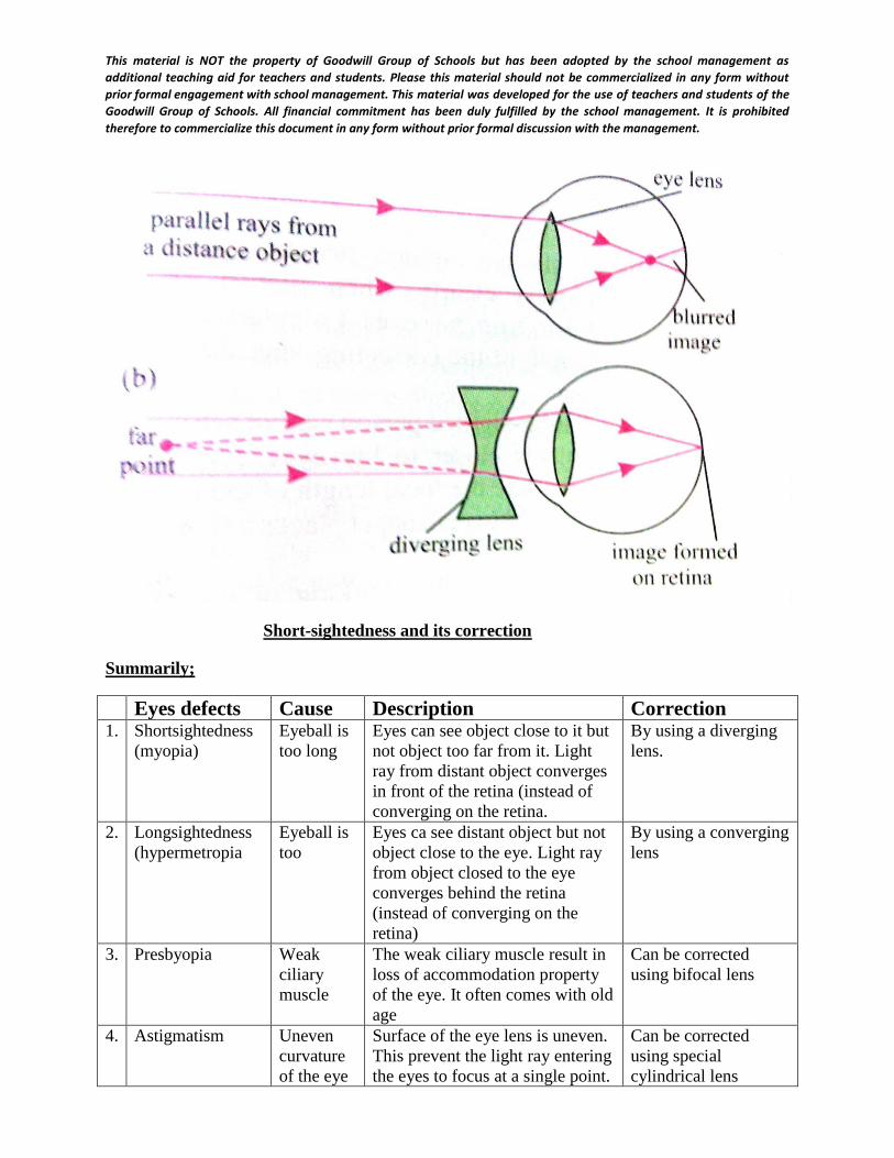
This material is NOT the property of Goodwill Group of Schools but has been adopted by the school management as
additional teaching aid for teachers and students. Please this material should not be commercialized in any form without
prior formal engagement with school management. This material was developed for the use of teachers and students of the
Goodwill Group of Schools. All financial commitment has been duly fulfilled by the school management. It is prohibited
therefore to commercialize this document in any form without prior formal discussion with the management.
Short-sightedness and its correction
Summarily;
Eyes defects Cause Description Correction 1. Shortsightedness
(myopia)
Eyeball is
too long
Eyes can see object close to it but
not object too far from it. Light
ray from distant object converges
in front of the retina (instead of
converging on the retina.
By using a diverging
lens.
2. Longsightedness
(hypermetropia
Eyeball is
too
Eyes ca see distant object but not
object close to the eye. Light ray
from object closed to the eye
converges behind the retina
(instead of converging on the
retina)
By using a converging
lens
3. Presbyopia Weak
ciliary
muscle
The weak ciliary muscle result in
loss of accommodation property
of the eye. It often comes with old
age
Can be corrected
using bifocal lens
4. Astigmatism Uneven
curvature
of the eye
Surface of the eye lens is uneven.
This prevent the light ray entering
the eyes to focus at a single point.
Can be corrected
using special
cylindrical lens
This material is NOT the property of Goodwill Group of Schools but has been adopted by the school management as
additional teaching aid for teachers and students. Please this material should not be commercialized in any form without
prior formal engagement with school management. This material was developed for the use of teachers and students of the
Goodwill Group of Schools. All financial commitment has been duly fulfilled by the school management. It is prohibited
therefore to commercialize this document in any form without prior formal discussion with the management.
lens This result in blur image.
Evaluation
1. Differentiate between long sight and short sight
2. What type of lens is normally used to correct the defects?
Some solved problems
Example 1
Calculate the focal length of a lens needed by a woman whose near point is50cm from her eyes,
assuming that the least distance of distinct vision for a normal eye is 25cm
Solution
for the woman to see an object clearly at 25cm from the eye, the image must be formed at 50cm
on the same side of the lens at her near point.
u = 25cm. v = -50cm (image is virtual).
Using the lens formula:
1
𝑓=
1
𝑢+
1
𝑣
1
𝑓=
1
25−
1
50
1
𝑓=
2 − 1
50
1
𝑓=
1
50
f = 50.0cm
Example 2
A short sighted person cannot see distinctly objects beyond 80cm from his eye. What is the focal
of the correcting lens he needs to see distant objects clearly?
Solution
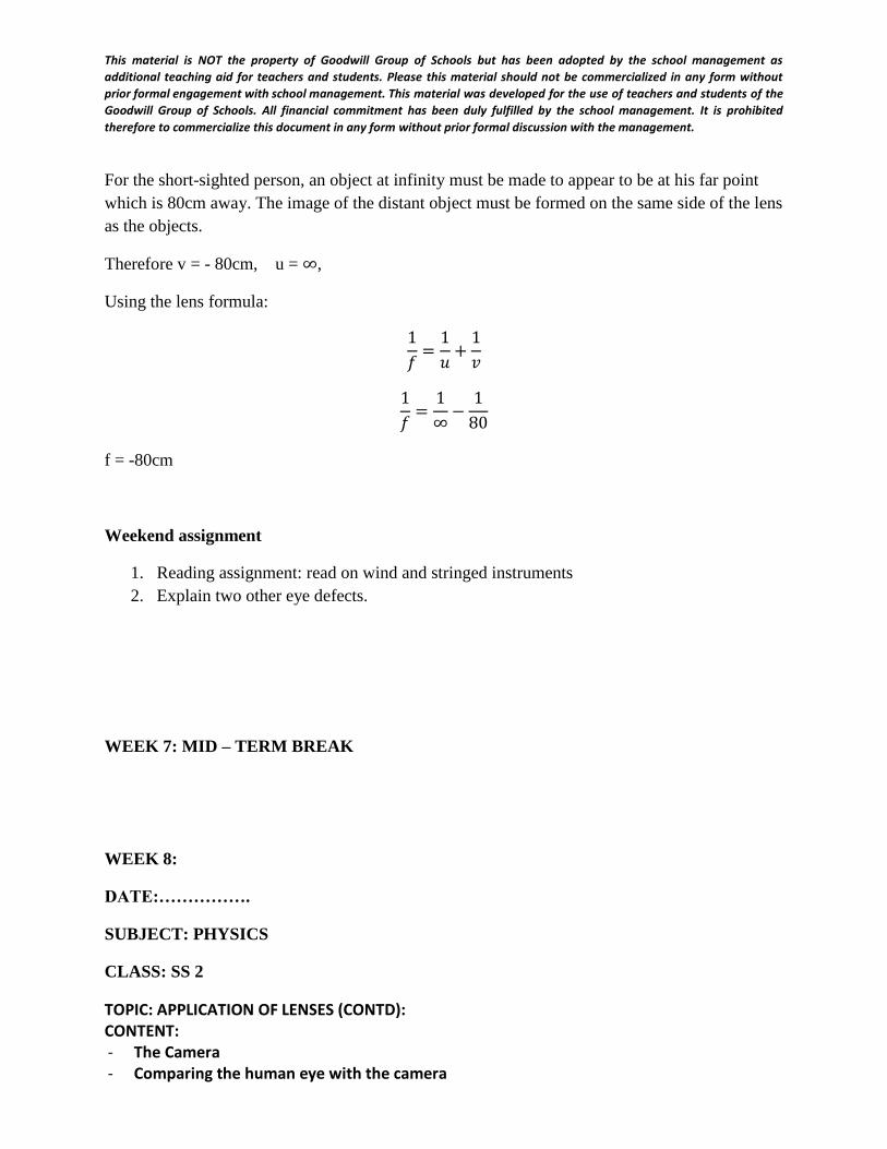
This material is NOT the property of Goodwill Group of Schools but has been adopted by the school management as
additional teaching aid for teachers and students. Please this material should not be commercialized in any form without
prior formal engagement with school management. This material was developed for the use of teachers and students of the
Goodwill Group of Schools. All financial commitment has been duly fulfilled by the school management. It is prohibited
therefore to commercialize this document in any form without prior formal discussion with the management.
For the short-sighted person, an object at infinity must be made to appear to be at his far point
which is 80cm away. The image of the distant object must be formed on the same side of the lens
as the objects.
Therefore v = - 80cm, u = ∞,
Using the lens formula:
1
𝑓=
1
𝑢+
1
𝑣
1
𝑓=
1
∞−
1
80
f = -80cm
Weekend assignment
1. Reading assignment: read on wind and stringed instruments
2. Explain two other eye defects.
WEEK 7: MID – TERM BREAK
WEEK 8:
DATE:…………….
SUBJECT: PHYSICS
CLASS: SS 2
TOPIC: APPLICATION OF LENSES (CONTD): CONTENT: - The Camera - Comparing the human eye with the camera
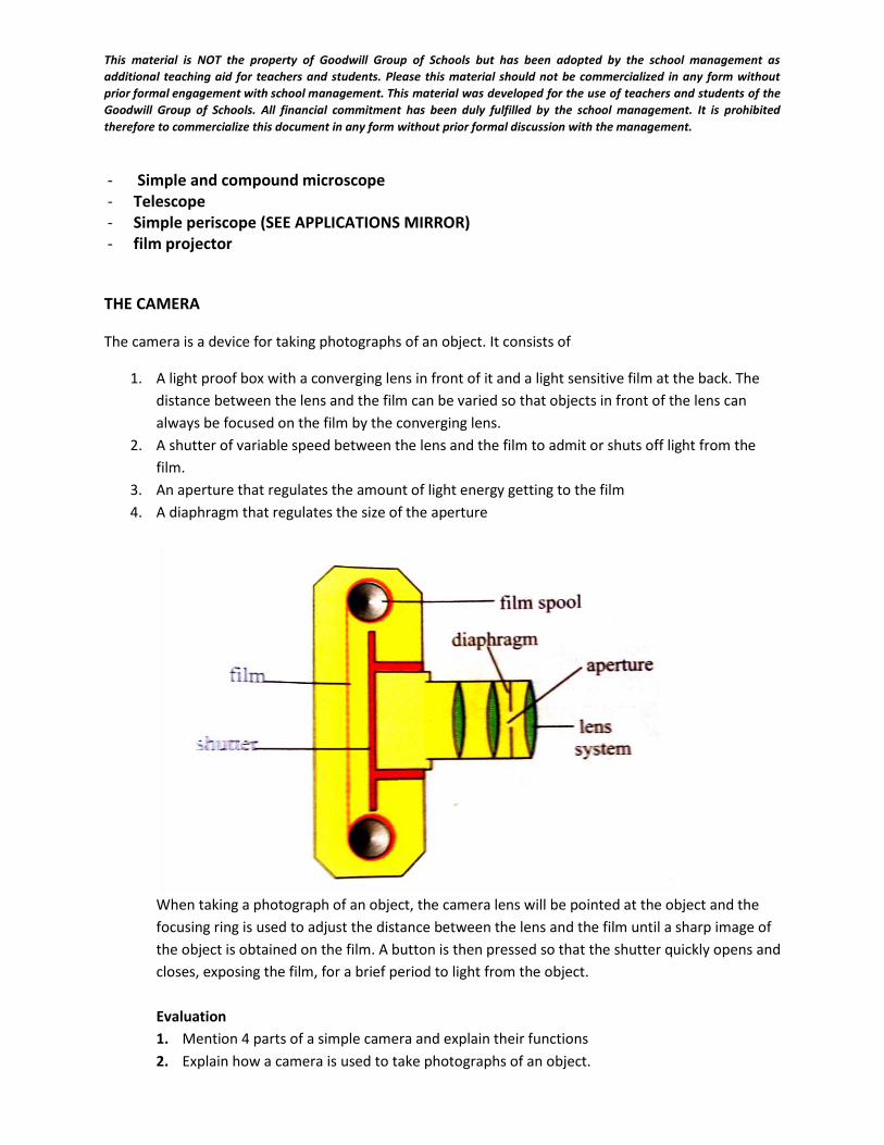
This material is NOT the property of Goodwill Group of Schools but has been adopted by the school management as
additional teaching aid for teachers and students. Please this material should not be commercialized in any form without
prior formal engagement with school management. This material was developed for the use of teachers and students of the
Goodwill Group of Schools. All financial commitment has been duly fulfilled by the school management. It is prohibited
therefore to commercialize this document in any form without prior formal discussion with the management.
- Simple and compound microscope - Telescope - Simple periscope (SEE APPLICATIONS MIRROR) - film projector
THE CAMERA
The camera is a device for taking photographs of an object. It consists of
1. A light proof box with a converging lens in front of it and a light sensitive film at the back. The
distance between the lens and the film can be varied so that objects in front of the lens can
always be focused on the film by the converging lens.
2. A shutter of variable speed between the lens and the film to admit or shuts off light from the
film.
3. An aperture that regulates the amount of light energy getting to the film
4. A diaphragm that regulates the size of the aperture
When taking a photograph of an object, the camera lens will be pointed at the object and the
focusing ring is used to adjust the distance between the lens and the film until a sharp image of
the object is obtained on the film. A button is then pressed so that the shutter quickly opens and
closes, exposing the film, for a brief period to light from the object.
Evaluation
1. Mention 4 parts of a simple camera and explain their functions
2. Explain how a camera is used to take photographs of an object.
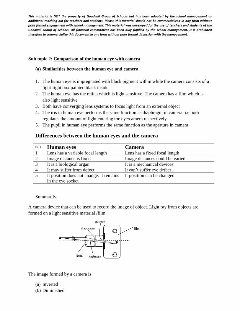
This material is NOT the property of Goodwill Group of Schools but has been adopted by the school management as
additional teaching aid for teachers and students. Please this material should not be commercialized in any form without
prior formal engagement with school management. This material was developed for the use of teachers and students of the
Goodwill Group of Schools. All financial commitment has been duly fulfilled by the school management. It is prohibited
therefore to commercialize this document in any form without prior formal discussion with the management.
Sub topic 2: Comparison of the human eye with camera
(a) Similarities between the human eye and camera
1. The human eye is impregnated with black pigment within while the camera consists of a
light-tight box painted black inside
2. The human eye has the retina which is light sensitive. The camera has a film which is
also light sensitive
3. Both have converging lens systems to focus light from an external object
4. The iris in human eye performs the same function as diaphragm in camera. i.e both
regulates the amount of light entering the eye/camera respectively
5. The pupil in human eye performs the same function as the aperture in camera
Differences between the human eyes and the camera
s/n Human eyes Camera 1 Lens has a variable focal length Lens has a fixed focal length
2 Image distance is fixed Image distances could be varied
3 It is a biological organ It is a mechanical devices
4 It may suffer from defect It can’t suffer eye defect
5 It position does not change. It remains
in the eye socket
It position can be changed
Summarily;
A camera device that can be used to record the image of object. Light ray from objects are
formed on a light sensitive material /film.
The image formed by a camera is
(a) Inverted
(b) Diminished
aperture
shutter
film diaphragm
lens
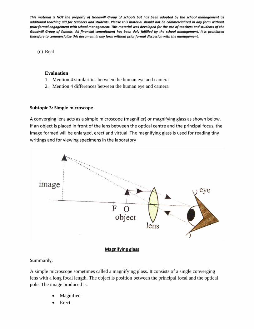
This material is NOT the property of Goodwill Group of Schools but has been adopted by the school management as
additional teaching aid for teachers and students. Please this material should not be commercialized in any form without
prior formal engagement with school management. This material was developed for the use of teachers and students of the
Goodwill Group of Schools. All financial commitment has been duly fulfilled by the school management. It is prohibited
therefore to commercialize this document in any form without prior formal discussion with the management.
(c) Real
Evaluation
1. Mention 4 similarities between the human eye and camera
2. Mention 4 differences between the human eye and camera
Subtopic 3: Simple microscope
A converging lens acts as a simple microscope (magnifier) or magnifying glass as shown below.
If an object is placed in front of the lens between the optical centre and the principal focus, the
image formed will be enlarged, erect and virtual. The magnifying glass is used for reading tiny
writings and for viewing specimens in the laboratory
Magnifying glass
Summarily;
A simple microscope sometimes called a magnifying glass. It consists of a single converging
lens with a long focal length. The object is position between the principal focal and the optical
pole. The image produced is:
Magnified
Erect
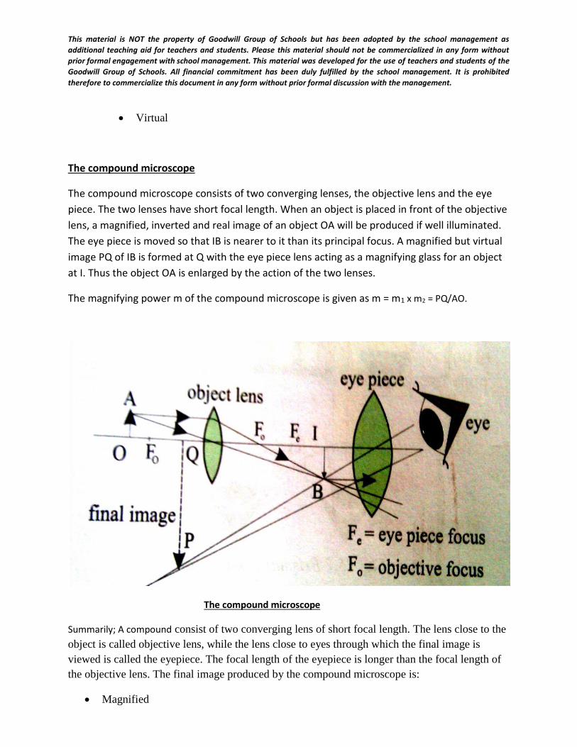
This material is NOT the property of Goodwill Group of Schools but has been adopted by the school management as
additional teaching aid for teachers and students. Please this material should not be commercialized in any form without
prior formal engagement with school management. This material was developed for the use of teachers and students of the
Goodwill Group of Schools. All financial commitment has been duly fulfilled by the school management. It is prohibited
therefore to commercialize this document in any form without prior formal discussion with the management.
Virtual
The compound microscope
The compound microscope consists of two converging lenses, the objective lens and the eye
piece. The two lenses have short focal length. When an object is placed in front of the objective
lens, a magnified, inverted and real image of an object OA will be produced if well illuminated.
The eye piece is moved so that IB is nearer to it than its principal focus. A magnified but virtual
image PQ of IB is formed at Q with the eye piece lens acting as a magnifying glass for an object
at I. Thus the object OA is enlarged by the action of the two lenses.
The magnifying power m of the compound microscope is given as m = m1 x m2 = PQ/AO.
The compound microscope
Summarily; A compound consist of two converging lens of short focal length. The lens close to the
object is called objective lens, while the lens close to eyes through which the final image is
viewed is called the eyepiece. The focal length of the eyepiece is longer than the focal length of
the objective lens. The final image produced by the compound microscope is:
Magnified
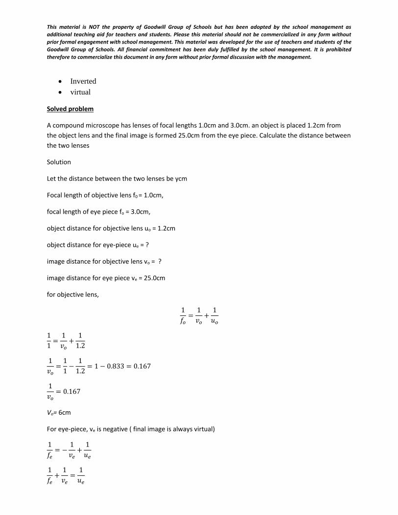
This material is NOT the property of Goodwill Group of Schools but has been adopted by the school management as
additional teaching aid for teachers and students. Please this material should not be commercialized in any form without
prior formal engagement with school management. This material was developed for the use of teachers and students of the
Goodwill Group of Schools. All financial commitment has been duly fulfilled by the school management. It is prohibited
therefore to commercialize this document in any form without prior formal discussion with the management.
Inverted
virtual
Solved problem
A compound microscope has lenses of focal lengths 1.0cm and 3.0cm. an object is placed 1.2cm from
the object lens and the final image is formed 25.0cm from the eye piece. Calculate the distance between
the two lenses
Solution
Let the distance between the two lenses be ycm
Focal length of objective lens f0 = 1.0cm,
focal length of eye piece fo = 3.0cm,
object distance for objective lens uo = 1.2cm
object distance for eye-piece ue = ?
image distance for objective lens vo = ?
image distance for eye piece ve = 25.0cm
for objective lens,
1
𝑓𝑜=
1
𝑣𝑜+
1
𝑢𝑜
1
1=
1
𝑣𝑜+
1
1.2
1
𝑣𝑜=
1
1−
1
1.2= 1 − 0.833 = 0.167
1
𝑣𝑜= 0.167
Vo= 6cm
For eye-piece, ve is negative ( final image is always virtual)
1
𝑓𝑒= −
1
𝑣𝑒+
1
𝑢𝑒
1
𝑓𝑒+
1
𝑣𝑒=
1
𝑢𝑒
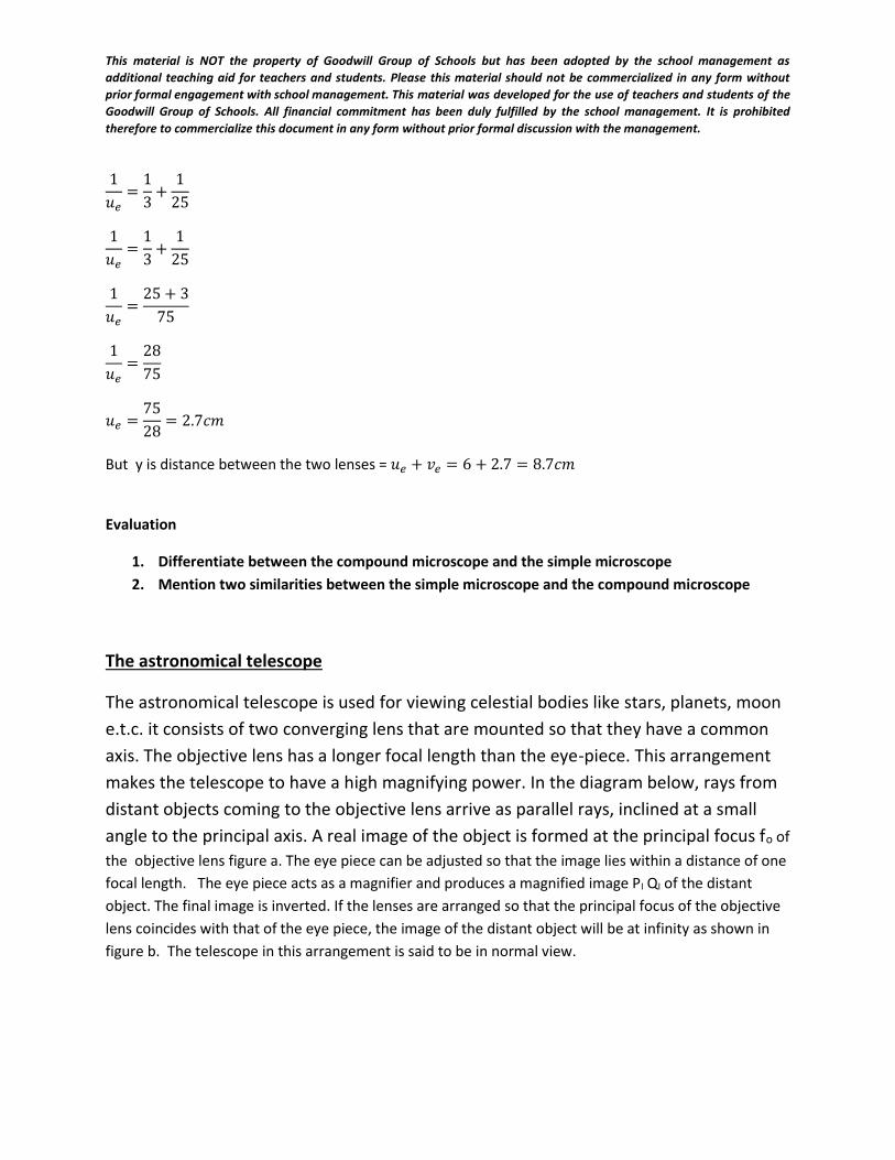
This material is NOT the property of Goodwill Group of Schools but has been adopted by the school management as
additional teaching aid for teachers and students. Please this material should not be commercialized in any form without
prior formal engagement with school management. This material was developed for the use of teachers and students of the
Goodwill Group of Schools. All financial commitment has been duly fulfilled by the school management. It is prohibited
therefore to commercialize this document in any form without prior formal discussion with the management.
1
𝑢𝑒=
1
3+
1
25
1
𝑢𝑒=
1
3+
1
25
1
𝑢𝑒=
25 + 3
75
1
𝑢𝑒=
28
75
𝑢𝑒 =75
28= 2.7𝑐𝑚
But y is distance between the two lenses = 𝑢𝑒 + 𝑣𝑒 = 6 + 2.7 = 8.7𝑐𝑚
Evaluation
1. Differentiate between the compound microscope and the simple microscope
2. Mention two similarities between the simple microscope and the compound microscope
The astronomical telescope
The astronomical telescope is used for viewing celestial bodies like stars, planets, moon
e.t.c. it consists of two converging lens that are mounted so that they have a common
axis. The objective lens has a longer focal length than the eye-piece. This arrangement
makes the telescope to have a high magnifying power. In the diagram below, rays from
distant objects coming to the objective lens arrive as parallel rays, inclined at a small
angle to the principal axis. A real image of the object is formed at the principal focus fo of
the objective lens figure a. The eye piece can be adjusted so that the image lies within a distance of one
focal length. The eye piece acts as a magnifier and produces a magnified image PI QI of the distant
object. The final image is inverted. If the lenses are arranged so that the principal focus of the objective
lens coincides with that of the eye piece, the image of the distant object will be at infinity as shown in
figure b. The telescope in this arrangement is said to be in normal view.
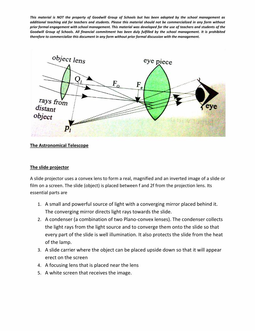
This material is NOT the property of Goodwill Group of Schools but has been adopted by the school management as
additional teaching aid for teachers and students. Please this material should not be commercialized in any form without
prior formal engagement with school management. This material was developed for the use of teachers and students of the
Goodwill Group of Schools. All financial commitment has been duly fulfilled by the school management. It is prohibited
therefore to commercialize this document in any form without prior formal discussion with the management.
The Astronomical Telescope
The slide projector
A slide projector uses a convex lens to form a real, magnified and an inverted image of a slide or
film on a screen. The slide (object) is placed between f and 2f from the projection lens. Its
essential parts are
1. A small and powerful source of light with a converging mirror placed behind it.
The converging mirror directs light rays towards the slide.
2. A condenser (a combination of two Plano-convex lenses). The condenser collects
the light rays from the light source and to converge them onto the slide so that
every part of the slide is well illumination. It also protects the slide from the heat
of the lamp.
3. A slide carrier where the object can be placed upside down so that it will appear
erect on the screen
4. A focusing lens that is placed near the lens
5. A white screen that receives the image.
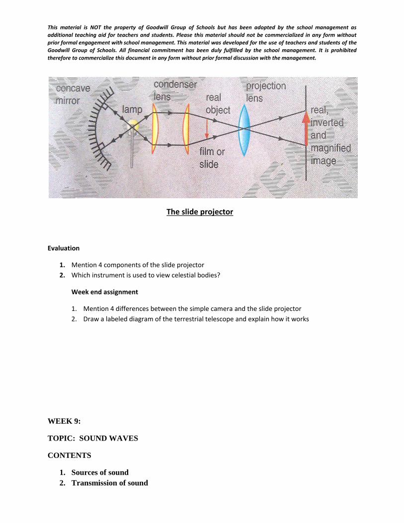
This material is NOT the property of Goodwill Group of Schools but has been adopted by the school management as
additional teaching aid for teachers and students. Please this material should not be commercialized in any form without
prior formal engagement with school management. This material was developed for the use of teachers and students of the
Goodwill Group of Schools. All financial commitment has been duly fulfilled by the school management. It is prohibited
therefore to commercialize this document in any form without prior formal discussion with the management.
The slide projector
Evaluation
1. Mention 4 components of the slide projector
2. Which instrument is used to view celestial bodies?
Week end assignment
1. Mention 4 differences between the simple camera and the slide projector
2. Draw a labeled diagram of the terrestrial telescope and explain how it works
WEEK 9:
TOPIC: SOUND WAVES
CONTENTS
1. Sources of sound
2. Transmission of sound
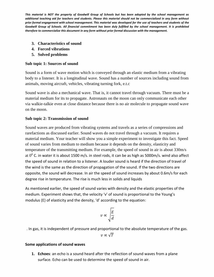
This material is NOT the property of Goodwill Group of Schools but has been adopted by the school management as
additional teaching aid for teachers and students. Please this material should not be commercialized in any form without
prior formal engagement with school management. This material was developed for the use of teachers and students of the
Goodwill Group of Schools. All financial commitment has been duly fulfilled by the school management. It is prohibited
therefore to commercialize this document in any form without prior formal discussion with the management.
3. Characteristics of sound
4. Forced vibrations
5. Solved problems
Sub topic 1: Sources of sound
Sound is a form of wave motion which is conveyed through an elastic medium from a vibrating
body to a listener. It is a longitudinal wave. Sound has a number of sources including sound from
animals, moving aircraft, vehicles, vibrating turning fork, e.t.c
Sound wave is also a mechanical wave. That is, it cannot travel through vacuum. There must be a
material medium for its to propagate. Astronauts on the moon can only communicate each other
via walkie-talkie even at close distance because there is no air molecule to propagate sound wave
on the moon.
Sub topic 2: Transmission of sound
Sound waves are produced from vibrating systems and travels as a series of compressions and
rarefactions as discussed earlier. Sound waves do not travel through a vacuum. It requires a
material medium. Your teacher will show you a simple experiment to investigate this fact. Speed
of sound varies from medium to medium because it depends on the density, elasticity and
temperature of the transmitting medium. For example, the speed of sound in air is about 330m/s
at 00 C. in water it is about 1500 m/s. in steel rods, it can be as high as 5000m/s. wind also affect
the speed of sound in relation to a listener. A louder sound is heard if the direction of travel of
the wind is the same as the direction of propagation of the sound. If the two directions are
opposite, the sound will decrease. In air the speed of sound increases by about 0.6m/s for each
degree rise in temperature. The rise is much less in solids and liquids
As mentioned earlier, the speed of sound varies with density and the elastic properties of the
medium. Experiment shows that, the velocity ‘v’ of sound is proportional to the Young’s
modulus (E) of elasticity and the density, ‘d’ according to the equation:
𝑣 ∝ √𝐸
𝑑
. In gas, it is independent of pressure and proportional to the absolute temperature of the gas.
𝑣 ∝ √𝑇
Some applications of sound waves
1. Echoes: an echo is a sound heard after the reflection of sound waves from a plane
surface. Echo can be used to determine the speed of sound in air.
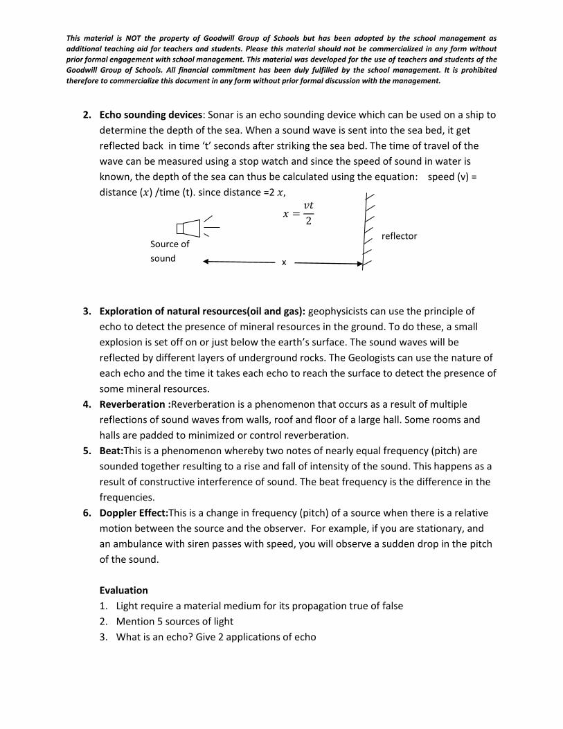
This material is NOT the property of Goodwill Group of Schools but has been adopted by the school management as
additional teaching aid for teachers and students. Please this material should not be commercialized in any form without
prior formal engagement with school management. This material was developed for the use of teachers and students of the
Goodwill Group of Schools. All financial commitment has been duly fulfilled by the school management. It is prohibited
therefore to commercialize this document in any form without prior formal discussion with the management.
2. Echo sounding devices: Sonar is an echo sounding device which can be used on a ship to
determine the depth of the sea. When a sound wave is sent into the sea bed, it get
reflected back in time ‘t’ seconds after striking the sea bed. The time of travel of the
wave can be measured using a stop watch and since the speed of sound in water is
known, the depth of the sea can thus be calculated using the equation: speed (v) =
distance (𝑥) /time (t). since distance =2 𝑥,
𝑥 =𝑣𝑡
2
3. Exploration of natural resources(oil and gas): geophysicists can use the principle of
echo to detect the presence of mineral resources in the ground. To do these, a small
explosion is set off on or just below the earth’s surface. The sound waves will be
reflected by different layers of underground rocks. The Geologists can use the nature of
each echo and the time it takes each echo to reach the surface to detect the presence of
some mineral resources.
4. Reverberation :Reverberation is a phenomenon that occurs as a result of multiple
reflections of sound waves from walls, roof and floor of a large hall. Some rooms and
halls are padded to minimized or control reverberation.
5. Beat:This is a phenomenon whereby two notes of nearly equal frequency (pitch) are
sounded together resulting to a rise and fall of intensity of the sound. This happens as a
result of constructive interference of sound. The beat frequency is the difference in the
frequencies.
6. Doppler Effect:This is a change in frequency (pitch) of a source when there is a relative
motion between the source and the observer. For example, if you are stationary, and
an ambulance with siren passes with speed, you will observe a sudden drop in the pitch
of the sound.
Evaluation
1. Light require a material medium for its propagation true of false
2. Mention 5 sources of light
3. What is an echo? Give 2 applications of echo
Source of
sound x
reflector
This material is NOT the property of Goodwill Group of Schools but has been adopted by the school management as
additional teaching aid for teachers and students. Please this material should not be commercialized in any form without
prior formal engagement with school management. This material was developed for the use of teachers and students of the
Goodwill Group of Schools. All financial commitment has been duly fulfilled by the school management. It is prohibited
therefore to commercialize this document in any form without prior formal discussion with the management.
Sub topic 3: Characteristics of sound
A musical note is a sound which originates from a source that is vibrating at certain set
frequencies. Noise is produced by sources vibrating with no definite frequency. Musical notes
are characterized by pitch, quality and loudness.
Pitch: Pitch is the characteristic of a note which enables us to differentiate a high note from a
low one. Pitch depend on frequency
Quality: The quality of a note is the characteristic that distinguishes it from another note of the
same pitch and loudness when played on musical instruments. The quality of the note ‘C’ played
on a piano is different from that of the middle ‘C’ played on a violin. Musical instruments consist
of sound of different frequencies blended together. That is why they cannot give out pure tones.
The strongest audible frequency in the instrument is the fundamental frequency ‘fo’ others are
integral multiples of fo such as, 2fo, 3fo, 4fo. e.t.c. These are called overtones or harmonics.
Intensity and loudness: The intensity of sound at a certain place is the rate of flow of energy
per unit area perpendicular to the direction of the sound wave.
Loudness: is a sensation in the mind of an individual observer, depending on the intensity of
sound.
Summarily;
Characteristics of sound Factor affecting the characteristic
1 Pitch Frequency
2 Intensity /loudness Amplitude
3 Quality Harmonics
Note that not all sounds can be heard by the human ear. The human ear can respond to sounds
of frequencies ranging between 20Hz to 20000Hz. Sounds with frequencies much above these
are called ultra sounds
Resonance: This is a phenomenon whereby a vibrating body makes another body to vibrate
when its frequency of vibration is the same with the natural frequency of the second body.
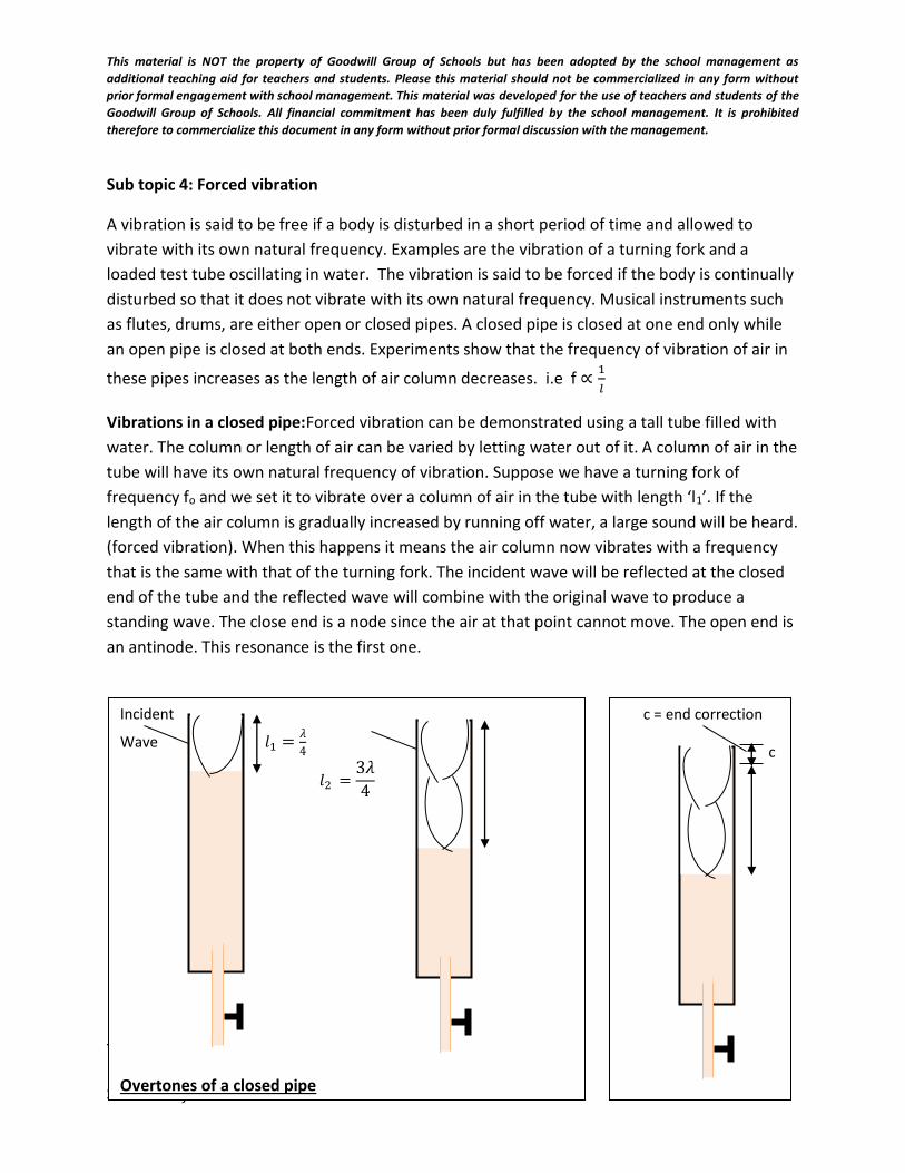
This material is NOT the property of Goodwill Group of Schools but has been adopted by the school management as
additional teaching aid for teachers and students. Please this material should not be commercialized in any form without
prior formal engagement with school management. This material was developed for the use of teachers and students of the
Goodwill Group of Schools. All financial commitment has been duly fulfilled by the school management. It is prohibited
therefore to commercialize this document in any form without prior formal discussion with the management.
Sub topic 4: Forced vibration
A vibration is said to be free if a body is disturbed in a short period of time and allowed to
vibrate with its own natural frequency. Examples are the vibration of a turning fork and a
loaded test tube oscillating in water. The vibration is said to be forced if the body is continually
disturbed so that it does not vibrate with its own natural frequency. Musical instruments such
as flutes, drums, are either open or closed pipes. A closed pipe is closed at one end only while
an open pipe is closed at both ends. Experiments show that the frequency of vibration of air in
these pipes increases as the length of air column decreases. i.e f ∝1
𝑙
Vibrations in a closed pipe:Forced vibration can be demonstrated using a tall tube filled with
water. The column or length of air can be varied by letting water out of it. A column of air in the
tube will have its own natural frequency of vibration. Suppose we have a turning fork of
frequency fo and we set it to vibrate over a column of air in the tube with length ‘l1’. If the
length of the air column is gradually increased by running off water, a large sound will be heard.
(forced vibration). When this happens it means the air column now vibrates with a frequency
that is the same with that of the turning fork. The incident wave will be reflected at the closed
end of the tube and the reflected wave will combine with the original wave to produce a
standing wave. The close end is a node since the air at that point cannot move. The open end is
an antinode. This resonance is the first one.
The wavelength λ is given as 𝑙 =λ
4 or λ = 4𝑙
Since 𝑣 = 𝑓 λ
c = end correction
c
Incident
Wave 𝑙1 =𝜆
4
𝑙2 =3𝜆
4
Overtones of a closed pipe
This material is NOT the property of Goodwill Group of Schools but has been adopted by the school management as
additional teaching aid for teachers and students. Please this material should not be commercialized in any form without
prior formal engagement with school management. This material was developed for the use of teachers and students of the
Goodwill Group of Schools. All financial commitment has been duly fulfilled by the school management. It is prohibited
therefore to commercialize this document in any form without prior formal discussion with the management.
The fundamental frequency fo is given as
𝑓𝑜 =𝑣
λ=
𝑣
4𝑙
Where v is the speed of the sound in air. f0 is the fundamental frequency of the closed pipe.
If we further increase the air column by running off water from the tube, a point will be
reached when another loud sound will be heard. In this position, a second node will be formed
so that the wavelength at this point is obtained from
𝑙 =3λ
4 or λ =.
4𝑙
3
The frequency 𝑓1 at this point is given as:
𝑓1 =𝑣
𝜆
𝑓1 =𝑣4𝑙
3
𝑓1 =3𝑣
4𝑙
𝑠𝑖𝑛𝑐𝑒 𝑓0 =𝑣
4𝑙 𝑓1 = 3𝑓0
This frequency 𝑓1 = 3𝑓𝑜 is called the third harmonic or first overtone of a closed pipe. A
harmonic is a note with frequency equal to an integral multiple of that of the fundamental
note. The next overtones are 5𝑓𝑜, 7𝑓𝑜, 9𝑓𝑜 and so on. Only odd harmonics are present.
If we consider the end correction ‘c’, At first resonance,
λ
4= 𝑙1 + 𝑐
At second resonance,
3λ
4= 𝑙2 + 𝑐
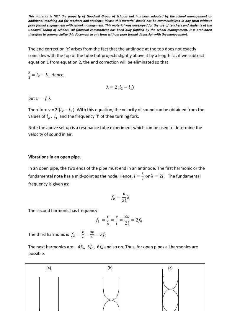
This material is NOT the property of Goodwill Group of Schools but has been adopted by the school management as
additional teaching aid for teachers and students. Please this material should not be commercialized in any form without
prior formal engagement with school management. This material was developed for the use of teachers and students of the
Goodwill Group of Schools. All financial commitment has been duly fulfilled by the school management. It is prohibited
therefore to commercialize this document in any form without prior formal discussion with the management.
The end correction ‘c’ arises from the fact that the antiinode at the top does not exactly
coincides with the top of the tube but projects slightly above it by a length ‘c’. if we subtract
equation 1 from equation 2, the end correction will be eliminated so that
λ
2= 𝑙2 − 𝑙1. Hence,
λ = 2(𝑙2 − 𝑙1)
but 𝑣 = 𝑓 λ
Therefore v = 2f(𝑙2 – 𝑙1 ). With this equation, the velocity of sound can be obtained from the
values of 𝑙2 , 𝑙1 and the frequency ‘f’ of thee turning fork.
Note the above set up is a resonance tube experiment which can be used to determine the
velocity of sound in air.
Vibrations in an open pipe.
In an open pipe, the two ends of the pipe must end in an antinode. The first harmonic or the
fundamental note has a mid-point as the node. Hence, 𝑙 =λ
2 or λ = 2𝑙. The fundamental
frequency is given as:
𝑓0 =𝑣
2𝑙λ
The second harmonic has frequency
𝑓1 =𝑣
λ=
𝑣
𝑙=
2𝑣
2𝑙= 2𝑓0
The third harmonic is 𝑓2 =𝑣
λ=
3𝑣
2𝑙= 3𝑓0
The next harmonics are: 4𝑓𝑜, 5𝑓𝑜, 6𝑓𝑜 and so on. Thus, for open pipes all harmonics are
possible.
(a) (b) (c)
This material is NOT the property of Goodwill Group of Schools but has been adopted by the school management as
additional teaching aid for teachers and students. Please this material should not be commercialized in any form without
prior formal engagement with school management. This material was developed for the use of teachers and students of the
Goodwill Group of Schools. All financial commitment has been duly fulfilled by the school management. It is prohibited
therefore to commercialize this document in any form without prior formal discussion with the management.
Note: The velocity of sound wave in air using resonance tube is given as v = 2f(𝑙2 – 𝑙1 )
Where v= velocity of sound in air, f is frequency of the vibrating air column, 𝑙1 is first
resonant length. 𝑙2 is length of second resonant.
Overtones in strings
Musical instruments such as guitar, violin,… produce sound when string attached to a sound
box vibrate. The frequency of the sound produced is depends on the following factors
Length of string: the frequency is inversely proportional to the length of the string.
𝑓 ∝1
𝑙
𝑓1
𝑓2=
𝑙2
𝑙1
Tension in the string: the frequency is directly proportional to the square root of the
tension in the string.
𝑓 ∝ √𝑇
𝑓1
𝑓2= √
𝑇1
𝑇2
Linear density of the string: the frequency is inversely proportional to linear density of
the string.
𝑓 ∝1
√𝜇
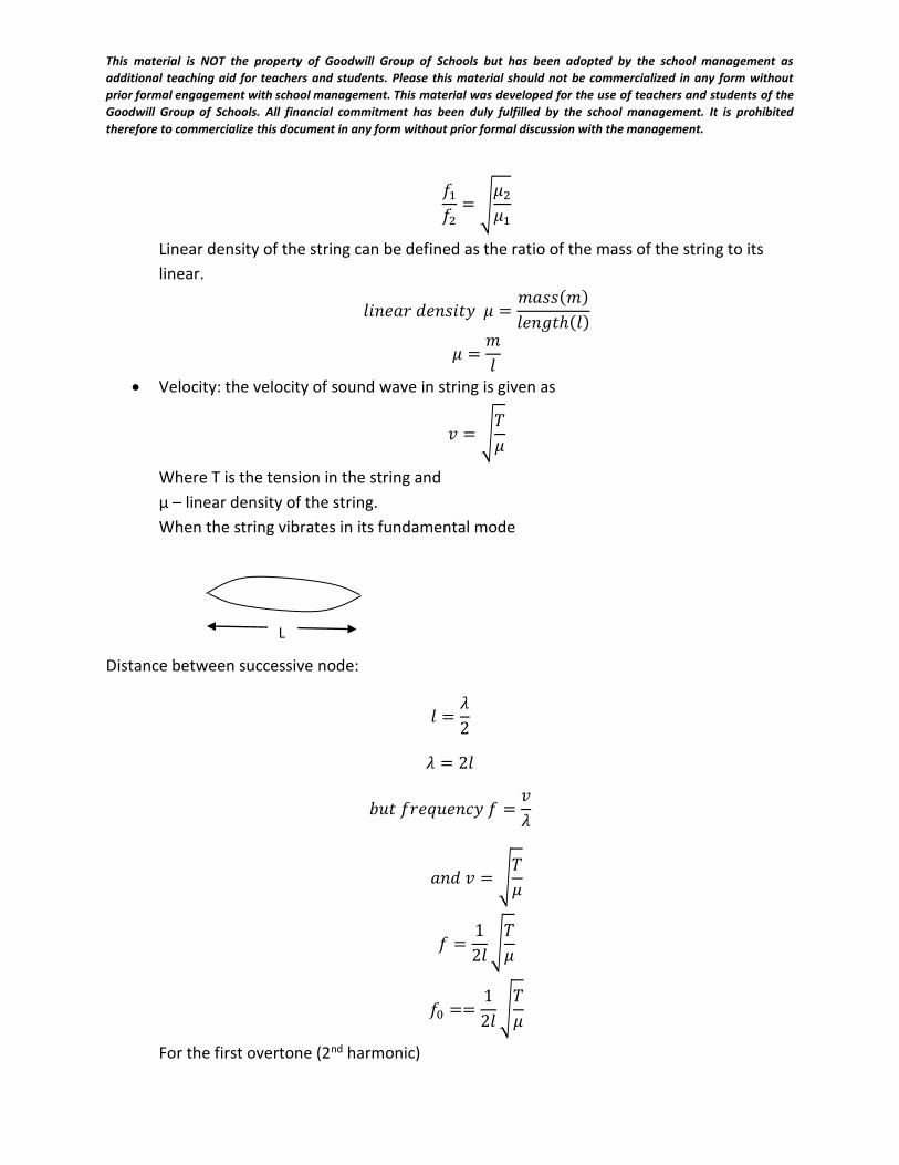
This material is NOT the property of Goodwill Group of Schools but has been adopted by the school management as
additional teaching aid for teachers and students. Please this material should not be commercialized in any form without
prior formal engagement with school management. This material was developed for the use of teachers and students of the
Goodwill Group of Schools. All financial commitment has been duly fulfilled by the school management. It is prohibited
therefore to commercialize this document in any form without prior formal discussion with the management.
𝑓1
𝑓2= √
𝜇2
𝜇1
Linear density of the string can be defined as the ratio of the mass of the string to its
linear.
𝑙𝑖𝑛𝑒𝑎𝑟 𝑑𝑒𝑛𝑠𝑖𝑡𝑦 𝜇 =𝑚𝑎𝑠𝑠(𝑚)
𝑙𝑒𝑛𝑔𝑡ℎ(𝑙)
𝜇 =𝑚
𝑙
Velocity: the velocity of sound wave in string is given as
𝑣 = √𝑇
𝜇
Where T is the tension in the string and
μ – linear density of the string.
When the string vibrates in its fundamental mode
Distance between successive node:
𝑙 =𝜆
2
𝜆 = 2𝑙
𝑏𝑢𝑡 𝑓𝑟𝑒𝑞𝑢𝑒𝑛𝑐𝑦 𝑓 =𝑣
𝜆
𝑎𝑛𝑑 𝑣 = √𝑇
𝜇
𝑓 =1
2𝑙√
𝑇
𝜇
𝑓0 ==1
2𝑙√
𝑇
𝜇
For the first overtone (2nd harmonic)
L
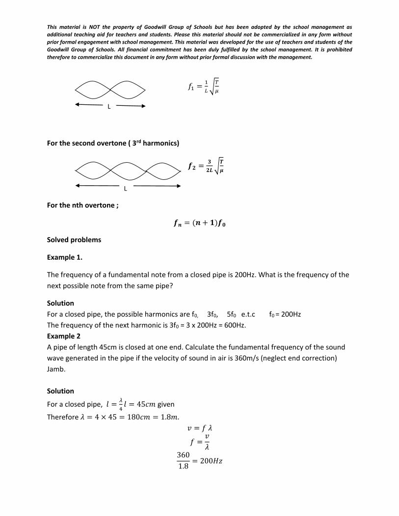
This material is NOT the property of Goodwill Group of Schools but has been adopted by the school management as
additional teaching aid for teachers and students. Please this material should not be commercialized in any form without
prior formal engagement with school management. This material was developed for the use of teachers and students of the
Goodwill Group of Schools. All financial commitment has been duly fulfilled by the school management. It is prohibited
therefore to commercialize this document in any form without prior formal discussion with the management.
𝑓1 =1
𝐿√
𝑇
𝜇
For the second overtone ( 3rd harmonics)
𝒇𝟐 =𝟑
𝟐𝑳√
𝑻
𝝁
For the nth overtone ;
𝒇𝒏 = (𝒏 + 𝟏)𝒇𝟎
Solved problems
Example 1.
The frequency of a fundamental note from a closed pipe is 200Hz. What is the frequency of the
next possible note from the same pipe?
Solution
For a closed pipe, the possible harmonics are f0, 3f0, 5f0 e.t.c f0 = 200Hz
The frequency of the next harmonic is 3f0 = 3 x 200Hz = 600Hz.
Example 2
A pipe of length 45cm is closed at one end. Calculate the fundamental frequency of the sound
wave generated in the pipe if the velocity of sound in air is 360m/s (neglect end correction)
Jamb.
Solution
For a closed pipe, 𝑙 =𝜆
4𝑙 = 45𝑐𝑚 given
Therefore 𝜆 = 4 × 45 = 180𝑐𝑚 = 1.8𝑚.
𝑣 = 𝑓 𝜆
𝑓 =𝑣
𝜆
360
1.8= 200𝐻𝑧
L
L
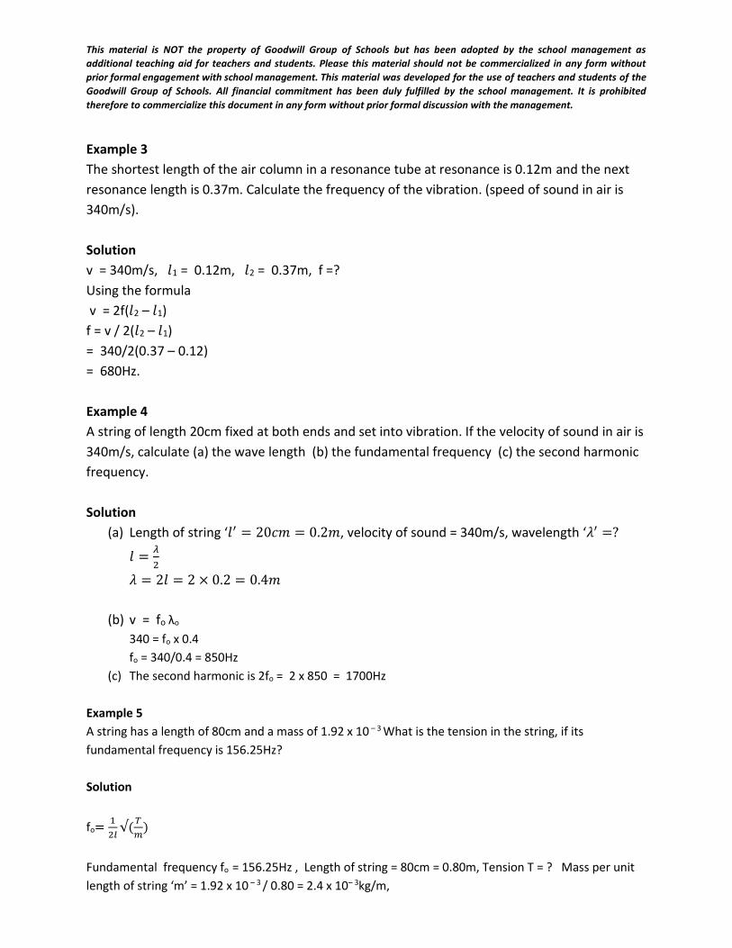
This material is NOT the property of Goodwill Group of Schools but has been adopted by the school management as
additional teaching aid for teachers and students. Please this material should not be commercialized in any form without
prior formal engagement with school management. This material was developed for the use of teachers and students of the
Goodwill Group of Schools. All financial commitment has been duly fulfilled by the school management. It is prohibited
therefore to commercialize this document in any form without prior formal discussion with the management.
Example 3
The shortest length of the air column in a resonance tube at resonance is 0.12m and the next
resonance length is 0.37m. Calculate the frequency of the vibration. (speed of sound in air is
340m/s).
Solution
v = 340m/s, 𝑙1 = 0.12m, 𝑙2 = 0.37m, f =?
Using the formula
v = 2f(𝑙2 – 𝑙1)
f = v / 2(𝑙2 – 𝑙1)
= 340/2(0.37 – 0.12)
= 680Hz.
Example 4
A string of length 20cm fixed at both ends and set into vibration. If the velocity of sound in air is
340m/s, calculate (a) the wave length (b) the fundamental frequency (c) the second harmonic
frequency.
Solution
(a) Length of string ‘𝑙′ = 20𝑐𝑚 = 0.2𝑚, velocity of sound = 340m/s, wavelength ‘𝜆′ =?
𝑙 =𝜆
2
𝜆 = 2𝑙 = 2 × 0.2 = 0.4𝑚
(b) v = fo λo
340 = fo x 0.4
fo = 340/0.4 = 850Hz
(c) The second harmonic is 2fo = 2 x 850 = 1700Hz
Example 5
A string has a length of 80cm and a mass of 1.92 x 10 – 3 What is the tension in the string, if its
fundamental frequency is 156.25Hz?
Solution
fo=1
2𝑙√(
𝑇
𝑚)
Fundamental frequency fo = 156.25Hz , Length of string = 80cm = 0.80m, Tension T = ? Mass per unit
length of string ‘m’ = 1.92 x 10 – 3 / 0.80 = 2.4 x 10– 3kg/m,
This material is NOT the property of Goodwill Group of Schools but has been adopted by the school management as
additional teaching aid for teachers and students. Please this material should not be commercialized in any form without
prior formal engagement with school management. This material was developed for the use of teachers and students of the
Goodwill Group of Schools. All financial commitment has been duly fulfilled by the school management. It is prohibited
therefore to commercialize this document in any form without prior formal discussion with the management.
156.25 =1
2×0.8√
𝑇
2.4×10⁻³
Squaring both sides, 156.252 = (1
(2×0.8))2 × (
𝑇
2.4×10⁻³ )
24,414.0625 =0.625 × 𝑇
0.0024
24,414.0625 x 0.0024 = 0.390625 x T
T = 24,414.0625 x 0.0024/0.390625 =150N.
Week end assignment:
1. Reading assignment: read on the human eye ( comparison of the eye and camera),
defects of the human eye and their corrections
2. Give three differences between music and noise
3. Give three applications of resonance.
4. Describe a simple experiment to determine the speed of sound in air using the principle
of echo.
5. A pipe closed at one end is sounding its fundamental note. If the length of the pipe is
10cm, calculate the wavelength of the note. (neglect end correction of the pipe).
Answer = 40cm
WEEK: 10
DATE:…………….
SUBJECT: PHYSICS
CLASS: SS 2
TOPIC: APPLICATION OF SOUND WAVES: (MUSICAL INSTRUMENTS)
CONTENTS
1. Wind instruments
2. String instruments
3. Percussion instruments
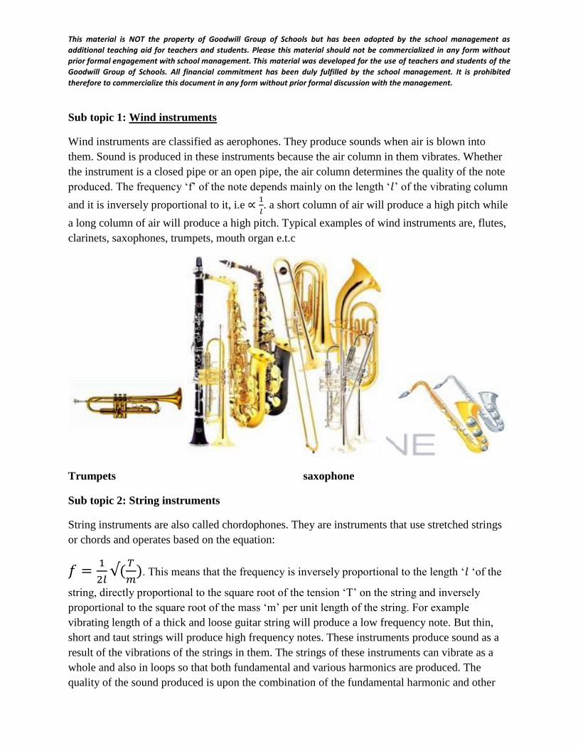
This material is NOT the property of Goodwill Group of Schools but has been adopted by the school management as
additional teaching aid for teachers and students. Please this material should not be commercialized in any form without
prior formal engagement with school management. This material was developed for the use of teachers and students of the
Goodwill Group of Schools. All financial commitment has been duly fulfilled by the school management. It is prohibited
therefore to commercialize this document in any form without prior formal discussion with the management.
Sub topic 1: Wind instruments
Wind instruments are classified as aerophones. They produce sounds when air is blown into
them. Sound is produced in these instruments because the air column in them vibrates. Whether
the instrument is a closed pipe or an open pipe, the air column determines the quality of the note
produced. The frequency ‘f’ of the note depends mainly on the length ‘𝑙’ of the vibrating column
and it is inversely proportional to it, i.e ∝1
𝑙. a short column of air will produce a high pitch while
a long column of air will produce a high pitch. Typical examples of wind instruments are, flutes,
clarinets, saxophones, trumpets, mouth organ e.t.c
Trumpets saxophone
Sub topic 2: String instruments
String instruments are also called chordophones. They are instruments that use stretched strings
or chords and operates based on the equation:
𝑓 =1
2𝑙√(
𝑇
𝑚). This means that the frequency is inversely proportional to the length ‘𝑙 ‘of the
string, directly proportional to the square root of the tension ‘T’ on the string and inversely
proportional to the square root of the mass ‘m’ per unit length of the string. For example
vibrating length of a thick and loose guitar string will produce a low frequency note. But thin,
short and taut strings will produce high frequency notes. These instruments produce sound as a
result of the vibrations of the strings in them. The strings of these instruments can vibrate as a
whole and also in loops so that both fundamental and various harmonics are produced. The
quality of the sound produced is upon the combination of the fundamental harmonic and other
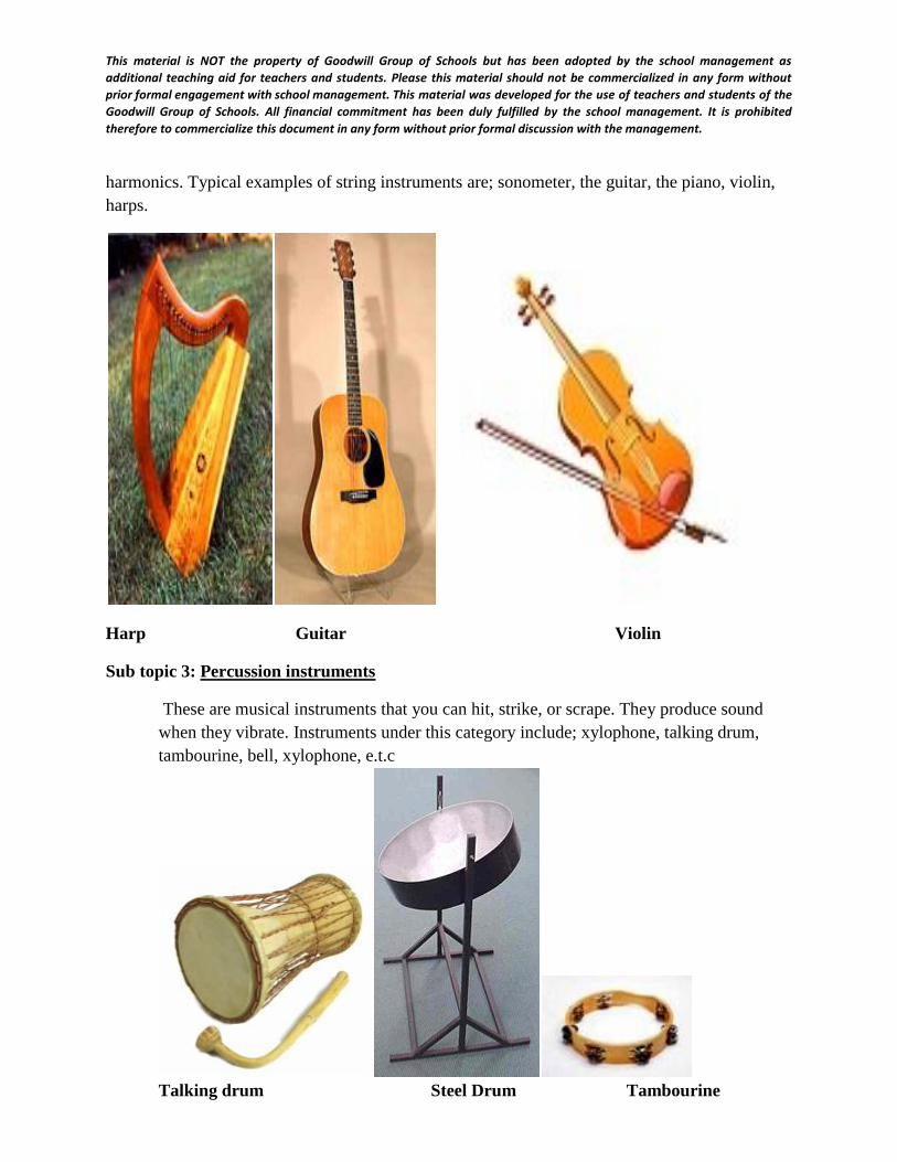
This material is NOT the property of Goodwill Group of Schools but has been adopted by the school management as
additional teaching aid for teachers and students. Please this material should not be commercialized in any form without
prior formal engagement with school management. This material was developed for the use of teachers and students of the
Goodwill Group of Schools. All financial commitment has been duly fulfilled by the school management. It is prohibited
therefore to commercialize this document in any form without prior formal discussion with the management.
harmonics. Typical examples of string instruments are; sonometer, the guitar, the piano, violin,
harps.
Harp Guitar Violin
Sub topic 3: Percussion instruments
These are musical instruments that you can hit, strike, or scrape. They produce sound
when they vibrate. Instruments under this category include; xylophone, talking drum,
tambourine, bell, xylophone, e.t.c
Talking drum Steel Drum Tambourine
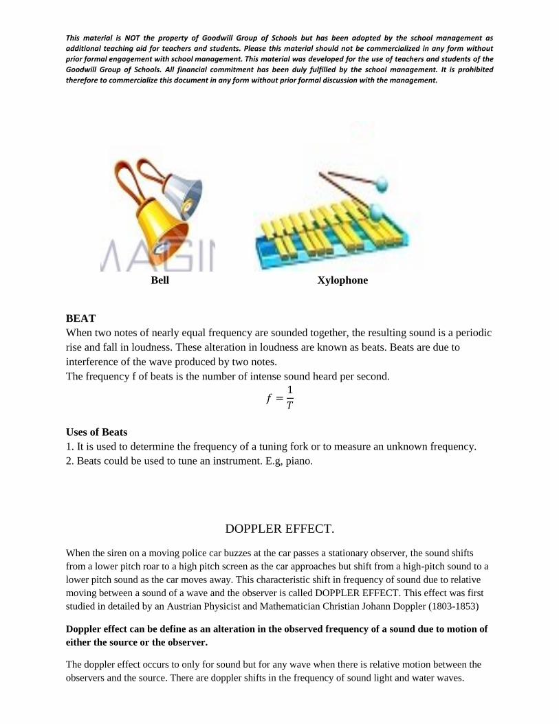
This material is NOT the property of Goodwill Group of Schools but has been adopted by the school management as
additional teaching aid for teachers and students. Please this material should not be commercialized in any form without
prior formal engagement with school management. This material was developed for the use of teachers and students of the
Goodwill Group of Schools. All financial commitment has been duly fulfilled by the school management. It is prohibited
therefore to commercialize this document in any form without prior formal discussion with the management.
Bell Xylophone
BEAT
When two notes of nearly equal frequency are sounded together, the resulting sound is a periodic
rise and fall in loudness. These alteration in loudness are known as beats. Beats are due to
interference of the wave produced by two notes.
The frequency f of beats is the number of intense sound heard per second.
𝑓 =1
𝑇
Uses of Beats
1. It is used to determine the frequency of a tuning fork or to measure an unknown frequency.
2. Beats could be used to tune an instrument. E.g, piano.
DOPPLER EFFECT.
When the siren on a moving police car buzzes at the car passes a stationary observer, the sound shifts
from a lower pitch roar to a high pitch screen as the car approaches but shift from a high-pitch sound to a
lower pitch sound as the car moves away. This characteristic shift in frequency of sound due to relative
moving between a sound of a wave and the observer is called DOPPLER EFFECT. This effect was first
studied in detailed by an Austrian Physicist and Mathematician Christian Johann Doppler (1803-1853)
Doppler effect can be define as an alteration in the observed frequency of a sound due to motion of
either the source or the observer.
The doppler effect occurs to only for sound but for any wave when there is relative motion between the
observers and the source. There are doppler shifts in the frequency of sound light and water waves.
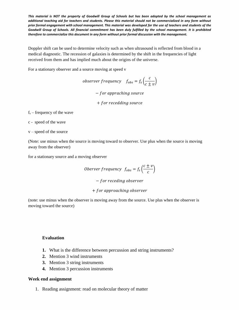
This material is NOT the property of Goodwill Group of Schools but has been adopted by the school management as
additional teaching aid for teachers and students. Please this material should not be commercialized in any form without
prior formal engagement with school management. This material was developed for the use of teachers and students of the
Goodwill Group of Schools. All financial commitment has been duly fulfilled by the school management. It is prohibited
therefore to commercialize this document in any form without prior formal discussion with the management.
Doppler shift can be used to determine velocity such as when ultrasound is reflected from blood in a
medical diagnostic. The recession of galaxies is determined by the shift in the frequencies of light
received from them and has implied much about the origins of the universe.
For a stationary observer and a source moving at speed v
𝑜𝑏𝑠𝑒𝑟𝑣𝑒𝑟 𝑓𝑟𝑒𝑞𝑢𝑒𝑛𝑐𝑦 𝑓𝑜𝑏𝑠 = 𝑓𝑠 (𝑐
𝑐 ± 𝑣)
− 𝑓𝑜𝑟 𝑎𝑝𝑝𝑟𝑎𝑐ℎ𝑖𝑛𝑔 𝑠𝑜𝑢𝑟𝑐𝑒
+ 𝑓𝑜𝑟 𝑟𝑒𝑐𝑒𝑑𝑑𝑖𝑛𝑔 𝑠𝑜𝑢𝑟𝑐𝑒
fs – frequency of the wave
c - speed of the wave
v – speed of the source
(Note: use minus when the source is moving toward to observer. Use plus when the source is moving
away from the observer)
for a stationary source and a moving observer
𝑂𝑏𝑒𝑟𝑣𝑒𝑟 𝑓𝑟𝑒𝑞𝑢𝑒𝑛𝑐𝑦 𝑓𝑜𝑏𝑠 = 𝑓𝑠 (𝑐 ± 𝑣
𝑐)
− 𝑓𝑜𝑟 𝑟𝑒𝑐𝑒𝑑𝑖𝑛𝑔 𝑜𝑏𝑠𝑒𝑟𝑣𝑒𝑟
+ 𝑓𝑜𝑟 𝑎𝑝𝑝𝑟𝑜𝑎𝑐ℎ𝑖𝑛𝑔 𝑜𝑏𝑠𝑒𝑟𝑣𝑒𝑟
(note: use minus when the observer is moving away from the source. Use plus when the observer is
moving toward the source)
Evaluation
1. What is the difference between percussion and string instruments?
2. Mention 3 wind instruments
3. Mention 3 string instruments
4. Mention 3 percussion instruments
Week end assignment
1. Reading assignment: read on molecular theory of matter
This material is NOT the property of Goodwill Group of Schools but has been adopted by the school management as
additional teaching aid for teachers and students. Please this material should not be commercialized in any form without
prior formal engagement with school management. This material was developed for the use of teachers and students of the
Goodwill Group of Schools. All financial commitment has been duly fulfilled by the school management. It is prohibited
therefore to commercialize this document in any form without prior formal discussion with the management.
2. Identify the different cultural groups in Nigeria and their local musical instruments.
WEEK 11: Revision
WEEK 12: Exams
REFERENCE TEXTS:
1. Senior Secondary School Physics by P.N. Okeke et al. 2011.
2. New School Physics for Senior Secondary Schools by Anyakoha, M.W. 2010
4. Science Teachers Association of Nigeria Physics for Senior Secondary School, Book 1. New
Edition; 2012.
5. Melrose Physics for Senior Secondary School, Book 1 by Akano, O and Onanuga, O.O. 2012.