
CIVIL ENGINEERING DEPARTMENT
56
CIVIL ENGINEERING DEPARTMENT STRUCTURAL ENGINEERING LABORATORIES TESTING AND CONSULTANCY BROCHURE BHARTIYA VIDYA BHAVAN'S, SARDAR PATEL COLLEGE OF ENGINEERING (Government Aided-Autonomous Institute) Bhavan's Campus, Munshi Nagar, Andheri (West), Mumbai 400 058.
-
Upload
khangminh22 -
Category
Documents
-
view
0 -
download
0
Transcript of CIVIL ENGINEERING DEPARTMENT

CIVIL ENGINEERING DEPARTMENT STRUCTURAL ENGINEERING LABORATORIES
TESTING AND CONSULTANCY BROCHURE
BHARTIYA VIDYA BHAVAN'S,
SARDAR PATEL COLLEGE OF
ENGINEERING
(Government Aided-Autonomous Institute)
Bhavan's Campus, Munshi Nagar, Andheri (West),
Mumbai 400 058.

BHARTIYA VIDYA BHAVAN’S SARDAR PATEL COLLEGE
OF ENGINEERING
Bharatiya Vidya Bhavan’s Sardar Patel College of Engineering (SPCE) was established in
1962 as a Government Aided Engineering College. The institute is affiliated to University of
Mumbai. In the year 2010, UGC conferred Academic Autonomy to SPCE. Currently SPCE
offers 3 UG courses in Electrical, Mechanical and Civil Engineering and 5 PG courses in
Structural, Thermal, Machine Design, Construction Management and Power Electronics and
Power Systems with total strength of around 1000 students. SPCE also offers Ph.D. in
Mechanical, Electrical and Civil Engineering. Civil Engineering Dept. offers very strong
consultancy and testing services and contributes voluminously in revenue generation of the
Institute.
Over the last 59 years the college has gained an excellent reputation in the field of Technical
Education. S.P.C.E. Grade “A” rating engineering college from Govt. of Maharashtra has
maintained a proud tradition of excellent academic records. Institute has won an award for
outstanding contribution in Industry Institute Partnership in govt. aided college category for
the year 2014-15 based on survey for the last three years conferred by SEED, Chennai. The
college has produced many graduates and Post-graduate Engineers, many of our past students
are now leaders in their professions. S.P.C.E. Alumni can be found in all public and private
sector organizations operating in diverse fields, often holding senior and key positions in the
organization.

Structural Engineering Laboratories
Engineering Mechanics, Strength of Materials, Concrete Technology, NDT, Structural
Dynamics, Computer Centre.
Computing facilities:
Faculty members are provided with computer with printer. Department has three LCD
projectors for presentations. A separate computer centre is provided for PG students with
latest computers, printers and softwares. All the computers are in Network with internet
access.
Major Equipments & Testing facilities available in department
Following testing facilities are available :
The Department undertakes testing of various materials for private and government
bodies involved in construction activities. The list of tests available are as follows :
AGGREGATE - COARSE & FINE
A) Physical Tests Coarse Aggregate
1 Sieve Analysis
2 Specific Gravity
3 Bulk Density
4 Water Absorption
5 Impact Value
6 Crushing Value
7 Abrasion value (Los Angles)
8 Elongation Index
9 Flakiness Index
B
)
Chemical Tests Coarse Aggregate
1 Soundness by Na2SO4
2 Total Deleterious Material
3 Alkali Aggregate Reactivity
4 Water Soluble Chloride Content
5 Water Soluble Sulphate Content
6 pH
C) Physical Tests Fine Aggregate
1 Sieve Analysis
2 Specific Gravity
3 Water Absorption
4 Bulk Density
5 % Finer than 75µ
D) Chemical Tests on Fine Aggregate
1 Soundness by Na2SO4
2 Total Deleterious Material
3 Alkali Aggregate Reactivity
4 Organic Impurities
5 Water Soluble Chloride Content
6 Water Soluble Sulphate Content
7 Ph Value
CHEMICAL ADMIXTURE
A) Physical

1 Workability
2 Setting Time
3 Bleeding
4 Water Content
5 Compressive Strength
6 Flexural Strength
7 Length Change
8 Air Content
B
)
Chemical/Uniformity Test
1 pH
2 Dry Material
3 Ash Content
4 Chloride Content
5 Relative Density
CEMENT
A) Chemical Tests on Cement
1 Chemical Analysis (SIO2, Al2O3, Fe2O3, CaO,
MgO) (SO3, Na2O, K2O)
2 Loss On Ignition
3 Insoluble Residue
4 Free Lime
B
)
Physical Tests On Cement
1 Fineness (Blaines, m2/kg)
2
Setting Time (Minutes)
Initial
Final
3 Compressive Strength (Mpa)
3,7 & 28 Days
4 Soundness
Le-Chatelier's Expansion (mm)
5 Normal Consistency
6 Specific Gravity
7 Autoclave Expansion (%)
8 Drying Shrinkage, (%)
CONCRETE
1 Compressive strength of Cubes upto M50
2 Compressive strength of Cubes Above M50
3 Accelerated Curing Test of Cubes
4 Core/Cylinder - Compressive Strength
5 Extraction of Concrete Core
6 Flexural Strength of concrete
7 Splitting tensile strength of concrete cylinder
8 Cement Content
9 Chloride Content
10 Sulphate Content
11 pH
12 Cement : Sand Proportion
CONCRETE DURABILITY TEST
1 Rapid Chloride Penetration Test (RCPT)
2 Water Permeability of concrete (WP)
3 Initial Surface absorption test (ISAT)
4 Modulus of Elasticity (MOE)
5 Drying Shrinkage

6 Moisture Movement
7 Water Absorption (WA)
8 Rapid Chloride Migration Test (RCMT)
9 Chloride Diffusion Test
CONCRETE MIX DESIGN
1 Grade of Concrete M10 To M50 and Above
2 Concrete design mix verification for Any Grade
3 Additional trial to arrive at economical mix on demand
FLYASH
A) Lime Reactivity (LR)
B
)
Physical Test
1 Fineness by Blaine's
2 Particles Retained on 45 Micron
3 Compressive Strength @ 28 days
4 Soundness by Autoclave
5 Specific Gravity
C) Chemical Testing
1 SiO2 %
2 Magnesium Oxide
3 Loss of Ignition %
4 Total Chlorides %
5 Alumina(Al2O3)
6 Ferric Oxide (Fe2O3)
7 Sulphuric Anhydride(SO3)
8 Available Alkalis %
9 SiO2 + Al2O3 + Fe2O3 %
GGBS
A) Physical Test as per ASTM Code
1 Slag Activity Index (7 & 28 Days)
2 Finess by Retain on 45 Micron
B) Physical Test as per IS Code
1 Slag Activity Index (7 & 28 Days)
2 Finess by Blains
3 Density/Specific Gravity
C ) Chemical Test
1 Magnesia Content
2 Magnesium Oxide
3 Sulphide Sulphur
4 Sulphate
5 Insoluble Residue
6 Chloride Content
7 Loss On Ignition
8 (Cao+Mgo+1/3Al2O3)/SiO2+2/3Al2O3
9 (Cao+Mgo+Al2O3)/SiO2
10 (Cao+CaS+1/2Mgo+Al2O3)/SiO2+MnO
D ) Glass Content of GGBS
1 Glass Content
MICRO SILICA
A) Micro silica Physical as per ASTM
1 Percent retained on 45 Micron
2 Accelerated Pozzolanic Strength
3 Bulk Density
B
)
Micro silica Physical as per IS
1 Percent retained on 45 Micron

3 Bulk Density
4 Compressive Strength @ 7 days
C) Micro Silica Chemical
1 SiO2
2 Moisture
3 LOI
4 Alkali
5 Chloride
STEEL / METALS
C) Couplers / Spliced Joints
1 Ultimate Tensile Strength & % Elongation
i) Bar 6 mm to 16 mm
ii) 20mm
iii) 25mm
iv) 32mm
2 Coupler Grade Confirmation
D) Fusion Bonded Epoxy Coated Bar.
1 Continuity of Coating
2 Adhesion of coating
3 Thickness of coating
F) Reinforcement Steel / TMT bars
1 Complete Physical Properties (Tensile, Bend & Rebend)
a. Bar 6 mm to 16 mm
b. 20mm
c. 25mm
d. 32mm
2 Tensile Strength
a. Bar 6 mm to 16 mm
b. 20mm
c. 25mm
d. 32mm
3 Bend Test
a. Bar 6 mm to 16 mm
b. 20mm
c. 25mm
d. 32mm
4 Rebend Test
a. Bar 6 mm to 16 mm
b. 20mm
c. 25mm
d. 32mm
5 Chemical Analysis (C,S & P)
6 Chemical Analysis (Upto CE)
5 Weight per meter of bars
a. Bar 6 mm to 16 mm
b. 20mm
c. 25mm
d. 32mm
1. Strength of Materials & Material Testing laboratory
Facilities available: 100 T Universal Testing Machine, 40T Universal Testing
Machine, Impact Testing machine, Hardness testing machines, Torsion testing

machine, Abrasion testing machine, Temperature controlled Oven, 40 T Capacity
loading frame, 30T capacity hydraulic jack, 30 channel strain measuring equipment,
Deflection measuring and crack width measuring sensors, EL sensors for tilt
measurement, Dial gauges, Proving rings etc.
Sr
No.
Name of
Equipment
Description
1. Universal
Testing
Machine
To carry out test on
steel and concrete
2. Impact
Testing
Machine
To carry out Impact
Test on Brass, Copper
and Mild Steel by
Charpy Impact Test
and Izod Impact test.

3. Hardness
Testing
Machine
To calculate the Brinell
Hardness no. and
Rockwell Hardness no.
for Mild Steel, Copper
and Brass.
4. Deflection
Test
To measure deflection
of simply supported
beams of different
materials.
5. Torsion
Testing
Machine
For determining the
modulus of rupture in
torsion for mild steel
and cast iron.

6. Oven
7. Tile Abrasion
Testing
Machine
To carry out Abrasion
Test on tile.
2. Concrete Technology & NDT laboratory
Facilities available: 200 T Compression Testing Machine, 200T Automatic
compression Testing Machine, Mortar mixing machine, Mortar vibrators, Flow table,
Vicat apparatus, VB compacting machine, Weighing balances, Curing tank, Table
vibrator, Accelerated curing Tank, UPV measuring instrument, Digital Test Hammers
etc.
Sr. No. Name of
machine
Image
Information
1
Compression
Testing
Machine
Used for compression tests on
concrete cubes, bricks, timber,
paver blocks
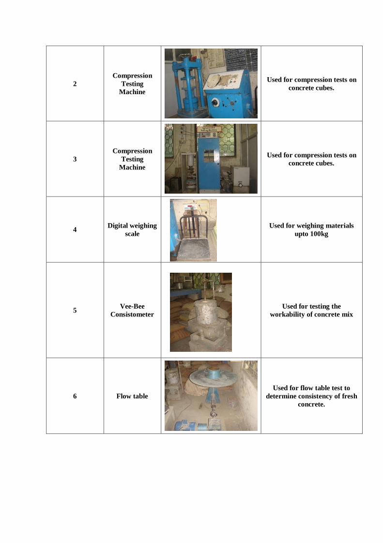
2
Compression
Testing
Machine
Used for compression tests on
concrete cubes.
3
Compression
Testing
Machine
Used for compression tests on
concrete cubes.
4 Digital weighing
scale
Used for weighing materials
upto 100kg
5 Vee-Bee
Consistometer
Used for testing the
workability of concrete mix
6 Flow table
Used for flow table test to
determine consistency of fresh
concrete.

8
Mortar cube
vibrating
machine
Used for compaction of mortar
cubes by vibration
9
Ultra sonic
pulse velocity
apparatus
Used for ultrasonic pulse
velocity test on concrete
10 Concrete mixer
Used for concrete mixing.
11
Compacting
factor
apparatus
Used to test compaction factor
for concrete
12 Vibrating table
Used for compaction of
concrete.
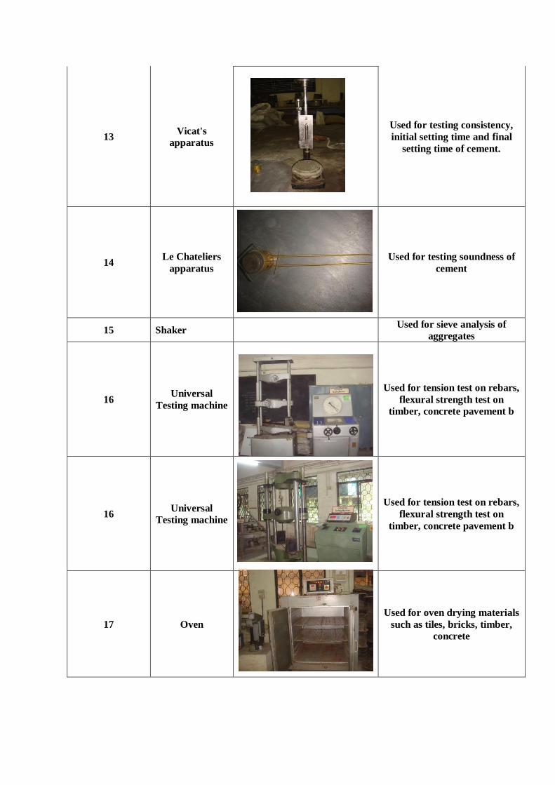
13 Vicat's
apparatus
Used for testing consistency,
initial setting time and final
setting time of cement.
14 Le Chateliers
apparatus
Used for testing soundness of
cement
15 Shaker
Used for sieve analysis of
aggregates
16 Universal
Testing machine
Used for tension test on rebars,
flexural strength test on
timber, concrete pavement b
16 Universal
Testing machine
Used for tension test on rebars,
flexural strength test on
timber, concrete pavement b
17 Oven
Used for oven drying materials
such as tiles, bricks, timber,
concrete

3. Dynamics Laboratory
Facilities available: Shake Table with 1 Ton capacity servo-hydraulic shaker,
Vibration sensors, Four channel charge amplifier, ‘OROS’ 8 channel vibration
recorder and analyzer, ‘System 7000’ 24 channel data acquisition system for dynamic
strain and deflection measurements, long distance laser based static and dynamic
displacement measuring system etc.
Shake table
(Model No. SH-01-1010,Capacity -1 T. Table size-1200x1200,Table acceleration-1
g,Actuator stroke 150mm,Height=417mm,Width=1900mm,Depth=1095mm,Weight-
1T)

‘OROS’ 8 channel vibration recorder and analyzer
‘System 7000’ 24 channel data acquisition system
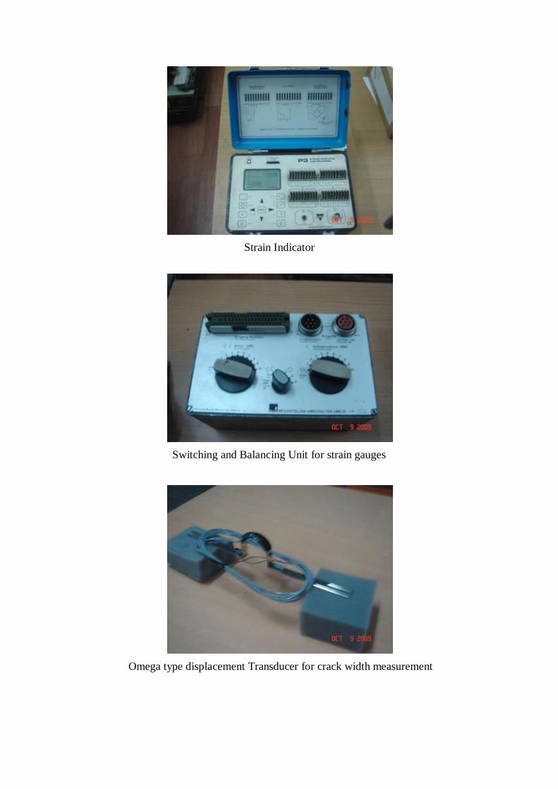
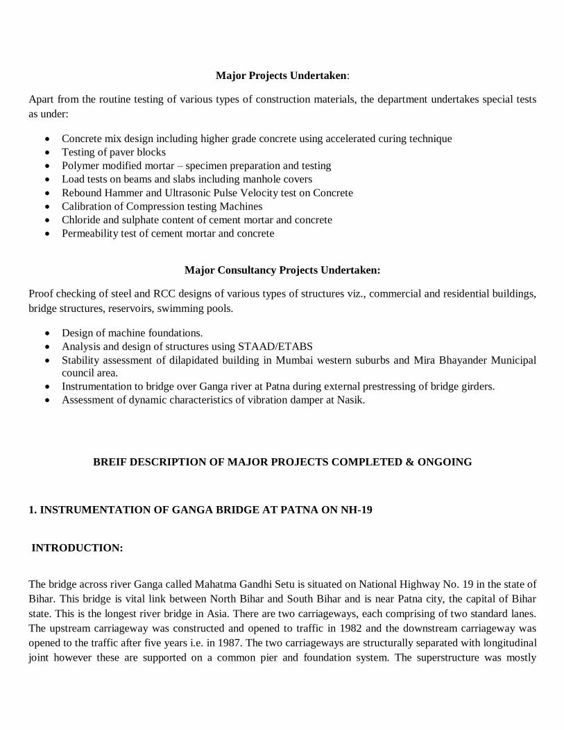
Strain Indicator
Switching and Balancing Unit for strain gauges
Omega type displacement Transducer for crack width measurement

Displacement sensor

Sr. No. Name of the Equipment Important Technical specifications Equipment useful for Equipment Photographs
1 Adjustable and sighting
Telescope for existing PSM
laser based displacement
sensor
Adjustable base- 360 degrees rotational and +/-
40 degrees vertical Sighting telescope range -
500 M
It helps in aiming laser
displacement sensor Type PSM
accurately on target
2 a) Hand held Vibration Meter -
1 No b)
Accelerometers - 5 Nos
a) Hand held Digital Vibration meter for
measuring vibration levels in three modes
b) High sensitivity ICP accelerometers,
Sensitivity - 100 mv/g, Freq range - 1 to 4 kHz
including low noise cables
a) For preliminary investigation
of vibration levels
b) Additional inputs directly to
existing vibration analyser for
vibration measurements
3 a) Load cells - 3 Nos b)
Electronic weighing balance -
2 Nos
a) Load cells with Digital indicators one each for
10 T, 25 T for compression and 40 T capacity for
both compression and Tension, Safe overload:
20% of rated capacity complete
b) Electronic weighing balance -
a) For measuring different loads
(replacement to old proving
rings), with digital indication
b) For proper weighing of
material for concrete mixing
4 Compression Testing Machine
with digital load and pace rate
indicator
Capacity - 3000 kN, Least count - 1 kN, Pace
rate indication - 0.1 to 20 kN/sec, Four column
high stiffnes welded frame, suitable for testing
cubes up to 200 mm and cylinders of 160 x 320
mm, with spacer blocks of 50 mm, 100 mm and
200 mm
For testing high strength
concrete cubes and cylinders
EQUIPMENT PROCURED UNDER TEQIP PROJECT

5 a) Function Generator - One b)
Solid state true RMS AC
Voltmeter / Multimeter
a) 10 MHz Function Generator with digital
display of frequency and amplitude for sine,
squre, triangular, pulse and DC generation in
different ranges and amplitude settings, Freq
resolution - 0.1 Hz, Output - 10 V p-p, Accuracy-
± 2% of setting, Freq rang
a) Replacement to the old
function generator, which is
used in vibration exciter system
b) For measuring AC voltages
6 Ultrasonic Pulse Velocity
Concrete Tester - One
UPV Concrete Tester which is light, portable,
rugged and simple to operate having highly
visible display (auto ranging transit time display
up to 9999 µsec), working on rechargable battery
and 240 V AC 50/60 Hz power supply with two
54-kHz transducers, ne
For measuring ultrasonic pulse
velocity in concrete structural
components for assessing quality
of concrete
7 Battery powered Digital
Storage Oscilloscope
Battery Powered digital storage oscilloscope,
Tektronix Type TPS2012B, 100 Mhz, having
two fully isolated channels and standard
accessories.
For monitoring vibration signals
8 Air Compressor Two stage, air cooled Air Compressor,
Maximum pressure - 175 psi, Displacement - 8.6
CFM, Air receiver capacity - 300 l, slow running
speed and low noise, fitted with necessary
valves, relay, pressure gauge, safety valve etc.
For providing air cushion to the
existing vibration table system
and for

9 Vibrating wire strain gauges
with data logger - one set
Four nos. Vibrating wire strain gauges of 125
mm gauge length with data logger,
Used for continuous monitoring
of static and quasi-static strains
in structures for prolonged
period.
10 Concrete Test Hammer Type
N
'Silver schmidt' concrete test hammer, type N,
which is impact direction independent Range -
10-100 N/ sq mm, Impact energy - 2.207Nm,
Hammer mass-115 g, Display - 17 x 71 pixels,
max number of impacts to be stored - 99, with
necessary software and acces
for Non Destructive Testing of
concrete structures
11 a) Advanceed Half Cell
Potential Survey System - one
b) Advanced system for
determining resonant
frequency of material, young's
modulus and Poissions ratio -
one c) Chloride
field test system - on
a) The system should have specially shaped
porous ceramic tip to allow half cell to take
readings in vertical, horizontal or inverted
position. It should have fully integrated data
acquisition and analysis unit for rapid analysis of
data in the fieldwith
a) This system is useful to
quickly identify areas of
probable rebar corrosion in
concrete for even large
structures b)
This system is useful for
determining Young's Modulus,
Poission's Ratio and resonant
frequency of conc

12 Rapid Chloride Permeability
Test apparatus with provision
for tests on 4 specimen
simultaneously.
Each RCPT cell should be as per ASTM c 1202-
05 for holding concrete specimen of 100 mm
diameter and 50 mm thick with necessary rubber
gaskets andwashers etc. Instrument is having
automatic Data Acquisition unit and regulated
DC current of 60 volts and nec
Useful for Rapid Permeability
Test of concrete specimen.
13 Sets of experimental set-ups
for Engineering Mechanics
Laboratory with necessary
work Panels
Apparatus sets for following experiments 1)
Equilibrium of forces containing necessary
pulleys, weight hangers, weights, cord, rings
magnetic protractor etc.
2) Bell crank Lever containing necessary pulle
These sets are useful for 1)
For experiments in concurrent
and non concurrent coplaner
forces and angles. 2)
experiments on principles of
moment, bell crank lever etc.
3) Experiments in beams with
different conditions and their
deflectio

14 Noise level meter with FFT
analysis software
Integrating sound level meter with single
channel FFT analysis of sound or Vibration
containing 1) Type 2250-G4 with BZ-7230 FFT
Analysis software 2) IEPE Accelerometer TEDS
10 mv/g, side connector, insulated base 3) Cable
low noise, 10-32 UNF(M) to triax
Useful for on sight analysis of
sound or vibration signals
15 a) Cement Autoclave
b) Accelerated curing tank
a) Inside chamber dimensions - 15 cm dia x 50
cm height, suitable for operation on single phase
AC power supply, consisting of rustproof S.S.
pressure vessel, microprocessor based PID
controller for accurately controlling the
temperature and pressure
a) Used for estimating delayed
expansion of Portland cement
caused by hydration of CaO and
MgO b)
Accelerated curing tank enables
the long term strength of
concrete after 1 year in as little
as 14 days. Thus accelerate

16 a) Core cutting and Grinding
machine b)
table vibrator c)
Heat of hydration apparatus
a) Suitable for cutting and Grinding cylindrical
rock or concrete specimen up to 100 mm size
with 200 mm dia diamond cutter, sample holding
device, protection shield etc b) Table
size 1 M x 1 M, frequency variable from 3600 to
2600 vibratio
a) This machine is used for
cutting and grinding rock or
concrete cores so that both of its
surfaces are parallel which can
be tested in machine.
b) Table vibrator is used for
compacting concrete in the
moulds by vibrating them
17 Longitudinal Compressometer Suitable for use with concrete cylinder of size
152 x 305 mm consisting of two annular cast
aluminium frames with clamping screws,
stainless steel pivot rod, tensioning spring and
digital dial gauge with resolution of 0.0025 mm.
a) Used for determination of
modulus of elasticity of concrete
using 15 cm dia x 30 cm high
cement concrete cylinders
subjected to compressive loads
Major Projects Undertaken:
Apart from the routine testing of various types of construction materials, the department undertakes special tests
as under:
Concrete mix design including higher grade concrete using accelerated curing technique
Testing of paver blocks
Polymer modified mortar – specimen preparation and testing
Load tests on beams and slabs including manhole covers
Rebound Hammer and Ultrasonic Pulse Velocity test on Concrete
Calibration of Compression testing Machines
Chloride and sulphate content of cement mortar and concrete
Permeability test of cement mortar and concrete
Major Consultancy Projects Undertaken:
Proof checking of steel and RCC designs of various types of structures viz., commercial and residential buildings,
bridge structures, reservoirs, swimming pools.
Design of machine foundations.
Analysis and design of structures using STAAD/ETABS
Stability assessment of dilapidated building in Mumbai western suburbs and Mira Bhayander Municipal
council area.
Instrumentation to bridge over Ganga river at Patna during external prestressing of bridge girders.
Assessment of dynamic characteristics of vibration damper at Nasik.
BREIF DESCRIPTION OF MAJOR PROJECTS COMPLETED & ONGOING
1. INSTRUMENTATION OF GANGA BRIDGE AT PATNA ON NH-19
INTRODUCTION:
The bridge across river Ganga called Mahatma Gandhi Setu is situated on National Highway No. 19 in the state of
Bihar. This bridge is vital link between North Bihar and South Bihar and is near Patna city, the capital of Bihar
state. This is the longest river bridge in Asia. There are two carriageways, each comprising of two standard lanes.
The upstream carriageway was constructed and opened to traffic in 1982 and the downstream carriageway was
opened to the traffic after five years i.e. in 1987. The two carriageways are structurally separated with longitudinal
joint however these are supported on a common pier and foundation system. The superstructure was mostly

constructed using pre-cast segmental construction. This Ganga Bridge or Mahatma Gandhi Setu, spans across
Ganga River near Patna, capital city of Bihar state. At other end of the bridge i.e. North end, there is a town called
Hajipur. There are two carriageways, each comprising of two standard lanes and a footpath. The Superstructure is
in pre-stressed concrete and is constructed by cantilever method using pre-cast segments. It is rigidly connected
with the pier and extends by about 60.5 M on either side of the pier. Each ‘T’ arm is therefore of nominal length
of 121 M. There are in all 45 ‘T’ arms and the total length of the bridge is 5445 M. The section is a box girder
with varying depths from 8 M at the pier to about 2.2 M at the tip of the cantilever. The tips of the cantilever are
connected by means of steel plunger bearings serving as load transfer mechanism
It was observed by the Public Works Department (PWD) of Bihar that most spans are suffering from distress such
as excessive sagging of the cantilevers on account of creep and other losses of pre-stress. At certain points, the
joints between two segments have also opened out, clearly indicating reduction in applied pre-stress. Due to
drooping of the cantilevers, the hinge bearings are also not functioning well and in some cases the plunger
bearings are damaged and holding bolts broken. Thus stability of the structure is threatened due to these distresses.
In order to restore the structural integrity of the superstructure, the Public Works Department of Bihar has decided
to strengthen affected spans by external pre-stressing for which strengthening program was chalked out. These
spans were to be strengthened by applying additional pre-stress, with external cables placed inside the box.
Assessment of additional pre-stress was based on the estimate of likely time dependent losses like creep and
shrinkage. To check the effectiveness of external pre-stressing, PWD desired to have measurements of strains and
deflections during pre-stressing of these spans. They also desired that a reputed institution should associate with
M/s FPCC Ltd. for carrying out these measurements during pre-stressing of these spans.
For this purpose M/s FPCC approached Department of Structural Engineering, Sardar Patel College of
Engineering (SPCE), Mumbai. This Department of SPCE has adequate facility and expertise to arrange for such
measurements and evaluation. The proposal was put up to the Principal of the college by Head of structural
Engineering Department and was approved The scope of work involved the various activities like planning of the
instrumentation scheme, installation of sensors and instruments inside the box girder, periodic measurements
during the various stages of pre-stressing and processing of data to give the strains and deflections. The work of
instrumentation and measurements during strengthening of these spans was carried. The work was started in 2005
in phases & presently the last 11th span work is going on.
Objectives
The purpose of the instrumentation was to check the efficacy of the external pre-stressing. It is envisaged that due
to external pre-stress, compressive strains shall be further induced in the box section. Besides, there would be
lifting of the cantilever tips due to application of the force. Measurements of all these parameters were recorded
after pre-stressing of each pair of cables. To measure all these effects the instrumentation proposed is described in
following paragraphs.
It was decided to plan instrumentation for following measurements.
a) Temperature measurements
b) Deflection measurements and
c) Strain measurements
INSTRUMENTS USED:
The following instruments and strain gauges were used for measuring strains.
1. Digital Strain Indicator (Photo-05)
Manufactured by: ‘VISHAY’ Micro-Measurements, USA
Type : Model P-3 strain indicator and recorder
Range : ± 31,000 micro-strains at GF=2.00
Accuracy : ± 0.1% of reading ±3 counts
Input circuit : 60 to 2000 ohms, half, quarter or full bridge
Internal dummy gauges provided for wheat-stone bridge completion.
Gauge factor : Adjustable from 0.5 to 9.900
Power : 2 x 1.5V Battery Cells
2. Switching Units
Manufactured by: HBM, Germany
Type: UMK-10
Capacity: 4 full bridges plus 10 channels half or quarter bridges
plus open position
External Circuits: Accepts quarter, half or full bridge
or any combination

Input Bridge Resistance: 50 to 2000 ohms
Switching Repeatability: Better than 1 /m
Following equipment was used for measuring deflections of the bridge.
1. Auto Levels
Manufactured by: Pentax, Japan make
Type: AFL 320
Setting accuracy: +/- 0.3 inch
Standard deviation: +/- 0.8 mm for 1Km double run leveling
Sensitivity: 8' / 2 mm
Following equipment was used for measuring Temperature.
1. Digital Temperature Indicator
Manufactured by: Precision Electronics, Bombay
Range: 0-600 0C
Resolution: 10 C
Display: 3 ½ Digit LCD with low bat indication
Power: single 9 V batteries
DEFLECTION MEASUREMENTS
Due to particular profile of the box girder, it was not possible to take deflection measurements inside the box
girder. These measurements were, therefore made on the deck surface. The deflections measurements were taken
by using an auto level and standard 3 Metre measuring staff with graduations of 5 mm. Auto level was positioned
on the pier, at the center of the span and also the bench mark, these reference points, being on the rigid pier, are
non-deflecting. On each cantilever three points were prepared on the tips, (Patna side and Hajipur side) with
epoxy-sand mortar over the deck surface, one on up-stream side, second at the center and third on the down-
stream side of the selected span. Thus in all 6 points were selected for deflection measurements. For achieving
maximum accuracy in measurements, during various stages of pre-stressing, the measurements of the all the
points were taken with a single setting of the leveling instrument. Although all efforts were made to measure
deflections at the accuracy of 1 mm, it was found difficult to measure accurately due to constant vibrations of the
bridge deck due to vehicular traffic on the adjoining carriageway. Since these measurements were not so accurate
these were used just for confirming behavior or trend of the span and not for actual calculations.
So deflection measurements were also taken with water level tube and scale attached at each location. For this
purpose rigid M.S. angles, of about 1 meter height, were erected at nine locations. For three sections, i.e. Patna
and Hajipur tips of the span and centre of the span, three locations each at downstream, upstream and centre of the
road were selected. A water filled plastic tube of about 10-12 mm diameter was laid and fixed on the angles
between centre and corresponding tip location. Scale was mounted on each angle erected so that water level in
each tube can be measured with 1 mm accuracy. Advantage of this system is that even if water is reduced due to
evaporation or water level varies due to expansion or contraction of the tube difference in levels at centre and tip
will always give correct position of the tip with respect to the centre of the span (on the pier) which is supposed to
be at constant level. Photo 07 and 08 shows arrangement for recording water levels on these spans. It was possible
with this method to take measurements with the accuracy of 1 mm.
5.3 TEMPERATURE MEASUREMENTS
Apart from strain and deflection measurements, it was decided to have temperature measurements before and
during pre-stressing so that strains and deflections due to variation of temperature can be estimated. For this
purpose readings of surface temperature on the top slab and inside the box were taken along with ambient
temperature that time. For recording concrete surface temperatures at different locations, temperature sensor
called PT sensor was fixed at each location. Sensing surface of the sensor was kept touching to the concrete
surface and was held in position by applying M-seal. Each PT sensor is having adaptor, which can be connected to
the temperature indicator. Concrete surface temperatures were recorded at all locations of strain gauges, on top of
deck slab and also at the bottom of box at both ends during temperature cycle and also during pre-stressing of
cables.

Ganga Bridge at Patna
Strain gauge with Dummy gauge in position
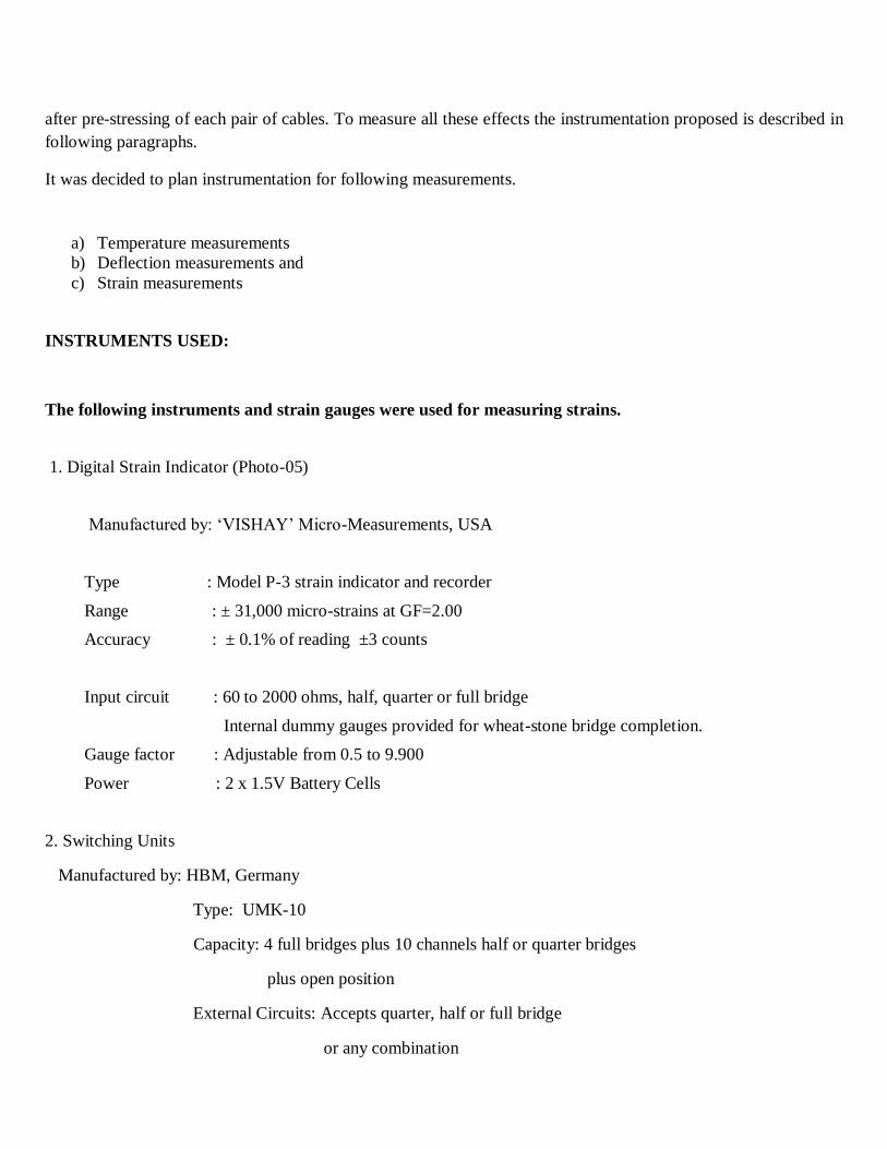
Instrumentation for 24 Channels
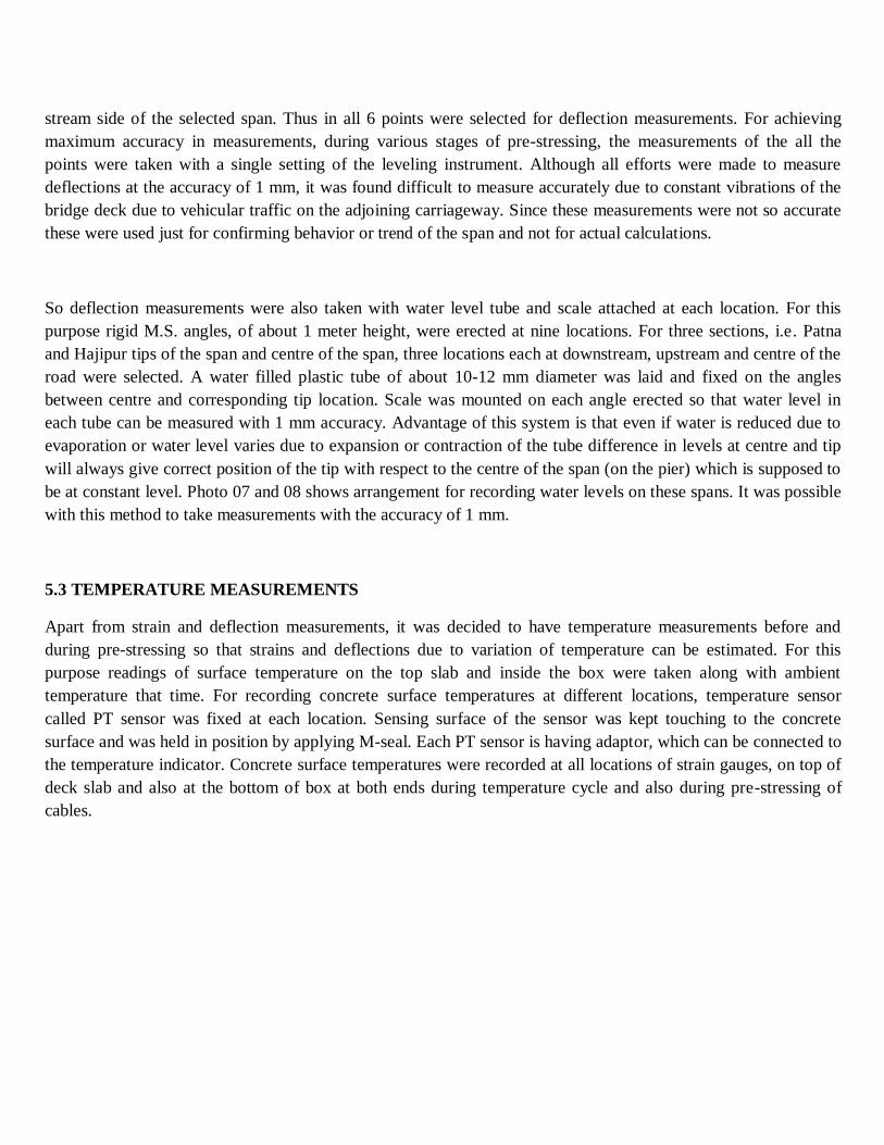
2. TESTING OF THE KARAL RAIL OVER BRIDGE AT JNPT, NAVI MUMBAI FOR THREE SPANS
REHABILITATED IN FIRST PHASE

Port at Nhava-Sheva, Navi Mumbai is managed by Jawaharlal Nehru Port Trust (JNPT). This port is one of
the busiest ports and handles about 70% of container traffic of whole INDIA. Port is connected by roads to the
National and State Highways in addition to Rail connectivity. A few bridges (Road over and rail over bridges)
have been constructed for efficient traffic flow. Rail over bridge at Karal (Fig. 1) is one of such important bridge.
The construction of this bridge was completed and opened for traffic since 1991. This bridge consists of 36 spans
of varying lengths with 37 expansion joints. The total length of bridge is 700 m. The portion is a slab-girder (T-
Beam) bridge system and the pre-stressed slab system. The bridge was functionally designed for crossing railway
line and was structurally designed for IRC 45R loading. As per the revised recommendations of IRC and
prevailing practice, the bridge is now required sustain IRC Class 70 R loading.
The bridge wearing coat and expansion joints were severely damaged after the severe and heavy rains in
July 2005. In addition, the vibrations in the bridge are becoming more and noticeable during the vehicle
movement. In view of the above, JNPT decided to carry out the detailed inspection of this bridge and suggest the
suitable measures to be taken-up for rehabilitation or maintenance of the bridge structure in order to enhance the
service level. After complete analysis of the bridge it has been observed that the superstructure is inadequate for
the revised IRC loading i.e. IRC class 70 R. Based on the critical site inspection and the comparison of the design
load versus the strength of the girders of the Karal ROB(conducted by IIT Bombay), it was observed that (i) the
girders provided in the bridge are not adequate to resist the design vehicle load as per revised IRC
recommendation, (ii) the phenomenon of structural inadequacy of the girders is confirmed by occurrence of the
structural cracks in the girders (i.e. vertical crack in the centre and diagonal cracks at the end) and (iii) the
presence of visible sag in the superstructure also confirms that the superstructure may not be quite adequate to
resist the increased vehicular traffic load on the Karal ROB in recent years. In view of the above, there was an
immediate need for strengthening of girders and replacement of bearings/ expansion joints. A complete scheme
for rehabilitation of the superstructure for slab-girder portion of the bridge recommended by Prof. Jangid, IIT
Bombay is given in section 2.
Three spans have been selected for trial in first phase of the rehabilitation. Testing of bridge has been desired
before and after rehabilitation to ascertain the effectiveness of rehabilitation. Based on the effectiveness of the
proposed rehabilitation scheme implemented on three trial spans, the rehabilitation of remaining spans is to be

carried out. Each span consists of 8 girder beams with two carriageways (East carriageway and West
carriageway). These beams are referred as G1 to G8 from east side to west side for purpose of this investigation.
The work of bridge testing before and after strengthening was entrusted to, Structural Engineering
Department, Sardar Patel College of Engineering, Mumbai .The Department of Structural Engineering SPCE has
adequate facility and expertise to arrange for such measurements and evaluation.
The scope of work includes various activities like planning of the instrumentation scheme, installation of
sensors etc and processing of data to give the strains and deflections. The work of development of testing scheme,
instrumentation and measurements of these spans was carried out.
SCOPE OF WORK
Scope of the testing work includes development of testing scheme in consultation with Prof. R. S. Jangid,
and carrying out measurements before and after rehabilitation. The various measurements to ascertain
strengthening effect has been presented below.
1. Measurement of strain, deflection and vibration of three spans of the Rail over Bridge of JNPT at the
identified locations under the static and rolling load.
2. Measurement of strain, deflection and vibration of the three spans of the Rail over Bridge of JNPT at the same
identified locations under the same static and rolling load after retrofitting.
3. To assess the effect of retrofitting/strengthening on the ROB.
4. To submit the report on the experimental studies.
Instrumentation for Assessing Strength of Concrete
1. Digital Rebound hammer (Fig. 20)
Manufactured by: Proceq, Switzerland
Type: DIGI - Schmidt 2000, Model ND
Impact Energy: 2.207 Nm
Measuring Range: 10 to 70 N/mm2
Display: Graphic LCD 128 x 128 pixels
2. Ultrasonic Pulse Velocity measuring instrument (Fig. 21)

Manufactured by: CNS Farnell , U.K.
Type: PUNDIT 6
Measuring Range: 0.1 and 1 µs
Accessories: Two ultrasonic probes with connecting cables
a) Instruments and Strain Gauges for Measuring Strains
1. Digital Strain Indicator (Fig. 22)
Manufactured by: ‘VISHAY’ Micro-Measurements, USA
Type : Model P-3 strain indicator and recorder
Range : ± 31,000 micro-strains at GF=2.00
Accuracy : ± 0.1% of reading ±3 counts
Input circuit : 60 to 2000 ohms, half, quarter or full bridge
(Internal dummy gauges provided for wheat-stone bridge completion.)
Gauge factor : Adjustable from 0.5 to 9.900
Power : 2 x 1.5V Battery Cells
2. Switching Unit (Fig. 23)
Manufactured by: HBM, Germany
Type: UMK-10
Capacity: 4 full bridges plus 10 channels half or quarter bridges
plus open position
External Circuits: Accepts quarter, half or full bridge
or any combination
Input Bridge Resistance: 50 to 2000 ohms
Switching Repeatability: Better than 1 /m

3. Omega type Displacement transducers (Fig. 24)
Manufactured by: TML, Japan
Type: PI-2-200
Capacity: ±2 mm
Gauge Length: 200 mm
4. Strain Gauges (Fig. 25)
Make: TML, Japan
Type: PL-60-
Gauge lengths used: 60 mm and 90 mm
b) Instrumentation for Deflection Measurement
Conductive Plastic Linear Potentiometers with its display unit (Fig. 26)
Manufactured by: ‘Sakae’ Japan make
Model: 13 FLP
Range: 0 – 25 mm
Resolution: Infinite depending upon display used
Display: 4 ½ Digit LCD
c) Instrumentation for Vibration Measurement
1. Piezoelectric Accelerometers (Fig. 27)
i) Manufactured by : B & K, Denmark
Model : Type 4392, Piezoelectric with suitable charge amplifiers
ii) ) Manufactured by : PCB Piezotronics

Model : ICP type, Model 353B33, Piezoelectric with cables
2. Portable Real Time Multi-channel Vibration Analyzer cum Recorder (Fig. 28)
Manufactured by : ‘OROS’, France
Model : OR36-FREQ-8Special with software ORNV –FFT
Channels: 8 with AC or ICP input
Software: NV Gate software platform supporting optional plug in analyzers,
real time and post processing operation
TEST PROCEDURE
The procedure followed for taking measurements on each span before and after strengthening is explained
in the following paragraphs.
Standard vehicle (Fig. 35) having distance of 3.1 meter between front and middle axel and 1.4 meter
between two rear axels and weighing 32 Ton each (average weight) were used for loading each span before and
after strengthening. Six different static load cases and two dynamic load cases were considered measurements.
Two standard vehicles have been placed side by side for static measurement. Following are the six static load
cases.
1. Load case 1 – For generating maximum shear stress on main girders near support B (towards JNPT) of the
span for east side carriageway. (Fig. 36 )
2. Load case 2 – For generating Maximum deflections and maximum bending moment on main girders of the
span for east side carriageway. (Fig. 37)
3. Load case 3 – For generating maximum shear stress on main girders near A (towards Uran) of the span for
east side carriageway. (Fig. 38)
4. Load case 4 – For generating maximum shear stress on main girders near support A (towards Uran) of the
span for west side carriageway. (Fig.39)
5. Load case 5 –For generating Maximum deflections and maximum bending moment on main girders of the
span for west side carriageway. (Fig. 40)
6. Load case 6 –.For generating maximum shear stress on main girders near support B (towards JNPT) of the
span for west side carriageway. (Fig. 41)

Two dynamic load cases decided were as follows:
a) Load case A – Both vehicles running one after other at the speed of 25 kmph with distance of 3 meters
between two vehicles. Vehicles moving on east side carriageway from JNPT to Uran.
b) Load case B – Both vehicles running one after other at the speed of 25 kmph with distance of 3 meters
between two vehicles. Vehicles moving on west side carriageway from Uran to JNPT.
Axel positions were marked on the road for both carriageways for static load cases, so that vehicles can be
located exactly for a particular load case. After all these initial preparations, strain, deflection and omega type
transducer readings were taken during no traffic condition. This is taken as no load or zero reference for
calculating strains, deflections etc. For static loading on the span, two loaded vehicles were positioned on the span
as marked for load case 1 and readings for strains and deflections were taken. Vehicles were then moved
successively to the positions marked, from load case 2 to load case 6 and readings of strains and deflections were
taken for each case.
After this two dynamic load cases were recorded. Initially no load signal was recorded for all accelerometers for
ambient vibrations, if any, for few seconds. Next vibration signals were recorded on multi-channel vibration
recorder and analyzer, for load case A, for which vehicles were made to run from JNPT side to Uran side at pre-
defined speed and pre-defined manner. Similarly vibration signals were recorded for load case B.
ROB ( Rail Over Bridge) at Karal Junction, JNPT

Installation of strain gage for flexural strain measurement (ERSG - 90 mm gage length
(Strain gage for shear strain measurement before strengthening

Figure 33. Installation of Linear potentiometer (deflection sensor)
Accelerometer mounted at beam bottom
Installation of piezoelectric accelerometer (Vibration sensor)
3. PROOF CHECKING OF DESIGN & DRAWING OF THE BRIDGE STRUCTURES IN ARUNACHAL
PRADESH
The department had undertaken and completed the proof checking of design & drawing of the following bridges at
Arunachal Pradesh.
1. Superstructure of Namchik Bridge (Span 40m)
2. Superstructure of Namgoi Bridge (Span 35m)
3. Substructure of one abutment of Namgoi Bridge

This work was assigned by Government of Arunachal Pradesh, PWD, Jairampur Highway Division.

4. FIELD INSTRUMENTATION OF SUPPORTING STRUCTURE FOR MUMBAI MONO-RAIL
PROJECT
The purpose of field instrumentation and measurement during the testing phase of the monorail is to evaluate the
properties of a constructed guide-way beams and supporting structure, and relate these to the required
performance parameters. Additionally, assumptions made during the design regarding the dynamic augmentation
factor and the hunting loads also need be verified using field measurements. One five-span continuous straight
span frame (Frame No. 128) and one three-span continuous curved span frame (Frame 131c) have been identified
for the field testing. Due to operational constraints, all external measurements of displacements and strains in the
monorail guide-way beams have to be done from the bottom of the guide-way beam. Due to this constraint, centre
of span is the most suited location to measure vertical and lateral displacements, and the longitudinal surface
strains. For this purpose 4-strain gauges of 120 mm gauge length were placed at the centre section of the span for
longitudinal strain measurements. Two strain gauges were placed on the bottom surface of the guide-way beam
150mm from the edges (SG 1 & 2) and the remaining two were placed on the side-face of the guide-way beam
150mm above the bottom surface (SG 3& 4). Additionally, four more strain gauges were put at L/3 span section –
similar to the centre section (SG 5 & 6, SG 7 & 8). One multi-channel+ Data acquisition system with sampling
rate of more than 50 samples per second was used for each span. Depending on the availability of the number of
sets of instruments, both spans of a frame can be taken together or one by one.
For each span, total of five load cases were studied:
(1) Static – monorail without pay load, (2) Static – monorail with symmetrically placed pay load, (3) Dynamic
at design speed of frame – monorail with symmetrically placed pay load, (4) Dynamic at design speed of
frame – monorail with un-symmetrically placed left-centric pay load, and (5) Dynamic at design speed of
frame – monorail with un-symmetrically placed right-centric pay load. All measurements were repeated
six times – monorail approaches the instrumented span from both sides three times.
Frame 128 of Monorail Guide-way

Frame 103A of Monorail Guide-way
Field testing of Mono rail Project

Strain gauge fixed at the bottom of Guide-way beam
Strain gauges and dummy blocks in position

Instrumentation for Dynamic strain measurements
PT sensor reading is being taken below sofit slab

Receiver mounted at beam bottom for deflection measurements

Transmitter mounted on ground for deflection measurements
5. NON-DESTRUCTIVE TESTING OF OLD BRIDGE ON RIVER SONE NEAR CHOPAN
INTRODUCTION
This bridge across river Sone in Sonebhadra district of Uttar Pradesh is situated on State Highway No. SH-
5A(Varanasi-Shaktinagar Road). This is an old bridge constructed in 1956 by M/s Gammon India Ltd, as a trunk
line of communication with the Rihand dam, mainly to facilitate flow of construction equipment, cement and
other building material for its construction. Presently this bridge is not in use and a new bridge constructed by the
side of this bridge is used for regular road traffic. (Photo:01). When Uttar Pradesh State Highway Authority
(UPSHA) awarded, work of ‘Four Laning of Varanasi - Shaktinagar Road’ to M/s Chetak Enterprise Limited
(CEL), it was decided to repair and rehabilitate this bridge, so that it can be utilized for one way traffic from
Varanasi to Shaktinagar.
This bridge is 1006.5 m long having 22 spans of 45.75 m centre to centre on piers. The bridge carries a 7.32 m
wide carriageway. The superstructure comprises composite pre-stressed and reinforced concrete construction.
Each span has four beams cast monolithic with the slab and cross braced by deep reinforced concrete diaphragms.
The beams span 44.1 m centre to centre of bearings, and are 2.44 m deep and 125 m wide. The cross beams are

spaced 4.9 m on centres and are 125 mm wide and 2.15 m deep. The main beams are spaced at 1.98 m centres and
support a slab 150 mm deep, a portion of slab being cantilevered out 0.847 m on either side of outer beams,
Details of the longitudinal and cross beams are shown in Fig. 01. The Freyssinet system of pre-stressing has been
adopted for decking of the bridge. The bridge is designed to carry two lanes of I. R. C. Class ‘A’ loading.
Before rehabilitating this bridge, it was necessary to assess existing condition of the bridge. For this purpose M/s
CEL allocated work of condition survey and NDT of this bridge to M/s Freyssinet Prestressed Concrete Company
Ltd. (FPCC). M/s FPCC, in turn, approached Department of Structural Engineering, Sardar Patel College of
Engineering (SPCE), Mumbai, for condition survey and NDT of all 22 spans of this old bridge on Sone river near
Chopan. This Department of SPCE has adequate facility and expertise to arrange for such measurements and
evaluation. The proposal was put up to the Principal of the college by Head of structural Engineering Department
and was approved vide letter No. 101/2013-14/4748 dated 21.06.2013. The scope of work involved Non
Destructing Tests, like rebound hammer test, Ultrasonic Pulse Velocity and Half- cell Potentiometer tests, and
also core cutting and mechanical and chemical analysis of these cores. Since we didn’t have sufficient manpower,
condition survey of all spans, physical inspection of bearings etc. was looked after by FPCC engineers. In short
the various activities like planning of the instrumentation scheme, NDT and processing of data was the
responsibility of SPCE and marking of NDT locations and providing access to these locations was responsibility
of FPCC. For accessing locations on beams from below, a gantry was proposed by FPCC which will move on rails
and cover whole bridge. Fabrication of this gantry took almost a year and FPCC approached SPCE again on
January 2014 for this work. After various meetings and discussions, final offer was given to FPCC vide letter
No.101/2013-14/3668 dated January 23, 2014 and actual work could start only in March 2014.
The work of instrumentation and NDT measurements of 22 spans was carried out by team of structural
Engineering Department lead by Dr. M. M. Murudi, Professor and Head, Structural Engineering Department
(Work Order No. YHS:2014:SC259:114 dated January 31, 2014). Details of instrumentation scheme, instruments
used for the measurements, the methodology of measurements and also the observations and results are described
in following pages of this report.
NON DESTRUCTIVE TESTING OF CONCRETE:
Non-destructive testing (NDT) methods for testing of structures are techniques used to obtain information about
the properties or internal condition of materials and components in such way that allows materials to be examined
without changing or destroying their usefulness. It is a quality assurance management tool which can give
impressive results when used correctly. It requires an understanding of the various methods available, their
capabilities and limitations, knowledge of the relevant standards and specifications for performing the tests. NDT
techniques can be used to monitor the integrity of the item or structure throughout its design life.
In most of the cases, an estimate strength of concrete in the structure is needed although parameters like overall
quality, uniformity etc., also become important. There are various methods that can be adopted for in-situ
assessment of strength properties of concrete but following NDT techniques were chosen by concerned authorities
to assess the condition of the bridge during this project.
I) Non Destructive Tests :
i) Rebound Hammer for assessing strength of concrete and surface hardness.
ii) Ultrasonic Pulse Velocity Test for assessing homogeneity and quality of concrete.
II) Partially Destructive Tests for Concrete :
i) Core cutting and compressive testing of cores
ii) Half cell Potentiometer test for knowing probability of corrosion of reinforcement bars.
iii) Chemical Analysis of concrete samples to know chloride and sulphate content
INSTRUMENTS USED
Following instruments were used for NDT work.
1. Digital Rebound hammer
Manufactured by: Proceq, Switzerland
Type: DIGI - Schmidt 2000, Model ND
Impact Energy: 2.207 Nm
Measuring Range: 10 to 70 N/mm2
Display: Graphic LCD 128 x 128 pixels
2. Digital Rebound hammer
Manufactured by: Proceq, Switzerland
Type: Silver - Schmidt, Model PC, N-Type
Impact Energy: 2.207 Nm
Measuring Range: 10 to 100 N/mm2
Memory data: 99 Number of Impacts per series
Display: Graphic LCD, 17x71 pixels

3. Ultrasonic Pulse Velocity measuring instrument
Manufactured by: RoopTelesonicUltrasonix Ltd.
Type: 4600
Measuring Range: 0.1 to 9999.9 µs
(10 mm to 5 Meters in Concrete)
Accuracy: ± 100 nano seconds
Frequency Response: 20 kHz to 500 kHz
Display: LED 5 Digit
Accessories: Two ultrasonic probes (60 kHz)
with connecting cables
4. Half Cell Potentiometer
Manufactured by: Technical and Scientific Sales, Mumbai
Type: TASS-1
Electrode type: Copper with copper sulphate
Display: High Impedance digital multimeter,
5. Core Cutting machine set
Make: Bosch
Capacity: 38 mm to 150 mm Core drilling
Battery operated drilling machine:
Core bits: 72-77 mm diameter (Tryloit make)
Rebar detector meter: Bosch make

NDT project on Chopan Bridge in U. P.
Core cutting on Girder

Half cell Potentiometer test
Ultra Pulse Velocity test by indirect method

Rebound hammer Test
6. Deflection Measurement Of Baitarni Bridge,Orissa
1. INTRODUCTION
The existing bridge on SH-9 across river Baitarani, located between Chandbali to Rajkanika, in Dist of
Bhadrak, Odisha. The total length of bridge is 287 m. The carriage way is 7.5m with 0.5m kerb railings.
The nearest habitat town is Chandbali in Dist of Bhadrak, Odisha. The bridge has 5 span configurations
with 3 Spans of PSC balanced cantilever portion with end slabs of RCC and 2 spans of PSC box girder
superstructure. Balanced cantilever portion is resting on plate piers; simply supported spans are resting
on regular piers. Return wing walls are of RCC. The bridge is about 9 years old.
Sr. No. Type of Structure Length (m)
1 Balanced Cantilever-01 104.4
2 Balanced Cantilever-02 103.15
3 Simply Supported-01 32.61
4 Simply Supported-02 33.15
5 Floating span-01 7.04
6 Floating span-02 6.95
287.3
2. PROCEDURE FOR DEFLECTION MEASUREMENT
The deflection measurements were carried out using Potentiometer Transducer. The readings were taken
in millivolts and were converted to mm. On site calibration was done in presence of Mr. Charan Singh
(PWD Assistant Engineer Chandbali-R&B Division) and Mr. B.A .Dora (FPCC-Site Engineer)for this
conversion. The readings were taken for live traffic flow. The traffic flow on bridge was minimal
consisting mostly of light vehicles and very few heavy vehicles (> 30T).
The readings were taken at 4 locations. ( 2 Locations per span- at cantilever ends). Observations were
made for heavy vehicles (50 T, 40T, 30T) and light vehicles.
3. INSTRUMENTS USED FOR DEFLECTION MEASUREMENT-

i. Digital Storage
Oscilloscope- Model-
TPS2012B
Channels-2
Bandwidth-
100MHz
ii. Draw-Wire Displacement
Sensor Series-WDS
Output-Potentiometer
Model-WPS-250-MK30-
P10
Measuring Range- 250mm
Fixing of Sensor
Calibration of Draw-Wire Displacement Sensor
4. INSTRUMENTATION SCHEME
i) Displacement Sensor locations- As shown in Figure 1 below, observations were made
at cantilever ends of both the spans.
ii) Fixing of Displacement Sensor-The sensor was anchored on bed of the river .Since the
sensors were to be fixed on a concrete surface ,initial preparation for fixing of sensors had to be made. A portion was marked on the location were sensors were to be fixed.
This portion of the surface was first rubbed with a brush so as to remove loose particles
of concrete, dust if any. Then this surface was ground with a grinder having diamond –
grinding wheel to remove unevenness of concrete surface. The sensor was fixed on steel bracket as shown in figure below. The sensor was anchored in bed of the river
using nylon rope.
iii) Calibration of system- For correctness of results it is necessary to calibrate system. For this job on site calibration was done in presence of Mr. Charan Singh (PWD Assistant
Engineer Chandbali-R&B Division) and Mr. B.A .Dora (FPCC-Site Engineer). Table 1
shows corresponding change in output voltage after extending wiper by 20mm.
7. Structural Audit Of Bridge At Reay Road Mumbai
1. Introduction
The existing Bridge is constructed in year 1994 & Maintained by Mumbai Post Trust. The
bridge is constructed for two way vehicular movement above the bridge. Below the bridge 3
bay openings are provided, two bays are for vehicular movement & one for train movement.
At present only two bays are in working for the purpose of vehicle movement below bridge
and the third bay for train movement is not functional.
After Construction, during a life span of 26 years extra concrete has been laid over the top
surface to maintain proper movement of traffic over the bridge. Pathway of bridge is
encroached & temporary hutments are constructed over it. Due to development of
surrounding area the vehicular traffic intensity on bridge increase up to a large extent. Due to
improper drainage system, water seeps into bottom of girders and at various location resulted
in corrosion of girders at various locations. Climatic effects had affected appearance of
structure. Considering above facts in order to assess the present condition of bridge, the
authority of Mumbai Port trust decided to do carry out structural audit of the bridge
structure so as to take corrective measures to strengthen the bridge. For this purpose Mumbai
Port Trust, approached Department of Civil Engineering, Sardar Patel College of
Engineering (SPCE), Mumbai. The structural audit was carried out by team of civil
Engineering Department under the guidance of Prof. M.M. Murudi, Head, Civil Engineering
Department.
A. Marking of Various Structural Element of Bridge For the purpose of identification, the bays and frames are marked as shown in the figure.

B. Structure Geometry Main Girder -
Main Girder is of plate welded to form C – Shape box open at top, arranged in sequence of alternate
grid up and down. Top, Bottom and web are connected with rivet. Main girder span is 30 feet &
width 81 feet, down portion of box is filled with Concrete.
View Towards Orange Gate – Detail Marking of various elements
Bay – 1-2-3 - Grid Numbering
System
Continuous C-Shape Steel Girder
Arrange opening up & down
continutySteel Girder
PLACRbeam giredrbeam
beam girderm
Frame-1
Bay -1
Frame-2
Parapet Wall
Bay -2 Bay -3
Left Right
Mid
G-1
G-24

Photographs of Main girder arrangements
Steel braced Frames -1 & 2
The top member of intermediate braced frame supporting main girders consists
of double I beam section. The double I beam is supported on 6 columns at a
spacing of 13’4”. These frames are diagonally braced on upper half height of
frame as shown in the fallowing photographs. Also the frames are numbered
and frame -1 and frame-2 as shown below:
Main Girder Supported On Steel Braced Frame
Frame -1 Frame -2

Details of Intermediate Frame supporting main Girder
Top Beam - 2 -I beams
Covered with top &
bottom plate
Column - 2 –Chaneel
Bracing for Column