
civil aviation requirements section 8 series 'c' part i 13th june ...
41
CIVIL AVIATION REQUIREMENTS SECTION 8 SERIES ‘C’ PART I 13 TH JUNE 2011 1 Rev. 2, 30 th April 2013 GOVERNMENT OF INDIA OFFICE OF THE DIRECTOR GENERAL OF CIVIL AVIATION OPP. SAFDARJUNG AIRPORT, NEW DELHI – 110 003 CIVIL AVIATION REQUIREMENT SECTION 8 AIRCRAFT OPERATIONS SERIES ‘C’ PART I Dated 13 th June 2011 EFFECTIVE: FORTHWITH F. No 22024/6/2012-FSD Subject: All Weather Operations (AWO) 1. INTRODUCTION Aerodrome Operating Minima are established in order to ensure the desired level of safety in Aeroplane Operations at an Aerodrome by limiting these operations in specified weather conditions. The values of aerodrome operating minima for a particular operation must ensure that at all times the combination of information available from external sources and the aeroplane instruments and equipment is sufficient to enable the aeroplane to be operated along the desired flight path. 2. APPLICABILITY : All Operators This Civil Aviation Requirement (CAR) lays down Aerodrome operating Minima for Scheduled, Non-scheduled and General Aviation operators (Aeroplane and Helicopters) and the procedure for obtaining approval of Aerodrome Operating Minima. This CAR is issued under the provisions of Schedule II, Rule 29C and Rule 133A of the Aircraft Rules, 1937 and lays down the requirements by the operator & individuals for all weather operations. 3. TERMINOLOGY For the purpose of this CAR, terminology associated with AWO is amplified below; Aerodrome operating minima. The limits of usability of an aerodrome for: a) take-off, expressed in terms of runway visual range and/or visibility and, if necessary, cloud conditions; b) landing in precision approach and landing operations, expressed in terms of visibility and/or runway visual range and decision altitude/height (DA/H) as
-
Upload
khangminh22 -
Category
Documents
-
view
1 -
download
0
Transcript of civil aviation requirements section 8 series 'c' part i 13th june ...

CIVIL AVIATION REQUIREMENTS SECTION 8 SERIES ‘C’ PART I 13TH JUNE 2011
1 Rev. 2, 30th April 2013
GOVERNMENT OF INDIA
OFFICE OF THE DIRECTOR GENERAL OF CIVIL AVIATION OPP. SAFDARJUNG AIRPORT, NEW DELHI – 110 003
CIVIL AVIATION REQUIREMENT SECTION 8 AIRCRAFT OPERATIONS SERIES ‘C’ PART I Dated 13th June 2011 EFFECTIVE: FORTHWITH
F. No 22024/6/2012-FSD
Subject: All Weather Operations (AWO)
1. INTRODUCTION
Aerodrome Operating Minima are established in order to ensure the desired level of safety in Aeroplane Operations at an Aerodrome by limiting these operations in specified weather conditions. The values of aerodrome operating minima for a particular operation must ensure that at all times the combination of information available from external sources and the aeroplane instruments and equipment is sufficient to enable the aeroplane to be operated along the desired flight path. 2. APPLICABILITY: All Operators
This Civil Aviation Requirement (CAR) lays down Aerodrome operating Minima for Scheduled, Non-scheduled and General Aviation operators (Aeroplane and Helicopters) and the procedure for obtaining approval of Aerodrome Operating Minima. This CAR is issued under the provisions of Schedule II, Rule 29C and Rule 133A of the Aircraft Rules, 1937 and lays down the requirements by the operator & individuals for all weather operations. 3. TERMINOLOGY For the purpose of this CAR, terminology associated with AWO is amplified below;
Aerodrome operating minima. The limits of usability of an aerodrome for:
a) take-off, expressed in terms of runway visual range and/or visibility and, if necessary, cloud conditions;
b) landing in precision approach and landing operations, expressed in terms of
visibility and/or runway visual range and decision altitude/height (DA/H) as
CIVIL AVIATION REQUIREMENTS SECTION 8 SERIES ‘C’ PART I 13TH JUNE 2011
2 Rev. 2, 30th April 2013
appropriate to the category of the operation; c) landing in approach and landing operations with vertical guidance, expressed
in terms of visibility and/or runway visual range and decision altitude/height (DA/H); and
d) landing in non-precision approach and landing operations, expressed in terms
of visibility and/or runway visual range, minimum descent altitude/height (MDA/H) and, if necessary, cloud conditions.
Alert height. An alert height is a height above the runway threshold based on the characteristics of the aeroplane and its fail operational landing system, above which a Category III operation would be discontinued and a missed approach initiated if a failure occurred in one of the redundant parts of the landing system, or in the relevant ground equipment.
All weather operations. Any surface movement, take-off, departure, approach or landing operations in conditions where visual reference is limited by weather conditions.
Alternate aerodrome. An aerodrome to which an aircraft may proceed when it becomes either impossible or inadvisable to proceed to or to land at the aerodrome of intended landing. Alternate aerodromes include the following:
Take-off alternate. An alternate aerodrome at which an aircraft can land should this become necessary shortly after take-off and it is not possible to use the aerodrome of departure.
En-route alternate. An aerodrome at which an aircraft would be able to land after experiencing an abnormal or emergency condition while en-route.
Destination alternate. An alternate aerodrome to which an aircraft may proceed should it become impossible or inadvisable to land at the aerodrome of intended landing.
Note. — The aerodrome from which a flight departs may also be an en-route or a destination alternate aerodrome for that flight.
Approach and landing operations using instrument approach procedures. Instrument approach and landing operations are classified as follows:
Non-precision approach and landing operations. An instrument approach and landing which utilizes lateral guidance but does not utilize vertical guidance.
Approach and landing operations with vertical guidance. An instrument approach and landing which utilizes lateral and vertical guidance but does not meet the requirements established for precision approach and landing operations.

CIVIL AVIATION REQUIREMENTS SECTION 8 SERIES ‘C’ PART I 13TH JUNE 2011
3 Rev. 2, 30th April 2013
Precision approach and landing operations. An instrument approach and landing using precision lateral and vertical guidance with minima as determined by the category of operation.
Note.— Lateral and vertical guidance refers to the guidance provided either by:
a) a ground-based navigation aid; or
b) computer generated navigation data.
Categories of precision approach and landing operations:
Category I (CAT I) operation. A precision instrument approach and landing with:
a) a decision height not lower than 60 m (200 ft); and
b) with either a visibility not less than 800 m or a runway visual range not less than 550 m.
Category II (CAT II) operation. A precision instrument approach and landing with:
a) a decision height lower than 60 m (200 ft), but not lower than 30 m (100 ft); and
b) a runway visual range not less than 300 m.
Category IIIA (CAT IIIA) operation. A precision instrument approach and landing with:
a) a decision height lower than 30 m (100 ft) or no decision height; and
b) a runway visual range not less than 175 m.
Category IIIB (CAT IIIB) operation. A precision instrument approach and landing with:
a) a decision height lower than 15 m (50 ft), or no decision height; and
b) a runway visual range less than 175 m but not less than 50 m.
Category IIIC (CAT IIIC) operation. A precision instrument approach and landing with no decision height and no runway visual range limitations.
Note.— Where decision height (DH) and runway visual range (RVR) fall into different categories of operation, the instrument approach and landing operation would be conducted in accordance with the requirements of the most demanding category (e.g. an operation with a DH in the range of CAT IIIA but with an RVR in the range of CAT IIIB would be considered a CAT IIIB operation

CIVIL AVIATION REQUIREMENTS SECTION 8 SERIES ‘C’ PART I 13TH JUNE 2011
4 Rev. 2, 30th April 2013
or an operation with a DH in the range of CAT II but with an RVR in the range of CAT I would be considered a CAT II operation).
Approach ban point. The point on a final approach where the reported weather conditions at the runway must meet the applicable minima so as to be able to meet regulatory requirements for continuing an instrument approach to a landing.
Automatic flight control system (AFCS) with coupled approach mode. Airborne system which provides automatic control of the flight path of the aeroplane during approach.
Automatic landing system. The airborne system which provides automatic control of the aeroplane during the approach and landing.
Categories of aeroplanes. The following five categories of typical aeroplanes have been established based on 1.3 times the stall speed in the landing configuration at maximum certificated landing mass.
Category A — less than 169 km/h (91 kt) IAS Category B — 169 km/h (91 kt) or more but less than 224 km/h (121 kt) IAS Category C — 224 km/h (121 kt) or more but less than 261 km/h (141 kt) IAS Category D — 261 km/h (141 kt) or more but less than 307 km/h (166 kt) IAS Category E — 307 km/h (166 kt) or more but less than 391 km/h (211 kt) IAS
Categories of precision approach and landing operations: (See under Approach and landing operations)
Ceiling. The height above the ground or water of the base of the lowest layer of cloud covering more than half the sky.
Circling approach. An extension of an instrument approach procedure which provides for visual circling of the aerodrome prior to landing.
Commercial air transport operation. An aircraft operation involving the transport of passengers, cargo or mail for remuneration or hire.
Continuous Descent Final Approach (CDFA). A technique, consistent with stabilized approach procedures, for flying the final approach segment of a non-precision instrument approach procedure as a continuous descent, without level-off, from an altitude/height at or above the final approach fix altitude/height to a point approximately 15 m (50 ft) above the landing runway threshold or the point where the flare manoeuvre should begin for the type of aircraft flown.
Note - This is also referred to as CANPA (Constant Angle Non-Precision Approach)

CIVIL AVIATION REQUIREMENTS SECTION 8 SERIES ‘C’ PART I 13TH JUNE 2011
5 Rev. 2, 30th April 2013
Converted Meteorological Visibility (CMV). A value equivalent to an RVR which is derived from the reported meteorological visibility, as converted in accordance with the specified requirements in the CAR
Decision altitude (DA) or decision height (DH). A specified altitude or height in the precision approach or approach with vertical guidance at which a missed approach must be initiated if the required visual reference to continue the approach has not been established.
Note 1. — Decision altitude (DA) is referenced to mean sea level and decision height (DH) is referenced to the threshold elevation.
Note 2. — The required visual reference means that section of the visual aids or of the approach area which should have been in view for sufficient time for the pilot to have made an assessment of the aircraft position and rate of change of position, in relation to the desired flight path. In Category III operations with a decision height the required visual reference is that specified for the particular procedure and operation.
Note 3. — For convenience where both expressions are used they may be written in the form “decision altitude/height” and abbreviated “DA/H”.
Enhanced vision system (EVS). A system to display electronic real-time images of the external scene achieved through the use of image sensors.
Equivalent position. A position that can be established by means of a DME distance, a suitably located NDB or VOR, SRE or PAR fix or any other suitable fix between three and five miles from threshold that independently establishes the position of the aeroplane.
Fail-operational automatic landing system. An automatic landing system is fail-operational if, in the event of a failure, the approach, flare and landing can be completed by the remaining part of the automatic system.
Fail-operational hybrid landing system. A system which consists of two or more independent landing systems. In the event of failure of one system, guidance or control is provided by the remaining system(s) to permit completion of the landing.
Note.— A fail-operational hybrid landing system may consist of a fail-passive automatic landing system with a monitored head-up display which provides guidance to enable the pilot to complete the landing manually after failure of the automatic landing system.
Fail-passive automatic landing system. An automatic landing system is fail-passive if, in the event of a failure, there is no significant deviation of aeroplane trim, flight path or attitude but the landing will not be completed automatically.

CIVIL AVIATION REQUIREMENTS SECTION 8 SERIES ‘C’ PART I 13TH JUNE 2011
6 Rev. 2, 30th April 2013
Final approach. That part of an instrument approach procedure which commences at the specified final approach fix or point, or where such a fix or point is not specified,
a) at the end of the last procedure turn, base turn or inbound turn of a racetrack procedure, if specified; or
b) At the point of interception of the last track specified in the approach
procedure; and ends at a point in the vicinity of an aerodrome from which: 1) A landing can be made; or 2) A missed approach procedure is initiated. Flight visibility. The visibility forward from the cockpit of an aircraft in flight.
GLS. An instrument approach operation that is based on GBAS.
Ground-based augmentation system (GBAS). An augmentation system in which the user receives augmentation information directly from a ground-based transmitter.
Head-up display (HUD). A display system that presents flight information into the pilot’s forward external field of view.
Head-up display (HUD) approach and landing guidance system (HUDLS). An airborne instrument system which presents sufficient information and guidance in a specific area of the aircraft windshield, superimposed for a conformal view with the external visual scene, which permits the pilot to manoeuvre the aircraft manually by reference to that information and guidance alone to a level of performance and reliability that is acceptable for the category of operation concerned.
Ground visibility. The visibility at an aerodrome as reported by an accredited observer or by automatic systems.
ILS critical area. An area of defined dimensions about the localizer and glide path antennas where vehicles, including aircraft, are excluded during all ILS operations. The critical area is protected because the presence of vehicles and/or aircraft inside its boundaries will cause unacceptable disturbance to the ILS signal-in-space.
ILS sensitive area. An area extending beyond the critical area where the parking and/or movement of vehicles, including aircraft, is controlled to prevent the possibility of unacceptable interference to the ILS signal during ILS operations. The sensitive area is protected to provide protection against interference caused by large moving objects outside the critical area but still normally within the airfield boundary.
Instrument approach procedure. A series of predetermined manoeuvres by reference to flight instruments with specified protection from obstacles from the initial approach fix, or where applicable, from the beginning of a defined arrival route to a

CIVIL AVIATION REQUIREMENTS SECTION 8 SERIES ‘C’ PART I 13TH JUNE 2011
7 Rev. 2, 30th April 2013
point from which a landing can be completed and thereafter, if a landing is not completed, to a position at which holding or en-route obstacle clearance criteria apply. Instrument approach procedures are classified as follows:
Non-precision approach (NPA) procedure. An instrument approach procedure which utilizes lateral guidance but does not utilize vertical guidance.
Approach procedure with vertical guidance (APV). An instrument approach procedure which utilizes lateral and vertical guidance but does not meet the requirements established for precision approach and landing operations.
Precision approach (PA) procedure. An instrument approach procedure using precision lateral and vertical guidance with minima as determined by the category of operation.
Note. — Lateral and vertical guidance refers to the guidance provided either by:
a) A ground-based navigation aid; or b) computer-generated navigation data.
Instrument flight rules (IFR). A set of rules governing the conduct of flight under instrument meteorological conditions.
Note.— IFR specifications are found in Chapter 4 of Annex 2. Instrument flight rules may be followed in both IMC and VMC.
Instrument meteorological conditions (IMC). Meteorological conditions expressed in terms of visibility, distance from cloud, and ceiling*, less than the minima specified for visual meteorological conditions.
Note 1.— *Ceiling as defined in Annex 2.
Note 2 - The specified minima for visual meteorological conditions are contained in Chapter 4 of Annex 2.
Low visibility procedures (LVP). Specific procedures applied at an aerodrome for the purpose of ensuring safe operations during Categories II and III approaches and/or low visibility take-offs.
Low visibility take-off (LVTO). A term used in relation to flight operations referring to a take-off on a runway where the RVR is less than 400 m.
Minimum descent altitude (MDA) or minimum descent height (MDH). A specified altitude or height in a non-precision approach or circling approach below which descent must not be made without the required visual reference.
CIVIL AVIATION REQUIREMENTS SECTION 8 SERIES ‘C’ PART I 13TH JUNE 2011
8 Rev. 2, 30th April 2013
Note 1.— Minimum descent altitude (MDA) is referenced to mean sea level and minimum descent height (MDH) is referenced to the aerodrome elevation or to the threshold elevation if that is more than 2 m (7 ft) below the aerodrome elevation. A minimum descent height for a circling approach is referenced to the aerodrome elevation.
Note 2. — The required visual reference means that section of the visual aids or of the approach area which should have been in view for sufficient time for the pilot to have made an assessment of the aircraft position and rate of change of position, in relation to the desired flight path. In the case of a circling approach the required visual reference is the runway environment.
Note 3. — For convenience when both expressions are used they may be written in the form “minimum descent altitude/ height” and abbreviated “MDA/H”.
Missed approach point (MAPt). That point in an instrument approach procedure at or before which the prescribed missed approach procedure must be initiated in order to ensure that the minimum obstacle clearance is not infringed.
Missed approach procedure. The procedure to be followed if the approach cannot be continued.
Obstacle clearance altitude (OCA) or obstacle clearance height (OCH). The lowest altitude or the lowest height above the elevation of the relevant runway threshold or the aerodrome elevation as applicable used in establishing compliance with appropriate obstacle clearance criteria.
Note 1. — Obstacle clearance altitude is referenced to mean sea level and obstacle clearance height is referenced to the threshold elevation or in the case of non-precision approaches to the aerodrome elevation or the threshold elevation if that is more than 2 m (7 ft) below the aerodrome elevation. An obstacle clearance height for a circling approach is referenced to the aerodrome elevation.
Note 2. — For convenience when both expressions are used they may be written in the form “obstacle clearance altitude/ height” and abbreviated “OCA/H”.
Obstacle free zone (OFZ). The airspace above the inner approach surface, inner transitional surfaces, and balked landing surface and that portion of the strip bounded by these surfaces, which is not penetrated by any fixed obstacle other than a low-mass and frangibly mounted one required for air navigation purposes.

CIVIL AVIATION REQUIREMENTS SECTION 8 SERIES ‘C’ PART I 13TH JUNE 2011
9 Rev. 2, 30th April 2013
Performance-based navigation (PBN). Area navigation based on performance requirements for aircraft operating along an ATS route, on an instrument approach procedure or in a designated airspace.
Note.— Performance requirements are expressed in navigation specifications (RNAV specification, RNP specification) in terms of accuracy, integrity, continuity, availability and functionality needed for the proposed operation in the context of a particular airspace concept.
Procedure turn. A manoeuvre in which a turn is made away from a designated track followed by a turn in the opposite direction to permit the aircraft to intercept and proceed along the reciprocal of the designated track.
Note 1. — Procedure turns are designated “left” or “right” according to the direction of the initial turn.
Note 2. — Procedure turns may be designated as being made either in level flight or while descending, according to the circumstances of each individual instrument approach procedure.
Required Navigation Performance (RNP). A statement of the navigation performance necessary for operation within a defined airspace
Note. — Navigation performance and requirements are defined for a particular RNP type and/or application.
Runway holding position. A designated position intended to protect a runway, an obstacle limitation surface, or an ILS critical/sensitive area at which taxiing aircraft and vehicles shall stop and hold, unless otherwise authorised by the aerodrome control tower.
Note. — In radiotelephony phraseologies, the expression “holding point” is used to designate the runway-holding position.
Runway visual range (RVR). The range over which the pilot of an aircraft on the centreline of a runway can see the runway surface markings or the lights delineating the runway or identifying its centreline.
Stabilised Approach. (SAp). An approach which is flown in a controlled and appropriate manner in terms of configuration, energy and control of the flight path from a pre-determined point or altitude/height down to a point 50 feet above the threshold or the point where the flare manoeuvre is initiated, if higher.
Straight-in Approach. An approach with the final approach track aligned within 15 degrees for Category ‘C’ and ‘D’ aircraft and within 30 degrees for Category ‘A’ and ‘B’ aircraft of the extended centerline of the runway of intended runway.

CIVIL AVIATION REQUIREMENTS SECTION 8 SERIES ‘C’ PART I 13TH JUNE 2011
10 Rev. 2, 30th April 2013
Surveillance radar. Radar equipment used to determine the position of an aircraft in range and azimuth.
Touchdown zone (TDZ). The portion of a runway, beyond the threshold, where it is intended landing aeroplanes first contact the runway.
Vertical Navigation (VNAV). A method of navigation which permits aircraft operation on a vertical flight profile using altimetry sources, external flight path references, or a combination of these.
Visibility. Visibility for aeronautical purposes is the greater of:
a) the greatest distance at which a black object of suitable dimensions, situated near the ground, can be seen and recognized when observed against a bright background;
b) The greatest distance at which lights in the vicinity of 1 000 candelas can be seen and identified against an unlit background.
Note 1. — The two distances have different values in air of a given extinction coefficient, and the latter b) varies with the background illumination. The former a) is represented by the meteorological optical range (MOR).
Note 2. — The definition applies to the observations of visibility in local routine and special reports, to the observations of prevailing and minimum visibility reported in METAR and SPECI and to the observations of ground visibility.
Visual approach. An approach by an IFR flight when either part or all of an instrument approach procedure is not completed and the approach is executed by visual reference to terrain.
Visual flight rules (VFR). Regulatory provisions for visual flight.
Note – VFR specifications are found in Chapter 4 of Annex 2
Visual meteorological conditions (VMC). Meteorological conditions expressed in terms of visibility, distance from cloud, and ceiling*, equal to or better than specified minima.
Note 1 - * Ceiling as defined in Annex 2.
Note 2 - VFR specifications are found in Chapter 4 of Annex 2
4. AERODROME OPERATING MINIMA (AOM) - GENERAL
4.1 To enable Scheduled, Non-scheduled and General Aviation Operators to operate safely at an Aerodrome under limiting weather conditions, Aerodrome Operating Minima are established. There are two sets of Aerodrome Operating Minima for

CIVIL AVIATION REQUIREMENTS SECTION 8 SERIES ‘C’ PART I 13TH JUNE 2011
11 Rev. 2, 30th April 2013
Indian Airports; Normal Aerodrome Operating Minima and Restricted Aerodrome Operating Minima.
4.2 An operator shall establish, for each aerodrome planned to be used, aerodrome operating minima. The method of determination of such minima must be acceptable to DGCA. Such minima shall not be lower than any that may be established for such aerodromes by the State in which the aerodrome is located, except when specifically approved by that State. Scheduled Operators who have well established capabilities to calculate the Aerodrome Operating Minima will be given approval, on application for the method of calculation of the Aerodrome Operating Minima as per the Manual of All Weather Operations DOC 9365/AN/910 (latest edition). Foreign Air Operators are to be authorized by the State of the Operator for the use of the Aerodrome Operating Minima in accordance with requirements. In no case may they operate at Indian Aerodromes at less than the Normal Aerodrome Operating Minima.
4.3 In establishing the aerodrome operating minima which will apply to any particular operation, an operator must take full account of:
(a) the type, performance and handling characteristics of the aeroplane;
(b) the composition of the flight crew, their competence and experience;
(c) the dimensions and characteristics of the runways which may be selected for use;
(d) the adequacy and performance of the available visual and non-visual ground aids;
(e) the equipment available on the aeroplane for the purpose of navigation and/or control of the flight path, as appropriate, during the take-off, the approach, the flare, the landing, roll-out and the missed approach;
(f) the obstacles in the approach, missed approach and the climb-out areas required for the execution of contingency procedures and necessary clearance;
(g) the obstacle clearance altitude/height for the instrument approach procedures;
(h) the means to determine and report meteorological conditions; and
(i) the flight technique to be used during the final approach.
4.4 The operator shall ensure the following:
(a) the Pilot-in-Command and Co-pilot must hold an instrument rating. All flight crew members should be qualified and trained for take-off, non-precision

CIVIL AVIATION REQUIREMENTS SECTION 8 SERIES ‘C’ PART I 13TH JUNE 2011
12 Rev. 2, 30th April 2013
and Cat-I/II/II approaches, as described in ICAO All Weather Operations Manual DOC 9365-AN/910.
(b) the flight crew members should have completed all necessary proficiency checks including demonstration of proficiency using the applicable instrument approach limits.
(c) the Operations Manual instructions are appropriate to the operation and reflect the mandatory procedures and/or limitations contained in the Flight Manual.
(d) the air operator must have gained sufficient experience with the system in
operational service in weather minima higher than those proposed.
(e) the Pilot-in-Command of a scheduled operator should have gained experience of 100 hours in the relevant aeroplane type with restricted (higher) landing minima as given below before being certified to use the normal (lower) approved landing minima.
4.5 Approach and landing conditions
Before commencing an approach to land, the PIC must satisfy himself/herself that, according to the information available to him/her, the weather at the aerodrome and the condition of the runway intended to be used should not prevent a safe approach, landing or missed approach, having regard to the performance information contained in the Operations Manual.
4.6 Commencement and Continuation of Approach
4.6.1 The PIC shall not commence an instrument approach if the reported RVR/Visibility is below the applicable minimum.
4.6.2 If, after commencing an instrument approach, the reported RVR/Visibility falls
below the applicable minimum, the approach shall be discontinued before the outer marker or equivalent position.
4.6.3 If, after passing the outer marker or equivalent position, the reported
RVR/visibility falls below the applicable minimum, the approach may be continued to DA/H or MDA/H.
4.6.4 Where no outer marker or equivalent position exists, the PIC shall make the
decision to continue or abandon the approach before descending below 1 000 ft above the aerodrome on the final approach segment. If the MDA/H is at or above 1 000 ft above the aerodrome, the operator shall establish a height, for

CIVIL AVIATION REQUIREMENTS SECTION 8 SERIES ‘C’ PART I 13TH JUNE 2011
13 Rev. 2, 30th April 2013
each approach procedure, below which the approach shall not be continued if RVR/visibility is less than applicable minima.
4.6.5 The approach may be continued below DA/H or MDA/H and the landing may
be completed provided that the required visual reference is established at the DA/H or MDA/H and is maintained.
4.6.6 The touch-down zone RVR is always controlling. If reported and relevant, the
mid-point and stop-end RVR are also controlling. The minimum RVR value for the mid-point is 125 m or the RVR required for the touch-down zone if less, and 50 m for the stop-end. For aeroplanes equipped with a stop-end (roll-out) guidance or control system, the minimum RVR value for the mid-point is 50 m.
Note: “Relevant”, in this context, means that part of the runway used during the high speed phase of the landing down to a speed of approximately 60 knots.
4.7 Stabilized Approaches
All approaches shall be flown as stabilised approaches (SAp) unless otherwise approved by DGCA for a particular approach to a particular runway.
4.8 Non-precision Approaches. All non-precision approaches shall be flown using the Continuous Descent Final Approaches (CDFA) technique unless otherwise approved by the DGCA for a particular approach to a particular runway. When calculating the minima the operator shall ensure that the applicable minimum RVR is increased by
200m for Cat A/B aeroplanes and by 400m for Cat C/D aeroplanes for approaches not flown using the CDFA technique, providing that the resulting RVR/CMV value does not exceed 5000m.
4.9 Conversion of Reported Meteorological Visibility to RVR/CMV
Horizontal visibility reported by the meteorological office could be different from the slant visibility observed by the pilot due to factors such as low lying haze and a smoke layer. The reported visibility has inherent limitations due to the fact that it is reported at a site that is removed from the point at which a pilot makes the approach to land and is expected to acquire the visual reference to continue the approach. An RVR is a better representation of the expected distance that the pilot may acquire visual cues on approach. As RVR and meteorological visibility are established differently, a ratio can be identified between the two. Effect of lighting intensities and background luminance play a role when establishing an RVR. In cases where the RVR is not reported, a pilot

CIVIL AVIATION REQUIREMENTS SECTION 8 SERIES ‘C’ PART I 13TH JUNE 2011
14 Rev. 2, 30th April 2013
may derive RVR/CMV by using a mathematical conversion depending upon the type of approach lighting and day/night conditions. The RVR/CMV derived from the table below may be used by an operator to commence or continue an approach to the applicable DA/MDA.
An Operator should ensure that a meteorological visibility to RVR conversion is not used;
a) for takeoff,
b) for calculating any other required RVR minimum less than 800 m,
c) for visual/circling approaches,
d) or when reported RVR is available.
When converting meteorological visibility to RVR in all other circumstances than those in sub-paragraph above, an operator should ensure that Table below is used:
Note- If the RVR is reported as being above the maximum value assessed by the aerodrome operator, e.g. “RVR more than 1500 metres”, it is not considered to be a reported value for the purpose of this paragraph.
Table 1: Conversion of Meteorological visibility to RVR
Lighting elements in operation
RVR = Reported Meteorological. Visibility x
Day Night
HI approach and runway lighting
1·5 2·0
Any type of lighting installation other
than above
1·0 1·5
No lighting 1·0 Not applicable
5. LOW VISIBILITY OPERATIONS - GENERAL
5.1 An operator shall not conduct Category II or III operations unless:
(a) Each aeroplane concerned is certified for operations with decision heights below 200 ft, or no decision height, and equipped in accordance with CAR Section 2 Series O Part XIV Airworthiness and Maintenance Requirements for CAT II/III Operations.

CIVIL AVIATION REQUIREMENTS SECTION 8 SERIES ‘C’ PART I 13TH JUNE 2011
15 Rev. 2, 30th April 2013
(b) The operations are approved by DGCA in accordance with CAR Section 2 Series O Part XIV Airworthiness and Maintenance Requirements for CAT II/III Operations, CAR Section 8 Series B Part I Operator Authorization for ILS CAT II/III/A/B Operations and this CAR.
(c) A suitable system for recording approach and/or automatic landing success
and failure is established and maintained to monitor the overall safety of the operation;
(d) The flight crew consists of at least two pilots; and
(e) Decision height is determined by means of a radio altimeter.
5.2 An operator shall not conduct low visibility take-offs in less than 400 m RVR unless approved by DGCA. Scheduled operators may be authorized LVTO minima of up to 125 m. This requires that a 90 m visual segment shall be available from the cockpit at the start of the take-off run. Foreign operators, who are authorized by their State Regulatory Authority for LVTO, shall submit requisite documents to DGCA for approval of LVTO at Indian Aerodromes.
6. LOW VISIBILITY OPERATIONS — AERODROME CONSIDERATIONS
6.1 An operator shall not use an aerodrome for Category II or III operations unless the aerodrome is approved for such operations.
6.2 An operator shall verify that low visibility procedures (LVP) have been established, and will be enforced, at those aerodromes where low visibility operations are to be conducted.
7. LOW VISIBILITY OPERATIONS — TRAINING AND QUALIFICATIONS
7.1 An operator shall ensure that low visibility training and checking is conducted in accordance with a detailed syllabus approved by FSD, DGCA and included in the Operations Manual. The flight crew qualification is specific to the operation and aircraft type. Specifically, an operator shall ensure that, prior to conducting Category II and III operations each flight crew member completes the training and checking requirements for CAT II/III prescribed herein to the limiting values of RVR and Decision Height appropriate to the operator’s approval; and is qualified in accordance with this CAR. Cat II/III authorization shall be applicable only to scheduled operators.
7.2 Qualifications and Flying Experience Requirements for Cat-II/III The pilot seeking authorization for ILS Cat-II or Cat-III operations shall meet the following qualifications and experience requirements:

CIVIL AVIATION REQUIREMENTS SECTION 8 SERIES ‘C’ PART I 13TH JUNE 2011
16 Rev. 2, 30th April 2013
7.2.1 Licence and Ratings
(a) Current CPL or higher licence. (b) Instrument Rating
7.2.2 Flying Experience for PIC
(a) Total flying experience 2500 hrs (b) PIC experience on type 500 hrs. (for initial authorisation), 200 (for
additional aircraft type authorization). (c) Night Flying on type 100 hrs. (d) Instrument Flying 100 hrs (including not more than 50 hrs on Full Flight
Simulator of the type).
7.2.3 Flying Experience for Co-Pilot (a) Total flying experience 500 hrs (b) On type experience as released Co-pilot 300 hrs (for initial
authorization), 200 hrs. (for additional aircraft type authorization). (c) Instrument Flying 100 hrs. (including not more than 50 hrs on Full
Flight Simulator of the type
7.3. Ground Training for PIC, Co-Pilot for Cat-II and Cat- III Authorization The ground training shall lay specific emphasis on the following;
7.3.1 All the technical aspects required for ILS Cat-II and Cat-III operations, the aircraft equipment required for carrying out ILS Cat-II and Cat-III approaches and associated weather phenomenon, with special emphasis on poor visibility in fog, rain, meteorological minima etc. This training shall be given by Ground Instructor/Flight Instructor/ Synthetic Flight Instructor trained in Cat-II and Cat-III operations
7.3.2 The techniques for ILS Cat-II and Cat-III operations, effects on operations due
failures in the airborne and ground equipment and their indications, and action required to be taken on various failures. This training shall be given by Flight Instructor/Synthetic Flight Instructor trained in Cat-II and Cat-III operations
7.4. Simulator Training and Line Flying for ILS Cat-II/Cat-III Authorization
The training exercises stipulated hereunder shall be the minimum to be carried out on an approved simulator. The Instructor and the Examiner shall ensure that the pilot acquires the required proficiency and if necessary additional training be given. In case of a gap between ground classes/ simulator training and line flying of more than six months the pilot shall undergo a simulator training session of at least one hour. Note: Incapacitation procedures shall be practiced.

CIVIL AVIATION REQUIREMENTS SECTION 8 SERIES ‘C’ PART I 13TH JUNE 2011
17 Rev. 2, 30th April 2013
7.4.1 Simulator Training for PIC/Co-pilot
(a) Training session(s) of minimum of 3 hours consisting of a minimum of 15 ILS Cat-II approaches in which at least 4 landings and 4 go around shall be accomplished, of which at least 2 each autoland and manual landings shall be accomplished. The exercise shall also include approaches with one engine inoperative for landing and go-around. Low visibility takeoffs and reject take-offs due to engine failure at low speeds and high speeds shall be carried out. LVTO training as specified in this CAR may be included in Cat II/III training Handling of failures and taking necessary corrective action shall also be part of the training.
(b) One session of 1 hour by an Examiner to check the proficiency for
ILS Cat-II operations including engine failure on approach and go around and recognition of aircraft and ground equipment failures and to take necessary corrective action.
(c) Only on successful completion of simulator training for Cat-II
Operations, Pilot shall undergo one session of 2 hours consisting of at least 6 ILS Cat-III approaches including autoland and go around with all engines operating, critical engine failure and also with equipment failures and to demonstrate ability to take necessary corrective actions to handle the failures.
(d) One evaluation session by an Examiner to check the proficiency for
ILS Cat-III operations consisting of a minimum of 2 approaches. Note: The Co-pilot shall be part of flight crew composition when simulator training and evaluation session by Examiner is being conducted for PIC as stipulated above.
7.4.2 Line Flying for PIC/Co-pilot
(a) One ILS Cat-II/ Cat-III approach for PIC in weather conditions at or above the Cat-I minima under the supervision of Flight Instructor/Examiner/DGCA Flight Operations Inspector. The Flight Instructor/Examiner/DGCA Flight Operations Inspector may occupy LHS/RHS/observer seat as appropriate.
(b) One ILS Cat-II/ Cat-III approach for Co-pilot with a Cat-II/II qualified PIC in
weather conditions at or above the Cat-I minima. 7.5 Recency Requirements for Cat-II/III
To exercise the privileges of ILS Cat-II or Cat-III authorisation, a PIC shall have carried out a minimum of 6 approaches (either actual or practice) of the applicable category including at least 1 on the aircraft within the preceding 6 months, and a Co-pilot shall have been a crew member on at least 3 ILS Cat-II or Cat-III approaches as applicable, within the preceding 6 months.

CIVIL AVIATION REQUIREMENTS SECTION 8 SERIES ‘C’ PART I 13TH JUNE 2011
18 Rev. 2, 30th April 2013
Note: All the above required practice approaches on the aircraft for initial authorization and recency can be carried out at any Category-I ILS runway where autoland can be carried out and which has been suitably assessed, after flight trials, by the operator. All Operators must maintain a periodically updated list of airports/ runways where practice CAT II/ III approaches/ autoland may be carried out.
7.6. Recurrent Training and Checking for Cat-II/III 7.6.1 Recurrent Ground Training.
Recurrent ground training shall provide any remedial review of topics specified in initial Cat-II and Cat-III ground training, to ensure continued familiarity with those topics. Emphasis shall be placed on any programme modifications, changes to aircraft equipment or procedures, review of any occurrences or incidents that may be pertinent, and finally emphasis may be placed on re-familiarisation with topics such as flight mode annunciation for failure conditions or other information which the pilots may not routinely see during normal line operations. Topics to be addressed for each Pilot-in-Command and Copilot are those topics, necessary for the performance of the assigned duties for each respective crew member in the current assignment. This training may be completed during annual refresher training.
7.6.2 Recurrent Simulator Training and Checks
(a) For Pilot-in-Command: Pilot’s knowledge and ability to perform the
tasks associated with the particular category of operation for which he is authorised, is to be demonstrated during proficiency/IR training and checks. This shall include a minimum of 3 Cat-II or Cat-III approaches as applicable and a minimum of 1 go-around. For Cat-II recurrency, at least 1 manual landing shall be carried out in the simulator during proficiency/IR training and checks.
(b) For Co-Pilot: The Co-Pilot must be a part of the flight crew
composition when simulator recurrent training and checks are being conducted for the PIC.
7.7. Addition of Aircraft Type to Pilot’s Authorisation
A pilot seeking addition of another type of aircraft to the current Cat- II or Cat -III authorization must comply with the following requirements:
7.7.1 Shall undergo adequate ground training on technical and operational
aspects of aircraft and its equipment in relation to Cat-II and Cat-III operations, effects on operations, of failures in airborne equipment and actions required to be taken on various failures.
7.7.2 Simulator practice session(s) consisting of Cat-II/Cat-III approaches in

CIVIL AVIATION REQUIREMENTS SECTION 8 SERIES ‘C’ PART I 13TH JUNE 2011
19 Rev. 2, 30th April 2013
which applicable exercises as for initial authorisation shall be carried out.
7.7.3 One simulator session of 1 hr. by an examiner to check proficiency of the pilot on type of aircraft for Cat- II/ Cat-III operations.
7.7.4 One ILS Cat-II/ Cat-III approach for PIC in weather conditions at or above the
Cat-I minima under the supervision of Flight Instructor/Examiner/DGCA Flight Operations Inspector.
7.7.5 One ILS Cat-II/ Cat-III approach for Co-pilot with a Cat-II/II qualified PIC in
weather conditions at or above the Cat-I minima.
Note 1 - All the above required practice approaches on the aircraft for initial authorization and recency can be carried out at any Category-I ILS runway where auto land can be carried out and which has been suitably assessed, after flight trials, by the operator. All Operators must maintain a periodically updated list of airports/ runways where practice CAT II/ III approaches/ autoland may be carried out.
Note 2 - Guidance on curriculum for Low Visibility and ILS CAT I/II/III training may be seen at Operations Circular XX/2012.
7.8 Qualification and Flying Experience Requirements for LVTO
7.8.1 An operator shall ensure that, prior to conducting Low Visibility Take-offs each flight crew member:
(a) Completes the training and checking requirements for LVTO prescribed
in this CAR as appropriate to the operator’s approval; and (b) Is qualified in accordance with this CAR
(c) On successful completion of LVTO training and checks, the Pilot’s proficiency to undertake LVTO Operations will be recorded and certified.
(d) The air operator is required to indicate in the Operations Manual the airfields along with their designated take-off alternate(s) for each of the aerodromes at which LVTO Operations would be carried out.
7.8.2 The PIC and Co-pilot should have gained experience of 100 hours in the relevant aeroplane type as PIC and released Co-pilot respectively before being authorized to use LVTO minima of 200 m. The PIC and Co-pilot may be authorized to use LVTO minima up to the limiting RVR on gaining experience as specified below;
(a) PIC - 500 hours on type as PIC for initial authorization and 200 hours on type as PIC for additional aircraft type authorization.

CIVIL AVIATION REQUIREMENTS SECTION 8 SERIES ‘C’ PART I 13TH JUNE 2011
20 Rev. 2, 30th April 2013
(b) Co-pilot – 300 hours on type as released Co-pilot for initial authorization and 200 hours on type for additional type authorization.
7.9 Ground Training for LVTO
This training programme shall outline the procedures and techniques, conditions and requirements (like MEL, Special Weather phenomenon etc.) for reduced visibility take-off under weather conditions below landing minima. Emphasis should be given on taxiing in low visibility conditions; CRM for Low Visibility Operations; R/T procedures and avoidance of runway incursions
7.10 Simulator Training and Checking for LVTO
The pilots shall be subjected to adequate simulator training (minimum 1 hour if not conducted with Cat-II/III training) to cover the following and any other relevant maneuvers:
(a) Take-offs under simulated conditions of RVR 125 m for Cat A, B, C
Aircraft & 150 m for Cat D Aircraft. (b) Reject take-off at low speed and high speed under limiting RVR
conditions.
(c) Exercise of diversion to the designated Take-off alternate from Engine Failure/Fire at V1 including climb-out to en-route airway and landing at Take-off Alternate at landing minima
Note: Incapacitation procedures shall be practised .
(d) Simulator check (minimum 1 hour if not conducted with Cat-II/III evaluation) covering the above to assess the proficiency.
7.11 Recurrent Simulator Training and Checking for LVTO
(a) For Pilot-in-Command: Pilot’s knowledge and ability to perform the
tasks associated with the particular category of operation for which he is authorised, is to be demonstrated during normal proficiency/IR training and checks. This shall include a minimum of one take-off and one reject take-off under limiting RVR conditions.
(b) For Co-Pilot: The Co-Pilot must be a part of the flight crew composition when simulator recurrent training are being conducted for PIC.
8. LOW VISIBILITY OPERATIONS — OPERATING PROCEDURES 8.1 An operator must establish procedures and instructions to be used for low
visibility take-off, Category II and III operations. These procedures must be included in the Operations Manual and contain the duties of flight crew

CIVIL AVIATION REQUIREMENTS SECTION 8 SERIES ‘C’ PART I 13TH JUNE 2011
21 Rev. 2, 30th April 2013
members during taxiing, take-off, approach, flare, landing, roll-out and missed approach as appropriate.
8.2 The PIC shall satisfy himself/herself that:
(a) The status of the visual and non-visual facilities is sufficient prior to
commencing a low visibility take-off, Category II or III approach; (b) Appropriate LVPs are in force according to information received from
Air Traffic Services, before commencing a low visibility take-off, Category II or III approach; and
(c) The flight crew members are properly qualified and trained prior to
commencing a low visibility take-off (in an RVR of less than 400 m), Category II or III approach.
9. LOW VISIBILITY OPERATIONS – MINIMUM EQUIPMENT (AIRCRAFT)
9.1 An operator must include in the Operations Manual , the minimum equipment that has to be serviceable at the commencement of a low visibility take-off, Category II or III approach in accordance with the AFM or other approved document. The following aircraft systems equipment listed as applicable/installed which are critical for LVTO Operations shall be fully serviceable;
9.1.1 Windshield wipers (where fitted) for both PIC and Co-pilot
9.1.2 Window heat system for all heated cockpit windows
9.1.3 Anti-skid system
9.1.4 Thrust reversers for all engines
9.2 The PIC shall satisfy himself/herself that the status of the aeroplane and of the relevant airborne systems is appropriate for the specific operation to be conducted.
10. VFR OPERATING MINIMA
An operator shall ensure that:
10.1 VFR flights are conducted in accordance with the Visual Flight Rules and in accordance with Table 2.

CIVIL AVIATION REQUIREMENTS SECTION 8 SERIES ‘C’ PART I 13TH JUNE 2011
22 Rev. 2, 30th April 2013
10.2 Special VFR flights are not permitted for commercial air transport aeroplanes
Table 2: Minimum Visibilities for VFR Operations
Altitude Band Airspace Class Flight Visbility Distance from Cloud
At or above 3050 m (10000 ft) AMSL
A3 B C D E F G 8 km 1500 m horizontally 300 m (1000 ft) vertically
Below 3050 m (10000 ft) and above 900 m (3000 ft) AMSL, or above 300 m (1000 ft) above terrain, whichever is the higher
A3B C D E F G 5 km 1500 m horizontally 300 m (1000 ft) vertically
At or below 900 m (3000 ft) AMSL, or 300 m (1000 ft) above terrain, whichever is the higher
A3 B C D E 5 km 1500 m horizontally 300 m (1000 ft) vertically
F G 5 km2 Clear of clouds and with the surface in sight
Note 1 - When the height of the transition altitude is lower than 3 050 m (10 000 ft) AMSL, FL 100 should be used in lieu of 10 000 ft.
Note 2 - When so prescribed by the appropriate ATS authority:
a) flight visibilities reduced to not less than 1 500 m may be permitted for flights operating:
1) at speeds that, in the prevailing visibility, will give adequate opportunity to observe other traffic or any obstacles in time to avoid collision; or
2) in circumstances in which the probability of encounters with other traffic would normally be low, e.g. in areas of low volume traffic and for aerial work at low levels.
b) Helicopters may be permitted to operate in less than 1 500 m flight visibility, if manoeuvred at a speed that will give adequate
CIVIL AVIATION REQUIREMENTS SECTION 8 SERIES ‘C’ PART I 13TH JUNE 2011
23 Rev. 2, 30th April 2013
opportunity to observe other traffic or any obstacles in time to avoid collision.
Note 3 - The VMC minima in Class A airspace are included for guidance to pilots and do not imply acceptance of VFR flights in Class A airspace.
11. AERODROME OPERATING MINIMA - LANDING 11.1 Normal Aerodrome Operating Minima
Normal AOM shall be calculated based on the latest information of airport facilities, procedures and OCAs. Operators shall ensure that only information promulgated by the Airports Authority of India (AAI) through the Aeronautical Information Service is used for calculation of AOM at civil and defence aerodromes.
11.2 Restricted Aerodrome Operating Minima.
Restricted AOM are for use of all Non-Scheduled and General Aviation Operators including operators who have not applied to DGCA and received approval for Normal AOM. The Restricted Aerodrome Operating Minima shall be based on additives applied to the Normal AOM DA(H) or MDA(H) and Normal AOM Vis/RVR to calculate the Restricted AOM DA(H) or MDA(H) and Restricted AOM Vis/RVR as below;
Restricted AOM DA(H) or MDA(H) = Normal AOM DA (H) or MDA (H) + 100 ft.
Restricted AOM Vis/RVR = Normal AOM Vis/RVR + 400 m.
Non-Scheduled and General Aviation Operators regularly flying at least 30 hours per month per aircraft may apply to DGCA for approval of normal AOM subject to the following conditions:
11.2.1 The PIC and Co-pilot shall have minimum 500 hours experience on type.
11.2.2 The PIC and Co-pilot shall have minimum 10 hours experience on type in the
preceding 90 days.
11.2.3 The operator shall provide adequate training including simulator training to its pilots to make them familiar with the operation under reduced visibility conditions and other associated hazards.
11.2.4 The PIC and Co-pilot shall have to demonstrate to an Examiner qualified on
type his proficiency to handle normal/abnormal situations under simulated/actual reduced visibility conditions.
11.3 Category I, APV and Non-Precision Approach Operations
CIVIL AVIATION REQUIREMENTS SECTION 8 SERIES ‘C’ PART I 13TH JUNE 2011
24 Rev. 2, 30th April 2013
11.3.1 A Category I approach operation is a precision instrument approach and landing using ILS, GLS (GNSS/GBAS) or PAR with a decision height not lower than 200 ft and with an RVR not less than 550 m.
11.3.2 A non-precision approach (NPA) operation is an instrument approach using any of the facilities described on Table 3 (System Minima) with a MDH or DH not lower than 250 ft and an RVR/CMV not lower than 750 m unless accepted by DGCA.
11.3.3 An APV operation is an instrument approach which utilizes lateral and vertical guidance, but does not meet the requirements established for precision approach and landing operations, with a DH not lower than 250 ft and a runway visual range of not less than 600 m unless approved by DGCA.
11.3.4 Decision height (DH). An operator must ensure that the decision height to be used for an approach is not lower than:
(a) the minimum height to which the approach aid can be used without the required visual reference; or
(b) the OCH for the category of aeroplane; or
(c) the published approach procedure decision height where applicable; or
(d) 200 ft for Category I approach operations; or
(e) the lowest decision height specified in the Aeroplane Flight Manual (AFM) or equivalent document, if stated;
whichever is higher.
11.3.5. Minimum descent height (MDH). An operator must ensure that the minimum descent height for an approach is not lower than:
(a) the OCH for the category of aeroplane; or
(b) the system minimum in Table 3; or
(c) the minimum descent height specified in the Aeroplane Flight Manual (AFM) if stated;
whichever is higher.
11.3.6. Visual reference. A pilot may not continue an approach below MDA/MDH unless at least one of the following visual references for the intended runway is distinctly visible and identifiable to the pilot:
(a) elements of the approach light system;
CIVIL AVIATION REQUIREMENTS SECTION 8 SERIES ‘C’ PART I 13TH JUNE 2011
25 Rev. 2, 30th April 2013
(b) the threshold;
(c) the threshold markings;
(d) the threshold lights;
(e) the threshold identification lights;
(f) the visual glide slope indicator;
(g) the touchdown zone or touchdown zone markings;
(h) the touchdown zone lights;
(i) runway edge lights
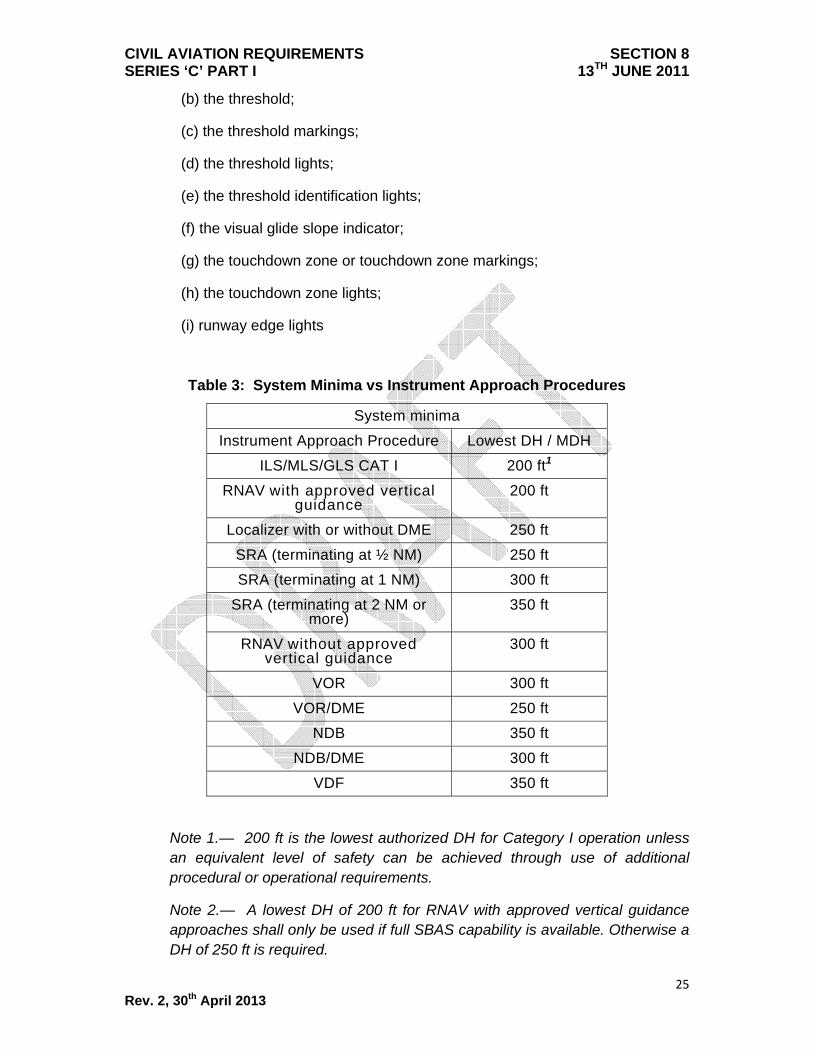
Table 3: System Minima vs Instrument Approach Procedures
System minima
Instrument Approach Procedure Lowest DH / MDH ILS/MLS/GLS CAT I 200 ft1
RNAV with approved vertical guidance
200 ft
Localizer with or without DME 250 ft SRA (terminating at ½ NM) 250 ft SRA (terminating at 1 NM) 300 ft
SRA (terminating at 2 NM or more)
350 ft
RNAV without approved vertical guidance
300 ft
VOR 300 ft VOR/DME 250 ft
NDB 350 ft NDB/DME 300 ft
VDF 350 ft
Note 1.— 200 ft is the lowest authorized DH for Category I operation unless an equivalent level of safety can be achieved through use of additional procedural or operational requirements.
Note 2.— A lowest DH of 200 ft for RNAV with approved vertical guidance approaches shall only be used if full SBAS capability is available. Otherwise a DH of 250 ft is required.

CIVIL AVIATION REQUIREMENTS SECTION 8 SERIES ‘C’ PART I 13TH JUNE 2011
26 Rev. 2, 30th April 2013
11.3.7 Determination of RVR/CMV/Visibility minima for Category 1, APV and non-precision approaches. The minimum RVR/CMV/Visibility shall be the highest of the values derived from Table 4 or Table 5, but not greater than the maximum values shown in Table 5 where applicable. The values in Table 4 are derived from the formula below with the length of the approach lighting system taken into account as part of the formula for derivation of RVR ;
Required RVR/Visibility (m) =
HATh (m) - the length of the approach lights
(m) tan (approach slope)
Table 4: Lowest Straight-in Approach Minima for Instrument Approach and Landing Operations Other Than CAT II or CAT III
DH or MDH (ft)
Class of Lighting Facility
DH or MDH (ft)
Class of Lighting Facility
FALS
IALS
BALS
NALS FALS
IALS
BALS
NALS
(metres) (metres)
See para 11.3.9. for RVR < 750 m
See para 11.3.9. for RVR < 750 m
200 - 210 550 750 1000 1200 541 - 560 1800 2100 2300 2500
211 - 220 550 800 1000 1200 561 - 580 1900 2200 2400 2600
221 - 230 550 800 1000 1200 581 - 600 2000 2300 2500 2700
231 - 240 550 800 1000 1200 601 - 620 2100 2400 2600 2800
241 - 250 550 800 1000 1300 621 - 640 2200 2500 2700 2900
251 - 260 600 800 1100 1300 641 - 660 2300 2600 2800 3000
261 - 280 600 900 1100 1300 661 - 680 2400 2700 2900 3100
281 - 300 650 900 1200 1400 681 - 700 2500 2800 3000 3200
301 - 320 700 1000 1200 1400 701 - 720 2600 2900 3100 3300
321 - 340 800 1100 1300 1500 721 - 740 2700 3000 3200 3400
341 - 360 900 1200 1400 1600 741 - 760 2700 3000 3300 3500
361 - 380 1000 1300 1500 1700 761 - 800 2900 3200 3400 3600
381 - 400 1100 1400 1600 1800 801 - 850 3100 3400 3600 3800

CIVIL AVIATION REQUIREMENTS SECTION 8 SERIES ‘C’ PART I 13TH JUNE 2011
27 Rev. 2, 30th April 2013
401 - 420 1200 1500 1700 1900 851 - 900 3300 3600 3800 4000
421 - 440 1300 1600 1800 2000 901 - 950 3600 3900 4100 4300
441 - 460 1400 1700 1900 2100 951 - 1000 3800 4100 4300 4500
461 - 480 1500 1800 2000 2200 1001 - 1100 4100 4400 4600 4900
481 - 500 1500 1800 2100 2300 1101 - 1200 4600 4900 5000 5000
501 - 520 1600 1900 2100 2400 1201 and above 5000 5000 5000 5000
521 - 540 1700 2000 2200 2400
Table 5: Minimum and Maximum RVR for Instrument Approaches down to CAT I Minima
Facility/Conditions RVR/CMV (m)
Aeroplane Category
A B C D
ILS/MLS/GLS, PAR, and RNAVwith approved vertical guidance
Min According to Table 4
Max 1500 1500 2400 2400
NDB, NDB/DME, VOR, VOR/DME, LOC, LOC/DME, VDF, SRA, RNAVwithout approved vertical guidance with a procedure which fulfills the critera in paragraph 11.3.8(b)
Min 750 750 750 750
Max 1500 1500 2400 2400
For NDB, NDB/DME, VOR, VOR/DME, LOC, LOC/DME, VDF, SRA, RNAVwithout approved vertical guidance:
- Not fulfilling the criteria in paragraph 11.3.8(b), or
- With a DH or MDH ≥ 1200 ft
Min 1000 1000 1200 1200
Max
According to Table 4, if flown using the CDFA technique, otherwise an add-on of 200/400 m applies to the values in Table 4 but not to result in a value exceeding 5000 m.

CIVIL AVIATION REQUIREMENTS SECTION 8 SERIES ‘C’ PART I 13TH JUNE 2011
28 Rev. 2, 30th April 2013
Table 5a: Failed or downgraded equipment – effect on landing minima
Failed or downgraded equipment 1
Effect on landing Minima
CAT IIIB2
CAT IIIA CAT II CAT I Non precision
ILS standby transmitter Not allowed No effect
Outer marker No effect if replaced by published equivalent position
Not applicable
Middle marker No effect No effect
Touchdown zone RVR assessment system
May be temporarily replaced with midpoint RVR
No effect
Midpoint or stopend (roll-out) RVR
No effect
Anemometer for runway in use
No effect if other ground source available
Ceilometer No effect
Approach lights Not allowed for DH>50 ft
Not allowed
Minima as for nil facilities
Approach lights except the last 210 m
No effect Not allowed
Minima as for nil facilities
Approach lights except the last 420 m
No effect Minima as for intermediate
facilities
Standby power for approach lights
No effect
Whole runway lighting system Not allowed Day – minima as for nil facilities
Night – not allowed
Edge lights Day only; Night - not allowed
Failed or downgraded equipment 1
Effect on Landing Minima
CAT CAT IIIA CAT II CAT I Non

CIVIL AVIATION REQUIREMENTS SECTION 8 SERIES ‘C’ PART I 13TH JUNE 2011
29 Rev. 2, 30th April 2013
IIIB2 precision
Centreline lights Day – RVR 300 m
Night – not allowed
Day – RVR
300 m
Night – RVR
550 m
No effect
Centreline lights spacing increased to 30 m
RVR 150m
No effect
Touchdown zone lights Day – RVR 200m
Night – RVR 300m
Day - RVR 300m
Night – RVR 550m
No effect
Standby power for runway lights
Not allowed No effect
Taxiway light system No effect – except delays due reduced movement rate
Note1 – Conditions applicable to Table 5a:
(a) multiple failures of runway lights other than indicated in Table 5a are not acceptable.
(b) deficiencies of approach and runway lights are treated separately.
(c) Category II or III operations. A combination of deficiencies in runway lights and RVR assessment equipment is not allowed.
(d) failures other than ILS affect RVR only and not DH.
Note 2 – For CAT IIIB operations with no DH, an operator shall ensure that, for aeroplanes authorized to conduct no DH operations with the lowest RVR limitations, the following applies in addition to the content of Table 5a:
(a) RVR. At least one RVR value must be available at the aerodrome;
(b) runway lights

CIVIL AVIATION REQUIREMENTS SECTION 8 SERIES ‘C’ PART I 13TH JUNE 2011
30 Rev. 2, 30th April 2013
(i) no runway edge lights, or no centerline lights – Day – RVR 200 m; Night – not allowed
(ii) no TDZ lights – no restrictions;
(iii) no standby power to runway lights – Day RVR 200 m; Night - not allowed
Table 6: Approach Lighting Systems
Class of facility Length, configuration and intensity of approach lights
FALS (full approach light system) ICAO: Precision approach CAT I lighting system (HIALS >720m) distance coded centreline, barrette centerline
IALS (intermediate approach light system) ICAO: Simple approach lighting system (HIALS 420-719m) single source, barrette
BALS (basic approach light system) Any other approach lighting system (HIALS, MIALS or ALS 210-419m)
NALS (no approach light system) Any other approach lighting system (HIALS, MIALS or ALS <210m) or no approach lights
11.3.8 In order to qualify for the lowest allowable values of RVR detailed in Table 4 (applicable to each approach grouping), the instrument approach procedures should be flown as an instrument approach and landing operation and shall meet at least the following facility requirements and associated conditions:
(a) Instrument approaches procedures with a designated vertical profile which does not require a rate of descent greater than 1000 feet per minute, unless other approach angles are approved by DGCA, where the facilities are:
i) ILS/MLS/GLS/PAR; or
ii) RNAV with approved vertical guidance; and
where the final approach track is offset by not more than 15 degrees for Category A and B aeroplanes or by not more than 5 degrees for Category C and D aeroplanes.
(b) Instrument approach procedures flown using the CDFA technique with a nominal vertical profile which does not require

CIVIL AVIATION REQUIREMENTS SECTION 8 SERIES ‘C’ PART I 13TH JUNE 2011
31 Rev. 2, 30th April 2013
a rate of descent greater than 1 000 feet per minute, unless other approach angles are approved by DGCA, where the facilities are NDB, NDB/DME, VOR, VOR/DME, LOC,LOC/DME, VDF, SRA or RNAV/LNAV, with a final approach segment of at least 3 NM, which also fulfill the following criteria:
i) the final approach track is offset by not more than 15 degrees for Category A and B aeroplanes or by not more than 5 degrees for Category C and D aeroplanes; and
ii) the FAF or another appropriate fix where descent is initiated is available, or distance to THR is available by FMS/RNAV or DME; and
ii) if the MAPt is determined by timing, the distance from FAF to THR is < 8 NM.
11.3.9 An RVR as low as 550 m as indicated in Table 4 may be used for:
(a) Category I operations to runways with FALS (see Table 6), runway touchdown zone lights (RTZL) and runway centre line lights (RCLL); or
(b) Category I operations to runways without RTZL and RCLL when an approved HUDLS, or equivalent approved system, or when conducting a coupled approach or flight-director-flown approach to the DH; or
(c) RNAV with approved vertical guidance approach procedures to runways with FALS, RTZL and RCLL
when using an approved HUD.
11.4 Precision Approach – Category II Operations
11.4.1 A Category II operation is a precision instrument approach and landing using ILS with:
(a) A decision height below 200 ft but not lower than 100 ft; and
(b) A runway visual range of not less than 300 m.
11.4.2 Decision Height. An operator must ensure that the decision height for Category II operations is not lower than:
(a) The minimum decision height specified in the AFM, if stated; or
(b) The minimum height to which the precision approach aid can be used without the required visual reference; or

CIVIL AVIATION REQUIREMENTS SECTION 8 SERIES ‘C’ PART I 13TH JUNE 2011
32 Rev. 2, 30th April 2013
(c) The OCH for the category of aeroplane; or
(d) The decision height to which the flight crew is authorised to operate; or
(e) 100 ft.
whichever is higher.
11.4.3 Visual reference. A pilot may not continue an approach below either the Category II decision height determined in accordance with Para 11.4.2 above unless visual reference containing a segment of at least 3 consecutive lights being the centre line of the approach lights, or touchdown zone lights, or runway centre line lights, or runway edge lights, or a combination of these is attained and can be maintained. This visual reference must include a lateral element of the ground pattern, i.e. an approach lighting crossbar or the landing threshold or a barrette of the touchdown zone lighting.
11.4.4 Required RVR. The lowest minima to be used by an operator for Category II operations is 300 m for a DH of 100 ft. If it is necessary to increase DH due to, for example, facility limitatioms or an increased OCH, then a corresponding increase in minimum RVR will be required as shown in Table 7.
Table 7: RVR for Category II operations minima
Decision Height Category II operations minima (RVR) coupled to below DH1
RVR/aeroplane Category A, B and C
RVR/aeroplane Category D
100 ft - 120 ft 300 m 300 m2 / 350 m
121ft - 140 ft 400 m 400 m
141 ft – 199 ft 450 m 450 m
Note1 - The reference to “Coupled to below DH” in this table means
continued use of the automatic flight control system down to a height which is not greater than 80 per cent of the applicable DH. Thus airworthiness requirements may, through minimum engagement height for the automatic flight control system, affect the DH to be applied.
Note 2- For a CAT D aeroplane conducting an autoland, 300 m may be used.

CIVIL AVIATION REQUIREMENTS SECTION 8 SERIES ‘C’ PART I 13TH JUNE 2011
33 Rev. 2, 30th April 2013
11.5 Precision Approach – Category III Operations
11.5.1 Category III operations are subdivided as follows:
(a) Category III A operations. A precision instrument approach and landing using ILS with:
(i) a decision height lower than 100 ft; and
(ii) a runway visual range not less than 175 m.
(b) Category III B operations. A precision instrument approach and landing using ILS with:
(i) a decision height lower than 100 ft, or no decision height; and
(ii) a runway visual range lower than 175 m but not less than 50 m.
Note: Where the decision height (DH) and runway visual range (RVR) do not fall within the same Category, the RVR will determine in which Category the operation is to be considered.
11.5.2. Decision height. For operations in which a decision height is used, an operator must ensure that the decision height is not lower than:
(a) the minimum decision height specified in the AFM, if stated; or
(b) the minimum height to which the precision approach aid can be used without the required visual reference; or
(c) the decision height to which the flight crew is authorised to operate.
11.5.3. No decision height operations. Operations with no decision height may only be conducted if:
(a) the operation with no decision height is authorised in the AFM; and
(b) the approach aid and the aerodrome facilities can support operations with no decision height; and
(c) the operator has an approval for CAT III operations with no decision height.
Note: In the case of a CAT III runway it may be assumed that operations with no decision height can be supported unless specifically restricted as published in the AIP or NOTAM.
11.5.4. Visual reference.
(a) For Category III A operations, and for Category III B operations conducted either with fail-passive flight control systems a pilot may not

CIVIL AVIATION REQUIREMENTS SECTION 8 SERIES ‘C’ PART I 13TH JUNE 2011
34 Rev. 2, 30th April 2013
continue an approach below the decision height determined in accordance with Para 11.5.2. above unless a visual reference containing a segment of at least three consecutive lights being the centreline of the approach lights, or touchdown zone lights, or runway centreline lights, or runway edge lights, or a combination of these is attained and can be maintained.
(b) For Category III B operations conducted either with fail-operational flight control systems or with a fail operational hybrid landing system using a decision height a pilot may not continue an approach below the decision height, determined in accordance with Para 11.5.2. above, unless a visual reference containing at least one centreline light is attained and can be maintained.
(c) For Category III B operations conducted either with fail-operational flight control systems or with a fail operational hybrid landing system without a decision height, there are no requirements for a visual verification prior to landing.
11.5.5. Required RVR. The lowest minima to be used by an operator for Category III operations depend on the decision height and aeroplane systems as shown in Table 8 below:
Table 8: RVR for Category III operations minima
Category Decision Height Roll-out control/guidance system RVR
IIIA Less than 100 ft Not required 175 m
IIIB Less than 100 ft Fail-passive 150 m
IIIB Less than 50 ft Fail-passive 125 m
IIIB Less than 50 ft or no DH Fail-operational 1 50 m
Note 1 – The fail-operational system referred to may consist of a fail operational hybrid system
12. CIRCLING APPROACH MINIMA
Circling approach and the associated minima will be authorized for Operators by Flight Standards Directorate as per the training programme implemented by Operators.
CIVIL AVIATION REQUIREMENTS SECTION 8 SERIES ‘C’ PART I 13TH JUNE 2011
35 Rev. 2, 30th April 2013
13. VISUAL APPROACH
An operator shall not use a visibility/RVR lower than the associated non-precision approach minima for that runway for a visual approach. If visual approach is requested for a runway which has only a circling approach, the ground visibility should not be less than 5 Km.
14. AERODROME OPERATING MINIMA – TAKE OFF 14.1 Take-off minima established by the operator must be expressed as visibility or
RVR limits, taking into account all relevant factors for each aerodrome planned to be used and the aeroplane characteristics. Where there is a specific need to see and avoid obstacles on departure and/or for a forced landing, additional conditions (e.g. ceiling) must be specified.
14.2 The PIC shall not commence take-off unless the weather conditions at the aerodrome of departure are equal to or better than applicable minima for landing at that aerodrome unless a suitable take-off alternate aerodrome is available. The take-off alternate aerodrome should have weather conditions and facilities suitable for landing the aeroplane in normal and non-normal configurations pertinent to the operation and shall be specified in the Operational Flight Plan. The take-off alternate weather (actual and forecast) shall not be less than ILS CAT I minima. The take-off alternate aerodrome should be located within the following distance from the aerodrome of departure:
(a) Aeroplanes with two engines: not more than a distance equivalent to one hour flight time at the single engine cruise speed;
(b) Aeroplanes with three or more engines: not more than a distance equivalent to two hours flight time at the one engine inoperative cruise speed
14.3 Visual reference.
The take-off minima must be selected to ensure sufficient guidance to control the aeroplane in the event of both a discontinued take-off in adverse circumstances and a continued take-off after failure of the critical power unit.
14.4 Required RVR/Visibility
For multi-engine aeroplanes, whose performance is such that, in the event of a critical power unit failure at any point during take-off, the aeroplane can either stop or continue the take-off to a height of 1500 ft above the aerodrome while clearing obstacles by the required margins, the take-off minima established by an operator must be expressed as RVR/Visibility values not lower than those

CIVIL AVIATION REQUIREMENTS SECTION 8 SERIES ‘C’ PART I 13TH JUNE 2011
36 Rev. 2, 30th April 2013
given in the table below. Use of these minima is based on the following factors:
14.4.1 Flight characteristics and cockpit instrumentation typical of multi-engine turbine aircraft;
14.4.2 Comprehensive programmes for crew qualification which address use of the
specified minima; 14.4.3 Comprehensive programmes for airworthiness, with any necessary equipment
operational (MEL); 14.4.5 Availability of specified facilities for the respective minima, including
programmes for assurance of the necessary reliability and integrity; 14.4.6 Availability of air traffic services to ensure separation of aircraft and timely and
accurate provision of weather, NOTAM, and other safety information; 14.4.7 Standard runway, airport, obstruction clearance, surrounding terrain, and
other characteristics typical of major facilities serving scheduled international operations;
14.4.8 Routine low visibility weather conditions (e.g. fog, precipitation, haze, wind
components, etc.) which do not require special consideration; and 14.4.9 Availability of alternate courses of action in the event of emergency situations.
Table 9 : RVR/Visibility for Take-off (Commercial Transport Aeroplanes)
Take-off RVR/Visibility
Facilities RVR/VIS 1
Cat A, B, C & D
Adequate Visual reference 2
(Day only) 500m
Runway edge lights or Runway centreline markings 3 400 m
Runway edge lights and Runway centreline markings 3 300 m

CIVIL AVIATION REQUIREMENTS SECTION 8 SERIES ‘C’ PART I 13TH JUNE 2011
37 Rev. 2, 30th April 2013
Runway edge lights and Runway centreline lights
200 m (Cat A, B and C)
250 m (Cat D)
Runway edge lights and Runway centreline lights and relevant RVR information 4
150 m (Cat A,B and C)
200 m (Cat D)
High intensity Runway edge lights and Runway centreline lights (spacing 15 m or less) and relevant RVR information 4
125 m (Cat A, B and C)
150 m (Cat D)
Note 1 – The TDZ RVR/VIS may be assessed by the pilot
Note 2 - Adequate Visual reference means, that a pilot is able to continuously identify the take-off surface and maintain directional control.
Note 3 - For night operations at least runway edge lights or centreline lights and runway end lights are available.
Note 4 - The required RVR must be achieved for all relevant RVR reporting points (touchdown, mid- point and stop-end/roll-out). The governing RVR shall be the lowest of the reported RVRs
15. This CAR supersedes CAR Section 7 Series X Part I Pilot Authorisation for ILS Category II and Category III Operations, Operations Circular 1/2008 Approval of Instructor/Examiner to carry our check from Observer Seat for Pilot Authorisation for Cat II/III AB Operations, Operations Circular 3/2008 ILS Cat II/III Aircraft Training.

CIVIL AVIATION REQUIREMENTS SECTION 8 SERIES ‘C’ PART I 13TH JUNE 2011
38 Rev. 2, 30th April 2013
Annexure
ADVERSE WEATHER /MONSOON OPERATIONS 1. Background Adverse weather is an integral part of flight operations. Adverse weather prevails in one part of an operator’s network or another at different times of the year. In India, monsoon period is a defined period of adverse weather. 2. Purpose: Despite the annual occurrence and predicted regularity of the Indian Monsoon, aviation incidents/ accidents occur every year. Analysis has shown that most of the incidents and accidents, that have occurred, were not generally attributable to inadequacies in aircraft performance but occurred mostly due to various deficiencies/shortcomings of the human element. Operating techniques applicable to each aircraft, under various generic adverse weather conditions, exist in flight manuals and must be adhered to. However, to ensure an enhanced level of safety, the reinforcement of these operating practices in the context of the Indian Monsoon with relevant, specific and mandatory regulatory guidelines is essential. Operators are to ensure that only pilots qualified as per this Annexure to CAR are detailed for flights into adverse weather/ monsoon affected regions. 3. Applicability: Indian registered aircraft and Indian operators 4. Pilots who have Obtained Command Rating for the First Time: Pilots, who have obtained their command rating on Jet Transport aircraft for the first time, will fall under this category, even if they have flown earlier in Turbo-prop aircraft. The following additional criteria must be fulfilled:
(a) Should have operated as a P2 during a minimum of one monsoon season prior to obtaining PIC rating for the first time.
(b) Should have at least 100 hours PIC experience on type before being
released to fly as PIC during adverse weather/monsoon conditions unless the pilot has a minimum of three monsoon seasons as P2 on type prior to obtaining PIC rating for the first time. In cases where a PIC is short of the 100 hours requirement or his endorsement has been obtained prior to or during

CIVIL AVIATION REQUIREMENTS SECTION 8 SERIES ‘C’ PART I 13TH JUNE 2011
39 Rev. 2, 30th April 2013
adverse weather/monsoons, the PIC may continue to fly from LHS with Examiners/Instructors/Check Pilots during adverse weather/monsoon conditions till they achieve 100 hours.
Note: For the purpose of this circular, 100 hours of PIC must include actual time in the left seat and NOT include hours logged as a cruise captain. Such flying would maintain his continuity and could be covered as “P1 Performance Monitoring”. Operators who do not have any Training Captains shall get FSD approval for their qualified and experienced Pilots having a minimum of 500 Hrs PIC experience on type, to occupy the RHS as PIC for non-adverse weather/monsoon qualified Pilots and give guidance and help making decisions during adverse weather/monsoon conditions. 5. Adverse Weather/Monsoon Training and Checks All Operators are to provide adverse weather/monsoon ground training as below to all their pilots irrespective of the fact that they may have flown during previous monsoon periods. All pilots are to undergo simulator training and checks as below before they are released to fly as PIC on a new type in actual or forecast, adverse weather/ monsoon conditions
(a) Ground Training Ground training shall cover, but not be limited to:
(i) Aircraft Performance during Take-off and Landing with specific emphasis on wet and contaminated runway conditions.
(ii) Calculation of Take-off and Landing field lengths and impact of individual
failure events (type specific).
(iii) Use of Weather Radar (type specific)
(iv) Techniques of Weather Avoidance.
(v) Indian Monsoon climatology
(vi) ALAR and Adverse Weather Tool Kit
(b) Simulator Training: (i) Two hours simulator training (in the form of LOFT) for adverse
weather/monsoon operations covering all aspects of adverse weather/monsoon conditions likely to be encountered en-route and in terminal areas covering aircraft performance related to wet/ contaminated runway conditions combined with MEL dispatch. Increased emphasis on landing performance should be given including assessment of landing

CIVIL AVIATION REQUIREMENTS SECTION 8 SERIES ‘C’ PART I 13TH JUNE 2011
40 Rev. 2, 30th April 2013
distance required in reduced braking effectiveness vs. actual Landing Distance Available (Safety Margins).
(ii) Two hours simulator check for adverse weather/monsoon operations to
cover pre-monsoon, monsoon and post monsoon weather .
(c) Aircraft not having Simulator (i) Pilots of such Operators will undergo ground training as given above. This
training should be arranged as close as possible to the onset of Monsoon season as forecast by the Indian Meteorology Department.
(ii) Two sector Route Check on aircraft. The check has to be done in actual
adverse weather/ rain conditions for landing.
5. General Conditions: (i) Minimum total cockpit experience level of the crew as PIC and Co-Pilot should
not be less than 500 hours on type. (ii) No supervised take-offs and landings in actual adverse weather/monsoon
conditions. (iii) Approach briefing prior to Top of Descent shall include wet/contaminated
Actual Landing Distance calculation. Scheduled Operators shall prepare a quick analysis table for use during normal operations for wet/contaminated ALD and 1.15*ALD in view of the high cockpit work-load environment.
(iv) ILS approaches are to be preferred to non-precision approaches. In case of non-precision approaches, emphasis must be given on CDFA.
(v) Greater emphasis on stabilized approaches (Refer Operations Circular No. 1 of 2003 on “ALAR India Training Tool Kit and Circular No.9 of 2009 – Standard Operating Procedures).
(vi) PANS OPS procedures for speed control in terminal areas must be followed. (vii) Flight Manual limitations and Company SOPs must be strictly adhered to. (viii)Go around procedure in case of wind shear and stall and recovery procedure
must be reviewed as per Operations Circular 2 of 2001. (ix) All Operators are required to follow a non-reprisal policy for Go around and
Diversion, (x) Documentation about upset recovery technique for specific airplane must be
reviewed. (xi) Full flap landing and adequate usage of Reverse thrust and consideration of
extra en-route/ terminal fuel computation shall be adhered to. (Type specific manufacturer’s guidance accepted)
6. MEL Requirements
The following equipment shall be serviceable during adverse weather/monsoon conditions operations in Indian Airspace.:
(a) All deceleration devices including Thrust reversers must be serviceable.
(b) Anti-skid system must be serviceable.

CIVIL AVIATION REQUIREMENTS SECTION 8 SERIES ‘C’ PART I 13TH JUNE 2011
41 Rev. 2, 30th April 2013
(c) Wind shield wipers (where fitted) on both sides must be serviceable. (d) Anti – icing and de-icing must be serviceable. (e) At least one Weather radar system must be serviceable. (f) Groove on tyres must be visible out of base stations.
The following items even though un-serviceable, could be accepted “to return direct to base station for maintenance” (i.e. one landing only) subject to acceptable weather conditions at departure and destination station”.
(a) One Thrust reverser provided other decelerating devices are serviceable – Subject to additional margin of minimum 1000 feet to field length requirement for take-off and landing.
(b) Anti-Skid system – Subject to performance limitations. (c) Wind-shield Wipers (where fitted) – Subject to the PIC side (LHS) being
serviceable. (d) Anti-icing and De-icing – Subject to performance limitations.
Note 1: Clubbing of 6 (c) and (d) is not permitted. So also, any system degradation causing impact on Flight Controls/Thrust Reversal/Anti-skid must be carefully weighed. Note 2: The above waivers to the MEL restrictions will in any case never be applied if the MEL/ other regulatory requirements are not permitting the same for any other specific operations. Note 3: For Simulator Monsoon Training and checks: the ADL must be revised to reflect the following functions must be operative: • Weather Radar.
• Appropriate Hi-Fidelity Special Effects for weather, turbulence/ windshear, wet/contaminated runway etc. as applicable.