Integrated Skills in English (ISE) Guide for Students — ISE II (B2)
Upload
khangminh22Category
view
3download
0
Cisco ISE 2.7 Admin Guide: Asset Visibility
Asset Visibility
Administrative Access to Cisco ISE Using an External Identity StoreIn Cisco ISE, you can authenticate administrators via an external identity store such as Active Directory,LDAP, or RSA SecureID. There are two models you can use to provide authentication via an external identitystore:
• External Authentication and Authorization—There are no credentials that are specified in the local CiscoISE database for the administrator, and authorization is based on external identity store group membershiponly. This model is used for Active Directory and LDAP authentication.
• External Authentication and Internal Authorization—The administrator’s authentication credentials comefrom the external identity source, and authorization and administrator role assignment take place usingthe local Cisco ISE database. This model is used for RSA SecurID authentication. This method requiresyou to configure the same username in both the external identity store and the local Cisco ISE database.
During the authentication process, Cisco ISE is designed to “fall back” and attempt to perform authenticationfrom the internal identity database, if communication with the external identity store has not been establishedor if it fails. In addition, whenever an administrator for whom you have set up external authentication launchesa browser and initiates a login session, the administrator still has the option to request authentication via theCisco ISE local database by choosing “Internal” from the Identity Store drop-down selector in the logindialog.
Administrators who belong to a Super Admin group, and are configured to authenticate and authorize usingan external identity store, can also authenticate with the external identity store for CLI access.
You can configure this method of providing external administrator authentication only via the Admin portal.The Cisco ISE Command Line Interface (CLI) does not feature these functions.
Note
If your network does not already have one or more existing external identity stores, ensure that you haveinstalled the necessary external identity stores and configured Cisco ISE to access those identity stores.
External Authentication and AuthorizationBy default, Cisco ISE provides internal administrator authentication. To set up external authentication, youmust create a password policy for the external administrator accounts that you define in the external identitystores. You can then apply this policy to the external administrator groups that eventually become a part ofthe external administrator RBAC policy.
In addition to providing authentication via an external identity store, your network may also require you touse a Common Access Card (CAC) authentication device.
To configure external authentication, you must:
Cisco ISE 2.7 Admin Guide: Asset Visibility1
• Configure password-based authentication using an external identity store.
• Create an external administrator group.
• Configure menu access and data access permissions for the external administrator group.
• Create an RBAC policy for external administrator authentication.
Configure a Password-Based Authentication Using an External Identity Store
You must first configure password-based authentication for administrators who authenticate using an externalidentity store such as Active Directory or LDAP.
Procedure
Step 1 Choose Administration > System > Admin Access > Authentication.Step 2 On the Authentication Method tab, select Password Based and choose one of the external identity sources
you should have already configured. For example, the Active Directory instance that you have created.Step 3 Configure any other specific password policy settings that you want for administrators who authenticate using
an external identity store.Step 4 Click Save.
Create an External Administrator Group
You will need to create an external Active Directory or LDAP administrator group. This ensures that CiscoISE uses the username that is defined in the external Active Directory or LDAP identity store to validate theadministrator username and password that you entered upon login.
Cisco ISE imports the Active Directory or LDAP group information from the external resource and stores itas a dictionary attribute. You can then specify that attribute as one of the policy elements when it is time toconfigure the RBAC policy for this external administrator authentication method.
Procedure
Step 1 Choose Administration > System > Admin Access > Administrators > Admin Groups.
The External Groups Mapped column displays the number of external groups that are mapped to internalRBAC roles. You can click the number corresponding to a admin role to view the external groups (for example,if you click 2 displayed against Super Admin, the names of two external groups are displayed).
Step 2 Click Add.Step 3 Enter a name and optional description.Step 4 Choose the External radio button.
If you have connected and joined to an Active Directory domain, your Active Directory instance name appearsin the Name field.
Step 5 From the External Groups drop-down list box, choose the Active Directory group that you want to map forthis external administrator group.
Cisco ISE 2.7 Admin Guide: Asset Visibility2
Asset VisibilityConfigure a Password-Based Authentication Using an External Identity Store

Click the “+” sign to map additional Active Directory groups to this external administrator group.
Step 6 Click Save.
Create an Internal Read-Only Admin
Procedure
Step 1 Choose Administration > System > Admin Access > Administrators > Admin Users .Step 2 Click Add and select Create An Admin User.Step 3 Check the Read Only check box to create a Read-Only administrator.
Map External Groups to the Read-Only Admin Group
Procedure
Step 1 Choose Administration > Identity Management > External Identity Sources to configure the externalauthentication source. See the Manage Users and External Identity Sources chapter for more information.
Step 2 Click the required external identity source, such as Active Directory or LDAP, and then retrieve the groupsfrom the selected identity source.
Step 3 Choose Administration > System > Admin Access > Authentication to map the authentication method forthe admin access with the identity source.
Step 4 Choose Administration > System > Admin Access > Administrators > Admin Groups and select ReadOnly Admin group.
Step 5 Check the Type External check box and select the required external groups for whom you intend to provideread-only privileges.
Step 6 Click Save.An external group that is mapped to a Read-Only Admin group cannot be assigned to any other admin group.
Configure Menu Access and Data Access Permissions for the External Administrator Group
Youmust configure menu access and data access permissions that can be assigned to the external administratorgroup.
Procedure
Step 1 Choose Administration > System > Admin Access > Permissions.Step 2 Click one of the following:
Cisco ISE 2.7 Admin Guide: Asset Visibility3
Asset VisibilityCreate an Internal Read-Only Admin

• Menu Access—All administrators who belong to the external administrator group can be grantedpermission at the menu or submenu level. Themenu access permission determines the menus or submenusthat they can access.
• Data Access—All administrators who belong to the external administrator group can be granted permissionat the data level. The data access permission determines the data that they can access.
Step 3 Specify menu access or data access permissions for the external administrator group.Step 4 Click Save.
Create an RBAC Policy for External Administrator Authentication
In order to configure Cisco ISE to authenticate the administrator using an external identity store and to specifycustom menu and data access permissions at the same time, you must configure a new RBAC policy. Thispolicy must have the external administrator group for authentication and the Cisco ISE menu and data accesspermissions to manage the external authentication and authorization.
You cannot modify an existing (system-preset) RBAC policy to specify these new external attributes. If youhave an existing policy that you would like to use as a “template,” be sure to duplicate that policy, rename it,and then assign the new attributes.
Note
Procedure
Step 1 Choose Administration > System > Admin Access > Authorization > RBAC Policy.Step 2 Specify the rule name, external administrator group, and permissions.
Remember that the appropriate external administrator group must be assigned to the correct administratoruser IDs. Ensure that the administrator in question is associated with the correct external administrator group.
Step 3 Click Save.
If you log in as an administrator, and the Cisco ISE RBAC policy is not able to authenticate your administratoridentity, Cisco ISE displays an “unauthenticated” message, and you cannot access the Admin portal.
Configure Admin Access Using an External Identity Store for Authentication with InternalAuthorization
This method requires you to configure the same username in both the external identity store and the localCisco ISE database. When you configure Cisco ISE to provide administrator authentication using an externalRSA SecurID identity store, administrator credential authentication is performed by the RSA identity store.However, authorization (policy application) is still done according to the Cisco ISE internal database. Inaddition, there are two important factors to remember that are different from external authentication andauthorization:
• You do not need to specify any particular external administrator groups for the administrator.
Cisco ISE 2.7 Admin Guide: Asset Visibility4
Asset VisibilityCreate an RBAC Policy for External Administrator Authentication

• Youmust configure the same username in both the external identity store and the local Cisco ISE database.
Procedure
Step 1 Choose Administration > System > Admin Access > Administrators > Admin Users.Step 2 Ensure that the administrator username in the external RSA identity store is also present in Cisco ISE. Ensure
that you click the External option under Password.
You do not need to specify a password for this external administrator user ID, nor are you requiredto apply any specially configured external administrator group to the associated RBAC policy.
Note
Step 3 Click Save.
External Authentication Process Flow
When the administrator logs in, the login session passes through the following steps in the process:
1. The administrator sends an RSA SecurID challenge.
2. RSA SecurID returns a challenge response.
3. The administrator enters a user name and the RSA SecurID challenge response in the Cisco ISE logindialog, as if entering the user ID and password.
4. The administrator ensures that the specified Identity Store is the external RSA SecurID resource.
5. The administrator clicks Login.
Upon logging in, the administrator sees only the menu and data access items that are specified in the RBACpolicy.
External Identity SourcesThese pages enable you to configure and manage external identity sources that contain user data that CiscoISE uses for authentication and authorization.
LDAP Identity Source SettingsThe following table describes the fields on the LDAP Identity Sources page, which you can use to create anLDAP instance and connect to it. The navigation path for this page is:Administration > Identity Management> External Identity Sources > LDAP.
LDAP General Settings
The following table describes the fields in the General tab.
Cisco ISE 2.7 Admin Guide: Asset Visibility5
Asset VisibilityExternal Authentication Process Flow

Table 1: LDAP General Settings
Usage GuidelinesFields
Enter a name for the LDAP instance. This value isused in searches to obtain the subject DN andattributes. The value is of type string and themaximum length is 64 characters.
Name
Enter a description for the LDAP instance. This valueis of type string, and has a maximum length of 1024characters.
Description
You can choose any one of the following built-inschema types or create a custom schema:
• Active Directory
• Sun Directory Server
• Novell eDirectory
You can click the arrow next to Schema to viewthe schema details.
If you edit the attributes of the predefinedschema, Cisco ISE automatically creates aCustom schema.
Schema
The following fields can be edited only when you choose the Custom schema.Note
Enter a value to be used in searches to obtain thesubject DN and attributes. The value is of type stringand the maximum length is 256 characters.
Subject Objectclass
Enter the name of the attribute containing theusername in the request. The value is of type stringand the maximum length is 256 characters.
Subject Name Attribute
Enter CN or DN or any supported attribute in theGroup Name Attribute field.
• CN—To retrieve the LDAP Identity StoreGroups based on Common Name.
• DN—To retrieve the LDAP Identity StoreGroups based on Distinguished Name.
Group Name Attribute
Enter the attribute that contains the certificatedefinitions. For certificate-based authentication, thesedefinitions are used to validate certificates that arepresented by clients.
Certificate Attribute
Cisco ISE 2.7 Admin Guide: Asset Visibility6
Asset VisibilityLDAP Identity Source Settings

Usage GuidelinesFields
Enter a value to be used in searches to specify theobjects that are recognized as groups. The value is oftype string and the maximum length is 256 characters.
Group Objectclass
Specifies the attribute that contains the mappinginformation. This attribute can be a user or groupattribute based on the reference direction that ischosen.
Group Map Attribute
Click this radio button if the subject objects containan attribute that specifies the group to which theybelong.
Subject Objects Contain Reference To Groups
Click this radio button if the group objects contain anattribute that specifies the subject. This value is thedefault value.
Group Objects Contain Reference To Subjects
(Only available when you select the Group ObjectsContain Reference To Subjects radio button) Specifieshow members are sourced in the group memberattribute and defaults to the DN.
Subjects in Groups Are Stored in Member AttributeAs
By default, predefined attributes are used to collectuser information (such as, first name, last name, email,telephone, locality, and so on) for the followingbuilt-in schema types:
• Active Directory
• Sun Directory Server
• Novell eDirectory
If you edit the attributes of the predefined schema,Cisco ISE automatically creates a Custom schema.
You can also select the Custom option from theSchema drop-down list to edit the user informationattributes based on your requirements.
User Info Attributes
LDAP Connection Settings
The following table describes the fields in the Connection Settings tab.
Cisco ISE 2.7 Admin Guide: Asset Visibility7
Asset VisibilityLDAP Identity Source Settings

Table 2: LDAP Connection Settings
Usage GuidelinesFields
Check this option to enable the secondary LDAPserver to be used as a backup if the primary LDAPserver fails. If you check this check box, you mustenter configuration parameters for the secondaryLDAP server.
Enable Secondary Server
Primary and Secondary Servers
Enter the IP address or DNS name of the machine thatis running the LDAP software. The hostname cancontain from 1 to 256 characters or a valid IP addressexpressed as a string. The only valid characters forhostnames are alphanumeric characters (a to z, A toZ, 0 to 9), the dot (.), and the hyphen (-).
Hostname/IP
Enter the TCP/IP port number on which the LDAPserver is listening. Valid values are from 1 to 65,535.The default is 389, as stated in the LDAPspecification. If you do not know the port number,you can find this information from the LDAP serveradministrator.
Port
Check this check box to configure primary andsecondary LDAP server hostnames/IP and their portsfor each PSN.
When this option is enabled, a table listing all thenodes in the deployment is displayed. You need toselect the node and configure the primary andsecondary LDAP server hostname/IP and their portsfor the selected node.
Specify server for each ISE node
Anonymous Access—Click to ensure that searcheson the LDAP directory occur anonymously. The serverdoes not distinguish who the client is and will allowthe client read access to any data that is configured asaccessible to any unauthenticated client. In the absenceof a specific policy permitting authenticationinformation to be sent to a server, a client should usean anonymous connection.
Authenticated Access—Click to ensure that searcheson the LDAP directory occur with administrativecredentials. If so, enter information for the Admin DNand Password fields.
Access
Cisco ISE 2.7 Admin Guide: Asset Visibility8
Asset VisibilityLDAP Identity Source Settings

Usage GuidelinesFields
Enter the DN of the administrator. The Admin DN isthe LDAP account that has permission to search allrequired users under the User Directory Subtree andto search groups. If the administrator specified doesnot have permission to see the group name attributein searches, group mapping fails for users who areauthenticated by that LDAP server.
Admin DN
Enter the LDAP administrator account password.Password
Click to use SSL to encrypt communication betweenCisco ISE and the primary LDAP server. Verify thatthe Port field contains the port number used for SSLon the LDAP server. If you enable this option, youmust choose a root CA.
Secure Authentication
Choose a trusted root certificate authority from thedrop-down list to enable secure authentication with acertificate.
LDAP Server Root CA
Enter the number of seconds that Cisco ISE waits fora response from the primary LDAP server beforedetermining that the connection or authentication withthat server has failed. Valid values are 1 to 99. Thedefault is 10.
Server Timeout
Enter themaximumnumber of concurrent connections(greater than 0) with LDAP administrator accountpermissions that can run for a specific LDAPconfiguration. These connections are used to searchthe directory for users and groups under the UserDirectory Subtree and the Group Directory Subtree.Valid values are 1 to 99. The default is 20.
Max. Admin Connections
Check this check box and enter the desired value inthe Seconds text box to force the server to renewLDAP connection at the specified time interval. Thevalid range is from 1 to 60 minutes.
Force reconnect every N seconds
Click to test and ensure that the LDAP server detailsand credentials can successfully bind. If the test fails,edit your LDAP server details and retest.
Test Bind to Server
Failover
Click this option if you want Cisco ISE to alwaysaccess the primary LDAP server first forauthentications and authorizations.
Always Access Primary Server First
Cisco ISE 2.7 Admin Guide: Asset Visibility9
Asset VisibilityLDAP Identity Source Settings

Usage GuidelinesFields
If the primary LDAP server that Cisco ISE attemptsto contact cannot be reached, Cisco ISE attempts tocontact the secondary LDAP server. If you want CiscoISE to use the primary LDAP server again, click thisoption and enter a value in the text box.
Failback to Primary Server After
LDAP Directory Organization Settings
The following table describes the fields in the Directory Organization tab.
Table 3: LDAP Directory Organization Settings
Usage GuidelinesFields
Enter the DN for the subtree that contains all subjects.For example:
o=corporation.com
If the tree containing subjects is the base DN, enter:
o=corporation.com
or
dc=corporation,dc=com
as applicable to your LDAP configuration. For moreinformation, refer to your LDAP databasedocumentation.
Subject Search Base
Enter the DN for the subtree that contains all groups.For example:
ou=organizational unit, ou=next organizational unit,o=corporation.com
If the tree containing groups is the base DN, type:
o=corporation.com
or
dc=corporation,dc=com
as applicable to your LDAP configuration. For moreinformation, refer to your LDAP databasedocumentation.
Group Search Base
Cisco ISE 2.7 Admin Guide: Asset Visibility10
Asset VisibilityLDAP Identity Source Settings

Usage GuidelinesFields
Enter a MACAddress format for Cisco ISE to use forsearch in the LDAP database. MAC addresses ininternal identity sources are sourced in the formatxx-xx-xx-xx-xx-xx. MAC addresses in LDAPdatabases can be sourced in different formats.However, when Cisco ISE receives a host lookuprequest, Cisco ISE converts the MAC address fromthe internal format to the format that is specified inthis field.
Use the drop-down list to enable searching for MACaddresses in a specific format, where <format> canbe any one of the following:
• xxxx.xxxx.xxxx
• xxxxxxxxxxxx
• xx-xx-xx-xx-xx-xx
• xx:xx:xx:xx:xx:xx
The format you choose must match the format of theMAC address sourced in the LDAP server.
Search for MAC Address in Format
Enter the appropriate text to remove domain prefixesfrom usernames.
If, in the username, Cisco ISE finds the delimitercharacter that is specified in this field, it strips allcharacters from the beginning of the username throughthe delimiter character. If the username contains morethan one of the characters that are specified in the<start_string> box, Cisco ISE strips characters throughthe last occurrence of the delimiter character. Forexample, if the delimiter character is the backslash (\)and the username is DOMAIN\user1, Cisco ISEsubmits user1 to an LDAP server.
The <start_string> cannot contain thefollowing special characters: the poundsign (#), the question mark (?), thequotation mark (“), the asterisk (*), theright angle bracket (>), and the left anglebracket (<). Cisco ISE does not allow thesecharacters in usernames.
Note
Strip Start of Subject Name Up To the LastOccurrence of the Separator
Cisco ISE 2.7 Admin Guide: Asset Visibility11
Asset VisibilityLDAP Identity Source Settings

Usage GuidelinesFields
Enter the appropriate text to remove domain suffixesfrom usernames.
If, in the username, Cisco ISE finds the delimitercharacter that is specified in this field, it strips allcharacters from the delimiter character through theend of the username. If the username contains morethan one of the characters that are specified in thisfield, Cisco ISE strips characters starting with the firstoccurrence of the delimiter character. For example,if the delimiter character is @ and the username isuser1@domain, then Cisco ISE submits user1 to theLDAP server.
The <end_string> box cannot contain thefollowing special characters: the poundsign (#), the question mark (?), thequotation mark ("), the asterisk (*), theright angle bracket (>), and the left anglebracket (<). Cisco ISE does not allow thesecharacters in usernames.
Note
Strip End of Subject Name from the First Occurrenceof the Separator
LDAP Group Settings
Table 4: LDAP Group Settings
Usage GuidelinesFields
Choose Add > Add Group to add a new group orchoose Add > Select Groups From Directory toselect the groups from the LDAP directory.
If you choose to add a group, enter a name for thenew group. If you are selecting from the directory,enter the filter criteria, and click Retrieve Groups.Check the check boxes next to the groups that youwant to select and click OK. The groups that you haveselected will appear in the Groups page.
Add
Cisco ISE 2.7 Admin Guide: Asset Visibility12
Asset VisibilityLDAP Identity Source Settings

LDAP Attribute Settings
Table 5: LDAP Attribute Settings
Usage GuidelinesFields
Choose Add > Add Attribute to add a new attributeor choose Add > Select Attributes From Directoryto select attributes from the LDAP server.
If you choose to add an attribute, enter a name for thenew attribute. If you are selecting from the directory,enter the username and click Retrieve Attributes toretrieve the user’s attributes. Check the check boxesnext to the attributes that you want to select, and thenclick OK.
Add
LDAP Advanced Settings
The following table describes the field in the Advanced Settings tab.
Table 6: LDAP Advanced Settings
Usage GuidelinesFields
Check this check box to enable the user to change thepassword in case of password expiry or password resetwhile using PAP protocol for device admin andRADIUSEAP-GTCprotocol for network access. Userauthentication fails for the unsupported protocols.This option also enables the user to change thepassword on their next login.
Enable Password Change
Related TopicsLDAP Directory Service, on page 123LDAP User Authentication, on page 124LDAP User Lookup, on page 128Add LDAP Identity Sources, on page 129
RADIUS Token Identity Sources SettingsThe following table describes the fields on the RADIUS Token Identity Sources page, which you can use toconfigure and connect to an external RADIUS identity source. The navigation path for this page is:Administration > Identity Management > External Identity Sources > RADIUS Token.
Table 7: RADIUS Token Identity Source Settings
Usage GuidelinesFields
Enter a name for the RADIUS token server. Themaximum number of characters allowed is 64.
Name
Cisco ISE 2.7 Admin Guide: Asset Visibility13
Asset VisibilityRADIUS Token Identity Sources Settings

Usage GuidelinesFields
Enter a description for the RADIUS token server. Themaximum number of characters is 1024.
Description
Check this check box if your RADIUS identity sourceis a SafeWord server.
SafeWord Server
Check this check box to enable the secondaryRADIUS token server for Cisco ISE to use as abackup in case the primary fails. If you check thischeck box, you must configure a secondary RADIUStoken server.
Enable Secondary Server
Click this radio button if you want Cisco ISE toalways access the primary server first.
Always Access Primary Server First
Click this radio button to specify the amount of timein minutes that Cisco ISE can authenticate using thesecondary RADIUS token server if the primary servercannot be reached. After this time elapses, Cisco ISEreattempts to authenticate against the primary server.
Fallback to Primary Server after
Primary Server
Enter the IP address of the primary RADIUS tokenserver. This field can take as input a valid IP addressthat is expressed as a string. Valid characters that areallowed in this field are numbers and dot (.).
Host IP
Enter the shared secret that is configured on theprimary RADIUS token server for this connection.
Shared Secret
Enter the port number on which the primary RADIUStoken server is listening.
Authentication Port
Specify the time in seconds that Cisco ISE shouldwait for a response from the primary RADIUS tokenserver before it determines that the primary server isdown.
Server Timeout
Specify the number of attempts that Cisco ISE shouldmake to reconnect to the primary server beforemovingon to the secondary server (if defined) or droppingthe request if a secondary server is not defined.
Connection Attempts
Secondary Server
Enter the IP address of the secondary RADIUS tokenserver. This field can take as input a valid IP addressthat is expressed as a string. Valid characters that areallowed in this field are numbers and dot (.).
Host IP
Enter the shared secret configured on the secondaryRADIUS token server for this connection.
Shared Secret
Cisco ISE 2.7 Admin Guide: Asset Visibility14
Asset VisibilityRADIUS Token Identity Sources Settings
Usage GuidelinesFields
Enter the port number on which the secondaryRADIUS token server is listening. Valid values arefrom 1 to 65,535. The default is 1812.
Authentication Port
Specify the time in seconds that Cisco ISE shouldwait for a response from the secondary RADIUS tokenserver before it determines that the secondary serveris down.
Server Timeout
Specify the number of attempts that Cisco ISE shouldmake to reconnect to the secondary server beforedropping the request.
Connection Attempts
Related TopicsRADIUS Token Identity Sources, on page 147Add a RADIUS Token Server, on page 152
RSA SecurID Identity Source SettingsThe following table describes the fields on the RSA SecurID Identity Sources page, which you can use tocreate and connect to an RSA SecurID identity source. The navigation path for this page is:Administration >Identity Management > External Identity Sources > RSA SecurID.
RSA Prompt Settings
The following table describes the fields in the RSA Prompts tab.
Table 8: RSA Prompt Settings
Usage GuidelinesFields
Enter a text string to obtain the passcode.Enter Passcode Prompt
Enter a text string to request the next token.Enter Next Token Code
Enter a text string to request the PIN type.Choose PIN Type
Enter a text string to accept the system-generated PIN.Accept System PIN
Enter a text string to request an alphanumeric PIN.Enter Alphanumeric PIN
Enter a text string to request a numeric PIN.Enter Numeric PIN
Enter a text string to request the user to re-enter thePIN.
Re-enter PIN
RSA Message Settings
The following table describes the fields in the RSA Messages tab.
Cisco ISE 2.7 Admin Guide: Asset Visibility15
Asset VisibilityRSA SecurID Identity Source Settings

Table 9: RSA Messages Settings
Usage GuidelinesFields
Enter a text string to label the system PIN message.Display System PIN Message
Enter a text string to inform the user to remember thenew PIN.
Display System PIN Reminder
Enter a message that instructs users to enter onlynumbers for the PIN.
Must Enter Numeric Error
Enter a message that instructs users to enter onlyalphanumeric characters for PINs.
Must Enter Alpha Error
Enter a message that the users see when their PIN isaccepted by the system.
PIN Accepted Message
Enter a message that the users see when the systemrejects their PIN.
PIN Rejected Message
Enter a message that the users see when they enter anincorrect PIN.
User Pins Differ Error
Enter a message that the users see when the systemaccepts their PIN.
System PIN Accepted Message
Enter a message that the users see when the PIN thatthey specify does not fall within the range specifiedin the PIN length policy.
Bad Password Length Error
Related TopicsRSA Identity Sources, on page 153Cisco ISE and RSA SecurID Server Integration, on page 154Add RSA Identity Sources, on page 157
Cisco ISE UsersIn this chapter, the term user refers to employees and contractors who access the network regularly as wellas sponsor and guest users. A sponsor user is an employee or contractor of the organization who creates andmanages guest-user accounts through the sponsor portal. A guest user is an external visitor who needs accessto the organization’s network resources for a limited period of time.
You must create an account for any user to gain access to resources and services on the Cisco ISE network.Employees, contractors, and sponsor users are created from the Admin portal.
User IdentityUser identity is like a container that holds information about a user and forms their network access credentials.Each user’s identity is defined by data and includes: a username, e-mail address, password, account description,associated administrative group, user group, and role.
Cisco ISE 2.7 Admin Guide: Asset Visibility16
Asset VisibilityCisco ISE Users

User GroupsUser groups are a collection of individual users who share a common set of privileges that allow them toaccess a specific set of Cisco ISE services and functions.
User Identity GroupsA user’s group identity is composed of elements that identify and describe a specific group of users that belongto the same group. A group name is a description of the functional role that the members of this group have.A group is a listing of the users that belong to this group.
Default User Identity Groups
Cisco ISE comes with the following predefined user identity groups:
• Employee—Employees of your organization belong to this group.
• SponsorAllAccount—Sponsor users who can suspend or reinstate all guest accounts in the Cisco ISEnetwork.
• SponsorGroupAccounts—Sponsor users who can suspend guest accounts created by sponsor users fromthe same sponsor user group.
• SponsorOwnAccounts—Sponsor users who can only suspend the guest accounts that they have created.
• Guest—A visitor who needs temporary access to resources in the network.
• ActivatedGuest—A guest user whose account is enabled and active.
User RoleA user role is a set of permissions that determine what tasks a user can perform and what services they canaccess on the Cisco ISE network. A user role is associated with a user group. For example, a network accessuser.
User Account Custom AttributesCisco ISE allows you to restrict network access based on user attributes for both network access users andadministrators. Cisco ISE comes with a set of predefined user attributes and also allows you to create customattributes. Both types of attributes can be used in conditions that define the authentication policy. You canalso define a password policy for user accounts so that passwords meet specified criteria.
Custom User Attributes
You can configure more user-account attributes on the User CustomAttributes page (Administration > IdentityManagement > Settings > User Custom Attributes). You can also view the list of predefined user attributeson this page. You cannot edit the predefined user attributes.
Enter the required details in the User Custom Attributes pane to add a new custom attribute. The customattributes and the default values that you add on the User Custom Attributes page are displayed while addingor editing a Network Access user (Administration > Identity Management > Identities > Users > Add/Edit)or Admin user (Administration > System > Admin Access > Administrators > Admin Users > Add/Edit). Youcan change the default values while adding or editing a Network Access or Admin user.
You can select the following data types for the custom attributes on the User Custom Attributes page:
Cisco ISE 2.7 Admin Guide: Asset Visibility17
Asset VisibilityUser Groups

• String—You can specify the maximum string length (maximum allowed length for a string attributevalue).
• Integer—You can configure the minimum and maximum value (specifies the lowest and the highestacceptable integer value).
• Enum—You can specify the following values for each parameter:
• Internal value
• Display value
You can also specify the default parameter. The values that you add in the Display field are displayedwhile adding or editing a Network Access or Admin user.
• Float
• Password—You can specify the maximum string length.
• Long—You can configure the minimum and maximum value.
• IP—You can specify a default IPv4 or IPv6 address.
• Boolean—You can set either True or False as the default value.
• Date—You can select a date from the calendar and set it as the default value. The date is displayed inyyyy-mm-dd format.
Check theMandatory check box if you want to make an attribute mandatory while adding or editing a NetworkAccess or Admin user. You can also set default values for the custom attributes.
The custom attributes can be used in the authentication policies. The data type and the allowable range thatyou set for the custom attributes are applied to the custom attribute values in the policy conditions.
User Authentication SettingsNot all external identity stores allow network access users to change their passwords. See the section for eachidentity source for more information.
Network use password rules are configured on Administration > Identity Management > Settings > UserAuthentication Settings..
The following content has additional information about some of the fields on the Password Policy tab.
• Required Characters:
If you configure a user-password policy that requires upper or lowercase characters, and the user’slanguage does not support these characters, the user cannot set a password. To support UTF-8 characters,uncheck the following check box options:
• Lowercase alphabetic characters.
• Uppercase alphabetic characters
• Password Change Delta:
Specifies the minimum number of characters that must change when changing the current password toa new password. Cisco ISE does not consider changing the position of a character as a change.
Cisco ISE 2.7 Admin Guide: Asset Visibility18
Asset VisibilityUser Authentication Settings
For Example, if the password delta is 3, and the current password is "?Aa1234?", then "?Aa1567?"("5","6" and "7" are the three new characters) is a valid new password. "?Aa1562?" fails, since the "?","2",and "?" characters are in the current password. "Aa1234??" fails, because even though the characterpositions changed, the same characters are in the current password.
Password change delta also considers the previous X passwords, where X is the value of Password mustbe different from the previous versions. If your password delta is 3, and your password history is 2,then you must change 4 characters that are not part of the past 2 passwords.
• Dictionary words: Check this check box to restrict the use of any dictionary word, its characters inreverse order, or its letters replaced with other characters.
Substitution of "$" for "s", "@" for "a", "0" for "o", "1" for "l", "!" for "i", "3" for "e", is not permitted.For example, "Pa$$w0rd".
• Default Dictionary: Choose this option to use the default Linux dictionary in Cisco ISE. The defaultdictionary contains approximately 480,000 English words.
• Custom Dictionary: Choose this option to use your customized dictionary. Click Choose File toselect a custom dictionary file. The text file must be of newline-delimited words, .dic extension,and size less than 20 MB.
The end- users are required to change the password periodically failing to which the user account will bedisabled temporarily. You can use the Password Lifetime section to update the password reset interval andreminder. To set the lifetime of the password, check the Disable user account after __ days if passwordwas not changed check box and enter the number of days in the input box. To enable a reminder for passwordreset, check the Display reminder __ days prior to password expiration check box and enter the numberdays in the input value to send notification to the user before the password is expired.
The Account Disable Policy tab is where you configure rules about when to disable an existing user account.See Disable User Accounts Globally for more information.
Related TopicsUser Account Custom Attributes, on page 17Add Users, on page 20
Generate Automatic Password for Users and AdministratorsCisco ISE introduces a Generate Password option on the user and administrator creation page to generateinstant password adhering to Cisco ISE password policies. This helps the users or administrators to use thepassword generated by Cisco ISE than spending time in thinking of a safe password to be configured.
The Generate Password option is available in the following three locations of Cisco ISE web interface:
• Users—Administration > Identity Management > Identities > Users.
• Administrators—Administration > System > Admin Access > Administrators > Admin Users.
• Logged in Administrator(Current Administrator)—Settings > Account Settings > Change Password.
Internal User Operations•
Cisco ISE 2.7 Admin Guide: Asset Visibility19
Asset VisibilityGenerate Automatic Password for Users and Administrators

Add Users
Cisco ISE allows you to view, create, modify, duplicate, delete, change the status, import, export, or searchfor attributes of Cisco ISE users.
If you are using a Cisco ISE internal database, you must create an account for any new user who needs accessto resources or services on a Cisco ISE network.
Procedure
Step 1 Choose Administration > Identity Management > Identities > Users.
You can also create users by accessing the Work Centers > Device Administration > Identities > Userspage.
Step 2 Click Add (+) to create a new user.Step 3 Enter values for the fields.
Do not include !, %, :, ;, [, {, |, }, ], `, ?, =, <, >, \ and control characters in the username. Username with onlyspaces is also not allowed. If you use the Cisco ISE Internal Certificate Authority (CA) for BYOD, theusername that you provide here is used as the Common Name for the endpoint certificate. Cisco ISE InternalCA does not support "+" or "*" characters in the Common Name field.
Step 4 Click Submit to create a new user in the Cisco ISE internal database.
Export Cisco ISE User Data
You might have to export user data from the Cisco ISE internal database. Cisco ISE allows you to export userdata in the form of a password-protected csv file.
Procedure
Step 1 Choose Administration > Identity Management > Identities > Users.Step 2 Check the check box that corresponds to the user(s) whose data you want to export.Step 3 Click Export Selected.Step 4 Enter a key for encrypting the password in the Key field.Step 5 Click Start Export to create a users.csv file.Step 6 Click OK to export the users.csv file.
Import Cisco ISE Internal Users
You can import new user data into ISE with a csv file to create new internal accounts. A template csv file isavailable for download on the pages where you can import user accounts. You can import users onAdministration > Identity Management > Identities > Users. Sponsors can import users on the Sponsorportal. The Sponsor Portal Guide tells Sponsors how to import guest accounts. See the Configure AccountContent for Sponsor Account Creation section in Cisco ISE Admin Guide: Guest and BYOD for informationabout configuring the information types that the sponsor guest accounts use.
Cisco ISE 2.7 Admin Guide: Asset Visibility20
Asset VisibilityAdd Users

If the csv file contains custom attributes, the data type and the allowable range that you set for the customattributes will be applied for the custom attribute values during import.
Note
Procedure
Step 1 Choose Administration > Identity Management > Identities > Users.Step 2 Click Import to import users from a comma-delimited text file.
If you do not have a comma-delimited text file, click Generate a Template to create a csv file with theheading rows filled in.
Step 3 In the File text box, enter the filename containing the users to import, or click Browse and navigate to thelocation where the file resides.
Step 4 Check the Create new user(s) and update existing user(s) with new data check boxes if you want to bothcreate new users and update existing users.
Step 5 Click Save to save your changes to the Cisco ISE internal database.
We recommend that you do not delete all the network access users at a time, because this may lead to CPUspike and the services to crash, especially if you are using a very large database.
Note
Endpoint Settings
The following table describes the fields on the Endpoints page, which you can use to create endpoints andassign policies for endpoints. The navigation path for this page is: Work Centers > Network Access >Identities > Endpoints.
Table 10: Endpoint Settings
Usage GuidelinesFields
Enter the MAC address in hexadecimal format tocreate an endpoint statically.
The MAC address is the device identifier for theinterface that is connected to the Cisco ISE enablednetwork
MAC Address
Check this check box when you want to create anendpoint statically in the Endpoints page and the statusof static assignment is set to static.
You can toggle the status of static assignment of anendpoint from static to dynamic or from dynamic tostatic.
Static Assignment
Cisco ISE 2.7 Admin Guide: Asset Visibility21
Asset VisibilityEndpoint Settings

Usage GuidelinesFields
(Disabled by default unless the Static Assignment ischecked) Choose a matching endpoint policy fromthe Policy Assignment drop-down list.
You can do one of the following:
• If you do not choose a matching endpoint policy,but use the default endpoint policy Unknown,then the static assignment status is set to dynamicfor the endpoint that allows dynamic profilingof an endpoint.
• If you choose a matching endpoint policy otherthan Unknown, then the static assignment statusis set to static for that endpoint and the StaticAssignment check box is automatically checked.
Policy Assignment
(Disabled by default unless the Static groupAssignment is checked) Check this check box whenyou want to assign an endpoint to an identity groupstatically.
In you check this check box, the profiling service doesnot change the endpoint identity group the next timeduring evaluation of the endpoint policy for theseendpoints, which were previously assigneddynamically to other endpoint identity groups.
If you uncheck this check box, then the endpointidentity group is dynamic as assigned by the ISEprofiler based on policy configuration. If you do notchoose the Static Group Assignment option, then theendpoint is automatically assigned to the matchingidentity group the next time during evaluation of theendpoint policy.
Static Group Assignment
Cisco ISE 2.7 Admin Guide: Asset Visibility22
Asset VisibilityEndpoint Settings

Usage GuidelinesFields
Choose an endpoint identity group to which you wantto assign the endpoint.
You can assign an endpoint to an identity group whenyou create an endpoint statically, or when you do notwant to use the CreateMatching Identity Group optionduring evaluation of the endpoint policy for anendpoint.
Cisco ISE includes the following system createdendpoint identity groups:
• Blacklist
• GuestEndpoints
• Profiled
• Cisco IP-Phone
• Workstation
• RegisteredDevices
• Unknown
Identity Group Assignment
Related TopicsIdentified Endpoints, on page 229Create Endpoints with Static Assignments of Policies and Identity Groups, on page 224
Endpoint Import from LDAP Settings
The following table describes the fields on the Import from LDAP page, which you can use to import endpointsfrom an LDAP server. The navigation path for this page is: Work Centers > Network Access > Identities >Endpoints.
Table 11: Endpoint Import from LDAP Settings
Usage GuidelinesFields
Connection Settings
Enter the hostname, or the IP address of the LDAPserver.
Host
Enter the port number of the LDAP server. You canuse the default port 389 to import from an LDAPserver, and the default port 636 to import from anLDAP server over SSL.
Cisco ISE supports any configured portnumber. The configured value shouldmatch the LDAP server connection details.
Note
Port
Cisco ISE 2.7 Admin Guide: Asset Visibility23
Asset VisibilityEndpoint Import from LDAP Settings

Usage GuidelinesFields
Check the Enable Secure Connection check box toimport from an LDAP server over SSL.
Enable Secure Connection
Click the drop-down arrow to view the trusted CAcertificates.
The Root CA Certificate Name refers to the trustedCA certificate that is required to connect to an LDAPserver. You can add (import), edit, delete, and exporttrusted CA certificates in Cisco ISE.
Root CA Certificate Name
Check the Anonymous Bind check box to enable theanonymous bind.
You must enable either the Anonymous Bind checkbox, or enter the LDAP administrator credentials fromthe slapd.conf configuration file.
Anonymous Bind
Enter the distinguished name (DN) configured for theLDAP administrator in the slapd.conf configurationfile.
Admin DN format example: cn=Admin,dc=cisco.com, dc=com
Admin DN
Enter the password configured for the LDAPadministrator in the slapd.conf configuration file.
Password
Enter the distinguished name of the parent entry.
Base DN format example: dc=cisco.com, dc=com.
Base DN
Query Settings
Enter the query filter, which is used for importing theMAC address. For example, ieee802Device.
MAC Address objectClass
Enter the returned attribute name for import. Forexample, macAddress.
MAC Address Attribute Name
Cisco ISE 2.7 Admin Guide: Asset Visibility24
Asset VisibilityEndpoint Import from LDAP Settings
Usage GuidelinesFields
Enter the name of the LDAP attribute. This attributeholds the policy name for each endpoint entry that isdefined in the LDAP server.
When you configure the Profile Attribute Name field,consider the following:
• If you do not specify this LDAP attribute in theProfile Attribute Name field or configure thisattribute incorrectly, then endpoints are marked“Unknown” during an import operation, andthese endpoints are profiled separately to thematching endpoint profiling policies.
• If you configure this LDAP attribute in theProfile Attribute Name field, the attribute valuesare validated to ensure that the endpoint policymatches with an existing policy in Cisco ISE,and endpoints are imported. If the endpointpolicy does not match with an existing policy,then those endpoints will not be imported.
Profile Attribute Name
Enter the time in seconds between 1 and 60 seconds.Time Out [seconds]
Related TopicsIdentified Endpoints, on page 229Import Endpoints from LDAP Server, on page 227
Identity Group Operations
Create a User Identity Group
You must create a user identity group before you can assign a user to it.
Procedure
Step 1 Choose Administration > Identity Management > Groups > Identity Groups > User Identity Groups> Add.
You can also create a user identity group by accessing the Work Centers > Device Administration > UserIdentity Groups > Identity Groups > User Identity Groups > Add page.
Step 2 Enter values in the Name and Description fields. Supported characters for the Name field are space # $ & ‘ () * + - . / @ _ .
Step 3 Click Submit.
Related TopicsUser Identity Groups, on page 17
Cisco ISE 2.7 Admin Guide: Asset Visibility25
Asset VisibilityIdentity Group Operations

Export User Identity Groups
Cisco ISE allows you to export locally configured user identity groups in the form of a csv file.
Procedure
Step 1 Choose Administration > Identity Management > Groups > Identity Groups > User Identity Groups.Step 2 Check the check box that corresponds to the user identity group that you want to export, and click Export.Step 3 Click OK.
Import User Identity Groups
Cisco ISE allows you to import user identity groups in the form of a csv file.
Procedure
Step 1 Choose Administration > Identity Management > Groups > Identity Groups > User Identity Groups.Step 2 Click Generate a Template to get a template to use for the import file.Step 3 Click Import to import network access users from a comma-delimited text file.Step 4 Check the Overwrite existing data with new data check box if you want to both add a new user identity
group and update existing user identity groups.Step 5 Click Import.Step 6 Click Save to save your changes to the Cisco ISE database.
Endpoint Identity Group Settings
The following table describes the fields on the Endpoint Identity Groups page, which you can use to createan endpoint group. The navigation path for this page is: Administration > Identity Management > Groups >Endpoint Identity Groups.
Table 12: Endpoint Identity Group Settings
Usage GuidelinesFields
Enter the name of the endpoint identity group that youwant to create.
Name
Enter a description for the endpoint identity groupthat you want to create.
Description
Choose an endpoint identity group from the ParentGroup drop-down list to which you want to associatethe newly created endpoint identity group.
Parent Group
Related TopicsIdentified Endpoints Grouped in Endpoint Identity Groups, on page 231
Cisco ISE 2.7 Admin Guide: Asset Visibility26
Asset VisibilityExport User Identity Groups

Create Endpoint Identity Groups, on page 231
Configure Maximum Concurrent SessionsFor optimal performance, you can limit the number of concurrent user sessions. You can set the limits at theuser level or at the group level. Depending upon the maximum user session configurations, the session countis applied to the user.
You can configure the maximum number of concurrent sessions for each user per ISE node. Sessions abovethis limit are rejected.
Procedure
Step 1 Choose Administration > System > Settings > Max Sessions > User.Step 2 Do one of the following:
• Enter the maximum number of concurrent sessions that are allowed for each user in the MaximumSessions per User field.
Or
• Check the Unlimited Sessions check box if you want the users to have unlimited sessions. This optionis selected by default.
Step 3 Click Save.
If the maximum number of sessions is configured at both the user and group level, the smaller value will haveprecedence. For example, if the maximum session value for a user is set as 10 and the maximum session valueof the group to which the user belongs is set as 5, the user can have a maximum of 5 sessions only.
If you configure the maximum sessions to 1, and the WLC the user connects with is not running a supportedversion of WLC, then users gets an error telling them to disconnect and reconnect again.
Maximum Concurrent Sessions for a Group
You can configure the maximum number of concurrent sessions for the identity groups.
Sometimes all the sessions can be used by a few users in the group. Requests from other users to create a newsession are rejected because the number of sessions has already reached the maximum configured value. CiscoISE allows you to configure a maximum session limit for each user in the group; each user belonging to aspecific identity group cannot open sessions more than the session limit, irrespective of the number of sessionsother users from the same group have opened. When calculating the session limit for a particular user, thelowest configuration value takes the precedence—whether the global session limit per user, the session limitper identity group that the user belongs to, or the session limit per user in the group.
To configure maximum number of concurrent sessions for an identity group:
Procedure
Step 1 Choose Administration > System > Settings > Max Sessions > Group.
Cisco ISE 2.7 Admin Guide: Asset Visibility27
Asset VisibilityConfigure Maximum Concurrent Sessions

All the configured identity groups are listed.
Step 2 Click the Edit icon next to the group that you want to edit and enter the values for the following:
• Maximum number of concurrent sessions permitted for that group. If the maximum number of sessionsfor a group is set as 100, the total count of all sessions established by all members of that group cannotexceed 100.
Group-level session limits are applied based on the group hierarchy.Note
• Maximum number of concurrent sessions permitted for each user in that group. This option overridesthe maximum number of sessions for a group.
If you want to set the maximum number of concurrent sessions for a group or maximum concurrent sessionsfor the users in a group as Unlimited, leave the Max Sessions for Group/Max Sessions for User in Groupfield blank, click the Tick icon, and then click Save. By default, both these values are set as Unlimited.
Step 3 Click Save.
Configure Counter Time Limit
You can configure the timeout value for concurrent user sessions.
Procedure
Step 1 Choose Administration > System > Settings > Max Sessions > Counter Time Limit.Step 2 Select one of the following options:
• Unlimited—Check this check box if you do not want to set any timeout or time limit for the sessions.
• Delete sessions after—You can enter the timeout value for concurrent sessions in minutes, hours, ordays. When a session exceeds the time limit, Cisco ISE deletes the session from the counter and updatesthe session count, thereby allowing new sessions. Users will not be logged out if their sessions exceedthe time limit.
Step 3 Click Save.
You can reset the session count from the RADIUS Live Logs page. Click the Actions icon displayed on theIdentity, Identity Group, or Server column to reset the session count. When you reset a session, the sessionis deleted from the counter (thereby allowing new sessions). Users will not be disconnected if their sessionsare deleted from the counter.
Account Disable PolicyCisco ISE introduces the account disable policy for users and administrators to achieve parity with CiscoSecure ACS. While authenticating or querying a user or administrator, Cisco ISE checks the global accountdisable policy settings atAdministration > Identity Management > Settings > User Authentication Settingspage and authenticates or returns a result based on the configuration.
Cisco ISE verifies the following three policies:
Cisco ISE 2.7 Admin Guide: Asset Visibility28
Asset VisibilityConfigure Counter Time Limit

• Disable user accounts that exceed a specified date (yyyy-mm-dd)—Disables the user account on thespecified date. However, the account disable policy settings for an individual network access userconfigured atAdministration > Identity Management > Identities > Users > Account Disable Policytakes precedence over the global settings.
• Disable user account after n days of account creation or last enable—Disables user accounts after specificnumber of days of account creation or the last date when the account was active. You can check the userstatus at Administration > Identity Management > Identities > Users > Status.
• Disable accounts after n days of inactivity—Disables administrator and user accounts that have not beenauthenticated for the configured consecutive number of days.
When you migrate from Cisco Secure ACS to Cisco ISE, the account disable policy settings specified for anetwork access user in Cisco Secure ACS is migrated to Cisco ISE.
Disable Individual User AccountsCisco ISE allows you to disable the user account for each individual user if the disable account date exceedsthe date specified by the admin user.
Procedure
Step 1 Choose Administration > Identity Management > Identities > Users.Step 2 Click Add to create a new user or check the check box next to an existing user and click Edit to edit the
existing user details.Step 3 Check the Disable account if the date exceeds check box and select the date.
This option allows you to disable the user account when the configured date exceeds at user level. You canconfigure different expiry dates for different users as required. This option overrules the global configurationfor each individual user. The configured date can either be the current system date or a future date.
You are not allowed to enter a date earlier than the current system date.Note
Step 4 Click Submit to configure the account disable policy for an individual user.
Disable User Accounts GloballyYou can disable user accounts on a certain date, several days after account creation or last access date, andafter several days of account inactivity.
Procedure
Step 1 Choose Administration > Identity Management > Settings > User Authentication Settings > AccountDisable Policy.
Step 2 Perform one of the following actions:
Cisco ISE 2.7 Admin Guide: Asset Visibility29
Asset VisibilityDisable Individual User Accounts
• Check the Disable account if date exceeds check box and select the appropriate date in yyyy-mm-ddformat. This option allows you to disable the user account after the configured date. TheDisable accountif date exceeds setting at user level takes precedence over this global configuration.
• Check the Disable account after n days of account creation or last enable check box and enter thenumber of days. This option disables the user account when the account creation date or last access dateexceeds the specified number of days. Administrators can manually enable the disabled user accounts,which reset the number of days count.
• Check the Disable account after n days of inactivity check box and enter the number of days. Thisoption disables the user account when the account is inactive for the specified number of days.
Step 3 Click Submit to configure the global account disable policy.
Internal and External Identity SourcesIdentity sources are databases that store user information. Cisco ISE uses user information from the identitysource to validate user credentials during authentication. User information includes group information andother attributes that are associated with the user. You can add, edit, and delete user information from identitysources.
Cisco ISE supports internal and external identity sources. Youi can use both sources to authenticate sponsorand guest users.
Internal Identity Sources
Cisco ISE has an internal user database whree you can store user information. Users in the internal userdatabase are called internal users. Cisco ISE also has an internal endpoint database that stores informationabout all the devices and endpoints that connect to it.
External Identity Sources
Cisco ISE allows you to configure the external identity source that contains user information. Cisco ISEconnects to an external identity source to obtain user information for authentication. External identity sourcesalso include certificate information for the Cisco ISE server and certificate authentication profiles. Cisco ISEuses authentication protocols to communicate with external identity sources. The following table listsauthentication protocols and the external identity sources that they support.
Note the following points while configuring policies for internal users:
• Configure an authentication policy to authenticate internal users against an internal identity store.
• Configure an authorization policy for internal user groups by selecting the following option:Identitygroup.Name EQUALS User Identity Groups: Group_Name
Cisco ISE 2.7 Admin Guide: Asset Visibility30
Asset VisibilityInternal and External Identity Sources
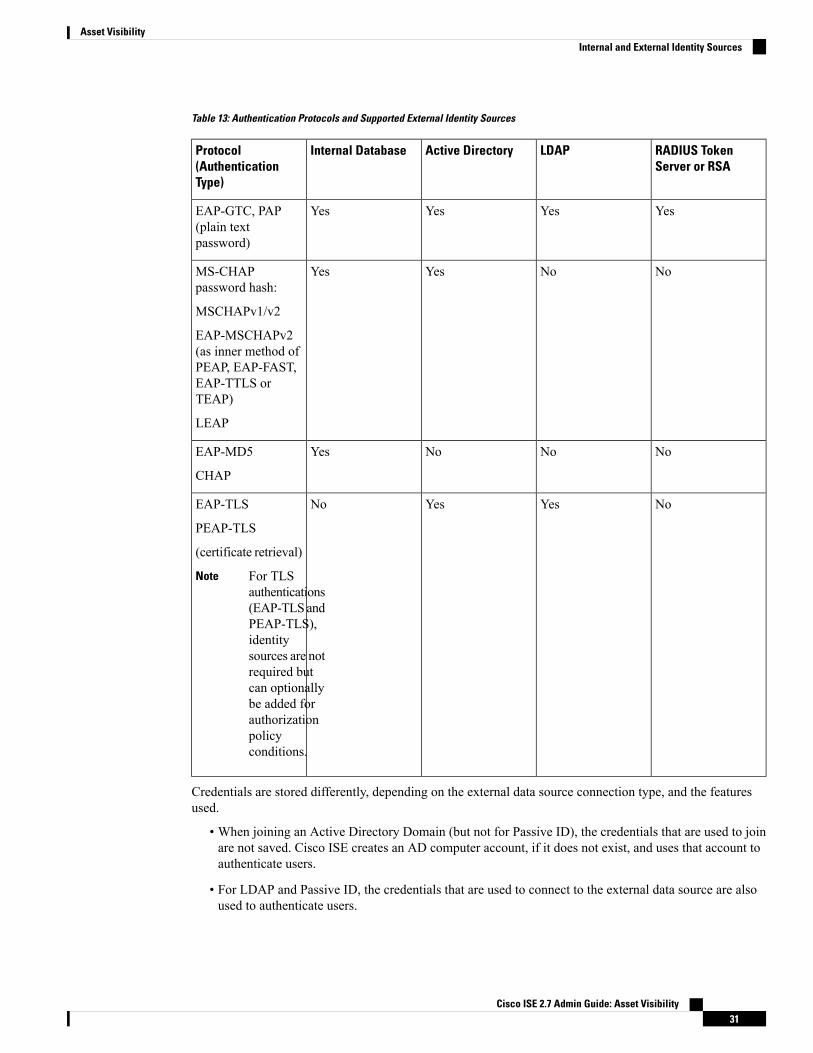
Table 13: Authentication Protocols and Supported External Identity Sources
RADIUS TokenServer or RSA
LDAPActive DirectoryInternal DatabaseProtocol(AuthenticationType)
YesYesYesYesEAP-GTC, PAP(plain textpassword)
NoNoYesYesMS-CHAPpassword hash:
MSCHAPv1/v2
EAP-MSCHAPv2(as inner method ofPEAP, EAP-FAST,EAP-TTLS orTEAP)
LEAP
NoNoNoYesEAP-MD5
CHAP
NoYesYesNoEAP-TLS
PEAP-TLS
(certificate retrieval)
For TLSauthentications(EAP-TLSandPEAP-TLS),identitysources are notrequired butcan optionallybe added forauthorizationpolicyconditions.
Note
Credentials are stored differently, depending on the external data source connection type, and the featuresused.
• When joining an Active Directory Domain (but not for Passive ID), the credentials that are used to joinare not saved. Cisco ISE creates an AD computer account, if it does not exist, and uses that account toauthenticate users.
• For LDAP and Passive ID, the credentials that are used to connect to the external data source are alsoused to authenticate users.
Cisco ISE 2.7 Admin Guide: Asset Visibility31
Asset VisibilityInternal and External Identity Sources

Create an External Identity SourceCisco ISE can connect with external identity sources such as Active Directory, LDAP, RADIUS Token, andRSA SecurID servers to obtain user information for authentication and authorization. External identity sourcesalso include certificate authentication profiles that you need for certificate-based authentications.
To work with passive identity services, which enable you to receive and share authenticated user identities,see the "Additional Passive Identity Service Providers" section in Cisco ISE Admin Guide: Asset Visibility.
Note
Procedure
Step 1 Choose Administration > Identity Management > External Identity Sources.Step 2 Choose one of these options:
• Certificate Authentication Profile for certificate-based authentications.• Active Directory to connect to an Active Directory as an external identity source See the Active Directoryas an External Identity Source section in Cisco ISE Admin Guide: Asset Visibility for more details.
• LDAP to add an LDAP identity source. See the LDAP section inCisco ISE Admin Guide: Asset Visibilityfor more details.
• RADIUS Token to add a RADIUS Token server. See the RADIUS Token Identity Sources section inCisco ISE Admin Guide: Asset Visibility for more details.
• RSA SecurID to add an RSA SecurID server. See the RSA Identity Sources section in Cisco ISE AdminGuide: Asset Visibility for more details.
• SAML Id Providers to add an identity provider (IdP), such as Oracle AccessManager. See the SAMLv2Identity Provider as an External Identity Source section in Cisco ISE Admin Guide: Asset Visibility formore details.
• Social Login to add a Social Login, such as Facebook, as an external identity source, see the SocialLogin for Self-Registered Guests section in Cisco ISE Admin Guide: Guest and BYOD .
Authenticate Internal User Against External Identity Store PasswordCisco ISE allows you to authenticate internal users against external identity store passwords. Cisco ISEprovides an option to select the password identity store for internal users from theAdministration > IdentityManagement > Identities > Users page. Administrators can select the identity store from the list of CiscoISE External Identity Sources while adding or editing users in the Users page. The default password identitystore for an internal user is the internal identity store. Cisco Secure ACS users will retain the same passwordidentity store during and after migration from Cisco Secure ACS to Cisco ISE.
Cisco ISE supports the following external identity stores for password types:
• Active Directory
• LDAP
• ODBC
• RADIUS Token server
Cisco ISE 2.7 Admin Guide: Asset Visibility32
Asset VisibilityCreate an External Identity Source

• RSA SecurID server
Certificate Authentication ProfilesFor each profile, you must specify the certificate field that should be used as the principal username andwhether you want a binary comparison of the certificates.
Add a Certificate Authentication ProfileYou must create a certificate authentication profile if you want to use the Extensible AuthenticationProtocol-Transport Layer Security (EAP-TLS) certificate-based authenticationmethod. Instead of authenticatingvia the traditional username and password method, Cisco ISE compares a certificate received from a clientwith one in the server to verify the authenticity of a user.
Before you begin
You must be a Super Admin or System Admin.
Procedure
Step 1 Choose Administration > Identity Management > External Identity Sources > CertificateAuthentication Profile > Add.
Step 2 Enter the name and an optional description for the certificate authentication profile.Step 3 Select an identity store from the drop-down list.
Basic certificate checking does not require an identity source. If you want binary comparison checking forthe certificates, you must select an identity source. If you select Active Directory as an identity source, subjectand common name and subject alternative name (all values) can be used to look up a user.
Step 4 Select the use of identity from Certificate Attribute or Any Subject or Alternative Name Attributes inthe Certificate. This will be used in logs and for lookups.
If you choose Any Subject or Alternative Name Attributes in the Certificate, Active Directory UPN willbe used as the username for logs and all subject names and alternative names in a certificate will be tried tolook up a user. This option is available only if you choose Active Directory as the identity source.
Step 5 Choose when you want to Match Client Certificate Against Certificate In Identity Store. For this youmust select an identity source (LDAP or Active Directory.) If you select Active Directory, you can choose tomatch certificates only to resolve identity ambiguity.
• Never—This option never performs a binary comparison.• Only to resolve identity ambiguity—This option performs the binary comparison of client certificate tocertificate on account in Active Directory only if ambiguity is encountered. For example, several ActiveDirectory accounts matching to identity names from certificate are found.
• Always perform binary comparison—This option always performs the binary comparison of clientcertificate to certificate on account in identity store (Active Directory or LDAP).
Step 6 Click Submit to add the certificate authentication profile or save the changes.
Cisco ISE 2.7 Admin Guide: Asset Visibility33
Asset VisibilityCertificate Authentication Profiles

Active Directory as an External Identity SourceCisco ISE uses Microsoft Active Directory as an external identity source to access resources such as users,machines, groups, and attributes. User and machine authentication in Active Directory allows network accessonly to users and devices that are listed in Active Directory.
ISE Community Resource
ISE Administrative Portal Access with AD Credentials Configuration Example
Active Directory Supported Authentication Protocols and FeaturesActive Directory supports features such as user and machine authentications, changing Active Directory userpasswords with some protocols. The following table lists the authentication protocols and the respectivefeatures that are supported by Active Directory.
Table 14: Authentication Protocols Supported by Active Directory
FeaturesAuthentication Protocols
User and machine authentication with the ability tochange passwords using EAP-FAST and PEAP withan inner method of MS-CHAPv2 and EAP-GTC
EAP-FAST and password based Protected ExtensibleAuthentication Protocol (PEAP)
User and machine authenticationPassword Authentication Protocol (PAP)
User and machine authenticationMicrosoft Challenge Handshake AuthenticationProtocol Version 1 (MS-CHAPv1)
User and machine authenticationMicrosoft Challenge Handshake AuthenticationProtocol Version 2 (MS-CHAPv2)
User and machine authenticationExtensible Authentication Protocol-Generic TokenCard (EAP-GTC)
• User and machine authentication
• Groups and attributes retrieval
• Binary certificate comparison
Extensible Authentication Protocol-Transport LayerSecurity (EAP-TLS)
• User and machine authentication
• Groups and attributes retrieval
• Binary certificate comparison
Extensible Authentication Protocol- FlexibleAuthentication via Secure Tunneling-Transport LayerSecurity (EAP-FAST-TLS)
• User and machine authentication
• Groups and attributes retrieval
• Binary certificate comparison
Protected Extensible AuthenticationProtocol-Transport Layer Security (PEAP-TLS)
Cisco ISE 2.7 Admin Guide: Asset Visibility34
Asset VisibilityActive Directory as an External Identity Source

FeaturesAuthentication Protocols
User authenticationLightweight Extensible Authentication Protocol(LEAP)
Active Directory Attribute and Group Retrieval for Use in Authorization PoliciesCisco ISE retrieves user or machine attributes and groups from Active Directory for use in authorizationpolicy rules. These attributes can be used in Cisco ISE policies and determine the authorization level for auser or machine. Cisco ISE retrieves user andmachine Active Directory attributes after successful authenticationand can also retrieve attributes for an authorization that is independent of authentication.
Cisco ISEmay use groups in external identity stores to assign permissions to users or computers; for example,to map users to sponsor groups. You should note the following restrictions on group memberships in ActiveDirectory:
• Policy rule conditions may reference any of the following: a user’s or computer’s primary group, thegroups of which a user or computer is a direct member, or indirect (nested) groups.
• Domain local groups outside a user’s or computer’s account domain are not supported.
You can use the value of the Active Directory attribute, msRadiusFramedIPAddress, as an IP address. ThisIP address can be sent to a network access server (NAS) in an authorization profile. ThemsRADIUSFramedIPAddress attribute supports only IPv4 addresses. Upon user authentication, themsRadiusFramedIPAddress attribute value fetched for the user will be converted to IP address format.
Note
Attributes and groups are retrieved and managed per join point. They are used in authorization policy (byselecting first the join point and then the attribute). You cannot define attributes or groups per scope forauthorization, but you can use scopes for authentication policy.When you use a scope in authentication policy,it is possible that a user is authenticated via one join point, but attributes and/or groups are retrieved via anotherjoin point that has a trust path to the user's account domain. You can use authentication domains to ensurethat no two join points in one scope have any overlap in authentication domains.
During the authorization process in a multi join point configuration, Cisco ISE will search for join points inthe order in which they listed in the authorization policy, only until a particular user has been found. Once auser has been found the attributes and groups assigned to the user in the join point, will be used to evaluatethe authorization policy.
Note
See Microsoft-imposed limits on the maximum number of usable Active Directory groups:http://technet.microsoft.com/en-us/library/active-directory-maximum-limits-scalability(v=WS.10).aspx
Note
An authorization policy fails if the rule contains an Active Directory group name with special characters suchas /, !, @, \, #, $, %, ^, &, *, (, ), _, +, or ~.
Cisco ISE 2.7 Admin Guide: Asset Visibility35
Asset VisibilityActive Directory Attribute and Group Retrieval for Use in Authorization Policies

Use Explicit UPN
To reduce ambiguity whenmatching user information against Active Directory's User-Principal-Name (UPN)attributes, you must configure Active Directory to use Explicit UPN. Using Implicit UPN can produceambiguous results if two users have the same value for sAMAccountName.
To set Explicit UPN in Active Directory, open the Advanced Tuning page, and set the attributeREGISTRY.Services\lsass\Parameters\Providers\ActiveDirectory\UseExplicitUPN to 1.
Support for Boolean Attributes
Cisco ISE supports retrieving Boolean attributes from Active Directory and LDAP identity stores.
You can configure the Boolean attributes while configuring the directory attributes for Active Directory orLDAP. These attributes are retrieved upon authentication with Active Directory or LDAP.
The Boolean attributes can be used for configuring policy rule conditions.
The Boolean attribute values are fetched from Active Directory or LDAP server as String type. Cisco ISEsupports the following values for the Boolean attributes:
Supported valuesBoolean attribute
t, T, true, TRUE, True, 1True
f, F, false, FALSE, False, 0False
Attribute substitution is not supported for the Boolean attributes.Note
If you configure a Boolean attribute (for example, msTSAllowLogon) as String type, the Boolean value ofthe attribute in the Active Directory or LDAP server will be set for the String attribute in Cisco ISE. You canchange the attribute type to Boolean or add the attribute manually as Boolean type.
Active Directory Certificate Retrieval for Certificate-Based AuthenticationCisco ISE supports certificate retrieval for user and machine authentication that uses the EAP-TLS protocol.The user or machine record on Active Directory includes a certificate attribute of the binary data type. Thiscertificate attribute can contain one or more certificates. Cisco ISE identifies this attribute as userCertificateand does not allow you to configure any other name for this attribute. Cisco ISE retrieves this certificate anduses it to perform binary comparison.
The certificate authentication profile determines the field where the username is taken from in order to lookupthe user in Active Directory to be used for retrieving certificates, for example, Subject Alternative Name(SAN) or Common Name. After Cisco ISE retrieves the certificate, it performs a binary comparison of thiscertificate with the client certificate.Whenmultiple certificates are received, Cisco ISE compares the certificatesto check for one that matches. When a match is found, the user or machine authentication is passed.
Active Directory User Authentication Process FlowWhen authenticating or querying a user, Cisco ISE checks the following:
• MS-CHAP and PAP authentications check if the user is disabled, locked out, expired or out of logonhours and the authentication fails if some of these conditions are true.
Cisco ISE 2.7 Admin Guide: Asset Visibility36
Asset VisibilitySupport for Boolean Attributes

• EAP-TLS authentications checks if the user is disabled or locked out and the authentication fails if someof these conditions is met.
Support for Active Directory Multidomain ForestsCisco ISE supports Active Directory with multidomain forests. Within each forest, Cisco ISE connects to asingle domain, but can access resources from the other domains in the Active Directory forest if trustrelationships are established between the domain to which Cisco ISE is connected and the other domains.
Refer to Release Notes for Cisco Identity Services Engine for a list of Windows Server Operating Systemsthat support Active Directory services.
Cisco ISE does not support Microsoft Active Directory servers that reside behind a network address translatorand have a Network Address Translation (NAT) address.
Note
Prerequisites for Integrating Active Directory and Cisco ISEThis section describes the manual steps necessary in order to configure Active Directory for integration withCisco ISE. However, in most cases, you can enable Cisco ISE to automatically configure Active Directory.The following are the prerequisites to integrate Active Directory with Cisco ISE.
• Ensure you have Active Directory Domain Admin credentials, required in order to make changes to anyof the AD domain configurations.
• Ensure you have the privileges of a Super Admin or System Admin in ISE.
• Use the Network Time Protocol (NTP) server settings to synchronize the time between the Cisco ISEserver and Active Directory. You can configure NTP settings from Cisco ISE CLI.
• Cisco ISE can connect with multiple Active Directory domains that do not have a two-way trust or havezero trust between them. If you want to query other domains from a specific join point, ensure that trustrelationships exist between the join point and the other domains that have user and machine informationto which you need access. If trust relationships does not exist, you must create another join point to theuntrusted domain. For more information on establishing trust relationships, refer to Microsoft ActiveDirectory documentation.
• You must have at least one global catalog server operational and accessible by Cisco ISE, in the domainto which you are joining Cisco ISE.
Cisco ISE 2.7 Admin Guide: Asset Visibility37
Asset VisibilitySupport for Active Directory Multidomain Forests
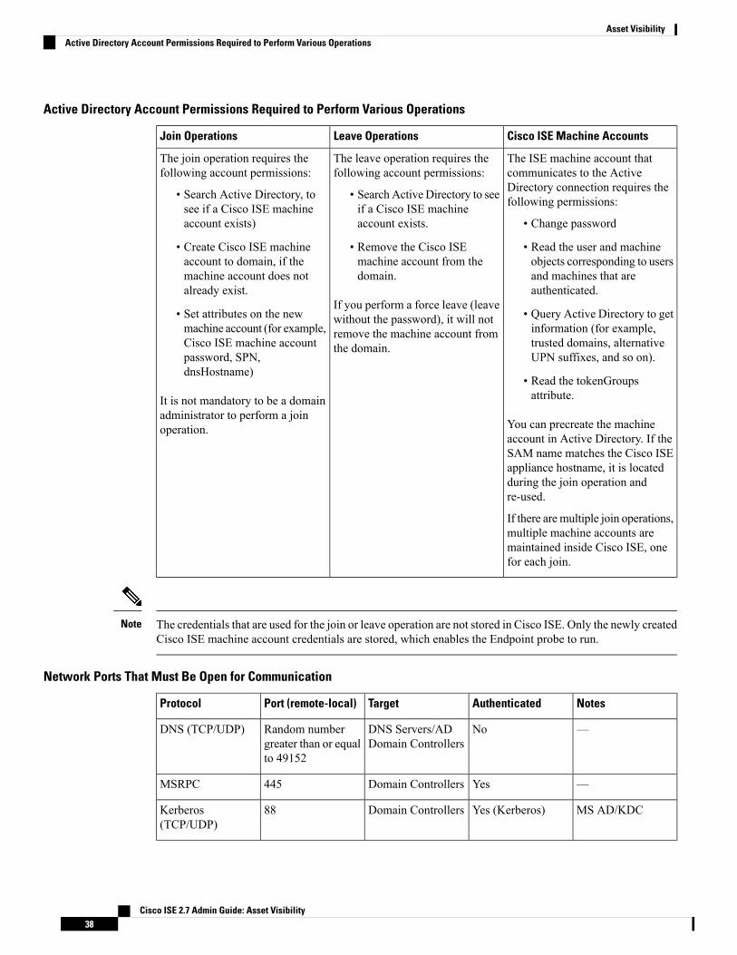
Active Directory Account Permissions Required to Perform Various Operations
Cisco ISE Machine AccountsLeave OperationsJoin Operations
The ISE machine account thatcommunicates to the ActiveDirectory connection requires thefollowing permissions:
• Change password
• Read the user and machineobjects corresponding to usersand machines that areauthenticated.
• Query Active Directory to getinformation (for example,trusted domains, alternativeUPN suffixes, and so on).
• Read the tokenGroupsattribute.
You can precreate the machineaccount in Active Directory. If theSAM name matches the Cisco ISEappliance hostname, it is locatedduring the join operation andre-used.
If there are multiple join operations,multiple machine accounts aremaintained inside Cisco ISE, onefor each join.
The leave operation requires thefollowing account permissions:
• Search Active Directory to seeif a Cisco ISE machineaccount exists.
• Remove the Cisco ISEmachine account from thedomain.
If you perform a force leave (leavewithout the password), it will notremove the machine account fromthe domain.
The join operation requires thefollowing account permissions:
• Search Active Directory, tosee if a Cisco ISE machineaccount exists)
• Create Cisco ISE machineaccount to domain, if themachine account does notalready exist.
• Set attributes on the newmachine account (for example,Cisco ISE machine accountpassword, SPN,dnsHostname)
It is not mandatory to be a domainadministrator to perform a joinoperation.
The credentials that are used for the join or leave operation are not stored in Cisco ISE. Only the newly createdCisco ISE machine account credentials are stored, which enables the Endpoint probe to run.
Note
Network Ports That Must Be Open for Communication
NotesAuthenticatedTargetPort (remote-local)Protocol
—NoDNS Servers/ADDomain Controllers
Random numbergreater than or equalto 49152
DNS (TCP/UDP)
—YesDomain Controllers445MSRPC
MS AD/KDCYes (Kerberos)Domain Controllers88Kerberos(TCP/UDP)
Cisco ISE 2.7 Admin Guide: Asset Visibility38
Asset VisibilityActive Directory Account Permissions Required to Perform Various Operations

NotesAuthenticatedTargetPort (remote-local)Protocol
—YesDomain Controllers389LDAP (TCP/UDP)
—YesGlobal CatalogServers
3268LDAP (GC)
—NoNTPServers/DomainControllers
123NTP
—Yes (Using RBACcredentials)
Other ISE Nodes inthe Deployment
80IPC
DNS Server
While configuring your DNS server, make sure that you take care of the following:
• The DNS servers that you configure in Cisco ISE must be able to resolve all forward and reverse DNSqueries for the domains that you want to use.
• The Authoritative DNS server is recommended to resolve Active Directory records, as DNS recursioncan cause delays and have significant negative impact on performance.
• All DNS servers must be able to answer SRV queries for DCs, GCs, and KDCswith or without additionalSite information.
• Cisco recommends that you add the server IP addresses to SRV responses to improve performance.
• Avoid using DNS servers that query the public Internet. They can leak information about your networkwhen an unknown name has to be resolved.
Configure Active Directory as an External Identity SourceConfigure Active Directory as an external identity source as part of the configuration for features such asEasy Connect and the PassiveID Work Center. For more information about these features, see Easy Connect,on page 69 and PassiveID Work Center , on page 73.
Before you configure Active Directory as an External Identity Source, make sure that:
• The Microsoft Active Directory server does not reside behind a network address translator and does nothave a Network Address Translation (NAT) address.
• The Microsoft Active Directory account intended for the join operation is valid and is not configuredwith the Change Password on Next Login.
• You have the privileges of a Super Admin or System Admin in ISE.
If you see operational issues when Cisco ISE is connected to Active Directory, see the ADConnector OperationsReport under Operations > Reports.
Note
You must perform the following tasks to configure Active Directory as an external identity source.
Cisco ISE 2.7 Admin Guide: Asset Visibility39
Asset VisibilityDNS Server

1. Add an Active Directory Join Point and Join Cisco ISE Node to the Join Point, on page 40
2. Configure Authentication Domains, on page 43
3. Configure Active Directory User Groups, on page 44
4. Configure Active Directory User and Machine Attributes, on page 45
5. (Optional)Modify Password Changes,Machine Authentications, andMachine Access Restriction Settings,on page 46
Add an Active Directory Join Point and Join Cisco ISE Node to the Join Point
Before you begin
Make sure that the Cisco ISE node can communicate with the networks where the NTP servers, DNS servers,domain controllers, and global catalog servers are located. You can check these parameters by running theDomain Diagnostic tool.
Join points must be created in order to work with Active Directory as well as with the Agent, Syslog, SPANand Endpoint probes of the Passive ID Work Center.
If you want to use IPv6 when integrating with Active Directory, then you must ensure that you have configuredan IPv6 address for the relevant ISE nodes.
Procedure
Step 1 Choose Administration > Identity Management > External Identity Sources > Active Directory.Step 2 Click Add and enter the domain name and identity store name from the Active Directory Join Point Name
settings.Step 3 Click Submit.
A pop-up appears asking if you want to join the newly created join point to the domain. Click Yes if you wantto join immediately.
If you clicked No, then saving the configuration saves the Active Directory domain configuration globally(in the primary and secondary policy service nodes), but none of the Cisco ISE nodes are joined to the domainyet.
Step 4 Check the checkbox next to the new Active Directory join point that you created and click Edit, or click onthe new Active Directory join point from the navigation pane on the left. The deployment join/leave table isdisplayed with all the Cisco ISE nodes, the node roles, and their status.
Step 5 In case the join point was not joined to the domain during Step 3, check the checkbox next to the relevantCisco ISE nodes and click Join to join the Cisco ISE node to the Active Directory domain.
You must do this explicitly even though you saved the configuration. To join multiple Cisco ISE nodes to adomain in a single operation, the username and password of the account to be used must be the same for alljoin operations. If different username and passwords are required to join each Cisco ISE node, the join operationshould be performed individually for each Cisco ISE node.
Step 6 Enter the Active Directory username and password from the Join Domain dialog box that opens.
Cisco ISE 2.7 Admin Guide: Asset Visibility40
Asset VisibilityAdd an Active Directory Join Point and Join Cisco ISE Node to the Join Point
It is strongly recommended that you choose Store credentials, in which case your administrator's user nameand password will be saved in order to be used for all Domain Controllers (DC) that are configured formonitoring.
The user used for the join operation should exist in the domain itself. If it exists in a different domain orsubdomain, the username should be noted in a UPN notation, such as [email protected].
Step 7 (Optional) Check the Specify Organizational Unit checkbox.
You should check this checkbox in case the Cisco ISE node machine account is to be located in a specificOrganizational Unit other than CN=Computers,DC=someDomain,DC=someTLD. Cisco ISE creates themachine account under the specified organizational unit or moves it to this location if the machine accountalready exists. If the organizational unit is not specified, Cisco ISE uses the default location. The value shouldbe specified in full distinguished name (DN) format. The syntax must conform to the Microsoft guidelines.Special reserved characters, such as /'+,;=<> line feed, space, and carriage returnmust be escaped by a backslash(\). For example, OU=Cisco ISE\,US,OU=IT Servers,OU=Servers\, andWorkstations,DC=someDomain,DC=someTLD. If the machine account is already created, you need not checkthis checkbox. You can also change the location of the machine account after you join to the Active Directorydomain.
Step 8 Click OK.
You can select more than one node to join to the Active Directory domain.
If the join operation is not successful, a failure message appears. Click the failure message for each node toview detailed logs for that node.
When the join is complete, Cisco ISE updates its AD groups and corresponding SIDS. Cisco ISEautomatically starts the SID update process. Youmust ensure that this process is allowed to complete.
Note
You might not be able to join Cisco ISE with an Active Directory domain if the DNS SRV recordsare missing (the domain controllers do not advertise their SRV records for the domain that you aretrying to join to). Refer to the following Microsoft Active Directory documentation fortroubleshooting information:
• http://support.microsoft.com/kb/816587
• http://technet.microsoft.com/en-us/library/bb727055.aspx
Note
You can only add up to 200 Domain Controllers on ISE. On exceeding the limit, you will receivethe error "Error creating <DC FQDN> - Number of DCs Exceeds allowed maximum of 200".
Note
What to do next
Configure Active Directory User Groups, on page 44
Configure authentication domains.
Cisco ISE 2.7 Admin Guide: Asset Visibility41
Asset VisibilityAdd an Active Directory Join Point and Join Cisco ISE Node to the Join Point
Add Domain Controllers
Procedure
Step 1 Choose Work Centers > PassiveID > Providers and then from the left panel choose Active Directory.Step 2 Check the check box next to the Active Directory join point that you created and click Edit. The deployment
join/leave table is displayed with all the Cisco ISE nodes, the node roles, and their statuses.Step 3 Note To add a new Domain Controller (DC) for Passive Identity services, you need the login credentials
of that DC.
Go to the PassiveID tab and click Add DCs.Step 4 Check the check box next to the domain controllers that you would like to add to the join point for monitoring
and click OK.The domain controllers appear in the Domain Controllers list of the PassiveID tab.
Step 5 Configure the domain controller:a) Checkmark the domain controller and click Edit. The Edit Item screen appears.b) Optionally, edit the different domain controller fields. For more information, see Active Directory Settings,
on page 78.c) If you selected WMI protocol, click Configure to configure WMI automatically and click Test to test the
connection. For more information about automatically configuringWMI, see ConfigureWMI for PassiveID, on page 42.
The DC failover mechanism is managed based on the DC priority list, which determines the order in whichthe DCs are selected in case of failover. If a DC is offline or not reachable due to some error, its priority isdecreased in the priority list. When the DC comes back online, its priority is adjusted accordingly (increased)in the priority list.
Cisco ISE does not support Read-only Domain Controller for authentication flows.Note
Configure WMI for Passive ID
Before you begin
Ensure you have Active Directory Domain Admin credentials, required in order to make changes to any ofthe AD domain configurations. Ensure that you enabled Passive ID for this node under System > Deployment.
Procedure
Step 1 Choose Administration > Identity Management > External Identity Sources > Active Directory.Step 2 Check the checkbox next to the Active Directory join point that you created and click Edit. The deployment
join/leave table is displayed with all the Cisco ISE nodes, the node roles, and their statuses. For moreinformation, see Table 17: Active Directory Join/Leave Table, on page 79.
Cisco ISE 2.7 Admin Guide: Asset Visibility42
Asset VisibilityAdd Domain Controllers

Step 3 Go to the Passive ID tab, check the check box next to the relevant domain controllers and click Config WMIto enable ISE to automatically configure the domain controllers you selected.To configure Active Directory and Domain Controllers manually, or to troubleshoot any problems withconfiguration, see Prerequisites for Integrating Active Directory and Cisco ISE , on page 37.
Leave the Active Directory Domain
If you no longer need to authenticate users or machines from this Active Directory domain or from this joinpoint, you can leave the Active Directory domain.
When you reset the Cisco ISE application configuration from the command-line interface or restoreconfiguration after a backup or upgrade, it performs a leave operation, disconnecting the Cisco ISE node fromthe Active Directory domain, if it is already joined. However, the Cisco ISE node account is not removedfrom the Active Directory domain. We recommend that you perform a leave operation from the Admin portalwith the Active Directory credentials because it also removes the node account from the Active Directorydomain. This is also recommended when you change the Cisco ISE hostname.
Before you begin
If you leave the Active Directory domain, but still use Active Directory as an identity source for authentication(either directly or as part of an identity source sequence), authentications may fail.
Procedure
Step 1 Choose Administration > Identity Management > External Identity Sources > Active Directory.Step 2 Check the checkbox next to the Active Directory join point that you created and click Edit. The deployment
join/leave table is displayed with all the Cisco ISE nodes, the node roles, and their statuses.Step 3 Check the checkbox next to the Cisco ISE node and click Leave.Step 4 Enter the Active Directory username and password, and clickOK to leave the domain and remove the machine
account from the Cisco ISE database.
If you enter the Active Directory credentials, the Cisco ISE node leaves the Active Directory domain anddeletes the Cisco ISE machine account from the Active Directory database.
To delete the Cisco ISE machine account from the Active Directory database, the Active Directorycredentials that you provide here must have the permission to removemachine account from domain.
Note
Step 5 If you do not have the Active Directory credentials, check the No Credentials Available checkbox, and clickOK.
If you check the Leave domain without credentials checkbox, the primary Cisco ISE node leaves the ActiveDirectory domain. The Active Directory administrator must manually remove the machine account that wascreated in Active Directory during the time of the join.
Configure Authentication Domains
The domain to which Cisco ISE is joined to has visibility to other domains with which it has a trust relationship.By default, Cisco ISE is set to permit authentication against all those trusted domains. You can restrictinteraction with the Active Directory deployment to a subset of authentication domains. Configuring
Cisco ISE 2.7 Admin Guide: Asset Visibility43
Asset VisibilityLeave the Active Directory Domain

authentication domains enables you to select specific domains for each join point so that the authenticationsare performed against the selected domains only. Authentication domains improves security because theyinstruct Cisco ISE to authenticate users only from selected domains and not from all domains trusted fromjoin point. Authentication domains also improve performance and latency of authentication request processingbecause authentication domains limit the search area (that is, where accounts matching to incoming usernameor identity will be searched). It is especially important when incoming username or identity does not containdomain markup (prefix or suffix). Due to these reasons, configuring authentication domains is a best practice,and we highly recommended it.
Procedure
Step 1 Choose Administration > Identity Management > External Identity Sources > Active Directory.Step 2 Click Active Directory join point.Step 3 Click the Authentication Domains tab.
A table appears with a list of your trusted domains. By default, Cisco ISE permits authentication against alltrusted domains.
Step 4 To allow only specified domains, uncheck Use all Active Directory domains for authentication check box.Step 5 Check the check box next to the domains for which you want to allow authentication, and click Enable
Selected. In the Authenticate column, the status of this domain changes to Yes.
You can also disable selected domains.
Step 6 Click Show Unusable Domains to view a list of domains that cannot be used. Unusable domains are domainsthat Cisco ISE cannot use for authentication due to reasons such as one-way trust, selective authenticationand so on.
What to do next
Configure Active Directory user groups.
Configure Active Directory User Groups
You must configure Active Directory user groups for them to be available for use in authorization policies.Internally, Cisco ISE uses security identifiers (SIDs) to help resolve group name ambiguity issues and toenhance group mappings. SID provides accurate group assignment matching.
Procedure
Step 1 Choose Administration > Identity Management > External Identity Sources > Active Directory.Step 2 Click the Groups tab.Step 3 Do one of the following:
a) Choose Add > Select Groups From Directory to choose an existing group.b) Choose Add > Add Group to manually add a group. You can either provide both group name and SID
or provide only the group name and press Fetch SID.Do not use double quotes (”) in the group name for the user interface login.
Cisco ISE 2.7 Admin Guide: Asset Visibility44
Asset VisibilityConfigure Active Directory User Groups

Step 4 If you are manually selecting a group, you can search for them using a filter. For example, enter admin* asthe filter criteria and click Retrieve Groups to view user groups that begin with admin. You can also enterthe asterisk (*) wildcard character to filter the results. You can retrieve only 500 groups at a time.
Step 5 Check the check boxes next to the groups that you want to be available for use in authorization policies andclick OK.
Step 6 If you choose to manually add a group, enter a name and SID for the new group.Step 7 Click OK.Step 8 Click Save.
If you delete a group and create a new group with the same name as original, you must clickUpdateSID Values to assign new SID to the newly created group. After an upgrade, the SIDs areautomatically updated after the first join.
Note
What to do next
Configure Active Directory user attributes.
Configure Active Directory User and Machine Attributes
You must configure Active Directory user and machine attributes to be able to use them in conditions inauthorization policies.
Procedure
Step 1 Choose Administration > Identity Management > External Identity Sources > Active Directory.Step 2 Click the Attributes tab.Step 3 Choose Add > Add Attribute to manually add a attribute, or choose Add > Select Attributes From
Directory to choose a list of attributes from the directory.
Cisco ISE allows you to configure the ADwith IPv4 or IPv6 address for user authentication when youmanuallyadd the attribute type IP.
Step 4 If you choose to add attributes from the directory, enter the name of a user in the Sample User or MachineAccount field, and click Retrieve Attributes to obtain a list of attributes for users. For example, enteradministrator to obtain a list of administrator attributes. You can also enter the asterisk (*) wildcard characterto filter the results.
When you enter an example username, ensure that you choose a user from the Active Directorydomain to which the Cisco ISE is connected. When you choose an example machine to obtainmachine attributes, be sure to prefix the machine name with “host/” or use the SAM$ format. Forexample, you might use host/myhost. The example value displayed when you retrieve attributes areprovided for illustration only and are not stored.
Note
Step 5 Check the check boxes next to the attributes from Active Directory that you want to select, and click OK.Step 6 If you choose to manually add an attribute, enter a name for the new attribute.Step 7 Click Save.
Cisco ISE 2.7 Admin Guide: Asset Visibility45
Asset VisibilityConfigure Active Directory User and Machine Attributes
Modify Password Changes, Machine Authentications, and Machine Access Restriction Settings
Before you begin
You must join Cisco ISE to the Active Directory domain. For more information, see Add an Active DirectoryJoin Point and Join Cisco ISE Node to the Join Point, on page 40.
Procedure
Step 1 Choose Administration > Identity Management > External Identity Sources > Active Directory.Step 2 Check the check box next to the relevant Cisco ISE node and click Edit .Step 3 Click the Advanced Settings tab.Step 4 Modify as required, the Password Change,Machine Authentication, andMachine Access Restrictions (MARs)
settings.
These options are enabled by default.
Enable Machine Access Restrictions - Aging Time: The time in hours before a MAC address in the MARcache times out, and is deleted.
Step 5 Check the Enable dial-in check check box to check the dial-in permissions of the user during authenticationor query. The result of the check can cause a reject of the authentication in case the dial-in permission isdenied.
Step 6 Check the Enable callback check for dial-in clients check box if you want the server to call back the userduring authentication or query. The IP address or phone number used by the server can be set either by thecaller or the network administrator. The result of the check is returned to the device on the RADIUS response.
Step 7 Check theUse Kerberos for Plain Text Authentications check box if you want to use Kerberos for plain-textauthentications. The default and recommended option is MS-RPC. Kerberos is used in ISE 1.2.
Machine Access Restriction (MAR) Cache
Cisco ISE stores the MAR cache content, calling-station-ID list, and the corresponding time stamps to a fileon its local disk when you manually stop the the application services. Cisco ISE does not store theMAR cacheentries of an instance when there is an accidental restart of the application services. Cisco ISE reads the MARcache entries from the file on its local disk based on the cache entry time to live when the application servicesrestart. When the application services come up after a restart, Cisco ISE compares the current time of thatinstance with the MAR cache entry time. If the difference between the current time and the MAR entry timeis greater than the MAR cache entry time to live, then Cisco ISE does not retrieve that entry from disk.Otherwise, Cisco ISE retrieves that MAR cache entry and updates its MAR cache entry time to live.
To Configure MAR Cache
On Advanced Settings tab of the Active Directory defined in External Identity Sources, verify that thefollowing options are checked:
• Enable Machine Authentication: To enable machine authentication.
• Enable Machine Access Restriction: To combine user and machine authentication before authorization.
Cisco ISE 2.7 Admin Guide: Asset Visibility46
Asset VisibilityModify Password Changes, Machine Authentications, and Machine Access Restriction Settings

To Use MAR Cache in Authorization
Use WasMachineAuthenticated is True in an authorization policy. You can use this rule plus a credentialsrule to do dual-authentication. Machine authentication must be done before AD credentials.
If you created a Node Group on the System > Deployment page, enable MAR Cache Distribution. MARcache distribution replicates the MAR cache to all the PSNs in the same node group.
For More Information
See the following Cisco ISE Community pages:
• Why isMAR useful even when EAP-TLS is available https://community.cisco.com/t5/policy-and-access/mar-why-is-it-useful/td-p/3213527
• MAR aging time vs AnyConnect EAP-TLS https://community.cisco.com/t5/policy-and-access/ise-2-1-mar-aging-time-eap-tls/td-p/3209628
Related TopicsConfigure Active Directory as an External Identity Source, on page 39
Configure Custom Schema
Before you begin
You must join Cisco ISE to the Active Directory domain.
Procedure
Step 1 Choose Administration > Identity Management > External Identity Sources > Active Directory.Step 2 Select the Join point.Step 3 Click the Advanced Settings tab.Step 4 Under the Schema section, select the Custom option from the Schema drop-down list. You can update the
user information attributes based on your requirements. These attributes are used to collect user information,such as, first name, last name, email, telephone, locality, and so on.
Predefined attributes are used for the Active Directory schema (built-in schema). If you edit the attributes ofthe predefined schema, Cisco ISE automatically creates a custom schema.
Support for Active Directory Multi-Join ConfigurationCisco ISE supports multiple joins to Active Directory domains. Cisco ISE supports up to 50 Active Directoryjoins. Cisco ISE can connect with multiple Active Directory domains that do not have a two-way trust or havezero trust between them. Active Directory multi-domain join comprises a set of distinct Active Directorydomains with their own groups, attributes, and authorization policies for each join.
You can join the same forest more than once, that is, you can join more than one domain in the same forest,if necessary.
Cisco ISE now allows to join domains with one-way trust. This option helps bypass the permission issuescaused by a one-way trust. You can join either of the trusted domains and hence be able to see both domains.
Cisco ISE 2.7 Admin Guide: Asset Visibility47
Asset VisibilityConfigure Custom Schema

• Join Point—In Cisco ISE, each independent join to an Active Directory domain is called a join point.The Active Directory join point is an Cisco ISE identity store and can be used in authentication policy.It has an associated dictionary for attributes and groups, which can be used in authorization conditions.
• Scope—A subset of Active Directory join points grouped together is called a scope. You can use scopesin authentication policy in place of a single join point and as authentication results. Scopes are used toauthenticate users against multiple join points. Instead of having multiple rules for each join point, if youuse a scope, you can create the same policy with a single rule and save the time that Cisco ISE takes toprocess a request and help improve performance. A join point can be present in multiple scopes. A scopecan be included in an identity source sequence. You cannot use scopes in an authorization policy conditionbecause scopes do not have any associated dictionaries.
When you perform a fresh Cisco ISE install, by default no scopes exist. This is called the no scope mode.When you add a scope, Cisco ISE enters multi-scope mode. If you want, you can return to no scopemode. All the join points will be moved to the Active Directory folder.
• Initial_Scope is an implicit scope that is used to store the Active Directory join points that wereadded in no scope mode. When multi-scope mode is enabled, all the Active Directory join pointsmove into the automatically created Initial_Scope. You can rename the Initial_Scope.
• All_AD_Instances is a built-in pseudo scope that is not shown in the Active Directory configuration.It is only visible as an authentication result in policy and identity sequences. You can select thisscope if you want to select all Active Directory join points configured in Cisco ISE.
Create a New Scope to Add Active Directory Join Points
Procedure
Step 1 Choose Administration > Identity Management > External Identity Sources > Active Directory.Step 2 Click Scope Mode.
A default scope called Initial_Scope is created, and all the current join points are placed under this scope.Step 3 To create more scopes, click Add.Step 4 Enter a name and a description for the new scope.Step 5 Click Submit.
Identity RewriteIdentity rewrite is an advanced feature that directs Cisco ISE to manipulate the identity before it is passed tothe external Active Directory system. You can create rules to change the identity to a desired format thatincludes or excludes a domain prefix and/or suffix or other additional markup of your choice.
Identity rewrite rules are applied on the username or hostname received from the client, before being passedto Active Directory, for operations such as subject searches, authentication, and authorization queries. CiscoISE will match the condition tokens and when the first one matches, Cisco ISE stops processing the policyand rewrites the identity string according to the result.
During the rewrite, everything enclosed in square bracket [ ] (such as [IDENTITY]) is a variable that is notevaluated on the evaluation side but instead added with the string that matches that location in the string.
Cisco ISE 2.7 Admin Guide: Asset Visibility48
Asset VisibilityCreate a New Scope to Add Active Directory Join Points

Everything without the brackets is evaluated as a fixed string on both the evaluation side and the rewrite sideof the rule.
The following are some examples of identity rewrite, considering that the identity entered by the user isACME\jdoe:
• If identity matches ACME\[IDENTITY], rewrite as [IDENTITY].
The result would be jdoe. This rule instructs Cisco ISE to strip all usernames with the ACME prefix.
• If the identity matches ACME\[IDENTITY], rewrite as [IDENTITY]@ACME.com.
The result would be [email protected]. This rule instructs Cisco ISE to change the format from prefixfor suffix notation or from NetBIOS format to UPN formats.
• If the identity matches ACME\[IDENTITY], rewrite as ACME2\[IDENTITY].
The result would be ACME2\jdoe. This rule instructs Cisco ISE to change all usernames with a certainprefix to an alternate prefix.
• If the identity matches [ACME]\jdoe.USA, rewrite as [IDENTITY]@[ACME].com.
The result would be jdoe\ACME.com. This rule instructs Cisco ISE to strip the realm after the dot, inthis case the country and replace it with the correct domain.
• If the identity matches E=[IDENTITY], rewrite as [IDENTITY].
The result would be jdoe. This is an example rule that can be created when an identity is from a certificate,the field is an email address, and Active Directory is configured to search by Subject. This rule instructsCisco ISE to remove ‘E=’.
• If the identity matches E=[EMAIL],[DN], rewrite as [DN].
This rule will convert certificate subject from [email protected], CN=jdoe, DC=acme, DC=com topure DN, CN=jdoe, DC=acme, DC=com. This is an example rule that can be created when identity istaken from a certificate subject and Active Directory is configured to search user by DN . This ruleinstructs Cisco ISE to strip email prefix and generate DN.
The following are some common mistakes while writing the identity rewrite rules:
• If the identity matches [DOMAIN]\[IDENTITY], rewrite as [IDENTITY]@DOMAIN.com.
The result would be [email protected]. This rule does not have [DOMAIN] in square brackets [ ] onthe rewrite side of the rule.
• If the identity matches DOMAIN\[IDENTITY], rewrite as [IDENTITY]@[DOMAIN].com.
Here again, the result would be [email protected]. This rule does not have [DOMAIN] in squarebrackets [ ] on the evaluation side of the rule.
Identity rewrite rules are always applied within the context of an Active Directory join point. Even if a scopeis selected as the result of an authentication policy, the rewrite rules are applied for each Active Directoryjoin point. These rewrite rules also applies for identities taken from certificates if EAP-TLS is being used.
Cisco ISE 2.7 Admin Guide: Asset Visibility49
Asset VisibilityIdentity Rewrite

Enable Identity Rewrite
This configuration task is optional. You can perform it to reduce authentication failures that can arise becauseof various reasons such as ambiguous identity errors.
Note
Before you begin
You must join Cisco ISE to the Active Directory domain.
Procedure
Step 1 Choose Administration > Identity Management > External Identity Sources > Active Directory.Step 2 Click the Advanced Settings tab.Step 3 Under the Identity Rewrite section, choose whether you want to apply the rewrite rules to modify usernames.Step 4 Enter the match conditions and the rewrite results. You can remove the default rule that appears and enter the
rule according to your requirement. Cisco ISE processes the policy in order, and the first condition that matchesthe request username is applied. You can use the matching tokens (text contained in square brackets) to transferelements of the original username to the result. If none of the rules match, the identity name remains unchanged.You can click the Launch Test button to preview the rewrite processing.
Identity Resolution SettingsSome type of identities include a domain markup, such as a prefix or a suffix. For example, in a NetBIOSidentity such as ACME\jdoe, “ACME” is the domain markup prefix, similarly in a UPN identity such [email protected], “acme.com” is the domain markup suffix. Domain prefix should match to the NetBIOS(NTLM) name of the Active Directory domain in your organization and domain suffix should match to theDNS name of Active Directory domain or to the alternative UPN suffix in your organization. For [email protected] is treated as without domain markup because gmail.com is not a DNS name of ActiveDirectory domain.
The identity resolution settings allows you to configure important settings to tune the security and performancebalance to match your Active Directory deployment. You can use these settings to tune authentications forusernames and hostnames without domain markup. In cases when Cisco ISE is not aware of the user's domain,it can be configured to search the user in all the authentication domains. Even if the user is found in onedomain, Cisco ISE will wait for all responses in order to ensure that there is no identity ambiguity. This mightbe a lengthy process, subject to the number of domains, latency in the network, load, and so on.
Avoid Identity Resolution Issues
It is highly recommended to use fully qualified names (that is, names with domain markup) for users andhosts during authentication. For example, UPNs and NetBIOS names for users and FQDN SPNs for hosts.This is especially important if you hit ambiguity errors frequently, such as, several Active Directory accountsmatch to the incoming username; for example, jdoe matches to [email protected] [email protected]. In some cases, using fully qualified names is the only way to resolve issue. In others,it may be sufficient to guarantee that the users have unique passwords. So, it is more efficient and leads toless password lockout issues if unique identities are used initially.
Cisco ISE 2.7 Admin Guide: Asset Visibility50
Asset VisibilityEnable Identity Rewrite

Configure Identity Resolution Settings
This configuration task is optional. You can perform it to reduce authentication failures that can arise becauseof various reasons such as ambiguous identity errors.
Note
Before you begin
You must join Cisco ISE to the Active Directory domain.
Procedure
Step 1 Choose Administration > Identity Management > External Identity Sources > Active Directory.Step 2 Click the Advanced Settings tab.Step 3 Define the following settings for identity resolution for usernames or machine names under the Identity
Resolution section. This setting provides you advanced control for user search and authentication.
The first setting is for the identities without a markup. In such cases, you can select any of the followingoptions:
• Reject the request—This option will fail the authentication for users who do not have any domainmarkups, such as a SAM name. This is useful in case of multi join domains where Cisco ISE will haveto look up for the identity in all the joined global catalogs, which might not be very secure. This optionforces the users to use names with domain markups.
• Only search in the “Authentication Domains” from the joined forest—This option will search forthe identity only in the domains in the forest of the join point which are specified in the authenticationdomains section. This is the default option and identical to Cisco ISE 1.2 behavior for SAM accountnames.
• Search in all the “Authentication Domains” sections—This option will search for the identity in allauthentication domains in all the trusted forests. This might increase latency and impact performance.
The selection is made based on how the authentication domains are configured in Cisco ISE. If only specificauthentication domains are selected, only those domains will be searched (for both “joined forest” or “allforests” selections).
The second setting is used if Cisco ISE cannot communicate with all Global Catalogs (GCs) that it needs toin order to comply with the configuration specified in the “Authentication Domains” section. In such cases,you can select any of the following options:
• Proceed with available domains— This option will proceed with the authentication if it finds a matchin any of the available domains.
• Drop the request—This option will drop the authentication request if the identity resolution encounterssome unreachable or unavailable domain.
Test Users for Active Directory AuthenticationThe Test User tool can be used to verify user authentication from Active Directory. You can also fetch groupsand attributes and examine them. You can run the test for a single join point or for scopes.
Cisco ISE 2.7 Admin Guide: Asset Visibility51
Asset VisibilityConfigure Identity Resolution Settings

Procedure
Step 1 Choose Administration > Identity Management > External Identity Sources > Active Directory.Step 2 Choose one of the following options:
• To run the test on all join points, choose Advanced Tools > Test User for All Join Points.• To run the test for a specific join point, select the joint point and click Edit. Select the Cisco ISE nodeand click Test User.
Step 3 Enter the username and password of the user (or host) in Active Directory.Step 4 Choose the authentication type. Password entry in Step 3 is not required if you choose the Lookup option.Step 5 Select the Cisco ISE node on which you want to run this test, if you are running this test for all join points.Step 6 Check the Retrieve Groups and Attributes checkboxes if you want to retrieve the groups and attributes from
Active Directory.Step 7 Click Test.
The result and steps of the test operation are displayed. The steps can help to identify the failure reason andtroubleshoot.
You can also view the time taken (in milliseconds) for Active Directory to perform each processing step (forauthentication, lookup, or fetching groups/attributes). Cisco ISE displays a warning message if the time takenfor an operation exceeds the threshold.
Delete Active Directory ConfigurationsYou should delete Active Directory configurations if you are not going to use Active Directory as an externalidentity source. Do not delete the configuration if you want to join another Active Directory domain. You canleave the domain to which you are currently joined and join a new domain.
Before you begin
Ensure that you have left the Active Directory domain.
Procedure
Step 1 Choose Administration > Identity Management > External Identity Sources > Active Directory.Step 2 Check the checkbox next to the configured Active Directory.Step 3 Check and ensure that the Local Node status is listed as Not Joined.Step 4 Click Delete.
You have removed the configuration from the Active Directory database. If you want to use Active Directoryat a later point in time, you can resubmit a valid Active Directory configuration.
Cisco ISE 2.7 Admin Guide: Asset Visibility52
Asset VisibilityDelete Active Directory Configurations

View Active Directory Joins for a NodeYou can use the Node View button on the Active Directory page to view the status of all Active Directoryjoin points for a given Cisco ISE node or a list of all join points on all Cisco ISE nodes.
Procedure
Step 1 Choose Administration > Identity Management > External Identity Sources > Active Directory.Step 2 Click Node View.Step 3 Select a node from the ISE Node drop-down list.
The table lists the status of Active Directory by node. If there are multiple join points and multiple Cisco ISEnodes in a deployment, this table may take several minutes to update.
Step 4 Click the join pointName link to go to that Active Directory join point page and perform other specific actions.Step 5 Click the link in theDiagnostic Summary column to go to theDiagnostic Tools page to troubleshoot specific
issues. The diagnostic tool displays the latest diagnostics results for each join point per node.
Diagnose Active Directory ProblemsThe Diagnostic Tool is a service that runs on every Cisco ISE node. It allows you to automatically test anddiagnose the Active Directory deployment and execute a set of tests to detect issues that may cause functionalityor performance failures when Cisco ISE uses Active Directory.
There are multiple reasons for which Cisco ISEmight be unable to join or authenticate against Active Directory.This tool helps ensure that the prerequisites for connecting Cisco ISE to Active Directory are configuredcorrectly. It helps detect problems with networking, firewall configurations, clock sync, user authentication,and so on. This tool works as a step-by-step guide and helps you fix problems with every layer in the middle,if needed .
Procedure
Step 1 Choose Administration > Identity Management > External Identity Sources > Active Directory.Step 2 Click the Advanced Tools drop-down and choose Diagnostic Tools.Step 3 Select a Cisco ISE node to run the diagnosis on.
If you do not select a Cisco ISE node then the test is run on all the nodes.
Step 4 Select a specific Active Directory join point.
If you do not select an Active Directory join point then the test is run on all the join points.
Step 5 You can run the diagnostic tests either on demand or on a scheduled basis.
• To run tests immediately, choose Run Tests Now.
• To run the tests at an scheduled interval, check the Run Scheduled Tests check box and specify the starttime and the interval (in hours, days, or weeks) at which the tests must be run.When this option is enabled,all the diagnostic tests are run on all the nodes and instances and the failures are reported in the Alarmsdashlet in the Home dashboard.
Cisco ISE 2.7 Admin Guide: Asset Visibility53
Asset VisibilityView Active Directory Joins for a Node

Step 6 Click View Test Details to view the details for tests with Warning or Failed status.This table allows you to rerun specific tests, stop running tests, and view a report of specific tests.
Enable Active Directory Debug LogsActive Directory debug logs are not logged by default. You must enable this option on the Cisco ISE nodethat has assumed the Policy Service persona in your deployment. Enabling Active Directory debug logs mayaffect ISE performance.
Procedure
Step 1 Choose Administration > System > Logging > Debug Log Configuration.Step 2 Click the radio button next to the Cisco ISE Policy Service node from which you want to obtain Active
Directory debug information, and click Edit.Step 3 Click the Active Directory radio button, and click Edit.Step 4 Choose DEBUG from the drop-down list next to Active Directory. This will include errors, warnings, and
verbose logs. To get full logs, choose TRACE.Step 5 Click Save.
Obtain the Active Directory Log File for TroubleshootingDownload and view the Active Directory debug logs to troubleshoot issues you may have.
Before you begin
Active Directory debug logging must be enabled.
Procedure
Step 1 Choose Operations > Troubleshoot > Download Logs.Step 2 Click the node from which you want to obtain the Active Directory debug log file.Step 3 Click the Debug Logs tab.Step 4 Scroll down this page to locate the ad_agent.log file. Click this file to download it.
Active Directory Alarms and ReportsCisco ISE provides various alarms and reports to monitor and troubleshoot Active Directory related activities.
Alarms
The following alarms are triggered for Active Directory errors and issues:
• Configured nameserver not available
Cisco ISE 2.7 Admin Guide: Asset Visibility54
Asset VisibilityEnable Active Directory Debug Logs

• Joined domain is unavailable
• Authentication domain is unavailable
• Active Directory forest is unavailable
• AD Connector had to be restarted
• AD: ISE account password update failed
• AD: Machine TGT refresh failed
Reports
You can monitor Active Directory related activities through the following two reports:
• RADIUSAuthentications Report—This report shows detailed steps of the Active Directory authenticationand authorization. You can find this report here: Operations > Reports > Auth Services Status >RADIUS Authentications.
• AD Connector Operations Report—The AD Connector Operations report provides a log of backgroundoperations performed by AD connector, such as Cisco ISE server password refresh, Kerberos ticketmanagement, DNS queries, DC discovery, LDAP, and RPC connections management. If you encounterany Active Directory failures, you can review the details in this report to identify the possible causes.You can find this report here: Operations > Reports > Auth Services Status > AD ConnectorOperations.
Active Directory Advanced TuningThe advanced tuning feature provides node-specific settings used for support action under the supervision ofCisco support personnel, to adjust the parameters deeper in the system. These settings are not intended fornormal administration flow, and should be used only under guidance.
Active Directory Identity Search AttributesCisco ISE identifies users using the attributes SAM, CN, or both. Cisco ISE, Release 2.2 Patch 5 and above,and 2.3 Patch 2 and above, use sAMAccountName attribute as the default attribute. In earlier releases, bothSAM and CN attributes were searched by default. This behavior has changed in Release 2.2 Patch 5 andabove, and 2.3 Patch 2 and above, as part of CSCvf21978 bug fix. In these releases, only the sAMAccountNameattribute is used as the default attribute.
You can configure Cisco ISE to use SAM, CN, or both, if your environment requires it. When SAM and CNare used, and the value of the SAMAccountName attribute is not unique, Cisco ISE also compares the CNattribute value.
The identity search behavior has been changed in Cisco ISE 2.4 to search the SAM account name only, bydefault. To modify this default behavior, change the value of the "IdentityLookupField" flag as mentioned inthe "Configure Attributes for Active Directory Identity Search" section.
Note
Cisco ISE 2.7 Admin Guide: Asset Visibility55
Asset VisibilityActive Directory Advanced Tuning

Configure Attributes for Active Directory Identity Search
1. Choose Administration > Identity Management > External Identity Sources > Active Directory . IntheActive Directorywindow, clickAdvanced Tools, and chooseAdvanced Tuning. Enter the followingdetails:
• ISE Node—Choose the ISE node that is connecting to Active Directory.
• Name—Enter the registry key that you are changing. To change the Active Directory search attributes,enter: REGISTRY.Services\lsass\Parameters\Providers\ActiveDirectory\IdentityLookupField
• Value—Enter the attributes that ISE uses to identify a user:
• SAM—To use only SAM in the query (this option is the default).
• CN—To use only CN in the query.
• SAMCN—To use CN and SAM in the query.
• Comment—Describe what you are changing, for example: Changing the default behavior to SAMand CN
2. Click Update Value to update the registry.
A pop-up window appears. Read the message and accept the change. The AD connector service in ISErestarts.
Example Search Strings
For the following examples, assume that the username is userd2only:
• SAM search string—filter=[(&(|(objectCategory=person)(objectCategory=computer))(|(cn=userd2only)(sAMAccountName=userd2only)))]
• SAM and CN search string—filter=[(&(|(objectCategory=person)(objectCategory=computer))(sAMAccountName=userd2only))]
Supplemental Information for Setting Up Cisco ISE with Active DirectoryFor configuring Cisco ISEwith Active Directory, youmust configure group policies, and configure a supplicantfor machine authentication.
Configure Group Policies in Active Directory
For more information about how to access the Group Policy management editor, refer to the Microsoft ActiveDirectory documentation.
Procedure
Step 1 Open the Group Policy management editor as shown in the following illustration.
Cisco ISE 2.7 Admin Guide: Asset Visibility56
Asset VisibilitySupplemental Information for Setting Up Cisco ISE with Active Directory
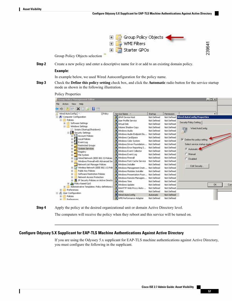
Group Policy Objects selection
Step 2 Create a new policy and enter a descriptive name for it or add to an existing domain policy.
Example:
In example below, we used Wired Autoconfiguration for the policy name.Step 3 Check the Define this policy setting check box, and click the Automatic radio button for the service startup
mode as shown in the following illustration.
Policy Properties
Step 4 Apply the policy at the desired organizational unit or domain Active Directory level.
The computers will receive the policy when they reboot and this service will be turned on.
Configure Odyssey 5.X Supplicant for EAP-TLS Machine Authentications Against Active Directory
If you are using the Odyssey 5.x supplicant for EAP-TLS machine authentications against Active Directory,you must configure the following in the supplicant.
Cisco ISE 2.7 Admin Guide: Asset Visibility57
Asset VisibilityConfigure Odyssey 5.X Supplicant for EAP-TLS Machine Authentications Against Active Directory

Procedure
Step 1 Start Odyssey Access Client.Step 2 Choose Odyssey Access Client Administrator from the Tools menu.Step 3 Double-click the Machine Account icon.Step 4 From the Machine Account page, you must configure a profile for EAP-TLS authentications:
a) Choose Configuration > Profiles.b) Enter a name for the EAP-TLS profile.c) On the Authentication tab, choose EAP-TLS as the authentication method.d) On the Certificate tab, check the Permit login using my certificate check box, and choose a certificate
for the supplicant machine.e) On the User Info tab, check the Use machine credentials check box.
If this option is enabled, the Odyssey supplicant sends the machine name in the formathost\<machine_name> and Active Directory identifies the request as coming from a machine and willlook up computer objects to perform authentication. If this option is disabled, the Odyssey supplicantsends the machine name without the host\ prefix and Active Directory will look up user objects and theauthentication fails.
AnyConnect Agent for Machine Authentication
When you configure AnyConnect Agent for machine authentication, you can do one of the following:
• Use the default machine hostname, which includes the prefix “host/.”
• Configure a new profile, in which case you must include the prefix “host/” and then the machine name.
Active Directory Requirements to Support Easy Connect and PassiveIdentity services
Easy Connect and Passive Identity services use Active Directory login audit events generated by the ActiveDirectory domain controller to gather user login information. The Active Directory server must be configuredproperly so the ISE user can connect and fetch the user login information. The following sections show howconfigure the Active Directory domain controller (configurations from the Active Directory side) to supportEasy Connect and Passive Identity services.
In order to configure Active Directory domain controllers (configurations from the Active Directory side) tosupport Easy Connect and Passive Identity services use, follow these steps:
1. Set up Active Directory join points and domain controllers from ISE. See Add an Active Directory JoinPoint and Join Cisco ISE Node to the Join Point, on page 40 and Add Domain Controllers, on page 42.
2. Configure WMI per domain controller. See Configure WMI for Passive ID, on page 42.
3. Perform the following steps from Active Directory:
• Configure Active Directory for Passive Identity service, on page 59
Cisco ISE 2.7 Admin Guide: Asset Visibility58
Asset VisibilityAnyConnect Agent for Machine Authentication

• Set the Windows Audit Policy, on page 62
4. (Optional) Troubleshoot automatic configurations performed by ISE on Active Directory with these steps:
• Set Permissions When AD User in the Domain Admin Group, on page 62
• Required Permissions when AD User not in Domain Admin Group, on page 63
• Permissions to Use DCOM on the Domain Controller, on page 64
• Set Permissions for Access to WMI Root/CIMv2 Name Space, on page 66
• Grant Access to the Security Event Log on the AD Domain Controller, on page 67
Configure Active Directory for Passive Identity serviceISE Easy Connect and Passive Identity services use Active Directory login audit events generated by theActive Directory domain controller to gather user login information. ISE connects to Active Directory andfetches the user login information.
The following steps should be performed from the Active Directory domain controller:
Procedure
Step 1 Make sure relevant Microsoft patches are installed on the Active Directory domain controllers.a) The following patches for Windows Server 2008 are required:
• http://support.microsoft.com/kb/958124
This patch fixes a memory leak in Microsoft’s WMI, which prevents ISE to establish successfulconnection with the domain controller (ISE administrator can experience it in ISE Active Directorydomain controller GUI page, where the status need to be “up” once the connection establishessuccessfully).
• http://support.microsoft.com/kb/973995
This patch fixes different memory leak in Microsoft’s WMI, which sporadically prevents the ActiveDirectory domain controller from writing the necessary user login events to the Security Log of thedomain controller. As result ISE may not get all user login events from this domain controller.
b) The following patches for Windows Server 2008 R2 are required (unless SP1 is installed):
• http://support.microsoft.com/kb/981314
This patch fixes memory leak inMicrosoft’sWMI, which sporadically prevents the Active Directorydomain controller from writing the necessary user login events to the Security Log of the domaincontroller. As result ISE may not get all user login events from this domain controller.
• http://support.microsoft.com/kb/2617858
This patch fixes unexpectedly slow startup or logon process in Windows Server 2008 R2.
c) The patches listed at the following link, for WMI related issues on Windows platform are required:
• http://support.microsoft.com/kb/2591403
Cisco ISE 2.7 Admin Guide: Asset Visibility59
Asset VisibilityConfigure Active Directory for Passive Identity service

These hot fixes are associated with the operation and functionality of the WMI service and its relatedcomponents.
Step 2 Make sure the Active Directory logs the user login events in the Windows Security Log.
Verify that the settings of the “Audit Policy” (part of the “Group Policy Management” settings) allowssuccessful logons to generate the necessary events in the Windows Security Log (this is the default Windowssetting, but you must explicitly ensure that this setting is correct). See Setting the Windows Audit Policy.
Step 3 Youmust have an Active Directory user with sufficient permissions for ISE to connect to the Active Directory.The following instructions show how to define permissions either for admin domain group user or none admindomain group user:
• Permissions Required when an Active Directory User is a Member of the Domain Admin Group, page2-4
• Permissions Required when an Active Directory User is Not a Member of the Domain Admin Group,page 2-4
Step 4 The Active Directory user used by ISE can be authenticated either by NT Lan Manager (NTLM) v1 or v2.You need to verify that the Active Directory NTLM settings are aligned with ISE NTLM settings to ensuresuccessful authenticated connection between ISE and the Active Directory Domain Controller. The followingtable shows allMicrosoft NTLMoptions, andwhich ISENTLMactions are supported. If ISE is set to NTLMv2,all six options described in are supported. If ISE is set to support NTLMv1, only the first five options aresupported.
Table 15: Supported Authentication Types Based on ISE and AD NTLM Version Settings
NTLMv2NTLMv1ISE NTLM setting options / ActiveDirectory (AD) NTLM settingoptions NTLMv1 NTLMv2
connection is allowedconnection is allowedSend LM & NTLM responsesconnection is allowed connectionis allowed
connection is allowedconnection is allowedSend LM&NTLM - use NTLMv2session security if negotiatedconnection is allowed connectionis allowed
connection is allowedconnection is allowedSend NTLM response onlyconnection is allowed connectionis allowed
connection is allowedconnection is allowedSend NTLMv2 response onlyconnection is allowed connectionis allowed
connection is allowedconnection is allowedSend NTLMv2 response only.Refuse LM connection is allowedconnection is allowed
Cisco ISE 2.7 Admin Guide: Asset Visibility60
Asset VisibilityConfigure Active Directory for Passive Identity service

NTLMv2NTLMv1ISE NTLM setting options / ActiveDirectory (AD) NTLM settingoptions NTLMv1 NTLMv2
connection is allowedconnection is refusedSend NTLMv2 response only.Refuse LM & NTLM connectionis refused connection is allowed
Figure 1: MS NTLM Authentication Type Options
Step 5 Make sure that you have created a firewall rule to allow traffic to dllhost.exe onActive Directory domaincontrollers.
You can either turn the firewall off, or allow access on a specific IP (ISE IP address) to the following ports:
• TCP 135: General RPC Port. When doing asynchronous RPC calls, the service listening on this port tellsthe client which port the component servicing this request is using.
• UDP 137: Netbios Name Resolution
• UDP 138: Netbios Datagram Service
• TCP 139: Netbios Session Service
• TCP 445: SMB
Cisco ISE 2.7 Admin Guide: Asset Visibility61
Asset VisibilityConfigure Active Directory for Passive Identity service

Higher ports are assigned dynamically or you can configure them manually. We recommend that you add%SystemRoot%\System32\dllhost.exe as a target. This program manages ports dynamically.
All firewall rules can be assigned to specific IP (ISE IP).
Set the Windows Audit PolicyEnsure that theAudit Policy (part of theGroup Policy Management settings) allows successful logons. Thisis required to generate the necessary events in theWindows Security Log of the AD domain controller machine.This is the default Windows setting, but you must verify that this setting is correct.
Procedure
Step 1 Choose Start > Programs > Administrative Tools > Group Policy Management.Step 2 Navigate under Domains to the relevant domain and expand the navigation tree.Step 3 Choose Default Domain Controller Policy, right click and choose Edit.
The Group Policy Management Editor appears.
Step 4 ChooseDefault Domain Controllers Policy >Computer Configuration > Policies >Windows Settings >Security Settings.
• For Windows Server 2003 or Windows Server 2008 (non-R2), choose Local Policies > Audit Policy.For the two Policy items, Audit Account Logon Events and Audit Logon Events, ensure that thecorresponding Policy Setting either directly or indirectly includes the Success condition. To include theSuccess condition indirectly, the Policy Setting must be set to Not Defined, indicating that the effectivevalue will be inherited from a higher level domain, and the Policy Setting for that higher level domainmust be configured to explicitly include the Success condition.
• For Windows Server 2008 R2 and Windows 2012, choose Advanced Audit Policy Configuration >Audit Policies > Account Logon. For the two Policy items, Audit Kerberos Authentication Serviceand Audit Kerberos Service Ticket Operations, ensure that the corresponding Policy Setting eitherdirectly or indirectly includes the Success condition, as described above.
Cisco ISE uses RC4 cipher in Kerberos protocol while communicating with Active Directory,unless this encryption type is disabled in Active Directory Domain Controller configuration.You can use the Network Security: Configure Encryption Types Allowed for Kerberosoption in Active Directory to configure the allowed encrytion types for Kerberos protocol.
Note
Step 5 If any Audit Policy item settings have been changed, you should then run gpupdate /force to force the newsettings to take effect.
Set Permissions When AD User in the Domain Admin GroupFor Windows 2008 R2,Windows 2012, and Windows 2012 R2, the Domain Admin group does not have fullcontrol on certain registry keys in the Windows operating system by default. The Active Directory adminmust give the Active Directory user Full Control permissions on the following registry keys:
Cisco ISE 2.7 Admin Guide: Asset Visibility62
Asset VisibilitySet the Windows Audit Policy

• HKEY_CLASSES_ROOT\CLSID\{76A64158-CB41-11D1-8B02-00600806D9B6}
• HKLM\Software\Classes\Wow6432Node\CLSID\{76A64158-CB41-11D1-8B02-00600806D9B6}
No registry changes are required for the following Active Directory versions:
• Windows 2003
• Windows 2003R2
• Windows 2008
To grant full control, the Active Directory admin must first take ownership of the key, as shown below.
Procedure
Step 1 Go to the Owner tab by right clicking the key.Step 2 Click Permissions.Step 3 Click Advanced.
Required Permissions when AD User not in Domain Admin GroupFor Windows 2012 R2, give the Active Directory user Full Control permissions on the following registrykeys:
• HKEY_CLASSES_ROOT\CLSID\{76A64158-CB41-11D1-8B02-00600806D9B6}
• HKLM\Software\Classes\Wow6432Node\CLSID\{76A64158-CB41-11D1-8B02-00600806D9B6}
The following permissions also are required when an Active Directory user is not in the Domain Admin group,but is in the Domain Users group:
• Add Registry Keys to Allow ISE to Connect to the Domain Controller (see below)
• Permissions to Use DCOM on the Domain Controller, on page 64
• Set Permissions for Access to WMI Root/CIMv2 Name Space, on page 66
These permissions are only required for the following Active Directory versions:
• Windows 2003
• Windows 2003R2
• Windows 2008
• Windows 2008 R2
• Windows 2012
• Windows 2012 R2
• Windows 2016
Cisco ISE 2.7 Admin Guide: Asset Visibility63
Asset VisibilityRequired Permissions when AD User not in Domain Admin Group

Add Registry Keys to Allow ISE to Connect to the Domain Controller
You must manually add some registry keys to the domain controller to allow ISE to connect as a DomainUser, and retrieve login authentication events. An agent is not required on the domain controllers or on anymachine in the domain.
The following registry script shows the keys to add. You can copy and paste this into a text file, save the filewith a .reg extension, and double click the file to make the registry changes. To add registry keys, the usermust be an owner of the root key.Windows Registry Editor Version 5.00
[HKEY_CLASSES_ROOT\CLSID\{76A64158-CB41-11D1-8B02-00600806D9B6}]"AppID"="{76A64158-CB41-11D1-8B02-00600806D9B6}"
[HKEY_CLASSES_ROOT\AppID\{76A64158-CB41-11D1-8B02-00600806D9B6}]"DllSurrogate"=" "
[HKEY_CLASSES_ROOT\Wow6432Node\AppID\{76A64158-CB41-11D1-8B02-00600806D9B6}]"DllSurrogate"=" "
Make sure that you include two spaces in the value of the key DllSurrogate.
Keep the empty lines as shown in the script above, including an empty line at the end of the file.
Permissions to Use DCOM on the Domain ControllerThe Active Directory user used for ISE Passive Identity services must have permissions to use DCOM (remoteCOM) on the Domain Controller. You can configure permissions with the dcomcnfg command line tool.
Procedure
Step 1 Run the dcomcnfg tool from the command line.Step 2 Expand Component Services.Step 3 Expand Computers > My Computer.Step 4 Select Action from the menu bar, click properties, and click COM Security.Step 5 Make sure that the account that ISE will use for both Access and Launch has Allow permissions. That Active
Directory user should be added to all the four options (Edit Limits and Edit Default for both Access Permissionsand Launch and Activation Permissions).
Step 6 Allow all Local and Remote access for both Access Permissions and Launch and Activation Permissions.
Cisco ISE 2.7 Admin Guide: Asset Visibility64
Asset VisibilityPermissions to Use DCOM on the Domain Controller
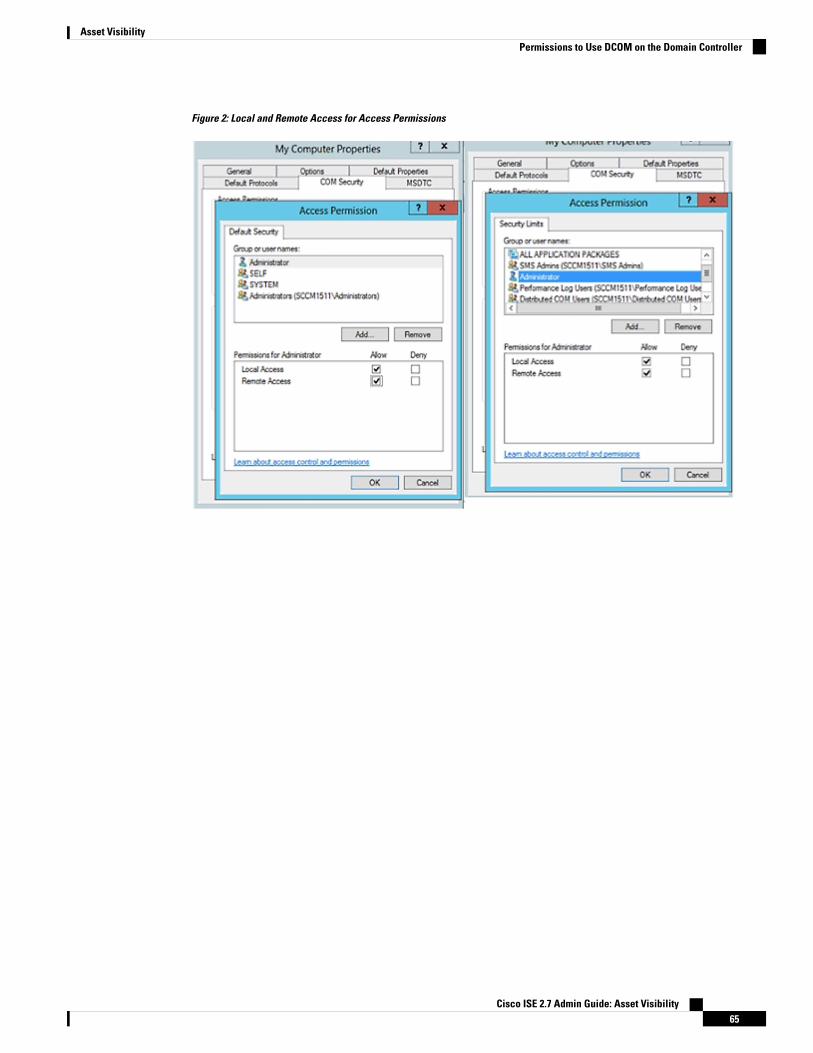
Figure 2: Local and Remote Access for Access Permissions
Cisco ISE 2.7 Admin Guide: Asset Visibility65
Asset VisibilityPermissions to Use DCOM on the Domain Controller

Figure 3: Local and Remote Access for Launch and Activation Permissions
Set Permissions for Access to WMI Root/CIMv2 Name SpaceBy default, Active Directory users do not have permissions for the Execute Methods and Remote Enable.You can grant access using the wmimgmt.msc MMC console.
Procedure
Step 1 Click Start > Run and type wmimgmt.msc.Step 2 Right-click WMI Control and click Properties.Step 3 Under the Security tab, expand Root and choose CIMV2.Step 4 Click Security.Step 5 Add the Active Directory user, and configure the required permissions as shown below.
Cisco ISE 2.7 Admin Guide: Asset Visibility66
Asset VisibilitySet Permissions for Access to WMI Root/CIMv2 Name Space

Figure 4: Required Permissions for WMI Root\CIMv2 Name Space
Grant Access to the Security Event Log on the AD Domain ControllerOn Windows 2008 and later, you can grant access to the AD Domain controller logs by adding the ISE IDMapping user to a group called Event Log Readers.
On all older versions of Windows, you must edit a registry key, as shown below.
Procedure
Step 1 To delegate access to the Security event logs, find the SID for the account .Step 2 Use the following command from the command line, also shown in the diagram below, to list all the SID
accounts.wmic useraccount get name,sid
You can also use the following command for a specific username and domain:
Cisco ISE 2.7 Admin Guide: Asset Visibility67
Asset VisibilityGrant Access to the Security Event Log on the AD Domain Controller

wmic useraccount where name=“iseUser” get domain,name,sid
Figure 5: List All the SID Accounts
Step 3 Find the SID, open the Registry Editor, and browse to the following location:HKEY_LOCAL_MACHINE/SYSTEM/CurrentControlSet/Services/Eventlog
Step 4 Click on Security, and double click CustomSD. See Figure 2-7
For example, to allow read access to the ise_agent account (SID -
S-1-5-21-1742827456-3351963980-3809373604-1107), enter(A;;0x1;;;S-1-5-21-1742827456-3351963980-3809373604-1107).
Figure 6: Edit CustomSD String
Step 5 Restart the WMI service on the Domain Controller. You can restart the WMI services in the following twoways:a) Run the following commands from the CLI:
net stop winmgmt
net start winmgmt
b) Run Services.msc, which opens the Windows Services Management tool. In the Windows ServicesManagement window, locate theWindows Management Instrumentation service, right click, and selectRestart.
Cisco ISE 2.7 Admin Guide: Asset Visibility68
Asset VisibilityGrant Access to the Security Event Log on the AD Domain Controller

Easy ConnectEasy Connect enables you to easily connect users from a wired endpoint to a network in a secure manner andmonitor those users by authenticating them through an Active Directory Domain Controller and not by CiscoISE. With Easy Connect, ISE collects user authentication information from the Active Directory DomainController. Because Easy Connect connects to a Windows system (Active Directory) using the MS WMIinterface and queries logs from the Windows event messaging, it currently only supports Windows-installedendpoints. Easy Connect supports wired connections using MAB, which is much easier to configure than802.1X. Unlike 802.1X, with Easy Connect and MAB:
• You don't need to configure supplicants
• You don't need to configure PKI
• ISE issues a CoA after the external server (AD) authenticates the user
Easy Connect supports these modes of operation:
• Enforcement-mode— ISE actively downloads the authorization policy to the network device forenforcement based on the user credentials.
• Visibility-mode—ISE publishes session merge and accounting information received from the NADdevice sensor in order to send that information to pxGrid.
In both cases, users authenticated with Active Directory (AD) are shown in the Cisco ISE live sessions view,and can be queried from the session directory using Cisco pxGrid interface by third-party applications. Theknown information is the user name, IP address, the AD DC host name and the AD DC NetBios name. Formore information about pxGrid, see the pxGrid Node section in Cisco ISE Admin Guide: Deployment .
Once you have set up Easy Connect, you can then filter certain users, based on their name or IP address. Forexample, if you have an administrator from IT services who logs in to an endpoint in order to assist the regularuser with that endpoint, you can filter out the administrator activity so it does not appear in Live Sessions,but rather only the regular user of that endpoint will appear. To filter passive identity services, see FilterPassive Identity Services, on page 116.
Easy Connect Restrictions
• MAC Authentication Bypass (MAB) supports Easy Connect. Both MAB and 802.1X can be configuredon the same port, but you must have a different ISE policy for each service.
• Only MAB connections are currently supported. You do not need a unique authentication policy forconnections, because the connection is authorized and permissions are granted by an Easy Connectcondition defined in the authorization policy.
• Easy Connect is supported in High Availability mode. Multiple nodes can be defined and enabled witha Passive ID. ISE then automatically activates one PSN, while the other nodes remain in standby.
• Only Cisco Network Access Devices (NADs) are supported.
• IPv6 is not supported.
• Wireless connections are not currently supported.
• Only Kerberos auth events are tracked and therefore Easy Connect enables only user authentication anddoes not support machine authentication.
Cisco ISE 2.7 Admin Guide: Asset Visibility69
Asset VisibilityEasy Connect

Easy Connect requires configuration in ISE, while the Active Directory Domain server must also have thecorrect patches and configuration based on instructions and guidelines issued by Microsoft. For informationabout configuring the Active Directory domain controller for ISE, see Active Directory Requirements toSupport Easy Connect and Passive Identity services, on page 58
Easy Connect Enforcement Mode
Easy Connect enables users to log on to a secure network from a wired endpoint (usually a PC) with aWindowsoperating system, by using MAC address bypass (MAB) protocol, and accessing Active Directory (AD) forauthentication. ISE Easy Connect listens for a Windows Management Instrumentation (WMI) event from theActive Directory server for information about authenticated users. Once AD authenticates a user, the DomainController generates an event log that includes the user name and IP address allocated for the user. ISE receivesnotification of log in from AD, and then issues a RADIUS Change of Authorization (CoA).
MAC address lookup is not done for aMAB request when the Radius service-type is set to call-check. Thereforethe return to the request is access-accept. This is the ISE default configuration.
Note
Easy Connect Enforcement Mode Process Flow
The Easy Connect Enforcement mode process is as follows:
1. The user connects to the NAD from a wired endpoint (such as a PC for example).
2. The NAD (which is configured for MAB) sends an access request to ISE. ISE responds with access, basedon user configuration, allowing the user to access AD. Configuration must allow at least access to DNS,DHCP and AD.
3. The user logs in to the domain and a security audit event is sent to ISE.
4. ISE collects the MAC address from RADIUS and the IP address and domain name, as well as accountinginformation (login information) about the user, from the security audit event.
5. Once all data is collected and merged in the ISE session directory, ISE issues a CoA to the NAD (basedon the appropriate policy managed in the policy service node (PSN)), and the user is provided access bythe NAD to the network based on that policy.
Figure 7: Easy Connect Enforcement Mode Basic Flow
Cisco ISE 2.7 Admin Guide: Asset Visibility70
Asset VisibilityEasy Connect

Figure 8: Easy Connect Enforcement Mode Detailed Flow
For more information about configuring Enforcement mode, see Configure Easy Connect Enforcement-Mode,on page 71.
Easy Connect Visibility Mode
With the Visibility mode, ISE only monitors accounting information from RADIUS (part of the device sensorfeature in the NAD) and does not perform authorization. Easy Connect listens for RADIUS Accounting andWMI events, and publishes that information to logs and reports, (and optionally, to pxGrid). Both RADIUSaccounting start and session termination are published to pxGrid during user login using Active Directorywhen pxGrid is setup.
Figure 9: Easy Connect Visibility Mode Flow
For more information about configuring Easy Connect Visibility mode, see Configure Easy ConnectVisibility-Mode, on page 73 .
Configure Easy Connect Enforcement-Mode
Before you begin
• For best performance, deploy a dedicated PSN to recieve WMI events.
• Create a list of Active Directory Domain Controllers for theWMI node, which receives AD login events.
Cisco ISE 2.7 Admin Guide: Asset Visibility71
Asset VisibilityConfigure Easy Connect Enforcement-Mode

• Determine the Microsoft Domain that ISE must join to fetch user groups from Active Directory.
• Determine the Active Directory groups that are used as a reference in the authorization policy.
• If you are using pxGrid to share session data from network devices with other pxGrid-enabled systems,then define a pxGrid persona in your deployment. For more information about pxGrid, see the pxGridNode section in Cisco ISE Admin Guide: Deployment
• After successful MAB, the NAD must provide a limited-access profile, which allows the user on thatport access to the Active Directory server (as described in the overview).
Procedure
Step 1 Note Passive Identity Service can be enabled on multiple nodes, but Easy Connect can only operate onone node at a time. If you enable the service for multiple nodes, ISE will automatically determinewhich node to use for the active Easy Connect session.
Enable the Passive Identity service on the dedicated Policy server (PSN) you intend to use for Easy Connect,so ISE can get group information and event information from Active Directory —Choose Administration >System > Deployment, open a node, and under General Settings, enable Enable Passive Identity Service.
Step 2 Configure an Active Directory join point and domain controller to be used by Easy Connect. To do this, andfor more information, see Active Directory Requirements to Support Easy Connect and Passive Identityservices, on page 58.
Step 3 Optionally, map AD domain controller groups in order to create different policies for different groups of users(for example, a different policy for Marketing employees versus Administration employees)—ChooseAdministration > Identity Management > External Identity Sources > Active Directory, select theActive Directory to use, select the Groups tab, and add the Active Directory groups you plan to use in yourauthorization policies.The Active Directory groups that youmap for the Domain Controller are dynamically updated in the PassiveIDdictionary and can then be used when you set up your policy conditions rules.
Step 4 Note Passive Identity Tracking must be enabled for all profiles used for Easy Connect authorization inorder for the Easy Connect process to run properly and enable ISE to issue a CoA.
Activate passive identity tracking—Choose Policy > Policy Elements > Results > Authorization >Authorization Profiles. For any profiles to be used by Easy Connect, open the profile and enable PassiveIdentify Tracking.
Step 5 Create policy rules—Choose Policy > Policy Elements >Conditions >Authorization > Simple Conditions,to create rules for Easy Connect. Click Add. Then define the condition:a) Enter a useful name and description.b) From Attribute, go to the PassiveID dictionary and select either PassiveID_Groups to create a condition
for domain controller groups, or select PassiveID_user to create a condition for individual users.c) Enter the correct operation.d) Enter the user name or group name to be included in the policy.
Step 6 Click Submit.
Cisco ISE 2.7 Admin Guide: Asset Visibility72
Asset VisibilityConfigure Easy Connect Enforcement-Mode

Configure Easy Connect Visibility-Mode
Before you begin
• For best performance, deploy a dedicated PSN to recieve WMI events.
• Create a list of Active Directory Domain Controllers for theWMI node, which receives AD login events.
• Determine the Microsoft Domain that ISE must join to fetch user groups from Active Directory.
• If you are using pxGrid to share session data from network devices with other pxGrid-enabled systems,then define a pxGrid persona in your deployment. For more information about pxGrid, see the pxGridNode section in Cisco ISE Admin Guide: Deployment
Procedure
Step 1 Enable the Passive Identity service on the dedicated Policy server (PSN) you intend to use for Easy Connect,so ISE can get group information and event information from Active Directory —Choose Administration >System > Deployment, open a node, and under General Settings, enable Enable Passive Identity Service.
Step 2 Configure an Active Directory join point and domain controller to be used by Easy Connect. To do this, andfor more information, see Active Directory Requirements to Support Easy Connect and Passive Identityservices, on page 58.
PassiveID Work CenterPassive Identity Connector (the PassiveID work center) offers a centralized, one-stop installation andimplementation enabling you to easily and simply configure your network in order to receive and share useridentity information with a variety of different security product subscribers such as Cisco FirepowerManagement Center (FMC) and Stealthwatch. As the full broker for passive identification, the PassiveIDwork center collects user identities from different provider sources, such as Active DirectoryDomain Controllers(AD DC), maps the user login information to the relevant IP addresses in use and then shares that mappinginformation with any of the subscriber security products that you have configured.
What is Passive Identity?
Standard flows offered by Cisco Identity Services Engine (ISE), which provide an authentication, authorizationand accounting (AAA) server, and utilize technologies such as 802.1X or Web Authentication, communicatedirectly with the user or endpoint, requesting access to the network, and then using their login credentials inorder to verify and actively authenticate their identity.
Passive identity services do not authenticate users directly, but rather gather user identities and IP addressesfrom external authentication servers such as Active Directory, known as providers, and then share thatinformation with subscribers. the PassiveID work center first receives the user identity information from theprovider, usually based on the user login and password, and then performs the necessary checks and servicesin order to match the user identity with the relevant IP address, thereby delivering the authenticated IP addressto the subscriber.
Cisco ISE 2.7 Admin Guide: Asset Visibility73
Asset VisibilityConfigure Easy Connect Visibility-Mode

Passive Identity Connector (PassiveID work center) Flow
The flow for the PassiveID work center is as follows:
1. Provider performs the authentication of the user or endpoint.
2. Provider sends authenticated user information to Cisco ISE.
3. Cisco ISE normalizes, performs lookups, merges, parses and maps user information to IP addresses andpublishes mapped details to pxGrid.
4. pxGrid subscribers receive the mapped user details.
The following diagram illustrates the high-level flow offered by Cisco ISE.
Figure 10: High Level Flow
Initial Setup and ConfigurationTo get started using Cisco PassiveID work center quickly, follow this flow:
1. Ensure you have properly configured the DNS server, including configuring reverse lookup for the clientmachine from ISE. For more information, see DNS Server, on page 39.
2. Enable the Passive Identity and pxGrid services on the dedicated Policy server (PSN) you intend to usefor any of the Passive Identity services — Choose Administration > System > Deployment, open therelevant node, and under General Settings, enable Enable Passive Identity Service and pxGrid.
3. Synchronize clock settings for the NTP servers.
4. Configure an initial provider with the ISE Passive Identity Setup. For more information, see GettingStarted with the PassiveID Setup , on page 76
5. Configure a single or multiple subscribers. For more information, see Subscribers, on page 119
After setting up an initial provider and subscriber, you can easily create additional providers (see the "AdditionalPassive Identity Service Providers" section in Cisco ISE Admin Guide: Asset Visibility) and manage yourpassive identification from the different providers in the PassiveID work center:
• See the RADIUS Live Sessions section in Cisco ISE Admin Guide: Troubleshooting
Cisco ISE 2.7 Admin Guide: Asset Visibility74
Asset VisibilityInitial Setup and Configuration

• See the Cisco ISE Alarms section in Cisco ISE Admin Guide: Troubleshooting
• See the Reports section in Cisco ISE Admin Guide: Maintain and Monitor
• See the TCP Dump Utility to Validate the Incoming Traffic section in Cisco ISE Admin Guide:Troubleshooting
PassiveID Work Center DashboardThe Cisco PassiveID Work Center dashboard displays consolidated and correlated summary and statisticaldata that is essential for effective monitoring and troubleshooting, and is updated in real time. Dashlets showactivity over the last 24 hours, unless otherwise noted. To access the dashboard, choose Work Centers >PassiveID and then from the left panel choose Dashboard. You can only view the Cisco PassiveID WorkCenter Dashboard in the Primary Administration Node (PAN).
The Home page has two default dashboards that show a view of your PassiveID Work Center data:
• Main—This view has a linearMetrics dashboard, chart dashlets, and list dashlets. In the PassiveIDWorkCenter, the dashlets are not configurable. Available dashlets include:
• Passive Identity Metrics—Passive Identity Metrics provides an overview of: the total number ofunique live sessions currently being tracked, the total number of identity providers configured inthe system, the total number of agents actively delivering identity data, and the total number ofsubscribers currently configured.
• Providers—Providers provide user identity information to PassiveID Work Center. You configurethe ISE probe (mechanisms that collect data from a given source) through which to receiveinformation from the provider sources. For example, an Active Directory (AD) probe and an Agentsprobe both help ISE-PIC collect data from AD (each with different technology) while a Syslogprobe collects data from a parser that reads syslog messages.
• Subscribers—Subscribers connect to ISE to retrieve user identity information.
• OS Types—The only OS type that can be displayed isWindows.Windows types display byWindowsversions. Providers do not report the OS type, but ISE can query Active Directory to get thatinformation. Up to 1000 entries are displayed in the dashlet. If you have more endpoints than that,or if you wish to display more OS types than Windows, you can upgrade to ISE.
• Alarms—User identity-related alarms.
Active Directory as a Probe and a ProviderActive Directory (AD) is a highly secure and precise source from which to receive user identity information,including user name, IP address and domain name.
The AD probe, a Passive Identity service, collects user identity information fromAD throughWMI technology,while other probes use AD as a user identity provider through other technologies and methods. For moreinformation about other probes and provider types offered by ISE, see the "Additional Passive Identity ServiceProviders" section in Cisco ISE Admin Guide: Asset Visibility.
By configuring the Active Directory probe you can also then quickly configure and enable these other probes(which also use Active Directory as their source):
• Agent—Active Directory Agents, on page 84
Cisco ISE 2.7 Admin Guide: Asset Visibility75
Asset VisibilityPassiveID Work Center Dashboard

The Active Directory agents are only supported on Windows Server 2008 andhigher.
Note
• SPAN—SPAN, on page 93
• Endpoint probe—Endpoint Probe, on page 117
In addition, configure the Active Directory probe in order to use AD user groups when collecting userinformation. You can use AD user groups for the AD, Agents, SPAN and Syslog probes. For more informationabout AD groups, see Configure Active Directory User Groups, on page 44.
Set Up an Active Directory (WMI) Probe
To configure Active Directory andWMI for Passive Identity services you can use the Passive IDWork CenterWizard (see Getting Started with the PassiveID Setup , on page 76) or you can follow the steps as follows(and see Active Directory Requirements to Support Easy Connect and Passive Identity services, on page 58for additional information):
1. Configure the Active Directory probe. See Add an Active Directory Join Point and Join Cisco ISE Nodeto the Join Point, on page 40.
2. Create a list of Active Directory Domain Controllers for theWMI-configured node (or nodes) that receivesAD login events. See Add Domain Controllers, on page 42.
3. Configure the Active Directory in order for it to integrate with ISE. See Configure WMI for Passive ID,on page 42.
4. (Optional) Manage the Active Directory Provider, on page 78.
Getting Started with the PassiveID Setup
ISE-PIC offers a wizard from which you can easily and quickly configure Active Directory as your first useridentity provider, in order to receive user identities from Active Directory. By configuring Active Directoryfor ISE-PIC, you also simplify the process for configuring other provider types later on. Once you haveconfigured Active Directory, you must then configure a Subscriber (such as Cisco Firepower ManagementCenter (FMC) or Stealthwatch), in order to define the client that is to receive the user data. For more informationabout subscribers, see Subscribers, on page 119.
Before you begin
• Ensure the Microsoft Active Directory server does not reside behind a network address translator anddoes not have a Network Address Translation (NAT) address.
• Ensure theMicrosoft Active Directory account intended for the join operation is valid and is not configuredwith the Change Password on Next Login.
• Ensure you have the privileges of a Super Admin or System Admin in ISE.
• Enable the Passive Identity and pxGrid services on the dedicated Policy server (PSN) you intend to usefor any of the Passive Identity services — Choose Administration > System > Deployment, open therelevant node, and under General Settings, enable Enable Passive Identity Service and pxGrid.
Cisco ISE 2.7 Admin Guide: Asset Visibility76
Asset VisibilityGetting Started with the PassiveID Setup

• Ensure that ISE has an entry in the domain name server (DNS). Ensure you have properly configuredreverse lookup for the client machine from ISE. For more information, see DNS Server, on page 39
Procedure
Step 1 Choose Work Centers > PassiveID. From the Passive Identity Connector Overview screen, click PassiveIdentity Wizard.
The PassiveID Setup opens:
Figure 11: The PassiveID Setup
Cisco ISE 2.7 Admin Guide: Asset Visibility77
Asset VisibilityGetting Started with the PassiveID Setup

Step 2 Click Next to begin the wizard.Step 3 From the Active Directory step, enter a unique name that distinguishes this configured Active Directory join
point quickly and easily in Join Point Name, from Active Directory domain enter the domain name for theActive Directory Domain to which this node is connected, and enter your Active Directory administrator username and password. For more information about these and other Active Directory settings, see Active DirectorySettings, on page 78.It is strongly recommended that you choose Store credentials, in which case your administrator's user nameand password will be saved in order to be used for all Domain Controllers (DC) that are configured formonitoring.
Step 4 Click Next to define Active Directory groups and check any user groups to be included and monitored.The Active Directory user groups automatically appear based on the Active Directory join point you configuredin the previous step.
Step 5 Click Next again to move to the Domain Controllers step. From the Domain Controllers step, select the DCsto be monitored. If you choose Custom, then from the next screen select the specific DCs for monitoring.When finished, click Next.Once you have selected specific DCs, you have finished creating your first Active Directory provider and thesummary screen itemizes the DCs selected and their details.
Step 6 Click Exit to complete the wizard.
What to do next
When you finish configuring Active Directory as your initial provider, you can easily configure additionalprovider types as well. For more information, see the "Additional Passive Identity Service Providers" sectionin Cisco ISE Admin Guide: Asset Visibility. Furthermore, you can now also configure a subscriber, designatedto receive the user identity information that is collected by any of the providers you have defined. For moreinformation, see Subscribers, on page 119.
Manage the Active Directory Provider
Once you have created and configured your Active Directory join points, continue to manage the ActiveDirectory probe with these tasks:
• Test Users for Active Directory Authentication, on page 51
• View Active Directory Joins for a Node, on page 53
• Diagnose Active Directory Problems, on page 53
• Leave the Active Directory Domain, on page 43
• Delete Active Directory Configurations, on page 52
• Enable Active Directory Debug Logs, on page 54
Active Directory Settings
Active Directory (AD) is a highly secure and precise source fromwhich to receive user information, includinguser name and IP address.
To create and manage Active Directory probes by creating and editing join points, choose Work Centers >PassiveID > Providers, from the left panel choose Active Directory.
Cisco ISE 2.7 Admin Guide: Asset Visibility78
Asset VisibilityManage the Active Directory Provider

For more information, see Add an Active Directory Join Point and Join Cisco ISE Node to the Join Point, onpage 40.
Table 16: Active Directory Join Point Name Settings and Join Domain Screen
DescriptionField
A unique name that distinguishes this configured joinpoint quickly and easily.
Join Point Name
The domain name for the Active Directory Domainto which this node is connected.
Active Directory Domain
This is the user principal name or the user accountname for the Active Directory user with administratorpriveleges.
Domain Administrator
This is the domain administrator's password asconfigured in Active Directory.
Password
Enter the administrator's organizational unitinformation
Specifiy Organizational Unit
It is strongly recommended that you choose Storecredentials, in which case your administrator's username and password will be saved in order to be usedfor all Domain Controllers (DC) that are configuredfor monitoring.
For the Endpoint probe, you must choose Storecredentials.
Store Credentials
Table 17: Active Directory Join/Leave Table
DescriptionField
The URL for the specific node in the installation.ISE Node
Indicates whether the node is the Primary orSecondary node in the installation.
ISE Node Role
Indicates whether the node is actively joined to theActive Directory domain.
Status
For nodes that are joined to Active Directory, thiscolumn indicates the specific Domain Controller towhich the node is connected in the Active DirectoryDomain.
Domain Controller
When an Active Directory forest is joined with ISE,this field indicates the specific Active Directory sitewithin the forest as it appears in the Active DirectorySites & Services area.
Site
Cisco ISE 2.7 Admin Guide: Asset Visibility79
Asset VisibilityActive Directory Settings

Choose Providers > Active Directory > PassiveID.
Table 18: Passive ID Domain Controllers (DC) List
DescriptionField
The fully qualified domain name of the server onwhich the domain controller is located.
Domain
The host on which the domain controller is located.DC Host
When an Active Directory forest is joined with ISE,this field indicates the specific Active Directory sitewithin the forest as it appears in the Active DirectorySites & Services area.
Site
The IP address of the domain controller.IP Address
Monitor Active Directory domain controllers for useridentity information by one of these methods:
• WMI—monitor Active Directory directly withthe WMI infrastructure.
• Agent name—if you have defined agents tomonitor Active Directory for user information,select the Agent protocol and choose the agentfrom the dropdown list that you would like touse. For more information about agents, seeActive Directory Agents, on page 84.
Monitor Using
Choose Providers > Active Directory > PassiveID. Click the link for the AD join point to be edited, go tothe PassiveID tab and click Edit to edit an existing Domain Controller from the list.
Table 19: Passive ID Domain Controllers (DC) Edit Screen
DescriptionField
Enter the fully qualified domain name of the serveron which the domain controller is located.
Host FQDN
Enter a unique description for this domain controllerin order to easily identiy it.
Description
The administrator's user name for accessing ActiveDirectory.
User Name
The administrator's password for accessing ActiveDirectory.
Password
Cisco ISE 2.7 Admin Guide: Asset Visibility80
Asset VisibilityActive Directory Settings
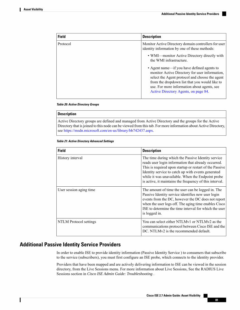
DescriptionField
Monitor Active Directory domain controllers for useridentity information by one of these methods:
• WMI—monitor Active Directory directly withthe WMI infrastructure.
• Agent name—if you have defined agents tomonitor Active Directory for user information,select the Agent protocol and choose the agentfrom the dropdown list that you would like touse. For more information about agents, seeActive Directory Agents, on page 84.
Protocol
Table 20: Active Directory Groups
Description
Active Directory groups are defined and managed from Active Directory and the groups for the ActiveDirectory that is joined to this node can be viewed from this tab. For more information about Active Directory,see https://msdn.microsoft.com/en-us/library/bb742437.aspx.
Table 21: Active Directory Advanced Settings
DescriptionField
The time during which the Passive Identity servicereads user login information that already occurred.This is required upon startup or restart of the PassiveIdentity service to catch up with events generatedwhile it was unavailable. When the Endpoint probeis active, it maintains the frequency of this interval.
History interval
The amount of time the user can be logged in. ThePassive Identity service identifies new user loginevents from the DC, however the DC does not reportwhen the user logs off. The aging time enables CiscoISE to determine the time interval for which the useris logged in.
User session aging time
You can select either NTLMv1 or NTLMv2 as thecommunications protocol between Cisco ISE and theDC. NTLMv2 is the recommended default.
NTLM Protocol settings
Additional Passive Identity Service ProvidersIn order to enable ISE to provide identity information (Passive Identity Service ) to consumers that subscribeto the service (subscribers), you must first configure an ISE probe, which connects to the identity provider.
Providers that have been mapped and are actively delivering information to ISE can be viewed in the sessiondirectory, from the Live Sessions menu. For more information about Live Sessions, See the RADIUS LiveSessions section in Cisco ISE Admin Guide: Troubleshooting .
Cisco ISE 2.7 Admin Guide: Asset Visibility81
Asset VisibilityAdditional Passive Identity Service Providers

The table below provides details about all of the provider and probe types available from ISE, while theremainder of the chapter provides information regarding all types available except for Active Directory whichis described in detail, in a dedicated chapter. For more information, see Active Directory as a Probe and aProvider, on page 75.
You can define these provider types:
Cisco ISE 2.7 Admin Guide: Asset Visibility82
Asset VisibilityAdditional Passive Identity Service Providers

Table 22: Provider Types
Document LinkUser IdentityInformationCollected
TechnologySourceSystem(Provider)
DescriptionProviderType(Probe)
Active Directory asa Probe and aProvider, on page75
• User name
• IP address
• Domain
WMIActiveDirectoryDomainController
A highly secure andprecise source, aswell as the mostcommon, fromwhichto receive userinformation.
As a probe, ADworks with WMItechnology to deliverauthenticated useridentities.
In addition, ADitself, rather than theprobe, functions as asource system (aprovider) fromwhichother probes retrieveuser data as well.
ActiveDirectory(AD)
Active DirectoryAgents, on page84
TheActiveDirectoryagentsare onlysupportedonWindowsServer2008 andhigher.
Note
• User name
• IP address
• Domain
Agents installedon the domaincontroller or onamember server.
A native 32-bitapplication installedon Active Directorydomain controllers oron member servers.The Agent probe is aquick and efficientsolution when usingActive Directory foruser identityinformation.
Agents
Endpoint Probe, onpage 117
Whether the user isstill connected
WMIAlways runs in thebackground inaddition to otherconfigured probes, inorder to verifywhether the user isstill connected.
Endpoint
SPAN, on page 93SPAN
Cisco ISE 2.7 Admin Guide: Asset Visibility83
Asset VisibilityAdditional Passive Identity Service Providers

Document LinkUser IdentityInformationCollected
TechnologySourceSystem(Provider)
DescriptionProviderType(Probe)
• User name
• IP address
• Domain
SPAN, installedon the switch,and Kerberosmessages
Sits on the networkswitch in order tolisten to networktraffic, and extractuser identityinformation based onActive Directorydata.
API Providers, onpage 89
• User name
• IP address
• Port range
• Domain
RESTful APIs.User identitysent tosubscribers inJSON format.
Any systemprogrammedtocommunicatewith a RESTAPI client.
Gather user identityinformation from anysystem programmedto communicate witha RESTful APIclient, using theRESTful API serviceoffered by ISE.
APIproviders
Syslog Providers,on page 95
• User name
• IP address
• MAC address
• Domain
Syslogmessages• Regularsyslogmessageproviders
• DHCPservers
Parse syslogmessages andretrieve useridentities, includingMAC addresses.
Syslog
Active Directory AgentsFrom the Passive Identity service work center install the native 32-bit application, Domain Controller (DC)agents, anywhere on the Active Directory (AD) domain controller (DC) or on a member server (based onyour configurations) to retrieve user identity information from AD and then send those identities to thesubscribers you have configured. The Agent probe is a quick and efficient solution when using Active Directoryfor user identity information. Agents can be installed on a separate domain, or on the AD domain, and onceinstalled, they provide status updates to ISE once every minute.
The agents can be either automatically installed and configured by ISE, or you can manually install them.Upon installation, the following occurs:
• The agent and its associated files are installed at the following path: Program Files/Cisco/CiscoISE PassiveID Agent
• A config file called PICAgent.exe.config is installed indicating the logging level for the agent.You can manually change the logging level from within the config file.
• The CiscoISEPICAgent.log file is stored with all logging messages.
• The nodes.txt file contains the list of all nodes in the deployment with which the agent can communicate.The agent contacts the first node in the list. If that node cannot be contacted, the agent continues toattempt communication according to the order of the nodes in the list. For manual installations, you must
Cisco ISE 2.7 Admin Guide: Asset Visibility84
Asset VisibilityActive Directory Agents

open the file and enter the node IP addresses. Once installed (manually or automatically), you can onlychange this file by manually updating it. Open the file and add, change or delete node IP addresses asnecessary.
• The Cisco ISE PassiveID Agent service runs on the machine, which you can manage from the WindowsServices dialog box.
• ISE supports up to 100 domain controllers, while each agent can monitor up to 10 domain controllers.
In order to monitor 100 domain controllers, you must configure 10 agents.Note
The Active Directory agents are only supported on Windows Server 2008 and higher.
If you cannot install agents, then use the Active Directory probe for passive identity services. For moreinformation, see Active Directory as a Probe and a Provider, on page 75.
Note
Automatically Install and Deploy Active Directory Agents
When configuring the Agent provider to monitor domain controllers for user identities, the agent must beinstalled on either a member server or on a domain controller. The agents can be either automatically installedby ISE, or you can manually install them. After installation, automatic or manual, you must then configurethe installed agent to monitor specified domain controllers rather than the default WMI. This process describeshow to enable automatic installation and configure the agent to monitor a domain controller.
Before you begin
Before you begin:
• Configure reverse lookup for the relevant DNS servers from the server side. For more information aboutthe DNS server configuration requirements for ISE, see DNS Server, on page 39
• Ensure Microsoft .NET Framework is updated for the machine designated for the agents, to a minimumof version 4.0. For more information about the .NET framework, see https://www.microsoft.com/net/framework.
• Active Passive ID and pxGrid services. For more information, see Initial Setup and Configuration, onpage 74.
• Create an AD join point and add at least one domain controller. For more information about creatingjoin points, see Active Directory as a Probe and a Provider, on page 75.
Use AD user groups for the AD, Agents, SPAN and Syslog probes. For more information about ADgroups, see Configure Active Directory User Groups, on page 44.
Cisco ISE 2.7 Admin Guide: Asset Visibility85
Asset VisibilityAutomatically Install and Deploy Active Directory Agents

Procedure
Step 1 Choose Work Centers > PassiveID > Providers and then choose Agents from the left panel to view allcurrently configured Domain Controller (DC) agents, to edit and delete existing agents, and to configure newagents.
Step 2 To add a new agent, click Add from the top of the table. To edit or change an existing client, checkmark theagent from the table and click Edit from the top of the table.
Step 3 To create the new agent and automatically install it on the host that you indicate in this configuration, selectDeploy New Agent.
Step 4 Complete all mandatory fields in order to configure the client correctly. For more information, see ActiveDirectory Agent Settings, on page 88.
Step 5 Click Deploy.The agent is automatically installed on the host according to the domain that you indicated in the configuration,and the settings are saved. The agent now also appears in the Agents table and can be applied to monitorspecified domain controllers, as described in the following steps.
Step 6 Choose Work Centers > PassiveID > Providers and then choose Active Directory from the left panel toview all currently configured join points.
Step 7 Click the link for the join point from which you would like to enable the agent you created.Step 8 Choose the Passive ID tab in order to work with the domain controllers that you added as part of the
prerequisites.Step 9 Check mark the domain controller that you would like to monitor with the agent you created. and click Edit.Step 10 From the dialog box that opens, ensure the mandatory fields are completed, from the Protocol dropdown
select Agent, from the Agent field that appears, select the agent you created from the dropdown list, enterthe user name and password credentials if you created any for the agent, and click Save.The agent is enabled for the domain controller and the dialog box closes.
Manually Install and Deploy Active Directory Agents
When configuring the Agent provider to monitor domain controllers for user identities, the agent must beinstalled on either a member server or on a domain controller. The agents can be either automatically installedby ISE, or you can manually install them. After installation, automatic or manual, you must then configurethe installed agent to monitor specified domain controllers rather than the default WMI. This process describeshow to manually install and configure the agent to monitor a domain controller.
Before you begin
Before you begin:
• Configure reverse lookup for the relevant DNS servers from the server side. For more information aboutthe DNS server configuration requirements for ISE, see DNS Server, on page 39
• Ensure Microsoft .NET Framework is updated for the machine designated for the agents, to a minimumof version 4.0. For more information about the .NET framework, see https://www.microsoft.com/net/framework.
• Active Passive ID and pxGrid services. For more information, see Initial Setup and Configuration, onpage 74.
Cisco ISE 2.7 Admin Guide: Asset Visibility86
Asset VisibilityManually Install and Deploy Active Directory Agents

• Create an AD join point and add at least one domain controller. For more information about creatingjoin points, see Active Directory as a Probe and a Provider, on page 75.
Use AD user groups for the AD, Agents, SPAN and Syslog probes. For more information about ADgroups, see Configure Active Directory User Groups, on page 44.
Procedure
Step 1 Choose Work Centers > PassiveID > Providers and then choose Agents from the left panel to view allcurrently configured Domain Controller (DC) agents, to edit and delete existing agents, and to configure newagents.
Step 2 Click Download Agent to download the picagent-installer.zip file for manual installation.The file is downloaded to your standard Windows Download folder.
Step 3 Place the zip file on the designated host machine and run the installation.Step 4 From the ISE GUI, again choose Work Centers > PassiveID > Providers and then choose Agents from the
left panel.Step 5 To configure a new agent, clickAdd from the top of the table. To edit or change an existing client, checkmark
the agent from the table and click Edit from the top of the table.Step 6 To configure the agent that you have already installed on the host machine, select Register Existing Agent.Step 7 Complete all mandatory fields in order to configure the client correctly. For more information, see Active
Directory Agent Settings, on page 88.Step 8 Click Save.
The agent settings are saved. The agent now also appears in the Agents table and can be applied to monitorspecified domain controllers, as described in the following steps.
Step 9 Choose Work Centers > PassiveID > Providers and then choose Active Directory from the left panel toview all currently configured join points.
Step 10 Click the link for the join point from which you would like to enable the agent you created.Step 11 Choose the Passive ID tab in order to work with the domain controllers that you added as part of the
prerequisites.Step 12 Check mark the domain controller that you would like to monitor with the agent you created. and click Edit.Step 13 From the dialog box that opens, ensure the mandatory fields are completed, from the Protocol dropdown
select Agent, from the Agent field that appears, select the agent you created from the dropdown list, enterthe user name and password credentials if you created any for the agent, and click Save.The agent is enabled for the domain controller and the dialog box closes.
Uninstall the Agent
Agents, installed automatically or manually, can be easily (manually) uninstalled directly from Windows.
Procedure
Step 1 From the Windows dialog, go to Programs and Features.Step 2 Find and select the Cisco ISE PassiveID Agent in the list of installed programs.
Cisco ISE 2.7 Admin Guide: Asset Visibility87
Asset VisibilityUninstall the Agent

Step 3 Click Uninstall.
Active Directory Agent Settings
Allow ISE to automatically install agents on a specified host in the network in order to retrieve user identityinformation from different Domain Controllers (DC) and deliver that information to Passive Identity servicesubscribers.
To create and manage agents, choose Providers > Agents. See Automatically Install and Deploy ActiveDirectory Agents, on page 85.
View current agent statuses from the Agents table. Choose Providers > Agents.
Table 23: Agents Table
DescriptionField
The agent name as you configured it.Name
The fully qualified domain name of the host on whichthe agent is installed.
Host
This is a comma separated list of domain controllersthat the specified agent is monitoring.
Monitoring
Table 24: Agents New
DescriptionField
• Deploy New Agent—install a new agent on thespecified host.
• Register Existing Agent—manually install theagent on the host and then configure that agentfrom this screen for Passive Identity service toenable the service.
Deploy New Agent or Register Existing Agent
Enter a name by which you can easily recognize theagent.
Name
Enter a description by which you can easily recognizethe agent.
Description
This is the fully qualified domain name for the hoston which the agent is installed (register existingagent), or is to be installed (automatic deployment).
Host FQDN
Enter your user name in order to access the host onwhich to install the agent. Passive Identity serviceuses these credentials in order to install the agent foryou.
User Name
Cisco ISE 2.7 Admin Guide: Asset Visibility88
Asset VisibilityActive Directory Agent Settings

DescriptionField
Enter your user password in order to access the hoston which to install the agent. Passive Identity serviceuses these credentials in order to install the agent foryou.
Password
API ProvidersThe API Providers feature in Cisco ISE enables you to push user identity information from your customizedprogram or from the terminal server (TS)-Agent to the built-in ISE passive identity services RESTAPI service.In this way, you can customize a programmable client from your network to send user identities that werecollected from any network access control (NAC) system to the service. Furthermore, the Cisco ISE APIprovider enables you to interface with network applications such as the TS-Agent on a Citrix server, whereall users have the same IP address but are assigned unique ports.
For example, an agent running on a Citrix server that provides identity mappings for users authenticatedagainst an Active Directory (AD) server can send REST requests to ISE to add or delete a user session whenevera new user logs in or off. ISE then takes the user identity information, including the IP address and assignedports, delivered from the client and sends it to pre-configured subscribers, such as the Cisco FirepowerManagement Center (FMC).
The ISE REST API framework implements the REST service over the HTTPS protocol (no client certificatevalidation necessary) and the user identity information is delivered in JSON (JavaScript Object Notation)format. For more information about JSON, see http://www.json.org/ .
The ISE REST API service parses user identities and in addition, maps that information to port ranges, inorder to distinguish between the different users logged in simultaneously to one system. Everytime a port isallocated to a user, the API sends a message to ISE.
The REST API Provider Flow
Once you have configured a bridge to your customized client from ISE by declaring that client as a Providerfor ISE and enabling that specific customized program (the client) to send RESTful requests, the ISE RESTservice works in the following way:
1. For client authentication, ISE requires an authentication token. A customized program on the client machinesends a request for an authentication token when initiating contact and then every time ISE notifies thatthe previous token has expired. The token is returned in response to the request, enabling ongoingcommunication between the client, and the ISE service.
2. Once a user has logged into the network, the client retrieves user identity information and posts thatinformaiton to the ISE REST service using the API Add command.
3. ISE receives and maps the user identity information.
4. ISE sends the mapped user identity information to the subscriber.
5. Whenever necessary, the customized machine can send a request to remove user information by sendinga Remove API call and including the user ID received as the response when the Add call was sent.
Work with REST API Providers in ISE
Follow these steps to activate the REST service in ISE:
Cisco ISE 2.7 Admin Guide: Asset Visibility89
Asset VisibilityAPI Providers

1. Configure the client side. For more information, see the client user documentation.
2. Activate Passive ID and pxGrid services. For more information, see Initial Setup and Configuration, onpage 74.
3. Ensure you have properly configured the DNS server, including configuring reverse lookup for the clientmachine from ISE. For more information about the DNS server configuration requirements for , see DNSServer, on page 39
4. See Configure a Bridge to the ISE REST Service for Passive Identity Services, on page 90.
To configure the API Provider to work with a TS-Agent add the TS-Agent information when creating a bridgefrom ISE to that agent, and then consult with the TS-Agent documentation for information about sending APIcalls.
Note
5. Generate an authentication token and send add and remove requests to the API service. #unique_135.
Configure a Bridge to the ISE REST Service for Passive Identity Services
In order to enable the ISE REST API service to receive information from a specific client, you must firstdefine the specific client from ISE. You can define multiple REST API clients with different IP addresses.
Before you begin
Before you begin:
• Ensure you have activated Passive ID and pxGrid services. For more information, see Initial Setup andConfiguration, on page 74.
• Ensure you have properly configured the DNS server, including configuring reverse lookup for the clientmachine from ISE. For more information about the DNS server configuration requirements for ISE, seeDNS Server, on page 39
Procedure
Step 1 Choose Work Centers > PassiveID > Providers and then choose API Providers from the left panel to viewall currently configured clients, to edit and delete existing clients, and to configure new clients.The API Providers table is displayed, including status information for each existing client.
Step 2 To add a new client, click Add from the top of the table. To edit or change an existing client, checkmark theclient from the table and click Edit from the top of the table.
Step 3 Complete all mandatory fields in order to configure the client correctly. For more information, see API ProviderSettings, on page 91.
Step 4 Click Submit.The client configuration is saved and the screen displays the updated API Providers table. The client can nowsend posts to the ISE REST service.
Cisco ISE 2.7 Admin Guide: Asset Visibility90
Asset VisibilityConfigure a Bridge to the ISE REST Service for Passive Identity Services

What to do next
Set up your customized client to post authentication tokens and user identities to the ISE REST service. SeeSend API Calls to the Passive ID REST Service, on page 91.
Send API Calls to the Passive ID REST Service
Before you begin
Configure a Bridge to the ISE REST Service for Passive Identity Services, on page 90
Procedure
Step 1 Enter the Cisco ISE URL in the address bar of your browser (for example, https://<ise hostname or ipaddress>/admin/)
Step 2 Enter the username and password that you specified and configured from the API Providers screen in the .ISEGUI. For more information, see Configure a Bridge to the ISE REST Service for Passive Identity Services,on page 90.
Step 3 Press Enter.Step 4 Enter the API call in the URL Address field of the target node as follows:Step 5 Click Send to issue the API call.
What to do next
See API Calls, on page 92 for more information and details about the different API calls, their schemas andtheir results.
API Provider Settings
Choose Providers > API Providers to configure a new REST API client for s.
The full API definition and object schemas can be retrieved with a request call as follows:
• For the full API specifications (wadl)—https://YOUR_ISE:9094/application.wadl
• For the API model and object schemas—https://YOUR_ISE:9094/application.wadl/xsd0.xsd
Note
Table 25: API Providers Settings
DescriptionField
Enter a unique name for this client that distinguishesit quickly and easily from other clients.
Name
Enter a clear description of this client.Description
Cisco ISE 2.7 Admin Guide: Asset Visibility91
Asset VisibilitySend API Calls to the Passive ID REST Service

DescriptionField
Select Enabled to enable the client to interact withthe REST services immediately upon completingconfiguration.
Status
Enter the IP address for the client host machine.Ensure you have properly configured the DNS server,including configuring reverse lookup for the clientmachine from ISE.
Host/ IP
Create a unique user name to be used when postingto the REST service.
User name
Create a unique password to be used when posting tothe REST service.
Password
API Calls
Use these API calls to manage user identity events for Passive Identity services with Cisco ISE.
Purpose: Generate Authentication Token
• Request
POST
https://<PIC IP address>:9094/api/fmi_platform/v1/identityauth/generatetoken
The request should contain the BasicAuth authorization header—provide the API provider's credentialsas previously created from the ISE-PIC GUI. For more information see API Provider Settings, on page91.
• Response Header
The header includes the X-auth-access-token. This is the token to be used when posting additional RESTrequests.
• Response Body
HTTP 204 No Content
Purpose: Add User
• Request
POST
https://<PIC IP address>:9094/api/identity/v1/identity/useridentity
Add X-auth-access-token in the header of the POST request. ( For example, Header: X-auth-access-token,Value: f3f25d81-3ac5-43ee-bbfb-20955643f6a7)
• Response Header
201 Created
• Response Body
Cisco ISE 2.7 Admin Guide: Asset Visibility92
Asset VisibilityAPI Calls

{
"user": "<username>",
"srcPatRange": {
"userPatStart": <user PAT start value>,
"userPatEnd": <user PAT end value>,
"patRangeStart": <PAT range start value>
},
"srcIpAddress": "<src IP address>",
"agentInfo": "<Agent name>",
"timestamp": "<ISO_8601 format i.e. “YYYY-MM-DDTHH:MM:SSZ" >",
"domain": "<domain>"
}
• Notes
• srcPatRange can be removed in above json to create a single IP user binding.
• Response body contains the "ID" which is the unique identifier for the user session binding created.Use this ID when sending a DELETE request to indicate which user should be removed.
• This reponse also contains the self link which is the URL for this newly created user session binding.
Purpose: Remove User
• Request
DELETE
https://<PIC IP address>:9094/api/identity/v1/identity/useridentity/<id>
In <id> enter the ID as was received from the Add response.
Add the X-auth-access-token in the header of the DELETE request. (For example, Header:X-auth-access-token, Value: f3f25d81-3ac5-43ee-bbfb-20955643f6a7)
• Response Header
200 OK
• Response Body
Response body contains the details about the user session binding which got deleted.
SPANSPAN is a Passive Identity service that allows you to quickly and easily enable ISE to listen to the networkand retrieve user information without having to configure Active Directory to work directly with ISE. SPANsniffs network traffic, specifically examining Kerberos messages, extracts user identity information also storedby Active Directory and sends that information to ISE. ISE then parses the information, ultimately deliveringuser name, IP address and domain name to the subscribers that you have also already configured from ISE.
Cisco ISE 2.7 Admin Guide: Asset Visibility93
Asset VisibilitySPAN

In order for SPAN to listen to the network and extract Active Directory user information, ISE and ActiveDirectory must both be connected to the same switch on the network. In this way, SPAN can copy and mirrorall user identity data from Active Directory.
With SPAN, user information is retrieved in the following way:
1. The user endpoint, on the network, logs in.
2. Log in and user data are stored in Kerberos messages.
3. Once the user logs in and the user data passes through the switch, SPAN mirrors the network data.
4. ISE listens to the network for user information and retrieves the mirrored data from the switch.
5. ISE parses the user information and updates passive ID mappings.
6. ISE delivers the parsed user information to the subscribers.
Working with SPAN
Before you begin
In order to enable ISE to receive SPAN traffic from a network switch, you must first define which nodes andnode interfaces are to listen to the switch. You can configure SPAN in order to listen to the different installedISE nodes. For each node, only one interface can be configured to listen to the network and the interface usedto listen must be dedicated to SPAN only.
Before you begin, ensure you have activated Passive ID and pxGrid services. Only nodes for which PassiveID has been turned on will appear in the list of available interfaces for configuring SPAN. For more information,see Initial Setup and Configuration, on page 74.
In addition, you must:
• Ensure Active Directory is configured on your network.
• Run a CLI on the switch in the network that is also connected to Active Directory in order to ensure theswitch can communicate with ISE.
• Configure the switch to mirror the network from AD.
• Configure a dedicated ISE network interface card (NIC) for SPAN. This NIC is used only for SPANtraffic.
• Ensure the NIC that you have dedicated to SPAN is activated via the command line interface.
• Create a VACL that sends only Kerberos traffic into the SPAN port.
Procedure
Step 1 Choose Work Centers > PassiveID > Providers and then choose SPAN from the left panel to configureSPAN.
Step 2 Note It is recommended that the GigabitEthernet0 network interface card (NIC) remain available andthat you select any other available NIC for configuring SPAN. GigabitEthernet0 is used for systemmanagement purposes.
Cisco ISE 2.7 Admin Guide: Asset Visibility94
Asset VisibilityWorking with SPAN

Enter a meaningful description (optional), select status Enabled, and choose the nodes and the relevant NICsthat will be used to listen to the network switch. For more information, see SPAN Settings, on page 95.
Step 3 Click Save.The SPAN configuration is saved and ISE-PIC ISE is now actively listening to network traffic.
SPAN Settings
From each node that you have deployed, quickly and easily configure ISE to receive user identities by installingSPAN on a client network.
Table 26: SPAN Settings
DescriptionField
Enter a unique description to remind you of whichnodes and interfaces are currently enabled.
Description
SelectEnabled to enable the client immediately uponcompleting configuration.
Status
Select one or more of the nodes installed for ISE, andthen for each selected node, choose the node interfacethat is to listen to the network for information.
It is recommended that theGigabitEthernet0NIC remain available andthat you select any other available NIC forconfiguring SPAN. GigabitEthernet0 isused for system management purposes.
Note
Interface NIC
Syslog ProvidersWith the Syslog feature, the Passive Identity service parses syslog messages from any client (identity dataprovider) that delivers syslog messages, including regular syslog messages (from providers such as InfoBlox,Blue Coat, BlueCat, and Lucent) as well as DHCP syslog messages, and sends back user identity information,including MAC addresses. This mapped user identity data is then delivered to subscribers.
The Passive Identity service utilizes syslogmessages received from a variety of providers once the administratoractivates Passive ID and pxGrid services and configures the syslog client from the GUI. When configuringthe provider, the administrator indicates the connection method (TCP or UDP) and the syslog template to beused for parsing.
When TCP is the configured connection type, if there is a problem with the message header and the host namecannot be parsed, then ISE attempts to match the IP address received in the packet to the IP address of any ofthe providers in the list of providers that have already been configured for Syslog messages in ISE. To viewthis list, choose Work Centers > PassiveID > Providers > Syslog Providers. It is recommended that youcheck the message headers and customize if necessary in order to guarantee parsing succeeds. For moreinformation about customizing headers, see Customize Syslog Headers, on page 102.
Note
Cisco ISE 2.7 Admin Guide: Asset Visibility95
Asset VisibilitySPAN Settings

Once configured, the syslog probe sends syslog messages that are received to the ISE parser, which maps theuser identity information, and publishes that information to ISE. ISE then delivers the parsed and mappeduser identity information to the Passive Identity service subscribers.
DHCP syslog messages do not contain user names. Therefore, these messages are delivered from the parserwith a delay so that ISE can first check users registered in the local session directory (displayed from LiveSessionss) and attempt to match those users by their IP addresses to the IP addresses listed in the DHCP syslogmessages received, in order to correctly parse and deliver user identity information. If the data received froma DHCP syslog message cannot be matched to any of the currently logged in users, then the message is notparsed and user identity is not delivered.
Note
In order to parse syslog messages for user identity from ISE:
• Configure syslog clients from which to receive user identity data—Configure Syslog Clients, on page96
• Customize a single message header—Customize Syslog Headers, on page 102
• Customize message bodies by creating templates—Customize the Syslog Message Body, on page 101.
• Use themessage templates pre-defined in ISEwhen configuring your syslog client as themessage templateused for parsing, or base your customized header or body templates on these pre-defined templates—Workwith Syslog Pre-Defined Message Templates, on page 105.
Configure Syslog Clients
In order to enable ISE to listen to syslog messages from a specific client, you must first define the specificclient from ISE. You can define multiple providers with different IP addresses.
Before you begin
Before you begin, ensure you have activated Passive ID and pxGrid services. For more information, see InitialSetup and Configuration, on page 74.
Procedure
Step 1 Choose Work Centers > PassiveID > Providers and then choose Syslog Providers from the left panel toview all currently configured clients, to edit and delete existing clients, and to configure new clients.The Syslog Providers table is displayed, including status information for each existing client.
Step 2 To configure a new syslog client, clickAdd from the top of the table. To edit or change a previously configuredclient, checkmark the client from the table and click Edit from the top of the table.
Step 3 Complete all mandatory fields (see Syslog Settings, on page 97 for more details) and create a message templateif necessary (see Customize the Syslog Message Body, on page 101 for more details) in order to configure theclient correctly.
Step 4 Click Submit.The client configuration is saved and the screen displays the updated Syslog Providers table.
Cisco ISE 2.7 Admin Guide: Asset Visibility96
Asset VisibilityConfigure Syslog Clients

Syslog Settings
Configure ISE to receive user identities, includingMAC addresses, by way of syslog messages from a specificclient. You can define multiple providers with different IP addresses.
Choose Work Centers > PassiveID > Providers, from the left panel choose Syslog Providers and from thetable click Add to create a new syslog client.
Table 27: Syslog Providers
DescriptionField
Enter a unique name that distinguishes this configuredclient quickly and easily.
Name
A meaningful description of this Syslog provider.Description
SelectEnabled to enable the client immediately uponcompleting configuration.
Status
Enter the FQDN of the host machine.Host
Enter UDP or TCP to indicate the channel by whichISE listens for syslog messages.
When TCP is the configured connectiontype, if there is a problemwith the messageheader and the host name cannot be parsed,then ISE-PIC ISE attempts to match the IPaddress received in the packet to the IPaddress of any of the providers in the listof providers that have already beenconfigured for Syslogmessages in ISE-PICISE.
To view this list, choose Work Centers >PassiveID > Providers > SyslogProviders. It is recommended that youcheck the message headers and customizeif necessary in order to guarantee parsingsucceeds. For more information aboutcustomizing headers, see Customize SyslogHeaders, on page 102.
Note
Connection Type
Cisco ISE 2.7 Admin Guide: Asset Visibility97
Asset VisibilitySyslog Settings

DescriptionField
Template
Cisco ISE 2.7 Admin Guide: Asset Visibility98
Asset VisibilitySyslog Settings

DescriptionField
A template indicates precise body message structureso that the parser can identify the pieces ofinformation within the syslog message that should beparsed, mapped and delivered.
For example, a template can indicate the exact positionof the user name so that the parser can find the username in every message received.
From this field, indicate the template (for the body ofthe syslog message) to be used in order to recognizeand correctly parse the syslog message.
Choose either from the pre-defined dropdown list, orclick New to create your own customized template.For more information about creating new templates,see Customize the Syslog Message Body, on page101. Most of the pre-defined templates use regularexpressions, and customized templates should alsouse regular expressions.
Only customized templates can be editedor removed, while pre-defined system
Note
templates in the dropdown cannot bealtered.
ISE currently offers these pre-defined DHCP providertemplates:
• InfoBlox
• BlueCat
• Lucent_QIP
• DHCPD
• MSAD DHCP
DHCP syslogmessages do not contain usernames. Therefore, these messages are
Note
delivered from the parser with a delay sothat ISE-PIC ISE can first check usersregistered in the local session directory(displayed from Live Sessionss) andattempt to match those users by their IPaddresses to the IP addresses listed in theDHCP syslog messages received, in orderto correctly parse and deliver user identityinformation.
If the data received from a DHCP syslogmessage cannot be matched to any of thecurrently logged in users, then the message
Cisco ISE 2.7 Admin Guide: Asset Visibility99
Asset VisibilitySyslog Settings
DescriptionField
is not parsed and user identity is notdelivered.
ISE offers these pre-defined regular syslog providertemplates:
• ISE
• ACS
• F5_VPN
• ASA_VPN
• Blue Coat
• Aerohive
• Safe connect_NAC
• Nortel_VPN
For information about templates, see Work withSyslog Pre-DefinedMessage Templates, on page 105.
If the domain is not identified in the syslog messagefor the specific user, this default domain isautomatically assigned to the user in order to ensurethat all users are assigned a domain.
With the default domain or with the domain that wasparsed from the message, the user name is appendedto username@domain, thereby including that domain,in order to get more information about the user anduser groups.
Default Domain
Customize Syslog Message Structures (Templates)
A template indicates precise message structure so that the parser can identify the pieces of information withinthe syslog message that should be parsed, mapped and delivered. For example, a template can indicate theexact position of the user name so that the parser can find the user name in every message received. Templatesdetermine the supported structures for both new and remove mapping messages.
Cisco ISE enables you to customize a single message header and multiple body structures, to be used by thePassive ID parser.
The templates should include regular expressions to define the structure for user name, IP address, MACaddress and domain in order to enable the Passive ID parser to correctly identify whether the message is toadd or remove user identity mapping and to correctly parse the user details.
When customizing your message templates, you can choose to base your customization on the messagetemplates pre-defined in ISE-PIC ISE by consulting with the regular expressions and message structures usedwithin those pre-defined options. For more information about the pre-defined template regular expressions,message structures, examples and more, seeWork with Syslog Pre-DefinedMessage Templates, on page 105.
Cisco ISE 2.7 Admin Guide: Asset Visibility100
Asset VisibilityCustomize Syslog Message Structures (Templates)

You can customize:
• A single message header—Customize Syslog Headers, on page 102
• Multiple message bodies—Customize the Syslog Message Body, on page 101.
DHCP syslog messages do not contain user names. Therefore, these messages are delivered from the parserwith a delay so that ISE-PIC ISE can first check users registered in the local session directory (displayed fromLive Sessionss) and attempt to match those users by their IP addresses to the IP addresses listed in the DHCPsyslog messages received, in order to correctly parse and deliver user identity information. If the data receivedfrom a DHCP syslog message cannot be matched to any of the currently logged in users, then the message isnot parsed and user identity is not delivered.
The delay necessary to properly match, parse and map details from DHCP messages cannot be applied tocustomized templates, and therefore it is not recommended that DHCP message templates be customized.Instead, use any of the pre-defined DHCP templates.
Note
Customize the Syslog Message Body
Cisco ISE enables you to customize your own syslog message templates (by customizing the message body)to be parsed by the Passive ID parser. The templates should include regular expressions to define the structurefor user name, IP address, MAC address and domain.
DHCP syslog messages do not contain user names. Therefore, these messages are delivered from the parserwith a delay so that ISE-PIC ISE can first check users registered in the local session directory (displayed fromLive Sessionss) and attempt to match those users by their IP addresses to the IP addresses listed in the DHCPsyslog messages received, in order to correctly parse and deliver user identity information. If the data receivedfrom a DHCP syslog message cannot be matched to any of the currently logged in users, then the message isnot parsed and user identity is not delivered.
The delay necessary to properly match, parse and map details from DHCP messages cannot be applied tocustomized templates, and therefore it is not recommended that DHCP message templates be customized.Instead, use any of the pre-defined DHCP templates.
Note
Create and edit syslog message body templates from within the syslog client configuration screen.
You can only edit your own customized templates. Pre-defined templates offered by the system cannot bechanged.
Note
Procedure
Step 1 Choose Work Centers > PassiveID > Providers and then choose Syslog Providers from the left panel toview all currently configured clients, to edit and delete existing clients, and to configure new clients.The Syslog Providers table is displayed, including status information for each existing client.
Cisco ISE 2.7 Admin Guide: Asset Visibility101
Asset VisibilityCustomize the Syslog Message Body

Step 2 Click Add to add a new syslog client or Edit to update an already configured client. If you only want to addor edit a template, it doesn't matter which of these options you select. For more information about configuringand updating syslog clients, see Configure Syslog Clients, on page 96.
Step 3 From the Syslog Providers screen, next to the Template field, click New to create a new message template.To edit an existing template, select the template from the dropdown list and click Edit.The Syslog Template screen opens.
Step 4 Complete all mandatory fields.
For information about how to enter the values correctly, see Syslog Customized Template Settings andExamples, on page 103.
Step 5 Click Test to ensure the message is correctly parsed based on the strings you have entered.Step 6 Click Save.
The customized template is saved and now appears in the dropdown list from the Template field whenconfiguring new and updating existing syslog clients.
Customize Syslog Headers
Syslog headers, amongst other details, also contain the host name from which the message originated. If yoursyslog messages are not recognized by the ISEmessage parser, you may need to customize the message headerby configuring the delimiter that proceeds the host name, thereby enabling ISE to recognize the host nameand parse the message correctly. For more details about the fields in this screen, see Syslog CustomizedTemplate Settings and Examples, on page 103. The customized header configuration is saved and added tothe header types that are used by the parser whenever messages are received.
You can only customize a single header. Once you customize a header, when you click Custom Header,create a template to be stored and click Submit, the newest configuration is saved and overrides the previouscustomization.
Note
Procedure
Step 1 Choose Work Centers > PassiveID > Providers and then choose Syslog Providers from the left panel toview all currently configured clients, to edit and delete existing clients, and to configure new clients.The Syslog Providers table is displayed, including status information for each existing client.
Step 2 Click Custom Header to open the Syslog Custom Header screen.Step 3 From the Paste sample syslog enter an example of the header format in your syslog messages. For example,
copy and paste this header from one of your messages: <181>Oct 10 15:14:08 Cisco.com.Step 4 From the Separator field, indicate whether words are separated by spaces or tabs.Step 5 From the Position of hostname in header field, indicate which place in the header is the host name. For
example, in the header offered above, the host name is the fourth word in the header. Enter 4 to indicate this.
TheHostname field displays the host name based on the details indicated in the first three fields. For example,if the header example in Paste sample syslog is as follows:
<181>Oct 10 15:14:08 Cisco.com
The separator is indicated as Space and the Position of hostname in header is entered as 4.
Cisco ISE 2.7 Admin Guide: Asset Visibility102
Asset VisibilityCustomize Syslog Headers

The Hostname will automatically appear as Cisco.com, which is the fourth word in the header phrase pastedin the Paste sample syslog field.
If the host name is incorrectly displayed, check the data you have entered in the Separator and Position ofhostname in header fields.
This example is as in the following screen capture:
Figure 12: Customize Syslog Headers
Step 6 Note You can only customize a single header. Once you customize a header, when you click CustomHeader, create a template to be stored and click Submit, the newest configuration is saved andoverrides the previous customization.
Click Submit.The customized header configuration is saved and added to the header types that are used by the parserwhenever messages are received.
Syslog Customized Template Settings and Examples
Cisco ISE enables you to customize your own syslog message templates to be parsed by the Passive ID parser.Customized templates determine the supported structures for both new and remove mapping messages. Thetemplates should include regular expressions to define the structure for user name, IP address, MAC addressand domain in order to enable the Passive ID parser to correctly identify whether the message is to add orremove user identity mapping and to correctly parse the user details.
Most of the pre-defined templates use regular expressions. Customized templates should also use regularexpressions.
Note
Cisco ISE 2.7 Admin Guide: Asset Visibility103
Asset VisibilitySyslog Customized Template Settings and Examples
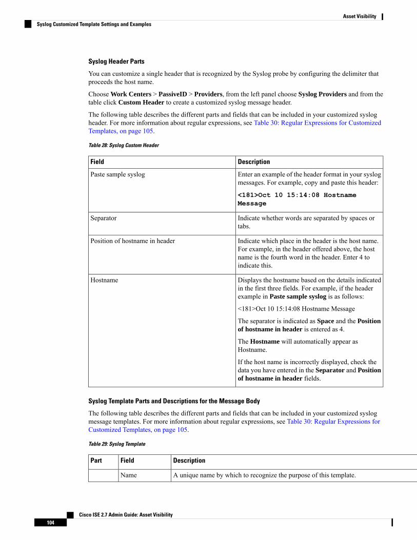
Syslog Header Parts
You can customize a single header that is recognized by the Syslog probe by configuring the delimiter thatproceeds the host name.
Choose Work Centers > PassiveID > Providers, from the left panel choose Syslog Providers and from thetable click Custom Header to create a customized syslog message header.
The following table describes the different parts and fields that can be included in your customized syslogheader. For more information about regular expressions, see Table 30: Regular Expressions for CustomizedTemplates, on page 105.
Table 28: Syslog Custom Header
DescriptionField
Enter an example of the header format in your syslogmessages. For example, copy and paste this header:
<181>Oct 10 15:14:08 HostnameMessage
Paste sample syslog
Indicate whether words are separated by spaces ortabs.
Separator
Indicate which place in the header is the host name.For example, in the header offered above, the hostname is the fourth word in the header. Enter 4 toindicate this.
Position of hostname in header
Displays the hostname based on the details indicatedin the first three fields. For example, if the headerexample in Paste sample syslog is as follows:
<181>Oct 10 15:14:08 Hostname Message
The separator is indicated as Space and the Positionof hostname in header is entered as 4.
The Hostname will automatically appear asHostname.
If the host name is incorrectly displayed, check thedata you have entered in the Separator and Positionof hostname in header fields.
Hostname
Syslog Template Parts and Descriptions for the Message Body
The following table describes the different parts and fields that can be included in your customized syslogmessage templates. For more information about regular expressions, see Table 30: Regular Expressions forCustomized Templates, on page 105.
Table 29: Syslog Template
DescriptionFieldPart
A unique name by which to recognize the purpose of this template.Name
Cisco ISE 2.7 Admin Guide: Asset Visibility104
Asset VisibilitySyslog Customized Template Settings and Examples
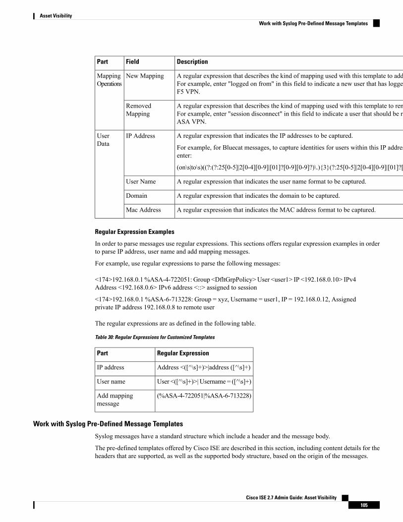
DescriptionFieldPart
A regular expression that describes the kind of mapping used with this template to add a new user.For example, enter "logged on from" in this field to indicate a new user that has logged on to theF5 VPN.
New MappingMappingOperations
A regular expression that describes the kind of mapping used with this template to remove a user.For example, enter "session disconnect" in this field to indicate a user that should be removed forASA VPN.
RemovedMapping
A regular expression that indicates the IP addresses to be captured.
For example, for Bluecat messages, to capture identities for users within this IP address range,enter:
(on\s|to\s)((?:(?:25[0-5]|2[0-4][0-9]|[01]?[0-9][0-9]?)\.){3}(?:25[0-5]|2[0-4][0-9]|[01]?[0-9][0-9]?))
IP AddressUserData
A regular expression that indicates the user name format to be captured.User Name
A regular expression that indicates the domain to be captured.Domain
A regular expression that indicates the MAC address format to be captured.Mac Address
Regular Expression Examples
In order to parse messages use regular expressions. This sections offers regular expression examples in orderto parse IP address, user name and add mapping messages.
For example, use regular expressions to parse the following messages:
<174>192.168.0.1%ASA-4-722051: Group <DfltGrpPolicy>User <user1> IP <192.168.0.10> IPv4Address <192.168.0.6> IPv6 address <::> assigned to session
<174>192.168.0.1 %ASA-6-713228: Group = xyz, Username = user1, IP = 192.168.0.12, Assignedprivate IP address 192.168.0.8 to remote user
The regular expressions are as defined in the following table.
Table 30: Regular Expressions for Customized Templates
Regular ExpressionPart
Address <([^\s]+)>|address ([^\s]+)IP address
User <([^\s]+)>| Username = ([^\s]+)User name
(%ASA-4-722051|%ASA-6-713228)Add mappingmessage
Work with Syslog Pre-Defined Message Templates
Syslog messages have a standard structure which include a header and the message body.
The pre-defined templates offered by Cisco ISE are described in this section, including content details for theheaders that are supported, as well as the supported body structure, based on the origin of the messages.
Cisco ISE 2.7 Admin Guide: Asset Visibility105
Asset VisibilityWork with Syslog Pre-Defined Message Templates

In addition, you can create your own templates with customized body content for sources that are not pre-definedin the system. The supported structure for customized templates is also described in this section. You canconfigure a single customized header to be used in addition to the headers pre-defined in the system, whenparsing messages, and you can configure multiple customized templates for the message body. For moreinformation about customizing the header, see Customize Syslog Headers, on page 102. For more informationabout customizing the body, see Customize the Syslog Message Body, on page 101.
Most of the pre-defined templates use regular expressions, and customized templates should also use regularexpressions.
Note
Message Headers
There are two header types recognized by the parser, for all message types (new and remove), for all clientmachines. These headers are as follows:
• <171>Host message
• <171>Oct 10 15:14:08 Host message
Once received, the header is parsed for host name, which can be IP address, hostname, or full FQDN.
Headers can also be customized. To customize your headers, see Customize Syslog Headers, on page 102.
Syslog ASA VPN Pre-Defined Template
The supported syslog message format and types for ASA VPN are as described below.
Headers
Headers supported by the parser are identical for all clients, as described in Work with Syslog Pre-DefinedMessage Templates, on page 105.
New Mapping Body Messages
There are different ASA VPN body messages that are recognized by the parser as described in the followingtable.
Cisco ISE 2.7 Admin Guide: Asset Visibility106
Asset VisibilitySyslog ASA VPN Pre-Defined Template

Parsing ExampleBody Message
[UserA,10.0.0.11]%ASA-6-109005 Authentication succeeded for userUserA from 10.0.0.11/100 to 10.10.11.11/20 oninterface eth1/1
%ASA-6-602303 IPSEC: An direction tunnel_typeSA (SPI=spi) between local_IP and 10.0.0.11 (UserA)has been created.
%ASA-6-721016 (device)WebVPN session for clientuser UserA, IP 10.0.0.11 has been created.
%ASA-6-603104 PPTP Tunnel created, tunnel_id isnumber, remote_peer_ip is remote_address,ppp_virtual_interface_id is number,\client_dynamic_ip is 10.0.0.11,ffg123 #% UserA isUserA, MPPE_key_strength is string
%ASA-6-603106 L2TP Tunnel created, tunnel_id isnumber, remote_peer_ip is remote_address,ppp_virtual_interface_id is number,\client_dynamic_ip is 10.0.0.11, UserA is user
%ASA-6-113039 Group group User UserA IP10.0.0.11 AnyConnect parent session started.
%ASA-6-802001 User UserA IP 10.100.1.1 OSos_nameUDID numberMDM action session started.
[UserA,172.16.0.11]
The parsed IP address from this messagetype is the private IP address, as indicatedin the message.
Note
%ASA-6-713228: Group = xyz, UserA = xxxx227,IP = 192.168.0.11, Assigned private IP address172.16.0.11 to remote user
[UserA,172.16.0.12]
The parsed IP address from this messagetype is the IPv4 address.
Note
%ASA-4-722051: Group <DfltGrpPolicy> User<UserA> IP <172.16.0.12> IPv4 Address<172.16.0.21> IPv6 address <::> assigned to session
Remove Mapping Body Messages
The Remove Mapping messages supported for ASA VPN by the parser are as described in this section.
Once received, the body is parsed for user details as follows:
[UserA,10.1.1.1]
Body Message
%ASA-4-113019 Group = group, UserA = UserA, IP = 10.1.1.1, Session disconnected. Session Type: type,Duration:\ duration, Bytes xmt: count,Bytes rcv: count, Reason: reason
Cisco ISE 2.7 Admin Guide: Asset Visibility107
Asset VisibilitySyslog ASA VPN Pre-Defined Template

Body Message
%ASA-4-717052 Group group nameUser UserA IP 10.1.1.1 Session disconnected due to periodic certificateauthentication failure. Subject Name id subject name Issuer Name id issuer name\ Serial Number id serialnumber
%ASA-6-602304 IPSEC: An direction tunnel_type SA (SPI=spi) between local_IP and 10.1.1.1 (UserA)has been deleted.
%ASA-6-721018 WebVPN session for client user UserA, IP 10.1.1.1 has been deleted.
%ASA-4-722049 Group group User UserA IP 10.1.1.1 Session terminated: SVC not enabled or invalidimage on the ASA
%ASA-4-722050 Group group User UserA IP 10.1.1.1 Session terminated: SVC not enabled for the user.
%ASA-6-802002 User UserA IP 10.1.1.1 OS os_name UDID number MDM action session terminated.
%ASA-3-716057 Group group User UserA IP 10.1.1.1 Session terminated, no type license available.
%ASA-3-722046 Group group User UserA IP 10.1.1.1 Session terminated: unable to establish tunnel.
%ASA-4-113035 Group group User UserA IP 10.1.1.1 Session terminated: AnyConnect not enabled orinvalid AnyConnect image on the ASA.
%ASA-4-716052 Group group-name User UserA IP 10.1.1.1 Pending session terminated.
%ASA-6-721018 WebVPN session for client user UserA, IP 10.1.1.1 has been deleted.
Syslog Bluecat Pre-Defined Template
The supported syslog message format and types for Bluecat are as described below.
Headers
Headers supported by the parser are identical for all clients, as described in Work with Syslog Pre-DefinedMessage Templates, on page 105.
New Mapping Body Messages
The messages supported for New Mapping for Bluecat syslog are as described in this section.
Once received, the body is parsed for user details as follows:
[macAddress=nn:xx:nn:ca:xx:nn,ip=172.16.0.12]
Body
Nov 7 23:37:32 xx-campus1 dhcpd: DHCPACK on 172.16.0.13 to nn:xx:nn:ca:xx:nn via 172.16.0.17
Remove Mapping Messages
There are no remove mapping messages known for Bluecat.
Cisco ISE 2.7 Admin Guide: Asset Visibility108
Asset VisibilitySyslog Bluecat Pre-Defined Template

Syslog F5 VPN Pre-Defined Template
The supported syslog message format and types for F5 VPN are as described below.
Headers
Headers supported by the parser are identical for all clients, as described in Work with Syslog Pre-DefinedMessage Templates, on page 105.
New Mapping Body Messages
There are different F5 VPN body messages that are recognized by the parser as described in the followingtable.
Once received, the body is parsed for user details as follows:
[user=UserA,ip=172.16.0.12]
Body
Apr 10 09:33:58 Oct 2 08:28:32 abc.xyz.org security[nnnnn]: [UserA@vendor-abcr] User UserA loggedon from 172.16.0.21 to \ 172.16.0.12 Sid = xyz\
Remove Mapping Messages
Currently there are no remove messages for F5 VPN that are supported.
Syslog Infoblox Pre-Defined Template
The supported syslog message format and types for Infoblox are as described below.
Headers
Headers supported by the parser are identical for all clients, as described in Work with Syslog Pre-DefinedMessage Templates, on page 105.
New Mapping Body Messages
There are different ASA VPN body messages that are recognized by the parser as described in the followingtable.
Once received, the body is parsed for user details as follows:
[macAddress= nn:xx:xx:xx:nn:nn,ip=10.0.10.100]
Body Message
Nov 15 11:37:26 user1-lnx dhcpd[3179]: DHCPACK on 10.0.0.14 to nn:xx:xx:nx:nn:nn(android-df67ddcbb1271593) via eth2 relay 10.0.0.24 lease-duration 3600
Nov 15 11:38:11 user1-lnx dhcpd[3179]: DHCPACK on 172.16.0.18 to nn:xx:xx:xn:nn:nn(DESKTOP-HUDGAAQ) via eth2 relay 172.16.0.13 lease-duration 691200 (RENEW)
Nov 15 11:38:11 192.168.0.12 dhcpd[25595]: DHCPACK to 10.0.0.11 (nn:xx:xx:xn:nn:nx) via eth1
Cisco ISE 2.7 Admin Guide: Asset Visibility109
Asset VisibilitySyslog F5 VPN Pre-Defined Template

Remove Mapping Messages
The following messages are supported for Remove Mapping.
There are several body messages recognized by the parser for remove mapping messages, as described in thetable below.
Once received, the body is parsed for user details as follows:
• If MAC address is included:
[00:0c:29:a2:18:34,10.0.10.100]
• If MAC address is not included:
[10.0.10.100]
Body Message
07-11-2016 23:37:32 Daemon.Info 10.0.10.2 Jul 12 10:42:26 10.0.10.2 dhcpd[26083]: DHCPEXPIRE10.0.10.100 has expired
07-11-2016 23:37:32 Daemon.Info 10.0.10.2 Jul 12 10:42:26 10.0.10.2 dhcpd[26083]: DHCPRELEASE of10.0.10.100 from 00:0c:29:a2:18:34 \ (win10) via eth1 uid 01:00:0c:29:a2:18:34
07-11-2016 23:37:32 Daemon.Info 10.0.10.2 Jul 12 10:42:26 10.0.10.2 dhcpd[25595]: RELEASE on10.20.31.172 to c0:ce:cd:44:4f:bd
Syslog Linux DHCPd3 Pre-Defined Template
The supported syslog message format and types for Linux DHCPd3 are as described below.
Headers
Headers supported by the parser are identical for all clients, as described in Work with Syslog Pre-DefinedMessage Templates, on page 105.
New Mapping Messages
There are different Linux DHCPd3 body messages that are recognized by the parser as described in thefollowing table.
Once received, the body is parsed for user details as follows:
[macAddress=24:ab:81:ca:f2:72,ip=172.16.0.21]
Body Message
Nov 11 23:37:32 dhcpsrv dhcpd: DHCPACK on 10.0.10.100 to 00:0c:29:a2:18:34 (win10) via eth1
Nov 11 23:37:32 dhcpsrv dhcpd: DHCPACK on 10.0.10.100 (00:0c:29:a2:18:34) via eth1
Remove Mapping Body Messages
The Remove Mapping messages supported for Linux DHCPd3 by the parser are as described in this section.
Once received, the body is parsed for user details as follows:
Cisco ISE 2.7 Admin Guide: Asset Visibility110
Asset VisibilitySyslog Linux DHCPd3 Pre-Defined Template

[00:0c:29:a2:18:34 ,10.0.10.100]
Body Message
Nov 11 23:37:32 dhcpsrv dhcpd: DHCPEXPIRE 10.0.10.100 has expired
Nov 11 23:37:32 dhcpsrv dhcpd: DHCPRELEASE of 10.0.10.100 from 00:0c:29:a2:18:34 (win10) via eth1
Syslog MS DHCP Pre-Defined Template
The supported syslog message format and types for MS DHCP are as described below.
Headers
Headers supported by the parser are identical for all clients, as described in Work with Syslog Pre-DefinedMessage Templates, on page 105.
New Mapping Body Messages
There are different MS DHCP body messages that are recognized by the parser as described in the followingtable.
Once received, the parser divides data by searching for the comma (,) and then messages of these formats areparsed as in the following example:
[macAddress=000C29912E5D,ip=10.0.10.123]
Body Message
Nov 11 23:37:3210,07/21/16,16:55:22,Assign,10.0.10.123,win10.IDCSPAN.Local,000C29912E5D,,724476048,0,,,,0x4D53465420352E30,MSFT,5.0
Remove Mapping Body Messages
The Remove Mapping messages supported for MS DHCP by the parser are as described in this section.
Once received, the parser divides data by searching for the comma (,) and then messages of these formats areparsed as in the following example:
[macAddress=000C29912E5D,ip=10.0.10.123]
Body Message
Nov 11 23:37:3212,07/21/16,16:55:18,Release,10.0.10.123,win10.IDCSPAN.Local,000C29912E5D,,3128563632,\ 0,,,,,,,,,0
Syslog SafeConnect NAC Pre-Defined Template
The supported syslog message format and types for SafeConnect NAC are as described below.
Headers
Headers supported by the parser are identical for all clients, as described in Work with Syslog Pre-DefinedMessage Templates, on page 105.
Cisco ISE 2.7 Admin Guide: Asset Visibility111
Asset VisibilitySyslog MS DHCP Pre-Defined Template

New Mapping Body Messages
There are different SafeConnect NAC body messages that are recognized by the parser as described in thefollowing table.
Once received, the body is parsed for user details as follows:
[user=galindk1i,p=xxxx.xx.xxx.xxd,domain=Resnet-Macs]
Body Message
Apr 10 09:33:58 nac Safe*Connect:authenticationResult|xxx.xx.xxx.xxx|xxx.xx.xxx.xxx|UserA|true|Resnet-Macs|TCNJ-Chain|001b63b79018|MAC
Remove Mapping Messages
Currently there are no remove messages for Safe Connect that are supported.
Syslog Aerohive Pre-Defined Templates
The supported syslog message format and types for Aerohive are as described below.
Headers
Headers supported by the parser are identical for all clients, as described in Work with Syslog Pre-DefinedMessage Templates, on page 105.
New Mapping Body Messages
There are different Aerohive body messages that are recognized by the parser as described in the followingtable.
Details parsed from the body include user name and IP address. The regular expression used for parsing is asin the following examples:
• New mapping—auth\:
• IP—ip ([A-F0-9a-f:.]+)
• User name—UserA ([a-zA-Z0-9\_]+)
Once received, the body is parsed for user details as follows:
[UserA,10.5.50.52]
Body Message
2013-04-01 14:06:05 info ah auth: Station 1cab:a7e6:cf7f ip 10.5.50.52 UserA UserA
Remove Mapping Messages
Currently the system does not support remove mapping messages from Aerohive.
Syslog Blue Coat Pre-Defined Templates—Main Proxy, Proxy SG, Squid Web Proxy
The system supports the following message types for Blue Coat:
• BlueCoat Main Proxy
Cisco ISE 2.7 Admin Guide: Asset Visibility112
Asset VisibilitySyslog Aerohive Pre-Defined Templates

• BlueCoat Proxy SG
• BlueCoat Squid Web Proxy
The supported syslog message format and types for Bluecoat messages are as described below.
Headers
Headers supported by the parser are identical for all clients, as described in Work with Syslog Pre-DefinedMessage Templates, on page 105.
New Mapping Body Messages
There are different Blue Coat body messages that are recognized by the parser as described in the followingtable.
Once received, the body is parsed for user details as follows:
[UserA,192.168.10.24]
Body Message (this example is taken from a BlueCoat Proxy SG message)
2016-09-21 23:05:33 58 10.0.0.1 UserA - - PROXIED "none" http://www.example.com/ 200 TCP_MISSGET application/json;charset=UTF-8 http site.api.example.com 80 /apis/v2/scoreboard/header?rand=1474499133503 - "Mozilla/5.0 (Windows NT 10.0; Win64; x64) AppleWebKit/537.36 (KHTML,like Gecko) Chrome/46.0.2486.0 Safari/537.36 Edge/13.10586" 192.168.10.24 7186 708 - "unavailable
The following table describes the different regular expression structures used per client for new mappingmessages.
Regular expressionsClient
New mapping
(TCP_HIT|TCP_MEM){1}
IP
\s((?:(?:[0-9]{1,3}\.){3}[0-9]{1,3})|(?:(?:[a-zA-Z0-9]{1,4}\:{1,2}){1,7}[a-zA-Z0-9]{1,4}))\s
User name
\s\-\s([a-zA-Z0-9\_]+)\s\-\s
BlueCoat Main Proxy
New mapping
(\-\sPROXIED){1}
IP
\s((?:(?:[0-9]{1,3}\.){3}[0-9]{1,3})|(?:(?:[a-zA-Z0-9]{1,4}\:{1,2}){1,7}[a-zA-Z0-9]{1,4}))\s[a-zA-Z0-9\_]+\s\-
User name
\s[0-9]{1,3}\.[0-9]{1,3}\.[0-9]{1,3}\.[0-9]{1,3}\s([a-zA-Z0-9\_]+)\s\-
BlueCoat Proxy SG
Cisco ISE 2.7 Admin Guide: Asset Visibility113
Asset VisibilitySyslog Blue Coat Pre-Defined Templates—Main Proxy, Proxy SG, Squid Web Proxy

Regular expressionsClient
New mapping
(TCP_HIT|TCP_MEM){1}
IP
\s((?:(?:[0-9]{1,3}\.){3}[0-9]{1,3})|(?:(?:[a-zA-Z0-9]{1,4}\:{1,2}){1,7}[a-zA-Z0-9]{1,4}))\sTCP
User name
\s([a-zA-Z0-9\._]+)\s\-\/
BlueCoat Squid Web Proxy
Remove Mapping Messages
Remove mapping messages are supported for Blue Coat clients, though no examples are currently available.
The following table describes the different known regular expression structure examples used per client forremove mapping messages.
Regular expressionsClient
(TCP_MISS|TCP_NC_MISS){1}BlueCoat Main Proxy
No example currently available.BlueCoat Proxy SG
(TCP_MISS|TCP_NC_MISS){1}BlueCoat Squid Web Proxy
Syslog ISE and ACS Pre-Defined Templates
When listening to ISE or ACS clients, the parser receives the following message types:
• Pass authentication—when the user is authenticated by ISE or ACS, the pass authentication message isissued notifying that authentication succeeded, and including user details. The message is parsed and theuser details and session ID are saved from this message.
• Accounting start and accounting update messages (new mapping)—received from ISE or ACS, theaccounting start or accounting update message is parsed with the user details and session ID that weresaved from the Pass Authentication message and then the user is mapped.
• Accounting stop (remove mapping)—when received from ISE or ACS, the user mapping is deleted fromthe system.
The supported syslog message format and types for ISE and ACS are as described below.
Pass Authentication Messages
The following messages are supported for Pass Authentication.
• Header
<181>Sep 13 10:51:41 Server logTag messageId totalFragments currentFragments message
For example: <181>Sep 13 10:51:41 Positron CISE_PassiveID 0000005255 1 0 message
• Body
Cisco ISE 2.7 Admin Guide: Asset Visibility114
Asset VisibilitySyslog ISE and ACS Pre-Defined Templates

Passed-Authentication 000011 1 0 2016-05-09 12:48:11.011 +03:00 0000012435 5200 NOTICEPassed-Authentication: Authentication succeeded, ConfigVersionId=104, Device IP Address=10.0.0.12,DestinationIPAddress=10.0.0.18, DestinationPort=1812, UserA=UserA, Protocol=Radius,RequestLatency=45, NetworkDeviceName=DefaultNetworkDevice, User-Name=UserA,NAS-IP-Address=1.1.1.1, Session-Timeout=90, Calling-Station-ID=, cisco-av-pair=audit-session-id=5
• Parsing Example
User name and session ID only are parsed.
[UserA,5]
Accounting Start/Update (New Mapping) Messages
The following messages are supported for New Mapping.
• Header
<181>Sep 13 10:51:41 Server logTag messageId totalFragments currentFragments message
For example: <181>Sep 13 10:51:41 Positron CISE_PassiveID 0000005255 1 0 message
• Body
CISE_RADIUS_Accounting 000011 1 0 2016-05-09 12:53:52.823 +03:00 0000012451 3000 NOTICERadius-Accounting: RADIUS Accounting start request, ConfigVersionId=104, Device IPAddress=10.0.0.12, RequestLatency=12, NetworkDeviceName=DefaultNetworkDevice,User-Name=UserA, NAS-IP-Address=10.0.0.1, Framed-IP-Address=10.0.0.16, Session-Timeout=90,Calling-Station-ID=, Acct-Status-Type=Start, Acct-Session-Id=6, cisco-av-pair=audit-session-id=5
• Parsing Example
Parsed details include user name, and framed IP address, as well as the MAC address if it is included inthe message.
[UserA,10.0.0.16]
Remove Mapping Messages
The following messages are supported for Remove Mapping.
• Header
<181>Sep 13 10:51:41 Server logTag messageId totalFragments currentFragments message
For example: <181>Sep 13 10:51:41 Positron CISE_PassiveID 0000005255 1 0 message
• Body
2016-05-09 12:56:27.274 +03:00 0000012482 3001 NOTICERadius-Accounting: RADIUSAccountingstop request, ConfigVersionId=104, Device IP Address=10.0.0.17, RequestLatency=13,NetworkDeviceName=DefaultNetworkDevice, User-Name=UserA, NAS-IP-Address=10.0.0.1,Framed-IP-Address=10.0.0.16, Session-Timeout=90, Calling-Station-ID=, Acct-Status-Type=Stop,Acct-Session-Id=104, cisco-av-pair=audit-session-id=5
• Parsing Example
Parsed details include user name, and framed IP address, as well as the MAC address if it is included inthe message.
Cisco ISE 2.7 Admin Guide: Asset Visibility115
Asset VisibilitySyslog ISE and ACS Pre-Defined Templates

[UserA,10.0.0.16]
Syslog Lucent QIP Pre-Defined Template
The supported syslog message format and types for Lucent QIP are as described below.
Headers
Headers supported by the parser are identical for all clients, as described in Work with Syslog Pre-DefinedMessage Templates, on page 105.
New Mapping Body Messages
There are different Lucent QIP body messages that are recognized by the parser as described in the followingtable.
The regular expression structure for these messages is as follows:
DHCP_GrantLease|:DHCP_RenewLease
Once received, the body is parsed for user details as follows:
[00:0C:29:91:2E:5D,10.0.0.11]
Body Message
DHCP:subtype=0:Single:$IGNORE_N$ DHCP_GrantLease: Host=$HOSTNAME$ P=10.0.0.11 MAC=00:0C:29:91:2E:5D
DHCP:subtype=0:Single:$IGNORE_N$ DHCP_RenewLease: Host=$HOSTNAME$ P=10.0.0.11 MAC=00:0C:29:91:2E:5D
Remove Mapping Body Messages
There are different Lucent QIP body messages that are recognized by the parser as described in the followingtable.
The regular expression structure for these messages is as follows:
Delete Lease:|DHCP Auto Release:
Once received, the body is parsed for user details as follows:
[10.0.0.11]
Body Message
DHCP:subtype=0:Single:$IGNORE_N$ Delete Lease: IP=10.0.0.11 $IGNORE_N$
DHCP:subtype=0:Single:$IGNORE_N$ DHCP Auto Release: IP=10.0.0.11 $IGNORE_N$
Filter Passive Identity ServicesYou can filter certain users, based on their name or IP address. For example, if you have an administratorfrom IT services who logs in to an endpoint in order to assist the regular user with that endpoint, you can filterout the administrator activity so it does not appear in Live Sessions, but rather only the regular user of thatendpoint will appear. The Live Session shows Passive Identity service components that are not filtered out
Cisco ISE 2.7 Admin Guide: Asset Visibility116
Asset VisibilitySyslog Lucent QIP Pre-Defined Template

by the Mapping Filters. You can add as many filters as needed. The “OR” logic operator applies betweenfilters. If both the fields are specified in a single filter, the “AND” logic operator applies between these fields.
Procedure
Step 1 Choose Work Centers > PassiveID > Providers and then from the left panel choose Mapping Filters.Step 2 Choose Providers > Mapping Filters.Step 3 Click Add, enter the Username and or IP address of the user you want to filter and click Submit.Step 4 To view the non-filtered users that are currently logged into the Monitoring session directory, choose
Operations > RADIUS Livelog.
Endpoint ProbeIn addition to the customized providers that you can configure the Endpoint probe is enabled in ISE when thePassive Identity service is activated and always runs in the background. The Endpoint probe periodicallychecks whether each specific user is still logged in to the system.
In order to ensure Endpoint runs in the background, you must first configure an initial Active Directory joinpoint and ensure you choose to Store Credentials. For more information about configuring the Endpointprobe, see Work with the Endpoint Probe, on page 118.
Note
To manually check for endpoint status go to Live Sessions , from the Actions column click Show Actionsand choose Check current user, as in the following figure.
Figure 13: Check Current User
For more information about endpoint user status, and manually running the check, See the RADIUS LiveSessions section in Cisco ISE Admin Guide: Troubleshooting .
Cisco ISE 2.7 Admin Guide: Asset Visibility117
Asset VisibilityEndpoint Probe
When the Endpoint probe recognizes that a user has connected, if 4 hours have passed since the last time thesession was updated for the specific endpoint, then it checks whether that user is still logged in and collectsthe following data:
• MAC address
• Operating system version
Based on the this check, the probe does the following:
• When the user is still logged in, the probe updates ISE with the status Active User.
• When the user has logged out, the session state is updated as Terminated and fifteen minutes later, theuser is removed from the Session Directory.
• When the user cannot be contacted, for example, when a firewall prevents contact or the endpoint hasshut down, the status is updated as Unreachable and the Subscriber policy will determine how to handlethe user session. The endpoint will remain in the Session Directory.
Work with the Endpoint Probe
Before you begin
Create and enable Endpoint probes based on subnet ranges. One Endpoint probe can be created per PSN. Towork with Endpoint probes, first ensure you have configured the following:
• Endpoints must have network connectivity to port 445.
• From ISE, configure an initial Active Directory join point and ensure you select Select Credentialswhenprompted. For more information about join points, see Active Directory as a Probe and a Provider, onpage 75.
In order to ensure Endpoint runs in the background, you must first configure aninitial Active Directory join point, which enables the Endpoint probe to run evenwhen the Active Directory probe is not fully configured.
Note
Procedure
Step 1 Choose Work Centers > Passive ID > Providers and then choose Endpoint Probes.Step 2 Click Add to create a new Endpoint probe.Step 3 Complete the mandatory fields, ensuring you select Enable from the Status field, and click Submit. See
Endpoint Probe Settings, on page 118 for more information.
Endpoint Probe Settings
Create a single Endpoint probe per PSN, based on subnet ranges. If you havemultiple PSNs in your deployment,then you can allot each PSN for a separate set of subnets, and in so doing, use each probe for a different groupof users.
Cisco ISE 2.7 Admin Guide: Asset Visibility118
Asset VisibilityWork with the Endpoint Probe

Choose Work Centers > Passive ID > Providers and then choose Endpoint Probes to configure a newEndpoint Probe for your PSN.
Table 31: Endpoint Probes Settings
DescriptionField
Enter a unique name by which to identify the use ofthis probe.
Name
Enter a unique description that explains the use forthis probe.
Description
Choose Enable in order to activate this probe.Status
Choose a PSN for this probe from the list of availablePSNs in your deployment.
Host Name
Enter the subnet range for the group of endpoints thatshould be checked by this probe. Use standard subnetmask ranges and separate subnet addresses withcommas.
For example:10.56.14.111/32,1.1.1.1/24,2.55.2.0/16,2.2.3.0/16,1.2.3.4/32
Each rangemust be unique and separate from all otherranges. For example, you cannot enter the followingranges for the same probe because they overlap witheach other: 2.2.2.0/16,2.2.3.0/16
Subnets
SubscribersThe Passive Identity services use Cisco pxGrid services to deliver authenticated user identities that are collectedfrom various providers and stored by the Cisco ISE session directory, to other network systems such as CiscoStealthwatch or Cisco Firepower Management Center (FMC).
In the following figure, the pxGrid node collects user identities from external providers. Those identities areparsed, mapped and formatted. pxGrid takes those formatted user identities and sends them to Passive Identityservice subscribers.
Cisco ISE 2.7 Admin Guide: Asset Visibility119
Asset VisibilitySubscribers
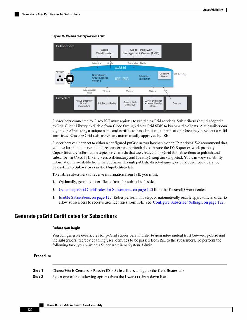
Figure 14: Passive Identity Service Flow
Subscribers connected to Cisco ISE must register to use the pxGrid services. Subscribers should adopt thepxGrid Client Library available from Cisco through the pxGrid SDK to become the clients. A subscriber canlog in to pxGrid using a unique name and certificate-based mutual authentication. Once they have sent a validcertificate, Cisco pxGrid subscribers are automatically approved by ISE.
Subscribers can connect to either a configured pxGrid server hostname or an IP Address. We recommend thatyou use hostname to avoid unnecessary errors, particularly to ensure the DNS queries work properly.Capabilities are information topics or channels that are created on pxGrid for subscribers to publish andsubscribe. In Cisco ISE, only SessionDirectory and IdentityGroup are supported. You can view capabilityinformation is available from the publisher through publish, directed query, or bulk download query, bynavigating to Subscribers in the Capabilities tab.
To enable subscribers to receive information from ISE, you must:
1. Optionally, generate a certificate from the subscriber's side.
2. Generate pxGrid Certificates for Subscribers, on page 120 from the PassiveID work center.
3. Enable Subscribers, on page 122. Either perform this step, or automatically enable approvals, in order toallow subscribers to receive user identities from ISE. See Configure Subscriber Settings, on page 122.
Generate pxGrid Certificates for Subscribers
Before you begin
You can generate certificates for pxGrid subscribers in order to guarantee mutual trust between pxGrid andthe subscribers, thereby enabling user identities to be passed from ISE to the subscribers. To perform thefollowing task, you must be a Super Admin or System Admin.
Procedure
Step 1 ChooseWork Centers > PassiveID > Subscribers and go to the Certificates tab.Step 2 Select one of the following options from the I want to drop-down list:
Cisco ISE 2.7 Admin Guide: Asset Visibility120
Asset VisibilityGenerate pxGrid Certificates for Subscribers

• Generate a single certificate without a certificate signing request—You must enter the Common Name(CN) if you select this option. In the CommonName field, enter the pxGrid FQDNwhich includes pxGridas the prefix. For example, www.pxgrid-ise.ise.net. Or, alternatively, use wildcards. For example, *.ise.net
• Generate a single certificate with a certificate signing request—You must enter the Certificate SigningRequest details if you select this option.
• Generate bulk certificates—You can upload a CSV file that contains the required details.
• Download Root Certificate Chain—download the ISE public root certificates in order to add them to thepxGrid client's trusted certificate store. The ISE pxGrid node only trusts the newly signed pxGrid clientcertificate and vice-versa, eliminating the need for outside certificate authorities.
Step 3 (optional) You can enter a description for this certificate.Step 4 View or edit the pxGrid Certificate template on which this certificate is based. Certificate templates contain
properties that are common to all certificates issued by the Certificate Authority (CA) based on that template.The certificate template defines the Subject, Subject Alternative Name (SAN), key type, key size, SCEP RAprofile that must be used, validity period of the certificate, and the extended key usage (EKU) that specifieswhether the certificate has to be used for client or server authentication or both. The internal Cisco ISE CA(ISE CA) uses a certificate template to issue certificates based on that template. To edit this template chooseAdministration > Certificates > Certificate Authority > Certificate Templates.
Step 5 Specify the Subject Alternative Name (SAN). You can addmultiple SANs. The following options are available:
• FQDN—Enter the fully qualified domain name of the ISE node. For example www.isepic.ise.net. Or,alternatively, use wildcards for the FQDN. For example, *.ise.net
An additional line can be added for FQDN in which the pxGrid FQDN can also be entered. This shouldbe identical to the FQDN you used in the Common Name field.
• IP address—Enter the IP address of the ISE node to be associated with the certificate. This informationmust be entered if the subscriber uses IP addresses instead of an FQDN.
This field is not displayed if you have selected the Generate Bulk Certificate option.Note
Step 6 Select one of the following options from the Certificate Download Format drop-down list:
• Certificate in Private Enhanced Electronic Mail (PEM) format, key in PKCS8 PEM format (includingcertificate chain)—The root certificate, the intermediate CA certificates, and the end entity certificateare represented in the PEM format. PEM formatted certificate are BASE64-encoded ASCII files. Eachcertificate starts with the "--------BEGIN CERTIFICATE-----" tag and ends with the "-------ENDCERTIFICATE----" tag. The end entity’s private key is stored using PKCS* PEM. It starts with the"-----BEGIN ENCRYPTED PRIVATE KEY----" tag and ends with the "-----END ENCRYPTEDPRIVATE KEY----" tag.
• PKCS12 format (including certificate chain; one file for both the certificate chain and key)—A binaryformat to store the root CA certificate, the intermediate CA certificate, and the end entity 's certificateand private key in one encrypted file.
Step 7 Enter a certificate password.Step 8 Click Create.
Cisco ISE 2.7 Admin Guide: Asset Visibility121
Asset VisibilityGenerate pxGrid Certificates for Subscribers

Enable SubscribersYou must perform this task, or alternatively automatically enable approvals, in order to allow subscribers toreceive user identities from . See Configure Subscriber Settings, on page 122.
Before you begin
• Enable the pxGrid persona on at least one node to view the requests from the Cisco pxGrid clients.
• Enable Passive Identity Service. For more information, see Easy Connect, on page 69.
Procedure
Step 1 Choose Work Centers > PassiveID > Subscribers and ensure you are viewing the Clients tab.Step 2 Check the checkbox next to the subscriber and click Approve.Step 3 Click Refresh to view the latest status.
View Subscriber Events from Live LogsThe Live Logs page displays all the Subscriber events. Event information includes the subscriber and capabilitynames along with the event type and timestamp.
Navigate to Subscribers and select the Live Log tab to view the list of events. You can also clear the logsand resynchronize or refresh the list.
Configure Subscriber Settings
Before you begin
To perform the following task, you must be a Super Admin or System Admin.
Procedure
Step 1 Choose Administration > pxGrid Services > Settings.Step 2 Select the following options based on your requirements:
• Automatically Approve New Accounts—Check this checkbox to automatically approve the connectionrequests from new pxGrid clients.
• Allow Password Based Account Creation—Check this checkbox to enable username/password basedauthentication for pxGrid clients. If this option is enabled, the pxGrid clients cannot be automaticallyapproved.
A pxGrid client can register itself with the pxGrid controller by sending the username via REST API.The pxGrid controller generates a password for the pxGrid client during client registration. Theadministrator can approve or deny the connection request.
Cisco ISE 2.7 Admin Guide: Asset Visibility122
Asset VisibilityEnable Subscribers

Step 3 Click Save.
Monitoring and Troubleshooting Service in PassiveID Work CenterLearn about how you can manage PassiveID Work Center with monitoring, troubleshooting and reportingtools.
• See the RADIUS Live Sessions section in Cisco ISE Admin Guide: Troubleshooting
• See the Cisco ISE Alarms section in Cisco ISE Admin Guide: Troubleshooting
• See the Reports section in Cisco ISE Admin Guide: Maintain and Monitor
• See the TCP Dump Utility to Validate the Incoming Traffic section in Cisco ISE Admin Guide:Troubleshooting
LDAPLightweight Directory Access Protocol (LDAP) is a networking protocol defined by RFC 2251 for queryingand modifying directory services that run on TCP/IP. LDAP is a lightweight mechanism for accessing anX.500-based directory server.
Cisco ISE integrates with an LDAP external database, which is also called an identity source, by using theLDAP protocol.
LDAP Directory ServiceLDAP directory service is based on a client-server model. A client starts an LDAP session by connecting toan LDAP server and sending operation requests to the server. The server then sends its responses. One ormore LDAP servers contain data from the LDAP directory tree or the LDAP backend database.
The directory service manages a directory, which is a database that holds information. Directory services usea distributed model for storing information, and that information is usually replicated between directoryservers.
An LDAP directory is organized in a simple tree hierarchy and can be distributed among many servers. Eachserver can have a replicated version of the total directory, which is synchronized periodically.
An entry in the tree contains a set of attributes, where each attribute has a name (an attribute type or attributedescription) and one or more values. The attributes are defined in a schema.
Each entry has a unique identifier: its distinguished name (DN). This name contains the relative distinguishedname (RDN), which is constructed from attributes in the entry, followed by the DN of the parent entry. Youcan think of the DN as a full filename, and the RDN as a relative filename in a folder.
Multiple LDAP InstancesBy creating more than one LDAP instance with different IP addresses or port settings, you can configureCisco ISE to authenticate using different LDAP servers or different databases on the same LDAP server. Eachprimary server IP address and port configuration, along with the secondary server IP address and portconfiguration, forms an LDAP instance that corresponds to one Cisco ISE LDAP identity source instance.
Cisco ISE 2.7 Admin Guide: Asset Visibility123
Asset VisibilityMonitoring and Troubleshooting Service in PassiveID Work Center

Cisco ISE does not require that each LDAP instance correspond to a unique LDAP database. You can havemore than one LDAP instance set to access the same database. This method is useful when your LDAPdatabase contains more than one subtree for users or groups. Because each LDAP instance supports only onesubtree directory for users and one subtree directory for groups, you must configure separate LDAP instancesfor each user directory and group directory subtree combination for which Cisco ISE submits authenticationrequests.
LDAP FailoverCisco ISE supports failover between a primary LDAP server and a secondary LDAP server. A failover occurswhen an authentication request fails because Cisco ISE could not connect to an LDAP server because it isdown or is otherwise unreachable.
If you establish failover settings and the first LDAP server that Cisco ISE attempts to contact cannot bereached, Cisco ISE always attempts to contact a second LDAP server. If you want Cisco ISE to use the firstLDAP server again, you must enter a value in the Failback Retry Delay text box.
Cisco ISE always uses the primary LDAP server to obtain groups and attributes for use in authorizationpolicies from the Admin portal, so the primary LDAP server must be accessible when you configure theseitems. Cisco ISE uses the secondary LDAP server only for authentications and authorizations at run time,according to the failover configuration.
Note
LDAP Connection ManagementCisco ISE supports multiple concurrent LDAP connections. Connections are opened on demand at the timeof the first LDAP authentication. The maximum number of connections is configured for each LDAP server.Opening connections in advance shortens the authentication time. You can set the maximum number ofconnections to use for concurrent binding connections. The number of open connections can be different foreach LDAP server (primary or secondary) and is determined based on the maximum number of administrationconnections configured for each server.
Cisco ISE retains a list of open LDAP connections (including the binding information) for each LDAP serverthat is configured in Cisco ISE. During the authentication process, the connection manager attempts to findan open connection from the pool. If an open connection does not exist, a new one is opened.
If the LDAP server closed the connection, the connection manager reports an error during the first call tosearch the directory, and tries to renew the connection. After the authentication process is complete, theconnection manager releases the connection.
LDAP User AuthenticationYou can configure LDAP as an external identity store. Cisco ISE uses plain password authentication. Userauthentication includes:
• Searching the LDAP server for an entry that matches the username in the request.
• Checking the user password with the one that is found in the LDAP server.
• Retrieving a group’s membership information for use in policies.
• Retrieving values for specified attributes for use in policies and authorization profiles.
Cisco ISE 2.7 Admin Guide: Asset Visibility124
Asset VisibilityLDAP Failover

To authenticate a user, Cisco ISE sends a bind request to the LDAP server. The bind request contains the DNand password of the user in clear text. If the DN and password of the user match the username and passwordin the LDAP directory, then the user is authenticated.
When Active Directory is used as LDAP, UPN names are used for user authentication. When Sun ONEDirectory Server is used as LDAP, SAM names are used for user authentication
Cisco ISE sends two searchRequest messages for every user authentication. This does not impact Cisco ISEauthorization or network performance. The second LDAP request is to make sure the Ciso ISE is talking tothe right identity.
Note
Cisco ISE as a DNS client, uses only the first IP returned in the DNS response to perform the LDAP bind.Note
We recommend that you protect the connection to the LDAP server using Secure Sockets Layer (SSL).
Password change is supported for LDAP only if there are remaining grace logins for the account after thepassword has expired. If password change is successful, the LDAP server's bindResponse is LDAP_SUCCESS,and includes the remaining grace logins control field in the bindResponse message. If the bindResponsemessage contains any additional control fields (other than remaining grace logins), Cisco ISE might not beable to decode the message.
Note
LDAP Group and Attribute Retrieval for Use in Authorization PoliciesCisco ISE can authenticate a subject (user or host) against an LDAP identity source by performing a bindoperation on the directory server to find and authenticate the subject. After a successful authentication, CiscoISE can retrieve groups and attributes that belong to the subject whenever they are required. You can configurethe attributes to retrieve in the Cisco ISE Admin portal by choosingAdministration > Identity Management> External Identity Sources > LDAP. These groups and attributes can be used by Cisco ISE to authorizethe subject.
To authenticate a user or query the LDAP identity source, Cisco ISE connects to the LDAP server andmaintainsa connection pool.
You should note the following restrictions on group memberships when Active Directory is configured as anLDAP store:
• Users or computers must be direct members of the group defined in the policy conditions to match thepolicy rule.
• The defined group may not be a user’s or computer’s primary group. This restriction is applicable onlywhen Active Directory is configured as an LDAP store.
LDAP Group Membership Information Retrieval
For user authentication, user lookup, and MAC address lookup, Cisco ISE must retrieve group membershipinformation from LDAP databases. LDAP servers represent the association between a subject (a user or ahost) and a group in one of the following ways:
Cisco ISE 2.7 Admin Guide: Asset Visibility125
Asset VisibilityLDAP Group and Attribute Retrieval for Use in Authorization Policies

• Groups Refer to Subjects—The group objects contain an attribute that specifies the subject. Identifiersfor subjects can be sourced in the group as the following:
• Distinguished names
• Plain usernames
• Subjects Refer to Groups—The subject objects contain an attribute that specifies the group to which theybelong.
LDAP identity sources contain the following parameters for group membership information retrieval:
• Reference direction—This parameter specifies the method to use when determining group membership(either groups to subjects or subjects to groups).
• Groupmap attribute—This parameter indicates the attribute that contains groupmembership information.
• Group object class—This parameter determines that certain objects are recognized as groups.
• Group search subtree—This parameter indicates the search base for group searches.
• Member type option—This parameter specifies how members are stored in the group member attribute(either as DNs or plain usernames).
LDAP Attributes Retrieval
For user authentication, user lookup, and MAC address lookup, Cisco ISE must retrieve the subject attributesfrom LDAP databases. For each instance of an LDAP identity source, an identity source dictionary is created.These dictionaries support attributes of the following data types:
• String
• Unsigned integer 32
• IPv4 address
For unsigned integers and IPv4 attributes, Cisco ISE converts the strings that it has retrieved to thecorresponding data types. If conversion fails or if no values are retrieved for the attributes, Cisco ISE logs adebug message, but the authentication or lookup process does not fail.
You can optionally configure default values for the attributes that Cisco ISE can use when the conversionfails or when Cisco ISE does not retrieve any values for the attributes.
LDAP Certificate Retrieval
If you have configured certificate retrieval as part of user lookup, then Cisco ISE must retrieve the value ofthe certificate attribute from LDAP. To retrieve the value of the certificate attribute from LDAP, you musthave previously configured the certificate attribute in the list of attributes to be accessed while configuringan LDAP identity source.
LDAP Group Membership Information Retrieval
For user authentication, user lookup, and MAC address lookup, Cisco ISE must retrieve group membershipinformation from LDAP databases. LDAP servers represent the association between a subject (a user or ahost) and a group in one of the following ways:
Cisco ISE 2.7 Admin Guide: Asset Visibility126
Asset VisibilityLDAP Group Membership Information Retrieval

• Groups Refer to Subjects—The group objects contain an attribute that specifies the subject. Identifiersfor subjects can be sourced in the group as the following:
• Distinguished names
• Plain usernames
• Subjects Refer to Groups—The subject objects contain an attribute that specifies the group to which theybelong.
LDAP identity sources contain the following parameters for group membership information retrieval:
• Reference direction—This parameter specifies the method to use when determining group membership(either groups to subjects or subjects to groups).
• Groupmap attribute—This parameter indicates the attribute that contains groupmembership information.
• Group object class—This parameter determines that certain objects are recognized as groups.
• Group search subtree—This parameter indicates the search base for group searches.
• Member type option—This parameter specifies how members are stored in the group member attribute(either as DNs or plain usernames).
LDAP Attributes Retrieval
For user authentication, user lookup, and MAC address lookup, Cisco ISE must retrieve the subject attributesfrom LDAP databases. For each instance of an LDAP identity source, an identity source dictionary is created.These dictionaries support attributes of the following data types:
• String
• Unsigned integer 32
• IPv4 address
For unsigned integers and IPv4 attributes, Cisco ISE converts the strings that it has retrieved to thecorresponding data types. If conversion fails or if no values are retrieved for the attributes, Cisco ISE logs adebug message, but the authentication or lookup process does not fail.
You can optionally configure default values for the attributes that Cisco ISE can use when the conversionfails or when Cisco ISE does not retrieve any values for the attributes.
LDAP Certificate Retrieval
If you have configured certificate retrieval as part of user lookup, then Cisco ISE must retrieve the value ofthe certificate attribute from LDAP. To retrieve the value of the certificate attribute from LDAP, you musthave previously configured the certificate attribute in the list of attributes to be accessed while configuringan LDAP identity source.
Errors Returned by the LDAP ServerThe following errors can occur during the authentication process:
• Authentication Errors—Cisco ISE logs authentication errors in the Cisco ISE log files.
Possible reasons for an LDAP server to return binding (authentication) errors include the following:
Cisco ISE 2.7 Admin Guide: Asset Visibility127
Asset VisibilityLDAP Attributes Retrieval

• Parameter errors—Invalid parameters were entered
• User account is restricted (disabled, locked out, expired, password expired, and so on)
• Initialization Errors—Use the LDAP server timeout settings to configure the number of secondsthat Cisco ISE should wait for a response from an LDAP server before determining that the connectionor authentication on that server has failed.
Possible reasons for an LDAP server to return an initialization error are:
• LDAP is not supported.
• The server is down.
• The server is out of memory.
• The user has no privileges.
• Administrator credentials are configured incorrectly.
The following errors are logged as external resource errors, indicating a possible problem with the LDAPserver:
• A connection error occurred
• The timeout expired
• The server is down
• The server is out of memory
The following error is logged as an Unknown User error:
• A user does not exist in the database
The following error is logged as an Invalid Password error, where the user exists, but the password sent isinvalid:
• An invalid password was entered
LDAP User LookupCisco ISE supports the user lookup feature with an LDAP server. This feature allows you to search for a userin the LDAP database and retrieve information without authentication. The user lookup process includes thefollowing actions:
• Searching the LDAP server for an entry that matches the username in the request
• Retrieving a user’s group membership information for use in policies
• Retrieving values for specified attributes for use in policies and authorization profiles
Cisco ISE 2.7 Admin Guide: Asset Visibility128
Asset VisibilityLDAP User Lookup

LDAP MAC Address LookupCisco ISE supports the MAC address lookup feature. This feature allows you to search for a MAC addressin the LDAP database and retrieve information without authentication. The MAC address lookup processincludes the following actions:
• Searching the LDAP server for an entry that matches the MAC address of the device
• Retrieving a MAC Address group information for the device for use in policies
• Retrieving values for specified attributes for use in policies
Add LDAP Identity Sources
Before you begin
• To perform the following task, you must be a Super Admin or System Admin.
• Cisco ISE always uses the primary LDAP server to obtain groups and attributes for use in authorizationpolicies. Therefore, your primary LDAP server must be reachable when you configure these items.
Procedure
Step 1 Choose Administration > Identity Management > External Identity Sources > LDAP > Add.Step 2 Enter the values.Step 3 Click Submit to create an LDAP instance.
LDAP Identity Source Settings
The following table describes the fields on the LDAP Identity Sources page, which you can use to create anLDAP instance and connect to it. The navigation path for this page is:Administration > Identity Management> External Identity Sources > LDAP.
LDAP General Settings
The following table describes the fields in the General tab.
Table 32: LDAP General Settings
Usage GuidelinesFields
Enter a name for the LDAP instance. This value isused in searches to obtain the subject DN andattributes. The value is of type string and themaximum length is 64 characters.
Name
Enter a description for the LDAP instance. This valueis of type string, and has a maximum length of 1024characters.
Description
Cisco ISE 2.7 Admin Guide: Asset Visibility129
Asset VisibilityLDAP MAC Address Lookup

Usage GuidelinesFields
You can choose any one of the following built-inschema types or create a custom schema:
• Active Directory
• Sun Directory Server
• Novell eDirectory
You can click the arrow next to Schema to viewthe schema details.
If you edit the attributes of the predefinedschema, Cisco ISE automatically creates aCustom schema.
Schema
The following fields can be edited only when you choose the Custom schema.Note
Enter a value to be used in searches to obtain thesubject DN and attributes. The value is of type stringand the maximum length is 256 characters.
Subject Objectclass
Enter the name of the attribute containing theusername in the request. The value is of type stringand the maximum length is 256 characters.
Subject Name Attribute
Enter CN or DN or any supported attribute in theGroup Name Attribute field.
• CN—To retrieve the LDAP Identity StoreGroups based on Common Name.
• DN—To retrieve the LDAP Identity StoreGroups based on Distinguished Name.
Group Name Attribute
Enter the attribute that contains the certificatedefinitions. For certificate-based authentication, thesedefinitions are used to validate certificates that arepresented by clients.
Certificate Attribute
Enter a value to be used in searches to specify theobjects that are recognized as groups. The value is oftype string and the maximum length is 256 characters.
Group Objectclass
Specifies the attribute that contains the mappinginformation. This attribute can be a user or groupattribute based on the reference direction that ischosen.
Group Map Attribute
Click this radio button if the subject objects containan attribute that specifies the group to which theybelong.
Subject Objects Contain Reference To Groups
Cisco ISE 2.7 Admin Guide: Asset Visibility130
Asset VisibilityLDAP Identity Source Settings

Usage GuidelinesFields
Click this radio button if the group objects contain anattribute that specifies the subject. This value is thedefault value.
Group Objects Contain Reference To Subjects
(Only available when you select the Group ObjectsContain Reference To Subjects radio button) Specifieshow members are sourced in the group memberattribute and defaults to the DN.
Subjects in Groups Are Stored in Member AttributeAs
By default, predefined attributes are used to collectuser information (such as, first name, last name, email,telephone, locality, and so on) for the followingbuilt-in schema types:
• Active Directory
• Sun Directory Server
• Novell eDirectory
If you edit the attributes of the predefined schema,Cisco ISE automatically creates a Custom schema.
You can also select the Custom option from theSchema drop-down list to edit the user informationattributes based on your requirements.
User Info Attributes
LDAP Connection Settings
The following table describes the fields in the Connection Settings tab.
Table 33: LDAP Connection Settings
Usage GuidelinesFields
Check this option to enable the secondary LDAPserver to be used as a backup if the primary LDAPserver fails. If you check this check box, you mustenter configuration parameters for the secondaryLDAP server.
Enable Secondary Server
Primary and Secondary Servers
Enter the IP address or DNS name of the machine thatis running the LDAP software. The hostname cancontain from 1 to 256 characters or a valid IP addressexpressed as a string. The only valid characters forhostnames are alphanumeric characters (a to z, A toZ, 0 to 9), the dot (.), and the hyphen (-).
Hostname/IP
Cisco ISE 2.7 Admin Guide: Asset Visibility131
Asset VisibilityLDAP Identity Source Settings

Usage GuidelinesFields
Enter the TCP/IP port number on which the LDAPserver is listening. Valid values are from 1 to 65,535.The default is 389, as stated in the LDAPspecification. If you do not know the port number,you can find this information from the LDAP serveradministrator.
Port
Check this check box to configure primary andsecondary LDAP server hostnames/IP and their portsfor each PSN.
When this option is enabled, a table listing all thenodes in the deployment is displayed. You need toselect the node and configure the primary andsecondary LDAP server hostname/IP and their portsfor the selected node.
Specify server for each ISE node
Anonymous Access—Click to ensure that searcheson the LDAP directory occur anonymously. The serverdoes not distinguish who the client is and will allowthe client read access to any data that is configured asaccessible to any unauthenticated client. In the absenceof a specific policy permitting authenticationinformation to be sent to a server, a client should usean anonymous connection.
Authenticated Access—Click to ensure that searcheson the LDAP directory occur with administrativecredentials. If so, enter information for the Admin DNand Password fields.
Access
Enter the DN of the administrator. The Admin DN isthe LDAP account that has permission to search allrequired users under the User Directory Subtree andto search groups. If the administrator specified doesnot have permission to see the group name attributein searches, group mapping fails for users who areauthenticated by that LDAP server.
Admin DN
Enter the LDAP administrator account password.Password
Click to use SSL to encrypt communication betweenCisco ISE and the primary LDAP server. Verify thatthe Port field contains the port number used for SSLon the LDAP server. If you enable this option, youmust choose a root CA.
Secure Authentication
Choose a trusted root certificate authority from thedrop-down list to enable secure authentication with acertificate.
LDAP Server Root CA
Cisco ISE 2.7 Admin Guide: Asset Visibility132
Asset VisibilityLDAP Identity Source Settings

Usage GuidelinesFields
Enter the number of seconds that Cisco ISE waits fora response from the primary LDAP server beforedetermining that the connection or authentication withthat server has failed. Valid values are 1 to 99. Thedefault is 10.
Server Timeout
Enter themaximumnumber of concurrent connections(greater than 0) with LDAP administrator accountpermissions that can run for a specific LDAPconfiguration. These connections are used to searchthe directory for users and groups under the UserDirectory Subtree and the Group Directory Subtree.Valid values are 1 to 99. The default is 20.
Max. Admin Connections
Check this check box and enter the desired value inthe Seconds text box to force the server to renewLDAP connection at the specified time interval. Thevalid range is from 1 to 60 minutes.
Force reconnect every N seconds
Click to test and ensure that the LDAP server detailsand credentials can successfully bind. If the test fails,edit your LDAP server details and retest.
Test Bind to Server
Failover
Click this option if you want Cisco ISE to alwaysaccess the primary LDAP server first forauthentications and authorizations.
Always Access Primary Server First
If the primary LDAP server that Cisco ISE attemptsto contact cannot be reached, Cisco ISE attempts tocontact the secondary LDAP server. If you want CiscoISE to use the primary LDAP server again, click thisoption and enter a value in the text box.
Failback to Primary Server After
LDAP Directory Organization Settings
The following table describes the fields in the Directory Organization tab.
Cisco ISE 2.7 Admin Guide: Asset Visibility133
Asset VisibilityLDAP Identity Source Settings

Table 34: LDAP Directory Organization Settings
Usage GuidelinesFields
Enter the DN for the subtree that contains all subjects.For example:
o=corporation.com
If the tree containing subjects is the base DN, enter:
o=corporation.com
or
dc=corporation,dc=com
as applicable to your LDAP configuration. For moreinformation, refer to your LDAP databasedocumentation.
Subject Search Base
Enter the DN for the subtree that contains all groups.For example:
ou=organizational unit, ou=next organizational unit,o=corporation.com
If the tree containing groups is the base DN, type:
o=corporation.com
or
dc=corporation,dc=com
as applicable to your LDAP configuration. For moreinformation, refer to your LDAP databasedocumentation.
Group Search Base
Cisco ISE 2.7 Admin Guide: Asset Visibility134
Asset VisibilityLDAP Identity Source Settings

Usage GuidelinesFields
Enter a MACAddress format for Cisco ISE to use forsearch in the LDAP database. MAC addresses ininternal identity sources are sourced in the formatxx-xx-xx-xx-xx-xx. MAC addresses in LDAPdatabases can be sourced in different formats.However, when Cisco ISE receives a host lookuprequest, Cisco ISE converts the MAC address fromthe internal format to the format that is specified inthis field.
Use the drop-down list to enable searching for MACaddresses in a specific format, where <format> canbe any one of the following:
• xxxx.xxxx.xxxx
• xxxxxxxxxxxx
• xx-xx-xx-xx-xx-xx
• xx:xx:xx:xx:xx:xx
The format you choose must match the format of theMAC address sourced in the LDAP server.
Search for MAC Address in Format
Enter the appropriate text to remove domain prefixesfrom usernames.
If, in the username, Cisco ISE finds the delimitercharacter that is specified in this field, it strips allcharacters from the beginning of the username throughthe delimiter character. If the username contains morethan one of the characters that are specified in the<start_string> box, Cisco ISE strips characters throughthe last occurrence of the delimiter character. Forexample, if the delimiter character is the backslash (\)and the username is DOMAIN\user1, Cisco ISEsubmits user1 to an LDAP server.
The <start_string> cannot contain thefollowing special characters: the poundsign (#), the question mark (?), thequotation mark (“), the asterisk (*), theright angle bracket (>), and the left anglebracket (<). Cisco ISE does not allow thesecharacters in usernames.
Note
Strip Start of Subject Name Up To the LastOccurrence of the Separator
Cisco ISE 2.7 Admin Guide: Asset Visibility135
Asset VisibilityLDAP Identity Source Settings

Usage GuidelinesFields
Enter the appropriate text to remove domain suffixesfrom usernames.
If, in the username, Cisco ISE finds the delimitercharacter that is specified in this field, it strips allcharacters from the delimiter character through theend of the username. If the username contains morethan one of the characters that are specified in thisfield, Cisco ISE strips characters starting with the firstoccurrence of the delimiter character. For example,if the delimiter character is @ and the username isuser1@domain, then Cisco ISE submits user1 to theLDAP server.
The <end_string> box cannot contain thefollowing special characters: the poundsign (#), the question mark (?), thequotation mark ("), the asterisk (*), theright angle bracket (>), and the left anglebracket (<). Cisco ISE does not allow thesecharacters in usernames.
Note
Strip End of Subject Name from the First Occurrenceof the Separator
LDAP Group Settings
Table 35: LDAP Group Settings
Usage GuidelinesFields
Choose Add > Add Group to add a new group orchoose Add > Select Groups From Directory toselect the groups from the LDAP directory.
If you choose to add a group, enter a name for thenew group. If you are selecting from the directory,enter the filter criteria, and click Retrieve Groups.Check the check boxes next to the groups that youwant to select and click OK. The groups that you haveselected will appear in the Groups page.
Add
Cisco ISE 2.7 Admin Guide: Asset Visibility136
Asset VisibilityLDAP Identity Source Settings
LDAP Attribute Settings
Table 36: LDAP Attribute Settings
Usage GuidelinesFields
Choose Add > Add Attribute to add a new attributeor choose Add > Select Attributes From Directoryto select attributes from the LDAP server.
If you choose to add an attribute, enter a name for thenew attribute. If you are selecting from the directory,enter the username and click Retrieve Attributes toretrieve the user’s attributes. Check the check boxesnext to the attributes that you want to select, and thenclick OK.
Add
LDAP Advanced Settings
The following table describes the field in the Advanced Settings tab.
Table 37: LDAP Advanced Settings
Usage GuidelinesFields
Check this check box to enable the user to change thepassword in case of password expiry or password resetwhile using PAP protocol for device admin andRADIUSEAP-GTCprotocol for network access. Userauthentication fails for the unsupported protocols.This option also enables the user to change thepassword on their next login.
Enable Password Change
Related TopicsLDAP Directory Service, on page 123LDAP User Authentication, on page 124LDAP User Lookup, on page 128Add LDAP Identity Sources, on page 129
Configure LDAP Schema
Procedure
Step 1 Choose Administration > Identity Management > External Identity Sources > LDAP.Step 2 Select the LDAP instance.Step 3 Click the General tab.Step 4 Click the drop-down arrow near the Schema option.Step 5 Select the required schema from the Schema drop-down list. You can select the Custom option to update the
attributes based on your requirements.
Cisco ISE 2.7 Admin Guide: Asset Visibility137
Asset VisibilityConfigure LDAP Schema
Predefined attributes are used for the built-in schema, such as Active Directory, Sun directory Server, NovelleDirectory. If you edit the attributes of the predefined schema, Cisco ISE automatically creates a customschema.
Configure Primary and Secondary LDAP Servers
After you create an LDAP instance, you must configure the connection settings for the primary LDAP server.Configuring a secondary LDAP server is optional.
Procedure
Step 1 Choose Administration > Identity Management > External Identity Sources > LDAP.Step 2 Check the check box next to the LDAP instance that you want to edit and click Edit.Step 3 Click the Connection tab to configure the primary and secondary servers.Step 4 Enter the values as described in LDAP Identity Source Settings.Step 5 Click Submit to save the connection parameters.
Enable Cisco ISE to Obtain Attributes from the LDAP Server
For Cisco ISE to obtain user and group data from an LDAP server, you must configure LDAP directory detailsin Cisco ISE. For LDAP identity source, the following three searches are applicable:
• Search for all groups in group subtree for administration
• Search for user in subject subtree to locate user
• Search for groups in which the user is a member
Procedure
Step 1 Choose Administration > Identity Management > External Identity Sources > LDAP.Step 2 Check the check box next to the LDAP instance that you want to edit and click Edit.Step 3 Click the Directory Organization tab.Step 4 Enter the values as described in LDAP Identity Source Settings.Step 5 Click Submit to save the configuration.
Retrieve Group Membership Details from the LDAP Server
You can add new groups or select groups from the LDAP directory.
Cisco ISE 2.7 Admin Guide: Asset Visibility138
Asset VisibilityConfigure Primary and Secondary LDAP Servers

Procedure
Step 1 Choose Administration > Identity Management > External Identity Sources > LDAP.Step 2 Check the check box next to the LDAP instance that you want to edit and click Edit.Step 3 Click the Groups tab.Step 4 Choose Add > Add Group to add a new group or choose Add > Select Groups From Directory to select
the groups from the LDAP directory.a) If you choose to add a group, enter a name for the new group.b) If you are selecting from the directory, enter the filter criteria, and click Retrieve Groups. Your search
criteria can contain the asterisk (*) wildcard character.
Step 5 Check the check boxes next to the groups that you want to select and click OK.
The groups that you have selected will appear in the Groups page.
Step 6 Click Submit to save the group selection.
Active Directory built-in groups are not supported when Active Directory is configured as LDAP IdentityStore in Cisco ISE.
Note
Retrieve User Attributes From the LDAP Server
You can obtain user attributes from the LDAP server for use in authorization policies.
Procedure
Step 1 Choose Administration > Identity Management > External Identity Sources > LDAP.Step 2 Check the check box next to the LDAP instance that you want to edit and click Edit.Step 3 Click the Attributes tab.Step 4 Choose Add > Add Attribute to add a new attribute or choose Add > Select Attributes From Directory
to select attributes from the LDAP server.a) If you choose to add an attribute, enter a name for the new attribute.b) If you are selecting from the directory, enter an example user and click Retrieve Attributes to retrieve
the user’s attributes. You can use the asterisk (*) wildcard character.
Cisco ISE allows you to configure the LDAP server with IPv4 or IPv6 address for user authentication whenyou manually add the attribute type IP.
Step 5 Check the check boxes next to the attributes that you want to select, then click OK.Step 6 Click Submit to save the attribute selections.
Cisco ISE 2.7 Admin Guide: Asset Visibility139
Asset VisibilityRetrieve User Attributes From the LDAP Server

Enable Secure Authentication with LDAP Identity SourceWhen you choose the Secure Authentication option in the LDAP configuration page, Cisco ISE uses SSL tosecure communicationwith the LDAP identity source. Secure connection to LDAP identity source is establishedusing:
• SSL tunnel—Using SSL v3 or TLS v1 (the strongest version supported by the LDAP server)
• Server authentication (authentication of LDAP server)—Certificate based
• Client authentication (authentication of Cisco ISE)—None (Administrator bind is used inside the SSLtunnel)
• Cipher suites—All cipher suites supported by Cisco ISE
We recommend that you use TLS v1 with the strongest encryption and ciphers that Cisco ISE supports.
To enable Cisco ISE to communicate securely with the LDAP identity source:
Before you begin
• Cisco ISE must be connected to an LDAP server
• TCP port 636 should be open
Procedure
Step 1 Import the full Certificate Authority (CA) chain of the CA that issued the server certificate to the LDAP serverin to Cisco ISE (Administration > System > Certificates > Trusted Certificates).
The full CA chain refers to the root CA and intermediate CA certificates; not the LDAP server certificate.
Step 2 Configure Cisco ISE to use secure authentication when communicating with the LDAP identity source(Administration > Identity Management > External Identity Sources > LDAP; be sure to check theSecure Authentication check box in the Connection Settings tab).
Step 3 Select the root CA certificate in the LDAP identity store.
ODBC Identity SourceYou can use an Open Database Connectivity (ODBC)-compliant database as an external identity source toauthenticate users and endpoints. ODBC identity source can be used in an identity store sequence and forGuest and Sponsor authentications. It can also be used for BYOD flow.
The following database engines are supported:
• MySQL
• Oracle
• PostgreSQL
• Microsoft SQL Server
Cisco ISE 2.7 Admin Guide: Asset Visibility140
Asset VisibilityEnable Secure Authentication with LDAP Identity Source

• Sybase
Configuring Cisco ISE to authenticate against an ODBC-compliant database does not affect the configurationof the database. To manage your database, refer to your database documentation.
Credential Check for ODBC DatabaseCisco ISE supports three different types of credential check for an ODBC database. You must configureappropriate SQL stored procedure for each credential check type. uses the stored procedure to query theappropriate tables in the ODBC database and receive the output parameters and/or recordset from ODBCdatabase. The database can return a recordset or a set of named parameters in response to an ODBC query.
The password can be stored in an ODBC database in clear text or encrypted format. The stored procedure candecrypt it back to clear text when it is called by Cisco ISE.
AuthenticationProtocols
Credential CheckODBC OutputParameters
ODBC InputParameters
Credential CheckType
PAP
EAP-GTC (asinner method ofPEAP orEAP-FAST)
TACACS
If the username andpassword are matched,relevant user informationis returned.
Result
Group
Account Info
Error string
Username
Password
Plain textpasswordauthentication inODBC database
CHAP
MSCHAPv1/v2
EAP-MD5
LEAP
EAP-MSCHAPv2(as innermethod ofPEAP orEAP-FAST)
TACACS
If the username is found,its password and relevantuser information isreturned by the storedprocedure. Cisco ISEcalculates the passwordhash based on theauthentication methodand compares it with theone received from theclient.
Result
Group
Account Info
Error string
Password
UsernamePlain textpassword fetchingfrom ODBCdatabase
Cisco ISE 2.7 Admin Guide: Asset Visibility141
Asset VisibilityCredential Check for ODBC Database

AuthenticationProtocols
Credential CheckODBC OutputParameters
ODBC InputParameters
Credential CheckType
MAB
Fast reconnect ofPEAP,EAP-FAST, andEAP-TTLS
If the username is found,relevant user informationis returned.
Result
Group
Account Info
Error string
The groupsthat arereturned inthe outputparametersare not usedin Cisco ISE.Only thegroups thatare retrievedby the FetchGroupsstoredprocedure areused in CiscoISE. Theaccount infois includedonly in theauthenticationaudit log.
Note
UsernameLookup
The following table lists the mapping between the result codes returned by the ODBC database stored procedureand Cisco ISE authentication result codes:
Cisco ISE authentication resultcode
DescriptionResult code(returned by thestoredprocedure)
NA (authentication passed)CODE_SUCCESS0
UnknownUserCODE_UNKNOWN_USER1
FailedCODE_INVALID_PASSWORD2
UnknownUserCODE_UNKNOWN_USER_OR_INVALID_PASSWORD3
ErrorCODE_INTERNAL_ERROR4
DisabledUserCODE_ACCOUNT_DISABLED10001
NotPerformedPasswordExpiredCODE_PASSWORD_EXPIRED10002
Cisco ISE 2.7 Admin Guide: Asset Visibility142
Asset VisibilityCredential Check for ODBC Database

Cisco ISE performs the actual authentication/lookup operation based on this mapped authentication resultcode.
Note
You can use the stored procedures to fetch groups and attributes from the ODBC database.
Sample procedure that returns recordset for plain text password authentication (for Microsoft SQL Server)
CREATE PROCEDURE [dbo].[ISEAuthUserPlainReturnsRecordset]@username varchar(64), @password varchar(255)
ASBEGIN
IF EXISTS( SELECT usernameFROM NetworkUsersWHERE username = @usernameAND password = @password )SELECT 0,11,'give full access','No Error'FROM NetworkUsersWHERE username = @usernameELSESELECT 3,0,'odbc','ODBC Authen Error'
END
Sample procedure that returns recordset for plain text password fetching (for Microsoft SQL Server)
CREATE PROCEDURE [dbo].[ISEFetchPasswordReturnsRecordset]@username varchar(64)
ASBEGIN
IF EXISTS( SELECT usernameFROM NetworkUsersWHERE username = @username)SELECT 0,11,'give full access','No Error',passwordFROM NetworkUsersWHERE username = @usernameELSESELECT 3,0,'odbc','ODBC Authen Error'
END
Sample procedure that returns recordset for Lookup (for Microsoft SQL Server)
CREATE PROCEDURE [dbo].[ISEUserLookupReturnsRecordset]@username varchar(64)
ASBEGIN
IF EXISTS( SELECT usernameFROM NetworkUsersWHERE username = @username)SELECT 0,11,'give full access','No Error'FROM NetworkUsersWHERE username = @usernameELSESELECT 3,0,'odbc','ODBC Authen Error'
END
Sample procedure that returns parameters for plain text password authentication (for Microsoft SQL Server)
CREATE PROCEDURE [dbo].[ISEAuthUserPlainReturnsParameters]@username varchar(64), @password varchar(255), @result INT OUTPUT, @group varchar(255)
OUTPUT, @acctInfo varchar(255) OUTPUT, @errorString varchar(255) OUTPUT
Cisco ISE 2.7 Admin Guide: Asset Visibility143
Asset VisibilityCredential Check for ODBC Database

ASBEGIN
IF EXISTS( SELECT usernameFROM NetworkUsersWHERE username = @usernameAND password = @password )SELECT @result=0, @group=11, @acctInfo='give full access', @errorString='No Error'FROM NetworkUsersWHERE username = @usernameELSESELECT @result=3, @group=0, @acctInfo='odbc', @errorString='ODBC Authen Error'
END
Sample procedure that returns parameters for plain text password fetching (for Microsoft SQL Server)
CREATE PROCEDURE [dbo].[ISEFetchPasswordReturnsParameters]@username varchar(64), @result INT OUTPUT, @group varchar(255) OUTPUT, @acctInfo
varchar(255) OUTPUT, @errorString varchar(255) OUTPUT, @password varchar(255) OUTPUTASBEGIN
IF EXISTS( SELECT usernameFROM NetworkUsersWHERE username = @username)SELECT @result=0, @group=11, @acctInfo='give full access', @errorString='No Error',
@password=passwordFROM NetworkUsersWHERE username = @usernameELSESELECT @result=3, @group=0, @acctInfo='odbc', @errorString='ODBC Authen Error'
END
Sample procedure that returns parameters for Lookup (for Microsoft SQL Server)
CREATE PROCEDURE [dbo].[ISEUserLookupReturnsParameters]@username varchar(64), @result INT OUTPUT, @group varchar(255) OUTPUT, @acctInfo
varchar(255) OUTPUT, @errorString varchar(255) OUTPUTASBEGIN
IF EXISTS( SELECT usernameFROM NetworkUsersWHERE username = @username)SELECT @result=0, @group=11, @acctInfo='give full access', @errorString='No Error'FROM NetworkUsersWHERE username = @usernameELSESELECT @result=3, @group=0, @acctInfo='odbc', @errorString='ODBC Authen Error'
END
Sample procedure that fetches groups from Microsoft SQL Server
CREATE PROCEDURE [dbo].[ISEGroupsH]@username varchar(64), @result int output
ASBEGIN
if exists (select * from NetworkUsers where username = @username)begin
set @result = 0select 'accountants', 'engineers', 'sales','test_group2'
endelse
set @result = 1END
Cisco ISE 2.7 Admin Guide: Asset Visibility144
Asset VisibilityCredential Check for ODBC Database

Sample procedure that fetches all the groups of all the users if the username is "*" (for Microsoft SQL Server)
ALTER PROCEDURE [dbo].[ISEGroupsH]@username varchar(64), @result int output
ASBEGIN
if @username = '*'begin
-- if username is equal to '*' then return all existinggroups
set @result = 0select 'accountants', 'engineers',
'sales','test_group1','test_group2','test_group3','test_group4'endelseif exists (select * from NetworkUsers where username = @username)begin
set @result = 0select 'accountants'
endelse
set @result = 1END
Sample procedure that fetches attributes from Microsoft SQL Server
CREATE PROCEDURE [dbo].[ISEAttrsH]@username varchar(64), @result int output
ASBEGIN
if exists (select * from NetworkUsers where username = @username)begin
set @result = 0select phone as phone, username as username, department as
department, floor as floor, memberOf as memberOf, isManager as isManager from NetworkUserswhere username = @username
endelse
set @result = 1END
Add ODBC Identity Source
Before you begin
To perform the following task, you must be a Super Admin or System Admin.
Procedure
Step 1 Choose Administration > Identity Management > External Identity Sources.Step 2 Click ODBC.Step 3 Click Add.Step 4 In the General tab, enter a name and description for the ODBC identity source.Step 5 In the Connection tab, enter the following details:
• Hostname or IP address of the ODBC database (If a non-standard TCP port is used for the database, youcan specify the port number in the following format: hostname or IP address:port)
Cisco ISE 2.7 Admin Guide: Asset Visibility145
Asset VisibilityAdd ODBC Identity Source

• Name of the ODBC database
• Admin username and password (Cisco ISE connects to the database using these credentials)
• Server timeout in seconds (default is 5 seconds)
• Connection attempts (default is 1)
• Select the database type. Choose one of the following:
• MySQL
• Oracle
• PostgreSQL
• Microsoft SQL Server
• Sybase
Step 6 Click Test Connection to check the connectivity with the ODBC database and to verify the existence of thestored procedures for the configured use cases.
Step 7 In the Stored Procedures tab, enter the following details:
• Stored Procedure Type—Select the type of output that your database provides:
• Returns Recordset—The database returns a recordset in response to an ODBC query.
• Returns Parameters—The database returns a set of named parameters in response to an ODBCquery.
• Plain Text Password Authentication—Enter the name of the stored procedure that runs on the ODBCserver for plain text password authentication. Used for PAP, EAP-GTC inner method, and TACACS.
• Plain Text Password Fetching—Enter the name of the stored procedure that runs on the ODBC serverfor plain text password fetching. Used for CHAP,MS-CHAPv1/v2, LEAP, EAP-MD5, EAP-MSCHAPv2inner method, and TACACS.
• Check username or machine exists—Enter the name of the stored procedure that runs on the ODBCserver for User/MAC address lookup. Used for MAB and fast reconnect of PEAP, EAP-FAST, andEAP-TTLS.
• Fetch Groups—Enter the name of the stored procedure that retrieves the groups from the ODBC database.
• Fetch Attributes—Enter the name of the stored procedure that retrieves the attributes and their valuesfrom the ODBC database.
• Search for MAC address in format—The incoming MAC address is normalized based on the selectedMAC format.
Step 8 Add the required attributes in the Attributes tab. While adding an attribute, you can specify how the attributename should appear in the authorization policy rules.
You can also fetch the attributes from the ODBC database. You can retrieve the attributes from the ODBCdatabase by using both the username and MAC address. String, boolean, and integer attributes are supported.These attributes can be used in the authorization policies.
Cisco ISE 2.7 Admin Guide: Asset Visibility146
Asset VisibilityAdd ODBC Identity Source

Step 9 Add the user groups in the Groups tab. You can also fetch the groups from the ODBC database by specifyingthe username or MAC address. These groups can be used in the authorization policies.
You can rename the groups and attributes. By default, the name that is displayed in the "Name in ISE" fieldis same as that in ODBC database, however, you can modify this name. This name is used in the authorizationpolicies.
Step 10 Click Submit.
RADIUS Token Identity SourcesA server that supports the RADIUS protocol and provides authentication, authorization, and accounting (AAA)services to users and devices is called a RADIUS server. A RADIUS identity source is simply an externalidentity source that contains a collection of subjects and their credentials and uses the RADIUS protocol forcommunication. For example, the Safeword token server is an identity source that can contain several usersand their credentials as one-time passwords that provides an interface that you can query using the RADIUSprotocol.
Cisco ISE supports any RADIUSRFC 2865-compliant server as an external identity source. Cisco ISE supportsmultiple RADIUS token server identities, for example the RSA SecurID server and the SafeWord server.RADIUS identity sources can work with any RADIUS token server that is used to authenticate a user.
The Process Host Lookup option must be enabled for MAB authentication. We recommend that you don’tconfigure the RADIUS token server that is used as the external identity source, for MAB authentication,because the devices that are using MAB authentication cannot generate an OTP or a RADIUS token (whichis required for RADIUS token server authentication). Hence, the authentication will fail. You can use theexternal RADIUS server option to process the MAB requests.
Note
RADIUS Token Server Supported Authentication ProtocolsCisco ISE supports the following authentication protocols for RADIUS identity sources:
• RADIUS PAP
• Protected Extensible Authentication Protocol (PEAP) with inner Extensible AuthenticationProtocol-Generic Token Card (EAP-GTC)
• EAP-FAST with inner EAP-GTC
Ports Used By the RADIUS Token Servers for CommunicationRADIUS token servers use the UDP port for authentication sessions. This port is used for all RADIUScommunication. For Cisco ISE to send RADIUS one-time password (OTP) messages to a RADIUS-enabledtoken server, you must ensure that the gateway devices between Cisco ISE and the RADIUS-enabled tokenserver allow communication over the UDP port. You can configure the UDP port through the Admin portal.
Cisco ISE 2.7 Admin Guide: Asset Visibility147
Asset VisibilityRADIUS Token Identity Sources

RADIUS Shared SecretYoumust provide a shared secret while configuring RADIUS identity sources in Cisco ISE. This shared secretshould be the same as the shared secret that is configured on the RADIUS token server.
Failover in RADIUS Token ServersCisco ISE allows you to configure multiple RADIUS identity sources. Each RADIUS identity source canhave primary and secondary RADIUS servers. When Cisco ISE is unable to connect to the primary server, ituses the secondary server.
Configurable Password Prompt in RADIUS Token ServersRADIUS identity sources allow you to configure the password prompt. You can configure the passwordprompt through the Admin portal.
RADIUS Token Server User AuthenticationCisco ISE obtains the user credentials (username and passcode) and passes them to the RADIUS token server.Cisco ISE also relays the results of the RADIUS token server authentication processing to the user.
User Attribute Cache in RADIUS Token ServersRADIUS token servers, by default, do not support user lookups. However, the user lookup functionality isessential for the following Cisco ISE features:
• PEAP session resume:—This feature allows the PEAP session to resume after successful authenticationduring EAP session establishment.
• EAP/FAST fast reconnect: This feature allows fast reconnection after successful authentication duringEAP session establishment.
• TACACS+ Authorization: Happens after a successful TACACS+ authentication.
Cisco ISE caches the results of successful authentications to process user lookup requests for these features.For every successful authentication, the name of the authenticated user and the retrieved attributes are cached.Failed authentications are not written to the cache.
The cache is available in the memory at runtime and is not replicated between Cisco ISE nodes in a distributeddeployment. You can configure the Time to Live (TTL) limit for the cache through the Admin portal. Startingwith ISE 2.6, you may choose to enable the identity caching option and set the aging time in minutes. Theoption is disabled by default and when enabled, the cache will be available in the memory for the specifiedamount of time.
RADIUS Identity Source in Identity SequenceYou can add the RADIUS identity source for authentication sequence in an identity source sequence. However,you cannot add the RADIUS identity source for attribute retrieval sequence because you cannot query theRADIUS identity source without authentication. Cisco ISE cannot distinguish among different errors whileauthenticating with a RADIUS server. RADIUS servers return an Access-Reject message for all errors. Forexample, when a user is not found in the RADIUS server, instead of returning a User Unknown status, theRADIUS server returns an Access-Reject message.
Cisco ISE 2.7 Admin Guide: Asset Visibility148
Asset VisibilityRADIUS Shared Secret

RADIUS Server Returns the Same Message for All ErrorsWhen a user is not found in the RADIUS server, the RADIUS server returns an Access-Reject message. CiscoISE provides an option to configure this message through the Admin portal as either an Authentication Failedor a User Not Found message. However, this option returns a User Not Found message not only for caseswhere the user is not known, but for all failure cases.
The following table lists the different failure cases that are possible with RADIUS identity servers.
Table 38: Error Handling
Reasons for FailureFailure Cases
• User is unknown.
• User attempts to log in with an incorrectpasscode.
• User login hours expired.
Authentication Failed
• RADIUS server is configured incorrectly inCisco ISE.
• RADIUS server is unavailable.
• RADIUS packet is detected as malformed.
• Problem during sending or receiving a packetfrom the RADIUS server.
• Timeout.
Process Failed
Authentication failed and the Fail on Reject option isset to false.
Unknown User
Safeword Server Supports Special Username FormatThe Safeword token server supports authentication with the following username format:
Username—Username, OTP
As soon as Cisco ISE receives the authentication request, it parses the username and converts it to the followingusername:
Username—Username
The SafeWord token servers support both of these formats. Cisco ISEworks with various token servers.Whileconfiguring a SafeWord server, you must check the SafeWord Server check box in the Admin portal for CiscoISE to parse the username and convert it to the specified format. This conversion is done in the RADIUStoken server identity source before the request is sent to the RADIUS token server.
Authentication Request and Response in RADIUS Token ServersWhen Cisco ISE forwards an authentication request to a RADIUS-enabled token server, the RADIUSauthentication request contains the following attributes:
Cisco ISE 2.7 Admin Guide: Asset Visibility149
Asset VisibilityRADIUS Server Returns the Same Message for All Errors

• User-Name (RADIUS attribute 1)
• User-Password (RADIUS attribute 2)
• NAS-IP-Address (RADIUS attribute 4)
Cisco ISE expects to receive any one of the following responses:
• Access-Accept—No attributes are required, however, the response can contain a variety of attributesbased on the RADIUS token server configuration.
• Access-Reject—No attributes are required.
• Access-Challenge—The attributes that are required per RADIUS RFC are the following:
• State (RADIUS attribute 24)
• Reply-Message (RADIUS attribute 18)
• One or more of the following attributes: Vendor-Specific, Idle-Timeout (RADIUS attribute 28),Session-Timeout (RADIUS attribute 27), Proxy-State (RADIUS attribute 33)
No other attributes are allowed in Access-Challenge.
RADIUS Token Identity Sources SettingsThe following table describes the fields on the RADIUS Token Identity Sources page, which you can use toconfigure and connect to an external RADIUS identity source. The navigation path for this page is:Administration > Identity Management > External Identity Sources > RADIUS Token.
Table 39: RADIUS Token Identity Source Settings
Usage GuidelinesFields
Enter a name for the RADIUS token server. Themaximum number of characters allowed is 64.
Name
Enter a description for the RADIUS token server. Themaximum number of characters is 1024.
Description
Check this check box if your RADIUS identity sourceis a SafeWord server.
SafeWord Server
Check this check box to enable the secondaryRADIUS token server for Cisco ISE to use as abackup in case the primary fails. If you check thischeck box, you must configure a secondary RADIUStoken server.
Enable Secondary Server
Click this radio button if you want Cisco ISE toalways access the primary server first.
Always Access Primary Server First
Cisco ISE 2.7 Admin Guide: Asset Visibility150
Asset VisibilityRADIUS Token Identity Sources Settings

Usage GuidelinesFields
Click this radio button to specify the amount of timein minutes that Cisco ISE can authenticate using thesecondary RADIUS token server if the primary servercannot be reached. After this time elapses, Cisco ISEreattempts to authenticate against the primary server.
Fallback to Primary Server after
Primary Server
Enter the IP address of the primary RADIUS tokenserver. This field can take as input a valid IP addressthat is expressed as a string. Valid characters that areallowed in this field are numbers and dot (.).
Host IP
Enter the shared secret that is configured on theprimary RADIUS token server for this connection.
Shared Secret
Enter the port number on which the primary RADIUStoken server is listening.
Authentication Port
Specify the time in seconds that Cisco ISE shouldwait for a response from the primary RADIUS tokenserver before it determines that the primary server isdown.
Server Timeout
Specify the number of attempts that Cisco ISE shouldmake to reconnect to the primary server beforemovingon to the secondary server (if defined) or droppingthe request if a secondary server is not defined.
Connection Attempts
Secondary Server
Enter the IP address of the secondary RADIUS tokenserver. This field can take as input a valid IP addressthat is expressed as a string. Valid characters that areallowed in this field are numbers and dot (.).
Host IP
Enter the shared secret configured on the secondaryRADIUS token server for this connection.
Shared Secret
Enter the port number on which the secondaryRADIUS token server is listening. Valid values arefrom 1 to 65,535. The default is 1812.
Authentication Port
Specify the time in seconds that Cisco ISE shouldwait for a response from the secondary RADIUS tokenserver before it determines that the secondary serveris down.
Server Timeout
Specify the number of attempts that Cisco ISE shouldmake to reconnect to the secondary server beforedropping the request.
Connection Attempts
Cisco ISE 2.7 Admin Guide: Asset Visibility151
Asset VisibilityRADIUS Token Identity Sources Settings

Related TopicsRADIUS Token Identity Sources, on page 147Add a RADIUS Token Server, on page 152
Add a RADIUS Token Server
Before you begin
To perform the following task, you must be a Super Admin or System Admin.
Procedure
Step 1 Choose Administration > Identity Management > External Identity Sources > RADIUS Token >Add.
Step 2 Enter the values in the General and Connection tabs.Step 3 Click the Authentication tab.
This tab allows you to control the responses to an Access-Reject message from the RADIUS token server.This response could either mean that the credentials are invalid or that the user is not known. Cisco ISE acceptsone of the following responses: Failed authentication or User not found. This tab also allows you to enableidentity caching and to set the aging time for the cache. You can also configure a prompt to request thepassword.
a) Click the Treat Rejects as ‘authentication failed’ radio button if you want the Access-Reject responsefrom the RADIUS token server to be treated as a failed authentication.
b) Click the Treat Rejects as ‘user not found’ radio button if you want the Access-Reject response fromthe RADIUS token server to be treated as an unknown user failure.
Step 4 Check the Enable Passcode Caching check box if you want Cisco ISE to store the passcode in the cacheafter the first successful authentication with an RADIUS token server and use the cached user credentials forthe subsequent authentications if they happen within the configured time period.
Enter the number of seconds for which the passcode must be stored in the cache in the Aging Time field.Within this period of time, the user can perform more than one authentication with the same passcode. Thedefault value is 30 seconds. The valid range is from 1 to 300 seconds.
Cisco ISE clears the cache after the first failed authentication. The user must enter a new, validpasscode.
Note
We strongly recommend that you enable this option only when you use a protocol that supportsencryption of the passcode, for example, EAP-FAST-GTC. For information on supportedauthentication protocols for RADIUS Token server, see RADIUS Token Server SupportedAuthentication Protocols, on page 147
Note
Step 5 Click the Authorization tab.
This tab allows you to configure a name that will appear for the attribute that is returned by the RADIUStoken server while sending an Access-Accept response to Cisco ISE. This attribute can be used in authorizationpolicy conditions. The default value is CiscoSecure-Group-Id.
Cisco ISE 2.7 Admin Guide: Asset Visibility152
Asset VisibilityAdd a RADIUS Token Server
If you want to send any attribute in Access-Accept from External ID source, Ext ID source needsto send <ciscoavpair> as attribute name and value in the format: ACS:<attrname>=<attrvalue>where <attrname> is configured in the Authorization tab.
Note
Step 6 Click Submit.
Delete a RADIUS Token Server
Before you begin
• To perform the following task, you must be a Super Admin or System Admin.
• Ensure that you do not select the RADIUS token servers that are part of an identity source sequence. Ifyou select a RADIUS token server that is part of an identity source sequence for deletion, the deleteoperation fails.
Procedure
Step 1 Choose Administration > Identity Management > External Identity Sources > RADIUS Token.Step 2 Check the check box next to the RADIUS token server or servers that you want to delete, then click Delete.Step 3 Click OK to delete the RADIUS token server or servers that you have selected.
If you select multiple RADIUS token servers for deleting, and one of them is used in an identity sourcesequence, the delete operation fails and none of the RADIUS token servers are deleted.
RSA Identity SourcesCisco ISE supports the RSA SecurID server as an external database. RSA SecurID two-factor authenticationconsists of the PIN of the user and an individually registered RSA SecurID token that generates single-usetoken codes based on a time code algorithm. A different token code is generated at fixed intervals (usuallyeach at 30 or 60 seconds). The RSA SecurID server validates this dynamic authentication code. Each RSASecurID token is unique, and it is not possible to predict the value of a future token based on past tokens.Thus, when a correct token code is supplied together with a PIN, there is a high degree of certainty that theperson is a valid user. Therefore, RSA SecurID servers provide a more reliable authentication mechanismthan conventional reusable passwords.
Cisco ISE supports the following RSA identity sources:
• RSA ACE/Server 6.x series
• RSA Authentication Manager 7.x and 8.0 series
You can integrate with RSA SecurID authentication technology in any one of the following ways:
• Using the RSA SecurID agent—Users are authenticated with their username and passcode through theRSA native protocol.
Cisco ISE 2.7 Admin Guide: Asset Visibility153
Asset VisibilityDelete a RADIUS Token Server

• Using the RADIUS protocol—Users are authenticated with their username and passcode through theRADIUS protocol.
The RSA SecurID token server in Cisco ISE connects with the RSA SecurID authentication technology byusing the RSA SecurID Agent.
Cisco ISE supports only one RSA realm.
Cisco ISE and RSA SecurID Server IntegrationThese are the two administrative roles involved in connecting Cisco ISE with an RSA SecurID server:
• RSA Server Administrator—Configures and maintains RSA systems and integration
• Cisco ISE Administrator—Configures Cisco ISE to connect to the RSA SecurID server and maintainsthe configuration
This section describes the processes that are involved in connecting Cisco ISE with the RSA SecurID serveras an external identity source. For more information on RSA servers, please refer to the RSA documentation.
RSA Configuration in Cisco ISE
The RSA administrative system generates an sdconf.rec file, which the RSA system administrator will provideto you. This file allows you to add Cisco ISE servers as RSA SecurID agents in the realm. You have to browseand add this file to Cisco ISE. By the process of replication, the primary Cisco ISE server distributes this fileto all the secondary servers.
RSA Agent Authentication Against the RSA SecurID Server
After the sdconf.rec file is installed on all Cisco ISE servers, the RSA agent module initializes, andauthentication with RSA-generated credentials proceeds on each of the Cisco ISE servers. After the agent oneach of the Cisco ISE servers in a deployment has successfully authenticated, the RSA server and the agentmodule together download the securid file. This file resides in the Cisco ISE file system and is in a well-knownplace defined by the RSA agent.
RSA Identity Sources in a Distributed Cisco ISE Environment
Managing RSA identity sources in a distributed Cisco ISE environment involves the following:
• Distributing the sdconf.rec and sdopts.rec files from the primary server to the secondary servers.
• Deleting the securid and sdstatus.12 files.
RSA Server Updates in a Cisco ISE Deployment
After you have added the sdconf.rec file in Cisco ISE, the RSA SecurID administrator might update thesdconf.rec file in case of decommissioning an RSA server or adding a new RSA secondary server. The RSASecurID administrator will provide you with an updated file. You can then reconfigure Cisco ISE with theupdated file. The replication process in Cisco ISE distributes the updated file to the secondary Cisco ISEservers in the deployment. Cisco ISE first updates the file in the file system and coordinates with the RSAagent module to phase the restart process appropriately. When the sdconf.rec file is updated, the sdstatus.12and securid files are reset (deleted).
Cisco ISE 2.7 Admin Guide: Asset Visibility154
Asset VisibilityCisco ISE and RSA SecurID Server Integration

Override Automatic RSA Routing
You can have more than one RSA server in a realm. The sdopts.rec file performs the role of a load balancer.Cisco ISE servers and RSA SecurID servers operate through the agent module. The agent module that resideson Cisco ISE maintains a cost-based routing table to make the best use of the RSA servers in the realm. Youcan, however, choose to override this routing with a manual configuration for each Cisco ISE server for therealm using a text file called sdopts.rec through the Admin portal. Refer to the RSA documentation forinformation on how to create this file.
RSA Node Secret Reset
The securid file is a secret node key file. When RSA is initially set up, it uses a secret to validate the agents.When the RSA agent that resides in Cisco ISE successfully authenticates against the RSA server for the firsttime, it creates a file on the client machine called securid and uses it to ensure that the data exchanged betweenthe machines is valid. At times, you may have to delete the securid file from a specific Cisco ISE server or agroup of servers in your deployment (for example, after a key reset on the RSA server). You can use the CiscoISE Admin portal to delete this file from a Cisco ISE server for the realm. When the RSA agent in Cisco ISEauthenticates successfully the next time, it creates a new securid file.
If authentications fail after upgrading to a latest release of Cisco ISE, reset the RSA secret.Note
RSA Automatic Availability Reset
The sdstatus.12 file provides information about the availability of RSA servers in the realm. For example, itprovides information on which servers are active and which are down. The agent module works with the RSAservers in the realm to maintain this availability status. This information is serially listed in the sdstatus.12file, which is sourced in a well-known location in the Cisco ISE file system. Sometimes this file becomes oldand the current status is not reflected in this file. You must remove this file so that the current status can berecreated. You can use the Admin portal to delete the file from a specific Cisco ISE server for a specific realm.Cisco ISE coordinates with the RSA agent and ensures correct restart phasing.
The availability file sdstatus.12 is deleted whenever the securid file is reset, or the sdconf.rec or sdopts.recfiles are updated.
RSA SecurID Identity Source SettingsThe following table describes the fields on the RSA SecurID Identity Sources page, which you can use tocreate and connect to an RSA SecurID identity source. The navigation path for this page is:Administration >Identity Management > External Identity Sources > RSA SecurID.
RSA Prompt Settings
The following table describes the fields in the RSA Prompts tab.
Table 40: RSA Prompt Settings
Usage GuidelinesFields
Enter a text string to obtain the passcode.Enter Passcode Prompt
Enter a text string to request the next token.Enter Next Token Code
Cisco ISE 2.7 Admin Guide: Asset Visibility155
Asset VisibilityOverride Automatic RSA Routing

Usage GuidelinesFields
Enter a text string to request the PIN type.Choose PIN Type
Enter a text string to accept the system-generated PIN.Accept System PIN
Enter a text string to request an alphanumeric PIN.Enter Alphanumeric PIN
Enter a text string to request a numeric PIN.Enter Numeric PIN
Enter a text string to request the user to re-enter thePIN.
Re-enter PIN
RSA Message Settings
The following table describes the fields in the RSA Messages tab.
Table 41: RSA Messages Settings
Usage GuidelinesFields
Enter a text string to label the system PIN message.Display System PIN Message
Enter a text string to inform the user to remember thenew PIN.
Display System PIN Reminder
Enter a message that instructs users to enter onlynumbers for the PIN.
Must Enter Numeric Error
Enter a message that instructs users to enter onlyalphanumeric characters for PINs.
Must Enter Alpha Error
Enter a message that the users see when their PIN isaccepted by the system.
PIN Accepted Message
Enter a message that the users see when the systemrejects their PIN.
PIN Rejected Message
Enter a message that the users see when they enter anincorrect PIN.
User Pins Differ Error
Enter a message that the users see when the systemaccepts their PIN.
System PIN Accepted Message
Enter a message that the users see when the PIN thatthey specify does not fall within the range specifiedin the PIN length policy.
Bad Password Length Error
Related TopicsRSA Identity Sources, on page 153Cisco ISE and RSA SecurID Server Integration, on page 154Add RSA Identity Sources, on page 157
Cisco ISE 2.7 Admin Guide: Asset Visibility156
Asset VisibilityRSA SecurID Identity Source Settings

Add RSA Identity SourcesTo create an RSA identity source, you must import the RSA configuration file (sdconf.rec). You must obtainthe sdconf.rec file from your RSA administrator. To perform this task, you must be a Super Admin or SystemAdmin.
Adding an RSA identity source involves the following tasks:
Import the RSA Configuration File
You must import the RSA configuration file to add an RSA identity source in Cisco ISE.
Procedure
Step 1 ChooseAdministration > Identity Management > External Identity Sources > RSA SecurID > Add.Step 2 ClickBrowse to choose the new or updated sdconf.rec file from the system that is running your client browser.
When you create the RSA identity source for the first time, the Import new sdconf.rec file field will be amandatory field. From then on, you can replace the existing sdconf.rec file with an updated one, but replacingthe existing file is optional.
Step 3 Enter the server timeout value in seconds. Cisco ISE will wait for a response from the RSA server for theamount of time specified before it times out. This value can be any integer from 1 to 199. The default valueis 30 seconds.
Step 4 Check the Reauthenticate on Change PIN check box to force a reauthentication when the PIN is changed.Step 5 Click Save.
Cisco ISE also supports the following scenarios:
• Configuring the Options File for a Cisco ISE Server and Resetting SecurID and sdstatus.12 Files.
• Configuring Authentication Control Options for RSA Identity Source.
Configure the Options File for a Cisco ISE Server and Resetting SecurID and sdstatus.12 Files
Procedure
Step 1 Log into the Cisco ISE server.Step 2 ChooseAdministration > Identity Management > External Identity Sources > RSA SecurID > Add.Step 3 Click the RSA Instance Files tab.
This page lists the sdopts.rec files for all the Cisco ISE servers in your deployment.
The Node Secret Status is displayed as Created when the user is authenticated against RSA SecurID tokenserver. The Node Secret Status can be one of the following—Created or Not Created. The Node Secret Statusis displayed as Not Created when it is cleared.
Step 4 Click the radio button next to the sdopts.rec file for a particular Cisco ISE server, and click Update OptionsFile.
Cisco ISE 2.7 Admin Guide: Asset Visibility157
Asset VisibilityAdd RSA Identity Sources

The existing file is displayed in the Current File region.
Step 5 Choose one of the following:
• Use the Automatic Load Balancing status maintained by the RSA agent—Choose this option if you wantthe RSA agent to automatically manage load balancing.
• Override the Automatic Load Balancing status with the sdopts.rec file selected below—Choose thisoption if you want to manually configure load balancing based on your specific needs. If you choose thisoption, you must click Browse and choose the new sdopts.rec file from the system that is running yourclient browser.
Step 6 Click OK.Step 7 Click the row that corresponds to the Cisco ISE server to reset the securid and sdstatus.12 files for that server:
a) Click the drop-down arrow and chooseRemove on Submit in the Reset securid File and Reset sdstatus.12File columns.
The Reset sdstatus.12 File field is hidden from your view. Using the vertical and horizontalscroll bars in the innermost frame, scroll down and then to your right to view this field.
Note
b) Click Save in this row to save the changes.
Step 8 Click Save.
Configure Authentication Control Options for RSA Identity Source
You can specify how Cisco ISE defines authentication failures and enable identity caching. The RSA identitysource does not differentiate between “Authentication failed” and “User not found” errors and sends anAccess-Reject response.
You can define how Cisco ISE should handle such failures while processing requests and reporting failures.Identity caching enables Cisco ISE to process requests that fail to authenticate against the Cisco ISE serverthe second time. The results and the attributes retrieved from the previous authentication are available in thecache.
Procedure
Step 1 ChooseAdministration > Identity Management > External Identity Sources > RSA SecurID > Add.Step 2 Click the Authentication Control tab.Step 3 Choose one of the following:
• Treat Rejects as “authentication failed”—Choose this option if you want the rejected requests to betreated as failed authentications.
• Treat Rejects as “user not found”—Choose this option if you want the rejected requests to be treated asuser not found errors.
Step 4 Check the Enable Passcode Caching check box if you want Cisco ISE to store the passcode in the cacheafter the first successful authentication and use the cached user credentials for the subsequent authenticationsif they happen within the configured time period.
Cisco ISE 2.7 Admin Guide: Asset Visibility158
Asset VisibilityConfigure Authentication Control Options for RSA Identity Source

Enter the number of seconds for which the passcode must be stored in the cache in the Aging Time field.Within this period of time, the user can perform more than one authentication with the same passcode. Thedefault value is 30 seconds. The valid range is from 1 to 300 seconds.
Cisco ISE clears the cache after the first failed authentication. The user must enter a new, validpasscode.
Note
We strongly recommend that you enable this option only when you use a protocol that supportsencryption of the passcode, for example, EAP-FAST-GTC.
Note
Step 5 Check the Enable Identity Caching check box if you want to enable ISE to process requests that fail toauthenticate against the Cisco ISE server the second time.
Step 6 Click Save to save the configuration.
Configure RSA Prompts
Cisco ISE allows you to configure RSA prompts that are presented to the user while processing requests sentto the RSA SecurID server.
Before you begin
To perform the following task, you must be a Super Admin or System Admin.
Procedure
Step 1 Choose Administration > Identity Management > External Identity Sources > RSA SecurID.Step 2 Click Prompts.Step 3 Enter the values as described in RSA SecurID Identity Source Settings.Step 4 Click Submit.
Configure RSA Messages
Cisco ISE allows you to configure messages that are presented to the user while processing requests sent tothe RSA SecurID server.
Before you begin
To perform the following task, you must be a Super Admin or System Admin.
Procedure
Step 1 Choose Administration > Identity Management > External Identity Sources > RSA SecurID.Step 2 Click Prompts.Step 3 Click the Messages tab.Step 4 Enter the values as described in RSA SecurID Identity Source Settings.
Cisco ISE 2.7 Admin Guide: Asset Visibility159
Asset VisibilityConfigure RSA Prompts

Step 5 Click Submit.
SAMLv2 Identity Provider as an External Identity SourceSecurity Assertion Markup Language (SAML) is an XML-based open standard data format that enablesadministrators to access a defined set of applications seamlessly after signing into one of those applications.SAML describes the exchange of security related information between trusted business partners. SAMLenables exchange of security authentication information between an Identity Provider (IdP) and a serviceprovider (in this case, ISE).
SAML Single Sign On (SSO) establishes a Circle of Trust (CoT) by exchanging metadata and certificates aspart of the provisioning process between the IdP and the Service Provider. The Service Provider trusts theIdP's user information to provide access to the various services or applications.
Enabling SAML SSO results in several advantages:
• It reduces password fatigue by removing the need for entering different user name and passwordcombinations.
• It improves productivity because you spend less time re-entering credentials for the same identity.
• It transfers the authentication from your system that hosts the applications to a third party system.
• It reduces costs as fewer help desk calls are made for password reset, thereby leading to more savings.
The IdP is an authentication module that creates, maintains, and manages identity information for users,systems, or services. The IdP stores and validates the user credentials and generates a SAML response thatallows the user to access the service provider protected resources.
You must be familiar with your IdP service, and ensure that it is currently installed and operational.Note
SAML SSO is supported for the following portals:
• Guest portal (sponsored and self-registered)
• Sponsor portal
• My Devices portal
• Certificate Provisioning portal
You cannot select IdP as external identity source for BYOD portal, but you can select an IdP for a guest portaland enable BYOD flow.
Cisco ISE is SAMLv2 compliant and supports all SAMLv2 compliant IdPs that use Base64-encoded certificates.The IdPs listed below have been tested with Cisco ISE:
• Oracle Access Manager (OAM)
• Oracle Identity Federation (OIF)
• SecureAuth
Cisco ISE 2.7 Admin Guide: Asset Visibility160
Asset VisibilitySAMLv2 Identity Provider as an External Identity Source

• PingOne
• PingFederate
• Azure Active Directory
The IdP cannot be added to an identity source sequence.
The SSO session will be terminated and Session Timeout error message will be displayed if there is no activityfor the specified time (default is 5 minutes).
If you want to add the Sign On Again button in the Error page of the portal, add the following JavaScript inthe Optional Content field in the Portal Error page:
<button class="cisco-ise" data-inline="true" data-mini="true" data-theme="b"
id="ui_aup_accept_button" onclick="location.href='PortalSetup.action?portal=<Portal ID>'"
type="button">SignOn Again</button>
Add a SAML Identity Provider
Before you begin
To perform the following task, you must be a Super Admin or System Admin.
Procedure
Step 1 Import the Certificate Authority (CA) certificate in to the Trusted Certificate Store, if the certificate is notself-signed by the IdP. Choose Administration > System > Certificates > Trusted Certificates > Importto import the CA certificate.
Step 2 Choose Work Centers > Network Access > Ext Id Sources.Step 3 Click SAML Id Providers.Step 4 Click Add.Step 5 In the SAML Identity Provider page, enter the following details:
Step 6 Click Submit.Step 7 Go to the Portal Settings page (Guest, Sponsor, Certificate Provisioning, or My Devices portal) and select the
IdP that you want to link to that portal in the Authentication Method field.
To access the Portal Settings page:
• Guest portal—Choose Work Centers > Guest Access > Portals and Components > Guest Portals >Create, Edit, or Duplicate > Portal Behavior and Flow Settings > Portal Settings (see the PortalSettings for Credentialed Guest Portals section in Cisco ISE Admin Guide: Guest and BYOD ).
• Sponsor portal—ChooseWork Centers >Guest Access >Portals and Components > Sponsor Portals >Create, Edit, or Duplicate > Portal Behavior and Flow Settings > Portal Settings (see the PortalSettings for Sponsor Portals section in Cisco ISE Admin Guide: Guest and BYOD ).
• My Devices portal—Choose Work Centers > BYOD > Configure > My Devices Portals > Create,Edit, or Duplicate > Portal Behavior and Flow Settings > Portal Settings (see the Portal Settings forMy Devices Portals section in Cisco ISE Admin Guide: Guest and BYOD ).
Cisco ISE 2.7 Admin Guide: Asset Visibility161
Asset VisibilityAdd a SAML Identity Provider

• Certificate Provisioning portal—Choose Administration > Device Portal Management > CertificateProvisioning > Create, Edit, or Duplicate > Portal Behavior and Flow Settings > Portal Settings(see the Portal Settings for Certificate Provisioning Portals section in Cisco ISE Admin Guide: Guestand BYOD ).
Step 8 Click Save.Step 9 Choose Work Centers > Network Access > Ext Id Sources > SAML Id Providers. Select the IdP that is
linked to that portal and click Edit.Step 10 (Optional) In the Service Provider Info tab, add the load balancer details. You can add a load balancer in
front of ISE nodes to simplify the configuration on the Identity Provider side and optimize the load on ISEnodes.
The load balancer can be a software-based or hardware-based appliance. It should be able to forward therequests to the ISE nodes in the deployment (by using the port specified at the Portal Settings page).
When a load balancer is used, only the load balancer URL is provided in the service provider metadata file.If load balancer is not configured, multiple AssertionConsumerService URLs will be included in the serviceprovider metadata file.
We recommend that you avoid using the same IP address of the load balancer at the portal FQDNsetting.
Note
Step 11 In the Service Provider Info tab, click Export to export the service provider metadata file.
The exported metadata includes the signing certificate of Cisco ISE. The signing certificate is identical to thechosen portal's certificate.
The exported metadata zip file includes a Readme file that contains the basic instructions for configuring eachIdP (such as, Azure Active Directory, PingOne, PingFederate, SecureAuth, and OAM).
You must re-export the service provider metadata, if a load balancer is not configured or if thereare any changes in the portal configuration, such as:
• A new ISE node is registered
• Hostname or IP address of a node is changed
• Fully qualified domain name (FQDN) of My Devices, Sponsor, or Certificate Provisioningportal is changed
• Port or interface settings are changed
If the updated metadata is not re-exported, user authentication may fail at the IdP side.
Note
Step 12 Click Browse in the dialog box and save the compressed files locally. Unzip the metadata file folder. Whenyou unzip the folder, you will get a metadata file with the name of the portal. The metadata file includes theProvider ID and Binding URI.
Step 13 Login as Admin user in IdP and import the service provider metadata file. Refer to the Identity Provider userdocumentation for information on how to import the service provider metadata file.
Step 14 In the Groups tab, add the required user groups.
Enter the assertion attribute that specifies the groupmembership of users in theGroup Membership Attributefield.
Cisco ISE 2.7 Admin Guide: Asset Visibility162
Asset VisibilityAdd a SAML Identity Provider

Step 15 Add the user attributes in the Attributes tab. While adding an attribute, you can specify how the attributeappears in the assertions returned from the IdP. The name that you specify in the "Name in ISE" field willappear in the policy rules. The following data types are supported for the attributes:
• String
• Integer
• IPv4
• Boolean
Adding groups and attributes is not mandatory. These groups and attributes can be used for policyand rule settings. If you are using the sponsor portal, you can add the groups and select these groupswhile configuring the settings for sponsor groups.
Note
Step 16 Configure the following options in the Advanced Settings tab:
• Identity Attribute—Select the attribute that specifies the identity of the user that is being authenticated.You can select the Subject Name attribute or an attribute from the Attribute drop-down list.
Cisco ISE does not support SAML IdP responses that contain subject name (NameID) intransient or persistent formats. Cisco ISE cannot retrieve the Username attribute assertion fromthe SAML IdP response if these methods are used and the authentication will fail.
Note
• Email attribute—Select the attribute that contains the email address of the sponsor. This is required tomatch the self-service guest requests with the sponsor.
• Email attribute— Select the assertion attribute which returns the email address of the user. The emailattribute must be configured if you plan to filter (limit) the list of sponsored guests to be approved to onesponsor.
• Select one of the following options for multi-value attributes:
• Each value in a separate XML element—Click this option if your IdP returns multiple values of thesame attribute in separate XML elements.
• Multiple values in a single XML element—Click this option if your IdP returns multiple values ina single XML element. You can specify the delimiter in the text box.
• Logout Settings
• Sign Logout Requests—Check this check box if you want the logout requests to be signed. Thisoption is not displayed for OAM and OIF.
SecureAuth does not support SAML Logout.Note
• Logout URL—This option is displayed only for OAM and OIF when a load balancer is notconfigured. When a user logs out of the Sponsor or My Devices portal, the user is redirected to theLogout URL at the IdP to terminate the SSO session and then redirected back to the login page.
• Redirect Parameter Name—This option is displayed only for OAM and OIF when a load balanceris not configured. The redirect parameter is used to pass the URL of the login page to which theuser must be redirected after logging out. The redirect parameter name may differ based on the IdP,for example, end_url or returnURL. This field is case sensitive.
Cisco ISE 2.7 Admin Guide: Asset Visibility163
Asset VisibilityAdd a SAML Identity Provider
If logout does not work as expected, check the Identity Provider documentation for the Logout URLand Redirect Parameter Name.
Step 17 Click Submit.
Example
For an example of configuring Ping Federate, seeConfigure ISE 2.1 Guest Portal with PingFederateSAML SSO
Delete an Identity Provider
Before you begin
To perform the following task, you must be a Super Admin or System Admin.
Ensure that the IdP that you want to delete is not linked to any portal. If the IdP is linked to any portal, thedelete operation fails.
Procedure
Step 1 Choose Work Centers > Network Access > Ext Id Sources > SAML Id Providers.Step 2 Check the check box next to the IdP that you want to delete, and then click Delete.Step 3 Click OK to delete the IdP that you have selected.
Authentication Failure LogWhen authentication against SAML ID Store fails and the IdP redirects the user back to ISE portal (throughSAML response), ISE will report a failure reason in the authentication log. For Guest portal (with or withoutBYOD flow enabled), you can check the RADIUS Livelog (Operations > RADIUS > Live Log) to know theauthentication failure reason. For My Devices portal and Sponsor portal, you can check the My DevicesLogin/Audit report and Sponsor Login/Audit report (under Operations > Reports > Guest) to know theauthentication failure reason.
In case of logout failure, you can check the reports and logs to know the failure reason for My Devices,Sponsor, and Guest portal.
Authentication can fail due to the following reasons:
• SAML Response parse errors
• SAML Response validation errors (for example, Wrong Issuer)
• SAML Assertion validation errors (for example, Wrong Audience)
• SAML Response signature validation errors (for example, Wrong Signature)
• IdP signing certificate errors (for example, Certificate Revoked)
Cisco ISE 2.7 Admin Guide: Asset Visibility164
Asset VisibilityDelete an Identity Provider

Cisco ISE does not support SAML responses with encrypted assertions. If this is configured in the IdP, youwill see the following error message in ISE: FailureReason=24803 Unable to find 'username' attribute
assertion.
Note
If the authentication fails, we recommend that you check the "DetailedInfo" attribute in the authenticationlog. This attribute provides additional information regarding the cause of failure.
Identity Source SequencesIdentity source sequences define the order in which Cisco ISE looks for user credentials in the differentdatabases.
If you have user information in more than one of the databases that are connected to Cisco ISE, you can definethe order in which you want Cisco ISE to look for information in these identity sources. Once a match isfound, Cisco ISE does not look any further, but evaluates the credentials, and returns the result to the user.This policy is the first match policy.
Create Identity Source Sequences
Before you begin
Ensure that you have configured your external identity sources in Cisco ISE.
To perform the following task, you must be a Super Admin or System Admin.
For allowing guest users to authenticate through Local WebAuth, you must configure both the Guest Portalauthentication source and the identity source sequence to contain the same identity stores.
Procedure
Step 1 Choose Administration > Identity Management > Identity Source Sequences > Add.Step 2 Enter a name for the identity source sequence. You can also enter an optional description.Step 3 Check the Select Certificate Authentication Profile check box and choose a certificate authentication profile
for certificate-based authentication.Step 4 Choose the database or databases that you want to include in the identity source sequence in the Selected List
box.Step 5 Rearrange the databases in the Selected list in the order in which you want Cisco ISE to search the databases.Step 6 Choose one of the following options in the Advanced Search List area:
• Do not access other stores in the sequence and set the AuthenticationStatus attribute to ProcessError—If you want Cisco ISE to discontinue the search, if the user is not found in the first selected identitysource.
• Treat as if the user was not found and proceed to the next store in the sequence —If you want CiscoISE to continue searching the other selected identity sources in sequence, if the user is not found in thefirst selected identity source.
Cisco ISE 2.7 Admin Guide: Asset Visibility165
Asset VisibilityIdentity Source Sequences

While processing a request, Cisco ISE searches these identity sources in sequence. Ensure that you havethe identity sources in the Selected list box listed in the order in which you want Cisco ISE to searchthem.
Step 7 Click Submit to create the identity source sequence that you can then use in policies.
Delete Identity Source SequencesYou can delete identity source sequences that you no longer use in policies.
Before you begin
• Ensure that the identity source sequence that you are about to delete is not used in any authenticationpolicy.
• To perform the following task, you must be a Super Admin or System Admin.
Procedure
Step 1 Choose Administration > Identity Management > Identity Source Sequences.Step 2 Check the check box next to the identity source sequence or sequences that you want to delete, then click
Delete.Step 3 Click OK to delete the identity source sequence or sequences.
Identity Source Details in ReportsCisco ISE provides information about the identity sources through the Authentications dashlet and IdentitySource reports.
Authentications DashletFrom the Authentications dashlet, you can drill down to find more information including failure reasons.
Choose Operations > RADIUS Livelog to view real-time authentication summary. For more informationabout RADIUS Live Logs, see the RADIUS Live Logs section in Cisco ISE Admin Guide: Troubleshooting.
Cisco ISE 2.7 Admin Guide: Asset Visibility166
Asset VisibilityDelete Identity Source Sequences

Figure 15: RADIUS Live Logs
Identity Source ReportsCisco ISE provides various reports that include information about identity sources. See the Available Reportssection for a description of these reports .
Profiled Endpoints on the NetworkThe Profiler service assists in identifying, locating, and determining the capabilities of all endpoints on yournetwork (known as identities in Cisco ISE), regardless of their device types, to ensure and maintain appropriateaccess to your enterprise network. The Cisco ISE Profiler function uses a number of probes to collect attributesfor all endpoints on your network, and pass them to the Profiler analyzer, where the known endpoints areclassified according to their associated policies and identity groups.
Cisco ISE 2.7 Admin Guide: Asset Visibility167
Asset VisibilityIdentity Source Reports

The Profiler Feed service allows administrators to retrieve new and updated endpoint profiling policies andthe updated OUI database as a feed from a designated Cisco feed server through a subscription in to CiscoISE.
Profiler Condition SettingsThe following table describes the fields in the Profiler Condition window. The navigation path for this windowis Policy > Policy Elements > Conditions > Profiling.
Table 42: Profiler Condition Settings
Usage GuidelinesField Name
Name of the profiler condition.Name
Description of the profiler condition.Description
Choose any one of the predefined types.Type
Choose an attribute on which to base the profilercondition.
Attribute Name
Choose an operator.Operator
Enter the value for the attribute that you have chosen.For Attribute Names that contain pre-definedAttributeValues, this option displays a drop-down list with thepre-defined values, and you can choose a value.
Attribute Value
Profiling conditions can be any one of the followingtypes:
• Cisco Provided: Profiling conditions that areprovided by Cisco ISE when deployed areidentified as Cisco Provided. You cannot edit ordelete them from the system.
• Administrator Created: Profiling conditionsthat you create as an administrator of Cisco ISEare identified as Administrator Created.
System Type
Related TopicsCisco ISE Profiling Service, on page 169Profiler Conditions, on page 193Profiler Feed Service, on page 233Create a Profiler Condition, on page 211
Cisco ISE 2.7 Admin Guide: Asset Visibility168
Asset VisibilityProfiler Condition Settings

Cisco ISE Profiling ServiceThe profiling service in Cisco Identity Services Engine (ISE) identifies the devices that connect to your networkand their location. The endpoints are profiled based on the endpoint profiling policies configured in CiscoISE. Cisco ISE then grants permission to the endpoints to access the resources in your network based on theresult of the policy evaluation.
The profiling service:
• Facilitates an efficient and effective deployment and ongoing management of authentication by usingIEEE standard 802.1X port-based authentication access control, MAC Authentication Bypass (MAB)authentication, and Network Admission Control (NAC) for any enterprise network of varying scale andcomplexity.
• Identifies, locates, and determines the capabilities of all of the attached network endpoints regardless ofendpoint types.
• Protects against inadvertently denying access to some endpoints.
ISE Community Resource
ISE Endpoint Profiles
How To: ISE Profiling Design Guide
Profiler Work CenterThe Profiler Work Center menu (Work Centers > Profiler) contains all the profiler pages, which acts as asingle start point for ISE administrators. The Profiler Work Center menu contains the following options:Overview, Ext ID Stores, Network Devices, Endpoint Classification, Node Config, Feeds, Manual Scans,Policy Elements, Profiling Policies, Authorization Policy, Troubleshoot, Reports, Settings, and Dictionaries.
Profiler DashboardThe Profiler dashboard (Work Centers > Profiler > Endpoint Classification) is a centralized monitoring toolfor the profiles, endpoints, and assets in your network. The dashboard represents data in both graphical andtable formats. The Profiles dashlet displays the logical and endpoint profiles that are currently active in thenetwork. The Endpoints dashlet displays the identity group, PSNs, OS types of the endpoints that connect toyour network. The Assets dashlet displays flows such as Guest, BYOD, and Corporate. The table displaysthe various endpoints that are connected and you can also add new endpoints.
Endpoint Inventory Using Profiling ServiceYou can use the profiling service to discover, locate, and determine the capabilities of all the endpointsconnected to your network. You can ensure and maintain appropriate access of endpoints to the enterprisenetwork, regardless of their device types.
The profiling service collects attributes of endpoints from the network devices and the network, classifiesendpoints into a specific group according to their profiles, and stores endpoints with their matched profilesin the Cisco ISE database. All the attributes that are handled by the profiling service need to be defined in theprofiler dictionaries.
Cisco ISE 2.7 Admin Guide: Asset Visibility169
Asset VisibilityCisco ISE Profiling Service

The profiling service identifies each endpoint on your network, and groups those endpoints according to theirprofiles to an existing endpoint identity group in the system, or to a new group that you can create in thesystem. By grouping endpoints, and applying endpoint profiling policies to the endpoint identity group, youcan determine the mapping of endpoints to the corresponding endpoint profiling policies.
Cisco ISE Profiler Queue Limit ConfigurationCisco ISE profiler collects a significant amount of endpoint data from the network in a short period of time.It causes Java Virtual Machine (JVM) memory utilization to go up due to accumulated backlog when someof the slower Cisco ISE components process the data generated by the profiler, which results in performancedegradation and stability issues.
To ensure that the profiler does not increase the JVMmemory utilization and prevent JVM to go out of memoryand restart, limits are applied to the following internal components of the profiler:
• Endpoint Cache—Internal cache is limited in size that has to be purged periodically (based on leastrecently used strategy) when the size exceeds the limit.
• Forwarder—The main ingress queue of endpoint information collected by the profiler.
• Event Handler—An internal queue that disconnects a fast component, which feeds data to a slowerprocessing component (typically related to a database query).
Endpoint Cache
• maxEndPointsInLocalDb = 100000 (endpoint objects in cache)
• endPointsPurgeIntervalSec = 300 (endpoint cache purge thread interval in seconds)
• numberOfProfilingThreads = 8 (number of threads)
The limit is applicable to all profiler internal event handlers. A monitoring alarm is triggered when queue sizelimit is reached.
Cisco ISE Profiler Queue Size Limits
• forwarderQueueSize = 5000 (endpoint collection events)
• eventHandlerQueueSize = 10000 (events)
Event Handlers
• NetworkDeviceEventHandler—For network device events, in addition to filtering duplicate NetworkAccess Device (NAD) IP addresses, which are already cached.
• ARPCacheEventHandler—For ARP Cache events.
Profiler Forwarder Persistence QueueThe Profiler Forwarder Persistence queue stores events before they are sent to the profiler module for furtherprocessing. In addition, the queuing capacity has also been increased to support increased event handling.This reduces the number events that are lost because of a sudden increase in the number of events. This inturn reduces the alarms raised, when the queue reaches its maximum limit.
Cisco ISE 2.7 Admin Guide: Asset Visibility170
Asset VisibilityCisco ISE Profiler Queue Limit Configuration

This feature is enabled by default. If required, you can disable this feature to fall back to the original mechanism,where events are sent directly to the profiler module. To enable or disable this feature, chooseAdministration >System > Settings > Profiling and check or uncheck the Enable Profiler Forwarder Persistence Queuecheck box.
Configure Profiling Service in Cisco ISE NodesYou can configure the profiling service that provides you a contextual inventory of all the endpoints that areusing your network resources in any Cisco ISE-enabled network.
You can configure the profiling service to run on a single Cisco ISE node that assumes all Administration,Monitoring, and Policy Service personas by default.
In a distributed deployment, the profiling service runs only on Cisco ISE nodes that assume the Policy Servicepersona and does not run on other Cisco ISE nodes that assume the Administration and Monitoring personas.
Procedure
Step 1 Choose Administration > System > Deployment.Step 2 Choose a Cisco ISE node that assumes the Policy Service persona.Step 3 Click Edit in the Deployment Nodes page.Step 4 On theGeneral Settings tab, check thePolicy Service check box. If the Policy Service check box is unchecked,
both the session services and the profiling service check boxes are disabled.Step 5 Perform the following tasks:
a) Check the Enable Session Services check box to run the Network Access, Posture, Guest, and ClientProvisioning session services.
b) Check the Enable Profiling Services check box to run the profiling service.c) Check the Enable Device Admin Service check box to run the device administration service to control
and audit an enterprise's network devices.
Step 6 Click Save to save the node configuration.
Network Probes Used by Profiling ServiceNetwork probe is a method used to collect an attribute or a set of attributes from an endpoint on your network.The probe allows you to create or update endpoints with their matched profile in the Cisco ISE database.
Cisco ISE can profile devices using a number of network probes that analyze the behavior of devices on thenetwork and determine the type of the device. Network probes help you to gain more network visibility.
IP Address and MAC Address BindingYou can create or update endpoints only by using their MAC addresses in an enterprise network. If you donot find an entry in the ARP cache, then you can create or update endpoints by using the L2 MAC address ofan HTTP packet and the IN_SRC_MAC of a NetFlow packet in Cisco ISE. The profiling service is dependenton L2 adjacency when endpoints are only a hop away. When endpoints are L2 adjacent, the IP addresses andMAC addresses of endpoints are alreadymapped, and there is no need for IP-MAC cachemapping. If endpoints
Cisco ISE 2.7 Admin Guide: Asset Visibility171
Asset VisibilityConfigure Profiling Service in Cisco ISE Nodes
are not L2 adjacent and are multiple hops away, mapping may not be reliable. Some of the known attributesof NetFlow packets that you collect include PROTOCOL, L4_SRC_PORT, IPV4_SRC_ADDR,L4_DST_PORT, IPV4_DST_ADDR, IN_SRC_MAC, OUT_DST_MAC, IN_SRC_MAC, andOUT_SRC_MAC. When endpoints are not L2 adjacent and are multiple L3 hops away, the IN_SRC_MACattributes carry only the MAC addresses of L3 network devices. When the HTTP probe is enabled in CiscoISE, you can create endpoints only by using the MAC addresses of HTTP packets, because the HTTP requestmessages do not carry IP addresses andMAC addresses of endpoints in the payload data. Cisco ISE implementsan ARP cache in the profiling service, so that you can reliably map the IP addresses and the MAC addressesof endpoints. For the ARP cache to function, you must enable either the DHCP probe or the RADIUS probe.The DHCP and RADIUS probes carry the IP addresses and the MAC addresses of endpoints in the payloaddata. The dhcp-requested address attribute in the DHCP probe and the Framed-IP-address attribute in theRADIUS probe carry the IP addresses of endpoints, along with their MAC addresses, which can be mappedand stored in the ARP cache.
NetFlow ProbeCisco ISE profiler implements Cisco IOS NetFlow Version 9. We recommend using NetFlow Version 9,which has additional functionality needed to enhance the profiler to support the Cisco ISE profiling service.
You can collect NetFlow Version 9 attributes from the NetFlow-enabled network access devices to create anendpoint, or update an existing endpoint in the Cisco ISE database. You can configure NetFlow Version 9 toattach the source and destinationMAC addresses of endpoints and update them. You can also create a dictionaryof NetFlow attributes to support NetFlow-based profiling.
For more information on the NetFlow Version 9 Record Format, see Table 6, “NetFlow Version 9 Field TypeDefinitions” of the NetFlow Version 9 Flow-Record Format document.
In addition, Cisco ISE supports NetFlow versions earlier than Version 5. If you use NetFlow Version 5 inyour network, then you can use Version 5 only on the primary network access device (NAD) at the accesslayer because it will not work anywhere else.
Cisco IOS NetFlow Version 5 packets do not contain MAC addresses of endpoints. The attributes that arecollected from NetFlow Version 5 cannot be directly added to the Cisco ISE database. You can discoverendpoints by using their IP addresses, and append the NetFlow Version 5 attributes to endpoints, which canbe done by combining IP addresses of the network access devices and IP addresses obtained from the NetFlowVersion 5 attributes. However, these endpoints must have been previously discovered with the RADIUS orSNMP probe.
The MAC address is not a part of IP flows in earlier versions of NetFlow Version 5, which requires you toprofile endpoints with their IP addresses by correlating the attributes information collected from the networkaccess devices in the endpoints cache.
For more information on the NetFlow Version 5 Record Format, see Table 2, “Cisco IOS NetFlow FlowRecord and Export Format Content Information” of the NetFlow Services Solutions Guide.
DHCP ProbeThe Dynamic Host Configuration Protocol probe in your Cisco ISE deployment, when enabled, allows theCisco ISE profiling service to reprofile endpoints based only on new requests of INIT-REBOOT, andSELECTING message types. Though other DHCP message types such as RENEWING and REBINDINGare processed, they are not used for profiling endpoints. Any attribute parsed out of DHCP packets is mappedto endpoint attributes.
Cisco ISE 2.7 Admin Guide: Asset Visibility172
Asset VisibilityNetFlow Probe

DHCPREQUEST Message Generated During INIT-REBOOT State
If the DHCP client checks to verify a previously allocated and cached configuration, then the client must notfill in the Server identifier (server-ip) option. Instead it should fill in the Requested IP address (requested-ip)option with the previously assigned IP address, and fill in the Client IP Address (ciaddr) field with zero in itsDHCPREQUEST message. The DHCP server will then send a DHCPNAK message to the client if theRequested IP address is incorrect or the client is located in the wrong network.
DHCPREQUEST Message Generated During SELECTING State
The DHCP client inserts the IP address of the selected DHCP server in the Server identifier (server-ip) option,fills in the Requested IP address (requested-ip) option with the value of the Your IP Address (yiaddr) fieldfrom the chosen DHCPOFFER by the client, and fills in the “ciaddr” field with zero.
Table 43: DHCP Client Messages from Different States
REBINDINGRENEWINGSELECTINGINIT-REBOOT—
broadcastunicastbroadcastbroadcastbroadcast/unicast
MUST NOTMUST NOTMUSTMUST NOTserver-ip
MUST NOTMUST NOTMUSTMUSTrequested-ip
IP addressIP addresszerozerociaddr
Wireless LAN Controller Configuration in DHCP Bridging Mode
We recommend that you configure wireless LAN controllers (WLCs) in Dynamic Host Configuration Protocol(DHCP) bridging mode, where you can forward all the DHCP packets from the wireless clients to Cisco ISE.You must uncheck the Enable DHCP Proxy check box available in the WLC web interface: Controller >Advanced > DHCP Master Controller Mode > DHCP Parameters. You must also ensure that the DHCPIP helper command points to the Cisco ISE Policy Service node.
DHCP SPAN ProbeThe DHCP Switched Port Analyzer (SPAN) probe, when initialized in a Cisco ISE node, listens to networktraffic, which are coming from network access devices on a specific interface. You need to configure networkaccess devices to forward DHCP SPAN packets to the Cisco ISE profiler from the DHCP servers. The profilerreceives these DHCP SPAN packets and parses them to capture the attributes of an endpoint, which can beused for profiling endpoints.
For example,
switch(config)# monitor session 1 source interface Gi1/0/4switch(config)# monitor session 1 destination interface Gi1/0/2
HTTP ProbeIn HTTP probe, the identification string is transmitted in an HTTP request-header field User-Agent, whichis an attribute that can be used to create a profiling condition of IP type, and to check the web browserinformation. The profiler captures the web browser information from the User-Agent attribute along withother HTTP attributes from the request messages, and adds them to the list of endpoint attributes.
Cisco ISE 2.7 Admin Guide: Asset Visibility173
Asset VisibilityWireless LAN Controller Configuration in DHCP Bridging Mode

Cisco ISE listens to communication from the web browsers on both port 80 and port 8080. Cisco ISE providesmany default profiles, which are built in to the system to identify endpoints based on the User-Agent attribute.
HTTP probe is enabled by default. Multiple ISE services such as CWA, Hotspot, BYOD, MDM, and Posturerely on URL-redirection of the client's web browser. The redirected traffic includes the RADIUS session IDof the connected endpoint. When a PSN terminates these URL-redirected flows, it has visibility into thedecrypted HTTPS data. Even when the HTTP probe is disabled on the PSN, the node will parse the browseruser agent string from the web traffic and correlate the data to the endpoint based on its associated sessionID. When browser strings are collected through this method, the source of the data is listed as Guest Portalor CP (Client Provisioning) rather than HTTP Probe.
HTTP SPAN ProbeThe HTTP probe in your Cisco ISE deployment, when enabled with the Switched Port Analyzer (SPAN)probe, allows the profiler to capture HTTP packets from the specified interfaces. You can use the SPANcapability on port 80, where the Cisco ISE server listens to communication from the web browsers.
HTTP SPAN collects HTTP attributes of an HTTP request-header message along with the IP addresses in theIP header (L3 header), which can be associated to an endpoint based on the MAC address of an endpoint inthe L2 header. This information is useful for identifying different mobile and portable IP-enabled devicessuch as Apple devices, and computers with different operating systems. Identifying different mobile andportable IP-enabled devices is made more reliable because the Cisco ISE server redirects captures during aguest login or client provisioning download. This allows the profiler to collect the User-Agent attribute andother HTTP attributes, from the request messages and then identify devices such as Apple devices.
Unable to Collect HTTP Attributes in Cisco ISE Running on VMware
If you deploy Cisco ISE on an ESX server (VMware), the Cisco ISE profiler collects the Dynamic HostConfiguration Protocol traffic but does not collect the HTTP traffic due to configuration issues on the vSphereclient. To collect HTTP traffic on a VMware setup, configure the security settings by changing the PromiscuousMode to Accept from Reject (by default) of the virtual switch that you create for the Cisco ISE profiler. Whenthe Switched Port Analyzer (SPAN) probe for DHCP and HTTP is enabled, Cisco ISE profiler collects boththe DHCP and HTTP traffic.
pxGrid ProbeThe pxGrid probe leverages Cisco pxGrid for receiving endpoint context from external sources. Prior to CiscoISE 2.4, Cisco ISE served only as a publisher and shared various context information such as session identityand group information as well as configuration elements to external subscribers. With the introduction of thepxGrid probe in Cisco ISE 2.4, other solutions serve as the publishers and Cisco ISE Policy Service nodesbecome the subscribers.
The pxGrid probe is based on pxGrid v2 specification using the Endpoint Asset topic/topic/com.cisco.endpoint.asset with Service Name com.cisco.endpoint.asset. The following table displaysthe topic attributes all of which are preceded by the prefix asset.
Table 44: Endpoint Asset Topic
DescriptionTypeAttribute Name
Asset IDLongassetId
Asset nameStringassetName
IP addressStringassetIpAddress
Cisco ISE 2.7 Admin Guide: Asset Visibility174
Asset VisibilityHTTP SPAN Probe
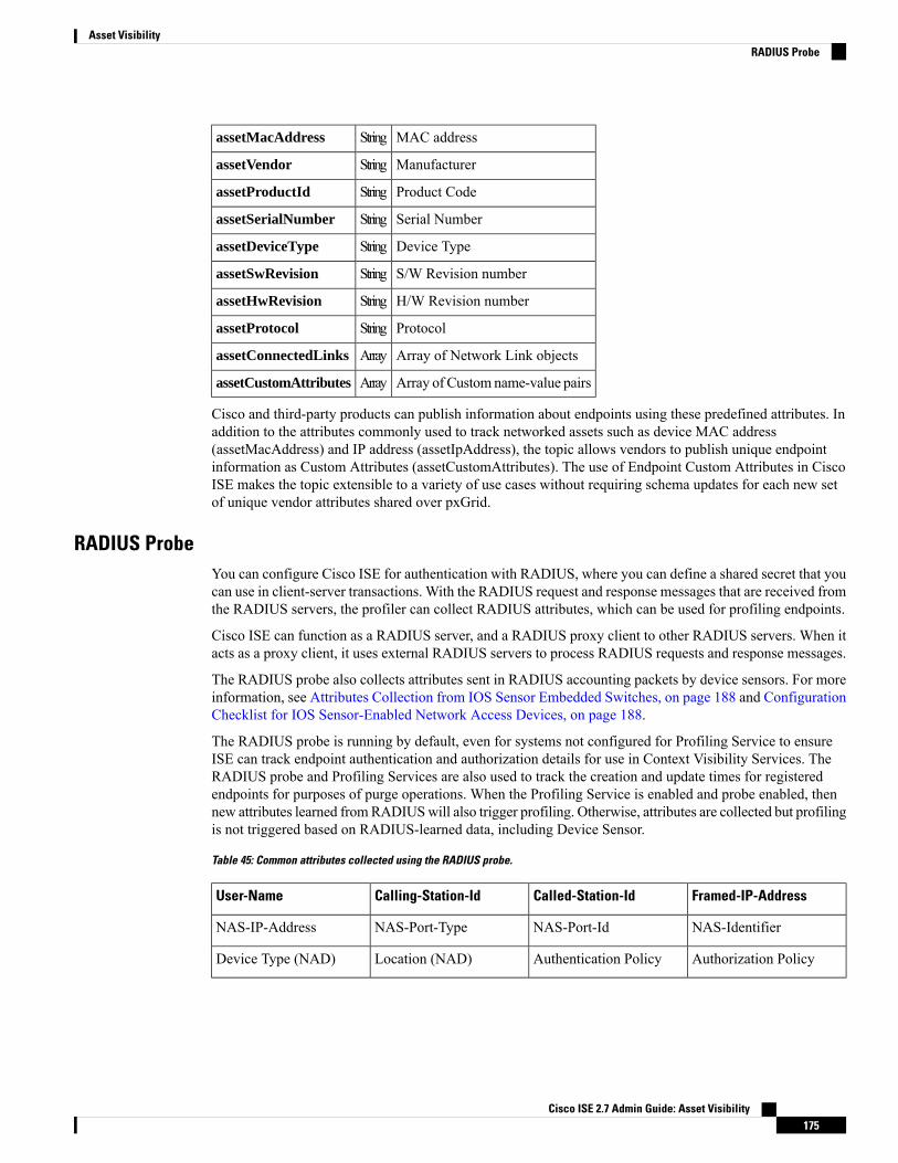
MAC addressStringassetMacAddress
ManufacturerStringassetVendor
Product CodeStringassetProductId
Serial NumberStringassetSerialNumber
Device TypeStringassetDeviceType
S/W Revision numberStringassetSwRevision
H/W Revision numberStringassetHwRevision
ProtocolStringassetProtocol
Array of Network Link objectsArrayassetConnectedLinks
Array of Custom name-value pairsArrayassetCustomAttributes
Cisco and third-party products can publish information about endpoints using these predefined attributes. Inaddition to the attributes commonly used to track networked assets such as device MAC address(assetMacAddress) and IP address (assetIpAddress), the topic allows vendors to publish unique endpointinformation as Custom Attributes (assetCustomAttributes). The use of Endpoint Custom Attributes in CiscoISE makes the topic extensible to a variety of use cases without requiring schema updates for each new setof unique vendor attributes shared over pxGrid.
RADIUS ProbeYou can configure Cisco ISE for authentication with RADIUS, where you can define a shared secret that youcan use in client-server transactions. With the RADIUS request and response messages that are received fromthe RADIUS servers, the profiler can collect RADIUS attributes, which can be used for profiling endpoints.
Cisco ISE can function as a RADIUS server, and a RADIUS proxy client to other RADIUS servers. When itacts as a proxy client, it uses external RADIUS servers to process RADIUS requests and response messages.
The RADIUS probe also collects attributes sent in RADIUS accounting packets by device sensors. For moreinformation, see Attributes Collection from IOS Sensor Embedded Switches, on page 188 and ConfigurationChecklist for IOS Sensor-Enabled Network Access Devices, on page 188.
The RADIUS probe is running by default, even for systems not configured for Profiling Service to ensureISE can track endpoint authentication and authorization details for use in Context Visibility Services. TheRADIUS probe and Profiling Services are also used to track the creation and update times for registeredendpoints for purposes of purge operations. When the Profiling Service is enabled and probe enabled, thennew attributes learned fromRADIUSwill also trigger profiling. Otherwise, attributes are collected but profilingis not triggered based on RADIUS-learned data, including Device Sensor.
Table 45: Common attributes collected using the RADIUS probe.
Framed-IP-AddressCalled-Station-IdCalling-Station-IdUser-Name
NAS-IdentifierNAS-Port-IdNAS-Port-TypeNAS-IP-Address
Authorization PolicyAuthentication PolicyLocation (NAD)Device Type (NAD)
Cisco ISE 2.7 Admin Guide: Asset Visibility175
Asset VisibilityRADIUS Probe

When an accounting stop is received, it triggers the Cisco ISE to reprofile the corresponding endpoint if itwas originally profiled with an IP address. Therefore if you have custom profiles for endpoints profiled withIP addresses, the only way to meet the total certainty factor for these profiles is to match on the correspondingIP address.
Note
Network Scan (NMAP) Probe
About the NMAP Probe
Cisco ISE enables you to detect devices in a subnet by using the NMAP security scanner. You enable theNMAP probe on the Policy Service node that is enabled to run the profiling service. You use the results fromthat probe in an endpoint profiling policy.
Each NMAPmanual subnet scan has a unique numeric ID that is used to update an endpoint source informationwith that scan ID. Upon detection of endpoints, the endpoint source information can also be updated to indicatethat it is discovered by the Network Scan probe.
The NMAPmanual subnet scan is useful for detecting devices such as printers with a static IP address assignedto them that are connected constantly to the Cisco ISE network, and therefore these devices cannot be discoveredby other probes.
NMAP Scan Limitations
Scanning a subnet is highly resource intensive. Scanning a subnet is lengthy process that depends on the sizeand density of the subnet. Number of active scans is always restricted to one scan, which means that you canscan only a single subnet at a time. You can cancel a subnet scan at any time while the subnet scan is inprogress. You can use the Click to see latest scan results link to view the most recent network scan resultsthat are stored in Work Centers > Profiler > Manual Scans > Manual NMAP Scan Results.
Manual NMAP Scan
The following NMAP command scans a subnet and sends the output to nmapSubnet.log:nmap -O -sU -p U:161,162 -oN /opt/CSCOcpm/logs/nmapSubnet.log
--append-output -oX - <subnet>
Table 46: NMAP Commands for a Manual Subnet Scan
Enables OS detection-O
UDP scan-sU
Scans only specified ports. For example, U:161, 162-p <port ranges>
Normal outputoN
XML outputoX
SNMP Read Only Community Strings for NMAP Manual Subnet Scan
The NMAP manual subnet scan is augmented with an SNMP Query whenever the scan discovers that UDPport 161 is open on an endpoint that results in more attributes being collected. During the NMAP manual
Cisco ISE 2.7 Admin Guide: Asset Visibility176
Asset VisibilityNetwork Scan (NMAP) Probe

subnet scan, the Network Scan probe detects whether SNMP port 161 is open on the device. If the port isopen, an SNMP Query is triggered with a default community string (public) with SNMP version 2c.
If the device supports SNMP and the default Read Only community string is set to public, you can obtain theMAC address of the device from the MIB value “ifPhysAddress”.
In addition, you can configure additional SNMP Read Only community strings separated by a comma for theNMAP manual network scan in the Profiler Configuration page. You can also specify new Read Onlycommunity strings for an SNMP MIB walk with SNMP versions 1 and 2c. For information on configuringSNMP Read Only community strings, see Setup CoA, SNMP RO Community, and Endpoint Attribute Filter,on page 182.
Manual NMAP Scan Results
The most recent network scan results are stored in Work Centers > Profiler > Manual Scans > Manual NMAPScan Results. TheManaul NMAP Scan Results page displays only the most recent endpoints that are detected,along with their associated endpoint profiles, their MAC addresses, and their static assignment status as theresult of a manual network scan you perform on any subnet. This page allows you to edit points that aredetected from the endpoint subnet for better classification, if required.
Cisco ISE allows you to perform the manual network scan from the Policy Service nodes that are enabled torun the profiling service. You must choose the Policy Service node from the primary Administration ISE nodeuser interface in your deployment to run the manual network scan from the Policy Service node. During themanual network scan on any subnet, the Network Scan probe detects endpoints on the specified subnet, theiroperating systems, and check UDP ports 161 and 162 for an SNMP service.
Additional Information
Given below is additional information related to the manual NMAP scan results:
• To detect unknown endpoints, NMAP should be able to learn the IP/MAC binding via NMAP or asupporting SNMP scan.
• ISE learns IP/MAC binding of known endpoints via Radius authentication or DHCP profiling.
• The IP/MAC bindings are not replicated across PSN nodes in a deployment. Therefore, you must triggerthe manual scan from the PSN, which has the IP/MAC binding in its local database (for example, thePSN against which a mac address was last authenticated with).
• The NMAP scan results do not display any information related to an endpoint that NMAP had previouslyscanned, manually or automatically.
DNS ProbeThe Domain Name Service (DNS) probe in your Cisco ISE deployment allows the profiler to lookup anendpoint and get the fully qualified domain name (FQDN). After an endpoint is detected in your CiscoISE-enabled network, a list of endpoint attributes is collected from the NetFlow, DHCP, DHCP SPAN, HTTP,RADIUS, or SNMP probes.
When you deploy Cisco ISE in a standalone or in a distributed environment for the first time, you are promptedto run the setup utility to configure the Cisco ISE appliance.When you run the setup utility, you will configurethe Domain Name System (DNS) domain and the primary nameserver (primary DNS server), where you canconfigure one or more nameservers during setup. You can also change or add DNS nameservers later afterdeploying Cisco ISE using the CLI commands.
Cisco ISE 2.7 Admin Guide: Asset Visibility177
Asset VisibilityManual NMAP Scan Results

DNS FQDN Lookup
Before a DNS lookup can be performed, one of the following probes must be started along with the DNSprobe: DHCP, DHCP SPAN, HTTP, RADIUS, or SNMP. This allows the DNS probe in the profiler to do areverse DNS lookup (FQDN lookup) against specified name servers that you define in your Cisco ISEdeployment. A new attribute is added to the attribute list for an endpoint, which can be used for an endpointprofiling policy evaluation. The FQDN is the new attribute that exists in the system IP dictionary. You cancreate an endpoint profiling condition to validate the FQDN attribute and its value for profiling. The followingare the specific endpoint attributes that are required for a DNS lookup and the probe that collects theseattributes:
• The dhcp-requested-address attribute—An attribute collected by the DHCP and DHCP SPAN probes.
• The SourceIP attribute—An attribute collected by the HTTP probe
• The Framed-IP-Address attribute—An attribute collected by the RADIUS probe
• The cdpCacheAddress attribute—An attribute collected by the SNMP probe
Configure Call Station ID Type in the WLC Web Interface
You can use theWLCweb interface to configure Call Station ID Type information. You can go to the Securitytab of theWLCweb interface to configure the calling station ID in the RADIUS Authentication Servers page.The MAC Delimiter field is set to Colon by default in the WLC user interface.
For more information on how to configure in the WLC web interface, see Chapter 6, “Configuring SecuritySolutions” in the Cisco Wireless LAN Controller Configuration Guide, Release 7.2.
For more information on how to configure in theWLCCLI using the config radius callStationIdType command,see Chapter 2, “Controller Commands” in the Cisco Wireless LAN Controller Command Reference Guide,Release 7.2.
Procedure
Step 1 Log in to your Wireless LAN Controller user interface.Step 2 Click Security.Step 3 Expand AAA, and then choose RADIUS > Authentication.Step 4 Choose System MAC Address from the Call Station ID Type drop-down list.Step 5 Check the AES Key Wrap check box when you run Cisco ISE in FIPS mode.Step 6 Choose Colon from the MAC Delimeter drop-down list.
SNMP Query ProbeIn addition to configuring the SNMP Query probe in the Edit Node page, you must configure other SimpleManagement Protocol settings in the following location:Administration >Network Resources > NetworkDevices.
You can configure SNMP settings in the new network access devices (NADs) in the Network Devices listpage. The polling interval that you specify in the SNMP query probe or in the SNMP settings in the networkaccess devices query NADs at regular intervals.
Cisco ISE 2.7 Admin Guide: Asset Visibility178
Asset VisibilityDNS FQDN Lookup

You can turn on and turn off SNMP querying for specific NADs based on the following configurations:
• SNMP query on Link up and New MAC notification turned on or turned off
• SNMP query on Link up andNewMAC notification turned on or turned off for Cisco Discovery Protocolinformation
• SNMP query timer for once an hour for each switch by default
For an iDevice, and other mobile devices that do not support SNMP, the MAC address can be discovered bythe ARP table, which can be queried from the network access device by an SNMP Query probe.
Cisco Discovery Protocol Support with SNMP Query
When you configure SNMP settings on the network devices, youmust ensure that the Cisco Discovery Protocolis enabled (by default) on all the ports of the network devices. If you disable the Cisco Discovery Protocolon any of the ports on the network devices, then you may not be able to profile properly because you willmiss the Cisco Discovery Protocol information of all the connected endpoints. You can enable the CiscoDiscovery Protocol globally by using the cdp run command on a network device, and enable the CiscoDiscovery Protocol by using the cdp enable command on any interface of the network access device. Todisable the Cisco Discovery Protocol on the network device and on the interface, use the no keyword at thebeginning of the commands.
Link Layer Discovery Protocol Support with SNMP Query
The Cisco ISE profiler uses an SNMP Query to collect LLDP attributes. You can also collect LLDP attributesfrom a Cisco IOS sensor, which is embedded in the network device, by using the RADIUS probe. See thedefault LLDP configuration settings that you can use to configure LLDP global configuration and LLDPinterface configuration commands on the network access devices.
Table 47: Default LLDP Configuration
FeatureFeature
DisabledLLDP global state
120 secondsLLDP holdtime (before discarding)
30 secondsLLDP timer (packet update frequency)
2 secondsLLDP reinitialization delay
Enabled to send and receive all TLVs.LLDP tlv-select
EnabledLLDP interface state
EnabledLLDP receive
EnabledLLDP transmit
Enabled to send all LLDP-MED TLVsLLDP med-tlv-select
CDP and LLDP Capability Codes Displayed in a Single Character
The Attribute List of an endpoint displays a single character value for the lldpCacheCapabilities andlldpCapabilitiesMapSupported attributes. The values are the Capability Codes that are displayed for thenetwork access device that runs CDP and LLDP.
Cisco ISE 2.7 Admin Guide: Asset Visibility179
Asset VisibilityCisco Discovery Protocol Support with SNMP Query

Example 1
lldpCacheCapabilities SlldpCapabilitiesMapSupported S
Example 2
lldpCacheCapabilities B;TlldpCapabilitiesMapSupported B;T
Example 3
Switch#show cdp neighborsCapability Codes:R - Router, T - Trans Bridge, B - Source Route Bridge, S - Switch, H - Host, I - IGMP,r - Repeater, P - Phone, D - Remote, C - CVTA, M - Two-port Mac Relay...Switch#
Switch#show lldp neighborsCapability codes:(R) Router, (B) Bridge, (T) Telephone, (C) DOCSIS Cable Device(W) WLAN Access Point, (P) Repeater, (S) Station, (O) Other...Switch#
SNMP Trap ProbeThe SNMP Trap receives information from the specific network access devices that support MAC notification,linkup, linkdown, and informs. The SNMP Trap probe receives information from the specific network accessdevices when ports come up or go down and endpoints disconnect from or connect to your network, whichresults in the information received that is not sufficient to create endpoints in Cisco ISE.
For SNMP Trap to be fully functional and create endpoints, you must enable SNMP Query so that the SNMPQuery probe triggers a poll event on the particular port of the network access device when a trap is received.To make this feature fully functional you should configure the network access device and SNMP Trap.
Cisco ISE does not support SNMP Traps that are received from the Wireless LAN Controllers (WLCs) andAccess Points (APs).
Note
Active Directory ProbeThe AD probe:
• Improves the fidelity of OS information for Windows endpoints. Microsoft AD tracks detailed OSinformation for AD-joined computers including version and service pack levels. The AD probe retrievesthis information directly using the AD Runtime connector to provide a highly reliable source of clientOS information.
Cisco ISE 2.7 Admin Guide: Asset Visibility180
Asset VisibilitySNMP Trap Probe

• Helps distinguish between corporate and non-corporate assets. A basic but important attribute availableto the AD probe is whether an endpoint exists in AD. This information can be used to classify an endpointcontained in the AD as a managed device or corporate asset.
You can enable the AD probe under theAdministration > System >Deployment > Profiling Configurationpage. When this probe is enabled, ISE fetches the AD attributes for a new endpoint as soon as it receives ahostname. The hostname is typically learned from the DHCP or DNS probes. Once successfully retrieved,ISE does not attempt to query AD again for the same endpoint until a the rescan timer expires. This is to limitthe load on AD for attribute queries. The rescan timer is configurable in the Days Before Rescan field(Administration > System > Deployment > Profiling Configuration > Active Directory). If there isadditional profiling activity on the endpoint, the AD is queried again.
The following AD probe attributes can be matched in the Policy > Policy Elements > Profiling using theACTIVEDIRECTORY condition. AD attributes collected using the AD Probe appear with the prefix “AD”in the endpoint details on the Context Visibility > Endpoints page.
• AD-Host-Exists
• AD-Join-Point
• AD-Operating-System
• AD-OS-Version
• AD-Service-Pack
Configure Probes per Cisco ISE NodeYou can configure one or more probes on the Profiling Configuration tab per Cisco ISE node in your deploymentthat assumes the Policy Service persona, which could be:
• A standalone node—If you have deployed Cisco ISE on a single node that assumes all Administration,Monitoring, and Policy Service personas by default.
• Multiple nodes—If you have registered more than one node in your deployment that assume PolicyService persona.
Before you begin
You can configure the probes per Cisco ISE node only from the Administration node, which is unavailableon the secondary Administration node in a distributed deployment.
Procedure
Step 1 Choose Administration > System > Deployment.Step 2 Choose a Cisco ISE node that assumes the Policy Service persona.Step 3 Click Edit in the Deployment Nodes page.Step 4 On theGeneral Settings tab, check thePolicy Service check box. If the Policy Service check box is unchecked,
both the session services and the profiling service check boxes are disabled.Step 5 Check the Enable Profiling Services check box.
Cisco ISE 2.7 Admin Guide: Asset Visibility181
Asset VisibilityConfigure Probes per Cisco ISE Node

Step 6 Click the Profiling Configuration tab.Step 7 Configure the values for each probe.Step 8 Click Save to save the probe configuration.
Setup CoA, SNMP RO Community, and Endpoint Attribute FilterCisco ISE allows a global configuration to issue a Change of Authorization (CoA) in the Profiler Configurationpage that enables the profiling service with more control over endpoints that are already authenticated.
In addition, you can configure additional SNMP Read Only community strings separated by a comma for theNMAP manual network scan in the Profiler Configuration page. The SNMP RO community strings are usedin the same order as they appear in the Current custom SNMP community strings field.
You can also configure endpoint attribute filtering in the Profiler Configuration page.
Procedure
Step 1 Choose Administration > System > Settings > Profiling.Step 2 Choose one of the following settings to configure the CoA type:
• No CoA (default)—You can use this option to disable the global configuration of CoA. This settingoverrides any configured CoA per endpoint profiling policy. If the goal is only visibilibility, retain thedefault value as No CoA.
• Port Bounce—You can use this option, if the switch port exists with only one session. If the port existswith multiple sessions, then use the Reauth option. If the goal is to immediately update the access policybased on profile changes, select the Port Bounce option, this will ensure that any clientless endpointsis reauthorized, and IP address is refreshed, if required.
• Reauth—You can use this option to enforce reauthentication of an already authenticated endpoint whenit is profiled. Select the Reauth option, if no VLAN or address change is expected following thereauthorization of the current session.
If you have multiple active sessions on a single port, the profiling service issues a CoA withthe Reauth option even though you have configured CoA with the Port Bounce option. Thisfunction avoids disconnecting other sessions, a situation that might occur with the Port Bounceoption.
Note
Step 3 Enter new SNMP community strings separated by a comma for the NMAPmanual network scan in theChangeCustom SNMP Community Strings field, and re-enter the strings in theConfirm Custom SNMP CommunityStrings field for confirmation.
The default SNMP community string used is public. Click Show in theCurrent Custom SNMP CommunityStrings section to verify this.
Step 4 Check the Endpoint Attribute Filter check box to enable endpoint attribute filtering.
On enabling the EndPoint Attribute Filter, the Cisco ISE profiler only keeps significant attributes anddiscards all other attributes. For more information, see Global Setting to Filter Endpoint Attributes with
Cisco ISE 2.7 Admin Guide: Asset Visibility182
Asset VisibilitySetup CoA, SNMP RO Community, and Endpoint Attribute Filter
Whitelist, on page 186 andAttribute Filters for ISEDatabase Persistence and Performance, on page 185 sections.As a best practice, we recommend you to enable Endpoint Attribute Filter in production deployments.
Step 5 Check the Enable Probe Data Publisher check box if you want Cisco ISE to publish endpoint probe data topxGrid subscribers that need this data to classify endpoints onboarding on ISE. The pxGrid subscriber canpull the endpoint records from Cisco ISE using bulk download during initial deployment phase. Cisco ISEsends the endpoint records to the pxGrid subscriber whenever they are updated in PAN. This option is disabledby default.
When you enable this option, ensure that the pxGrid persona is enabled in your deployment.
Step 6 Click Save.
Global Configuration of Change of Authorization for Authenticated EndpointsYou can use the global configuration feature to disable change of authorization (CoA) by using the defaultNo CoA option or enable CoA by using port bounce and reauthentication options. If you have configured PortBounce for CoA in Cisco ISE, the profiling service may still issue other CoAs as described in the “CoAExemptions” section.
The global configuration chosen dictates the default CoA behavior only in the absense of more specific settings.See Change of Authorization Configuration per Endpoint Profiling Policy, on page 218.
You can use the RADIUS probe or the Monitoring persona REST API to authenticate the endpoints. You canenable the RADIUS probe, which allows faster performance. If you have enabled CoA, then we recommendthat you enable the RADIUS probe in conjunction with your CoA configuration in the Cisco ISE applicationfor faster performance. The profiling service can then issue an appropriate CoA for endpoints by using theRADIUS attributes that are collected.
If you have disabled the RADIUS probe in the Cisco ISE application, then you can rely on the Monitoringpersona REST API to issue CoAs. This allows the profiling service to support a wider range of endpoints. Ina distributed deployment, your network must have at least one Cisco ISE node that assumes the Monitoringpersona to rely on the Monitoring persona REST API to issue a CoA.
Cisco ISE arbitrarily will designate either the primary or secondaryMonitoring node as the default destinationfor REST queries in your distributed deployment, because both the primary and secondary Monitoring nodeshave identical session directory information.
Use Cases for Issuing Change of AuthorizationThe profiling service issues the change of authorization in the following cases:
• Endpoint deleted—When an endpoint is deleted from the Endpoints page and the endpoint is disconnectedor removed from the network.
• An exception action is configured—If you have an exception action configured per profile that leads toan unusual or an unacceptable event from that endpoint. The profiling service moves the endpoint to thecorresponding static profile by issuing a CoA.
• An endpoint is profiled for the first time—When an endpoint is not statically assigned and profiled forthe first time; for example, the profile changes from an unknown to a known profile.
• An endpoint identity group has changed—When an endpoint is added or removed from an endpointidentity group that is used by an authorization policy.
Cisco ISE 2.7 Admin Guide: Asset Visibility183
Asset VisibilityGlobal Configuration of Change of Authorization for Authenticated Endpoints

The profiling service issues a CoA when there is any change in an endpoint identity group, and theendpoint identity group is used in the authorization policy for the following:
• The endpoint identity group changes for endpoints when they are dynamically profiled
• The endpoint identity group changes when the static assignment flag is set to true for a dynamicendpoint
• An endpoint profiling policy has changed and the policy is used in an authorization policy—When anendpoint profiling policy changes, and the policy is included in a logical profile that is used in anauthorization policy. The endpoint profiling policy may change due to the profiling policy match or whenan endpoint is statically assigned to an endpoint profiling policy, which is associated to a logical profile.In both the cases, the profiling service issues a CoA, only when the endpoint profiling policy is used inan authorization policy.
Exemptions for Issuing a Change of AuthorizationThe profiling service does not issue a CoA when there is a change in an endpoint identity group and the staticassignment is already true.
Cisco ISE does not issue a CoA for the following reasons:
• An Endpoint disconnected from the network—When an endpoint disconnected from your network isdiscovered.
• Authenticatedwired (Extensible Authentication Protocol) EAP-capable endpoint—When an authenticatedwired EAP-capable endpoint is discovered.
• Multiple active sessions per port—When you have multiple active sessions on a single port, the profilingservice issues a CoAwith the Reauth option even though you have configured CoAwith the Port Bounceoption.
• Packet-of-Disconnect CoA (Terminate Session) when a wireless endpoint is detected—If an endpoint isdiscovered as wireless, then a Packet-of-Disconnect CoA (Terminate-Session) is issued instead of thePort Bounce CoA. The benefit of this change is to support the Wireless LAN Controller (WLC) CoA.
• Profiler CoA is suppressed when the Suppress Profiler CoA for endpoints in Logical Profile optionis used for the configured logical profile in the Authorization Profile. Profiler CoA will be triggered forall other endpoints by default.
• Global No CoA Setting overrides Policy CoA—Global No CoA overrides all configuration settings inendpoint profiling policies as there is no CoA issued in Cisco ISE irrespective of CoA configured perendpoint profiling policy.
No CoA and Reauth CoA configurations are not affected, and the profiler serviceapplies the same CoA configuration for wired and wireless endpoints.
Note
Cisco ISE 2.7 Admin Guide: Asset Visibility184
Asset VisibilityExemptions for Issuing a Change of Authorization

Change of Authorization Issued for Each Type of CoA Configuration
Table 48: Change of Authorization Issued for Each Type of CoA Configuration
AdditionalInformation
ReauthConfiguration
Port BounceConfiguration
No CoAConfiguration
Scenarios
—ReauthenticationPort BounceNo CoAGlobal CoAconfiguration inCisco ISE (typicalconfiguration)
Change ofauthorization isdetermined by theRADIUS attributeAcct-Status -Typevalue Stop.
No CoANo CoANo CoAAn endpoint isdisconnected onyour network
Reauthenticationavoids disconnectingother sessions.
ReauthenticationReauthenticationNo CoAWired with multipleactive sessions onthe same switch port
Support to WirelessLAN Controller.
ReauthenticationPacket-of-DisconnectCoA (TerminateSession)
No CoAWireless endpoint
Due to missingRADIUS attributes.
No CoANo CoANo CoAIncomplete CoAdata
Attribute Filters for ISE Database Persistence and PerformanceCisco ISE implements filters for Dynamic Host Configuration Protocol (both DHCPHelper and DHCP SPAN),HTTP, RADIUS, and Simple Network Management Protocol probes except for the NetFlow probe to addressperformance degradation. Each probe filter contains the list of attributes that are temporal and irrelevant forendpoint profiling and removes those attributes from the attributes collected by the probes.
The isebootstrap log (isebootstrap-yyyymmdd-xxxxxx.log) contains messages that handles the creation ofdictionaries and with filtering of attributes from the dictionaries. You can also configure to log a debugmessagewhen endpoints go through the filtering phase to indicate that filtering has occurred.
The Cisco ISE profiler invokes the following endpoint attribute filters:
• A DHCP filter for both the DHCP Helper and DHCP SPAN contains all the attributes that are notnecessary and they are removed after parsing DHCP packets. The attributes after filtering are mergedwith existing attributes in the endpoint cache for an endpoint.
• An HTTP filter is used for filtering attributes from HTTP packets, where there is no significant changein the set of attributes after filtering.
• A RADIUS filter is used once the syslog parsing is complete and endpoint attributes are merged into theendpoint cache for profiling.
Cisco ISE 2.7 Admin Guide: Asset Visibility185
Asset VisibilityChange of Authorization Issued for Each Type of CoA Configuration

• SNMP filter for SNMP Query includes separate CDP and LLDP filters, which are all used forSNMP-Query probe.
Global Setting to Filter Endpoint Attributes with WhitelistYou can reduce the number of persistence events and replication events by reducing the number of endpointattributes that do not change frequently at the collection point. Enabling the EndPoint Attribute Filter willhave the Cisco ISE profiler only to keep significant attributes and discard all other attributes. Significantattributes are those used by the Cisco ISE system or those used specifically in an endpoint profiling policy orrule.
To enable theEndpoint Attribute Filter), see the Setup CoA, SNMPROCommunity, and Endpoint AttributeFilter, on page 182 section.
A whitelist is a set of attributes that are used in custom endpoint profiling policies for profiling endpoints,and that are essential for Change of Authorization (CoA), BringYour OwnDevice (BYOD), Device RegistrationWebAuth (DRW), and so on to function in Cisco ISE as expected. The whitelist is always used as a criteriawhen ownership changes for the endpoint (when attributes are collected by multiple Policy Service nodes)even when disabled.
By default, the whitelist is disabled and the attributes are dropped only when the attribute filter is enabled.The white list is dynamically updated when endpoint profiling policies change including from the feed toinclude new attributes in the profiling policies. Any attribute that is not present in the whitelist is droppedimmediately at the time of collection, and the attribute cannot participate in profiling endpoints.When combinedwith the buffering, the number of persistence events can be reduced.
You must ensure that the whitelist contains a set of attributes determined from the following two sources:
• A set of attributes that are used in the default profiles so that you can match endpoints to the profiles.
• A set of attributes that are essential for Change of Authorization (CoA), Bring Your OwnDevice (BYOD),Device Registration WebAuth (DRW), and so on to function as expected.
To add an new attribute to the whitelist, the administrator needs to create a new profiler condiion and policythat uses the attribute. This new attribute will be automatically added to the whitelist of stored and replicatedattributes.
Note
Table 49: Whitelist Attributes
BYODRegistrationAAA-Server
Certificate Expiration DateCalling-Station-ID
Certificate Issuer NameCertificate Issue Date
DescriptionCertificate Serial Number
Device IdentifierDestinationIPAddress
DeviceRegistrationStatusDevice Name
EndPointPolicyIDEndPointPolicy
Cisco ISE 2.7 Admin Guide: Asset Visibility186
Asset VisibilityGlobal Setting to Filter Endpoint Attributes with Whitelist

EndPointSourceEndPointProfilerServer
FirstCollectionFQDN
IdentityGroupFramed-IP-Address
IdentityStoreGUIDIdentityGroupID
L4_DST_PORTIdentityStoreName
MACAddressLastNmapScanTime
MatchedPolicyIDMatchedPolicy
NAS-IP-AddressNADAddress
NAS-Port-TypeNAS-Port-Id
NmapSubnetScanIDNmapScanCount
OUIOS Version
PortalUserPolicyVersion
ProductPostureApplicable
—RegistrationTimeStamp
StaticGroupAssignmentStaticAssignment
Total Certainty FactorTimeToProfile
cdpCacheAddressUser-Agent
cdpCacheDeviceIdcdpCacheCapabilities
cdpCacheVersioncdpCachePlatform
dhcp-class-identifierciaddr
host-namedhcp-requested-address
ifIndexhrDeviceDescr
lldpCacheCapabilitiesip
lldpSystemDescriptionlldpCapabilitiesMapSupported
sysDescroperating-system
—161-udp
Cisco ISE 2.7 Admin Guide: Asset Visibility187
Asset VisibilityGlobal Setting to Filter Endpoint Attributes with Whitelist

Attributes Collection from IOS Sensor Embedded SwitchesAn IOS sensor integration allows Cisco ISE run time and the Cisco ISE profiler to collect any or all of theattributes that are sent from the switch. You can collect DHCP, CDP, and LLDP attributes directly from theswitch by using the RADIUS protocol. The attributes that are collected for DHCP, CDP, and LLDP are thenparsed andmapped to attributes in the profiler dictionaries in the following location:Policy >Policy Elements >Dictionaries.
For information about the supported Catalyst platforms for Device sensors, seehttps://communities.cisco.com/docs/DOC-72932.
IOS Sensor Embedded Network Access DevicesIntegrating IOS sensor embedded network access devices with Cisco ISE involves the following components:
• An IOS sensor
• Data collector that is embedded in the network access device (switch) for gathering DHCP, CDP, andLLDP data
• Analyzers for processing the data and determining the device-type of endpoints
There are two ways of deploying an analyzer, but they are not expected to be used in conjunction witheach other:
• An analyzer can be deployed in Cisco ISE
• Analyzers can be embedded in the switch as the sensor
Configuration Checklist for IOS Sensor-Enabled Network Access DevicesThis section summarizes a list of tasks that you must configure in the IOS sensor-enabled switches and CiscoISE to collect DHCP, CDP, and LLDP attributes directly from the switch:
• Ensure that the RADIUS probe is enabled in Cisco ISE.
• Ensure that network access devices support an IOS sensor for collecting DHCP, CDP, and LLDPinformation.
• Ensure that network access devices run the following CDP and LLDP commands to capture CDP andLLDP information from endpoints:
cdp enablelldp run
• Ensure that session accounting is enabled separately by using the standard AAA and RADIUS commands.
For example, use the following commands:
aaa new-modelaaa accounting dot1x default start-stop group radius
radius-server host <ip> auth-port <port> acct-port <port> key <shared-secret>radius-server vsa send accounting
Cisco ISE 2.7 Admin Guide: Asset Visibility188
Asset VisibilityAttributes Collection from IOS Sensor Embedded Switches
• Ensure that you run IOS sensor-specific commands.
• Enabling Accounting Augmentation
You must enable the network access devices to add IOS sensor protocol data to the RADIUSaccounting messages and to generate additional accounting events when it detects new sensorprotocol data. This means that any RADIUS accounting message should include all CDP, LLDP,and DHCP attributes.
Enter the following global command:
device-sensor accounting
• Disabling Accounting Augmentation
To disable (accounting) network access devices and add IOS sensor protocol data to the RADIUSaccounting messages for sessions that are hosted on a given port (if the accounting feature is globallyenabled), enter the following command at the appropriate port:
no device-sensor accounting
• TLV Change Tracking
By default, for each supported peer protocol, client notifications and accounting events are generatedonly when an incoming packet includes a type, length, and value (TLV) that has not been receivedpreviously in the context of a given session.
You must enable client notifications and accounting events for all TLV changes where there areeither new TLVs, or where previously received TLVs have different values. Enter the followingcommand:
device-sensor notify all-changes
• Be sure that you disable the IOS Device Classifier (local analyzer) in the network access devices.
Enter the following command:
no macro auto monitor
This command prevents network access devices from sending two identicalRADIUS accounting messages per change.
Note
Support for Cisco IND Controllers by the ISE ProfilerISE can profile and display the status of devices attached to a Cisco Industrial Network Device (IND). PxGridconnects ISE and the Cisco Industrial Network Director to communicate endpoint (IoT) data. pxGrid on ISEconsumes CIND events, and queries CIND to update endpoint type.
The ISE profiler has dictionary attributes for IoT devices. Navigate toPolicy >Policy Elements >Dictionaries,and select IOTASSET from the list of System Dictionaries to see the dictionary attributes.
Cisco ISE 2.7 Admin Guide: Asset Visibility189
Asset VisibilitySupport for Cisco IND Controllers by the ISE Profiler

Guidelines and Recommendations
If you have several ISE nodes configured for profiling, we recommend that you enable pxGrid for IND onone node.
If ISE goes down, then when ISE comes back up, you reconnect to IND in CIND. To reconnect, in CIND,navigate to the pxGrid page, and click Reconnect.
Multiple IND devices can connect to a single ISE.
If the same endpoint is received from two or more publishers (IND), ISE only keeps the last publisher's datafor that endpoint.
In pxGrid, ISE gets IND data from the service names com.cisco.endpoint.asset, and/topic/com.cisco.endpoint.asset.
IND Profiling Process Flow
CIND Asset discovery finds an IoT device, and publishes the endpoint data for that device to pxGrid. ISEsees the event on pxGrid, and gets the endpoint data. Profiler policies in ISE assign the device data to attributesin the ISE profiler dictionary, and applies those attributes to the endpoint in ISE.
IoT endpoint data which does not meet the existing attributes in ISE are not saved. But you can create moreattributes in ISE, and register them with CIND.
ISE does a bulk download of endpoints when the connection to CIND through pxGrid is first established. Ifthere is a network failure, ISE does another bulk download of accumulated endpoint changes.
Configure ISE and CIND for IND Profiling
You must install the ISE certificate in CIND, and install the CIND certificate in ISE, before you activatepxGrid in CIND.
Note
1. In ISE, enable pxGrid—Navigate to Administration > Deployment. Edit the PSN that you plan to useas pxGrid consumer, and enable pxGrid. This PSN is the one that creates endpoints from pxGrid datapublished by Cisco IND and profiling.
2. In ISE, create a pxGrid certificate—Navigate toAdministration > pxGrid Services to verify that pxGridis running. Then click the Certificates tab, and fill in the certificate fields. Click Create to issue thecertificate, and opens a window for you to select a download directory. The certificate downloads to thatdirectory in a zipped format.
• For I want to, select “Generate a single certificate (without a certificate signing request), CommonName, enter a name for the CIND you are connecting with.
• For Certificate Download Format, choose PKS12 format.
• For Certificate Password, create a password.
The ISE internal CA must be enabled, and if your browser blocks popups, you won’t be able to download thecertificate. Unzip the certificate to make the PEM file available for the next step.
Note
Cisco ISE 2.7 Admin Guide: Asset Visibility190
Asset VisibilitySupport for Cisco IND Controllers by the ISE Profiler

3. In CIND, export the CIND certificate—In CIND, navigate to Settings > pxGrid, and Click Download.pem IND certificate. Keep this window open.
4. In ISE, navigate to Administration > pxGrid Services > All Clients. When you see the IND pxGridclient, approve it.
5. In CIND, move the slider to enable pxGrid. Another screen opens, where you define the location of theISE node, the name of the certificate that you entered for this pxGrid server in ISE, and the password youprovided. Click Upload Certificate, and locate the ISE pxGrid PEM file.
6. In ISE, import the CIND system certificate—Navigate to Administration > Certificates > TrustedCertificates, click the Import button, and enter the path to the certificate you got from CIND.
7. In CIND, click Activate.
8. In ISE, navigate to Adminstration->Deployment, select the PSN you are using for the IND connection,select the Profiling page, and enable the pxGrid probe.
9. The pxGrid connection between ISE and CIND is now active. Verify that by displaying the IoT endpointsthat CIND has found.
Add an Attribute for IND Profiling
CIND may return attributes that are not in the ISE dictionary. You can add more attributes to ISE, so you canmore accurately profile that IoT device. To add a new attribute, you create a custom attribute in ISE, and sendthat attribute to CIND over pxGrid.
1. Create the attribute in ISE—Navigate to Administration > Identity Management > Settings, and selectEndpoint Custom Attributes. Create an attribute endpoint attribute.
2. You can now use this attribute in a profiler policy to identify assets with the new attribute. Navigate toPolicy > Profiling, and create a new profiler policy. In the Rules section, create a new rule. When youadd an attribute/value, select the CUSTOMATTRIBUTE folder, and the custom attribute you created.
ISE Support for MUDManufacturer Usage Descriptor (MUD) is an IETF standard, which defines a way to on-board IoT devices.It provides seamless visibility and segmentation automation of IoT devices. MUD has been approved in IETFprocess, and released as RFC8520.
https://datatracker.ietf.org/doc/draft-ietf-opsawg-mud/.
Cisco ISE, Release 2.6 supports identification of IoT devices. Cisco ISE automatically creates profiling policiesand Endpoint Identity Groups. MUD supports profiling IoT devices, creating profiling policies dynamically,and automating the entire process of creating policies and Endpoint Identity Groups. Administrators can usethese profiling policies to create manually Authorization Policies and Profiles. IoT devices emitting MUDURL in DHCP and LLDP packets are on board, using those profiles and policies. Full automation, includingenforcement in the system, is expected to be added in a future release.
Cisco ISE performs unsigned classification of IoT devices, and accessed through profiler policies. ISE doesnot store the MUD attributes; the attributes are only used in the current session. In theContext and Visibility> Endpoints window, you can filter IoT devices by the Endpoint Profile field.
The following devices support sending MUD data to Cisco ISE:
Cisco ISE 2.7 Admin Guide: Asset Visibility191
Asset VisibilityISE Support for MUD

• Cisco Identity Services Engine 2.6
• Cisco Catalyst 3850 Series Switches running Cisco IOS XE Version 16.9.1 & 16.9.2
• Cisco Catalyst Digital Building Series Switches running Cisco IOS Version 15.2(6)E2
• Cisco Industrial Ethernet 4000 Series Switches running Cisco IOS Version 15.2(6)E2
• Internet of Things (IoT) devices with embedded MUD functionality
Cisco ISE supports the following profiling protocols and profiling probes:
• LLDP and Radius - TLV 127
• DHCP - Option 161
Both fields can be sent to ISE by IOS Device Sensor.
Configuring ISE for MUD
1. 1. Enable MUD in Profiler Settings. Navigate to Work Centers > Profiler > Profiler Settings , andcheck Enable profiling for MUD for MUD.
2. Add the Network Access Device that can send MUD URIs to ISE. Network devices are added onAdministration > Network Resources > Network Devices.
3. Verify that the MUD-URL connection is working.
a. Open Context Visibility > Endpoints, and find IoT endpoints that ISE successfully classified. Youcan filter IoT devices by the Endpoint profile name, which starts with IOT-MUD.
b. Click the endpoint MAC address of one of the IoT devices, and select the attribute tag. Verify thatthere is a mud-url in the list of attributes.
c. Navigate to Policy > Profiling, show theQuick Filter, and filter the list by selecting IOT Createdfor System Type.
4. Optionally configure debug logging for the new IoT devices.
a. Navigate to System > Logging > Debug Log Configuration, and select the ISE node that has theMUD configuration.
b. Select Debug Log Configuration in the left menu, then select profiler.
Operation
As more IoT devices are classified, all devices of the same category or group with same MUD-URL areassigned to the same endpoint group. For example, if a Molex light connects, and is classified, a profiler groupis created for thatMolex light. AsmoreMolex lights of the same type (with the sameMUD-URL) are classified,they inherit the same classification or endpoint identity group.
Verify MUD Traffic Flow in ISE and the Switch
1. Before turning on the IoT device, either connect port or unshut the interface.
a. Start packet capture at ISE.
Cisco ISE 2.7 Admin Guide: Asset Visibility192
Asset VisibilityISE Support for MUD
b. Start packet capture at switch ports.
2. View the following output on the switch.
a. show device-sensor cache all
b. show access-session
c. show radius statistics
3. Turn on the IoT devices.
4. Repeat the following every minute.
a. show device-sensor cache all
b. show access-session
c. show radius statistics
5. Wait for 3 to 5 minutes for all the devices show up on ISE.
6. Stop both the ISE and switch packet captures.
7. Repeat the following every minute.
a. show device-sensor cache all
b. show access-session
c. show radius statistics
Profiler ConditionsProfiling conditions are policy elements and are similar to other conditions. However unlike authentication,authorization, and guest conditions, the profiling conditions can be based on a limited number of attributes.The Profiler Conditions page lists the attributes that are available in Cisco ISE and their description.
Profiler conditions can be one of the following:
• Cisco Provided—Cisco ISE includes predefined profiling conditions when deployed and they are identifiedas Cisco Provided in the Profiler Conditions page. You cannot delete Cisco Provided profiling conditions.
You can also find Cisco Provided conditions in the System profiler dictionaries in the following location:Policy > Policy Elements > Dictionaries > System.
For example, MAC dictionary. For some products, the OUI (Organizationally Unique Identifier) is anunique attribute that you can use it first for identifying the manufacturing organization of devices. It isa component of the device MAC address. The MAC dictionary contains the MACAddress and OUIattributes.
• Administrator Created—Profiler conditions that you create as an administrator of Cisco ISE or predefinedprofiling conditions that are duplicated are identified as Administrator Created. You can create a profilercondition of DHCP, MAC, SNMP, IP, RADIUS, NetFlow, CDP, LLDP, and NMAP types using theprofiler dictionaries in the Profiler Conditions page.
Cisco ISE 2.7 Admin Guide: Asset Visibility193
Asset VisibilityProfiler Conditions

Although, the recommended upper limit for the number of profiling policies is 1000, you can stretch up to2000 profiling policies.
Profiling Network Scan ActionsAn endpoint scan action is a configurable action that can be referred to in an endpoint profiling policy, andthat is triggered when the conditions that are associated with the network scan action are met.
An endpoint scan is used to scan endpoints in order to limit resources usage in the Cisco ISE system. A networkscan action scans a single endpoint, unlike resource-intensive network scans. It improves the overallclassification of endpoints, and redefines an endpoint profile for an endpoint. Endpoint scans can be processedonly one at a time.
You can associate a single network scan action to an endpoint profiling policy. Cisco ISE predefines threescanning types for a network scan action, which can include one or all three scanning types: for instance, anOS-scan, an SNMPPortsAndOS-scan, and a CommonPortsAndOS-scan. You cannot edit or delete OS-scan,SNMPPortsAndOS-scan, and CommonPortsAndOS-scans, which are predefined network scan actions inCisco ISE. You can also create a new network scan action of your own.
Once an endpoint is appropriately profiled, the configured network scan action cannot be used against thatendpoint. For example, scanning an Apple-Device allows you to classify the scanned endpoint to an Appledevice. Once an OS-scan determines the operating system that an endpoint is running, it is no longer matchedto an Apple-Device profile, but it is matched to an appropriate profile for an Apple device.
Create a New Network Scan ActionA network scan action that is associated with an endpoint profiling policy scans an endpoint for an operatingsystem, Simple Network Management Protocol (SNMP) ports, and common ports. Cisco provides networkscan actions for the most common NMAP scans, but you can also create one of your own.
When you create a new network scan, you define the type of information that the NMAP probe will scan for.
Before you begin
The Network Scan (NMAP) probe must be enabled before you can define a rule to trigger a network scanaction. The procedure for that is described in Configure Probes per Cisco ISE Node.
Procedure
Step 1 ChoosePolicy > Policy Elements > Results > Profiling > Network Scan (NMAP) Actions. Alternatively,you can choose Work Centers > Profiler > Policy Elements > NMAP Scan Actions.
Step 2 Click Add.Step 3 Enter a name and description for the network scan action that you want to create.Step 4 Check one or more check boxes when you want to scan an endpoint for the following:
• Scan OS—To scan for an operating system
• Scan SNMP Port—To scan SNMP ports (161, 162)
• Scan Common Port—To scan common ports.
• Scan Custom Ports—To scan custom ports.
Cisco ISE 2.7 Admin Guide: Asset Visibility194
Asset VisibilityProfiling Network Scan Actions
• Scan Include Service Version Information—To scan the version information, whichmay contain detaileddescription of the device.
• Run SMB Discovery Script—To scan SMB ports (445 and 139) to retrieve information such as the OSand computer name.
• Skip NMAP Host Discovery—To skip the initial host discovery stage of the NMAP scan.
The Skip NMAP Host Discovery option is selected by default for automatic NMAP scan,however, you must select it to run manual NMAP scan.
Note
Step 5 Click Submit.
NMAP Operating System Scan
The operating system scan (OS-scan) type scans for an operating system (and OS version) that an endpointis running. This is a resource intensive scan.
The NMAP tool has limitations on OS-scan which may cause unreliable results. For example, when scanningan operating system of network devices such as switches and routers, the NMAP OS-scan may provide anincorrect operating-system attribute for those devices. Cisco ISE displays the operating-system attribute, evenif the accuracy is not 100%.
You should configure endpoint profiling policies that use the NMAP operating-system attribute in their rulesto have low certainty value conditions (Certainty Factor values). We recommend that whenever you createan endpoint profiling policy based on the NMAP:operating-system attribute, include an AND condition tohelp filter out false results from NMAP.
The following NMAP command scans the operating system when you associate Scan OS with an endpointprofiling policy:nmap -sS -O -F -oN /opt/CSCOcpm/logs/nmap.log -append-output -oX - <IP-address>
The following NMAP command scans a subnet and sends the output to nmapSubnet.log:nmap -O -sU -p U:161,162 -oN /opt/CSCOcpm/logs/nmapSubnet.log
--append-output -oX - <subnet>
Table 50: NMAP Commands for a Manual Subnet Scan
Enables OS detection-O
UDP scan-sU
Scans only specified ports. For example, U:161, 162-p <port ranges>
Normal outputoN
XML outputoX
Operating System Ports
The following table lists the TCP ports that NMAP uses for OS scanning. In addition, NMAP uses ICMP andUDP port 51824.
191713976431
Cisco ISE 2.7 Admin Guide: Asset Visibility195
Asset VisibilityNMAP Operating System Scan

323026252423222120
807970534943423733
999089888584838281
135125119113111110109106100
211199179163161146144143139
301280264259256255254222212
417416407406389366340311306
481465464458445444443427425
543541524515514513512500497
616593587563555554548545544
668667666648646636631625617
722720714711705700691687683
808801800787783777765749726
903902901900898888880873843
999995993992990987981912911
102210211011101010091007100210011000
103110301029102810271026102510241023
1040-110010391038103710361035103410331032
111211111110110811071106110511041102
112611241123112211211119111711141113
114811471145114111381137113211311130
116911661165116411631154115211511149
119911981192118711861185118311751174
124412361234123312181217121612131201
130012961287127712721271125912481247
141713521334132813221311131013091301
150315011500149414611455144314341433
164116001594158315801556153315241521
172017191718171717001688168716661658
Cisco ISE 2.7 Admin Guide: Asset Visibility196
Asset VisibilityOperating System Ports

181218051801178317821761175517231721
193519141900187518641863186218401839
2021202020131998-201019841974197219711947
20652045-20492040-2043203820352034203320302022
21262121211921112105-21072103210020992068
219621912190217921702161216021442135
2381-238323662323230122882260225122222200
255725252522250024922401239923942393
270227012638260826072605260426022601
287528692811280928002725271827172710
300330013000299829682967292029102909
305230313030301730133011300730063005
326832613260322132113168312830773071
332533243323332233063301330032833269
339033893372337133703369336733513333
365935803551354635273517349334763404
380938013800378437663737370336903689
388038783871386938513828382738263814
399539863971394539203918391439053889
42424224412941264125411140454000-40063998
455044494446444544444443434343214279
503050095000-5004499849004899484846624567
510050875080506150605054505150505033
522552225221521452005190512051025101
543254315414540553575298528052695226
563155665560555555505544551055005440
580258015800573057185679567856665633
587758625859585058255822581558115810
595959525950592559225915591159105900-5907
Cisco ISE 2.7 Admin Guide: Asset Visibility197
Asset VisibilityOperating System Ports

6106610161006059602560095998-60075987-59895960-5963
654365106502638963466156612961236112
66896669666866676666664665806565-65676547
690168816839679267896788677966996692
707070257019700770047002700170006969
749674437435740272017200710671037100
791178007778777777417676762776257512
800780028001800079997938793779217920
804580428031802280218011801080098008
819481938192818181808100809980938080-8090
838383338300829282918290825482228200
865486528651864986008500844384028400
900290019000899488998888887388008701
908190809071905090409011901090099003
911191109103910291019100909990919090
950295009485941894159290922092079200
987696669618959595949593957595359503
996899449943992999179900989898789877
1001010009100041000310002100011000099999998
106161056610243102151018010082100251002410012
119671111111110107781062910628106261062110617
140001378313782137221345612345122651217412000
157421566015004150031500215000144421444114238
169931699216113160801601816016160121600116000
193501931519283191011898818101180401798817877
208282022220221200312000520000198421980119780
270002621425735257342480024444235022293921571
309513071830000282012771527356273552735327352
327743277332772327713277032769327683133731038
Cisco ISE 2.7 Admin Guide: Asset Visibility198
Asset VisibilityOperating System Ports

327833278232781327803277932778327773277632775
355003460134573345723457133899333543278532784
444434444244176425104151140911401933829236869
491574915649155491544915349152480804510044501
491764917549167491654916349161491604915949158
503895030050006500035000250001500004999949400
528695284852822526735149351103508005063650500
572945673856737556005555555056550555432854045
646236333162078619006153260443600205808057797
65389651296500064680
NMAP SNMP Port Scan
The SNMPPortsAndOS-scan type scans an operating system (and OS version) that an endpoint is runningand triggers an SNMP Query when SNMP ports (161 and 162) are open. It can be used for endpoints that areidentified and matched initially with an Unknown profile for better classification.
The following NMAP command scans SNMP ports (UDP 161 and 162) when you associate the Scan SNMPPort with an endpoint profiling policy:
nmap -sU -p U:161,162 -oN /opt/CSCOcpm/logs/nmap.log --append-output -oX - <IP-address>
Table 51: NMAP Commands for an Endpoint SNMP Port Scan
UDP scan.-sU
Scans only specified ports. For example, scans UDPports 161 and 16.2
-p <port-ranges>
Normal output.oN
XML output.oX
IP-address of an endpoint that is scanned.IP-address
NMAP Common Ports Scan
The CommanPortsAndOS-scan type scans an operating system (and OS version) that an endpoint is runningand common ports (TCP and UDP), but not SNMP ports. The following NMAP command scans commonports when you associate Scan Common Port with an endpoint profiling policy:nmap -sTU -pT:21,22,23,25,53,80,110,135,139,143,443,445,3306,3389,8080,U:53,67,68,123,135,137,138,139,161,445,500,520,631,1434,1900-oN /opt/CSCOcpm/logs/nmap.log --append-output -oX - <IP address>
Table 52: NMAP Commands for an Endpoint Common Ports Scan
Both TCP connect scan and UDP scan.-sTU
Cisco ISE 2.7 Admin Guide: Asset Visibility199
Asset VisibilityNMAP SNMP Port Scan

Scans TCP ports: 21,22,23,25,53,80,110,135,139,143,443,445,3306,3389,8080 and UDP ports:53,67,68,123,135,137,138,139,161,445,500,520,631,1434,1900
-p <port ranges>
Normal output.oN
XML output.oX
IP address of an endpoint that is scanned.IP address
Common Ports
The following table lists the common ports that NMAP uses for scanning.
Table 53: Common Ports
UDP PortsTCP Ports
ServicePortsServicePorts
domain53/udpftp21/tcp
dhcps67/udpssh22/tcp
dhcpc68/udptelnet23/tcp
ntp123/udpsmtp25/tcp
msrpc135/udpdomain53/tcp
netbios-ns137/udphttp80/tcp
netbios-dgm138/udppop3110/tcp
netbios-ssn139/udpmsrpc135/tcp
snmp161/udpnetbios-ssn139/tcp
microsoft-ds445/udpimap143/tcp
isakmp500/udphttps443/tcp
route520/udpmicrosoft-ds445/tcp
ms-sql-m1434/udpms-term-serv3389/tcp
upnp1900/udphttp-proxy8080/tcp
NMAP Custom Ports Scan
In addition to the common ports, you can use custom ports (Work Centers > Profiler > Policy Elements >NMAP Scan Actions or Policy > Policy Elements >Results > Profiling > Network Scan (NMAP) Actions)to specify automatic and manual NMAP scan actions. NMAP probes collect the attributes from endpoints viathe specified custom ports that are open. These attributes are updated in the endpoint's attribute list in the ISEIdentities page (Work Centers > Network Access > Identities > Endpoints). You can specify up to 10 UDPand 10 TCP ports for each scan action. You cannot use the same port numbers that you have specified ascommon ports. Refer to the Configure Profiler Policies Using the McAfee ePolicy Orchestrator section formore information.
Cisco ISE 2.7 Admin Guide: Asset Visibility200
Asset VisibilityCommon Ports

NMAP Include Service Version Information Scan
The Include Service Version Information NMAP probe automatically scans the endpoints to better classifythem, by collecting information about services running on the device. The service version option can becombined with common ports or custom ports.
Example:
CLI Command: nmap -sV -p T:8083 172.21.75.217
Output:
VersionServiceStatePort
McAfee ePolicyOrchestrator Agent4.8.0.1500(ePOServerName:WIN2008EPO,AgentGuid:{1F5ED719-0A22-4F3B-BABA-00FAE756C2FE})
httpopen8083/tcp
NMAP SMB Discovery Scan
NMAPSMBDiscovery scan helps differentiate theWindows versions, and results in a better endpoint profiling.You can configure the NMAP scan action to run the SMB discovery script that is provided by NMAP.
The NMAP scan action is incorporated within the windows default policies and when the endpoint matchesthe policy and the scanning rule, the endpoint is scanned and the result helps to determine the exact windowsversion. The policy will be then configured on the feed service and new pre-defined NMAP scan is createdwith the SMB discovery option.
The NMAP scan action is invoked by the Microsoft-Workstation policies and the result of the scan is savedon the endpoint under the operating system attribute and leveraged to the Windows policies. You can alsofind the SMB Discovery script option in the manual scan on the subnet.
For SMB discovery, be sure to enable the Windows file sharing option in the endpoint.Note
SMB Discovery Attributes
When the SMB discovery script is executed on the endpoint, new SMB discovery attributes, such asSMB.Operating-system, are added to the endpoint. These attributes are considered for updating the Windowsendpoint profiling policies on the feed service. When a SMB discovery script is run, the SMB discoveryattribute is prefixed with SMB, such as SMB.operating-system, SMB.lanmanager, SMB.server, SMB.fqdn,SMB.domain, SMB.workgroup, and SMB.cpe.
Skip NMAP Host Discovery
Scanning every port of every single IP address is a time-consuming process. Depending on the purpose of thescan, you can skip the NMAP host discovery of active endpoints.
If a NMAP scan is triggered after the classification of an endpoint, the profiler always skips the host discoveryof the endpoint. However, if a manual scan action is triggered after enabling the Skip NMAP Host DiscoveryScan, then host discovery is skipped.
Cisco ISE 2.7 Admin Guide: Asset Visibility201
Asset VisibilityNMAP Include Service Version Information Scan

NMAP Scan Workflow
Steps to be followed to perform a NMAP scan:
Before you begin
In order to run NMAP SMB discovery script, you must enable the file sharing in your system. Refer to theEnable File Sharing to Run NMAP SMB Discovery Script topic for an example.
Procedure
Step 1 Create an SMB Scan Action.Step 2 Configure the Profiler Policy Using the SMB Scan Action.Step 3 Add a New Condition Using the SMB Attribute.
Create an SMB Scan Action
Procedure
Step 1 Choose Policy > Policy Elements > Results > Profiling > Network Scan (NMAP) Actions page.Step 2 Enter the Action Name and Description.Step 3 Check the Run SMB Discovery Script checkbox.Step 4 Click Add to create the network access users.
Cisco ISE 2.7 Admin Guide: Asset Visibility202
Asset VisibilityNMAP Scan Workflow

What to do next
You should configure the profiler policy using the SMB scan action.
Configure the Profiler Policy Using the SMB Scan Action
Before you begin
You must create a new profiler policy to scan an endpoint with the SMB scan action. For example, you canscan aMicrosoftWorkstation by specifying a rule that if the DHCP class identifier contains theMSFT attribute,then a network action should be taken.
Procedure
Step 1 Choose Policy > Profiling > Add page.Step 2 Enter the Name and Description.Step 3 In the drop-down, select the scan action (for example, SMBScanAction) that you had created.
Network Scan (NMAP) Action
Cisco ISE 2.7 Admin Guide: Asset Visibility203
Asset VisibilityConfigure the Profiler Policy Using the SMB Scan Action

What to do next
You should add a new condition using the SMB attribute.
Add a New Condition Using the SMB Attribute
Before you begin
You should create a new profiler policy to scan the version of an endpoint. For example, you can scan forWindows 7 under the Microsoft Workstation parent policy.
Procedure
Step 1 Choose Policy > Profiling > Add page.Step 2 Enter the Name (for example, Windows-7Workstation) and Description.Step 3 In the Network Scan (NMAP) Action drop-down, select None.Step 4 In the Parent Policy drop-down choose the Microsoft-Workstation policy.
Cisco ISE 2.7 Admin Guide: Asset Visibility204
Asset VisibilityAdd a New Condition Using the SMB Attribute

Enable File Sharing to Run NMAP SMB Discovery Script
Given below is an example to enable file sharing inWindows OS version 7, to run the NMAP SMB discoveryscript.
Procedure
Step 1 Choose Control Panel > Network and Internet.Step 2 Choose the Network and Sharing Center.Step 3 Select Change Advanced Sharing Settings.Step 4 Ensure that the Turn on File and Printer Sharing radio button is selected.Step 5 Be sure that theEnable File Sharing for Devices That Use 40- or 56-bit Encryption andTurn on Password
Protected Sharing radio buttons are selected.Step 6 (Optional) Click Save Changes.Step 7 Configure the Firewall settings.
a) In the Control Panel, navigate to System and Security >Windows Firewall >Allow a Program ThroughWindows Firewall.
b) Be sure to check the File and Printer Sharing check box.c) Click OK.
Step 8 Configure the shared folder.a) Right-click the destination folder, and select Properties.b) Click the Sharing tab, and click Share.
Cisco ISE 2.7 Admin Guide: Asset Visibility205
Asset VisibilityEnable File Sharing to Run NMAP SMB Discovery Script

c) In the File Sharing dialog box, add the required names and click Share.d) Click Done after the selected folder is shared.e) Click Advanced Sharing and select the Share This Folder check box.f) Click Permissions.g) In the Permissions for Scans dialog box, choose Everyone and check the Full Control check box.h) Click OK.
Exclude Subnets from NMAP Scan
You can perform an NMAP scan to identify an endpoint's OS or SNMP port.
When performing the NMAP scan, you can exclude a whole subnet or IP range that should not be scannedby NMAP. You can configure the subnet or IP range in the NMAP Scan Subnet Exclusions page (WorkCenters > Profiler > Settings > NMAP Scan Subnet Exclusions). This helps limit the load on your networkand saves a considerable amount of time.
For Manual NMAP scan, you can use the Run Manual NMAP Scan page (Work Centers > Profiler > ManualScans > Manual NMAP Scan > Configure NMAP Scan Subnet Exclusions At) to specify the subnet or IPrange.
Manual NMAP Scan Settings
You can perform a manual NMAP scan (Work Centers > Profiler >Manual Scans >Manual NMAP Scan)using the scan options that are available for automatic NMAP scan. You can choose either the scan optionsor the predefined ones.
Table 54: Manual NMAP Scan Settings
Usage GuidelinesFields
Choose the ISE node from which the NMAP scan isrun.
Node
Enter the range of subnet IP addresses of endpointsfor which you want to run the NMAP scan.
Manual Scan Subnet
You will be directed to the Work Centers >Profiler > Settings > NMAP Scan SubnetExclusions page. Specify the IP address and subnetmask that should be excluded. If there is a match, theNMAP scan is not run.
Configure NMAP Scan Subnet Exclusions At
• Specify Scan Options
• Or, select an Existing NMAP Scan
NMAP Scan Subnet
Select the required scan options: OS, SNMP Port,Common Ports, Custom Ports, Include ServiceVersion Information, Run SMB Discovery Script,Skip NMAP Host Discovery. Refer to the Create aNewNetwork ScanAction topic formore information.
Specify Scan Options
Cisco ISE 2.7 Admin Guide: Asset Visibility206
Asset VisibilityExclude Subnets from NMAP Scan

Usage GuidelinesFields
Displays the ExistingNMAPScanActions drop-downthat displays the default profiler NMAP scan actions.
Select an Existing NMAP Scan
Click the button to restore default settings (all scanoptions are checked).
Reset to Default Scan Options
Enter an action name and a description.Save as NMAP Scan Action
Run a Manual NMAP Scan
Procedure
Step 1 Choose Work Centers > Profiler > Manual Scans > Manual NMAP Scan.Step 2 In the Node drop-down, select the ISE node from which you intend to run the NMAP scan.Step 3 In the Manual Scan Subnet text box, enter the subnet address whose endpoints you intend to check for open
ports.Step 4 Select the required Scan Options.
a) Choose Specify Scan Options, and on the right side of the page, choose the required scan options. Referto the Create a New Network Scan Action page for more information.
b) Or, Choose Select An Existing NMAP Scan Action to select the default NMAP scan action, such asMCAFeeEPOOrchestratorClientScan.
Step 5 Click Run Scan.
Configure Profiler Policies Using the McAfee ePolicy Orchestrator
Cisco ISE profiling services can detect if the McAfee ePolicy Orchestrator (McAfee ePO) client is presenton the endpoint. This helps in determining if a given endpoint belongs to your organization.
The entities involved in the process are the:
• ISE Server
• McAfee ePO Server
• McAfee ePO Agent
Cisco ISE provides an in-built NMAP scan action (MCAFeeEPOOrchestratorClientscan) to check if theMcAfee agent is running on an endpoint using NMAP McAfee script on the configured port. You can alsocreate new NMAP scan options using the custom ports (for example, 8082). You can configure a new NMAPscan action using the McAfee ePO software by following the steps below:
Procedure
Step 1 Configure the McAfee ePo NMAP Scan Action.Step 2 Configure the McAfee ePO Agent.
Cisco ISE 2.7 Admin Guide: Asset Visibility207
Asset VisibilityRun a Manual NMAP Scan

Step 3 Configure Profiler Policies Using the McAfee ePO NMAP Scan Action.
Configure the McAfee ePo NMAP Scan Action
Procedure
Step 1 Choose Work Centers > Profiler > Policy Elements > Network Scan (NMAP) Actions.
Step 2 Click Add.Step 3 Enter the Action Name and Description.
Step 4 In the Scan Options, check the Custom Ports.Step 5 In the Custom Ports dialog box, add the required TCP port. The 8080 TCP port is enabled by default for
McAfee ePO.Step 6 Check the Include Service Version Information checkbox.Step 7 Click Submit.
What to do next
Configure the McAfee ePO agent.
Configure the McAfee ePO Agent
Procedure
Step 1 In your McAfee ePO server, check the recommended settings to facilitate the communication between theMcAfee ePO agent and the ISE server.
Figure 16: McAfee ePO Agent Recommended Options
Cisco ISE 2.7 Admin Guide: Asset Visibility208
Asset VisibilityConfigure the McAfee ePo NMAP Scan Action
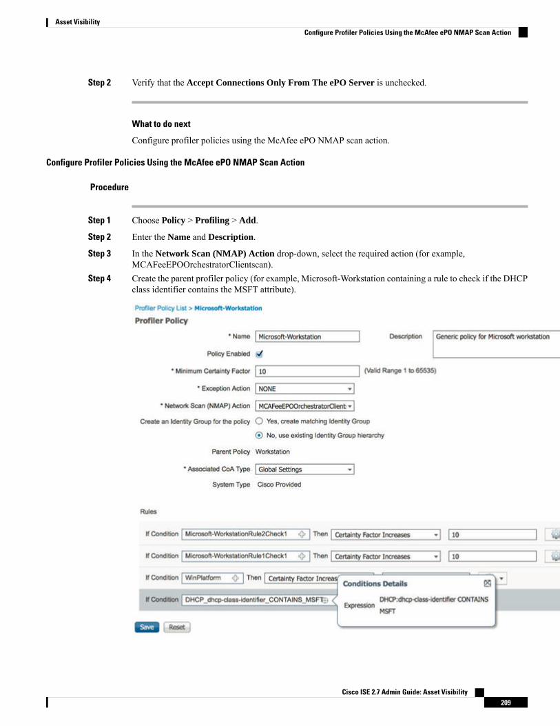
Step 2 Verify that the Accept Connections Only From The ePO Server is unchecked.
What to do next
Configure profiler policies using the McAfee ePO NMAP scan action.
Configure Profiler Policies Using the McAfee ePO NMAP Scan Action
Procedure
Step 1 Choose Policy > Profiling > Add.
Step 2 Enter the Name and Description.
Step 3 In the Network Scan (NMAP) Action drop-down, select the required action (for example,MCAFeeEPOOrchestratorClientscan).
Step 4 Create the parent profiler policy (for example, Microsoft-Workstation containing a rule to check if the DHCPclass identifier contains the MSFT attribute).
Cisco ISE 2.7 Admin Guide: Asset Visibility209
Asset VisibilityConfigure Profiler Policies Using the McAfee ePO NMAP Scan Action

Step 5 Create a new policy (for example CorporateDevice) within the parent NMAPMcAfee ePO policy (for example,Microsoft-Workstation) to check if the McAfee ePO agent is installed on the endpoint.
Endpoints that meet the condition are profiled as corporate devices. You can use the policy to move endpointsprofiled with McAfee ePO agent to a new VLAN.
Profiler Endpoint Custom Attributes
You can use the Endpoint Administration > Identity Management > Settings > Endpoint CustomAttributes page to assign attributes to endpoints, besides the attributes that the endpoint gathers from theprobe. The endpoint custom attributes can be used in authorization policies to profile endpoints.
You can create a maximum of 100 endpoint custom attributes. The types of endpoint custom attributessupported are: Int, String, Long, Boolean, and Float.
You can add values for the endpoint custom attributes in the Context Directory > Endpoints > EndpointClassification page.
Use cases for endpoint custom attributes include, to white list or black list devices based on certain attributesor to assign certain privileges based on the authorization.
Using Endpoint Custom Attributes in Authorization Policy
The endpoint custom attributes section allows you to configure extra attributes. Each definition consists ofthe attribute and type (String, Int, Boolean, Float, Long). You can profile devices using endpoint customattributes.
You must have a plus or higher license to add custom attributes to the endpoints.Note
The following steps show how to create an authorization policy using endpoint custom attributes.
Cisco ISE 2.7 Admin Guide: Asset Visibility210
Asset VisibilityProfiler Endpoint Custom Attributes

Procedure
Step 1 Create the endpoint custom attributes and assign values.a) Choose Administration > Identity Management > Settings > Endpoint Custom Attributes page.b) In the Endpoint Custom Attributes area, enter the Attribute Name (for example, deviceType), Data
Type (for example, String) and Parameters.c) Click Save.d) Choose Context Visibility > Endpoints > Summary.e) Assign the custom attribute values.
• Check the required MAC address check box, and click Edit.
• Or, click the required MAC address, and on the Endpoints page, click Edit.
f) In the Edit Endpoint dialog box, in the Custom Attribute area enter the required attribute values (forexample, deviceType = Apple-iPhone).
g) Click Save.
Step 2 Create an authorization policy using the custom attributes and values.a) Choose Policy > Policy Sets.b) Create the authorization policy by selecting the custom attributes from the Endpoints dictionary (for
example, Rule Name: Corporate Devices, Conditions:EndPoints:deviceType Contains Apple-iPhone,Permissions: then PermitAccess).
c) Click Save.
Related TopicsProfiler Endpoint Custom Attributes, on page 210
Create a Profiler ConditionEndpoint profiling policies in Cisco ISE allow you to categorize discovered endpoints on your network, andassign them to specific endpoint identity groups. These endpoint profiling policies are made up of profilingconditions that Cisco ISE evaluates to categorize and group endpoints.
Before you begin
To perform the following task, you must be a Super Admin or Policy Admin.
Procedure
Step 1 Choose Policy > Policy Elements > Conditions > Profiling > Add.Step 2 Enter values for the fields as described in the Endpoint Profiling Policies Settings, on page 212.Step 3 Click Submit to save the profiler condition.Step 4 Repeat this procedure to create more conditions.
Cisco ISE 2.7 Admin Guide: Asset Visibility211
Asset VisibilityCreate a Profiler Condition

Endpoint Profiling Policy RulesYou can define a rule that allows you to choose one or more profiling conditions from the library that arepreviously created and saved in the policy elements library, and to associate an integer value for the certaintyfactor for each condition, or associate either an exception action or a network scan action for that condition.The exception action or the network scan action is used to trigger the configurable action while Cisco ISE isevaluating the profiling policies with respect to the overall classification of endpoints.
When the rules in a given policy are evaluated separately with an OR operator, the certainty metric for eachrule contributes to the overall matching of the endpoint profiles into a specific category of endpoints. If therules of an endpoint profiling policy match, then the profiling policy and the matched policy are the same forthat endpoint when they are dynamically discovered on your network.
Logically Grouped Conditions in Rules
An endpoint profiling policy (profile) contains a single condition or a combination of multiple single conditionsthat are logically combined using an AND or OR operator, against which you can check, categorize, and groupendpoints for a given rule in a policy.
A condition is used to check the collected endpoint attribute value against the value specified in the conditionfor an endpoint. If you map more than one attribute, you can logically group the conditions, which helps youto categorize endpoints on your network. You can check endpoints against one or more such conditions witha corresponding certainty metric (an integer value that you define) associated with it in a rule or trigger anexception action that is associated to the condition or a network scan action that is associated to the condition.
Certainty Factor
The minimum certainty metric in the profiling policy evaluates the matching profile for an endpoint. Eachrule in an endpoint profiling policy has a minimum certainty metric (an integer value) associated to the profilingconditions. The certainty metric is a measure that is added for all the valid rules in an endpoint profiling policy,which measures how each condition in an endpoint profiling policy contributes to improve the overallclassification of endpoints.
The certainty metric for each rule contributes to the overall matching of the endpoint profiles into a specificcategory of endpoints. The certainty metric for all the valid rules are added together to form the matchingcertainty. It must exceed the minimum certainty factor that is defined in an endpoint profiling policy. Bydefault, the minimum certainty factor for all new profiling policy rules and predefined profiling policies is10.
Endpoint Profiling Policies SettingsThe following table describes the fields in the Endpoint Policies window. The navigation path for this pageis: Policy > Profiling > Profiling Policies.
Table 55: Endpoint Profiling Policies Settings
Usage GuidelinesField Name
Enter the name of the endpoint profiling policy thatyou want to create.
Name
Cisco ISE 2.7 Admin Guide: Asset Visibility212
Asset VisibilityEndpoint Profiling Policy Rules

Usage GuidelinesField Name
Enter the description of the endpoint profiling policythat you want to create.
Description
By default, the Policy Enabled check box is checkedto associate a matching profiling policy when youprofile an endpoint.
When unchecked, the endpoint profiling policy isexcluded when you profile an endpoint.
Policy Enabled
Enter the minimum value that you want to associatewith the profiling policy. The default value is 10.
Minimum Certainty Factor
Choose an exception action, which you want toassociate with the conditions when defining a rule inthe profiling policy.
The default is NONE. The exception actions aredefined in the following location: Policy > PolicyElements > Results > Profiling > Exception Actions.
Exception Action
Choose a network scan action from the list, whichyou want to associate with the conditions whendefining a rule in the profiling policy, if required.
The default is NONE. The exception actions aredefined in the following location: Policy > PolicyElements > Results > Profiling > Network Scan(NMAP) Actions.
Network Scan (NMAP) Action
Check one of the following options to create anendpoint identity group:
• Yes, create matching Identity Group
• No, use existing Identity Group hierarchy
Create an Identity Group for the policy
Choose this option to use an existing profiling policy.
This option creates a matching identity group for thoseendpoints and the identity group will be the child ofthe Profiled endpoint identity group when an endpointprofile matches an existing profiling policy.
For example, the Xerox-Device endpoint identitygroup is created in the Endpoints Identity Groups pagewhen endpoints discovered on your network matchthe Xerox-Device profile.
Yes, create matching Identity Group
Cisco ISE 2.7 Admin Guide: Asset Visibility213
Asset VisibilityEndpoint Profiling Policies Settings

Usage GuidelinesField Name
Check this check box to assign endpoints to thematching parent endpoint identity group usinghierarchical construction of profiling policies andidentity groups.
This option allows you to make use of the endpointprofiling policies hierarchy to assign endpoints to oneof the matching parent endpoint identity groups, aswell as to the associated endpoint identity groups tothe parent identity group.
For example, endpoints that match an existing profileare grouped under the appropriate parent endpointidentity group. Here, endpoints that match theUnknown profile are grouped under Unknown, andendpoints that match an existing profile are groupedunder the Profiled endpoint identity group. Forexample,
• If endpoints match the Cisco-IP-Phone profile,then they are grouped under the Cisco-IP-Phoneendpoint identity group.
• If endpoints match the Workstation profile, thenthey are grouped under theWorkstation endpointidentity group.
The Cisco-IP-Phone and Workstation endpointidentity groups are associated to the Profiledendpoint identity group in the system.
No, use existing Identity Group hierarchy
Choose a parent profiling policy that are defined inthe system to which you want to associate the newendpoint profiling policy.
You can choose a parent profiling policy from whichyou can inherit rules and conditions to its child.
Parent Policy
Choose one of the following CoA types that you wantto associate with the endpoint profiling policy:
• No CoA
• Port Bounce
• Reauth
• Global Settings that is applied from the profilerconfiguration set in Administration > System >Settings > Profiling
Associated CoA Type
Cisco ISE 2.7 Admin Guide: Asset Visibility214
Asset VisibilityEndpoint Profiling Policies Settings

Usage GuidelinesField Name
One or more rules that are defined in endpointprofiling policies determine the matching profilingpolicy for endpoints, which allows you to groupendpoints according to their profiles.
One or more profiling conditions from the policyelements library are used in rules for validatingendpoint attributes and their values for the overallclassification.
Rules
Click the plus [+] sign to expand the Conditionsanchored overlay, and click the minus [-] sign, or clickoutside the anchored overlay to close it.
Click Select Existing Condition from Library orCreate New Condition (Advanced Option) .
Select Existing Condition from Library---You candefine an expression by selecting Cisco predefinedconditions from the policy elements library.
Create New Condition (Advanced Option)---Youcan define an expression by selecting attributes fromvarious system or user-defined dictionaries.
You can associate one of the following with theprofiling conditions:
• An integer value for the certainty factor for eachcondition
• Either an exception action or a network scanaction for that condition
Choose one of the following predefined settings toassociate with the profiling condition:
• Certainty Factor Increases: Enter the certaintyvalue for each rule, which can be added for allthe matching rules with respect to the overallclassification.
• Take Exception Action: Triggers an exceptionaction that is configured in the Exception Actionfield for this endpoint profiling policy.
• Take Network Scan Action: Triggers a networkscan action that is configured in the NetworkScan (NMAP) Action field for this endpointprofiling policy.
Conditions
Cisco ISE 2.7 Admin Guide: Asset Visibility215
Asset VisibilityEndpoint Profiling Policies Settings

Usage GuidelinesField Name
You can do the following:
• You can choose Cisco predefined conditions thatare available in the policy elements library, andthen use an AND or OR operator to add multipleconditions.
• Click the Action icon to do the following in thesubsequent steps:
• Add Attribute or Value: You can addad-hoc attribute or value pairs
• Add Condition from Library: You canadd Cisco predefined conditions
• Duplicate: Create a copy of the selectedcondition
• Add Condition to Library: You can savead-hoc attribute/value pairs that you createto the policy elements library
• Delete: Delete the selected condition.
Select Existing Condition from Library
You can do the following:
• You can add ad-hoc attribute/value pairs to yourexpression, and then use an AND or OR operatorto add multiple conditions.
• Click the Action icon to do the following in thesubsequent steps:
• Add Attribute or Value: You can addad-hoc attribute or value pairs
• Add Condition from Library: You canadd Cisco predefined conditions
• Duplicate: Create a copy of the selectedcondition
• Add Condition to Library: You can savead-hoc attribute/value pairs that you createto the policy elements library
• Delete: Delete the selected condition. Youcan use the AND or OR operator
Create New Condition (Advance Option)
Related TopicsCisco ISE Profiling Service, on page 169Create Endpoint Profiling Policies, on page 217
Cisco ISE 2.7 Admin Guide: Asset Visibility216
Asset VisibilityEndpoint Profiling Policies Settings

Endpoint Context Visibility Using UDID Attribute, on page 257
Create Endpoint Profiling PoliciesYou can use the Profiling Policies page to manage endpoint profiling policies that you create as an administratorof Cisco ISE, and also endpoint profiling profiles that are provided by Cisco ISE when deployed.
You can create new profiling policies to profile endpoints by using the following options in the New ProfilerPolicy page:
• Policy Enabled
• Create an Identity Group for the policy to create a matching endpoint identity group or use the endpointidentity group hierarchy
• Parent Policy
• Associated CoA Type
When you choose to create an endpoint policy in the Profiling Policies page, donot use the Stop button on your web browsers. This action leads to the following:stops loading the New Profiler Policy page, loads other list pages and the menuswithin the list pages when you access them, and prevents you from performingoperations on all the menus within the list pages except the Filter menus. Youmight need to log out of Cisco ISE, and then log in again to perform operationson all the menus within the list pages.
Note
You can create a similar characteristic profiling policy by duplicating an endpoint profiling policy throughwhich you can modify an existing profiling policy instead of creating a new profiling policy by redefining allconditions.
Procedure
Step 1 Choose Policy > Profiling > Profiling Policies.Step 2 Click Add.Step 3 Enter a name and description for the new endpoint policy that you want to create. The Policy Enabled check
box is checked by default to include the endpoint profiling policy for validation when you profile an endpoint.Step 4 Enter a value for the minimum certainty factor within the valid range 1 to 65535.Step 5 Click the arrow next to the Exception Action drop-down list to associate an exception action or click the
arrow next to the Network Scan (NMAP) Action drop-down list to associate a network scan action.Step 6 Choose one of the following options for Create an Identity Group for the policy:
• Yes, create matching Identity Group
• No, use existing Identity Group hierarchy
Step 7 Click the arrow next to the Parent Policy drop-down list to associate a parent policy to the new endpointpolicy.
Cisco ISE 2.7 Admin Guide: Asset Visibility217
Asset VisibilityCreate Endpoint Profiling Policies

Step 8 Choose a CoA type to be associated in the Associated CoA Type drop-down list.Step 9 Click in the rule to add conditions and associate an integer value for the certainty factor for each condition or
associate either an exception action or a network scan action for that condition for the overall classificationof an endpoint.
Step 10 Click Submit to add an endpoint policy or click the Profiler Policy List link from the New Profiler Policypage to return to the Profiling Policies page.
Change of Authorization Configuration per Endpoint Profiling PolicyIn addition to the global configuration of change of authorization (CoA) types in Cisco ISE, you can alsoconfigure to issue a specific type of CoA associated for each endpoint profiling policy.
The global No CoA type configuration overrides each CoA type configured in an endpoint profiling policy.If the global CoA type is set other than the No CoA type, then each endpoint profiling policy is allowed tooverride the global CoA configuration.
When a CoA is triggered, each endpoint profiling policy can determine the actual CoA type, as follows:
• General Setting—This is the default setting for all the endpoint profiling policies that issues a CoA perglobal configuration.
• No CoA—This setting overrides any global configuration and disables CoA for the profile.
• Port Bounce—This setting overrides the global Port Bounce and Reauth configuration types, and issuesport bounce CoA.
• Reauth—This setting overrides the global Port Bounce and Reauth configuration types, and issuesreauthentication CoA.
If the profiler global CoA configuration is set to Port Bounce (or Reauth), ensurethat you configure corresponding endpoint profiling policies with No CoA, theper-policy CoA option so that the BYOD flow does not break for your mobiledevices.
Note
See the summary of configuration below combined for all the CoA types and the actual CoA type issued ineach case based on the global and endpoint profiling policy settings.
Table 56: CoA Type Issued for Various Combination of Configuration
Reauth Type perPolicy
Port Bounce Typeper Policy
No coA Type perPolicy
Default CoA Typeset per Policy
Global CoA Type
No CoANo CoANo CoANo CoANo CoA
Re-AuthPort BounceNo CoAPort BouncePort Bounce
Re-AuthPort BounceNo CoAReauthReauth
Cisco ISE 2.7 Admin Guide: Asset Visibility218
Asset VisibilityChange of Authorization Configuration per Endpoint Profiling Policy

Import Endpoint Profiling PoliciesYou can import endpoint profiling policies from a file in XML by using the same format that you can createin the export function. If you import newly created profiling policies that have parent policies associated, thenyou must have defined parent policies before you define child policies.
The imported file contains the hierarchy of endpoint profiling policies that contain the parent policy first, thenthe profile that you imported next along with the rules and checks that are defined in the policy.
Procedure
Step 1 Choose Policy > Profiling > Profiling > Profiling Policies.Step 2 Click Import.Step 3 Click Browse to locate the file that you previously exported and want to import.Step 4 Click Submit.Step 5 Click the Profiler Policy List link to return to the Profiling Policies page.
Export Endpoint Profiling PoliciesYou can export endpoint profiling policies to other Cisco ISE deployments. Or, you can use the XML file asa template for creating your own policies to import. You can also download the file to your system in thedefault location, which can be used for importing later.
A dialog appears when you want to export endpoint profiling policies, which prompts you to open theprofiler_policies.xml with an appropriate application or save it. This is a file in XML format that you canopen in a web browser, or in other appropriate applications.
Procedure
Step 1 Choose Policy > Profiling > Profiling > Profiling Policies.Step 2 Choose Export, and choose one of the following:
• Export Selected—You can export only the selected endpoint profiling policies in the Profiling Policiespage.
• Export Selected with Endpoints—You can export the selected endpoint profiling policies, and theendpoints that are profiled with the selected endpoint profiling policies.
• Export All—By default, you can export all the profiling policies in the Profiling Policies page.
Step 3 Click OK to export the endpoint profiling policies in the profiler_policies.xml file.
Cisco ISE 2.7 Admin Guide: Asset Visibility219
Asset VisibilityImport Endpoint Profiling Policies

Predefined Endpoint Profiling PoliciesCisco ISE includes predefined default profiling policies when Cisco ISE is deployed, and their hierarchicalconstruction allows you to categorize identified endpoints on your network, and assign them to a matchingendpoint identity groups. Because endpoint profiling policies are hierarchical, you can find that the ProfilingPolicies page displays the list of generic (parent) policies for devices and child policies to which their parentpolicies are associated in the Profiling Policies list page.
The Profiling Policies page displays endpoint profiling policies with their names, type, description and thestatus, if enabled or not for validation.
The endpoint profiling policy types are classified as follows:
• Cisco Provided—Endpoint profiling policies that are predefined in Cisco ISE are identified as the CiscoProvided type.
• Administrator Modified—Endpoint profiling policies are identified as the Administrator Modifiedtype when you modify predefined endpoint profiling policies. Cisco ISE overwrites changes thatyou have made in the predefined endpoint profiling policies during upgrade.
• Administrator Created—Endpoint profiling policies that you create or when you duplicate Cisco-providedendpoint profiling policies are identified as the Administrator Created type.
We recommend that you create a generic policy (a parent) for a set of endpoints from which its children caninherit the rules and conditions. If an endpoint has to be classified, then the endpoint profile has to first matchthe parent, and then its descendant (child) policies when you are profiling an endpoint.
For example, Cisco-Device is a generic endpoint profiling policy for all Cisco devices, and other policies forCisco devices are children of Cisco-Device. If an endpoint has to be classified as a Cisco-IP-Phone 7960, thenthe endpoint profile for this endpoint has to first match the parent Cisco-Device policy, its child Cisco-IP-Phonepolicy, and then the Cisco-IP-Phone 7960 profiling policy for better classification.
Cisco ISE will not overwrite the Administrator Modified policies nor their children policies even if they arestill labeled as Cisco Provided. If an Administrator Modified policy is deleted, it reverts back to the previousCisco Provided policy. Next time when Feed Update happens, all children policies are updated.
Note
Predefined Endpoint Profiling Policies Overwritten During UpgradeYou can edit existing endpoint profiling policies in the Profiling Policies page. You must also save all yourconfigurations in a copy of the predefined endpoint profiles when you want to modify the predefined endpointprofiling policies.
During an upgrade, Cisco ISE overwrites any configuration that you have saved in the predefined endpointprofiles.
Unable to Delete Endpoint Profiling PoliciesYou can delete selected or all the endpoint profiling policies in the Profiling Policies page. By default, youcan delete all the endpoint profiling policies from the Profiling Policies page.When you select all the endpointprofiling policies and try to delete them in the Profiling Policies page, some of them may not be deleted when
Cisco ISE 2.7 Admin Guide: Asset Visibility220
Asset VisibilityPredefined Endpoint Profiling Policies

the endpoint profiling policies are a parent policy mapped to other endpoint profiling policies or mapped toan authorization policy and a parent policy to other endpoint profiling policies.
For example,
• You cannot delete Cisco Provided endpoint profiling policies,
• You cannot delete a parent profile in the Profiling Policies page when an endpoint profile is defined asa parent to other endpoint profiles. For example, Cisco-Device is a parent to other endpoint profilingpolicies for Cisco devices.
• You cannot delete an endpoint profile when it is mapped to an authorization policy. For example,Cisco-IP-Phone is mapped to the Profiled Cisco IP Phones authorization policy, and it is a parent to otherendpoint profiling policies for Cisco IP Phones.
Predefined Profiling Policies for Draeger Medical DevicesCisco ISE contains default endpoint profiling policies that include a generic policy for Draeger medicaldevices, a policy for Draeger-Delta medical device, and a policy for Draeger-M300 medical device. Both themedical devices share ports 2050 and 2150, and therefore you cannot classify the Draeger-Delta andDraeger-M300 medical devices when you are using the default Draeger endpoint profiling policies.
If these Draeger devices share ports 2050 and 2150 in your environment, you must add a rule in addition tochecking for the device destination IP address in the default Draeger-Delta and Draeger-M300 endpointprofiling policies so that you can distinquish these medical devices.
Cisco ISE includes the following profiling conditions that are used in the endpoint profiling policies for theDraeger medical devices:
• Draeger-Delta-PortCheck1 that contains port 2000
• Draeger-Delta-PortCheck2 that contains port 2050
• Draeger-Delta-PortCheck3 that contains port 2100
• Draeger-Delta-PortCheck4 that contains port 2150
• Draeger-M300PortCheck1 that contains port 1950
• Draeger-M300PortCheck2 that contains port 2050
• Draeger-M300PortCheck3 that contains port 2150
Endpoint Profiling Policy for Unknown EndpointsAn endpoint that does not match existing profiles and cannot be profiled in Cisco ISE is an unknown endpoint.An unknown profile is the default system profiling policy that is assigned to an endpoint, where an attributeor a set of attributes collected for that endpoint do not match with existing profiles in Cisco ISE.
An Unknown profile is assigned in the following scenarios:
• When an endpoint is dynamically discovered in Cisco ISE, and there is no matching endpoint profilingpolicy for that endpoint, it is assigned to the unknown profile.
• When an endpoint is statically added in Cisco ISE, and there is no matching endpoint profiling policyfor a statically added endpoint, it is assigned to the unknown profile.
Cisco ISE 2.7 Admin Guide: Asset Visibility221
Asset VisibilityPredefined Profiling Policies for Draeger Medical Devices

If you have statically added an endpoint to your network, the statically added endpoint is not profiled bythe profiling service in Cisco ISE. You can change the unknown profile later to an appropriate profileand Cisco ISE will not reassign the profiling policy that you have assigned.
Endpoint Profiling Policy for Statically Added EndpointsFor the endpoint that is statically added to be profiled, the profiling service computes a profile for the endpointby adding a new MATCHEDPROFILE attribute to the endpoint. The computed profile is the actual profileof an endpoint if that endpoint is dynamically profiled. This allows you to find the mismatch between thecomputed profile for statically added endpoints and the matching profile for dynamically profiled endpoints.
Endpoint Profiling Policy for Static IP DevicesIf you have an endpoint with a statically assigned IP address, you can create a profile for such static IP devices.
You must enable the RADIUS probe or SNMP Query and SNMP Trap probes to profile an endpoint that hasa static IP address.
Endpoint Profiling Policy MatchingCisco ISE always considers a chosen policy for an endpoint that is the matched policy rather than an evaluatedpolicy when the profiling conditions that are defined in one or more rules are met in a profiling policy. Here,the status of static assignment for that endpoint is set to false in the system. But, this can be set to true afterit is statically reassigned to an existing profiling policy in the system, by using the static assignment featureduring an endpoint editing.
The following apply to the matched policies of endpoints:
• For statically assigned endpoint, the profiling service computes the MATCHEDPROFILE.
• For dynamically assigned endpoints, the MATCHEDPROFILEs are identical to the matching endpointprofiles.
You can determine a matching profiling policy for dynamic endpoints using one or more rules that are definedin a profiling policy and assign appropriately an endpoint identity group for categorization.
When an endpoint is mapped to an existing policy, the profiling service searches the hierarchy of profilingpolicies for the closest parent profile that has a matching group of policies and assigns the endpoint to theappropriate endpoint policy.
Endpoint Profiling Policies Used for AuthorizationYou can use an endpoint profiling policy in authorization rules, where you can create a new condition toinclude a check for an endpoint profiling policy as an attribute, and the attribute value assumes the name ofthe endpoint profiling policy. You can select an endpoint profiling policy from the endpoints dictionary, whichincludes the following attributes: PostureApplicable, EndPointPolicy, LogicalProfile, and BYODRegistration.
The attribute value for PostureApplicable is auto set based on the operating system. It is set to No for IOSand Android devices since there is no AnyConnect available on those platforms to perform Posture. The valueis set as Yes for Mac OSX and Windows devices.
You can define an authorization rule that includes a combination of EndPointPolicy, BYODRegistration, andidentity groups.
Cisco ISE 2.7 Admin Guide: Asset Visibility222
Asset VisibilityEndpoint Profiling Policy for Statically Added Endpoints

Endpoint Profiling Policies Grouped into Logical ProfilesA logical profile is a container for a category of profiles or associated profiles, irrespective of Cisco-providedor administrator-created endpoint profiling policies. An endpoint profiling policy can be associated to multiplelogical profiles.
You can use the logical profile in an authorization policy condition to help create an overall network accesspolicy for a category of profiles. You can create a simple condition for authorization, which can be includedin the authorization rule. The attribute-value pair that you can use in the authorization condition is the logicalprofile (attribute) and the name of the logical profile (value), which can be found in the EndPoints systemsdictionary.
For example, you can create a logical profile for all mobile devices like Android, Apple iPhone, or Blackberryby assigning matching endpoint profiling policies for that category to the logical profile. Cisco ISE containsIP-Phone, a default logical profile for all the IP phones, which includes IP-Phone, Cisco-IP-Phone,Nortel-IP-Phone-2000-Series, and Avaya-IP-Phone profiles.
Create Logical ProfilesYou can create a logical profile that you can use to group a category of endpoint profiling policies, whichallows you to create an overall category of profiles or associated profiles. You can also remove the endpointprofiling policies from the assigned set moving them back to the available set. For more information aboutLogical Profiles, see Endpoint Profiling Policies Grouped into Logical Profiles, on page 223.
Procedure
Step 1 Choose Policy > Profiling > Profiling > Logical Profiles.Step 2 Click Add.Step 3 Enter a name and description for the new logical profile in the text boxes for Name and Description.Step 4 Choose endpoint profiling policies from the Available Policies to assign them in a logical profile.Step 5 Click the right arrow to move the selected endpoint profiling policies to the Assigned Policies.Step 6 Click Submit.
Profiling Exception ActionsAn exception action is a single configurable action that can be referred to in an endpoint profiling policy, andthat is triggered when the exception conditions that are associated with the action are met.
Exception Actions can be any one of the following types:
• Cisco-provided—You can not delete Cisco-provided exception actions. Cisco ISE triggers the followingnoneditable profiling exception actions from the system when you want to profile endpoints in CiscoISE:
• Authorization Change—The profiling service issues a change of authorization when an endpoint isadded or removed from an endpoint identity group that is used by an authorization policy.
Cisco ISE 2.7 Admin Guide: Asset Visibility223
Asset VisibilityEndpoint Profiling Policies Grouped into Logical Profiles
• Endpoint Delete—An exception action is triggered in Cisco ISE and a CoA is issued when anendpoint is deleted from the system in the Endpoints page, or reassigned to the unknown profilefrom the edit page on a Cisco ISE network.
• FirstTimeProfiled—An exception action is triggered in Cisco ISE and a CoA is issued when anendpoint is profiled in Cisco ISE for the first time, where the profile of that endpoint changes froman unknown profile to an existing profile but that endpoint is not successfully authenticated on aCisco ISE network.
• Administrator-created—Cisco ISE triggers profiling exception actions that you create.
Create Exception ActionsYou can define and associate one or more exception rules to a single profiling policy. This association triggersan exception action (a single configurable action) when the profiling policy matches and at least one of theexception rules matches in the profiling endpoints in Cisco ISE.
Procedure
Step 1 Choose Policy > Policy Elements > Results > Profiling > Exception Actions.Step 2 Click Add.Step 3 Enter a name and description for the exception action in the text boxes for Name and Description.Step 4 Check the CoA Action check box.Step 5 Click the Policy Assignment drop-down list to choose an endpoint policy.Step 6 Click Submit.
Create Endpoints with Static Assignments of Policies and Identity GroupsYou can create a new endpoint statically by using the MAC address of an endpoint in the Endpoints page.You can also choose an endpoint profiling policy and an identity group in the Endpoints page for staticassignment.
The regular and mobile device (MDM) endpoints are displayed in the Endpoints Identities list. In the listingpage, columns for attributes like Hostname, Device Type, Device Identifier for MDM endpoints are displayed.Other columns like Static Assignment and Static Group Assignment are not displayed by default.
You cannot add, edit, delete, import, or export MDM Endpoints using this page.Note
Procedure
Step 1 Choose Work Centers > Network Access > Identities > Endpoints.Step 2 Click Add.
Cisco ISE 2.7 Admin Guide: Asset Visibility224
Asset VisibilityCreate Exception Actions

Step 3 Enter the MAC address of an endpoint in hexadecimal format and separated by a colon.Step 4 Choose a matching endpoint policy from the Policy Assignment drop-down list to change the static assignment
status from dynamic to static.Step 5 Check the Static Assignment check box to change the status of static assignment that is assigned to the
endpoint from dynamic to static.Step 6 Choose an endpoint identity group to which you want to assign the newly created endpoint from the Identity
Group Assignment drop-down list.Step 7 Check the Static Group Assignment check box to change the dynamic assignment of an endpoint identity
group to static.Step 8 Click Submit.
Import Endpoints from CSV FilesYou can import endpoints from a CSV file that you have created from a Cisco ISE template and update itwith endpoint details. Endpoints exported from ISE contains around 75 attributes and therefore cannot beimported directly into another ISE deployment. If columns that are not allowed for import are present in theCSV file, a message with the list of columns are displayed. You must delete the specified columns beforetrying to import the file again.
To import endpoint custom attributes, you have to create the same custom attributes as in the CSV file in theAdministration > Identity Management > Settings > Endpoint Custom Attributes page using the correctdata types. These attributes have to be prefixed with "CUSTOM." to differentiate them from endpoint attributes.
Note
There are about 30 attributes that can be imported. The list includes MACAddress, EndPointPolicy, andIdentityGroup. Optional attributes are:
LastNamePortalUserDescription
EmailAddressPortalUser.FirstNamePortalUser.GuestType
host-nameDevice TypePortalUser.Location
LocationStaticAssignmentPortalUser.GuestStatus
MDMEnrolledStaticGroupAssignmentPortalUser.CreationType
MDMOSVersionUser-NamePortalUser.EmailAddress
MDMServerNameDeviceRegistrationStatusPortalUser.PhoneNumber
MDMServerIDAUPAcceptedPortalUser.LastName
BYODRegistrationFirstNamePortalUser.GuestSponsor
——CUSTOM.<customattribute name>
The file header has to be in the format as specified in the default import template so that the list of endpointsappear in this order: MACAddress, EndpointPolicy, IdentityGroup <List of attributes listed above as optionalattributes>. You can create the following file templates:
Cisco ISE 2.7 Admin Guide: Asset Visibility225
Asset VisibilityImport Endpoints from CSV Files

• MACAddress
• MACAddress, EndPointPolicy
• MACAddress, EndPointPolicy, IdentityGroup
• MACAddress, EndPointPolicy, IdentityGroup, <List of attributes listed above as optional attributes>
All attribute values, except MAC address, are optional for importing endpoints from a CSV file. If you wantto import endpoints without certain values, the values are still separated by the comma.
For example,
• MAC1, Endpoint Policy1, Endpoint Identity Group1
• MAC2
• MAC3, Endpoint Policy3
• MAC4, , Endpoint Identity Group4
• MAC5, , Endpoint Identity Group5, MyDescription, MyPortalUser, and so on
Procedure
Step 1 Choose Context Visibility > Endpoints > Import .Step 2 Click Import From File.Step 3 Click Browse to locate the CSV file that you have already created.Step 4 Click Submit.
Default Import Template Available for Endpoints
You can generate a template in which you can update endpoints that can be used to import endpoints. Bydefault, you can use the Generate a Template link to create a CSV file in theMicrosoft Office Excel applicationand save the file locally on your system. The file can be found inContext Visibility > Endpoints > Import >Import From File. You can use the Generate a Template link to create a template, and the Cisco ISE serverwill display the Opening template.csv dialog. This dialog allows you to open the default template.csv file, orsave the template.csv file locally on your system. If you choose to open the template.csv file from the dialog,the file opens in the Microsoft Office Excel application. The default template.csv file contains a header rowthat displays the MAC address, Endpoint Policy, and Endpoint Identity Group, and other optional attributes.
You must update the MAC addresses of endpoints, endpoint profiling policies, endpoint identity groups alongwith any of the optional attribute values you wish to import, and save the file with a new file name. This filecan be used to import endpoints. See the header row in the template.csv file that is created when you use theGenerate a Template link.
Table 57: CSV Template File
Other Optional AttributesIdentityGroupEndpointPolicyMAC
<Empty>/<Value>ProfiledAndroid11:11:11:11:11:11
Cisco ISE 2.7 Admin Guide: Asset Visibility226
Asset VisibilityDefault Import Template Available for Endpoints

Unknown Endpoints Reprofiled During Import
If the file used for import contains endpoints that have their MAC addresses, and their assigned endpointprofiling policies is the Unknown profile, then those endpoints are immediately reprofiled in Cisco ISE to thematching endpoint profiling policies during import. However, they are not statically assigned to the Unknownprofile. If endpoints do not have endpoint profiling policies assigned to them in the CSV file, then they areassigned to the Unknown profile, and then reprofiled to the matching endpoint profiling policies. See belowhow Cisco ISE reprofiles Unknown profiles that match the Xerox_Device profile during import and also howCisco ISE reprofiles an endpoint that is unassigned.
Table 58: Unknown Profiles: Import from a File
Endpoint Profiling Policy AssignedAfter Import in Cisco ISE
Endpoint Profiling Policy AssignedBefore Import in Cisco ISE
MAC Address
Xerox-DeviceUnknown.00:00:00:00:01:02
Xerox-DeviceUnknown.00:00:00:00:01:03
Xerox-DeviceUnknown.00:00:00:00:01:04
Xerox-DeviceIf no profile is assigned to anendpoint, then it is assigned to theUnknown profile, and alsoreprofiled to the matching profile.
00:00:00:00:01:05
Endpoints with Invalid Attributes Not Imported
If any of the endpoints present in the CSV file have invalid attributes, then the endpoints are not importedand an error message is displayed.
For example, if endpoints are assigned to invalid profiles in the file used for import, then they are not importedbecause there are no matching profiles in Cisco ISE. See below how endpoints are not imported when theyare assigned to invalid profiles in the CSV file.
Table 59: Invalid Profiles: Import from a File
Endpoint Profiling Policy AssignedAfter Import in Cisco ISE
Endpoint Profiling Policy AssignedBefore Import in Cisco ISE
MAC Address
Xerox-DeviceUnknown.00:00:00:00:01:02
The endpoint is not importedbecause there is nomatching profilein Cisco ISE.
If an endpoint such as00:00:00:00:01:05 is assigned to aninvalid profile other than theprofiles that are available in CiscoISE, then Cisco ISE displays awarning message that the policyname is invalid and the endpointwill not be imported.
00:00:00:00:01:05
Import Endpoints from LDAP ServerYou can import the MAC addresses, the associated profiles, and the endpoint identity groups of endpointssecurely from an LDAP server.
Cisco ISE 2.7 Admin Guide: Asset Visibility227
Asset VisibilityUnknown Endpoints Reprofiled During Import

Before you begin
Before you begin to import endpoints, ensure that you have installed the LDAP server.
You have to configure the connection settings and query settings before you can import from an LDAP server.If the connection settings or query settings are configured incorrectly in Cisco ISE, then the “LDAP importfailed:” error message appears.
Procedure
Step 1 Choose Context Visibility > Endpoints > Import > Import from LDAP.Step 2 Enter the values for the connection settings.Step 3 Enter the values for the query settings.Step 4 Click Submit.
Export Endpoints with Comma-Separated Values FileYou can export selected or all endpoints from a Cisco ISE server into a CSV file in which endpoints are listedwith around 75 attributes along with their MAC addresses, endpoint profiling policies, and endpoint identitygroups. The custom attributes created in Cisco ISE will also be exported to the CSV file and is prefixed with"CUSTOM." to differentiate them from other endpoint attributes.
To import endpoint custom attributes exported from one deployment to another, you must create the samecustom attributes in theAdministration > Identity Management > Settings >Endpoint Custom Attributespage and use the same data type as specified in the original deployment.
Note
Export All exports all the endpoints in Cisco ISE, whereas Export Selected exports only the endpoints selectedby the user. By default, the profiler_endpoints.csv is the CSV file and Microsoft Office Excel is the defaultapplication to open the CSV file.
Procedure
Step 1 Choose Context Visibility > Endpoints.Step 2 Click Export, and choose one of the following:
• Export Selected—You can export only the selected endpoints in the Endpoints page.
• Export All—By default, you can export all the endpoints in the Endpoints page.
Step 3 Click OK to save the profiler_endpoints.csv file.
Most of the attributes in the exported spreadsheet are simple. The following attributes require an explanation:
Cisco ISE 2.7 Admin Guide: Asset Visibility228
Asset VisibilityExport Endpoints with Comma-Separated Values File

• UpdateTime : The last time that the profiler updated the endpoint, due to a change to an endpoint attribute.The value is 0 if there have been no updates since the endpoint session started. It will be blank briefly,during an update.
• InactivityTime: Time since the endpoint was active.
Identified EndpointsCisco ISE displays identified endpoints that connect to your network and use resources on your network inthe Endpoints page. An endpoint is typically a network-capable device that connect to your network throughwired and wireless network access devices and VPN. Endpoints can be personal computers, laptops, IP phones,smart phones, gaming consoles, printers, fax machines, and so on.
The MAC address of an endpoint, expressed in hexadecimal form, is always the unique representation of anendpoint, but you can also identify an endpoint with a varying set of attributes and the values associated tothem, called an attribute-value pair. You can collect a varying set of attributes for endpoints based on theendpoint capability, the capability and configuration of the network access devices and the methods (probes)that you use to collect these attributes.
Dynamically Profiled Endpoints
When endpoints are discovered on your network, they can be profiled dynamically based on the configuredprofiling endpoint profiling policies, and assigned to the matching endpoint identity groups depending ontheir profiles.
Statically Profiled Endpoints
An endpoint can be profiled statically when you create an endpoint with its MAC address and associate aprofile to it along with an endpoint identity group in Cisco ISE. Cisco ISE does not reassign the profilingpolicy and the identity group for statically assigned endpoints.
Unknown Endpoints
If you do not have a matching profiling policy for an endpoint, you can assign an unknown profiling policy(Unknown) and the endpoint therefore will be profiled as Unknown. The endpoint profiled to the Unknownendpoint policy requires that you create a profile with an attribute or a set of attributes collected for thatendpoint. The endpoint that does not match any profile is grouped within the Unknown endpoint identitygroup.
Identified Endpoints Locally Stored in Policy Service Nodes DatabaseCisco ISE writes identified endpoints locally in the Policy Service node database. After storing endpointslocally in the database, these endpoints are then made available (remote write) in the Administration nodedatabase only when significant attributes change in the endpoints, and replicated to the other Policy Servicenodes database.
The following are the significant attributes:
• ip
• EndPointPolicy
• MatchedValue
Cisco ISE 2.7 Admin Guide: Asset Visibility229
Asset VisibilityIdentified Endpoints

• StaticAssignment
• StaticGroupAssignment
• MatchedPolicyID
• NmapSubnetScanID
• PortalUser
• DeviceRegistrationStatus
• BYODRegistration
When you change endpoint profile definitions in Cisco ISE, all endpoints have to be reprofiled. A PolicyService node that collects the attributes of endpoints is responsible for reprofiling of those endpoints.
When a Policy Service node starts collecting attributes about an endpoint for which attributes were initiallycollected by a different Policy Service node, then the endpoint ownership changes to the current Policy Servicenode. The new Policy Service node will retrieve the latest attributes from the previous Policy Service nodeand reconcile the collected attributes with those attributes that were already collected.
When a significant attribute changes in the endpoint, attributes of the endpoint are automatically saved in theAdministration node database so that you have the latest significant change in the endpoint. If the PolicyService node that owns an endpoint is not available for some reasons, then the Administrator ISE node willreprofile an endpoint that lost the owner and you have to configure a new Policy Service node for suchendpoints.
Policy Service Nodes in ClusterCisco ISE uses Policy Service node group as a cluster that allows to exchange endpoint attributes when twoor more nodes in the cluster collect attributes for the same endpoint. We recommend to create clusters for allPolicy Service nodes that reside behind a load balancer.
If a different node other than the current owner receives attributes for the same endpoint, it sends a messageacross the cluster requesting the latest attributes from the current owner to merge attributes and determine ifa change of ownership is needed. If you have not defined a node group in Cisco ISE, it is assumed that allnodes are within one cluster.
There are no changes made to endpoint creation and replication in Cisco ISE. Only the change of ownershipfor endpoints is decided based on a list of attributes (white list) used for profiling that are built from staticattributes and dynamic attributes.
Upon subsequent attributes collection, the endpoint is updated on the Administration node, if anyone of thefollowing attributes changes:
• ip
• EndPointPolicy
• MatchedValue
• StaticAssignment
• StaticGroupAssignment
• MatchedPolicyID
• NmapSubnetScanID
Cisco ISE 2.7 Admin Guide: Asset Visibility230
Asset VisibilityPolicy Service Nodes in Cluster

• PortalUser
• DeviceRegistrationStatus
• BYODRegistration
When an endpoint is edited and saved in the Administration node, the attributes are retrieved from the currentowner of the endpoint.
Create Endpoint Identity GroupsCisco ISE groups endpoints that it discovers in to the corresponding endpoint identity groups. Cisco ISEcomes with several system-defined endpoint identity groups. You can also create additional endpoint identitygroups from the Endpoint Identity Groups page. You can edit or delete the endpoint identity groups that youhave created. You can only edit the description of the system-defined endpoint identity groups; you cannotedit the name of these groups or delete them.
Procedure
Step 1 Choose Administration > Identity Management > Groups > Endpoint Identity Groups.Step 2 Click Add.Step 3 Enter the name for the endpoint identity group that you want to create (do not include spaces in the name of
the endpoint identity group).Step 4 Enter the description for the endpoint identity group that you want to create.Step 5 Click the Parent Group drop-down list to choose an endpoint identity group to which you want to associate
the newly created endpoint identity group.Step 6 Click Submit.
Identified Endpoints Grouped in Endpoint Identity GroupsCisco ISE groups discovered endpoints into their corresponding endpoint identity groups based on the endpointprofiling policies. Profiling policies are hierarchical, and they are applied at the endpoint identify groups levelin Cisco ISE. By grouping endpoints to endpoint identity groups, and applying profiling policies to endpointidentity groups, Cisco ISE enables you to determine the mapping of endpoints to the endpoint profiles bychecking corresponding endpoint profiling policies.
Cisco ISE creates a set of endpoint identity groups by default, and allows you to create your own identitygroups to which endpoints can be assigned dynamically or statically. You can create an endpoint identitygroup and associate the identity group to one of the system-created identity groups. You can also assign anendpoint that you create statically to any one of the identity groups that exists in the system, and the profilingservice cannot reassign the identity group.
Default Endpoint Identity Groups Created for EndpointsCisco ISE creates the following five endpoint identity groups by default: Blacklist, GuestEndpoints, Profiled,RegisteredDevices, and Unknown. In addition, it creates two more identity groups, such as Cisco-IP-Phone
Cisco ISE 2.7 Admin Guide: Asset Visibility231
Asset VisibilityCreate Endpoint Identity Groups

and Workstation, which are associated to the Profiled (parent) identity group. A parent group is the defaultidentity group that exists in the system.
Cisco ISE creates the following endpoint identity groups:
• Blacklist—This endpoint identity group includes endpoints that are statically assigned to this group inCisco ISE and endpoints that are blacklisted in the device registration portal. An authorization profilecan be defined in Cisco ISE to permit, or deny network access to endpoints in this group.
• GuestEndpoints—This endpoint identity group includes endpoints that are used by guest users.
• Profiled—This endpoint identity group includes endpoints that match endpoint profiling policies exceptCisco IP phones and workstations in Cisco ISE.
• RegisteredDevices—This endpoint identity group includes endpoints, which are registered devices thatare added by an employee through the devices registration portal. The profiling service continues toprofile these devices normally when they are assigned to this group. Endpoints are statically assigned tothis group in Cisco ISE, and the profiling service cannot reassign them to any other identity group. Thesedevices will appear like any other endpoint in the endpoints list. You can edit, delete, and blacklist thesedevices that you added through the device registration portal from the endpoints list in the Endpointspage in Cisco ISE. Devices that you have blacklisted in the device registration portal are assigned to theBlacklist endpoint identity group, and an authorization profile that exists in Cisco ISE redirects blacklisteddevices to an URL, which displays “UnauthorisedNetworkAccess”, a default portal page to the blacklisteddevices.
• Unknown—This endpoint identity group includes endpoints that do not match any profile in Cisco ISE.
In addition to the above system created endpoint identity groups, Cisco ISE creates the following endpointidentity groups, which are associated to the Profiled identity group:
• Cisco-IP-Phone—An identity group that contains all the profiled Cisco IP phones on your network.
• Workstation—An identity group that contains all the profiled workstations on your network.
Endpoint Identity Groups Created for Matched Endpoint Profiling PoliciesIf you have an endpoint policy that matches an existing policy, then the profiling service can create a matchingendpoint identity group. This identity group becomes the child of the Profiled endpoint identity group. Whenyou create an endpoint policy, you can check the Create Matching Identity Group check box in the ProfilingPolicies page to create a matching endpoint identity group. You cannot delete the matching identity groupunless the mapping of the profile is removed.
Add Static Endpoints in Endpoint Identity GroupsYou can add or remove statically added endpoints in any endpoint identity group.
You can add endpoints from the Endpoints widget only to a specific identity group. If you add an endpointto the specific endpoint identity group, then the endpoint is moved from the endpoint identity group where itwas dynamically grouped earlier.
Upon removal from the endpoint identity groupwhere you recently added an endpoint, the endpoint is reprofiledback to the appropriate identity group. You do not delete endpoints from the system but only remove themfrom the endpoint identity group.
Cisco ISE 2.7 Admin Guide: Asset Visibility232
Asset VisibilityEndpoint Identity Groups Created for Matched Endpoint Profiling Policies

Procedure
Step 1 Choose Administration > Identity Management > Groups > Endpoint Identity Groups.Step 2 Choose an endpoint identity group, and click Edit.Step 3 Click Add.Step 4 Choose an endpoint in the Endpoints widget to add the selected endpoint in the endpoint identity group.Step 5 Click the Endpoint Group List link to return to the Endpoint Identity Groups page.
Dynamic Endpoints Reprofiled After Adding or Removing in Identity GroupsIf an endpoint identity group assignment is not static, then endpoints are reprofiled after you add or removethem from an endpoint identity group. Endpoints that are identified dynamically by the ISE profiler appearin appropriate endpoint identity groups. If you remove dynamically added endpoints from an endpoint identitygroup, Cisco ISE displays a message that you have successfully removed endpoints from the identity groupbut reprofiles them back in the endpoint identity group.
Endpoint Identity Groups Used in Authorization RulesYou can effectively use endpoint identity groups in the authorization policies to provide appropriate networkaccess privileges to the discovered endpoints. For example, an authorization rule for all types of Cisco IPPhones is available by default in Cisco ISE in the following location: Policy > Policy Sets > Default >Authorization Policy .
You must ensure that the endpoint profiling policies are either standalone policies (not a parent to otherendpoint profiling policies), or their parent policies of the endpoint profiling policies are not disabled.
Profiler Feed ServiceProfiler conditions, exception actions, and NMAP scan actions are classified as Cisco-provided oradministrator-created, as shown in the System Type attribute. Endpoint profiling policies are classified asCisco-provided, administrator-created, or administrator- modified. These classifications are shown in theSystem Type attribute.
You can perform different operations on the profiler conditions, exception actions, NMAP scan actions, andendpoint profiling policies depending on the System Type attribute. You cannot edit or delete Cisco-providedconditions, exception actions, and nmap scan actions. You can not delete Endpoint policies that are providedby Cisco. When you edit policies, they are called administrator-modified. When the feed service updatespolicies, the administrator-modified policies are replaced by the up-to-date version of the Cisco-providedpolicy that it was based on.
You can retrieve new and updated endpoint profiling policies and the updated OUI database from the Ciscofeed server. You must have a subscription to Cisco ISE. You can also receive e-mail notifications aboutapplied, success, and failure messages. You can send the anonymous information back to Cisco about feedservice actions, which helps Cisco improve the feed service.
The OUI database contains the MAC OUIs assigned to vendors. The OUI list is available here:http://standards.ieee.org/develop/regauth/oui/oui.txt
Cisco ISE 2.7 Admin Guide: Asset Visibility233
Asset VisibilityDynamic Endpoints Reprofiled After Adding or Removing in Identity Groups

Cisco ISE downloads policies and OUI database updates every day at 1:00 A.M of the local Cisco ISE servertime zone. Cisco ISE automatically applies these downloaded feed server policies, and stores the the changesso that you can revert to the previous state. When you revert to a previous state, the new endpoint profilingpolicies are removed and updated endpoint profiling policies are reverted to the previous state. In addition,the profiler feed service is automatically disabled.
You can also update the feed services manually in offline mode. You can download the updates manually byusing this option if you cannot connect your ISE deployments to Cisco feed service.
Updates from the Feed Service are not allowed after the license goes Out of Compliance (OOC) for 45 dayswithin a 60-day window period. The license is out of compliance when it has expired, or when the usageexceeds the allowed number of sessions.
Note
Configure Profiler Feed ServiceThe Profiler Feed Service retrieves new and updated endpoint profiling policies and MAC OUI databaseupdates from the Cisco Feed server. If the Feed Service is unavailable or other errors have occurred, it isreported in the Operations Audit report.
You can configure Cisco ISE to send anonymous feed service usage report back to Cisco, which sends thefollowing information to Cisco:
• Hostname - Cisco ISE hostname
• MaxCount - Total number of endpoints
• ProfiledCount - Profiled endpoints count
• UnknownCount - Unknown endpoints count
• MatchSystemProfilesCount - Cisco Provided profiles count
• UserCreatedProfiles - User created profiles count
You can change the CoA type in a Cisco-provided profiling policy. When the feed service updates that policy,the CoA type will not be changed, but the rest of that policy's attributes will be still be updated.
Starting with ISE 2.7, you can now manually download OUI updates without downloading policy updates. Ifyou customized some of your profiler conditions to change more than just the CoA type, you may not wantthe profiler feed to replace those conditions. You may still want the OUI updates, so the profiler can identifynew devices as manufacturers add them. The option to download only OUI is available on the Feed Serviceportal.
Before you begin
The Profiler feed service can only be configured from the Cisco ISE Admin portal in a distributed deploymentor in a standalone ISE node.
Set up a SimpleMail Transfer Protocol (SMTP) server if you plan to send e-mail notifications from the Adminportal about feed updates(Administration > System > Settings).
To update the Feed Services online:
Cisco ISE 2.7 Admin Guide: Asset Visibility234
Asset VisibilityConfigure Profiler Feed Service

Procedure
Step 1 ChooseAdministration >Certificates >Trusted Certificates, and check ifVerisign Class 3 Public PrimaryCertification Authority and Verisign Class 3 Server CA - G3 are enabled.
Step 2 Choose Work Centers > Profiler > Feeds.You can also access the option in the Administration > FeedService > Profiler page.
Step 3 Click the Online Subscription Update tab.Step 4 Click the Test Feed Service Connection button to verify that there is a connection to the Cisco Feed Service,
and that the certificate is valid.Step 5 Check the Enable Online Subscription Update check box.Step 6 Enter time in HH:MM format (local time zone of the Cisco ISE server). By default, Cisco ISE feed service
is scheduled at 1.00 AM every day.Step 7 Check the Notify administrator when download occurs check box and enter your e-mail address in the
Administrator email address text box. Check the Provide Cisco anonymous information to help improveprofiling accuracy check box, if you want to allow Cisco ISE to collect non-sensitive information (that willbe used to provide better services and additional features in forthcoming releases).
Step 8 Click Save.Step 9 Click Update Now.
Instructs Cisco ISE to contact Cisco feed server for new and updated profiles created since the last feed serviceupdate. This re-profiles all endpoints in the system, which may cause an increase the load on the system. Dueto updated endpoint profiling policies, there may be changes in the authorization policy for some endpointsthat are currently connected to Cisco ISE.
The Update Now button is disabled when you update new and updated profiles created since the last feedservice and enabled only after the download is completed. You must navigate away from the profiler feedservice Configuration page and return to this page.
Related TopicsConfigure Profiler Feed Services Offline, on page 235
Configure Profiler Feed Services OfflineYou can update the feed services offline when Cisco ISE is not directly connected to the Cisco feed server.You can download the offline update package from the Cisco feed server and upload it to Cisco ISE usingthe offline feed update. You can also set email notifications about new policies that are added to the feedserver.
Configuring the profiler feed services offline involves the following tasks:
1. Download Offline Update Package
2. Apply Offline Feed Updates
Download Offline Update Package
To download offline update package:
Cisco ISE 2.7 Admin Guide: Asset Visibility235
Asset VisibilityConfigure Profiler Feed Services Offline

Procedure
Step 1 Choose Work Centers > Profiler > Feeds.You can also access the option in the Administration > FeedService > Profiler page.
Step 2 Click the Offline Manual Update tab.Step 3 Click Download Updated Profile Policies link. You will be redirected to Feed Service Partner Portal.
You can also go to https://ise.cisco.com/partner/ from your browser, to go to the feed service partner portaldirectly.
Step 4 If you are a first time user, accept the terms and agreements.An email will be triggered to Feed Services administrator to approve your request. Upon approval, you willreceive a confirmation email.
Step 5 Login to the partner portal using your Cisco.com credentials.Step 6 Choose Offline Feed > Download Package .Step 7 Click Generate Package .Step 8 Click the Click to View the Offline Update Package contents link to view all the profiles and OUIs that
are included in the generated package.
• The policies under Feed Profiler 1 and Feed OUI will be downloaded to all versions of Cisco ISE.
• The policies under Feed Profiler 2 will be downloaded only to Cisco ISE Release 1.3 and later.
• The policies under Feed Profiler 3 will be downloaded only to Cisco ISE Release 2.1 and later.
Step 9 Click Download Package and save the file to your local system.You can upload the saved file to Cisco ISE server to apply the feed updates in the downloaded package.
Apply Offline Feed Updates
To apply the downloaded offline feed updates:
Before you begin
You must have downloaded the offline update package before applying the feed updates.
Procedure
Step 1 Choose Work Centers > Profiler > Feeds .You can also access the option in the Administration > FeedService > Profiler page.
Step 2 Click the Offline Manual Update tab.Step 3 Click Browse and choose the downloaded profiler feed package.Step 4 Click Apply Update .
Configure Email Notifications for Profile and OUI Updates
You can configure your email address to receive notifications on profile and OUI updates.
Cisco ISE 2.7 Admin Guide: Asset Visibility236
Asset VisibilityApply Offline Feed Updates

To configure email notifications:
Procedure
Step 1 Perform Step 1 through Step 5 in the Download Offline Update Package section to go to the Feed ServicePartner Portal.
Step 2 Choose Offline Feed > Email Preferences.Step 3 Check the Enable Notifications checkbox to receive notifications.Step 4 Choose the number of days from the days drop-down list to set the frequency in which you want to receive
the notifications on new updates.Step 5 Enter the e-mail address/addresses and click Save .
Undo Feed UpdatesYou can revert endpoint profiling policies that were updated in the previous update and remove endpointprofiling policies and OUIs that are newly added through the previous update of the profiler feed service .
An endpoint profiling policy, if modified after an update from the feed server is not changed in the system.
Procedure
Step 1 Choose Work Centers > Profiler > Feeds.Step 2 Click Go to Update Report Page if you want to view the configuration changes made in the Change
Configuration Audit report.Step 3 Click Undo Latest.
Profiler ReportsCisco ISE provides you with various reports on endpoint profiling, and troubleshooting tools that you can useto manage your network. You can generate reports for historical as well as current data. You may be able todrill down on a part of the report to view more details. For large reports, you can also schedule reports anddownload them in various formats.
You can run the following reports for endpoints from Operations > Reports > Endpoints and Users:
• Endpoint Session History
• Profiled Endpoint Summary
• Endpoint Profile Changes
• Top Authorizations by Endpoint
• Registered Endpoints
Cisco ISE 2.7 Admin Guide: Asset Visibility237
Asset VisibilityUndo Feed Updates

Detect Anomalous Behavior of EndpointsCisco ISE protects your network from the illegitimate use of a MAC address. ISE detects the endpointsinvolved in MAC address spoofing and allows you to restrict the permission of the suspicious endpoints.
The following are the two options in the profiler configuration page for Anomalous Behavior:
• Enable Anomalous Behavior Detection
• Enable Anomalous Behavior Enforcement
If you enable Anomalous Behavior detection, Cisco ISE probes for data, and checks for any contradiction tothe existing data with respect to changes in attributes related to NAS-Port-Type, DHCP Class Identifier, andEndpoint Policy. If so, an attribute called AnomalousBehavior set to true is added to the endpoint whichhelps you to filter and view the endpoints in the Visibility Context page. Audit logs are also generated for therespective MAC address.
When anomalous behavior detection is enabled, Cisco ISE checks if the following attributes of existingendpoints have changed:
1. Port-Type—Determines if the access method of an endpoint has changed. This only applies when thesame MAC address that is connected via Wired Dot1x has been used for Wireless Dot1x and visa-versa.
2. DHCP Class Identifier—Determines whether the type of client or vendor of an endpoint has changed.This only applies when DHCP Class identifier attribute is populated with a certain value and is thenchanged to another value. If an endpoint is configured with a static IP, the DHCP Class Identifier attributeis empty in Cisco ISE. Later on, if another device spoofs the MAC address of this endpoint and usesDHCP, the Class Identifier changes from an empty value to a specific string. This will not trigger anomalousbehavior detection.
3. Endpoint Policy—Determines if there are significant profile changes. This only applies when the profileof an endpoint changes from a “Phone” or “Printer” to a “Workstation”.
If you enable Anomalous Behavior Enforcement, a CoA is issued upon detection of the anomalous Behavior, which can be used to re-authorize the suspicious endpoints, based on the authorization rules configured inthe Profiler Configuration page.
To set the authorization policy rules for endpoints with anomalous Behavior, see .
Set Authorization Policy Rules for Endpoints with Anomalous BehaviorYou can choose the action to be taken against any endpoint with anomalous Behavior by setting thecorresponding rules on the Authorization Policy page.
Procedure
Step 1 Choose Policy > Policy Sets.
Step 2 Click the arrow icon from theView column corresponding to the Default Policy to open the Set view screenand view and manage the default authorization policy.
Step 3 From the Actions column on any row, click the cog icon and then from the drop-down list, insert a newauthorization rule by selecting any of the insert or duplicate options, as necessary.
Cisco ISE 2.7 Admin Guide: Asset Visibility238
Asset VisibilityDetect Anomalous Behavior of Endpoints

A new row appears in the Policy Sets table.Step 4 Enter the Rule Name.Step 5 From the Conditions column, click the (+) symbol.Step 6 Create the required conditions in the Conditions Studio Page. In the Editor section, click the Click To Add
an Attribute text box, and select the required Dictionary and Attribute (for example,Endpoints.AnomalousBehaviorEqualsTrue).
You can also drag and drop a Library condition to the Click To Add An Attribute text box.
Step 7 Click Use to set the authorization policy rules for endpoints with anomalous behavior.Step 8 Click Done.
View Endpoints with Anomalous BehaviorYou can view the endpoints with anomalous behavior by using any of the following options:
• Click Anomalous Behavior from Home > Summary > Metrics. This action opens a new tab withAnomalous Behaviour column in the lower pane of the page.
• Choose Context Visibility > Endpoints > Endpoint Classification. You can view the AnomalousBehaviour column in the lower pane of the page.
• You can create a new Anomalous Behavior column in Authentication view or Compromised Endpointsview in the Context Visibility page as explained in the following steps:
Procedure
Step 1 ChooseContext Visibility >Endpoints >Authentication orContext Visibility >Endpoints >CompromisedEndpoints.
Step 2 Click the Settings icon in the lower pane of the page and check Anomalous Behavior checkbox..Step 3 Click Go.
You can view the Anomalous Behavior column in the Authentication or Compromised Endpoints View.
Create Endpoints with Static Assignments of Policies and Identity GroupsYou can create a new endpoint statically by using the MAC address of an endpoint in the Endpoints page.You can also choose an endpoint profiling policy and an identity group in the Endpoints page for staticassignment.
The regular and mobile device (MDM) endpoints are displayed in the Endpoints Identities list. In the listingpage, columns for attributes like Hostname, Device Type, Device Identifier for MDM endpoints are displayed.Other columns like Static Assignment and Static Group Assignment are not displayed by default.
You cannot add, edit, delete, import, or export MDM Endpoints using this page.Note
Cisco ISE 2.7 Admin Guide: Asset Visibility239
Asset VisibilityView Endpoints with Anomalous Behavior

Procedure
Step 1 Choose Work Centers > Network Access > Identities > Endpoints.Step 2 Click Add.Step 3 Enter the MAC address of an endpoint in hexadecimal format and separated by a colon.Step 4 Choose a matching endpoint policy from the Policy Assignment drop-down list to change the static assignment
status from dynamic to static.Step 5 Check the Static Assignment check box to change the status of static assignment that is assigned to the
endpoint from dynamic to static.Step 6 Choose an endpoint identity group to which you want to assign the newly created endpoint from the Identity
Group Assignment drop-down list.Step 7 Check the Static Group Assignment check box to change the dynamic assignment of an endpoint identity
group to static.Step 8 Click Submit.
Import Endpoints from CSV FilesYou can import endpoints from a CSV file that you have created from a Cisco ISE template and update itwith endpoint details. Endpoints exported from ISE contains around 75 attributes and therefore cannot beimported directly into another ISE deployment. If columns that are not allowed for import are present in theCSV file, a message with the list of columns are displayed. You must delete the specified columns beforetrying to import the file again.
To import endpoint custom attributes, you have to create the same custom attributes as in the CSV file in theAdministration > Identity Management > Settings > Endpoint Custom Attributes page using the correctdata types. These attributes have to be prefixed with "CUSTOM." to differentiate them from endpoint attributes.
Note
There are about 30 attributes that can be imported. The list includes MACAddress, EndPointPolicy, andIdentityGroup. Optional attributes are:
LastNamePortalUserDescription
EmailAddressPortalUser.FirstNamePortalUser.GuestType
host-nameDevice TypePortalUser.Location
LocationStaticAssignmentPortalUser.GuestStatus
MDMEnrolledStaticGroupAssignmentPortalUser.CreationType
MDMOSVersionUser-NamePortalUser.EmailAddress
MDMServerNameDeviceRegistrationStatusPortalUser.PhoneNumber
MDMServerIDAUPAcceptedPortalUser.LastName
BYODRegistrationFirstNamePortalUser.GuestSponsor
Cisco ISE 2.7 Admin Guide: Asset Visibility240
Asset VisibilityImport Endpoints from CSV Files

——CUSTOM.<customattribute name>
The file header has to be in the format as specified in the default import template so that the list of endpointsappear in this order: MACAddress, EndpointPolicy, IdentityGroup <List of attributes listed above as optionalattributes>. You can create the following file templates:
• MACAddress
• MACAddress, EndPointPolicy
• MACAddress, EndPointPolicy, IdentityGroup
• MACAddress, EndPointPolicy, IdentityGroup, <List of attributes listed above as optional attributes>
All attribute values, except MAC address, are optional for importing endpoints from a CSV file. If you wantto import endpoints without certain values, the values are still separated by the comma.
For example,
• MAC1, Endpoint Policy1, Endpoint Identity Group1
• MAC2
• MAC3, Endpoint Policy3
• MAC4, , Endpoint Identity Group4
• MAC5, , Endpoint Identity Group5, MyDescription, MyPortalUser, and so on
Procedure
Step 1 Choose Context Visibility > Endpoints > Import .Step 2 Click Import From File.Step 3 Click Browse to locate the CSV file that you have already created.Step 4 Click Submit.
Default Import Template Available for Endpoints
You can generate a template in which you can update endpoints that can be used to import endpoints. Bydefault, you can use the Generate a Template link to create a CSV file in theMicrosoft Office Excel applicationand save the file locally on your system. The file can be found inContext Visibility > Endpoints > Import >Import From File. You can use the Generate a Template link to create a template, and the Cisco ISE serverwill display the Opening template.csv dialog. This dialog allows you to open the default template.csv file, orsave the template.csv file locally on your system. If you choose to open the template.csv file from the dialog,the file opens in the Microsoft Office Excel application. The default template.csv file contains a header rowthat displays the MAC address, Endpoint Policy, and Endpoint Identity Group, and other optional attributes.
You must update the MAC addresses of endpoints, endpoint profiling policies, endpoint identity groups alongwith any of the optional attribute values you wish to import, and save the file with a new file name. This filecan be used to import endpoints. See the header row in the template.csv file that is created when you use theGenerate a Template link.
Cisco ISE 2.7 Admin Guide: Asset Visibility241
Asset VisibilityDefault Import Template Available for Endpoints

Table 60: CSV Template File
Other Optional AttributesIdentityGroupEndpointPolicyMAC
<Empty>/<Value>ProfiledAndroid11:11:11:11:11:11
Unknown Endpoints Reprofiled During Import
If the file used for import contains endpoints that have their MAC addresses, and their assigned endpointprofiling policies is the Unknown profile, then those endpoints are immediately reprofiled in Cisco ISE to thematching endpoint profiling policies during import. However, they are not statically assigned to the Unknownprofile. If endpoints do not have endpoint profiling policies assigned to them in the CSV file, then they areassigned to the Unknown profile, and then reprofiled to the matching endpoint profiling policies. See belowhow Cisco ISE reprofiles Unknown profiles that match the Xerox_Device profile during import and also howCisco ISE reprofiles an endpoint that is unassigned.
Table 61: Unknown Profiles: Import from a File
Endpoint Profiling Policy AssignedAfter Import in Cisco ISE
Endpoint Profiling Policy AssignedBefore Import in Cisco ISE
MAC Address
Xerox-DeviceUnknown.00:00:00:00:01:02
Xerox-DeviceUnknown.00:00:00:00:01:03
Xerox-DeviceUnknown.00:00:00:00:01:04
Xerox-DeviceIf no profile is assigned to anendpoint, then it is assigned to theUnknown profile, and alsoreprofiled to the matching profile.
00:00:00:00:01:05
Endpoints with Invalid Attributes Not Imported
If any of the endpoints present in the CSV file have invalid attributes, then the endpoints are not importedand an error message is displayed.
For example, if endpoints are assigned to invalid profiles in the file used for import, then they are not importedbecause there are no matching profiles in Cisco ISE. See below how endpoints are not imported when theyare assigned to invalid profiles in the CSV file.
Table 62: Invalid Profiles: Import from a File
Endpoint Profiling Policy AssignedAfter Import in Cisco ISE
Endpoint Profiling Policy AssignedBefore Import in Cisco ISE
MAC Address
Xerox-DeviceUnknown.00:00:00:00:01:02
The endpoint is not importedbecause there is nomatching profilein Cisco ISE.
If an endpoint such as00:00:00:00:01:05 is assigned to aninvalid profile other than theprofiles that are available in CiscoISE, then Cisco ISE displays awarning message that the policyname is invalid and the endpointwill not be imported.
00:00:00:00:01:05
Cisco ISE 2.7 Admin Guide: Asset Visibility242
Asset VisibilityUnknown Endpoints Reprofiled During Import

Import Endpoints from LDAP ServerYou can import the MAC addresses, the associated profiles, and the endpoint identity groups of endpointssecurely from an LDAP server.
Before you begin
Before you begin to import endpoints, ensure that you have installed the LDAP server.
You have to configure the connection settings and query settings before you can import from an LDAP server.If the connection settings or query settings are configured incorrectly in Cisco ISE, then the “LDAP importfailed:” error message appears.
Procedure
Step 1 Choose Context Visibility > Endpoints > Import > Import from LDAP.Step 2 Enter the values for the connection settings.Step 3 Enter the values for the query settings.Step 4 Click Submit.
Export Endpoints with Comma-Separated Values FileYou can export selected or all endpoints from a Cisco ISE server into a CSV file in which endpoints are listedwith around 75 attributes along with their MAC addresses, endpoint profiling policies, and endpoint identitygroups. The custom attributes created in Cisco ISE will also be exported to the CSV file and is prefixed with"CUSTOM." to differentiate them from other endpoint attributes.
To import endpoint custom attributes exported from one deployment to another, you must create the samecustom attributes in theAdministration > Identity Management > Settings >Endpoint Custom Attributespage and use the same data type as specified in the original deployment.
Note
Export All exports all the endpoints in Cisco ISE, whereas Export Selected exports only the endpoints selectedby the user. By default, the profiler_endpoints.csv is the CSV file and Microsoft Office Excel is the defaultapplication to open the CSV file.
Procedure
Step 1 Choose Context Visibility > Endpoints.Step 2 Click Export, and choose one of the following:
• Export Selected—You can export only the selected endpoints in the Endpoints page.
• Export All—By default, you can export all the endpoints in the Endpoints page.
Cisco ISE 2.7 Admin Guide: Asset Visibility243
Asset VisibilityImport Endpoints from LDAP Server

Step 3 Click OK to save the profiler_endpoints.csv file.
Most of the attributes in the exported spreadsheet are simple. The following attributes require an explanation:
• UpdateTime : The last time that the profiler updated the endpoint, due to a change to an endpoint attribute.The value is 0 if there have been no updates since the endpoint session started. It will be blank briefly,during an update.
• InactivityTime: Time since the endpoint was active.
Identified EndpointsCisco ISE displays identified endpoints that connect to your network and use resources on your network inthe Endpoints page. An endpoint is typically a network-capable device that connect to your network throughwired and wireless network access devices and VPN. Endpoints can be personal computers, laptops, IP phones,smart phones, gaming consoles, printers, fax machines, and so on.
The MAC address of an endpoint, expressed in hexadecimal form, is always the unique representation of anendpoint, but you can also identify an endpoint with a varying set of attributes and the values associated tothem, called an attribute-value pair. You can collect a varying set of attributes for endpoints based on theendpoint capability, the capability and configuration of the network access devices and the methods (probes)that you use to collect these attributes.
Dynamically Profiled Endpoints
When endpoints are discovered on your network, they can be profiled dynamically based on the configuredprofiling endpoint profiling policies, and assigned to the matching endpoint identity groups depending ontheir profiles.
Statically Profiled Endpoints
An endpoint can be profiled statically when you create an endpoint with its MAC address and associate aprofile to it along with an endpoint identity group in Cisco ISE. Cisco ISE does not reassign the profilingpolicy and the identity group for statically assigned endpoints.
Unknown Endpoints
If you do not have a matching profiling policy for an endpoint, you can assign an unknown profiling policy(Unknown) and the endpoint therefore will be profiled as Unknown. The endpoint profiled to the Unknownendpoint policy requires that you create a profile with an attribute or a set of attributes collected for thatendpoint. The endpoint that does not match any profile is grouped within the Unknown endpoint identitygroup.
Identified Endpoints Locally Stored in Policy Service Nodes DatabaseCisco ISE writes identified endpoints locally in the Policy Service node database. After storing endpointslocally in the database, these endpoints are then made available (remote write) in the Administration nodedatabase only when significant attributes change in the endpoints, and replicated to the other Policy Servicenodes database.
The following are the significant attributes:
Cisco ISE 2.7 Admin Guide: Asset Visibility244
Asset VisibilityIdentified Endpoints
• ip
• EndPointPolicy
• MatchedValue
• StaticAssignment
• StaticGroupAssignment
• MatchedPolicyID
• NmapSubnetScanID
• PortalUser
• DeviceRegistrationStatus
• BYODRegistration
When you change endpoint profile definitions in Cisco ISE, all endpoints have to be reprofiled. A PolicyService node that collects the attributes of endpoints is responsible for reprofiling of those endpoints.
When a Policy Service node starts collecting attributes about an endpoint for which attributes were initiallycollected by a different Policy Service node, then the endpoint ownership changes to the current Policy Servicenode. The new Policy Service node will retrieve the latest attributes from the previous Policy Service nodeand reconcile the collected attributes with those attributes that were already collected.
When a significant attribute changes in the endpoint, attributes of the endpoint are automatically saved in theAdministration node database so that you have the latest significant change in the endpoint. If the PolicyService node that owns an endpoint is not available for some reasons, then the Administrator ISE node willreprofile an endpoint that lost the owner and you have to configure a new Policy Service node for suchendpoints.
Policy Service Nodes in ClusterCisco ISE uses Policy Service node group as a cluster that allows to exchange endpoint attributes when twoor more nodes in the cluster collect attributes for the same endpoint. We recommend to create clusters for allPolicy Service nodes that reside behind a load balancer.
If a different node other than the current owner receives attributes for the same endpoint, it sends a messageacross the cluster requesting the latest attributes from the current owner to merge attributes and determine ifa change of ownership is needed. If you have not defined a node group in Cisco ISE, it is assumed that allnodes are within one cluster.
There are no changes made to endpoint creation and replication in Cisco ISE. Only the change of ownershipfor endpoints is decided based on a list of attributes (white list) used for profiling that are built from staticattributes and dynamic attributes.
Upon subsequent attributes collection, the endpoint is updated on the Administration node, if anyone of thefollowing attributes changes:
• ip
• EndPointPolicy
• MatchedValue
• StaticAssignment
Cisco ISE 2.7 Admin Guide: Asset Visibility245
Asset VisibilityPolicy Service Nodes in Cluster

• StaticGroupAssignment
• MatchedPolicyID
• NmapSubnetScanID
• PortalUser
• DeviceRegistrationStatus
• BYODRegistration
When an endpoint is edited and saved in the Administration node, the attributes are retrieved from the currentowner of the endpoint.
Create Endpoint Identity Groups
Cisco ISE groups endpoints that it discovers in to the corresponding endpoint identity groups. Cisco ISEcomes with several system-defined endpoint identity groups. You can also create additional endpoint identitygroups from the Endpoint Identity Groups page. You can edit or delete the endpoint identity groups that youhave created. You can only edit the description of the system-defined endpoint identity groups; you cannotedit the name of these groups or delete them.
Procedure
Step 1 Choose Administration > Identity Management > Groups > Endpoint Identity Groups.Step 2 Click Add.Step 3 Enter the name for the endpoint identity group that you want to create (do not include spaces in the name of
the endpoint identity group).Step 4 Enter the description for the endpoint identity group that you want to create.Step 5 Click the Parent Group drop-down list to choose an endpoint identity group to which you want to associate
the newly created endpoint identity group.Step 6 Click Submit.
Identified Endpoints Grouped in Endpoint Identity Groups
Cisco ISE groups discovered endpoints into their corresponding endpoint identity groups based on the endpointprofiling policies. Profiling policies are hierarchical, and they are applied at the endpoint identify groups levelin Cisco ISE. By grouping endpoints to endpoint identity groups, and applying profiling policies to endpointidentity groups, Cisco ISE enables you to determine the mapping of endpoints to the endpoint profiles bychecking corresponding endpoint profiling policies.
Cisco ISE creates a set of endpoint identity groups by default, and allows you to create your own identitygroups to which endpoints can be assigned dynamically or statically. You can create an endpoint identitygroup and associate the identity group to one of the system-created identity groups. You can also assign anendpoint that you create statically to any one of the identity groups that exists in the system, and the profilingservice cannot reassign the identity group.
Cisco ISE 2.7 Admin Guide: Asset Visibility246
Asset VisibilityCreate Endpoint Identity Groups

Default Endpoint Identity Groups Created for Endpoints
Cisco ISE creates the following five endpoint identity groups by default: Blacklist, GuestEndpoints, Profiled,RegisteredDevices, and Unknown. In addition, it creates two more identity groups, such as Cisco-IP-Phoneand Workstation, which are associated to the Profiled (parent) identity group. A parent group is the defaultidentity group that exists in the system.
Cisco ISE creates the following endpoint identity groups:
• Blacklist—This endpoint identity group includes endpoints that are statically assigned to this group inCisco ISE and endpoints that are blacklisted in the device registration portal. An authorization profilecan be defined in Cisco ISE to permit, or deny network access to endpoints in this group.
• GuestEndpoints—This endpoint identity group includes endpoints that are used by guest users.
• Profiled—This endpoint identity group includes endpoints that match endpoint profiling policies exceptCisco IP phones and workstations in Cisco ISE.
• RegisteredDevices—This endpoint identity group includes endpoints, which are registered devices thatare added by an employee through the devices registration portal. The profiling service continues toprofile these devices normally when they are assigned to this group. Endpoints are statically assigned tothis group in Cisco ISE, and the profiling service cannot reassign them to any other identity group. Thesedevices will appear like any other endpoint in the endpoints list. You can edit, delete, and blacklist thesedevices that you added through the device registration portal from the endpoints list in the Endpointspage in Cisco ISE. Devices that you have blacklisted in the device registration portal are assigned to theBlacklist endpoint identity group, and an authorization profile that exists in Cisco ISE redirects blacklisteddevices to an URL, which displays “UnauthorisedNetworkAccess”, a default portal page to the blacklisteddevices.
• Unknown—This endpoint identity group includes endpoints that do not match any profile in Cisco ISE.
In addition to the above system created endpoint identity groups, Cisco ISE creates the following endpointidentity groups, which are associated to the Profiled identity group:
• Cisco-IP-Phone—An identity group that contains all the profiled Cisco IP phones on your network.
• Workstation—An identity group that contains all the profiled workstations on your network.
Endpoint Identity Groups Created for Matched Endpoint Profiling Policies
If you have an endpoint policy that matches an existing policy, then the profiling service can create a matchingendpoint identity group. This identity group becomes the child of the Profiled endpoint identity group. Whenyou create an endpoint policy, you can check the Create Matching Identity Group check box in the ProfilingPolicies page to create a matching endpoint identity group. You cannot delete the matching identity groupunless the mapping of the profile is removed.
Add Static Endpoints in Endpoint Identity Groups
You can add or remove statically added endpoints in any endpoint identity group.
You can add endpoints from the Endpoints widget only to a specific identity group. If you add an endpointto the specific endpoint identity group, then the endpoint is moved from the endpoint identity group where itwas dynamically grouped earlier.
Upon removal from the endpoint identity groupwhere you recently added an endpoint, the endpoint is reprofiledback to the appropriate identity group. You do not delete endpoints from the system but only remove themfrom the endpoint identity group.
Cisco ISE 2.7 Admin Guide: Asset Visibility247
Asset VisibilityDefault Endpoint Identity Groups Created for Endpoints

Procedure
Step 1 Choose Administration > Identity Management > Groups > Endpoint Identity Groups.Step 2 Choose an endpoint identity group, and click Edit.Step 3 Click Add.Step 4 Choose an endpoint in the Endpoints widget to add the selected endpoint in the endpoint identity group.Step 5 Click the Endpoint Group List link to return to the Endpoint Identity Groups page.
Dynamic Endpoints Reprofiled After Adding or Removing in Identity Groups
If an endpoint identity group assignment is not static, then endpoints are reprofiled after you add or removethem from an endpoint identity group. Endpoints that are identified dynamically by the ISE profiler appearin appropriate endpoint identity groups. If you remove dynamically added endpoints from an endpoint identitygroup, Cisco ISE displays a message that you have successfully removed endpoints from the identity groupbut reprofiles them back in the endpoint identity group.
Endpoint Identity Groups Used in Authorization Rules
You can effectively use endpoint identity groups in the authorization policies to provide appropriate networkaccess privileges to the discovered endpoints. For example, an authorization rule for all types of Cisco IPPhones is available by default in Cisco ISE in the following location: Policy > Policy Sets > Default >Authorization Policy .
You must ensure that the endpoint profiling policies are either standalone policies (not a parent to otherendpoint profiling policies), or their parent policies of the endpoint profiling policies are not disabled.
Agent Download Issues on Client Machine
Problem
The client machine browser displays a “no policy matched” error message after user authentication andauthorization. This issue applies to user sessions during the client provisioning phase of authentication.
Possible Causes
The client provisioning policy is missing required settings.
Posture Agent Download Issues
Remember that downloading the posture agent installer requires the following:
• The user must allow the ActiveX installer in the browser session the first time an agent is installed onthe client machine. (The client provisioning download page prompts for this.)
• The client machine must have Internet access.
Cisco ISE 2.7 Admin Guide: Asset Visibility248
Asset VisibilityDynamic Endpoints Reprofiled After Adding or Removing in Identity Groups

Resolution
• Ensure that a client provisioning policy exists in Cisco ISE. If yes, verify the policy identity group,conditions, and type of agent(s) defined in the policy. (Also ensure whether or not there is any agentprofile configured under Policy > Policy Elements > Results > Client Provisioning >ResourcesAddAnyConnect Posture Profile, even a profile with all default values.)
• Try re-authenticating the client machine by bouncing the port on the access switch.
EndpointsThese pages enable you to configure and manage endpoints that connect to your network.
Endpoint SettingsThe following table describes the fields on the Endpoints page, which you can use to create endpoints andassign policies for endpoints. The navigation path for this page is: Work Centers > Network Access >Identities > Endpoints.
Table 63: Endpoint Settings
Usage GuidelinesFields
Enter the MAC address in hexadecimal format tocreate an endpoint statically.
The MAC address is the device identifier for theinterface that is connected to the Cisco ISE enablednetwork
MAC Address
Check this check box when you want to create anendpoint statically in the Endpoints page and the statusof static assignment is set to static.
You can toggle the status of static assignment of anendpoint from static to dynamic or from dynamic tostatic.
Static Assignment
(Disabled by default unless the Static Assignment ischecked) Choose a matching endpoint policy fromthe Policy Assignment drop-down list.
You can do one of the following:
• If you do not choose a matching endpoint policy,but use the default endpoint policy Unknown,then the static assignment status is set to dynamicfor the endpoint that allows dynamic profilingof an endpoint.
• If you choose a matching endpoint policy otherthan Unknown, then the static assignment statusis set to static for that endpoint and the StaticAssignment check box is automatically checked.
Policy Assignment
Cisco ISE 2.7 Admin Guide: Asset Visibility249
Asset VisibilityEndpoints

Usage GuidelinesFields
(Disabled by default unless the Static groupAssignment is checked) Check this check box whenyou want to assign an endpoint to an identity groupstatically.
In you check this check box, the profiling service doesnot change the endpoint identity group the next timeduring evaluation of the endpoint policy for theseendpoints, which were previously assigneddynamically to other endpoint identity groups.
If you uncheck this check box, then the endpointidentity group is dynamic as assigned by the ISEprofiler based on policy configuration. If you do notchoose the Static Group Assignment option, then theendpoint is automatically assigned to the matchingidentity group the next time during evaluation of theendpoint policy.
Static Group Assignment
Choose an endpoint identity group to which you wantto assign the endpoint.
You can assign an endpoint to an identity group whenyou create an endpoint statically, or when you do notwant to use the CreateMatching Identity Group optionduring evaluation of the endpoint policy for anendpoint.
Cisco ISE includes the following system createdendpoint identity groups:
• Blacklist
• GuestEndpoints
• Profiled
• Cisco IP-Phone
• Workstation
• RegisteredDevices
• Unknown
Identity Group Assignment
Related TopicsIdentified Endpoints, on page 229Create Endpoints with Static Assignments of Policies and Identity Groups, on page 224
Cisco ISE 2.7 Admin Guide: Asset Visibility250
Asset VisibilityEndpoint Settings

Endpoint Import from LDAP SettingsThe following table describes the fields on the Import from LDAP page, which you can use to import endpointsfrom an LDAP server. The navigation path for this page is: Work Centers > Network Access > Identities >Endpoints.
Table 64: Endpoint Import from LDAP Settings
Usage GuidelinesFields
Connection Settings
Enter the hostname, or the IP address of the LDAPserver.
Host
Enter the port number of the LDAP server. You canuse the default port 389 to import from an LDAPserver, and the default port 636 to import from anLDAP server over SSL.
Cisco ISE supports any configured portnumber. The configured value shouldmatch the LDAP server connection details.
Note
Port
Check the Enable Secure Connection check box toimport from an LDAP server over SSL.
Enable Secure Connection
Click the drop-down arrow to view the trusted CAcertificates.
The Root CA Certificate Name refers to the trustedCA certificate that is required to connect to an LDAPserver. You can add (import), edit, delete, and exporttrusted CA certificates in Cisco ISE.
Root CA Certificate Name
Check the Anonymous Bind check box to enable theanonymous bind.
You must enable either the Anonymous Bind checkbox, or enter the LDAP administrator credentials fromthe slapd.conf configuration file.
Anonymous Bind
Enter the distinguished name (DN) configured for theLDAP administrator in the slapd.conf configurationfile.
Admin DN format example: cn=Admin,dc=cisco.com, dc=com
Admin DN
Enter the password configured for the LDAPadministrator in the slapd.conf configuration file.
Password
Enter the distinguished name of the parent entry.
Base DN format example: dc=cisco.com, dc=com.
Base DN
Cisco ISE 2.7 Admin Guide: Asset Visibility251
Asset VisibilityEndpoint Import from LDAP Settings

Usage GuidelinesFields
Query Settings
Enter the query filter, which is used for importing theMAC address. For example, ieee802Device.
MAC Address objectClass
Enter the returned attribute name for import. Forexample, macAddress.
MAC Address Attribute Name
Enter the name of the LDAP attribute. This attributeholds the policy name for each endpoint entry that isdefined in the LDAP server.
When you configure the Profile Attribute Name field,consider the following:
• If you do not specify this LDAP attribute in theProfile Attribute Name field or configure thisattribute incorrectly, then endpoints are marked“Unknown” during an import operation, andthese endpoints are profiled separately to thematching endpoint profiling policies.
• If you configure this LDAP attribute in theProfile Attribute Name field, the attribute valuesare validated to ensure that the endpoint policymatches with an existing policy in Cisco ISE,and endpoints are imported. If the endpointpolicy does not match with an existing policy,then those endpoints will not be imported.
Profile Attribute Name
Enter the time in seconds between 1 and 60 seconds.Time Out [seconds]
Related TopicsIdentified Endpoints, on page 229Import Endpoints from LDAP Server, on page 227
Endpoint Profiling Policies SettingsThe following table describes the fields in the Endpoint Policies window. The navigation path for this pageis: Policy > Profiling > Profiling Policies.
Table 65: Endpoint Profiling Policies Settings
Usage GuidelinesField Name
Enter the name of the endpoint profiling policy thatyou want to create.
Name
Enter the description of the endpoint profiling policythat you want to create.
Description
Cisco ISE 2.7 Admin Guide: Asset Visibility252
Asset VisibilityEndpoint Profiling Policies Settings

Usage GuidelinesField Name
By default, the Policy Enabled check box is checkedto associate a matching profiling policy when youprofile an endpoint.
When unchecked, the endpoint profiling policy isexcluded when you profile an endpoint.
Policy Enabled
Enter the minimum value that you want to associatewith the profiling policy. The default value is 10.
Minimum Certainty Factor
Choose an exception action, which you want toassociate with the conditions when defining a rule inthe profiling policy.
The default is NONE. The exception actions aredefined in the following location: Policy > PolicyElements > Results > Profiling > Exception Actions.
Exception Action
Choose a network scan action from the list, whichyou want to associate with the conditions whendefining a rule in the profiling policy, if required.
The default is NONE. The exception actions aredefined in the following location: Policy > PolicyElements > Results > Profiling > Network Scan(NMAP) Actions.
Network Scan (NMAP) Action
Check one of the following options to create anendpoint identity group:
• Yes, create matching Identity Group
• No, use existing Identity Group hierarchy
Create an Identity Group for the policy
Choose this option to use an existing profiling policy.
This option creates a matching identity group for thoseendpoints and the identity group will be the child ofthe Profiled endpoint identity group when an endpointprofile matches an existing profiling policy.
For example, the Xerox-Device endpoint identitygroup is created in the Endpoints Identity Groups pagewhen endpoints discovered on your network matchthe Xerox-Device profile.
Yes, create matching Identity Group
Cisco ISE 2.7 Admin Guide: Asset Visibility253
Asset VisibilityEndpoint Profiling Policies Settings

Usage GuidelinesField Name
Check this check box to assign endpoints to thematching parent endpoint identity group usinghierarchical construction of profiling policies andidentity groups.
This option allows you to make use of the endpointprofiling policies hierarchy to assign endpoints to oneof the matching parent endpoint identity groups, aswell as to the associated endpoint identity groups tothe parent identity group.
For example, endpoints that match an existing profileare grouped under the appropriate parent endpointidentity group. Here, endpoints that match theUnknown profile are grouped under Unknown, andendpoints that match an existing profile are groupedunder the Profiled endpoint identity group. Forexample,
• If endpoints match the Cisco-IP-Phone profile,then they are grouped under the Cisco-IP-Phoneendpoint identity group.
• If endpoints match the Workstation profile, thenthey are grouped under theWorkstation endpointidentity group.
The Cisco-IP-Phone and Workstation endpointidentity groups are associated to the Profiledendpoint identity group in the system.
No, use existing Identity Group hierarchy
Choose a parent profiling policy that are defined inthe system to which you want to associate the newendpoint profiling policy.
You can choose a parent profiling policy from whichyou can inherit rules and conditions to its child.
Parent Policy
Choose one of the following CoA types that you wantto associate with the endpoint profiling policy:
• No CoA
• Port Bounce
• Reauth
• Global Settings that is applied from the profilerconfiguration set in Administration > System >Settings > Profiling
Associated CoA Type
Cisco ISE 2.7 Admin Guide: Asset Visibility254
Asset VisibilityEndpoint Profiling Policies Settings

Usage GuidelinesField Name
One or more rules that are defined in endpointprofiling policies determine the matching profilingpolicy for endpoints, which allows you to groupendpoints according to their profiles.
One or more profiling conditions from the policyelements library are used in rules for validatingendpoint attributes and their values for the overallclassification.
Rules
Click the plus [+] sign to expand the Conditionsanchored overlay, and click the minus [-] sign, or clickoutside the anchored overlay to close it.
Click Select Existing Condition from Library orCreate New Condition (Advanced Option) .
Select Existing Condition from Library---You candefine an expression by selecting Cisco predefinedconditions from the policy elements library.
Create New Condition (Advanced Option)---Youcan define an expression by selecting attributes fromvarious system or user-defined dictionaries.
You can associate one of the following with theprofiling conditions:
• An integer value for the certainty factor for eachcondition
• Either an exception action or a network scanaction for that condition
Choose one of the following predefined settings toassociate with the profiling condition:
• Certainty Factor Increases: Enter the certaintyvalue for each rule, which can be added for allthe matching rules with respect to the overallclassification.
• Take Exception Action: Triggers an exceptionaction that is configured in the Exception Actionfield for this endpoint profiling policy.
• Take Network Scan Action: Triggers a networkscan action that is configured in the NetworkScan (NMAP) Action field for this endpointprofiling policy.
Conditions
Cisco ISE 2.7 Admin Guide: Asset Visibility255
Asset VisibilityEndpoint Profiling Policies Settings

Usage GuidelinesField Name
You can do the following:
• You can choose Cisco predefined conditions thatare available in the policy elements library, andthen use an AND or OR operator to add multipleconditions.
• Click the Action icon to do the following in thesubsequent steps:
• Add Attribute or Value: You can addad-hoc attribute or value pairs
• Add Condition from Library: You canadd Cisco predefined conditions
• Duplicate: Create a copy of the selectedcondition
• Add Condition to Library: You can savead-hoc attribute/value pairs that you createto the policy elements library
• Delete: Delete the selected condition.
Select Existing Condition from Library
You can do the following:
• You can add ad-hoc attribute/value pairs to yourexpression, and then use an AND or OR operatorto add multiple conditions.
• Click the Action icon to do the following in thesubsequent steps:
• Add Attribute or Value: You can addad-hoc attribute or value pairs
• Add Condition from Library: You canadd Cisco predefined conditions
• Duplicate: Create a copy of the selectedcondition
• Add Condition to Library: You can savead-hoc attribute/value pairs that you createto the policy elements library
• Delete: Delete the selected condition. Youcan use the AND or OR operator
Create New Condition (Advance Option)
Related TopicsCisco ISE Profiling Service, on page 169Create Endpoint Profiling Policies, on page 217
Cisco ISE 2.7 Admin Guide: Asset Visibility256
Asset VisibilityEndpoint Profiling Policies Settings

Endpoint Context Visibility Using UDID Attribute, on page 257
Endpoint Context Visibility Using UDID AttributeThe Unique Identifier (UDID) is an endpoint attribute that identifies MAC addresses of a particular endpoint.An endpoint can have multiple MAC addresses. For example, one MAC address for the wired interface andanother for the wireless interface. The AnyConnect agent generates a UDID for that endpoint, and saves it asan endpoint attribute. You can use the UDID in authorization query. The UDID remains constant for anendpoint; the UDID does not change with the AnyConnect installation or uninstallation. When using UDID,Context Visibility window (Context Visibility > Endpoints > Compliance) displays one entry instead ofmultiple entries for endpoints with multiple NICs. You can ensure posture control on a specific endpointrather than on a Mac address.
The endpoint must have AnyConnect 4.7 or higher to create the UDID.Note
IF-MIBTable 66:
OIDObject
1.3.6.1.2.1.2.2.1.1ifIndex
1.3.6.1.2.1.2.2.1.2ifDescr
1.3.6.1.2.1.2.2.1.3ifType
1.3.6.1.2.1.2.2.1.5ifSpeed
1.3.6.1.2.1.2.2.1.6ifPhysAddress
1.3.6.1.2.1.2.2.1.7ifAdminStatus
1.3.6.1.2.1.2.2.1.8ifOperStatus
SNMPv2-MIBTable 67:
OIDObject
1.3.6.1.2.1.1system
1.3.6.1.2.1.1.1.0sysDescr
1.3.6.1.2.1.1.2.0sysObjectID
1.3.6.1.2.1.1.3.0sysUpTime
Cisco ISE 2.7 Admin Guide: Asset Visibility257
Asset VisibilityEndpoint Context Visibility Using UDID Attribute

OIDObject
1.3.6.1.2.1.1.4.0sysContact
1.3.6.1.2.1.1.5.0sysName
1.3.6.1.2.1.1.6.0sysLocation
1.3.6.1.2.1.1.7.0sysServices
1.3.6.1.2.1.1.8.0sysORLastChange
1.3.6.1.2.1.1.9.0sysORTable
IP-MIBTable 68:
OIDObject
1.3.6.1.2.1.4.20.1.2ipAdEntIfIndex
1.3.6.1.2.1.4.20.1.3ipAdEntNetMask
1.3.6.1.2.1.4.22.1.2ipNetToMediaPhysAddress
1.3.6.1.2.1.4.35.1.4ipNetToPhysicalPhysAddress
CISCO-CDP-MIBTable 69:
OIDObject
1.3.6.1.4.1.9.9.23.1.2.1.1cdpCacheEntry
1.3.6.1.4.1.9.9.23.1.2.1.1.1cdpCacheIfIndex
1.3.6.1.4.1.9.9.23.1.2.1.1.2cdpCacheDeviceIndex
1.3.6.1.4.1.9.9.23.1.2.1.1.3cdpCacheAddressType
1.3.6.1.4.1.9.9.23.1.2.1.1.4cdpCacheAddress
1.3.6.1.4.1.9.9.23.1.2.1.1.5cdpCacheVersion
1.3.6.1.4.1.9.9.23.1.2.1.1.6cdpCacheDeviceId
1.3.6.1.4.1.9.9.23.1.2.1.1.7cdpCacheDevicePort
1.3.6.1.4.1.9.9.23.1.2.1.1.8cdpCachePlatform
Cisco ISE 2.7 Admin Guide: Asset Visibility258
Asset VisibilityIP-MIB

OIDObject
1.3.6.1.4.1.9.9.23.1.2.1.1.9cdpCacheCapabilities
1.3.6.1.4.1.9.9.23.1.2.1.1.10cdpCacheVTPMgmtDomain
1.3.6.1.4.1.9.9.23.1.2.1.1.11cdpCacheNativeVLAN
1.3.6.1.4.1.9.9.23.1.2.1.1.12cdpCacheDuplex
1.3.6.1.4.1.9.9.23.1.2.1.1.13cdpCacheApplianceID
1.3.6.1.4.1.9.9.23.1.2.1.1.14cdpCacheVlanID
1.3.6.1.4.1.9.9.23.1.2.1.1.15cdpCachePowerConsumption
1.3.6.1.4.1.9.9.23.1.2.1.1.16cdpCacheMTU
1.3.6.1.4.1.9.9.23.1.2.1.1.17cdpCacheSysName
1.3.6.1.4.1.9.9.23.1.2.1.1.18cdpCacheSysObjectID
1.3.6.1.4.1.9.9.23.1.2.1.1.19cdpCachePrimaryMgmtAddrType
1.3.6.1.4.1.9.9.23.1.2.1.1.20cdpCachePrimaryMgmtAddr
1.3.6.1.4.1.9.9.23.1.2.1.1.21cdpCacheSecondaryMgmtAddrType
1.3.6.1.4.1.9.9.23.1.2.1.1.22cdpCacheSecondaryMgmtAddr
1.3.6.1.4.1.9.9.23.1.2.1.1.23cdpCachePhysLocation
1.3.6.1.4.1.9.9.23.1.2.1.1.24cdpCacheLastChange
CISCO-VTP-MIBTable 70:
OIDObject
1.3.6.1.4.1.9.9.46.1.3.1.1.18.1vtpVlanIfIndex
1.3.6.1.4.1.9.9.46.1.3.1.1.4.1vtpVlanName
1.3.6.1.4.1.9.9.46.1.3.1.1.2.1vtpVlanState
Cisco ISE 2.7 Admin Guide: Asset Visibility259
Asset VisibilityCISCO-VTP-MIB

CISCO-STACK-MIBTable 71:
OIDObject
1.3.6.1.4.1.9.5.1.4.1.1.11portIfIndex
1.3.6.1.4.1.9.5.1.9.3.1.3.1vlanPortVlan
BRIDGE-MIBTable 72:
OIDObject
1.3.6.1.2.1.17.4.3.1.2dot1dTpFdbPort
1.3.6.1.2.1.17.1.4.1.2dot1dBasePortIfIndex
OLD-CISCO-INTERFACE-MIBTable 73:
OIDObject
1.3.6.1.4.1.9.2.2.1.1.20locIfReason
CISCO-LWAPP-AP-MIBTable 74:
OIDObject
1.3.6.1.4.1.9.9.513.1.1.1cLApEntry
1.3.6.1.4.1.9.9.513.1.1.1.1.1cLApSysMacAddress
1.3.6.1.4.1.9.9.513.1.1.1.1.2cLApIfMacAddress
1.3.6.1.4.1.9.9.513.1.1.1.1.3cLApMaxNumberOfDot11Slots
1.3.6.1.4.1.9.9.513.1.1.1.1.4cLApEntPhysicalIndex
1.3.6.1.4.1.9.9.513.1.1.1.1.5cLApName
Cisco ISE 2.7 Admin Guide: Asset Visibility260
Asset VisibilityCISCO-STACK-MIB

OIDObject
1.3.6.1.4.1.9.9.513.1.1.1.1.6cLApUpTime
1.3.6.1.4.1.9.9.513.1.1.1.1.7cLLwappUpTime
1.3.6.1.4.1.9.9.513.1.1.1.1.8cLLwappJoinTakenTime
1.3.6.1.4.1.9.9.513.1.1.1.1.9cLApMaxNumberOfEthernetSlots
1.3.6.1.4.1.9.9.513.1.1.1.1.10cLApPrimaryControllerAddressType
1.3.6.1.4.1.9.9.513.1.1.1.1.11cLApPrimaryControllerAddress
1.3.6.1.4.1.9.9.513.1.1.1.1.12cLApSecondaryControllerAddressType
1.3.6.1.4.1.9.9.513.1.1.1.1.13cLApSecondaryControllerAddress
1.3.6.1.4.1.9.9.513.1.1.1.1.14cLApTertiaryControllerAddressType
1.3.6.1.4.1.9.9.513.1.1.1.1.15cLApTertiaryControllerAddress
1.3.6.1.4.1.9.9.513.1.1.1.1.16cLApLastRebootReason
1.3.6.1.4.1.9.9.513.1.1.1.1.17cLApEncryptionEnable
1.3.6.1.4.1.9.9.513.1.1.1.1.18cLApFailoverPriority
1.3.6.1.4.1.9.9.513.1.1.1.1.19cLApPowerStatus
1.3.6.1.4.1.9.9.513.1.1.1.1.20cLApTelnetEnable
1.3.6.1.4.1.9.9.513.1.1.1.1.21cLApSshEnable
1.3.6.1.4.1.9.9.513.1.1.1.1.22cLApPreStdStateEnabled
1.3.6.1.4.1.9.9.513.1.1.1.1.23cLApPwrInjectorStateEnabled
1.3.6.1.4.1.9.9.513.1.1.1.1.24cLApPwrInjectorSelection
1.3.6.1.4.1.9.9.513.1.1.1.1.25cLApPwrInjectorSwMacAddr
1.3.6.1.4.1.9.9.513.1.1.1.1.26cLApWipsEnable
1.3.6.1.4.1.9.9.513.1.1.1.1.27cLApMonitorModeOptimization
1.3.6.1.4.1.9.9.513.1.1.1.1.28cLApDomainName
1.3.6.1.4.1.9.9.513.1.1.1.1.29cLApNameServerAddressType
1.3.6.1.4.1.9.9.513.1.1.1.1.30cLApNameServerAddress
1.3.6.1.4.1.9.9.513.1.1.1.1.31cLApAMSDUEnable
1.3.6.1.4.1.9.9.513.1.1.1.1.32cLApEncryptionSupported
1.3.6.1.4.1.9.9.513.1.1.1.1.33cLApRogueDetectionEnabled
Cisco ISE 2.7 Admin Guide: Asset Visibility261
Asset VisibilityCISCO-LWAPP-AP-MIB

CISCO-LWAPP-DOT11-CLIENT-MIBTable 75:
OIDObject
1.3.6.1.4.1.9.9.599.1.3.1.1cldcClientEntry
1.3.6.1.4.1.9.9.599.1.3.1.1.1cldcClientMacAddress
1.3.6.1.4.1.9.9.599.1.3.1.1.2cldcClientStatus
1.3.6.1.4.1.9.9.599.1.3.1.1.3cldcClientWlanProfileName
1.3.6.1.4.1.9.9.599.1.3.1.1.4cldcClientWgbStatus
1.3.6.1.4.1.9.9.599.1.3.1.1.5cldcClientWgbMacAddress
1.3.6.1.4.1.9.9.599.1.3.1.1.6cldcClientProtocol
1.3.6.1.4.1.9.9.599.1.3.1.1.7cldcAssociationMode
1.3.6.1.4.1.9.9.599.1.3.1.1.8cldcApMacAddress
1.3.6.1.4.1.9.9.599.1.3.1.1.9cldcIfType
1.3.6.1.4.1.9.9.599.1.3.1.1.10cldcClientIPAddress
1.3.6.1.4.1.9.9.599.1.3.1.1.11cldcClientNacState
1.3.6.1.4.1.9.9.599.1.3.1.1.12cldcClientQuarantineVLAN
1.3.6.1.4.1.9.9.599.1.3.1.1.13cldcClientAccessVLAN
1.3.6.1.4.1.9.9.599.1.3.1.1.14cldcClientLoginTime
1.3.6.1.4.1.9.9.599.1.3.1.1.15cldcClientUpTime
1.3.6.1.4.1.9.9.599.1.3.1.1.16cldcClientPowerSaveMode
1.3.6.1.4.1.9.9.599.1.3.1.1.17cldcClientCurrentTxRateSet
1.3.6.1.4.1.9.9.599.1.3.1.1.18cldcClientDataRateSet
CISCO-AUTH-FRAMEWORK-MIBTable 76:
OIDObject
1.3.6.1.4.1.9.9.656.1.2.1.1cafPortConfigEntry
Cisco ISE 2.7 Admin Guide: Asset Visibility262
Asset VisibilityCISCO-LWAPP-DOT11-CLIENT-MIB

OIDObject
1.3.6.1.4.1.9.9.656.1.4.1.1.2cafSessionClientMacAddress
1.3.6.1.4.1.9.9.656.1.4.1.1.5cafSessionStatus
1.3.6.1.4.1.9.9.656.1.4.1.1.6cafSessionDomain
1.3.6.1.4.1.9.9.656.1.4.1.1.10cafSessionAuthUserName
1.3.6.1.4.1.9.9.656.1.4.1.1.12cafSessionAuthorizedBy
1.3.6.1.4.1.9.9.656.1.4.1.1.14cafSessionAuthVlan
EEE8021-PAE-MIB: RFC IEEE 802.1XTable 77:
OIDObject
1.0.8802.1.1.1.1.2.1.1.5dot1xAuthAuthControlledPortStatus
1.0.8802.1.1.1.1.2.1.1.6dot1xAuthAuthControlledPortControl
1.0.8802.1.1.1.1.2.4.1.9dot1xAuthSessionUserName
HOST-RESOURCES-MIBTable 78:
OIDObject
1.3.6.1.2.1.25.3.2.1.3hrDeviceDescr
1.3.6.1.2.1.25.3.2.1.5hrDeviceStatus
LLDP-MIBTable 79:
OIDObject
1.0.8802.1.1.2.1.4.1.1lldpEntry
1.0.8802.1.1.2.1.4.1.1.1lldpTimeMark
1.0.8802.1.1.2.1.4.1.1.2lldpLocalPortNum
Cisco ISE 2.7 Admin Guide: Asset Visibility263
Asset VisibilityEEE8021-PAE-MIB: RFC IEEE 802.1X

OIDObject
1.0.8802.1.1.2.1.4.1.1.3lldpIndex
1.0.8802.1.1.2.1.4.1.1.4lldpChassisIdSubtype
1.0.8802.1.1.2.1.4.1.1.5lldpChassisId
1.0.8802.1.1.2.1.4.1.1.6lldpPortIdSubtype
1.0.8802.1.1.2.1.4.1.1.7lldpPortId
1.0.8802.1.1.2.1.4.1.1.8lldpPortDescription
1.0.8802.1.1.2.1.4.1.1.9lldpSystemName
1.0.8802.1.1.2.1.4.1.1.10lldpSystemDescription
1.0.8802.1.1.2.1.4.1.1.11ldpCapabilitiesMapSupported
1.0.8802.1.1.2.1.4.1.1.12lldpCacheCapabilities
Session Trace for an EndpointYou can use the global search box available at the top of the Cisco ISE home page to get session informationfor a particular endpoint. When you search with a criteria, you get a list of endpoints. Click on any of theseendpoints to see the session trace information for that endpoint. The following figure shows an example ofthe session trace information displayed for an endpoint.
The dataset used for search is based on Endpoint ID as indexes. Therefore, when authentication occurs, it ismandatory to have Endpoint IDs for the endpoints for those authentications to include them in the searchresult set.
Note
Cisco ISE 2.7 Admin Guide: Asset Visibility264
Asset VisibilitySession Trace for an Endpoint

Figure 17: Session Trace of an Endpoint
You can use the clickable timeline at the top to see major authorization transitions. You can also export theresults in .csv format by clicking the Export Results button. The report gets downloaded to your browser.
You can click on the Endpoint Details link to see more authentication, accounting, and profiler informationfor a particular endpoint. The following figure shows an example of endpoint details information displayedfor an endpoint.
Cisco ISE 2.7 Admin Guide: Asset Visibility265
Asset VisibilitySession Trace for an Endpoint

Figure 18: Endpoint Details
Session Removal from the DirectorySessions are cleaned from the session directory on the Monitoring and Troubleshooting node as follows:
• Terminated sessions are cleaned 15 minutes after termination.
• If there is authentication but no accounting, then such sessions are cleared after one hour.
• All inactive sessions are cleared after five days.
Global Search for EndpointsYou can use the global search box available at the top of the Cisco ISE home page to search for endpoints.You can use any of the following criteria to search for an endpoint:
• User name
• MAC Address
• IP Address
• Authorization Profile
• Endpoint Profile
Cisco ISE 2.7 Admin Guide: Asset Visibility266
Asset VisibilitySession Removal from the Directory

• Failure Reason
• Identity Group
• Identity Store
• Network Device name
• Network Device Type
• Operating System
• Posture Status
• Location
• Security Group
• User Type
You should enter at least three characters for any of the search criteria in the Search field to display data.
If an endpoint has been authenticated by Cisco ISE, or its accounting update has been received, it can be foundthrough the global search. Endpoints that have beenmanually added and are not authenticated by or accountedfor in Cisco ISE will not show up in the search results.
Note
The search result provides a detailed and at-a-glance information about the current status of the endpoint,which you can use for troubleshooting. Search results display only the top 25 entries. It is recommended touse filters to narrow down the results.
The following figure shows an example of the search result.
Figure 19: Search Result For Endpoints
You can use any of the properties in the left panel to filter the results. You can also click on any endpoint tosee more detailed information about the endpoint, such as:
• Session trace
Cisco ISE 2.7 Admin Guide: Asset Visibility267
Asset VisibilityGlobal Search for Endpoints

• Authentication details
• Accounting details
• Posture details
• Profiler details
• Client Provisioning details
• Guest accounting and activity
Cisco ISE 2.7 Admin Guide: Asset Visibility268
Asset VisibilityGlobal Search for Endpoints

© 2019 Cisco Systems, Inc. All rights reserved.
Copyright © 2022 FDOKUMEN