Cisco Data Center Assurance Program (DCAP) 4.0 Volume 10 ...
34
Americas Headquarters Cisco Systems, Inc. 170 West Tasman Drive San Jose, CA 95134-1706 USA http://www.cisco.com Tel: 408 526-4000 800 553-NETS (6387) Fax: 408 527-0883 Cisco Data Center Assurance Program (DCAP) 4.0 Volume 10 Application: Tibco Rendezvous THE SPECIFICATIONS AND INFORMATION REGARDING THE PRODUCTS IN THIS MANUAL ARE SUBJECT TO CHANGE WITHOUT NOTICE. ALL STATEMENTS, INFORMATION, AND RECOMMENDATIONS IN THIS MANUAL ARE BELIEVED TO BE ACCURATE BUT ARE PRESENTED WITHOUT WARRANTY OF ANY KIND, EXPRESS OR IMPLIED. USERS MUST TAKE FULL RESPONSIBILITY FOR THEIR APPLICATION OF ANY PRODUCTS.
-
Upload
khangminh22 -
Category
Documents
-
view
3 -
download
0
Transcript of Cisco Data Center Assurance Program (DCAP) 4.0 Volume 10 ...
Cisco Data Center Assurance Program (DCAP) 4.0 Volume 10 Application: Tibco RendezvousTHE SPECIFICATIONS AND INFORMATION REGARDING THE PRODUCTS IN THIS MANUAL ARE SUBJECT TO CHANGE WITHOUT NOTICE. ALL STATEMENTS, INFORMATION, AND RECOMMENDATIONS IN THIS MANUAL ARE BELIEVED TO BE ACCURATE BUT ARE PRESENTED WITHOUT WARRANTY OF ANY KIND, EXPRESS OR IMPLIED. USERS MUST TAKE FULL RESPONSIBILITY FOR THEIR APPLICATION OF ANY PRODUCTS.
Americas HeadquartersCisco Systems, Inc.170 West Tasman DriveSan Jose, CA 95134-1706 USAhttp://www.cisco.comTel: 408 526-4000
800 553-NETS (6387)Fax: 408 527-0883

THE SOFTWARE LICENSE AND LIMITED WARRANTY FOR THE ACCOMPANYING PRODUCT ARE SET FORTH IN THE INFORMATION PACKET THAT SHIPPED WITH THE PRODUCT AND ARE INCORPORATED HEREIN BY THIS REFERENCE. IF YOU ARE UNABLE TO LOCATE THE SOFTWARE LICENSE OR LIMITED WARRANTY, CONTACT YOUR CISCO REPRESENTATIVE FOR A COPY.
The Cisco implementation of TCP header compression is an adaptation of a program developed by the University of California, Berkeley (UCB) as part of UCB’s public domain version of the UNIX operating system. All rights reserved. Copyright © 1981, Regents of the University of California.
NOTWITHSTANDING ANY OTHER WARRANTY HEREIN, ALL DOCUMENT FILES AND SOFTWARE OF THESE SUPPLIERS ARE PROVIDED “AS IS” WITH ALL FAULTS. CISCO AND THE ABOVE-NAMED SUPPLIERS DISCLAIM ALL WARRANTIES, EXPRESSED OR IMPLIED, INCLUDING, WITHOUT LIMITATION, THOSE OF MERCHANTABILITY, FITNESS FOR A PARTICULAR PURPOSE AND NONINFRINGEMENT OR ARISING FROM A COURSE OF DEALING, USAGE, OR TRADE PRACTICE.
IN NO EVENT SHALL CISCO OR ITS SUPPLIERS BE LIABLE FOR ANY INDIRECT, SPECIAL, CONSEQUENTIAL, OR INCIDENTAL DAMAGES, INCLUDING, WITHOUT LIMITATION, LOST PROFITS OR LOSS OR DAMAGE TO DATA ARISING OUT OF THE USE OR INABILITY TO USE THIS MANUAL, EVEN IF CISCO OR ITS SUPPLIERS HAVE BEEN ADVISED OF THE POSSIBILITY OF SUCH DAMAGES.
Cisco Data Center Assurance Program (DCAP) 4.0 © 2008 Cisco Systems, Inc. All rights reserved.
Volume 10—Tibco Rendezvous
C O N T E N T S
Preface iii
About DCAP i-iii
The Cisco DCAP 4.0 Suite i-v
Volume 1: Overview i-v
Volume 2: LAN (Layer 2-3) Infrastructure i-v
Volume 3: LAN (Layer 4-7) Services i-vVolume 4: Storage Area Networking (SAN) i-vi
Volume 5: Wide Area Application Services (WAAS) i-vi
Volume 6: Global Site Selector (GSS) i-vii
Volume 7: Bladeswitching i-vii
Volume 8: Applications: Oracle E-Business Suite i-vii
Volume 9: Applications: Microsoft Exchange i-viii
Volume 10: Applications: Tibco Rendezvous i-viii
Volume 11: Data Center High Availability i-viii
Volume 12: DCAP Appendix i-ix
Volume 13: LAN (Layer 2-3) CSM Configurations i-ix
Volume 14: LAN (Layer 2-3) ACE Configurations i-ix
Volume 15: LAN (Layer 4-7) CSM Configurations i-ix
Volume 16: LAN (Layer 4-7) ACE Configurations i-ix
Volume 17: LAN (Layer 4-7) Service Switch Configurations i-ix
Volume 18: ACE Configurations i-x
Volume 19: IDSM IPS Configurations i-x
Volume 20: SAN Configurations i-x
Volume 21: WAAS ACE Configurations i-x
Volume 22: WAAS WCCP Configurations i-x
Volume 23: GSS Configurations i-x
Volume 24: Bladeswitching Configurations i-xi
Volume 25: Oracle Configurations i-xi
Volume 26: MS Exchange 2003 Configurations i-xi
Volume 27: Tibco Rendezvous Configurations i-xi
Volume 28: High Availability Configurations i-xi
Results Documents i-xi
iCisco Data Center Assurance Program (DCAP) 4.0
Contents
CHAPTER 1 TIBCO Rendezvous 1-1
TIBCO Rendezvous Concepts 1-1
Test Results Summary 1-3
Test Cases 1-4
Latency 1-4
Classic RVD Latency DCa to DCa 1-4
Embedded Daemon Baseline 1-6
Embedded Daemon Latency DCa to DCa 1-7
Multicast 1-9
Multi Data Center Auto-RP with MSDP Functionality 1-9
Throughput 1-12
Maximum Receiving Rate T2A 1-12
Maximum Sending Rate T1A 1-13
Maximum Sending Rate T1B 1-14
Maximum Sustained Rate T3A DCa to DCa 1-15
Maximum Sustained Rate T3A 1-17
Maximum Sustained Rate T3B DCa to DCa 1-18
Maximum Sustained Rate T3B 1-19
iiCisco Data Center Assurance Program (DCAP) 4.0
Volume 10—Tibco Rendezvous
Preface
The Data Center Assurance Program (DCAP) was created to provide a data center design solution that is tested persistently, completely, and objectively. This phase of the testing builds on the elements covered in the previous phase, and adds additional features and coverage. Future phases will repeat the testing executed in this phase as well as add testing for additional features and coverage. Testing is executed and results are reported as they were experienced. In short, the goal of DCAP is to provide transparency in testing so that our customers feel comfortable deploying these recommended designs.
About DCAPThe Data Center Assurance Program (DCAP) was created to provide a data center design solution that is tested persistently, completely, and objectively. This phase of the testing builds on the elements covered in the previous phase, and adds additional features and coverage. Future phases will repeat the testing executed in this phase as well as add testing for additional features and coverage. Testing is executed and results are reported as they were experienced. In short, the goal of DCAP is to provide transparency in testing so that our customers feel comfortable deploying these recommended designs.
The DCAP team does not exist as a standalone entity. Rather, it maintains close relationships with many successful teams within the Cisco testing community. The Enterprise Solutions Engineering (ESE) datacenter team supplies the starting point for datacenter topology design through its various SRND documents, which have been created through a close collaboration with marketing organizations and customer feedback sources. Testing direction is also guided by the Data Center Test Labs (DCTL) and Advanced Services (AS) teams, consisting of engineers who maintain tight relationships with customers while sustaining a solid track record of relevant and useful testing. Testing performed as part of Cisco DCAP 4.0 was undertaken by members of the Safe Harbor and NSITE test teams.
Table 1 lists ESE Data Center Design Guides that were referenced for this release. Where possible and sensible, these design guides are leveraged for the various technologies that will be implemented in DCAP. Visit http://www.cisco.com/go/srnd for more information on Cisco design guides.
Table 1 Relevant ESE Design Guides for DCAP 4.0
Design Guide External URL
Data Center Infrastructure Design Guide 2.1 http://www.cisco.com/application/pdf/en/us/guest/netsol/ns107/c649/ccmigration_09186a008073377d.pdf
Data Center Infrastructure DG 2.1 Readme http://www.cisco.com/application/pdf/en/us/guest/netsol/ns107/c133/ccmigration_09186a0080733855.pdf
iiiCisco Data Center Assurance Program (DCAP) 4.0
Volume 10—Application: Tibco Rendezvous
Preface About DCAP
There are other sources of design guidance as well that were leveraged in designing the DCAP 4.0 test environment, including white papers and implementation guides from third-party vendors. For a more robust list of resources used in DCAP 4.0, please see the Appendix.
The Safe Harbor testing team provides the starting point for DCAP software candidate selection through its proven methodology and code-hardening testing. Where applicable, each software image used in the DCAP test topology has been tested and passed, or is under test, by the Safe Harbor team in their own test topologies.
The key to the DCAP program is the customer involvement, whether direct or indirect. Customer interaction is maintained directly through DCAP team presence at forums such as Cisco Technical Advisory Board (TAB) conferences and through customer feedback through direct polling and conversations. Indirectly, the various customer account teams provide valuable insight into the data center-related issues that are concerning our customers and the direction that customers are moving as data center technologies evolve.
To help maintain this culture of customer feedback, the DCAP team invites the reader to subscribe to the following email aliases by sending an email with the subject “subscribe”:
• [email protected] – provided for Cisco’s external customers interested in the DCAP program
• [email protected] – provided for Cisco sales engineers, CA engineers, account managers, or anyone with a customer that might benefit from DCAP testing
Additionally, there are a number of websites where DCAP program information can be found:
• http://www.cisco.com/go/dcap
• http://www.cisco.com/go/cvd
• http://www.cisco.com/go/datacenter
• http://www.cisco.com/go/srnd
• (Cisco Internal) http://wwwin.cisco.com/marketing/datacenter/programs/dcap.shtml
• (Cisco Internal) http://safeharbor.cisco.com/
Data Center Infrastructure DG 2.1 Release Notes
http://www.cisco.com/application/pdf/en/us/guest/netsol/ns107/c133/ccmigration_09186a00807337fc.pdf
Server Farm Security in the Business Ready Data Center Architecture v2.1
http://www.cisco.com/application/pdf/en/us/guest/netsol/ns376/c649/ccmigration_09186a008078e021.pdf
Enterprise Data Center Wide Area Application Services
http://www.cisco.com/application/pdf/en/us/guest/netsol/ns377/c649/ccmigration_09186a008081c7da.pdf
Data Center Blade Server Integration Guide http://www.cisco.com/application/pdf/en/us/guest/netsol/ns304/c649/ccmigration_09186a00807ed7e1.pdf
Integrating Oracle E-Business Suite 11i in the Cisco Data Center
http://www.cisco.com/application/pdf/en/us/guest/netsol/ns50/c649/ccmigration_09186a00807688ce.pdf
Table 1 Relevant ESE Design Guides for DCAP 4.0 (continued)
Design Guide External URL
ivCisco Data Center Assurance Program (DCAP) 4.0
Volume 10—Application: Tibco Rendezvous
Preface The Cisco DCAP 4.0 Suite
The Cisco DCAP 4.0 SuiteThough all of the elements in the data center function as a whole, these elements can also be viewed individually. Cisco DCAP 4.0 testing was performed both on the individual technologies and on the data center as a whole. This Cisco DCAP 4.0 suite consists of an overview, 10 test volumes, an appendix, and 16 configuration volumes. Each test volume focuses on a particular component of the data center, with the final volume focusing on the data center as a whole. The appendix is used to document procedures and methods used in support of the testing, that may or may not be directly related to the testing itself.
Volume 1: OverviewThis introductory chapter provides information on the testing methodology used in DCAP and a broad overview of the scope of this phase of testing. It also touches on hardware used from our 3rd party vendor partners such as NetApp, Hewlett-Packard and EMC. A summary of software used in this phase of testing is provided here.
Refer to the associated Cisco Data Center Assurance Program (DCAP) 4.0 document, “Volume 1: Overview” for respective testing information and details.
Volume 2: LAN (Layer 2-3) InfrastructureThe Cisco DCAP 4.0 LAN infrastructure is built around the Catalyst 6500 switching platform that provides for various features such as 10-Gigabit Ethernet connectivity, hardware switching, and distributed forwarding. While testing focuses on the Catalyst 6500 platform, the Catalyst 4948-10GE switch is also deployed to provide top-of-rack access to data center servers. The LAN infrastructure design is tested for both functionality and response to negative events.
Refer to the associated Cisco Data Center Assurance Program (DCAP) 4.0 document, “Volume 2: LAN (Layer 2-3) Infrastructure” for respective testing information and details.
Volume 3: LAN (Layer 4-7) ServicesThe modular Catalyst 6500 switching platform supports various line cards which provide services at Layers 4-7, such as the Content Switching Module (CSM), Firewall Services Module (FWSM) and Application Control Engine (ACE). The tests in this chapter focus on the ability of these Service Modules to work together to provide load-balancing, and security services to data center traffic.
Two physically different deployments were tested in Cisco DCAP 4.0. In one, the Aggregation Layer switches are used to house Service Modules and to provide aggregation for the Access Layer. In the other, the Service Modules are deployed in separate Service Chassis that are connected to the Aggregation Layer switches. Testing was performed on each of these physically different topologies.
The following two Service Module combinations were tested in the Aggregation Layer switch deployment.
• Content Switching Module (CSM), Firewall Services Module (FWSM), Secure Socket Layer Services Module (SSLSM), and Intrusion Detection Services Module (IDSM)
• Application Control Engine (ACE), FWSM, and IDSM)
vCisco Data Center Assurance Program (DCAP) 4.0
Volume 10—Application: Tibco Rendezvous
Preface The Cisco DCAP 4.0 Suite
Though the CSM, FWSM, SSLSM, and IDSM combination was set up in the DCa topology (integrated in the Aggregation Layer switch) for many of these tests, for the majority of Cisco DCAP 4.0 testing, the ACE, FWSM, and IDSM combination was used in the Aggregation Layer switch. In the Service Chassis deployment, only the CSM, FWSM, SSLSM, and IDSM combination was tested.
In all of the various hardware configurations that were used in the testing, the Network Application Module (NAM) was installed and configured, though it wasn’t tested directly at any time.
Refer to the associated Cisco Data Center Assurance Program (DCAP) 4.0 document, “Volume 3: LAN (Layer 4-7) Services” for respective testing information and details.
Volume 4: Storage Area Networking (SAN)The DCAP SAN topology incorporates Cisco MDS fabric director products and design guides, industry best practices, and storage vendor implementation guidelines to provide a SAN infrastructure that is representative of the typical enterprise data center environment. The centerpiece of the topology is the Cisco MDS 9513 multi protocol SAN director running SAN-OS version 3.1(3a). The Cisco MDS 9124e embedded SAN fabric switch is also part of the topology.
The topology provides redundant fibre channel connectivity for Linux and Windows hosts using QLogic and Emulex host bus adaptors (HBA) to three different types of fibre channel enterprise storage arrays, namely the EMC DMX3, NetApp FAS6070, and Hewlett Packard XP10000. The topology also provides redundant fibre channel connectivity for synchronous storage replication and fibre channel over IP (FCIP) connectivity for asynchronous storage replication. Delay simulators and cable spools allow modeling of a redundant data center environment for disaster recovery and business continuance testing. The topology is designed to use actual hosts and applications to generate test traffic to model actual customer environments as close as possible.
The topology also includes a Quantum (formerly ADIC) i500 Scalar tape library with two IBM LTO3 tape drives.
Refer to the associated Cisco Data Center Assurance Program (DCAP) 4.0 document, “Volume 4: Storage Area Networking (SAN)” for respective testing information and details.
Volume 5: Wide Area Application Services (WAAS)Cisco Wide Area Application Services (WAAS) is an application acceleration and WAN optimization solution for geographically separated sites that improves the performance of any TCP-based application operating across a wide area network (WAN) environment. With Cisco WAAS, enterprises can consolidate costly branch office servers and storage into centrally managed data centers, while still offering LAN-like service levels for remote users.
The DCAP WAAS topology incorporates the Wide-area Application Engines (WAE) at the remote branch and in the data center, either at the DC WAN edge or at the aggregation layer. For TCP traffic redirection at the WAN edge of Data Center B, Web Cache Communication Protocol version 2 (WCCPv2) was used. At Data Center A the Cisco Application Control Engine (ACE) was used at the data center aggregation layer for transparent TCP redirection. The tests in this chapter focus on the functionality of the WAAS software on the WAE devices as well as the ability of the data center ACE and WAN Edge routers to intercept and redirect TCP-based traffic. Microsoft Exchange 2003 and Oracle 11i E-Business Suite traffic was sent and optimization and functionality were verified and quantified.
Refer to the associated Cisco Data Center Assurance Program (DCAP) 4.0 document, “Volume 5: Wide Area Application Services (WAAS)” for respective testing information and details.
viCisco Data Center Assurance Program (DCAP) 4.0
Volume 10—Application: Tibco Rendezvous
Preface The Cisco DCAP 4.0 Suite
Volume 6: Global Site Selector (GSS)The Global Site Selector (GSS) leverages DNS’s distributed services in order to provide high availability to existing data center deployments by incorporating features above and beyond today’s DNS services.
The GSS devices are integrated into the existing DCAP topology along with BIND Name Servers and tested using various DNS rules configured on the GSS. Throughout the testing, the GSS receives DNS queries sourced from client machines as well as via DNS proxies (D-Proxies). The Name Server zone files on the D-Proxies are configured to nsfoward DNS queries to the GSS in order to obtain authoritative responses. Time-To-Live (TTL) values associated with the various DNS resource records are observed and taken into consideration throughout the testing.
The tests in this chapter focus on the fundamental ability of the GSS working together with existing BIND Name Servers in order to provide global server load balancing.
Refer to the associated Cisco Data Center Assurance Program (DCAP) 4.0 document, “Volume 6: Global Site Selector (GSS)” for respective testing information and details.
Volume 7: BladeswitchingThe HP c-Class BladeSystem is a complete infrastructure of servers, network management and storage integrated in a modular design, built to deliver the services vital to a business data center. By consolidating these services into a single enclosure, power, cooling, physical space, management, server provisioning and connectivity savings can all be benefited.
In the DCAP topology both the Intel-based BL460c and AMD-based BL465c were provisioned to run the front end Oracle 11i E-Business Suite web application. BL685c servers were provisioned to provide back-end database service with Oracle Real Application Clusters (RAC). VMware ESX 3.0.2 was installed on BL485c servers, which were set up with boot from SAN and clustered to provide VMotioning capabilities. Each ESX server hosted Oracle Web application, Exchange Server 2003 hosts, and Windows Server 2003 domain controllers. The integrated Cisco 3020 Layer 2+ switch provided network connectivity to the data center Aggregation Layer in Data Center A. Four switches were housed in the DCA blade chassis and each one was configured with a dual-port Etherchannel dual homed to the Aggregation Layer switches. The Blade Enclosure in Data Center B was deployed with pass-thru modules allowing each server to connect directly into the Access Layer Catalyst 4948 and 6500 switches. The tests in this chapter focus on the basic feature functionality of the 3020 switch and its response to negative events.
Refer to the associated Cisco Data Center Assurance Program (DCAP) 4.0 document, “Volume 7: Bladeswitching” for respective testing information and details.
Volume 8: Applications: Oracle E-Business SuiteThis phase of Oracle application testing consisted of Oracle 11i E-business Suite (11.5.10.2) with Oracle Database (10gR2) on Real Application Clusters (RAC) in Active/Active Hybrid mode implemented across two active data centers. A single Oracle Application Tier was shared across two data centers making it Active/Active while Database Tier is Active in only one data center with data being replicated synchronously to the second Data center making it Active/Passive. The architecture deployed validates various Cisco products (including GSS, ACE, CSM and MDS) which made up the entire solution. Cisco WAAS technologies were leveraged to optimize Oracle Application traffic sent from branch offices.
The Oracle Vision Environment was leveraged for Application testing which includes generating real application traffic using the HP-Mercury Load Runner tool. Traffic generated was sent to both data centers from clients located at three branch offices. Tests include verifying the configuration and
viiCisco Data Center Assurance Program (DCAP) 4.0
Volume 10—Application: Tibco Rendezvous

Preface The Cisco DCAP 4.0 Suite
functionality of E-business application integration with GSS, ACE, CSM, Active/Active hybrid mode and WAAS optimizations. Tests also cover failover and failback of E-business Application in data center disaster recovery situation.
Refer to the associated Cisco Data Center Assurance Program (DCAP) 4.0 document, “Volume 8: Applications: Oracle E-Business Suite” for respective testing information and details.
Volume 9: Applications: Microsoft ExchangeThe Microsoft Exchange 2003 topology consisted of two Windows 2003 active/passive back end clusters, one in each data center. The primary cluster hosted the Exchange Virtual Server and the other cluster acted as a disaster recovery/business continuance standby cluster. The clusters use fibre channel to attach to storage from EMC, HP, and NetApp. This storage was replicated synchronously from the primary to the standby cluster. Tests included running Microsoft Jetstress on the primary cluster, failing the primary cluster over to the standby cluster, and failing the standby cluster back to the primary cluster. Client access for failover/failback testing was from Outlook 2003 clients at three remote branches via the MAPI protocol over the test intranet, which was accelerated by WAAS.
Refer to the associated Cisco Data Center Assurance Program (DCAP) 4.0 document, “Volume 9: Applications: Microsoft Exchange” for respective testing information and details.
Volume 10: Applications: Tibco RendezvousTibco Rendezvous (RV) is a multicast-based messaging middleware of particular interest to those financial customers with trading floors as part of their business. Tibco RV takes financial data feeds in and sends them out to interested receivers subscribed to various multicast groups. The tests in this chapter, performed against Tibco RV v7.5, verify the functionality of the networking infrastructure in its ability to deliver these messages as well as validating the ability of the network infrastructure to deliver inter-DC multicast data.
Refer to the associated Cisco Data Center Assurance Program (DCAP) 4.0 document, “Volume 10: Applications: Tibco Rendezvous” for respective testing information and details.
Volume 11: Data Center High AvailabilityCisco DCAP 4.0 testing included disaster recovery testing for the Oracle 11i E-Business Suite, Oracle 10gR2 database, and Microsoft Exchange 2003 application test beds described above. The data center disaster recovery tests included failing both applications over to DCb, and then failing the applications back to DCa. Replication of SAN data over fibre channel (with write acceleration enabled) and replication of NAS data over IP (with WAAS optimization) were key enablers.
Failover testing started with a simulation of a disaster by severing all WAN and SAN links to and from DCa. Failback testing started with a controlled shutdown of applications in DCb. Application data created or modified in DCb during failover was replicated back to DCa as part of the failback procedure. Parts of the failover and failback procedures were automated with GSS, ACE, and CSM, and other parts were manual. For each test, a timeline of automatic and manual steps was constructed and two key metrics, the Recovery Point Objective (RPO) and Recovery Time Objective (RTO), were determined and reported.
Refer to the associated Cisco Data Center Assurance Program (DCAP) 4.0 document, “Volume 11: Data Center High Availability” for respective testing information and details.
viiiCisco Data Center Assurance Program (DCAP) 4.0
Volume 10—Application: Tibco Rendezvous
Preface The Cisco DCAP 4.0 Suite
Volume 12: DCAP AppendixCisco DCAP 4.0 appendices summarizes the configuration, deployment, and/or implementation details for SAN, Cisco GSS, WAAS, HP Blade Server, Oracle 11i and MS Exchange applications, high availability, Bill of Materials and Power Draw requirements, DCAP 4.0 Resource considerations, and a test list of the latest Safe Harbor certified software releases used in DCAP testing.
Refer to the associated Cisco Data Center Assurance Program (DCAP) 4.0 document, “Volume 12: DCAP Appendix” for details.
Volume 13: LAN (Layer 2-3) CSM ConfigurationsLayer 2-3 configurations are provided for testing considerations.
Refer to the Volume 2: LAN (Layer 2-3) Infrastructure, page -v summary, and associated Cisco Data Center Assurance Program (DCAP) 4.0 document for respective testing information and details.
Volume 14: LAN (Layer 2-3) ACE ConfigurationsLayer 2-3 configurations are provided for testing considerations.
Refer to the Volume 2: LAN (Layer 2-3) Infrastructure, page -v summary, and associated Cisco Data Center Assurance Program (DCAP) 4.0 document for respective testing information and details.
Volume 15: LAN (Layer 4-7) CSM ConfigurationsLayer 4-7 configurations are provided for testing considerations.
Refer to the Volume 3: LAN (Layer 4-7) Services, page -v summary, and associated Cisco Data Center Assurance Program (DCAP) 4.0 document for respective testing information and details.
Volume 16: LAN (Layer 4-7) ACE ConfigurationsLayer 4-7 configurations are provided for testing considerations.
Refer to the Volume 3: LAN (Layer 4-7) Services, page -v summary, and associated Cisco Data Center Assurance Program (DCAP) 4.0 document for respective testing information and details.
Volume 17: LAN (Layer 4-7) Service Switch ConfigurationsLayer 4-7 configurations are provided for testing considerations.
Refer to the Volume 3: LAN (Layer 4-7) Services, page -v summary, and associated Cisco Data Center Assurance Program (DCAP) 4.0 document for respective testing information and details.
ixCisco Data Center Assurance Program (DCAP) 4.0
Volume 10—Application: Tibco Rendezvous
Preface The Cisco DCAP 4.0 Suite
Volume 18: ACE ConfigurationsACE configurations are provided for testing considerations.
Refer to the Volume 3: LAN (Layer 4-7) Services, page -v summary, and associated Cisco Data Center Assurance Program (DCAP) 4.0 document for respective testing information and details.
Volume 19: IDSM IPS ConfigurationsIDSM IPS configurations are provided for testing considerations.
Refer to the Volume 3: LAN (Layer 4-7) Services, page -v summary, and associated Cisco Data Center Assurance Program (DCAP) 4.0 document for respective testing information and details.
Volume 20: SAN ConfigurationsSAN configurations are provided for testing considerations.
Refer to the Volume 4: Storage Area Networking (SAN), page -vi summary, and associated Cisco Data Center Assurance Program (DCAP) 4.0 document for respective testing information and details.
Volume 21: WAAS ACE ConfigurationsWAAS configurations are provided for testing considerations.
Refer to the Volume 5: Wide Area Application Services (WAAS), page -vi summary, and associated Cisco Data Center Assurance Program (DCAP) 4.0 document for respective testing information and details.
Volume 22: WAAS WCCP ConfigurationsWAAS configurations are provided for testing considerations.
Refer to the Volume 5: Wide Area Application Services (WAAS), page -vi summary, and associated Cisco Data Center Assurance Program (DCAP) 4.0 document for respective testing information and details.
Volume 23: GSS ConfigurationsGSS configurations are provided for testing considerations.
Refer to the Volume 6: Global Site Selector (GSS), page -vii summary, and associated Cisco Data Center Assurance Program (DCAP) 4.0 document for respective testing information and details.
xCisco Data Center Assurance Program (DCAP) 4.0
Volume 10—Application: Tibco Rendezvous
Preface Results Documents
Volume 24: Bladeswitching ConfigurationsBlade Server configurations are provided for testing considerations.
Refer to the Volume 7: Bladeswitching, page -vii summary, and associated Cisco Data Center Assurance Program (DCAP) 4.0 document for respective testing information and details.
Volume 25: Oracle ConfigurationsOracle 11i configurations are provided for testing considerations.
Refer to the Volume 8: Applications: Oracle E-Business Suite, page -vii summary, and associated Cisco Data Center Assurance Program (DCAP) 4.0 document for respective testing information and details.
Volume 26: MS Exchange 2003 ConfigurationsMS Exchange configurations are provided for testing considerations.
Refer to the Volume 9: Applications: Microsoft Exchange, page -viii summary, and associated Cisco Data Center Assurance Program (DCAP) 4.0 document for respective testing information and details.
Volume 27: Tibco Rendezvous ConfigurationsTibco Rendezvous configurations are provided for testing considerations.
Refer to the Volume 10: Applications: Tibco Rendezvous, page -viii summary, and associated Cisco Data Center Assurance Program (DCAP) 4.0 document for respective testing information and details.
Volume 28: High Availability ConfigurationsHigh Availability (Disaster Recovery) configurations are provided for testing considerations.
Refer to the Volume 11: Data Center High Availability, page -viii summary, and associated Cisco Data Center Assurance Program (DCAP) 4.0 document for respective testing information and details.
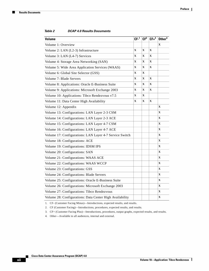
Results DocumentsTable 2 summarizes results documents available in EDCS for Cisco internal audiences. External customers can find externally viewable documents at http://www.cisco.com/go/dcap. External customers may request internal documents from account teams.
Refer to “Volume 1: Overview” for a list of results documents EDCS numbers.
Note There are no output graphs in “Volume 6: Global Site Selector (GSS)” and “Volume 10: Applications: Tibco Rendezvous” test results so the Customer Facing Plus (CF+) document for these tests is not available.
xiCisco Data Center Assurance Program (DCAP) 4.0
Volume 10—Application: Tibco Rendezvous
Preface Results Documents
Table 2 DCAP 4.0 Results Documents
Volume CF-1
1. CF- (Customer Facing Minus)—Introductions, expected results, and results.
CF2
2. CF (Customer Facing)—Introductions, procedures, expected results, and results.
CF+3
3. CF+ (Customer Facing Plus)—Introductions, procedures, output graphs, expected results, and results.
Other4
4. Other—Available to all audiences, internal and external.
Volume 1: Overview X
Volume 2: LAN (L2-3) Infrastructure X X X
Volume 3: LAN (L4-7) Services X X X
Volume 4: Storage Area Networking (SAN) X X X
Volume 5: Wide Area Application Services (WAAS) X X X
Volume 6: Global Site Selector (GSS) X X
Volume 7: Blade Servers X X X
Volume 8: Applications: Oracle E-Business Suite X X X
Volume 9: Applications: Microsoft Exchange 2003 X X X
Volume 10: Applications: Tibco Rendezvous v7.5 X X
Volume 11: Data Center High Availability X X X
Volume 12: Appendix X
Volume 13: Configurations: LAN Layer 2-3 CSM X
Volume 14: Configurations: LAN Layer 2-3 ACE X
Volume 15: Configurations: LAN Layer 4-7 CSM X
Volume 16: Configurations: LAN Layer 4-7 ACE X
Volume 17: Configurations: LAN Layer 4-7 Service Switch X
Volume 18: Configurations: ACE X
Volume 19: Configurations: IDSM IPS X
Volume 20: Configurations: SAN X
Volume 21: Configurations: WAAS ACE X
Volume 22: Configurations: WAAS WCCP X
Volume 23: Configurations: GSS X
Volume 24: Configurations: Blade Servers X
Volume 25: Configurations: Oracle E-Business Suite X
Volume 26: Configurations: Microsoft Exchange 2003 X
Volume 27: Configurations: Tibco Rendezvous X
Volume 28: Configurations: Data Center High Availability X
xiiCisco Data Center Assurance Program (DCAP) 4.0
Volume 10—Application: Tibco Rendezvous
Volume 10—TIBCO Rendezvous
C H A P T E R 1
TIBCO RendezvousThis phase of testing introduced the TIBCO Rendezvous application into the DCAP data center topology. Hardware consisted of a single client/server pair hosted by HP BL460c, 3.0Ghz Dual-core Intel Xeon, HP blade servers with 8GB of RAM. Baseline tests were first performed between directly connected hosts to qualify the performance with no network transmission delay. After the baselines were completed, testing was performed by running several publisher/subscriber combinations on the client/server pair. The messages were routed through the data center network which was configured with PIM Sparse-mode multicast and Anycast Auto-RP. Latency measurements were calculated by comparing the baseline statistics with the statistics collected when routing through the network. Finally, the data center router’s CPU and memory performances were monitored while sending a maximum sustained rate of TIBCO-generated multicast traffic through the network.
TIBCO Rendezvous software makes it easy to deploy distributed applications that exchange data across a network. The Rendezvous daemon runs on each computer involved with message communication. All information that travels between program processes passes through the Rendezvous daemon as the information enters and exits host computers. The daemon also passes information between program processes running on the same host.
TIBCO Rendezvous ConceptsMessages—Carry data among program processes or threads. Messages contain self-describing data fields. Programs can manipulate message fields, send messages, and receive messages.
Events—Create event objects to register interest in significant conditions. For example, dispatching a listener event notifies the program that a message has arrived; dispatching a timer event notifies the program that its interval has elapsed. Programs define event callback functions to process events.
Subjects—Messages are associated with a logical name (subject). Programs listen for a particular subject, or publish messages under a specific subject.
Certified Message Delivery—Confirms delivery of each message to each registered recipient. Certified delivery assures programs that every certified message reaches each intended recipient—in the order sent. When delivery is not possible, both sending and listening programs receive explicit information about each undelivered message.
Programs determine an explicit time limit for each message. After a program sends a certified message, TIBCO Rendezvous software continues delivery attempts until delivery succeeds, or until the message’s time limit expires.
TIBCO Rendezvous certified delivery software presents advisory messages to inform programs of every significant event relating to delivery. TIBCO Rendezvous certified delivery software records the status of each message in a ledger. Programs that require certification only for the duration of the program
1-1Cisco Data Center Assurance Program (DCAP) 4.0
Chapter 1 TIBCO Rendezvous TIBCO Rendezvous Concepts
process should use a process-based ledger. Programs that require certification that transcends process termination and program restart use a file-based ledger. When certified delivery is not allowed, delivery conditions decrease to the standard TIBCO Rendezvous reliable delivery semantics.
Distributed Queue Daemons—Distribute a service over several processes.
The TIBCO Rendezvous daemon completes the information pathway between TIBCO Rendezvous program processes across the network. Programs try to connect to a TIBCO Rendezvous daemon process. If a local daemon process is not yet running, the program starts one automatically and connects to it. The TIBCO Rendezvous daemon arranges the details of data transport, packet ordering, receipt acknowledgement, retransmission requests, and dispatching information to the correct program processes. The daemon hides all these details from TIBCO Rendezvous programs. The TIBCO Rendezvous daemon is almost invisible to the programs that depend on it. Programs send and receive information using TIBCO Rendezvous communications calls, and the TIBCO Rendezvous daemon does the work of getting information to the appropriate place.
The daemon performs the following tasks:
• Transmits outbound messages from program processes to the network.
• Delivers inbound messages from the network to program processes.
• Filters subject-addressed messages.
• Shields programs from operating system idiosyncrasies, such as low-level sockets.
1-2Cisco Data Center Assurance Program (DCAP) 4.0
Volume 10—TIBCO Rendezvous
Chapter 1 TIBCO Rendezvous Test Results Summary
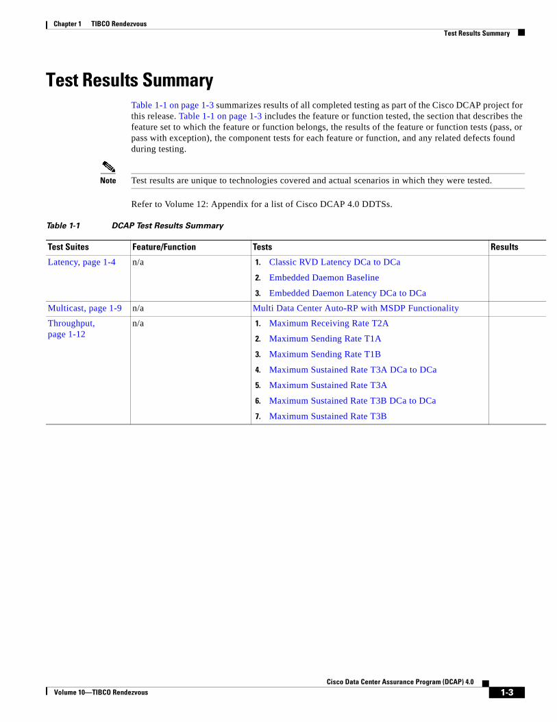
Test Results SummaryTable 1-1 on page 1-3 summarizes results of all completed testing as part of the Cisco DCAP project for this release. Table 1-1 on page 1-3 includes the feature or function tested, the section that describes the feature set to which the feature or function belongs, the results of the feature or function tests (pass, or pass with exception), the component tests for each feature or function, and any related defects found during testing.
Note Test results are unique to technologies covered and actual scenarios in which they were tested.
Refer to Volume 12: Appendix for a list of Cisco DCAP 4.0 DDTSs.
Table 1-1 DCAP Test Results Summary
Test Suites Feature/Function Tests Results
Latency, page 1-4 n/a 1. Classic RVD Latency DCa to DCa
2. Embedded Daemon Baseline
3. Embedded Daemon Latency DCa to DCa
Multicast, page 1-9 n/a Multi Data Center Auto-RP with MSDP Functionality
Throughput, page 1-12
n/a 1. Maximum Receiving Rate T2A
2. Maximum Sending Rate T1A
3. Maximum Sending Rate T1B
4. Maximum Sustained Rate T3A DCa to DCa
5. Maximum Sustained Rate T3A
6. Maximum Sustained Rate T3B DCa to DCa
7. Maximum Sustained Rate T3B
1-3Cisco Data Center Assurance Program (DCAP) 4.0
Volume 10—TIBCO Rendezvous
Chapter 1 TIBCO Rendezvous Test Cases
Test CasesFunctionality critical to global enterprises tested for this Cisco Safe Harbor release is described in the following sections. See Appendix: Topology Configurations for test device configurations.
• Latency, page 1-4
• Multicast, page 1-9
• Throughput, page 1-12
LatencyMessage latency includes the overall latency time from message request from a host client to message receive acknowledgment by the application server. Latency baselines are determined by sending traffic between directly connected client/server hosts. Data Center latency is comprised of the additional latency added when routing the traffic through the Data Center LAN.
This section contains the following topics:
• Classic RVD Latency DCa to DCa, page 1-4
• Embedded Daemon Baseline, page 1-6
• Embedded Daemon Latency DCa to DCa, page 1-7
Classic RVD Latency DCa to DCaPrograms using Tibco depend on the Rendezvous daemon, a background process (rvd), for reliable and efficient network communication. The Rendevous daemon completes the information pathway between Rendezvous program processes across the network. (Usually the daemon runs on the same computer as the program; however, it is possible to connect to a remote daemon.)
The Rendezvous daemon arranges the details of data transport, packet ordering, receipt acknowledgment, retransmission requests, and dispatching information to the correct program processes. The daemon hides all these details from Rendezvous programs.
The Rendezvous daemon is nearly invisible to the programs that depend upon it. Programs send and receive information using Rendezvous communications callls, and the Rendezvous daemon does the work of getting information to the right place.
This test was used to verify the baseline round trip latency statistics for 64 byte multicast messages sent from the Tibco Rendezvous server and received by the Tibco Rendezvous client on the classic rvd bus. The Tibco provided rvlat-classic script was used and run on both clients in both server and client modes. The server listens on TCP and UDP ports 7500 for requests of messages to group 224.1.1.5. The client then requests 100,000 messages of size 64B and the Round Trip Time (RTT) latency for message request, receipt, and acknowledgment is measured.
For this test the servers were placed on different Data Center Vlans so traffic was routed through the LAN. The results were compared to the directly connected client baseline to measure latency added by routing through the Data Center.
1-4Cisco Data Center Assurance Program (DCAP) 4.0
Volume 10—TIBCO Rendezvous
Chapter 1 TIBCO Rendezvous Latency
Test Procedure
The procedure used to perform the Classic RVD Latency DCa to DCa test follows:
Step 1 Begin background scripts to collect initial status of test network devices. Monitor memory and CPU utilization of those network devices.
Step 2 SSH to the Tibco Rendezvous client and server and verify that they are on the different inband subnets by issuing the ifconfig command. This will cause the traffic to pass through the DC LAN and be routed between client and server.
Step 3 Verify in-band connectivity between the client and server with the ping command.
Step 4 On both the client and server, change directories to /root/tibco/RVLAT.
Step 5 On the client and server, start the following script:
rvd -reliability 5 &
The script will start the classic rvd listener bus process on both clients with a reliability scope of 5s. This will allow for messages up to 5s to for the Tibco acknowledgment message to be sent and received.
Step 6 On the server, start the following script:
./rvlat-classic srv -network "eth1;224.1.1.5" -daemon "7500" -service "7500"
The server will begin listening on eth1 for requests to the 224.1.1.5 network on TCP daemon port 7500 and UDP service port 7500. When a data request is made it will respond with the data requested.
Step 7 On the client, start the following script:
./rvlat-classic cli -network "eth1;224.1.1.5" -daemon "7500" -service "7500" -messages "100000" -size "64" > L2BtoA.txt
The client will begin sending requests for 100,000 messages that have a size of 64B to daemon and TCP/UDP service ports 7500. Verify all 100,000 messages are received and that they are within the expected response window.
Copy the results to the Harbor Master directory from the client and server with the scp command and analyze by comparing with the baseline statistics. Quantify the amount of time added to the average message response time by subtracting the baseline from the routed average.
Step 8 Gather the Data Center A(DCA) multicast state by issuing the show ip pim rp map 224.1.1.5 and show ip mroute 224.1.1.5 commands on each DCA LAN device.
Step 9 Issue ctrl+c on the server side to end the listener script.
Step 10 Issue the same scripts used previously but swap the server/client role. Verify that the stats are similar to what they are in the prior run.
Copy the results to the Harbor Master directory from the client and server with the scp command and analyze by comparing with the baseline statistics. Quantify the amount of time added to the average message response time by subtracting the average baseline from the routed average.
Step 11 Gather the DCA multicast state by issuing the show ip pim rp map 224.1.1.5 and show ip mroute 224.1.1.5 commands on each DCA LAN device.
Step 12 Kill the rvd process running on each server with the killall -9 rvd command.
Step 13 Stop background scripts to collect final status of network devices and analyze for error.
Step 14 Verify that memory and the CPU did not suffer severe, sustained, or unacceptable impact.
1-5Cisco Data Center Assurance Program (DCAP) 4.0
Volume 10—TIBCO Rendezvous
Chapter 1 TIBCO Rendezvous Latency
Expected Results
The following test results are anticipated:
• We expect that no messages will be lost.
• We expect that the average latency per message will be less than 430us.
• We expect both hosts to have similar statistics when acting as the sender/receiver pair.
• We expect that the average amount of time added to the average message response time when routing through the network will be less than 200us.
• We expect no CPU or memory problems.
Results
Classic RVD Latency DCa to DCa passed.
Embedded Daemon BaselinePrograms attempt to connect to a Rendezvous daemon process. If a local daemon process is not yet running, the program starts one automatically and connects to it.
The Rendezvous daemon arranges the details of data transport, packet ordering, receipt acknowledgment, retransmission requests, and dispatching information to the correct program processes. The daemon hides all these details from Rendezvous programs.
The Rendezvous daemon is nearly invisible to the programs that depend upon it. Programs send and receive information using Rendezvous communications callls, and the Rendezvous daemon does the work of getting information to the right place.
This test was used to verify the baseline round trip latency statistics for 64 byte multicast messages sent from the TIBCO server and received by the TIBCO client. The rvlat-embedded script was used and run on both clients in both server and client modes. The rvd process is not manually started which causes the embedded process to be started when the Application script is run. The script on the server listens on TCP and UDP ports 7500 for requests to group 224.1.1.5. The client requests 10000 messages of size 64B and the RTT latency between message request, receipt, and acknowledgment is measured.
For this test the server and client were connected via Layer 2, no routing was done through the DC LAN. This was to baseline the server to client capabilities prior to testing the traffic across the network.
Test Procedure
The procedure used to perform the Embedded Daemon Baseline test follows:
Step 1 Begin background scripts to collect initial status of test network devices. Monitor memory and CPU utilization of those network devices.
Step 2 SSH to the Tibco Rendezvous client and server and verify that they are on the same inband subnet. This will allow for the traffic to pass without routing through the network as the client and server will appear directly connected.
Step 3 Verify in-band connectivity between the client and server with the ping command.
Step 4 On both the client and host, change directories to /root/tibco/RVLAT.
Step 5 On the server, start the following script:
./rvlat-embedded srv -network "eth1;224.1.1.5"
1-6Cisco Data Center Assurance Program (DCAP) 4.0
Volume 10—TIBCO Rendezvous
Chapter 1 TIBCO Rendezvous Latency
The script will cause the server to send IGMPv2 Membership Reports for group 224.1.1.5 to the embedded rvd daemon which is started when the script is called.
Step 6 On the client, start the following script:
./rvlat-embedded cli -network "eth1;224.1.1.5" -messages "10000" -size "64"
The script will cause the client to send 10000, 64 byte, messages to the 224.1.1.5 group via the embedded rvd daemon which is started when the script is called. The client should recieve 10000 responses back. The statistics form a baseline for client to server latency. With the servers directly connected this time should average to be less than 175us.
Copy the results to the Harbor Master directory from the client and server with the scp command and analyze.
Step 7 Issue ctrl+c on the server side to end the embedded daemon script.
Step 8 Issue the same scripts used previously but swap the server/client role. Verify that the stats are similar to what they were when run previously. Like before, the total request average response time should be less than 175us.
Copy the results to the Harbor Master directory from the client and server with the scp command and analyze.
Step 9 Stop background scripts to collect final status of network devices and analyze for error.
Step 10 Verify that memory and the CPU did not suffer severe, sustained, or unacceptable impact.
Expected Results
The following test results are anticipated:
• We expect that no messages will be lost.
• We expect that the average latency per message will be less than 200us.
• We expect both hosts to have similar statistics when acting as the sender.
• We expect no CPU or memory problems.
Results
Embedded Daemon Baseline passed.
Embedded Daemon Latency DCa to DCaPrograms using Tibco attempt to connect to a Rendezvous daemon process. If a local daemon process is not yet running, the program starts one automatically and connects to it.
The Rendezvous daemon arranges the details of data transport, packet ordering, receipt acknowledgment, retransmission requests, and dispatching information to the correct program processes. The daemon hides all these details from Rendezvous programs.
The Rendezvous daemon is nearly invisible to the programs that depend upon it. Programs send and receive information using Rendezvous communications callls, and the Rendezvous daemon does the work of getting information to the right place.
1-7Cisco Data Center Assurance Program (DCAP) 4.0
Volume 10—TIBCO Rendezvous
Chapter 1 TIBCO Rendezvous Latency
This test was used to verify the baseline round trip latency statistics for 64 byte multicast messages sent from the Tibco server and received by the Tibco client. The Tibco provided rvlat-embedded script was used and run on both clients in both server and client modes. The rvd process is not manually started which causes the embedded process to be started when the application script is run. The script on the server listens on TCP and UDP ports 7500 for requests to group 224.1.1.5. The client requests 100,000 messages of size 64B and the Round Trip Time (RTT) latency for message request, receipt, and acknowledgment is measured.
For this test the client and server were placed on different Data Center Vlans so traffic was routed through the LAN. The results were compared to the directly connected client baseline to measure latency added by routing through the Data Center.
Test Procedure
The procedure used to perform the Embedded Daemon Latency DCa to DCa test follows:
Step 1 Begin background scripts to collect initial status of test network devices. Monitor memory and CPU utilization of those network devices.
Step 2 SSH to the Tibco Rendezvous client and server and verify that they are on different subnets by issuing the ifconfig command. This will allow the traffic to pass through the Data Center LAN and be routed between client and server.
Step 3 Verify in-band connectivity between the client and server with the ping command.
Step 4 On both the client and server, change directories to /root/tibco/RVLAT.
Step 5 On the server, start the following script:
./rvlat-embedded srv -network "eth1;224.1.1.5"
The script will cause the server to send IGMPv2 Membership Reports for group 224.1.1.5 to the embedded daemon which is started when the script is called.
Step 6 On the client, start the following script:
./rvlat-embedded cli -network "eth1;224.1.1.5" -messages "10000" -size "64"
The script will cause the client to send 100,000 64 byte messages to the 224.1.1.5 group via the embedded daemon which is started when the script is called. The client should receive 100,000 responses back.
Copy the results to the Harbor Master directory from the client and server with the scp command and analyze by comparing with the baseline statistics. Quantify the amount of time added to the average message response time by subtracting the baseline from the routed average.
Step 7 Gather the Data Center A (DCA) multicast state by issuing the show ip pim rp map 224.1.1.5 and show ip mroute 224.1.1.5 commands on each DCA LAN device.
Step 8 Issue ctrl+c on the server side to end the embedded daemon script.
Step 9 Issue the same scripts used previously but swap the server/client role. Verify that the stats are similar to what they were when run previously.
Copy the results to the Harbor Master directory from the client and server with the scp command and analyze by comparing with the baseline statistics. Quantify the amount of time added to the average message response time by subtracting the baseline from the routed average.
Step 10 Gather the DCA multicast state by issuing the show ip pim rp map 224.1.1.5 and show ip mroute 224.1.1.5 commands on each DCA LAN device.
Step 11 Stop background scripts to collect final status of network devices and analyze for error.
1-8Cisco Data Center Assurance Program (DCAP) 4.0
Volume 10—TIBCO Rendezvous
Chapter 1 TIBCO Rendezvous Multicast
Step 12 Verify that memory and the CPU did not suffer severe, sustained, or unacceptable impact.
Expected Results
The following test results are anticipated:
• We expect that no messages will be lost.
• We expect that the average latency per message will be less than 330us.
• We expect that the average amount of time added to the average message response time when routing through the network will be less than 200us.
• We expect both hosts to have similar statistics when acting as the sender.
• We expect no CPU or memory problems.
Results
Embedded Daemon Latency DCa to DCa passed.
MulticastPIM Sparse Mode (PIM-SM) uses a pull model to deliver multicast traffic. Only networks that have active receivers that have explicitly requested the data will be forwarded the traffic. PIM-SM is defined in RFC 2362. PIM-SM uses a shared tree to distribute the information about active sources. Depending on the configuration options, the traffic can remain on the shared tree or switch over to an optimized source distribution tree. The latter is the default behavior for PIM-SM on Cisco routers. The traffic starts to flow down the shared tree, and then routers along the path determine whether there is a better path to the source. If a better, more direct path exists, the designated router (the router closest to the receiver) will send a join message toward the source and then reroute the traffic along this path. PIM-SM has the concept of an RP, since it uses shared trees—at least initially. The RP must be administratively configured in the network. Sources register with the RP, and then data is forwarded down the shared tree to the receivers. If the shared tree is not an optimal path between the source and the receiver, the routers dynamically create a source tree and stop traffic from flowing down the shared tree. This is the default behavior in IOS. Network administrators can force traffic to stay on the shared tree by using a configuration option (lp pim spt-threshold infinity). PIM-SM scales well to a network of any size, including those with WAN links. The explicit join mechanism prevents unwanted traffic from flooding the WAN links.
This section contains the following topics:
• Multi Data Center Auto-RP with MSDP Functionality, page 1-9
Multi Data Center Auto-RP with MSDP FunctionalityAuto-RP is a feature that automates the distribution of group-to-RP mappings in a PIM network. This feature has the following benefits:
1. It is easy to use multiple RPs within a network to serve different group ranges. 2. It allows load splitting among different RPs and arrangement of RPs according to the location of group participants. 3. It avoids inconsistent, manual RP configurations that can cause connectivity problems.
1-9Cisco Data Center Assurance Program (DCAP) 4.0
Volume 10—TIBCO Rendezvous
Chapter 1 TIBCO Rendezvous Multicast
To make Auto-RP work, a router must be designated as an RP-mapping agent, which receives the RP-announcement messages from the RPs and arbitrates conflicts. The RP-mapping agent then sends the consistent group-to-RP mappings to all other routers. Thus, all routers automatically discover which RP to use for the groups they support.
In the Data Center, each core device is configured to use Auto-RP and Multi Source Discovery Protocol(MSDP). In a multi Data Center deployment a full meshing of RP’s with MSDP is configured so that each data center can learn multicast routing information from the neighboring data center.
This test verified the basic functionality of Auto-RP with fully meshed MSDP between two data centers. The configuration on each core router is first shown and the RP mappings on each router in the network is verified. Finally traffic is sent to recievers in each data center and multicast state on each router is verified.
Test Procedure
The procedure used to perform the Multi Data Center Auto-RP with MSDP Functionality test follows:
Step 1 Begin background scripts to collect initial status of test network devices. Monitor memory and CPU utilization of those network devices.
Step 2 Verify the Auto-RP configuration on dca-core-1, dca-core-2, dcb-core-1, and dcb-core-2.
For each Auto-RP candidate, we see the following configuration:
1. A static configuration on loopback 1 defining the anycast address, 10.10.0.1, as the RP
2. All Auto-RP candidates are configured to send RP announce messages (to group 224.0.1.39). The Auto-RP in each data center is announcing its candidacy for all multicast groups.
3. Each RP is also configured as a PIM mapping agent. A mapping agent will listen to group 224.0.1.39 for all candidate RP’s. It will then elect an RP based on the highest IP address (in the case of dca-core-1 and dca-core-2, dca-core-2 is selected because its Loopback 0, or Router ID, interface address is higher.) Once it has elected an RP, it will cache RP-to-group mapping information, and send it out periodically to 224.0.1.40, through which all other routers in the network learn the RP-to-group information.
Step 3 Verify that each core device in both DCA and DCB is fully meshed to the other neighboring core device within the same data center and with both core devices in the neighboring data center by issuing the show ip msdp peer peer ip command.
Step 4 Verify each core device shows up as the elected Auto-RP for the data center by issuing the show ip pim rp mapping and show ip pim rp commands.
In Data Center’s A and B, dca-core-2 and dcb-core-2 are the active RP’s, respectively.
Step 5 Verify the RP information is passed downstream to the aggregation switches by issuing the show ip pim rp mapping and show ip pim rp commands.
Step 6 Begin sending traffic with the Shenick test tool. Traffic will be source from a single host in each data center. The DCa source is advertising 10 muticast groups(239.100.1.[1-10]) and the DCb source is also advertising 10 multicast groups(239.200.1.[1-10]). The stream also consists of a multicast receiver for these groups.
Verify the traffic is received correctly by the receiver in each Data Center on the Shenick tool by verifying the streams become colored green.
Step 7 Verify that the DCA and DCB core devices have correct mroute entries and flags for the test traffic groups and that traffic is being hardware switched.
1-10Cisco Data Center Assurance Program (DCAP) 4.0
Volume 10—TIBCO Rendezvous
Chapter 1 TIBCO Rendezvous Multicast
For groups 239.100.0.[1-10], dca-core-2 is the PIM-RP. Being the PIM-RP, we expect dca-core-2 to have an (S,G) entry for each of these 10 groups. We expect to see the following flags on each entry: a T-flag indicating that the Shortest-Path Tree (SPT) is being used. The incoming interface for all 10 groups should be TenGigabitEthernet1/3. GigabitEthernet5/1 should be in the Outgoing Interface List (OIL). An RPF-MFD tag should be on each mroute entry indicating that the entry is hardware-switching capable. An H-flag should accompany each interface in the OIL, indicating that traffic out that interface is being hardware-switched. The MMLS entries should be consistent with the mroute entries.
For groups 239.200.0.[1-10], dcb-core-2 is the PIM-RP. Being the PIM-RP, we expect dcb-core-2 to have an (S,G) entry for each of these 10 groups. We expect to see the following flags on each entry: a T-flag indicating that the Shortest-Path Tree (SPT) is being used. The incoming interface for all 10 groups should be TenGigabitEthernet1/3. GigabitEthernet5/1 should be in the Outgoing Interface List (OIL). An RPF-MFD tag should be on each mroute entry indicating that the entry is hardware-switching capable. An H-flag should accompany each interface in the OIL, indicating that traffic out that interface is being hardware-switched. The MMLS entries should be consistent with the mroute entries.
Step 8 Verify that the DCA and DCB aggregation devices have correct mroute entries and flags for the test traffic groups and that traffic is being hardware switched.
dca-agg-2 is first-hop router for traffic groups 239.100.0.[1-10]. As such, it should be registered with the RP, 10.10.0.1. The first-hop router, and all routers up to and including the RP, will have an (S,G) entry for a given group, as per the rules of PIM sparse-mode. dca-agg-2 should have the (S,G) entry for each group in the test range. It should also have the F and T flags set for this (S,G) entry. The F flag is set because the source is registered with the RP. The T flag is set because a Shortest-Path Tree (SPT) is formed from the source to the RP. The Incoming interface is VLAN1133. The outgoing interface is TenGigabitEthernet 9/2, as this is the best path to dca-core-2, the primary PIM-RP. The outgoing interface should also have the H flag set, indicating that it is being hardware-switched. Each group should have an MMLS entry with the (S,G) entry. This (S,G) in the MMLS entry should have incoming and outgoing interfaces listed that are consistent with the mroute (S,G) entry.
dcb-agg-1 is first-hop router for traffic groups 239.200.0.[1-10]. As such, it should be registered with the RP, 172.30.0.201. The first-hop router, and all routers up to and including the RP, will have an (S,G) entry for a given group, as per the rules of PIM sparse-mode. dca-agg-1 should have the (S,G) entry for each group in the test range. It should also have the F and T flags set for this (S,G) entry. The F flag is set because the source is registered with the RP. The T flag is set because a Shortest-Path Tree (SPT) is formed from the source to the RP. The Incoming interface is VLAN1133. The outgoing interface is TenGigabitEthernet3/3, as this is the best path to dcb-core-2, the primary PIM-RP. The outgoing interface should also have the H flag set, indicating that it is being hardware-switched. Each group should have an MMLS entry with the (S,G) entry. This (S,G) in the MMLS entry should have incoming and outgoing interfaces listed that are consistent with the mroute (S,G) entry.
Step 9 Stop background scripts to collect final status of network devices and analyze for error.
Step 10 Verify that memory and the CPU did not suffer severe, sustained, or unacceptable impact.
Expected Results
The following test results are anticipated:
• We expect that each data center will be configured with Auto-RP.
• We expect that the RP’s in each data center will be fully meshed with MSDP.
• We expect that the basic functionality of the dual data center PIM deployment will pass test traffic as expected.
• We expect that the mroute state will be correct on all routers in each data center.
1-11Cisco Data Center Assurance Program (DCAP) 4.0
Volume 10—TIBCO Rendezvous
Chapter 1 TIBCO Rendezvous Throughput
• We expect no CPU or memory problems.
Results
Multi Data Center Auto-RP with MSDP Functionality passed.
ThroughputThroughput is a measure of the maximum sending and receiving rate of the Tibco client and server. Throughput baselines are determined by sending traffic between directly connected client/server hosts. Throughput effects on the network were measured by monitoring CPU/Memory usage on the Data Center LAN devices while sending traffic between the client/server hosts at the maximum sustainable rate.
This section contains the following topics:
• Maximum Receiving Rate T2A, page 1-12
• Maximum Sending Rate T1A, page 1-13
• Maximum Sending Rate T1B, page 1-14
• Maximum Sustained Rate T3A DCa to DCa, page 1-15
• Maximum Sustained Rate T3A, page 1-17
• Maximum Sustained Rate T3B DCa to DCa, page 1-18
• Maximum Sustained Rate T3B, page 1-19
Maximum Receiving Rate T2AThis test was used to verify maximum receiving rate a system was capable of receiving messages at. For this test system A ran 1 RVD daemon and 1 Application service to send traffic to 8 subscribers on system B.
Test Procedure
The procedure used to perform the Maximum Receiving Rate T2A test follows:
Step 1 Begin background scripts to collect initial status of test network devices. Monitor memory and CPU utilization of those network devices.
Step 2 SSH to the Tibco Rendevous server(System A) and client(System B) and verify eth1 is configured on the inband network.
Step 3 On both systems, change directories to /root/tibco/THRUPUT.
Step 4 On both systems start the following script:
rvd -reliability 5 -listen 7501 &
The script will start the class rvd listener bus process listening on TCP port 7501 on the system with a reliability of 5s.
Step 5 On System B start the following script:
./rvperf-sustained-sub_t2a.bash
1-12Cisco Data Center Assurance Program (DCAP) 4.0
Volume 10—TIBCO Rendezvous
Chapter 1 TIBCO Rendezvous Throughput
The script will start 8 copies of rvperfs which are message subscribers. Use the command ps -ef | grep rv to verify 8 instances of this have started. If there are any issues issue the kill -9 rvperfs command and restart the script.
Step 6 On System A start the following script:
./rvperf-sustained_t2a.bash
This will start sending messages of sizes 64B, 500B, 1350B, 2KB, 10KB, 50KB, 1MB, and 1.2MB to the listening receivers.
Step 7 Upon completion issue the following command on system B to gather the results:
grep Messages/second rvperfsrun*.txt >> step7-t2a_results.txt
Copy the results to the correct Harbor Master directory and anylyze.
Step 8 On system A copy the following files to the results directory:
t2a-results.pub.txt t2b-results.sub.txt
If t2a_results.sub.txt if missing some data points retrieve from the t2a_results.txt file.
Step 9 Kill all rvperfs and rvd running processes on the client by issuing the killall -9 rvperfs command. Verify all processes have been killed with the ps -ef | grep rv command.
Step 10 Stop background scripts to collect final status of network devices and analyze for error.
Step 11 Verify that memory and the CPU did not suffer severe, sustained, or unacceptable impact.
Expected Results
The following test results are anticipated:
• We expect that the client will send messages of 64B, 500B, 1350B, 2KB, 10KB, 50KB, and 100KB.
• We expect the script to complete without maxing out the systems CPU utilization.
• We expect no CPU or memory problems.
Results
Maximum Receiving Rate T2A passed.
Maximum Sending Rate T1AThis test was used to verify the maximum sending rate a system was capable of sending messages at. For this test, System A, the "server," runs 1 rvd daemon and 8 Application services. This traffic is destined for 1 Publisher/Service. Since the test is only concerned with the sending rate of the system sending messages the listener system, system B, is virtual.
Test Procedure
The procedure used to perform the Maximum Sending Rate T1A test follows:
Step 1 Begin background scripts to collect initial status of test network devices. Monitor memory and CPU utilization of those network devices.
Step 2 SSH to the Tibco Rendevous server(System A) and verify eth1 is configured on the inband network.
1-13Cisco Data Center Assurance Program (DCAP) 4.0
Volume 10—TIBCO Rendezvous
Chapter 1 TIBCO Rendezvous Throughput
Step 3 On System A, change directories to /root/tibco/THRUPUT.
Step 4 On System A start the following script:
rvd -reliability 5 -listen 7501 &
The script will start the class rvd listener bus process listening on TCP port 7501 on the system with a reliability of 5s.
Step 5 On System A start the following script:
./rvperf_t1a.bash
The script will start 8 application daemon’s sending messages of increasing sizes: 64B, 500B, 1350B, 2KB, 10KB, 50KB, and 100KB. All messages of one size will be sent, then the message size will increase.
Step 6 Upon completion copy the results t1a_results.txt from the client to the results directory. The data gathered is a baseline for the maximum send rate the server is capable of for each message size.
Step 7 Stop background scripts to collect final status of network devices and analyze for error.
Step 8 Verify that memory and the CPU did not suffer severe, sustained, or unacceptable impact.
Expected Results
The following test results are anticipated:
• We expect that the client will send messages of 64B, 500B, 1350B, 2KB, 10KB, 50KB, and 100KB.
• We expect to baseline the servers maximum sending rate.
• We expect no CPU or memory problems.
Results
Maximum Sending Rate T1A passed.
Maximum Sending Rate T1BIn most situations, each host runs one Rendezvous daemon process, however, multiple rvd daemon’s can be run on a host.
This test was used to verify maximum sending rate a system was capable of sending messages at using multiple rvd daemons. For this test system A used 4 rvd daemon’s and 8 Application services to send traffic to 1 Publisher/Service. Since the test is only concerned with the sending rate of the system sending messages the listener system, system B, is virtual.
Test Procedure
The procedure used to perform the Maximum Sending Rate T1B test follows:
Step 1 Begin background scripts to collect initial status of test network devices. Monitor memory and CPU utilization of those network devices.
Step 2 SSH to the Tibco Rendevous server(System A) and verify eth1 is configured on the inband network.
Step 3 On System A, change directories to /root/tibco/THRUPUT.
1-14Cisco Data Center Assurance Program (DCAP) 4.0
Volume 10—TIBCO Rendezvous
Chapter 1 TIBCO Rendezvous Throughput
Step 4 On System A start the following script:
rvd -reliability 5 -listen 7501 & rvd -reliability 5 -listen 7502 & rvd -reliability 5 -listen 7503 & rvd -reliability 5 -listen 7504 &
The script will start the class rvd listener bus process listening on TCP port 7501-7504 on the system with a reliability of 5s.
Step 5 On System A start the following script:
./rvperf_t1b.bash
The script will start 8 application daemon’s sending messages of increasing sizes: 64B, 500B, 1350B, 2KB, 10KB, 50KB, and 100KB. All messages of one size will be sent, then the message size will increase.
Step 6 Upon completion copy the results t1b_results.txt from the client to the results directory.
Step 7 Stop background scripts to collect final status of network devices and analyze for error.
Step 8 Verify that memory and the CPU did not suffer severe, sustained, or unacceptable impact.
Expected Results
The following test results are anticipated:
• We expect that the client will send messages of 64B, 500B, 1350B, 2KB, 10KB, 50KB, and 100KB.
• We expect to baseline the servers maximum sending rate when using multiple rvd daemons.
• We expect no CPU or memory problems.
Results
Maximum Sending Rate T1B passed.
Maximum Sustained Rate T3A DCa to DCaThis test was used to verify maximum sustaining rate the systems were capable of sending/receiving messages at when located in the same Data Center. For this test the Server, System A, started 1 RVD daemon, 8 Application services, and 1 Publisher/Service to respond to message requests. The Client, System B, started 1 RVD daemon, 8 Application Service, and 1 Publisher/Service to request messages of 64B, 500B, 1350B, 2KB, 50MB, and 100MB.
This test was designed to stress and verify the network did not suffer unacceptable memory or CPU impact when sending the maximum sustained rate traffic through the DCA network from client to server.
Test Procedure
The procedure used to perform the Maximum Sustained Rate T3A DCa to DCa test follows:
Step 1 Begin background scripts to collect initial status of test network devices. Monitor memory and CPU utilization of those network devices.
Step 2 SSH to the Tibco Rendezvous server and client and verify that they are on located in the same Data Center but on different subnets by issuing the ifconfig command. This will cause traffic between hosts to be routed through the DC LAN.
1-15Cisco Data Center Assurance Program (DCAP) 4.0
Volume 10—TIBCO Rendezvous
Chapter 1 TIBCO Rendezvous Throughput
Step 3 On both systems, change directories to /root/tibco/THRUPUT.
Step 4 On both the client and server start the following script:
rvd -reliability 5 -listen 7501 &
The script will start the class rvd listener bus process listening on TCP port 7501 on the system with a reliability of 5s.
Step 5 On the client start the following script:
./rvperf-sustained-sub_t3a.bash
The script will start 8 copies of rvperfs which are message subscribers that will request messages of sizes 64B, 500B, 1350B, 2KB, 10KB, 50KB, 100KB from the 8 application services sending to 239.1.1.1-239.1.1.8. Use the command ps -ef | grep rv to verify 8 instances of this have started. If there are any issues issue the kill -9 rvperfs command and restart the script.
Step 6 On the server start the following script:
./rvperf-sustained_t3a.bash
This will source messages of sizes 64B, 500B, 1350B, 2KB, 10KB, 50KB, 100KB to the 8 application services groups 239.1.1.1-239.1.1.8.
Step 7 While the traffic is running, verify the multicast state state on each device in both Data Centers by issuing the show ip pim rp map and show ip mroute commands. The test runs for approximately 1 hour. Check the mcast state every 30 minutes to verify state remains consistent.
Step 8 Upon completion issue the following command on the client to gather the results:
grep Messages/second rvperfsrun*.txt >> step8-t3a_results.txt
Copy the results to the correct Harbor Master directory.
Step 9 On the server copy the following files to the results directory:
t3a-results.pub.txt t3a-results.sub.txt
If t3a_results.sub.txt if missing some data points retrieve from the t3a_results.txt file. The files will report the amount of data traffic sent through the network by the scripts.
Step 10 Kill all rvperfs running processes on the client by issuing the killall -9 rvperfs command. Verify all runinng processes have been killed with the ps -ef | grep rv command.
Step 11 Stop background scripts to collect final status of network devices and analyze for error.
Step 12 Verify that memory and the CPU did not suffer severe, sustained, or unacceptable impact.
Expected Results
The following test results are anticipated:
• We expect 8 application subscribers on System B to request messages of 64B, 500B, 1350B, 2KB, 50MB, and 100MB.
• We expect that the 8 application clients on System A will respond to message requests from System B.
• We expect no CPU or memory problems.
Results
Maximum Sustained Rate T3A DCa to DCa passed.
1-16Cisco Data Center Assurance Program (DCAP) 4.0
Volume 10—TIBCO Rendezvous
Chapter 1 TIBCO Rendezvous Throughput
Maximum Sustained Rate T3AThis test was used to verify maximum sustained the systems were capable of sending/receiving messages at. For this test the Server, System A, ran 1 RVD daemon, 8 Application services, and 1 Publisher/Service to respond to message requests. The Client, System B, ran 1 RVD daemon, 8 Application Service, and 1 Publisher/Service to request messages of 64B, 500B, 1350B, 2KB, 50MB, and 100MB. The maximum sustained rate was baselined by using a directly connected server and client.
Test Procedure
The procedure used to perform the Maximum Sustained Rate T3A test follows:
Step 1 Begin background scripts to collect initial status of test network devices. Monitor memory and CPU utilization of those network devices.
Step 2 SSH to the Tibco Rendevous server(System A) and client(System B) and verify eth1 is configured on the inband network.
Step 3 On both systems, change directories to /root/tibco/THRUPUT.
Step 4 On both systems start the following script:
rvd -reliability 5 -listen 7501 &
The script will start the class rvd listener bus process listening on TCP port 7501 on the system with a reliability of 5s.
Step 5 On System B start the following script:
./rvperf-sustained-sub_t3a.bash
The script will start 8 copies of rvperfs which are message subscribers that will request messages of sizes 64B, 500B, 1350B, 2KB, 10KB, 50KB, 100KB from the 8 application services sending to 239.1.1.1-239.1.1.8. Use the command ps -ef | grep rv to verify 8 instances of this have started. If there are any issues issue the kill -9 rvperfs command and restart the script.
Step 6 On System A start the following script:
./rvperf-sustained_t3a.bash
This will source messages of sizes 64B, 500B, 1350B, 2KB, 10KB, 50KB, 100KB to the 8 application services groups 239.1.1.1-239.1.1.8.
Step 7 Upon completion issue the following command on system B to gather the results:
grep Messages/second rvperfsrun*.txt >> step7-t3a_results.txt
Copy the results to the correct Harbor Master directory.
Step 8 On system A copy the following files to the results directory:
t3a-results.pub.txt t3a-results.sub.txt
If t3a_results.sub.txt if missing some data points retrieve from the t3a_results.txt file.
Step 9 Kill all rvperfs running processes on the client by issuing the killall -9 rvperfs command. Verify all runinng processes have been killed with the ps -ef | grep rv command.
Step 10 Stop background scripts to collect final status of network devices and analyze for error.
Step 11 Verify that memory and the CPU did not suffer severe, sustained, or unacceptable impact.
1-17Cisco Data Center Assurance Program (DCAP) 4.0
Volume 10—TIBCO Rendezvous
Chapter 1 TIBCO Rendezvous Throughput
Expected Results
The following test results are anticipated:
• We expect 8 application subscribers on System B to request messages of 64B, 500B, 1350B, 2KB, 50MB, and 100MB.
• We expect that the 8 application clients on System A will respond to message requests from System B.
• We expect no CPU or memory problems.
Results
Maximum Sustained Rate T3A passed.
Maximum Sustained Rate T3B DCa to DCaThis test was used to verify maximum sustained the systems were capable of sending/receiving messages at. For this test System A used 4 RVD Daemons, 2 Services/Daemon, and 8 Publishers to send messages to multicast groups 239.1.1.1-239.1.1.8 on ports 7501-7504. System B used 4 RVD Daemons, 2 Services/Daemon, and 8 subscribers to make data requests from groups 239.1.1.1-239.1.1.8 on ports 7501-7504. The servers were placed on different DC Vlan’s so traffic was routed through the DCA LAN.
Test Procedure
The procedure used to perform the Maximum Sustained Rate T3B DCa to DCa test follows:
Step 1 Begin background scripts to collect initial status of test network devices. Monitor memory and CPU utilization of those network devices.
Step 2 SSH to the Tibco Rendezvous server(System A) and client(System B) and verify that they are on located in the same Data Center but on different subnets. This will cause traffic between hosts to be routed through the DC LAN.
Step 3 On both systems, change directories to /root/tibco/THRUPUT.
Step 4 On both systems start the following scripts:
rvd -reliability 5 -listen 7501 & rvd -reliability 5 -listen 7502 & rvd -reliability 5 -listen 7503 & rvd -reliability 5 -listen 7504 &
The script will start the classic rvd listener bus process listening on TCP ports 7501-7504 on the system with a reliability of 5s.
Step 5 On System B start the following script:
./rvperf-sustained-sub_t3b.bash
The script will start 8 copies of rvperfs which are message subscribers that will request messages of sizes 64B, 500B, 1350B, 2KB, 10KB, 50KB, 100KB from the 8 application services sending to 239.1.1.1-239.1.1.8. Use the command ps -ef | grep rv to verify 8 instances of this have started. If there are any issues issue the kill -9 rvperfs command and restart the script.
Step 6 On System A start the following script:
./rvperf-sustained_t3b.bash
This will source messages of sizes 64B, 500B, 1350B, 2KB, 10KB, 50KB, 100KB to the 8 application services groups 239.1.1.1-239.1.1.8.
1-18Cisco Data Center Assurance Program (DCAP) 4.0
Volume 10—TIBCO Rendezvous
Chapter 1 TIBCO Rendezvous Throughput
Step 7 While the traffic is running, verify the multicast state state on each device in both Data Centers by issuing the show ip pim rp ma and show ip mroute commands. The test runs for approximately 1 hour. Check the mcast state every at the beginning and again 30 minutes into the test to verify state remains consistent.
Step 8 Upon completion issue the following command on system B to gather the results:
grep Messages/second rvperfsrun*.txt >> step8-t3b_results-log.txt
Copy the results to the correct Harbor Master directory.
Step 9 On system A copy the following files to the results directory:
t3b-results.pub.txt t3b-results.sub.txt
If t3b_results.sub.txt if missing some data points retrieve from the t3b_results.txt file.
Step 10 Kill all rvperfs running processes on the client by issuing the killall -9 rvperfs command. Verify all runinng processes have been killed with the ps -ef | grep rv command.
Step 11 Stop background scripts to collect final status of network devices and analyze for error.
Step 12 Verify that memory and the CPU did not suffer severe, sustained, or unacceptable impact.
Expected Results
The following test results are anticipated:
• We expect that the 8 application clients on System A will send messages to the 4 local RVD busses.
• We expect the 4 remote RVD busses to collect the sent messages and distribute among the 8 subscribers.
• We expect no CPU or memory problems.
Results
Maximum Sustained Rate T3B DCa to DCa passed.
Maximum Sustained Rate T3BThis test was used to verify maximum sustained the systems were capable of sending/receiving messages at. For this test System A used 4 RVD Daemons, 2 Services/Daemon, and 8 Publishers to send messages to multicast groups 239.1.1.1-239.1.1.8 on ports 7501-7504. System B used 4 RVD Daemons, 2 Services/Daemon, and 8 subscribers to make data requests from groups 239.1.1.1-239.1.1.8 on ports 7501-7504.
Test Procedure
The procedure used to perform the Maximum Sustained Rate T3B test follows:
Step 1 Begin background scripts to collect initial status of test network devices. Monitor memory and CPU utilization of those network devices.
Step 2 SSH to the Tibco Rendevous server(System A) and client(System B) and verify eth1 is configured on the inband network.
Step 3 On both systems, change directories to /root/tibco/THRUPUT.
1-19Cisco Data Center Assurance Program (DCAP) 4.0
Volume 10—TIBCO Rendezvous

Chapter 1 TIBCO Rendezvous Throughput
Step 4 On both systems start the following scripts:
rvd -reliability 5 -listen 7501 & rvd -reliability 5 -listen 7502 & rvd -reliability 5 -listen 7503 & rvd -reliability 5 -listen 7504 &
The script will start the classic rvd listener bus process listening on TCP ports 7501-7504 on the system with a reliability of 5s.
Step 5 On System B start the following script:
./rvperf-sustained-sub_t3b.bash
The script will start 8 copies of rvperfs which are message subscribers. Use the command ps -ef | grep rv to verify 8 instances of this have started. If there are any issues issue the kill -9 rvperfs command and restart the script.
Step 6 On System A start the following script:
./rvperf-sustained_t3b.bash
This will start sending messages of sizes 8 application services to the 8 listening recievers. There are two applications services sending to each rvd bus.
Step 7 Upon completion issue the following command on system B to gather the results:
grep Messages/second rvperfsrun*.txt >> step7-t3b_results.txt
Copy the results to the correct Harbor Master directory.
Step 8 On system A copy the following files to the results directory:
t3b-results.pub.txt t3b-results.sub.txt
If t3b_results.sub.txt if missing some data points retrieve from the t3b_results.txt file.
Step 9 Kill all rvperfs running processes on the client by issuing the killall -9 rvperfs command. Verify all runinng processes have been killed with the ps -ef | grep rv command.
Step 10 Stop background scripts to collect final status of network devices and analyze for error.
Step 11 Verify that memory and the CPU did not suffer severe, sustained, or unacceptable impact.
Expected Results
The following test results are anticipated:
• We expect that the 8 application clients on System A will send messages to the 4 local RVD busses.
• We expect the 4 remote RVD busses to collect the sent messages and distribute among the 8 subscribers.
• We expect message loss to be acceptable.
• We expect no CPU or memory problems.
Results
Maximum Sustained Rate T3B passed.
1-20Cisco Data Center Assurance Program (DCAP) 4.0
Volume 10—TIBCO Rendezvous