
Cisco AVS User Guide (Software Version 6.0) Book-Length PDF
386
Corporate Headquarters Cisco Systems, Inc. 170 West Tasman Drive San Jose, CA 95134-1706 USA http://www.cisco.com Tel: 408 526-4000 800 553-NETS (6387) Fax: 408 526-4100 Cisco Application Velocity System User Guide Software Release 6.0 April 2006 Text Part Number: OL-9338-01
-
Upload
khangminh22 -
Category
Documents
-
view
3 -
download
0
Transcript of Cisco AVS User Guide (Software Version 6.0) Book-Length PDF

Corporate HeadquartersCisco Systems, Inc.170 West Tasman DriveSan Jose, CA 95134-1706 USAhttp://www.cisco.comTel: 408 526-4000
800 553-NETS (6387)Fax: 408 526-4100
Cisco Application Velocity System User GuideSoftware Release 6.0April 2006
Text Part Number: OL-9338-01

THE SPECIFICATIONS AND INFORMATION REGARDING THE PRODUCTS IN THIS MANUAL ARE SUBJECT TO CHANGE WITHOUT NOTICE. ALL STATEMENTS, INFORMATION, AND RECOMMENDATIONS IN THIS MANUAL ARE BELIEVED TO BE ACCURATE BUT ARE PRESENTED WITHOUT WARRANTY OF ANY KIND, EXPRESS OR IMPLIED. USERS MUST TAKE FULL RESPONSIBILITY FOR THEIR APPLICATION OF ANY PRODUCTS.
THE SOFTWARE LICENSE AND LIMITED WARRANTY FOR THE ACCOMPANYING PRODUCT ARE SET FORTH IN THE INFORMATION PACKET THAT SHIPPED WITH THE PRODUCT AND ARE INCORPORATED HEREIN BY THIS REFERENCE. IF YOU ARE UNABLE TO LOCATE THE SOFTWARE LICENSE OR LIMITED WARRANTY, CONTACT YOUR CISCO REPRESENTATIVE FOR A COPY.
The Cisco implementation of TCP header compression is an adaptation of a program developed by the University of California, Berkeley (UCB) as part of UCB’s public domain version of the UNIX operating system. All rights reserved. Copyright © 1981, Regents of the University of California.
NOTWITHSTANDING ANY OTHER WARRANTY HEREIN, ALL DOCUMENT FILES AND SOFTWARE OF THESE SUPPLIERS ARE PROVIDED “AS IS” WITH ALL FAULTS. CISCO AND THE ABOVE-NAMED SUPPLIERS DISCLAIM ALL WARRANTIES, EXPRESSED OR IMPLIED, INCLUDING, WITHOUT LIMITATION, THOSE OF MERCHANTABILITY, FITNESS FOR A PARTICULAR PURPOSE AND NONINFRINGEMENT OR ARISING FROM A COURSE OF DEALING, USAGE, OR TRADE PRACTICE.
IN NO EVENT SHALL CISCO OR ITS SUPPLIERS BE LIABLE FOR ANY INDIRECT, SPECIAL, CONSEQUENTIAL, OR INCIDENTAL DAMAGES, INCLUDING, WITHOUT LIMITATION, LOST PROFITS OR LOSS OR DAMAGE TO DATA ARISING OUT OF THE USE OR INABILITY TO USE THIS MANUAL, EVEN IF CISCO OR ITS SUPPLIERS HAVE BEEN ADVISED OF THE POSSIBILITY OF SUCH DAMAGES.
Any Internet Protocol (IP) addresses used in this document are not intended to be actual addresses. Any examples, command display output, and figures included in the document are shown for illustrative purposes only. Any use of actual IP addresses in illustrative content is unintentional and coincidental.
Cisco Application Velocity System User Guide© 2005-2007 Cisco Systems, Inc. All rights reserved.
CCVP, the Cisco Logo, and the Cisco Square Bridge logo are trademarks of Cisco Systems, Inc.; Changing the Way We Work, Live, Play, and Learn is a service mark of Cisco Systems, Inc.; and Access Registrar, Aironet, BPX, Catalyst, CCDA, CCDP, CCIE, CCIP, CCNA, CCNP, CCSP, Cisco, the Cisco Certified Internetwork Expert logo, Cisco IOS, Cisco Press, Cisco Systems, Cisco Systems Capital, the Cisco Systems logo, Cisco Unity, Enterprise/Solver, EtherChannel, EtherFast, EtherSwitch, Fast Step, Follow Me Browsing, FormShare, GigaDrive, GigaStack, HomeLink, Internet Quotient, IOS, iPhone, IP/TV, iQ Expertise, the iQ logo, iQ Net Readiness Scorecard, iQuick Study, LightStream, Linksys, MeetingPlace, MGX, Networking Academy, Network Registrar, Packet, PIX, ProConnect, RateMUX, ScriptShare, SlideCast, SMARTnet, StackWise, The Fastest Way to Increase Your Internet Quotient, and TransPath are registered trademarks of Cisco Systems, Inc. and/or its affiliates in the United States and certain other countries.
All other trademarks mentioned in this document or Website are the property of their respective owners. The use of the word partner does not imply a partnership relationship between Cisco and any other company. (0612R)
iiiCisco Application Velocity System User Guide
OL-9338-01
C O N T E N T S
Preface xv
Audience xv
Organization xv
Related Documentation xvii
New in Version 6.0 xvii
New in Version 5.0 xvii
Conventions xviii
Obtaining Documentation xix
Cisco.com xix
Product Documentation DVD xix
Ordering Documentation xx
Documentation Feedback xx
Cisco Product Security Overview xx
Reporting Security Problems in Cisco Products xxi
Obtaining Technical Assistance xxi
Cisco Technical Support & Documentation Website xxii
Submitting a Service Request xxii
Definitions of Service Request Severity xxii
Obtaining Additional Publications and Information xxiii
C H A P T E R 1 Product Overview 1-1
C H A P T E R 2 AVS Description 2-1
Delta Optimization 2-2
Delta Optimization Overview 2-2
Web Browser Support 2-3
Web Server Support 2-4
Web Content Support 2-4
Character Set Support 2-4
Unsupported HTML Elements 2-4
Configurable Condensation Modes 2-5
Adaptive Dynamic Caching 2-5
FlashForward Object Acceleration 2-6
Contents
ivCisco Application Velocity System User Guide
OL-9338-01
Just-In-Time Object Acceleration 2-7
Smart Image Optimization 2-8
Smart Redirect 2-11
SSL Termination and Proxy 2-11
Fast NTLM Authentication 2-12
Server Connection Offload 2-12
Text Compression 2-12
FlashConnect 2-12
Other Features 2-13
Class-Based Condensation 2-13
Base File Management 2-13
Canonical URL 2-14
Base File Selection Policy 2-14
Anonymous Base Files 2-14
Smart Rebasing 2-15
MIME-Type Exclusion 2-16
SNMP Support 2-16
Destination Mapping 2-16
Log File Management 2-17
Cookie Usage 2-17
Web Application Security Firewall 2-18
AppScope Performance Monitoring 2-18
Operation 2-19
Detailed AVS-Client Interaction 2-19
Visit One—New Client 2-19
Visit Two—Client Returns 2-20
Cache Control Headers 2-23
FlashForward Operation 2-23
FlashForward Overview 2-23
FlashForward and Delta Optimization Options 2-23
FlashForward and Repeat Visits 2-24
How FlashForward Works With Delta Optimization 2-24
How FlashForward Works Without Delta Optimization 2-27
How FlashForward Works With CDN URLs 2-29
Contents
vCisco Application Velocity System User Guide
OL-9338-01
C H A P T E R 3 Appliance Administration 3-1
Starting and Stopping Software Components 3-1
Configuring the Node 3-2
Clock Synchronization 3-3
Core Files 3-3
Files Installed 3-3
Node Manager SSL Certificate 3-4
Replacing the Node Manager SSL Certificate 3-4
Importing the Node Manager SSL Certificate to the Management Console 3-5
Transparent Proxy Setup 3-5
C H A P T E R 4 Command-Line Interface 4-1
Logging into and Exiting the CLI 4-1
Using CLI Commands 4-1
Syntax Conventions 4-2
Variable Argument Conventions 4-2
CLI Command Keyboard Shortcuts 4-3
Understanding CLI Syntax Checking and Error Messages 4-4
Getting CLI Help 4-4
CLI Reference 4-4
delete 4-5
delete admin 4-5
delete lb 4-5
delete route 4-6
download log 4-6
edit admin 4-7
enable 4-7
ping 4-8
quit 4-8
reboot 4-8
set 4-8
set admin 4-9
set am 4-9
set condenser 4-10
set console 4-10
set date 4-11
set dns 4-11
set hostname 4-11

Contents
viCisco Application Velocity System User Guide
OL-9338-01
set interface 4-12
set lb cluster 4-12
set lb server 4-13
set lb status 4-14
set log-server 4-14
set ntp 4-15
set route 4-15
show 4-15
show admin 4-16
show am 4-16
show condenser 4-16
show console 4-17
show date 4-17
show dns 4-17
show hostname 4-17
show interface 4-18
show inventory 4-18
show lb 4-18
show log 4-18
show log-server 4-19
show ntp 4-19
show route 4-20
show sys-stat 4-20
show timezone 4-20
sysopen 4-20
traceroute 4-21
C H A P T E R 5 Configuration Reference 5-1
fgn.conf 5-1
Application Class Specification 5-7
OptimizationPolicy Element 5-12
Base File Selection Policy 5-15
Using Conditional Blocks 5-18
Adaptive Caching Configuration 5-18
Image Optimization Configuration 5-24
URL Mapping Configuration 5-26
Client View Logging Configuration 5-28
XML/XSL Transformations 5-30
Destination Mapping Configuration 5-30
Destination Mapping Examples 5-31
Contents
viiCisco Application Velocity System User Guide
OL-9338-01
SSL Configuration 5-33
Dynamic Caching Configuration Guidelines 5-34
When is Dynamic Caching Appropriate? 5-34
When is Dynamic Caching Inappropriate? 5-35
Configuring Dynamic Caching 5-35
httpd.conf 5-37
SSL Configuration Entries 5-37
Logging Level 5-38
mimetypes.conf 5-38
useragent.conf 5-39
fgnsnmpd.conf 5-39
magentd.conf 5-39
C H A P T E R 6 Web Application Security Configuration 6-1
Overview 6-1
Map Summary Interface 6-2
Global Configuration and Utilities 6-3
System Utilities 6-3
Display Utilities 6-4
Configuration Utilities 6-9
Traffic Class Maps 6-17
Default Traffic Maps 6-20
Policy Maps 6-21
Adding a New Policy Map 6-21
Adding a Traffic Map to a Policy Map 6-22
Associating Security Feature Maps with a Traffic Map 6-24
Pattern Definitions 6-26
Security Feature Configuration 6-28
URL Normalization 6-28
Cookie Protection 6-30
Response Attribute Rule Maps 6-33
Response Rule Maps 6-33
Request Rule Maps 6-35
ID Theft Protection 6-36
Request Limits 6-37
Error/Redirect Pages 6-39
Send Page Configuration 6-40
Redirect Page Configuration 6-43
Web Cloaking 6-45

Contents
viiiCisco Application Velocity System User Guide
OL-9338-01
Interaction with AVS Acceleration in Gateway Mode 6-47
URL Tagging 6-47
HTTP Protocol Conformance 6-49
IM Controls 6-49
P2P Controls 6-52
Tunnelling Policies 6-52
Generic Pattern Matcher 6-52
Transfer Encoding 6-52
MIME Type Controls 6-54
URL Black Listing 6-56
Control HTTP Methods 6-57
Header Integrity Check 6-59
Input Validation Checks 6-60
Cross Site Scripting 6-60
SQL Injection 6-62
OS Command Injection 6-64
LDAP Injection 6-66
Meta Character Detection 6-68
Format String Attacks 6-70
Web Application Security Regular Expression Syntax 6-72
C H A P T E R 7 AppScreen Configuration 7-1
Overview 7-1
Testing the Default AppScreen Configuration 7-2
Preprocessing Content Transformation 7-2
AppScreen Class 7-3
AppScreen Policies 7-4
Policy Rule Reference 7-5
Policy Disposition 7-5
Forward Disposition 7-6
Redirect Disposition 7-6
Ignore Disposition 7-7
Policy Actions 7-8
AppScreen Rules 7-8
Rule Components 7-9
Rule Operators 7-9
Rule Attributes 7-10
Rule Values 7-11
Using Multiple Attributes and Values 7-11

Contents
ixCisco Application Velocity System User Guide
OL-9338-01
Regular Expression Matching 7-12
Content 7-12
Regular Expression Patterns 7-12
Exec Environment 7-13
Predefined Rules 7-14
Scanning POST Data and File Uploads 7-15
Buffer Limit 7-15
Content Types 7-16
AppScreen Logging 7-16
SNMP Notification 7-17
Receiving and Processing SNMP Traps 7-17
MIB 7-18
AppScreen Reports 7-18
C H A P T E R 8 Management Console 8-1
Accessing the Management Console 8-1
Changing the User Name or Password 8-2
Clusters 8-3
Register Cluster 8-3
Register Node 8-4
Edit Cluster Name 8-6
Unregister Cluster 8-7
Cluster Status 8-7
Cluster Control 8-8
Cluster Information 8-9
Cluster Configuration 8-9
Global 8-10
Node-Level Global Configuration 8-11
Destination Mapping 8-12
Node-Level Destination Mapping Configuration 8-12
Application Class 8-12
Node-Level Application Class Configuration 8-14
AppScreen Class 8-14
Node-Level AppScreen Class Configuration 8-16
Publish 8-17
Import 8-18
Web Application Security 8-20
Managing Individual Nodes 8-20
Edit Properties 8-20

Contents
xCisco Application Velocity System User Guide
OL-9338-01
Unregister Node 8-21
Cache Management 8-22
Configuring Individual Nodes 8-23
Global 8-23
Destination Mapping 8-24
Application Class 8-25
AppScreen Class 8-27
View Configuration 8-29
Reports 8-30
Version 8-31
Console Configuration 8-31
Securing the Management Console 8-32
C H A P T E R 9 Reporting 9-1
Accessing the Management Console 9-1
Bandwidth Savings Reports 9-2
Throughput Reports 9-4
AppScreen Reports 9-6
Graphical Incidents Summary 9-7
Tabular Incidents Details 9-7
Incident Details 9-8
AppScope Reports 9-10
Performance Monitoring Details 9-10
Basic Reports 9-11
Defining the Query 9-13
Generating the Report 9-14
Drilldown Reports 9-17
Drilldown by Source IP Address Blocks 9-18
Drilldown by Defined Source Locations 9-19
Charts 9-20
Filtering AppScope Data 9-21
Saved Reports 9-22
Saving Reports 9-22
Accessing Saved Reports 9-23
Viewing Reports 9-24
Editing Reports 9-24
Copying Reports 9-24
Scheduling Reports 9-24
Contents
xiCisco Application Velocity System User Guide
OL-9338-01
Renaming Reports 9-25
Deleting Reports 9-25
Scheduled Reports 9-25
Adding a Schedule 9-27
Daily Schedule 9-27
Weekly Schedule 9-28
Monthly Schedule 9-29
Yearly Schedule 9-30
Editing a Schedule 9-31
Deleting a Schedule 9-32
Configuring E-mail for Scheduling 9-32
Managing Locations 9-33
Defining Transaction Types 9-35
Adding a Transaction Type 9-36
Substitute Client Timing 9-38
Adding a New Expression 9-38
Editing a Transaction Type 9-40
Deleting a Transaction Type 9-40
Managing Transaction Type Mapping 9-41
Defining Business Transactions 9-42
Adding a Business Transaction 9-43
Editing a Business Transaction 9-45
Deleting a Business Transaction 9-45
Upload Data 9-45
C H A P T E R 10 NMS Integration 10-1
Transaction Grouping 10-1
Defining Transaction Groups 10-2
Adding a Transaction Group 10-3
Editing a Transaction Group 10-5
Deleting a Transaction Group 10-5
Data Lifecycle 10-5
MIB Data Elements 10-5
SNMP Data Access 10-6
Example Query with HP OpenView 10-7
Example Graph with HP OpenView 10-8
Thresholds and Alerts 10-8
Contents
xiiCisco Application Velocity System User Guide
OL-9338-01
C H A P T E R 11 Availability Manager Clustering 11-1
Terminology 11-1
Overview 11-1
Configuring and Activating AM 11-3
lvs.cf File 11-5
SSL Session Persistence 11-7
FAQ 11-8
Limitations 11-10
C H A P T E R 12 Database Maintenance 12-1
Database Archiving Overview 12-1
Configuring Archiving 12-2
Managing Optimal Database Performance 12-3
A P P E N D I X A Logs A-1
Log File Management A-1
FgnStatLog A-2
Error_log A-8
Access_log A-8
Configuring Extended access_log Formats A-9
W3CExtended Example A-10
IISW3CExtended Example A-11
Postgres Database Logging A-12
Management Console Logging A-13
A P P E N D I X B SNMP MIB B-1
AppScope Statistics MIB B-3
A P P E N D I X C Deployment Options C-1
Deploying Clear-Text or SSL-Based Application Appliance C-1
Deploying a Single Non-SSL Application Appliance C-3
Deploying a Cluster of Non-SSL Application Appliances C-3
Deploying a Single SSL-Terminating Application Appliance C-4
Deploying a Cluster of SSL-Terminating Application Appliances C-6
Deploying a Single SSL-Proxying Application Appliance C-7
Deploying a Cluster of SSL-Proxying Application Appliances C-8

Contents
xiiiCisco Application Velocity System User Guide
OL-9338-01
Failover and Load Distribution C-9
A P P E N D I X D Frequently Asked Questions and Troubleshooting D-1
Frequently Asked Questions (FAQ) D-1
Troubleshooting D-5
A P P E N D I X E Anonymous Base File Statistical Model E-1
Statistical Model for Anonymous Base File Technology E-1
Case 1: p=1% E-3
Case 2: p=5% E-3
A P P E N D I X F Regular Expressions F-1
Regular Expression Reference F-1
Regular Expression Pattern Examples F-3
Additional Information F-3
A P P E N D I X G AppScreen Rules DTD G-1
G L O S S A R Y
I N D E X

Contents
xivCisco Application Velocity System User Guide
OL-9338-01
xvCisco Application Velocity System User Guide
OL-9338-01
Preface
Cisco Application Velocity System User Guide is the configuration, administration, and user’s guide for the Cisco Application Velocity System (AVS).
This preface provides an overview of this document and discusses the conventions that are used in this document. It includes the following sections:
• Audience
• Organization
• Related Documentation
• New in Version 6.0
• New in Version 5.0
• Conventions
• Obtaining Documentation
• Documentation Feedback
• Cisco Product Security Overview
• Obtaining Technical Assistance
• Obtaining Additional Publications and Information
AudienceThis document is intended for system administrators who want to install and configure the Cisco AVS in their network data center to provide dynamic content acceleration and reduce outbound bandwidth usage.
This document is intended for those with previous Linux system administration experience.
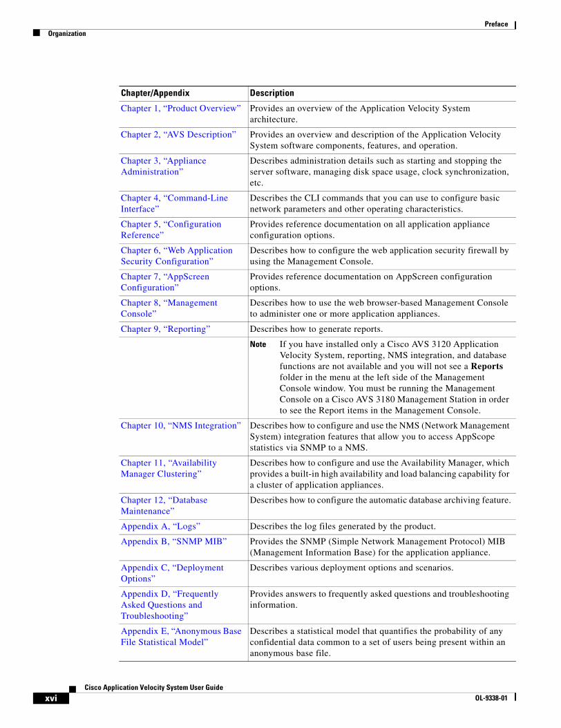
Organization• This publication is organized as follows:
xviCisco Application Velocity System User Guide
OL-9338-01
PrefaceOrganization
Chapter/Appendix Description
Chapter 1, “Product Overview” Provides an overview of the Application Velocity System architecture.
Chapter 2, “AVS Description” Provides an overview and description of the Application Velocity System software components, features, and operation.
Chapter 3, “Appliance Administration”
Describes administration details such as starting and stopping the server software, managing disk space usage, clock synchronization, etc.
Chapter 4, “Command-Line Interface”
Describes the CLI commands that you can use to configure basic network parameters and other operating characteristics.
Chapter 5, “Configuration Reference”
Provides reference documentation on all application appliance configuration options.
Chapter 6, “Web Application Security Configuration”
Describes how to configure the web application security firewall by using the Management Console.
Chapter 7, “AppScreen Configuration”
Provides reference documentation on AppScreen configuration options.
Chapter 8, “Management Console”
Describes how to use the web browser-based Management Console to administer one or more application appliances.
Chapter 9, “Reporting” Describes how to generate reports.
Note If you have installed only a Cisco AVS 3120 Application Velocity System, reporting, NMS integration, and database functions are not available and you will not see a Reports folder in the menu at the left side of the Management Console window. You must be running the Management Console on a Cisco AVS 3180 Management Station in order to see the Report items in the Management Console.
Chapter 10, “NMS Integration” Describes how to configure and use the NMS (Network Management System) integration features that allow you to access AppScope statistics via SNMP to a NMS.
Chapter 11, “Availability Manager Clustering”
Describes how to configure and use the Availability Manager, which provides a built-in high availability and load balancing capability for a cluster of application appliances.
Chapter 12, “Database Maintenance”
Describes how to configure the automatic database archiving feature.
Appendix A, “Logs” Describes the log files generated by the product.
Appendix B, “SNMP MIB” Provides the SNMP (Simple Network Management Protocol) MIB (Management Information Base) for the application appliance.
Appendix C, “Deployment Options”
Describes various deployment options and scenarios.
Appendix D, “Frequently Asked Questions and Troubleshooting”
Provides answers to frequently asked questions and troubleshooting information.
Appendix E, “Anonymous Base File Statistical Model”
Describes a statistical model that quantifies the probability of any confidential data common to a set of users being present within an anonymous base file.
xviiCisco Application Velocity System User Guide
OL-9338-01
PrefaceRelated Documentation
Related DocumentationIn addition to this document, the AVS documentation set includes:
New in Version 6.0This section summarizes the changes in the AVS and documentation for version 6.0 and contains links to the sections where you can find more details:
• A new web application security module provides a policy-based application firewall. For details, see Chapter 6, “Web Application Security Configuration.”
• If you are using the new web application security module, the AVS 3120 uses Ethernet ports other than Port 1. For details, see the “System Settings” section on page 6-9.
• Software version 6.0 operates only on the AVS 3120 and AVS 3180 hardware platforms.
• There is a new command line interface (CLI) command named show inventory. This command displays information about the application appliance such as its name, serial number, description, model name, and hardware revision.
• There are five new SNMP MIB variables that provide the same information as the new show inventory command. These are listed at the end of Table B-2.
New in Version 5.0This section summarizes the changes in the AVS and documentation for version 5.0 and contains links to the sections where you can find more details:
• The product was acquired by Cisco Systems and the user interface was rebranded to reflect this change.
Appendix F, “Regular Expressions”
Describes the regular expression syntax used by application appliance.
Appendix G, “AppScreen Rules DTD”
Provides the document type definition (DTD) of the AppScreen rules XML files.
Glossary Provides a glossary of terms.
Chapter/Appendix Description
Document Title Provides
Cisco AVS 3120 Application Velocity System Hardware Installation Guide
Information on installing the Cisco AVS 3120 Application Velocity System and getting it ready for operation.
Cisco AVS 3180 Management Station Hardware Installation Guide
Information on installing the Cisco AVS 3180 Management Station and getting it ready for operation.
Release Note for the Cisco Application Velocity System
Information on upgrading the AVS software, new features, operating considerations, and caveats for the AVS software.

xviiiCisco Application Velocity System User Guide
OL-9338-01
PrefaceConventions
• The product now operates on two different hardware platforms: AVS 3120 and AVS 3180. The AVS 3120 device implements all product features except for reporting and database functions. The AVS 3180 device implements all Management Console features, including reporting and database functions.
• A new command-line interface (CLI) allows you to configure networking and related functions on the Cisco application appliance hardware. For details, see Chapter 4, “Command-Line Interface.” If you are running the AVS 6.0 software on the AVS 3110 product or older hardware due to an upgrade, the CLI is not available.
• On the AVS 3120 and AVS 3180 hardware, there is a new directory structure for application components, logs, and other files. This is reflected throughout the documentation where directories and paths are mentioned.
• The mechanism that uploads FgnStatLog data to the management station database is new and improved. FgnStatLog data is collected on the AVS 3120 and is then sent to the AVS 3180 for loading into the management station database.
• Syslog logging is now supported.
• The meaning and default value of the FgnStatLogArchivingPolicy configuration keyword has changed; see Table 5-1. The default value of the FgnStatLogFileSizeLimit configuration keyword has also changed; see Table 5-1 for more information.
• The access_log file is no longer generated by default. For more information about the access_log file, see Appendix A “Logs.”
• The error_log file is no longer viewable from within the Management Console.
• The User Agent report is no longer supported.
• The product documentation is no longer included in the Management Console GUI. You can access the product documentation on Cisco.com under the AVS products.
• A new software upgrade procedure is covered in the Release Note for the Cisco Application Velocity System.
ConventionsThis document uses the following conventions:
boldface font Commands and keywords are in boldface.
italic font Variables for which you supply values are in italics.
[ ] Elements in square brackets are optional.
{x | y | z} Alternative keywords are grouped in braces and separated by vertical bars.
[x | y | z] Optional alternative keywords are grouped in brackets and separated by vertical bars.
string A nonquoted set of characters. Do not use quotation marks around the string, or the string will include the quotation marks.
screen font Terminal sessions and information the system displays are in screen font.
boldface screen font Information you must enter is in boldface screen font.
italic screen font Variables for which you supply values are in italic screen font.
This pointer highlights an important line of text in an example.
xixCisco Application Velocity System User Guide
OL-9338-01
PrefaceObtaining Documentation
Note Means reader take note. Notes contain helpful suggestions or references to materials not contained in this manual.
Caution Means reader be careful. You might do something that could result in equipment damage or loss of data.
1. A numbered list indicates that the order of the list items is important.
a. An alphabetical list indicates that the order of the secondary list items is important.
• A bulleted list indicates that the order of the list topics is unimportant.
– An indented list indicates that the order of the list subtopics is unimportant.
Obtaining DocumentationCisco documentation and additional literature are available on Cisco.com. Cisco also provides several ways to obtain technical assistance and other technical resources. These sections explain how to obtain technical information from Cisco Systems.
Cisco.comYou can access the most current Cisco documentation at this URL:
http://www.cisco.com/techsupport
You can access the Cisco website at this URL:
http://www.cisco.com
You can access international Cisco websites at this URL:
http://www.cisco.com/public/countries_languages.shtml
Product Documentation DVDThe Product Documentation DVD is a comprehensive library of technical product documentation on a portable medium. The DVD enables you to access multiple versions of installation, configuration, and command guides for Cisco hardware and software products. With the DVD, you have access to the same HTML documentation that is found on the Cisco website without being connected to the Internet. Certain products also have .PDF versions of the documentation available.
^ The symbol ^ represents the key labeled Control. For example, the key combination ^D in a screen display means hold down the Control key while you press the D key.
< > Nonprinting characters, such as passwords, are in angle brackets.
xxCisco Application Velocity System User Guide
OL-9338-01
PrefaceDocumentation Feedback
The Product Documentation DVD is available as a single unit or as a subscription. Registered Cisco.com users (Cisco direct customers) can order a Product Documentation DVD (product number DOC-DOCDVD= or DOC-DOCDVD=SUB) from Cisco Marketplace at this URL:
http://www.cisco.com/go/marketplace/
Ordering DocumentationRegistered Cisco.com users may order Cisco documentation at the Product Documentation Store in the Cisco Marketplace at this URL:
http://www.cisco.com/go/marketplace/
Nonregistered Cisco.com users can order technical documentation from 8:00 a.m. to 5:00 p.m. (0800 to 1700) PDT by calling 1 866 463-3487 in the United States and Canada, or elsewhere by calling 011 408 519-5055. You can also order documentation by e-mail at [email protected] or by fax at 1 408 519-5001 in the United States and Canada, or elsewhere at 011 408 519-5001.
Documentation FeedbackYou can rate and provide feedback about Cisco technical documents by completing the online feedback form that appears with the technical documents on Cisco.com.
You can submit comments about Cisco documentation by using the response card (if present) behind the front cover of your document or by writing to the following address:
Cisco SystemsAttn: Customer Document Ordering170 West Tasman DriveSan Jose, CA 95134-9883
We appreciate your comments.
Cisco Product Security OverviewCisco provides a free online Security Vulnerability Policy portal at this URL:
http://www.cisco.com/en/US/products/products_security_vulnerability_policy.html
From this site, you will find information about how to:
• Report security vulnerabilities in Cisco products.
• Obtain assistance with security incidents that involve Cisco products.
• Register to receive security information from Cisco.
A current list of security advisories, security notices, and security responses for Cisco products is available at this URL:
http://www.cisco.com/go/psirt

xxiCisco Application Velocity System User Guide
OL-9338-01
PrefaceObtaining Technical Assistance
To see security advisories, security notices, and security responses as they are updated in real time, you can subscribe to the Product Security Incident Response Team Really Simple Syndication (PSIRT RSS) feed. Information about how to subscribe to the PSIRT RSS feed is found at this URL:
http://www.cisco.com/en/US/products/products_psirt_rss_feed.html
Reporting Security Problems in Cisco ProductsCisco is committed to delivering secure products. We test our products internally before we release them, and we strive to correct all vulnerabilities quickly. If you think that you have identified a vulnerability in a Cisco product, contact PSIRT:
• For Emergencies only— [email protected]
An emergency is either a condition in which a system is under active attack or a condition for which a severe and urgent security vulnerability should be reported. All other conditions are considered nonemergencies.
• For Nonemergencies— [email protected]
In an emergency, you can also reach PSIRT by telephone:
• 1 877 228-7302
• 1 408 525-6532
Tip We encourage you to use Pretty Good Privacy (PGP) or a compatible product (for example, GnuPG) to encrypt any sensitive information that you send to Cisco. PSIRT can work with information that has been encrypted with PGP versions 2.x through 9.x.
Never use a revoked or an expired encryption key. The correct public key to use in your correspondence with PSIRT is the one linked in the Contact Summary section of the Security Vulnerability Policy page at this URL:
http://www.cisco.com/en/US/products/products_security_vulnerability_policy.html
The link on this page has the current PGP key ID in use.
If you do not have or use PGP, contact PSIRT at the aforementioned e-mail addresses or phone numbers before sending any sensitive material to find other means of encrypting the data.
Obtaining Technical AssistanceCisco Technical Support provides 24-hour-a-day award-winning technical assistance. The Cisco Technical Support & Documentation website on Cisco.com features extensive online support resources. In addition, if you have a valid Cisco service contract, Cisco Technical Assistance Center (TAC) engineers provide telephone support. If you do not have a valid Cisco service contract, contact your reseller.
xxiiCisco Application Velocity System User Guide
OL-9338-01
PrefaceObtaining Technical Assistance
Cisco Technical Support & Documentation WebsiteThe Cisco Technical Support & Documentation website provides online documents and tools for troubleshooting and resolving technical issues with Cisco products and technologies. The website is available 24 hours a day, at this URL:
http://www.cisco.com/techsupport
Access to all tools on the Cisco Technical Support & Documentation website requires a Cisco.com user ID and password. If you have a valid service contract but do not have a user ID or password, you can register at this URL:
http://tools.cisco.com/RPF/register/register.do
Note Use the Cisco Product Identification (CPI) tool to locate your product serial number before submitting a web or phone request for service. You can access the CPI tool from the Cisco Technical Support & Documentation website by clicking the Tools & Resources link under Documentation & Tools. Choose Cisco Product Identification Tool from the Alphabetical Index drop-down list, or click the Cisco Product Identification Tool link under Alerts & RMAs. The CPI tool offers three search options: by product ID or model name; by tree view; or for certain products, by copying and pasting show command output. Search results show an illustration of your product with the serial number label location highlighted. Locate the serial number label on your product and record the information before placing a service call.
Submitting a Service RequestUsing the online TAC Service Request Tool is the fastest way to open S3 and S4 service requests. (S3 and S4 service requests are those in which your network is minimally impaired or for which you require product information.) After you describe your situation, the TAC Service Request Tool provides recommended solutions. If your issue is not resolved using the recommended resources, your service request is assigned to a Cisco engineer. The TAC Service Request Tool is located at this URL:
http://www.cisco.com/techsupport/servicerequest
For S1 or S2 service requests, or if you do not have Internet access, contact the Cisco TAC by telephone. (S1 or S2 service requests are those in which your production network is down or severely degraded.) Cisco engineers are assigned immediately to S1 and S2 service requests to help keep your business operations running smoothly.
To open a service request by telephone, use one of the following numbers:
Asia-Pacific: +61 2 8446 7411 (Australia: 1 800 805 227)EMEA: +32 2 704 55 55USA: 1 800 553-2447
For a complete list of Cisco TAC contacts, go to this URL:
http://www.cisco.com/techsupport/contacts
Definitions of Service Request SeverityTo ensure that all service requests are reported in a standard format, Cisco has established severity definitions.
xxiiiCisco Application Velocity System User Guide
OL-9338-01
PrefaceObtaining Additional Publications and Information
Severity 1 (S1)—An existing network is down, or there is a critical impact to your business operations. You and Cisco will commit all necessary resources around the clock to resolve the situation.
Severity 2 (S2)—Operation of an existing network is severely degraded, or significant aspects of your business operations are negatively affected by inadequate performance of Cisco products. You and Cisco will commit full-time resources during normal business hours to resolve the situation.
Severity 3 (S3)—Operational performance of the network is impaired, while most business operations remain functional. You and Cisco will commit resources during normal business hours to restore service to satisfactory levels.
Severity 4 (S4)—You require information or assistance with Cisco product capabilities, installation, or configuration. There is little or no effect on your business operations.
Obtaining Additional Publications and InformationInformation about Cisco products, technologies, and network solutions is available from various online and printed sources.
• The Cisco Product Quick Reference Guide is a handy, compact reference tool that includes brief product overviews, key features, sample part numbers, and abbreviated technical specifications for many Cisco products that are sold through channel partners. It is updated twice a year and includes the latest Cisco offerings. To order and find out more about the Cisco Product Quick Reference Guide, go to this URL:
http://www.cisco.com/go/guide
• Cisco Marketplace provides a variety of Cisco books, reference guides, documentation, and logo merchandise. Visit Cisco Marketplace, the company store, at this URL:
http://www.cisco.com/go/marketplace/
• Cisco Press publishes a wide range of general networking, training and certification titles. Both new and experienced users will benefit from these publications. For current Cisco Press titles and other information, go to Cisco Press at this URL:
http://www.ciscopress.com
• Packet magazine is the Cisco Systems technical user magazine for maximizing Internet and networking investments. Each quarter, Packet delivers coverage of the latest industry trends, technology breakthroughs, and Cisco products and solutions, as well as network deployment and troubleshooting tips, configuration examples, customer case studies, certification and training information, and links to scores of in-depth online resources. You can access Packet magazine at this URL:
http://www.cisco.com/packet
• iQ Magazine is the quarterly publication from Cisco Systems designed to help growing companies learn how they can use technology to increase revenue, streamline their business, and expand services. The publication identifies the challenges facing these companies and the technologies to help solve them, using real-world case studies and business strategies to help readers make sound technology investment decisions. You can access iQ Magazine at this URL:
http://www.cisco.com/go/iqmagazine
or view the digital edition at this URL:
http://ciscoiq.texterity.com/ciscoiq/sample/
xxivCisco Application Velocity System User Guide
OL-9338-01
PrefaceObtaining Additional Publications and Information
• Internet Protocol Journal is a quarterly journal published by Cisco Systems for engineering professionals involved in designing, developing, and operating public and private internets and intranets. You can access the Internet Protocol Journal at this URL:
http://www.cisco.com/ipj
• Networking products offered by Cisco Systems, as well as customer support services, can be obtained at this URL:
http://www.cisco.com/en/US/products/index.html
• Networking Professionals Connection is an interactive website for networking professionals to share questions, suggestions, and information about networking products and technologies with Cisco experts and other networking professionals. Join a discussion at this URL:
http://www.cisco.com/discuss/networking
• World-class networking training is available from Cisco. You can view current offerings at this URL:
http://www.cisco.com/en/US/learning/index.html
C H A P T E R
1-1Cisco Application Velocity System User Guide
OL-9338-01
1Product Overview
The Cisco Application Velocity System (AVS) offers state-of-the-art dynamic content acceleration and web application security. AVS consists of these software components:
• Condenser: An application accelerator that applies several optimization technologies to accelerate Web application performance.
• Web Application Security Firewall: A highly configurable web application firewall.
• AppScope Performance Monitor: A sophisticated performance monitoring and reporting facility.
• Management Console: A Web browser-based console that allows you to manage deployed AVS nodes and generate reports. It includes a relational database that stores log and performance monitoring data.
All components run on the Cisco AVS 3120 Application Velocity System, with the following exceptions:
• The AppScope performance monitoring component runs on the AVS 3120, while the AppScope reporting facility runs on the Cisco AVS 3180 Management Station.
• The AVS 3120 can run a Device Management Console, which can configure and manage one or more AVS 3120 devices, but it includes no database and reporting features.
Note The Device Management Console is not active in the default configuration of the AVS 3120. You must explicitly start the console by using the CLI command set console start. For details, refer to the “CLI Reference” section on page 4-4.
The Cisco AVS 3180 Management Station runs the Management Console that includes device management, database, and reporting features, including AppScope and AppScreen reporting.
The system components are illustrated in Figure 1-1.

1-2Cisco Application Velocity System User Guide
OL-9338-01
Chapter 1 Product Overview
Figure 1-1 Application Velocity System Components
The Node Manager component shown in Figure 1-1 acts as a communications agent, allowing application appliance server components to communicate with the Management Console through a secure channel. It is included here for completeness, though it is not a user-visible component.
To learn more about the different components of AVS, refer to the following documentation:
• For a detailed description of the Condenser, refer to Chapter 2, “AVS Description,” and for configuration information, refer to Chapter 5, “Configuration Reference.”
• For detailed information about the Web Application Security Firewall, refer to Chapter 6, “Web Application Security Configuration.”
• For detailed information about AppScope Performance Monitor, refer to the section Chapter 9, “Reporting.”
• For detailed information about the Management Console, refer to Chapter 8, “Management Console.”
• For information about the AVS hardware, and to get started with installation, refer to the Cisco AVS 3120 Application Velocity System Hardware Installation Guide or the Cisco AVS 3180 Management Station Hardware Installation Guide.
1489
24
Cisco AVS 3120 Application Velocity System
Cisco AVS 3180 Management Station
Node Manager
RelationalDatabase
Management Console(device management and reporting)
CondenserApplicationAccelerator
Web ApplicationSecurity Firewall
AppScopePerformance Monitor
(data collection)Device Management
Console
C H A P T E R
2-1Cisco Application Velocity System User Guide
OL-9338-01
2AVS Description
The Cisco Application Velocity System (AVS) application appliance accelerates enterprise applications, resulting in increased employee productivity, enhanced customer retention, and increased online revenues. The application appliance enables enterprises to optimize network performance and improve access to critical business information. The application appliance accelerates the performance of web applications, including customer relationship management (CRM), portals, and online collaboration by up to 10 times.
The application appliance provides highly configurable web application security and intrusion protection with the Web Application Security Firewall module.
The application appliance’s unique application acceleration benefits are enabled by a number of Condenser Application Accelerator technologies, which are described in these sections:
• Delta Optimization, page 2-2
• Adaptive Dynamic Caching, page 2-5
• FlashForward Object Acceleration, page 2-6
• Just-In-Time Object Acceleration, page 2-7
• Smart Image Optimization, page 2-8
• Smart Redirect, page 2-11
• SSL Termination and Proxy, page 2-11
• Fast NTLM Authentication, page 2-12
• Server Connection Offload, page 2-12
• Text Compression, page 2-12
• FlashConnect, page 2-12
Additional features are described in the “Other Features” section on page 2-13.
AppScope Performance Monitoring is described in the “AppScope Performance Monitoring” section on page 2-18.
The Web Application Security Firewall is described in the “Web Application Security Firewall” section on page 2-18.
Finally, this chapter includes a description of how the Condenser works in the “Operation” section on page 2-19.
2-2Cisco Application Velocity System User Guide
OL-9338-01
Chapter 2 AVS DescriptionDelta Optimization
Delta OptimizationThis section includes the following topics:
• Delta Optimization Overview, page 2-2
• Web Browser Support, page 2-3
• Web Server Support, page 2-4
• Web Content Support, page 2-4
• Configurable Condensation Modes, page 2-5
Delta Optimization OverviewThe application appliance enables enterprises to dynamically update client browser caches directly with content differences, or deltas, resulting in faster page downloads, improved employee productivity, and increased online revenues.
Many web pages are created dynamically, such that each request produces different content. The differences in content could result from different ad payloads being rotated in and out of the page, or from more deeply rooted HTML content changes (for example, changing stock quotes, changing news headlines, and so on). Because these dynamically created pages change with every request, they are not cacheable by traditional caching solutions. Even with web caching, users must download the entire HTML document from the origin server each time that the document is requested, even though the differences in each subsequent download are small compared to the size of the entire page.
For example, a news service home page consists of 70 KB of HTML. This page is dynamic because it contains different ad payloads for each request. In addition, news headlines on this page may change during the day. Without condensation technology, a user must download the entire 70 KB with every subsequent visit to the page, even though the changes in the underlying HTML comprise only about 2 KB of the page.
Condensation technology allows the application appliance to enable the content provider to dynamically calculate the content differences, or deltas, between subsequent content retrievals (on a per-user basis if desired) and send only those deltas for subsequent visits to the dynamic content. As a result, a user would retrieve 70 KB on the first visit to the home page but would need to retrieve only the 2-KB content delta on subsequent visits, resulting in a factor of 35 reduction in outbound bandwidth requirements and delivering a factor of up to 10 content acceleration for the client. With condensation, only the deltas between subsequently requested pages are sent to users. These deltas, which are encoded by using dynamic HTML, enable the application appliance to directly update the client's browser cache, much like an origin server updates a traditional edge cache.
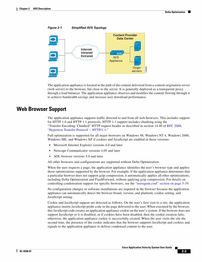
Figure 2-1 shows how the application appliance fits into the network topology.
2-3Cisco Application Velocity System User Guide
OL-9338-01
Chapter 2 AVS DescriptionDelta Optimization
Figure 2-1 Simplified AVS Topology
The application appliance is located in the path of the content delivered from a content origination server (web server) to the browser, but close to the server. It is generally deployed as a transparent proxy through a load balancer. The application appliance observes and modifies the content flowing through it to achieve bandwidth savings and increase user download performance.
Web Browser SupportThe application appliance supports traffic directed to and from all web browsers. This includes support for HTTP 1.0 and HTTP 1.1 protocols. HTTP 1.1 support includes chunking using the “Transfer-Encoding: Chunked” HTTP request header as described in section 14.40 of RFC 2068, “Hypertext Transfer Protocol -- HTTP/1.1.”
Full optimization is supported for all major browsers on Windows 98, Windows NT 4, Windows 2000, Windows ME, and Windows XP if cookies and JavaScript are enabled in these versions:
• Microsoft Internet Explorer versions 4.0 and later
• Netscape Communicator versions 4.05 and later
• AOL browser versions 5.0 and later
All other browsers and configurations are supported without Delta Optimization.
When the user requests a page, the application appliance identifies the user’s browser type and applies those optimizations supported by the browser. For example, if the application appliance determines that a particular browser does not support gzip compression, it automatically applies all other optimizations, including Delta Optimization and FlashForward, without applying gzip compression. For details on controlling condensation support for specific browsers, see the “useragent.conf” section on page 5-39.
No configuration changes or software installations are required in the browser because the application appliance can automatically detect the browser brand, version, and platform, cookie setting, and JavaScript setting.
Cookie and JavaScript support are detected as follows. On the user’s first visit to a site, the application appliance inserts JavaScript probe code in the page delivered to the user. When executed by the browser, this JavaScript code creates an application appliance cookie on the user’s system. If the browser does not support JavaScript or it is disabled, or if cookies have been disabled, then the cookie creation fails; otherwise, the application appliance cookie is successfully created. When the user visits the site the second time, the presence of the cookie indicates that the browser supports JavaScript and cookies and signals to the application appliance to deliver condensed content to the user.
1436
80
InternetIntranet/Extranet
AVS
Originservers
Content ProviderData Center
AVSAppliance
2-4Cisco Application Velocity System User Guide
OL-9338-01
Chapter 2 AVS DescriptionDelta Optimization
Note The application appliance also handles the case where a user subsequently reconfigures their browser to disable JavaScript. For more information, see the “Cookie Usage” section on page 2-17.
The application appliance can also detect browsers that can handle gzip-encoded content (it gzip compresses the response content, even if the content is not condensed).
Web Server SupportThe application appliance supports all web servers and web application servers that support the HTTP 1.0 or 1.1 protocols on all platforms. HTTP 1.1 support includes support for HTTP 1.1 chunked transfer encoding through the “Transfer-Coding:Chunked” HTTP request header as described in section 14.40 of RFC 2068, “Hypertext Transfer Protocol -- HTTP/1.1.”.
Web Content SupportThe application appliance supports all web content without modification to the content or the server software. Not all web content is suitable for condensation, however. Uncondensable content is passed through unmodified. The following sections describe the limitations to condensation support:
• Character Set Support, page 2-4
• Unsupported HTML Elements, page 2-4
Character Set Support
Condensation occurs only on HTML content that uses the iso-8859-1 character set because the application appliance supports only single-byte characters. All other types of content are passed through uncondensed.
The character set type is detected by examining the Content-Type HTTP response header, which looks like this:
Content-Type: text/html; charset=iso-8859-1
If no character set specification is present, it is assumed to be iso-8859-1.
Unsupported HTML Elements
Certain types of HTML content are not condensable. Inline frames (IFRAME tags), external script includes (SCRIPT tags including the SRC attribute), and embedded object (OBJECT tags) cannot be condensed. While pages containing these elements are condensed, these elements within the page are passed through uncondensed.
The application appliance uses its content inspection feature to examine pages for other elements that make pages uncondensable and automatically excludes those pages from condensation if it finds any of those elements. The application appliance performs content inspection by examining the first 1 KB of each page by using a content sensing algorithm from the W3C library. Content inspection is enabled by default and may be disabled if desired.
2-5Cisco Application Velocity System User Guide
OL-9338-01
Chapter 2 AVS DescriptionAdaptive Dynamic Caching
Content inspection can be a useful feature, but it can slow the overall performance of the application appliance, so we recommend that you do not use this feature unless absolutely necessary. Instead, we recommend that you remove unsupported elements from your web pages, or exclude such pages from condensation.
All JavaScript code embedded in a page is passed through uncondensed and in the exact order in which it appears in the origin page. This avoids problems related to JavaScript dependencies and execution order.
Configurable Condensation ModesThe condensation mode specifies whether the web pages to be condensed are common to all users or personalized for individual users, which determines what kind of page deltas are generated by the application appliance.
The application appliance supports two condensation modes:
• All-user condensation
• Per-user condensation
In the all-user condensation mode, the delta is generated against a single base file that is shared by all users of the URL. The all-user condensation mode is usable in most cases—even in the case of dynamic personalized content, if the structure of a page is common across users. The disk space overhead is minimal (the disk space requirements are determined by the number of condensed pages, not the number of users).
In the per-user condensation mode, when a specific user requests a URL, the delta for the response is generated against a base file that is created specifically for that user. The per-user condensation mode is useful in situations where the contents of a page (including layout elements) are different for each user. It delivers the highest level of condensation. However, a copy of the base page that is delivered to each user has to be kept in the application appliance cache and this increases the requirements on disk space for the application appliance cache. The per-user condensation mode is useful for content privacy because base pages are not shared among users.
Adaptive Dynamic CachingAdaptive dynamic caching enables the application appliance to fulfill requests for dynamic or personalized information, thus offloading application servers and databases. Adaptive dynamic caching not only significantly improves application response time but also reduces server load and enables more concurrent users to be served, resulting in improved scalability and lower ongoing server upgrade costs. The performance assurance caching policy enables the application appliance to monitor server load in real-time and make intelligent “closed-loop” content expiration decisions. This maximizes site performance and uses hardware resources most efficiently even during peak traffic load.
Adaptive dynamic caching enables the application appliance to cache dynamic content such as content created by an active server pages (ASP) script or application server. Dynamic content is not usually cached, because the generated content may contain up-to-the-minute data; however, by allowing flexible configuration and algorithmic processes, the application appliance allows you to cache this kind of content for some period of time.
2-6Cisco Application Velocity System User Guide
OL-9338-01
Chapter 2 AVS DescriptionFlashForward Object Acceleration
Adaptive dynamic caching has these features:
• Cache parameterization—Can differentiate a response by more than the URL and its query parameters. It allows the use of other parameters such as cookie values, HTTP header values, and the HTTP method used. This feature allows the application appliance to cache multiple responses for a single URL, depending on the specified cache parameters. This feature applies to both static (FlashForward) and dynamic caching.
• Cacheability rules—Allows IF/ELSE conditional rules to determine if a dynamic response is cacheable. The rules can examine URL query parameters, cookies, HTTP headers, and the HTTP method used. This feature applies to both static (FlashForward) and dynamic caching.
• Expanded expiration rules—Can set the automatic expiration of cached content based on time or through performance assurance with load-based expiration.
• Delta Cache—When the original HTML content is in the dynamic cache and a rebase has not occurred, the delta content can be stored in cache, which is a memory-only object.
Adaptive dynamic caching does not have any default configuration that suits a wide variety of situations automatically. You must configure this feature specifically for a web site or application. It is configurable at the Application Class level, which allows different caching rules to be applied to different sets of URLs. For guidelines on when to use dynamic caching and the steps required to implement it, refer to the “Dynamic Caching Configuration Guidelines” section on page 5-34.
For reference information on configuring dynamic caching in the fgn.conf file, see the “Adaptive Caching Configuration” section on page 5-18.
FlashForward Object AccelerationFlashForward object acceleration extends the application appliance’s bandwidth usage reduction and download acceleration benefits to objects that are embedded within HTML pages. This feature combines local object storage with dynamic renaming of embedded objects to enforce object freshness within the parent HTML page.
FlashForward renames and caches static objects in the application appliance, alters embedded object HTTP headers to extend their validity within the browser cache, and modifies the URL references in the parent HTML code to refer to the renamed objects so that the client only requests objects known to be new or modified at the time of the HTML request. This technique results in significantly accelerated page downloads as realized by the client and reduced upstream traffic associated with object validation requests.
FlashForward eliminates the network delays associated with embedded web objects such as images, style sheets, JavaScript files, and so on. Without the application appliance, the user experiences delays when pages with graphic images load, because each object requires validation to ensure that the user has the latest version. Object validation can result in 20 KB or more of unnecessary “upstream” traffic. Each validation involves an HTTP request from the client to the server. FlashForward enforces embedded object version management at the server. All object validity information is carried in the single download of the parent HTML document, which eliminates unnecessary validation requests.
The web’s current object freshness validation mechanism forces the client to assume that all objects cached within the browser are invalid (stale) in subsequent sessions until the server explicitly communicates its object validity to the client. This approach can create significant page load delays on subsequent visits to a previously cached page because it forces the client to issue a validation request for each object. A page load delay can be quite lengthy for pages that embed many objects because the objects cannot be rendered until the client-to-server round-trips are completed. In addition, this approach wastes significant upstream bandwidth.

2-7Cisco Application Velocity System User Guide
OL-9338-01
Chapter 2 AVS DescriptionJust-In-Time Object Acceleration
FlashForward places the responsibility for validating object freshness on the application appliance, rather than on the client, reversing the process and making it more efficient. FlashForward guarantees that clients request only the latest objects and never issue validation requests for objects in the browser cache that the application appliance has determined to be valid. Working together with Delta Optimization technology, small delta pages are used to deliver the information that references new objects. With FlashForward, the client never needs to validate the freshness of browser-cached objects with the origin server, which significantly accelerates page downloads, and reduces both upstream and downstream traffic that is associated with object validation requests.
For details on how FlashForward operates, see the “FlashForward Operation” section on page 2-23. To configure FlashForward, use the FlashForward and FlashForwardObject policy keywords, as described in Table 5-3 on page 5-12.
Just-In-Time Object AccelerationJust as FlashForward accelerates delivery of embedded cacheable objects, just-in-time object acceleration enables acceleration of noncacheable embedded objects, which results in improved application response time. This feature eliminates the need for users to download these objects on each request. Instead, the application appliance automatically tracks the freshness of each object in real time. If a requested object has not changed, the application appliance instructs the client to use its cached version of the object. If an object has changed, the application appliance delivers it to the client. The application appliance delivers the object only if it determines that the object has changed, guaranteeing the optimal application response times for all users.
Static content like images is handled with FlashForward, and dynamic HTML is handled with delta optimization. Just-in-time object acceleration is useful for dynamic content that cannot be handled by delta optimization, such as under the following conditions:
• HTML content is dynamic and larger than the maximum condensable page size (250 KB).
• Content is marked by the origin server as expired or not cacheable, just in case it might occasionally change, but actually it does not change often.
We recommend that you use just-in-time object acceleration with compression, for best results.
This feature is implemented as follows. The browser first requests an object and the application appliance fetches it on behalf of the browser request. The application appliance constructs and inserts an ETag (entity tag) header by using an MD5 hash of the content; and then it sends the object to the browser. The ETag (entity tag) is a request header that can be used to identify different versions of the same object. All subsequent requests from the browser include this ETag header, which the application appliance compares with a recomputed MD5 hash of the latest origin server content. If the content has not changed, then the application appliance returns a 304 (Not Modified) response and no data. If the content has changed, the application appliance retrieves the new content and resets the ETag.
To configure just-in-time object acceleration, use the DynamicETag policy keyword, as described in Table 5-3 on page 5-12.
2-8Cisco Application Velocity System User Guide
OL-9338-01
Chapter 2 AVS DescriptionSmart Image Optimization
Smart Image OptimizationSmart image optimization reduces JPEG and PNG image file sizes while optimizing image quality, which results in faster image download times, faster page renders, and more efficient bandwidth utilization.
Existing image compression techniques uniformly compress images so that areas of rich detail are compressed as much as areas of low detail. These approaches reduce image sizes but severely degrade image quality.
Smart image optimization recompresses only low detail areas within images to ensure that image sizes are significantly reduced (up to 90%) while maintaining rich visual detail. No changes to client software, server content, or server configuration are required.
Smart image optimization works with FlashForward to enable the fastest image optimization and delivery available today.
Smart image optimization is applied intelligently, and is not used for small images such as thumbnails, or when optimization reduces the file size by less than 10%. Only images that can be cached are optimized. If content includes very large images that you want optimized, you may need to increase the MaxCacheableObjectSize (which is set to 250 KB by default) to ensure that they are cached.
For detailed configuration information, see the “Image Optimization Configuration” section on page 5-24.
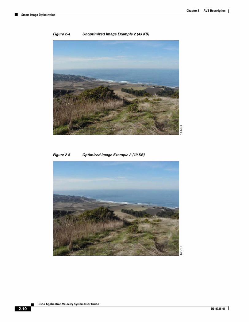
It is possible that you could see the difference in image quality between optimized and unoptimized images; however, unless you are looking for a problem, little difference is noticeable. The JPEG images in Figure 2-2, Figure 2-3, Figure 2-4, and Figure 2-5, show before and after versions, where the image size has been reduced by at least 50% in each case.

2-9Cisco Application Velocity System User Guide
OL-9338-01
Chapter 2 AVS DescriptionSmart Image Optimization
Figure 2-2 Unoptimized Image Example 1 (67 KB)
Figure 2-3 Optimized Image Example 1 (31 KB)
2-10Cisco Application Velocity System User Guide
OL-9338-01
Chapter 2 AVS DescriptionSmart Image Optimization
Figure 2-4 Unoptimized Image Example 2 (43 KB)
Figure 2-5 Optimized Image Example 2 (19 KB)
2-11Cisco Application Velocity System User Guide
OL-9338-01
Chapter 2 AVS DescriptionSmart Redirect
Smart RedirectSome applications and content management systems enable enterprises to automatically redirect users from one page to another through HTML META tags. Using HTML META tag page redirections can cause poor download times because it forces the browser to issue freshness validation requests for every object in the redirected page, which could result in potentially significant page download delays.
Smart redirect enables the application appliance to automatically and transparently convert HTML META tag redirections into more efficient HTTP header-based redirections. Using this feature eliminates the need for unnecessary freshness validation requests and results in significantly faster page response times, without sacrificing the META tag redirection flexibility enabled by many enterprise applications.
Note This feature is not suitable in situations where the intent of the META tag redirect is simply to reload the page, rather than redirect to a different page.
To configure smart redirect, use the MetaRefreshTo302 policy keyword, as described in Table 5-3 on page 5-12.
SSL Termination and ProxyThe application appliance supports condensation of SSL (Secure Sockets Layer) content. This configurable option enables the application appliance to deliver condensation for selected SSLv3 encrypted content. With this feature, you can configure the product as an SSL terminator, SSL proxy, and/or a Condenser.
As an SSL terminator, the application appliance operates as an application-layer proxy that communicates with end-user clients through HTTPS (SSL) and with the origin server within the data center through clear-text HTTP. SSL termination enables client-to-appliance security through SSL encryption, leaving appliance-to-server traffic in the clear through HTTP.
As an SSL proxy, the application appliance operates as an application-layer proxy that communicates with end-user clients and with the origin server within the data center through HTTPS (SSL). All traffic between the client and the server is encrypted through SSL; no clear-text traffic is seen. SSL proxying enables end-to-end client-to-server security through SSL encryption.
In a single application appliance environment where the application appliance is deployed as a terminator, the application appliance terminates an SSL session, decrypts the request, passes the decrypted request to the origin server, retrieves, optimizes, and encrypts the server response with SSL, and delivers the encrypted response to the client. Where the application appliance is deployed as a proxy, it decrypts the request to inspect the query, reencrypts the request, transparently proxies it through SSL to the origin server, retrieves, decrypts, optimizes, and reencrypts the server response with SSL, and delivers the encrypted response to the client.
SSL termination and proxy are disabled by default and must be explicitly enabled. They are enabled through destination mapping and other configuration parameters in the httpd.conf and fgn.conf files. See the following sections for specific information:
• For information on enabling SSL features in the httpd.conf file, see the “SSL Configuration Entries” section on page 5-37.
• For information on configuring destination mapping and Condensation policy in the fgn.conf file, see the “SSL Configuration” section on page 5-33.
2-12Cisco Application Velocity System User Guide
OL-9338-01
Chapter 2 AVS DescriptionFast NTLM Authentication
Fast NTLM AuthenticationThe application appliance significantly improves the overall application performance in NT LAN Manager (NTLM)-enabled environments by eliminating redundant NTLM authentication traffic associated with object validation requests. This is similar to how the application appliance improves SSL performance by eliminating unnecessary object validation requests that require costly SSL handshakes.
Server Connection OffloadServer connection offload enables the application appliance to optimize TCP-level efficiency by “pooling” a number of appliance-to-server TCP connections. Pooling enables multiple users to share a single TCP connection from the application appliance to the origin server, eliminating the need to create a new TCP connection for each transaction. Connection sharing increases the application appliance performance and scalability by reducing network-level overhead associated with TCP connection management.
Text CompressionTypically, standard text compression provides only modest improvements in real-world conditions and is not sufficiently powerful or robust for enterprise requirements. The application appliance uses industry-standard gzip compression to further reduce the byte size of delta optimized pages. Reducing page sizes is key to accelerating download times.
The application appliance compresses response content even if the content is not able to be condensed.
You can select either the gzip or deflate compression type by using the CompressionMethod keyword, listed in Table 5-1 on page 5-2.
FlashConnectLike FlashForward, FlashConnect allows the application appliance to reduce the bandwidth usage and accelerate downloading of objects that are embedded within HTML pages.
FlashConnect dynamically renames embedded objects by adding a prefix and changing the hostname, making the objects appear to reside on different hosts even though they may all reside on a single host. FlashConnect makes the browser open separate connections to the origin server for each object, which increases the network performance because the objects are retrieved in parallel, rather than one after another.
To use this feature, you must also configure DNS so that all requests for the rewritten object URLs are resolved back to the application appliance node (that rewrote them initially).
FlashConnect is disabled by default and must be explicitly enabled by specifying the policy keywords FlashConnect (for container pages) and FlashConnectObject (for embedded objects), as described in Table 5-3 on page 5-12.
Additionally, you can limit the number of artificial hosts that FlashConnect uses by specifying a limit with the FlashConnectLimit global keyword. The default limit is four. Finally, you can use the FlashConnectPrefix global keyword to set the prefix that is added to embedded object URLs. The default prefix is flashconnect. These keywords are described in Table 5-1 on page 5-2.

2-13Cisco Application Velocity System User Guide
OL-9338-01
Chapter 2 AVS DescriptionOther Features
Other FeaturesThe application appliance includes other features described in these sections:
• Class-Based Condensation, page 2-13
• Base File Management, page 2-13
• Canonical URL, page 2-14
• Base File Selection Policy, page 2-14
• Anonymous Base Files, page 2-14
• Smart Rebasing, page 2-15
• MIME-Type Exclusion, page 2-16
• SNMP Support, page 2-16
• Destination Mapping, page 2-16
• Log File Management, page 2-17
• Cookie Usage, page 2-17
Class-Based CondensationClass-based condensation allows a common base file to be shared among multiple URLs, known as a class of URLs. This is different from the normal URL-based mode in which a separate base file is maintained for each URL being condensed.
Class-based condensation allows you to define classes of web pages that have similar layout and/or content. For a particular class of pages, any page within the class is condensed against a single master base page that represents all pages in the class. With this feature, one document can be condensed against a similar, previously retrieved document rather than being condensed against a previously downloaded version of the same document, as in URL-based condensation.
A class of URLs is defined by specifying a regular expression that matches all URLs in the class. For example, the expression http://host/thisdir/* groups all files in the specified path into one class. If this path contained the two files http://host/thisdir/first.html and http://host/thisdir/second.html, they would share a common base file.
Note The application appliance requires GNU POSIX regular expression syntax. For more information, see Appendix F, “Regular Expressions.”
Base File ManagementThe application appliance uses a caching mechanism to optimize performance. It implements an automatic, transparent cache for base pages, where the least-used pages are discarded from the cache when it becomes full.
2-14Cisco Application Velocity System User Guide
OL-9338-01
Chapter 2 AVS DescriptionOther Features
Canonical URLThe application appliance uses the canonical URL feature to modify a parameterized request to eliminate the “?” and the characters that follow, to identify the general part of the URL. This general URL is then used to create the base file. The application appliance uses this feature to map multiple parameterized URLs to a single canonical URL.
For example, the two URLs http://www.servers.com/books?id=235 and http://www.servers.com/books?id=576 would both be reduced to the URL http://www.servers.com/books. As a result, both of these parameterized URLs would share the same base file that represents the canonical URL http://www.servers.com/books. Condensation levels will be relatively low if these original URLs reference two pages that do not share much content or layout (relatively large delta files could be delivered for requests across parameterized URLs that do not share content or layout).
The canonical URL feature is enabled by default but can be overridden through the application appliance’s base file selection policy feature, which is described in the next section.
Base File Selection PolicyBase file selection policy is similar to the canonical URL feature, but it provides more flexibility in specifying a base file to be shared among a group of URLs.
The base file selection policy allows you to define, on a class-based basis, regular expressions that define how URLs should be generalized. For example, Amazon.com uses URLs that look like the following: http://www.amazon.com/exec/obidos/tg/browse/-/289728/ref=k_kh_ln_bp_2/105-3394538-7390300, http://www.amazon.com/exec/obidos/tg/browse/-/289737/105-3394538-7390300, etc.
These URLs are parameterized by ID numbers within the path, rather than the typical ? character. You can configure the base file selection policy to determine that the common URL in this example is http://www.amazon.com/exec/obidos/tg/browse/-/, and that the base file should be created for this base URL. All similar requests would share this same base file.
You specify the base file selection policy by using the CanonicalUrl keyword in an Application Class in the fgn.conf file. For details, see the “Base File Selection Policy” section on page 5-15.
Anonymous Base FilesThe application appliance incorporates an anonymous base file feature to address user privacy concerns. This feature, which is an all-user condensation option, enables customers to use the application appliance nodes to deliver personalized confidential content such as online trading accounts, banking statements, business accounts, and so on. Customers typically use this feature with SSL to enable secure and private condensed content delivery.
Information that is common to a large set of users is generally nonconfidential and/or non user specific. Conversely, information that is unique to a specific user or common across a very small set of users is generally confidential and/or user specific. This feature enables the application appliance to create and deliver base files that contain only information that is common to a large set of users. No information unique to a particular user (or across a very small subset of users) is included in anonymous base files. Using anonymous base files eliminates any context for the data within a base file, making it impossible to associate the information with a given user. The anonymous base file no longer represents any initial (potentially confidential) content as viewed by the first visitor to a particular URL.

2-15Cisco Application Velocity System User Guide
OL-9338-01
Chapter 2 AVS DescriptionOther Features
The feature works as follows: Consider two numbers m and n, where m represents the anonymity level and n represents the base file sample size. This feature seeks to create a shared base file that contains content only common to m out of n base files (and users). For example, if m=4 and n=20, the anonymous base file will contain content only common to at least 4 of 20 user-specific base files. Any content unique to any one of the 20 base files will not be included in the anonymous base file. In addition, content that is common to less than four base files will not be included. These 20 base files will be of a per-user type created solely to enable this feature (these per-user base files will not be used to condense content). The base files in the base file sample size are chosen as the first n unique requests from unique browsers for the given URL.
You can configure the anonymity level (m). (Where m=0, no anonymity will be enabled). The application appliance will then select n=max(5,3m) to ensure highly anonymous base files. That is, n is set to the larger of 5 or 3*m. Through extensive testing, we recommend an anonymity level of 2.
This feature is disabled by default and must be explicitly enabled by using the all-user condensation mode and specifying an additional BaseFileAnonLevel configuration keyword (corresponding to m, above) in the Application Class. For details, see the “Application Class Specification” section on page 5-7.
For details about the statistical model used to calculate anonymity probabilities, refer to Appendix E, “Anonymous Base File Statistical Model.”
Smart RebasingRebasing refers to the process of updating the base file that is used for generating deltas. Because the base content of a site often changes over a period of time, the size of the generated deltas can grow relatively large. To maintain the effectiveness of the condensation process, the base files are automatically updated as required.
Smart rebasing enables the application appliance to instantly rebase URLs when appropriate and to maintain a copy of the old base page so that subsequent requests for it can be fulfilled.
An Application Class parameter called RebaseFlashForwardPercent provides a threshold control for rebasing based on the percent of FlashForwarded URLs in the response. Where the existing parameter, RebaseDeltaPercent, triggers rebasing when the delta response size exceeds the threshold as a percentage of base file size; this new parameter triggers rebasing when the difference between the percentages of FlashForwarded URLs in the delta response and the base file exceed the threshold. The default value for RebaseFlashForwardPercent is 50%.
With Smart Rebasing, the application appliance tracks the number of delta responses sampled, how many of the responses have a delta size bigger than the RebaseDeltaPercent threshold, and how many of the responses have too many FlashForwarded URLs (through the RebaseFlashForwardPercent threshold). When a reasonable sample size (10, to be specific) is reached, the application appliance looks at the percentages of delta responses that have exceeded the RebaseDeltaPercent and RebaseFlashForwardPercent thresholds. By default, rebasing is automatically triggered when either percentage exceeds 50%. Smart rebasing enables the application appliance to automatically rebase a page when it determines that the existing base file does not result in minimally sized delta responses for the majority of requests.
Smart rebasing improves overall application appliance performance and content acceleration because it ensures that delta optimization occurs at all times, even when a rebase occurs.
2-16Cisco Application Velocity System User Guide
OL-9338-01
Chapter 2 AVS DescriptionOther Features
MIME-Type ExclusionBecause some content providers choose to label text/html content as non-text/html MIME types (and vice versa) in the HTTP entity header field to prevent web crawlers, this feature allows you to explicitly configure specific MIME types as uncondensable. For example, suppose that you configure the web server to report JavaScript as MIME type “application/x-text.” With this feature configured to identify this MIME type as uncondensable, the application appliance will not condense responses for this MIME type. When you disable this feature, the application appliance will condense responses for this MIME type.
You can also list specific MIME types that are not to be compressed.
This feature is configured by listing MIME types that are not to be condensed or compressed in the mimetypes.conf file. If this file is empty, or does not exist, then all MIME types are considered condensable and compressible. For details on configuring MIME-type exclusion, see the “mimetypes.conf” section on page 5-38.
No configuration is necessary for this feature. It is enabled automatically.
SNMP SupportThe application appliance supports Simple Network Management Protocol (SNMP) for remote network management. The application appliance Management Information Base (MIB) is described in Appendix B, “SNMP MIB.”
This MIB is defined in the file $AVS_HOME/perfnode/conf/fgn_cds_mib.mib. A network management application can import this file. In this MIB, several traps are also defined that monitor the status of the application appliance. On the management application side, it is up to the administrator to define the severity of the traps and the corresponding actions.
Destination MappingThe application appliance uses destination mapping to proxy requests to a specified destination IP address and port number or hostname and port. The application appliance supports wide scope mapping and host header mapping. Destination mapping is useful in clustered application appliance environments and these typical scenarios:
• the application appliance handles both an intranet and an Internet application
• the application appliance listens on one port and handles multiple internal sites
• the application appliance listens on multiple ports and redirects to multiple sites
• the application appliance resides behind a load balancer but redirects to a site through a proxy
• an SSL-terminating application appliance forwards decrypted requests to another application appliance
• an SSL-proxy application appliance forwards reencrypted requests to a site
In an SSL-terminating scenario, a load balancer redirects an SSL request to an application appliance SSL terminator through a virtual IP (VIP) configured on the load balancer. This VIP is bound to the real IP addresses of the application appliance.
The SSL terminator next proxies the request to an application appliance node through the load balancer. To achieve load balancing and failover of these requests, the SSL terminator must proxy the request to a new VIP or the same VIP on a different port bound to the application appliance IP address and port.
2-17Cisco Application Velocity System User Guide
OL-9338-01
Chapter 2 AVS DescriptionOther Features
If a mapped destination port is not explicitly identified, the currently bound port will be used.
This feature is disabled by default and must be explicitly configured to enable it. For details, see the “Destination Mapping Configuration” section on page 5-30.
Log File ManagementThe application appliance supports automatic log rotation and uploading logs to the Management Console database.
For details on the configuration directives in the fgn.conf file that control logging, see the “fgn.conf” section on page 5-1.
For details on log file management and the format of data contained in the log files, refer to Appendix A, “Logs.”
Cookie UsageTo determine browser support for cookies and JavaScript, the application appliance inserts JavaScript code into the page returned to a user on the user’s first visit to a site. When executed by the client browser, this code creates a cookie with a randomly generated 128-bit user ID. Client browsers that do not support JavaScript will ignore the script, and no application appliance cookie will be created.
Upon a second request from the client, the application appliance looks for the application appliance cookie to verify client JavaScript and cookie support. If the application appliance sees the application appliance cookie, it assumes that the client supports JavaScript. If it does not see the application appliance cookie, it assumes that the client does not support JavaScript or cookies (or that this may be the first request from this client), and it will not provide condensation for this user’s requests.
The application appliance cookie has the attributes listed in Table 2-1.
The application appliance supports automatic cookie expiration, which enables the application appliance to handle the potential failure scenario of the user disabling JavaScript after an initial JavaScript-enabled visit. Without such support, the browser would display a blank page upon retrieving condensed content (which is wrapped in JavaScript) from the application appliance. To handle this case, the application appliance includes a <NOSCRIPT> tag in its responses to clients. If JavaScript is disabled on the browser after the initial JavaScript-enabled request, client execution of this HTML code automatically forces the client to expire the application appliance cookie and fetch subsequent pages uncondensed (until JavaScript is reenabled).
Table 2-1 Application Velocity System Cookie Properties
Attribute Value
Name FGNCDN
Life 30 days
Domain Same as the target site
Path “/” (the entire site)
Value A 128-bit randomly generated user ID. This ID uniquely identifies the user to the application appliance.
2-18Cisco Application Velocity System User Guide
OL-9338-01
Chapter 2 AVS DescriptionWeb Application Security Firewall
If JavaScript is disabled, the client executes HTML code within the <NOSCRIPT> tags to fetch a URL like “http://www.example.com/?cisco=removeCookie.” When the application appliance sees this request, it issues an HTTP 302 Temporary Redirect to the client, redirecting it to the originally requested page. The response also includes a Set-Cookie HTTP header that immediately expires the client’s application appliance cookie.
Web Application Security FirewallThe web application security firewall enables the application appliance to provide web application security and intrusion protection. The web application security firewall comes with the firewall preconfigured, and it is highly customizable to fit your environment. It can protect against the following kinds of application attacks:
• identity theft
• SQL, OS, and LDAP command injection
• cross site scripting
• meta character and format string attacks
• buffer overflow
• form exploitation
• URL redirects and directory traversal
• error message exploitation
• cookie exploitation
• noncompliant HTTP
• web server fingerprinting
The web application security firewall can scan and analyze all HTTP/HTTPS requests, preventing unwanted requests from going to the origin server and masking web server and application details from clients. The web application security firewall uses policy-driven, rule-based management.
For details on configuring web application security, see Chapter 6, “Web Application Security Configuration.”
AppScope Performance MonitoringAppScope measures true end-to-end application performance as seen by end users. AppScope also accurately determines both the server delay and network delay components associated with the user experience at the transaction level. AppScope’s unique Statistical Traffic Sampling technology enables an enterprise to statistically sample user requests, making AppScope highly scalable for high-traffic applications.
The AVS AppScope Performance Monitor provides a browser-based reporting facility that enables enterprises to efficiently track application performance. AppScope’s reporting engine provides detailed graphical performance monitoring results with drilldown reports.
All AppScope Performance Monitor data is stored in a self-contained relational Postgres database. This database allows an organization to use its own reporting tools, such as Crystal Reports, or to create its own custom performance monitoring reports.
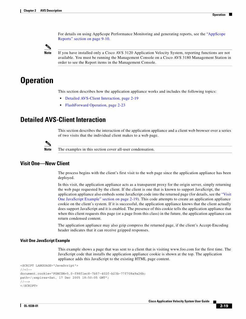
2-19Cisco Application Velocity System User Guide
OL-9338-01
Chapter 2 AVS DescriptionOperation
For details on using AppScope Performance Monitoring and generating reports, see the “AppScope Reports” section on page 9-10.
Note If you have installed only a Cisco AVS 3120 Application Velocity System, reporting functions are not available. You must be running the Management Console on a Cisco AVS 3180 Management Station in order to see the Report items in the Management Console.
OperationThis section describes how the application appliance works and includes the following topics:
• Detailed AVS-Client Interaction, page 2-19
• FlashForward Operation, page 2-23
Detailed AVS-Client InteractionThis section describes the interaction of the application appliance and a client web browser over a series of two visits that the individual client makes to a web page.
Note The examples in this section cover all-user condensation.
Visit One—New Client
The process begins with the client’s first visit to the web page since the application appliance has been deployed.
In this visit, the application appliance acts as a transparent proxy for the origin server, simply returning the web page requested by the client. If the client is one that is known to support JavaScript, the application appliance also embeds some JavaScript code into the returned page (for details, see the “Visit One JavaScript Example” section on page 2-19). This code attempts to create an application appliance cookie on the client’s system. If it is successful, the application appliance knows that the client actually does support JavaScript and it is enabled. The presence of this cookie tells the application appliance that when this client requests this page (or a page from this class) in the future, the application appliance can return condensed content.
The application appliance may also gzip compress the returned page, if the client’s Accept-Encoding header indicates that it can receive gzipped responses.
Visit One JavaScript Example
This example shows a page that was sent to a client that is visiting www.foo.com for the first time. The JavaScript code that installs the application appliance cookie is shown at the top. The application appliance adds this JavaScript to the existing HTML page content.
<SCRIPT LANGUAGE="JavaScript">//<!--document.cookie="FGNCDN=5.0-f98f1ec8-7b57-402f-b23b-77f708a9a26b;path=/;expires=Sat, 17 Dec 2005 18:50:05 GMT";//--></SCRIPT>
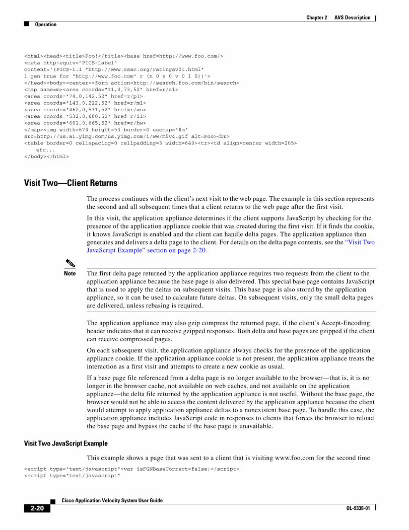
2-20Cisco Application Velocity System User Guide
OL-9338-01
Chapter 2 AVS DescriptionOperation
<html><head><title>Foo!</title><base href=http://www.foo.com/><meta http-equiv="PICS-Label" content='(PICS-1.1 "http://www.rsac.org/ratingsv01.html" l gen true for "http://www.foo.com" r (n 0 s 0 v 0 l 0))'></head><body><center><form action=http://search.foo.com/bin/search><map name=m><area coords="11,0,73,52" href=r/a1><area coords="74,0,142,52" href=r/p1><area coords="143,0,212,52" href=r/m1><area coords="462,0,531,52" href=r/wn><area coords="532,0,600,52" href=r/i1><area coords="601,0,665,52" href=r/hw></map><img width=674 height=53 border=0 usemap="#m"src=http://us.a1.yimg.com/us.yimg.com/i/ww/m5v4.gif alt=Foo><br><table border=0 cellspacing=0 cellpadding=3 width=640><tr><td align=center width=205>
etc...</body></html>
Visit Two—Client Returns
The process continues with the client’s next visit to the web page. The example in this section represents the second and all subsequent times that a client returns to the web page after the first visit.
In this visit, the application appliance determines if the client supports JavaScript by checking for the presence of the application appliance cookie that was created during the first visit. If it finds the cookie, it knows JavaScript is enabled and the client can handle delta pages. The application appliance then generates and delivers a delta page to the client. For details on the delta page contents, see the “Visit Two JavaScript Example” section on page 2-20.
Note The first delta page returned by the application appliance requires two requests from the client to the application appliance because the base page is also delivered. This special base page contains JavaScript that is used to apply the deltas on subsequent visits. This base page is also stored by the application appliance, so it can be used to calculate future deltas. On subsequent visits, only the small delta pages are delivered, unless rebasing is required.
The application appliance may also gzip compress the returned page, if the client’s Accept-Encoding header indicates that it can receive gzipped responses. Both delta and base pages are gzipped if the client can receive compressed pages.
On each subsequent visit, the application appliance always checks for the presence of the application appliance cookie. If the application appliance cookie is not present, the application appliance treats the interaction as a first visit and attempts to create a new cookie as usual.
If a base page file referenced from a delta page is no longer available to the browser—that is, it is no longer in the browser cache, not available on web caches, and not available on the application appliance—the delta file returned by the application appliance is not useful. Without the base page, the browser would not be able to access the content delivered by the application appliance because the client would attempt to apply application appliance deltas to a nonexistent base page. To handle this case, the application appliance includes JavaScript code in responses to clients that forces the browser to reload the base page and bypass the cache if the base page is unavailable.
Visit Two JavaScript Example
This example shows a page that was sent to a client that is visiting www.foo.com for the second time.
<script type="text/javascript">var isFGNBaseCorrect=false;</script> <script type="text/javascript"
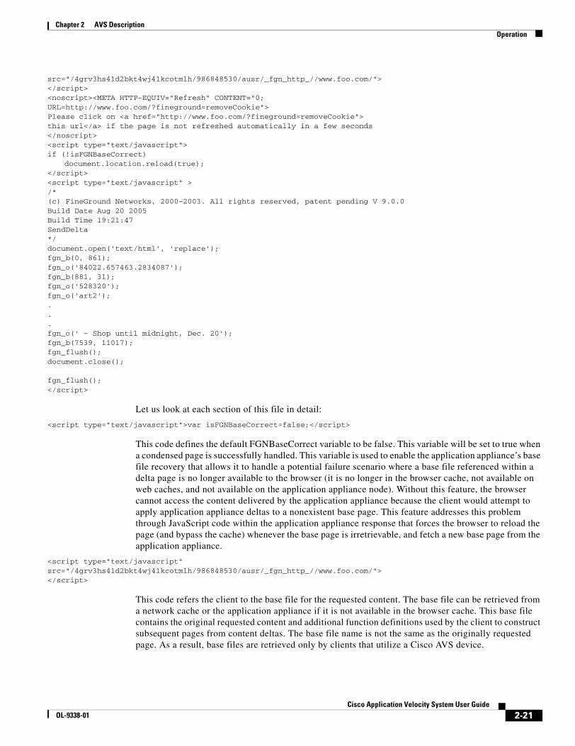
2-21Cisco Application Velocity System User Guide
OL-9338-01
Chapter 2 AVS DescriptionOperation
src="/4grv3hs41d2bkt4wj41kcotmlh/986848530/ausr/_fgn_http_//www.foo.com/"> </script><noscript><META HTTP-EQUIV="Refresh" CONTENT="0;URL=http://www.foo.com/?fineground=removeCookie"> Please click on <a href="http://www.foo.com/?fineground=removeCookie"> this url</a> if the page is not refreshed automatically in a few seconds</noscript><script type="text/javascript">if (!isFGNBaseCorrect)
document.location.reload(true);</script><script type="text/javascript" >/*(c) FineGround Networks, 2000-2003. All rights reserved, patent pending V 9.0.0Build Date Aug 20 2005Build Time 19:21:47SendDelta*/document.open('text/html', 'replace');fgn_b(0, 861);fgn_o('84022.657463.2834087');fgn_b(881, 31);fgn_o('528320');fgn_o('art2');...fgn_o(' - Shop until midnight, Dec. 20');fgn_b(7539, 11017);fgn_flush();document.close();
fgn_flush();</script>
Let us look at each section of this file in detail:
<script type="text/javascript">var isFGNBaseCorrect=false;</script>
This code defines the default FGNBaseCorrect variable to be false. This variable will be set to true when a condensed page is successfully handled. This variable is used to enable the application appliance’s base file recovery that allows it to handle a potential failure scenario where a base file referenced within a delta page is no longer available to the browser (it is no longer in the browser cache, not available on web caches, and not available on the application appliance node). Without this feature, the browser cannot access the content delivered by the application appliance because the client would attempt to apply application appliance deltas to a nonexistent base page. This feature addresses this problem through JavaScript code within the application appliance response that forces the browser to reload the page (and bypass the cache) whenever the base page is irretrievable, and fetch a new base page from the application appliance.
<script type="text/javascript" src="/4grv3hs41d2bkt4wj41kcotmlh/986848530/ausr/_fgn_http_//www.foo.com/"></script>
This code refers the client to the base file for the requested content. The base file can be retrieved from a network cache or the application appliance if it is not available in the browser cache. This base file contains the original requested content and additional function definitions used by the client to construct subsequent pages from content deltas. The base file name is not the same as the originally requested page. As a result, base files are retrieved only by clients that utilize a Cisco AVS device.
2-22Cisco Application Velocity System User Guide
OL-9338-01
Chapter 2 AVS DescriptionOperation
Let’s examine the base file naming convention in this example. The first string, “4grv3hs41d2bkt4wj41kcotmlh,” is the application appliance ID that uniquely identifies the application appliance that generated this base file. It is a one-way hash based on the MAC address, IP address, and port of the application appliance node. The second string, “986848530,” represents a modification timestamp of the base file that enables the application appliance to detect base file version changes.
<noscript><META HTTP-EQUIV="Refresh" CONTENT="0;URL=http://www.foo.com/?fineground=removeCookie">Please click on <a href="http://www.foo.com/?fineground=removeCookie">this url</a> if the page is not refreshed automatically in a few seconds</noscript>
This code enables the automatic cookie expiration feature, which allows the application appliance to guarantee content delivery in scenarios where JavaScript is disabled on the client. In this scenario, the client explicitly disables JavaScript support subsequent to an initial JavaScript-enabled visit. Without this feature, the browser would display a blank page upon retrieving condensed content (JavaScript) from the application appliance. The solution is to include this <NOSCRIPT> tag in application appliance responses to clients. If JavaScript is disabled on the browser after the initial JavaScript-enabled request, client execution of this code will automatically force the client to expire the application appliance cookie and fetch subsequent pages uncondensed (without application appliance-generated JavaScript coding).
<script type="text/javascript">if (!isFGNBaseCorrect)
document.location.reload(true);</script>
An important failover mechanism, this code enables the browser to reload the page uncondensed, bypassing the cache whenever the base file is unavailable. This ensures that the client will always be able to retrieve content even when base files are unavailable.
<script type="text/javascript">/* (c) FineGround Networks, 2000-2003. All rights reserved, patent pending V 9.0.0Build Date Aug 20 2005Build Time 19:21:47SendDelta*/document.open('text/html', 'replace');fgn_b(0, 861);fgn_o('84022.657463.2834087');fgn_b(881, 31);fgn_o('528320');fgn_o('art2');...fgn_o(' - Shop until midnight, Dec. 20');fgn_b(7539, 11017);fgn_flush();document.close();
fgn_flush();
This code represents the content delta information. Using simple string-manipulating JavaScript functions defined in the base file, it enables the client to construct the newly requested page from the previously retrieved base file.
2-23Cisco Application Velocity System User Guide
OL-9338-01
Chapter 2 AVS DescriptionOperation
Cache Control Headers
The delta pages sent to clients by the application appliance use exactly the same HTTP cache control headers as the original page served by the origin server. This allows network caches to cache these pages in the same manner as the original page.
By default, base pages sent to clients by the application appliance use cache control headers that enable caching for 30 days to leverage network edge caches.
FlashForward OperationThese sections describe how FlashForward works:
• FlashForward Overview, page 2-23
• FlashForward and Delta Optimization Options, page 2-23
• FlashForward and Repeat Visits, page 2-24
• How FlashForward Works With Delta Optimization, page 2-24
• How FlashForward Works Without Delta Optimization, page 2-27
• How FlashForward Works With CDN URLs, page 2-29
FlashForward Overview
If an embedded object has a “Last-Modified” date and an “Expires” date so that the object has not yet expired in the browser cache, a revisit in a new browser session to the HTML page that references the object will not trigger any kind of HTTP GET request for the object. This feature reduces upstream HTTP request traffic and accelerates the delivery of the page.
FlashForward and Delta Optimization Options
FlashForward and delta optimization are independent mechanisms. While the recommended configuration is to use both delta optimization and FlashForward simultaneously for optimal acceleration and bandwidth savings, it is possible to configure FlashForward by itself or delta optimization by itself.
Configuring FlashForward by itself (without delta optimization) may be appropriate for sites with small HTML pages that contain many cacheable embedded objects. Such a configuration will not provide HTML acceleration benefits because it will not accelerate HTML delivery in repeat visits. It will, however, accelerate embedded object delivery in repeat visits, typically across browser sessions. A side benefit of this type of configuration is that it eliminates the requirement that client browsers support cookies or JavaScript-based DHTML. FlashForward by itself supports all browsers automatically, but delta optimization requires the browser to support DHTML.
Configuring delta optimization without FlashForward may be appropriate for sites with large HTML pages that contain few cacheable embedded objects. Such a configuration will accelerate HTML delivery both within and across browser sessions but will not accelerate embedded object delivery across browser sessions. Any application appliance configuration that uses delta optimization requires that the client browser support both cookies and JavaScript-based DHTML. We recommend that you use both delta optimization and FlashForward for optimal results.
2-24Cisco Application Velocity System User Guide
OL-9338-01
Chapter 2 AVS DescriptionOperation
FlashForward and Repeat Visits
Most users will first experience FlashForward acceleration benefits on their first repeat visit to a given page. The examples in this section assume that the application appliance was just installed and include an extra initial step required to prime the application appliance cache with FlashForwarded objects. The examples show that the user will start to see FlashForward benefits on the second repeat visit to a given page (the third overall visit). Once the application appliance cache is primed, clients will begin to see FlashForward benefits on their first repeat visit (the second overall visit).
Note Most users will experience FlashForward benefits on their first repeat visit to a given page. (This “First Repeat Visit” represents the actual first visit for clients after the application appliance cache is primed.) Regardless of whether FlashForward is configured with or without delta optimization, the examples in this section show that, for the very first visit to the URL, the client will gain the FlashForward benefits on the second and subsequent repeat visits. This three-visit requirement only applies to the client that actually primes the application appliance cache with new (not modified) objects from the origin server (that is, the very first client that requested the new object). All other clients will take advantage of the first client’s sacrifice in priming the application appliance cache and will gain the FlashForward benefits on the first repeat visit and later. Why? Because other clients will fetch FlashForwarded objects on the very first visit; that is, the cookie-drop page (if delta optimization is configured), or the plain HTML page (if delta optimization is not configured). These clients will contain the transformed URLs that point to FlashForwarded objects in the application appliance cache.
How FlashForward Works With Delta Optimization
This section describes how FlashForward works with delta optimization over a series of three visits to a page by a client browser.
Visit 1: Priming the Cache
This section describes the process for priming the cache on an application appliance that has just been installed (its cache is empty). No base files or objects are yet in the application appliance cache. The very first request for a given URL overall (not the first visit per client) is used to prime the application appliance cache as follows:
1. The client requests a URL. The application appliance proxies it to the origin server.
2. The origin server delivers the HTML page to the application appliance.
3. The application appliance retrieves the page, parses through the HTML looking for references to embedded objects, and checks if the referenced objects are currently cached locally. In this case, none of the embedded objects referenced in the HTML are cached in the application appliance because for this first visit, the application appliance cache has not yet been primed with the embedded objects. The application appliance prepends the application appliance cookie through JavaScript and delivers the page compressed but otherwise unaltered (a standard cookie-drop page is created and delivered without any FlashForwarding taking place).
4. The application appliance creates the base page as usual because this visit is the first to the URL by anyone.
5. The client retrieves the compressed “cookie-drop” page, parses the HTML looking for references to embedded objects, and requests the embedded objects directly from the origin server through HTTP GET requests.

2-25Cisco Application Velocity System User Guide
OL-9338-01
Chapter 2 AVS DescriptionOperation
6. Because the application appliance is a proxy, the HTTP GETs are passed through the application appliance to the origin server and the subsequent object responses (HTTP “200 OK”) from the origin server are passed through the application appliance to the client. The application appliance caches all cacheable objects as they pass through, which primes the cache. In this way, the application appliance uses the client’s HTTP GET requests to populate the cache rather than resorting to some complex cache pre-population capability. This process only occurs the first time new objects are delivered from the server to the client (only when the application appliance determines that the original HTML references objects that are not in the cache at the time of the HTML request). The application appliance cache is now primed.
7. The client browser retrieves and caches the original objects referenced in the HTML, as delivered by the origin server.
First Repeat Visit: The FlashForward Transformation
This section describes the process for the first repeat visit:
1. In a new browser session, the client requests the same (or similar) URL.
2. The application appliance sees its cookie and knows that the client can support optimized responses.
3. The application appliance proxies the request to the origin server.
4. The origin server creates and delivers the HTML page to the application appliance.
5. The application appliance parses through the HTML looking for references to embedded objects and checks if the referenced objects are cached locally. If so, the application appliance checks to see if the cached objects can be FlashForwarded (it determines if it is configured to FlashForward the object type). If the objects are both cacheable and can be FlashForwarded, the application appliance issues HTTP IMS requests to the origin server to determine whether or not the cached objects are still valid.
Note The application appliance does not issue IMS requests on every client request (it does not check object freshness with the origin server every time it gets a request from a client.) Instead, it uses the application appliance’s cache freshness settings to determine how often it should issue IMS requests. For example, if you configure the cache expiration setting to be 10 minutes, the application appliance will issue IMS requests for that object type only every 10 minutes.
a. If the origin server responds with an HTTP 304 “Not Modified” status code, the application appliance renames the already cached object by adding a version to the object name (URL), and adds a long-lived “Expires” HTTP response header to it (the default expiration date is greater than 20 years). This object has just undergone the FlashForward transformation. The application appliance uses the 304 response information to eliminate the need for the client to issue IMS requests to validate the freshness of this object. This process eliminates the WAN round-trip time associated with IMS/304 traffic and results in an accelerated page download that is seen by the client.
b. If the origin server responds with an HTTP 200 “OK” status code (with the modified object), the application appliance caches the modified object, renames the newly cached object by adding a version to the object name (URL), and adds a long-lived “Expires” HTTP response header to it (the default expiration date is greater than 20 years). This object has just undergone the FlashForward transformation.
6. The application appliance next rewrites the HTML delivered by the origin server so that the embedded object references (URLs) point to the new FlashForward-transformed names (the version-added names that represent the objects in the application appliance cache) rather than the original objects on the origin server.

2-26Cisco Application Velocity System User Guide
OL-9338-01
Chapter 2 AVS DescriptionOperation
7. The application appliance compares the rewritten HTML to the base page to create a delta page (it performs delta optimization on the rewritten HTML). Delta optimization is used to deliver the changes in the HTML content and the changes in the URL references that result from the FlashForward process. This is the key to how FlashForward and delta optimization work together.
8. The application appliance compresses and delivers the delta page to the client.
9. The client retrieves the delta page and reconstructs the rewritten HTML from it (and the base page).
10. The client browser parses through the HTML looking for references to embedded objects. These references now point to the FlashForwarded objects cached in the application appliance.
11. The client requests the FlashForwarded objects from the application appliance; the application appliance delivers the FlashForwarded objects to the client.
12. The client browser retrieves and caches the FlashForwarded objects.
Second Repeat Visit: Gaining the Benefit
This section describes the process for the second repeat visit:
1. In a new browser session, the client requests the same (or similar) URL.
2. The application appliance sees its cookie and knows that the client can support condensed responses.
3. The application appliance proxies the request to the origin server.
4. The origin server creates and delivers the HTML page to the application appliance.
5. The application appliance parses through the HTML looking for references to embedded objects and checks if the referenced objects are cached locally. If so, the application appliance checks if the cached objects can be FlashForwarded (determines if the application appliance is configured to FlashForward the object type). If the objects are both cacheable and can be FlashForwarded, the application appliance issues HTTP IMS requests to the origin server to determine whether or not the cached objects are still valid.
a. If the origin server responds with an HTTP 304 “Not Modified” status code, the application appliance knows that the already renamed FlashForwarded object currently in the cache is still valid.
b. If the origin server responds with an HTTP 200 “OK” status code (with the modified object), the application appliance caches the modified object, renames the newly cached object by adding a version to the object name (URL), and adds a long-lived “Expires” HTTP response header to it (the default expiration date is greater than 20 years). This object has just undergone the FlashForward transformation.
6. The application appliance next rewrites the HTML delivered by the origin server so that the embedded object URLs point to the FlashForward-transformed names. If the object did not change, the object name would be the same object name previously referenced in visit 2 (the same name under which the client has cached it in the browser). If the object was modified, the name would be the new version-attached name (it represents an object not currently in the client's browser cache).
7. The application appliance compares the rewritten HTML to the base page to create a delta page (it performs delta optimization on the rewritten HTML). Delta optimization is used to deliver both changes in the HTML content and changes in URL references resulting from the FlashForward process.
8. The application appliance compresses and delivers the delta page to the client.
9. The client retrieves the delta page and reconstructs the rewritten HTML from it (and the base page).
10. The client (browser) parses through the HTML looking for references to embedded objects. These references now point to the FlashForwarded objects cached in the application appliance.
2-27Cisco Application Velocity System User Guide
OL-9338-01
Chapter 2 AVS DescriptionOperation
11. Because of the Expires header added to the embedded objects within the browser cache, the browser now issues HTTP GET requests only for objects referenced in the HTML that are not already cached in the browser (only the changed objects will be requested through HTTP GETs). No HTTP GET requests of any kind will be issued for any of the FlashForwarded objects already cached because they are known to still be fresh when they have the long-lived Expires date on them. FlashForward enables the application appliance to determine embedded object freshness dynamically and explicitly communicate this information to the client so that the client does not waste valuable time and bandwidth issuing requests to validate object freshness. This process accelerates the page download because it eliminates all IMS requests for objects known by the application appliance to still be valid.
The next section discusses how FlashForward works without delta optimization enabled.
How FlashForward Works Without Delta Optimization
This section describes how FlashForward works without delta optimization over a series of two visits to a page by a client browser.
Visit 1: Priming the Application Appliance Cache
This section describes the process for an application appliance that has just been installed (its cache is empty). The very first request for a given URL overall (not the first visit per client) is used to prime the application appliance cache as follows:
1. The client requests a URL. The application appliance proxies it to the origin server.
2. The origin server delivers the HTML page to the application appliance.
3. The application appliance retrieves the page, parses through the HTML looking for references to embedded objects, and checks if the referenced objects are currently cached locally. In this case, no embedded objects that are referenced in the HTML are cached in the application appliance because the application appliance cache has not yet been primed with the embedded objects. The application appliance delivers the page compressed but otherwise unaltered as usual (a standard cookie-drop page is created and delivered without any FlashForwarding taking place). Because delta optimization is not configured, no cookie-drop JavaScript will be added to the page.
4. The client retrieves the compressed HTML page, parses the HTML looking for references to embedded objects, and requests the embedded objects directly from the origin server through HTTP GET requests.
5. Because the application appliance is a proxy, the HTTP GETs are passed through the application appliance to the origin server and the subsequent object responses (HTTP “200 OK”) from the origin server are passed through the application appliance to the client. The application appliance caches all cacheable objects as they pass through, thus priming the cache. The application appliance uses the client’s HTTP GET requests to populate the cache rather than having to resort to some complex cache pre-population capability. This process only occurs the first time that new objects are delivered from the server to the client (when the original HTML references objects not yet in the cache at the time of the HTML request). The application appliance cache is now primed.
6. The client browser retrieves and caches the original objects referenced in the HTML as delivered by the origin server.
First Repeat Visit: The FlashForward Transformation
This section describes the process for the first repeat visit:
1. In a new browser session, the client requests the same (or similar) URL.
2-28Cisco Application Velocity System User Guide
OL-9338-01
Chapter 2 AVS DescriptionOperation
2. The application appliance proxies the request to the origin server.
3. The origin server creates and delivers the HTML page to the application appliance.
4. The application appliance parses through the HTML looking for references to embedded objects and checks if the referenced objects are cached locally. If so, the application appliance checks if the cached objects can be FlashForwarded (it determines if it is configured to FlashForward the object type). If the objects are both cacheable and can be FlashForwarded, the application appliance issues HTTP IMS requests to the origin server to determine if the cached objects are still valid.
a. If the origin server responds with an HTTP 304 “Not Modified” status code, the application appliance renames the already cached object by adding a version to the object name (URL), and adds a long-lived “Expires” HTTP response header to it (the default expiration date is greater than 20 years). This object has just undergone the FlashForward transformation. The application appliance uses the 304 response information to eliminate the need for the client to issue IMS requests to validate the freshness of this object. This process eliminates the WAN round-trip time associated with IMS/304 traffic, which results in an accelerated page download that is seen by the client.
b. If the origin server responds with an HTTP 200 “OK” status code (with the modified object), the application appliance caches the modified object and renames the newly cached object by adding a version to the object name (URL), and adds a long-lived “Expires” HTTP response header to it (the default expiration date is greater than 20 years). This object has just undergone the FlashForward transformation.
5. The application appliance next rewrites the HTML delivered by the origin server so that the embedded object references (URLs) point to the new FlashForward-transformed names rather than the original objects on the origin server.
6. The application appliance compresses and delivers the rewritten HTML page to the client.
7. The client browser retrieves the rewritten HTML and parses through it looking for references to embedded objects. These references now point to the FlashForwarded objects cached in the application appliance.
8. The client requests the FlashForwarded objects from the application appliance; the application appliance delivers the FlashForwarded objects to the client.
9. The client browser retrieves and caches the FlashForwarded objects.
Second Repeat Visit: Gaining the Benefit
This section describes the process for the second repeat visit:
1. In a new browser session, the client requests the same (or similar) URL.
2. The application appliance proxies the request to origin server.
3. The origin server creates and delivers the HTML page to the application appliance.
4. The application appliance parses through the HTML looking for references to embedded objects and checks if the referenced objects are cached locally. If so, the application appliance checks if the cached objects can be FlashForwarded (it determines if it is configured to FlashForward the object type). If the objects are both cacheable and can be FlashForwarded, the application appliance issues HTTP IMS requests to the origin server to determine if the cached objects are still valid.
a. If the origin server responds with an HTTP 304 “Not Modified” status code, the application appliance knows that the already renamed FlashForwarded object currently in the cache is still valid.

2-29Cisco Application Velocity System User Guide
OL-9338-01
Chapter 2 AVS DescriptionOperation
b. If the origin server responds with an HTTP 200 “OK” status code (with the modified object), the application appliance caches the modified object and renames the newly cached object by adding a version to the object name (URL), and adds a long-lived “Expires” HTTP response header to it (the default expiration date is greater than 20 years). This object has just undergone the FlashForward transformation.
5. The application appliance next rewrites the HTML delivered by the origin server so that the embedded object URLs point to the FlashForward-transformed names. If the object did not change, the object name would be the same object name previously referenced in visit 2 (the same name under which the client has cached it in the browser); but if the object was modified, the name would be the new version-attached name (it represents an object not currently in the client’s browser cache).
6. The application appliance compresses and delivers the rewritten HTML to the client.
7. The client browser retrieves the rewritten HTML and parses through it looking for references to embedded objects. These references now point to the FlashForwarded objects cached in the application appliance.
8. Because of the Expires header added to the embedded objects within the browser cache, the browser now issues HTTP GET requests only for objects referenced in the HTML that are not already cached in the browser (only the changed objects will be requested through HTTP GETs). No HTTP GET requests of any kind will be issued for any of the FlashForwarded objects already cached because they are known to still be fresh when they have the long-lived Expires date on them. FlashForward enables the application appliance to determine embedded object freshness dynamically and explicitly communicate this information to the client so that the client does not waste valuable time and bandwidth issuing requests to validate object freshness. This process accelerates the page download because it eliminates all IMS requests for objects known by the application appliance to still be valid.
Embedded Objects Referenced Within JavaScript and Not Within HTML
To find references to embedded objects, the application appliance parses for img, script, href, and background tags within the HTML. It will not find references to embedded objects within JavaScript. Because the application appliance caches all cacheable embedded objects during the priming stage, it will still FlashForward cacheable JavaScript-embedded objects by adding an Expires header to them without renaming them. The date/time associated with the added Expires header is defined by the application appliance cache freshness settings (CacheMinTTL, CacheTTLPercent, and CacheMaxTTL). This FlashForward JavaScript-embedded objects feature is off by default and must be enabled explicitly through the ExpiresSetting parameter within the fgn.conf configuration file.
How FlashForward Works With CDN URLs
This feature enables the application appliance to apply FlashForward object acceleration to objects and URLs transformed by content delivery networks (CDNs).
As an example to clarify the problem, consider the following typical URL that has been transformed by Akamai:
http://a484.g.akamai.net/f/484/868/1h/www.hilton.com/en/hi/media/images/tabs/tab_0.gif
Embedding the original name in the CDN URL is required to allow the CDN edge cache to identify and fetch the object from the origin server the first time that it is requested.
Also consider the following typical URL that has been transformed by Speedera:
http://gateway.speedera.net/www.gateway.com/images/cp/banners/homepage_bnr_broadband01.gif
2-30Cisco Application Velocity System User Guide
OL-9338-01
Chapter 2 AVS DescriptionOperation
In both cases, the CDN-modified URLs consist of a CDN ID portion, followed by the original URL. To make this easier to see, the CDN ID portion appears in bold in the following examples.
http://a484.g.akamai.net/f/484/868/1h/www.hilton.com/en/hi/media/images/tabs/tab_0.gif
http://gateway.speedera.net/www.gateway.com/images/cp/banners/homepage_bnr_broadband01.gif
Because CDN-modified URLs embed the origin server URLs within them, the application appliance is able to extract the original portion of the URLs needed for FlashForward object validation.
This feature enables you to specify whether Akamai and/or Speedera are being used on the content being FlashForwarded. The feature enables the application appliance to identify and parse through such CDN URLs to extract the original URL portion and enables the application appliance to perform embedded object validation requests with the origin server as required by FlashForward. FlashForward transformation occurs as usual; for example, the application appliance appends a unique ID to the CDN URL. The FlashForward-transformed CDN URL changes whenever the object is modified (the ID is based on an MD5 hash of the object, so if the object changes, the hash changes, and the URL changes).
FlashForward-transformed CDN URLs look like the following for Akamai:
http://a484.g.akamai.net/f/484/868/1h/www.hilton.com/en/hi/media/images/tabs/tab_0_FineGround_vtmmi14xg2fvmlkxsxuk0ty1xd_FGN_V01.gif
Here tab_0.gif has been replaced with the FlashForward-transformed object name:
tab_0_FineGround_vtmmi14xg2fvmlkxsxuk0ty1xd_FGN_V01.gif
Similarly, for Speedera, the FlashForward-transformed URL looks like this:
http://gateway.speedera.net/www.gateway.com/images/cp/banners/homepage_bnr_broadband01_FineGround_5f1fdnjgsaigblyav4f42wnb1g_FGN_V01.gif
Here homepage_bnr_broadband01.gif has been replaced with the FlashForward-transformed object name:
homepage_bnr_broadband01_FineGround_5f1fdnjgsaigblyav4f42wnb1g_FGN_V01.gif
This feature enables the application appliance to FlashForward objects transformed by Akamai and Speedera and thus enables these CDNs to deliver and cache the FlashForward-transformed objects. The end result is that clients are able to fetch FlashForwarded objects from the CDN, and clients no longer need to issue IMS requests to the CDN on subsequent session requests.
To configure an Application Class to modify the cache key, use the CacheKeyModifier directive, which is identical to the canonical URL definition in use. It is based on regular expressions. An example is as follows:
<ApplicationClass AkamaiModifierClass>Url "^.*akamai.net.*www(.*\.jpg)$"Url "^.*akamai.net.*www(.*\.gif)$"Url "^.*akamai.net.*www(.*\.jpeg)$"CacheKeyModifier http://www$(1)OptimizationPolicy NoDeltaOptimize,NoCompress, FlashForwardObjectRequestCachePolicy OverrideAll
</ApplicationClass>
The AkamaiModifierClass matches images that have URLs transformed by Akamai (see the first three lines of the class definition). The parentheses in this example define a subexpression, that when matched, is used in the CacheKeyModifier line. Each “( )” expression is numbered (index starting at 1) and can be used in any way using the expression $(number). For more details on using subexpressions, see Table 5-4 on page 5-16.
2-31Cisco Application Velocity System User Guide
OL-9338-01
Chapter 2 AVS DescriptionOperation
Note The application appliance requires a GNU POSIX regular expression syntax. For more information, see Appendix F, “Regular Expressions.”
In this example, the cache key is modified to strip away the Akamai portion of the URL to ensure that f1==f2, and FlashForward operates correctly. However, CDN may not fetch the object from the application appliance for a considerable period of time, in which case FlashForward is not effective.
A similar example for Speedera is as follows:
<ApplicationClass SpeederaModifierClass>Url "^.*speedera.net.*www(.*\.gif)$"CacheKeyModifier http://www$(1)OptimizationPolicy NoDeltaOptimize,NoCompress, FlashForwardObjectRequestCachePolicy OverrideAll
</ApplicationClass>
Essentially this is the same as the Akamai example, except the URLs that match this class are different.

2-32Cisco Application Velocity System User Guide
OL-9338-01
Chapter 2 AVS DescriptionOperation
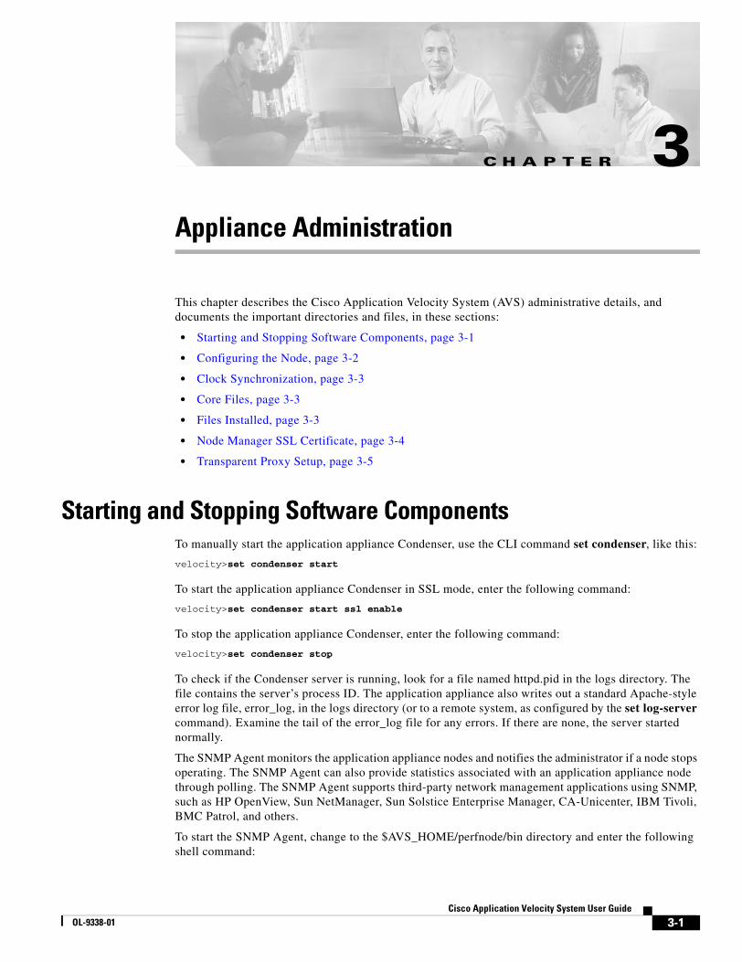
C H A P T E R
3-1Cisco Application Velocity System User Guide
OL-9338-01
3Appliance Administration
This chapter describes the Cisco Application Velocity System (AVS) administrative details, and documents the important directories and files, in these sections:
• Starting and Stopping Software Components, page 3-1
• Configuring the Node, page 3-2
• Clock Synchronization, page 3-3
• Core Files, page 3-3
• Files Installed, page 3-3
• Node Manager SSL Certificate, page 3-4
• Transparent Proxy Setup, page 3-5
Starting and Stopping Software ComponentsTo manually start the application appliance Condenser, use the CLI command set condenser, like this:
velocity>set condenser start
To start the application appliance Condenser in SSL mode, enter the following command:
velocity>set condenser start ssl enable
To stop the application appliance Condenser, enter the following command:
velocity>set condenser stop
To check if the Condenser server is running, look for a file named httpd.pid in the logs directory. The file contains the server’s process ID. The application appliance also writes out a standard Apache-style error log file, error_log, in the logs directory (or to a remote system, as configured by the set log-server command). Examine the tail of the error_log file for any errors. If there are none, the server started normally.
The SNMP Agent monitors the application appliance nodes and notifies the administrator if a node stops operating. The SNMP Agent can also provide statistics associated with an application appliance node through polling. The SNMP Agent supports third-party network management applications using SNMP, such as HP OpenView, Sun NetManager, Sun Solstice Enterprise Manager, CA-Unicenter, IBM Tivoli, BMC Patrol, and others.
To start the SNMP Agent, change to the $AVS_HOME/perfnode/bin directory and enter the following shell command:
3-2Cisco Application Velocity System User Guide
OL-9338-01
Chapter 3 Appliance AdministrationConfiguring the Node
./snmpctl start -d $AVS_HOME/perfnode
To stop the SNMP Agent, enter the following shell command:
./snmpctl stop -d $AVS_HOME/perfnode
You do not need to individually start and stop the Management Console, the Management Console database, and Node Manager components, because these components are started automatically when the application appliance is rebooted. However, you can enter the following commands to manually start/stop these components:
• Management Console and database (CLI command):
velocity>set console start|stop|restart
• Node Manager (shell commands):
cd $AVS_HOME/perfnode/node_manager/bin;./fgnnmctl start|stop
Note When stopping the Management Console, make sure that no users are logged in. Otherwise, the Management Console will not shut down correctly.
Configuring the NodeYou will probably want to make changes to the application appliance node configuration file, fgn.conf, for your particular application. Rather than editing this file manually, you can use the Web Configurator feature of the Management Console to manage and edit the node configuration.
The Management Console lets you manage and edit the application appliance configuration file at both the cluster and node level. For details on using the Management Console to manage clusters of application appliance nodes, see the “Cluster Configuration” section on page 8-9. To configure individual nodes, see the “Configuring Individual Nodes” section on page 8-23.
For details on the configuration keywords, see Chapter 5, “Configuration Reference.”
For details on configuring the web application security firewall, see Chapter 6, “Web Application Security Configuration.”
To make a typical configuration change, such as adding an Application Class to an application appliance node, follow these steps in the Management Console:
1. Click Register Cluster to create a new cluster (if there are no clusters yet).
2. Click Register Node to add the application appliance node to a cluster (if the application appliance node has not yet been added to a cluster).
3. Click Import to import the default configuration file from the newly installed application appliance node into the database.
4. Click Application Class to edit an existing Application Class, or create a new one by cloning an existing class or adding a new one. (To edit global parameters that are not within an Application Class, use the Global command.) Click Apply Changes to save your changes to the database.
5. Click Publish to write out the changed configuration file to the application appliance node.
6. Click Cluster Control to restart the node so that it reads the new configuration file.

3-3Cisco Application Velocity System User Guide
OL-9338-01
Chapter 3 Appliance AdministrationClock Synchronization
Clock SynchronizationMany features of the application appliance depend on having the clocks synchronized between the application appliance and the origin servers. Be sure to synchronize all clocks after the software is installed. We recommend that you use Network Time Protocol (NTP) to synchronize the clocks. You can use the CLI command set ntp to configure an NTP server.
Core FilesThe application appliance will store core files if the httpd process generates them. They are stored in the $AVS_HOME/perfnode/logs/coredump directory by default. You can change the location of this directory by using the CoreDumpDirectory keyword. This core directory is managed by the directory pruner process, which will begin deleting core files once the total amount of disk space reaches 2 GB.
When a core file is generated, the following message is logged in the $AVS_HOME/perfnode/logs/error_log file:
[Wed Sep 8 13:39:40 2004] [notice] child pid 3790 exit signal Segmentation fault (11), possible coredump in $AVS_HOME/perfnode/logs/core
Files InstalledThe product files are installed into the following directories:
• The Condenser and AppScope files are installed into several subdirectories in $AVS_HOME/perfnode.
The $AVS_HOME/perfnode/logs directory contains log information from the Condenser acceleration software, Management Console, and file management processing.
• The Management Console files are installed into several subdirectories in $AVS_HOME/console.
• The AVS system files are installed in $AVS_HOME/appliance.
• The web application security firewall files are installed in $AVS_HOME/nh.
The subdirectories under $AVS_HOME/perfnode include the following:
• bin—for executable files
• conf—for configuration files
• logs—for log files
The following tables describe the important files in each of these subdirectories.
Table 3-1 bin Files
Filename Description
fgncache Cache pruning executable
fgnctl Script that starts the server
httpd Server executable
snmpctl Script that starts the Master SNMP agent daemon and the SNMP agent daemon
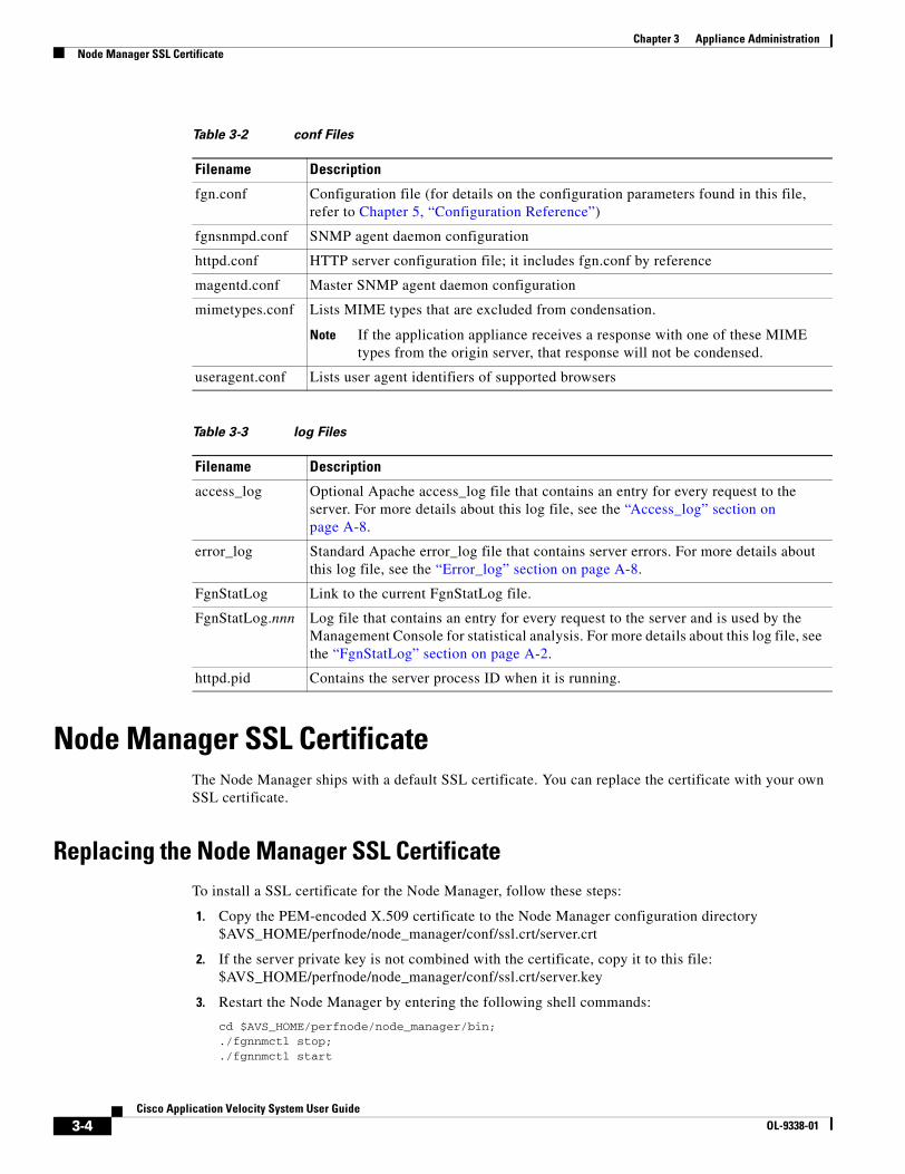
3-4Cisco Application Velocity System User Guide
OL-9338-01
Chapter 3 Appliance AdministrationNode Manager SSL Certificate
Node Manager SSL CertificateThe Node Manager ships with a default SSL certificate. You can replace the certificate with your own SSL certificate.
Replacing the Node Manager SSL Certificate To install a SSL certificate for the Node Manager, follow these steps:
1. Copy the PEM-encoded X.509 certificate to the Node Manager configuration directory$AVS_HOME/perfnode/node_manager/conf/ssl.crt/server.crt
2. If the server private key is not combined with the certificate, copy it to this file:$AVS_HOME/perfnode/node_manager/conf/ssl.crt/server.key
3. Restart the Node Manager by entering the following shell commands:
cd $AVS_HOME/perfnode/node_manager/bin;./fgnnmctl stop;./fgnnmctl start
Table 3-2 conf Files
Filename Description
fgn.conf Configuration file (for details on the configuration parameters found in this file, refer to Chapter 5, “Configuration Reference”)
fgnsnmpd.conf SNMP agent daemon configuration
httpd.conf HTTP server configuration file; it includes fgn.conf by reference
magentd.conf Master SNMP agent daemon configuration
mimetypes.conf Lists MIME types that are excluded from condensation.
Note If the application appliance receives a response with one of these MIME types from the origin server, that response will not be condensed.
useragent.conf Lists user agent identifiers of supported browsers
Table 3-3 log Files
Filename Description
access_log Optional Apache access_log file that contains an entry for every request to the server. For more details about this log file, see the “Access_log” section on page A-8.
error_log Standard Apache error_log file that contains server errors. For more details about this log file, see the “Error_log” section on page A-8.
FgnStatLog Link to the current FgnStatLog file.
FgnStatLog.nnn Log file that contains an entry for every request to the server and is used by the Management Console for statistical analysis. For more details about this log file, see the “FgnStatLog” section on page A-2.
httpd.pid Contains the server process ID when it is running.
3-5Cisco Application Velocity System User Guide
OL-9338-01
Chapter 3 Appliance AdministrationTransparent Proxy Setup
Importing the Node Manager SSL Certificate to the Management ConsoleIf you use SSL certificates issued by certification authorities such as VeriSign Inc., or RSA Data Security Inc., no change is needed on the Management Console. Otherwise, to import your certificates to the Management Console follow these steps:
1. Copy the PEM-encoded X.509 certificate (server.crt) to a temporary directory, such as /tmp, on the management station machine.
2. Change the directory to the Management Console configuration directory and make the file node_manager_cacert writable as follows:
cd $AVS_HOME/console/jboss-3.0.1_tomcat-4.0.4/server/default/deploy/condenser-mbeans.sar/META-INFchmod +w ./node_manager_cacert
3. Make sure that the java utility keytool is in the path.
4. Import the certificate as follows:
keytool -import -trustcacerts -alias mycertificate -file /tmp/server.crt -keystore ./node_manager_cacert
5. When prompted for the keystore password, enter fineground and press the Enter key.
6. Type yes when prompted with the question:
Trust this certificate? [no]:
7. Restart the Node Manager and Management Console (see the “Starting and Stopping Software Components” section on page 3-1).
Transparent Proxy SetupThis section describes how to set up a single application appliance as a transparent proxy. For multiple application appliance configuration, you must use a load balancer.
The ideal way to set up a single application appliance as a transparent proxy is to use a layer 4 web switch to redirect all port 80 traffic to the application appliance on the port that it is listening on. Configure the load balancer to fail over directly to the origin server in case the application appliance fails.
If a layer 4 switch is not available (or for testing), then the second best option is to change the DNS server configuration or client host file to point to the application appliance for the hostname of interest, and configure the application appliance to listen on port 80 in the httpd.conf file. A destination mapping entry may also be necessary.
If configuring the application appliance to listen on port 80 is not acceptable, you can use a tool such as iptables on Linux to set up the application appliance as a transparent proxy. When using a packet filtering tool such as iptables, performance may be degraded.
Under Linux, to set up the application appliance as a transparent proxy for the origin servers, you use the native Linux transparent proxy capability. A transparent proxy takes all incoming traffic for the HTTP port and redirects it through the application appliance.
3-6Cisco Application Velocity System User Guide
OL-9338-01
Chapter 3 Appliance AdministrationTransparent Proxy Setup
You use the Linux iptables tool to configure a set of packet redirection rules in the Linux system. This enables the system to send all non-SSL and SSL traffic through the application appliance to the origin server, and act as a transparent proxy for port 80 (World Wide Web) for non-SSL traffic and for port 443 for SSL traffic.
Use the Linux iptables tool to enable SSL pass-through for a single application appliance deployment. For a multiple application appliance deployment, enable SSL pass-through on the load balancer.
An example shell script that shows how to use iptables to configure transparent proxying is as follows:
#!/bin/sh# enable iptablesecho 1 > /proc/sys/net/ipv4/ip_forward # delete any existing rules/sbin/iptables -t nat -F# redirect any requests from Port 80 to Port 8080 (the application appliance http port)/sbin/iptables -t nat -A PREROUTING -p tcp --dport 80 -j REDIRECT --to-ports 8080# redirect any requests from Port 443 to Port 8443 (the application appliance https port)/sbin/iptables -t nat -A PREROUTING -p tcp --dport 443 -j REDIRECT --to-ports 8443# list the rules/sbin/iptables -t nat -L
C H A P T E R
4-1Cisco Application Velocity System User Guide
OL-9338-01
4Command-Line Interface
This chapter describes the command-line interface (CLI) that you can use to configure certain basic operating parameters of the Cisco AVS software. The CLI is available on both the application appliance and the management station, although certain commands apply only to one device.
This chapter consists of these sections:
• Logging into and Exiting the CLI
• Using CLI Commands
• Getting CLI Help
• CLI Reference
Logging into and Exiting the CLITo log in to the AVS device and access the CLI, you can use a terminal device connected to the console port on the AVS device, or you can use Secure Shell (SSH) over the network.
You can use the CLI from any terminal device that is compatible with ANSI, VT52, or VT100 characteristics. ANSI and VT100 devices let you use these cursor-control and cursor-movement keys: left-arrow, up-arrow, down-arrow, right-arrow, Delete, and Backspace. The CLI senses the use of cursor-control keys and automatically uses the optimal device characteristics.
Note The first time you log in to the CLI, use the default login name of fgn and the default password of fineground.
To exit from the CLI, use the quit command.
Using CLI CommandsThis section provides information on:
• Syntax Conventions
• Variable Argument Conventions
• CLI Command Keyboard Shortcuts
• Understanding CLI Syntax Checking and Error Messages
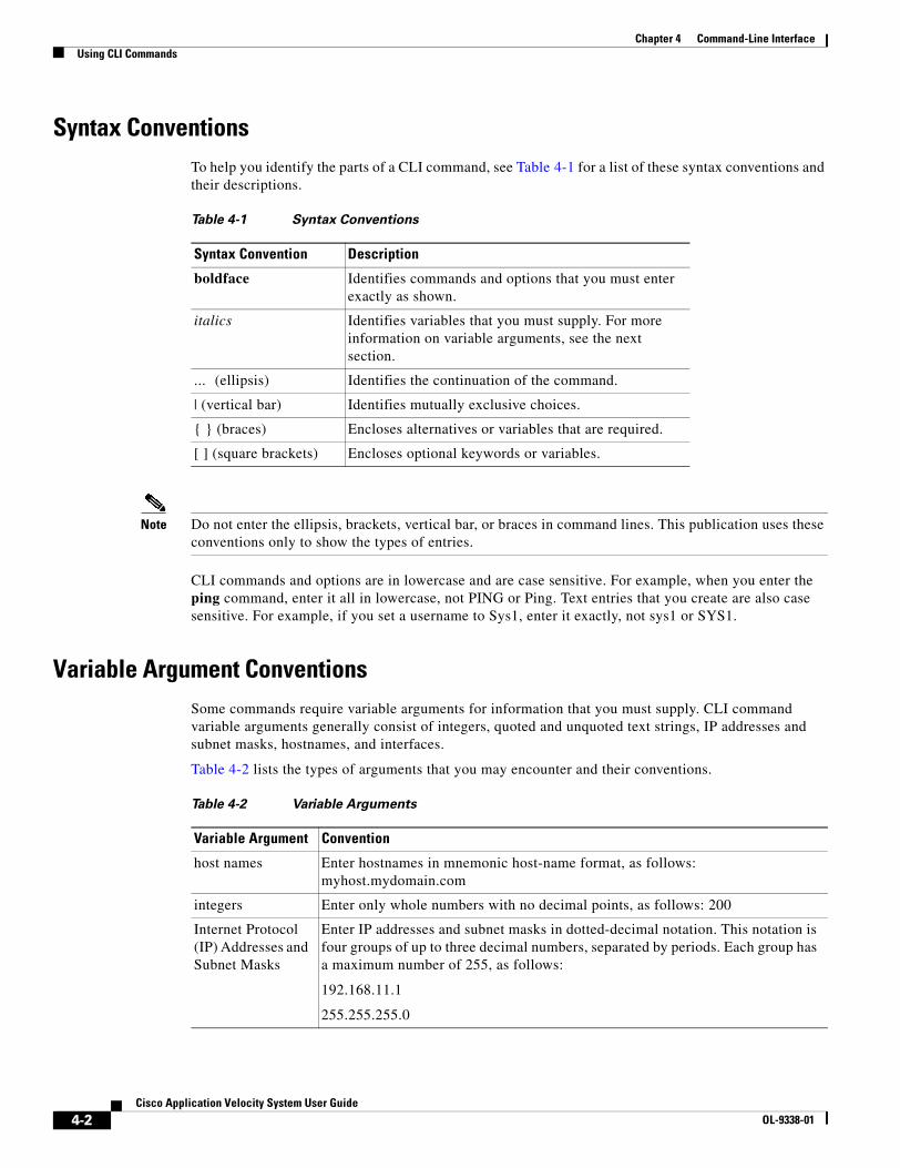
4-2Cisco Application Velocity System User Guide
OL-9338-01
Chapter 4 Command-Line InterfaceUsing CLI Commands
Syntax ConventionsTo help you identify the parts of a CLI command, see Table 4-1 for a list of these syntax conventions and their descriptions.
Note Do not enter the ellipsis, brackets, vertical bar, or braces in command lines. This publication uses these conventions only to show the types of entries.
CLI commands and options are in lowercase and are case sensitive. For example, when you enter the ping command, enter it all in lowercase, not PING or Ping. Text entries that you create are also case sensitive. For example, if you set a username to Sys1, enter it exactly, not sys1 or SYS1.
Variable Argument ConventionsSome commands require variable arguments for information that you must supply. CLI command variable arguments generally consist of integers, quoted and unquoted text strings, IP addresses and subnet masks, hostnames, and interfaces.
Table 4-2 lists the types of arguments that you may encounter and their conventions.
Table 4-1 Syntax Conventions
Syntax Convention Description
boldface Identifies commands and options that you must enter exactly as shown.
italics Identifies variables that you must supply. For more information on variable arguments, see the next section.
... (ellipsis) Identifies the continuation of the command.
| (vertical bar) Identifies mutually exclusive choices.
{ } (braces) Encloses alternatives or variables that are required.
[ ] (square brackets) Encloses optional keywords or variables.
Table 4-2 Variable Arguments
Variable Argument Convention
host names Enter hostnames in mnemonic host-name format, as follows: myhost.mydomain.com
integers Enter only whole numbers with no decimal points, as follows: 200
Internet Protocol (IP) Addresses and Subnet Masks
Enter IP addresses and subnet masks in dotted-decimal notation. This notation is four groups of up to three decimal numbers, separated by periods. Each group has a maximum number of 255, as follows:
192.168.11.1
255.255.255.0
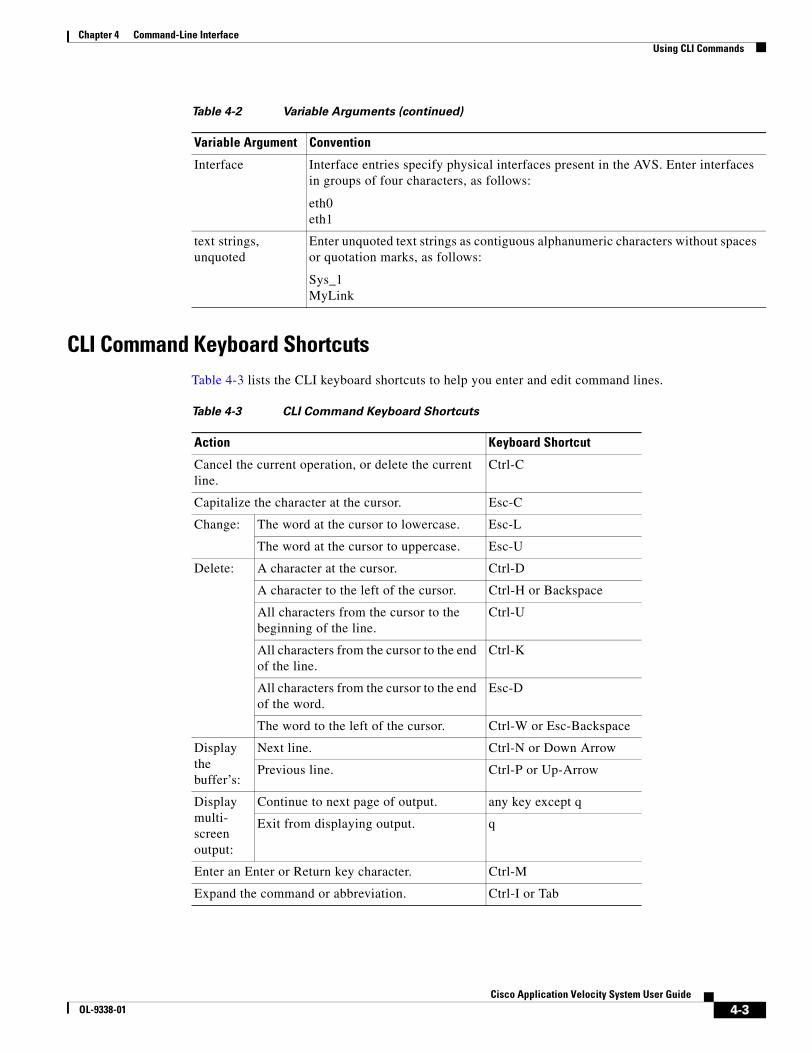
4-3Cisco Application Velocity System User Guide
OL-9338-01
Chapter 4 Command-Line InterfaceUsing CLI Commands
CLI Command Keyboard ShortcutsTable 4-3 lists the CLI keyboard shortcuts to help you enter and edit command lines.
Interface Interface entries specify physical interfaces present in the AVS. Enter interfaces in groups of four characters, as follows:
eth0eth1
text strings, unquoted
Enter unquoted text strings as contiguous alphanumeric characters without spaces or quotation marks, as follows:
Sys_1MyLink
Table 4-2 Variable Arguments (continued)
Variable Argument Convention
Table 4-3 CLI Command Keyboard Shortcuts
Action Keyboard Shortcut
Cancel the current operation, or delete the current line.
Ctrl-C
Capitalize the character at the cursor. Esc-C
Change: The word at the cursor to lowercase. Esc-L
The word at the cursor to uppercase. Esc-U
Delete: A character at the cursor. Ctrl-D
A character to the left of the cursor. Ctrl-H or Backspace
All characters from the cursor to the beginning of the line.
Ctrl-U
All characters from the cursor to the end of the line.
Ctrl-K
All characters from the cursor to the end of the word.
Esc-D
The word to the left of the cursor. Ctrl-W or Esc-Backspace
Display the buffer’s:
Next line. Ctrl-N or Down Arrow
Previous line. Ctrl-P or Up-Arrow
Display multi-screen output:
Continue to next page of output. any key except q
Exit from displaying output. q
Enter an Enter or Return key character. Ctrl-M
Expand the command or abbreviation. Ctrl-I or Tab
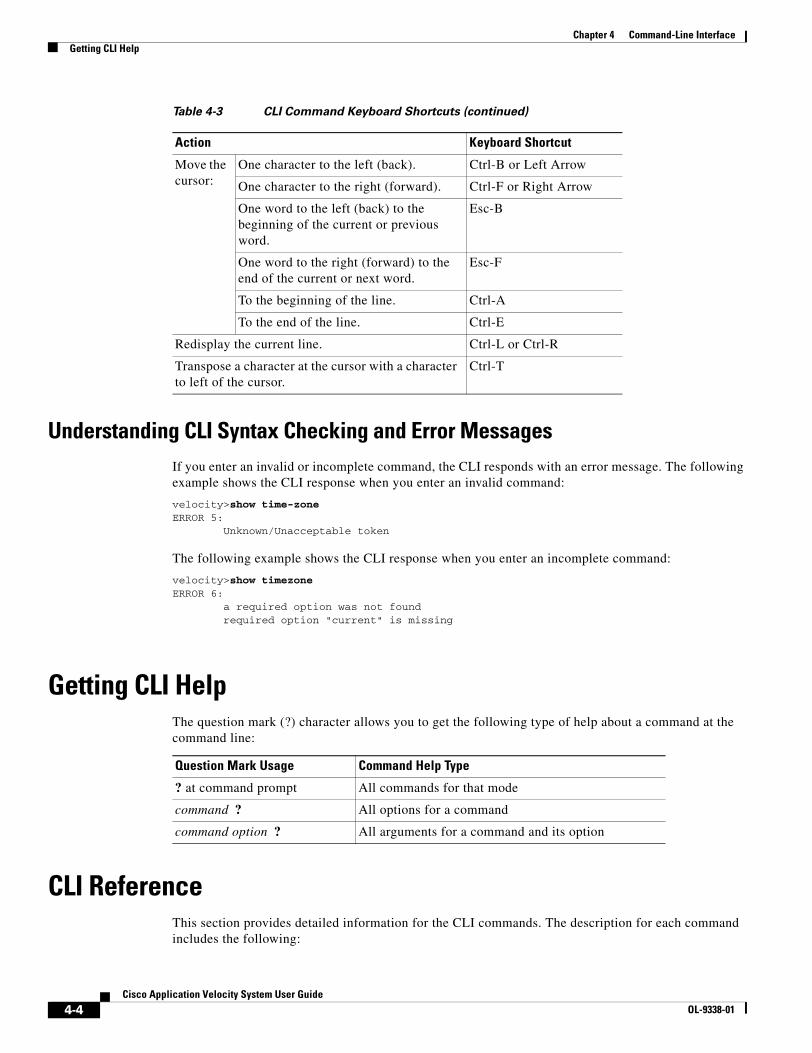
4-4Cisco Application Velocity System User Guide
OL-9338-01
Chapter 4 Command-Line InterfaceGetting CLI Help
Understanding CLI Syntax Checking and Error MessagesIf you enter an invalid or incomplete command, the CLI responds with an error message. The following example shows the CLI response when you enter an invalid command:
velocity>show time-zoneERROR 5: Unknown/Unacceptable token
The following example shows the CLI response when you enter an incomplete command:
velocity>show timezoneERROR 6: a required option was not found required option "current" is missing
Getting CLI HelpThe question mark (?) character allows you to get the following type of help about a command at the command line:
CLI ReferenceThis section provides detailed information for the CLI commands. The description for each command includes the following:
Move the cursor:
One character to the left (back). Ctrl-B or Left Arrow
One character to the right (forward). Ctrl-F or Right Arrow
One word to the left (back) to the beginning of the current or previous word.
Esc-B
One word to the right (forward) to the end of the current or next word.
Esc-F
To the beginning of the line. Ctrl-A
To the end of the line. Ctrl-E
Redisplay the current line. Ctrl-L or Ctrl-R
Transpose a character at the cursor with a character to left of the cursor.
Ctrl-T
Table 4-3 CLI Command Keyboard Shortcuts (continued)
Action Keyboard Shortcut
Question Mark Usage Command Help Type
? at command prompt All commands for that mode
command ? All options for a command
command option ? All arguments for a command and its option
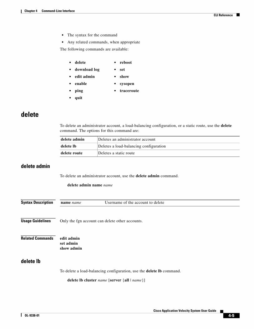
4-5Cisco Application Velocity System User Guide
OL-9338-01
Chapter 4 Command-Line InterfaceCLI Reference
• The syntax for the command
• Any related commands, when appropriate
The following commands are available:
deleteTo delete an administrator account, a load-balancing configuration, or a static route, use the delete command. The options for this command are:
delete admin
To delete an administrator account, use the delete admin command.
delete admin name name
Syntax Description
Usage Guidelines Only the fgn account can delete other accounts.
Related Commands edit adminset adminshow admin
delete lb
To delete a load-balancing configuration, use the delete lb command.
delete lb cluster name [server {all | name}]
• delete
• download log
• edit admin
• enable
• ping
• quit
• reboot
• set
• show
• sysopen
• traceroute
delete admin Deletes an administrator account
delete lb Deletes a load-balancing configuration
delete route Deletes a static route
name name Username of the account to delete
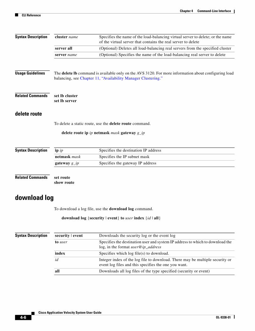
4-6Cisco Application Velocity System User Guide
OL-9338-01
Chapter 4 Command-Line InterfaceCLI Reference
Syntax Description
Usage Guidelines The delete lb command is available only on the AVS 3120. For more information about configuring load balancing, see Chapter 11, “Availability Manager Clustering.”
Related Commands set lb clusterset lb server
delete route
To delete a static route, use the delete route command.
delete route ip ip netmask mask gateway g_ip
Syntax Description
Related Commands set routeshow route
download logTo download a log file, use the download log command.
download log {security | event} to user index {id | all}
Syntax Description
cluster name Specifies the name of the load-balancing virtual server to delete; or the name of the virtual server that contains the real server to delete
server all (Optional) Deletes all load-balancing real servers from the specified cluster
server name (Optional) Specifies the name of the load-balancing real server to delete
ip ip Specifies the destination IP address
netmask mask Specifies the IP subnet mask
gateway g_ip Specifies the gateway IP address
security | event Downloads the security log or the event log
to user Specifies the destination user and system IP address to which to download the log, in the format user@ip_address
index Specifies which log file(s) to download.
id Integer index of the log file to download. There may be multiple security or event log files and this specifies the one you want.
all Downloads all log files of the type specified (security or event)

4-7Cisco Application Velocity System User Guide
OL-9338-01
Chapter 4 Command-Line InterfaceCLI Reference
Usage Guidelines The download log command requires a SSH server at the remote end (corresponding to the specified IP address). The log file is placed in the user’s home directory on the destination server. This behavior can be overridden by additional SSHD/SSH configuration in the destination server.
To list the indexes of the log files that are available, use the show log security | event index all command. Entering this command will list the log files in order, beginning with index 0, as follows:
velocity>show log security index allLog File Order Last Modification0-secure Wed Oct 26 15:45:38 20051-secure Tue Oct 25 11:11:16 2005
The index is the number at the left of each row.
Related Commands set log-servershow logshow log-server
edit adminTo change the username or password for an administrator account, use the edit admin command.
edit admin current-name name [new-name newname] [new-password password]
Syntax Description
Usage Guidelines Only the fgn account can change other accounts.
Related Commands delete adminset adminshow admin
enableTo enable the writing of system configuration parameters, use the enable command.
enable
Usage Guidelines The enable command must be used in a console session before any of the set commands can be used.
If the user that is logged in does not have write privileges, this command will fail because this user is not allowed to use the set commands. Write privileges are set by the set admin command that creates an account. Write privileges can be enabled for only one logged-in user at a time.
name Current username of the account to edit
new-name newname (Optional) Specifies a new username for the account
new-password password (Optional) Specifies a new password for the account
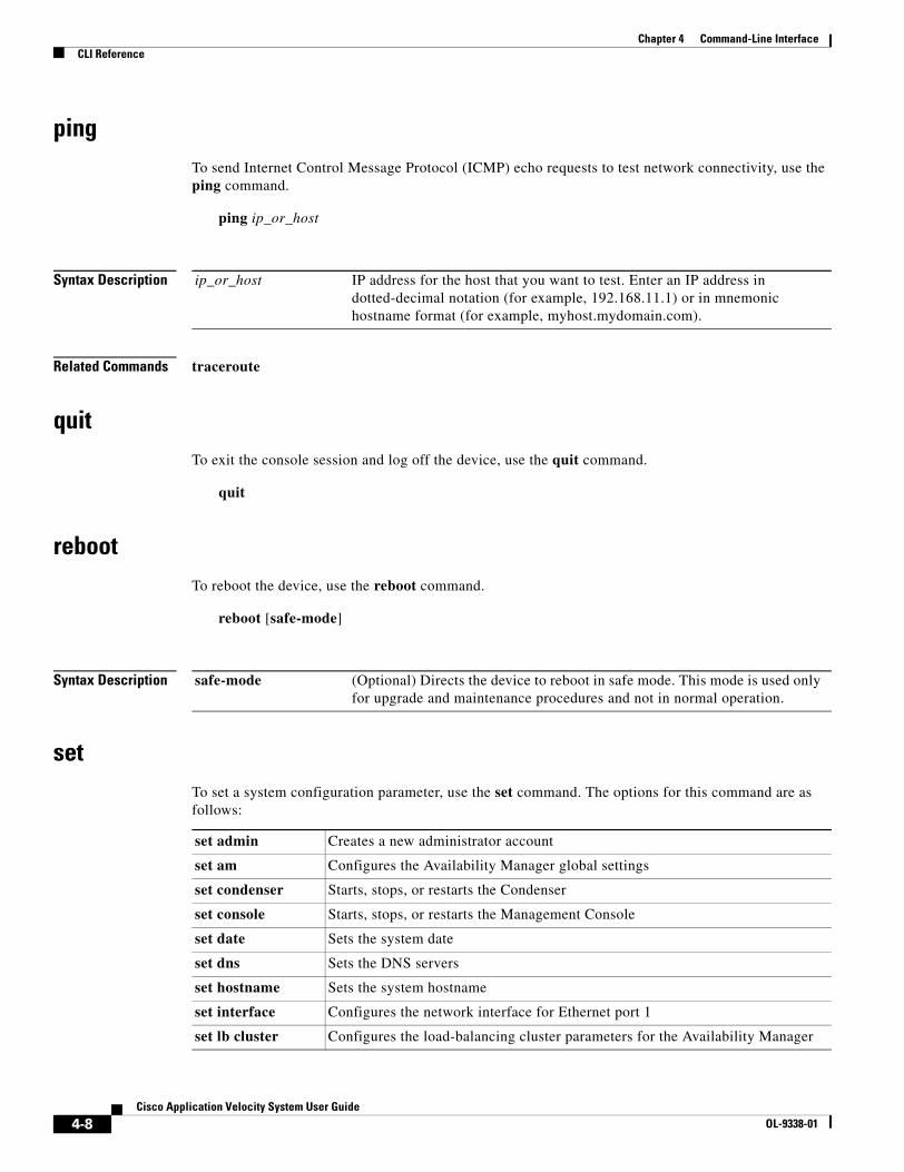
4-8Cisco Application Velocity System User Guide
OL-9338-01
Chapter 4 Command-Line InterfaceCLI Reference
pingTo send Internet Control Message Protocol (ICMP) echo requests to test network connectivity, use the ping command.
ping ip_or_host
Syntax Description
Related Commands traceroute
quitTo exit the console session and log off the device, use the quit command.
quit
rebootTo reboot the device, use the reboot command.
reboot [safe-mode]
Syntax Description
setTo set a system configuration parameter, use the set command. The options for this command are as follows:
ip_or_host IP address for the host that you want to test. Enter an IP address in dotted-decimal notation (for example, 192.168.11.1) or in mnemonic hostname format (for example, myhost.mydomain.com).
safe-mode (Optional) Directs the device to reboot in safe mode. This mode is used only for upgrade and maintenance procedures and not in normal operation.
set admin Creates a new administrator account
set am Configures the Availability Manager global settings
set condenser Starts, stops, or restarts the Condenser
set console Starts, stops, or restarts the Management Console
set date Sets the system date
set dns Sets the DNS servers
set hostname Sets the system hostname
set interface Configures the network interface for Ethernet port 1
set lb cluster Configures the load-balancing cluster parameters for the Availability Manager
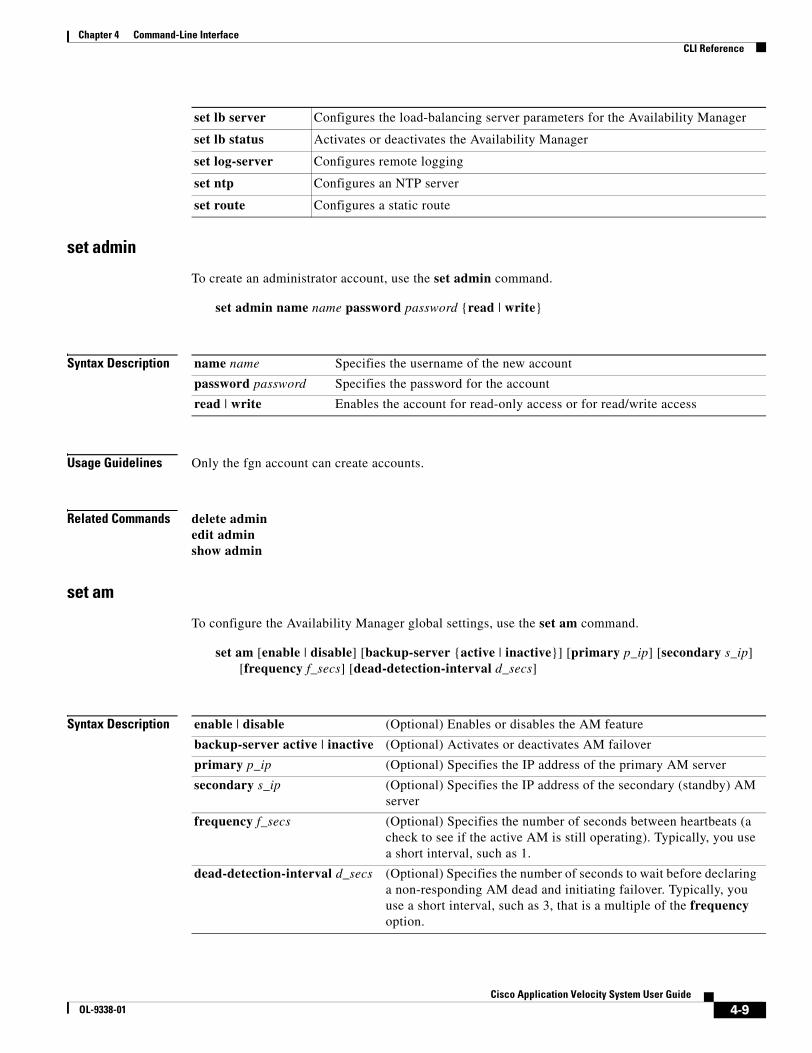
4-9Cisco Application Velocity System User Guide
OL-9338-01
Chapter 4 Command-Line InterfaceCLI Reference
set admin
To create an administrator account, use the set admin command.
set admin name name password password {read | write}
Syntax Description
Usage Guidelines Only the fgn account can create accounts.
Related Commands delete adminedit adminshow admin
set am
To configure the Availability Manager global settings, use the set am command.
set am [enable | disable] [backup-server {active | inactive}] [primary p_ip] [secondary s_ip] [frequency f_secs] [dead-detection-interval d_secs]
Syntax Description
set lb server Configures the load-balancing server parameters for the Availability Manager
set lb status Activates or deactivates the Availability Manager
set log-server Configures remote logging
set ntp Configures an NTP server
set route Configures a static route
name name Specifies the username of the new account
password password Specifies the password for the account
read | write Enables the account for read-only access or for read/write access
enable | disable (Optional) Enables or disables the AM feature
backup-server active | inactive (Optional) Activates or deactivates AM failover
primary p_ip (Optional) Specifies the IP address of the primary AM server
secondary s_ip (Optional) Specifies the IP address of the secondary (standby) AM server
frequency f_secs (Optional) Specifies the number of seconds between heartbeats (a check to see if the active AM is still operating). Typically, you use a short interval, such as 1.
dead-detection-interval d_secs (Optional) Specifies the number of seconds to wait before declaring a non-responding AM dead and initiating failover. Typically, you use a short interval, such as 3, that is a multiple of the frequency option.

4-10Cisco Application Velocity System User Guide
OL-9338-01
Chapter 4 Command-Line InterfaceCLI Reference
Usage Guidelines The set am command is available only on the AVS 3120. For more information about configuring the Availability Manager, see Chapter 11, “Availability Manager Clustering.”
Related Commands delete lbset lb clusterset lb serverset lb statusshow am
set condenser
To start, stop, or restart the Condenser, use the set condenser command.
set condenser {start | stop | restart} [ssl {enable | disable}]
Syntax Description
Usage Guidelines The set condenser command is available only on the AVS 3120.
Related Commands set consoleshow condenser
set console
To start, stop or restart the Management Console, use the set console command.
set console {start | stop | restart}
Syntax Description
Usage Guidelines On the AVS 3180, the set console command also controls the starting and stopping of the Postgres database in addition to the Management Console.
Related Commands set condensershow console
start | stop | restart Starts, stops, or restarts the Condenser
ssl enable | disable (Optional) Enables or disables SSL mode when starting the Condenser
start | stop | restart Starts, stops, or restarts the Management Console

4-11Cisco Application Velocity System User Guide
OL-9338-01
Chapter 4 Command-Line InterfaceCLI Reference
set date
To set the system date, use the set date command.
set date [time MM:DD:hh:mm:YYYY] [tz timezone]
Syntax Description
Related Commands set ntpshow dateshow ntpshow timezone
set dns
To set the DNS servers, use the set dns command.
set dns [primary ip_or_value] [secondary ip_or_value]
Syntax Description
Related Commands show dns
set hostname
To set the hostname of the AVS device, use the set hostname command.
set hostname name
Syntax Description
Related Commands show hostname
time MM:DD:hh:mm:YYYY
(Optional) Specifies the time to set in the format MM:DD:hh:mm:YYYY (that is, month:day:hour:minute:year)
tz timezone (Optional) Specifies the current city/time zone name, such as America/New_York. To see a list of available city/time zone names, use the show timezone all command.
primary ip_or_value (Optional) Specifies the IP address or hostname value of the primary DNS server.
secondary ip_or_value (Optional) Specifies the IP address or hostname value of the secondary DNS server.
name Hostname.
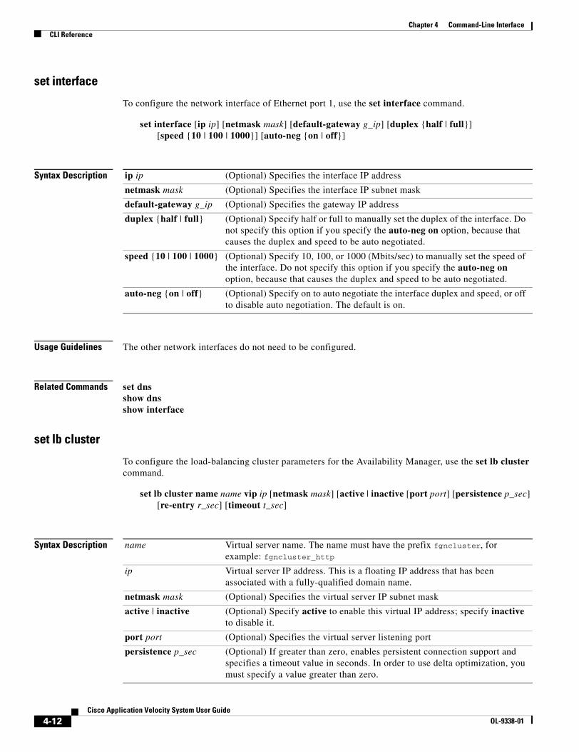
4-12Cisco Application Velocity System User Guide
OL-9338-01
Chapter 4 Command-Line InterfaceCLI Reference
set interface
To configure the network interface of Ethernet port 1, use the set interface command.
set interface [ip ip] [netmask mask] [default-gateway g_ip] [duplex {half | full}] [speed {10 | 100 | 1000}] [auto-neg {on | off}]
Syntax Description
Usage Guidelines The other network interfaces do not need to be configured.
Related Commands set dnsshow dnsshow interface
set lb cluster
To configure the load-balancing cluster parameters for the Availability Manager, use the set lb cluster command.
set lb cluster name name vip ip [netmask mask] [active | inactive [port port] [persistence p_sec] [re-entry r_sec] [timeout t_sec]
Syntax Description
ip ip (Optional) Specifies the interface IP address
netmask mask (Optional) Specifies the interface IP subnet mask
default-gateway g_ip (Optional) Specifies the gateway IP address
duplex {half | full} (Optional) Specify half or full to manually set the duplex of the interface. Do not specify this option if you specify the auto-neg on option, because that causes the duplex and speed to be auto negotiated.
speed {10 | 100 | 1000} (Optional) Specify 10, 100, or 1000 (Mbits/sec) to manually set the speed of the interface. Do not specify this option if you specify the auto-neg on option, because that causes the duplex and speed to be auto negotiated.
auto-neg {on | off} (Optional) Specify on to auto negotiate the interface duplex and speed, or off to disable auto negotiation. The default is on.
name Virtual server name. The name must have the prefix fgncluster, for example: fgncluster_http
ip Virtual server IP address. This is a floating IP address that has been associated with a fully-qualified domain name.
netmask mask (Optional) Specifies the virtual server IP subnet mask
active | inactive (Optional) Specify active to enable this virtual IP address; specify inactive to disable it.
port port (Optional) Specifies the virtual server listening port
persistence p_sec (Optional) If greater than zero, enables persistent connection support and specifies a timeout value in seconds. In order to use delta optimization, you must specify a value greater than zero.
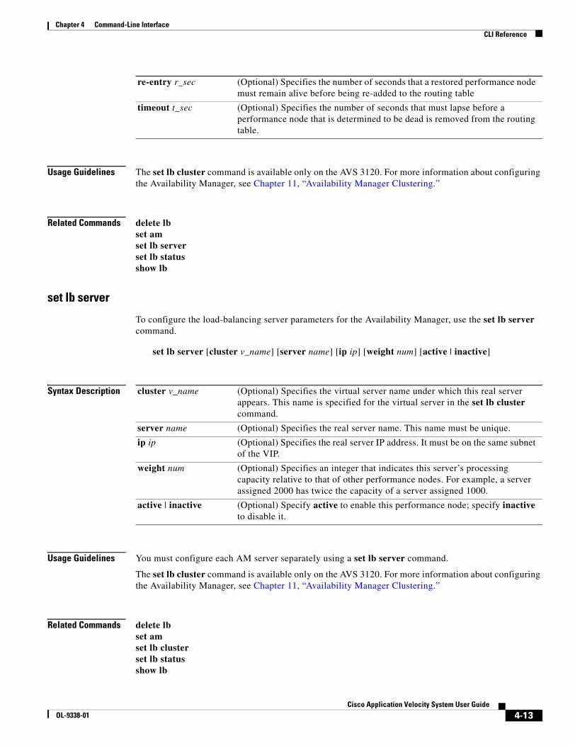
4-13Cisco Application Velocity System User Guide
OL-9338-01
Chapter 4 Command-Line InterfaceCLI Reference
Usage Guidelines The set lb cluster command is available only on the AVS 3120. For more information about configuring the Availability Manager, see Chapter 11, “Availability Manager Clustering.”
Related Commands delete lbset amset lb serverset lb statusshow lb
set lb server
To configure the load-balancing server parameters for the Availability Manager, use the set lb server command.
set lb server [cluster v_name] [server name] [ip ip] [weight num] [active | inactive]
Syntax Description
Usage Guidelines You must configure each AM server separately using a set lb server command.
The set lb cluster command is available only on the AVS 3120. For more information about configuring the Availability Manager, see Chapter 11, “Availability Manager Clustering.”
Related Commands delete lbset amset lb clusterset lb statusshow lb
re-entry r_sec (Optional) Specifies the number of seconds that a restored performance node must remain alive before being re-added to the routing table
timeout t_sec (Optional) Specifies the number of seconds that must lapse before a performance node that is determined to be dead is removed from the routing table.
cluster v_name (Optional) Specifies the virtual server name under which this real server appears. This name is specified for the virtual server in the set lb cluster command.
server name (Optional) Specifies the real server name. This name must be unique.
ip ip (Optional) Specifies the real server IP address. It must be on the same subnet of the VIP.
weight num (Optional) Specifies an integer that indicates this server’s processing capacity relative to that of other performance nodes. For example, a server assigned 2000 has twice the capacity of a server assigned 1000.
active | inactive (Optional) Specify active to enable this performance node; specify inactive to disable it.

4-14Cisco Application Velocity System User Guide
OL-9338-01
Chapter 4 Command-Line InterfaceCLI Reference
set lb status
To activate or deactivate the Availability Manager, use the set lb status command.
set lb status {am-active | am-inactive | server-only}
Syntax Description
Usage Guidelines The set lb status command is available only on the AVS 3120. For more information about configuring the Availability Manager, see Chapter 11, “Availability Manager Clustering.”
Related Commands delete lbset amset lb clusterset lb servershow lb
set log-server
To configure remote logging, use the set log-server command.
set log-server {local | remote ip}
Syntax Description
Usage Guidelines On the AVS 3180, when you specify remote, two log files are not sent to the remote host: the jboss server log and the localhost-access log. For more information about logging, see Appendix A, “Logs.”
Note This command does not apply to web application security firewall logging, which is managed by the web application security firewall module itself. For details see the “Log Server Config” section on page 6-16.
Related Commands download logshow logshow log-server
am-active Activates the AM on this server
am-inactive Deactivates the AM on this server
server-only Configures this server to operate as an additional performance node only, not as the primary or standby AM server
local Configures logs to be stored on the local system
remote ip Configures logs to be stored on a remote system that is identified by its IP address
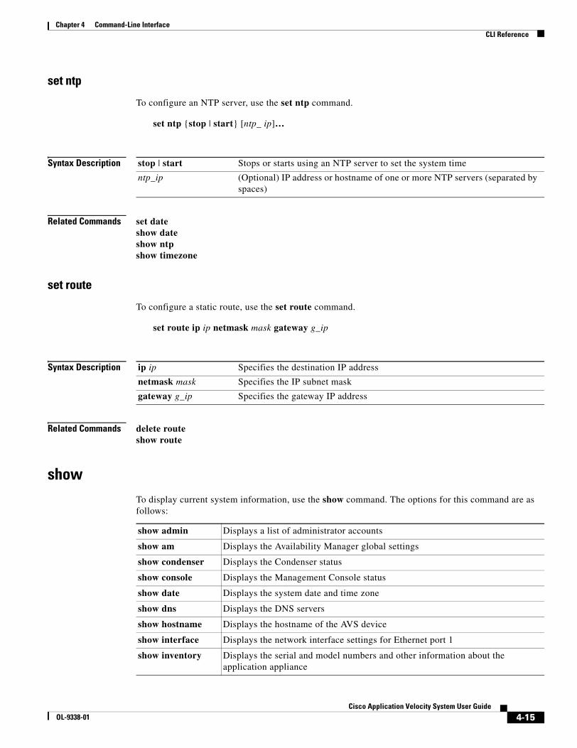
4-15Cisco Application Velocity System User Guide
OL-9338-01
Chapter 4 Command-Line InterfaceCLI Reference
set ntp
To configure an NTP server, use the set ntp command.
set ntp {stop | start} [ntp_ ip]…
Syntax Description
Related Commands set dateshow dateshow ntpshow timezone
set route
To configure a static route, use the set route command.
set route ip ip netmask mask gateway g_ip
Syntax Description
Related Commands delete routeshow route
showTo display current system information, use the show command. The options for this command are as follows:
stop | start Stops or starts using an NTP server to set the system time
ntp_ip (Optional) IP address or hostname of one or more NTP servers (separated by spaces)
ip ip Specifies the destination IP address
netmask mask Specifies the IP subnet mask
gateway g_ip Specifies the gateway IP address
show admin Displays a list of administrator accounts
show am Displays the Availability Manager global settings
show condenser Displays the Condenser status
show console Displays the Management Console status
show date Displays the system date and time zone
show dns Displays the DNS servers
show hostname Displays the hostname of the AVS device
show interface Displays the network interface settings for Ethernet port 1
show inventory Displays the serial and model numbers and other information about the application appliance
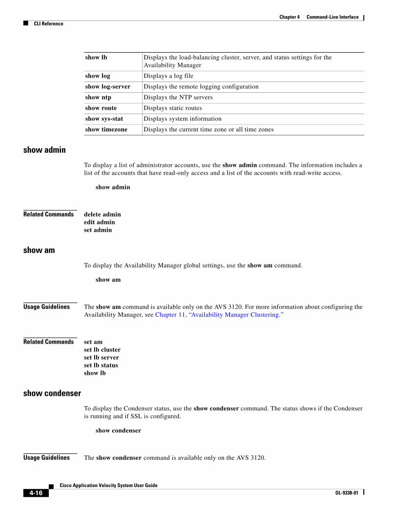
4-16Cisco Application Velocity System User Guide
OL-9338-01
Chapter 4 Command-Line InterfaceCLI Reference
show admin
To display a list of administrator accounts, use the show admin command. The information includes a list of the accounts that have read-only access and a list of the accounts with read-write access.
show admin
Related Commands delete adminedit adminset admin
show am
To display the Availability Manager global settings, use the show am command.
show am
Usage Guidelines The show am command is available only on the AVS 3120. For more information about configuring the Availability Manager, see Chapter 11, “Availability Manager Clustering.”
Related Commands set amset lb clusterset lb serverset lb statusshow lb
show condenser
To display the Condenser status, use the show condenser command. The status shows if the Condenser is running and if SSL is configured.
show condenser
Usage Guidelines The show condenser command is available only on the AVS 3120.
show lb Displays the load-balancing cluster, server, and status settings for the Availability Manager
show log Displays a log file
show log-server Displays the remote logging configuration
show ntp Displays the NTP servers
show route Displays static routes
show sys-stat Displays system information
show timezone Displays the current time zone or all time zones
4-17Cisco Application Velocity System User Guide
OL-9338-01
Chapter 4 Command-Line InterfaceCLI Reference
Related Commands set condensershow console
show console
To display the Management Console status, use the show console command. The status shows if Java, the database, and the node manager are running.
show console
Related Commands set consoleshow condenser
show date
To display the system date and time zone, use the show date command.
show date
Related Commands set dateset ntpshow ntpshow timezone
show dns
To display the DNS servers, use the show dns command.
show dns
Related Commands set dnsset interface
show hostname
To display the hostname of the AVS device, use the show hostname command.
show hostname
Related Commands set hostname

4-18Cisco Application Velocity System User Guide
OL-9338-01
Chapter 4 Command-Line InterfaceCLI Reference
show interface
To display the network interface settings of Ethernet port 1, use the show interface command.
show interface
Related Commands set dnsset interface
show inventory
To display information about the application appliance such as its name, serial number, description, model name, and hardware revision, use the show inventory command.
show inventory
Usage Guidelines The information that is displayed by this command is also available through SNMP. For details, see Table B-2 on page B-2.
show lb
To display the load-balancing cluster, server, and status settings for the Availability Manager, use the show lb command.
show lb {[cluster name | all] | status}
Syntax Description
Usage Guidelines The show lb command is available only on the AVS 3120. For more information about configuring the Availability Manager, see Chapter 11, “Availability Manager Clustering.”
Related Commands delete lbset lb clusterset lb serverset lb statusshow am
show log
To display a log file, use the show log command.
show log {security | event | condenser | console | nmgr | postgres} index {id | all}} [tail]
cluster name (Optional) Specifies the name of the virtual server
all (Optional) Displays the settings for all virtual servers
status (Optional) Displays the Availability Manager status
4-19Cisco Application Velocity System User Guide
OL-9338-01
Chapter 4 Command-Line InterfaceCLI Reference
Syntax Description
Usage Guidelines To list the indexes of the log files that are available, use the index all option. This option will list the log files in order, beginning with index 0, as follows:
velocity>show log security index allLog File Order Last Modification0-secure Wed Oct 26 15:45:38 20051-secure Tue Oct 25 11:11:16 2005
The index is the number at the left of each row.
Related Commands download logset log-server
show log-server
To display the remote logging configuration, use the show log-server command.
show log-server
Related Commands set log-server
show ntp
To display the NTP servers, use the show ntp command.
show ntp
Related Commands set dateset ntpshow dateshow timezone
security | event | condenser | console | nmgr | postgres
Name of the log to display. On the AVS 3180, the condenser and ngmr logs are not available.
index Specifies which log file to display.
id Integer index of the log file to display. There may be multiple log files of one type and this specifies which one you want.
all Displays a list of log files of the specified type
tail (Optional) Displays the last several lines of the selected log file. You cannot use this option with the index all option.
4-20Cisco Application Velocity System User Guide
OL-9338-01
Chapter 4 Command-Line InterfaceCLI Reference
show route
To display static routes, use the show route command.
show route
Related Commands delete routeset route
show sys-stat
To display system information, use the show sys-stat command.
show sys-stat {cpu | memory | io} [help]
Syntax Description
show timezone
To display the current time zone or all time zones, use the show timezone command.
show timezone {all | current}
Syntax Description
Related Commands set dateshow dateshow ntp
sysopenTo access the system shell, use the sysopen command.
sysopen
cpu | memory | io Specifies the type of system information to display
help (Optional) Displays help information about the returned statistics
all Lists all time zones
current Displays the current time zone
4-21Cisco Application Velocity System User Guide
OL-9338-01
Chapter 4 Command-Line InterfaceCLI Reference
tracerouteTo trace the connectivity and the path to an IP address, use the traceroute command.
traceroute ip_or_host
Syntax Description
Related Commands ping
ip_or_host IP address that you want to trace. Enter an IP address in dotted-decimal notation (for example, 192.168.11.1) or in mnemonic hostname format (for example, myhost.mydomain.com).

4-22Cisco Application Velocity System User Guide
OL-9338-01
Chapter 4 Command-Line InterfaceCLI Reference
C H A P T E R
5-1Cisco Application Velocity System User Guide
OL-9338-01
5Configuration Reference
This chapter describes the configuration options that are available through entries in the various configuration files that affect the operation of the application appliance. This chapter contains these sections that describe the configuration files:
• fgn.conf, page 5-1
• httpd.conf, page 5-37
• mimetypes.conf, page 5-38
• useragent.conf, page 5-39
• fgnsnmpd.conf, page 5-39
• magentd.conf, page 5-39
fgn.confThe fgn.conf file is the main application appliance configuration file. It contains all of the application appliance-specific configuration elements and includes the mimetypes.conf and useragent.conf files by reference.
The following topics are included in this section:
• Application Class Specification, page 5-7
• Destination Mapping Configuration, page 5-30
• SSL Configuration, page 5-33
• Dynamic Caching Configuration Guidelines, page 5-34
The Management Console lets you manage and edit the application appliance configuration file at both the cluster and node level within its graphical interface. You do not need to manually edit the fgn.conf file. For details on using the Management Console to manage the configuration of the application appliance node, see Chapter 8, “Management Console.”
Note If the fgn.conf configuration file is edited on a Microsoft Windows system, it will contain Carriage Return (\r) characters in addition to the normal UNIX LineFeed (\n) characters. When the fgnctl startup script is invoked, it detects this problem and warns you to correct this situation. If you receive this warning, you should edit the file to remove the Carriage Return characters. You can use the Linux dos2unix command to convert the file.
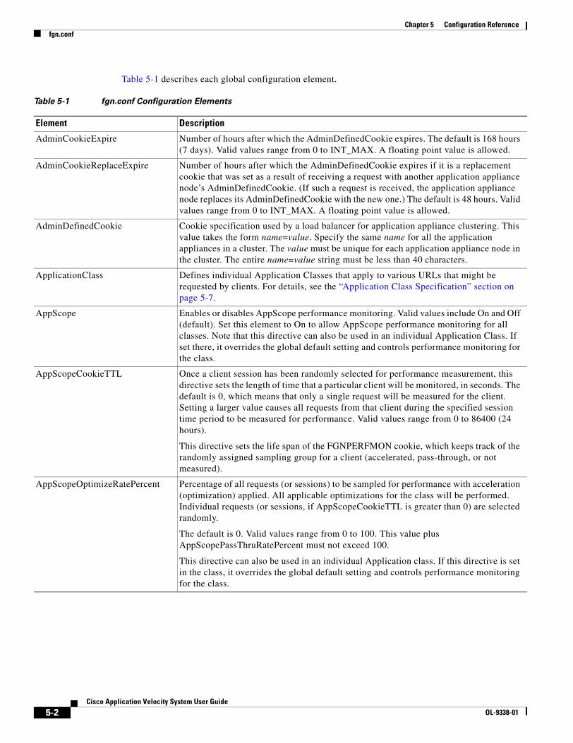
5-2Cisco Application Velocity System User Guide
OL-9338-01
Chapter 5 Configuration Referencefgn.conf
Table 5-1 describes each global configuration element.
Table 5-1 fgn.conf Configuration Elements
Element Description
AdminCookieExpire Number of hours after which the AdminDefinedCookie expires. The default is 168 hours (7 days). Valid values range from 0 to INT_MAX. A floating point value is allowed.
AdminCookieReplaceExpire Number of hours after which the AdminDefinedCookie expires if it is a replacement cookie that was set as a result of receiving a request with another application appliance node’s AdminDefinedCookie. (If such a request is received, the application appliance node replaces its AdminDefinedCookie with the new one.) The default is 48 hours. Valid values range from 0 to INT_MAX. A floating point value is allowed.
AdminDefinedCookie Cookie specification used by a load balancer for application appliance clustering. This value takes the form name=value. Specify the same name for all the application appliances in a cluster. The value must be unique for each application appliance node in the cluster. The entire name=value string must be less than 40 characters.
ApplicationClass Defines individual Application Classes that apply to various URLs that might be requested by clients. For details, see the “Application Class Specification” section on page 5-7.
AppScope Enables or disables AppScope performance monitoring. Valid values include On and Off (default). Set this element to On to allow AppScope performance monitoring for all classes. Note that this directive can also be used in an individual Application Class. If set there, it overrides the global default setting and controls performance monitoring for the class.
AppScopeCookieTTL Once a client session has been randomly selected for performance measurement, this directive sets the length of time that a particular client will be monitored, in seconds. The default is 0, which means that only a single request will be measured for the client. Setting a larger value causes all requests from that client during the specified session time period to be measured for performance. Valid values range from 0 to 86400 (24 hours).
This directive sets the life span of the FGNPERFMON cookie, which keeps track of the randomly assigned sampling group for a client (accelerated, pass-through, or not measured).
AppScopeOptimizeRatePercent Percentage of all requests (or sessions) to be sampled for performance with acceleration (optimization) applied. All applicable optimizations for the class will be performed. Individual requests (or sessions, if AppScopeCookieTTL is greater than 0) are selected randomly.
The default is 0. Valid values range from 0 to 100. This value plus AppScopePassThruRatePercent must not exceed 100.
This directive can also be used in an individual Application class. If this directive is set in the class, it overrides the global default setting and controls performance monitoring for the class.
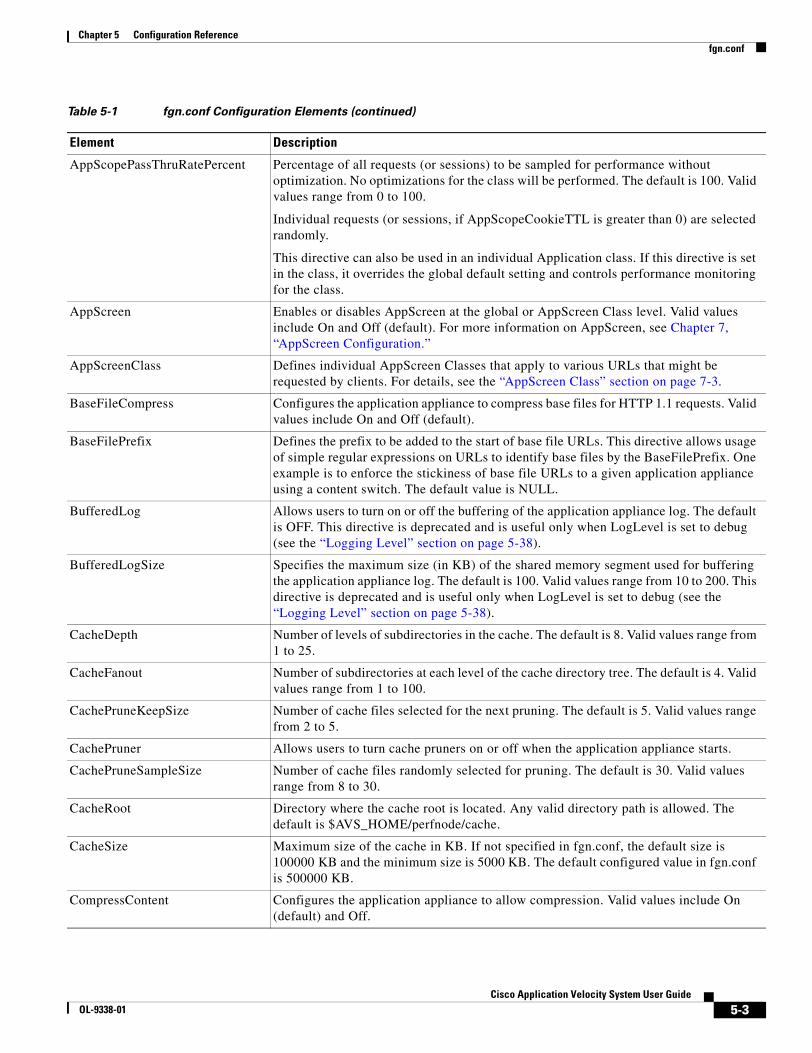
5-3Cisco Application Velocity System User Guide
OL-9338-01
Chapter 5 Configuration Referencefgn.conf
AppScopePassThruRatePercent Percentage of all requests (or sessions) to be sampled for performance without optimization. No optimizations for the class will be performed. The default is 100. Valid values range from 0 to 100.
Individual requests (or sessions, if AppScopeCookieTTL is greater than 0) are selected randomly.
This directive can also be used in an individual Application class. If this directive is set in the class, it overrides the global default setting and controls performance monitoring for the class.
AppScreen Enables or disables AppScreen at the global or AppScreen Class level. Valid values include On and Off (default). For more information on AppScreen, see Chapter 7, “AppScreen Configuration.”
AppScreenClass Defines individual AppScreen Classes that apply to various URLs that might be requested by clients. For details, see the “AppScreen Class” section on page 7-3.
BaseFileCompress Configures the application appliance to compress base files for HTTP 1.1 requests. Valid values include On and Off (default).
BaseFilePrefix Defines the prefix to be added to the start of base file URLs. This directive allows usage of simple regular expressions on URLs to identify base files by the BaseFilePrefix. One example is to enforce the stickiness of base file URLs to a given application appliance using a content switch. The default value is NULL.
BufferedLog Allows users to turn on or off the buffering of the application appliance log. The default is OFF. This directive is deprecated and is useful only when LogLevel is set to debug (see the “Logging Level” section on page 5-38).
BufferedLogSize Specifies the maximum size (in KB) of the shared memory segment used for buffering the application appliance log. The default is 100. Valid values range from 10 to 200. This directive is deprecated and is useful only when LogLevel is set to debug (see the “Logging Level” section on page 5-38).
CacheDepth Number of levels of subdirectories in the cache. The default is 8. Valid values range from 1 to 25.
CacheFanout Number of subdirectories at each level of the cache directory tree. The default is 4. Valid values range from 1 to 100.
CachePruneKeepSize Number of cache files selected for the next pruning. The default is 5. Valid values range from 2 to 5.
CachePruner Allows users to turn cache pruners on or off when the application appliance starts.
CachePruneSampleSize Number of cache files randomly selected for pruning. The default is 30. Valid values range from 8 to 30.
CacheRoot Directory where the cache root is located. Any valid directory path is allowed. The default is $AVS_HOME/perfnode/cache.
CacheSize Maximum size of the cache in KB. If not specified in fgn.conf, the default size is 100000 KB and the minimum size is 5000 KB. The default configured value in fgn.conf is 500000 KB.
CompressContent Configures the application appliance to allow compression. Valid values include On (default) and Off.
Table 5-1 fgn.conf Configuration Elements (continued)
Element Description
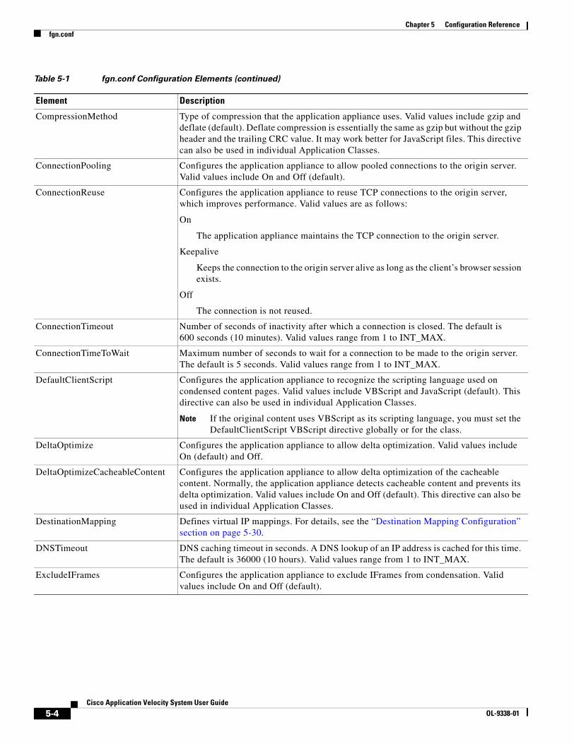
5-4Cisco Application Velocity System User Guide
OL-9338-01
Chapter 5 Configuration Referencefgn.conf
CompressionMethod Type of compression that the application appliance uses. Valid values include gzip and deflate (default). Deflate compression is essentially the same as gzip but without the gzip header and the trailing CRC value. It may work better for JavaScript files. This directive can also be used in individual Application Classes.
ConnectionPooling Configures the application appliance to allow pooled connections to the origin server. Valid values include On and Off (default).
ConnectionReuse Configures the application appliance to reuse TCP connections to the origin server, which improves performance. Valid values are as follows:
On
The application appliance maintains the TCP connection to the origin server.
Keepalive
Keeps the connection to the origin server alive as long as the client’s browser session exists.
Off
The connection is not reused.
ConnectionTimeout Number of seconds of inactivity after which a connection is closed. The default is 600 seconds (10 minutes). Valid values range from 1 to INT_MAX.
ConnectionTimeToWait Maximum number of seconds to wait for a connection to be made to the origin server. The default is 5 seconds. Valid values range from 1 to INT_MAX.
DefaultClientScript Configures the application appliance to recognize the scripting language used on condensed content pages. Valid values include VBScript and JavaScript (default). This directive can also be used in individual Application Classes.
Note If the original content uses VBScript as its scripting language, you must set the DefaultClientScript VBScript directive globally or for the class.
DeltaOptimize Configures the application appliance to allow delta optimization. Valid values include On (default) and Off.
DeltaOptimizeCacheableContent Configures the application appliance to allow delta optimization of the cacheable content. Normally, the application appliance detects cacheable content and prevents its delta optimization. Valid values include On and Off (default). This directive can also be used in individual Application Classes.
DestinationMapping Defines virtual IP mappings. For details, see the “Destination Mapping Configuration” section on page 5-30.
DNSTimeout DNS caching timeout in seconds. A DNS lookup of an IP address is cached for this time. The default is 36000 (10 hours). Valid values range from 1 to INT_MAX.
ExcludeIFrames Configures the application appliance to exclude IFrames from condensation. Valid values include On and Off (default).
Table 5-1 fgn.conf Configuration Elements (continued)
Element Description

5-5Cisco Application Velocity System User Guide
OL-9338-01
Chapter 5 Configuration Referencefgn.conf
FgnStatLogArchivingPolicy Controls what happens to FgnStatLog files that are full and closed. This keyword can have these possible values:
keep num
Keeps the num most recent log files and deletes all older files. The default value is 10; valid values range 1 to 10.
num
Same as keep num.
leave
delete
move
Each of these previously supported values now have no meaning. If they are specified, it is the same as specifying “keep 10” for the value of this directive. Additionally, an entry is made in the error log.
FgnStatLogFileSizeLimit Integer that specifies the maximum size of each FgnStatLog file in MB. The default is 25; valid values range from 1 to 60. All log entries are placed in 1000 rotating files with names FgnStatLog.000 through FgnStatLog.999. This directive sets the maximum size of each file before the next file is created.
FgnWorkDir Directory where the temporary files created by the shared memory data manager are located. Any valid directory path is allowed, except not on an NFS drive. The default is $AVS_HOME/perfnode/workdir.
FileCacheSize Configures the size of the in-memory cache that the application appliance uses for base files and other cacheable objects. The default value is 64 MB. Valid values range from 8 to 1000 (1 GB).
FlashConnectLimit Configures the application appliance to limit the number of artificial hosts used by FlashConnect. Specify an integer limit; the default is 4. For details on FlashConnect, see the “FlashConnect” section on page 2-12.
FlashConnectPrefix Specifies a prefix to be inserted in embedded object URLs before the hostname, when transformed by FlashConnect. Specify a string; the default is flashconnect. For details, see the “FlashConnect” section on page 2-12.
HTTP10Compress Configures the application appliance to compress files for HTTP 1.0 requests. Valid values include On and Off (default).
IgnoreOriginServerBody Specifies a comma-separated list of response codes for which the response body must not be read (it is ignored). For example, IgnoreOriginServerBody 302 directs the application appliance to ignore the response body in the case of a 302 (redirect) response from the origin server.
LogDir Directory where the log files are located. Any valid directory path is allowed. The default is $AVS_HOME/perfnode/logs.
MaxAttemptsToOpenConnection Maximum number of attempts to open a connection. The default is 12. Valid values range from 1 to 12.
Table 5-1 fgn.conf Configuration Elements (continued)
Element Description

5-6Cisco Application Velocity System User Guide
OL-9338-01
Chapter 5 Configuration Referencefgn.conf
MaxBufferSizeForOriginServerObject
If the response from the origin server exceeds this size, the application appliance will start streaming (reading from the server and writing to the client simultaneously). It compresses the response, but no other optimizations are applied. The default value is 25000000 bytes (about 25 MB). Valid values range from 1000 to 25000000 bytes.
MaxCondensablePage Maximum page size that can be condensed, in bytes. The default is 250000. Valid values range from the MinCondensablePage or 1024 bytes to 250000 bytes.
MaxConnectionPoolSize Configures the maximum number of connections in the pool. When this limit is reached, the least recently used connection is closed and a new connection is made. The default is 20. Valid values range from 1 to 100.
MaxRequestsPerConnection Maximum number of requests that a connection can serve. After serving this number of requests, the connection is closed. The default is INT_MAX. Valid values range from 1 to INT_MAX.
MaxSharedMemSegment Defines the maximum size of shared memory segment to create. The default is 128. Valid values range from 4 to 128 MB.
MetaDataCacheSize MetaDataCacheSize Size of the shared memory segment used by the shared memory data manager. The default is 16 MB. Valid values range from 4 KB to 16 MB.
MinCondensablePage Minimum page size that can be condensed, in bytes. The default is 1024. Valid values range from 1 byte to the value of MaxCondensablePage.
MinSharedMemSegment Defines the minimum size of shared memory segment to create. The default is 32. Valid values range from 4 to 128 MB.
Netscape4Compress Configures the application appliance to compress base files for Netscape 4.x browsers. Valid values include On and Off (default). For this option to work, HTTP10Compress must be set to On.
ObjCachePercent Defines the percentage of SharedMemory MetaDataCacheSize that would be used to store Metadata. The remaining is used to store base files. The default is 50%. Valid values range from 25% to 75%.
PruneInterval Number of seconds that the pruning thread sleeps between cache pruning operations. After this interval, the thread wakes up to check if pruning is needed. The default is 900 (15 minutes). Valid values range from 1 to INT_MAX seconds.
RebaseDeltaPercent Delta threshold at which rebasing is triggered. This number represents the size of a page delta relative to the page total size, expressed as a percentage. For details, see the “Smart Rebasing” section on page 2-15. The default threshold is 50%. Valid values range from 0 to 10000%.
RebaseFlashForwardPercent Rebase, based on the percent of FlashForwarded URLs in the response. Rebasing is triggered when the difference between the percentages of FlashForwarded URLs in the delta response and the base file exceed the threshold. The default is 50%. Valid values range from 0 to 10000.
RebaseHistorySize Controls how much history is kept before resetting. Once the sample collection reaches this size, AVS resets all rebase control parameters to zero and starts over. This parameter is needed to prevent the base file from becoming too rigid. If a base file has served well for, say over 1 million pages, then it would take another half million unfavorable responses before the base file can be rebased. The default value for this parameter is 1000. Valid values range from 10 to INT_MAX.
Table 5-1 fgn.conf Configuration Elements (continued)
Element Description
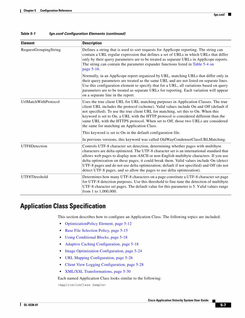
5-7Cisco Application Velocity System User Guide
OL-9338-01
Chapter 5 Configuration Referencefgn.conf
Application Class SpecificationThis section describes how to configure an Application Class. The following topics are included:
• OptimizationPolicy Element, page 5-12
• Base File Selection Policy, page 5-15
• Using Conditional Blocks, page 5-18
• Adaptive Caching Configuration, page 5-18
• Image Optimization Configuration, page 5-24
• URL Mapping Configuration, page 5-26
• Client View Logging Configuration, page 5-28
• XML/XSL Transformations, page 5-30
Each named Application Class looks similar to the following:
<ApplicationClass Sample>
RequestGroupingString Defines a string that is used to sort requests for AppScope reporting. The string can contain a URL regular expression that defines a set of URLs in which URLs that differ only by their query parameters are to be treated as separate URLs in AppScope reports. The string can contain the parameter expander functions listed in Table 5-4 on page 5-16.
Normally, in an AppScope report organized by URL, matching URLs that differ only in their query parameters are treated as the same URL and are not listed on separate lines. Use this configuration element to specify that for a URL, all variations based on query parameters are to be treated as separate URLs for reporting. Each variation will appear on a separate line in the report.
UrlMatchWithProtocol Uses the true client URL for URL matching purposes in Application Classes. The true client URL includes the protocol (scheme). Valid values include On and Off (default if not specified). To use the true client URL for matching, set this to On. When this keyword is set to On, a URL with the HTTP protocol is considered different than the same URL with the HTTPS protocol. When set to Off, those two URLs are considered the same for matching an Application Class.
This keyword is set to On in the default configuration file.
In previous versions, this keyword was called OldWayCondenserClassURLMatching.
UTF8Detection Controls UTF-8 character set detection, determining whether pages with multibyte characters are delta optimized. The UTF-8 character set is an international standard that allows web pages to display non-ASCII or non-English multibyte characters. If you use delta optimization on these pages, it could break them. Valid values include On (detect UTF-8 pages and do not use delta optimization; default if not specified) and Off (do not detect UTF-8 pages, and so allow the pages to use delta optimization).
UTF8Threshold Determines how many UTF-8 characters on a page constitute a UTF-8 character set page for UTF-8 detection purposes. Use this threshold to fine tune the detection of multibyte UTF-8 character set pages. The default value for this parameter is 5. Valid values range from 1 to 1,000,000.
Table 5-1 fgn.conf Configuration Elements (continued)
Element Description

5-8Cisco Application Velocity System User Guide
OL-9338-01
Chapter 5 Configuration Referencefgn.conf
Url "(.*/catalog)/(.*)$"CanonicalUrl $(1)/$param(category)OptimizationPolicy DeltaOptimize,Compress,
DeltaOptimizeAllUsers,FlashForwardBaseFileAnonLevel 2
</ApplicationClass>
Each Application Class is defined by a series of configuration elements that are described in Table 5-2.
Table 5-2 ApplicationClass Configuration Elements
Element Description
AppscopeLogNonInstrumented Enables AppScope to log statistics for requests where client-side timings cannot be measured because the response page is not in HTML or cannot accept the JavaScript instrumentation. Normally, such requests are not logged. Valid values include On and Off (default).
To allow AppScope to report on these transactions, define an Application Class with this keyword set to On, define a transaction type for this class by using the “ApplicationClass Matches” expression, and set the Substitute Client Timing, as described in the “Substitute Client Timing” section on page 9-38.
BaseFileAnonLevel Specifies an integer between 0 and 50 that defines the base file anonymity level for all-user condensation. This element is used only with the DeltaOptimizeAllUsers policy element. It sets the anonymity level for the base file between 0 (no anonymity) and 50 (very high anonymity). For more details, see the “Anonymous Base Files” section on page 2-14.
CacheKeyModifier Specifies a regular expression if you want to modify the canonical URL portion of the cache key (for example to remove CDN information). The default is NULL. For more details, see the “CacheKeyModifier” section on page 5-20.
CacheMaxTTL Maximum time in seconds that an object without an explicit expiration time should be considered fresh. The default is 259200 (72 hours). Valid values range from 0 to INT_MAX.
CacheMinTTL Minimum time in seconds that an object without an explicit expiration time should be considered fresh. For static caching (FlashForwardObject), this value should normally be 0. For dynamic caching (CacheDynamic), this value should be set to indicate how long the application appliance should cache the page. The default is 0. Valid values range from 0 to INT_MAX.
CacheParameter Specifies an expression including one or more parameter expander functions if you want to modify the parameter portion of the cache key. The default is NULL. For more details, see the “CacheParameter” section on page 5-21.
CacheTTLPercent Percent of an object’s age at which an embedded object without an explicit expiration time is considered fresh. The default is 0. Valid values range from 0 to 100.
CanonicalUrl Specifies a string containing a canonical URL regular expression that defines a set of URLs to which the class applies. At least one URL must be specified using the Url or CanonicalUrl elements. The CanonicalUrl element is described below in the “Base File Selection Policy” section on page 5-15.
ExcludeNonASCII Configures the application appliance to exclude non-ASCII data from condensation. Valid values include On and Off (default). Set this element to On if the content has UTF8 characters. This excludes such characters from delta optimization but the rest of that page can still be delta optimized.
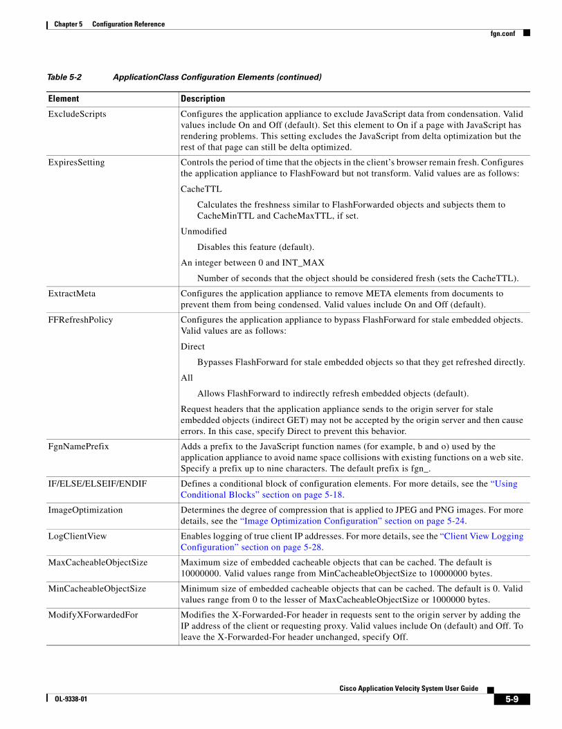
5-9Cisco Application Velocity System User Guide
OL-9338-01
Chapter 5 Configuration Referencefgn.conf
ExcludeScripts Configures the application appliance to exclude JavaScript data from condensation. Valid values include On and Off (default). Set this element to On if a page with JavaScript has rendering problems. This setting excludes the JavaScript from delta optimization but the rest of that page can still be delta optimized.
ExpiresSetting Controls the period of time that the objects in the client’s browser remain fresh. Configures the application appliance to FlashFoward but not transform. Valid values are as follows:
CacheTTL
Calculates the freshness similar to FlashForwarded objects and subjects them to CacheMinTTL and CacheMaxTTL, if set.
Unmodified
Disables this feature (default).
An integer between 0 and INT_MAX
Number of seconds that the object should be considered fresh (sets the CacheTTL).
ExtractMeta Configures the application appliance to remove META elements from documents to prevent them from being condensed. Valid values include On and Off (default).
FFRefreshPolicy Configures the application appliance to bypass FlashForward for stale embedded objects. Valid values are as follows:
Direct
Bypasses FlashForward for stale embedded objects so that they get refreshed directly.
All
Allows FlashForward to indirectly refresh embedded objects (default).
Request headers that the application appliance sends to the origin server for stale embedded objects (indirect GET) may not be accepted by the origin server and then cause errors. In this case, specify Direct to prevent this behavior.
FgnNamePrefix Adds a prefix to the JavaScript function names (for example, b and o) used by the application appliance to avoid name space collisions with existing functions on a web site. Specify a prefix up to nine characters. The default prefix is fgn_.
IF/ELSE/ELSEIF/ENDIF Defines a conditional block of configuration elements. For more details, see the “Using Conditional Blocks” section on page 5-18.
ImageOptimization Determines the degree of compression that is applied to JPEG and PNG images. For more details, see the “Image Optimization Configuration” section on page 5-24.
LogClientView Enables logging of true client IP addresses. For more details, see the “Client View Logging Configuration” section on page 5-28.
MaxCacheableObjectSize Maximum size of embedded cacheable objects that can be cached. The default is 10000000. Valid values range from MinCacheableObjectSize to 10000000 bytes.
MinCacheableObjectSize Minimum size of embedded cacheable objects that can be cached. The default is 0. Valid values range from 0 to the lesser of MaxCacheableObjectSize or 1000000 bytes.
ModifyXForwardedFor Modifies the X-Forwarded-For header in requests sent to the origin server by adding the IP address of the client or requesting proxy. Valid values include On (default) and Off. To leave the X-Forwarded-For header unchanged, specify Off.
Table 5-2 ApplicationClass Configuration Elements (continued)
Element Description

5-10Cisco Application Velocity System User Guide
OL-9338-01
Chapter 5 Configuration Referencefgn.conf
OptimizationPolicy Specifies a string of policy keywords separated by commas. The “OptimizationPolicy Element” section on page 5-12 describes the keywords that can be used in an OptimizationPolicy element. They control how the content corresponding to the specified URLs is treated by the application appliance.
ParamSummary Enables the logging of query parameters for transactions in the FgnStatLog file (in the <PSM> element). Valid values include On (default) and Off.
ParamSummaryParamValueLimit
Sets the maximum number of bytes that are logged for each parameter value in the parameter summary of a transaction log entry in the FgnStatLog. Valid values range from 0 to 10,000 bytes; the default is 100 bytes. If a parameter value is longer than this limit, it is truncated at the limit.
PostContentBufferLimit Sets the maximum number of kilobytes of POST data to scan for parameters for logging transaction parameters in the FgnStatLog. Parameters beyond this limit will not be logged. Valid values range from 0 to 1000 KB; the default is 40 KB.
RequestCachePolicy Provides a mechanism to override client request headers (primarily for embedded objects). Values include the following:
OverrideAll
All cache headers are ignored.
None
No headers are overridden (default).
Using this option violates the HTTP standard.
RequestHeader Provides a mechanism to set client request headers to specific values. The values are not case sensitive. Values include the following:
Set name value
Sets the value of the header identified by name to value. If the named header exists, its value is changed to value, and if it does not exist, it is created.
Unset name
Removes the header specified by name.
We do not recommend that you first unset and then set the same header in a single Application Class specification because the results may be unexpected.
ResponseCachePolicy Provides a mechanism to override origin server response headers (primarily for embedded objects). Values include the following:
OverrideAll
All cache headers are ignored.
None
No headers are overridden (default).
Using this option violates the HTTP standard.
Table 5-2 ApplicationClass Configuration Elements (continued)
Element Description

5-11Cisco Application Velocity System User Guide
OL-9338-01
Chapter 5 Configuration Referencefgn.conf
Application Classes are applied to a request in cascading order. For a given request, the application appliance checks the classes in the order in which they are listed in the configuration file, until it finds a class that applies to the requested URL. The policy in that class is then applied to the request. If no class that applies to the request is found, the application appliance sends an uncondensed response.
ResponseHeader Provides a mechanism to set response headers to specific values. The values are not case sensitive. Values include the following:
Set name value
Sets the value of the header identified by name to value. If the named header exists, its value is changed to value, and if it does not exist, it is created.
Unset name
Removes the header specified by name.
We do not recommend that you first unset and then set the same header in a single Application Class specification because the results may be unexpected.
Url Specifies a string containing a URL to which the class applies. You can include a number of URL elements in the class definition to include multiple URLs in the class. URLs can be specified as regular expressions using the GNU POSIX syntax (see Appendix F, “Regular Expressions.”) At least one URL must be specified using the Url or CanonicalUrl elements.
Urlmap Allows the application appliance to alter URLs in the data stream between the origin server and the client browser. Note that this alteration applies only to HTML files, unless you also set the UrlmapNonHtml keyword to On.
Specify a string that begins with the word scope, contains a scope keyword, and contains a replacement directive. For details on how to configure URL mapping, see the “URL Mapping Configuration” section on page 5-26.
UrlmapNonHtml Configures the application appliance to allow URL mapping on files other than HTML files. Valid values include On and Off (default). Set this element to On if you want to map URLs in non-HTML files. This will enable URL mapping on all files, so make sure that you use the correct ApplicationClass to target selected files, otherwise performance can suffer.
XsltMerge Enables the XSLT merge feature. Valid values include On and Off (default). This feature is used for XML source files. It causes the application appliance to transform the XML source by applying an XSLT stylesheet, and the resulting document is returned to the requester. The XSLT stylesheet can be specified in the XML document or specified by the XsltUseStylesheet directive. After the document is transformed, other optimizations are applied. For an example, see the “XML/XSL Transformations” section on page 5-30.
XsltUseStylesheet Specifies the URL of an XSLT stylesheet. Forces the use of this particular stylesheet, regardless of any XSL specified in the XML source file. This keyword applies only if the XsltMerge keyword is set to On.
Table 5-2 ApplicationClass Configuration Elements (continued)
Element Description
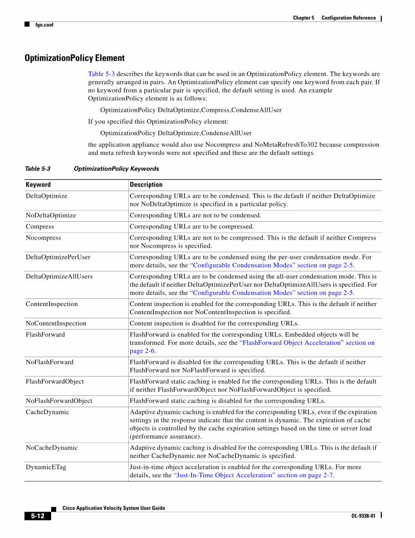
5-12Cisco Application Velocity System User Guide
OL-9338-01
Chapter 5 Configuration Referencefgn.conf
OptimizationPolicy Element
Table 5-3 describes the keywords that can be used in an OptimizationPolicy element. The keywords are generally arranged in pairs. An OptimizationPolicy element can specify one keyword from each pair. If no keyword from a particular pair is specified, the default setting is used. An example OptimizationPolicy element is as follows:
OptimizationPolicy DeltaOptimize,Compress,CondenseAllUser
If you specified this OptimizationPolicy element:
OptimizationPolicy DeltaOptimize,CondenseAllUser
the application appliance would also use Nocompress and NoMetaRefreshTo302 because compression and meta refresh keywords were not specified and these are the default settings.
Table 5-3 OptimizationPolicy Keywords
Keyword Description
DeltaOptimize Corresponding URLs are to be condensed. This is the default if neither DeltaOptimize nor NoDeltaOptimize is specified in a particular policy.
NoDeltaOptimize Corresponding URLs are not to be condensed.
Compress Corresponding URLs are to be compressed.
Nocompress Corresponding URLs are not to be compressed. This is the default if neither Compress nor Nocompress is specified.
DeltaOptimizePerUser Corresponding URLs are to be condensed using the per-user condensation mode. For more details, see the “Configurable Condensation Modes” section on page 2-5.
DeltaOptimizeAllUsers Corresponding URLs are to be condensed using the all-user condensation mode. This is the default if neither DeltaOptimizePerUser nor DeltaOptimizeAllUsers is specified. For more details, see the “Configurable Condensation Modes” section on page 2-5.
ContentInspection Content inspection is enabled for the corresponding URLs. This is the default if neither ContentInspection nor NoContentInspection is specified.
NoContentInspection Content inspection is disabled for the corresponding URLs.
FlashForward FlashForward is enabled for the corresponding URLs. Embedded objects will be transformed. For more details, see the “FlashForward Object Acceleration” section on page 2-6.
NoFlashForward FlashForward is disabled for the corresponding URLs. This is the default if neither FlashForward nor NoFlashForward is specified.
FlashForwardObject FlashForward static caching is enabled for the corresponding URLs. This is the default if neither FlashForwardObject nor NoFlashForwardObject is specified.
NoFlashForwardObject FlashForward static caching is disabled for the corresponding URLs.
CacheDynamic Adaptive dynamic caching is enabled for the corresponding URLs, even if the expiration settings in the response indicate that the content is dynamic. The expiration of cache objects is controlled by the cache expiration settings based on the time or server load (performance assurance).
NoCacheDynamic Adaptive dynamic caching is disabled for the corresponding URLs. This is the default if neither CacheDynamic nor NoCacheDynamic is specified.
DynamicETag Just-in-time object acceleration is enabled for the corresponding URLs. For more details, see the “Just-In-Time Object Acceleration” section on page 2-7.
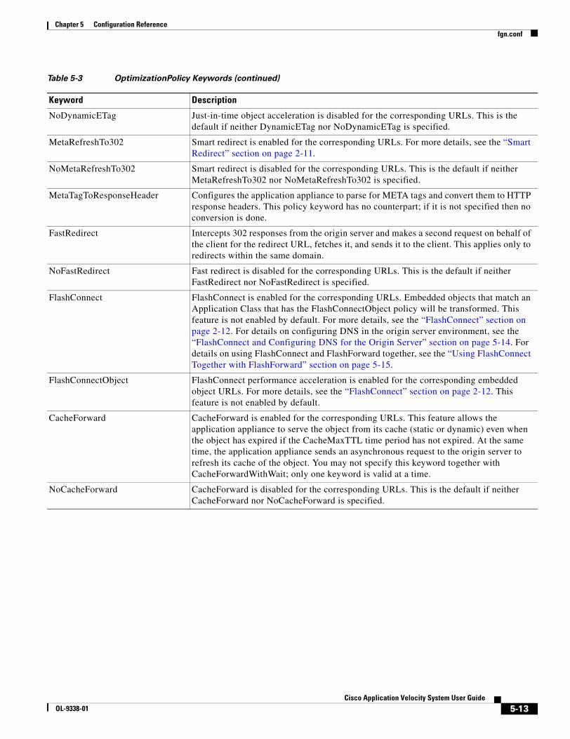
5-13Cisco Application Velocity System User Guide
OL-9338-01
Chapter 5 Configuration Referencefgn.conf
NoDynamicETag Just-in-time object acceleration is disabled for the corresponding URLs. This is the default if neither DynamicETag nor NoDynamicETag is specified.
MetaRefreshTo302 Smart redirect is enabled for the corresponding URLs. For more details, see the “Smart Redirect” section on page 2-11.
NoMetaRefreshTo302 Smart redirect is disabled for the corresponding URLs. This is the default if neither MetaRefreshTo302 nor NoMetaRefreshTo302 is specified.
MetaTagToResponseHeader Configures the application appliance to parse for META tags and convert them to HTTP response headers. This policy keyword has no counterpart; if it is not specified then no conversion is done.
FastRedirect Intercepts 302 responses from the origin server and makes a second request on behalf of the client for the redirect URL, fetches it, and sends it to the client. This applies only to redirects within the same domain.
NoFastRedirect Fast redirect is disabled for the corresponding URLs. This is the default if neither FastRedirect nor NoFastRedirect is specified.
FlashConnect FlashConnect is enabled for the corresponding URLs. Embedded objects that match an Application Class that has the FlashConnectObject policy will be transformed. This feature is not enabled by default. For more details, see the “FlashConnect” section on page 2-12. For details on configuring DNS in the origin server environment, see the “FlashConnect and Configuring DNS for the Origin Server” section on page 5-14. For details on using FlashConnect and FlashForward together, see the “Using FlashConnect Together with FlashForward” section on page 5-15.
FlashConnectObject FlashConnect performance acceleration is enabled for the corresponding embedded object URLs. For more details, see the “FlashConnect” section on page 2-12. This feature is not enabled by default.
CacheForward CacheForward is enabled for the corresponding URLs. This feature allows the application appliance to serve the object from its cache (static or dynamic) even when the object has expired if the CacheMaxTTL time period has not expired. At the same time, the application appliance sends an asynchronous request to the origin server to refresh its cache of the object. You may not specify this keyword together with CacheForwardWithWait; only one keyword is valid at a time.
NoCacheForward CacheForward is disabled for the corresponding URLs. This is the default if neither CacheForward nor NoCacheForward is specified.
Table 5-3 OptimizationPolicy Keywords (continued)
Keyword Description

5-14Cisco Application Velocity System User Guide
OL-9338-01
Chapter 5 Configuration Referencefgn.conf
FlashConnect and Configuring DNS for the Origin Server
When using FlashConnect, you must configure DNS in the origin server environment to send all requests for the rewritten object URLs to the appropriate origin server.
If a container page matches the FlashConnect policy, FlashConnect causes embedded object URLs to be rewritten as shown in the following example.
An example of a container page before optimization is as follows:
<html><img src="img1.jpg"><img src="img2.jpg"><img src="img3.jpg"><img src="img4.jpg">
</html>
The embedded object URLs are rewritten by FlashConnect as follows:
<html> <img src="http://fgn00.flashconnect.myhost/img1.jpg"> <img src="http://fgn01.flashconnect.myhost/img2.jpg"> <img src="http://fgn02.flashconnect.myhost/img3.jpg"> <img src="http://fgn03.flashconnect.myhost/img4.jpg"></html>
URLs for embedded objects that match the FlashConnectObject policy are rewritten to be absolute with a host prefix that creates an artificial number of host servers (fgn00, fgn01, fgn02, fgn03, and so on). Additionally, the FlashConnect prefix (flashconnect in this example) is inserted before the actual host name to form a new absolute URL.
The origin server environment must have DNS configured with wildcards as follows. All URLs that match this expression:
fgn*.FlashConnectPrefix.myhost
must be mapped to the host myhost. The FlashConnectPrefix part is the string set by the FlashConnectPrefix global keyword.
All requests to the various artificial host servers are directed to the single actual host server.
CacheForwardWithWait CacheForwardWithWait is enabled for the corresponding URLs. If the object has expired but the CacheMaxTTL time period has not expired, the application appliance sends a request to the origin server for the object. The other users requesting this page will still receive content from the cache during this time. When the fresh object is returned, it is sent to the requesting user and the cache is updated. This is similar to CacheForward, except that a single user must wait for the object to be updated before their request is satisfied.
This feature is useful in situations where you cannot use CacheForward because the application requires a context for processing and an asynchronous update process is not appropriate.
You may not specify this keyword together with CacheForward; only one keyword is valid at a time.
NoCacheForwardWithWait CacheForwardWithWait is disabled for the corresponding URLs. This is the default if neither CacheForwardWithWait nor NoCacheForwardWithWait is specified.
Table 5-3 OptimizationPolicy Keywords (continued)
Keyword Description
5-15Cisco Application Velocity System User Guide
OL-9338-01
Chapter 5 Configuration Referencefgn.conf
Using FlashConnect Together with FlashForward
Unlike FlashForward, which relies on the application appliance having first cached the object, FlashConnect is not bound by this requirement. However, an issue needs to be addressed in the fgn.conf configuration file if you use both policies.
If an Application Class is as follows:
<ApplicationClass BadClass>Url ^.*\.jpg$OptimizationPolicy FlashForwardObject, FlashConnectObject
</ApplicationClass>
With this policy, any JPEG image will be FlashConnected. However, for JPEG images that do not return to the application appliance (for example, external site links) the FlashConnect URL will not resolve back to the correct site, which causes a broken link. To avoid this situation, you should declare the FlashConnect policy in prior Application Classes that apply only to the internal site. Later Application Classes can then be used for FlashForwarding all remaining images.
This example shows the content from a site called mysite.com:
<html><img src="http://www.example.com/logo.gif"><img src="me1.gif"><img src="me2.gif"></html>
The Application Classes should look as follows:
<ApplicationClass HandleInternalImages>Url ^.*foo\.com.*\.jpg$OptimizationPolicy FlashForwardObject, FlashConnectObject
</ApplicationClass>
<ApplicationClass jpegs>Url ^.*\.jpg$OptimizationPolicy FlashForwardObject
</ApplicationClass>
Only those images that are hosted by mysite.com (me1.gif and me2.gif) will be both FlashConnected and FlashForwarded. External images not matching the domain will only be FlashForwarded.
Base File Selection Policy
The CanonicalUrl element in an Application Class is used to specify a base file selection policy. This regular expression is used to match a variety of actual URLs. All matched URLs share a single base file.
Note The application appliance requires GNU POSIX regular expression syntax. For more details, see Appendix F, “Regular Expressions.”
The CanonicalUrl element can contain parameter expander functions that evaluate to strings. Table 5-4 lists parameter expander functions.
5-16Cisco Application Velocity System User Guide
OL-9338-01
Chapter 5 Configuration Referencefgn.conf
Table 5-4 Parameter Expander Functions
Variable Description
$(number) Expands to the corresponding matching subexpression (by number) in the URL pattern. Subexpressions are marked in a URL pattern using parentheses (). The numbering of the subexpressions begins with 1 and is the number of the left parenthesis ( counting from the left. You can specify any positive integer for the number. $(0) matches the entire URL. For example, if the URL pattern is ((http://server/.*)/(.*)/)a.jsp, and the URL that matched it is as follows:
http://server/main/sub/a.jsp?category=shoes&session=99999
then the following is true:
$(0) = http://server/main/sub/a.jsp
$(1) = http://server/main/sub/
$(2) = http://server/main
$(3) = sub
If the specified subexpression does not exist in the URL pattern, then the variable expands to the empty string.
$http_query_string() Expands to the value of the whole query string in the URL. For example, if the URL is as follows:
http://myhost/dothis?param1=value1¶m2=value2
then the following is true:
$http_query_string() = param1=value1¶m2=value2
This function applies to both GET and POST requests.
$http_query_param(query-param-name)
This obsolete syntax also is supported:
$param(query-param-name)
Expands to the value of the named query parameter (case sensitive). For example, if the URL is as follows:
http://server/main/sub/a.jsp?category=shoes&session=99999
then the following is true:
$http_query_param(category) = shoes
$http_query_param(session) = 99999
If the specified parameter does not exist in the query, then the variable expands to the empty string. This function applies to both GET and POST requests.
$http_cookie(cookie-name) Evaluates to the value of the named cookie. For example, $http_cookie(cookiexyz). The cookie name is case sensitive.
$http_header(request-header-name)
Evaluates to the value of the specified HTTP request header. For multivalued headers, it is the single representation as specified in the HTTP specification. For example, $http_header(user-agent). The HTTP header name is not case sensitive.
$http_method() Evaluates to the HTTP method used for the request, such as GET or POST.

5-17Cisco Application Velocity System User Guide
OL-9338-01
Chapter 5 Configuration Referencefgn.conf
The following example shows how this feature can be used. If a catalog website has the following pages:
http://server/catalog/business?category=pencilshttp://server /catalog/business?category=erasershttp://server /catalog/consumer?category=pencilshttp://server /catalog/consumer?category=erasers
The pencils pages for both the business and consumer sections have a lot of common content and similarly, the erasers pages for both the business and consumer sections have a lot of common content. It would be efficient if the base pages for these categories can be shared. That is, the base page for the following two pages would be the same, as follows:
http://server/catalog/business?category=pencilshttp://server/catalog/consumer?category=pencils
Using the CanonicalUrl element, you can configure the following Application Class:
<ApplicationClass PencilsAndErasers>Url "(.*/catalog)/(.*)$"CanonicalUrl $(1)/$http_query_param(category)OptimizationPolicy DeltaOptimize,Compress,
DeltaOptimizeAllUsers</ApplicationClass>
Boolean Functions:
$http_query_param_present(query-param-name)
$http_query_param_notpresent(query-param-name)
$http_cookie_present(cookie-name)
$http_cookie_notpresent(cookie-name)
$http_header_present(request-header-name)
$http_header_notpresent(request-header-name)
$http_method_present(method-name)
$http_method_notpresent(method-name)
Evaluates to a Boolean value: true or false, depending on the presence or absence of the element in the request. The elements are: a specific query parameter (query-param-name), a specific cookie (cookie-name), a specific request header (request-header-name), or a specific HTTP method (method-name). All identifiers are case sensitive except for the HTTP request header name.
$regex_match(param1, param2) Evaluates to a Boolean value: true if the two parameters match and false if they do not match. The two parameters can be any two expressions, including regular expressions, that evaluate to two strings. For example, this function compares the query URL with the regular expression string ^.*Store\.asp.*$
$regex_match($http_query_param(URL), “^.*Store\.asp.*$”)
If the URL matches this regular expression, this function evaluates to true.
Table 5-4 Parameter Expander Functions
Variable Description
5-18Cisco Application Velocity System User Guide
OL-9338-01
Chapter 5 Configuration Referencefgn.conf
This class will match all four URLs above. If the request URL is as follows:
http://server/catalog/business?category=pencils
then $(1) is the string http://server/catalog and $http_query_param(category) expands to the string pencils string. The resulting canonical URL is http://server/catalog/pencils.
The same is true for the URL http://server/catalog/consumers?category=pencils. These two URLs will share the same base file.
Similarly, the canonical URL for the eraser URLs will be http://server/catalog/erasers, and they will share the same base file.
Using Conditional Blocks
You can use IF/THEN/ELSEIF/ENDIF conditional blocks to override global settings for an Application Class. The conditional blocks must appear after all global settings in an Application Class specification; any global settings that appear after a conditional block are ignored.
The form of a conditional block is as follows:
IF Boolean-expression THENconfiguration settings
ELSEIF Boolean-expression THENconfiguration settings
ELSEconfiguration settings
ENDIF
In a conditional block, only the IF and ENDIF statements are required; ELSEIF and ELSE are optional. The ELSEIF statement combines an ELSE with another IF. Multiple ELSEIF statements are allowed, but only one ELSE is permitted.
Only one conditional block is allowed within an Application Class at the same level. However, a nested conditional block is allowed inside an IF, ELSEIF, or ELSE clause. This restriction applies to every conditional block recursively.
Similar to a standard conditional statement, if the Boolean expression evaluates to true, the statements following it (until an ELSE, ELSEIF, or ENDIF) are executed and the ELSE or ELSEIF block is skipped; and if it evaluates to false, the statements between it and the first ELSE or ELSEIF are not executed and the ELSE or ELSEIF block is executed.
For the Boolean expressions, you can use the parameter expander functions listed in Table 5-4.
Adaptive Caching Configuration
This section includes reference information for configuring both static and dynamic adaptive caching in an Application Class.
For guidelines on when to use dynamic caching and the steps required to implement it, see the “Dynamic Caching Configuration Guidelines” section on page 5-34.
If an Application Class is found that matches a request, its cache policy is inspected and applied to that object.
There are two aspects of all cached objects:
• The key under which the object is cached, which is controlled by the keywords URL or CanonicalURL (described in the previous section), CacheKeyModifier, and CacheParameter. For details, see the “Cache Object Key” section on page 5-19.
5-19Cisco Application Velocity System User Guide
OL-9338-01
Chapter 5 Configuration Referencefgn.conf
• The expiration behavior of the cached content, which can be time based or performance assurance with load-based expiration. For details, see the “Configuring Cache Object Expiration” section on page 5-22.
The keywords that are used to configure dynamic caching in an Application Class are as follows:
<ApplicationClass className># URL matching
Url or CanonicalURL ...
# Class cache key modifierCacheKeyModifier ...
# Class parameterizationCacheParameter ...
# Class policyOptimizationPolicy CacheDynamic, ...
# Class expirationCacheMinTTL ...CacheMaxTTL ...ServerLoadShortWindow ...ServerLoadLongWindow ...ServerLoadTriggerPercent ...CacheTTLChangePercent ...
# Conditional blocks to override class settingsIF ... THEN ...ELSEIF ... THEN ...ELSE ...ENDIF</ApplicationClass>
The following topics are included in this section:
• Cache Object Key, page 5-19
• CacheKeyModifier, page 5-20
• CacheParameter, page 5-21
• Configuring Cache Object Expiration, page 5-22
• Example of Cache Configuration, page 5-23
Cache Object Key
The cache object key is the unique identifier that is used to identify a cached object to be served to the client, thereby replacing a trip to the origin server.
The HTTP protocol is not session based (each request for every page and dependent object is entirely autonomous, with no state preserved between requests), leading web application developers to use session tracking techniques like cookies. Thus, it is sometimes necessary to include more in the cache key than simply the URL.
The key that the application appliance uses for any given requesting URL comprises one or more of the following two components, which are illustrated in Figure 5-1:
• Canonical URL (the URL portion up to a “?”). This can be modified by the CacheKeyModifier keyword.

5-20Cisco Application Velocity System User Guide
OL-9338-01
Chapter 5 Configuration Referencefgn.conf
• Query parameters (the URL portion after a”?”). This can be modified by the CacheParameter keyword, which can be used to include just selected query parameters, a cookie value, an HTTP header value, and other values.
Figure 5-1 How Cache Key is Formed from URL
For details on how to use the CacheKeyModifier and CacheParameter keywords to modify the cache key, see the next sections:
• CacheKeyModifier
• CacheParameter
CacheKeyModifier
The CacheKeyModifier element in an Application Class is used to modify the canonical form of a URL—that is, the portion before the ?—for use in forming the cache key.
The CacheKeyModifier element specifies a regular expression containing embedded variables that are expanded by the application appliance. You can include zero or more instances of the $(number) variable, as described in Table 5-4 on page 5-16. Only regular expressions are supported; the other parameter expander functions are not supported.
The expanded string resulting from the CacheKeyModifier element replaces the default canonical URL portion of the cache key. If the CacheKeyModifier element is not specified, the canonical URL is used as the default value for the URL portion of the cache key (there may also be a query parameter portion).
An example of using a CacheKeyModifier element to strip out the portion of a URL added by a content delivery network (CDN) is as follows:
<ApplicationClass Example_1>Url "^.*mycdn\.net.*www(.*\.gif)$"CacheKeyModifier http://www$(1)
1436
81
Canonical URL (portion before the “?”)
“http://www.xyz.com/somepage.asp”
Query parameters (portion after the “?”)
“action=browse&level=2”
Request Object URL
“http://www.xyz.com/somepage.asp?action=browse&level=2”
Cache Key
Modifiable withCacheKeyModifier
keyword
Modifiable withCacheParameter
keyword
URL is composed of two parts
5-21Cisco Application Velocity System User Guide
OL-9338-01
Chapter 5 Configuration Referencefgn.conf
OptimizationPolicy ...</ApplicationClass>
The Url line specifies a regular expression that identifies URLs for which this Application Class is to be used. It reads as follows: Start with any number of any characters, up to the literal mycdn.net, followed by any sequence of characters up to the literal www, followed by a subexpression group (in parentheses) that ends the URL. The subexpression group is any sequence of characters followed by the literal .gif, which must end the string. The subexpression group can be expanded by using the $(number) syntax. In this case it is the first and only subexpression, so it can be referenced by $(1).
The CacheKeyModifier line replaces the original URL with a new string that begins with http://www and ends with the value of subexpression group 1 from the previous line. The purpose is to strip out the portion of the URL that was used for redirection to a CDN. It transforms a matched URL such as the following:
http://a188.g.mycdn.net/f/188/920/1d/www.mysite.com/images/logo.gif
to this string:
http://www.mysite.com/images/logo.gif
CacheParameter
The CacheParameter element in an Application Class is used to modify the query parameter part of a URL—that is, the portion after the ?—for use in forming the cache key.
The CacheParameter element specifies one or more parameter expander functions that evaluate to strings. These strings are appended to the canonical URL to form the last portion of the cache key. The parameter expander functions are listed in Table 5-4 on page 5-16.
The string specified in the CacheParameter element replaces the default query parameter that is used in the cache key. If the CacheParameter element is not specified, the query parameter portion of the URL is used as the default value for this portion of the cache key (the canonical URL, possibly modified by the CacheKeyModifier, is the first part of the cache key).
An example of using a CacheParameter element to create a different instance of the dynamically cached page for each value of the version query parameter is as follows:
<ApplicationClass Example_2>Url "^.*dyncache/page3\.asp.*$"CacheParameter $http_query_param (version)OptimizationPolicy ...
</ApplicationClass>
The Url line specifies a regular expression that identifies URLs for which this Application Class is to be used. It reads as follows: Start with any number of any characters, up to the literal dyncache/page3.asp, followed by any sequence of characters up to the end of the URL.
The CacheParameter line sets the value of the query parameter portion of the cache key to the value of the version query parameter. (The default value of the query parameter portion of the cache key is the entire query parameter portion of the URL.)
It extracts from a matched URL such as the following:
http:www.mysite.com/dyncache/page3.asp?session=nqyfxe46&m=int&version=12
The following string is the value of the version parameter:
12
This string is appended to the URL portion of the cache key to form the complete cache key.

5-22Cisco Application Velocity System User Guide
OL-9338-01
Chapter 5 Configuration Referencefgn.conf
Configuring Cache Object Expiration
An object in the cache can be expired (excluding the natural process of cache pruning) in these two methods:
• Time based, where the object lives for some minimum and maximum time interval.
To specify a time-based expiration for the cache, use the CacheMinTTL (default=0) and CacheMaxTTL (default=259200, 72 hours) keywords.
• Performance assurance with load-based expiration, where the origin server’s load determines when the object expires.
This type of expiration allows you to dynamically increase the time to live (TTL) of cached responses if the current response time (average computed over a short time window) from the origin servers is larger than the average response time (average computed over a longer time window) by a threshold amount. Similarly, the TTL is dynamically decreased if the reverse holds true. The starting value for the cache TTL is the CacheMinTTL value or 0 if not specified. The purpose of a moving average-based calculation is to allow the cache to respond to trends in usage patterns, which smooths out uncharacteristic spikes.
Performance assurance with load-based expiration is controlled by the keywords listed in Table 5-5.
Table 5-5 Keywords Configuring Load-Based Expiration
Keyword Description
ServerLoadShortWindow Defines the time window in which the short-term response time is computed, expressed in seconds. For example, if the value is set to 300, then the short-term response time is computed as the average of all responses that occurred in the last 5 minutes. The default is 300 seconds (5 minutes).
ServerLoadLongWindow Defines the time window in which the long-term response time is computed, expressed in seconds. For example, if the value is set to 604800, then the long-term response time is computed as the average of all responses that occurred in the last 7 days. The default is 604800 seconds (7 days).
ServerLoadTriggerPercent Defines the threshold that triggers a change in the cache TTL.
This feature enables the application appliance to monitor the server load in real time and make intelligent “closed loop” content expiration decisions so that site performance is maximized and existing hardware resources are used most efficiently even during periods of peak traffic load.
If the ServerLoadShortWindow value exceeds the ServerLoadLongWindow value by the ServerLoadTriggerPercent (20% by default), then the object TTL is increased by the CacheTTLChangePercent (20% by default). Similarly, if the ServerLoadShortWindow value is less than the ServerLoadLongWindow value by the ServerLoadTriggerPercent, then the object TTL is decreased by the CacheTTLChangePercent. The default ServerLoadTriggerPercent is 20%.
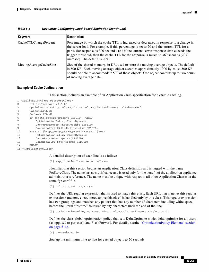
5-23Cisco Application Velocity System User Guide
OL-9338-01
Chapter 5 Configuration Referencefgn.conf
Example of Cache Configuration
This section includes an example of an Application Class specification for dynamic caching.
1 <ApplicationClass PetStoreClass>2 Url "(.*/estore)/(.*)$"3 OptimizationPolicy DeltaOptimize,DeltaOptimizeAllUsers, FlashForward4 CacheMinTTL 205 CacheMaxTTL 606 IF ($http_cookie_present(SESSID)) THEN7 OptimizationPolicy CacheDynamic8 CacheParameter $http_cookie(SESSID)9 CanonicalUrl $(0)/$http_cookie(SESSID)10 ELSEIF ($http_query_param_present(SESSID))THEN 11 OptimizationPolicy CacheDynamic12 CacheParameter $param(SESSID)13 CanonicalUrl $(0)/$param(SESSID)14 ENDIF15 </ApplicationClass>
A detailed description of each line is as follows:
[1] <ApplicationClass PetStoreClass>
Identifies that this section begins an Application Class definition and is tagged with the name PetStoreClass. The name has no significance and is used only for the benefit of the application appliance administrator’s reference. The name must be unique with respect to all other Application Classes in the same fgn.conf file.
[2] Url "(.*/estore)/(.*)$"
Defines the URL regular expression that is used to match this class. Each URL that matches this regular expression (and none encountered above this class) is handled only by this class. This regular expression has two groupings and matches any pattern that has any number of characters including white space before the literal “/estore/” followed by any characters until the end of the line.
[3] OptimizationPolicy DeltaOptimize, DeltaOptimizeAllUsers,FlashForward
Defines the class global optimization policy that sets DeltaOptimize mode, delta optimize for all users (as opposed to per user), and FlashForward. For details, see the “OptimizationPolicy Element” section on page 5-12.
[4] CacheMinTTL 20
Sets up the minimum time to live for cached objects to 20 seconds.
CacheTTLChangePercent Percentage by which the cache TTL is increased or decreased in response to a change in the server load. For example, if this percentage is set to 20 and the current TTL for a particular response is 300 seconds, and if the current server response time exceeds the trigger threshold, then the cache TTL for the response is raised to 360 seconds (20% increase). The default is 20%.
MovingAverageCacheSize Size of the shared memory, in KB, used to store the moving average objects. The default is 500 KB. Each moving average object occupies approximately 1000 bytes, so 500 KB should be able to accommodate 500 of these objects. One object contains up to two hours of moving average data.
Table 5-5 Keywords Configuring Load-Based Expiration (continued)
Keyword Description
5-24Cisco Application Velocity System User Guide
OL-9338-01
Chapter 5 Configuration Referencefgn.conf
[5] CacheMaxTTL 60
Sets up the maximum time to live for cached objects to 60 seconds.
[6] IF ($http_cookie_present(SESSID)) THEN
Begins a set of conditional rules that override class global policies. This first IF statement checks for the presence of a cookie identified by the name SESSID. The cookie name is case sensitive.
[7] OptimizationPolicy CacheDynamic
Enables dynamic caching for objects that match the conditional test in line 6.
[8] CacheParameter $http_cookie(SESSID)
Specifies that the cache key is to include the value of the SESSID cookie to uniquely identify the object.
[9] CanonicalUrl $(0)/$http_cookie(SESSID)
Specifies that the base filename is to consist of the canonical URL, a forward slash (/) and the value of the SESSID cookie to uniquely identify the object. $(0) refers to the entire URL string.
[10] ELSEIF ($http_query_param_present(SESSID))THEN
If the condition in line 6 fails, execution continues here. This statement checks for the presence of a query parameter named SESSID. The parameter name is case sensitive.
[11] OptimizationPolicy CacheDynamic[12] CacheParameter $param(SESSID)[13] CanonicalUrl $(0)/$param(SESSID)
These statements perform the same functions as lines 7, 8, and 9. Except in this case, the additional token that is used to generate the cache key and identify the base file is the value of the SESSID query parameter (not the cookie, as before).
[14] ENDIF
A syntactical element that terminates the conditional block.
[15] </ApplicationClass>
Signifies the end of this Application Class definition.
Image Optimization Configuration
The ImageOptimization element in an Application Class controls how JPEG and PNG images are compressed by the application appliance. For an overview of Smart Image Optimization, see the “Smart Image Optimization” section on page 2-8.
By default, image optimization is disabled in the application appliance. You must explicitly use the ImageOptimization element to enable it.
Image optimization is applied intelligently, and is not used for small images such as thumbnails, or when optimization reduces the file size by less than 10%. Image optimization is not used for images that have many high frequency components that do not compress well.
There are two basic modes of image optimization are standard mode and advanced mode. In standard mode, the application appliance optimizes the image, smoothing it, if needed, to help reduce noise. To specify standard mode, use this configuration:
ImageOptimization standard
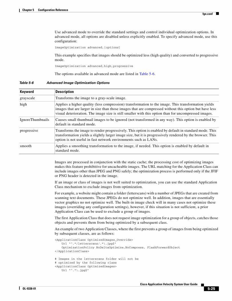
5-25Cisco Application Velocity System User Guide
OL-9338-01
Chapter 5 Configuration Referencefgn.conf
Use advanced mode to override the standard settings and control individual optimization options. In advanced mode, all options are disabled unless explicitly enabled. To specify advanced mode, use this configuration:
ImageOptimization advanced,[options]
This example specifies that images should be optimized less (high quality) and converted to progressive mode.
ImageOptimization advanced,high,progressive
The options available in advanced mode are listed in Table 5-6.
Images are processed in conjunction with the static cache; the processing cost of optimizing images makes this feature prohibitive for uncacheable images. The URL matching for the Application Class can include images other than JPEG and PNG safely; the optimization process is performed only if the JFIF or PNG header is detected in the image.
If an image or class of images is not well suited to optimization, you can use the standard Application Class mechanism to exclude images from optimization.
For example, a website might contain a folder (letterscans) with a number of JPEGs that are created from scanning text documents. These JPEGs do not optimize well. In addition, images that are essentially vector graphics no not optimize well. The built-in image check will in many cases not optimize these images (overriding any configuration settings), however, if this situation is not sufficient, a prior Application Class can be used to exclude a group of images.
The first Application Class that does not request image optimization for a group of objects, catches those objects and prevents them from being optimized by a subsequent class.
An example of two Application Classes, where the first prevents a group of images from being optimized by subsequent classes, are as follows:
<ApplicationClass OptimizedImages_Override>Url "^.*/letterscans/.*\.jpg$"OptimizationPolicy NoDeltaOptimize,NoCompress, FlashForwardObject
</ApplicationClass>
# Images in the letterscans folder will not be # optimized by the following class<ApplicationClass OptimizedImages>
Url "^.*\.jpg$"
Table 5-6 Advanced Image Optimization Options
Keyword Description
grayscale Transforms the image to a gray-scale image.
high Applies a higher quality (less compression) transformation to the image. This transformation yields images that are larger in size than those images that are compressed without this option but have less visual deterioration. The image size is still smaller with this option than for uncompressed images.
IgnoreThumbnails Causes small thumbnail images to be ignored (not transformed in any way). This option is enabled by default in standard mode.
progressive Transforms the image to render progressively. This option is enabled by default in standard mode. This transformation yields a slightly larger image size, but it is progressively rendered by the browser. This option is not useful in fast network environments such as LANs.
smooth Applies a smoothing transformation to the image, if needed. This option is enabled by default in standard mode.
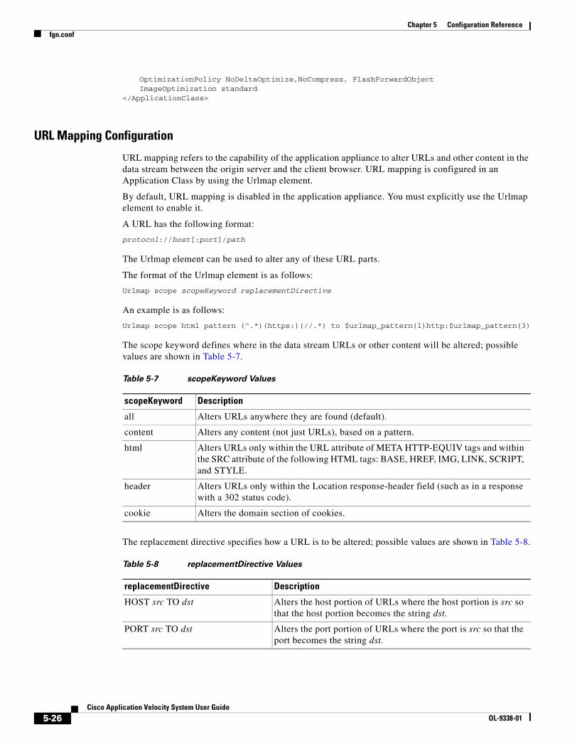
5-26Cisco Application Velocity System User Guide
OL-9338-01
Chapter 5 Configuration Referencefgn.conf
OptimizationPolicy NoDeltaOptimize,NoCompress, FlashForwardObjectImageOptimization standard
</ApplicationClass>
URL Mapping Configuration
URL mapping refers to the capability of the application appliance to alter URLs and other content in the data stream between the origin server and the client browser. URL mapping is configured in an Application Class by using the Urlmap element.
By default, URL mapping is disabled in the application appliance. You must explicitly use the Urlmap element to enable it.
A URL has the following format:
protocol://host[:port]/path
The Urlmap element can be used to alter any of these URL parts.
The format of the Urlmap element is as follows:
Urlmap scope scopeKeyword replacementDirective
An example is as follows:
Urlmap scope html pattern (^.*)(https:)(//.*) to $urlmap_pattern(1)http:$urlmap_pattern(3)
The scope keyword defines where in the data stream URLs or other content will be altered; possible values are shown in Table 5-7.
The replacement directive specifies how a URL is to be altered; possible values are shown in Table 5-8.
Table 5-7 scopeKeyword Values
scopeKeyword Description
all Alters URLs anywhere they are found (default).
content Alters any content (not just URLs), based on a pattern.
html Alters URLs only within the URL attribute of META HTTP-EQUIV tags and within the SRC attribute of the following HTML tags: BASE, HREF, IMG, LINK, SCRIPT, and STYLE.
header Alters URLs only within the Location response-header field (such as in a response with a 302 status code).
cookie Alters the domain section of cookies.
Table 5-8 replacementDirective Values
replacementDirective Description
HOST src TO dst Alters the host portion of URLs where the host portion is src so that the host portion becomes the string dst.
PORT src TO dst Alters the port portion of URLs where the port is src so that the port becomes the string dst.

5-27Cisco Application Velocity System User Guide
OL-9338-01
Chapter 5 Configuration Referencefgn.conf
Using the PATTERN Directive
The PATTERN directive has the syntax: PATTERN src TO dst
The src part uses the regular expression syntax to define subexpressions within the input stream that are to be altered. Subexpressions are delimited using parentheses (). The numbering of the subexpressions begins with 1 and is the number of the left parenthesis ( counting from the left. For example, the following pattern defines three subexpressions in the input stream:
(^.*)(fast)(.*$)
The first subexpression is everything before the word “fast.” The second subexpression is the word “fast.” The third subexpression is everything after the word “fast.”
The dst string specifies the replacement pattern; the complete string defined by src is replaced by the string defined by dst. In the dst string, you can use any of the parameter expander functions listed in Table 5-4 on page 5-16, or one or more $urlmap_pattern(number) variables, which refer back to specific subexpressions in the original input stream.
$urlmap_pattern(0) matches the entire input stream, $urlmap_pattern(1) matches the first subexpression, $urlmap_pattern(2) matches the second subexpression, and so on.
If the specified subexpression does not exist in the input stream, then the variable evaluates to the empty string.
Note The parameter expander functions listed in Table 5-4 apply only to the context of the HTTP request from the client, not to the data stream being sent as a response to the client. For example, the function $http_query_string() evaluates to the query string of the request URL.
For example, given this Urlmap element:
urlmap scope content pattern (^.*)(fast)(.*$) to $urlmap_pattern(1)faster$urlmap_pattern(3)
and this input stream:
Cisco makes accessing the web fast now.
The result will be this stream:
Cisco makes accessing the web faster now.
PROTOCOL HTTP(S) TO HTTP(S) Alters the URL protocol from HTTP to HTTPS or from HTTPS to HTTP.
PATTERN src TO dst Alters any portion of the input stream. The pattern src is a regular expression that defines subexpressions within the input stream that are to be altered. The dst string specifies the replacement pattern. For details, see the “Using the PATTERN Directive” section.
Table 5-8 replacementDirective Values (continued)
replacementDirective Description
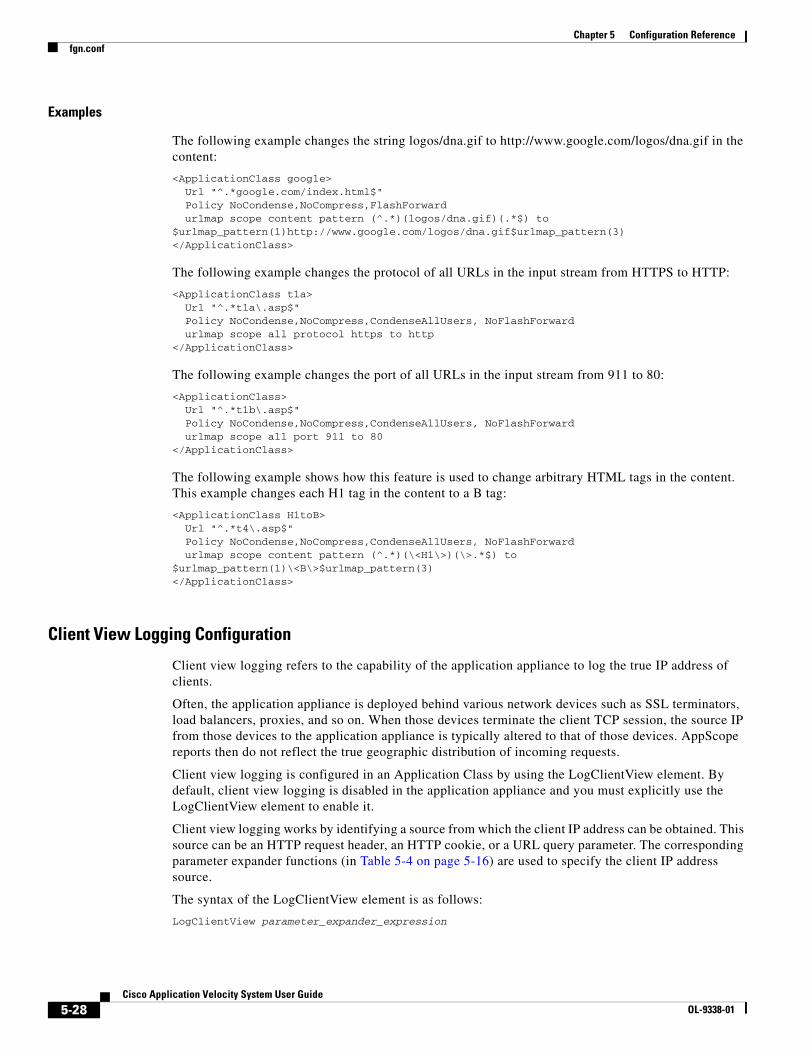
5-28Cisco Application Velocity System User Guide
OL-9338-01
Chapter 5 Configuration Referencefgn.conf
Examples
The following example changes the string logos/dna.gif to http://www.google.com/logos/dna.gif in the content:
<ApplicationClass google>Url "^.*google.com/index.html$"Policy NoCondense,NoCompress,FlashForwardurlmap scope content pattern (^.*)(logos/dna.gif)(.*$) to
$urlmap_pattern(1)http://www.google.com/logos/dna.gif$urlmap_pattern(3)</ApplicationClass>
The following example changes the protocol of all URLs in the input stream from HTTPS to HTTP:
<ApplicationClass t1a>Url "^.*t1a\.asp$"Policy NoCondense,NoCompress,CondenseAllUsers, NoFlashForwardurlmap scope all protocol https to http
</ApplicationClass>
The following example changes the port of all URLs in the input stream from 911 to 80:
<ApplicationClass>Url "^.*t1b\.asp$"Policy NoCondense,NoCompress,CondenseAllUsers, NoFlashForwardurlmap scope all port 911 to 80
</ApplicationClass>
The following example shows how this feature is used to change arbitrary HTML tags in the content. This example changes each H1 tag in the content to a B tag:
<ApplicationClass H1toB>Url "^.*t4\.asp$"Policy NoCondense,NoCompress,CondenseAllUsers, NoFlashForwardurlmap scope content pattern (^.*)(\<H1\>)(\>.*$) to
$urlmap_pattern(1)\<B\>$urlmap_pattern(3)</ApplicationClass>
Client View Logging Configuration
Client view logging refers to the capability of the application appliance to log the true IP address of clients.
Often, the application appliance is deployed behind various network devices such as SSL terminators, load balancers, proxies, and so on. When those devices terminate the client TCP session, the source IP from those devices to the application appliance is typically altered to that of those devices. AppScope reports then do not reflect the true geographic distribution of incoming requests.
Client view logging is configured in an Application Class by using the LogClientView element. By default, client view logging is disabled in the application appliance and you must explicitly use the LogClientView element to enable it.
Client view logging works by identifying a source from which the client IP address can be obtained. This source can be an HTTP request header, an HTTP cookie, or a URL query parameter. The corresponding parameter expander functions (in Table 5-4 on page 5-16) are used to specify the client IP address source.
The syntax of the LogClientView element is as follows:
LogClientView parameter_expander_expression

5-29Cisco Application Velocity System User Guide
OL-9338-01
Chapter 5 Configuration Referencefgn.conf
The expression must evaluate to a well-formed IP address or a list of well-formed IP addresses separated by commas. The first IP address in the list is recorded as the client IP address in the FgnStatLog file. If the expression does not evaluate to an IP address, the source socket IP is logged as the IP address.
The LogClientView element can be defined in a hierarchy along with the Application Class. If the child class does not have LogClientView specified, it inherits the LogClientView specified in the parent class. If the child class has LogClientView specified, it overrides the LogClientView specified in the parent class.
The client IP address of a request, as determined by the LogClientView element, is reported in the FgnStatLog by the <CLO><CIP> entry (see Table A-1 on page A-3).
Examples
This section describes some examples of LogClientView elements that derive the client IP address from different sources.
This first example looks for the client IP address in the HTTP request header true-clinet-ip:
LogClientView $http_header(true-clinet-ip)
The following example looks for the client IP address in the URL query parameter true-clinet-ip:
LogClientView $http_query_param(true-client-ip)
The following example looks for the client IP address in the cookie true-clinet-ip:
LogClientView $http_cookie(true-client-ip)
It is possible that the client view can be derived from multiple places in a request. For example, the true client IP can sometimes be from a cookie, sometimes from a header, and sometimes from a parameter. You can use multiple parameter expander functions in one LogClientView expression, or you can use multiple LogClientView elements in one Application Class.
The evaluation order is the same as the order of the parameter expander functions. During the evaluation process, the first expression encountered with a value is used. If there are multiple values associated with a parameter expander function, the leftmost value is used. If the value is not valid, other values or parameter expander functions are not scanned for consideration.
An example of a single LogClientView expression that includes all three types of parameter expander functions is as follows:
LogClientView $http_header(true-clinet-ip)$http_query_param(true-client-ip)$http_cookie(true-client-ip)
A similar configuration that uses three separate statements to do the same thing is as follows:
LogClientView $http_header(true-clinet-ip)LogClientView $http_query_param(true-client-ip)LogClientView $http_cookie(true-client-ip)
Given the configuration above, and this request:
GET /?true-client-ip=10.0.0.1 HTTP/1.1true-client-ip: 192.168.0.1Cookie: true-client-ip="209.140.0.1"
The application appliance will log the IP 192.168.0.1 as the true client IP address because the $http_header expression is evaluated and satisfied first.
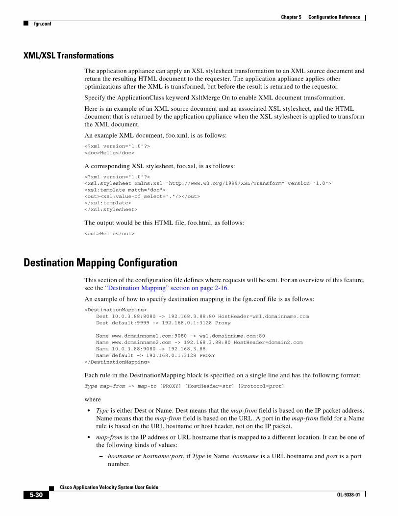
5-30Cisco Application Velocity System User Guide
OL-9338-01
Chapter 5 Configuration Referencefgn.conf
XML/XSL Transformations
The application appliance can apply an XSL stylesheet transformation to an XML source document and return the resulting HTML document to the requester. The application appliance applies other optimizations after the XML is transformed, but before the result is returned to the requestor.
Specify the ApplicationClass keyword XsltMerge On to enable XML document transformation.
Here is an example of an XML source document and an associated XSL stylesheet, and the HTML document that is returned by the application appliance when the XSL stylesheet is applied to transform the XML document.
An example XML document, foo.xml, is as follows:
<?xml version="1.0"?><doc>Hello</doc>
A corresponding XSL stylesheet, foo.xsl, is as follows:
<?xml version="1.0"?> <xsl:stylesheet xmlns:xsl="http://www.w3.org/1999/XSL/Transform" version="1.0"><xsl:template match="doc"><out><xsl:value-of select="."/></out></xsl:template></xsl:stylesheet>
The output would be this HTML file, foo.html, as follows:
<out>Hello</out>
Destination Mapping ConfigurationThis section of the configuration file defines where requests will be sent. For an overview of this feature, see the “Destination Mapping” section on page 2-16.
An example of how to specify destination mapping in the fgn.conf file is as follows:
<DestinationMapping>Dest 10.0.3.88:8080 -> 192.168.3.88:80 HostHeader=ws1.domainname.comDest default:9999 -> 192.168.0.1:3128 Proxy
Name www.domainname1.com:9080 -> ws1.domainname.com:80Name www.domainname2.com -> 192.168.3.88:80 HostHeader=domain2.comName 10.0.3.88:9080 -> 192.168.3.88 Name default -> 192.168.0.1:3128 PROXY
</DestinationMapping>
Each rule in the DestinationMapping block is specified on a single line and has the following format:
Type map-from -> map-to [PROXY] [HostHeader=str] [Protocol=prot]
where
• Type is either Dest or Name. Dest means that the map-from field is based on the IP packet address. Name means that the map-from field is based on the URL. A port in the map-from field for a Name rule is based on the URL hostname or host header, not on the IP packet.
• map-from is the IP address or URL hostname that is mapped to a different location. It can be one of the following kinds of values:
– hostname or hostname:port, if Type is Name. hostname is a URL hostname and port is a port number.

5-31Cisco Application Velocity System User Guide
OL-9338-01
Chapter 5 Configuration Referencefgn.conf
– IPaddress or IPaddress:port, if Type is Dest. IPaddress is an IP address and port is a port number.
– default or default:port, valid for both Types of rules. port is a port number. The default keyword represents all map-from locations other than those previously specified in the rules block. If default without a specific port is needed, it must be the last rule; any subsequent rules are ignored. Multiple default rules specific to different ports are valid.
If port is not specified in the map-from value, it means to map all ports.
• map-to is the symbolic or numeric address to which map-from is mapped. It can be one of the following kinds of values:
– hostname or hostname:port, where hostname is a URL hostname and port is a port number.
– IPaddress or IPaddress:port, where IPaddress is an IP address and port is a port number.
– If Type is Name and the map-from value is default, then you can specify the value default for map-to also. This setting directs the connection to the host whose name is the same as what the Host header specifies. This rule is useful if an internal DNS server alters the DNS resolution.
An example of this rule is as follows:Name default -> default Protocol=ClientProtocol
If port is not specified in the map-to value, it means to use the port specified in the map-from value.
• PROXY is an optional keyword that indicates the mapping is a proxy request. It ensures that the application appliance sends the absolute URI to the mapped proxy server.
• HostHeader=str optionally directs the application appliance to replace the host header value with the value of the string specified by str. It has no impact on which server the application appliance connects to.
• Protocol=prot optionally directs the application appliance to connect to the backend (origin) server by using the protocol specified by prot. Valid protocol values are as follows:
– HTTP: Use the HTTP protocol. This is the default.
– HTTPS: Use the HTTPS protocol. Specify this value for SSL proxy mode.
– ClientProtocol: Use the same protocol as specified by the client request. This value also uses SSL proxy mode, but only if the client request uses HTTPS.
If two rules overlap, the first one listed takes precedence.
The rules are not case sensitive.
Destination Mapping Examples
This section provides some typical examples that show how to specify destination mapping rules.
Example 1
In this example, the application appliance handles both an intranet application on domain name testIntranet.enterprise.com (the origin server runs at 10.0.0.5 on port 80) and an Internet application. The Internet application has to be accessed through a corporate proxy server 10.0.0.1 on port 3128.
<DestinationMapping>Name testIntranet.enterprise.com -> 10.0.0.5:80Name default -> 10.0.0.1:3128 PROXY
</DestinationMapping>
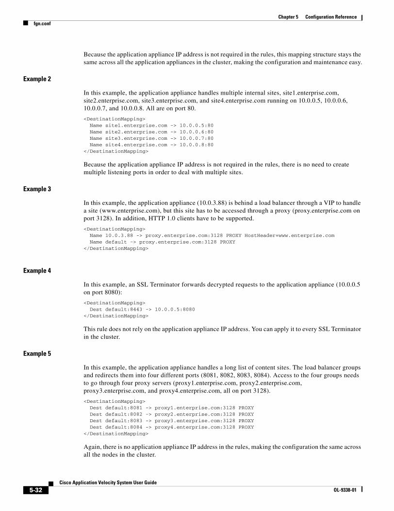
5-32Cisco Application Velocity System User Guide
OL-9338-01
Chapter 5 Configuration Referencefgn.conf
Because the application appliance IP address is not required in the rules, this mapping structure stays the same across all the application appliances in the cluster, making the configuration and maintenance easy.
Example 2
In this example, the application appliance handles multiple internal sites, site1.enterprise.com, site2.enterprise.com, site3.enterprise.com, and site4.enterprise.com running on 10.0.0.5, 10.0.0.6, 10.0.0.7, and 10.0.0.8. All are on port 80.
<DestinationMapping>Name site1.enterprise.com -> 10.0.0.5:80Name site2.enterprise.com -> 10.0.0.6:80Name site3.enterprise.com -> 10.0.0.7:80Name site4.enterprise.com -> 10.0.0.8:80
</DestinationMapping>
Because the application appliance IP address is not required in the rules, there is no need to create multiple listening ports in order to deal with multiple sites.
Example 3
In this example, the application appliance (10.0.3.88) is behind a load balancer through a VIP to handle a site (www.enterprise.com), but this site has to be accessed through a proxy (proxy.enterprise.com on port 3128). In addition, HTTP 1.0 clients have to be supported.
<DestinationMapping>Name 10.0.3.88 -> proxy.enterprise.com:3128 PROXY HostHeader=www.enterprise.comName default -> proxy.enterprise.com:3128 PROXY
</DestinationMapping>
Example 4
In this example, an SSL Terminator forwards decrypted requests to the application appliance (10.0.0.5 on port 8080):
<DestinationMapping>Dest default:8443 -> 10.0.0.5:8080
</DestinationMapping>
This rule does not rely on the application appliance IP address. You can apply it to every SSL Terminator in the cluster.
Example 5
In this example, the application appliance handles a long list of content sites. The load balancer groups and redirects them into four different ports (8081, 8082, 8083, 8084). Access to the four groups needs to go through four proxy servers (proxy1.enterprise.com, proxy2.enterprise.com, proxy3.enterprise.com, and proxy4.enterprise.com, all on port 3128).
<DestinationMapping>Dest default:8081 -> proxy1.enterprise.com:3128 PROXYDest default:8082 -> proxy2.enterprise.com:3128 PROXYDest default:8083 -> proxy3.enterprise.com:3128 PROXYDest default:8084 -> proxy4.enterprise.com:3128 PROXY
</DestinationMapping>
Again, there is no application appliance IP address in the rules, making the configuration the same across all the nodes in the cluster.
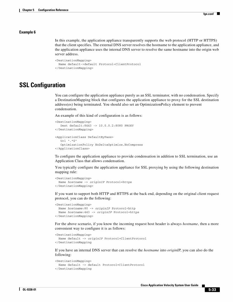
5-33Cisco Application Velocity System User Guide
OL-9338-01
Chapter 5 Configuration Referencefgn.conf
Example 6
In this example, the application appliance transparently supports the web protocol (HTTP or HTTPS) that the client specifies. The external DNS server resolves the hostname to the application appliance, and the application appliance uses the internal DNS server to resolve the same hostname into the origin web server address.
<DestinationMapping>Name default->default Protocol=ClientProtocol
</DestinationMapping>
SSL ConfigurationYou can configure the application appliance purely as an SSL terminator, with no condensation. Specify a DestinationMapping block that configures the application appliance to proxy for the SSL destination address(es) being terminated. You should also set an OptimizationPolicy element to prevent condensation.
An example of this kind of configuration is as follows:
<DestinationMapping>Dest default:8443 -> 10.0.0.2:8080 PROXY
</DestinationMapping>
<ApplicationClass DefaultByPass>Url ".*$"OptimizationPolicy NoDeltaOptimize,NoCompress
</ApplicationClass>
To configure the application appliance to provide condensation in addition to SSL termination, use an Application Class that allows condensation.
You typically configure the application appliance for SSL proxying by using the following destination mapping rule:
<DestinationMapping>Name hostname -> originIP Protocol=https
</DestinationMapping>
If you want to support both HTTP and HTTPS at the back end, depending on the original client request protocol, you can do the following:
<DestinationMapping>Name hostname:80 -> originIP Protocol=httpName hostname:443 -> originIP Protocol=https
</DestinationMapping>
For the above scenario, if you know the incoming request host header is always hostname, then a more convenient way to configure it is as follows:
<DestinationMapping>Name default -> originIP Protocol=ClientProtocol
</DestinationMapping
If you have an internal DNS server that can resolve the hostname into originIP, you can also do the following:
<DestinationMapping>Name default -> default Protocol=ClientProtocol
</DestinationMapping

5-34Cisco Application Velocity System User Guide
OL-9338-01
Chapter 5 Configuration Referencefgn.conf
This destination mapping is particularly useful in a test environment where you can add an entry “hostname applicationApplianceIP” into your client hosts file. Then your client machine will resolve the hostname into the applicationApplianceIP, making the request go to the application appliance. But the hostname will be resolved at the application appliance into the actual origin server virtual IP address.
For details on defining the DestinationMapping block, see the “Destination Mapping Configuration” section on page 5-30. For details on defining the Application Class, see the “Application Class Specification” section on page 5-7.
Dynamic Caching Configuration GuidelinesBefore deploying the application appliance, we recommend that you analyze traffic patterns to determine the suitability of the various features offered by the application appliance (FlashForward, adaptive dynamic caching, image optimization, compression, and so on). There are many ways to determine the optimal configuration settings in an fgn.conf configuration file; however, follow these guidelines to provide a framework to guide the process of configuring dynamic caching:
• When is Dynamic Caching Appropriate?, page 5-34
• When is Dynamic Caching Inappropriate?, page 5-35
• Configuring Dynamic Caching, page 5-35
For reference information on configuring dynamic caching in the fgn.conf file, see the “Adaptive Caching Configuration” section on page 5-18.
When is Dynamic Caching Appropriate?
Dynamic caching is appropriate in the following cases:
• Dynamic caching is useful only if the response can be reused over some period of time, however short.
• Dynamic caching is useful only if a cached response can be used multiple times before the response expires. This can happen in one of the following ways:
– The same response is usable by multiple users within a certain period of time (the content is sharable). This is the ideal situation. It can be useful even if the cache expiration period is very small, if enough users access the response within that period. An example would be a hierarchical directory browser application (a catalog store or a document management application) where the directory is generated dynamically, but is the same view seen by all users. Dynamic caching can avoid the cost of regenerating the directory pages for each user.
– The response is usable by only a single user (it is personalized), but the user accesses it multiple times. This can happen in one of the following ways:
The reuse of the response occurs across multiple browser sessions for that user (for example, the response generated in one session can be used unchanged in a second session).
The reuse of the response can occur only within a single browser session because the response is tied to that particular session.
• Dynamically cacheable responses are identifiable using one or more of the following:
– The URL matches a regular expression.
– The presence or absence of specific query parameters.
– The presence or absence of specific cookies in the request.
5-35Cisco Application Velocity System User Guide
OL-9338-01
Chapter 5 Configuration Referencefgn.conf
– The presence or absence of specific HTTP headers in the request.
For example, a particular application uses the same URL for various actions, only some of which are cacheable. Consider the case where the URLs in the application are as follows:
1. http://xyz.com/doit.jsp?action=login&username=xyz
2. http://xyz.com/doit.jsp?action=browse&level=1
3. http://xyz.com/doit.jsp?action=browser&level=2
All the URLs are the same; however, the response to (1) cannot be cached, but assume the response to (2) and (3) can be cached. In this case, dynamic caching is achievable by testing for the presence or absence of the username query parameter by using an IF/ELSE/ENDIF conditional block.
When is Dynamic Caching Inappropriate?
Dynamic caching is not appropriate in the following cases:
• The response becomes stale immediately upon delivery. Examples of this are as follows:
– The response sets cookies that are specific to that session. For example, the response to a login page is specific to a particular session.
– The response contains data that is specific to a previous action in the session. For example, a confirmation number for a transaction that was just executed is not cacheable.
• The life of a response is indeterminate. The response contains data that becomes stale based on a future action. For example, the portfolio page of a brokerage account user changes when the user executes transactions.
• Different versions of the response cannot be distinguished using the URL, the URL query parameters, or the cookies in the request. For example, the response contains some personalized settings such as the name of the user; however, there is no URL query parameter or cookie to directly identify the user. There is something in the request that indirectly identifies the user in order for the origin server to generate the personalized response, for example, a session cookie. You could dynamically cache a version of the page that is different for each user session. In this case, dynamic caching is useful only if the user accesses the page multiple times within a single browser session.
Configuring Dynamic Caching
Once you establish that dynamic caching is appropriate for a page, you must configure it in the application appliance. To configure dynamic caching, follow these steps:
1. Identify the URL or URLs for an Application Class. This involves developing the regular expression to match the URL(s).
– Run the performance test using the Accelerometer or another performance testing program on the LAN. The LAN is used so that the focus is on identifying server latency problems, not network latency problems.
– Examine the error log to look at entries where the origin server response time is large. Large means that it is a significant part of the page download time as measured by the end user. For example, if a page download on the LAN takes 10 seconds, then any individual component download with an origin server response time of greater than 1 second is worth examining.
– This will identify the list of URLs to target.
2. Identify the dynamically cacheable instances of the URL. This should include the following:
– The regular expression matching the URL.

5-36Cisco Application Velocity System User Guide
OL-9338-01
Chapter 5 Configuration Referencefgn.conf
– In case the regular expression matches many responses, some of which can be dynamically cached, and some which cannot be cached, check if the cacheable responses can be separated from the uncacheable ones by testing for the presence or absence of specific query parameters, cookies, or HTTP headers. If so, use an IF/ELSE/ENDIF conditional block to set up different policies for the different responses (see the “Using Conditional Blocks” section on page 5-18).
3. Identify the versions of the response. Once the dynamically cacheable instances are identified, then determine how many different versions of the response are to be cached using Cache Parameterization. Look at the request parameters and the response content to determine what defines the content of the response. Examine these request parameters:
– URL and its components
– Query parameters
– Cookies
– HTTP header values
Develop the minimal set of parameters that uniquely determine the content of the response. Add CacheParameter and CacheKeyModifier settings to the Application Class for this URL. For example:
– The response is determined uniquely by the URL and all its parameters. In this case, nothing needs to be done because that is the default cache key.
– The response is determined by only some of the parameters. In this case, use CacheParameter to specify those parameters. For example, a site might have a URL similar to: http://xyz.com/dosomething.asp?action=browse&dir=x&session=13345. The contents of the response might be determined by the “action” and “dir” query parameters, and the “session” query parameter has no bearing on the response. In that case, use the following settings:
CacheParameter $http_query_param(action)CacheParameter $http_query_param(dir)
– The response is dependent on the value of some cookie(s). Add them to the CacheParameter list, as follows:
CacheParameter $http_cookie(foo)
– Some parts of the URL need to be ignored. For example, some sites embed the session ID in the URL itself, but the response is not dependent on the session ID. The URL subexpressions can be used in the CacheKeyModifier. For example, if a site has a URL similar to: http://xyz.com/sess12345/dosomething.asp?action=browse&dir=x, if “sess12345” has no bearing on the response, then specify the URL-matching regular expression and CacheKeyModifier as follows:
Url "^(.*)/(sess.*)/(dosomething.asp)$"CacheKeyModifier $(1)/$(3)
This configuration eliminates the (sessNNNNN) string from the cache key.
4. Identify how long the response can be cached. Consider the nature of the content. For example, a new item may be viewed for 3 hours after which it becomes stale.
The two main timing related parameters are CacheMinTTL and CacheMaxTTL. The minimum time-to-live (CacheMinTTL) is the minimum time that the content can be cached, which corresponds to the live-time of the content. If a new item is valid for 3 hours, this value would be 3*60*60 = 10800 seconds. The maximum time-to-live (CacheMaxTTL) is used to determine how the application appliance handles the case when the object has passed its CacheMinTTL value.

5-37Cisco Application Velocity System User Guide
OL-9338-01
Chapter 5 Configuration Referencehttpd.conf
You can also configure object expiration using performance assurance with load-based expiration, which allows you to dynamically increase the time-to-live of cached responses, if the current response time (average computed over a short time window) from the origin servers is larger than the average response time (average computed over a longer time window) by a threshold amount. Similarly, the TTL is dynamically decreased if the reverse holds true.
For more details on configuring cache expiration, see the “Configuring Cache Object Expiration” section on page 5-22.
httpd.confThe httpd.conf file is the standard Apache web server configuration file, slightly modified for the application appliance. This file includes the fgn.conf configuration file by reference.
You may want to modify the following entries:
• Port—Set this to the port on which you want to allow access to the application appliance server for HTTP requests.
• AdminPort—Set this to the port on which you want to allow access to the application appliance management functions from the Management Console.
• Listen—Set this to each port on which you want the application appliance to listen for requests. There can be multiple Listen entries for HTTP, HTTPS, and management function requests.
• User—Change this entry to the user under which the server should be run. This is set to nobody by default.
• Group—Change this entry to the group under which the server should be run. This is set to nobody by default.
• ServerAdmin—Change this to the e-mail address of the server administrator for error reporting.
• MaxClients—Sets the maximum number of concurrent clients (active TCP/IP sessions) that the application appliance can support. This keyword is set to 500 by default.
• SSL entries, including Listen and VirtualHost—Change these entries to enable the application appliance to handle SSL connections. For details, see the “SSL Configuration Entries” section.
• LogLevel—Use this entry to enable a debugging level of logging. For details, see the “Logging Level” section.
• FgnLogFormat and CustomLog—Use these entries to define and use an extended access_log format. For details, see Appendix A, “Logs.”
• CoreDumpDirectory—Use this entry to change where core files are located.
SSL Configuration EntriesTo configure the application appliance to handle SSL connections, you must set Listen and VirtualHost configuration entries.
Listen is defined as follows:
<IfDefine SSL>Listen 8443</IfDefine>
Set the port to listen to for SSL connections.

5-38Cisco Application Velocity System User Guide
OL-9338-01
Chapter 5 Configuration Referencemimetypes.conf
The VirtualHost block is defined as follows:
<VirtualHost _default_:443>SSLCertificateFile file-pathSSLCertificateKeyFile file-path…………</VirtualHost >
Set the SSLCertificateFile entry to a PEM-encoded certificate. If the certificate is encrypted, you will be prompted for a pass phrase.
Set the SSLCertificateKeyFile entry to the key file, if it is not combined with the certificate.
The application appliance can support multiple certificates through multiple virtual hosts. Each virtual host supports a single certificate.
Logging LevelNormally, you will not need to change the LogLevel configuration entry, which controls the logging level employed by the application appliance. The normal setting of this directive is as follows:
LogLevel error
To configure the application appliance so that statistical log entries are written both to the error_log file and the FgnStatLog file, set LogLevel to debug. Normally, statistical log entries are written only the FgnStatLog file, as described in the “Log File Management” section on page A-1.
Do not use the LogLevel debug directive except when testing, as this will slow performance and generate much unnecessary log information.
mimetypes.confThe mimetypes.conf file is used to configure MIME type support for the application appliance. It contains a list of MIME types that are excluded from condensation and/or compression.
Whenever the application appliance receives data from the origin server, it checks the MIME type of the data against the entries in this file. If the MIME type of the data matches one of the MIME types listed in this file, the data is not condensed if the directive is NoDeltaOptimizeMimeType, and it is not compressed if the directive is NoCompressMimeType.
An example of specifying a MIME type that is not to be condensed is as follows:
NoDeltaOptimizeMimeType application/pdf
An example of specifying a MIME type that is not to be compressed is as follows:
NoCompressMimeType application/x-javascript
You can use regular expressions in the mimetypes.conf file to specify MIME types to be excluded from condensation.
For more details about MIME type exclusion, see the “MIME-Type Exclusion” section on page 2-16.
Note The application appliance requires GNU POSIX regular expression syntax. For details, see Appendix F, “Regular Expressions.”
5-39Cisco Application Velocity System User Guide
OL-9338-01
Chapter 5 Configuration Referenceuseragent.conf
useragent.confThe useragent.conf file is used to configure user agent (browser) support for delta optimization. It contains a list of user agent identifiers for user agents that support delta optimization. The user agent identifiers are strings that correspond to the HTTP User-Agent header returned by browsers.
If the application appliance receives a request from a browser that has a user-agent string that is not listed in this file, then content will not receive delta optimization for that request but will receive all other appropriate optimizations.
You can use regular expressions (using the GNU POSIX syntax) in the useragent.conf file to specify user agents that should explicitly receive delta optimization. For details, see Appendix F, “Regular Expressions.”
Tip You should only list user agents that you know are supported for delta optimization. For details on supported browsers, see the “Web Browser Support” section on page 2-3.
fgnsnmpd.confThe fgnsnmpd.conf file is used to configure SNMP support. The most import configuration directive in this file is the Port directive:
Port 8080
If you change the default port that the application appliance listens to for HTTP requests, you must also change this Port directive to the same port.
For additional SNMP information, see Appendix B, “SNMP MIB.”
magentd.confThe magentd.conf file is used to configure the community string for sending SNMP traps. The default directive is as follows:
COMMUNITY public ALLOW ALL OPERATIONS USE NO ENCRYPTION
To specify a different community string, change public to a different string.

5-40Cisco Application Velocity System User Guide
OL-9338-01
Chapter 5 Configuration Referencemagentd.conf

C H A P T E R
6-1Cisco Application Velocity System User Guide
OL-9338-01
6Web Application Security Configuration
This chapter describes how to configure web application security. The following topics are covered:
• Overview
• Global Configuration and Utilities
• Security Feature Configuration
• Web Application Security Regular Expression Syntax
OverviewThe web application security feature enables the application appliance to act as an application firewall and provide web application security and intrusion protection.
Note The web application security module described in this chapter supersedes the AppScreen security feature described in Chapter 7, “AppScreen Configuration,” which is still available and operates as before for backward compatibility. For the highest level of web application security, we recommend that you use the web application security module described in this chapter instead of AppScreen.
Web application security is highly configurable, and can protect against the following kinds of application attacks:
• identity theft
• SQL, OS, and LDAP command injection
• cross site scripting
• meta character and format string attacks
• buffer overflow
• form exploitation
• URL redirects and directory traversal
• error message exploitation
• cookie exploitation
• noncompliant HTTP
• web server fingerprinting
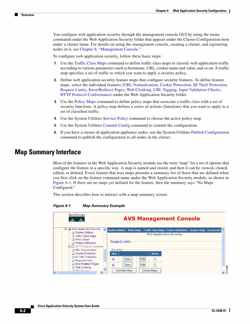
6-2Cisco Application Velocity System User Guide
OL-9338-01
Chapter 6 Web Application Security ConfigurationOverview
You configure web application security through the management console GUI by using the menu commands under the Web Application Security folder that appears under the Cluster Configuration item under a cluster name. For details on using the management console, creating a cluster, and registering nodes in it, see Chapter 8, “Management Console.”
To configure web application security, follow these basic steps:
1. Use the Traffic Class Maps command to define traffic class maps to classify web application traffic according to various parameters such as hostname, URL, cookie name and value, and so on. A traffic map specifies a set of traffic to which you want to apply a security policy.
2. Define web application security feature maps that configure security features. To define feature maps, select the individual features (URL Normalization, Cookie Protection, ID Theft Protection, Request Limits, Error/Redirect Pages, Web Cloaking, URL Tagging, Input Validation Checks, HTTP Protocol Conformance) under the Web Application Security folder.
3. Use the Policy Maps command to define policy maps that associate a traffic class with a set of security functions. A policy map defines a series of actions (functions) that you want to apply to a set of classified traffic.
4. Use the System Utilities Service Policy command to choose the active policy map.
5. Use the System Utilities Commit Config command to commit the configuration.
6. If you have a cluster of application appliance nodes, use the System Utilities Publish Configuration command to publish the configuration to all nodes in the cluster.
Map Summary InterfaceMost of the features in the Web Application Security module use the term “map” for a set of options that configure the feature in a specific way. A map is named and stored, and then it can be viewed, cloned, edited, or deleted. Every feature that uses maps presents a summary list of those that are defined when you first click on the feature command name under the Web Application Security module, as shown in Figure 6-1. If there are no maps yet defined for the feature, then the summary says “No Maps Configured.”
This section describes how to interact with a map summary screen.
Figure 6-1 Map Summary Example
6-3Cisco Application Velocity System User Guide
OL-9338-01
Chapter 6 Web Application Security ConfigurationGlobal Configuration and Utilities
The example in Figure 6-1 shows the map summary that is displayed when you click on the Request Limits command. Every other map summary looks similar and contains similar controls. The following paragraphs describe how to use the controls on a map summary page.
Each row in the summary lists one defined map. Using the controls on a summary row you can view, clone, edit, or delete the map.
To view the definition of a map, click its underlined name at the left end of the row. The displayed page shows a read-only listing of the map definition.
To copy a map to use as the basis of a new map, click the Clone button next to the map that you want to clone. AVS displays a map editing screen that is similar to the one shown when you are adding a new map, except that all the settings are copied from the map that you cloned.
To edit a map, click the Edit button in the summary. AVS displays a map editing screen where you can change the settings in the map.
To delete one or more maps, check the box in the Delete column for each map that you want to delete. Then click the Delete Maps button to delete the checked maps.
To add a new map, click the Add New Map button to display a map editing screen where you can define the map and give it a name. The sections throughout this chapter describe the unique map editing screens for each feature.
You can click the links in the blue bar at the top of the frame to go directly to the screens identified by name.
Global Configuration and UtilitiesThis section describes the following global configuration and utility items that appear under the Web Application Security folder in the lefthand menu of the management console:
• System Utilities
• Traffic Class Maps
• Policy Maps
• Pattern Definitions
System UtilitiesVarious utilities let you manage web application security configuration, logging, and statistics.
Use the System Utilities command to display a page that contains links to the system utilities, as shown in Figure 6-2. To use a utility function, click on its link.

6-4Cisco Application Velocity System User Guide
OL-9338-01
Chapter 6 Web Application Security ConfigurationGlobal Configuration and Utilities
Figure 6-2 Utilities Page
The following sections describe the two groups of items listed on the System Utilities page:
• Display Utilities
• Configuration Utilities
Display Utilities
The utilities grouped under the Display Utilities heading let you display various information. The following items are included:
• Startup Configuration
• Running Configuration
• New Configuration
• System Stats
• Traffic Level Stats
• Policy Level Stats
• Current Log
• Saved Log
• Show Version
• Show Tech Support
• Default Config
Startup Configuration
The Startup Configuration link displays the default web application security configuration. This information is not relevant for users; it is for debugging only.
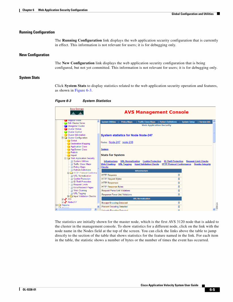
6-5Cisco Application Velocity System User Guide
OL-9338-01
Chapter 6 Web Application Security ConfigurationGlobal Configuration and Utilities
Running Configuration
The Running Configuration link displays the web application security configuration that is currently in effect. This information is not relevant for users; it is for debugging only.
New Configuration
The New Configuration link displays the web application security configuration that is being configured, but not yet committed. This information is not relevant for users; it is for debugging only.
System Stats
Click System Stats to display statistics related to the web application security operation and features, as shown in Figure 6-3.
Figure 6-3 System Statistics
The statistics are initially shown for the master node, which is the first AVS 3120 node that is added to the cluster in the management console. To show statistics for a different node, click on the link with the node name in the Nodes field at the top of the screen. You can click the links above the table to jump directly to the section of the table that shows statistics for the feature named in the link. For each item in the table, the statistic shows a number of bytes or the number of times the event has occurred.

6-6Cisco Application Velocity System User Guide
OL-9338-01
Chapter 6 Web Application Security ConfigurationGlobal Configuration and Utilities
Traffic Level Stats
Click Traffic Level Stats to display statistics organized by traffic classification map. The display looks similar to that shown in Figure 6-3, but a full set of statistics is listed for each traffic class map. Links to each of the traffic class maps appear across the top of the screen; click one to jump to the statistics for that map. For more information about traffic class maps, see the “Traffic Class Maps” section on page 6-17.
The statistics are initially shown for the master node, which is the first AVS 3120 node that is added to the cluster in the management console. To show statistics for a different node, click on the link with the node name in the Nodes field at the top of the screen.
Policy Level Stats
Click Policy Level Stats to display statistics organized by policy map. The display looks similar to that shown in Figure 6-3, but a full set of statistics is listed for each policy map. Links to each of the policy maps appear across the top of the screen; click one to jump to the statistics for that map. For more information about policy maps, see the “Policy Maps” section on page 6-21.
The statistics are initially shown for the master node, which is the first AVS 3120 node that is added to the cluster in the management console. To show statistics for a different node, click on the link with the node name in the Nodes field at the top of the screen.
Current Log
Click Current Log to display the current web application security log, as shown in Figure 6-4. The content of the current log varies depending on your system configuration, as follows:
• If you have an AVS 3180 Management Station, then Current Log displays the log file of the master node (the first AVS 3120 node that was added to the cluster).
• If you do not have an AVS 3180 Management Station, then Current Log displays the log file of the current AVS 3120 node on which you are running the management console.

6-7Cisco Application Velocity System User Guide
OL-9338-01
Chapter 6 Web Application Security ConfigurationGlobal Configuration and Utilities
Figure 6-4 Current Log Display
You can scroll the log window to the right to see additional columns that include the URI, the feature responsible for the log entry, the policy map, traffic class map, feature map, and the log message. The policy map, traffic class map, and feature map names are hyperlinks, which when clicked will take you to a screen where you can edit the named map.
This page displays log entries from all web application security features by default. You can filter the displayed log items by feature by choosing the feature from the Filter By Feature drop-down list. Then click Refresh Saved Logs.
You can clear the current log file by using Clear Current Logs.
Saved Log
Click Saved Log to display the saved log, which looks similar to Figure 6-4. The saved log item works differently, depending on your system configuration, as follows:
• If you have an AVS 3180 Management Station, then Saved Log displays the aggregate log file of all AVS 3120 nodes that are part of the cluster in the management console. (In order to aggregate log files from all nodes in the cluster, you must configure all nodes to send log messages to the AVS 3180 Management Station, as described in the “Log Server Config” section on page 6-16.)
• If you do not have an AVS 3180 Management Station, then Saved Log displays nothing and is not useful.
The log filtering works the same as for Current Log.
Show Version
Click Show Version to display version information about the web application security software.

6-8Cisco Application Velocity System User Guide
OL-9338-01
Chapter 6 Web Application Security ConfigurationGlobal Configuration and Utilities
Show Tech Support
Click Show Tech Support to display information about the web application security software that can be helpful for technical support.
Default Config
Click Default Config to display a page that controls the defaults for various web application security features, as shown in Figure 6-5.
Figure 6-5 Default Configuration
This page lists the web application security features and pattern definitions that can have default configurations. A default configuration is the configuration that appears when you create a new map for a feature.
To view the default configuration for a feature or pattern definition, click the View link next to its name. To enable the feature or pattern definition to have a default configuration, check the Enable check box.
If you make any changes to this screen, click Apply Changes at the top to save your changes, or click another AVS command in the lefthand menu to exit this screen without saving your changes.
6-9Cisco Application Velocity System User Guide
OL-9338-01
Chapter 6 Web Application Security ConfigurationGlobal Configuration and Utilities
You can change the default configuration for a feature or pattern definition by creating a new map for it, configuring the settings as needed, and clicking the Set As Default button. Creating a default in this way will automatically enable the default configuration if it is not already enabled.
Configuration Utilities
The utilities grouped under the Configuration Utilities heading let you manage the global web application security configuration and logging. The following items are included:
• System Settings
• Cluster Control
• Publish Configuration
• Service Policy
• Clear System Config
• Commit Config
• Force Commit
• Save Config
• Clear Config
• Clear System Stats
• Clear Traffic Stats
• Clear Policy Stats
• Log Server Config
• Clear Current Logs
System Settings
Click System Settings to display a page that controls overall web application security system operation, as shown in Figure 6-6.
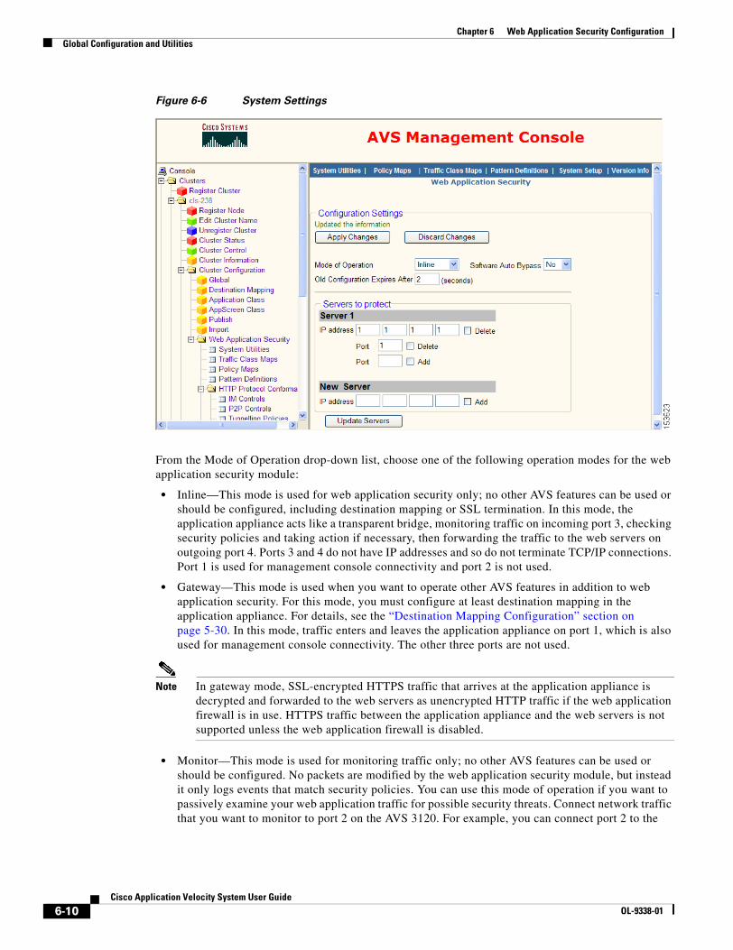
6-10Cisco Application Velocity System User Guide
OL-9338-01
Chapter 6 Web Application Security ConfigurationGlobal Configuration and Utilities
Figure 6-6 System Settings
From the Mode of Operation drop-down list, choose one of the following operation modes for the web application security module:
• Inline—This mode is used for web application security only; no other AVS features can be used or should be configured, including destination mapping or SSL termination. In this mode, the application appliance acts like a transparent bridge, monitoring traffic on incoming port 3, checking security policies and taking action if necessary, then forwarding the traffic to the web servers on outgoing port 4. Ports 3 and 4 do not have IP addresses and so do not terminate TCP/IP connections. Port 1 is used for management console connectivity and port 2 is not used.
• Gateway—This mode is used when you want to operate other AVS features in addition to web application security. For this mode, you must configure at least destination mapping in the application appliance. For details, see the “Destination Mapping Configuration” section on page 5-30. In this mode, traffic enters and leaves the application appliance on port 1, which is also used for management console connectivity. The other three ports are not used.
Note In gateway mode, SSL-encrypted HTTPS traffic that arrives at the application appliance is decrypted and forwarded to the web servers as unencrypted HTTP traffic if the web application firewall is in use. HTTPS traffic between the application appliance and the web servers is not supported unless the web application firewall is disabled.
• Monitor—This mode is used for monitoring traffic only; no other AVS features can be used or should be configured. No packets are modified by the web application security module, but instead it only logs events that match security policies. You can use this mode of operation if you want to passively examine your web application traffic for possible security threats. Connect network traffic that you want to monitor to port 2 on the AVS 3120. For example, you can connect port 2 to the
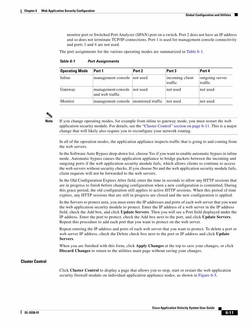
6-11Cisco Application Velocity System User Guide
OL-9338-01
Chapter 6 Web Application Security ConfigurationGlobal Configuration and Utilities
monitor port or Switched Port Analyzer (SPAN) port on a switch. Port 2 does not have an IP address and so does not terminate TCP/IP connections. Port 1 is used for management console connectivity and ports 3 and 4 are not used.
The port assignments for the various operating modes are summarized in Table 6-1.
Note If you change operating modes, for example from inline to gateway mode, you must restart the web application security module. For details, see the “Cluster Control” section on page 6-11. This is a major change that will likely also require you to reconfigure your network routing.
In all of the operation modes, the application appliance inspects traffic that is going to and coming from the web servers.
In the Software Auto Bypass drop-down list, choose Yes if you want to enable automatic bypass in inline mode. Automatic bypass causes the application appliance to bridge packets between the incoming and outgoing ports if the web application security module fails, which allows clients to continue to access the web servers without security checks. If you choose No and the web application security module fails, client requests will not be forwarded to the web servers.
In the Old Configuration Expires After field, enter the time in seconds to allow any HTTP sessions that are in progress to finish before changing configuration when a new configuration is committed. During this grace period, the old configuration still applies to active HTTP sessions. When this period of time expires, any HTTP sessions that are still in progress are closed and the new configuration is applied.
In the Servers to protect area, you must enter the IP addresses and ports of each web server that you want the web application security module to protect. Enter the IP address of a web server in the IP address field, check the Add box, and click Update Servers. Then you will see a Port field displayed under the IP address. Enter the port to protect, check the Add box next to the port, and click Update Servers. Repeat this procedure to add each port that you want to protect on the web server.
Repeat entering the IP address and ports of each web server that you want to protect. To delete a port or web server IP address, check the Delete check box next to the port or IP address and click Update Servers.
When you are finished with this form, click Apply Changes at the top to save your changes, or click Discard Changes to return to the utilities main page without saving your changes.
Cluster Control
Click Cluster Control to display a page that allows you to stop, start or restart the web application security firewall module on individual application appliance nodes, as shown in Figure 6-5.
Table 6-1 Port Assignments
Operating Mode Port 1 Port 2 Port 3 Port 4
Inline management console not used incoming client traffic
outgoing server traffic
Gateway management console and web traffic
not used not used not used
Monitor management console monitored traffic not used not used
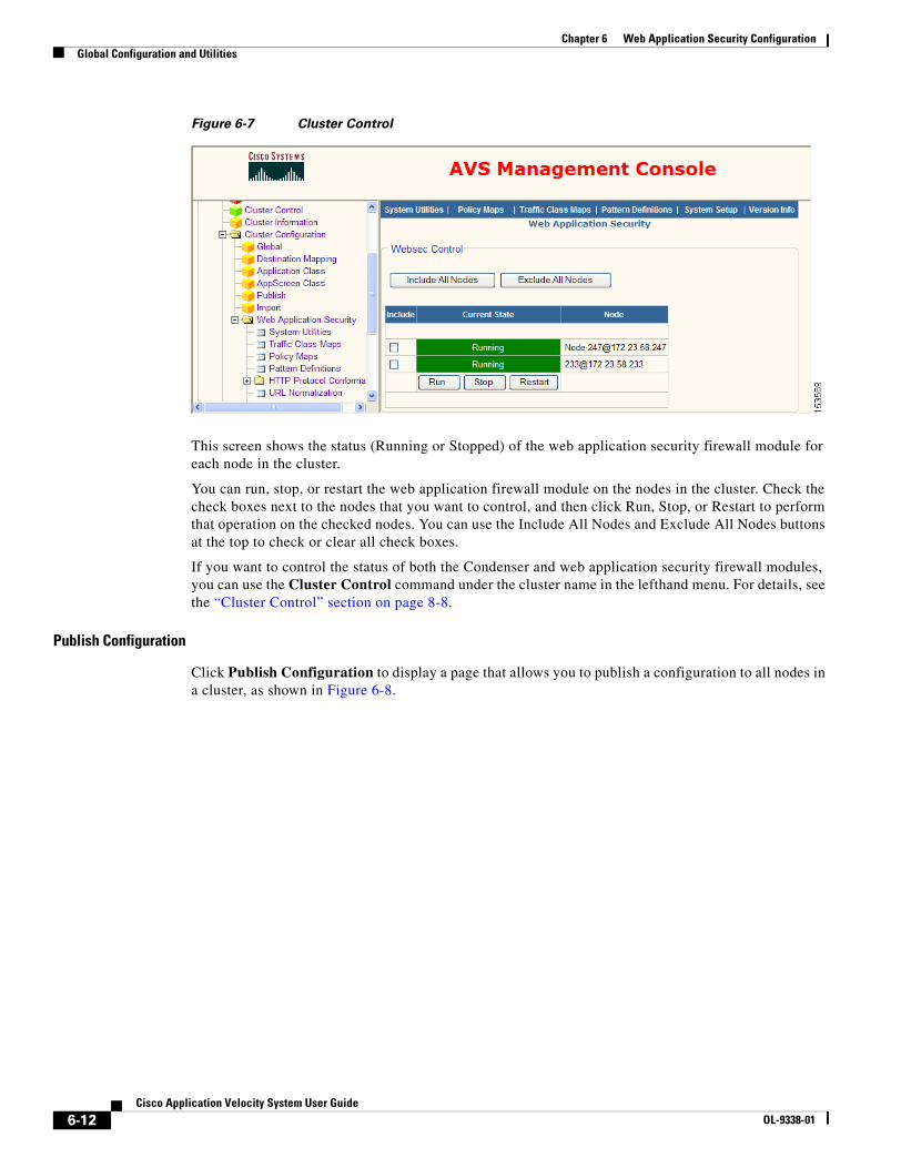
6-12Cisco Application Velocity System User Guide
OL-9338-01
Chapter 6 Web Application Security ConfigurationGlobal Configuration and Utilities
Figure 6-7 Cluster Control
This screen shows the status (Running or Stopped) of the web application security firewall module for each node in the cluster.
You can run, stop, or restart the web application firewall module on the nodes in the cluster. Check the check boxes next to the nodes that you want to control, and then click Run, Stop, or Restart to perform that operation on the checked nodes. You can use the Include All Nodes and Exclude All Nodes buttons at the top to check or clear all check boxes.
If you want to control the status of both the Condenser and web application security firewall modules, you can use the Cluster Control command under the cluster name in the lefthand menu. For details, see the “Cluster Control” section on page 8-8.
Publish Configuration
Click Publish Configuration to display a page that allows you to publish a configuration to all nodes in a cluster, as shown in Figure 6-8.
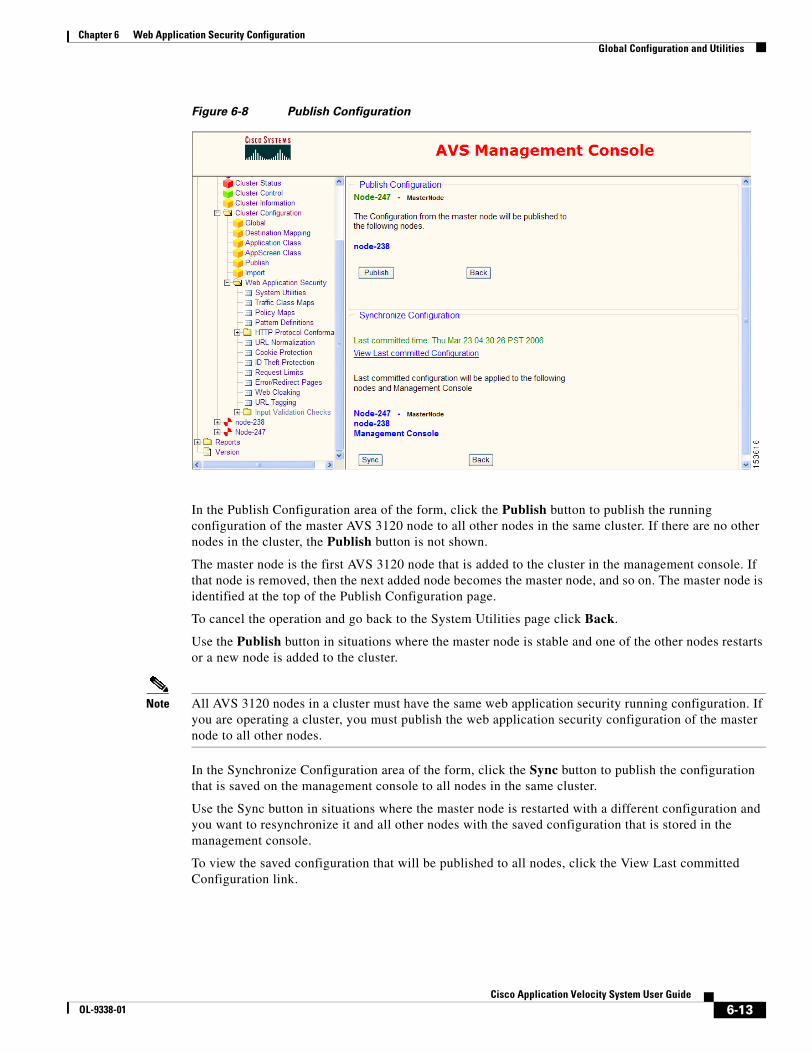
6-13Cisco Application Velocity System User Guide
OL-9338-01
Chapter 6 Web Application Security ConfigurationGlobal Configuration and Utilities
Figure 6-8 Publish Configuration
In the Publish Configuration area of the form, click the Publish button to publish the running configuration of the master AVS 3120 node to all other nodes in the same cluster. If there are no other nodes in the cluster, the Publish button is not shown.
The master node is the first AVS 3120 node that is added to the cluster in the management console. If that node is removed, then the next added node becomes the master node, and so on. The master node is identified at the top of the Publish Configuration page.
To cancel the operation and go back to the System Utilities page click Back.
Use the Publish button in situations where the master node is stable and one of the other nodes restarts or a new node is added to the cluster.
Note All AVS 3120 nodes in a cluster must have the same web application security running configuration. If you are operating a cluster, you must publish the web application security configuration of the master node to all other nodes.
In the Synchronize Configuration area of the form, click the Sync button to publish the configuration that is saved on the management console to all nodes in the same cluster.
Use the Sync button in situations where the master node is restarted with a different configuration and you want to resynchronize it and all other nodes with the saved configuration that is stored in the management console.
To view the saved configuration that will be published to all nodes, click the View Last committed Configuration link.
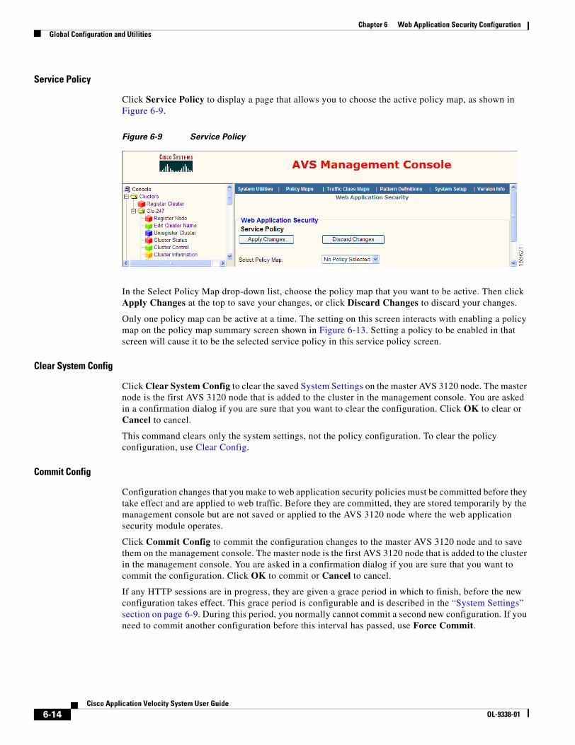
6-14Cisco Application Velocity System User Guide
OL-9338-01
Chapter 6 Web Application Security ConfigurationGlobal Configuration and Utilities
Service Policy
Click Service Policy to display a page that allows you to choose the active policy map, as shown in Figure 6-9.
Figure 6-9 Service Policy
In the Select Policy Map drop-down list, choose the policy map that you want to be active. Then click Apply Changes at the top to save your changes, or click Discard Changes to discard your changes.
Only one policy map can be active at a time. The setting on this screen interacts with enabling a policy map on the policy map summary screen shown in Figure 6-13. Setting a policy to be enabled in that screen will cause it to be the selected service policy in this service policy screen.
Clear System Config
Click Clear System Config to clear the saved System Settings on the master AVS 3120 node. The master node is the first AVS 3120 node that is added to the cluster in the management console. You are asked in a confirmation dialog if you are sure that you want to clear the configuration. Click OK to clear or Cancel to cancel.
This command clears only the system settings, not the policy configuration. To clear the policy configuration, use Clear Config.
Commit Config
Configuration changes that you make to web application security policies must be committed before they take effect and are applied to web traffic. Before they are committed, they are stored temporarily by the management console but are not saved or applied to the AVS 3120 node where the web application security module operates.
Click Commit Config to commit the configuration changes to the master AVS 3120 node and to save them on the management console. The master node is the first AVS 3120 node that is added to the cluster in the management console. You are asked in a confirmation dialog if you are sure that you want to commit the configuration. Click OK to commit or Cancel to cancel.
If any HTTP sessions are in progress, they are given a grace period in which to finish, before the new configuration takes effect. This grace period is configurable and is described in the “System Settings” section on page 6-9. During this period, you normally cannot commit a second new configuration. If you need to commit another configuration before this interval has passed, use Force Commit.
6-15Cisco Application Velocity System User Guide
OL-9338-01
Chapter 6 Web Application Security ConfigurationGlobal Configuration and Utilities
After committing a configuration, we recommend that you save the configuration on the master node by using Save Config. If you have a cluster of AVS 3120 nodes, you must also publish the configuration to all nodes in the cluster by using Publish Configuration. The application appliance does not support a cluster where the nodes have different web application security configurations.
Force Commit
Click Force Commit to immediately commit configuration changes, if you have recently committed another configuration and the grace period for that commit has not yet expired. See the previous section, Commit Config, for details.
You are asked in a confirmation dialog if you are sure that you want to force commit the configuration. Click OK to commit or Cancel to cancel.
After committing a configuration, we recommend that you save the configuration by using Save Config. If you have a cluster of AVS 3120 nodes, you must also publish the configuration to all nodes in the cluster by using Publish Configuration. The application appliance does not support a cluster where the nodes have different web application security configurations.
Save Config
Click Save Config to save the running configuration on the master AVS 3120 node so that it will be preserved across a reboot of that node. The master node is the first AVS 3120 node that is added to the cluster in the management console. You are asked in a confirmation dialog if you are sure that you want to save the configuration. Click OK to save or Cancel to cancel.
After committing a configuration by using Commit Config, we recommend that you save the configuration by using Save Config.
Clear Config
Click Clear Config to clear the saved policy configuration on the master AVS 3120 node. The master node is the first AVS 3120 node that is added to the cluster in the management console. You are asked in a confirmation dialog if you are sure that you want to clear the configuration. Click OK to clear or Cancel to cancel.
Clearing the configuration clears only the saved copy of the configuration on the master AVS 3120 node. It does not clear the running configuration, so the node will continue to operate with its running configuration. If it is rebooted, that configuration will be lost because it is no longer saved.
Clear System Stats
Resets the statistics accumulated and displayed by the System Stats command.
Clear Traffic Stats
Resets the statistics accumulated and displayed by the Traffic Level Stats command.
Clear Policy Stats
Resets the statistics accumulated and displayed by the Policy Level Stats command.

6-16Cisco Application Velocity System User Guide
OL-9338-01
Chapter 6 Web Application Security ConfigurationGlobal Configuration and Utilities
Log Server Config
The log server configuration page lets you configure remote logging for the web application security firewall. Web application security logs are separate from other AVS logs. Click the Log Server Config link to display the page shown in Figure 6-10, where you can configure remote syslog servers to which logs are sent by the web application security module.
Figure 6-10 Log Server Configuration
In the IP Address field, enter the IP address of a remote server to which AVS should send web application security logs. Check the Add check box and click Update IP Addresses to add the address to the list of remote log servers. Repeat these steps to add additional remote log servers. To delete a log server from the list, check the Delete check box next to it and click Update IP Addresses.
The servers that you specify must have the syslog facility running and configured to receive messages from the network.
If you are managing a cluster of AVS 3120 nodes with the AVS 3180 Management Station, you must configure the AVS 3180 as one of the remote log servers. This allows the management console to display aggregated logs from all nodes in the cluster (see the “Saved Log” section on page 6-7). If you do not have an AVS 3180 Management Station, you may still want to enter the IP address of at least one remote log server where logs will be aggregated, though these will not be accessible through the management console interface.
When you are finished with this form, click Apply Changes at the top to save your changes, or click Discard Changes to discard your changes.
Clear Current Logs
Clears the current log file. The current log file is different, depending on your configuration, as follows:
• If you have an AVS 3180 Management Station, then Clear Current Logs clears the log file of the first AVS 3120 node that is listed in the cluster in the management console.
• If you do not have an AVS 3180 Management Station, then Clear Current Log clears the log file of the current AVS 3120 node on which you are running the management console.
To view the current log file, use Current Log.
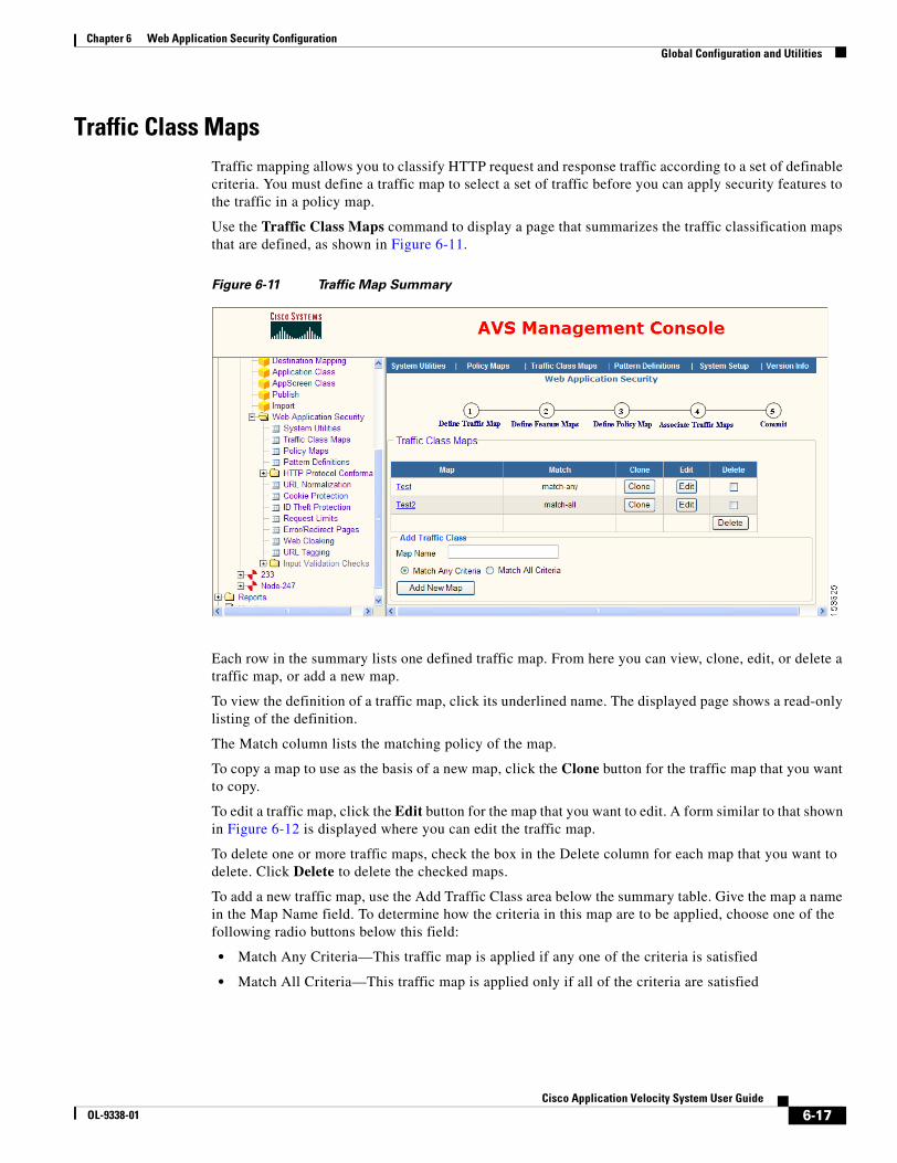
6-17Cisco Application Velocity System User Guide
OL-9338-01
Chapter 6 Web Application Security ConfigurationGlobal Configuration and Utilities
Traffic Class MapsTraffic mapping allows you to classify HTTP request and response traffic according to a set of definable criteria. You must define a traffic map to select a set of traffic before you can apply security features to the traffic in a policy map.
Use the Traffic Class Maps command to display a page that summarizes the traffic classification maps that are defined, as shown in Figure 6-11.
Figure 6-11 Traffic Map Summary
Each row in the summary lists one defined traffic map. From here you can view, clone, edit, or delete a traffic map, or add a new map.
To view the definition of a traffic map, click its underlined name. The displayed page shows a read-only listing of the definition.
The Match column lists the matching policy of the map.
To copy a map to use as the basis of a new map, click the Clone button for the traffic map that you want to copy.
To edit a traffic map, click the Edit button for the map that you want to edit. A form similar to that shown in Figure 6-12 is displayed where you can edit the traffic map.
To delete one or more traffic maps, check the box in the Delete column for each map that you want to delete. Click Delete to delete the checked maps.
To add a new traffic map, use the Add Traffic Class area below the summary table. Give the map a name in the Map Name field. To determine how the criteria in this map are to be applied, choose one of the following radio buttons below this field:
• Match Any Criteria—This traffic map is applied if any one of the criteria is satisfied
• Match All Criteria—This traffic map is applied only if all of the criteria are satisfied
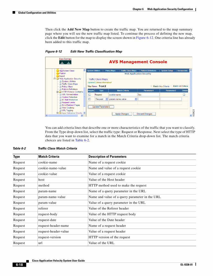
6-18Cisco Application Velocity System User Guide
OL-9338-01
Chapter 6 Web Application Security ConfigurationGlobal Configuration and Utilities
Then click the Add New Map button to create the traffic map. You are returned to the map summary page where you will see the new traffic map listed. To continue the process of defining the new map, click the Edit button for the map to display the screen shown in Figure 6-12. One criteria line has already been added to this traffic map.
Figure 6-12 Edit New Traffic Classification Map
You can add criteria lines that describe one or more characteristics of the traffic that you want to classify. From the Type drop-down list, select the traffic type: Request or Response. Next select the type of HTTP data that you want to examine for a match in the Match Criteria drop-down list. The match criteria choices are listed in Table 6-2.
Table 6-2 Traffic Class Match Criteria
Type Match Criteria Description of Parameters
Request cookie-name Name of a request cookie
Request cookie-name-value Name and value of a request cookie
Request cookie-value Value of a request cookie
Request host Value of the Host header
Request method HTTP method used to make the request
Request param-name Name of a query parameter in the URL
Request param-name-value Name and value of a query parameter in the URL
Request param-value Value of a query parameter in the URL
Request referer Value of the Referer header
Request request-body Value of the HTTP request body
Request request-date Value of the Date header
Request request-header-name Name of a request header
Request request-header-value Value of a request header
Request request-version HTTP version of the request
Request url Value of the URL
6-19Cisco Application Velocity System User Guide
OL-9338-01
Chapter 6 Web Application Security ConfigurationGlobal Configuration and Utilities
Next to the match criteria in the Parameter1 and Parameter2 fields, enter the values that are the match criteria. Most match criteria items require only a single value, which you enter into the Parameter1 field. A few of the match criteria items require both a name and a value, such as a cookie name and value or a parameter name and value. Enter the name into the Parameter1 field and the value into the Parameter2 field. If the Parameter2 field is not needed, then it is not shown.
For example, if you choose host for the Match Criteria, then the Parameter1 value would be a host name such as www.cisco.com; the Parameter2 field is not used. If you choose param-name-value for the Match Criteria, then the Parameter1 value would be the name of a request parameter, and the Parameter2 value would be the value of the specified request parameter.
Regular expressions are allowed; for details see the “Web Application Security Regular Expression Syntax” section on page 6-72.
Click the check box in the Negate column if you want to match all traffic that does not meet the criteria. For example, if you check Negate and enter www.cisco.com for host, this criteria matches all requests where the host does not equal www.cisco.com.
Request user-agent Value of the User-Agent header
Response content-encoding Value of the Content-Encoding header
Response content-location Value of the Content-Location header
Response content-type Value of the Content-Type header
Response reason-phrase Value of the reason phrase
Response response-body Value of the HTTP response body
Response response-date Value of the Date header
Response response-header-name Name of a request header
Response response-header-value Value of a request header
Response response-version HTTP version of the response
Response server Value of the Server header
Response set-cookie-name Name of a cookie being set
Response set-cookie-name-value Name and value of a cookie being set
Response set-cookie-value Value of a cookie being set
Response status-code Value of the status code
Response transfer-encoding Value of the Transfer-Encoding header
Table 6-2 Traffic Class Match Criteria (continued)
Type Match Criteria Description of Parameters
6-20Cisco Application Velocity System User Guide
OL-9338-01
Chapter 6 Web Application Security ConfigurationGlobal Configuration and Utilities
Note Traffic maps that contain response criteria cannot be used to trigger a feature that is operating on a request. For example, if you have a traffic map that uses the content-type criteria (a response criteria), this traffic map cannot be used in a policy where it is associated with a request limits feature map.
Many features can apply to both requests and responses. Such a feature can be associated with a traffic map that contains response criteria only if it does not operate on request data. For example, if you have a traffic map that uses the set-cookie-name criteria (a response criteria), this traffic map can be used in a policy where it is associated with a cookie protection map, as long as the cookie protection map operates only on response cookies. If the cookie protection map includes any request cookie operations, then the policy is invalid.
When you are finished entering one criteria line, click the Update Parameters button to update the page and give you a new line on which to enter another criteria. To delete one or more criteria lines, click the Delete check box on each line that you want to delete and then click Update Parameters to delete all checked lines.
When you are finished with this form, click Apply Changes to save your changes, or click Discard Changes to return to the summary page without saving your changes.
Default Traffic Maps
The system defines some default traffic class maps that you can use in policy maps. The following default maps are defined:
• class-all—This traffic map includes all traffic, both requests and responses. Actions and features that are associated with class-all in a policy map are always executed.
• class-default-request—This traffic map includes all request traffic that does not match any of the user-defined classes. At the end of an HTTP request, if no user-defined classes have matched, the actions and features in the policy map that is associated with the class-default-request traffic map are executed.
In a policy map, this traffic map can be associated with feature maps that operate only on request data. A policy map that contains the class-default-request traffic map cannot include other traffic maps that contain the request-body matching criteria (or negation of this criteria).
• class-default-response—This traffic map includes all response traffic that does not match any of the user-defined classes. At the end of an HTTP response, if no user-defined classes have matched, the actions and features in the policy map that is associated with the class-default-response traffic map are executed.
This traffic map can be associated with feature maps that operate only on response data. A policy map that contains the class-default-response traffic map cannot include other traffic maps that contain the response-body matching criteria (or negation of this criteria).
You cannot edit or delete these default traffic maps. No security features are associated with these traffic maps by default. You must use the Policy Maps command to create a policy that associates features with them.
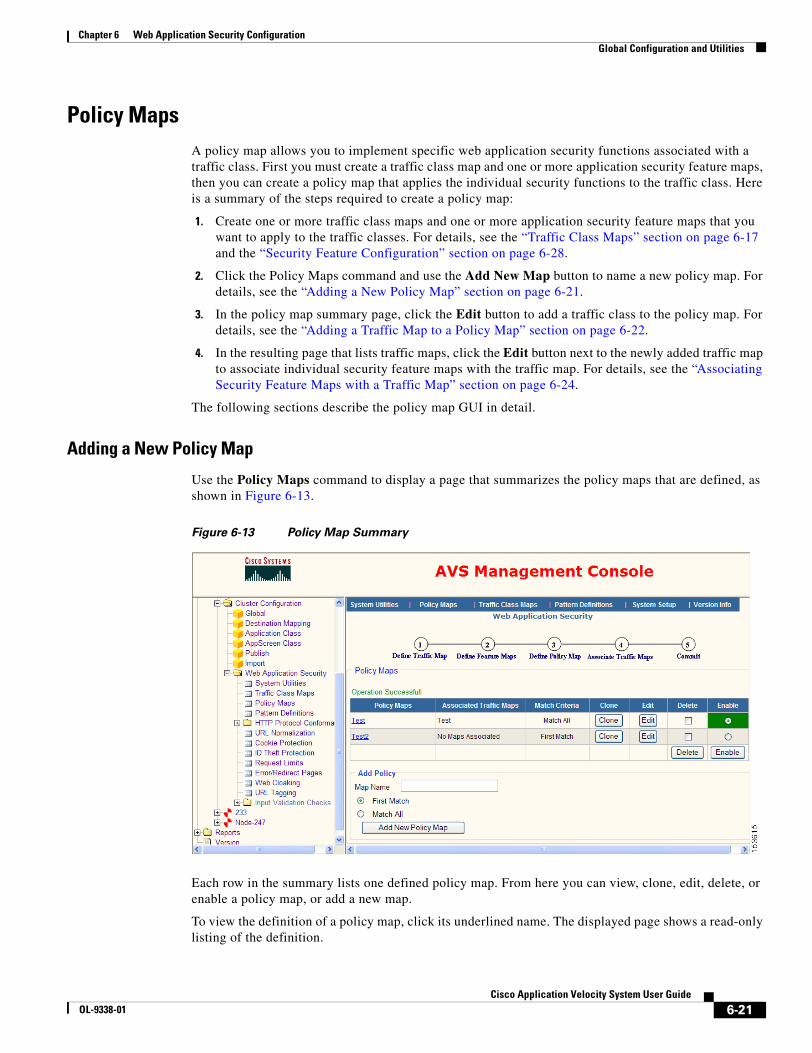
6-21Cisco Application Velocity System User Guide
OL-9338-01
Chapter 6 Web Application Security ConfigurationGlobal Configuration and Utilities
Policy MapsA policy map allows you to implement specific web application security functions associated with a traffic class. First you must create a traffic class map and one or more application security feature maps, then you can create a policy map that applies the individual security functions to the traffic class. Here is a summary of the steps required to create a policy map:
1. Create one or more traffic class maps and one or more application security feature maps that you want to apply to the traffic classes. For details, see the “Traffic Class Maps” section on page 6-17 and the “Security Feature Configuration” section on page 6-28.
2. Click the Policy Maps command and use the Add New Map button to name a new policy map. For details, see the “Adding a New Policy Map” section on page 6-21.
3. In the policy map summary page, click the Edit button to add a traffic class to the policy map. For details, see the “Adding a Traffic Map to a Policy Map” section on page 6-22.
4. In the resulting page that lists traffic maps, click the Edit button next to the newly added traffic map to associate individual security feature maps with the traffic map. For details, see the “Associating Security Feature Maps with a Traffic Map” section on page 6-24.
The following sections describe the policy map GUI in detail.
Adding a New Policy Map
Use the Policy Maps command to display a page that summarizes the policy maps that are defined, as shown in Figure 6-13.
Figure 6-13 Policy Map Summary
Each row in the summary lists one defined policy map. From here you can view, clone, edit, delete, or enable a policy map, or add a new map.
To view the definition of a policy map, click its underlined name. The displayed page shows a read-only listing of the definition.
6-22Cisco Application Velocity System User Guide
OL-9338-01
Chapter 6 Web Application Security ConfigurationGlobal Configuration and Utilities
The Associated Traffic Maps column lists the traffic class maps that are associated with a policy. If no traffic class maps are yet associated, it reads “No Maps Associated.” The Match Criteria column lists the matching policy of the map.
To copy a map to use as the basis of a new map, click the Clone button for the map that you want to copy.
To edit a policy map and add traffic class maps, click the Edit button for the map that you want to edit. A form similar to that shown in Figure 6-14 is displayed where you can edit the policy map.
To delete one or more policy maps, check the box in the Delete column for each map that you want to delete. Click Delete to delete the checked maps.
To enable a policy map (make it active), click the radio button in the Enable column for the map that you want to enable, then click the Enable button at the bottom of the column. You can only enable a policy map that has associated traffic class maps, and you can only enable one policy map at a time. This setting interacts with the policy map selected in the Service Policy screen of the System Utilities, as described in the “Service Policy” section on page 6-14. Selecting a policy to be active in that screen will cause it to be displayed as enabled in this policy map summary screen.
To add a new policy map, use the Add Policy area below the summary table. Give the map a name in the Map Name field. Choose when to execute the policy by clicking one of the following radio buttons:
• First Match—Execute the policy only on the first traffic map that matches the traffic
• Match All—Execute the policy on all traffic maps that match the traffic
Then click Add New Policy Map to add the map to the summary. The new map is not yet configured, and to do that click the Edit button for the map.
Tip When you choose First Match for the type of traffic map matching, it is important to understand the order in which AVS matches traffic maps. Traffic matching is driven by the order in which the traffic data arrives, which is: HTTP method, HTTP version, host, URL, cookie name, and cookie value. There can be multiple cookies and they can arrive in any order, so the value of one cookie could cause a match before the name of another cookie.
Say that you have a traffic map, url-class, that matches on a specific URL, and another traffic map, cookie-class that matches on a cookie name. In an incoming request, the URL arrives before any cookies, so if the URL matches url-class, then this will cause a First Match policy to fire (if it uses this traffic map). The cookie-class might also match this request, but it is not invoked since the url-class already triggered its policy.
The order in which traffic maps are listed in the traffic maps list (see Figure 6-15) is irrelevant and does not signify the order in which traffic maps are evaluated for a match.
Adding a Traffic Map to a Policy Map
To define a policy map and add traffic class maps, in the map summary table click the Edit button for the map that you want to edit. A form similar to that shown in Figure 6-14 is displayed where you can edit the policy map.
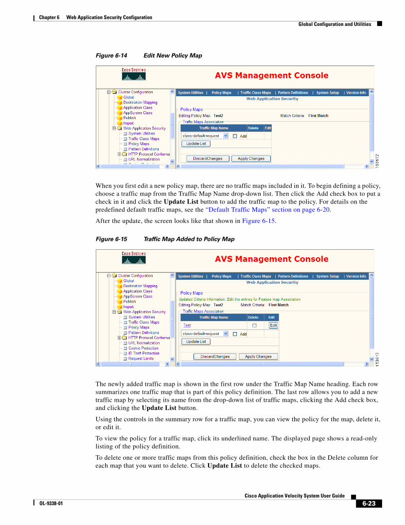
6-23Cisco Application Velocity System User Guide
OL-9338-01
Chapter 6 Web Application Security ConfigurationGlobal Configuration and Utilities
Figure 6-14 Edit New Policy Map
When you first edit a new policy map, there are no traffic maps included in it. To begin defining a policy, choose a traffic map from the Traffic Map Name drop-down list. Then click the Add check box to put a check in it and click the Update List button to add the traffic map to the policy. For details on the predefined default traffic maps, see the “Default Traffic Maps” section on page 6-20.
After the update, the screen looks like that shown in Figure 6-15.
Figure 6-15 Traffic Map Added to Policy Map
The newly added traffic map is shown in the first row under the Traffic Map Name heading. Each row summarizes one traffic map that is part of this policy definition. The last row allows you to add a new traffic map by selecting its name from the drop-down list of traffic maps, clicking the Add check box, and clicking the Update List button.
Using the controls in the summary row for a traffic map, you can view the policy for the map, delete it, or edit it.
To view the policy for a traffic map, click its underlined name. The displayed page shows a read-only listing of the policy definition.
To delete one or more traffic maps from this policy definition, check the box in the Delete column for each map that you want to delete. Click Update List to delete the checked maps.

6-24Cisco Application Velocity System User Guide
OL-9338-01
Chapter 6 Web Application Security ConfigurationGlobal Configuration and Utilities
To edit the policy for a traffic map, click the Edit button.
When you are finished adding or editing traffic map policies, click Apply Changes to save your changes, or click Discard Changes to return to the summary page without saving your changes.
Associating Security Feature Maps with a Traffic Map
To edit the policy for a traffic map, click the Edit button in the summary. A form similar to that shown in Figure 6-16 is displayed where you can edit the policy definition by choosing which security feature maps to apply to the traffic class.
Figure 6-16 Associating Features with a Traffic Class
On this screen, you choose which security features to apply to the traffic map shown in the Traffic Map Name field. You can choose a general response action and/or apply one or more feature maps to the traffic.
To apply a general response action, choose one of the following actions from the Response Action drop-down list:
• None—Take no action
• Reset client—Reset the client side of the connection
• Drop—Drop the connection silently
• Reset server client—Reset both the server and client sides of the connection
• Reset server—Reset the server side of the connection
• Error Page—Send an error page. Choose the error page to send from the next drop-down list to the right. You define such error pages by using the send page feature described in the “Error/Redirect Pages” section on page 6-39
Click the Log check box to log the event.

6-25Cisco Application Velocity System User Guide
OL-9338-01
Chapter 6 Web Application Security ConfigurationGlobal Configuration and Utilities
To apply a feature map to the traffic, choose a feature from the Feature drop-down list and then from the Map Name drop-down list, choose one of the feature maps that you have defined for that feature. Then click the Update List button to take you back to the screen shown in Figure 6-15. You can add multiple feature maps to be applied to this traffic map by editing the traffic map again and following the same procedure.
Note Traffic maps that contain response criteria cannot be used to trigger a feature that is operating on a request. For example, if you have a traffic map that uses the content-type criteria (a response criteria), this traffic map cannot be used in a policy where it is associated with a request limits feature map.
Many features can apply to both requests and responses. If such a feature operates only on response data and not on request data, then it can be associated with a traffic map that contains response criteria. For example, if you have a traffic map that uses the set-cookie-name criteria (a response criteria), this traffic map can be used in a policy where it is associated with a cookie protection map, as long as the cookie protection map operates only on response cookies. If the cookie protection map includes any request cookie operations, then the policy is invalid and will not be allowed.
The default traffic map class-default-request can be associated with feature maps that operate only on request data. A policy map that contains the class-default-request traffic map cannot include other traffic maps that contain the request-body matching criteria.
The default traffic map class-default-response can be associated with feature maps that operate only on response data. A policy map that contains the class-default-response traffic map cannot include other traffic maps that contain the response-body matching criteria.
To delete an associated feature map, check the Delete check box for the map and click Update List.
If you would rather cancel the changes that you made on this form, click the Discard Changes button.
The following features are available in the Feature drop-down list:
• Cookie Protection—Protects against cookie tampering by using hashed cookies and provides cookie privacy by encrypting cookies; see the “Cookie Protection” section on page 6-30.
• HTTP Protocol conformance-MIME Type Controls—Validates that the content’s MIME type matches the MIME type specified in the HTTP Content-type header; see the “MIME Type Controls” section on page 6-54. This features operates only on responses.
• HTTP Protocol conformance-Control HTTP Method—Filters traffic based on the HTTP method; see the “Control HTTP Methods” section on page 6-57.
• HTTP Protocol conformance-Generic Pattern Matcher—Filters traffic based on any user-definable criteria; see the “Generic Pattern Matcher” section on page 6-52.
• HTTP Protocol conformance-Header Integrity Check—Checks headers for integrity; see the “Header Integrity Check” section on page 6-59.
• HTTP Protocol conformance-IM Controls—Filters instant messenger traffic; see the “IM Controls” section on page 6-49.
• HTTP Protocol conformance-P2P Controls—Filters peer-to-peer file sharing traffic; see the “P2P Controls” section on page 6-52.
• HTTP Protocol conformance-Transfer Encoding—Filters traffic based on the HTTP Transfer-Encoding header; see the “Transfer Encoding” section on page 6-52.
• HTTP Protocol conformance-Tunnelling Policies—Filters traffic that is tunneled over HTTP, such as ShoutCast, GoToMyPC and the like; see the “Tunnelling Policies” section on page 6-52.
6-26Cisco Application Velocity System User Guide
OL-9338-01
Chapter 6 Web Application Security ConfigurationGlobal Configuration and Utilities
• HTTP Protocol conformance-URL Black Listing—Blocks access to specific URLs; see the “URL Black Listing” section on page 6-56.
• IV-OS Command Injection—Validates that input does not contain disallowed command strings; see the “OS Command Injection” section on page 6-64.
• IV-Cross Site Scripting—Validates that input does not contain a cross site scripting attack; see the “Cross Site Scripting” section on page 6-60.
• IV-Format String Attacks—Validates that input does not contain disallowed formatting strings; see the “Format String Attacks” section on page 6-70.
• IV-LDAP Injection—Validates that input does not contain disallowed LDAP strings; see the “LDAP Injection” section on page 6-66.
• IV-Meta Character Detection—Validates that input does not contain disallowed meta characters; see the “Meta Character Detection” section on page 6-68.
• IV-SQL Injection—Validates that input does not contain disallowed SQL command strings; see the “SQL Injection” section on page 6-62.
• ID Theft Protection—Guards against the unsolicited disclosure of social security and credit card numbers in HTTP responses to clients; see the “ID Theft Protection” section on page 6-36. This features operates only on responses.
• Request Limits—Enforces boundary length checking on all inputs received from the client; see the “Request Limits” section on page 6-37.
• URL Normalization—Secures web applications from attacks that use the URL in HTTP requests, such as directory traversal; see the “URL Normalization” section on page 6-28.
• URL Tagging—Adds information to request URLs that can be used by other downstream devices such as load balancers or application servers; see the “URL Tagging” section on page 6-47.
• Web Cloaking—Hides identifying information about the web server and application; see the “Web Cloaking” section on page 6-45.
Pattern DefinitionsPattern definitions define regular expression sets for matching strings used by other web security features. For example, the identity theft protection feature uses regular expressions that match social security numbers and credit card numbers.
Use the Pattern Definitions command to display a page that summarizes the pattern maps that are defined and to view, delete, clone, edit or add new maps. For details on using the summary page GUI, see the “Map Summary Interface” section on page 6-2.
When you click the button to add a new map, AVS displays the screen shown in Figure 6-17.

6-27Cisco Application Velocity System User Guide
OL-9338-01
Chapter 6 Web Application Security ConfigurationGlobal Configuration and Utilities
Figure 6-17 Add Pattern Definition
Give the new regular expression set a name in the Pattern Definition Name field.
In the Type drop-down list, select the type of regular expression set that you are defining, from the following choices:
• Social Security Number—Regular expressions that describe social security numbers
• Credit Card—Regular expressions that describe credit card numbers
• Custom—Custom regular expression
• Cross Site Scripting—Regular expressions that describe cross site scripting strings
• SQL Injection—Regular expressions that describe SQL command strings
• Command Injection—Regular expressions that describe command strings
• LDAP Injection—Regular expressions that describe LDAP strings
• Meta Character Detection—Regular expressions that describe meta characters
• Format String Attacks—Regular expressions that describe format strings
Select one or more regular expressions that you want to use from the Standard Regular Expressions list and add them to the Included Regular Expressions list on the right side of the page by clicking the right arrow (-->) button. The list of standard regular expressions changes depending on the type you choose. You can also add a custom regular expression by typing it into the Custom field and clicking the right arrow (-->) button next to that field. For details on the regular expression syntax that is allowed, see the “Web Application Security Regular Expression Syntax” section on page 6-72. If you enter a value into the Custom field, in the Size field you must also enter a maximum number of characters to search for this expression in the target data. Size must be greater than 0 for the custom expression to be added to the Included Regular Expressions list.
6-28Cisco Application Velocity System User Guide
OL-9338-01
Chapter 6 Web Application Security ConfigurationSecurity Feature Configuration
You can remove a regular expression from the Included Regular Expressions list by selecting it and clicking the left arrow (<--) button.
When you are finished with this form, click Apply Changes at the top to save your changes, or click Discard Changes to return to the summary page without saving your changes. If you want to use the settings on this form as the default for new maps of this type, click Set As Default.
Security Feature ConfigurationThis section describes the following security feature configuration items that appear under the Web Application Security folder in the lefthand menu of the Management Console:
• URL Normalization
• Cookie Protection
• ID Theft Protection
• Request Limits
• Error/Redirect Pages
• Web Cloaking
• URL Tagging
• HTTP Protocol Conformance
• Input Validation Checks
URL NormalizationThe URL normalization feature lets you secure web applications from attacks that use the URL in HTTP requests, such as directory traversal.
To deobfuscate potential attacks, the application appliance first scans the URL in incoming requests and normalizes it by decoding all encoded characters. It can detect the following encoding schemes: escaped encoding, %U encoding, unicode encoding using UTF-8 (up to three bytes in length), and IP address encoding. Additionally, it can handle a combination of encoding schemes and double encoding of the same character.
Use the URL Normalization command to display a page that summarizes the URL normalization maps that are defined and to view, delete, clone, edit or add new maps. For details on using the summary page GUI, see the “Map Summary Interface” section on page 6-2.
When you click the button to add a new map, AVS displays the screen shown in Figure 6-18.
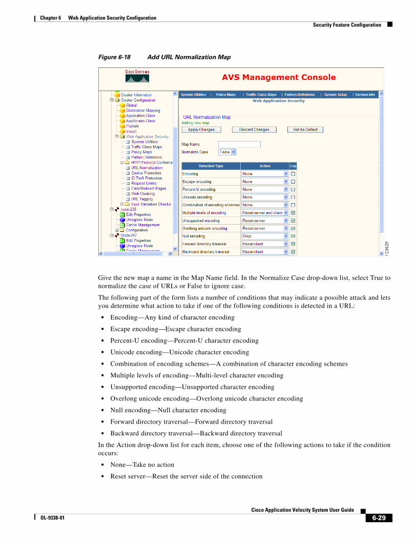
6-29Cisco Application Velocity System User Guide
OL-9338-01
Chapter 6 Web Application Security ConfigurationSecurity Feature Configuration
Figure 6-18 Add URL Normalization Map
Give the new map a name in the Map Name field. In the Normalize Case drop-down list, select True to normalize the case of URLs or False to ignore case.
The following part of the form lists a number of conditions that may indicate a possible attack and lets you determine what action to take if one of the following conditions is detected in a URL:
• Encoding—Any kind of character encoding
• Escape encoding—Escape character encoding
• Percent-U encoding—Percent-U character encoding
• Unicode encoding—Unicode character encoding
• Combination of encoding schemes—A combination of character encoding schemes
• Multiple levels of encoding—Multi-level character encoding
• Unsupported encoding—Unsupported character encoding
• Overlong unicode encoding—Overlong unicode character encoding
• Null encoding—Null character encoding
• Forward directory traversal—Forward directory traversal
• Backward directory traversal—Backward directory traversal
In the Action drop-down list for each item, choose one of the following actions to take if the condition occurs:
• None—Take no action
• Reset server—Reset the server side of the connection
6-30Cisco Application Velocity System User Guide
OL-9338-01
Chapter 6 Web Application Security ConfigurationSecurity Feature Configuration
• Reset client—Reset the client side of the connection
• Reset server and client—Reset both the server and client sides of the connection
• Drop—Drop the connection silently
• [SEND-PAGE] pagename—Send the error page identified by pagename. You define such error pages by using the send page feature described in the “Error/Redirect Pages” section on page 6-39.
• [REDIRECT-PAGE] pagename—Send the redirection page identified by pagename. You define such redirection pages by using the redirect page feature described in the “Error/Redirect Pages” section on page 6-39.
For each item you can also click the Log check box to log the event.
When you are finished with this form, click Apply Changes at the top to save your changes, or click Discard Changes to return to the summary page without saving your changes. If you want to use the settings on this form as the default for new maps of this type, click Set As Default.
Cookie ProtectionWeb applications store a variety of information in plain text cookies. The application appliance protects against cookie tampering by using hashed cookies and provides cookie privacy by encrypting cookies. The application appliance also supports adding and removing cookie attributes, and filtering cookies based on user configurable attributes such as HTTP-only cookies, maximum age, number of cookies, and others. The cookie protection features operate both on server cookies sent to clients in HTTP responses and on client cookies that are sent back to servers in HTTP requests.
Use the Cookie Protection command to display a page that summarizes the cookie protection maps that are defined and to view, delete, clone, edit or add new maps. For details on using the summary page GUI, see the “Map Summary Interface” section on page 6-2.
When you click the button to add a new map, AVS displays the screen shown in Figure 6-19.

6-31Cisco Application Velocity System User Guide
OL-9338-01
Chapter 6 Web Application Security ConfigurationSecurity Feature Configuration
Figure 6-19 Add Cookie Protection Map
Give the new map a name in the Map Name field.
The next three Tamper Proof fields set the key and algorithm used for hashing cookies. In the Tamper Proof Key Length drop-down list, choose the key length in bits that you want to use. In the Tamper Proof Key field, enter a key of the chosen length. You must enter 16 characters for a 128-bit key or 32 characters for a 256-bit key. Spaces are not allowed in keys. In the Tamper Proof Algorithm drop-down list, choose the hashing algorithm to use. Currently, AVS supports only SHA-1.
6-32Cisco Application Velocity System User Guide
OL-9338-01
Chapter 6 Web Application Security ConfigurationSecurity Feature Configuration
The next three Encrypt fields set the key and algorithm used for encrypting cookies. In the Encrypt Key Length drop-down list, choose the key length in bits that you want to use. In the Encrypt Key field, enter a key of the chosen length. You must enter 16 characters for a 128-bit key or 32 characters for a 256-bit key. Spaces are not allowed in keys. In the Encrypt Algorithm drop-down list, choose the encryption algorithm to use. Currently, AVS supports only AES.
In the Process Response Cookies drop-down list, choose the cookie protection actions to take on all response cookies (cookies sent from the server to the client). The following actions are defined:
• Allow individual cookie processing—Allow response rule map processing whereby you can enable encryption and/or tamper proofing on selected cookies, based on cookie/attribute names and values; see the section “Response Rule Maps” section on page 6-33
• Encrypt all cookies—Encrypt all cookies
• Tamper proof all cookies—Hash all cookies to prevent tampering
• Encrypt and tamper proof all cookies—Encrypt and hash all cookies
The next part of the form lists a number of cookie problems and lets you determine what action to take if one of the following events occurs:
• Alien Cookie—A cookie is observed that is not one processed by the AVS cookie protection feature
• Old Cookie—A cookie sent from the client uses an old version of the hash or encryption key. In this case, the cookie cannot be unhashed or decrypted.
• Encrypt Fail—Cookie decryption failed
• Tamper Proof Verification Fail—Verification that the cookie was not tampered with failed, so this may indicate possible cookie tampering
• Server Cookie Range not between—The number of server cookies is not within the specified range. Enter a range of integers, with the smaller number in the first field and the larger number in the second field.
• Client Cookie Range not between—The number of client cookies is not within the specified range. Enter a range of integers, with the smaller number in the first field and the larger number in the second field.
In the Action drop-down list for each item, choose one of the following actions to take if the event occurs:
• Allow—Allow the request unchanged
• Remove cookie—Remove the cookie that triggered the event
• Drop—Drop the connection silently
• Reset—Reset the connection
• [SEND-PAGE] pagename—Send the error page identified by pagename. You define such error pages by using the send page feature described in the “Error/Redirect Pages” section on page 6-39.
• [REDIRECT-PAGE] pagename—Send the redirection page identified by pagename. You define such redirection pages by using the redirect page feature described in the “Error/Redirect Pages” section on page 6-39.
For each item you can also click the Log check box to log the event.
By using the next parts of the form, you can add rule-based processing to cookies that is based on their values and attributes. These next form parts are described in the following sections:
• Response Attribute Rule Maps
• Response Rule Maps

6-33Cisco Application Velocity System User Guide
OL-9338-01
Chapter 6 Web Application Security ConfigurationSecurity Feature Configuration
• Request Rule Maps
When you are finished with this form, click Apply Changes at the top to save your changes, or click Discard Changes to return to the summary page without saving your changes. If you want to use the settings on this form as the default for new maps of this type, click Set As Default.
Response Attribute Rule Maps
In the Response Attribute Rule Maps section, you can define operations to set, insert, or remove specific cookie attributes from response cookies (cookies sent from the server to the client). You can delete one or more operations by clicking the Delete check box next to each operation that you want to delete and then clicking the Delete button.
To add a new attribute operation, click the Add New button to open the window shown in Figure 6-20.
Figure 6-20 Add Attribute Operation
From the Operation drop-down list, select the type of operation you want to perform, as follows:
• Insert—Insert an attribute with the specified name and value. If the attribute already exists, its value is replaced with the specified value.
• Remove—Remove the attribute with the specified name and value. If the attribute exists but the value is different from the specified value, it is not removed.
• Set—Set an existing attribute with the specified name to the specified value. If the attribute does not exist, it is not added. To insert a new attribute, use Insert.
Enter the attribute name in the Attribute Name field and its value in the Attribute Value field. When you are finished, click Create to add the operation or Close Window to cancel the operation.
When you add a new operation, it will be listed in the Response Attribute Rule Maps section of the cookie protection map form.
Response Rule Maps
In the Response Rule Maps section, you can define rule maps for response cookies (cookies sent from the server to the client). In a response rule map, you can specify specific cookies to which to apply encryption and/or tamper proofing actions. This response rule map processing applies only if the Process Response Cookies element is set to Allow individual cookie processing in the cookie protection map.
If there are already rule maps listed here, you can view them by clicking on the underlined identifier in the RuleMaps column. You can edit a rule map by clicking the Edit button next to the map name. You can delete one or more rule maps by clicking the Delete check box next to each rule map that you want to delete and then the clicking the Delete button.
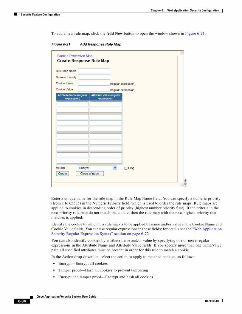
6-34Cisco Application Velocity System User Guide
OL-9338-01
Chapter 6 Web Application Security ConfigurationSecurity Feature Configuration
To add a new rule map, click the Add New button to open the window shown in Figure 6-21.
Figure 6-21 Add Response Rule Map
Enter a unique name for the rule map in the Rule Map Name field. You can specify a numeric priority (from 1 to 65535) in the Numeric Priority field, which is used to order the rule maps. Rule maps are applied to cookies in descending order of priority (highest number priority first). If the criteria in the next priority rule map do not match the cookie, then the rule map with the next highest priority that matches is applied.
Identify the cookie to which this rule map is to be applied by name and/or value in the Cookie Name and Cookie Value fields. You can use regular expressions in these fields; for details see the “Web Application Security Regular Expression Syntax” section on page 6-72.
You can also identify cookies by attribute name and/or value by specifying one or more regular expressions in the Attribute Name and Attribute Value fields. If you specify more than one name/value pair, all specified attributes must be present in order for this rule to match a cookie.
In the Action drop-down list, select the action to apply to matched cookies, as follows:
• Encrypt—Encrypt all cookies
• Tamper proof—Hash all cookies to prevent tampering
• Encrypt and tamper proof—Encrypt and hash all cookies
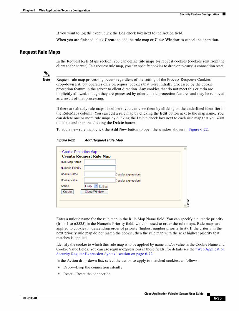
6-35Cisco Application Velocity System User Guide
OL-9338-01
Chapter 6 Web Application Security ConfigurationSecurity Feature Configuration
If you want to log the event, click the Log check box next to the Action field.
When you are finished, click Create to add the rule map or Close Window to cancel the operation.
Request Rule Maps
In the Request Rule Maps section, you can define rule maps for request cookies (cookies sent from the client to the server). In a request rule map, you can specify cookies to drop or to cause a connection reset.
Note Request rule map processing occurs regardless of the setting of the Process Response Cookies drop-down list, but operates only on request cookies that were initially processed by the cookie protection feature in the server to client direction. Any cookies that do not meet this criteria are implicitly allowed, though they are processed by other cookie protection features and may be removed as a result of that processing.
If there are already rule maps listed here, you can view them by clicking on the underlined identifier in the RuleMaps column. You can edit a rule map by clicking the Edit button next to the map name. You can delete one or more rule maps by clicking the Delete check box next to each rule map that you want to delete and then the clicking the Delete button.
To add a new rule map, click the Add New button to open the window shown in Figure 6-22.
Figure 6-22 Add Request Rule Map
Enter a unique name for the rule map in the Rule Map Name field. You can specify a numeric priority (from 1 to 65535) in the Numeric Priority field, which is used to order the rule maps. Rule maps are applied to cookies in descending order of priority (highest number priority first). If the criteria in the next priority rule map do not match the cookie, then the rule map with the next highest priority that matches is applied.
Identify the cookie to which this rule map is to be applied by name and/or value in the Cookie Name and Cookie Value fields. You can use regular expressions in these fields; for details see the “Web Application Security Regular Expression Syntax” section on page 6-72.
In the Action drop-down list, select the action to apply to matched cookies, as follows:
• Drop—Drop the connection silently
• Reset—Reset the connection
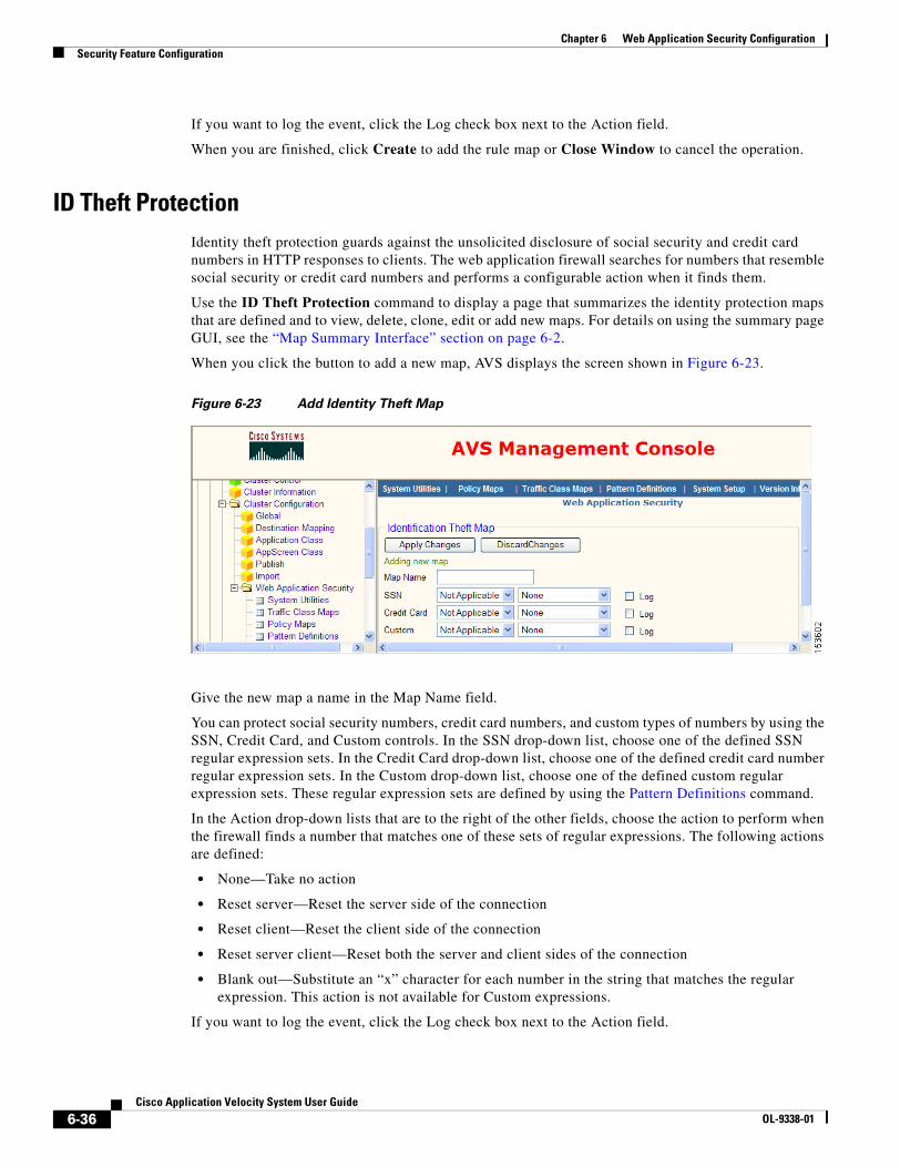
6-36Cisco Application Velocity System User Guide
OL-9338-01
Chapter 6 Web Application Security ConfigurationSecurity Feature Configuration
If you want to log the event, click the Log check box next to the Action field.
When you are finished, click Create to add the rule map or Close Window to cancel the operation.
ID Theft ProtectionIdentity theft protection guards against the unsolicited disclosure of social security and credit card numbers in HTTP responses to clients. The web application firewall searches for numbers that resemble social security or credit card numbers and performs a configurable action when it finds them.
Use the ID Theft Protection command to display a page that summarizes the identity protection maps that are defined and to view, delete, clone, edit or add new maps. For details on using the summary page GUI, see the “Map Summary Interface” section on page 6-2.
When you click the button to add a new map, AVS displays the screen shown in Figure 6-23.
Figure 6-23 Add Identity Theft Map
Give the new map a name in the Map Name field.
You can protect social security numbers, credit card numbers, and custom types of numbers by using the SSN, Credit Card, and Custom controls. In the SSN drop-down list, choose one of the defined SSN regular expression sets. In the Credit Card drop-down list, choose one of the defined credit card number regular expression sets. In the Custom drop-down list, choose one of the defined custom regular expression sets. These regular expression sets are defined by using the Pattern Definitions command.
In the Action drop-down lists that are to the right of the other fields, choose the action to perform when the firewall finds a number that matches one of these sets of regular expressions. The following actions are defined:
• None—Take no action
• Reset server—Reset the server side of the connection
• Reset client—Reset the client side of the connection
• Reset server client—Reset both the server and client sides of the connection
• Blank out—Substitute an “x” character for each number in the string that matches the regular expression. This action is not available for Custom expressions.
If you want to log the event, click the Log check box next to the Action field.

6-37Cisco Application Velocity System User Guide
OL-9338-01
Chapter 6 Web Application Security ConfigurationSecurity Feature Configuration
When you are finished with this form, click Apply Changes at the top to save your changes, or click Discard Changes to return to the summary page without saving your changes.
Request LimitsMany web sites use user-supplied input to create dynamic web pages. Improper validation of inputs such as URL, URL query string, and HTTP headers, can lead to buffer overflow attacks. A buffer overflow attack is when a program writes data beyond its allocated space. These attacks can cause denial of service by crashing the server and/or injecting malicious code to alter program execution. Execution of the malicious code facilitates exploit of downstream resources. Such attacks can be prevented by enforcing boundary length checking on all inputs received from the client.
Use the Request Limits command to display a page that summarizes the request limit maps that are defined and to view, delete, clone, edit or add new maps. For details on using the summary page GUI, see the “Map Summary Interface” section on page 6-2.
When you click the button to add a new map, AVS displays the screen shown in Figure 6-24.
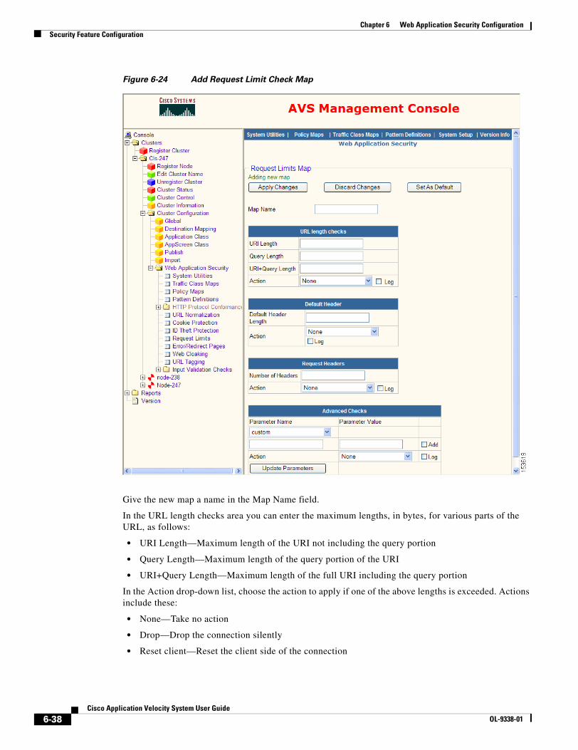
6-38Cisco Application Velocity System User Guide
OL-9338-01
Chapter 6 Web Application Security ConfigurationSecurity Feature Configuration
Figure 6-24 Add Request Limit Check Map
Give the new map a name in the Map Name field.
In the URL length checks area you can enter the maximum lengths, in bytes, for various parts of the URL, as follows:
• URI Length—Maximum length of the URI not including the query portion
• Query Length—Maximum length of the query portion of the URI
• URI+Query Length—Maximum length of the full URI including the query portion
In the Action drop-down list, choose the action to apply if one of the above lengths is exceeded. Actions include these:
• None—Take no action
• Drop—Drop the connection silently
• Reset client—Reset the client side of the connection
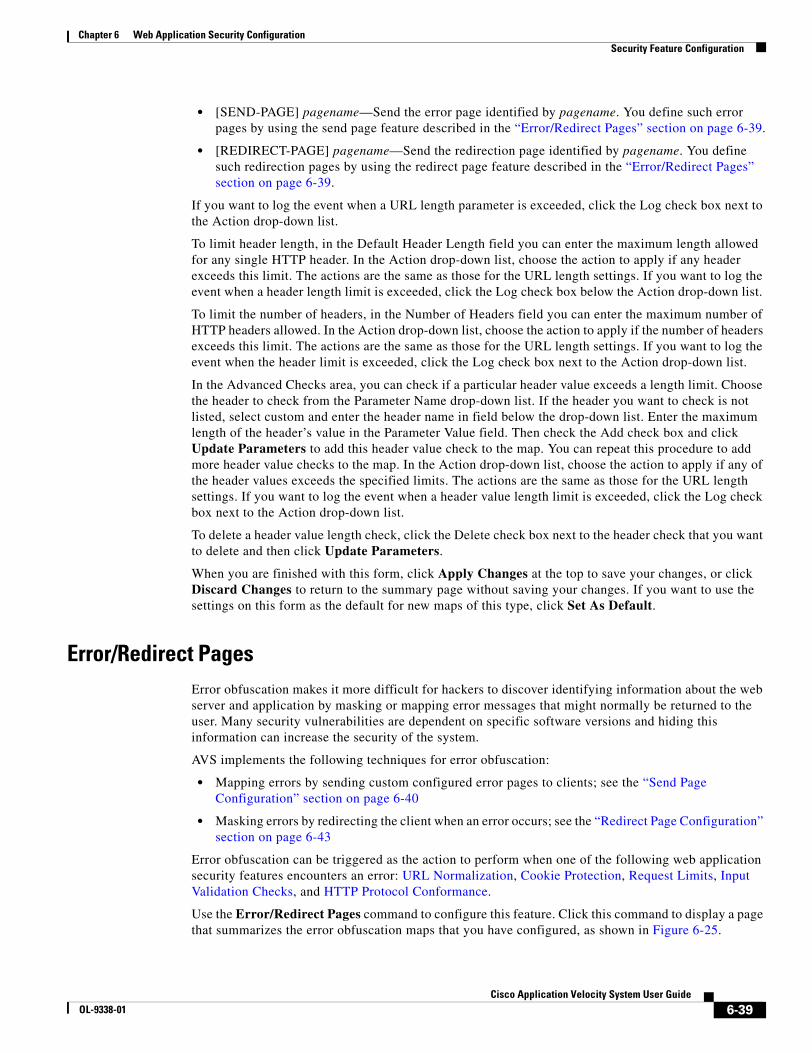
6-39Cisco Application Velocity System User Guide
OL-9338-01
Chapter 6 Web Application Security ConfigurationSecurity Feature Configuration
• [SEND-PAGE] pagename—Send the error page identified by pagename. You define such error pages by using the send page feature described in the “Error/Redirect Pages” section on page 6-39.
• [REDIRECT-PAGE] pagename—Send the redirection page identified by pagename. You define such redirection pages by using the redirect page feature described in the “Error/Redirect Pages” section on page 6-39.
If you want to log the event when a URL length parameter is exceeded, click the Log check box next to the Action drop-down list.
To limit header length, in the Default Header Length field you can enter the maximum length allowed for any single HTTP header. In the Action drop-down list, choose the action to apply if any header exceeds this limit. The actions are the same as those for the URL length settings. If you want to log the event when a header length limit is exceeded, click the Log check box below the Action drop-down list.
To limit the number of headers, in the Number of Headers field you can enter the maximum number of HTTP headers allowed. In the Action drop-down list, choose the action to apply if the number of headers exceeds this limit. The actions are the same as those for the URL length settings. If you want to log the event when the header limit is exceeded, click the Log check box next to the Action drop-down list.
In the Advanced Checks area, you can check if a particular header value exceeds a length limit. Choose the header to check from the Parameter Name drop-down list. If the header you want to check is not listed, select custom and enter the header name in field below the drop-down list. Enter the maximum length of the header’s value in the Parameter Value field. Then check the Add check box and click Update Parameters to add this header value check to the map. You can repeat this procedure to add more header value checks to the map. In the Action drop-down list, choose the action to apply if any of the header values exceeds the specified limits. The actions are the same as those for the URL length settings. If you want to log the event when a header value length limit is exceeded, click the Log check box next to the Action drop-down list.
To delete a header value length check, click the Delete check box next to the header check that you want to delete and then click Update Parameters.
When you are finished with this form, click Apply Changes at the top to save your changes, or click Discard Changes to return to the summary page without saving your changes. If you want to use the settings on this form as the default for new maps of this type, click Set As Default.
Error/Redirect PagesError obfuscation makes it more difficult for hackers to discover identifying information about the web server and application by masking or mapping error messages that might normally be returned to the user. Many security vulnerabilities are dependent on specific software versions and hiding this information can increase the security of the system.
AVS implements the following techniques for error obfuscation:
• Mapping errors by sending custom configured error pages to clients; see the “Send Page Configuration” section on page 6-40
• Masking errors by redirecting the client when an error occurs; see the “Redirect Page Configuration” section on page 6-43
Error obfuscation can be triggered as the action to perform when one of the following web application security features encounters an error: URL Normalization, Cookie Protection, Request Limits, Input Validation Checks, and HTTP Protocol Conformance.
Use the Error/Redirect Pages command to configure this feature. Click this command to display a page that summarizes the error obfuscation maps that you have configured, as shown in Figure 6-25.
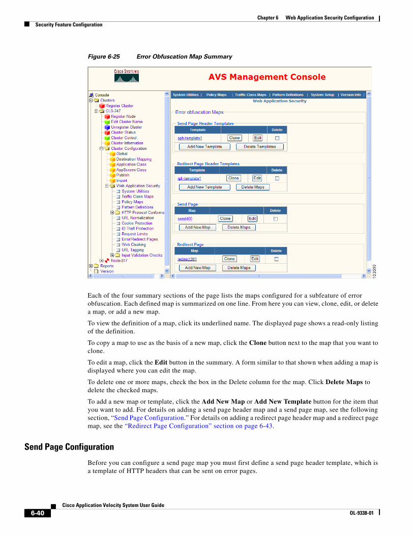
6-40Cisco Application Velocity System User Guide
OL-9338-01
Chapter 6 Web Application Security ConfigurationSecurity Feature Configuration
Figure 6-25 Error Obfuscation Map Summary
Each of the four summary sections of the page lists the maps configured for a subfeature of error obfuscation. Each defined map is summarized on one line. From here you can view, clone, edit, or delete a map, or add a new map.
To view the definition of a map, click its underlined name. The displayed page shows a read-only listing of the definition.
To copy a map to use as the basis of a new map, click the Clone button next to the map that you want to clone.
To edit a map, click the Edit button in the summary. A form similar to that shown when adding a map is displayed where you can edit the map.
To delete one or more maps, check the box in the Delete column for the map. Click Delete Maps to delete the checked maps.
To add a new map or template, click the Add New Map or Add New Template button for the item that you want to add. For details on adding a send page header map and a send page map, see the following section, “Send Page Configuration.” For details on adding a redirect page header map and a redirect page map, see the “Redirect Page Configuration” section on page 6-43.
Send Page Configuration
Before you can configure a send page map you must first define a send page header template, which is a template of HTTP headers that can be sent on error pages.
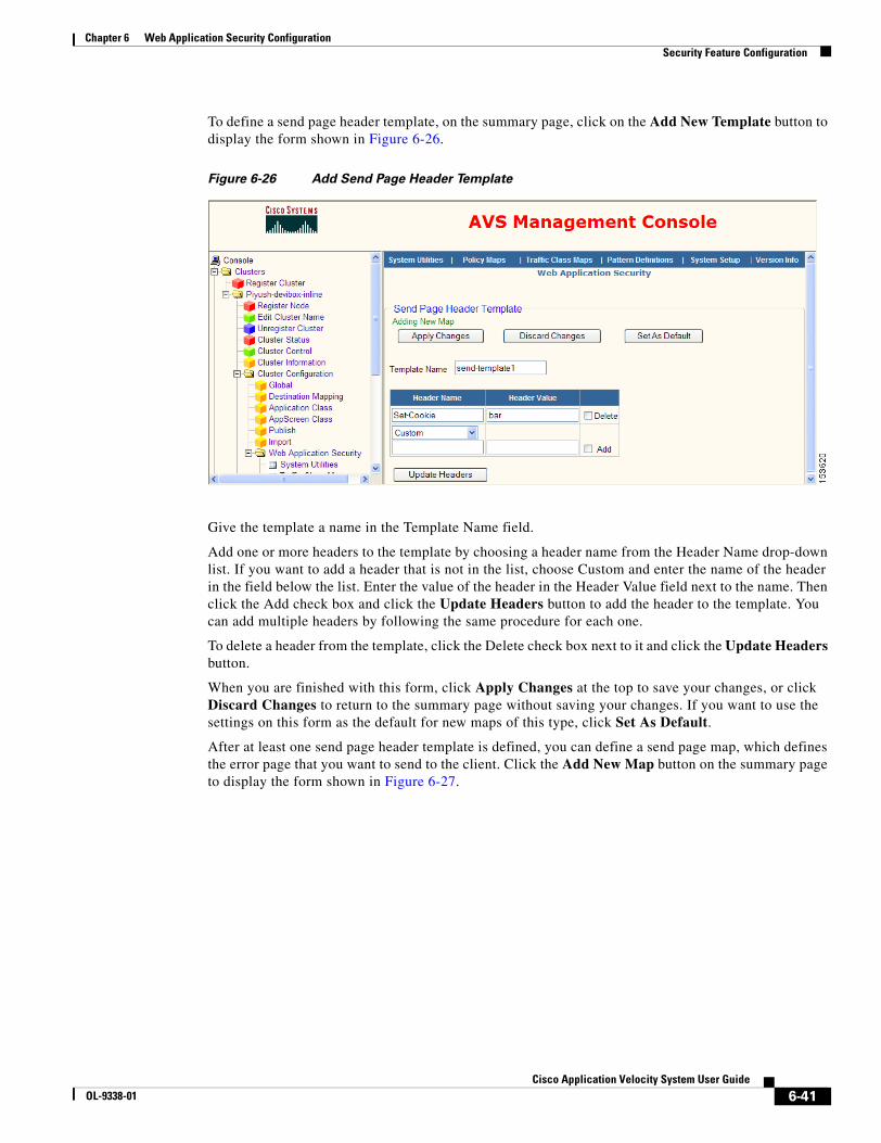
6-41Cisco Application Velocity System User Guide
OL-9338-01
Chapter 6 Web Application Security ConfigurationSecurity Feature Configuration
To define a send page header template, on the summary page, click on the Add New Template button to display the form shown in Figure 6-26.
Figure 6-26 Add Send Page Header Template
Give the template a name in the Template Name field.
Add one or more headers to the template by choosing a header name from the Header Name drop-down list. If you want to add a header that is not in the list, choose Custom and enter the name of the header in the field below the list. Enter the value of the header in the Header Value field next to the name. Then click the Add check box and click the Update Headers button to add the header to the template. You can add multiple headers by following the same procedure for each one.
To delete a header from the template, click the Delete check box next to it and click the Update Headers button.
When you are finished with this form, click Apply Changes at the top to save your changes, or click Discard Changes to return to the summary page without saving your changes. If you want to use the settings on this form as the default for new maps of this type, click Set As Default.
After at least one send page header template is defined, you can define a send page map, which defines the error page that you want to send to the client. Click the Add New Map button on the summary page to display the form shown in Figure 6-27.
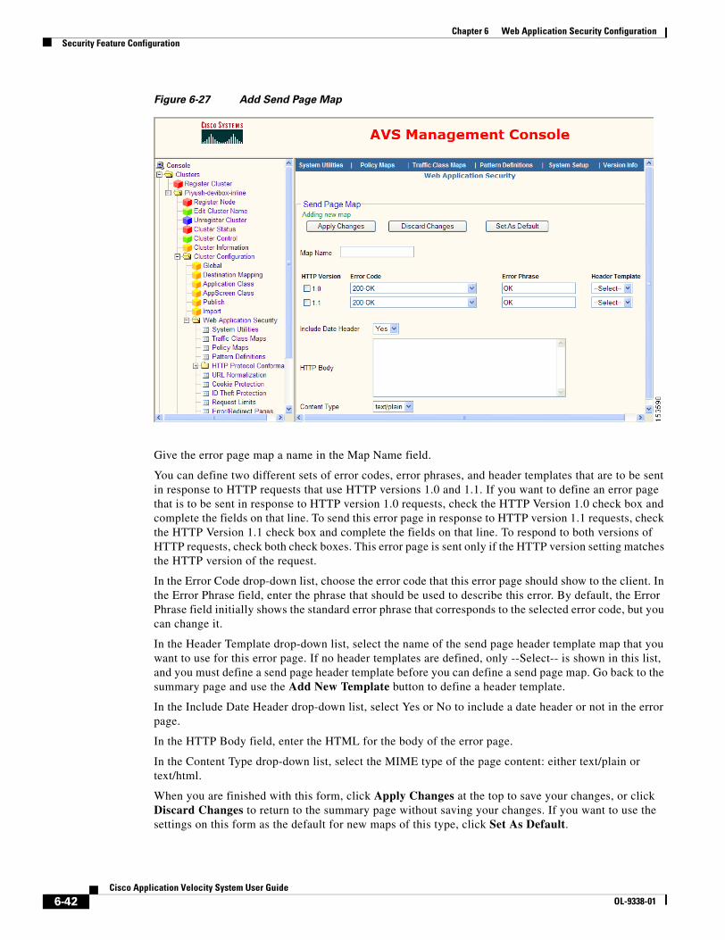
6-42Cisco Application Velocity System User Guide
OL-9338-01
Chapter 6 Web Application Security ConfigurationSecurity Feature Configuration
Figure 6-27 Add Send Page Map
Give the error page map a name in the Map Name field.
You can define two different sets of error codes, error phrases, and header templates that are to be sent in response to HTTP requests that use HTTP versions 1.0 and 1.1. If you want to define an error page that is to be sent in response to HTTP version 1.0 requests, check the HTTP Version 1.0 check box and complete the fields on that line. To send this error page in response to HTTP version 1.1 requests, check the HTTP Version 1.1 check box and complete the fields on that line. To respond to both versions of HTTP requests, check both check boxes. This error page is sent only if the HTTP version setting matches the HTTP version of the request.
In the Error Code drop-down list, choose the error code that this error page should show to the client. In the Error Phrase field, enter the phrase that should be used to describe this error. By default, the Error Phrase field initially shows the standard error phrase that corresponds to the selected error code, but you can change it.
In the Header Template drop-down list, select the name of the send page header template map that you want to use for this error page. If no header templates are defined, only --Select-- is shown in this list, and you must define a send page header template before you can define a send page map. Go back to the summary page and use the Add New Template button to define a header template.
In the Include Date Header drop-down list, select Yes or No to include a date header or not in the error page.
In the HTTP Body field, enter the HTML for the body of the error page.
In the Content Type drop-down list, select the MIME type of the page content: either text/plain or text/html.
When you are finished with this form, click Apply Changes at the top to save your changes, or click Discard Changes to return to the summary page without saving your changes. If you want to use the settings on this form as the default for new maps of this type, click Set As Default.
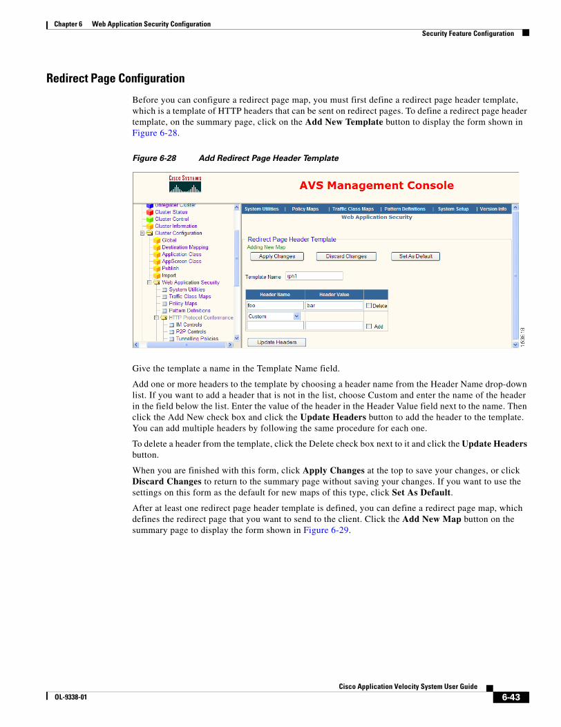
6-43Cisco Application Velocity System User Guide
OL-9338-01
Chapter 6 Web Application Security ConfigurationSecurity Feature Configuration
Redirect Page Configuration
Before you can configure a redirect page map, you must first define a redirect page header template, which is a template of HTTP headers that can be sent on redirect pages. To define a redirect page header template, on the summary page, click on the Add New Template button to display the form shown in Figure 6-28.
Figure 6-28 Add Redirect Page Header Template
Give the template a name in the Template Name field.
Add one or more headers to the template by choosing a header name from the Header Name drop-down list. If you want to add a header that is not in the list, choose Custom and enter the name of the header in the field below the list. Enter the value of the header in the Header Value field next to the name. Then click the Add New check box and click the Update Headers button to add the header to the template. You can add multiple headers by following the same procedure for each one.
To delete a header from the template, click the Delete check box next to it and click the Update Headers button.
When you are finished with this form, click Apply Changes at the top to save your changes, or click Discard Changes to return to the summary page without saving your changes. If you want to use the settings on this form as the default for new maps of this type, click Set As Default.
After at least one redirect page header template is defined, you can define a redirect page map, which defines the redirect page that you want to send to the client. Click the Add New Map button on the summary page to display the form shown in Figure 6-29.
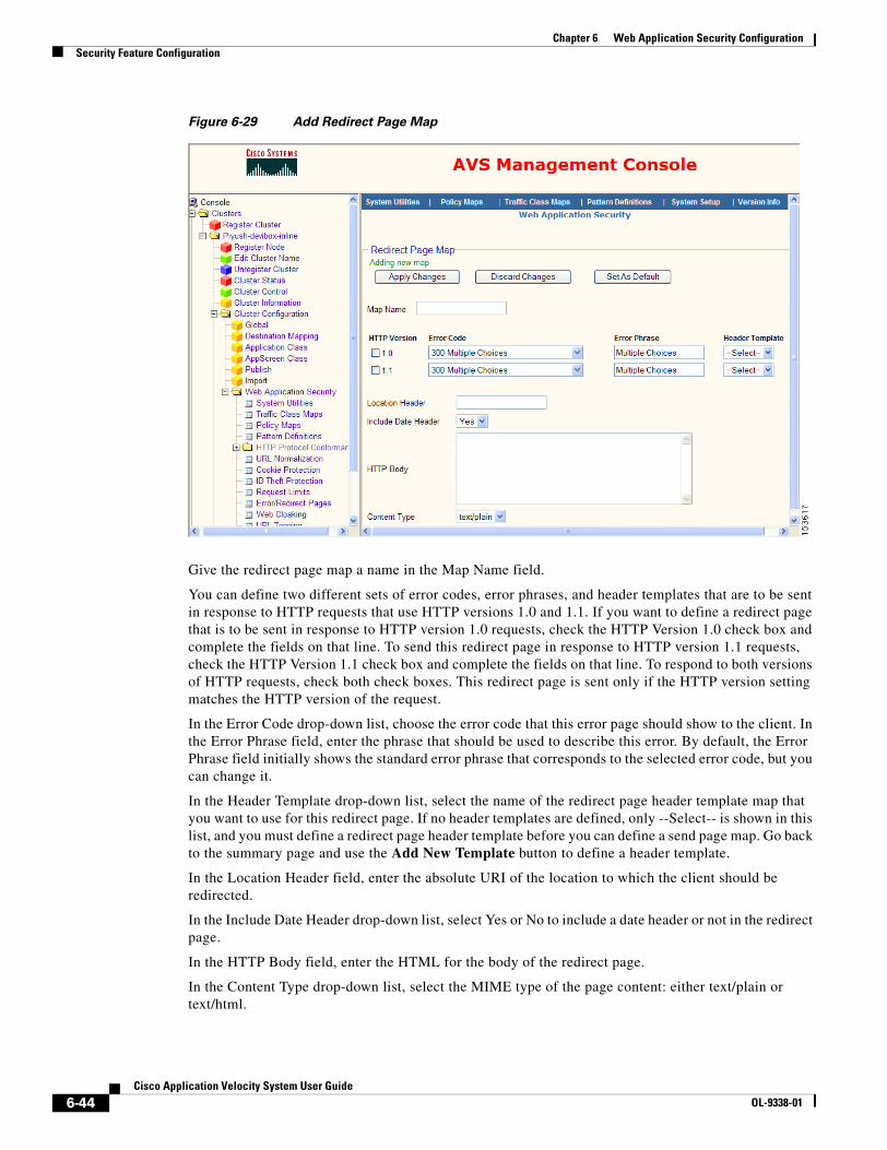
6-44Cisco Application Velocity System User Guide
OL-9338-01
Chapter 6 Web Application Security ConfigurationSecurity Feature Configuration
Figure 6-29 Add Redirect Page Map
Give the redirect page map a name in the Map Name field.
You can define two different sets of error codes, error phrases, and header templates that are to be sent in response to HTTP requests that use HTTP versions 1.0 and 1.1. If you want to define a redirect page that is to be sent in response to HTTP version 1.0 requests, check the HTTP Version 1.0 check box and complete the fields on that line. To send this redirect page in response to HTTP version 1.1 requests, check the HTTP Version 1.1 check box and complete the fields on that line. To respond to both versions of HTTP requests, check both check boxes. This redirect page is sent only if the HTTP version setting matches the HTTP version of the request.
In the Error Code drop-down list, choose the error code that this error page should show to the client. In the Error Phrase field, enter the phrase that should be used to describe this error. By default, the Error Phrase field initially shows the standard error phrase that corresponds to the selected error code, but you can change it.
In the Header Template drop-down list, select the name of the redirect page header template map that you want to use for this redirect page. If no header templates are defined, only --Select-- is shown in this list, and you must define a redirect page header template before you can define a send page map. Go back to the summary page and use the Add New Template button to define a header template.
In the Location Header field, enter the absolute URI of the location to which the client should be redirected.
In the Include Date Header drop-down list, select Yes or No to include a date header or not in the redirect page.
In the HTTP Body field, enter the HTML for the body of the redirect page.
In the Content Type drop-down list, select the MIME type of the page content: either text/plain or text/html.
6-45Cisco Application Velocity System User Guide
OL-9338-01
Chapter 6 Web Application Security ConfigurationSecurity Feature Configuration
When you are finished with this form, click Apply Changes at the top to save your changes, or click Discard Changes to return to the summary page without saving your changes. If you want to use the settings on this form as the default for new maps of this type, click Set As Default.
Web CloakingWeb cloaking makes it more difficult for hackers to discover identifying information about the web server and application. Many security vulnerabilities are dependent on specific software versions and hiding this information can increase the security of the system.
AVS focuses on the HTTP response headers and implements the following techniques for web server cloaking:
• Changing the sequence of individual header fields in the response (web servers can be fingerprinted based on the sequence of header fields in the response)
• Changing the case of header names (web servers can be fingerprinted based on the capitalization of header names)
• Changing the value of a header based on its name and value
• Removing a header based on its name and value
• Adding false headers to confuse attackers
Use the Web Cloaking command to display a page that summarizes the web cloaking maps that are defined and to view, delete, clone, edit or add new maps. For details on using the summary page GUI, see the “Map Summary Interface” section on page 6-2.
When you click the button to add a new map, AVS displays the screen shown in Figure 6-30.

6-46Cisco Application Velocity System User Guide
OL-9338-01
Chapter 6 Web Application Security ConfigurationSecurity Feature Configuration
Figure 6-30 Edit Web Cloaking Map
Give the new map a name in the Map Name field.
If you want to log web cloaking actions, click the Enable Log check box.
In the Available Headers/Header Sequence area you can change the sequence of individual HTTP headers in responses. Select the header that you want to be first from the Standard list and click the right arrow (>) to add it to the Header Sequence list on the right side of the page. Then select the header that you want to be second, and so on, adding each one in turn to the Header Sequence list. When you add a header, it is always added at the bottom of the list. You can also add a custom header that is not listed by typing its name into the Custom field and clicking the right arrow (>) next to that field.
To reorder the headers listed in the Header Sequence list, select a header and click the up arrow next to the list to move the header up one position in the list, or click the down arrow to move it one position down. Repeat the process each time that you want to move the header one more position up or down.
In the Add/Modify/Remove Response Headers area you can add, modify, or remove HTTP headers in responses. You can add multiple functions in this area; one operation is summarized on each line.
6-47Cisco Application Velocity System User Guide
OL-9338-01
Chapter 6 Web Application Security ConfigurationSecurity Feature Configuration
To add an operation, in the Operation drop-down list choose the type of operation: ADD, MODIFY, or REMOVE. In the Response Header drop-down list, choose the name of the header that you want to add, modify, or remove. If the header name is not listed, choose custom from the list and type the name of the header in the Response Header field below the drop-down list. Next, enter values in the Old Value and New Value fields, as follows:
• If you are adding a header, enter a value in the New Value field only and leave Old Value empty.
• If you are modifying a header, enter the existing value to match in the Old Value field and enter the value to change it to in the New Value field. Only headers whose value matches the Old Value will be changed to New Value.
• If you are removing a header, enter a value in the Old Value field only, to remove only headers that have this value.
Finally, click the Add check box to add the header operation to this web cloaking map. The operation is added after you click Update Parameters, and a new blank operation line is shown below the newly added one, where you can add another operation. Also, a Delete check box is shown at the right end of each operation line, which you can use to delete an operation by checking it and clicking Update Parameters.
In the Header Name Normalization area, you can force specific header names to be all uppercase or all lowercase. To normalize the case of a header name, select it in the list at the left side of the page and click the Uppercase right arrow (>) button to make it uppercase, or click the Lowercase right arrow button to make it lowercase. Do the same for each header name that you want to normalize. If you want to normalize a custom header name, choose Custom in the list and type the name in the Custom field below the list. Then click the appropriate right arrow button. To remove a header name from a normalization list at the right side, select it and click the left arrow (<) button next to the list.
When you are finished with this form, click Apply Changes at the top to save your changes, or click Discard Changes to return to the summary page without saving your changes. If you want to use the settings on this form as the default for new maps of this type, click Set As Default.
Interaction with AVS Acceleration in Gateway Mode
When you use web cloaking and operate the web application firewall in gateway mode, the AVS acceleration features interact with the response and can change HTTP response headers. AVS acceleration processing occurs after web application firewall processing, so the response might contain headers different from those set by web cloaking.
Specifically, AVS acceleration features may add, remove, or change the following headers:
• Add—Content-Encoding, Transfer-Encoding, Set-Cookie
• Remove—Content-Length
• Change—Connection
If Web Cloaking normalizes, sequences, adds, removes, or modifies any of these headers, the AVS acceleration processing may undo or change these actions in the response.
URL TaggingThe URL tagging feature lets you add information to request URLs that can be used by other downstream devices such as load balancers or application servers. You can search for a string in the URL and if there is a match you can either replace the complete URL with another URL or replace only the matched string. Additionally, you can insert or remove parameter name/value pairs.
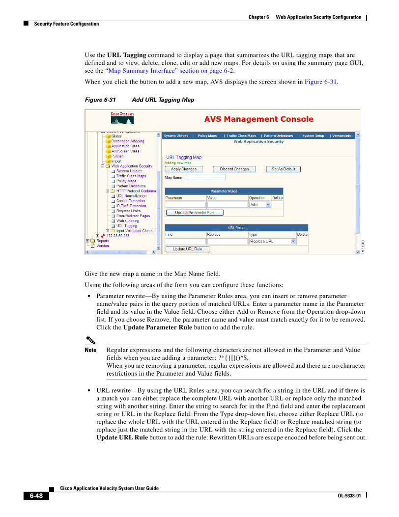
6-48Cisco Application Velocity System User Guide
OL-9338-01
Chapter 6 Web Application Security ConfigurationSecurity Feature Configuration
Use the URL Tagging command to display a page that summarizes the URL tagging maps that are defined and to view, delete, clone, edit or add new maps. For details on using the summary page GUI, see the “Map Summary Interface” section on page 6-2.
When you click the button to add a new map, AVS displays the screen shown in Figure 6-31.
Figure 6-31 Add URL Tagging Map
Give the new map a name in the Map Name field.
Using the following areas of the form you can configure these functions:
• Parameter rewrite—By using the Parameter Rules area, you can insert or remove parameter name/value pairs in the query portion of matched URLs. Enter a parameter name in the Parameter field and its value in the Value field. Choose either Add or Remove from the Operation drop-down list. If you choose Remove, the parameter name and value must match exactly for it to be removed. Click the Update Parameter Rule button to add the rule.
Note Regular expressions and the following characters are not allowed in the Parameter and Value fields when you are adding a parameter: ?*{}[]()^$,When you are removing a parameter, regular expressions are allowed and there are no character restrictions in the Parameter and Value fields.
• URL rewrite—By using the URL Rules area, you can search for a string in the URL and if there is a match you can either replace the complete URL with another URL or replace only the matched string with another string. Enter the string to search for in the Find field and enter the replacement string or URL in the Replace field. From the Type drop-down list, choose either Replace URL (to replace the whole URL with the URL entered in the Replace field) or Replace matched string (to replace just the matched string in the URL with the string entered in the Replace field). Click the Update URL Rule button to add the rule. Rewritten URLs are escape encoded before being sent out.
6-49Cisco Application Velocity System User Guide
OL-9338-01
Chapter 6 Web Application Security ConfigurationSecurity Feature Configuration
Note Regular expressions and the following characters are mostly not allowed in the Find and Replace fields: ?*{}[]()^$,When you are replacing a complete URL, then regular expression are allowed and there are no character restrictions in the Find field.
For details on the regular expression syntax that is allowed, see the “Web Application Security Regular Expression Syntax” section on page 6-72.
To delete an existing parameter or URL rewriting rule, click the Delete check box on the same line as the rule, and when you click Update Parameter Rule (to delete parameter rules) or Update URL Rule (to delete URL rewrite rules), the rule will be deleted.
When you are finished with this form, click Apply Changes at the top to save your changes, or click Discard Changes to return to the summary page without saving your changes. If you want to use the settings on this form as the default for new maps of this type, click Set As Default.
HTTP Protocol ConformanceHTTP protocol conformance provides deep analysis of web traffic, enabling granular control over HTTP sessions for improved protection from a wide range of web-based attacks. In addition, this feature allows administrative control over instant messaging applications, peer-to-peer file sharing applications, and applications that attempt to tunnel over port 80 or any port used for HTTP transactions. Capabilities provided include RFC compliance enforcement, HTTP command authorization and enforcement, response validation, Multipurpose Internet Mail Extension (MIME) type validation and content control, URL blacklisting, and more.
The following sections describe the HTTP Protocol Conformance menu commands:
• IM Controls
• P2P Controls
• Tunnelling Policies
• Generic Pattern Matcher
• Transfer Encoding
• MIME Type Controls
• URL Black Listing
• Control HTTP Methods
• Header Integrity Check
IM Controls
The IM controls feature allows you to control incoming and outgoing instant messaging traffic by logging or denying it.
Use the IM Controls command to display a page that summarizes the instant messaging maps that are defined and to view, delete, clone, edit or add new maps. For details on using the summary page GUI, see the “Map Summary Interface” section on page 6-2.
When you click the button to add a new map, AVS displays the screen shown in Figure 6-32.
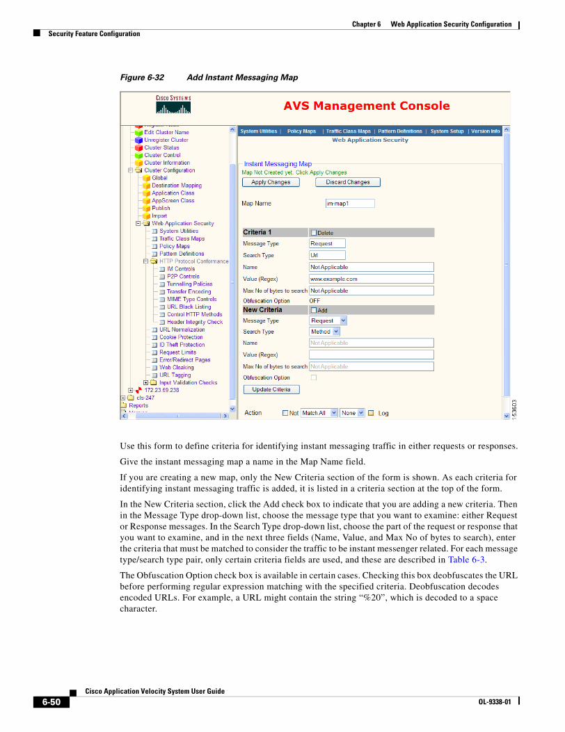
6-50Cisco Application Velocity System User Guide
OL-9338-01
Chapter 6 Web Application Security ConfigurationSecurity Feature Configuration
Figure 6-32 Add Instant Messaging Map
Use this form to define criteria for identifying instant messaging traffic in either requests or responses.
Give the instant messaging map a name in the Map Name field.
If you are creating a new map, only the New Criteria section of the form is shown. As each criteria for identifying instant messaging traffic is added, it is listed in a criteria section at the top of the form.
In the New Criteria section, click the Add check box to indicate that you are adding a new criteria. Then in the Message Type drop-down list, choose the message type that you want to examine: either Request or Response messages. In the Search Type drop-down list, choose the part of the request or response that you want to examine, and in the next three fields (Name, Value, and Max No of bytes to search), enter the criteria that must be matched to consider the traffic to be instant messenger related. For each message type/search type pair, only certain criteria fields are used, and these are described in Table 6-3.
The Obfuscation Option check box is available in certain cases. Checking this box deobfuscates the URL before performing regular expression matching with the specified criteria. Deobfuscation decodes encoded URLs. For example, a URL might contain the string “%20”, which is decoded to a space character.

6-51Cisco Application Velocity System User Guide
OL-9338-01
Chapter 6 Web Application Security ConfigurationSecurity Feature Configuration
The Value field can be a regular expression; for details see the “Web Application Security Regular Expression Syntax” section on page 6-72.
When you are done entering the criteria, make sure the Add check box is checked and click the Update Criteria button to add the criteria to the map. You can add more criteria by following the same procedure for each one. To delete a criteria from the map, click the Delete check box next to it and click the Update Criteria button.
After you have defined the criteria to identify instant messenger traffic, you can configure the action to apply when such traffic is observed. In the first Action drop-down list, choose one of the following items:
• Match All—All criteria must be matched to apply the action
• Match Any—Any single criteria must be matched to apply the action
Click the Not check box if you want to match all traffic that does not meet the criteria. If Not is checked, the match criteria are interpreted as follows:
• Match All—Fewer than all criteria must be matched to apply the action
• Match Any—None of the criteria must be matched to apply the action
In the second drop-down list, choose one of the following actions:
• None—Take no action
• Deny—Block the traffic
Table 6-3 Instant Messaging Criteria
Message Type/ Search Type Criteria Fields Used Description
Request/Method Name Enter the HTTP request method name in the Name field.
Request/Url Value, Obfuscation Option check box
In the Value field, enter a string to match in the URL and check the Obfuscation Option check box to deobfuscate the URL before matching. You can enter either a full URL or a partial string. If any part of the value is found in the URL, then the match is successful. Only the URL is searched for a match, not the query parameters.
Request/Arg Value, Obfuscation Option check box
In the Value field, enter a string to match in the query portion of the URL and check the Obfuscation Option check box to deobfuscate the URL before matching. If any part of the value is found in the query parameters, then the match is successful. Only the query parameter portion of the URL is searched.
Request/Header Name, Value Enter the name of the HTTP request header in the Name field and the header value in the Value field.
Request/Body Value, Max No of bytes to search
Enter the string to search for in the body of the request in the Value field, and enter the maximum number of bytes to search in the body in the Max No of bytes to search field. The match is successful if the specified string is found anywhere in the body, ending at the byte specified in Max No of bytes to search.
Response/StatusCode Value Enter the numeric response status code to search for in the Value field.
Response/Header Name, Value Enter the name of the HTTP response header in the Name field and the header value in the Value field.
Response/Body Value, Max No of bytes to search
Enter the string to search for in the body of the response in the Value field, and enter the maximum number of bytes to search in the body in the Max No of bytes to search field. The match is successful if the specified string is found anywhere in the body, ending at the byte specified in Max No of bytes to search.
6-52Cisco Application Velocity System User Guide
OL-9338-01
Chapter 6 Web Application Security ConfigurationSecurity Feature Configuration
• [SEND-PAGE] pagename—Send the error page identified by pagename. You define such error pages by using the send page feature described in the “Error/Redirect Pages” section on page 6-39.
• [REDIRECT-PAGE] pagename—Send the redirection page identified by pagename. You define such redirection pages by using the redirect page feature described in the “Error/Redirect Pages” section on page 6-39.
If you want to log the event, click the Log check box next to the Action drop-down lists.
When you are finished with this form, click Apply Changes at the top to save your changes, or click Discard Changes to return to the summary page without saving your changes.
P2P Controls
The P2P controls feature allows you to control incoming and outgoing peer-to-peer application traffic by logging or denying it. Use the P2P Controls command to configure peer-to-peer application control. This command works exactly like the IM Controls command, so for details, see the “IM Controls” section on page 6-49.
Tunnelling Policies
The tunnelling policies feature allows you to control incoming and outgoing tunnelled application traffic by logging or denying it. Use the Tunelling Policies command to configure tunnelling application control. This command works exactly like the IM Controls command, so for details, see the “IM Controls” section on page 6-49.
Generic Pattern Matcher
The generic pattern matcher feature allows you to configure a policy based on any user-definable criteria in the traffic, to control incoming and outgoing traffic by logging or denying it. Use the Generic Pattern Matcher command to configure such control. This command works exactly like the IM Controls command, so for details, see the “IM Controls” section on page 6-49.
Transfer Encoding
The transfer encoding feature allows you to control incoming and outgoing traffic that has a specific Transfer-Encoding header by logging or denying it.
Use the Transfer Encoding command to display a page that summarizes the transfer encoding maps that are defined and to view, delete, clone, edit or add new maps. For details on using the summary page GUI, see the “Map Summary Interface” section on page 6-2.
When you click the button to add a new map, AVS displays the screen shown in Figure 6-33.
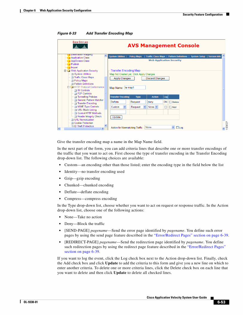
6-53Cisco Application Velocity System User Guide
OL-9338-01
Chapter 6 Web Application Security ConfigurationSecurity Feature Configuration
Figure 6-33 Add Transfer Encoding Map
Give the transfer encoding map a name in the Map Name field.
In the next part of the form, you can add criteria lines that describe one or more transfer encodings of the traffic that you want to act on. First choose the type of transfer encoding in the Transfer Encoding drop-down list. The following choices are available:
• Custom—an encoding other than those listed; enter the encoding type in the field below the list
• Identity—no transfer encoding used
• Gzip—gzip encoding
• Chunked—chunked encoding
• Deflate—deflate encoding
• Compress—compress encoding
In the Type drop-down list, choose whether you want to act on request or response traffic. In the Action drop-down list, choose one of the following actions:
• None—Take no action
• Deny—Block the traffic
• [SEND-PAGE] pagename—Send the error page identified by pagename. You define such error pages by using the send page feature described in the “Error/Redirect Pages” section on page 6-39.
• [REDIRECT-PAGE] pagename—Send the redirection page identified by pagename. You define such redirection pages by using the redirect page feature described in the “Error/Redirect Pages” section on page 6-39.
If you want to log the event, click the Log check box next to the Action drop-down list. Finally, check the Add check box and click Update to add the criteria to this form and give you a new line on which to enter another criteria. To delete one or more criteria lines, click the Delete check box on each line that you want to delete and then click Update to delete all checked lines.
6-54Cisco Application Velocity System User Guide
OL-9338-01
Chapter 6 Web Application Security ConfigurationSecurity Feature Configuration
There is another Action drop-down list at the bottom of the form, labeled Action for Nonmatching Traffic. This action applies to all traffic that has a transfer encoding that does not match any of the criteria on this form. You can choose the same actions as on the other Action list. Also, you can click the Log check box next to this drop-down list if you want to log such traffic.
When you are finished with this form, click Apply Changes at the top to save your changes, or click Discard Changes to return to the summary page without saving your changes.
MIME Type Controls
The MIME type controls feature allows you to validate that the MIME type specified in the HTTP Content-Type header matches the content type’s magic number in the body of the message. (Magic numbers are byte sequences that are always present in a particular MIME type and thus can be used to identify entities as being of a given media type.)
Use the MIME Type Controls command to display a page that summarizes the content type verification maps that are defined and to view, delete, clone, edit or add new maps. For details on using the summary page GUI, see the “Map Summary Interface” section on page 6-2.
When you click the button to add a new map, AVS displays the screen shown in Figure 6-34.
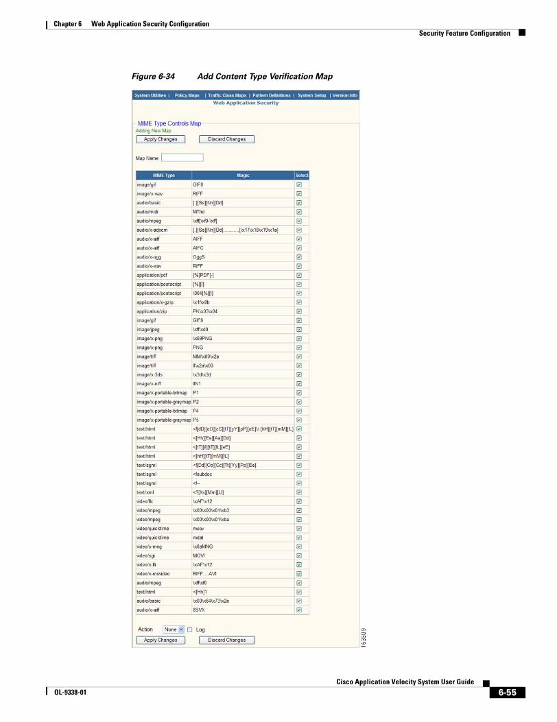
6-55Cisco Application Velocity System User Guide
OL-9338-01
Chapter 6 Web Application Security ConfigurationSecurity Feature Configuration
Figure 6-34 Add Content Type Verification Map
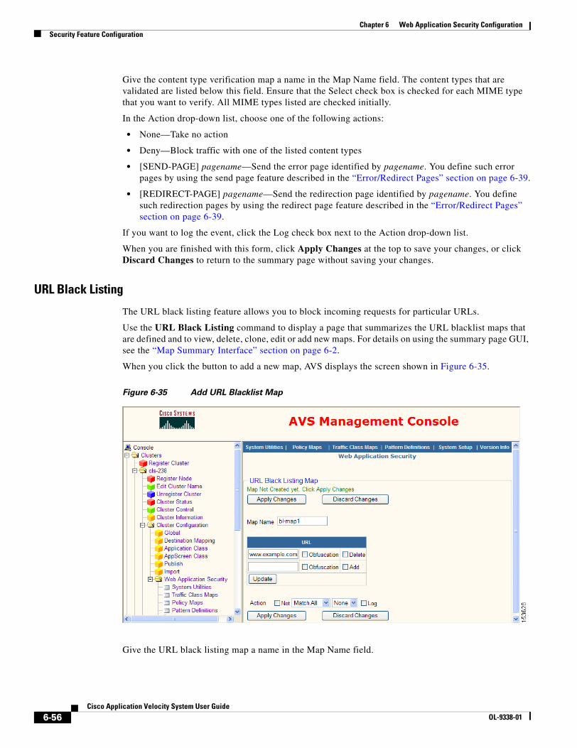
6-56Cisco Application Velocity System User Guide
OL-9338-01
Chapter 6 Web Application Security ConfigurationSecurity Feature Configuration
Give the content type verification map a name in the Map Name field. The content types that are validated are listed below this field. Ensure that the Select check box is checked for each MIME type that you want to verify. All MIME types listed are checked initially.
In the Action drop-down list, choose one of the following actions:
• None—Take no action
• Deny—Block traffic with one of the listed content types
• [SEND-PAGE] pagename—Send the error page identified by pagename. You define such error pages by using the send page feature described in the “Error/Redirect Pages” section on page 6-39.
• [REDIRECT-PAGE] pagename—Send the redirection page identified by pagename. You define such redirection pages by using the redirect page feature described in the “Error/Redirect Pages” section on page 6-39.
If you want to log the event, click the Log check box next to the Action drop-down list.
When you are finished with this form, click Apply Changes at the top to save your changes, or click Discard Changes to return to the summary page without saving your changes.
URL Black Listing
The URL black listing feature allows you to block incoming requests for particular URLs.
Use the URL Black Listing command to display a page that summarizes the URL blacklist maps that are defined and to view, delete, clone, edit or add new maps. For details on using the summary page GUI, see the “Map Summary Interface” section on page 6-2.
When you click the button to add a new map, AVS displays the screen shown in Figure 6-35.
Figure 6-35 Add URL Blacklist Map
Give the URL black listing map a name in the Map Name field.
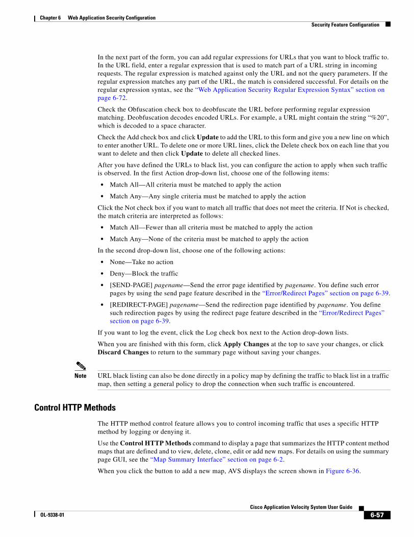
6-57Cisco Application Velocity System User Guide
OL-9338-01
Chapter 6 Web Application Security ConfigurationSecurity Feature Configuration
In the next part of the form, you can add regular expressions for URLs that you want to block traffic to. In the URL field, enter a regular expression that is used to match part of a URL string in incoming requests. The regular expression is matched against only the URL and not the query parameters. If the regular expression matches any part of the URL, the match is considered successful. For details on the regular expression syntax, see the “Web Application Security Regular Expression Syntax” section on page 6-72.
Check the Obfuscation check box to deobfuscate the URL before performing regular expression matching. Deobfuscation decodes encoded URLs. For example, a URL might contain the string “%20”, which is decoded to a space character.
Check the Add check box and click Update to add the URL to this form and give you a new line on which to enter another URL. To delete one or more URL lines, click the Delete check box on each line that you want to delete and then click Update to delete all checked lines.
After you have defined the URLs to black list, you can configure the action to apply when such traffic is observed. In the first Action drop-down list, choose one of the following items:
• Match All—All criteria must be matched to apply the action
• Match Any—Any single criteria must be matched to apply the action
Click the Not check box if you want to match all traffic that does not meet the criteria. If Not is checked, the match criteria are interpreted as follows:
• Match All—Fewer than all criteria must be matched to apply the action
• Match Any—None of the criteria must be matched to apply the action
In the second drop-down list, choose one of the following actions:
• None—Take no action
• Deny—Block the traffic
• [SEND-PAGE] pagename—Send the error page identified by pagename. You define such error pages by using the send page feature described in the “Error/Redirect Pages” section on page 6-39.
• [REDIRECT-PAGE] pagename—Send the redirection page identified by pagename. You define such redirection pages by using the redirect page feature described in the “Error/Redirect Pages” section on page 6-39.
If you want to log the event, click the Log check box next to the Action drop-down lists.
When you are finished with this form, click Apply Changes at the top to save your changes, or click Discard Changes to return to the summary page without saving your changes.
Note URL black listing can also be done directly in a policy map by defining the traffic to black list in a traffic map, then setting a general policy to drop the connection when such traffic is encountered.
Control HTTP Methods
The HTTP method control feature allows you to control incoming traffic that uses a specific HTTP method by logging or denying it.
Use the Control HTTP Methods command to display a page that summarizes the HTTP content method maps that are defined and to view, delete, clone, edit or add new maps. For details on using the summary page GUI, see the “Map Summary Interface” section on page 6-2.
When you click the button to add a new map, AVS displays the screen shown in Figure 6-36.
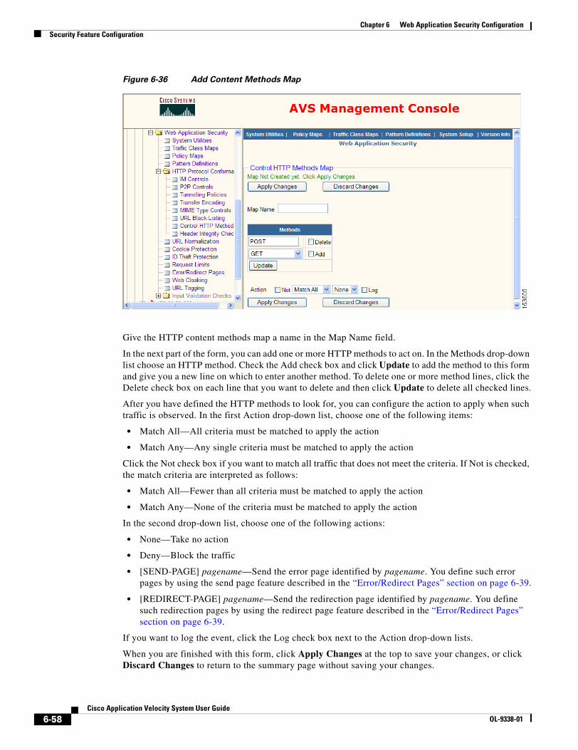
6-58Cisco Application Velocity System User Guide
OL-9338-01
Chapter 6 Web Application Security ConfigurationSecurity Feature Configuration
Figure 6-36 Add Content Methods Map
Give the HTTP content methods map a name in the Map Name field.
In the next part of the form, you can add one or more HTTP methods to act on. In the Methods drop-down list choose an HTTP method. Check the Add check box and click Update to add the method to this form and give you a new line on which to enter another method. To delete one or more method lines, click the Delete check box on each line that you want to delete and then click Update to delete all checked lines.
After you have defined the HTTP methods to look for, you can configure the action to apply when such traffic is observed. In the first Action drop-down list, choose one of the following items:
• Match All—All criteria must be matched to apply the action
• Match Any—Any single criteria must be matched to apply the action
Click the Not check box if you want to match all traffic that does not meet the criteria. If Not is checked, the match criteria are interpreted as follows:
• Match All—Fewer than all criteria must be matched to apply the action
• Match Any—None of the criteria must be matched to apply the action
In the second drop-down list, choose one of the following actions:
• None—Take no action
• Deny—Block the traffic
• [SEND-PAGE] pagename—Send the error page identified by pagename. You define such error pages by using the send page feature described in the “Error/Redirect Pages” section on page 6-39.
• [REDIRECT-PAGE] pagename—Send the redirection page identified by pagename. You define such redirection pages by using the redirect page feature described in the “Error/Redirect Pages” section on page 6-39.
If you want to log the event, click the Log check box next to the Action drop-down lists.
When you are finished with this form, click Apply Changes at the top to save your changes, or click Discard Changes to return to the summary page without saving your changes.
6-59Cisco Application Velocity System User Guide
OL-9338-01
Chapter 6 Web Application Security ConfigurationSecurity Feature Configuration
Header Integrity Check
The header integrity check feature allows you to check the integrity of HTTP headers and take action if problems are found.
Use the Header Integrity Check command to display a page that summarizes the header integrity check maps that are defined and to view, delete, clone, edit or add new maps. For details on using the summary page GUI, see the “Map Summary Interface” section on page 6-2.
When you click the button to add a new map, AVS displays the screen shown in Figure 6-37.
Figure 6-37 Add Header Integrity Check Map
Give the header integrity check map a name in the Map Name field.
In the next part of the form, you can configure actions to take when the following problems are found in a header:
• Null Encoding—Transfer-encoding header has no encodings listed
• Non ASCII Characters—Non-ASCII characters are found in a header
• Illegal Content Length—Content-length header contains non-numeric characters
• Illegal Chunk Encoding—Chunk encoding is not valid
• Multiple Length Headers—Multiple content-length headers appear in the request
For each listed header integrity problem, select one of the following actions from the Action drop-down list:
• None—Take no action
• Reset server—Reset the server side of the connection
• Reset client—Reset the client side of the connection
• Reset server client—Reset both the server and client sides of the connection
• Drop—Drop the connection silently
• [SEND-PAGE] pagename—Send the error page identified by pagename. You define such error pages by using the send page feature described in the “Error/Redirect Pages” section on page 6-39.
6-60Cisco Application Velocity System User Guide
OL-9338-01
Chapter 6 Web Application Security ConfigurationSecurity Feature Configuration
• [REDIRECT-PAGE] pagename—Send the redirection page identified by pagename. You define such redirection pages by using the redirect page feature described in the “Error/Redirect Pages” section on page 6-39.
If you want to log a problem, click the Log check box next to the Action drop-down list.
When you are finished with this form, click Apply Changes at the top to save your changes, or click Discard Changes to return to the summary page without saving your changes. If you want to use the settings on this form as the default for new maps of this type, click Set As Default.
Input Validation ChecksThe input validation module inspects incoming HTTP messages from clients and web servers to protect against a variety of attacks that use form input submitted by the GET or POST methods. The following sections describe these input validation checks:
• Cross Site Scripting
• SQL Injection
• OS Command Injection
• LDAP Injection
• Meta Character Detection
• Format String Attacks
All input validation checks use regular expression sets that have been defined with the Pattern Definitions command; for details, see the “Pattern Definitions” section on page 6-26.
Cross Site Scripting
A cross site scripting attack takes advantage of dynamically generated web pages in which data is usually gathered in the form of a hyperlink. An attacker, when prompted to enter information like a user name, will instead pass a script to be executed. A web server that does not properly perform input validation will execute the script and wait for an innocent user to click the link provided by the attacker. The victim may unknowingly release information to the attacker.
Use the Cross Site Scripting command to display a page that summarizes the cross site scripting maps that are defined and to view, delete, clone, edit or add new maps. For details on using the summary page GUI, see the “Map Summary Interface” section on page 6-2.
When you click the button to add a new map, AVS displays the screen shown in Figure 6-38.
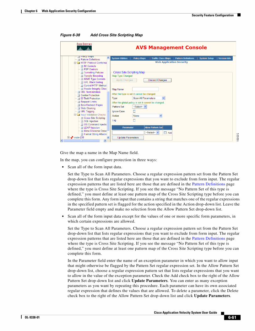
6-61Cisco Application Velocity System User Guide
OL-9338-01
Chapter 6 Web Application Security ConfigurationSecurity Feature Configuration
Figure 6-38 Add Cross Site Scripting Map
Give the map a name in the Map Name field.
In the map, you can configure protection in three ways:
• Scan all of the form input data.
Set the Type to Scan All Parameters. Choose a regular expression pattern set from the Pattern Set drop-down list that lists regular expressions that you want to exclude from form input. The regular expression patterns that are listed here are those that are defined in the Pattern Definitions page where the type is Cross Site Scripting. If you see the message “No Pattern Set of this type is defined,” you must define at least one pattern map of the Cross Site Scripting type before you can complete this form. Any form input that contains a string that matches one of the regular expressions in the specified pattern set is flagged for the action specified in the Action drop-down list. Leave the Parameter field empty and make no selection from the Allow Pattern Set drop-down list.
• Scan all of the form input data except for the values of one or more specific form parameters, in which certain expressions are allowed.
Set the Type to Scan All Parameters. Choose a regular expression pattern set from the Pattern Set drop-down list that lists regular expressions that you want to exclude from form input. The regular expression patterns that are listed here are those that are defined in the Pattern Definitions page where the type is Cross Site Scripting. If you see the message “No Pattern Set of this type is defined,” you must define at least one pattern map of the Cross Site Scripting type before you can complete this form.
In the Parameter field enter the name of an exception parameter in which you want to allow input that might otherwise be flagged by the Pattern Set regular expression set. In the Allow Pattern Set drop-down list, choose a regular expression pattern set that lists regular expressions that you want to allow in the value of the exception parameter. Check the Add check box to the right of the Allow Pattern Set drop-down list and click Update Parameters. You can enter as many exception parameters as you want by repeating this procedure. Each parameter can have its own associated regular expression that defines the values that are allowed. To delete a parameter, click the Delete check box to the right of the Allow Pattern Set drop-down list and click Update Parameters.
6-62Cisco Application Velocity System User Guide
OL-9338-01
Chapter 6 Web Application Security ConfigurationSecurity Feature Configuration
Any form input that contains a string that matches one of the regular expressions in the Pattern Set is flagged for the action specified in the Action drop-down list. If an exception parameter value contains a string that matches both the Pattern Set and Allow Pattern Set regular expressions, then it is allowed rather than being flagged for action.
• Scan the values of a one or more specific form parameters within the input data.
Set the Type to Scan Specific Parameters. Choose a regular expression pattern set from the Pattern Set drop-down list and enter the name of a form parameter to scan in the Parameter field. Check the Add check box to the right of the parameter name and click Update Parameters. You can enter as many parameters as you want by repeating this procedure. To delete a parameter, click the Delete check box to the right of the parameter name and click Update Parameters. If any of the specified parameter values contain a string that matches one of the regular expressions in the specified pattern set, the request is flagged for the action specified in the Action drop-down list.
Check the Ignore Case check box if you do not need to match the case of a parameter specified in the Parameter field. If you do need to match the case exactly, leave this check box unchecked.
In the Action drop-down list, choose the action to apply if a form input string that matches this map is detected. Actions include these:
• None—Take no action
• Reset server client—Reset both the server and client sides of the connection
• Drop—Drop the connection silently
• [SEND-PAGE] pagename—Send the error page identified by pagename. You define such error pages by using the send page feature described in the “Error/Redirect Pages” section on page 6-39.
• [REDIRECT-PAGE] pagename—Send the redirection page identified by pagename. You define such redirection pages by using the redirect page feature described in the “Error/Redirect Pages” section on page 6-39.
If you want to log the event, click the Log check box below the Action drop-down list.
When you are finished with this form, click Apply Changes at the top to save your changes, or click Discard Changes to return to the summary page without saving your changes.
SQL Injection
A SQL injection attack appends or modifies SQL commands in form input with the intention of gathering information regarding the application and obtaining access to unauthorized data.
Use the SQL Injection command to display a page that summarizes the SQL injection maps that are defined and to view, delete, clone, edit or add new maps. For details on using the summary page GUI, see the “Map Summary Interface” section on page 6-2.
When you click the button to add a new map, AVS displays the screen shown in Figure 6-39.

6-63Cisco Application Velocity System User Guide
OL-9338-01
Chapter 6 Web Application Security ConfigurationSecurity Feature Configuration
Figure 6-39 Add SQL Injection Map
Give the map a name in the Map Name field.
In the map, you can configure protection in three ways:
• Scan all of the form input data.
Set the Type to Scan All Parameters. Choose a regular expression pattern set from the Pattern Set drop-down list that lists regular expressions that you want to exclude from form input. The regular expression patterns that are listed here are those that are defined in the Pattern Definitions page where the type is SQL Injection. If you see the message “No Pattern Set of this type is defined,” you must define at least one pattern map of the SQL Injection type before you can complete this form. Any form input that contains a string that matches one of the regular expressions in the specified pattern set is flagged for the action specified in the Action drop-down list. Leave the Parameter field empty and make no selection from the Allow Pattern Set drop-down list.
• Scan all of the form input data except for the values of one or more specific form parameters, in which certain expressions are allowed.
Set the Type to Scan All Parameters. Choose a regular expression pattern set from the Pattern Set drop-down list that lists regular expressions that you want to exclude from form input. The regular expression patterns that are listed here are those that are defined in the Pattern Definitions page where the type is SQL Injection. If you see the message “No Pattern Set of this type is defined,” you must define at least one pattern map of the SQL Injection type before you can complete this form.
In the Parameter field enter the name of an exception parameter in which you want to allow input that might otherwise be flagged by the Pattern Set regular expression set. In the Allow Pattern Set drop-down list, choose a regular expression pattern set that lists regular expressions that you want to allow in the value of the exception parameter. Check the Add check box to the right of the Allow Pattern Set drop-down list and click Update Parameters. You can enter as many exception parameters as you want by repeating this procedure. Each parameter can have its own associated regular expression that defines the values that are allowed. To delete a parameter, click the Delete check box to the right of the Allow Pattern Set drop-down list and click Update Parameters.
6-64Cisco Application Velocity System User Guide
OL-9338-01
Chapter 6 Web Application Security ConfigurationSecurity Feature Configuration
Any form input that contains a string that matches one of the regular expressions in the Pattern Set is flagged for the action specified in the Action drop-down list. If an exception parameter value contains a string that matches both the Pattern Set and Allow Pattern Set regular expressions, then it is allowed rather than being flagged for action.
• Scan the values of a one or more specific form parameters within the input data.
Set the Type to Scan Specific Parameters. Choose a regular expression pattern set from the Pattern Set drop-down list and enter the name of a form parameter to scan in the Parameter field. Check the Add check box to the right of the parameter name and click Update Parameters. You can enter as many parameters as you want by repeating this procedure. To delete a parameter, click the Delete check box to the right of the parameter name and click Update Parameters. If any of the specified parameter values contain a string that matches one of the regular expressions in the specified pattern set, the request is flagged for the action specified in the Action drop-down list.
Check the Ignore Case check box if you do not need to match the case of a parameter specified in the Parameter field. If you do need to match the case exactly, leave this check box unchecked.
In the Action drop-down list, choose the action to apply if a form input string that matches this map is detected. Actions include these:
• None—Take no action
• Reset server client—Reset both the server and client sides of the connection
• Drop—Drop the connection silently
• [SEND-PAGE] pagename—Send the error page identified by pagename. You define such error pages by using the send page feature described in the “Error/Redirect Pages” section on page 6-39.
• [REDIRECT-PAGE] pagename—Send the redirection page identified by pagename. You define such redirection pages by using the redirect page feature described in the “Error/Redirect Pages” section on page 6-39.
If you want to log the event, click the Log check box below the Action drop-down list.
When you are finished with this form, click Apply Changes at the top to save your changes, or click Discard Changes to return to the summary page without saving your changes.
OS Command Injection
An OS command injection attack inserts OS commands into form input with the intention to gain elevated privileges to access a web server.
Use the OS Command Injection command to display a page that summarizes the command injection maps that are defined and to view, delete, clone, edit or add new maps. For details on using the summary page GUI, see the “Map Summary Interface” section on page 6-2.
When you click the button to add a new map, AVS displays the screen shown in Figure 6-40.

6-65Cisco Application Velocity System User Guide
OL-9338-01
Chapter 6 Web Application Security ConfigurationSecurity Feature Configuration
Figure 6-40 Add Command Injection Map
Give the map a name in the Map Name field.
In the map, you can configure protection in three ways:
• Scan all of the form input data.
Set the Type to Scan All Parameters. Choose a regular expression pattern set from the Pattern Set drop-down list that lists regular expressions that you want to exclude from form input. The regular expression patterns that are listed here are those that are defined in the Pattern Definitions page where the type is Command Injection. If you see the message “No Pattern Set of this type is defined,” you must define at least one pattern map of the Command Injection type before you can complete this form. Any form input that contains a string that matches one of the regular expressions in the specified pattern set is flagged for the action specified in the Action drop-down list. Leave the Parameter field empty and make no selection from the Allow Pattern Set drop-down list.
• Scan all of the form input data except for the values of one or more specific form parameters, in which certain expressions are allowed.
Set the Type to Scan All Parameters. Choose a regular expression pattern set from the Pattern Set drop-down list that lists regular expressions that you want to exclude from form input. The regular expression patterns that are listed here are those that are defined in the Pattern Definitions page where the type is Command Injection. If you see the message “No Pattern Set of this type is defined,” you must define at least one pattern map of the Command Injection type before you can complete this form.
In the Parameter field enter the name of an exception parameter in which you want to allow input that might otherwise be flagged by the Pattern Set regular expression set. In the Allow Pattern Set drop-down list, choose a regular expression pattern set that lists regular expressions that you want to allow in the value of the exception parameter. Check the Add check box to the right of the Allow Pattern Set drop-down list and click Update Parameters. You can enter as many exception
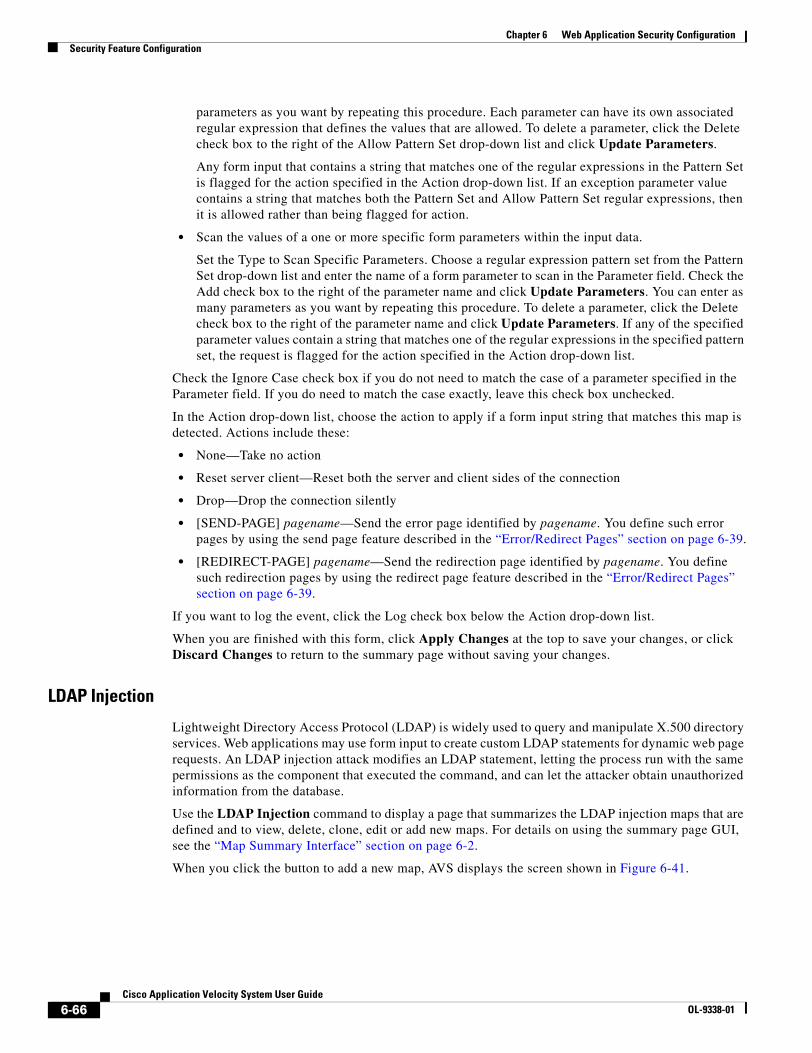
6-66Cisco Application Velocity System User Guide
OL-9338-01
Chapter 6 Web Application Security ConfigurationSecurity Feature Configuration
parameters as you want by repeating this procedure. Each parameter can have its own associated regular expression that defines the values that are allowed. To delete a parameter, click the Delete check box to the right of the Allow Pattern Set drop-down list and click Update Parameters.
Any form input that contains a string that matches one of the regular expressions in the Pattern Set is flagged for the action specified in the Action drop-down list. If an exception parameter value contains a string that matches both the Pattern Set and Allow Pattern Set regular expressions, then it is allowed rather than being flagged for action.
• Scan the values of a one or more specific form parameters within the input data.
Set the Type to Scan Specific Parameters. Choose a regular expression pattern set from the Pattern Set drop-down list and enter the name of a form parameter to scan in the Parameter field. Check the Add check box to the right of the parameter name and click Update Parameters. You can enter as many parameters as you want by repeating this procedure. To delete a parameter, click the Delete check box to the right of the parameter name and click Update Parameters. If any of the specified parameter values contain a string that matches one of the regular expressions in the specified pattern set, the request is flagged for the action specified in the Action drop-down list.
Check the Ignore Case check box if you do not need to match the case of a parameter specified in the Parameter field. If you do need to match the case exactly, leave this check box unchecked.
In the Action drop-down list, choose the action to apply if a form input string that matches this map is detected. Actions include these:
• None—Take no action
• Reset server client—Reset both the server and client sides of the connection
• Drop—Drop the connection silently
• [SEND-PAGE] pagename—Send the error page identified by pagename. You define such error pages by using the send page feature described in the “Error/Redirect Pages” section on page 6-39.
• [REDIRECT-PAGE] pagename—Send the redirection page identified by pagename. You define such redirection pages by using the redirect page feature described in the “Error/Redirect Pages” section on page 6-39.
If you want to log the event, click the Log check box below the Action drop-down list.
When you are finished with this form, click Apply Changes at the top to save your changes, or click Discard Changes to return to the summary page without saving your changes.
LDAP Injection
Lightweight Directory Access Protocol (LDAP) is widely used to query and manipulate X.500 directory services. Web applications may use form input to create custom LDAP statements for dynamic web page requests. An LDAP injection attack modifies an LDAP statement, letting the process run with the same permissions as the component that executed the command, and can let the attacker obtain unauthorized information from the database.
Use the LDAP Injection command to display a page that summarizes the LDAP injection maps that are defined and to view, delete, clone, edit or add new maps. For details on using the summary page GUI, see the “Map Summary Interface” section on page 6-2.
When you click the button to add a new map, AVS displays the screen shown in Figure 6-41.
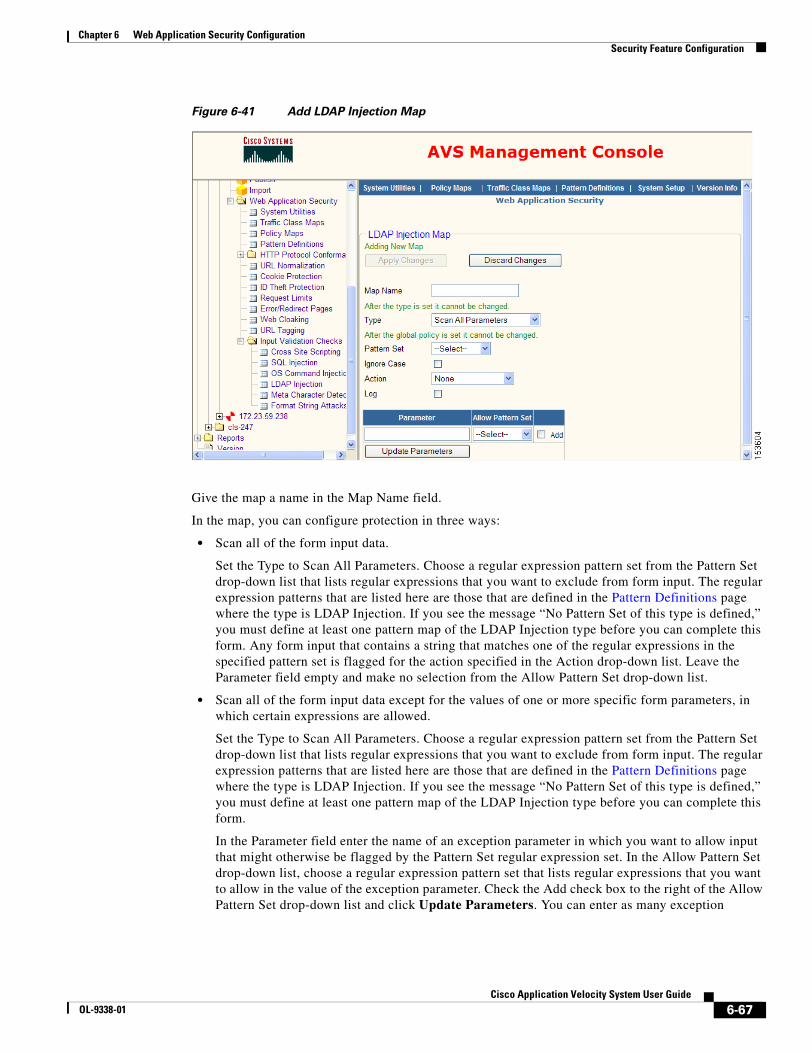
6-67Cisco Application Velocity System User Guide
OL-9338-01
Chapter 6 Web Application Security ConfigurationSecurity Feature Configuration
Figure 6-41 Add LDAP Injection Map
Give the map a name in the Map Name field.
In the map, you can configure protection in three ways:
• Scan all of the form input data.
Set the Type to Scan All Parameters. Choose a regular expression pattern set from the Pattern Set drop-down list that lists regular expressions that you want to exclude from form input. The regular expression patterns that are listed here are those that are defined in the Pattern Definitions page where the type is LDAP Injection. If you see the message “No Pattern Set of this type is defined,” you must define at least one pattern map of the LDAP Injection type before you can complete this form. Any form input that contains a string that matches one of the regular expressions in the specified pattern set is flagged for the action specified in the Action drop-down list. Leave the Parameter field empty and make no selection from the Allow Pattern Set drop-down list.
• Scan all of the form input data except for the values of one or more specific form parameters, in which certain expressions are allowed.
Set the Type to Scan All Parameters. Choose a regular expression pattern set from the Pattern Set drop-down list that lists regular expressions that you want to exclude from form input. The regular expression patterns that are listed here are those that are defined in the Pattern Definitions page where the type is LDAP Injection. If you see the message “No Pattern Set of this type is defined,” you must define at least one pattern map of the LDAP Injection type before you can complete this form.
In the Parameter field enter the name of an exception parameter in which you want to allow input that might otherwise be flagged by the Pattern Set regular expression set. In the Allow Pattern Set drop-down list, choose a regular expression pattern set that lists regular expressions that you want to allow in the value of the exception parameter. Check the Add check box to the right of the Allow Pattern Set drop-down list and click Update Parameters. You can enter as many exception
6-68Cisco Application Velocity System User Guide
OL-9338-01
Chapter 6 Web Application Security ConfigurationSecurity Feature Configuration
parameters as you want by repeating this procedure. Each parameter can have its own associated regular expression that defines the values that are allowed. To delete a parameter, click the Delete check box to the right of the Allow Pattern Set drop-down list and click Update Parameters.
Any form input that contains a string that matches one of the regular expressions in the Pattern Set is flagged for the action specified in the Action drop-down list. If an exception parameter value contains a string that matches both the Pattern Set and Allow Pattern Set regular expressions, then it is allowed rather than being flagged for action.
• Scan the values of a one or more specific form parameters within the input data.
Set the Type to Scan Specific Parameters. Choose a regular expression pattern set from the Pattern Set drop-down list and enter the name of a form parameter to scan in the Parameter field. Check the Add check box to the right of the parameter name and click Update Parameters. You can enter as many parameters as you want by repeating this procedure. To delete a parameter, click the Delete check box to the right of the parameter name and click Update Parameters. If any of the specified parameter values contain a string that matches one of the regular expressions in the specified pattern set, the request is flagged for the action specified in the Action drop-down list.
Check the Ignore Case check box if you do not need to match the case of a parameter specified in the Parameter field. If you do need to match the case exactly, leave this check box unchecked.
In the Action drop-down list, choose the action to apply if a form input string that matches this map is detected. Actions include these:
• None—Take no action
• Reset server client—Reset both the server and client sides of the connection
• Drop—Drop the connection silently
• [SEND-PAGE] pagename—Send the error page identified by pagename. You define such error pages by using the send page feature described in the “Error/Redirect Pages” section on page 6-39.
• [REDIRECT-PAGE] pagename—Send the redirection page identified by pagename. You define such redirection pages by using the redirect page feature described in the “Error/Redirect Pages” section on page 6-39.
If you want to log the event, click the Log check box below the Action drop-down list.
When you are finished with this form, click Apply Changes at the top to save your changes, or click Discard Changes to return to the summary page without saving your changes.
Meta Character Detection
A meta character attack inserts meta characters in the form input. Meta characters include characters such as semicolons (;), pipes (|), tildes (~), and so on.
Use the Meta Character Detection command to display a page that summarizes the meta character maps that are defined and to view, delete, clone, edit or add new maps. For details on using the summary page GUI, see the “Map Summary Interface” section on page 6-2.
When you click the button to add a new map, AVS displays the screen shown in Figure 6-42.

6-69Cisco Application Velocity System User Guide
OL-9338-01
Chapter 6 Web Application Security ConfigurationSecurity Feature Configuration
Figure 6-42 Add Meta Character Detection Map
Give the map a name in the Map Name field.
In the map, you can configure protection in three ways:
• Scan all of the form input data.
Set the Type to Scan All Parameters. Choose a regular expression pattern set from the Pattern Set drop-down list that lists regular expressions that you want to exclude from form input. The regular expression patterns that are listed here are those that are defined in the Pattern Definitions page where the type is Meta Character Detection. If you see the message “No Pattern Set of this type is defined,” you must define at least one pattern map of the Meta Character Detection type before you can complete this form. Any form input that contains a string that matches one of the regular expressions in the specified pattern set is flagged for the action specified in the Action drop-down list. Leave the Parameter field empty and make no selection from the Allow Pattern Set drop-down list.
• Scan all of the form input data except for the values of one or more specific form parameters, in which certain expressions are allowed.
Set the Type to Scan All Parameters. Choose a regular expression pattern set from the Pattern Set drop-down list that lists regular expressions that you want to exclude from form input. The regular expression patterns that are listed here are those that are defined in the Pattern Definitions page where the type is Meta Character Detection. If you see the message “No Pattern Set of this type is defined,” you must define at least one pattern map of the Meta Character Detection type before you can complete this form.
In the Parameter field enter the name of an exception parameter in which you want to allow input that might otherwise be flagged by the Pattern Set regular expression set. In the Allow Pattern Set drop-down list, choose a regular expression pattern set that lists regular expressions that you want to allow in the value of the exception parameter. Check the Add check box to the right of the Allow Pattern Set drop-down list and click Update Parameters. You can enter as many exception
6-70Cisco Application Velocity System User Guide
OL-9338-01
Chapter 6 Web Application Security ConfigurationSecurity Feature Configuration
parameters as you want by repeating this procedure. Each parameter can have its own associated regular expression that defines the values that are allowed. To delete a parameter, click the Delete check box to the right of the Allow Pattern Set drop-down list and click Update Parameters.
Any form input that contains a string that matches one of the regular expressions in the Pattern Set is flagged for the action specified in the Action drop-down list. If an exception parameter value contains a string that matches both the Pattern Set and Allow Pattern Set regular expressions, then it is allowed rather than being flagged for action.
• Scan the values of a one or more specific form parameters within the input data.
Set the Type to Scan Specific Parameters. Choose a regular expression pattern set from the Pattern Set drop-down list and enter the name of a form parameter to scan in the Parameter field. Check the Add check box to the right of the parameter name and click Update Parameters. You can enter as many parameters as you want by repeating this procedure. To delete a parameter, click the Delete check box to the right of the parameter name and click Update Parameters. If any of the specified parameter values contain a string that matches one of the regular expressions in the specified pattern set, the request is flagged for the action specified in the Action drop-down list.
Check the Ignore Case check box if you do not need to match the case of a parameter specified in the Parameter field. If you do need to match the case exactly, leave this check box unchecked.
In the Action drop-down list, choose the action to apply if a form input string that matches this map is detected. Actions include these:
• None—Take no action
• Reset server client—Reset both the server and client sides of the connection
• Drop—Drop the connection silently
• [SEND-PAGE] pagename—Send the error page identified by pagename. You define such error pages by using the send page feature described in the “Error/Redirect Pages” section on page 6-39.
• [REDIRECT-PAGE] pagename—Send the redirection page identified by pagename. You define such redirection pages by using the redirect page feature described in the “Error/Redirect Pages” section on page 6-39.
If you want to log the event, click the Log check box below the Action drop-down list.
When you are finished with this form, click Apply Changes at the top to save your changes, or click Discard Changes to return to the summary page without saving your changes.
Format String Attacks
A format string attack passes format string characters as form input, which may result in the unwarranted change of the stack, which can cause segmentation faults or an unanticipated program to run.
Use the Format String Attacks command to display a page that summarizes the format string attack maps that are defined and to view, delete, clone, edit or add new maps. For details on using the summary page GUI, see the “Map Summary Interface” section on page 6-2.
When you click the button to add a new map, AVS displays the screen shown in Figure 6-43.
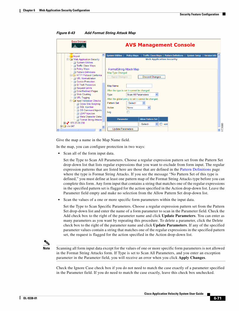
6-71Cisco Application Velocity System User Guide
OL-9338-01
Chapter 6 Web Application Security ConfigurationSecurity Feature Configuration
Figure 6-43 Add Format String Attack Map
Give the map a name in the Map Name field.
In the map, you can configure protection in two ways:
• Scan all of the form input data.
Set the Type to Scan All Parameters. Choose a regular expression pattern set from the Pattern Set drop-down list that lists regular expressions that you want to exclude from form input. The regular expression patterns that are listed here are those that are defined in the Pattern Definitions page where the type is Format String Attacks. If you see the message “No Pattern Set of this type is defined,” you must define at least one pattern map of the Format String Attacks type before you can complete this form. Any form input that contains a string that matches one of the regular expressions in the specified pattern set is flagged for the action specified in the Action drop-down list. Leave the Parameter field empty and make no selection from the Allow Pattern Set drop-down list.
• Scan the values of a one or more specific form parameters within the input data.
Set the Type to Scan Specific Parameters. Choose a regular expression pattern set from the Pattern Set drop-down list and enter the name of a form parameter to scan in the Parameter field. Check the Add check box to the right of the parameter name and click Update Parameters. You can enter as many parameters as you want by repeating this procedure. To delete a parameter, click the Delete check box to the right of the parameter name and click Update Parameters. If any of the specified parameter values contain a string that matches one of the regular expressions in the specified pattern set, the request is flagged for the action specified in the Action drop-down list.
Note Scanning all form input data except for the values of one or more specific form parameters is not allowed in the Format String Attacks form. If Type is set to Scan All Parameters, and you enter an exception parameter in the Parameter field, you will receive an error when you click Apply Changes.
Check the Ignore Case check box if you do not need to match the case exactly of a parameter specified in the Parameter field. If you do need to match the case exactly, leave this check box unchecked.
6-72Cisco Application Velocity System User Guide
OL-9338-01
Chapter 6 Web Application Security ConfigurationWeb Application Security Regular Expression Syntax
In the Action drop-down list, choose the action to apply if a form input string that matches this map is detected. Actions include these:
• None—Take no action
• Reset server client—Reset both the server and client sides of the connection
• Drop—Drop the connection silently
• [SEND-PAGE] pagename—Send the error page identified by pagename. You define such error pages by using the send page feature described in the “Error/Redirect Pages” section on page 6-39.
• [REDIRECT-PAGE] pagename—Send the redirection page identified by pagename. You define such redirection pages by using the redirect page feature described in the “Error/Redirect Pages” section on page 6-39.
If you want to log the event, click the Log check box that is below the Action drop-down list.
When you are finished with this form, click Apply Changes at the top to save your changes, or click Discard Changes to return to the summary page without saving your changes.
Web Application Security Regular Expression SyntaxThe web application security module uses a regular expression syntax that is different from the regular expression syntax used by other AVS features (and that is described in the Appendix F, “Regular Expressions”). The regular expression syntax used by the web application security module is summarized in Table 6-4.
Table 6-4 Web Application Security Regular Expression Syntax
Metacharacter Description
. Matches any single character, except for the new line character (0x0A). For example, the regular expression r.t matches the strings rat, rut, r t, but not root.
^ Matches the beginning of a line. For example, the regular expression ^When in matches the beginning of the string “When in the course of human events” but not the string “What and When in the”
* Matches zero or more occurrences of the character immediately preceding. For example, the regular expression .* means match any number of any characters.
\ This is the quoting character; use it to treat the following metacharacter as an ordinary character. For example, \^ is used to match the caret character (^) rather than the beginning of a line. Similarly, the expression \. is used to match the period character rather than any single character.
[ ]
[c1-c2]
[^c1-c2]
Matches any one of the characters between the brackets. For example, the regular expression r[aou]t matches rat, rot, and rut, but not ret. Ranges of characters are specified by a beginning character (c1), a hyphen, and an ending character (c2). For example, the regular expression [0-9] means match any digit. Multiple ranges can be specified as well. The regular expression [A-Za-z] means match any upper or lower case letter. To match any character except those in the range (that is, the complement range), use the caret as the first character after the opening bracket. For example, the expression [^269A-Z] matches any characters except 2, 6, 9, and uppercase letters.
( ) Treat the expression between ( and ) as a group, limiting the scope of other metacharacters.
| Logical OR two conditions together. For example (him|her) matches the line “it belongs to him” and matches the line “it belongs to her” but does not match the line “it belongs to them.”
+ Matches one or more occurrences of the character or regular expression immediately preceding. For example, the regular expression 9+ matches 9, 99, and 999.
6-73Cisco Application Velocity System User Guide
OL-9338-01
Chapter 6 Web Application Security ConfigurationWeb Application Security Regular Expression Syntax
The web application security regular expression evaluator matches the shortest pattern possible.
? Matches 0 or 1 occurrence of the character or regular expression immediately preceding.
{i}
{i,}
Matches a specific number (i) or minimum number (i,) of instances of the preceding character. For example, the expression A[0-9]{3} matches “A” followed by exactly 3 digits. That is, it matches A123 but not A1234. The expression [0-9]{4,} matches any sequence of 4 or more digits.
\r Matches the carriage return character (0x0D).
\n Matches the new line character (0x0A).
\t Matches the tab character (0x09).
\f Matches the form feed character (0x0C).
\xNN Matches the character with the hexadecimal code NN, where N is between 0 and F.
\NNN Matches the character with the octal code NNN, where N is between 0 and 8.
Table 6-4 Web Application Security Regular Expression Syntax (continued)
Metacharacter Description

6-74Cisco Application Velocity System User Guide
OL-9338-01
Chapter 6 Web Application Security ConfigurationWeb Application Security Regular Expression Syntax
C H A P T E R
7-1Cisco Application Velocity System User Guide
OL-9338-01
7AppScreen Configuration
This chapter describes how to configure the AppScreen feature.
Note AppScreen is superseded by the web application security module described in Chapter 6, “Web Application Security Configuration.” AppScreen is still available and operates as described here for backward compatibility. However, for the highest level of web application security, we recommend that you use the web application security module instead of AppScreen.
This chapter consists of these sections:
• Overview, page 7-1
• AppScreen Class, page 7-3
• AppScreen Policies, page 7-4
• AppScreen Rules, page 7-8
• AppScreen Logging, page 7-16
• SNMP Notification, page 7-17
OverviewAppScreen enables the application appliance to provide web application security and intrusion protection. AppScreen is highly configurable, and the following types of request filtering are preconfigured:
• Binary blocking
• Cross-site script blocking
• Directory traversal blocking
• SQL injection blocking
• File upload blocking
AppScreen can scan all HTTP requests and prevent unwanted requests from going to the origin server. AppScreen supports the following:
• Positive (whitelist) screening, where the administrator describes the content to allow.
• Negative (blacklist) screening, where the administrator describes the content to deny.
7-2Cisco Application Velocity System User Guide
OL-9338-01
Chapter 7 AppScreen ConfigurationOverview
AppScreen supports only request content screening. It can scan all of the content sent from the end user’s browser (or other front-end system) to the origin server through the AppScreen proxy in between. AppScreen does not currently support response content screening, which is scanning content that is returned from the origin server and/or AppScreen.
AppScreen is configured through two constructs:
• AppScreen Rules describe the matching of web transaction content with values provided in the rule (for example, looking for the text “<script” in a query parameter).
An AppScreen rule determines whether the current request matches the criteria specified in the rule. If it does match, then an AppScreen policy that uses the rule is applied; otherwise, the policy is skipped. AppScreen rules are specified in two XML configuration files: appscreen-rules-standard.xml and appscreen-rules-custom.xml.
• AppScreen Policies determine which rules (if any) will be tested for the current request, and which actions (if any) will be taken if the request matches a rule.
AppScreen policies are specified in the fgn.conf file at both the global level and within a type of class called an AppScreen Class. Like Application Classes, such classes allow requests to be segmented based on their attributes such as URL, header values, cookie values, and so on.
AppScreen policies allow the evaluation (or invocation) of AppScreen rules to be decoupled from the definition of the rules.
AppScreen is disabled by default. It is controlled by the AppScreen global keyword in the fgn.conf file. To turn it on, specify AppScreen On.
If AppScreen is set to Off, all screening is disabled and all requests are passed through.
Testing the Default AppScreen ConfigurationThe factory-default AppScreen configuration specifies Pass as the disposition for all of the predefined policies (see Table 7-2 on page 7-5). This setting allows you to view the results of AppScreen content inspection without disrupting your web site or application traffic. To enable AppScreen and test the default configuration, follow these steps:
1. Install AppScreen and enable it using the configuration keyword AppScreen On, as described above.
2. Pass traffic through AppScreen for several hours or a day to get a representative sample of requests. Because all of the dispositions are set to Pass, AppScreen will not block or otherwise change the flow of the traffic.
3. Examine the AppScreen reports. If necessary, tune the AppScreen configuration for your environment. For example, you may have a particular web page such as a content management editor that should allow HTML <script> tags. In such a case, you can remove that restriction by setting the disposition to Ignore for that particular page or section of the application.
4. Now you can set the desired disposition for each policy, either keeping it as Pass or setting it to Deny, Redirect, Forward, Ignore, and so on. For more information on policy dispositions, see the “Policy Disposition” section on page 7-5.
Preprocessing Content TransformationBefore AppScreen examines the request content, the application appliance performs the following transformations:
7-3Cisco Application Velocity System User Guide
OL-9338-01
Chapter 7 AppScreen ConfigurationAppScreen Class
• It transforms URL-encoded characters (in hexadecimal) to their corresponding characters. For example, “%41” would be transformed to the character “A”. The one exception is that the sequence “%00” is left as is and is not transformed to a null byte (character code zero).
• It transforms the + (plus) character to the space character.
These transformations are applied to the following request elements:
• URL
• Parameter names and values
• Cookie names and values
• Header names and values
• Query string and URL with query string (but be cautious about using these strings; see the “Regular Expression Matching” section on page 7-12)
• File names of uploaded files
• Content types of uploaded files
Additionally, for the POST content that AppScreen examines, the application appliance transforms any null bytes to the sequence %00 so that these strings can be searched.
These transformations are transient; they are done only internally for AppScreen to examine the normalized content. If the request is allowed through, AppScreen sends through the original request, without any transformation.
AppScreen ClassAppScreen Classes are similar to Application Classes, because they allow requests to be segmented based on their attributes such as URL, header values, cookie values, and so on. AppScreen Classes define a group of URLs for which specific AppScreen processing is desired.
AppScreen Classes are defined in the fgn.conf file, similar to Application Classes. An example of defined classes is as follows:
# AppScreen classes<AppScreenClass AllowHtmlTagsInForumPosts>
Url "/myapp/forum/addComment\.jsp"AppScreenPolicy htmlTagStart | IgnoreAppScreenPolicy invalidHtmlTagForForumPost | Deny 403
</AppScreenClass>
<AppScreenClass AllowTechSuppFileUploads>Url "/techsupport/uploadFile\.cgi"AppScreenPolicy prohibitedFileUpload | Ignore
</AppScreenClass>
AppScreen Class definitions can include a number of keywords that also can be used at the global level in the fgn.conf file. The AppScreen-specific keywords are listed in Table 7-1.

7-4Cisco Application Velocity System User Guide
OL-9338-01
Chapter 7 AppScreen ConfigurationAppScreen Policies
AppScreen PoliciesAn AppScreen policy definition in the fgn.conf file uses this syntax:
AppScreenPolicy rulename | disposition | [action [ | action ...]]
This definition could appear at the global level, or within an AppScreen Class:
AppScreenPolicy checkBinary | Deny 403 | Severity 3
Table 7-1 AppScreen Configuration Keywords
Keyword Description
AppScreen Enables or disables AppScreen at the global or AppScreen Class level. Valid values include On and Off (default).
AppScreenAlertSeverity Configures the alert severity threshold. When an AppScreen policy is matched, if the severity level of the policy is less than or equal to AppScreenAlertSeverity, then an SNMP alert is triggered as described in the “SNMP Notification” section on page 7-17. The default is 0. Valid values include the integers from 0 through 5.
AppScreenDefaultSeverity Configures the default AppScreen policy severity level. The default is 3. Valid values include the integers from 1 through 5.
For more information about severity levels, see the Severity keyword in Table 7-3 on page 7-8.
AppScreenSnmpTrap Enables or disables the AppScreen SNMP trap feature at the global or AppScreen Class level. If set to On, then an SNMP trap is sent if a policy is matched and the severity level of the policy is less than or equal to AppScreenAlertSeverity. Valid values include On and Off (default). If you set this to On, you must also define a location to send traps to with AppScreenSnmpTrapSink.
For more information about SNMP and AppScreen, see the “SNMP Notification” section on page 7-17.
AppScreenSnmpCommunity Defines the SNMP community string to be used when sending SNMP traps. The default is public.
For more information about SNMP and AppScreen, see the “SNMP Notification” section on page 7-17.
AppScreenSnmpTrapSink Defines the location of an SNMP trap sink (an SNMP management station). Specify a host name or IP address, optionally followed by a colon and the port number. If you do not specify the port number, the standard SNMP trap port of 162 is used. This keyword can be specified multiple times to have the traps sent to multiple destinations.
There is no default for this keyword, and it must be defined if AppScreenSnmpTrap is set to On, otherwise SNMP traps will not be sent. For more information about SNMP and AppScreen, see the “SNMP Notification” section on page 7-17.
PostContentBufferLimit Sets the maximum amount of POST data that can be buffered by AppScreen in kilobytes (KB). Valid values range from 0 to 1000, with a default of 40 KB. For more information about how this value is used, see the “Scanning POST Data and File Uploads” section on page 7-15.
7-5Cisco Application Velocity System User Guide
OL-9338-01
Chapter 7 AppScreen ConfigurationAppScreen Policies
AppScreen policies have the following elements:
• Policy Rule Reference—Begins with the name of the rule that is evaluated. If the rule evaluates to true for this request, then this policy is applied. If the rule evaluates to false, this policy is skipped.
• Policy Disposition—Determines the disposition of the request (for example, if it will be blocked or allowed). There must be exactly one disposition for each policy.
• Policy Actions—Determines what action(s) to take when the rule is matched. Zero or more actions can be specified.
The policy elements are described in detail in the following sections.
The sequence of the policies is important. AppScreen processes policies in order, so earlier policies take precedence over later policies. However, a global policy can be overridden by an AppScreenClass policy that matches the same rule, and in that case, the AppScreenClass policy takes precedence even if it is later in the configuration file.
AppScreen checks each policy for a match against the current request:
• If there is no match, AppScreen continues to the next policy.
• If there is a match, the behavior depends upon the disposition defined for the policy. In most cases, AppScreen makes an allow/deny decision based on the first matching policy. For more details, see the “Policy Disposition” section on page 7-5.
Policy Rule ReferenceThe Rule reference is the name of the rule that will be evaluated for this policy. If the rule evaluates to true for this request, then this policy is applied. If the rule evaluates to false, this policy is skipped.
Only one rule can be named. If multiple rules need to be evaluated, then it is possible to define a rule that evaluates other rules. For more details, see the “AppScreen Rules” section on page 7-8.
Policy DispositionDisposition is the end result of this policy’s rule being matched. Each policy must have exactly one disposition. Disposition keywords are listed in Table 7-2.
Table 7-2 Policy Disposition Keywords
Disposition Keyword Description
Deny errcode Blocks the request and returns the specified HTTP error code.
Allow Allows the request. This disposition immediately allows the request to go through; the remaining AppScreen policies (if any) are not evaluated.
Pass Is a no-operation disposition. AppScreen continues on to the next policy in the list of policies. This is useful to tag a request as having matched a given rule. This information is used by the ruleMatch operator (described in Table 7-4 on page 7-9).
Forward url Forwards to the specified URL. The URL must be absolute (e.g., http://...). For details, see the “Forward Disposition” section.
7-6Cisco Application Velocity System User Guide
OL-9338-01
Chapter 7 AppScreen ConfigurationAppScreen Policies
Forward Disposition
The Forward disposition forwards the current request to the specified URL. This disposition allows the origin server to handle this client request and perform operations such as logging out the client or resource cleanup.
To use this feature, specify the URL to which to forward. All the request headers from the client are sent to the origin server with the exception of the Content-length and Location headers. The Host header is appropriately fixed up.
The forwarding URL can be constructed using the parameter expander functions (see Table 5-4 on page 5-16), as follows:
http://myserver/cgi-bin/test-cgi?lang=$http_query_param(hl)
where h1 is a query parameter that was received from the request.
Redirect Disposition
The Redirect disposition sends an HTTP redirect instruction (HTTP 302 response status code) to the client (web browser or other application). This is useful to display a customized error page instead of a generic error page, as may be displayed by the browser when receiving a Deny 500 error code, for example.
Using the Redirect disposition is as simple as specifying the URL to be displayed. However, special care must be taken to avoid introducing “looping” redirects when you are handling redirect dispositions. For example, consider the following sequence of events:
1. You have a policy called myPolicy that says:
Redirect http://www.mycompany.com/error.asp
2. A request comes in that matches myPolicy.
3. AppScreen sends a redirect to error.asp.
4. The request for error.asp comes to AppScreen.
5. Something about the request for error.asp (the URL, a header field, or so on), causes this request to also match myPolicy.
6. AppScreen will send another redirect to error.asp, and the browser and AppScreen are caught in a loop. Each request for error.asp results in a redirect to error.asp, and so on.
This looping is not a security risk; however, it is a waste of AppScreen server resources, and it may be annoying to the user until they click the browser Stop button or close the browser window.
To avoid this looping problem, AppScreen tries to detect and prevent this condition. The person creating the AppScreen policies should also be aware of this issue and take some precautions.
Redirect url Redirects to the specified URL. The URL must be absolute (e.g., http://...). For details, see the “Redirect Disposition” section.
Ignore Is a special disposition that means “do not bother to evaluate this rule.” For details, see the “Ignore Disposition” section.
Table 7-2 Policy Disposition Keywords (continued)
Disposition Keyword Description

7-7Cisco Application Velocity System User Guide
OL-9338-01
Chapter 7 AppScreen ConfigurationAppScreen Policies
Redirect Loop Detection
When an AppScreen policy is matched, and the disposition is Redirect, AppScreen compares the URL of the current request (the Request URL) to all of the Redirect URLs defined for all AppScreen policies. If the Request URL exactly matches any Redirect URL, then AppScreen realizes that there is a danger of a redirect loop, and it does not do the requested redirect. Instead, it performs a Deny 500 disposition. A message is logged in the error log (at the info level), which is similar to the following example:
The request for URL http://www.mycompany.com:13188/index.html matches AppScreen policy myPolicy, which calls for a redirect to http://www.mycompany.com:13188/index.html. However, the requested URL is itself an AppScreen redirect URL, so the current request will not be redirected.
Policy Creation Guidelines
When creating a policy with a Redirect disposition, to help ensure that the URL will not create a looping situation, follow these steps:
1. Open a web browser window, paste the Redirect URL into the Address field, and press Enter to go to the URL.
2. After the page has displayed, look in the Address field and check if the URL has changed.
3. If the URL in the Address field is different from what you pasted in, copy the URL from the Address field and use that URL as your Redirect URL.
Note It might seem obvious that the Address field should not change. However, the Address field could change in these situations:
• If the destination page itself does a redirect. For example, if error.asp does a redirect to error2.asp, then you should use error2.asp as your redirect URL.
• If the destination URL is not in a standard form. For example, if you enter the URL http://www.company.com, it is often standardized to http://www.company.com/ or http://www.company.com/index.html.
Ignore Disposition
The Ignore disposition is similar to the Pass disposition. Pass actually evaluates the rule to see if the policy applies. In contrast, Ignore ignores the rule without evaluating it, even if a higher-level policy (such as a global policy or a policy in a higher-level IF statement) references the rule.
Having a policy with an Ignore disposition might seem identical to not having the policy at all. At a given AppScreen Class level, this situation is true. However, the Ignore disposition is used to allow a given AppScreen Class policy to override a policy that was set in a higher-level AppScreen Class. A feature of the AppScreen Class is that it allows you to specify behavior that overrides previously defined behavior. You can use the Ignore keyword to effectively remove existing policies.
For example, if a global policy specifies a rule to be evaluated, and you want that rule to be ignored for a given AppScreen class, in that AppScreen class, you would create a policy with an Ignore disposition that references the rule.
The following configuration enables the checkFileUpload rule at the global level but disables it for a particular URL, if the expected cookie is set:
AppScreenPolicy checkFileUpload | Deny 403 | Audit

7-8Cisco Application Velocity System User Guide
OL-9338-01
Chapter 7 AppScreen ConfigurationAppScreen Rules
<AppScreenClass AllowTechSuppFileUploads>Url "/techsupport/uploadFile\.cgi"IF ($http_cookie_present(SUPPORT_USER)) THEN
AppScreenPolicy checkFileUpload | IgnoreENDIF
</AppScreenClass>
Policy ActionsActions are things that AppScreen does when this policy’s rule is matched. A policy can have zero or more actions. Action keywords are listed in Table 7-3.
AppScreen RulesAppScreen rules determine whether the current request matches the criteria specified in the rule. Matching is done by applying operators (regular expression match and rule match) to attributes (URL, query string, cookie value, and so on.) and values (regular expressions and rule names) that are specified in the rule definition.
A rule is a Boolean expression that evaluates to true if the match conditions are satisfied, or false if the conditions are not satisfied.
A rule can be a simple expression (for example, comparing a single attribute against a specified value), or a rule can be a compound expression, tying together simple expressions with ANDs and ORs.
Table 7-3 Policy Action Keywords
Action Keyword Description
Severity level Sets the severity of this policy. The level is an integer between 1 and 5, where 1 is the most critical. The severity levels are as follows:
1. Critical
2. Major
3. Normal
4. Minor
5. Informational
If level is not specified, it defaults to 3.
If the policy is matched, and if the severity level of the policy is less than or equal to AppScreenAlertSeverity, then an SNMP alert is triggered as described in the “SNMP Notification” section on page 7-17
Exec command Executes a specified system command (such as a binary or a shell script). The path to the command must be an absolute path (beginning with /).
Pause millisec Pauses for the specified number of milliseconds. The valid values for millisec are from 0 to 3600000 (one hour).
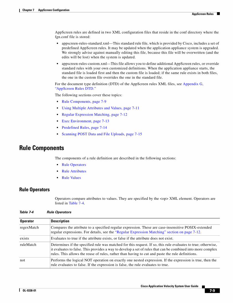
7-9Cisco Application Velocity System User Guide
OL-9338-01
Chapter 7 AppScreen ConfigurationAppScreen Rules
AppScreen rules are defined in two XML configuration files that reside in the conf directory where the fgn.conf file is stored:
• appscreen-rules-standard.xml—This standard rule file, which is provided by Cisco, includes a set of predefined AppScreen rules. It may be updated when the application appliance system is upgraded. We strongly advise against manually editing this file, because this file will be overwritten (and the edits will be lost) when the system is updated.
• appscreen-rules-custom.xml—This file allows you to define additional AppScreen rules, or override standard rules with your own customized definitions. When the application appliance starts, the standard file is loaded first and then the custom file is loaded; if the same rule exists in both files, the one in the custom file overrides the one in the standard file.
For the document type definition (DTD) of the AppScreen rules XML files, see Appendix G, “AppScreen Rules DTD.”
The following sections cover these topics:
• Rule Components, page 7-9
• Using Multiple Attributes and Values, page 7-11
• Regular Expression Matching, page 7-12
• Exec Environment, page 7-13
• Predefined Rules, page 7-14
• Scanning POST Data and File Uploads, page 7-15
Rule ComponentsThe components of a rule definition are described in the following sections:
• Rule Operators
• Rule Attributes
• Rule Values
Rule Operators
Operators compare attributes to values. They are specified by the <op> XML element. Operators are listed in Table 7-4.
Table 7-4 Rule Operators
Operator Description
regexMatch Compares the attribute to a specified regular expression. These are case-insensitive POSIX-extended regular expressions. For details, see the “Regular Expression Matching” section on page 7-12.
exists Evaluates to true if the attribute exists, or false if the attribute does not exist.
ruleMatch Determines if the specified rule was matched for this request. If so, this rule evaluates to true; otherwise, it evaluates to false. This provides a way to develop a set of rules that can be combined into more complex rules. This allows the reuse of rules, rather than having to cut and paste the rule definitions.
not Performs the logical NOT operation on exactly one nested expression. If the expression is true, then the rule evaluates to false. If the expression is false, the rule evaluates to true.

7-10Cisco Application Velocity System User Guide
OL-9338-01
Chapter 7 AppScreen ConfigurationAppScreen Rules
Rule Attributes
Rule attributes are attributes of the request. They are specified by the <attribSet> XML element. Each <attribSet> element can contain one or more <attrib> elements specifying the attributes to match.
Attribute keywords are listed in Table 7-5.
and Performs the logical AND operation on two or more nested expressions. All nested expressions must evaluate to true for the rule to evaluate to true.
or Performs the logical OR operation on two or more nested expressions. Any of the nested expressions must evaluate to true for the rule to evaluate to true.
Table 7-4 Rule Operators (continued)
Operator Description
Table 7-5 Rule Attributes
Attribute Keyword Description
Single Request Attributes
URL URL, not including any query string. For example, for this full URL:
http://jdoe:[email protected]/a/b.jsp?s=1&t=2
the following value is used:
http://jdoe:[email protected]/a/b.jsp
URL_WITH_QUERY_STRING URL, including any query string. For example, for this full URL:
http://jdoe:[email protected]/a/b.jsp?s=1&t=2
its complete value is used:
http://jdoe:[email protected]/a/b.jsp?s=1&t=2
QUERY_STRING Query string, or the empty string if there is no query string. For example, for this full URL:
http://jdoe:[email protected]/a/b.jsp?s=1&t=2
the following value is used:
s=1&t=2
METHOD GET, POST, HEAD, and so on.
REMOTE_ADDR Client IP address from which the request was received.
cookie[name] Value of the cookie identified by name.
header[name] Value of the header identified by name.
Multiple Request Attributes
For each of these attributes, the attribute represents the union of all values of the multivalued attribute. The matching logic cycles through all of the values of the specified attribute in an attempt to find a match.
param[name] All values of the parameter identified by name.
ALL_CONTENT URL (without query string), parameter names and values, cookie names and values, and header names and values.
ALL_CONTENT_VALUES URL (without query string), parameter values, cookie values, and header values.
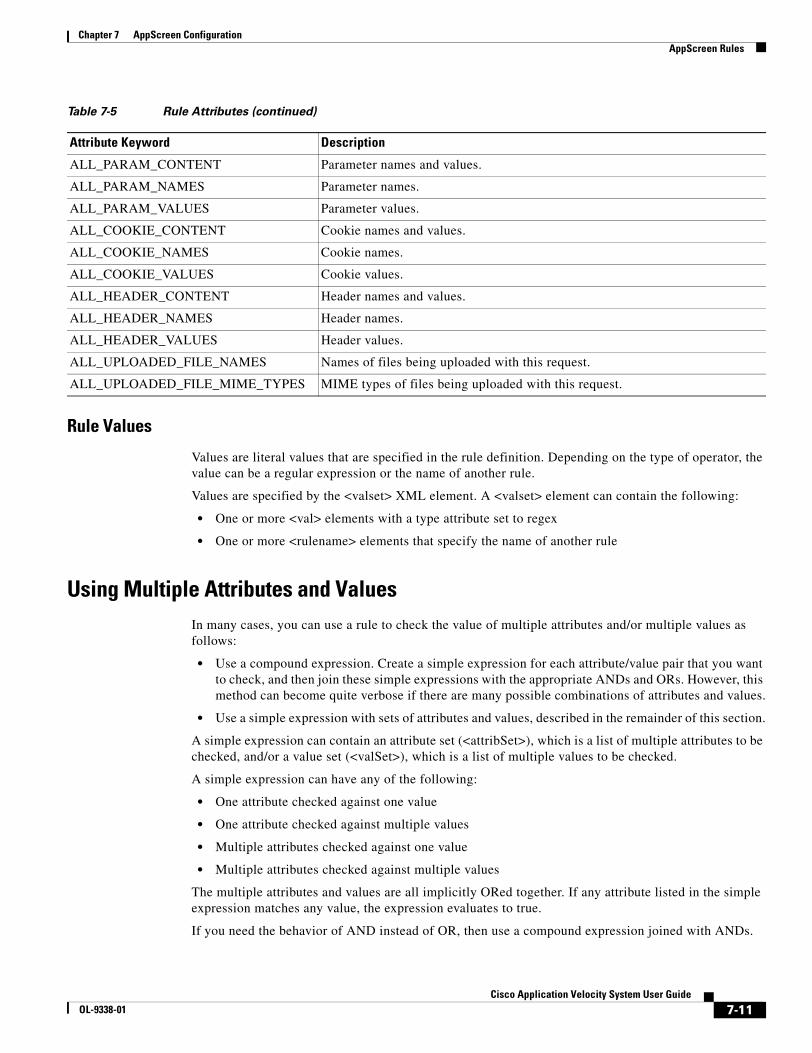
7-11Cisco Application Velocity System User Guide
OL-9338-01
Chapter 7 AppScreen ConfigurationAppScreen Rules
Rule Values
Values are literal values that are specified in the rule definition. Depending on the type of operator, the value can be a regular expression or the name of another rule.
Values are specified by the <valset> XML element. A <valset> element can contain the following:
• One or more <val> elements with a type attribute set to regex
• One or more <rulename> elements that specify the name of another rule
Using Multiple Attributes and ValuesIn many cases, you can use a rule to check the value of multiple attributes and/or multiple values as follows:
• Use a compound expression. Create a simple expression for each attribute/value pair that you want to check, and then join these simple expressions with the appropriate ANDs and ORs. However, this method can become quite verbose if there are many possible combinations of attributes and values.
• Use a simple expression with sets of attributes and values, described in the remainder of this section.
A simple expression can contain an attribute set (<attribSet>), which is a list of multiple attributes to be checked, and/or a value set (<valSet>), which is a list of multiple values to be checked.
A simple expression can have any of the following:
• One attribute checked against one value
• One attribute checked against multiple values
• Multiple attributes checked against one value
• Multiple attributes checked against multiple values
The multiple attributes and values are all implicitly ORed together. If any attribute listed in the simple expression matches any value, the expression evaluates to true.
If you need the behavior of AND instead of OR, then use a compound expression joined with ANDs.
ALL_PARAM_CONTENT Parameter names and values.
ALL_PARAM_NAMES Parameter names.
ALL_PARAM_VALUES Parameter values.
ALL_COOKIE_CONTENT Cookie names and values.
ALL_COOKIE_NAMES Cookie names.
ALL_COOKIE_VALUES Cookie values.
ALL_HEADER_CONTENT Header names and values.
ALL_HEADER_NAMES Header names.
ALL_HEADER_VALUES Header values.
ALL_UPLOADED_FILE_NAMES Names of files being uploaded with this request.
ALL_UPLOADED_FILE_MIME_TYPES MIME types of files being uploaded with this request.
Table 7-5 Rule Attributes (continued)
Attribute Keyword Description
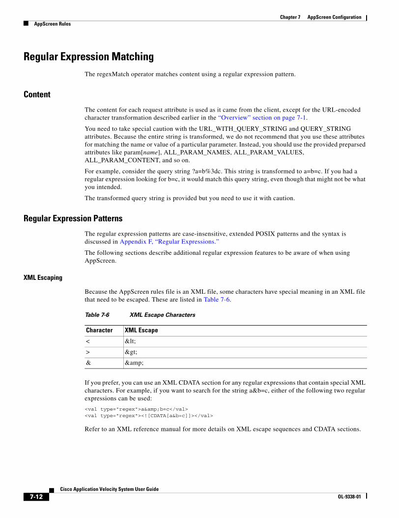
7-12Cisco Application Velocity System User Guide
OL-9338-01
Chapter 7 AppScreen ConfigurationAppScreen Rules
Regular Expression MatchingThe regexMatch operator matches content using a regular expression pattern.
Content
The content for each request attribute is used as it came from the client, except for the URL-encoded character transformation described earlier in the “Overview” section on page 7-1.
You need to take special caution with the URL_WITH_QUERY_STRING and QUERY_STRING attributes. Because the entire string is transformed, we do not recommend that you use these attributes for matching the name or value of a particular parameter. Instead, you should use the provided preparsed attributes like param[name], ALL_PARAM_NAMES, ALL_PARAM_VALUES, ALL_PARAM_CONTENT, and so on.
For example, consider the query string ?a=b%3dc. This string is transformed to a=b=c. If you had a regular expression looking for b=c, it would match this query string, even though that might not be what you intended.
The transformed query string is provided but you need to use it with caution.
Regular Expression Patterns
The regular expression patterns are case-insensitive, extended POSIX patterns and the syntax is discussed in Appendix F, “Regular Expressions.”
The following sections describe additional regular expression features to be aware of when using AppScreen.
XML Escaping
Because the AppScreen rules file is an XML file, some characters have special meaning in an XML file that need to be escaped. These are listed in Table 7-6.
If you prefer, you can use an XML CDATA section for any regular expressions that contain special XML characters. For example, if you want to search for the string a&b=c, either of the following two regular expressions can be used:
<val type="regex">a&b=c</val><val type="regex"><![CDATA[a&b=c]]></val>
Refer to an XML reference manual for more details on XML escape sequences and CDATA sections.
Table 7-6 XML Escape Characters
Character XML Escape
< <
> >
& &
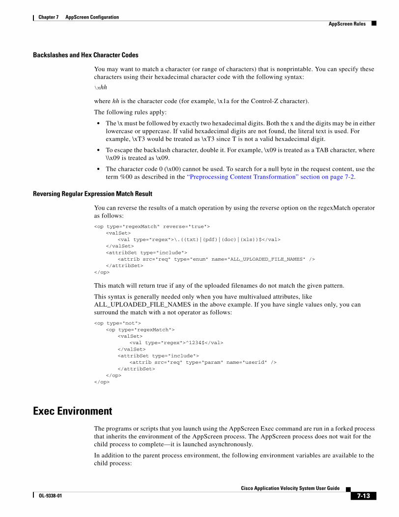
7-13Cisco Application Velocity System User Guide
OL-9338-01
Chapter 7 AppScreen ConfigurationAppScreen Rules
Backslashes and Hex Character Codes
You may want to match a character (or range of characters) that is nonprintable. You can specify these characters using their hexadecimal character code with the following syntax:
\xhh
where hh is the character code (for example, \x1a for the Control-Z character).
The following rules apply:
• The \x must be followed by exactly two hexadecimal digits. Both the x and the digits may be in either lowercase or uppercase. If valid hexadecimal digits are not found, the literal text is used. For example, \xT3 would be treated as \xT3 since T is not a valid hexadecimal digit.
• To escape the backslash character, double it. For example, \x09 is treated as a TAB character, where \\x09 is treated as \x09.
• The character code 0 (\x00) cannot be used. To search for a null byte in the request content, use the term %00 as described in the “Preprocessing Content Transformation” section on page 7-2.
Reversing Regular Expression Match Result
You can reverse the results of a match operation by using the reverse option on the regexMatch operator as follows:
<op type="regexMatch" reverse="true"><valSet>
<val type="regex">\.((txt)|(pdf)|(doc)|(xls))$</val></valSet><attribSet type="include">
<attrib src="req" type="enum" name="ALL_UPLOADED_FILE_NAMES" /></attribSet>
</op>
This match will return true if any of the uploaded filenames do not match the given pattern.
This syntax is generally needed only when you have multivalued attributes, like ALL_UPLOADED_FILE_NAMES in the above example. If you have single values only, you can surround the match with a not operator as follows:
<op type="not"><op type="regexMatch">
<valSet><val type="regex">^1234$</val>
</valSet><attribSet type="include">
<attrib src="req" type="param" name="userid" /></attribSet>
</op></op>
Exec EnvironmentThe programs or scripts that you launch using the AppScreen Exec command are run in a forked process that inherits the environment of the AppScreen process. The AppScreen process does not wait for the child process to complete—it is launched asynchronously.
In addition to the parent process environment, the following environment variables are available to the child process:

7-14Cisco Application Velocity System User Guide
OL-9338-01
Chapter 7 AppScreen ConfigurationAppScreen Rules
• APPSCREEN_URL—This variable is equal to the attribute URL_WITH_QUERY_STRING.
• APPSCREEN_CLASS—The name of the AppScreen class to which this request belongs.
• APPSCREEN_POLICY—The name of the AppScreen policy that was matched.
• APPSCREEN_TRNID—The unique transaction ID for this request. This variable is the concatenation of the instance ID (instanceID), a dash character (-), and the transaction sequence number (trnNum) in the FgnStatLog file. It is a string similar to the following: r0liy3whwsjbeviy2a31yxppzg-2.
• APPSCREEN_PORT—The port number of this instance of the application appliance performance node. This variable is useful in cases where multiple nodes are installed and running on the same server.
• APPSCREEN_SEVERITY—The numeric severity of the policy (a number from 1 to 5, where smaller numbers are more severe), as set by the Severity keyword (see Table 7-3 on page 7-8). If not set, the default severity is used.
You can use these variables in a program or script, as follows:
#!/bin/bash
LOG_DIR="/path/to/some/dir"LOG_FILE="$LOG_DIR/appscreen-match.log"
# blank lineecho "" >>"$LOG_FILE"
# timestampTSTAMP=$(date)echo "[$TSTAMP] $0 $@" >>"$LOG_FILE"
# details of match# (the following echo command is all on one line)echo "AppScreen Policy matched: $APPSCREEN_POLICY, URL: $APPSCREEN_URL, TRNID: $APPSCREEN_TRNID" >>"$LOG_FILE"
This example will produce output similar to the following:
[Mon Jul 26 14:30:02 PDT 2004] /some/dir/report-appscreen-match-1.sh AppScreen Policy matched: checkTest, URL: http://testserver/test.jsp?p=lion&q=tiger&r=bear, TRNID: 5rytbq1attdu4uix0uu5ixnfpe-2
Predefined RulesTable 7-7 describes the factory-default rules that are predefined in the appscreen-rules-standard.xml configuration file. These rules are provided to scan content for known risks. For rule definitions, you can see the rule text in the appscreen-rules-standard.xml file. As described in the “AppScreen Rules” section on page 7-8, these rules can be overridden (and new rules can be added) by editing the appscreen-rules-custom.xml file.
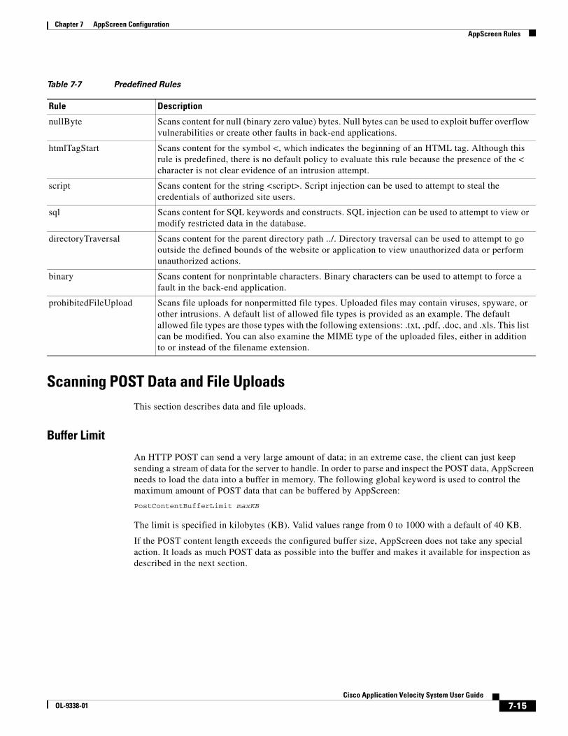
7-15Cisco Application Velocity System User Guide
OL-9338-01
Chapter 7 AppScreen ConfigurationAppScreen Rules
Scanning POST Data and File UploadsThis section describes data and file uploads.
Buffer Limit
An HTTP POST can send a very large amount of data; in an extreme case, the client can just keep sending a stream of data for the server to handle. In order to parse and inspect the POST data, AppScreen needs to load the data into a buffer in memory. The following global keyword is used to control the maximum amount of POST data that can be buffered by AppScreen:
PostContentBufferLimit maxKB
The limit is specified in kilobytes (KB). Valid values range from 0 to 1000 with a default of 40 KB.
If the POST content length exceeds the configured buffer size, AppScreen does not take any special action. It loads as much POST data as possible into the buffer and makes it available for inspection as described in the next section.
Table 7-7 Predefined Rules
Rule Description
nullByte Scans content for null (binary zero value) bytes. Null bytes can be used to exploit buffer overflow vulnerabilities or create other faults in back-end applications.
htmlTagStart Scans content for the symbol <, which indicates the beginning of an HTML tag. Although this rule is predefined, there is no default policy to evaluate this rule because the presence of the < character is not clear evidence of an intrusion attempt.
script Scans content for the string <script>. Script injection can be used to attempt to steal the credentials of authorized site users.
sql Scans content for SQL keywords and constructs. SQL injection can be used to attempt to view or modify restricted data in the database.
directoryTraversal Scans content for the parent directory path ../. Directory traversal can be used to attempt to go outside the defined bounds of the website or application to view unauthorized data or perform unauthorized actions.
binary Scans content for nonprintable characters. Binary characters can be used to attempt to force a fault in the back-end application.
prohibitedFileUpload Scans file uploads for nonpermitted file types. Uploaded files may contain viruses, spyware, or other intrusions. A default list of allowed file types is provided as an example. The default allowed file types are those types with the following extensions: .txt, .pdf, .doc, and .xls. This list can be modified. You can also examine the MIME type of the uploaded files, either in addition to or instead of the filename extension.
7-16Cisco Application Velocity System User Guide
OL-9338-01
Chapter 7 AppScreen ConfigurationAppScreen Logging
Content Types
The two types of standard HTTP form POST operations are distinguished by the value in the Content-Type header as follows:
• application/x-www-form-urlencoded
This POST type represents the majority of all HTTP POSTs. This type is a standard POST of a web page form.
This POST type is similar to a GET request because AppScreen allows the same access to all of the form parameter names and values, just as it would if the parameters were specified in a GET query string. The only limitation is that you have access only to the amount of data that fits in the AppScreen POST buffer, whose size is set by the PostContentBufferLimit keyword.
• multipart/form-data
This POST type is much less common. It allows browser users to upload files to a web site or application. For example, if you use a web-based e-mail program, and you want to attach a file to an e-mail that you are sending, the upload of the file is done using this POST type. Another usage (even less common) of this POST type is to send binary data (for example, from a custom browser plug-in or from a non-browser HTTP client).
For this POST type, AppScreen does not allow access to the parameter names and values. However, AppScreen does allow access to the other parts of the request (URL, headers, and cookies).
Also, if the post includes one or more file uploads, AppScreen makes the filenames and MIME types of the uploaded files available for inspection with the following request attributes: ALL_UPLOADED_FILE_NAMES and ALL_UPLOADED_FILE_MIME_TYPES. With AppScreen, you could block all POSTs of this type, or you could allow such posts only when they contain file uploads with file names ending in .doc, files of type text/plain, and so on.
Note A POST could be sent with a Content-Type other than the two standard types mentioned above. This operation would not be done by a standard web browser but by an unusual (or malicious) user agent. AppScreen rules can detect and block such POSTs by examining the HTTP method and the Content-Type header.
AppScreen LoggingRequests that match AppScreen Classes are logged in the FgnStatLog file.
Note An AppScreen policy with an Ignore disposition is not logged, because no matching occurs for such policies.
An FgnStatLog excerpt that shows a request that did not match any policy is as follows:
<APS> <AST> 1 </AST> </APS>
An FgnStatLog excerpt that shows a request that matched the script policy in the Root AppScreen Class is as follows:
<APS> <AST> 0 </AST> <ASC> Root </ASC> <ASP> script </ASP> <ASL> 1 </ASL> </APS>
For details on these log entries, see the “FgnStatLog” section on page A-2.
7-17Cisco Application Velocity System User Guide
OL-9338-01
Chapter 7 AppScreen ConfigurationSNMP Notification
Reports of requests that match AppScreen Classes are also available through the AppScreen Reports command in the Management Console. For details, see the “AppScreen Reports” section on page 9-6.
SNMP NotificationAn SNMP trap is issued if the severity of a matched policy is less than or equal to the value defined by the AppScreenAlertSeverity keyword (see Table 7-1 on page 7-4).
You can control whether AppScreen sends these traps, and you can configure AppScreen to send the trap to one or more SNMP trap sinks (SNMP management stations).
To enable SNMP traps, set the following configuration parameters (the values given here are examples; replace these with your own values):
AppScreenAlertSeverity 2AppScreenSnmpTrap OnAppScreenSnmpTrapSink 10.0.10.131AppScreenSnmpCommunity AppScreenAlert
With this example configuration, any matched AppScreen policies with a severity less than or equal to 2 will result in SNMP traps being sent.
The default value for AppScreenSnmpCommunity is public, so you do not need to specify that keyword if you want to use the default.
You can use either a hostname or IP address for the trap sink. By default, AppScreen sends SNMP traps to the standard SNMP trap port of 162. You can specify a different port by appending it to the trap sink host value with a colon, like this: 10.0.10.131:22345
Also, you can specify the AppScreenSnmpTrapSink keyword multiple times if you want the notification to be sent to multiple destinations.
Another example configuration is as follows:
AppScreenAlertSeverity 2AppScreenSnmpTrap OnAppScreenSnmpTrapSink myhost:12345AppScreenSnmpTrapSink 10.0.10.131
Receiving and Processing SNMP TrapsAppScreen SNMP traps can be received and processed by any software or system that is capable of handling standard SNMP v1 traps, such as HP OpenView or other commercial network management software, or the open source snmptrapd program.
Figure 7-1 shows example of how an AppScreen trap appears in the HP OpenView user interface.
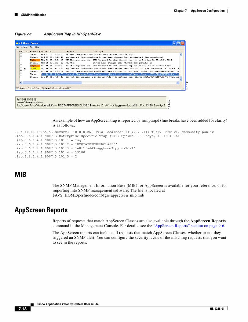
7-18Cisco Application Velocity System User Guide
OL-9338-01
Chapter 7 AppScreen ConfigurationSNMP Notification
Figure 7-1 AppScreen Trap in HP OpenView
An example of how an AppScreen trap is reported by snmptrapd (line breaks have been added for clarity) is as follows:
2004-10-01 19:55:53 devsrv3 [10.0.0.26] (via localhost [127.0.0.1]) TRAP, SNMP v1, community public.iso.3.6.1.4.1.9007.3 Enterprise Specific Trap (101) Uptime: 265 days, 13:18:49.61.iso.3.6.1.4.1.9007.3.101.1 = "sql".iso.3.6.1.4.1.9007.3.101.2 = "ROOTAPPSCREENCLASS/".iso.3.6.1.4.1.9007.3.101.3 = "a0f1fvd43zsggknnm3tpyrux2d-1".iso.3.6.1.4.1.9007.3.101.4 = 13180.iso.3.6.1.4.1.9007.3.101.5 = 2
MIBThe SNMP Management Information Base (MIB) for AppScreen is available for your reference, or for importing into SNMP management software. The file is located at $AVS_HOME/perfnode/conf/fgn_appscreen_mib.mib
AppScreen ReportsReports of requests that match AppScreen Classes are also available through the AppScreen Reports command in the Management Console. For details, see the “AppScreen Reports” section on page 9-6.
The AppScreen reports can include all requests that match AppScreen Classes, whether or not they triggered an SNMP alert. You can configure the severity levels of the matching requests that you want to see in the reports.

C H A P T E R
8-1Cisco Application Velocity System User Guide
OL-9338-01
8Management Console
This chapter describes how you can use the web browser-based Management Console to manage all Performance Nodes (each node represents an application appliance server). The Management Console allows you to do the following tasks:
• Group nodes into logical administrative groups, called clusters
• View and change individual node configuration parameters and system information
• Generate and view reports (for details on reporting items, see Chapter 9, “Reporting”)
Note The full version of the Management Console is installed on the Cisco AVS 3180 Management Station, which allows you to configure and manage multiple AVS 3120 devices, monitor AVS performance with AppScope Performance Monitor, and generate a variety of reports. A device Management Console with no database and no reporting functions is installed on the Cisco AVS 3120 Application Velocity System, though it is not active by default. This console allows you to configure and manage one or more AVS 3120 devices from one of them. If you want to use the device Management Console on the AVS 3120, you must explicitly start the console by using the CLI command set console start. For details, refer to the “CLI Reference” section on page 4-4.
This chapter includes these sections:
• Accessing the Management Console, page 8-1
• Clusters, page 8-3
• Cluster Configuration, page 8-9
• Managing Individual Nodes, page 8-20
• Configuring Individual Nodes, page 8-23
• Reports, page 8-30
• Version, page 8-31
• Console Configuration, page 8-31
• Securing the Management Console, page 8-32
Accessing the Management Console
Note To access the Management Console, you must use Microsoft Internet Explorer version 6.0 or higher.
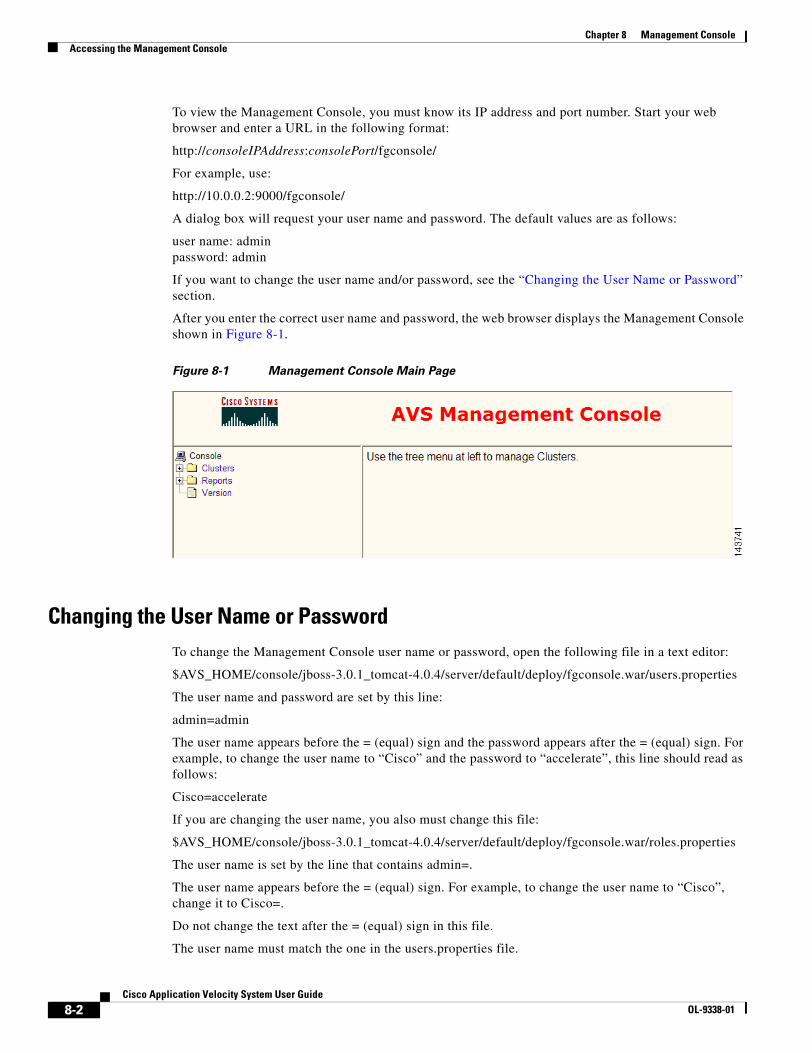
8-2Cisco Application Velocity System User Guide
OL-9338-01
Chapter 8 Management ConsoleAccessing the Management Console
To view the Management Console, you must know its IP address and port number. Start your web browser and enter a URL in the following format:
http://consoleIPAddress:consolePort/fgconsole/
For example, use:
http://10.0.0.2:9000/fgconsole/
A dialog box will request your user name and password. The default values are as follows:
user name: adminpassword: admin
If you want to change the user name and/or password, see the “Changing the User Name or Password” section.
After you enter the correct user name and password, the web browser displays the Management Console shown in Figure 8-1.
Figure 8-1 Management Console Main Page
Changing the User Name or PasswordTo change the Management Console user name or password, open the following file in a text editor:
$AVS_HOME/console/jboss-3.0.1_tomcat-4.0.4/server/default/deploy/fgconsole.war/users.properties
The user name and password are set by this line:
admin=admin
The user name appears before the = (equal) sign and the password appears after the = (equal) sign. For example, to change the user name to “Cisco” and the password to “accelerate”, this line should read as follows:
Cisco=accelerate
If you are changing the user name, you also must change this file:
$AVS_HOME/console/jboss-3.0.1_tomcat-4.0.4/server/default/deploy/fgconsole.war/roles.properties
The user name is set by the line that contains admin=.
The user name appears before the = (equal) sign. For example, to change the user name to “Cisco”, change it to Cisco=.
Do not change the text after the = (equal) sign in this file.
The user name must match the one in the users.properties file.
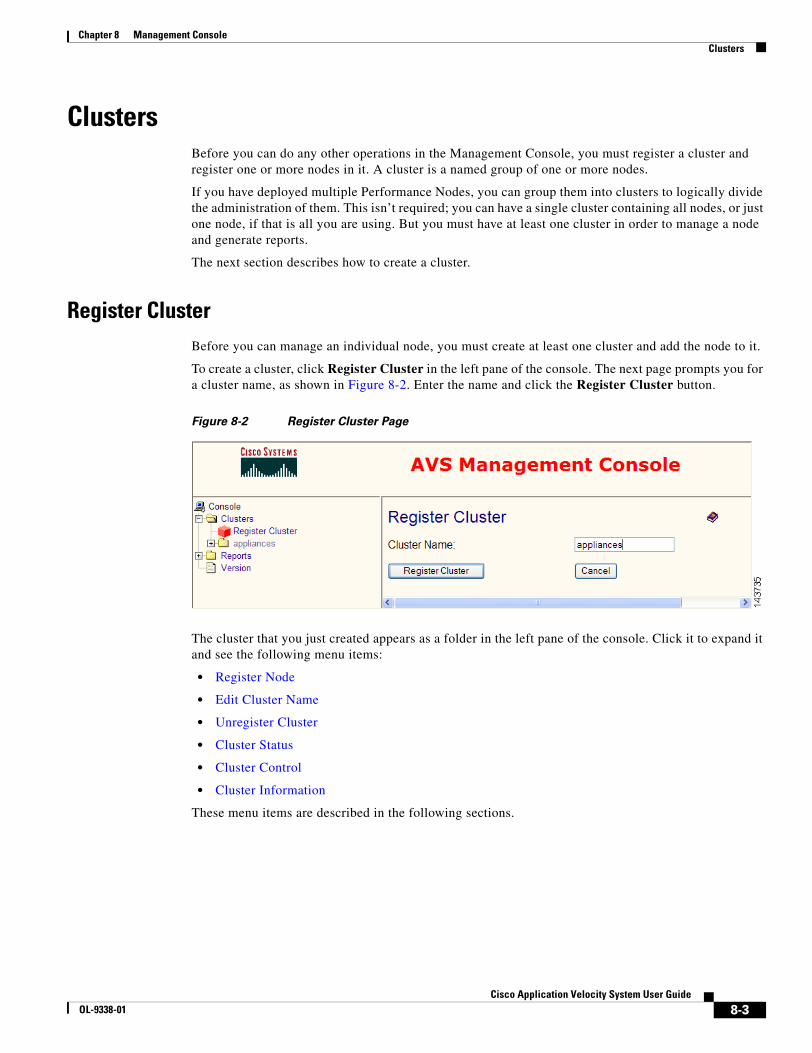
8-3Cisco Application Velocity System User Guide
OL-9338-01
Chapter 8 Management ConsoleClusters
ClustersBefore you can do any other operations in the Management Console, you must register a cluster and register one or more nodes in it. A cluster is a named group of one or more nodes.
If you have deployed multiple Performance Nodes, you can group them into clusters to logically divide the administration of them. This isn’t required; you can have a single cluster containing all nodes, or just one node, if that is all you are using. But you must have at least one cluster in order to manage a node and generate reports.
The next section describes how to create a cluster.
Register ClusterBefore you can manage an individual node, you must create at least one cluster and add the node to it.
To create a cluster, click Register Cluster in the left pane of the console. The next page prompts you for a cluster name, as shown in Figure 8-2. Enter the name and click the Register Cluster button.
Figure 8-2 Register Cluster Page
The cluster that you just created appears as a folder in the left pane of the console. Click it to expand it and see the following menu items:
• Register Node
• Edit Cluster Name
• Unregister Cluster
• Cluster Status
• Cluster Control
• Cluster Information
These menu items are described in the following sections.
8-4Cisco Application Velocity System User Guide
OL-9338-01
Chapter 8 Management ConsoleClusters
Additionally, the Cluster Configuration folder contains more menu items that relate to cluster configuration and control and comprise the Web Configurator:
• Global
• Destination Mapping
• Application Class
• AppScreen Class
• Publish
• Import
• Web Application Security
These items are described in the “Cluster Configuration” section on page 8-9.
Register NodeUse the Register Node command to add an application appliance server node to a cluster. Click this command to display a form where you identify the node that you want to add to the cluster, as shown in Figure 8-3. Fill in the fields on the form and click Register to add the node to the cluster.
Note The Node Manager must be running when you register a new node so that the Management Console can determine the type and version of the node. If the Node Manager is not running and you attempt to register a node, an error message similar to the message in Figure 8-4 is displayed.
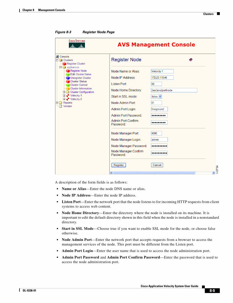
8-5Cisco Application Velocity System User Guide
OL-9338-01
Chapter 8 Management ConsoleClusters
Figure 8-3 Register Node Page
A description of the form fields is as follows:
• Name or Alias—Enter the node DNS name or alias.
• Node IP Address—Enter the node IP address.
• Listen Port—Enter the network port that the node listens to for incoming HTTP requests from client systems to access web content.
• Node Home Directory—Enter the directory where the node is installed on its machine. It is important to edit the default directory shown in this field when the node is installed in a nonstandard directory.
• Start in SSL Mode—Choose true if you want to enable SSL mode for the node, or choose false otherwise.
• Node Admin Port—Enter the network port that accepts requests from a browser to access the management services of the node. This port must be different from the Listen port.
• Admin Port Login—Enter the user name that is used to access the node administration port.
• Admin Port Password and Admin Port Confirm Password—Enter the password that is used to access the node administration port.
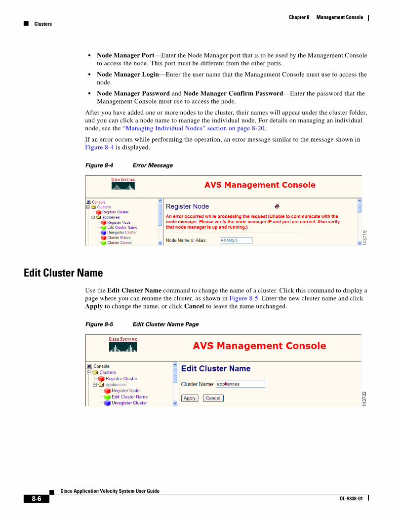
8-6Cisco Application Velocity System User Guide
OL-9338-01
Chapter 8 Management ConsoleClusters
• Node Manager Port—Enter the Node Manager port that is to be used by the Management Console to access the node. This port must be different from the other ports.
• Node Manager Login—Enter the user name that the Management Console must use to access the node.
• Node Manager Password and Node Manager Confirm Password—Enter the password that the Management Console must use to access the node.
After you have added one or more nodes to the cluster, their names will appear under the cluster folder, and you can click a node name to manage the individual node. For details on managing an individual node, see the “Managing Individual Nodes” section on page 8-20.
If an error occurs while performing the operation, an error message similar to the message shown in Figure 8-4 is displayed.
Figure 8-4 Error Message
Edit Cluster NameUse the Edit Cluster Name command to change the name of a cluster. Click this command to display a page where you can rename the cluster, as shown in Figure 8-5. Enter the new cluster name and click Apply to change the name, or click Cancel to leave the name unchanged.
Figure 8-5 Edit Cluster Name Page

8-7Cisco Application Velocity System User Guide
OL-9338-01
Chapter 8 Management ConsoleClusters
Unregister ClusterUse the Unregister Cluster command to delete a cluster. Click this command to display a page where you can confirm that you want to delete the cluster, as shown in Figure 8-6. Click Yes to delete the cluster, or click No to leave the cluster unchanged.
Caution Deleting a cluster also deletes all nodes added to the cluster. (Not the physical nodes, of course, but only their records in the Management Console.)
Figure 8-6 Unregister Cluster Page
Cluster StatusUse the Cluster Status command to view the status of all nodes in the cluster. Click this command to display a page that shows a status line for each node in the cluster, as shown in Figure 8-7.
The status line shows the node name and IP address, type, status (running or stopped), and the machine load. The status page is refreshed every 15 seconds.
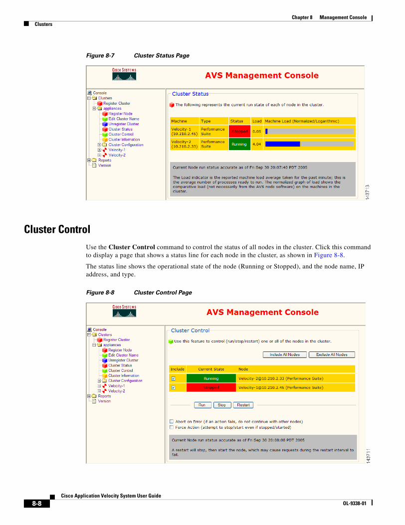
8-8Cisco Application Velocity System User Guide
OL-9338-01
Chapter 8 Management ConsoleClusters
Figure 8-7 Cluster Status Page
Cluster ControlUse the Cluster Control command to control the status of all nodes in the cluster. Click this command to display a page that shows a status line for each node in the cluster, as shown in Figure 8-8.
The status line shows the operational state of the node (Running or Stopped), and the node name, IP address, and type.
Figure 8-8 Cluster Control Page
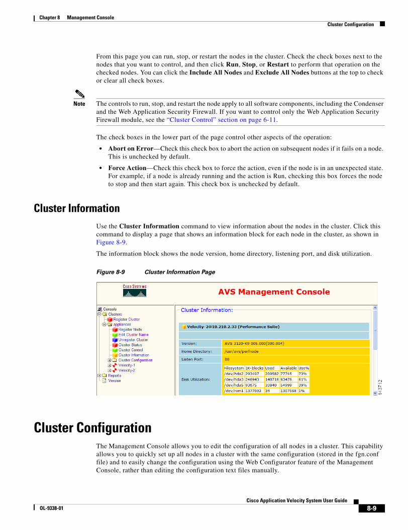
8-9Cisco Application Velocity System User Guide
OL-9338-01
Chapter 8 Management ConsoleCluster Configuration
From this page you can run, stop, or restart the nodes in the cluster. Check the check boxes next to the nodes that you want to control, and then click Run, Stop, or Restart to perform that operation on the checked nodes. You can click the Include All Nodes and Exclude All Nodes buttons at the top to check or clear all check boxes.
Note The controls to run, stop, and restart the node apply to all software components, including the Condenser and the Web Application Security Firewall. If you want to control only the Web Application Security Firewall module, see the “Cluster Control” section on page 6-11.
The check boxes in the lower part of the page control other aspects of the operation:
• Abort on Error—Check this check box to abort the action on subsequent nodes if it fails on a node. This is unchecked by default.
• Force Action—Check this check box to force the action, even if the node is in an unexpected state. For example, if a node is already running and the action is Run, checking this box forces the node to stop and then start again. This check box is unchecked by default.
Cluster InformationUse the Cluster Information command to view information about the nodes in the cluster. Click this command to display a page that shows an information block for each node in the cluster, as shown in Figure 8-9.
The information block shows the node version, home directory, listening port, and disk utilization.
Figure 8-9 Cluster Information Page
Cluster ConfigurationThe Management Console allows you to edit the configuration of all nodes in a cluster. This capability allows you to quickly set up all nodes in a cluster with the same configuration (stored in the fgn.conf file) and to easily change the configuration using the Web Configurator feature of the Management Console, rather than editing the configuration text files manually.

8-10Cisco Application Velocity System User Guide
OL-9338-01
Chapter 8 Management ConsoleCluster Configuration
The following Web Configurator commands are available in the Cluster Configuration menu folder:
• Global
• Destination Mapping
• Application Class
• AppScreen Class
• Publish
• Import
• Web Application Security
After you add one or more nodes to a cluster, you can also edit the configuration of those individual nodes by choosing the menu items in the Configuration folder inside the node folder. These menu items include the Global, Destination Mapping, Application Class, AppScreen Class, and View Configuration commands. These commands work the same as at the cluster level but apply only to the fgn.conf file of a single node. They are described in the “Configuring Individual Nodes” section on page 8-23.
To edit the configuration of nodes at the cluster level, follow these steps:
1. Use the Import command to import a configuration file from one of the nodes in the cluster to use as a template for all nodes in the cluster. This step imports an fgn.conf file into the Management Console database, so that it can be viewed and edited through your web browser. You must perform this step even if you have only a single node in the cluster.
2. Use the Global command to edit the global configuration parameters; these fgn.conf elements apply globally to the nodes and not to specific application classes defined in the nodes.
3. Use the Destination Mapping command to edit the destination mapping configuration; these destination mapping parameters defined in fgn.conf apply globally to the nodes.
4. Use the Application Class command to edit the Application Class configurations; these specific application classes are defined in the fgn.conf file.
5. Use the AppScreen Class command to edit the AppScreen Class configurations; these specific AppScreen classes are defined in the fgn.conf file.
6. Use the Publish command to write actual fgn.conf files to each of the nodes in the cluster.
7. Use the menu items under the Web Application Security folder to configure the web application security firewall features.
See the following sections for details on using each of the commands related to the cluster configuration.
GlobalUse the Global command to edit the global configuration parameters in the template that applies to all nodes in the cluster. Click this command to display a form where you can edit the existing parameters and add a new parameter, as shown in Figure 8-10. Edit the fields on the form and click Apply Changes to apply the changes to the template. The changes are not copied to the individual nodes until you use the Publish command.
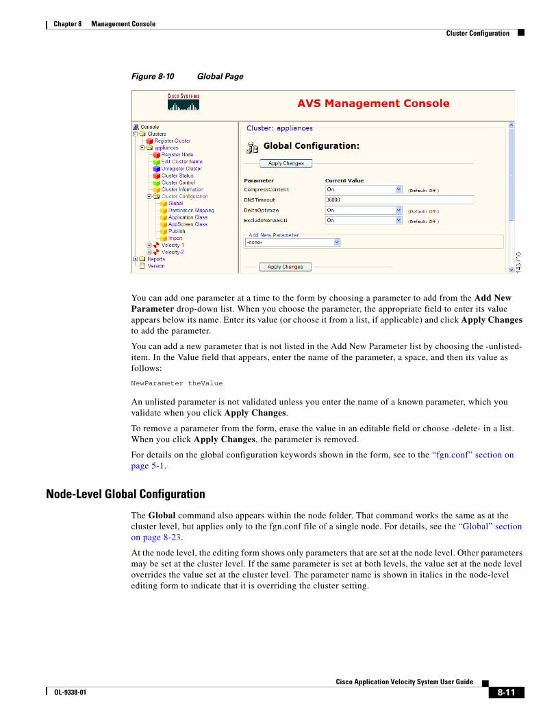
8-11Cisco Application Velocity System User Guide
OL-9338-01
Chapter 8 Management ConsoleCluster Configuration
Figure 8-10 Global Page
You can add one parameter at a time to the form by choosing a parameter to add from the Add New Parameter drop-down list. When you choose the parameter, the appropriate field to enter its value appears below its name. Enter its value (or choose it from a list, if applicable) and click Apply Changes to add the parameter.
You can add a new parameter that is not listed in the Add New Parameter list by choosing the -unlisted- item. In the Value field that appears, enter the name of the parameter, a space, and then its value as follows:
NewParameter theValue
An unlisted parameter is not validated unless you enter the name of a known parameter, which you validate when you click Apply Changes.
To remove a parameter from the form, erase the value in an editable field or choose -delete- in a list. When you click Apply Changes, the parameter is removed.
For details on the global configuration keywords shown in the form, see to the “fgn.conf” section on page 5-1.
Node-Level Global Configuration
The Global command also appears within the node folder. That command works the same as at the cluster level, but applies only to the fgn.conf file of a single node. For details, see the “Global” section on page 8-23.
At the node level, the editing form shows only parameters that are set at the node level. Other parameters may be set at the cluster level. If the same parameter is set at both levels, the value set at the node level overrides the value set at the cluster level. The parameter name is shown in italics in the node-level editing form to indicate that it is overriding the cluster setting.
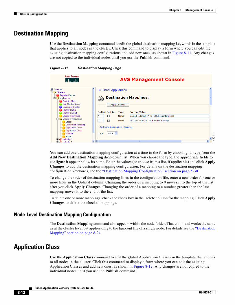
8-12Cisco Application Velocity System User Guide
OL-9338-01
Chapter 8 Management ConsoleCluster Configuration
Destination MappingUse the Destination Mapping command to edit the global destination mapping keywords in the template that applies to all nodes in the cluster. Click this command to display a form where you can edit the existing destination mapping configurations and add new ones, as shown in Figure 8-11. Any changes are not copied to the individual nodes until you use the Publish command.
Figure 8-11 Destination Mapping Page
You can add one destination mapping configuration at a time to the form by choosing its type from the Add New Destination Mapping drop-down list. When you choose the type, the appropriate fields to configure it appear below its name. Enter the values (or choose from a list, if applicable) and click Apply Changes to add the destination mapping configuration. For details on the destination mapping configuration keywords, see the “Destination Mapping Configuration” section on page 5-30.
To change the order of destination mapping lines in the configuration file, enter a new order for one or more lines in the Ordinal column. Changing the order of a mapping to 0 moves it to the top of the list after you click Apply Changes. Changing the order of a mapping to a number greater than the last mapping moves it to the end of the list.
To delete one or more mappings, check the check box in the Delete column for the mapping. Click Apply Changes to delete the checked mappings.
Node-Level Destination Mapping Configuration
The Destination Mapping command also appears within the node folder. That command works the same as at the cluster level but applies only to the fgn.conf file of a single node. For details see the “Destination Mapping” section on page 8-24.
Application ClassUse the Application Class command to edit the global Application Classes in the template that applies to all nodes in the cluster. Click this command to display a form where you can edit the existing Application Classes and add new ones, as shown in Figure 8-12. Any changes are not copied to the individual nodes until you use the Publish command.

8-13Cisco Application Velocity System User Guide
OL-9338-01
Chapter 8 Management ConsoleCluster Configuration
Figure 8-12 Application Class Page
The Application Class Summary section at the top allows you to change the order of classes, delete classes, clone classes, and add new classes. Below that, each class is listed with its parameters. These parameters are read-only listings.
To edit a class, click the Edit button in the summary, or click the class name link that is at the top of a class listing. A form similar to that shown in Figure 8-13 is displayed where you can edit, add, or delete parameters. For details on the Application Class configuration keywords, see the “Application Class Specification” section on page 5-7.
To change the order of Application Classes in the configuration file, enter a new order for one or more classes in the Order column. Changing the order of a class to 0 moves it to the top of the list after you click Apply Changes. Changing the order of a class to a number greater than the last class moves it to the end of the list.
To delete one or more classes, check the check box in the Delete column for the class. Click Delete Checked Classes to delete the checked classes.
To copy a class to use as the basis of a new class, click the Clone button next to the class that you want to clone. Cloned classes are put at the top of the list.
To add a new class, click Add New Application Class. This action displays a new form where you can edit the class name and its parameters, as shown in Figure 8-13. To select multiple keywords in the OptimizationPolicy list, press the Ctrl key while clicking on keywords.
To add a new parameter to the class, choose a parameter from the New Parameter drop-down list and enter its value in the field that will appear under its name. Click Apply Changes when you are done editing or adding new parameters. To go back to the Application Class summary page, click the Application Class command again in the menu at the left side. New classes are put at the top of the list.
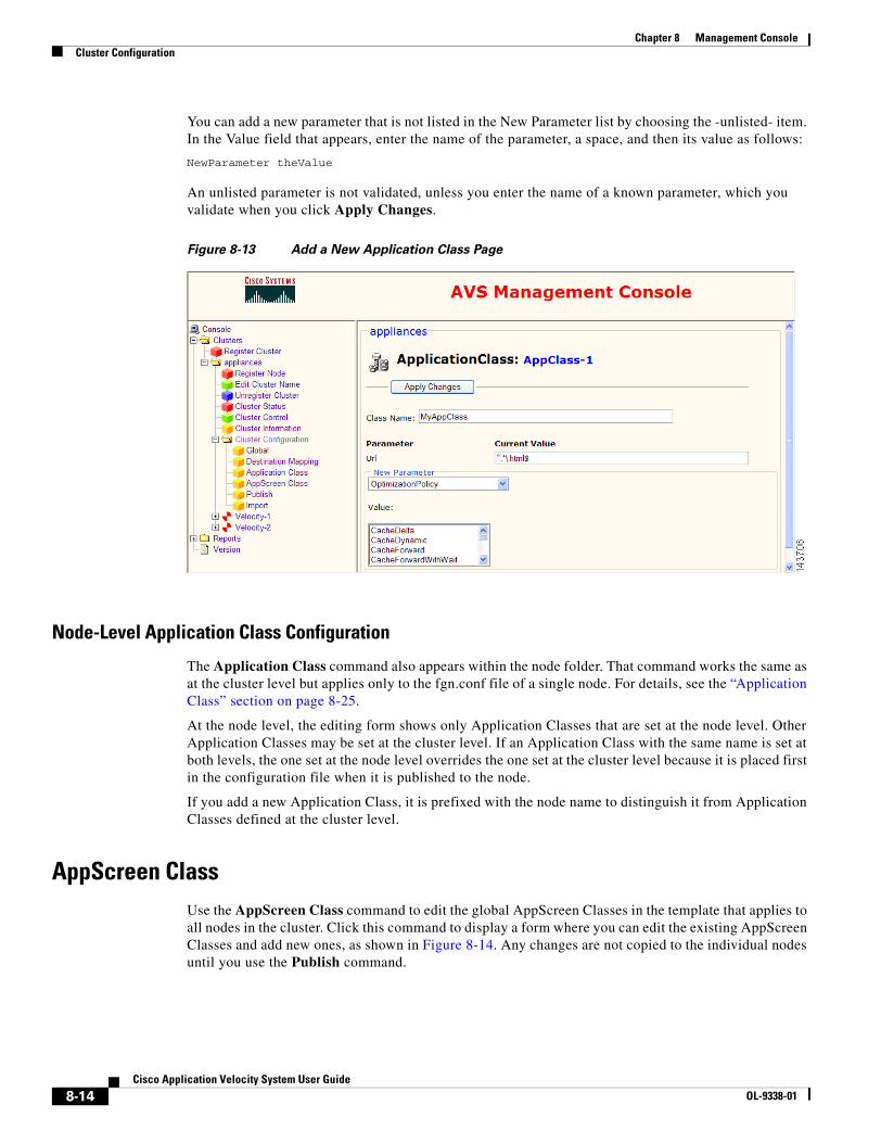
8-14Cisco Application Velocity System User Guide
OL-9338-01
Chapter 8 Management ConsoleCluster Configuration
You can add a new parameter that is not listed in the New Parameter list by choosing the -unlisted- item. In the Value field that appears, enter the name of the parameter, a space, and then its value as follows:
NewParameter theValue
An unlisted parameter is not validated, unless you enter the name of a known parameter, which you validate when you click Apply Changes.
Figure 8-13 Add a New Application Class Page
Node-Level Application Class Configuration
The Application Class command also appears within the node folder. That command works the same as at the cluster level but applies only to the fgn.conf file of a single node. For details, see the “Application Class” section on page 8-25.
At the node level, the editing form shows only Application Classes that are set at the node level. Other Application Classes may be set at the cluster level. If an Application Class with the same name is set at both levels, the one set at the node level overrides the one set at the cluster level because it is placed first in the configuration file when it is published to the node.
If you add a new Application Class, it is prefixed with the node name to distinguish it from Application Classes defined at the cluster level.
AppScreen ClassUse the AppScreen Class command to edit the global AppScreen Classes in the template that applies to all nodes in the cluster. Click this command to display a form where you can edit the existing AppScreen Classes and add new ones, as shown in Figure 8-14. Any changes are not copied to the individual nodes until you use the Publish command.

8-15Cisco Application Velocity System User Guide
OL-9338-01
Chapter 8 Management ConsoleCluster Configuration
Figure 8-14 AppScreen Class Page
The AppScreen Class Summary section at the top allows you to change the order of classes, delete classes, clone classes, and add new classes. Below that, each class is listed with its parameters. These parameters are read-only listings.
To edit a class, click the Edit button in the summary, or click the class name link that is at the top of a class listing. A form similar to that shown in Figure 8-15 is displayed where you can edit, add, or delete parameters. For information on the AppScreen Class configuration keywords, see Chapter 7, “AppScreen Configuration.”
To change the order of AppScreen Classes in the configuration file, enter a new order for one or more classes in the Order column. Changing the order of a class to 0 moves it to the top of the list after you click Apply Changes. Changing the order of a class to a number greater than the last class moves it to the end of the list.
To delete one or more classes, check the box in the Delete column for the class. Click Delete Checked Classes to delete the checked classes.
To copy a class to use as the basis of a new class, click the Clone button next to the class you want to clone. Cloned classes are put at the top of the list.
To add a new class, click Add New AppScreen Class. This action displays a new form where you can edit the class name and its parameters, as shown in Figure 8-15.

8-16Cisco Application Velocity System User Guide
OL-9338-01
Chapter 8 Management ConsoleCluster Configuration
Figure 8-15 Add a New AppScreen Class Page
To add a new parameter to the class, select it from the New Parameter drop-down list and enter its value in the field that will appear under its name. Click Apply Changes when you are done editing or adding new parameters. To go back to the AppScreen Class summary page, click the AppScreen Class command again in the menu at the left side. New classes are put at the top of the list.
When you add or edit the AppScreenPolicy parameter, you can edit this field manually, or use the AppScreen Policy Builder. To use the AppScreen Policy Builder, click the Edit button next to the field that you want to edit. This action opens the AppScreen Policy Builder window, as shown in Figure 8-16. You can specify the Rule, Disposition, and Actions for this AppScreen Policy. When done, click Apply Changes to close the Policy Builder window, and then click Apply Changes again in the AppScreen Class window.
Figure 8-16 AppScreen Policy Builder Window
Node-Level AppScreen Class Configuration
The AppScreen Class command also appears within the node folder. That command works the same as at the cluster level, but applies only to the fgn.conf file of a single node. For details, see the “AppScreen Class” section on page 8-27.
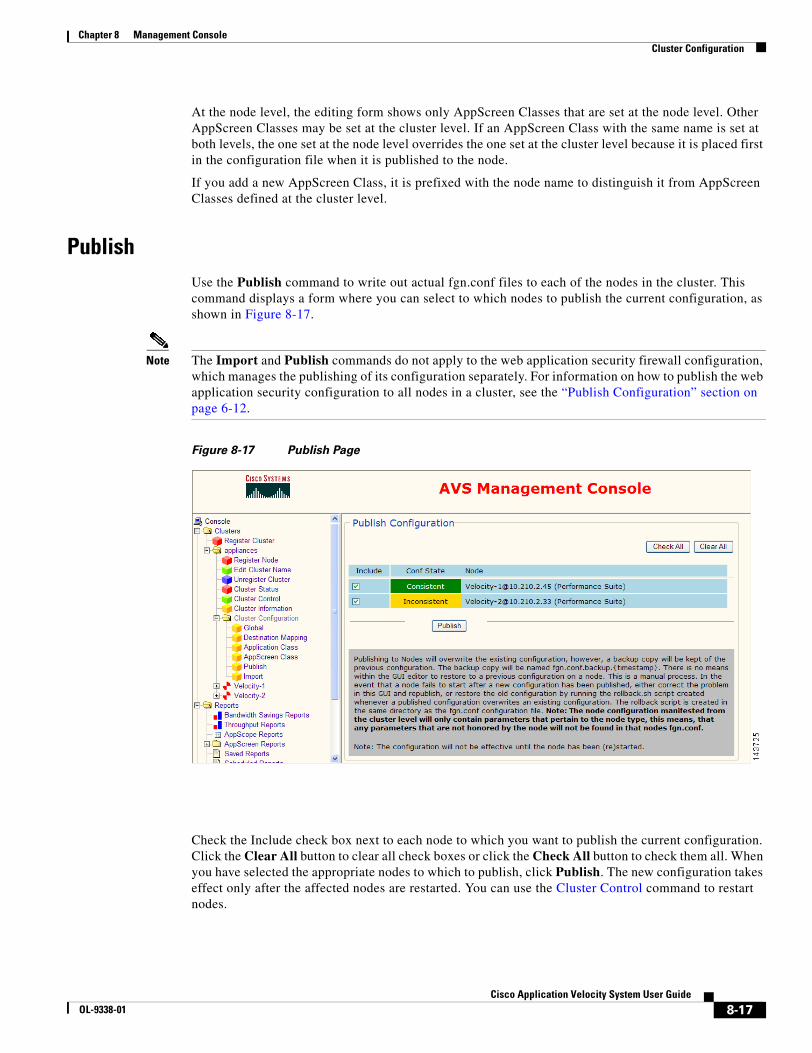
8-17Cisco Application Velocity System User Guide
OL-9338-01
Chapter 8 Management ConsoleCluster Configuration
At the node level, the editing form shows only AppScreen Classes that are set at the node level. Other AppScreen Classes may be set at the cluster level. If an AppScreen Class with the same name is set at both levels, the one set at the node level overrides the one set at the cluster level because it is placed first in the configuration file when it is published to the node.
If you add a new AppScreen Class, it is prefixed with the node name to distinguish it from AppScreen Classes defined at the cluster level.
PublishUse the Publish command to write out actual fgn.conf files to each of the nodes in the cluster. This command displays a form where you can select to which nodes to publish the current configuration, as shown in Figure 8-17.
Note The Import and Publish commands do not apply to the web application security firewall configuration, which manages the publishing of its configuration separately. For information on how to publish the web application security configuration to all nodes in a cluster, see the “Publish Configuration” section on page 6-12.
Figure 8-17 Publish Page
Check the Include check box next to each node to which you want to publish the current configuration. Click the Clear All button to clear all check boxes or click the Check All button to check them all. When you have selected the appropriate nodes to which to publish, click Publish. The new configuration takes effect only after the affected nodes are restarted. You can use the Cluster Control command to restart nodes.
8-18Cisco Application Velocity System User Guide
OL-9338-01
Chapter 8 Management ConsoleCluster Configuration
The Conf State column shows whether the configuration for a node is Consistent or Inconsistent. Consistent means that the configuration file for the node matches the database representation (as shown by the View Configuration command). Inconsistent means that the node configuration file does not match the database representation and may have been manually edited outside the Management Console interface.
Publishing to nodes overwrites the existing node configuration files. A backup copy of the previous configuration is saved and named fgn.conf.backup.date, where date is the date/time when the new configuration was published. If a node fails to start with a newly published configuration, you can either edit the configuration and republish it by using the Management Console commands, or you can revert to the saved backup configuration.
To revert to a saved backup configuration, use the Import command and select a previously saved configuration to import. Then publish this configuration to the nodes that you want to restore. Alternatively, you can manually run the rollback.sh script in the /conf directory, which restores the last saved configuration.
ImportUse the Import command to import a configuration file from one of the nodes in the cluster, or the factory default, to use as a template for all nodes in the cluster. This imports an fgn.conf file into the Management Console database, so that it can be viewed and edited through your web browser. You must use the Publish command to publish the configuration to nodes to make it take effect.
Note The Import and Publish commands do not apply to the web application security firewall configuration, which manages the publishing of its configuration separately. For information on how to publish the web application security configuration to all nodes in a cluster, see the “Publish Configuration” section on page 6-12.
Click the Import command to display a form where you select the node whose configuration file that you want to import, as shown in Figure 8-18. Select the node and click Preview to preview the configuration before actually importing it.
Alternatively, you can reset the cluster configuration template to the factory default settings for Performance Suite nodes, or you can restore a previously saved configuration. Choose the appropriate configuration and click Preview to preview the configuration before actually importing it. If you choose Select From Previously Published Configurations, when you click Preview, an additional screen will allow you to choose which saved backup configuration you want to restore. Choose one and click Preview again.
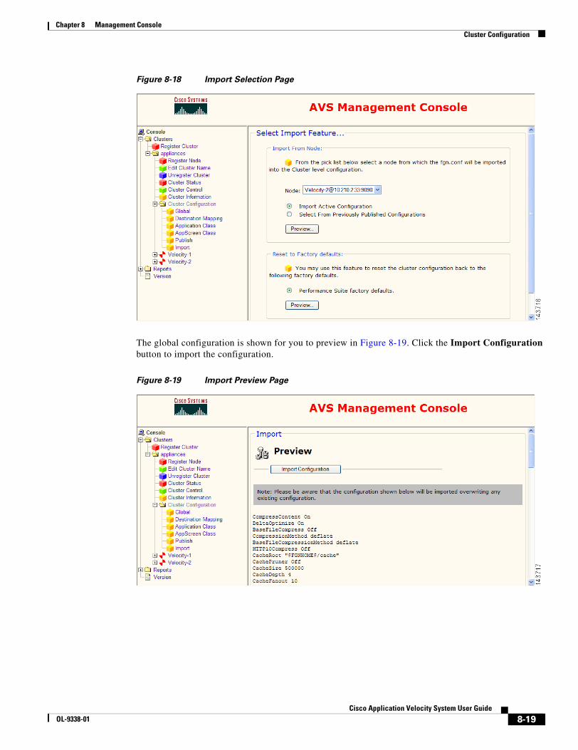
8-19Cisco Application Velocity System User Guide
OL-9338-01
Chapter 8 Management ConsoleCluster Configuration
Figure 8-18 Import Selection Page
The global configuration is shown for you to preview in Figure 8-19. Click the Import Configuration button to import the configuration.
Figure 8-19 Import Preview Page
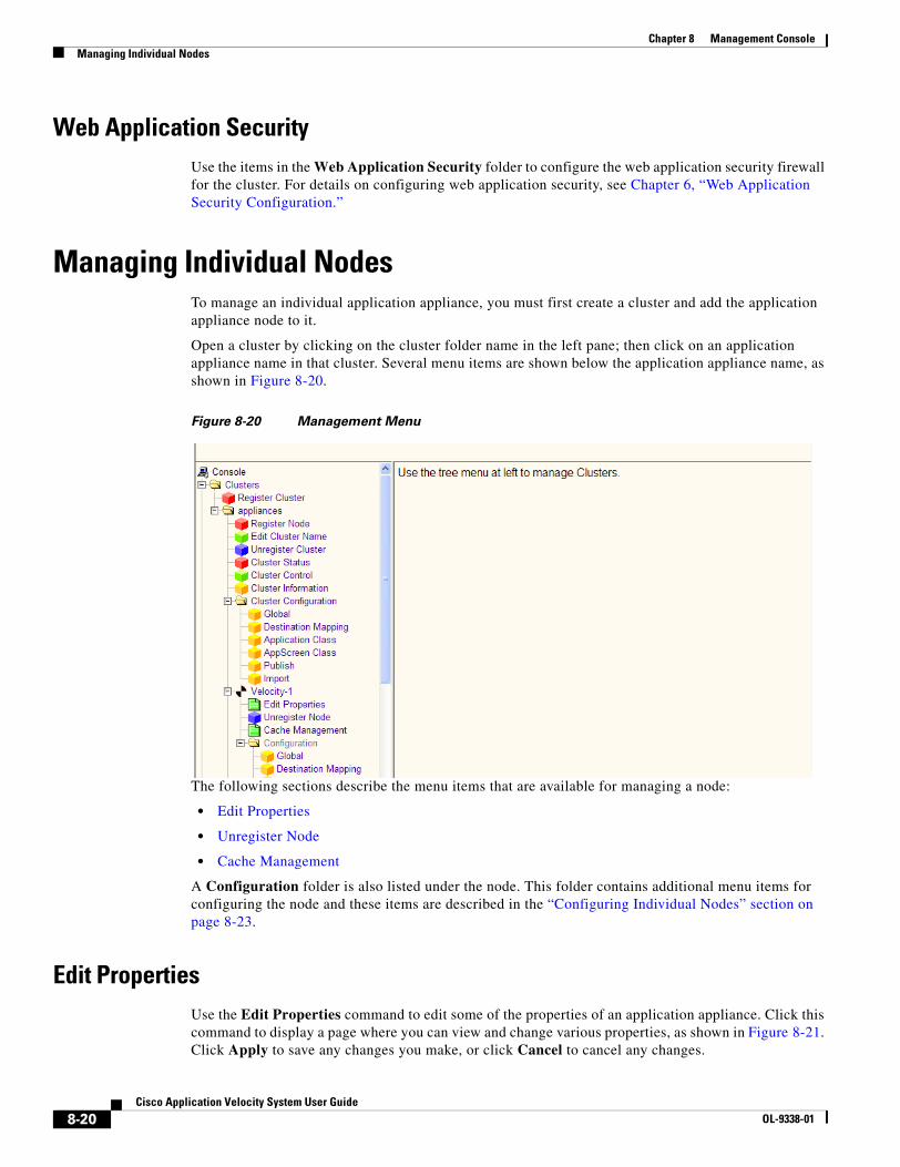
8-20Cisco Application Velocity System User Guide
OL-9338-01
Chapter 8 Management ConsoleManaging Individual Nodes
Web Application SecurityUse the items in the Web Application Security folder to configure the web application security firewall for the cluster. For details on configuring web application security, see Chapter 6, “Web Application Security Configuration.”
Managing Individual NodesTo manage an individual application appliance, you must first create a cluster and add the application appliance node to it.
Open a cluster by clicking on the cluster folder name in the left pane; then click on an application appliance name in that cluster. Several menu items are shown below the application appliance name, as shown in Figure 8-20.
Figure 8-20 Management Menu
The following sections describe the menu items that are available for managing a node:
• Edit Properties
• Unregister Node
• Cache Management
A Configuration folder is also listed under the node. This folder contains additional menu items for configuring the node and these items are described in the “Configuring Individual Nodes” section on page 8-23.
Edit PropertiesUse the Edit Properties command to edit some of the properties of an application appliance. Click this command to display a page where you can view and change various properties, as shown in Figure 8-21. Click Apply to save any changes you make, or click Cancel to cancel any changes.

8-21Cisco Application Velocity System User Guide
OL-9338-01
Chapter 8 Management ConsoleManaging Individual Nodes
These are the same properties set by the Register Node command; for details on the fields, see the “Register Node” section on page 8-4.
Figure 8-21 Edit Properties Page
Unregister NodeUse the Unregister Node command to remove a node from the cluster. Click this command to display a page where you can confirm that you want to remove the node, as shown in Figure 8-22. Click Yes to remove the node, or No to leave it unchanged.
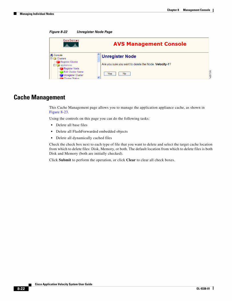
8-22Cisco Application Velocity System User Guide
OL-9338-01
Chapter 8 Management ConsoleManaging Individual Nodes
Figure 8-22 Unregister Node Page
Cache ManagementThis Cache Management page allows you to manage the application appliance cache, as shown in Figure 8-23.
Using the controls on this page you can do the following tasks:
• Delete all base files
• Delete all FlashForwarded embedded objects
• Delete all dynamically cached files
Check the check box next to each type of file that you want to delete and select the target cache location from which to delete files: Disk, Memory, or both. The default location from which to delete files is both Disk and Memory (both are initially checked).
Click Submit to perform the operation, or click Clear to clear all check boxes.
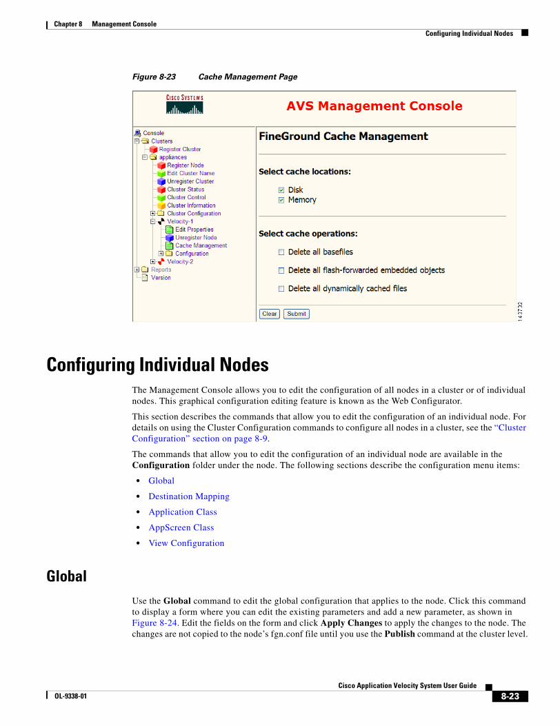
8-23Cisco Application Velocity System User Guide
OL-9338-01
Chapter 8 Management ConsoleConfiguring Individual Nodes
Figure 8-23 Cache Management Page
Configuring Individual NodesThe Management Console allows you to edit the configuration of all nodes in a cluster or of individual nodes. This graphical configuration editing feature is known as the Web Configurator.
This section describes the commands that allow you to edit the configuration of an individual node. For details on using the Cluster Configuration commands to configure all nodes in a cluster, see the “Cluster Configuration” section on page 8-9.
The commands that allow you to edit the configuration of an individual node are available in the Configuration folder under the node. The following sections describe the configuration menu items:
• Global
• Destination Mapping
• Application Class
• AppScreen Class
• View Configuration
GlobalUse the Global command to edit the global configuration that applies to the node. Click this command to display a form where you can edit the existing parameters and add a new parameter, as shown in Figure 8-24. Edit the fields on the form and click Apply Changes to apply the changes to the node. The changes are not copied to the node’s fgn.conf file until you use the Publish command at the cluster level.
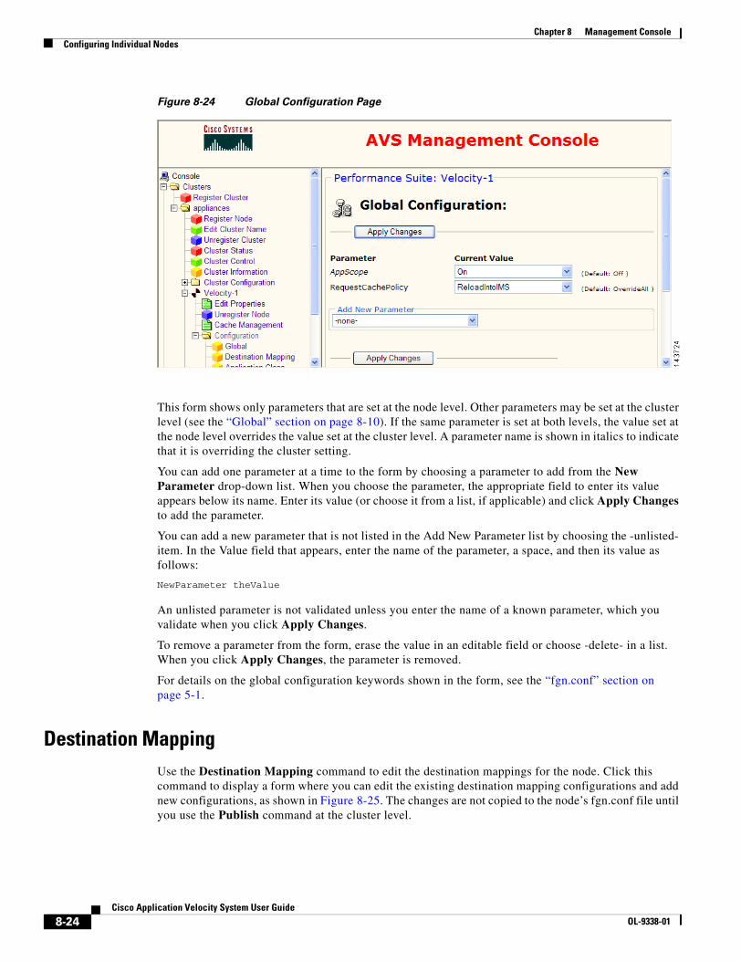
8-24Cisco Application Velocity System User Guide
OL-9338-01
Chapter 8 Management ConsoleConfiguring Individual Nodes
Figure 8-24 Global Configuration Page
This form shows only parameters that are set at the node level. Other parameters may be set at the cluster level (see the “Global” section on page 8-10). If the same parameter is set at both levels, the value set at the node level overrides the value set at the cluster level. A parameter name is shown in italics to indicate that it is overriding the cluster setting.
You can add one parameter at a time to the form by choosing a parameter to add from the New Parameter drop-down list. When you choose the parameter, the appropriate field to enter its value appears below its name. Enter its value (or choose it from a list, if applicable) and click Apply Changes to add the parameter.
You can add a new parameter that is not listed in the Add New Parameter list by choosing the -unlisted- item. In the Value field that appears, enter the name of the parameter, a space, and then its value as follows:
NewParameter theValue
An unlisted parameter is not validated unless you enter the name of a known parameter, which you validate when you click Apply Changes.
To remove a parameter from the form, erase the value in an editable field or choose -delete- in a list. When you click Apply Changes, the parameter is removed.
For details on the global configuration keywords shown in the form, see the “fgn.conf” section on page 5-1.
Destination MappingUse the Destination Mapping command to edit the destination mappings for the node. Click this command to display a form where you can edit the existing destination mapping configurations and add new configurations, as shown in Figure 8-25. The changes are not copied to the node’s fgn.conf file until you use the Publish command at the cluster level.

8-25Cisco Application Velocity System User Guide
OL-9338-01
Chapter 8 Management ConsoleConfiguring Individual Nodes
Figure 8-25 Destination Mapping Page
You can add one destination mapping configuration at a time to the form by choosing its type from the Add New Destination Mapping drop-down list. When you choose the type, the appropriate fields to configure it appear below its name. Enter the values (or choose from a list, if applicable) and click Apply Changes to add the destination mapping configuration. For details on the destination mapping configuration keywords, see the “Destination Mapping Configuration” section on page 5-30.
To change the order of destination mapping lines in the configuration file, enter a new order for one or more lines in the Ordinal column. Changing the order of a mapping to 0 moves it to the top of the list after you click Apply Changes. Changing the order of a mapping to a number greater than the last mapping moves it to the end of the list.
To delete one or more mappings, check the check box in the Delete column for the mapping. Click Apply Changes to delete the checked mappings.
This form shows only destination mappings that are set at the node level. Other destination mappings may be set at the cluster level (see the “Destination Mapping” section on page 8-12).
Application ClassUse the Application Class command to edit the Application Classes for the node. Click this command to display a form where you can edit the existing Application Classes and add new ones, as shown in Figure 8-26. Any changes are not copied to the node’s fgn.conf file until you use the Publish command at the cluster level.

8-26Cisco Application Velocity System User Guide
OL-9338-01
Chapter 8 Management ConsoleConfiguring Individual Nodes
Figure 8-26 Application Class Configuration Page
This form shows only Application Classes that are set at the node level. Other Application Classes may be set at the cluster level (see the “Application Class” section on page 8-12). If an Application Class with the same name is set at both levels, the one set at the node level overrides the one set at the cluster level because it is placed first in the configuration file when it is published to the node.
The Application Class Summary section at the top allows you to change the order of classes, delete classes, clone classes, and add new classes. Below that, each class is listed with its parameters. These parameters are read-only listings. To edit a class, click the Edit button in the summary, or click the class name link that is at the top of a class listing. A form similar to that shown in Figure 8-27 is displayed where you can edit, add, or delete parameters. For details on the Application Class configuration keywords, see the “Application Class Specification” section on page 5-7.
To change the order of Application Classes in the configuration file, enter a new order for one or more classes in the Order column. Changing the order of a class to 0 moves it to the top of the list after you click Apply Changes. Changing the order of a class to a number greater than the last class moves it to the end of the list.
To delete one or more classes, check the check box in the Delete column for the class. Click Delete Checked Classes to delete the checked classes.
To copy a class to use as the basis of a new class, click the Clone button next to the class that you want to clone. Cloned classes are put at the top of the list.
To add a new class, click Add New Application Class. This displays a new form where you can edit the class name and its parameters, as shown in Figure 8-27. To select multiple keywords in lists, press the Ctrl key while clicking on keywords.

8-27Cisco Application Velocity System User Guide
OL-9338-01
Chapter 8 Management ConsoleConfiguring Individual Nodes
To add a new parameter to the class, select it from the New Parameter drop-down list and enter its value in the field that will appear under its name. Click Apply Changes when you are done editing or adding new parameters. To go back to the Application Class summary page, click the Application Class command again in the menu at the left side. New classes are put at the top of the list.
You can add a new parameter that is not listed in the New Parameter list by choosing the -unlisted- item. In the Value field that appears, enter the name of the parameter, a space, and then its value as follows:
NewParameter theValue
An unlisted parameter is not validated unless you enter the name of a known parameter, which you validate when you click Apply Changes.
Figure 8-27 Add a New Application Class Page
AppScreen ClassUse the AppScreen Class command to edit the AppScreen Classes for the node. Click this command to display a form where you can edit the existing AppScreen Classes and add new classes, as shown in Figure 8-28. Any changes are not copied to the node’s fgn.conf file until you use the Publish command at the cluster level.

8-28Cisco Application Velocity System User Guide
OL-9338-01
Chapter 8 Management ConsoleConfiguring Individual Nodes
Figure 8-28 AppScreen Class Configuration Page
This form shows only AppScreen Classes that are set at the node level. Other AppScreen Classes may be set at the cluster level (see the “AppScreen Class” section on page 8-14). If an AppScreen Class with the same name is set at both levels, the one set at the node level overrides the one set at the cluster level because it is placed first in the configuration file when it is published to the node.
The AppScreen Class Summary section at the top allows you to change the order of classes, delete classes, clone classes, and add new classes. Below that, each class is listed with its parameters. These parameters are read-only listings. To edit a class, click the Edit button in the summary, or click the class name link that is at the top of a class listing. A form similar to that shown in Figure 8-29 is displayed where you can edit, add, or delete parameters. For details on the AppScreen Class configuration keywords, see the “AppScreen Class” section on page 7-3.
To change the order of AppScreen Classes in the configuration file, enter a new order for one or more classes in the Order column. Changing the order of a class to 0 moves it to the top of the list after you click Apply Changes. Changing the order of a class to a number greater than the last class moves it to the end of the list.
To delete one or more classes, check the check box in the Delete column for the class. Click Delete Checked Classes to delete the checked classes.
To copy a class to use as the basis of a new class, click the Clone button next to the class that you want to clone. Cloned classes are put at the top of the list.
To add a new class, click Add New AppScreen Class. This action displays a new form where you can edit the class name and its parameters, as shown in Figure 8-29.
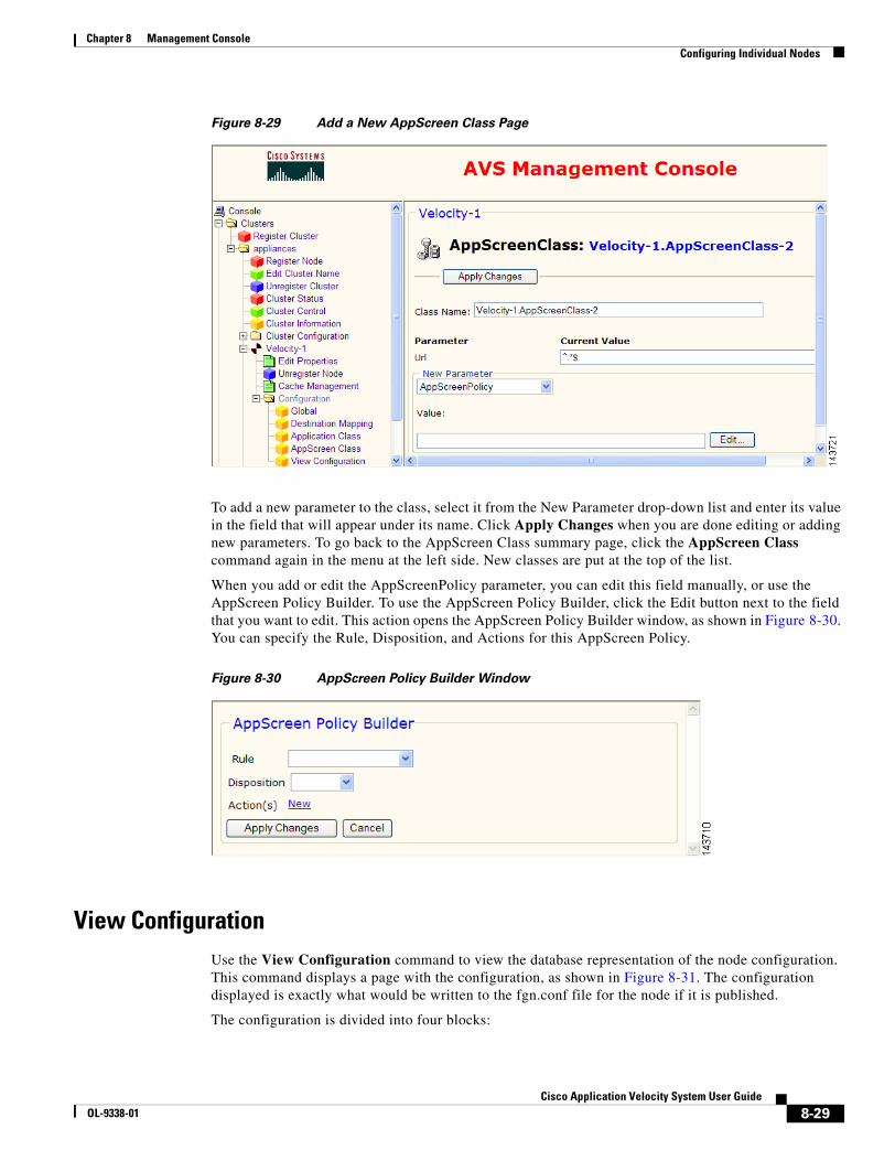
8-29Cisco Application Velocity System User Guide
OL-9338-01
Chapter 8 Management ConsoleConfiguring Individual Nodes
Figure 8-29 Add a New AppScreen Class Page
To add a new parameter to the class, select it from the New Parameter drop-down list and enter its value in the field that will appear under its name. Click Apply Changes when you are done editing or adding new parameters. To go back to the AppScreen Class summary page, click the AppScreen Class command again in the menu at the left side. New classes are put at the top of the list.
When you add or edit the AppScreenPolicy parameter, you can edit this field manually, or use the AppScreen Policy Builder. To use the AppScreen Policy Builder, click the Edit button next to the field that you want to edit. This action opens the AppScreen Policy Builder window, as shown in Figure 8-30. You can specify the Rule, Disposition, and Actions for this AppScreen Policy.
Figure 8-30 AppScreen Policy Builder Window
View ConfigurationUse the View Configuration command to view the database representation of the node configuration. This command displays a page with the configuration, as shown in Figure 8-31. The configuration displayed is exactly what would be written to the fgn.conf file for the node if it is published.
The configuration is divided into four blocks:
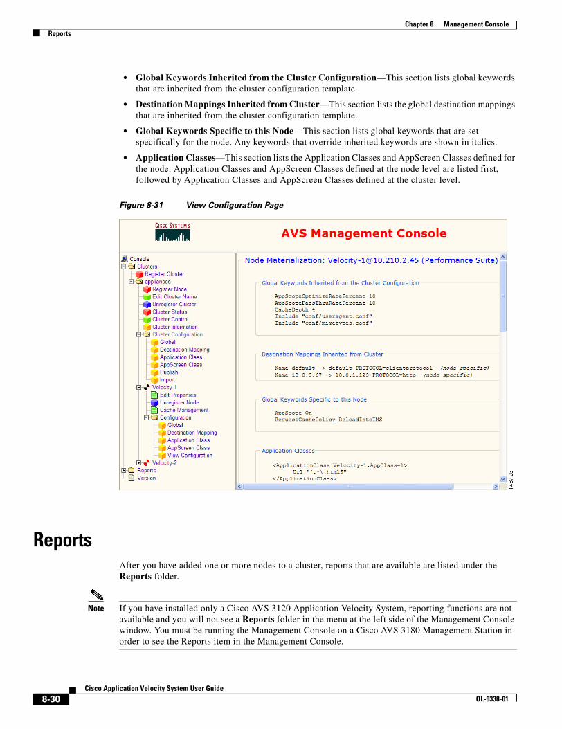
8-30Cisco Application Velocity System User Guide
OL-9338-01
Chapter 8 Management ConsoleReports
• Global Keywords Inherited from the Cluster Configuration—This section lists global keywords that are inherited from the cluster configuration template.
• Destination Mappings Inherited from Cluster—This section lists the global destination mappings that are inherited from the cluster configuration template.
• Global Keywords Specific to this Node—This section lists global keywords that are set specifically for the node. Any keywords that override inherited keywords are shown in italics.
• Application Classes—This section lists the Application Classes and AppScreen Classes defined for the node. Application Classes and AppScreen Classes defined at the node level are listed first, followed by Application Classes and AppScreen Classes defined at the cluster level.
Figure 8-31 View Configuration Page
ReportsAfter you have added one or more nodes to a cluster, reports that are available are listed under the Reports folder.
Note If you have installed only a Cisco AVS 3120 Application Velocity System, reporting functions are not available and you will not see a Reports folder in the menu at the left side of the Management Console window. You must be running the Management Console on a Cisco AVS 3180 Management Station in order to see the Reports item in the Management Console.
8-31Cisco Application Velocity System User Guide
OL-9338-01
Chapter 8 Management ConsoleVersion
The following AppScope-related report items are available:
• AppScope Reports
• Saved Reports
• Scheduled Reports
• Manage Locations
• Transaction Types
• Business Transaction Types
• Transaction Groups
The following other reports and items are available:
• Bandwidth Savings Reports
• Throughput Reports
• AppScreen Reports
• Upload Data
• Database Archiving
For details on reporting items, see Chapter 9, “Reporting.” For details on the Transaction Types and Transaction Groups items, see Chapter 10, “NMS Integration.” For details on the Database Archiving item, see Chapter 12, “Database Maintenance.”
VersionUse the Version command to display a page that shows the version of the Management Console.
Console ConfigurationYou can change the database user name and password for the Management Console by modifying an XML configuration file that the Management Console server reads on startup.
Look for the following file and open it in a text editor:
$AVS_HOME/console/jboss-3.0.1_tomcat-4.0.4/server/default/deploy/postgres-service.xml
In this file, look for the following section:
<!--set these only if you want only default logins, not through JAAS --><config-property name="UserName" type="java.lang.String">fineground</config-property><config-property name="Password" type="java.lang.String">condenser</config-property>
To change the user name, change the value for the UserName configuration property (fineground in this example). To change the password, change the value for the Password configuration property (condenser in this example). Save and close the file. You will also need to stop and restart the Management Console for the new setting to take effect.
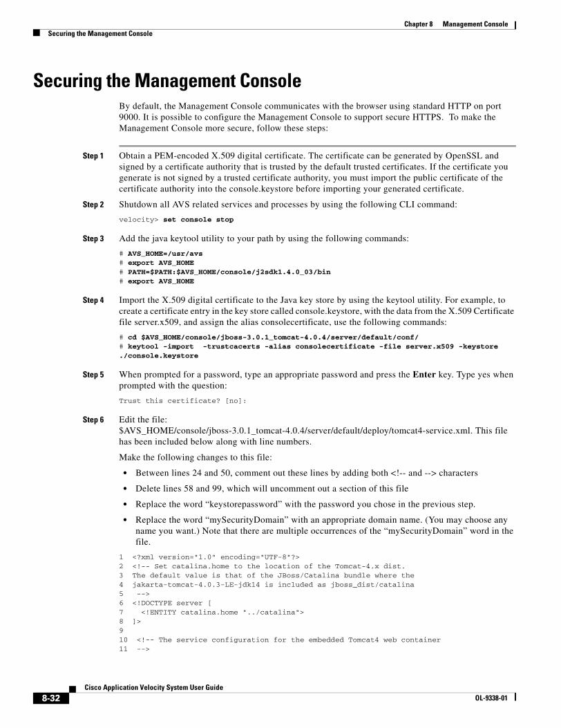
8-32Cisco Application Velocity System User Guide
OL-9338-01
Chapter 8 Management ConsoleSecuring the Management Console
Securing the Management ConsoleBy default, the Management Console communicates with the browser using standard HTTP on port 9000. It is possible to configure the Management Console to support secure HTTPS. To make the Management Console more secure, follow these steps:
Step 1 Obtain a PEM-encoded X.509 digital certificate. The certificate can be generated by OpenSSL and signed by a certificate authority that is trusted by the default trusted certificates. If the certificate you generate is not signed by a trusted certificate authority, you must import the public certificate of the certificate authority into the console.keystore before importing your generated certificate.
Step 2 Shutdown all AVS related services and processes by using the following CLI command:
velocity> set console stop
Step 3 Add the java keytool utility to your path by using the following commands:
# AVS_HOME=/usr/avs# export AVS_HOME# PATH=$PATH:$AVS_HOME/console/j2sdk1.4.0_03/bin# export AVS_HOME
Step 4 Import the X.509 digital certificate to the Java key store by using the keytool utility. For example, to create a certificate entry in the key store called console.keystore, with the data from the X.509 Certificate file server.x509, and assign the alias consolecertificate, use the following commands:
# cd $AVS_HOME/console/jboss-3.0.1_tomcat-4.0.4/server/default/conf/# keytool -import -trustcacerts -alias consolecertificate -file server.x509 -keystore ./console.keystore
Step 5 When prompted for a password, type an appropriate password and press the Enter key. Type yes when prompted with the question:
Trust this certificate? [no]:
Step 6 Edit the file: $AVS_HOME/console/jboss-3.0.1_tomcat-4.0.4/server/default/deploy/tomcat4-service.xml. This file has been included below along with line numbers.
Make the following changes to this file:
• Between lines 24 and 50, comment out these lines by adding both <!-- and --> characters
• Delete lines 58 and 99, which will uncomment out a section of this file
• Replace the word “keystorepassword” with the password you chose in the previous step.
• Replace the word “mySecurityDomain” with an appropriate domain name. (You may choose any name you want.) Note that there are multiple occurrences of the “mySecurityDomain” word in the file.
1 <?xml version="1.0" encoding="UTF-8"?>2 <!-- Set catalina.home to the location of the Tomcat-4.x dist.3 The default value is that of the JBoss/Catalina bundle where the4 jakarta-tomcat-4.0.3-LE-jdk14 is included as jboss_dist/catalina5 -->6 <!DOCTYPE server [7 <!ENTITY catalina.home "../catalina">8 ]>910 <!-- The service configuration for the embedded Tomcat4 web container11 -->
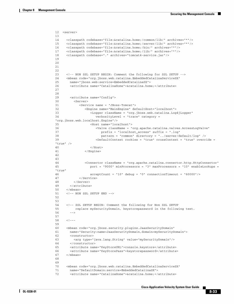
8-33Cisco Application Velocity System User Guide
OL-9338-01
Chapter 8 Management ConsoleSecuring the Management Console
12 <server>1314 <classpath codebase="file:&catalina.home;/common/lib/" archives="*"/>15 <classpath codebase="file:&catalina.home;/server/lib/" archives="*"/>16 <classpath codebase="file:&catalina.home;/bin/" archives="*"/>17 <classpath codebase="file:&catalina.home;/lib/" archives="*"/>18 <classpath codebase="." archives="tomcat4-service.jar"/>1920212223 <!-- NON SSL SETUP BEGIN: Comment the following for SSL SETUP --> 24 <mbean code="org.jboss.web.catalina.EmbeddedCatalinaServiceSX"25 name="jboss.web:service=EmbeddedCatalinaSX">26 <attribute name="CatalinaHome">&catalina.home;</attribute>272829 <attribute name="Config">30 <Server>31 <Service name = "JBoss-Tomcat">32 <Engine name="MainEngine" defaultHost="localhost">33 <Logger className = "org.jboss.web.catalina.Log4jLogger"34 verbosityLevel = "trace" category = "org.jboss.web.localhost.Engine"/>35 <Host name="localhost">36 <Valve className = "org.apache.catalina.valves.AccessLogValve"37 prefix = "localhost_access" suffix = ".log"38 pattern = "common" directory = "../server/default/log" />39 <DefaultContext cookies = "true" crossContext = "true" override = "true" />40 </Host>41 </Engine>424344 <Connector className = "org.apache.catalina.connector.http.HttpConnector"45 port = "9000" minProcessors = "3" maxProcessors = "10" enableLookups = "true"46 acceptCount = "10" debug = "0" connectionTimeout = "60000"/>47 </Service>48 </Server>49 </attribute>50 </mbean>51 <!-- NON SSL SETUP END --> 525354 <!-- SSL SETUP BEGIN: Comment the following for Non SSL SETUP 55 replace mySecurityDomain, keystorepassword in the following text.56 --> 5758 <!---5960 <mbean code="org.jboss.security.plugins.JaasSecurityDomain"61 name="Security:name=JaasSecurityDomain,domain=mySecurityDomain">62 <constructor>63 <arg type="java.lang.String" value="mySecurityDomain"/>64 </constructor>65 <attribute name="KeyStoreURL">console.keystore</attribute>66 <attribute name="KeyStorePass">keystorepassword</attribute>67 </mbean>686970 <mbean code="org.jboss.web.catalina.EmbeddedCatalinaServiceSX"71 name="DefaultDomain:service=EmbeddedCatalinaSX">72 <attribute name="CatalinaHome">&catalina.home;</attribute>
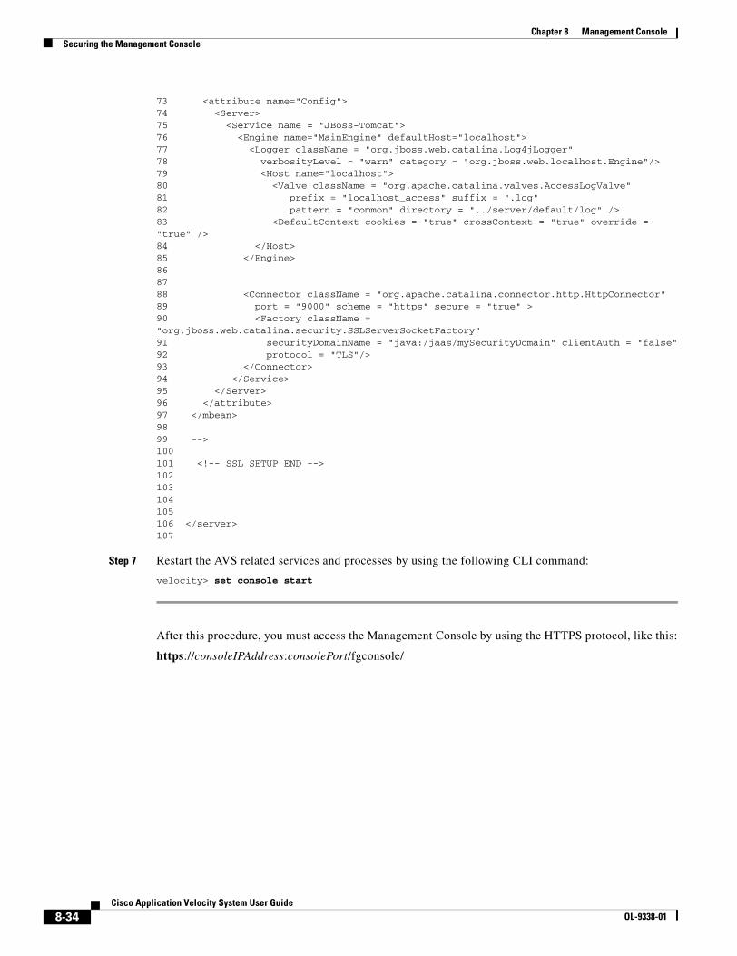
8-34Cisco Application Velocity System User Guide
OL-9338-01
Chapter 8 Management ConsoleSecuring the Management Console
73 <attribute name="Config">74 <Server>75 <Service name = "JBoss-Tomcat">76 <Engine name="MainEngine" defaultHost="localhost">77 <Logger className = "org.jboss.web.catalina.Log4jLogger"78 verbosityLevel = "warn" category = "org.jboss.web.localhost.Engine"/>79 <Host name="localhost">80 <Valve className = "org.apache.catalina.valves.AccessLogValve"81 prefix = "localhost_access" suffix = ".log"82 pattern = "common" directory = "../server/default/log" />83 <DefaultContext cookies = "true" crossContext = "true" override = "true" />84 </Host>85 </Engine>868788 <Connector className = "org.apache.catalina.connector.http.HttpConnector"89 port = "9000" scheme = "https" secure = "true" >90 <Factory className = "org.jboss.web.catalina.security.SSLServerSocketFactory"91 securityDomainName = "java:/jaas/mySecurityDomain" clientAuth = "false"92 protocol = "TLS"/>93 </Connector>94 </Service>95 </Server>96 </attribute>97 </mbean>9899 -->100101 <!-- SSL SETUP END --> 102103104 105106 </server>107
Step 7 Restart the AVS related services and processes by using the following CLI command:
velocity> set console start
After this procedure, you must access the Management Console by using the HTTPS protocol, like this:
https://consoleIPAddress:consolePort/fgconsole/
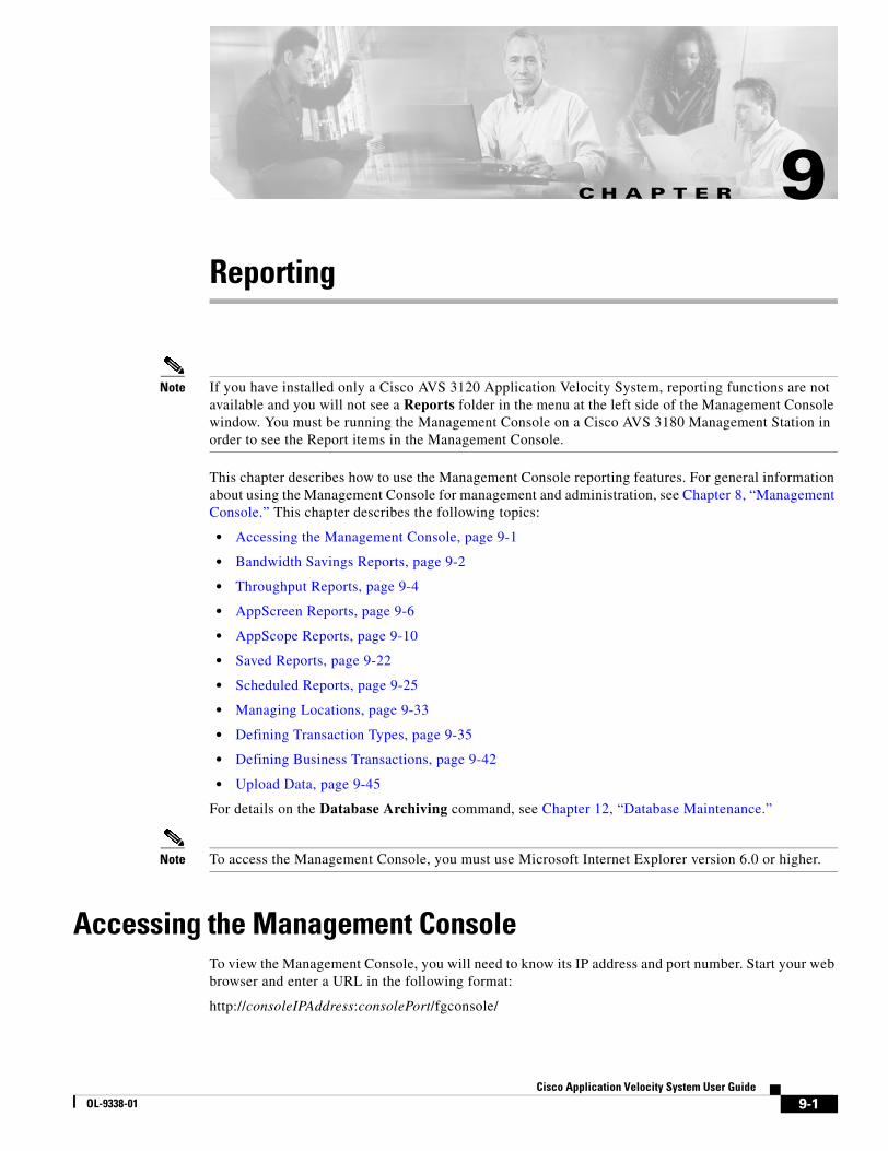
C H A P T E R
9-1Cisco Application Velocity System User Guide
OL-9338-01
9Reporting
Note If you have installed only a Cisco AVS 3120 Application Velocity System, reporting functions are not available and you will not see a Reports folder in the menu at the left side of the Management Console window. You must be running the Management Console on a Cisco AVS 3180 Management Station in order to see the Report items in the Management Console.
This chapter describes how to use the Management Console reporting features. For general information about using the Management Console for management and administration, see Chapter 8, “Management Console.” This chapter describes the following topics:
• Accessing the Management Console, page 9-1
• Bandwidth Savings Reports, page 9-2
• Throughput Reports, page 9-4
• AppScreen Reports, page 9-6
• AppScope Reports, page 9-10
• Saved Reports, page 9-22
• Scheduled Reports, page 9-25
• Managing Locations, page 9-33
• Defining Transaction Types, page 9-35
• Defining Business Transactions, page 9-42
• Upload Data, page 9-45
For details on the Database Archiving command, see Chapter 12, “Database Maintenance.”
Note To access the Management Console, you must use Microsoft Internet Explorer version 6.0 or higher.
Accessing the Management ConsoleTo view the Management Console, you will need to know its IP address and port number. Start your web browser and enter a URL in the following format:
http://consoleIPAddress:consolePort/fgconsole/

9-2Cisco Application Velocity System User Guide
OL-9338-01
Chapter 9 ReportingBandwidth Savings Reports
For example, you can enter:
http://10.0.0.2:9000/fgconsole/
A dialog box will request your user name and password. The default values are as follows:
user name: adminpassword: admin
For details on changing the user name or password, refer to “Accessing the Management Console” section on page 8-1.
After you enter the correct user name and password, the web browser displays the Management Console shown in Figure 9-1.
Figure 9-1 Management Console Main Page
For details on creating clusters, adding nodes to a cluster, and other items not covered here, see Chapter 8, “Management Console.”
Before you can manage an individual application appliance, you must create at least one cluster and add the application appliance node to it. After you have added one or more nodes to a cluster, their names will appear at the bottom of the list of cluster menu items, and you can click a node name to manage the individual node.
The following sections describe the specific functions related to reporting and management that you can perform by using the menu options in the left pane under the Reports folder.
Bandwidth Savings ReportsThe Bandwidth Savings Reports page (shown in Figure 9-2) allows you to generate color-coded graphical reports, based on a configurable reporting period, that show the actual bandwidth savings realized for traffic delivered by the application appliance. In addition, this feature provides both summary reports and detailed reports organized by content type to allow you to easily quantify actual bandwidth reduction and the resulting return on investment (ROI).
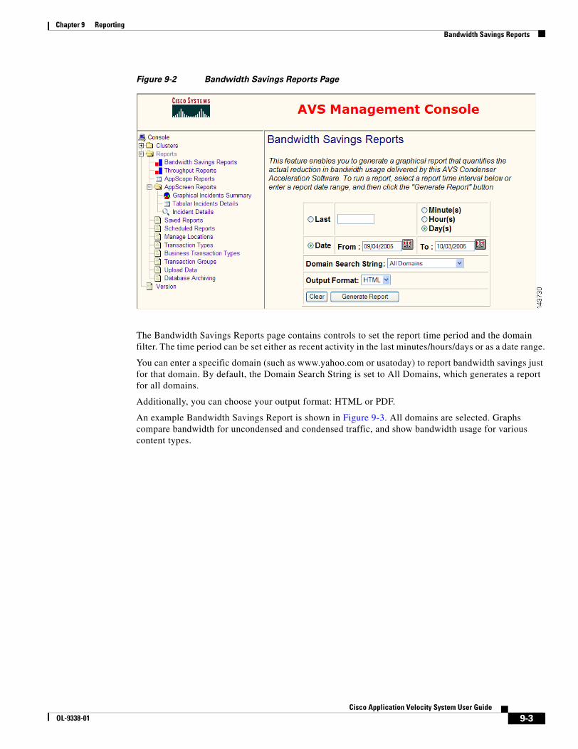
9-3Cisco Application Velocity System User Guide
OL-9338-01
Chapter 9 ReportingBandwidth Savings Reports
Figure 9-2 Bandwidth Savings Reports Page
The Bandwidth Savings Reports page contains controls to set the report time period and the domain filter. The time period can be set either as recent activity in the last minutes/hours/days or as a date range.
You can enter a specific domain (such as www.yahoo.com or usatoday) to report bandwidth savings just for that domain. By default, the Domain Search String is set to All Domains, which generates a report for all domains.
Additionally, you can choose your output format: HTML or PDF.
An example Bandwidth Savings Report is shown in Figure 9-3. All domains are selected. Graphs compare bandwidth for uncondensed and condensed traffic, and show bandwidth usage for various content types.
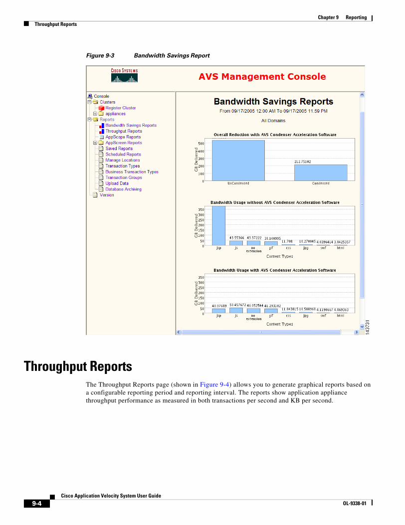
9-4Cisco Application Velocity System User Guide
OL-9338-01
Chapter 9 ReportingThroughput Reports
Figure 9-3 Bandwidth Savings Report
Throughput ReportsThe Throughput Reports page (shown in Figure 9-4) allows you to generate graphical reports based on a configurable reporting period and reporting interval. The reports show application appliance throughput performance as measured in both transactions per second and KB per second.
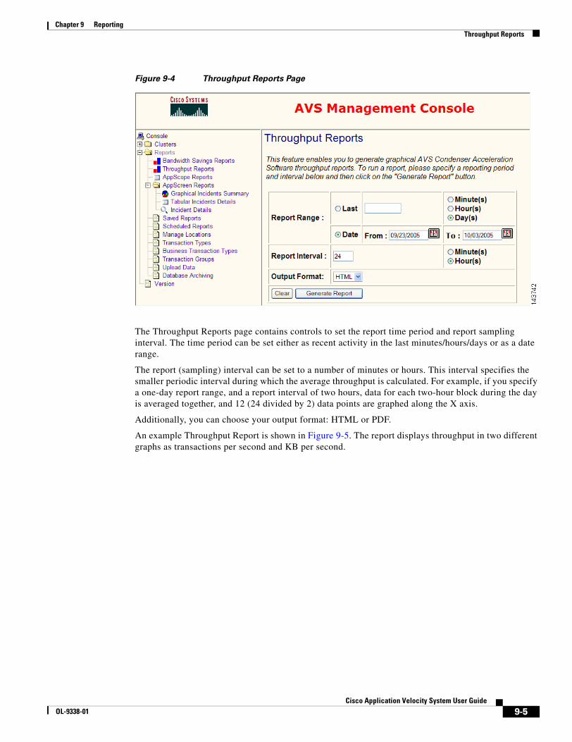
9-5Cisco Application Velocity System User Guide
OL-9338-01
Chapter 9 ReportingThroughput Reports
Figure 9-4 Throughput Reports Page
The Throughput Reports page contains controls to set the report time period and report sampling interval. The time period can be set either as recent activity in the last minutes/hours/days or as a date range.
The report (sampling) interval can be set to a number of minutes or hours. This interval specifies the smaller periodic interval during which the average throughput is calculated. For example, if you specify a one-day report range, and a report interval of two hours, data for each two-hour block during the day is averaged together, and 12 (24 divided by 2) data points are graphed along the X axis.
Additionally, you can choose your output format: HTML or PDF.
An example Throughput Report is shown in Figure 9-5. The report displays throughput in two different graphs as transactions per second and KB per second.

9-6Cisco Application Velocity System User Guide
OL-9338-01
Chapter 9 ReportingAppScreen Reports
Figure 9-5 Throughput Report
AppScreen ReportsThe AppScreen Reports folder within the Reports menu includes commands that allow you to generate reports of requests that matched AppScreen Classes. You can use these reports to monitor attempts at web site intrusion and application security breaches. For more details on AppScreen request filtering, see Chapter 7, “AppScreen Configuration.”
Click the AppScreen Reports menu folder to see the following reporting commands:
• Graphical Incidents Summary
• Tabular Incidents Details
• Incident Details
These commands are described in the following subsections.
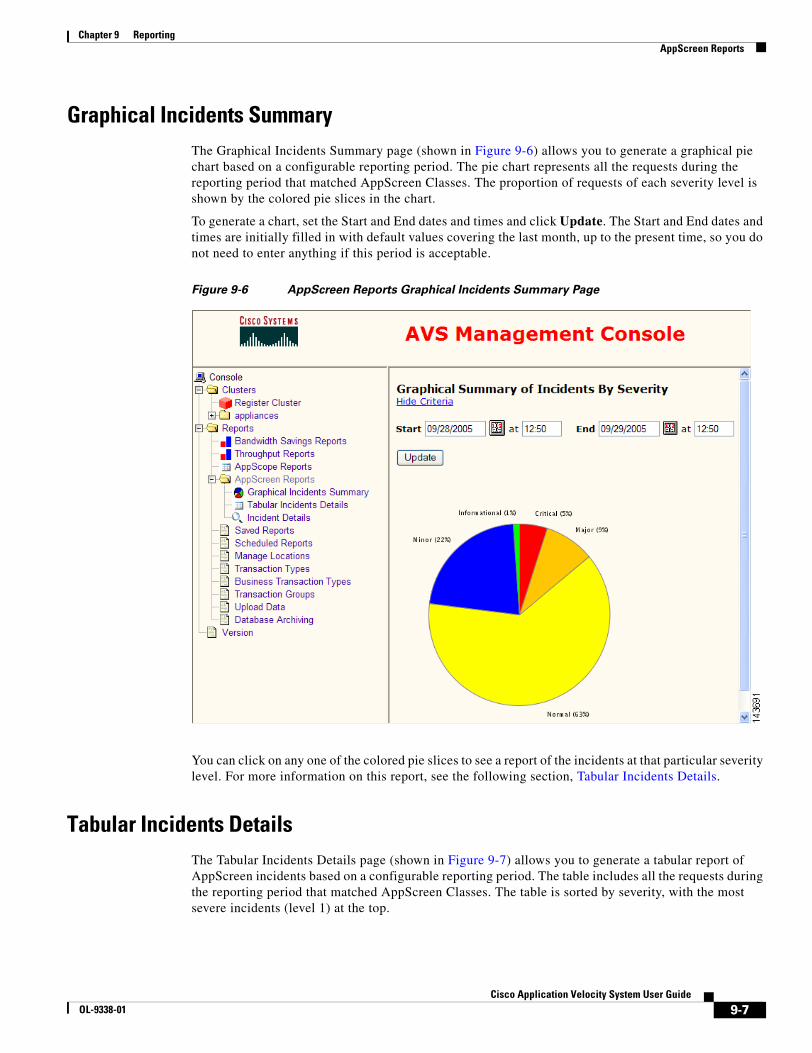
9-7Cisco Application Velocity System User Guide
OL-9338-01
Chapter 9 ReportingAppScreen Reports
Graphical Incidents SummaryThe Graphical Incidents Summary page (shown in Figure 9-6) allows you to generate a graphical pie chart based on a configurable reporting period. The pie chart represents all the requests during the reporting period that matched AppScreen Classes. The proportion of requests of each severity level is shown by the colored pie slices in the chart.
To generate a chart, set the Start and End dates and times and click Update. The Start and End dates and times are initially filled in with default values covering the last month, up to the present time, so you do not need to enter anything if this period is acceptable.
Figure 9-6 AppScreen Reports Graphical Incidents Summary Page
You can click on any one of the colored pie slices to see a report of the incidents at that particular severity level. For more information on this report, see the following section, Tabular Incidents Details.
Tabular Incidents DetailsThe Tabular Incidents Details page (shown in Figure 9-7) allows you to generate a tabular report of AppScreen incidents based on a configurable reporting period. The table includes all the requests during the reporting period that matched AppScreen Classes. The table is sorted by severity, with the most severe incidents (level 1) at the top.
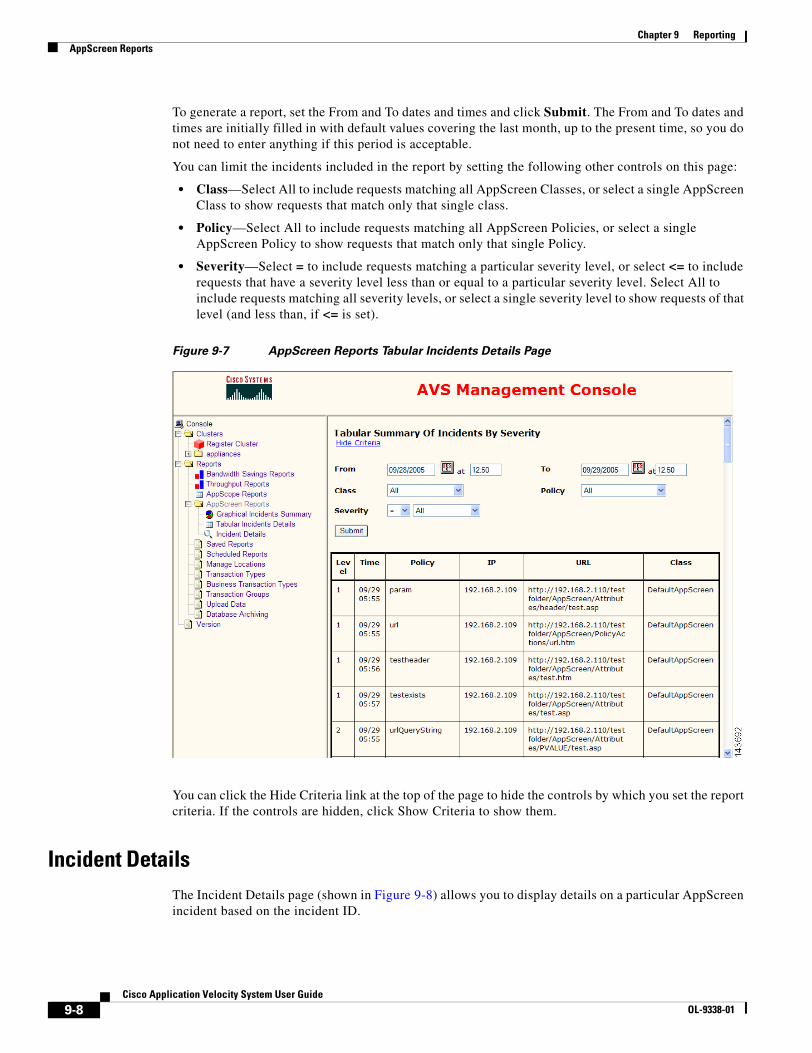
9-8Cisco Application Velocity System User Guide
OL-9338-01
Chapter 9 ReportingAppScreen Reports
To generate a report, set the From and To dates and times and click Submit. The From and To dates and times are initially filled in with default values covering the last month, up to the present time, so you do not need to enter anything if this period is acceptable.
You can limit the incidents included in the report by setting the following other controls on this page:
• Class—Select All to include requests matching all AppScreen Classes, or select a single AppScreen Class to show requests that match only that single class.
• Policy—Select All to include requests matching all AppScreen Policies, or select a single AppScreen Policy to show requests that match only that single Policy.
• Severity—Select = to include requests matching a particular severity level, or select <= to include requests that have a severity level less than or equal to a particular severity level. Select All to include requests matching all severity levels, or select a single severity level to show requests of that level (and less than, if <= is set).
Figure 9-7 AppScreen Reports Tabular Incidents Details Page
You can click the Hide Criteria link at the top of the page to hide the controls by which you set the report criteria. If the controls are hidden, click Show Criteria to show them.
Incident DetailsThe Incident Details page (shown in Figure 9-8) allows you to display details on a particular AppScreen incident based on the incident ID.

9-9Cisco Application Velocity System User Guide
OL-9338-01
Chapter 9 ReportingAppScreen Reports
To retrieve the details on an incident, enter the incident ID in the Incident ID field and click Submit. You also can click on an incident URL in the tabular summary of incidents report to display details on that incident.
The incident ID can be obtained from the Incident ID field in the SNMP trap if you configured AppScreen to send traps to an SNMP Management Station.
Figure 9-8 AppScreen Reports Incident Details Page
Figure 9-9 shows an example of an incident details report.
Figure 9-9 AppScreen Reports Incident Details Example
9-10Cisco Application Velocity System User Guide
OL-9338-01
Chapter 9 ReportingAppScope Reports
AppScope ReportsThe AppScope Reports page (shown in Figure 9-10) allows you to generate reports that measure accurate end-to-end application performance as seen by real end users. AppScope also accurately determines both the server delay and network delay components associated with the user experience at the transaction level. AppScope’s unique statistical traffic sampling technology allows an enterprise to statistically sample user requests, making AppScope highly scalable for high-traffic applications.
You can measure true application performance by grouping transactions into sets of business transactions that define a series of individual web page transactions done by a user in a typical application task such as filing an online expense report. Aggregate statistics and charts show performance trends for the whole business transaction in addition to individual transactions. For more details on business transaction, see the “Defining Business Transactions” section on page 9-42.
Performance Monitoring DetailsThe AppScope performance monitoring feature measures total page download times from the point of view of the client. AppScope measures both accelerated (condensed) and pass-through (uncondensed) transactions, so that you can compare these and determine the benefit of application appliance optimization. When measuring pass-through transactions, AppScope operates in proxy mode.
AppScope’s ability to measure a sample of all transactions enables it to easily scale in high-traffic situations. When used in a load-balanced environment, the load balancer sends some portion of the traffic to AppScope (using the load balancing rule). In this situation, AppScope should be configured to measure 100 percent of all transactions it sees. In other words, although AppScope will see only a portion of the traffic, it should be configured to measure all of this portion.
When AppScope is not used with a load balancer (that is, all transactions are passed through the AppScope server), AppScope should be configured to measure only a portion of the traffic. Although AppScope can be configured to measure 100 percent of the traffic in this situation, for scalability reasons we recommend measuring only a portion of the traffic. For example, AppScope can be configured to measure 10 percent of accelerated transactions and 10 percent of pass-through transactions, as follows:
AppScopeOptimizeRatePercent 10AppScopePassThruRatePercent 10
When measuring a transaction, AppScope begins measuring the time when the server first receives the main request for a page. AppScope stops measuring time when the client acknowledges that it has received the remaining bytes of data for the page, including all embedded objects.
In order to accurately measure page download time from the client’s perspective, AppScope inserts a small amount of JavaScript code into the page that is delivered to the client. This code calculates the page download time on the client and reports it back to the server using a query parameter in a GET request. The server inserts the performance data into a log file, which is then loaded into the Management Console database, from which performance reports are generated.
Measurement sampling can be configured in two ways:
• Individual request sampling
Each transaction request is treated individually and randomly selected for a measurement group: accelerated measurement, pass-through measurement, or no measurement.
• Session-based sampling
Once a transaction request has been randomly selected for a measurement group, all subsequent requests from that client are handled the same, for a configurable period of time, up to one day.
9-11Cisco Application Velocity System User Guide
OL-9338-01
Chapter 9 ReportingAppScope Reports
This feature is configured by the AppScopeCookieTTL directive, which is described in Table 5-1. When set to 0, AppScope uses individual request sampling; when set to a number of seconds, AppScope samples in sessions of that length. The FGNPERFMON cookie informs AppScope of the client’s assigned measurement group until it expires and is deleted.
AppScope performance monitoring relies on very accurate time measurement, in the millisecond range. If you have installed multiple application appliances, different parts of a single transaction might be handled by different nodes, so it is important that the clocks be synchronized. To satisfy this requirement, you should enable Network Time Protocol (NTP) on all application appliance nodes.
The following sections describe:
• Basic Reports, page 9-11
• Drilldown Reports, page 9-17
• Charts, page 9-20
• Filtering AppScope Data, page 9-21
Basic ReportsThis section describes how to generate basic AppScope Performance reports.
Tip If the original content uses VBScript as its scripting language, you must set the DefaultClientScript VBScript directive globally or for the class. For details on this directive, see Table 5-1 on page 5-2.
Click on the AppScope Reports item in the left menu to display the main AppScope reports page, as shown in Figure 9-10.
Note AppScope Reports may not be visible under the Reports folder until you have registered at least one cluster that contains an application appliance node.
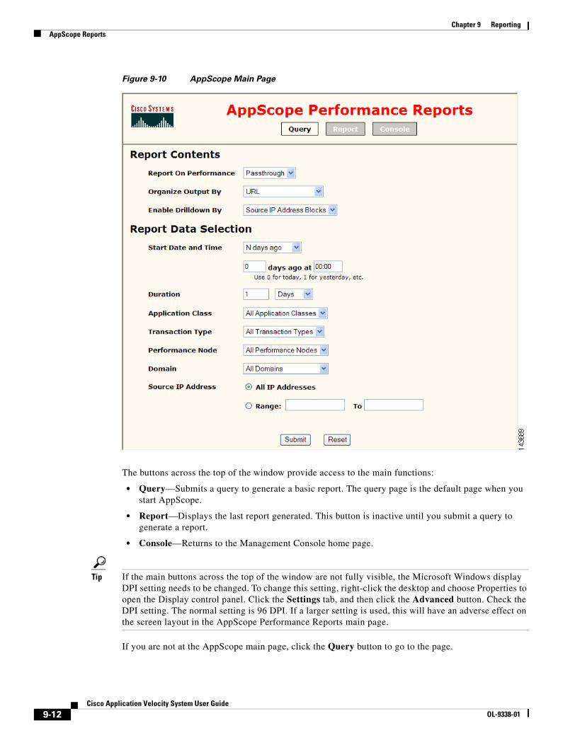
9-12Cisco Application Velocity System User Guide
OL-9338-01
Chapter 9 ReportingAppScope Reports
Figure 9-10 AppScope Main Page
The buttons across the top of the window provide access to the main functions:
• Query—Submits a query to generate a basic report. The query page is the default page when you start AppScope.
• Report—Displays the last report generated. This button is inactive until you submit a query to generate a report.
• Console—Returns to the Management Console home page.
Tip If the main buttons across the top of the window are not fully visible, the Microsoft Windows display DPI setting needs to be changed. To change this setting, right-click the desktop and choose Properties to open the Display control panel. Click the Settings tab, and then click the Advanced button. Check the DPI setting. The normal setting is 96 DPI. If a larger setting is used, this will have an adverse effect on the screen layout in the AppScope Performance Reports main page.
If you are not at the AppScope main page, click the Query button to go to the page.

9-13Cisco Application Velocity System User Guide
OL-9338-01
Chapter 9 ReportingAppScope Reports
Defining the Query
The query page contains a number of controls that set the query parameters for generating a report:
• Report on Performance—Choose Passthrough, Accelerated, or Comparison to show a report on only pass-through (unoptimized) requests, only accelerated (optimized) requests, or to compare the two types, respectively.
• Organize Output By—Choose URL to organize the report output by URLs, choose Application Class to organize the output by Application class, or choose Business Transaction to organize the output by business transaction.
– When organized by URL, each row of the report contains data for one request URL. Matching URLs that differ only in their query parameters (after the ?) are treated as the same URL and are not listed on separate lines, but they are combined on one line. You can use the RequestGroupingString configuration element to specify that, for a given URL, all variations based on query parameters are to be treated as separate URLs for reporting purposes. Each variation will then appear on a separate line in the report.
– When organized by Application Class, each row of the report contains aggregated data for all URLs in one class. A class uses regular expressions to define a set of URLs. For more information on defining classes, see the “Application Class Specification” section on page 5-7.
– When organized by Business Transaction, each row of the report contains aggregated data for all URLs in one business transaction. For more information on defining business transactions, see the “Defining Business Transactions” section on page 9-42.
• Enable Drilldown By—Choose Source IP Address Blocks to enable drilling down on the report by IP address blocks of the requesting clients, or select Defined Source Locations to enable drilling down by named locations that have been defined with the Manage Locations command (under the Reports folder in the left-hand navigation menu).
• Start Date and Time—Choose the type of start date you want to use: a relative time in the past or a specific date. Enter the number of time units in the past or enter a specific date and time. For details on how to select a date, see the “Date Selection” section on page 9-14.
• Duration—Enter the duration of the reporting period and select the units of time (Minutes, Hours, Days, Weeks, or Months). By choosing longer periods of time, you can generate charts that show performance trends over a period of time.
• Application Class—Choose All Application Classes to aggregate results from all Application classes, or choose a single Application class to show results only from one class. Note that this pull-down list is disabled when Organize Output By is set to Business Transaction.
• Transaction Type—Choose All Transaction Types to aggregate results from all Transaction Types, or choose a single Transaction Type to show results only from that type. For information on defining Transaction Types, see Chapter 10, “NMS Integration.”
• Performance Node—Choose All Performance Nodes to aggregate results from all nodes (if you have more than one installed), or choose a single node to show results only from that node.
• Domain—Choose All Domains to aggregate results from all domains, or choose a single domain to show results only from one domain.
• Source IP Address—Click the All IP Addresses radio button to aggregate results from all source IP addresses, or click Range and enter a beginning and ending IP address to show results only from that range of source IP addresses.
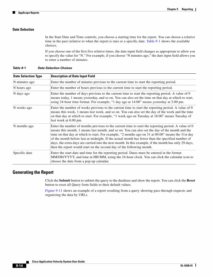
9-14Cisco Application Velocity System User Guide
OL-9338-01
Chapter 9 ReportingAppScope Reports
Date Selection
In the Start Date and Time controls, you choose a starting time for the report. You can choose a relative time in the past (relative to when the report is run) or a specific date. Table 9-1 shows the available choices.
If you choose one of the first five relative times, the date input field changes as appropriate to allow you to specify the value for “N.” For example, if you choose “N minutes ago,” the date input field allows you to enter a number of minutes.
Generating the Report
Click the Submit button to submit the query to the database and show the report. You can click the Reset button to reset all Query form fields to their default values.
Figure 9-11 shows an example of a report resulting from a query showing pass-through requests and organizing the data by URLs.
Table 9-1 Date Selection Choices
Date Selection Type Description of Date Input Field
N minutes ago Enter the number of minutes previous to the current time to start the reporting period.
N hours ago Enter the number of hours previous to the current time to start the reporting period.
N days ago Enter the number of days previous to the current time to start the reporting period. A value of 0 means today, 1 means yesterday, and so on. You can also set the time on that day at which to start, using 24-hour time format. For example, “1 day ago at 14:00” means yesterday at 2:00 pm.
N weeks ago Enter the number of weeks previous to the current time to start the reporting period. A value of 0 means this week, 1 means last week, and so on. You can also set the day of the week and the time on that day at which to start. For example, “1 week ago on Tuesday at 18:00” means Tuesday of last week at 6:00 pm.
N months ago Enter the number of months previous to the current time to start the reporting period. A value of 0 means this month, 1 means last month, and so on. You can also set the day of the month and the time on that day at which to start. For example, “2 months ago on 31 at 00:00” means the 31st day of the month before last at midnight. If the actual month has fewer than the specified number of days, the extra days are carried into the next month. In this example, if the month has only 29 days, then the report would start on the second day of the following month.
Specific date Enter the start date and time for the reporting period. Dates must be entered in the format MM/DD/YYYY, and time in HH:MM, using the 24-hour clock. You can click the calendar icon to choose the date from a pop-up calendar.
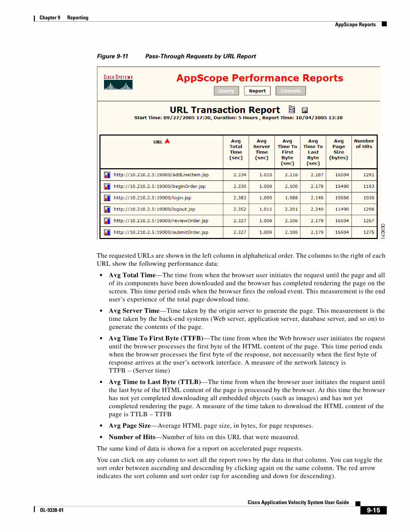
9-15Cisco Application Velocity System User Guide
OL-9338-01
Chapter 9 ReportingAppScope Reports
Figure 9-11 Pass-Through Requests by URL Report
The requested URLs are shown in the left column in alphabetical order. The columns to the right of each URL show the following performance data:
• Avg Total Time—The time from when the browser user initiates the request until the page and all of its components have been downloaded and the browser has completed rendering the page on the screen. This time period ends when the browser fires the onload event. This measurement is the end user’s experience of the total page download time.
• Avg Server Time—Time taken by the origin server to generate the page. This measurement is the time taken by the back-end systems (Web server, application server, database server, and so on) to generate the contents of the page.
• Avg Time To First Byte (TTFB)—The time from when the Web browser user initiates the request until the browser processes the first byte of the HTML content of the page. This time period ends when the browser processes the first byte of the response, not necessarily when the first byte of response arrives at the user’s network interface. A measure of the network latency is TTFB – (Server time)
• Avg Time to Last Byte (TTLB)—The time from when the browser user initiates the request until the last byte of the HTML content of the page is processed by the browser. At this time the browser has not yet completed downloading all embedded objects (such as images) and has not yet completed rendering the page. A measure of the time taken to download the HTML content of the page is TTLB – TTFB
• Avg Page Size—Average HTML page size, in bytes, for page responses.
• Number of Hits—Number of hits on this URL that were measured.
The same kind of data is shown for a report on accelerated page requests.
You can click on any column to sort all the report rows by the data in that column. You can toggle the sort order between ascending and descending by clicking again on the same column. The red arrow indicates the sort column and sort order (up for ascending and down for descending).
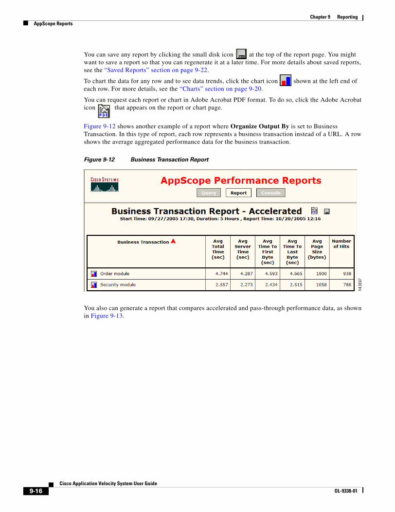
9-16Cisco Application Velocity System User Guide
OL-9338-01
Chapter 9 ReportingAppScope Reports
You can save any report by clicking the small disk icon at the top of the report page. You might want to save a report so that you can regenerate it at a later time. For more details about saved reports, see the “Saved Reports” section on page 9-22.
To chart the data for any row and to see data trends, click the chart icon shown at the left end of each row. For more details, see the “Charts” section on page 9-20.
You can request each report or chart in Adobe Acrobat PDF format. To do so, click the Adobe Acrobat icon that appears on the report or chart page.
Figure 9-12 shows another example of a report where Organize Output By is set to Business Transaction. In this type of report, each row represents a business transaction instead of a URL. A row shows the average aggregated performance data for the business transaction.
Figure 9-12 Business Transaction Report
You also can generate a report that compares accelerated and pass-through performance data, as shown in Figure 9-13.
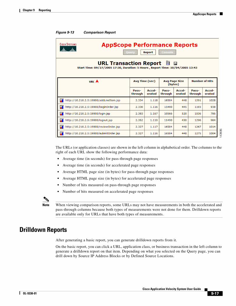
9-17Cisco Application Velocity System User Guide
OL-9338-01
Chapter 9 ReportingAppScope Reports
Figure 9-13 Comparison Report
The URLs (or application classes) are shown in the left column in alphabetical order. The columns to the right of each URL show the following performance data:
• Average time (in seconds) for pass-through page responses
• Average time (in seconds) for accelerated page responses
• Average HTML page size (in bytes) for pass-through page responses
• Average HTML page size (in bytes) for accelerated page responses
• Number of hits measured on pass-through page responses
• Number of hits measured on accelerated page responses
Note When viewing comparison reports, some URLs may not have measurements in both the accelerated and pass-through columns because both types of measurements were not done for them. Drilldown reports are available only for URLs that have both types of measurements.
Drilldown ReportsAfter generating a basic report, you can generate drilldown reports from it.
On the basic report, you can click a URL, application class, or business transaction in the left column to generate a drilldown report on that item. Depending on what you selected on the Query page, you can drill down by Source IP Address Blocks or by Defined Source Locations.

9-18Cisco Application Velocity System User Guide
OL-9338-01
Chapter 9 ReportingAppScope Reports
For drilling down into business transactions, when you click on a business transaction name, it shows a new report (see Figure 9-14) listing the individual transaction types in the business transaction, then clicking on one of those drills down into the individual URL, and finally into the source IP block or defined location as usual.
Figure 9-14 Drilldown Report into Business Transaction
Drilldown by Source IP Address Blocks
If you selected the Source IP Address Blocks value for the Enable Drilldown By item on the Query page, then you can drill down multiple levels on a particular URL, application class, or business transaction. Each drilldown level includes data from a narrower block of client IP addresses for the URL or application class selected. For business transactions, there are intermediate levels of individual transactions and URL reports shown before IP blocks.
From a basic report that is organized by URL, clicking a URL drills down one level, showing a report similar to that in Figure 9-15, where IP address blocks are shown on each row. You can click an IP address block up to three more times to drilldown further, narrowing the scope of the report to smaller blocks of IP addresses.
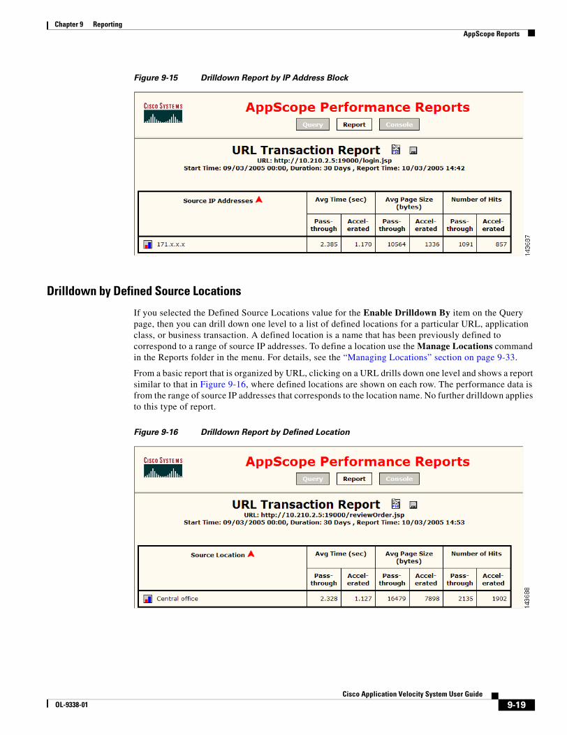
9-19Cisco Application Velocity System User Guide
OL-9338-01
Chapter 9 ReportingAppScope Reports
Figure 9-15 Drilldown Report by IP Address Block
Drilldown by Defined Source Locations
If you selected the Defined Source Locations value for the Enable Drilldown By item on the Query page, then you can drill down one level to a list of defined locations for a particular URL, application class, or business transaction. A defined location is a name that has been previously defined to correspond to a range of source IP addresses. To define a location use the Manage Locations command in the Reports folder in the menu. For details, see the “Managing Locations” section on page 9-33.
From a basic report that is organized by URL, clicking on a URL drills down one level and shows a report similar to that in Figure 9-16, where defined locations are shown on each row. The performance data is from the range of source IP addresses that corresponds to the location name. No further drilldown applies to this type of report.
Figure 9-16 Drilldown Report by Defined Location

9-20Cisco Application Velocity System User Guide
OL-9338-01
Chapter 9 ReportingAppScope Reports
ChartsCharts are available for each row of data at every report level. You can use charts to view performance trends over time. Each report row includes a chart icon at the left edge of the row.
Click the chart icon to generate a chart of the row data. Figure 9-17 shows an example of a chart for a row of data in a business transaction report. The colored stacked bars in the top chart show the various response time measurements for each reporting period. The colored bars are stacked on top of each other, with the light blue at the back, then the dark blue, light green, and dark green in the front. The red bars in the chart at the bottom show the number of hits that were measured.
Figure 9-17 Chart of Transaction Data
Figure 9-18 shows an example of a chart of a comparison report. This chart shows two colored bars for each reporting period: one for accelerated responses (green) and one for pass-through responses (blue).
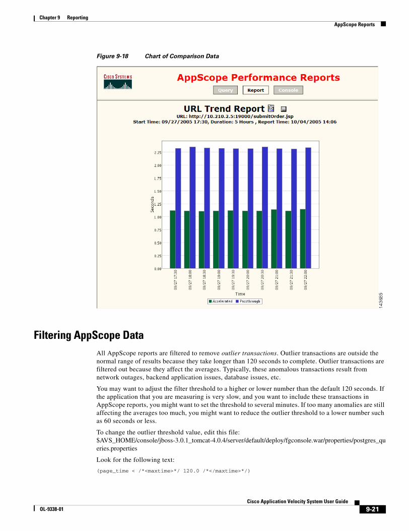
9-21Cisco Application Velocity System User Guide
OL-9338-01
Chapter 9 ReportingAppScope Reports
Figure 9-18 Chart of Comparison Data
Filtering AppScope DataAll AppScope reports are filtered to remove outlier transactions. Outlier transactions are outside the normal range of results because they take longer than 120 seconds to complete. Outlier transactions are filtered out because they affect the averages. Typically, these anomalous transactions result from network outages, backend application issues, database issues, etc.
You may want to adjust the filter threshold to a higher or lower number than the default 120 seconds. If the application that you are measuring is very slow, and you want to include these transactions in AppScope reports, you might want to set the threshold to several minutes. If too many anomalies are still affecting the averages too much, you might want to reduce the outlier threshold to a lower number such as 60 seconds or less.
To change the outlier threshold value, edit this file:$AVS_HOME/console/jboss-3.0.1_tomcat-4.0.4/server/default/deploy/fgconsole.war/properties/postgres_queries.properties
Look for the following text:
(page_time < /*<maxtime>*/ 120.0 /*</maxtime>*/)

9-22Cisco Application Velocity System User Guide
OL-9338-01
Chapter 9 ReportingSaved Reports
Change the 120.0 value to the number of seconds that you want to set as the outlier threshold.
This text occurs multiple times in the properties file. Make sure to change all occurrences to the new value.
Saved ReportsThis section includes the following topics related to AppScope reports:
• Saving Reports, page 9-22
• Accessing Saved Reports, page 9-23
Saving ReportsYou can save any AppScope report by clicking the Save (disk) icon at the top of the report page. You might want to save a report so that you can regenerate it at a later time. Saving a report is especially useful if the report is based on a relative starting date, for example, the last day, last month, or one week ago. Whenever you regenerate such a report, the report data is recalculated based on the specified time period relative to the time the report is regenerated.
When you save a report on which you have executed drilldown, sorting, or charting options, those effects are saved also, so when it is regenerated again, the report (or chart) will look exactly as it did when you saved it.
Saving reports is available only from HTML report pages, not PDF pages. Saving reports is not available when viewing a previously saved report from the Saved Reports page or when executing a previously saved report from an external link, such as an e-mail.
When you click the Save icon, a dialog prompts you to name the report. Enter a name and click OK, or click Cancel to cancel the save. If you enter a name that is already used for a saved report, the warning shown in Figure 9-19 is displayed. Click Yes to overwrite the existing report with the new report. Click No to cancel the operation and return to the report page; in that case, click the Save icon again to choose a different name.
When you successfully save a report, the report page is redisplayed with a confirmation message at the top: Report “Your report name” has been saved.
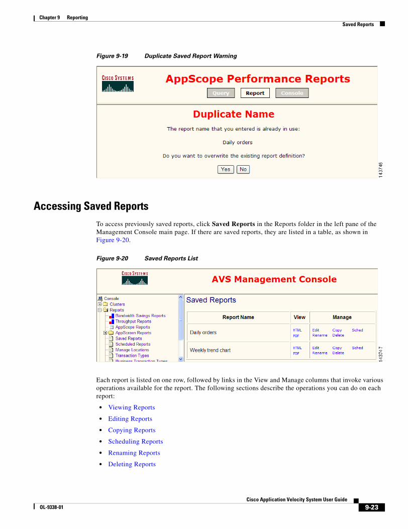
9-23Cisco Application Velocity System User Guide
OL-9338-01
Chapter 9 ReportingSaved Reports
Figure 9-19 Duplicate Saved Report Warning
Accessing Saved ReportsTo access previously saved reports, click Saved Reports in the Reports folder in the left pane of the Management Console main page. If there are saved reports, they are listed in a table, as shown in Figure 9-20.
Figure 9-20 Saved Reports List
Each report is listed on one row, followed by links in the View and Manage columns that invoke various operations available for the report. The following sections describe the operations you can do on each report:
• Viewing Reports
• Editing Reports
• Copying Reports
• Scheduling Reports
• Renaming Reports
• Deleting Reports

9-24Cisco Application Velocity System User Guide
OL-9338-01
Chapter 9 ReportingSaved Reports
Only authenticated (logged in) Management Console users can save and manage reports using the functions described in this section. However, any user with access to the server and port that is running the Management Console can view reports as long as they have a URL to view the saved report. This allows unauthenticated users to view reports that are sent to them as links in e-mail or saved as browser bookmarks.
Viewing Reports
You can view a saved report in HTML or PDF format by clicking either the HTML or PDF link in the View column. The report is regenerated when you click the link, so if it uses a relative starting date, the report data will be recalculated, relative to the moment that you clicked the link.
Editing Reports
You can edit the query for a saved report by clicking the Edit link in the Manage column. The report query page is displayed, with the selection criteria set to the original criteria used for the report. You can take these actions:
• View the criteria on the report query page, for example, to review the criteria if the report is not producing the expected data.
• Click the Report button in the top frame to regenerate the saved report, including the drilldown level, sorting, and charting that is defined in the report. You can then change the drilldown level, sorting, or charting, and then save the modified report by clicking the Save icon.
• Click the Submit button at the bottom of the query page to regenerate the report at the top level, without using any drilldown, sorting, or charting settings that may have been saved in the original report definition. After the report is displayed, you can drill down, resort, or chart the data. If desired, you can save the modified report by clicking the Save icon.
If you modify and then save an existing report, the name field of the Save dialog box is initialized with the existing name of the report. You can click OK to save the report under that name, overwriting the existing report, or you can change the name to a new name and click OK to create a new saved report. If you choose to overwrite the existing report with the same name, no warning is displayed.
Copying Reports
You can copy a report by clicking the Copy link. A Save dialog box is displayed where you can enter a name for the copy of the report. Click OK to save the copy, or click Cancel to cancel it. You will receive a warning message if you enter a report name that already exists.
Another way of making a copy of a report is to edit it, view the report, click the Save icon, and specify a new name for the copy.
Scheduling Reports
The scheduling feature allows you to define a periodic schedule at which a saved report is automatically generated, and then e-mailed to a distribution list.
You can schedule a report for regeneration at a future time by clicking the Sched link.

9-25Cisco Application Velocity System User Guide
OL-9338-01
Chapter 9 ReportingScheduled Reports
Note If the e-mail configuration for scheduled reports is not yet set up when you click this link, you must click the Scheduled Reports command to visit the Scheduled Reports page and click Email Configuration to set it up (see the “Configuring E-mail for Scheduling” section on page 9-32).
If there are one or more schedules already defined for the report, they are listed in the Report Schedule page, as shown in Figure 9-21.
Figure 9-21 Report Schedule Page
The saved report name is shown above the table. Each row in the table lists one schedule for the report. The schedule interval is shown, followed by the e-mail distribution list, and links that allow you to edit or delete the schedule. Use the Add Schedule link below the table to add a new schedule for the report.
For more information on adding, editing, and deleting scheduling reports, see the “Scheduled Reports” section on page 9-25.
Renaming Reports
You can rename a report by clicking the Rename link. A Save dialog box is displayed where you can enter a new name for the report. Click OK to change the name, or click Cancel to cancel it. You will receive a warning message if you enter a report name that already exists.
Deleting Reports
You can delete a saved report by clicking the Delete link. You are prompted with a dialog to confirm that you want to delete the report. Click OK to delete the report, or click Cancel to retain the report.
Scheduled ReportsThe AppScope scheduled reports feataure allows you to define a periodic schedule at which a saved report is automatically generated and then e-mailed to a distribution list.
Click the Scheduled Reports command (in the Reports folder in the left pane) to view a list of all saved reports, as shown in Figure 9-22. A report must be saved before it can be scheduled.
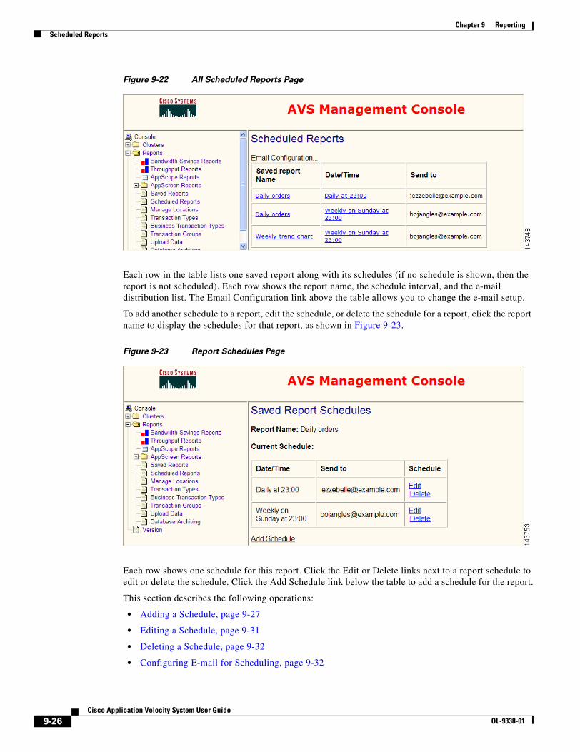
9-26Cisco Application Velocity System User Guide
OL-9338-01
Chapter 9 ReportingScheduled Reports
Figure 9-22 All Scheduled Reports Page
Each row in the table lists one saved report along with its schedules (if no schedule is shown, then the report is not scheduled). Each row shows the report name, the schedule interval, and the e-mail distribution list. The Email Configuration link above the table allows you to change the e-mail setup.
To add another schedule to a report, edit the schedule, or delete the schedule for a report, click the report name to display the schedules for that report, as shown in Figure 9-23.
Figure 9-23 Report Schedules Page
Each row shows one schedule for this report. Click the Edit or Delete links next to a report schedule to edit or delete the schedule. Click the Add Schedule link below the table to add a schedule for the report.
This section describes the following operations:
• Adding a Schedule, page 9-27
• Editing a Schedule, page 9-31
• Deleting a Schedule, page 9-32
• Configuring E-mail for Scheduling, page 9-32
9-27Cisco Application Velocity System User Guide
OL-9338-01
Chapter 9 ReportingScheduled Reports
Adding a ScheduleYou can add a schedule for a report by clicking the Add Schedule link below the schedule table. The schedule configuration page is displayed.
Initially, the Report Frequency is set to Weekly, which means that the schedule is for a weekly report. You can change this to one of the other choices for a repeating schedule: Daily, Monthly, or Yearly. The schedule configurator feature works differently in each case and is described in the following sections:
• Daily Schedule, page 9-27
• Weekly Schedule, page 9-28
• Monthly Schedule, page 9-29
• Yearly Schedule, page 9-30
Each version of the configurator allows you to choose the report type, which is common to all versions. These are the report type choices:
• Link to HTML—Inserts in the e-mail a link to an HTML report. When the user clicks the link, an interactive report is generated in which the user can click to drill down, sort, or show charts. However, if the report includes a lot of data, there may be a significant delay before the report is displayed. The data for the report usually is not available indefinitely. Depending on the archiving and maintenance policy for the database, older data is typically archived or purged, and may not be available if the user opens the e-mail and clicks the link only after some time. HTML reports are less suitable for printing than PDF reports.
• Link to PDF—Inserts in the e-mail a link to a PDF report. When the user clicks the link, the report is generated. It is not an interactive report, so no drill down, sorting, or charting is possible. If the report includes a lot of data, there may be a significant delay before the report is displayed. The data for the report usually is not available indefinitely. Depending on the archiving and maintenance policy for the database, older data is typically archived or purged, and may not be available if the user opens the e-mail and clicks the link only after some time. PDF is more suitable for printing than HTML.
• PDF Attachment—Attaches a PDF report to the e-mail. The report is generated when the scheduled task executes, so there is no waiting for the report to be generated when the e-mail attachment is opened. The report is self-contained and requires no server access (other than the e-mail server access required to initially retrieve the e-mail, just like any other e-mail the user receives). This option is more suitable for traveling users, laptops not connected to the network, and similar situations. PDF is more suitable for printing than HTML, but it is not interactive.
Daily Schedule
A Daily schedule generates the report every day. Figure 9-24 shows the daily configurator page.
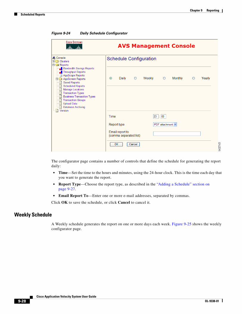
9-28Cisco Application Velocity System User Guide
OL-9338-01
Chapter 9 ReportingScheduled Reports
Figure 9-24 Daily Schedule Configurator
The configurator page contains a number of controls that define the schedule for generating the report daily:
• Time—Set the time to the hours and minutes, using the 24-hour clock. This is the time each day that you want to generate the report.
• Report Type—Choose the report type, as described in the “Adding a Schedule” section on page 9-27.
• Email Report To—Enter one or more e-mail addresses, separated by commas.
Click OK to save the schedule, or click Cancel to cancel it.
Weekly Schedule
A Weekly schedule generates the report on one or more days each week. Figure 9-25 shows the weekly configurator page.
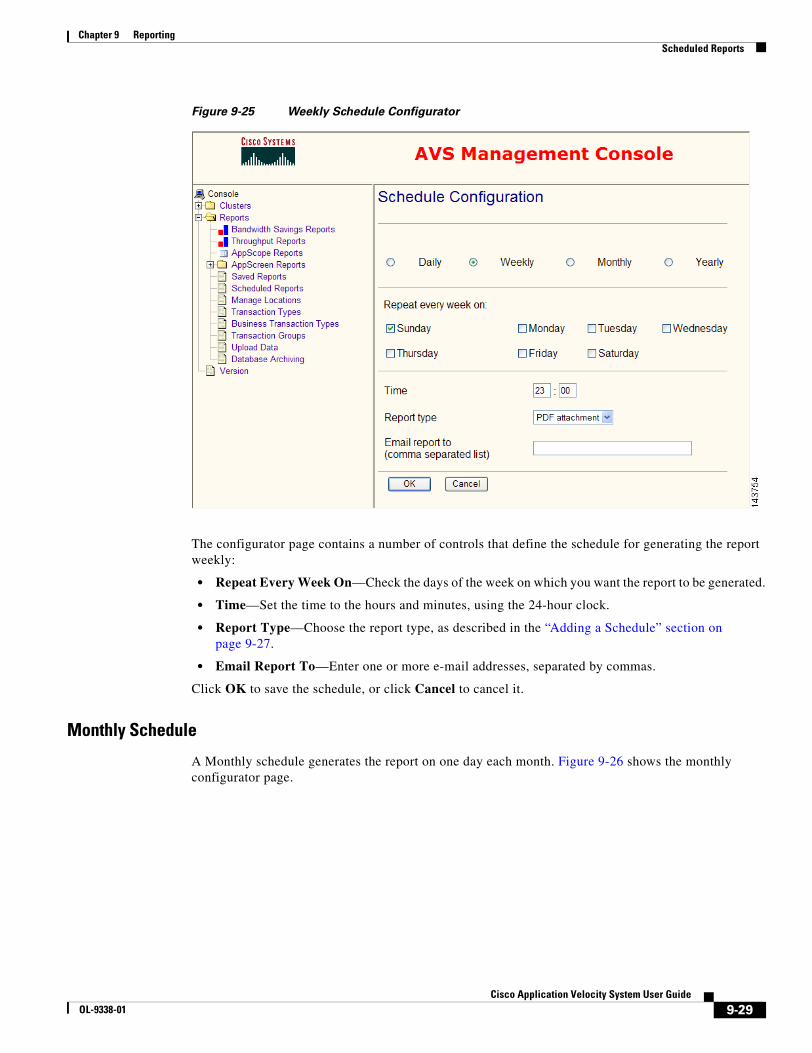
9-29Cisco Application Velocity System User Guide
OL-9338-01
Chapter 9 ReportingScheduled Reports
Figure 9-25 Weekly Schedule Configurator
The configurator page contains a number of controls that define the schedule for generating the report weekly:
• Repeat Every Week On—Check the days of the week on which you want the report to be generated.
• Time—Set the time to the hours and minutes, using the 24-hour clock.
• Report Type—Choose the report type, as described in the “Adding a Schedule” section on page 9-27.
• Email Report To—Enter one or more e-mail addresses, separated by commas.
Click OK to save the schedule, or click Cancel to cancel it.
Monthly Schedule
A Monthly schedule generates the report on one day each month. Figure 9-26 shows the monthly configurator page.
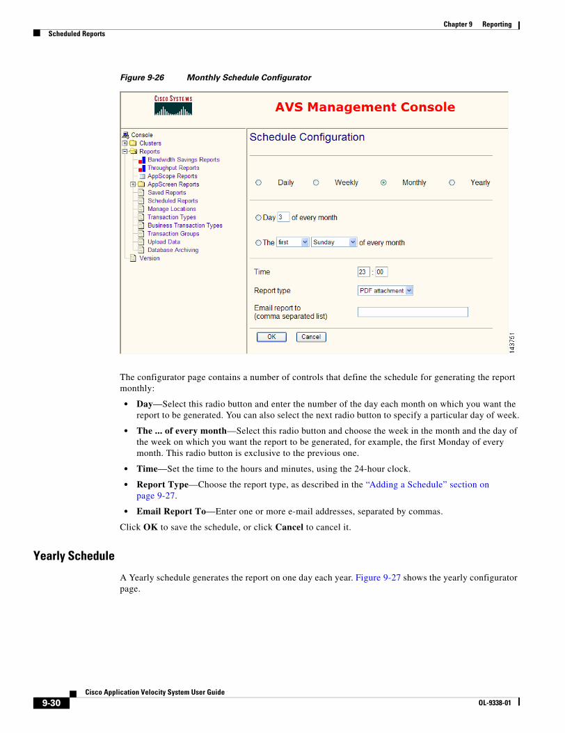
9-30Cisco Application Velocity System User Guide
OL-9338-01
Chapter 9 ReportingScheduled Reports
Figure 9-26 Monthly Schedule Configurator
The configurator page contains a number of controls that define the schedule for generating the report monthly:
• Day—Select this radio button and enter the number of the day each month on which you want the report to be generated. You can also select the next radio button to specify a particular day of week.
• The ... of every month—Select this radio button and choose the week in the month and the day of the week on which you want the report to be generated, for example, the first Monday of every month. This radio button is exclusive to the previous one.
• Time—Set the time to the hours and minutes, using the 24-hour clock.
• Report Type—Choose the report type, as described in the “Adding a Schedule” section on page 9-27.
• Email Report To—Enter one or more e-mail addresses, separated by commas.
Click OK to save the schedule, or click Cancel to cancel it.
Yearly Schedule
A Yearly schedule generates the report on one day each year. Figure 9-27 shows the yearly configurator page.
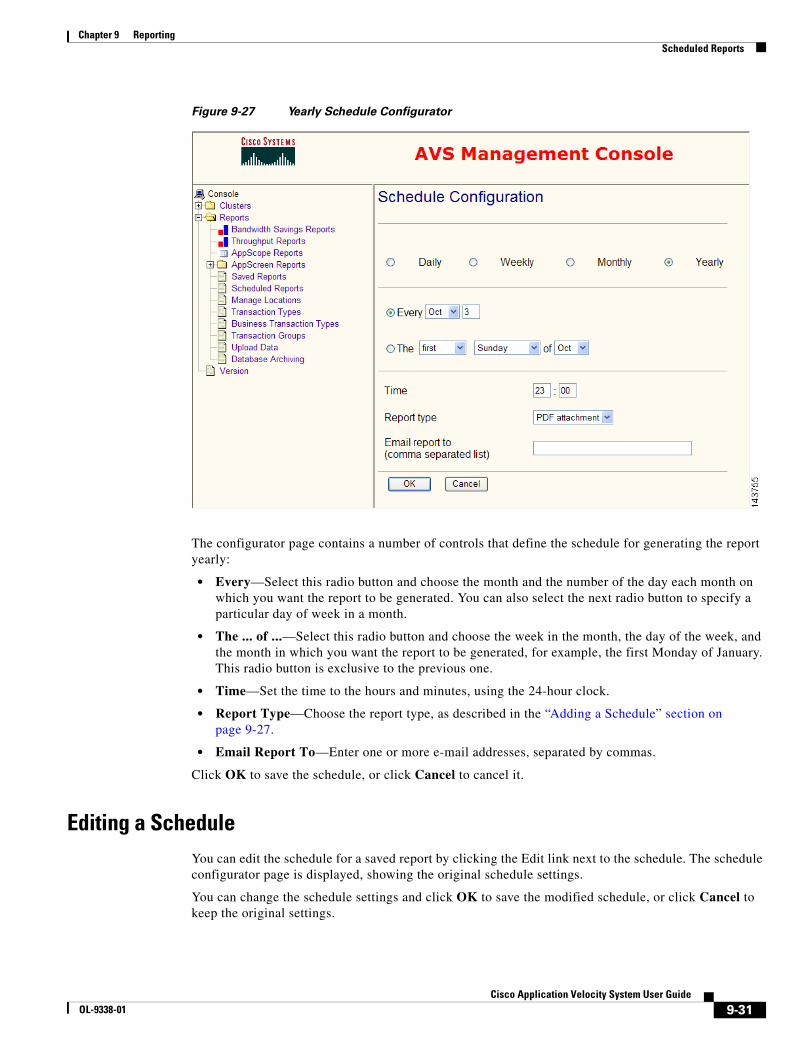
9-31Cisco Application Velocity System User Guide
OL-9338-01
Chapter 9 ReportingScheduled Reports
Figure 9-27 Yearly Schedule Configurator
The configurator page contains a number of controls that define the schedule for generating the report yearly:
• Every—Select this radio button and choose the month and the number of the day each month on which you want the report to be generated. You can also select the next radio button to specify a particular day of week in a month.
• The ... of ...—Select this radio button and choose the week in the month, the day of the week, and the month in which you want the report to be generated, for example, the first Monday of January. This radio button is exclusive to the previous one.
• Time—Set the time to the hours and minutes, using the 24-hour clock.
• Report Type—Choose the report type, as described in the “Adding a Schedule” section on page 9-27.
• Email Report To—Enter one or more e-mail addresses, separated by commas.
Click OK to save the schedule, or click Cancel to cancel it.
Editing a ScheduleYou can edit the schedule for a saved report by clicking the Edit link next to the schedule. The schedule configurator page is displayed, showing the original schedule settings.
You can change the schedule settings and click OK to save the modified schedule, or click Cancel to keep the original settings.

9-32Cisco Application Velocity System User Guide
OL-9338-01
Chapter 9 ReportingScheduled Reports
For details on using the schedule configurator for each type of schedule, see the “Adding a Schedule” section on page 9-27.
Deleting a ScheduleYou can delete a schedule for a report by clicking the Delete link next to the schedule. No confirmation message appears before the schedule is deleted.
Configuring E-mail for SchedulingThe e-mail configuration for scheduled reports must be set up before you can schedule any reports. To configure e-mail settings, click the Email Configuration link at the top of the Scheduled Reports page. The Email Configuration page is displayed as shown in Figure 9-28.
Figure 9-28 Email Configuration Page
The e-mail configuration page defines the e-mail account settings that are to be used for distributing scheduled reports by e-mail. The page includes the following fields:
9-33Cisco Application Velocity System User Guide
OL-9338-01
Chapter 9 ReportingManaging Locations
• Outgoing mail (SMTP) Server—Enter the name of the outgoing e-mail server to be used by the AppScope server to send out scheduled reports.
• Server port number—Enter the mail server port number.
• Server requires authentication—Check this box if the mail server requires an account name and password for access. Enter the account name and password in the fields that follow the check box.
• Send Test Message upon Submit—Check this box to send a test message using the information entered on this form when the form is submitted.
• Logon using: Account—Enter the user name for the e-mail account to be used by the AppScope server to send out scheduled reports. Leave this field blank if you have not checked the Server requires authentication box.
• Password—Enter the password for the e-mail account. Leave this field blank if you have not checked the Server requires authentication box.
• From name—Enter the name to be shown in the From field on the e-mail.
• From address—Enter the e-mail address to be shown in the Return address field on the e-mail.
• Subject template—Enter the e-mail subject to be shown in the Subject field on the e-mail. You can use the expressions %%reportname%%, which is replaced with the actual report name, or %%reportlink%%, which is replaced with a hypertext link to the report.
• Email Report Link URL Prefix—Enter the URL prefix (including the port number) for report links used in the e-mail. This field is initialized automatically to the local URL of the Management Console, but you can override it if needed. To check that this field is set correctly, be sure to send yourself a test scheduled report and click the report link to make sure it works.
• Body template—Enter the body of the e-mail. You can use the expressions %%reportname%% or %%reportlink%% here as well.
Click OK to save the e-mail settings, or Cancel to cancel the operation.
Managing LocationsThe Manage Locations command defines and manages locations. A location is a named range of source IP addresses. Locations can be used in AppScope reports to easily group results from particular IP address blocks.
Click this command to display a page showing a list of defined locations, where you can delete existing locations and define new ones, as shown in Figure 9-29.
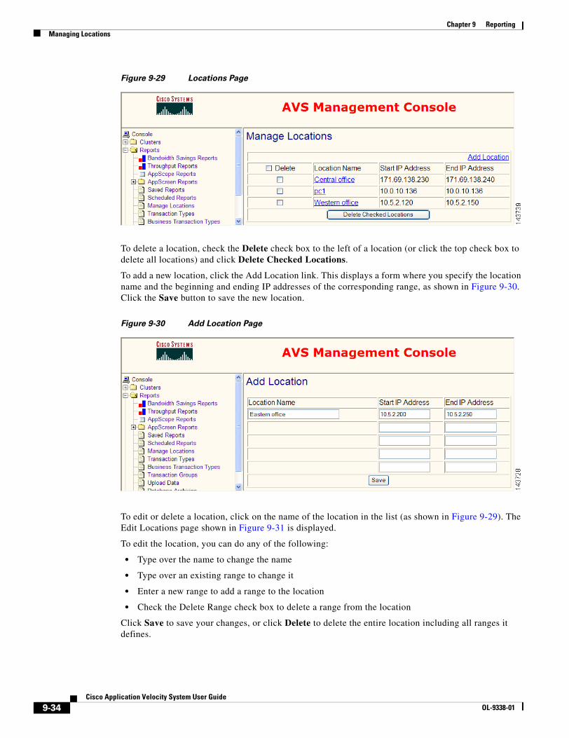
9-34Cisco Application Velocity System User Guide
OL-9338-01
Chapter 9 ReportingManaging Locations
Figure 9-29 Locations Page
To delete a location, check the Delete check box to the left of a location (or click the top check box to delete all locations) and click Delete Checked Locations.
To add a new location, click the Add Location link. This displays a form where you specify the location name and the beginning and ending IP addresses of the corresponding range, as shown in Figure 9-30. Click the Save button to save the new location.
Figure 9-30 Add Location Page
To edit or delete a location, click on the name of the location in the list (as shown in Figure 9-29). The Edit Locations page shown in Figure 9-31 is displayed.
To edit the location, you can do any of the following:
• Type over the name to change the name
• Type over an existing range to change it
• Enter a new range to add a range to the location
• Check the Delete Range check box to delete a range from the location
Click Save to save your changes, or click Delete to delete the entire location including all ranges it defines.
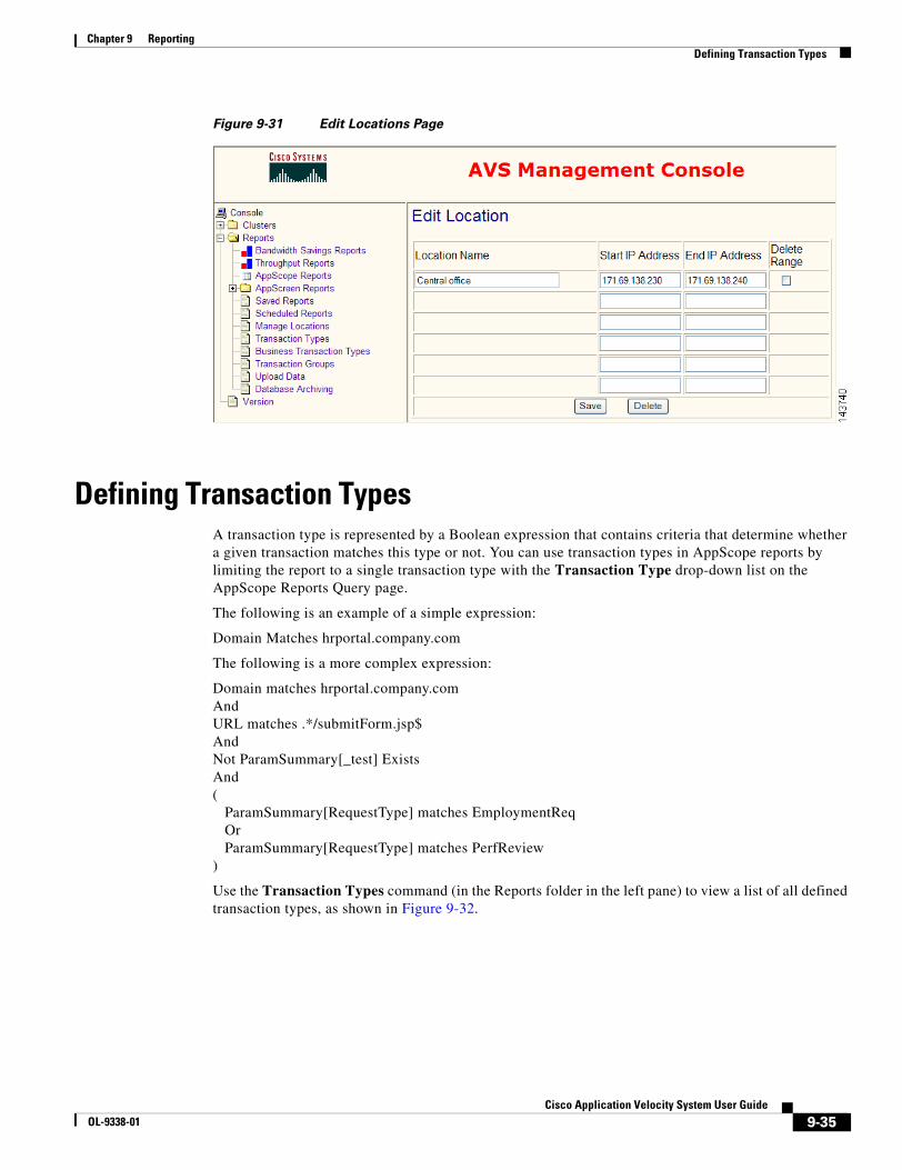
9-35Cisco Application Velocity System User Guide
OL-9338-01
Chapter 9 ReportingDefining Transaction Types
Figure 9-31 Edit Locations Page
Defining Transaction TypesA transaction type is represented by a Boolean expression that contains criteria that determine whether a given transaction matches this type or not. You can use transaction types in AppScope reports by limiting the report to a single transaction type with the Transaction Type drop-down list on the AppScope Reports Query page.
The following is an example of a simple expression:
Domain Matches hrportal.company.com
The following is a more complex expression:
Domain matches hrportal.company.comAndURL matches .*/submitForm.jsp$AndNot ParamSummary[_test] ExistsAnd(
ParamSummary[RequestType] matches EmploymentReqOrParamSummary[RequestType] matches PerfReview
)
Use the Transaction Types command (in the Reports folder in the left pane) to view a list of all defined transaction types, as shown in Figure 9-32.
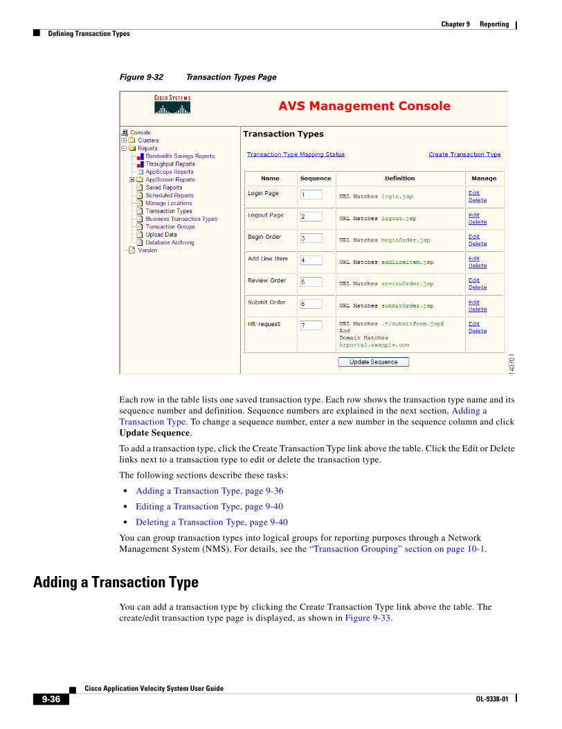
9-36Cisco Application Velocity System User Guide
OL-9338-01
Chapter 9 ReportingDefining Transaction Types
Figure 9-32 Transaction Types Page
Each row in the table lists one saved transaction type. Each row shows the transaction type name and its sequence number and definition. Sequence numbers are explained in the next section, Adding a Transaction Type. To change a sequence number, enter a new number in the sequence column and click Update Sequence.
To add a transaction type, click the Create Transaction Type link above the table. Click the Edit or Delete links next to a transaction type to edit or delete the transaction type.
The following sections describe these tasks:
• Adding a Transaction Type, page 9-36
• Editing a Transaction Type, page 9-40
• Deleting a Transaction Type, page 9-40
You can group transaction types into logical groups for reporting purposes through a Network Management System (NMS). For details, see the “Transaction Grouping” section on page 10-1.
Adding a Transaction TypeYou can add a transaction type by clicking the Create Transaction Type link above the table. The create/edit transaction type page is displayed, as shown in Figure 9-33.
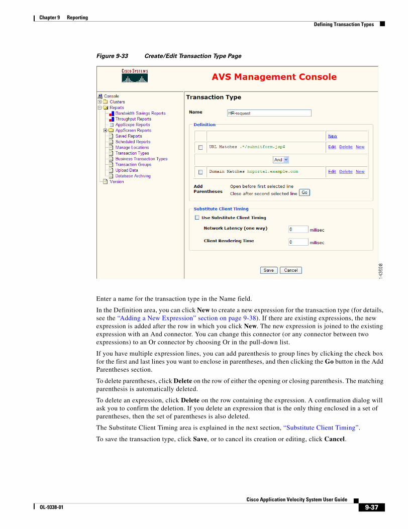
9-37Cisco Application Velocity System User Guide
OL-9338-01
Chapter 9 ReportingDefining Transaction Types
Figure 9-33 Create/Edit Transaction Type Page
Enter a name for the transaction type in the Name field.
In the Definition area, you can click New to create a new expression for the transaction type (for details, see the “Adding a New Expression” section on page 9-38). If there are existing expressions, the new expression is added after the row in which you click New. The new expression is joined to the existing expression with an And connector. You can change this connector (or any connector between two expressions) to an Or connector by choosing Or in the pull-down list.
If you have multiple expression lines, you can add parenthesis to group lines by clicking the check box for the first and last lines you want to enclose in parentheses, and then clicking the Go button in the Add Parentheses section.
To delete parentheses, click Delete on the row of either the opening or closing parenthesis. The matching parenthesis is automatically deleted.
To delete an expression, click Delete on the row containing the expression. A confirmation dialog will ask you to confirm the deletion. If you delete an expression that is the only thing enclosed in a set of parentheses, then the set of parentheses is also deleted.
The Substitute Client Timing area is explained in the next section, “Substitute Client Timing”.
To save the transaction type, click Save, or to cancel its creation or editing, click Cancel.
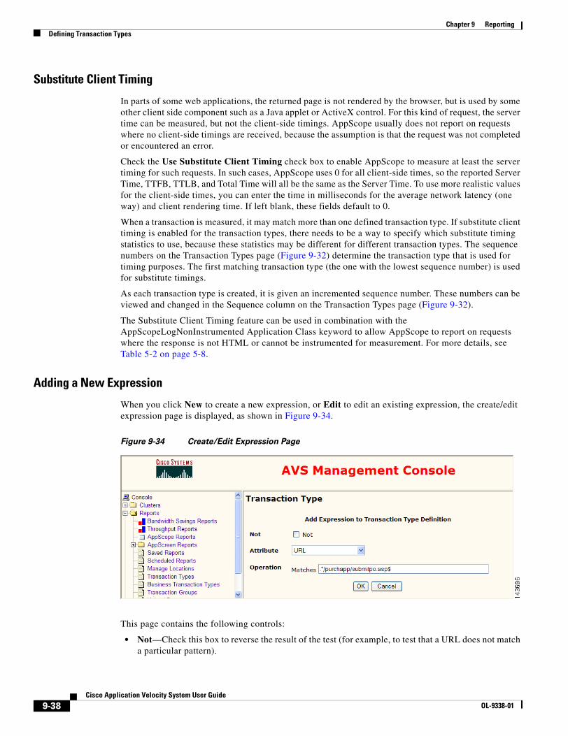
9-38Cisco Application Velocity System User Guide
OL-9338-01
Chapter 9 ReportingDefining Transaction Types
Substitute Client Timing
In parts of some web applications, the returned page is not rendered by the browser, but is used by some other client side component such as a Java applet or ActiveX control. For this kind of request, the server time can be measured, but not the client-side timings. AppScope usually does not report on requests where no client-side timings are received, because the assumption is that the request was not completed or encountered an error.
Check the Use Substitute Client Timing check box to enable AppScope to measure at least the server timing for such requests. In such cases, AppScope uses 0 for all client-side times, so the reported Server Time, TTFB, TTLB, and Total Time will all be the same as the Server Time. To use more realistic values for the client-side times, you can enter the time in milliseconds for the average network latency (one way) and client rendering time. If left blank, these fields default to 0.
When a transaction is measured, it may match more than one defined transaction type. If substitute client timing is enabled for the transaction types, there needs to be a way to specify which substitute timing statistics to use, because these statistics may be different for different transaction types. The sequence numbers on the Transaction Types page (Figure 9-32) determine the transaction type that is used for timing purposes. The first matching transaction type (the one with the lowest sequence number) is used for substitute timings.
As each transaction type is created, it is given an incremented sequence number. These numbers can be viewed and changed in the Sequence column on the Transaction Types page (Figure 9-32).
The Substitute Client Timing feature can be used in combination with the AppScopeLogNonInstrumented Application Class keyword to allow AppScope to report on requests where the response is not HTML or cannot be instrumented for measurement. For more details, see Table 5-2 on page 5-8.
Adding a New Expression
When you click New to create a new expression, or Edit to edit an existing expression, the create/edit expression page is displayed, as shown in Figure 9-34.
Figure 9-34 Create/Edit Expression Page
This page contains the following controls:
• Not—Check this box to reverse the result of the test (for example, to test that a URL does not match a particular pattern).
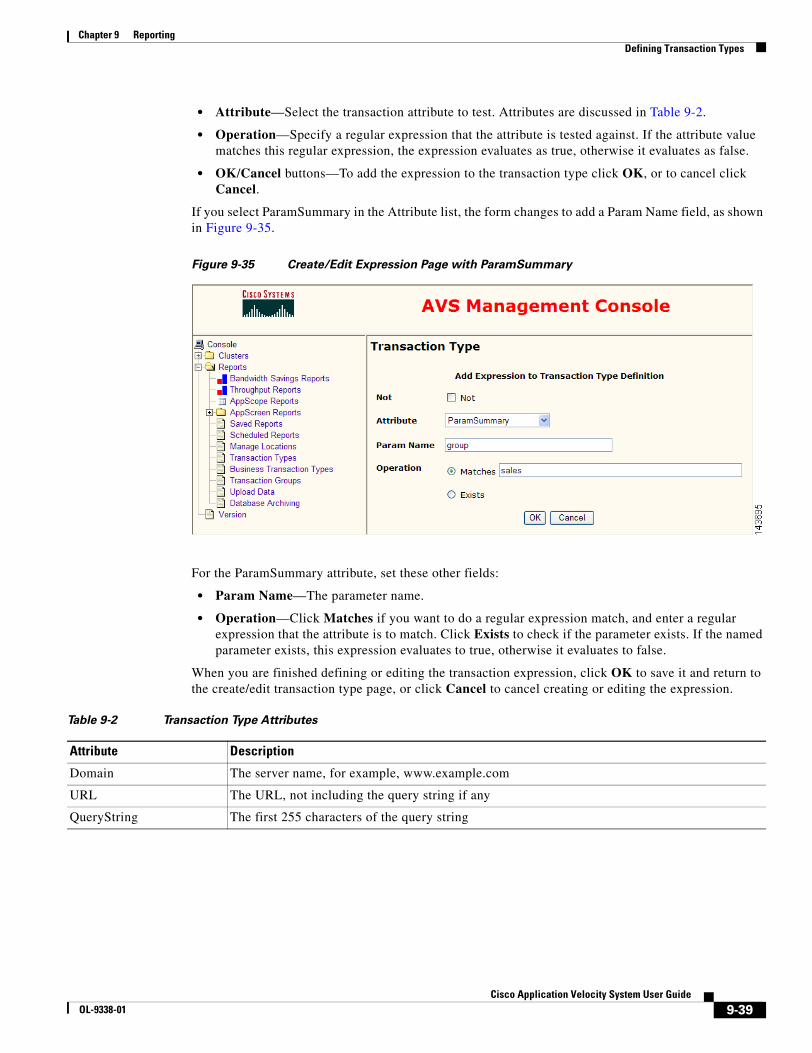
9-39Cisco Application Velocity System User Guide
OL-9338-01
Chapter 9 ReportingDefining Transaction Types
• Attribute—Select the transaction attribute to test. Attributes are discussed in Table 9-2.
• Operation—Specify a regular expression that the attribute is tested against. If the attribute value matches this regular expression, the expression evaluates as true, otherwise it evaluates as false.
• OK/Cancel buttons—To add the expression to the transaction type click OK, or to cancel click Cancel.
If you select ParamSummary in the Attribute list, the form changes to add a Param Name field, as shown in Figure 9-35.
Figure 9-35 Create/Edit Expression Page with ParamSummary
For the ParamSummary attribute, set these other fields:
• Param Name—The parameter name.
• Operation—Click Matches if you want to do a regular expression match, and enter a regular expression that the attribute is to match. Click Exists to check if the parameter exists. If the named parameter exists, this expression evaluates to true, otherwise it evaluates to false.
When you are finished defining or editing the transaction expression, click OK to save it and return to the create/edit transaction type page, or click Cancel to cancel creating or editing the expression.
Table 9-2 Transaction Type Attributes
Attribute Description
Domain The server name, for example, www.example.com
URL The URL, not including the query string if any
QueryString The first 255 characters of the query string
9-40Cisco Application Velocity System User Guide
OL-9338-01
Chapter 9 ReportingDefining Transaction Types
The ParamSummary and QueryString attributes contain similar data, but each has its advantages and disadvantages:
• The QueryString contains only the first 255 characters of the query string, so depending on the length of the query string, it might not contain all of the parameters.
• The ParamSummary contains all of the parameter names (strictly speaking, it contains all of those that appear within the first 40 KB of the posted data), but it includes only the first 100 characters of each parameter value.
• For a GET query, the QueryString and ParamSummary contain the same data (except for possible truncation due to the character length limits mentioned above).
• For a POST query, the QueryString does not contain any of the POST data, but the ParamSummary contains the POST parameter names and the first 100 characters of each parameter value.
Editing a Transaction TypeYou can edit a transaction type by clicking the Edit link on the same row as the expression. The create/edit transaction type page is displayed, as shown in Figure 9-33. The process for editing a transaction type is exactly the same as described in the “Adding a Transaction Type” section on page 9-36.
Deleting a Transaction TypeYou can delete a transaction type by clicking the Delete link on the same row as the expression. A confirmation dialog will ask you to confirm the deletion.
You cannot delete a transaction type that is used in a business transaction unless it is removed from the business transaction or the business transaction is deleted.
ParamSummary A summary of all the query parameters in the request, including the full text of each parameter name and the first 100 bytes of each parameter value. The number of bytes is configurable by the ParamSummaryParamValueLimit value in the fgn.conf file. For more details, see Table 5-2 on page 5-8.
The ParamSummary attribute is indexed by the parameter name; for example, the expression ParamSummary[UserAction] returns the value of the UserAction parameter.
The parameter can be very large during a browser POST, so the scan for parameters is limited to the first 40 KB of posted data, by default. You can change this limit by using the PostContentBufferLimit keyword in the fgn.conf file. For more details see Table 5-2 on page 5-8.
The ParamSummary attribute is not available by default and must be enabled by the ParamSummary keyword in the fgn.conf file. For more details see Table 5-2 on page 5-8.
ApplicationClass Allows the Application Class of a request to be used to determine its transaction type.
RequestGroupingString Allows the request grouping string of a request to be used to determine its transaction type. The request grouping string is defined by the RequestGroupingString keyword. For more details see Table 5-1 on page 5-2.
Table 9-2 Transaction Type Attributes (continued)
Attribute Description

9-41Cisco Application Velocity System User Guide
OL-9338-01
Chapter 9 ReportingDefining Transaction Types
Managing Transaction Type MappingAt the time each transaction is recorded in the database, AppScope determines its transaction types and stores them in the database. This is known as the mapping between transactions and defined transaction types. When a query is executed using the transaction type filter, the stored transaction type mappings are used to determine which results to display. For information on using transaction types in queries, see the Transaction Type drop-down list in the “Defining the Query” section on page 9-13.
Because you can update the transaction type definitions at any time, some of the mappings in the database may become obsolete. There are two ways to deal with this situation:
• If you only want to categorize new data, you do not need to take any further action. New transactions are automatically categorized using the new transaction type definitions.
• If you want to recategorize existing data using the new transaction type definitions, then you must use the Transaction Type Mapping Status page to instruct AppScope to update the mappings.
To reach the Transaction Type Mapping Status page, use the Transaction Types command (in the Reports folder in the left pane). Click on the Transaction Type Mapping Status link in the upper left of the page to display the page shown in Figure 9-36.
Figure 9-36 Transaction Type Mapping Status Page
In the figure, you can see that the current transaction type version number is 61. There are a total of 34490 transactions in the database. None of the transaction type mappings are current because their transaction type version is 41 or 0.
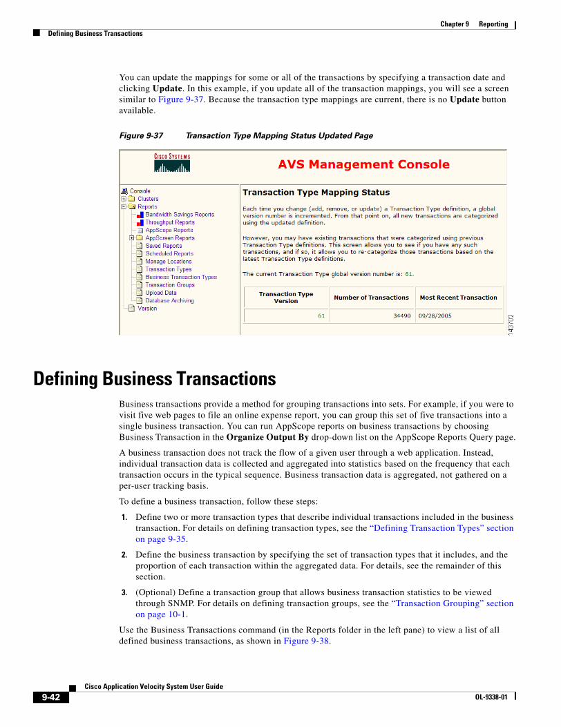
9-42Cisco Application Velocity System User Guide
OL-9338-01
Chapter 9 ReportingDefining Business Transactions
You can update the mappings for some or all of the transactions by specifying a transaction date and clicking Update. In this example, if you update all of the transaction mappings, you will see a screen similar to Figure 9-37. Because the transaction type mappings are current, there is no Update button available.
Figure 9-37 Transaction Type Mapping Status Updated Page
Defining Business TransactionsBusiness transactions provide a method for grouping transactions into sets. For example, if you were to visit five web pages to file an online expense report, you can group this set of five transactions into a single business transaction. You can run AppScope reports on business transactions by choosing Business Transaction in the Organize Output By drop-down list on the AppScope Reports Query page.
A business transaction does not track the flow of a given user through a web application. Instead, individual transaction data is collected and aggregated into statistics based on the frequency that each transaction occurs in the typical sequence. Business transaction data is aggregated, not gathered on a per-user tracking basis.
To define a business transaction, follow these steps:
1. Define two or more transaction types that describe individual transactions included in the business transaction. For details on defining transaction types, see the “Defining Transaction Types” section on page 9-35.
2. Define the business transaction by specifying the set of transaction types that it includes, and the proportion of each transaction within the aggregated data. For details, see the remainder of this section.
3. (Optional) Define a transaction group that allows business transaction statistics to be viewed through SNMP. For details on defining transaction groups, see the “Transaction Grouping” section on page 10-1.
Use the Business Transactions command (in the Reports folder in the left pane) to view a list of all defined business transactions, as shown in Figure 9-38.
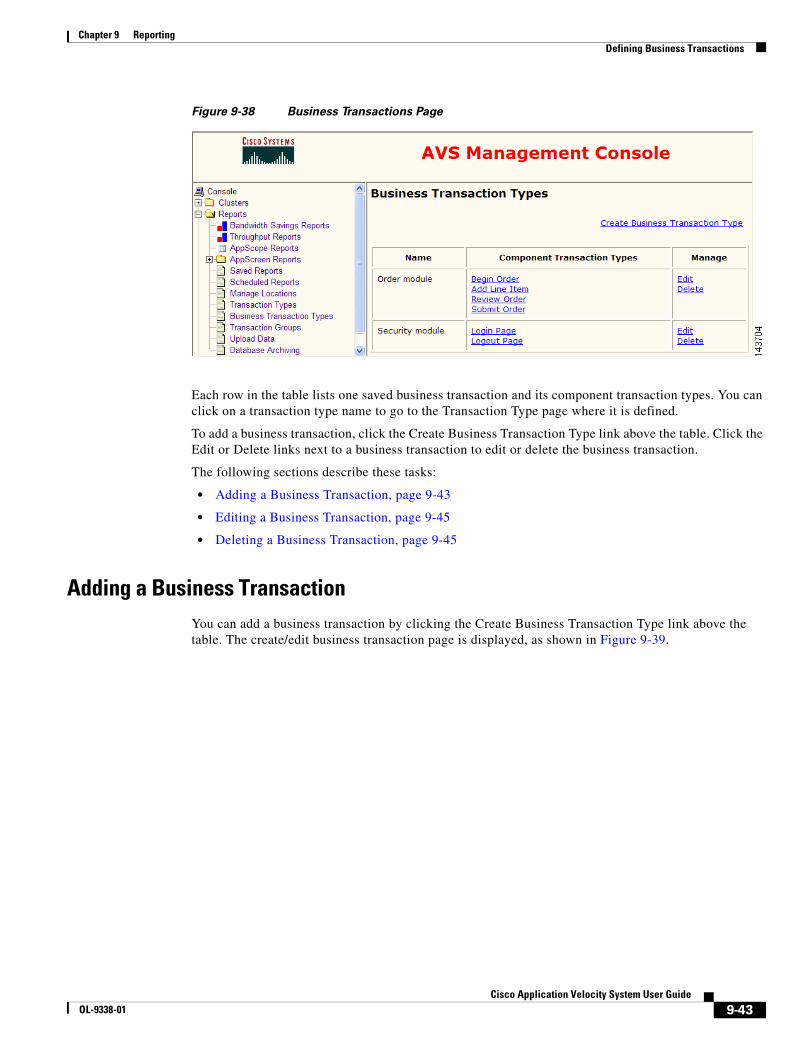
9-43Cisco Application Velocity System User Guide
OL-9338-01
Chapter 9 ReportingDefining Business Transactions
Figure 9-38 Business Transactions Page
Each row in the table lists one saved business transaction and its component transaction types. You can click on a transaction type name to go to the Transaction Type page where it is defined.
To add a business transaction, click the Create Business Transaction Type link above the table. Click the Edit or Delete links next to a business transaction to edit or delete the business transaction.
The following sections describe these tasks:
• Adding a Business Transaction, page 9-43
• Editing a Business Transaction, page 9-45
• Deleting a Business Transaction, page 9-45
Adding a Business TransactionYou can add a business transaction by clicking the Create Business Transaction Type link above the table. The create/edit business transaction page is displayed, as shown in Figure 9-39.

9-44Cisco Application Velocity System User Guide
OL-9338-01
Chapter 9 ReportingDefining Business Transactions
Figure 9-39 Create/Edit Business Transaction Page
In the Available Transaction Types area, choose the transaction types that you want to include in the business transaction. Click to select a single entry in the list, Shift-click to select a range of entries, or Ctrl-click to select disjoint entries. You can also use the Select All or Select None buttons. When you have selected the desired transaction types, click Add Selected Types to Business Transaction. (The figure shows that two transaction types have already been added to the business transaction.)
In the Business Transaction Definition area, enter a name for the business transaction in the Name field. This name must be unique among both business transactions and transaction types.
In the Component Transaction Frequency area, select the appropriate radio button for how the frequency of a transaction is to be computed:
• Choose Use actual frequency to compute the frequency based on the actual data of how many times a transaction occurs within a business transaction.
• Choose Use specified frequency to compute the frequency from numbers you enter. Enter the frequencies in the Component Transaction Types area. You might want to select this option in the following cases:
– A transaction is used in some other context outside the given business transaction.
– The frequency of a transaction is known or is expected to fluctuate over time. If it fluctuates, this allows you to do equivalent comparisons over time.
The Component Transaction Types area allows you to enter frequency information and reorder the transactions.
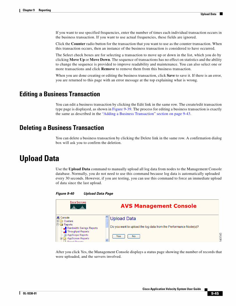
9-45Cisco Application Velocity System User Guide
OL-9338-01
Chapter 9 ReportingUpload Data
If you want to use specified frequencies, enter the number of times each individual transaction occurs in the business transaction. If you want to use actual frequencies, these fields are ignored.
Click the Counter radio button for the transaction that you want to use as the counter transaction. When this transaction occurs, then an instance of the business transaction is considered to have occurred.
The Select check boxes are for selecting a transaction to move up or down in the list, which you do by clicking Move Up or Move Down. The sequence of transactions has no effect on statistics and the ability to change the sequence is provided to improve readability and maintenance. You can also select one or more transactions and click Remove to remove them from this business transaction.
When you are done creating or editing the business transaction, click Save to save it. If there is an error, you are returned to this page with an error message at the top explaining what is wrong.
Editing a Business TransactionYou can edit a business transaction by clicking the Edit link in the same row. The create/edit transaction type page is displayed, as shown in Figure 9-39. The process for editing a business transaction is exactly the same as described in the “Adding a Business Transaction” section on page 9-43.
Deleting a Business TransactionYou can delete a business transaction by clicking the Delete link in the same row. A confirmation dialog box will ask you to confirm the deletion.
Upload DataUse the Upload Data command to manually upload all log data from nodes to the Management Console database. Normally, you do not need to use this command because log data is automatically uploaded every 30 seconds. However, if you are testing, you can use this command to force an immediate upload of data since the last upload.
Figure 9-40 Upload Data Page
After you click Yes, the Management Console displays a status page showing the number of records that were uploaded, and the servers involved.

9-46Cisco Application Velocity System User Guide
OL-9338-01
Chapter 9 ReportingUpload Data

C H A P T E R
10-1Cisco Application Velocity System User Guide
OL-9338-01
10NMS Integration
The application appliance includes a Network Management System (NMS) integration feature that makes the AppScope performance data available to an NMS through SNMP MIBs. This feature allows an administrator at a NMS console to identify and investigate performance issues.
Note If you have installed only a Cisco AVS 3120 Application Velocity System, NMS integration and reporting features are not available and you will not see a Reports folder in the menu at the left side of the Management Console window. You must be running the Management Console on a Cisco AVS 3180 Management Station in order to see the Report items in the Management Console.
This chapter describes the NMS integration features and the user interface via which you manage it.
• Transaction Grouping, page 10-1
• Data Lifecycle, page 10-5
• MIB Data Elements, page 10-5
• SNMP Data Access, page 10-6
Transaction GroupingAppScope collects statistics for each transaction that it measures. You can use the NMS feature to get a global summary of the statistics for all transactions. However, it is generally more useful to collect and display statistics based on some logical grouping of transactions.
A transaction group is a set of transactions whose statistics will be collected and grouped together for reporting and analysis. A transaction group can be based either on transaction types or on business transactions, but not on a mixture of the two.
A transaction group based on transaction types is defined by specifying the transaction type and source location of the transactions. Such a transaction group definition can include zero or more transaction types, and zero or more source locations. A transaction group based on business transactions is defined in a similar way, but with business transactions instead of transaction types. Table 10-1 shows examples of transaction groups.
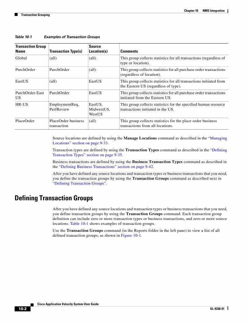
10-2Cisco Application Velocity System User Guide
OL-9338-01
Chapter 10 NMS IntegrationTransaction Grouping
Source locations are defined by using the Manage Locations command as described in the “Managing Locations” section on page 9-33.
Transaction types are defined by using the Transaction Types command as described in the “Defining Transaction Types” section on page 9-35.
Business transactions are defined by using the Business Transaction Types command as described in the “Defining Business Transactions” section on page 9-42.
After you have defined any source locations and transaction types or business transactions that you need, you define the transaction groups by using the Transaction Groups command as described next in “Defining Transaction Groups”.
Defining Transaction GroupsAfter you have defined any source locations and transaction types or business transactions that you need, you define transaction groups by using the Transaction Groups command. Each transaction group definition can include zero or more transaction types or business transactions, and zero or more source locations. Table 10-1 shows examples of transaction groups.
Use the Transaction Groups command (in the Reports folder in the left pane) to view a list of all defined transaction groups, as shown in Figure 10-1.
Table 10-1 Examples of Transaction Groups
Transaction Group Name Transaction Type(s)
Source Location(s) Comments
Global (all) (all) This group collects statistics for all transactions (regardless of type or location).
PurchOrder PurchOrder (all) This group collects statistics for all purchase order transactions (regardless of location).
EastUS (all) EastUS This group collects statistics for all transactions initiated from the Eastern US (regardless of type).
PurchOrder-EastUS
PurchOrder EastUS This group collects statistics for all purchase order transactions initiated from the Eastern US.
HR-US EmploymentReq, PerfReview
EastUS, MidwestUS, WestUS
This group collects statistics for the specified human resource transactions initiated in the US.
PlaceOrder PlaceOrder business transaction
(all) This group collects statistics for the place order business transactions from all locations.
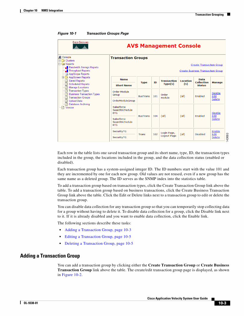
10-3Cisco Application Velocity System User Guide
OL-9338-01
Chapter 10 NMS IntegrationTransaction Grouping
Figure 10-1 Transaction Groups Page
Each row in the table lists one saved transaction group and its short name, type, ID, the transaction types included in the group, the locations included in the group, and the data collection status (enabled or disabled).
Each transaction group has a system-assigned integer ID. The ID numbers start with the value 101 and they are incremented by one for each new group. Old values are not reused, even if a new group has the same name as a deleted group. The ID serves as the SNMP index into the statistics table.
To add a transaction group based on transaction types, click the Create Transaction Group link above the table. To add a transaction group based on business transactions, click the Create Business Transaction Group link above the table. Click the Edit or Delete links next to a transaction group to edit or delete the transaction group.
You can disable data collection for any transaction group so that you can temporarily stop collecting data for a group without having to delete it. To disable data collection for a group, click the Disable link next to it. If it is already disabled and you want to enable data collection, click the Enable link.
The following sections describe these tasks:
• Adding a Transaction Group, page 10-3
• Editing a Transaction Group, page 10-5
• Deleting a Transaction Group, page 10-5
Adding a Transaction Group
You can add a transaction group by clicking either the Create Transaction Group or Create Business Transaction Group link above the table. The create/edit transaction group page is displayed, as shown in Figure 10-2.
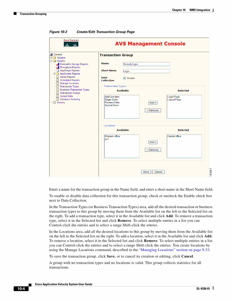
10-4Cisco Application Velocity System User Guide
OL-9338-01
Chapter 10 NMS IntegrationTransaction Grouping
Figure 10-2 Create/Edit Transaction Group Page
Enter a name for the transaction group in the Name field, and enter a short name in the Short Name field.
To enable or disable data collection for this transaction group, check or uncheck the Enable check box next to Data Collection.
In the Transaction Types (or Business Transaction Types) area, add all the desired transaction or business transaction types to this group by moving them from the Available list on the left to the Selected list on the right. To add a transaction type, select it in the Available list and click Add. To remove a transaction type, select it in the Selected list and click Remove. To select multiple entries in a list you can Control-click the entries and to select a range Shift-click the entries.
In the Locations area, add all the desired locations to this group by moving them from the Available list on the left to the Selected list on the right. To add a location, select it in the Available list and click Add. To remove a location, select it in the Selected list and click Remove. To select multiple entries in a list you can Control-click the entries and to select a range Shift-click the entries. You create locations by using the Manage Locations command, described in the “Managing Locations” section on page 9-33.
To save the transaction group, click Save, or to cancel its creation or editing, click Cancel.
A group with no transaction types and no locations is valid. This group collects statistics for all transactions.
10-5Cisco Application Velocity System User Guide
OL-9338-01
Chapter 10 NMS IntegrationData Lifecycle
Editing a Transaction Group
You can edit a transaction group by clicking the Edit link on the same row. The create/edit transaction group page is displayed, as shown in Figure 10-2. The process for editing a transaction group is exactly the same as described in the “Adding a Transaction Group” section on page 10-3.
Deleting a Transaction Group
You can delete a transaction group by clicking the Delete link on the same row. A confirmation dialog will ask you to confirm the deletion.
Data LifecycleThe AppScope SNMP agent has a data aggregator that collects the AppScope transaction type statistics every 5 minutes and collects the business transaction statistics every 60 minutes by default. These intervals can be changed by editing the following parameters in the console.properties file:
• NMS_AGGREGATION_DURATION_IN_MINS=5
• NMS_BT_AGGREGATION_DURATION_IN_MINS=60
The default location of this file is: $AVS_HOME/console/jboss-3.0.1_tomcat-4.0.4/server/default/deploy/condenser-mbeans.sar/properties/console.properties.
The Management Console needs to be restarted after making any changes. If you upgraded the product from a previous version, the NMS_BT_AGGREGATION_DURATION_IN_MINS parameter might not exist in this file, and you can change the value by adding it.
When the user issues an SNMP Get query (for example, through an NMS Manager such as HP OpenView), the AppScope SNMP agent returns transaction type statistics for the immediately preceding 5 minutes. This aggregation duration can be adjusted. However, the aggregation duration must be equal to or greater than the collection interval.
As each collection interval goes by, the most recent statistics are collected and stored in the data aggregator, and the least recent statistics are dropped. Using an SNMP Get query, the client application can retrieve the statistics for only the most recent aggregation duration number of minutes. For example, the client cannot ask for data from an earlier time, or data for a longer duration.
If you want to save and access historical SNMP data, you can use one of these methods:
• An NMS Manager that supports Data Collection (for example, HP OpenView)
• A utility program that supports Data Collection (for example, RRDTool)
The same statistical data that is available through SNMP also is stored in the AppScope database for longer-term access using AppScope reports, or any database or reporting tool that you would like to use.
MIB Data ElementsThe following data points are collected for each defined transaction group:
• Transaction Group ID—A unique, system-generated number that uniquely identifies the transaction group. This number is the SNMP index for the statistics table.
• Transaction Group Name—The user-defined name.
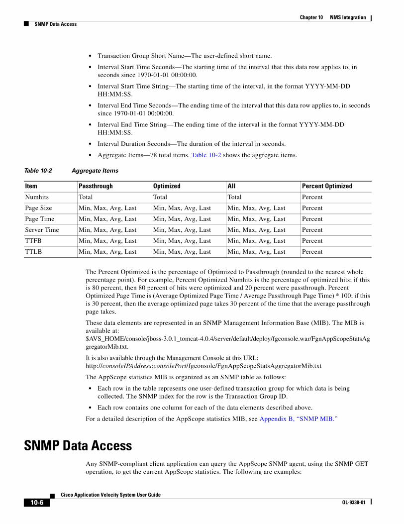
10-6Cisco Application Velocity System User Guide
OL-9338-01
Chapter 10 NMS IntegrationSNMP Data Access
• Transaction Group Short Name—The user-defined short name.
• Interval Start Time Seconds—The starting time of the interval that this data row applies to, in seconds since 1970-01-01 00:00:00.
• Interval Start Time String—The starting time of the interval, in the format YYYY-MM-DD HH:MM:SS.
• Interval End Time Seconds—The ending time of the interval that this data row applies to, in seconds since 1970-01-01 00:00:00.
• Interval End Time String—The ending time of the interval in the format YYYY-MM-DD HH:MM:SS.
• Interval Duration Seconds—The duration of the interval in seconds.
• Aggregate Items—78 total items. Table 10-2 shows the aggregate items.
The Percent Optimized is the percentage of Optimized to Passthrough (rounded to the nearest whole percentage point). For example, Percent Optimized Numhits is the percentage of optimized hits; if this is 80 percent, then 80 percent of hits were optimized and 20 percent were passthrough. Percent Optimized Page Time is (Average Optimized Page Time / Average Passthrough Page Time) * 100; if this is 30 percent, then the average optimized page takes 30 percent of the time that the average passthrough page takes.
These data elements are represented in an SNMP Management Information Base (MIB). The MIB is available at: $AVS_HOME/console/jboss-3.0.1_tomcat-4.0.4/server/default/deploy/fgconsole.war/FgnAppScopeStatsAggregatorMib.txt.
It is also available through the Management Console at this URL: http://consoleIPAddress:consolePort/fgconsole/FgnAppScopeStatsAggregatorMib.txt
The AppScope statistics MIB is organized as an SNMP table as follows:
• Each row in the table represents one user-defined transaction group for which data is being collected. The SNMP index for the row is the Transaction Group ID.
• Each row contains one column for each of the data elements described above.
For a detailed description of the AppScope statistics MIB, see Appendix B, “SNMP MIB.”
SNMP Data AccessAny SNMP-compliant client application can query the AppScope SNMP agent, using the SNMP GET operation, to get the current AppScope statistics. The following are examples:
Table 10-2 Aggregate Items
Item Passthrough Optimized All Percent Optimized
Numhits Total Total Total Percent
Page Size Min, Max, Avg, Last Min, Max, Avg, Last Min, Max, Avg, Last Percent
Page Time Min, Max, Avg, Last Min, Max, Avg, Last Min, Max, Avg, Last Percent
Server Time Min, Max, Avg, Last Min, Max, Avg, Last Min, Max, Avg, Last Percent
TTFB Min, Max, Avg, Last Min, Max, Avg, Last Min, Max, Avg, Last Percent
TTLB Min, Max, Avg, Last Min, Max, Avg, Last Min, Max, Avg, Last Percent
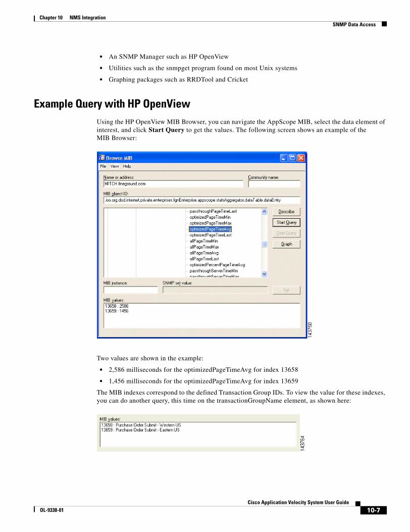
10-7Cisco Application Velocity System User Guide
OL-9338-01
Chapter 10 NMS IntegrationSNMP Data Access
• An SNMP Manager such as HP OpenView
• Utilities such as the snmpget program found on most Unix systems
• Graphing packages such as RRDTool and Cricket
Example Query with HP OpenViewUsing the HP OpenView MIB Browser, you can navigate the AppScope MIB, select the data element of interest, and click Start Query to get the values. The following screen shows an example of the MIB Browser:
Two values are shown in the example:
• 2,586 milliseconds for the optimizedPageTimeAvg for index 13658
• 1,456 milliseconds for the optimizedPageTimeAvg for index 13659
The MIB indexes correspond to the defined Transaction Group IDs. To view the value for these indexes, you can do another query, this time on the transactionGroupName element, as shown here:
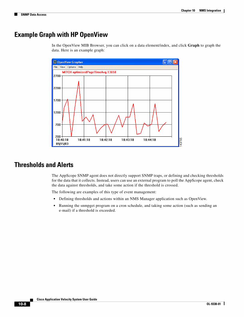
10-8Cisco Application Velocity System User Guide
OL-9338-01
Chapter 10 NMS IntegrationSNMP Data Access
Example Graph with HP OpenViewIn the OpenView MIB Browser, you can click on a data element/index, and click Graph to graph the data. Here is an example graph:
Thresholds and AlertsThe AppScope SNMP agent does not directly support SNMP traps, or defining and checking thresholds for the data that it collects. Instead, users can use an external program to poll the AppScope agent, check the data against thresholds, and take some action if the threshold is crossed.
The following are examples of this type of event management:
• Defining thresholds and actions within an NMS Manager application such as OpenView.
• Running the snmpget program on a cron schedule, and taking some action (such as sending an e-mail) if a threshold is exceeded.
C H A P T E R
11-1Cisco Application Velocity System User Guide
OL-9338-01
11Availability Manager Clustering
This chapter describes how to configure and use the Availability Manager (AM), which provides a built-in high-availability and load-balancing capability for a cluster of application appliances. This chapter includes the following topics:
• Terminology, page 11-1
• Overview, page 11-1
• Configuring and Activating AM, page 11-3
• SSL Session Persistence, page 11-7
• FAQ, page 11-8
• Limitations, page 11-10
Note The Availability Manager operates on the AVS 3120 (not on the AVS 3180 Management Station).
TerminologyCluster is a widely-used term meaning independent computers combined together into a unified system through software and networking. Cluster computing consists of three important branches:
• High-availability (HA) clustering uses multiple machines to add an extra level of reliability for a service or group of services.
• Load-balance clustering uses specialized routing techniques to dispatch traffic to a pool of servers.
• Computation clustering (such as Beowulf) uses multiple machines to provide greater computing power for computationally intensive tasks. This type of clustering is not addressed by Availability Manager.
Availability Manager is a clustering solution that is based on the first two types of clustering technology.
OverviewAvailability Manager (AM) provides a built-in high-availability and load-balancing capability for a cluster of application appliances. No additional load-balancing hardware is required.
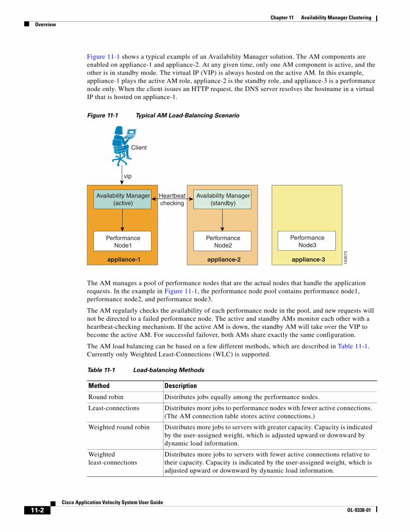
11-2Cisco Application Velocity System User Guide
OL-9338-01
Chapter 11 Availability Manager ClusteringOverview
Figure 11-1 shows a typical example of an Availability Manager solution. The AM components are enabled on appliance-1 and appliance-2. At any given time, only one AM component is active, and the other is in standby mode. The virtual IP (VIP) is always hosted on the active AM. In this example, appliance-1 plays the active AM role, appliance-2 is the standby role, and appliance-3 is a performance node only. When the client issues an HTTP request, the DNS server resolves the hostname in a virtual IP that is hosted on appliance-1.
Figure 11-1 Typical AM Load-Balancing Scenario
The AM manages a pool of performance nodes that are the actual nodes that handle the application requests. In the example in Figure 11-1, the performance node pool contains performance node1, performance node2, and performance node3.
The AM regularly checks the availability of each performance node in the pool, and new requests will not be directed to a failed performance node. The active and standby AMs monitor each other with a heartbeat-checking mechanism. If the active AM is down, the standby AM will take over the VIP to become the active AM. For successful failover, both AMs share exactly the same configuration.
The AM load balancing can be based on a few different methods, which are described in Table 11-1. Currently only Weighted Least-Connections (WLC) is supported.
1436
73
appliance-1
vip
Client
PerformanceNode1
Availability Manager(active)
appliance-2
PerformanceNode2
Availability Manager(standby)
appliance-3
PerformanceNode3
Heartbeatchecking
Table 11-1 Load-balancing Methods
Method Description
Round robin Distributes jobs equally among the performance nodes.
Least-connections Distributes more jobs to performance nodes with fewer active connections. (The AM connection table stores active connections.)
Weighted round robin Distributes more jobs to servers with greater capacity. Capacity is indicated by the user-assigned weight, which is adjusted upward or downward by dynamic load information.
Weighted least-connections
Distributes more jobs to servers with fewer active connections relative to their capacity. Capacity is indicated by the user-assigned weight, which is adjusted upward or downward by dynamic load information.
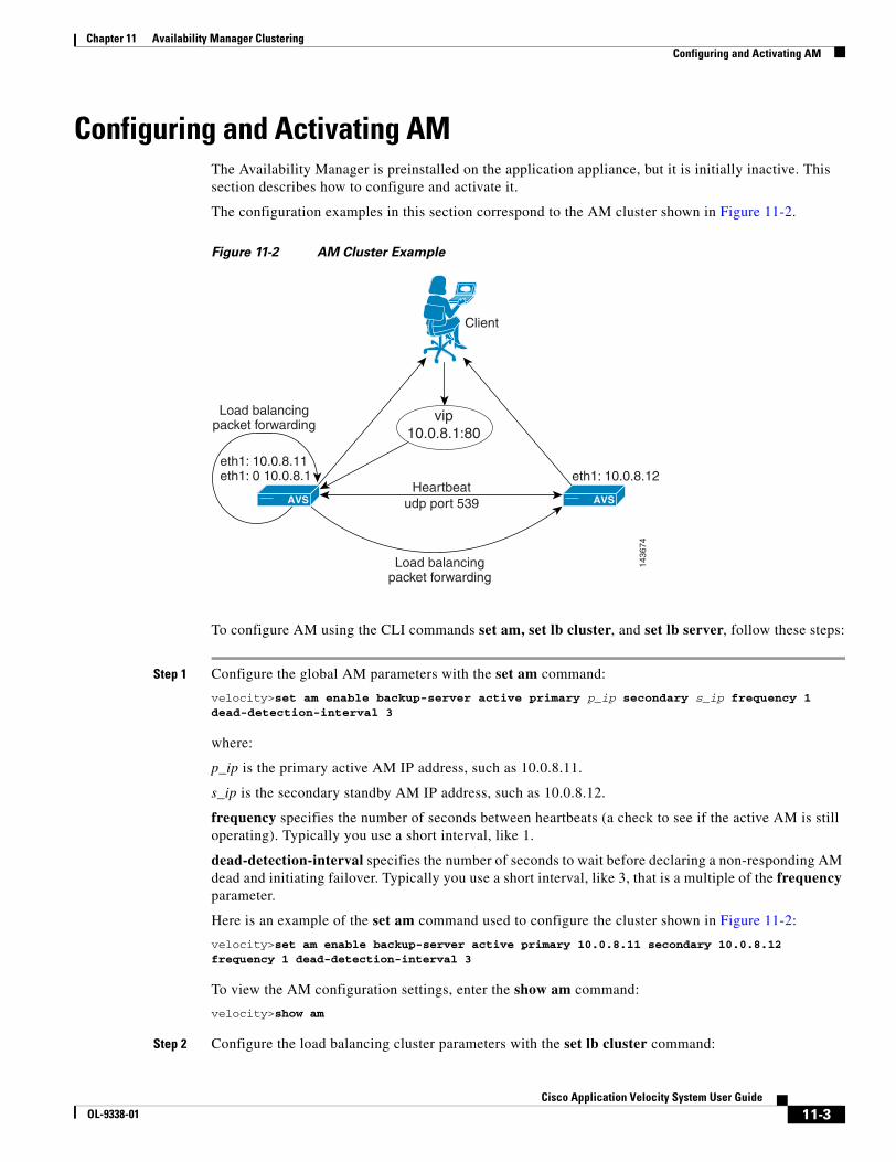
11-3Cisco Application Velocity System User Guide
OL-9338-01
Chapter 11 Availability Manager ClusteringConfiguring and Activating AM
Configuring and Activating AMThe Availability Manager is preinstalled on the application appliance, but it is initially inactive. This section describes how to configure and activate it.
The configuration examples in this section correspond to the AM cluster shown in Figure 11-2.
Figure 11-2 AM Cluster Example
To configure AM using the CLI commands set am, set lb cluster, and set lb server, follow these steps:
Step 1 Configure the global AM parameters with the set am command:
velocity>set am enable backup-server active primary p_ip secondary s_ip frequency 1 dead-detection-interval 3
where:
p_ip is the primary active AM IP address, such as 10.0.8.11.
s_ip is the secondary standby AM IP address, such as 10.0.8.12.
frequency specifies the number of seconds between heartbeats (a check to see if the active AM is still operating). Typically you use a short interval, like 1.
dead-detection-interval specifies the number of seconds to wait before declaring a non-responding AM dead and initiating failover. Typically you use a short interval, like 3, that is a multiple of the frequency parameter.
Here is an example of the set am command used to configure the cluster shown in Figure 11-2:
velocity>set am enable backup-server active primary 10.0.8.11 secondary 10.0.8.12 frequency 1 dead-detection-interval 3
To view the AM configuration settings, enter the show am command:
velocity>show am
Step 2 Configure the load balancing cluster parameters with the set lb cluster command:
1436
74
Client
Heartbeatudp port 539
vip10.0.8.1:80
AVS
eth1: 10.0.8.11eth1: 0 10.0.8.1
Load balancingpacket forwarding
eth1: 10.0.8.12
Load balancingpacket forwarding
AVS
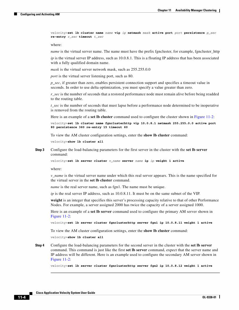
11-4Cisco Application Velocity System User Guide
OL-9338-01
Chapter 11 Availability Manager ClusteringConfiguring and Activating AM
velocity>set lb cluster name name vip ip netmask mask active port port persistence p_sec re-entry r_sec timeout t_sec
where:
name is the virtual server name. The name must have the prefix fgncluster, for example, fgncluster_http
ip is the virtual server IP address, such as 10.0.8.1. This is a floating IP address that has been associated with a fully qualified domain name.
mask is the virtual server network mask, such as 255.255.0.0
port is the virtual server listening port, such as 80.
p_sec, if greater than zero, enables persistent connection support and specifies a timeout value in seconds. In order to use delta optimization, you must specify a value greater than zero.
r_sec is the number of seconds that a restored performance node must remain alive before being readded to the routing table.
t_sec is the number of seconds that must lapse before a performance node determined to be inoperative is removed from the routing table.
Here is an example of a set lb cluster command used to configure the cluster shown in Figure 11-2:
velocity>set lb cluster name fgnclusterhttp vip 10.0.8.1 netmask 255.255.0.0 active port 80 persistence 360 re-entry 15 timeout 60
To view the AM cluster configuration settings, enter the show lb cluster command:
velocity>show lb cluster all
Step 3 Configure the load-balancing parameters for the first server in the cluster with the set lb server command:
velocity>set lb server cluster v_name server name ip ip weight 1 active
where:
v_name is the virtual server name under which this real server appears. This is the name specified for the virtual server in the set lb cluster command.
name is the real server name, such as fgn1. The name must be unique.
ip is the real server IP address, such as 10.0.8.11. It must be on the same subnet of the VIP.
weight is an integer that specifies this server’s processing capacity relative to that of other Performance Nodes. For example, a server assigned 2000 has twice the capacity of a server assigned 1000.
Here is an example of a set lb server command used to configure the primary AM server shown in Figure 11-2:
velocity>set lb server cluster fgnclusterhttp server fgn1 ip 10.0.8.11 weight 1 active
To view the AM cluster configuration settings, enter the show lb cluster command:
velocity>show lb cluster all
Step 4 Configure the load-balancing parameters for the second server in the cluster with the set lb server command. This command is just like the first set lb server command, expect that the server name and IP address will be different. Here is an example used to configure the secondary AM server shown in Figure 11-2:
velocity>set lb server cluster fgnclusterhttp server fgn2 ip 10.0.8.12 weight 1 active
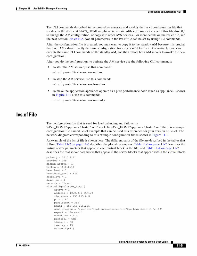
11-5Cisco Application Velocity System User Guide
OL-9338-01
Chapter 11 Availability Manager ClusteringConfiguring and Activating AM
The CLI commands described in the procedure generate and modify the lvs.cf configuration file that resides on the device at $AVS_HOME/appliance/cluster/conf/lvs.cf. You can also edit this file directly to change the AM configuration, or copy it to other AVS devices. For more details on the lvs.cf file, see the next section, lvs.cf File. Not all parameters in the lvs.cf file can be set by using CLI commands.
After the configuration file is created, you may want to copy it to the standby AM because it is crucial that both AMs share exactly the same configuration for a successful failover. Alternatively, you can execute the same CLI commands on the standby AM, and then reboot both AM servers to invoke the new configuration.
After you do the configuration, to activate the AM service use the following CLI commands:
• To start the AM service, use this command:
velocity>set lb status am-active
• To stop the AM service, use this command:
velocity>set lb status am-inactive
• To make the application appliance operate as a pure performance node (such as appliance-3 shown in Figure 11-1), use this command:
velocity>set lb status server-only
lvs.cf FileThe configuration file that is used for load balancing and failover is $AVS_HOME/appliance/cluster/conf/lvs.cf. In $AVS_HOME/appliance/cluster/conf, there is a sample configuration file named lvs.cf.example that can be used as a reference for your version of lvs.cf. The network diagram corresponding to this example configuration file is shown in Figure 11-2.
An example of the lvs.cf file is shown here. The different parts of the file are described in the tables that follow. Table 11-2 on page 11-6 describes the global parameters; Table 11-3 on page 11-7 describes the virtual server parameters that appear in each virtual block in the file; and Table 11-4 on page 11-7 describes the real server parameters that appear in the server blocks that appear within the virtual block.
primary = 10.0.8.11service = lvsbackup_active = 1backup = 10.0.8.12heartbeat = 1heartbeat_port = 539keepalive = 1deadtime = 3network = directvirtual fgncluster_http { active = 1 address = 10.0.8.1 eth1:0 vip_nmask = 255.255.0.0 port = 80 persistent = 360 pmask = 255.255.255.255 send_program = "/usr/avs/appliance/cluster/bin/fgn_heartbeat.pl %h 80" expect = "Succeed" scheduler = wlc protocol = tcp timeout = 60 reentry = 15 server fgn1 {
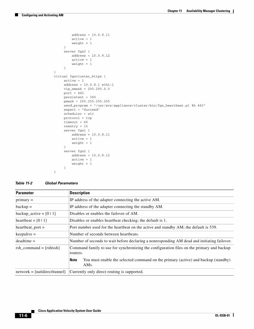
11-6Cisco Application Velocity System User Guide
OL-9338-01
Chapter 11 Availability Manager ClusteringConfiguring and Activating AM
address = 10.0.8.11 active = 1 weight = 1 } server fgn2 { address = 10.0.8.12 active = 1 weight = 1 }}virtual fgncluster_https { active = 1 address = 10.0.8.1 eth1:1 vip_nmask = 255.255.0.0 port = 443 persistent = 360 pmask = 255.255.255.255 send_program = "/usr/avs/appliance/cluster/bin/fgn_heartbeat.pl %h 443" expect = "Succeed" scheduler = wlc protocol = tcp timeout = 60 reentry = 15 server fgn1 { address = 10.0.8.11 active = 1 weight = 1 } server fgn2 { address = 10.0.8.12 active = 1 weight = 1 }}
Table 11-2 Global Parameters
Parameter Description
primary = IP address of the adapter connecting the active AM.
backup = IP address of the adapter connecting the standby AM.
backup_active = [0 | 1] Disables or enables the failover of AM.
heartbeat = [0 | 1] Disables or enables heartbeat checking; the default is 1.
heartbeat_port = Port number used for the heartbeat on the active and standby AM; the default is 539.
keepalive = Number of seconds between heartbeats.
deadtime = Number of seconds to wait before declaring a nonresponding AM dead and initiating failover.
rsh_command = [rsh|ssh] Command family to use for synchronizing the configuration files on the primary and backup routers.
Note You must enable the selected command on the primary (active) and backup (standby) AMs.
network = [nat|direct|tunnel] Currently only direct routing is supported.
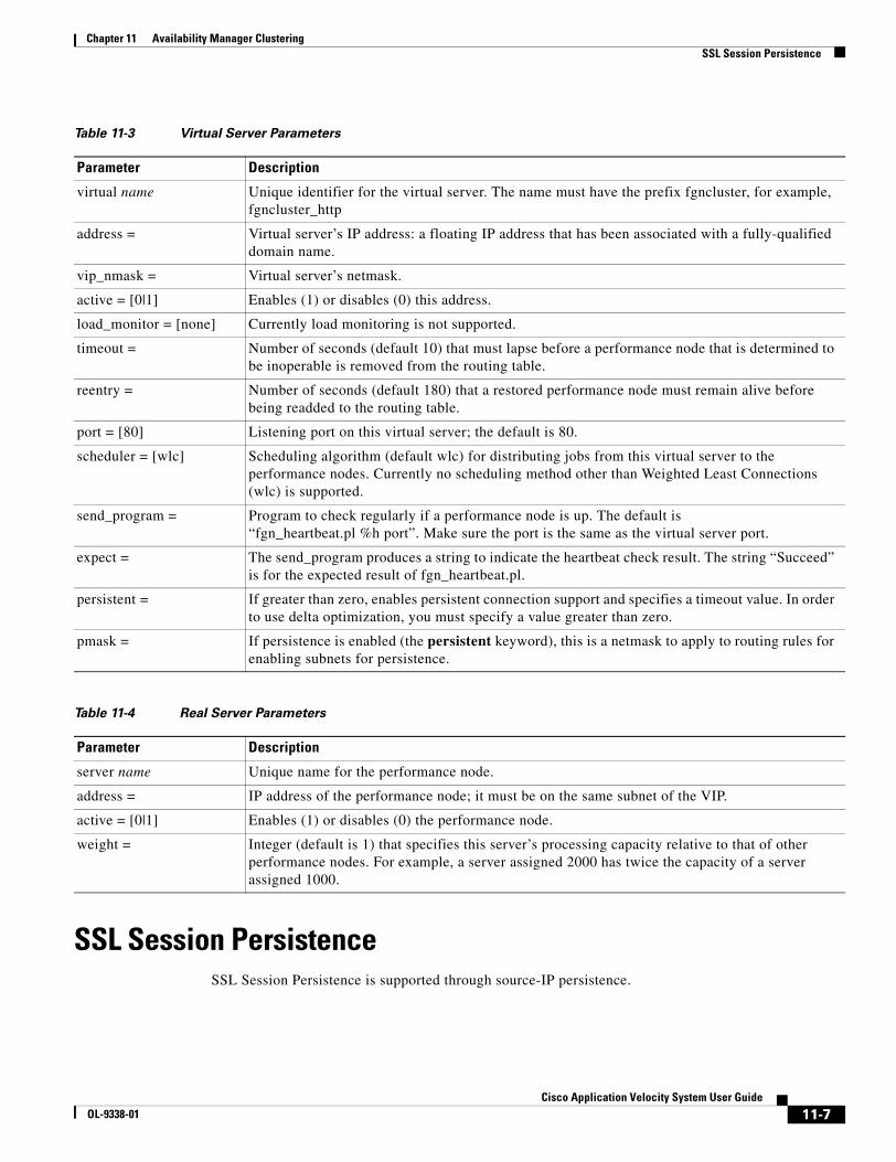
11-7Cisco Application Velocity System User Guide
OL-9338-01
Chapter 11 Availability Manager ClusteringSSL Session Persistence
SSL Session PersistenceSSL Session Persistence is supported through source-IP persistence.
Table 11-3 Virtual Server Parameters
Parameter Description
virtual name Unique identifier for the virtual server. The name must have the prefix fgncluster, for example, fgncluster_http
address = Virtual server’s IP address: a floating IP address that has been associated with a fully-qualified domain name.
vip_nmask = Virtual server’s netmask.
active = [0|1] Enables (1) or disables (0) this address.
load_monitor = [none] Currently load monitoring is not supported.
timeout = Number of seconds (default 10) that must lapse before a performance node that is determined to be inoperable is removed from the routing table.
reentry = Number of seconds (default 180) that a restored performance node must remain alive before being readded to the routing table.
port = [80] Listening port on this virtual server; the default is 80.
scheduler = [wlc] Scheduling algorithm (default wlc) for distributing jobs from this virtual server to the performance nodes. Currently no scheduling method other than Weighted Least Connections (wlc) is supported.
send_program = Program to check regularly if a performance node is up. The default is “fgn_heartbeat.pl %h port”. Make sure the port is the same as the virtual server port.
expect = The send_program produces a string to indicate the heartbeat check result. The string “Succeed” is for the expected result of fgn_heartbeat.pl.
persistent = If greater than zero, enables persistent connection support and specifies a timeout value. In order to use delta optimization, you must specify a value greater than zero.
pmask = If persistence is enabled (the persistent keyword), this is a netmask to apply to routing rules for enabling subnets for persistence.
Table 11-4 Real Server Parameters
Parameter Description
server name Unique name for the performance node.
address = IP address of the performance node; it must be on the same subnet of the VIP.
active = [0|1] Enables (1) or disables (0) the performance node.
weight = Integer (default is 1) that specifies this server’s processing capacity relative to that of other performance nodes. For example, a server assigned 2000 has twice the capacity of a server assigned 1000.

11-8Cisco Application Velocity System User Guide
OL-9338-01
Chapter 11 Availability Manager ClusteringFAQ
FAQThis section contains frequently asked questions.
Is your AM solution active-active or active-passive?
The solution is both. In terms of load balancing decision making, it is active-passive because at any given time, there is only one AM node allowed to host the VIP. In terms of performance nodes receiving requests, it is active-active because requests will be distributed to all of the performance nodes placed into the cluster.
How do I know which server is the active AM and how do I know an AM failover has happened?
To determine which server is the active AM, enter this command on each application appliance:
$AVS_HOME/appliance/cluster/bin/cluster_whoami
One of these responses is displayed:
"I am the ACTIVE AM."
"I am the STANDBY AM."
"I have no AM running."
How do I know if the AM is functioning according to my configuration file?
Enter this command:
ipvsadm -L
The active load-balancing rules and the connection statistics are displayed. For example, on the active AM you might see this result:
ipvsadm -LIP Virtual Server version 1.0.8 (size=65536)Prot LocalAddress:Port Scheduler Flags -> RemoteAddress:Port Forward Weight ActiveConn InActConnTCP 10.0.8.1:http wlc -> 10.0.8.11:http Local 1 0 0 -> 10.0.8.12:http Route 1 0 0
On the standby AM, you should see an empty rule similar to this result:
ipvsadm -LIP Virtual Server version 1.0.8 (size=65536)Prot LocalAddress:Port Scheduler Flags -> RemoteAddress:Port Forward Weight ActiveConn InActConn
I have modified lvs.cf and saved the file on both AMs. Why is the AM rule display still not updated?
You have to restart the pulse daemon to make the new configuration changes effective on the active AM server by entering this command:
service pulse restart
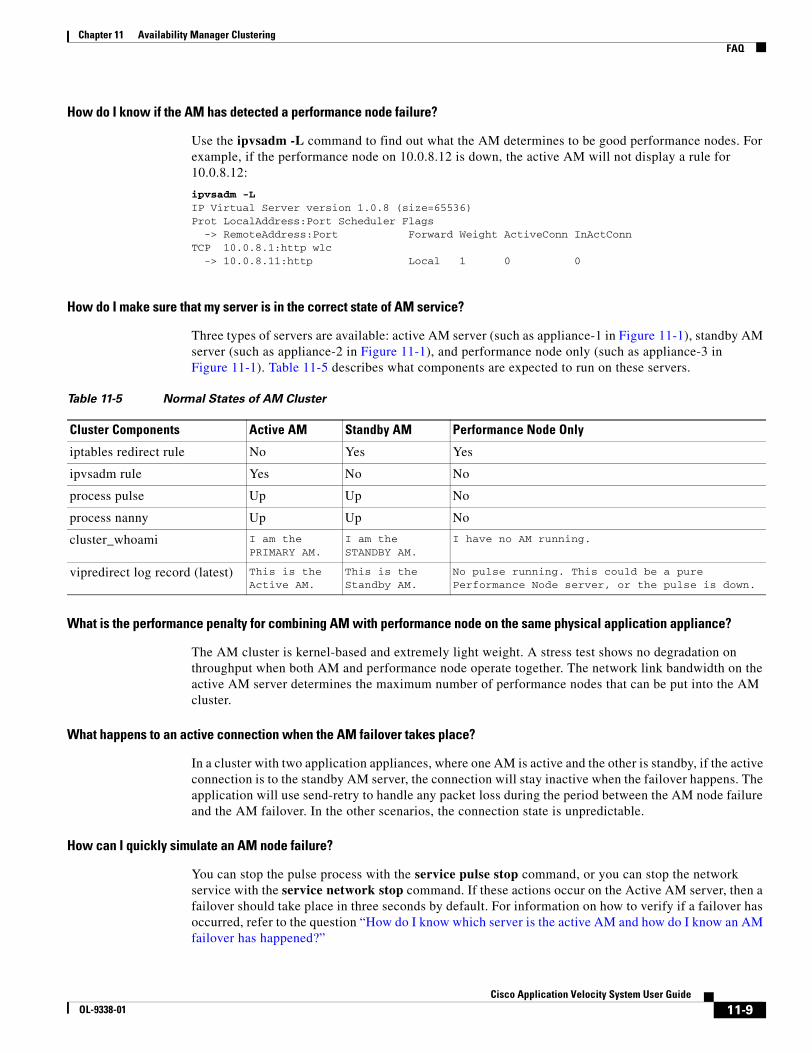
11-9Cisco Application Velocity System User Guide
OL-9338-01
Chapter 11 Availability Manager ClusteringFAQ
How do I know if the AM has detected a performance node failure?
Use the ipvsadm -L command to find out what the AM determines to be good performance nodes. For example, if the performance node on 10.0.8.12 is down, the active AM will not display a rule for 10.0.8.12:
ipvsadm -LIP Virtual Server version 1.0.8 (size=65536)Prot LocalAddress:Port Scheduler Flags -> RemoteAddress:Port Forward Weight ActiveConn InActConnTCP 10.0.8.1:http wlc -> 10.0.8.11:http Local 1 0 0
How do I make sure that my server is in the correct state of AM service?
Three types of servers are available: active AM server (such as appliance-1 in Figure 11-1), standby AM server (such as appliance-2 in Figure 11-1), and performance node only (such as appliance-3 in Figure 11-1). Table 11-5 describes what components are expected to run on these servers.
What is the performance penalty for combining AM with performance node on the same physical application appliance?
The AM cluster is kernel-based and extremely light weight. A stress test shows no degradation on throughput when both AM and performance node operate together. The network link bandwidth on the active AM server determines the maximum number of performance nodes that can be put into the AM cluster.
What happens to an active connection when the AM failover takes place?
In a cluster with two application appliances, where one AM is active and the other is standby, if the active connection is to the standby AM server, the connection will stay inactive when the failover happens. The application will use send-retry to handle any packet loss during the period between the AM node failure and the AM failover. In the other scenarios, the connection state is unpredictable.
How can I quickly simulate an AM node failure?
You can stop the pulse process with the service pulse stop command, or you can stop the network service with the service network stop command. If these actions occur on the Active AM server, then a failover should take place in three seconds by default. For information on how to verify if a failover has occurred, refer to the question “How do I know which server is the active AM and how do I know an AM failover has happened?”
Table 11-5 Normal States of AM Cluster
Cluster Components Active AM Standby AM Performance Node Only
iptables redirect rule No Yes Yes
ipvsadm rule Yes No No
process pulse Up Up No
process nanny Up Up No
cluster_whoami I am the PRIMARY AM.
I am the STANDBY AM.
I have no AM running.
vipredirect log record (latest) This is the Active AM.
This is the Standby AM.
No pulse running. This could be a pure Performance Node server, or the pulse is down.

11-10Cisco Application Velocity System User Guide
OL-9338-01
Chapter 11 Availability Manager ClusteringLimitations
Can I use your AM cluster for my origin servers?
Technically it is possible, but that configuration is not currently supported.
After the failover takes place, will the original active AM node take back the VIP if it is back online?
Not until the new active AM node fails.
Can I use a proxy in front of the AM cluster?
Yes, however, a proxy typically forwards all requests to the AM cluster with the proxy’s IP address as the source IP address. The AM uses the source IP address for persistence determination, which is required for delta optimization. All requests sent through a proxy will be handled by only one performance node. If you have two performance nodes, the other performance node will act as a standby node.
If delta optimization is not used, then the persistence parameter can be removed from the AM configuration file, and both performance nodes will be used in an active-active mode.
LimitationsThe AM currently has the following limitations:
• The performance node must listen to the same port as the virtual server. A performance node must listen on port 80 for HTTP virtual service and on port 443 for HTTPS virtual service.
• Cookie persistence is not supported. A workaround is to use source-IP persistence, which is illustrated in the lvs.cf.example file.
• Only one AM node is allowed to be the active AM, and only one AM node is allowed to be the standby AM node. You will not have more redundancy for AM when you deploy more than two application appliances. If you deploy more than two application appliances, your performance node capacity will increase.
• The AM scheduling algorithm only supports Weighted Least Connection (WLC) mode.
• The performance node IP must be on the same subnet as the VIP. Separating performance nodes into a different network from the VIP is currently not supported.
C H A P T E R
12-1Cisco Application Velocity System User Guide
OL-9338-01
12Database Maintenance
The Management Console can automatically summarize, back up, and delete old data from the Management Console database. This chapter discusses the following database maintenance topics:
• Database Archiving Overview, page 12-1
• Configuring Archiving, page 12-2
• Managing Optimal Database Performance, page 12-3
Note If you have installed only a Cisco AVS 3120 Application Velocity System, reporting and database functions are not available, and you will not see a Reports folder in the menu at the left side of the Management Console window. You must be running the Management Console on a Cisco AVS 3180 Management Station in order to see the Report items in the Management Console.
Note The Management Console database does not store web application security firewall information.
Database Archiving OverviewOver time the Management Console database can grow very large, and it is possible to run out of disk space to store new data. Also, the accumulation of more data results in longer query and update times and decreases the performance of the database. Routine database archiving addresses these concerns. There are four aspects to database archiving: summarizing, backup, pruning, and clean up.
• Summarizing—Older data is aggregated and summarized so that concise trend information is maintained for future analysis without having to keep all of the individual records. Transaction data is summarized in the transaction_aggregates table, and performance monitoring data (if AppScope is used) is summarized in the summarized_performance_monitorings table.
• Backup—Older data that is summarized is backed up to external files outside the database. Backing up enables retrieval of the data if needed for some reason by restoring from the backup files.
Note This is not a backup of the entire database, but only of the older summarized data. A periodic file backup of the entire database, logs, cache files, etc. is recommended as part of a typical system recovery plan.
• Pruning—After summarizing and backing up, the unneeded older data is deleted from the database.

12-2Cisco Application Velocity System User Guide
OL-9338-01
Chapter 12 Database MaintenanceConfiguring Archiving
• Clean-Up—Transaction logs are cleaned up and disk space is recovered using the SQL vacuum command. This command also performs query optimization analysis that Postgres uses to improve the performance of the database.
The following section describes how to configure database archiving.
Configuring ArchivingTo configure database archiving, use the Database Archiving command in the Reports folder in the menu at the left side of the Management Console, as shown in Figure 12-1.
Figure 12-1 Database Archiving Configuration Page
Table 12-1 lists the names and values of the database archiving parameters that appear on this page.
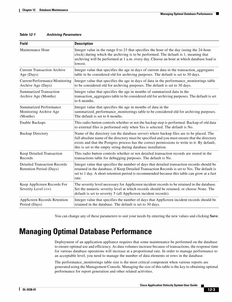
12-3Cisco Application Velocity System User Guide
OL-9338-01
Chapter 12 Database MaintenanceManaging Optimal Database Performance
You can change any of these parameters to suit your needs by entering the new values and clicking Save.
Managing Optimal Database PerformanceDeployment of an application appliance requires that some maintenance be performed on the database to ensure optimal use and efficiency. As data volumes increase because of transactions, the response time for various database operations will increase at a proportional rate. In order to manage performance to an acceptable level, you need to manage the number of data elements or rows in the database.
The performance_monitorings table size is the most critical component when various reports are generated using the Management Console. Managing the size of this table is the key to obtaining optimal performance for report generation and other related activities.
Table 12-1 Archiving Parameters
Field Description
Maintenance Hour Integer value in the range 0 to 23 that specifies the hour of the day (using the 24-hour clock) during which the archiving is to be performed. The default is 1, meaning that archiving will be performed at 1 a.m. every day. Choose an hour at which database load is lowest.
Current Transaction Archive Age (Days)
Integer value that specifies the age in days of current data in the transaction_aggregates table to be considered old for archiving purposes. The default is set to 30 days.
Current Performance Monitoring Archive Age (Days)
Integer value that specifies the age in days of data in the performance_monitorings table to be considered old for archiving purposes. The default is set to 30 days.
Summarized Transaction Archive Age (Months)
Integer value that specifies the age in months of summarized data in the transaction_aggregates table to be considered old for archiving purposes. The default is set to 6 months.
Summarized Performance Monitoring Archive Age (Months)
Integer value that specifies the age in months of data in the summarized_performance_monitorings table to be considered old for archiving purposes. The default is set to 6 months.
Enable Backups This radio button controls whether or not the backup step is performed. Backup of old data to external files is performed only when Yes is selected. The default is No.
Backup Directory Name of the directory (on the database server) where backup files are to be placed. The full absolute name of the directory must be specified and you must ensure that the directory exists and that the Postgres process has the correct permissions to write to it. By default, this is set to the empty string during database installation.
Keep Detailed Transaction Records
This radio button controls whether or not detailed transaction records are stored in the transactions table for debugging purposes. The default is No.
Detailed Transaction Records Retention Period (Days)
Integer value that specifies the number of days that detailed transaction records should be retained in the database, if Keep Detailed Transaction Records is set to Yes. The default is set to 1 day. A short retention period is recommended because this table can grow at a fast rate.
Keep AppScreen Records For Severity Level (<=)
The severity level necessary for AppScreen incident records to be retained in the database. Set the numeric severity level at which records should be retained, or choose None. The default is set to severity 5 (all AppScreen incident records).
AppScreen Records Retention Period (Days)
Integer value that specifies the number of days that AppScreen incident records should be retained in the database. The default is set to 30 days.
12-4Cisco Application Velocity System User Guide
OL-9338-01
Chapter 12 Database MaintenanceManaging Optimal Database Performance
The growth of this table is governed by the number of page views that the node is handling and the number of page views that are measured, as configured by the sampling percentages defined in the standard production configuration file: fgn.conf. By default, this file includes the AppScopeOptimizeRatePercent and AppScopePassThruRatePercent AppScope directives, which control the sampling rates for client performance monitoring. It is recommended that the performance_monitorings table be kept under 8 million rows in size to maintain reasonable database performance.
In general, an application appliance node can handle one million page views per day (a day is defined as a 10-hour window of operations). Assuming network peak load and usage, this would yield a result in the performance_monitorings table of about one million rows of new data. Due to this data volume, the database can process only eight days worth of data. The need to archive the oldest data (about one million rows) is required, which would bring the total amount of data back under the threshold.
Another example is handling 500,000 page views per day. In this scenario, you can store approximately 16 days worth of data in the database using a single node. However, if you have a dual-node configuration, then the total number of days is reduced by half, to only eight days (assuming each node is handling 500,000 page views per day).
Another important aspect of database maintenance is the archiving of older data. Currently, the archiving process takes approximately two hours to complete. By default, this activity is scheduled to run automatically every night starting at 1:00 a.m. Considering the daily growth of the database of one million page views, as explained earlier, the archive process will delete approximately one million rows nightly.
It is recommended that no other processing be done on the database system during the archiving maintenance window, including, for example, Condenser optimization operations or scheduled report generation. If additional activity is permitted during the archiving window, the archiving process will require more time to complete.
In order to control the number of rows that are archived automatically, the archive policy must be changed on the Management Console. If you need to archive one million data rows, as described earlier, a single day’s data is represented. To archive these rows, you must alter the Current Performance Monitoring Archive Age archive parameter to archive only seven days worth of data (seven out of eight days). By default, this parameter is set to 30 days.

A-1Cisco Application Velocity System User Guide
OL-9338-01
A P P E N D I X ALogs
This appendix describes the logs generated by the application appliance servers and other related topics.
• Log File Management, page A-1
• FgnStatLog, page A-2
• Error_log, page A-8
• Access_log, page A-8
• Configuring Extended access_log Formats, page A-9
• Postgres Database Logging, page A-12
• Management Console Logging, page A-13
In addition to the error_log file, the logs directory also contains SSL files that indicate any failures related to the SSL protocol.
Note If you have installed only a Cisco AVS 3120 Application Velocity System, the Management Console database and reporting features are not available, and you will not see a Reports folder in the menu at the left side of the Management Console window. You must be running the Management Console on a Cisco AVS 3180 Management Station, which supports a database, in order to see the Report items in the Management Console.The web application security firewall module manages its own logs separately, and they are not discussed in this appendix. For details, see the “System Utilities” section on page 6-3.
Log File ManagementThe application appliance supports automatic log rotation and uploading of logs to the Management Console database.
For every request, the server writes a log entry to the FgnStatLog file, stored in the $AVS_HOME/perfnode/logs directory. The initial log file is named FgnStatLog.000. When this file fills to its maximum size (25 MB, by default), it is closed, and a new log file is created, FgnStatLog.001, and after that FgnStatLog.002, and so on, up to FgnStatLog.999. This allows you to save multiple log files, which are each 25 MB in size.
No more than ten of these FgnStatLog files can be saved, and typically, only the current file is saved. You can control the size of log files with the FgnStatLogFileSizeLimit configuration directive.
In addition to this auto-rotation feature, log data from the current FgnStatLog file is frequently uploaded to the Management Console database. Every 30 seconds the Management Console component requests the latest batch of log entries from the application appliance server (or servers, if there are more than
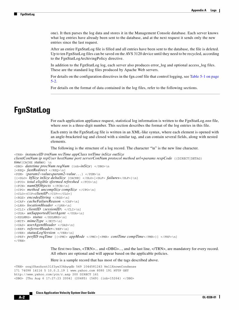
A-2Cisco Application Velocity System User Guide
OL-9338-01
Appendix A LogsFgnStatLog
one). It then parses the log data and stores it in the Management Console database. Each server knows what log entries have already been sent to the database, and at the next request it sends only the new entries since the last request.
After an entire FgnStatLog file is filled and all entries have been sent to the database, the file is deleted. Up to ten FgnStatLog files can be saved on the AVS 3120 device until they need to be recycled, according to the FgnStatLogArchivingPolicy directive.
In addition to the FgnStatLog log, each server also produces error_log and optional access_log files. These are the standard log files produced by Apache Web servers.
For details on the configuration directives in the fgn.conf file that control logging, see Table 5-1 on page 5-2.
For details on the format of data contained in the log files, refer to the following sections.
FgnStatLogFor each application appliance request, statistical log information is written to the FgnStatLog.nnn file, where nnn is a three-digit number. This section describes the format of the log entries in this file.
Each entry in the FgnStatLog file is written in an XML-like syntax, where each element is opened with an angle-bracketed tag and closed with a similar tag, and can contain several fields, along with nested elements.
The following is the structure of a log record. The character “\n” is the new line character.
<TRN> instanceID trnNum recTime appClass totTime inSize outSize clientConNum ip repUser hostName port serverConNum protocol method url+params respCode {{DIRECT|DETAG} time|CACHE status} \n<DBG> datetime procNum reqNum {inb=inSize} </DBG>\n[<REQ> fastRedirect </REQ>\n]<PSM> {param1=value¶m2=value...} </PSM>\n[{<DLO> bfSize inSize deltaSize [CACHE] </DLO>|<DLF> failures</DLF>}\n][<FCO> total eligible xformed refreshed </FCO>\n][<FCN> numOfObjects </FCN>\n][<CPO> method uncompSize compSize </CPO>\n][<CLO><CIP>clientIP</CIP></CLO>][<RGS> encodedString </RGS>\n][<CAF> cacheFailureReason </CAF>\n][<LRH> locationHeader </LRH>\n][<CLI> clientID {sessionID} </CLI>\n][<UUA> unSupportedUserAgent </UUA>\n][<XSLMRG> status </XSLMRG>\n][<MIT> mimeType </MIT>\n][<UAS> userAgentHeader </UAS>\n][<REF> referrerHeader</REF>\n][<VER> statusLogVersion </VER>\n][<PRF> perfID reqTime [{<PMC> appMode </PMC>|<PMR> contTime compTime</PMR>}] </PRF>\n]</TRN>
The first two lines, <TRN>... and <DBG>..., and the last line, </TRN>, are mandatory for every record. All others are optional and will appear based on the applicable policies.
Here is a sample record that has most of the tags described above.
<TRN> ooqj0hxohrnt3lf3ye33kbyqdb 549 1044581243 WellKnownCondense171 74098 14116 5 10.0.2.19 1 www.yahoo.com 8080 191 HTTP GEThttp://www.yahoo.com/ycn/r.asp 200 DIRECT 161<DBG> [Thu Aug 6 17:27:23 2004] (20485) {549} {inb=15264} </DBG>
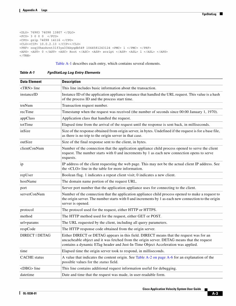
A-3Cisco Application Velocity System User Guide
OL-9338-01
Appendix A LogsFgnStatLog
<DLO> 76983 74098 13807 </DLO><FCO> 3 0 0 0 </FCO><CPO> gzip 74098 14116 </CPO><CLO><CIP> 10.0.2.13 </CIP></CLO><PRF> ooqj0hxohrnt3lf3ye33kbyqdb549 1044581243124 <PMC> 1 </PMC> </PRF><APS> <AST> 0 </AST> <ASC> Root </ASC> <ASP> script </ASP> <ASL> 1 </ASL> </APS></TRN>
Table A-1 describes each entry, which contains several elements.
Table A-1 FgnStatLog Log Entry Elements
Data Element Description
<TRN> line This line includes basic information about the transaction.
instanceID Instance ID of the application appliance instance that handled the URL request. This value is a hash of the process ID and the process start time.
trnNum Transaction request number.
recTime Timestamp when the request was received (the number of seconds since 00:00 January 1, 1970).
appClass Application class that handled the request.
totTime Elapsed time from the arrival of the request until the response is sent back, in milliseconds.
inSize Size of the response obtained from origin server, in bytes. Undefined if the request is for a base file, as there is no trip to the origin server in that case.
outSize Size of the final response sent to the client, in bytes.
clientConNum Number of the connection that the application appliance child process opened to serve the client request. The number starts with 0 and increments by 1 as each new connection opens to serve requests.
ip IP address of the client requesting the web page. This may not be the actual client IP address. See the <CLO> line in the table for more information.
repUser Boolean flag. 1 indicates a repeat client visit; 0 indicates a new client.
hostName The domain name portion of the request URL.
port Server port number that the application appliance uses for connecting to the client.
serverConNum Number of the connection that the application appliance child process opened to make a request to the origin server. The number starts with 0 and increments by 1 as each new connection to the origin server is opened.
protocol The protocol used for the request, either HTTP or HTTPS.
method The HTTP method used for the request, either GET or POST.
url+params The URL requested by the client, including all query parameters.
respCode The HTTP response code obtained from the origin server.
DIRECT | DETAG Either DIRECT or DETAG appears in this field. DIRECT means that the request was for an uncacheable object and it was fetched from the origin server. DETAG means that the request contains a dynamic ETag header and Just-In-Time Object Acceleration was applied.
time Elapsed time the origin server took to respond, in milliseconds.
CACHE status A value that indicates the content origin. See Table A-2 on page A-6 for an explanation of the possible values for the status field.
<DBG> line This line contains additional request information useful for debugging.
datetime Date and time that the request was made, in user-readable form.
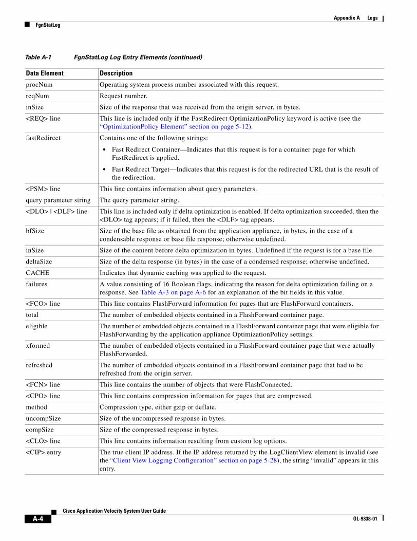
A-4Cisco Application Velocity System User Guide
OL-9338-01
Appendix A LogsFgnStatLog
procNum Operating system process number associated with this request.
reqNum Request number.
inSize Size of the response that was received from the origin server, in bytes.
<REQ> line This line is included only if the FastRedirect OptimizationPolicy keyword is active (see the “OptimizationPolicy Element” section on page 5-12).
fastRedirect Contains one of the following strings:
• Fast Redirect Container—Indicates that this request is for a container page for which FastRedirect is applied.
• Fast Redirect Target—Indicates that this request is for the redirected URL that is the result of the redirection.
<PSM> line This line contains information about query parameters.
query parameter string The query parameter string.
<DLO> | <DLF> line This line is included only if delta optimization is enabled. If delta optimization succeeded, then the <DLO> tag appears; if it failed, then the <DLF> tag appears.
bfSize Size of the base file as obtained from the application appliance, in bytes, in the case of a condensable response or base file response; otherwise undefined.
inSize Size of the content before delta optimization in bytes. Undefined if the request is for a base file.
deltaSize Size of the delta response (in bytes) in the case of a condensed response; otherwise undefined.
CACHE Indicates that dynamic caching was applied to the request.
failures A value consisting of 16 Boolean flags, indicating the reason for delta optimization failing on a response. See Table A-3 on page A-6 for an explanation of the bit fields in this value.
<FCO> line This line contains FlashForward information for pages that are FlashForward containers.
total The number of embedded objects contained in a FlashForward container page.
eligible The number of embedded objects contained in a FlashForward container page that were eligible for FlashForwarding by the application appliance OptimizationPolicy settings.
xformed The number of embedded objects contained in a FlashForward container page that were actually FlashForwarded.
refreshed The number of embedded objects contained in a FlashForward container page that had to be refreshed from the origin server.
<FCN> line This line contains the number of objects that were FlashConnected.
<CPO> line This line contains compression information for pages that are compressed.
method Compression type, either gzip or deflate.
uncompSize Size of the uncompressed response in bytes.
compSize Size of the compressed response in bytes.
<CLO> line This line contains information resulting from custom log options.
<CIP> entry The true client IP address. If the IP address returned by the LogClientView element is invalid (see the “Client View Logging Configuration” section on page 5-28), the string “invalid” appears in this entry.
Table A-1 FgnStatLog Log Entry Elements (continued)
Data Element Description

A-5Cisco Application Velocity System User Guide
OL-9338-01
Appendix A LogsFgnStatLog
<RGS> line This line contains an encoded string that is made based on the specified RequestGroupingString definition in fgn.conf.
<CAF> line This line provides reason codes for not caching a given response. See Table A-4 on page A-7 for an explanation of the bit fields in this value.
<LRH> line This is the Location header from the 302 redirect response from the application appliance to the client.
<CLI> line This line records a unique identifier for a given client.
clientID The unique ID for a client recorded by dropping a cookie that does not expire for 2 years.
sessionID The unique session ID for a client recorded by dropping a session cookie.
<UUA> line When the application appliance encounters a user agent that is not on the list of supported user agents (see the “useragent.conf” section on page 5-39) for delta optimization, this item is set to 1. Also see the <UAS> line in this table.
<XSLMRG> line This line provides XSLMerge status flags. See Table A-5 on page A-7 for an explanation of the bit fields in this value.
<MIT> line The MIME type of the response from the origin server.
<UAS> line The User-Agent header from the client that is making the request.
<REF> line The Referer header from the client that is making the request.
<VER> line The version of the status log (fgnstatlog).
<PRF> line Contains performance monitoring information, if this request was selected for measurement.
perfID Unique ID of the request.
reqTime Timestamp when the request was made.
<PMC> entry This entry appears only if the page triggered performance monitoring; that is, it is the container page.
appMode AppScope mode:
0 indicates unknown mode.
1 indicates an accelerated (optimized) measured request.
2 indicates a pass-through (unoptimized) measured request.
3 indicates a request that was not measured by AppScope.
<PMR> entry This entry appears when the performance measurement is finished for the page.
contTime Reserved for internal use.
compTime Reserved for internal use.
<APS> line This line contains AppScreen information.
<AST> entry Elapsed time (in milliseconds) that was required for AppScreen to analyze the request and perform the specified actions.
<ASC> entry AppScreen Class for the match.
<ASP> entry AppScreen policy that was matched.
<ASL> entry AppScreen severity level for this policy.
Table A-1 FgnStatLog Log Entry Elements (continued)
Data Element Description
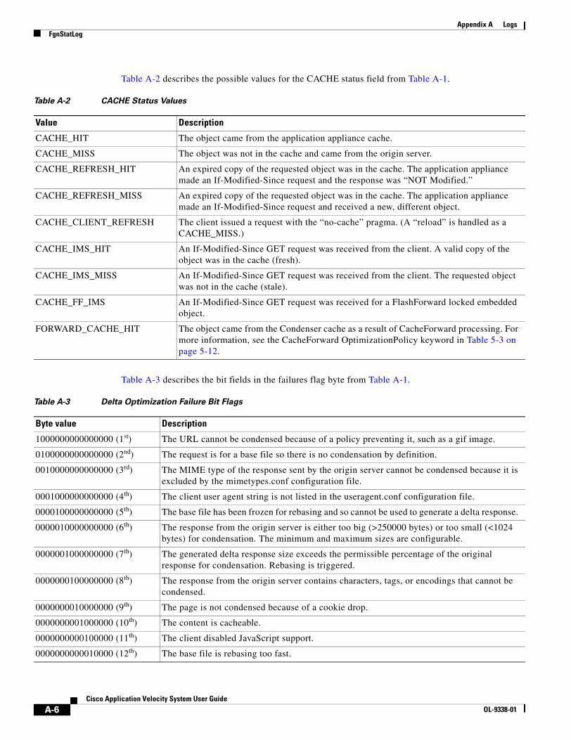
A-6Cisco Application Velocity System User Guide
OL-9338-01
Appendix A LogsFgnStatLog
Table A-2 describes the possible values for the CACHE status field from Table A-1.
Table A-3 describes the bit fields in the failures flag byte from Table A-1.
Table A-2 CACHE Status Values
Value Description
CACHE_HIT The object came from the application appliance cache.
CACHE_MISS The object was not in the cache and came from the origin server.
CACHE_REFRESH_HIT An expired copy of the requested object was in the cache. The application appliance made an If-Modified-Since request and the response was “NOT Modified.”
CACHE_REFRESH_MISS An expired copy of the requested object was in the cache. The application appliance made an If-Modified-Since request and received a new, different object.
CACHE_CLIENT_REFRESH The client issued a request with the “no-cache” pragma. (A “reload” is handled as a CACHE_MISS.)
CACHE_IMS_HIT An If-Modified-Since GET request was received from the client. A valid copy of the object was in the cache (fresh).
CACHE_IMS_MISS An If-Modified-Since GET request was received from the client. The requested object was not in the cache (stale).
CACHE_FF_IMS An If-Modified-Since GET request was received for a FlashForward locked embedded object.
FORWARD_CACHE_HIT The object came from the Condenser cache as a result of CacheForward processing. For more information, see the CacheForward OptimizationPolicy keyword in Table 5-3 on page 5-12.
Table A-3 Delta Optimization Failure Bit Flags
Byte value Description
1000000000000000 (1st) The URL cannot be condensed because of a policy preventing it, such as a gif image.
0100000000000000 (2nd) The request is for a base file so there is no condensation by definition.
0010000000000000 (3rd) The MIME type of the response sent by the origin server cannot be condensed because it is excluded by the mimetypes.conf configuration file.
0001000000000000 (4th) The client user agent string is not listed in the useragent.conf configuration file.
0000100000000000 (5th) The base file has been frozen for rebasing and so cannot be used to generate a delta response.
0000010000000000 (6th) The response from the origin server is either too big (>250000 bytes) or too small (<1024 bytes) for condensation. The minimum and maximum sizes are configurable.
0000001000000000 (7th) The generated delta response size exceeds the permissible percentage of the original response for condensation. Rebasing is triggered.
0000000100000000 (8th) The response from the origin server contains characters, tags, or encodings that cannot be condensed.
0000000010000000 (9th) The page is not condensed because of a cookie drop.
0000000001000000 (10th) The content is cacheable.
0000000000100000 (11th) The client disabled JavaScript support.
0000000000010000 (12th) The base file is rebasing too fast.
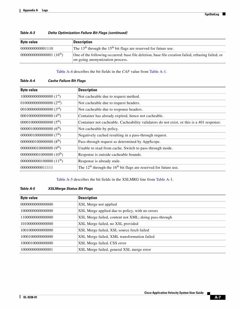
A-7Cisco Application Velocity System User Guide
OL-9338-01
Appendix A LogsFgnStatLog
Table A-4 describes the bit fields in the CAF value from Table A-1.
Table A-5 describes the bit fields in the XSLMRG line from Table A-1.
0000000000001110 The 13th through the 15th bit flags are reserved for future use.
0000000000000001 (16th) One of the following occurred: base file deletion, base file creation failed, rebasing failed, or on-going anonymization process.
Table A-3 Delta Optimization Failure Bit Flags (continued)
Byte value Description
Table A-4 Cache Failure Bit Flags
Byte value Description
1000000000000000 (1st) Not cacheable due to request method.
0100000000000000 (2nd) Not cacheable due to request headers.
0010000000000000 (3rd) Not cacheable due to response headers.
0001000000000000 (4th) Container has already expired, hence not cacheable.
0000100000000000 (5th) Container not cacheable. Cacheability validators do not exist, or this is a 401 response.
0000010000000000 (6th) Not cacheable by policy.
0000001000000000 (7th) Negatively cached resulting in a pass-through request.
0000000100000000 (8th) Pass-through request as determined by AppScope.
0000000010000000 (9th) Unable to read from cache. Switch to pass-through mode.
0000000001000000 (10th) Response is outside cacheable bounds.
0000000000100000 (11th) Response is already stale.
0000000000011111 The 12th through the 16th bit flags are reserved for future use.
Table A-5 XSLMerge Status Bit Flags
Byte value Description
0000000000000000 XSL Merge not applied
1000000000000000 XSL Merge applied due to policy, with no errors
1100000000000000 XSL Merge failed, content not XML; doing pass-through
1010000000000000 XSL Merge failed, no XSL provided
1001000000000000 XSL Merge failed, XSL source fetch failed
1000100000000000 XSL Merge failed, XML transformation failed
1000010000000000 XSL Merge failed, CSS error
1000000000000001 XSL Merge failed, general XSL merge error
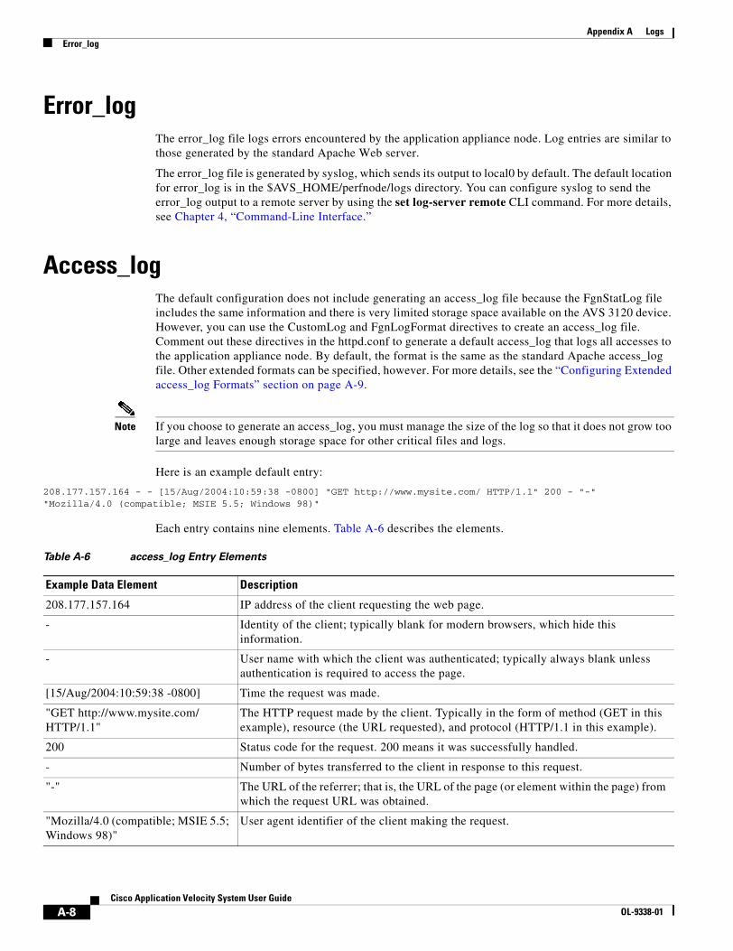
A-8Cisco Application Velocity System User Guide
OL-9338-01
Appendix A LogsError_log
Error_logThe error_log file logs errors encountered by the application appliance node. Log entries are similar to those generated by the standard Apache Web server.
The error_log file is generated by syslog, which sends its output to local0 by default. The default location for error_log is in the $AVS_HOME/perfnode/logs directory. You can configure syslog to send the error_log output to a remote server by using the set log-server remote CLI command. For more details, see Chapter 4, “Command-Line Interface.”
Access_logThe default configuration does not include generating an access_log file because the FgnStatLog file includes the same information and there is very limited storage space available on the AVS 3120 device. However, you can use the CustomLog and FgnLogFormat directives to create an access_log file. Comment out these directives in the httpd.conf to generate a default access_log that logs all accesses to the application appliance node. By default, the format is the same as the standard Apache access_log file. Other extended formats can be specified, however. For more details, see the “Configuring Extended access_log Formats” section on page A-9.
Note If you choose to generate an access_log, you must manage the size of the log so that it does not grow too large and leaves enough storage space for other critical files and logs.
Here is an example default entry:
208.177.157.164 - - [15/Aug/2004:10:59:38 -0800] "GET http://www.mysite.com/ HTTP/1.1" 200 - "-" "Mozilla/4.0 (compatible; MSIE 5.5; Windows 98)"
Each entry contains nine elements. Table A-6 describes the elements.
Table A-6 access_log Entry Elements
Example Data Element Description
208.177.157.164 IP address of the client requesting the web page.
- Identity of the client; typically blank for modern browsers, which hide this information.
- User name with which the client was authenticated; typically always blank unless authentication is required to access the page.
[15/Aug/2004:10:59:38 -0800] Time the request was made.
"GET http://www.mysite.com/ HTTP/1.1"
The HTTP request made by the client. Typically in the form of method (GET in this example), resource (the URL requested), and protocol (HTTP/1.1 in this example).
200 Status code for the request. 200 means it was successfully handled.
- Number of bytes transferred to the client in response to this request.
"-" The URL of the referrer; that is, the URL of the page (or element within the page) from which the request URL was obtained.
"Mozilla/4.0 (compatible; MSIE 5.5; Windows 98)"
User agent identifier of the client making the request.
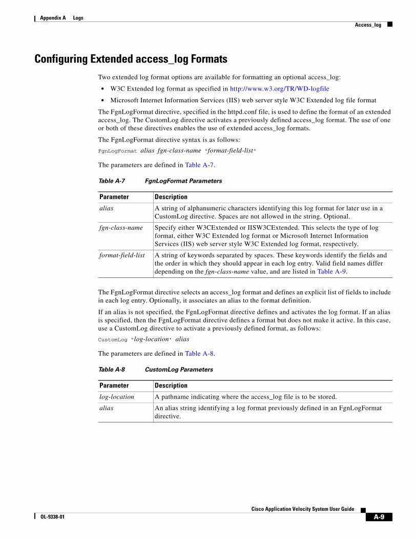
A-9Cisco Application Velocity System User Guide
OL-9338-01
Appendix A LogsAccess_log
Configuring Extended access_log FormatsTwo extended log format options are available for formatting an optional access_log:
• W3C Extended log format as specified in http://www.w3.org/TR/WD-logfile
• Microsoft Internet Information Services (IIS) web server style W3C Extended log file format
The FgnLogFormat directive, specified in the httpd.conf file, is used to define the format of an extended access_log. The CustomLog directive activates a previously defined access_log format. The use of one or both of these directives enables the use of extended access_log formats.
The FgnLogFormat directive syntax is as follows:
FgnLogFormat alias fgn-class-name "format-field-list"
The parameters are defined in Table A-7.
The FgnLogFormat directive selects an access_log format and defines an explicit list of fields to include in each log entry. Optionally, it associates an alias to the format definition.
If an alias is not specified, the FgnLogFormat directive defines and activates the log format. If an alias is specified, then the FgnLogFormat directive defines a format but does not make it active. In this case, use a CustomLog directive to activate a previously defined format, as follows:
CustomLog "log-location" alias
The parameters are defined in Table A-8.
Table A-7 FgnLogFormat Parameters
Parameter Description
alias A string of alphanumeric characters identifying this log format for later use in a CustomLog directive. Spaces are not allowed in the string. Optional.
fgn-class-name Specify either W3CExtended or IISW3CExtended. This selects the type of log format, either W3C Extended log format or Microsoft Internet Information Services (IIS) web server style W3C Extended log format, respectively.
format-field-list A string of keywords separated by spaces. These keywords identify the fields and the order in which they should appear in each log entry. Valid field names differ depending on the fgn-class-name value, and are listed in Table A-9.
Table A-8 CustomLog Parameters
Parameter Description
log-location A pathname indicating where the access_log file is to be stored.
alias An alias string identifying a log format previously defined in an FgnLogFormat directive.
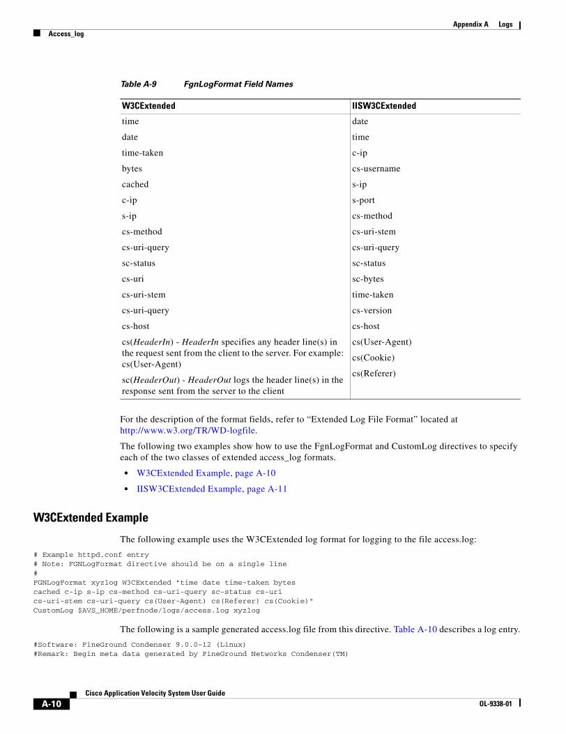
A-10Cisco Application Velocity System User Guide
OL-9338-01
Appendix A LogsAccess_log
For the description of the format fields, refer to “Extended Log File Format” located at http://www.w3.org/TR/WD-logfile.
The following two examples show how to use the FgnLogFormat and CustomLog directives to specify each of the two classes of extended access_log formats.
• W3CExtended Example, page A-10
• IISW3CExtended Example, page A-11
W3CExtended Example
The following example uses the W3CExtended log format for logging to the file access.log:
# Example httpd.conf entry# Note: FGNLogFormat directive should be on a single line#FGNLogFormat xyzlog W3CExtended "time date time-taken bytes cached c-ip s-ip cs-method cs-uri-query sc-status cs-uri cs-uri-stem cs-uri-query cs(User-Agent) cs(Referer) cs(Cookie)"CustomLog $AVS_HOME/perfnode/logs/access.log xyzlog
The following is a sample generated access.log file from this directive. Table A-10 describes a log entry.
#Software: FineGround Condenser 9.0.0-12 (Linux)#Remark: Begin meta data generated by FineGround Networks Condenser(TM)
Table A-9 FgnLogFormat Field Names
W3CExtended IISW3CExtended
time
date
time-taken
bytes
cached
c-ip
s-ip
cs-method
cs-uri-query
sc-status
cs-uri
cs-uri-stem
cs-uri-query
cs-host
cs(HeaderIn) - HeaderIn specifies any header line(s) in the request sent from the client to the server. For example: cs(User-Agent)
sc(HeaderOut) - HeaderOut logs the header line(s) in the response sent from the server to the client
date
time
c-ip
cs-username
s-ip
s-port
cs-method
cs-uri-stem
cs-uri-query
sc-status
sc-bytes
time-taken
cs-version
cs-host
cs(User-Agent)
cs(Cookie)
cs(Referer)
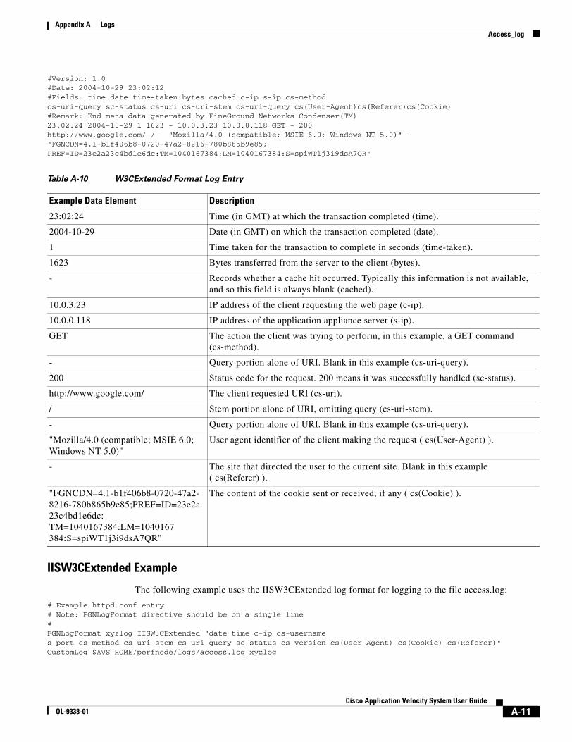
A-11Cisco Application Velocity System User Guide
OL-9338-01
Appendix A LogsAccess_log
#Version: 1.0#Date: 2004-10-29 23:02:12#Fields: time date time-taken bytes cached c-ip s-ip cs-method cs-uri-query sc-status cs-uri cs-uri-stem cs-uri-query cs(User-Agent)cs(Referer)cs(Cookie)#Remark: End meta data generated by FineGround Networks Condenser(TM)23:02:24 2004-10-29 1 1623 - 10.0.3.23 10.0.0.118 GET - 200 http://www.google.com/ / - "Mozilla/4.0 (compatible; MSIE 6.0; Windows NT 5.0)" -"FGNCDN=4.1-b1f406b8-0720-47a2-8216-780b865b9e85;PREF=ID=23e2a23c4bd1e6dc:TM=1040167384:LM=1040167384:S=spiWT1j3i9dsA7QR"
IISW3CExtended Example
The following example uses the IISW3CExtended log format for logging to the file access.log:
# Example httpd.conf entry# Note: FGNLogFormat directive should be on a single line#FGNLogFormat xyzlog IISW3CExtended "date time c-ip cs-username s-port cs-method cs-uri-stem cs-uri-query sc-status cs-version cs(User-Agent) cs(Cookie) cs(Referer)"CustomLog $AVS_HOME/perfnode/logs/access.log xyzlog
Table A-10 W3CExtended Format Log Entry
Example Data Element Description
23:02:24 Time (in GMT) at which the transaction completed (time).
2004-10-29 Date (in GMT) on which the transaction completed (date).
1 Time taken for the transaction to complete in seconds (time-taken).
1623 Bytes transferred from the server to the client (bytes).
- Records whether a cache hit occurred. Typically this information is not available, and so this field is always blank (cached).
10.0.3.23 IP address of the client requesting the web page (c-ip).
10.0.0.118 IP address of the application appliance server (s-ip).
GET The action the client was trying to perform, in this example, a GET command (cs-method).
- Query portion alone of URI. Blank in this example (cs-uri-query).
200 Status code for the request. 200 means it was successfully handled (sc-status).
http://www.google.com/ The client requested URI (cs-uri).
/ Stem portion alone of URI, omitting query (cs-uri-stem).
- Query portion alone of URI. Blank in this example (cs-uri-query).
"Mozilla/4.0 (compatible; MSIE 6.0; Windows NT 5.0)"
User agent identifier of the client making the request ( cs(User-Agent) ).
- The site that directed the user to the current site. Blank in this example ( cs(Referer) ).
"FGNCDN=4.1-b1f406b8-0720-47a2-8216-780b865b9e85;PREF=ID=23e2a23c4bd1e6dc: TM=1040167384:LM=1040167 384:S=spiWT1j3i9dsA7QR"
The content of the cookie sent or received, if any ( cs(Cookie) ).
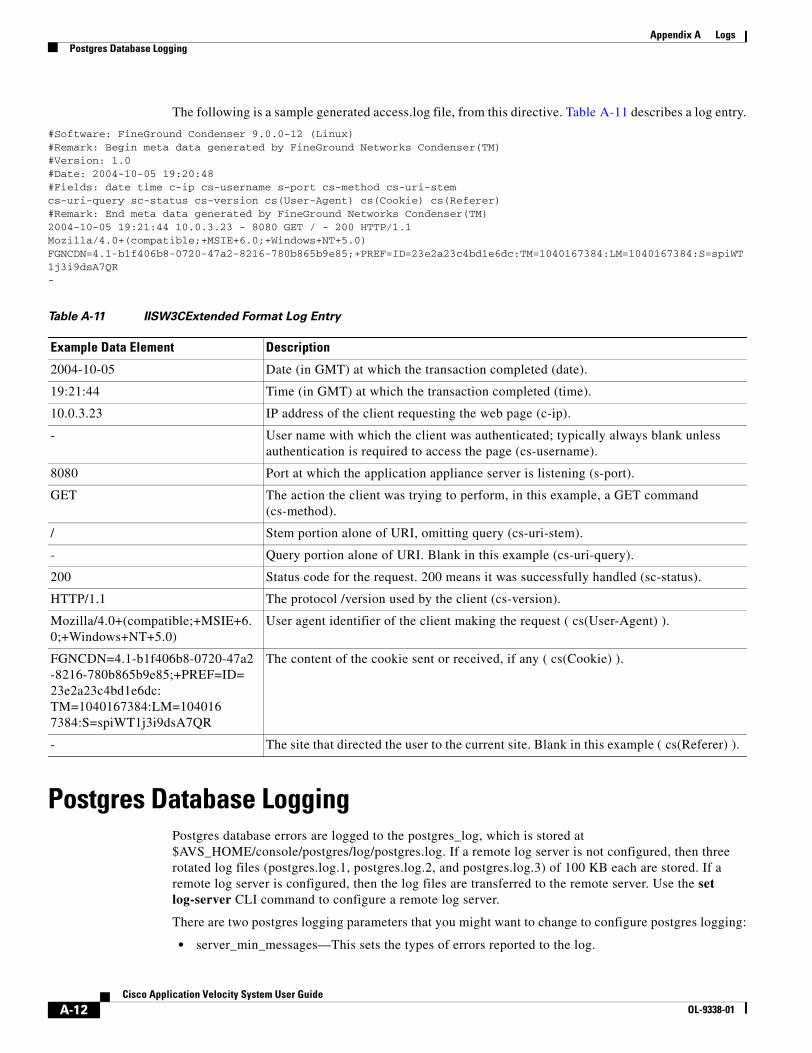
A-12Cisco Application Velocity System User Guide
OL-9338-01
Appendix A LogsPostgres Database Logging
The following is a sample generated access.log file, from this directive. Table A-11 describes a log entry.
#Software: FineGround Condenser 9.0.0-12 (Linux)#Remark: Begin meta data generated by FineGround Networks Condenser(TM)#Version: 1.0#Date: 2004-10-05 19:20:48#Fields: date time c-ip cs-username s-port cs-method cs-uri-stem cs-uri-query sc-status cs-version cs(User-Agent) cs(Cookie) cs(Referer)#Remark: End meta data generated by FineGround Networks Condenser(TM)2004-10-05 19:21:44 10.0.3.23 - 8080 GET / - 200 HTTP/1.1Mozilla/4.0+(compatible;+MSIE+6.0;+Windows+NT+5.0)FGNCDN=4.1-b1f406b8-0720-47a2-8216-780b865b9e85;+PREF=ID=23e2a23c4bd1e6dc:TM=1040167384:LM=1040167384:S=spiWT1j3i9dsA7QR-
Postgres Database LoggingPostgres database errors are logged to the postgres_log, which is stored at $AVS_HOME/console/postgres/log/postgres.log. If a remote log server is not configured, then three rotated log files (postgres.log.1, postgres.log.2, and postgres.log.3) of 100 KB each are stored. If a remote log server is configured, then the log files are transferred to the remote server. Use the set log-server CLI command to configure a remote log server.
There are two postgres logging parameters that you might want to change to configure postgres logging:
• server_min_messages—This sets the types of errors reported to the log.
Table A-11 IISW3CExtended Format Log Entry
Example Data Element Description
2004-10-05 Date (in GMT) at which the transaction completed (date).
19:21:44 Time (in GMT) at which the transaction completed (time).
10.0.3.23 IP address of the client requesting the web page (c-ip).
- User name with which the client was authenticated; typically always blank unless authentication is required to access the page (cs-username).
8080 Port at which the application appliance server is listening (s-port).
GET The action the client was trying to perform, in this example, a GET command (cs-method).
/ Stem portion alone of URI, omitting query (cs-uri-stem).
- Query portion alone of URI. Blank in this example (cs-uri-query).
200 Status code for the request. 200 means it was successfully handled (sc-status).
HTTP/1.1 The protocol /version used by the client (cs-version).
Mozilla/4.0+(compatible;+MSIE+6.0;+Windows+NT+5.0)
User agent identifier of the client making the request ( cs(User-Agent) ).
FGNCDN=4.1-b1f406b8-0720-47a2-8216-780b865b9e85;+PREF=ID= 23e2a23c4bd1e6dc: TM=1040167384:LM=104016 7384:S=spiWT1j3i9dsA7QR
The content of the cookie sent or received, if any ( cs(Cookie) ).
- The site that directed the user to the current site. Blank in this example ( cs(Referer) ).
A-13Cisco Application Velocity System User Guide
OL-9338-01
Appendix A LogsManagement Console Logging
• log_timestamp—Adds timestamp prefixes to each line in the log.
To change these parameters, edit the postgres configuration file at this location:$AVS_HOME/console/postgres/Database/postgresql.conf
The server_min_messages value is set as follows:
server_min_messages = fatal
This parameter sets the minimum level of logging and means that only the specified level of errors and those higher are reported to the log. The available log levels include these (ordered from highest to lowest levels):
• panic—Reports why all backend sessions restarted.
• fatal—Reports why a backend session terminated.
• log—Reports information of interest to administrators, for example, checkpoint activity.
• error—Reports errors that caused a transaction to abort.
• warning—Provides warnings to the user, for example, COMMIT outside a transaction.
• notice—Provides information that may be helpful to users, for example, truncation of long identifiers and index creation as part of primary keys.
The log_timestamp value is set as follows:
log_timestamp = true
This setting causes each log entry to be prefixed by a timestamp. You can set this value to false to disable this feature.
Management Console LoggingManagement Console log files are stored in the following directory: $AVS_HOME/console/jboss-3.0.1_tomcat-4.0.4/server/default/log

A-14Cisco Application Velocity System User Guide
OL-9338-01
Appendix A LogsManagement Console Logging
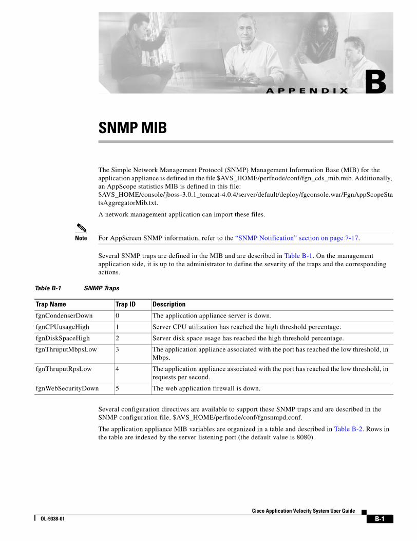
B-1Cisco Application Velocity System User Guide
OL-9338-01
A P P E N D I X BSNMP MIB
The Simple Network Management Protocol (SNMP) Management Information Base (MIB) for the application appliance is defined in the file $AVS_HOME/perfnode/conf/fgn_cds_mib.mib. Additionally, an AppScope statistics MIB is defined in this file: $AVS_HOME/console/jboss-3.0.1_tomcat-4.0.4/server/default/deploy/fgconsole.war/FgnAppScopeStatsAggregatorMib.txt.
A network management application can import these files.
Note For AppScreen SNMP information, refer to the “SNMP Notification” section on page 7-17.
Several SNMP traps are defined in the MIB and are described in Table B-1. On the management application side, it is up to the administrator to define the severity of the traps and the corresponding actions.
Several configuration directives are available to support these SNMP traps and are described in the SNMP configuration file, $AVS_HOME/perfnode/conf/fgnsnmpd.conf.
The application appliance MIB variables are organized in a table and described in Table B-2. Rows in the table are indexed by the server listening port (the default value is 8080).
Table B-1 SNMP Traps
Trap Name Trap ID Description
fgnCondenserDown 0 The application appliance server is down.
fgnCPUusageHigh 1 Server CPU utilization has reached the high threshold percentage.
fgnDiskSpaceHigh 2 Server disk space usage has reached the high threshold percentage.
fgnThruputMbpsLow 3 The application appliance associated with the port has reached the low threshold, in Mbps.
fgnThruputRpsLow 4 The application appliance associated with the port has reached the low threshold, in requests per second.
fgnWebSecurityDown 5 The web application firewall is down.
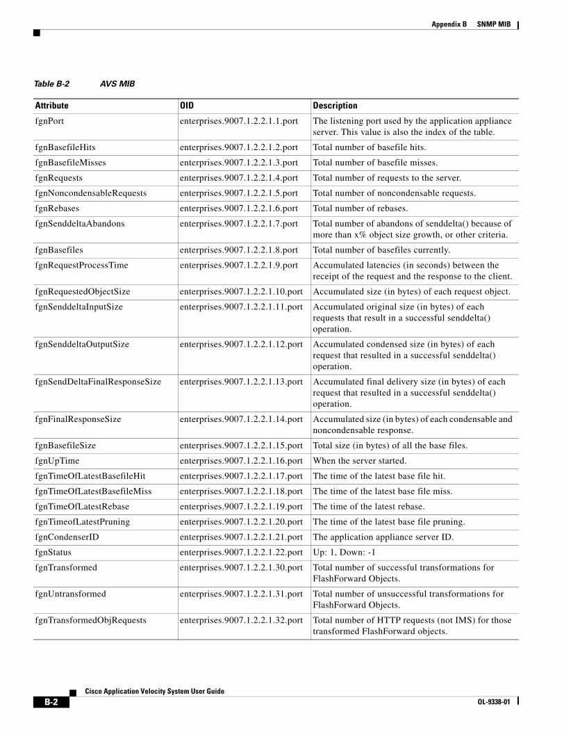
B-2Cisco Application Velocity System User Guide
OL-9338-01
Appendix B SNMP MIB
Table B-2 AVS MIB
Attribute OID Description
fgnPort enterprises.9007.1.2.2.1.1.port The listening port used by the application appliance server. This value is also the index of the table.
fgnBasefileHits enterprises.9007.1.2.2.1.2.port Total number of basefile hits.
fgnBasefileMisses enterprises.9007.1.2.2.1.3.port Total number of basefile misses.
fgnRequests enterprises.9007.1.2.2.1.4.port Total number of requests to the server.
fgnNoncondensableRequests enterprises.9007.1.2.2.1.5.port Total number of noncondensable requests.
fgnRebases enterprises.9007.1.2.2.1.6.port Total number of rebases.
fgnSenddeltaAbandons enterprises.9007.1.2.2.1.7.port Total number of abandons of senddelta() because of more than x% object size growth, or other criteria.
fgnBasefiles enterprises.9007.1.2.2.1.8.port Total number of basefiles currently.
fgnRequestProcessTime enterprises.9007.1.2.2.1.9.port Accumulated latencies (in seconds) between the receipt of the request and the response to the client.
fgnRequestedObjectSize enterprises.9007.1.2.2.1.10.port Accumulated size (in bytes) of each request object.
fgnSenddeltaInputSize enterprises.9007.1.2.2.1.11.port Accumulated original size (in bytes) of each requests that result in a successful senddelta() operation.
fgnSenddeltaOutputSize enterprises.9007.1.2.2.1.12.port Accumulated condensed size (in bytes) of each request that resulted in a successful senddelta() operation.
fgnSendDeltaFinalResponseSize enterprises.9007.1.2.2.1.13.port Accumulated final delivery size (in bytes) of each request that resulted in a successful senddelta() operation.
fgnFinalResponseSize enterprises.9007.1.2.2.1.14.port Accumulated size (in bytes) of each condensable and noncondensable response.
fgnBasefileSize enterprises.9007.1.2.2.1.15.port Total size (in bytes) of all the base files.
fgnUpTime enterprises.9007.1.2.2.1.16.port When the server started.
fgnTimeOfLatestBasefileHit enterprises.9007.1.2.2.1.17.port The time of the latest base file hit.
fgnTimeOfLatestBasefileMiss enterprises.9007.1.2.2.1.18.port The time of the latest base file miss.
fgnTimeOfLatestRebase enterprises.9007.1.2.2.1.19.port The time of the latest rebase.
fgnTimeofLatestPruning enterprises.9007.1.2.2.1.20.port The time of the latest base file pruning.
fgnCondenserID enterprises.9007.1.2.2.1.21.port The application appliance server ID.
fgnStatus enterprises.9007.1.2.2.1.22.port Up: 1, Down: -1
fgnTransformed enterprises.9007.1.2.2.1.30.port Total number of successful transformations for FlashForward Objects.
fgnUntransformed enterprises.9007.1.2.2.1.31.port Total number of unsuccessful transformations for FlashForward Objects.
fgnTransformedObjRequests enterprises.9007.1.2.2.1.32.port Total number of HTTP requests (not IMS) for those transformed FlashForward objects.

B-3Cisco Application Velocity System User Guide
OL-9338-01
Appendix B SNMP MIBAppScope Statistics MIB
AppScope Statistics MIBFor AppScope performance statistics, there is a separate SNMP agent and another MIB for statistics details.
For the AppScope statistics MIB, the variables are organized in a table and described in Table B-3.
The OID for each variable is similar to the following:
enterprises.fgnEnterprise.appscope.statsAggregator.dataTable.dataEntry.attributeName.transactionID
The attributeName value is the name from Table B-3 and the transactionID value is the transaction ID of the transaction group.
fgnTransformedObjIMS_Requests enterprises.9007.1.2.2.1.33.port Total number of If-Modified-Since requests for those transformed FlashForward objects.
fgnStaticObjHits enterprises.9007.1.2.2.1.34.port Total number of cacheable objects served from the local machine (not including ‘304’ replies).
fgnStaticObjHitSize enterprises.9007.1.2.2.1.35.port Accumulated size (in bytes) of the cacheable objects served from the local machine (not including ‘304’ replies).
fgnStaticObjMisses enterprises.9007.1.2.2.1.36.port Total number of cacheable objects not found from the local machine.
fgnStaticObjMissSize enterprises.9007.1.2.2.1.37.port Accumulated size (in bytes) of the cacheable objects not found from the local machine.
fgnRefreshHits enterprises.9007.1.2.2.1.38.port Total number of requests for stale objects that have the responses from the origin server as ‘Not Modified’.
fgnIMS_Hits enterprises.9007.1.2.2.1.39.port Total number of If-Modified-Since requests for valid copies of objects in the local machine.
fgnIMS_Misses enterprises.9007.1.2.2.1.40.port Total number of If-Modified-Since requests for objects that either do not exist or are stale in the local machine.
fgnDirectRequests enterprises.9007.1.2.2.1.41.port Total number of non-cacheable object requests.
fgnCacheHitRatio enterprises.9007.1.2.2.1.42.port The hit rate in percent for cacheable object hits (including IMS) over total number of cacheable object requests.
entPhysicalName .1.3.6.1.2.1.47.1.1.1.1.7.0 Name of application appliance
entPhysicalSerialNumber .1.3.6.1.2.1.47.1.1.1.1.11.0 Serial number of application appliance
entPhysicalDescription .1.3.6.1.2.1.47.1.1.1.1.2.0 Description of application appliance
entPhysicalModelName .1.3.6.1.2.1.47.1.1.1.1.13.0 Model name of application appliance
entPhysicalHardwareRev .1.3.6.1.2.1.47.1.1.1.1.8.0 Hardware revision of application appliance
Table B-2 AVS MIB (continued)
Attribute OID Description
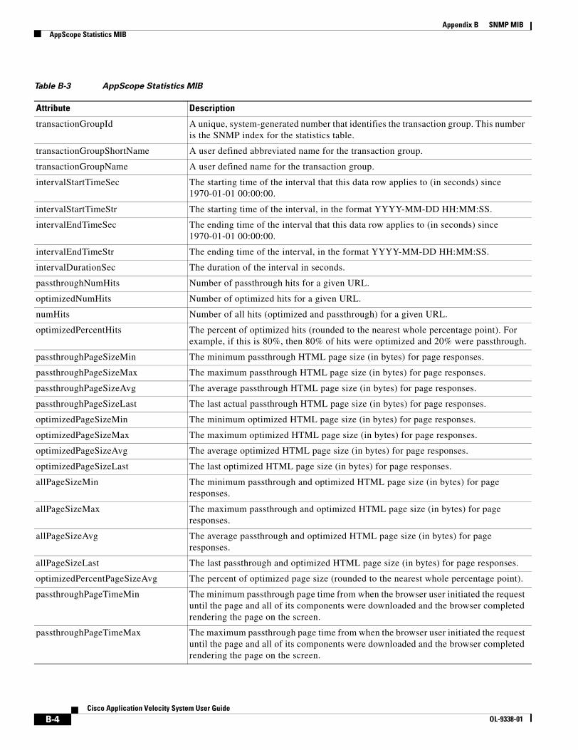
B-4Cisco Application Velocity System User Guide
OL-9338-01
Appendix B SNMP MIBAppScope Statistics MIB
Table B-3 AppScope Statistics MIB
Attribute Description
transactionGroupId A unique, system-generated number that identifies the transaction group. This number is the SNMP index for the statistics table.
transactionGroupShortName A user defined abbreviated name for the transaction group.
transactionGroupName A user defined name for the transaction group.
intervalStartTimeSec The starting time of the interval that this data row applies to (in seconds) since 1970-01-01 00:00:00.
intervalStartTimeStr The starting time of the interval, in the format YYYY-MM-DD HH:MM:SS.
intervalEndTimeSec The ending time of the interval that this data row applies to (in seconds) since 1970-01-01 00:00:00.
intervalEndTimeStr The ending time of the interval, in the format YYYY-MM-DD HH:MM:SS.
intervalDurationSec The duration of the interval in seconds.
passthroughNumHits Number of passthrough hits for a given URL.
optimizedNumHits Number of optimized hits for a given URL.
numHits Number of all hits (optimized and passthrough) for a given URL.
optimizedPercentHits The percent of optimized hits (rounded to the nearest whole percentage point). For example, if this is 80%, then 80% of hits were optimized and 20% were passthrough.
passthroughPageSizeMin The minimum passthrough HTML page size (in bytes) for page responses.
passthroughPageSizeMax The maximum passthrough HTML page size (in bytes) for page responses.
passthroughPageSizeAvg The average passthrough HTML page size (in bytes) for page responses.
passthroughPageSizeLast The last actual passthrough HTML page size (in bytes) for page responses.
optimizedPageSizeMin The minimum optimized HTML page size (in bytes) for page responses.
optimizedPageSizeMax The maximum optimized HTML page size (in bytes) for page responses.
optimizedPageSizeAvg The average optimized HTML page size (in bytes) for page responses.
optimizedPageSizeLast The last optimized HTML page size (in bytes) for page responses.
allPageSizeMin The minimum passthrough and optimized HTML page size (in bytes) for page responses.
allPageSizeMax The maximum passthrough and optimized HTML page size (in bytes) for page responses.
allPageSizeAvg The average passthrough and optimized HTML page size (in bytes) for page responses.
allPageSizeLast The last passthrough and optimized HTML page size (in bytes) for page responses.
optimizedPercentPageSizeAvg The percent of optimized page size (rounded to the nearest whole percentage point).
passthroughPageTimeMin The minimum passthrough page time from when the browser user initiated the request until the page and all of its components were downloaded and the browser completed rendering the page on the screen.
passthroughPageTimeMax The maximum passthrough page time from when the browser user initiated the request until the page and all of its components were downloaded and the browser completed rendering the page on the screen.
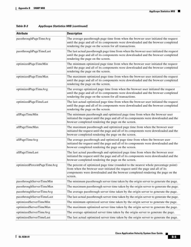
B-5Cisco Application Velocity System User Guide
OL-9338-01
Appendix B SNMP MIBAppScope Statistics MIB
passthroughPageTimeAvg The average passthrough page time from when the browser user initiated the request until the page and all of its components were downloaded and the browser completed rendering the page on the screen for all transactions.
passthroughPageTimeLast The last actual passthrough page time from when the browser user initiated the request until the page and all of its components were downloaded and the browser completed rendering the page on the screen.
optimizedPageTimeMin The minimum optimized page time from when the browser user initiated the request until the page and all of its components were downloaded and the browser completed rendering the page on the screen.
optimizedPageTimeMax The maximum optimized page time from when the browser user initiated the request until the page and all of its components were downloaded and the browser completed rendering the page on the screen.
optimizedPageTimeAvg The average optimized page time from when the browser user initiated the request until the page and all of its components were downloaded and the browser completed rendering the page on the screen for all transactions.
optimizedPageTimeLast The last actual optimized page time from when the browser user initiated the request until the page and all of its components were downloaded and the browser completed rendering the page on the screen.
allPageTimeMin The minimum passthrough and optimized page time from when the browser user initiated the request until the page and all of its components were downloaded and the browser completed rendering the page on the screen.
allPageTimeMax The maximum passthrough and optimized page time from when the browser user initiated the request until the page and all of its components were downloaded and the browser completed rendering the page on the screen.
allPageTimeAvg The average passthrough and optimized page time from when the browser user initiated the request until the page and all of its components were downloaded and the browser completed rendering the page on the screen.
allPageTimeLast The last actual passthrough and optimized page time from when the browser user initiated the request until the page and all of its components were downloaded and the browser completed rendering the page on the screen.
optimizedPercentPageTimeAvg The percent of optimized page time (rounded to the nearest whole percentage point) from when the browser user initiated the request until the page and all of its components were downloaded and the browser completed rendering the page on the screen.
passthroughServerTimeMin The minimum passthrough server time taken by the origin server to generate the page.
passthroughServerTimeMax The maximum passthrough server time taken by the origin server to generate the page.
passthroughServerTimeAvg The average passthrough server time taken by the origin server to generate the page.
passthroughServerTimeLast The last actual passthrough server time taken by the origin server to generate the page.
optimizedServerTimeMin The minimum optimized server time taken by the origin server to generate the page.
optimizedServerTimeMax The maximum optimized server time taken by the origin server to generate the page.
optimizedServerTimeAvg The average optimized server time taken by the origin server to generate the page.
optimizedServerTimeLast The last actual optimized server time taken by the origin server to generate the page.
Table B-3 AppScope Statistics MIB (continued)
Attribute Description

B-6Cisco Application Velocity System User Guide
OL-9338-01
Appendix B SNMP MIBAppScope Statistics MIB
allServerTimeMin The minimum passthrough and optimized server time taken by the origin server to generate the page.
allServerTimeMax The maximum passthrough and optimized server time taken by the origin server to generate the page.
allServerTimeAvg The average passthrough and optimized server time taken by the origin server to generate the page.
allServerTimeLast The last actual passthrough and optimized server time taken by the origin server to generate the page.
optimizedPercentServerTimeAvg The percent of passthrough and optimized server time (rounded to the nearest whole percentage point) taken by the origin server to generate the page.
passthroughTtfbMin The minimum passthrough value from when the web browser user initiated the request until the browser processed the first byte of the HTML content of the page.
passthroughTtfbMax The maximum passthrough value from when the web browser user initiated the request until the browser processed the first byte of the HTML content of the page.
passthroughTtfbAvg The average passthrough value from when the web browser user initiated the request until the browser processed the first byte of the HTML content of the page.
passthroughTtfbLast The last actual passthrough value from when the web browser user initiated the request until the browser processed the first byte of the HTML content of the page.
optimizedTtfbMin The minimum optimized value from when the web browser user initiated the request until the browser processed the first byte of the HTML content of the page.
optimizedTtfbMax The maximum optimized value from when the web browser user initiated the request until the browser processed the first byte of the HTML content of the page.
optimizedTtfbAvg The average optimized value from when the web browser user initiated the request until the browser processed the first byte of the HTML content of the page.
optimizedTtfbLast The last actual optimized value from when the web browser user initiated the request until the browser processed the first byte of the HTML content of the page.
allTtfbMin The minimum passthrough and optimized values from when the web browser user initiated the request until the browser processed the first byte of the HTML content of the page.
allTtfbMax The maximum passthrough and optimized values from when the web browser user initiated the request until the browser processed the first byte of the HTML content of the page.
allTtfbAvg The average passthrough and optimized values from when the web browser user initiated the request until the browser processed the first byte of the HTML content of the page.
allTtfbLast The last actual passthrough and optimized values from when the web browser user initiated the request until the browser processed the first byte of the HTML content of the page.
optimizedPercentTtfbAvg The percent of passthrough and optimized values from when the web browser user initiated the request until the browser processed the first byte of the HTML content of the page.
passthroughTtlbMin The minimum passthrough time from when the browser user initiated the request until the last byte of the HTML contents of the pages is processed by the browser.
Table B-3 AppScope Statistics MIB (continued)
Attribute Description
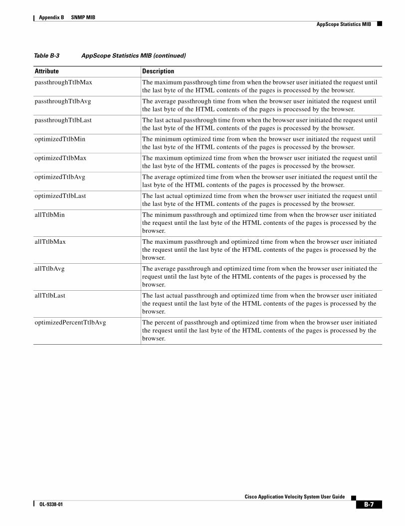
B-7Cisco Application Velocity System User Guide
OL-9338-01
Appendix B SNMP MIBAppScope Statistics MIB
passthroughTtlbMax The maximum passthrough time from when the browser user initiated the request until the last byte of the HTML contents of the pages is processed by the browser.
passthroughTtlbAvg The average passthrough time from when the browser user initiated the request until the last byte of the HTML contents of the pages is processed by the browser.
passthroughTtlbLast The last actual passthrough time from when the browser user initiated the request until the last byte of the HTML contents of the pages is processed by the browser.
optimizedTtlbMin The minimum optimized time from when the browser user initiated the request until the last byte of the HTML contents of the pages is processed by the browser.
optimizedTtlbMax The maximum optimized time from when the browser user initiated the request until the last byte of the HTML contents of the pages is processed by the browser.
optimizedTtlbAvg The average optimized time from when the browser user initiated the request until the last byte of the HTML contents of the pages is processed by the browser.
optimizedTtlbLast The last actual optimized time from when the browser user initiated the request until the last byte of the HTML contents of the pages is processed by the browser.
allTtlbMin The minimum passthrough and optimized time from when the browser user initiated the request until the last byte of the HTML contents of the pages is processed by the browser.
allTtlbMax The maximum passthrough and optimized time from when the browser user initiated the request until the last byte of the HTML contents of the pages is processed by the browser.
allTtlbAvg The average passthrough and optimized time from when the browser user initiated the request until the last byte of the HTML contents of the pages is processed by the browser.
allTtlbLast The last actual passthrough and optimized time from when the browser user initiated the request until the last byte of the HTML contents of the pages is processed by the browser.
optimizedPercentTtlbAvg The percent of passthrough and optimized time from when the browser user initiated the request until the last byte of the HTML contents of the pages is processed by the browser.
Table B-3 AppScope Statistics MIB (continued)
Attribute Description

B-8Cisco Application Velocity System User Guide
OL-9338-01
Appendix B SNMP MIBAppScope Statistics MIB
C-1Cisco Application Velocity System User Guide
OL-9338-01
A P P E N D I X CDeployment Options
Because network environments vary from site to site, several application appliance deployment options are available. The option you choose depends on several factors including your need for the following features:
• Application appliance scalability
• Application appliance failover/redundancy
• Optimization of SSL-based content
This appendix describes the following application appliance deployment topics:
• Deploying Clear-Text or SSL-Based Application Appliance, page C-1
• Deploying a Single Non-SSL Application Appliance, page C-3
• Deploying a Cluster of Non-SSL Application Appliances, page C-3
• Deploying a Single SSL-Terminating Application Appliance, page C-4
• Deploying a Cluster of SSL-Terminating Application Appliances, page C-6
• Deploying a Single SSL-Proxying Application Appliance, page C-7
• Deploying a Cluster of SSL-Proxying Application Appliances, page C-8
• Failover and Load Distribution, page C-9
Deploying Clear-Text or SSL-Based Application ApplianceYou can choose to deploy the application appliance in a clear-text environment, as an SSL terminator, or as an SSL proxy based on your business requirements and your application architecture.
In a clear-text environment, the application appliance operates as an application-layer proxy that communicates with end-user clients and the origin server within the data center using clear-text HTTP. This type of deployment is appropriate for any application that currently runs over HTTP.
As an SSL terminator, the application appliance operates as an application-layer proxy communicating with clients using HTTPS (SSL) and communicating with the origin server within the data center using HTTP (clear-text). SSL termination enables client-to-appliance security using SSL encryption, leaving appliance-to-server traffic in the clear using HTTP as indicated in Figure C-1.
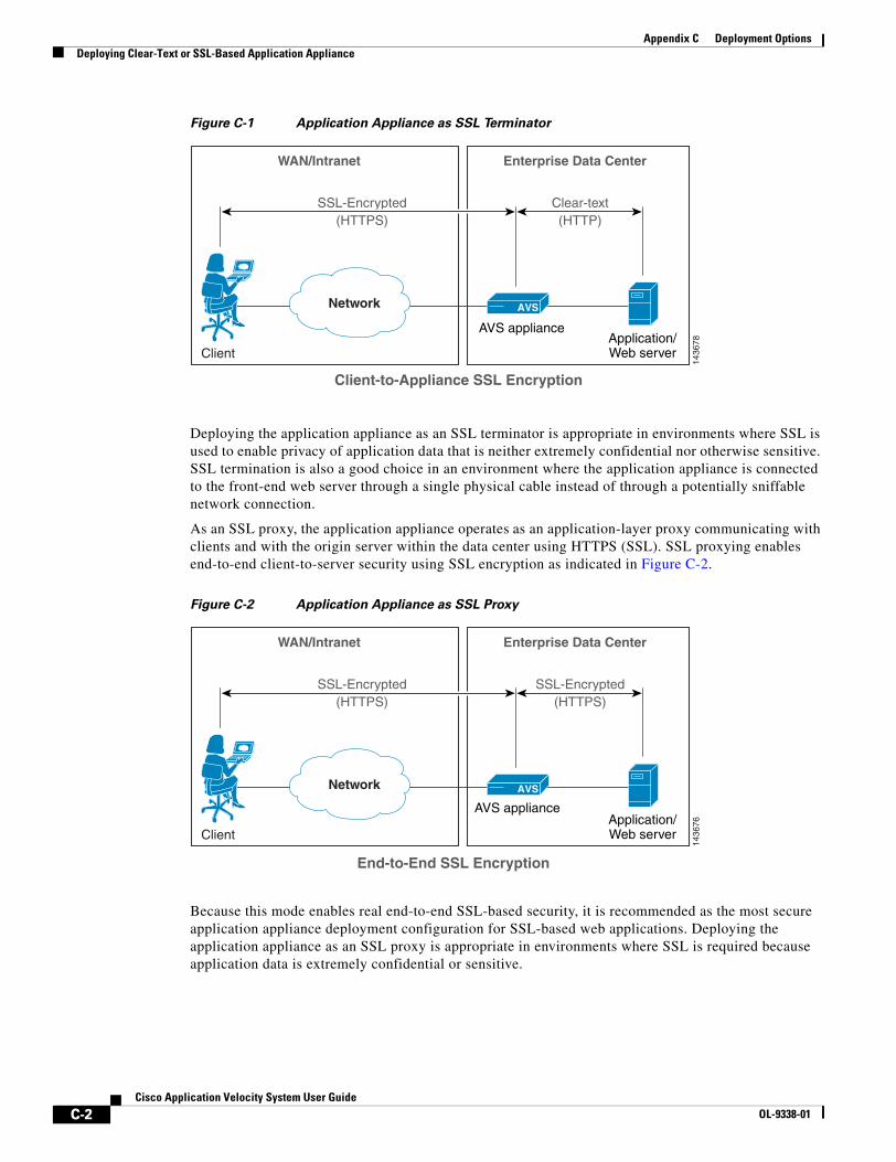
C-2Cisco Application Velocity System User Guide
OL-9338-01
Appendix C Deployment OptionsDeploying Clear-Text or SSL-Based Application Appliance
Figure C-1 Application Appliance as SSL Terminator
Deploying the application appliance as an SSL terminator is appropriate in environments where SSL is used to enable privacy of application data that is neither extremely confidential nor otherwise sensitive. SSL termination is also a good choice in an environment where the application appliance is connected to the front-end web server through a single physical cable instead of through a potentially sniffable network connection.
As an SSL proxy, the application appliance operates as an application-layer proxy communicating with clients and with the origin server within the data center using HTTPS (SSL). SSL proxying enables end-to-end client-to-server security using SSL encryption as indicated in Figure C-2.
Figure C-2 Application Appliance as SSL Proxy
Because this mode enables real end-to-end SSL-based security, it is recommended as the most secure application appliance deployment configuration for SSL-based web applications. Deploying the application appliance as an SSL proxy is appropriate in environments where SSL is required because application data is extremely confidential or sensitive.
AVS appliance
1436
78
Enterprise Data Center
Application/Web server
AVS
WAN/Intranet
Client
Network
SSL-Encrypted(HTTPS)
Clear-text(HTTP)
Client-to-Appliance SSL Encryption
AVS appliance
1436
76
Enterprise Data Center
Application/Web server
AVS
WAN/Intranet
Client
Network
SSL-Encrypted(HTTPS)
SSL-Encrypted(HTTPS)
End-to-End SSL Encryption
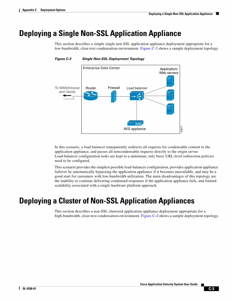
C-3Cisco Application Velocity System User Guide
OL-9338-01
Appendix C Deployment OptionsDeploying a Single Non-SSL Application Appliance
Deploying a Single Non-SSL Application ApplianceThis section describes a simple single non-SSL application appliance deployment appropriate for a low-bandwidth, clear-text condensation environment. Figure C-3 shows a sample deployment topology.
Figure C-3 Single Non-SSL Deployment Topology
In this scenario, a load balancer transparently redirects all requests for condensable content to the application appliance, and passes all noncondensable requests directly to the origin server. Load-balancer configuration tasks are kept to a minimum; only basic URL-level redirection policies need to be configured.
This scenario provides the simplest possible load-balancer configuration, provides application appliance failover by automatically bypassing the application appliance if it becomes unavailable, and may be a good start for customers with low-bandwidth utilization. The main disadvantages of this topology are the inability to continue delivering condensed responses if the application appliance fails, and limited scalability associated with a single-hardware platform approach.
Deploying a Cluster of Non-SSL Application AppliancesThis section describes a non-SSL clustered application appliance deployment appropriate for a high-bandwidth, clear-text condensation environment. Figure C-4 shows a sample deployment topology.
AVS appliance
1436
77
Enterprise Data Center
Router Firewall Load balancer
Application/Web servers
AVS
To WAN/Intranetand clients

C-4Cisco Application Velocity System User Guide
OL-9338-01
Appendix C Deployment OptionsDeploying a Single SSL-Terminating Application Appliance
Figure C-4 Clustered Non-SSL Deployment Topology
In this scenario, a load balancer transparently distributes all requests for condensable content across the application appliance cluster, and passes all noncondensable requests directly to the origin server. Failover is enabled by the load balancer’s ability to automatically redirect requests away from an unavailable application appliance to an available one, and ultimately bypass the entire application appliance cluster if it becomes unavailable. The main advantages of this topology are the ability to continue delivering optimized responses in the case of application appliance failure, and low-cost incremental condensation scalability associated with a multiple hardware platform approach.
An even easier way to enable load balancing and high availability is to use the built-in Availability Manager feature of the application appliance. This feature makes a separate load balancer unnecessary because the appliance provides this function. For more details, see the “Failover and Load Distribution” section on page C-9.
Deploying a Single SSL-Terminating Application ApplianceThis section describes a single SSL-terminating application appliance deployment appropriate for a low-traffic application environment. Figure C-5 shows a sample deployment topology.
AVS appliances
1436
75
AVS
Enterprise Data Center
Router Firewall Load balancer
Application/Web servers
AVS AVS
To WAN/Intranetand clients
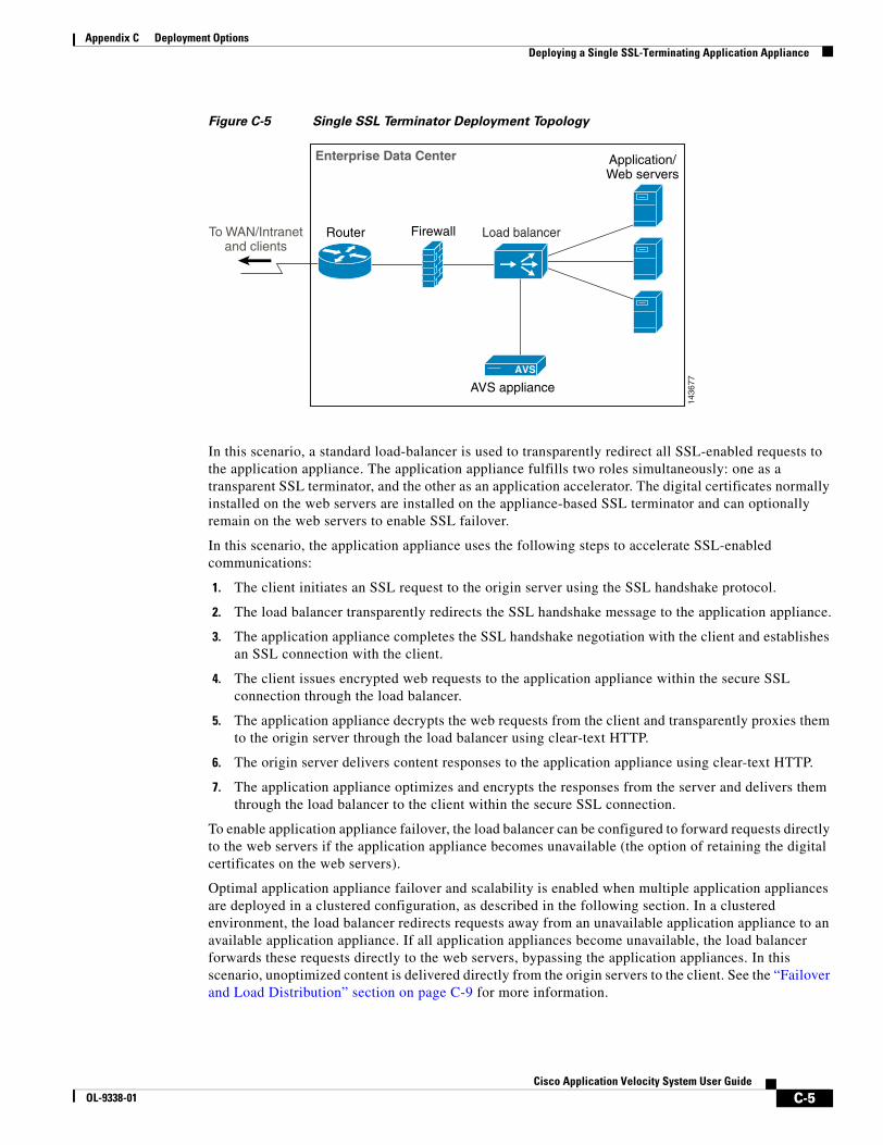
C-5Cisco Application Velocity System User Guide
OL-9338-01
Appendix C Deployment OptionsDeploying a Single SSL-Terminating Application Appliance
Figure C-5 Single SSL Terminator Deployment Topology
In this scenario, a standard load-balancer is used to transparently redirect all SSL-enabled requests to the application appliance. The application appliance fulfills two roles simultaneously: one as a transparent SSL terminator, and the other as an application accelerator. The digital certificates normally installed on the web servers are installed on the appliance-based SSL terminator and can optionally remain on the web servers to enable SSL failover.
In this scenario, the application appliance uses the following steps to accelerate SSL-enabled communications:
1. The client initiates an SSL request to the origin server using the SSL handshake protocol.
2. The load balancer transparently redirects the SSL handshake message to the application appliance.
3. The application appliance completes the SSL handshake negotiation with the client and establishes an SSL connection with the client.
4. The client issues encrypted web requests to the application appliance within the secure SSL connection through the load balancer.
5. The application appliance decrypts the web requests from the client and transparently proxies them to the origin server through the load balancer using clear-text HTTP.
6. The origin server delivers content responses to the application appliance using clear-text HTTP.
7. The application appliance optimizes and encrypts the responses from the server and delivers them through the load balancer to the client within the secure SSL connection.
To enable application appliance failover, the load balancer can be configured to forward requests directly to the web servers if the application appliance becomes unavailable (the option of retaining the digital certificates on the web servers).
Optimal application appliance failover and scalability is enabled when multiple application appliances are deployed in a clustered configuration, as described in the following section. In a clustered environment, the load balancer redirects requests away from an unavailable application appliance to an available application appliance. If all application appliances become unavailable, the load balancer forwards these requests directly to the web servers, bypassing the application appliances. In this scenario, unoptimized content is delivered directly from the origin servers to the client. See the “Failover and Load Distribution” section on page C-9 for more information.
AVS appliance
1436
77
Enterprise Data Center
Router Firewall Load balancer
Application/Web servers
AVS
To WAN/Intranetand clients
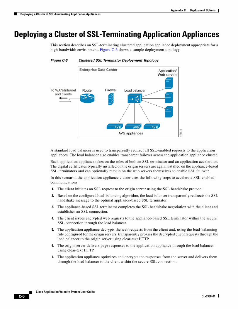
C-6Cisco Application Velocity System User Guide
OL-9338-01
Appendix C Deployment OptionsDeploying a Cluster of SSL-Terminating Application Appliances
Deploying a Cluster of SSL-Terminating Application AppliancesThis section describes an SSL-terminating clustered application appliance deployment appropriate for a high-bandwidth environment. Figure C-6 shows a sample deployment topology.
Figure C-6 Clustered SSL Terminator Deployment Topology
A standard load balancer is used to transparently redirect all SSL-enabled requests to the application appliances. The load balancer also enables transparent failover across the application appliance cluster.
Each application appliance takes on the roles of both an SSL terminator and an application accelerator. The digital certificates typically installed on the origin servers are again installed on the appliance-based SSL terminators and can optionally remain on the web servers themselves to enable SSL failover.
In this scenario, the application appliance cluster uses the following steps to accelerate SSL-enabled communications:
1. The client initiates an SSL request to the origin server using the SSL handshake protocol.
2. Based on the configured load-balancing algorithm, the load balancer transparently redirects the SSL handshake message to the optimal appliance-based SSL terminator.
3. The appliance-based SSL terminator completes the SSL handshake negotiation with the client and establishes an SSL connection.
4. The client issues encrypted web requests to the appliance-based SSL terminator within the secure SSL connection through the load balancer.
5. The application appliance decrypts the web requests from the client and, using the load-balancing rule configured for the origin servers, transparently proxies the decrypted client requests through the load balancer to the origin server using clear-text HTTP.
6. The origin server delivers page responses to the application appliance through the load balancer using clear-text HTTP.
7. The application appliance optimizes and encrypts the responses from the server and delivers them through the load balancer to the client within the secure SSL connection.
AVS appliances
1436
75
AVS
Enterprise Data Center
Router Firewall Load balancer
Application/Web servers
AVS AVS
To WAN/Intranetand clients
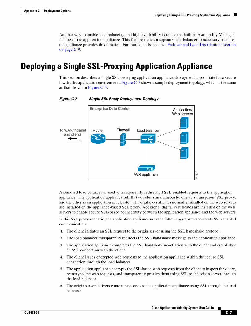
C-7Cisco Application Velocity System User Guide
OL-9338-01
Appendix C Deployment OptionsDeploying a Single SSL-Proxying Application Appliance
Another way to enable load balancing and high availability is to use the built-in Availability Manager feature of the application appliance. This feature makes a separate load balancer unnecessary because the appliance provides this function. For more details, see the “Failover and Load Distribution” section on page C-9.
Deploying a Single SSL-Proxying Application ApplianceThis section describes a single SSL-proxying application appliance deployment appropriate for a secure low-traffic application environment. Figure C-7 shows a sample deployment topology, which is the same as that shown in Figure C-5.
Figure C-7 Single SSL Proxy Deployment Topology
A standard load balancer is used to transparently redirect all SSL-enabled requests to the application appliance. The application appliance fulfills two roles simultaneously: one as a transparent SSL proxy, and the other as an application accelerator. The digital certificates normally installed on the web servers are installed on the appliance-based SSL proxy. Additional digital certificates are installed on the web servers to enable secure SSL-based connectivity between the application appliance and the web servers.
In this SSL proxy scenario, the application appliance uses the following steps to accelerate SSL-enabled communications:
1. The client initiates an SSL request to the origin server using the SSL handshake protocol.
2. The load balancer transparently redirects the SSL handshake message to the application appliance.
3. The application appliance completes the SSL handshake negotiation with the client and establishes an SSL connection with the client.
4. The client issues encrypted web requests to the application appliance within the secure SSL connection through the load balancer.
5. The application appliance decrypts the SSL-based web requests from the client to inspect the query, reencrypts the web requests, and transparently proxies them using SSL to the origin server through the load balancer.
6. The origin server delivers content responses to the application appliance using SSL through the load balancer.
AVS appliance
1436
77
Enterprise Data Center
Router Firewall Load balancer
Application/Web servers
AVS
To WAN/Intranetand clients
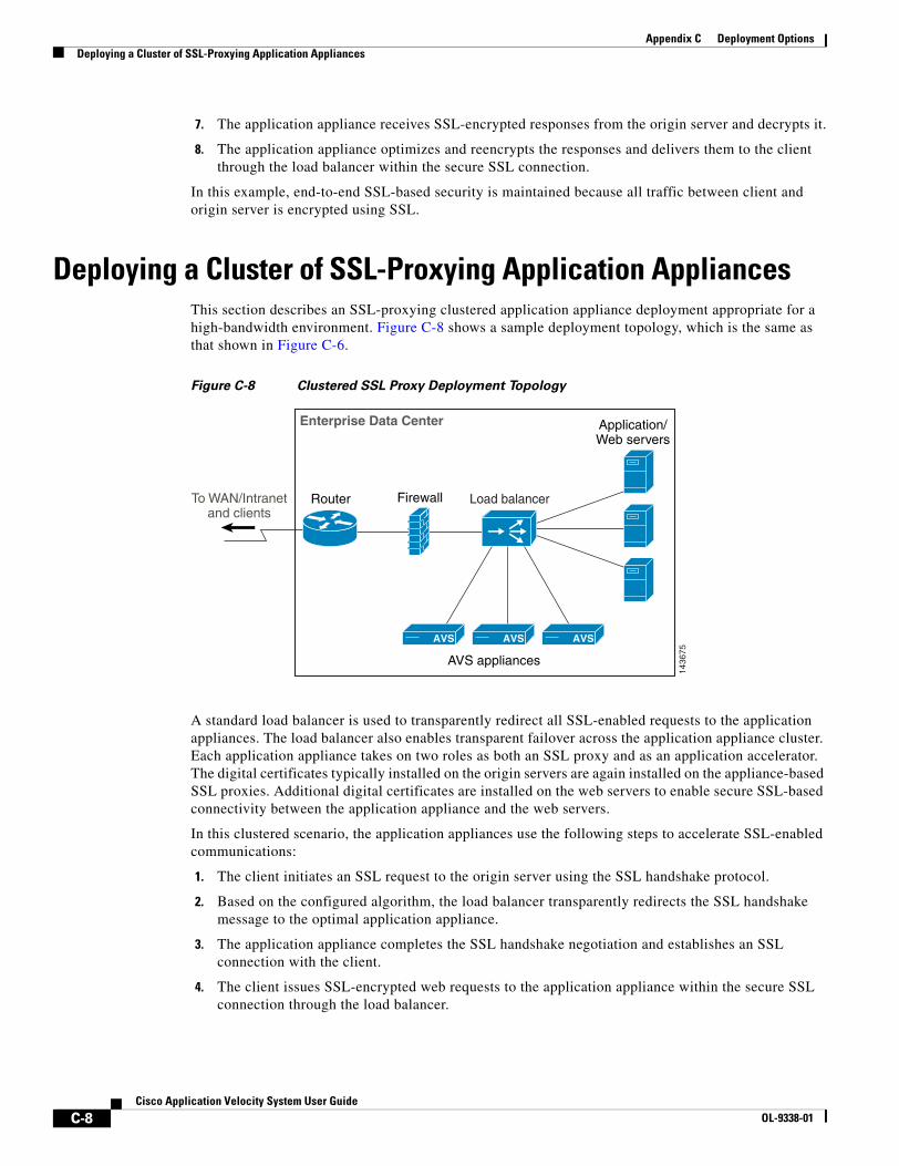
C-8Cisco Application Velocity System User Guide
OL-9338-01
Appendix C Deployment OptionsDeploying a Cluster of SSL-Proxying Application Appliances
7. The application appliance receives SSL-encrypted responses from the origin server and decrypts it.
8. The application appliance optimizes and reencrypts the responses and delivers them to the client through the load balancer within the secure SSL connection.
In this example, end-to-end SSL-based security is maintained because all traffic between client and origin server is encrypted using SSL.
Deploying a Cluster of SSL-Proxying Application AppliancesThis section describes an SSL-proxying clustered application appliance deployment appropriate for a high-bandwidth environment. Figure C-8 shows a sample deployment topology, which is the same as that shown in Figure C-6.
Figure C-8 Clustered SSL Proxy Deployment Topology
A standard load balancer is used to transparently redirect all SSL-enabled requests to the application appliances. The load balancer also enables transparent failover across the application appliance cluster. Each application appliance takes on two roles as both an SSL proxy and as an application accelerator. The digital certificates typically installed on the origin servers are again installed on the appliance-based SSL proxies. Additional digital certificates are installed on the web servers to enable secure SSL-based connectivity between the application appliance and the web servers.
In this clustered scenario, the application appliances use the following steps to accelerate SSL-enabled communications:
1. The client initiates an SSL request to the origin server using the SSL handshake protocol.
2. Based on the configured algorithm, the load balancer transparently redirects the SSL handshake message to the optimal application appliance.
3. The application appliance completes the SSL handshake negotiation and establishes an SSL connection with the client.
4. The client issues SSL-encrypted web requests to the application appliance within the secure SSL connection through the load balancer.
AVS appliances
1436
75
AVS
Enterprise Data Center
Router Firewall Load balancer
Application/Web servers
AVS AVS
To WAN/Intranetand clients
C-9Cisco Application Velocity System User Guide
OL-9338-01
Appendix C Deployment OptionsFailover and Load Distribution
5. The application appliance decrypts the SSL-based web requests from the client to inspect the query, reencrypts the web requests, and transparently proxies them using SSL to the origin server through the load balancer.
6. The origin server delivers SSL-based content responses to the application appliance through the load balancer.
7. The application appliance receives SSL-encrypted responses from the origin server and decrypts them.
8. The application appliance optimizes and reencrypts the responses and delivers them to the client through the load balancer within the secure SSL connection.
End-to-end SSL-based security is maintained because all traffic between client and origin server is encrypted using SSL.
Another way to enable load balancing and high availability is to use the built-in Availability Manager feature of the application appliance. This feature makes a separate load balancer unnecessary because the appliance provides this function. For more details, see the “Failover and Load Distribution” section next.
Failover and Load DistributionOptimal application appliance failover and scalability is enabled when multiple appliances are deployed in a clustered configuration. To enable appliance failover, you can use one of the following strategies:
• Enable the built-in Availability Manager, which provides a built-in high availability and load-balancing capability for a cluster of application appliances. Figure C-9 shows a cluster of application appliances directly handling web requests from clients. No load balancer is needed because the appliances are configured in a high availability, load-balanced cluster by using the Availability Manager feature. Refer to Chapter 11, “Availability Manager Clustering” for more information on using this feature.
• Use a load balancer to direct traffic to both the application appliances and the origin web servers. Figure C-10 shows a cluster of application appliance handling web requests from clients behind a load balancer. In a clustered environment, the load balancer redirects requests away from an unavailable application appliance to an available application appliance. If all application appliances become unavailable, the load balancer forwards these requests directly to the origin servers, bypassing the application appliances. In that case, pages are delivered as-is, directly from the origin servers to the client.

C-10Cisco Application Velocity System User Guide
OL-9338-01
Appendix C Deployment OptionsFailover and Load Distribution
Figure C-9 Appliance Cluster Using Built-in Availability Manager
vip1
1436
71
10.0.1.10
10.0.1.20
AVS appliancesAVS
LAN/WAN/Internet AVS
Application/Web servers
Name: mysite.mydomain.comAddress: 10.0.1.10
vip2
<DestinationMapping> Dest 10.0.1.10 -> 10.0.1.20 protocol=clientprotocol</DestinationMapping>
In a clustered configuration, the VIP (Virtual IP address) is configured and managed by eachsystem’s own cluster management software. In this case, vip1 is assigned an IP address of10.0.1.10 and is managed by the AVS Availability Manager. Vip2 is assigned an IP address of10.0.1.20 and is managed by the clustering software used by the application/web servers. Thedomain name mysite.mydomain.com is assigned the IP address of vip1, in this case, 10.0.1.10.
When a client browser makes a request to http://mysite.mydomain.com, it’ll open an HTTPconnection to 10.0.1.10, which is distributed to an AVS appliance by the AVS Availability Manager.When the appliance receives the request, it’ll make the HTTP request to IP address 10.0.1.20, asspecified in the DestinationMapping rule. The application/web server clustering software thendistributes the request to 10.0.1.20, to the pool of web application servers. The response from theapplication/web servers is then processed by the AVS appliance and sent back to the browser.

C-11Cisco Application Velocity System User Guide
OL-9338-01
Appendix C Deployment OptionsFailover and Load Distribution
Figure C-10 Appliance Cluster Behind Load Balancer
vip1
1436
79
10.0.1.10
10.0.1.20
AVS appliances
AVS
LAN/WAN/Internet
AVS
Application/Web servers
Name: mysite.mydomain.comAddress: 10.0.1.10
vip2
<DestinationMapping> Dest 10.0.1.10 -> 10.0.1.20 protocol=clientprotocol</DestinationMapping>
Load balancer
In a load balanced configuration, the VIP (Virtual IPaddress) is configured and managed by the load balancer,with vip1 assigned to the pool of AVS appliances and vip2assigned to the pool of application/web servers. Thedomain name mysite.mydomain.comis assigned the IPaddress of vip1, in this case, 10.0.1.10.
When a client browser makes a request tohttp://mysite.mydomain.com, it’ll open an HTTPconnection to 10.0.1.10, which is distributed to the pool ofAVS appliances by the load balancer. When an appliancereceives the request, it’ll make the HTTP request to IPaddress 10.0.1.20, as specified in the Destination Mappingrule. The load balancer then distributes the request to10.0.1.20, to the pool of web application servers. Theresponse from the application/web servers is thenprocessed by the AVS appliance and sent back to thebrowser.

C-12Cisco Application Velocity System User Guide
OL-9338-01
Appendix C Deployment OptionsFailover and Load Distribution
D-1Cisco Application Velocity System User Guide
OL-9338-01
A P P E N D I X DFrequently Asked Questions and Troubleshooting
This chapter includes the following sections:
• Frequently Asked Questions (FAQ), page D-1
• Troubleshooting, page D-5
Frequently Asked Questions (FAQ)What is the Cisco Performance Suite?
Available in the hardware-based Cisco Application Velocity System, the Cisco Performance Suite is the industry’s leading enterprise application performance-optimization and monitoring solution. A transparent solution, the Cisco Performance Suite consists of the following product components:
• Condenser—Transparently accelerates the performance of HTTP and HTTPS-based enterprise applications. See the Condenser Acceleration Software FAQ for more information.
• Web Application Security Firewall—Provides web application security and intrusion protection.
• AppScope Performance Monitor—Monitors the actual end-user experience of HTTP and HTTPS-based enterprise applications at the transaction level without requiring client software or client emulation agents.
What are the Condenser Application Accelerator and Application Velocity System?
Available in the hardware-based Application Velocity System, the Condenser Application Accelerator is the leading solution that accelerates enterprise application performance, resulting in increased employee productivity, improved user experience, and reduced infrastructure costs. Using the broadest suite of optimization techniques available, the Condenser enables enterprises to optimize performance and improve access to critical business information. Cisco unlocks the value of existing enterprise investments and achieves significant returns by accelerating the performance of HTTP and HTTPS (SSL)-based web applications including CRM, ERP, portals, and online collaboration.

D-2Cisco Application Velocity System User Guide
OL-9338-01
Appendix D Frequently Asked Questions and TroubleshootingFrequently Asked Questions (FAQ)
What are the AppScope Performance Monitor and Application Velocity System?
Available in the hardware-based Application Velocity System, the AppScope Performance Monitor is the industry’s only low-cost, low-complexity agentless end-to-end performance measurement solution for HTTP and HTTPS (SSL)-based applications. AppScope may be used independently to measure the end-user experience or in combination with the Condenser Application Accelerator Module to accelerate application performance.
Unlike existing solutions that require the deployment of additional software agents that emulate client requests and measure simulated response times at the object level, Cisco’s AppScope technology measures accurate end-to-end application performance as seen by real end users. AppScope also accurately determines and reports both the server delay and network delay components associated with the user experience.
The AppScope Performance Monitor provides a sophisticated GUI-based reporting engine that enables enterprises to efficiently track application performance. AppScope’s reporting engine provides detailed graphical performance monitoring results with drilldowns available using transactions (URL groups), source IP address groups, and source geography groups.
AppScope’s web-based GUI configurator eases product configuration to enable fast deployment. In addition, all AppScope Performance Monitor data is stored in a self-contained relational database, providing additional flexibility for an organization to use its own reporting tools, such as Crystal Reports, or create its own custom performance monitoring reports.
Does the Cisco Performance Suite or Application Velocity System require any special client/server software or configuration?
No. A truly transparent and automatic solution, Cisco products require no additional software or configuration changes on browser clients or origin and application servers and require no changes in origin and application server pages.
What is delta optimization technology?
Delta optimization eliminates redundant traffic on the network by computing and transmitting only the changes that occur in a web page between successive downloads of the same page or similar pages. This eliminates the need to download redundant information between successive visits to the page, and instead enables the client to download only the changes to the page.
What is FlashForward object acceleration technology?
FlashForward object acceleration technology eliminates network delays associated with embedded cacheable web objects such as images, style sheets, JavaScript files, etc. FlashForward object acceleration places the responsibility for validating object freshness on the Condenser, rather than on the client, making it more efficient. With FlashForward, the client never needs to validate the freshness of browser-cached objects with the origin server, which significantly accelerates page downloads, and reduces both upstream and downstream traffic associated with object validation requests.
What is just-in-time object acceleration technology?
Just as FlashForward accelerates delivery of embedded cacheable objects, just-in-time object acceleration enables acceleration of noncacheable embedded objects, resulting in improved application response time. This feature eliminates the need for users to download these objects on each request. Instead, the Condenser automatically tracks the freshness of each of these objects in real-time. If a requested object has not changed, the Condenser instructs the client to use the cached version of the
D-3Cisco Application Velocity System User Guide
OL-9338-01
Appendix D Frequently Asked Questions and TroubleshootingFrequently Asked Questions (FAQ)
object. If an object has indeed changed, the Condenser delivers it to the client. The Condenser delivers the object only if it determines that the object has changed, guaranteeing the optimal application response times for all users.
What is smart image optimization technology?
Smart image optimization automatically reduces image file sizes while optimizing image quality, resulting in faster image download times, faster page renders, and more efficient bandwidth utilization. Smart image optimization balances image size and quality by intelligently recompressing only low-detail areas within images. This ensures that image sizes are significantly reduced (up to 90 percent) while maintaining rich visual detail. Smart image optimization works together with FlashForward object acceleration to enable the fastest image optimization and delivery available today.
What is smart redirect technology?
Some applications and content management systems enable enterprises to automatically redirect users from one page to another using HTML META tags. Unfortunately, using META-based page redirections causes poor download times because it forces the end user to issue freshness validation requests for every object in the redirected page, resulting in potentially significant page download delays. The smart redirect feature enables the Condenser to automatically and transparently convert HTML META tag-based redirections into more efficient HTTP header-based redirections in order to eliminate the need for unnecessary freshness validation requests. This results in significantly faster page response times without sacrificing the META tag-based redirection flexibility enabled by many enterprise applications.
What is adaptive dynamic caching technology?
Adaptive dynamic caching accelerates enterprise application performance and improves server system scalability by enabling the Condenser to fulfill requests for dynamic content, which offloads application servers and databases. This feature not only significantly improves application response time, it also reduces server load and enables more concurrent users to be served, resulting in improved scalability and lower ongoing server upgrade costs. The Performance Assurance caching policy enables the Condenser to monitor server load in real-time and make intelligent closed-loop content expiration decisions so that site performance is maximized and existing hardware resources are used most efficiently, even during periods of peak traffic load.
What does the SSL Acceleration feature do?
The Condenser’s SSL acceleration feature enables it to handle the SSL handshake with clients, decrypt web requests from clients, transparently proxy them to the content server, condense the server responses (using the delta optimization and FlashForward capabilities), encrypt the condensed responses, and deliver them to clients within secure SSL connections.
The Condenser accelerates SSL performance by requiring only small delta optimized pages to be encrypted rather than the entire page. In addition, FlashForward object acceleration eliminates the vast majority of object validation requests from clients on subsequent page visits, resulting in a significantly reduced number of SSL-based transactions and a significant increase in SSL scalability. Integrated SSL capabilities make the Condenser the only transparent solution to deliver guaranteed secure content acceleration.
What does server connection offload do?
The server connection offload feature enables the Condenser to take on the overhead of managing network connections with browsers by maintaining persistent TCP connections with the web and application servers. In order to optimize overall performance as traffic levels change, the Condenser

D-4Cisco Application Velocity System User Guide
OL-9338-01
Appendix D Frequently Asked Questions and TroubleshootingFrequently Asked Questions (FAQ)
intelligently increases and decreases the number of persistent TCP connections to the web servers as load conditions require. This feature enables web and application servers to focus solely on content generation, resulting in a significant improvement in web server capacity.
How is industry-standard text compression used?
Although standard text compression has become more popular, it typically provides only modest improvements in real world conditions and is not sufficiently powerful or robust for enterprise requirements. The Condenser leverages compression to further reduce the byte size of delta optimized pages. Reducing page sizes is key to accelerating download times. The Condenser combines delta optimization with compression to deliver optimal page size reductions because it enables the Condenser to send only the compressed version of what has changed to the client.
How does AppScope measure the end-user experience without the use of additional client, server, or synthetic transaction agents?
Because the AppScope Performance Monitor is a transparent reverse-proxy, it does not need to rely on passive sniffing mechanisms to monitor traffic. AppScope’s unique proxy architecture enables it to accurately monitor both HTTP and HTTPS (SSL)-based traffic without comprising security by actively instrumenting each page for measurement dynamically. This page instrumentation enables the client to actively notify the AppScope server when the page has been fully received and rendered. This technique, combined with other gathered metrics, enables AppScope to accurately report the actual end-user experience at the transaction level rather than at the individual object level. AppScope’s SSL-proxying capability makes it the only agentless solution that can monitor SSL-based traffic while retaining end-to-end SSL-based security.
What is AppScope’s Statistical Sampling mechanism?
Unlike existing performance monitoring solutions that require you to measure all user requests, AppScope’s unique Statistical Traffic Sampling technology enables an enterprise to statistically sample user requests, making AppScope highly scalable for high-traffic applications. AppScope enables you to utilize your existing load balancer to transparently direct a portion of the traffic for measurement. In environments where a load balancer is not used, AppScope can be configured to see all of the traffic passing between client and server and measure a portion of the total.
Why is an agentless performance measurement solution superior to agent-based solutions?
Agentless solutions such as AppScope eliminate the need for you to deploy additional software agents or plug-ins on clients, servers, or elsewhere. In addition, agentless solutions eliminate the need for the software vendor to invest capital in the development and delivery of agent software. This decreased complexity results in simplified product deployment and a significantly decreased total cost of ownership (TCO). In addition, many existing agent-based solutions can only measure the response times associated with agents that periodically issue synthetic transactions. These solutions cannot measure the actual end-user experience. AppScope measures the actual end-user experience.
Can AppScope be used to monitor SSL-based applications?
Yes, AppScope’s SSL-proxying capability makes it the only agentless solution that can monitor SSL-based traffic while retaining true end-to-end SSL-based security. When deployed as an SSL Proxy, AppScope maintains end-to-end SSL-based security because all traffic between client and origin server is encrypted using SSL.

D-5Cisco Application Velocity System User Guide
OL-9338-01
Appendix D Frequently Asked Questions and TroubleshootingTroubleshooting
What does the Management Console do?
Integrated within the Application Velocity System, the centralized browser-based Management Console enables the administrator to manage and monitor groups of application appliances using a standard browser. The Management Console enables you to access the configuration, system information, and performance reports (on the AVS 3180). These management and monitoring capabilities simplify and reduce the time and cost associated with ongoing system management tasks.
On which platforms are the Performance Suite and Application Velocity System products available?
The Performance Suite is available in the Cisco AVS 3120 Application Velocity System, which also includes a Device Management Console that allows you to manage and configure one or more AVS 3120 devices. The full Management Console, with device management and reporting features, is available in the Cisco AVS 3180 Management Station.
How do I enable product redundancy and fail-over?
The built-in Availability Manager allows you to deploy a cluster of two or more application appliances with high availability and load balancing. One active Availability Manager appliance can manage one standby appliance and other additional appliances. If the active appliance is found to be down, the standby appliance takes over the load-balancing role.
The Cisco AVS products can also be deployed with existing load balancers to provide redundancy and fail-over. In this configuration, the load balancer automatically bypasses an unavailable application appliance device when it detects that it is no longer responding.
Which load balancers have Cisco Networks certified as Cisco-compatible?
Cisco has certified the following load balancers for use with the Application Velocity System products: Cisco Arrowpoint, Cisco LocalDirector, F5 Networks Big/IP, Alteon AceDirector, Resonate Central Dispatch, and Foundry Server Iron.
How do I access the application appliance remotely?
The only way to access the appliance remotely is by using SSH.
TroubleshootingThe application appliance is not receiving requests, nor is it delivering responses. What should I do?
• Verify that network connectivity is established for the application appliance.
• Verify that the application appliance server processes are up and running.
Use the following UNIX command to verify that the application appliance HTTP process is running:
ps -aef | grep -i http
• If you are using a web browser to test the application appliance, verify that its proxy setting is not configured to bypass the application appliance node.
D-6Cisco Application Velocity System User Guide
OL-9338-01
Appendix D Frequently Asked Questions and TroubleshootingTroubleshooting
Although the application appliance is receiving requests and is delivering responses, it does not appear to be delivering condensed content. What should I do?
• Verify that the useragent.conf configuration file explicitly includes the browser User Agent string for the browser originating the requests to the application appliance. Only browsers with User Agent strings identified in the useragent.conf configuration file will receive condensed responses. The useragent.conf configuration file supports the use of regular-expression matching.
• Verify the following parameters in the fgn.conf configuration file:
– DeltaOptimize is set to On. Condensation will not occur if this parameter is set to Off.
– CacheRoot is set to a valid directory path. Condensation will not occur if this parameter is not valid.
– Verify that the content associated with the problematic URLs is no smaller than 1024 bytes and no larger than 250 KB. By default, the application appliance will not condense responses outside of these size ranges. This size range can be configured using the MinCondensablePage and MaxCondensablePage parameters.
– Verify that your condensation policies are correctly defined. Make sure that the problematic URLs are configured to receive condensation.
• Verify that the MIME types of the content associated with the problematic URLs are not included in the mimetypes.conf configuration file. The application appliance will not condense responses with MIME types identified in the mimetypes.conf configuration file.
• Verify that the content associated with the problematic URLs does not contain the following non-condensable content:
– Inline frame (IFRAME tags)
– External JavaScript includes (SCRIPT tags including the SRC attribute)
– Embedded objects (OBJECT tags)
These elements are passed through uncondensed. All JavaScript code embedded in a page is passed through uncondensed and in the exact order in which it appears in the origin page. This technique avoids problems related to JavaScript dependencies and execution order.
• Use the command ls -l cacherootDirectory to verify that the user who started the application appliance node has full read and write permissions for the CacheRoot directory.
• Verify that JavaScript is supported and enabled in the browser originating the requests to the application appliance. The application appliance will not condense responses to requests from browsers that do not support JavaScript or have it disabled.
Although the application appliance is receiving requests and is delivering responses, it does not appear to be delivering compressed content. What should I do?
• Verify the following parameters in the fgn.conf configuration file:
– CompressContent is set to On. Compression will not occur if this parameter is set to Off.
– Verify that your condensation policies are correctly defined. Check that the problematic URLs are configured to receive compression.
• Verify that the browser originating the requests to the application appliance can accept gzip-compressed content. The application appliance will only deliver gzip-compressed responses to browsers that include an “Accept-Encoding: gzip” or an “Accept-Encoding: x-gzip” HTTP request header. Responses to requests that do not contain this request header will be delivered uncompressed.

D-7Cisco Application Velocity System User Guide
OL-9338-01
Appendix D Frequently Asked Questions and TroubleshootingTroubleshooting
• Verify that the configuration settings for the BaseFileCompress and HTTP10Compress parameters in the fgn.conf file are set correctly. By default neither base files nor HTTP 1.0 responses will receive gzip compression (that is, the default value for both is “Off”).
I am seeing unexpected condensation behavior. What should I do?
• If you are using Per-URL condensation, verify that the content associated with the problematic URLs is receiving repeated requests from a given user. In this mode, a base file is created for each URL and condensed content is delivered for subsequent visits to that same page (that is, the page is condensed against previous versions of the same page or URL). The end-user must request the base page for the first visit to a given URL. Although the application appliance can be configured to gzip-compress them, they will be larger in size than subsequent delta pages. As a result, (in the absence of edge-caching) if many unique users visit a given page, the application appliance will need to deliver the base page on each user’s first visit.
The base files are always marked as cacheable using the HTTP Cache-Control response header. As a result, caches within the application appliance-to-client path will cache application appliance base files. When this occurs, the edge-cache will fulfill requests from new visitors for the base file, reducing the load on the application appliance node, and improving the condensation levels delivered.
• Determine the nature of content delivered by parameterized URLs (that is, URLs that embed a “?” character). The application appliance automatically parses parameterized requests to eliminate the “?” and the characters that follow in order to identify the unique part of the URL. This unique URL is then used to create the base file. The application appliance uses this feature to map multiple parameterized URLs to a single canonical URL. For example, the two URLs, http://www.servers.com/books?id=235 and http://www.servers.com/books?id=576, would both be reduced to the URL http://www.servers.com/books. As a result, both of these parameterized URLs would share the same base file that represents the canonical URL http://www.servers.com/books. Condensation levels will be relatively low if these original URLs reference two pages that do not share much content or layout (that is, relatively large delta files could be delivered for requests across parameterized URLs that do not share content or layout).
Generating a Core File
On rare occasions, it may become necessary to have the application appliance node dump core information in order to debug or aid in troubleshooting operational problems. To generate a core file, follow these steps:
Step 1 Within the $AVS_HOME/perfnode/conf/httpd.conf configuration file, specify the directory where the core file is to be written by using the CoreDumpDirectory keyword. For example:
CoreDumpDirectory /tmp
This example directive will place the core files within the /tmp directory. The default directory is $AVS_HOME/perfnode/logs/coredump.
Step 2 Generate the core file by entering the following commands:
# ulimit -c unlimited# cd $AVS_HOME/perfnode/bin# ./fgnctl start

D-8Cisco Application Velocity System User Guide
OL-9338-01
Appendix D Frequently Asked Questions and TroubleshootingTroubleshooting
Once a core file has been produced, you should see an entry similar to the following in the error log:
[Wed Sep 8 13:39:40 2004] [notice] child pid 3790 exit signal Segmentation fault (11), possible coredump in /tmp
Log rotation is not supported currently for these core files. As a result, you must manage these files to avoid running out of disk space.
E-1Cisco Application Velocity System User Guide
OL-9338-01
A P P E N D I X EAnonymous Base File Statistical Model
This appendix presents a statistical model that quantifies the probability of any confidential data common to a set of users (and context for that data to be associated with a user) being present within an anonymous base file.
Consider two variables m and n, where m represents the “base file anonymity level” and n represents the “base file sample size.” This technology creates a single base file shared by all users that contains only content common to m out of n user-specific base files (and users). For example, if m=5 and n=15, the anonymous base file will contain only content common to at least 5 of 15 base files. Any content unique to any of the 15 user-specific base files is excluded from the anonymous base file. Content common to less than 5 of the 15 user-specific base files is excluded.
The user-specific base files in the base file sample size are selected as the first n unique requests (that is, with unique application appliance cookie IDs) for a given URL or set of URLs, depending on application appliance configuration. The n base files within the sample size are of a per-user type created solely to enable this feature. These per-user base files are not used to condense content themselves; only the resulting anonymous base file is used to condense content.
The BaseFileAnonLevel configuration parameter enables the administrator to select a value of m. The application appliance automatically sets the base file sample size n to the greater of 3m or 5 (n=max (3m, 5)) to ensure an extremely low probability of creating a shared anonymous base file that contains confidential information common to the user-specific base files within the base file sample size. Through extensive testing, Cisco recommends an anonymity level of m=2 for those who use this feature. The anonymous base files feature is an all-user Condensation option and must be explicitly configured to be enabled.
Statistical Model for Anonymous Base File TechnologyIn this section a statistical model is described that quantifies the probability of any confidential data common to a set of users (and context for that data to be associated with a user) being present within an anonymous base file.
m represents the “base file anonymity level” and n represents the “base file sample size”. Given m and n, the only way for the anonymous base file to include some user-specific context is for at least m out of n selected base files within the base file sample size to contain common confidential user-specific information such as a home address, credit card number, etc. As an example of how this might occur, consider the following scenario for m=2.
Suppose different users on different machines use the same credit card online. This could occur when a corporate or shared family credit card is used for an online transaction. In this case, if these transactions occur in rapid succession so that their associated user-specific base files are selected as part of the base
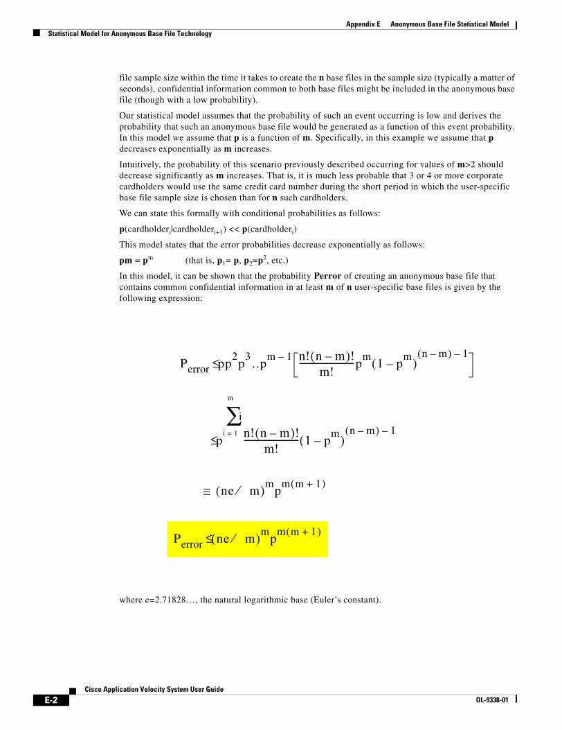
E-2Cisco Application Velocity System User Guide
OL-9338-01
Appendix E Anonymous Base File Statistical ModelStatistical Model for Anonymous Base File Technology
file sample size within the time it takes to create the n base files in the sample size (typically a matter of seconds), confidential information common to both base files might be included in the anonymous base file (though with a low probability).
Our statistical model assumes that the probability of such an event occurring is low and derives the probability that such an anonymous base file would be generated as a function of this event probability. In this model we assume that p is a function of m. Specifically, in this example we assume that p decreases exponentially as m increases.
Intuitively, the probability of this scenario previously described occurring for values of m>2 should decrease significantly as m increases. That is, it is much less probable that 3 or 4 or more corporate cardholders would use the same credit card number during the short period in which the user-specific base file sample size is chosen than for n such cardholders.
We can state this formally with conditional probabilities as follows:
p(cardholderi|cardholderi+1) << p(cardholderi)
This model states that the error probabilities decrease exponentially as follows:
pm = pm (that is, p1= p, p2=p2, etc.)
In this model, it can be shown that the probability Perror of creating an anonymous base file that contains common confidential information in at least m of n user-specific base files is given by the following expression:
where e=2.71828…, the natural logarithmic base (Euler’s constant).
Perror pp2p
3…pm 1– n! n m–( )!
m!-------------------------p
m1 p
m–( )
n m–( ) 1–≤
p
i
i 1=
m
∑n! n m–( )!
m!------------------------- 1 p
m–( )
n m–( ) 1–≤
ne m⁄( )mp
m m 1+( )≅
Perror ne m⁄( )mp
m m 1+( )≤
E-3Cisco Application Velocity System User Guide
OL-9338-01
Appendix E Anonymous Base File Statistical ModelStatistical Model for Anonymous Base File Technology
Case 1: p=1%In this example, it is assumed that the probability of m cardholders using the same credit card number to execute an online transaction within the time required to generate n user-specific base files (on the order of a few seconds) is (.01)m.
Assuming p=1% so that pm=(.01)m, various values of m, and n=max(3m,5), refer to Table E-1 for values of Perror.
In this model, using the recommended configuration value of m=2, and thus n=6, Table E-1 shows that the probability Perror of creating such an anonymous base file is about 1 in 1.5x 10¹⁰ (that is, 1 in 15 billion).
Case 2: p=5%In this example, it is assumed that the probability of m cardholders using the same credit card number to execute an online transaction within the time required to generate n user-specific base files (on the order of a few seconds) is (.05)m.
Assuming p=5% so that pm=(.05)m, various values of m, and n=max(3m,5), refer to Table E-2 for values of Perror.
Using the recommended configuration value of m=2 and n=6, Table E-2 shows that the probability Perror of creating such an anonymous base file is 1 in 9.6 x 10⁵ (about 1 in 1 million).
Table E-1 Case 1, p=1%
m n Perror (%) Ratio
2 6 6.6501E-11 1 in 1.5037E+10
3 9 5.4231E-22 1 in 1.8440E+21
4 12 4.4224E-37 1 in 2.2612E+36
5 15 3.6064E-56 1 in 2.7728E+55
6 18 2.9410E-79 1 in 3.4002E+78
7 21 2.3983E-106 1 in 4.1696E+105
Table E-2 Case 2, p=5%
m n Perror (%) Ratio
2 6 1.0391E-06 1 in 9.6239E+05
3 9 1.3240E-13 1 in 7.5529E+12
4 12 4.2176E-23 1 in 2.3710E+22
5 15 3.3587E-35 1 in 2.9773E+34
6 18 6.6870E-50 1 in 1.4954E+49
7 21 3.3283E-67 1 in 3.0045E+66

E-4Cisco Application Velocity System User Guide
OL-9338-01
Appendix E Anonymous Base File Statistical ModelStatistical Model for Anonymous Base File Technology
This model clearly shows that the probability of generating an anonymous base file that contains common confidential information and user-specific context is extremely low (almost zero). As a result, this feature is a highly effective mechanism for enabling condensation of personalized or confidential content. When this feature is used in conjunction with SSL, the application appliance enables condensed content confidentiality as well as condensed content security via SSL encryption.
F-1Cisco Application Velocity System User Guide
OL-9338-01
A P P E N D I X FRegular Expressions
This appendix contains information about the regular expression syntax used by the application appliance. The syntax is the GNU POSIX regular expression syntax.
• Regular Expression Reference, page F-1
• Regular Expression Pattern Examples, page F-3
• Additional Information, page F-3
Note The web application security module uses a regular expression syntax that is different from the regular expression syntax described in this appendix, which the other AVS features use. The regular expression syntax used by the web application security module is described in the “Web Application Security Regular Expression Syntax” section on page 6-72.
Regular Expression ReferenceThis section contains regular expression reference information. The following table contains the most common regular expression metacharacters, but is not comprehensive.
Table F-1 Regular Expression Syntax
Metacharacter Description
. Matches any single character. For example, the regular expression r.t matches the strings rat, rut, r t, but not root.
$ Matches the end of a line. For example, the regular expression you$ matches the end of the string “Thank you” but not the string “Thank you very much.”
^ Matches the beginning of a line. For example, the regular expression ^When in matches the beginning of the string “When in the course of human events” but not the string “What and When in the.”
* Matches zero or more occurrences of the character immediately preceding. For example, the regular expression .* means match any number of any characters.
\ This is the quoting character; use it to treat the following metacharacter as an ordinary character. For example, \$ is used to match the dollar sign character ($) rather than the end of a line. Similarly, the expression \. is used to match the period character rather than any single character.
F-2Cisco Application Velocity System User Guide
OL-9338-01
Appendix F Regular ExpressionsRegular Expression Reference
The regular expression evaluator matches the longest pattern possible.
For example, say you want to parse a URL. You might use a regular expression like this:
(http)://(.*)/(.*)
expecting to parse a URL such as “http://www.example.com/images/kournikova.jpg” into these strings:
group 0: “http://www.example.com/images/kournikova.jpg”
group 1: “http”
group 2: “www.example.com”
group 3: “/images/kournikova.jpg”
However, this attempt yields unexpected results for groups 2 and 3:
group 2: “www.example.com/images/”
group 3: “kournikova.jpg”
This result occurs because the group 2 string that the regular expression evaluator found represents the longest match for the given pattern. The matched string does not end with the first / found, it ends with the last one found.
To achieve the desired result, use this regular expression:
http://([^/]*)/(.*)$
This works because the first group (the first expression in parenthesis) matches 0 or more characters up to any that is not in the set that includes /.
[ ]
[c1-c2]
[^c1-c2]
Matches any one of the characters between the brackets. For example, the regular expression r[aou]t matches rat, rot, and rut, but not ret. Ranges of characters are specified by a beginning character (c1), a hyphen, and an ending character (c2). For example, the regular expression [0-9] means match any digit. Multiple ranges can be specified as well. The regular expression [A-Za-z] means match any upper or lower case letter. To match any character except those in the range (that is, the complement range), use the caret as the first character after the opening bracket. For example, the expression [^269A-Z] matches any characters except 2, 6, 9, and uppercase letters.
\< \> Matches the beginning (\<) or end (\>) of a word. For example, the expression \<the matches “the” in the string “for the wise” but does not match “the” in “otherwise.”
( ) Treats the expression between ( and ) as a group. Also, saves the characters matched by the expression into temporary holding areas. Up to nine pattern matches can be saved by a single regular expression. They can be referenced as \1 through \9 (on the same line only).
| Logical OR two conditions together. For example (him|her) matches the line “it belongs to him” and matches the line “it belongs to her” but does not match the line “it belongs to them.”
+ Matches one or more occurrences of the character or regular expression immediately preceding. For example, the regular expression 9+ matches 9, 99, and 999.
? Matches 0 or 1 occurrence of the character or regular expression immediately preceding.
{i}
{i,j}
Matches a specific number (i) or range (i through j) of instances of the preceding character. For example, the expression A[0-9]{3} matches “A” followed by exactly 3 digits. That is, it matches A123 but not A1234. The expression [0-9]{4,6} matches any sequence of 4, 5, or 6 digits.
Table F-1 Regular Expression Syntax (continued)
Metacharacter Description
F-3Cisco Application Velocity System User Guide
OL-9338-01
Appendix F Regular ExpressionsRegular Expression Pattern Examples
Regular Expression Pattern ExamplesTable F-2 lists some examples of regular expression patterns.
Additional InformationFor more information about regular expressions, refer to a POSIX regular expression reference book.
Table F-2 Regular Expression Pattern Examples
Pattern Regular Expression
IP Address (\[0-9]{1,3})\.(\[0-9]{1,3})\.(\[0-9]{1,3})\.(\[0-9]{1,3})
Domain Name ^[a-zA-Z]([a-zA-Z0-9-][a-zA-Z0-9])?\.[a-zA-Z]([a-zA-Z0-9-][a-zA-Z0-9])?(\.[a-zA-Z]([a-zA-Z0-9-][a-zA-Z0-9])?)?$
E-mail addresses {^[A-Za-z0-9._-]+@[[A-Za-z0-9.-]+$}
URL ("http://"|"mailto:"|"ftp://")[^ \n\r\"\<\\]+

F-4Cisco Application Velocity System User Guide
OL-9338-01
Appendix F Regular ExpressionsAdditional Information
G-1Cisco Application Velocity System User Guide
OL-9338-01
A P P E N D I X GAppScreen Rules DTD
The following DTD describes the syntax of the AppScreen rules file:
<!ELEMENT appscreen:rules (version, rules)>
<!ELEMENT version (#PCDATA)>
<!-- Allow zero-or-more (*) rules, instead of one-or-more (+) - this allows all of the rules to be commented out, and the rules file is still valid.--><!ELEMENT rules (rule)*>
<!ELEMENT rule (op)+><!ATTLIST rule name CDATA #REQUIRED>
<!ELEMENT op (op*, valSet*, attribSet*)><!ATTLIST op type (regexMatch | exists | ruleMatch | not | and | or) #IMPLIED reverse (true | false) #IMPLIED>
<!ELEMENT valSet (val)+><!ELEMENT val (#PCDATA)><!ATTLIST val type (regex | rulename) #IMPLIED>
<!ELEMENT attribSet (attrib)+><!ATTLIST attribSet type (include | exclude) #IMPLIED>
<!ELEMENT attrib EMPTY><!ATTLIST attrib src CDATA #FIXED "req" type (param | cookie | header | enum) #IMPLIED name CDATA #REQUIRED>

G-2Cisco Application Velocity System User Guide
OL-9338-01
Appendix G AppScreen Rules DTD
GL-1Cisco Application Velocity System User Guide
OL-9338-01
G L O S S A R Y
application class A set of rules governing how the application appliance should optimize a request. An application class is identified by a name, contains a list of URLs to which it applies, and contains keywords that define what optimization actions the application appliance should take when it receives a request for one of the listed URLs.
AppScreen class A set of rules governing how AppScreen should process a request. An AppScreen class is identified by a name, contains a list of URLs to which it applies, and contains keywords and policies that define what screening actions the application appliance should take when it receives a request for one of the listed URLs.
CDN Content Delivery Network, such as Akamai or Speedera.
compression See gzip.
condensation The process of generating and sending to clients only the changes in web pages that they repeatedly visit. Condensation reduces bandwidth requirements and accelerates performance.
cookie A packet of information sent by a web server to a browser and then sent back by the browser each time it accesses that server. Cookies can contain any arbitrary information the server chooses and are used to maintain state between otherwise stateless HTTP transactions. Typically this is used to authenticate or identify a user of a web site without requiring them to sign in every time they access that site.
delta The difference between a base copy of a web page and a more recent version of that page (or a similar page).
FlashForward
container
An HTML document that contains embedded references to other objects.
FlashForward object An object (image, script file, or linked style sheet) embedded in an HTML document.
gzip A file compression format popularized by the GNU compression utility and used by the application appliance.
MIME type Multipurpose Internet Mail Extensions type. This refers to a system of identifying the type of email and world-wide web content so that data of varying types can be exchanged among many different computer systems.
origin server The original server on which content resides (not a caching server that may also have a copy of the origin server content).
rebasing The process of updating the base file against which content differences are calculated. The base file is stored both on the application appliance server and on the end user’s system.
user agent The specific application (usually a browser) that is requesting a resource from a web server. The HTTP User-Agent header is sent with every request from a client to a web server, and it uniquely identifies the type, version, and operating system of the browser making the request.

Glossary
GL-2Cisco Application Velocity System User Guide
OL-9338-01
IN-1Cisco Application Velocity System User Guide
OL-9338-01
I N D E X
A
access_log A-8
extended formats A-9
active AM keyword 11-7
adaptive dynamic caching
See dynamic caching
adding a scheduled report 9-27
address AM keyword 11-7
AdminCookieExpire fgn keyword 5-2
AdminCookieReplaceExpire fgn keyword 5-2
AdminDefinedCookie fgn keyword 5-2
administration 3-1, 8-1
AdminPort httpd keyword 5-37
All-user condensation mode 2-5
anonymous base files 2-14
statistical model E-1
appliance
administration 3-1
operation overview 2-19
application class
configuring 5-7
definition GL-1
Application Class command 8-12, 8-25
ApplicationClass fgn keyword 5-2
application security
configuring 6-1 to 6-73
AppScope
adding a scheduled report 9-27
basic reports 9-11
charts 9-20
copying saved reports 9-24
deleting saved reports 9-25
deleting scheduled reports 9-32
drilldown reports 9-17
editing saved reports 9-24
editing scheduled reports 9-31
email setup for scheduled reports 9-32
overview 2-18
renaming saved reports 9-25
report times defined 9-15
saving reports 9-22
scheduling reports 9-24, 9-25
types of scheduled reports 9-27
viewing saved reports 9-24
AppScopeCookieTTL fgn keyword 5-2
AppScope fgn keyword 5-2
AppscopeLogNonInstrumented fgn keyword 5-8
AppScopeOptimizeRatePercent fgn keyword 5-2
AppScopePassThruRatePercent fgn keyword 5-3
AppScreen
configuration 7-1
testing 7-2
AppScreenAlertSeverity fgn keyword 7-4
AppScreen Class command 8-14, 8-27
AppScreenClass fgn keyword 5-3, 7-3
AppScreenDefaultSeverity fgn keyword 7-4
AppScreen fgn keyword 5-3, 7-2, 7-4
AppScreenPolicy fgn keyword 7-4
AppScreen Records Retention Period archiving parameter 12-3
AppScreen reports
graphical incidents summary 9-7
incident details 9-8
menu folder 9-6
tabular incidents details 9-7
Index
IN-2Cisco Application Velocity System User Guide
OL-9338-01
AppScreenSnmpTrap fgn keyword 7-4
AppScreenSnmpTrapSink fgn keyword 7-4
APS FgnStatLog element A-5
archiving database 12-1
ASC FgnStatLog element A-5
ASL FgnStatLog element A-5
ASP FgnStatLog element A-5
AST FgnStatLog element A-5
authentication, NTLM 2-12
Availability Manager 11-1
configuring 11-3
FAQ 11-8
overview 11-1
starting and stopping 11-3
AVS
description 2-1
B
backing up database 12-1
backup_active AM keyword 11-6
backup AM keyword 11-6
Backup directory archiving parameter 12-3
bandwidth savings 2-2
bandwidth savings reports 9-2
BaseFileAnonLevel fgn keyword 5-8
BaseFileCompress fgn keyword 5-3
BaseFilePrefix fgn keyword 5-3
base files
anonymous 2-14
management 2-13
selection policy 2-14
unavailable 2-20
updating 2-15
browser support 2-3
BufferedLog fgn keyword 5-3
BufferedLogSize fgn keyword 5-3
business transactions
adding 9-43
AppScope report on 9-16
deleting 9-45
drilling down on AppScope report 9-18
editing 9-45
frequency of transactions 9-44
in AppScope query 9-13
overview 9-42
C
cache
example configuration of dynamic 5-23
object expiration 5-22
cache control headers 2-23
CacheDepth fgn keyword 5-3
CacheDynamic policy keyword 5-12
CacheFanout fgn keyword 5-3
CacheForward policy keyword 5-13
CacheForwardWithWait policy keyword 5-14
cache key 5-19
CacheKeyModifier fgn keyword 5-8
Cache Management command 8-22
CacheMaxTTL fgn keyword 5-8
CacheMinTTL fgn keyword 5-8
CacheParameter fgn keyword 5-8
CachePruneKeepSize fgn keyword 5-3
CachePruner fgn keyword 5-3
CachePruneSampleSize fgn keyword 5-3
CacheRoot fgn keyword 5-3
CacheSize fgn keyword 5-3
CACHE status values A-6
CacheTTLChangePercent fgn keyword 5-23
CacheTTLPercent fgn keyword 5-8
caching
of base files 2-13
overview of dynamic 2-5
overview of static 2-6
reference for dynamic 5-18
CAF FgnStatLog element A-5
Index
IN-3Cisco Application Velocity System User Guide
OL-9338-01
canonical URL 2-14
CanonicalUrl fgn keyword 5-8
cautions, description of xix
CDN
definition GL-1
URLs from 2-29
character set support 2-4
charts 9-20
CIP FgnStatLog element A-4
class
application 5-7
AppScreen 7-3
traffic map 6-17
class-all traffic map 6-20
class-based condensation 2-13
class-default-request traffic map 6-20
class-default-response traffic map 6-20
class maps for traffic, web security 6-17
Clear Config 6-15
Clear Current Logs 6-16
Clear Policy Stats 6-15
Clear System Config 6-14
Clear System Stats 6-15
CLI command
delete 4-5
delete admin 4-5
delete lb 4-5
delete route 4-6
download log 4-6
edit admin 4-7
enable 4-7
ping 4-8
quit 4-8
reboot 4-8
set 4-8, 4-15
set admin 4-9
set am 4-9
set condenser 4-10
set console 4-10, 4-17
set date 4-11, 4-17
set dns 4-11
set hostname 4-11
set interface 4-12
set lb cluster 4-12
set lb server 4-13
set lb status 4-14
set log-server 4-14
set ntp 4-15
set route 4-15
show admin 4-16
show am 4-16
show condenser 4-16
show dns 4-17
show hostname 4-17
show interface 4-18
show inventory 4-18
show lb 4-18
show log 4-18
show log-server 4-19
show ntp 4-19
show route 4-20
show sys-stat 4-20
show timezone 4-20
sysopen 4-20
traceroute 4-21
client timing, substitute 9-38
CLI FgnStatLog element A-5
clock synchronization 3-3
CLO FgnStatLog element A-4
Cluster Configuration menu folder 8-10
Cluster Control 6-11
Cluster Control command 8-8
Cluster Information command 8-9
clustering appliances C-3
clustering SSL proxying appliances C-8
clustering SSL terminating appliances C-6
Cluster Status command 8-7
Command Injection command 6-64
Index
IN-4Cisco Application Velocity System User Guide
OL-9338-01
Commit Config 6-14
components 1-1
CompressContent fgn keyword 5-3
compression
definition GL-1
image 2-8
text 2-4, 2-12
CompressionMethod fgn keyword 5-4
Compress policy keyword 5-12
condensation, definition GL-1
condensation modes 2-5
All-user 2-5
Per-user 2-5
Condenser, starting and stopping 3-1
conditional block
for dynamic caching configuration 5-18
configuration reference 5-1
AppScreen 7-1
Availability Manager 11-3
fgn.conf 5-1
fgnsnmpd.conf 5-39
httpd.conf 5-37
magentd.conf 5-39
mimetypes.conf 5-38
useragent.conf 5-39
web application security 6-1 to 6-73
ConnectionPooling fgn keyword 5-4
ConnectionReuse fgn keyword 5-4
connections, pooled 2-12
ConnectionTimeout fgn keyword 5-4
ConnectionTimeToWait fgn keyword 5-4
console 8-1
logging A-13
content acceleration 2-2
content delivery networks
URLs from 2-29
content inspection feature 2-4
ContentInspection policy keyword 5-12
content support 2-4
secure content 2-11
Control HTTP Methods command 6-57
cookie
automatic expiration 2-17
creation 2-3, 2-17
definition GL-1
support 2-3
usage 2-17
Cookie Protection command 6-30
copying saved reports 9-24
CoreDumpDirectory httpd keyword 5-37
CPO FgnStatLog element A-4
criteria for traffic class map 6-18
Cross Site Scripting command 6-60
Current Log 6-6
Current performance monitoring archive age archiving parameter 12-3
Current transaction archive age archiving parameter 12-3
CustomLog httpd.conf keyword A-9
D
database
archiving 12-1
backup 12-1
configuring archiving 12-2
managing optimal performance 12-3
starting and stopping 3-1
uploading data to 9-45
Database Archiving command 12-2
DBG FgnStatLog element A-3
deadtime AM keyword 11-6
DefaultClientScript fgn keyword 5-4
Default Config 6-8
default traffic class maps 6-20
delete admin CLI command 4-5
delete CLI command 4-5
delete lb CLI command 4-5
delete route CLI command 4-6
Index
IN-5Cisco Application Velocity System User Guide
OL-9338-01
deleting saved reports 9-25
delta 2-2
definition GL-1
DeltaOptimizeAllUsers policy keyword 5-12
DeltaOptimizeCacheableContent fgn keyword 5-4
DeltaOptimize fgn keyword 5-4
DeltaOptimizePerUser policy keyword 5-12
DeltaOptimize policy keyword 5-12
deployment C-8
destination mapping 2-16
configuration 5-30
Destination Mapping command 8-12, 8-24
DestinationMapping fgn keyword 5-4
DETAG FgnStatLog element A-3
Detailed Transaction Records Retention Period archiving parameter 12-3
DIRECT FgnStatLog element A-3
DLF FgnStatLog element A-4
DLO FgnStatLog element A-4
DNSTimeout fgn keyword 5-4
download log CLI command 4-6
drilldown reports 9-17
dynamic caching
configuration reference 5-18
overview 2-5
DynamicETag policy keyword 5-12
E
edit admin CLI command 4-7
Edit Cluster Name command 8-6
editing saved reports 9-24
Edit Properties command 8-20
email setup for scheduled reports 9-32
Enable backups archiving parameter 12-3
enable CLI command 4-7
Error/Redirect Pages command 6-39
error_log A-8
error page 6-40
Ethernet port assignments 6-10 to 6-11
ExcludeIFrames fgn keyword 5-4
ExcludeNonASCII fgn keyword 5-8
ExcludeScripts fgn keyword 5-9
expect AM keyword 11-7
expiration of cache objects 5-22
expiration of cookie 2-17
ExpiresSetting fgn keyword 5-9
ExtractMeta fgn keyword 5-9
F
FAQ
Availability Manager 11-8
general D-1
FastRedirect policy keyword 5-13
FCN FgnStatLog element A-4
FCO FgnStatLog element A-4
FFRefreshPolicy fgn keyword 5-9
fgn.conf 5-1
fgn.conf.backup file 8-18
fgncache 3-3
fgnctl 3-3
FgnLogFormat httpd.conf keyword A-9
FgnNamePrefix fgn keyword 5-9
fgnsnmpd.conf 5-39
FgnStatLog 2-17, A-1, A-2
FgnStatLogArchivingPolicy fgn keyword 5-5
FgnStatLogFileSizeLimit fgn keyword 5-5
FgnWorkDir fgn keyword 5-5
FileCacheSize fgn keyword 5-5
files installed 3-3
firewall, configuring 6-1 to 6-73
first match policy map 6-22
FlashConnect, description 2-12
FlashConnectLimit fgn keyword 5-5
FlashConnectObject policy keyword 5-13
FlashConnect policy keyword 5-13
FlashConnectPrefix fgn keyword 5-5

Index
IN-6Cisco Application Velocity System User Guide
OL-9338-01
FlashForward
description 2-6
handling CDN URLs 2-29
operation 2-23
FlashForward container, definition GL-1
FlashForward object, definition GL-1
FlashForwardObject policy keyword 5-12
FlashForward policy keyword 5-12
Force Commit 6-15
Format String Attacks command 6-70
frequently asked questions
Availability Manager 11-8
general D-1
G
gateway mode, web application security 6-10
Generic Pattern Matcher command 6-52
Global command 8-10, 8-23
grayscale image optimization option 5-25
Group httpd keyword 5-37
gzip
definition GL-1
support 2-4
H
Header Integrity Check command 6-59
heartbeat_port AM keyword 11-6
heartbeat AM keyword 11-6
high image optimization option 5-25
HTML support 2-4
HTTP 1.0 support 2-3
HTTP 1.1 support 2-3
HTTP10Compress fgn keyword 5-5
httpd 3-3
httpd.conf 5-37
httpd.pid 3-4
HTTP protocol conformance 6-49
HTTPS support 2-11
I
ID Theft Protection command 6-36
IF/ELSE conditional blocks 5-18
IF/ELSE fgn keyword 5-9
IFRAME tag support 2-4
IgnoreOriginServerBody fgn keyword 5-5
IgnoreThumbnails image optimization option 5-25
image optimization
configuration 5-24
overview 2-8
ImageOptimization fgn keyword 5-9
IM Controls command 6-49
Import command 8-18
inline mode, web application security 6-10
input validation checks 6-60
installed files 3-3
ipchains 3-5
J
JavaScript
disabled on client 2-17
support 2-3
just-in-time object acceleration 2-7
K
keepalive AM keyword 11-6
Keep AppScreen Records For Severity Level archiving parameter 12-3
Keep Detailed Transaction Records archiving parameter 12-3
key, cache object 5-19
Index
IN-7Cisco Application Velocity System User Guide
OL-9338-01
L
LDAP Injection command 6-66
Listen httpd keyword 5-37
load_monitor AM keyword 11-7
load balancing, See Availability Manager
locations, managing 9-33
log
access_log A-8
error_log A-8
extended access_log formats A-9
FgnStatLog A-2
LogLevel keyword 5-38
management console A-13
management of 2-17, A-1
Postgres database A-12
uploading data from 9-45
web application security, current 6-6
web application security, saved 6-7
LogClientView fgn keyword 5-9
LogDir fgn keyword 5-5
LogLevel httpd keyword 5-38
Log Server Config 6-16
LRH FgnStatLog element A-5
lvs.cf file 11-5
M
magentd.conf 5-39
maintenance hour archiving parameter 12-3
management console 8-1
logging A-13
managing locations 9-33
match all policy map 6-22
match criteria, traffic class map 6-18
MaxAttemptsToOpenConnection fgn keyword 5-5
MaxBufferSizeForOriginServerObject fgn keyword 5-6
MaxCacheableObjectSize fgn keyword 5-9
MaxClients httpd keyword 5-37
MaxCondensablePage fgn keyword 5-6
MaxConnectionPoolSize fgn keyword 5-6
MaxRequestsPerConnection fgn keyword 5-6
MaxSharedMemSegment fgn keyword 5-6
MetaDataCacheSize fgn keyword 5-6
MetaRefreshTo302 policy keyword 5-13
MetaTagToResponseHeader policy keyword 5-13
MIB, SNMP B-1
MIME type
configuration 5-38
definition GL-1
exclusion 2-16
MIME Type Controls command 6-54
mimetypes.conf 5-38
MinCacheableObjectSize fgn keyword 5-9
MinCondensablePage fgn keyword 5-6
MinSharedMemSegment fgn keyword 5-6
MIT FgnStatLog element A-5
modes of condensation 2-5
All-user 2-5
class-based 2-13
Per-user 2-5
modes of operation, web security 6-10
ModifyXForwardedFor fgn keyword 5-9
monitor mode, web application security 6-10
MovingAverageCacheSize fgn keyword 5-23
N
Netscape4Compress fgn keyword 5-6
network AM keyword 11-6
New Configuration 6-5
NMS integration 10-1
NoCacheDynamic policy keyword 5-12
NoCacheForward policy keyword 5-13
NoCacheForwardWithWait policy keyword 5-14
NoCompressMimeType mimetypes keyword 5-38
Nocompress policy keyword 5-12
NoContentInspection policy keyword 5-12
Index
IN-8Cisco Application Velocity System User Guide
OL-9338-01
node
administration and reports 8-1
editing application class configuration 8-25
editing AppScreen Class configuration 8-27
editing configuration 8-23
unregistering 8-21
viewing configuration 8-29
NoDeltaOptimizeMimeType mimetypes keyword 5-38
NoDeltaOptimize policy keyword 5-12
node manager 1-2
SSL certificate 3-4
NoDynamicETag policy keyword 5-13
NoFastRedirect policy keyword 5-13
NoFlashForwardObject policy keyword 5-12
NoFlashForward policy keyword 5-12
NoMetaRefreshTo302 policy keyword 5-13
NTLM authentication 2-12
O
ObjCachePercent fgn keyword 5-6
OBJECT tag support 2-4
OldWayCondenserClassURLMatching fgn keyword 5-7
operating mode, web application security 6-10
operation 2-19
detailed interaction 2-19
first visit 2-19
second visit 2-20
optimization of images, See image optimization
OptimizationPolicy fgn keyword 5-10
origin server, definition GL-1
OS Command Injection command 6-64
overview
AVS 2-1
Performance Suite 1-1
P
P2P Controls command 6-52
ParamSummary fgn keyword 5-10
ParamSummaryParamValueLimit fgn keyword 5-10
Pattern Definitions command 6-26
performance increase 2-2
performance monitoring 9-10
Performance Suite, description 2-1
persistent AM keyword 11-7
Per-user condensation mode 2-5
ping CLI command 4-8
pmask AM keyword 11-7
PMC FgnStatLog element A-5
PMR FgnStatLog element A-5
Policy Level Stats 6-6
Policy Maps command 6-21
policy maps for web security 6-21
pooled connections 2-12
port AM keyword 11-7
port assignments 6-11
Port httpd keyword 5-37
ports
Ethernet port assignments 6-10 to 6-11
PostContentBufferLimit fgn keyword 5-10, 7-4
Postgres, logging A-12
PRF FgnStatLog element A-5
primary AM keyword 11-6
progressive image optimization option 5-25
properties of appliance node 8-20
proxy 3-5
PruneInterval fgn keyword 5-6
PSM FgnStatLog element A-4
Publish command 8-17
Publish Configuration 6-12
Q
quit CLI command 4-8
Index
IN-9Cisco Application Velocity System User Guide
OL-9338-01
R
RebaseDeltaPercent fgn keyword 5-6
RebaseFlashForwardPercent fgn keyword 5-6
RebaseHistorySize fgn keyword 5-6
rebasing 2-15
definition GL-1
reboot CLI command 4-8
redirect, smart
description 2-11
redirect page 6-43
reentry AM keyword 11-7
REF FgnStatLog element A-5
Register Cluster command 8-3
Register Node command 8-4
regular expressions F-1
web security module 6-72
renaming saved reports 9-25
reports 9-1
adding a schedule 9-27
AppScope 9-11
AppScreen 9-6
AppScreen graphical incidents summary 9-7
AppScreen incident details 9-8
AppScreen tabular incidents details 9-7
bandwidth savings 9-2
copying saved 9-24
deleting saved 9-25
deleting scheduled 9-32
editing saved 9-24
editing scheduled 9-31
email setup 9-32
renaming saved 9-25
saving 9-22
scheduling 9-24, 9-25
throughput 9-4
times defined 9-15
types of scheduled 9-27
viewing saved 9-24
Reports folder 8-30
REQ FgnStatLog element A-4
RequestCachePolicy fgn keyword 5-10
RequestGroupingString fgn keyword 5-7
RequestHeader fgn keyword 5-10
Request Limits command 6-37
ResponseCachePolicy fgn keyword 5-10
ResponseHeader fgn keyword 5-11
RGS FgnStatLog element A-5
rollback.sh script 8-18
rsh_command AM keyword 11-6
Running Configuration 6-5
S
Save Config 6-15
Saved Log 6-7
saving reports 9-22
scheduled reports 9-24, 9-25
adding 9-27
deleting 9-32
editing 9-31
email setup 9-32
types of 9-27
scheduler AM keyword 11-7
secure content support 2-11
security
configuring web application firewall 6-1 to 6-73
send_program AM keyword 11-7
send page 6-40
ServerAdmin httpd keyword 5-37
server AM keyword 11-7
server connection offload 2-12
ServerLoadLongWindow fgn keyword 5-22
ServerLoadShortWindow fgn keyword 5-22
ServerLoadTriggerPercent fgn keyword 5-22
server support 2-4
Service Policy 6-14
set admin CLI command 4-9
Index
IN-10Cisco Application Velocity System User Guide
OL-9338-01
set am CLI command 4-9
set CLI command 4-8, 4-15
set condenser CLI command 4-10
set console CLI command 4-10, 4-17
set date CLI command 4-11, 4-17
set dns CLI command 4-11
set hostname CLI command 4-11
set interface CLI command 4-12
set lb cluster CLI command 4-12
set lb server CLI command 4-13
set lb status CLI command 4-14
set log-server CLI command 4-14
set ntp CLI command 4-15
set route CLI command 4-15
show admin CLI command 4-16
show am CLI command 4-16
show condenser CLI command 4-16
show dns CLI command 4-17
show hostname CLI command 4-17
show interface CLI command 4-18
show inventory CLI command 4-18
show lb CLI command 4-18
show log CLI command 4-18
show log-server CLI command 4-19
show ntp CLI command 4-19
show route CLI command 4-20
show sys-stat CLI command 4-20
Show Tech Support 6-8
show timezone CLI command 4-20
Show Version 6-7
smart image optimization, See image optimization
smart redirect 2-11
smooth image optimization option 5-25
SNMP
Appscope integration 10-1
MIB B-1
overview of support 2-16
traps B-1
SNMP configuration 5-39
snmpctl 3-3
SQL Injection command 6-62
SRC within SCRIPT tag support 2-4
SSL
clustered proxying appliance deployment C-8
clustered terminating appliance deployment C-6
configuration 5-30, 5-33, 5-37
single proxying appliance deployment C-7
single terminating appliance deployment C-4
support 2-11
SSLCertificateFile httpd keyword 5-38
SSLCertificateKeyFile httpd keyword 5-38
SSL proxy
configuration 5-31, 5-33
deploying cluster of nodes C-8
deploying single node C-7
description C-2
SSL terminator
configuration 5-33
deploying cluster of nodes C-6
deploying single node C-4
description C-1
starting appliance components 3-1
Startup Configuration 6-4
static caching, overview 2-6
statistical model for anonymous base files E-1
statistics
web application security 6-5
stopping appliance components 3-1
substitute client timing in transaction type 9-38
Summarized performance monitoring archive age archiving parameter 12-3
Summarized transaction archive age archiving parameter 12-3
synchronize configuration 6-13
sysopen CLI command 4-20
System Settings 6-9
System Stats 6-5
System Utilities command 6-3
Index
IN-11Cisco Application Velocity System User Guide
OL-9338-01
T
technical assistance, obtaining xxi
text compression 2-12
throughput reports 9-4
timeout AM keyword 11-7
traceroute CLI command 4-21
traffic class maps
adding to policy map 6-22
associating security features with 6-24
default 6-20
for web security 6-17
match criteria 6-18
Traffic Class Maps command 6-17
Traffic Level Stats 6-6
transaction types
adding 9-36
adding expression 9-38
deleting 9-40
editing 9-40
mapping 9-41
overview 9-35
substitute client timing in 9-38
Transfer Encoding command 6-52
transparent proxy 3-5
traps, SNMP B-1
TRN FgnStatLog element A-3
troubleshooting D-1
Tunelling Policies command 6-52
U
UAS FgnStatLog element A-5
Unregister Cluster command 8-7
Unregister Node command 8-21
unsupported HTML 2-4
updating base file 2-15
uploading log data 9-45
URL
canonical 2-14
classes of 2-13
handling CDN URLs 2-29
URL Black Listing command 6-56
Url fgn keyword 5-11
Urlmap fgn keyword 5-11
UrlmapNonHtml fgn keyword 5-11
URL mapping configuration 5-26
UrlMatchWithProtocol fgn keyword 5-7
URL Normalization command 6-28
URL Tagging command 6-47
user agent, definition GL-1
useragent.conf 5-39
User-Agent configuration 5-39
User httpd keyword 5-37
UTF8Detection fgn keyword 5-7
UTF8Threshold fgn keyword 5-7
UUA FgnStatLog element A-5
V
VER FgnStatLog element A-5
Version command 8-31
View Configuration command 8-29
viewing saved reports 9-24
VIP 2-16
vip_nmask AM keyword 11-7
virtual AM keyword 11-7
VirtualHost httpd keyword 5-38
virtual IP address 2-16
W
web application security firewall configuration 6-1 to 6-73
web-based management console 8-1
web browser support 2-3
Web Cloaking command 6-45
web content support 2-4
Index
IN-12Cisco Application Velocity System User Guide
OL-9338-01
web server support 2-4
weight AM keyword 11-7
X
XsltMerge fgn keyword 5-11
XsltUseStylesheet fgn keyword 5-11