Chemical Process Safety Professor Shishir Sinha Department ...
24
Chemical Process Safety Professor Shishir Sinha Department of Chemical Engineering Indian Institute of Technology Roorkee Lecture 28 Designs to Prevent Fire & Explosion: Inerting & Purging Welcome to the new lecture that is the design to prevent fire and explosions, so up till now in the different modules we have studied different type of fires and explosion, we have classified them, we have find out that what are the causes for those fires whether it is a positive sense or in a negative sense. Now, since we all agree upon that these fires and explosion are extremely destructive in nature, so we must design the system through which we can prevent the hazard of fire and explosion. So, in these this particular chapter we will discuss all the aspect that how we can prevent the fire and explosion though theoretically we know we all agree upon that if you remove any arm of a fire triangle then definitely we can extinguish the fire, but sometimes it is not at all feasible. So how we can design the system in such a way that we can prevent the hazard of fire and explosion? So, in this particular chapter we will discuss this type of things in different modules. (Refer Slide Time: 01:41) So, in this particular module we are going to study the design to prevent the fire explosion systems, how we can design it, different type of inerting, vacuum purging, pressure purging, combined
-
Upload
khangminh22 -
Category
Documents
-
view
3 -
download
0
Transcript of Chemical Process Safety Professor Shishir Sinha Department ...
Chemical Process Safety
Professor Shishir Sinha
Department of Chemical Engineering
Indian Institute of Technology Roorkee
Lecture 28
Designs to Prevent Fire & Explosion: Inerting & Purging
Welcome to the new lecture that is the design to prevent fire and explosions, so up till now in the
different modules we have studied different type of fires and explosion, we have classified them,
we have find out that what are the causes for those fires whether it is a positive sense or in a
negative sense. Now, since we all agree upon that these fires and explosion are extremely
destructive in nature, so we must design the system through which we can prevent the hazard of
fire and explosion.
So, in these this particular chapter we will discuss all the aspect that how we can prevent the fire
and explosion though theoretically we know we all agree upon that if you remove any arm of a
fire triangle then definitely we can extinguish the fire, but sometimes it is not at all feasible. So
how we can design the system in such a way that we can prevent the hazard of fire and explosion?
So, in this particular chapter we will discuss this type of things in different modules.
(Refer Slide Time: 01:41)
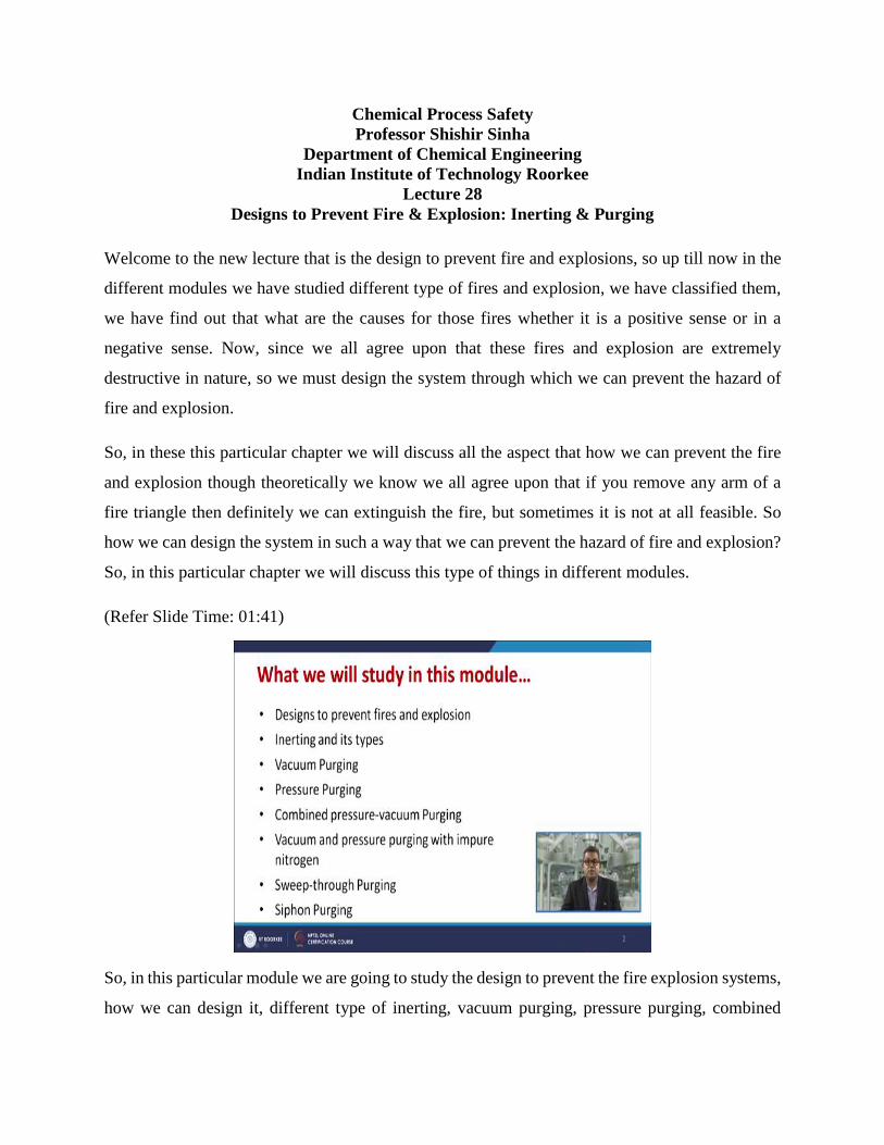
So, in this particular module we are going to study the design to prevent the fire explosion systems,
how we can design it, different type of inerting, vacuum purging, pressure purging, combined
pressure and vacuum purging, vacuum and pressure purging with impure nitrogen, sweep through
purging and siphon purging.
(Refer Slide Time: 01:57)
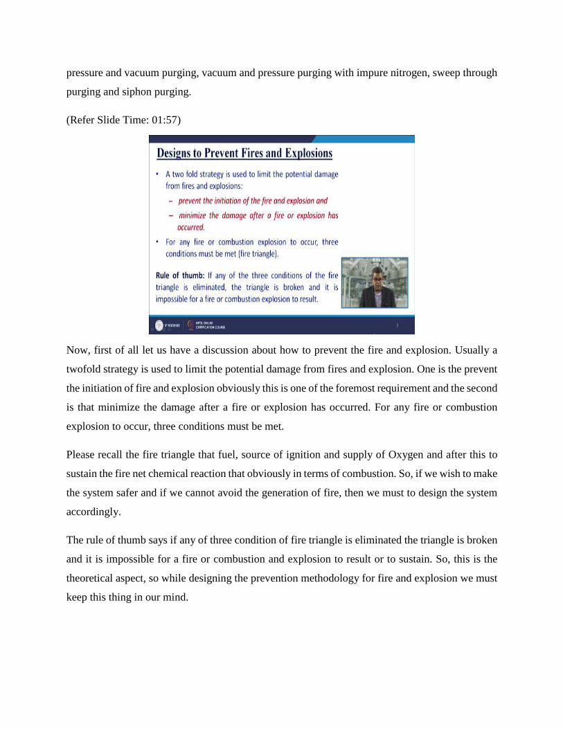
Now, first of all let us have a discussion about how to prevent the fire and explosion. Usually a
twofold strategy is used to limit the potential damage from fires and explosion. One is the prevent
the initiation of fire and explosion obviously this is one of the foremost requirement and the second
is that minimize the damage after a fire or explosion has occurred. For any fire or combustion
explosion to occur, three conditions must be met.
Please recall the fire triangle that fuel, source of ignition and supply of Oxygen and after this to
sustain the fire net chemical reaction that obviously in terms of combustion. So, if we wish to make
the system safer and if we cannot avoid the generation of fire, then we must to design the system
accordingly.
The rule of thumb says if any of three condition of fire triangle is eliminated the triangle is broken
and it is impossible for a fire or combustion and explosion to result or to sustain. So, this is the
theoretical aspect, so while designing the prevention methodology for fire and explosion we must
keep this thing in our mind.
(Refer Slide Time: 03:29)
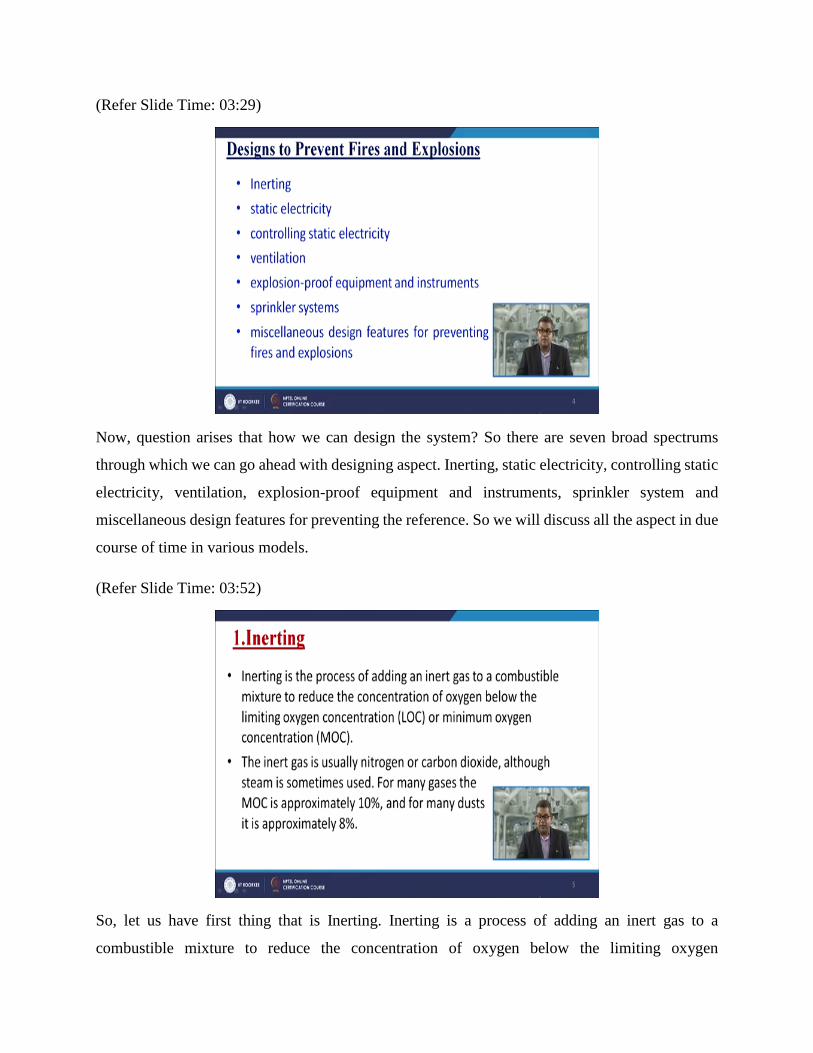
Now, question arises that how we can design the system? So there are seven broad spectrums
through which we can go ahead with designing aspect. Inerting, static electricity, controlling static
electricity, ventilation, explosion-proof equipment and instruments, sprinkler system and
miscellaneous design features for preventing the reference. So we will discuss all the aspect in due
course of time in various models.
(Refer Slide Time: 03:52)
So, let us have first thing that is Inerting. Inerting is a process of adding an inert gas to a
combustible mixture to reduce the concentration of oxygen below the limiting oxygen
concentration or minimum oxygen concentration. So that the required stoichiometric demand is
depleted, and flammable mixture or inflammable mixture does not catch fire. The inert gas is
usually Nitrogen or Carbon dioxide, although steam is sometimes used, but not in a common
fashion. For many gases the MOC is approximately 10 percent and for many dusts it is
approximately 8 percent.
(Refer Slide Time: 04:37)
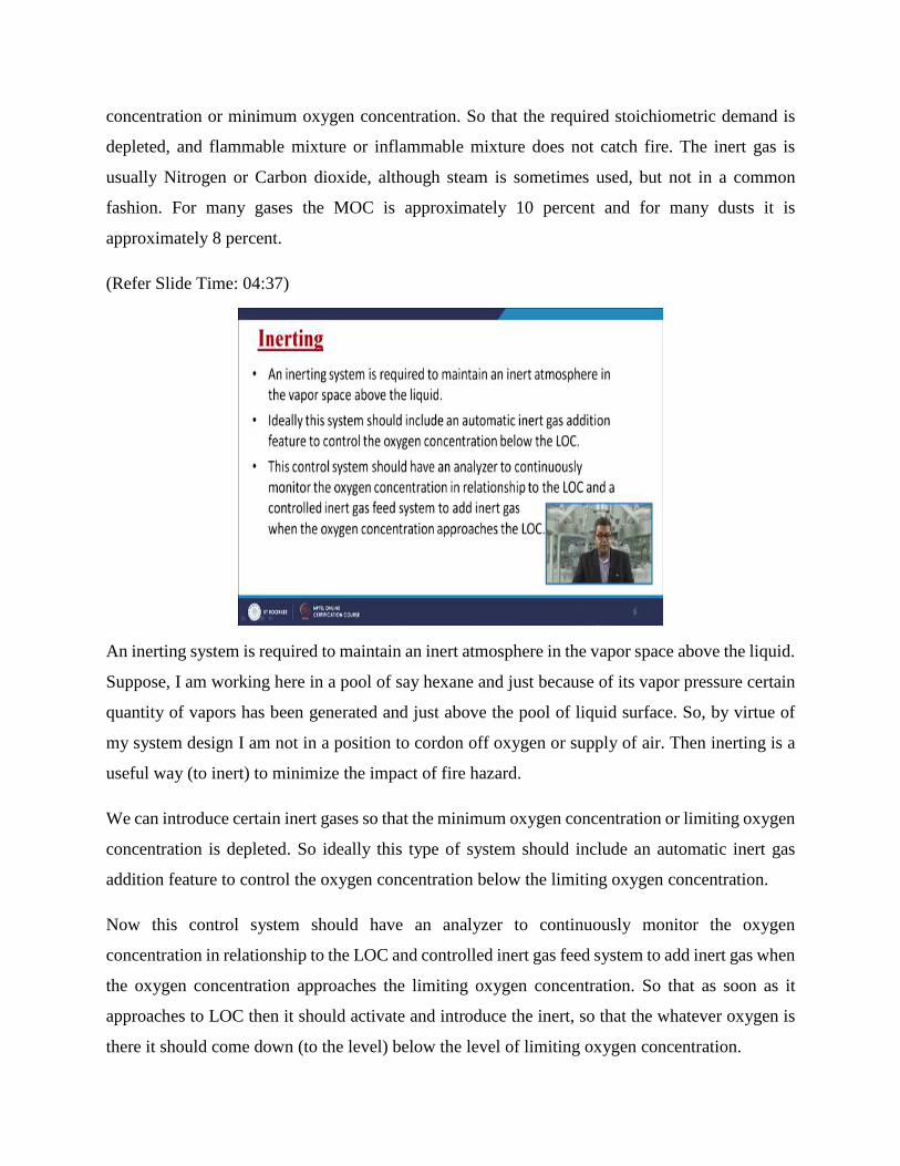
An inerting system is required to maintain an inert atmosphere in the vapor space above the liquid.
Suppose, I am working here in a pool of say hexane and just because of its vapor pressure certain
quantity of vapors has been generated and just above the pool of liquid surface. So, by virtue of
my system design I am not in a position to cordon off oxygen or supply of air. Then inerting is a
useful way (to inert) to minimize the impact of fire hazard.
We can introduce certain inert gases so that the minimum oxygen concentration or limiting oxygen
concentration is depleted. So ideally this type of system should include an automatic inert gas
addition feature to control the oxygen concentration below the limiting oxygen concentration.
Now this control system should have an analyzer to continuously monitor the oxygen
concentration in relationship to the LOC and controlled inert gas feed system to add inert gas when
the oxygen concentration approaches the limiting oxygen concentration. So that as soon as it
approaches to LOC then it should activate and introduce the inert, so that the whatever oxygen is
there it should come down (to the level) below the level of limiting oxygen concentration.
(Refer Slide Time: 06:16)
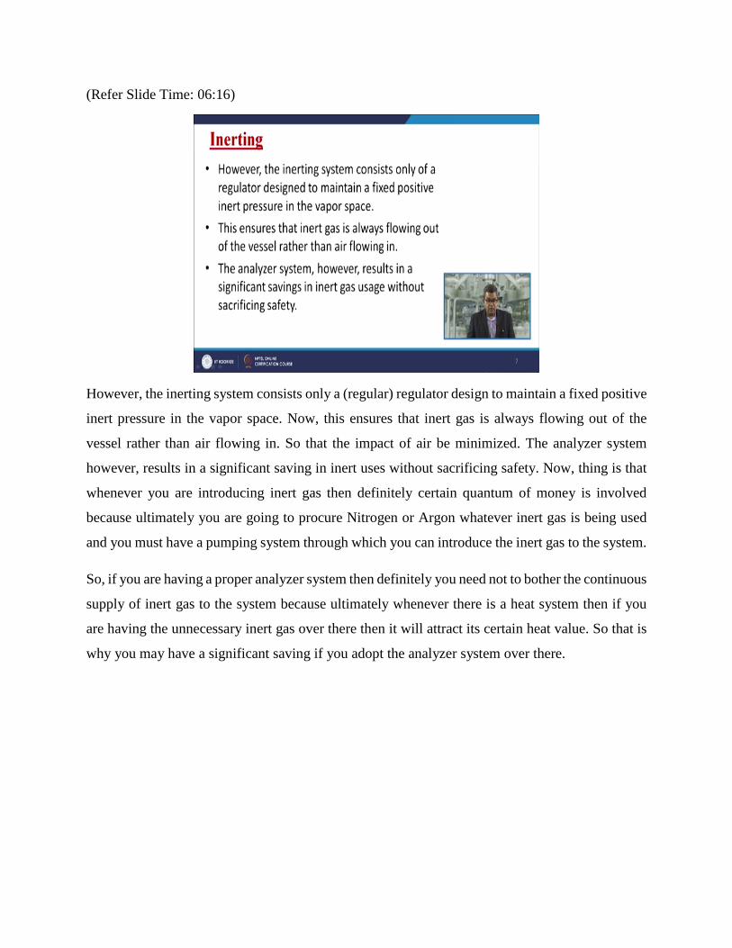
However, the inerting system consists only a (regular) regulator design to maintain a fixed positive
inert pressure in the vapor space. Now, this ensures that inert gas is always flowing out of the
vessel rather than air flowing in. So that the impact of air be minimized. The analyzer system
however, results in a significant saving in inert uses without sacrificing safety. Now, thing is that
whenever you are introducing inert gas then definitely certain quantum of money is involved
because ultimately you are going to procure Nitrogen or Argon whatever inert gas is being used
and you must have a pumping system through which you can introduce the inert gas to the system.
So, if you are having a proper analyzer system then definitely you need not to bother the continuous
supply of inert gas to the system because ultimately whenever there is a heat system then if you
are having the unnecessary inert gas over there then it will attract its certain heat value. So that is
why you may have a significant saving if you adopt the analyzer system over there.
(Refer Slide Time: 07:22)
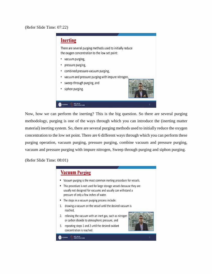
Now, how we can perform the inerting? This is the big question. So there are several purging
methodology, purging is one of the ways through which you can introduce the (inerting matter
material) inerting system. So, there are several purging methods used to initially reduce the oxygen
concentration to the low set point. There are 6 different ways through which you can perform these
purging operation, vacuum purging, pressure purging, combine vacuum and pressure purging,
vacuum and pressure purging with impure nitrogen, Sweep through purging and siphon purging.
(Refer Slide Time: 08:01)
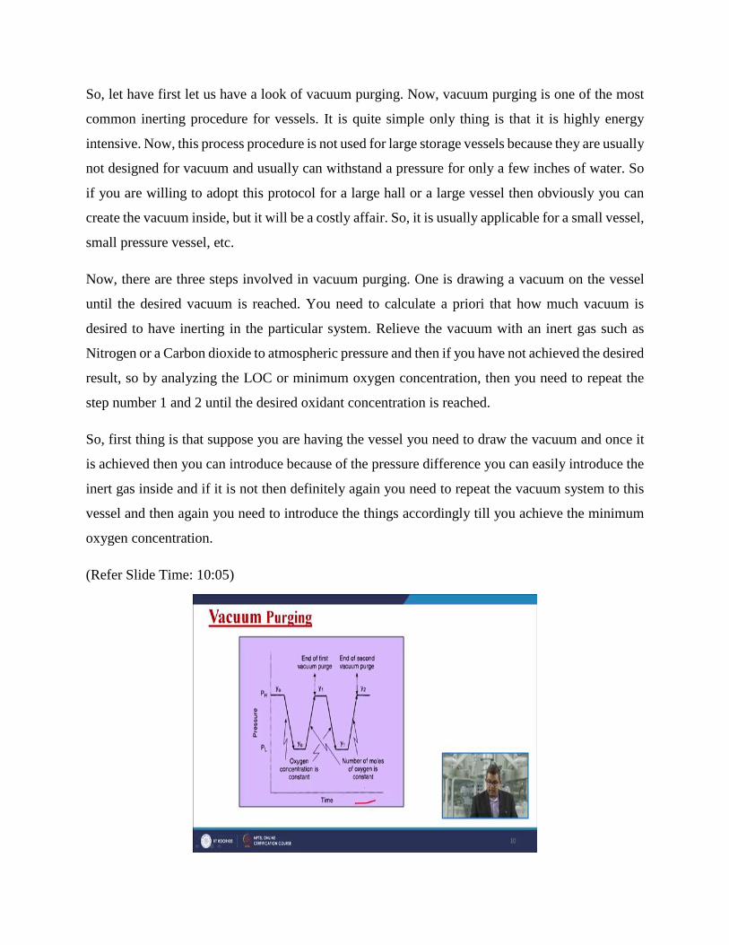
So, let have first let us have a look of vacuum purging. Now, vacuum purging is one of the most
common inerting procedure for vessels. It is quite simple only thing is that it is highly energy
intensive. Now, this process procedure is not used for large storage vessels because they are usually
not designed for vacuum and usually can withstand a pressure for only a few inches of water. So
if you are willing to adopt this protocol for a large hall or a large vessel then obviously you can
create the vacuum inside, but it will be a costly affair. So, it is usually applicable for a small vessel,
small pressure vessel, etc.
Now, there are three steps involved in vacuum purging. One is drawing a vacuum on the vessel
until the desired vacuum is reached. You need to calculate a priori that how much vacuum is
desired to have inerting in the particular system. Relieve the vacuum with an inert gas such as
Nitrogen or a Carbon dioxide to atmospheric pressure and then if you have not achieved the desired
result, so by analyzing the LOC or minimum oxygen concentration, then you need to repeat the
step number 1 and 2 until the desired oxidant concentration is reached.
So, first thing is that suppose you are having the vessel you need to draw the vacuum and once it
is achieved then you can introduce because of the pressure difference you can easily introduce the
inert gas inside and if it is not then definitely again you need to repeat the vacuum system to this
vessel and then again you need to introduce the things accordingly till you achieve the minimum
oxygen concentration.
(Refer Slide Time: 10:05)
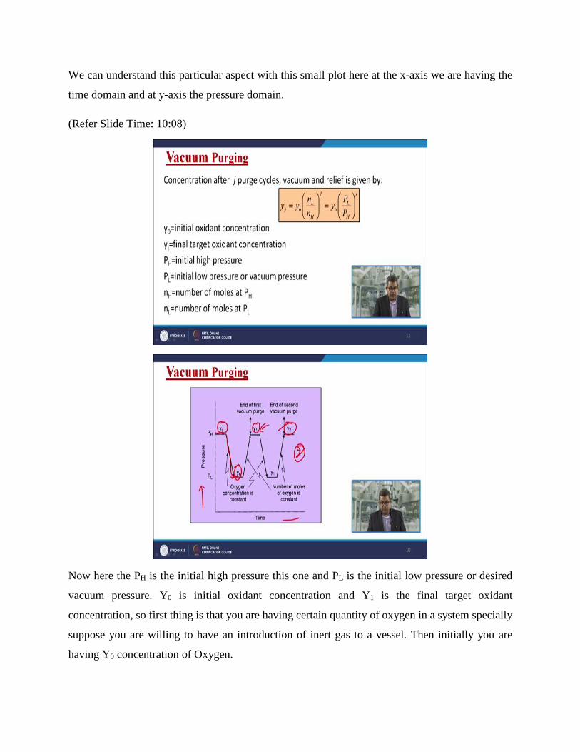
We can understand this particular aspect with this small plot here at the x-axis we are having the
time domain and at y-axis the pressure domain.
(Refer Slide Time: 10:08)
Now here the PH is the initial high pressure this one and PL is the initial low pressure or desired
vacuum pressure. Y0 is initial oxidant concentration and Y1 is the final target oxidant
concentration, so first thing is that you are having certain quantity of oxygen in a system specially
suppose you are willing to have an introduction of inert gas to a vessel. Then initially you are
having Y0 concentration of Oxygen.
Then you reduce the pressure until it reaches to PL that is the lower pressure limit, here you
maintain the pressure and you introduce the desired oxygen concentration. Suppose you have
achieved the desired Oxygen concentration by introducing the inert material and then you raise the
pressure so that it can acquire the desired pressure to maintain the reaction mechanism.
So, here you have a Y1 that is the final oxygen concentration and suppose if you are unable to have
this LOC requirement then you need to repeat this system for again and again. So, here in this
particular plot the things are repeated for twice so until it reaches the final desired concentration
of oxidant.
(Refer Slide Time: 11:47)
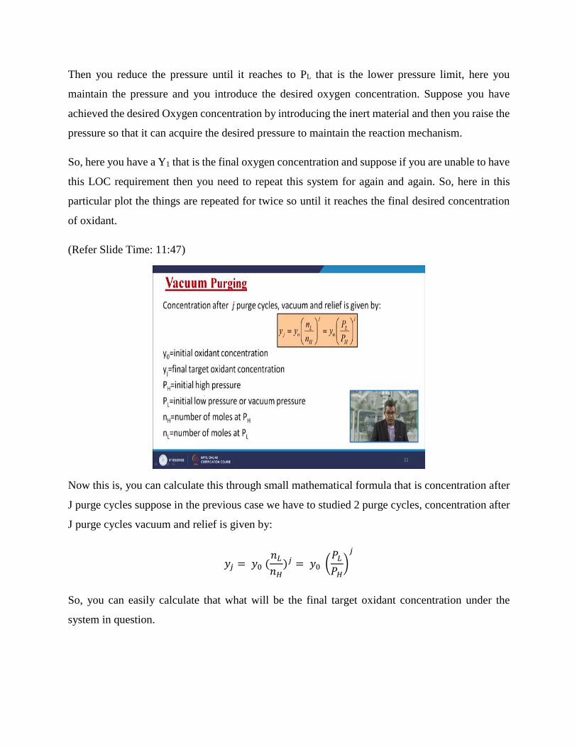
Now this is, you can calculate this through small mathematical formula that is concentration after
J purge cycles suppose in the previous case we have to studied 2 purge cycles, concentration after
J purge cycles vacuum and relief is given by:
𝑦𝑗 = 𝑦0 (𝑛𝐿
𝑛𝐻)𝑗 = 𝑦0 (
𝑃𝐿
𝑃𝐻)
𝑗
So, you can easily calculate that what will be the final target oxidant concentration under the
system in question.
(Refer Slide Time: 12:21)
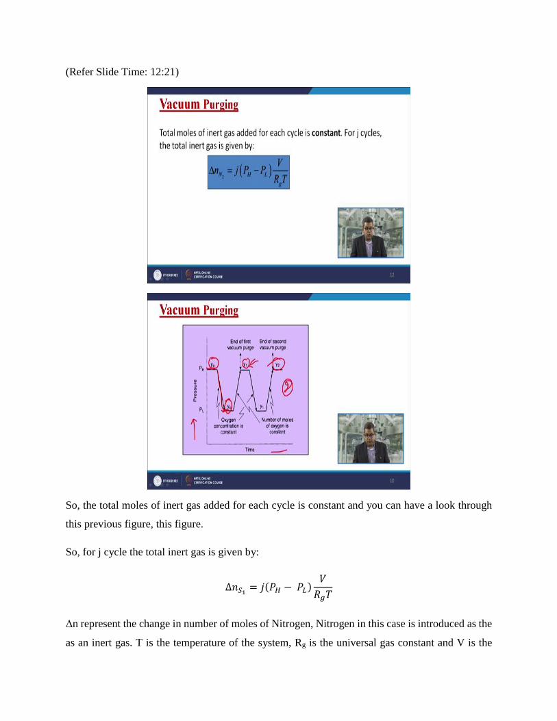
So, the total moles of inert gas added for each cycle is constant and you can have a look through
this previous figure, this figure.
So, for j cycle the total inert gas is given by:
∆𝑛𝑆1= 𝑗(𝑃𝐻 − 𝑃𝐿)
𝑉
𝑅𝑔𝑇
Δn represent the change in number of moles of Nitrogen, Nitrogen in this case is introduced as the
as an inert gas. T is the temperature of the system, Rg is the universal gas constant and V is the
volume. So, by this way you can calculate that how many cycles are required, how many moles
are needed to, how many moles of inert is needed to inert the system, the pressure system, pressure
vessel system inside the reactor.
(Refer Slide Time: 13:19)
Now let us have look of pressure purging. Now, vessel can be pressure purged by addition of inert
gas under pressure. Sometimes it performs action like sweep through purging so after the added
gas is diffused throughout the vessel, it is vented to the atmosphere usually down to atmospheric
pressure. So, more than one pressure cycle may be necessary to reduce the oxygen content to the
desired concentration.
(Refer Slide Time: 13:41)
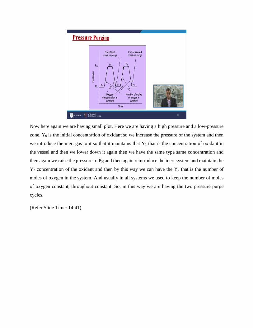
Now here again we are having small plot. Here we are having a high pressure and a low-pressure
zone. Y0 is the initial concentration of oxidant so we increase the pressure of the system and then
we introduce the inert gas to it so that it maintains that Y1 that is the concentration of oxidant in
the vessel and then we lower down it again then we have the same type same concentration and
then again we raise the pressure to PH and then again reintroduce the inert system and maintain the
Y2 concentration of the oxidant and then by this way we can have the Y2 that is the number of
moles of oxygen in the system. And usually in all systems we used to keep the number of moles
of oxygen constant, throughout constant. So, in this way we are having the two pressure purge
cycles.
(Refer Slide Time: 14:41)
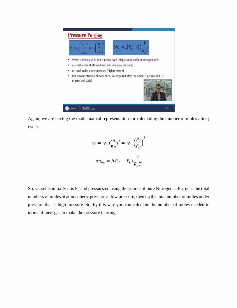
Again, we are having the mathematical representation for calculating the number of moles after j
cycle.
𝑦𝑗 = 𝑦0 (𝑛𝐿
𝑛𝐻)𝑗 = 𝑦0 (
𝑃𝐿
𝑃𝐻)
𝑗
∆𝑛𝑛2= 𝑗(𝑃𝐻 − 𝑃𝐿)
𝑉
𝑅𝑔𝑇
So, vessel is initially it is PL and pressurized using the source of pure Nitrogen at PH, nL is the total
numbers of moles at atmospheric pressure at low pressure, then nH the total number of moles under
pressure that is high pressure. So, by this way you can calculate the number of moles needed in
terms of inert gas to make the pressure inerting.
(Refer Slide Time: 15:36)
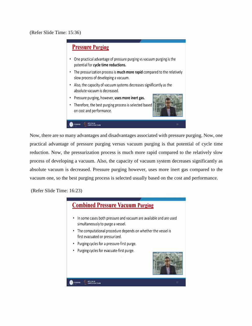
Now, there are so many advantages and disadvantages associated with pressure purging. Now, one
practical advantage of pressure purging versus vacuum purging is that potential of cycle time
reduction. Now, the pressurization process is much more rapid compared to the relatively slow
process of developing a vacuum. Also, the capacity of vacuum system decreases significantly as
absolute vacuum is decreased. Pressure purging however, uses more inert gas compared to the
vacuum one, so the best purging process is selected usually based on the cost and performance.
(Refer Slide Time: 16:23)
So, if you are willing to inert the hydrocarbon piping system then definitely the pressure purging
is most advantageous because it will be very difficult to have a vacuum purging for a pipeline
having a distance of say 1000 kilometer or 500 kilometer it will be very difficult. So, in some cases
both pressure and vacuum purging are available and are used simultaneously to purge a vessel.
In that particular case, we need to go ahead with the combined pressure vacuum purging system
because sometimes it is a need of time. So, the computational procedure depends on whether the
vessel is first evacuated or pressurized. Now, purging cycle for pressure is the first purge then
purging cycle two for evacuate that is the first purge.
(Refer Slide Time: 17:13)
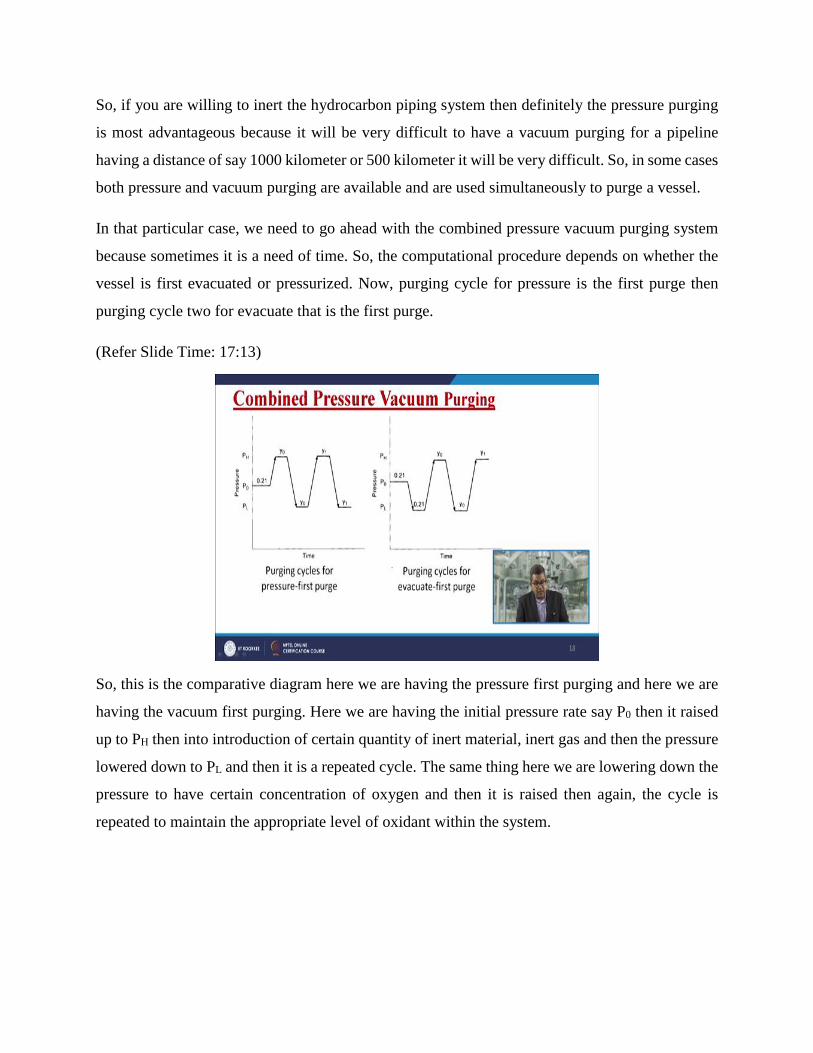
So, this is the comparative diagram here we are having the pressure first purging and here we are
having the vacuum first purging. Here we are having the initial pressure rate say P0 then it raised
up to PH then into introduction of certain quantity of inert material, inert gas and then the pressure
lowered down to PL and then it is a repeated cycle. The same thing here we are lowering down the
pressure to have certain concentration of oxygen and then it is raised then again, the cycle is
repeated to maintain the appropriate level of oxidant within the system.
(Refer Slide Time: 18:08)
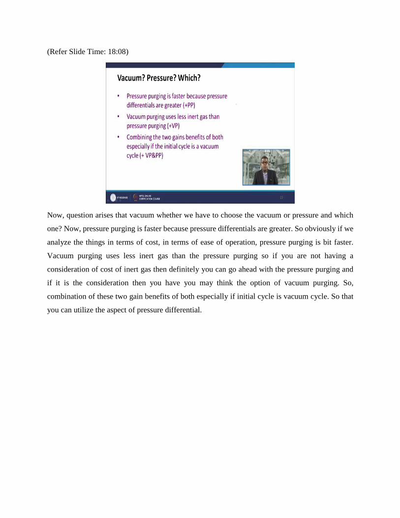
Now, question arises that vacuum whether we have to choose the vacuum or pressure and which
one? Now, pressure purging is faster because pressure differentials are greater. So obviously if we
analyze the things in terms of cost, in terms of ease of operation, pressure purging is bit faster.
Vacuum purging uses less inert gas than the pressure purging so if you are not having a
consideration of cost of inert gas then definitely you can go ahead with the pressure purging and
if it is the consideration then you have you may think the option of vacuum purging. So,
combination of these two gain benefits of both especially if initial cycle is vacuum cycle. So that
you can utilize the aspect of pressure differential.
(Refer Slide Time: 19:01)
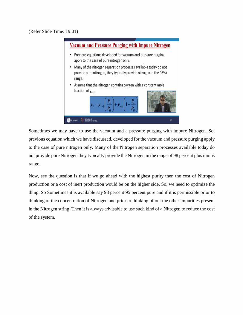
Sometimes we may have to use the vacuum and a pressure purging with impure Nitrogen. So,
previous equation which we have discussed, developed for the vacuum and pressure purging apply
to the case of pure nitrogen only. Many of the Nitrogen separation processes available today do
not provide pure Nitrogen they typically provide the Nitrogen in the range of 98 percent plus minus
range.
Now, see the question is that if we go ahead with the highest purity then the cost of Nitrogen
production or a cost of inert production would be on the higher side. So, we need to optimize the
thing. So Sometimes it is available say 98 percent 95 percent pure and if it is permissible prior to
thinking of the concentration of Nitrogen and prior to thinking of out the other impurities present
in the Nitrogen string. Then it is always advisable to use such kind of a Nitrogen to reduce the cost
of the system.
(Refer Slide Time: 20:03)
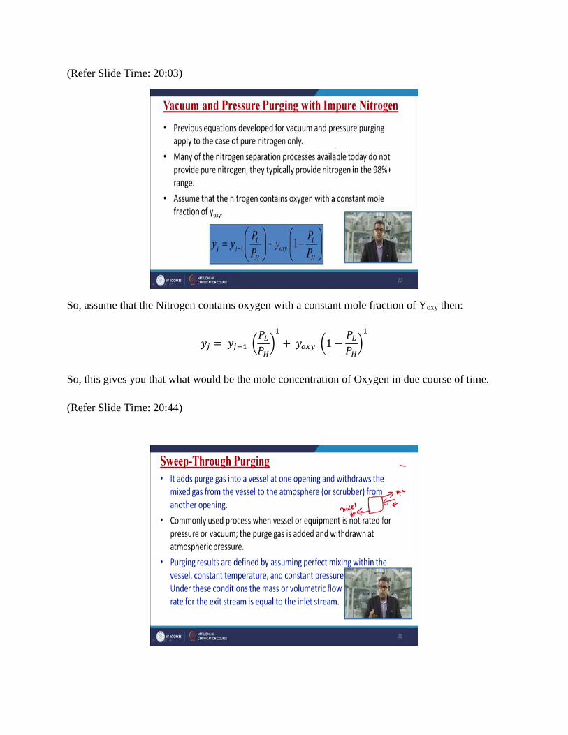
So, assume that the Nitrogen contains oxygen with a constant mole fraction of Yoxy then:
𝑦𝑗 = 𝑦𝑗−1 (𝑃𝐿
𝑃𝐻)
1
+ 𝑦𝑜𝑥𝑦 (1 −𝑃𝐿
𝑃𝐻)
1
So, this gives you that what would be the mole concentration of Oxygen in due course of time.
(Refer Slide Time: 20:44)
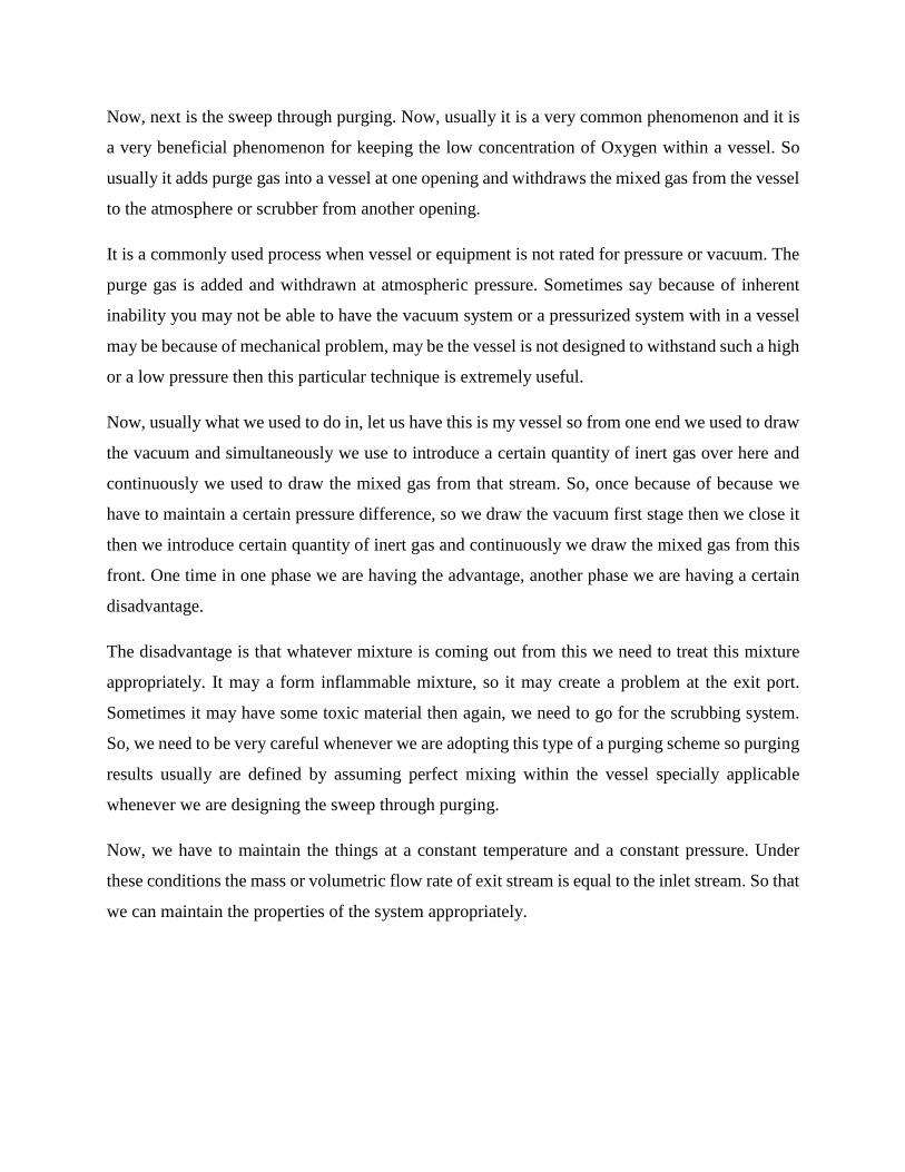
Now, next is the sweep through purging. Now, usually it is a very common phenomenon and it is
a very beneficial phenomenon for keeping the low concentration of Oxygen within a vessel. So
usually it adds purge gas into a vessel at one opening and withdraws the mixed gas from the vessel
to the atmosphere or scrubber from another opening.
It is a commonly used process when vessel or equipment is not rated for pressure or vacuum. The
purge gas is added and withdrawn at atmospheric pressure. Sometimes say because of inherent
inability you may not be able to have the vacuum system or a pressurized system with in a vessel
may be because of mechanical problem, may be the vessel is not designed to withstand such a high
or a low pressure then this particular technique is extremely useful.
Now, usually what we used to do in, let us have this is my vessel so from one end we used to draw
the vacuum and simultaneously we use to introduce a certain quantity of inert gas over here and
continuously we used to draw the mixed gas from that stream. So, once because of because we
have to maintain a certain pressure difference, so we draw the vacuum first stage then we close it
then we introduce certain quantity of inert gas and continuously we draw the mixed gas from this
front. One time in one phase we are having the advantage, another phase we are having a certain
disadvantage.
The disadvantage is that whatever mixture is coming out from this we need to treat this mixture
appropriately. It may a form inflammable mixture, so it may create a problem at the exit port.
Sometimes it may have some toxic material then again, we need to go for the scrubbing system.
So, we need to be very careful whenever we are adopting this type of a purging scheme so purging
results usually are defined by assuming perfect mixing within the vessel specially applicable
whenever we are designing the sweep through purging.
Now, we have to maintain the things at a constant temperature and a constant pressure. Under
these conditions the mass or volumetric flow rate of exit stream is equal to the inlet stream. So that
we can maintain the properties of the system appropriately.
(Refer Slide Time: 23:12)
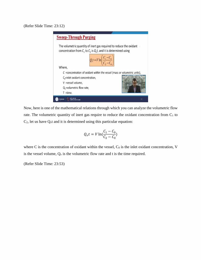
Now, here is one of the mathematical relations through which you can analyze the volumetric flow
rate. The volumetric quantity of inert gas require to reduce the oxidant concentration from C1 to
C2, let us have Qvt and it is determined using this particular equation:
𝑄𝑣𝑡 = 𝑉 ln(𝐶1 − 𝐶0
𝐶2 − 𝐶0)
where C is the concentration of oxidant within the vessel, C0 is the inlet oxidant concentration, V
is the vessel volume, Qv is the volumetric flow rate and t is the time required.
(Refer Slide Time: 23:53)
Now, purging results are defined by assuming perfect mixing within the vessel. Constant
temperature and a constant pressure. So, under these conditions the mass or a volumetric flow rate
for the exit stream is equal to the inlet stream. So, these are certain things we need to keep in mind.
(Refer Slide Time: 24:15)
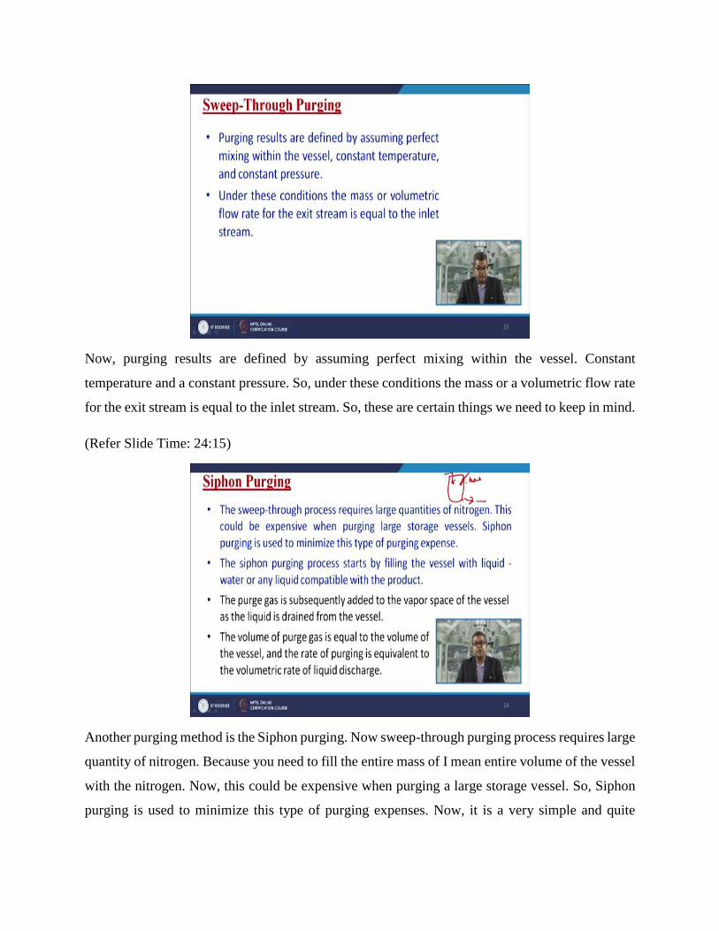
Another purging method is the Siphon purging. Now sweep-through purging process requires large
quantity of nitrogen. Because you need to fill the entire mass of I mean entire volume of the vessel
with the nitrogen. Now, this could be expensive when purging a large storage vessel. So, Siphon
purging is used to minimize this type of purging expenses. Now, it is a very simple and quite
effective. The Siphon purging processes starts by filling the vessel with the liquid and sometimes
with water or any liquid compatible with the product.
Now, then the purge gas is subsequently added to the vapor space of the vessel and liquid is drained
from the vessel simultaneously. So, it is just like this that you are having this vessel. You filled it
with liquid and then you introduce the inert gas and simultaneously you withdraw the filled liquid
or a water in this case so that you can inert. Because there will be no room for air to entrap so that
the concentration of oxygen will remain low as desired. The volume of purge gas is equal to the
volume of the vessel and rate of purging is equivalent to the volumetric rate of liquid discharge.
(Refer Slide Time: 25:38)
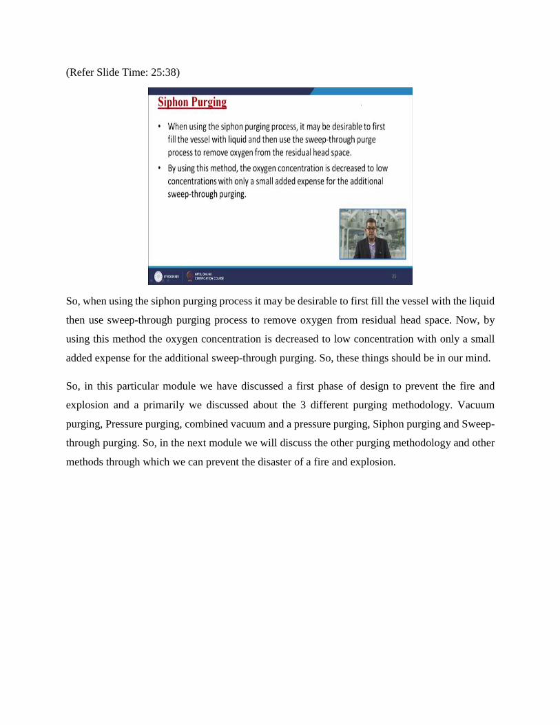
So, when using the siphon purging process it may be desirable to first fill the vessel with the liquid
then use sweep-through purging process to remove oxygen from residual head space. Now, by
using this method the oxygen concentration is decreased to low concentration with only a small
added expense for the additional sweep-through purging. So, these things should be in our mind.
So, in this particular module we have discussed a first phase of design to prevent the fire and
explosion and a primarily we discussed about the 3 different purging methodology. Vacuum
purging, Pressure purging, combined vacuum and a pressure purging, Siphon purging and Sweep-
through purging. So, in the next module we will discuss the other purging methodology and other
methods through which we can prevent the disaster of a fire and explosion.

(Refer Slide Time: 26:37)
You can always see the various references those who are enlisted over here for your further
reading. Thank you.