Zebra Technologies Europe Ltd Valid for Customers ... - exalt.pl
Upload
khangminh22Category
view
0download
0
Doc. No.: GP&EC/PNQ/BID-EDSSUGAR/2020-21/CPN/75
Date : February 16, 2020
Assign No.: PWR-2020-03133
Date : October 21, 2020
NOTICE INVITING E-TENDERING
BID DOCUMENT
(Volume II or II)
FOR
ELECTRICAL DITRIBUTION SYSTEM
FOR SUGAR POWER& MILL HOUSE
(HT PANELS, TRANSFORMERS & BUSDUCT)
AT
M/s. Shri Dudhganga Vedganga Sahakari Sakhar Karkhana
Limited Bidri (Mauninagar) – 416 208
Tal. Kagal, Dist. Kolhapur
Prepared by
MITCON Consultancy & Engineering Services Ltd. Kubera Chambers, 1st Floor,
Dr. Rajendra Prasad Road, Shivajinagar
Pune - 411 005, Maharashtra State, India
February, 2021

BID DOCUMENT (Volume II of II)
FOR
ELECTRICAL DITRIBUTION SYSTEM FOR SUGAR POWER& MILL
HOUSE
(HT PANELS, TRANSFORMERS & BUSDUCT)
TABLE OF CONTENTS
Chapter No.
Title
Page No.
1. Scope of Work 1.1 General 1.2 Scope of Supply & services 1.3 Battery Limits 1.4 Performance Guarantee 1.5 Data required with Bid 1.6 Bill of Material
1 2 3 3 3 4
2.
Technical Specifications 2.1 General 2.2 Codes and Standards 2.3 Performance test 2.4 Work schedule 2.5 Technical Specifications 2.5.1 11KV Panel 2.5.2 Transformers 2.5.3 Battery Charger cum DCDB 2.5.4 Bus duct 2.5.5 Erection & Commissioning 2.6 Data Sheet ‘A’ 2.7 Data Sheet ‘B’
5 5 5 5
7 7 8 11 13
14
22
Annexure I - List of Applicable Standards 26
Annexure II - List of Approved makes 28
Annexure III – Performance Security Form 29
Annexure IV – List of Documents and Drawings 30

CHAPTER 1
SCOPE OF WORK 1.1 General
The scope of work of the contractor will include supply of the electrical system package & auxiliaries as detailed in specifications. The bidder will also need to complete all associated electrical, mechanical and instrumentation jobs of installation and commissioning at site. The bidder will need to adhere to the below commitments desired along with the bid. The bidder will be responsible for providing an efficient, reliable and state of art technology electrical system for Power Distribution to Sugar Factory. The detailed specifications in the next chapter, attempt to define the bidders scope and specifications. However, the onus of providing the appropriate electrical system package and auxiliaries rests with the bidder.
The scope of work for HT Panel, Transformer & Bus duct package covered under the specification detailed will include but not limited to the following.
Supply
Engineering, Design, fabrication, manufacture, assembly, shop testing and inspection at manufacturer's works. Providing all labourers, materials and equipment for testing at shop as required. All spare parts required for the commissioning of the Electrical Installation and auxiliary systems. Spare parts as recommended by equipment manufacturers for two (2) years of trouble free operation of the Electrical evacuation package and auxiliaries. Special tools and tackles required for operation and maintenance, inspection, and repair of the equipment / systems offered.
Services Under Scope of Supply
Inspection and expediting, handling, packing, forwarding, transporting (including transport insurance), obtaining statutory approvals from electrical inspectorate of Maharashtra government, any other authority as required and documentation. Preparation of necessary drawings and documents and obtaining approval and safely clearance certificate from the Electrical Inspector PWD of Maharashtra for the trial runs and commercial operation of the plant.
Erection and Commissioning
Technical Bid Document for Electrical Distribution System for Sugar Power & Mill House( HT Panel, Transformers, Busduct)_ SDVSSKL
2
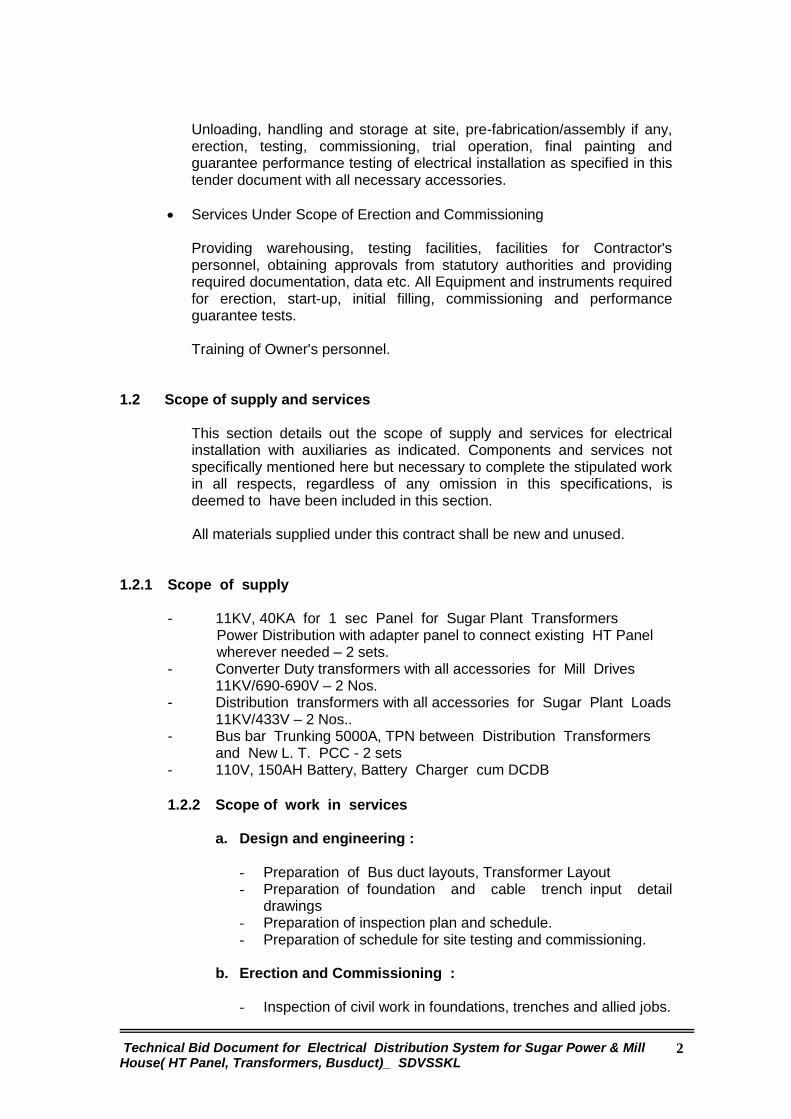
Unloading, handling and storage at site, pre-fabrication/assembly if any, erection, testing, commissioning, trial operation, final painting and guarantee performance testing of electrical installation as specified in this tender document with all necessary accessories.
Services Under Scope of Erection and Commissioning
Providing warehousing, testing facilities, facilities for Contractor's personnel, obtaining approvals from statutory authorities and providing required documentation, data etc. All Equipment and instruments required for erection, start-up, initial filling, commissioning and performance guarantee tests. Training of Owner's personnel.
1.2 Scope of supply and services
This section details out the scope of supply and services for electrical installation with auxiliaries as indicated. Components and services not specifically mentioned here but necessary to complete the stipulated work in all respects, regardless of any omission in this specifications, is deemed to have been included in this section.
All materials supplied under this contract shall be new and unused.
1.2.1 Scope of supply
- 11KV, 40KA for 1 sec Panel for Sugar Plant Transformers Power Distribution with adapter panel to connect existing HT Panel wherever needed – 2 sets. - Converter Duty transformers with all accessories for Mill Drives
11KV/690-690V – 2 Nos. - Distribution transformers with all accessories for Sugar Plant Loads
11KV/433V – 2 Nos.. - Bus bar Trunking 5000A, TPN between Distribution Transformers and New L. T. PCC - 2 sets
- 110V, 150AH Battery, Battery Charger cum DCDB
1.2.2 Scope of work in services
a. Design and engineering :
- Preparation of Bus duct layouts, Transformer Layout - Preparation of foundation and cable trench input detail
drawings - Preparation of inspection plan and schedule. - Preparation of schedule for site testing and commissioning.
b. Erection and Commissioning :
- Inspection of civil work in foundations, trenches and allied jobs.

Technical Bid Document for Electrical Distribution System for Sugar Power & Mill House( HT Panel, Transformers, Busduct)_ SDVSSKL
3
- Unloading, unpacking, shifting to locations, positioning, aligning and fixing of equipments.
- Pre-commissioning checks. - Commissioning , testing and trials - Completion of documentation and records.
c. Statutory approvals :
- Obtaining approvals on drawing and designs from Electrical
Inspector authorities. - Arranging inspections and approvals for commissioning of
Sugar Plant Installation added as per this bid document from Local and Chief Electrical Inspector PWD
d. Inspections / Review Meetings :
- Making the arrangements for periodical and final inspection of
all major equipments in the system at manufacturers works - Attending the periodical review meetings at site or the agreed
locations.
1.3 Battery Limits
For Power Supply -
From : 11KV Busbar in existing 11KV Switchboard To : LT PCC for Dist. Transformers & Sec. terminal box of Conv. transformers
1.4 Performance Guarantee
All equipment shall be guaranteed for workmanship and materials and for satisfactory performance in accordance with the relevant clauses of the General Conditions of Contract.
The guarantee for performance shall cover individual items and systems
for their ratings/outputs, as required in the specification.
The PACKAGE contractor shall conduct performance/acceptance tests on each of the major items of equipment supplied to demonstrate that the equipment supplied is capable of achieving the performance parameters specified and contracted for, in accordance with the General Conditions of Contract, Instruments, gauges and meters installed for the normal operation of the equipment shall be made use of during the acceptance tests as far as practicable.
1.5 Data Required Along with Bid
All data sheets included in the following chapter should be duly completed and submitted along with bid. All relevant information must be submitted without mentioning ‘latter date’ in the data sheets.
Technical Bid Document for Electrical Distribution System for Sugar Power & Mill House( HT Panel, Transformers, Busduct)_ SDVSSKL
4
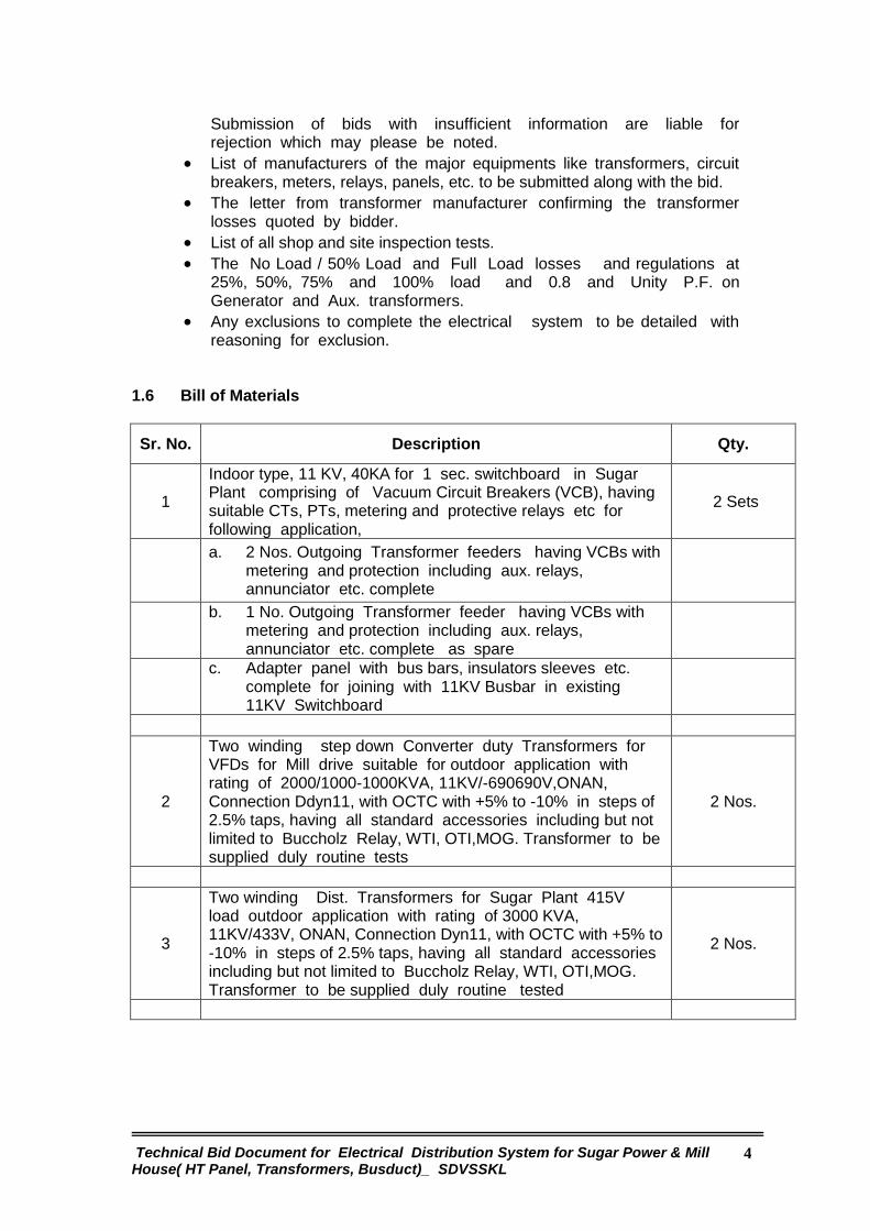
Submission of bids with insufficient information are liable for rejection which may please be noted.
List of manufacturers of the major equipments like transformers, circuit breakers, meters, relays, panels, etc. to be submitted along with the bid.
The letter from transformer manufacturer confirming the transformer losses quoted by bidder.
List of all shop and site inspection tests.
The No Load / 50% Load and Full Load losses and regulations at 25%, 50%, 75% and 100% load and 0.8 and Unity P.F. on Generator and Aux. transformers.
Any exclusions to complete the electrical system to be detailed with reasoning for exclusion.
1.6 Bill of Materials
Sr. No. Description Qty.
1
Indoor type, 11 KV, 40KA for 1 sec. switchboard in Sugar Plant comprising of Vacuum Circuit Breakers (VCB), having suitable CTs, PTs, metering and protective relays etc for following application,
2 Sets
a. 2 Nos. Outgoing Transformer feeders having VCBs with
metering and protection including aux. relays, annunciator etc. complete
b. 1 No. Outgoing Transformer feeder having VCBs with
metering and protection including aux. relays, annunciator etc. complete as spare
c. Adapter panel with bus bars, insulators sleeves etc.
complete for joining with 11KV Busbar in existing 11KV Switchboard
2
Two winding step down Converter duty Transformers for VFDs for Mill drive suitable for outdoor application with rating of 2000/1000-1000KVA, 11KV/-690690V,ONAN, Connection Ddyn11, with OCTC with +5% to -10% in steps of 2.5% taps, having all standard accessories including but not limited to Buccholz Relay, WTI, OTI,MOG. Transformer to be supplied duly routine tests
2 Nos.
3
Two winding Dist. Transformers for Sugar Plant 415V load outdoor application with rating of 3000 KVA, 11KV/433V, ONAN, Connection Dyn11, with OCTC with +5% to -10% in steps of 2.5% taps, having all standard accessories including but not limited to Buccholz Relay, WTI, OTI,MOG. Transformer to be supplied duly routine tested
2 Nos.

Technical Bid Document for Electrical Distribution System for Sugar Power & Mill House( HT Panel, Transformers, Busduct)_ SDVSSKL
5
4
415V,5000A, TPN, Bus bar trunking between 3000 KVA Transformers and L.T. PCC for sugar plant with enclosure fabricated from 3 mm thick AL. sheet with canopy for outdoor portion, duly painted /powder coated. The trunking shall have bends, flex. copper connections at transformer end, zinc passivated hardware etc. Complete (Approx. Length 15 Mtrs. each)
2 Sets
5 Battery, Battery Charger cum DCDB with 110VD.C., 150AH SMF Battery set, stand, Float & Float cum Boost (F&FCBC) charger with all accessories etc complete
1 Set
6 Miscellaneous items as per statutory requirements including but not limited to the following,
a. Rubber mat of 11KV & 600V rating with suitable length to be provided in front of all Panels, 11 KV switchboards, LT Panels etc.
20 Mtr.
b. Shock Treatment Charts in Marathi , Hindi and English in Glass frame.
2 Nos.
c. Sand Buckets 4 Nos. mounted on fabricated stand in switchyard.
2 Sets
d. First Aid Box with necessary medicines, ointments etc. 2 Sets
7 Liaison with Electrical Inspectorate PWD for drawing approval and Inspections for the additions done in sugar plant installation.
1

Technical Bid Document for Electrical Distribution System for Sugar Power & Mill House( HT Panel, Transformers, Busduct)_ SDVSSKL
6
CHAPTER 2
SPECIFICATIONS
2.1 General I) This specification is intended to cover the design, manufacture, delivery,
erection, testing and commissioning of electrical system including transformers, circuit breakers, relays etc. to complete the package.
ii) Supplies and services shall be rendered in conformity with proven
engineering principles, taking into account the current state of the art technology. The requirements of the contract must be fulfilled in its entirety.
iii) The supplies and services within the scope shall be rendered inclusive of all
appliances and interconnecting arrangements with other supplies, necessary for installation of all accessories and for satisfactory maintenance and repair.
iv) The scope of supply and services shall include all necessary work and supply
of equipment and material whether mentioned in these specifications or not, but which are necessary for the satisfactory, reliable and safe operation and maintenance and required for achieving guaranteed performance of the plant.
Any equipment, device or material even if not included in this bid but found necessary for the safe and satisfactory functioning of the unit under the bid, shall be supplied, erected and commissioned by the PACKAGE contractor at no extra cost to the owner, as though, such equipment, material or work were originally specified and formed part of the scope of work.
2.2 Codes & Standards
The design, manufacture, testing and performance of the electrical evacuation package and accessories shall comply with the requirements of applicable Indian / British / American Standards, such as those indicated in the respective sections of this specification, and those standards specified therein, in so far as they apply. The vendor should specifically mentioned relevant codes.
2.3 Performance Test
After completion of erection, the plant shall be trial operated and performance tested as detailed in the relevant sections of the specifications. The Bidder may note that the performance parameters guaranteed shall be considered in the bid evaluation. The Bidder shall furnish these and other parameters as required in the performance data sheets.
2.4 Work Schedule
The earliest feasible schedule shall be given by bidder along with milestone activity chart.

Technical Bid Document for Electrical Distribution System for Sugar Power & Mill House( HT Panel, Transformers, Busduct)_ SDVSSKL
7
2.5 Technical Specifications :
2.5.1 11KV Switchboard :
- The panel shall be self supporting, free standing, floor mounted, modular type with construction having degree of protection of IP 54 as per IS 2147.
- 11KV Switchboard shall be fabricated from 2.5mm thick CRCA sheet steel. Partitions may be fabricated from 16 SWG CRCA if no components are mounted on them.
- The panel shall be painted with 2 coats of primer after pre treatment and 2 coats of Polyurethane / epoxy paint with shade 631 of IS 5. Alternately epoxy powder coating shall be done in place of paint.
- Stiffeners shall be provided at corners & between modules to make panel rugged. The stiffeners will necessarily be required for relay compartments or doors where heavy components are mounted.
- The open able covers shall be provided with lift off type hinges, quarter turn door locks and flexible copper wire for earth connection.
- The panel shall be dust and vermin proof. Synthetic or neoprene gaskets shall be provided at all openings
- The panel shall be of dead front construction suitable for front operated and back maintained functioning.
- Panel shall be provided with fl. lamp of 20 w capacity operated by door operated limit switch. Panel shall also have space heaters and thermostat arrangement.
- Panel shall be provided with 3 pin switch socket combined unit of 5 Amp capacity.
- Lifting hooks shall be provided at the top of the panel. - The hardware components used in the panel shall be hot dipped galvanized. - The control components shall be fixed on mounting plate by drilling &
tapping. - Aluminum anodized legend plates shall be provided for all the components.
For components mounted on front fascia, legend plate from inside shall also be provided.
- Pretreatment by 7 tank process shall be done before painting / powder coating the panel.
- Panel shall be have provision of drawing pocket. - The panel shall be designed to ensure maximum safety during operation
inspection, connection of cables and maintenance. Inside panel, checking and removal of components shall be possible without disturbing other units.
- Cable entries will be from bottom. The opening of cable entry shall be covered by 3 mm thick gland plates.
- The panel shall be provided with all necessary components / devices and instruments as per the enclosed schematic diagram and functional requirements.
- The components such as protective relays, auxiliary relays, push buttons, switches, instruments shall be flush mounted on the front side of a panel.
- The control wiring shall be done with PVC insulated flexible copper wire. For CT secondary circuits 2.5 sq.mm. wire shall be used. For control wiring 1.5 sq.mm.
wire shall be used. - Earthing bus bar of suitable cross section shall be provided throughout the
length of panel. - The panel shall be fully wired All the terminals shall be brought out for cable
connections. 10 % spare terminals shall be provided on each terminal block.

Technical Bid Document for Electrical Distribution System for Sugar Power & Mill House( HT Panel, Transformers, Busduct)_ SDVSSKL
8
Separate terminal block shall be provided for different voltages. All wire shall have P.V.C. ferrules as per wiring diagram.
- Proper shrouding to incoming and outgoing terminals shall be provided to ensure safety during operation, inspection and maintenance.
- Indicating lamps shall be with multiple LEDs & shall be suitable for the voltage specified .
- All the components in the panel shall be properly labeled. The labels shall be made of non rusting metal or engraved PVC material properly fixed by screws.
- The panel layout shall be made in such a way that it will always facilitate easy removal and reconnection of control cables without disturbing other wiring.
- Centre lines of control switches, push buttons and indicating lamps shall be matched so as to give neat appearance. Similarly top lines of indicating instruments and relays shall also be matched.
- The panel shall be provided with electrolytic grade aluminum bus bar of suitable cross section so as to maintain max current density of 0.75 AMP/ Sq. mm. Bus bar sizing calculations shall be submitted along with drawings for approval.
- Bus bars shall be provided with 12KV grade heat shrinkable sleeves. The bus bar joints in 11KV switchboard shall be provided with shrouds.
- Bus bars shall be supported by high quality epoxy insulators provided at specified distances so as to withstand to the given short circuit withstand current..
- The bus bar chambers shall be provided with suitable ventilation arrangements so as to limit the maximum temperature of 90°C while carrying rated current.
- Proper clearance shall be maintained between phase bus bars and ground as per type tested design.
- The panel shall be inspected at manufactures works before dispatch to site. - All routine tests shall be carried out on the panel in presence of purchaser or
his representative. These tests shall include following, a. Verification of components ratings and operation. b. High voltage measurement test. c. Insulation Resistance measurement. d. Control testing. - Approval on following drawings shall be obtained before manufacturing the
panels a. General arrangement drawing. b. Wiring Diagram. c. Detail bill of material. d. Type test certificate 2.5.2 Transformers :
a. General :
This specification covers the supply design, fabrication, testing, packing,
loading, unloading & transportation of oil cooled power transformer.
The transformer shall comply with the latest edition of the following & other
relevant Indian Standard Specifications,

Technical Bid Document for Electrical Distribution System for Sugar Power & Mill House( HT Panel, Transformers, Busduct)_ SDVSSKL
9
IS 335 : Insulating Oil IS 1271 : Classification of insulating materials IS 2026 (Part I) : Power Transformers - General IS 2026 (Part II) : Power Transformers - Temperature
rise IS 2026 (PART
III) : Power Transformers – Insulation &
dielectric tests IS 2026 (Part IV) : Power Transformers - Terminal
markings, Tapping & Connections
IS 2099 : High Voltage Protection of Bushing IS 2705 (Part I &
III) : Current Transformer
IS 3202 : Code of Practice for Climate Proofing IS 3639 : Power transformer fitting and
accessories IS 6600 : Guide for loading of oil immersed
transformers IS 5 : Painting
b. Construction :
- Transformer tank shall be of welded sheet steel construction and provided
with gaskets steel cover plates. Base shall be suitably reinforced to prevent any distortion during lifting. Base channels shall be provided with skids and pulling eyes to facilitate handling.
- All covers and seals shall be oil and air tight and shall not be affected by mineral oil or synthetic oil action. Detachable radiators equipped with air vent drain plug and lifting lugs shall be provided with cut off valves to permit removal of any radiator unit without emptying the tank. Radiators shall be securely braced to prevent undue vibration.
- All fasteners and bolts etc. shall be galvanized or zinc passivated. All surfaces to be painted shall be thoroughly cleaned, descaled, made free from rust and given a priming coat of rust resisting paint followed by two finishing coats of approved shade. Paint shall be suitable to withstand specified atmospheric conditions.
c. Terminals and marshalling box : - Windings shall be brought out and terminated on terminal bushings and
cable box. - Cable end box shall be supplied with cable lugs & glands. The lugs shall be
non-soldering, long barrel, crimping type - Terminal chamber for cable box shall have gasketed cover plate bolted to it.
- Marshaling box shall be weatherproof, waterproof with IP 55 enclosure. All protective devices and neutral CTS shall be wired by means of PVC insulated armored cables up to the marshaling box. Terminals shall be bolted type only. Removable gland plate with compression type glands of non-magnetic material shall be provided.
d. Cooling :
The cooling of the transformer shall be ONAN.

Technical Bid Document for Electrical Distribution System for Sugar Power & Mill House( HT Panel, Transformers, Busduct)_ SDVSSKL
10
e. Oil : The Transformer shall be supplied with first filling of oil. Additional 10%
quantity of oil shall be supplied in sealed drums. The cost of the additional oil shall be included in tender.
f. Accessories : Following minimum accessories shall be necessarily included in the scope
of supply in addition to the accessories required as per CBIP guidelines.
a. Oil conservator complete with oil filling plug & cap. Oil drain valve &
magnetic oil level gauge . b. Silica Gel Breather – It shall be mounted such that the silica gel shall be
visible from the ground level and the breather is removable from the ground. c. Shut off valve between conservator & main tank. d. Explosion relief vent mounted on the tank with double diaphragm &
equalizer pipe. The explosion vent shall be rotatable in all directions. e. Air release plugs. f. 150 mm dia. magnetic oil gauge with low level alarm and trip contact. g. 150 mm dia. oil temperature indicator with maximum reading pointer and a
set of contacts for alarm and trip. - 150 mm dia. winding temperature indicator with maximum reading pointer
and set of contacts for alarm & trip. - Thermometer pocket with mercury in glass thermometer (0-120 °C) - Bottom drain valve- with pipe nipple. It shall be possible to drain off 90 % of
the oil within 10 minutes. h. Sampling valves with plug. i. Filter valves with threaded adapter top & bottom. j. Inspection cover on top plate. k. Two grounding (Earthing) Pads placed on opposite sides with tapped holes,
M-12 Bolts and spring washers. l. Jacking pads, hauling lifting lugs. m. Bidirectional Flanged Wheels. n. Rating plate. terminal marking plates & name plates. o. Double Float type Buccholz Relay with Alarm and Trip contacts. p. Cable disconnection chamber for HV side of Dist. Trafo & HV & LV side
for conv. Trafo.. q. Neutral CT on LV side for Restricted Earth Fault g. Core and winding : - Transformer shall be double wound, core type with cold rolled grain oriented
lamination perfectly insulated and clamped to minimize vibrations and noise. - Care shall be taken to insulate core fastening bolts to reduce losses and
avoid hot spot. All parts of the magnetic circuit shall be bonded to earth. - Windings shall be of copper and shall be designed to withstand the specified
thermal and dynamic short circuit stresses.

Technical Bid Document for Electrical Distribution System for Sugar Power & Mill House( HT Panel, Transformers, Busduct)_ SDVSSKL
11
h. Tapping : - Off Circuit Tap Changing arrangement shall be provided on High Voltage
side of the transformer. - i. Inspection and testing : - Purchasers representative shall be given free access in the works from time
to time for stage inspection & progress reporting. - Tests shall be carried out at manufacturers works at his expenses in
presence of the purchasers representative. All routine tests as specified in IS 2026 & IS 1180 shall be conducted.
- Vendor shall also furnish a list of guaranteed technical particulars with his offer.
j. Drawings and documentations : - General arrangement drawing for the following shall be submitted with bid.
Transformer Marshalling Box LV Cable box and H.V. Bushing Cooling plan
All drawings shall be submitted in 5 copies of which one will be returned duly commented/approved.
- Owners approval of manufacturers drawings shall not relieve the manufacturer of his responsibility for supplying equipment conforming to relevant IS or for any mistakes, errors or omissions in his drawings.
- Manufacturer shall submit FINAL Prints of all drawings in 5 sets incorporating all changes during approval, inspection & commissioning stage.
k. Packing and transport : - The main tank shall be oil filled during transportation. All accessories shall
be packed separately during transportation. Care shall be taken to pack the radiators such that radiator fins are not damaged during transportation. Packing dimension shall be furnished much in advance of transportation.
- All accessories shall be wrapped with polythene sheets before packing. - All valve flanges including those for the radiators shall be closed by blank flanges.
2.5.3 Battery, Battery Charger cum DCDB : Battery, Battery Charger cum D.C.D.B. shall have following specifications,
Component Specifications : - Batteries : Batteries are the main component in this panel. The batteries shall
be Sealed Maintenance Free (SMF) type. Batteries shall be free from orientation constraints, eco friendly, and ready to use.

Technical Bid Document for Electrical Distribution System for Sugar Power & Mill House( HT Panel, Transformers, Busduct)_ SDVSSKL
12
The same shall be long service life and shall have low self discharge. The battery used in this panel shall have excellent charge retention capability. SMF battery used shall have high rate of discharge and is expected to have highest functional reliability.
In addition to the above requirements, batteries shall have following specifications
a.
Type:- Lead Acid Stationery sealed type, storage battery set.
b.
Rating – 110V D.C., 150 AH at 10 Hr rate of discharge.
c.
Standard: IS 1651 – 1979, Performance as per JIS C 8702
d.
Container : Plastic Resin , ABS or PP
e.
Terminal posts : Designed to accommodate external bolted connections suitably.
b. Battery Charger : The battery charger unit shall be Float & Float cum Boost
type and have following specifications, - Charger shall be of ‘Constant Potential‘ type with current limiting facility. - Charger shall have provision to change the charging voltage on the front
panel. Normal charging voltage shall not exceed 2.25 volts per cell. - MCB of suitable rating shall be provided as incomer to charger. The rating
shall be suitable for battery short circuit current. - D.C. output voltage during float charging shall be stabilized within 1% of the
set value of D.C. bus voltage for variation in parameters as follows, - Input A. C. voltage : 10% - Input Frequency : 5% - D.C. Load variation 0 to 100% - The ripple contents shall be within 3% of the nominal D.C. rated voltage. - Load Limiting feature of charger shall be designed for short time overload to
take care of intermittent loads coming on D.C. bus. - All PCBs shall be of plug in type, If more than one PCBs are to be provided
in panel then the same shall be interlocked to prevent insertion in wrong slot.
- Normal operating condition shall be indicated by LED mounted on PCB. - The boost charging voltage shall be adjustable between 70% to 100% of
max. value of 2.45 volts per cell. Boost charge current shall have provision for adjustment between 30% to 100% of its maximum value.
- Battery charger panel shall be provided with one potential free contact for collective trouble in battery charger system. This contact shall be wired up to terminal block for inter phasing with Master Control Panel.
- Following minimum protections shall be provided in charger, - Charger shall go in current limiting mode if battery current or charger current
exceed the set value. - Charger shall trip in case input voltage decreases beyond set value. - Charger shall trip in case of D.C. voltage is increased. - D.C. current is increased beyond set value. - Following indications, metering and protections shall be provided on battery
charger unit, - A.C. input supply ON,
- D.C. supply ON, - Charger ON,

Technical Bid Document for Electrical Distribution System for Sugar Power & Mill House( HT Panel, Transformers, Busduct)_ SDVSSKL
13
- Battery on LOAD, - Battery under voltage and over voltage, - Battery Charger Failure, - Input A.C. supply Voltmeter with selector switch, - Input A.C. Ammeter with selector switch, - Output D.C. supply Voltmeter with selector switch, - Output D.C. Ammeter with selector switch, - Under voltage Relay to isolate battery from load when voltage drops less
than 80 % of set value. - Fault annunciation such as control card failure, thyristor failure, fuse failure
etc. - Charging voltage and current adjustment potentials.
Panel Wiring : All the components discussed in earlier section of this document shall be
supplied completely wired and in ready to interface condition at the terminal strip. The wiring inside panel shall be carried out with 1.1 KV grade P.V.C. insulated stranded copper conductor wires. Minimum conductor size for wiring shall be 1.5 sq. mm. For control wiring. For D.C. circuits 4 sq. mm. Wires shall be used. Wire terminations are to be made with crimping type tinned copper lugs which firmly grip the conductor and insulation. Each wire shall be terminated with separate lug. Engraved P.V.C. ferrules shall be provided for each wire corresponding to the approved wiring diagram. The ferrules shall be firm and shall not come out on disconnection of wire from the connector. Clip on type connectors shall be used for all terminal blocks with suitable barriers end clips, terminal studs and hardware. All terminals shall have identification marks/ nos. Not more than two wires shall be terminated on any terminal. The rating of terminal block shall be suitable for current rating with minimum size of 6 sq. mm. Separate terminal blocks shall be provided for different voltage levels.
2.5.4 Bus bar trunking : - The bus trunking shall be suitable for 3 phase 4 wire, 433 V 50 Hz, 0.8
power factor and rating of 5000A, TPN - The bus trunking shall be connected between LT side of transformers to the
L.T. Panel and between L.T. Panels. - The bus bars shall be EC 91 E grade Aluminum as per relevant standards. - The earth bus bar of GI Strip 75 X 10 mm shall run through out the length of the bus trunking.
- All the above bus bar shall be mounted on epoxy type insulators at equal intervals
- The bus trunking enclosure shall be fabricated from 3mm thick Aluminium sheet and angle supports where necessary.
- The sheet structure shall be carried out by 7 tank process and stove enameled type with grey color shall be applied
- Set of flexible copper joints shall be provided at transformer end. - For the outdoor portion of the bus trunking canopy over and above the bus
trunking shall be provided. - The necessary supports also be supplied along with bus bar trunking.

Technical Bid Document for Electrical Distribution System for Sugar Power & Mill House( HT Panel, Transformers, Busduct)_ SDVSSKL
14
2.5.5 Erection and Commissioning :
Transformer :
The transformers shall be installed as per following specifications.
a. Through external examination shall be made for any damage during transport particularly to radiators, explosion vents & for oil leakages.
b. Transformer shall be lifted by crane of adequate capacity or by applying jacks at jacking pads provided on tank. The transformer shall be placed on its foundation & locked by means of wedges or angles driven in foundation.
c. Breather shall be mounted on extension pipe fitted to conservator. It shall be ensured that breathing hole of the seal is not blocked by director foreign material. Color of silica gel shall be blue when filled.
d. Earthing to transformer neutral and body shall be completed before energizing.
e. The insulation resistance between windings and between winding to earth shall be checked by 1000v megger / 5000V megger in case of 132KV winding while testing no external lines shall be connected in circuit. Before testing all bushings in cable box and bus bar chamber shall be thoroughly cleaned.
f. Tap changing mechanism shall be checked for its proper functioning & locking arrangements.
g. Check shall be made on proper line connection of cable and alignment of bus bars.
h. General checks on installation such as oil level in conservator, oil leakages, earthing, cable connections, possibility of movement during operation shall be made before energizing the transformer. On energizing the transformer shall be checked for unable noise & vibrations. After 4 to 6 hours of energisation on no load the transformer shall be loaded gradually. The currents & voltages at steps of loading shall be recorded for future reference.
2.6 DATA SHEETS ‘A’
(SPECIFIC PROJECT REQUIREMENTS)
2.6.1 Distribution Transformers :
a.
Rating (KVA) : 2 Nos. 3000 KVA ,11/0.433KV as Sugar Plant transformer
b.
Voltage ratio : 11 KV / 433 V
c.
Vector Group : Dyn11

Technical Bid Document for Electrical Distribution System for Sugar Power & Mill House( HT Panel, Transformers, Busduct)_ SDVSSKL
15
d.
Quantity : 2Nos. 2000 KVA ,11/0.433KV as Sugar Plant transformer
e.
Type of cooling : ONAN
f.
Temp. rise over an ambient
of 45 C in oil by thermometer
: 55 C
g.
Tapping on HV winding
: 7.5 % through off circuit tap changer in steps of 2.5 %
h.
Ref. Standard : IS 2026 part I to IV
i.
Winding connection : Dyn11
j.
Transformer losses (max. value without positive tolerance)
No load at Rated Voltage and Frequency
: 2.5 KW for 3000KVA Trafo.
Load Losses at 75˚C and Rated Current at 0.8 p.f.
: 24.0KW for 3000KVA Trafo.
k.
Impedance : 8 % for 3000KVA Trafo.
l. The various fittings for the transformer will be as below : - Rating and diagram plate along with labels. wherever necessary - Earthing terminals - Lifting lugs for complete transformer - Air release plug on tank cover - Dehydrating breather 0 1 No silica gel type with oil seal and
connecting pipe. - 150 mm dial Magnetic type oil level indicator with one set of
contacts, for low oil level alarm - 1 No for the transformer conservator
- 150 mm dial oil temperature indicator with maximum reading pointer and electrically separate contacts for trip and alarm.
- 150 mm dial winding temperature indicator with maximum reading point and electrically separate contacts for trip and alarm
- Oil filling hope with cap, on conservator - Oil conservator with drain valve and plug - Drain valve with plug - Filter valve with plug - Sampling valves - Explosion vent with double diaphragm and pressure equalizer
pipe connection - Thermometer pocket - Double float type Buccholz Relay with two sets of contacts and
one shutoff valve on either side of the Buccholz Relay - Jacking lugs and hauling holes - Marshalling box with wiring according to our standard practice - Disconnection Chamber for H.V. Cable - Neutral CT for REF

Technical Bid Document for Electrical Distribution System for Sugar Power & Mill House( HT Panel, Transformers, Busduct)_ SDVSSKL
16
The bidder shall quote the transformer with minimum losses. Considering the lowest quoted losses as reference, all other bids will be loaded by Rs.3.00 Lakhs per KW during bid evaluation. Letter from transformer manufacturer is to be submitted with bid in support of the losses quoted.
2.6.2 Converter Duty Transformers :
S.No Description Details
1 Site Data : Refer Design Basis.
Design Amb. Temp. : 45˚ C
Altutude : <1000M above MSL
2 Standards : IS 2026 : Specification of
Transformer
: IS 10028: Code Of Practice
For
Selection, Installation &
Maintenance Of
Transformers.
3 Application : Power supply to Mill
converter drives
(Converter duty transformers)
4 Transformer Location : Outdoor
5
Quantity and Rating
2 Nos. – 2000/1000-1000 KVA
6 Type Cooling ONAN
7 Tap Changer
a) Type Off Circuit. (OCTC)
b) Visual position
indicator of Tap
Yes
c) Tap to provide on
HV winding
+ 7.5 % to
– 7.5 %
d) Tap Range in steps of 2.5%
8 Frequency ( Hertz) 50 HZ , +/- 3 %
9 No. of Phases 3
10 Primary Voltage & 11 KV, +/- 10 %

Technical Bid Document for Electrical Distribution System for Sugar Power & Mill House( HT Panel, Transformers, Busduct)_ SDVSSKL
17
Percentage Variation
11 Highest system voltage @ primary 12 KV
12 Secondary Voltage 2 Nos. secondary winding
of 690 V
13 Maximum flux density at
1) 100% Rated Voltage----
2) 110% Rated Voltage----
1.65 wb/mm2
1.75 wb/ mm2
14 No Load Current
1) At 90% Rated Voltage---
2) At 100% Rated Voltage---
3) At 110% Rated Voltage---
1 % of Rated Full load current
2 % of Rated Full load current
3 % of Rated Full load current
15 Isolation Valve on both side of
Buchholz Relay
Yes
16 Winding material Copper
17 Primary connection Delta
18 Secondary connection Winding 1 : delta
Winding 2 : Star
19 Vector Group Ddyn11 (for 3 winding)
20 Secondary Neural
- Solidly Grounded
Floating
21 Bushing Type Porcelain
22 CT provided in
transformer Neutral
No
23 Termination
- H.V. Side
- L.V. Side
Cable Box
Cable Box
24 Cable Isolation Box /Disconnecting
Chamber on
- H.V. Side
- L.V. Side
YES
YES
25 1 minute Power Frequency
Withstand Voltage in KV RMS
a) Primary 28 KV

Technical Bid Document for Electrical Distribution System for Sugar Power & Mill House( HT Panel, Transformers, Busduct)_ SDVSSKL
18
b) Secondary 3 KV
26 Impulse withstand
voltage Peak .KV
a) Primary 75 KV
b) Secondary -----
27 % Impedance 6.25 %
28 Type of Oil Non PCB Mineral Oil
29 Temperature Rise over Ambient
Temperature in °C at rated voltage
& Power
A) Oil 50 Deg. C
B) Winding 55 Deg. C
30 ACCESSORIES
1) Conservator with filter cap, drain
plug with MOG(Magnetic Oil Gauge)
1 N.O. Contact
:
2) Silica Gel Breather with
connecting pipe and Oil seal.
:
3) Shut Off Valve between
Conservator and Tank
:
4) Air release plug Pressure release
valve
:
5) Oil filtration valve with threaded
adaptor
:
6) Drain valve with threaded adaptor :
7) Oil sampling valve :
8) Man hole for access to internal
parts
:
9) Lifting lugs :
10) Jacking Pads.
11) Roller :
12) Ground pads :
13) Buchholz Relay with isolation
valve & Contact for Alarm & Trip.
:
15) Winding Temperature Indicator :

Technical Bid Document for Electrical Distribution System for Sugar Power & Mill House( HT Panel, Transformers, Busduct)_ SDVSSKL
19
wit 2 N.O. Contact for Alarm & Trip.
16) Oil temperature Indicator with
Contact 2 N.O. for Alarm & Trip.
:
17) Skid under base. :
2.6.3 11KV Switchboard :
Following are the technical specifications of 11 KV switchgear panel required for the project.
1.0 Switchgear Cubicle & Bus bars 1.1 Type of switchgear Metal Clad, Indoor, Draw out type 1.2 Rated Voltage and Frequency 11KV, 3Ph., 50 Hz. 1.3 Max. System Voltage Class 12 KV, Indoor switchgear 1.4 P.F. withstand Capacity for 1min. 28KV (r.m.s.) for 11KV,
2.5 KV for 415 Volts 1.5 Impulse Withstand Voltage 75 KV peak 1.6 Short Circuit Withstand Capacity at
rated voltage 40 KA for 3 sec.
1.7 Design Amb. Temp. 45 C 1.8 Cont. Current Rating of Busbar 1250 Amp. 1.9 Max. Temp. at cont. Operating
Current As per IEC 694
1.10 Applicable Standard As per IS 13118 2.0 Switchgear Construction 2.1 Material of construction CRCA sheet steel 2.2 Thickness of Sheet steel Panel, Frame, Gland Plate, 10 SWG Doors, Removable covers, Partitions 14 SWG 2.3 Degree of protection IP 5X as per IS 2147 2.4 Color of Finish shade Light Gray Semi glossy finish as
per Shade 631 of IS 5 for Exterior and Brilliant White finish for interior
2.5 Bus bar Material Electrolytic Aluminum with Heat Shrinkable Sleeves
2.6 Earthing Bus bar Material Copper Flat 50 x 6 mm min or Equiv. Al.
2.7 Minimum Clearance in Air 150 mm between phases 80 mm between phase and earth
2.8 Cable Entry Bottom 3.0 Circuit Breaker Details 3.1 Type Vacuum Circuit Breaker 3.2 Rated Operating Duty 0-3min.- CO - 3min - CO 3.3 Rated Current at amb. Temp. As per feeder details given 3.4 Rated Breaking Capacity 40KA for 3 sec. 3.5 Rated Making Capacity 100KAp 3.6 Total Opening Time 2.5 to 3 cycles 3.7 Total Closing Time 3 to 3.5 cycles 3.8 Type of operating mechanism a. Motorized spring charging
mechanism

Technical Bid Document for Electrical Distribution System for Sugar Power & Mill House( HT Panel, Transformers, Busduct)_ SDVSSKL
20
with mechanical trip facility b. Trip free and anti pumping
mechanism Required.
3.9 Min. No. of auxiliary contacts 4No + 4 NC for purchasers use. 3.10 Auxiliary Control Voltage 110V, D.C. for Closing tripping,
protection and indication circuit 230 V, A.C. for Spring Charging motor and space heater circuits.
4.0 Current Transformers 4.1 Type Cast Resin 4.2 Class of insulation Class 'E' or better 4.3 Winding Material Copper 4.4 Accuracy Class Class 0.5 for metering
Class 5P10 for protection and Class PS for diff. Protection
4.5 Applicable Standard IS 2705 5.0 Voltage Transformers 5.1 Type Single phase , Cast Resin 5.2 Rated Voltage 11000 V / V3 for Primary and
110 V / V3 for secondary 5.3 Connection Star / Star 5.4 Burden As per SLD 5.5 Accuracy Class Class 1 5.6 Rated Voltage Factor 1.2 Cont. / 1.9 for 30 Sec 5.7 Class of insulation Class 'E' or better 5.6 Applicable Standard IS 3156 6.0 Feeder Details in Switchboard As per SLD
2.6.7 Bus bar Trunking -
Following are the requirements of bus bar trunking sets,
From 3000 KVA transformer to L.T. Panel Rating 5000Amps – Approx. Length 15 meter. – 2 sets From L.T. Panel (Sugar Plant) to Existing Sugar Plant Main Panel Rating 3200Amps – Approx. Length 15 meter - 2 sets
Sr.No. Particulars
Specific Data
1 General 1.1 Location Indoor/Outdoor Outdoor / Indoor 1.2 Reference Ambient Temperature 45 C 1.3 Climatic Conditions Tropical, hot humid &
dusty 1.4 Power System A) VOLTAGE, PHASE, WIRE,
FREQUENCY 415V, 3PH, 4W, 50HZ
B) SHORT CIRCUIT LEVEL 50KA SYM for 1 sec for 5000 Amps ratings

Technical Bid Document for Electrical Distribution System for Sugar Power & Mill House( HT Panel, Transformers, Busduct)_ SDVSSKL
21
C) NEUTRAL EARTHING Solidly earthed 1.5 Type Of Bus Duct Non segregated phase
rectangular
2 Bus Bars 2.1 Material Alumi. on Alumin alloy
(ECE 91 E grade)
2.2 Rated Voltage And Continuous Current
433V, as specified
2.3 Short Time Current & Duration 50KA SYM for 1 sec for 3200 Amps ratings
2.4 Dynamic Current Rating 100KApeak for 3200A 2.5 Air Clearance A) PHASE TO PHASE 25 mm B) PHASE TO EARTH 25 mm 2.6 Insulator Creepage Distance 40 mm 2.7 Temp. Rise Over Specified
Ambient Temp. When Carrying Continuous Current at 50 Hz
40 C
2.8 Withstand voltage a) 1 min, power frequency 3 KV for 1 min. b) Impulse 1.2/50 micro sec. wave -- 2.9 Size of Bus Bars As required.
3 Enclosure 3.1 Degree of Protection Provided IP:55 for outdoor / IP52
for indoor portion 3.2 Color Interior manuf. STD. Exterior Light gray (631 OF IS:5) Special Paint Epoxy finish & Zn
chromate primer 3.3 Material And Thickness Al. 3.0 mm thickness
3.4 Length of Bus Duct As given above 3.5 No. of ‘L’ Bend As required 3.6 No. of CU flexible joints 1 set per transformer
as per rating 4 Bus duct support MS Channels / angles 5 Wall frame assembly Required 6 Material and size of earth bus Gl. 75 x 10 MM FLAT 7 Portable hot air blowing equipment Not required 8 Space heaters Not required 9 Phase transposition assembly To be considered 10 Applicable Standard
IS:8084 and IS:5082
11 Configuration Inter linked
Note : Short circuit calculations and temp. rise calculations for bus bar trunking shall be approved before manufacturing the trunking.

Technical Bid Document for Electrical Distribution System for Sugar Power & Mill House( HT Panel, Transformers, Busduct)_ SDVSSKL
22
2.7 DATA SHEETS ‘B’
(TO BE FILLED IN BY CONTRACTOR AND SUBMITTED WITH BID)
8.7.1 11kV Switchgear .
a) Type of Circuit Breaker
b) Rated voltage, Phases and Frequency
V, Hz
c) Type of Construction
d) Maximum system voltage kV
e) One minute Power Frequency withstand voltage taken first time
kV (rms)
f) 1.2/50 micro second full wave impulse withstand voltage
kV (peak)
g) Material of bus bars
h) Continuous current rating of bus bars under design ambient temperature of 35°C
A
i) Rated Breaking Capacity MVA
j) Maximum temperature of main and auxiliary bus bars at continuous rated current rating under site design ambient temperature of 35°C
oC
k) Type of indicating lamps
l) Color finish shade as per IS:5
1) Interior
2) Exterior
m) Earthing bus material and size mmxmm
n) Rated operating duty
o) Type of operating mechanism
p) Minimum no. of auxiliary contacts
q) Auxiliary Control Voltage
1) For Closing/tripping coil V
2) For spring charging motor V
3) For space heater and lighting V
r) Antipumping feature Yes/No
s) Cable Entry
VCB Details
1) Type : 2) Make 3) Quantity : 4) Rated Voltage : 5) KA Rating : 6) Fault level of system :

Technical Bid Document for Electrical Distribution System for Sugar Power & Mill House( HT Panel, Transformers, Busduct)_ SDVSSKL
23
7) Continuous Rating : 8) Type test certificate : 9) Catalogue Reference : 10) Accessories : 11) Weight / Dimensions : 12) Application : 13) Type of Connection : 14) Rated Current / No of
Poles :
15) Rated short circuit making current
:
16) Rated frequency : 17) Rated operating
sequence :
18) Rated breaking time rated closing time
:
19) Rated Gas Pressure : 20) Type of operation :
21) Latching current : 22) Type of operating Mech. :
Note : Bidder to enclose drawings / specification along with all data sheets included in this bid document, detailed scope of work and deviation, if any
2.7.2 Bus duct
1 Type of Bus Duct :
1.1 Make :
1.2 Type Reference :
1.3 Reference Standards :
1.4 Rated Voltage :
1.5 Phase Nos. :
1.6 Frequency Hz :
1.7 Withstand Voltage :
a) 1 Min. power Frequency KV rms :
b) Impulse 1.2/50 Micro sec wave KV Peak
: :
1.8 Rated Continuous Current
a) Main Run A :
b) Tap Off A :
1.9 Maximum Temperature rise over ambient temperature when carrying continuous current at 50 Hz
a) Bus Conductor Deg.C. :
b) Bus Enclosure Deg.C. :
1.10 Guaranteed calculated losses per set of
Bus Duct without any positive tolerance
a) Conductor KW :
b) Enclosure KW :

Technical Bid Document for Electrical Distribution System for Sugar Power & Mill House( HT Panel, Transformers, Busduct)_ SDVSSKL
24
c) Total KW :
1.11 Rated short time current main run and tap off
:
1.12 Weight per meter run of Bus Duct :
1.13 Shipping Data
a) Weight of heaviest package :
b) Dimension of larges MM package (L x B x H)
:
1.14 Material
a) Conductor :
b) Enclosure :
1.15 Conductivity
a) Conductor :
b) Enclosure :
1.16 Conductor shaper and size including flexible joints
:
1.17 Degree of protection provided by enclosure
:
1.18 Enclosure details :
1.19 D.C. & A.C. resistance at in Micro OHM/Meter/Phase
:
a) 20 Deg.C. :
b) 85 Deg.C. :
1.20 Skin-Effect Ratio :
1.21 50 Hz Reactance in OHM/Meter/Phase :
1.22 Capacitance to earth in Microfarad/Meter/Phase
:
1.23 Losses in Watt/Meter/Phase :
1.24 Enclosure Finish
Outside :
Inside :
1.25 Bus Insulators
a) Make :
b) Type :
c) Reference Standard :
d) Number per support :
e) Voltage Class KV :
f) Creep age Distance MM :
g) Compression Strength KG :
h) Cantilever Strength KG :
I) Support Insulator Spacing :
1.26 Supporting Steel Structure Yes / No
:
1.27 Earthing
a) Material & size of earth Bus provided separately
:
b) Number of earth pads provided :
1.28 Switchboard terminal adapter box
a) Material of enclosure :
b) Thickness of enclosure MM :
c) Material of interface barrier, if any.
:

Technical Bid Document for Electrical Distribution System for Sugar Power & Mill House( HT Panel, Transformers, Busduct)_ SDVSSKL
25
d) Thickness of interface barrier :
1.29 Seal-Off Bushings
a) Make :
b) Type :
c) Reference Standards :
d) Rated Voltage KV :
e) 1 Minute power Frequency withstand voltage
:
Dry KV :
Weight KV :
f) Impulse withstand KVPK :
g) Creep age Distance MM :
h) Weight of each Bushing KG :
1.30 Bus Duct Layout Reference Drawing No.
:
1.31 Catalogue enclosed for various equipment Yes / No
:
2. FLEXIBLE HOT AIR DUCT
a) Type :
b) Material :
c) Length :
2.1 Total Weight :
3 TYPE TEST CERTIFICATE REFERENCE NOS.
:

Technical Bid Document for Electrical Distribution System for Sugar Power & Mill House( HT Panel, Transformers, Busduct)_ SDVSSKL
26
Annexure I
LIST OF APPLICABLE STANDARDS
IS 325 Three phase induction motors
IS 638 Sheet rubber jointing and rubber insertion jointing
IS 694 PVC insulated cables for working voltages up to and including 1100 volts
IS 722 AC electricity meters
IS 732 Code of practice for Electrical wiring installations
IS 1239 Part I : Mild steel tubing Part II : Mild steel tubular and other wrought steel pipe fittings
IS 1248 Direct acting indicating analogue electrical measuring instruments and their accessories
IS 1293 Plugs and socket outlets of 250 volts and rated current up to 16 amps
IS 1364 Hexagon head bolts, screws and nuts of product grades A & B
IS 1367 Technical supply conditions for threaded steel fastener
IS 1534 Ballast for fluorescent lamps
IS 1554 PVC insulated (Heavy duty) electric cables
IS 1777 Industrial Luminaries with metal reflectors
IS 1913 General and safety requirement
IS 2026 Power Transformers
IS 2062 Steel for General Structure
IS 2071 Methods of High Voltage Testing
IS 2223 Dimensions of 3 phase flange mounted motors
IS 2253 Types of construction and mounting of motors
IS 2254 Dimension of Vertical shaft motor
IS 2259 Methods of tests for determination of insulating resistance of solid insulating materials
IS 2834 Shunt capacitors for power system
IS 2419 Dimension for Panel Mounted indicating and recording electrical instruments
IS 2544 Porcelain post insulators for systems with nominal voltage greater than 1000 V
IS 2551 Danger Notice Plates
IS 21107 Fittings for rigid steel conduits for electrical wiring
IS 2705 Current Transformer
IS 3043 Code of Practice for earthing
IS 3156 Voltage transformers
IS 3231 Electrical relays for power system protection
IS 3427 Metal enclosed switchgear and control gear for voltage above 1000 V but not exceeding 11000 V
IS 3646 Code of practice for interior illumination.
IS 3725 Resistance wires, tapes and strips for heating elements
IS 3961 Recommended current ratings for cables
IS 5216 Recommendations on safety procedures and practices in electrical work
IS 5578 Guide for marking of insulated conductors
IS 6875 Control switches (switching devices for control and auxiliary circuits, including contactor relays) for voltages up to and including 1000 V AC and 1200 V DC
IS 7098 Specification for cross linked polyethylene insulated PVC sheathed cables
IS 8828 Miniature circuit breakers

Technical Bid Document for Electrical Distribution System for Sugar Power & Mill House( HT Panel, Transformers, Busduct)_ SDVSSKL
27
IS 13703 Low voltage fuses
IS 9385 High voltage fuses
IS 9921 Alternating current disconnectors (isolators) and earthing switches for voltage above 1000 V
IS 10028 Code of practice for selection, installation and maintenance of transformers
IS 10118 Code of practice for selection, installation and maintenance of switchgear and control gear
IS 10322 Luminaries
IS 10918 Vented type nickel cadmium batteries
IS 1271 Classification of insulating material
IS 12360 Voltage bands for electrical installations including preferred voltage and frequency
IS 13947 Motor starters for voltage not exceeding 1000 Volts
IS 13032 MCB Distribution Boards
IS 13947 Degrees of protections provided by enclosures for low voltage switchgear and control gear
IS 13947 Molded case circuit breakers
IS 18118 General requirements of circuit breaker for voltages above 1000v
IS 3427 Metal enclosed switchgear and control gear (1 KV to 11KV)
IS 375 Marking and arrangement of bus bars in switchgear panels
IS 2705 Specifications for current transformers
IS 3156 Specifications for voltage transformers
IS 3231 Electrical relays for power system protection
IS 1248 Electrical indicating instruments
IS 722 Integrating meters
IS 6865 Control switches and pushbuttons
IS 694 PVC insulated cable with copper for voltages up to 1100V
IEC 56 Circuit Breaker above 1KV.
IEEE80 Specifications for earth mat design.

Technical Bid Document for Electrical Distribution System for Sugar Power & Mill House( HT Panel, Transformers, Busduct)_ SDVSSKL
28
Annexure II
MAKE OF COMPONENTS
Sr. No.
Item Make
1 Transformers Crompton / Voltamp / Kiroloskar /Raychem
2 11KV Switchboard Siemens/ABB// Schneider
3 Battery Charger cum DCDB
Amar Raja / HBL Nife / Chhabi
4 Battery Banks Amar Raja / Excide / HBL Nife / Crompton
5
6 MCB Legrand/Siemens/Schneider/ L & T/ABB
7 Protective Relays Areva / Siemens / L & T /ABB/ CSPC
8 Push Buttons L & T /Siemens/Technic/Schneider
9 Indicating Lamps Technic/Siemens/ L & T / Schneider
10 Selector Switches Kaycee/Salzar
11 Bus trunking CPRI Approved type tested panel builder
Note :The makes of equipment given in this list shall only be followed for execution of the project. No change in the approved make shall be entertained after award of contract.

Technical Bid Document for Electrical Distribution System for Sugar Power & Mill House( HT Panel, Transformers, Busduct)_ SDVSSKL
29
Annexure - III
PERFORMANCE SECURITY FORM
To : (Name of the Purchaser) . WHEREAS (Name of the Supplier ) . hereinafter called "the Supplier", has undertaken to supply and install (Description of Goods) in pursuance of Contract No. dated 2009 hereinafter called "the Contract"; AND WHEREAS it has been stipulated by you in the Contract that the Supplier shall furnish you with a Bank Guarantee by a recognized Bank for the sum specified therein as security for compliance with the Supplier's performance obligations in accordance with the Contract; AND WHEREAS we have agreed to give the Supplier a Guarantee; THEREFORE WE hereby affirm that we are Guarantors and responsible to you on behalf of the Supplier, up to a total of (Amount of the Guarantee in Words and Figures), and we undertake to pay you, upon your first written demand declaring the Supplier to be in default under the Contract, and without cavil or argument, any sum or sums as specified by you, within the limit of (Amount of Guarantee)as aforesaid, without your needing to prove or to show grounds or reasons for your demand or the sum specified therein. This guarantee is valid until the day of 2021.
(Name of Guarantor) By (Title) Authorised Representative Date : Address : Note : This is a draft. If supplier has any other format he may get the same
approved from buyer.

Technical Bid Document for Electrical Distribution System for Sugar Power & Mill House( HT Panel, Transformers, Busduct)_ SDVSSKL
30
Annexure - IV
DOCUMENTS, DRAWINGS AND MANUALS
The drawings and documents to be furnished by the select vender shall include but not limited to the following :
Sr. No.
Item Approval of Category
I
Transformers
1. General out line drawing, showing front side elevations and plan views of the transformer and all accessories and external features with detailed dimensions, weights, crane lift for untanking and for erection / removal of bushings, size of lifting lugs and pulling eyes, HV and LV terminal clearances , live terminal to ground clearance, quantity of insulating oil, dimensional details for foundation
Approval
2. Assembly drawings of HV, LV and Neutral groundings Information 3. Schematic control and wiring drawings and drawings showing
temperature indicator circuits and control system for cooling equipment
Information
4. Drawing showing construction and mounting details of marshalling box
Information
5. Drawing, giving details of name plate, terminal marking and
connection diagram Approval
6. Drawing on tap changer gear assembly Information 7. Remote tap changer control panel Information
8. Remote tap changer control circuit Information 9. The magnetization characteristic curves of the bushing current
transformers, indicating the knee point voltage excitation current and secondary resistance
Information
10. Drawing on terminal clamps Information 11. Core saturation curves Information 12. Final drawings shall be supplied for the transformer, sufficiently
before the actual dispatch of the equipment Information
13. All bulletins, complete instruction manuals for the erection, operation and maintenance of the transformer are to be supplied before they are dispatched
Information
II 11KV switchgear panels
1. Design calculations for bus bars for short circuit and and temp rise
Approval
2. Connection diagram for all units (like incomer, outgoing feeders, breaker wiring diagrams, starter wiring diagrams, etc.)
Information
3. Schematic diagram for the complete switch board Approval 4. Terminal connection diagram of the main terminal boards Information 5. Sketches of the overall dimensions of the board / bus duct – Plan,
elevation and section views clearly showing the bus size Approval
6. Typical internal arrangement drawings for all types of feeders, Information

Technical Bid Document for Electrical Distribution System for Sugar Power & Mill House( HT Panel, Transformers, Busduct)_ SDVSSKL
31
showing clearly the dimensions of components / devices and clearances
7. Brand names of all components incorporated like, circuit breakers, relays, contactors, pilot device, pilot lamps, current transformers, HRC fuse fittings / links, terminal blocks, wirings, cable sockets, meters, selector switches for instruments, instrument fuse fittings / links etc.
Information
8. Guaranteed technical particulars for the critical components Information 9. Certificates of tests giving the results of tests conducted as per the
appropriate standards on similar switchboard and interior components
Information
IV Bus ducts
1. General arrangement and routing drawings to show the support arrangements
Approval
2. Cross section of the bus duct, to show bus bar support details, space heaters, breathers, flexible, joints, bends, bellows, seal off bushings, etc.
Approval
3. Calculations for sizing and temp rise Information 4. Type test certificates
VII DC System
1. GA and wiring diagrams of Battery Charger Approval 2. Battery sizing calculations Approval 3. Dimensional details of battery banks
Approval
Copyright © 2022 FDOKUMEN