
Chapter 6: Experimental Facilities - Advanced Photon Source
264
Advanced Photon Source Upgrade Project Preliminary Design Report September 2017 Chapter 6: Experimental Facilities
-
Upload
khangminh22 -
Category
Documents
-
view
6 -
download
0
Transcript of Chapter 6: Experimental Facilities - Advanced Photon Source

Advanced Photon Source Upgrade Project
Preliminary Design Report
September 2017
Chapter 6: Experimental Facilities
Document Number : APSU-2.01-RPT-002ICMS Content ID : APSU_1705610
Advanced Photon Source Upgrade Project
6ii Table of Contents
Table of Contents
6 Experimental Facilities 1
6-1 Experimental Facilities Overview . . . . . . . . . . . . . . . . . . . . . . . . . . . . . 1
6-1.1 Feature Beamline Selection . . . . . . . . . . . . . . . . . . . . . . . . . . . . 1
6-1.2 APS-U Roadmap . . . . . . . . . . . . . . . . . . . . . . . . . . . . . . . . . 4
6-2 ATOMIC: A beamline for extremely high resolution coherent imaging of atomisticstructures . . . . . . . . . . . . . . . . . . . . . . . . . . . . . . . . . . . . . . . . . . 6
6-2.1 Executive Summary . . . . . . . . . . . . . . . . . . . . . . . . . . . . . . . . 6
6-2.2 Scientic Objectives and Capabilities . . . . . . . . . . . . . . . . . . . . . . . 7
6-2.3 Source & Front End Requirements . . . . . . . . . . . . . . . . . . . . . . . . 14
6-2.4 Beamline Layout . . . . . . . . . . . . . . . . . . . . . . . . . . . . . . . . . . 15
6-2.5 R&D Needs . . . . . . . . . . . . . . . . . . . . . . . . . . . . . . . . . . . . . 29
6-3 The 3D Micro Nano Diraction . . . . . . . . . . . . . . . . . . . . . . . . . . . . . . 31
6-3.1 Executive Summary . . . . . . . . . . . . . . . . . . . . . . . . . . . . . . . . 31
6-3.2 Scientic Objectives & Capabilities . . . . . . . . . . . . . . . . . . . . . . . . 31
6-3.3 Source & Front-End Requirements . . . . . . . . . . . . . . . . . . . . . . . . 36
6-3.4 Beamline Layout . . . . . . . . . . . . . . . . . . . . . . . . . . . . . . . . . . 37
6-3.5 R&D Needs . . . . . . . . . . . . . . . . . . . . . . . . . . . . . . . . . . . . . 46
6-4 Coherent High-Energy X-ray Sector for In Situ Science (CHEX Sector) . . . . . . . . 47
6-4.1 Executive Summary . . . . . . . . . . . . . . . . . . . . . . . . . . . . . . . . 47
6-4.2 Scientic Objectives & Capabilities . . . . . . . . . . . . . . . . . . . . . . . . 47
6-4.3 Source & Front End Requirements . . . . . . . . . . . . . . . . . . . . . . . . 59
6-4.4 Beamline Layout . . . . . . . . . . . . . . . . . . . . . . . . . . . . . . . . . . 61
6-4.5 R&D Needs . . . . . . . . . . . . . . . . . . . . . . . . . . . . . . . . . . . . . 73
Advanced Photon Source Upgrade Project

Table of Contents 6iii
6-5 Coherent Surface Scattering Imaging (CSSI) Beamline . . . . . . . . . . . . . . . . . 75
6-5.1 Executive Summary . . . . . . . . . . . . . . . . . . . . . . . . . . . . . . . . 75
6-5.2 Scientic Objectives . . . . . . . . . . . . . . . . . . . . . . . . . . . . . . . . 75
6-5.3 Source & Front-End Requirements . . . . . . . . . . . . . . . . . . . . . . . . 79
6-5.4 Beamline Layout . . . . . . . . . . . . . . . . . . . . . . . . . . . . . . . . . . 79
6-5.5 R&D Needs . . . . . . . . . . . . . . . . . . . . . . . . . . . . . . . . . . . . . 90
6-6 High-Energy X-Ray Microscope (HEXM) Beamline . . . . . . . . . . . . . . . . . . . 95
6-6.1 Executive Summary . . . . . . . . . . . . . . . . . . . . . . . . . . . . . . . . 95
6-6.2 Scientic Objectives & Capabilities . . . . . . . . . . . . . . . . . . . . . . . . 96
6-6.3 Source and Front-End . . . . . . . . . . . . . . . . . . . . . . . . . . . . . . . 102
6-6.4 Beamline Layout . . . . . . . . . . . . . . . . . . . . . . . . . . . . . . . . . . 103
6-6.5 R&D Needs . . . . . . . . . . . . . . . . . . . . . . . . . . . . . . . . . . . . . 114
6-7 In Situ Nanoprobe Beamline . . . . . . . . . . . . . . . . . . . . . . . . . . . . . . . 117
6-7.1 Executive Summary . . . . . . . . . . . . . . . . . . . . . . . . . . . . . . . . 117
6-7.2 Scientic Objectives & Capabilities . . . . . . . . . . . . . . . . . . . . . . . . 117
6-7.3 Source & Front End Requirements . . . . . . . . . . . . . . . . . . . . . . . . 123
6-7.4 Beamline Layout . . . . . . . . . . . . . . . . . . . . . . . . . . . . . . . . . . 124
6-7.5 R&D Needs . . . . . . . . . . . . . . . . . . . . . . . . . . . . . . . . . . . . . 133
6-8 PtychoProbe . . . . . . . . . . . . . . . . . . . . . . . . . . . . . . . . . . . . . . . . 135
6-8.1 Executive Summary . . . . . . . . . . . . . . . . . . . . . . . . . . . . . . . . 135
6-8.2 Scientic Objectives & Capabilities . . . . . . . . . . . . . . . . . . . . . . . . 135
6-8.3 Source & Front End Requirements . . . . . . . . . . . . . . . . . . . . . . . . 139
6-8.4 Beamline Layout . . . . . . . . . . . . . . . . . . . . . . . . . . . . . . . . . . 140
6-8.5 R&D Needs . . . . . . . . . . . . . . . . . . . . . . . . . . . . . . . . . . . . . 155
6-9 POLAR: Polarization Modulation Spectroscopy . . . . . . . . . . . . . . . . . . . . . 158
Advanced Photon Source Upgrade Project

6iv Table of Contents
6-9.1 Executive Summary . . . . . . . . . . . . . . . . . . . . . . . . . . . . . . . . 158
6-9.2 Scientic Objectives & Capabilities . . . . . . . . . . . . . . . . . . . . . . . . 158
6-9.3 Source & Front End Requirements . . . . . . . . . . . . . . . . . . . . . . . . 163
6-9.4 Beamline Layout . . . . . . . . . . . . . . . . . . . . . . . . . . . . . . . . . . 169
6-9.5 R&D Needs . . . . . . . . . . . . . . . . . . . . . . . . . . . . . . . . . . . . . 189
6-10 APS-U XPCS Beamline . . . . . . . . . . . . . . . . . . . . . . . . . . . . . . . . . . 190
6-10.1 Executive Summary . . . . . . . . . . . . . . . . . . . . . . . . . . . . . . . . 190
6-10.2 Scientic Objectives and Capabilities . . . . . . . . . . . . . . . . . . . . . . . 190
6-10.3 Source and Front End Requirements . . . . . . . . . . . . . . . . . . . . . . . 193
6-10.4 Beamline Layout . . . . . . . . . . . . . . . . . . . . . . . . . . . . . . . . . . 194
6-10.5 R&D Needs and Outstanding Issues . . . . . . . . . . . . . . . . . . . . . . . 223
6-11 Nano-focusing Optics Development for the APS-Upgrade . . . . . . . . . . . . . . . . 224
6-12 Beamline Enhancements . . . . . . . . . . . . . . . . . . . . . . . . . . . . . . . . . . 227
References 239
Advanced Photon Source Upgrade Project
List of Figures 6v
List of Figures
Figure 6.1: (a) SEM of cobaltate articial leaf lms. Models shown above of organized ac-tive domains and their potential stacking[1, 2]. (b) A 300nm gold crystal, imagedwith BCDI, before (inset) and after exposure to ascorbic acid. Surface color rep-resents lattice strain. Reactive MD simulation (above) explains increased strainat corners is due to hydroxyl ions chemisorbed to the surface[3]. (c) SEM show-ing slip planes transiting grain boundaries in regions of high strain(inset) imagedwith EBSD. MD simulations (above) are used to understand energies associatedwith dislocations crossing grain boundaries of dierent types[4]. (d) Plastic fail-ure of metallic glasses occurs with shear bands. The atomic organization of suchfailure modes is still unknown (inset cartoon)[5]. . . . . . . . . . . . . . . . . . . 7
Figure 6.2: Assembled from Dietze et al.[6]. (a) The criterion for sucient signal to image atatomic resolution was obtained by (b) accurately simulating coherent diractionfrom an atomistic model and (c) conducting phase retrieval to recover the image.(d) The obtained resolution as a function in time integrated photon ux on acrystalline sample. (e) The same as (b) for an amorphous sample of the sameatomic composition. Inset in (d) and (e) is the position error associated withdierent defects or locations in the sample. . . . . . . . . . . . . . . . . . . . . . 10
Figure 6.3: The anticipated coherent ux tuning curves of the APS Upgrade for a represen-tative undulator sources. . . . . . . . . . . . . . . . . . . . . . . . . . . . . . . . 11
Figure 6.4: Taken from Figure 2 of Larson et al.[7]. (a) The usual broadband Laue microd-iraction measurement, with a beam proler to determine 3D structure. (b)A Laue diraction pattern of a polycrystalline sample. (c) indexed diractionpattern from just a single grain in the sample extracted from the polycrystallinediraction pattern in (b). . . . . . . . . . . . . . . . . . . . . . . . . . . . . . . . 13
Figure 6.5: ATOMIC beamline optical layout. The components of the coherence mode selec-tion, monochromatization, and beam focusing sections of the beamline, as wellas their distances (in meters) from the source. . . . . . . . . . . . . . . . . . . . 16
Figure 6.6: Preliminary layout of the FOE showing slits (S1), collimator, beam positionmonitor, and white beam mirror. . . . . . . . . . . . . . . . . . . . . . . . . . . . 17
Figure 6.7: Preliminary layout of SOE and the experiment enclosures. The SOE housesthe coherence dening aperture (slit S2), monochromators, and rst KB mirrorpair (ZKB1)at 54m. The experimental enclosure will contain the nal KB anddiraction instrumentation at roughly 70 m. . . . . . . . . . . . . . . . . . . . . 18
Advanced Photon Source Upgrade Project
6vi List of Figures
Figure 6.8: Zoom KB schematic[8]. The total numerical aperture of the system is tuned bymodifying the shapes of the mirror pairs, separately in horizontal and vertical,to move the rst focus relative to the rst mirror, thereby adjusting the eectivenumerical aperture of the second mirror. . . . . . . . . . . . . . . . . . . . . . . 19
Figure 6.9: Comparison between simulation and experiment for a Zoom KB system. . . . . . 20
Figure 6.10: Available Numerical Aperture (NA) of a Zoom KB system as a function of sepa-ration of the mirror pairs for horizontal (left) and vertical focusing (center). Theoverall transmission as a function of mirror separation (right). . . . . . . . . . . 20
Figure 6.11: Final focal spot size (left) as a function of rst focal distance for a range of secondhorizontal mirror lengths. The ux density in the horizontal (right) for dierentsecond horizontal mirror lengths. . . . . . . . . . . . . . . . . . . . . . . . . . . . 21
Figure 6.12: Shadow-Hybrid simulation of optimized conguration at 10 keV and 20 keV x-rayenergy. . . . . . . . . . . . . . . . . . . . . . . . . . . . . . . . . . . . . . . . . . 22
Figure 6.13: (Left) Vertical focal size on abscissa, as a function of rst mirror focal distance.(middle) The total system transmission as a function of rst mirror focal dis-tance (or nal spot size since they are directly related) shown for several verticalfocusing mirror lengths. (right) the ux density in the vertical for several secondvertical mirror focal lengths. . . . . . . . . . . . . . . . . . . . . . . . . . . . . . 22
Figure 6.14: Eect of mirror angle on the nal focused ux density. . . . . . . . . . . . . . . . 23
Figure 6.15: The Velociprobe instrument at APS with stable granite components capable ofmicrometer reproducible movements. . . . . . . . . . . . . . . . . . . . . . . . . 24
Figure 6.16: Simulated focal spots from an apodized (left) and non-apodized (right) zoom KBsystem. . . . . . . . . . . . . . . . . . . . . . . . . . . . . . . . . . . . . . . . . . 24
Figure 6.17: Experimental coherent diraction measured from apodized (top left) and non-apodized(top right) zoom KB mirrors. The lower plot illustrates the remarkableimprovement in diraction pattern visibility. . . . . . . . . . . . . . . . . . . . . 25
Figure 6.18: An example of an inverse-joystick goniometer. A third axis could easily be addedby rotating the hemisphere about a line parallel to the joystick arm[9]. . . . . . . 26
Figure 6.19: The new diractometer at ESRF ID1. The black granite block supports boththe x-ray optics and sample manipulations. The detector circles are completelyseparated from the optics and sample platform. . . . . . . . . . . . . . . . . . . . 27
Figure 6.20: Basic optical layout of the two branch lines for micro-diraction and nano-diraction. . . . . . . . . . . . . . . . . . . . . . . . . . . . . . . . . . . . . . . . 37
Advanced Photon Source Upgrade Project

List of Figures 6vii
Figure 6.21: Possible sector 34 layout showing user experimental stations in E and G and newLN2 cooled Si mirrors in A. Micro-monochromators are located in C. StationsA-E already exist, F & G would be new construction.Possible sector 34 layoutshowing user experimental stations in E and G and new LN2 cooled Si mirrorsin A. Micro-monochromators are located in D and F. Stations A-E already exist,F & G would be new construction. . . . . . . . . . . . . . . . . . . . . . . . . . 39
Figure 6.22: Characteristics of a 1.2 m long, 1.9 cm period superconducting undulator asa function of photon energy, showing (left) peak brightness tuning curves and(right) peak coherent ux tuning curves. Both odd and even harmonics areshown. At higher photon energies, the even harmonics are signicant. . . . . . . 60
Figure 6.23: Characteristics of a 1.2 m long, 1.9 cm period superconducting undulator as afunction of photon energy, showing (left) spectrum for fundamental energy of 5keV, and (right) peak on-axis ux tuning curves. Both odd and even harmonicsare shown. . . . . . . . . . . . . . . . . . . . . . . . . . . . . . . . . . . . . . . . 60
Figure 6.24: Conceptual layout of CHEX sector. . . . . . . . . . . . . . . . . . . . . . . . . . 61
Figure 6.25: Three xed-energy branch lines indicated in green. One tunable-energy branchline indicated in blue. . . . . . . . . . . . . . . . . . . . . . . . . . . . . . . . . . 61
Figure 6.26: Plots of sin(θ) vs. undulator fundamental energy showing Bragg's law lines fordiamond (green lines) and silicon (red lines) and odd undulator harmonics. Solid,dashed, and dash-dot lines are for (111), (220), and (400) reections, respectively.Vertical dotted lines show potential undulator fundamental operating points,and horizontal lines show potential beamline central angles. Title gives central2θ values in degrees. Intersections of Bragg angles with operating points closeto the central angles are marked with symbols (circle, diamond, and square for(111), (220), and (400), respectively). . . . . . . . . . . . . . . . . . . . . . . . . 63
Figure 6.27: Plots of sin(θ) vs. undulator fundamental energy showing Bragg's law lines fordiamond (green lines) and silicon (red lines) and odd undulator harmonics. Solid,dashed, and dash-dot lines are for (111), (220), and (400) reections, respectively.Vertical dotted lines show potential undulator fundamental operating points, andhorizontal lines show potential beamline central angles. The central 2θ valueproposed for CHEX xed-energy branches 1 and 2 is 23.2 degrees. Three optionsfor the angle of branch 3 are shown (7.6, 6.4, and 5.0 degrees), all of whichare compatible with the proposed layout. Intersections of Bragg angles withoperating points close to the central angles are marked with symbols (circle,diamond, and square for (111), (220), and (400), respectively). . . . . . . . . . 64
Figure 6.28: Sketch showing the pairing of CRLs to achieve adjustable focal spot sizes withoutchanging the location of the spot on the sample. . . . . . . . . . . . . . . . . . 66
Advanced Photon Source Upgrade Project
6viii List of Figures
Figure 6.29: Calculated focusing performance of dual CRLs, for branch line C at 15 keV. (left)and (middle) give number of 300 or 100 um radius lenses needed for front or backCRL 1 or 2 to achieve a given spot size, for continuous or discrete variation inlens power. (right) gives change in position of CRL 2 to maintain focus at sample. 68
Figure 6.30: Calculated focusing performance of dual CRLs, for branch line C at 35 keV. (left)and (middle) give number of 300 or 50 um radius lenses needed for front or backCRL 1 or 2 to achieve a given spot size, for continuous or discrete variation inlens power. (right) gives change in position of CRL 2 to maintain focus at sample. 69
Figure 6.31: CSSI demonstration at the APS Sector 8. (A) Schematics of experiment setupwith two specic coordinate systems that used throughout the proposal text.The sample was a lithographically prepared gold pattern at silicon surface. (B)The size of the pattern was 400 µm long (along the x-ray footprint direction) and5 µm wide with a feature size of 0.32 µm. The coherent surface scattering pattern(C) was taking over a period of a few hours to improve the data statistics witha maximum scattering intensity of 3000 counts. The reconstructed 3D structure(D) has resolutions of 2.6 µm, 22 nm and 2.7 nm in each of the three directions. 77
Figure 6.32: CSSI measurement carried out at P10 beamline of PETRA-III: (A) scatteringpattern taken within 10 s and (B) reconstructed pattern with spatial resolution10 times better than what is achievable at current APS. With a more coherentsource, optimized optics, instruments, and detectors, the data collection e-ciency was improved by a factor of 105. . . . . . . . . . . . . . . . . . . . . . . 78
Figure 6.33: Brightness curves of a 4.8-m long revolver type undulator with 21 and 25 mmpole periods that can be tuned continuously from 5 to 30 keV. . . . . . . . . . . 80
Figure 6.34: Schematic layout of CSSI beamline source, optics, instrument, sample handlingapparatus and detectors. . . . . . . . . . . . . . . . . . . . . . . . . . . . . . . . 81
Figure 6.35: Engineering drawing of CSSI beamline to locate at APS Sector 9, includingstandard APS-U high heat load Front End (FE), First Optics Enclosure (FOE),and End Station (ES). . . . . . . . . . . . . . . . . . . . . . . . . . . . . . . . . . 82
Figure 6.36: Reectivity curves of three reection stripes: 1) uncoated Si, 2) Pd coating, and3) Pt coating. The three stripes will be sucient for high harmonics rejection inthe energy range from 6 to 30 keV. . . . . . . . . . . . . . . . . . . . . . . . . . 84
Figure 6.37: Monochromator arrangement at CSSI: (A) Model of a low-oset pseudo channel-cut monochromator, (B) schematic top view of the monochromators with doubleSi(111) and Si(220) crystals, and double multilayer setup on a translation stageto move in and out of the x-ray beam, and (C) side view of the low oset (ca. 1mm) arrangement. . . . . . . . . . . . . . . . . . . . . . . . . . . . . . . . . . . 85
Advanced Photon Source Upgrade Project
List of Figures 6ix
Figure 6.38: Focusing optical layout for CSSI with two sets of dierent beam size using fo-cusing Banks 2 and 3 located 51 and 54 m from the source, respectively. Thechange of the beam size is achieved by the zoom mechanism of the two banks.Similarly, Banks 1 and 2 will be used to create the focused beam for GIXPCSand Bank 1 alone for GISAXS/WAXS beam. The focusing elements images thesource directly. . . . . . . . . . . . . . . . . . . . . . . . . . . . . . . . . . . . . . 86
Figure 6.39: Photon energy dependence of sample-to-detector distance in CSSI setup for bothEiger and MMPAD detectors. The calculation is based on 1 or 2 µm beam size inhorizontal direction and 5× oversample in the vertical direction. A 20-m sampleto detector distance is found critical to facilitate CSSI experiments at APS-U. . 87
Figure 6.40: Design of prototype CSSI nanostage (left) and assembled vacuum compatiblenanostage (right) without the `coarse' phi stage. . . . . . . . . . . . . . . . . . . 88
Figure 6.41: Double crystal liquid diractometer for coherent scattering experiments: (A)concept and crystal reection geometry, (B) model of an existing instrument atPETRA-III. The advantage of the setup is that the sample position remains tobe the same when the beam tilting angle changes, which is ideally suited for theliquid GIXPCS and GISAXS/WAXS experiments at the beamline. . . . . . . . 89
Figure 6.42: Concept and simulation of coherent scattering data collected at dierent az-imuthal angles: A) scattering geometry, B) improvement of spatial resolutionalong X direction with angular tomography, C-F) eect of number of view-ing angles on reconstruction resolution, G-I) experimental data in a small (±3°)viewing angle range collected at P10 beamline of PETRA-III using a verticallyfocused x-ray beam (SEM image of the surface pattern is shown in the inset. . . 92
Figure 6.43: Genetic algorithm for reconstructing CSSI data: (A) inner iteration loops thatare similar to conventional CDI phase retrieval and reconstruction algorithmto generate complex qz-depending complex real-space distribution P j (r). Thereconstruction is done by iterative Fourier transform of images in both real andreciprocal spaces. These loops are nested in (B) GA loops with selection rulesthat optimize the sample pattern ρ (r) from a set of P j (r) obtained from Ij
taken at various incident angles. . . . . . . . . . . . . . . . . . . . . . . . . . . . 94
Figure 6.44: Conceptual layout (not to scale) of the HEXM beamline indicating stations, x-rayoptics, sample locations, and detectors. See also Fig. 6.55. . . . . . . . . . . . . . 96
Figure 6.45: The nf-HEDM method collects diraction spots (center) from grains illuminatedby a line-focused beam under sample translations/rotations and at multiple dis-tances (left). Signicant computation reconstructs grain maps with crystallo-graphic orientation (right). . . . . . . . . . . . . . . . . . . . . . . . . . . . . . . 100
Figure 6.46: Brilliance tuning curves of the proposed SCU-HEXM source (APS-U brightnessmode, 200 mA) compared to various insertion devices (SCU1, U33, U23) thatare/have been used at APS 1-ID (100 mA). Device magnetic lengths and periodsare given. . . . . . . . . . . . . . . . . . . . . . . . . . . . . . . . . . . . . . . . . 102
Advanced Photon Source Upgrade Project

6x List of Figures
Figure 6.47: HEXM-FOE/A station . . . . . . . . . . . . . . . . . . . . . . . . . . . . . . . . 104
Figure 6.48: Tunable, xed-exit monochromator (denoted as M1 in other layout sketches)consisting of two bent Laue crystals in nested Rowland conditions. Crystals areshown with small thinned regions that diract the x-rays. . . . . . . . . . . . . . 104
Figure 6.49: The beam from the bent Laue monochromator undergoing further bandwidthreduction using a four-reection high-energy-resolution monochromator (M2 inlayouts). Refractive lenses (L2) positioned in between the monochromators col-limate the x-rays. . . . . . . . . . . . . . . . . . . . . . . . . . . . . . . . . . . . 105
Figure 6.50: HEXM-B station. . . . . . . . . . . . . . . . . . . . . . . . . . . . . . . . . . . . 105
Figure 6.51: HEXM-C station plan view. See Fig. 6.54 for elevation view. . . . . . . . . . . . 106
Figure 6.52: Focusing by (a) saw-tooth and (b) kinoform refractive lenses. . . . . . . . . . . . 107
Figure 6.53: Optics operational conguration for obtaining large focal spots (FWHM) for BCDI.107
Figure 6.54: HEXM-C station elevation view. See Fig. 6.51 for plan view. . . . . . . . . . . . 109
Figure 6.55: HEXM layout. Two currently existing 20-ID stations are still shown here, justbefore the HEXM-B station. . . . . . . . . . . . . . . . . . . . . . . . . . . . . . 116
Figure 6.56: In situ study of the formation of the solar cell absorber layer CuInxGa1-xSe2(CIGS). This study was performed using an in situ heating stage at 600, viadiusion of Se into metallic CuInxGa1-x in inert atmosphere to form the semi-conductor CIGS. Left: the Se concentration peaks in the beginning when Seevaporates. Right: the Cu is homogeneously distributed in the beginning andgoes through intermediate phases until it stabilizes. The map size is 10 µm x10 µm, the acquisition of an individual map took about 7 min. Courtesy M.Bertoni, B. West, M. Stuckelberger. . . . . . . . . . . . . . . . . . . . . . . . . . 119
Figure 6.57: Tuning curve for 4.6m long revolver undulator with periods of 2.5cm and 2.1cm,respectively. . . . . . . . . . . . . . . . . . . . . . . . . . . . . . . . . . . . . . . 123
Figure 6.58: Optical layout of the ISN beamline. Sh and Sv are the horizontal and verticalsource sizes, respectively. L is the distance of the sample from the source, andLa is the distance of the beam dening aperture from the source. dh and dv arethe sizes of the beam dening aperture in the horizontal and vertical directions.A is the acceptance of nanofocusing mirrors. . . . . . . . . . . . . . . . . . . . . 126
Figure 6.59: Focal intensity distribution for a photon Energy of 25 keV. Results for BDAsizes of both 13.8 x 4.8 µm2 (fully coherent illumination) and 26.6 x 9.6 8 µm2
(partially coherent illumination) are shown in the upper and lower panel, respec-tively. The eect of surface gure errors on the nal spot size are shown, withperfect mirror gure in the panels on the left side, and RMS height errors of 1nm shown in the right panel. . . . . . . . . . . . . . . . . . . . . . . . . . . . . . 127
Advanced Photon Source Upgrade Project
List of Figures 6xi
Figure 6.60: Sketch of beamline physical layout. . . . . . . . . . . . . . . . . . . . . . . . . . 129
Figure 6.61: PtychoProbe Elemental Sensitivity. Simulated elemental maps of an integratedcircuit with copper and tungsten wires with arsenic-doped regions. (a) Contem-porary scanning nanoprobe at the APS, (b) the PtychoProbe at APS-U with 5nm spatial resolution[10]. . . . . . . . . . . . . . . . . . . . . . . . . . . . . . . 138
Figure 6.62: Darwin curves for silicon <311> with sigma (left) and pi (right) polarizationdemonstrate that only a horizontal ID is suitable for the PtychoProbe, becauseof the drastic polarization losses otherwise caused for low photon energies[11]. . 139
Figure 6.63: Optical layout of the PtychoProbe Beamline. In High Resolution mode (top) x-rays from the source pass through a horizontal monochromator and are focusedby mirrors M1 and M2 (∼30m) onto a secondary-source aperture SSA2 (60m)from which point the beam propagates to the nanofocusing optic NFO (70m)and nally to a movable pixel-array detector PAD (71-75m). In Long WorkingDistance mode (bottom) SSA2 is removed from the beam path. Mirrors M1and M2 refocus the beam onto SSA1 (40m). Energy dispersive detectors EDDsare utilized for the detection of x-ray uorescence from the sample (EDD inbackscattering geometry not shown). Beam position monitors (BPM1,2) areused as diagnostic tools to keep the optics focused onto the SSA1 or SSA2. . . 143
Figure 6.64: Calculations of the coherent ux of the PtychoProbe beamline. (a) The Si<111>reection will provide the highest ux. (b) The Si<311> reection will reducethe beamline ux, but it will oer the small band width necessary for 5-nmfocusing at low photon energies. Note that the actual ux on the sample has tobe adjusted by including the eciency of the nanofocusing optics. . . . . . . . . 144
Figure 6.65: Chart showing the relative motion between the Velociprobe sample position andthe optics gantry. This level of relative motion in a stage system is very low, ina range typically associated with very short distances on rigid structure. . . . . 150
Figure 6.66: Comparison of the resolution of the Velociprobe nanopositioning scanning stagefor three dierent types of control algorithms. The data were acquired withzero input to the system, and the resulting measured output is attributed solelyto system and environmental noise. The histograms are: blue the open loopsystem, green closed loop system using the manufacturer supplied controller,and red a FPGA-based H-innity controller. The positioning resolution isdened as 3σ. The open loop, built-in, and H-innity algorithms resulted in 1.6nm, 1.2 nm, and 0.5 nm resolution, respectively. This shows that sub-nanometerresolutions are achievable. . . . . . . . . . . . . . . . . . . . . . . . . . . . . . . 151
Advanced Photon Source Upgrade Project

6xii List of Figures
Figure 6.67: Chart showing both the absolute oor motion in the X and Y directions andthe relative oor motion between two points separated by 18 m (slightly longerthan the SSA to sample distance in the PtychoProbe) in the APS storage ringtunnel. From .1 to about 8 Hz, the relative motion is much less (∼10x) than theabsolute motion. This is very good, as the absolute oor motion is quite largein this same range. On the other hand, above 10 Hz, the relative motion is thesame or larger than the absolute motion. . . . . . . . . . . . . . . . . . . . . . . 151
Figure 6.68: Distance between the sample and the detector for ptychography (pixel size: 75µm; pixel number: 512). (a) 5-nm probe with 0.5 nm resolution pixel size in thereconstruction. (b) 20-nm probe with 5 nm resolution pixel size. . . . . . . . . 153
Figure 6.69: X-ray beam size requirements for high- pressure measurements into the multipleMbar regime (100 GPa=1 Mbar). The x-ray resonant conditions often require useof perforated (weakened) diamond anvils, hence ∼ 2× smaller culet size relativeto regular anvils to reach the same nal pressure. Long working distances as-sociated with simultaneous low-temperature/high- magnetic eld/high-pressuresample environments limit demagnication ratios and focused beam size relativeto sample environments with short working distances. APS-U brilliant beamsextend the pressure range tenfold and allow for mapping of electronic inhomo-geneity with ∼ 200 nm resolution. . . . . . . . . . . . . . . . . . . . . . . . . . . 160
Figure 6.70: Helical (left) and SCAPE (right) SC undulators enabled by round ID vacuumchambers [12]. . . . . . . . . . . . . . . . . . . . . . . . . . . . . . . . . . . . . . 162
Figure 6.71: Phase retarding optics operated in Bragg transmission geometry allow fast po-larization switching but strongly attenuate x-ray beams, deliver LCP and RCPbeams with dierent intensity, and produce incomplete L-V polarization [13, 14, 15].163
Figure 6.72: Tuning curves for 4-jaw uSCU (SCAPE) device in circular, elliptical, and linearmodes and comparison with phase plates. Resonances/edges of interest are shownat the top. . . . . . . . . . . . . . . . . . . . . . . . . . . . . . . . . . . . . . . . 164
Figure 6.73: Fast polarization switching using two in-line SCAPE undulators and electronorbit bumps to provide an alternating source of polarized x-rays with oppositepolarization. Orbit bumps are in the horizontal plane. The ellipses in the gureare steering corrector magnets. The steering corrector magnet between the twoIDs is a DC magnet providing a static ∼ 30 µrad bump while the other four arefast correctors. The implementation of this scheme in the hard x-rays enablessmaller orbit bumps of ∼ 30 µrad relative to the 200 µrad bumps implementedpreviously at a Spring-8 soft x-ray beamline[16]. . . . . . . . . . . . . . . . . . . 165
Figure 6.74: (left) Scheme for rapid polarization switching utilizing dual 4-jaw SCAPE SCundulators (Middle) Time-dependent current bumps used for polarization mod-ulation (LCP/RCP or L-H/L-V) and (right) harmonic energy shift with 6.4%change in K (∼ 6 A current) value. . . . . . . . . . . . . . . . . . . . . . . . . . 166
Advanced Photon Source Upgrade Project
List of Figures 6xiii
Figure 6.75: Angular ux density (ph/s/mrad2/0.1% BW) circularly polarized radiation at2.7, 8, and 17 keV. The black square represents a white beam aperture 20 µradon a side corresponding to 0.5×0.5 mm2 at 25 m. . . . . . . . . . . . . . . . . . 167
Figure 6.76: (Left) Fraction of leaked radiation from bypassed SCAPE undulator tuned to2.7 and 8 keV in circular mode (rst harmonic) and 17 keV in elliptical mode(third harmonic). The results are practically the same for linear polarizationmodes. (Right) Angular prole of degree of circular polarization at 8 keV (rstharmonic, circular mode) and 17 keV (third harmonic, elliptical mode Kx=1/3Ky). . . . . . . . . . . . . . . . . . . . . . . . . . . . . . . . . . . . . . . . . . . . 167
Figure 6.77: Angular prole of power density for a 3.0 cm period, 1.5 m long SCAPE undulatortuned to 2.7 and 8 keV in circular mode (rst harmonic) and 17 keV in ellipticalmode (third harmonic, Kx=1/3 Ky). . . . . . . . . . . . . . . . . . . . . . . . . . 168
Figure 6.78: Power through 0.5×0.5 mm2 aperture at 25 mm incident on monochromatorfrom a single SCAPE device as a function of horizontal angle steering for selectedenergies in dierent polarization modes. Change in power during dynamic orbitbumps are always below 5% of time-average values. The latter range from 10 Wto 95 W across the entire energy range and dierent polarization modes. . . . . 168
Figure 6.79: Model of tandem SCAPE superconducting undulators located in a single cryostat.169
Figure 6.80: Simplied version/schematic of x-ray optical layout of POLAR beamline. . . . . 170
Figure 6.81: Transmission and focused spot size were parameterized in terms of mirror lengthL1, L2 to balance polarized ux and focused spot size. . . . . . . . . . . . . . . . 172
Figure 6.82: Inverse of compounded spot-size 1/S (left), compounded transmission T (middle)and gure of merit T/S2 (right) as function of V, H mirror lengths for APS-U48 bunch mode (E=10 keV). Units for left and right plots are mm2 and mm4,respectively. Data is for instrument at 72 m (WD=400 mm). . . . . . . . . . . . 174
Figure 6.83: Inverse of compounded spot-size 1/S (left), compounded transmission T (middle)and gure of merit T/S2 (right) as function of V, H mirror lengths for APS-U48 bunch mode (E=10 keV). Units for left and right plots are mm2 and mm4,respectively. Data is for instrument at 59 m (WD=100 mm). . . . . . . . . . . . 174
Figure 6.84: Energy-dependence of compounded K-B mirror transmission and spot size inboth timing and brilliance modes. Data are for short WD instrument located at59 m. Beam size units are mm. . . . . . . . . . . . . . . . . . . . . . . . . . . . . 175
Figure 6.85: Brilliance gain relative to current APS dened as (SAPS/SAPS-U )*(TAPS-U/TAPS) where S and T are compounded spot size and transmission, respec-tively. Top (right) plots are for short(long) WD instruments at 59(72) m, re-spectively. Average gains are ∼ ×50 at 10 keV with roughly ×20 coming fromreduced horizontal source size and the additional ×2.5 from reduced horizontalsource divergence. Average gains are ∼ × 80 at 20 keV. . . . . . . . . . . . . . . 175
Advanced Photon Source Upgrade Project
6xiv List of Figures
Figure 6.86: Ray tracing calculations of focused beams at diractometer (59 m) and higheld magnet (73 m) positions obtained with double toroid mirror located at 49m from the source. . . . . . . . . . . . . . . . . . . . . . . . . . . . . . . . . . . 176
Figure 6.87: Ray tracing/hybrid calculations of focused beams for short WD=100 mm instru-ment at 59 m (left) and long WD=400 mm instrument at 72 m (right) usingthe upstream insertion device as the source. Calculated ux is 5.4×10¹² ph/secand 1.3×10¹³ ph/sec, respectively. Spot sizes of 115×122 nm2 (295×240 nm2 )and transmission values of 35% are obtained. These calculations use wave prop-agation [17] and 1 nm RMS gure error. Calculations are at 8 keV using thebrilliance mode (324 bunch) of the 42 pm-rad source. . . . . . . . . . . . . . . . 177
Figure 6.88: Ray tracings/hybrid calculations of focused beams at 59 m (short WD instru-ment) at E=10 keV in brightness (324 bunch) mode. A 1 nm RMS gure erroris used. The focused beams are images of an undulator source in the middle ofthe straight section (top left) and sources displaced by 1 m (top middle) and -1m (top right). Since the asymmetry is due to improper elliptical mirror shapewhen the source is displaced, the eect is more signicant in the vertical direction(mirror length for vertical focusing is more than double the length of horizontalfocusing mirrors, see Table 6.30 of Section 6-9.4.2). . . . . . . . . . . . . . . . . . 178
Figure 6.89: Focusing at 59 m from undulator sources at + 1 m (top left) and -1 m (top right)from the center of the straight section. The asymmetry in spot size is largelyremoved by limiting the illuminated area of the mirror with a dening slit, witha reduction in ux by ∼ × 2.2. . . . . . . . . . . . . . . . . . . . . . . . . . . . 178
Figure 6.90: Three single crystals of 6H-SiC used in white beam topography and mono beamdouble crystal rocking curve topography [18]. . . . . . . . . . . . . . . . . . . . . 179
Figure 6.91: White beam topographs for crystals #3 (left), #2 (middle) and #1 (right).Crystal #3 is plagued with dislocations and is therefore unsuitable. Crystal #2 isof high quality although some superscrew dislocations (micropipes) are observed.Crystal #3 is of highest quality with a much lower density of micropipes (courtesyof XiangRong Huang [18]). . . . . . . . . . . . . . . . . . . . . . . . . . . . . . . 180
Figure 6.92: Rocking curve topographs of (00012) reection of 6H-SiC crystal #2 (8 keV) overa 2×4 mm2 area showing peak reectivity and Darwin width near theoreticalvalues (courtesy T. Kolodziej [18]). . . . . . . . . . . . . . . . . . . . . . . . . . . 180
Figure 6.93: 6H-SiC crystal mounted on Ni-plated Cu block with GaIn eutectic for thermalcontact (left) and corresponding rocking curve topographs (middle/right). Themounting/clamping did not introduce signicant strain in the crystal (courtesyT. Kolodziej [18]). . . . . . . . . . . . . . . . . . . . . . . . . . . . . . . . . . . . 180
Figure 6.94: Stripe conguration for moderate focusing mirrors. T, C, and F stand for toroid,cylinder, and at, respectively. . . . . . . . . . . . . . . . . . . . . . . . . . . . . 181
Advanced Photon Source Upgrade Project
List of Figures 6xv
Figure 6.95: Overall physical layout assuming location at S4. Expanded views of the enclo-sures are shown later in this document. . . . . . . . . . . . . . . . . . . . . . . . 182
Figure 6.96: Physical layout of rst optical enclosure denoting component locations and de-scriptions. . . . . . . . . . . . . . . . . . . . . . . . . . . . . . . . . . . . . . . . 183
Figure 6.97: Mini-hutch enclosure with list and status of components. . . . . . . . . . . . . . 184
Figure 6.98: First experimental station 4-ID-B with list and status of components. . . . . . . 184
Figure 6.99: Schematic of XMCD instrument in rst experimental enclosure (P <1 Mbar, T> 10 K, H < 0.8 T). . . . . . . . . . . . . . . . . . . . . . . . . . . . . . . . . . . 185
Figure 6.100:Schematic of resonant scattering instrument in rst experimental enclosure (P=6 Mbar, T=1.3 K, H=1 T). This setup is mounted on a six-circle diractometer. 185
Figure 6.101:Second experimental station 4-ID-D with list and status of components. . . . . . 187
Figure 6.102:Schematic of XMCD/XMLD instrument in second experimental enclosure. Theparameter space is P=6Mbar, H=10 T (longitudinal), H=1 T (transverse/vertical),T=1.3 K. The split coil geometry (only one pair of coils is shown in the schematicat left) allows insertion of Ruby/Raman spectrometers and uorescence detectorinto reentrant warm bores along the split direction. . . . . . . . . . . . . . . . . 188
Figure 6.103:Brightness versus energy for a 4.6-m-long revolver undulator with two periods:21 and 25 mm. The brightest ID would be selected using the revolver device fora particular x-ray energy. Also shown (dashed lines) is the tuning curve for a4.6-m-long HGVPU with a 27 mm period. . . . . . . . . . . . . . . . . . . . . . 194
Figure 6.104:FFT of the time series of intensity from a nominally static speckle pattern. The147 Hz oscillation arises from uctuations arising from the SR corrector magnets. 195
Figure 6.105:Sample-to-detector distances to achieve 1:1 speckle sampling for dierent spotsizes and x-ray energies relevant to the XPCS beamline. The green curves arefor a detector pixel size of 25 µm, red are for 55 µm and black are for 75 µm. . . 196
Figure 6.106:Optical layout for the XPCS beamline. Either Optic 1 and 2 are in the beam(for WA-XPCS) or Optic 1 and 3 (for SA-XPCS). . . . . . . . . . . . . . . . . . 196
Figure 6.107:Critical angles as a function of x-ray energy for various mirror materials or stripes.202
Figure 6.108:Geometry for the at high heat-load mirrors in the FOE. . . . . . . . . . . . . . 203
Figure 6.109:Longitudinal coherence lengths for Si(111), Si(311), Ge(111), 0.32% (δλ/λ, mul-tilayer) and undulator harmonics n = 1 (circles) and n = 3 (triangles) througha 3 × 3 coherence lengths aperture. . . . . . . . . . . . . . . . . . . . . . . . . . 204
Figure 6.110:Monochromator Bragg angles as a function of x-ray energy. . . . . . . . . . . . . 204
Advanced Photon Source Upgrade Project

6xvi List of Figures
Figure 6.111:Overall plan view of the APS-U XPCS beamline situated at 8-ID. . . . . . . . . 206
Figure 6.112:Plan view of the component layout in 8-ID-A. The mirror pair assumes 3.0 mradincidence angles and, for shielding purposes, a minimum lateral synchrotron-Bremsstrahlung beam oset of 17.5 mm. . . . . . . . . . . . . . . . . . . . . . . 208
Figure 6.113:Mirror axis orientation. . . . . . . . . . . . . . . . . . . . . . . . . . . . . . . . . 210
Figure 6.114:Schematic representation of the horizontal monochromator. Key motion require-ments, as well as the coordinate system, are illustrated. . . . . . . . . . . . . . . 211
Figure 6.115:Relative source broadening induced by a vibrating optic with the rms vibrationamplitudes shown. Calculation performed for the APS-U κ = 0.1 mode. Thinnerblue lines: horizontal vibration; thicker black lines: vertical vibration. . . . . . . 212
Figure 6.116:Preliminary plan view of the SOE and its components. . . . . . . . . . . . . . . 214
Figure 6.117:Left: transfocator designed for P10 at Petra-III [19]. . . . . . . . . . . . . . . . . 216
Figure 6.118:Plan view of the component layout in 8-ID-C. . . . . . . . . . . . . . . . . . . . 217
Figure 6.119:Schematic of the WA-XPCS sample-positioning goniometer. . . . . . . . . . . . . 219
Figure 6.120:Plan view of the component layout in 8-ID-D. . . . . . . . . . . . . . . . . . . . 220
Figure 6.121:The base (left) and six (right) zone plate used for stacking experiments with 80nm outer zone width, the six zone plate should be positioned 4 mm away fromthe base zone plate at 25 keV X-ray energy focusing. . . . . . . . . . . . . . . . 224
Figure 6.122:Zone plate with 20 nm outer zone width and 20 aspect ratio designed to be 2 mmfrom the base zone plate at 10 keV X-ray energy for a future stacking experiment. 225
Figure 6.123:(left) A prole view of six zone plates stacked from the experiment at 27 keVduring the test, (right) looking at the stacking apparatus from the front sidewith ve zone plates out of beamline. . . . . . . . . . . . . . . . . . . . . . . . . 226
Advanced Photon Source Upgrade Project
List of Tables 6xvii
List of Tables
Table 6.1: APS-U Beamline Selection Review Committee . . . . . . . . . . . . . . . . . . . . 2
Table 6.2: Feature Beamline Selection Evaluation Criteria . . . . . . . . . . . . . . . . . . . 2
Table 6.3: APS-U Feature Beamline Scope . . . . . . . . . . . . . . . . . . . . . . . . . . . . 3
Table 6.4: The proposed APS-U Roadmap . . . . . . . . . . . . . . . . . . . . . . . . . . . 5
Table 6.5: Principal beamline components, designations, and their distances from the source 18
Table 6.6: Mirror pair 1 beam acceptance . . . . . . . . . . . . . . . . . . . . . . . . . . . . 21
Table 6.7: Focus at sample, FWHM at 62 m from source assuming mirrors with 0.1µrad rmsslope error. . . . . . . . . . . . . . . . . . . . . . . . . . . . . . . . . . . . . . . . 41
Table 6.8: Focus at sample, FWHM at 66 m from source assuming mirrors with 0.05µradrms slope error. . . . . . . . . . . . . . . . . . . . . . . . . . . . . . . . . . . . . . 41
Table 6.9: Communities served by the CHEX sector and examples of instruments . . . . . . 55
Table 6.10: Undulator fundamental energy (keV), crystal reection, undulator harmonic, pho-ton energy (keV), and exact 2θ angle (degrees) for branches 1 and 2 at a nominal2θ of 23°. . . . . . . . . . . . . . . . . . . . . . . . . . . . . . . . . . . . . . . . . 62
Table 6.11: Undulator fundamental energy (keV), crystal reection, undulator harmonic, pho-ton energy (keV), and exact 2θ angle (degrees) for branch 3 option at a nominal2θ of 7.6°. . . . . . . . . . . . . . . . . . . . . . . . . . . . . . . . . . . . . . . . . 63
Table 6.12: Undulator fundamental energy (keV), crystal reection, undulator harmonic, pho-ton energy (keV), and exact 2θ angle (degrees) for branch 3 option at a nominal2θ of 6.4°. . . . . . . . . . . . . . . . . . . . . . . . . . . . . . . . . . . . . . . . . 65
Table 6.13: Undulator fundamental energy (keV), crystal reection, undulator harmonic, pho-ton energy (keV), and exact 2θ angle (degrees) for branch 3 option at a nominal2θ of 5.0°. . . . . . . . . . . . . . . . . . . . . . . . . . . . . . . . . . . . . . . . . 65
Table 6.14: Summary of energies accessible at each xed energy branch for each undulatoroperating point, showing three options for xed energy branch 3. . . . . . . . . . 65
Advanced Photon Source Upgrade Project
6xviii List of Tables
Table 6.15: Summary of dual compound refractive lens (CRL) focusing geometries for eachbranch beamline (and instrument location, if applicable). The rst ve rows givethe distances from the center of the ring straight section to the critical beamlineoptical elements. (Note that the actual X-ray sources from the canted undulatorswill be at ±1.2 m from the center of the straight section; this has been neglectedhere.) The next two rows give the range of horizontal focal spot sizes possible byvarying the powers of the two CRLs, imaging the 50 µm horizontal source (324bunch mode) at the instrument position. The next four rows give the minimumdesign photon energy, and for this energy the required focus size to resolve specklein a 55 µm detector pixel, the required number of single Be refractive lens sectionsof 50 µm apex radius in CRL 2, and the transmission of CRL 2. The nal fourrows give these quantities for the maximum design photon energy. . . . . . . . . . 69
Table 6.16: Summary of beam properties at the sample location . . . . . . . . . . . . . . . . 79
Table 6.17: Major components of CSSI beamline and their locations at Sector 9-ID of the APS 82
Table 6.18: Major brilliance properties of APS-U source for CSSI beamline . . . . . . . . . . 83
Table 6.19: Design specications of the APS Z7-4101 compact rotary exure stage . . . . . . 88
Table 6.20: Comparison of two promising complimentary detectors that are suited for theCSSI beamline . . . . . . . . . . . . . . . . . . . . . . . . . . . . . . . . . . . . . 90
Table 6.21: High-energy x-ray benets from low emittance and a long beamline . . . . . . . . 98
Table 6.22: HEXM techniques' benets from a long end-station . . . . . . . . . . . . . . . . . 98
Table 6.23: HEXM beam-handling components after the front-end, including optics and ex-perimental instruments. Bremsstrahlung shielding is not listed. . . . . . . . . . . 103
Table 6.24: Current and anticipated detector performance parameters relevant to HEXM tech-niques . . . . . . . . . . . . . . . . . . . . . . . . . . . . . . . . . . . . . . . . . . 113
Table 6.25: Beamline components location . . . . . . . . . . . . . . . . . . . . . . . . . . . . . 130
Table 6.26: Calculation of the natural bandwidth and the broadening due to the horizontaldivergence for Si<111> and Si<311>. Results for the two expected operationalsynchrotron modes are presented. The <311> reection provides the requiredbandwidth for the nanofocusing optics in the high-resolution mode at low energies 145
Table 6.27: Calculation of the bandwidth and the broadening due to the horizontal divergencefor a demagnication of 3:1 as used in the long working distance mode of thePtychoProbe. Here, the <111> reection provides the required bandwidth . . . 146
Table 6.28: Zone plate parameters for optics with 5 nm resolution limit (drN = 4 nm) main-taining the minimal working distance of 2 mm . . . . . . . . . . . . . . . . . . . 147
Advanced Photon Source Upgrade Project
List of Tables 6xix
Table 6.29: Component Reference Table. The source point is given by the center of the IDstraight section . . . . . . . . . . . . . . . . . . . . . . . . . . . . . . . . . . . . . 147
Table 6.30: Analytical calculations of x-ray focal size and transmission (at 10 keV) obtainedwith zone plate and K-B mirror focusing optics for two dierent instruments withworking distances (100 mm and 400 mm). Source-to- image distance is 59 m(100 mm WD) and 72 m (400 mm WD). K-B mirrors are separated by 10 mm.Spot sizes and transmission are given for timing 48 bunch (brilliance 324 bunch)modes, respectively, using 42 pm-rad lattice parameters. K-B mirror lengths areaveraged of optimized lengths for timing and brilliance modes. K-B mirror lengthis obtained by optimizing gure of merit T/S2 as described elsewhere in thissection. K-B transmission includes mirrors' reectivity (0.81) . . . . . . . . . . . 173
Table 6.31: Mirror conguration for moderate focusing and harmonic rejection across the2.75-27 keV range. Emphasis is placed on large harmonic rejection below 10 keVas well as preserving focused spot size . . . . . . . . . . . . . . . . . . . . . . . . 181
Table 6.32: Worldwide comparison of the proposed APS-U XPCS beamline with other recentor newly proposed beamlines. Results are for 1 × 1 transverse coherence modesand assume 0.01% relative bandwidth. For APS-U we have assumed a 4.6-m-long21-mm-period device at 12 keV and a 4.6-m-long 25-mm-period device at 20 keVwhile for ESRF-EBS we assume 2× CPMU19 IDs. The per pulse number forAPS-U assumes κ = 0.99 (48 MHz) operations, for Petra-III it assumes 40-bunchtiming mode operations (192 ns bunch separation), while for NSLS-II it assumes2 ns bunch separation. . . . . . . . . . . . . . . . . . . . . . . . . . . . . . . . . . 192
Table 6.33: Focusing at the SA-XPCS sample position (67.5 m) with 2-D CRLs at two dif-ferent locations for 1× 1 coherence mode. All sizes are calculated at the sampleposition, not at the best focus. Transmission numbers include the entrance slitacceptance and the CRL transmission. . . . . . . . . . . . . . . . . . . . . . . . . 197
Table 6.34: Focusing at the SA-XPCS sample position (67.5 m) with 2-D CRLs at two dier-ent locations for 3.2×3.2 coherence modes. All sizes are calculated at the sampleposition, not at the best focus. Transmission numbers include the entrance slitacceptance and the CRL transmission. . . . . . . . . . . . . . . . . . . . . . . . . 198
Table 6.35: Focusing at the WA-XPCS sample position (55 m) with 2-D CRLs at the upstreamlocation and a KB mirror in the downstream location for 1× 1 coherence modes.All sizes are calculated at the sample position, not at the best focus. . . . . . . . 199
Table 6.36: Focusing at the WA-XPCS sample position (55 m) with 2-D CRLs at the upstreamlocation and a KB mirror in the downstream location for 3.2 × 3.2 coherencemodes. All sizes are calculated at the sample position, not at the best focus. . . . 200
Advanced Photon Source Upgrade Project
6xx List of Tables
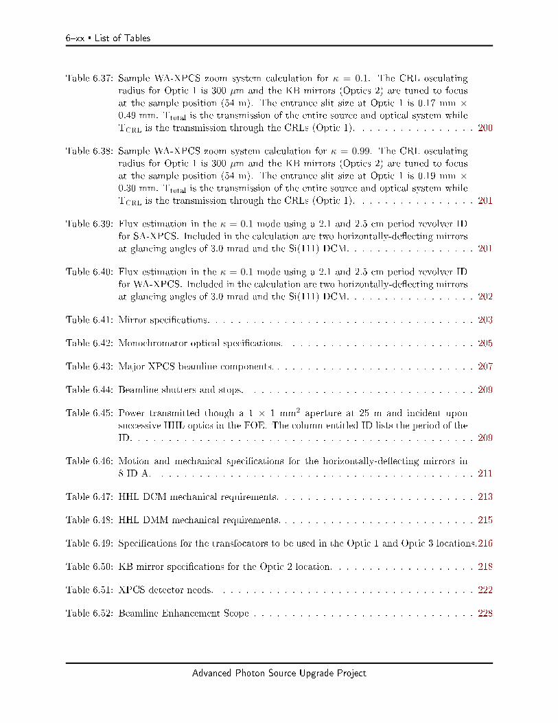
Table 6.37: Sample WA-XPCS zoom system calculation for κ = 0.1. The CRL osculatingradius for Optic 1 is 300 µm and the KB mirrors (Optics 2) are tuned to focusat the sample position (54 m). The entrance slit size at Optic 1 is 0.17 mm ×0.49 mm. Ttotal is the transmission of the entire source and optical system whileTCRL is the transmission through the CRLs (Optic 1). . . . . . . . . . . . . . . . 200
Table 6.38: Sample WA-XPCS zoom system calculation for κ = 0.99. The CRL osculatingradius for Optic 1 is 300 µm and the KB mirrors (Optics 2) are tuned to focusat the sample position (54 m). The entrance slit size at Optic 1 is 0.19 mm ×0.30 mm. Ttotal is the transmission of the entire source and optical system whileTCRL is the transmission through the CRLs (Optic 1). . . . . . . . . . . . . . . . 201
Table 6.39: Flux estimation in the κ = 0.1 mode using a 2.1 and 2.5 cm period revolver IDfor SA-XPCS. Included in the calculation are two horizontally-deecting mirrorsat glancing angles of 3.0 mrad and the Si(111) DCM. . . . . . . . . . . . . . . . . 201
Table 6.40: Flux estimation in the κ = 0.1 mode using a 2.1 and 2.5 cm period revolver IDfor WA-XPCS. Included in the calculation are two horizontally-deecting mirrorsat glancing angles of 3.0 mrad and the Si(111) DCM. . . . . . . . . . . . . . . . . 202
Table 6.41: Mirror specications. . . . . . . . . . . . . . . . . . . . . . . . . . . . . . . . . . . 203
Table 6.42: Monochromator optical specications. . . . . . . . . . . . . . . . . . . . . . . . . 205
Table 6.43: Major XPCS beamline components. . . . . . . . . . . . . . . . . . . . . . . . . . . 207
Table 6.44: Beamline shutters and stops. . . . . . . . . . . . . . . . . . . . . . . . . . . . . . 209
Table 6.45: Power transmitted though a 1 × 1 mm2 aperture at 25 m and incident uponsuccessive HHL optics in the FOE. The column entitled ID lists the period of theID. . . . . . . . . . . . . . . . . . . . . . . . . . . . . . . . . . . . . . . . . . . . . 209
Table 6.46: Motion and mechanical specications for the horizontally-deecting mirrors in8-ID-A. . . . . . . . . . . . . . . . . . . . . . . . . . . . . . . . . . . . . . . . . . 211
Table 6.47: HHL DCM mechanical requirements. . . . . . . . . . . . . . . . . . . . . . . . . . 213
Table 6.48: HHL DMM mechanical requirements. . . . . . . . . . . . . . . . . . . . . . . . . . 215
Table 6.49: Specications for the transfocators to be used in the Optic 1 and Optic 3 locations.216
Table 6.50: KB mirror specications for the Optic 2 location. . . . . . . . . . . . . . . . . . . 218
Table 6.51: XPCS detector needs. . . . . . . . . . . . . . . . . . . . . . . . . . . . . . . . . . 222
Table 6.52: Beamline Enhancement Scope . . . . . . . . . . . . . . . . . . . . . . . . . . . . . 228
Advanced Photon Source Upgrade Project
Acronyms 6xxi
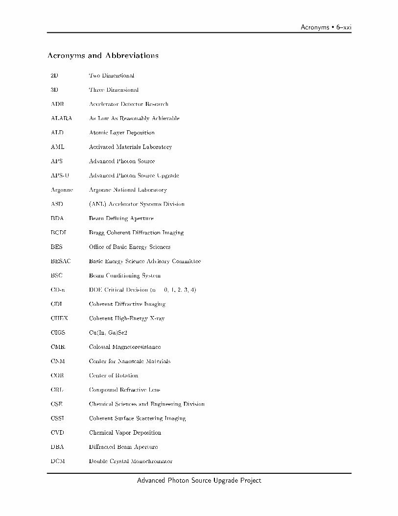
Acronyms and Abbreviations
2D Two Dimensional
3D Three Dimensional
ADR Accelerator Detector Research
ALARA As Low As Reasonably Achievable
ALD Atomic Layer Deposition
AML Activated Materials Laboratory
APS Advanced Photon Source
APS-U Advanced Photon Source Upgrade
Argonne Argonne National Laboratory
ASD (ANL) Accelerator Systems Division
BDA Beam Dening Aperture
BCDI Bragg Coherent Diraction Imaging
BES Oce of Basic Energy Sciences
BESAC Basic Energy Science Advisory Committee
BSC Beam Conditioning System
CD-n DOE Critical Decision (n = 0, 1, 2, 3, 4)
CDI Coherent Diractive Imaging
CHEX Coherent High-Energy X-ray
CIGS Cu(In, Ga)Se2
CMR Colossal Magnetoresistance
CNM Center for Nanoscale Materials
COR Center of Rotation
CRL Compound Refractive Lens
CSE Chemical Sciences and Engineering Division
CSSI Coherent Surface Scattering Imaging
CVD Chemical Vapor Deposition
DBA Diracted-Beam Aperture
DCM Double Crystal Monochromator
Advanced Photon Source Upgrade Project

6xxii Acronyms
DMM Double Multilayer Monochromator
DOE U.S. Department of Energy
DWBA Distorted Wave Born Approximation
EBSD Electron Backscatter Diraction
EDD Energy Dispersive Detectors
EE Experimental Enclosure
ER Error Reduction
ES Experimental Station
ESAC Experimental System Advisory Committee
FE Front End
-HEDM far-eld high-energy x-ray diraction microscopy
FFT Fast Fourier Transform
FOE First Optics Enclosure
FPGA Field Programmable Gate Array
FWHM Full Width Half Maximum
GA Generic Algorithm
GB Gigabyte (109 bytes)
GISAXS Grazing-Incidence Small-Angle X-ray Scattering
GIXPCS Grazing-Incidence X-ray Photon Correlation Spectroscopy
GUI Graphical User Interface
H Horizontal
H-BDA Horizontally Beam Dening Aperture
HE High Energy
HEDM high-energy x-ray diraction microscopy (prexes nf-, -, and v- denote near-eld, far-eld,and very-far-eld technique variants)
HERIX High Energy Resolution Inelastic X-ray Spectrometer
HEXM High-Energy X-Ray Microscope beamline
HGVPU Horizontal Gap Vertically Polarized Undulator
HHL High Heat Load
Advanced Photon Source Upgrade Project

Acronyms 6xxiii
HIO Hybrid Input-Output
HV High Vacuum
ID Insertion Device
ISF Intermediate Scattering Function
ISN In Situ Nanoprobe
KB Kirkpatrick-Baez
KL Kinoform Lens
LDRD Laboratory-Directed Research and Development
LLD Lower Level Discrimination
LN2 Liquid Nitrogen
µ-CT computed micro-tomography
MBA Multi-Bend Achromat
MBE Molecular Beam Epitaxy
MDI Materials Discovery Institute
MH Mini Hutch
MLL Multilayer-Laue-Lens
MM-PAD Mixed-Mode Pixel Array Detector
NA Numerical Aperture
nf-HEDM near-eld high-energy x-ray diraction microscopy
NFO Nanofocusing Optic
NMPZ Non-Minimum Phase Zero
NNSA National Nuclear Safety Administration
NSLS-II National Synchrotron Light Source II
NSUF Nuclear Science User Facilities
PAD Pixel Array Detector
PCS Photon Correlation Spectroscopy
ph photon
PLD Pulsed Laser Deposition
R&D Research and Development
Advanced Photon Source Upgrade Project

6xxiv Acronyms
RIXS Resonant Inelastic X-ray Scattering
rms Root Mean Square
RSS Radiation Safety System
SAC Scientic Advisory Committee
SA-XPCS Small-Angle X-ray Photon Correlation Spectroscopy
SAXS Small-Angle X-ray Scattering
SC Superconducting
SCU Superconducting Undulator
SCAPE Superconducting Arbitrarily Polarized Emitter
SCM Single-Crystal Monochromator
SEM Scanning Electron Microscope
SF Spatial Filter
SME Subject Matter Experts
SMS Sample Manipulation System
SNR Signal-to-Noise Ratio
SOE Second Optics Enclosure
SR Storage Ring
SSA Secondary Source Aperture
ST Scattering Tomography
TB Terabyte (1012 bytes)
TBD To Be Determined
TEM Transmission Electron Microscope
TM Transition Metal
TXM Transmission X-ray Microscope
UFXC Ultra Fast X-ray Camera
UHV Ultra-High Vacuum
V Vertical
V-BDA Vertically Beam-Dening Aperture
v-HEDM very-far-eld high-energy x-ray diraction microscopy
Advanced Photon Source Upgrade Project
Acronyms 6xxv
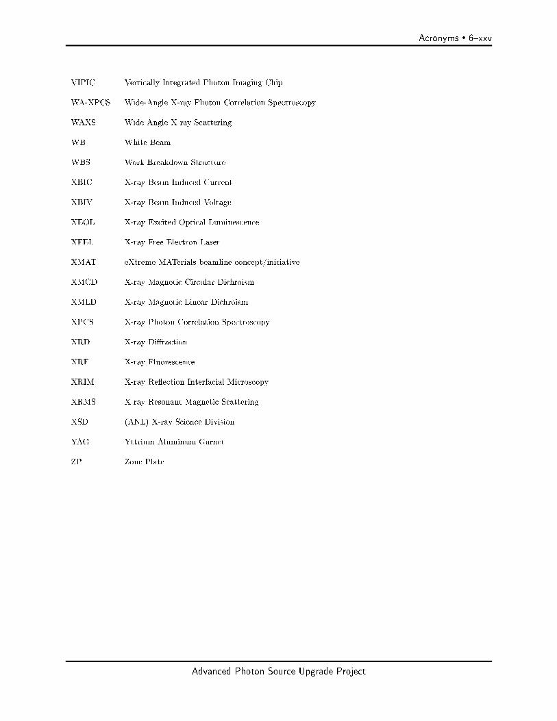
VIPIC Vertically Integrated Photon Imaging Chip
WA-XPCS Wide-Angle X-ray Photon Correlation Spectroscopy
WAXS Wide-Angle X-ray Scattering
WB White Beam
WBS Work Breakdown Structure
XBIC X-ray Beam Induced Current
XBIV X-ray Beam Induced Voltage
XEOL X-ray Excited Optical Luminescence
XFEL X-ray Free Electron Laser
XMAT eXtreme MATerials beamline concept/initiative
XMCD X-ray Magnetic Circular Dichroism
XMLD X-ray Magnetic Linear Dichroism
XPCS X-ray Photon Correlation Spectroscopy
XRD X-ray Diraction
XRF X-ray Fluorescence
XRIM X-ray Reection Interfacial Microscopy
XRMS X-ray Resonant Magnetic Scattering
XSD (ANL) X-ray Science Division
YAG Yttrium Aluminum Garnet
ZP Zone Plate
Advanced Photon Source Upgrade Project
Experimental Facilities Page 61
6 Experimental Facilities
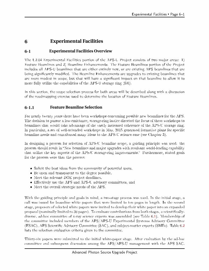
6-1 Experimental Facilities Overview
The U2.04 Experimental Facilities portion of the APS-U Project consists of two major areas: 1)Feature Beamlines and 2) Beamline Enhancements. The Feature Beamlines portion of the Projectincludes all APS-U beamlines that are either entirely new, or are existing APS beamlines that arebeing signicantly modied. The Beamline Enhancements are upgrades to existing beamlines thatare more modest in scope, but that will have a signicant impact on that beamline to allow it tomore fully utilize the capabilities of the APS-U storage ring (SR).
In this section, the scope selection process for both areas will be described along with a discussionof the roadmapping exercise used to determine the location of Feature Beamlines.
6-1.1 Feature Beamline Selection
For nearly twenty years there have been workshops concerning possible new beamlines for the APS.The decision to pursue a low-emittance, storage-ring lattice directed the focus of these workshops tobeamlines that would take advantage of the vastly increased coherence of the APS-U storage ring.In particular, a set of well-attended workshops in May, 2015 generated formative plans for specicbeamline needs and contributed many ideas to the APS-U science case (see Chapter 3).
In designing a process for selection of APS-U beamline scope, a guiding principle was used: theprocess should result in New beamlines and major upgrades with resultant world-leading capabilitythat utilize the key aspects of the APS-U storage-ring improvements. Furthermore, stated goalsfor the process were that the process:
Solicit the best ideas from the community of potential users, Be open and transparent to the degree possible, Meet the relevant DOE project deadlines, Eectively use the APS and APS-U advisory committees, and Meet the overall strategic needs of the APS.
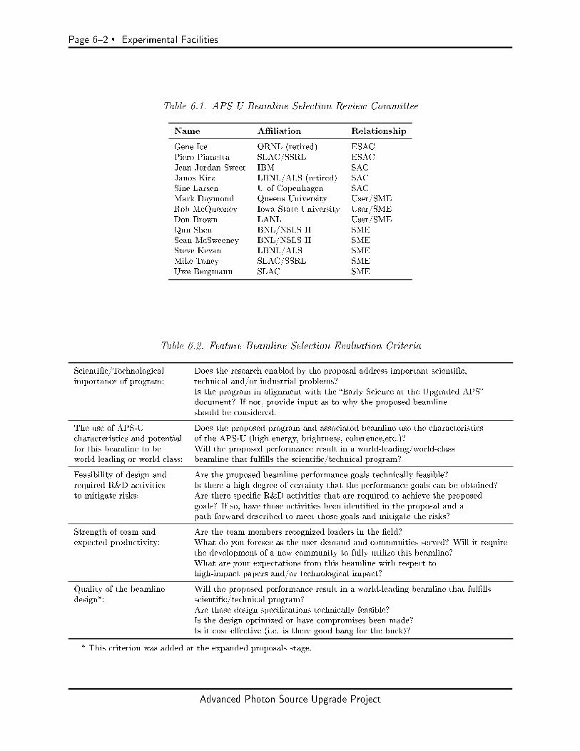
With the guiding principle and goals in mind, a two-stage process was used. In the initial stage, acall was issued for beamline white papers that were limited to ten pages in length. In the secondstage, proposers of selected white papers were invited to develop their white paper into an expandedproposal (nominally limited to 30 pages). To evaluate contributions from both stages, a scientically-diverse, ad-hoc committee of x-ray science experts was assembled (see Table 6.1). Membership ofthe committee included members of the APS/APS-U Experimental Systems Advisory Committee(ESAC), APS Scientic Advisory Committee (SAC), and subject-matter experts (SMEs). Table 6.2lists the selection evaluation criteria given to the committee.
Thirty-six papers were submitted to the initial white-paper stage. After evaluation by the ad-hoccommittee and subsequent discussion among the APS/APS-U management with the APS SAC,
Advanced Photon Source Upgrade Project
Page 62 Experimental Facilities
Table 6.1. APS-U Beamline Selection Review Committee
Name Aliation Relationship
Gene Ice ORNL (retired) ESACPiero Pianetta SLAC/SSRL ESACJean Jordan-Sweet IBM SACJanos Kirz LBNL/ALS (retired) SACSine Larsen U of Copenhagen SACMark Daymond Queens University User/SMERob McQueeney Iowa State University User/SMEDon Brown LANL User/SMEQun Shen BNL/NSLS II SMESean McSweeney BNL/NSLS II SMESteve Kevan LBNL/ALS SMEMike Toney SLAC/SSRL SMEUwe Bergmann SLAC SME
Table 6.2. Feature Beamline Selection Evaluation Criteria
Scientic/Technological Does the research enabled by the proposal address important scientic,importance of program: technical and/or industrial problems?
Is the program in alignment with the Early Science at the Upgraded APSdocument? If not, provide input as to why the proposed beamlineshould be considered.
The use of APS-U Does the proposed program and associated beamline use the characteristicscharacteristics and potential of the APS-U (high energy, brightness, coherence,etc.)?for this beamline to be Will the proposed performance result in a world-leading/world-classworld-leading or world-class: beamline that fullls the scientic/technical program?
Feasibility of design and Are the proposed beamline performance goals technically feasible?required R&D activities Is there a high degree of certainty that the performance goals can be obtained?to mitigate risks: Are there specic R&D activities that are required to achieve the proposed
goals? If so, have those activities been identied in the proposal and apath forward described to meet those goals and mitigate the risks?
Strength of team and Are the team members recognized leaders in the eld?expected productivity: What do you foresee as the user demand and communities served? Will it require
the development of a new community to fully utilize this beamline?What are your expectations from this beamline with respect tohigh-impact papers and/or technological impact?
Quality of the beamline Will the proposed performance result in a world-leading beamline that fulllsdesign*: scientic/technical program?
Are those design specications technically feasible?Is the design optimized or have compromises been made?Is it cost eective (i.e. is there good bang for the buck)?
* This criterion was added at the expanded proposals stage.
Advanced Photon Source Upgrade Project
Experimental Facilities Page 63
seventeen were selected for further developments. Of these, three proposals in the area of wide-eldimaging were asked to merge and two proposals emphasizing time-resolved methods were asked tomerge. In total, fourteen invitations were given for proposers to develop expanded proposals. Itshould be noted that in several cases, APS/APS-U management gave directed feedback to proposersto rene alignment to APS strategic plans. For the development of expanded proposals, the APS-U provided engineering and optics-simulation support to the proposers. In addition, each of thefourteen proposals was presented to the user community for feedback during a workshop at theAPS/CNM Users Meeting.
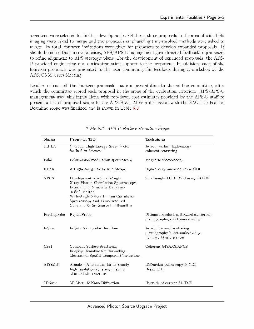
Leaders of each of the fourteen proposals made a presentation to the ad-hoc committee, afterwhich the committee scored each proposal in the areas of the evaluation criterion. APS/APS-Umanagement used this input along with top-down cost estimates provided by the APS-U sta topresent a list of proposed scope to the APS SAC. After a discussion with the SAC, the FeatureBeamline scope was nalized and is shown in Table 6.3.
Table 6.3. APS-U Feature Beamline Scope
Name Proposal Title Technique
CH EX Coherent High Energy X-ray Sector In situ, surface high-energyfor In Situ Science coherent scattering
Polar Polarization modulation spectroscopy Magnetic spectroscopy
HEXM A High-Energy X-ray Microscope High-energy microscopies & CDI
XPCS Development of a Small-Angle Small-angle XPCS, Wide-angle XPCSX-ray Photon Correlation SpectroscopyBeamline for Studying Dynamicsin Soft MatterWide-Angle X-Ray Photon CorrelationSpectroscopy and Time-ResolvedCoherent X-Ray Scattering Beamline
Ptychoprobe PtychoProbe Ultimate resolution, forward scatteringptychography/spectromicroscopy
InSitu In Situ Nanoprobe Beamline In situ, forward scatteringptychography/spectromicroscopyLong working distances
CSSI Coherent Surface Scattering Coherent GISAXS,XPCSImaging Beamline for UnravelingMesoscopic Spatial-Temporal Correlations
ATOMIC Atomic A beamline for extremely Diraction microscopy & CDIhigh resolution coherent imaging Bragg CDIof atomistic structures
3DNano 3D Micro & Nano Diraction Upgrade of current 34-ID-E
Advanced Photon Source Upgrade Project
Page 64 Experimental Facilities
6-1.2 APS-U Roadmap
The process of siting the Feature Beamlines is known as the APS-U Roadmap. As an upgrade toan existing facility, the implementation of the APS-U Feature Beamlines scope presents challengesas well as signicant opportunities. Currently, only two ID ports at the APS are not occupied by anoperating beamline. It is obvious that at least six of the Feature Beamlines will need to be placed atsites that are currently being used. An additional complicating factor is that for two of the selectedFeature Beamlines, strong technical cases have been made for extending those beamlines beyondthe current APS Experimental Hall. These long beamlines (HEXM and InSitu), will have endstations in a new building built adjacent to the current APS building. As will be discussed below,there are a limited number of places around the APS where a beamline can be existed beyond theexisting building, and neither of the currently unoccupied ports are suitable for such extension. Insummary, the main considerations in developing the APS-U Roadmap were the following:
Maximizing Feature Beamline performance, leading to world-leading and world-class APSbeamlines,
Constraints of the APS-U Feature Beamline budget, Impact on existing beamlines, Long beamline location, Reuse of existing infrastructure, Compatibility with XSD strategic plans, and Compatibility with CAT plans.
It was clear from the beginning of the process that locations of the long beamlines were key todetermination of all of the other issues, and had the potential to cause the most diculty. It wasdecided that the only practical approach was to site the two long beamlines adjacent to one anotherso that they could share infrastructure, in particular, a new building adjacent to the current APSbuilding. APS-U sta worked with John Sidarous of the APS Site Operation Group and StudioGC, a Chicago-based architectural rm, to evaluate every APS ID beamline site for suitabilitybased on a variety of factors, including: environmental issues (e.g., wetlands), impact on non-APS infrastructure (e.g., roads, utility lines, sewers), impact on APS infrastructure (e.g., lab ocemodules), topography, and impact on existing beamlines.
Three locations were identied as the most suitable and these locations were subjected to detailedanalysis. The locations were 3&4-ID, 19&20-ID, and 30&31-ID. The results of this are given in [20],with the 19&20-ID site being the clearly preferred option. In addition to the siting study, conceptualplans were developed for a platform, stairs, and elevators to allow access for areas blocked by thelong beamlines.
With the locations of the long beamlines determined, other siting decisions become possible, andafter deliberations among APS/APS-U management and aected stakeholders, the roadmap shownin Table 6.4 was developed. The roadmap given in Table 6.4 is the assumption for the beamlinesections given in the rest of this chapter and will be the basis for the designs, cost, schedule, andother documentation for the CD-2 phase of the Project. As developments occur with existing APSprograms, the APS-U Roadmap may be adjusted in response to opportunities that arise, and APS-Uplans will be adjusted accordingly using the standard APS-U Project change request process.
Advanced Photon Source Upgrade Project

Experimental Facilities Page 65
Table 6.4. The proposed APS-U Roadmap
Program Selected Aected Existing CommentLocation APS Program
In Situ 19-ID SBC-CAT Long beamlineHEXM 20-ID Current 20-ID Long beamline
Current 20-ID program will relocate to 25-ID.Polar 4-ID 4-ID-C The IDs for the Polar program
will occupy the entire 4-ID straight section,requiring relocation of the 4-ID-C soft x-ray branch.
XPCS 8-ID Currently location of XPCS program. SAXPCSand WAXPCS programs combined.
CSSI 9-ID USAXS USAXS tentatively slated to move to 12-IDBionanoprobe Bionanoprobe slated to move to 2-ID
CHEX 28-ID 28-ID currently unoccupiedPtychoprobe 33-ID Current 33-ID program Current 33-ID will be absorbed into
existing XSD diraction beamlines.ATOMIC/ 34-ID Both programs are based on instruments3DMicroNano currently located on the canted 34-ID beamline
Advanced Photon Source Upgrade Project
Page 66 Experimental Facilities
6-2 ATOMIC: A beamline for extremely high resolution coherent imaging ofatomistic structures
6-2.1 Executive Summary
The ATOMIC beamline will enable extremely high-resolution (<1 nm) investigation of materialsstructure and high resolution (<10 nm) imaging of a material's operando conditions. The APS MBAlattice will produce an unprecedented amount of coherent ux in the hard x-ray region. This willenable coherent diractive imaging (CDI) of material structure at a resolution approaching atomicdimensions within a reasonable measurement time (10s of minutes).
ATOMIC will address structural questions intersecting nearly every branch of science. We haveoutlined several where we believe the impact will be transformative. One such example is catalysis,which would enable one to literally see into the functional nature of these materials while theyare active. We will address important questions in structural materials, such as the inuence ofgrain boundaries, defects, and the nucleation of voids leading to failure. Dislocation dynamics playa critical role in materials failure. ATOMIC will be capable of imaging their interactions withpoint defects as well as clusters of defects. Extremely high-resolution coherent imaging expands ourunderstanding of failure mechanisms in amorphous materials like bulk metallic glasses, which areamong the strongest materials known. Finally, magnetic and other properties of correlated electronsystems typically scatter x-rays weakly, hindering local understanding of spin and lattice couplingin these systems. ATOMIC will facilitate the performance of high resolution imaging measurementson them on practical time scales. The ATOMIC beamline, together with the tremendous coherentux of the APS MBA lattice, will literally make the invisible, visible.
The ATOMIC beamline is conceptually simple. The major components consist of an undulatorsource, a set of slits, a monochromator, and a focusing system to tailor the coherent x-ray beam tothe sample, a stage to manipulate and orient the sample, and a detector to capture the coherentlyscattered photons. We outline aggressive, no-compromise design goals for both the optics and samplemanipulations based on technologies that are past their proof-of-principle stage. We identify R&Drequired to take these components from the design stage to full-edged instrumentation in supportof the science program. A key feature of the ATOMIC beamline is a variable numerical aperturefocusing system capable of more than one decade of continuous tuning of the focal spot size. Thissystem, based on Kirk-Patrick Baez (KB) mirror pairs, combined with beamline optics to providethe necessary coherent beam properties, will enable the ambitious scientic program outlined above.ATOMIC will be alone in the world as a dedicated coherent imaging beamline for studies of atomisticstructure in materials based on state-of-the-art technical capabilities and a synchrotron x-ray source.
This section outlines the scientic objectives and case for ATOMIC, the beamline technical capa-bilities and key performance specications, the source and front-end requirements, the beamlinelayout and optics, experimental station instrumentation, detector and data acquisition planned,and R&D work needed to realize the above. A drawing of the beamline layout and a componentlist are covered later in this section.
Advanced Photon Source Upgrade Project

Experimental Facilities Page 67
6-2.2 Scientific Objectives and Capabilities
6-2.2.1 Science case for beamline (See Section 2.2)
Interrogating modern functional materials to unravel the tangle of structural, chemical, and physicalproperties is currently a major endeavor[21]. Few structural techniques possess sensitivity to localatomic structure across tens of nanometers to micrometers of sample volume while also permittingoperando investigations. Billinge et al. summarize this endeavor nicely in their review in ScienceMagazine entitled The Problem with Determining Atomic Structure at the Nanoscale[21]. Typ-ically atomic and mesoscale information is gathered by a variety of techniques on micrometer andmillimeter size samples. Modeling and simulation are then employed to extract a plausible storyof the structural and functional properties of that sample. There is a strong need for techniquesthat can acquire atomistic structural information across many length scales in full three-dimensionaldetail. If these same techniques can function with operando environmental cells, they will have atransformative impact on many disciplines of science. The ATOMIC beamline aims to be that tool.
Figure 6.1. (a) SEM of cobaltate articial leaf lms. Models shown above of orga-nized active domains and their potential stacking[1, 2]. (b) A 300nm gold crystal, im-aged with BCDI, before (inset) and after exposure to ascorbic acid. Surface color repre-sents lattice strain. Reactive MD simulation (above) explains increased strain at cornersis due to hydroxyl ions chemisorbed to the surface[3]. (c) SEM showing slip planes tran-siting grain boundaries in regions of high strain(inset) imaged with EBSD. MD simula-tions (above) are used to understand energies associated with dislocations crossing grainboundaries of dierent types[4]. (d) Plastic failure of metallic glasses occurs with shearbands. The atomic organization of such failure modes is still unknown (inset cartoon)[5].
6-2.2.2 Description of user community
Beyond the experiments described in detail in Section 2.2, coherent imaging is currently contributingto many branches of science. The current coherent imaging end station at APS contributes tostudies in nano-materials, energy materials, chemical and catalysis materials, x-ray optics, andto a lesser extent, some life science themed studies. The emphasis is on operando as well as insitu characterization. The community continues to grow. The APS Upgrade will eectively movecoherent imaging from a specialist technique to the mainstream method for nanoscale structuralcharacterization. Challenging coherent imaging experiments today will be the routine experimentsof the APS Upgrade in the future.
Advanced Photon Source Upgrade Project

Page 68 Experimental Facilities
High Pressure The high pressure community possesses almost no high resolution imaging ca-pabilities. Both the diamonds and gaskets in modern panoramic high pressure cells greatly hinderdirect imaging methods. Coherent imaging however, particularly using Bragg peaks of sampleswithin diamond-anvil cell, has rendered nanoscale investigations possible[22, 23].
Wenge Yang 1000 talents Award Sta Scientist, Shanghai Laboratory of HPSTAR & High Pres-sure Synergetic Consortium, Carnegie Institution of Washington.
Correlated systems and complex materials Paul Evans, Department of Materials Scienceand Engineering, University of Wisconsin at Madison. Structure and response of complex oxidesunder extreme elds.
Phil Ryan, X-ray Science Division, Argonne. Magnetic x-ray scattering, thin lms, and electronicstructure of correlated systems.
Oleg Shpyrko, Shpyrko Research Group, UC San Diego Nanoscale dynamics, energy materials,metallic glasses, quantum uctuations, novel coherent x-ray scattering methods.
Edwin Fohtung, Department of Physics, NewMexico State University. Research focuses on nanoscalephysics of ferroelectric and multiferroic systems.
Joshua Turner, LCLS, Stanford Linear Accelerator Laboratory. Ordering and phase transitions incorrelated electron systems, x-ray resonant scattering.
Ian McNulty, Center for Nanoscale Materials, Argonne National Laboratory. Coupling of mag-netism and strain in nanomagnetic and correlated electron materials. Ordering behavior at phasetransitions.
Energy Materials Coherent imaging of operando energy storage materials.
Andrew Ulvestad, Synchrotron Radiation Studies Group, Materials Science Division, Argonne Ma-terial interfaces and catalysis for energy conversion and storage.
Oleg Shpyrko, Shpyrko Research Group, UC San Diego Nanoscale dynamics, energy materials,metallic glasses, quantum uctuations, novel coherent x-ray scattering methods.
Paul Fuoss, Synchrotron Radiation Studies Group, Materials Science Division, Argonne Epitaxiallms and crystal growth, novel coherent x-ray scattering methods.
Felix Hofmann, Department of Engineering Science, University of Oxford, irradiation damage instructural materials, nano- and dislocation mechanics.
Chemistry and Catalysis Hoydoo You, Synchrotron Radiation Studies Group, Materials Sci-ence Division, Argonne Material interfaces and catalysis for energy conversion and storage.
Advanced Photon Source Upgrade Project

Experimental Facilities Page 69
Prof. Hyunjung Kim, Sogang University, Zeolites and metallic catalysts.
Life Science Recent progress has been made in imaging biological macromolecule crystals usingCDI. The APS-U will improve this through more ecient collection of scattered photons, given thatthe limiting factor with these samples is damaging dose[24].
H. D. Coughlan, C. Darmanin,N. W. Phillips, B. Abbey - Australian Research Council Centreof Excellence in Advanced Molecular Imaging, Department of Chemistry and Physics, La TrobeUniversity, Melbourne 3086, Australia.
6-2.2.3 APS-U characteristics
The experiments outlined in our science case have a tremendous need for coherent ux, both from thestandpoint of reaching atomic resolution[6, 25, 26] by CDI, and pushing current detection limits tothat of single-defect, chemical species identication, or spin and orbital-sensitive measurements. Theproposed APS Upgrade source will not only revolutionize the science done with coherent imaging,but also drive the evolution of the method itself. We will be able to manipulate and use thecoherent modal composition of the beam like never before. Polychromatic and multimodal coherentimaging methods have been demonstrated are under further development[27, 28, 29]. The relativelynarrow bandwidth of the spectral components of the new source will make these methods even morepromising.
It is not optimistic to expect sub 10-nm resolution imaging of operando materials in tens of secondswith this instrument. Atomic resolution imaging of 50-nm volumes could be achieved in tens ofminutes. This capability nicely complements operando Transmission Electron Microscopy (TEM)where strong beam-matter interactions limits the technique to a few to tens of nanometer resolution.
Dietze et al.[6] have recently published a comprehensive study on the required photon ux to imageboth crystalline and amorphous high-z materials with coherent diraction at atomic resolution. Inthis study, the authors performed realistic simulations of coherent diraction data that was thenphased using current methods to retrieve and image the sample. For this reason, this article ishighly valuable for estimates regarding what can be achieved with coherent imaging at the APS-U.The required photon uxes have been specied by the delity of the resulting image of the atomsin the sample. Figure 6.2 is assembled from Dietze et al.[6] The authors have determined thatto faithfully image a 20 nm gold crystal, one needs an incident time-integrated ux of about 1018
ph/µm2. This corresponds to about 40 s of integration for a full 3D atomic resolution image usingthe estimated APS-U coherent ux at 10 keV, taken from the plot in Figure 6.3. Of course thisassumes absolutely no losses in focusing of the beam to exactly the size of the sample and alsoperfect eciency in collection of the scattered photons. Even if we only come within an order ofmagnitude of perfection, we may still achieve atomic resolution in a reasonable time period. Inthe case of atomic resolution imaging of an amorphous gold sample, Dietze et al. found that thesituation improves by a further order of magnitude, achieving faithful images of their sample withjust 1017 ph/µm2 of time integrated ux. This is summarized in Figure 6.2. where the achievedimage resolution is found to plunge by nearly an order of magnitude upon reaching the thresholdux in each case. This improvement for amorphous samples is explained at least qualitatively by thefact that very little information is actually contained in the Bragg peaks of a crystalline scattering
Advanced Photon Source Upgrade Project
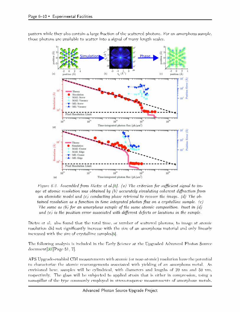
Page 610 Experimental Facilities
pattern while they also contain a large fraction of the scattered photons. For an amorphous sample,those photons are available to scatter into a signal of many length scales.
Figure 6.2. Assembled from Dietze et al.[6]. (a) The criterion for sucient signal to im-age at atomic resolution was obtained by (b) accurately simulating coherent diraction froman atomistic model and (c) conducting phase retrieval to recover the image. (d) The ob-tained resolution as a function in time integrated photon ux on a crystalline sample. (e)The same as (b) for an amorphous sample of the same atomic composition. Inset in (d)and (e) is the position error associated with dierent defects or locations in the sample.
Dietze et al. also found that the total time, or number of scattered photons, to image at atomicresolution did not signicantly increase with the size of an amorphous material and only linearlyincreased with the size of crystalline samples[6].
The following analysis is included in the Early Science at the Upgraded Advanced Photon Sourcedocument[30][Page 51, 7].
APS Upgrade-enabled CDI measurements with atomic (or near-atomic) resolution have the potentialto characterize the atomic rearrangements associated with yielding of an amorphous metal. Asenvisioned here, samples will be cylindrical, with diameters and lengths of 20 nm and 50 nm,respectively. The glass will be subjected to applied strain that is either in compression, using ananopillar of the type commonly employed in stress-response measurements of amorphous metals,
Advanced Photon Source Upgrade Project

Experimental Facilities Page 611
Figure 6.3. The anticipated coherent ux tuning curves ofthe APS Upgrade for a representative undulator sources.
or that is in tension, where dog bone-shaped samples would isolate the failure region to a desiredcylindrical segment. In either case, CDI reconstructions would be performed as a function of xedstrain, as the stress is simultaneously monitored so that rearrangement events can be directlyconnected to nonlinear mechanical response.
As an assessment of the feasibility of such measurements, we have calculated the expected scatteringintensities in coherent diraction patterns from a sample of amorphous metal, based on moleculardynamics simulations. The simulation results contain the positions of 96,000 atoms within anapproximately 8 x 8 x 26 nm3 specimen of the widely studied metallic glass composition Cu64Zr36before and after yielding under an applied shear stress.
The diraction patterns, which are shown on a log scale and extend to a maximum wave-vectorqmax = 1.26 A-1, were calculated based on a 20 x 26 nm2 incident beam on the specimen with atotal dose of 1013 photons/nm2. Patterns with such scattering intensity to this qmax can be used toreconstruct the real-space atomic conguration with a precision of 0.1 A-1 in the atomic positions.Assuming that the top half of a cylindrical sample is being imaged, so that the beam and samplesize approximately match (and so that the total number of atoms being imaged is about six timesthe number in the simulation), and using the expected coherent ux at APS-U that can be focusedinto a 20 x 26 nm2 spot of 2x10¹² photons/s (0.01% BW), we estimate that the total exposuretime needed to collect such a dataset from the nanopillar will be approximately 7 min. Further,assuming one obtains roughly 10 such datasets from dierent orientations to make a tomographic3D reconstruction, the total time for a measurement at each strain position will be about 1 h. Wetherefore expect that atomic-resolution images of the amorphous metal nanopillar at multiple strainamplitudes, and at multiples stages of yielding, should be feasible.
Advanced Photon Source Upgrade Project
Page 612 Experimental Facilities
While coherent imaging remains a primary driver for most low emittance synchrotrons worldwide,none are planning fully dedicated coherent diractive imaging instrumentation with the technicalcapabilities of ATOMIC. Coherent imaging is typically considered in the context of nanoprobes orsmall angle x-ray scattering (SAXS) instrumentation where coherent diractive imaging will not bethe primary function of the beamline. The only notable exception to this is the proposed BCDIbeamline at the National Synchrotron Light Source (NSLS2) at Brookhaven National Laboratory.When constructed, this beamline will be a fully dedicated coherent image beamline with boththe ability to measure Bragg peaks of crystalline samples and capabilities for scanning coherentdiraction (ptychography). The APS-U source will be at least one order of magnitude brighterthan NSLS2 at 10 keV, giving obvious advantages to ATOMIC at hard x-ray wavelengths, thoughATOMIC will nicely compliment the BCDI instrument at NSLS2. The NSLS2-BCDI instrumentis planning to operate in the 6-15 keV energy range with intended focal spots of 1-7 μm. Thisbeamline will also include laser pump, x-ray probe coherent imaging capabilities for time resolvedstudies of materials properties.
There are major advantages to a dedicated beamline for coherent imaging. ATOMIC will be able toimplement state-of-the-art optics and sample manipulation without compromising other measure-ments. Those components will be reliably congured and maintained for a suite of experiments. Infact, the greatest advantage of the current APS coherent imaging beamline, 34-ID-C, compared toothers in the world, is its dedicated nature. The fact that core capabilities of the beamline are neveraltered, and only slowly improved, has enabled a substantial scientic productivity in the last veyears. (There have been more than 55 publications, most with high impact factors). While beam-lines at ESRF can deliver greater coherent ux and SLS beamlines have more capable detectors,the APS beamline (34-ID-C) is permanently set up and ready for measurements. Among otheropportunities, this enables development of dedicated capabilities such as environments for specicmeasurements.
6-2.2.4 Key beamline characteristics
To achieve the high resolution imaging goals of this beamline, it is vital to deliver maximal coherentux to a precisely determined area, or volume, of the sample. The beamline will enable imagingacross multiple length scales of complex samples under operando conditions. The proposed zoomKB system in the ATOMIC beamline promises to enable this with a continuously variable spot sizefrom 50 nm to 1.5 µm. While in principle ptychography methods will be used for coherent imaging ofarbitrary elds of view within a sample, the overhead associated with scanning overlapping regionsof the sample will greatly reduce the temporal resolution of operando experiments on functionalmaterials. ATOMIC will be capable, through the zoom KB system, of imaging samples that areless than 50 nm to greater than 1 µm in size in a single scan to accumulate high resolution data.For samples larger than our proposed 1.5 µm spot size, we will use ptychography methods withoptimized x-ray beam size for a given experiment.
The beamline will support the use of broadband Laue diraction to obtain crystallographic orien-tations of the samples prior to coherent diraction measurements and enable polychromatic CDImethods currently under development. A randomly oriented crystallographic sample, such as thosedescribed in our science case, will be nearly impossible to measure unless one can determine theorientation of the crystallographic axis. By using broadband illumination, multiple Bragg peaks ofthe crystal will simultaneously be excited and can be used as a map of the samples' lattice orien-
Advanced Photon Source Upgrade Project

Experimental Facilities Page 613
tation. Once analyzed, one can dial up any desired Bragg orientation with a monochromatic beamand do coherent diraction measurements. Micro-Laue diraction, as shown in Figure 6.4, hasbeen extensively developed at the APS over the last two decades and can achieve the orientationaccuracy required for our experiments[7]. The existing instrument has been used recently to deter-mine orientations of samples for CDI experiments. Great care must be taken to ensure the samplemounting is compatible with both instruments, and therefore orientations are typically accurate toa few degrees. In situ Laue diraction orientation would be used every day if it were available atthe CDI instrument today.
Laue microdiraction measurement will not be conducted at high spatial resolution at ATOMIC, sothe smallest beams will not be necessary with broadband illumination. This will relieve a need todeal with the high power in the broadband illumination throughout the nal optics to the sample.
Figure 6.4. Taken from Figure 2 of Larson et al.[7]. (a) The usual broadband Laue mi-crodiraction measurement, with a beam proler to determine 3D structure. (b) A Lauediraction pattern of a polycrystalline sample. (c) indexed diraction pattern from justa single grain in the sample extracted from the polycrystalline diraction pattern in (b).
The broadband capabilities of the beamline will also enable polychromatic coherent diractiveimaging measurements.
We anticipate that as many as 10 spatial coherence modes or the full spectral width of a harmoniccan be used in some CDI experiments by exploiting recent advances in phase retrieval algorithmsand measurement methods[27, 28]. This will enable use of more total ux from the source, e.g.for weakly scattering samples. Use of broadband coherent ux will also enable full 3D imagingwithout rocking the sample. This can be employed for operando measurements or mechanicallyforced materials at the ATOMIC beamline[31].
An experiment that highlights the unique capabilities of ATOMIC was envisaged in the developmentof our science case. We will be able to image a binary alloy nanocrystal, such as silver-gold, atextremely high resolution to characterize the morphology and individual defects within the crystal.We would then like to perform operando electrochemical dealloying and analyze the nature of thedealloying process that selectively removes silver from the lattice. We can do this either in real time
Advanced Photon Source Upgrade Project
Page 614 Experimental Facilities
at modest resolution, or incrementally stop the process and image at extremely high resolution,approaching the spacing of individual atoms within the sample. Using anomalous CDI, we cantrack the local density of silver atoms that remain in the lattice after partial dealloying and analyzethe transport mechanisms underlying the dealloying process. Does the dissolution initiate andprogress from specic facets of the crystal, or are the edges and corners particularly important?What is the role of defects in the as-grown material in this process? Where, and perhaps how, dodefects arise in the sample as the dealloying occurs? Once the silver is gone, the gold will be left asa nano-porous structure. We can then conduct catalysis on this material, such as the decompositionof ascorbic acid, and watch as the lattice responds at active sites throughout the 3D volume of thematerial. The density of active sites and the rate at which they become active can be studied at veryhigh resolution. The same nano-porous gold will then be coarsened operando by heating followedby further catalysis cycles to understand how the morphology of the coarsened gold impacts thedensity of active sites or the rate at which they are utilized. Of course, this exact process can berepeated with crystals of dierent sizes, utilizing the zoom optics of the beamline, to understandhow the initial size impacts the entire process. The Laue diraction for orientation determinationwill allow us to select crystals at will, without regard for special sample preparation to control thecrystal growth directions.
The beamline will eciently deliver a coherent beam with a photon energy between 5 - 25 keV intothe end station. The high end of this range serves two purposes for ATOMIC. One is the need toobtain broadband Laue diraction for determination of sample orientation. The higher order Braggreections will be excited with high energy x-rays. These are extremely valuable for accuratelydetermining crystal orientation. The other need is for penetration into environmental cells, suchas the catalysis chamber envisioned in our science case. Experiments that simply need to occur inglass, silicon, or high pressure diamond anvil walled chambers can be easily probed with 25 keVx-rays, where the source will have a coherence on par with today's APS at 5 keV.
The low end of this spectrum is intended for taking advantage of an increased scattering crosssection of light elements and to access absorption edges of elements like Manganese and Vanadium,which have important properties in correlated electron systems.
6-2.3 Source & Front End Requirements
6-2.3.1 Insertion Device
The proposed science program will be best served by an insertion device (ID) that delivers thehighest achievable coherent photon ux over the 5-25 keV energy range. These coherent ux re-quirements are driven by the goal of reaching atomic resolution images. This energy range willenable access to resonances down to the V and Mn K-edge at the lower end of the range, andecient crystallographic orientation of samples by Laue methods with broadband radiation andpenetration into environmental cells at the upper end of the range.
To minimize losses in horizontally oriented optics and monochromators, a horizontally orientedundulator used to produce vertically polarized x-rays will be considered. Losses to a horizontalmonochromator can be as great at 40% at the lower x-ray energies used at ATOMIC. The lossescan grow tremendously at higher reections that would be used for smaller energy bandwidth orgreater temporal coherence.
Advanced Photon Source Upgrade Project

Experimental Facilities Page 615
6-2.3.2 Other source requirements
The source stability requirements for the ATOMIC beamline are met by the planned source stabilityspecications, i.e. <= 10% variation in the source size and divergence.
6-2.3.3 Front End Requirements
The beamline front-end should be windowless to minimize scattering and introduction of phasestructure in the coherent x-ray beam.
6-2.4 Beamline Layout
The current APS source lends itself to use of the entire extent of the beam in the vertical directionand dening the source in the horizontal direction for nano-focusing. This has been optimallyachieved using a focusing mirror and aperture in the horizontal[32]. The substantially smallerhorizontal emittance of the APS-U source oers much greater freedom to manipulate the beam toan optimal coherence conguration before focusing into the experiment.
The optical layout of the ATOMIC beamline is designed to take advantage of this freedom byselecting a beam with a well-dened set of coherence modal properties and matching it ecientlyto the experiment. The following section outlines the conceptual scheme and principal componentsof the beamline optics.
6-2.4.1 X-ray Optical Layout
The following beamline optical design is based on three sections with associated optical functionsthat target the science program of ATOMIC: (i) spatial coherent mode selection, (ii) temporalcoherence selection (monochromatization), and (iii) focusing. Figure 6.5 shows the approximatelocations of the components of each section and their distances from the source, dened to be thecenter of the straight section containing the undulator.
Coherence mode selection is accomplished with two sets of beam dening apertures (slit pairs)separated by a drift path, to allow the beam to propagate freely between them. The rst white-beam slit pair, S1, located ∼27 from the undulator source, can be closed to dene a secondaryeective source or be opened to accept a partially coherent beam to the optics and experimentdownstream. The second slit pair, S2, located at ∼51 m from the source, can also be closed oropened to accept a fully or partially coherent beam from the rst slit pair. Together, the purpose ofthe two slit pairs is to dene the coherence properties of the beam, ranging from a single coherentmode to as many as several modes in both the horizontal and vertical planes, depending on thex-ray energy and coherence requirements of the experiment.
Temporal coherence selection is accomplished by a double-crystal monochromator (DCM), andoptionally, a double multi-layer monochromator (DMM) located after slit pair S2 at ∼51 m fromthe source. A temporal (longitudinal) coherence length of λ2/∆λ ∼ 0.5µm at 10 keV, which is metby a Si(111) DCM, will be sucient to reach atomic resolution with a sample diameter of 50 nm.Higher-order crystal reections can be utilized if a longer temporal coherence length is required.
Advanced Photon Source Upgrade Project
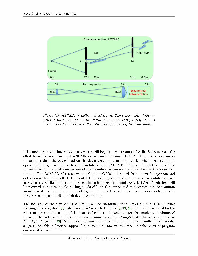
Page 616 Experimental Facilities
Figure 6.5. ATOMIC beamline optical layout. The components of the co-herence mode selection, monochromatization, and beam focusing sectionsof the beamline, as well as their distances (in meters) from the source.
A harmonic rejection/horizontal oset mirror will be just downstream of the slits S1 to increase theoset from the beam feeding the 3DMN experimental station (34-ID-D). This mirror also servesto further reduce the power load on the downstream apertures and optics when the beamline isoperating at high energies with small undulator gap. ATOMIC will include a set of removablesilicon lters in the upstream section of the beamline to remove the power load in the lower har-monics. The DCM/DMM are conventional although likely designed for horizontal dispersion anddeection with minimal oset. Horizontal deection may oer the greatest angular stability againstgravity sag and vibration communicated through the experimental oor. Detailed simulations willbe required to determine the cooling needs of both the mirror and monochromators to maintainan estimated maximum gure error of 100nrad. Ideally they will need very modest cooling that isreadily accomplished with a high degree of stability.
The focusing of the source to the sample will be performed with a variable numerical-aperturefocusing optical system [33], also known as zoom KB optics [8, 33, 34]. This approach enables thecoherent size and dimensions of the beam to be eciently tuned to specic samples and volumes ofinterest. Recently, a zoom KB system was demonstrated at SPring-8 that achieved a zoom rangefrom 100 - 1400 nm [33]. While not implemented for user operations at a beamline, these resultssuggest a feasible and exible approach to matching beam size to samples for the scientic programenvisioned for ATOMIC.
Advanced Photon Source Upgrade Project
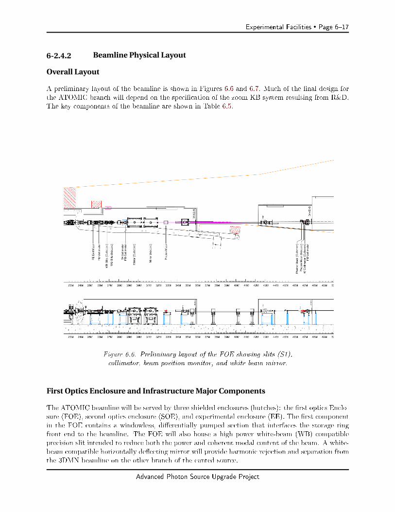
Experimental Facilities Page 617
6-2.4.2 Beamline Physical Layout
Overall Layout
A preliminary layout of the beamline is shown in Figures 6.6 and 6.7. Much of the nal design forthe ATOMIC branch will depend on the specication of the zoom KB system resulting from R&D.The key components of the beamline are shown in Table 6.5.
Figure 6.6. Preliminary layout of the FOE showing slits (S1),collimator, beam position monitor, and white beam mirror.
First Optics Enclosure and Infrastructure Major Components
The ATOMIC beamline will be served by three shielded enclosures (hutches): the rst optics Enclo-sure (FOE), second optics enclosure (SOE), and experimental enclosure (EE). The rst componentin the FOE contains a windowless, dierentially pumped section that interfaces the storage ringfront end to the beamline. The FOE will also house a high power white-beam (WB) compatibleprecision slit intended to reduce both the power and coherent modal content of the beam. A white-beam compatible horizontally deecting mirror will provide harmonic rejection and separation fromthe 3DMN beamline on the other branch of the canted source.
Advanced Photon Source Upgrade Project

Page 618 Experimental Facilities
Figure 6.7. Preliminary layout of SOE and the experiment enclosures. The SOE houses the coher-ence dening aperture (slit S2), monochromators, and rst KB mirror pair (ZKB1)at 54m. Theexperimental enclosure will contain the nal KB and diraction instrumentation at roughly 70 m.
Table 6.5. Principal beamline components, designations, and their distances from the source
Enclosure Distance Name Component Function(m)
FOE First optics enclosure Radiation shielding27 S1 Slits Primary spatial coherence selection31 M1 White beam mirror Harmonic rejection and beam separation32 BPM1 Beam position monitor Beam position/angle diagnostics
SOE Second optics enclosure Radiation shielding51 S2 Slits Secondary spatial coherence selection
Power ltering, harmonic rejection51.5 DCM Double crystal Temporal coherence selection
monochromator (narrow bandwidth)52 DMM Double multilayer Temporal coherence selection
(not shown) monochromator (moderate bandwidth)53 Polarizer Diamond phase plate x-ray beam polarization control
(not shown)54 ZKB1 Zoom KB: Focusing optics (upstream)
upstream mirrorsEE Experimental enclosure Radiation shielding,
experiment isolation68 BPM2 Beam position monitor Beam position/angle diagnostics69 ZKB2 Zoom KB: Focusing optics (downstream)
down-stream mirrors69.050 DIFF Diractometer Reciprocal space selection72-75 DET Detector Swallows the photons
Advanced Photon Source Upgrade Project
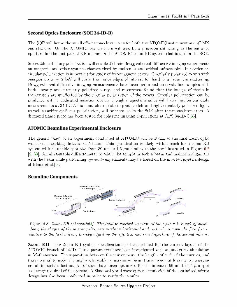
Experimental Facilities Page 619
Second Optics Enclosure (SOE 34-ID-B)
The SOE will house the small oset monochromators for both the ATOMIC instrument and 3DMNend stations. On the ATOMIC branch there will also be a precision slit acting as the entranceaperture for the rst pair of KB mirrors in the ATOMIC zoom KB system that is also in the SOE.
Selectable, arbitrary polarization will enable dichroic Bragg coherent diractive imaging experimentson magnetic and other systems characterized by molecular and orbital anisotropies. In particular,circular polarization is important for study of ferromagnetic states. Circularly polarized x-rays withenergies up to ∼12 keV will cover the major edges of interest for hard x-ray resonant scattering.Bragg coherent diractive imaging measurements have been performed on crystalline samples withboth linearly and circularly polarized x-rays and researchers found that the images of strain inthe crystals are unaected by the circular polarization of the x-rays. Circular polarization can beproduced with a dedicated insertion device, though magnetic studies will likely not be our dailymeasurements at 34-ID. A diamond phase plate to produce left and right circularly polarized light,as well as arbitrary linear polarization, will be installed in the SOE after the monochromators. Adiamond phase plate has been tested for coherent imaging applications at APS 34-ID-C[35].
ATOMIC Beamline Experimental Enclosure
The generic size of an experiment conducted at ATOMIC will be 10cm, so the nal zoom opticwill need a working distance of 50 mm. This specication is likely within reach for a zoom KBsystem with a tunable spot size from 50 nm to 1.5 µm similar to the one illustrated in Figure 6.8[8, 33]. An ultra-stable diractometer to orient the sample in such a beam and maintain alignmentwith the beam while performing operando experiments may be based on the inverted joystick designof Blank et al.[9].
Beamline Components
Figure 6.8. Zoom KB schematic[8]. The total numerical aperture of the system is tuned by modi-fying the shapes of the mirror pairs, separately in horizontal and vertical, to move the rst focusrelative to the rst mirror, thereby adjusting the eective numerical aperture of the second mirror.
Zoom KB The Zoom KB system specication has been rened for the current layout of theATOMIC branch of 34-ID. Three parameters have been investigated with an analytical simulationin Mathematica. The separation between the mirror pairs, the lengths of each of the mirrors, andthe potential to make the angles adjustable to maximize beam transmission at lower x-ray energiesare all important factors. All of these have been optimized for the intended 50 nm to 1.5 µm spotsize range required of the system. A Shadow-hybrid wave optical simulation of the optimized mirrordesign has also been conducted in order to verify the results.
Advanced Photon Source Upgrade Project
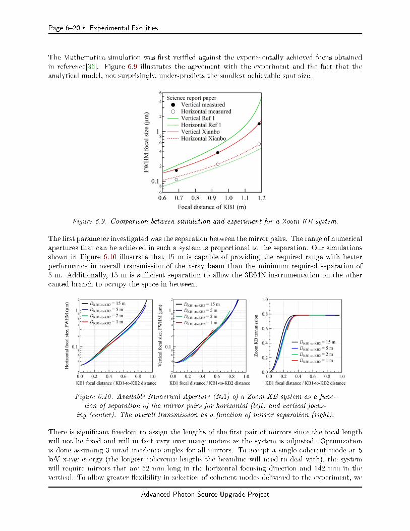
Page 620 Experimental Facilities
The Mathematica simulation was rst veried against the experimentally achieved focus obtainedin reference[36]. Figure 6.9 illustrates the agreement with the experiment and the fact that theanalytical model, not surprisingly, under-predicts the smallest achievable spot size.
Figure 6.9. Comparison between simulation and experiment for a Zoom KB system.
The rst parameter investigated was the separation between the mirror pairs. The range of numericalapertures that can be achieved in such a system is proportional to the separation. Our simulationsshown in Figure 6.10 illustrate that 15 m is capable of providing the required range with betterperformance in overall transmission of the x-ray beam than the minimum required separation of5 m. Additionally, 15 m is sucient separation to allow the 3DMN instrumentation on the othercanted branch to occupy the space in between.
Figure 6.10. Available Numerical Aperture (NA) of a Zoom KB system as a func-tion of separation of the mirror pairs for horizontal (left) and vertical focus-
ing (center). The overall transmission as a function of mirror separation (right).
There is signicant freedom to assign the lengths of the rst pair of mirrors since the focal lengthwill not be xed and will in fact vary over many meters as the system is adjusted. Optimizationis done assuming 3 mrad incidence angles for all mirrors. To accept a single coherent mode at 5keV x-ray energy (the longest coherence lengths the beamline will need to deal with), the systemwill require mirrors that are 62 mm long in the horizontal focusing direction and 142 mm in thevertical. To allow greater exibility in selection of coherent modes delivered to the experiment, we
Advanced Photon Source Upgrade Project
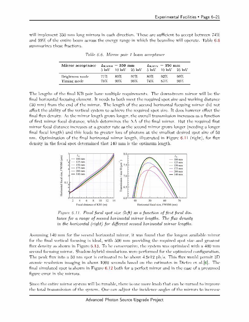
Experimental Facilities Page 621
will implement 350 mm long mirrors in each direction. These are sucient to accept between 74%and 99% of the entire beam across the energy range in which the beamline will operate. Table 6.6summarizes these fractions.
Table 6.6. Mirror pair 1 beam acceptance
Mirror acceptance LKB1H = 350 mm LKB1V = 350 mm5 keV 10 keV 25 keV 5 keV 10 keV 25 keV
Brightness mode 77% 89% 97% 80% 92% 99%Timing mode 78% 90% 98% 74% 85% 93%
The lengths of the nal KB pair have multiple requirements. The downstream mirror will be thenal horizontal focusing element. It needs to both meet the required spot size and working distance(50 mm) from the end of the mirror. The length of the second horizontal focusing mirror did notaect the ability of the vertical system to achieve the required spot size. It does however eect thenal ux density. As the mirror length grows longer, the overall transmission increases as a functionof rst mirror focal distance, which determines the NA of the nal mirror. But the required rstmirror focal distance increases at a greater rate as the second mirror grows longer (needing a longernal focal length) and this leads to greater loss of photons at the smallest desired spot size of 50nm. Optimization of the nal horizontal mirror length, illustrated in Figure 6.11 (right), for uxdensity in the focal spot determined that 140 mm is the optimum length.
Figure 6.11. Final focal spot size (left) as a function of rst focal dis-tance for a range of second horizontal mirror lengths. The ux densityin the horizontal (right) for dierent second horizontal mirror lengths.
Assuming 140 mm for the second horizontal mirror, it was found that the longest available mirrorfor the nal vertical focusing is ideal, with 500 mm providing the required spot size and greatestux density as shown in Figure 6.13. To be conservative, the system was optimized with a 400 mmsecond focusing mirror. Shadow-hybrid simulations were performed for the optimized conguration.The peak ux into a 50 nm spot is estimated to be about 4.9e12 ph/s. This ux would permit 3Datomic resolution imaging in about 1000 seconds based on the estimates in Dietze et al.[6]. Thenal simulated spot is shown in Figure 6.12 both for a perfect mirror and in the case of a presumedgure error in the mirrors.
Since the entire mirror system will be tunable, there is one more knob that can be turned to improvethe total transmission of the system. One can adjust the incidence angles of the mirrors to increase
Advanced Photon Source Upgrade Project

Page 622 Experimental Facilities
Figure 6.12. Shadow-Hybrid simulation of opti-mized conguration at 10 keV and 20 keV x-ray energy.
Figure 6.13. (Left) Vertical focal size on abscissa, as a function of rst mirror focal dis-tance. (middle) The total system transmission as a function of rst mirror focal distance(or nal spot size since they are directly related) shown for several vertical focusing mirror
lengths. (right) the ux density in the vertical for several second vertical mirror focal lengths.
Advanced Photon Source Upgrade Project
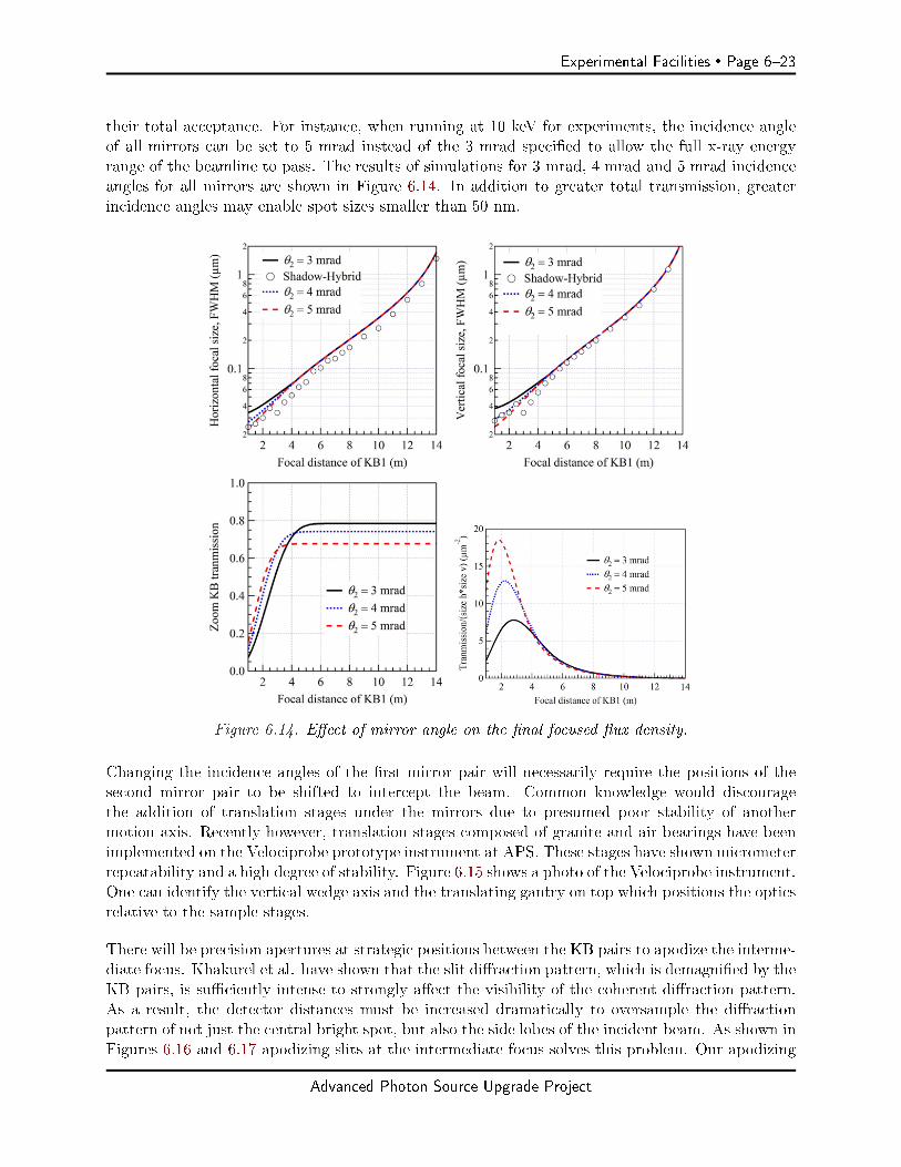
Experimental Facilities Page 623
their total acceptance. For instance, when running at 10 keV for experiments, the incidence angleof all mirrors can be set to 5 mrad instead of the 3 mrad specied to allow the full x-ray energyrange of the beamline to pass. The results of simulations for 3 mrad, 4 mrad and 5 mrad incidenceangles for all mirrors are shown in Figure 6.14. In addition to greater total transmission, greaterincidence angles may enable spot sizes smaller than 50 nm.
Figure 6.14. Eect of mirror angle on the nal focused ux density.
Changing the incidence angles of the rst mirror pair will necessarily require the positions of thesecond mirror pair to be shifted to intercept the beam. Common knowledge would discouragethe addition of translation stages under the mirrors due to presumed poor stability of anothermotion axis. Recently however, translation stages composed of granite and air bearings have beenimplemented on the Velociprobe prototype instrument at APS. These stages have shown micrometerrepeatability and a high degree of stability. Figure 6.15 shows a photo of the Velociprobe instrument.One can identify the vertical wedge axis and the translating gantry on top which positions the opticsrelative to the sample stages.
There will be precision apertures at strategic positions between the KB pairs to apodize the interme-diate focus. Khakurel et al. have shown that the slit diraction pattern, which is demagnied by theKB pairs, is suciently intense to strongly aect the visibility of the coherent diraction pattern.As a result, the detector distances must be increased dramatically to oversample the diractionpattern of not just the central bright spot, but also the side lobes of the incident beam. As shown inFigures 6.16 and 6.17 apodizing slits at the intermediate focus solves this problem. Our apodizing
Advanced Photon Source Upgrade Project
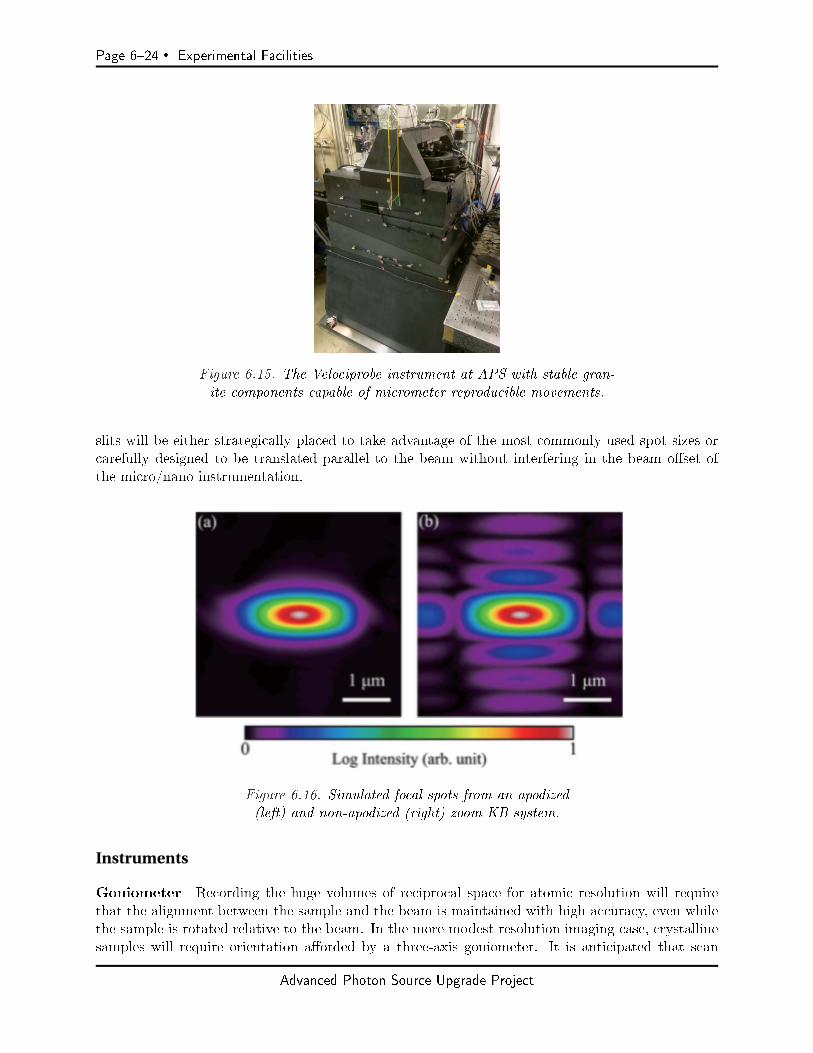
Page 624 Experimental Facilities
Figure 6.15. The Velociprobe instrument at APS with stable gran-ite components capable of micrometer reproducible movements.
slits will be either strategically placed to take advantage of the most commonly used spot sizes orcarefully designed to be translated parallel to the beam without interfering in the beam oset ofthe micro/nano instrumentation.
Figure 6.16. Simulated focal spots from an apodized(left) and non-apodized (right) zoom KB system.
Instruments
Goniometer Recording the huge volumes of reciprocal space for atomic resolution will requirethat the alignment between the sample and the beam is maintained with high accuracy, even whilethe sample is rotated relative to the beam. In the more modest resolution imaging case, crystallinesamples will require orientation aorded by a three-axis goniometer. It is anticipated that scan
Advanced Photon Source Upgrade Project
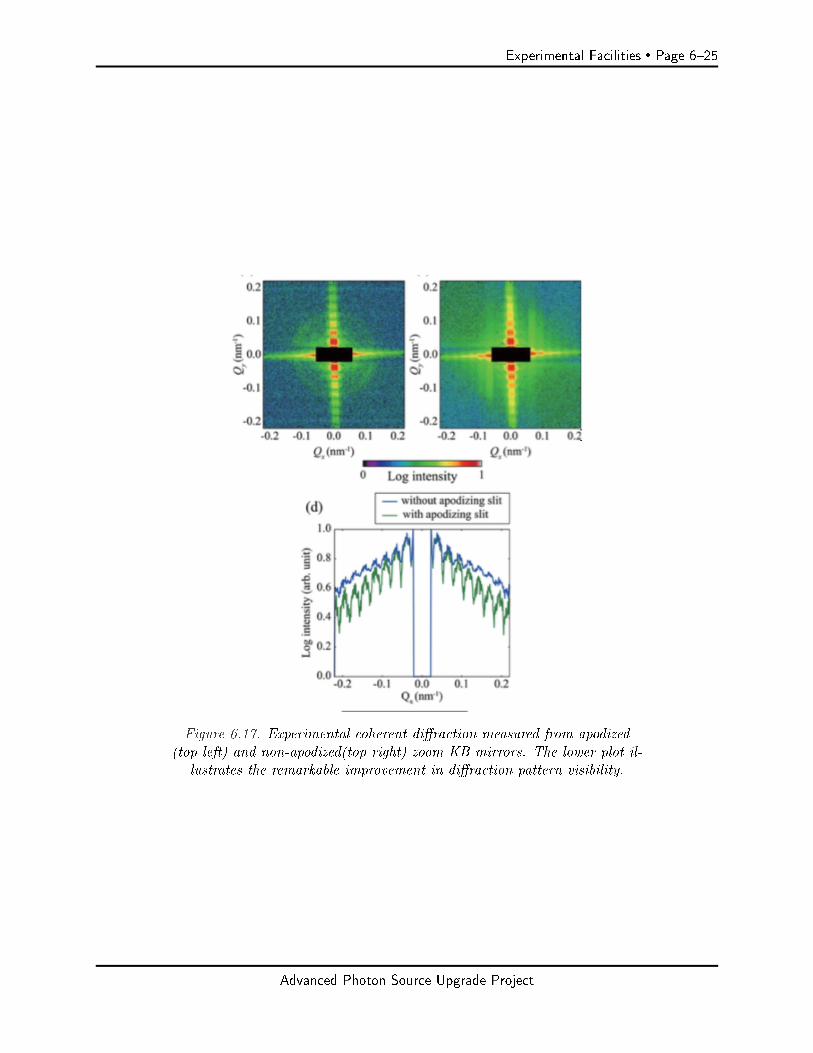
Experimental Facilities Page 625
Figure 6.17. Experimental coherent diraction measured from apodized(top left) and non-apodized(top right) zoom KB mirrors. The lower plot il-
lustrates the remarkable improvement in diraction pattern visibility.
Advanced Photon Source Upgrade Project
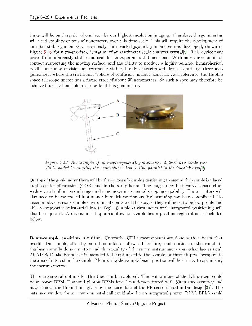
Page 626 Experimental Facilities
times will be on the order of one hour for our highest resolution imaging. Therefore, the goniometerwill need stability of tens of nanometers over this time scale. This will require the development ofan ultra-stable goniometer. Previously, an inverted joystick goniometer was developed, shown inFigure 6.18, for ultra-precise orientation of an centimeter scale analyzer crystal[9]. This device mayprove to be inherently stable and scalable to experimental dimensions. With only three points ofcontact supporting the moving surface, and the ability to produce a highly polished hemisphericalcradle, one may envision an extremely stable, highly characterized, low eccentricity, three axisgoniometer where the traditional sphere of confusion is not a concern. As a reference, the Hubblespace telescope mirror has a gure error of about 30 nanometers. So such a spec may therefore beachieved for the hemispherical cradle of this goniometer.
Figure 6.18. An example of an inverse-joystick goniometer. A third axis could eas-ily be added by rotating the hemisphere about a line parallel to the joystick arm[9].
On top of the goniometer there will be three axes of sample positioning to ensure the sample is placedat the center of rotation (COR) and in the x-ray beam. The stages may be exural constructionwith several millimeters of range and nanometer incremental stepping capability. The actuators willalso need to be controlled in a manor in which continuous (y) scanning can be accomplished. Toaccommodate various sample environments on top of the stages, they will need to be low prole andable to support a substantial load(>1kg). Sample environments with integrated positioning willalso be explored. A discussion of opportunities for sample-beam position registration is includedbelow.
Beam-sample position monitor Currently, CDI measurements are done with a beam thatoverlls the sample, often by more than a factor of two. Therefore, small motions of the sample inthe beam simply do not matter and the stability of the entire instrument is somewhat less critical.At ATOMIC the beam size is intended to be optimized to the sample, or through ptychography, tothe area of interest in the sample. Monitoring the sample-beam position will be critical to optimizingthe measurements.
There are several options for this that can be explored. The exit window of the KB system couldbe an x-ray BPM. Diamond photon BPMs have been demonstrated with 50nm rms accuracy andmay achieve the 15 nm limit given by the noise oor of the RF sensors used in the design[37]. Theentrance window for an environmental cell could also be an integrated photon BPM. BPMs could
Advanced Photon Source Upgrade Project
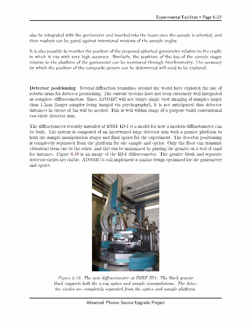
Experimental Facilities Page 627
also be integrated with the goniometer and inserted into the beam once the sample is oriented, andthen readout can be gated against intentional motions of the sample angles.
It is also possible to monitor the position of the proposed spherical goniometer relative to the cradlein which it sits with very high accuracy. Similarly, the positions of the top of the sample stagesrelative to the platform of the goniometer can be monitored through interferometry. The accuracyby which the position of the composite system can be determined will need to be explored.
Detector positioning Several diraction beamlines around the world have explored the use ofrobotic arms for detector positioning. The current systems have not been extremely well integratedas complete diractometers. Since ATOMIC will not target single view imaging of samples largerthan 1.5µm (larger samples being imaged via ptychography), it is not anticipated that detectordistances in excess of 5m will be needed. This is well within range of a purpose build conventionaltwo circle detector arm.
The diractometer recently installed at ESRF ID-1 is a model for how a modern diractometer canbe built. The system is composed of an intertwined large detector arm with a granite platform tohold the sample manipulation stages and nal optics for the experiment. The detector positioningis completely separated from the platform for the sample and optics. Only the oor can transmitvibrations from one to the other, and this can be minimized by placing the granite on a bed of sandfor instance. Figure 6.19 is an image of the ID-1 diractometer. The granite block and separatedetector circles are visible. ATOMIC is will implement a similar design optimized for the goniometerand optics.
Figure 6.19. The new diractometer at ESRF ID1. The black graniteblock supports both the x-ray optics and sample manipulations. The detec-tor circles are completely separated from the optics and sample platform.
Advanced Photon Source Upgrade Project

Page 628 Experimental Facilities
6-2.4.3 Additional
Detectors
The greatest photon density expected on the detector is the fully transmitted coherent beam with thezoom KB system congured for the largest spot size (least divergence) assuming minimal absorptionby the sample. Even for the 50 nm focusing, the divergence is about 2.3x2.5 mrad, so at a detectordistance 0.2 m (slighter greater than factor three oversampling of a 50 nm object) the beam strikingthe detector is about 460x500 µm. This leads to very poor ux per pixel at 12 keV. The 50 nmbeam with no attenuation falling on a 75 um pixel detector would impart 7e10 ph/s/pixel onto thedetector. For the 1.5 um focusing, the divergence is about 65x70 µrad, so at 4 m detector distancethe beam occupies about 260x280 µm on the detector. The ux in this case will fall on just sixteen75 µm pixels and be completely unmanageable at 2.0e11 ph/sec/pixel.
In practice, the photon density will not be this severe, but even modern, o-the-shelf detectors likeEiger from Dectris can only linearly detect about 3e6 ph/s/pixel, based on specications publishedon the Dectris web page. The unattenuated ux of the APS-U is still out of reach to even cuttingedge detectors today. The best count rate achieved by a detector today is about 1x10⁸ ph/sex/pixel[38].
It must be emphasized that current, o-the-shelf, detectors are not going to be capable of dealingwith the signals the APS-U will produce. Only the cutting edge detectors of today can even comeclose. There needs to be investment in advancing the cutting edge of today to the workhorse detectorof the APS-U era.
An estimation of the required distance of a detector can be made using the formula for the spacingof the fringes of a single-slit diraction pattern, or sinc function.
sample size =λ ∗ det dist
fringe spacing
Assuming 75 µm pixels and a sampling criterion of three pixels between speckles (bright dark bright) at 12 keV for the intended range of x-ray spot sizes, a detector distance of 0.112 metersfor 50 nm spot and 3.375 meters for a 1.5 µm sample is calculated. Typically, data is sampled atgreater than the theoretical minimum required for the method. Higher-order Bragg peaks give alinearly greater sensitivity to lattice distortions in the sample. For example, to reach the next-orderBragg peaks in gold (333 and 400) at 12 keV, the two-theta angles are 60 - 80 degrees.
Computing & Controls & Data Acquisition
For Bragg CDI, the phase-retrieval step represents perhaps the most challenging part for the non-specialist user. As such, we plan to provide a standard set of algorithms that are known to workwell in a diverse set of applications.
Currently the most eective phase retrieval methods in use for CDI are based on a genetic algorithmthat begins by using the data with dierent sets of random phases to form the rst populationof images. The population (anywhere between 5-50 independent starts) is then iterated using a
Advanced Photon Source Upgrade Project

Experimental Facilities Page 629
combination of Error Reduction (ER)[39] (the original Gerchberg-Saxton algorithm) and the HybridInput-Output (HIO) algorithm prescribed to Fienup[39]. Every 5 iterations, the support is updatedvia the shrinkwrap method[40]. The procedure continuously switches between 10-20 iterations of ERfollowed by 90-100 iterations of HIO. This is repeated 3-4 times for each member of the populationof images. After the nal iteration, the best member of the population is chosen according to aparticular metric. For highly strained crystals, selecting the best reconstruction according to thesharpness metric has been shown to converge to the correct image with a higher success rate thanusing the standard error metric as a criterion[41]. The sharpness metric is only eective in the caseof a sample with uniform density throughout, however. Therefore, the user will need to choose themetric based on the sample at hand and anything that is known about the sample. Once the bestmember of the population has been selected, it is combined with each of the other images to formthe next generation and the entire process is repeated. Typically, running 5-50 population membersfor 5-10 generations to get the nal image is advised. This is computationally intensive, so we planto run a reduced version of this to provide lower condence images as the data is being taken at thebeamline. The ptychography phase retrieval needs of ATOMIC will mirror those of the Ptychoprobeand In-situ Nanoprobe beamlines. In this regard there will be a strong synergy and cooperation intechnical development.
Data from the current CDI beamline at APS provides useful examples. In a population of 3 randominitial images run for 3 generations of the phasing algorithms, using an array size of 256x256x64, thealgorithm can run one member of the population in about two seconds on an NVIDIA Titan BlackGPU card interfaced with the MATLAB GPU computing toolbox. A factor of 10 improvement inspeed is expected by porting the code to a dedicated compiled C++ library. The best data collectedin recent runs at 34-ID-C are too large for the memory of a Tesla K40 GPU card to run the HIOalgorithm.
Finally, because each member of the population does not depend on any other member, each GPUcard can iterate on as many members of the population of images as can t in memory on the card.We expect that this should allow a good quality image to be reconstructed in minutes after the datais taken. This length of time is key as it allows the users to decide if the crystal under investigationis good enough and/or gauge how quickly the dynamics under study are happening and adjustthe experiment to maximize beam time accordingly.
In addition to improving the speed of the phase retrieval algorithms, a fully dedicated pipeline fordata transfer and phase retrieval will be developed. With data rates expected to exceed ve datasets per minute, the time required to convert those data sets into images becomes prodigious.
6-2.5 R&D Needs
The main technical areas that have been identied for investment in research and development(R&D) are the zoom KB focusing system, the high stability, low-eccentricity goniometer for thediractometer, and CDI phase retrieval algorithms optimized for both speed and ease of use inCDI.
A key R&D question to address is the feasibility of scaling up the Matsuyama et al. variablenumerical aperture zoom KB design to achieve the numerical aperture (NA) required to deliver a50 nm spot to the sample with a working distance of 50 mm in a functional instrument for user
Advanced Photon Source Upgrade Project
Page 630 Experimental Facilities
experiments. The proposed system will include in situ prole monitoring to maintain the state ofthe system and enable near real-time zoom capabilities without a need to realign the beam andsample when the spot size is modied.
Specications for the sample goniometer were included above, as well as ideas for implementation.Conventional wisdom says that it is impossible to accurately monitor, and provide feedback, on aposition on top of a multi-axis goniometer. We believe that a path towards achieving this is aordedby the inverse joystick goniometer, but research and development will be necessary to determinethe limits of this capability.
There is signicant room for improvement in the genetic algorithms used in CDI phase retrieval. Newtness metrics will need to be developed for guiding the population to a high condence solution ofarbitrary samples. Perhaps metrics with atomistic constraints will be necessary for the very highestresolution datasets. For example, users have observed current GA metrics are insucient whennetworks of dislocations are present in the sample. This requires further investigation. Entirelynew concepts for coherent diraction data analysis need to be explored. For example, one couldreturn to the old days of tting data to a model, but now do this with a library of models composedof atomistic structures formulated from molecular statics simulations of materials properties. Thetting could be done by machine learning techniques such as the convolutional neural networks todirectly interrogate the features present in the data sets and piece together an image of the sample,based on knowledge acquired from the library of models and previous data sets from the materialof interest.
ATOMIC will deliver an extremely high photon ux density on-sample, approaching 2x10⁹ ph/s/nm2.Based on a growing body of experimental evidence [24], as well as quantitative estimates [25, 42],we expect that this ux density will be signicantly above the threshold for causing observable ra-diation damage in most soft condensed materials and many hard materials. R&D will be necessaryto determine the limits of signal vs. radiation dose to scale up to experiments with ATOMIC. Inaddition, the power in the focused beam (8.0 mW over an area of 50 x 50 nm2 at 10 keV) willbe signicant even when only a small fraction of this power is absorbed by the sample. Thermalmanagement of samples will, for the rst time, become important for some experiments. We willaggressively investigate strategies to mitigate radiation damage and thermally induced changes tosamples, including use of inert and reducing gaseous environments, electrochemical protectants, andcryo-preservation where appropriate.
Advanced Photon Source Upgrade Project
Experimental Facilities Page 631
6-3 The 3D Micro Nano Diffraction
6-3.1 Executive Summary
The 3D Micro & Nano Diraction beamline is designed to directly address a wide range of spatiallyinhomogeneous materials problems at the mesoscopic length scale. These are problems in materialsscience, physics, geoscience, and most other elds of science where previous x-ray diraction tech-niques are insucient due to the short length scale of the inhomogeneities in the materials. Thisinhomogeneity is an important or intrinsic part of the material's properties, and so must be studiedon its length scale; large perfect samples are either impossible to make or do not represent the realmaterial. Due to the current extreme diculty or impossibility of making these measurements weplan to use the bright APS-U source to provide small intense x-ray spots (50 200 nm) to investigatethe important spatial variations of strain and structure that dene this wide range of scienticallyand technologically important materials.
6-3.2 Scientific Objectives & Capabilities
6-3.2.1 Science Case for Beamline
In the rst part of the last century, great advances were made in understanding the mechanical andelectrical properties of materials by assuming a simple perfect crystal structure. However, it wasalways recognized that the real properties of a material often depend critically upon the defectsand spatial inhomogeneities that were either induced or inherent in the material. For example,the strength of copper changes drastically with even the simplest work hardening, and in stronglycorrelated electron systems, local phase separation and competition give rise to exotic macroscopicelectronic properties such as colossal magnetoresistance (CMR), or ferroelectric domains to namejust two. For these and many other examples, just knowing the average strain or the average struc-ture is not sucient for understanding the new and interesting properties; one needs to know thelocal spatial distribution of strain and structure. The common theme in all of these cases is that in-homogeneous local interactions give rise to fundamentally interesting and technologically importantphysical phenomena. Moreover, in all of these cases, the 3D micro-and nano-diraction" capabil-ities provided by this beamline will provide critically needed, previously unavailable, quantitativedescriptions of these local mesoscopic interactions. Illuminating the underlying microstructuralmechanisms is imperative for understanding materials behavior, guiding the development of newmaterials, improved processing techniques and developing predictive modeling capabilities.
The very small x-ray beams will provide the resolution in both real-space and reciprocal-spaceto address scientic problems such as: The distribution and evolution of crystalline defects (e.g.dislocations) and elastic strains at the nanometer and micrometer length scales within deformedmetallic structures that have broad implications for developing a better understanding of mechanicalbehavior as a function of plastic deformation. The ability to probe high-pressure materials indiamond anvil cells at even higher pressures, and thus smaller samples sizes. The internal strainsin dierent types of electronic devices. The internal strains in complex oxide materials occurringin nanoelectronic devices, fuel cells, and novel ferroelectric devices, as well as the strains leadingto phase separation in new complex oxides. To spatially resolve the internal strains that occur inthe novel microstructures arising from additive manufacturing. Coherent scattering from embeddedprecipitates to determine the precipitates internal strain and orientation.
Advanced Photon Source Upgrade Project
Page 632 Experimental Facilities
6-3.2.2 User Community/Stakeholders
The techniques and capabilities in this proposal are extremely versatile and will provide opportu-nities in almost all branches of materials-related science. The option to use either monochromaticor polychromatic focused beams greatly expands the range of science and samples that can be in-vestigated. Previous and ongoing work at 34-ID and 2-ID has already appealed to many dierentareas in materials physics, including mechanical properties in metals, correlated electron behav-iors in complex oxides, semiconductor device physics, structure inside individual nanocrystals, andhigh-pressure research.
The proposed beamline would greatly benet the metals deformation community. The 3D micro-diraction capabilities represent the only experimental technique that allows both scanned polychro-matic and monochromatic operations, thus enabling both orientation and absolute lattice parameters(∆d/d=10-4) from depth-resolved sample volumes. As one example of the new measurement capa-bilities possible with this instrument, experiments at 34-ID-E have already demonstrated the abilityto measure all nine components of the elastic strain tensor from ~300 nm sample volumes within in-dividual dislocation cell interiors, revealing unexpected and exciting large stress excursions that arenot predicted by existing deformation theories. Rening these measurements to even smaller lengthscales (with volumes ~100 nm across) would allow researchers to extend strain tensor measurementsto the critical dislocation cell wall structures where these stresses originate.
As an example of the importance of this instrument to the user community, NIST has committedto spend at least $500 K over the next few years to work with APS sta to develop and installan in situ nanoindentation system on 34-ID-E. This new nanoindenter system will provide anunprecedented look at how metal systems deform in situ during nanoindentation. In addition, insitu nanoindentation measurements on semiconductor materials such as Si would also allow directidentication of the mysterious transient high-pressure phases that develop under the nanoindenter.
The submicron and 3D facilities will provide new scientic opportunities in many other areas in-volving mechanical properties, including fracture, creep, crack propagation, advanced ceramics andalloy development. For example, developing a polychromatic nano-diraction (~50 nm) user capa-bility would also allow groundbreaking studies on new advanced alloy systems including additivemanufacturing that are now being developed for industrial use. Many of these alloys (especiallyadvanced high-strength steels) have extremely complex microstructures with multiple phases, par-tially lamellar microstructures, and precipitates. These small-scale microstructural features worktogether to provide the high strength/weight ratio, formability and crash worthiness characteristicsnecessary for improved mileage and safety in next-generation automotive applications. The highspatial resolution of the nano-diraction instrument would allow the interplay between these mi-crostructural features to be explored directly, providing unparalleled information for guiding thedevelopment of these advanced materials.
The condensed matter physics community is actively engaged as users of submicron diractioncapabilities and will benet tremendously from the availability of smaller beams, particularly inareas involving strongly-correlated electron systems. This community appreciates the underlyingrole of nanoscale phase separation and competition in the emergence of fundamentally interestingand technologically useful exotic macroscopic electronic properties. Phenomena such as colossalmagnetoresistance (CMR), ferroelectric domain switching, multiferroics, metal-insulator transitions,
Advanced Photon Source Upgrade Project

Experimental Facilities Page 633
phase change materials and superconductivity all provide exciting scientic challenges and potentialfor novel applications. In all of these phenomena, local structural inhomogeneities are believed toplay a central, controlling role.[43] The high-resolution local probes proposed for 34-ID will beideally suited for studies revealing how domain and phase interactions give rise to these emergentbehaviors. In many cases, the relevant length scales are of order ~50-100 nm. Thus, the proposedimplementation of both polychromatic and monochromatic nano-diraction instruments will be anideal match to the needs of this community. Other condensed matter research areas which willbenet directly from the proposed submicron and 3D diraction capabilities include high-pressureresearch, studies on solar cell photovoltaic eciency [44] and understanding epitaxial lm growthmechanisms.[45] The condensed matter community has also beneted greatly from various scanningprobe microscopies (e.g. piezo force microscopy), and the APS may wish to consider incorporatingan in-situ scanning probe instrument at 34-ID in the future.
The nanoscience and nanotechnology communities will likely realize the most direct benet from thedevelopment of polychromatic and monochromatic nano-diraction capabilities at 34-ID. Althoughthis community is broadly-dened and overlaps somewhat with other communities, the need forquantitative characterization of nanostructures is the justication for co-locating the Center forNanoscale Materials (CNM) with the APS. This community is already well acquainted with high-resolution imaging using electron-based imaging techniques, but realizes the need for quantitative,penetrating, nondestructive, imaging instruments. The availability of a polychromatic probe willenable studies of randomly aligned nanostructures. Examples of nanoscience research which willbe enabled by the proposed nano- and 3D diraction capabilities include strain mapping in CMOSsemiconductor devices with ~30 nm features as described above and interfacial structural changesdue to dynamic ionic conductivity that are relevant to applications in fuel cells, batteries andcatalysts.
We are convinced that the impact on research communities will eventually extend to all branches ofmaterials-related science. The growth of community involvement is often related to the exibilityand availability of a technique. The proposed 3D micro- and nano-diraction tools are extremelyversatile, but are limited in availability. The 3D polychromatic approach provides the Laue dirac-tion pattern generated by each submicron volume element within a sample (i.e. point-to-pointscanning). The class of all materials with crystalline (or semi-crystalline) grains in the 40 nm to fewµm range is incredibly broad. We believe that the scientic impact of submicron techniques at 34-IDon a wider range of disciplines has in the past been constrained primarily by user beam time avail-ability. The cuto for proposals receiving time at 34-ID-E has typically been a rating of 1.4 (closerto extraordinary than to excellent) in recent cycles. Thus, excellent science is being delayed orrejected. We expect that new micro- nano-diraction capabilities should only attract new users,and provide the existing users with more opportunities for exciting science. We believe that thisfacility will also attract users from diverse materials communities including geosciences, environ-mental science, biology, biomaterials, archeology, and art history. Local structural inhomogeneitiescontrol materials properties and performance in all of these disciplines. Geologists and environ-mental scientists need 3D maps to reveal mineral interactions; bones are hierarchical structurescontaining nanocrystals; and archaeologists and art historians need nondestructive characterizationto understand past techniques involving material processing.
With the closing of 2-ID-D to micro-diraction, there is now an inux of displaced users with micro-diraction experiments requiring a probe under 200 nm. So the user base for the current 34-ID-E
Advanced Photon Source Upgrade Project
Page 634 Experimental Facilities
facility is expected to grow signicantly in just the next few months, and the enhanced capabilityprovided by the upgrade (smaller spots and greater intensity) will only increase the demand.
All of the current users that have been contacted are all strongly in favor of improving their favoriteinstrument by a factor of 100. To quote Conal Murray from IBM, a smaller spot size will be veryimportant to our eorts as the volumes we need to interrogate are also shrinking.
The white/monochromatic micro-diraction beamline with depth resolution (giving 3D volumesof strain and orientation) currently operating at the APS is unique in the world. Increasing iteciency by more than a factor of 100 should cement its place as the world leader. For descriptionssee [46, 47, 48, 49]
In April 2017, there was a workshop to engage users that attracted many current and potentiallyfuture users of this planned facility. This includes scientic programs that were not even mentionedin the scientic case.
6-3.2.3 Use of APS-U Characteristics
The most obvious characteristic of the APS Upgrade is the MBA lattice. The MBA lattice isdesigned to provide an x-ray source that is ~100 times brighter than the existing source.
The prime characteristic of this proposal is its use of a suite of small-beam, scanning probes withdiameters of 50 nm to ~150 nm. This small probe is obtained by creating an image of the sourceat the sample position. For an imaging optic at 62 m from the source with a focal length of 150mm, the spot at the sample will be an image of the source demagnied by a factor of 62/0.150= 413. So, a 27 µm FWHM source size becomes a 65 nm spot at the sample. The brighter thesource, the brighter the focused spot. Further, this decrease in probe size is accompanied by anincrease in the intensity. Since the source has a smaller divergence, more of the emitted x-rays hita Kirkpatrick-Baez (K-B) mirror of a given size, so the intensity increases. In general, the totalbrightness of the focused x-ray spot should scale as the brightness of the undulator source, againbecause the spot is an image of the source. This discussion of beam intensity and spot size is exactlythe same whether the focusing optic is a K-B mirror pair, a zone plate, or a compound refractivelens; increases in source brightness transfer directly to an increased brightness in the focused spot.
The greatly increased coherence of the incident beam is another prime characteristic of the MBAsource. As mentioned in section G of the science case above, there are coherent scattering exper-iments planned for this beamline. Measurements taken at 34ID-E with the current dierentiallydeposited K-B mirrors at 8 keV showed a horizontal coherence length of ξh > 50 µm with 50 µmhorizontal slit at 28 m which decreased to ξh = 26 µm after opening the slit to 250 µm. In thevertical direction, the coherence length was ξv = 35 µm without any vertical slit. This unexpectedlysmall vertical coherence length was attributed to vertical vibrations in the monochromator. With amore stable monochromator, the vertical coherence length should increase. Using the focused beam(the D-station at 62 m) for coherent scattering should only require the installation of a suitablearea detector that can be located 2 3 m from the sample and positioned to intercept the diractedbeam
Advanced Photon Source Upgrade Project
Experimental Facilities Page 635
6-3.2.4 Key Beamline Characteristics
The micro-nano diraction project will consist of two instruments on one canted beam line. Allwindows will be carefully designed to preserve the wavefront to ensure that the source characteristicsare not deteriorated. Upstream of the monochromator there should only be slits or dierentiallypumped apertures and one LN2 cooled Si mirror.
The rst station at 60 m will be for micro-diraction. It will provide pink or monochromatic x-rays focused into a <200 nm spot with a large working distance. The monochromator will bedesigned so that it can be switched between pink and monochromatic beams in a few seconds. Thismonochromator will feed both instruments in the experimental station. The focused spot shouldnot move (or move in a predictable manner) when switching between pink and monochromaticmodes. Thus, the same location on the sample can be examined with pink and mono beams. Thedesired monochromatic energy range is [5.3 30] keV. 5.3 keV gives access to elemental edges downto Vanadium. The high energy of 30 keV is set by the critical angle of the mirrors. Although thecritical energy of the mirrors is less than 30 keV, there is still some usable ux up to 30 keV.
The second station at 66 m will be for nano-diraction. It will again provide pink or monochromaticx-rays focused into a ~50 nm spot and a reduced working distance. The focused spot again shouldnot move (or move in a predictable manner) when switching between pink and monochromaticmodes. Thus, the same location on the sample can be examined with pink and mono beams. Thedesired monochromatic energy is again [5.3 30] keV.
The monochromator (which should be substantially identical to the one on the neighboring ATOMICbeam line) will be similar to the existing small oset monochromator currently located in 34-ID-D.A redesign of the existing monochromator will be needed to provide the clearance for the x-ray beamof the inboard canted line, and to improve stability, and speed and repeatability when changing orscanning energy. Both monochromators must be very stable so that the projected source does notappear to move which would degrade the focused spot and the coherence.
Both instruments will require a sample stage with ~10 nm resolution capable of supporting andscanning both small samples and more substantial environmental cells (e.g. diamond anvil cells).A scanning knife-edge stage will also be required with <10 nm resolution but a longer travel andsmaller load capacity than the sample stage. All stages and supports must be stable and scannable.
The expected ux for pink beam is ~1014 (ph s-1) and for monochromatic beam it is ~1012 (ph s-1).This is approximately 50 times greater than current operations with a 500 nm spot size.
In addition to the factor of 100 that comes from the MBA, there are also three other areas wherean additional enhancement is planned.
Improved K-B Mirrors
The current K-B mirrors are spherical Si substrates that have been dierentially coated with Pt toprovide the desired elliptical gure. These mirrors currently provide a spot size of only ~500 nm,and then only when apertured to ~60 x 60 µm2. By obtaining state of the art mirrors we will notonly be able to reach a smaller spot size, but we can simultaneously open the 60 µm aperture to
Advanced Photon Source Upgrade Project
Page 636 Experimental Facilities
fully illuminate the mirrors while increasing the ux by a factor of ~9 without degrading the spotsize.
Multiple Knife-Edge Structure, or Coded Aperture
The current knife-edge is used to provide depth resolution that is a key feature of both the currentand new beamlines. When scanning the knife-edge, the step size is determined from the desireddepth resolution, but the distance of the scan is determined mostly by the width of the angular fanhitting the detector. With a smaller spot, we will need a correspondingly ner depth resolution,and thus a smaller step size in a knife-edge scan. However, the angular range on the detector isnot changed, and so the length of the scan is also unchanged. Thus a resolution improvement from500 nm to 100 nm will require 5 times as many images at each sample position. To alleviate thisproblem, we propose to make a structure comprising multiple knife-edges spaced to cover the entireangular range but only requiring a scan with 1/5 as many positions. This is similar to a codedaperture used in x-ray astronomy, but simpler since this is only a 1D problem.
Improved Detector
The current amorphous Si area detectors have a large thermal noise that makes it dicult tomeasure weak signals. One method to measure weak signals contaminated with noise is to increasethe counting time. This problem will become more acute as the required depth resolution shrinks andthe signals get weaker. In general, the diracted intensity goes down by the volume of material, butwe suer no reduction as we focus the x-rays to smaller sizes since no photons are lost. However,as we reduce the desired depth resolution the scattering does decrease linearly with the depthresolution. So, a factor of 5 reduction in depth resolution will mean a factor of 5 reduction inscattered signal strength. With a resolution of 100 nm, all of our samples will look 5 times weakerthan at 500 nm resolution. The solution to this is to use a pixel detector where the noise isintrinsically much lower and the frame rate is high enough to make ecient use of our intensefocused beam. The improvement from this detector is hard to estimate, but it will probably lie inthe range of X5 - X15 depending upon the experiment.
With a factor of 100 increase from the MBA, a factor of 9 from better K-B mirrors, a factor of 5 fromthe knife-edge structure, and a factor 10 from the detector we anticipate an overall enhancement of100x9 = 900 for most experiments, 900x5 = 4,500 for many experiments and perhaps 4,500x10 =45,000 for some experiments as compared to the current situation.
6-3.3 Source & Front-End Requirements
6-3.3.1 Insertion Device
The insertion device should be a standard undulator, probably of 27 mm period in a Multi-Bend-Achromat (MBA) storage ring running at ~6 GeV. This undulator will be, of course, tunable so thatthe undulator spectrum can match the monochromator setting. It should also provide for taperingto broaden the spectrum for measuring Laue patterns. The undulator gap will also be frequentlyscanned.
Advanced Photon Source Upgrade Project
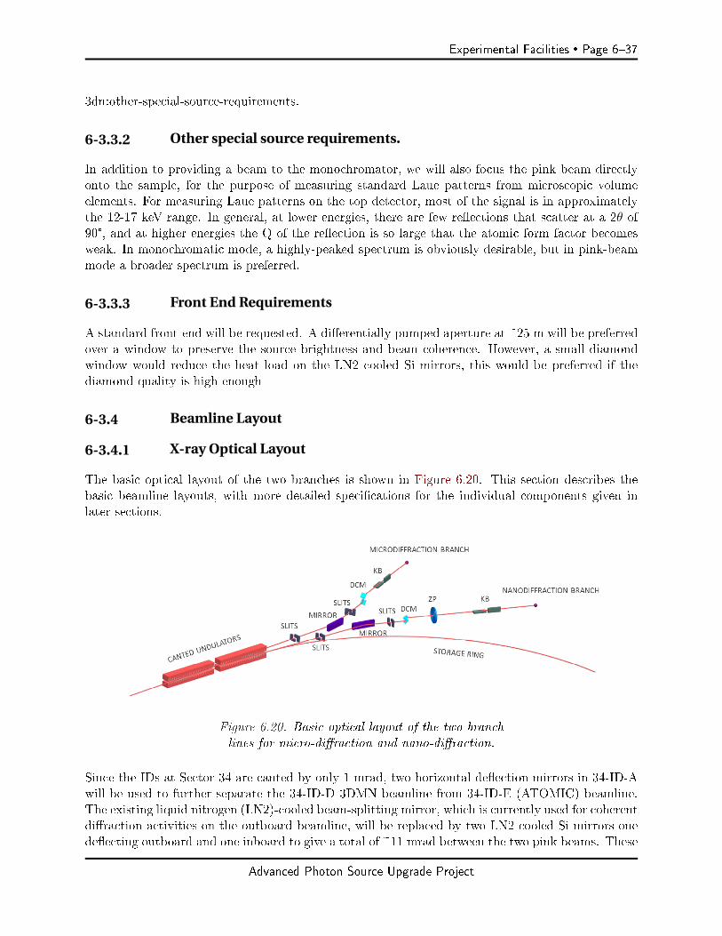
Experimental Facilities Page 637
3dn:other-special-source-requirements.
6-3.3.2 Other special source requirements.
In addition to providing a beam to the monochromator, we will also focus the pink beam directlyonto the sample, for the purpose of measuring standard Laue patterns from microscopic volumeelements. For measuring Laue patterns on the top detector, most of the signal is in approximatelythe 12-17 keV range. In general, at lower energies, there are few reections that scatter at a 2θ of90°, and at higher energies the Q of the reection is so large that the atomic form factor becomesweak. In monochromatic mode, a highly-peaked spectrum is obviously desirable, but in pink-beammode a broader spectrum is preferred.
6-3.3.3 Front End Requirements
A standard front-end will be requested. A dierentially pumped aperture at ~25 m will be preferredover a window to preserve the source brightness and beam coherence. However, a small diamondwindow would reduce the heat load on the LN2 cooled Si mirrors, this would be preferred if thediamond quality is high enough
6-3.4 Beamline Layout
6-3.4.1 X-ray Optical Layout
The basic optical layout of the two branches is shown in Figure 6.20. This section describes thebasic beamline layouts, with more detailed specications for the individual components given inlater sections.
Figure 6.20. Basic optical layout of the two branchlines for micro-diraction and nano-diraction.
Since the IDs at Sector 34 are canted by only 1 mrad, two horizontal deection mirrors in 34-ID-Awill be used to further separate the 34-ID-D 3DMN beamline from 34-ID-E (ATOMIC) beamline.The existing liquid nitrogen (LN2)-cooled beam-splitting mirror, which is currently used for coherentdiraction activities on the outboard beamline, will be replaced by two LN2 cooled Si mirrors onedeecting outboard and one inboard to give a total of ~11 mrad between the two pink beams. These
Advanced Photon Source Upgrade Project
Page 638 Experimental Facilities
two LN2 cooled mirrors will need sucient angular stability to not broaden the source, and alsoaccurate surface gures. It may prove desirable to have the mirrors slightly curved to collimate thex-rays.
A switchable, small-oset Si 111 monochromator covering the energy range of 5.330 keV will beinstalled in the 34-ID-C optical enclosure to provide monochromatic x-rays to the 34-ID-D station.The monochromator will pass either a pink beam or a monochromatic beam (thus switchable)through the same exit slit and will be either water or LN2 cooled.
A K-B micro-focusing mirror instrument will be installed in the front of 34-ID-D for Laue micro-diraction measurements in either polychromatic or monochromatic mode. The system will have afocal spot of <200 nm and should reach 100 nm with sucient working distance for small environ-mental chambers.
A new K-B nano-focusing mirror system will be installed in the rear of 34-ID-D for Laue nano-diraction measurements in either polychromatic or monochromatic mode. The system will havean initial focal spot of <100 nm with a future target of ∼50 nm.
This proposal envisions using the outboard branch of the existing 34-ID canted ID line with onelarge user enclosure for the experimental work, providing instruments at 60 m and 66 mm as shownin Figure 6.21. The existing 34-ID-D & 34-ID-E stations will be joined, and a 2 m extension willbe added to the end to form the new larger 34-ID-D station. The front of D- station will have aninstrument for the larger spot sizes of ≤200 nm with a working distance of ≥ 50 mm, and wouldcontain a single pink or mono Kirkpatrick-Baez (K-B) mirror set used for 3D micro-diraction. Thisupstream instrument will also be capable of performing some coherent diraction measurements.
At the rear of the new D-station there will be a dedicated nano-diraction instrument using aK-B nano-probe for ultra-high-resolution studies of advanced materials. The greater distance andreduced working distance will increase the demagnication providing a smaller spot size of ∼50 nm.This instrument will also require special temperature stabilization and likely an enclosed controlarea to maintain that stable temperature.
To provide a greater separation between the two canted beamlines there will be two LN2 cooled Sideecting mirrors in the rst white enclosure at ~30 m providing a separation of ~400 mm in therst user station (D- station). These mirrors may be either at, or perhaps gured to provide somepre-focusing or collimation of the white beam. An additional reason for these mirrors is to protectthe K-B focusing optics from the raw white radiation that can cause damage to the precisely guredK-B mirrors.
The micro-monochromator that currently feeds the existing 34-ID-E station will not be suitable forthe new beam line because it cannot pass the inboard undulator beam, and it is not stable enoughto preserve the increased brightness of the MBA. It will be necessary to build a slightly smallermicro-monochromator with enhanced stability to feed the user station. This will again use Si 111crystals, and it should have a modest cost due the small size. This micro-monochromator will havenegligible translational shift in the output over the desired 5.330 keV energy range. Additionally,the micro-monochromator can be automatically removed from the x-ray beam to send the pink beamdown to the user instruments. Due to the similar specications, the monochromator described hereshould be substantially similar to the one feeding the neighboring ATOMIC project on the inboard
Advanced Photon Source Upgrade Project

Experimental Facilities Page 639
part of the cant (ATOMIC will use the new 34-ID-E station).
Figure 6.21. Possible sector 34 layout showing user experimental stations in E and G andnew LN2 cooled Si mirrors in A. Micro-monochromators are located in C. Stations A-E al-ready exist, F & G would be new construction.Possible sector 34 layout showing user exper-imental stations in E and G and new LN2 cooled Si mirrors in A. Micro-monochromatorsare located in D and F. Stations A-E already exist, F & G would be new construction.
Stability of the K-B mirror mounts are extremely important, and this is currently being evaluatedby using a new exure based mirror stage that has been recently installed at the current 34-ID-E.
The instrument at ~60 m will be a fairly standard K-B mirror system feeding an xyz sample stagewith a scanning knife-edge. Using state of the art mirrors, this system should provide a ≤ 150 nmspot with a ≥ 50 mm working distance. This could accommodate in-situ experiments requiringsmall environmental chambers.
For the second user experimental instrument at 66 m, there will be a set of advanced K-B mirrorswith ultra-low slope errors of ~0.05 µrad. This will bring the focal size down to <50 nm with areasonable working distance of ~30 mm. A sample xyz stage and a scanning knife-edge (dierentialaperture) with 5 nm precision will be required for the measurement in all three dimensions. Thissystem will also require a low noise detector (similar to a Pilatus 6M) to allow measurement of lowintensity signals from the smaller volumes and from weaker scatters. Having a large solid-anglecoverage and moderate pixel size is preferred.
Liquid Nitrogen Cooled Horizontally Deflecting Mirrors
To provide a greater separation between the two canted beamlines there will be two LN2 cooledSi deecting mirrors at ~30 m providing a separation of ~400 mm in the rst user station (D-station). These mirrors may be either at, or perhaps slightly gured to provide some pre-focusingor collimation of the white beam. An additional reason for these mirrors is to protect the K-Bfocusing optics from the raw white radiation that can cause damage to gured K-B mirrors. Theywill require great stability, particularly against horizontal rotations. For a mirror at 30 m from thesource, an rms rotational vibration of 0.8 µrad will broaden the source by 50 µm (which is the MBAsource width). So, a horizontal rotational stability of 20 µrad will be required.
Advanced Photon Source Upgrade Project

Page 640 Experimental Facilities
Heat load on these mirrors is an issue, that is why they are cooled by liquid nitrogen. This techniquehas proven adequate for the existing Bragg CDI program, and we intend to use the same techniquein this project.
Monochromator
The micro-monochromator currently feeding the existing 34-ID-E station will not be suitable for thenew beam line because it cannot pass the inboard undulator beam that feeds ATOMIC, and it is notstable enough to preserve the increased brightness of the MBA. It will be necessary to build a slightlydierent micro-monochromator with enhanced stability to feed the user station. This will again useSi 111 crystals, and it should have a modest cost due the small size. This micro-monochromatorshould provide negligible translational shift in the output over the desired 5.330 keV energy range.Additionally, the micro-monochromator can be automatically removed from the x-ray beam to sendthe pink beam down to the user instruments. This monochromator should be substantially similarto the one required for the ATOMIC project on the inboard part of the cant, and so a commondesign should be possible. The main undecided issue is whether to use water or LN2 cooling on themonochromator. Calculations need to be made whether water will be sucient to avoid a thermalbump on the rst crystal. If water cooling is insucient, then LN2 will be used. We also needto decide upon the orientation, either horizontally deecting or vertically deecting. Traditionalmonochromators deect vertically due to the smaller vertical source divergence and to avoid oflosses due to the polarization correction ∼ cos2(2θ). With the MBA lattice, the source divergenceis small in both directions, and at 5.3 keV, the polarization loss will be ~1/2, for 8 keV the lossis 1/4, and at 12 keV it is only 10%. The main reason for considering horizontal diraction is thehope of improved angular stability with only a minor loss of eciency [11]. The choice of 5.3 keVfor the lower limit is governed partly by the geometry of getting the x-rays through the crystals, butmostly by the rapid increase in θ with decreasing energy. Note that increasing the monochromatorupper-energy limit from 25 to 30 keV only changes the angular range by 0.75°, whereas changingthe monochromator lower energy limit from 5.3 to 6.3 keV changes the angular range by a muchlarger 3.6°. The energy resolution of the usual Si 111 double bounce monochromator is ∆E/E ≈10-4, which is well matched to the desired q-resolution. While desirable for a variety of experimentspurposes, energies towards 5.3 keV are not as important as the somewhat higher energies to theoverall mission of the beamline, and if compromises on energy range are required, the lower limitcan be raised somewhat.
The main monochromator requirements are:Switchable between white and pink beam with negligible exit beam motionSmall oset, ~1.1 mm.White and pink beams exit the monochromator collinearlyEnergy range 5.330 keV (although the low energy limit may be raised, if needed)Rotational vibrational stability of 0.2 µrad rms about the θ axisSucient cooling on rst crystal to avoid a thermal bump.Does not need to accept the entire beam (only < 300 X 300 µm2 are needed).Allow passage of neighboring canted beam.
Advanced Photon Source Upgrade Project
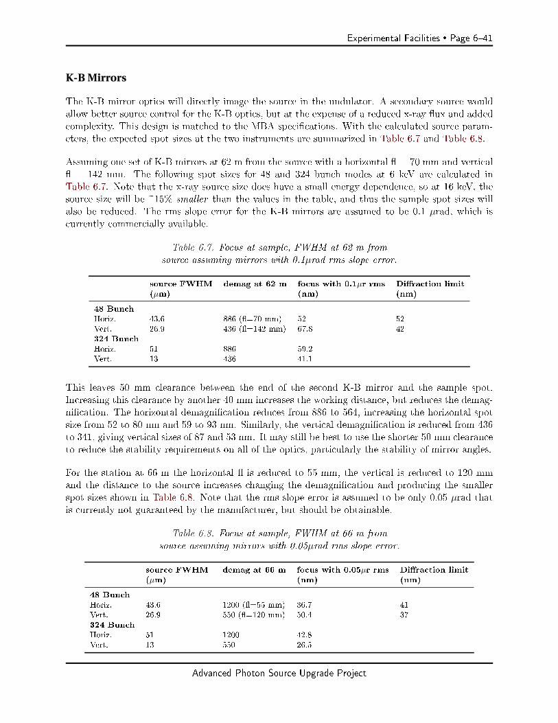
Experimental Facilities Page 641
K-B Mirrors
The K-B mirror optics will directly image the source in the undulator. A secondary source wouldallow better source control for the K-B optics, but at the expense of a reduced x-ray ux and addedcomplexity. This design is matched to the MBA specications. With the calculated source param-eters, the expected spot sizes at the two instruments are summarized in Table 6.7 and Table 6.8.
Assuming one set of K-B mirrors at 62 m from the source with a horizontal = 70 mm and vertical = 142 mm. The following spot sizes for 48 and 324 bunch modes at 6 keV are calculated inTable 6.7. Note that the x-ray source size does have a small energy dependence, so at 16 keV, thesource size will be ~15% smaller than the values in the table, and thus the sample spot sizes willalso be reduced. The rms slope error for the K-B mirrors are assumed to be 0.1 µrad, which iscurrently commercially available.
Table 6.7. Focus at sample, FWHM at 62 m fromsource assuming mirrors with 0.1µrad rms slope error.
source FWHM demag at 62 m focus with 0.1µr rms Diraction limit(µm) (nm) (nm)
48 BunchHoriz. 43.6 886 (=70 mm) 52 52Vert. 26.9 436 (=142 mm) 67.8 42324 BunchHoriz. 51 886 59.2Vert. 13 436 41.1
This leaves 50 mm clearance between the end of the second K-B mirror and the sample spot.Increasing this clearance by another 40 mm increases the working distance, but reduces the demag-nication. The horizontal demagnication reduces from 886 to 564, increasing the horizontal spotsize from 52 to 80 nm and 59 to 93 nm. Similarly, the vertical demagnication is reduced from 436to 341, giving vertical sizes of 87 and 53 nm. It may still be best to use the shorter 50 mm clearanceto reduce the stability requirements on all of the optics, particularly the stability of mirror angles.
For the station at 66 m the horizontal is reduced to 55 mm, the vertical is reduced to 120 mmand the distance to the source increases changing the demagnication and producing the smallerspot sizes shown in Table 6.8. Note that the rms slope error is assumed to be only 0.05 µrad thatis currently not guaranteed by the manufacturer, but should be obtainable.
Table 6.8. Focus at sample, FWHM at 66 m fromsource assuming mirrors with 0.05µrad rms slope error.
source FWHM demag at 66 m focus with 0.05µr rms Diraction limit(µm) (nm) (nm)
48 BunchHoriz. 43.6 1200 (=55 mm) 36.7 41Vert. 26.9 550 (=120 mm) 50.4 37324 BunchHoriz. 51 1200 42.8Vert. 13 550 26.5
Advanced Photon Source Upgrade Project

Page 642 Experimental Facilities
Using the focused beam (in the 62 m station) for coherent scattering only requires the installationof a suitable area detector that can be located 2 3 m from the sample and positioned to interceptthe diracted beam. To scan through a particular reection, we plan to scan energy, leaving thesample xed.
6-3.4.2 Beamline Physical Layout
Overall Beamline
The physical layout of the beamline is shown in earlier section and in Figure 6.21.
Major Component List
A-station White beam slits at front (~26 m)Outboard deecting LN2 cooled Si mirror (~30 m)
B-station Possible diagnostic (~43 m)
C-station micro-mono, monochromator with integral slits.Photon shutter used for accessing D-station.
D-station (main experimental station) Micro-diraction instrument, with K-B mirrors, stages,detectors:1 Large area detector above sample2 medium area detectors somewhat to the sides.1 uorescence detector (close to sample)1 medium size area detector in the forward scattering direction with horizontal motion
Coherent scattering detector:Movable medium size area detector.
Nano-diraction instrument, with K-B mirrors, stages, thermal enclosure, detectors:1 Large area detector above sample2 medium area detectors somewhat to the sides.1 uorescence detector (close to sample)1 medium size area detector in the forward scattering direction with horizontal motion
First Optics Enclosure and Infrastructure (A-station)
As seen in Figure 6.21, the rst optics enclosure (A- station) is a white beam station that willcontain a window or dierentially pumped aperture, two LN2 cooled Si mirrors, and adjustableslits for each of the canted lines. It will also contain masks and collimators as needed for safetyrequirements. The vacuum will be ultra-high vacuum (UHV) all the way down to the experimental
Advanced Photon Source Upgrade Project
Experimental Facilities Page 643
station (D-station). After the LN2 cooled Si mirrors, the masks and collimators should change thebeam from white to pink. This means that any new enclosures need only be pink beam capable,not white.
In this and the following stations, Bremsstrahlung collimators and other apertures will be placedas determined by ray tracing following standard APS radiation shielding guidelines.
B-Station
This is an existing white beam station that will provide space for a mask, and collimator. It mayalso hold a beam diagnostic module for beam alignment. All beam transport will be in UHV.
C-Station
This is an existing experimental station that is to be repurposed for beam line optics. It will containthe small-oset monochromator with its associated slits, and the pink-beam shutter that stops thex-rays for accessing the following experimental station (D- station). All of the beam path in thisstation will be in UHV, and this station is already white beam compatible.
End Station (D-station)
There will be two experimental sites in the D station. The rst (upstream) is the micro diractioninstrument. It will be for more conventional micro/nano diraction with the capability of also doingcoherent scattering from selected small particles. This experimental site will use a K-B mirror pairto provide an ~150 nm spot on the sample.
The second instrument is the nano diraction instrument located at the end of the station. It iscongured for the smallest beam sizes. It will have a short focus K-B mirror pair to provide a spoton the sample of ~50 nm.
This station will require a shielded beam pipe to pass the x-rays from the inboard undulator on tothe new E station. With the 1 mrad cant and the two white beam mirrors, the separation at 58 mwill be 414 mm (assuming all horizontal mirrors at 2.5 mrad).
The D station will require temperature control to maintain dimensional stability of the instruments.Temperature stability of 0.05 is required, this cannot be done using current APS air handlingunits.
This station is currently white beam capable, so the major radiation safety issue will be the pinkbeam transport for the inboard line. This will be similar to the shielded white beam transportcurrently in 34-ID-C. The UHV will end at a window at the front of this station, all subsequentbeam transport will be in either He or rough vacuum. The only other UHV will be the K-B mirrorbox, which will be a small standalone UHV system.
Micro-diraction instrument The rst instrument in D station is the low-resolution instru-ment. It will be similar to the existing 34-ID-E instrument, but with multiple improvements, better
Advanced Photon Source Upgrade Project
Page 644 Experimental Facilities
mirror, better K-B mirrors, better detectors, and a movable detector for doing coherent diractionon identied particles.
This instrument will use a K-B mirror pair to provide an ~150 nm spot on the sample. Sincecoherent diraction is expected, there will be a detector at ~3 m from the sample that can bemoved to intercept the diracted beam. This movable detector will be mounted on a robot or largex-y translator to position the detector on a single diraction spot. The main detector will be xedmounted above the sample position which is necessary for depth-resolution.
The xed detector does not have to have small pixels, what is important is having more pixels.The height is adjusted to make 1-pixel equivalent to ~10-4 in ∆d/d, and then with many pixels youwill also span a large angular range. The angle between pixels determines your ability to measurethe strain of a particular reection. The angular span of the detector determines your ability tomeasure shear and other o-diagonal strain components.
Nano- diraction instrument The second instrument in D station is the high-resolution in-strument, which will be congured for the smallest beam sizes. This experimental site will have aseparate thermal enclosure to provide the best thermal stability. Temperature regulation of 0.02 is required. It will have a short focus K-B mirror pair to provide a spot on the sample of ~50 nm.It will also require a very-low noise detector to see the small signals.
6-3.4.3 Additional
Detectors
All measurements require large low noise high count rate detectors. There is no obvious need fordevelopment of special detectors.
The main detector located above the sample should be similar to a Pilatus 6M; it has many pixels,low noise, and high frame rate. For the two side detectors, two smaller detectors such as the 1Mor 2M are sucient. These three detectors surrounding the sample at the micro or nano diractioninstruments do not need particularly small pixels. The current Perkin-Elmer detectors have 200 µmpixels which work ne; the detector distance is adjusted to provide the desired 10-4 resolution in Q.To get accurate o diagonal strain components, the detector should cover as large a solid angle aspractical to allow measuring a wide range of q-vectors. These two conditions imply that a detectorwith a large number of pixels is desired; this is the important criteria. A detector speed of < 200Hz should be sucient to keep up with the expected signal.
We also plan of providing a medium size area detector for measuring the forward scattered beam.This will provide valuable information for thin samples, and is essential for some of the programssuch as the high-pressure work.
The movable detector for coherent measurements should have smaller pixels appropriate for doingcoherent scattering measurements, but does not need to be especially large or fast. The limitationon pixel size is given by the distance (~3m) and the expected particle size. See the discussion ofdetectors in the ATOMIC project. For a particle size of 1.5 µm and a pixel size of 75 µm, the
Advanced Photon Source Upgrade Project

Experimental Facilities Page 645
detector distance should be 3.3 m at 12 keV.
Additionally, require a fast uorescent detector to provide elemental maps. The uorescent signalis sometimes part of the experimental result, and is sometimes used to nd ducials for locating aspecic location on a sample. A detector similar to a Vortex is appropriate. A 1 mm thick detectoris preferred for detecting higher energy emission lines.
Computing
In general, the control system will be a standard APS EPICS control system. There will be aneed for y-scanning on the knife-edge, monochromator, and on at least one of the three samplepositioners. The biggest challenge on the motion system will be to:1) position the sample and knife-edge to less than the x-ray spot size (<200 nm), and2) avoid thermal-drifts so that the sample does not drift away from the x-ray spot during themeasurement.
The data rate from either of these two instruments may get quite high. Running a Pilatus 6Mcontinuously at 100 Hz for 24 hours produces 113 TB of data (with an 80% duty factor), with 3detectors that increases to 189 Tb/day. So, generating 10 TB/day should become common, and100 TB becomes a quite possible goal. The detector images will all have to be processed promptlyso that the user can see the results in near real time. This will require a fast connection betweenthe detectors and the disk array, and a fast connection to the compute nodes to keep up. The datarate is expected to be steady state, and not composed of bursts. It is likely that it will becomenecessary to analyze the images without ever saving all the images to disk; i.e., rst storing theimages directly to memory for processing, and saving only the tted peak positions to disk..
The expected workow will depend upon the type of measurement. A 3D white beam diractionexperiment should consist of a series of knife-edge y-scans, with each y-scan consisting of between50 and 2000 images. After each knife-edge scan the sample is moved a small distance in thetransverse direction, and the knife-edge scan is repeated. These images are then depth-resolved toprovide individual Laue patterns on an xyz grid in the sample. The individual Laue patterns areindexed which gives the user the crystallographic orientation of each volume element. The codedaperture development is intended to reduce the need for 2000 images in a knife-edge scan down to400.
For measurements of absolute strain, the process will be similar, but with the addition of energyscanning the monochromator. For individual reections, this means that only a small ROI of thedetector is needed, and the knife-edge scan is also reduced.
Specific Safety Requirements
A normal APS safety envelope should be sucient. There are no special hazards anticipated. Whilethe occasional radioactive sample will probably be measured, such samples will arrive sealed in sucha manner that no special permanent facilities will be required.
Advanced Photon Source Upgrade Project
Page 646 Experimental Facilities
Specific Conventional Facilities Requirements
In general, we are concerned about vibration and temperature uctuations.
Due to the need for long term position stability in all of the instrument, the station will require atemperature stabilized buer area around the entrance. A temperature stability of 0.1is required;this is achievable using the current APS air handling units. This enclosed area will also be wherethe experimenters sit while operating the instruments.
The inside of the station will require better temperature stability, perhaps 0.03 or 0.05 . Thiswill require moving as much electronics as possible out of the station and including a separate airhandling unit to stabilize the station temperature. A 100 mm long piece of aluminum will expandby 100 nm with a temperature change of 0.04 (α = 24e-6 C-1).
The nano-diraction instrument will have to be surrounded by an additional temperature barrierand have an additional unit to stabilize the temperature of the nano-diraction instrument to atleast 0.02 .
Since vibration is clearly important, both instruments will be mounted on large granite rocks. Theold table at 34-ID-E with steel post legs provided ~50 nm rms vibrations, granite should be better.
Support facilities
This project should not require any special laboratory or sample preparation facilities beyond awork area outside the station for sample mounting.
6-3.5 R&D Needs
6-3.5.1 Knife-edge / coded aperture development.
To improve throughput on 3D measurements we propose to develop a coded aperture type structureto replace the existing knife-edge. A coded aperture may be able to speed up the depth measure-ments by a factor of 5 with the possibility of providing better signal to noise, and the hope ofproviding some energy information about the scattered x-rays.
Advanced Photon Source Upgrade Project
Experimental Facilities Page 647
6-4 Coherent High-Energy X-ray Sector for In Situ Science (CHEX Sector)
6-4.1 Executive Summary
The Coherent High Energy X-ray (CHEX) Sector for In Situ Science will advance the frontier forin situ, real time studies of materials synthesis and chemical transformations in natural operatingenvironments using the unprecedented coherence of the high-energy X-ray beams provided by theAPS Upgrade. Research areas addressed include epitaxial lm growth, bulk crystal growth, synthesisof materials by advanced methods, etching and corrosion, electrochemistry, geochemistry, energystorage, and catalysis. Coherent diractive imaging and photon correlation spectroscopy (PCS)will provide transformative insight into a material's structure, heterogeneity and disorder, chemicaland long-range interactions, dynamics, and evolution under real-world conditions and time frames.Undulator sources, beamline optics, diractometers, and detectors will be optimized for coherent X-ray techniques at the high energies (15-60 keV) needed for in situ studies. By using canted undulatorsand multiplexing monochromators, four simultaneously operating branch beamlines will ecientlyaccommodate eight instruments on a single APS sector and amplify the beam time available forprograms to address high-impact problems. Infrastructure needed for in situ measurements ofsynthesis and transformations will be provided, such as chemical exhaust, gas sources and safetysystems, and sample chambers suitable for coherent beam studies. The beamline layout ts ontoAPS Sector 28, close to related materials synthesis and characterization facilities at the Center forNanoscale Materials. The CHEX Sector will capitalize on the world-leading brightness and coherentux of the APS-U at high photon energies to enable studies not feasible at other facilities.
6-4.2 Scientific Objectives & Capabilities
6-4.2.1 Scientific Case for Beamline
In November 2015, the DOE Basic Energy Sciences Advisory Committee (BESAC) published Chal-lenges at the Frontiers of Matter and Energy: Transformative Opportunities for Discovery Science,a report that highlighted an essential and growing need for in situ studies in materials science andchemistry:
While it will always be valuable to examine a structure after the fact, it is increasinglyimportant that we develop characterization tools to evaluate the evolution of structureand function in real time. If this capability can be achieved, it creates the critical linkbetween computational design and experimental realization, and signicantly acceleratesthe pace of materials discovery, especially for hierarchically assembled materials andcomplex chemical transformations. [50]
The scientic goal of the Coherent High Energy X-ray (CHEX) sector is to advance the frontierfor in situ, real time studies of dynamics using the unprecedented coherence of the high-energyX-ray beams provided by the APS Upgrade. Such research promises breakthroughs in discovering,developing, and understanding the materials and processes that are needed to address our globalchallenges in energy, environment, health, and security.
The scientic impact of the proposed facility for coherent high-energy in situ studies will be broad,cutting across the sections of the APS-U Early Science document [51] on advanced materials, chem-
Advanced Photon Source Upgrade Project

Page 648 Experimental Facilities
istry, condensed matter physics, and environmental science, bringing together researchers in theseareas with common underlying scientic questions and technical approaches. Here we focus on twomajor areas: in situ materials synthesis, and transformations under real conditions. Specic areasinclude:
within in situ studies of materials synthesis:
2D materials, metastable materials, mesoscale heterostructures Film deposition and bulk crystal growth Electrochemical growth, nanoparticle growth, additive manufacturing
and within transformations under real conditions:
Reactive ion etching, lithography, corrosion Energy storage, geochemistry Structural evolution during catalysis Materials under irradiation
An overarching scientic theme crosscutting these areas is the need for understanding the criticalroles of heterogeneity, interfaces, and disorder. This need is articulated in the report put out byBESAC:
Real materials, both natural ones and those we engineer, are usually a complex mix-ture of compositional and structural heterogeneities, interfaces, and disorder across allspatial and temporal scales. It is the uctuations and disorderly states of these hetero-geneities and interfaces that often determine the system's properties and functionality.... Developing new approaches to understanding interfacial structure, its heterogene-ity and disorder, chemical and long-range interactions, dynamics, and evolution underreal-world conditions and time frames represents a Transformative Opportunity. [50]
Penetrating high-energy X-rays have proven to be a powerful tool for in situ studies, revealingatomic scale structure and dynamics under actual operating environments in a broad range ofcurrent research at APS. While there has been continued improvement in spatial and time resolution,techniques using incoherent X-ray beams that are sensitive to averages over the illuminated volumehave often required that we study ideal crystals or interfaces that are as homogeneous as possible overmacroscopic regions and time scales. For example, to observe atomic mechanisms at an interface,it has typically been necessary to study a model interface that is at and uniform over a large area,and simultaneously undergoes the same process at all locations. For the great variety of systemsand processes that are inherently inhomogeneous, only the average behavior can be observed.
The advent of high-energy coherent X-ray beams at the APS Upgrade will deliver unprecedentednew opportunities to investigate the spatial and temporal inhomogeneity in "real" systems withdefects, disorder, and hierarchical nanostructure. We can anticipate that these new experimentalcapabilities in imaging and dynamics using coherent X-rays will converge with ever-more-powerfulcomputer modeling and simulation capabilities to greatly accelerate the pace of discovery.
Advanced Photon Source Upgrade Project

Experimental Facilities Page 649
Here we take a closer look at some of the major scientic opportunities in materials synthesis andchemical transformations.
In Situ Studies of Materials Synthesis
To date, chemistry and materials research has focused on understanding and manipu-lating the relationship between structure and function, with the goal of predicting wherethe atoms should be placed in order to achieve a desired property. Scant attention hasbeen directed toward the predictive science of synthesisthat is, toward understandinghow to get the atoms where they need to go to achieve a desired structure. ... In situand real-time monitoring of growth and synthesis processes is essential to understandand ultimately control chemistry and materials synthesis. [50]
Not only do we need to understand the proper arrangements of atoms in materials and nanostruc-tures that give the desired functionality, but as the BESAC report points out, we also need tolearn how to synthesize and stabilize these arrangements. Rather than a trial-and-error approach,developing the science underlying materials synthesis promises the most extensive and sustainableprogress.
New capabilities provided by the APS Upgrade will dramatically impact the science of synthesis.The orders-of-magnitude increase in X-ray brightness at high energies will enable in situ coherentX-ray studies of synthesis mechanisms down to the atomic scale with sub-microsecond time reso-lution. As described below, coherent imaging and correlation spectroscopy techniques will revealunprecedented detail regarding atomic arrangements and dynamics. In parallel, orders-of-magnitudeincreases in computing power are enabling ab-initio simulations not just of ground-state materialsstructure and properties, but also of the competing chemical reactions and materials kinetics thatoccur during synthesis. Both coherent X-ray techniques and atomic scale modeling enable us tosee beyond the average behavior of a uctuating system and reveal the microscopic arrangements,correlations, and dynamics underpinning the synthesis process. The combination of in situ observa-tion of structure and dynamics during synthesis with advanced computational studies will usher ina powerful new framework for discovering, isolating, and optimizing desired growth pathways andoutcomes.
The primary issues in materials synthesis, such as phase selection and microstructure develop-ment, typically revolve around a competition between dierent underlying atomic-scale processes.A dominant theme in heteroepitaxial lm growth, critical for synthesis and function of advanceddevices, is the simultaneous control of strain, composition, dislocation nucleation, and the growthinstabilities that favor nonuniformity. An important example is the growth of superlattices and het-erostructures that are designed using advanced theoretical approaches to have properties targetedfor specic applications- for example, enhanced ferroelectricity or superconductivity. The formationof atomically abrupt interfaces required for high performance materials results from a competitionbetween surface diusion, island nucleation, mechanical constraints, epitaxial strain, and uctua-tions in deposition rates [52, 53]. In situ observation of a variety of vapor phase growth processes(e.g. pulsed laser deposition, molecular beam epitaxy, and atomic layer deposition) provides apowerful tool for characterizing and addressing challenges to synthesizing complex heterostructures.Likewise, heterogeneous nucleation at interfaces is critical for thermodynamic phase and crystal ori-
Advanced Photon Source Upgrade Project
Page 650 Experimental Facilities
entation control in bulk crystal growth and in synthesis of two-dimensional materials on substrates.The ability to image these uctuations dynamically will transform our ability to create the desiredstructures. These new capabilities, made possible by the high coherent ux from the APS Upgrade,will be enabled by the CHEX facility.
Successful materials synthesis often involves nding the "trick" that allows formation of a metastablephase, such as alloying InN into the active layers of ecient solid-state lighting devices [54], orbuilding cation and anion sublattices under vastly dierent conditions in bulk magnetic oxides [55].Rational design of metastable materials synthesis processes requires understanding the specicityof dierent sites and interfacial defects to catalyze certain reaction pathways. Imaging the com-plex, non-equilibrium interface chemistry in the growth environment will be crucial for forming newmetastable materials via chemical vapor deposition and electrochemical and nanoparticle growth,and in developing new synthesis methods such as 3D printing for additive manufacturing. Selectivegrowth of bulk crystals requires identication of nucleating species to direct synthesis of new ortargeted materials, or monitoring of dopant proles during growth to isolate homogeneous speci-mens. In situ observation of these processes will shed light on phase selection and allow isolation ofmetastable compounds. Alternatively, monitoring of crystal habit, grain boundaries, and extendeddefects are key opportunities for in situ study of bulk crystal growth processes such as Bridgmangrowth. In this case, optimized growth can be achieved by combining real-time in situ feedbackwith newly developed predictive modeling approaches [56]. Coherent diractive imaging of thedeveloping nanoscale strain elds during growth will provide a powerful tool for these studies.
Transformations under Real Conditions
The need for in situ studies of materials and chemical transformations spans across a wide rangeof research activities. These include the atomic-scale understanding of advanced lithographic pro-cesses such as reactive ion etching and additive manufacturing, complementary to the science of thinlm synthesis; understanding the relationship between surface site structure and reactivity duringheterogeneous catalysis, and the evolution of the catalyst structure; the formation mechanisms ofmetastable microstructures under extreme conditions such as ion irradiation; as well as heteroge-neous phase transitions and chemical reactions in energy storage and geochemical systems. Thepower of coherent, high-energy X-ray techniques to image and observe dynamics at the nanoscaleunder operating conditions provides a transformational opportunity in all of these areas. Here wedescribe some example opportunities in greater detail.
The BESAC report states that understanding the basic properties of rock formations in contactwith reactive uids is critical to ensuring safe long-term storage of CO2 and will require new ap-proaches to measuring the surface and near-surface properties of minerals and uids under realisticconditions using synchrotron X-rays, combined with molecular models of the interactions. [50] Theability to understand and control the processes that underlie rock-uid interactions in natural sys-tems is limited by the inherently high heterogeneity of these systems and the opacity of such systemsto most experimental probes. While traditional (incoherent) high-energy X-ray and neutron tech-niques can penetrate such samples, they typically elucidate spatially averaged rock properties (e.g.,mean particle size, porosity). A molecular-scale understanding of interfacial reactivity has been ob-tained only for at homogeneous single crystalline mineral-water interfaces. A robust understandingof the reactivity of complex rock architectures will need to connect this mechanistic understand-ing of mineral-water reactivity to porous geomaterials, relevant to our understanding of geological
Advanced Photon Source Upgrade Project
Experimental Facilities Page 651
transport of energy-related materials (e.g., CO2, radiological waste, etc.). In these systems, re-activity is controlled by the interplay between the hierarchy of pore structures, and the resultinguid ow patterns and the uid-mineral interactions that can be strongly modulated by nanoscaleconnement. The coherent hard X-ray beams from the CHEX facility at the APS-U will providea fundamentally new opportunity to extend such a molecular-scale understanding to the complexstructures in the real rock interfaces found in natural systems, and can be used to directly testour predictive capabilities on well-dened systems. Here, the robust use of coherence enables multi-ple imaging modalities capable of elucidating reactivity with resolutions spanning from nanometers(e.g., coherent diraction imaging) to micrometers (e.g., transmission X-ray microscopy) and evento macroscopic distances (e.g., tomography). The new coherent capabilities will allow the principlesgoverning reactivity (e.g., nucleation, growth, dissolution) to be discovered through direct in situobservations at the conditions of interest (e.g., under connement, ow, etc.) and ultimately inreal-time.
Similar considerations also apply to the complex processes that occur in the intricate environmentsof energy storage systems. In addition to the challenges inherent to natural rock-water systems,energy storage systems have degrees of complexity associated with extreme gradients of appliedpotentials, the driven transport of the active ions (e.g., Li+ or O-), the substantial volume changesand complex phase transformations that occur during ion insertion and removal within the electrode,and the coupled spatiotemporal responses within these complex structures. These challenges limitthe performance of the energy storage system (e.g., in terms of stored energy, number of charge-discharge cycles that can be accessed, or magnitudes of voltage losses at the electrodes). As inthe case of the natural rock-water systems, the use of coherent high-energy X-ray techniques opensup the possibility to understand, from direct observation, the deterministic processes that occurassociated with the specic structures, rather than the average response of the system. Thus,the use of coherent imaging should enable the discovery of the principles that will allow the fulltheoretical performance of these systems to be achieved.
Corrosion and fouling impose enormous costs on society that exceed 3% of GDP in the United States[57]. The ability of coherent X-rays to penetrate thick layers and create real-time images of nanoscaleto millimeter structures will allow an upgraded APS to address the grand challenges in corrosionscience identied by the National Academy of Sciences [57]. Corrosion and fouling mechanismsare exceptionally dicult to predict and control because they have strong electrochemical andmechanical couplings that guide diusion of the reactants, determine the shape of particles, andstrongly inuence their internal atomic and mesoscopic arrangements. A particular challenge inunderstanding corrosion is the multiple length scales and multiple time scales. The initial processesthat happen quickly and over relatively short length scales have been studied with traditional surfacescience probes. However, corrosion problems quickly become much more dicult to study as thecorrosion layers build up and large gradients in chemical potentials (particularly the oxygen chemicalpotential) and mechanical stresses are introduced into the problem. The facility we propose willenable the study of both the initial, rapid formation of corrosion products and, through exiblesharing of the beamline capabilities, the long-term (days and weeks) evolution of those products.
Coherent, High Energy X-ray Techniques for Heterogeneous Systems
In general, coherent X-ray techniques will provide powerful new probes to characterize defects andheterogeneities in materials. Classical scattering techniques with incoherent X-ray sources give the
Advanced Photon Source Upgrade Project
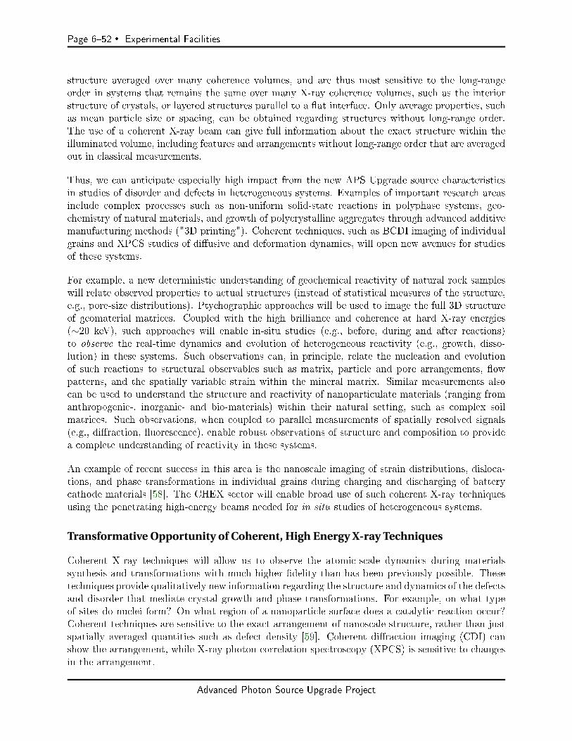
Page 652 Experimental Facilities
structure averaged over many coherence volumes, and are thus most sensitive to the long-rangeorder in systems that remains the same over many X-ray coherence volumes, such as the interiorstructure of crystals, or layered structures parallel to a at interface. Only average properties, suchas mean particle size or spacing, can be obtained regarding structures without long-range order.The use of a coherent X-ray beam can give full information about the exact structure within theilluminated volume, including features and arrangements without long-range order that are averagedout in classical measurements.
Thus, we can anticipate especially high impact from the new APS Upgrade source characteristicsin studies of disorder and defects in heterogeneous systems. Examples of important research areasinclude complex processes such as non-uniform solid-state reactions in polyphase systems, geo-chemistry of natural materials, and growth of polycrystalline aggregates through advanced additivemanufacturing methods ("3D printing"). Coherent techniques, such as BCDI imaging of individualgrains and XPCS studies of diusive and deformation dynamics, will open new avenues for studiesof these systems.
For example, a new deterministic understanding of geochemical reactivity of natural rock sampleswill relate observed properties to actual structures (instead of statistical measures of the structure,e.g., pore-size distributions). Ptychographic approaches will be used to image the full 3D structureof geomaterial matrices. Coupled with the high brilliance and coherence at hard X-ray energies(∼20 keV), such approaches will enable in-situ studies (e.g., before, during and after reactions)to observe the real-time dynamics and evolution of heterogeneous reactivity (e.g., growth, disso-lution) in these systems. Such observations can, in principle, relate the nucleation and evolutionof such reactions to structural observables such as matrix, particle and pore arrangements, owpatterns, and the spatially variable strain within the mineral matrix. Similar measurements alsocan be used to understand the structure and reactivity of nanoparticulate materials (ranging fromanthropogenic-, inorganic- and bio-materials) within their natural setting, such as complex soilmatrices. Such observations, when coupled to parallel measurements of spatially resolved signals(e.g., diraction, uorescence), enable robust observations of structure and composition to providea complete understanding of reactivity in these systems.
An example of recent success in this area is the nanoscale imaging of strain distributions, disloca-tions, and phase transformations in individual grains during charging and discharging of batterycathode materials [58]. The CHEX sector will enable broad use of such coherent X-ray techniquesusing the penetrating high-energy beams needed for in situ studies of heterogeneous systems.
Transformative Opportunity of Coherent, High Energy X-ray Techniques
Coherent X-ray techniques will allow us to observe the atomic-scale dynamics during materialssynthesis and transformations with much higher delity than has been previously possible. Thesetechniques provide qualitatively new information regarding the structure and dynamics of the defectsand disorder that mediate crystal growth and phase transformations. For example, on what typeof sites do nuclei form? On what region of a nanoparticle surface does a catalytic reaction occur?Coherent techniques are sensitive to the exact arrangement of nanoscale structure, rather than justspatially averaged quantities such as defect density [59]. Coherent diraction imaging (CDI) canshow the arrangement, while X-ray photon correlation spectroscopy (XPCS) is sensitive to changesin the arrangement.
Advanced Photon Source Upgrade Project

Experimental Facilities Page 653
Ongoing rapid development of these techniques, e.g. time-resolved CDI [3], 3-dimensional Braggptychography [60], polychromatic CDI [29], combined full-eld X-ray microscopy and CDI [61], co-herent grazing-incidence small-angle scattering [62], high speed XPCS [63], and analysis of complex2-time, 2-q correlations in XPCS [64, 65], promise to further extend their capabilities. By providinggreatly increased coherent ux at the penetrating, high photon energies (15-60 keV) needed for insitu studies, the CHEX sector of the APS Upgrade will bring these powerful techniques to bear onthe new frontiers of materials synthesis and transformations.
6-4.2.2 Description of User Community and Stakeholders
Discussion with the research community regarding needs for advanced facilities for in situ syn-chrotron X-ray studies has been ongoing since the original workshops to outline future scienticdirections for APS beginning a decade ago. These included workshops on in situ characterizationof interface structures and catalysis [66, 67], interfacial and surface science [68], and in situ stud-ies of interfacial reectivity [69]. Community excitement for in situ studies of materials synthesisand chemistry was a highlighted topic in the summary workshop to dene the science case for theAPS Upgrade [70], and was a primary driver for a proposal to develop an X-ray Interface Sciencesector at APS [71], which was included in the conceptual design for the APS Upgrade[72]. Theplanning for this facility was continued at a dedicated workshop [73] that included reports fromthe community on Buried Interfaces, Electrochemistry and Geochemistry, Materials Synthesis, andUHV Nanoscience. These helped inform its preliminary design [74] and develop many of the designconcepts listed above. The in situ studies community has been involved in continuing workshops onthe new horizons opened by coherent X-ray techniques [75] and to envision their scientic impactas part of the APS-U science case [51].
Enthusiastic community support for upgraded facilities at the APS for in situ studies has emergedat all of these workshops. Since the development of the initial CHEX white paper, we have contin-ued to solicit community input. The CHEX proposal is synergistic with two other APS-U beamlineproposals that focus on in situ studies, the In Situ Nanoprobe (ISN) and ATOMIC. CHEX enablescoherent X-ray scattering at photon energies up to 60 keV, while ISN and ATOMIC are designedfor nanoprobe and Bragg CDI studies, respectively, at lower photon energies. Together, the leadersof these three proposals convened a workshop on May 10-11, 2016 at the APS Users Meeting, "InSitu Studies of Materials Transformations using Coherent X-rays," to explore the future applica-tions of coherent X-ray techniques, such as photon correlation spectroscopy and coherent diractiveimaging, for in situ studies of materials dynamics. This workshop explored three general scienceareascatalysis and interface chemistry, materials synthesis, and dynamics in complex materialswith 12 presentations by experts, and a discussion session. Forefront work was presented in areassuch as nanodiraction for phase and strain mapping in microelectronics, Bragg CDI studies re-vealing eects of surface reactions on strain in nanocrystal catalysts, and XPCS studies of surfacemorphology and reconstruction dynamics during lm growth and etching. There were several con-nections between the areas, such as the importance of both uid-solid and solid-solid interfaces innext-generation batteries, and the synthesis of materials through both uid-solid and solid-statereactions at interfaces. Collaborations were discussed among the participants in areas such as cre-ating standard software packages for coherent diractive imaging reconstruction, and developinginstruments for in situ studies with coherent X-rays.
The May 2016 workshop further informed the goals and design of the CHEX sector. Needed beamline
Advanced Photon Source Upgrade Project
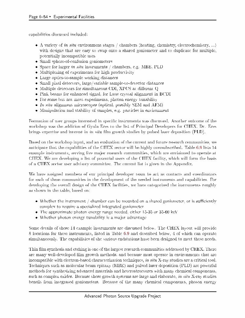
Page 654 Experimental Facilities
capabilities discussed included:
A variety of in situ environment stages / chambers (heating, chemistry, electrochemistry, ...)with designs that are easy to swap onto a shared goniometer and to duplicate for multiple,potentially incompatible uses
Small sphere-of-confusion goniometers Space for larger in situ instruments / chambers, e.g. MBE, PLD Multiplexing of experiments for high productivity Large optics-to-sample working distances Small pixel detectors, large/variable sample-to-detector distances Multiple detectors for simultaneous CDI, XPCS at dierent Q Pink beams for enhanced signal, for Laue crystal alignment in BCDI For some but not most experiments, photon energy tunability In situ alignment microscopes (optical, possibly SEM and AFM) Manipulation and stability of samples, e.g. particles in environment
Formation of user groups interested in specic instruments was discussed. Another outcome of theworkshop was the addition of Gyula Eres to the list of Principal Developers for CHEX. Dr. Eresbrings expertise and interest in in situ lm growth studies by pulsed laser deposition (PLD).
Based on the workshop input, and an evaluation of the current and future research communities, weanticipate that the capabilities of the CHEX sector will be highly oversubscribed. Table 6.9 lists 14example instruments, serving ve major research communities, which are envisioned to operate atCHEX. We are developing a list of potential users of the CHEX facility, which will form the basisof a CHEX sector user advisory committee. The current list is given in the Appendix.
We have assigned members of our principal developer team to act as contacts and coordinatorsfor each of these communities in the development of the needed instruments and capabilities. Fordeveloping the overall design of the CHEX facilities, we have categorized the instruments roughlyas shown in the table, based on:
Whether the instrument / chamber can be mounted on a shared goniometer, or is sucientlycomplex to require a specialized integrated goniometer
The approximate photon energy range needed, either 15-35 or 35-60 keV Whether photon energy tunability is a major advantage
Some details of these 14 example instruments are discussed below. The CHEX layout will provide8 locations for these instruments, listed in Table 6.9 and described below, 4 of which can operatesimultaneously. The capabilities of the various endstations have been designed to meet these needs.
Thin lm synthesis and etching is one of the largest research communities addressed by CHEX. Thereare many well-developed lm growth methods, and because most operate in environments that areincompatible with electron-based characterization techniques, in situ X-ray studies are a critical tool.Techniques such as molecular beam epitaxy (MBE) and pulsed laser deposition (PLD) are powerfulmethods for synthesizing advanced materials and heterostructures with many chemical components,such as complex oxides. Because these growth systems are large and elaborate, in situ X-ray studiesbenet from integrated goniometers. Because of the many chemical components, photon energy
Advanced Photon Source Upgrade Project
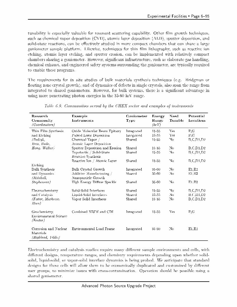
Experimental Facilities Page 655
tunability is especially valuable for resonant scattering capability. Other lm growth techniques,such as chemical vapor deposition (CVD), atomic layer deposition (ALD), sputter deposition, andsolid-state reactions, can be eectively studied in more compact chambers that can share a largegoniometer sample platform. Likewise, techniques for thin lm lithography, such as reactive ionetching, atomic layer etching, and sputter erosion, can be implemented with relatively compactchambers sharing a goniometer. However, signicant infrastructure, such as elaborate gas handling,chemical exhaust, and engineered safety systems surrounding the goniometer, are typically requiredto enable these programs.
The requirements for in situ studies of bulk materials synthesis techniques (e.g. Bridgman oroating zone crystal growth), and of dynamics of defects in single crystals, also span the range fromintegrated to shared goniometers. However, for bulk systems, there is a signicant advantage inusing more penetrating photon energies in the 35-60 keV range.
Table 6.9. Communities served by the CHEX sector and examples of instruments
Research Example Goniometer Energy Need PotentialCommunity Instruments Type Range Tunable Locations(Coordinators) (keV)
Thin Film Synthesis Oxide Molecular Beam Epitaxy Integrated 15-35 Yes F,Gand Etching Pulsed Laser Deposition Integrated 15-35 Yes F,G(Bedzyk, Chemical Vapor / Shared 15-35 No B,C,D1,D2Eres, Haile, Atomic Layer DepositionHong, Walker) Sputter Deposition and Erosion Shared 15-35 No B,C,D1,D2
Topotactic / Solid-State Shared 15-35 No B,C,D1,D2Reactive SynthesisReactive Ion / Atomic Layer Shared 15-35 No B,C,D1,D2
EtchingBulk Synthesis Bulk Crystal Growth Integrated 35-60 No E1,E2and Dynamics Additive Manufacturing / Shared 35-60 No E1,E2(Mitchell, Nanoparticle GrowthStephenson) High Energy Diuse Speckle Shared 35-60 No E1,E2
Electrochemistry Solid-Solid Interfaces Shared 15-35 No B,C,D1,D2and Catalysis Liquid-Solid Interfaces Shared 15-35 No B,C,D1,D2(Fister, Markovic, Vapor-Solid Interfaces Shared 15-35 No B,C,D1,D2Zhou)
Geochemistry, Combined XRIM and CDI Integrated 15-35 Yes F,GEnvironmental Science(Fenter)
Corrosion and Nuclear Environmental Load Frame Integrated 35-60 No E1,E2Materials(Highland, Yildiz)
Electrochemistry and catalysis studies require many dierent sample environments and cells, withdierent designs, temperature ranges, and chemistry requirements depending upon whether solid-solid, liquid-solid, or vapor-solid interface dynamics is being probed. We anticipate that standarddesigns for these cells will allow them to be economically duplicated and customized by dierentuser groups, to minimize issues with cross-contamination. Operation should be possible using ashared goniometer.
Advanced Photon Source Upgrade Project
Page 656 Experimental Facilities
The geochemistry and environmental science community has proposed a specialized instrument[61] that combines X-ray reection interfacial microscopy (XRIM) and BCDI to enable studies ofinterfaces on multiple length scales, including resonant studies. For in situ studies of corrosion andnuclear materials under stress, a mechanical loading system with temperature and environmentalcontrol using the 35-60 keV range is envisioned.
We expect some instruments to be in the scope of the CHEX beamline project, while others maybe brought by partners and funded separately. Examples in the rst category could be goniometerand detector systems shared by several sample environments / chambers that are easily swapped,with some chambers available at the facility, and some brought by user groups. Examples in thesecond category could be large specialized systems with integrated goniometer, funded, for example,through special DOE or NSF instrumentation grants. For this second category, we will organizeuser groups interested in carrying out such in situ experimental programs at the APS, to proposebuilding the required major equipment. The CHEX facility should provide the infrastructure tooptimize research with both types of instruments.
User Access Modes and Instrument Development and Operation
Access to instruments at CHEX will be through the standard APS General User and Partner Userprograms. Most instruments will be APS owned and operated, such as all of the shared goniometersand sample chambers that use them. These will be accessed through the General User program.For specialized instruments that are funded and developed by partner user groups, access will beaccording to the Partner User agreement approved by the APS following the standard peer reviewand Scientic Advisory Committee review of partner programs. These typically involve transitionsfrom an instrument development phase to a general user phase, with details of the timing andfractions depending upon the source of funding (APS or partner) for instrumentation and for eortfor continuing user support during operations.
It has been a strength of the APS to have exible user access modes that allow complex experi-mental programs to be developed in partnership with user groups for the long-term benet of thewhole community. The CHEX facility will provide the infrastructure and access modes for majorexperimental programs to attack grand challenges in a exible way that provides opportunity forcompetitive program turnover to address new problems. As can be seen from the list of instrumentsand communities in Table 6.9, we expect each of the CHEX endstations to be oversubscribed. Thisemphasizes both the need and eciency of having four simultaneously operating experiments atCHEX.
The CHEX sector is a potential location for the proposed Extreme Materials (XMAT) facility [76],which would enable study of materials under MeV-per-nucleon ion irradiation. This would be aseparately funded facility, and if implemented at CHEX would require the ion accelerator to belocated on an upper level feeding ion beams into one or more hutches. It has also been proposedthat XMAT could instead reside at the High Energy Diraction Microscopy beamline, in a separatebuilding outside of the APS experimental hall. The XMAT facility is a very exciting opportunity,and an optimum location for it should be decided as part of the APS-U beamline planning process.Facilities at CHEX for high-energy coherent X-ray studies will be of interest to the nuclear materialscommunities, independent of the location of XMAT.
Advanced Photon Source Upgrade Project
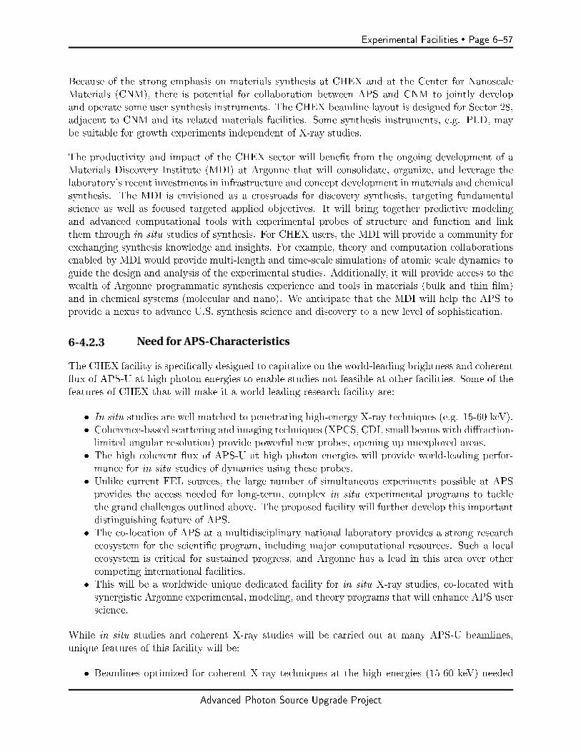
Experimental Facilities Page 657
Because of the strong emphasis on materials synthesis at CHEX and at the Center for NanoscaleMaterials (CNM), there is potential for collaboration between APS and CNM to jointly developand operate some user synthesis instruments. The CHEX beamline layout is designed for Sector 28,adjacent to CNM and its related materials facilities. Some synthesis instruments, e.g. PLD, maybe suitable for growth experiments independent of X-ray studies.
The productivity and impact of the CHEX sector will benet from the ongoing development of aMaterials Discovery Institute (MDI) at Argonne that will consolidate, organize, and leverage thelaboratory's recent investments in infrastructure and concept development in materials and chemicalsynthesis. The MDI is envisioned as a crossroads for discovery synthesis, targeting fundamentalscience as well as focused targeted applied objectives. It will bring together predictive modelingand advanced computational tools with experimental probes of structure and function and linkthem through in situ studies of synthesis. For CHEX users, the MDI will provide a community forexchanging synthesis knowledge and insights. For example, theory and computation collaborationsenabled by MDI would provide multi-length and time-scale simulations of atomic scale dynamics toguide the design and analysis of the experimental studies. Additionally, it will provide access to thewealth of Argonne programmatic synthesis experience and tools in materials (bulk and thin lm)and in chemical systems (molecular and nano). We anticipate that the MDI will help the APS toprovide a nexus to advance U.S. synthesis science and discovery to a new level of sophistication.
6-4.2.3 Need for APS-Characteristics
The CHEX facility is specically designed to capitalize on the world-leading brightness and coherentux of APS-U at high photon energies to enable studies not feasible at other facilities. Some of thefeatures of CHEX that will make it a world-leading research facility are:
In situ studies are well matched to penetrating high-energy X-ray techniques (e.g. 15-60 keV). Coherence-based scattering and imaging techniques (XPCS, CDI, small beams with diraction-limited angular resolution) provide powerful new probes, opening up unexplored areas.
The high coherent ux of APS-U at high photon energies will provide world-leading perfor-mance for in situ studies of dynamics using these probes.
Unlike current FEL sources, the large number of simultaneous experiments possible at APSprovides the access needed for long-term, complex in situ experimental programs to tacklethe grand challenges outlined above. The proposed facility will further develop this importantdistinguishing feature of APS.
The co-location of APS at a multidisciplinary national laboratory provides a strong researchecosystem for the scientic program, including major computational resources. Such a localecosystem is critical for sustained progress, and Argonne has a lead in this area over othercompeting international facilities.
This will be a worldwide unique dedicated facility for in situ X-ray studies, co-located withsynergistic Argonne experimental, modeling, and theory programs that will enhance APS userscience.
While in situ studies and coherent X-ray studies will be carried out at many APS-U beamlines,unique features of this facility will be:
Beamlines optimized for coherent X-ray techniques at the high energies (15-60 keV) needed
Advanced Photon Source Upgrade Project
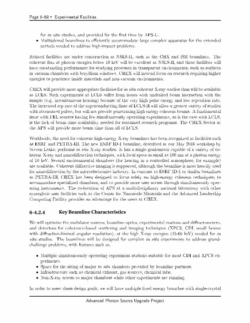
Page 658 Experimental Facilities
for in situ studies, and provided for the rst time by APS-U. Multiplexed beamlines to eciently accommodate large complex apparatus for the extendedperiods needed to address high-impact problems.
Related facilities are under construction at NSLS-II, such as the CHX and ISR beamlines. Thecoherent ux at photon energies below 10 keV will be excellent at NSLS-II, and these facilities willhave outstanding performance for studying processes in transparent environments, such as surfacesin vacuum chambers with beryllium windows. CHEX will instead focus on research requiring higherenergies to penetrate inside materials and non-vacuum environments.
CHEX will provide more appropriate facilities for in situ coherent X-ray studies than will be availableat LCLS. Such experiments at LCLS suer from issues with undesired beam interaction with thesample (e.g. instantaneous heating) because of the very high pulse energy and low repetition rate.The increased rep rate of the superconducting linac of LCLS-II will allow a greater variety of studieswith attenuated pulses, but will not provide penetrating high energy coherent beams. A fundamentalissue with FEL sources having few simultaneously operating experiments, as is the case with LCLS,is the lack of beam time availability needed for sustained research programs. The CHEX Sector atthe APS will provide more beam time than all of LCLS.
Worldwide, the need for coherent high-energy X-ray beamlines has been recognized at facilities suchas ESRF and PETRA-III. The new ESRF ID-1 beamline, described at our May 2016 workshop bySteven Leake, performs in situ X-ray studies. It has a single goniometer capable of a variety of co-herent X-ray and nanodiraction techniques, with focal spots as small as 100 nm at a photon energyof 10 keV. Several environmental chambers (for heating in a controlled atmosphere, for example)are available. Coherent diractive imaging is supported, although the beamline is most heavily usedfor nanodiraction by the microelectronics industry. In contrast to ESRF ID-1 or similar beamlinesat PETRA-III, CHEX has been designed to focus solely on high-energy coherent techniques, toaccommodate specialized chambers, and to provide more user access through simultaneously oper-ating instruments. The co-location of APS at a multidisciplinary national laboratory with othersynergistic user facilities such as the Center for Nanoscale Materials and the Advanced LeadershipComputing Facility provides an advantage for the users at CHEX.
6-4.2.4 Key Beamline Characteristics
We will optimize the undulator sources, beamline optics, experimental stations and diractometers,and detectors for coherence-based scattering and imaging techniques (XPCS, CDI, small beamswith diraction-limited angular resolution), at the high X-ray energies (15-60 keV) needed for insitu studies. The beamlines will be designed for complex in situ experiments to address grand-challenge problems, with features such as,
Multiple simultaneously operating experiment stations suitable for most CDI and XPCS ex-periments.
Space for the siting of major in situ chambers provided by beamline partners. Infrastructure such as chemical exhaust, gas sources, chemical labs. Non-X-ray access to major chambers while other experiments are running.
In order to meet these design goals, we will have multiple xed energy branches with single-crystal
Advanced Photon Source Upgrade Project
Experimental Facilities Page 659
monochromators that will transmit the undiracted portion of the beam to downstream experimentsto allow multiplexing of several simultaneously operating experiments on dierent branch lines:
Simultaneous experiments will share a common undulator fundamental energy (K value). Judicious choice of mono angles and crystals will give exibility in energy choices for eachbranch.
Because the spatial resolution of a chosen area detector determines the necessary hutch size andfocal spot size required to resolve speckle features, we will need longer hutches, and smaller focalspots for higher energy coherent X-ray experiments.
Important design features to meet these goals include:
Canted undulators One feeding a tunable branch with a double-crystal mono, 15-60 keV. One feeding three simultaneously operating xed energy branches with single-crystalmonos for multiplexed, simultaneously operating experiments at various energies from15-60 keV.
Focusing optics, diraction instruments, and hutches with the needed sample-to-detector dis-tance to resolve the speckle from the illuminated volume at photon energies of 15-60 keV.
Area detectors with the small pixel size and large angular range needed for speckle experiments,and sensitivity at 15-60 keV.
Tandem hutches that combine a front station housing an instrument that does not requireaccess when other experiments are running (e.g. a diractometer onto which samples, smallenvironmental cells, or chambers can be mounted), and a back station having space for spe-cialized chambers that do require access while experiments are ongoing in the front station(e.g. large growth chambers).
Beamline layout that ts on Sector 28, located close to the related materials synthesis andanalysis facilities at the Center for Nanoscale Materials.
Option for pink beam availability, e.g. for polychromatic CDI.
6-4.3 Source & Front End Requirements
6-4.3.1 Insertion Devices
The sector will require canted undulators, optimized for brightness for the 15-60 keV energy range:
One fully tunable, to provide a single energy in the 15-60 keV range One providing a variety of xed energies in the 15-60 keV range from dierent harmonics 1 mrad cant angle Likely use superconducting undulators (SCUs) to achieve high brightness at 15-60 keV (willneed 3rd harmonic to reach 15 keV, which implies SCU period 1.9 cm. Will mount both SCUsand the intervening cant magnet inside a single cryostat to maximize undulator length).
Use of a 1.5 m length undulator will increase the brightness and coherent ux at 15 keV by37%, and should be considered. The undulator length may be limited by the tolerable heatload on front end components.
Advanced Photon Source Upgrade Project
Page 660 Experimental Facilities
6-4.3.2 Other Source Requirements
No special bunch timing requirements.
6-4.3.3 Front End Requirements
Canted undulators, with a high heat load front end to allow for operation of the 3rd harmonic at15 keV with maximum undulator length.
Figure 6.22. Characteristics of a 1.2 m long, 1.9 cm period superconducting un-dulator as a function of photon energy, showing (left) peak brightness tuning
curves and (right) peak coherent ux tuning curves. Both odd and even harmon-ics are shown. At higher photon energies, the even harmonics are signicant.
Figure 6.23. Characteristics of a 1.2 m long, 1.9 cm period superconducting undulator asa function of photon energy, showing (left) spectrum for fundamental energy of 5 keV,and (right) peak on-axis ux tuning curves. Both odd and even harmonics are shown.
Advanced Photon Source Upgrade Project

Experimental Facilities Page 661
6-4.4 Beamline Layout
Figure 6.24. Conceptual layout of CHEX sector.
6-4.4.1 X-ray Optical Layout
Overall layout
The CHEX sector optical layout is based on two canted undulators:
One undulator feeding xed-energy branches 1, 2, and 3 with single-crystal monochromatorsfor multiplexed, simultaneously operating experiments at various energies from 15 to 60 keV.
One undulator feeding a tunable-energy branch 4 with a double-crystal monochromator havingan energy range of 15-60 keV.
Figure 6.25. Three xed-energy branch lines indicated ingreen. One tunable-energy branch line indicated in blue.
Advanced Photon Source Upgrade Project

Page 662 Experimental Facilities
Description of optical components: Fixed-energy branches 1, 2, and 3
Three simultaneously operating xed-energy branch lines will include 4 hutches:
Branch 1: two tandem hutches, B and C Branch 2: one hutch, D, with 2 instrument positions Branch 3: one hutch, E, with 2 instrument positions
Monochromators: Single crystal, horizontal deection at nearly xed angle, diamond and silicon,various reections to allow choice of energy at xed angle.
Heat load: Consider ltering power below 15 keV. Use single-crystal diamond lters to avoiddisturbing wavefront
Fixed Energy Branch Angle Choices
Figures 6.26 and 6.27 below show calculated Bragg angles for various monochromator crystal ma-terials (diamond and silicon) and reections ((111), (220), and (400)), that match odd harmonicenergies of an undulator, as a function of the undulator fundamental energy. Potential beamlineangles are represented by horizontal lines, and potential operating points for the undulator arerepresented by vertical lines. The intersections marked by symbols show which beamline choiceswould match a Bragg condition for each operating point. Note that the (111), (220), and (400) re-ections have nearly identical Bragg angles for harmonics having a ratio of 3, 5, and 7, respectively.This can provide exibility in energy choice for a given beamline simply by switching between itsmonochromator crystals, keeping the operating point and beamline angle nearly xed. Figure 6.26shows the full range of potential beamline angles and operating points, while Figure 6.27 shows thebeamline angles and operating points proposed for CHEX.
Tables 6.10 to 6.13 below show the fundamental energy, crystal reection, undulator harmonic,photon energy, and exact 2θ angle for each of the proposed beamline angles and operating pointsin Figure 6.27.
Table 6.10. Undulator fundamental energy (keV), crystal reection, undulator harmonic, pho-ton energy (keV), and exact 2θ angle (degrees) for branches 1 and 2 at a nominal 2θ of 23°.
Operating Fundamental Crystal Reection Harmonic Photon Energy 2 ThetaPoint # (keV) (keV) (deg)
1 5 C 111 3 15 23.154C 220 5 25 22.68C 400 7 35 22.913
2 6.93 C 400 5 34.64 23.1543 8.16 C 220 3 24.49 23.1544 11.55 C 400 3 34.64 23.1545 15 C 111 1 15 23.154
Advanced Photon Source Upgrade Project
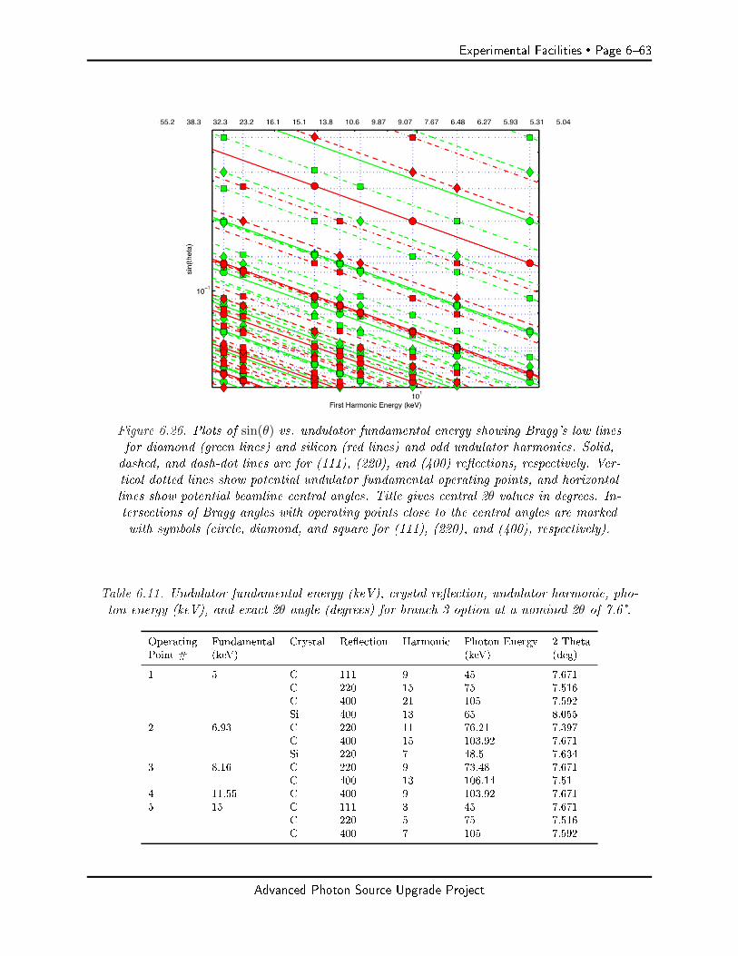
Experimental Facilities Page 663
Figure 6.26. Plots of sin(θ) vs. undulator fundamental energy showing Bragg's law linesfor diamond (green lines) and silicon (red lines) and odd undulator harmonics. Solid,dashed, and dash-dot lines are for (111), (220), and (400) reections, respectively. Ver-tical dotted lines show potential undulator fundamental operating points, and horizontallines show potential beamline central angles. Title gives central 2θ values in degrees. In-tersections of Bragg angles with operating points close to the central angles are markedwith symbols (circle, diamond, and square for (111), (220), and (400), respectively).
Table 6.11. Undulator fundamental energy (keV), crystal reection, undulator harmonic, pho-ton energy (keV), and exact 2θ angle (degrees) for branch 3 option at a nominal 2θ of 7.6°.
Operating Fundamental Crystal Reection Harmonic Photon Energy 2 ThetaPoint # (keV) (keV) (deg)
1 5 C 111 9 45 7.671C 220 15 75 7.516C 400 21 105 7.592Si 400 13 65 8.055
2 6.93 C 220 11 76.21 7.397C 400 15 103.92 7.671Si 220 7 48.5 7.634
3 8.16 C 220 9 73.48 7.671C 400 13 106.14 7.51
4 11.55 C 400 9 103.92 7.6715 15 C 111 3 45 7.671
C 220 5 75 7.516C 400 7 105 7.592
Advanced Photon Source Upgrade Project
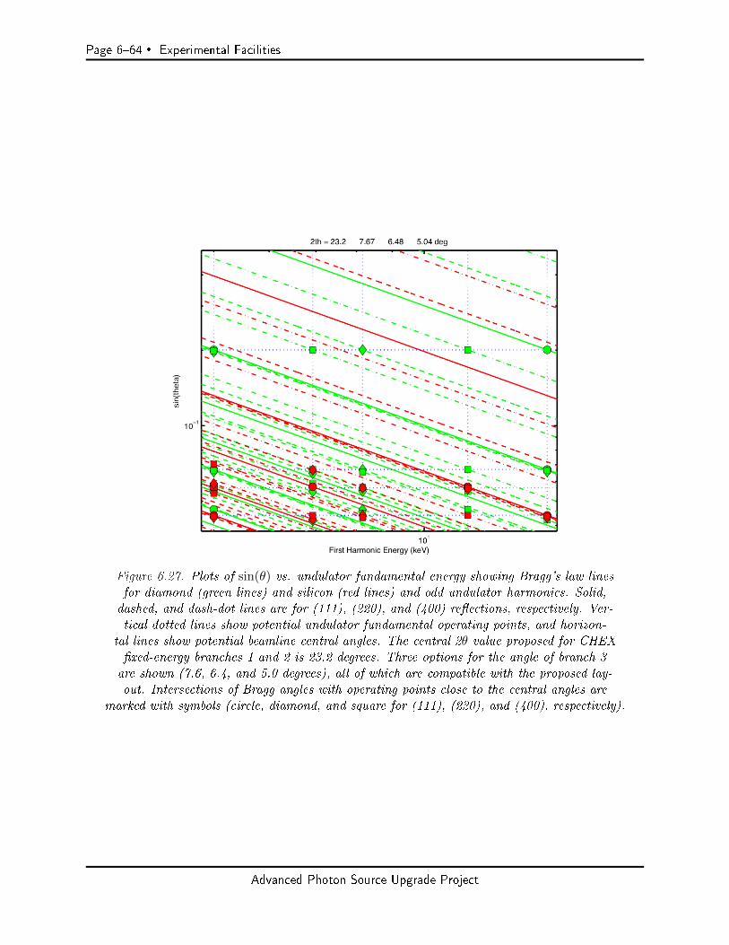
Page 664 Experimental Facilities
Figure 6.27. Plots of sin(θ) vs. undulator fundamental energy showing Bragg's law linesfor diamond (green lines) and silicon (red lines) and odd undulator harmonics. Solid,dashed, and dash-dot lines are for (111), (220), and (400) reections, respectively. Ver-tical dotted lines show potential undulator fundamental operating points, and horizon-
tal lines show potential beamline central angles. The central 2θ value proposed for CHEXxed-energy branches 1 and 2 is 23.2 degrees. Three options for the angle of branch 3are shown (7.6, 6.4, and 5.0 degrees), all of which are compatible with the proposed lay-out. Intersections of Bragg angles with operating points close to the central angles are
marked with symbols (circle, diamond, and square for (111), (220), and (400), respectively).
Advanced Photon Source Upgrade Project
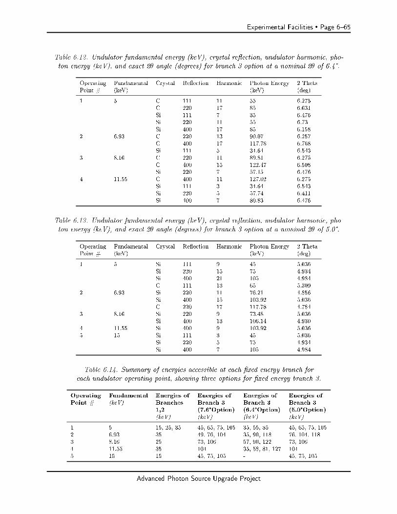
Experimental Facilities Page 665
Table 6.12. Undulator fundamental energy (keV), crystal reection, undulator harmonic, pho-ton energy (keV), and exact 2θ angle (degrees) for branch 3 option at a nominal 2θ of 6.4°.
Operating Fundamental Crystal Reection Harmonic Photon Energy 2 ThetaPoint # (keV) (keV) (deg)
1 5 C 111 11 55 6.275C 220 17 85 6.631Si 111 7 35 6.476Si 220 11 55 6.73Si 400 17 85 6.158
2 6.93 C 220 13 90.07 6.257C 400 17 117.78 6.768Si 111 5 34.64 6.543
3 8.16 C 220 11 89.81 6.275C 400 15 122.47 6.508Si 220 7 57.15 6.476
4 11.55 C 400 11 127.02 6.275Si 111 3 34.64 6.543Si 220 5 57.74 6.411Si 400 7 80.83 6.476
Table 6.13. Undulator fundamental energy (keV), crystal reection, undulator harmonic, pho-ton energy (keV), and exact 2θ angle (degrees) for branch 3 option at a nominal 2θ of 5.0°.
Operating Fundamental Crystal Reection Harmonic Photon Energy 2 ThetaPoint # (keV) (keV) (deg)
1 5 Si 111 9 45 5.036Si 220 15 75 4.934Si 400 21 105 4.984C 111 13 65 5.309
2 6.93 Si 220 11 76.21 4.856Si 400 15 103.92 5.036C 220 17 117.78 4.784
3 8.16 Si 220 9 73.48 5.036Si 400 13 106.14 4.930
4 11.55 Si 400 9 103.92 5.0365 15 Si 111 3 45 5.036
Si 220 5 75 4.934Si 400 7 105 4.984
Table 6.14. Summary of energies accessible at each xed energy branch foreach undulator operating point, showing three options for xed energy branch 3.
Operating Fundamental Energies of Energies of Energies of Energies ofPoint # (keV) Branches Branch 3 Branch 3 Branch 3
1,2 (7.6°Option) (6.4°Option) (5.0°Option)(keV) (keV) (keV) (keV)
1 5 15, 25, 35 45, 65, 75, 105 35, 55, 85 45, 65, 75, 1052 6.93 35 49, 76, 104 35, 90, 118 76, 104, 1183 8.16 25 73, 106 57, 90, 122 73, 1064 11.55 35 104 35, 58, 81, 127 1045 15 15 45, 75, 105 - 45, 75, 105
Advanced Photon Source Upgrade Project
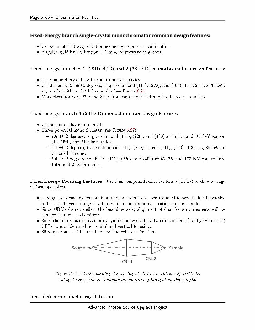
Page 666 Experimental Facilities
Fixed-energy branch single-crystal monochromator common design features:
Use symmetric Bragg reection geometry to preserve collimation Angular stability / vibration < 1 µrad to preserve brightness
Fixed-energy branches 1 (28ID-B/C) and 2 (28ID-D) monochromator design features:
Use diamond crystals to transmit unused energies Use 2 theta of 23 ±0.5 degrees, to give diamond (111), (220), and (400) at 15, 25, and 35 keV,e.g. on 3rd, 5th, and 7th harmonics (see Figure 6.27)
Monochromators at 27.9 and 39 m from source give ∼4 m oset between branches
Fixed-energy branch 3 (28ID-E) monochromator design features:
Use silicon or diamond crystals Three potential mono 2 thetas (see Figure 6.27):
7.6 ±0.2 degrees, to give diamond (111), (220), and (400) at 45, 75, and 105 keV e.g. on9th, 15th, and 21st harmonics.
6.4 ±0.3 degrees, to give diamond (111), (220), silicon (111), (220) at 35, 55, 85 keV onvarious harmonics.
5.0 ±0.2 degrees, to give Si (111), (220), and (400) at 45, 75, and 105 keV e.g. on 9th,15th, and 21st harmonics.
Fixed Energy Focusing Features Use dual compound refractive lenses (CRLs) to allow a rangeof focal spot sizes.
Having two focusing elements in a tandem, zoom lens arrangement allows the focal spot sizeto be varied over a range of values while maintaining its position on the sample.
Since CRL's do not deect the beamline axis, alignment of dual focusing elements will besimpler than with KB mirrors.
Since the source size is reasonably symmetric, we will use two-dimensional (axially symmetric)CRLs to provide equal horizontal and vertical focusing.
Slits upstream of CRLs will control the coherent fraction.
Figure 6.28. Sketch showing the pairing of CRLs to achieve adjustable fo-cal spot sizes without changing the location of the spot on the sample.
Area detectors: pixel array detectors
Advanced Photon Source Upgrade Project

Experimental Facilities Page 667
For optical design, assume minimum pixel size, p, is 55 µm, based on pixel sizes of currentadvanced detectors:
Pixirad: 52x60 µm Eiger: 75 µm SLAC ePix: 50 µm Medipix/Merlin: 55 µm.
For weak signals, sub-pixel spatial resolution can be obtained through a droplet analysis.
Table 6.15 gives the focusing geometries for all branches, which meet the goal of resolving speckleup to high energy. Variables used in formulas given below are:
R = maximum sample-to-detector distance p = detector pixel size
where p/R is the detector angular resolution. This determines the maximum focal spot size, a=0.886 λ R/p, which varies inversely with photon energy E = hc/ λ. Using p = 55 µm, one obtains
a (in µm) = 20 R (in m) / E (in keV)
Since the horizontal source size, e.g. 50 µm FWHM in 324-bunch mode, is typically larger thanthe vertical source size, the largest focal spot size will be in the horizontal (using axially symmetricCRLs).
Note that 2x oversampling of speckles is typically required for CDI. This will be obtained by:
Focusing optics designed to go smaller than the limit given above, especially at photon energiesless than the design maximum.
Horizontal sample size or sample aperture smaller than the focal spot size. Use of a detector with an eective pixel size less than 55 µm, including the use of dropletalgorithms that provide sub-pixel spatial resolution.
using the vertical focus, typically 5 times smaller than the horizontal.
Values for the maximum required focal spot size at the minimum and maximum design energies aregiven in Table 6.15 for each experimental station. The range of horizontal focal spot sizes achievedby the dual CRL optics is also listed for comparison, using a horizontal source size FWHM of 50µm.
The designs for CRL 2 (the downstream element of the dual CRL), which produces the small-est focus needed at the highest energy, is most critical. The required number of single Be lensesand the transmission of CRL 2 are shown in Table 6.15, calculated from the CRL calculator athttp://www.rxoptics.de/parameters.html using typical Be lens parameters of 50 µm radius of curva-ture and 30 µm thickness at apices. These values are reasonable for all experimental stations.
Advanced Photon Source Upgrade Project
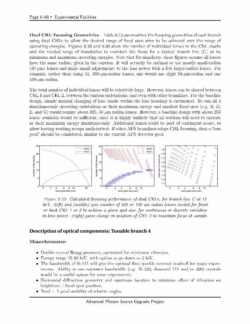
Page 668 Experimental Facilities
Dual CRL Focusing Geometries Table 6.15 summarizes the focusing geometries of each branchusing dual CRLs to allow the desired range of focal spot sizes to be achieved over the range ofoperating energies. Figures 6.29 and 6.30 show the number of individual lenses in the CRL stacksand the needed range of translation to maintain the focus for a typical branch line (C) at itsminimum and maximum operating energies. Note that for simplicity, these gures assume all lenseshave the same radius, given in the caption. It will actually be optimal to use mostly small-radius(50 µm) lenses and make small adjustments to the lens power with a few larger-radius lenses. Forexample, rather than using 51, 300-µm-radius lenses, one would use eight 50-µm-radius and one100-µm radius.
The total number of individual lenses will be relatively large. However, lenses can be shared betweenCRL 1 and CRL 2, between the various endstations, and even with other beamlines. For the baselinedesign, simple manual changing of lens stacks within the lens housings is envisioned. To run all 4simultaneously operating endstations at their maximum energy and smallest focal spot (e.g. B, D,E, and G) would require about 335, 50 µm radius lenses. However, a baseline design with about 250lenses available would be sucient, since it is highly unlikely that all stations will need to operateat their maximum energy simultaneously. Additional lenses could be part of contingent scope, toallow leaving working setups undisturbed. If other APS beamlines adopt CRL focusing, then a lenspool should be considered, similar to the current APS detector pool.
Figure 6.29. Calculated focusing performance of dual CRLs, for branch line C at 15keV. (left) and (middle) give number of 300 or 100 um radius lenses needed for frontor back CRL 1 or 2 to achieve a given spot size, for continuous or discrete variationin lens power. (right) gives change in position of CRL 2 to maintain focus at sample.
Description of optical components: Tunable branch 4
Monochromator:
Double crystal Bragg geometry, optimized for minimum vibration. Energy range 15-60 keV, with option to go down to 5 keV. The bandwidth of Si 111 will give the optimal ux/speckle contrast tradeo for many exper-iments. Ability to use narrower bandwidth (e.g. Si 220, diamond 111 and/or 220) crystalswould be a useful option for some experiments.
Horizontal diraction geometry and upstream location to minimize eect of vibration onbrightness / focal spot position.
Need < 1 µrad stability of relative angles.
Advanced Photon Source Upgrade Project

Experimental Facilities Page 669
Table 6.15. Summary of dual compound refractive lens (CRL) focusing geometries for each branchbeamline (and instrument location, if applicable). The rst ve rows give the distances from thecenter of the ring straight section to the critical beamline optical elements. (Note that the actualX-ray sources from the canted undulators will be at ±1.2 m from the center of the straight section;
this has been neglected here.) The next two rows give the range of horizontal focal spot sizespossible by varying the powers of the two CRLs, imaging the 50 µm horizontal source (324 bunchmode) at the instrument position. The next four rows give the minimum design photon energy,
and for this energy the required focus size to resolve speckle in a 55 µm detector pixel, the requirednumber of single Be refractive lens sections of 50 µm apex radius in CRL 2, and the transmission
of CRL 2. The nal four rows give these quantities for the maximum design photon energy.
Beamline Branch / InstrumentItem Location: B C D/1 D/2 E/1 E/2 F G
Mono (m) 27.9 27.9 39 39 42 42 34 34CRL 1 (m) 29 29 40 40 45 45 50 50CRL 2 (m) 33.5 41.5 44 48 50.75 52.25 63 69.25Instrument (m) 35 43 45.5 49.5 53 54.5 64.5 71.5Detector (m) 39 47 48.5 53.5 62 62 68.5 77.5
Optical Performance and Requirements:hor. focus min. (µm) 2.2 1.8 1.7 1.6 2.2 2.2 1.2 1.6hor. focus max. (µm) 10.3 24.1 6.9 11.9 8.9 10.6 14.5 21.5
at E min (keV) 15 15 15 15 35 35 15 15req'd focus (max., µm) 5.3 5.3 4.0 5.3 5.1 4.3 5.3 8.0CRL 2 N lens max 12 11 11 11 42 42 11 8CRL 2 transmission 0.72 0.74 0.74 0.74 0.54 0.54 0.74 0.80
at E max (keV) 35 35 35 35 55 55 35 55req'd focus (max., µm) 2.3 2.3 1.7 2.3 3.3 2.7 2.3 2.2CRL 2 N lens max 64 63 63 63 105 105 62 103CRL 2 transmission 0.42 0.43 0.43 0.43 0.31 0.31 0.43 0.32
Figure 6.30. Calculated focusing performance of dual CRLs, for branch line C at 35keV. (left) and (middle) give number of 300 or 50 um radius lenses needed for frontor back CRL 1 or 2 to achieve a given spot size, for continuous or discrete variationin lens power. (right) gives change in position of CRL 2 to maintain focus at sample.
Advanced Photon Source Upgrade Project
Page 670 Experimental Facilities
Option for double-multilayer monochromator, and/or direct pink beam.
Focusing:
Use dual compound refractive lenses to allow a range of focal spot sizes (see description above). Compare performance of KB mirrors instead of CRLs for this branch, to allow fast changingof energy.
Table 6.15 gives the focusing geometries for the F and G stations, which meet the goal of resolvingspeckle up to high energy (analysis given in Section 6-4.4.1 above).
Heat load: Consider ltering power below 15 keV as described above.
Hutches: Two in tandem, F and G, sized to resolve speckle at high energy.
Area detectors: Pixel array detectors as above.
6-4.4.2 Beamline Physical Layout
Overall Beamline
General Description Appendix 2 gives the overall layout, showing three horizontally diractingsingle-crystal monochromators on one undulator feeding branches 1, 2, and 3 (stations B/C, D, andE), and a double-crystal monochromator on the other undulator feeding branch 4 (stations F/G).Each station has an enclosed control area. Advantage is taken of space available from sectors 27 and29 adjacent to sector 28 to provide multiple hutches, four of which can operate simultaneously forhigh productivity and beam time access. This is possible because of the short beamline at 27-ID andthe lack of bending-magnet beamlines at 28-BM and 29-BM. Relatively long hutches are optimizedfor coherent beam speckle observation.
Radiation Safety Aspects Nothing unusual. To minimize monochromator vibration, the DCMon the tunable branch may have a small oset, with appropriately designed bremsstrahlung shieldingdownstream.
Vacuum System Because of the highly interconnected nature of the multiple branches, andbecause of the relatively frequent need to open beamline vacuum to change CRLs, for reliabilityand risk mitigation we propose to use window(s) to separate the tunable and xed energy beamlinesfrom the ring vacuum, and potentially from each other. Appropriately polished, high quality Be ordiamond windows should preserve the beam collimation. It is desirable to leave sucient space forinstallation of dierential pumps for windowless operation if needed in the future.
Advanced Photon Source Upgrade Project

Experimental Facilities Page 671
First Optics Enclosure and Infrastructure
Major Components Three single-crystal monochromators (SCMs) and a horizontally deectingdouble-crystal monochromator (DCM) (with option for a tandem double-multilayer monochromator(DMM)) will be located in the FOE, as described above.
The upstream CRL 1 housing of the dual-CRL focusing optics for each of the three xed-energybranches will be located just downstream of each SCM in the FOE. The location of CRL 1 for thetunable-energy branch will be in a separate enclosure downstream of the FOE, to allow access forchanging lenses without disturbing operation of the xed-energy branches.
The baseline scope will include simple CRL housings for manual changing of lenses. As an option incontingent scope, automated `transfocators' would allow changing CRL 1 lenses in the FOE withoutdisturbing other experiments or opening beamline vacuum. Likewise, transfocators for the tunablebranch could allow more rapid changes in energy.
A chemical exhaust system will service the experimental hutches B through G and their associatedgas cabinets. The plenums will be sized to minimize vibration at the needed ow. Filtered make-upair will be provided in the hutches so that they are maintained at neutral or positive pressure, tomaintain cleanliness.
Windows, Slits, Collimators, Shutters/Stops A polished Be or diamond window will sepa-rate the beamline from the ring vacuum, with space to replace it with a dierential pump in thefuture if needed.
Two power lters to reduce heat load on the monochromators will be located on each undulatorbeam.
Two sets of white beam slits will be located on each undulator beam upstream of the rstmonochromator.
Four sets of monochromatic beam slits will be located upstream of each CRL 1 to adjust thecoherent fraction.
Four shutters for the three xed energy branches and the tunable branch will be located inthe FOE.
Fixed Energy Branches 1, 2, 3, and Tunable Branch 4
Components Each of the four branches includes two locations for experiments, either in tandemhutches (B and C on xed energy branch 1, or F and G on the tunable branch 4), or within asingle hutch (D on branch 2, E on branch 3). Housings for CRL 2, as well as slit sets to adjust thecoherent fraction, will be positioned upstream of all eight experimental locations.
Instruments Four goniometers will be included in the baseline scope, one for each branch line.These will support the instruments using shared goniometers shown in Table 6.9. Sample goniome-ters will have all six degrees of angular and positional control, stable to sub-microradian angle andsub-µm position accuracy, and capable of supporting 50 kg chambers. Final slits close to the sample
Advanced Photon Source Upgrade Project

Page 672 Experimental Facilities
position will be needed to adjust the illumination and provide harmonic rejection. Incident intensitymonitors will be needed upstream and downstream of these slits. The goniometer will also includeseparate detector circles for supporting a pixel array detector at distances up to 1.5 m from thesample. (An example of such an advanced goniometer is the one recently installed at 12-ID-D.)Anti-scatter slits downstream of the sample will prevent background from reaching the detector.Attenuators will allow the detector to record the direct beam and Bragg peaks. For longer detectordistances, the detector will be positioned on a separate moving support, with software control of itsmotion relative to the goniometer.
Outside the funded scope of the project, we anticipate that the community will provide severalinstruments with integrated goniometers through Partner User agreements. Some of these are alsoindicated in Table 6.9.
6-4.4.3 Additional
Detectors
Four low-noise, small-pixel pixel, rapid-readout array detectors with good sensitivity to high energyX-rays will be needed for each of the simultaneously operating experiments. Detectors with ∼55 µmor smaller pixels and CdTe sensors are envisioned, similar to those available from Pixirad or Merlin.As contingent scope, additional detectors would allow coverage of multiple regions of reciprocal space(e.g. low angle and high angle), and minimize switching of detectors between operating setups.
Computing
Goniometer control through an advanced scattering software control interface such as SPEC isneeded. Online, real-time analysis of XPCS and CDI data owing from the pixel array detectorswill require a dedicated, modest computational facility (e.g. high-performance Linux workstations).The average data rate will be about 1 TB per day for each of the four operating experiments. Afacility to store about 1000 TB of data prior to reduction / analysis will be required.
Specific Safety Requirements
Equipment and engineered controls, such as gas cabinets, puriers, gas sensors, automated ow con-trol systems, and chemical exhaust for hazardous gases (e.g. hydrogen, ammonia, carbon monoxide),will provide needed synthesis sources and chemical environmental control to all of the experimentalstations. A coordinated, multiplexed system will allow ecient sharing of gas sources when theyare needed by multiple experiments at the CHEX facility.
Specific Conventional Facilities Requirements
Stable ambient temperature, beam position monitoring and feedback, and systems designed to re-duce creation and sensitivity to vibration will be required to maintain the position and angle stabilityof the X-ray beam and sample to the µm and microradian level needed for coherent experiments.
Advanced Photon Source Upgrade Project
Experimental Facilities Page 673
Support facilities
Standard dry and wet laboratories in the adjacent LOM will be required for sample preparationand experimental setup. As part of contingent scope, a clean (e.g. class 100) sample preparationspace in the control area adjacent to the beamline would be very useful.
6-4.5 R&D Needs
Here we list some open questions about the design that could be addressed either by further devel-opment and comparison of design alternatives, or by more elaborate R&D or prototyping work.
Superconducting undulator and heat load on front end
Increasing the length of each undulator from 1.2 m to 1.5 m would give 37% higher brightness at15 keV, but would also increase the power and power density on front-end components by 24%.Further design work is needed to determine the best undulator choice, including comparison withrevolvers.
Heat load on monochromators
An analysis, and potentially prototyping, should be performed to determine the heat load eectson coherence preservation by the monochromators, and the potential benets of using an upstreamadjustable power lter to remove intensity at energies below the operating energy (e.g. from lowerharmonics).
Focusing optics
Currently CRLs are used at coherent X-ray beamlines at LCLS, NSLS-II, and elsewhere. However,improvements may be possible, such as improving the grade of Be used. A study of the eects ofCRLs on beam coherence, in collaboration with the manufacturer and users worldwide, would bevaluable.
While CRLs oer the simplicity of no displacement of the beamline axis and simple adjustmentof focal spot size, the strong photon energy dependence of their focal length may complicate ex-periments in which the energy is scanned or changed repeatedly. For the tunable beamline, thiscould be mitigated by employing a transfocator that can exchange CRLs by automation to rapidlyadjust for energy changes. Alternatively, KB focusing optics that have no energy dependence up toa critical value should be considered.
Harmonic rejection
Because CRLs have a very dierent focal length for each harmonic, slits close to the focus caneectively reject unwanted harmonics by factors of up to 105. For cases in which this is insucient,a design option for a small harmonic rejection mirror in the hutch should be considered.
Advanced Photon Source Upgrade Project
Page 674 Experimental Facilities
Small sphere-of-confusion goniometers
For many experiments, goniometers with one or more axes having sub-µm axis stability would bedesirable. Designs for such goniometers should be prototyped and tested.
Manipulation and stability of samples
Methods to manipulate and hold samples stably, such as small particles in reactive environments,should be developed and prototyped.
Pixel Array detectors
Many dierent pixel array detector systems are available or under development that have character-istics suitable for high-energy XPCS or CDI experiments. Testing of these systems and developmentof integrated analysis techniques, such as time correlation analysis, droplet algorithms, sub-pixelspatial resolution, etc., should be pursued.
Detector positioner
To position an area detector up to several meters away from the sample, long goniometer arms areimpractical. Designs, such as towers mounted on air pads, with laser-based position determination(using commercial systems developed for virtual reality headsets, for example), should be developedand prototyped.
CDI algorithm standardization
On-the-y analysis of CDI data, as well as subsequent renement, will be required. This eld is ripefor development of standardized algorithms with tested and accepted error and resolution metrics.A cross-facility eort in this area would be useful.
Electronic logbook and metadata system
Like many beamlines, the CHEX sector would benet from an electronic logbook system thatcould easily capture experiment status, linked to data les and plots, and provide it in an editable,logbook format documenting the sequence of the experiments. Newly available platforms, such astablets with good handwriting input, provide an opportunity to create a next-generation electroniclogbook.
Advanced Photon Source Upgrade Project
Experimental Facilities Page 675
6-5 Coherent Surface Scattering Imaging (CSSI) Beamline
6-5.1 Executive Summary
At the center stage of the scientic topics, surface/interface phenomena are of great interest toscientists in a variety of elds. Imaging techniques provide ideal tools to directly observe sur-face/interface structures and monitor their dynamic evolution responding to changes in externalconditions. Much progress has been made in the development of hard x-ray sources and tools,including the development of storage-ring and x-ray free-electron-laser (XFEL) sources. Among all,grazing-incidence x-ray scattering and x-ray photon correlation spectroscopy (XPCS) exhibit uniqueadvantages for exploring the surface/interface problems that are challenging to solve using otherimaging techniques dynamics probes. The APS Upgrade will increase brightness by a factor of 100to 1000 clearly high-brightness and coherence are the cornerstones of the upgraded source. Thex-ray beams from the upgraded source possesses a large coherent fraction, which is well suited formeasuring the spatiotemporal evolution of structures in complex systems with the highest precisionat surfaces and interfaces. A new beamline for coherent surface-scattering imaging (CSSI) takesadvantage of the much improved x-ray beam coherence and is ideal for probing and understand-ing mesoscopic spatial-temporal correlations by integrating the coherence-based surface x-ray probewith state-of-the-art coherence-preserving optics and advanced x-ray detectors.
6-5.2 Scientific Objectives
Surface/interface phenomena are of great interest to scientists in a variety of elds. More specif-ically, these challenging topics include, but are not limited to: evolution of biological membranesand supramolecules in aqueous environments, thin lm and quantum dot growth at surfaces and in-terfaces, assembly of planner polymer nanocomposites, and structural analysis of three-dimensional(3D) nanoscaled electronic circuits using additive manufacturing. The temporal and spatial resolu-tion promised by the APS low-emittance upgrade ideally matches the challenges of understandingmesoscaled structure and dynamics from nm to mm and ns to s. The experiments at CSSI beamlinecan provide much needed structural and dynamical information to answer the following questions:
Hierarchical assembly of functional materials: how physical and chemical processes and dy-namics are involved to lead to hierarchical order in mesoscopic structures and the functional-ities;
How to advance nanopatterning using combination of top-down and bottom-up techniques forthe controlled fabrication of complex and multicomponent nanomaterials that are needed foradvanced functional applications;
How to control the morphology of thin-lm based photovoltaic to optimize the eciency ofthe devices; and
How do the dynamics at every level of the hierarchical structures control the complexity andspecic functionalities of mesoscopic systems.
Those questions often need to be addressed in association with processes that involve non-equilibriumtemporal evolution of structural complexity at molecular, nanoscopic, and mesoscopic scales [77].More specically, the CSSI beamline will be the prime user facility for the research will be include:
Self-assembly of mesoscale structures at surfaces and interfaces,
Advanced Photon Source Upgrade Project
Page 676 Experimental Facilities
Three-dimensional surface nanopatterning and nanofabrication, Three-dimensional morphology of photovoltaic thin lms, Dynamics at surfaces and Interfaces, Capillary instability in conned geometry, and At-wavelength and in-situ metrology for x-ray coherence preserving reective optics.
Coherent surface-scattering imaging (CSSI) [78] will satisfy the needs as a non-destructive in situstructure characterization with three-dimensional high resolution and temporal resolution aordedby the intense coherent x-ray beam from the upgraded APS. In the meantime, grazing-incidence x-ray photon correlation spectroscopy (GIXPCS) is a complementary way to understand the interplaybetween the dynamics and structure in order to gain the control of the structure evolution in thematerials processing. More detailed science cases are described in Chapter 2.
6-5.2.1 Use of APS-U Characteristics
At worldwide synchrotron x-rays sources, coherent diractive imaging (CDI), coupled with advancedx-ray detectors and computational algorithms, has opened up new research frontiers in structuralsciences that are simply not attainable previously [79]. The reconstruction of the images in realspaces requires phase retrieval to complement the x-ray scattering intensity measurement usingpartially coherent beam. Most CDI methods use transmission geometry, which is not suitable fornanostructures grown on opaque substrates or for objects of interest comprising only surfaces orinterfaces, which are highlighted in the Science Section. In order to gain the information in 3rd
dimension, namely, in the direction perpendicular to the surfaces/interfaces of interest, CSSI ingrazing-incidence geometry takes advantage of enhanced x-ray surface scattering and interferencenear total external reection. The concept of CSSI was demonstrated the successful reconstructionof substrate-supported non-periodic surface patterns in three dimensions as shown Figure 6.31[78].Similar to other CDI methods, one of the unique advantages of CSSI is lensless approach, thetheoretical resolution is only limited by the x-ray wavelength.
Coherent beam from the APS Undulator A through a coherence dening slit set was used to re-constructing 3D structures of a silicon-supported Argonne logo (Figure 6.31B). This measurementwas made at 8-ID-E beamline of the APS with a monochromatic incident beam (photon energy E=7.35 keV with ∆E/E = 2×10⁻⁴). The transverse coherence length along the horizontal directionwas 7 µm and the beam was fully coherent across the entire vertical direction over the 15 µmbeam. The coherent ux was approximately 1 X 10⁹ photons/sec. A CCD-based Coolsnap HQ2
detector was placed 0.7 m away from the sample for collecting scattering patterns. A 5× lens wasused, resulting in an eective pixel dimension of 1.29 X 1.29 µm2 on the detector, to provide thene reciprocal space resolution for recording speckle patterns with such a short sample-to-detectordistance. However, the overall detection eciency of the detector system suered, which was es-timated to be only 0.13% (i.e. 1 photon detected for about 750 scattered photons). To obtaineddetectable coherent scattering signal in the demonstration experiment at the APS, the sample sizewas designed to be very large (400 µm long, 5 µm wide and 40 nm thick). Despite the large sample,the scattering signal was still low. A typical data collected from measurements requiring a few hoursof time resulted in 3D imaging reconstruction resolutions of 2.6 µm, 22 nm and 2.7 nm in each ofthe 3 dimensions. Again, the limitation came from insucient sample-to-detector distance thatrenders ecient but large-pixel-size detectors unusable, resulting the poor data collection eciency.
Advanced Photon Source Upgrade Project

Experimental Facilities Page 677
Figure 6.31. CSSI demonstration at the APS Sector 8. (A) Schematics of experiment setupwith two specic coordinate systems that used throughout the proposal text. The sample was alithographically prepared gold pattern at silicon surface. (B) The size of the pattern was 400µm long (along the x-ray footprint direction) and 5 µm wide with a feature size of 0.32 µm.
The coherent surface scattering pattern (C) was taking over a period of a few hours to improvethe data statistics with a maximum scattering intensity of 3000 counts. The reconstructed 3Dstructure (D) has resolutions of 2.6 µm, 22 nm and 2.7 nm in each of the three directions.
Advanced Photon Source Upgrade Project
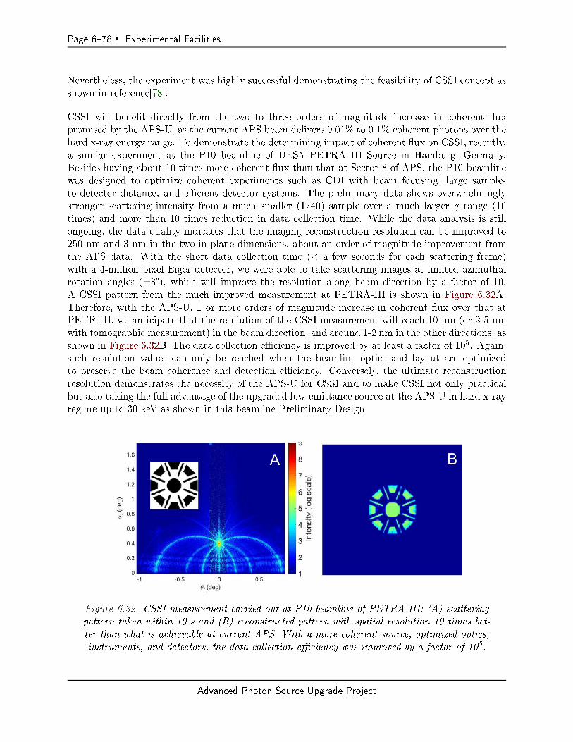
Page 678 Experimental Facilities
Nevertheless, the experiment was highly successful demonstrating the feasibility of CSSI concept asshown in reference[78].
CSSI will benet directly from the two to three orders of magnitude increase in coherent uxpromised by the APS-U, as the current APS beam delivers 0.01% to 0.1% coherent photons over thehard x-ray energy range. To demonstrate the determining impact of coherent ux on CSSI, recently,a similar experiment at the P10 beamline of DESY-PETRA III Source in Hamburg, Germany.Besides having about 10 times more coherent ux than that at Sector 8 of APS, the P10 beamlinewas designed to optimize coherent experiments such as CDI with beam focusing, large sample-to-detector distance, and ecient detector systems. The preliminary data shows overwhelminglystronger scattering intensity from a much smaller (1/40) sample over a much larger q range (10times) and more than 10 times reduction in data collection time. While the data analysis is stillongoing, the data quality indicates that the imaging reconstruction resolution can be improved to250 nm and 3 nm in the two in-plane dimensions, about an order of magnitude improvement fromthe APS data. With the short data collection time (< a few seconds for each scattering frame)with a 4-million pixel Eiger detector, we were able to take scattering images at limited azimuthalrotation angles (±3°), which will improve the resolution along beam direction by a factor of 10.A CSSI pattern from the much improved measurement at PETRA-III is shown in Figure 6.32A.Therefore, with the APS-U, 1 or more orders of magnitude increase in coherent ux over that atPETR-III, we anticipate that the resolution of the CSSI measurement will reach 10 nm (or 2-5 nmwith tomographic measurement) in the beam direction, and around 1-2 nm in the other directions, asshown in Figure 6.32B. The data collection eciency is improved by at least a factor of 105. Again,such resolution values can only be reached when the beamline optics and layout are optimizedto preserve the beam coherence and detection eciency. Conversely, the ultimate reconstructionresolution demonstrates the necessity of the APS-U for CSSI and to make CSSI not only practicalbut also taking the full advantage of the upgraded low-emittance source at the APS-U in hard x-rayregime up to 30 keV as shown in this beamline Preliminary Design.
Figure 6.32. CSSI measurement carried out at P10 beamline of PETRA-III: (A) scatteringpattern taken within 10 s and (B) reconstructed pattern with spatial resolution 10 times bet-ter than what is achievable at current APS. With a more coherent source, optimized optics,instruments, and detectors, the data collection eciency was improved by a factor of 105.
Advanced Photon Source Upgrade Project

Experimental Facilities Page 679
6-5.2.2 Key Beamline Characteristics
The key characteristics of the beam at the sample position at CSSI beamline are summarized inTable 6.16. The coherent ux delivered at the sample position at all beam energies up to 30keV will be at least 1 order of magnitude higher than any existing beamline worldwide. With allfocusing devices imaging the source directly the coherent photon ux is preserved. We anticipatethat the beamline will be the world leading beamline that is well suited for coherent scattering forsurfaces and interfaces and for understanding mesoscopic spatial-temporal correlations in functionalmaterials and their processing.
Table 6.16. Summary of beam properties at the sample location
Properties CSSI GIXPCS GISAXS/WAXS
Coherent ux @8 keV @15 keV @10 keV @30 keV Total Flux(ph/s) > 5x10¹² > 1x10¹² > 5x10¹² > 5x10¹¹ > 1x10¹³
E Range (keV) 6 - 20 6 - 30 6 - 30Beam size 1-2 15-20 35horizontal (µm)Beam size 0.2 -0.4 3-5 10vertical (µm)
6-5.3 Source & Front-End Requirements
6-5.3.1 Insertion Device
There are two gures of merit to consider to choose proper undulator source: coherent ux andx-ray photon energy tunability/tuning range. The eciency of the CSSI measurement is criticallydepending on coherent ux, which requires a 4.8-m long undulator that spans the entire straightsection of about 5 m. The commonly used x-ray photon energy for CSSI will be between 7 and8 keV to optimize coherent ux, penetrability of dry lm samples, speckle size, detector eciencyand radiation damage. When ultimate coherent ux is needed, the beamline should allow a photonenergy as low as 6 keV. The proposed CSSI beamline will also be a world-class facility for studies ofliquid-liquid, liquid-vapor, and liquid-solid interfaces. Structure and dynamic studies of those buriedinterfaces require photon energy tunable to 30 keV, sucient to penetrate samples of 1 cm thick ionicsolutions with metal species such as zinc, copper, cadmium, etc. To accommodate coherence-basedexperiments on samples at liquid/liquid and liquid/solid interfaces, such high-energy x-rays willbe necessary to reduce absorption and background scattering from bulk liquids/solid. Undulatorscapable of producing 30-keV coherent beam can only be aorded at the APS-U, a hard x-ray coherentsource. A revolver type undulator with two magnetic pole periods of 21 and 25 mm would t thebill: high coherent ux, continuous tunability from 6 to 30 keV as seen in Figure 6.33. Since onlythe 1st and 3rd harmonics will be used to cover the energy range, there is no appreciable drop intotal ux at the high-energy end. The peak brilliance will be over 1022 ph/s/mrad2/mm2/0.1%bwat 10 keV, a full two orders of magnitude higher than the current Undulator A beam.
6-5.4 Beamline Layout
Given at least 10 times higher coherent ux at APS-U over PETRA-III, the CSSI beamline directlytakes advantage of the APS-U source property. Similar to other CDI methods using transmission
Advanced Photon Source Upgrade Project
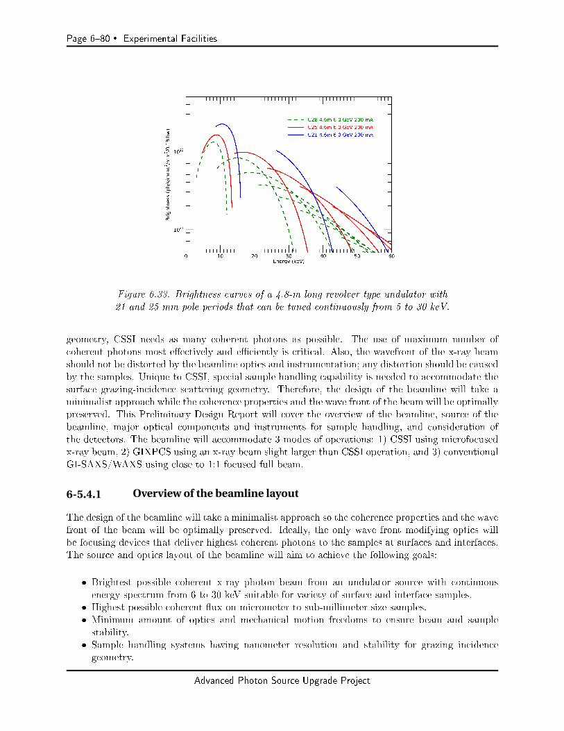
Page 680 Experimental Facilities
Figure 6.33. Brightness curves of a 4.8-m long revolver type undulator with21 and 25 mm pole periods that can be tuned continuously from 5 to 30 keV.
geometry, CSSI needs as many coherent photons as possible. The use of maximum number ofcoherent photons most eectively and eciently is critical. Also, the wavefront of the x-ray beamshould not be distorted by the beamline optics and instrumentation; any distortion should be causedby the samples. Unique to CSSI, special sample handling capability is needed to accommodate thesurface grazing-incidence scattering geometry. Therefore, the design of the beamline will take aminimalist approach while the coherence properties and the wave front of the beam will be optimallypreserved. This Preliminary Design Report will cover the overview of the beamline, source of thebeamline, major optical components and instruments for sample handling, and consideration ofthe detectors. The beamline will accommodate 3 modes of operations: 1) CSSI using microfocusedx-ray beam, 2) GIXPCS using an x-ray beam slight larger than CSSI operation, and 3) conventionalGI-SAXS/WAXS using close to 1:1 focused full beam.
6-5.4.1 Overview of the beamline layout
The design of the beamline will take a minimalist approach so the coherence properties and the wavefront of the beam will be optimally preserved. Ideally, the only wave front modifying optics willbe focusing devices that deliver highest coherent photons to the samples at surfaces and interfaces.The source and optics layout of the beamline will aim to achieve the following goals:
Brightest possible coherent x-ray photon beam from an undulator source with continuousenergy spectrum from 6 to 30 keV suitable for variety of surface and interface samples.
Highest possible coherent ux on micrometer to sub-millimeter size samples. Minimum amount of optics and mechanical motion freedoms to ensure beam and samplestability.
Sample handling systems having nanometer resolution and stability for grazing incidencegeometry.
Advanced Photon Source Upgrade Project

Experimental Facilities Page 681
Sucient sample to detector distance to achieve speckle oversampling using ecient but large-pixel detectors.
Ecient detectors over the entire photon energy range up to 30 keV.
The following source and major optics are planned at the beamline:
A revolver-type undulator that covers continuous spectrum required for CSSI samples A single at mirror with multiple coating stripes to reject higher-order harmonics in dierentphoton energy ranges
Multiples sets of monochromators (in the same vacuum chamber) to deliver either narrowbandwidth (10-4) or wide bandwidth (10-2) photon beam to the sample.
Multiple sets of focusing devices (either sets of CRLs, kinoform lenses, or KB mirrors) in zoomconguration. The focusing device will generate x-ray spot sizes suitable for CSSI (submi-crometers to micrometers), GIXPCS (up to 10 micrometers), and GISAXS (10s micrometers)modes.
Sample positioning and handling need motions, reproducibility and stability of nanometerresolution to satisfy the requirement of grazing incident geometry. A liquid diractometerwill facilitate the study of nanosctructures at air/liquid and liquid/liquid interfaces.
Probing mesoscaled structures and dynamics requires detecting scattering patterns at bothsmall angles (low-q) and wide angles (high-q) with two detectors. The wide-angle detectorswill be close to the sample and the small-angle detector should be at a large distance fromthe sample to ensure the q-space resolution. A long end station will ensure the large sampleto detector distance.
Most ecient large area detectors are to be used as small-angle detectors. CSSI is a uniquemethod that uses scattering patterns near primary reection without a beam stop. Therefore,a high-count-rate and high-dynamic-range detector is essential for the complement the large-area commercial detector.
Based on the design concept, Figure 6.34 shows a schematic layout of the beamline with the locationsof major beamline components.
Figure 6.34. Schematic layout of CSSI beamline source, op-tics, instrument, sample handling apparatus and detectors.
To accommodate the requirements of the beamline layout, Sector 9-ID beamline is chosen to hostthe proposed CSSI instruments. An engineering drawing is provided in Figure 6.35 to depict thebeamline layout at scale, as Table 6.17 includes a list of major beamline components and theirapproximate locations in the beamline.
Advanced Photon Source Upgrade Project
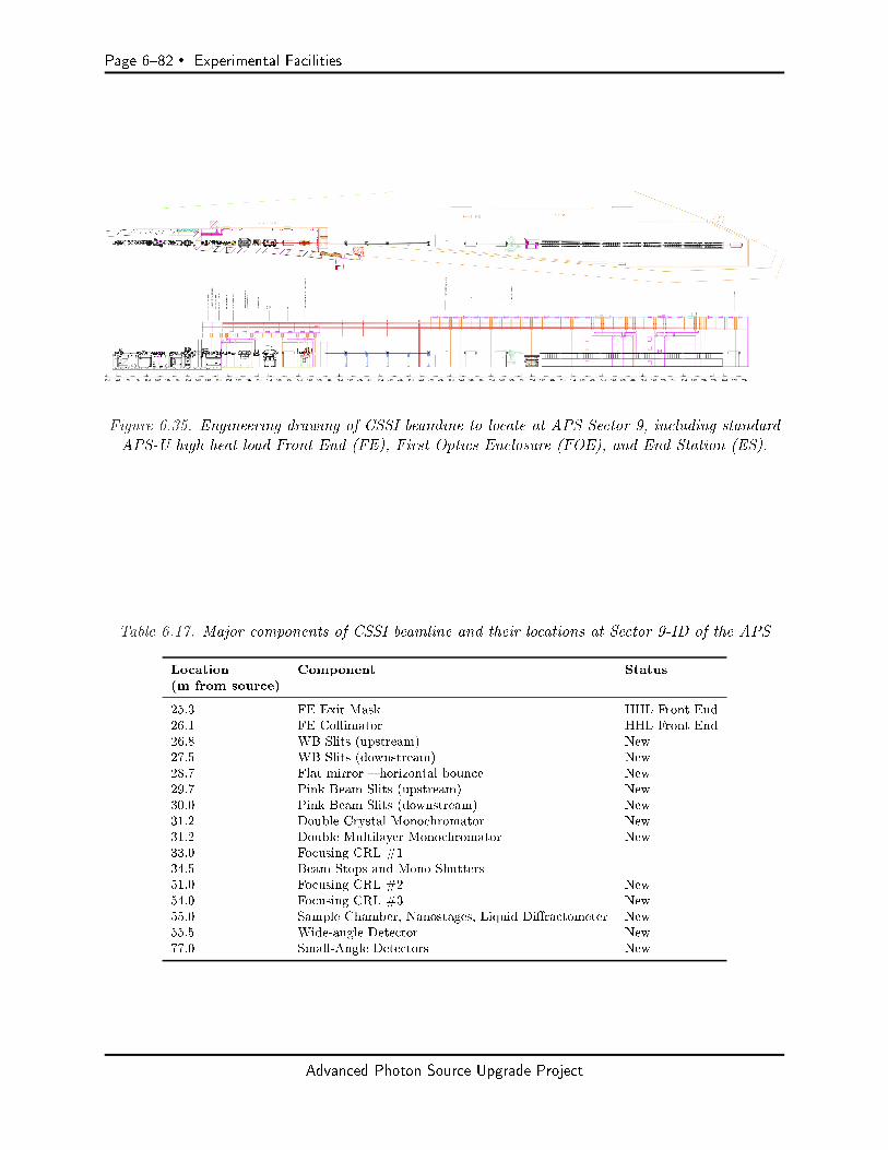
Page 682 Experimental Facilities
Figure 6.35. Engineering drawing of CSSI beamline to locate at APS Sector 9, including standardAPS-U high heat load Front End (FE), First Optics Enclosure (FOE), and End Station (ES).
Table 6.17. Major components of CSSI beamline and their locations at Sector 9-ID of the APS
Location Component Status(m from source)
25.3 FE Exit Mask HHL Front End26.1 FE Collimator HHL Front End26.8 WB Slits (upstream) New27.5 WB Slits (downstream) New28.7 Flat mirror horizontal bounce New29.7 Pink Beam Slits (upstream) New30.0 Pink Beam Slits (downstream) New31.2 Double Crystal Monochromator New31.2 Double Multilayer Monochromator New33.0 Focusing CRL #134.5 Beam Stops and Mono Shutters51.0 Focusing CRL #2 New54.0 Focusing CRL #3 New55.0 Sample Chamber, Nanostages, Liquid Diractometer New55.5 Wide-angle Detector New77.0 Small-Angle Detectors New
Advanced Photon Source Upgrade Project
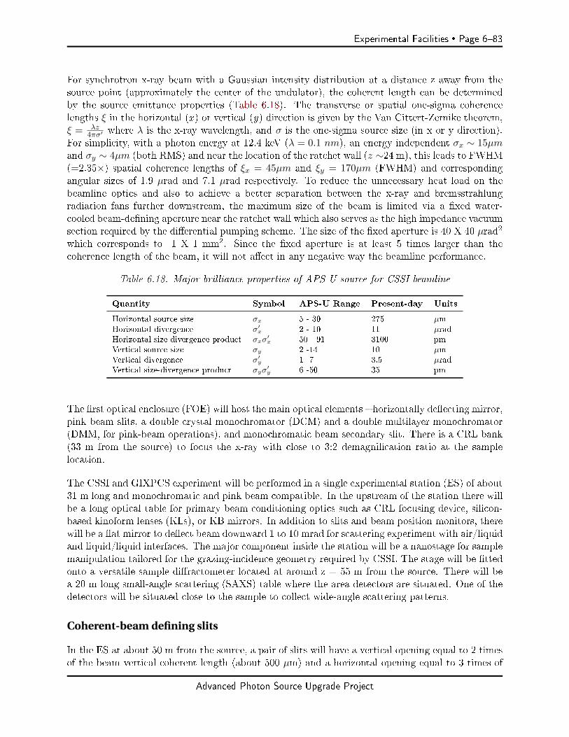
Experimental Facilities Page 683
For synchrotron x-ray beam with a Gaussian intensity distribution at a distance z away from thesource point (approximately the center of the undulator), the coherent length can be determinedby the source emittance properties (Table 6.18). The transverse or spatial one-sigma coherencelengths ξ in the horizontal (x ) or vertical (y) direction is given by the Van Cittert-Zernike theorem,ξ = λz
4πσ′ where λ is the x-ray wavelength, and σ is the one-sigma source size (in x or y direction).For simplicity, with a photon energy at 12.4 keV (λ = 0.1 nm), an energy independent σx ∼ 15µmand σy ∼ 4µm (both RMS) and near the location of the ratchet wall (z ∼24 m), this leads to FWHM(=2.35×) spatial coherence lengths of ξx = 45µm and ξy = 170µm (FWHM) and correspondingangular sizes of 1.9 µrad and 7.1 µrad respectively. To reduce the unnecessary heat load on thebeamline optics and also to achieve a better separation between the x-ray and bremsstrahlungradiation fans further downstream, the maximum size of the beam is limited via a xed water-cooled beam-dening aperture near the ratchet wall which also serves as the high impedance vacuumsection required by the dierential pumping scheme. The size of the xed aperture is 40 X 40 µrad2
which corresponds to 1 X 1 mm2. Since the xed aperture is at least 5 times larger than thecoherence length of the beam, it will not aect in any negative way the beamline performance.
Table 6.18. Major brilliance properties of APS-U source for CSSI beamline
Quantity Symbol APS-U Range Present-day Units
Horizontal source size σx 5 - 30 275 µmHorizontal divergence σ′x 2 - 10 11 µradHorizontal size-divergence product σxσ
′x 50 - 91 3100 pm
Vertical source size σy 2 -14 10 µmVertical divergence σ′y 1 -7 3.5 µradVertical size-divergence product σyσ
′y 6 -50 35 pm
The rst optical enclosure (FOE) will host the main optical elements horizontally deecting mirror,pink beam slits, a double crystal monochromator (DCM) and a double multilayer monochromator(DMM, for pink-beam operations), and monochromatic beam secondary slit. There is a CRL bank(33 m from the source) to focus the x-ray with close to 3:2 demagnication ratio at the samplelocation.
The CSSI and GIXPCS experiment will be performed in a single experimental station (ES) of about31 m long and monochromatic and pink beam compatible. In the upstream of the station there willbe a long optical table for primary beam conditioning optics such as CRL focusing device, silicon-based kinoform lenses (KLs), or KB mirrors. In addition to slits and beam position monitors, therewill be a at mirror to deect beam downward 1 to 10 mrad for scattering experiment with air/liquidand liquid/liquid interfaces. The major component inside the station will be a nanostage for samplemanipulation tailored for the grazing-incidence geometry required by CSSI. The stage will be ttedonto a versatile sample diractometer located at around z = 55 m from the source. There will bea 20 m long small-angle scattering (SAXS) table where the area detectors are situated. One of thedetectors will be situated close to the sample to collect wide-angle scattering patterns.
Coherent-beam defining slits
In the ES at about 50 m from the source, a pair of slits will have a vertical opening equal to 2 timesof the beam vertical coherent length (about 500 µm) and a horizontal opening equal to 3 times of
Advanced Photon Source Upgrade Project
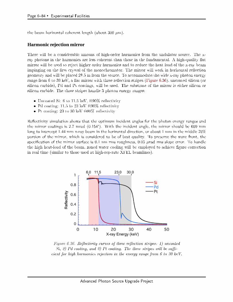
Page 684 Experimental Facilities
the beam horizontal coherent length (about 300 µm).
Harmonic rejection mirror
There will be a considerable amount of high-order harmonics from the undulator source. The x-ray photons in the harmonics are less coherent than those in the fundamental. A high-quality atmirror will be used to reject higher order harmonics and to reduce the heat load of the x-ray beamimpinging on the rst crystal of the monochromator. The mirror will work in horizontal reectiongeometry and will be placed 28.5 m from the source. To accommodate the wide x-ray photon energyrange from 6 to 30 keV, a at mirror with three reection stripes (Figure 6.36), uncoated silicon (orsilicon carbide), Pd and Pt coatings, will be used. The substrate of the mirror is either silicon orsilicon carbide. The three stripes handle 3 photon energy ranges:
Uncoated Si: 6 to 11.5 keV, @90% reectivity Pd coating: 11.5 to 23 keV @90% reectivity Pt coating: 23 to 30 keV @80% reectivity
Reectivity simulation shows that the optimum incident angles for the photon energy ranges andthe mirror coatings is 2.7 mrad (0.154°). With the incident angle, the mirror should be 600 mmlong to intercept 1.44 mm x-ray beam in the horizontal direction, or about 1 mm in the middle 70%portion of the mirror, which is considered to be of best quality. To preserve the wave front, thespecication of the mirror surface is 0.1 nm rms roughness, 0.05 µrad rms slope error. To handlethe high heat-load of the beam, zoned water cooling will be employed to achieve gure correctionin real time (similar to those used at high-rep-rate XFEL beamlines).
Figure 6.36. Reectivity curves of three reection stripes: 1) uncoatedSi, 2) Pd coating, and 3) Pt coating. The three stripes will be su-
cient for high harmonics rejection in the energy range from 6 to 30 keV.
Advanced Photon Source Upgrade Project
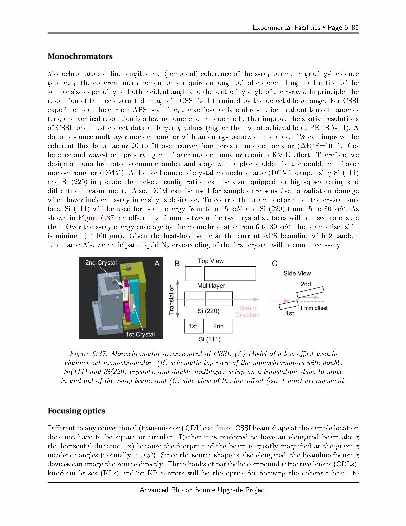
Experimental Facilities Page 685
Monochromators
Monochromators dene longitudinal (temporal) coherence of the x-ray beam. In grazing-incidencegeometry, the coherent measurement only requires a longitudinal coherent length a fraction of thesample size depending on both incident angle and the scattering angle of the x-rays. In principle, theresolution of the reconstructed images in CSSI is determined by the detectable q range. For CSSIexperiments at the current APS beamline, the achievable lateral resolution is about tens of nanome-ters, and vertical resolution is a few nanometers. In order to further improve the spatial resolutionsof CSSI, one must collect data at larger q values (higher than what achievable at PETRA-III). Adouble-bounce multilayer monochromator with an energy bandwidth of about 1% can improve thecoherent ux by a factor 20 to 50 over conventional crystal monochromator (∆E/E=10-4). Co-herence and wave-front preserving multilayer monochromator requires R& D eort. Therefore, wedesign a monochromator vacuum chamber and stage with a place-holder for the double multilayermonochromator (DMM). A double bounce of crystal monochromator (DCM) setup, using Si (111)and Si (220) in pseudo channel-cut conguration can be also equipped for high-q scattering anddiraction measurement. Also, DCM can be used for samples are sensitive to radiation damagewhen lower incident x-ray intensity is desirable. To control the beam footprint at the crystal sur-face, Si (111) will be used for beam energy from 6 to 15 keV and Si (220) from 15 to 30 keV. Asshown in Figure 6.37, an oset 1 to 2 mm between the two crystal surfaces will be used to ensurethat. Over the x-ray energy coverage by the monochromator from 6 to 30 keV, the beam oset shiftis minimal (< 100 µm). Given the heat-load value at the current APS beamline with 2 tandemUndulator A's, we anticipate liquid N2 cryo-cooling of the rst crystal will become necessary.
Figure 6.37. Monochromator arrangement at CSSI: (A) Model of a low-oset pseudochannel-cut monochromator, (B) schematic top view of the monochromators with doubleSi(111) and Si(220) crystals, and double multilayer setup on a translation stage to movein and out of the x-ray beam, and (C) side view of the low oset (ca. 1 mm) arrangement.
Focusing optics
Dierent to any conventional (transmission) CDI beamlines, CSSI beam shape at the sample locationdoes not have to be square or circular. Rather it is preferred to have an elongated beam alongthe horizontal direction (x) because the footprint of the beam is greatly magnied at the grazingincidence angles (normally < 0.5°). Since the source shape is also elongated, the beamline focusingdevices can image the source directly. Three banks of parabolic compound refractive lenses (CRLs),kinoform lenses (KLs) and/or KB mirrors will be the optics for focusing the coherent beam to
Advanced Photon Source Upgrade Project
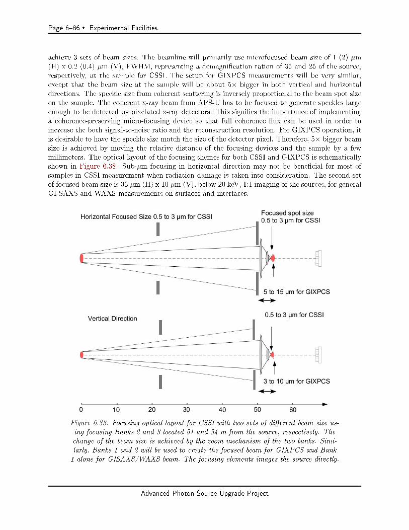
Page 686 Experimental Facilities
achieve 3 sets of beam sizes. The beamline will primarily use microfocused beam size of 1 (2) µm(H) x 0.2 (0.4) µm (V), FWHM, representing a demagnication ration of 35 and 25 of the source,respectively, at the sample for CSSI. The setup for GIXPCS measurements will be very similar,except that the beam size at the sample will be about 5× bigger in both vertical and horizontaldirections. The speckle size from coherent scattering is inversely proportional to the beam spot sizeon the sample. The coherent x-ray beam from APS-U has to be focused to generate speckles largeenough to be detected by pixelated x-ray detectors. This signies the importance of implementinga coherence-preserving micro-focusing device so that full coherence ux can be used in order toincrease the both signal-to-noise ratio and the reconstruction resolution. For GIXPCS operation, itis desirable to have the speckle size match the size of the detector pixel. Therefore, 5× bigger beamsize is achieved by moving the relative distance of the focusing devices and the sample by a fewmillimeters. The optical layout of the focusing themes for both CSSI and GIXPCS is schematicallyshown in Figure 6.38. Sub-µm focusing in horizontal direction may not be benecial for most ofsamples in CSSI measurement when radiation damage is taken into consideration. The second setof focused beam size is 35 µm (H) x 10 µm (V), below 20 keV, 1:1 imaging of the sources, for generalGI-SAXS and WAXS measurements on surfaces and interfaces.
Figure 6.38. Focusing optical layout for CSSI with two sets of dierent beam size us-ing focusing Banks 2 and 3 located 51 and 54 m from the source, respectively. Thechange of the beam size is achieved by the zoom mechanism of the two banks. Simi-larly, Banks 1 and 2 will be used to create the focused beam for GIXPCS and Bank1 alone for GISAXS/WAXS beam. The focusing elements images the source directly.
Advanced Photon Source Upgrade Project
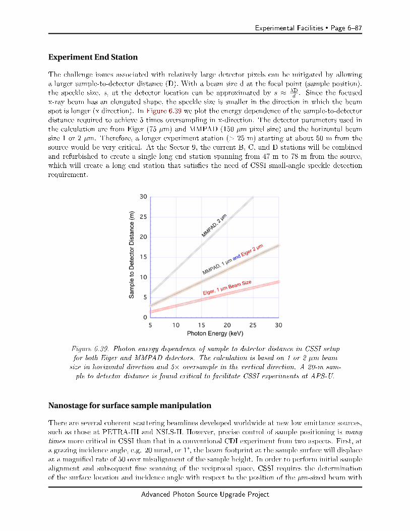
Experimental Facilities Page 687
Experiment End Station
The challenge issues associated with relatively large detector pixels can be mitigated by allowinga larger sample-to-detector distance (D). With a beam size d at the focal point (sample position),the speckle size, s, at the detector location can be approximated by s ≈ λD
d . Since the focusedx-ray beam has an elongated shape, the speckle size is smaller in the direction in which the beamspot is longer (x direction). In Figure 6.39 we plot the energy dependence of the sample-to-detectordistance required to achieve 5 times oversampling in x-direction. The detector parameters used inthe calculation are from Eiger (75 µm) and MMPAD (150 µm pixel size) and the horizontal beamsize 1 or 2 µm. Therefore, a longer experiment station (> 25 m) starting at about 50 m from thesource would be very critical. At the Sector 9, the current B, C, and D stations will be combinedand refurbished to create a single long end station spanning from 47 m to 78 m from the source,which will create a long end station that satises the need of CSSI small-angle speckle detectionrequirement.
Figure 6.39. Photon energy dependence of sample-to-detector distance in CSSI setupfor both Eiger and MMPAD detectors. The calculation is based on 1 or 2 µm beamsize in horizontal direction and 5× oversample in the vertical direction. A 20-m sam-ple to detector distance is found critical to facilitate CSSI experiments at APS-U.
Nanostage for surface sample manipulation
There are several coherent scattering beamlines developed worldwide at new low-emittance sources,such as those at PETRA-III and NSLS-II. However, precise control of sample positioning is manytimes more critical in CSSI than that in a conventional CDI experiment from two aspects. First, ata grazing incidence angle, e.g. 20 mrad, or 1°, the beam footprint at the sample surface will displaceat a magnied rate of 50 over misalignment of the sample height. In order to perform initial samplealignment and subsequent ne scanning of the reciprocal space, CSSI requires the determinationof the surface location and incidence angle with respect to the position of the µm-sized beam with
Advanced Photon Source Upgrade Project

Page 688 Experimental Facilities
precision of < 50 nm and < 1 µrad, respectively. Second, thermal drift and acoustic/mechanical vi-brations, especially for in-situ sample conditions where samples are manipulated in thermal, solventor in-operando environments, need to be minimized to within tolerance required by the resolution.Leveraged by the resources from a current strategic LDRD project, a prototype high-vacuum com-patible sample nano-positioning system (Figure 6.40) has been designed, fabricated, and assembled.It will soon be commissioned at the APS beamline 8-ID-E. The sample position is controlled byclose-loop feedback systems with all the motors to achieve a position reproducibility of 50 nm. Thespecications are presented in Table 6.19. The design of the stage will be rened to use a laserinterferometry system to provide a real-time positional feedback. The iteration of this nanostagewill be part of the beamline development tasks.
Figure 6.40. Design of prototype CSSI nanostage (left) and assem-bled vacuum compatible nanostage (right) without the `coarse' phi stage.
Table 6.19. Design specications of the APS Z7-4101 compact rotary exure stage
Z7-4101 compact rotary exure stage
Overall dimensions (mm) 144 (L) x 106 (W) x 34 (H)(with open-loop coarse driver)
Overall dimensions (mm) 149 (L) x 149 (W) x 34 (H)(with closed-loop coarse driver)
Normal load capacity (kg) 0.5Coarse driver type PicomotorTM linear actuatorCoarse driver encoder type Optical grating sensorFine driver type PI 841.10V PZT actuatorFine driver encoder type Strain gage sensorRotary stage encoder type Optical grating sensor or
Laser interferometerCoarse angular travel range (degree) 12Fine angular travel range (degree/mrad) 0.011/200Coarse min. incremental (nrad) 400Fine min. incremental (nrad) 2Laser interferometer resolution (nrad) 10Vacuum compatibility UHV Flexure mechanism
HV linear actuators
Advanced Photon Source Upgrade Project
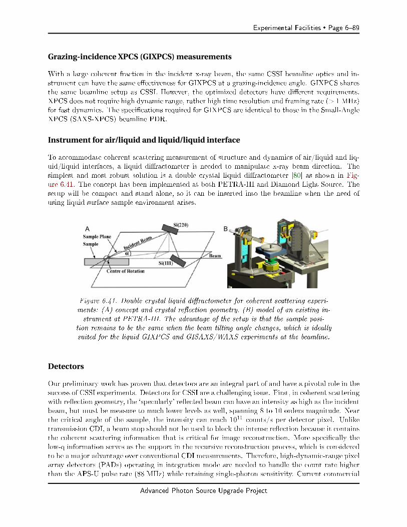
Experimental Facilities Page 689
Grazing-incidence XPCS (GIXPCS) measurements
With a large coherent fraction in the incident x-ray beam, the same CSSI beamline optics and in-strument can have the same eectiveness for GIXPCS at a grazing-incidence angle. GIXPCS sharesthe same beamline setup as CSSI. However, the optimized detectors have dierent requirements.XPCS does not require high dynamic range, rather high time resolution and framing rate (> 1 MHz)for fast dynamics. The specications required for GIXPCS are identical to those in the Small-AngleXPCS (SAXS-XPCS) beamline PDR.
Instrument for air/liquid and liquid/liquid interface
To accommodate coherent scattering measurement of structure and dynamics of air/liquid and liq-uid/liquid interfaces, a liquid diractometer is needed to manipulate x-ray beam direction. Thesimplest and most robust solution is a double crystal liquid diractometer [80] as shown in Fig-ure 6.41. The concept has been implemented at both PETRA-III and Diamond Light Source. Thesetup will be compact and stand alone, so it can be inserted into the beamline when the need ofusing liquid surface sample environment arises.
Figure 6.41. Double crystal liquid diractometer for coherent scattering experi-ments: (A) concept and crystal reection geometry, (B) model of an existing in-strument at PETRA-III. The advantage of the setup is that the sample posi-
tion remains to be the same when the beam tilting angle changes, which is ideallysuited for the liquid GIXPCS and GISAXS/WAXS experiments at the beamline.
Detectors
Our preliminary work has proven that detectors are an integral part of and have a pivotal role in thesuccess of CSSI experiments. Detectors for CSSI are a challenging issue. First, in coherent scatteringwith reection geometry, the `specularly' reected beam can have an intensity as high as the incidentbeam, but must be measure to much lower levels as well, spanning 8 to 10 orders magnitude. Nearthe critical angle of the sample, the intensity can reach 1011 counts/s per detector pixel. Unliketransmission CDI, a beam stop should not be used to block the intense reection because it containsthe coherent scattering information that is critical for image reconstruction. More specically thelow-q information serves as the support in the recursive reconstruction process, which is consideredto be a major advantage over conventional CDI measurements. Therefore, high-dynamic-range pixelarray detectors (PADs) operating in integration mode are needed to handle the count rate higherthan the APS-U pulse rate (88 MHz) while retaining single-photon sensitivity. Current commercial
Advanced Photon Source Upgrade Project
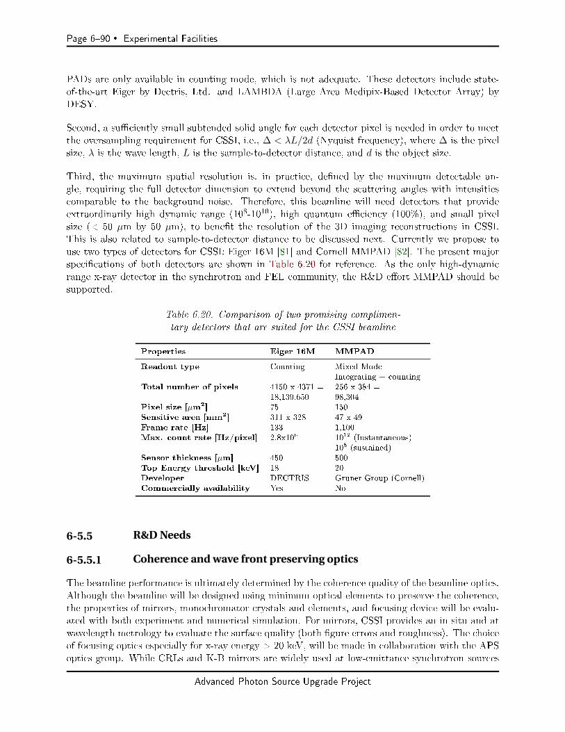
Page 690 Experimental Facilities
PADs are only available in counting mode, which is not adequate. These detectors include state-of-the-art Eiger by Dectris, Ltd. and LAMBDA (Large Area Medipix-Based Detector Array) byDESY.
Second, a suciently small subtended solid angle for each detector pixel is needed in order to meetthe oversampling requirement for CSSI, i.e., ∆ < λL/2d (Nyquist frequency), where ∆ is the pixelsize, λ is the wave length, L is the sample-to-detector distance, and d is the object size.
Third, the maximum spatial resolution is, in practice, dened by the maximum detectable an-gle, requiring the full detector dimension to extend beyond the scattering angles with intensitiescomparable to the background noise. Therefore, this beamline will need detectors that provideextraordinarily high dynamic range (108-1010), high quantum eciency (100%), and small pixelsize (< 50 µm by 50 µm), to benet the resolution of the 3D imaging reconstructions in CSSI.This is also related to sample-to-detector distance to be discussed next. Currently we propose touse two types of detectors for CSSI: Eiger 16M [81] and Cornell MMPAD [82]. The present majorspecications of both detectors are shown in Table 6.20 for reference. As the only high-dynamicrange x-ray detector in the synchrotron and FEL community, the R&D eort MMPAD should besupported.
Table 6.20. Comparison of two promising complimen-tary detectors that are suited for the CSSI beamline
Properties Eiger 16M MMPAD
Readout type Counting Mixed ModeIntegrating + counting
Total number of pixels 4150 x 4371 = 256 x 384 =18,139,650 98,304
Pixel size [µm2] 75 150Sensitive area [mm2] 311 x 328 47 x 49Frame rate [Hz] 133 1,100Max. count rate [Hz/pixel] 2.8x10⁶ 1012 (Instantaneous)
108 (sustained)Sensor thickness [µm] 450 500Top Energy threshold [keV] 18 20Developer DECTRIS Gruner Group (Cornell)Commercially availability Yes No
6-5.5 R&D Needs
6-5.5.1 Coherence and wave front preserving optics
The beamline performance is ultimately determined by the coherence quality of the beamline optics.Although the beamline will be designed using minimum optical elements to preserve the coherence,the properties of mirrors, monochromator crystals and elements, and focusing device will be evalu-ated with both experiment and numerical simulation. For mirrors, CSSI provides an in situ and atwavelength metrology to evaluate the surface quality (both gure errors and roughness). The choiceof focusing optics especially for x-ray energy > 20 keV, will be made in collaboration with the APSoptics group. While CRLs and K-B mirrors are widely used at low-emittance synchrotron sources
Advanced Photon Source Upgrade Project
Experimental Facilities Page 691
such as PETRA-III and NSLS-II, single-crystal Si based KLs have large numerical apertures andare suitable for high-energy applications. The potential of KLs [83] as wave front preserving opticswill be explored.
6-5.5.2 Improving CSSI experiment methods
In grazing-incidence geometry, the transverse coherence length is greatly enlarged as the footprintof the x-ray beam on the sample may reach centimeter scale; however, the detectable q range forthe incident direction (X) gets geometrically decreased correspondingly. This results in a muchpoorer image resolution as compared with the other two directions (Y and Z in Figure 6.42A). Theanisotropic spatial resolutions thereby limit the application of CSI technique in studying sampleswith symmetric dimensions along X and Y directions. In order to solve this problem, we proposed tocollect a series of scattering patterns of the sample at dierent in-plane rotation angles (azimuthaldirection, φ). In such a way, as shown in Figure 6.42B the combined reciprocal data containssucient oversampling rate for reconstructing the ne structure of the sample with high resolutionsin all in-plane directions. Even a rotation of several degrees can improve the resolution by an orderof magnitude. A systematic scatter simulation has been performed to demonstrate the eect inFigure 6.42C-E, where (simulated) data taken at several rotation angles (6 and 18) were used toreconstruct the surface pattern. The improved resolution is readily seen. Experiments have beendesigned to prove the `tomographic' concept and to illustrate the eectiveness of the rotation. Againat PETRA-III, we collected the coherent scattering data from a more complex sample (Figure 6.42Ginset) at a small angular range (±3°, Figure 6.31G-I). The reconstruction using the data set will beperformed to reveal the quantitative eect. In the future experiments, the rotation will be done in amuch larger range. Currently, the range is limited by the poor precision of the sample stage, whichwill be resolved by a nano-positioning and rotation stage shown in Figure 6.40. The tomographiclike experiment will ultimately benet from the upgraded APS because of much improved datacollection eciency. The result will be a homogenized high-resolution imaging reconstruction in allthree dimensions.
6-5.5.3 Developing Advanced Coherent Surface Scattering Reconstruction MethodIncorporating Dynamical Scattering Theory
The reconstruction of the images in real space requires phase retrieval to complement the x-rayscattering intensity measurement using partially coherent beam. However, all image-recovery al-gorithms thus far have used the kinematic theory, assuming that the scattering from the samplesis weak (Born approximation). With the assumption, the reconstruction is only a mathematicalprocess involving recursive fast Fourier transform (FFT) and inverse FFT (FFT-1). These algo-rithms cannot be simply applied to the CSSI cases where the weak scattering assumption is notsatised at grazing angles. There has not been reconstruction algorithm developed for handlingcoherent scattering data taken in this unique but powerful way. Therefore, to prepare for the dawnof the new era of CSSI at upgraded APS source while taking advantage of exascale computingcapabilities in Argonne, we are in a unique position to develop the computationally intensive andphysics-based reconstruction technique for the rst time. In grazing-incident condition when CSSIapplies, dynamical scattering contain multiple-beam scattering and can be dominating in total ex-ternal reection regime. By take full advantage of the dynamical scattering characteristics, theapplication of distorted wave Born approximation (DWBA) in this regime can revealed enormous
Advanced Photon Source Upgrade Project

Page 692 Experimental Facilities
Figure 6.42. Concept and simulation of coherent scattering data collected at dierent azimuthalangles: A) scattering geometry, B) improvement of spatial resolution along X direction with
angular tomography, C-F) eect of number of viewing angles on reconstruction resolution, G-I)experimental data in a small (±3°) viewing angle range collected at P10 beamline of PETRA-IIIusing a vertically focused x-ray beam (SEM image of the surface pattern is shown in the inset.
Advanced Photon Source Upgrade Project
Experimental Facilities Page 693
amount 3D structural information of the surface/interface patterns with a coherent x-ray beam.Here, we hypothesize that the dynamical scattering data collected with coherent x-rays can be usedfor solving surface structures with unprecedented 3D spatial resolution. To test this hypothesis,our specic objectives are to develop a novel reconstruction method (possible genetic algorithm,GA) that incorporates DWBA framework and is far more eective for surface scattering imagingthan the conventional reconstruction algorithm illustrated. In the meantime, we predict that therobustness of the reconstruction algorithm will be enhanced due to incorporation of multi-beamdynamical scattering theory in the DWBA framework. Undoubtedly, the implementation of thenew reconstruction requires Argonne's HPC power with optimized algorithm through collaborationbetween x-ray scientists at the APS and HPC experts at ALCF. The reconstruction algorithmsrequire modifying the conventional phase retrieval algorithm. proposed here is a genetic algorithm(GA) that takes advantages of genetic selection of parallel processing to yield fast converging results.As shown in Figure 6.43, the GA algorithm will consist of two nesting loops: (A) iteration loop ofprocessing individual scattering images that is nested inside of (B) GA loop with selections rules togenerate real 3D pattern. This type of GA approach may be proven ecient not only for CSSI butalso for conventional CDI reconstruction.
Advanced Photon Source Upgrade Project

Page 694 Experimental Facilities
Figure 6.43. Genetic algorithm for reconstructing CSSI data: (A) inner iteration loopsthat are similar to conventional CDI phase retrieval and reconstruction algorithm togenerate complex qz-depending complex real-space distribution P j (r). The reconstruc-tion is done by iterative Fourier transform of images in both real and reciprocal spaces.These loops are nested in (B) GA loops with selection rules that optimize the sam-
ple pattern ρ (r) from a set of P j (r) obtained from Ij taken at various incident angles.
Advanced Photon Source Upgrade Project
Experimental Facilities Page 695
6-6 High-Energy X-Ray Microscope (HEXM) Beamline
The High-Energy X-Ray Microscope (HEXM) will be a long beamline located at APS-20-ID. Op-erating in the monochromatic 35120 keV range and also being white-beam capable, it will receiveradiation from a superconducting undulator (SCU) source. HEXM will consist of an A station,or rst-optics-enclosure (FOE), at 30 m from the source, and two experimental end-stationsa Bstation at 70 m (within the main experimental oor) and a C station at 180 m (in an external build-ing). The external building will be shared with another long APS-U beamline (In-Situ Nanoprobe[ISN] at 19-ID).
6-6.1 Executive Summary
HEXM will investigate micro-structure and evolution within bulk materials, often in extreme en-vironments, using enhanced high-energy x-ray scattering techniques used today (e.g., at beamline1-ID) and new coherence techniques, all enabled by the low-emittance APS-U multi-bend-achromat(MBA) lattice. High-energy x-rays interact with matter with low attenuation, small scattering an-gles (giving large reciprocal space access), and the validity of the single-scattering approximation.These features, when combined with a brilliant source like the APS-U at high energies, make suchx-rays the scattering probe of choice for interrogating bulk material structure. Such a combinationof penetration capability with high spatial, reciprocal-space, and temporal resolution, enables thesex-rays to measure phase, texture, and strain distributions non-destructively under complex sampleenvironments.
These principles will be implemented by combining the low-emittance MBA lattice, an SCU source,and a long beamline with a large end-station, as conceptually shown in Figure 6.44 (to scale inFigure 6.55). The high-energy x-rays (35120 keV) will be applied through multiple techniques, suchas high-energy diraction microscopy (HEDM), wide- and small-angle scattering (WAXS/SAXS),micro-tomography (µ-CT), scattering tomography (ST), transmission x-ray microscopy (TXM), andBragg coherent diraction imaging (BCDI)available at the same sample location (C station) toprobe length scales covering many orders of magnitude. Materials subjected to these techniqueswould be of relevance to mechanical engineering, biophysics, irradiation/nuclear energy, energystorage, and advanced manufacturing (see HEXM science case in Chapter 3).
The primary experimental station (C) will be 20 m in length, with samples and environments locatedat 180 m distance from the source. The long beamline will enable:
Focusing down to small spot sizes at convenient working distances. Ecient performance of expansion optics when large beams in one or both dimensions areneeded (e.g., near-eld-HEDM, µ-CT).
Producing relatively large, coherent focal spots (tens of µm for BCDI) through low source-demagnication or magnication geometries.
Furthermore, the long end-station enables distances greater than 15 m between the sample andsome detectors to optimize direct or reciprocal space resolutions in certain techniques (very-far-eld-HEDM, BCDI, SAXS, TXM). Finally, being away from the main APS experimental hall,the external building that houses the C station will be compatible with unique facilities like insitu irradiation with an ion source (XMAT initiative, Sections 6-6.2.1 and 6-6.4.8) and activated
Advanced Photon Source Upgrade Project
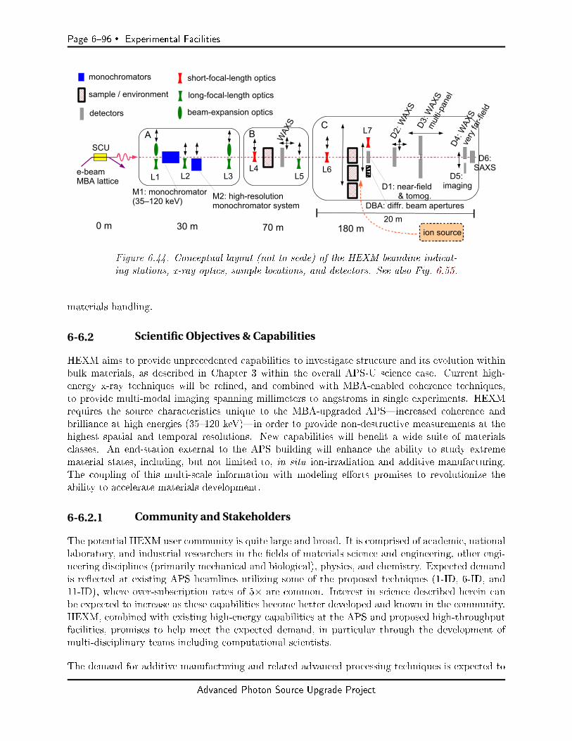
Page 696 Experimental Facilities
Figure 6.44. Conceptual layout (not to scale) of the HEXM beamline indicat-ing stations, x-ray optics, sample locations, and detectors. See also Fig. 6.55.
materials handling.
6-6.2 Scientific Objectives & Capabilities
HEXM aims to provide unprecedented capabilities to investigate structure and its evolution withinbulk materials, as described in Chapter 3 within the overall APS-U science case. Current high-energy x-ray techniques will be rened, and combined with MBA-enabled coherence techniques,to provide multi-modal imaging spanning millimeters to angstroms in single experiments. HEXMrequires the source characteristics unique to the MBA-upgraded APSincreased coherence andbrilliance at high energies (35120 keV)in order to provide non-destructive measurements at thehighest spatial and temporal resolutions. New capabilities will benet a wide suite of materialsclasses. An end-station external to the APS building will enhance the ability to study extremematerial states, including, but not limited to, in situ ion-irradiation and additive manufacturing.The coupling of this multi-scale information with modeling eorts promises to revolutionize theability to accelerate materials development.
6-6.2.1 Community and Stakeholders
The potential HEXM user community is quite large and broad. It is comprised of academic, nationallaboratory, and industrial researchers in the elds of materials science and engineering, other engi-neering disciplines (primarily mechanical and biological), physics, and chemistry. Expected demandis reected at existing APS beamlines utilizing some of the proposed techniques (1-ID, 6-ID, and11-ID), where over-subscription rates of 5× are common. Interest in science described herein canbe expected to increase as these capabilities become better developed and known in the community.HEXM, combined with existing high-energy capabilities at the APS and proposed high-throughputfacilities, promises to help meet the expected demand, in particular through the development ofmulti-disciplinary teams including computational scientists.
The demand for additive manufacturing and related advanced processing techniques is expected to
Advanced Photon Source Upgrade Project
Experimental Facilities Page 697
grow steadily over the next decade. In real-world manufacturing processes, local variations in themicrostructure exist throughout components. Many models exist to predict these variations, butneed validation, and thus there are almost unlimited opportunities for using HEXM experimentsto validate new classes of models that address in situ processing. The non-destructive strain andmicro-structural mapping capabilities can also be used to verify post-manufacturing processes (e.g.,peening, case hardening) often applied industrially, but typically measured using layer-removaltechniques. Existing partners using APS in this area include Pratt & Whitney, Rolls-Royce, GE,GM, John Deere, and Caterpillar.
Grain mapping will be enhanced through HEXM and remain the premier non-destructive methodfor this purpose. Currently, there are over 1500 electron backscatter diraction (EBSD) systems inthe world that provide 2D grain mapping at surfaces. EBSD can be extended to 3D through serialsectioning (polishing or focused ion beams) which, however, is time consuming and destructive,making in situ measurements impossible. A signicant fraction of EBSD users are possible usersof HEXM. Thus there will be a high demand for emphex situ HEDM alone, particularly giventhe increase in spatial resolutions which will approach those of EBSD. These increased resolutionswill allow systems with ner grain sizes and more complex microstructures to be investigated,including those related to energy storage, (nano-)electronics and bio-materials, in addition to thelarger grained metals and ceramics mapped today. The ability to perform 4D (3D+ in situ response)characterization will remain unique and be a large portion of expected demand in this area.
The interest and demand of the nuclear materials community to use synchrotron x-rays to advancethese goals has grown rapidly in recent years. Opportunities are well documented in the BasicResearch Needs for Advanced Nuclear Energy Systems (DOE-BES 2006), and addressed in a seriesof workshops including Research Needs and Opportunities for Characterization of Activated Samplesat Neutron and X-Ray User Facilities (LANL 2009), Role of Synchrotron Radiation in SolvingScientic Challenges in Advanced Nuclear Energy Systems (ANL 2010), and Synchrotron X-RayStudies of Advanced Nuclear Energy Systems at NSLS-II (BNL 2011). The Argonne workshopconcluded that there is unanimous agreement that synchrotron studies hold enormous potential toanswer questions central to all aspects of nuclear energy production, from simulation validation, toquantifying materials problems, to environmental remediation.
HEXM is in a position to deliver goals of the XMAT concept/initiative (eXtreme MATerialsbeamline) [84], a strategic initiative within Argonne, to be a leader in developing next-generationradiation-tolerant materials and predictive capabilities, by integrating an ion source into an x-raybeamline. Funding for the ion source is being sought from three dierent agenciesNNSA, DOE-FES, and DOE-NE. Each agency has an important interest in the issues in radiation damage thatHEXM can address. Even without the ion source a signicant number of issues can be addressed byperforming HEXM techniques on post-irradiated (at ATLAS or other national facilities includingthe Advanced Test Reactor) samples. Interest by the NNSA in particular extends beyond the ionsource. Over the next few decades, the challenges implicit in remanufacturing and aging of thenuclear stockpile demand insight beyond the historical approach. Most notably, diagnostics areneeded at the length scales at which mechanisms of response occur, in addition to greater relianceon physical simulations at lower length scales. This work must also be directly coupled to the ques-tions raised at the device level. The NNSA has a compelling interest in collections of experimentswith direct observation of physical mechanisms over a wide variation of length scales and thus hasa strong interest in the success and development of the HEXM beamline.
Advanced Photon Source Upgrade Project
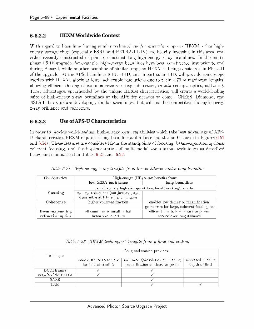
Page 698 Experimental Facilities
6-6.2.2 HEXM Worldwide Context
With regard to beamlines having similar technical and/or scientic scope as HEXM, other high-energy storage rings (especially ESRF and PETRA-III/IV) are heavily investing in this area, andeither recently constructed or plan to construct long high-energy x-ray beamlines. In the multi-phase ESRF upgrade, for example, high-energy beamlines have been constructed just prior to andduring Phase-I, while another beamline of similar scope to HEXM is being considered in Phase-IIof the upgrade. At the APS, beamlines 6-ID, 11-ID, and in particular 1-ID, will provide some scopeoverlap with HEXM, albeit at lower achievable resolutions due to their < 70 m maximum lengths,allowing ecient sharing of common resources (e.g., detectors, in situ set-ups, optics, software).These advantages, spearheaded by the unique HEXM characteristics, will create a world-leadingsuite of high-energy x-ray beamlines at the APS for decades to come. CHESS, Diamond, andNSLS-II have, or are developing, similar techniques, but will not be competitive for high-energyx-ray brilliance and coherence.
6-6.2.3 Use of APS-U Characteristics
In order to provide world-leading, high-energy x-ray capabilities which take best advantage of APS-U characteristics, HEXM requires a long beamline and a large end-station C shown in Figures 6.51and 6.54). These features are considered from the standpoints of focusing, beam-expansion options,coherent focusing, and the implementation of multi-modal zoom-in/out techniques as describedbelow and summarized in Tables 6.21 and 6.22.
Table 6.21. High-energy x-ray benets from low emittance and a long beamline
Consideration High-energy (HE) x-ray benets from:low MBA emittance long beamline
small spots / high demags at long focal (working) lengthsFocusing σy , σy′ reductions (not just σx , σx′)
discernible at HE, enhancing gains
Coherence higher coherent fraction enables low-demag or magnicationgeometries for large, coherent focal spots
Beam-expanding ecient due to small initial ecient due to low refractive powerrefractive optics beam size, aperture needed over long distance
Table 6.22. HEXM techniques' benets from a long end-station
Long end-station provides:Technique
more distance to achieve improved Q-resolution or imaging increased imagingfar-eld at small λ magnication on detector pixels depth of eld
BCDI fringes X XVery-far-eld HEDM X X
SAXS XTXM X X
Advanced Photon Source Upgrade Project
Experimental Facilities Page 699
Long Beamline with Low Emittance: High-Energy Focusing Optics
The emittance reduction from the MBA lattice is most dramatic in the horizontal plane, enhancingfocused beam production at all photon energies. However, the emittance reduction in the verticalplane is also substantial in the brightness mode (low-coupling, 324-bunch), having εy = 4.2 pmversus today's εy = 40 pm. High x-ray energies can benet from vertical emittance reduction to amore signicant degree than do lower energy x-rays. For the latter, the vertical beam divergencecan be dominated by an undulator's intrinsic radiation divergence σr′ ∝
√λ, so the reduction of
electron source divergence σy′ doesn't fully translate into more ux intercepted vertically by focusingoptics apertures. Vertical source size σy reduction also yields diminishing returns at low energiesdue to vertical focusing already being optics diraction limited. For high energies, the situation isvery dierent. The smaller σr′ broadening enhances photon capture within small focusing opticsapertures in both directions (assuming appropriate reductions are made in particle beam energyspread). Due to increased challenges of optics fabrication at high energies, focal lengths are relativelylong and vertical spot sizes are still source size limited. Therefore, high-energy focusing benetsfrom a smaller vertical source size as well. The APS-U brightness mode is most attractive in termsof pushing the limits of vertical focusing of high-energy x-rays. Also, the lower vertical divergenceat high energies combined with emittance reduction improves the eciency of narrow-angular-acceptance high-energy-resolution crystal monochromator systems to be employed.
The ability to obtain smaller spots at longer focal distances from the MBA emittance is furtherfacilitated by a long beamline, providing benets from various standpoints: optics fabrication,depth of focus, large working distance for complex sample environments and nearby hardware,and reduced beam divergence contribution to diraction resolution. With a focal length of 2 mat 180 m distance, assuming a 150 µm refractive lens aperture and ∆E/E = 10−3 energy spreadat 70 keV, the FWHM contributions to the vertical spot size are 100 nm, 150 nm, and 100 nm,from source demagnication, chromatic aberration, and diraction limit, respectively, which addin quadrature to 210 nm. With a combination of reduced focal length (e.g., 1 m), higher energyresolution (1.4×10⁻⁴ bandwidth), and larger aperture lenses (400 µm using kinoforms), sub-100 nmvertical focusing is achievable at such high energies, with respective contributions 50 nm, 60 nm,and 20 nm. KB mirrors, being achromatic, obviate the need for reducing bandwidth and couldoer similar focal spot sizes with higher ux, but at the expense of short working distances (< 0.3m) to permit slope errors of 0.050.1 rad (rms). For the reasons of sucient working distances toaccommodate complex sample environments and in-line focusing optics to facilitate multi-modaltechniques, HEXM places more emphasis on the refractive lens approach.
Long Beamline with Low Emittance: Expansion Optics
Although the low emittance oers higher spatial resolution capabilities, certain high-energy tech-niques benet from larger beams, in one or both directions. Standard tomography (µ-CT) is oneexample where a several-mm-wide beam is desired to match mm-level penetration depths for truebulk studies. Another example, the near-eld(nf)-HEDM method, uses a long line-focus beamprolefocused to a (sub-)micron size vertically, but (ideally) as large as 34 mm horizontallytodiract from a large number of grains within a polycrystalline material, one thin slice at a time.From large data sets of diraction exposures taken (by detector D1, Fig. 6.44) under sample rotationand ne vertical translation at multiple close detector distances (12 cm), one can reconstruct a 3Dgrain map with orientation (Fig. 6.45). A low-coupling MBA lattice, with a long beamline, would
Advanced Photon Source Upgrade Project

Page 6100 Experimental Facilities
clearly help the vertical focusing to 100 nm levels. However, even at 180 m distance, the horizontalbeam size is only ∼ 2 mm FWHM (brightness mode), driving consideration of beam-expandingoptics. Simulation shows that refractive lens beam expanders work best on long beamlines wherethe beam starts out very small. Closer to the source where the refractive expander is placed, thesmall starting beam size requires a small lens aperture. This, combined with the low refractionneeded in propagation over a long beamline, helps transmission eciency. Calculations show thatin the case of diamond refractive optics placed at 34 m (lenses L3), where the beam's horizontal sizeis 480 µm FWHM at 70 keV, one can easily expand it to 34 mm at 180 m with high eciency.
Figure 6.45. The nf-HEDM method collects diraction spots (center) from grains illuminatedby a line-focused beam under sample translations/rotations and at multiple distances (left).Signicant computation reconstructs grain maps with crystallographic orientation (right).
Multi-Scale Direct-Space Imaging at HEXM
In direct-space imaging, standard tomography with millimeters of eld of view would be facilitatedby a long beamline coupled with beam expansion optics (L3) as discussed above, with a broadbandpass beam expansion optics (L1) option giving the highest ux and temporal resolution. Thiswill permit tomographic data-sets at 1 µm resolution to be collected on the order of fractions ofseconds. Zoomed-in imaging would be achievable with a high-energy transmission x-ray microscope(TXM). Such a full-eld TXM, based on a refractive lens objective after the sample (L7 in Figure6.44), has already been demonstrated at 45 keV having 500 nm resolution, with the specimen,objective, and detector all tting within a 6 m length in the current APS 1-ID-E end-station [85].Having more sample-detector length (∼ 15 m to detector D5) in a new end-station would enable aTXM system with higher magnication, larger sample depth of eld, and detector pixel oversamplingto achieve 100 nm imaging resolution at high energies, with samples being positioned at the samelocation/environment for interrogation by other techniques in the C station. For samples in theB station, the interesting possibility of a very high-magnication TXM arises by using an x-rayobjective in the B station to image onto detector D5, with >100 m separation between them.
Multi-Scale Scattering-Based Imaging at HEXM
Although shorter wavelengths are always disadvantaged relative to longer wavelengths in termsof coherence, the APS-U source size reduction improves transverse coherence at all energies. Along beamline would exploit the increased coherence at high energies to pursue BCDI, currently
Advanced Photon Source Upgrade Project
Experimental Facilities Page 6101
conducted at low energies [86], to obtain a highly zoomed-in measurement of the internal strainelds and shapes of single grains buried within a bulk polycrystalline specimen, complementing therelatively zoomed-out HEDM measurements. Aside from the already discussed facilitation of highsource demagnication geometries, a long beamline also enables very low demagnication (or evensource magnication, geometries (e.g., by focusing with L5) needed to create relatively large focusedspots of tens of µm that can be made highly coherent by aperture selection at the focusing optics(more in Section 6-6.4.2). The low emittance on a long beamline facilitates the transverse coherenceat high energies for BCDI, and also the high-aspect-ratio line-focus for nf-HEDM due to goodvertical focusing and refractive beam expansion in the two orthogonal directions. Finally, increasedend-station length also allows detector D4 pixel oversampling of ne, far-eld BCDI fringes at highenergies and permits new approaches for placing refractive optics in diracted beams from singlegrains (L7 in Figure 6.44). One approach can provide very high-resolution imaging by implementingthe concept of TXM in diracted beams [87]. Another approach could help reciprocal-space imagingby adjusting the lensing not to image the grain, but instead to bring far-eld diraction patternsto the D4 detector plane (e.g., for very-far-eld(v)-HEDM [88] or BCDI).
In addition, the large sample-detector (D6) distance enabled by the long end-station, coupled withfocusing optics, allows access to smaller Qmin (larger dmax) using SAXS than possible today. Inparticular, at a minimum radius from the direct beam of 0.5 mm (achievable using long-lengthfocusing optics and a set of C station slits upstream of the sample for parasitic scattering) and 14 mdistance, we can access Qmin = 0.0007 [0.0014] Å−1 at 40 [80] keV with corresponding maximumobservable feature sizes of dmax = 868 [434] nm, representing a 6× higher range than possible todayat 1-ID-E. Of particular interest is that this range will, for the rst time, overlap with the directspace imaging from the TXM, allowing the same features (e.g., voids, nanoparticles) to be detectedin both reciprocal and direct space.
Choice of HEXM Beamline Length
The beamline length (source to C station sample location) was revised from 150 m to 180 m. Theoriginal length of 150 m, proposed in the HEXM white-paper and full-proposal documents, is abouttwice the maximum possible distance for an end-station within the regular APS experimental hall,and would permit sub-100 nm vertical focusing at 1-m working distances (in APS-U brightnessmode) due to source demagnication. Increasing the distance from the source yields diminishingreturns due to the spot size contributions from chromatic aberration and the optics diraction limit(although it would help in the case of the APS-U timing-mode lattice [high coupling, 48-bunch],having a larger vertical source size). Lengthening the beamline would also reduce the x-ray uxcaptured within the distant focusing optics aperture, more so in the less optimal timing mode, withits larger vertical beam size. The 150-m length was adequate to enable magnifying (in a focusinggeometry, e.g, using lenses L3 or L5) the small vertical source size (9 µm FWHM) to a few tens ofµm for BCDI. A distance of 150 m is also enough for a beam-expander (nf-HEDM application) toenlarge the horizontal beam size to 34 mm, although allowing more propagation distance wouldimprove upon the expander eciency. The reason for slightly increasing the planned distance from150 m to 180 m was to enable a single external building to house the distance end-stations of boththe long beamlines HEXM (20-ID) and ISN (19-ID), the latter desiring a length in the 220250 mrange.
Advanced Photon Source Upgrade Project

Page 6102 Experimental Facilities
6-6.3 Source and Front-End
6-6.3.1 Superconducting Undulator
The HEXM beamline's techniques and tunable x-ray energy range require a high-brilliance sourcecapable of covering the spectrum from 35 keV to beyond 100 keV. Optimal source performance atthese energies drives the selection of SCU device technology, which enables the achievement of highelds at short device periods, to provide full coverage of the desired energy range with the oddharmonics. An SCU candidate for this purpose would be a 1.65-cm-period device of approximately3.5 m magnetic length, operating at a xed 8.0-mm gap, with a maximum deection parameterKmax = 1.63, corresponding to a 1.06-T peak eld. Due to the added cryostat space requirementsof SCUs, a magnetic length of 3.5 m would be the most possible in the 5-m-long straight section.Furthermore, it would most likely be segmented, e.g., as 2× 1.75 m, requiring an adjustable delayfor keeping the segments properly phased. The spectral brilliance tuning curves of this proposedSCU-HEXM is shown in Figure 6.46 along with the current SCU1 and past permanent magnetundulators used at the 1-ID high-energy beamline. The SCU-HEXM (brightness mode) wouldoutperform the current SCU1 device by a factor of 530 in brilliance and a factor of 4.5 in totalux within the central cone. In ux density at the same distance it outperforms by about an orderof magnitude. Accounting for the distance change to 180 m (HEXM) from today's 70 m (1-ID),SCU-HEXM outperforms SCU1 by 1.5 in ux density.
Figure 6.46. Brilliance tuning curves of the proposed SCU-HEXM source (APS-U bright-ness mode, 200 mA) compared to various insertion devices (SCU1, U33, U23) that
are/have been used at APS 1-ID (100 mA). Device magnetic lengths and periods are given.
6-6.3.2 Front-End
The SCU-HEXM insertion device with parameters given here imposes a thermal load of 17.9 kW(total power) and 616 kW/mrad2 (power density) at the maximum eld. This is within the designlimits of the high-heat-load front-end.
Advanced Photon Source Upgrade Project
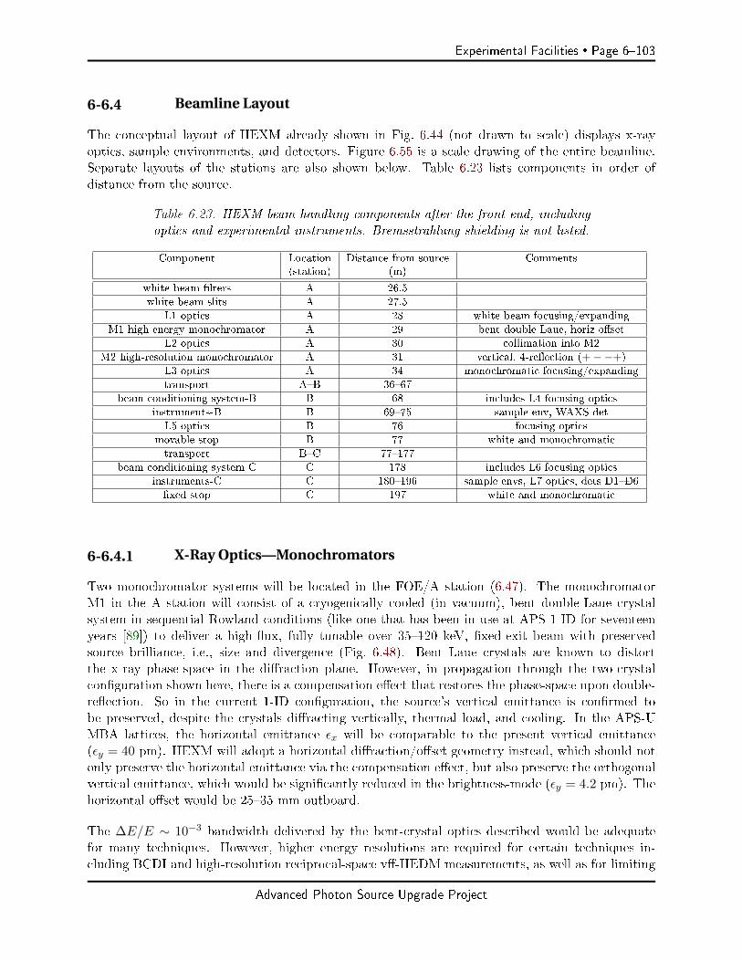
Experimental Facilities Page 6103
6-6.4 Beamline Layout
The conceptual layout of HEXM already shown in Fig. 6.44 (not drawn to scale) displays x-rayoptics, sample environments, and detectors. Figure 6.55 is a scale drawing of the entire beamline.Separate layouts of the stations are also shown below. Table 6.23 lists components in order ofdistance from the source.
Table 6.23. HEXM beam-handling components after the front-end, includingoptics and experimental instruments. Bremsstrahlung shielding is not listed.
Component Location Distance from source Comments(station) (m)
white beam lters A 26.5
white beam slits A 27.5
L1 optics A 28 white beam focusing/expanding
M1 high-energy monochromator A 29 bent double-Laue, horiz oset
L2 optics A 30 collimation into M2
M2 high-resolution monochromator A 31 vertical, 4-reection (+−−+)
L3 optics A 34 monochromatic focusing/expanding
transport AB 3667
beam conditioning system-B B 68 includes L4 focusing optics
instruments-B B 6975 sample env, WAXS det
L5 optics B 76 focusing optics
movable stop B 77 white and monochromatic
transport BC 77177
beam conditioning system-C C 178 includes L6 focusing optics
instruments-C C 180196 sample envs, L7 optics, dets D1D6
xed stop C 197 white and monochromatic
6-6.4.1 X-Ray Optics—Monochromators
Two monochromator systems will be located in the FOE/A station (6.47). The monochromatorM1 in the A station will consist of a cryogenically cooled (in vacuum), bent double-Laue crystalsystem in sequential Rowland conditions (like one that has been in use at APS 1-ID for seventeenyears [89]) to deliver a high-ux, fully tunable over 35120 keV, xed-exit beam with preservedsource brilliance, i.e., size and divergence (Fig. 6.48). Bent Laue crystals are known to distortthe x-ray phase-space in the diraction plane. However, in propagation through the two-crystalconguration shown here, there is a compensation eect that restores the phase-space upon double-reection. So in the current 1-ID conguration, the source's vertical emittance is conrmed tobe preserved, despite the crystals diracting vertically, thermal load, and cooling. In the APS-UMBA lattices, the horizontal emittance εx will be comparable to the present vertical emittance(εy = 40 pm). HEXM will adopt a horizontal diraction/oset geometry instead, which should notonly preserve the horizontal emittance via the compensation eect, but also preserve the orthogonalvertical emittance, which would be signicantly reduced in the brightness-mode (εy = 4.2 pm). Thehorizontal oset would be 2535 mm outboard.
The ∆E/E ∼ 10−3 bandwidth delivered by the bent-crystal optics described would be adequatefor many techniques. However, higher energy resolutions are required for certain techniques in-cluding BCDI and high-resolution reciprocal-space v-HEDM measurements, as well as for limiting
Advanced Photon Source Upgrade Project

Page 6104 Experimental Facilities
Figure 6.47. HEXM-FOE/A station
S1
S2
S3
Rowland circles,diameter ≈ 30 m
asym Si(111) bent Laue
divergence unaffected
springthick Sileaf
two thin walls for different energy ranges
Figure 6.48. Tunable, xed-exit monochromator (denoted as M1 in other lay-out sketches) consisting of two bent Laue crystals in nested Rowland condi-tions. Crystals are shown with small thinned regions that diract the x-rays.
chromatic aberration in nanofocusing. To meet such conditions, a high-resolution monochromatorsystem M2 in the A station, operating in air, would be available to optionally further reduce theenergy bandwidth down to 10−410−6 levels (Fig. 6.49). Such a system, whose performance im-proves with lower source emittance, has already been developed and utilized at 1-ID for many yearsand consists of four at Bragg Si crystal reections in a vertically diracting (+ − −+) dispersiveconguration [90]. Dierent crystal reections would be used, depending on the resolution required.Si(111) reections would provide ∆E/E ∼ 10−4. The highest energy resolution (10−510−6, from Sireections in the (444)(660) range) would meet stringent longitudinal coherence requirements forconducting BCDI on reasonably large sized 10 µm crystal grains. A vertically collimating lens L2placed in between the monochromators M1 and M2 would enhance the throughput of the narrow-angular-acceptance M2 system. If focusing is also required along with the narrower bandwidth,downstream focusing optics (L3L6) located in the A, B, or C stations could be used as well.
6-6.4.2 X-Ray Optics—Focusing and Beam-Expansion
Cooled refractive focusing lenses (L1) immediately upstream of the monochromator (in white beam)would deliver a focused high-ux pink beam (e.g., a full undulator harmonic of 0.6% bandwidth at70 keV) into the end-stations for low-Q-resolution (e.g., PDF/SAXS) experiments at the highest
Advanced Photon Source Upgrade Project

Experimental Facilities Page 6105
Figure 6.49. The beam from the bent Laue monochromator undergoing further bandwidthreduction using a four-reection high-energy-resolution monochromator (M2 in layouts).Refractive lenses (L2) positioned in between the monochromators collimate the x-rays.
ux. In the brightness mode, the FWHM spot sizes would be 50 × 15µm2 and 180 × 50µm2
in the B and C stations, respectively, with 45 times more ux than would be obtained with themonochromator. A separate set of lenses (also part of L1) could be alternatively used as white beamexpansion optics, to deliver beams on the order of several mm to the end-stations for direct-beamimaging applications. Recently there has been notable progress in single-crystal diamond compoundrefractive lens (CRL) fabrication, making them suitable candidates for such purposes, particularlyin view of the thermal load.
Figure 6.50. HEXM-B station.
Additional refractive lenses would also be placed in the A station. As already mentioned, one set(L2) placed between the primary and high-resolution monochromators would be used to collimatethe beam vertically into the narrow angular acceptance of the high-resolution at crystal reections.Another set (L3) at the downstream end of the FOE would provide long-focal-length focusing intothe B and C end-stations, or serve as beam expansion optics to deliver larger monochromatic beams(similar to the broadband case with L1) for imaging applications. On beam conditioning system(BCS) tables positioned at the upstream ends of both end-stations (Figs. 6.50, 6.51), short-focal-length focusing optics (L4, L6) would be available to focus x-rays to micron and sub-micron sizes,with sub-100 nm achievable vertically in the distant C station. The BCS tables in B and C stations
Advanced Photon Source Upgrade Project
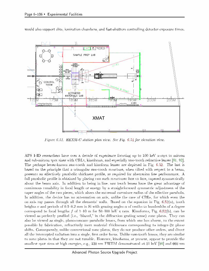
Page 6106 Experimental Facilities
would also support slits, ionization chambers, and fast-shutters controlling detector exposure times.
Figure 6.51. HEXM-C station plan view. See Fig. 6.54 for elevation view.
APS 1-ID researchers have over a decade of experience focusing up to 100 keV x-rays to micronand sub-micron spot sizes with CRLs, kinoforms, and especially saw-tooth refractive lenses [91, 92].The perhaps lesser-known saw-tooth and kinoform lenses are depicted in Fig. 6.52. The last isbased on the principle that a triangular saw-tooth structure, when tilted with respect to a beam,presents an eectively parabolic thickness prole, as required for aberration-free performance. Afull parabolic prole is obtained by placing two such structures face-to-face, tapered symmetricallyabout the beam axis. In addition to being in-line, saw-tooth lenses have the great advantage ofcontinuous tunability in focal length or energy by a straightforward symmetric adjustment of thetaper angles of the two pieces, which alters the extremal curvature radius of the eective parabola.In addition, the device has no attenuation on-axis, unlike the case of CRLs, for which even theon-axis ray passes through all the elements' walls. Based on the equation in Fig. 6.52(a), toothheights v and periods of 0.10.2 mm in Si with grazing angles α of tenths to hundredths of a degreecorrespond to focal lengths f of 110 m for 50100 keV x-rays. Kinoforms, Fig. 6.52(b), can beviewed as perfectly proled (i.e., blazed, in the diraction grating sense) zone plates. They canalso be viewed as single, plano-concave parabolic lenses, from which one has absent, to the extentpossible by fabrication, refractively inert material thicknesses corresponding to integer-2π phaseshifts. Consequently, unlike conventional zone plates, they do not produce other orders, and directall the intercepted radiation into a single, rst order focus. Unlike saw-tooth lenses, they are similarto zone plates in that they are not tunable. However, kinoforms, at present, appear to provide thesmallest spot sizes at high energies, e.g., 230 nm FWHM demonstrated at 51 keV [91] and 660 nm
Advanced Photon Source Upgrade Project
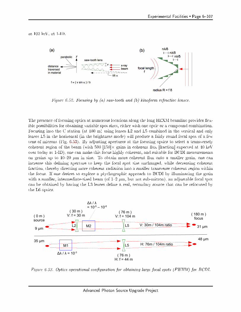
Experimental Facilities Page 6107
at 102 keV, at 1-ID.
Figure 6.52. Focusing by (a) saw-tooth and (b) kinoform refractive lenses.
The presence of focusing optics at numerous locations along the long HEXM beamline provides ex-ible possibilities for obtaining variable spot sizes, either with one optic or a compound combination.Focusing into the C station (at 180 m) using lenses L2 and L5 combined in the vertical and onlylenses L5 in the horizontal (in the brightness mode) will produce a fairly round focal spot of a fewtens of microns (Fig. 6.53). By adjusting apertures at the focusing optics to select a transverselycoherent region of the beam (with 500 [150]× gains in coherent ux [fraction] expected at 40 keVover today at 1-ID), one can make this focus highly coherent, and suitable for BCDI measurementson grains up to 1020 µm in size. To obtain more coherent ux onto a smaller grain, one canincrease this dening aperture to keep the focal spot size unchanged, while decreasing coherentfraction, thereby directing more coherent radiation into a smaller transverse coherent region withinthe focus. If one desires to explore a ptychographic approach to BCDI by illuminating the grainwith a smaller, intermediate-sized beam (of 12 µm, but not sub-micron), an adjustable focal spotcan be obtained by having the L3 lenses dene a real, secondary source that can be refocused bythe L6 optics.
Figure 6.53. Optics operational conguration for obtaining large focal spots (FWHM) for BCDI.
Advanced Photon Source Upgrade Project

Page 6108 Experimental Facilities
6-6.4.3 Filters and White Beam Slits
Emerging from the front-end, the beam will go though lters and white beam slits, in that order.The cooled lters will provide thermal load alleviation for the white beam slits, lenses L1 (whenused), and the monochromator M1.
6-6.4.4 Shutters and Stops
The front-end shutter will be capable of blocking the beam from entering the beamline, includingthe A station.
A multi-mode shutter/stop would be present at the downstream end of A. This component's statuscould be in one of two modes, white or monochromatic, with remote shuttering capability ineither mode. In white beam mode it shutters the white beam. In monochromatic mode it servesa white beam stop while shuttering the monochromatic beam.
A compact, cooled, movable stop would be integrated into monochromator M1 after the rst crystalto block the transmitted white beam. This stop is intended for downstream equipment protectionduring monochromatic operation, and would not be part of the radiation safety system (RSS) forpersonnel protection. The multi-mode shutter/stop in A would meet that purpose. However, ifthe white beam stop as part of the monochromator is designed to meet RSS standards with whitebeam shuttering capability, then the component at the downstream end of A would only need to bea monochromatic shutter. Another possibility is to relocate the multimode shutter/stop to placeit just after monochromator M1, dispensing with the need for the additional compact white beamstop.
A cooled, movable stop would be present at the downstream end of B. When open, it would letwhite and monochromatic beams pass. When closed, it would stop both beams. This arrangementpermits white and monochromatic beam experiments in either B or C, with personnel access to Cwhen any experiments with beam are ongoing in B. The previously discussed situation of focusinga full undulator harmonic using lenses L1 would require white beam operation of an end-station.One could also have the possibility of broadband short-focal-length focusing, e.g., using ellipticallybent multilayers.
At the downstream end of C, the nal component would be a cooled, xed stop for white andmonochromatic beams.
6-6.4.5 Transports, Windows, and Vacuum
Both experimental stations and evacuated beam transports (A-to-B and B-to-C) would have tobe white beam compatible. The long transport from B to C would be unsheltered. However, theISN beamline's long transport would be built on a fully enclosed/sheltered corridor for enablingpersonnel and equipment to transit between the main APS experimental hall and the externalbuilding.
Aside from the front-end, the HEXM beamline would consist of three vacuum sections. The rstwould extend from the font-end exit window up to and including the monochromator M1. The
Advanced Photon Source Upgrade Project
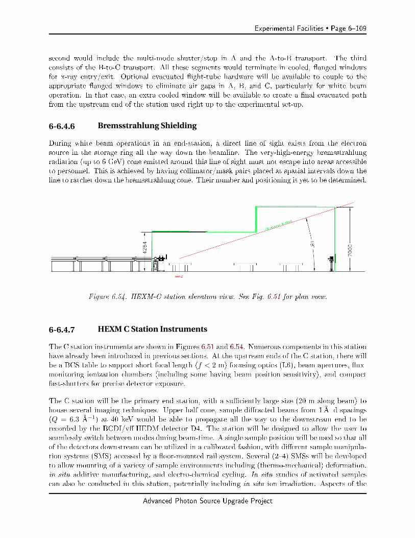
Experimental Facilities Page 6109
second would include the multi-mode shutter/stop in A and the A-to-B transport. The thirdconsists of the B-to-C transport. All these segments would terminate in cooled, anged windowsfor x-ray entry/exit. Optional evacuated ight-tube hardware will be available to couple to theappropriate anged windows to eliminate air gaps in A, B, and C, particularly for white beamoperation. In that case, an extra cooled window will be available to create a nal evacuated pathfrom the upstream end of the station used right up to the experimental set-up.
6-6.4.6 Bremsstrahlung Shielding
During white beam operations in an end-station, a direct line of sight exists from the electronsource in the storage ring all the way down the beamline. The very-high-energy bremsstrahlungradiation (up to 6 GeV) cone emitted around this line of sight must not escape into areas accessibleto personnel. This is achieved by having collimator/mask pairs placed at spatial intervals down theline to ratchet down the bremsstrahlung cone. Their number and positioning is yet to be determined.
Figure 6.54. HEXM-C station elevation view. See Fig. 6.51 for plan view.
6-6.4.7 HEXM C Station Instruments
The C station instruments are shown in Figures 6.51 and 6.54. Numerous components in this stationhave already been introduced in previous sections. At the upstream ends of the C station, there willbe a BCS table to support short-focal-length (f < 2 m) focusing optics (L6), beam apertures, ux-monitoring ionization chambers (including some having beam position sensitivity), and compactfast-shutters for precise detector exposure.
The C station will be the primary end-station, with a suciently large size (20 m along beam) tohouse several imaging techniques. Upper-half-cone, sample-diracted beams from 1Å d-spacings(Q = 6.3 Å−1) at 40 keV would be able to propagate all the way to the downstream end to berecorded by the BCDI/v-HEDM detector D4. The station will be designed to allow the user toseamlessly switch between modes during beam-time. A single sample position will be used so that allof the detectors downstream can be utilized in a calibrated fashion, with dierent sample manipula-tion systems (SMS) accessed by a oor-mounted rail system. Several (24) SMSs will be developedto allow mounting of a variety of sample environments including (thermo-mechanical) deformation,in situ additive manufacturing, and electro-chemical cycling. In situ studies of activated samplescan also be conducted in this station, potentially including in situ ion irradiation. Aspects of the
Advanced Photon Source Upgrade Project
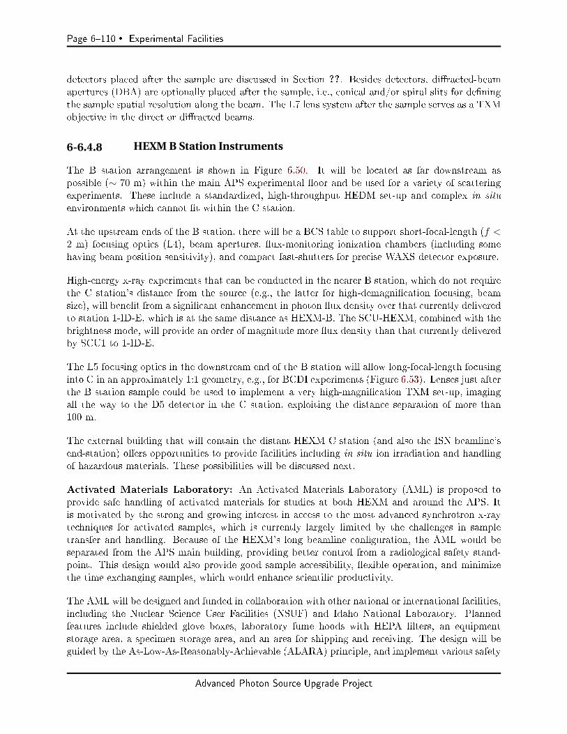
Page 6110 Experimental Facilities
detectors placed after the sample are discussed in Section ??. Besides detectors, diracted-beamapertures (DBA) are optionally placed after the sample, i.e., conical and/or spiral slits for deningthe sample spatial resolution along the beam. The L7 lens system after the sample serves as a TXMobjective in the direct or diracted beams.
6-6.4.8 HEXM B Station Instruments
The B station arrangement is shown in Figure 6.50. It will be located as far downstream aspossible (∼ 70 m) within the main APS experimental oor and be used for a variety of scatteringexperiments. These include a standardized, high-throughput HEDM set-up and complex in situenvironments which cannot t within the C station.
At the upstream ends of the B station, there will be a BCS table to support short-focal-length (f <2 m) focusing optics (L4), beam apertures, ux-monitoring ionization chambers (including somehaving beam position sensitivity), and compact fast-shutters for precise WAXS detector exposure.
High-energy x-ray experiments that can be conducted in the nearer B station, which do not requirethe C station's distance from the source (e.g., the latter for high-demagnication focusing, beamsize), will benet from a signicant enhancement in photon ux density over that currently deliveredto station 1-ID-E, which is at the same distance as HEXM-B. The SCU-HEXM, combined with thebrightness mode, will provide an order of magnitude more ux density than that currently deliveredby SCU1 to 1-ID-E.
The L5 focusing optics in the downstream end of the B station will allow long-focal-length focusinginto C in an approximately 1:1 geometry, e.g., for BCDI experiments (Figure 6.53). Lenses just afterthe B station sample could be used to implement a very high-magnication TXM set-up, imagingall the way to the D5 detector in the C station, exploiting the distance separation of more than100 m.
The external building that will contain the distant HEXM C station (and also the ISN beamline'send-station) oers opportunities to provide facilities including in situ ion irradiation and handlingof hazardous materials. These possibilities will be discussed next.
Activated Materials Laboratory: An Activated Materials Laboratory (AML) is proposed toprovide safe handling of activated materials for studies at both HEXM and around the APS. Itis motivated by the strong and growing interest in access to the most advanced synchrotron x-raytechniques for activated samples, which is currently largely limited by the challenges in sampletransfer and handling. Because of the HEXM's long beamline conguration, the AML would beseparated from the APS main building, providing better control from a radiological safety stand-point. This design would also provide good sample accessibility, exible operation, and minimizethe time exchanging samples, which would enhance scientic productivity.
The AML will be designed and funded in collaboration with other national or international facilities,including the Nuclear Science User Facilities (NSUF) and Idaho National Laboratory. Plannedfeatures include shielded glove boxes, laboratory fume hoods with HEPA lters, an equipmentstorage area, a specimen storage area, and an area for shipping and receiving. The design will beguided by the As-Low-As-Reasonably-Achievable (ALARA) principle, and implement various safety
Advanced Photon Source Upgrade Project
Experimental Facilities Page 6111
measures and engineering controls. The AML will allow sample handling and preparation in a fumehood or shielded glove boxes, e.g., mounting and remounting samples into sample holders, sampleloading into environmental chambers, and simple sample modication. Optical microscopy, thermaltreatment, experimental chamber pre-pumping, and fabrication of small-scale samples by SEM/FIBfor in situ ion irradiation experiments may also be conducted in the AML. A staging area will bedesigned to assist sample transfer to other beamlines around the APS. The specimen storage areawill provide users short-term storage options before and after the experiment. The proposed facilitywill work in conjunction with other radiological facilities at the laboratory for receiving, shipping,and more involved preparation work (e.g., cutting, polishing, etc.).
XMAT Ion Source: An MeV-per-nucleon ion accelerator (similar to the recently upgradedArgonne-ATLAS front end) would provide a unique radiation damage source whose damage depthis well matched to HEXM characterization depths. Ions would be steered into the C station usingapertures and focusing lenses to impinge on the sample with a variable size down to 10µm2 inthe vicinity of the x-ray beam. The design would also allow hundreds to thousands of samples toreceive preliminary doses before being moved into the C station for analysis. Thus even multi-yeardose rates can be accommodated, with users moving samples to the AML and/or HEXM stationfor periodic examinations. The ion source itself would require approximately 2030 m of space anda preliminary design has been produced by the ATLAS sta [84]. The conguration of the HEXMbeamline provides exibility for siting this source with respect to the C station, as shown in Figure6.51.
6-6.4.9 HEXM Beamline Stability
The APS-U electron beam stability specications are approximately one-tenth of the emittancesizes and divergences. In addition to this x-ray source contribution, other instability inuencesare mechanical and thermal in nature, depending on various elements in the beamline, includingoptics, samples, and detectors. As already mentioned, the current APS 1-ID bent double-Lauemonochromator (cryogenically cooled) preserves the APS vertical emittance, even while operatingin the vertical diraction geometry. This performance holds true in view of concerns from cryogeniccooling vibrations, as well as diraction eects in bent Laue crystals. Rotating the monochromatorto operate in the horizontal geometry in APS-U should therefore preserve the comparable horizontalemittance, and also the out-of-diraction-plane vertical emittance, from the standpoint of stability.
Experiments in the distant end-station C that employ a short focal distance are, in principle, notaected by overall rigid translations that impart the same displacement to both the focusing opticsand sample. However, thermal and vibrational eects on dierent sub-structures (separated by12 m working distances) may not be equal or in phase. For this reason, achieving 100 nm focusingwould require oor vibration below 20 nm (rms). A separate foundation of sucient thickness forthe external building housing the C station should help achieve such requirements, with additionalresults possible from an isolation-joint perimeter separating the C station oor from the rest of thebuilding. Temperature stability is also a concern, and could be addressed through nested zones oftighter tolerances, e.g., 0.5 C (peak-to-peak) in the building, and appropriately narrower marginsin the C station and a possible enclosure surrounding the BCS table and sample.
Beam position stability in long focal length congurations where the focusing optics and sample arein separated stations (e.g., A-to-C or B-to-C focusing) can pose a challenge due to the long lever
Advanced Photon Source Upgrade Project
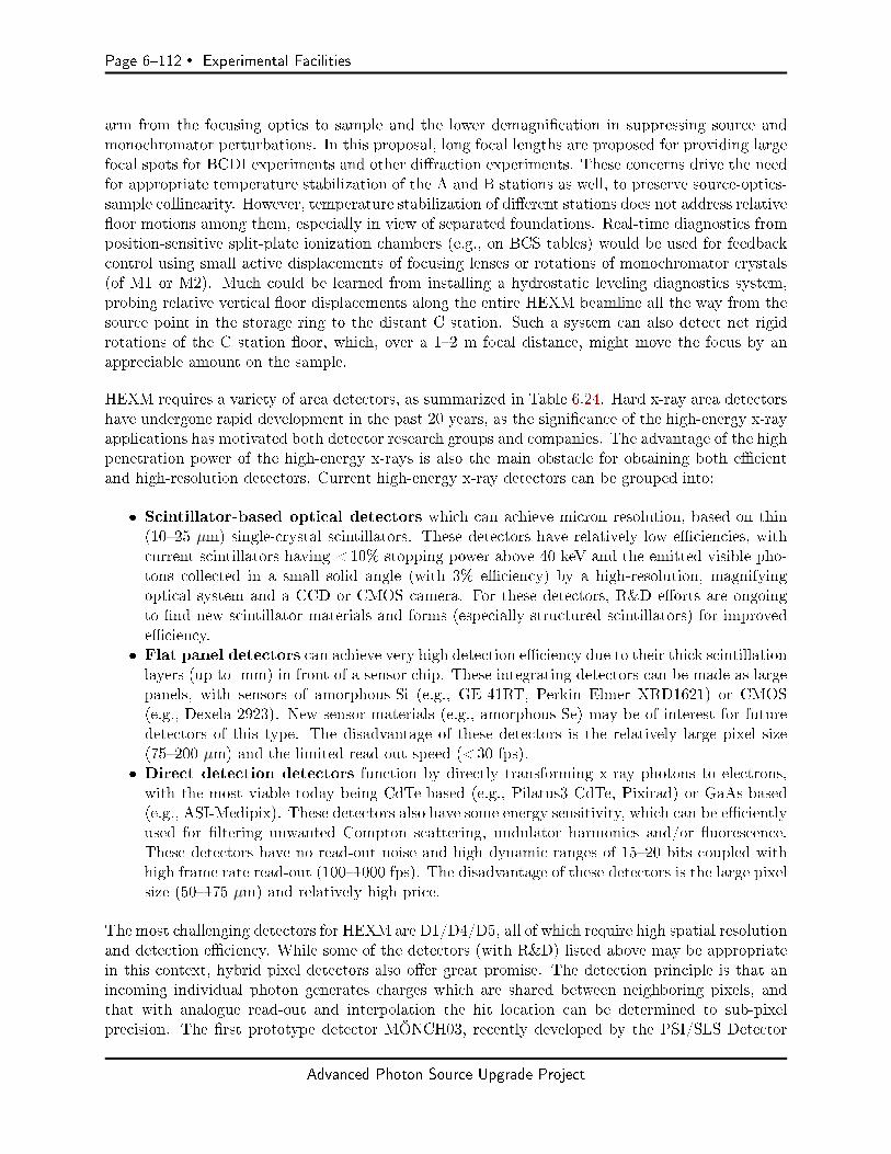
Page 6112 Experimental Facilities
arm from the focusing optics to sample and the lower demagnication in suppressing source andmonochromator perturbations. In this proposal, long focal lengths are proposed for providing largefocal spots for BCDI experiments and other diraction experiments. These concerns drive the needfor appropriate temperature stabilization of the A and B stations as well, to preserve source-optics-sample collinearity. However, temperature stabilization of dierent stations does not address relativeoor motions among them, especially in view of separated foundations. Real-time diagnostics fromposition-sensitive split-plate ionization chambers (e.g., on BCS tables) would be used for feedbackcontrol using small active displacements of focusing lenses or rotations of monochromator crystals(of M1 or M2). Much could be learned from installing a hydrostatic leveling diagnostics system,probing relative vertical oor displacements along the entire HEXM beamline all the way from thesource point in the storage ring to the distant C station. Such a system can also detect net rigidrotations of the C station oor, which, over a 12 m focal distance, might move the focus by anappreciable amount on the sample.
HEXM requires a variety of area detectors, as summarized in Table 6.24. Hard x-ray area detectorshave undergone rapid development in the past 20 years, as the signicance of the high-energy x-rayapplications has motivated both detector research groups and companies. The advantage of the highpenetration power of the high-energy x-rays is also the main obstacle for obtaining both ecientand high-resolution detectors. Current high-energy x-ray detectors can be grouped into:
Scintillator-based optical detectors which can achieve micron resolution, based on thin(1025 µm) single-crystal scintillators. These detectors have relatively low eciencies, withcurrent scintillators having <10% stopping power above 40 keV and the emitted visible pho-tons collected in a small solid angle (with 3% eciency) by a high-resolution, magnifyingoptical system and a CCD or CMOS camera. For these detectors, R&D eorts are ongoingto nd new scintillator materials and forms (especially structured scintillators) for improvedeciency.
Flat panel detectors can achieve very high detection eciency due to their thick scintillationlayers (up to mm) in front of a sensor chip. These integrating detectors can be made as largepanels, with sensors of amorphous-Si (e.g., GE-41RT, Perkin Elmer XRD1621) or CMOS(e.g., Dexela 2923). New sensor materials (e.g., amorphous-Se) may be of interest for futuredetectors of this type. The disadvantage of these detectors is the relatively large pixel size(75200 µm) and the limited read-out speed (< 30 fps).
Direct detection detectors function by directly transforming x-ray photons to electrons,with the most viable today being CdTe-based (e.g., Pilatus3 CdTe, Pixirad) or GaAs-based(e.g., ASI-Medipix). These detectors also have some energy sensitivity, which can be ecientlyused for ltering unwanted Compton scattering, undulator harmonics and/or uorescence.These detectors have no read-out noise and high dynamic ranges of 1520 bits coupled withhigh frame rate read-out (1001000 fps). The disadvantage of these detectors is the large pixelsize (50175 µm) and relatively high price.
The most challenging detectors for HEXM are D1/D4/D5, all of which require high spatial resolutionand detection eciency. While some of the detectors (with R&D) listed above may be appropriatein this context, hybrid pixel detectors also oer great promise. The detection principle is that anincoming individual photon generates charges which are shared between neighboring pixels, andthat with analogue read-out and interpolation the hit location can be determined to sub-pixelprecision. The rst prototype detector MÖNCH03, recently developed by the PSI/SLS Detector
Advanced Photon Source Upgrade Project

Experimental Facilities Page 6113
Table 6.24. Current and anticipated detector per-formance parameters relevant to HEXM techniques
Detector Technique Current Anticipated
D1, D5 µ-CT, nf-HEDM, TXM LuAG:Ce scintillator + mirror R&D needed for ≤ 1µm+ microscope (in-house design) resolution at higher eciency
D2, D3 WAXS/-HEDM Dexela 2923, 4× GE-41RT Pilatus 6M, Dexela/GEequivalents, high dynamic range
D4 BCDI/v-HEDM none R&D needed for ≤ 5µmresolution at high eciency,
high dynamic range
D6 SAXS Pixirad Pixirad or equivalent
Group, has achieved ∼ 1µm resolution with 25-µm-size pixels in an 400× 400 array and was testedup to 55 keV, thus being of great interest for HEXM applications. Another new type of detector isthe so-called mixed-mode pixel array detector (MM-PAD), developed by Cornell University, whichis combining the analog integration with counter-based detection in each pixel, and is also availablein a CdTe-based version. This detector is unique with its high frame-rate (1000 Hz) that does notsacrice dynamic range (a trade-o disadvantage of other detectors), making it very valuable fordynamic, time-resolved studies. A prototype has been tested at APS-1-ID and commercializationof this detector is ongoing. In summary, considering the APS-U timeline, these detectors currentlyunder development have a very good chance of being commercially available by the start of theupgrade implementation phase.
6-6.4.10 Computing
Several computing requirements need to be addressed to make best use of the high-volume datagenerated by HEXM. Data rates are expected to be about 100 times higher than the current ratesat 1-ID due to the enhanced brilliance and expected gains in detector technology. In addition,users increasingly wish to attain real-time data analysis, such that experimenters can better steerexperimental strategy, such as modifying the level of applied load prior to crack initiation. Keyelements to meet these challenges include stable data acquisition systems, reliable software, andappropriate storage, network, and computing resources. For some existing experimental techniquessuch as WAXS/SAXS and µ-CT imaging, 1-ID is at the cusp of real-time data analysis today. ForHEDM, the infrastructure necessary for real-time data analysis is being built in collaboration withinternal and external partners. In the case of -HEDM, for example, interrogating a 3D slice ofa polycrystalline aggregate takes approximately 10 minutes and yields approximately 1560 GBof data today. The analysis of this dataset typically takes approximately ve minutes to severaltens of minutes on the moderately sized APS cluster Orthros, depending on the micro-mechanicalstate of the aggregate and the resulting diraction patterns. While this is an acceptable time framefor a more static process such as monotonic loading, improvement is necessary to study dynamicprocesses such as crack initiation during cyclic loading of a structural alloy or material degradationdue to electro-chemical cycling of batteries.
Simply deploying a larger cluster will not necessarily resolve the computational needs. Real-timedata analysis means that large network and computing resources are utilized in burststhese re-sources are idle when the dataset is being collected but the full capacity is needed once the datacollection is completed. To meet the computational requirements in a more economically sound
Advanced Photon Source Upgrade Project
Page 6114 Experimental Facilities
way, several avenues will be considered. The rst is taking advantage of computational capabili-ties of graphical processing units, which can deliver large computational resources without a hugeinvestment. The second is working with computational workow experts to optimize the analysisprocedures so that computing resources like the Argonne Leadership Computing Facility can beutilized eectively.
To best utilize the zoomed-in modes of TXM and BCDI, data-sets from the complementary zoom-out modes (standard µ-CT and HEDM, respectively) need to be rapidly analyzed and visualized sothat an interesting sub-volume can be chosen more intelligently. Tools utilizing general-purposevisualization packages like ParaView or VisIt, as well as specialized packages like Dream3D, will bedeveloped in collaboration with both Argonne and external partners.
Finally, data storage and archiving must be adequately addressed. For example, a full, in situ-HEDM dataset is typically on the order of several tens of TB today. As mentioned earlier in thesection, this is expected to be at least two orders of magnitude larger after the APS-U. Multi-modal,zoomed-in/out capabilities will make these datasets even larger. Ecient and secure data storagesolutions that can be accessed by computing resources for analysis and discovery, while maintainingthe integrity and provenance of the data, are vital. One promising avenue towards this goal is thedata management pilot program (run by Scientic Software Engineering and Data ManagementGroup within the APS X-Ray Science Division) which has been deployed at the 1-ID beamline.
6-6.5 R&D Needs
Previous sections listed key infrastructure components for the HEXM beamline, several of which(detectors, stability, and computing) will benet from R&D eorts. Below, two additional areas arepointed out, focusing optics and BCDI approaches, for which R&D is warranted so that they canhave the highest impact.
6-6.5.1 High-Energy X-Ray Focusing
For reasons of larger working distances and operating in an in-line geometry, HEXM considerationslean more towards refractive lenses, mainly saw-tooth lenses and kinoforms for the short focaldistances (12 m in B and C stations). Saw-tooth lenses oer straightforward, continuous tunability,whereas kinoforms appear to oer the smallest focal spot sizes. Eorts in improving the performanceof both these types of lenses are intended to realize the full capabilities of the low-emittance APS-Usource and long beamline.
Currently, saw-tooth lenses routinely used at 1-ID focus vertically down to slightly over 1µm inthe 5090 keV range. Simulations show that improvements in the periodic saw-tooth prole qualityshould achieve 700 nm focusing. Pushing the focusing down to a few 100 nm would likely requirecorrecting for a so-called length aberration by imposing bending or having a tooth period gradient.These high-energy focusing eorts are being supported by funding from the DOE-BES Acceleratorand Detector Research (ADR) Program, whose scope was expanded to include x-ray optics.
Kinoforms have already demonstrated sub-micron focusing at 1-ID in collaboration with NSLS-IIand LANL. Further kinoform development eorts will be directed towards improved fabrication forachieving larger spatial apertures and smaller spot sizes. This further development is also supported
Advanced Photon Source Upgrade Project

Experimental Facilities Page 6115
by ADR funding.
There are eorts by a few researchers worldwide on diamond CRL fabrication. This is of interestto HEXM in implementing ecient beam expansion optics (L3) and white beam focusing (L1).
6-6.5.2 Bragg Coherent Diffraction Imaging
Currently available HEDM techniques are capable of mapping intra-granular crystallographic orien-tation changes with approximately 1µm spatial resolution and 0.01 in angular resolution. However,intragranular strain tensor elds cannot be retrievedonly the grain-average strain tensor can bedetermined. The coherent diraction imaging program at the APS has demonstrated (at lowerenergies with nano-sized grains) that with appropriate data collection strategies and reconstructionalgorithms, the intra-granular orientation changes and strain tensor eld, as well as the shape of acrystal of interest, can be determined [86]. With the APS-U and the long HEXM beamline thatcan deliver stable and coherent beams at higher energies, BCDI is a natural avenue that can deliveradditional information at smaller length scales (down to tens of nm).
HEXM aims to have the capability to conduct BCDI measurements on crystal grains of ∼ 10µmin bulk by making such measurements at 40 keV. Challenges in achieving this in the combinedparameter space of large grains and high energy include: high-resolution monochromatization(∆E/E ∼ 10−410−6) to meet longitudinal coherence requirements, and the angular compression ofreciprocal space features with respect to the diracted wave-vector. The latter entails two eectsthe increased Ewald sphere radius and the reduction in crystal-size interference fringes, therebydriving the need for a long end-station and high-spatial resolution detectors with high eciencyand dynamic range. Several groups have demonstrated that undersampled 3D diraction prolescan be treated by providing additional constraints on the reconstruction algorithms [93, 94]. Over-coming diraction prole undersampling can be addressed by denser sampling in angular (or energy)stepping, interrogation of multiple reections for the same grain, sub-pixel detector displacements,ptychographic approaches to generate larger fringe spacings, and use of nf-HEDM-provided grainshape as a constraint for the BCDI reconstruction. All these considerations are the subject of ahigh-energy x-ray BCDI feasibility study being pursued by a collaboration among Argonne-XSD,MSD, and MCS researchers, funded by an Argonne Laboratory-Directed Research and Development(LDRD) Program.
Advanced Photon Source Upgrade Project
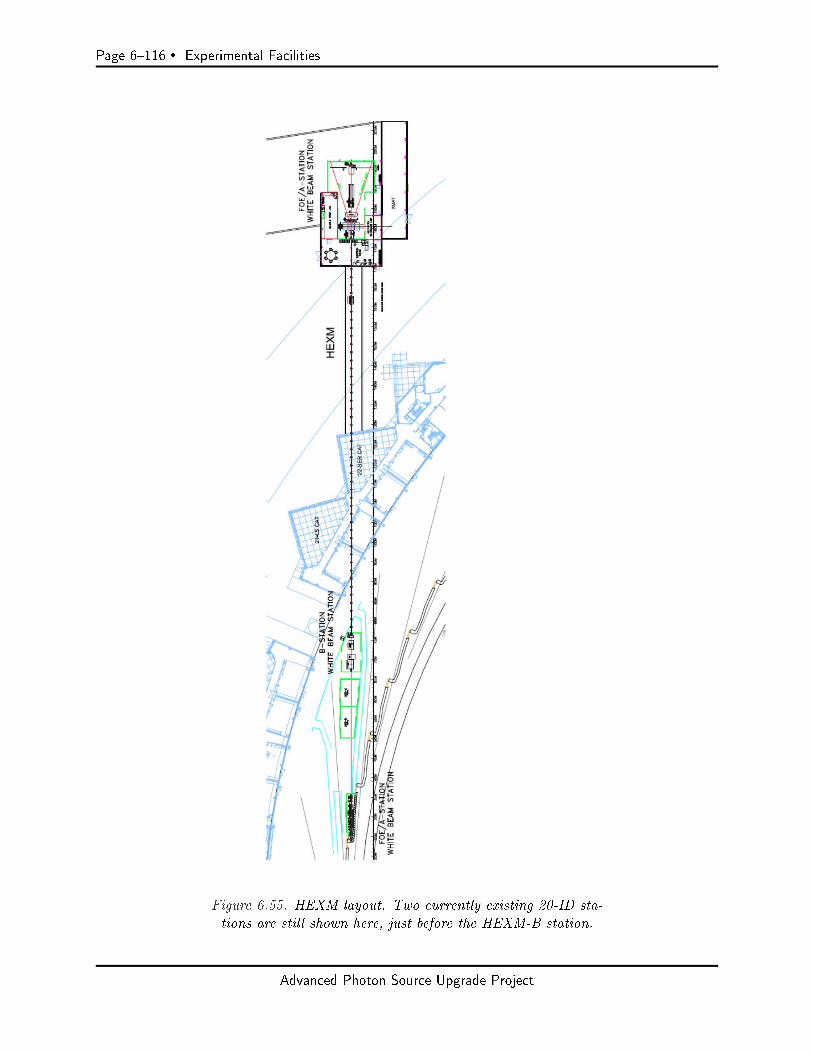
Page 6116 Experimental Facilities
Figure 6.55. HEXM layout. Two currently existing 20-ID sta-tions are still shown here, just before the HEXM-B station.
Advanced Photon Source Upgrade Project
Experimental Facilities Page 6117
6-7 In Situ Nanoprobe Beamline
6-7.1 Executive Summary
The In Situ Nanoprobe (ISN) will utilize the massive increase in coherent ux in the hard x-rayrange at APS-U to provide transformative imaging and spectroscopy capabilities for in situ studiesof complex multiscale materials and systems in varying environments, at very high spatial reso-lution, and with close to atomic sensitivity. This capability will enable entirely new microscopicstudies of materials as diverse as catalysts, batteries, photovoltaic systems, nano-electronics, andearth and environmental systems, under a broad range of conditions, such as during synthesis andduring operation. These systems have in common heterogeneity at length scales from nanometersto macroscopic scales, complex compositional, chemical and structural features, functional unitsand sites, and high sensitivity to often multiple external environments such as temperature, gaseousenvironment, acidity, and external elds. The ISN will focus the coherent ux provided by theMBA lattice into a focal spot of 20 nm, enabling rapid, multidimensional imaging across manylength scales, and combining x-ray uorescence imaging and spectroscopy with coherent methods toachieve sub-10 nm spatial resolution and close to atomic sensitivity. The combination of brillianceincrease and instrument design enables an increase in focused ux by 3 to 5 orders of magnitude com-pared to current nanofocusing capabilities, enabling very fast data acquisition across many lengthscales, and fast imaging of responses to changes in environmental parameters. Coupled with broadin situ capabilities and long working distance, this enables paradigm-shifting new understandingof functional materials and systems, and contributes to inspiring and conceiving new materials,materials systems, and approaches required to address some of the current and future challenges inenergy and sustainability.
6-7.2 Scientific Objectives & Capabilities
6-7.2.1 Science Case for the Beamline
The Upgrade of the Advanced Photon Source with an MBA magnetic lattice, APS-U, will providemassively increased coherent x-ray ux in the hard x-ray range, and 20x reduced source size in thehorizontal dimension, making it ideally suited to bring to bear coherent methods to a broad rangeof questions from materials and condensed matter science to chemical science and environmentalscience. Both nanofocusing approaches and coherence-based techniques benet directly from thehigh brilliance and new source geometry, by (i) achieving diraction limited spot sizes of 20 nm andbelow, (ii) massively increased speed of data acquisition, which in turn enables multiscale imagingof complex systems, and (iii) enabling high time resolution for the study of dynamic processes, suchas defect formation and growth, and uctuations. At the same time, the brilliance gain at highphoton energies signicantly enhances the essential capabilities of hard x-rays to penetrate gases,uids, windows, and matrices, enabling very high spatial resolution imaging and nanospectroscopyunder in situ conditions, and access to K and L absorption edges of most elements in the periodicsystem.
The In Situ Nanoprobe (ISN) exploits the transformative capabilities of APS-U by focusing coherenthard x-rays into a focal spot 20 nm in size, and uses coherent techniques to achieve a spatial reso-lution down to a few nanometers. The ISN allows probing of structure, composition, and chemistryof complex, multi-scale materials in 2D and 3D, with close to atomic sensitivity. The high coherent
Advanced Photon Source Upgrade Project

Page 6118 Experimental Facilities
ux allows imaging of heterogeneous samples with nanoscale features across many length scales,enabling, for example, study of the evolution of an individual defect inside a material with macro-scopic dimensions. The ISN uses x-rays with photon energies between 4.8 and 30 keV, enablingquantitative nano-spectroscopy at the K and L edges of transition metals and rare Earth metals,as well as penetration through environments and windows, and into materials to sites where activeprocesses are taking place. To enable the study of materials under actual synthesis and operatingconditions, the ISN will provide a very large working distance of 55 mm. This enables deploy-ment of a large range of in situ environments, namely low, high, and variable temperatures, owof gases and uids, varying pH, high pressure, and application of external elds. It also providesadded exibility to integrate advanced detectors, such as emission spectrometers. The scienticfocus of the ISN beamline is the investigation of complex, functional materials, and materials sys-tems, such as catalysts, batteries, photovoltaic systems, nanoscale earth and environmental samplesduring synthesis, operation, and under actual environmental conditions. The ISN is designed tostudy these systems across many lengths scales, under in situ conditions, using x-ray uorescence(XRF) for composition and trace contaminants, XRF nano-spectroscopy for local composition andchemical state, X-ray induced current[95] and voltage (XBIC/XBIV)[96], and X-ray excited opticalluminescence (XEOL)[97] for electronic properties, and coherent methods such as ptychography forstructural imaging and coherent diraction to study slow dynamics.
A typical example of the kind of science the ISN will perform is the characterization of defects andtheir evolution under changing external conditions in photovoltaic materials. In these systems, aswell as in many other materials, small local defects, such as contaminants or structural defects, canaect the macroscopic materials and systems response and properties. Examples include organic[98] and inorganic PV materials [99], and advanced thin-lm materials with tunable properties. De-fects and inhomogeneities that aect overall device eciency can occur at grain boundaries, insideof grains, or at interfaces, and can be distributed over macroscopic dimensions. The ISN will beable to quantitatively characterize the composition and chemical state of individual defects, andmap their distribution across macroscopic scales, with close to atomic sensitivity. These studieswill be performed under change of temperature and/or ow of gases, to understand the evolution ofindividual defects and their distribution. Compositional/structural measurements will be coupledwith measurements of local electronic properties, providing pixel-by-pixel correlation between localmaterials properties and the local electronic response. Very fast mapping in 2D and 3D enablesseveral qualitatively new scientic problems to be addressed: (1) Some of the most exciting novelmaterials in photovoltaics, hybrid organic-inorganic perovskites, are also very susceptible to beamdamage [100]; fast and ecient scanning, with total radiation dose comparable or even lower thanwith current approaches, will enable synchrotron-based compositional studies of these materials atthe nanoscale. (2) Fast scanning with varying spatial resolution enables correlative microscopy,bridging the length scales of nano-XRF to lab-scale mapping and imaging techniques with microm-eter to millimeter sizes. (3) Fast scanning enables multi modal studies to be conducted undernon-repeatable conditions, such as in situ conditions.
The ISN will be capable of elucidating defect formation and evolution in energy materials in re-sponse to heating, cooling, electrical stimulation, light bias, and interaction with various gases. Thiscan lead to new insights into defect engineering to improve process parameters or performance. Forexample, synthesis of chalcogenides thin lms such as Cu(In, Ga)Se2 (CIGS) can be studied un-der ow of H2Se over CIG under temperature change, or under ow of H2S over a CIG thin lmcovered with a capping thin selenium layer, allowing direct observation of the formation of CIGS
Advanced Photon Source Upgrade Project
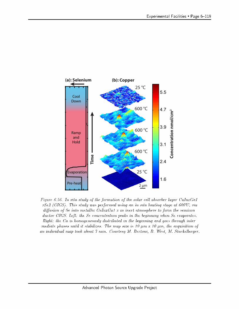
Experimental Facilities Page 6119
25 °C
600 °C
600 °C
600 °C
600 °C
600 °C
25 °C
2 µm
(b): Copper
1.6
2.4
3.1
3.9
4.7
5.5
Conc
entr
atio
n nm
ol/c
m2
(a): Selenium
RampandHold
Pre-heat
Evaporation
CoolDown
Tim
e
Figure 6.56. In situ study of the formation of the solar cell absorber layer CuInxGa1-xSe2 (CIGS). This study was performed using an in situ heating stage at 600, viadiusion of Se into metallic CuInxGa1-x in inert atmosphere to form the semicon-ductor CIGS. Left: the Se concentration peaks in the beginning when Se evaporates.Right: the Cu is homogeneously distributed in the beginning and goes through inter-mediate phases until it stabilizes. The map size is 10 µm x 10 µm, the acquisition ofan individual map took about 7 min. Courtesy M. Bertoni, B. West, M. Stuckelberger.
Advanced Photon Source Upgrade Project
Page 6120 Experimental Facilities
and associated defect evolution (Figure 6.56)[101, 102]. Knowledge of defect reactions can serveas inputs and validation of kinetic process simulations, accelerating the pace of materials opti-mization and industrial scale-up.[103] The intrinsic multimodal approach to imaging with the ISNwill provide qualitatively new understanding of local materials properties, by combining composi-tion (XRF), structure (XRD), local defects (coherent scattering), time performance (XBIC) andbandgap (XEOL), with correlation of local properties at the individual pixel level.
6-7.2.2 Description of user community/stakeholders
The ISN scientic community encompasses both existing users of synchrotron x-ray imaging capa-bilities at the APS and other laboratories, as well as new communities. Many existing users havetaken advantage of APS microprobes and nanoprobes, and, in the process, have communicated avariety of needs to better understand their materials systems, and to reduce the often long dataacquisition times. Specically, they require much faster data acquisition, signicantly increasedelemental sensitivity, smaller spot sizes to access smaller sample regions, and, in particular, in situcapabilities such as heating/cooling and/or ow of gases, applied elds, and high pressure. As im-portant as a wide variety and combination of in situ environments there is an ever-increasing needfor fast data acquisition in 2D and 3D, and in particular fast acquisition under changing in situconditions. Enabling collection of 3D data with very high resolution and elemental sensitivity whilechanging several independent experimental parameters, such as temperature and process gas, hasbeen a continuously rising but yet unmet demand. New users, such as users of electron microscopy,optical microscopy or of non-focusing x-ray beamlines, are used to a broad variety of in situ capa-bilities, often commercially available, and take them for granted. As such, providing broad in-situcapabilities with nanoscale resolution and sensitivity at the APS will open new user communities.
The Buonassisi and the Bertoni groups have for many years performed x-ray characterization oninorganic solar materials, using microprobe, nanoprobe and microspectroscopy capabilities, in aneort to understand and manipulate performance-limiting defects at ever smaller lengths scales toachieve improved solar materials eciency. Both groups have invested in initial in situ capabilitiesat 2-ID-D. The range of in situ capabilities at high spatial resolution will enable the study ofdefects under realistic growth and processing conditions, enabling the development of strategiesto improve performance of low-cost and/or high-performance materials. Users studying polymericsolar materials have, to a signicant degree, used nanospectroscopy in the soft x-ray range to obtainthe chemical state of block-copolymers and other materials; study of the eect of metal impurities ina polymer matrix at small length scales has to date rarely been performed, and will open up a newcommunity. New users or users with new programs of interest, such as David Fenning, bring in newmaterials or materials systems. Nanoelectronics require a multitude of characterization techniques.Conal Murry represents a broader community of industrial researchers that study approaches toenhance future technology nodes, and develop materials capable of handling some of the fundamentalmaterials issues related to the very small scale of next-generation transistors. With increasing 3Dcharacteristics of future electronics devices and relevant lengths scales of 20 nm and below, with CDIproviding a path towards nanometer resolution, the ISN facility is expected to serve both existingusers from industry and academia, and attract new users from the community. The theme ofChemistry and Catalysis taps into a new user community that has, to date, used mostly incoherenttechniques and microprobe-based spectroscopy. There is signicant experience using scattering anddiraction-based methods to study catalysts or chemistry. The potential to perform spectroscopy atlength scales below 50 nm is unique and powerful, and the combination of spectroscopy with high-
Advanced Photon Source Upgrade Project
Experimental Facilities Page 6121
resolution structural imaging via ptychography and auxiliary XRD contrast opens new ways to look,in particular, at catalysts. Both Argonne sta scientists, such as Randy Winans (XSD) and DavidTiede (CSE), and experienced external users, such as Simon Bare, represent large communitiesof academic and industrial scientists that could become major users of the ISN facility. The E3
community has traditionally relied on microprobe studies, particularly spectroscopy. Opening anew length scale, as exemplied by Tony Lanzirotti, for example will attract a community that isinterested in micro- and nanoscale complex systems, such as marine and terrestrial microorganismsand microbes at interfaces with soil and gases. Aside from fundamental interest in understandingmarine and terrestrial microorganisms in their complex environment, there is the opportunity todevelop technologies for use of subsurface reservoirs as primary targets for carbon capture andsequestration, and for new energy production technologies. At the same time, there is potentialto reduce impacts related to unintentional release of contaminants to the environment, and inunderstanding the global cycling of elements that are drivers for climatic change. With nanoscale 3Dimaging, and spectroscopy under established in situ conditions established, we anticipate signicantgrowth of this community.
6-7.2.3 Use of APS-U characteristics
The ISN beamline will make use of two aspects of the MBA Upgrade: the coherence gain and thereduced horizontal emittance of the x-ray source. The coherence gain allows both diraction-limitedfocusing to a very small spot, and use of coherent techniques.
Use of coherence: nanofocusing and gain in focused flux
1) The ISN depends on diraction-limited focusing to achieve the smallest possible focal spot size.Given that only the coherent part of the undulator beam will be used for diraction-limitedfocusing, the massive increase in coherent ux delivered by the MBA lattice will directlyincrease the focused ux of the ISN.
2) The ISN requires high photon energy to penetrate environments and windows to access buriedmaterials structures and interfaces. Therefore, the ISN takes particular advantage of theincrease of coherent ux for higher photon energies. The design of the ISN source calls for arevolver undulator with two dierent magnetic structures, one of which (with period 2.3 cm)is aimed at further increasing the coherent ux at high photon energies.
3) By virtue of using non-chromatic nanofocusing mirrors as high-resolution optics, the ISN willbe able to use the full undulator bandwidth of 1% for elemental mapping, yielding anotherfactor of approximately 25x in focused ux.
4) The high reectivity of mirrors provides 10x increase in focusing eciency over diractiveoptics at 10 keV, and of 100x at 30 keV.
5) Overall, the ISN design maximizes the coherent ux that can be obtained from the MBAlattice. It yields a focused ux gain of 103 x to 104 x over existing nanoprobes for spectroscopyapplications with a bandwidth of 0.01%, and a total ux gain of 104x to 105 x for elementalmapping and ptychography, with a bandwidth of 1%.
Advanced Photon Source Upgrade Project
Page 6122 Experimental Facilities
Use of coherence: coherent techniques
The diraction-limited nanofocus is intrinsically coherent. Therefore, coherent techniques suchas ptychography can be performed. Ptychography will be done on a routine basis with everytransparent sample. This will yield a factor of 5x to 10x improvement in spatial resolution beyondthe spot size, enabling sensitivity to nanoscale structures. Ptychography yields both the aperturefunction of the nanofocusing optic and the sample amplitude and phase. As such, measured XRFmaps can be deconvolved with the aperture function of the optics, providing an increase of ∼ 2x inthe spatial resolution of elemental maps, to ∼ 10 nm.
Status of ISN beamline, domestically and internationally
The ISN beamline will be the leading hard x-ray nanoprobe in the U.S., based on the small spotsize in the hard x-ray range (only surpassed by the HXN beamline at NSLSL-II), the massivefocused ux, which is superior to other US facilities by orders of magnitude, and, in particular,by the long working distance it provides for in situ x-ray microscopy. The combination of workingdistance, focused ux, and spatial resolution is unmatched in the US, and positions the ISN asone of the leading or possibly the leading hard x-ray nanoprobe beamline worldwide. Internationalcompetitors are at the ESRF, SOLEIL, DIAMOND, PETRA III, and MAXLAB. The NI branchof NINA at the ESRF achieves ∼15 nm spatial resolution at two select energies (17 keV, 33.6 keV)via use of nanofocusing multilayer mirrors. The NA branch achieves 50 nm resolution, at photonenergies between 5 and 70 keV. NANOSCOPIUM at SOLEIL delivers a spatial resolution of 50 nmand is limited by the brilliance of a 3rd generation synchrotron, and the low electron energy of thestorage ring. The HX Nanoprobe at the 3rd generation DIAMOND ring aims at 10 nm resolution.NanoMAX, which aims at a spot size of 10 nm, and is powered by a 4th generation SR source, willbe a main competitor in regard to spatial resolution (10 nm), and in the lower part of the energyrange (5 30 keV). It will not provide the working distance and in situ capabilities of the ISN,and is limited in brilliance at high photon energy. It is worth noting that all of these beamlines arelonger than 90 m, with NI at ESRF and HX at DIAMOND being 185 m long, NanoMAX being 94m long, and ESRF-NA as well as NANOSCOPIUM being 165 m and 160 m long, respectively.
6-7.2.4 Key beamline characteristics
The ISN beamline will use hard x-rays with photon energies between 4.8 keV and 30 keV. This willprovide access to absorption edges of most elements in the periodic system, including the Ti Kαedge at the lower end of the energy range, I Kα at the high end of the energy range, and the L edgesof the rare earth elements and heavy elements such as Pb and Bi. In addition, the penetration ofx-rays into matter increases with photon energy, allowing study of samples in environmental cellswith windows, and in gases and uids.
The design of the ISN beamline is based on a spatial lter, with intermediate focusing on a beamdening aperture (BDA), which in turn denes a secondary x-ray source. All beamline optics,namely two focusing mirrors, a crystal monochromator and a multilayer monochromator, are posi-tioned upstream of the BDA. Thus, any wavefront deterioration or instability caused by the beam-line optics will be ltered out at the BDA, which in turn denes a coherent source that enablesdiraction-limited focusing by the nanofocusing optics.
Advanced Photon Source Upgrade Project
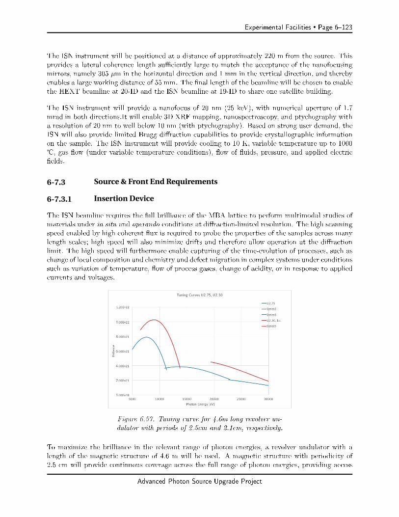
Experimental Facilities Page 6123
The ISN instrument will be positioned at a distance of approximately 220 m from the source. Thisprovides a lateral coherence length suciently large to match the acceptance of the nanofocusingmirrors, namely 305 µm in the horizontal direction and 1 mm in the vertical direction, and therebyenables a large working distance of 55 mm. The nal length of the beamline will be chosen to enablethe HEXT beamline at 20-ID and the ISN beamline at 19-ID to share one satellite building.
The ISN instrument will provide a nanofocus of 20 nm (25 keV), with numerical aperture of 1.7mrad in both directions.It will enable 3D XRF mapping, nanospectroscopy, and ptychography witha resolution of 20 nm to well below 10 nm (with ptychography). Based on strong user demand, theISN will also provide limited Bragg diraction capabilities to provide crystallographic informationon the sample. The ISN instrument will provide cooling to 10 K, variable temperature up to 1000, gas ow (under variable temperature conditions), ow of uids, pressure, and applied electricelds.
6-7.3 Source & Front End Requirements
6-7.3.1 Insertion Device
The ISN beamline requires the full brilliance of the MBA lattice to perform multimodal studies ofmaterials under in situ and operando conditions at diraction-limited resolution. The high scanningspeed enabled by high coherent ux is required to probe the properties of the samples across manylength scales; high speed will also minimize drifts and therefore allow operation at the diractionlimit. The high speed will furthermore enable capturing of the time-evolution of processes, such aschange of local composition and chemistry and defect migration in complex systems under conditionssuch as variation of temperature, ow of process gases, change of acidity, or in response to appliedcurrents and voltages.
Figure 6.57. Tuning curve for 4.6m long revolver un-dulator with periods of 2.5cm and 2.1cm, respectively.
To maximize the brilliance in the relevant range of photon energies, a revolver undulator with alength of the magnetic structure of 4.6 m will be used. A magnetic structure with periodicity of2.5 cm will provide continuous coverage across the full range of photon energies, providing access
Advanced Photon Source Upgrade Project

Page 6124 Experimental Facilities
to all elemental absorption edges situated in the 4.8 30 keV range of photon energies. A magneticstructure with periodicity of 2.1 cm provides higher brilliance at higher photon energies in particular,fully exploiting the strength of the upgraded APS for high photon energies. The device must allowtapering for nanospectroscopy. A nal decision on insertion devices will be made during the naldesign stage.
6-7.3.2 Other Source Requirements
Source stability is vital to avoid loss of ux and intensity variations during data acquisition. 10%variation in source position and angle will be acceptable.
We desire accurate information on source positions and angles (e.g. EPICS PV's) to allow us tofollow potential source changes. We wish to explore a hardware-link with source position/angleinformation, to potentially integrate with a feedback system.
6-7.3.3 Front End Requirements
To preserve the brilliance of the source, a windowless front end with dierential pumping section isrequired. Two Si3N4 windows will be used as exit windows in the experimental endstation.
A small front end exit mask is desired to minimize total power into the First Optical Enclosure, andreduce scattering at beamline optics. The aperture needs to be suciently large to allow for opticsalignment and to accommodate potential beam motions. We currently anticipate an exit aperturewith a size of 2 x 2 mm, but a smaller size with improved power reduction might be feasible as well.
6-7.4 Beamline Layout
The ISN beamline is designed for the highest-resolution 2D and 3D imaging, uorescence mappingand nanospectroscopy of energy materials, and other complex, hierarchical systems under in situconditions. The ISN will use nanofocusing mirrors in Kirkpatrick-Baez (K-B) geometry to focushard x-rays to a diraction-limited focal spot of 20 nm size. To achieve a long working distance of55 mm, the ISN will use long mirrors with correspondingly large acceptance and long focal length.The beamline is designed to provide the large lateral coherence lengths required to illuminate thefull length of the mirrors. The resulting focused x-rays will be spatially coherent, enabling the use ofcoherent methods, such as ptychography, to achieve sub-10 nm resolution in transmission imaging,and sub-20 nm resolution in uorescence mapping.
The ISN beamline is designed along two guiding principles:
(i) Use of a spatial lter to allow adjustment of the lateral coherence length with minimum loss ofbrilliance to guard against brilliance deterioration by upstream beamline optics, and preventpotential positional or angular instabilities of these optics to aect the focal position.
(ii) Enable the large lateral coherence length required for diraction-limited focusing with ananofocusing K-B system with large working distance. The beamline must provide su-cient positional and angular stability to enable 2D and 3D mapping at a spatial resolution of20 nm.
Advanced Photon Source Upgrade Project
Experimental Facilities Page 6125
These principles lead to the the following beamline layout:
A high-heatload mirror and a pink beam mirror, M2, are used to focus x-rays from the undulatoron a Beam Dening Aperture (BDA). M1, which focuses the white undulator beam in the verticaldirection, is placed as close to the source as possible, to allow a secondary focus as far upstreamas possible, without reducing the size of the secondary source below the original source size. M2is positioned such that the horizontal source is demagnied by a factor of two and positioneddownstream of the secondary source in the vertical direction, thus matching the lateral coherencelength to the horizontally focusing nanofocusing K-B. This astigmatic design reects the astigmaticnanofocusing setup and leads to a symmetrical focal point. The BDA will consist of two separateslits, one horizontally aperturing (H-BDA) and the second one vertically aperturing (V-BDA), eachpositioned on the focal plane of the respective focusing mirror.
A Double Crystal Monochromator (DCM) and a Double Multilayer Monochromator (DMM) arepositioned directly downstream of M1, where the power density is lowest. The BDA positions forvertical and horizontal directions at 55 m (V-BDA) and 64 m (H-BDA), respectively.
A set of white beam slits is required upstream of M1 to dene the area that is illuminated; a setof pink beam slits is required upstream of M2. A set of pink beam slits is required upstream of themonochromators. A removable x-ray ag and beam intensity sensor are required downstream of eachmonochromator. A mono beam slit designed to handle the power density of a two-dimensionallyfocused pink beam with a bandwidth of 10−2is required in front of M2. A removable beam ag isrequired downstream of the last BDA. Beam position monitors are required after each BDA.
6-7.4.1 X-ray Optical Layout
The ISN beamline will provide very high spatial resolution of 20 nm, and very high photon uxand ux density using Kirkpatrick-Baez (K-B) mirrors in a diraction-limited conguration asnanofocusing optics. The ISN beamline will provide a range of photon energies between 4.8 keVand 30 keV, select a spatially coherent x-ray beam, and provide control of the lateral coherencelength in horizontal and vertical directions at the ISN instrument station. The ISN beamline isdesigned around a spatial lter (SF) consisting of a two-dimensionally focusing mirror system anda two-component beam-dening aperture (BDA). This setup provides a clean secondary source inthe horizontal and vertical directions. To maintain reasonable minimum sizes for the BDA close to5 µm, the BDA components are placed at a position of 55 m (V-BDA) and 64 m (H-BDA) from thesource, respectively. The undulator beam is focused horizontally and vertically on these positions viahigh heatload mirrors placed at 27.5 m and 43 m from the source, respectively, yielding a secondarysource with a size of 16.4 µm FWHM x 4.4 µm FWHM (elliptical beam mode). All beamline opticsare positioned upstream of the BDA, such as to remove any eects of source motion, optics motion,or wavefront deterioration from aecting the focused beam in the ISN instrument. By positioningthe beamline optics as such, only monochromatic beam is focused on the BDA, which in turn can bedesigned to be highly stable and move with high accuracy, without engineering constraints imposedby high heatload design. In addition, further reduction of secondary source size by closing the BDAfor manipulation of the lateral coherence length of the beam at the ISN position. Figure 6.58 showsthe optical concept of the ISN beamline. The ISN beamline will deploy a crystal monochromator(DCM) with a bandpass ∆E/E of 10-4 for spectroscopy, and a double multilayer monochromator(DMM) with ∆E/E of 10-2 for high-speed imaging. Use of the DMM in combination with the non-
Advanced Photon Source Upgrade Project
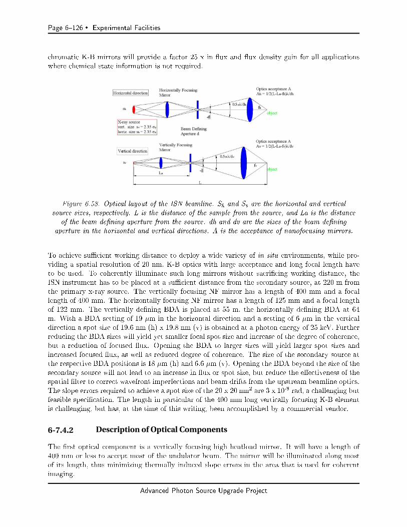
Page 6126 Experimental Facilities
chromatic K-B mirrors will provide a factor 25 x in ux and ux density gain for all applicationswhere chemical state information is not required.
Figure 6.58. Optical layout of the ISN beamline. Sh and Sv are the horizontal and verticalsource sizes, respectively. L is the distance of the sample from the source, and La is the distance
of the beam dening aperture from the source. dh and dv are the sizes of the beam deningaperture in the horizontal and vertical directions. A is the acceptance of nanofocusing mirrors.
To achieve sucient working distance to deploy a wide variety of in situ environments, while pro-viding a spatial resolution of 20 nm, K-B optics with large acceptance and long focal length haveto be used. To coherently illuminate such long mirrors without sacricing working distance, theISN instrument has to be placed at a sucient distance from the secondary source, at 220 m fromthe primary x-ray source. The vertically focusing NF mirror has a length of 400 mm and a focallength of 400 mm. The horizontally focusing NF mirror has a length of 125 mm and a focal lengthof 122 mm. The vertically dening BDA is placed at 55 m, the horizontally dening BDA at 64m. With a BDA setting of 19 µm in the horizontal direction and a setting of 6 µm in the verticaldirection a spot size of 19.6 nm (h) x 19.8 nm (v) is obtained at a photon energy of 25 keV. Furtherreducing the BDA sizes will yield yet smaller focal spot size and increase of the degree of coherence,but a reduction of focused ux. Opening the BDA to larger sizes will yield larger spot sizes andincreased focused ux, as well as reduced degree of coherence. The size of the secondary source atthe respective BDA positions is 18 µm (h) and 6.6 µm (v). Opening the BDA beyond the size of thesecondary source will not lead to an increase in ux or spot size, but reduce the eectiveness of thespatial lter to correct wavefront imperfections and beam drifts from the upstream beamline optics.The slope errors required to achieve a spot size of the 20 x 20 nm2 are 3 x 10⁻⁸ rad, a challenging butfeasible specication. The length in particular of the 400 mm long vertically focusing K-B elementis challenging, but has, at the time of this writing, been accomplished by a commercial vendor.
6-7.4.2 Description of Optical Components
The rst optical component is a vertically focusing high heatload mirror. It will have a length of400 mm or less to accept most of the undulator beam. The mirror will be illuminated along mostof its length, thus minimizing thermally induced slope errors in the area that is used for coherentimaging.
Advanced Photon Source Upgrade Project

Experimental Facilities Page 6127
Figure 6.59. Focal intensity distribution for a photon Energy of 25 keV. Results for BDAsizes of both 13.8 x 4.8 µm2 (fully coherent illumination) and 26.6 x 9.6 8 µm2 (par-tially coherent illumination) are shown in the upper and lower panel, respectively. Theeect of surface gure errors on the nal spot size are shown, with perfect mirror gurein the panels on the left side, and RMS height errors of 1 nm shown in the right panel.
Advanced Photon Source Upgrade Project

Page 6128 Experimental Facilities
Monochromators are required to select the photon energy and to dene an energy bandwidth. Theyare positioned downstream of M1 and consequently experience only pink beam thermal load. Beingpositioned close to M1 minimizes the power density on the monochromator optics. A double-crystal monochromator (DCM) using Si <111> crystals is required to provide the small bandwidthneeded to achieve diraction-limited resolution with nanofocusing diractive optics and to allowspectroscopic studies. A double-multilayer monochromator (DMM) is required to provide a ux ofroughly 25 times more at increased bandwidth for operation with reective optics. To minimize anyeects the mirror optics or monochromator optics have on the uniformity of the wavefront in thevertical direction, horizontally deecting geometry as opposed to vertically deecting geometry willbe used. Wavefront aberrations caused by the monochromators will be corrected by spatial lteringusing a BDA at approx. 60 m. In horizontally deecting geometry, some intensity will be lost dueto reduced reectivity of the π polarized component of the incident x-ray beam. The reectivity ofthe π component is 83% for a photon energy of 5 keV (θSi <111> = 23°). Given that the coherentux increases inversely with the photon energy, this small reduction of brilliance at the low photonenergies has a minimal eect on the beamline throughput.
M2 is positioned downstream of the monochromators and, as such, experiences pink beam thermalconditions (10−2 - 10−4 bandwidths). However, M2 is placed into the vertically convergent beamdownstream of M1, and, as such, experiences increased power density.
High positional stability of the focused spot in the end station requires high angular stability of thebeam accepted by the focusing optics. This requires high relative angular stability of the 1st withregard to the 2nd crystal of the DCM, estimated at ∼ 0.1 µrad. Similar stability is required for theDMM to provide diraction-limited resolution and positional stability of the focal spot obtainedwith reective mirror optics.
Pink beam with high total power at closed gap will impinge on the DMM and the DCM. To allowoperation at 20 nm spot size, the local thermal expansion (thermal bump) of the monochromatoroptics needs to be minimized. This is typically achieved by cooling with liquid nitrogen (LN2).Therefore, LN2 cooled monochromators and the requisite LN2 pump is required.
6-7.4.3 Beamline Physical Layout
The ISN beamline has a length of 220, measured from the center of the straight section. It willextend well beyond the APS oor, with the ISN instrument located in a satellite station. Thesatellite station will be shared with the HEXM program; therefore, the nal length of the ISNbeamline and of the HEXM program are being determined with shared occupancy of the satellitestation in mind.
Overall Beamline General Description
The scheme of the physical layout of the ISN beamline is shown in Figure 6.60. All beamlinecomponents other than the BDAs are positioned in the First Optical Enclosure (FOE) (current19-ID-A and 19-ID-B enclosures). The FOE contains a dierential pumping section to enablewindowless operation, a set of white beam slits, a vertically focusing HHL mirror (M1), a doublecrystal monochromator and a double multilayer monochromator, and a horizontally focusing mirror(M2). The second optical enclosure (SOE) (current 19-ID-C and 19-ID-D enclosures) contain the
Advanced Photon Source Upgrade Project

Experimental Facilities Page 6129
BDAs and the related beam diagnostics. A list of the positions of the optical elements is shown inTable 6.25.
Figure 6.60. Sketch of beamline physical layout.
The FOE will be followed by a long propagation path, with the ISN instrument positioned at adistance of approximately 220 m from the source. The ISN Enclosure will be positioned as a satellitestation outside the APS oor. We anticipate a length of the enclosure of approximately 10 m, toprovide sucient propagation distance between the sample and detectors used for ptychography.The satellite station must be suciently stable in position to angle to reduce virtual source motionscaused by relative motions between BDA and ISN instruments to below 10 nm. It needs to bedesigned with suciently small vibration background. Detailed specications will be developedwith the APS engineering team.
General Description of Radiation Safety Aspects, Vacuum System
The beamline will follow all APS and APS-U radiation standards. There are not exceptional radi-ation requirements for the beamline.
First Optical Enclosure
The rst optical enclosure corresponds to the current 19-ID-A and 19-ID-B stations. It contains adierential pumping section, a set of white beam slits, a vertically focusing high heatload mirror,a set of pink beam slits, a horizontally focusing double crystal monochromator and a horizontallyfocusing double multilayer monochromator, a horizontally focusing mirror, and a white beam stop.
Second Optical Enclosure
The second optical enclosure corresponds to the current 19-ID-C and 19-ID-D stations. They housethe vertically aperturing and the horizontally aperturing beam dening apertures.
Advanced Photon Source Upgrade Project

Page 6130 Experimental Facilities
Table 6.25. Beamline components location
Component Distance to center Notesof straight section(m)
Front end exit window N/A Windowless front end.Dierential pumping section 25.5White beam slit, WBS 26.7 Dene beam size and total power for mirror system.Mirror M1 27.5 Up- or down-deecting high-heat-load mirror. Focuses
vertically on beam-dening aperture at 55 m.Pink beam slit PBS 29 Limits beam size and total power to monochromators
(DCM, DMM).Double-crystal 30 Energy selection between 4.8 keV and 30 keV,monochromator DCM with bandwidth of 10-4. Angular stability of ∼ 0.1 µrad
between 1st and 2nd crystal.Double-multilayer 32 Energy selection between 4.8 keV and 30 keV,monochromator, DMM with bandwidth of 10-2. Angular stability of ∼0.1 µrad
between 1st and 2nd multilayer optic.Access to ratchet wall door 36-37.8 Access to ratchet wall door.Mono Beam slit 41 Dene beam size on M2Mirror M2 43 Inboard or outboard deecting high-heat-load mirror.
Focuses horizontally on beam-dening aperture at 64 m.White beam stop 43Beam-dening aperture, 55 Dene the vertical size of intermediate x-ray source.vertically aperturing, V-BDABeam-dening aperture, 64 Dene the horizontal size of intermediate x-ray source.horizontally aperturing, H-BDAExit window assembly 216 Filter boxes, shutter, exit window for ISN branchISN control room TBD. Controls room Control room will be temperature stabilized to match
must be adjacent to enclosure temperature. Must include an anteroom toISN enclosure and provide enclosure access. Control room must provideprovide direct access. user access to end station.
ISN enclosure 215-225. Enclosure must accommodate monochromatic beam.Enclosure must provide HVAC system with temperaturestability of ∼0.1 and low air ow speeds.
ISN instrument 220 ISN instrument with high-resolution focusing optics,in situ environment, energy dispersive detector,area detectors
Advanced Photon Source Upgrade Project

Experimental Facilities Page 6131
Endstation
The endstation houses an exit window assembly, the ISN instrument, detectors and related elec-tronics, and the instrument controls. The exit window assembly contains a fast shutter, absorbers,beam diagnostics, and a double Si3N4 window It further houses in situ equipment, including a gashandling system for reactive gases.
As part of the construction of the satellite building for the HEXM and ISN instruments, the oorof the endstation must be constructed to be positionally and vibrationally stable. Initial meetingspointed to a thickened oor underneath the ISN hutch as a promising approach. All componentspositioned inside the endstation must be specied/designed such that they minimize sources ofvibration or heating. The HVAC system required for temperature stabilization must provide laminarow of temperature-stabilized air. Passive cooling for all components inside the endstation is highlydesired. No fans, pumps, or similar equipment should be positioned inside the endstation, or onthe oor surrounding the station. In cases where that is not feasible, damping and vibrationaldecoupling of the equipment in question must be designed and implemented.
Instrument
The ISN instrument will use elliptically gured mirror optics to focus x-rays with large bandpass to aspot size of 20 nm. Mirrors have reectivities between 80% and 90% across the full energy range, andtherefore propagate most incident coherent photons onto the samples. Mirrors are non-chromatic,which enables spectroscopy at very high speeds, without the need to adjust optics or sample position.Mirrors also serve as low-pass lters, which allows improvement of higher-harmonics rejectionandthereby improves the detection limitprovided by upstream beamline optics. The ISN instrumentwill further integrate components designed to provide in situ environments: a heating/coolingstage to provide temperatures between 40 K and ∼500, a high temperature stage to providetemperatures of 1000or above, sample cells that accommodate ow of gases and uids, cellsoptimized for high pressure, and cells optimized for application of electric elds. The ISN will beoptimized for x-ray uorescence detection. Complementary to uorescence detection, the ISN willprovide phase contrast as well as coherent diractive imaging capabilities to allow simultaneousmapping of low-Z matrices using hard x-rays, as well as enable super resolution by deconvolvingXRF maps via ptychography. The ISN will deploy y scanning techniques, i.e. data acquisitionwhile the sample moves, in XRF mode. This will allow acquisition of high-resolution maps with alarge number of pixels in 2D and 3D.
To fully exploit the opportunity on non-chromatic focusing with nanofocusing mirrors, the ISNbeamline is conceived as a long beamline, with a length of approximately 220 m. This allows forthe achievement of a very small focal spot of 20 nm and, at the same time, yields very large workingdistances of 55 mm, which is vital to enable the wide variety of in situ environments required topursue the proposed science program.
Detectors
The ISN requires energy dispersive detectors for x-ray uorescence imaging and spectroscopy, andarea detectors for diraction and coherent diraction/ptychography.
Advanced Photon Source Upgrade Project

Page 6132 Experimental Facilities
Energy dispersive detectors
The workhorse detector for XRF mapping and spectroscopy will be an energy dispersive, thermo-electrically cooled multi-element detector with a typical energy resolution of 125 eV at Mn Ka. Toprocess the high incident count rate, detectors and electronics capable of processing 108 Photons/sor more, with minimum loss of energy resolution, are required. While the large working distanceof the ISN instrument eases constraints for capturing a signicant solid angle of emitted x-rays, itis still anticipated that the detector must have a snout that allows for positioning of the sensorclose to the specimen, thereby maximizing the solid angle of detection. It is important that thedetector minimize coupling of vibrations into the ISN instrument, in order to not degrade the spatialresolution achieved in scanning.
He-cooled detectors for emission spectroscopy, with an energy resolution on the order of a few eV,but very low count rate capability, are under development. These would be very suitable for emissionspectroscopy if the count rate is signicantly improved.
Area detectors
For ptychography, area detectors with high dynamic range and single-photon counting capability,positioned on-axis on the transmitted beam, are required. Fast scanning requires the detector towork with a very high frame rate, on the order of tens of microseconds. Therefore, multi-Kilohertzframe rates with duty cycle > 99% will be a critical parameter for the detector used in the ISN. Inaddition, a large dynamic range with pixel counter depth of more than 20 bits is needed for high-resolution (∼nm) ptychography imaging with the new upgraded source. A large dynamic range forthe pixel counter can be obtained through on-board image summation, a technique that is employedin an EIGER detector that extends the data depth from 12 bits to 32 bits. Based on the abovediscussion, example detectors, such as EIGER characterized by a small pixel size (75x75 µm2), aframe rate up to 22 kHz and a small dead time between frames (4 µs) and its developing generations,can be considered in the In Situ Nanoprobe.
An auxiliary area detector on a detector arm will be used to detect diracted x-rays from the sampleand help identify the local crystallographic phase of the sample and its evolution under the changeof in situ conditions. The detector will be positioned in one of the upper quadrants downstream ofthe ISN sample, either inboard or outboard. The detector will be able to capture diracted x-raysfrom small angles of a few degrees to large angles of 80 degrees in the horizontal direction, and toangles of 45-60 degrees in the vertical direction. Single-photon counting is required to capture smallsignals from nanocrystals. The detector will be particular useful in conjunction with the broadbandpass delivered by the DMM, and, as such, must be able to process high data rates. Single-photon counting capability is not a requirement, given that Bragg peaks as opposed to scatteringaround Bragg peaks will be recorded.
Computing
A standard EPICS-based beamline controls system will be sucient for the purposes of beamlinecontrols.
For data acquisition at high speed, we anticipate the need for a dedicated controller and related
Advanced Photon Source Upgrade Project
Experimental Facilities Page 6133
controls software implementation. Fly-scanning in 2D and 3D is anticipated to require large buersizes, with acquisition rates of 1GB/s for XRF imaging, and 20 GB/s for ptychography. In addition,the DAQ controller must monitor sample and optics positions and correct for beam drifts. Fly scancontrol hardware and software will be specied in close interaction with the APS detector groupand the BCDA groups. We will work closely with the Ptychoprobe beamline and the ATOMICbeamline, as well as other relevant beamlines, such as 2-ID, to arrive at solutions that have broaderutility and can be eciently supported by APS controls engineers.
Specific Safety Requirements
The ISN instrument will use uids and gases that may pose hazards. Gases may include toxic gases.Fluids may be acidic or basic. As such, a gas cabinet and related venting system is required.
The ISN may deploy LHe-cooled beamline devices such as monochromators, which will be connectedto the APS distributed LN2 system.
Specific Conventional Facilities Requirements
The ISN enclosure must be temperature stabilized, with laminar ow to minimize acoustic vibra-tions.
A temperature-controlled controls room is required to minimize thermal gradients. An anteroombetween the controls room and hutch is required to prevent air ows when opening the hutch door.
The ISN enclosure should be positioned in an area that has very low vibration background.
Support Facilities Requirements
The anteroom to the ISN enclosure will be used for specimen mounting. Laboratory space for limitedspecimen preparation should be in close proximity. Lab space should also provide areas to stageand store nanofocusing optics and sensitive beamline equipment such as crystals, monochromators,detectors, environmental sample holders, and related equipment.
6-7.5 R&D Needs
The ISN beamline represents a next-generation nanoprobe, with advanced capabilities that requiresignicant development to implement. While the ISN does not aim to achieve the smallest-possiblefocal spot size, the requirements of achieving 20 nm resolution at a very long working distance andunder in situ conditions are very demanding. The challenges that need to be addressed can beclassied into three topics:
(i) Provide sucient accuracy and stability for the nanopositioning system to maintain a specimen-optics registration of 10 nm or below.
(ii) Maintain positioning accuracy under in situ conditions, in particular during variable temper-ature experiments.
(iii) Maintain registration between the ISN instrument, at ∼ 180 m, and the Beam Dening Aper-
Advanced Photon Source Upgrade Project
Page 6134 Experimental Facilities
ture, at ∼ 60 m to prevent virtual motions of the source.(iv) An added area of study is approaches to minimize radiation dose to the sample to the min-
imum number required to achieve the desired spatial resolution and elemental sensitivity.Approaches include fast shutters that open and close in synchronization with the specimenscan, prepositioning/ducialization of the sample, and precharacterization of the sample usingnon-ionizing radiation.
The rst challenge requires development of a nanopositioner that holds and positions a 122 mmlong and 400 mm long nanofocusing mirror, and has sucient angular and positional stability tomaintain registration with the specimen to 10 nm or better. A prototype for such a system wasdeveloped by Wenjun Liu and Deming Shu, in collaboration with Barry Lai and Jörg Maser, andhas been tested and implemented at APS sector 34-ID. The nanopositioning system with the JTECmirrors system has demonstrated a spatial resolution on the order of 50 nm. R&D aimed at the ISNinstrument needs to provide better than 0.1 micro-radian angular stability over extended periods.
The second challenge involves developing specimen environments that provide high positional sta-bility under heating and cooling conditions, in particular. Barry Lai and Jörg Maser pursueddevelopment of a heating stage with gas ow under a DOE BRIDGE grant, in collaboration withMariana Bertoni at ASU and Tonio Buonassisi from MIT. The stage demonstrated high positionalstability under heating to 600 , under ow of H2S. The system was aimed at operation at the2-ID-D beamline, which operates with a spot size of 150 nm. R&D would be focused on implement-ing the approaches used at MIT to develop a system capable of stability at the sub-20 nm level.Contact has also been made with Natana Inc. and Hummingbird concerning the development ofboth heating stages and variable temperature stages with the lowest temperatures of 10 K. Natanahas developed a variable temperature stage for x-ray microscopy in the past, aimed at a spatialresolution of below 50 nm resolution, and has developed concepts for cooling to below 10 K.
The third challenge of registration the nanofocus to the BDA requires development of a conceptfor sensing the position of the BDA from a reference point at the ISN instrument. We considersuch an approach to be relevant if the satellite station shows insucient stability with respect tothe APS experimental oor, both in regard to slow drifts or cycles, and with regard to vibrations.The sensitivity of the position of the focal spot depends on the size of the BDA, with larger BDAopenings being less sensitive than smaller BDA. Before setting out on such a development we willstudy existing long beamlines to understand the actual displacements encountered.
Other challenges, such as development of approaches to minimize the radiation dose to the sample,are not currently anticipated to require specic R&D funding.
Advanced Photon Source Upgrade Project
Experimental Facilities Page 6135
6-8 PtychoProbe
6-8.1 Executive Summary
The race is on for chemical x-ray imaging with nanoscale resolution. There currently are substan-tial eorts underway at hard x-ray synchrotron facilities worldwide that aim to improve the spatialresolution and chemical sensitivity of x-ray microscopes. The excitement of the scientic commu-nity regarding the development of these techniques is clearly evident in the ever-growing numberof research teams working toward this aim. The PtychoProbe project we propose here is unique,because it will enable the world's rst general user program for 5-nm focusing with ultra-fast scan-ning, facilitated through the APS upgrade. It will give nanoscientists unprecedented capabilities toaccelerate the discovery of complex materials and establish the APS as the go-to place for hard x-rayhigh-resolution microscopy. There is a lot at stake in this competitive landscape. Nevertheless, thePtychoProbe beamline will guarantee U.S. leadership for years to come.
The goal of the PtychoProbe (Ptychography + Nanoprobe) beamline is to realize the highest possi-ble spatial resolution x-ray microscopy both for structural and chemical information. The unprece-dented brightness of the APS MBA lattice will be exploited to produce a nm beam of focused hardx-rays to achieve the highest possible sensitivity to trace elements. Ptychography will be used tofurther improve the spatial resolution for structural components to its ultimate limit. The beamlinewill enable high-resolution, two- and three-dimensional imaging of thick objects, bridging the reso-lution gap between contemporary x-ray and electron microscopy. Pushing x-ray microscopy into thenanoscale is crucial for understanding complex hierarchical systems on length scales from atomic upto meso- and macroscales, so as to be applicable to scientic questions ranging from biology, earthand environmental materials science, electrochemistry, catalysis and corrosion, and more.
6-8.2 Scientific Objectives & Capabilities
6-8.2.1 Science case for beamline
The PtychoProbe will take signicant advantage of the enhancements of the APS-U source param-eters. Needle-like x-ray beams with a diameter down to 5 nm will enable high-resolution, two- andthree-dimensional imaging of thick objects, bridging the resolution gap between contemporary x-rayand electron microscopy. Pushing x-ray microscopy into the nanoscale is crucial for understandingcomplex hierarchical systems on length scales from close atomic up to meso- and macroscales.
The scientic applications of the PtychoProbe will range from biology, earth and environmental ma-terials science, electrochemistry, catalysis and corrosion, and more. For example, the understandingand control of energy capture, conversion, and storage constitutes one of the grand challenges of so-ciety. Nano-architectured structures are expected to provide powerful solutions. However, advancedx-ray microscopes such as the PtychoProbe are needed in order to visualize related nanoscale struc-tures, and consequently guide and improve their design. Likewise, the drive to miniaturize electron-ics also calls for microscopes with high-spatial resolution. The current roadmap of the semiconductorindustry plans for lateral structures sizes of 5 nm in 2021. In addition to the shrinking structuressizes, controlled doping and low impurity concentrations will become very important to enhance theproperties of nanoelectronics. The PtychoProbe will not only deliver the desired spatial resolution,it will also oer the required trace-element sensitivity.
Advanced Photon Source Upgrade Project
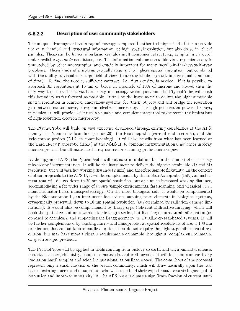
Page 6136 Experimental Facilities
6-8.2.2 Description of user community/stakeholders
The unique advantage of hard x-ray microscopy compared to other techniques is that it can providenot only chemical and structural information, at high spatial resolution, but also do so in `thick'samples. These can be buried interfaces, complex multicomponent structures, samples in a reactorunder realistic operando conditions, etc. The information volume accessible via x-ray microscopy isunmatched by other microscopies, and crucially important for many `needle-in-the-haystack'-typeproblems. These kinds of problems typically require the highest spatial resolution, but combinedwith the ability to visualize a large eld of view (to see the whole haystack in a reasonable amountof time). To nd the needle, sucient contrast, i.e., ux density, is needed. If it is possible toapproach 3D resolutions at 10 nm or below in a sample of 100s of microns and above, then theonly way to access this is via hard x-ray microscopy techniques, and the PtychoProbe will pushthis boundary as far forward as possible. It will be the instrument to deliver the highest possiblespatial resolution in complex, amorphous systems, for `thick' objects and will bridge the resolutiongap between contemporary x-ray and electron microscopy. The high penetration power of x-rays,in particular, will provide scientists a valuable and complementary tool to overcome the limitationsof high-resolution electron microscopy.
The PtychoProbe will build on vast expertise developed through existing capabilities at the APS,namely the Nanoprobe beamline (sector 26), the Bionanoprobe (currently at sector 9), and theVelociprobe project (2-ID, in commissioning). It will also benet from what has been learned atthe Hard H-ray Nanoprobe (HXN) at the NSLS II, to combine instrumentational advances in x-raymicroscopy with the ultimate hard x-ray source for scanning probe microscopies.
At the upgraded APS, the PytchoProbe will not exist in isolation, but in the context of other x-raymicroscopy instrumentation. It will be the instrument to deliver the highest attainable 2D and 3Dresolution, but will sacrice working distance (2 mm) and therefore sample exibility. In the contextof other proposals to the APS-U, it will be complemented by the In Situ Nanoprobe (ISN), an instru-ment that will deliver down to 20 nm spatial resolution, but at a much increased working distance,accommodating a far wider range of in situ sample environments, fast scanning, and `classical', i.e.,monochromator-based nanospectroscopy. On the more biological side, it would be complementedby the Bionanoprobe II, an instrument focused on mapping trace elements in biological systems,cryogenically preserved, down to 10 nm spatial resolution (as determined by radiation damage lim-itations). It would also be complemented by Bragg-type Coherent Diractive Imaging, which willpush the spatial resolution towards atomic length scales, but focusing on structural information (asopposed to chemical), and supporting the Bragg geometry to visualize crystal-based systems. It willbe further complemented by existing micro- and nanoprobes, at spatial resolutions of about 100 nmto microns, that can address scientic questions that do not require the highest possible spatial res-olution, but may have more stringent requirements on sample throughput, complex environments,or spectroscopic precision.
The PtychoProbe will be applied in elds ranging from biology to earth and environmental science,materials science, chemistry, composite materials, and well beyond. It will focus on comparatively`radiation hard' samples and scientic questions, as outlined above. The co-authors of the proposalrepresent only a small fraction of the overall community, which will draw naturally upon the userbase of existing micro- and nanoprobes, who wish to extend their experiments towards higher spatialresolution and improved sensitivity. At the APS, we anticipate a signicant fraction of current users
Advanced Photon Source Upgrade Project

Experimental Facilities Page 6137
of 2-ID-D, 2-ID-E, 9-ID, 13-ID, 20-ID, 21-ID-D, and 26-ID to want to extend their experimentscorrespondingly (there will still be a very signicant demand on these types of beamlines, a demandprobably only limited by the available overall beam time; the PtychoProbe will simply providean avenue through which those types of experiments can be extended to new resolution regimes).Similarly, we expect users of HXN and SRX beamlines at NSLS II that have hit the limits of thoserespective beamlines to want to extend their experiments by using the PtychoProbe. Furthermore,we expect that the PtychoProbe will draw numerous users from analytical electron microscopy whothus far have been unable to make use of x-ray microscopy due to limits in the spatial resolution ofexisting hard x-ray micro- and nanoprobes, but require the increased sensitivity of x-ray excitationand penetration depth to extend their experiments to the next level. The PtychoProbe will be theinstrument of choice in both the U.S. and internationally to carry out the highest resolution hardx-ray nanoprobe experiments with both elemental as well as structural contrast.
6-8.2.3 Use of APS-U characteristics
Hard x-ray nanoprobes are purely brightness driven instruments. Therefore, the PtychoProbe willbe a well-matched instrument for the APS upgrade. The source is imaged onto the sample, whilethe sample raster scanned through the focused beam. The spot size, s, on the sample is given bythe convolution of the diraction limited spot size sdi of the optics combined with the demagniedsource size sdemag.
s =(s2demag + s2di
) 12
In order to achieve diraction-limited spatial resolution, the source therefore needs to either besuciently small to be indistinguishable from a point source, or fully coherent. In practice, thisis achieved by using slits to spatially lter out incoherent modes, but at the cost of much reducedfocused ux. For example, to achieve high spatial resolution at 2-ID-D today, typically horizontal slitsettings of 80 microns are used, sacricing 90% of the total ux of the APS in order to achieve highspatial resolution. Even if we had optics capable of 5-nm focusing today, the losses due to spatialltering would be so large that experiments would not be feasible. Today's slow data acquisitionmakes it impossible to scan suciently large sample areas with drift between scan points for whichcorrections are necessary. In contrast, as the coherent ux increases by more than two orders ofmagnitude after the upgrade, the focused ux increases correspondingly. The extreme ux densityand nanometer focused beam of the PtychoProbe will oer exquisite sensitivity to low elementalconcentrations (see also Figure 6.61). In samples that are a few microns thick, it should be possibleto detect concentrations as low as a few zinc atoms via x-ray uorescence.
The second thrust for the drive toward achieving high spatial resolution is using the ptychographytechnique. Ptychography is a form of coherent diractive imaging that is able to image beyond theresolution limit of a microscope's focusing optics. The sample is scanned through a focused beamof x-rays and a detector in the far-eld of the sample records a coherent diraction pattern. Byensuring that there is an overlap in the illuminated region between adjacent scan positions, it ispossible to recover the complex transmission function (phase and absorption image) of the sample.The spatial resolution, given by the numerical aperture subtended by the far-eld area detector, istheoretically only limited by the x-ray wavelength and can easily exceed the best focusing optics.The latter makes it an attractive candidate for pushing the frontiers of spatial resolution in x-ray
Advanced Photon Source Upgrade Project
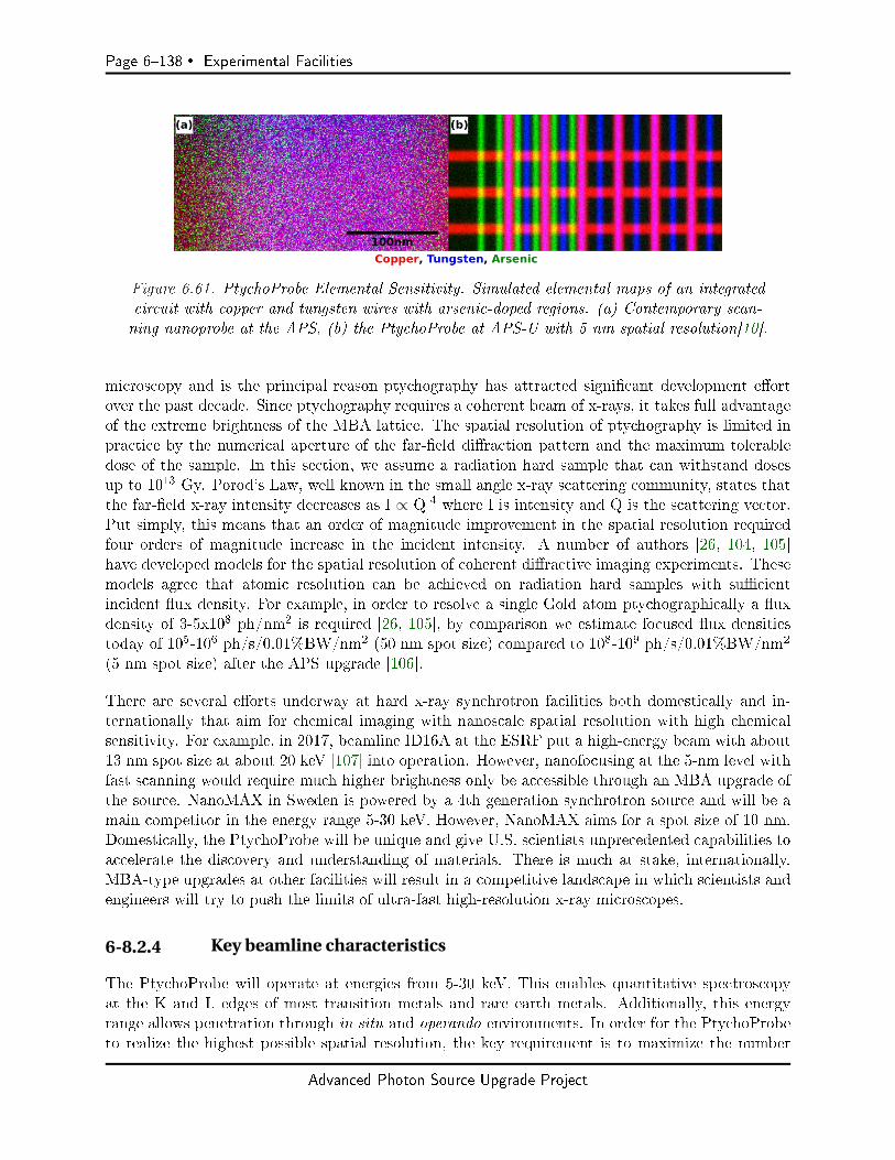
Page 6138 Experimental Facilities
Figure 6.61. PtychoProbe Elemental Sensitivity. Simulated elemental maps of an integratedcircuit with copper and tungsten wires with arsenic-doped regions. (a) Contemporary scan-ning nanoprobe at the APS, (b) the PtychoProbe at APS-U with 5 nm spatial resolution[10].
microscopy and is the principal reason ptychography has attracted signicant development eortover the past decade. Since ptychography requires a coherent beam of x-rays, it takes full advantageof the extreme brightness of the MBA lattice. The spatial resolution of ptychography is limited inpractice by the numerical aperture of the far-eld diraction pattern and the maximum tolerabledose of the sample. In this section, we assume a radiation hard sample that can withstand dosesup to 1013 Gy. Porod's Law, well known in the small angle x-ray scattering community, states thatthe far-eld x-ray intensity decreases as I ∝ Q-4 where I is intensity and Q is the scattering vector.Put simply, this means that an order of magnitude improvement in the spatial resolution requiredfour orders of magnitude increase in the incident intensity. A number of authors [26, 104, 105]have developed models for the spatial resolution of coherent diractive imaging experiments. Thesemodels agree that atomic resolution can be achieved on radiation hard samples with sucientincident ux density. For example, in order to resolve a single Gold atom ptychographically a uxdensity of 3-5x10⁸ ph/nm2 is required [26, 105], by comparison we estimate focused ux densitiestoday of 105-106 ph/s/0.01%BW/nm2 (50 nm spot size) compared to 108-109 ph/s/0.01%BW/nm2
(5 nm spot size) after the APS upgrade [106].
There are several eorts underway at hard x-ray synchrotron facilities both domestically and in-ternationally that aim for chemical imaging with nanoscale spatial resolution with high chemicalsensitivity. For example, in 2017, beamline ID16A at the ESRF put a high-energy beam with about13 nm spot size at about 20 keV [107] into operation. However, nanofocusing at the 5-nm level withfast scanning would require much higher brightness only be accessible through an MBA upgrade ofthe source. NanoMAX in Sweden is powered by a 4th generation synchrotron source and will be amain competitor in the energy range 5-30 keV. However, NanoMAX aims for a spot size of 10 nm.Domestically, the PtychoProbe will be unique and give U.S. scientists unprecedented capabilities toaccelerate the discovery and understanding of materials. There is much at stake, internationally.MBA-type upgrades at other facilities will result in a competitive landscape in which scientists andengineers will try to push the limits of ultra-fast high-resolution x-ray microscopes.
6-8.2.4 Key beamline characteristics
The PtychoProbe will operate at energies from 5-30 keV. This enables quantitative spectroscopyat the K and L edges of most transition metals and rare earth metals. Additionally, this energyrange allows penetration through in situ and operando environments. In order for the PtychoProbeto realize the highest possible spatial resolution, the key requirement is to maximize the number
Advanced Photon Source Upgrade Project
Experimental Facilities Page 6139
of coherent photons on the sample per unit time. At the same time, it is necessary to maximizestability of the beamline, in order to achieve the desired spatial resolution. To achieve the latter,it is paramount to utilize a horizontally deecting monochromator. This minimizes the degradinginuence of oor vibrations, whose amplitude is always much smaller in the horizontal versus thevertical direction. The monochromator will be equipped with Si<111> and Si<311> crystals toenable the required bandwidth for 5-nm focusing over the whole photon energy range of 5-30 keV.
6-8.3 Source & Front End Requirements
6-8.3.1 Insertion Device
The PtychoProbe will directly depend on maximized coherent ux to achieve its goal of 5-nm spatialresolution (or better, using ptychographic approaches). The PtychoProbe depends on maximizedfocused ux so as to be able to scan samples as rapidly as possible to minimize loss of spatialresolution and sample distortions due to sample drift. An insertion device that provides maximumbrilliance across energies between 5 keV and 30 keV is required. It has to deliver an overall tuningcurve that should be close to continuous in order to access all relevant elemental edges.
Figure 6.62. Darwin curves for silicon <311> with sigma (left) and pi (right) po-larization demonstrate that only a horizontal ID is suitable for the PtychoProbe, be-cause of the drastic polarization losses otherwise caused for low photon energies[11].
Due to the use of a stable horizontally deecting monochromator (required for beamline stability),the PtychoProbe beamline demands a horizontal ID to achieve the required polarization that al-lows nanofocusing. The monochromator provides the required bandwidth for nanofocusing usingthe Si<311> reection for low photon energies. Only the sigma polarization provides a suitablereectivity for <311>, while the pi polarization would lead to drastic polarization losses (Figure6.62). Consequently, nanofocusing with the anticipated working distance of 2 mm would be renderedimpossible without a horizontal ID.
6-8.3.2 Front End Requirements
The PtychoProbe requires a windowless standard high-heat-load front end to maintain the brillianceof the beam even at low photon energies. Since the PtychoProbe utilizes the coherent part of thebeam for most of its operation, the front end exit window should be as small as possible, to minimizethe power load on the rst optical elements in the beam path. Assuming that steering is highly
Advanced Photon Source Upgrade Project

Page 6140 Experimental Facilities
stable, the exit window could be as small as 1 x 1 mm2, corresponding to about 16 coherence lengthsat a photon energy of 5 keV, or 100 coherence length at a photon energy of 30 keV.
6-8.4 Beamline Layout
6-8.4.1 Overall layout
The main goal of the PtychoProbe is to realize the highest possible spatial resolution x-ray mi-croscopy of samples, both with structural and chemical information. In order to reach this goal,working distance between the optics and sample will be sacriced, and the beamline will thereforeonly support a limited set of in situ and operando environments. Nevertheless, based on compara-ble working distances present in electron microscopy or soft x-ray microscopy, the PtychoProbe isexpected to be able to address important high impact questions as laid out in the science case. ThePtychoProbe focuses primarily on attaining the highest spatial resolution for chemical information,i.e., using x-ray uorescence contrast. This is achieved by using diractive optics such as eitherMultilayer-Laue-Lenses (MLLs) or Fresnel zone plates (ZP). This information is supplemented byadding phase and absorption contrast information at spatial resolution beyond the diraction limitvia ptychography. In addition, the instrument will support `ptychography-poly' mode where muchlarger sample areas can be scanned rapidly with a comparatively large beam (100 nm - micronsized) and ptychography is used to recover structural detail down to the nm level. Ptychographydecouples the microscope's spatial resolution from the focused beam size and extends it to thediraction limit. Spatial resolution below 10 nm has already been demonstrated using ptychogra-phy [108, 109, 110, 111]. With the ux density that is achievable assuming even modest focusing,it may be possible to achieve atomic resolution for radiation hard samples [26, 42, 104, 105]. X-rayuorescence (XRF) oers exquisite sensitivity for measuring elemental concentration. Collecting thephoton stimulated secondary uorescence signal with an energy resolving detector will add elementalcontrast complemented by structural contrast from ptychography. When combined with ptychog-raphy, additional improvements in spatial resolution beyond the native XRF elemental maps canbe achieved using deconvolution techniques [112]. In addition, the microscope can be operated inspectroscopic mode to yield chemical state contrast (chemical state mapping, by scanning a sampleat well dened incident energies). Assuming the technology matures suciently, as seems plausiblebased on recent results [113], the PtychoProbe plans to incorporate superconducting spectrometersfor emission spectroscopy. The `holy grail' would be to combine elemental mapping with emissionspectroscopy, to fully characterize chemically (elements and speciation) the sample at the 5-nmspatial resolution level.
Both diraction-limited nanofocusing and ptychography require a high degree of coherence [114] ofthe x-ray beam. For the beamline design, there are two important contributions to the coherence ofthe beam: the source properties (size, divergence, energy, and bandwidth) and the properties andstability of the beamline optics (roughness, slope errors, heat eects, vibrations, and drift). Thephoton beam source properties are set by the undulator and electron beam and are not generallymodied for each experiment. However, by re-imaging the source onto a secondary-source aperture(SSA), or beam-dening aperture (BDA), the spatial coherence of the transmitted beam can bemanipulated. As a matter of fact, even the best optics have some imperfection and unwantedmotions, but these can be mitigated by the SSA because it acts as a spatial lter to produce astable wavefront. Vibrations in the optics upstream of the SSA therefore only aect focused ux(i.e., they lead to intensity uctuations), as opposed to apparent source motions (i.e., a smeared-out
Advanced Photon Source Upgrade Project
Experimental Facilities Page 6141
focus spot size).
With these goals in mind, a preliminary design has been developed (Figure 6.63) that oers theexibility to image a broad range of samples with the highest possible simplicity for ease of align-ment and use. The PtychoProbe beamline employs a simple but ultra-stable design that combinesthe exibility of a single endstation to accommodate both the highest spatial resolution (∼5-nm)focusing optics as well as high ux optics that can be used for fast overview scans to determinetarget areas for high-resolution scanning. A ptychography-only mode will be used when only struc-tural information is desired. The energy range of 530 keV was chosen to cover a broad range ofspectroscopic edges from elements of interest and make use of the increased coherent beam fractionat lower energies. The upgraded APS will be able to run in two dierent modes. The beamlinedesign will be optimized for the high brilliance mode. In high brightness mode, the beam will essen-tially be elliptic, in timing mode, much closer to round. In order to perform well in both modes ofoperation, be able to potentially accommodate future possibly dierent operational modes, and beable to accommodate dierent set of optics that permit one to trade spatial resolution vs. focusedux, the beamline will be capable of re-imaging the source onto a SSA at two dierent locationsusing bendable mirrors. The two SSAs will be located at 40 m and 60 m from the source, but onlyone will be used at a time. The 60 m SSA was chosen to maximize stability and achieve the highestresolution nanofocusing, whereas the 40 m SSA was chosen to maximize the working distance. Thelonger working distance can be used to accommodate in situ environments as well as larger samplesfor ptychography-only mode. There will be no optical elements between the SSA and nanofocusingoptic so as not to disturb the wavefront or introduce instability.
The beamline front end will be designed for windowless operation capable of handling the heat loadfrom the undulator(s). An exit mask will limit the total power entering the rst optical enclosure.The exit mask will be followed by a pair of crossed white beam slits designed to further limitthe power on the rst optical component. A pair of dynamically bendable mirrors, M1 and M2,will be used to focus the beam onto either of the two SSA positions. Following the horizontallyfocusing mirror M1, the beam will pass through a horizontally deecting monochromator withLN2 side-cooled Si crystals with small oset for optimal angular stability. The monochromatorwill house a pair of Si<111> and Si<311> crystals to fulll the required bandwidth needs ofthe PtychoProbe. The horizontally deecting geometry is used to minimize vibrations. Basedon previous experience, e.g. at NSLS II, horizontally deecting monochromators are signicantlymore stable than those that oer vertical deection. The monochromator is used to select themonochromaticity required by the nanofocusing optic and to match the longitudinal coherencelength of the beam to the sample. The monochromator bandwidth is adjusted by choosing either the<111> or <311> reections, which provide dE/E∼10-4 and dE/E ∼ 10-5, respectively. In additionto the double-crystal monochromator (DCM), a double-multilayer monochromator (DMM) is usedto provide a relatively wide-energy bandpass beam. This supports many ptychography experimentsin which higher ux is preferred to speed up data collection and improve the signal to noise ratio.The combination of two monochromators (DCM/DMM) provides rapid switching between highresolution and high ux modes. The rst secondary-source aperture (SSA1) is mounted on a stablegranite block at 40 m from the source. It will be actively water-cooled to maintain a constanttemperature and to minimize drifts. During operation, M1 and M2 will project an image of thesource demagnied by 3:1. The SSA1 aperture will be approximately 3x3 mm2. A feedback systeminvolving a diagnostic measurement (BPM1) on the upstream side of SSA1 will be used to keep thebeam focused on the aperture. The feedback will dynamically adjust the angle and curvature of M1
Advanced Photon Source Upgrade Project
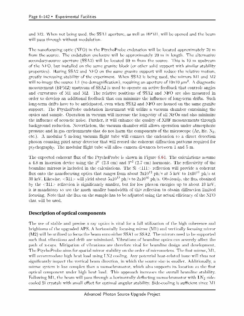
Page 6142 Experimental Facilities
and M2. When not being used, the SSA1 aperture, as well as BPM1, will be opened and the beamwill pass through without modulation.
The nanofocusing optic (NFO) in the PtychoProbe endstation will be located approximately 70 mfrom the source. The endstation enclosure will be approximately 20 m in length. The alternativesecondary-source aperture (SSA2) will be located 60 m from the source. This is 10 m upstreamof the NFO, but installed on the same granite block (or other solid support with similar stabilityproperties). Having SSA2 and NFO on the same granite support will reduce the relative motion,greatly increasing stability of the experiment. When SSA2 is being used, the mirrors M1 and M2will re-image the source 1:1 (no demagnication), requiring an aperture of 10x10 µm2. A diagnosticmeasurement (BPM2) upstream of SSA2 is used to operate an active feedback that controls anglesand curvatures of M1 and M2. The relative positions of SSA2 and NFO are also measured inorder to develop an additional feedback that can minimize the inuence of long-term drifts. Suchlong-term drifts have to be anticipated, even when SSA2 and NFO are housed on the same granitesupport. The PtychoProbe endstation instrument will utilize a vacuum chamber containing theoptics and sample. Operation in vacuum will increase the longevity of all NFOs and also minimizethe inuence of acoustic noise. Further, it will enhance the quality of XRF measurements throughbackground reduction. Nevertheless, the vacuum chamber still allows operation under atmosphericpressure and in gas environments that do not harm the components of the microscope (Ar, He, N2,etc.). A modular 5 m-long vacuum ight tube will connect the endstation to a direct detectionphoton counting pixel array detector that will record the coherent diraction patterns required forptychography. The modular ight tube will allow camera distances between 1 and 5 m.
The expected coherent ux of the PtychoProbe is shown in Figure 6.64. The calculations assumea 4.8 m insertion device using the 1st (2.3 cm) and 3rd (2.7 cm) harmonic. The reectivity of thebeamline mirrors is included in the calculations. The Si <111> reection will provide a coherentux onto the nanofocusing optics that ranges from about 2x10¹³ ph/s at 5 keV to 1x10¹¹ ph/s at30 keV. Likewise, <311> will yield about 5x10¹² ph/s to 2x10¹⁰ ph/s. Obviously, the ux obtainedby the <311> reection is signicantly smaller, but for low photon energies up to about 10 keV,it is mandatory to use the much smaller bandwidth of this reection to obtain diraction limitedfocusing. Note that the ux on the sample has to be adjusted using the actual eciency of the NFOthat will be used.
Description of optical components
The use of stable and precise x-ray optics is vital for a full utilization of the high coherence andbrightness of the upgraded APS. A horizontally focusing mirror (M1) and vertically focusing mirror(M2) will be utilized to focus the beam onto either SSA1 or SSA2. The mirrors need to be supportedsuch that vibrations and drift are minimized. Vibrations of beamline optics can severely aect thepath of x-rays. Mitigation of vibrations are therefore vital for beamline design and development.The PtychoProbe aims for spatial mirror stability on the order of micrometers. The rst mirror, M1,will accommodate high heat load using LN2 cooling. Any potential heat-related issue will thus notsignicantly impact the vertical beam direction, in which the source size is smaller. Additionally, amirror system is less complex than a monochromator, which also supports its location as the rstoptical component under high heat load. This approach increases the overall beamline stability.Following M1, the beam will pass through a horizontally deecting monochromator with LN2 side-cooled Si crystals with small oset for optimal angular stability. Side-cooling is sucient since M1
Advanced Photon Source Upgrade Project
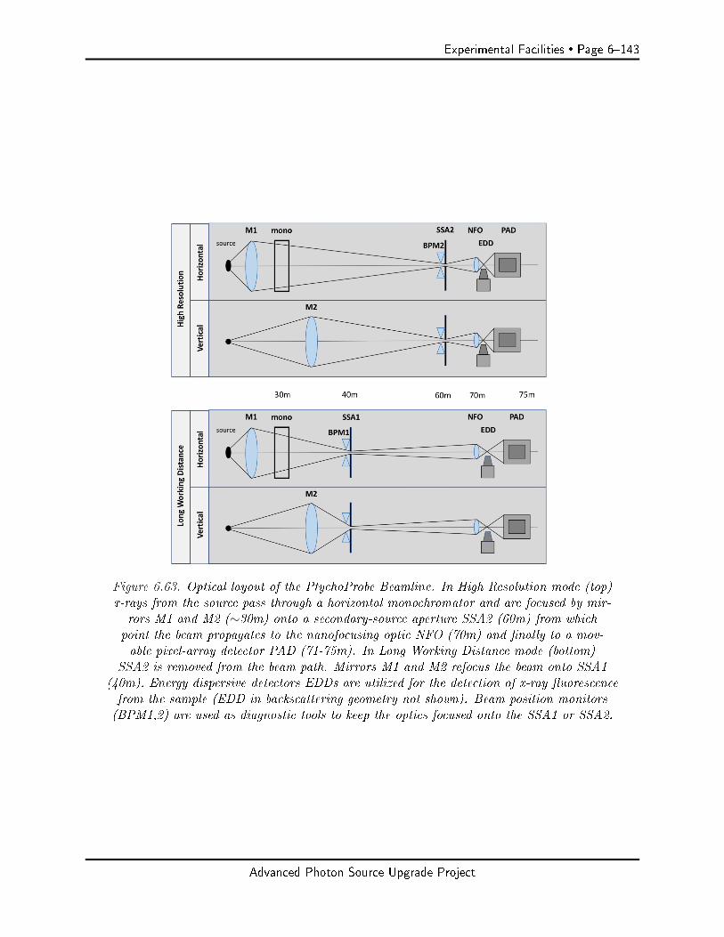
Experimental Facilities Page 6143
Figure 6.63. Optical layout of the PtychoProbe Beamline. In High Resolution mode (top)x-rays from the source pass through a horizontal monochromator and are focused by mir-rors M1 and M2 (∼30m) onto a secondary-source aperture SSA2 (60m) from whichpoint the beam propagates to the nanofocusing optic NFO (70m) and nally to a mov-able pixel-array detector PAD (71-75m). In Long Working Distance mode (bottom)
SSA2 is removed from the beam path. Mirrors M1 and M2 refocus the beam onto SSA1(40m). Energy dispersive detectors EDDs are utilized for the detection of x-ray uorescencefrom the sample (EDD in backscattering geometry not shown). Beam position monitors(BPM1,2) are used as diagnostic tools to keep the optics focused onto the SSA1 or SSA2.
Advanced Photon Source Upgrade Project
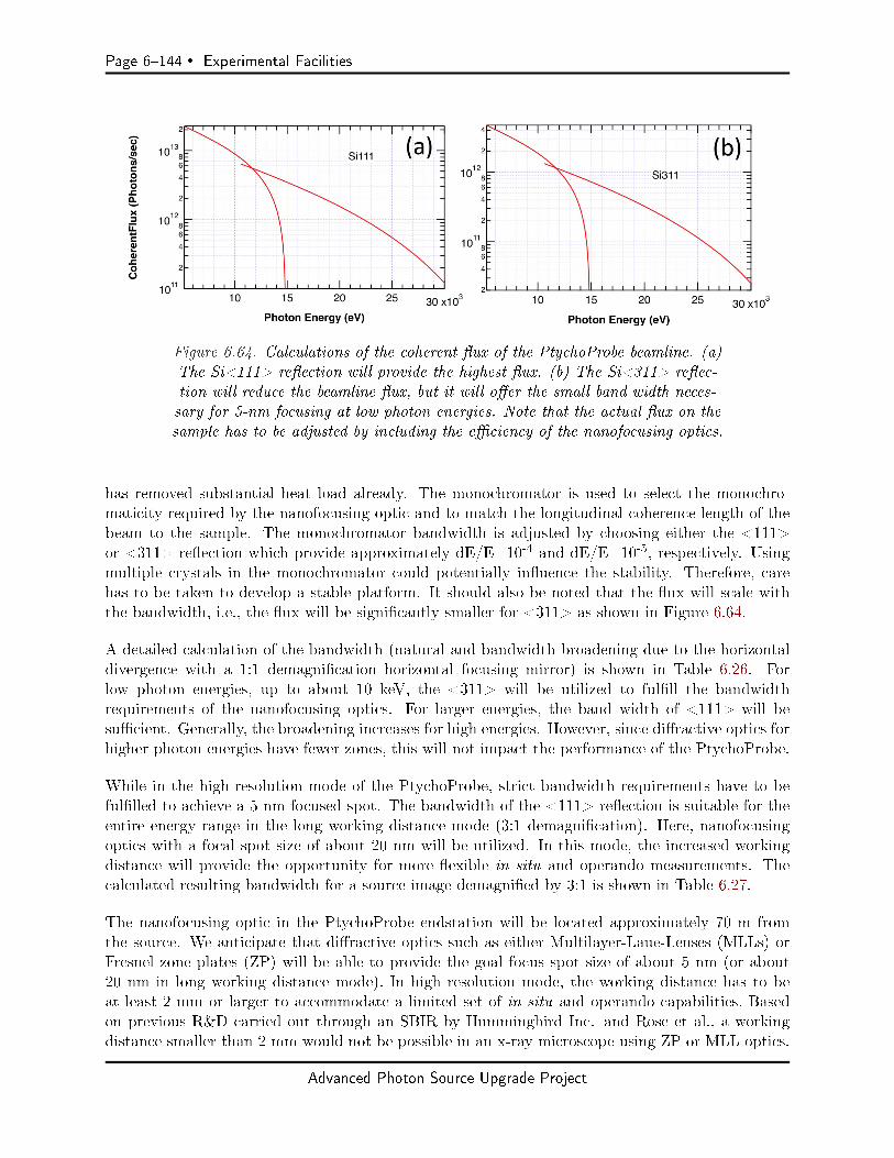
Page 6144 Experimental Facilities
Figure 6.64. Calculations of the coherent ux of the PtychoProbe beamline. (a)The Si<111> reection will provide the highest ux. (b) The Si<311> reec-tion will reduce the beamline ux, but it will oer the small band width neces-sary for 5-nm focusing at low photon energies. Note that the actual ux on thesample has to be adjusted by including the eciency of the nanofocusing optics.
has removed substantial heat load already. The monochromator is used to select the monochro-maticity required by the nanofocusing optic and to match the longitudinal coherence length of thebeam to the sample. The monochromator bandwidth is adjusted by choosing either the <111>or <311> reection which provide approximately dE/E=10-4 and dE/E=10-5, respectively. Usingmultiple crystals in the monochromator could potentially inuence the stability. Therefore, carehas to be taken to develop a stable platform. It should also be noted that the ux will scale withthe bandwidth, i.e., the ux will be signicantly smaller for <311> as shown in Figure 6.64.
A detailed calculation of the bandwidth (natural and bandwidth broadening due to the horizontaldivergence with a 1:1 demagnication horizontal focusing mirror) is shown in Table 6.26. Forlow photon energies, up to about 10 keV, the <311> will be utilized to fulll the bandwidthrequirements of the nanofocusing optics. For larger energies, the band width of <111> will besucient. Generally, the broadening increases for high energies. However, since diractive optics forhigher photon energies have fewer zones, this will not impact the performance of the PtychoProbe.
While in the high-resolution mode of the PtychoProbe, strict bandwidth requirements have to befullled to achieve a 5-nm focused spot. The bandwidth of the <111> reection is suitable for theentire energy range in the long working distance mode (3:1 demagnication). Here, nanofocusingoptics with a focal spot size of about 20 nm will be utilized. In this mode, the increased workingdistance will provide the opportunity for more exible in situ and operando measurements. Thecalculated resulting bandwidth for a source image demagnied by 3:1 is shown in Table 6.27.
The nanofocusing optic in the PtychoProbe endstation will be located approximately 70 m fromthe source. We anticipate that diractive optics such as either Multilayer-Laue-Lenses (MLLs) orFresnel zone plates (ZP) will be able to provide the goal focus spot size of about 5 nm (or about20 nm in long working distance mode). In high resolution mode, the working distance has to beat least 2 mm or larger to accommodate a limited set of in situ and operando capabilities. Basedon previous R&D carried out through an SBIR by Hummingbird Inc. and Rose et al., a workingdistance smaller than 2 mm would not be possible in an x-ray microscope using ZP or MLL optics.
Advanced Photon Source Upgrade Project
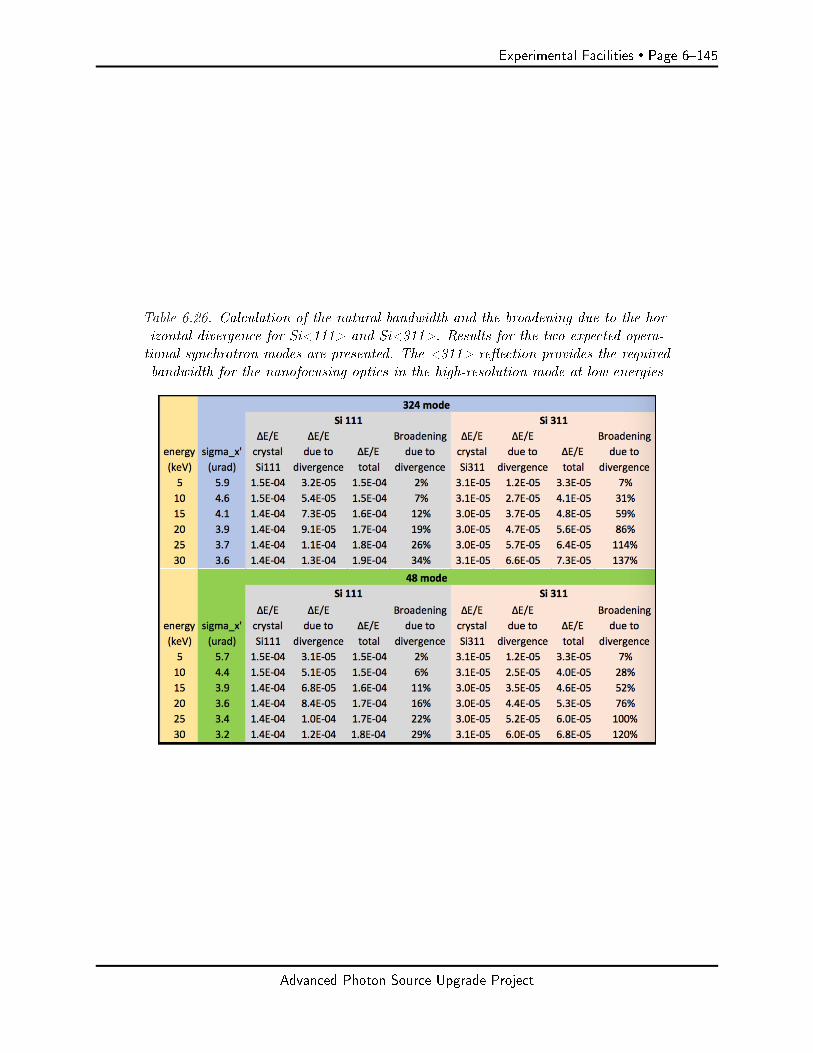
Experimental Facilities Page 6145
Table 6.26. Calculation of the natural bandwidth and the broadening due to the hor-izontal divergence for Si<111> and Si<311>. Results for the two expected opera-tional synchrotron modes are presented. The <311> reection provides the requiredbandwidth for the nanofocusing optics in the high-resolution mode at low energies
Advanced Photon Source Upgrade Project
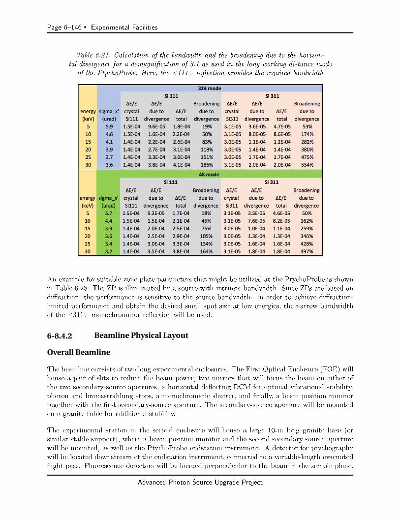
Page 6146 Experimental Facilities
Table 6.27. Calculation of the bandwidth and the broadening due to the horizon-tal divergence for a demagnication of 3:1 as used in the long working distance mode
of the PtychoProbe. Here, the <111> reection provides the required bandwidth
An example for suitable zone plate parameters that might be utilized at the PtychoProbe is shownin Table 6.28. The ZP is illuminated by a source with intrinsic bandwidth. Since ZPs are based ondiraction, the performance is sensitive to the source bandwidth. In order to achieve diraction-limited performance and obtain the desired small spot size at low energies, the narrow bandwidthof the <311> monochromator reection will be used.
6-8.4.2 Beamline Physical Layout
Overall Beamline
The beamline consists of two long experimental enclosures. The First Optical Enclosure (FOE) willhouse a pair of slits to reduce the beam power, two mirrors that will focus the beam on either ofthe two secondary-source apertures, a horizontal deecting DCM for optimal vibrational stability,photon and bremsstrahlung stops, a monochromatic shutter, and nally, a beam position monitortogether with the rst secondary-source aperture. The secondary-source aperture will be mountedon a granite table for additional stability.
The experimental station in the second enclosure will house a large 10-m long granite base (orsimilar stable support), where a beam position monitor and the second secondary-source aperturewill be mounted, as well as the PtychoProbe endstation instrument. A detector for ptychographywill be located downstream of the endstation instrument, connected to a variable-length evacuatedight pass. Fluorescence detectors will be located perpendicular to the beam in the sample plane.
Advanced Photon Source Upgrade Project
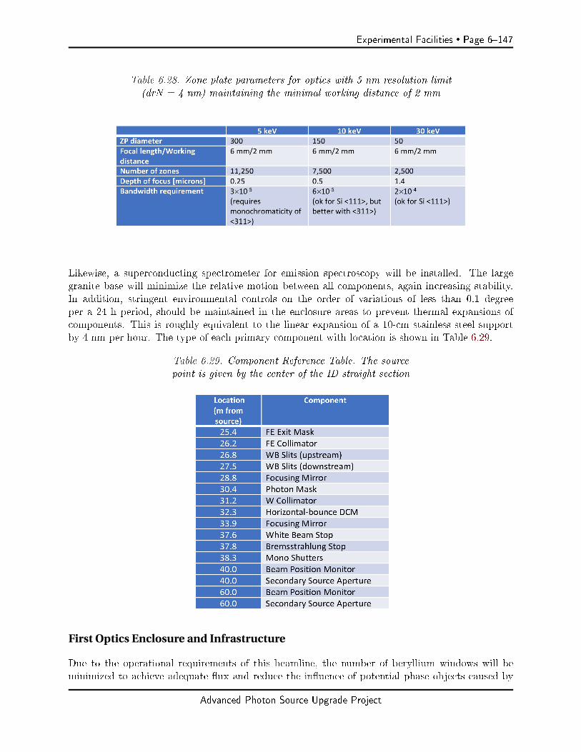
Experimental Facilities Page 6147
Table 6.28. Zone plate parameters for optics with 5 nm resolution limit(drN = 4 nm) maintaining the minimal working distance of 2 mm
Likewise, a superconducting spectrometer for emission spectroscopy will be installed. The largegranite base will minimize the relative motion between all components, again increasing stability.In addition, stringent environmental controls on the order of variations of less than 0.1 degreeper a 24 h period, should be maintained in the enclosure areas to prevent thermal expansions ofcomponents. This is roughly equivalent to the linear expansion of a 10-cm stainless steel supportby 4 nm per hour. The type of each primary component with location is shown in Table 6.29.
Table 6.29. Component Reference Table. The sourcepoint is given by the center of the ID straight section
First Optics Enclosure and Infrastructure
Due to the operational requirements of this beamline, the number of beryllium windows will beminimized to achieve adequate ux and reduce the inuence of potential phase objects caused by
Advanced Photon Source Upgrade Project

Page 6148 Experimental Facilities
windows. As stated earlier, the PtychoProbe will utilize a windowless dierential pumping exit table.APS requirements state that for a windowless beamline, a residual gas analyzer must be installedand monitored in the FOE to prevent accidental contamination of the front end and/or storage ring.The front end exit table will be supplied with a standard tungsten collimator; however, in order toachieve the low monochromator oset required (25 mm or below), another tungsten collimator willlikely need to be added just upstream of the monochromator. Detailed bremsstrahlung ray tracingwill be done to determine exact specications.
A high-heat-load slit design will be used for this application. It is capable of withstanding theheat loads generated by the horizontal undulator. The beamline will utilize two secondary-sourceapertures (SSA1 and SSA2) with beam position monitors (BPM1 and BPM2) as secondary sourcesthat are imaged onto the sample. The SSAs will consist of a pair of water-cooled slits in bothhorizontal and vertical directions. Any mirror and monochromator vibrations then become intensityuctuations, as opposed to position movements. Changes in intensity can be corrected via a M1(M2) feedback system using BPM1 (BPM2) to overcome long-term thermal drifts. Vibrations ordrifts of the slits itself have to be controlled as well. These would lead to a position movement ofthe focused beam on the sample. A shift of an SAA by the amount of the slit size would translatethe focused beam by the equivalent of the focused spot size. Thus, the horizontal and verticalvibrational stability of the slits should be better than 10% of the slit size, i.e., 300 nm for SSA1 and1000 nm (peak to peak) for SSA2. SSA1 will be located in the FOE, while SSA2 will be located inthe endstation hutch.
A horizontally focusing mirror will be the rst optical component. In order to accommodate thehigh heat load, cryogenic cooling is required. The mirror has to enable stable focusing into the twosecondary-source apertures. Vibration of the mirror as well as thermal drifts have to be minimized.In order to achieve the highest possible stability, a horizontal monochromator will be utilized. It willhouse two cryo-cooled crystal pairs next to each other with <111> and <311> cut. This will providethe required bandwidth for the nanofocusing optics in the endstation instrument (Si<111> for 10-4
bandwidth, and Si<311> for 10-5 bandwidth). A vertically focusing mirror located downstream ofthe monochromator will focus the beam into the two secondary-source apertures. Water cooling ofthe mirrors is anticipated. Vibration of the mirror as well as thermal drifts have to be minimized.The movable segmented beam-position monitors will be located upstream of the secondary-sourceapertures in order to characterize vertical, horizontal, and angular displacements of the beam. Anactive feedback control of the focusing mirrors will be implemented to correct for temperature drifts.This allows for maximization and stabilization of the amount of coherent ux passing through theSSAs. Movable uorescence screens will be located behind the mirrors and the monochromatoras well as upstream of the secondary-source apertures. These will serve alignment procedures.The locations of SSA1 as well as SSA2 relative to the NFO will be monitored, e.g., using laserinterferometry. These diagnostics enable a feedback between the SSAs and the focusing optics tocontrol slow thermal drifts.
The PtychoProbe will not utilize monochromatic beam alone, therefore a photon and bremsstrahlungstop will be installed in the FOE downstream of the monochromator and mirrors.
Advanced Photon Source Upgrade Project
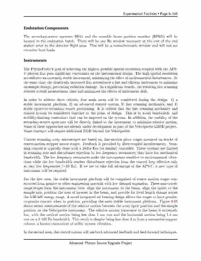
Experimental Facilities Page 6149
Endstation Components
The secondary-source aperture SSA2 and the movable beam position monitor (BPM2) will belocated in the endstation hutch. There will be one Be window necessary at the exit of the endstation prior to the detector ight pass. This will be a monochromatic window and will not seeexcessive heat loads.
Instruments
The PtychoProbe's goal of achieving the highest possible spatial resolution coupled with the APS-U photon ux puts signicant constraints on the instrumental design. The high spatial resolutionnecessitates an extremely stable instrument, minimizing the eect of environmental disturbances. Atthe same time, the drastically increased ux necessitates a fast and ecient instrument to minimizeon-sample dosage, preventing radiation damage. As a signicant benet, the resulting fast scanningreduces overall measurement time and minimizes the eects of instrument drift.
In order to address these criteria, four main areas will be considered during the design: 1) astable instrument platform, 2) an advanced control system, 3) fast scanning mechanics, and 4)stable optics-to-secondary-source positioning. It is critical that the fast scanning mechanics andcontrol system be considered together at the point of design. This is to avoid bandwidth- andstability-limiting constraints that can be imposed on the system. In addition, the stability of thesecondary-source apertures will be directly linked to the instrument to minimize relative motion.Some of these approaches are already under development as part of the Velociprobe LDRD project.Some concepts will require additional R&D beyond the Velociprobe.
Current scanning x-ray microscopes are based on, ne-motion piezo stages mounted on stacks ofcoarse-motion stepper motor stages. Feedback is provided by ber-coupled interferometry. Scan-ning control is typically done with a Delta-Tau (or similar) controller. These systems are limitedin scanning rate and disturbance rejection by low frequency resonances; they have low mechanicalbandwidth. The low frequency resonances make the instruments sensitive to environmental vibra-tions while the low bandwidth renders disturbance rejection from the control loop eective onlyat very low frequencies (∼10 Hz). If we are to take full advantage of the APS-U, a new type ofinstrument will be required.
For the rst area, the stable instrument platform will be comprised of coarse motion stages con-structed from granite or other engineering material with low thermal expansion. These mm-travel-range stages form the instrument base, align the instrument to the beam, align the optics to thesample axis, position the area of interest in the beam, and provide for focal length change acrossthe 5-30 keV energy range. A novel integrated air bearing design allows the stages to have granite-to-granite contact when in position, providing the most stable instrument platform. Figure 6.65shows recent measurements of the relative motion between the x-ray optic position and the sampleposition on the Velociprobe instrument. The relative motion transverse to the beam is extremelylow, with the vertical motion being less than 1 nm rms and the horizontal motion being 1.4 nmrms on a 5-100 Hz bandwidth. This result is despite being less than 2 m from a mezzanine supportcolumn, a known transmitter of utility system vibration.
In the second area, the control system will use both advanced feedback and feed-forward techniques.
Advanced Photon Source Upgrade Project

Page 6150 Experimental Facilities
Figure 6.65. Chart showing the relative motion between the Velociprobe sample po-sition and the optics gantry. This level of relative motion in a stage system is verylow, in a range typically associated with very short distances on rigid structure.
State of the art ber-coupled interferometry will be used to accurately measure the sample, zoneplate, and secondary-source position feedback. Robust feedback control techniques will maximizethe ability of the system to reject external disturbance, mitigate system vibrations, and controlsystem dynamics. The feedforward control will increase system bandwidth. The resulting systemperformance and accurate position metrology will enable more ecient scanning techniques suchas Lissajous trajectories. The scanning controller(s) will be implemented on a eld-programmablegate array (FPGA), such as those available from National Instruments or other manufacturers. Allother motion control can be handled with a conventional motion controller, an example of which isa Delta Tau controller like those used by the Bionanoprobe and Velociprobe.
The scanning control and mechanics need to be considered as a system and designed together.Recent work on the Velociprobe scanning control show that signicant gains in bandwidth, stability,and resolution can be achieved with an FPGA-based H-innity control algorithm design. Figure6.66 shows measured results from a positioning resolution experiment on the Velociprobe scanningstage. Sub-nanometer positioning resolution can be achieved with this scanning stage and controller,and a similar performance can be expected for systems used in the PtychoProbe. In addition, thecontroller also increased in the bandwidth at which a particular scan trajectory can be tracked fora given amount of error. Furthermore, the scanning controller design process allows the bandwidth,noise rejection, and tracking error to be quantied a priori. For the PtychoProbe, integrated designof the scanning system and controller will ensure the best possible performance.
Finally, special attention should be paid to the relative stability of the sample, zone plate optics,and SSA. The SSA for the high-resolution mode will be located 15 m upstream of the sample. Therelative motion between these two points will inuence the resolution of the instrument. Figure6.67 shows the oor motions in the X and Y directions, both the absolute, and the relative motionbetween two points 18 m apart.
Advanced Photon Source Upgrade Project
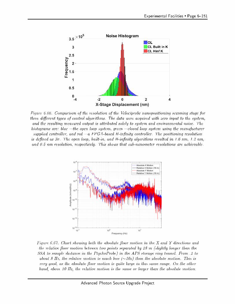
Experimental Facilities Page 6151
Figure 6.66. Comparison of the resolution of the Velociprobe nanopositioning scanning stage forthree dierent types of control algorithms. The data were acquired with zero input to the system,and the resulting measured output is attributed solely to system and environmental noise. Thehistograms are: blue the open loop system, green closed loop system using the manufacturersupplied controller, and red a FPGA-based H-innity controller. The positioning resolutionis dened as 3σ. The open loop, built-in, and H-innity algorithms resulted in 1.6 nm, 1.2 nm,and 0.5 nm resolution, respectively. This shows that sub-nanometer resolutions are achievable.
Figure 6.67. Chart showing both the absolute oor motion in the X and Y directions andthe relative oor motion between two points separated by 18 m (slightly longer than theSSA to sample distance in the PtychoProbe) in the APS storage ring tunnel. From .1 toabout 8 Hz, the relative motion is much less (∼10x) than the absolute motion. This isvery good, as the absolute oor motion is quite large in this same range. On the otherhand, above 10 Hz, the relative motion is the same or larger than the absolute motion.
Advanced Photon Source Upgrade Project

Page 6152 Experimental Facilities
These numbers vary somewhat around the facility and the data shown are from the storage ringtunnel, which likely behaves somewhat better than the experimental hall oor. Measurement atthe nal beamline location and compensation of these relative motions are necessary to achieve therequired instrument performance.
6-8.4.3 Additional
Detectors
Area detector. The performance of detectors plays an important role in ptychography. Param-eters like single-photon precision, single-pixel point-spread function, no readout noise, and highdynamic range are critically important to high precision ptychography with few nanometers res-olution. In order for the PtychoProbe to realize the highest possible spatial resolution, single-photon-counting detectors will be employed for ptychography experiments. The resultant focusedux density will be increased by ve orders of magnitude through increased coherent ux by theAPS Upgrade, improved optic eciency, and smaller spot size (down to 5 nm), and therefore theexposure time per diraction frame can be greatly reduced. Using fast scanning, this requires thedetector to work with a high frame rate. With 108-109 ph/s /nm2 after the APS upgrade, theexposure time can be reduced to tens of microseconds. Therefore, multi-Kilohertz frame rates withduty cycle > 99% will be a critical parameter for the detector used in the PtychoProbe. In addition,large dynamic range with pixel counter depth of more than 20 bits is needed for high-resolution(∼nm) ptychography imaging with the new upgraded source. Two types of pixelated area detectorcan be considered for the PtychoProbe: one is a photon counting detector which has good dynamicrange but has its performance limited by the count range. Based on the data from current and fu-ture beam source, a count rate better than 109 ph/s is needed for ptychography using the upgradedbeam source. The other is a photon integrating detector which does not have a count rate limit,but has limited dynamic range. The limited dynamic range issue needs to be solved if a photonintegrating detector is considered for the PtychoProbe. For example, a semi-transparent beam stopcan be added in front of the photon integrating detector so as to increase the dynamic range. Alarge dynamic range for the pixel counter can be obtained through on-board image summation, atechnique that is already employed today in some detectors that extends the data depth from 12bits to 32 bits.
Based on the above discussion, detectors with a frame rate of 3 kHz and a small dead time betweenframes (3 µs or better) can be considered for the PtychoProbe. In addition to the dynamic rangeand the frame rate, the detector has to oer a suitable pixel number, pixel size, and distance fromthe sample. For example, with a probe size of 5 nm and a resolution pixel size in the reconstructionof 0.5 nm, a detector with a pixel size of 75x75 µm2 and 512 pixels has to be located only 155 mmdownstream of the sample at 10 keV. This arrangement would provide a suitable oversampling ratioof 51; simulations without noise show that a reconstruction converges when the oversampling is 10or larger. Thus, for a small beam the oversampling requirement for ptychography reconstructions iseasy to meet. In the long working distance mode, the PtychoProbe will utilize a probe size of about20 nm. This will increase the detector distance up to about 5 m. The respective detector distancesfor a 5-nm and 20-nm probe size are shown in Figure 6.68. Depending on the NFO and desiredresolution, the distance ranges between a few centimeters and 5 meters. Therefore, the detector willbe connected to an adjustable-length ight pass.
Advanced Photon Source Upgrade Project
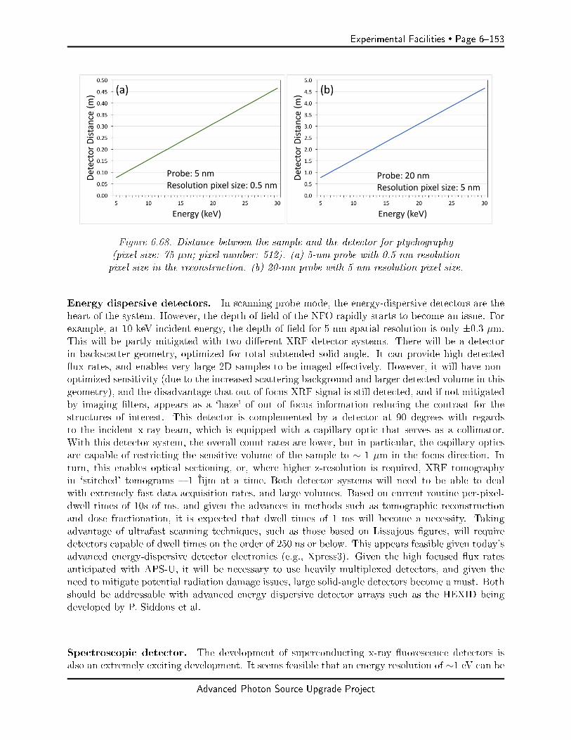
Experimental Facilities Page 6153
Figure 6.68. Distance between the sample and the detector for ptychography(pixel size: 75 µm; pixel number: 512). (a) 5-nm probe with 0.5 nm resolutionpixel size in the reconstruction. (b) 20-nm probe with 5 nm resolution pixel size.
Energy dispersive detectors. In scanning probe mode, the energy-dispersive detectors are theheart of the system. However, the depth of eld of the NFO rapidly starts to become an issue. Forexample, at 10 keV incident energy, the depth of eld for 5-nm spatial resolution is only ±0.3 µm.This will be partly mitigated with two dierent XRF detector systems. There will be a detectorin backscatter geometry, optimized for total subtended solid angle. It can provide high detectedux rates, and enables very large 2D samples to be imaged eectively. However, it will have non-optimized sensitivity (due to the increased scattering background and larger detected volume in thisgeometry), and the disadvantage that out-of-focus XRF signal is still detected, and if not mitigatedby imaging lters, appears as a `haze' of out of focus information reducing the contrast for thestructures of interest. This detector is complemented by a detector at 90 degrees with regardsto the incident x-ray beam, which is equipped with a capillary optic that serves as a collimator.With this detector system, the overall count rates are lower, but in particular, the capillary opticsare capable of restricting the sensitive volume of the sample to ∼ 1 µm in the focus direction. Inturn, this enables optical sectioning, or, where higher z-resolution is required, XRF tomographyin `stitched' tomograms 1 μm at a time. Both detector systems will need to be able to dealwith extremely fast data acquisition rates, and large volumes. Based on current routine per-pixel-dwell times of 10s of ms, and given the advances in methods such as tomographic reconstructionand dose fractionation, it is expected that dwell times of 1 ms will become a necessity. Takingadvantage of ultrafast scanning techniques, such as those based on Lissajous gures, will requiredetectors capable of dwell times on the order of 250 ns or below. This appears feasible given today'sadvanced energy-dispersive detector electronics (e.g., Xpress3). Given the high focused ux ratesanticipated with APS-U, it will be necessary to use heavily multiplexed detectors, and given theneed to mitigate potential radiation damage issues, large solid-angle detectors become a must. Bothshould be addressable with advanced energy dispersive detector arrays such as the HEXID beingdeveloped by P. Siddons et al.
Spectroscopic detector. The development of superconducting x-ray uorescence detectors isalso an extremely exciting development. It seems feasible that an energy resolution of ∼1 eV can be
Advanced Photon Source Upgrade Project

Page 6154 Experimental Facilities
reached, which would enable x-ray emission spectroscopy. If this could be combined with substantialmultiplexing to achieve large subtended solid angles and high overall count rates, such a detectorwould be an incredible boon for the PtychoProbe. It would make it potentially possible to acquirea full chemical state map of elements of interest by simple XRF mapping, and in one shot ateach pixel acquire (presumably complimentary) chemical information (for example, if both Fe andCo are co-localized in pixel, one might be able to get both oxidation states, and thus a far moresuperior handle for understanding in detail the localized chemistry occurring in the sample). Whilethe scientic program of the PtychoProbe does not depend on this development, it would benethugely.
Computing
A number of research and development challenges must be addressed for the PtychoProbe. Theincreased brightness of the source relative to 3rd generation storage rings will enable rapid dataacquisition with per pixel dwell times approaching one microsecond. A rapid-scanning, precise-motion, ultra-stable imaging platform requires signicant advancement in motion control and dataacquisition systems. In addition to the mechanics and control challenges, such an instrument couldproduce several TB's of data per second that need to be reduced in real time. This beamlinepositions the APS at the leading edge in optics, coherent imaging, big data, motion and control toopen up new frontiers in x-ray microscopy.
We will require the ability to directly stream the acquired data to `local' data storage space, and thenthe ability to analyze the acquired data in close-to-real time, so as to steer ongoing experiments. Forthe analysis, high performance computing resources will be required, in particular for ptychography.For scanning probe mode, a (raw) data throughput on the order of 1 GB / min is achievable, forptychography mode, 2-3 orders of magnitude higher data rates will need to be accomplished. Someof these data volumes may be mitigated by the development of methods that make eective use ofcompressed sensing approaches to only store relevant data. Also, in order to reconstruct acquireddata for XRF tomography or ptychography, vast volumes of data need to be processed. Considerthe example of connectomics: it seems feasible to acquire the necessary data to reconstruct a full3D dataset of a (1 mm)3 volume at a resolution of (10 nm)3 voxels, in about 1 day of beam time. Ifeach voxel is represented as a single byte grey scale value, the dataset volume is 1 petabyte. Today'sapproaches are not able to handle such data, yet work like the collaboration between XSD and MCSis underway to develop methods that will enable exactly this kind of data analysis.
6-8.4.4 Specific Safety Requirements
All safety aspects are within the normal beamline safety envelope, and all APS and APS-U safetyguidelines will be observed.
6-8.4.5 Specific Conventional Facilities Requirements
Conventional facilities are a critical enabling aspect of the PtychoProbe system. As previouslystated, the PtychoProbe will be designed to achieve the highest spatial resolution (toward 5 nm).Ideally, any environmentally-driven disturbances should have a maximum amplitude of no morethan 2 nm. While the PtychoProbe system will be designed to be as insensitive as possible to
Advanced Photon Source Upgrade Project
Experimental Facilities Page 6155
environmental disturbance, performance is always enhanced with a thermally and vibrationallystable environment. This is still the conceptual stage and the engineering specications are stillbeing determined, but it is reasonable to expect a hutch temperature stability of 0.1 for a 24h period (recent work in the APS storage ring has shown that .03 variation is possible) and avibration background of less than 20 nm rms on a 2-100 Hz bandwidth.
To highlight the importance of long-term stability, we consider two engineering materials that couldbe used in the construction of the PtychoProbe: a 10-cm length of aluminum or a 10-cm length ofgranite. If each material undergoes a 0.1 temperature cycle over a 24 hour period, this results in230 nm and 60 nm length changes, respectively. Or put another way, a drift rate of 9.6 and 2.5 nmper hour, respectively. Providing the best achievable hutch temperature stability will help mitigatetemperature-driven instabilities.
Likewise, for vibrational stability, minimizing the relative motion between the nanofocusing opticsand sample is very important. This relative motion should be at the nanometer level. The ambientvibration environment and the air ow in the hutch are the main sources of mechanical disturbanceto the instrument. Providing the best achievable ambient vibration environment will help mitigatevibrational instabilities.
The PtychoProbe team plans on working with the APS engineering sta to ensure that the instru-ment is installed in the best achievable environment. Vibration and temperature surveys will beconducted at the beamline. The known vibration sources of deionized water pumps, experimentalhall air handlers, and hutch-mounted water piping can be address as needed. Working with the APSand FMS, low-risk and relatively low-cost changes can be made on an as-needed basis to mitigatethe eects of these sources. In addition, air distribution to the hutch will be done in a manner thatminimizes turbulence (similar to S26 and S32). On the temperature control side, recent experienceshows that 0.1 temperature control should be achievable with standard modications to theair handling system. Carefully addressing these conventional facilities aspects will ensure the bestenvironment for the siting of the PtychoProbe.
6-8.4.6 Support facilities
We require `standard' support facilities, such as a drylab for various instrument development andmaintenance tasks, as well as a wet lab for sample preparation, mounting, and sample preview usingcomplimentary methods (e.g., state of the art light microscopy or table-top electron microscopy).
6-8.5 R&D Needs
A number of research and development challenges must be addressed for the PtychoProbe. Someof these research needs are already actively being addressed to a certain degree, such as the LDRDproject to develop the Velociprobe. This project aims for the development of a stable microscopeplatform that enables ultra-fast scanning for ptychography.
Area: Continued work on scanning control design and implementation There is synergy here (bydesign) with the Velociprobe. Continued work is necessary on both the algorithm and the controlhardware. The best algorithm approach for the PtychoProbe may be slightly dierent than the VPdue to possibly scanning the sample rather than the zone plate. Less expensive, APS-supported
Advanced Photon Source Upgrade Project

Page 6156 Experimental Facilities
hardware should be explored for algorithm implementation.Work needed: Explore fast scanning of larger systems, e.g. sample with environment. Explorebest hardware to implement H-innity or similar algorithms.
Area: Scanning mechanics development (in parallel with controller) O-the-shelf motion systemsmay not meet the instrument requirements. Likewise, choosing a fast scanning system withoutconsidering the control of the system may result in unintended constraints on performance. Anexample of this could be stages stacked to achieve three axis motion. This conguration is one way(not the only way) through which the feedback control phenomena of non-minimum phase zeros(NMPZ) can arise. Without much explanation, these NMPZs can put constraints on bandwidthand cause system instability. Current x-ray microscopes at the APS exhibit this behavior.Work needed: Simulation and design eorts are necessary to determine what is required for thescanning stages. These simulations can help determine if an o-the-shelf system exists. If not, anappropriate system will be designed.
Area: Secondary-source aperture-to-optics stability There may be some synergy here with theAPS-U beam/beamline stability work. The APS-U accelerator side is working on using water levelsto measure relative positions of components widely separated (∼20 m). For the PtychoProbe high-resolution mode, sub-micron relative position stability may be needed.Work needed: Quantify expected relative motions between optics and SSA. Determine feasibleway to measure the vertical and transverse relative positions of the zone plate optics, sample, andSSA. Develop approach for feedback control of relative position.
Area: Quantication (and remediation) of environmental noise at beamline location. Environmen-tal vibration environment can greatly inuence the instrument performance. The current environ-ment should be known before the instrument is designed and installed. Any signicant environmen-tal vibration issues should be addressed.Work needed: A vibration survey should be conducted at the proposed beamline location. Anylarge sources of vibrational noise should be addressed. The work done at S26 may be viewed as amodel for this work.
Area: Development of zone plate (ZP) optics for 5-nm focusing. The primary technical milestoneto achieve the desired focus spot with ZPs is to fabricate the desired zone width. Currently, thereare limitations in the lithography that complicate fabricating structures with a size below 10 nm.High resolution lithography, in addition to pattern thinning via etching, can reduce feature size tosub-10 nm reliably, but this technique would have to be developed for the grating-like structureof zone plates. The resulting structure can be combined with zone doubling and interlacing thepattern to achieve the desired zone width. This indicates that most likely, to achieve the requiredspecications, no single technical development can achieve the desired focus spot size, and a com-bination of technologies would be required.Work needed: A dedicated R&D eort needs to be established at Argonne to achieve the speci-cations for the optics desired. In addition to the technologies described in the previous section, newconcepts should be explored, such as developing sputter slice zone plates to maximize the chanceof success. In general, the tools required for R&D are available at Argonne today, though collab-orations with groups at BNL or SLAC would provide access to more advanced tools than thoseavailable now. Additional R&D is required for integrating any fabricated optics into the beamline.
Advanced Photon Source Upgrade Project
Experimental Facilities Page 6157
Area: Development of multilayer Laue lenses (MLL) for 5-nm focusing. Multilayer Laue lenses(MLLs) are a realistic candidate for focusing down to 5 nm. Although they are more dicult toalign (2 MLLs are needed for point focusing), they might provide higher eciencies. The opticsgroup is world-leading in the fabrication of MLLs. As a risk mitigation strategy, we expect todesign the PtychoProbe endstation instrumentation such that MLLs could be accommodated if thedevelopment of appropriate ZPs does not lead to the expected success.Work needed: Existing equipment at Argonne needs to be optimized to be able to grow therequired large number of layers for a 5-nm MLL. Additionally, materials R&D has to be conductedto grow such structures.
Area: Data management for an instrument that delivers high data volumes at fast speed. To takefull advantage of APS-U, an ultra-fast detector with short exposure times and frame rates in thekilohertz range will be utilized. Today's EIGER detector already acquires up to 180,000 frames andabout 360 gigabytes per minute. The goal is to not only stream and save these large data volumes,but to make them available to analysis tools in close-to real-time. Scientists should be able to obtaina rough analysis of the measurements on-the-y.Work needed: Today's data infrastructure is not capable of dealing with the high data volume.Thoughtful R&D in hard- and software is paramount for the success and ecient operation of thePtychoProbe.
Area: The beamline design of the PtychoProbe requires a horizontal insertion device to meet itsspecication of focusing down to 5 nm with high stability. Otherwise, polarization losses would notallow for a horizontal monochromator that is required for beam stability. Currently, a horizontal gapvertically polarized undulator (HGVPU) of 29 mm period is under consideration. In case a horizontalID is not available, the PtychoProbe beamline design would be adjusted; most importantly, avertical-reecting monochromator would be employed. However, this would negatively inuencethe beam stability, one of the most important qualities for achieving 5-nm focusing. Therefore,R&D for a horizontal ID is critical.Work needed: R&D needs to be initiated based on feasibility studies that are ongoing.
Advanced Photon Source Upgrade Project
Page 6158 Experimental Facilities
6-9 POLAR: Polarization Modulation Spectroscopy
6-9.1 Executive Summary
Electronic inhomogeneity is a hallmark of correlated electron systems with competing interactions.These inhomogeneous quantum states underlie some of the most exciting phenomena of current in-terest in condensed matter physics including nematic charge/spin stripe order as a possible mediatorof high Tc superconductivity in copper-oxide cuprates, and spin liquids where bond directionalanisotropy or geometrical frustration leads to complex magnetic textures. We leverage two keyproperties of APS-U, namely, brilliant x-ray beams and round insertion device vacuum chambersto enable studies of mesoscale electronic/magnetic inhomogeneity by means of tuning/controllingcompeting ground states under extreme high-pressure conditions (Mbar range). A novel schemefor rapid polarization switching (both linear and circular) using dual superconducting undulators,coupled with ∼ 200 nm focused beams, results in ×500 average polarized ux density gains atcurrently accessible electronic resonances below 13 keV, and opens up access to new resonances inthe 14-27 keV range. These brilliant, polarized beams enable a tenfold increase in pressure rangeopening remarkable opportunities for discovery of new phases and furthering our understanding ofquantum matter, allowing x-ray probes of electronic matter at extreme pressure conditions to entera new era of search and discovery.
6-9.2 Scientific Objectives & Capabilities
6-9.2.1 Science Case for Beamline
Competing interactions in correlated electron systems lead to degenerate ground states resulting inquantum critical points or spontaneous electronic phase separation at low temperatures. [115, 116]These complex ground states are highly responsive to external stimuli allowing manipulation, andultimately controlling, complex electronic matter. While proximity to electronic degeneracy canbe achieved with chemical doping, i.e., changing charge density via chemical pressure or via elec-tron/hole doping, extrinsic doping leads to chemical inhomogeneity aecting electronic texture andpreventing a thorough understanding of the driving forces behind intrinsic electronic heterogeneity.Advances in high-pressure generation now allow reaching multi-Mbar pressures and large changesin energy density ∼ eV/Å3 [117, 118], bringing pure, undoped compounds to the regime of quantumdegeneracy/criticality via tuning of Coulomb interactions, electronic bandwidth, hybridization, andcrystal elds triggering electronic order (magnetic, ferroelectric, superconducting, Kondo lattice),electronic disorder (mixed/uctuating valence, Kondo screening, magnetic frustration), or compet-ing/segregated phases at the nano/meso-scale. [119, 120, 121] Polarization dependent x-ray probessuch as x-ray magnetic circular/linear dichroism (XMCD/XMLD) and x-ray resonant magneticscattering (XRMS), coupled with high-ux nm-to-µm sized beams and extreme conditions, providea unique route to unraveling the nature of electronic heterogeneity and drive discovery of novelphases of electronic matter. Hard x-rays enable studies in extreme environments where penetrat-ing radiation is required. In the case of extreme pressures (Mbar regime), polarized x-rays are aunique probe of electronic matter providing element-specic information on valence state, orbitaloccupancies, hybridization, charge transfer, and electronic/magnetic ordering. [122, 123, 124] Theability to probe most types of electronic/magnetic order, including inhomogeneity with polarized ∼200 nm x-ray beams at extreme pressure conditions (Mbar range) at low temperature (∼ 1 K) inhigh magnetic eld (10 T), is unique to high-brilliance synchrotron radiation and will remain so for
Advanced Photon Source Upgrade Project

Experimental Facilities Page 6159
the foreseeable future.
The new capability will provide much needed insight into critical problems in condensed matterphysics. In the area of interplay between mixed valence, Kondo instabilities, magnetic order andcrystal structure in 4f (rare-earth) and 5f (actinide) heavy fermion systems, resonant scatteringwill provide rich information on the nature of magnetic ordering while polarized spectroscopy willprobe mixed valency, f-conduction electron hybridization, and magnetic order. Combined, thesetechniques allow imaging the inhomogeneous magnetic state expected to arise in the intermediateregime between onset of Kondo screening and collapse of magnetic ordering. In 5f systems, long-standing questions such as the nature of hidden order in URu2Si2 [125] and unusual magnetism inPu [126, 127] can be addressed with polarization modulation experiments at ambient- and high-pressure conditions in the 16-27 keV range which spans the L2,3 edges of actinides, a capabilitycurrently unavailable. Large ux gains at the M4,5 edges of actinides in the 3.4-4.5 keV range willallow probing 5f electronic states directly. Insight will also be provided into the unique propertiesof transition metal (TM) oxides which display a wide variety of exotic phenomena including high-Tc superconductivity, charge-orbital order, colossal magneto-resistance, and multiferroicity, as wellas related electronic inhomogeneity associated with these competing ground states. [128, 129]Pressure tuned electronic bandwidth thus provides a unique tool to drive I-M transitions and helpunderstand the underlying physics of Mott insulators. This beamline will allow the probing ofelectronic order and inhomogeneity in TM oxides with low compressibility (high bulk modulus150-300 GPa) across their I-M transitions, helping clarify the role of magnetic correlations in gapformation. The discovery of conventional high Tc superconductivity at 203 K in a sulfur hydride inthe 1-2 Mbar pressure range generated renewed interest in the electronic properties of hydrides. [119]Since BCS has no theoretical upper bound for Tc, prospects for room-temperature superconductivityare not unrealistic. Compounds with light hydrogen atoms displaying hydrogen bonding with high-frequency phonon modes are natural candidates, with iron hydrides synthesized under pressurerecently coming to the forefront.[130] A strong interplay between magnetism, dimensionality, protonzero-point energy, and superconductivity is at play, providing a fertile ground for discovery of newelectronic phenomena. Finally, the ability to tune interatomic distances and bond angles withexternal pressure is unique in engineering frustrated magnetic states via tuning of (competing)exchange pathways and interactions. The new capabilities will allow studies of spin melting/freezingwith resonant scattering and spectroscopic probes including mapping spin liquid/solid mixtures andtheir evolution across rst-order transitions. Stabilization of long sought-after novel quantum statessuch as the Kitaev quantum spin liquid [131] may be possible. High-pressure studies of thesephenomena necessitate the highest possible brilliance, particularly when measuring weak diusex-ray resonant magnetic scattering from regions with short-range magnetic order. A full scienticcase for this beamline is described in Chapter 3.
6-9.2.2 Description of User Community/Stakeholders
This beamline upgrade builds on ∼ 10 years experience at beamline 4-ID-D of the APS developingx-ray instrumentation and a robust and productive user program for condensed matter physicsstudies at intermediate pressure conditions using XMCD (APS lead, ∼ 0.5 Mbar) and XRMS (U.Chicago and APS leads, ∼ 0.2 Mbar). These programs are unique in the US and are generallyregarded as world leading. The information provided by these probes is by and large not accessiblewith any other probe (neutrons, electrons, nuclear; with minor exceptions) so these capabilitiesare essential. Despite only ∼ 30% of beam time at 4-ID-D allocated to high-pressure studies since
Advanced Photon Source Upgrade Project
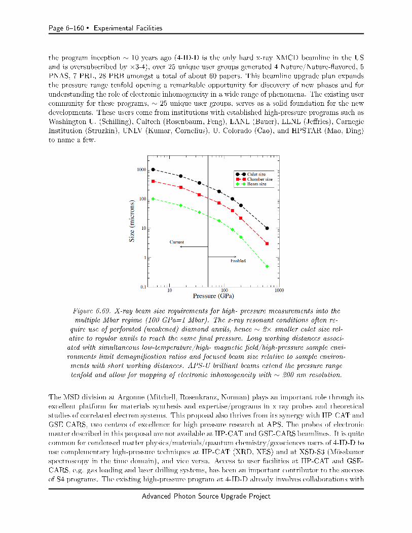
Page 6160 Experimental Facilities
the program inception ∼ 10 years ago (4-ID-D is the only hard x-ray XMCD beamline in the USand is oversubscribed by ×3-4), over 25 unique user groups generated 4 Nature/Nature-avored, 5PNAS, 7 PRL, 28 PRB amongst a total of about 60 papers. This beamline upgrade plan expandsthe pressure range tenfold opening a remarkable opportunity for discovery of new phases and forunderstanding the role of electronic inhomogeneity in a wide range of phenomena. The existing usercommunity for these programs, ∼ 25 unique user groups, serves as a solid foundation for the newdevelopments. These users come from institutions with established high-pressure programs such asWashington U. (Schilling), Caltech (Rosenbaum, Feng), LANL (Bauer), LLNL (Jeries), CarnegieInstitution (Struzkin), UNLV (Kumar, Cornelius), U. Colorado (Cao), and HPSTAR (Mao, Ding)to name a few.
Figure 6.69. X-ray beam size requirements for high- pressure measurements into themultiple Mbar regime (100 GPa=1 Mbar). The x-ray resonant conditions often re-
quire use of perforated (weakened) diamond anvils, hence ∼ 2× smaller culet size rel-ative to regular anvils to reach the same nal pressure. Long working distances associ-ated with simultaneous low-temperature/high- magnetic eld/high-pressure sample envi-ronments limit demagnication ratios and focused beam size relative to sample environ-ments with short working distances. APS-U brilliant beams extend the pressure rangetenfold and allow for mapping of electronic inhomogeneity with ∼ 200 nm resolution.
The MSD division at Argonne (Mitchell, Rosenkranz, Norman) plays an important role through itsexcellent platform for materials synthesis and expertise/programs in x-ray probes and theoreticalstudies of correlated electron systems. This proposal also thrives from its synergy with HP-CAT andGSE-CARS, two centers of excellence for high-pressure research at APS. The probes of electronicmatter described in this proposal are not available at HP-CAT and GSE-CARS beamlines. It is quitecommon for condensed matter physics/materials/quantum chemistry/geosciences users of 4-ID-D touse complementary high-pressure techniques at HP-CAT (XRD, XES) and at XSD-S3 (Mössbauerspectroscopy in the time domain), and vice versa. Access to user facilities at HP-CAT and GSE-CARS, e.g. gas loading and laser drilling systems, has been an important contributor to the successof S4 programs. The existing high-pressure program at 4-ID-D already involves collaborations with
Advanced Photon Source Upgrade Project
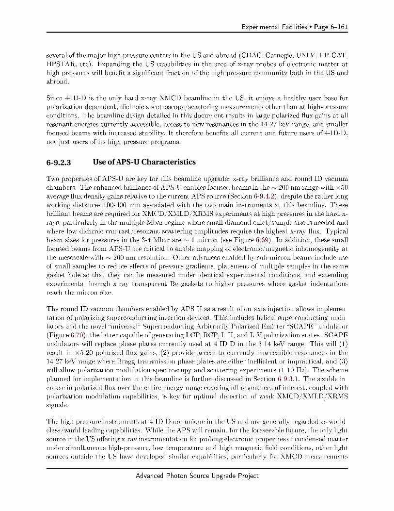
Experimental Facilities Page 6161
several of the major high-pressure centers in the US and abroad (CDAC, Carnegie, UNLV, HP-CAT,HPSTAR, etc). Expanding the US capabilities in the area of x-ray probes of electronic matter athigh pressures will benet a signicant fraction of the high pressure community both in the US andabroad.
Since 4-ID-D is the only hard x-ray XMCD beamline in the US, it enjoys a healthy user base forpolarization dependent, dichroic spectroscopy/scattering measurements other than at high-pressureconditions. The beamline design detailed in this document results in large polarized ux gains at allresonant energies currently accessible, access to new resonances in the 14-27 keV range, and smallerfocused beams with increased stability. It therefore benets all current and future users of 4-ID-D,not just users of its high pressure programs.
6-9.2.3 Use of APS-U Characteristics
Two properties of APS-U are key for this beamline upgrade: x-ray brilliance and round ID vacuumchambers. The enhanced brilliance of APS-U enables focused beams in the ∼ 200 nm range with ×50average ux density gains relative to the current APS source (Section 6-9.4.2), despite the rather longworking distances 100-400 mm associated with the two main instruments at this beamline. Thesebrilliant beams are required for XMCD/XMLD/XRMS experiments at high pressures in the hard x-rays, particularly in the multiple Mbar regime where small diamond culet/sample size is needed andwhere low dichroic contrast/resonant scattering amplitudes require the highest x-ray ux. Typicalbeam sizes for pressures in the 3-4 Mbar are ∼ 1 micron (see Figure 6.69). In addition, these smallfocused beams from APS-U are critical to enable mapping of electronic/magnetic inhomogeneity atthe mesoscale with ∼ 200 nm resolution. Other advances enabled by sub-micron beams include useof small samples to reduce eects of pressure gradients, placement of multiple samples in the samegasket hole so that they can be measured under identical experimental conditions, and extendingexperiments through x-ray transparent Be gaskets to higher pressures where gasket indentationsreach the micron size.
The round ID vacuum chambers enabled by APS-U as a result of on-axis injection allows implemen-tation of polarizing superconducting insertion devices. This includes helical superconducting undu-lators and the novel universal Superconducting Arbitrarily Polarized Emitter SCAPE undulator(Figure 6.70), the latter capable of generating LCP, RCP, L-H, and L-V polarization states. SCAPEundulators will replace phase plates currently used at 4-ID-D in the 3-14 keV range. This will (1)result in ×5-20 polarized ux gains, (2) provide access to currently inaccessible resonances in the14-27 keV range where Bragg-transmission phase plates are either inecient or impractical, and (3)will allow polarization modulation spectroscopy and scattering experiments (1-10 Hz). The schemeplanned for implementation in this beamline is further discussed in Section 6-9.3.1. The sizable in-crease in polarized ux over the entire energy range covering all resonances of interest, coupled withpolarization modulation capabilities, is key for optimal detection of weak XMCD/XMLD/XRMSsignals.
The high-pressure instruments at 4-ID-D are unique in the US and are generally regarded as world-class/world leading capabilities. While the APS will remain, for the foreseeable future, the only lightsource in the US oering x-ray instrumentation for probing electronic properties of condensed matterunder simultaneous high-pressure, low temperature and high magnetic eld conditions, other lightsources outside the US have developed similar capabilities, particularly for XMCD measurements
Advanced Photon Source Upgrade Project

Page 6162 Experimental Facilities
Figure 6.70. Helical (left) and SCAPE (right) SC un-dulators enabled by round ID vacuum chambers [12].
(ESRF ID-24, Spring-8 BL39XU). New eorts have started at PETRA III (P09), ESRF (ID12), andSIRIUS (Extreme Conditions beamline) aimed at mostly replicating current capabilities at 4-ID-D.Thus, the proposed upgrade extending pressure range tenfold, expanding polarization tunabilityinto the 14-27 keV range with polarization modulation capabilities, increasing polarized ux acrossall resonances of interest, and enabling probes of electronic inhomogeneity in the diamond anvil cellwith ∼ 200 nm resolution, will ensure world leading status for this beamline.
6-9.2.4 Key Beamline Characteristics
Three key ingredients are needed to meet the requirements of the scientic case: (i) polarizing inser-tion device(s) producing fully tunable, rapidly switchable (modulated) polarization states across awide energy range covering all resonances of interest; (ii) ∼ 200 nm focused beams with high polar-ized ux and high spatial stability; (iii) unique instrumentation for dichroic and resonant/magneticscattering experiments at simultaneous extremes of pressure (Mbar range), high magnetic elds (∼10 Tesla), and low temperature (∼ 1 K).
Specically, this beamline will deliver the highest ux in sub-micron beams with tunable polarizationstates (LCP, RCP, L-H, L-V) covering electronic resonances in the 2.75-27 keV range including K,L, M edges of 3d, 4d, 5d, 4f, 5f elements. Additionally, rapid polarization switching betweenLCP/RCP or L-H/L-V polarization states, enabled by a novel implementation of tandem SCAPEsuperconducting undulators (see Section 6-9.3.1), allows measurements of weak XMCD/XMLDsignals (down to 10 ppm of absorption edge jump) and weak XRMS signals (down to 1 ppb oflattice Bragg peaks). The rather long working distances required to implement high pressure sampleenvironments under simultaneous low temperature and high magnetic eld conditions, coupled withux requirements, results in optimized spot sizes of about 100 (250) nm for the proposed instrumentswith 100 (400) mm working distance (Section 6-9.4.2). These sub-micron spot sizes are sucientto achieve a ten-fold increase in pressure relative to today's capabilities, matching the limit ofstatic high-pressure generation technology (6-7 Mbar). This beamline delivers a ×500 increase inpolarized ux density in∼ 200 nm beams relative to today's source (×10 average gains from novel SCundulator x-ray source and ×50 average gains from reduced source emittance). The new source also
Advanced Photon Source Upgrade Project
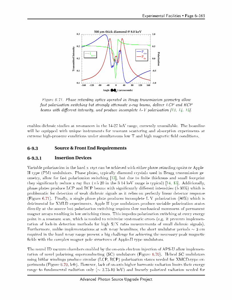
Experimental Facilities Page 6163
0.1
0.1
0.2
0.2
0.3
-1.0
-0.5
0.0
0.5
1.0
-160 -120 -80 -40 0 40 80 120 160
500 µm thick diamond @ 8.0 keV
Itrans
PcircPlin
Tran
smitt
ed In
tens
ityPolarization
Angle θ−θB (arcseconds)
Figure 6.71. Phase retarding optics operated in Bragg transmission geometry allowfast polarization switching but strongly attenuate x-ray beams, deliver LCP and RCPbeams with dierent intensity, and produce incomplete L-V polarization [13, 14, 15].
enables dichroic studies at resonances in the 14-27 keV range, currently unavailable. The beamlinewill be equipped with unique instruments for resonant scattering and absorption experiments atextreme high-pressure conditions under simultaneous low T and high magnetic eld conditions.
6-9.3 Source & Front End Requirements
6-9.3.1 Insertion Devices
Variable polarization in the hard x-rays can be achieved with either phase retarding optics or Apple-II type (PM) undulators. Phase plates, typically diamond crystals used in Bragg transmission ge-ometry, allow for fast polarization switching [13], but due to nite thickness and small footprintthey signicantly reduce x-ray ux (×5-20 in the 3-14 keV range is typical) [14, 15]. Additionally,phase plates produce LCP and RCP beams with signicantly dierent intensities (5-30%) which isproblematic for detection of weak dichroic signals as it relies on perfectly linear detector response(Figure 6.71). Finally, a single phase plate produces incomplete L-V polarization (80%) which isdetrimental for XMLD experiments. Apple-II type undulators produce variable polarization statesdirectly at the source but polarization switching requires slow mechanical movement of permanentmagnet arrays resulting in low switching times. This impedes polarization switching at every energypoint in a resonant scan, which is needed to minimize systematic errors (e.g. it prevents implemen-tation of lock-in detection methods for high S/N ratio measurements of small dichroic signals).Furthermore, unlike implementations at soft x-ray beamlines, the short undulator periods ∼ 3 cmrequired in the hard x-ray range present a big challenge for achieving the necessary peak magneticelds with the complex magnet pole structures of Apple-II type undulators.
The round ID vacuum chambers enabled by the on-axis electron injection of APS-U allow implemen-tation of novel polarizing superconducting (SC) undulators (Figure 6.70). Helical SC undulatorsusing bilar windings produce circular (LCP, RCP) polarization states needed for XMCD-type ex-periments (Figure 6.70, left). However, lack of on-axis higher harmonic radiation limits their energyrange to fundamental radiation only (∼ 2.75-10 keV) and linearly polarized radiation needed for
Advanced Photon Source Upgrade Project
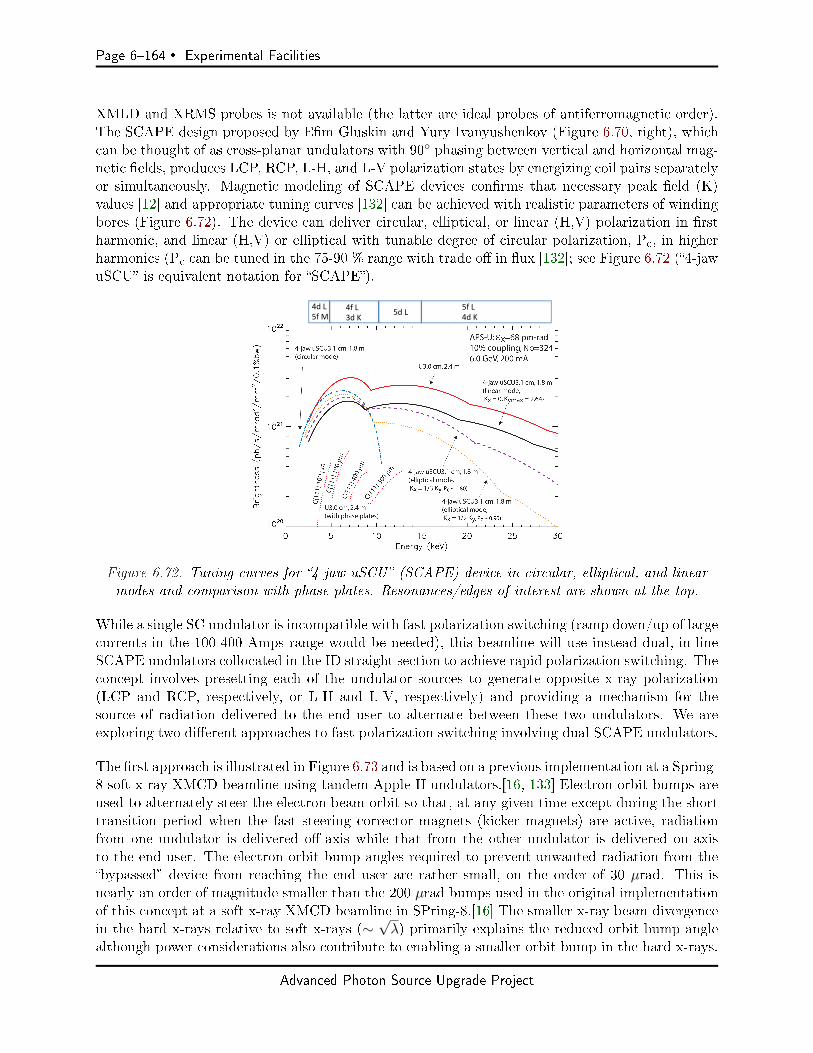
Page 6164 Experimental Facilities
XMLD and XRMS probes is not available (the latter are ideal probes of antiferromagnetic order).The SCAPE design proposed by Em Gluskin and Yury Ivanyushenkov (Figure 6.70, right), whichcan be thought of as cross-planar undulators with 90 phasing between vertical and horizontal mag-netic elds, produces LCP, RCP, L-H, and L-V polarization states by energizing coil pairs separatelyor simultaneously. Magnetic modeling of SCAPE devices conrms that necessary peak eld (K)values [12] and appropriate tuning curves [132] can be achieved with realistic parameters of windingbores (Figure 6.72). The device can deliver circular, elliptical, or linear (H,V) polarization in rstharmonic, and linear (H,V) or elliptical with tunable degree of circular polarization, Pc, in higherharmonics (Pc can be tuned in the 75-90 % range with trade o in ux [132]; see Figure 6.72 (4-jawuSCU is equivalent notation for SCAPE).
4dL5fM
4fL3dK 5dL 5fL
4dK
Figure 6.72. Tuning curves for 4-jaw uSCU (SCAPE) device in circular, elliptical, and linearmodes and comparison with phase plates. Resonances/edges of interest are shown at the top.
While a single SC undulator is incompatible with fast polarization switching (ramp down/up of largecurrents in the 100-400 Amps range would be needed), this beamline will use instead dual, in-lineSCAPE undulators collocated in the ID straight section to achieve rapid polarization switching. Theconcept involves presetting each of the undulator sources to generate opposite x-ray polarization(LCP and RCP, respectively, or L-H and L-V, respectively) and providing a mechanism for thesource of radiation delivered to the end user to alternate between these two undulators. We areexploring two dierent approaches to fast polarization switching involving dual SCAPE undulators.
The rst approach is illustrated in Figure 6.73 and is based on a previous implementation at a Spring-8 soft x-ray XMCD beamline using tandem Apple-II undulators.[16, 133] Electron orbit bumps areused to alternately steer the electron beam orbit so that, at any given time except during the shorttransition period when the fast steering corrector magnets (kicker magnets) are active, radiationfrom one undulator is delivered o-axis while that from the other undulator is delivered on-axisto the end user. The electron orbit bump angles required to prevent unwanted radiation from thebypassed device from reaching the end user are rather small, on the order of 30 µrad. This isnearly an order of magnitude smaller than the 200 µrad bumps used in the original implementationof this concept at a soft x-ray XMCD beamline in SPring-8.[16] The smaller x-ray beam divergencein the hard x-rays relative to soft x-rays (∼
√λ) primarily explains the reduced orbit bump angle
although power considerations also contribute to enabling a smaller orbit bump in the hard x-rays.
Advanced Photon Source Upgrade Project

Experimental Facilities Page 6165
The smaller orbit bumps require ∼ × 7 lower elds in the fast steering corrector magnets, whichtranslates into reduced perturbation of the electron beam orbit and may lead to higher switchingfrequencies. In order to achieve polarization modulation at 10 Hz with a duty cycle of 80% orhigher, the synced, transient current ramp times in the fast steering corrector magnets producingthe orbit bumps would need to be 10 msec or faster. Higher polarization switching frequencies above10 Hz may be achievable with this method. Calculations used to derive the size of the requiredorbit bumps, including power considerations and polarization purity, are described below in Section6-9.3.2.
Figure 6.73. Fast polarization switching using two in-line SCAPE undulators and electronorbit bumps to provide an alternating source of polarized x-rays with opposite polariza-tion. Orbit bumps are in the horizontal plane. The ellipses in the gure are steering cor-rector magnets. The steering corrector magnet between the two IDs is a DC magnet pro-viding a static ∼ 30 µrad bump while the other four are fast correctors. The implemen-tation of this scheme in the hard x-rays enables smaller orbit bumps of ∼ 30 µrad rela-tive to the 200 µrad bumps implemented previously at a Spring-8 soft x-ray beamline[16].
An alternative scheme for polarization switching, currently under development, involves applyinga small ∼ 6 Amps undulator current bump that alternates between the insertion devices in orderto shift undulator harmonic energy by an amount comparable to its bandwidth (Figure 6.74).The monochromator downstream eectively becomes a selector of polarization since ux from thedetuned device is reduced by ∼ × 100 (see Figure 6.74 right [134]). Polarization modulation inthe 1-10 Hz range may be achieved in this scheme with use of secondary coils wrapped around theprimary NbTi coils in the SCAPE devices. These secondary coils would use small lament NbTiwire specically designed for fast current ramps with lower AC (hysteresis) losses than those inregular NbTi wire.
While the undulator current bump approach has an advantage over the electron orbit bumpapproach in that it does not directly perturb the electron orbit, an o-project R&D is still requiredto bring this concept into reality. The electron orbit bump approach can be implemented withcurrent technology and is therefore a lower risk approach. It also carries the potential to enablefaster polarization switching, perhaps even at kHz rates. Therefore, we currently plan to implementthe electron orbit bump approach at the beamline. If the o-project R&D work on the undulatorcurrent bump were to lead to a practical solution in the near future, we will evaluate its possibleimplementation at that time.
Advanced Photon Source Upgrade Project

Page 6166 Experimental Facilities
Figure 6.74. (left) Scheme for rapid polarization switching utilizing dual 4-jaw SCAPE SCundulators (Middle) Time-dependent current bumps used for polarization modulation (LCP/RCPor L-H/L-V) and (right) harmonic energy shift with 6.4% change in K (∼ 6 A current) value.
The wide energy range and polarization tunability of the SCAPE devices enables XMCD, XMLD,and XRMS measurements in the 2.75-27 keV energy range covering all resonances of interest (seetop bar of Figure 6.72). These insertion devices are revolutionary in many respects: 1) they providelarge polarized ux gains in the 3-14 keV range by replacing phase retarding optics, 2) they enableXMCD/XMLD measurements at higher energies (14-27 keV) where Bragg transmission phase platesare either impractical or very inecient, and 3) when two devices are used in tandem they enablepolarization modulation in the 1-10 Hz range (and possibly higher) while delivering on-axis beamswith alternating polarization (in contrast with approaches that use dierent optical paths for beamswith opposite polarization emanating from canted undulators where polarization selection is donewith a chopper).[135]
6-9.3.2 Orbit Bump Angle with Dual SCAPE Undulators
A successful implementation of the electron orbit bump scheme requires accepting most of the centralcone from the undulator delivering on-axis radiation while minimizing radiation leakage from thebypassed, o-axis, undulator. Figure 6.75 shows angular ux density distribution (ph/s/mrad2/0.1%BW) for a 3.0 cm, 1.5 m long SCAPE device at selected energies, with APS-U operated in brightnessmode. Similar results are expected for timing mode since the beam divergence is dominated by thesingle electron photon divergence. A 0.5×0.5 mm2 white beam aperture placed at 25 m from thecenter of the ID straight accepts 20 µrad and is shown superimposed on the plots. This apertureis sucient to accept nearly all of the central cone radiation at 8 and 17 keV, and most of it evenat a low energy of 2.7 keV (note that the relative change in ux density with angle is the same forlinear and circular polarization modes). The total ux for circular (linear) polarization through thisaperture at 8 keV is 3.1×10¹⁴ (2.6×10¹⁴) ph/s/0.1% BW. At 2.7 keV the corresponding numbers are3.9×1014 (2.4×10¹⁴) ph/s/0.1% BW. At 17 keV (third harmonic) the total ux for elliptical (linear)polarization is 1.3×10¹⁴ (1.4×10¹⁴). The undulator settings in elliptical mode are Kx=1/3 Ky.
The amount of on-axis radiation leakage from the bypassed device can be quantied as a function ofthe horizontal orbit bump angle by integrating the ux density in Figure 6.75 through the 0.5×0.5mm2 aperture at 25 m, as this aperture is shifted in the horizontal direction. The results aresummarized in Figure 6.76. By selecting a horizontal electron orbit bump of 30 µrad, the leakedon-axis ux through the aperture from the bypassed undulator is 0.5% or less of the ux from theactive undulator at 8 and 17 keV keV. This leaked fraction increases at lower energies but does notreach 5% even at 2.7 keV. The leaked radiation, which adds incoherently to the radiation from theactive undulator and has opposite polarization, eectively reduces the degree of polarization seen
Advanced Photon Source Upgrade Project
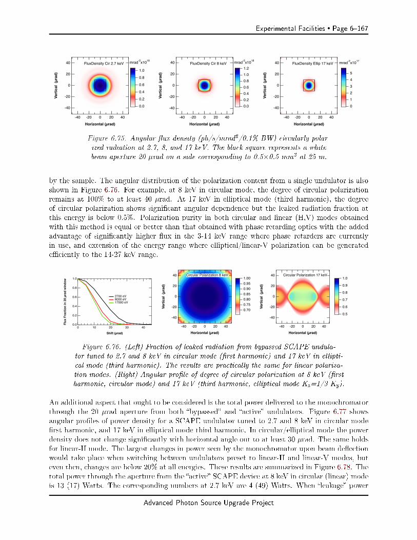
Experimental Facilities Page 6167
-40
-20
0
20
40
Vert
ical
(µr
ad)
-40 -20 0 20 40
Horizontal (µrad)
1.0
0.8
0.6
0.4
0.2
0.0
mrad-2x10¹⁸ FluxDensity Cir 2.7 keV
-40
-20
0
20
40
Vert
ical
(µr
ad)
-40 -20 0 20 40
Horizontal (µrad)
1.21.00.80.60.40.20.0
mrad-2x10¹⁸ FluxDensity Cir 8 keV
-40
-20
0
20
40
Vert
ical
(µr
ad)
-40 -20 0 20 40
Horizontal (µrad)
543210
mrad-2x10¹⁷FluxDensity Ellip 17 keV
Figure 6.75. Angular ux density (ph/s/mrad2/0.1% BW) circularly polar-ized radiation at 2.7, 8, and 17 keV. The black square represents a whitebeam aperture 20 µrad on a side corresponding to 0.5×0.5 mm2 at 25 m.
by the sample. The angular distribution of the polarization content from a single undulator is alsoshown in Figure 6.76. For example, at 8 keV in circular mode, the degree of circular polarizationremains at 100% to at least 40 µrad. At 17 keV in elliptical mode (third harmonic), the degreeof circular polarization shows signicant angular dependence but the leaked radiation fraction atthis energy is below 0.5%. Polarization purity in both circular and linear (H,V) modes obtainedwith this method is equal or better than that obtained with phase retarding optics with the addedadvantage of signicantly higher ux in the 3-14 keV range where phase retarders are currentlyin use, and extension of the energy range where elliptical/linear-V polarization can be generatedeciently to the 14-27 keV range.
1.0
0.8
0.6
0.4
0.2
0.0Flux
Fra
ctio
n in
20
µrad
win
dow
403020100
Shift (µrad)
2700 eV 8000 eV 17000 eV
-40
-20
0
20
40
Vert
ical
(µr
ad)
-40 -20 0 20 40
Horizontal (µrad)
1.000.950.900.850.800.750.70
Circular Polarization 8 keV
-40
-20
0
20
40
Vert
ical
(µr
ad)
-40 -20 0 20 40
Horizontal (µrad)
1.0
0.9
0.8
0.7
0.6
0.5
Circular Polarization 17 keV
Figure 6.76. (Left) Fraction of leaked radiation from bypassed SCAPE undula-tor tuned to 2.7 and 8 keV in circular mode (rst harmonic) and 17 keV in ellipti-cal mode (third harmonic). The results are practically the same for linear polariza-tion modes. (Right) Angular prole of degree of circular polarization at 8 keV (rstharmonic, circular mode) and 17 keV (third harmonic, elliptical mode Kx=1/3 Ky).
An additional aspect that ought to be considered is the total power delivered to the monochromatorthrough the 20 µrad aperture from both bypassed and active undulators. Figure 6.77 showsangular proles of power density for a SCAPE undulator tuned to 2.7 and 8 keV in circular moderst harmonic, and 17 keV in elliptical mode third harmonic. In circular/elliptical mode the powerdensity does not change signicantly with horizontal angle out to at least 30 µrad. The same holdsfor linear-H mode. The largest changes in power seen by the monochromator upon beam deectionwould take place when switching between undulators preset to linear-H and linear-V modes, buteven then, changes are below 20% at all energies. These results are summarized in Figure 6.78. Thetotal power through the aperture from the active SCAPE device at 8 keV in circular (linear) modeis 13 (17) Watts. The corresponding numbers at 2.7 keV are 4 (49) Watts. When leakage power
Advanced Photon Source Upgrade Project
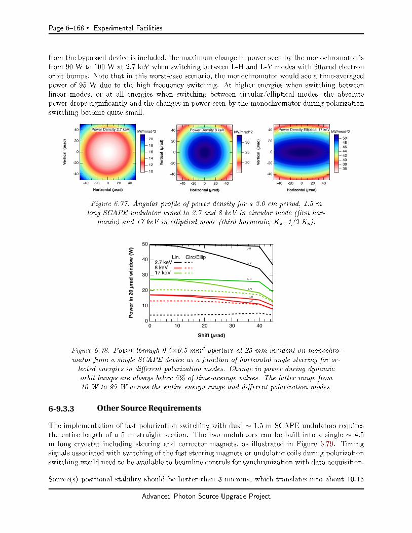
Page 6168 Experimental Facilities
from the bypassed device is included, the maximum change in power seen by the monochromator isfrom 90 W to 100 W at 2.7 keV when switching between L-H and L-V modes with 30µrad electronorbit bumps. Note that in this worst-case scenario, the monochromator would see a time-averagedpower of 95 W due to the high frequency switching. At higher energies when switching betweenlinear modes, or at all energies when switching between circular/elliptical modes, the absolutepower drops signicantly and the changes in power seen by the monochromator during polarizationswitching become quite small.
-40
-20
0
20
40
Vert
ical
(µr
ad)
-40 -20 0 20 40
Horizontal (µrad)
201816141210
kW/mrad^2Power Density 2.7 keV
-40
-20
0
20
40
Vert
ical
(µr
ad)
-40 -20 0 20 40
Horizontal (µrad)
30
25
20
kW/mrad^2Power Density 8 keV
Power density, circular polarization
6
The figures above show the angular power density for circular polarized radiation emitted at 8 keV (left) and 2.7 keV (right). The units in the color scale are kW/mrad2.
The total power for circular polarization through the beamline aperture for 8 keV is 13 W and for 2.7 keV is 4 W.
-40
-20
0
20
40
Vert
ical
(µr
ad)
-40 -20 0 20 40
Horizontal (µrad)
201816141210
kW/mrad^2Power Density 2.7 keV
-40
-20
0
20
40
Vert
ical
(µr
ad)
-40 -20 0 20 40
Horizontal (µrad)
30
25
20
kW/mrad^2Power Density 8 keV
Power density, circular polarization
6
The figures above show the angular power density for circular polarized radiation emitted at 8 keV (left) and 2.7 keV (right). The units in the color scale are kW/mrad2.
The total power for circular polarization through the beamline aperture for 8 keV is 13 W and for 2.7 keV is 4 W.
17 keV, 3 harmonic
10
-40
-20
0
20
40
Vert
ical
(µr
ad)
-40 -20 0 20 40
Horizontal (µrad)
5048464442403836
kW/mrad^2Power Density Elliptical 17 keV
Figure 6.77. Angular prole of power density for a 3.0 cm period, 1.5 mlong SCAPE undulator tuned to 2.7 and 8 keV in circular mode (rst har-
monic) and 17 keV in elliptical mode (third harmonic, Kx=1/3 Ky).
50
40
30
20
10
0
Pow
er in
20
µrad
win
dow
(W)
403020100
Shift (µrad)
Lin. Circ/Ellip2.7 keV 8 keV 17 keV
L-H
L-V
L-H
L-V
L-HL-V
Figure 6.78. Power through 0.5×0.5 mm2 aperture at 25 mm incident on monochro-mator from a single SCAPE device as a function of horizontal angle steering for se-lected energies in dierent polarization modes. Change in power during dynamicorbit bumps are always below 5% of time-average values. The latter range from10 W to 95 W across the entire energy range and dierent polarization modes.
6-9.3.3 Other Source Requirements
The implementation of fast polarization switching with dual ∼ 1.5 m SCAPE undulators requiresthe entire length of a 5 m straight section. The two undulators can be built into a single ∼ 4.5m long cryostat including steering and corrector magnets, as illustrated in Figure 6.79. Timingsignals associated with switching of the fast steering magnets or undulator coils during polarizationswitching would need to be available to beamline controls for synchronization with data acquisition.
Source(s) positional stability should be better than 3 microns, which translates into about 10-15
Advanced Photon Source Upgrade Project
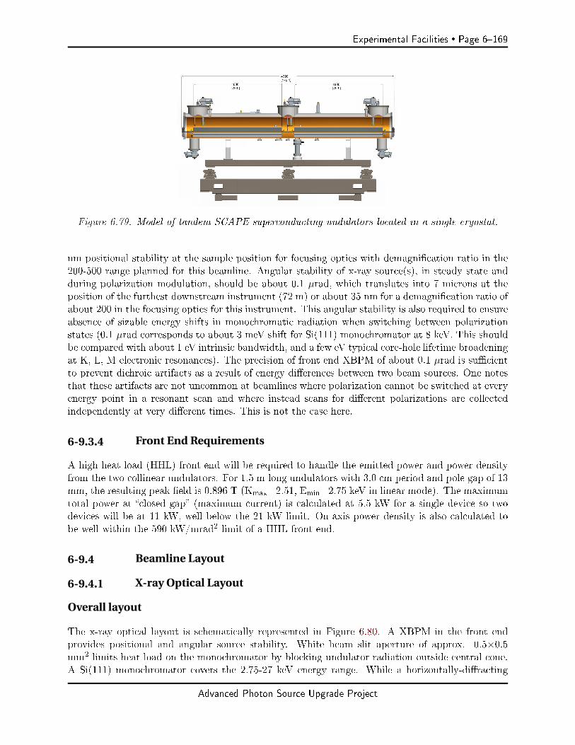
Experimental Facilities Page 6169
Figure 6.79. Model of tandem SCAPE superconducting undulators located in a single cryostat.
nm positional stability at the sample position for focusing optics with demagnication ratio in the200-500 range planned for this beamline. Angular stability of x-ray source(s), in steady state andduring polarization modulation, should be about 0.1 µrad, which translates into 7 microns at theposition of the furthest downstream instrument (72 m) or about 35 nm for a demagnication ratio ofabout 200 in the focusing optics for this instrument. This angular stability is also required to ensureabsence of sizable energy shifts in monochromatic radiation when switching between polarizationstates (0.1 µrad corresponds to about 3 meV shift for Si(111) monochromator at 8 keV. This shouldbe compared with about 1 eV intrinsic bandwidth, and a few eV typical core-hole lifetime broadeningat K, L, M electronic resonances). The precision of front end XBPM of about 0.1 µrad is sucientto prevent dichroic artifacts as a result of energy dierences between two beam sources. One notesthat these artifacts are not uncommon at beamlines where polarization cannot be switched at everyenergy point in a resonant scan and where instead scans for dierent polarizations are collectedindependently at very dierent times. This is not the case here.
6-9.3.4 Front End Requirements
A high heat load (HHL) front end will be required to handle the emitted power and power densityfrom the two collinear undulators. For 1.5 m long undulators with 3.0 cm period and pole gap of 13mm, the resulting peak eld is 0.896 T (Kmax=2.51, Emin=2.75 keV in linear mode). The maximumtotal power at closed gap (maximum current) is calculated at 5.5 kW for a single device so twodevices will be at 11 kW, well below the 21 kW limit. On-axis power density is also calculated tobe well within the 590 kW/mrad2 limit of a HHL front end.
6-9.4 Beamline Layout
6-9.4.1 X-ray Optical Layout
Overall layout
The x-ray optical layout is schematically represented in Figure 6.80. A XBPM in the front endprovides positional and angular source stability. White beam slit aperture of approx. 0.5×0.5mm2 limits heat load on the monochromator by blocking undulator radiation outside central cone.A Si(111) monochromator covers the 2.75-27 keV energy range. While a horizontally-diracting
Advanced Photon Source Upgrade Project

Page 6170 Experimental Facilities
monochromator may present an advantage in terms of vibrations (better tolerated in the horizontalplane due to the larger source size), power restrictions on the linear-vertical mode may force avertically-diracting geometry which preserves intensity of linear-horizontal polarized beams. Sec-ond crystal PZT stages for ne control of both pitch and roll angular motions are needed for dynamiccontrol (feedback) of horizontal and vertical beam position using XBPMs located in the end stations(0.1 micro-rad accuracy). Vertically-reecting, toroidal and cylindrical mirrors provide near full IDux into focused beams in the 10-40 micron range at two end stations, in addition to harmonicrejection. These mirrors are used for experiments that do not require spot sizes below 20 microns(e.g. XMCD/XMLD experiments at ambient or low pressures) or experiments that cannot use astrongly convergent beam (e.g. high Q resolution x-ray resonant magnetic scattering experiments athigh pressure). An in-vacuum polarimeter is used to measure the polarization content of the beam.Diamond XBPMs are used for active feedback stabilization of beam position utilizing monochro-mator second crystal PZT stages. An in-vacuum chopper operating at approximately 1 kHz is usedin double lock-in measurements where signals from photodiodes undergo beam on/o modulation(for dark current subtraction) in addition to polarization modulation (dichroic eect measurement).K-B mirrors with xed curvature are used to deliver high ux (approx. 25-40% of ID beam) into ∼150 (250) nm focused beams at short (long) working distance instruments at two end stations.
Figure 6.80. Simplied version/schematic of x-ray optical layout of POLAR beamline.
Description of optical components
Universal SCU (×2) (New): Two identical SCAPE superconducting undulators placed ina single cryostat with steering and corrector magnets provide tunable polarization states (LCP,RCP, L-H, L-V) in the 2.75-27 keV energy range with ability to rapidly modulate polarization usingelectron orbit bumps or undulator current bumps.
Double Crystal Monochromator (∼ 29 m): LN2 Internally-cooled, low vibration (< 0.1 micro-rad) diracting DCM with provision for two sets of crystals. Second crystal stage equipped withpitch and roll PZT stages for dynamic feedback of beam position using diamond x-ray beam positionmonitors in end stations (0.1 micro-rad stability). Si(111) crystals are used for the entire 2.75-27 keV range with the exception of a narrow energy range around 2.8 keV when operating incircular or L-V polarization modes (θBragg=45°). A second set of 6H-SiC crystals can potentiallypreserve polarization/intensity at these energies (L-edges of 4d metals Ru, Rh, Pd are in the 2.8-3.3 keV range). The (0006) reection of 6H-SiC crystals is at θBragg=61.5°at 2.8 keV and thermalconductivity, peak reectivity, and energy resolution are similar to Si (Section 6-9.4.2). In addition,SCAPE undulators can generate elliptical polarization at these energies to preserve the degree ofcircular polarization after the mono.
Advanced Photon Source Upgrade Project
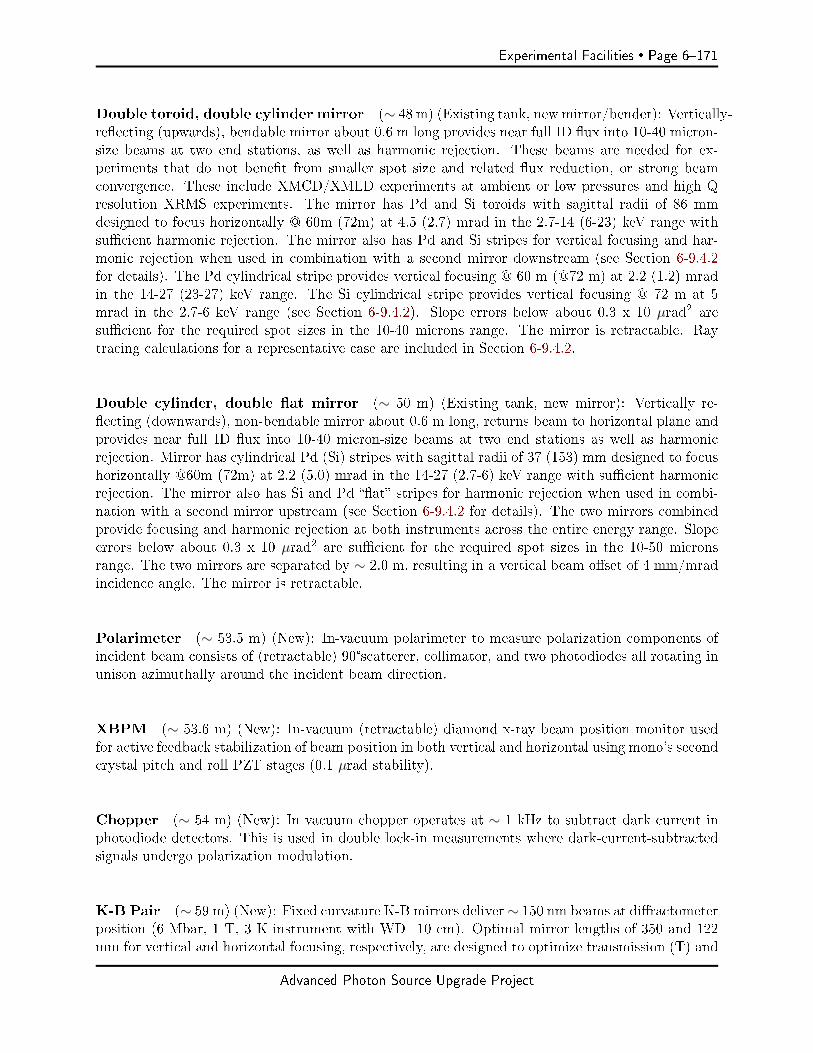
Experimental Facilities Page 6171
Double toroid, double cylinder mirror (∼ 48 m) (Existing tank, new mirror/bender): Vertically-reecting (upwards), bendable mirror about 0.6 m long provides near full ID ux into 10-40 micron-size beams at two end stations, as well as harmonic rejection. These beams are needed for ex-periments that do not benet from smaller spot size and related ux reduction, or strong beamconvergence. These include XMCD/XMLD experiments at ambient or low pressures and high Qresolution XRMS experiments. The mirror has Pd and Si toroids with sagittal radii of 86 mmdesigned to focus horizontally @ 60m (72m) at 4.5 (2.7) mrad in the 2.7-14 (6-23) keV range withsucient harmonic rejection. The mirror also has Pd and Si stripes for vertical focusing and har-monic rejection when used in combination with a second mirror downstream (see Section 6-9.4.2for details). The Pd cylindrical stripe provides vertical focusing @ 60 m (@72 m) at 2.2 (1.2) mradin the 14-27 (23-27) keV range. The Si cylindrical stripe provides vertical focusing @ 72 m at 5mrad in the 2.7-6 keV range (see Section 6-9.4.2). Slope errors below about 0.3 x 10 µrad2 aresucient for the required spot sizes in the 10-40 microns range. The mirror is retractable. Raytracing calculations for a representative case are included in Section 6-9.4.2.
Double cylinder, double at mirror (∼ 50 m) (Existing tank, new mirror): Vertically re-ecting (downwards), non-bendable mirror about 0.6 m long, returns beam to horizontal plane andprovides near full ID ux into 10-40 micron-size beams at two end stations as well as harmonicrejection. Mirror has cylindrical Pd (Si) stripes with sagittal radii of 37 (153) mm designed to focushorizontally @60m (72m) at 2.2 (5.0) mrad in the 14-27 (2.7-6) keV range with sucient harmonicrejection. The mirror also has Si and Pd at stripes for harmonic rejection when used in combi-nation with a second mirror upstream (see Section 6-9.4.2 for details). The two mirrors combinedprovide focusing and harmonic rejection at both instruments across the entire energy range. Slopeerrors below about 0.3 x 10 µrad2 are sucient for the required spot sizes in the 10-50 micronsrange. The two mirrors are separated by ∼ 2.0 m, resulting in a vertical beam oset of 4 mm/mradincidence angle. The mirror is retractable.
Polarimeter (∼ 53.5 m) (New): In-vacuum polarimeter to measure polarization components ofincident beam consists of (retractable) 90°scatterer, collimator, and two photodiodes all rotating inunison azimuthally around the incident beam direction.
XBPM (∼ 53.6 m) (New): In-vacuum (retractable) diamond x-ray beam position monitor usedfor active feedback stabilization of beam position in both vertical and horizontal using mono's secondcrystal pitch and roll PZT stages (0.1 µrad stability).
Chopper (∼ 54 m) (New): In vacuum chopper operates at ∼ 1 kHz to subtract dark current inphotodiode detectors. This is used in double lock-in measurements where dark-current-subtractedsignals undergo polarization modulation.
K-B Pair (∼ 59 m) (New): Fixed curvature K-B mirrors deliver∼ 150 nm beams at diractometerposition (6 Mbar, 1 T, 3 K instrument with WD=10 cm). Optimal mirror lengths of 350 and 122mm for vertical and horizontal focusing, respectively, are designed to optimize transmission (T) and
Advanced Photon Source Upgrade Project
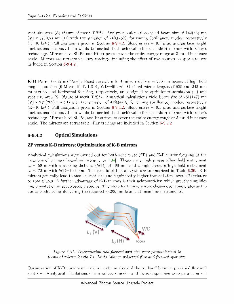
Page 6172 Experimental Facilities
spot size area (S) (gure of merit T/S2). Analytical calculations yield beam size of 142(83) nm(V) x 97(107) nm (H) with transmission of 24%(25%) for timing (brilliance) modes, respectively(E=10 keV). Full analysis is given in Section 6-9.4.2. Slope errors ∼ 0.1 µrad and surface heightuctuations of about 1 nm would be needed, both achievable for such short mirrors with today'stechnology. Mirrors have Si, Pd and Pt stripes to cover the entire energy range at 3 mrad incidenceangle. Mirrors are retractable. Ray tracings, including the eect of two sources on spot size, areincluded in Section 6-9.4.2.
K-B Pair (∼ 72 m) (New): Fixed curvature K-B mirrors deliver ∼ 250 nm beams at high eldmagnet position (6 Mbar, 10 T, 1.3 K, WD=40 cm). Optimal mirror lengths of 535 and 243 mmfor vertical and horizontal focusing, respectively, are designed to optimize transmission (T) andspot size area (S) (gure of merit T/S2). Analytical calculations yield beam size of 261(147) nm(V) x 237(267) nm (H) with transmission of 41%(42%) for timing (brilliance) modes, respectively(E=10 keV). Full analysis is given in Section 6-9.4.2. Slope errors ∼ 0.1 µrad and surface heightuctuations of about 1 nm would be needed, both achievable for such short mirrors with today'stechnology. Mirrors have Si, Pd, and Pt stripes to cover the entire energy range at 3 mrad incidenceangle. The mirrors are retractable. Ray tracings are included in Section 6-9.4.2.
6-9.4.2 Optical Simulations
ZP versus K-B mirrors; Optimization of K-B mirrors
Analytical calculations were carried out for both zone plate (ZP) and K-B mirror focusing at thelocations of primary beamline instruments [134]. These are a high pressure/low eld instrumentat ∼ 59 m with a working distance (WD) of 100 mm and a high pressure/high eld instrumentat ∼ 72 m with WD=400 mm. The results of this analysis are summarized in Table 6.30. K-Bmirrors generally lead to smaller spot size and signicantly higher transmission (over ×2) relativeto zone plates. A further advantage of K-B mirrors is their achromaticity, which greatly simpliesimplementation in spectroscopic studies. Therefore K-B mirrors were chosen over zone plates as theoptics of choice for delivering the required ∼ 200 nm beams at beamline instruments.
L1(V)L2(H)
WD
Figure 6.81. Transmission and focused spot size were parameterized interms of mirror length L1, L2 to balance polarized ux and focused spot size.
Optimization of K-B mirrors involved a careful analysis of the trade-o between polarized ux andspot size. Analytical calculations of mirror transmission and focused spot size were parameterized
Advanced Photon Source Upgrade Project

Experimental Facilities Page 6173
Table 6.30. Analytical calculations of x-ray focal size and transmission (at 10 keV) obtainedwith zone plate and K-B mirror focusing optics for two dierent instruments with work-ing distances (100 mm and 400 mm). Source-to- image distance is 59 m (100 mm WD)and 72 m (400 mm WD). K-B mirrors are separated by 10 mm. Spot sizes and transmis-sion are given for timing 48 bunch (brilliance 324 bunch) modes, respectively, using 42pm-rad lattice parameters. K-B mirror lengths are averaged of optimized lengths for tim-ing and brilliance modes. K-B mirror length is obtained by optimizing gure of merit T/S2
as described elsewhere in this section. K-B transmission includes mirrors' reectivity (0.81)
Transmission Focal size FWHM (H) Focal size FWHM (V)48b(324b) 48b(324b) 48b(324b)
100 mm WDZone Plate 9(10)% 167(188) nm 117(80) nm∆r (out. zone)= 50 nmD = 750 µm3720 zones
KB pair 24(25)% 97(107) nm 142(83) nm122 (H) x 350 (V) mm2
3 mrad incidence
400 mm WDZone Plate 17(18)% 525(596) nm 348(210) nm∆r (out. zone)= 100 nmD = 1500 µm3720 zones
KB pair 41 (42)% 237(267) nm 261(147) nm243 (H) x 535 (V) mm2
3 mrad incidence
Advanced Photon Source Upgrade Project

Page 6174 Experimental Facilities
in terms of the length of KB mirrors (see Figure 6.81) [134]. Geometrical constraints accountfor location and WD for the two instruments and a 10 mm separation between mirrors (verticalfocusing mirror placed upstream of horizontal focusing mirror). Undulator length of 1.8 m wasused to calculate source size and divergence. Calculations of spot size include contributions fromdiraction and demagnication (slope errors, neglected in the analytical calculations, would needto be about 0.1 micro-rad). Mirror incidence angle is 3 mrad. Calculations were done using sourcesize and divergence values for the 42 pm-rad APS-U lattice in 48 (timing) and 324 (brilliance)bunch modes, as well as for current APS values. We dene (S1, T1) and (S2, T2) as the spot sizesand transmissions for V and H mirrors, respectively. We also dene a compounded spot size andtransmission for both mirrors, S=S1×S2 and T=T1×T2.
Figure 6.82. Inverse of compounded spot-size 1/S (left), compounded trans-mission T (middle) and gure of merit T/S2 (right) as function of V, H mir-
ror lengths for APS-U 48 bunch mode (E=10 keV). Units for left and right plotsare mm2 and mm4, respectively. Data is for instrument at 72 m (WD=400 mm).
Figure 6.83. Inverse of compounded spot-size 1/S (left), compounded trans-mission T (middle) and gure of merit T/S2 (right) as function of V, H mir-
ror lengths for APS-U 48 bunch mode (E=10 keV). Units for left and right plotsare mm2 and mm4, respectively. Data is for instrument at 59 m (WD=100 mm).
Figure 6.82 (left) shows a plot of 1/S (inverse compounded spot size) for the 72 m instrument(WD=400 mm) as a function of V, H mirror lengths. Results for 48 bunch/timing mode are shown(E=10 keV). Spot size rst decreases with a decrease in mirror length due to increased demagni-cation, only to increase again at short mirror lengths due to diraction. Figure 6.82 (middle) showscompounded transmission T which increases with mirror length until full illumination is achieved.In order to balance transmitted ux and spot size, a gure of merit is dened as T/S2 and plottedin Figure 6.82 (right) as function of mirror length. The maximum in this 3D plot corresponds to516 (246) mm V(H) mirror lengths, and 259(237) nm V(H) spot size with a combined transmissionof 0.41 (including 0.81 reectivity from double bounce). Other gures of merit were also explored.
Advanced Photon Source Upgrade Project
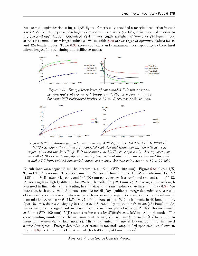
Experimental Facilities Page 6175
For example, optimization using a T/S3 gure of merit only provided a marginal reduction in spotsize (< 7%) at the expense of a larger decrease in ux density (∼ 15%) hence deemed inferior tothe power=2 optimization. Optimized V(H) mirror length is slightly dierent for 324 bunch modeat 554(241) mm. Mirror length values shown in Table 6.30 are averages of optimized values for 48and 324 bunch modes. Table 6.30 shows spot sizes and transmission corresponding to these nalmirror lengths in both timing and brilliance modes.
Figure 6.84. Energy-dependence of compounded K-B mirror trans-mission and spot size in both timing and brilliance modes. Data arefor short WD instrument located at 59 m. Beam size units are mm.
Figure 6.85. Brilliance gain relative to current APS dened as (SAPS/SAPS-U )*(TAPS-U/TAPS) where S and T are compounded spot size and transmission, respectively. Top
(right) plots are for short(long) WD instruments at 59(72) m, respectively. Average gains are∼ ×50 at 10 keV with roughly ×20 coming from reduced horizontal source size and the addi-tional ×2.5 from reduced horizontal source divergence. Average gains are ∼ × 80 at 20 keV.
Calculations were repeated for the instrument at 59 m (WD=100 mm). Figure 6.84 shows 1/S,T, and T/S2 contours. The maximum in T/S2 for 48 bunch mode (10 keV) is obtained for 327(125) mm V(H) mirror lengths, and 140 (97) nm spot sizes with a combined transmission of 0.23.Mirror length is slightly dierent for 324 bunch mode, 371(121) mm V(H). Averaged mirror lengthwas used in nal calculations leading to spot sizes and transmission values listed in Table 6.30. Wenote that both spot size and mirror transmission display signicant energy dependence as a resultof decreasing source size and divergence with increasing energy. For example, compounded mirrortransmission becomes ∼ 60 (42)% at 27 keV for long (short) WD instruments in 48 bunch mode.Spot size area decreases slightly in the 10-27 keV range, by up to 25(5)% in 324(48) bunch mode,respectively, but a signicant increase in spot size takes place below 5 keV. For the instrumentat 59 m (WD=100 mm), V(H) spot size increases by 57(90)% at 3 keV in 48 bunch mode. Thecorresponding numbers for the instrument at 72 m (WD=400 mm) are 42(50)% (this is due toincrease in source size at low energies). Mirror transmission drops at low energy due to increasedsource divergence. Energy dependence of transmission and compounded spot sizes are shown inFigure 6.85 for the short WD instrument (both 48 and 324 bunch modes).
Advanced Photon Source Upgrade Project

Page 6176 Experimental Facilities
It is instructive to compare gains in brilliance for the optimized focused beams in APS-U relativeto the current APS source. Figure 6.90 shows the gure of merit for brilliance gains[(SAPS/SAPS-U)×(TAPS-U/TAPS)] for both instruments. The gains average to ×50 at 10 keV (trans-mission contributes ∼ ×2.5, a result of reduced beam divergence, and spot size ∼ ×20, a result ofreduced beam size).
Ray tracing calculations for Toroidal mirror
Ray tracing calculations were carried out for a double toroid mirror located at ∼ 49 m from thesource using APS-U source parameters corresponding to 48 bunch mode. The active area of themirror is 600 mm. Meridional and sagittal slope errors are 0.3 µrad x 10 µrad, respectively. Thesespecs are standard even with today's mirror technology. In these calculations, each toroid is designedto focus at the location of a primary instrument (diractometer @ ∼ 59 m and high-eld magnet@ ∼ 73 m) at 3 mrad incidence angle. Sagittal radii Rs=50(95) mm and meridional radii 5.5(10.5)km were used for 59(73) m instruments, respectively (mirror is bendable). Figure 6.86 shows spotsizes of 10×20 µm (HxV) and 20×40 µm for the instruments at 59 and 73 m, respectively (E= 8keV). All rays are intercepted so transmission is only limited by reectivity of mirror (0.9). Usinga 1.8 m long, SCAPE undulator as source and Si(111) bandwidth, the calculated ux in focusedbeams is 4.5×10¹³ ph/sec.
-40
-20
0
20
40
Vert
ical
(x1
0-3 m
m)
-40 -20 0 20 40
Horizontal (x10-3 mm)
Rays: 1.98e+05 SDx: 0.00737 SDy: 0.00412 Inten: 1.98e+05 FWHMx: 0.0193 FWHMy: 0.0096949->59, 48 bunch, 0.3x10 µradxµrad
600
500
400
300
200
100
0
-40
-20
0
20
40
Vert
ical
(x1
0-3 m
m)
-40 -20 0 20 40
Horizontal (x10-3 mm)
Rays: 1.98e+05 SDx: 0.0152 SDy: 0.00871 Inten: 1.97e+05 FWHMx: 0.0411 FWHMy: 0.021149->73, 48 bunch, 0.3x10 µradxµrad
160140120100806040200
Figure 6.86. Ray tracing calculations of focused beams at diractometer (59 m) and high eldmagnet (73 m) positions obtained with double toroid mirror located at 49 m from the source.
Ray tracing/Hybrid calculations for K-B mirrors
The analytical calculations used to optimize K-B mirror length and T/S2 gure of merit describedin Section 6-9.4.2 placed the x-ray source at the center of the straight section. Ray tracing/hybridcalculations were carried out separately for each one of the two undulator sources envisioned for thisbeamline (1.8 m undulators, sources separated by 2 m). Calculations are for E=8 keV in brilliance(324 bunch) mode, and ux estimates are for a single insertion device in circular polarization mode.Figure 6.87 shows ray tracing/hybrid calculations of focused beams using the downstream SCAPEundulator as the source (hence distances to instruments are 58 m and 71 m, respectively) and mirrorlengths obtained from T/S2 optimization (given in Table 6.30, Section 6-9.4.2).
The eect of K-B mirrors not imaging a source at the center of the ID, but rather two sourcesdisplaced by ± 1 m, was evaluated in more detail. Figure 6.88 shows ray tracing/hybrid calculations
Advanced Photon Source Upgrade Project
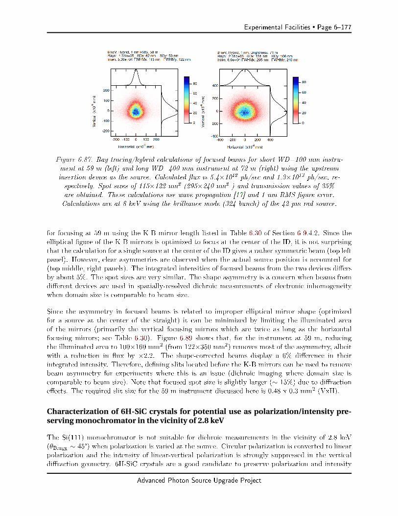
Experimental Facilities Page 6177
Figure 6.87. Ray tracing/hybrid calculations of focused beams for short WD=100 mm instru-ment at 59 m (left) and long WD=400 mm instrument at 72 m (right) using the upstreaminsertion device as the source. Calculated ux is 5.4×10¹² ph/sec and 1.3×10¹³ ph/sec, re-spectively. Spot sizes of 115×122 nm2 (295×240 nm2 ) and transmission values of 35%are obtained. These calculations use wave propagation [17] and 1 nm RMS gure error.Calculations are at 8 keV using the brilliance mode (324 bunch) of the 42 pm-rad source.
for focusing at 59 m using the K-B mirror length listed in Table 6.30 of Section 6-9.4.2. Since theelliptical gure of the K-B mirrors is optimized to focus at the center of the ID, it is not surprisingthat the calculation for a single source at the center of the ID gives a rather symmetric beam (top leftpanel). However, clear asymmetries are observed when the actual source position is accounted for(top middle, right panels). The integrated intensities of focused beams from the two devices diersby about 5%. The spot sizes are very similar. The shape asymmetry is a concern when beams fromdierent devices are used in spatially-resolved dichroic measurements of electronic inhomogeneitywhen domain size is comparable to beam size.
Since the asymmetry in focused beams is related to improper elliptical mirror shape (optimizedfor a source at the center of the straight) it can be minimized by limiting the illuminated areaof the mirrors (primarily the vertical focusing mirrors which are twice as long as the horizontalfocusing mirrors; see Table 6.30). Figure 6.89 shows that, for the instrument at 59 m, reducingthe illuminated area to 100×160 mm2 (from 122×350 mm2) removes most of the asymmetry, albeitwith a reduction in ux by ×2.2. The shape-corrected beams display a 6% dierence in theirintegrated intensity. Therefore, dening slits located before the K-B mirrors can be used to removebeam asymmetry for experiments where this is an issue (dichroic imaging where domain size iscomparable to beam size). Note that focused spot size is slightly larger (∼ 15%) due to diractioneects. The required slit size for the 59 m instrument discussed here is 0.48 x 0.3 mm2 (VxH).
Characterization of 6H-SiC crystals for potential use as polarization/intensity pre-serving monochromator in the vicinity of 2.8 keV
The Si(111) monochromator is not suitable for dichroic measurements in the vicinity of 2.8 keV(θBragg ∼ 45°) when polarization is varied at the source. Circular polarization is converted to linearpolarization and the intensity of linear-vertical polarization is strongly suppressed in the verticaldiraction geometry. 6H-SiC crystals are a good candidate to preserve polarization and intensity
Advanced Photon Source Upgrade Project

Page 6178 Experimental Facilities
Figure 6.88. Ray tracings/hybrid calculations of focused beams at 59 m (short WD instru-ment) at E=10 keV in brightness (324 bunch) mode. A 1 nm RMS gure error is used.The focused beams are images of an undulator source in the middle of the straight sec-tion (top left) and sources displaced by 1 m (top middle) and -1 m (top right). Since theasymmetry is due to improper elliptical mirror shape when the source is displaced, the ef-fect is more signicant in the vertical direction (mirror length for vertical focusing is morethan double the length of horizontal focusing mirrors, see Table 6.30 of Section 6-9.4.2).
Figure 6.89. Focusing at 59 m from undulator sources at + 1 m (top left) and -1 m (top right)from the center of the straight section. The asymmetry in spot size is largely removed by limiting
the illuminated area of the mirror with a dening slit, with a reduction in ux by ∼ × 2.2.
Advanced Photon Source Upgrade Project
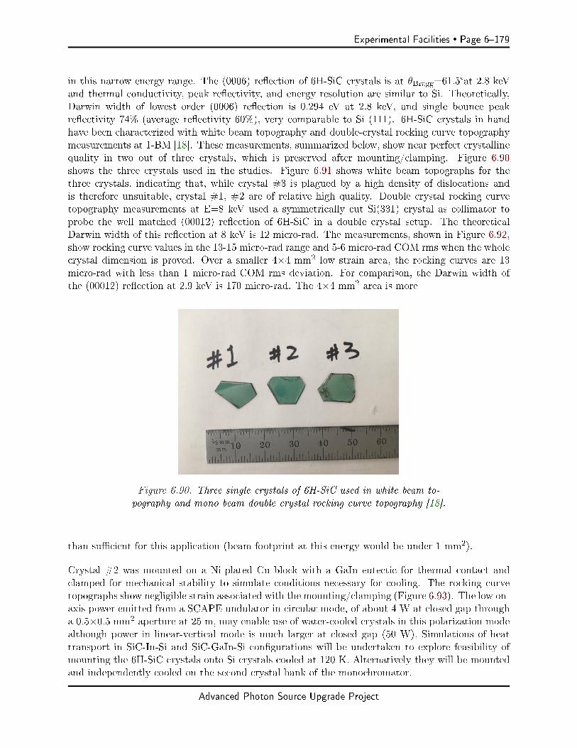
Experimental Facilities Page 6179
in this narrow energy range. The (0006) reection of 6H-SiC crystals is at θBragg=61.5°at 2.8 keVand thermal conductivity, peak reectivity, and energy resolution are similar to Si. Theoretically,Darwin width of lowest order (0006) reection is 0.294 eV at 2.8 keV, and single bounce peakreectivity 74% (average reectivity 60%), very comparable to Si (111). 6H-SiC crystals in handhave been characterized with white beam topography and double-crystal rocking curve topographymeasurements at 1-BM [18]. These measurements, summarized below, show near perfect crystallinequality in two out of three crystals, which is preserved after mounting/clamping. Figure 6.90shows the three crystals used in the studies. Figure 6.91 shows white beam topographs for thethree crystals, indicating that, while crystal #3 is plagued by a high density of dislocations andis therefore unsuitable, crystal #1, #2 are of relative high quality. Double crystal rocking curvetopography measurements at E=8 keV used a symmetrically cut Si(331) crystal as collimator toprobe the well matched (00012) reection of 6H-SiC in a double crystal setup. The theoreticalDarwin width of this reection at 8 keV is 12 micro-rad. The measurements, shown in Figure 6.92,show rocking curve values in the 13-15 micro-rad range and 5-6 micro-rad COM rms when the wholecrystal dimension is proved. Over a smaller 4×4 mm2 low strain area, the rocking curves are 13micro-rad with less than 1 micro-rad COM rms deviation. For comparison, the Darwin width ofthe (00012) reection at 2.9 keV is 170 micro-rad. The 4×4 mm2 area is more
Figure 6.90. Three single crystals of 6H-SiC used in white beam to-pography and mono beam double crystal rocking curve topography [18].
than sucient for this application (beam footprint at this energy would be under 1 mm2).
Crystal #2 was mounted on a Ni-plated Cu block with a GaIn eutectic for thermal contact andclamped for mechanical stability to simulate conditions necessary for cooling. The rocking curvetopographs show negligible strain associated with the mounting/clamping (Figure 6.93). The low on-axis power emitted from a SCAPE undulator in circular mode, of about 4 W at closed gap througha 0.5×0.5 mm2 aperture at 25 m, may enable use of water-cooled crystals in this polarization modealthough power in linear-vertical mode is much larger at closed gap (50 W). Simulations of heattransport in SiC-In-Si and SiC-GaIn-Si congurations will be undertaken to explore feasibility ofmounting the 6H-SiC crystals onto Si crystals cooled at 120 K. Alternatively they will be mountedand independently cooled on the second crystal bank of the monochromator.
Advanced Photon Source Upgrade Project

Page 6180 Experimental Facilities
Figure 6.91. White beam topographs for crystals #3 (left), #2 (middle) and #1 (right). Crys-tal #3 is plagued with dislocations and is therefore unsuitable. Crystal #2 is of high qual-ity although some superscrew dislocations (micropipes) are observed. Crystal #3 is of high-est quality with a much lower density of micropipes (courtesy of XiangRong Huang [18]).
Figure 6.92. Rocking curve topographs of (00012) reection of 6H-SiC crystal #2 (8 keV) over a 2×4 mm2 area showing peak reectiv-
ity and Darwin width near theoretical values (courtesy T. Kolodziej [18]).
Figure 6.93. 6H-SiC crystal mounted on Ni-plated Cu block with GaIn eutectic for ther-mal contact (left) and corresponding rocking curve topographs (middle/right). The mount-ing/clamping did not introduce signicant strain in the crystal (courtesy T. Kolodziej [18]).
Advanced Photon Source Upgrade Project
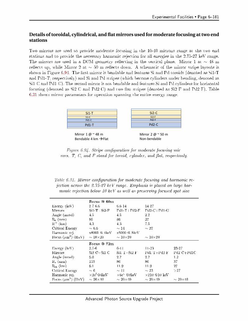
Experimental Facilities Page 6181
Details of toroidal, cylindrical, and flat mirrors used for moderate focusing at two endstations
Two mirrors are used to provide moderate focusing in the 10-40 microns range at the two endstations and to provide the necessary harmonic rejection for all energies in the 2.75-27 keV range.The mirrors are used in a DCM geometry reecting in the vertical plane. Mirror 1 at ∼ 48 mreects up, while Mirror 2 at ∼ 50 m reects down. A schematic of the mirror stripe layouts isshown in Figure 6.94. The rst mirror is bendable and features Si and Pd toroids (denoted as Si1-Tand Pd1-T, respectively) and Si and Pd stripes (which become cylinders under bending, denoted asSi1-C and Pd1-C). The second mirror is not bendable and features Si and Pd cylinders for horizontalfocusing (denoted as Si2-C and Pd2-C) and two at stripes (denoted as Si2-F and Pd2-F). Table6.31 shows mirror parameters for operation spanning the entire energy range.
Si1-T
Pd1-T
Mirror1@~48m Bendable4kmàFlat
Si2-C
Pd2-C
Mirror2@~50m Non-bendable
S1-CPd1-C
Si2-FPd2-F
Figure 6.94. Stripe conguration for moderate focusing mir-rors. T, C, and F stand for toroid, cylinder, and at, respectively.
Table 6.31. Mirror conguration for moderate focusing and harmonic re-jection across the 2.75-27 keV range. Emphasis is placed on large har-monic rejection below 10 keV as well as preserving focused spot size
Focus @ 60mEnergy (keV) 2.7-6.6 6.6-14 14-27Mirrors Si1-T+Si2-F Pd1-T+Pd2-F Pd2-C+Pd1-CAngle (mrad) 4.5 4.5 2.2Rs (mm) 86 86 37Rm (km) 4.3 4.3 7.5Critical Energy ∼ 6.6 ∼ 14 ∼ 27Harmonic rej. x8000 @ 4keV x8000 @ 8keVFocus (µm2) (HxV) ∼ 10×20 ∼ 10×20 ∼ 10×20
Focus @ 72mEnergy (keV) 2.7-6 6-11 11-23 23-27Mirrors Si2-C+Si1-C Si1-T+Si2-F Pd1-T+Pd2-F Pd2-C+Pd1CAngle (mrad) 5.0 2.7 2.7 1.2Rs (mm) 153 86 86 37Rm (km) 6.1 11.9 11.9 27Critical Energy ∼ 6 ∼ 11 ∼ 23 >27Harmonic rej. ×2e5@4keV ×6e4 @8keV ×210 @10 keVFocus (µm2) (HxV) ∼ 20×40 ∼ 20×40 ∼ 20×40 ∼ 20×40
Advanced Photon Source Upgrade Project
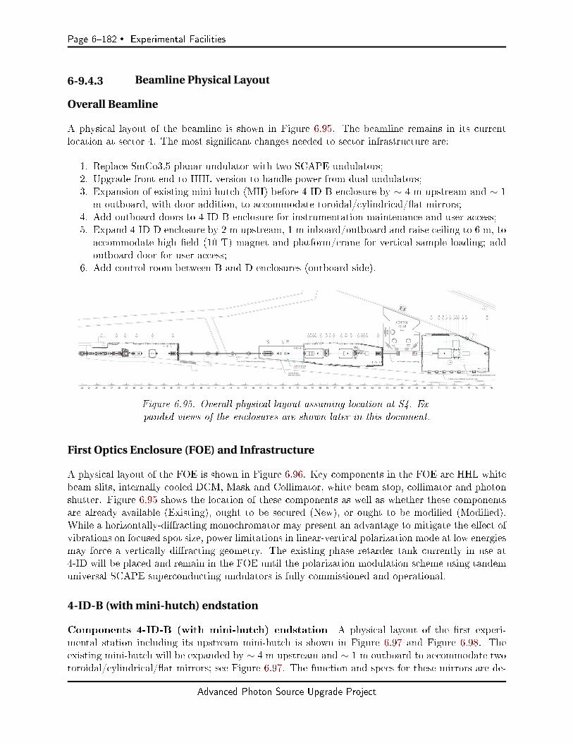
Page 6182 Experimental Facilities
6-9.4.3 Beamline Physical Layout
Overall Beamline
A physical layout of the beamline is shown in Figure 6.95. The beamline remains in its currentlocation at sector 4. The most signicant changes needed to sector infrastructure are:
1. Replace SmCo3.5 planar undulator with two SCAPE undulators;2. Upgrade front end to HHL version to handle power from dual undulators;3. Expansion of existing mini-hutch (MH) before 4-ID-B enclosure by ∼ 4 m upstream and ∼ 1
m outboard, with door addition, to accommodate toroidal/cylindrical/at mirrors;4. Add outboard doors to 4-ID-B enclosure for instrumentation maintenance and user access;5. Expand 4-ID-D enclosure by 2 m upstream, 1 m inboard/outboard and raise ceiling to 6 m, to
accommodate high eld (10 T) magnet and platform/crane for vertical sample loading; addoutboard door for user access;
6. Add control room between B and D enclosures (outboard side).
Figure 6.95. Overall physical layout assuming location at S4. Ex-panded views of the enclosures are shown later in this document.
First Optics Enclosure (FOE) and Infrastructure
A physical layout of the FOE is shown in Figure 6.96. Key components in the FOE are HHL whitebeam slits, internally cooled DCM, Mask and Collimator, white beam stop, collimator and photonshutter. Figure 6.95 shows the location of these components as well as whether these componentsare already available (Existing), ought to be secured (New), or ought to be modied (Modied).While a horizontally-diracting monochromator may present an advantage to mitigate the eect ofvibrations on focused spot size, power limitations in linear-vertical polarization mode at low energiesmay force a vertically diracting geometry. The existing phase retarder tank currently in use at4-ID will be placed and remain in the FOE until the polarization modulation scheme using tandemuniversal SCAPE superconducting undulators is fully commissioned and operational.
4-ID-B (with mini-hutch) endstation
Components 4-ID-B (with mini-hutch) endstation A physical layout of the rst experi-mental station including its upstream mini-hutch is shown in Figure 6.97 and Figure 6.98. Theexisting mini-hutch will be expanded by ∼ 4 m upstream and ∼ 1 m outboard to accommodate twotoroidal/cylindrical/at mirrors; see Figure 6.97. The function and specs for these mirrors are de-
Advanced Photon Source Upgrade Project
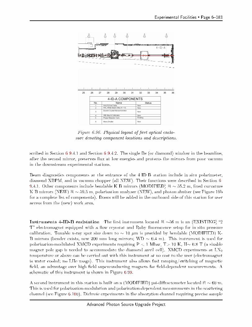
Experimental Facilities Page 6183
A A A
0 0 A
0
L ¢ i;;;i dt56 tj!iW • A W .. A
A A
0 0
I ,. . 1• A "*r" a;w.,.
4-10-A
1111111 I111111111 I111111111 I111111111 I111111111 I111111111 I111111111 I111111111 I111111111 I111111111 I111111111 I111111111 I1
25 26 27 28 29 30 31 32 33 34 35 36
4-ID-A COMPONENTS
No. Name Status
1 HHLFE Exit Table New
2 HHL White Beam Slits (H + V) New
3 New Double Crystal Monochromator
4 WB Stop & Collimator New
5 Phase Retarder Tank Existing
6 Mono Shutter New
Figure 6.96. Physical layout of rst optical enclo-sure denoting component locations and descriptions.
scribed in Section 6-9.4.1 and Section 6-9.4.2. The single Be (or diamond) window in the beamline,after the second mirror, preserves ux at low energies and protects the mirrors from poor vacuumin the downstream experimental stations.
Beam diagnostics components at the entrance of the 4-ID-B station include in-situ polarimeter,diamond XBPM, and in-vacuum chopper (all NEW). Their functions were described in Section 6-9.4.1. Other components include bendable K-B mirrors (MODIFIED) @ ∼ 55.2 m, xed curvatureK-B mirrors (NEW) @ ∼ 59.5 m, polarization analyzer (NEW), and photon shutter (see Figure 19bfor a complete list of components). Doors will be added in the outboard side of this station for useraccess from the (new) work area.
Instruments 4-ID-B endstation The rst instrument located @ ∼56 m is an (EXISTING) 2T electromagnet equipped with a ow cryostat and Ruby uorescence setup for in-situ pressurecalibration. Tunable x-ray spot size down to ∼ 10 µm is provided by bendable (MODIFIED) K-B mirrors (bender exists, new 200 mm long mirrors; WD ∼ 0.4 m). This instrument is used forpolarization-modulated XMCD experiments requiring P < 1 Mbar, T> 10 K, H∼ 0.8 T (a sizablemagnet pole gap is needed to accommodate the diamond anvil cell). XMCD experiments at LN2
temperature or above can be carried out with this instrument at no cost to the user (electromagnetis water cooled; no LHe usage). This instrument also allows fast ramping/switching of magneticeld, an advantage over high eld superconducting magnets for eld-dependent measurements. Aschematic of this instrument is shown in Figure 6.99.
A second instrument in this station is built on a (MODIFIED) psi-diractometer located @ ∼ 60 m.This is used for polarization-modulation and polarization-dependent measurements in the scatteringchannel (see Figure 6.100). Dichroic experiments in the absorption channel requiring precise sample
Advanced Photon Source Upgrade Project
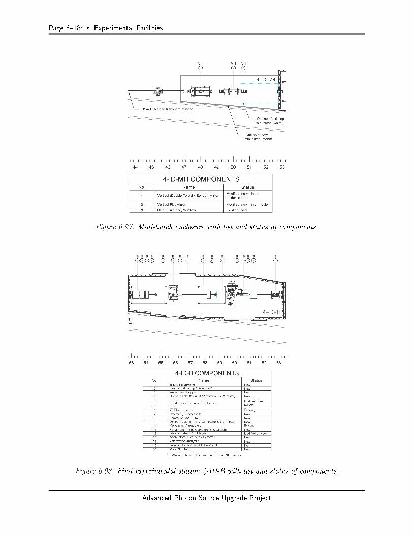
Page 6184 Experimental Facilities
Figure 6.97. Mini-hutch enclosure with list and status of components.
Figure 6.98. First experimental station 4-ID-B with list and status of components.
Advanced Photon Source Upgrade Project
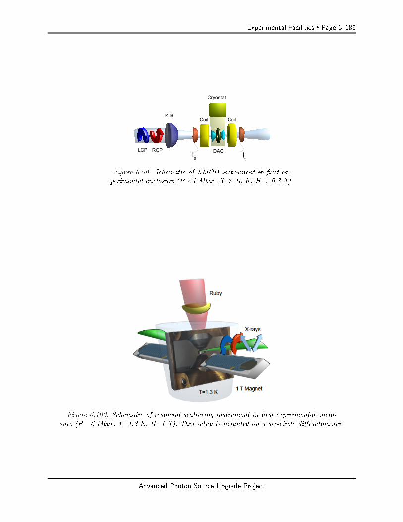
Experimental Facilities Page 6185
I0
It
K-BCoil Coil
Cryostat
DACRCPLCP
Figure 6.99. Schematic of XMCD instrument in rst ex-perimental enclosure (P <1 Mbar, T > 10 K, H < 0.8 T).
Figure 6.100. Schematic of resonant scattering instrument in rst experimental enclo-sure (P= 6 Mbar, T=1.3 K, H=1 T). This setup is mounted on a six-circle diractometer.
Advanced Photon Source Upgrade Project

Page 6186 Experimental Facilities
alignment or highest spatial resolution can also be done in this instrument. X-ray focusing for thisinstrument ∼ 100 x 100 nm2 is provided by xed-curvature K-B mirrors described in Section 6-9.4.1and Section 6-9.4.2 (WD=0.1 m). This allows for mapping of electronic inhomogeneity as well asreaching extreme pressures of up to 6 Mbar. Panoramic DACs made out of high thermal conductivitymaterial CuBe are used to access large swaths of reciprocal space and reach low temperatures. Anonline Ruby uorescence system is used for in-situ pressure calibration. Magnetic eld is limited to∼ 1 T in order to enable short WD (highest spatial resolution) and preserve angular access (limitedwith high eld SC magnets). Flow cryostats are used to avoid vibrations, and mapping is doneby scanning the DAC with high resolution stages compatible with operation at low T in magneticelds. A schematic of this instrument is shown in Figure 6.100 (diractometer not shown). Modieddiractometer will have an Eulerian cradle with an open top to access high Bragg angles at lowresonant energies and a robust 2-theta arm to support in-vacuum polarization/energy analyzers.
4-ID-D endstation
Components 4-ID-D A physical layout of the second experimental station 4-ID-D is shown inFigure 6.101. The existing enclosure will be expanded by ∼ 2 m upstream and 1 m inboard/outboardto accommodate the 10 T high eld magnet, a platform required for safe top loading of samples,accessories such as dewars for cryogenic cooling and online Ruby/Raman systems for pressure cali-bration. A footprint of current and expanded enclosures is shown in Figure 6.101. A door is addedin the outboard side of the station for user access from the (new) work area. Components in thisenclosure include diamond XBPM, xed curvature K-B mirrors, optical tables/mounts for detectionof incident, transmitted, and uorescence intensity, and Ruby uorescence/Raman systems. Thehutch ceiling ought to be raised to 6 m to enable top loading of a sample insert into a magnet withthe crane operation.
Instruments 4-ID-D A high eld superconducting magnet with 10 T longitudinal eld and abore large enough (∼ 3) to accommodate a membrane-driven diamond anvil cell is located @ ∼73.2 m. This instrument is used for polarization-modulated XMCD and XMLD experiments (1 Ttransverse and vertical elds are provided by two additional pairs of split coils). X-ray focusing forthis instrument ∼ 200 (V) × 250 (H) nm2 is provided by xed-curvature K-B mirrors described inSection 6-9.4.1 and Section 6-9.4.2 (WD=0.4 m). This allows mapping electronic inhomogeneity aswell as reaching extreme pressures up to 6 Mbar. Online Ruby uorescence and Raman systemsare used for in-situ pressure calibration. The sample is cooled with He vapor to avoid vibrations.Attocube stages compatible with 10 T elds and low temperatures are used to scan the DAC forreal space mapping. Experiments in both transmission and uorescence channels are accessible, thelatter using axial (backscattering) or radial (gasket) geometries. A schematic of this instrument isshown in Figure 6.102.
6-9.4.4 Additional
Detectors
Experiments in the absorption channel require incident, transmitted, and uorescence intensitymonitors with high dynamic range and linearity. Calibrated photodiodes are preferred for incident
Advanced Photon Source Upgrade Project
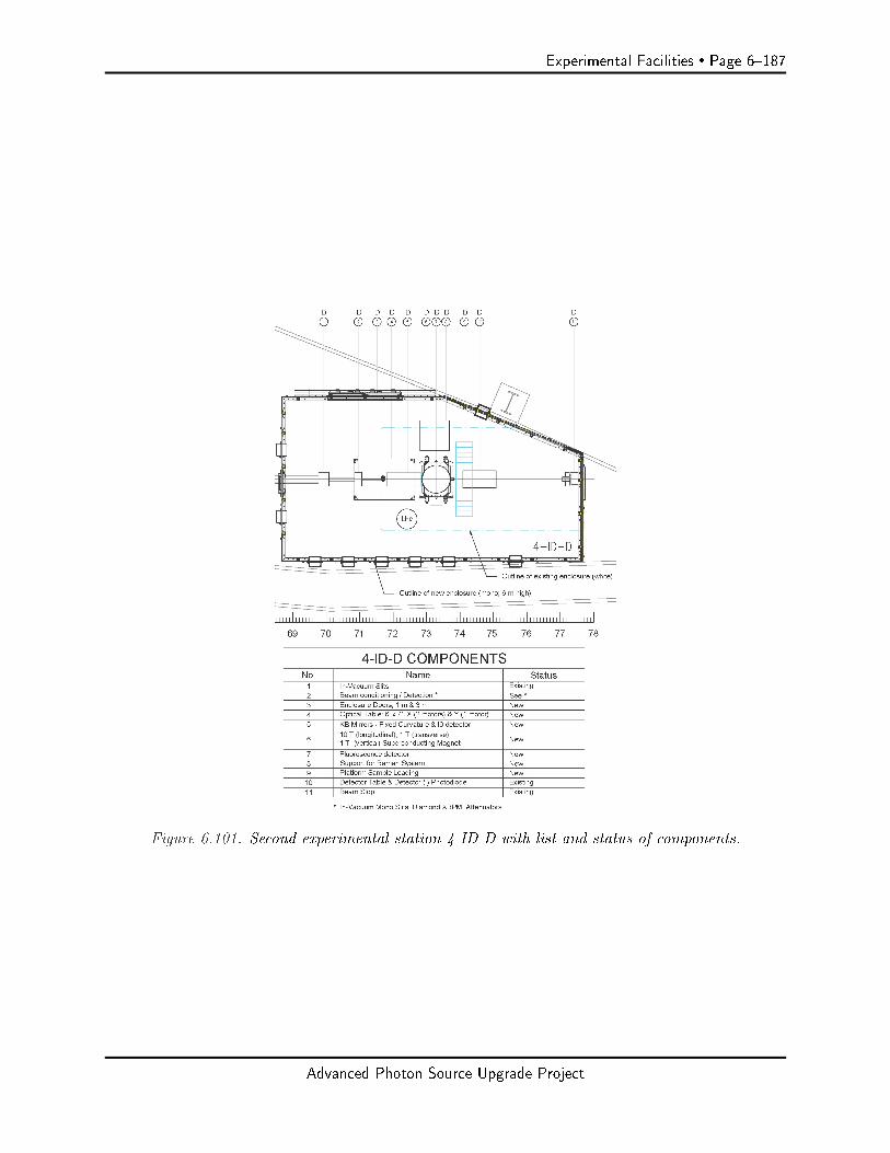
Experimental Facilities Page 6187
Figure 6.101. Second experimental station 4-ID-D with list and status of components.
Advanced Photon Source Upgrade Project
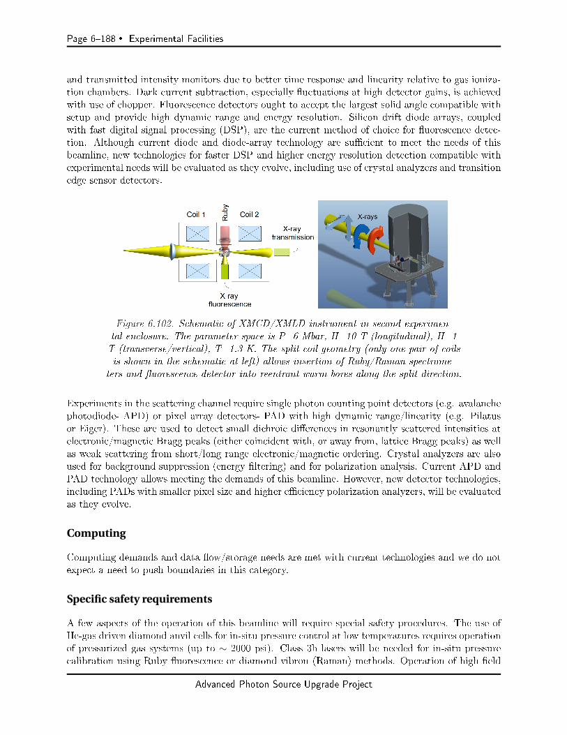
Page 6188 Experimental Facilities
and transmitted intensity monitors due to better time response and linearity relative to gas ioniza-tion chambers. Dark current subtraction, especially uctuations at high detector gains, is achievedwith use of chopper. Fluorescence detectors ought to accept the largest solid angle compatible withsetup and provide high dynamic range and energy resolution. Silicon drift diode arrays, coupledwith fast digital signal processing (DSP), are the current method of choice for uorescence detec-tion. Although current diode and diode-array technology are sucient to meet the needs of thisbeamline, new technologies for faster DSP and higher energy resolution detection compatible withexperimental needs will be evaluated as they evolve, including use of crystal analyzers and transitionedge sensor detectors.
Figure 6.102. Schematic of XMCD/XMLD instrument in second experimen-tal enclosure. The parameter space is P=6 Mbar, H=10 T (longitudinal), H=1T (transverse/vertical), T=1.3 K. The split coil geometry (only one pair of coilsis shown in the schematic at left) allows insertion of Ruby/Raman spectrome-
ters and uorescence detector into reentrant warm bores along the split direction.
Experiments in the scattering channel require single photon counting point detectors (e.g. avalanchephotodiode- APD) or pixel array detectors- PAD with high dynamic range/linearity (e.g. Pilatusor Eiger). These are used to detect small dichroic dierences in resonantly scattered intensities atelectronic/magnetic Bragg peaks (either coincident with, or away from, lattice Bragg peaks) as wellas weak scattering from short/long range electronic/magnetic ordering. Crystal analyzers are alsoused for background suppression (energy ltering) and for polarization analysis. Current APD andPAD technology allows meeting the demands of this beamline. However, new detector technologies,including PADs with smaller pixel size and higher eciency polarization analyzers, will be evaluatedas they evolve.
Computing
Computing demands and data ow/storage needs are met with current technologies and we do notexpect a need to push boundaries in this category.
Specific safety requirements
A few aspects of the operation of this beamline will require special safety procedures. The use ofHe-gas driven diamond anvil cells for in-situ pressure control at low temperatures requires operationof pressurized gas systems (up to ∼ 2000 psi). Class 3b lasers will be needed for in-situ pressurecalibration using Ruby uorescence or diamond vibron (Raman) methods. Operation of high eld
Advanced Photon Source Upgrade Project
Experimental Facilities Page 6189
(10 T) magnet will require user access restrictions when magnet is energized and elevated platformfor top sample loading. Radioactive samples will require special handling. All of the above canbe addressed with implementation of controls, interlocks, special operating procedures, and usertraining.
Specific conventional facilities requirements
Air temperature stability in the experimental enclosures will be needed to maintain spot size sta-bility. This will be accomplished with installation of air conditioning units and curtains at doorlocations in experimental enclosures. Vibration isolation, also critical for spot size stability, willbe achieved with use of He ow/vapor cooling in low temperature experiments, as opposed tocompressor-based closed cycle refrigerators. Optical tables and instrument support tables/frameswill be designed for optimal vibration isolation.
Support facilities
Helium capture facilities are needed to reduce the operational costs of running vibration-free Heow/vapor cryostats in low temperature experiments. The APS is currently planning the installationof such a system at selected locations around the ring, to be liqueed elsewhere at Argonne. It isexpected that cost to users will be 1/3 of current cost. Facilities for work with diamond anvilcells are needed, especially for complex sample loading in multi-mbar experiments. This includesprogrammable micro-manipulators for DAC loading, a gas loading system, laser drilling facilityfor gasket drilling, glove box for reactive samples, and a facility for EDM drilling of Be gaskets.Finally, radioactive samples are currently loaded at the Actinide facilities (Argonne Bldg 200). Thesefacilities are not optimized for loading of high pressure samples and it will be greatly benecialfor APS to explore having a designated, properly equipped laboratory for handling of radioactivesamples, if this were to be feasible.
6-9.5 R&D Needs
R&D activities are also needed in the area of preservation of circular and L-V polarization (or L-H for a horizontally-diracting mono) in a narrow range of energy around 2.8 keV where Si(111)crystals diract at θBragg=45°. While this narrow, low energy region is secondary in importance tothe higher energy 3.5-27 keV range, it does provide a unique capability (L-edges of 4d metals Ru,Rh, Pd are in the 2.8-3.3 keV range). Note that XRMS experiments using L-H (L-V) polarizationare unaected with a vertically (horizontally) diracting monochromator. The possibility of using6H-SiC crystals as a monochromator is being explored in collaboration with the Optics group atAPS. Its lowest order c-axis reection (0006) is at θBragg=61.5°at 2.8 keV. 6H-SiC has excellentthermal conductivity, peak reectivity, and energy resolution. High quality single crystals havebeen secured (Section 6-9.4.2). Since beam footprint at this large Bragg angle is small (∼ 1×1 mm)and penetration depth shallow at this energy (microns), only a small crystal is needed. Crystalsmay be placed on top of internally cooled Si(111) crystals for indirect (contact) cooling, or placedside by side with Si(111) crystals in the second bank of the monochromator with direct or indirectcooling. In circular mode, the on-axis power at closed gap through a 0.5×0.5 mm2 aperture at 25m is only 4 W which may enable use of water cooling (see Section 6-9.4.2 for more details).
Advanced Photon Source Upgrade Project
Page 6190 Experimental Facilities
6-10 APS-U XPCS Beamline
6-10.1 Executive Summary
XPCS characterizes uctuations in condensed matter at a combination of mesoscale length scalesand timescales not otherwise accessible. Signal strengths depend on the x-ray beam coherence andminimum accessible delay times scale inversely with the square of the source brilliance so XPCSwill benet tremendously from APS-U. The preliminary design of an in-place upgrade to existingbeamline 8-ID has been completed. The goal is for this to become a facility fully dedicated tostate-of-the-art WA- and SA-XPCS that fully leverages the outstanding gains in brilliance providedby APS-U. Features of the beamline include uniquely high time-averaged coherent ux, access totime delays as short as 100 ns and high coherent ux in the energy range of 825 keV with thehigher x-ray energies providing penetration into diverse samples and sample environments. Thepreliminary beamline design achieves these objectives via maximally-bright IDs that span the entire8-ID straight section, small horizontal oset mirror pairs and monochromators (single crystal andmultilayer optics), and two experiment stations each with compound (zoom) optical focusing, anddedicated and optimized experiment infrastructure for WA- and SA-XPCS, respectively.
Using WA-XPCS, the beamline will advance studies in a host of key areas in physics, materialsscience, and engineering that include dynamic heterogeneity, structural dynamics in super-cooledliquids, and uctuations associated with competing mesoscale interactions in emergent materials.Using SA-XPCS, the beamline will enable dynamics-related studies in areas as diverse as in siturheometry, nanouidic ow, and high pressure that will signicantly impact key problems in softmatter and advance their potential applications in technologies across an array of sectors includingenergy, transportation, health, agriculture, and national defense.
6-10.2 Scientific Objectives and Capabilities
6-10.2.1 Description of User Community/Stakeholders
Today, XPCS primarily serves a subset of the soft matter and hard condensed matter community.While XPCS has transformed from an expert user only technique 10 years ago to a productiveGeneral User program (the 2009 Arthur Compton award was presented at the APS to the pioneersof XPCS for this very reason), the limitations in coherent ux, and therefore accessible dynamicallength and time scales, has limited systems that can be studied to slowly uctuating materials.Even under these non-ideal conditions, XPCS at the APS is over subscribed with a steadily growinguser community that produces many high impact publications.
With unprecedented gains in coherent ux provided by APS-U, the science enabled for XPCS willextend to a wide range of new and increasingly broad elds such as biological soft matter, materialsunder high pressure, geophysics and glass and super-cooled liquid physics. Moreover existing areasof study will see dramatic gains. With the APS-U providing access to 10100 ns time scales andsensitivity to 1 nm or less length scales, systems in or buried under aqueous media, for example,can be readily examined.
The APS-U Early Science workshops and Early Science document [51], and the subsequent XPCSbeamline workshop, generated signicant enthusiasm from a diverse community and has produced
Advanced Photon Source Upgrade Project
Experimental Facilities Page 6191
specic lists of high impact rst experiments. Partial lists of stakeholder names and aliationsare listed in the brief and full white papers submitted to APS-U as part of the beamline selectionprocess. APS-U will surpass all the other synchrotron light sources (present and upgraded) bydelivering more than 10× more coherent ux across a broad range of energies. XPCS stands togain the highest amongst the many APS-U-enabled techniques as its merits scale quadratically withgains in brilliance.
6-10.2.2 Explicit Statement of Use of APS-U Characteristics and Analysis of Pro-posed Beamline’s World Class/Leading Status
In its most common incarnation, XPCS measures uctuations within a sample by determining theintensity autocorrelation function, g2(Q, t) = [〈I(Q, t′)I(Q, t + t′)〉t′ ]/[〈I(Q, t′)〉2t′ ], of the sample'sx-ray speckle pattern versus delay time (t) and wavevector (Q), where the t′ subscripts denotean average over time t′. The quantity g2(Q, t) is related to the sample's normalized intermediatescattering function (ISF) [f(Q, t) = S(Q, t)/S(Q, 0)] via g2(Q, t) = 1 + A[f(Q, t)]2, where A is thespeckle contrast. The ISF, which is equivalent to the sample's Q- and t-dependent density-densityautocorrelation function, is an important quantity for condensed matter systems and is often keyin comparing theory to experiment. XPCS is nominally equivalent to its laser-light-based analogue,namely PCS, but is challenging because there are many fewer coherent photons in x-ray beamsfrom even the brightest synchrotrons than from laser sources, and also because x-ray scatteringcross-sections are typically small. As a result, a crucial aspect of an XPCS experiment is the SNR.To fully leverage XPCS, it is essential that the source be as bright as possible and it is for thisreason that XPCS is particularly well poised to use the unprecedented source brightness that willbe provided by APS-U.
The XPCS signal-to-noise (SNR) is proportional to n√TtaNp [136], where n is the number of
photons per detector pixel per second, T is the measurement duration, ta is the accumulationtime (integration time of the detector), and Np is the number of pixels. In this expression, n isproportional to ni(dΣ/dΩ)dΩ, where ni is the number of x-rays incident on the sample per second,(dΣ/dΩ) is the sample's x-ray scattering cross-section per unit volume, and dΩ is the solid angle perpixel. The quantity ni is proportional to the incident coherent ux, Fc, which is directly proportionalto the source brightness, B, via Fc = Bλ2/4 [137] so the XPCS SNR is linearly proportional tothe source brightness. Since the brightness of APS-U will exceed by a factor of 100× or more thanthat of the APS today, the APS-U XPCS beamline represents a revolution in the kinds of samplesthat will be accessible for study. Interestingly, while the SNR scales linearly with B, it also scalesas the square root of the accumulation time (which should be a few times smaller than the sample'scorrelation time). It follows that for samples of a given scattering strength, XPCS measurements willbe possible at APS-U on time scales that are about 104× faster than are possible today at the APS.Since the current state-of-the art for diuse scattering measurements corresponds to accumulationtimes of about 1 ms, we anticipate time resolutions at APS-U of 100 ns (roughly the bunch spacing ofAPS-U in 99% coupling mode). The XPCS beamline will also leverage other unique characteristicsof the APS-U source. First, APS-U's uniquely high SR brightness extends to higher x-ray energiesthan NSLS-II, for example. As described in the document Early Science at the Upgraded APS [51],this will allow access to uctuations in considerably more extreme environments. Second, the peakbrightness of APS-U ideally lls the span between the extremely high peak values at x-ray FELsthat often result in sample damage or destruction and the much lower per pulse values at a morecontinuous source like NSLS-II that will preclude measurements at the pulse spacing. Third, the
Advanced Photon Source Upgrade Project
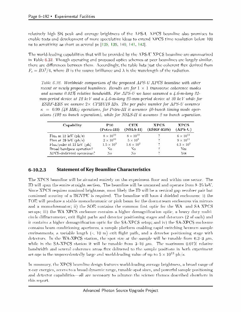
Page 6192 Experimental Facilities
relatively high SR peak and average brightness of the APS-U XPCS beamline also promises toenable tests and development of more speculative ideas to extend XPCS time resolution below 100ns to sensitivity as short as several ps [138, 139, 140, 141, 142].
The world-leading capabilities that will be provided by the APS-U XPCS beamline are summarizedin Table 6.32. Though operating and proposed optics schemes at peer beamlines are largely similar,there are dierences between them. Accordingly, the table lists just the coherent ux derived fromFc = Bλ2/4, where B is the source brilliance and λ is the wavelength of the radiation.
Table 6.32. Worldwide comparison of the proposed APS-U XPCS beamline with otherrecent or newly proposed beamlines. Results are for 1 × 1 transverse coherence modesand assume 0.01% relative bandwidth. For APS-U we have assumed a 4.6-m-long 21-mm-period device at 12 keV and a 4.6-m-long 25-mm-period device at 20 keV while forESRF-EBS we assume 2× CPMU19 IDs. The per pulse number for APS-U assumesκ = 0.99 (48 MHz) operations, for Petra-III it assumes 40-bunch timing mode oper-ations (192 ns bunch separation), while for NSLS-II it assumes 2 ns bunch separation.
Capability P10 CHX XPCS XPCS(Petra-III) (NSLS-II) (ESRF-EBS) (APS-U)
Flux at 12 keV (ph/s) 8× 10¹⁰ 8× 10¹⁰ ? 6× 10¹²
Flux at 20 keV (ph/s) 2× 10¹⁰ 5× 10⁹ ? 9× 10¹¹
Flux/pulse at 12 keV (ph) 1.5× 10³ 1.6× 10² ? 4.3× 10⁵
Broad bandpass operation? No No ? YesXPCS-dedicated operations? No No ? Yes
6-10.2.3 Statement of Key Beamline Characteristics
The XPCS beamline will be situated entirely on the experiment oor and within one sector. TheID will span the entire straight section. The beamline will be uncanted and operate from 825 keV.Since XPCS requires maximal brightness, most likely the ID will be a vertical gap revolver pair butcontinued scrutiny of a HGVPU is required. The beamline will have 4 shielded enclosures: i) theFOE will produce a stable monochromatic or pink beam for the downstream enclosures via mirrorsand a monochromator; ii) the SOE contains the common rst optic for the WA- and SA-XPCSsetups; iii) the WA-XPCS enclosure contains a higher demagnication optic, a heavy duty multi-circle diractometer, exit ight paths and detector positioning stages and detectors (2 of each) andit contains a higher demagnication optic for the SA-XPCS setup; and iv) the SA-XPCS enclosurecontains beam conditioning apertures, a sample platform enabling rapid switching between sampleenvironments, a variable length (< 10 m) exit ight path, and a detector positioning stage withdetectors. In the WA-XPCS station, the spot size at the sample will be tunable from 0.33 µm,while in the SA-XPCS station it will be tunable from 310 µm. The maximum 0.01% relativebandwidth and several coherence areas ux delivered to the sample positions in both experimentset-ups is the unprecedentedly large and world-leading value of up to 5× 10¹³ ph/s.
In summary, the XPCS beamline design features world-leading average brightness, a broad range ofx-ray energies, access to a broad dynamic range, tunable spot sizes, and powerful sample positioningand detector capabilitiesall are necessary to advance the science themes described elsewhere inthis report.
Advanced Photon Source Upgrade Project
Experimental Facilities Page 6193
6-10.3 Source and Front End Requirements
6-10.3.1 Insertion Device
The SNR for XPCS is proportional to the brilliance, B, so an ID that spans an entire straightsection is critical. The required energy range for the beamline is 825 keV and is based on thebalance between the peak brilliance deliverable by APS-U, detector eciency, and the need fortransmission through various sample environments. Continuous tunability over this range is notrequired as there is not a particular scientic motivation to access specic absorption edges. It isuseful, however, to consider 3 broad x-ray-energy ranges, namely low (812 keV), medium (1220keV), and high (2025 keV), that are targeted towards dierent scientic themes. Specics of thedierent energy ranges are provided below:
1. The low range is suitable for experiments where penetration through sample environmentsand radiation damage are not concerns. This regime provides the highest coherent ux.
2. The medium range is best suited for sample environments such as rheometers, shear cells, andcryostats and ovens. The need for increased x-ray penetration mitigates the reduced coherentux.
3. The high range is well suited to biophysical and DNA-templated systems because of theextreme sensitivity of such systems to radiation damage. It will also advance work such asstudies of polyamorphic phase transitions using high pressure environments where penetrationthrough thick diamond anvil cells is often required.
Since XPCS is a time domain technique, source (and optical) considerations that facilitate stabilityor are less sensitive to vibrations are also important. We therefore strongly prefer a monochromatorand experiment goniometer that deect in the horizontal, providing a strong impetus for a HGVPUbecause this allows scattering to occur in the horizontal scattering plane without polarization penal-ties.
There are not any special needs with respect to non-planar polarization or rapid tuning. Examiningthe list of possible planar IDs for APS-U, we conclude that, for the moment, a vertical gap revolverdevice is required to provide the maximum brightness over the broad tuning range specied above.Figure 6.103 shows tuning curves for a combination of APS-U planar IDs that meet the needsdiscussed above. For comparison, we have also plotted the tuning curve for a HGVPU that isclosest to meeting our needs. The two features in this tuning curve that dampen our enthusiasmfor a HGVPU are the approximate factor two decrease in brilliance relative to the vertical gap pairand the tuning gap between 1013.5 keV.
6-10.3.2 Other Source Requirements
Excluding more speculative split and delay units [138, 139, 140, 141] or speckle-visibility techniquesperformed at the level of the bunch length or between the bunch spacing [142], the ultimate timeresolution of XPCS is set by the bunch spacing. Time uctuating speckle patterns must thereforebe read out at the bunch frequency. Such measurements will be challenging because of the relativelylow signal level per bunch (when compared to an x-ray free electron laser, for example). To performexperiments at this limit, therefore, the highest per bunch signal is required. Accordingly, we requestoperation of the APS-U SR at least a part of the time in the κ = 0.99 mode. Suitably jitter-reduced
Advanced Photon Source Upgrade Project
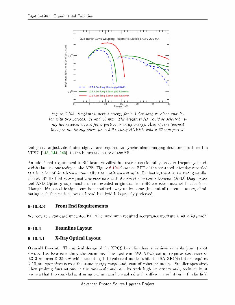
Page 6194 Experimental Facilities
0 5 10 15 20 25 30Energy (keV)
1021
1022
Brig
htne
ss (p
h/s/
mra
d2 /mm
2 /0.1
%bw
)
U27 4.6m long 10mm gap HGVPUU25 4.6m long 8.5mm gap RevolverU21 4.6m long 8.5mm gap Revolver
324 Bunch 10 % Coupling - 41pm RB Lattice 6 GeV 200 mA
Figure 6.103. Brightness versus energy for a 4.6-m-long revolver undula-tor with two periods: 21 and 25 mm. The brightest ID would be selected us-ing the revolver device for a particular x-ray energy. Also shown (dashedlines) is the tuning curve for a 4.6-m-long HGVPU with a 27 mm period.
and phase adjustable timing signals are required to synchronize emerging detectors, such as theVIPIC [143, 144, 145], to the bunch structure of the SR.
An additional requirement is SR beam stabilization over a considerably broader frequency band-width than is done today at the APS. Figure 6.104 shows an FFT of the scattered intensity recordedas a function of time from a nominally static reference sample. Evidently, there is is a strong oscilla-tion at 147 Hz that subsequent conversations with Accelerator Systems Division (ASD) Diagnosticsand XSD Optics group members has revealed originates from SR corrector magnet uctuations.Though this parasitic signal can be smoothed away under some (but not all) circumstances, elimi-nating such uctuations over a broad bandwidth is greatly preferred.
6-10.3.3 Front End Requirements
We require a standard uncanted FE. The maximum required acceptance aperture is 40 × 40 µrad2.
6-10.4 Beamline Layout
6-10.4.1 X-Ray Optical Layout
Overall Layout The optical design of the XPCS beamline has to achieve variable (zoom) spotsizes at two locations along the beamline. The upstream WA-XPCS set-up requires spot sizes of0.33 µm over 825 keV while accepting 110 coherent modes while the SA-XPCS station requires310 µm spot sizes across the same energy range and span of coherent modes. Smaller spot sizesallow probing uctuations at the mesoscale and smaller with high sensitivity and, technically, itensures that the speckled scattering pattern can be resolved with sucient resolution in the far eld
Advanced Photon Source Upgrade Project
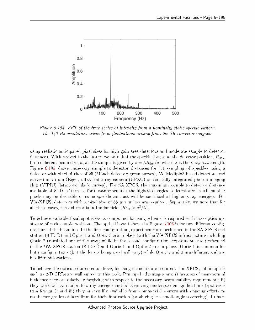
Experimental Facilities Page 6195
100 200 300 400 500Frequency (Hz)
0
0.2
0.4
0.6
0.8
1
Am
plitu
de
Figure 6.104. FFT of the time series of intensity from a nominally static speckle pattern.The 147 Hz oscillation arises from uctuations arising from the SR corrector magnets.
using realistic anticipated pixel sizes for high gain area detectors and moderate sample-to-detectordistances. With respect to the latter, we note that the speckle size, s, at the detector position, Rdet,for a coherent beam size, a, at the sample is given by s = λRdet/a, where λ is the x-ray wavelength.Figure 6.105 shows necessary sample-to-detector distances for 1:1 sampling of speckles using adetector with pixel pitches of 25 (Mönch detector; green curves), 55 (Medipix3-based detectors; redcurves) or 75 µm (Eiger, ultra fast x-ray camera (UFXC) or vertically integrated photon imagingchip (VIPIC) detectors; black curves). For SA-XPCS, the maximum sample-to-detector distanceavailable at 8-ID is 10 m, so for measurements at the highest energies, a detector with still smallerpixels may be desirable or some speckle contrast will be sacriced at higher x-ray energies. ForWA-XPCS, detectors with a pixel size of 55 µm or less are required. Separately, we note that forall these cases, the detector is in the far eld (Rdet > a2/λ).
To achieve variable focal spot sizes, a compound focusing scheme is required with two optics up-stream of each sample position. The optical layout shown in Figure 6.106 is for two dierent cong-urations of the beamline. In the rst conguration, experiments are performed in the SA-XPCS endstation (8-ID-D) and Optic 1 and Optic 3 are in place (with the WA-XPCS infrastructure includingOptic 2 translated out of the way) while in the second conguration, experiments are performedin the WA-XPCS station (8-ID-C) and Optic 1 and Optic 2 are in place. Optic 1 is common forboth congurations (but the lenses being used will vary) while Optic 2 and 3 are dierent and arein dierent locations.
To achieve the optics requirements above, focusing elements are required. For XPCS, inline opticssuch as 2-D CRLs are well suited to this task. Principal advantages are: i) because of near-normalincidence they are relatively forgiving with respect to the necessary beam stability requirements; ii)they work well at moderate x-ray energies and for achieving moderate demagnications (spot sizesto a few µm); and iii) they are readily available from commercial sources with ongoing eorts touse better grades of beryllium for their fabrication (producing less small-angle scattering). In fact,
Advanced Photon Source Upgrade Project
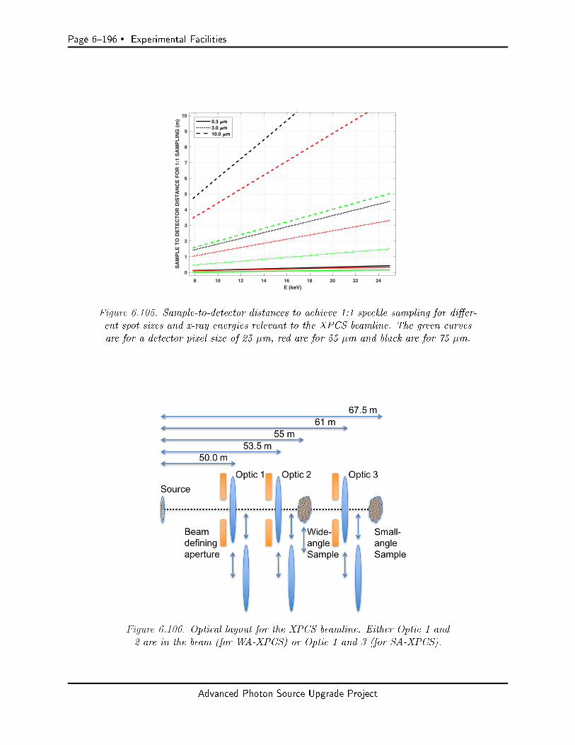
Page 6196 Experimental Facilities
8 10 12 14 16 18 20 22 24E (keV)
0
1
2
3
4
5
6
7
8
9
10
SA
MP
LE
TO
DE
TE
CT
OR
DIS
TA
NC
E F
OR
1:1
SA
MP
LIN
G (
m) 0.3 m
3.0 m10.0 m
Figure 6.105. Sample-to-detector distances to achieve 1:1 speckle sampling for dier-ent spot sizes and x-ray energies relevant to the XPCS beamline. The green curvesare for a detector pixel size of 25 µm, red are for 55 µm and black are for 75 µm.
Figure 6.106. Optical layout for the XPCS beamline. Either Optic 1 and2 are in the beam (for WA-XPCS) or Optic 1 and 3 (for SA-XPCS).
Advanced Photon Source Upgrade Project
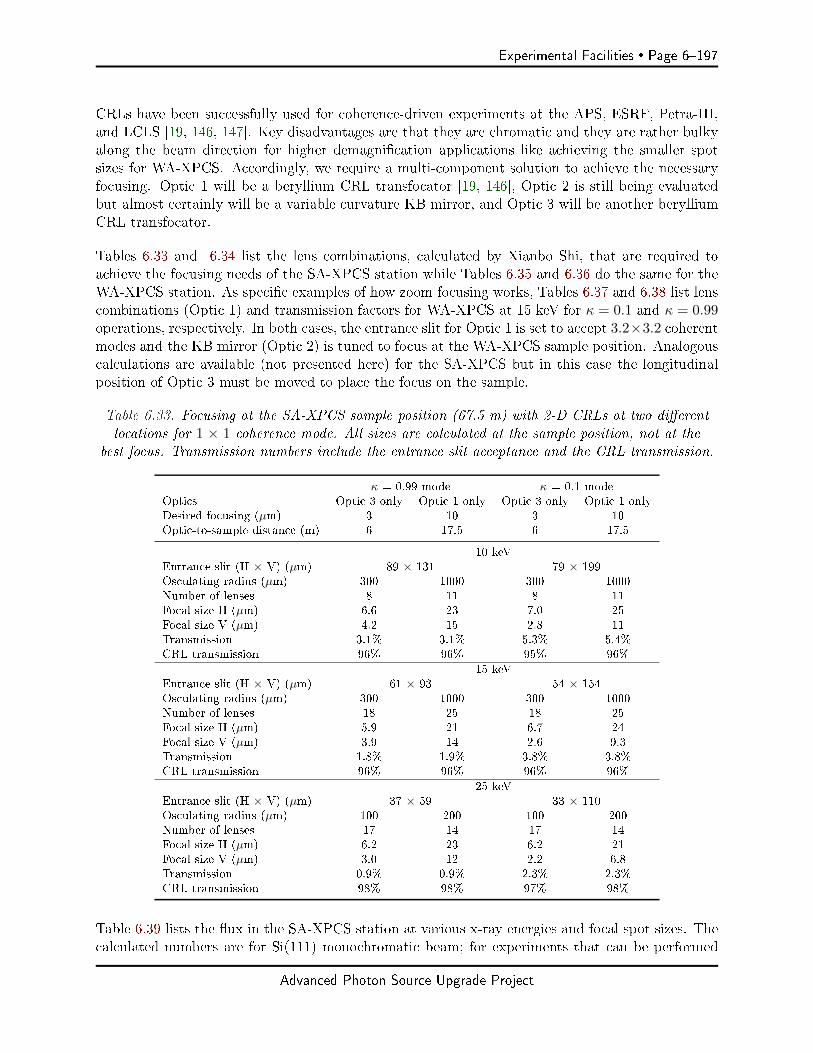
Experimental Facilities Page 6197
CRLs have been successfully used for coherence-driven experiments at the APS, ESRF, Petra-III,and LCLS [19, 146, 147]. Key disadvantages are that they are chromatic and they are rather bulkyalong the beam direction for higher demagnication applications like achieving the smaller spotsizes for WA-XPCS. Accordingly, we require a multi-component solution to achieve the necessaryfocusing. Optic 1 will be a beryllium CRL transfocator [19, 146], Optic 2 is still being evaluatedbut almost certainly will be a variable curvature KB mirror, and Optic 3 will be another berylliumCRL transfocator.
Tables 6.33 and 6.34 list the lens combinations, calculated by Xianbo Shi, that are required toachieve the focusing needs of the SA-XPCS station while Tables 6.35 and 6.36 do the same for theWA-XPCS station. As specic examples of how zoom focusing works, Tables 6.37 and 6.38 list lenscombinations (Optic 1) and transmission factors for WA-XPCS at 15 keV for κ = 0.1 and κ = 0.99operations, respectively. In both cases, the entrance slit for Optic 1 is set to accept 3.2×3.2 coherentmodes and the KB mirror (Optic 2) is tuned to focus at the WA-XPCS sample position. Analogouscalculations are available (not presented here) for the SA-XPCS but in this case the longitudinalposition of Optic 3 must be moved to place the focus on the sample.
Table 6.33. Focusing at the SA-XPCS sample position (67.5 m) with 2-D CRLs at two dierentlocations for 1 × 1 coherence mode. All sizes are calculated at the sample position, not at the
best focus. Transmission numbers include the entrance slit acceptance and the CRL transmission.
κ = 0.99 mode κ = 0.1 modeOptics Optic 3 only Optic 1 only Optic 3 only Optic 1 onlyDesired focusing (µm) 3 10 3 10Optic-to-sample distance (m) 6 17.5 6 17.5
10 keVEntrance slit (H × V) (µm) 89 × 131 79 × 199Osculating radius (µm) 300 1000 300 1000Number of lenses 8 11 8 11Focal size H (µm) 6.6 23 7.0 25Focal size V (µm) 4.2 15 2.8 11Transmission 3.1% 3.1% 5.3% 5.4%CRL transmission 96% 96% 95% 96%
15 keVEntrance slit (H × V) (µm) 61 × 93 54 × 154Osculating radius (µm) 300 1000 300 1000Number of lenses 18 25 18 25Focal size H (µm) 5.9 21 6.7 24Focal size V (µm) 3.9 14 2.6 9.3Transmission 1.8% 1.9% 3.8% 3.8%CRL transmission 96% 96% 96% 96%
25 keVEntrance slit (H × V) (µm) 37 × 59 33 × 110Osculating radius (µm) 100 200 100 200Number of lenses 17 14 17 14Focal size H (µm) 6.2 23 6.2 21Focal size V (µm) 3.0 12 2.2 6.8Transmission 0.9% 0.9% 2.3% 2.3%CRL transmission 98% 98% 97% 98%
Table 6.39 lists the ux in the SA-XPCS station at various x-ray energies and focal spot sizes. Thecalculated numbers are for Si(111) monochromatic beam; for experiments that can be performed
Advanced Photon Source Upgrade Project

Page 6198 Experimental Facilities
Table 6.34. Focusing at the SA-XPCS sample position (67.5 m) with 2-D CRLs at two dierentlocations for 3.2 × 3.2 coherence modes. All sizes are calculated at the sample position, not at thebest focus. Transmission numbers include the entrance slit acceptance and the CRL transmission.
κ = 0.99 mode κ = 0.1 modeOptics Optic 3 only Optic 1 only Optic 3 only Optic 1 onlyDesired focusing (µm) 3 10 3 10Optic-to-sample distance (m) 6 17.5 6 17.5
10 keVEntrance slit (H × V) (µm) 283 × 418 253 × 636Osculating radius (µm) 300 1000 300 1000Number of lenses 8 11 8 11Focal size H (µm) 3.9 15 4.3 16Focal size V (µm) 3.3 15 3.3 17Transmission 25% 26% 33% 36%CRL transmission 89% 94% 86% 93%
15 keVEntrance slit (H × V) (µm) 194 × 296 172 × 494Osculating radius (µm) 300 1000 300 1000Number of lenses 18 25 18 25Focal size H (µm) 3.6 13 4.1 15Focal size V (µm) 2.7 9.5 2.5 9.9Transmission 16% 17% 26% 27%CRL transmission 92% 94% 89% 94%
25 keVEntrance slit (H × V) (µm) 119 × 188 105 × 351Osculating radius (µm) 100 200 100 200Number of lenses 17 14 17 14Focal size H (µm) 3.9 12 3.9 14Focal size V (µm) 3.2 7.7 4.8 5.7Transmission 8.4% 8.7% 17% 18%CRL transmission 95% 98% 91% 96%
Advanced Photon Source Upgrade Project

Experimental Facilities Page 6199
Table 6.35. Focusing at the WA-XPCS sample position (55 m) with 2-D CRLs atthe upstream location and a KB mirror in the downstream location for 1 × 1 co-
herence modes. All sizes are calculated at the sample position, not at the best focus.
κ = 0.99 mode κ = 0.1 modeOptics Optic 1 only Optic 2 only Optic 1 only Optic 2 onlyDesired focusing (µm) 3 0.3 3 0.3Optic-to-sample distance (m) 4.5 0.4 4.5 0.4
10 keVEntrance slit (H × V) (µm) 89×131 79×199Osculating radius (µm) 500 500Number of lenses 18 18Focal size H (µm) 6.0 0.5 6.2 0.4Focal size V (µm) 3.9 0.4 2.6 0.3Transmission 2.7% 3.0% 4.7% 5.1%Optics transmission 85% 91% 84% 91%
15 keVEntrance slit (H × V) (µm) 61×93 54×154Osculating radius (µm) 300 300Number of lenses 24 24Focal size H (µm) 5.3 0.4 6.1 0.5Focal size V (µm) 5.5 0.3 2.1 0.2Transmission 1.4% 1.5% 2.8% 2.9%Optics transmission 71% 74% 71% 74%
25 keVEntrance slit (H × V) (µm) 37×59 33×110Osculating radius (µm) 100 100Number of lenses 22 22Focal size H (µm) 6.0 0.4 5.9 0.4Focal size V (µm) 3.2 0.3 1.8 0.3Transmission 0.7% 0.7% 1.7% 1.8%Optics transmission 74% 76% 73% 76%
Advanced Photon Source Upgrade Project

Page 6200 Experimental Facilities
Table 6.36. Focusing at the WA-XPCS sample position (55 m) with 2-D CRLs atthe upstream location and a KB mirror in the downstream location for 3.2 × 3.2 co-herence modes. All sizes are calculated at the sample position, not at the best focus.
κ = 0.99 mode κ = 0.1 modeOptics Optic 1 only Optic 2 only Optic 1 only Optic 2 onlyDesired focusing (µm) 3 0.3 3 0.3Optic-to-sample distance (m) 4.5 0.4 4.5 0.4
10 keVEntrance slit (H × V) (µm) 283×418 253×636Osculating radius (µm) 500 500Number of lenses 18 18Focal size H (µm) 3.3 0.3 3.8 0.3Focal size V (µm) 2.4 0.3 1.5 0.2Transmission 22% 21% 29% 28%Optics transmission 79% 76% 76% 72%
15 keVEntrance slit (H × V) (µm) 194×296 172×494Osculating radius (µm) 300 300Number of lenses 24 24Focal size H (µm) 3.2 0.2 3.6 0.3Focal size V (µm) 2.1 0.2 1.2 0.2Transmission 12% 13% 19% 21%Optics transmission 68% 74% 66% 72%
25 keVEntrance slit (H × V) (µm) 119×188 105×351Osculating radius (µm) 100 100Number of lenses 22 22Focal size H (µm) 3.3 0.2 3.6 0.2Focal size V (µm) 2.1 0.2 1.1 0.1Transmission 6.4% 6.7% 13% 14%Optics transmission 72% 76% 69% 73%
Table 6.37. Sample WA-XPCS zoom system calculation for κ = 0.1. The CRL osculating radiusfor Optic 1 is 300 µm and the KB mirrors (Optics 2) are tuned to focus at the sample position(54 m). The entrance slit size at Optic 1 is 0.17 mm × 0.49 mm. Ttotal is the transmission ofthe entire source and optical system while TCRL is the transmission through the CRLs (Optic 1).
Number of Focal size (µm) Ttotal TCRL
CRLs H V (%) (%)
0 0.3 0.2 21 728 0.4 0.3 21 7112 0.5 0.4 20 7015 0.7 0.5 20 6917 0.8 0.5 20 6818 0.9 0.6 20 6819 1.1 0.7 20 6820 1.2 0.7 20 6721 1.3 0.7 19 6722 1.8 0.8 19 6723 2.4 1.0 19 6624 3.6 1.2 19 66
Advanced Photon Source Upgrade Project
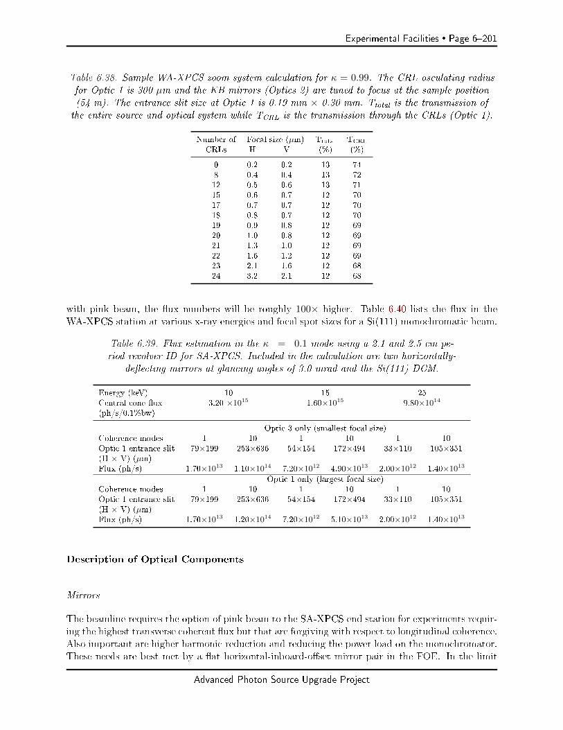
Experimental Facilities Page 6201
Table 6.38. Sample WA-XPCS zoom system calculation for κ = 0.99. The CRL osculating radiusfor Optic 1 is 300 µm and the KB mirrors (Optics 2) are tuned to focus at the sample position(54 m). The entrance slit size at Optic 1 is 0.19 mm × 0.30 mm. Ttotal is the transmission ofthe entire source and optical system while TCRL is the transmission through the CRLs (Optic 1).
Number of Focal size (µm) Ttotal TCRL
CRLs H V (%) (%)
0 0.2 0.2 13 748 0.4 0.4 13 7212 0.5 0.6 13 7115 0.6 0.7 12 7017 0.7 0.7 12 7018 0.8 0.7 12 7019 0.9 0.8 12 6920 1.0 0.8 12 6921 1.3 1.0 12 6922 1.6 1.2 12 6923 2.1 1.6 12 6824 3.2 2.1 12 68
with pink beam, the ux numbers will be roughly 100× higher. Table 6.40 lists the ux in theWA-XPCS station at various x-ray energies and focal spot sizes for a Si(111) monochromatic beam.
Table 6.39. Flux estimation in the κ = 0.1 mode using a 2.1 and 2.5 cm pe-riod revolver ID for SA-XPCS. Included in the calculation are two horizontally-
deecting mirrors at glancing angles of 3.0 mrad and the Si(111) DCM.
Energy (keV) 10 15 25Central cone ux 3.20 ×10¹⁵ 1.60×10¹⁵ 9.80×10¹⁴
(ph/s/0.1%bw)
Optic 3 only (smallest focal size)Coherence modes 1 10 1 10 1 10Optic 1 entrance slit 79×199 253×636 54×154 172×494 33×110 105×351(H × V) (µm)Flux (ph/s) 1.70×10¹³ 1.10×10¹⁴ 7.20×10¹² 4.90×10¹³ 2.00×10¹² 1.40×10¹³
Optic 1 only (largest focal size)Coherence modes 1 10 1 10 1 10Optic 1 entrance slit 79×199 253×636 54×154 172×494 33×110 105×351(H × V) (µm)Flux (ph/s) 1.70×10¹³ 1.20×10¹⁴ 7.20×10¹² 5.10×10¹³ 2.00×10¹² 1.40×10¹³
Description of Optical Components
Mirrors
The beamline requires the option of pink beam to the SA-XPCS end station for experiments requir-ing the highest transverse coherent ux but that are forgiving with respect to longitudinal coherence.Also important are higher harmonic reduction and reducing the power load on the monochromator.These needs are best met by a at horizontal-inboard-oset mirror pair in the FOE. In the limit
Advanced Photon Source Upgrade Project
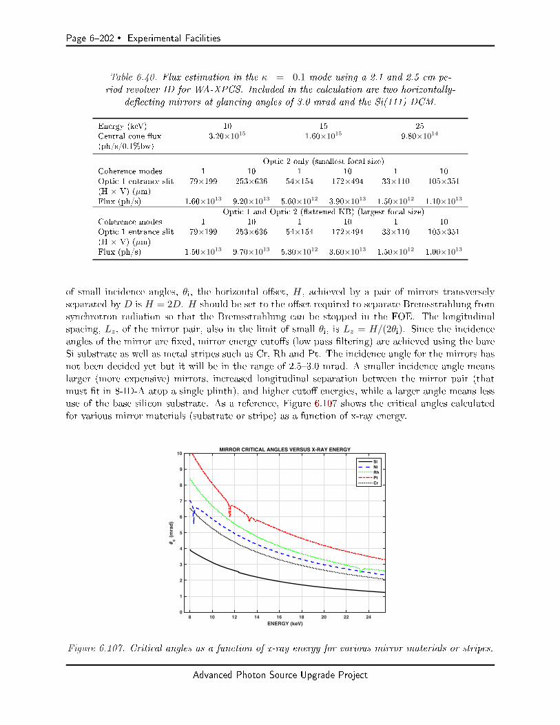
Page 6202 Experimental Facilities
Table 6.40. Flux estimation in the κ = 0.1 mode using a 2.1 and 2.5 cm pe-riod revolver ID for WA-XPCS. Included in the calculation are two horizontally-
deecting mirrors at glancing angles of 3.0 mrad and the Si(111) DCM.
Energy (keV) 10 15 25Central cone ux 3.20×10¹⁵ 1.60×10¹⁵ 9.80×10¹⁴
(ph/s/0.1%bw)
Optic 2 only (smallest focal size)Coherence modes 1 10 1 10 1 10Optic 1 entrance slit 79×199 253×636 54×154 172×494 33×110 105×351(H × V) (µm)Flux (ph/s) 1.60×10¹³ 9.20×10¹³ 5.60×10¹² 3.90×10¹³ 1.50×10¹² 1.10×10¹³
Optic 1 and Optic 2 (attened KB) (largest focal size)Coherence modes 1 10 1 10 1 10Optic 1 entrance slit 79×199 253×636 54×154 172×494 33×110 105×351(H × V) (µm)Flux (ph/s) 1.50×10¹³ 9.70×10¹³ 5.30×10¹² 3.60×10¹³ 1.50×10¹² 1.00×10¹³
of small incidence angles, θi, the horizontal oset, H, achieved by a pair of mirrors transverselyseparated by D is H = 2D. H should be set to the oset required to separate Bremsstrahlung fromsynchrotron radiation so that the Bremsstrahlung can be stopped in the FOE. The longitudinalspacing, Lz, of the mirror pair, also in the limit of small θi, is Lz = H/(2θi). Since the incidenceangles of the mirror are xed, mirror energy cutos (low pass ltering) are achieved using the bareSi substrate as well as metal stripes such as Cr, Rh and Pt. The incidence angle for the mirrors hasnot been decided yet but it will be in the range of 2.53.0 mrad. A smaller incidence angle meanslarger (more expensive) mirrors, increased longitudinal separation between the mirror pair (thatmust t in 8-ID-A atop a single plinth), and higher cuto energies, while a larger angle means lessuse of the base silicon substrate. As a reference, Figure 6.107 shows the critical angles calculatedfor various mirror materials (substrate or stripe) as a function of x-ray energy.
8 10 12 14 16 18 20 22 24ENERGY (keV)
0
1
2
3
4
5
6
7
8
9
10
c (
mra
d)
MIRROR CRITICAL ANGLES VERSUS X-RAY ENERGY
SiNiRhPtCr
Figure 6.107. Critical angles as a function of x-ray energy for various mirror materials or stripes.
Advanced Photon Source Upgrade Project
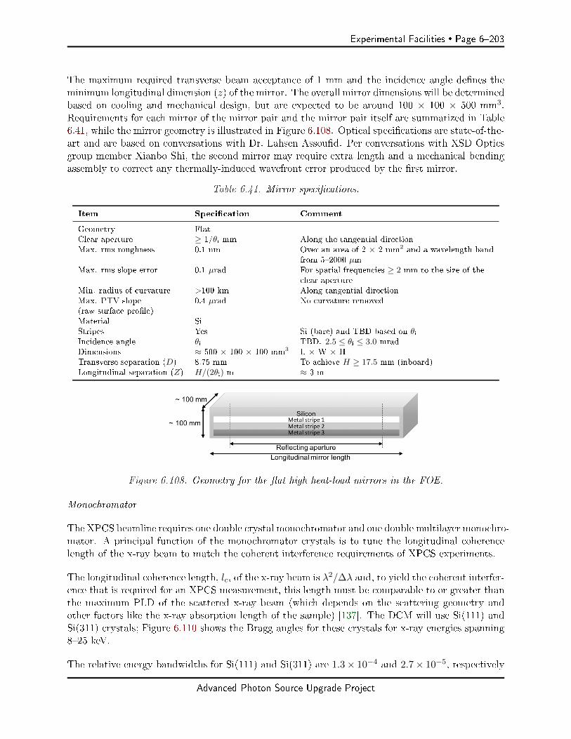
Experimental Facilities Page 6203
The maximum required transverse beam acceptance of 1 mm and the incidence angle denes theminimum longitudinal dimension (z) of the mirror. The overall mirror dimensions will be determinedbased on cooling and mechanical design, but are expected to be around 100 × 100 × 500 mm3.Requirements for each mirror of the mirror pair and the mirror pair itself are summarized in Table6.41, while the mirror geometry is illustrated in Figure 6.108. Optical specications are state-of-the-art and are based on conversations with Dr. Lahsen Assoud. Per conversations with XSD Opticsgroup member Xianbo Shi, the second mirror may require extra length and a mechanical bendingassembly to correct any thermally-induced wavefront error produced by the rst mirror.
Table 6.41. Mirror specications.
Item Specication Comment
Geometry FlatClear aperture ≥ 1/θi mm Along the tangential directionMax. rms roughness 0.1 nm Over an area of 2 × 2 mm2 and a wavelength band
from 52000 µmMax. rms slope error 0.1 µrad For spatial frequencies ≥ 2 mm to the size of the
clear apertureMin. radius of curvature >100 km Along tangential directionMax. PTV slope 0.4 µrad No curvature removed(raw surface prole)Material SiStripes Yes Si (bare) and TBD based on θiIncidence angle θi TBD. 2.5 ≤ θi ≤ 3.0 mradDimensions ≈ 500 × 100 × 100 mm3 L × W × HTransverse separation (D) 8.75 mm To achieve H ≥ 17.5 mm (inboard)Longitudinal separation (Z) H/(2θi) m ≈ 3 m
Figure 6.108. Geometry for the at high heat-load mirrors in the FOE.
Monochromator
The XPCS beamline requires one double crystal monochromator and one double multilayer monochro-mator. A principal function of the monochromator crystals is to tune the longitudinal coherencelength of the x-ray beam to match the coherent interference requirements of XPCS experiments.
The longitudinal coherence length, lc, of the x-ray beam is λ2/∆λ and, to yield the coherent interfer-ence that is required for an XPCS measurement, this length must be comparable to or greater thanthe maximum PLD of the scattered x-ray beam (which depends on the scattering geometry andother factors like the x-ray absorption length of the sample) [137]. The DCM will use Si(111) andSi(311) crystals; Figure 6.110 shows the Bragg angles for these crystals for x-ray energies spanning825 keV.
The relative energy bandwidths for Si(111) and Si(311) are 1.3× 10⁻⁴ and 2.7× 10⁻⁵, respectively
Advanced Photon Source Upgrade Project
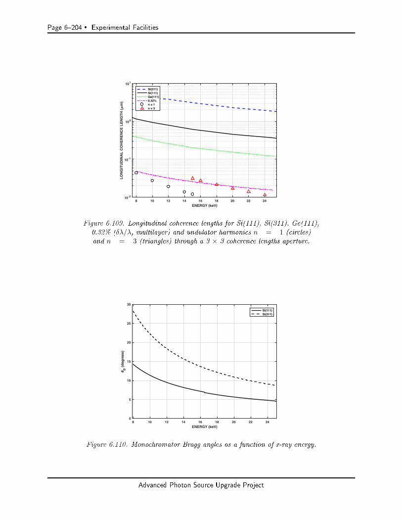
Page 6204 Experimental Facilities
8 10 12 14 16 18 20 22 24ENERGY (keV)
10-2
10-1
100
101
LO
NG
ITU
DIN
AL
CO
HE
RE
NC
E L
EN
GT
H (
m)
Si(311)Si(111)Ge(111)0.32%n = 1n = 3
Figure 6.109. Longitudinal coherence lengths for Si(111), Si(311), Ge(111),0.32% (δλ/λ, multilayer) and undulator harmonics n = 1 (circles)and n = 3 (triangles) through a 3 × 3 coherence lengths aperture.
8 10 12 14 16 18 20 22 24ENERGY (keV)
0
5
10
15
20
25
30
B (
deg
rees
)
Si(111)Si(311)
Figure 6.110. Monochromator Bragg angles as a function of x-ray energy.
Advanced Photon Source Upgrade Project
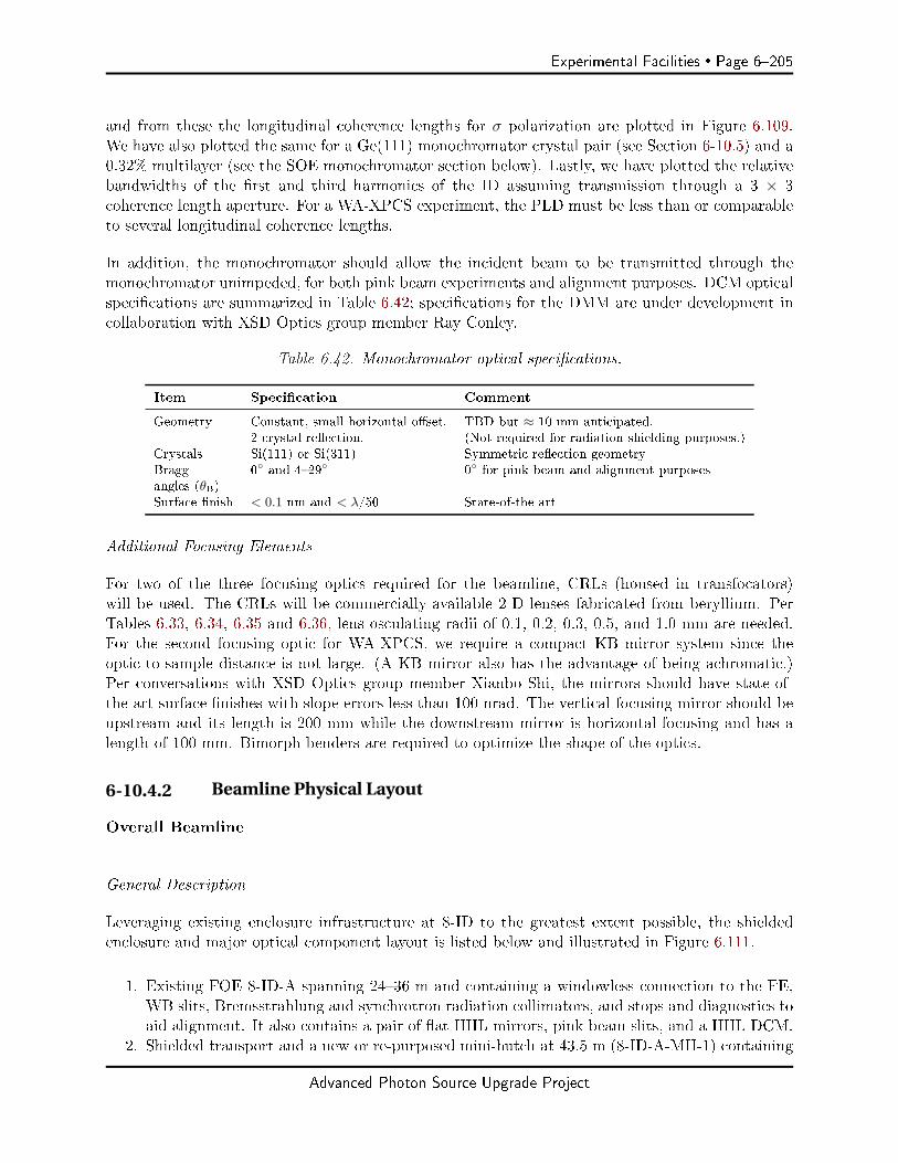
Experimental Facilities Page 6205
and from these the longitudinal coherence lengths for σ polarization are plotted in Figure 6.109.We have also plotted the same for a Ge(111) monochromator crystal pair (see Section 6-10.5) and a0.32% multilayer (see the SOE monochromator section below). Lastly, we have plotted the relativebandwidths of the rst and third harmonics of the ID assuming transmission through a 3 × 3coherence length aperture. For a WA-XPCS experiment, the PLD must be less than or comparableto several longitudinal coherence lengths.
In addition, the monochromator should allow the incident beam to be transmitted through themonochromator unimpeded, for both pink beam experiments and alignment purposes. DCM opticalspecications are summarized in Table 6.42; specications for the DMM are under development incollaboration with XSD Optics group member Ray Conley.
Table 6.42. Monochromator optical specications.
Item Specication Comment
Geometry Constant, small horizontal oset. TBD but ≈ 10 mm anticipated.2 crystal reection. (Not required for radiation shielding purposes.)
Crystals Si(111) or Si(311) Symmetric reection geometryBragg 0 and 429 0 for pink beam and alignment purposesangles (θB)Surface nish < 0.1 nm and < λ/50 State-of-the art
Additional Focusing Elements
For two of the three focusing optics required for the beamline, CRLs (housed in transfocators)will be used. The CRLs will be commercially-available 2-D lenses fabricated from beryllium. PerTables 6.33, 6.34, 6.35 and 6.36, lens osculating radii of 0.1, 0.2, 0.3, 0.5, and 1.0 mm are needed.For the second focusing optic for WA-XPCS, we require a compact KB mirror system since theoptic-to-sample distance is not large. (A KB mirror also has the advantage of being achromatic.)Per conversations with XSD Optics group member Xianbo Shi, the mirrors should have state-of-the-art surface nishes with slope errors less than 100 nrad. The vertical-focusing mirror should beupstream and its length is 200 mm while the downstream mirror is horizontal-focusing and has alength of 100 mm. Bimorph benders are required to optimize the shape of the optics.
6-10.4.2 Beamline Physical Layout
Overall Beamline
General Description
Leveraging existing enclosure infrastructure at 8-ID to the greatest extent possible, the shieldedenclosure and major optical component layout is listed below and illustrated in Figure 6.111.
1. Existing FOE 8-ID-A spanning 2436 m and containing a windowless connection to the FE,WB slits, Bremsstrahlung and synchrotron radiation collimators, and stops and diagnostics toaid alignment. It also contains a pair of at HHL mirrors, pink beam slits, and a HHL DCM.
2. Shielded transport and a new or re-purposed mini-hutch at 43.5 m (8-ID-A-MH-1) containing
Advanced Photon Source Upgrade Project

Page 6206 Experimental Facilities
Figure 6.111. Overall plan view of the APS-U XPCS beamline situated at 8-ID.
the 8-ID-B shutter and connecting the FOE to the SOE.3. New SOE 8-ID-B spanning 4652 m (encompassing existing enclosure 8-ID-D) housing a
DMM, pink beam slits (2), a CRL transfocator (Optic 1), diagnostics and the 8-ID-C pinkbeam shutter/stop.
4. Existing experiment enclosure 8-ID-C (née 8-ID-E) for WA-XPCS spanning 50.561.5 m andcontaining a higher demagnication optic (Optic 2), monochromatic beam slits and a heavy-duty multi-circle diractometer, and exit ight paths and detectors (2). It also containsdiagnostics, monochromatic beam slits, the second optic for SA-XPCS (Optic 3), and the8-ID-D pink beam shutter/stop.
5. Existing enclosure 8-ID-C-MH-1 (née 8-ID-D-MH-1) spanning 61.563.5 m and containing the8-ID-D pink and mono beam compatible shutter.
6. Existing experiment enclosure 8-ID-D (née 8-ID-I) for SA-XPCS spanning 63.578 m and con-taining pink-beam-compatible slits; a sample area supporting multiple sample environmentssuch as ow, high pressure, and shear cells, as well as a rheometer; a variable length and angle(2θ ≤ 70 mrad) exit ight path, and a multi-detector support and positioning assembly.
Table 6.43 lists the major optical components and their position along the beamline in both distancefrom the source and location inside a shielded enclosure.
Radiation Safety
The beamline will meet or exceed all APS radiation safety standards. We do not anticipate anyspecial circumstances or anticipate extensive studies of radiological samples or use of radioactivesources.
Vacuum
To preserve the beam brilliance, we require a UHV windowless connection to the front end. We alsorequire brilliance preserving pink beam capable windows at the entrances to 8-ID-C and 8-ID-D andat the exit of 8-ID-C. To preserve the mirror and monochromator nishes and the transfocator lensesand to be compatible with a windowless connection to the SR, the beamline should be UHV untilthe 8-ID-C entrance window and contain no direct coolant-to-vacuum joints. Beyond this window,10−8 mbar (HV) vacuum levels will suce. Since the beamline will need to switch operations backand forth between 8-ID-C and 8-ID-D, a convenient way to assemble and disassemble ight paththrough 8-ID-C and bring it rapidly to the required vacuum levels is needed.
Advanced Photon Source Upgrade Project
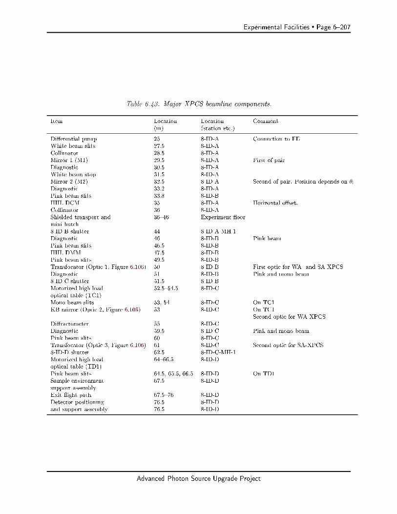
Experimental Facilities Page 6207
Table 6.43. Major XPCS beamline components.
Item Location Location Comment(m) (station etc.)
Dierential pump 25 8-ID-A Connection to FEWhite beam slits 27.5 8-ID-ACollimator 28.5 8-ID-AMirror 1 (M1) 29.5 8-ID-A First of pairDiagnostic 30.5 8-ID-AWhite beam stop 31.5 8-ID-AMirror 2 (M2) 32.5 8-ID-A Second of pair. Position depends on θiDiagnostic 33.2 8-ID-APink beam slits 33.8 8-ID-BHHL DCM 35 8-ID-A Horizontal oset.Collimator 36 8-ID-AShielded transport and 3646 Experiment oormini hutch8-ID-B shutter 44 8-ID-A-MH-1Diagnostic 46 8-ID-B Pink beamPink beam slits 46.5 8-ID-BHHL DMM 47.5 8-ID-BPink beam slits 49.5 8-ID-BTransfocator (Optic 1, Figure 6.106) 50 8-ID-B First optic for WA- and SA-XPCSDiagnostic 51 8-ID-B Pink and mono beam8-ID-C shutter 51.5 8-ID-BMotorized high load 52.554.5 8-ID-Coptical table (TC1)Mono beam slits 53, 54 8-ID-C On TC1KB mirror (Optic 2, Figure 6.106) 53 8-ID-C On TC1
Second optic for WA-XPCSDiractometer 55 8-ID-CDiagnostic 59.5 8-ID-C Pink and mono beamPink beam slits 60 8-ID-CTransfocator (Optic 3, Figure 6.106) 61 8-ID-C Second optic for SA-XPCS8-ID-D shutter 62.5 8-ID-C-MH-1Motorized high load 6466.5 8-ID-Doptical table (TD1)Pink beam slits 64.5, 65.5, 66.5 8-ID-D On TD1Sample environment 67.5 8-ID-Dsupport assemblyExit ight path 67.576 8-ID-DDetector positioning 76.5 8-ID-Dand support assembly 76.5 8-ID-D
Advanced Photon Source Upgrade Project

Page 6208 Experimental Facilities
First Optics Enclosure and Infrastructure The beamline will use existing FOE 8-ID-A. Fig-ure 6.112 illustrates the new component layout. One required improvement is temperature control
Figure 6.112. Plan view of the component layout in 8-ID-A. The mir-ror pair assumes 3.0 mrad incidence angles and, for shielding purposes,a minimum lateral synchrotron-Bremsstrahlung beam oset of 17.5 mm.
of the station to ≤ ± 0.05 C to help ensure positional stability of the optical components. Thisspecication is arrived at by assuming a typical thermal expansion coecient for granite (antici-pated plinth material for slits, mirrors, and monochromators) of 5× 10⁻⁶ K−1 and 1 m of supportmaterial yielding a change in height of 0.5 µm with a temperature of 0.1 C. This is acceptablesince it is comparable to the needed positioning accuracy for the slits.
Windows
To help preserve the beam brilliance, a windowless, i.e., dierential pump, connection to the FE isrequired. The exit aperture should subtend an angle of 40 µrad × 40 µrad (1 × 1 mm2).
Slits
The rst slits are HHL slits, have a maximum aperture of 5 × 5 mm2, and provide a sharp-edgedaperture over the beamline operating energy of 825 keV. The entire slit assembly should be locatedatop a stable motorized table so that once an aperture has been set, it can be scanned in the x-raybeam without moving the slit blades. The required table translation in the X and Y directions is±6 mm.
Collimators
Collimators and stops are required in the FOE to contain the Bremsstrahlung radiation to theFOE. The FOE Bremsstrahlung collimators work in concert with collimators in the FE to achievethe necessary osets and apertures.
Shutters/Stops
The beamline requires three pink beam shutters, one white beam stop and one pink beam stop.Requirements are summarized in Table 6.44.
Advanced Photon Source Upgrade Project
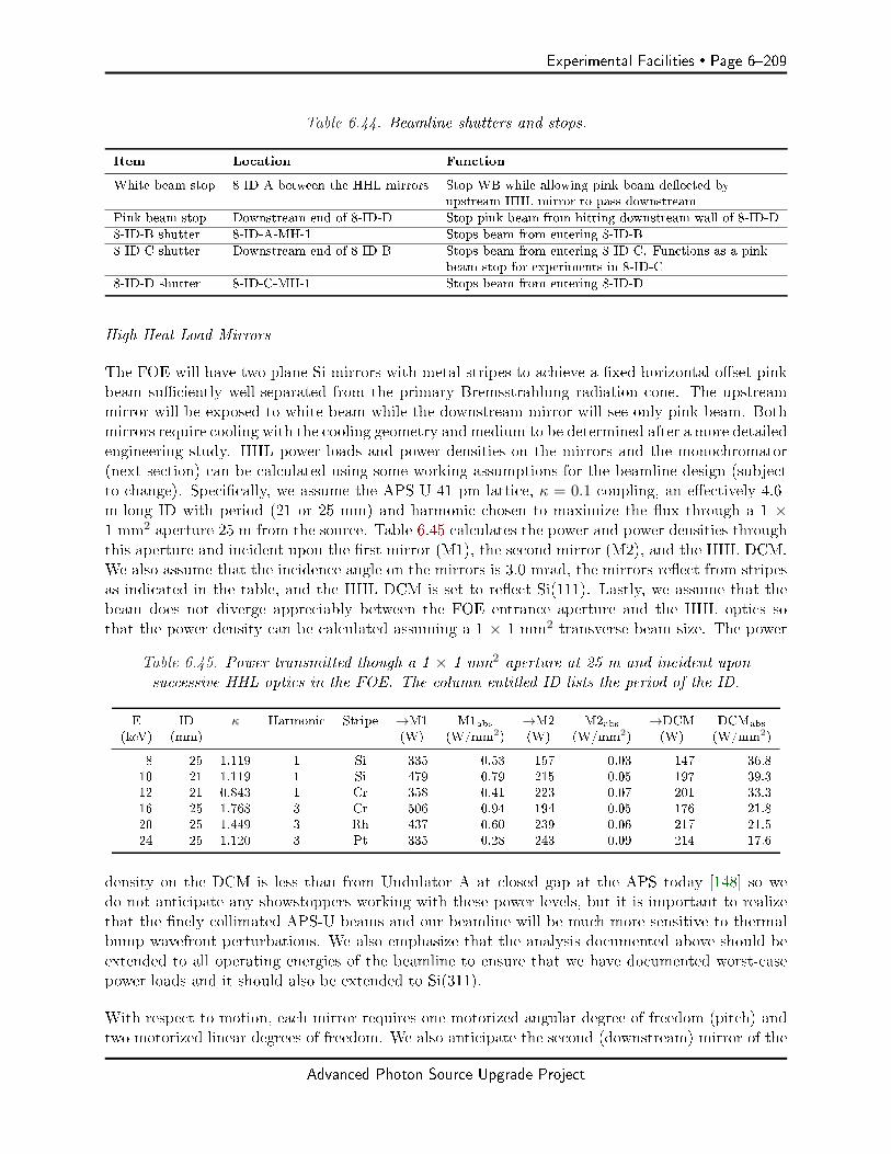
Experimental Facilities Page 6209
Table 6.44. Beamline shutters and stops.
Item Location Function
White beam stop 8-ID-A between the HHL mirrors Stop WB while allowing pink beam deected byupstream HHL mirror to pass downstream
Pink beam stop Downstream end of 8-ID-D Stop pink beam from hitting downstream wall of 8-ID-D
8-ID-B shutter 8-ID-A-MH-1 Stops beam from entering 8-ID-B
8-ID-C shutter Downstream end of 8-ID-B Stops beam from entering 8-ID-C. Functions as a pinkbeam stop for experiments in 8-ID-C
8-ID-D shutter 8-ID-C-MH-1 Stops beam from entering 8-ID-D
High-Heat-Load Mirrors
The FOE will have two plane Si mirrors with metal stripes to achieve a xed horizontal oset pinkbeam suciently well-separated from the primary Bremsstrahlung radiation cone. The upstreammirror will be exposed to white beam while the downstream mirror will see only pink beam. Bothmirrors require cooling with the cooling geometry and medium to be determined after a more detailedengineering study. HHL power loads and power densities on the mirrors and the monochromator(next section) can be calculated using some working assumptions for the beamline design (subjectto change). Specically, we assume the APS-U 41 pm lattice, κ = 0.1 coupling, an eectively 4.6-m-long ID with period (21 or 25 mm) and harmonic chosen to maximize the ux through a 1 ×1 mm2 aperture 25 m from the source. Table 6.45 calculates the power and power densities throughthis aperture and incident upon the rst mirror (M1), the second mirror (M2), and the HHL DCM.We also assume that the incidence angle on the mirrors is 3.0 mrad, the mirrors reect from stripesas indicated in the table, and the HHL DCM is set to reect Si(111). Lastly, we assume that thebeam does not diverge appreciably between the FOE entrance aperture and the HHL optics sothat the power density can be calculated assuming a 1 × 1 mm2 transverse beam size. The power
Table 6.45. Power transmitted though a 1 × 1 mm2 aperture at 25 m and incident uponsuccessive HHL optics in the FOE. The column entitled ID lists the period of the ID.
E ID κ Harmonic Stripe →M1 M1abs →M2 M2abs →DCM DCMabs
(keV) (mm) (W) (W/mm2) (W) (W/mm2) (W) (W/mm2)
8 25 1.119 1 Si 335 0.53 157 0.03 147 36.810 21 1.119 1 Si 479 0.79 215 0.05 197 39.312 21 0.843 1 Cr 358 0.41 223 0.07 201 33.316 25 1.768 3 Cr 506 0.94 194 0.05 176 21.820 25 1.449 3 Rh 437 0.60 239 0.06 217 21.524 25 1.120 3 Pt 335 0.28 243 0.09 214 17.6
density on the DCM is less than from Undulator A at closed gap at the APS today [148] so wedo not anticipate any showstoppers working with these power levels, but it is important to realizethat the nely collimated APS-U beams and our beamline will be much more sensitive to thermalbump wavefront perturbations. We also emphasize that the analysis documented above should beextended to all operating energies of the beamline to ensure that we have documented worst-casepower loads and it should also be extended to Si(311).
With respect to motion, each mirror requires one motorized angular degree of freedom (pitch) andtwo motorized linear degrees of freedom. We also anticipate the second (downstream) mirror of the
Advanced Photon Source Upgrade Project

Page 6210 Experimental Facilities
pair requiring a bender to correct any wavefront perturbations introduced by the high heat load onthe rst mirror. Figure 6.113 show the axis orientations for the mirror degrees of freedom. Fine
Figure 6.113. Mirror axis orientation.
positioning and subsequent lockdown of the yaw and roll degrees of freedom is required only duringinstallation so for these axes, manual adjustment is suitable.
The most critical motorized degree of freedom is the pitch. The nominal incidence angle is to bedetermined (in the range of 2.53.0 mrad with 3.0 mrad = 0.172 used in this document). Therequired travel range is small, requiring motion from 0 to 0.20. Allowing for some beam and/orsurvey alignment errors, we request motion in the range -0.050.22. Table 6.46 summarizes themotion requirements for the horizontally deecting HHL mirrors.
Monochromators
As evidenced by the operational experience of XPCS beamlines at APS, ESRF, Petra-III, and NSLS-II, the beamline monochromator requires exceptional mechanical stability since XPCS measurementsare performed in the time domain. A horizontal oset design is required as this will facilitate amore stable mechanical design. Figure 6.114 is a schematic representation of the monochromatorgeometry.
The horizontal oset monochromator is preferred because the degrading eect of any residual vibra-tions is ameliorated in this direction because the horizontal source size is bigger than in the vertical.Specically, for an optic located a distance, p, from the source having an rms angular vibrationamplitude, σv, the eective source size is broadened by
√Σ2 + (2pσv)2/Σ, where Σx,y is the rms
source size in the x (horizontal) or y (vertical) direction =√σ2x,y + σ2r , σx,y is the rms electron
beam size and σr is the rms photon beam size. Figure 6.115 shows the source broadening for dier-ent vibration amplitudes. The thicker black lines are relative vertical source broadening while thethinner blue lines are relative horizontal broadening. The calculations assume APS-U brightnessmode operation (41 pm emittance and 10% coupling) and an optic 35 m from the source vibratingwith the rms amplitudes shown in the legend. Not surprisingly, the relative source blurring is muchlarger in the vertical than the horizontal.
Advanced Photon Source Upgrade Project
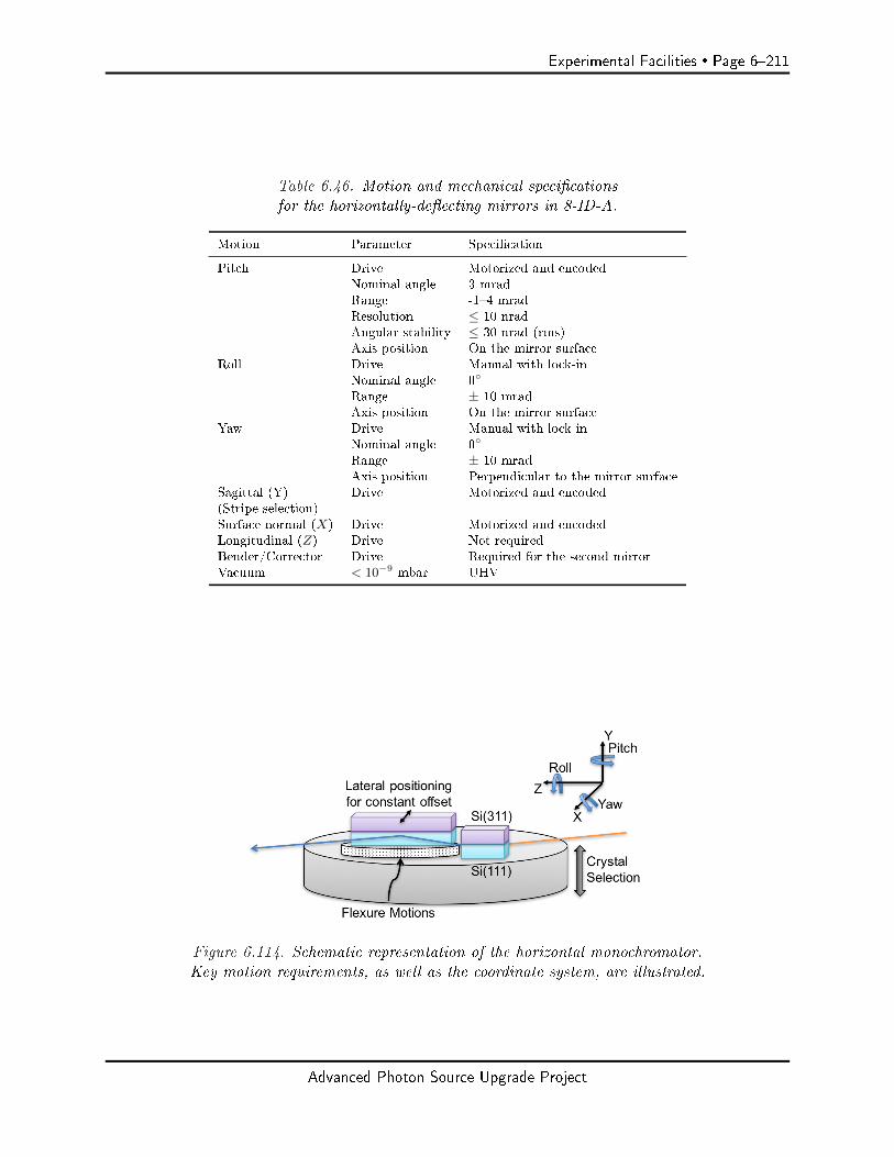
Experimental Facilities Page 6211
Table 6.46. Motion and mechanical specicationsfor the horizontally-deecting mirrors in 8-ID-A.
Motion Parameter Specication
Pitch Drive Motorized and encodedNominal angle 3 mradRange -14 mradResolution ≤ 10 nradAngular stability ≤ 30 nrad (rms)Axis position On the mirror surface
Roll Drive Manual with lock-inNominal angle 0
Range ± 10 mradAxis position On the mirror surface
Yaw Drive Manual with lock inNominal angle 0
Range ± 10 mradAxis position Perpendicular to the mirror surface
Sagittal (Y) Drive Motorized and encoded(Stripe selection)Surface normal (X) Drive Motorized and encodedLongitudinal (Z) Drive Not requiredBender/Corrector Drive Required for the second mirrorVacuum < 10−9 mbar UHV
Figure 6.114. Schematic representation of the horizontal monochromator.Key motion requirements, as well as the coordinate system, are illustrated.
Advanced Photon Source Upgrade Project

Page 6212 Experimental Facilities
8 10 12 14 16 18 20 22 24ENERGY (keV)
0
20
40
60
80
100
120
140
160
180
200
RE
LA
TIV
E S
OU
RC
E B
RO
AD
EN
ING
(%
)
VERT. (THICKER BLACK LINES), HORZ. (THINNER BLUE LINES)
40 nrad100 nrad200 nrad
Figure 6.115. Relative source broadening induced by a vibrating optic with the rms vi-bration amplitudes shown. Calculation performed for the APS-U κ = 0.1 mode.Thinner blue lines: horizontal vibration; thicker black lines: vertical vibration.
The smallest vibration amplitude plotted, 40 nrad, is roughly the state-of-the-art of published cryo-cooled monochromator vibration studies [149, 150, 151]. Moreover, a so-called articial channelcut monochromator has demonstrated suitable stability for XPCS measurements [152] (albeit withwater cooling) and vendors have documented LN2-cooled designs on their web sites, demonstrating50 nrad rms (http://www.idtnet.co.uk/mono_stability.html) and 25 nrad rms (http://www.idtnet.co.uk/ultra_stable_horizontal_dcm.html) stability, respectively. In short, the stabilityspecications should be achievable.
The monochromator cooling must also be able to withstand the high-power loads and power densitiesgenerated by the ID with minimal distortion of the rst crystal face. The monochromator mechanicalrequirements are summarized in Table 6.47 while power loads on the rst Si(111) crystal at selectedoperating energies are documented in Table 6.45.
Other Optics
We do not anticipate the need for any additional optics in the FOE.
Diagnostics
Beam diagnostics are required in two locations in the FOE to aid the alignment of the undulatorcentral cone through the xed upstream beamline mask and for alignment of the mirrors. A suitablediagnostic would provide a white beam BPM, a yttrium aluminum garnet (YAG) screen that couldfunction with the undulator gap almost wide open, a photocurrent monitor, and a bypass aperture.
Advanced Photon Source Upgrade Project
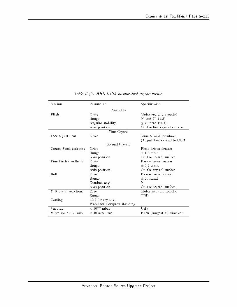
Experimental Facilities Page 6213
Table 6.47. HHL DCM mechanical requirements.
Motion Parameter Specication
AssemblyPitch Drive Motorized and encoded
Range 0 and 214.5
Angular stability ≤ 40 nrad (rms)Axis position On the rst crystal surface
First CrystalFace adjustment Drive Manual with lockdown
(Adjust rst crystal to COR)Second Crystal
Coarse Pitch (miscut) Drive Piezo-driven exureRange ± 1.5 mradAxis position On the crystal surface
Fine Pitch (feedback) Drive Piezo-driven exureRange ± 0.2 mradAxis position On the crystal surface
Roll Drive Piezo-driven exureRange ± 20 mradNominal angle 0
Axis position On the crystal surface
Y (Crystal selection) Drive Motorized and encodedRange TBD
Cooling LN2 for crystals.Water for Compton shielding.
Vacuum < 10−9 mbar UHV
Vibration amplitude < 40 nrad rms Pitch (tangential) direction
Advanced Photon Source Upgrade Project
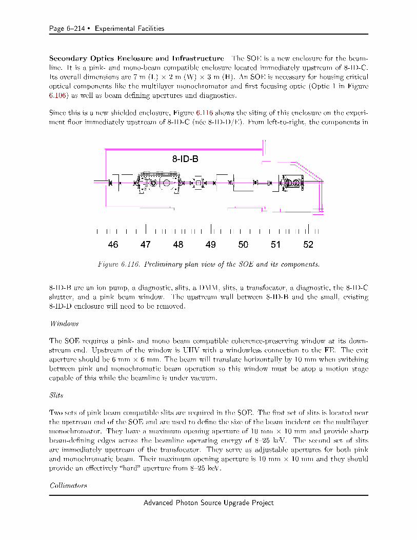
Page 6214 Experimental Facilities
Secondary Optics Enclosure and Infrastructure The SOE is a new enclosure for the beam-line. It is a pink- and mono-beam compatible enclosure located immediately upstream of 8-ID-C.Its overall dimensions are 7 m (L) × 2 m (W) × 3 m (H). An SOE is necessary for housing criticaloptical components like the multilayer monochromator and rst focusing optic (Optic 1 in Figure6.106) as well as beam dening apertures and diagnostics.
Since this is a new shielded enclosure, Figure 6.116 shows the siting of this enclosure on the experi-ment oor immediately upstream of 8-ID-C (née 8-ID-D/E). From left-to-right, the components in
Figure 6.116. Preliminary plan view of the SOE and its components.
8-ID-B are an ion pump, a diagnostic, slits, a DMM, slits, a transfocator, a diagnostic, the 8-ID-Cshutter, and a pink beam window. The upstream wall between 8-ID-B and the small, existing8-ID-D enclosure will need to be removed.
Windows
The SOE requires a pink- and mono beam compatible coherence-preserving window at its down-stream end. Upstream of the window is UHV with a windowless connection to the FE. The exitaperture should be 6 mm × 6 mm. The beam will translate horizontally by 10 mm when switchingbetween pink and monochromatic beam operation so this window must be atop a motion stagecapable of this while the beamline is under vacuum.
Slits
Two sets of pink beam compatible slits are required in the SOE. The rst set of slits is located nearthe upstream end of the SOE and are used to dene the size of the beam incident on the multilayermonochromator. They have a maximum opening aperture of 10 mm × 10 mm and provide sharpbeam-dening edges across the beamline operating energy of 825 keV. The second set of slitsare immediately upstream of the transfocator. They serve as adjustable apertures for both pinkand monochromatic beam. Their maximum opening aperture is 10 mm × 10 mm and they shouldprovide an eectively hard aperture from 825 keV.
Collimators
Advanced Photon Source Upgrade Project
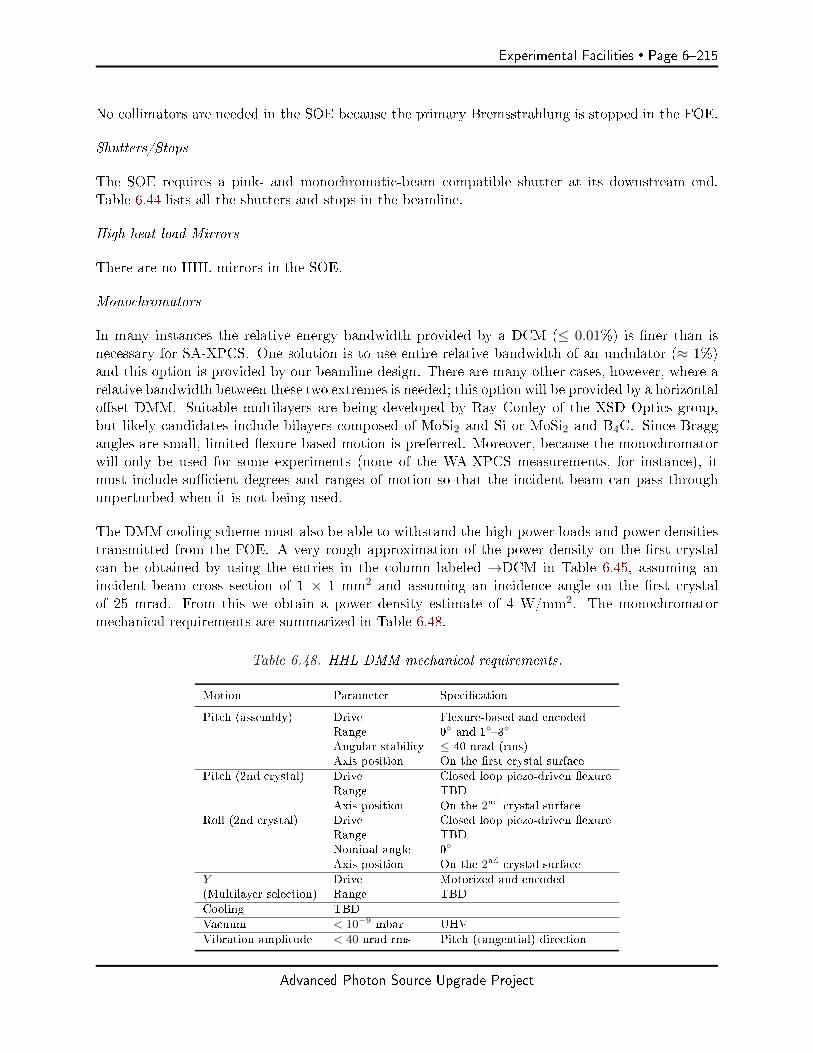
Experimental Facilities Page 6215
No collimators are needed in the SOE because the primary Bremsstrahlung is stopped in the FOE.
Shutters/Stops
The SOE requires a pink- and monochromatic-beam compatible shutter at its downstream end.Table 6.44 lists all the shutters and stops in the beamline.
High-heat-load Mirrors
There are no HHL mirrors in the SOE.
Monochromators
In many instances the relative energy bandwidth provided by a DCM (≤ 0.01%) is ner than isnecessary for SA-XPCS. One solution is to use entire relative bandwidth of an undulator (≈ 1%)and this option is provided by our beamline design. There are many other cases, however, where arelative bandwidth between these two extremes is needed; this option will be provided by a horizontaloset DMM. Suitable multilayers are being developed by Ray Conley of the XSD Optics group,but likely candidates include bilayers composed of MoSi2 and Si or MoSi2 and B4C. Since Braggangles are small, limited exure-based motion is preferred. Moreover, because the monochromatorwill only be used for some experiments (none of the WA-XPCS measurements, for instance), itmust include sucient degrees and ranges of motion so that the incident beam can pass throughunperturbed when it is not being used.
The DMM cooling scheme must also be able to withstand the high-power loads and power densitiestransmitted from the FOE. A very rough approximation of the power density on the rst crystalcan be obtained by using the entries in the column labeled →DCM in Table 6.45, assuming anincident beam cross section of 1 × 1 mm2 and assuming an incidence angle on the rst crystalof 25 mrad. From this we obtain a power density estimate of 4 W/mm2. The monochromatormechanical requirements are summarized in Table 6.48.
Table 6.48. HHL DMM mechanical requirements.
Motion Parameter Specication
Pitch (assembly) Drive Flexure-based and encodedRange 0 and 13
Angular stability ≤ 40 nrad (rms)Axis position On the rst crystal surface
Pitch (2nd crystal) Drive Closed loop piezo-driven exureRange TBD
Axis position On the 2nd crystal surfaceRoll (2nd crystal) Drive Closed loop piezo-driven exure
Range TBDNominal angle 0
Axis position On the 2nd crystal surface
Y Drive Motorized and encoded(Multilayer selection) Range TBD
Cooling TBD
Vacuum < 10−9 mbar UHV
Vibration amplitude < 40 nrad rms Pitch (tangential) direction
Advanced Photon Source Upgrade Project

Page 6216 Experimental Facilities
Other Optics
Evident from the lens and focusing optic congurations listed in Tables 6.33, 6.34, 6.35 and 6.36,variable numbers and radii of CRLs are required to achieve the focusing requirements of the beam-line. In the two locations where CRLs are specied, a so-called transfocator is a device to achievethis. Requirements for the transfocator are UHV compatibility, x, y and z translations, pitch andyaw rotations, and the ability to remove and insert variable numbers of lenses. The number oflens banks required will be determined when the nal optical design is complete. As an example,Figure 6.117 shows a transfocator designed for the P10 beamline at Petra-III that contains 12 banksallowing for 212 = 4, 096 combinations of lenses.
Figure 6.117. Left: transfocator designed for P10 at Petra-III [19].
Preliminary specications for the Optic 1 and Optic 3 transfocator systems are listed in Table 6.49.
Table 6.49. Specications for the transfocators to be used in the Optic 1 and Optic 3 locations.
Item Specication Comment
Vacuum level UHVCooling Water required Pink beam operationMotions X, Y , Z, pitch and yaw Motorized and encodedX ±15 mm To switch between monochromatic and pink beam as well as between
the lenses and the clear apertureY ±5 mm For centering lenses in the beamZ ±300 mm Optic 3 only. To adjust the lens position to focus on the sample over
the entire energy rangePitch ±2
Yaw ±2
Lenses Yes For inserting and removing lens stacks in the beam
Diagnostics
Beam diagnostics are required in two locations in the SOE. The rst location is the most upstreamposition in the SOE while the second position is immediately upstream of the beam-dening aperture
Advanced Photon Source Upgrade Project

Experimental Facilities Page 6217
for Optic 1. In the upstream location, the diagnostic will aid in the alignment and monitoring of thestability of the beam from the FOE. A suitable diagnostic would provide a diamond BPM, a YAGscreen that could function with the undulator gap almost wide open to facilitate alignment, and abypass aperture. In the downstream location, the diagnostic will be used to aid in the alignmentof the multilayer monochromator and as a beam position feedback source for experiments beingperformed in 8-ID-C. The diagnostic must be compatible with both pink and monochromatic beamwith the same suite of capabilities mentioned immediately above.
Wide-Angle XPCS Enclosure and Infrastructure The 8-ID-C enclosure is for performingwide-angle (diraction) XPCS experiments. A preliminary plan view of the station layout is shownin Figure 6.118. The station will have upstream beam preparation optics [mono beam slits and
Figure 6.118. Plan view of the component layout in 8-ID-C.
a higher demagnication focusing optic (KB mirror), attenuators and an experiment shutter] sup-ported on a heavy-duty motorized optical table. It will also have a sample positioning goniometerand two ight path and detector positioning assemblies (with detectors)one horizontal and onevertical. Additional components in 8-ID-C are for the SA-XPCS program in 8-ID-D. These in-clude a BPM, pink and monochromatic-beam compatible precision slits, a pink and monochromaticbeam transfocator, and the 8-ID-D shutter/stop assembly (8-ID-C-MH-1). All components past thedetector positioning assembly are for components related to the SA-XPCS program that will behosted in 8-ID-D.
Other Optics
Optic 2 combines with Optic 1 to produce variable spot size focused beams for WA-XPCS. In the
Advanced Photon Source Upgrade Project
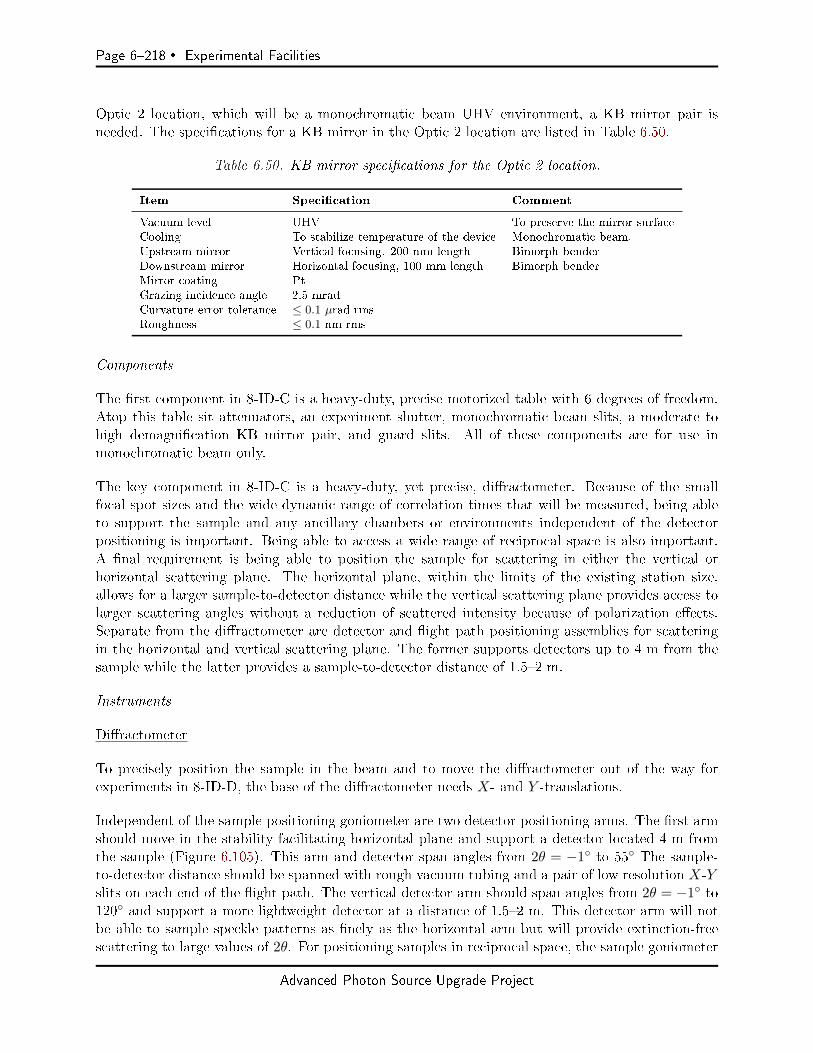
Page 6218 Experimental Facilities
Optic 2 location, which will be a monochromatic beam UHV environment, a KB mirror pair isneeded. The specications for a KB mirror in the Optic 2 location are listed in Table 6.50.
Table 6.50. KB mirror specications for the Optic 2 location.
Item Specication Comment
Vacuum level UHV To preserve the mirror surfaceCooling To stabilize temperature of the device Monochromatic beam.Upstream mirror Vertical focusing. 200 mm length Bimorph benderDownstream mirror Horizontal focusing, 100 mm length Bimorph benderMirror coating PtGrazing incidence angle 2.5 mradCurvature error tolerance ≤ 0.1 µrad rmsRoughness ≤ 0.1 nm rms
Components
The rst component in 8-ID-C is a heavy-duty, precise motorized table with 6 degrees of freedom.Atop this table sit attenuators, an experiment shutter, monochromatic beam slits, a moderate tohigh demagnication KB mirror pair, and guard slits. All of these components are for use inmonochromatic beam only.
The key component in 8-ID-C is a heavy-duty, yet precise, diractometer. Because of the smallfocal spot sizes and the wide dynamic range of correlation times that will be measured, being ableto support the sample and any ancillary chambers or environments independent of the detectorpositioning is important. Being able to access a wide range of reciprocal space is also important.A nal requirement is being able to position the sample for scattering in either the vertical orhorizontal scattering plane. The horizontal plane, within the limits of the existing station size,allows for a larger sample-to-detector distance while the vertical scattering plane provides access tolarger scattering angles without a reduction of scattered intensity because of polarization eects.Separate from the diractometer are detector and ight path positioning assemblies for scatteringin the horizontal and vertical scattering plane. The former supports detectors up to 4 m from thesample while the latter provides a sample-to-detector distance of 1.52 m.
Instruments
Diractometer
To precisely position the sample in the beam and to move the diractometer out of the way forexperiments in 8-ID-D, the base of the diractometer needs X- and Y -translations.
Independent of the sample positioning goniometer are two detector positioning arms. The rst armshould move in the stability-facilitating horizontal plane and support a detector located 4 m fromthe sample (Figure 6.105). This arm and detector span angles from 2θ = −1 to 55 The sample-to-detector distance should be spanned with rough vacuum tubing and a pair of low resolution X-Yslits on each end of the ight path. The vertical detector arm should span angles from 2θ = −1 to120 and support a more lightweight detector at a distance of 1.52 m. This detector arm will notbe able to sample speckle patterns as nely as the horizontal arm but will provide extinction-freescattering to large values of 2θ. For positioning samples in reciprocal space, the sample goniometer
Advanced Photon Source Upgrade Project
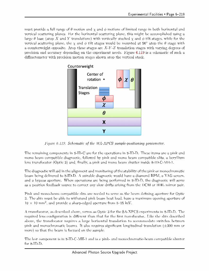
Experimental Facilities Page 6219
must provide a full range of θ motion and χ and φ motions of limited range in both horizontal andvertical scattering planes. For the horizontal scattering plane, this might be accomplished using alarge θ base (atop X and Y translations) with vertically stacked χ and φ tilt stages, while for thevertical scattering plane, the χ and φ tilt stages would be mounted at 90 atop the θ stage witha counterweight opposite. Atop these stages are X-Y -Z translation stages with varying degrees ofprecision and accuracy depending on the experiment needs. Figure 6.119 is a schematic of such adiractometer with precision motion stages shown atop the vertical stack.
Figure 6.119. Schematic of the WA-XPCS sample-positioning goniometer.
The remaining components in 8-ID-C are for the operations in 8-ID-D. These items are a pink andmono beam compatible diagnostic, followed by pink and mono beam compatible slits, a berylliumlens transfocator (Optic 3) and, nally, a pink and mono beam shutter inside 8-ID-C-MH-1.
The diagnostic will aid in the alignment and monitoring of the stability of the pink or monochromaticbeam being delivered to 8-ID-D. A suitable diagnostic would have a diamond BPM, a YAG screen,and a bypass aperture. When operations are being performed in 8-ID-D, the diagnostic will serveas a position feedback source to correct any slow drifts arising from the DCM or HHL mirror pair.
Pink and mono-beam compatible slits are needed to serve as the beam dening aperture for Optic3. The slits must be able to withstand pink beam heat load, have a maximum opening aperture of10 × 10 mm2, and provide a sharp-edged aperture from 825 keV.
A transfocator, as described above, serves as Optic 3 for the SA-XPCS experiments in 8-ID-D. Therequired lens conguration is dierent than that for the rst transfocator. Like the slits describedabove, the transfocator requires a large horizontal translation to accommodate switches betweenpink and monochromatic beams. It also requires signicant longitudinal translation (±300 mm ormore) so that the beam is focused on the sample.
The last component is in 8-ID-C-MH-1 and is a pink- and monochromatic-beam compatible shutterfor 8-ID-D.
Advanced Photon Source Upgrade Project
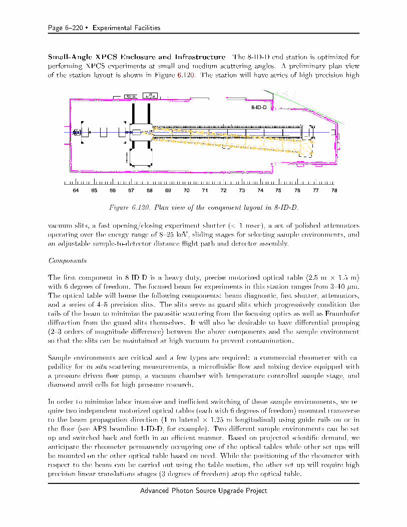
Page 6220 Experimental Facilities
Small-Angle XPCS Enclosure and Infrastructure The 8-ID-D end station is optimized forperforming XPCS experiments at small and medium scattering angles. A preliminary plan viewof the station layout is shown in Figure 6.120. The station will have series of high precision high
Figure 6.120. Plan view of the component layout in 8-ID-D.
vacuum slits, a fast opening/closing experiment shutter (< 1 msec), a set of polished attenuatorsoperating over the energy range of 825 keV, sliding stages for selecting sample environments, andan adjustable sample-to-detector distance ight path and detector assembly.
Components
The rst component in 8-ID-D is a heavy-duty, precise motorized optical table (2.5 m × 1.5 m)with 6 degrees of freedom. The focused beam for experiments in this station ranges from 310 µm.The optical table will house the following components: beam diagnostic, fast shutter, attenuators,and a series of 45 precision slits. The slits serve as guard slits which progressively condition thetails of the beam to minimize the parasitic scattering from the focusing optics as well as Fraunhoferdiraction from the guard slits themselves. It will also be desirable to have dierential pumping(23 orders of magnitude dierence) between the above components and the sample environmentso that the slits can be maintained at high vacuum to prevent contamination.
Sample environments are critical and a few types are required: a commercial rheometer with ca-pability for in situ scattering measurements, a microuidic ow and mixing device equipped witha pressure driven ow pump, a vacuum chamber with temperature controlled sample stage, anddiamond anvil cells for high pressure research.
In order to minimize labor intensive and inecient switching of these sample environments, we re-quire two independent motorized optical tables (each with 6 degrees of freedom) mounted transverseto the beam propagation direction (1 m lateral × 1.25 m longitudinal) using guide rails on or inthe oor (see APS beamline 1-ID-D, for example). Two dierent sample environments can be setup and switched back and forth in an ecient manner. Based on projected scientic demand, weanticipate the rheometer permanently occupying one of the optical tables while other set ups willbe mounted on the other optical table based on need. While the positioning of the rheometer withrespect to the beam can be carried out using the table motion, the other set up will require highprecision linear translations stages (3 degrees of freedom) atop the optical table.
Advanced Photon Source Upgrade Project

Experimental Facilities Page 6221
For optimal SNR, the sample to detector distance has to be adjusted based on the x-ray energy andthe focal spot size so that the speckle size equals the detector pixel size. Further, as shown in Figure6.105, the sample-detector distance has to be varied over a range of 115 m, but in 8-ID-D thisdistance is limited to < 10 m and so operation above 16 keV may be non-optimal in terms of SNRdepending on future detector developments. A suite of detectors will be mounted at the end of theight path on a dedicated table with long-travel X and Y translation stages. The most downstreamsection of the ight path will comprise motorized translation stages to precisely position the directbeam stop before a thin Kapton (polyimide) window that separates the ight path from the detectorassembly. We propose that this last section of the ight path and the detector assembly will move asa single unit when the sample-detector distance is adjusted based on the operating x-ray energy. Anal requirement is the ability to rotate the exit ight path and detector support assembly arounda (virtual) pivot point dened at the sample position. This feature is necessary since when thedetector is far from the sample, it only subtends a small range of reciprocal space. Rotation aroundthe pivot point will provide access to a larger range of reciprocal space. Figure 6.111 shows theexit ight path rotated inboard by 4. The exact amount of rotation will be determined based onthe design of the exit ight path and the detector support assembly, as well as required space forpersonnel egress.
Instruments
The major instruments required are (i) a commercially-available stress-controlled rheometer and(ii) a pressure driven microuidic ow pump with a microchip based ow and mixing device. Thetemperature-controlled sample cell in a vacuum chamber will be built in-house and the high-pressurediamond anvil cells and the accessories will be developed via collaboration.
The rheometer allows the measurement of the real and imaginary parts of the viscosity that arerespectively related to the modulus and dissipation in materials. These macroscopic propertiescan be directly correlated to the nanoscale dynamic properties using in situ XPCS measurements.While shear cells today are made of polycarbonate that are well suited for lower energy (812 keV)operations, their chemical incompatibility with several systems limit their use.
A compact pressure driven and controlled microuidic ow control system will also have to beprocured. This technology oers advantages over the traditional syringe pump based ow systemsthat are known to introduce instabilities in the ow. The ow cell will involve custom fabricationas it has to be made of x-ray transparent material such as Si3N4 or silicon.
6-10.4.3 Additional Needs
Detectors Equal in importance to the source, area detectors are critical to the XPCS beamline. Ingeneral, suitable detectors should be fast with relatively small pixels and the ability to resolve smallnumbers of scattered photons per pixel per frame with high delity. Rapid frame rates or samplingrates and high eciency to higher x-ray energies (25 keV) are important to take advantage of thebrilliance gains that will be provided by APS-U. Appropriate detectors have advanced considerablyin recent years. Today, commercial detectors that warrant consideration are those based on sensorsand systems developed at the Paul Scherrer Institute [153, 154, 155] and around the Medipix-3[156] sensor. Ongoing research and development detectors such as the UFXC [157, 158] and VIPIC[143, 144, 145] among others [159] also warrant continued examination. Detector requirements are
Advanced Photon Source Upgrade Project
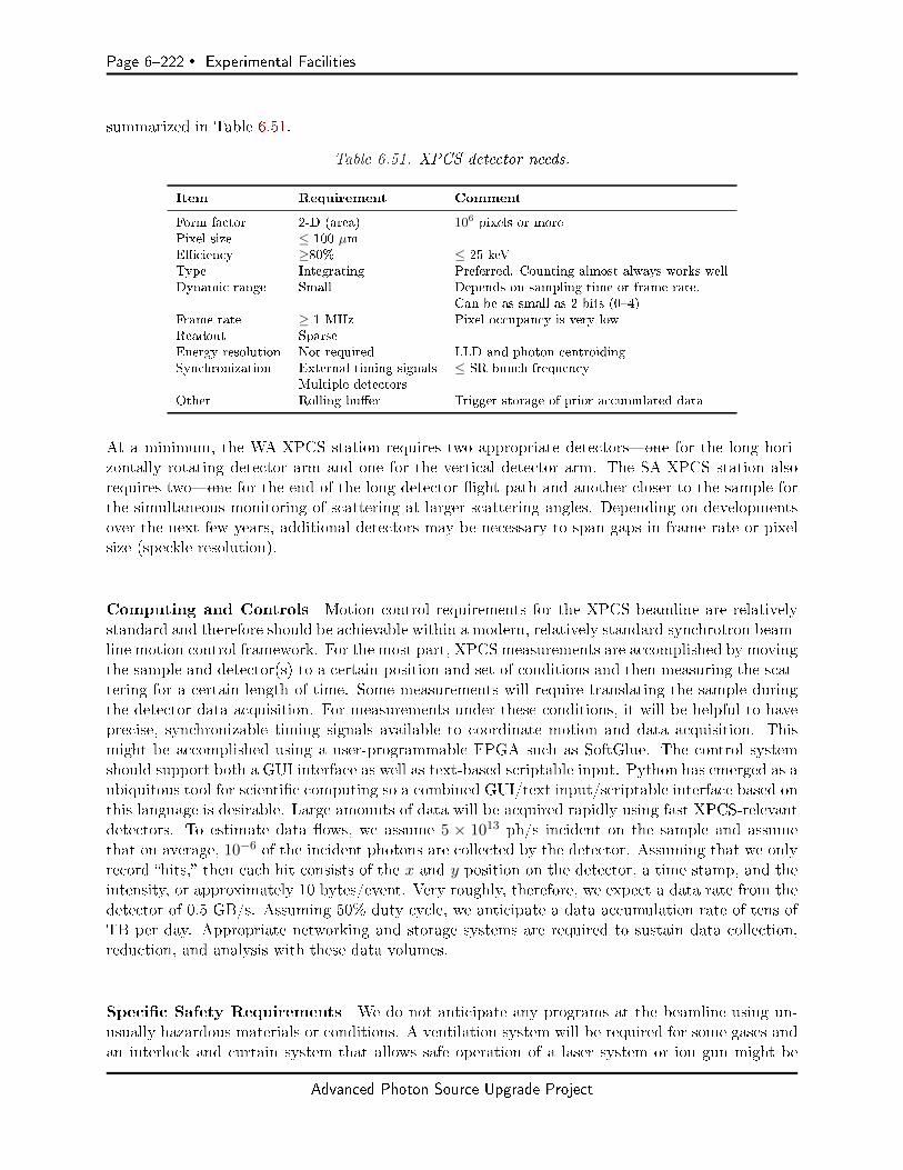
Page 6222 Experimental Facilities
summarized in Table 6.51.
Table 6.51. XPCS detector needs.
Item Requirement Comment
Form factor 2-D (area) 106 pixels or morePixel size ≤ 100 µmEciency ≥80% ≤ 25 keVType Integrating Preferred. Counting almost always works wellDynamic range Small Depends on sampling time or frame rate.
Can be as small as 2 bits (04)Frame rate ≥ 1 MHz Pixel occupancy is very lowReadout SparseEnergy resolution Not required LLD and photon centroidingSynchronization External timing signals ≤ SR bunch frequency
Multiple detectorsOther Rolling buer Trigger storage of prior accumulated data
At a minimum, the WA-XPCS station requires two appropriate detectorsone for the long hori-zontally rotating detector arm and one for the vertical detector arm. The SA-XPCS station alsorequires twoone for the end of the long detector ight path and another closer to the sample forthe simultaneous monitoring of scattering at larger scattering angles. Depending on developmentsover the next few years, additional detectors may be necessary to span gaps in frame rate or pixelsize (speckle resolution).
Computing and Controls Motion control requirements for the XPCS beamline are relativelystandard and therefore should be achievable within a modern, relatively standard synchrotron beam-line motion control framework. For the most part, XPCS measurements are accomplished by movingthe sample and detector(s) to a certain position and set of conditions and then measuring the scat-tering for a certain length of time. Some measurements will require translating the sample duringthe detector data acquisition. For measurements under these conditions, it will be helpful to haveprecise, synchronizable timing signals available to coordinate motion and data acquisition. Thismight be accomplished using a user-programmable FPGA such as SoftGlue. The control systemshould support both a GUI interface as well as text-based scriptable input. Python has emerged as aubiquitous tool for scientic computing so a combined GUI/text input/scriptable interface based onthis language is desirable. Large amounts of data will be acquired rapidly using fast XPCS-relevantdetectors. To estimate data ows, we assume 5 × 10¹³ ph/s incident on the sample and assumethat on average, 10−6 of the incident photons are collected by the detector. Assuming that we onlyrecord hits, then each hit consists of the x and y position on the detector, a time stamp, and theintensity, or approximately 10 bytes/event. Very roughly, therefore, we expect a data rate from thedetector of 0.5 GB/s. Assuming 50% duty cycle, we anticipate a data accumulation rate of tens ofTB per day. Appropriate networking and storage systems are required to sustain data collection,reduction, and analysis with these data volumes.
Specic Safety Requirements We do not anticipate any programs at the beamline using un-usually hazardous materials or conditions. A ventilation system will be required for some gases andan interlock and curtain system that allows safe operation of a laser system or ion gun might be
Advanced Photon Source Upgrade Project

Experimental Facilities Page 6223
required for some experiments. We do not anticipate measuring radioactive materials.
Specic Conventional Facilities Requirements The temperature in the experiment stationsshould be stabilized with gentle air handling systems to ±0.05C to avoid slow temperature-induceddrifts in the position of critical optical components. Also important are curtains at the stationentrances to minimize temperature instabilities and turbulence when the station doors are opened.Avoiding strongly directed airows by ventilating through diusers should make for a more stableand comfortable working environment. Temperature stabilization in the experiment enclosures willbe facilitated by a temperature-controlled control room encompassing the main entry doors to 8-ID-C and 8-ID-D. Since XPCS is a time domain technique, minimizing vibrations is important.Locating equipment in water-cooled racks on the station roofs is required. Specic locations includethe roofs atop 8-ID-A, 8-ID-B, and the downstream end of 8-ID-D
Support Facilities Limited and basic laboratory space is required for minimal sample preparationsuch as epoxying samples to mounts, loading samples in glove boxes, or attaching leads to samples.It will also be necessary to have a small space with a ventilated work area in a corner or end ofthe experiment control area. Digital macroscopes and microscopes will be required for inspectingsamples.
6-10.5 R&D Needs and Outstanding Issues
The following are R&D topics and outstanding questions related to the design of the APS-U XPCSbeamline:
1. CRL quality and performance specications vis-à-vis suitability for the highly-coherent APS-U x-ray beams need to be determined. Simulations are required to determine the amountof coherence degradation from commercially-available lenses so that a decision can be madeabout whether CRLs are suitable for focusing at APS-U.
2. Do metal mirror stripes such as Cr, Ni, Rh, or Pt on the surface of otherwise state-of-the-artpolished silicon reduce the quality, i.e, degrade the coherence of the reected x-ray beam? Arethere specic coatings in this regard that are better or worse than others?
3. Thermal analysis is required for the beamline mirrors and monochromator so that the ade-quacy of various cooling schemes can be determined.
4. Determine whether Ge(111) monochromator crystals would work well enough at LN2 tem-peratures for APS-U. (Germanium's thermal properties improve with decreasing temperature[160] but not nearly so dramatically and favorably as the properties of silicon do.) Adding aGe(111) option to the XPCS beamline monochromator [along with Si(111) and Si(311)] wouldprovide a dramatic factor of 3× more coherent ux for almost all SA-XPCS experiments re-quiring monochromatic radiation and might be useful for a few WA-XPCS experiments.
5. Examine the coherence preservation for narrower bandpass (0.10.5% relative bandwidth)multilayer optics. In a similar vein, evaluate the performance and cooling requirements formultilayer optics under moderate heat loads (≈ 5 W/mm2).
Advanced Photon Source Upgrade Project
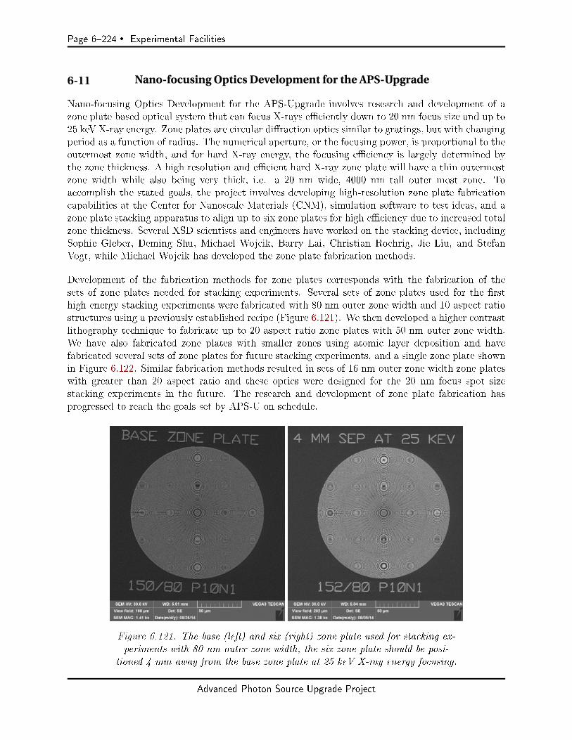
Page 6224 Experimental Facilities
6-11 Nano-focusing Optics Development for the APS-Upgrade
Nano-focusing Optics Development for the APS-Upgrade involves research and development of azone plate based optical system that can focus X-rays eciently down to 20 nm focus size and up to25 keV X-ray energy. Zone plates are circular diraction optics similar to gratings, but with changingperiod as a function of radius. The numerical aperture, or the focusing power, is proportional to theoutermost zone width, and for hard X-ray energy, the focusing eciency is largely determined bythe zone thickness. A high resolution and ecient hard X-ray zone plate will have a thin outermostzone width while also being very thick, i.e. a 20 nm wide, 4000 nm tall outer most zone. Toaccomplish the stated goals, the project involves developing high-resolution zone plate fabricationcapabilities at the Center for Nanoscale Materials (CNM), simulation software to test ideas, and azone plate stacking apparatus to align up to six zone plates for high eciency due to increased totalzone thickness. Several XSD scientists and engineers have worked on the stacking device, includingSophie Gleber, Deming Shu, Michael Wojcik, Barry Lai, Christian Roehrig, Jie Liu, and StefanVogt, while Michael Wojcik has developed the zone plate fabrication methods.
Development of the fabrication methods for zone plates corresponds with the fabrication of thesets of zone plates needed for stacking experiments. Several sets of zone plates used for the rsthigh energy stacking experiments were fabricated with 80 nm outer zone width and 10 aspect ratiostructures using a previously established recipe (Figure 6.121). We then developed a higher contrastlithography technique to fabricate up to 20 aspect ratio zone plates with 50 nm outer zone width.We have also fabricated zone plates with smaller zones using atomic layer deposition and havefabricated several sets of zone plates for future stacking experiments, and a single zone plate shownin Figure 6.122. Similar fabrication methods resulted in sets of 16 nm outer zone width zone plateswith greater than 20 aspect ratio and these optics were designed for the 20 nm focus spot sizestacking experiments in the future. The research and development of zone plate fabrication hasprogressed to reach the goals set by APS-U on schedule.
Figure 6.121. The base (left) and six (right) zone plate used for stacking ex-periments with 80 nm outer zone width, the six zone plate should be posi-
tioned 4 mm away from the base zone plate at 25 keV X-ray energy focusing.
Advanced Photon Source Upgrade Project
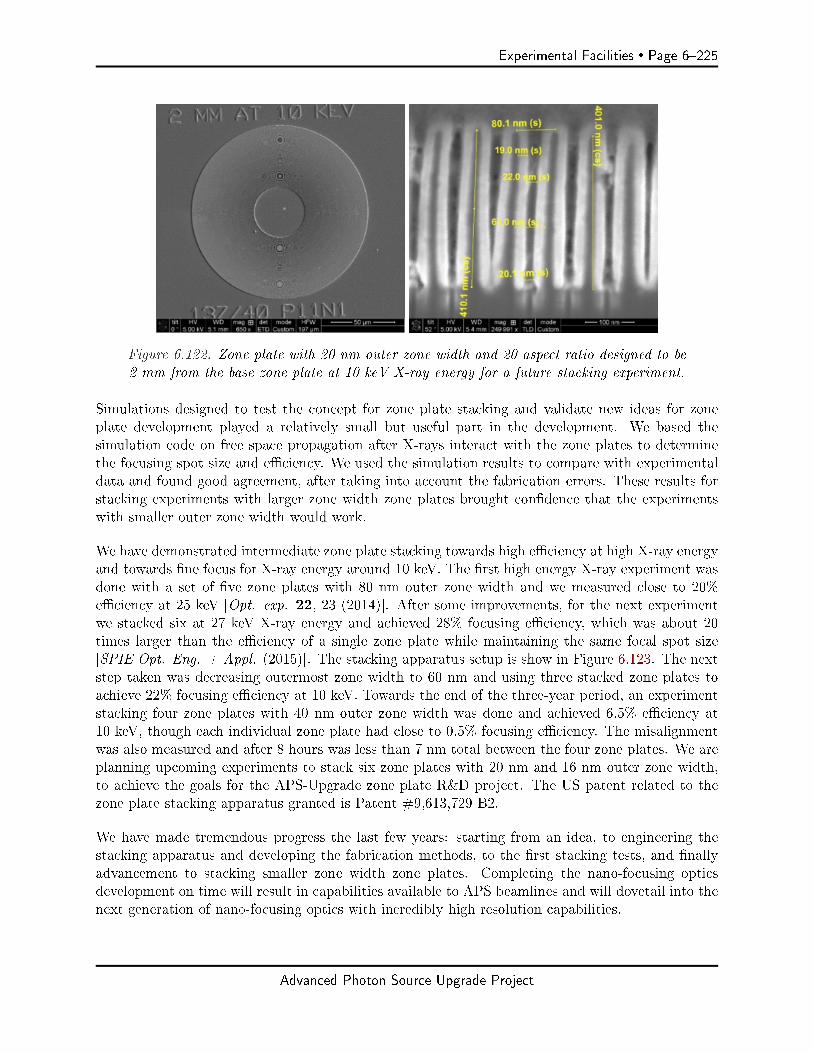
Experimental Facilities Page 6225
Figure 6.122. Zone plate with 20 nm outer zone width and 20 aspect ratio designed to be2 mm from the base zone plate at 10 keV X-ray energy for a future stacking experiment.
Simulations designed to test the concept for zone plate stacking and validate new ideas for zoneplate development played a relatively small but useful part in the development. We based thesimulation code on free space propagation after X-rays interact with the zone plates to determinethe focusing spot size and eciency. We used the simulation results to compare with experimentaldata and found good agreement, after taking into account the fabrication errors. These results forstacking experiments with larger zone width zone plates brought condence that the experimentswith smaller outer zone width would work.
We have demonstrated intermediate zone plate stacking towards high eciency at high X-ray energyand towards ne focus for X-ray energy around 10 keV. The rst high energy X-ray experiment wasdone with a set of ve zone plates with 80 nm outer zone width and we measured close to 20%eciency at 25 keV [Opt. exp. 22, 23 (2014)]. After some improvements, for the next experimentwe stacked six at 27 keV X-ray energy and achieved 28% focusing eciency, which was about 20times larger than the eciency of a single zone plate while maintaining the same focal spot size[SPIE Opt. Eng. + Appl. (2015)]. The stacking apparatus setup is show in Figure 6.123. The nextstep taken was decreasing outermost zone width to 60 nm and using three stacked zone plates toachieve 22% focusing eciency at 10 keV. Towards the end of the three-year period, an experimentstacking four zone plates with 40 nm outer zone width was done and achieved 6.5% eciency at10 keV, though each individual zone plate had close to 0.5% focusing eciency. The misalignmentwas also measured and after 8 hours was less than 7 nm total between the four zone plates. We areplanning upcoming experiments to stack six zone plates with 20 nm and 16 nm outer zone width,to achieve the goals for the APS-Upgrade zone plate R&D project. The US patent related to thezone plate stacking apparatus granted is Patent #9,613,729 B2.
We have made tremendous progress the last few years: starting from an idea, to engineering thestacking apparatus and developing the fabrication methods, to the rst stacking tests, and nallyadvancement to stacking smaller zone width zone plates. Completing the nano-focusing opticsdevelopment on time will result in capabilities available to APS beamlines and will dovetail into thenext generation of nano-focusing optics with incredibly high resolution capabilities.
Advanced Photon Source Upgrade Project
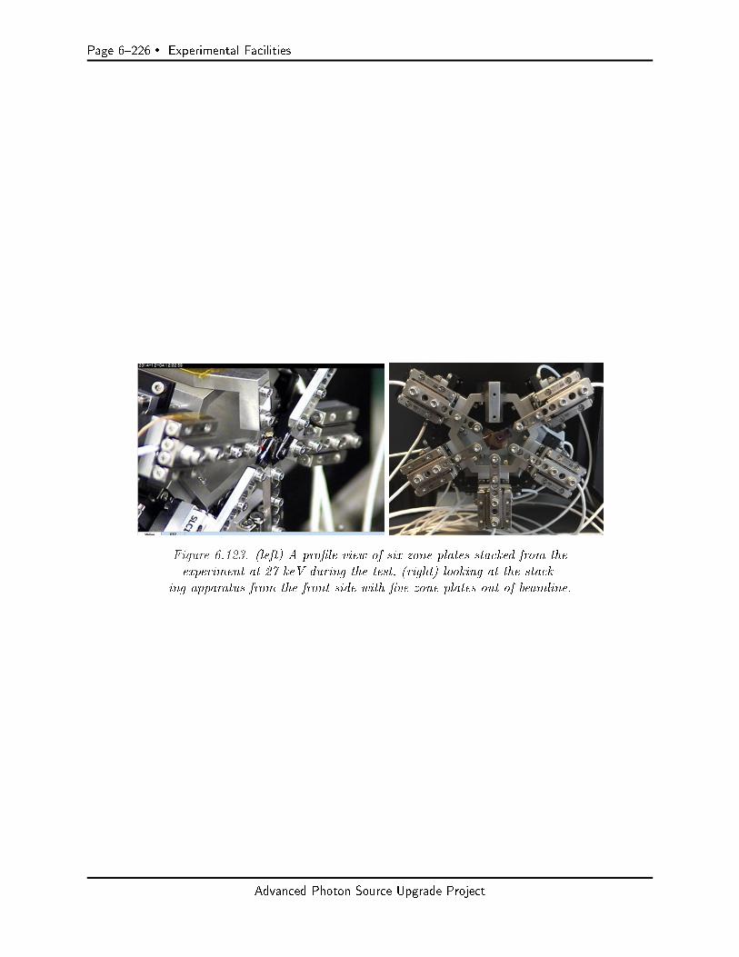
Page 6226 Experimental Facilities
Figure 6.123. (left) A prole view of six zone plates stacked from theexperiment at 27 keV during the test, (right) looking at the stack-
ing apparatus from the front side with ve zone plates out of beamline.
Advanced Photon Source Upgrade Project
Experimental Facilities Page 6227
6-12 Beamline Enhancements
The APS-U Feature Beamline scope is designed to deliver a relatively small number of new or signif-icantly upgraded beamlines that will be recognized as world-leading or world-class in performance,and are explicitly designed to capitalize on the strengths of the APS-U storage ring. What shouldnot be overlooked is that the current APS has over sixty operating beamlines, many of which arestate-of-the-art for a particular x-ray technique. A relatively small investment in key areas (e.g.,optics) allows for many beamlines to utilize the improved emittance of the APS-U storage ring andtremendously leverages the APS-U Project.
The APS-U Beamline Enhancements process and scope is designed to address the opportunity thatexists to make relatively minor investments in existing beamlines with resultant large increases in abeamline's ability to utilize the improvements of the APS-U. Two guiding principles were used for theBeamline Enhancements: 1) No beamline should lose ground in its performance after the APS-U isnished do no harm, and 2) it is prudent to make relatively minor investments that signicantlyimprove a beamlines performance bang for the buck. For the APS-U Beamline Enhancementsprocess, the do-no-harm items that fall under the rst principle are considered Non-Discretionary,and those that fall under the second bang-for-the-buck principle as Discretionary.
To establish a baseline for the APS-U Beamline Enhancements, APS-U sta solicited a self-evaluationfrom every APS beamline. The items in the self-evaluation were costed and evaluated for merit toproduce a top-down cost estimate and proposed budget that was presented at the APS-U DOECD-3B review. The self-evaluation also provided information that was used to identify the Non-Discretionary items for APS-Beamlines. These items could be sorted as:
Realignment of bending-magnet beamlines Shielding enhancements Beam choppers for bunch separation Optics (typically needed because of heat-load performance) High-heat-load safety components (e.g., stops, shutters) Beamline canting components
Using the remaining Beamline Enhancement budget as a starting point, a call was made in De-cember, 2016 for any APS beamline to submit short proposals with items to be considered as aDiscretionary Beamline Enhancement. Items in proposals were evaluated for feasibility and costed.In total, 47 proposals were submitted, nearly all with multiple items. An ad-hoc review committeemet and evaluated the proposals on March 21, 2017. Subsequently, APS/APS-U management usedthat evaluation and a discussion with the APS SAC to select the preliminary Beamline Enhancementscope. This scope is shown in Table 6.52.
Advanced Photon Source Upgrade Project

Page 6228 Experimental Facilities
Table 6.52. Beamline Enhancement Scope
Beamline Proposal Item
1-ID Upgrade Enhancements for the 1-ID-E station extension1-ID Beamline for APS-U Added tilt stage
Hexapod
1-ID 1-ID EnhancementHigh-Energy Monochromator upgradeMonochromator Upgrade
2-ID Enhancement of the 2-ID Two vertical focusing mirrorsBeamline and Microprobe Beam Dening Aperture
Figured KB mirrors mounted inside vacuum chamberCompact laser interferometers, two on each KB mirrorHigh-stiness fast-scanning sample stages
3-ID Beamline Enhancement Request for 3-ID KB-mirror system
5-ID APS Upgrade Project: DND-CAT Renished MirrorsBeamline Enhancement Request Upgraded Monochromator
6-ID 6-ID-D: Disorder in materials Focusing capabilities using CRLsat extreme conditions
6-ID Studying Mesoscopic Principles CRLs for horizontalunderlying Emergent Behaviors in and vertical focusingCondensed Matter Physics
7-ID 7-ID Beamline Enhancement Proposal Mirror for diraction branchNanodiraction focusing opticsDetector arm
11-ID 11-ID-D/E: A multi-modal Cant 11-ID beamlinehigh-energy X-ray beamline Bent Laue, double crystal monochromator
Multiple sets of compound refractive lenses
12-ID Upgrade of 12-ID SAXS Programs Long SAXS tube/USAXSEnclosure modicationCRL System
13-ID APS-U Beamline Enhancement Dual horizontal mirrors (500 mm)Proposals for Sector 13 (GSECARS) Two sets of KB mirrors
Double crystal monochromatorEnd station instrumentation (Table upgrade for
stability)1.0 m long mirrors (one vertical and one horizontal
focusing)KB system - 350 mm long mirrors
15-ID ChemMatCARS (15-ID) Beamline 2D CRL focusing systemEnhancement Proposal One harmonic rejection mirror system
Bent-Flat Vertical Focusing Mirror System
Advanced Photon Source Upgrade Project
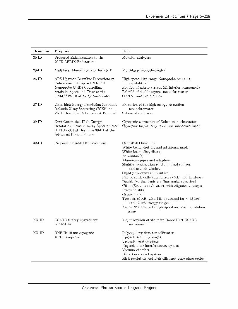
Experimental Facilities Page 6229
Beamline Proposal Item
20-ID Proposed Enhancements to the Movable analyzers20-ID LERIX Endstation
20-ID Multilayer Monochromator for 20-ID Multi-layer monochromator
26-ID APS-Upgrade Beamline Discretionary High-speed high-range Nanoprobe scanningEnhancement Proposal: The 4D capabilitiesNanoprobe (N4D) Controlling Rebuild of mirror system M1 interior componentsStrain in Space and Time at the Rebuild of double crystal monochromatorCNM/APS Hard X-ray Nanoprobe Stacked zone plate optics
27-ID Ultra-high Energy Resolution Resonant Extension of the high-energy-resolutionInelastic X-ray Scattering (RIXS) at monochromator27-ID Beamline Enhancement Proposal Sphere of confusion
30-ID Next Generation High Energy Cryogenic conversion of Kohzu monochromatorResolution Inelastic X-ray Spectrometer Cryogenic high-energy resolution monochromator(HERIX-30) at Beamline 30-ID at theAdvanced Photon Source
32-ID Proposal for 32-ID Enhancement Cant 32-ID beamlineWhite beam shutter, and additional maskWhite beam slits, ltersBe window(s)Aluminum pipes and adaptersSlightly modication to the manual shutter,
and new Be windowSlightly modied end shutterPair of small deecting mirrors (ML) and hardwareDouble (vertical) mirrors (harmonics rejection)CRLs (Small transfocator), with alignments stagesPrecision slitsGranite tableTwo sets of KB, with ML optimized for ∼ 25 keV
and 12 keV energy rangesNano-CT stack, with high speed air bearing rotation
stage
XX-ID USAXS facility upgrade for Major revision of the main Bonse-Hart USAXSAPS-MBA instrument
XX-ID BNP-II: 10 nm cryogenic Polycapillary detector collimatorXRF nanoprobe Upgrade scanning stages
Upgrade rotation stageUpgrade laser interferometer systemVacuum chamberDelta tau control systemHigh-resolution and high-eciency zone plate optics
Advanced Photon Source Upgrade Project

Page 6230 References
References
[1] G Kwon, O Kokhan, A Han, K W Chapman, P J Chupas, P Du, D M Tiede, and IUCr.Oxyanion induced variations in domain structure for amorphous cobalt oxide oxygen evolvingcatalysts, resolved by X-ray pair distribution function analysis. Acta Crystallographica SectionB: Structural Science, Crystal Engineering and Materials, 71(6):713721, December 2015.
[2] David M Tiede. Private Communication (2016).
[3] A Ulvestad, A Tripathi, S O Hruszkewycz, W Cha, S MWild, G B Stephenson, and P H Fuoss.Coherent diractive imaging of time-evolving samples with improved temporal resolution.Physical Review B, 93(18):184105, May 2016.
[4] Wael Z Abuzaid, Michael D Sangid, Jay D Carroll, Huseyin Sehitoglu, and John Lambros.Slip transfer and plastic strain accumulation across grain boundaries in Hastelloy X. Journalof the Mechanics and Physics of Solids, 60(6):12011220, June 2012.
[5] Golden Kumar, Amish Desai, and Jan Schroers. Bulk Metallic Glass: The Smaller the Better.Advanced Materials, 23(4):461476, January 2011.
[6] S H Dietze, O G Shpyrko, and IUCr. Coherent diractive imaging: towards achieving atomicresolution. Journal of Synchrotron Radiation, 22(6):14981508, November 2015.
[7] B C Larson, Wenge Yang, G E Ice, J D Budai, and J Z Tischler. Three-dimensional X-raystructural microscopy with submicrometre resolution. Nature, 415(6874):887890, February2002.
[8] Takashi Kimura, Satoshi Matsuyama, Kazuto Yamauchi, and Yoshinori Nishino. Coherentx-ray zoom condenser lens for diractive and scanning microscopy. Opt. Express, 21(8):9267,2013.
[9] B Blank, T Kupp, E Johnson, and A Deyhim. Development of a goniometer with nanoradianaccuracy. . . . Engineering Design of . . . , 2002.
[10] S. Vogt. Personal communication. 2014.
[11] T. Graber. Eciency of horizontal monochromators for aps-u beamlines. Technical report,APS, ANL/APS/LS-347, 2017.
[12] Yury Ivanyushenkov. Modeling of magnetic structure. 2017.
[13] M. Suzuki and et al. Jpn. J. App. Phys., 37:L1488, 1998.
[14] S. Francoual and et al. Journal of Physics: Conference Series, 425:132010, 2013.
[15] Scagnoli and et al. J. Synchrotron Radiat., 16:778, 2009.
[16] T. Hara and et al. Nucl. Instr. and Meth. in Phys. Res. A, 498:496, 2003.
[17] X. Shi and et al. J. Synchrotron Rad, 21:669.
Advanced Photon Source Upgrade Project
References Page 6231
[18] T. Kolodziej, H. XianRong, Y. Shvydko, and et al.
[19] A V Zozulya, S Bondarenko, A Schavkan, F Westermeier, G Grübel, and M Sprung. Micro-focusing transfocator for 1D and 2D compound refractive lenses. Optics Express, 20:18967,July 2012.
[20] J. Sidarous and StudioGC. Argonne national laboratory long beamline feasibility study.November 28 2016.
[21] Simon J L Billinge and Igor Levin. The problem with determining atomic structure at thenanoscale. Science, 316(5824):561565, April 2007.
[22] Wenge Yang, Xiaojing Huang, Ross Harder, Jesse N Clark, Ian K Robinson, and Ho-kwangMao. Coherent diraction imaging of nanoscale strain evolution in a single crystal under highpressure. Nature Communications, 4:1680, April 2013.
[23] Xiaojing Huang, Wenge Yang, Ross Harder, Yugang Sun, Ming Lu, Yong S Chu, Ian KRobinson, and Ho-kwang Mao. Deformation Twinning of a Silver Nanocrystal under HighPressure. Nano Lett., 15(11):76447649, October 2015.
[24] H D Coughlan, C Darmanin, N W Phillips, F Hofmann, J N Clark, R J Harder, D J Vine,and B Abbey. Radiation damage in a micron-sized protein crystal studied via reciprocal spacemapping and Bragg coherent diractive imaging. Structural Dynamics, 2(4):041704, July2015.
[25] Qun Shen, Ivan Bazarov, and Pierre Thibault. Diractive imaging of nonperiodic materi-als with future coherent X-ray sources. Journal of Synchrotron Radiation, 11(5):432438,September 2004.
[26] Andreas Schropp and Christian G Schroer. Dose requirements for resolving a given feature inan object by coherent x-ray diraction imaging. New Journal of Physics, 12(3):035016, March2010.
[27] Brian Abbey, Lachlan W Whitehead, Harry M Quiney, David J Vine, Guido A Cadenazzi,Clare A Henderson, Keith A Nugent, Eugeniu Balaur, Corey T Putkunz, Andrew G Peele, G JWilliams, and I McNulty. Lensless imaging using broadband x-ray sources. Nature Photonics,5(7):420424, June 2011.
[28] Bo Chen, Ruben A Dilanian, Sven Teichmann, Brian Abbey, Andrew G Peele, Garth JWilliams, Peter Hannaford, Lap Van Dao, Harry M Quiney, and Keith A Nugent. Multi-ple wavelength diractive imaging. Physical Review A, 79(2):023809, February 2009.
[29] W. Cha, W. Liu, R. Harder, R. Xu, P.H. Fuoss, and S.O. Hruszkewycz. Utilizing broadbandx-rays in a bragg coherent x-ray diraction imaging experiment. 2016.
[30] Early Science at the Upgraded Advanced Photon Source https://www1.aps.anl.gov/APS-Upgrade. 2015.
[31] W Cha, A Ulvestad, M Allain, V Chamard, R Harder, S J Leake, J Maser, P H Fuoss, andS O Hruszkewycz. Three Dimensional Variable-Wavelength X-Ray Bragg Coherent DiractionImaging. Physical review letters, 117(22):225501, November 2016.
Advanced Photon Source Upgrade Project

Page 6232 References
[32] Robert PWinarski, Martin V Holt, Volker Rose, Peter Fuesz, Dean Carbaugh, Christa Benson,Deming Shu, David Kline, G Brian Stephenson, Ian McNulty, and Jörg Maser. A hard X-ray nanoprobe beamline for nanoscale microscopy. Journal of Synchrotron Radiation, 19(Pt6):10561060, November 2012.
[33] Satoshi Matsuyama, Hiroki Nakamori, Takumi Goto, Takashi Kimura, Krishna P Khakurel,Yoshiki Kohmura, Yasuhisa Sano, Makina Yabashi, Tetsuya Ishikawa, Yoshinori Nishino, andKazuto Yamauchi. Nearly diraction-limited X-ray focusing with variable-numerical-aperturefocusing optical system based on four deformable mirrors. Scientic reports, 6:24801, April2016.
[34] Paul Kirkpatrick and A V Baez. Formation of Optical Images by X-Rays. JOSA, 38(9):766774, September 1948.
[35] Jonathan Logan, Ross Harder, Luxi Li, Daniel Haskel, Pice Chen, Robert Winarski, PeterFuesz, Deborah Schlagel, David Vine, Christa Benson, and Ian McNulty. Hard X-ray polarizerto enable simultaneous three-dimensional nanoscale imaging of magnetic structure and latticestrain. Journal of Synchrotron Radiation, 23(5):12101215, 2016.
[36] Satoshi Matsuyama, Hiroki Nakamori, Takumi Goto, Takashi Kimura, Krishna P Khakurel,Yoshiki Kohmura, Yasuhisa Sano, Makina Yabashi, Tetsuya Ishikawa, Yoshinori Nishino, andKazuto Yamauchi. Nearly diraction-limited X-ray focusing with variable-numerical-aperturefocusing optical system based on four deformable mirrors. Scientic reports, 6(1):srep24801,April 2016.
[37] J Morse, B Solar, H Graafsma, and IUCr. Diamond X-ray beam-position monitoring using sig-nal readout at the synchrotron radiofrequency. Journal of Synchrotron Radiation, 17(4):456464, July 2010.
[38] Klaus Giewekemeyer, Hugh T Philipp, Robin N Wilke, Andrew Aquila, Markus Osterho,Mark W Tate, Katherine S Shanks, Alexey V Zozulya, Tim Salditt, Sol M Gruner, andAdrian P Mancuso. High-dynamic-range coherent diractive imaging: ptychography usingthe mixed-mode pixel array detector. Journal of Synchrotron Radiation, 21(5):11671174,September 2014.
[39] J Fienup. Phase retrieval algorithms: a comparison. Applied optics, 21(15):27582769, 1982.
[40] S Marchesini, H He, H Chapman, S Hau-Riege, A Noy, M Howells, U Weierstall, and J Spence.X-ray image reconstruction from a diraction pattern alone. Physical Review B, 68(14):140101,2003.
[41] Jesse N Clark, Loren Beitra, Gang Xiong, David M Fritz, Henrik T Lemke, Diling Zhu,Matthieu Chollet, Garth J Williams, Marc M Messerschmidt, Brian Abbey, Ross J Harder,Alexander M Korsunsky, Justin S Wark, David A Reis, and Ian K Robinson. Imaging transientmelting of a nanocrystal using an X-ray laser. Proceedings of the National Academy of Sciencesof the United States of America, 112(24):74447448, June 2015.
[42] M R Howells, T Beetz, H N Chapman, C Cui, J M Holton, C J Jacobsen, J Kirz, E Lima,S Marchesini, H Miao, D Sayre, D A Shapiro, John Spence, and D Starodub. An assessmentof the resolution limitation due to radiation-damage in X-ray diraction microscopy. Journalof Electron Spectroscopy and Related Phenomena, 170(1-3):412, 2009.
Advanced Photon Source Upgrade Project
References Page 6233
[43] Elbio Dagotto. Complexity in strongly correlated electronic systems. Science, 309(5732):257262, 2005.
[44] GE Jellison, John D Budai, Charlee JC Bennett, Jonathan Zachary Tischler, Chad E Duty,V Yelundur, and A Rohatgi. High-resolution x-ray and light beam induced current (lbic)measurements of multcrystalline silicon solar cells. In Photovoltaic Specialists Conference(PVSC), 2010 35th IEEE, pages 001715001720. IEEE, 2010.
[45] John D Budai, Wenge Yang, Nobumichi Tamura, Jin-Seok Chung, Jonathan Z Tischler, Ben-nett C Larson, Gene E Ice, Chan Park, and David P Norton. X-ray microdiraction study ofgrowth modes and crystallographic tilts in oxide lms on metal substrates. Nature Materials,2(7):487492, 2003.
[46] Gene E Ice and Judy WL Pang. Tutorial on x-ray microlaue diraction. Materials Charac-terization, 60(11):11911201, 2009.
[47] Wenge Yang, BC Larson, GM Pharr, GE Ice, JD Budai, JZ Tischler, and Wenjun Liu. Defor-mation microstructure under microindents in single-crystal cu using three-dimensional x-raystructural microscopy. Journal of materials research, 19(01):6672, 2004.
[48] BC Larson, Wenge Yang, GE Ice, JD Budai, and JZ Tischler. Three-dimensional x-raystructural microscopy with submicrometre resolution. Nature, 415(6874):887890, 2002.
[49] Jonathan Z. Tischler. Reconstructing 2d and 3d x-ray orientation maps from white-beamlaue. In Rozaliya Barabash and Gene Ice, editors, Strain and Dislocation Gradients fromDiraction, chapter 10, pages 358375. Imperial College Press, London, 2014.
[50] Challenges at the Frontiers of Matter and Energy: Transformative Opportunities for DiscoveryScience. Technical report, Basic Energy Sciences Advisory Committee, November 2015.
[51] Early Science at the Upgraded APS. https://www1.aps.anl.gov/files/download/
Aps-Upgrade/Beamlines/APS-U%20Early-Science-103015-FINAL.pdf, 2015.
[52] M. H. Yang and C. P. Flynn. Phys. Rev. Lett., 62:2476, 1989.
[53] J. Y. Tsao. Materials fundamentals of molecular beam epitaxy. Academic, San Diego, 1993.
[54] F. Jiang, A. Munkholm, R.-V. Wang, S. K. Streier, Carol Thompson, P. H. Fuoss, K. Lati,K. R. Elder, and G. B. Stephenson. Phys. Rev. Lett., 101:086102, 2008.
[55] J. E. Millburn, J. F. Mitchell, and D. N. Argyriou. Chem. Commun., 15:13891390, 1999.
[56] A. Yeckel, P. Daoutidis, and J. J. Derby. J. Cryst. Growth, 361:16, 2012.
[57] D.J. Duquette and et al. Research Opportunities in Corrosion Science and Engineering. TheNational Academies Press, 2011.
[58] A Ulvestad, A Singer, J N Clark, H M Cho, J W Kim, R Harder, J Maser, Y S Meng,and O G Shpyrko. Topological defect dynamics in operando battery nanoparticles. Science,348(6241):13441347, June 2015.
[59] S. Ravy. Acta Cryst. A, 69:543, 2013.
Advanced Photon Source Upgrade Project
Page 6234 References
[60] ] S.O. Hruszkewycz, M. Allain, M. V. Holt, C. E. Murray, J. R. Holt, P. H. Fuoss, andV. Chamard. High resolution three dimensional structural microscopy by single angle braggptychography. [cond.mat. mtrl. sci] arxiv:1506.01262, 2015.
[61] P. Fenter. 2016.
[62] M. G. Rainville, C. Wagenbach, J. G. Ulbrandt, S. Narayanan, A. R. Sandy, Hua Zhou, R. L.Headrick, and Jr. K. F. Ludwig. Phys. Rev. B, 92:214102, 2015.
[63] E. M. Dufresne, S. Narayanan, A. R. Sandy, D. M. Kline, Q. Zhang, E. C. Landahl, andS. Ross. Optics Express, 24:355, 2016.
[64] M. Altarelli, R. P. Kurta, and I. A. Vartanyants. Phys. rev. B 82:104207, 2010.
[65] M. Sutton. 2016.
[66] In situ characterization of surface and interface structures and processes. In Workshop. APS,Argonne Natational Laboratory, Sept 8-9 2005.
[67] Catalysis research. In Workshop. APS, Argonne Natational Laboratory, Sept 12-13 2005.
[68] Interfacial and surface science. In Woorkshop. APS, Argonne Natational Laboratory, june 292006.
[69] In situ studies of interfacial reectivity. In Workshop. APS, Argonne Natational Laboratory,May 10 2007.
[70] Aps renewal project workshop. Lisle, IL, Oct 20-21 2008.
[71] M. Bedzyk, P. Fenter, and P. Fuoss. X-ray interfacial science collaborative development teamproposal to the aps. Technical report, Dec 2008.
[72] APS Upgrade Conceptual Design Report. 2011.
[73] X-ray interface science at the advanced photon source: New sector development. APS, Ar-gonne National Laboratory, Jan 10-12 2012.
[74] APS Upgrade Preliminary Design Report. 2012.
[75] New science opportunities provided by a multi-bend achromat lattice at the aps. InWorkshop.APS, Argonne National Laboratory, Oct 21-22 2013.
[76] http://www.ne.anl.gov/xmat/.
[77] H.M. Jaeger and A.J. Liu. cond-mat.soft, 2010. arXiv:1009.487v1.
[78] T.Sun, Z. Jiang, J. Strzalka, L. Ocola, and J. Wang. Nat. Photon, 6:586590, 2012.
[79] J. Miao, T. Ishikawa, I.K. Robinson, and M.M. Murnane. Science, 348:530535, 2015.
[80] Murphy and et al. J. Synchrotron Radiat., 21:4556, 2014.
[81] https://www.dectris.com/EIGER.html.
[82] Tate and et al. J. Physics: Conf. Series, 425, 2013.
Advanced Photon Source Upgrade Project

References Page 6235
[83] A.F. Isakovic and et al. J. Synchrotron Rad., 16:813, 2009.
[84] M. Pellin. eXtreme MATerials (XMAT) beamline. Argonne National Laboratory, web-site:http://www.ne.anl.gov/xmat/.
[85] S. D. Shastri, P. Kenesei, and R. M. Suter. Refractive lens based full-eld x-ray imaging at4550 keV with sub-micron resolution). SPIE, 9592:95920X19, 2015.
[86] A. Ulvestad, H. M. Cho, R. Harder, J. W. Kim, , S. H. Dietze, E. Fohtung, Y. S. Meng, ,and O. G. Shypyrko. Nanoscale strain mapping in battery nanostructures. Appl. Phys. Lett.,104:07310815, 2014.
[87] H. Simons, A. King, W. Ludwig, C. Detlefs, W. Pantleon, S. Schmidt, I. Snigireva, A. Snigirev,and H. F. Poulsen. Dark-eld x-ray microscopy for multiscale structural characterization.Nature Communications, 6:609816, 2015.
[88] B. Jakobsen, H. F. Poulsen, U. Lienert, J. Almer, S. D. Shastri, H. Sorenson, C. Gundlach, andW. Pantleon. Formation and subdivision of deformation structures during plastic deformation.Science, 312:889892, 2006.
[89] S. D. Shastri, K. Fezzaa, A. Mashayekhi, W.-K. Lee, P. B. Fernandez, and P. L. Lee.Cryogenically-cooled, bent double-Laue monochromator for high-energy undulator x-rays (50200 keV). J. Synchrotron Radiation, 9:317322, 2002.
[90] S. D. Shastri. Combining at crystals, bent crystals, and compound refractive lenses forhigh-energy x-ray optics. J. Synchrotron Radiation, 11:150156, 2004.
[91] S. D. Shastri, K. Evans-Lutterodt, R. L Sheeld, A. Stein, M. Metzler, and P. Kenesei.Kinoform lens focusing of high-energy x-rays (50100 keV). SPIE, 9207:92070419, 2014.
[92] S. D. Shastri, J. Almer, C. Ribbing, and B. Cederström. High-energy x-ray optics with siliconsaw-tooth refractive lenses. J. Synchrotron Radiation, 14:204211, 2007.
[93] S. O. Hruszkewycz, M. V. Holt, M. Allain, V. Chamard, S. M. Polvino, C. E. Murray, andP. H. Fuoss. Ecient modeling of Bragg coherent x-ray nanobeam diraction. Optics Letters,40:32413244, 2015.
[94] D. J. Batey, T. B. Edo, C. Rau, U Wagner, Z. D. Pesic, T. A. Waigh, and J. M. Rodenburg.Reciprocal-space up-sampling from real-space oversampling in x-ray ptychography. Phys. Rev,A89:04381215, 2014.
[95] M. Stuckelberger, B. West, T. Nietzold, B. Lai, J. M. Maser, V. Rose, and M. I. Bertoni.Review: Engineering solar cells based on correlative x-ray microscopy. Journal of MaterialsResearch, 32(10):18251854, 2017.
[96] M. Stuckelberger, T. Nietzold, G. N. Hall, B.West, J. Werner, B. Niesen, C. Ballif, V. Rose,D. P. Fenning, and M.Bertoni. Charge collection in hybrid perovskite solar cells: relation tothe nanoscale elemental distribution. IEEE J. Photovolt., 7(2):590597, 2017.
[97] G. Martinez-Criado, J. Segura-Ruiz, B. Alèn, J. Eymery, A. Rogalev, R. Tucoulou, andA. Homs. Exploring single semiconductor nanowires with a multimodal hard x-ray nanoprobe.Adv. Mater., 26:78737879, 2014.
Advanced Photon Source Upgrade Project

Page 6236 References
[98] M. P. Nikiforov, B. Lai, W. Chen, S. Chen, R. D.Schaller, J. Strzalka, J. Maser, and S. B.Darling. Detection and role of trace impurities in high-performance organic solar cells. EnergyEnviron. Sci., 6:1513, 2013.
[99] M. I. Bertoni, D. P. Fenning, M. Rinio, V. Rose, M. Holt, J. Maser, and T. Buonassisi.Nanoprobe x-ray uorescence characterization of defects in large-area solar cells. EnergyEnviron. Sci., 4:42525257, 2011.
[100] R. L. Z. Hoye, R. E. Brandt, A. Osherov, V. Stevanovi¢, S. D. Stranks, M. W. B. Wilson,H. Kim, A. J. Akey, J. D. Perkins, R. C. Kurchin, J. R. Poindexter, E. N. Wang, M. G.Bawendi, V. Bulovi¢, and T. Buonassisi. Chem. Eur. J., 2016. doi:10.1002/chem.201505055.
[101] V. K. Kapur, B. M. Basol, and E. S. Tseng. Low cost methods for the production of semicon-ductor lms for cuinse2/cds solar cells. Solar Cells, 21:6572, 1987.
[102] M. Kaelin, D. Rudmann, F. Kurdesau, H. Zogg, T. Meyer, and A. N. Tiwari. Low-cost cigssolar cells by paste coating and selenization. Thin Solid Films, 480â481:486490, 2005.
[103] D. P. Fenning, J. Hofstetter, A. E. Morishige, D. M. Powell, A. Zuschlag, G. Hahn, andT. Buonassisi. Darwin at high temperature: Advancing solar cell material design using defectkinetics simulations and evolutionary optimization. Adv. Energy Mater., 4(13):1400459, 2013.
[104] D. Starodub and et al. Dose, exposure time and resolution in serial x-ray crystallography.Journal of Synchrotron Radiation, 15:6273, 2008.
[105] Q. Shen, I. Bazarov, and P. Thibault. Diractive imaging of nonperiodic materials with futurecoherent x-ray sources. Journal of Synchrotron Radiation, 11:432438, 2004.
[106] D. Vine. Personal communication. 2015.
[107] J.C. Da Silva and et al. Ecient concentration of high-energy x-rays for diraction-limitedimaging resolution. Optica, 4(5):492495, 2017.
[108] H. N. Chapman and et al. High-resolution ab initio three-dimensional x-ray diraction mi-croscopy. Journal of the Optical Society of America a-Optics Image Science and Vision,,23(5):11791200, 2006.
[109] J. Miao and et al. Direct determination of the absolute electron density of nanostructuredand disordered materials at sub-10-nm resolution. Physical Review B,, 68(1), 2003.
[110] C. G. Schroer and et al. Coherent x-ray diraction imaging with nanofocused illumination.Physical Review Letters, 101(9), 2008.
[111] Y. Takahashi and et al. High-resolution diraction microscopy using the plane-wave eld ofa nearly diraction limited focused x-ray beam. Physical Review B, 80(5), 2009.
[112] D.J. Vine and et al. Simultaneous x-ray uorescence and ptychographic microscopy of cy-clotella meneghiniana. Opt. Express, 20(16):1828718296, 2012.
[113] J. Uhlig and et al. High-resolution x-ray emission spectroscopy with transition-edge sensors:present performance and future potential. J Synchrotron Radiat, 22(Pt 3):766775, 2015.
Advanced Photon Source Upgrade Project

References Page 6237
[114] L. Mandel and E. Wolf. Optical Coherence and Quantum Optics. Cambridge University Press,1995.
[115] G.G. Lonzarich. Nat. Phys., 1:11, 2005.
[116] C. Peiderer. Rev. Mod. Phys., 81:1551, 2009.
[117] L. Dubrovinsky and et al. Nature, 525:226229, 2015.
[118] M. Eremets and et al. Nature, 411:170, 2011.
[119] Drozdov and et al. Nature, 525:73, 2015.
[120] L. Mirebeau and et al. Nature, 420:54, 2002.
[121] Aronson and et al. Phy. Rev. Let., 63:2311, 1989.
[122] N. Souza-Neto and et al. Phy. Rev. Let., 109:026403, 2012.
[123] N. Ishimatzu and et al. Phy. Rev. B, 83:180409, 2011.
[124] R. Torchio and et al. PHY. REV. B, 84:060403, 2011.
[125] H. H. Kung and et al. Science, 347:6228.
[126] J. C. Lashley and et al. Phys. Rev. B, 72:054416, 2005.
[127] R. H. Hener and et al. Phys. Rev. B, 73:094453, 2006.
[128] S. Maekawa and et al. Physics of transition metal oxides. Springer Series in Solid StateSciences, 144:337, 2004.
[129] C.N.R. Rao and B. Raveau. Transition Metal Oxides: Structure, Properties, and Synthesis ofCeramic Oxides. Number 392. Wiley-VCH., 1998.
[130] C. M. Pepin and et al. Phys. Rev. Lett., 113:265504, 2014.
[131] A. Kitaev. Ann. Phys. (N.Y.), 321:2.
[132] Roger Dejus. Tuning curves calculated. 2016.
[133] T. Hara and et al. J. Synchotron Rad., 5:426, 1998.
[134] Ruben Reininger and Xianbo Shi. Calculations. 2017.
[135] R. Reininger and et al. In AIP Conf. Proc, volume 1234, page 383, 2010.
[136] E Jakeman. Photon Correlation and Light Beating Spectroscopy. Plenum, New York, 1973.
[137] Friso van der Veen and Franz Pfeier. Coherent x-ray scattering. Journal of Physics: Con-densed Matter, 16(28):50035030, July 2004.
[138] W Roseker, H Franz, H Schulte-Schrepping, A Ehnes, O Leupold, F Zontone, A Robert, andG Grübel. Performance of a picosecond x-ray delay line unit at 8.39 keV. Optics Letters,34(12):17681770, June 2009.
Advanced Photon Source Upgrade Project
Page 6238 References
[139] Wojciech Roseker, Hermann Franz, Horst Schulte-Schrepping, Anita Ehnes, Olaf Leupold,Federico Zontone, Sooheyong Lee, Aymeric Robert, and Gerhard Grübel. Development of ahard X-ray delay line for X-ray photon correlation spectroscopy and jitter-free pumpprobeexperiments at X-ray free-electron laser sources. Journal of Synchrotron Radiation, 18(3):481491, March 2011.
[140] Wojciech Roseker, Sooheyong Lee, Michael Walther, Horst Schulte-Schrepping, HermannFranz, Amber Gray, Marcin Sikorski, Paul H Fuoss, G Brian Stephenson, Aymeric Robert,and Gerhard Grübel. Hard x-ray delay line for x-ray photon correlation spectroscopy andjitter-free pump-probe experiments at LCLS. In Stefan P Moeller, Makina Yabashi, and Ste-fan P Hau-Riege, editors, SPIE Optical Engineering + Applications, pages 85040I7. SPIE,October 2012.
[141] Yuri P Stetsko, Yuri V Shvyd'ko, and G Brian Stephenson. Time-delayed beam splitting withenergy separation of x-ray channels. Applied Physics Letters, 103(17):1735085, 2013.
[142] J Wingert, A Singer, and O G Shpyrko. A new method for studying sub-pulse dynamics atsynchrotron sources. Journal of Synchrotron Radiation, 22:11411146, August 2015.
[143] Grzegorz W Deptuch, Gabriella Carini, Pawel Grybos, Piotr Kmon, Piotr Maj, Marcel Trimpl,David P Siddons, Robert Szczygiel, and Raymond Yarema. Design and Tests of the VerticallyIntegrated Photon Imaging Chip. IEEE Transactions on Nuclear Science, 61(1):663674,February 2014.
[144] Grzegorz W Deptuch, Gabriella Carini, Paul Enquist, Pawel Grybos, Scott Holm, Ronald Lip-ton, Piotr Maj, Robert Patti, David Peter Siddons, Robert Szczygiel, and Raymond Yarema.Fully 3-D Integrated Pixel Detectors for X-Rays. IEEE Transactions on Electron Devices,63(1):205214, December 2015.
[145] A K Rumaiz, D P Siddons, G Deptuch, P Maj, A J Kuczewski, G A Carini, S Narayanan,E M Dufresne, A Sandy, R Bradford, A Fluerasu, and M Sutton. First experimental feasi-bility study of VIPIC: a custom-made detector for X-ray speckle measurements. Journal ofSynchrotron Radiation, pages 16, February 2016.
[146] G B M Vaughan, J P Wright, A Bytchkov, M Rossat, H Gleyzolle, I Snigireva, and A Sni-girev. X-ray transfocators: focusing devices based on compound refractive lenses. Journal ofSynchrotron Radiation, 18:125133, December 2010.
[147] M Sikorski, S Song, A Schropp, F Seiboth, Y Feng, R Alonso-Mori, M Chollet, H T Lemke,D Sokaras, T C Weng, W Zhang, A Robert, and D Zhu. Focus characterization at an X-ray free-electron laser by coherent scattering and speckle analysis. Journal of SynchrotronRadiation, 22:599605, April 2015.
[148] Undulator A magnetic properties and spectral performance. Technical report, Advanced Pho-ton Source, Argonne National Laboratory, 05 2002.
[149] P Kristiansen, J Horbach, R Dohrmann, and J Heuer. Vibration measurements of high-heat-load monochromators for DESY PETRA III extension. Journal of Synchrotron Radiation,22:879885, May 2015.
Advanced Photon Source Upgrade Project
References Page 6239
[150] P Kristiansen, U Johansson, T Ursby, and B N Jensen. Vibrational stability of a cryocooledhorizontal double-crystal monochromator. Journal of Synchrotron Radiation, 23:10761081,July 2016.
[151] I Sergueev, R Dohrmann, J Horbach, and J Heuer. Angular vibrations of cryogenically cooleddouble-crystal monochromators. Journal of Synchrotron Radiation, pages 17, August 2016.
[152] S Narayanan, A Sandy, D Shu, M Sprung, C Preissner, and J Sullivan. Design and perfor-mance of an ultra-high-vacuum-compatible articial channel-cut monochromator. Journal ofSynchrotron Radiation, 15:1218, December 2007.
[153] I Johnson, A Bergamaschi, J Buitenhuis, R Dinapoli, D Greienberg, B Henrich, T Ikonen,G Meier, A Menzel, A Mozzanica, V Radicci, D K Satapathy, B Schmitt, and X Shi. Captur-ing dynamics with Eiger, a fast-framing X-ray detector. Journal of Synchrotron Radiation,19:10011005, September 2012.
[154] I Johnson, A Bergamaschi, H Billich, S Cartier, R Dinapoli, D Greienberg, M Guizar-Sicairos,B Henrich, J Jungmann, D Mezza, A Mozzanica, B Schmitt, X Shi, and G Tinti. Eiger: asingle-photon counting x-ray detector. Journal of Instrumentation, 9(05):C05032C05032,May 2014.
[155] M. Ramilli, A. Bergamaschi, M. Andrae, M. Brückner, S. Cartier, R. Dinapoli, E. Fröjdh,D. Greienberg, T. Hutwelker, C. Lopez-Cuenca, D. Mezza, A. Mozzanica, M. Ruat, S. Red-ford, B. Schmitt, X. Shi, G. Tinti, and J. Zhang. Measurements with mönch, a 25 µm pixelpitch hybrid pixel detector. Journal of Instrumentation, 12(01):C01071, 2017.
[156] R Ballabriga, J Alozy, G Blaj, M Campbell, M Fiederle, E Frojdh, E H M Heijne, X Llopart,M Pichotka, S Procz, L Tlustos, and WWong. The Medipix3RX: a high resolution, zero dead-time pixel detector readout chip allowing spectroscopic imaging. Journal of Instrumentation,8(02):C02016C02016, February 2013.
[157] P Grybos, P Kmon, P Maj, and R Szczygiel. 32k Channel Readout IC for Single PhotonCounting Pixel Detectors with Pitch, Dead Time of 85 ns, Oset Spread and 2% rms GainSpread. IEEE Transactions on Nuclear Science, 63(2):11551161, April 2016.
[158] Q Zhang, E M Dufresne, P Grybos, P Kmon, P Maj, S Narayanan, G W Deptuch, R Szczy-giel, and A Sandy. Submillisecond X-ray photon correlation spectroscopy from a pixel arraydetector with fast dual gating and no readout dead-time. Journal of Synchrotron Radiation,23:679684, April 2016.
[159] G Blaj, P Caragiulo, G Carini, S Carron, A Dragone, D Freytag, G Haller, P Hart, J Hasi,R Herbst, S Herrmann, C Kenney, B Markovic, K Nishimura, S Osier, J Pines, B Reese,J Segal, A Tomada, and M Weaver. X-ray detectors at the Linac Coherent Light Source.Journal of Synchrotron Radiation, pages 17, April 2015.
[160] Donald H. Bilderback, Andreas K. Freund, Gordon S. Knapp, and Dennis M. Mills. The his-torical development of cryogenically cooled monochromators for third-generation synchrotronradiation sources. Journal of Synchrotron Radiation, 7(2):5360, March 2000.
Advanced Photon Source Upgrade Project