APS_1410547.pdf - Advanced Photon Source - Argonne ...
527
ANL-87-15 ?- 0: .: 0: OJ H , -'LI BRARY eiRC TO: RECtD:. SE 1.51989 --------- ~ o .q LD o i- ~ I r- Cû I -I Z .: Z 0: Source Conceptual Design Report LI Argonne National Laboratory, Argonne, Illinois 60439 operated by The University of Chicago for the U.S. Department of Energy under Contract W-31-109-Eng-38
-
Upload
khangminh22 -
Category
Documents
-
view
1 -
download
0
Transcript of APS_1410547.pdf - Advanced Photon Source - Argonne ...

ANL-87-15
?-0:.:0:OJH
,
-'LI BRARYeiRC TO:
RECtD:. SE 1.51989---------
~o.q
LDoi-~
Ir-Cû
I-IZ.:
Z0:
Source
Conceptual Design Report
LIArgonne National Laboratory, Argonne, Illinois 60439operated by The University of Chicago for the U.S. Department of Energy under Contract W-31-109-Eng-38

Argonne National Laboratory, with facilities in the states of Ilinois and Idaho, isowned by the United States government, and operated by The University of Chicagounder the provisions of a contract with the Department of Energy.
DISCLAIMERThis report was prepared as an account of work sponsored by an agency ofthe United States Government. Neither the United States Government norany agency thereof, nor any of their employees, makes any warranty, expressor implied, or assumes any legal liability or responsibility for the accuracy,completeness, or usefulness of any information, apparatus, product, or pro-cess disclosed, or represents that its use would not infringe privately ownedrights. Reference herein to any specific commercial product, process, orservice by trade name, trademark, manufacturer, or otherwise, does not nec-essarily constitute or imply its endorsement, recommendation, or favoring bythe United States Government or any agency thereof. The views and opinionsof authors expressed herein do not necessarily state or reflect those of theUnited States Government or any agency thereof.
This report has been reproduced from the bestavailable copy.
Available from theNational Technical Information ServiceU.S. Department of Commerce5285 Port Royal RoadSpringfield, VA 22161
Price: Printed Copy A23Microfiche AO 1

DistributionCategory
UC-400
ARGONNE NATIONAL LABORATORY9700 South Cass Avenue, Argonne, Ilinois 60439
ANL-87-15
7-GeV ADVANCED PHOTON SOURCECONCEPTUAL DESIGN REPORT
April 1987
work sponsored by
U.S. DEPARTMENT OF ENERGYOffice of Energy Research

CHAPTER I.
1.
2.
3.
CHAPTER II.
1.
TABLE OF CONTENTS
BACKGROUND AND OVERVIEW
INTRODUCTION. . . . . . . . . . . . . . . . . . . . . . . . . . . . . . . . . . . . . . . . . . . . . . . . . . .
1.11.21.3
Background. . . . . . . . . . . . . . . . . . . . . . . . . . . . . . . . . . . . . . . . . . . . . . . . . . .Storage Ring EnergyProject Description.
. . . . . . . . . . . . . . . . . . . . . . . . . . . . . . . . . . . . . .
. . . . . . . . . . . . . . . . . . . . . . . . . . . . . . . . . . . . . .
DESIGN SPECIFICATIONS AND PERFORMANCE ......................
2.12.2
Accelera tor Syste m
Experimental Capabilties. . . . . . . . . . . . . . . . . . . . . . . . . . . . . . . . . . . . . .. . . . . . . . . . . . . . . . . . . . . . . . . . . . . . . . . . . . . .
DESCRIPTION OF FACILITY. . . . . . . . . . . . . . . . . . . . . . . . . . . . . . . . . . . . . . . .
3.13.23.33.4
Overview of Accelerator System Design. . . . . . . . . . . . . . . . . . . . . . . . . .Overview of Experimental Facilties Design. . . . . . .Special Beam Line Facilties. . . . . . . . . . . . . . . . . . . .References . . . . . . . . . . . . . . . . . . . . . . . . . . . . . . . . . . . . . . . . . . . . . . . . . . .
. . . . . . . . . . . . .
. . . . . . . . . . . . .
STORAGE RING
MAGNET LATTICE.. . ... ...1.11.21.31.4
. . . . . . . . . . . . . . . . . . . . . . . . . . . . . . . . . .
1.51.61. 71.8
Introduction ..........
Choice of Lattice .........................................Description of Lattice .........................................Dynamic Aperture. . . . . . .1.4.1 Chromaticity Correction. ... . . . .. .1.4.2 Harmonic Correction1.4.3 Tolerances.................. . . . . . . . . . . . . . . . . . . . . . . . . . . .1.4.4 Multipole Imperfections. . . . . . . . . . . . . . . . . .1.4.5 Closed-Orbit CorrectionLocal Steering in the Insertion Regions. . . . . .Influence of Insertion Devices. . . . . . . . . . . . . . . . . . . .Adjustment of Horizontal-Vertical Coupling .......Influences of Vibration. . . . . . . . . . . . . . . . . . . . . . . . . . . . . . . . . . . . . .1.8.1 Emittance Growth. . . . . . . . . . . . . . . . . . . . . . . . . . . . . . . . . . . . . . .1.8.2 Vibration Criteria. . . . . . . . . . . . . . . . . . . . . . . . . . . . . . . . . . . . . . .1.8.3 Effects of Magnet Supports. . . . . . . . . . . . .Beam Abort SystemInjection ..........
Detuned LatticeCommissioning ProceduresReferences . . . . . . . . . . . . . . . . . . . . . . . . . . . . . . . . . . . . . . . . . . . . . . . . .
. . . . . . . . . . . . . . . . . . . . . . . . . . . . . . . . . .
. . . . . . . . . . . . . . . . . . . . . . . . . . . . . . . . .. . . . . . . . . . . . .. . . . . . . . . . . . .
. . . . . . . . . . . . .. . . . . . . . . . . . . . . . . . . . . . . . . . . . . . . . .
. . . . . . . . . . .
. . . . . . . . . . .
. . . . . . . . . .
. . . . . . . . . . . . . . . .1.91.101.111.121.13
. . . . . . . . . . . . . . . . . . . . . . . . . . . . . . . . . . . . . .
. . . . . . . . . . . . . . . . . . . . . . . . . . . . . . . . . . . . . .. . . . . . . . . . . . . . . . . . . . . . . . . . . . . . . . . . . . . . . . . . . . . .
. . . . . . . . . . . . . . . . . . . . . . . . . . . . . . . . . . .
111
Page
1.1-1
1.1-11.1-21.1-3
1.2-1
1.2-11.2-2
1.3-1
1.3-11.3-41.3-61.3-8
11.1-1II.1-1II. 1-3II.1-5II. 1-9II.1-9
II.1-13II.1-17II.1-2411.1-32II.1-32II.1-36II.1-38II.1-4111.1-41II.1-42II. 1-43II. 1-44II. 1-48II.1-55II.1-55II.1-60

2.
3.
4.
TABLE OF CONTENTS (Cont'd)
BEAM STABILITY AND LIFETIME. . . . . . . . . . . .2.12.2
. . . . . . . . . . . . . . . . . . . . . . . .
Page
11.2-111.2-111.2-411.2-4
II.2-1011.2-13II.2-1511.2-16II.2-18II.2-18II.2-19II.2-19II.2-22II.2-2211.2-23
11.3-111.3-1II.3-1II.3-4
11.3-1011.3-10II.3-12II.3-12
11.4-111.4-1II.4-111.4-5II.4-5II.4-9
11.4-1111.4-15II.4-1511.4-17II.4-17II.4-17II.4-2011.4-20II.4-2011.4-2211.4-23II.4-23II.4-23
11.4-2311.4-26
2.32.4
Introduction .. . . . ..Beam Instabilties ..2.2.1 Impedance and Loss Parameters. . . . . . . . . . . . . . . . . . . . . .2.2.2 Impedance Scaling and Bunch Length. . . . . . . . . . . . . . . . . . . . . .2.2.3 Single Bunch Instability .................................2.2.4 Coupled Bunch Instabilties .. . . . . . . . . . . . . . . . . . . . . . . . . . . . .Intrabeam and Gas Scattering. . . . . . . . . . . . . . . . . . . . . . . . . . . . . . . . . . .Beam Lifetime. . . . . . . . . . . . . . . . . e_. . ~ . . . . . . . . . . . . . . . . . . . . . . . . . . .
. . . . . . . . . . . . . . . . .. . . . . . . . . . . . . . . . . . . . . .
. . . . . . . . . . . . . . . . . . . . . . . . . . . . . . . . . . .
2.52.6
Quantum Lifetimes. . . . . . . . . . . . . . . . . . . . . . . . . . . . . . . . . . . . .Touschek LifetimeBremsstrahlung Lifetime ... . . . . . .* . . . . . . . . . . . . . . . . . . . . . . .
2.4.4 Single Coulomb Scattering. . . . . . . . . . . . . . . . . . . . . . . . . . . . . . .ConclusionReferences
2.4.12.4.22.4~3
. . . . . . . . . . . . . . . . . . . . . . . . . . . . . . . . . . . . .
. . . . . . . . . . . . . . . . . . . . . . . . . . . . . . . . . . . . . . . . . . . . . . . .
. . . . . . . . . . . . . . . . . . . . . . . . . . . . . . . . . . . . . . . . . . . . . . . .
STORAGE RING RADIO FREQUENCY SYSTEM3.13.23.33.43.53.63.7
. . . . . . . . . . . . . . . . . . .In traduction .. . . . . . . . . . . . . . . . . . . . . . . . . . . . . . . . . . . . . . . . . . . .
353-MHz Accelerating StructuresRadio Frequency Power System .................................Beam Loading1059-MHz Radio Frequency System. ...Low-Level Radio Frequency System and Control. . . . . . . . . . .. . . . . . . .
. . . . . .. . . . . . . . . . . . . . . . . . . . . . . . .
. . . . . . . . . . . . . . . . . . . . . . . . . . . . . . . . . . . . . . . . . . . . . . . .. . . . . . . . . . . . . . . . . . . . . . . . . .
References . . . . . . . . . . . . . . . . . . . . . . . . . . . . . . . . . . . . . . . . . . . . . . . . . . .
MAGNET SYSTEM4.14.24.34.44.54.64.7
. . . . . . . . . . . . . . . . . . . . . . . . . . . . . . . . . . . .
4.8
Introduction .. .Field Quali ty ..
Dipole Magnets ...................... _. . . . . . . . . . . . . . . . . . . . . . . . .Quadrupole Magnets .................. _ . . . . . . . . . . . . . . . . . . . . . . . .Sextupole Magnets ...............Correction MagnetsInjection Magnets ..4.7.1 Septum Magnets ................4.7.2 Storage Ring Injection Bumper ....Abort Magnets . . . . . . . . . . . . . . . . . . . . . . . . .. . . . . . . . . . . . . . . . . . . . . . .4.8.1 Kicker Magnets .. . . . . . . . . . . . . . . . . . . . . . . . . . . . . . . . . . . . . . .4.8.2 Abort Lambertson Septum MagnetMagnet- Measuring Facilty ó............4.9.14.9.24.9.3 Insertion Devices. . . . . . . . . . . . . .. . . . . . . . . . . . . . . . . . . . . . . . .Magnet Supports ......................4.10.1 Storage Ring Dipole Support. . . .. . . . . . . . . . . . . . . . . .. . . . .4.10.2 Storage Ring Quadrupole, Sextupole, and Correction
Magnet Support ............References. . . . . . . . . . . . . . . . . . . . . .' .
. . . . . . . . . . . . . . . . . . . . . . . . . . .. . . . . . . . . . . . .
. . . . . . . . . . . . . . . . . . . . . . . . . . . . . . . . . . .
. . . . . . . . . . . . . . . . . . . . . . . .
. . . . . . . .,. . . . . . . . . . . . . . . . . . . . . .
. . . . . .. . . . . . . . . . . . . . .- . . . . . . . . . . . . .. . . . . . . . . . . . . . . . . .
. . . . . . . . . . . . . . . . . .
. . . . . . . . . . . . . . . . . . .
4.9 . . . . . .-. . . . . . . .. . . . .
Dipoles... .'........... .,.,_....: .,.. ..'. .'..................
Quadrupoles and Sextupoles . . . . . . . . . . . . . . . . . . . . . . . . . . . . . .
4.10 . . . . . .. . . . . . . . . . . . .
. . . . . . . . . . . . . . . . . . .
4.11 . . . . . . . . . . . . . . . . . . .
lV

5.5.15.25.35.45.55.6
6.
7.
8.
TABLE OF CONTENTS (Cont'd)
POWER SUPPLIES .................................................
5.75.85.95.10
Introduction ..................................................Main Dipole Power Supply ............. . . . . . . . . . . . . . . . . . . . . . . . . .Quadrupole and Sextupole Power Supplies. . . . . . . . . . . . . . . . . . . . . . . . .Correction Magnet Power Supplies. . . . . . . . . . . . . . . . . . . . . . . . . . . . . . .Electromagnetic Insertion Device Power Supplies. . . . . . . . . . . . . . . . . .Injection Magnet Power Supplies5.6.1 Septum Magnet Power Supplies. . . . . . . . . . . . . . . . . . . . . . . . . . . .5.6.2 Storage Ring Injection Bumper Power Supply. . . . . . . . . . . . . . . .Storage Ring Abort Kicker Power Supply .........................Control System and Control Electronics ............... 0 . . . . . . . . . .
. . . . . . . . . . . . . . . . . . . . . . . . . . . . . . . .
Grounding. . . . . . . . . . . . . . . . . . . . . . . . . . . . . . . . . . . . . . . . . . . . . . . . . . . .References. . . . . . . . . . . . . . . . . . . . . . . . . . . . . . . . . . . . . . . . . . . . . . . . . . .
VACUUM SYSTEM .................................................6.16.26.3
Vacuum Requirements .........................................Photon-Induced Desorption ......................................Description of Vacuum System ..................................6.3.1 Vacuum Chamber6.3.26.3.3 Nonevaporable Getter Pump ..............................6.3.4 Backup Pumping ........................................6.3.5 Baking and Cooling ......................................6.3.6 System Monitoring ......................................Vacuum Chamber Pumping Impedance. . . . . . . . . . . . . . . . . . . . . . . . . . . .Experience to Date . . . . . . . . . . . . . . . . . . . . . . . . . . . . . . . . . . . . . . . . . . . .References . . . . . . . . . . . . . . . . . . . . . . . . . . . . . . . . . . . . . . . . . . . . . . . . . . .
. . . . . . . . . . . . . . . . . . . . . . . . . . . . . . . . . . . . . . .Absorbers ..............................................
6.46.56.6
BEAM DIAGNOSTIC INSTRUMENTATION...... .... ... ..... ....... . .. .7.17.27.37.47.57.67.7
Introduction ..................................................
7.8
Storage Ring Beam Position Monitors ............................Current Transformers. . . . . . . . . . . . . . . . . . . . . . . . . . . . . . . . . . . . . . . . . .Photon Monitoring Stations .....................................Special Beam Studies Instrumentation. . . . . . . . . . . . . . . . . . . . . . . . . . . .Other Beam Diagnostic Instrumentation .. . . . . . . . . . . . . . . . . . . . . . . . .Photon Beam Feedback Loop Methodology . . . . . . . . . . . . . . . . . . . . . . . .7.7.1 Phase 1 - Commissioning .... . . . . . . . . . . . . . . . . . . . . . . . . . . . . .7.7.2 Phase 2 - Initial Beam Line Operation . . . . . . . . . . . . . . . . . . . . . .7.7.3 Phase 3 Mature Operation. . . . . . . . . . . . . . . . . . . . . . . . . . . . . . .References. . . . . . . . . . . . . . . . . . . . . . . . . . . . . . . . . . . . . . . . . . . . . . . . . . .
CONTROL SYSTEM8.18.2
Introduction and Philosophy. . . . . . . . . . . . . . . . . . . . . . . . . . . . . . . . . . . . .Control System Components ... . . . . . . . . . . . . . . . . . . . . . . . . . . . . . . . . .8.2.1 Host Computer8.2.28.2.38.2.48.2.5
Console Computer. . . . . . . . . . . . . . . . . . . . . . . . . . . . . . . . . . . . . . .Front-End Computer. . . . . . . . . . . . . . . . . . . . . . . . . . . . . . . . . . . . .Microprocessor Cluster ..................................Local MIL-1553 Networks................................
v
Page
II.5-1II.5-1II.5-4II.5-4II.5-8
II. 5-12II.5-12II.5-1211.5-12II.5-14II.5-14II.5-16II.5-18
II.6-1II.6-1II.6-1II.6-211.6-2II.6-8
II.6-11II.6-12II.6-12II.6-12II.6-12II.6-14II.6-14
11.7-1II.7-1II.7-1II.7-411.7-4II.7-5II.7-511.7-6II.7-6II.7-611.7-6II.7-7
11.8-111.8-1II.8-1II.8-4II.8-4II.8-4II.8-6II.8-8

8.2.68.2.7
\
TABLE OF CONTENTS (Cont'd)
Addi tional Loop ProcessorsHost and System Networks
. . . . . . . . . . . . . . . . . . . . . . . . . . . . . .
. . . . . . . . . . . . . . . . . . . . . . . . . . . . . .
Software . . . . . . . . . . . . . . . . . . . . . . . . . . . . . . . . . . . . . . . . . . . . . . . . . . . . .
9.19.29.39.4
Other Services . . . . . . . . . . . . . . . . . . . . . . . . . . . . . . . . . . . . . . . . . . . . . . . .8.4.1 Timing System. .. .. .. ......... . .. ......... .-.. . ... . ... ...8.4.2 Osciloscope Signal Cross-Bar System .....................8.4.3 Beam-View and Access-Control Television. . . . . . . . . . . . .. . . .8.4.4 Intercom System... .... .. ....... ..... ..... .'.. .... ... ...8.4.5 Network Access from Offices and Laboratories. . . . . . . . . . . . .Relation to the Injection System ................................Expert Syste rns ...............................................Reliability and Safety. . . . . . . . . . . . . . . . . . . . . . . . . . . . . . . . . . . . . . . . . .References . . . . . . . . . . . . . . . . . . . . . . . . . . . . . . . . . . . . . . . . . . . . . . . . . . .
9. INSERTION DEVICES. . . . . . . . . . . . . . . . . . . . . . . . . . . . . . . . . . . . . . . . . . . . . . .
10.
8.38.4
8.58.68.78.8
In traduction ...................................................Nature of Insertion Devices on the APS ..........................Tunabilty of Radiation and Choice of Storage Ring Energy .........Tunable U ndula tor A . . . . . . . . . . . . . . . . . . . . . . . . . . . . . . . . . . . . . . . . . . .9.4.1 Introduction. . . . . . . . . . . . . . . . . . . . . . . . . . . . . . . . . . . . . . . . . . .9.4.29.3.3
9.5 Tunable Undulator B . . . . . . . . . . . . . . . . . . . . . . . . . . . . . . . . . . . . . . . . . . .9.5.1 Introduction. . . . . . . . . . . . . . . . . . . . . . . . . . . . . . . . . . . . . . . . . . .9.5.2 Preliminary Design Parameters ..........................Segmented Undulator .. . . . . . . . . . . . . . . . . . . . . . . . . . . . . . . . . . . . . . . . .Effects of Random Errors on the Undulator Spectrum ..............
9.69.79.8 Wigglers .....................................................
9.8.1 Introduction. . . . . . . . . . . . . . . . . . . . . . . . . . . . . . . . . . . . . . . . . . .9.8.2 Design Parameters of an Undulator- Wiggler. . . . . . . . . . . . . . . .Photon Source Dimensions. . . . . . . . . . . . . . . . . . . . . . . . . . . . . . .. . . . . . .Special Devices ....... . . . . . . . . . . . . . . . . . . . . . . . . . . . . . . . . . . . . . . . .Extra-Long Straight Sections ...................................References . . . . . . . . . . . . . . . . . . . . . . . . . . . . . . . . . . . . . . . . . . . . . . . . . . .
9.99.109.119.12
INJECTION SYSTEM ................................................10.1 Introduction - Injection Process .................................
10.2 Linac........................................................10.2.110.2.210.2.310.2.410.2.510.2.610.2.710.2.810.2.9
Introduction ...........................................Linac Injection System. . . . . . . . . . . . . . . . . . . . . . . . . . . . . . . . . .Linac Accelerating Sections ............................ ~Linac Klystron and Modulators ..................... . . . . . .
Linac Radio-Frequency Distribution ......................Linac Low-Level Radio-Frequency and Phase Control. ... .. .Posi tron Production ....................................Linac Focusing. . . . . . . . . . . . . . . . . . . . . . . . . . . . . . . . . . . . . . . . .Vacuum . . . . . . . . . . . . . . . . . . . . . . . . . . . . . . . . . . . . . . . . . . . . . . .
vi
Page
11.8-911.8-9
II.8-10II.8-10II.8-1011.8-10II.8- 11II.8- 11II.8- 11II.8- 11II.8-12II.8-12II.8-13
11.9-1II.9-1II.9-111.9-3II. 9-8II.9-8II.9-9
II.9-10II.9- 15II.9-15II.9-15It9-1eII.9-18II.9-19II.9-19II.9-2111.9-23II.9-25II.9-26II.9-27
II.10-1II.10-1II.10-2II.10-2II.10-4II.10-4II.10-6II.10-7II.I0-711.10-8II.10-8II.10-9

TABLE OF CONTENTS (Cont'd)
10.3 Injector Synchrotron. . . . . . . . . . . . . . . . . . . . . . . . . . . . . . . . . . . . . . . . . . .10.3.1 Introduction.. . . . . . . . . . . . . . . . . . . . . . . . . . . . . . . . . . . . . . . . . .10.3.2 Injector Synchrotron Lattice. . . . . . . . . . . . . . . . . . . . . . . . . . . . .10.3.3 Injector Synchrotron Performance ........................10.3.4 Injector Synchrotron Magnets, Supports, and Power
Page
11.10-9II.10-9
11.10-11II.10-11
Supplies. . . . . . . . . . . . . . . . . . . . . . . . . . . . . . . . . . . . . . . . . . . . . .. 11.10-1710.3.4.1 Injector Synchrotron Magnets................... 11.10-1710.3.4.2 Injector Synchrotron Magnet Supports.. . . . . . . . . .. II.10-2110.3.4.3 Injector Synchrotron Ring Magnet Power
Supplies. . . . . . . . . . . . . . . . . . . . . . . . . . . . . . . . . . . . .. 11.10-2110.3.5 Vacuum System... ....... . .. .... . .. ... .. ..... .. .. . . .. .. 11.10-29
10.3.5.1 Vacuum Chamber ............................. II.10-2910.3.5.2 Pumping. . . . . . . . . . . . . . . . . . . . . . . . . . . . . . . . . . . .. 11.10-2910.3.5.3 System Monitoring ............................ II.10-29
10.3.6 Injector Synchrotron Radio Frequency System. . .. . . . . . . . . .. II.10-3010.3.6.1 Introduction.. . . . . ... ... . .... ... .. .. . .... . .... 11.10-3010.3.6.2 39.22-MHz Cavity.. .. ... .. ........... .... ..... 11.10-30
10.3.6.3 39.22-MHz Radio Frequency Amplifier...... . .... II.10-3210.3.6.4 353-MHz Radio Frequency Cavity.......... ... .. II.10-3310.3.6.5 353-MHz Radio Frequency Power System.... . .... II.10-34
10.4 Transport and Injection into Injector Synchrotron .................. II.10-34
10.4.1 Transport Line from Linac. ... ..... . .... .. . .... . .... . . ... II.10-3410.4.2 Injection Geometry and Procedure.. . . .. . ....... .. . .. ..... II.10-3410.4.3 Injection Septum Magnet. . . . . . . . . . . . . . . .. . . . . . . . . . . . . . .. 11.10-3410.4.4 Injection Kicker Magnet. . . . .. . . ... .. .. . .. .. ... .. . . . ... .. II.10-37
10.5 Extraction from Synchrotron and Transport to Storage Ring. . . . . . . .. II.10-4010.5.1 Extraction Procedure and Geometry. . .. . .. ..... ... .. ... .. II.10-4010.5.2 Kicker Magnet. . . . .. . . . . . . . . . . . . . . . .. . . . . . . .. . . . . . . . . .. 11.10-4010.5.3 Septum Magnet. ........ . . .. . . . . . .. .. . .. . .... .. . .. ..... 11.10-4010.5.4 Transport to Storage Ring. . . . . . . . . . . . . . . . . . . . . . . . . . . . ... II.10-4610.5.5 Beam Diagnostics Line.. . . .. . ..... . . .. . .. .. ... . .... .. ... 11.10-48
10.6 Beam Diagnostic Instrumentation for Injector System .............. II.10-4810.7 Injector Control System. . . .. . . . . . . . . . . . . . . . . . . . . . . . . . . . . . . . . . .. II.10-5010.8 References................................................... 11.10-52
CHAPTER II. EXPERIMENTAL FACILITIES
1. GENERAL LAYOUT. . . . . . . . . . . . . . . . . . . . . . . . . . . . . . . . . . . . . . . . . . . . . . . .1.1 Introduction. . . . . . . . . . . . . . . . . . . . . . . . . . . . . . . . . . . . . . . . . . . . . . . . . .1.2 Disposition of Beam Lines and Experimental Stations. . . . . . . . . . . . . . .
2. FRONT- END OF A BEAM LINE ......................................2.1 Introduction. . . . . . . . . . . . . . . . . . . . . . . . . . . . . . . . . . . . . . . . . . . . . . . . . .2.2 Radiation Power ..............................................2.3 Reduction of Power Densities. . . . . . . . . . . . . . . . . . . . . . . . . . . . . . . . . . .2.4 Front- End Layout .............................................2.5 First Optical Component. . . . . . . . . . . . . . . . . . . . . . . . . . . . . . . . . . . . . . .
vii
II. 1-1II. 1-1II. 1-2
II.2-1II.2-1II. 2- i
II. 2- i
II. 2-2II. 2-4

TABLE OF CONTENTS (Cont'd)
3. DESCRIPTION OF BEAM LINES... ...........3.1 Facilty-Funded Beam Lines .............3.2 Insertion Devices for the Beam Lines
3.33.43.5
. . . . . . . . . . . . . . . . . . . . . . . .
Page
II.3-1II.3-1II. 3-2II.3-2
II. 3-1111.3-11
II.4-1II. 4-1II. 4-1II.4-1II. 4-2II.4-2II.4-2II. 4-4II. 4-4II.4-4II. 4-4II.4-5II.4-5II. 4-5II.4-5II.4-6II. 4-6II. 4-6II. 4-6II. 4-7II. 4-7II. 4-7II.4-7II.4-7II. 4-8II.4-8II. 4-8II.4-8
IV.1-1IV.1-1IV.1-4
IV.2-1IV.2-1IV.2-3IV.2-3IV.2-4
. . . . . . . . . . . . . . . .. . . . . . . .. . . . . . . . . . . . . . . . . . . . . . . . . . . . .
Beam Line Concepts . . . . . . . . . . . . . . . . . . . . . . .Detector Development. . . . . . . . . . . . . . . . .References . . . . . . . . . . . . . . . . . . . . . . . . . . .
. . . . . .. . . . . . . . . . . . . . .
. . . . . . . . . . . . . . . . . . . . .
. . . . . . . . . . . . . . . . . . . . .
4. DATA ANALYSIS COMPUTER FACILITy.............................4.1 Introduction...................................................4.2 Computer Hardware ....................'........................
4.2.1 Host Processor. . . . . . . . . . . . . . . . . . . . . . . . . . . . . . . . . . . . . . . . . .4.2.2 Cluster Hardware .......................................4.2.3 Disk/Tape Server. . . . . . . . . . . . e.. . . . . . . . . . . . . . . . . .. . . . . . . . .4.2.4 Disk Drive4.2~5 Tape Drive. . . . . . . . . . . . . . . . . . . . . . . . . . . . . . . . . . . . . . . .4.2.6 Optical Disk. . . . . . . . . . . . . . . . . . . . . . . . . . . . . . . . . . . . . . .4.2.7 Printers. . . . . . . . . . . . . . . . . . ... . . . . . . . . . . . . . . . . . . . . . . . . . . . .4.2.84.2.94.2.104.2.114.2.124.2.134.2.14 Cabling................................................
4.3 Computer Software. . . . . . . . . . . . . . . . . . . . . . . . . . . . . . . . . . . . . . . . . . . . .4.3.1 Operating System ................4.3.2 Languages. . . . . . . . . . . . . . . . . . . . . . . . . . . . . . . . . . . . . . . . . . . . . .4.3.3 Graphics. . . . . . . . . . . . . . . . . . . . .. . . . . . . . . . . . . . . . . . . . . . . . . .4.3.4 Communications. . . . . . . . . . . . . . . . . ... . . . . . . . . . . . . . . . . . . . . .4.3.5 Data Management. . . . . . . . . . . . . . . . . . . . .; . . . . . . . . . . . .. . . . . .4.3.6 Code Management. . . . . . . . . . . ... . . . . . . . . . . . ._. . . . . . . . . . . . . .4.3.7 User Interface ..........................................4.3.8 Data Analysis. . . . . ,. . . . . . . . . . . . . . . . . . . ... . . . . . . . . . . . . . . . . .4.3.9 Performance Monitoring4.3.10 Office Automation ......................................
. . . . . . . . . . . . . . . . . . . . . . . . ... . . .. . . . . . . . . . . . . . . .
Plotting Equipment. . . . . . . . . . . .Local Network Interface .................................
. . . . . . . . ... . . . . . . . . ... . . . . . .
Interface to Central Computing Facilty. . . . . .. . . . . . . .. . . . . .Terminal Server. . . . . . . . . . . . . . . . . . . . . . . . . . . . . . . . . . . . . . . . .User Workstation. . . . . . . . . . . . . . . . . . . . . . . . . . . . . . . . . . . . . . . .Phone Lines/Modems . . . . ... . . . . . . . . . . . . . . . . . . . . . . . . .' . . . . .
. .. . . . . . . . . . . . . . . . . . .
. . . . . . . . . . . . . . . . . . . . . . . . . . . . . . . . .
CHAPTER IV. CONVENTIONAL FACILITIES
1. OVERVIEW . . . . . . . . . . . . '. . . . . . . . . . . . . . .... . . . . . . . . .,. . . . . . . . . . . . ... . . . .1.11.2
Objective of the Facilties' Construction ..........
Organization and Layout of Facilty Components . . . . . . . . . . . . .. . . . . . . . . . . . .
2. TECHNICAL AND LEGAL DETERMINANTS. . . . . . . .. . . .. . .. .. . .. .. . . . .2.12.2
Siting Constraints .......................
Geotechnical Evaluation2.2.1 Geology. . . . .2.2.2 SeiSmology . . . . . . . . .. . . . . . . . . . . ..'. . .
. . . . . . . . . . . . . . . . . . . . . . .. . . . . . . . . . . . . . . . . . . . . . . . . . . . . ,. . . . . . . . .. . ,. .. .. . . . . . .. . . .. . . . . . *' . . . . . . .
.. . . . '. . ... . . .. . . .
viii

3.
TABLE OF CONTENTS (Cont'd)
2.3 Shielding Requirements ........................................2.3.1 Introduction.. . . . . . . . . . . . . . . . . . . . . . . . . . . . . . . . . . . . . . . . . . .2.3.22.3.32.3.42.3.5
Shielding Design Objectives. . . . . . . . . . . . . . . . . . . . . . . . . . . . . . .Access Objectives. . . . . . . . . . . . . . . . . . . . . . . . . . . . . . . . . . . . . . .Shielding Approach . . . . . . . . .. . . . . . . . . . . . . . . . . . . . . . . . . . . . . .Recommended Shielding. . . . . . . . . . . . . . . . . . . . . . . . . . . . . . . . . .2.3.5.1 Linac System. ..... . .. .. .... ... . .. ......... ... . .2.3.5.2 Injector Synchrotron. . . . . . . . . . . . . . . . . . . . . . . . . . . . .2.3.5.3 Storage Ring ...................................2.3.5.4 Photon Beam Line Safety Consideration for
2.4Injection .......................................
Alignment. . . . . . . . . . . . . . . . . . . . . . . . . . . . . . . . . . . . . . . . . . . . . . . . . . . .2.4.1 Introduction.. . . . . . . . . . . . . . . . . . . . . . . . . . . . . . . . . . . . . . . . . . .2.4.2 Geodetic Reference .....................................2.4.3 Alignment Tolerances. . . . . . . . . . . . . . . . . . . . . . . . . . . . . . . . . . . .2.4.4 Storage Ring Alignment. . . . . . . . . . . . . . . . . . . . . . . . . . . . . . . . . .2.4.5 Injector Synchrotron Alignment ...........................2.4.6 Beam Line Layout. . . . . . . . . . . . . . . . . . . . . . . . . . . . . . . . . . . . . . .2.4.7 Alignment Facilties and Equipment .......................Vibration Control .............................................2.5.1 Introduction............................................2.5.2 Excitation Sources ......................................2.5.3 Vibration Study .........................................
2.5.3.1 Measurement Program. .. . . . . . . . . . . . . . . . . . . . . . . . .2.5.3.2 Modeling/Analysis Program. . . . . . . . . . . . . . . . . . . . . . .2.5.3.3 Flow-Induced Vibration of Magnets ................2.5.3.4 Vibration Isolation. . . . . . . . . . . . . . . . . . . . . . . . . . . . . . .
Life Safety Provisions .........................................Other Special Requirements ....................................2.7.1 Temperature Differential. ... ..... .... ........ ...........
2.7.2 Soil Volume Change .....................................2.7.3 Concrete Shrinkage. . . . . . . . . . . . . . . . . . . . . . . . . . . . . . . . . . . . . .2.7.4 Variations in Load on the Storage Ring Tunnel Roof. . . . . . . . . .Applicable Codes and Standards .................................Environmental Compliance .....................................2.9.1 Approach to Environmental Compliance ....................2.9.2 Preliminary Environmental Evaluation .....................References . . . . . . . . . . . . . . . . . . . . . . . . . . . . . . . . . . . . . . . . . . . . . . . . . . .
2.5
2.62.7
2.82.9
2.10
BUILDING SYSTEMS DESCRIPTION. . . . . . . . . . . . . . . . . . . . . . . . . . . . . . . . . .3.1 Machine Support ..............................................
3.1.1 Introduction......... . . . . . . . . . . . . . . . . . . . . . . . . . . . . . . . . . . .3.1.2 Linac Building ..........................................
3.1.2.1 Architecture. . .. ..... ... . .. . . .... ... . .... . .. .. .3.1.2.23.1.2.33.1.2043.1.2.5
Structure ......................................Heating, Ventilation, and Air-Conditioning. . . . . . . . . .Plumbing/Process Piping/Fire Protection. . . . . . . . . . .Electrical Power ........ . . . . . . . . . . . . . . . . . . . . . . . .
lX
Page
IV.2-5IV.2-5IV.2-5IV.2-6IV.2-6IV.2-7IV.2-7IV.2-7IV.2-8
IV.2-8IV.2-8IV.2-8IV.2-9IV.2-9IV.2-9
IV.2-12IV.2-12IV.2-12IV.2-12IV.2-12IV.2-13IV.2-13IV.2-13IV.2-14IV.2-15IV.2-15IV.2-15IV.2-16IV.2-16IV.2-17IV.2-17IV.2-17IV.2-17IV.2-21IV.2-21IV.2-22IV.2-24
IV.3-1IV.3-1IV.3-1IV.3-3IV.3-5IV.3-5IV.3-6IV.3-6IV.3-6

TABLE OF CONTENTS (Cont'd)
3.2
3.1.3 Synchrotron Injection Building ............................
3.1.3.1 Architecture..... ....... ... .. ..... ... .. .. ......3.1.3.2 Structure. . . . . . . . . . . . . . . . . . . . . . . . . . . . . . . . . . . . . .3.1.3.3 Heating, Ventilation, and Air-Conditioning. . . . . . . . . .3.1.3.4 Plumbing/Procešs Piping/Fire Protection. . . . . . . . . . .3.1.3.5 Electrical Power. . .. .. . . . . . . . . . . . . . . . . . . . . . . . . . .
3.1.4 Synchrotron Enclosure ...................................3.1.4.1 Archi tecture ...................................3.1.4.2 Structure. . . . . . . . . . . . . . . . . . . . . . . . . . . . . . . . . . . . . .3.1.4.3 Heating, Ventilation, and Air-Conditioning. . . . . . . . . .3.1.4.4 Process Piping/Fire Protection. . . . . . . . . . . . . . . . . . . .3.1.4.5 Electrical Power .... . . . . . . . . . . . . . . . . . . . . . . . . . . . .
3.1.5 Synchrotron Extraction Building. . . . . . . . . . . . . . . . . . . . . . . . . . .3.1.5.1 Architecture. . . . . . . . . . . . . . . . . . . . . . . . . . . . . . . . ~ . .3.1.5.2 Structure. . . . . . . . . . . . . . . . . . . . . . . . . . . . . . . . . . . . . .3.1.5.3 Heating, Ventilation, and Air-Conditioning. . . . . . . . . .3.1.5.4 Plumbing/Process Piping/Fire Protection. . . . . . . . . . .3.1.5.5 Electrical Power ............ . . . . . . . . . . . . . . . . . . . .
3.1.6 Storage Ring Enclosure ..................................3.1.6.1 Architecture.. .......... .... . .. .. . ... .. .. ... ...3.1.6.2 Structure. . ........ ........ . ... ......... .. ... ...
3.1.6.3 Heating, Ventilation, and Air-Conditioning. . . . . . . . . .3.1.6.4 Process Piping/Fire Protection. . . . . . . . . . . . . . . . . . . .3.1.6.5 Electrical Power. . . . . . . . . . . . . . . . . . . . . . . . . . . . . . . .
3.1.7 RF /Power Buildings .....................................3.1.7.1 Architecture.. ............... .. . .. .. ..... ... ...3.1.7.2 Structure. . . . . . . . . . . . . . . . . . . . . . . . . . . . . . . . . . . . . .3.1.7.3 Heating, Ventilation, and Air-Conditioning..........
3.1.7.4 Plumbing/Process Piping/Fire Protection. . . . . . . . . . .3.1.7.5 Electrical Power ................................
Experiment Support ...........................................3.2.1 Introduction................. . . . . . . . . . . . . . . . . . . . . . . . . . . .3.2.2 Experiment Hall ........................................
3.2.2.1 Architecture.. ..... .......... . . . . ... .... . ..... .3.2.2.2 Structure. . . . . . . . . . . . . . . . . . . . . . . . . . . . . . . . . . . . . .3.2.2.3 Heating, Ventilation, and Air-Conditioning.. ........
3.2.2.4 Plumbing/Process Piping/Fire Protection. . . . . . . . . . .3.2.2.5 Electrical Power . . . . . . . . . . . . . . . . . . . . . . . . . . . . . . . .
3.2.3 Laboratory/Office Modules. . . . . . . . . . . . . . . . . . . . . . . . . . . . . . .3.2.3.1 Architecture. . . . . . . . . . . . . . . . . . . . . . . . . . . . . . . . . . .3.2.3.2 Structure. . . . . . . . . .. . . . . . . . . . . . . . . . . . . . . . . . . . . .3.2.3.3 Heating, Ventilation, and Air-Conditioning. . . . . . . . . .3.2.3.4 Plumbing/Process Piping/Fire Protection. . . . . . . . . . .3.2.3.5 Electrical Power. . . . . . . . . . . . . . . . . . . . . . . . . . . . . . . .
3.2.4 Central Laboratory/Office Building -- Support Wing. . . . . . . . . .3.2.4.1 Architecture.. ......... . ..... .. ... .. ... .. ... .. .3.2.4.2 Structure. . . . . . . . . . . . . . . . . . . . . . . . . . . . . . . . . . . . . .3.2.4.3 Heating, Ventilation, and Air-Conditioning. . . . . . . . . .
x
Page
IV.3-7IV.3-7IV.3-9IV.3-9
IV.3-10IV.3-10IV.3-11IV.3-11IV.3-11IV.3-12IV.3-12IV.3-12IV.3-13IV.3-13IV.3-15IV.3-15IV.3-15IV.3-15IV.3-16IV.3-16IV.3-19IV.3-19IV.3-20IV.3-20IV.3-20IV.3-22IV.3-22IV.3-22IV.3-23IV.3-23IV.3-24IV.3-24IV.3-25IV.3-27IV.3-27IV.3-28IV.3-29IV.3-30IV.3-30IV.3-31IV.3-31IV.3-34IV.3-34IV.3-34IV.3-35IV.3-38IV.3-38IV.3-40

TABLE OF CONTENTS (Cont'd)
Page
3.2.4.4 Plumbing/Process Piping/Fire Protection. . . . . . . . . .. IV.3-403.2.4.5 Electrical Power. . . . . . . . . . . . . . . . . . . . . . . . . . . . . . .. IV.3-40
3.2.5 Central Laboratory/Office Building - Office Wing ........... IV.3-423.2.5.1 Architecture. .... ... . ... .. .. . .... .. ... . .. . . .. .. IV.3-423.2.5.2 Structure. . . . . . . . . . . . . . . . . . . . : . . . . . . . . . . . . . . . .. IV.3-453.2.5.3 Heating, Ventilation, and Air-Conditioning. . . . . . . . .. IV.3-453.2.5.4 Plumbing/Process Piping/Fire Protection. . . . . . . . . .. IV.3-473.2.5.5 Electrical Power... .. . .... . . . .... . . . . .. . . . . . .... IV.3-47
3.2.6 Central Laboratory/Office Building - Auditorium Wing ....... IV.3-48
3.2.6.1 Architecture...... .. . ....... ..... .. . .... ... .... IV.3-483.2.6.2 Structure. . . . . . . . . . . . . . . . . . . . . . . . . . . . . . . . . . . . .. IV.3-503.2.6.3 Heating, Ventilation, and Air-Conditioning. . . . . . . . .. IV.3-503.2.6.4 Plumbing/Fire Protection ........................ IV.3-503.2.6.5 Electrical Power. . . . . . . . . . . . . . . . . . . . . . . . . . . . . . .. IV.3-51
3.3 Utilities and Sitework........ ....... . ...... . ..... . .... .. .. . .... IV.3-513.3.1 Utilty Services to the Site ............................... IV.3-51
3.3.1.1 Electrical Power. . . .. . . . . . . . . . . . . . . . . . . . . . . . . . .. IV.3-513.3.1.2 Steam System .................................. IV.3-533.3.1.3 Cooling Tower Makeup Water.. ... . .. . ... . . .. . .... IV.3-533.3.1.4 Domestic Water and Fire Protection Water
Supply. . . . . . . . . . . . . . . . . . . . . . . . . . . . . . . . . . . . . . . .. IV.3-533.3.1.5 Laboratory Service Water Supply. . . . . . . . . . . . . . . . .. IV.3-533.3.1.6 Natural Gas Supply... . ...... . ..... .. . .. . . . . . .... IV.3-533.3.1.7 Drainage Systems ............................... IV.3-54
3.3.2 Utility Building ......................................... IV.3-543.3.2.1 Archi tecture ................................... IV.3-563.3.2.2 Structure. . . . . . . . . . . . . . . . . . . . . . . . . . . . . . . . . . . . .. IV.3-563.3.2.3 Heating, Ventilation, and Air-Conditioning. . . . . . . . .. IV.3-563.3.2.4 Plumbing/Process Piping/Fire Protection. . . . . . . . . .. IV.3-573.3.2.5 Electrical Power. . . . . . . . . . . . . . . . . . . . . . . . . . . . . . .. IV.3-58
3.3.3 Site Preparation and Excavation. .. . . . . . . . .. . .... ... .. . . . .. IV.3-583.3.4 Grading and Drainage..... . ... . ....... .... . . . . . .... . . .... IV.3-613.3.5 Access Tunnels ......................................... IV.3-62
3.3.5.1 Vehicle Tunnel....... . ...... . .... .. . . . ... . . . .... IV.3-623.3.5.2 Control Tunnel. . . . . . . . . . . . . . . . . . . . . . . . . . . . . . . . .. IV.3-623.3.5.3 Utility Tunnel .................................. IV.3-63
3.3.6 Roadways and Parking ................................... IV.3-643.3.7 Landscaping............................................ IV.3-64
3.4 References. . . . . . . . . . . . . . . . . . . . . . . . . . . . . . . . . . . . . . . . . . . . . . . . . .. IV.3-64
xi

TABLE OF CONTENTS (Cont'd)
CHAPTER V. COST AND SCHEDULE
1. INTRODUCTION. . . . . . . . . . . . . . . . . . . . . . . . . . . . . . . . . . . . . . . . . . . . . . . . . . . .
Page
V.l..1
V.2-1
V.3-1
V.4-1
A-1
B-1B-2B-2B-2B-3B-4B-6B-6B-7B-7B-8
B-8B-8B-8B-8
B-10B-llB-12B-12B-14B-14B-14B-15B-15B-16B-17B-17B-19
2. C OST ESTIMATE. . . . . . . . . . . . ., . . . . . . . . . . . . . . . . . . . . . . . . . . . . . . . . . . . . . . .
3. TIME SCHEDULE . . . . . . . . . . . . . . . . . . . . . . . . . . . . . . . . . . . . . . . . . . . . . . . . . . .
4. COST SCHEDULE . . . . . . . . . . .. . . . . . . . . . . . . . . . . . . . . . . . . . . . . . . . . . . . . . . .
APPENDIX A PARAMETER LIST .. . . . . . . . . . . . . . . . . . . . . . . . . . . . . . . . . . . . . . .
APPENDIX B PRECONSTRUCTION RESEARCH AND DEVELOPMENT PROGRAM
B.1B.2
In troduction ........................................................Accelera tor Physics it........... it . . . . .' . . . . . . . . . . . . . . . . . . . . . . . . . .'. . . .B.2.1 Theoretical - Lattice and Beam Dynamics. . . . . . . . . . . . . . . . . 0 0 . . .B.2.2 Experimental - Measurements at Existing Storage Rings. . . . . . . . . .B.2.3 Coupling Impedance - Vacuum Chamber. 0 . . . . . . 0 . . 0 . . . . . . . . . . . .B.2.4 Accelerator Physics R&D Milestones 0 . . . . . . . . . . . . . . 0 . . 0.0. 0 . . . .Accelerator Components Prototypingand Testing. . . . . . . . . . . . . . . . .. . . . . .8.3.1 Vacuum Chamber ...........................................B.3.2B.3.3B.3.4B.3.5
B.3
Storage Ring Magnets and Power Supplies ......................Radio-Frequency System .....................................Diagnostic Equipment. ... . . . . . . . . . . . . . . . . . . . . . . . . . .. . . . . . . ... .Milestones for Accelerator Component Prototyping and
B.4Bo5
Testing ....:.....,....... .,. ... . . . . ,. . . .. .'. . .. . . . . . . .. . . . .. . . . .Preconstruction R&D on Architecture and Engineering ..................Detector Development. . . . . . . . . . . . '. . . . . . . . . . . . . . . . . . . . . . . . . . ., . . . . . . .B.5.! Introduction. . . . . . . . . . . . . . . . . . . . . . . . . . . . . . . . . . . . . . . . . . . . . . . .8.5.2 Detector Design ............................................B.5.3 Detector Development. . . . . . . . . . . . . . . .. . . . . . . . . . . . . . . . . . . . . . .Insertion Devices on APS Storage Ring . . . . . . . . . . . . . . . . . . . . . . . . . . . . . . . .B.6.1 Insertion Device Technology . . . . . . . 0 . . . . . . . 0 . . . . . . . . . . . . . . . . . .B.6.2 Undulator Tuning and Positron Beam Stabilty. . . . . . . . . . . . . . . . . . .Beam Line Components ................. ." . . . . . . . . . . . . . . . . . . . . . . . . . . .B. 7.1 Introduction. . . . . . . . . . .. . . . . . . . '. . .. . . . . . . . . . . . . . . .. . . . . . . . ..B.7.2B.7.3B.7.4B. 7.5 Optical Ray-Tracing Analysis .. . . . . . . . . . . . . . . . . . . . . . . . 0 . . . . . . .Costs for Preconstruction Research and Development Program ...........
B.6
B.7
Power Density Reduction. . . .-. . . . . . . . . . . . . . . . . . . . . . . . . . . . . . . . .First Optical Element...........,............,.................Superla ttice Optical Elements ................................
Bo8B.9 References . . . . . . . . . . . . . . . . . . . . . . . . . . . . . . . . . . . . . . . . . . . . . . . . . . . . . . . .
:xiî

TABLE OF CONTENTS (Cont'd)
APPENDIX C USER POLICIES AND PROCEDURES
C.1C.2C.3
In traduction ................... . . . . . . . . . . . . . . . . . . . . . . . . . . . . . . . . . . . .Overall Beam Line Plan .............................................User Access ........................~...............................C.3.1C.3.2C.3.3C.3.4
Introduction ............................................... .Argonne Beam Lines . . . . . . . . . . . . . . . . . . . . . . . . . . . . . . . . . . . . . . . . .Participating Research Teams ................................University/ Argonne Synchrotron Radiation Professorships. . . .. . . . .
APPENDIX D TBA LATTICE STUDIES. .. . . . . .. . . .. . . .. ... .. . . . . . . . . . . . . . .
xiii
Page
C-1C-1C-2C-2C-2C-3C-4
D-1

1.1.3-1
1.2.2-1
1.3.1-1
1.3.2-1
II.1.1-1
11.1.3-1
II. 1.3-2
11.1.3-3
11.1.4-1
II. 1.4-2
II. 1.4-3
11.1.4-4
II. 1.4-5
LIST OF FIGURES
Page
Layout of the Advanced Photon Source . . . . . . . . . . . . . . . . . . . . . . . . . 1.1-4
High-brillance characteristics of the hard x-rays from typicalinsertion devices and the bending-magnet source on the 7-GevAPS. The parameters of the various sources are given inSection 11.9 . . . . . . . . . . . . . . . . . . . . . . . . . . . . . . . . . . . . . . . . . . . . . . . . . 1.2-3
One cell of the storage ring magnet lattice ..................... 1.3-2
Layout of a part of the experiment building. . . . . . . . . . . . . . . . . . . . . 1.3-5
Relationship between the energy of the storage ring and theminimum undulator gap required for a 7- to 14-keV undulator.In the figure, R is the ratio of the maximum magnet gapto the undulator period. . . . . . . . . . . . . . . . . . . . . . . . . . . . . . . . . . . . . . . II.1-2
Layout of magnets for one cell of the APS storage ring........... II. 1-6
La ttice functions, ßx' ßy' and dispersion function, D,
for one cell. . . . . . . . . . . . . . . . . . . . . . . . . . . . . . . . . . . . . . . . . . . . . . . . . 11.1-8
Tune diagram showing the working point. Also shown is the tuneshift due to momentum changes up to I:p/p = :!2% (residualchromaticity) and due to betatron amplitude changes along
the coupling line Nx = Ny for (Nx x Ny) = (0 x 0)to (40 x 40) . . . . . . . . . . . . . . . . . . . . . . . . . . . . . . . . . . . . . . . . . . . . . . . . . 11.1-10
Dynamic aperture obtained by tracking (solid curve) and predictedby first-order resonance (dotted curve) with chromaticity-correcting sextupoles only. . . . . . . . . . . . . . . . . . . . . . . . . . . . . . . . . . . . II.1-14
Residual tune variations with momentum deviation.Chromaticity-correcting sextupoles only....................... 11.1-15
Influence of momentum deviation on dynamic aperture.Chromaticity sextupoles only. The dashed curve is the zero-momentum-deviation dynamic aperture ........................ 11.1-16
Dynamic aperture with chromaticity- and harmonic-correctingsextupoles for I:p/p=O and :!1.9%. Results are obtained bytracking ................................................... 11.1-18
Residual tune variation vs. momentum deviation with bothchromaticity- and harmonic-correcting sextupoles ... . . ... ...... . II.1-19
xiv

II.l.4-6
II.1.4-7
II. 1.4-8
11.1.4-9
LIST OF FIGURES (Cont'd)
Page
Amplitude-dependent tune shifts as a function of Nx for threevalues of Ny with all sextupoles on. Tunes are obtained fromtracking .................................................... 11.1-20
Amplitude-dependent tune shifts as a function of Ny for threevalues of Nx with all sextupoles on. Tunes are obtained fromtracking .................................................... 11.1-21
t, Urms for closed-orbit distortions (a) per unit of dipole rmsstrength error, t,B/B (in units of 10-3) and (b) per unit of
quadrupole rms alignment error, t,U (Quads)rms' where U
represents x for horizontal and y for vertical distortions orerrors. These ratios are conventionally defined as the closed-
orbit amplification factors for dipole and quadrupole
errors ...................................................... 11.1-23
Dynamic aperture for a tolerance level of 10-4. The datapoints are the average dynamic aperture for 10 differentmachines. The error bars represent the rms spread of thedynamic aperture for the 10 machines. For comparison, theideal lattice dynamic aperture is plotted as the solidcurve... .... ... .. ........ .. ... .. ... . ... ... .... . .... ... . . . . .. 11.1-25
II.1.4-10 The average and rms spread (circles and error bars) of thedynamic aperture Nx = N for 10 machines, as a functionof the tolerance level. The diamond shows the dynamic aperturefor an individual machine resulting from the orbit correctiondescribed in Section 11.1.4.5. . . . . . . . . . . . . . . . . . . . . . . . . . . . . . . . . . . . II.1-26
II.L.4-11 Dynamic aperture for systematic and random sextupole components
in the diPole, Ib21 = 2.5x10⁻⁵ cm -2 and (b2)rms =-l) -22.5xlO em ............................................... 11.1-28
II.1.4-12 Dynamic aperture for systematic and random multipole components
in the dipoles, equal to the values listed inTable 11.1.4-3 ................................................ 11.1-30
II.1.4-13 Dynamic aperture for systematic and random dodecapole
components in the dipole, Ib51 = 2.5xlO-6 cm-5 and-5 -5(bS)rms = 2.5xlO em ....................................... 11.1-31
II.1.4-14 Monitors and correction dipole for one cell of the storage
ring. .. . ..... .... .. ...... . . . . . .. .... . .. .. .... . . . ... ... .. ... . 11.1-33
xv

LIST OF FIGURES (Cont'd)
Page
11.1.4-15 Closed-orbit distortions at the monitors for the entiremachine, at a 10-4 tolerance level, with and withoutcorrection: (a) horizontal, (b) vertical .......................... II.1-34
11.1.4-16 Horizontal and vertical correction magnet strength in mradfor the corrections shown in Figure 11.1.4-15 (a and b) ............. II.1-35
11.1.6-1 The upper curve is the dynamic aperture with 32 insertiondevices in the ring. The lower curve shows the limiting
initial betatron amplitudes of tracked particles thatsurvived a physical vacuum chamber aperture of :t4 mm, atthe 32 insertion devices considered in the upper curve. . . . . . . . . . . . . II.1-39
11.1.6-2 The upper and lower curves show the limiting initial betatronamplitudes that survive physical vacuum chamber aperturesof :t20 mm and :t4 mm, respectively. . . . . . . . . . . . . . . . . . . . . . . . . . . . . II.1-40
11.1.8-1
11.1.8-2
11.1.8-3
11.1.9-1
11.1.9-2
11.1.9-3
Allowable amplitude of ground vibration for 1096 growth inemittance when support effects are considered: (a) vertical,(b) horizontal. (Propagation velocity of ground motion isassumed to be 2500 m/s.) . . . . . . . . . . . . . . . . . . . . . . .. . . . . . . . . . . . . . . . II.1-45
Allowable amplitude of ground vibration for 1096 growth inemittance when support effects are ignored: (a) vertical,(b) horizontal. (Propagation velocity of ground motion isassumed to be 2500 m/s.) ............... .......... ............. II.1-46
Envelope of the peaks of natural rms ground vibrationsplotted vs. frequency for a quiet period, December 26, 1985,and a busy period, January 3, 1986 . . . . . . . . . . . . . . . . . . . . . . . . . . . . . . II. 1-4 7
Horizontal displacement of beam in abort mode. The septummagnet bends the beam vertically downward (into page) ........... II.1-49
Relative positions of the stored and aborted beam withrespect to the 2-mm septum in abort system (ax = 0.322 mm) ....... II.1-50
Details of the beam dump target ............................... II.1-51
xvi

LIST OF FIGURES (Cont'd)
Page
II.1.10-1 Envelope for injected and bumped beam at the injection
straight section ... . . . . . . . . . . . . . . . . . . . . . . . . . . . . . . . . . . . . . . . . . . . 11.1-52
II.1.10-2 Injection efficiency as a function of the effective
aperture .................................................... 11.1-53
II.1.10-3 The relative positions and sizes of the stored, bumped, and
injected beams at the exit of the injection septum... ............. 11.1-54
11.1.11-1 Lattice functions ßx' ßy' and D for the detuned lattice........... . 11.1-56
II. 1.11-2 Dynamic aperture for the chromaticity-corrected de tunedlattice with tJp/p = 0 (solid curve). The data points and errorbars are the average and rms dynamic aperture (for 10 machines)
with 10-4 tolerance levels. No harmonic-correcting sextupoles
II.2.2-1
11.2.2-2
11.2.2-3
II.2.2-4
are used .................................................... 11.1-57
SUPERFISH output of the magnetic field lines for the first TMmode of the storage ring beam vacuum chamber. The entirevacuum chamber cross section is shown for reference ............. II.2-5
Loss parameter as a function of bunch length. The solid curveshows the total estimated vacuum chamber loss parameter,including transitions and beam ports. The upper dashed curveis the scaled vacuum chamber loss parameter measured at PEP.The lower dashed curve shows the estimated loss parameterfor 15 rf cavities. . . . . . . . . . . . . . . . . . . . . . . . . . . . . . . . . . . . . . . . . . . . . II.2-9
Bunch length as a function of bunch current. The solid anddashed curves show the calculation by ZAP using "SPEAR scaling"with and without the potential well distortion, respectively.The dot-dashed curve presents the minimum bunch length for agiven current using the "free space" impedance estimate. Thecircles are the current values listed in Table II.2.2-2. Thehorizontal line corresponds to the maximum bunch length(0g, = 1. 75 cm) assumed here, consistent with adequatequantum lifetime. . . . . . . . . . . . . . . . . . . . . . . . . . . . . . . . . . . . . . . . . . . . . 11.2-11
Rms energy spread as a function of bunch current as calculatedby ZAP using "SPEAR scaling." The circles are the valuespresented in Table II.2.2-2. The horizontal line indicates themaximum energy spread (oE/E = 2.9x10⁻³) assumed' here,consistent with adequate lifetime .............................. II.2-12
xvii

11.2.4-1
II.3.2-1
II.3.3-1
II.3.3-2
II.3.3-3
II.3.5-1
II.4.3-1
11.4.3-2
II.4.4-1
II.4.5-1
II.4.6-1
II.4.6-2
LIST OF FIGURES (Cont'd)
Page
Touschek lifetime as a function of the average single bunchcurrent for (1t = 0.58, 1 and 2 cm. The solid curves arecalcula ted by the program ZAP and the dashed curve byBEAMPARAM. The dot-dashed line is the Touschek lifetimecalculated by ZAP, for the bunch lengthening given by the
"SPEAR scaling" assumption . . . . . . . . . . . . . . . . . . . . . . . . . . . . . . . . . . . 11.2-20
353-MHz rf accelerating structure showing a top view of twocavities and a vertical cross section ............................ II.3-3
Schematic diagram of circuit used to split the power fromone 353-MHz, 1-MW klystron and distribute it to five rfcavities. . . . . . . . . . . . . . . . . . . . . . . . . . . . . . . . . . . . . . . . . . . . . . . . . . . . . 11.3-5
Load lines for 7 GeV and 7.5 GeV with 3-MW input rr. Themaximum beam current is shown as a function of the insertiondevice energy loss for 7 and 7.5 GeV operation, with the 3-MWrf system. The end points for each curve represent the
maximum design voltage of 800 kV/cavity ....................... 11.3-8
Elevation and plan views of adjacent cavity, waveguide, andklystron systems in one of the rf power buildings ................. II.3-9
1059-MHz on-axis coupled structure............................ II.3-11
End view of the storage ring dipole magnet ...................... 11.4-6
The computed field deviation llB/Bo (10-4) of the dipolemagnet ..................................................... 11.4-7
End view of the storage ring quadrupole magnets ................. II.4-8
End view of the storage ring sextupole magnet ................... II.4-10
Vertical field magnet for horizontal corrections. . . . . . . . . . . . . . . . . . 11.4-13
Vertical/horizontal correction magnet .......................... II.4-14
xviii

LIST OF FIGURES (Cont'd)
Page
II.4.7-1 Cross section of pulsed septum magnet used for injection intothe storage ring . . . . . . . . . . . . . . . . . . . . . . . . . . . . . . . . . . . . . . . . . . . . . . 11.4-16
II.4.7-2 Cross section of thin dc septum magnet used for injection intostorage ring ................................................. 11.4-18
II.4.7-3 Cross section of injection bumper magnet ....................... II.4-19
II.4.8-1 Lambertson permanent type septum magnet ..................... II.4-21
II.4.10-1 Support for the storage ring dipole magnet. . . . . . . . . . . . . . . . . . . . . . . II.4-24
II.4.10-2 Support for the storage ring quadrupoles, sextupoles, and
correction dipoles. . . . . . . . . . . . . . . . . . . . . . . . . . . . . . . . . . . . . . . . . . . . 11.4-25
II.S.1-1 One-line diagram of the storage ring magnet power supplysystem. . . . . . . . . . . . . . . . . . . . . . . . . . . . . . . . . . . . . . . . . . . . . . . . . . . . . . 11.5-3
II.S.2-1 Power circuit for dipole power supply. . . . . . . . . . . . . . . . . . . . . . . . . . . ii.S-S
II.S.2-2 Block diagram of regulator for dipole power supply ............... II.S-6
II.S.3-1 Variable-duty-cycle pulse-width-modulated dc power supply..... .. . II.S-7
II.S.3-2 Series-resonant PWM dc power supplies ......................... II.S-9
II.S.4-1 Bipolar dc-dc power supply. .. . ..... ... . .................... .. . II.S-IO
II.S.4-2 Bipolar dc-ac-dc power supply ................................. II.S-11
II.S.6-1 Storage ring injector bumper power supply. . . . . . . . . . . . . . . . . . . . . . . II.S-13
ii.S. 7 -1 Power supply for storage ring abort kicker. . . . . . . . . . . . . . . . . . . . . . . II.S-14
II.6.2-1A Exact synchrotron radiation spectra of different machines. . . . . . . . . II.6-3
II.6.2-1B Approximate synchrotron radiation spectra of differentmachines. . . . . . . . . . . . . . . . . . . . . . . . . . . . . . . . . . . . . . . . . . . . . . . . . . . . 11.6-3
II.6.2-2 Distribution of the bending-magnet radiation on one sector ofthe vacuum chamber wal without crotches and absorbers. Thedistance from the storage ring orbit to the wall in the radialdirection is 23.8 em .......................................... 11.6-4
X1X

11.6.2-3
11.6.2-4
II.6.3-1
11.6.3-2
11.6.3-3
11.6.4-1
11.7.2-1
11.8.2-1
11.8.2-2
II.8.2-3
11.8.2-4
11.9.3-1
II.9.3-2
II.9.3-3
LIST OF FIGURES (Cont'd)
Section of cell showing absorbers and pumping ...................
Distribution of the power absorbed by the crotches and absorbers,together with their locations.. . . . . . . . . . . . . . . . . . . . . . . . . . . . . . . . . . .
Storage ring vacuum chamber cross section ......................
Plan view of a sector .........................................
Cross section of crotch area showing the synchrotron
Page
II.6-S
II.6-6
II.6-7
II.6-9
radiation (8. R.) .............................................. 11.6-10
Pressure gradient profile ...................................... II.6- 16
Vacuum chamber cross section showing beam position monitorassembly.. . . . . .. . . . . . . . .. . ... . . . . . . . . . . . . . . . . . . . . . . . . . . . . . . . .
Control system processor and network hierarchy. . . . . . . . . . . . . . . . . .
Geographic relationship of processors and networks. . . . . . . . . . . . . . .
Control console features and arrangement (four identicalsystems provided) .... ,. . . . . . . . . . . . . . . . . . .. . . . .'. 'e,. . . . . . . . . . . . . .
Microprocessor cluster components .............................
The magnet gaps required for an undulator to produce fundamentalradiation between 7 and 14 keV as a function of storage ringenergy. The period of the device at each ring energy is alsoshown in the figure. The horizontal line corresponds to theinitial APS operation at a minimum gap of approximately1.4 em. . . . . . . . . . . . ., . . . . . . . . . . . . . . . . . . . . . . . . . . . . . . . . . . . . . . . . .
Tunabilty of fundamental undulator radiation of devices Aand B as a function of magnet gap for the 7-GeV APS. Thetunabilty. of the third-harmonic of device A is shown by thedotted line ............ _. . . . . . . . . . . . . . . . . . . . .-. . .. . . . . . . . . . . . . . .
The angle-integrated on-axis briliance of fundamental andthird-harmonic radiation from undulator A and the briliance
of fundamental radiation from undulator B at various photonenergies for the 7-GeV APS with 100 rnA stored current. . . . . . . . . ..
xx
II.7-3
II.8-2
II.8-3
II.8-S
II.8-7
II.9-S
II. 9-6
II.9-7

11.9.4-1
11.9.4-2
11.9.4-3
11.9.4-4
II.9.5-1
11.9.7-1
11.9.8-1
11.9.8-2
LIST OF FIGURES (Cont'd)
Page
Magnetic flux profile of a quarter period of undulator Ashowing the dimensions of the pole and permanent magnet pieces.The inset shows the detail of the pole and permanent magnetshaping used to avoid saturation and demagnetization ............. II.9-11
Magnetic field variation along the undulator axis (z) overa half-period of undulator A at a gap of 1.4 cm. The y valuesare distances above and below the mid-plane . . . . . . . . . . . . . . . . . . . . . II.9-12
The angle-integrated briliance of the fundamental radiationfrom the undulator A on the APS with 100 rnA at 7 GeV. Thefundamental peaks at various photon energies are obtained atmagnet gap settings of a) 11.2 mm, b) 13.9 mm, c) 16.5 mm,d) 19.7 mm, e) 24.7 mm, and f) 30.1 mm. These calculationsinclude the phase space dimensions of the positron beam.. ... ...... II.9-13
A cross section of the ID vacuum chamber and its support. Partof the undulator A assembly is also shown ....................... II.9-14
The angle-integrated briliance of the fundamental radiation
from the undulator B for the APS at 7 GeV and 100 mAo Thefundamental peaks at various photon energies are obtained atmagnet gap settings of a) 10 mm, b) 11.5 mm, c) 13.5 mm,d) 17.5 mm. These calculations include the phase spacedimensions of the positron beam. . . . . . . . . . . . . . . . . . . . . . . . . . . . . . . . II.9-17
The normalized photon intensity of the first and third harmonicsof undulators A and B as functions of random magnetic fielderrors, using Kincaid's model. The K-value is 1 for eachdevice ...................................................... 11.9- 20
The on-axis briliance of wigglers A and B versus photon
energy for the APS at 7 GeV and 100 mAo ....................... 11.9-23
The angle-integrated on-axis spectral briliance versus photon
energy for the undulator-wiggler at the three different gap
values indicated. The K-values are also shown. The simulationincludes the finite emittancè of the source ...................... II.9-24
11.10.2-1 Schematic diagram of the electron and positron linacs showingthe rf power d"Istribution ...................................... II. I 0-3
II.10.3-1 Physical layout of the injector synchrotron...................... II.10-10
xxi

II.10.3-2
II.10.3-3
II.10.3-4
II.10.3-S
II.10.3-6
II.10.3-7
II.10.3-8
LIST OF FIGURES (Cont'd)
Page
Normal cell lattice functions ................................. 11.10-12
Lattice functions through the dispersion suppressor and
dispersion free cells .................................... -. . . .. 11.10-13
Injector synchrotron lattice for one-fourth of the machine.The lattice is symmetrical about either end........ ..... . .... . .. II.10-14
End view of the injector synchrotron dipole magnet....... .... . .. 11.10-18
End view of the injector synchrotron quadrupole magnet. . . .... . .. 11.10-19
End view of the injector sextupole magnet.. . . . .. . . ... . . . ... . . .. 11.10-20
Injector synchrotron horizontal correction dipolemagnet .................................................... 11.10-22
II.10.3-9 Current and voltage shapes and block diagram of the dipole ring
magnet power supply for the injector synchrotron. . . . .. . . . . . . . . .. II.10-24
II.10.3-10 Current and voltage shapes and block diagram of the
sextupole power supply for the injector synchrotron. . . . . . . .. . . . .. II.10-28
II.10.3-11 39.22-MHz accelerating cavity....... .......... . . ......... . . .. 11.10-31
II.10.4-1
11.10.4-2
11.10.4-3
II.10.4-4
,.'..:
II.10.4-S
II.10.4-6
II.10.S-1
Layout for the linac-to-injector-synchrotron transferline ....................................................... 11.10-35
ß and dispersion functions for linac to synchrotrontransfer line . . . . . . . . . . . . . . . . . . . . . . . . . . . . . . . . . . . . . . . . . . . . . . .. 11.10-36
Schematic for injection into synchrotron ....................... II.10-38
Beam trajectory and 4-0 envelope for the injected andundamped beams in the injection region of the injectorsynchrotron. The 2-mm injection septum is 21 mm from theunperturbed orbit. . . . . . . ... . . . . . . . . . . . . . . . . . . . . . . . . . . . . . . . . .. II. i 0-3 9
Cross section of kicker magnets. . . . .. . .. . . . . . . . . . . . . . . . .. . . . .. II.10-41
Schematic diagram for power supply and injection kicker ......... II.10-42
Position and 3-0 envelope for extracted beam. The 4-0 envelopefor the injected beam is also shown. . . . . . . . . . . . . . . . . . . . . .. . . . .. 11.10-43
xxii

1I.10.S-2
1I.10.S-3
II.10.S-4
II.1.2-1
II.2.4-1
II.2.S-1
II.3.3-1
II.3.3-2
II.3.3-3
II.3.3-4
II.3.3-S
II.3.3-6
II.3.3-7
II.4.2-1
IV.l.1-1
LIST OF FIGURES (Cont'd)
Page
Power supply for extraction kicker ............................ II. 1 0-44
ß and dispersion functions for synchrotron-to-storage-ringtransfer line . . . . . . . . . . . . . . . . . . . . . . . . . . . . . . . . . . . . . . . . . . . . . . .. 11.10-47
Layout of injector-synchrotron-to-storage-ring transferline ....................................................... 11.10-49
Layout of the beam lines in a part of the storage ringexperimental hall. These beam lines are defined for aselected set of investigations and use undulator, wiggler,
and 8M sources ............................................. 111.1-3
Layout of the various components of a generic front-end for anID source .................................................. 111.2-4
Schematic of an electromagnetic induction pump used for
circulating liquid Ga . . . . . . . . . . . . . . . . . . . . . . . . . . . . . . . . . . . . . . . . . 111.2-6
Schematic of beam line F1 for topography and radiography/tomography ................................................ 111.3-4
Schematic drawing of the optical elements for inelasticscattering with the ultrahigh-energy-resolution beamline, F2 ..................... . . . . . . . . . . . . . . . . . . . . . . . . . . . . . . . 111.3-6
Schematic drawing of the high-momentum-resolution beamline, F8 ..................... . . . . . . . . . . . . . . . . . . . . . . . . . . . . . . . 111.3-7
Schematic drawing of the low-energy inelastic scatteringbeam line, F5 . . . . . . . . . . . . . . . . . . . . .. . . . . . . . . . . . . . . . . . . . . . . . . . . 111.3-8
Beam line, F7, for advanced x-ray photoelectron spectroscopy.(a) Schematic of the variable aperture. (b) Schematic of the
premonochromator-monochromator layout. . . . . . . . .. . . . .. . . . . . . . II. 3-9
Schematic drawing of the small-angle scattering beamline, F6 ...... . . . . . . . . . . . . . . . . . . . . . . . . . . . . . . . . . . . . . . . . . . . . .. 111.3-10
Conceptual layout of the energy-dispersive beam line, F9 . . . . . . . .. II.3-13
Diagram of the data analysis computer facilty network .......... II.4-3
Project site isometric......... ............................... IV.1-2
xxiii

LIST OF FIGURES (Cont'd)
Page
IV.L.1-2 Argonne campus plan......................................... IV.l-S
IV.L.1-3 Project area plan................................. .......... . . iv. 1-6
IV.l.2-1 Project site plan............................................. IV.1-7
IV.2.4-1 Position of geodetic control points... . . ............. .... . ....... IV.2-10
IV.2.4-2 Position of control points in one cell of storage ringlattice. .. . .. . . . .. ............ ....'. . ... ................... . .. IV.2-11
IV.3.1-1 Infield isometric projection............. ..................... . . IV.3-2
IV.3.1-2 Linac building ............................................... IV.3-4
. IV.3.1-3 Synchrotron injection building........... ................ . .... . . IV.3-8
IV.3.1-4 Synchrotron extraction building ................................ IV.3-14
IV.3.1-S Experiment hall segment............ .............. . ........... IV.3-17
IV.3.1-6 Cross section through storage ring enclosure... .................. IV.3-18
IV.3.1-7 Typical rf building" .................................... ........ IV.3-21
IV.3.2-1 Experiment hall cross section. ...... . .............. ........ .. .. IV.3-26
IV.3.2-2 Typical laboratory/office module. . . . . . . . . . . . . . . . . . . . . . . . . . . . . .. IV.3-32
IV.3.2-3 Laboratory/office module eye level perspective .................. IV.3-33
IV.3.2-4 Central laboratory/office building bird's-eye perspective .. . . . . . . . . IV.3-36
IV.3.2-S Support wing, central laboratory/office building ground
floor plan. .. ..... . ....'. ",' ............,.. .... .'................ IV.3-37
IV.3.2-6 Support wing, central laboratory/office building sections .......... IV.3-38
IV.3.2-7 Support wing, central laboratory/office building mechanicalpenthouse plan . " . . . . . . .. . .. .. . . . . . . . . . . . . '," . ... .. . .. . .. . . ... IV.3-40
IV.3.2-8 Office wing, central laboratory/office building ground
floor plan ................................................... IV.3-43
xxiv

IV.3.2-9
LIST OF FIGURES (Cont'd)
Page
Office wing, central laboratory/office building service
level plan ................................................... iV. 3-44
IV.3.2-10 Office wing, central laboratory/office building sections ........... IV.3-46
IV.3.2-11 Auditorium wing, central laboratory/office building........ ....... IV.3-49
IV.3.3-1 Utility area plan.. . . . .. ...................................... IV.3-52
IV.3.3-2 Utility building ..................... ~ . . . . . . . . . . . . . . . . . . . . . . .. IV.3-55
IV.3.3-3 Electrical site distribution system. . . . . . . . . . . . . . . . . . . . . . . . . . . . .. IV.3-59
IV.3-3-4 Typical building electrical system .............................. IV.3:-60
V.3-1 Conventional facilties schedule. . . . . . . . . . . . . . . . . . . . . . . . . . . . . . . . V.3-2
V.3-2(a)
V.3-2(b)
V.3-3
V.4-1
V.4-2
V.4-3
B.2.4-1
B.3.5-1
C-1
Technical components schedule . . . . . . . . . . . . . . . . . . . . . . . . . . . . . . . . V.3-3
Technical components schedule . . . . . . . . . . . . . . . . . . . . . . . . . . . . . . . . V.3-4
Project critical path. . . . . . . . . . . . . . . . . . . . . . . . . . . . . . . . . . . . . . . . . . V.3-5
Effort distribution. . . . . . . . . . . . . . . . . . . . . . . . . . . . . . . . . . . . . . . . . . . . V.4-2
Project budget profile ........................................ V.4-3
Cumulative budget distribution. . . . . . . . . . . . . . . . . . . . . . . . . . . . . . . . . V.4-5
Accelerator physics preconstruction R&D schedule andmilestones .................................................. B-5
Accelerator components preconstruction R&D schedule and
milestones .................................................. 8-9
Energy of radiation from a set of hybrid REC undulators withdifferent periods on a 7-GeV storage ring as a function ofthe ratio of the magnet gap and undulator period ................. C-2
C-2 Variation of the deflection parameter K for a set of hybridundulators with different period OR a 7-GeV storage ring
as a function of the ratio of the magnet gap and undulatorperiod ...................................................... C-3
xxv

LIST OF FIGURES (Cont'd)
Page
D-1 Lattice functions (ßx and ßr) and dispersion function (D) for
one half-cell of the TBA la tice. The parameters shown aremirror symmetric about the midpoint of the cell. . . . . . . . . . . . . . . . . . D-2
D-2 The non integer tune dependence on momentum for the TBA lattice,with the natural chromaticity tuned to zero using two
sextupole families. . . . . . . . . . ., . . . . . . . . . . . . . . . . . . . . . . . . . . . . . . . . . D-S
D-3 The horizontal tune dependence on the horizontal betatronamplitude, Nx = ó.x/ ax for fixed values of the verticalbetatron amplitude Ny' = ó.y/ay = 0, 30, and 60. Theseresults were obtained by Fourieranalysis of particletrajectories obtained with PATRICIA ........................... D-6
D-4 The vertical tune dependence on the vertical betatronamplitude, Ny for fixed Nx = 0, 30, and 60 ....................... D-7
D-S The dynamic aperture for the TBA lattice obtained bytracking particles for 1000 turns using PATRICIA. . . . . . . . . . . . . . . . . D-8
D-6 Working point diagram for the TBA lattice solid point, withchromatic tune shifts for ó.p/p = f2% and amplitude-dependenttune shifts for Ny = 0 to 80 (for Nx = 10), and Nx = 0 to SO
(for Ny = 10). Heavy straight lines are 1st and 2nd-order .resonances, light lines are the 3rd-order resonances anddashed lines are for 4th-order resonances. . . . . . . . . . . . . . . . . . . . . . . . D-9
D-7 The average value and rffS spread (circles and error bars,respectively) for the dynamic aperture obtained by trackingfor 10 TBA machines with a tolerance level of Sx10-S. Thesolid curve is the zero-tolerance-level dynamic aperture. . . . . . . . . . . D-10
D-8 The circles with error bars represent the average and rmsdynamic aperture for ten machines, as a function oftolerance level for the point Nx = Ny. The diamondrepresents the dynamic aperture for two machines at a10-4 tolerance level, with closed-orbit correction.. . . ... . . ... . . . . . D-12
xxvi

II. 1.2-1
II.L.3-1
II.1.3-2
II.L.4-1
II.L.4-2
II.1.4-3
II.1.6-1
II.1.8-1
II.1.8-2
II.2.1-1
11.2.2-1
II.2.2-2
II.2.2-3
II.3.1-1
II.3.2-1
II.3.3-1
11.3.3-2
LIST OF TABLES
Page
Design Goal Parameters of Storage Rings. . . . . . . . . . . . . . . . . . . . . . . . II.
1-4
Cell Parameters (7 GeV, Bp = 23.349 T. m) . . ... ...... ....... . .. . . 11.1-11
Lattice Parameters. . . . . . . . . . . . . . . . . . . . . . . . . . . . . . . . . . . . . . . . . . . II.1-12
Horizontal and Vertical Tune Changes Caused by IndividualQuadrupole Gradient Errors. . . . . . . . . . . . . . . . . . . . . . . . . . . . . . . . . . . . II.1-24
Storage Ring Tolerances ...................................... II.1-27
Multipole Coefficients for Dipole Magnet at O.6-T Field... . . . .. . . . II.1-29
Undulator Parameters ........................................ II.1-38
Magnification Factors Ax and Ay for Closed-Orbit BeamDistortions .................................................. 11.1-43
Maximum Allowable Vibration Amplitude for an EmittanceGrowth of 10%.. ...... ....... .. . .. . . . . . ......... ... .. . . . .. . . . II.
1-44
Storage Ring Parameters Used for Stabilty and LifetimeCalculations. . . . . . . . . . . . . . . . . . . . . . . . . . . . . . . . . . . . . . . . . . . . . . . . . 11.2-2
Fundamental and Higher-Order Modes for the 353-MHz rfCavity. . . . . . . . . . . . . . . . . . . . . . . . . . . . . . . . . . . . . . . . . . . . . . . . . . . . . . II.2-7
Impedances and Threshold Current for 7-GeV Storage Ring.. .... . . . II.
2-8
Coupled Bunch Threshold Currents. . . . . . . . . . . . . . . . . . . . . . . . . . . . . . II.2-17
Radio Frequency Parameters for 7-GeV and 100-mA Operation.. . . . II.3-2
Shunt Impedances of Some of the Higher-Order Modes of theSingle-Cell Spherical Cavity. . . . . . . . . . . . . . . . . . . . . . . . . . . . . . . . . . . II.3-4
Parameters for the Thomson-CSF TH2089 1-MW 353-MHzKlystron .................................................... II.3-6
Power Required under Different Operating Conditions. . . . . . . . . . . . .II.3-7
xxvii

LIST OF TABLES (Cont'd)
Page
11.4.1-1 Parameters for Storage Ring Magnets. . . . . . . . . . . . . . . . . . . . . . . . . . . 11.4-2
II.4.6-1 Parameters for Storage Ring Injection Septum Magnet ............ 11.4-11
II.5.1 -1 Magnet Power Supplies for the Storage Ring ..................... 11.5-2
11.5.7-1 System Specifications and Design for Abort Kicker Magnets. . . . . . . . 11.5-15
. 11.6.2-1 Synchrotron- Radiation- Related Gas-Load Distribution/Sector ...... 11.6-8
11.6.4-1 Finite Element Analysis Input Data................ . ......... .. . 11.6-13
11.7.1 -1 Beam Diagnostic Instrumentation for Storage Ring. . . . . . . . . . . . . . . . 11.7-2
11.9.3-1 The Tunabilty Parameters of Two Undulators on the APS Which
Satisfy the Recommendations of the National Task Group. . . . . . . . . . 11.9-8
11.9.4-1 Optimized Parameters of a Nd-Fe-B Hybrid Undulator A .......... 11.9-9
11.9.5-1 Optimized Parameters of Nd-Fe-B Hybrid Undulator B ............ 11.9-16
11.9.8-1 Parameters for Wigglers A and B ............................... 11.9-21
11.9.8-2 Parameters of Nd-Fe-B Hybrid Undulator-Wiggler ................ 11.9-23
11.9.9-1 The Values of Beta Function in the Different Parts of theLattice and the Dimensions of Different Sources ................. 11.9-25
II.10.2-1 Nominal Linac Parameters .................................... 11.10-5
11.10.2-2 Characteristics of the Accelerating Sections. . . . . . .. . . . . . . . . . . . . . 11.10-6
11.10.3-1 Injector Synchrotron Normal Cell Length 9.1731 m ................ 11.10-15
11.10.3-2 Injector Synchrotron Parameters............................... 11.10-16
11.10.3-3 Field Qualities of Injector Synchrotron Magnets. .... .. ........... 11.10-17
II.10.3-4 Parameters for Injector Synchrotron Magnets .................... 11.10-25
II.10.3-5 Magnet Power Supplies for Injector Synchrotron. . . . . . . . . . . . . . . . .. 11.10-26
xxviii

LIST OF TABLES (Cont'd)
Page
11.10.3-6 Dimensions of the 39.22-MHz Cavity (m) ........................ II.10-32
II.10.3-7 Performance Characteristics of the 39.22-MHz Cavity... .. . . . .. .. 11.10-32
11.10.3-8 Parameters for the Seven-Cell, )./2, 353-MHz Cavity..... ..... .. .. 11.10-33
II.10.4-1 Parameters for Magnets in Transport Line between Linac and
Synchrotron ................................................. 11.10-37
II.10.5-1 Design and System Specifications for Synchrotron Injection
and Extraction Kickers. . . . . . . . . . . . . . . . . . . . . . . . . . . . . . . . . . . . . . .. 11.10-45
II.10.5-2 Parameters for Injector Synchrotron Septa.. .. .............. .. ... II.10-46
II.IO.5-3 Parameters for Magnets in Transport Line to Storage Ring
and Beam Diagnostics Line .................................... II.10-50
II.IO.6-1 Beam Diagnostic Instrumentation for Injector System ............. II.10-51
II.3.2-1 Parameters of Radiation Sources Used in the 15 Beam Lines
Listed in Section III.3.2.1 . . . . . .. . . . . . . . . . . . . . . . . . . . . . . . .. . . . . . . III.3-3
IV.l.2-1 Building Dimensions. . . ..... .... ...... .. . . . .. ... .... . .... . . ... IV.1-9
V.L-1 Complete Work Breakdown Structure ........................... V.1-2
V.2-1 Craft Code and Rate Table...... ... .. . . . . .... ....... . ..... . ... V.2-2
V.2-2 Escalation Rates. .... . ................. . . . ...... ........ . .. . . V.2-3
V.2-3 Project Cost Breakdown by Major Categories .................... V.2-5
V.2-4 Project Cost Breakdown by WBS Code. . . . . . . . . . . . . . . . . . . . . . . . . . . V.2-6
V.4-1 Project Cost Breakdown by FY (M$) ............................ V.4-4
B.5-1 Detector Requirements for Synchrotron Radiation Studies......... B-10
B.8-1 Effort and Costs for Preconstruction R&D. . . . . . . . . . . . . . . . . . . . . . . B-18
C-l Projected Distribution of Beam Lines between Argonne
and PRTs ................................................... C-2
D-1 Three-Bend Achromat Lattice Parameters. . . . . . . . . . . . . . . . . . . . . . . D-3
xxix

i.
Background & Overview

CHAPTER I BACKGROUND AND OVERVIEW
I. 1. INTRODUCTION
1.1 Backgound
During the past decade, synchrotron radiation emitted by circulating electron
beams has come into wide use as a powerful, versatile source of x-rays for probing thestructure of matter and for studying various physical processes. Several synchrotronradiation facilties with different designs and characteristics are now in regular
operation throughout the world, with recent additions in this country being the 0.8-GeVand 2.5-GeV rings of NSLS at Brookhaven National Laboratory. However, none of the
operating facilties has been designed to use a low-emittance, high-energy stored beam,together with modern undulator devices, to produce a large number of hard x-ray beamsof extremely high briliance.
In October of 1983, an ad hoc committee was convened by the U.S. Department ofEnergy (DOE), Office of Basic Energy Sciences, with the charter to "solicit and evaluate
ideas from synchrotron-radiation providers and users as to the future opportunities and
technical needs for synchrotron-radiation based research." The committee had amembership of 17 scientists actively pursuing research using synchrotron radiation andwas co-chaired by Peter Eisenberger and Michael L. Knotek. The committee(l) foundthat current research and development programs in materials science, physics, biology,chemistry, and other fields that use synchrotron radiation could greatly benefit from theavailabilty of two additional facilties in the U.S. The one with the higher priority was ahigh-energy storage ring capable of providing fundamental undulator radiation in thex-ray region of the spectrum up to 20 keV, with an early 1990's target date for fulloperation. Such a storage ring requires an electron or positron beam of energy around6 GeV. The second priority went to a lower-energy ring capable of providingfundamental undulator radiation in the soft x-ray region of the spectrum up to 2.0 keV.Such a ring requires a beam energy around 1.5 GeV. Both machines should be based oninsertion devices (undulators and wigglers) and should be capable of accommodating alarge number of these insertion devices (IDs).
The recommendation by the Eisenberger-Knotek Committee was later studied andendorsed by the Major Materials Facilties Committee of the National Academy ofSciences, chaired by Frederick Seitz and Dean E. Eastman, (2) and the top priority for the6-GeV facilty was clearly reaffirmed. During the past year, the high priority need forthis facilty has also been strongly endorsed by the National Research Council (Brinkman)Committee(3) and by two subcommittees of the DOE Energy Research AdvisoryBoard. (4,5)
This document is a proposal to the Department of Energy to construct and operatesuch a hih-energy synchrotron radiation facilty at Argonne National Laboratory. Asdescribed below, we have now chosen to set the design energy of this facilty at 7.0 GeV,with the capabilty to operate at up to 7.5 GeV.
1.1-1

I. 1. INTRODUCTION
1.2 Storage Ring Energ
Following the intent that we described in our 1986 Conceptual Design Report,(6)
and as recommended by the DOE Design Review Committee in its favorable review ofthat report, we have given addltional consideration to the choice of storage ring energy
for this facilty. As a starting point, a National Task Group was formed in early 1986 to
reconsider user needs for photon energy tunabilty of undulator beams. The report ofthat Task Group(7) makes the following two principal recommendations:
. For the initial phase of operation, an undulator should provide fundamental
radiation tunable over the range of 7 to 14 keV. In addition, 20-keV radiationshould be available in the fundamental of a second undulator or, if possible, bythe third harmonic of the first undulator.
. At the mature phase of operation, the minimum gap and the ring energy should
alow for the first undulator to be tunable over the interval of 4.7 to 14 keY. Asecond iindulator should deliver 20-keV radiation. Again, although two devicesper straight section are considered reasonable, the third harmonic intensities ofthe first undulator might be large enough in many applications to dispense withthe need for a second undulator on the same straight section.
The design of the storage ring to operate nominally at 7.0 GeV, with the capabiltyto achieve energies up to 7.7 GeV, wil permit us to meet the above criteria, as wil be
described in Section 11.9. We are planning to configure the storage ring as follows:
. During the initial period of operation, the ring wil use a straight section
vacuum chamber that permits a minimum ID gap of 1.4 cm.
. The minimum ID gap wil be reduced to 1.0 cm during mature operation toenhance both the tunabilty range and the undulator briliance.
In this way, we have chosen parameters for mature operation that wil provide agood balance among: (1) storage ring energy (and related capital and operating costs);(2) expectations for achievable beam size in. the straight sections; and (3) capabilty tonormally meet diverse experimental needs with just one undulator per straight section(which yields simplifications and cost savings). As wil be described in Section 11.9, inorder to meet the above tunabilty criteria, the dependence of the required storage ring
energy upon the minimum undulator gap is substantial, approximately 0.25 GeV per mm.For this reason, we have placed strong emphasis on the goals of minimizing both thevacuum chamber wall thickness (1 mm) and the vacuum chamber straightness deviationsin the straight sections, and we have also planned the two-stage operating scenariooutlned above.
Since the nominal design energy of this storage ring wil be 7.0 GeV, we havenamed the facilty the "7-GeV Advanced Photon Source."
1.1-2

I. 1. INTRODUCTION
1.3 Prject Description
The 7-GeV Advanced Photon Source (APS) design presented here uses a storagering having a 1060-m circumference with the capabilty of accommodating 34 IDs andtheir associated ph9ton beam lines. In addition, 35 photon beams can be provided frombending magnets. The experimental area is large enough to accommodate beam lengthsup to 80 m within the experiment hall. Design considerations include arrangements such
that long beam lines can be extended through the external wall of the experiment hallwith minimal disruption.
The design briliances of the ID photon beams are much higher than any existing.The design positron beam energy is'7.0 GeV, but the system can be operated at energiesas high as 7.7 GeV. Reliabilty, stabilty, and flexibilty are emphasized in the design.
Specifically, the storage ring is designed to accommodate all types of IDs with all tuningconditions desired by the users.
Twelve iD and three bending-magnet beam lines are included in this constructionproposal. We anticipate that a comparable number wil be ready at commissioningthrough the efforts of Participating Research Teams (PRTs; see Appendix C). Further IDand bending-magnet beam lines wil be added later. Figure 1.1.3-1 shows a layout of theproposed 7-GeV Advanced Photon Source.
The design for the APS is the combined effort of a large number of scientists andengineers, many of whom have participated in the design and operation of other user-oriented facilties at Argonne. Examples of such facilties include the 12-GeV Zero
Gradient Synchrotron for high energy physics research, the high-current 22-MeV electronlinac for chemistry research, the Intense Pulsed Neutron Source for condensed matterresearch, and the recently completed Argonne Tandem-Linear Accelerator System(ATLAS) for heavy ion, atomic, and nuclear physics research.
Argonne also has a number of scientists now carrying out research that usessynchrotron radiation from sources elsewhere and developing related instrumentation.This group, currently concentrated in the Materials Science Division, constitutes a strongnucleus for the large scientific and user liaison team that wil be in place prior tocommissioning.
The total area occupied by the facilty is about 79 acres. A convenient andattractive site with good geology is available at Argonne. The Laboratory is centrallylocated in the country and conveniently accessible from O'Hare Airport, one of thelargest airports in the United States.
Assuming the initiation of construction in FY 1989, the total cost is estimated tobe $384 millon, including contingency and escalation. The estimated time required fromground breaking to commissioning is four and a half years.
The European Synchrotron Radiation Facilty (ESRF), which is planned for a 1987construction start in Grenoble, France, uses a 6-GeV storage ring, and its design(8) is
1.1-3

I. 1. INTRODUCTION iJ~illllillilCENTR LA/OFFICE S
~
OFFICEWNG
ROFlI (
~
I
(
/
SLFC
rci +
1.~ -
~~\--j~.. TYPIAL
LAS/OFFICE MOOL
o
EBfLo (l ':
I Im &l i.TfRS
IO lLo 50 m ,'O "''X "frFigue 1.1.3-1
Layout of the Advanced Photon Source.
1.1-4

I. 1. INTRODUCTION
similar in many respects to that of the APS. We have good communication with theESRF design group, allowing valuable exchanges of design ideas and independent checksof important calculations.
The remainder of this introductory chapter gives further overview informationabout the project. The other chapters contain in-depth descriptions of the 7-GeV
Advanced Photon Source project, including the storage ring and accelerator systems andcomponents, the insertion devices and beam lines, the conventional facilties, estimatedcosts, schedules, user policies and procedures, and a research and development plan. Wehave not included a discussion of the scientific/technological justification for the projectin this volume. Extensive descriptions of the scientific case appear in Refs. 1 and 2, andthere are recent summaries by p) Eisenberger in Science magazine(9) and in the report ofthe Scientific Case Workshop. (10
I.I-5

I. 2. DESIGN SPECIFICATIONS AND PERFORMANCE
2.1 Accelerator Sytem
The original performance specifications for the high-energy ñnchrotron x-raysource were discussed first by the Eisenberger-Knotek Committee, ( and thenextensively during a scoping meeting held in Ames, Iowa, in October 1984, involvingaccelerator designers and users of x-rays. The report of the Ames meeting included ashort table of desired performance parameters. (1 ) These specifications were furtherstudied and reconfirmed at several subsequent meetings and workshops, notably at theMachine Workshop on the 6-GeV Synchrotron Radiation Source held at the NationalBureau of Standards in March 1985.(12)
As described in Section 1-1.2 above, we have now chosen a central design energyof 7.0 GeV for the storage ring. We have also (provisionally) chosen a 40-sector
Chasman-Green lattice. The following list compares key parameters of the APS withthose chosen at the Ames meeting.
Beam Energy
Beam Current
Beam Lifetime
Number of Bunches
Bunch Duration
Horizontal Emittance
Circumference
Number of Straight Sections
Straight Section Length (standard)
Straight Section Vertical ApertureRadia tion Sources
Fundamental Undulator Energy(10-mm ID gap)
Beam ParticleInjection Energy
Ames (1984) APS (1987)6 GeV 7 GeV
~100 mA ~ 100 mA
;10 h ;10 h
1-40 1-60
10-100 ps 10-100 ps
:S 7x10⁻⁹ m .rad :S 7x10⁻⁹ m .rad
'" 800 m 1060 m
32 40
6 m 6 m
8 mm 8 mm
Undulators Undulators,Wigglers, Wigglers,
Bending Magnets Bending Magnets20 keV 20 keV
(tunable)Positron PositronFull Energy Full Energy
The APS facilty is specifically designed to optimize the use of IDs (undulators andwigglers) because of the extremely high briliance of the radiation produced by these
1.2-1

I. 2. DESIGN SPECIFICATIONS AND PERFORMANCE
devices. Therefore, a large number of straight sections are included to accommodatethese IDs. Detailed iD considerations yield the conclusion that each straight sectionshould accommodate an ID up to 5.2 m in length. As discussed later in Section II.9.11, itwil be possible for special purposes to have a limited number of extra-long straight
sections.
Full-energy injection is an important design criterion because it enables thestorage ring to run totally dc. With machine components running at fixed tuningconditions, all beam characteristics wil remain static, a most desirable condition forexperimental use, particularly for a sensitive low-emittance machine. Moreover, with afull-energy injector, it is possible to just "top-up" the beam when its current hasdegraded after a period of running.
A positron beam is preferred over an electron beam because the former ispositively charged and hence wil not trap and be detuned by positive ions from the
residual gases.
2.2 Exrimental Capabilties
Synchrotron radiation research is a dynamic and changing field, and new andimportant areas of investigation develop rapidly. Vast improvements in experimentaltechniques are expected. We have aimed for a storage ring design that wil be flexibleenough to accommodate and exploit emerging scientific concepts and new devices.
The beam emittance and current are adjustable over a wide range, but thespecified minimum emittance and maximum current should be simultaneously achieved.The wide ranges of the number arid the length of beam bunches in the ring make possiblethe use of the machine for a wide variety of applications.
The storage ring lattice is designed so that, in principle, the positron beam sizeand position at each insertion device can be tuned independently to optimize theperformance of the device. The experiment floor is provided with crane coverage andhas adequate area for photon beams up to about 80 m in length within the experimenthall. Longer beam lines can be accommodated by extending them beyond the outsidewall of the experimental area. The experiment floor is vibration-isolated from all otherparts of the facilty so that the effects of mechanical vibrations on the storage ring and
the photon beam components are minimized. Sufficient shielding is provided around thestorage ring, especially at the injection point, so that users do not have to be evacuatedfrom the experiment floor during injection or "top-up" of the beam.
Of the 40 straight sections, six wil be occupied by accelerator equipmentservicing the storage ring. Thus a total of 34 straight sections are available for IDs.
The briliance and tunabilty of the radiation from two typical undulators at theAPS are shown in Fig. 1.2.2-1. Such beams wil have a briliance greater by about fiveorders of magnitude than that of any x-ray beam existing today. The briliances of a
1.2-2

I. 2. DESIGN SPECIFICATIONS AND PERFORMANCE
Undulator A./ l\, . Undulator B, ,- , 1/C\ lOSI iE iE I
Ñ" ,"0 ,n: i'-E ,-- ,~ 1017 1
1OJ i Wiggler A~ 10
J /,.~
,1,.c i
0- 10S& \- ,W \() \Z \ct , Bending Magnet:J \,..
1015"
a:.
OJ
101.0.00 10.0 20.0
ENERGY (keV)
30.0
Figue 1.2.2-1High-brillance characteristics of the hard x-rays from typical insertiondevices and the bending-magnet source on the 7-GeV APS. The parametersof the various sources are given in Section II.9.
1.2-3
40.0

I. 2. DESIGN SPECIFICATIONS AND PERFORMANCE
typical permanent-magnet wiggler and of bending-magnet radiation are also shown in thesame graph. The APS bending-magnet beam lines wil have unique capabilties above-20 keV.
1.2-4

I. 3. DESCRIPTION OF FACILITY
3.1 Overview of Accelerator Sytem Design
The storage ring, which has a 1060-m circumference and 40 straight sections (each6.2 m long), stores a 7-GeV positron beam. To minimize the effects of individualinsertion devices on the stored beam emittance, all straight sections have zerodispersion. They are, thus, connected by 9° achromatic bends. Each achromatic bendconsists of two dipole magnets separated by a mirror-symmetric section of fourquadrupole magnets.
We have chosen to have the beam parameters be identical in each of the straightsections for the nominal tune of the lattice. This is a change from our earlier designs,
which used different beam sizes for undulators and for wigglers. To permit sufficientflexibilty in adjusting the beam size in the straight sections, three quadrupoles are
placed beyond the achromatic-bend dipoles_on either end. There are, then, two dipolesand ten quadrupoles between every pair of straight sections. The total ring consists of 40of these "cells." In addition, to make the dynamic aperture of the ring as large aspossible, seven sextupole magnets are strategically interspersed between thequadrupoles. A larger dynamic aperture gives a machine that is more stable and easierto operate.
Altogether, the complement of magnets in the storage ring lattice is as follows:
Dipole magnets
Quadrupole magnets - three types
Number
80
8080
240
280
Lengh (m)
3.06
0.800.600.50
0.24Sextupole magnets
One cell of the storage ring lattice is shown in Fig. 1.3.1-1. This magnet latti~earrangement is a slightly modified version of the well-tested Chasman-Green lattice.
A characteristic of all low-emittance synchrotron radiation source lattices atthese high energies is that they are very sensitive to alignment errors. That was the casein our 1986 design of the 6-GeV ring, and similar conclusions were reached by theEuropean Synchrotron Radiation Facilty designers from their study of three types oflattices.
In order to aleviate this sensitivity to alignment errors, we have lowered the tuneper unit cell from 0.94 to 0.88. This results in a reduction of the sensitivity by a factorof two compared with that for the 1986 design.
1.3-1

I.. 3. DESCRIPTION OF FACILITY
.: ."
¡
O~~
~~\
..C' w 0r- lD ::
e ~ ~,
\
0co0~
oNØ)IÔ
~,.
C/0:W0 i-(/ w
v :Eaio L( W0 -l.. v -:(/io Ua
(Y (.v0 (\0 t(/
r
II ::II
!
C'(/
.."..(/Na
0I' ..N "i-
Li1.3-2
ajC).-+-+-QS..+-cuc:
~.- ei ti.- c:. .-.. c..- cu
if... +-~ rn
~+-eio::cuC)
cu
ã

I. 3. DESCRIPTION OF FACILITY
Further understanding of magnet placement errors has been obtained during thepast year. The most harmful effect comes from the displaced orbit in the sextupoles.The displaced orbit is caused by placement errors of the quadrupoles. Using thisknowledge, we have designed the orbit corrector system to ensure that the orbitdisplacements in the sextupoles are minimal.
Further reduction of the sensitivity to misalignment errors is possible by using a"de tuned" lattice for the initial tuneup of the storage ring. By allowing the emittance toincrease to 11 nm, the tune per cell is reduced to 0.8, producing a lattice that is lesssensitive to alignment errors and requires fewer sextupoles.
Another way in which we plan to faciltate the tuneup of the lattice has alreadybeen (partially) described. We wil first tune the machine with full-size vacuumchambers (4.0-cm vertical aperture) in the straight sections. Then, an initial stage ofoperation for users wil be carried out with a 1.2-cm-aperture vacuum chamber in thestraight sections. Finally, when mature operation is achieved, a chamber of 0.8-cmvertical aperture wil be installed, allowing a wider energy-tuning range for ID beams.
Six of the 40 straight sections are reserved for injection hardware, rf cavities,positron beam diagnostics, and other equipment. The remaining 34 straight sections canbe used to accommodate IDs. Thirty-four photon beams from the IDs can thus emergethrough the downstream dipoles. In addition, another 35 bending-magnet-radiation beamsemerging from the downstream dipoles can be accommodated. Except for the 69 photonbeam ports, the storage ring is enclosed in a narrow concrete tunnel for effectiveradiation shielding so that experimenters can use the space immediately outside theshielded tunnel.
The ring magnets are of conventional design, modified only in detail to adapt tothe specific application. However, a novel and highly effective vacuum system isproposed for the machine. The vacuum system is an important and potentiallytroublesome component of the storage ring. We have designed the vacuum chamber sothat synchrotron radiation wil strike only a small number of localized absorbers located
far from the stored positron beam. Hence, outgassing by synchrotron radiation is
localized, and the small number of local absorbers is easy to vacuum-clean. The newlydeveloped nonevaporable getter (NeG) pumping strips are used throughout to providehigh-speed distributed pumping so the desorbed gases from the localized sources arepumped before they ever get to the stored beam. Our research and development programto develop this type of vacuum system is now under way and is yielding encouragingresults.
Injection of 7-GeV positrons is from the inner-radius side of the storage ring.High-current (3-A) electron pulses from a 200-MeV linac are made to strike a tungstentarget from which 25-mA positron pulses are produced. These positron pulses areaccelerated in a second linac to 450 MeV and then injected into a synchrotron. The pulsecurrent at 450 MeV is 15 mAo The synchrotron, which accelerates the positron beam to
1.3-3

I. 3. DESCRIPTION OF FACILITY
7 GeV in 1/3 second, is of relatively conventional design. Each of the linacs and thesynchrotron are housed in individual shielded enclosures.
The accelerated positron bunches in the synchrotron are then extracted andinjected into any designated numbers of the 1248 available sites (rf buckets) in the .storage ring. This way, in every second, a batch of 8 bunches of positrons is injected intothe storage ring. It takes only about 4 min to stack up a 100-mA beam in the storagering. Depending on the number of IDs and on the application, we estimate that amaximum of 300 mA of beam current could be stored under ideal conditions. Weanticipate a beam lifetime of ; 15 h for operation at 100 mAo
A modern computer control system structured around a central network linkagewil be employed. The objective is to achieve the greatest flexibilty, maximumreliabilty, feedback to overcome beam position drifts, and the shortest time andmaximum ease in converting from one mode of operation to another.
3.2 Overview of Exrimental Facilties Design
The photon beams from the IDs located in the 34 straight sections emerge throughthe beam ports in the vacuum chamber at the downstream ends of the downstreamdipoles. The beams travel in vacuum pipes out of the storage ring shielding tunnel intothe experiment hall. Each beam is generally manipulated a number of times with various
types of optical elements before reaching the sample for the experiment. The beam linesand experiments, some of which may extend more than 80 m in length, occupy theannular floor space around the storage ring, the experimental area, and possibly beyond.
To accommodate 80-m beams, the radial width of the experiment hall is about 27 m. Itis expected that some extra-long beam lines wil extend beyond the outside wall of theexperiment hall and wil be housed in special extended enclosures. A partial layout of
the experiment building showing the photon beams is given in Fig. 1.3.2-1.
Generally speaking, a photon beam line consists of four functional sections. Thefirst section is the ID on the storage ring straight section that provides the radiationsource. In some cases, the bending magnets deliver the radiation.
The second section, immediately outside the storage ring but stil inside theconcrete shielding tunnel, is the front-end section. This section contains safety shutters,masks, and other components to define the emerging x-ray beam.
The third section contains hard x-ray optics. In a majority of experiments, thisassembly delivers a focused monochromatic beam of x-rays. The section includes crystaland/or mirror optics that are designed to handle the radiation power loads and provide
the monochromatization required for the specific investigation.
These monochromatic x-rays are delivered to an experimental station that formsthe fourth section. This station contains the sample under investigation and detectors
1.3-4

TYPICAl !-AC :: y
DIFFUSE AI r: rw(ß
IN T
fUSS
Sf
AI
i- . w I VI
::'-T
YIC
Al S
Ucm
ICOIT SYSTEM
~ Z
l !'E
RS
88.
!i~. ~
.æA
~I!£
A, : V
C41
SSC
F~ï
i()
: , ~tS rEM FOR
: : E
XII
' I-
, , , , , , , , , , , I ...
b1~() FE
rL o 1 S () r.ERS
, . " " " " " " , , , , , , , , , i , ,E
BIr
HSECTION A iS ALSO SHOWN ON FIGURE TI.3.2-1
SECTION B iS SHOWN ON FIGURE 17.3.1-6
Fig
ue 1
.3.2
-1La
yout
of a
par
t of t
he e
xper
imen
t bui
ldin
g.
=- w . t: t: ai n i: - g 2l o ~ ~ ~ n §

I. 3. DESCRIPTION OF FACILITY
and/or analyzers to detect and characterize the scattering, imaging, and absorption
processes.
Most of the beam lines, including the experimental setups, wil be shorter than80 m and can be housed in the experiment hall. The entire 27-m-wJde annularexperiment hall is serviced by two 10-ton overhead cranes and by several clusters ofoffices, laboratories, clean rooms, experiment staging rooms, etc., distributed along theperiphery.
The central laboratory/office building is a three-story building with -180,000 ft2total floor area (exclusive of auditorium), located adjacent to the experiment hall. Thecentral laboratory/office building houses the regular operations staff, control room,clean room, staging areas for major component assemblies, computer facilties,auditorium, library, machine shops, and various other services.
Convenient housing for the many outside users of the source wil be an important
component of the overall facilty. Current predictions of user numbers indicate an initialneed for a 240-bed complex. It would be highly desirable to have this housing completedapproximately one year before the source is user-ready to be available to research groupsconstructing beam lines prior to commissioning.
We are indeed pleased that the State of Ilinois has agreed to help finance such ahousing complex. A letter to this effect from Governor James Thompson has beenreceived by the Laboratory; it is reproduced on the next page.
3.3 Spcial Beam Line Facilties
It is expected that a number of specialized beam line facilties for which fundingis not included in the scope of this proposal wil be built at the APS.
One example is a special beam line facilty for coronary angiography studies. Inview of the encouraging results(13)of recent angiography tests at Stanford using
synchrotron radiation, further research using a dedicated beam at the APS wil be .ofunique value for developing these techniques and for extending the use of synchrotronradiation into new realms of medical examination and diagnosis.
A proposai(14) for the design, construction, and instrumentation of a BiomedicalX-Ray Complex at the APS has recently been submitted to the Office of Health andEnvironmental Research of DOE. This Complex would include one beam line for basicresearch in medical imaging, mainly angiography, and two beam lines for proteincrystallography.
Another example concerns specialized facilties for classified research. In view ofthe DOE intent that classified research be carried out at the APS if the need arises, wehave considered various means for carrying out such work effectively, with minimalimpact on other activities at the APS.
1.3-6

I. 3. DESCRIPTON OF FACILITY
STATE OF ILLINOIS
OFFICE OF TOE GOVERNORSPRINGFIELD 62706
JAMES R. THOM~SOH
GOVI."O. February 14, 1986
Dr. Alan SchriesheimDirectorArgonne National Laboratory9700 South Cass AvenueArgonne, Illinois 60439
Dear Dr. Schriesheim:
I am pleased to inform you of the State l s continuedcommitment to support Argonne and its endeavor to build a majorresearch facility, the 6 GeV X-ray Source. I recognize theimportance of this facility to the State and Nation l s scientificand technological research communi ties.
It is my understanding that a 240 bed housing facility willbe necessary by June i 990 for use by researchers who will, atthat time, be installing their beam lines and other experimentalapparatus in preparation for the operation of the 6 GeV X-raySource in early 1991. The state is interested in providingwhatever assistance possible. Obviously, in order to commitbonding available through the Illinois Education FacilitiesAuthority, we would need to have a specific, financially feasibleproposal. Assuming Argonne submi ts such a package, we would bedelighted to assist in the provision of housing.
James R. ThompsonGOVERNOR
1.3-7

I. 3. DESCRIPTION OF FACILITY
If an extensive program of classified research is required, a beam line could beextended southeast some 100 m beyond the wall of the experiment hall into the existingsecure area in which Building 316 is located. Smaller-scale classified research wouldpresumably be carried out on beam lines within the APS experiment hall.
3.4 References
1. "pianning Study for Advanced National Synchrotron-Radiation Facilties,"
P. Eisenberger and M. L. Knotek, Chairmen, Sandia National Laboratory Report(March 1984).
2. "Major Facilties for Materials Research and Related Disciplines," F. Seitz and
D. Eastman, Chairmen, National Academy of Sciences, Washington, D.C. (1984).
3. "Physics Throughout the 1990's: An Overview," W. Brinkman, Chairman, NRCReport, National Academy of Sciences, Washington, D.C. (1986).
4. "Review of the National Research Council Report on Major Facilties for MaterialsResearch," F. Stehli, Chairman, Energy Research Advisory Board Subcommittee,DOE (1986).
5. "Review of the National Research Council Report on Physics through the 1990's,"
B. Ancker-Johnson, Chairperson, Energy Research Advisory Board Subcommittee,DOE (1987).
6. "6-GeV Synchrotron X-Ray Source Conceptual Design Report," Argonne National
Laboratory Report, ANL-86-8 (February 1986).
7. "Ring Energy Selections and Extra Long Straight Sections for the Advanced PhotonSource: Report and Recommendations by the National Task Group (1987),"G.K. Shenoy (Chairman), G. Brown, Y. Cho, J. Hastings, S.Krinsky, D. Monèton,and P.J. Viccaro, Argonne National Laboratory Report, ANL-87-14 (April 1987).
8. "The Red Book, Draft B," European Synchrotron Radiation Facilty (January 1987).
9. P. Eisenberger, Science 231, 687 (1986).
10. "Report on the Workshop on the Scientific Case for a 6-GeV Synchrotron Source,"
workshop held December 9-11, 1985, at Argonne, Il., sponsored by U.S. Departmentof Energy, Office óf Basic Energy Sciences, Washington, D.C. (1986).
11. "Report of a Program Review: Synchrotron Radiation Source Research and
Development," Ames Laboratory, Iowa State University, Ames, Iowa (October1984).
1.3-8

I. 3. DESCRIPTION OF FACILITY
12. "Report of Machine Workshop on the 6-GeV Synchrotron Radiation Source,"
National Bureau of Standards, Gaithersburg, Md. (March 1985).
13. E. Rubenstein, R. Hofstadter, H. D. Zeman, A. C. Thompson, A. C. Otis,
G. S. Brown, J. C. Giacomini, H. J. Gordon, R. S. Kernoff, D. C. Harrison, and
W. Thomlinson, submitted for publication (1987).
14. E. Westbrook et al., Aronne National Laboratory, unpublished information (January
1987).
1.3-9

II.
Storage Ring

CHAPTER IT STORAGE RING
IT. 1. MAGNET LATTICE
1.1 Introduction
The magnetic lattice of the 7-GeV Advanced Photon Source (APS) storage ring isthe foundation that determines the character and quality of the emerging photonbeams. The parameters of the APS storage ring are derived from the 6-Ge V storage ringparameters agreed on by a group of users-at-iarre and machine designers in a jointmeeting held at Ames, Iowa, in October 1984. (l The basic parameters of the 6-GeV
storage ring were reaffirmed in a subsequent meeting held at Gaithersburg, Maryland, in
March 1985. (2)
The ring energy of 6 GeV at the Ames meeting was determined by the requirementof producing 20-keV first-harmonic undulator beams. It was pointed out at the meetingthat present-day undulator technology, together with its requirement of 8-mm aperturesin the storage ring, would give little safety margin in achieving the 20-keV radiation at6 GeV. Thus, the report recommended the consideration of built-in 7-GeV capabilty.
Based on these parameters, in February 1986, Argonne 8~rsonnel produced the
"6 GeV Synchrotron X-ray Source Conceptual Design Report." 3 The 1986 design of thestorage ring was optimized to operate at 6 GeV, but the design of the hardware includedthe capabilty of operating at 7 GeV. During the 6-GeV-ring design phase, it became
apparent that with a 6-GeV ring, providing a wide range of photon beam energy to abeam line required several undulators per straight section. It was also found that thisrequirement could be alleviated if the storage ring energy were hiTher than 6 GeV. Twopossible 7-GeV options were discussed in the 1986 design report. (4 The options were: to
operate the 6-GeV ring at 7 GeV, and to design an optimized 7-GeV ring.
In the fall of 1986, after extensive discussions with the user community, (S) the
DOE Design Review Committee, and advisory groups, we decided to design an optimized7-GeV storage ring with the capabilty of operating at 7.S GeV as described in
Chapter I. The 7.S-GeV capabilty is to ensure early commencement of experimentalprograms while the storage ring is being commissioned. A 7-GeV storage ring operatingwith an insertion device gap of 1 cm satisfies the undulator tuning-range requirement ofthe hard x-ray experimental program, while a 7.S-GeV storage ring operating withL.4-cm-gap insertion device also satisfies the requirement by using two appropriatelyranged undulators per straight section. Therefore, until such time as the circulatingbeam orbit in the storage ring is well enough understood to permit us to reduce theundulator gap to 1 cm, the operating energy of the storage ring is expected to be7.S GeV.
Figure II.L.1-1 shows the relationship between the energ of the storage ring andthe minimum gap required for a 7- to 14-keV undulator. The figure shows that for anundulator gap of 1.4 cm, the storage ring energy should be 7.S GeV when the device is
11.1-1

ll. 1. MAGNET LATTICE
REC-Hybrid//
r" /:; ----- Nd-Fe-B /CD 8.50 //\ø R=O.7,.. / \/ \)- / '- R=0.76ø 8.00 /æ: /w /Z /W *ø 7.50z /æ:
//W 7.00 /ø /c: /æ: /0 6.50
/ 14 keY UNDULA TOR/i- / TUNABILITY: 7 to 14 keYU) ///
6.000.50 1.00 1.50 2.00 2.50
MAGNET GAP (em)
Fi g. I i. 1 .1 -1
. ; .~.
Figue ll.I.I-1Relationship between the energy of the storage ring and the minimumundulator gap required for a 7- to 14-keV undulator. In the figure,R is the ratio of the maximum magnet gap to the undulator period.
II .1-2

II. 1. MAGNET LATTICE
made of permanent magnet material Nd-Fe-B. The undulator gap is defined as themagnet gap. The undulator aperture is the vertical aperture of the vacuum chamber inthe gap. The vacuum chamber aperture is 2 mm less than the magnet gap.
1.2 Choice of Lattice
The goal of the lattice design effort is to devise a lattice that meets the requiredbasic performance parameters, provides flexibilty in tuning and ease of construction andoperation, ensures an adequate dynamic aperture for injection, and provides a longstorage time. Table II.1.2-1 shows the 7-GeV machine performance parameter goals,along with the Ames meeting parameters of a model 6-GeV ring. The design goalparameters in the table are essentially the same as the Ames parameters, except for themachine energy, circumference, and the number of straight sections. We determined thelast two parameters as described in the following discussion.
The lattice choices studied were the Chasman-Green and triple-bend-achromatic(TBA) cell types. The double-bend achromatic or Chasman-Green cell consists of twobending magnets and 10 quadrupoles per unit cell, while a TBA cell consists of threezero-gradient bending magnets and 14 quadrupoles. (For reasons of lattice tunabilty, thegradient magnet TBA was judged to be less flexible, and no further study of it wasperformed.)
Increasing the ring energy from 6 GeV to 7 GeV while keeping the 7-nm horizontalemittance of the design requires detailed consideration of lattice types, because thenatural emittance of a ring is proportional to the square of the energy and inversely
proportional to the third power of the number of bending magnets in the ring.
In order to keep the operating power cost of the radio-frequency (rf) acceleratingsystem of the storage ring at a reasonable level, the bending radius of the dipoles in thering is increased from 25 m at 6 GeV to 39 m at 7 GeV. The rf power required isproportional to the fourth power of the ring energy and inversely proportional to bending
radius. An additional consideration included in the question of energy and bending radius
change is the critical energy of the bending-magnet radiation. The critical energy has animportant implication for heat removal from accelerator components and beam lineoptical elements. The critical energy of the 7-GeV ring is about 19 keV, the same as that
of the 6-GeV ring. These considerations of power and critical energy are independent oflattice type.
The bending radius change of 14 m results in a circumference increase of less than100 m. The circumference also depends strongly on the choice of lattice. Therefore, itis worthwhile to discuss and compare the geometries of the two lattice types and thepossible trade-offs between various parameters, such as the number of straight sectionsvs. the number of bending magnets.
II.I-J

II.!. MAGNET LATTICE
Table II.L.2-1
Design Goal Parameters of Storage Rings
6-GeV RingO)(Ames Parameters)
7-GeV Ring(APS)
Beam Energy
Beam Current
Beam Lifetime
Number of Bunches
Bunch Duration
Horizontal Emittance
CircumferenceNumber of Straight Sections
Machine Aperture (minimum)*
Straight Section Length
Radiation Sources
Fundamental Undulator Energy
Beam Particle
Injection Energy
6 GeV
~100 rn
~10 h
1-40
10-100 ps
..7 nm
7 GeV
~100 rn
~10 h
1-60
10-100 ps
..7 nm
-800 m
32
8 in6 m
Bending Magnets,Wigglers, Undulators
20 keY
Open
Open
8 in6 m
Bending Magnets,Wigglers, Undulators
20 keV, Tunable
Posi tronPositron
*At insertion device.
6 GeV 7 GeV
The TBA lattice, which consists of three bending magnets and 14 quadrupolemagnets per unit achromatic cell, has a longer unit cell length due to the number ofmagnets involved. On the other hand, because there are three dipoles per unit cell, thenatural emittance of this lattice is smaller than that of the Chasman-Green type whenboth types have the same number of cells. An optimization study showed that the celllength is 33.75 m for a 32-ceU TBA storage ring with natural emittance in the order of7 nm or smaller. The resulting circumference of this type lattice is about 1080 m. Itmust be noted that 1080 m is a minimum circumference, because unlike the Chasman-Green lattice described next, a detailed study of space needed for smaller hardware wasnot performed.
II. 1-4

ll. 1. MAGNET LATTICE
The Chasman-Green lattice, which consists of two bending magnets and 10quadrupole magnets per unit achromatic cell, has substantially shorter cell
length due tothe smaller number of magnets involved. It has a larger natural emittance compared withthe TBA lattice for the same number of cells. Therefore, we decided to increase thenumber of cells in the Chasman-Green lattice to 40 in order to lower its naturalemittance. This makes the Chasman-Green lattice a 40-sector machine with a unit celllength of 26.5 m and a circumference of 1060 m, comparable with that of the TBAdiscussed above. This 1060-m circumference also includes a fine adjustment for inclusionof all necessary hardware.
The above discussions have to do with the ring geometries. In order to decide thelattice type for the APS storage ring, extensive lattice performance investigations havebeen carried out with both numerical and analytical calculations for the above twolattices. We have then evaluated the results in terms of (1) accelerator physicsperformance, and (2) constructabilty and serviceabilty of the lattice.
Studies performed to date indicate that, as far as accelerator physics isconcerned, both lattices provide similar performance within 10-20%. With respect toconstructabilty, the TBA has a disadvantage in extracting the photon beams from the
lattice because of the smaller bend angle per dipole. This bend angle makes it difficultto achieve adequate separation between the photon beam and the circulating beam nearthe photon beam exit port. Furthermore, the 40-sector Chasman-Green lattice has 40straight sections, compared with 32 in the TBA lattice, allowing for more experiments inthe facilty.
Taking into account all of these considerations, we have made the followinginterim decisions: Since there is no distinct advantage in accelerator physicsperformance of one lattice type over the other, the engineering design of the facilty wilproceed with the 40-sector Chasman-Green lattice. At the same time, the performance
studies of both lattices wil be continued until a major review of the choice can beperformed with a group of accelerator experts. Should there be a lattice change, thechange can be incorporated in the Title I design with little additional effort.
Therefore, this conceptual report is based on the Chasman-Green lattice, and theresults of the TBA study are described in Appendix D.
1.3 Description of Lattice
The 7-GeV APS storage ring contains 40 dispersion-free straight sections, 34 ofwhich are available for insertion devices. Four of these sections are reserved for rfcavities, one is used for injection, and one for the beam abort system. The magnetcomponents in a unit cell, 1/40 of the ring, are shown in Fig~ II~1,,3-1. The centers of twoinsertion-device straight sections are located at the left and right ends of the figure.Each of these sections contains two sets of triplet quadrupole magnets that can be used
11.1-5

ll. 1. MAGNET LATTICE
..0:J
g ~
bÕc:.-~Q,bO
0 ~~co 00 ..,. ui
(/ ciæ ~w c(
0 r- ~enW .- ..
V ~ I ei
0 ei 0If W
.._. -It = Q,
0 0 .- ~C' .. .q c:
~ g(l enió It u0
(Y (/.- ~~ 0
v ei0 ui(\ ..
Q,
0 c:(/ ~~
I¡
e0 ei
:: 0co
1\
..0 ::,. 0
¡ ~; ~~
C'(/
..0..(/C'0
0.. ..C' 0r'
LiII. 1-.6

ß. 1. MAGNET LATTICE
to achieve desired lattice functions in the straight sections. The 6.2 m of separationbetween these triplets can accommodate up to 5.2 m of insertion device.
The achromatic bending system from one dispersion-free section to the next isprovided by two 4.50 bending magnets separated by two pairs of doublet quadrupoles.The straight section containing these doublets is called the dispersive straight section.
Fig. II.L.3-2 shows the horizontal and vertical lattice functions, ßx and ßy' for thecell. The dispersion function D is also shown. The cell has reflective symmetry aboutthe center of the dispersive region. The rms beam sizes in the horizontal and verticalplanes due to betatron motion are determined by the relations O'x = Ißxe:x and O'y =ISye:y' where e:x and E: are the emittances in the two planes. The quantities e:x and
E:y are determined by fhe natural emittance, e:n' and the coupling constant, k, by therelations
e:n
E: =-x l+k
andke:
ne: =-y l+k
The beam size due to the rms energy spread is given by the product of the rmsfractional energy spread, O'E/E, and the dispersion function, D.
The two doublets are adjusted to provide mirror symmetry for the dispersion andß-functions at the midpoint of the cell.
With reflective symmetry at the center of the cell, there are five independentquadrupole adjustments per cell. Since the doublet pair satisfies the achromatic bendcondition, the four remaining independent quadrupole adjustments can be used to achieveacceptable values of the beam emittance, the lattice functions in the insertion region,and the phase advance per cell for each plane.
The lattice function values at the midpoints of the insertion straight sections,
ßx * = 13 m, ßy * = 10 m, have been chosen to satisfy the requirements for hard x-raysfrom high-brightness wigglers and undulators. These values for Bx * and By' * produce
better than 9496 of the maximum achievable brilance for undulators individually tuned toproduce photons with energies above 5 keV. Although the triplets in the insertionstraight section can vary Bx * and By * over a wide range, the chosen values simplify the
lattice calculation without compromising the insertion device briliance. Therefore, all
calculations have been carried out with these values.
The horizontal phase advance per cell has been set at 0.88 x 27T, which produces anatural emittance, en' at 7 GeV of 8.0xl0-9 m. The vertical phase advance per cell hasbeen chosen to avoid coupling and sum resonances produced by the chromaticity-correcting sextupoles (see Section II. 1.4). A final adjustment of quadrupoles is made to
II.1-7

u. 1. MAGNET LATTICE
L(.
toN
(J0:Wl-W~
oorr
oN
o~ o
S~313~
II.1-8
~ãi(JCIc:o'"ocid§.-+-(J
§ci" c:i 0'1 .ëi~ '". CI= ~II .-,~~... c:~ ~
exatrl§.-+-(J
§ciCI(J.-+-+-~i-

II. 1. MAGNET LATTICE
ensure that the fractional tune is near 0.25 in both planes. The working point is shown inFig. 11.1.3-3. The cell parameters are given in Table 11.1.3-1. The lattice parameters ofthe storage ring are shown in Table 11.1.3-2.
1.4 Dyamic Aperture
1.4.1 Chrmaticity Correction
Chromaticity, defined as E; = dv/(dp/p), is the tune shift experienced by individualparticles in the machine due to momentum deviation, dp/p. The chromaticities for thelattice described in Section II.1.3 are E;x = -63.7 and E;y = -26.0. Chromaticity iscorrected by the addition of sextupoles in the dispersive region of the lattice. The
momentum deviation of a particle produces an orbit shift in this region equal to theproduct of the momentum deviation and the dispersion function. This orbit shift in turnintroduces a quadrupole field at each sextupole. The tune shift produced in either planeby the sextupole is proportional to the generated quadrupole strength times the ßfunction for that plane.
The three sextupoles (SF, SDs) shown in the dispersive straight section ofFig. II.1.3-1 can be adjusted to simultaneously correct the chromaticities in both planes.The sextupole strengths, B"i/Bp, required to correct the chromaticities are 3.92/m 2
(horizontal focusing) for the center sextupole (SF) and -4.27/m 2 (horizontal defocusing)
for each of the two side sextupoles (SD).
Since the lattice has a 40-fold symmetry, the first-order intrinsic resonances thatcan be driven by these sextupoles are
3v = 40 N ,x
v = 40 Nx
v + 2v = 40 Nx y
and v - 2v = 40 Nx y
where N is any integer. Since vx/40 = 0.88, the dynamic aperture for the latticedescribed in this report is limited by and can be predicted from the first-orderresonances, 3vx = 120 and Vx = 40. The dynamic aperture in the presence of nonlinear
fields is defined for either plane as the limiting betatron oscilation amplitude that isstil stable. It is convenient to express the oscilation amplitudes in terms of beam size.
For this purpose we us Nx and Ny' which are, respetively, tlie horizontal and verticaloscilation amplitudes in units of ax and ay. The value of ax is calculated by using zero
II.1-9

ß. 1. MAGNET LATTICE
.1
14.5
.4
.3
'"~,2
_-l.-". ". I
14.0
35.0 .1 .2 .3 .4 35.57Jx
Figue ß.1.3-3Tune diagram showing the working point. Also shown is the tune shift dueto momentum changes up to tip/p = :f296 (residual chromaticity) and due tobetatron amplitude changes along the coupling line Nx = Ny for (Nx x
Ny) =
(0 x 0) to (40 x 40). .
II.l-lO

ß. 1. MAGNET LATTICE
Table ß.1.3-1
Cell Parameters (7 GeV, Bp = 23.349 T. m)
Element Length (m)Magnet StrengthB', p, B"i/Bp
L
Q1L1
Q2L21S1
L22
Q3L31S2
L32M
L4lSD
L42
Q4L5
Q5L6
SF
Reflection
3.100.500.660.800.130.240.130.500.730.240.203.060.200.240.700.500.370.600.230.12
Point
-10.8427 TIm
15.7919 TIm
L.9023/m2
-10.5850 TIm
-3.6962/m2
38.9611 m
-4.2655Im2
-18.9021 TIm
18.2479 TIm
L.9799/m2
Legend: L = Drift
Q = Quadrupole (B i = field gradient)
M = Bending Magnet (p = bend radius)
B"iS = Sextupole (s- = integrated normalized
sextupole strength)
II. 1-11

ß. 1. MAGNET LATTICE
Table ß.1.3-2
Lattice Parameters
CircumferenceRevolution Time, To
Energy, E
No. of Insertion Regions
Length of Insertion Region
Dipole Length
Dipole FieldBend Radius, p
Maximum Quadrupole Strength
No. of Dipoles
No. of Quadrupoles
Tunes, Vx and vy
Transition Gamma, YT
Momentum Compaction Factor, Qp
Chromaticities, ;x' ;y
Chromo Corr. Sextupoles
Number of Chromatic Sextupoles
Number of Harmonic Sextupoles
Maximum Dispersion
Maximum ßx and ßy
Natural Emittance, €n
Transverse Damping Time, LX=Ly
Synchrotron Damping Time, LE
Bending-Magnet Critical Energy, €c
Energy Loss per Turn, Uo
Radio Frequency, frf
Harmonic Number, h
Natural Energy Spread, 0E/E
1060 m
3.5358 lIS7 GeV
406.2 m
3.06 m
0.599 T
38.9611 m
18.9 Tim
80400
35.22, 14.30
64.912.374x10-4
-63.7, -26.0
3.92, -4.27/m2
120160
0.39 m
22.3, 19.8 m
8x10⁻⁹ m
9.08 ms
4.54 ms
19.5 keY
5.45 MeV
352.96 MHz
12480.096%
coupling. The value of ay is calculated using full coupling. These are the largest possibleas in each plane. These quantities are given by
ax = Ißx€n = 0.32 mm
and
a = Iß € 12 = 0.20 mm ,y y nat the center of the insertion region.
II.1-12

n. 1. MAGNET LATTICE
Dynamic aperture limits are determined by tracking individual particles aroundthe ring. Particles are considered to be stable if they track for 1000 turns. A number ofcomputer codes have been used for this Qurpose. These include TR, (6) PATRICIA, (7)MAD,(8) RACETRACK,(9) and PATRIS.(IO)
The dynamic aperture for the lattice described in Section II.1.3 with only thechromaticity-correcting sextupoles is shown in Fig. II.1.4-1. The result agrees well withthe predicted aperture based on first-order resonance theory. Since the source of these
limitations on the dynamic aperture is understood, it can be predicted that tuningharmonic-correcting sextupoles located in the dispersion-free straight sections wil allowthe dynamic aperture to be increased. (11) The adjustment of the latter sextupoles toboth increase the dynamic aperture and reduce the amplitude-dependent tune shifts isthe subject of the next section.
The nonlinear tune shift remaining after correction of the chromaticity is small,as is shown in Fig. II.1.4-2. Tracking with :t1.9% momentum error demonstrates that thesmall residual tune shift has little effect on the dynamic aperture (see Fig. II.1.4-3).
1.4.2 Harmonic Correction
Harmonic-correcting sextupoles are used to enlarge the dynamic aperture andreduce the amplitude-dependent tune shifts that would otherwise occur because of theproximity of the first-order resonance \Ix = 40.(11) Based on first-order perturbation
theory, the calculated amplitude-dependent tune shifts are
2.87xlO-4 N 2-4 2
t: \I = + O.60xlO Nx x y
and
-4N 2
-4 2t: \I = 1.20xlO + O.39xlO N .
Y x Y
The largest contributions come from the ßx 3/2 and ßx l/2ß coefficients of the
40th harmonic of the Fourier-expanded Hamiltonian for the equations of motion. Theseharmonic components can be reduced by the addition of two familes of sextupoles in thedispersion-free sections of the lattice. Since the sextupole coefficients of these two
harmonic terms are known, it is possible to calculate the harmonic-correction sextupolestrengths required to cancel them. Total cancellation of the 40th harmonic components,however, produces a negative amplitude-dependent tune shift. The harmonic-correction
sextupoles are optimal ata value that is about 68% of thet required fof' eomplete
II. 1-13

ß. 1. MAGNET LATTICE
ooC'
o00r-oCOr-
i
-100 -80 -60 -40 -20 0
NX
20 40 60 80 100
Figue ß.1.4-1Dynamic aperture obtained by tracking (solid curve) and predicted by first-order resonance (dotted curve) with chromaticity-correcting sextupolesonly.
II.1-14

ll. 1. MAGNET LATTICE
0.5
() 0.4c::
Vy-f0 0.3 --i.01
Vx()-fC --
I
0.2c0z
0.1
0.0-2 '-1 o
QE (%)P
1
Fie 11.1.4-2Residual tune variations with momentum deviation. Chromaticity-correcting sextupoles only.
ii.I-IS
2

ll. 1. MAGNET LATTICE
200
150
50
~ =-1.9%P
r-
Ny 100
~:- =1.9%
o-100 -50 o
Nx50 100
Figue ll.1.4-3Influence of momentum deviation on dynamic aperture. Chromaticitysextupoles only. The dashed curve is the zero-momentum-deviationdynamic aperture.
II.1-16

ll. 1. MAGNET LATTICE
removal of the harmonic terms. With the sextupoles set to these values, first-orderperturbation theory gives
dv = 0.00 N 2 + 0.72xlO-S N 2x x yand
dv = 1.44xlO-S N 2 + 0.98xlO-S N 2y x yThe increase in dynamic aperture resulting from the 68% suppression of the harmoniccomponents is shown in Figure II.1.4-4.
The residual chromaticity produced by the four familes of sextupoles(chromaticity + harmonic correction) is shown in Fig. 11.1.4-5. Comparison withFig. 11.1.4-2 demonstrates that the partial suppression of the harmonic components hasled to a very small value of dVy and a change of sign for dVx over the range dp/p = :t2%.
The amplitude-dependent tune shifts determined by tracking are shown inFigs. II.1.4-6 and 11.1.4-7. These tracking results verify the predictions of the first-order
perturbation theory. Together with the increase in dynamic aperture, this reduction ofthe amplitude-dependent tune shift greatly improves the performance of the lattice,especially with regard to magnet tolerance, as wil be discussed in Section II.1.4.3.
1.4.3 Tolerances
Imperfection in magnet construction, fluctuations in magnet power supplies, andmisalignment of magnet components during survey and assembly of the machine areunavoidable. State-of-the-art capabilties for construction and alignment are:
· fractional field imperfection :: 10-4
· roll angle misalignment :: 10-4 radians
· transverse misalignment :: 10-4 meters
Depending on the type of magnet, each of these sources of error affects the performanceof the storage ring in a different way. This section examines the tolerances to be set forthe different kinds of magnets. These tolerances are expressed as a tolerance level (10-3to 10-4) with units as described above.
Individual imperfections or fluctuations in the field of the dipole bending magnetscause horizontal orbit distortion. The magnitude of the distortion caused by anyone
II. 1-17

n. 1. MAGNET LATTICE
50
200
150
Ny 100
o- 200 -100
N x
o 100
Figue n.l.4-4Dynamic aperture with chromaticity- and harmonic-correcting sextupolesfor Ap/p=O and tl.9%. Results are obtained by tracking.
II.l-iS

D. 1. MAGNET LATTICE
0.4~ Q.c
Vy:i+-0.3 --
0i.O"
VxQ.+-c 0.2Ic0z
0.1
0.5
0.0-2 -1 o
~(%)p
21
Figue II.l.4-5Residual tune variation vs. momentum deviation with both chromaticity-and harmonic-correcting sextupoles.
II.1-19

ß. 1. MAGNET LATTICE
37.0
36.5
A: Ny=oB: Ny = 40
C: Ny = 80
Vx 36.0
35.5
c8
A
35.0-100 -50 o
N x
50 100
Fig ß.1.4-6Amplitude-dependent tune shifts as a function of Nx for three values of Nywith all sextupoles on. Tunes are obtained from tracking.
II.1-20

ß. 1. MAGNET LATTICE
15.00
A : Nx 0
B : Nx - 30c: Nx - 60
14.75
Vy
14.50
14.25
o 50 100
Ny
150 200
FIgue II.L.4-'1Amplitude-dependent tune shifts as a function of Ny for three values of Nxwith all sextupoles on. Tunes are obtained from tracking.
II.1-21

ß. 1. MAGNET LATTICE
dipole magnet imperfection is proportional to the product of the fractional fielddifference, iìBiiBi, multiplied by the lattice function, ßx' in the magnet region. Sinceßx is relatively small in the bending magnets, the horizontal orbit distortions are notstrongly dependent on iìBilBi. Vertical field misalignment of the dipole magnetproduces fractional horizontal field components proportional to the roll angle. Becauseof the larger value of ßy' the vertical orbit distortions caused by the roll angle are largerthan the horizontal distortions.
Figure II.l.4-8(a) shows a plot of the expected rms horizontal and verticaldistortions through one lattice ¡eriod produced by 10-3 rms fractional field and rollerrors. With tolerances of 10- , the distortions due to these errors are less than 1 mm.
Quadrupole gradient errors cause tune changes. The sensitivity of the horizontaland vertical tunes to individual quadrupole gradient changes is shown in Table II.1.4-1.The numbers at the bottom of the table are the ratios of the rms tune changes due to thequadrupole fractional gradient errors. Setting a limit of 10-4 on the gràdient errors
limits the tune changes to 10-3.
The most sensitive magnets for generating orbit distortions through misalignmentare the quadrupoles. A quadrupole displacement in either plane produces a dipole fieldproportional to the product of quadrupole gradient times the displacement and causes anorbit distortion in the corresponding plane. The ratio of the rms distortion to the rmsplacement error is called the amplification factor.
The calculated amplification factors are plotted for one lattice period inFig. II.1.4-8(b). This figure shows that quadrupole rms placement errors of the order of0.1 mm are expected to produce rms distortions of up to 8 mm in some quadrupoles. Thequadrupole placement tolerances have been set at 0.1 mm.
Sextupole misalignments do not produce significant closed-orbit distortions, butresult in tune changes and nonlinear coupling. The expected tune change resulting froman rms sextupole misalignment of 0.1 mm is 0.007. Based on this value, an alignmenttolerance of 10-4 m is chosen. The magnitude of this tune change is negligible comparedwith the change coming from closed-orbit distortions produced by quadrupolemisalignment. The latter distortion wil be reduced by the closed-orbit correction system
(see Section II.1.4.S). However, the ultimate improvement of the closed-orbit distortionsin the sextupoles wil be limited by the sextupole alignment relative to the beam positionmonitors.
The nonlinear effects on the dynamic aperture due to the closed-orbit distortionsin the sextupoles are .not easily stUdi~d analytically and are treated numerically by usingthe tracking program RACETRACK. 9) Typically, 10 different machines are generatedwith Ga_ussian-distributed random errors defined by the tolerance level given above. Thetolerance level has been varied over the range of 10-Sto Sx10-4, and at each level theaverage and rms dynamic apertures are determined for the 10 machines. Figure II.L.4-9
II.1-22

ll. 1. MAGNET LATTICE
,- 3EE'-
II I'E ~ 2:) x
(J ~CD
c(1
5
(0)
4
o
oU U 'V 0 0~u u &æ oo 0
80
HORIZONTAL (b)
60II
E,-II fI
E"00
40:) :J0c( '-
:)cx
20
o
Fige ll.1.4-8t. Ui:ms for closed-orbit distortions (a) per unit of dipole rIDS strength error,l1B/B tin unts of 10-3) and (0) per unit of quauple rms alignment error,ôU (Quads)rms' where U represents x for horizontal and y for verticaldistortions or errors. These ratios are conventionally defined as the closed-
orbit amplification factors for dipole and quadrupole errors.
II.1-23

ll. 1. MAGNET LATTICE
Table ll.1.4-1
Horizontal and Vertical Tune Changes Caused byIndividual Quadrupole Gradient Errors
t:'I t:'I Number ofx y Quadst:B'ÛBp t:B'ÛBp
Q1 -0.264 0.200 80
. .Q2 0.960 -0.300 80
Q3 -0.191 0.216 80
Q4 -0.179 0.620 80
Q5 0.522 -0.380 80
Totals t:'I rms t:'I rmsx 10.3
(t:B ' i7BP )rms7.5
(t:B'ÛBp)rms= =
presents the dynamic aperture for a tolerance level of 10-4. This dynamic aperture ismore than adequate for efficient injection and operation.
Figure 11.1.4-10 shows the dependence of the dynamic aperture (Nx = Ny? on thetolerance level. This shows that a finite aperture exists up to a tolerance level of2xlO-4, although not sufficient for routine operation. The effect of closed-orbit
correction (described in detail in Section II.1.4.5) is also shown, indicating that thisreduction in dynamic aperture can be largely recovered.
This study therefore indicates that the chosen tolerances, which are summarizedin Table 11.1.4-2, wil yield adequate dynamic apertures.
,"-. 1.4.4 Multipole Imperfections
The influence of systematic and random multipole imperfections on the dynamicaperture is described in this section. The definition of the multipole expansion is given in
Section 11.4.2. The multipole coefficients common to all magnets of a particular type arethe systematic imperfections. Random imperfections are the rms variations of thesecoefficients between magnets of a given type. The systematic imperfections come from
II. 1-24

ß. 1. MAGNET LATTICE
200
150
~ 100Z
50
t
\ Io
-200 -100 o 100
Nx
Figue ß.1.4-9Dynamic aperture for a tolerance level of 10-4. The data points are theaverage dynamic aperture for 10 different machines. The error barsrepresent the rms spread of the dynamic aperture for the 10 machines. Forcomparison, the ideal lattice dynamic aperture is plotted as the solid curve.
11.1-25

ß. 1. MAGNET LATTICE
100Uncorrected
0: Corrected
20
o80
~ 60z\Ixz 40
o
10 -5 10-4Tolerance level
10-3
Figue ß.1.4-10The average and rms spread (circles and error bars) of the dynamicaperture Nx = Ny for 10 machines, as a function of the tolerance level.The diamond shows the dynamic aperture for an individual machineresulting from the orbit correction described in Section 11.1.4.5.
11.1-26

ß. 1. MAGNET LATTICE
Table ß.1.4-2
Storage Ring Tolerances
Quadrupole Placement 10-4 m
10-4 mSextupole Placement
l1Bii/Bii 10-4
10-4 radMagnet Roll
l1B'ii/B'ii 10-4
10-3
10-3
l1B"ii/B"ii
Correcting-Dipole Current
magnet design, and the random imperfections come from magnet constructiontolerances.
The influence of dipole imperfections has been considered first for a sextupolecomponent. Figure II.1.4-11 shows the reduction of dynamic aperture due to the additionof s~stematic sextupole coefficients for every dipole magnet equal to Ib2' = 2.Sx10-S
cm- , plus Gaussian-distributed random sextupole coefficients (b2)rms = 2.Sx10-S cm-2.The reduction in dynamic aperture is about 20% vertically and lS% horizontally and isdue almost entirely to the random coefficients. For systematic coefficients alone, asimilar dynamic aperture reduction to that of Fig. II.1.4-11 is obtained for a Ib2'
-S -2~ 7.Sx10 cm .
The influence of higher-order multipole (l (; n :$ 9) imperfections in the dipolemagnets was estimated by using the harmonic coefficients calculated by POISSON(12) ata 2-cm radius for the designed dipole magnet at a field of 0.6 T. These multipolecomponents are listed in Table 11.1.4-3. Dynamic aperture with systematic multipolesagreed with the aperture without multipoles. By adding a random rms component equalto 100% of the systematic multipoles as shown in Table 11.1.4-3, the dynamic aperturewas reduced to that shown in Fig. 11.1.4-12. The greatest reduction was in the verticalplane, about lS%.
Imperfections in the quadrupole magnets have been parameterized by introducinga dodeeapole component, bS = 2.5xlO-ë cm-S. This error level has insignificant effect onthe dynamic aperture for systematic errors, while adding rms random errors at this levelresults in the reduction of dynamic aperture shown in Fig. 11.1.4-13. The largestreduction in aperture is in the horizontal plane, by about 2S%.
II.1-27

ß. 1. MAGNET LATTCE
200
150
;:Z 100
50
a100-200 -100 o
Nx
Figue ß.1.4- 11Dynamic aperture for systematic and random sextupole components in thedipole, Ib21 = 2.5x10-S cm-2 and (b2)rms = 2.Sx10-S cm-2.
II. 1-28

ß. 1. MAGNET LATTICE
Table ß.1.4-3
Multipole Coefficients for Dipole Magnetat O.6-T Field
n bnCcm-n) an (cm-n)
0 1.0 5.67xlO-7
1 2.02xlO-6 5.0xlO-7
2 1.2BxlO-5 -1.07xlO-B
3 9.3xlO-B 7.1xlO-9
4 5.9xlO-7 1.6xlO-B
5 4.BxlO-B 7.BxlO-9
6 -1.2xlO-7 1.2xlO-10
7 B.5xlO-9 B.BxlO-10
B -1.6xlO-B 4.3xlO-10
9 -1.3xlO-10 -3.3xlO-ll
(B + iB ) B L (b + ia )(x . )n= + iyy x 0
n=On n
Based on these calculations, tolerance levels are set for the following magnets:
· Sextupole component in dipole - b2 systematic ~ 7.Sx10-S cm-2
b2 random ~ 2.Sx10-S cm-2
· Multipole components in dipole - systematic ~ 2 times values given inTable II.1.4-3
random ~ 1 times values given inTable 11.1.4.-3
II.1-29

n. 1. MAGNET LATTICE
200
150
~Z 100
50
o-200 -100 100o
Nx
Figue n.l.4-12Dynamic aperture for systematic and random multipole components in thedipoles, equal to the values listed in Table II.L.4-3.
II .1-30

ß. 1. MAGNET LATTICE
200
150
)0Z 100
I50
o-200 -100 o 100
Nx
Fig. ß.l.4-13Dynamic aperture for systematic and random dodecapole com¡onents in thequadrupoles, /bS/ = 2.Sx10-6 cm-S and (bS)rms = 2.Sx10-6 cm- .
II.1-31

II. 1. MAGNET LATTICE
. Dodecapole component in quadrupole - b5 systematic ~ 5.0x10⁻⁶ cm-5
b5 random ~ 2.5x10⁻⁶ cm-5
These coefficients are comparable with or less than the actual values obtained from PEPmagnets.
1.4.5 Closed-Orbit Correction
The reduction in dynamic aperture results mainly from the closed-orbit distortionsin the sextupoles. Consequently, beam position monitors for beam steering are provided
as close as possible to every sextupole and also at several other locations, as shown inFig. 11.1.4-14. Horizontal and vertical correction magnets (also shown in Fig. II.1.4-14)are placed in the lattice to reduce the closed-orbit distortions at the monitors and
therefore in the sextupoles. The correction scheme is simple and uses only four
horizontal and four vertical corrector magnets per cell. The remaining correctors arereserved for local steering (see Section 11.1.5).
The ~rograms used for orbit correction were RACETRACK, (9) MAD, (8) andPETROS.(l ) They indicate that the chosen correction scheme can restore the tune tobetter than to.01 and the emittance to within 2%, for a tolerance level of 10-4.Figure 11.1.4-15 (a and b) shows the horizontal and vertical closed-orbit distortions at the
monitors before and after correction. The corrected closed orbit is limited by anassumed to.1-mm rms monitor positioning accuracy. Figure II.1.4-16 shows thehorizontal and vertical corrector strengths for the entire machine. The maximumcorrector strength is less than 0.25 mrad for the four machines studied.
The dynamic aperture for the corrected closed orbit is calculated by usingtracking in RACETRACK and MAD. These results are presented in Fig. II.1.4-10 andindicate that the dynamic aperture can be fully restored for a tolerance level of 10-4 andto better than 70% of the zero-error dynamic aperture, even for levels of 5x10⁻⁴.
1.5 Local Steering in the Inertion Regions
Orbit correctors are provided at every straight section containing insertiondevices. The positron beam position can be measured to 30 microns. Better positionaccuracy can be provided by the photon beam. Each photon beam line is equipped with amonitoring and feedback steering system to control the position and direction of thepositron beam as it enters the device.
The local orbit steering system is composed of two pairs of magnets for eachplane. A pair of magnets in each plane located upstream of the device adjusts bothposition and angle of the positron beam in the insertion device. The downstream pair of
II.1-32

ß. 1. MAGNET LATTICE
T
:i
3:
\
1II.1-33

..EE..~ 4.0'"oi
~ 0UloÜe ..4o:;'"
~-8
(b)
8
I I I i I
- I-
,U
~ff
~-~
f\l-
- "" (\ ~ -r-
V \ v.
- \t ~V ~
~ \ -
., -,
i T i I I
200 400 600 800 1000
Length (m)
Fige 0.1.4-15
Closed-orbit distortions at the monitors for the entire machine, at a10-4 tolerance level, with and without correction: (a) horizontal,
(b) vertical.
II.1-34

= . ~ .I
II
II
II
II:
l-~
.2 -
-lI
iI
0 z: t2 ~
~~ II
j ~~
l~
,.¡
~""
I I0
l~
I
('"-
lL
it2
E.1
~ ..~
JI 1
111
III
ft 1
\ 1A
i l-
-+ O'
C Q)
I-"-
I--+
.0.
(f.. I W
"-V
I0 -+
II i-
(, Q) "- "- 0
-.1
-I ii
iII II I
IIII I
II II
UII
,If
,I
i t-
o
- i ,
i
I
i
rI
II
II
II
020
4060
8010
012
014
016
0
Cor
rect
or N
umbe
r
Fig
ure
IL 1
.4-1
6Horizontal and vertical correction magnet strength in mrad for the corrections shown in Figure 11.1.4-15
(a a
nd b
).

II. 1. MAGNET LATlICE
magnets in each plane restores the positron beam to the circulating orbit. The distancebetween the magnets of a pair is 1 m, and maximum integrated field of each magnet is0.032 T. m. This system produces maximum position and angle changes of 1.4 mm and1.4 mrad. These local steering magnets are shown in Fig. 11.1.4-14.
1.6 inuence of Inertion Devices
The expressions generally used to represent the fields in undulators and wigglersare
B = B cosh (k x) cosh (k y) cos (kz)y 0 x Y
kB =.. B sinh (k x) sinh (k y) cos (kz)x k 0 x Yy
and B-k
cosh (k x) sinh (k y) sin (kz)= - Bz k 0 x YY
where
k 2 + k 2x y2
= k2 = (~lf) ,o
Ào is the period of the insertion device, x and yare the coordinates in the transversedirection, and z is the cooordinate in the longitudinal direction. The nonlinear effects ofthese fields on the stored beam are discussed below.
With kx smallt the equations of motion about the oscilating equilbrium orbit,
averaged over z, are 14)
y" = -sinh(2ky)
4kp2and
x" = 0
where p is the radius of curvature in the peak field in the insertion devices, Bo.
The vertical linear tune shift caused by a single insertion device of length L is
ß L ß L B2âv (linear) = -1 = -l 0Y 8lfp2 8lf (3.33 E)2 '
II.1-36

II. 1. MAGNET LATTICE
where E is in GeV and ßy is the average vertical lattice function.
At 7 GeV with a field of 0.65 T, L = 5 m and ßy = 10 m, the value is
6v (linear) = l.Sx10-3 per 10.y
With many such devices around the ring, these tune changes are additive. They
can be reduced by adjusting the quadrupoles in the ID section.
In this study, the linear effects of the device are represented by a pseudo-quadrupole matrix with vertical elements equal to those for a vertically focusingquadrupole with a gradient of Bo/2p and length L, and the horizontal elements equal tothose for a drift space of length L. After introducing the matrix into the insertion
region, the quadrupole triplets at both ends of the insertion region are adjusted to matchthe insertion device into the lattice structure. Since only two quadrupoles are required
for the matching, the third quadrupole is adjusted so that the sum of the squares of thetune changes in both planes is a minimum. For the example shown above, the changes intunes after matching are
-46v (linear) = 6v (linear) = - 3x10 per 10.x yThe quadrupole adjustments are of the order of 2 to 396.
The nonlinear tune shift is given by
ß L6v (nonlinear) = ~y 8~p (sinh(2ky) -1)2ky
For Ào = 2.2 cm and y = 4 mm, which is the half-aperture of the vacuum chamber,6vy (nonlinear) is 7x10⁻⁴. Therefore, insertion devices have very little effect on thestored beam at 7 GeV. Numerical simulations described below agree with thisconclusion.
For tracking purposes, the nonlinear terms of the undulators are lumped at thecenter. The vertical kick produced by the nonlinear terms is expressed by
6y' = ~ (sinh (2ky) - 2kyJ4kp2
Two tunable undulators designed to cover the photon energy range from 5 to20 keV were tested. These undulators are listed in Table II.1.6-I.
II.1-37

ll. 1. MAGNET LATTICE
Table ll.1.6-1
Undulator Parameters
Energy Gap FieldÀo No. of Range Range Range
Device (em) Periods (keV) (em) (T)
A 3.3 158 14-3.5 3.25-1.0 0.098-0.81
B 2.2 236 20-14 1.7-1.0 0.165-0.45
Positrons were tracked with up to 10 undulators of type A operating at 0.81 T andup to 14 undulators of type B operating at 0.45 T. This combination of undulators andmagnetic fields represents the most extreme case that is expected to be encountered.All dynamic apertures were larger than the :t4 mm physical aperture of the vacuumchamber.
Figure 11.1.6-1 is typical of all the tracking runs. For this run, 16 of the type Aundulators and 16 of the type B undulators are chosen with fields ranging from minimumto maximum and placed at random in 32 of the insertion straight sections. The resultingvertical dynamic aperture is well outside the physical aperture. Comparison of thephysical-aperture-limited results with the corresponding results without insertion devices
(Fig. 11.1.6-2) shows no real difference. The difference between the aperture (shown as astraight line in both figures) and the aperture-limited vertical oscilation amplitudes isdue to the smearing of the vertical amplitudes. This term is used to describe thevariations in amplitude of the vertical oscilations caused by coupling with the horizontal
oscilations in the sextupoles. Any increase of this smearing due to the presence of the
insertion devices would signify a reduction in beam lifetime. The smearing shown in thetwo figures is almost identical. Therefore, this study indicates that the insertion devicesshould have no effect on beam lifetime beyond that introduced by the physical apertureitself.
1. '1 Adjustment of Horizontal-Vertical Coupling
Twenty skew quadrupoles are used to adjust the horizontal-vertical betatroncoupling in order to vary the ratio between the horizontal and vertical emittances.These are located between the upstream Q4 and Q5 pair in every other dispersionsection. Each skew quadrupole is 15 cm long and capable of a maximum gradient of2 Tim.
II.1-38

I- I- . .. I w \Ø
!= .. . ~ ~ ~ ti
~20
E E ~ I- et W ?10
-30 -20
o 10
(mm
)-1
0 HO
RZ
2030
Fig
ue 0
.1.6
-1T
he u
pper
cur
ve is
the
dyna
mic
ape
rtur
e w
ith 3
2 in
sert
ion
devi
ces
in th
e ri
ng. T
he lo
wer
cur
ve s
how
s.th
elim
iting
initi
al b
etat
ron
ampl
itude
s of
trac
ked
part
icle
s th
at s
urvi
ved
a ph
ysic
al v
acuu
m c
ham
ber
aper
ture
of
:t4 m
m, a
t the
32
inse
rtio
n de
vice
s co
nsid
ered
in th
e up
per
curv
e.

~ I- . s:
r~ 0
20~ i:
I
-~ - ('
I
ti
C '-I-
I
l- 10
I- .0:
.. iI
Woi Q
i?
-30
-20
o 10
(mm
)--
----
-~
2030
-10 HO
RZ
Fig
ue 0
.1.6
-2The upper
and
low
er c
urve
s sh
ow th
e lim
iting
initi
al b
etat
ron
ampl
itude
s th
at s
urvi
ve p
hysi
cal v
acuu
m c
ham
ber
aper
ture
s of
:t20
mm
and
:t4
mm
, res
pect
ivel
y.

ß. 1. MAGNET LATTICE
The most effective way to adjust the coupling is to use the harmonic of the skewquadrupole field which excites the nearest linear coupling resonance. For the presenttunes of "x = 35.216 and "y = 14.298, this resonance is "x -" = 21. With 20symmetrically distributed skew quadrupoles, to create the 2~t harmonic we need toexcite them in a first-harmonic pattern. To obtain 10096 coupling at these tune values,
one only needs a gradient of - 0.6 TIm, but since tuning for the optimal operatingconditions on the completed machine may result in tune values quite different from thedesign values and since 2 TIm is stil a very modest gradient we have chosen this value.This gradient is adequate to yield 10096 coupling even if the operating tunes are at the
maximum distance of 0.5 away from the 21st-harmonic coupling resonance given above.
At the opposite end, these skew quadrupoles are also necessary to totally decouplethe horizontal and the vertical betatron oscilations. Because of imperfections in
construction and alignment, error skew quadrupole fields wil exist in the storage ring.The skew quadrupole system is needed to compensate for these error fields to obtaintotal decoupling between the horizontal and the vertical planes.
1.8 Inuences of Vibration
In the design of the storage ring, the natural emittance € is a parameter of primeimportance. The natural emittance of this storage ring is 8x10⁻⁹ m. Any vibrations thatlead to distortions in the closed orbit wil result in a larger effective emittance.
Vibration criteria for the storage ring, in terms of allowable horizontal andvertical vibration of the pertinent magnets in the lattice, are discussed and defined in
this section. Possible excitation sources and a study program that includes vibration
measurements, model development and analysis, and vibration isolation are discussed inSection IV.2.5.
1.8.1 Emittance Growth
The total effective emittance is
€eff = € + IJ€
where IJ€ is the emittance growth due to vibration.
External perturbations associated with mechanical vibration result in closed-orbitdeviations that change with time. The vibrations lead to positron and photon beam
steering for low frequencies and to an apparent emittance growth for high frequencies.The effect of low-frequency vibrations (below 20 Hz) can be alleviated with feedbacksystems using steerip.g magnets. Higher frequency vibrations that result in unacceptableemittance growth cannot be corrected in this manner and must be eliminated at their
II.1-41

ll. 1. MAGNET LATTICE
source or otherwise controlled (see Section IV.2.5). For 10% emittance coupling of the xand y planes, the beam parameters in the ID region are:
ax = 321 iim a~ = 24.7 iirad
ay = 89 iim ; a~ = 8.9 iirad
If the emittance growth is to be limited to 10%, the closed-orbit displacements and
angles are:
Âa c: 16.1 iimxÂa' c: 1.2 iirad
x
Âa c: 4.4 iim; Âa' c: 0.45 iirad .y yThese deviations are a small percentage of the nominal beam phase-space dimensionsgiven above.
1.8.2 Vibration Criteria
Establishing criteria for allowable levels and frequencies of vibration of themagnet elements requires development of relationships (magnification factors) betweenthe closed-orbit distortions and magnet vibrations, and the definition of a thresholdfrequency below which magnet vibrations can be corrected with correction magnets.
Among the basic magnet types (dipole, quadrupole, and sextupole) that make upthe storage ring lattice, vibration of quadrupoles has the most significant effect on theclosed-orbit distortions and, hence, on the emittance growth. We have considered theeffect on emittance growth of: (a) the vibration of a single quadrupole due to localexcitation, (b) random (uncorrelated) vibration of all the quadrupoles, and (c) plane-wavevibration of the magnet lattice due to ground motions. The magnification factors, Axand Ay' of the closed-orbit disturbance correspondinñ to each of these types of vibrationhave Been calculated and are given in Table II.1.8-1. 5) The results given in this tablefor excitation of a single quadrupole are for the particular quadrupole giving the highest
magnification factor. Since we are most interested in the effective emittance growth inthe ID regions, the results given in the table correspond to that region.
Assuming that the maximum allowable emittance growth due to vibration is 10%,these magnification factors yield the maximum allowable vibration amplitudes, which aregiven in Table 11.1.8-2. As noted above, the vibrations at frequencies less than about20 Hz can be controlled by the correction magnets.
II. 1-42

II. 1. MAGNET LATTICE
Table II.L.8-1
Magnification Factors Ax and Ay forClosed-Orbit Beam Distortions
Vibration Type Ax Ay
Single Quadrupole 7.2 3.4
Random (all quadrupoles) 62 37
Plane Wave*
(v in m/ s, f in Hz)f .: 0.0072 v 1.0 1.0
0.0072 v c: f c: 0.015 v 1.0 1.0-15.60.015 v c: f c: 0.025 v 1.0 15.60.025 v ( f .: 0.044 v 1.0-17.9 15.6
f ;: 0.044 v 17.9 15.6
*The propagation velocity v of a plane wave in theground depends on the soil structure of the APSsite and is being measured.
1.8.3 Effects of Maget Supports
The values of the magnification factors of the plane-wave-type vibration listed inTable II.L.8-1 are calculated by assuming that the displacement of the magnet elementsis equal to that of the ground. In order to get a more realistic estimate of themagnification factors, one has to take the effects of the magnet support into account.
In each straight section of the storage ring, several quadrupoles and sextupoles aresupported on a girder which, in turn, is supported off the floor slab on jacks, asilustrated in Fig. 11.4.10-2. The magnet/support assembly represents a dynamic systemthat can act to either amplify or attenuate vibration motion associated with groundmovement. A normal mode method has been used to analyze this system. (16) As anexample, we have employed this method to run a numerical simulation usingrepresentative values for the parameters characterizing the magnets and supportstructures. The results are given in Fig. 11.1.8-1 as allowable amplitude of groundvibration for an emittance growth of 1096. The results show that at the third (-41 Hz)and fifth (-128 Hz) natural frequencies of the magnet/support system, the inherentdynamic amplification drives the allowable amplitude of ground motion to extremely lowvalues; as a comparison, Fig. II.L.8-2 shows the allowed vibration amplitude when thedynamic characteristics of the supports are neglected.
II.1-43

ll. 1. MAGNET LATTICE
Tablell.l.8-2
Maximum Allowable Vibration Amplitude for. f *an Emittance Growth 0 10%
Vibration Type (ô ) I l1m (ôm)vlmax' l1mm H max'
Single Quadrupole 2.2 1.29
Random (all quadrupoles) 0.26 0.12
Plane Wave (v in m/ s, f in Hz)
f -i 0.0072 v 16.1 4.40.0072 v -i f -i 0.015 v 16.1 4.4-0.280.015 v -i f -i 0.025 v 16.1 0.280.025 v -i f -i 0.044 v 16.1-0.90 0.28
f :: 0.044 v 0.90 0.28
*(& )H.and (ô )V are the horizontal and vertical components,m . m .,respectively, of magnet vibration.
This example serves to ilustrate the importance of including the dynamics of the
support structure in any vibration analysis. In addition, it should be pointed out that inorder to shift the resonant frequencies in Fig. 11.1.8-1 when it becomes necessary, apossible way is to change some mechanical parameters of the magnet/support system.
Preliminary measurements of ground vibrations as a function of frequency are
shown in Fig. 11.1.8-3. The ground vibration amplitudes shown in this figure aresubstantially less than the allowable amplitudes shown in Figs. 11.1.8-1 and 11.1.8-2.
1.9 Beam Abort System
In order to remove the stored beam in a safe and controlled manner for normal
and abnormal operation, a beam abort system is provided.
The cleanest and most effective beam abort system is high-efficiency single-turnbeam extraction. The abort system consists of a fast kicker system, a septum magnet, abeam transport line, and a beam dump. The rise time of the kicker is shorter than theseparation time between bunches of about 55 ns and has a flat top of 4 llS so that all beambunches are extracted in a single turn. The septum magnet is a Lambertson typeconstructed from permanent magnets and deflects the beam downward.
II.1-44
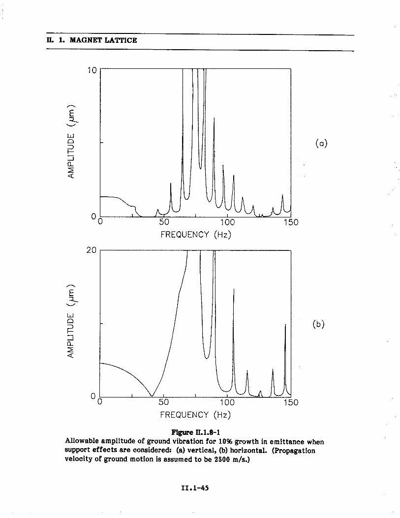
n. 1. MAGNET LATlCE
10
".E~'-w
(0)0::~-.Q.¿c:
50 100FREQUENCY (Hz)
15000
20
".E~'-w0
(b)::~-.Q.¿c:
50 100FREQUENCY (Hz)
15000
Fige D.1.8-1Alowable amplitude of ground vibration for 1096 growth in emittance whensupport effects are considered: (a) vertical, (b) horizontal. (Propagationvelocity of ground motion is assumed to be 2500 m/s.)
11.1-45

ll. 1. MAGNET LATTICE
10 .
~E~'-wo::r--l0.2.:
(0)
00~vVlJvVi I
50FREQUENCY
VVUVUvvI
100
(Hz)
150
20
\J vV U\i i I . 1
(b)
~E~'-wo::r--l0.2.:
°0 50 100FREQUENCY (Hz)
150
Figue ß.1.8-'2Allowable amplitude of ground vibration for 10% growth in emittance whensupport effects are ignored: (a) vertical, (b) horizontal. (Propagationvelocity of ground motion is assumed to be 2500 m/s.)
II. 1-46

~ E10
-1~ .. i- z w
10-2
I-~
I-W
. ..0
Ic:
.p .... a. (f
10-3
0
10-4
0.1
1
..,"
""
""" .
", 1\.
'----
, I "
i" I
"---
"", " ~
I I I \ a
, "
'", .,
, . " .
BUSY RMS
QU
IET
RM
S
110
100
FRE
QU
EN
CY
(H
z)
Fig
ue ß
.l.8-
3E
nvel
ope
of th
e pe
aks
of n
atur
al r
ms
grou
nd v
ibra
tions
plo
tted
vs. f
requ
ency
for
a q
uiet
per
iod,
Dec
embe
r 26
,1985, and a busy period, January 3, 1986.
:= .. . ~ z: ~ ~ t2

II. 1. MAGNET LATTICE
When the beam is to be aborted, it is first deflected inward 1.14 mrad by a 55-cmkicker K1 as shown in Fig. II.1.9-1. It then traverses through almost a full sector suchthat at a second kicker K2, it is about 24 mm from the central orbit. K2 deflects thebeam outward 1.14 mrad and puts the beam at 19.4 mm, with a slope of 0.7 mrad at theentrance to the septum. The phase advance between K1 and the septum is 2900.
Throughout its deflected path, the maximum excursion is 24 mm, as shown in
Fig. II.1.9-1. The beam then enters the 3-m-long septum magnet. The septum is 2 mmthick and located 50 ax from the central orbit, allowing 4 ax for extracted beamclearance, as shown in Fig. II.1.9-2.
The septum magnet bends the beam 5.50 vertically downward. At the firstquadrupole downstream of the septum, the beam is 40 cm below and 2 cm to the outsideof the central orbit. The beam dump is positioned after this quadrupole, with detailsshown in Fig. II.1.9-3.
1.10 Injection
Injection into the storage ring is from the inner radius into a long straight
section. The injector synchrotron accelerates eight bunches to 7 GeV at a 1-Hz rate.
(See Section II.10.1.) These eight bunches are extracted one at a time on the flat top of
the synchrotron and injected into designated rf buckets in the ring at a 60-Hz rate. Theacceleration cavities of the two machines have equal frequencies and are locked togetherin phase.
In the storage ring, four bumper magnets are used to locally displace the orbitof the stored beam inward toward a thin-septum magnet. Two of the bumpers arelocated in the straight section, while the other two are located between Q1 and Q2(Fig. 11.1.10-1). The Q1 provides an additional kick to the beam, requiring the bumpersin the straight section to operate at a higher field. These bumper magnets operate at a60-Hz repetition rate, but they have rise and fall times of 10.0 lls.
Since the bumped beam stays close to the septum only for a brief time, it isallowed to come within 5 ax of the septum. The thin-septum magnet is placed at 50 Oxfrom the central orbit. The emittance of 8x10⁻⁹ m and ßx = 13 m give Ox = 0.322 mff in
the injection region. Therefore, the septum is 16.1 mm and the bumped orbit 14.5 mmfrom the central orbit.
The injected beam from the synchrotron has a 0i of 1.3 mm. It leaves the septummagnet at a distance of 2.2 0i from the septum. The septum thickness is 2 mm so thatthe injected beam is 20 Ox from the bumped orbit. The injection efficiency as a functionof the effective aperture of the ring is shown in Fig. 11.1.10-2. For an efficiency of more
than 95%, the effective aperture must be greater than 28 ox. Figure II.1.10-3 shows the
relative position and sizes of stored, bumped, and injected beams at the thin septum.The bumper and septum magnets are described in Section II.4. 7 .
II .1-48

ß. 1. MAGNET LATTICE
LAMBERTSONSEPTUM
..
". 20EE'-E 100(1..
'+ 0020~I.
0+. -10ü(1...0l.I- -20
Distance (m)
Figue ß.1.9-1Horizontal displacement of beam in abort mode. The septum magnet bendsthe beam vertically downward (into page).
II. 1-49

ß. 1. MAGNET LATTCE
Septum
StoredBeam
10X
50 OX2mm 80;
Figue ß.l.9-2Relative positions of the stored and aborted beam with respect to the2-mm septum in abort system (ax = 0.322 mm).
II.I-50

ALL METAL
SHU
TIR
1- 1- . .. I VI ..
-C
OPP
ER
AB
SOR
BE
R?
BA
FF
LE G
AS
ALL
ME
TA
L Io
n~LEAD SHIELD BUFFER
7 VALVE Pump
/ n 2201/s
'//fi ,//"7 , A I
'/, '/ i.. .:' "..... ~ë~~ .. e+ )
'/// '/ ¿.. .."...... ('
'// 71 I U w i
J 1000 l/s 1000 l/s
SiiE
L B
ER
YL
UU
M H
EA
T N
eg P
ump
Neg
Pum
pDIFFUSER PLATES
1.5
m
Fig
ue ß
.l.9-
3D
etai
ls o
f the
bea
m d
ump
tare
t.
Fl .. . ~ z: ~ ~ (" ti

ll. 1. MAGNET LATTICE
(ww) 9100S IDOIlJ91\
a aa ~ N
N0 ¿0.-..l:CIrn...i~bO0 ...QSi:..rni:0.....
~ l:CI
~
~-e .SW N - .-z:: CD E CI-~ -- .i
.. ..Ffr 0 I..W Q) ~ QSCf ~ õ~ u 0 ~ e~
0w UJ . QS
= CI()~ J ~CI .0E z õ~ 'g
00. E ~ ..w O~~ c ... 0.Cf ~ 0_ 0 ii e
Cf a: CD N ::~ ~a: lL a: 1: .0
~ L: EO a 0 '0:i i:0. -- 0-- QS
W U -e '0Cf
~ ~ l!CI..c.() -e z CI...0 w ~ IJ i:
CD -e ().-i:
~0~CI0.0..
J l CI71 :;
i:.. r.0
II.I-52

ll. 1. MAGNET LATTICE
100
..~'-~ 750c(l.-0.-4- 504-
W
C0.. 250(l.~c
o
10 20 30 40 50 60Nx ,Effective Aperture
Figue LL.I.10-2Injection efficiency as a function of the effective aperture.
11.1-53

ß. 1. MAGNET LATTICE
SeptumInjected
Beam
StoredBeam
BumpedBeam
1
.2mm
~20o;-=450;
Figue ß.1.10-3The relative positions and sizes of the stored, bumped, and injected beamsat the exit of the injection septum.

ll. 1. MAGNET LATTICE
1.11 Detuned Lattice
For the initial turn-on of the storage ring, the lattice can be tuned to a somewhathigher emittance condition with a reduced phase advance per period. The resultingdynamic aperture given by the_ chromaticity-correcting sextupoles is large enough so thatthe harmonic-correcting sextupoles are not required. Operating under these conditions,the storage ring is less sensitive to dipole field and quadrupole placement errors.
The lattice and dispersion functions for the detuned condition are shown inFig. 11.1.11-1. The natural emittance at 7 GeV is 1i.Ox10-9 m. The horizontal andvertical tunes are Vx = 32.22 (0.80S per period) and vy = 11.36, respectively.
The dynamic aperture due to the chromaticity-correcting sextupoles is shown inFig. 11.1.11-2. Because of the larger emittance and ßx in the insertion region, ax is about1.3 times that of the fully tuned machine. In units of mm, the dynamic aperture is aboutthe same as that of the fully tuned machine after enlargement by the harmonic-correcting sextupoles.
Figure II.1.11-2 also shows the average and rms dynamic apertures for 10machines with uncorrected orbits resulting from a 10-4 error level. With fullchromaticity correction and without the aid of harmonic-correcting sextupoles, thedynamic aperture of the detuned lattice is comparable, at the same tolerance level, tothat of the fully tuned lattice with harmonic-correcting sextup'oles. All 10 machinesexamined for the detuned lattice at a tolerance level of 2x10-il had stable closed-orbitsolutions.
Using the procedures described in Section 11.1.12, the orbit correctors are adjustedto ensure full injection and beam lifetime capabilty. The lattice wil then be brought tothe final low emittance condition by tuning the quadrupoles and adjusting the orbitcorrection magnets.
1.12 Commissioning Procedures
To expedite commissioning of the accelerator system, special capabilties,concepts, and procedures pertinent to the turn-on process have been incorporated in thedesign. Such considerations are included in the conceptual design stage because:
(a) construction tolerances have major impacts on the commissioning of accelerators; and(b) a majority of these capabilties, though they are low-cost items in the constructionphase, may become costly items when they are retrofitted.
The first beam to be injected into the storage ring wil be a single bunch of
electrons equivalent to a few mA in the ring. The number of electrons needed is about3x1910. Electrons are used initially to inject a high-current single bunch in order toutilze all diagnostic equipment in the storage ring, keep track of turn-by-turncirculation of the beam in the storage ring, and expedite the injection process.
II.I-55

n. 1. MAGNET LATTICE
~c:
o1"
oN
o~ o
Stl313~
II.I-56
L(N
.1"~
(J~wi-w~
o
qjCo.-.....!"0~='..CI"0
~...- i.i 0= ei~ i:.. "0- i:CI CX
~ ar~ "'~
co
~o.-..g='eiCICo.-..1;..

ll. 1. MAGNET LATTICE
200
".E 150E
cotoN
.0II
100~
b..~Z 50
\ iø/
0
-100 0 100
Nx(o-x - 0.428 mm)
Figue ll.1.11-2Dynamic aperture for the chromaticIty~con"ected detuned lattice withó.p/p = 0 (solid curve). The data points and error bars are the average andrms dynamic aperture (for 10 machines) with 10-4 tolerance levels. Noharmonic-correcting sextupoles are used.
11.1-51

ll. 1. MAGNET LATTICE
The positron linac and the electron linac described in Section II.10 together arecapable of accelerating electrons to 650 MeV with a pulse current of 300 rnA and pulse
length of 16.5 ns. This single pulse corresponds to 3xl010 electrons and a bunch currentin the storage ring of 1.6 mAo The injector synchrotron is capable of accelerating asingle bunch of 650 MeV electrons from the combined linacs to 7 GeV. To do this,polarity-reversing switches in appropriate power supplies are provided.
The transfer line between the injector sychrotron and the storage ring is equippedwith a beam diagnostic system to measure the properties of the synchrotron beam,including the transverse phase spaces, energy, and energy spread during the synchrotroncommissioning period. It is planned to know these properties well enough to match intothe magnetic field, injection angle, and position at the storage ring.
The next step in the turn-on process is to inject the single bunch into the ring withno coherent betatron oscilation amplitude for the first turn. The purpose of eliminating
the coherent oscilation is to avoid confusion between large coherent oscilation due to
mismatch and the orbit distortion due to alignment tolerances in the first-turncirculation. To do this, the following three items are considered:
. The synchrotron beam energy and the ring magnetic field should be matched.Measurement of the synchrotron beam energy was already mentioned, and thestorage ring magnetic field is monitored in the 81st magnet with an NMRprobe. This 81st dipole in the storage ring is discussed in Section 11.5.2.
Measuring accuracies in 6E/E and 6B/B of 10-3 or better are sufficient forthis purpose.
. The injection position should be at the center of the storage ring acceptance.
This is achieved by moving the storage ring injection orbit to the incomingbeam position in the injection septum magnet. The injection bumpersdescribed in Section 11.4 are capable of satisfying the requirement, and a goodmatch between the four bumpers is essential. In-situ wire-orbit measurementcan be used to check the bumper matching.
. The injection angle of the incoming beam should be known to the order of
0.5 mrad. This angle is adjusted by the injection septum magnet system.
It should be noted here that, although it has been customary to optimize these variablesby independently sweeping each variable, special considerations are included in thedesign because the storage ring lattice has larger error magnification factors thanexisting rings.
All of the insertion-device straight sections in the storage ring at the time ofstart-up are equipped with the large aperture (4 cm x 7 cm) vacuum chambers of thering, rather than the smaller aperture (8 mm x 5 cm) chambers of the insertion devices.

II. 1. MAGNET LATTICE
Commissioning begins with a detuned lattice in order to reduce the sensitivity toerrors. All sextupoles are turned off to eliminate the tune shift due to closed-orbit
distortion in the sextupoles. In this condition, the quantum lifetime is several seconds, so
most of the beam properties can be measured.
.
With the injection orbit placed in the septum magnet as discussed above, theincoming beam is transported through a sector at a time while optimizing thetransmission efficiency and minimizing the orbit deviations using the ring dipolecorrectors. The diagnostic equipment available for this comprises nine beam positionmonitors (BPMs) and a scintilator device located in the downstream end of each sector.
The scintilator is a destructive monitor that stops the beam, and the BPM is capable of
measuring turn-by-turn beam positions. It is important to note that utilzation of single-bunch high-intensity electrons makes this process possible.
Once the bunch is transmitted through one turn satisfactorily, the storage ringbumped orbit is moved outside of the septum to permit the second turn to circulate. Thesecond-turn transmission is also done one sector at a time. In this case the scintilator is
retracted from the beam, and the BPMs are used to measure beam positions of the firstand second turns. The time separation between two turns is about 3.5 llS, and the use of asingle bunch makes the turn-by-turn beam position measurements much simpler. Thetuning process involves adjustments of dipole correctors to maximize transmissionefficiency and to minimize orbit deviations for both turns.
Once a few turns of transmission are established, then the usual procedures ofstart-up, such as the study of the survival time vs. the quadrupole magnet settings, arecarried out to search for a better working point. Once the closed orbit is established, theorbit correction program takes over to correct the orbit. Two important points should be
noted: (a) without sextupole magnets energized, the quantum lifetime is sufficiently longto do most of the lattice adjustments, and (b) because all BPMs are placed near thesextupole magnets, it is reasonable to assume that the closed orbit is in the middle of thesextupoles. If this is not the case, the displaced orbit effect should be apparent wheneach sextupole magnet is energized to compensate for the natural chromaticities of thelattice.
After the properties of the detuned lattice are understood, the low-emittancelattice is implemented in the storage ring. The knowledge gained from the de tunedlattice is then used to commission the low-emittance machine.
The use of electrons rather than positrons has the additional advantage ofproviding rapid beam cleaning of the vacuum chamber. Electron injection rates up to15 mA/s can be provided, compared with 0.5 mA/s for positron injection.
II.I-59

ß. 1. MAGNET LATTICE
1.13 References
1. "Report of Synchrotron Radiation Source Research and Development Program
Review," Ames Laboratory, Iowa State University, Ames, Iowa (October 1984).
2. "Machine Workshop on the 6-GeV Synchrotron Radiation Source," National Bureauof Standards, Gaithersburg, Md. (March 1985).
3. "6 GeV Synchrotron X-ray Source Conceptual Design Report," ANL Report
ANL-86-8 (February 1986).
4. Ref. 3, Appendix C.
5. G. Brown, Y. Cho, J. Hastings, S. Krinsky, D. Moncton, G. K. Shenoy (Chairman),
and P. J. Viccaro, "Ring Energy Selection and Extra Long Straight Sections for theAdvanced Photon Source: A Report and Recommendations by the National TaskGroup," ANL Report ANL-87-14 (April 1987).
6. E. Crosbie, unpublished program.
7. H. Wiedemann, SSRL ACD Note 22 (1984).
8. F. Iselin, CERN-LEP-TH/85-15 (1985).
9. A. WrUlich, DESY Report-84-026 (1984).
10. A. Ruggiero, unpublished program.
11. E. Crosbie, "Improvement of the Dynamic Aperture in Chasman-Green Lattice
Design Light Source Storage Rings," IEEE Conference Record, 87CH2837-9.
12. POISSON is an improved version of TRIM (A. M. Winslow, J. Computer Phys. !, 149,1967) that was developed by K. Halbach et al.
13. K. Steffen and J. Kewisch, "Study of Integer Resonances in Distorted PETRA
Optics," DESY PET-76/09 (1976).
14. L. Smith, ESG Technical Note-24 (1986).
15. W. Chou, ANL Report, Light Source Note LS-87 (1987).
16. W. Chou, ANL Report, Light Source Note LS-88 (1987).
II.1-60

ß. 2. BEAM STABILITY AND LIFETIME
2.1 Intrduction
A charged particle beam circulating in a metal vacuum chamber induces electro-magnetic fields that act back on individual particles in the beam. These wake fields wilaffect the beam properties and may lead to beam blowup or beam loss and thus couldlimit the beam current or density. The effect of these fields is expressed below in terms
of the effective impedance of various components in the beam pipe as a function of therms bunch length, a ii: These impedances are estimated using measurements from otherstorage rings and calculations for the radio-frequency (rf) cavity. For the beam blowupinstabilties, increasing the current per bunch above the threshold value only increases
the bunch length. For beam loss instabilties, an attempt to increase the current abovethe threshold value results in rapid beam loss from the ring.
The beam lifetime is determined by losses of beam due to the following effects:
. The quantum nature of the synchrotron radiation allows positrons in the beamto emit high-energy photons, causing the positrons to lose energy in a randomfashion and leading to a diffusion from the stable rf bucket, as well as fromthe transverse aperture (quantum lifetime, Lq).
. Collsions of particles within a beam bunch can give rise to exchange of
sufficient energy in the transverse plane that particles are lost from the rfbucket or momentum aperture (Touschek lifetime, Lt).
. Single scattering of beam particles from residual gas molecules can cause
beam particles to be lost from the rf bucket (bremsstrahlung lifetime, Lb) and
from the transverse aperture (single elastic scattering lifetime, LS).
Effects that do not lead directly to beam loss but to an increase in emittance aremultiple Coulomb scattering by residual gas molecules and multiple intrabeamscattering. These effects add to the quantum fluctuations of the beam, which must be
counteracted by synchrotron radiation damping. This yields an equilbrium transverseemittance that is dependent on bunch current and greater than the natural emittance.
The parameters on which the above effects depend are numerous and include
lattice properties, rf properties, beam current, vacuum pressure and composition,physical apertures, etc. A grand optimization is therefore not easily attained. Themethod used here is to fix the lattice functions and physical apertures as given inTable II.2.1-1. The rf properties are then chosen to yield adequate lifetime, a beamcurrent of ;: 100 rnA, and sufficient voltage and power for insertion devices. Staòiltyand lifetime then determine the properties of the individual bunches, the current perbunch, and the number of bunches required. The peak rf voltage, with full beam
II.2-1

ß. 2. BEAM STABILITY AND LIFETIME
Table ß.2.1-1
Storage Ring Parameters Used for Stabilty and Lifetime Calculations
Ring Circumference, C = 2~R
Average Radius, R
Revolution Frequency, foHorizontal Tune, Vx
Vertical Tune, vy
Average Betatron Function
Horizontal, ~Sx~
Vertical, ~By~
Momentum Compaction, ap
Transition Gamma, Yt
Beam Energy, E
Horizontal Emittance (10% Coupling), £x
Vertical Emíttance (10% Coupling), £y
Natural Energy Spread, 0E/E
Minimum rms bunch length
Bending Magnet Synchrotron Energy Loss, Uo
Radio Frequency, frf
Harmonic Number, h
Peak rf Vol tage, V rfBucket Hàlf Height, ÂErf/E
Synchrotron Frequency, f s
Equi valent Vacuum Chamber Radius, b
Minimum Vertical Vacuum Chamber Aperture in Undulator, g
Maximum Vertical Betatron Function inUndulator, By
1060 m
168.7 m
0.2828 MHz
35.22
14.30
Ring
Ring
Ring
Horizontal Acceptance, £x
Vert ical Acceptance, ÊyVertical Acceptance with Undulators, Ay
10 m
13 m
2.374xlO-4
64.97 GeV
7.3xlO-9 m
7.3x10⁻¹⁰ m
O. 96x 10-3
0.58 cm
5.45 MeVlturn
352.96 MHz
1248 = 25 . 3 . 13
9.5 MV
2.0%
1.88 kHz
30 mm
8 in11 m
32.7x10⁻⁶m
17 .1x10-6 m
1.45xlO-6 m
1.0 nTorrVacuum Pressure
II.2-2

ll. 2. BEAM STABILITY AND LIFETIME
intensity, is Vrf = 9.5 MV, which is obtainable from the present system. In order toensure adequate lifetime, an rf-bucket height of tiErf/E = :t 2.0% or -21 times the natural(zero current) energy spread is assumed. This yields a long quantum lifetime, evenallowing a safety factor of 3 for possible growth in the beam-energy spread. Thisbucket-height selection determines the synchronous phase angle, cPs' to be
sin cPs = l $ 0.72
and the total average energy loss, U, of the beam to be..
U = eVrf l $ 6.9 MeV/turn.
Since the dipoles alone account for an energy loss of Uo = 5.45 MeV/turn, the excessenergy available, Uex = 1.45 MeV, to compensate for energy loss in insertion devices,UID' and for higher-order mode (HOM) losses, UHOM' in the ring is given by
Uex = 1.45 MeV/turn ~ Urn + UHOM
andUHOM = ZHOM rse ,
where Is = average beam current (per bunch) and ZHOM = HOM impedance. The HOMlosses willlimit the number of insertion devices, depending on the average bunch current,as given by
Urn
Nu
= Ii=l
Ui = 1.45 - ZHOMrSe
where Ui are energy loss per pass for each of the Nu undulators. For this conservative rfdesign, a total of 12 high field (0.81 T) undulators with Ui = 0.1 MeV/turn are possible.These numbers wil allow considerable reserve for the typical operation, which isestimated to be less than half of this total undulator energy loss.
For this voltage and l, the bunch length and energy spread of the beam arerelated by
C1t =ci c
P21ff
s
C1
(E E) =C1E
602 x (E) ,
where C12, is in cm. The zero current bunch length corresponds to C19, = 0.58 cm.
II .2-3

u. 2. BEAM STABILITY AND LIFETIME
2.2 Beam Intabilties
2.2.1 Impedance and Loss Parameters.
The circulating beam in the storage ring induces electromagnetic fields in thevacuum chamber elements. The induced electromagnetic fields, which are
proportionalto the impedance seen by the circulating beam, may drive instabilties for the beam.When the growth time of such an instabilty is longer than the radiation damping time,the beam is stable. As bunch current increases, the growth time becomes shorter; at thethreshold current, the growth time and the damping time become equal. Consider nowthe longitudinal phase space. As current in the bunch increases beyond the threshold
value, the bunch wil grow in length and energy spread. In effect, this bunch lengtheningreduces the bunch current until the new threshold condition is satisfied. However, in thetransverse phase space, exceeding the current threshold may result in fast beam lossfrom the bunch. The threshold current calculated below indicates that there are nosingle-bunch transverse instabilty problems below the 10-mA bunch current level.
The impedance wil eventually need to be measured for the specific hardware inthe ring, but the estimated impedances used here wil allow an estimate of threshold
currents. To estimate the total impedance, the effective loss parameter for each com-
ponent in the ring is summed. The effective loss parameter is the average of the realimpedance over the power spectrum in the beam and therefore depends on the bunchlength, o~: We separate the total loss parameters, ktot' intorfcavities, krf, and vacuumchamber, kvc' components:
ktot(oi) = kvc(oi) + krf(oi)
For the vacuum chamber with bellows, vacuum pump ports, and instrumentation(see Section 11.6), the measured loss parameter from PEP is scaled to the storage ring bythe ratio of the circumference of the two rings. The measured loss parameter for PEP,in volts per picocoulombi the unit Wj wil use throughout for the loss parameter, is givenby kvc(oi) = 28(oi(cm)r .23 V/~C.(l This scaled loss parameter is more than a factor offour larger than that estimated 2) for the bare vacuum chamber designed for this ring,thus accounting for the loss parameters for the additional elements. Scaling themeasured PEP vacuum chamber impedance to obtain the storage ring vacuum chamberimpedance is valid, despite the presence of the antechamber (see Fig. 11.2.2-1), becausethe transverse-magnetic (TM) modes do not couple between the beam and antechamberbelow 15 GHz. Computer calculations using SUPERFISH(3) and OSCAR(4) verify thisconclusion, as shown in Fig. 11.2.2-1, where the magnetic field at the cutoff frequency(first TM mode) is plotted. Since PEP is not designed for synchrotron radiation beams,the effect of 80 beam ports is considered separately. The loss parameter for each beam
II.2-4

ß. 2. BEAM STABILITY AND LIFETIME
H Field Lines
Vacuum ChamberBeam Region
Pumping Slot BetweenBeam Chamber andAntechamber
Beam Chamber AntechamberFige 1L2,,2- i
SUPERFISH output of the magnetic field lines for the first TM mode of thestorage ring beam vacuum chamber. The entire vacuum chamber crosssection is shown for reference.
II.2-5

ll. 2. BEAM STABILITY AND LIFETIME
port consists of the loss parameter due to the vacuum chamber discontinuity,(5) kd(O'g) =0.08 (0'g,(cm)r2, and the beam port slot, ks(O'g) = 0.0055 (0'g,(cm)r5. The effective vacuumchamber loss parameter is expressed as
kvc(O'n) = 13.S(C1n)-i.23 + 6 4( )-2 0 44( )-S~ ~ . O'g, +. O'g,- (v/pc)
with 0' g, = rms bunch length in cm.
The rf cavity, being a tuned system, has a number of HOMs. The impedance seenby the beam bunch is an effective average over these modes. The loss parameter for therf cavity is estimated by
krf(O'g,) = L kn(o)n
2 2 2-wnO'g,lce per cavity,
where kn(o) = calculated loss parameter for mode nand wn = 2l times the frequency ofmode n. The summation is performed for n = 2,3,4,...,10, thus excluding the firstharmonic, which is actively compensated for by the coupling loop feedback. The kn andwn are calculated using the program URMEL(6) and listed in Table 11.2.2-1. Theseparameters are similar to the values for the LEP and ESRP cavities. (7) In order toaccount for the higher frequency modes, not included in Table II.2.2-1, the total krf(O' g,)was increased by 1.7 times the calculated values. This results in a krf(O' g,) value within1096 of those measured for the PEP rf cavities.(8) The total loss parameter (vacuumchamber plus 15 rf cavities) is calculated as a function of beam bunch length and is listedin Table II.2.2-2. Figure 11.2.2-2 shows the dependence of the loss parameter on O'g,.
The impedance seen by the beam is related to the loss parameter by
i ~ wO'g, 2k (0') = - r Re ( Z (w) ) . exp ( - (-- ) ) dw .tot g, ~ 0 c
The impedance Z(w) is approximated by a parallel resonant circuit with a quality factorQ = 1 and resonant frequency equal to the cutoff frequency of the vacuum chamber(fc = 3.82 GHz). (2) The shunt impedance, Rs' is calculated by fitting the loss parameterdata with the above integral expression. The longitudinal impedance, Z Ii' is given by
Iz~ I
R=~f(t)
o
(Q)
where n is the mode number (_104). Table 11.2.2-2 gives the estimated values for Rs andIzil Inl as a function of O'g,.
II.2-6

II. 2. BEAM STABILITY AND LIFETIME
Table 11.2.2-1
Fundamental and Higher-Order Modes
for the 353-MHz rf Cavity
Mode No. Frequency Rs10-3 Q
Loss Parametern fn (MHz) (MQ) (V fpc)
1 353.0 11.23 49 0.128
2 743.0 0.03 42 0.000
3 925.0 1.25 109 0.017
4 1174 0.33 43 0.014
5 1330 0.03 129 0.001
6 1511 1.09 88 0.029
7 1654 0.07 46 0.004
8 1679 1.06 46 0.060
9 1842 0.33 121 0.006
10 1972 2.98 55 0.165
In order to estimate the bunch length, and therefore the HOM loss in the storagering, the microwave longitudinal instabilty modei(9) was used. The threshold bunch
current, I ii' is included in Table II.2.2-2 as a function of bunch length. Below the bunchlengthening threshold current, the bunch shortens slightly as the bunch current isincreased due to the potential-well distortion. Above this threshold current, the bunch
length increases with current. For an average bunch current of I = 4.0 mA, a bunch
lengthening of three times the zero current bunch length is expec¥ed (0' i r: 1. 75 cm). Thisalso results in a similar increase in the energy spread (O'E/E r: 2.9x10⁻³).
The HOM loss can now be estimated for the bunch parameters listed inTable II.2.2-2 using the relation
UHOM = eZHOMI B =ektot (0'2. )IB
fo
The HOM loss at the threshold bunch current is also listed in Table II.2.2-2. For all bunchlengths listed, UHOM r: 0.2 MeV, leaving an excess energy Uin = 1.25 MeV tocompensate for insertion device losses. Increasing the bunch current wil result in bunchlengthening and reduced HOM impedance (ZHOM)' but the HOM energy loss is
II .2-7

ll. 2. BEAM STABILITY AND LIFETIME
Table ll.2.2-2
Impedances and Threshold Current for 7-GeV Storage Ring
0g, (cm)
0.7 1 1.5 2 3 4
O'E
(%) 0.116 0.166 0.250 0.333 0.499 0.666.:... . E
kvc (V fpc) 36.6 20.3 11.1 7.37 4.27 2.85
krf (V fpc) 7.23 6.65 5.62 4.43 2.37 1.06
ktota1 (V/pC) 43.8 26.9 16.7 11.8 6.58 3.91
Rs (kn) 2.06 4.03 8.47 14.2 26.7 38.2
Zii/n (n) 0.15 0.30 0.63 1.1 1.9 2.8
I II (per bunch) (rn) 1.4 2.0 3.3 4.7 8.3 13.6
UHOM (for Is = Iii) (MY) 0.22 0.21 0.20 0.20 0.20 0.19
approximately independent of bun'ch length. However, increasing the bunch length alsomeans an increase in energy spread and a decrease in the beam lifetime.
In order to ensure that the impedance estimate is reasonable, an attempt wasmade to measure the loss parameter for a 1-m length of beam chamber, with transitionsections. (10) The bench method used a T g, :: 65 ps signal (corresponding to 0' :: 2 cm) ona coaxial wire to measure the energy loss in the beam pipe. Table 11.2.2-2 inåicates theloss parameter should be approximately kvc(2 cm):: 0.007 V fpC (per meter). Themeasured loss parameter was consistent with zero (k :5 0.008) to within the systematicmeasurement uncertainty. Although not determining a precise value of kvc' thispreliminary measurement supports the claim that the presence of the pumpingantechamber yields an insignificant increase in the loss parameter relative to that of anellptical chamber. Therefore, the use of the scaled PEP value for kvc(0g,) is justified.
II.2-8

II. 2. BEAM STABILITY AND LIFETIME
102
,.Ü0.~::"-
1 0 1,.00("-..
10°o
\\\\\\\\"'"--- "
"".. "" ".., ".. .." ".. ...." ........
, ...." ....-., ...." ..", RF,
1 2 3as( (em)
4 5
Fig. II.2.2-2
Loss parameter as a function of bunch length. The solid curve shows the
total estimated vacuum chamber loss parameter, including transitions andbeam ports. The upper dashed curve is the scaled vacuum chamber lossparameter measured at PEP. The lower dashed curve shows the estimatedloss parameter for 15 rf cavities.
II .2-9

ll. 2. BEAM STABILITY AND LIFETIME
2.2.2 Impedance Scaling and Bunch Length
The impedance estimates used in Table II.2.2-2 were obtained by using theassumed Q = 1 resonance model for the Zii (00) dependence for each bunch length. Thismethod assures agree.ment between the loss parameter and Z II (00). The programZAP(ll) assumes that I Z II In I is independent of frequency up to the "SPEAR scaling"characteristic frequency ooc = c/b, where b is the effective beam pipe radius. Above thisfrequency, the longitudinal impedance is scaled by the empirical "SPEAR scaling." Usingthis formalism, the estimated impedance is given by the relation
':111 = A1.68
C1(b~) .for C1 ~ ~ b , (11.2.2.2-1)
where A is approximately two ohms, which is obtained by fitting impedance values inTable 11.2.2-2.
Using this impedance estimate, ZAP can evaluate the bunch length and energyspread as a function of bunch current using the microwave instabilty model. (9) These
results are shown in Figures II.2.2-3 and 11.2.2-4. The bunch current estimated using thismethod is approximately 25% higher than the threshold currents listed in Table II.2.2-2,resulting from a reduction of the estimated impedance for cr~ 0( b of Eq. 11.2.2.2-1.
This reduction in impedance is an empirical estimate of the uncertainty of theimpedance at high frequency. The "SPEAR scaling" estimate of bunch lengthening withcurrent is actually larger than the values seen at PEP, PETRA, and CESR.(12)Therefore, the IB = 5 rnA estimated here represents a lower value of the current possiblein a bunch with cr~ = 1.75 cm.
The minimum bunch length for a given bunch current wil ultimately be limited bythe coherent interaction of the low-frequency synchrotron radiation (00 0(0( Ec/li). Thiseffect can be expressed as a "free space" impedance, (13) described in Section 11.2.2.3.The actual impedance of the storage ring must be greater than this value for all cr~. Thisminimum bunch length for a given bunch current due to this "free space" impedance isalso presented in Figure II.2.2-3. This shows that for a bunch length of cr ~ = 1.75 cm
(crE/E :5 2.9 x 10⁻³), the bunch current limit_by "free space" impedance is 10 mA,compared to the "SPEAR scaling" value of Ia= 5 mA, corresponding to ~n impedanceof I Z II In I = 0.7 Q. Therefore, we use the "SPEAR scaling" estimate for IB = 5 mA atcr~ = 1.75 cm as a conservative estimate.
Transverse impedance for the vacuum chamber is not easily estimated. However,the cylindrically symmetric vacuum chamber estimate(ll) of
1:11 = t 1:111(£)m (11.2.2.2-2)

n. 2. BEAM STABILITY AND LIFETIME
3
,.E()"-
.--".'."'".."......",.,.... . FREE"J .,.,,, ."0/ ./:% .~
o2
OCX
1
oo 2 4 6 8 10
Is(mA)
Fig. n.2.2-3Bunch length as a function of bunch current. The solid and dashed curves
show the calculation by ZAP using "SPEAR scaling" with and without thepotential well distortion, respectively. The dot-dashed curve presents theminimum buooh length fop a given eurrent using the "free spaee'l impedaneeestimate. The circles are the current values listed in Table 11.2.2-2. Thehorizontal line corresponds to the maximum bunch length (0'9,= 1.75 cm)assumed here, consistent with adequate quantum lifetime.
II. 2-11

II. 2. BEAM STABILITY AND LIFETIME
0.5
0.4
,,~ 0.3"'w'"w
0.2b
0.0o
0.1
2 6 8 104
IB(mA)
Fig. 11.2.2-4
Rms energy spread as a function of bunch current as calculated by ZAPusing "SPEAR scaling." The circles are the values presented inTable 11.2.2-2. The horizontal line indicates the maximum energy spread(oE/E = 2.9xlO-3) assumed here, consistent with adequate lifetime.
II.2-12

II. 2. BEAM STABILITY AND LIFETIME
should provide a reasonable estimate and wil be used for single bunch fast transverseinstabilty estimates (see Section 11.2.2.3).
2.2.3 Single Buch Intabilty
A single bunch can be unstable due to internal coherent motion if the coherencewavelength is less than the bunch length. This is true for both longitudinal andtransverse motion. The stabilty limit is represented by the maximum allowable coupling
impedances, I z" / n I and I Z / n I, for the longitudinal and transverse motion,respectively, for given beam bunch current and bunch dimensions.
The stabilty limits are given by the equations(9,11,14)
I:" 1
.: a E 2_ -L (!E)
Ie p (11.2.2.3-1)
and
I Z l 1 ~ apE VY/!EI .n 2R e I p (11.2.2.3-2)
These equations come from conventional coasting beam theory. For bunched beamconsiderations, it is customary to replace the beam current, I, in the above equations bythe peak current in the bunch, Ip. The value (Llp/p) represents the full width at half-maximum momentum spread.
Equations 11.2.2.3-1 and 11.2.2.3-2 are valid in the case of the so-called fast
instabilty, where otherwise the bunches are unstable with growth rates larger than the
synchrotron frequency. This is the most common and critical limitation of the bunchcurrent.
The relation between the rms energy spread, O'E/E, or the rms bunch length, 0' i'and Llp/p is given by
-3Ll P / p = 2. 355 0' E / E = 3. 92 x 10 0' i ( em) .
For Gaussian bunches the average bunch current, Is' is related to the peak current by
IP
= ¡i; R -IS0' i
II .2-13

ll. 2. BEAM STABILITY AND LIFETIME
In terms of the average bunch current, IB' and rms bunch length, cri,Eqs. II.2.2.3-1 and 11.2.2.3-2 give the following coupling impedance limits:
I:" I ~ (0.605 0) :,3IB
and
IB
where cr i is in cm and IB is in mAo If IB = 5.0 mA and cr i = 1.75 cm, which correspondsto three times the zero-current bunch length, then the impedances must satisfy
Zl .~ (6.60 Q)n m2
C1i
1:"1~0.70and
n
Z 1 c:- 5.1 o/m
in order to ensure stabilty of the individual bunch.
As already mentioned, only wavelengths that are shorter than the bunch lengthcan cause a violent instabilty within the bunch. This corresponds to frequencies above
20 GHz, a frequency above the cutoff of the vacuum chamber pipe. It is not clear, and itis practically impossible to determine with either calculations or measurements, whatthe contribution is to the coupling impedance in this frequency range from the variouscomponents along the vacuum chamber. The best estimate that can be used is the so-called "free-space" impedance due to the synchrotron radiation itself.
Taking into account the radiation in dipoles and undulators and the absence ofradiation in straight sections, the contribution from "free space" is
L:il - 220 nn -210.n(II.2.2.3-3)
which, for this case, is the only contribution that need be taken into account.(13)
For the above case with cr i = 1.75 cm, the integer mode number n is givenapproximately by (21fR)/(2cri) = 3.03x10⁴. Thus,
II .2-14

II. 2. BEAM STABILITY AND LIFETIME
1:111 "'O.23n
significantly below the estimated threshold value. Figure II.2.2-3 shows the bunch lengthas a function of current for the "free space" impedance inserted into Eq. 11.2.2.3-1. No
significant contribution to Z 1/ n is expected from the "free space" impedance.
Using the cylindrically symmetric estimate for the transverse impedanceeqi;ation, Eq. II.2.2.3-2, the threshold current for transverse fast instabilty is givenbytll)
2_ 4 E Vs b(18)1 = ~(~)e Inl "ß::
(11.2.2.3-4)
The program ZAP estimates this threshold current without "SPEAR scaling" for I Z II /n I .For the bunch length Cf i = 1. 75 ern, the transverse threshold current is esti ma ted to
be ~ 2 times the longitudinal current of 5 mAo
The relationship between the bunch current and the bunch length imposed by theseinstabilty threshold equations can be changed by providing a higher harmonic rf system.
These threshold equations assume that there is a single rf system of a given frequencywhich provides a unique relationship among the energy spread, synchrotron frequency,and the bunch length. The addition of a higher harmonic, say third-harmonic, systemenables one to vary the bunch length and the synchrotron frequency independently of theenergy spread and the rf voltage of the primary system. For this reason, a 1059-MHzcavity system capable of -2 MV peak voltage is designed. The system can lengthen thebunch length by a factor of 1.7 without increasing the energy spread, thus enabling thebunch current to be increased by a similar factor.
The third-harmonic rf system can also be used to shorten the bunch length, asopposed to the above-mentioned lengthening of the bunch. The "zero" current bunchlength of the main rf system is about 39 ps. The third-harmonic system can shorten thislength to around 15 ps. The expected bunch current for this case is lower than that ofthe normal operating current.
2.2.4 Coupled Bunch Intabilties
As the number of bunches, M, increases in the storage ring, a second type ofinstabilty must be considered. The higher-order modes (HOMs) in the rf cavities haverelatively high quality factors, Q, in the absence of HOM damping, and decay with a timeconstant T Z 2Q/w. As the separation between bunches is reduced, the threshold forcoupled bunch instabilties, resulting from HOM fields, decreases. The longitudinalinstabilties do not generally result in beam loss, but the transverse instabilties may
II.2-15

u. 2. BEAM STABILITY AND LIFETIME
drive beam loss mechanisms. These instabilties may occur whenever the resonantfrequency of the HOM satisfies the relations
IIfHOM = f 0 (p M + n + m "s) for longitudinal modes,
and
lfHOM = f (p M + n + " + m " ) for transverse modes,o s
where m, n, and p are integers. The threshold currents are obtained when the growthrates of the instabilties are set equal to the radiation damping times.
The programs BBi(15) and ZAP(ll) are used for estimating the threshold currents
for the m = 1 (dipole) and m = 2 (quadrupole) modes and for M = 13 and 26 bunches.These numbers were deduced from consideration of the harmonic number and thecapabilty for yielding an average current of 100 mAo The longitudinal HOMs are listedin Table II.2.2-1 and the transverse HOMs are taken from a similar rf cavity.(7) In thelongitudinal phase space, damped modes are assumed and all 15 cavities are assumed tohave the same frequencies for the HOMs. The bunch parameters were taken to be at =1.75 cm and (aE/E) = 2.9x10⁻³. The threshold currents are calculated using growth rates
that are scaled from those calculated by ZAP. The growth rate is scaled linearly withcurrent until it is equal to the synchrotron damping rate for each mode. These thresholdcurrents are listed in Table II.2.2-3 for M = 13 and 26 bunches. The smallest current forthe coupled bunch mode n for each bunch shape mode m was taken.
The threshold currents listed in Table II.2.2-3 are somewhat higher than the100 rnA for nominal operation, indicating no problem for coupled bunch stabilty.
2.3 Intrabeam and Gas Scattering
The Coulomb scattering between individual particles within a bunch causes adiffusion of particles to larger transverse phase space. This diffusion rate fromintrabeam scattering is counteracted by the transverse synchrotron radiation damping,and the equilbrium emittance increases until the quantum fluctuation plus intrabeamscattering rate equals the damping rate. The increase in the equilbrium emittance iscalculated in each plane by the program ZAP, which averages the diffusion rate over theentire lattice. The calculated fractional increase in the emittance for this lattice isgiven by
/jE; -6 _~ ~ 6.5xlO IBx,y
II.2-16

ll. 2. BEAM STABILITY AND LIFETIME
Table ll.2.2-3
Coupled Bunch Threshold Currents
Mode, -II -1C1g, t I t 1 I
M (cm) m (m~) (rJ) (ms) (rJ)
13 1. 75 1 22.6 326 17.8 12813 1. 75 2 94.0 1357 46.6 335
26 1. 75 1 14.5 418 19.5 28126 1. 75 2 56.0 1618 49.5 715
I" = total average beam current at longitudinal0 threshold,-1
total average beam current at transverseI =0 threshold,
til = growth time of longi tudinal instability atIa = 5 mA.
t 1 = growth time of transverse inst~bility atIa = 5 mA.
where Ia is the average bunch current in mAo This calculation assumed C12, = 1.75 cm,
but the change is negligibly small even for C1 g, = 0.6 cm.
A similar emittance growth wil result from multiple Coulomb scattering with theresidual gas atoms. The rate of increase in the angular divergence of the beam is givenby
d-: e 2;:
dtE 2
= (E S)pcLR
where Es :: 21.2 MeV,
E = beam energy,
LR = radiation length for the residual gas, and
p = density of the gas.
II.2-17

II. 2. BEAM STABILITY AND LIFETIME
The angular divergence growth contributes to an emittance growth
dE.1
Qm = "d =
C:ß.::dc:e2::1
E 2 C:ß.::= (2.) -! pcE LRdt
for i = x or y. Similar to the case for intrabeam scattering, the equilbrium emittance isobtained by setting the sum of the quantum fluctuation and multiple scattering growthrates equal to the synchrotron damping rates:
2€.1
Qq + Qm = Qdamping = ~1
where "ti is the synchrotron damping time. The change in the emittance from the naturalemittance is given by
ó,€. "to1 1-=-Q€. 2€. m1 1where i = x or y. For the current lattice, with N2 gas at pressure P (nTorr), LR =
38 g/cm2, and p = L.496x10-9 P (g/m3), the fractional change in the equilbriumemittance is given by
ó,€ .1 -4O.747xlO P.-=
e: .1
2.4 Beam Lifetime
2.4.1 Quantum Lifetimes
The total decay rate of the beam from the ring is the result of several lossprocesses considered below. The first effect to be considered is quantum lifetime due tosynchrotron radiation loss from the rf bucket or momentum acceptance of the machine.The momentum acceptance due to physical apertures in dispersive sections of the latticeis :t 3.5%. Consequently the maximum momentum error acceptance is determined bg- therf-bucket height of -2.0%. The quantum lifetime is then given by the relationship(l )
"t éE"tq = 2T
II.2-18

II. 2. BEAM STABILITY AND LIFETIME
where
l1E 2t" 1 (-!).. = i CYE
LE is the longitudinal synchrotron radiation damping time, and l1Erf is the height of the rfbucket. For CYE/E = 2.9x10⁻³, the longitudinal quantum lifetime is L ;: 1000 h, a
conservative value for 'q considering its rapid dependence on CYE. T%e quantum lifetimefor the transverse aperture limit is obtained by replacing LE with LX and puttingt = 1/2 Ni, where NV is the ratio of the dynamic aperture to beam size in the verticaldirection. The dynamic aperture from tracking with errors yields NV n 10, which meansa transverse quantum lifetime 'q ;:;: 1000 h.
2.4.2 Touschek Lifetime
The intrabeam scattering, discussed previously for the transverse emittanceblow-up, can also cause an exchange of energy between beam particles in the samebucket. If the energy transfer is great enough, these particles may be scattered outsideof the rf bucket or the momentum aperture of the lattice and be lost from the stablebeam. The lifetime has been given by Bruck. (17) This formalism can be used by insertingaverage lattice parameters, but the program ZAP(ll) uses this formalism weighted overthe actual lattice functions. In addition, ZAP can account for beam loss due to physicalmomentum aperture, as well as the rf-bucket height. Figure II.2.4-1 shows the lifetimeas a function of IB per bunch calculated by ZAP for CYE/E = 0.96x10⁻³, 1.7x10⁻³, and
3.3x10⁻³, corresponding to CY2, = 0.58, 1.0, and 2.0 cm, respectively. Figure II.2.4-1 also
shows the Touschek lifetime when the bunch lengthening is calculated by assuming"SPEAR scaling." The effect of increasing bunch current, which tends to reduce theTouschek lifetime, is balanced by the increase in bunch length (decrease in particledensity), such that the Touschek lifetime is almost constant (Lt '" 190 h) for bunchcurrents between 2 and 8 mAo
As an additional check, the program BEAMPARAM(l8) was used to calculate theTouschek lifetime, which is also shown in Fig. II.2.4-1. This program does not allow forbunch lengthening, but computes the lifetime for CY2, = 0.58 cm and CYE/E = 0.96x10⁻³. All
calculations agree to better than :t 1096.
2.4.3 Bremsstrahung Lifetime
The positrons in the beam sometimes collde with the atoms in the residual gas,thereby undergoing' a deceleration and emission of a photon or photons. If the energy loss
is larger than the bucket height, the particle is lost from the rf bucket. The
11.2-19

o. 2. BEAM STABILITY AND LIFETIME
500
400
~..""..\-
300
200
100
ZAP----- SEAMPARAM_._.-.- ZAP + SPEAR
1.0--- 0.58
oo 4 6 8 102
I s(mA)
Figue 0.2.4- iTouschek lifetime as a function of the average single bunch current for(J ii = 0.58, 1, and 2 cm. The solid curves are calculated by the programZAP(ll) and the dashed curve by BEAMP ARAM. (17) The dot-dashed line isthe Touschek lifetime calculated by ZAP, for the bunch lengthening given
by the "SPEAR scaling" assumption.
II.2-20

II. 2. BEAM STABILITY AND LIFETIME
bremsstrahlung cross section that results in beam loss is obtained by integrating thedifferential cross section from Ey = LlErf to Ey = E, and is given by
24re 4 E 5 -1/3Gb = 137 Z(Z + E) (3 1n (¡w) - "6J 1n (183 Z .)
rf
where
1n (1440 z-2/3)E = 1n (183 Z-1/3)
re = classical electron radius, and Z = atomic number of the gas atoms. (19) The rate ofbeam loss is then given by
1- =t'b
where N is the atomic density of the gas, .
c N Gb
N = 6.43412xl013 p ( atoms3)
nTorr m
at T = 300 K for a diatomic gas such as H2, N2, O2, etc., and P is the pressure in nTorr.The assumption of Z = 7 (N 2) yields a "worst case" lifetime of
= 53.3 (h)t'b P .For a mixture of gases X and Y, an estimate of the lifetime is obtained by summing therates for each element at its partial pressure
1 1t'b = t'b (X)
+ 1t'b (y)
For a partial pressure mixture of 7596 H2 and 2596 CO, we find
t' = 187 (h)b PTherefore, the bremsstrahlung lifetime at the expected operating pressure of 1 nTorr is187 hours.
11.2-21

ß. 2. BEAM STABILITY AND LIFETIME
12. J. Bisognano, "Report of Machine Workshop on the 6-GeV Synchrotron Radiation
Source," Gaithersburg, Md. (March 28-30, 1985).
13. A. Faltens and L. J. Laslett, Proc. 1975 ISABELLE Summer Study, II, 486 (1975);
A. G. Ruggiero, KEK Report, KEK 80-16 (1981).
14. J. D. Lawson, The Physics of Charged-Particle Beams, pp. 345-383, Clarendon
Press, Oxford (1977).
15. M. Gygi-Hanney et al., CERN/LEP-TH/83-2 (1983).
16. M. Sands, SLAC Report, SLAC-121 (1970).
17. H. Bruck, "Circular Particle Accelerators," LANL Report, LA-TR-72-10, translatedby R. McElroy Co., Inc. (1972).
18. M. Hanney and E. Keil, CERN-ISR/TH-79-29 (1979).
19. T. Khoe, ANL Report, Light Source Note LS-27 (1985).
20. Touschek lifetime must be expressed as an e-1 time in keeping with the definitionof the other lifetimes; see S. Kramer, ANL Report, Light Source Note LS-68 (1986).
II.2-24

II. 3. STORAGE RING RADIO FREQUENCY SYSTEM
3.1 Introduction
The rf system must provide adequate voltage and power to compensate forsynchrotron radiation from the dipole magnets and the insertion devices, excitation ofparasitic modes by the beam, and overvoltage for an adequate beam lifetime. Designlimits in the storage ring rf are: (a) 200 kW of rf power per ceramic window and(b) 800-kV accelerating voltage per cavity. The nominal frequency of operation for thestorage ring rf system is 353 MHz.
The rf system uses 15 single-cell, spherical cavities. These are the same type ofcavities used on the Photon Factory in Tsukuba(l) and the SRS in Daresbury.c2) Three
1-MW klystrons provide the rf power. The power from each klystron drives fivecavities. Each group of five cavities is located in a 6-m straight section; these arelocated in the 9th, 10th, and 29th straight sections after the injection straight section. Athird-harmonic cavity, operating at 1059 MHz and 1.8 MV, is located in the 30th straightsection after injection. The rf parameters are listed in Table 11.3.1-1.
3.2 353-MHz Accelerating Strctures
Figure II.3.2-1 shows the cross section and dimensions of the single-cell cavityused for the storage ring. Calculations with the computer program URMEL(3) andestimates made by scaling from the Photon Factory measurements indicate that a singlecavity can develop 800 kV with 62 kW of copper loss and with a peak electric field at thecopper surface of 5.9 MV 1m. The same fabrication technique used for the PhotonFactory cavities is used. The cavity is machined in two halves from solid blocks of
Oxygen-Free High Conductivity (OFHC) copper, with cooling channels machined intoeach component. The inner surfaces are machined to a high surface finish and the twohalves silver-brazed together. Stainless steel vacuum flanges are fitted to the beamports.
Each cavity is provided with five 14-cm-diameter ports. One port is used for thecoupling loop. The coupling loop, which is post-excited from a WR2300 waveguide,provides for coupling-coefficient adjustments. The post is vacuum-sealed from the air-filed waveguide by a cylindrical ceramic window. The second port is provided with atuning plunger. The plunger has a 9.5-cm diameter and a 6.0-cm travel. This provides afrequency-tuning range of 1.0 MHz to compensate for beam loading, temperatureeffects, etc. A third port is used for vacuum pumping. Two 14-cm ports are provided forthe beam.
The need for damping the higher-order modes (HOMs) in the cavity to sup~ressinstabilties has been demonstrated on the 2.5-GeV Photon Factory storage ring. 4)Therefore, an antenna and a loop coupler with a band-stop filter for the fundamental
II.3-1
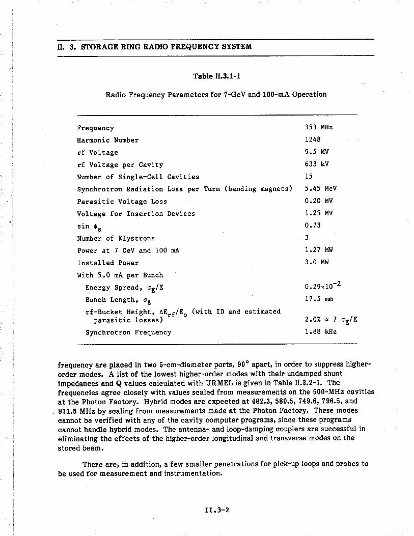
ß. 3. STORAGE RING RADIO FREQUENCY SYSTEM
Table ß.3.1-1
Radio Frequency Parameters for 7-GeV and 100-mA Operation
Frequency
Harmonic Number
rf Voltage
rf Voltage per Cavity
Number of Single-Cell Cavities
Synchrotron Radiation Loss per Turn (bending magnets)
Parasitic Voltage Loss
Voltage for Insertion Devices
sin els
Number of Klystrons
Power at 7 GeV and 100 rn
Installed Power
wi th 5.0 rn per Bunch
Energy Spread, 0E/E
Bunch Length, ° i
rf-Bucket Height, ~Erf/Eo (with ID and estimatedparas i t ic losses)
Synchrotron Frequency
353 MHz
1248
9.5 MV
633 kV
15
5.45 MeV
0.20 MV
1.25 MV
0.73
3
1.27 MW
3.0 MW
0.29xlO-2
17.5 mm
2.0% '" 7 0E/E
1.88 kHz
frequency are placed in two 5-cm-diameter ports, 90° apart, in order to suppress higher-order modes. A list of the lowest higher-order modes with their undamped shuntimpedances and Q values calculated with URMEL is given in Table II.3.2-1. Thefrequencies agree closely with values scaled from measurements on the 500-MHz cavitiesat the Photon Factory. Hybrid modes are expected at 482.3, 580.5, 749.6, 796.5, and871.5 MHz by scaling from measurements made at the Photon Factory. These modescannot be verified with any of the cavity computer programs, since these programscannot handle hybrid modes. The antenna- and loop-damping couplers are successful ineliminating the effects of the higher-order longitudinal and transverse modes on the
stored beam.
There are, in addition, a few smaller penetrations for pick-up loops and probes to
be used for measurement and instrumentation.
II.3-2

ß. 3. STORAGE RING RADIO FREQUENCY SYSTEM
BEAM DIRECTION
DIMENSIONSIN CENTIMETERS
INPUT POWER COUPLER
TUNING ASSEMBLYCOAXIAL VACUUMWINDOW
"H" PROBE"HOM" ABSORBER
1 /2 WAVELENGTH STUB
"E" PROBE
VACUUM PUMP
Fig. n.3.2-1353-MHz rf accelerating structure showing a top view of two cavities and avertical cross section.
II.3-3

II. 3. STORAGE RING RADIO FREQUENCY SYSTEM
Table 11.3.2-1
Shunt Impedances of Some of the Higher-Order
Modes of the Single-Cell Spherical Cavity
Shunt ImpedanceFrequency (undamped) Q
MHz Mn (undamped)
353.0 11.23 48,600
743.0 0.03 41,630
925.0 1.25 108,800
1174 0.33 43,450
1330 0.03 129,000
1511 1.09 88,130
1654 0.07 45,710
1679 1.06 46,260
1842 0.33 121,250
1972 2.98 54,850
Each cavity is pumped by a 220-ils ion pump. Remotely driven beam line valvesare provided at each end of the straight section for isolation. One roughing system,
including sorption pumps and turbopumps, is provided in each of the two rf powerbuildings. The base pressure of the cavity reaches 0.75 nTorr.
3.3 Radio Frequency Power System
A 1-MW klystron is used to drive five cavities. A block diagram for the five-cavity arrangement is shown in Fig. II.3.3-1. From the klystron, the power is dividedequally to the five cavities. The first division is via a 2/5:3/5 hybrid T plus a second
1/3:2/3 hybrid. Two more 1:1 hybrids provide equal power to each cavity. Table II.3.3-1lists the operating parameters for the Thomson-CSF TH2089 klystrons. The YK 1350klystron available from Valvo has similar characteristics, and either tube could be used.A total of three 1-MW klystrons are required for 15 cavities.
The power requirements for several different operating scenarios, including thenormal operating condition, are listed in Table II.3.3-2.
II. 3-4

DC
Pow
..Su
pply
H,
i: . w . ~ 0 ~ P.T
S10
~ ~ - !z 0 ~ P. t: Õ ~ ~ ~ £) c: ~ z: (' ~ ~ ~ ~ a:
Input fr low
leve
Rf
syse
mI- I- . w I V
I
C - Clculator
DC
- D
Irec
Iona
l Cop
l..H, - 3.98 db H)brld Copler
H2 - 4.n db H)bd Copler
H3 - 3 db H)brld Copler
PS
- P
hase
ShI
fter
TS - Tuning System
DC
L.
Pha
se a
nd A
mpl
itude
Fee
back
Fig
ue 0
.3.3
-1Sc
hem
atic
dia
gram
of
circ
uit u
sed
to s
plit
the
pow
er f
rom
one
353
-MH
z, 1
-MW
kly
stro
n an
d di
stri
bute
it to
fiv
erf
cav
ites.

II. 3. STORAGE RING RADIO FREQUENCY SYSTEM
Table 11.3.3-1
Parameters for the Thomson-CSF TH2089 1-MW,353-MHz Klystron
Operating Frequency
Mechanical Tuning Range with Respectto Center Frequency
Continuous Output Power
Reflected Power, Maximum
Drive Power, Maximum
Gain, Minimum
Gain, Typical
EfficiencyBeam Voltage
Beam Current
Length (horizontal position)
Height (horizontal position)Width
Output Waveguide
353 MHz
:! 3 MHz
1.0 MW
16.6 kW
200 W
40 dB
41 dB
65-70%
90 kV
18 A
4.8 m
1.85 m
i.o m
WR2300
The load lines for 3-MW input rf power, plotted in Fig. 11.3.3-2 for 7.0 GeV and7.5 GeV, indicate that the rf system wil be able to produce voltages and currents well inexcess of the nominal operating conditions; 7 GeV and 300 mA is within the system'scapabilties, even with 2.2-MeV losses for insertion devices.
The power from the 1-MW klystron is divided five ways. There is a three-portcirculator, and a mechanically driven phase-shifter, between the hybrid and the cavity.The harmonic voltages that are generated by the beam are absorbed by the HOM deviceson the cavities. The circulator prevents reflected power from reaching the klystron or
other branches of the rf system.
The center-to-center spacing of the cavities is 0.8493 m. The waveguide lengthsare adjusted to provide the right nominal phase with respect to the beam, andmechanically tunable phase-shifters are used for fine tuning of the cavity phase ("'0.5 to1.0°).
II.3-6

ß. 3. STORAGE RING RADIO FREQUENCY SYSTEM
Table ß.3.3-2
Power Required under Different Operating Conditions
7.0 GeV, 7.0 GeV, 7.5 GeV,100 rn 300 rn 200 rn
Copper Loss (kW) 582 582 935
Power for Bending MagnetSynchrotron Radiation (kW) 545 1635 1436
Power for Insertion DeviceSynchrotron Radiation(full complement) (kW) 125 375 286
Power for Parasitic ModeLoss (kW) 20 60 40
Total Power into Storage Ring (kW) 1272 2652 2697
Storage Ring Voltage (MY) 9.5 9.5 12.04
Elevation and plan views of adjacent cavity, waveguide, and klystron systems in anrf power building are shown in Fig. II.3.3-3.
The coupling loop on each cavity is adjustable to change the coupling constantfrom about 1.0 to 5. Since the circulators and klystron can safely handle large amountsof reflected power, the loop is normally set for optimum operation at the highestexpected beam current during the operating period. This implies that the loop isovercoupled for lower currents, which wil result in reflected power. The feedback loopthat drives the tuning plunger works on only the reactive element of cavity inputimpedance. The klystrons with circulators can handle the reflected power fromovercoupling at power levels below the maximum point in the designated operating cycle.
Klystron beam power is supplied by a 90-kV, 20-A multiphase rectifier with 0.1 %ripple and regulation. A modulating anode supply is used to maximize efficiency. Theklystron is fully protected by an electronic crowbar and arc detection circuitry.
II .3-7

!
400
.. 4( .. 300
l- ZI-
WI-
0:.
~ 200
L, i 00
U :: 4( ~ 100
r= w . ~ ~ t: e ~ ~ II == t: £) c: t: ~ i- ~ a a:
v = 800 kV /Cavity
V 800
kV/C
avity
o1 2 3
INS
ER
TIO
N D
EV
ICE
LO
SS
ES
(M
eV)
4
Figu
e 11
.3.3
-2Lo
ad li
nes
for
7 G
eV a
nd 7
.5 G
eV w
ith 3
-MW
inpu
t rf.
The
max
imum
bea
m c
urre
nt is
sho
wn
as a
func
tion
of th
ein
sert
ion
devi
ce e
nerg
y lo
ss fo
r 7
and
7.5
GeV
ope
ratio
n, w
ith th
e 3-
MW
rf s
yste
m. T
he e
nd p
oint
s fo
r ea
chcu
rve
repr
esen
t the
max
imum
des
ign
volta
ge o
f 800
kV
/cav
ity.

ll. 3. STORAGE RING RADIO FREQUENCY SYSTEM
ci en
~ :g..~-§ :i.¡; '-:i .B
- i:Õ .2:i ..o
.s .~E en- '- '-
~ ~ .soII II ::~ t- e
ü'-.B
ci ~~.2 E
.. 00..
.~ .2
ê öQ) .!:t- ÜII II
i= -
en Q)Q):; .0.5.xo Q)ü G:II II
ü La
t-r-
..Q) 55
.c gi E0'.. a.
I 0.3~ 0'W
t- ..
'- '-Q) Q).. .... .. '-.- .- Q)a. ã...U' U' ~"0 "0 ã.._ .- U''- '-
'J:~ :: ~ ~ ~o :i:i '-~§ .o.o~o '- "0 :i0'.. "0Q) ~ CD " .0
P- :::: en " "0~ ~ ,..q n~~O II II II:i ~ a: ~Nnr J "":i :i :i :i
~- - ~~
t- ..
(':ii.-
'-Q)
~.cU'
Q)eno.c0-
Il II
a: U'w 0-
n:i- ~
en en"0 "0i: i:Q) Q)a: a:n
:iI: I:
i. :i w~,. I: :~ ~~l; a: II;;w a::i~ -
.. I- U'
il il il il il 0-
;:::='====. I-- -'=
i i I I I. . .. .- ~ ,.- -;:- -
La
-
-U ~i... tx. ..· i -- -
II.3-9
I
0
L
J
V
:a
;1
( (
( (c: c:
:ø
..(..=-
0..ui,, bl
en i:'- :eQ) -.. .~Q) ==
:E.0i:-- II
Q) ~io "õ 0
0 Oi
U' ..i:II.i....0
~ IIi:00 .5ciEII..ci:;cii:0i:..ci
C" ~1-CO ~co '0. i:= ~I\ ..~~... ==ii blII
;:~~~..
'5=~e,..i:IIe,~...'0~..0ci~.~;:i:~-Oi'0i:~i:0.....~;:II-ç.

ß. 3. STORAGE RING RADIO FREQUENCY SYSTEM
3.4 Beam Loading
The rf power delivered to the beam via the cavities can be much larger than thatused to excite the cavity to the required voltage. The highest coupling constant, ß,
required is about 4.5. The cavity coupling wil be adjusted to give a mat~hed condition atthe circulating current.
It is necessary to compensate for the reactive component of the beam loading.This is done prior to injection ii de tuning to comply with the requirement of theRobinson instabilty criterion. ( For Robinson stabilty,
(1/(1 + ß)J(Pb/Pc) ~ 1
The required amount of de tuning from the no-beam resonance condition to the fullyloaded condition is
6£ = -(£rf/2Qo) x (Pb/Pc) x cot (phase angle)
= (353x106/2x40x103) x (176/39) x cot (51.2°) = -16 kHz
This detuning coverage can easily be handled by the tuning system, which has arange of 1 MHz. Detuning requires additional power. After beam filing is completed,
the cavities are tuned closer to resonance, and the Robinson instabilty is counteractedwith dynamic feedback via the low-level controls. The low-level loops are fast enoughfor this application.
3.5 l059-MHz Radio Frequency System
A third-harmonic system is included in the design to provide additional Landaudamping or bunch lengthening if required for added stabilty. An axial accelerating
voltage of 1.8 MV from astanding-wave biperiodic structure operating in the If/2 mode isused.
Among the various geometries for cavity structures with high shunt impedance,the most successful are the side-coupled cavity xeometry developed at Los AlamosNational Laboratory for the LAMPF accelerator 6) and the on-axis coupled structuredeveloped at the Chalk River Laboratories. (7)
Both of these cavities have been studied extensively, and either one could be usedfor the 1059-MHz rf system. The on-axis coupled structure is used, and is shown in crosssection in Fig. II.3.5-1.The inside bore diameter of the iris is 6 cm to allow anunobstructed path for synchrotron radiation.
This geometry has several advantages. Fabrication is simplified because of thecoaxial symmetry, and excitation of transverse deflecting modes can be suppressed by
II.3-10

II. 3. STORAGE RING RADIO FREQUENCY SYSTEM
On Axis Coupled
-- 15.0 em r-
20.0
6.0
CouplingCavity
Figue II.3.5-11059-MHz on-axis coupled structure.
II .3-11
CouplingSlot

II. 3. STORAGE RING RADIO FREQUENCY SYSTEM
splitting the resonance frequencies for hybrid HEM110-like modes. This splitting isaccomplished by rotating the coupling slots that connect adjacent cavities. (8) For thisreason, the Mainz group has successfully used the on-axis coupled geometry for theMainz microtron (MAMI) system of cascaded microtrons.
-
The frequency of the cavity is 1.059 GHz with ß = 1, and the effective shuntimpedance per unit length (the "bare" shunt impedance per unit length multiplied by thesquare of the transit time factor) is 41 Mn/m with a 6-cm diameter aperture. The rfpower dissipated in the cavity at the accelerating field of 1.8 MV, is 19 kW/m, andcooling is easily accomplished.
Power is fed into the center of the 2-m-long rf structure through an rf couplerconnected by flanges to the two sections. The 10% coupling factor of this type of cavityis quite adequate for this length.
With a bore of 6 cm, three 220-i/s ion pumps (one in each end and one at the
center) keep the structure at a pressure below 1 nTorr. The 1.059-GHz cavity is drivenfrom a single klystron. A modified Valvo YK 1250 klystron can be used.
3.6 Low-Level Radio Frequency System and Control
The frequency and phase of the storage ring rf system affect the beam positionand energy. The main frequency source is stable and controllable, with phase continuityto several parts in 1011. The low-level rf system utilzes a digital synthesizer to controla phase-locked, voltage-controlled oscilator as the source. The output of this commonfrequency source is fed via phase-stable cables to each of the klystron amplifiers in thesystem. The input to each klystron amplifier driver has a computer-controlled rfamplitude modulator and a computer-controlled relative phase shifter. An amplitudecomparator compares the sum of the voltages from all cavities and adjusts the rfmodulator to maintain the required voltage. The phase of the voltage developed in thecavities is compared with the reference, and the phase of the drive to the klystron isadjusted to maintain the cavity voltage phase within :t1.0o (Fig. II.3.3-1).
The klystron power is controlled by a control loop through the modulating anodesystem, while the klystron drive is maintained in the linear gain region. In this way theklystron efficiency remains optimum.
3.7 References
1. "Photon Factory Activity Report, 1982/83," National Laboratory for High Energy
Physics, KEK, Japan (1983).
2. D. M. Dykes and B. Taylor, "Development of a High Power RF System for the
Daresbury SRS," IEEE Trans. on Nuclear Science, NS-30, 3475 (August 1983).
II.3-12

II. 3. STORAGE RING RADIO FREQUENCY SYSTEM
3. T. Weiland, "Computer Modeling of Two- and Three-Dimensional Cavities," IEEE
Trans. on Nuclear Science, NS-32, 2738 (October 1985).
4. Y. Yamazaki, K. Takata, and S. Tokumoto, "Damping Test of the Higher-Order
Modes of the Re-entrant Accelerating Cavity," IEEE Trans. on Nuclear Science,
NS-28, 2915 (June 1981).
5. K. W. Robinson, "Stabilty of Beam in Radio Frequency System," CEAL-1010, p. 8
(February 27, 1964).
6. E. A. Knapp, B. C. Knapp, and J. M. Potter, Rev. Sci. Instr., 39, 979 (1960).
7. S. O. Schriber, E. A. Heighway, and L. W. Funk, Proc. 1972 Proton Linac Conf.,
LAN Report No. LA-5115, 114 (1972).
8. S. O. Schriber, "Room Temperature Cavities for Accelerating Structures," Proc.
Conf. on Future Possibilties for Electron Accelerators, J. S. McCarthy andR. R. Whitney, eds., p. L (January 1979).
II .3-13

ß. 4. MAGNET SYSTEM
4.1 Intruction
The storage ring contains 80 dipoles, 400 quadrupoles, and 280 sextupoles. Thereare also 678 dipole correctors -- 360 of them are part of the dipole or sextupole magnetassemblies, 240 of them are individual horizontal correctors, and 78 of them provide bothvertical and horizontal corrections. The main features of their construction aredescribed in this section. All the magnets are optimized for 7-GeV operation and capableof 7.7-GeV operation. The magnetic field calculations have been done for each of thesemagnets using the two-dimensional program called POISSON. Conformal transforma-tions(l) of these geometries allowed the linear elements in the calculation to moreaccurately represent the nonlinear potentials in the gaps. The designs wil be verified by
building full-scale prototypes and measuring magnetic fields. These prototypes wil beused to develop construction techniques.
All magnets allow the synchrotron radiation beam lines to exit the ring from theoutside radius. The dipoles, quadrupoles, and sextupoles are assembled from low-carbon(SAE 1010) steel laminations, solid low-carbon steel end plates which are 25 mm thick,and hollow copper conductor which is insulated with fiberglass and vacuum impregnatedwith epoxy resin. The parameters for these magnets have been determined with the
program MADEST(2) and are summarized in Table II.4.1-1.
Each core is held under compression by welded parts on the exterior surfaces ortie rods installed under tension and extending between the end plates. The solid steel endplates transfer the compression to the pole tips, which are located relatively far fromthe ties near the outside surfaces of the core. These solid plates also faciltate the
machining of the contours required to properly control the field shapes at the ends of thepoles. They are also easily beveled along the pole edges, allowing the coils to hug theends of the cores, thereby minimizing the overall lengths of the assembled magnets.
After all magnets have been tested and measured, they are assembled on support
structures. These assemblies are initially aligned and then moved as a unit into the ringwhere a final alignment check is made. To permit this type of installation, the focusingmagnets are separated into top and bottom halves. The designs of the horizontal,midplane joints in these units permit them to be reassembled while maintaining theoriginal geometrical alignment of the parts.
4.2 Field Quality
The field quality is expressed in terms of the relative field intensity, tiB/Bo' fordipole; the relative field gradlent, fiG/Go' for quadrupole; and the relative field second-
gradient, tiK/Ko' for sextupole. Alternatively, it can be expressed in terms of the
multipole coefficients, bn and an. Neglecting the end effects, the two-dimensional field
II.4-1

ll. 4. MAGNET SYSTEM
Table II.4.1-1
Parameters for Storage Ring Magnets
Field Type Dipole Quadrupoles Sextupole
Number Required 80 80 80 240 280
Strength at 7.0 GeV 0.60 T 19.1 Tim 490 T/m2
Effective Length (m) 3.06 0.8 0.6 0.5 0.24
Gap Height 01" Diameter (mm) 60 80 100
Bending Radius (m) 38.96
Total Mass of Magnet (kg) 5130 1815 1374 1153 580
Coils pel. Pole 2 1 1
Conductor Height (mm) 22.0 11 .5 7.4
Width (mm) 12.2 11 .5 5.6
Hole Diameter (mm) 9.0 6.3 3.6
Number of Turns pel. Pole 32 32 44
Total Inductance (mH) 51 27 20 17 36
Total Resistance (mg) 38 44 35 30 98
Time Constant (ms) 1342 614 571 567 367
Peak Current (A) 452 416 195
Current Density in Coil (A/mm2) 1.4 2.6 3.9
Voltage (V) 17.3 18.5 14.4 12.4 19.0
Power (kW) 7.8 7.7 6.0 5.2 3.7
Cooling Water Circuits 2 4 6
pel. Magnet
Total Water Flow (gal/min) 2.4 2.8 3.2 3.4 2.3
Water Pressure Drop (psi) 100 40 100
Water Temperature Rise COC) 12 13 9 7 7
II.4-2

ll. 4. MAGNET SYSTEM
in the transverse plane (rectangular coordinates x,y or polar coordinates r,e) can bewritten as
en CD
B = B + iBy x = B ¿ (b + ia )(x + iy)n = Bo n=O n n 0n=o¿ (bn
o ) n+ 1a z
n
where B :: By + iBx and z :: x + iy are the complex field and position variables. Thecomplex fiefd gradient and second-derivative are given by
aBG - =- az
CDB Io n=l ( ) n-ln b + ia zn n
and
1 a 2B CD ( 1) 0 n-2K :: -2 --2 = B t n ~ - (bn + 1 a ) zaz 0 ng2 n
For a dipole magnet, the design field intensity is Bo (bo = 1, ao = 0) and oneobtains
t1B B-Bo-=-=B Bo 0CD
In=l
(b + ia )(x + iy)nn n
For a quadrupole magnet, the design field gradient is Go :: Bob1 (a1 = 0) and one obtains
CD b an n-lt1G t (n 0 ) ( 0)G = L n b + 1 b x + 1Yo n=2 1 1
For a sextupole magnet, the design field second-derivative is Ko :: Bob2 (a2 = 0) and one
obtains
CD
t1K = ¿Ko n=3
b an(n-l) (n 1 _n)(x + iOy. )n-2-+2 b2 b2
For skew quadrupole and sextupole magnets, we have b1 = 0, a1 = 1 and b2 = 0, a2 = 1,respectively, and get similar expressions for the relative field gradient and second-gradient.
II .4-3

ß. 4. MAGNET SYSTEM
To measure the multipole coefficients, we need only to measure the a-harmonicsof 6B/Bo at radius roo The relative field at radius ro is
68 (z = r eia) = l (b + ia )r neinSBo 0 n=l n n 0The nth harmonic coefficient is, therefore, simply (bn + ian)r 0 n and gives directly thecoefficients bn and an.
The calculated two-dimensional relative field deviations and leading multipolecoefficients are listed in Table 11.4.2-1.
Table ß.4.2-1
Field Qualities of Ring Magnets
Dipole Quadrupole Sextupo1e
RelativeDeviation (10-4)
(~B) =o max
min
+ 1.5- 1.0 (~G)
o maxmin
+ 0.5=- 2.6 (~K) =
o maxmin
+ 14.9- 10.3
for I x I ~ 30 mi
I yl ~ 20 mi
for ro ~ 25 mi for ro ~ 25 mi
MultipoleCoefficients00-6 em-n)
b2 = 12.5
b4 = 0.59
b5 = 0.70
b9 = -0.012
be = 1. 1b14 = 0.00011
II.4-4

II. 4. MAGNET SYSTEM
4.3 Dipole Magets
An end view of the dipole magnet is shown in Fig. II.4.3-1, with dimensionsincluding those of the pole-edge shims. These magnets have 1.5-mm-thick corelaminations. The height of the gap between the ~hims is sufficient to allow the vacuumchamber to be installed from the outside radius. The required vertical gap height is60 mm, which provides 40 mm for the beam clear space inside the vacuum chamber andon the top and bottom 7 mm for vacuum chamber wall thickness, 1 mm for thermalinsulation, and 2 mm for clearance. The thickness of the yoke is sufficient to keep thevertical deflections of the poles to less than 0.025 mm.
The axis of the dipole gap is curved with a radius of 38.96 m, which minimizes thepole width required. The laminations and end plates are assembled as a parallel-endedstack against a curved reference surface along the outside radius (open) side. After
stacking, the core is axially compressed, and 12.5-mm-thick steel plates are weldedunder tension to the end plates and laminations on the top and bottom surfaces. A9.5-mm-thick steel plate is then drawn up against the inside radius surface of theassembly and welded between the top and bottom plates. These plates form a structure
of sufficient strength to limit vertical deflections along the length of the assembly toless than 0.025 mm.
The relative field intensity for the geometry shown has been calculated to be
I ~B/B Io-4:$ L.SxlO
within an ellptical aperture of x = I30 mm, y = I20 mm. Figure II.4.3-2a shows LiB/Bo in
the beam aperture. In Fig. II.4.3-2b LiB/Bo is plotted along the radial direction within thebeam aperture. The leading multipole coefficients are listed in Table II.4.2-1. Thenormal and skew harmonic coefficients corresponding to random errors due toanticipated manufacturing variations in the coil or conductor placements and poledeflections are much less than these leading terms.
4.4 Quadrpole Magets
An end view of a quadrupole is shown in Fig. 11.4.4-1 with dimensions includingthose of the pole-edge shims. All quadrupoles in the storage ring have the same designwith tapered poles except that there are three different lengths provided: 0.8 m, 0.6 m,and 0.5 m. These magnets are made with 1.5-mm-thick core laminations. The borediameter is 80 mm, which provides a minimum of 2 mm of clearance between each poleand the vacuum chamber. The vacuum chamber, which contains 2 mm of thermalinsulation on the exterior surfaces, is shown in the drawing for reference. Also shownare the photon beam extraction channeï and the antechamber, which give the mostrestrictive requirements on the magnet-joining hardware.
11.4-5

ß. 4. MAGNET SYSTEM
I..53.6 em .1
57 em
40 em
Figue ß.4.3-1End view of the storage ring dipole magnet.
II.4-6

II. 4. MAGNET SYSTEM
a -1.5
30mm --0.34
-0.20.+0.01. -0.09
AB (10-4)Bo
+0.42.
0.0
.-0.07
-0.10 +0.35 +1.22. .. .-0.06 +0.12 +1.75
.+0.33
-0.12
.-0.11
-0.33
1"--2.0
II
I
L__
r y=-10mm r1 '0.-..IDI 0.. ID
x(mm)
bo
-2.0
Figue 11.4.3-2The computed field deviation òB/Bo (10-4) of the dipole magnet.
II.4-7

ß. 4. MAGNET SYSTEM
7.6 em
X= 4.587y= 1.744
7.6XY= 8
X=y=
73 em
I
o i 00,0o 0
57 em
70 em
Figue ß.4.4-1End view of the storage ring quadrupole magnets.
r1.4-8

ß. 4. MAGNET SYSTEM
The cores of these quadrupoles contain four separate sections, which permitsinstallation of the coils around each pole. The two sections that make up the top andbottom halves, however, are simultaneously assembled as a pair using a fixturecontaining precision reference surfaces. This fixture supplies a means of securely
holding the laminations against the reference surfaces while the stack is compressed andthe dowel pins, tie rods, and bars are attached. The required welds in the assembly areapplied at this stage.
The top and bottom halves are joined through stainless steel parts that extendacross the midplane. On the inside radius side, these parts are solid blocks that arereproducibly located with hardened dowels between bolted flanges welded to thelaminations and end plates. On the opposite side, these parts are cylindrical spacerssecured between the bolted flanges. These spacers are positioned, for any specificmagnet, at several locations along the length and at radii compatible with the vacuumchamber and photon beam channel that must pass through it.
The relative field gradient for the pole-tip-shim geometry shown in Fig. II.4.4-1has been calculated to be
lâG/G I ~ 3.0xlO-4o
inside a radius of 25 mm. The leading multipole coefficients are listed in Table II.4.2-1.The effects of moving all coils 2 mm away from the pole tip and of removing theconductor nearest the pole tip on all poles were determined to be much less than theseleading terms.
4.5 Sextupole Magets
All the sextupoles in the storage ring have the same design with tapered poles. Anend view of a sextupole is shown in Fig. II.4.5-1, with dimensions including those for thepole tip. The vacuum chamber is also shown for reference. The bore diameter is100 mm, which provides clearance between the neck of the vacuum chamber and the twoadjacent poles. The outside radius yoke is located to give 2-mm clearance with theantechamber, including 2 mm of thermal insulation. Also shown in the figure is thephoton beam vacuum chamber, which approaches the outside edge of the yoke mostclosely. Because of this chamber, all sextupole magnets have a small relief machinedinto the outside surface of the yoke, which gives a minimum clearance of about 2 mmwith the chamber. For this magnet, the yokes extend across the horizontal midplane.The outside radius yoke, however, is thicker to provide the same reluctance for the fluxthat passes through it as that for the other five thinner and shorter yokes. This providesthe required magnetic symmetry and greatly simplifies the assembly. The core lamina-tions are Qs5 mm thick and allow the magnet to respond to frequeneies up to 25 Hz.
To permit the coils to be installed around the poles, the center pole and coil inboth the top and bottom halves are inserted as a separate unit. The type of joint
11.4-9

n. 4. MAGNET SYSTEM
HORIZONTAL DIPOLECORRECTION COILS
~AiI
X= 4.515y= 2.000
1.538 R '- ---/X= 4.850y= 1.400
50
54 em
57 em
78 em
Figue n.4.5-1End view of the storage ring sextupole magnet.
II.4-10

ll. 4. MAGNET SYSTEM
between the center pole tips and yokes is a modified dovetail. Assembly of thelaminations, end plates, and ties for each half of this magnet is done with fixtures similar
to those described above for the quadrupoles. The coils are placed over the side poles,and the center pole assembly, complete with its coil, is axially moved into position andheld in place with the wedge shown.
The relative field second-derivative for the geometry shown has been calculatedto be
laK/K I ~ 1.5xlO -3o
inside a radius of 25 mm. The leading multipole coefficients are listed in Table II.4.2-1.
In addition to the sextupole coils, these magnets contain four coils to produce ahorizontal dipole field of magnitude ~ 0.11 T (:! 0.032 T. m) for vertical closed-orbitcorrections. Superimposing this dipole field on the sextupole field in the magnet poleiron (hysteresis) causes negligible field errors in the 10-cm magnet aperture. The field atthe pole tip, ~ 0.71 T, is composed of a sextupole contribution ~ 0.6 T and a dipolecontribution ~ 0.11 T.
4.6 Correction Magets
Vertical fields for horizontal corrections are provided by auxilary coils in themain dipole magnets and by separate small magnets. Horizontal fields for verticalcorrections are provided by auxilary coils in the sextupole magnets. In addition, dual-function correction magnets are provided where the vacuum chamber is ellptical. The
parameters for these coils and magnets are summarized in Table II.4.6-1 for operation atpeak rated currents. The field quality is given at :!20 mm from the magnet axis.
The auxilary coils in the main dipoles are assembled with the adjacent main coilsection before potting. The auxilary coils in the sextupoles are installed after each half-magnet is assembled.
Small adjustments in the correction fields, except those in the main dipoles, aremade at rates of up to 25 Hz with feedback loops. This requires 0.5-mm-thick corelaminations for all correction magnets.
The horizontal correction magnet is shown in Fig. II.4.6-L. It has an overall lengthof 0.14 m. A C-core magnet is used to faciltate placement over the vacuum chamber.The coils are made with hollow copper conductor and insulated with fiberglass andvacuum impregnated with epoxy resin.
The vertical/horizontal correction magnet shown in Fig. II.4.6-2 produces bothhorizontal and vertical dipole fields with all coils wrapped around the picture-frameyokes. To give about the same field quality for both fields, all coil ends are beveled.
11.4-11

o. 4. MAGNET SYSTEM
Table 0.4.6-1
Parameters of the Correction Dipole Magnets
Main Horizontal Horiz/VertDipole Sextupole Correction Correction
Trim Coils Dipole Coils Magnet Magnet
Dipole Field V H V V/H
Number Requi red 80 280 240 78
Peak Field at (T) 0.04 0.10 0.22 0.147.0 GeV
168/8 I (%) 0.01 3 0.2 3/2
Physical Length (m) 3.23 0.32 0.14 0.14
Effective Length (m) 3.06 0.28 0.14 0.20
Gap Height (mm) 60 100 80 11.4/13.4Conductor Height 5.0 5.0 4.3 4.1
Conductor Width 5.0 5.0 4.3 4.1
Conductor HoleDiameter 2.8 2.8 2.4 2.3
Turns/Pole 18 80 84 108/150
Inductance (mH) 16 9 12 3/4
Resistance (mn) 243 187 127 95/133
Time Constant (ms) 66 48 94 32/30
Peak Current (A) 49 103 81 122/105
Voltage (dc) (V) 11.9 19.3 10.3 11.6/14.0Water Flow (gal/min) 0.2 0.6 0.2 0.2
Water Pressure (psi) 100 100 100 100Drop
Water Temp. ( DC) 14 15 17 25/32Rise
II.4-12

U. 4. MAGNET SYSTEM
@ 6.8 @
6.835.2
- -- .._---
IIIII
1- 16~~@ @
I:32.8 ..i i. 8 ~35.8 em 14 em
Figue U.4.6-1
Vertical field magnet for horizontal corrections.
II.4-13

II. 4. MAGNET SYSTEM
I
I
I
I
I
I
I
I
I
. I
I
__ _ _ _ _ I _ _ _ _ __2.8 ii
I
i
8.822.2
25.2 em
Figue II.4.6-2Vertical/horizontal correction magnet.
II.4-14

ß. 4. MAGNET SYSTEM
This design is compatible with the ellptical vacuum chamber section at the associatedlocations in the ring.
4.7 Injection_ Magets
4.7.1 Septum Magets
The septum magnets used for injection into the storage ring consist of a pulsedmagnet and two dc magnets. The parameters for these are listed in Table II.4. 7 - 1. Thepulsed septum magnet is shown in Fig. II.4.7-1. This magnet is a transformer type with asingle-turn secondary winding and a three-turn primary winding. The minimum totalthickness of the septum is 2 mm, but it gradually thickens along its length to provideimproved mechanical and thermal characteristics. The design of this magnet is similarto the pulsed septum magnet(3) used to extract beam from the IPNS rapid-cycling
Table ß.4.7-1
Parameters for Storage Ring Injection Septum Magnets
DC
Type Thick Thin Pulsed
Minimum Septum Thickness (mm) 30 14 2
Field at 7 GeV (T) 1.14 1.14 0.8Physical Length (m) 1.25 1.15 0.85Effective Length (m) 1.2 1.1 0.8Gap Height (mm) 30 25 20
Gap Width (mm) 40 40 40Number of Turns 36 12 3
Total Inductance (mH) 5.2 0.6 0.02Total Resistance (mQ) 98 19 5.4Peak Supply Current (A) 740 1860 4286Peak Power (kwì 54 66 245Power (kW) 54 66 0.28
i1.4-15

ß. 4. MAGNET SYSTEM
WA TER COOLINGCHANNEL
SUPPORT ANDCOOLING ELEMENTS
SECONDARYBACK LEGCONDUCTOR
SEPTUM PLATE OFSOLID STEEL C-CORE
LAMINA TlONS
SECONDARYSEPTUMCONDUCTOR
PRIMARYCOIL
0.29.5
1- 10.5 ~..I12 em
SOLID
U// STEEL(1010)
I///A SILICON STEELL_-- LAMINATIONS ~ COPPER
Figue II.4.7-1Cross section of pulsed septum magnet used for injection into the storagering.
II.4-16

II. 4. MAGNET SYSTEM
synchrotron at Argonne. The core is made with 0.15-mm-thick silcon steel laminationsthat are excited with 1.5-kHz, half-sine-wave pulses at 60 pps for eight pulses every
second during the accelerating period of the injector synchrotron. Two dc magnets withdifferent septum widths are used to reduce power consumption. The magnet with thethinner septum is shown in Fig. II.4.7-2. The dc septum magnets have straight axes andmultiturn coils made from hollow copper conductor and insulated with fiberglass andvacuum impregnated with epoxy resin.
4.1.2 Storage Ring Injection Bumper
During the injection of each beam bunch from the synchrotron, the circulatingbeam is moved to a position close to the septum magnet through which the next bunch isinjected. This is accomplished by a local orbit bump generated by a set of four bumpermagnets. Each magnet has an effective length of 0.4 m, with a peak field of 0.46 T forthe Bl-type and 0.52 T for the B2-type as shown in Figure II.1.10-1. The system produceseight pulses every second at a 60-Hz rate. A cross section of the bumper magnet isshown in Fig. II.4.7-3. The bumper magnet core is made with 18 C-cores wound fromO.0254-mm-thick, 4-cm-wide grain-oriented silcon steel tape. To assure parallelism ofthe pole faces and dimensional stabilty of the air gap, the tape-wound C-cores aremachined from uncut cores. The one-turn coil is made from two straight halves, eachcomprised of a copper conductor 3 rom (W) x 47 mm (H) x 46 cm (L) insulated with mica-tape. After vacuum impregnation, the coil insulation is coated with conducting paint todefine the ground plane. This prevents corona formation on the edges of the groundedcore laminations. With apertures of 4.54 cm x 6.7 cm and 4.00 cm x 6.7 cm, the
36-cm-long bumper magnets, Bl and B2, have inductances of 0.76 l.H and 0.82 l.H,respectively. Its ceramic vacuum chamber is aluminized on the inside surface to athickness of -10 l.m to minimize its impedance to the beam.
4.8 Abort Magets
The beam abort system includes two fast kicker magnets and a Lambertsonseptum magnet. Except for initial turn-on, when only a few rnA of current are required,the system must be fully operational whenever beam is circulating in the storage ring.To assure this, the pulse-forming network (PFN) for the fast kicker is fully charged. Theseptum magnet uses permanent magnet material to generate the field and is alwaysready for use.
4.8.1 Kicker Magets
Two fast kicker magnets, each 0.55 m long and separated by 18 m, are required.The cross section of each is identical with the injection kicker in Sec. II.10.4.4. The fieldis 0.0485 T in the gap region (57.5 mm wide and 40.0 mm height), its rise time is 56 ns,the flat-top 4 l.S and the fall time 95 ns. The magnet has an inductance of 555 nH per coil.
II.4-17

ll. 4. MAGNET SYSTEM
1.4
f..5
\ 0 00 0 0 0 0 0 000 000f. 4
2.5~ 0t - 0 0 0 0 0 0
/0 00
.
"-
12.5
I.. 16.6
:117.6 em
Figue 11.4.7-2Cross section of thin dc septum magnet used for injection into storage ring.
II.4-18

n. 4. MAGNET SYSTEM
16.0cm
I 1.3 1.3 I COPPERiI COIL
6.0'! l ~ -.
, ¡ i
II
q i4.54 FOR 8112.0
rII,
4.00 FOR 82
ii , i I
,
TAPE WOUNDCORE
CERAMICVACUUM CHAMBER
Figue n.4.7-3Cross section of injection bumper magnet.
11.4-19

II. 4. MAGNET SYSTEM
4.8.2 Abort Lambertson Septum Maget
The thin septum magnet, shown in Fig. 11.4.8-1, uses Nd-Fe-B permanent magnetblocks to generate the gap field. The field is 0.7 T in the gap region (20 mm wide and30 mm high), and the minimum thickness of the septum is 2 mm. The effective length ofthe magnet is 3 m. In order to minimize the magnet dimensions, the gap axis is curved tofollow the aborted beam trajectory.
4.9 Maget-Measuring Facilty
Before installation, the magnetic field produced by each magnet is measured overthe specified ranges to ensure that the requirements of the field quality are met and todetermine the location of the magnetic axes for later alignment. The performance ofeach magnet is also measured and analyzed with and without the nearest adjacentmagnets in the storage ring lattice. The magnet data wil be stored for future referencefor each magnet during the lifetime of the machine.
The magnet-measuring facilty (MMF) is established to provide the requiredmagnet measurements with sufficient accuracy and precision to determine that the fieldshave the required qualities specified in Sec. II.4.2. Three major and two minor magnet-measuring systems are provided: one major system for dipole magnets and insertiondevices, one major one for quadrupole magnets, and one major one for sextupole magnetsand two minor systems for correction and all other special magnets. The probes forthese measuring stands are search-coil arrays and Hall probes. In addition, an NMRmagnetometer system is included in the MMF to provide a calibration standard for themeasuring stands. The measurement methods necessary for this MMF have beensuccessfully implemented in existing facilties at Argonne and other laboratories. (4-6)
The measuring stands are semiautomatic systems, in which a computer systemreads all switch settings, magnet-exciting currents, probe positions, data values, andtheir analyses. Before a magnet is removed from the test stand, the results are reviewedto validate the measurements.
4.9.1 Dipoles
The storage ring and synchrotron dipole magnets have positron beam bendingangles of 4.50 and 5.30 per dipole, respectively. Because of the bending angles, a pair ofplanar search coils, instead of a rotating-type search coil, is used for the measurement ofthe field quality along the beam orbit. One planar coil is used for the vertical andanother for the horizontal field components. The planar coils, which are longer than themagnetic field region of the magnet, are curved to follow the beam path through theregions. These coils are moved longitudinally and laterally by a probe-positioningmanipulator. The measurements determine the effective lengths of the dipoles and thelocations of the magnetic midplanes with accuracies better than 0.1 mm. The multipolecoefficients are deduced from sufficient sets of measurements.
II.4-20

II. 4. MAGNET SYSTEM
Nd-Fe-B PermanentMagnet Block
24.0cm
O.2cm
15.0cm
Figue 11.4.8-1Lambertson permanent type septum magnet.
II.4-21

II. 4. MAGNET SYSTEM
In addition to the integral field measurements of transverse lIB/Bo and harmoniccoefficients, local field measurements are used to evaluate possible local imperfectionsin the magnets.
4.9.2 Quadrpoles and Sertupoles
These magnets are straight and relatively short compared to the dipole magnets.Rotating coils of tangential or radial windings measure the field qualities in relativelyshort times with sufficient accuracy. The coil is rotated at a constant angular velocity.An optical angular encoder attached to the axis of the rotating coil provides triggers todigitize the induced voltage of the coil device. The values of the induced voltage vs.angle are Fourier analyzed to give the harmonic coefficients of the field.
The two-dimensional field can be described in terms of a multipole expansion inCartesian coordinates
a:
B + iBy x = Bo Ln=O
(b + ia ) (x + iy)nn n
where bn and an are called the normal and skew multipole coefficients, respectively.The flux linkages of the vertical and horizontal planar coils are related to the aboveequation to obtain the multipole coefficients.
The flux linkages of the rotating coil probes are related to
B(r,e)a:
= Ln=l
n-lC (-Rr) (1 sin n(e-a ) + Iecos n(e-a ) 1n r n n
where Cn is the magnitude of the (2n)th multipole field at a reference radius R, an is theangular orientation of the corresponding multipole, I is the unit vector in the r
direction, and Ieis the unit vector in the a direction. rTypically, R is the radius of the
rotating coil.
The multipole coefficients bn and an are related to Cn by
Cnb = -- cos(n+l)a +1n B Rn n
o
and
-cna = -- sin(n+l)an+1n B Rn
o
II.4-22

II. 4. MAGNET SYSTEM
4.9.3 Inertion Devices
The MMF also measures the magnetic properties of insertion devices. Fieldmeasuring probes are mounted on a granite test bed which is flat to better than 0.03 mmover the ID length. The measuring system provides a complete on-axis fietd profileincluding field errors. In addition, a single magnetic pole test apparatus measures thethree dimensional field profile of any given magnet configuration that is used for thefinal design of an ID.
4.10 Maget Supports
4.10.1 Storage Ring Dipole Support
The storage ring dipole, a correction dipole, and two sextupoles are mounted on acommon rigid girder about 5 m long as shown in Fig. 11.4.10-1. This girder has adequatetransverse and torsional stiffness to satisfy deflection and vibration requirements. Threefive-ton jacks are mounted on top of a stand that is grouted and bolted to the floor.Between the jack stems and the girder is hardware to provide adjustments for transverseand longitudinal position for precise alignment of the magnet system. The stand andjacks permit adjustments to 0.025 mm. The dipole, correction dipole, and sextupoles arethen adjusted using their own supports on top of the girder.
4.10.2 Storage Ring Quadrupole, Sextupole, and Correction Maget Support
The quadrupole, sextupole, and correction magnets in each dispersive straightsection are mounted on a rigid girder 4.0 m long, as shown in Fig. II.4.10-2. This girderhas adequate transverse and torsional stiffness to satisfy deflection and vibrationrequirements. The focusing and correction magnets in the insertion straight sections aresimilarly mounted on two common rigid girders 3.7 m long.
The individual magnets have their own adjustable supports on the rigid girders sothat each magnet is aligned to the common magnetic center of the group within 1: 0.1 mmin a staging area. The rigid girders, with their pre aligned magnets locked in place, aretransported to their positions in the ring and mounted on three vertical five-ton jacks, onstands provided with transverse and longitudinal adjustments. Survey targets on the endmagnets allow alignment of the string of magnets to the beam line as a unit, therebysignificantly reducing the amount of final alignment in the storage ring tunnel. Themagnet supports are designed to be used to hold power bus, control cabling, magnetcooling water piping, and power supplies.
II.4-23

~ ~ . t ~ .p
-1--
1.5 METERS
:=
I
----
--I
---
iii--
i---
-~-:
~_:_
:___
..-:
~-~
~~
~~
~--
----
----
----
- ,-
I--
-,--
- I
III ------- -----
I
_ -m -l- _ - -'- - - - -. - - - ------~ ---i k'"
i
III I _..-------=., i-t-
-1-.
.III I i----------- ____------1 '".:"
----
----
)!:t:
-=..-
...-=
-=...
.-=
=..-
=-=
::-=
:.~~~
L~~
~~~~
~=:~
~~~~
-_~~
~~i-
t---
--
'f ~ ~ ~ ~ a:
5 METERS
VACUUM CHAMBER
CO
RR
EC
TIO
N D
IPO
LE M
AG
NE
T
SEXTUPOLE MAGNET
DIP
OLE
MA
GN
ET
-- -
- -
- -
- -
--
- -
- -'-
- -
- --
-
~ , IL
EV
EL
ING
JA
CK
AD
JUST
ME
NT
BA
SE
Figue 11.4.10-1
Supp
ort f
or th
e st
orag
e ri
ng d
ipol
e m
agne
t.

II..
....
....
....
¡. D;,
0I
// 1:
----
--=
---
~i
;=
$;=
----
I I - -=-:.:::.t:
---
S--
----
---1
----
-I
i I I
---
t:::-
----
-..
l-I
-I- -
H--
--
- -
i- :::::=:::-
~,
--- ¡
oi-
-~
/
bJ
~I I
\-8
.._- -----'"
---
~ -
~ l -
=-=
-=~
..-=
---_
____
_1""
1---
----
-f-
'=..-
----
--~
..
~~
\\ t-
----
¡:-I
'J
I19
ap!
IiII
IIII
II
p "" .
4 METERS
ac ~ ~ ~ ~ ~ tz ac
1- 1- . ~ I N VI
CO
RR
EC
TIO
N D
IPO
LE M
AG
NE
T
QUADRUPOLE MAGNET
SEXTUPOLE MAGNET
VACUUM CHAMBER
1.5 METERS
AD
JUST
ME
NT
BA
SE
j
Fig
ue ß
.4.1
0-2
Support for the storage ring quadrupoles, sextupoles, and correction dipoles.

ß. 4. MAGNET SYSTEM
4.11 References
1. K. Halbach, "Application of Conformal Mapping to Evaluation and Design of Magnets
Containing Iron with Nonlinear B(H) Characteristics," Nucl. Instru. and Meth., 64,278 (1968).
2. K.M. Thompson, "An Interactive Computer Program for the Design and Costing of
Magnets," Proc. 8th International Conf. Magnet Technology, Grenoble, France(1983).
3. M. Foss, K. Thompson, and W. Praeg, "A Transformer Septum Magnet," IEEE Trans.
Nucl. Sci., NS-26, 4024 (1979).
4. O. Pagano et al., "A Highly Automated Measuring System for the LEP Magnetic
Lenses," J. de Phys., C1-949 (1983).
5. B.C. Brown et al., "Data Acquisition System Design for Production Measurements of
Magnets for the Fermilab Anti-Proton Source," IEEE Trans. Nucl. Sci., NS-32, 2050(1985).
6. K. M. Thompson, Argonne National Laboratory, unpublished information (1981).
II.4-26

ll. 5. POWER SUPPLIES
5.1 Introduction
A stabilty of 30 ppm is the design goal for the main bending and focusing magnets(dipoles and quadrupoles), in order to achieve an overall stabilty of 100 ppm whenrandom field and position errors of the magnets are included. For the correctionmagnets, the requirements are less stringent; these requirements range from 300 ppm forsextupoles and orbit trim windings in the main dipoles to 400 ppm for dipole correction
magnets. All the power supplies have an upper limit of operation corresponding to7.7 GeV.
The main bending magnets are connected in series and fed from a single 850-kW,12-phase power supply connected to the 2.4-kV power line. For maximum flexibilty inadjusting the lattice functions, all other magnets are energized from individual powersupplies, as is done at the Cornell Electron Storage Ring (CESR). (1) For the multipolemagnets, the power supplies are unidirectional; for the correction dipoles, they arebipolar. Table II.5.1-1lists the power supplies, their output ratings, and other
performance specifications. Figure II.5.1-1 shows a one-line drawing of the storage ringpower supply system. The current stabilty and reproducibilty include effects due tonormal power-line fluctuations, load variations, component drifts, and temperature coef-ficients over the range from 10° to 40°C. The aluminum vacuum chamber of the storagering, described in Section II.6, is an effective low pass filter. (2) Eddy current shieldingattenuates vertical ripple fields above 8 Hz by 6 dB/octave; horizontal ripple fields areattenuated above 25 Hz at the same rate. Because of this filtering effect, the ripplespecifications for the magnet power supplies are much less demanding than the stabiltyand reproducibilty requirements. An 81st dipole magnet, located outside the storagering and connected in series with the storage ring magnets, is used to monitor the fieldwith a nuclear magnetic resonance (NMR) probe and permits feedback from the field tothe power supply control circuit. There wil be 20 three-phase 13.2 kV/460 V,
500 kV A, power distribution transformers spaced uniformly around the periphery of the
ring, to provide ac power for the multipole and correction dipole magnets.
The magnetic field attained with a given current depends on the value of theresidual field in the core and the eddy currents produced in the core laminations inreaching the given current. Precise repeatabilty of the residual field is especiallycritical for the main dipole magnets and for the quadrupole magnets. At the start ofevery operating period, a reproducible residual field wil be attained by cycling allmagnets between zero and rated current for several minutes with a fixed current pattern(e.g., an isosceles triangular shape).
II.5-1

II. 5. POWER SUPPLIES
cQ) 0CJ .~C ~Q) ~-I- .- ~ .. M .. M MQ) o .~ .- .- .- .- .-~ ai ..Q) Q) -i: i:
òO -. -. -. -. -.C I- I 1 , I 1.~ 0 0 0 0 0 0~ I- .- .- .- .- .-CJ I- x x x x xtIW .- .. N .. ..I- +1 +1 +1 +1 +1~
-Ie~ -Ie -. N M M NC Q) 1 I I I 1Q) .- 0 0 0 0 0I- i: .- .- .- .- .-I- i: x x x x x
~ ~ .~ -. .- N N .-!i ti Ui: +1 +1 +1 +1 +1
.5 eHi: -H
Q, e: ~~ ~ ~ i. -. i. -. -.'0 .~ , I I I 1~ o .- 0 0 0 0 00 I- .~ .- .- .- .- .-.. i: .. x x x x x I-cr
Q) .~ i. \0 i. \0 \0 Q)Q, ci CJ +1 +1 +1 +1 +1 ~
~ .i .-I
.. .~~ ~ ~. 0 ~Lt .. ~ i. -. i. -. -. ai. .~ I 1 I , 1 ai:= en
Q, .- 0 0 0 0 0 tiQ, .- .~ .- .- .- .- .- i:.. .. x x x x x I
~0. ti M M M M M ~0. ~ +1 +1 +1 +1 +1 0=' en .-cr~ -- Q)Q, ::~ - N M .. .. -. .- N 0" 00 -. .~0 o. :3 0" \0 . ~i: ~ \0 i. \0 00 -. N 0 .- .- CJ- 0 Q).. ~Q, ~i: -i Q)!i - 0 M -. \0 0 .- .- .- i. M'" C ;: ;: M .- .- ,. N N N .- .- .- C:: .~ - i. ti~ .- +1 +1 +1 +1 +1
ti aici .~- N 0" \0 \0 \0 i. M .- N i. I-H .e i. .; .- .- ,. 0" 0 00 N 0 Q)- -. -. -. -. ,. .- .- .- ..
eti..~ CJ0 ai
~ .- .- 0 0 0 0 0 0 :: ;: e. .~ 00 -. 00 00 00 00 -. 00 00 ;: ~0 C N N N N .. .. Q) ~Z ~ t: CJ
ti.. )i: ~ e.~ ti ;:
e e e 0 cQ) Q) . i: öO .~,. .- i. \0 00 ~ ..- C e~ 0 0 Q) Q) 0 ..- ~~ .~ i: i: 0 0 0 .- en I- ~ .-
Q) ~ ..- '.- 0 I- ti tiC CJ 0 0 .. .. i: I- I- 0 Q) I-öO I- . . ~ I- I- U .- Q) Q)ti.~ C e '0 '0 '0 .. 0 0 0 i: ..i: u ..- ..- ti ti II ~ U U ;: i: 0 ~
II I- ~ ~ ;: Q) 1 1 ~ .~ -i ~c
i: ~ CY CY CY en ;: :: :: 0 -Ie
II.5-2

~ (1
~~:~
liHj (
It;i~
~IIH
j (i:r
r~~"
~ l ~ ~ I: 'r1ik~ i ir:-
(a (S
r (
CO
. DI.
HPU
SH P
Ull
AM
P I
121.
1KW
QU
AO
PI O
.8m
I
H QUAOUP:J
QU
AO
PI o
.!5
I MAIN OIPOl
CH
OPE
R 4
CH
OP
4C
HO
P12
12 P
HA
S/D
10.l!
S.1K
W8.
9K8J
W
SEPO
lI '4
Y_'
'''H:)
TRM DI. COIL
CH
OlE
RC
HO
PER
4C
HO
PPE
I 4
4.lI
1.9K
W ~
O.8
KW
NlJBE OF
SO
PO
\ DIP
Ol I
POW
E S
UPP
UE
S
Y COR DI. H/V-H
CH
OP
14C
HO
PP
E I
4(3)
2.K
W2.
OK
W
Figu
e 11
.5.1
-1O
ne-l
ine
diag
ram
of
the
stor
age
ring
mag
net p
ower
sup
ply
syst
em.
:= C1 . c! ~ ti =: ~ I' 5 rn
;",

n. 5. POWER SUPPLIES
5.2 Main Dipole Power Supply
The main dipole magnets are connected in series and energized from a 12-phase dcpower supply. Having only one power supply for 81 magnets reduces cost as compared tomultiple feedpoints. The voltage to ground of ~ :t765 V causes current leakage through
the cooling water paths. Magnet unbalances caused by these leakage currents are
compensated with the dipole trim coils. The magnet cooling water inlet temperature isregulated to be 320 C :t 1.10 C. The corresponding dimensional changes of the dipole
(-12 ppm¡OC) do not affect JBdl; the changes in gap height are compensated by an equal
change in length.
:~ , Power supplies offering a true current regulation of 10 ppm with power ratings upto 2 MW are commercially available. (3) Figure II.5.2-1 shows a typical power circuitconfiguration. The delta- and wye-connected secondaries of the rectifier transformerfeed two series-connected silcon-controlled-rectifier (SCR) bridges. The 12-phase raw
dc output is filtered by a ground-symmetrical, damped, passive LC-filter(4) to attenuatethe fundamental 720-Hz ripple to levels acceptable for the range of the seriesregulator. A high-frequency (HF) filter to attenuate the common mode voltage ripple isplaced between the passive filter and the Series regulator. The series regulator consistsof parallel-connected power transistors.
A block diagram of the regulator circuit is shown in Fig. 11.5.2-2. A fastpre regulator attenuates line disturbances before they reach the main filter. The outputof the filters is controlled by the tracking regulator, which maintains an average voltageof 9-10 V across the series regulator power transistors. The series regulator controls thefinal output voltage in accordance with the output of the current re~uiator, whichobtains its feedback from a high-precision current transductor (CT). 5) Communicationwith the ground potential regulators is via optically isolated amplifiers.
5.3 Quadrupole and Sextupole Power Supplies
A total of 680 unidirectional power supplies, having power ratings from 4.1 to
8.4 kW, are required. Two types of high-frequency, pulse-width-modulated (PWM) powersupplies are being considered. The first, a dc-dc converter, uses a solid-state switch tointerrupt the magnet current at frequencies above the audio range. It regulates thecurrent by changing the ratio of the ON to OFF time of the switch. Power supplies formagnets with similar voltage ratings are energized from a common dc source, as shownin Fig. II.5.3-1a. A monotonic digital-to-analog converter (DAC) is the reference for thecurrent regulator, which obtains its feedback from a precision CT. Fast changes in thedc bus voltage are corrected by an inner voltage loop controlled by the current loop. Asilustrated in Fig. II.5.3-1b, the switch stays closed until the current reaches the valuecalled for by the DAC. The switch then opens, and the magnet current transfers to thediode D across the magnet. The current decays through the diode with the L/R time-constant of the magnet until it falls to the value set by the DAC. This causes closure ofthe switch, and the above cycle repeats. Figure II.5.3-1c shows the variations of
II.5-4

I- I- . VI I VI
TR
AN
SFO
RM
ER
RE
CT
IFIE
RSE
RIE
SR
EG
UL
AT
OR
o
AC
TIV
EG
RO
UN
OH
II
o
+
Figu
e 11
.5.2
-1Po
wer
cir
cuit
for
dipo
le p
ower
sup
ply.
~ c. . (g ~ ~ i: ~ "' "' s: t: m

G:
G:
1& ..1&
¿..
l-
æ HACTIVE
l-
LL
.
r-G
RO
Utd
V1
!:.. REG. II
i Ø\
C ~i:
iI
II
I".
CT
= . en . "' 0 ~ t3 =: ~ "' to s:
+i ~
FlR
ING
GE
N.
of
1- ---- ------,
I C
UR
RE
NT
17
BIT
OA
e :
RE
G. i
I I
LWA
T~
~E
D M
QI.U
J_ _
_ _
J
PRE
RE
G.
.. ~
ITR
AC
ICIN
RE
G.
Figu
e 11
.5.2
-2B
lock
dia
gram
of
regu
lato
r fo
r di
pole
pow
er s
uppl
y.

U. 5. POWER SUPPLIES
COMMON DC BUS
(a)
ID
.r;; CLOCK--- ~ -';(9)Is à____.. I
~l~ :~
1M ! lEi -----j Ii CT i
I~ /"IM~---
_. - -1 ,-") ~=.0CK 7r'0 (9" Ñ )
¿____.. :
Äi i1Ó-----j i
I
_161,-
i
it
(b)
61 = + 1x10.6
I -
30 QUADRUPOLE
MAGNET CURRENT25 =458A
INDUCTANCE =27 mH
20 RESISTANCE = 45m n
VOL T AGE DROP15 OF SWITCH = 1
10VOL T AGE DROPOF DIODE = 1
5t kHz V ..
(c)0
0 10 20 30 40 50
Figue U.5.3-1
Variable-duty-cycle pulse-width-modulated dc power supply.
II.5-7

II. 5. POWER SUPPLIES
switching frequency versus dc input voltage for various current ripple parameters. (6) AtN20 kHz, eddy currents in the vacuum chamber attenuate vertical ripple fields by 68 dBand horizontal fields by 58 dB, (2) therefore, no separate ripple filter is required. Thepulse load on the line is distributed by arranging the power supplies into smaller groupsand by phase-shifting the clock frequency of the PWMs of these groups. This type ofsystem offers great versatilty at a low level of complexity and cost. It is inherentlycapable of operating over a wide current and voltage range, utilzing transistors for low-and thyristors for high-power switches. However, the switch operates at rated magnetcurrent, and the circuit does not permit electrical isolation of the loads.
The second type of PWM high-frequency power supply, a dc-ac-dc converter, usesseries-resonant circuits; the spacing between sine waves is controlled. These circuitshave the advantage that the switching èlement does not operate at rated magnetcurrent. A transformer provides electrical isolation and the dc bus voltage can be higherand the switching current correspondingly lower than the magnet current and voltage.As shown in Fig. 11.5.3-2, the circuits consist of half- or full-wave bridges driving theprimary of an HF transformer. On the transformer secondary is a full-wave rectifier towhich the magnet load is connected. Thyristors or transistors may be used as switchingelements. These circuits are capable of precise control of large amounts of power over awide range of load voltages.
For a stabilty of 30 ppm of full scale, each power supply control loop is placed inan oven in which the temperature is maintained within :ti.Oo C. The high-gain, high-stabilty, low-noise input amplifier of this control loop receives an input signal that is thedifference between the reference voltage (magnet current value set with a DAC) and avoltage that is proportional to the magnet current. The cost of the reference voltageand the current measuring device is a major part of the total price of the PWM powersupplies. Commercially available high precision zero-flux CTs(5) measure the magnetcurrents and commercial DACs produce the reference voltages.
5.4 Correction Maget Power Supplies
A total of 756 power supplies is required for correction coil excitation; they havepower ratings of 0.6 kW to 2.2 kW. The need for smooth control of the current throughzero requires bipolar supplies. Bipolar converter circuits are used, which operate atfrequencies between 20 and 50 kHz and use, as switching elements, power transistors anddiodes or reverse conducting thyristors (RCTs).
The principle of the one-quadrant converter of Fig. II.5.3-1 can be applied to two-quadrant operation, as shown in Fig. II.5.4- 1. For positive magnet current, Q1 and Q2 areturned on. When Qi is turned off, the current decays through the stil-turned-on Q2 andD1. For current control in the negative direction, Q3' Q4' and D2 are used in a similar
fashion. (6) Isolation between magnet loads is provided by the circuit of Fig. II.5.4-2.Twenty 50-kW dc power supplies are uniformly spaced around the storage ring peripheryfor the 280 vertical correction magnets. Each of these power supplies energizes 14 HF
II.5-8

II. 5. POWER SUPPLIES
o--r--:B--- ~--iI r--~ I+ I~Ii i
.JIC Ii
I
i
_Jlo\ I
(a) HALF BRIDGE...lOAD IN SERIES
+
C A
l
..
Co\ i(b) FUll BRIDGE. LOAD IN SERIES
Figue II.5.3-2Series-resonant PWM dc power supplies.
--------
Alo
- --- --ri
Co B
(c) FUll BRIDGE. lOAD IN PARAllEL
II.5-9

II. 5. POWER SUPPLIES'.. .:
MAGNET
01 02Q4
Figue 11.5.4-1Bipolar dc-dc power supply.
lI.S-10

DC
SO
UR
CE
HF
INV
ER
TE
RCOMMON TO f
14 I
NV
ER
TE
RS
0
i- i- . VI I .. ..
*
t= en .
i
+
PHA
SEC
ON
TR
OL
LE
DR
EC
TIF
IER
S
fol(
(l1r
)
:! ~ ~ ~ "' ii s: t: rn
MA
GN
ET
LO
AD
18M
AG
NE
TC
T
Figu
e 11
.5.4
-2B
ipol
ar d
c-ac
-dc
pow
er s
uppl
y.

II. 5. POWER SUPPLIES
inverters. The inverter output transformer is connected to two pairs of phase-controlled
full-wave rectifier circuits. These rectifiers control the magnitude and polarity of themagnet current. Both the HF inverters and the phase-controlled rectifiers operate atfrequencies above the audio range. The polarity of the magnet current is determined bywhich pair of rectifiers is selected. The magnitude of the magnet current is controlledby changing the phase delay, a, on the selected rectifier pair. For a positive current,
trigger pulses to SCRs, 2b and 2a are blocked, and SCRs 1a and 1b are triggered at phaseangles 0.1 and 0.1 + '1, respectively (0 =: 0.1 =: 1T). The phase angle, a, is measured from thepositive zero crossing of the inverter output voltage. The magnet voltage is proportionalto 0.5 (1 + cos a)~ For a negative magnet current, trigger pulses to SCRs 1a and 1b areblocked, and SCRs 2b and 2a are triggered at phase angles 0.2 and 0.2 + 1T, respectively.
5.5 Electromagetic Inertion Device Power Supplies
The electromagnetic insertion devices require 600 V, 100 A dc power supplies withan overall regulation of 10-4. They are commercially available.
5.6 Injection Maget Power Supplies
5.6.1 Septum Maget Power Supplies
For the pulsed transformer septum magnet, the primary pulse is provided by acapacitor discharge power supply. This supply produces a pulse that is approximately ahalf-sine-wave with a base width of about 1/3 ms; its peak current is repeatable withini:0.05%. The septum steel is reset by a half-sine-wave pulse of reverse polarity a fewmiliseconds later.
For the dc septum magnets, commercial dc power supplies, regulated to withini:0.03%, are used.
5.6.2 Storage Ring Injection Bumper Power Supply
When the incoming beam bunch and a specific bucket are in synchronism, themagnetic fields in the 0.4-m-long bumper magnets are energized. A capacitor dischargecircuit is used to resonate with the bumper magnets and produce a half-sine-wavecurrent pulse of 20 llS width. The top of the sine wave is within 0.1% of its crest valuefor 570 ns.
The four bumper magnets are connected in series to form two figure eights, asshown in the power supply circuit of Fig. II.5.6-1. In this circuit, a high-voltage powersupply charges two 20.3-11F capacitors to i:6.3 kV i: 0.05% with respect to ground. Adeuterium-filed pentode thyratron (English Electric Valve Company type CX 1625) is

~ .. R:
I-::
I-;: C/
HI.
.i: a:
VI .
W..
~V
J
~ +
- --
- --
, I I i I L__
_..
r---
i i I
-- -
___
__J
+ 2C
tEe
L t-l.
II SEPTUM
2C--
L.
+
. B2~
II_
_.V
D
D
RR
Figu
e 11
.5.6
-1St
orag
e ri
ng in
ject
or b
umpe
r po
wer
sup
ply.
STO
RE
DB
EA
MPA
TH
Fl CI . C! ~ t: == ~ 'i 'i 5 ai

II. 5. POWER SUPPLIES
triggered 10 lls before bunch injection. The capacitors discharge into the bumper in 10 llS,driving a l/4-cycle sine-wave current to 16.6 kA. Resistors, R, and diodes, D, in parallelwith the capacitors, 2C, limit the voltage and current in the reverse polarity when thebumpers discharge. There is little effect on the crest of the current pulse. At the end ofthe current pulse, the capacitor voltage is small and discharges to zero through resistors,
R. With a 60-Hz repetition rate, the HV power supply charges the capacitors to 12.6 kV
:to.05% within 16 ms via hard-tube series-regulator circuits.
5. '1 Storage Ring Abort Kicker Power Supply
For the two fast kicker magnets of Section II.4.8.1 a compact PFN, made fromdiscrete low-Q sections produces a 4-llS flat top. A regulated high-voltage power supplycharges and maintains the charge on the PFN. As shown in Fig. 11.5.7-1, the PFNdischarges through the magnet coils when the thyratron is triggered. The four half-turn
coils are connected to terminating networks. The transmission line to the first magnet isshorter than that to the second, which corrects for the time of flight of the beambetween the two magnet positions. Table 11.5.7-1 gives the system specifications anddesign requirements.
5.8 Control Sytem and Control Electronics
Since most power supplies must have regulation and control to very high resolution(30 ppm), the critical digital-to-analog (D-A) and analog-to-digital (A-D) conversiondevices are incorporated with the regulator circuits within a shielded enclosure close tothe magnets. Communication with these regulator units is by means of a multidrop-cablelocal network. (This local network system is described in Section II.8.2.5, LocalMIL-1553 Networks.) These networks operate at a 1-MHz serial bit-rate and are drivenfrom 20 microprocessor clusters located above the ring shield enclosure and spaceduniformly around the ring periphery. The local network slave processor, which controls a
multiregulator group, is able to update all current commands according to a downloadedgroup of settings or by means of a linear, point-slope-derived sequence as updatecommands are received over the local network.
Local control of the regulator group is by means of a local control consoleprovided for the control system. (See Section II.8.2.4, Microprocessor Clusters.) Thislocal console is able to simulate all local network actions while displaying regulatorresponses and status. This same system of local control and testing is used in theconstruction phase to ~ench-check the regulator systems, with no other control systemcomponents required.
II .5-14

ß. 5. POWER SUPPLIES
lo lo
.Magnet 1..
RegulatedHV
2.5..4.0l~ec
YK-218Transmission
Lines%o=10..
+
..Magnet 2
~
lo
Fige ß.5.7-1
Power supply for storage ring abort kicker.
U.5-I5

II. 5. POWER SUPPLIES
Table 11.5.7-1
System Specifications and Design for Abort Kicker Magnets
Rise Time (ns) 56
Flat Top (iiS)
Fall Time (ns)
4.0
95
PFN Voltage (kV) 30.9
Transmission Cables YK-218
Cable Impedance (n)
Time Delay (ns/m)
21.0
5.77
Configuration 2 cells
4 half-turn coils
Peak Field (T) 0.0485
Peak Magnet Current (kA/coil) 1.54
Magnet Inductance (nH/ coil) 555
Magnet Gap Dimensions:Height (cm)Width (cm)Length (cm)
45.7555
Ferri te Type Ceramic Magnetics Type CMD-5005
5.9 Grounding
A large portion of the problems encountered in power supply applications originatefrom inappropriate grounding practices which can be explained by the different meaningsattributed to the term "ground." For a power-frequency engineer, "ground" is
synonymous with "earth"; its function is to provide a low-impedance path for return ofpower system fault currents to the generator. This low-impedance path serves a safetyrole by limiting voltage differences during system faults and by allowing sufficient faultcurrents to assure prompt tripping of the source circuit breakers.
11.5-16

ß. 5. POWER SUPPLIES
For power electronics and data processing equipment, "ground" is synonymous with"chassis." That is, with the metal enclosure of the equipment, sometimes concentratedinto a single metal pad at the bottom of the cabinet, to which all connections to "ground"are routed. The data processing circuitry involves analog or pulse voltage signals ofgenerally less than 15 V, or it involves current loops of a few rnA. These signals can betransferred in a balanced, ungrounded circuit or a single-ended circuit with a commonreference. Balanced circuits are isolated from ground, but their voltage with respect toground (common mode) is stil significant to the operation and potential susceptibilty ofthe circuits. Single-ended circuits carry signals referred to a common potential, mostoften that of the equipment's internal chassis, generally called "reference." Thus, ineither case, concern is that the referencing system carries signal currents that canbecome polluted by spurious ground currents, either through common connection pointswith the earthed system or by common-mode noise coupling.
For electronic circuits, the impedance of the "reference" system includes asubstantial inductive component, because of the high frequency of the signal and noisecurrents. The large existing copper cables, suitable for earthing, are not suitable forreferencing. A ground reference grid providing a large number of different path-links forthe various noise frequencies wil have to be incorporated into the system. Forelectronic loads, both safety and noise are of concern. Safe operation of an electrical orelectronic system depends on the integrity and low impedance of its earthing.Undisturbed operation of the same systems depends on the geometry and intrinsic lowimpedance of its reference, regardless of the impedance between the reference and theearth. (7)
In addition, to the noise voltages coupled to various equipment by ground currentsflowing through a common ground bus, electric and magnetic field coupling betweencircuits must also be considered.
In summary power supply monitoring and control circuits are designed to:
. Generate as little noise as practicable
· Be affected by noise as little as practicable
. Keep electromagnetic interference to a minimum
· Keep conductive coupling to a minimum
. Keep common impedance coupling to a minimum
At ANL, we have a long and successful history of both conventional and digitalcomputer-based control and monitoring of large, complex power systems. Solutions toproblems associated with high and low signal levels in high electromagnetic noise andotherwise hostile environments were found; these include synchrotrons, both conventional
11.5-17

ß. 6. VACUUM SYSTEM
A useful approximation for this integral that is valid for e (; ec is given by:
3 .d N . = 1.Slxl014 ~ (!-)-2/3dedtdi E2 ec (II.6-2)
The total number of photons per second per miliampere of stored beam is obtained byintegrating Eq. II.6-2 from e = 0 to ec. Above ec' the number of photons falls offsharply. In Fig. II.6.2-1 are shown the exact and approximate synchrotron radiationspectra from Eqs. II.6-1 and 11.6-2 for PETRA, TRISTAN, the Photon Factory, INS-SOR,and the proposed 7-GeV storage ring.
From Eq. 11.6-2, the total photon flux for the storage ring is 1.82x 10²¹ photons persecond at 7 GeVand 300 mA operation. The distribution of the associated synchrotronradiation power through one sector of the storage ring is shown in Fig. II.6.2-2. (2)
The photon-induced outgassing rate is given by 2no(ny)K (3) where K = 3.11x10⁻²⁰Torr.i/mol, nO = number of photons per second, and ny = 2x10⁻⁷ mol/photon after
150 A. h of bombardment. The total photon desorption gas load for the storage ring istherefore 2.26x10⁻⁵ Torr. Ms. In addition, the thermal outgassing load of the storagering is 1.51x10⁻⁵ Torr.i/s, based on a unit outgassing value of 3x10-12 Torr.M(s.cm2).Therefore, the total gas load is 3.77x10⁻⁵ Torr. i/s.
The thermal out%assing load is uniformly distributed around the ring and isapproximately 1. 75x10- Torr. i/(s. m). The synchrotron-radiation-related gas-loaddistribution, however, is based on the percentage of photons intercepted by the crotchand end flange absorbers placed downstream of the bending magnet from which thephotons originated (see Figs. II.6.2-3 and II.6.2-4). The distribution is shown inTable 11.6.2-1.
6.3 Description of Vacuum Sytem
6.3.1 Vacuum Chamber
The cross-sectional view of the vacuum chamber between elements is shown inFig. 11.6.3-1. The chamber consists of two main parts, positron beam aperture andantechamber, which are connected by a photon beam channel with a gap of 10 mm. Thisgap is wide enough for the extracted photon beams to pass through to the extractionchannel, but narrow enough so that the rf leakage is negligible. The outside dimension ofthe chamber at the beam aperture varies somewhat, depending on its location in thestorage ring lattice. The antechamber is shown with the NeG pumping strips in place.The NeG strips are the primary pumping source of the storage ring; they pumpunenergized at room temperature (see Sec. II.6.3.3). The antechamber entraps theoutgassing that permeates from the absorber locations. The high-speed pumping in the
II .6-2

i: . en . ~ n ~
10 1
7 i
~
II
ai
II
I10
17
iI
II
~i
iI
-~
.. I
-~,
I
00 10
..I
II;
i
,J.1 10 16
i ..i
~~
-. 10 15
! 10 15
II ~II
I-0
gI-
:i.
Q.
0
IS 10 14
:iØ
\Q
.
IIS 10 14
wff lD
ff:: ~ 10 13
lD :: ;: 13 ..
z 10
10 12
1010 6
10 12 .1
0102 10 3 10" 10 5
PH
OT
ON
EN
ER
GY
. (eV
)10
2 10
3 10
4 1
05PH
OT
ON
EN
ER
GY
(eV
)10
6
Fig
ue II
.6.2
-1A
Exa
ct s
ynch
rotr
on r
adia
tion
spec
tra
of d
iffe
rent
mac
hine
s.Figue 11.6.2-18
App
roxi
mat
e sy
nchr
otro
n ra
diat
ion
spec
tra
of d
iffer
ent
mac
hine
s.

II. 6. VACUUM SYSTEM
E = 7.0 GeV
1 = 300 rnA
4.0FROM M1 FROM M2,,
EE..
3:..Z0i=-:ac(a:z 2.00~0a::i()
FROM M2~(f
o10 10
Figue 11.6.2-2Distribution of the bending-magnet radiation on one sector of the vacuumchamber wall without crotches and absorbers. The distance from thestorage ring orbit to the wall in the radial direction is 23.8 cm.
II.6-4

i- i- . 0' I VI
CO
NT
INU
OU
S N
EG
S1R
IP P
UM
PS
LUMPED NEG AND ION PUMP
I L_ POSI1RON BEAMLUMPED NEG
AND ION PUMP
Figu
e 11
.6.2
-3Se
ctio
n of
cel
l sho
win
g ab
sorb
ers
and
pum
ping
.
CO
NT
INU
OU
S N
EG
S1R
IP P
UM
PS
Fl Ø)
. ~ n d d s: ~ ~ t: ~

II. 6. VACUUM SYSTEM
o
~ FROM M1 RADIATIONE = 7.0 GeV
0 FROM M2 RADIATIONI = 300 rnA
.. ESCAPE TOID BEAM
~ ESCAPE TOBM BEAM
.
l-
n .. n ~I M1 I I M2
A3 A4 C1 A1 C2 A2
15.0
~,:'-z 10.0oi=tIQ:o(/tIc: 5.0
Figue 11.6.2-4Distribution of the power absorbed by the crotches and absorbers, togetherwith their locations.
II.6-6

II. 6. VACUUM SYSTEM
E ¿. () 0c .-...- C)
4: enOl V 0 Q)
" 0. Cui,. ui
~ .-.- ui
N l: 0 0i:
en0 rr C).. i:
.. Ü i Q)
.. OlC" .0
:2 c ~ i. . E~ ~
3= .0.Q) Q) N = .... .. L( Q) C)
= E E0 ~ 5
3=:J :J 0 ... ::
Li Q. .. i: C),. ~
ü ;:bOi:
Ei:
0 0 Q)
:J bO
C~i:
E
0..rn
:J0:-0Q)-0:Ji...X
W
II.6-7

II. 6. VACUUM SYSTEM
Table II.6.2- i
Synchrotron- Radia tion-Rela ted Gas-Load Distribution/Sector
Absorber% ~l(
Intercepted,Power Absorbed
(kW)DesorptionbTorr. I/s)
at 10-1 Torr
ClAlC2A2A3 & A4*~'(ID BeamBM Beam
67.52569.5225.53.07.5
13.85.1
14.24.51.1
1.91xl0-77.06xl0-B1.96xl0-76.22xl0-B1.55xio-B
*Total radiation power from one dipole magnet (100%) at 7 GeVand 300 rn is 20.5 kW.
**Part gf this is absorbed by the narrow insertion device (ID)chamber wal 1 .
antechamber. assures efficient removal of both photon and thermal desorbed gases. The. enlarged cross section of the antechamber improves the conductance of desorbed gases., to the pumping surface of the NeG pumps. The chamber is an aluminum extrusion andincorporates the desirable features of the desi~ns of the vacuum chambers for the 1983ALS by Lawrence Berkeley Laboratory (LBL). ( ) .
A plan view of a sector is shown in Figure II.6.3-2 with magnet cross sections.The compact placement of machine components clearly indicates the advantage of theantechamber with its distributed NeG pumping strips. The necessity for large numbers ofexternal pumps is eliminated.
6.3.2 Absorbers
Figure 11.6.3-3 shows a cross-sectional view of the crotch absorber area with
localized pumping of the desorbed gasses. ¡his crotch absorber, similar to the
synchrotron radiation exit-line crotch absorber for the CESR ring, (5) is shown justdownstream of the dipole magnet in Figure II.6.2-3. It is positioned so as to intercept thegreatest percentage of photons without interruption of the experimental beam lines
orinterference with the positron beam. The crotch absorber features a composite of aberyllum heat diffuser and an axially cooled copper cylinder. The calculated power
II.6-8

= .1.
0.P
MP
MN
eG p
umPi
ngz
M P
= .
~ ~
~Strip ~ "FO
--::
~¡"
n c: c: I: ~ ~6
26
3n
?t:
64
M 2
4M
P4
5n
4 Ln
_ I i
sI
\\
---
----
l- l- . CJ I \Ø
64
.~
-~x
I
v1
Hor
izon
tal
& V
ertic
alC
orre
ctio
ntv
1agn
et
3Dipole With
Trim
Coi
l
2H
oriz
onta
lC
orre
ctio
nM
agne
t
3
4Sextupole and
Ver
tical
Cor
rect
ion
5C
rotc
hA
bsor
ber
6Q
uadr
upol
eM
agne
t
M =
Bea
m P
ositi
on M
onito
rP = Lumped Ion and/or NeG Vacuum Pump
Figure 11.6.3-2
Pla
n vi
ew o
f a s
ecto
r.

II. 6. VACUUM SYSTEM
Cooling Water- r; .... --..;,r- r-'-
r
-n n
Crotch,~ tAbsorber -- ~~~
~
~
S.R. l ,~Be-- "-
(l
i
~N1000 I/see,, 'eG Pump
lJ
I
~ r~~o ~:~~c
r' "1
Figue II.6.3-3Cross section of crotch area showing the synchrotron radiation (S.R.).
II.6-10

II. 6. VACUUM SYSTEM
density for the storage ring crotches is ::300 W/mm2, which is less than the 740 W/mm2calculated for the CESR crotch assemblies.
The density of desorbed gas is expected to be highest in the crotch areas. For this
reason, higher concentrated pumping speed is provided in these regions. Lumped 220-ilsion and ioOO-ils NeG pumps are combined here to remove a good portion of the desorbedgases. The remaining gas streaming along the chamber is trapped by the distributed NeGpumping strips in the antechambers.
6.3.3 Nonevaporable Getter Pump
The Nonevaporable Getter(6) is a nonmagnetic strip coated with an alloy ofZrl AI. This alloy forms thermally stable chemical compounds with most of the activegases (02, CO, N2, and CO2), while the absorption of H2 is thermally reversible. To
become effective as a pump, the strip is activated after pump-down from atmosphericpressure. This procedure consists of heating the getter, which results in diffusion of thesaturated surface layer into the bulk of the material. The heating also reduces the H2content in the getter whenever the H2 dissociation pressure of the getter exceeds the H2pressure in the vacuum system. After activation, the strength of the gettering actiondepends on the temperature of the getter and on the amounts and molecular species ofthe gases that have been pumped. The pumping speeds immediately after activation arehigh, but they decrease progressively as the getter surfaces saturate. Before saturation,
which is dependent on the gas composition, the NeG strip is heated again to restore thepumping speed. The CERN Laboratory has determined ex~erimentaiiy that a fewminutes of heating at 400°C is sufficient for this purpose. 7) This operation is referredto as "conditioning" (as distinct from "activation," which is carried out at 700°C for45 min and is necessary only after exposure to air). Heating of the NeG strips is done
only during activation and conditioning. During normal pumping, the strips are notpowered and operate at ambient temperature.
After pump-down and activation of the NeG strip, an additional three or fourconditionings of the NeG strip wil be necessary during beam-on before reaching 150A. h. However, several hundred conditionings are possible. The total capacity of the
NeG is expected to be higher than the lifetime gas load of the storage ring. When thevacuum system is vented, dry N2 is used instead of air. The N2 covers the surface andprevents other gases from being absorbed until the NeG strip is activated. With this
procedure, "'30 ventings would result in a pumping-speed reduction of the NeG of only10%.
The use of NeG as a primary pumping source in the Argonne storage ring is basedon experiments carried out at Argonne National Laboratory since 1979; on the in-depthsystem by CERN; and, in particular, on the actual testing of the CERN studies onelectron storage rings at PETRA and DCI. The CERN studies confirmed the feasibiltyof NeG pumping for the 26-km-circumference ring of LEP. The present experiments at
Argonne, using a full-size aluminum test vacuum chamber section with two NeG pumping
II.6-11

ll. 6. VACUUM SYSTEM
strips in the antechamber, confirm thermal desorption pumping results with pumpingeffectiveness extending to pressures below 0.1 nTorr.
6.3.4 Backup Pumping
The NeG strips do not pump Ar, He, and CH4; therefore, ion pumps are required.Since high-speed lumped ion and NeG pumps are placed at each absorber, the spacingaround the ring is such as to assure adequate pumping of these species for the entirering. The ion pumps are started after bake-out and just prior to isolation of theturbo molecular pumps as the activated NeG begins to dominate the pumping.
For pump-down from atmospheric pressure, portable oil-free mechanical pumpsevacuate the system to :: 50 Torr, after which sorption pumps reduce the pressure toturbo molecular pump starting pressure. Mobile turbo molecular pumping stations are usedto further reduce the pressure to NeG and ion pump starting pressure.
6.3.5 Baking and Cooling
The extruded aluminum vacuum chamber contains cooling channels, as shown inFig. II.6.3-1. Bake-out is achieved by disconnecting the cooling circuit from the mainwater system and connecting it to mobile water-heating units, which bring thetemperature of the chamber up to "150°C. Achieving bake-out in this manner results inuniform temperatures with a minimum risk of overheating. The chamber is covered withat least two milimeters of thermal insulation to reduce heat losses. The ion pumps,
gauges, valves, bellows, and rf cavities are baked using electrical heating tapes.
6.3.6 Sytem Monitoring
Ionization gauges are distributed along the length of the vacuum chambers.Because the ion pumps are situated in areas of highest desorption rate, their currents aremonitored continuously and should provide adequate pressure measurements down to0.1 nTorr. Gas analyzers, strategically placed around the ring and permanentlyconnected to the central computer control system, are used to monitor the compositionof the residual gas. High-pressure gauges are installed in each cell to shut down the NeGpower supplies in the event of a vacuum failure during the infrequent activation andconditioning periods.
6.4 Vacuum Chamber Pumping Impedance
A vacuum finite-eiement-analg,sis computer program was developed to calculatethe pressure profile around the ring. ( ,9) A lattice cell of the storage ring is divided
into 26 elements for which lengths, volume, conductance, pumping speed, and thermal
II.6-12

II. 6. VACUUM SYSTEM
-Ol.. ._
Cl e: coe '" .'" 0 '"(l Ol '".c (l 0E- Q E--
e:"'-0 Ol. Ol_U (l co~Q .
'"en . '"~ 0
el E-c: -
~(l(l-e: Olen -
coe:-~ 3~~ ø.ci~:: (l0. ui: i:- el-.. en lJ Ol
I .;; u-.. :; :: coCD .. ~-. ~ i:i: i: 0~ -c u:a ~~
i:(le (l~ 3-..~ .. co
CI0-
~ :;...i:...~
.clJ -1l ei:-~
l-C(l~..
ez
~ 0 00 00 ~ ~ 00 00 00 00 0 00 00 00 00 ~ ~ 00 00 00 ~ 0 00 00 0 ~o.. 000 ooooo..ooooooo ooo.. oo.. 01 1 1 1 1 1 1 1 1 1 1 1 1 1 1 1 I 1 1 1 1 1 1 1 1 1QQQQQQQ QQ QQQ QQQQQ QQ QQQQQQQ0000000000000000000000000000000 o.... M N O~ ~NN O~ ~~~ 0 o.... 0 0.. 0 00 00 N ~ ~ ~ ~ 0 000 ro ~ ~ ~ ~ ~ ~ ~.. 0 ~ ~ ~ ~. ... . ... . . .... ...~NN~..N NN ..~.. ......M.. NN N ~~N N~..
~ ~ ~ ~~ ~ ~ ~ ~ M ~ ~ ~ ~~ ~~ ~ ~ ~ M ~ ~ ~ ~ ~000000000000000000000000001 1 1 1 1 1 1 1 1 1 1 1 1 1 1 1 1 1 1 1 1 1 1 1 1 1QQQQQQQ QQ QQQ QQQQQQQ QQQ QQQQo ~ ~ ~ ~ ~ 0 0 ~ M ~ ~ ~ M M 00 ~ ~ ~ o.. ~ 00 00 M ~N ~ N N M ~ ~ ~ o.. ~ 0 0 ~ ~ ~.. ~ ~ 00 ~ ~.... 000o ~ ~ ~ ~ ~ 00 00 ~ M ~ N N 00 00 ~ M ~ ~ ~ M ~ ~ ~ ~ 0. . . . . . . . . . . . . . . . . . . . . . .~ ~ ~ ~ ~ ~ ~ ~ ~ N ~ ~ ~ M M oo.. ~ ~ ~ N ~ ~ ~ ~..
00 NN.. ON N N MON N NN NON N N M ON N N 000000000000000000000000000++++++++++++ +++++++ ++ +++++QQQQQ QQ QQQQQQQQQQQQ QQQ QQQQ00000000000000000000000000OONN 0 ON N ~ N O~ ~~~ 00 0 0 N N O~ ~ 0 0OO~~O O~ ~~N O~~~~ N 0 ~~ ~ N O.... N 0. . . . . . . . . . . . . . . . . . . . . . . . . .OO~~~ O~~~.. OMMMM N 0 ~~~.. 0 ~ ~ ~O
NN N N MN N N N N NN N NN MN N N NMN N N N N00000000000000000000000000+++++ ++ ++ +++ +++++ ++ +++ ++++QQ Q Q Q QQ Q Q QQ Q Q QQQQ Q Q Q Q Q Q Q Q Q000000 0 0 0 0 00000 0 ~ 0 0 0 0 ~ 0 0000~ M M M ~ ~ ~ ~ N N M ~ ~ ~ ~ 0 n 00 00 00 ~ M.... N ~~ ~ ~ ~ ~........ 0 ~ M M ~ ~ ~ 0 0 0 O.. ~ 00 00 M ~. ..... .~ ro N N.. ~ M M M 00 00 ~ ~ ~ ~ N ~ M M M.. ro N N 00 M
........0..000 0..00000.. 0 0 00..........0000000000000000000000000011+++1++++1+++++1++++1++11QQQQQQQ QQQ~Q QQQQQQ QQQQ QQQ Q00 N N 0 00 0000 0 0 0000 0 0 0 0 0 MM 0 000 MMM ON N ~~OO O~~~O ~ ~~.. 0 ~ ~ 0 0oo.. 0 0 ~ ~ ~ ~ ~ ~.. ~ ~ M M N 00 ~ ~ ~ ~.. 0 0 M ~. . . . . . . . . . . . . . . . . . . . . . . . . .~M...... ~~~~MM~~~~..~ ~ ~~N M.... M ~
N~ooooNN..~~N. . . . .00....0~~oooo~~~~~....oo.. O~~~~~~MMMM~..~~~~..M~~~M..~~..M. . . . . . . . . .. ..O...... 00000000...... 00.... 00
(l (l~ ~.. ..el '" '" el:; (l (l :;
.0 .0't e e '0i: el el Cel .c e: .. e: N .c elu
3Ol 1 Ol
3Ol 1 Ol U
Ol NM 3 .c 3 3 .c 3 Ol
3 . 0' 0' ø. 0 u 0 ø. 0 u 0 N.. . 30 Ol I 1 .. .. N M l- .. .. .. N M l- .. 0'0' Ol 0.. i: ..N i: .. 1 1 1 o..~~~~ i:.. 1 1 1 o .. 1 1 C .... el 0'0' 0 (l.. .. .. '" (l 0'0'0'0'0 (l NNN '" (iMN el ..Gl '" i- ll:E:E:E Ull 1= i; :£ :E :£ Ui;O'C'uii'" E- E- '"
~ ..NM~~~~oo~O..NM~~~~oo~O..NM~~~....................NNNNNNN
II.6-13

II. 6. VACUUM SYSTEM
and photon desorptions were calculated for input to the program. Table 11.6.4-1 lists theelements and the various parameters for these elements. The lengths given are notnecessarily the lengths of the elements, but they may include some length of chamberprotruding from each end.
Figure 11.6.4-1 ilustrates the expected pressure gradient through each cell asgiven by the program, based on the input listed in Table II.6.4- 1. The curves show typicalpressures after 1, 10, and 100 A. h of pump-down. The abundant pumping of the NeGstrips in the antechamber sections is clearly evident in the pressures below 0.1 nTorr.This distributed pumping and the reasonably good conductance of the chamber crosssection contribute to the achievement of ~ressures in the low O.l-nTorr region in thecrotch and strip photon absorber sections. 10)
6.5 Exrience to Date
An aluminum test vacuum chamber 168 cm long with an internal geometry similarto that of the vacuum chamber has been constructed and used for testing the feasibiltyof the NeG strip for pumping. (11) Two Zr/V/Fe NeG strips are installed in the testchamber. A pressure of 6.5x10⁻¹¹ Torr has been achieved in this chamber using thepumping techniques described in Section 6.3.3.
A full-size sector (26.5 m in length) of the storage ring is now underconstruction. It consists o~ a working vacuum system with diagnostic equipment and full-size models of the magnets. This facilty wil provide a means of testing fabricationmethods, assembly methods, and vacuum performance at full scale. The vacuumchamber extrusions are completed, and the bending-magnet vacuum chambers are beingformed to fit the magnet curvature. A welding development program is in progress, andall necessary vacuum hardware has been purchased.
6.6 References
1. J. Kouptsidis and A. G. Mathewson, DESY Report, DESY 76/49 (1976).
2. S. H. Kim, llDistribution of the Bending Magnet Radiation," ANL Report, LightSource Note LS-91 (1987).
3. S. Tazzari, IISynchrotron Radiation Distribution along the Vacuum Chamber,"European Synchrotron Radiation Project Report ESRP-IRM-32/84 (1984).
4. "Conceptual Design Report," National Center for Advanced Materials, Vol. 1,Lawrence Berkeley Laboratory Report PUB-5084 (1983).

ß. 6. VACUUM SYSTEM
5. D. M. Mils, D. H. Bilderback, and B. W. Batterman, "Thermal Design of
Synchrotron Radiation Exit Ports at CESR," IEEE Trans. Nucl. Sci.,. NS-26, 3854(June 1979).
6. B. Ferrario, L. Rosai, and P. della Porta, "Distributed Pumping by Non-EvaporableGetters in Particle Accelerators," IEEE Trans. Nucl. Sci., NS-28, 3333 (June 1981).
7. "LEP Design Report," Vol. II, Chapter 8, CERN-LEP/84-01 (June 1984).
8. J. F. J. Van Den Brand and A. P. Kaan, "Design Study of the Vacuum System for the
E.S.R.F.," European Synchrotron Radiation Project Report ESRP-IRM-61/84 (1984).
9. J. Kneuer, unpublished information (1985).
10. R. Wehrle, J. Moenich, S. Kim, and R. Nielsen, "Vacuum System for the
Synchrotron X-ray Source at Argonne," IEEE Conference Record 87CH2837-9.
11. R. Nielsen, J. Moenich, and R. Wehrle, "Vacuum Chamber Development for the
Synchrotron X-Ray Source at Argonne," IEEE Conference Record 87CH2837-9.
II.6-15

ß. 6. VACUUM SYSTEM
10-8
~10-9~"'W0::Jenen
~ 10-10a.
10-11
.0000 .01 100 eoOooo eol1 A. h
10 oeODD oe
2 4 6 8 10 12 14 16 18 20 22 24 26ELEMENTS
Figue ß.6.4-1Pressure gradient profile.
II.6-16

II. 7. BEAM DIAGNOSTIC INSTRUMENTATION
7.1 Introduction
The APS storage ring requires diagnostic instrumentation to monitor the beamposition, profile, current, and beam losses. Table 11.7.1-1 shows the types and quantities
of the installed instrumentation. The circulating beam trajectory in the storage ringdirectly determines the external photon beam trajectory. To maintain stabilty of the
photon beam from insertion devices, it has been estimated that, for critical experiments,the path of the positrons through the insertion device must be maintained to :t0 l.m inposition and less than :!1 jJrad in angle. (1) Storage ring beam position monitors (BPMs) arenot currently accurate enough to ensure that these requirements are met. Accordingly,photon BPMs are used in the photon beam lines as the signal source for the positioncorrection system in the storage ring. The photon beam feedback system is discussed inSection II. 7 . 7.
7.2 Storage Ring Beam Position Monitors
The main requirement of a beam position measurement system is to provideaccurate and repeatable measurements of the circulating beam orbit for input to thecontrol system for closed orbit correction. Not only short-term, but also long-term
repeatabilty is required, to maintain a constant closed orbit for proper storage ring
operation and stable photon beam position at the experiments. For the APS storage ring,the BPM system is designed to measure the beam position under normal operatingconditions with an accuracy of 30 l.m. Methods for maintaining the accuracy and
repeatabilty of the measurements are incorporated.
The beam position is measured at 9 locations in each sector, providing a total of360 measurements around the storage ring. The BPM locations in a typical sector areshown in Fig. II.6.3-2. Each BPM consists of a set of four button electrodes mounted inthe walls of the vacuum chamber. To maintain mechanical stabilty of the electrodes,the wall thickness of the beam vacuum chamber is maintained at 1.25 cm at the BPMlocations. Precision machining of the vacuum chamber ensures that the electrode,mounted to a vacuum feedthrough, is positioned accurately. Each electrode iscapacitively coupled to the beam, and by comparing the signal amplitudes from the fourelectrodes, the position of the center of charge of the circulating beam can bedetermined. A cross section of the vacuum chamber, showing the location of the fourBPM electrodes, is shown in Figure II.7.2-1. The signals from each BPM are transmittedover low-loss, high-frequency cables to processing electronics located outside the storagering shielding. The cables are routed through conduit, to provide additional shielding
from electromagnetic interference.
Each BPM electrode signal is processed independently, to achieve the highestpossible accuracy for all signal amplitudes. Independent processing also allows the
II.7-1

D. 'I. BEAM DIAGNOSTIC INSTRUMENTATION
Table D.'I.l-l
Beam Diagnostic Instrumentation for Storage Ring
Quantity Monitor Type Function
2 Current Transformers Beam Current
360 4-Button Pickups Beam Position
2 Photon Monitoring StationsIncluding: Photomultipliers
PhotodiodesTV CamerasStreak Camera (1)
Intensity, Transverse, andLongitudinal BeamCharacteristics
2 RF-Drive Electrodes and Amplifiers Betatron Tune
2 Stripline Pickups Longi tudinal & TransverseFrequency Component s
2 Horizontal and Vertical Pingers Damping Factor & BeamTransfer Function
80 Loss Monitors Losses
2 X and Y Beam Scrapers Injection Halo Trimming,Machine Studies
40 Fluorescent Screens Injection Position, Profile
system to provide reliable and repeatable signals for continuous closed-orbit correction,as well as the abilty to measure the beam position during a single turn. The lattercapabilty is essential for commissioning of the storage ring, although the measurementaccuracy in this mode is limited to 200 l.m. Each signal is processed by a narrow-bandcircuit which filters and heterodynes the bunch frequency component to an intermediatefrequency of 30 MHz, where the signal is amplified and detected. These signals aresampled by track-and-holds and digitized by 12-bit A-D converters. The BPM computers,located at the control and monitoring system diagnostic nodes, sample, linearize, and
correct the signals, they compute the individual beam positions for operator display andclosed-orbit correction. Fast signals from selected BPMs are multiplexed into the
control room for osciloscope monitoring.
II.7-2

ll. 7. BEAM DIAGNOSTIC INSTRUMENTATION
II.7-3
::...0e41uiui~~o...2oei:.9.....uioOi
e1" ~I 41
~ .0~ bD== .541 ==
~~i; i:o
¡:l:41ui
~~l:~41.0e~..l:e::::l:~~

II. 1. BEAM DIAGNOSTIC INSTRUMENTATION
To assure the accuracy and repeatabilty of the signals from the BPM system,each BPM and its electronics is checked thoroughly from installation through operation.After installation of the electrodes in the vacuum chamber, the electrical center andsensitivity of each BPM is measured by transmitting pulses down a wire and measuringthe response of the BPM as the wire is moved with precision-positioning stages. Theelectrical center of each BPM is marked with alignment fiducials on the vacuum
chamber. The sensitivity data is recorded in the BPM computer database. Duringoperation, signal averaging techniques are used to improve measurement accuracy. Tominimize systematic error effects in the processing electronics, calibration signals areinjected and compared by the computer to preset standards. Any deviations are appliedas corrections to the succeeding position measurements. In addition, the absoluteposition of the BPM with respect to the magnetic centers of the adjacent quadrupole andsextupole is calibrated by varying the current in the quadrupole and observing the orbit
shift. The beam position at which no measurable beam motion is observed due to thequadrupole current variation is stored by the BPM computer as the center reference forthat BPM.
1.3 Curent Tranformers
The average beam intensity in the storage ring is measured by a dc currenttransformer based on a design used at many storage rings. (2) Measurement accuracy ofbetter than 0.1% provides fast and Rccurate measurement of beam lifetime.
The current transformer is mounted on a metallzed ceramic vacuum chamberwhich allows the low frequency beam components to pass through, but blocks the highfrequency components and minimizes the impedance seen by the beam. The currenttransformer is made up of three magnetic cores. A modulator, operating at a lowfrequency, drives two of the cores in opposite directions into saturation. The circulatingbeam induces in the cores even harmonics of the core excitation frequency. This inducedsignal is measured by a sense loop, extracted by a second harmonic synchronaus detector,amplified and applied to another loop which cancels the beam-induced flux. This signal,a direct measure of the circulating current, is digitized and processed for display.
1.4 Photon Monitoring Stations
Two photon monitoring stations are provided. One uses photon radiation from abending magnet and the other from an undulator insertion device. Both stations areequipped with photon beam position monitors and have end stations containing photo-multiplier tubes, ion chambers, photodiode arrays and other instrumentation formeasuring the circulating beam intensity, and transverse and longitudinal beamcharacteristics.
The bending magnet station contains two photon beam position monitors. Thefirst is a photoemission type monitor mounted on a high precision movable stage. The
II.7-4

II. 7. BEAM DIAGNOSTIC INSTRUMENTATION
second is an ion chamber located 10 meters downstream from the first. The twomeasurements provide information on the vertical source position and tangent angle ofthe positron beam. In addition, a streak camera is contained in the bending magnet endstation to measure the length of the particle beam bunches to better than 5 ps. The endstation, located outside the ring shield wall, also contains equipment for measurementopf the photon beam intensity.
The insertion device diagnostic beam line contains a low intensity undulator with aK " 0.5 and a period of approximately 6 cm. For 7 GeV operation of the storage ring, thefirst harmonic of the undulator is approximately 7 keY. In order to avoid thermal loadingof components, the total power delivered from the undulator is made as small aspossible. The lower limit is determined by the amount of stray bending magnet radiationpresent at the measurement location downstream. The beam line contains four photonposition monitors consisting of photoemissive elements mounted on high precisionmovable stages. The two sets of monitors provide the horizontal an~ vertical position,size and tangent angle of the positron beam in the undulator region. 3) In addition, aspatial ma~ling of the first harmonic radiation from the undulator is made using a slitassembly. ( These measurements are used to calculate the positron beam emittance inthe undulator straight section.
7.5 Spcial Beam Studies Intrumentation
The storage ring is provided with horizontal and vertical high-frequency pickupelectrodes, driver electrodes with power amplifiers, and horizontal and vertical pingers.These systems are used for storage ring performance optimization. Measurement ofbasic beam properties such as the betatron tune, damping factor, and beam transferfunctions can be performed. Specialized high-frequency instrumentation, such as
spectrum and network analyzers are provided for these measurements.
7.6 Other Beam Diagostic Intrumentation
Fluorescent screens viewed by TV cameras are provided. These are interceptive
beam monitors and are normally located within the vacuum chamber, but outside thecirculating beam path. They are remotely inserted to measure the position and profile ofthe first turn injected into the storage ring.
Ion chamber beam loss monitors are provided throughout the facilty at strategic
locations, to detect and help locate any excessive beam losses. These monitors, togetherwith the beam position system, are used to initiate a beam abort.
Movable beam scrapers are provided in the storage ring, to trim the injected beamhalo and to define the physical aperture.
II. 7-5

ß. 1. BEAM DIAGNOSTIC INSTRUMENTATION
1.1 Photon Beam Feedback Lop Methodolog
The positron beam trajectory through an insertion device or bending magnetcontrols the photon beam divergence, exit angle, and position. Consequently, photon
beam sensors are highly effective monitors of the positron beam orbit errors. Inaddition, they are essential in beam lines with tight tolerances in the photon beamtrajectory. Monitors of this type are presently used in several synchrotron light sources
as diagnostic sensors. (5,6,7)
The incorporation of these high-sensitivity photon monitors into the feedbackcontrol of the positron beam trajectory occurs after an initial commissioning period,
during which time the positron beam monitors are used. The actual schedule, which
involves three distinct phases of operation of the ring, is described below.
1.1.1 Phae 1 - Commissioning
During the commissioning phase, when none or very few of the IDs are present,the positron BPMs are used to determine the beam orbit, and correction magnets areused to initially establish a closed orbit and, later, the preferred operating orbit. Duringthis period, the various correction sensitivities are explored and calibrated. Controlalgorithms are refined to allow orthogonal changes in beam trajectory confined to singleID regions. Accuracy and sensitivity is limited to that of the positron BPMs (about30 l1m).
1.7.2 Phae 2 - Initial Beam Line Opration
During this phase, the needed high-sensitivity photon beam position sensors comeinto use as the photon beam users who require this sensitivity come on line. Thealgorithms and control techniques are further refined to work successfully with these
higher sensitivities.
7.7.3 Phae 3 - Mature Operation
To provide the means to correct photon beam trajectories for low-frequencyvibration and/or long-term drift, a feedback system based on the photon beam isneeded. In f~ct, the small beam size wil dictate more stringent control andregulation. (8 To this end, feedback loop control of the photon beam trajectory isincorporated, with four magnets and two photon beam position sensors for each of thetwo axes (horizontal and vertical). (The closed orbit correction magnets and powersupplies with separate control inputs are used for the photon beam correction.) Thissystem is capable of low-amplitude control of the beam trajectory for frequencies up to20 Hz.
II.7-6

II. 7. BEAM DIAGNOSTIC INSTRUMENTATION
7.8 References
1. K.H. Reich, "Control of Photon Beam Position and Stabilty," ESRP-IRM-27/84
(March 1984).
2. K. Unser, "A Toroidal DC Current Transformer with High Resolution," IEEE Trans.
Nucl. Sci., NS-28, No.3, 2344 (1981).
3. F.P. Wolf and W. Peat man, "Synchrotron Radiation Diagnostics at Bessy," NuclearInstruments and Methods in Physics Research, A246, 408 (1986).
4. G. Brown et al., "Operation of PEP in a Low Emittance Mode," IEEE Conference
Record 87CH2837-9.
5. R. Hettel, "Beam Steering at the Stanford Synchrotron Radiation Laboratory,"
IEEE Trans. Nucl. Sci., NS-30, No.4, 2228 (1983).
6. J. Tischler and P.L. Hartman, "Photo-Electron and Ionization Chamber Position
Monitors for CHESS," Nuclear Instruments and Methods, 172, 67 (1980).
7. H. Rarbach, private communication (February 1987).
8. R. Hettel, "Synchrotron Beam Steering," Report of Machine Workshop on the 6-GeV
Synchrotron Radiation Source, National Bureau of Standards, Gaithersburg, Md.,Appendix D-4 (March 1985).
II.7-7

ß. 8. CONTROL SYSTEM
8.1 Introduction and Phiosophy
Several modern accelerator control systems are presently in the process ofchanging to accommodate expanded or unanticipated ticcelerator needs and to takeadvantage of new control system tools now available. 1-6) The APS control system isdesigned not only to accommodate the known requirements of the present acceleratordesign, but also to be able to expand in capacity and capabilty in the future. These arenot conflicting requirements; instead, they imply the use of a network of specializedresources to create a distributed, modular control system. Such
a methodology adapts tochanging needs in several ways:
· It expands in capacity by allowing the addition of units of existing types.
· It expands in capabilty by the addition of specialized units, such as closed-loop
processors or array processors.
· It expands in capabilty by the substitution of improved versions of existing
units.
This methodology is possible and even attractive due to the present trend in
computer technology to standardize network protocols and messages, rather than vendordata buses. Peripherals and processors from different vendors can be intermixed to
optimize the organization and performance of a distributed computer resource system.
The abilty to interconnect with network components of differing characteristicsalso allows these components to be specialized as to function. The APS control systemincorporates processors specialized for computation speed and storage capacity, operatorinteraction, database maintenance, low-level equipment monitoring, and multiple parallelprocessor activity. This separation and specialization of function also allows the
upgrading or expansion of one or more functional areas without affecting the operation
or performance of the remaining areas.
8.2 Control System Components
Figure 11.8.2-1 shows schematically the various types of processors and their
interconnecting networks. The processor types are listed in decreasing hierarchical orderon the right side of the figure and the networks on the left side. Figure 11.8.2-2 shows
the same elements in geographic relationship to the light source complex and shows howthe networks allow the elements to be distributed in optimal ways.
II.8-1

o. 8. CONTROL SYSTEM
....
ExperimentalData Network ..(10 M Bit)
LAN Bridge toData Network
· B
Host Network
(10 M-Bit).
System Networks
(10 M-Bit)..
Twisted PairLocal Network
(1 M-Bit)
H - Host Computer (1)
_ Console Computers (5)
Front-End Computers (2)
MicroprocessorClusters (35)
..
Subsystem Interfaces (120)
Figue 0.8.2-1Control system processor and network hierarchy.
II.8-2

II. 8. CONTROL SYSTEM
MAIN CONTROL ROOM
CONSOLECOMPUTERS
H HOST COMPUTER
(F~ FRONT-END COMPUTERS
- ~"HOT SPARE"
STORAGE RING
Figue II.8.2-2Geographic relationship of processors and networks.
11.8-3

ß. 8. CONTROL SYSTEM
8.2.1 Host Computer
The host computer is chosen for its high computation speedt large internalmemory capacity, and multiple job stream capabilty. During the operational phase ofthe light source, this processor provides database decorIposition and downloading, printerand mass storage facilties for other processors in the system, computational services(such as accelerator modeling) for these same processors, and general time-sharedservices for the control staff involved in software and hardware development. Duringthe development and construction phase, this processor acts as the repository and controlpoint for all software development activities. The capabilty of the host computer isequivalent to that of a Digital Equipment Corporation (DEC) VAX-8500.
8.2.2 Console Computer
A computer system especially enhanced as an engineering workstation is theprimary operator interaction device. Its primary tool is a high-resolution color displaysystem capable of supporting several separate graphic displays simultaneously throughthe use of "windows." Each window is controlled by separate tasks, all running under amultitasking operating system. A separate microprocessor provides these complexscreen services, unloading them from the console computer. Other tasks provide theconventional accelerator interaction tools, such as touch screens and control knobs.
Figure II.8.2-3 schematically ilustrates the various console features and their tentativearrangement. The console computer also has a virtual memory system, allowing largeapplication programs to be "resident" along with the other tasks and stil provide quick
response to opera tor actions.
The console computer capabilties are equivalent to those of a DEC Vaxstation-II/GPX, based on the MicroVAX-II computer. It is estimated to have the computationalpower of 80 to 90% of a VAX-780. Five identical console systems are provided, with oneinstalled in the injector control area. Both the number and location aret of course,subject to easy adaptation, since they communicate with other processors via a serialnetwork that can reach readily to all areas of the complex. All five console systemshave access to all accelerators in the light source complex andt depending on softwaredesign, can control any of the various systems. Depending on machine mode (filing,routine storage, autonomous linac and synchrotron operation, initial development, orsystem maintenance), they are used alone or in conjunction with adjacent consolesystems.
8.2.3 Front-End Computer
The front-end computers act as interfaces between the host and consolecomputers and the accelerator systems. A separate front-end is provided for each of themajor light source components (injector and storage ring), and each maintains aconstantly updated database for that component. In this way data needed by the host or
II.8-4
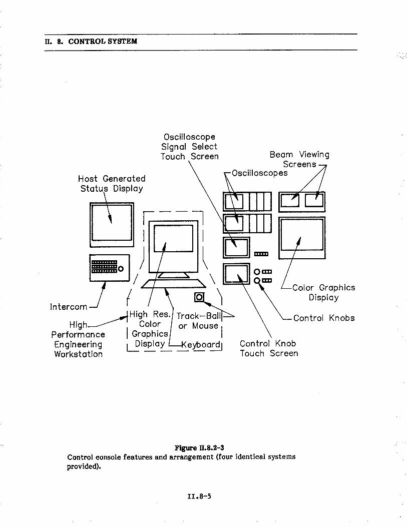
n. 8. CONTROL SYSTEM
OscilloscopeSignal Select
T ou ch Screen Beam ViewingScreens
Oscil! oscop esHost GeneratedStatus Display
i;--Ji I) ~/ \
Intercom ( ~ ì~High Res. Track-B~High~ i Color or Mouse
Performance I Graphics IEngineering Lispla~ ~eyboardiWorkstation
FEhi'YI"""'11"95180EliFFEF'p'.
am
Color GraphicsDisplay
Control Knobs
Control KnobT ou ch Screen
Figue ß.8.2-3Control console features and arrangement (four identical systemsprovided).
II.8-5

ll. 8. CONTROL SYSTEM
console computers are provided immediately (unless it is a new or time-coordinated dataset, in which case an appropriate delay is incurred). (Actually two front-end computersare provided for the storage ring system, as shown in Fig. II.8.2-2; these are described inSection II.8. 7, Control System Reliabilty.) Aside from maintaining a current machine-state database, the primary task of the front-end computer is to take global, multi-parameter data requests from the host and console computers and translate these intoone or more data requests for the microprocessor clusters, which do the actual work.Conversely, the data returning from one or several sources are assembled into multi-parameter messages for the host and console computers. Comparison of measured versusnominal operating parameters can also be done in this computer, with error statusmessages provided over the network or directly via video displays. The capabilties ofthe front-end computer are equivalent to those of a DEC MicroVAX-II computer.Commonality of parts, operating systems, and software with the console and hostcomputers has a beneficial influence on development and operating costs.
8.2.4 Microprocessor Cluster
The many microprocessor clusters are interconnected with the front-endcomputers via two system networks, one for the linac and synchrotron, and one for thestorage ring. The contents of a typical cluster are ilustrated in Fig. II.8.2-4, with thefollowing devices depicted from left to right:
· A network processor, which interprets the network protocol, provides errorrecovery, and transfers data requests and responses to and from the taskprocessor.
· The task processor, which handles most equipment interface tasks via input-output (1-0) modules or a local network master.
· One or more optional loop processors, which handle high-performance closed-loop functions such as photon beam trajectory control or linac klystron systemcontrol.
· A complement of 1-0 modules, which provide digital-to-analog (D-A), analog-to-digital (A-D), and binary control and monitoring functions.
· An optional local network master, which (through a multidrop network)controls a series of slave crate systems containing additional 1-0 modules (seeSection II.8.2.5).
The task processor design is based on the Motorola 68020 32-bit processor.Additional processors of this type could be added if future needs so dictate. The loopprocessor choice is based on the needs of the particular control loop. The microprocessorcluster design is based on the Motorola VME crate system because of its advanced.
II.8-6

ß. 8. CONTROL SYSTEM
r'-
Local__DConsole ~
(PC)
System Network,---------------,I l l l INetwork Task 1-0 i- Local Net II Processor Processor Loop Modules MasterI lProcessor i I II IL_ '-------r------i-~
r; ~IiLocal Processor Crate I lLocal Netl
Slave 11-0
Subsystem ~ack-- I. Modules nor Chassis
ìI
IL___--
Figue ß.8.2-4,Microprocessor cluster components.
II.8-1

II. 8. CONTROL SYSTEM
processor bus structure, reliable connector system, and multiple vendor support. A localconsole is implemented through the use of a personal computer connected to the networkprocessor. This console is used in a variety of ways, depending on the software utilzed:
· It accesses and uses local 1-0 modules directly in order to troubleshoot local
systems directly.
. It controls the local network master in the same way.
. It reads and writes the task and loop processor memories in order to control,
test, and modify their operation.
. Through the network processor, it performs these and other more complex
operations by communicating over the system network with other clusters andwith the front.,end computer.
A local console is provided for about half of the clusters and wil have capabiltiesequivalent to the Apple Macintosh@ system. Interference by the local consoles duringnormal operations is eliminated by front-end computer instructions to the communicationprocessor to discontinue local console service. .
8.2.5 Local MIL-1553 Networks
The lowest network level is implemented with the MIL-1553 network protocol. A1-MHz bit-serial data stream is carried over a multidrop cable to several small crateassemblies located in power supply regulator racks or within diagnostic electronicschassis. These slave crates are used for all applications where high-resolution (14- to
17-bit A-D and D-A) interfacing is needed and where careful control of noise andgrounding is required. These applications include virtually all magnet power supplies andmost diagnostic systems. A low-performance microprocessor such as the Motorola 6809is used as a local crate controller and can provide special control intellgence. With aspecial interface adapter, the local console is used to field- and bench-test this localnetwork and the slave and 1-0 modules contained in the MIL-1553 crates. Special
software loaded into the local console provides sophisticated testing involving a minimumof equipment.
Since these local slave crates control all magnet power supplies, they become thefocal point of the coordinated, simultaneous, multimagnet control necessary in storagering operation. To accomplish this, new magnet settings are downloaded from the host orconsole computer, through the front-end computer, to the group of several taskprocessors involved. After verifying that all commands have been received accurately,all task processors are commanded to begin issuing current change sequences to the slavecrates. . Several other scenarios are possible, but the system planned is able to makecoordinated changes "simultaneously" to less than 10 j.S (see Section II.5.6, ControlSystem and Control Electronics).
II.8-8
ß. 8. CONTROL SYSTEM
8.2.6 Additional Loop Processors
The multiprocessor VME crate system allows the use of additional loop-controldigital processors without affecting normal assigned crate functions. A wide range ofsophistication is possible, iacluding the use of array processors if necessary. As anexample, the photon beam trajectory control system described in Section II. 7.7 is handledwith a Motorola 68020 having a 68881 floating-point coprocessor. Another possible
approach would employ specialized digital signal processing devices, such as the TexasInstruments TMS 320 family, which are designed to process analog signals numerically inreal time. Since there is one microprocessor cluster for each pair of insertion devicestraight sections (a total of 20 around the ring), two such photon beam trajectory controlprocessors share each cluster. The loop gains and polynomial contr..l function
parameters are downloaded from the host processor whenever they change as a result ofsteering, focusing, or other tuning changes.
8.2.7 Host and System Networks
To implement the upper-level, high-performance networks, we employ bus-type,peer-protocol systems. The bus-connected networks permit normal operation withabsent, failed, or removed nodes, unlike ring-connected or store-and-forward hubs, whichrely on active nodes to relay message streams. A bus network makes small configurationcheckouts possible during construction and maintenance periods and allows degradedoperation of a system with an inoperable node. A faulty network node can be located andpowered down, have replacement modules inserted, be rebooted from the network, and bebrought back into service without impairing the use of the network by the remainingnetwork nodes.
A peer-protocol access method extends this philosophy by implementing theaccess protocol in each node, instead of having a master node that would poll the nodes
or otherwise keep track of their normal operation. This Local Area Network (LAN) is theCarrier-Sense, Multiple-Access with Collsion Detection (CSMA/CD) protocol, alsoknown as Ethernet. This system has wide industry acceptance due to nationalstandardization and in-service success and reliabilty.
The use of the CSMA/CD protocol, which resolves simultaneous access attemptswith randomly delayed retries, may incur delays when many diagnostic or error messagesare produced by the microprocessor clusters as a result of activities that are deliberatelyor accidentally simultaneous. Since this condition is seen to be likely, an internalprotocol layer is implemented that wil prioritize these messages in two levels. High-priority error or alarm messages use the normal procedures without delay, while routinefront-end-directed responses await specific requests for their transmission.
The host network has a LAN bridge node, which allows communication with theexperimental data network (see Fig. 11.8.2-1, top). This link serves to provide theexperimental area with pertinent operational information and acts as a means for the
II.8-9

ll. 8. CONTROL SYSTEM
beam line personnel to request photon beam steering changes when this becomespossible. The bridge node also prevents excess network traffic by blocking controlsystem traffic from the data network and vice-versa.
8.3 Software
The same separation of function described above with respect to the variousprocessor types and duties is reflected in the software structure and operation. Acomprehensive database defines all machine parameters, both real and virtual. Thisdatabase is edited and maintained in the host computer. It is broken down, encoded, and
separated into parts appropriate for use in the various locations and hierarchical levels.These parts are then downloaded to the various processors, where they are used to obtainneeded information. Such a database system is in use at SLAC.(7)
8.4 Other Services
8.4.1 Timing System
Two classes of timing coordination are necessary, the first being associated withthe need to control beam transfer events and signal sampling in the linac andsynchrotron. The second class is associated with the need to control sampling of positronbeam position in the storage ring. Both systems use essentially the same methods, butwith different clock rates and sources. Depending on the mode of operation, various
delay counts are downloaded to the microprocessor clusters and set into clock-delaymodules in the VME crates. After a systemwide start pulse is received, the delaymodules count a clock source and produce a pulse output after their programmed delay.For event sequencing in the synchrotron, a crystal-derived clock is used that producesreal-time triggers. For sampling beam parameters, an rf-based clock is used. The delay
calculation takes into account the location of the module and the location of the beambunch at the time the start pulse is issued. In this way a single bunch is tracked around
the machine or all bunches are sampled simultaneously. The timing resolution needed isthe interbunch spacing with some margin, since the beam diagnostic electronics is beam-triggered after being armed by the timing pulse. Such a system is in use at SLAC for the
same purpose and with similar timing requirements. (8) A system based on a MicroVAX-IIhas also been described. (9)
8.4.2 Osciloscope Signal Cross-Bar System
In order to convey the hundreds of high-bandwidth signals to the control consoleareas and to accommodate the console flexibilty described above, a distributed cross-barconnection system is used. The coaxial relay modules are distributed with and controlledby the microprocessor clusters. At the console end the signals are finally switched to the
II.B-IO

ß. 8. CONTROL SYSTEM
desired display or instrument. The choice of signal and destination of output are selectedby the operator using a touch-screen display.
8.4.3 Beam-View and Access-Control Television
The same distributed cross-bar method used for signal patching is also used forvideo sources. Again the computer system provides the control. The signals terminate inthe console areas and are further gated to selected video displays in the access-control
consoles, as well as the operational consoles. In the case of the beam-view videosources, they can be gated to television frame-store memories or to a videocassetterecorder for later static or dynamic study, respectively.
8.4.4 Intercom System
A multilne intercommunication system is provided for each major light sourcecomponent (linac, synchrotron, and storage ring). Eight communication circuits areprovided for the local component, plus two tie-lines for each of the other two. Consolesare provided full access to all three components. The door access intercom system isseparate and interconnected with the door release system. Access-control consolepositions are provided in both the main and injector control areas.
8.4.5 Network Access from Offices and Laboratories
Terminal server units are connected to the host network to allow terminal usage
with the control system from the office and laboratory areas of the operational staff.This faciltates equipment checkout, status inquiries, and software development to takeplace on a noninterfering basis. Actual control of the various systems is highly restrictedand controlled by the host software required to make such links.
8.5 Relation to the Injection System
The network-connected, modular design of the control system makes possible twoimportant features regarding the injection accelerators:
· Operational independence is provided by the full-feature control consolelocated in the injector control area. As long as the host computer and its
network are operational, the injection accelerators can be considered ascompletely autonomous systems.
· During machine commissioning or subsequent accelerator research with thelinac and synchrotron, the full capabilties of the three main control areaconsoles can be utilzed.
II .8-11

ß. 8. CONTROL SYSTEM
8.6. Exrt Sytems
The APS wil be a large, complex machine with many beam lines. The task ofcommissioning a machine of this size generally involves a sequence of iterative steps.The beam is injected, diagnostic devices are monitored, and then magnet currents areadjusted. These steps are repeated as the beam travels further around the ring and cantake a considerable length of time to perform. Because of the time and costs involved in
the commissioning, we wil investigate the use of artificial intellgence (AI) techniques inthe form of an expert system to help tune the beam. The use of expert systems is nowbeing investigated by several accelerator laboratories.(l0-12) An expert system is acomputer program that can perform a task normally requiring human expertise orexperience. Typical characteristics of these systems are their use of "qualitative"processing, flexibilty, and abilty to handle very complex problems.
8.'1 Reliabilty and Saety
Control system reliabilty is divided into two broad categories -- software andhardware. With respect to software, there is a growing realization that as softwarefunctions and features become more complex, exhaustive pretesting of all operationalcontingencies becomes impossible. To this end, run-time self-checking of both hardwareand software facilties and error recovery procedures are utilzed to make the systemfail-safe, or at least fail-soft. The penalty paid for this capabilty is prolonged
processing time and additional memory space. For these reasons relativelyhigh-performance processors are used in the cluster, front-end, and console systems.
Reliabilty of control system hardware is enhanced through the use of proven
processors and network concepts. Quick recovery from failures of system components (insome cases without loss of control or the stored beam) is faciltated by the followingfeatures:
. A running "hot spare" is provided for the storage ring front-end computer.
Connections are made to the host and system networks in parallel with theprimary front-end, as shown in Fig. II.8.2-2, and the database of the "hotspare" is periodically updated so that a quick and possibly transparentchangeover is achieved. Since the same processor type is used for all front-end and console computers, this extra processor also acts like a ready "coldspare" as well.
· After filing the storage ring, the host computer provides what might pe
considered nonessential services (printing, archiving, computation assistance,and general time-sharing services), so it is possible to maintain continuedoperation of the various systems in a degraded mode without the hostcomputer or any of its peripherals.
11.8-12

ß. 8. CONTROL SYSTEM
· Since all five console systems are provided with access to all acceleratorsystems, normal operation can continue with a console out of service.
For those areas involving both personnel safety and vacuum system protection,hardwired circuits are used; these circuits are monitored by the control system. Theaccess-control console (duplicated for the linac and synchrotron in the injector controlarea) communicates with the various access door intercoms and door release mechanismssimultaneously in order to ensure proper door operation. Access door switches aremonitored by the control system so that interlock chain breaks can be graphicallypresented to the operator as a troubleshooting aid.
Vacuum system protection is provided by dedicated, hardwired modules thatprovide interlock logic for valve operation. Remote valve operation through the controlsystem (where possible) is passed through this same permit logic. All valve position andvacuum level data used by these chassis are monitored by the control system, again tohelp in trouble diagnosis and general vacuum system surveilance.
8.8 References
1. N. Phinney, "Current Status of the SLC Control System," presented at the 1985
Accelerator Controls Workshop, Los Alamos Scientific Laboratory (October 1985).
2. B. Culwick and J. Smith, "Status of the NSLS Controls Upgrade," presented at the
1985 Accelerator Controls Workshop, Los Alamos Scientific Laboratory (October1985).
3. S. Brown et al., "The LAMPF Controls Upgrade," presented at the 1985 Accelerator
Controls Workshop, Los Alamos Scientific Laboratory (October 1985).
4. C. Cork et a!., "A Networked Real Time Control System for the Stanford Photon
Research Laboratory," IEEE Conference Record 87CH2837-9.
5. M. Lee et al., "Modern Approaches to Accelerator Simulation and Control," IEEE
Conference Record 87CH2837-9.
6. A. Abola et al., "Experience in Using Workstation as Hosts in an Accelerator
Control Environment," IEEE Conference Record 87CH2832-9.
7. N. Phinney, "Implementation of the SLC Control System Database," presented at
the 1985 Accelerator Controls Workshop, Los Alamos Scientific Laboratory
(October 1985).
II .8-13

ll. 8. CONTROL SYSTEM
8. K. Thompson and N. Phinney, "Timing System Control Software in the SLC," IEEE
Trans. on Nucl. Sci., NS-32, 2123 (1985).
9. J. Potter et al., "Programmable Master Tuner System," IEEE Conference Record
87CH2837-9.
10. S. Clearwater et al., "Prototype Development of a Beam Line Expert System," IEEE
Conference Record 87CH2837-9.
11. D. Weygand, "Artificial Intellgence and Accelerator Control," IEEE ConferenceRecord 87CH2837-9.
12. E. Malandain and P. Skarek, "An Expert System for Accelerator Fault Diagnosis,"
IEEE Conference Record 87CH2837-9.
II.8-14

u. 9. INSERTION DEVICES
9.1 Introduction
The primary purpose of the 7-GeV Advanced Photon Source (APS) is to provideinsertion device-based radiation sources. Two types of insertion devices (IDs), undulatorsand wigglers, have been developed to satisfy the requirements of various investigations.These requirements include: (a) the need for pseudo-monochromatic radiation from thefirst few harmonics of undulators with ultrahigh spectral briliance or brightness, tunablefrom about 3 keV to 40 keY, (b) sources a few micrometers in size, (c) radiation withspecific polarization characteristics, (d) extremely low divergence radiation, and(e) matching of the radiation characteristics with those of the x-ray optical elements foroptimum utilzation of such sources. There should be flexibilty to install newer devices,such as those producing broad-band undulator radiation and circularly polarized hardx-rays.
Any of the above capabilties can be provided by a proper match between thecharacteristics of the storage-ring and those of the IDs. Unlike the IDs presently
retrofitted on existing storage rings, the undulators and high-brightness wigglers on the
APS storage ring are highly optimized in performance, and form an integral part of thedesign. In addition, the design of the storage ring and the IDs is flexible, in order toaccommodate improvements in the use of ID radiation and new applications.
9.2 Nature of Inertion Devices on the APS
The distinction between the two types of IDs, wigglers and undulators, is based onthe value of the so-called deflection parameter, K, and the horizontal opening angle of
the radiation, SH. These are given by
K = 0.934 Bo Ào
and
SH = '!K/y
where Bo is the peak magnetic field in the device in Tesla, Ào is the spatial period of themagnetic structure in cm, and y is the relativistic enhancement of the positron restenergy; y = 13699 for 7-GeV.
When K is small (0(4), the device is called an undulator. The radiation from variousperiods of an undulator has constructive interference effects which results in a
II.9-1

II. 9. INSERTION DEVICES
spectrally-compressed series of narrow peaks at harmonics of the fundamental energy,E1. This energy is given by
E1 (keV) =0.95 E2 (GeV2)
ÀO(cm) (1 + K2/2)
where E is the positron energy. The following are important features of APS undulators:
. The undulators on the APS ring built with available Nd-Fe-B hybrid magnet
technology deliver fundamental radiation with energies ranging from a fewhundred eV to 22 keV. The typical on-axis, angle-integrated brillance for thefundamental radiation ranges from 1018 to 1019 photonsls/0.1%BW/mrad21mm2.
. A fully tunable undulator with a 3.3 cm tleriod on the 7-GeV APS wil deliver
radiation approximately from 4 to 13 keV in the fundamental and from 12 to 40
keY in the third-harmonic. The energy tunabilty is achieved by varying theundulator gap from 1.0 cm to about 2.8 cm.
. For applications needing only the high-energy undulator fundamental radiation,
a device with a period of 2.3 cm wil be tunable from 13 to 20 keV through gapvariation.
. The phase space dimensions of the photon source are nearly equal to that of
the positron beam for the hard x-rays delivered by the APS undulators, and is
minimized to deliver very high briliance.
. The vacuum chambers for the undulators wil permit a minimum gap of either1.4 cm or 1.0 cm. The former chamber wil be used during the initial operationof the APS.
. Because the various applications of the APS undulator radiation impose littledemand for harmonics higher than the third, (1) the required magnet designtolerances are well within those achieved for existing devices. The lower limitof 0.5% in field error achievable with tlresent day technology is more thansufficient for the successful op,eration of the undulators planned for theAPS.(2)
When K is large (;. 10), the device is called a wiggler. The peaks of higherharmonic radiation of a wiggler tend to smooth out, due to the smearing effects of thetlositron-beam emittance and energy spread. This results in a smooth spectrum, similarto that from a bending magnet (BM). The intensity of the radiation from a wiggler withN periods is approximately equal to an incoherent sum of the intensities from 2N poles.One can also increase or decrease the energy of the photons from a wiggler by a tlroper
11.9-2

II. 9. INSERTION DEVICES
choice of Bo' while maintaining a large value of K. The photon critical energy for theAPS operated at 7 GeV is given by
ec (keV) = 32. S9 Bo
Several important features of the APS wigglers deserve mentioning:
· They wil rarely require magnetic fields produced by superconducting
magnets. The field provided either by Nd-Fe-B hybrid magnets or byconventional electromagnets is adequate to obtain large K values and nearly-smooth photon energy spectra.
· Because of the relatively large value of y, the value of SH for the APS wigglersis approximately:t1 mrad. Hence, the APS wigglers deliver very high-brightness hard x-rays, compared with those on low-energy storage rings.
· The availabilty of 6-m straight sections is suitable for long-period wigglersdesigned to provide radiation of low critical energy. These devices (with K-10) operate with ß ~10 m, and provide a low divergence photon beam. Thesehigh-brightness wigglers are unique to the present machine and are essentialfor many research programs.
· In many investigations, there is a need for radiation with linear polarizationalong the vertical axis. A design for a high-brightness wiggler with a hybrid
magnet configuration which generates such polarization is presented in Ref. 3.
· For wigglers with a Nd-Fe-B hybrid configuration and Ào = 8 cm, the magnet
gap, G, needed to produce a L.2-T peak field is 2.1 cm. A design for a rigidvacuum chamber with a vertical aperture of 1.4 cm, appropriate for thiswiggler, is presented in Section II.9.4.3.
The IDs with 4 ~ K ~ 10 produce energy spectra with features that are
intermediate between those of undulators and wigglers.
More details on all the above aspects of the various APS IDs are presented inRefs. 3, 4, 5, and 6. Design studies for two tunable undulators and a wiggler-undulatorare presented in Sections II.9.4, 11.9.5, and 11.9.6. A detailed study of the interaction ofIDs with the storage ring is presented in Section II.1.6. The measuring facilty for IDs isdiscussed in Section II.4.9.
9.3 Tuabilty of Radiation and Choice of Storage Ring Energ
For the APS, the original user requirement(7) for an undulator with a 20-keVfundamental photon energy can be met at a storage ring energy of 6 GeV and the
II.9-3

ll. 9. INSERTION DEVICES
proposed ring aperture. (8) However, as additional capabilties of the undulator sourceswere investigated,(9) it became evident that, at 6 GeV, the tunabilty of undulators withfundamental energies above 10 keV is rather limited. As a result, as many as fiveundulators would be needed in a single straight section to span the photon energy intervalof 5 to 20 keY. The expense and complication of having so many undulators in a givenstraight section, with the capabilty of switching from one device to another was an
incentive to look for alternate ways to increase the tunabilty of a single device. As waspointed out, (9,10) the tunabilty range of an undulator is a complex function of theminimum storage ring aperture and the positron energy.
For hybrid magnets based on Nd-Fe-B magnet blocks and vanadium permendurpole tips, Bo is given by
Bo = 0.95 x 3.44 exp (- R (5.08 - 1.54 R))
where R = G/Ào and G is the undulator gap in cm. In the above equation, the factor 0.95represents the "filing factor" of the high-permeabilty blocks in the undulator
assembly. This equation is valid only in the interval 0.07 ~ R ~ 0.7 and onlyapproximately represents the peak field for 0.7 (; R :: 1. For R ~ 0.7, however, the valueof K for small period devices becomes small and results in a small photon flux. Hence,we have taken the ratio R = 0.85 as a conservative and "safe" upper limit for the devicesdiscussed below.
Within all the above constraints, the tunabilty of an undulator on the APS can beanalyzed using the above equations. The analysis is presented in detail in Ref. 10. InFig. 11.9.3-1, the relationship between the storage-ring energy and the gap is shown,which relates to the recommendations of the National Task Group given in Chapter I.The design energy of 7 GeV and the capabilty to operate the storage ring as high as
7.7 GeV wil adequately provide for the required tunabilty of undulator radiation. Thefollowing points are noted:
. During the initial period of operation, the vacuum chamber wil permit a
minimum ID gap of 1.4 cm.
. The minimum gap wil be reduced to 1.0 cm after mature operation isattained. This wil increase both the tunabilty range and the photon
briliance.
. The undulators designed for the initial operation period wil deliver their fullperformance during the mature operation.
The first undulator (A), with a period of 3.3 cm, fulfils all the above operationalcriteria based on the recommendations of the National Task Group. The characteristicsare presented in Figs. II.9.3-2 and II.9.3-3, in which are plotted the tunabilty of this
II.9-4

ll. 9. INSERTION DEVICES
oto
.tT
ooCD
oin..
:;Q)
C.-)-C.exwzwC.zexo
ini.
-E 0 0(, 0 00 tT ..0exw0.
0 0tT 0
.
C\ 0 i.0 0 0 0 00 in 0 in 0 inC' C\ C\ .. .. 0
(w:i) dv'Ð .L3NÐVlA
II.9-5
e¡o Q)i: .5
.9 1"
ê: tai: ..:: i:e¡ 0Cl .~fI ~Cl ,g
;: Q)Q) .i.i E-~,. .'C Q)i: ~Cl bDto c:
i: Q)Q).i .Q) .. es= i: eJ.. ...
.oQ) i: ~s= ~i: 0 :;o.i -:; fi Q)Cl 0 ~:a ~ eCl Cl._~ fi :-..... 0
~;s ~ ~CO i: ~ 0.ø) Q) Q) Cl. e i: e¡
= Cl Q) 0Q) 'C bD 0.e: i: i: Cl&i¿ .¡: bD... Q) .i e~ eJ eJ ::
:: Cl e'C Q)._o .. i:~ Cl'Ëo ~ Cl.. ...~ ~ ..o Q) Cl.. 'C i:~ Q) 0:: .i'-'C .. ~i: e¡ i.:: 0 Q)i: 'C 0.Cl 0 0~ ... 00o ~ iie¡ 8.~'C Q) _~.i .!'S E- ;~0' . i:Q) :;'-~ bD Q)fi ~ .i0. Q) ..Cl i: 0bD Q) ..
~ ~~i: ... i:bD ~ 0.$ Q,e bD fiCl Q)~ ~~ 0 ~E- ~ g

...... 40
.0
30.0
S' l )-I-
(!20
.0I-
a:. \C
W
I
ZØ
\W Z 0 b i
10.0
a.
-'..-
--..-
......
"..
Und
ulat
or A
(T
hird
Har
mon
ic)
...."
"..
'" , , , , / , , , ,,," , , , , , , , , ,
,,~ Unduiator B (Fundamental)
0.00
0.50
= . ~ ~ ~ :z t: ~ ?i
1.00
1. 5
0 2.
00M
AG
NE
T G
AP
(em
)
2.50
3.00
Fig
ue n
.9.3
-2T
unab
ilty
of f
unda
men
tal u
ndul
ator
rad
iatio
n of
dev
ices
A a
nd B
as
a fu
nctio
n of
mag
net g
ap f
or th
e 7-
GeV
APS
. The
tuna
bilty
of
the
thir
d-ha
rmon
ic o
f de
vice
A is
sho
wn
by th
e do
tted
line.

C\ E E -. C\ "0 cø .. E ~ OJ ~ 0 ,.
I-0
I--.
.~
\0.c
Ia.
..- w Ü Z c( .. .. ex O
J
1018
1017
1018
Und
ulat
or A
(F
unda
men
tal)
/..
, , \ , , '\ . , , , \
30.0
:: ~ ~ g iz 1: ~ ~
..Undulator B (Fundamental)
....
/"""
"U
ndul
ator
A (
Thi
rd H
arm
onic
)'
10.0
40.0
Fig
. ll.9
.3-3
The
ang
le-in
tegr
ated
on-
axis
bril
ianc
e of
fund
amen
tal a
nd th
ird-h
arm
onic
rad
iatio
n fr
om u
ndul
ator
A a
nd th
ebr
ilian
ce o
f fu
ndam
enta
l rad
iatio
n fr
om u
ndul
ator
B a
t var
ious
pho
ton
ener
gies
for
the
7-G
eV A
PS w
ith10
0 m
A s
tore
d cu
rren
t.
0.00
20.0
EN
ER
GY
(ke
V)

II. 9. INSERTION DEVICES
device in terms of the briliance from the fundamental and the third harmonic as a
function of the photon energy.
A second undulator (B), with a period of 2.3 cm, also satisfies the recommenda-tions by the National Task Group. Its tunabilty and the briliance characteristics arealso shown in Figs. II.9.3-2 and II.9.3-3. The parameters of both undulators A and Bduring the initial operation at 7.5 GeV and the mature operation at 7.0 GeV are given inTable II.9.3- 1.
9.4 Tuable UnduIator A
9.4.1 Introduction
One of the undulators (A), as seen above, satisfies the user criteria of providingfirst-harmonic tunabilty over the energy range from 7 to 14 keV during the early
operation, and from 3.5 to 13.0 keV during mature operation. This criteria for thetunabilty is set because of the needs of a host of scientific experiments. This sectionpresents a preliminary design study of such an undulator.
Table II.9.3-1
The Tunabilty Parameters of Two Undulators on the APS Which
Satisfy the Recommendations of the National Task Group
Fundamental Energy Range
Period Emin GaPmin Kmax Emax Gapmax KminUndulator (em) (keV) (em) (keV) (em)
Initial Operation (7.5 GeV):
A 3.3 1.0 1.4 1.6 14.5 2.8 0.4
B 2.3 19.0 1.4 0.6 21.5 1.9 0.3
Mature Operation (7.0 GeV):
A 3.3 3.5 1.0 2.5 13.0 2.8 0.4
B 2.3 13.0 1.0 1.1 19.5 2.0 0.3
11.9-8

II. 9. INSERTION DEVICES
9.4.2 Preliminar Design Parameters(ll)
The transverse undulator, A, has a hybrid magnet configuration in which themagnetic field strength and distribution depend on the geometry of the pole tips. Thefield quality is much less dependent on the magnetic and geometric quality of permanentmagnets. For this hybrid geometry, the magnetic material is Nd-Fe-B. The design ofthis device is based on a preliminary optimization of the magnetic structure withvanadium permendur pole tips. In this procedure, various geometrical parameters of thestructure are iteratively optimized through a two-dimensional field computation (yzplane). The resulting parameters are presented in Table II.9.4- 1. - Three-dimensionaleffects are estimated in order to obtain a pole width and a magnet width which providesthe required field homogeneity.
Table II.9.4-1
Optimized Parameters of a Nd-Fe-B Hybrid Undulator A
Undulator Period, Ào (cm)
Magnet Gap Range, G (cm)
Pole Width in x Direction (cm)
3.3
1.0 - 2.8
5.0
3.5
0.62
6.6
4.2
1.03
0.08 to 0.1
0.78 to 0.21
2.0
5.2
158
Pole Height in y Direction (cm)
Pole Thickness 1n z Direction (cm)
Magnet Width in x Direction (cm)
Magnet Height in y Direction (cm)
Magnet Thickness in z Direction (cm)
Pole-Tip Overhang in y Direction (cm)
Peak Field Range on Axis, Bo (T)
Peak Field Increase (%) at 0.1 cmoff Axis in y Direction
Maximum Length Available for Undulator (m)
Maxi~dm Undulator Periods, N
II.9-9

II. 9. INSERTION DEVICES
Figure 11.9.4-1 shows the optimized two-dimensional magnetic flux lines of aquarter period of the 3.3-cm undulator at a gap of 1.4 cm. The shapes of the vanadiumpermendur pole-tip and the Nd- Fe-B permanent magnet shown in the inset in Fig. II.9.4-1were optimized to have sinusoidal field variation along the undulator axis, to avoid fluxsaturation at the corners of the pole-tip, and to avoid demagnetization of the permanentmagnet. This optimization reduces the peak field by only 296 from the maximumexpected value of 0.5 T.
The field variation along a quarter period of the undulator at its minimum gap of1.4 cm is shown in Fig. II.9.4-2. At points y = :t1 mm from the undulator axis, the fieldincrease is 296 for various gap values.
The widths of the pole-tips and the permanent magnet blocks are determined fromharmonic analysis. The pole-tip width of 5.0 cm is wide enough that the undulator fieldconfiguration can be considered as two-dimensional.
The following dimensional tolerances are estimated from a two-dimensional fieldanalysis:
Thickness tolerance 0.05 mm (:t 2 mil)
Height tolerance 0.25 mm (i:0 mil)
Width tolerance 0.25 mm (:t10 mil)
The undulator assemblies have magnetic field end-correctors.
The angle-integrated on-axis briliance of the fundamental radiation from thisundulator A at different gaps is shown in Fig. II.9.4-3.
It should be pointed out that the Argonne team has collaborated with a Cornellgroup on the design of a 3.2-cm period Nd-Fe-B undulator to be operated on Cornell HighEnergy Synchrotron Source (CHESS) and this 2.4-m long device is now being built. (12)This is a prototype of the APS undulators and is expected to be commissioned in early1988.
9.4.3 Inertion Device Vacuum Chamber Mounts
Rigid vacuum chambers are installed in the straight sections of the storage ringfor IDs. During initial operation, the chambers wil have a minimum magnet gap of1.4 cm, and during mature operation, 1.0 cm. In addition, a similar vacuum chamber with1.4-cm gap has been designed. The following discussion is limited to the 1.0-cm gapvacuum chamber.
This vacuum chamber has two sections; the beam chamber and the pumpingantechamber, as shown in Fig. II.9.4-4. A Zrl Al NeG pumping strip is mounted in the
II .9-10

II. 9. INSERTION DEVICES
(a) (b)
VanadiumPermendur
EEC\e
EE
LOM
r 3.1 mm +5.15 mm
~i
EEco
Figue II.9.4-1Magnetic flux profile of a quarter period of undulator A showing thedimensions of the pole and permanent magnet pieces. The inset shows thedetail of the pole and permanent magnet shaping used to avoid saturationand demagnetization.
r1.9-11

ß. 9. INSERTION DEVICES
0.5
0.4
0.3
'P'-~
a:
0.2
0.1
y(em) = 0.20.1
o
oo 0.2 0.4
Z (em)
0.6 0.8
Figue ß.9.4-2Magnetic field variation along the undulator axis (z) over a half-period ofundulator A at a gap of 1.4 cm. The y values are distances above and belowthe mid-plane.
II .9-12

ll. 9. INSERTION DEVICES
000
a: ~ ca in . cr- - - - - -0 0 0 0 0 0.. .. .. .. .. . ..
(GWW/GPBJW/M8%~'O/S/4d) 30NVIlllt:8
11.9-13
ooC\ .
oLO..
0 -:;Q)0 ~-.. )-(!a:UJzUJ
00LO
.. ..el 6 QJ
~ 6 ~6 C' g.Q ~ QJ~ .. gi..-.... el 0-... ei QJ~ 0..ii ~..~ i: QJ~ ... 'C
.. ='QJ .. -.. QJ C).. u. i:
c. ...i: el u.o bO §~.. ...i. QJ 1Uo i: '31U ~ C)'3 6 -;'C .. C)i: el QJ
=' 'C u.QJ QJ QJ.. i: .... ... E-el6'" .
C" 0 .0 6i i. 0. ei QJ 6· i: i. ..~ 0 el .=... u. Q
.. QJ MQJ .:g 'bø-!: 'C i. eiSi ~ QJ 'C... i: i:~-;QJel.. i: ..i: 0 6
QJ Õ 66.. ~el c.~--
'g u. ~=' =' C"ei 0_QJ .¡: QJ.. el .... :: 6
'(1;6.QJu.t-;C)~Q) QJ; QJ .. .0
a o.~ i:... ãl .. 0~.. 6 b.. i: ...'CQJ6¡g2 6 U) 0.el el ~ QJi. 'C .. ..bO i: ..QJ =' -.. ei C) ei.5 QJ .. 0I .. 6 u..$E-6§bO ...i: .Q) u.Cl:; . i:ll C" øQJe,~E.. ..._E- to .0 '0

ß. 9. INSERTION DEVICES
Chamber Mountstructure
LockWedgeBlock
BeamChamber
I
I
I
I----r---I
I
NdFeBMagnetBlock
c VanadiumPermendur
PoleAluminum Keeper
AntechamberWith Zr / Ai/Strip
Figue ß.9.4-4A cross section of the ID vacuum chamber and its support. Part of the
undulator A assembly is also shown.
II.9-14

ll. 9. INSERTION DEVICES
antechamber. The entire aluminum vacuum chamber is extruded using standardtechniques. The beam chamber and antechamber are connected by a series of slots(1.0 cm long x 0.4 cm high), which are miled in the wall separating the two chambers inthe extruded piece. Each slot has a conductance of approximately 1.6 iis. The initialeffective pumping speeds of the vacuum chamber at room temperature for CO and H2are 50 and 150 tIs per meter of ID length respectively, assuming the slots to be 0.5 cmapart. Several 6-m-long samples of Al vacuum chamber have been extruded and arebeing tested for both their mechanical integrity and vacuum performance.
As has been mentioned, the mechanical precision of the gap determined by theheight of the undulator vacuum chamber and the alignment of the beam chamber axisalong the positron trajectory are both crucial for optimum performance of the insertiondevice. Hence, careful mounting of the vacuum chamber is essential. The mountingassembly is designed to hold the chamber true to better than :t2 mils over its 6-m length.
The top and bottom halves of the undulator magnet assembly are mounted onbacking beams having the capabilty of changing the gap. The mounting assembly is rigidenough to hold the undulator halves with less than :t2 mils of gap deflection. The gapvariation is remotely controlled.
9.5 Tuable Undulator B
9.5.1 Introduction
One of the requirements of the present APS design is to deliver approximately20-keV of photon energy in the fundamental harmonic radiation of an undulator. This
design goal was set because a host of scientific experiments need high-energy (14 to 20keV), high-briliance radiation. These experiments range from absorption spectroscopy ofthe Mo K-edge for understanding the structure of proteins and catalysts to ultra-high-energy-resolution inelastic scattering from collective excitations, such as phonons andcharge density waves. This photon energy range is provided by the undulator B with aperiod of 2.3 cm discussed in Section II.9-3. This section presents a preliminary designstudy of this undula tor.
9.5.2 Preliminar Design Parameters
As pointed out earlier, this device provides photons, in the fundamental harmonic,in the energy range of about 18 to 20 keV during initial operation of the storage ring.The tunabilty is considerably increased during mature operation (see Table II.9.3-1). Forthe Nd-Fe-B hybrid configuration, the two-dimensional field optimization discussed inSection II.9.4.3 is carried out for gap values ranging from 1.0 to 1.9 cm. The results ofthis iterative analysis are given in Table II. 9. 5- 1.
II.9-15

ß. 9. INSERTION DEVICES
Table ß.9.5-1
Optimized Parameters of Nd-Fe-B Hybrid Undulator B
Undulator Period, Ào 2.3
Magnet Gap Range, G (cm) 1.0-1.9
Pole Width in x Direction (cm) 0.4
Pole Height in y Direction (cm) 2.4
Pole Thickness in z Direction (cm) 0.42
Magnet Width in x Direction (cm) 5.2
Magnet Width in y Direction (cm) 3.0
Magnet Thickness in z Direction (cm) 0.73
Pole-Tip Overhang in y Direction (cm) 0.07
Peak Field Range on Axis, Bo (T)
Peak Field Increase (%) at 0.1 cmoffAx~s in y Direction
0.47-0.13
2.0
Maximum Length Available for Undulator (m) 5.2
Maximum Undulator Periods, N 226
The angle-integrated on-axis briliance of the fundamental radiation fromundulator B at different gap settings is shown in Fig. 11.9.5-1. The vacuum chamberdiscussed in Section II.9.4.3 is also suitable for this device.
9.6 Semented Undulator
Long undulators with a large number of periods are built to enhance thebriliance. Indeed, for an idealized single-particle (zero-emittance) beam, one expectsthe briliance to depend quadratically on N, the number of periods. This expectation hasencouraged the design of long undulators with many periods, requiring close-toleranceengineering designs as described above.
II.9-16

= . lQ . - ~ l' t' ~ :j 0 ~C
\10
18
rIr
tf n
~.1
t: t'E
=:
E c\n
"0t'
eul'
.. E --10
17~ C
D ~ 0 T"
I-0 --
I-~
...
1016
\Qa.
I-
~W
..Ü Z c( .. ..
1015
a: CD
1014
5.00
10.0
15.0
EN
ER
GY
(ke
V)
20.0
25.0
Fig
ue ll
.9.5
-1The angle-integrated briliance of the fundamental radiation from the undulator B for the APS at 7 GeV and
100
mA
o T
he fu
ndam
enta
l pea
ks a
t var
ious
pho
ton
ener
gies
are
obt
aine
d at
mag
net g
ap s
ettin
gs o
f a)
10 m
m,
b) 1
1.5
mm
, c)
13.5
mm
, d)
17.5
mm
. The
se c
alcu
latio
ns in
clud
e th
e ph
ase
spac
e di
men
sion
s of
the
posi
tron
beam
.

n. 9. INSERTION DEVICES
A full Monte Carlo type calculation using a finite emittance shows that thebriliance from an undulator is proportional to N° where 1 :5 ° :5 2. For the APS
undulators, 0=1.2.(13)
The above fact leads us to simplify the engineering design of the APS undulatorsby segmenting them and mounting the segments together. In the space available for theID of about 5.2 m along the straight section, one can design, for example, 2 separateundulators with the same period and equal length. The generic undulator A, with a period
of 3.3 cm and 77 periods, wil be 2.54 m long. Two such undulators, with additional spacefor end correctors, can easily be accommodated in a straight section.
The segmentation of a long undulator into two shorter devices reduces thebrillance by only about 13% and, at the same time, provides the following advantages:
. The mechanical design of the ID vacuum chamber is simplified, making iteasier to achieve the required tolerances.
. Magnetic measurements on the segmented undulator are considerably easier.
. The CHESS undulator design mentioned above becomes an exact prototype ofthese segmented undulators.
. Individual segments of the undulator can be separately tested for performance.
. The effects of random errors (see Section II.9.7) are smaller for a segmentedundulator.
. The power load on the first optical element can be adjusted for its bestperformance, by selecting the number of segments. This provides needed
flexibilty in the optics design.
In view of the above considerations, the option of using segmented undulators wilbe investigated in greater detail.
9.7 Effects of Random Erors on the Undulator Spectrm
Random mechanical and magnetic field errors affect the radiation spectra fromhigh performance undulators. Construction techniques and tolerances can result inrandom magnetic field errors of about 0.5 to 2.0% in the peak magnetic field along theaxis of the device. The actual size of the error determines the reduction in intensity ofthe various harmonics from a given undulator. This reduction is greater for radiationfrom higher harmonics. In the case of the APS undulators, only radiation from, at most,the third harmonic wil be used.
11.9-18

II. 9. INSERTION DEVICES
The effects of random errors can be estimated, using the model developed by
Kincaid. (14) We have determined the influence of random errors on undulators A and B,discussed in Sections II.9.4.2 and II.9.5.2, respectively. Both devices are assumed to becompensated and treated in the large error limit discussed in Ref. 14. The normalizedintensity of the fundamental and. third harmonic radiation is estimated numerically as afunction of the magnetic field error, 6Bo/Bo. The results are shown in Fig. II.9. 7- 1.Note that the influence of the field error is greater on the undulator with a shorterperiod. A field error of 0.5% reduces the intensity of the fundamental radiation fromundulators A and B by about 17% and 38%, respectively. A similar error reduces the
intensity of the third-harmonic radiation from undulator A by about 30%. The loss ofintensity in third-harmonic radiation from the short-period undulator B is even larger.Fortunately, there is no compellng reason to use third-harmonic radiation from short-period undulators, since they have small K values. We conclude that both APSundulators, A and B, wil provide the desired radiation from 4 to 40 keV with acceptableloss in intensity, provided the random field errors are kept below 0.5%. Such tolerancefigures have already been achieved for devices operating on existing synchrotrons andfree-electron laser devices.
Note that the above analysis is based on a single-particle (zero-emittance)trajectory in an undulator. While the inclusion of the finite positron beam emittance isessential for a more complete analysis, the present analysis provides an upper limit onthe intensity loss.
9.8 Wigglers
9.8.1 Introduction
As has been pointed out, the prerequisite for wigglers is a large K-value, whichwil result in a continuous and wide energy spectrum. This is achieved by having eitherlarge Bo and/or large Ào. The critical energy of the spectrum can be made either largeor small by proper choice of the peak magnetic field. In Table II.9.8-1, parameters fortwo typical APS wigglers are given. Wiggler A has high critical energy, while wiggler Bis typical of the low critical energy devices. Both kinds of devices have applications inmany areas of science. Wiggler A can be assembled with permanent magnets in a hybridconfiguration, while wiggler B is best constructed from electromagnets.
In Fig. 11.9.8-1, the energy spectra of wigglers A and B are shown. It is noted thatwiggler A can provide very high briliance even at 100 keV. The critical energy ofwiggler B is half that of the APS bending magnet radiation (€c = 19 keV).
II .9-19

)- J- (f z0.
8w J- Z Z 0 J-
I-0
0.6
I-:r
. \0a.
I !' 00 W N -. ~
0.4
~ a: 0 z
0.2
0.0
Fl co .
1.0
~ ~ ~ t: ~ n ~
. UNDULA TOR A
. UNDULATOR B
FIR
ST
HA
RM
ON
IC--- THIRD HARMONIC
0.5
1.0
~ .6 BIB )0 (%)
2.0
1.5
Fig
ue ll
.9. '
(-1
The
nor
mal
ized
pho
ton
inte
nsity
of
the
firs
t and
thir
d ha
rmon
ics
of u
ndul
ator
s A
and
B a
s fu
nctio
ns o
f ra
ndom
mag
netic
fie
ld e
rror
s, u
sing
Kin
caid
's m
odei
.(l4
) T
he K
-val
ue is
1 f
or e
ach
devi
ce.

II. 9. INSERTION DEVICES
Table 11.9.8-1
Parameters for Wigglers A and B
Parameters Wiggler A Wiggler B
Peak Field on Axis, Bo (T)
Gap, G (cm)
1.0 0.33.7 2.5
Period, Ào (cm)
Bending radius, p (m)
15.0 25.023.3 78.0
K 14 7Number of Periods, N 10 20Length, L (m) 1.5 5.0Critical Energy, €c (keV) 32.6 9.8Structure Nd-Fe-B Electromagnet
Hybrid
Flux at €c
1014 (phi slo .1%BW/mrad) 2.2 4.5
9.8.2 Design Parameters of an Undulator-Wiggler
It is very useful to have an ID that provides a wide variabilty in K from 1 to 9,which can serve both as an undulator and a wiggler. Such a device has many interesting
applications, as it permits different kinds of investigations to be carried out on a beamline without restructuring the ID. To demonstrate this capabilty in the case of the APS,a design is presented for a device with an 8-cm period.
At gaps larger than 4 cm, the device has undulator characteristics, with K varyingbetween 1 and 2.5. The minimum gap necessary for the device to be a wiggler is about1. 7 cm. With the Nd-Fe-B hybrid configuration, we achieve a K value of about 9 atthis gap. The results of iterative two-dimensional field optimization, discussed in
Section n~9$4.2, are presented in Table II.9.8-2.
The angle-integrated on-axis briliance as a function of photon energy for thisdevice is shown in Fig. II.9.8-2 for three different values of K. The first-harmonic
II.9-21

-,'.,
== to .
1017
Li
;i
,,
,, , , I
i,
¡¡
, , i=:
I g
-~
C\ E
2i
E~
l;
c\
I:
"0
~
(l ..
0
E10
16
I:
.. 3:
rn
0) ~ 0t-
or
t-0
...
\C~
I
.!N
a.N
- W Ü10
15Z c: :: -I 0: 0)
1014
1.0
10.0
EN
ER
GY
(ke
V)
100
Fig
ue 0
.9.8
-1T
he o
n-ax
is b
rilia
nce
of w
iggl
ers
A a
nd B
ver
sus
phot
on e
nerg
y fo
r th
e A
PS a
t 7 G
eV a
nd 1
00 m
Ao

U. 9. INSERTION DEVICES
Table U.9.8-2
Parameters of Nd-Fe-B Hybrid Undulator-Wiggler
Undulator period, Ào (cm)
Magnet Gap, G (cm)
8.0
1.5 to 5.8
Pole Width in x Direction (cm) 11.5
Pole Height in y Direction (cm) 1,.25
Pole Thickness in z Direction (cm) 2.0
Magnet Width in x Direction (cm) 13.5
Magnet Height in y Direction (cm) 4.5
Magnet Thickness in z Direction (cm) 6.0
Pole-Tip Overhang in y Direction (cm) 0.25
Peak Field on Axis, Bo (T) 1.2 to 0.15
Peak K on Axi s 9 to 1
Maximum Length Available for ID (m) 5.2
Maximum Number of Periods, N 62
energy peaks for the two undulator cases are located at approximately 1.6 and 3.0 keV.
A vacuum chamber with a minimum magnet gap of 1.4 cm can be used for this device.
9.9 Photon Source Dimensions
The spectral briliance, the quantity which is maximized in the design, is thespectral intensity emitted per unit phase-space volume of the radiation field. Hence, itis essential to minimize the phase-space volume of the radiation. In the hard x-rayrange, the phase-space volume of the photon field is totally determined by the positronphase-space volume. In terms of the beta functions, ßx and ßy' horizontal and vertical,tbe rms Gaussian widtl'.s and divergences of the positron beam are given by
cr. = le.ß. ; cr! = le./ß. ;1 1 1 1 1 1 i = x,y,
II.9-23

.:'
~ cø . ~ ~Case A (Gap = 5.8 em , K=1.37) :j o
(Gap
= 4
.5 e
m ,
K=
2.30
) Z
C\ ~ t:
E 1
018
I ~
Cas
eG (
Gap
= 1
.7 e
m ,
K=
9.00
) ~
J: iV I c:
~ - ~ ~
ro ~ ~
.. E -- ~ 1017
-; o1- T"
~ ~ m
\Q ~ i
I.! I
N ~ 10~ i
~ - I
W I
o I
Z ~ ~
oc \ ,
~ m m
~ 10~ ~
co
1014
0.00
2.00
4.00
EN
ER
GY
(ke
V)
6.00
10.0
08.
00
Fig
ue ll
.9.8
-2The angle-integrated on-axis spectral briliance versus photon energy for the undulator-wiggler at the three
diff
eren
t gap
val
ues
indi
cate
d. T
he K
-val
ues
are
also
sho
wn.
The
sim
ulat
ion
incl
udes
the
fini
te e
mitt
ance
of
the
sour
ce.

ß. 9. INSERTION DEVICES
where EX = 7 x 10⁻⁹ m and Ey = 7 x 10⁻¹⁰ m are the horizontal and vertical emittances.
The phase-space volume is given by S = 4iroxoyo~O; and is governed only by the storagering emittance. (6,15)
The source size however, can be altered by changing the values of the betafunctions at the source point. The two sets of quadrupole triplet on either side of aninsertion region can be used to vary ßx and ßy' for that region over a large range, withoutchanging the values in the other insertion regions. In the undulator straight sections,small values of the beta functions wil produce broad energy peaks and higher intensity inthe higher harmonics. Such a spectral distribution is useful for certain applications, suchas anomalous scattering. On the other hand, many investigations demand small angular
divergence of the undulator beam and sharper peaks in the energy spectrum. For thesecases, it is appropriate to use larger beta function values. It should be pointed out that,because of the small vertical emittance, the vertical angular divergence is usually
smal. Hence, it is adequate to increase only the value of ßx' to achieve small-divergence photon beams.
In Table 11.9.9-1, some typical values of the beta functions that are possible at
various parts of the APS lattice source points are given, along with the resulting source
dimensions.
9.10 Spcial Devices
Many new devices are being planned, which wil support special needs of the usercommunity. These devices include a "broad-band" undulator which delivers a nearly-flat
Table II.9.9- i
The Values of Beta Function in the Different Parts ofthe Lattice and the Dimensions of Different Sources
, ,
ßx ß Ox 0y Ox 0ySource (m) (~) ( lJm) ( lJm) (lJrad) (lJrad)
Bending Magnet 1.8 17.0 114 111 63 7
Undulator 1 13.0 10.0 308 85 24 9
Undulator 2 20.0 5.0 382 60 19 12
Wiggler 13.0 10.0 308 85 24 9
II.9-25

II. 9. INSERTION DEVICES
," .:
spectral distribution. This device is of considerable value in various spectroscopies and
in anomalous dispersive investigations. A preliminary design of a "broad-band"undulatorhas been developed. (16)
It is possible to control the polarization of hard x-rays with an "asymmetric"wiggler. In such a wigglèr, (17) the positrons experience an asymmetric magnetic fielddistribution and the radiation retains a high degree of circular polarization. This device
wil be used in the study of circular dichromism, spin polarized x-ray photoelectron
spectroscopy (XPS), magnetic Compton scattering, etc.
The wigglers provide radiation with linear polarization in the orbital plane(x-direction). There are numerous experiments that demand that this polarization axis beperpendicular to the orbital plane (y-direction). This can be achieved by a permanentmagnet wiggler with field lines in the x-direction. A "vertical" wiggler st:itabie for thispurpose has been designed using available permanent magnet technology. 3)
9.11 Exa-Long Straight Sections
The straight sections in the APS lattice are 6.2 m long and can accommodate amaximum ID length of 5.2 m. There wil sometimes be a need for extra-long straightsections, to accommodate unusually long IDs or IDs in tandem in the same straightsection.
To determine the need for such extra-long straight sections, and to establish theirlength, the issue was addressed by the National Task Group mentioned earlier. In theirreport, (4) the group pointed to the adequacy of 6-m-long straight sections to carry outcurrently proposed scientific research. The committee suggested that some longerstraight sections be included in the lattice design, to increase the flexibilty to carry out
experiments, in the future that have not yet been conceived.
The suggested length of the extra-long straight section is between 8 and 12 m.The committee emphasized that the inclusion of the extra-long straight sections shouldnot be at the cost of ring performance, and that the number of these extra-long straightsections should be dictated by the symmetry requirements of the lattice.
In the APS design, the above recommendation is met. The extra-long straightsections are provided by removing a quadrupole magnet from each end of a 6.2-mstraight section. This produces an 8.5-m extra-long straight section. The removal of the
quadrupole magnets is not expected to disturb the storage ring performance, although thevalues of the beta functions in this straight section may not be easily altered.
II.9-26

II. 9. INSERTION DEVICES
9.12 References
1. "Report of a Workshop on the Scientific Case for a 6 GeV Synchrotron Source,"
edited by J. B. Cohen and K. O. Hodgson, Argonne National Laboratory,December 9-11, 1985. U. S. Department of Energy, Office of Basic EnergySciences.
2. K. Halbach and E. Hoyer, "Workshop on Insertion Devices for a 6-GeV Synchrotron
Source," Argonne National Laboratory (December 11, 1985).
3. "Conceptual Design of Proposed Beam Lines for the 6-GeV Light Source," ANL
Report, Light Source Note, LS-51 (March 1986).
4. G. Brown, Y. Cho, J. Hastings, S. Krinsky, D. Moncton, G. K. Shenoy (Chairman),
and P. J. Viccaro, "Ring Energy Selection and Extra-Long Straight Sections for theAdvanced Photon Source: A Report and Recommendations by the National TaskGroup," Argonne National Laboratory Report ANL-87-14 (April 1987).
5. G. K. Shenoy and P.J. Viccaro, "An Overview of the Characteristics of the 6-GeV
Synchrotron Radiation: A Preliminary Guide for Users," ANL Report ANL-85-69(October 1985).
6. "Characteristics of the Insertion Devices for the 6-GeV Synchrotron Source", ANL
Report, Light Source Note LS-52 (March 1986).
7. Report of a Program Review, Synchrotron Radiation Source Research and
Development, Ames Laboratory, Iowa State University, Ames, Iowa (October 1984).
8. "6-Ge V Synchrotron X-Ray Source: Conceptual Design Report," ANL Report
ANL-86-8 (February 1986).
9. Ref. 8, Appendix C, "Options For 7-GeV Operation."
10. P. J. Viccaro and G. K. Shenoy, "Undulator Tunabilty and Ring Energy," ANL
Report, Light Source Note LS-73 (1986), IEEE Conference Record 87CH2837-9.
11. S. H. Kim, P. J. Viccaro, and G. K. Shenoy, "Spectral Character of Optimized
Undulator Insertion Devices for the Synchrotron X-ray Source at Argonne," IEEE
Conference Record 87CH2837-9.
12. G. K. Shenoy, P. J. Viccaro, and S. Kim, "Nd-Fe-B Undulator Design for CESR,"
ANL Report, Light Source Note LS-72 (1986).
II .9-27

II. 9. INSERTION DEVICES
13. G. K. Shenoy and P. J. Viccaro, Aronne National Laboratory, unpublishedinformation (April 1987).
14. B. M. Kincaid, "Random Errors in Undulators and Their Effects on the RadiationSpectrum," J. Opt. Soc. Amer., B2, 1294 (1985).
15. Kwang-Je Kim, "Brightness, Coherence, and Propagation Characteristics ofSychrotron Radiation," Nucl. Instrum. Methods, A246, 71 (1986); S. Kim,
"Dependence of Briliance on Beta Functions," ANL Report, Light Source Note,LS-62 (May 1986); Y. Cho, "Optimization of Beta Functions through IDs," ANLReport, Light Source Note, LS-53 (February 1986).
16. G. K. Shenoy and P. J. Viccaro, Argonne National Laboratory, unpublishedinformation (April 1987).
17. J. Goulan, P. Elleaume, and D. Roux, "The Special Multipole Wiggler Beam DesignProducing Circularly Polarized Synchrotron Radiation," to be published in Nucl.Inst. and Meth.
II.9-28

ß. 10. INJECTION SYSTEM
10.1 Introduction - Injection Process
Injection of positrons into the 7-GeV storage ring is accomplished via a 200-MeVelectron linac, a tungsten positron production target, a 450-MeV positron linac, and a450-MeV to 7-GeV 1-Hz injector synchrotron. The injector synchrotron has two separaterf accelerating systems. The first, a low-frequency system, is used to capture and
accelerate eight positron bunches from the linac to 2.73 GeV. At this energy, the bunchlengths are sufficiently small to fit the higher frequency rf buckets. When these twosystems are used, there is no need for a separate positron accumulator and damping ring.
Eight 3-A electron pulses, each 16.5 ns in duration, are accelerated in the200-MeV linac at a nominal 60-Hz rate. These electrons are focused to a 3-mm-diameterspot at the 7-mm-thick tungsten positron-production target. The target yields 0.0083
(positrons/incident electron) within a solid-angle acceptance of 0.15 steradian and anenergy range of 8 :t 1.5 MeV. Hence, each positron pulse from the target has a current of25 mA and a 95th percentile emittance of 330 x 330 (mm. mrad)2. The positron pulsesfrom the target are focused by a high-field pulsed solenoid before injection into thepositron linac for acceleration to 450 MeV. If a 6096 transmission efficiency is assumed,
the positron bunch current at 450 MeV is 15 mAo The energy spread is :t2.5 MeV.Including a dilution factor of 1.12, the 95th percentile emittance is 6.6 x 6.6(mm.mrad)2. This corresponds to an rms emittance of 1.1 x 1.1 (mm.mrad)2. The finale+/e- ratio is 0.005.
At injection, during the l/6-s flat bottom of the synchrotron cycle, the lowerfrequency system (system I, f = 39.218 MHz, h = 48) is turned on at 60 kV. The 16.5-nspulses of positrons are injected into every sixth 25.5-ns bucket of the rf system using aseptum magnet and an injection kicker. The injection kicker operates at 60 Hz with riseand fall times of 100 ns. With eight pulses injected, each containing 15 rnA of positrons,
the injector synchrotron receives 1.24x10¹⁰ positrons each cycle.
The longitudinal phase space area for an incoming positron bunch is about0.082 eV.s/bunch; the rf system, with a cavity voltage of 60 kV at the constant-injection
field, provides a stationary bucket area of 0.20 eV's/bucket. The bucket area is madelarger than the bunch area in order to minimize the beam loss during bunch-to-buckettransfer of the beam from the linac to the synchrotron. Because of the synchrotronmotion, the bunch area is expected to grow to fit the bucket area. After eight pulses are
injected, the rf voltage is increased to 250 kV in a few synchrotron oscilation periods toprepare for the acceleration. Consideration of the B functions and incoming beamemittance leads to the conclusion that there are no aperture restrictions. About 596 of
the total beam is assumed to be lost in the injection and capture processes. As themagnetic field of the synchrotron increases and the positrons are accelerated at a
II .10-1

ß. 10. INJECTION SYSTEM
constant rate of 19.65 GeVls (24.0 keV per turn), the bunch length is damped by radiationand acceleration. At 2.73 GeV, the bunch length is about 2 ns.
The 2-ns bunch length at 2.73 GeV is small enough to fit inside the bucket of thehigher frequency (352.964 MHz, h = 432) rf system, designated system II. The positro_nsare then accelerated to 7 GeV using system II with system I turned off. The total
acceleration time is 1/3 s. Our experience indicates that the acceleration and
frequency-changing process is at least 90% efficient.
After reaching 7 GeV, the eight positron bunches are extracted individually at a60-Hz rate on a 1/6-s flat top using a single fast-extraction kicker, a pulsed septum, andextraction magnets. The exact firing time of the kicker magnet is controlled so thateach pulse can be injected into any desired bucket in the storage ring. The process ofinjection into the storage ring is 95% efficient.
The time required for one injector synchrotron cycle is 1 s. In each synchrotroncycle, 1.0x10¹⁰ positrons are injected into the storage ring. The total time required for
an initial fil of the ring to 2.2xl012 positrons (100 mA) is 3.7 min. The total efficiencyfrom injection to the positron linac to injection into the storage ring is 49%.
10.2 Linac
10.2.1 Introduction
The general design of the linacs and their beam parameters are set by therequirements of the system and the acceptance of the injector synchrotron(Fig. II.10.2-1). The first section is a 200-MeV high-current electron linac whose 16.5-nsbeam of 3.0 A impinges on a converter target to generate the positrons. The positronsthus generated are focused through a pulsed solenoidal magnetic field and thenaccelerated by the second section of the linac, called the positron linac, to 450 MeV forinjection into the synchrotron. The option of injecting 300 rnA of electrons with energiesup to 650 MeV by withdrawing the positron target is available.
A large energy spread due to transient beam loading wil result in a large beamspot at the positron target. For that reason the section immediately after the taperedbuncher is a biperiodic standing-wave structure with a 20-MeV/m accelerating field.(l)
The traveling-wave disc-loaded accelerating sections are of the SLAC type withconstant gradient, operating in the 21T/3 mode. With an input power of 20 MW, eachgenerates a 16.6-MeV/m accelerating field. This structure is very efficient in bothenergy gain and stored energy (::10 joules). The chosen 3-m length is a compromisebetween rf efficiency and manufacturing ease.
The 4-m-long region between the two linacs contains a spectrometer magnet, afocusing quadrupole triplet for the 200-MeV electrons, and the positron converter. The
II.IO-2

1- 1- . .. o i W
í
I --
L 1_
_, - -'
e+
--l i i
__ I
K K
lyst
ron
ap S
LAC
-SLE
D R
eson
ator
s
i: W. G. Load'
lt Power Splitter
Ø' Phase Shifter
PB P
rebu
nche
rB Buncher
L Lenses
X V
alve
WG
Wav
egui
de
C P
ositr
on C
onve
rter
SW S
tand
ing
Wav
e
Figue 11.10.2-1
Sch
emat
ic d
iagr
am o
f the
ele
ctro
n an
d po
sitr
on li
nacs
sho
win
g th
e rf
pow
er d
istr
ibut
ion.
:= .. c: . ~ t' (" g iz ~ ;! t' ==

II. 10. INJECTION SYSTEM
converter itself wil absorb about 20% of the electron power. The resulting radiation
levels are high enough to require local shielding.
The positron accelerating sections are of the constant-gradient, traveling-wavetype, exactly like the electron sections. To avoid arcing due to radiation,_ the firstpositron-accelerating section operates at a low field of -7 MV/m and the following twosections operate at -11.3 MV/m. The remaining four sections operate at 16.7 MV/m. Ifarcing requires that the first section operate at an even lower field, there is enough rfpower available for the rest of the sections to compensate. Care has been taken to keepthe positron beam diameter smaller than 13 mm by using a focusing system similar tothose at DESY and LEP. This ensures that the positron beam is injected into thesynchrotron with minimal loss. Linac parameters are listed in Table II.10.2-1.
10.2.2 Linac Injection System
The output of the electron linac injection system is a 50-MeV beam of 3.0-Acurrent and 16.5-ns pulse length at 60 Hz, with an emittance of 3.0ir mm. mrad and anenergy spread of no more than f:5%. The present L-band linac at Argonne(2) accelerates
20 A of electrons in 20-ns pulses with 75% efficiency. Essentially the same system isused here. It consists of a triode electron gun with a thermionic cathode similar to theone used at SLAC for the SLC. (3) It injects a beam pulse of -5.0 A (the gun is capable of10 A) and 16.5-ns duration at 135 keV, ß = 0.6. A set of two thin lenses focuses the
electrons into a reentrant cavity, which acts as the first prebuncher and operates at thefundamental frequency of 3 GHz. After a drift distance of 60 cm, the electrons arefurther prebunched in a traveling-wave prebuncher, which is one wavelength long atß = 0.6. They are then injected into the tapered (from ß = 0.6 to ß = 1.0) bunching section
powered by -5 MW of 3-GHz rf power to produce a tightly bunched electron beam formatched injection into the standing-wave section. This section has a high 20-MV/maccelerating field for low transient beam loading. The power and phase of all theinjector components are adjustable through power splitters and phase shifters. The com-plete injector system, after the gun and including the standing-wave section, is in an
axial magnetic field of -0.1 T provided by a continuous Helmholtz coil system.Provisions are made so that the optimum magnetic profile is established and no externalmagnetic field penetrates the cathode of the electron gun. A separate 35-MW, non-SLEDklystron is used for rf power with appropriate power division between the injector andthe first accelerating section of the positron linac.
10.2.3 Linac Accelerating Sections
The linac accelerating sections consist of disc-loaded waveguides operating in the2ir/3 traveling-wave mode with constant field gradient, except for the injection section,which is a biperiodic standing-wave structure operating in the ir/2 mode. There are threetraveling-wave sections in the electron linac and 10 in the positron linac.
II. 10-4

II. 10. INJECTION SYSTEM
Table II.10.2-1
Nominal Linac Parameters
GeneralFrequencyKl ys t ron PowerNo. of Klystrons
No. of Sections/Traveling Wave
No. of Sections/Standing Wave
Repetition Rate
Beam Pulse Width
No. of Pul ses
Electron Linac
No. of Sections (incl. buncher)
Input Current
Input Energy
Output Current
Output Energy
Output Emittance
Ac t i ve Length
ConverterTypeThicknessConversion Efficiency e + / e-at Converter (for 200-MeV e-)
Po sit ron Linac
Input Current
No. of Traveling-Wave Sections
Output Energy
Input Energy (mean)
Resol ved Output CurrentEmittance (95th percentile)
Energy Spread, óE/E (95th percentile)
Active Length
Transmission Efficiency
Overall e+/e- Efficiency
2.8 GHz
35 MW
413i
60 Hz
16.5 ns
8
5
5.0 A
135 keV
3.0 A
200 MeV
1.2 mm-mrad
13 m
Tungsten7 mm
0.0083
25 rn
10450 MeV
8 MeV
15 rn
6.6 mm-mrad
:to. 0130 m
60%
0.005
II.lO-S

ll. 10. INJECTION SYSTEM
Section lengths of 3 m for both electrons and positrons are a compromise betweenthe minimum number of klystrons required and the brazing of long structures. The designof the accelerating sections is similar to the SLAC design.c4) The basic performancecriterion is an energy gain of 50 MeV per section, with 25-MW input power and a fieldgradient of 16.6 MV/m. The first accelerating section of the injector operates at a20-MV/m accelerating field for low transient beam loading. The first three positron-accelerating sections operate at low accelerating fields of 7 MV/m to 11 MV/m to avoidarcing due to radiation and the presence of electrons from the positron target.
With an attenuation of 0.57 Np per section and 25 MW of input power, 13.0 MW ofrf power is dissipated in the section and the rest in the terminating load. Eachaccelerating section has a separate cooling system that controls its temperature to:to.2°C, which corresponds to a frequency shift of :to.5 MHz.
Each section consists of 86 elementary cells, including the two end couplers, withthe iris diameter varying smoothly from 2.622 cm to 1.924 cm. The characteristics ofthe accelerating sections are listed in Table II.10.2-2.
10.2.4 Linac Klystron and Modulators
Since both linacs are working in th~ transient mode with a very short pulse of16.5 ns, we use the SLAC-SLED system. (5 Power is stored in the front part for the rfpulse for about 3 ns in two high-Q cavities before a 180° phase reversal at the klystroninput causes the energy in the storage cavities to be emptied into the acceleratingstructures. This increases the real power by a factor of three. These results have beenduplicated at Laboratoire de l'Accelerateur Lineaire, Orsay, on a ilrototype of the SLEDsystem using a 20-MW klystron and working into a resistive load. ( )
Table ll.10.2-2
Characteristics of the Accelerating Sections
FrequencyAccelerating ModeNo. of cellsRange of Iris DiameterFilling TimeEnergy Gain per Section (with 20 MW input)Group Velocity vg/cShunt ImpedanceAttenuation TLength
2.856 GHz2Tf /3
862.622 cm to 1.924 cm
0.83xl0-6 s50 MeV0.0122S3 Mnlm0.57 Np
3 m
II.I0-6

II. 10. INJECTION SYSTEM
The rf power sources are 35-MW klystrons, such as the Thomson-CSF.TH2094.(7)Three klystron modulator assemblies using the SLAC-SLED system are required to powerthe accelerating sections of the electron and positron linacs.
One additional klystron modulator assembly with~ut SLED is used to power theinjector and the first accelerating section of the positron linac. Most of the rf power ofthis klystron is directed to the injector through a power splitter and phase shifter.
The modulators are of the standard pulse-forming network line type with a tetrodecharging switch in the input to regulate the input charge accurately. Modulators of thistype, with peak powers of 75 MW to 80 MW (280 kV and 290 A) at 60 Hz and withoutextremely stringent requirements in pulse flatness, do not require extensive engineeringand development.
10.2.5 Linac Radio-Frequency Distribution
The output of the SLED resonant cavities (-100 MW) exceeds the arcing thresholdof a transmission waveguide pressurized with SF 6; for that reason, the cavities and thetransmission waveguide are under vacuum.
Copper rectangular waveguide (WR 284) is used for low rf losses. The estimatedrf losses per accelerating section, including those of rf flanges, are -0.4 db; hence, nowater cooling is required.
The output from each SLED cavity is divided and then subdivided into equal partswith magic T's as required (see Fig. II.10.2-1). The phase of the rf power fed to thewaveguides is controlled by high-power mechanical phase shifters.
10.2.6 Linac Low-Level Radio-Frequency and Phae Control
The 3-GHz output of an ultrastable master oscilator is amplified to the 20-kWpeak power level by a small booster klystron. A rigid coaxial line distributes this signal
to the four klystrons through an electronic phase-control circuit.
The phase adjustment of the accelerator is initially made by maximizing theenergy of both linacs and at the same time minimizing the energy spread. From then on,the phases of the accelerating and bunching sections are compared to a reference cavityin the injector, and the relative phase difference is kept constant by the controlcomputer. A system measuring the phase difference between two cavities with anaccuracy of :t1° has been tested at Argonne and is incorporated into the system. Thefixed energy, pulse width, and duty cycle for both electrons and positrons make thephase-control system of the linac relatively simple.
II .10-7

II. 10. INJECTION SYSTEM
10.2.7 Positron Production
For maximum utilzation of the geometrical acceptance of the positron-accelerating sections, the 200-MeV electron beam impinging on the positron-conversiontarget is focused tightly to a spot size of no more than 3 mm in diameter. The chromaticeffects of the focusing system, together with the energy spread of the electron beam,would limit achieving a 3-mm-diameter spot size if the energy spread were too large.For this reason, the incoming electron energy spread is limited to :t5%.
Following the DESY design, (8) the positrons are produced in a water-cooledretractable tungsten target, two radiation lengths (7 mm) thick.
Positrons emerging from the target have the typical energy distribution predictedby bremsstrahlung followed by pair-production mechanisms. The energy distribution isinversely proportional to the positron energy; thus, there are more lower energy thanhigher energy positrons. The energy acceptance of the positron linac is set to accept thepositron energy of 8 :t 1.5 MeV. Solid-angle acceptance of the system is defined by apulsed solenoid placed immediately downstream of the target and by matching into thepositron-accelerating waveguide with the solenoid, which has a field strength of 1.5 T.The aperture of the solenoid is equivalent to the acceptance solid angle of 0.15
steradians; thus, the positrons from production angles up to 220 mrad in each transverseplane are captured in the acceptance aperture.
The accepted positron emittance is then e: = 330 mm. mrad (220 mrad x 1.5 mm) ineach transverse plane, where the beam size of 1.5-mm radius is used. The positron yieldper incident electron of 200 MeV accepted by the system is 0.0083. This yield isequivalent to injection of 25-mA positron pulse current into the positron linac. Thepositron linac loss factor is assumed to be 40% in the first two accelerating sections.The final positron-to-incident-electron ratio is e + Ie - = 0.005,(8) which results in a 15-mApositron current at 450 MeV.
The 450-MeV positron beam has a 95th percentile emittance of 6.6 mm. mrad (rmsemittance of 1.1 mm. mrad) in each transverse plane and an energy spread of LiE/E =
:to.006. An emittance dilution of 12% is assumed.
10.2.8 Linac Focusing
The electron beam leaving the gun is focused by two short solenoid lenses. Fromthere on, and all along the injector, the beam is radially focused by an axial magneticfield produced by a Helmholtz coil system of O.l-T field and appropriate profile.
Downstream from the Helmholtz coil system, the beam is focused by threequadrupole triplets placed between accelerating sections to give the required beam spoton the positron target with a corresponding emittance of 6 mm. mrad (at 200 MeV) for95% of the electrons.
II.I0-8

II. 10. INJECTION SYSTEM
After the target and the short pulsed solenoid (-1.5 T), the positrons are focused
by a solenoid with a 0.4-T magnetic field, which is wound around the first two positron-accelerating sections. There is a limiting aperture of 1.5 cm at the entrance of the firstpositron-accelerating section.
Subsequent focusing is similar to that ~t LEP(6) and consists of a matching sectionof quadrupoles followed by a FODO system. The spacing of the quadrupoles increaseswith energy.
10.2.9 Vacuum
The only critical item in the vacuum system is the pumping of the 3-m-longtraveling-wave accelerating structure. To achieve a satisfactory vacuum in the
accelerating structure (-c5x10-7 Torr), the Cu structure is enclosed in a stainless steelcylindrical envelope and the pumping is through 4-mm-diameter holes in the outer wall ofthe cavities. Two 100-i/s ion pumps keep the pressure in the accelerating sections below
5x10⁻⁷ Torr with rf power on.
Turbomolecular pumps and metal-to-metal valves are installed between vacuumsections, which also correspond to klystron sections.
The positron conversion target system has its own vacuum system. The electrongun also has its own vacuum pump to maintain the pressure below 1x10⁻⁸ Torr for longcathode life.
10.3 Injector Sychrotron
10.3.1 Introduction
The 366.92-m circumference of the injector synchrotron is 432/1248 times thecircumference of the storage ring. With the rf systems of the ring and the synchrotronphase locked at the same frequency (352.96 MHz), this ratio of harmonics providesflexibilty for the extraction and injection of the eight equally spaced positron bunches in
the synchrotron into any buckets in the ring during each synchrotron cycle.
The lattice is a FODO arrangement to produce a small natural emittance. Thereare four dispersion-free, empty-magnet, half cells on opposite sides of the synchrotrongiving a racetrack shape. Injection is on one side and extraction on the other side. Alow-frequency rf cavity is located immediately downstream of the injection kicker. Twoof the high-frequency rf cavities are located in the next two downstream sections. Thereare also two high-frequency rÎ cavites in two straight sections downstream of theextraction region. Figure II.10.3-1 shows the physicailayout of the injector synchrotron.
II.I0-9

~
:= ~ tz ~ z: ~ ~ tz iš.. o .
353 MHz
RF CAVITIES
~ ~ . i- o I i- o
---,
353 MHz
RF CAVITIES
39 MHz
RF CAVITY
LIN
AC
Figue 11.10.3-1
Phys
ical
la
yout
of
the
inje
ctor
syn
chro
tron
.

ß. 10. INJECTION SYSTEM
10.3.2 Injector Synchrotron Lattice
The injector synchrotron has 40 FODO cells with phase advance of about 1050 and860 in the horizontal and vertical planes, respectively. Figure II.10.3-2 shows the lattice
functions for a normal cell. Ther~ are 32 normal cells in the lattice. Dispersion issuppressed by removing a bending magnet from a normal cell, followed by a full emptycell as shown in Fig. II.I0.3-3. A unique phase advance in both planes is chosen toremove dispersion with this magnet arrangement. The lattice functions for one quarterof the synchrotron are shown in Fig. 11-10.3-4.
For the normal cell values shown in Table II.10.3-1, the horizontal and verticaltunes are, respectively, 11.71 and 9.76. The natural emittance at 7 GeV is 1.3x10⁻⁷ m.There are four 3.98-m-long dispersion-free straight sections in each super period asshown in Figs. 11.10.3-3 and II.10.3-4.
The natural chromaticities of the lattice are r;x = -15.23 and r;y = -13.01. To
correct the chromaticities, 34 focusing and 34 defocusing sextupoles, each 0.2 m long,
are placed near focusing and defocusing quadrupoles. The sextupole strengths required,in units of B"iiBp, are 0.549/m 2 for the focusing and - 1.083/m 2 for defocusing
sextupoles. The locations of these sextupoles in a normal cell and lattice functions areshown in Fig. II.10.3-2.
The parameter list for the injector synchrotron is shown in Table 10.3-2.
10.3.3 Injector Synchrotron Performance
The lattice for the injector synchrotron is a conventional separate-functionstrong-focusing system. Sixty-eight sextupoles provided in the lattice control thechromaticities, and the lattice has a large dynamic aperture according to thecalculations performed using the tracking code PATRICIA. (9)
The lattice is equipped with 40 horizontal and 40 vertical orbit correctors tocorrect the closed-orbit displacement due to the quadrupole magnet placementtolerances. The rms tolerance is 0.1 mm, which is the same as that of the storage ring.Since the magnification factor of this tolerance is 14 in each plane, the expected rmsorbit distortion is about 1.4 mm without corrections, and the corrected value should beabout 0.1 mm.
The most important consideration regarding the aperture of the synchrotron has todo with the injection aperture. The incoming beam rms emittance of 1.1x10⁻⁶ m and themaximum ß function at the synchrotron quadrupoles of 16 m give the rms beam size of4.2 mm at the quadrupoles. The vertical half-height of the vacuum chamber in thequadupole is 18'05 mm, which is 4e4 times the rms beam size in tbe vertical plane. In the
bending magnets, the vacuum chamber height is also 37 mm, and the vertical ß functionis less than 16 m. Since the horizontal chamber dimension is large compared to thevertical dimension, no further discussion is needed for consideration of the aperture.
II .10-11

o. 10. INJECTION SYSTEM
en0:~ 10w~
20 QFBend QD Bend QF
A/ \/ \/ "/ "/ "/ "////o
o 1
HG
2 3 4 5 6DISTANCE (m)
Figue 0.10.3-2Normal cell lattice functions.
II .10-12
ex
""'" ey--
o
7 8 9

ß. 10. INJECTION SYSTEM
;: xCO CO
ui....0 lV
JH .. I:lVlVi...i:.2tii.lV0.ti:eJH "00 i:~I" ". ~
E 0ti~ tilV~ ~W i 0.
() ~ 0.. :iZ = ti..4: . i:- 0-.. Q) .iiJH (f
~ ~0 0 ... tiC\ ~ :elV.i...ibD:i0~.i8H ..tii:
0 .2..~ I:i::i..lVI:.-..
8H ..~..
oC\
o oo~SèJ313~
II. 10-13

H H . I- o I I- ~
(f 0: ~ 10
w 2
20
,,:,.:
A 1 \
1 \.
\ 1 V
A A
A A
i eX
1\ 1\ 1\ 1\
1\ 1\ 1\ 1\
\ '\ \ 1 \ 1 \ 1\ 1\
V V
V V
\ (r
y00 10 20 30 40 50 60 70
DISTANCE (m)
90
Figue 11.10.3-4
Inje
ctor
syn
chro
tron
latti
ce f
or o
ne-f
ourt
h of
the
mac
hine
. The
latti
ce is
sym
met
rica
l abo
ut e
ither
end
.
Fl ~ o . - ~ ~ z: ~ ~ tz ==

II. 10. INJECTION SYSTEM
Table 1I.10.3-1
Injector Synchrotron Normal CellLength 9.1731 m (Bp = 23.3494 T. m)
Length B, B i, or Bit (7 GeV)Element (m) (T, Tim, or T/m2)
Quadrupole QD 0.6 -12.5220Drift D1 0.1217Sextupole SD 0.2 -126.390Drift Di 0.1217Magnet B 3.1 0.6960Drift D 0.4433Quadrupole QF 0.6 13.9359Drift D1 0.1217Sextupole SF 0.2 64.044Drift D1 0.1217Magnet B 3.1 0.6960Drift D 0.4433
The beam current in the synchrotron injected from the linac is about 1. 7 rnA ineight bunches or about 0.2 mA per bunch. This current is substantially lower than that ofthe storage ring. Thus, it is expected that the synchrotron current is far below anyinstabilty threshold current.
At injection, special care is taken to contain the longitudinal phase space area of
the incoming linac macropulse in the bucket of the 39.22-MHz rf system. The macro-pulse has a longitudinal phase space area of 0.08 eV.s, while the waiting bucket has0.2 eV.s. The linac macropulse is 16.5 ns long, while the bucket length is 25.5 ns. Theseconsiderations of the phase space areas and the durations of the pulse and the bucketassure a good capture efficiency. The bucket area of 0.2 eV.s is chosen to minimize
dilution of the phase space of the injected pulse due to synchrotron oscilation. Aftercapture, the longitudinal phase space of the positron bunch is about 0.13 eV.s.
The transition point of switching from the 48-harmonic system to the 432-harmonic rf system at 2.73 Ge V was chosen from the bunch-length damping considera-
tion. At this energy, the bunch length is about 2 ns, which is short enough to fit into the353-MHz rf system's bucket length of 2.8 RS. This transfer of pa.rticle bunches from alower frequency rf system to a higher frequency system is normal operation for thepositron damping ring PIA. (10)
II.IO-15
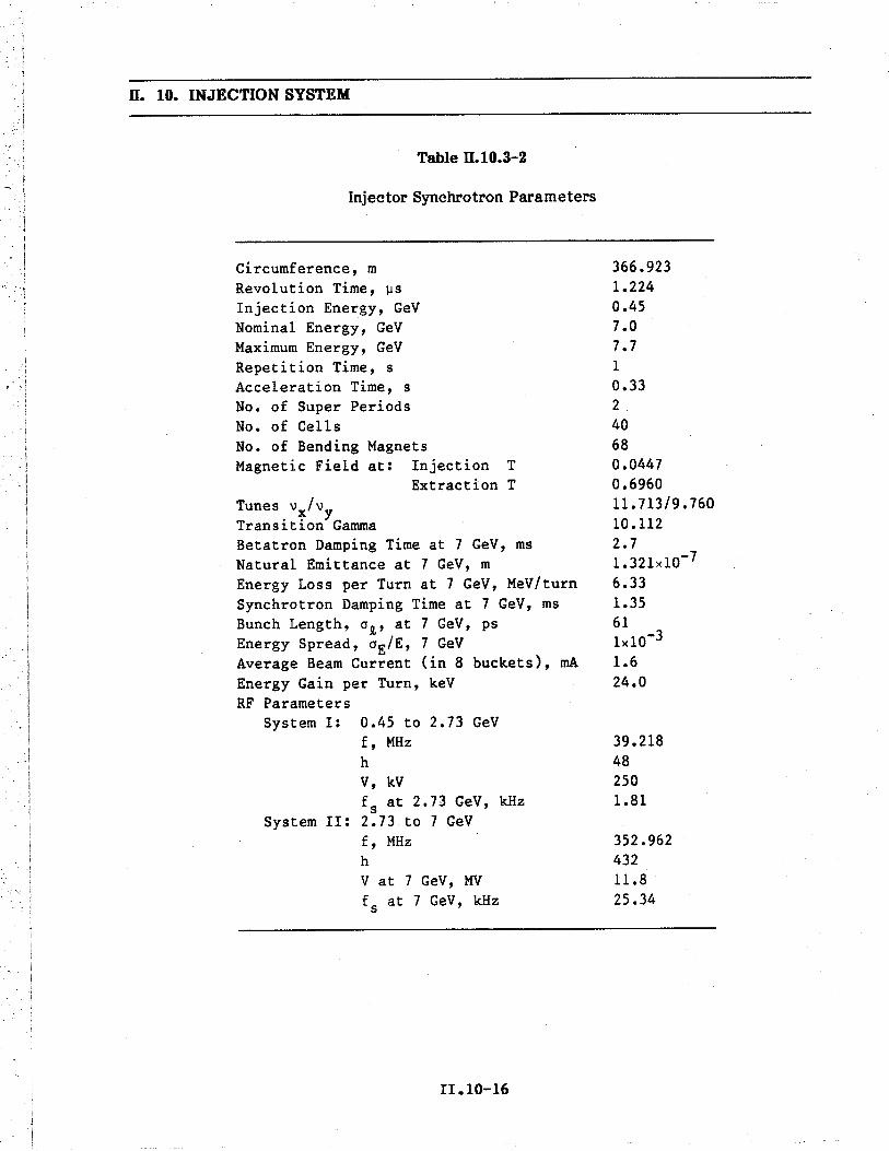
ll. 10. INJECTION SYSTEM
Table ll.10.3-2
Injector Synchrotron Parameters
Circumference, m
Revolution Time, ~s
Injection Energy, GeV
Nominal Energy, GeV
Maximum Energy, GeV
Repet i t ion Time, sAcceleratíon Time, sNo. of Super Periods
No. of Cells
No. of Bending Magnets
Magnetic Field at: Injection TExtraction T
Tunes vx/vy
Transition Gamma
Betatron Damping Time at 7 GeV, ms
Natural Emittance at 7 GeV, m
Energy Loss per Turn at 7 GeV, MeV/turn
Synchrotron Damping Time at 7 GeV, ms
Bunch Length, crl, at 7 GeV, ps
Energy Spread, crE/E, 7 GeV
Average Beam Current (in 8 buckets), rn
Energy Gain per Turn, keV
RF ParametersSystem I: 0.45 to 2.73 GeV
f, MHz
hV, kV
f s at 2.73 GeV, kHz
System II: 2.73 to 7 GeV
f, MHz
hV at 7 GeV, MV
fs at 7 GeV, kHz
366.9231.2240.457.07.71
0.332
40680.04470.696011. 713/9. 76010.1122.71.321x10-76.331.35611x10-31.624.0
39.218482501.81
352.96243211.825.34
II.10-16

ll. 10. INJECTION SYSTEM
10.3.4 Injector Sychrotron Magets, Supports, and Power Supplies
10.3.4.1 Injector Sychrotron Magets
The major ring magnets for the injector synchrotron consist of 68 dipoles,80 quadrupoles, and 68 sextupoles. End views of these magnets are shown in
Figs. II.10.3-5, II.10.3-6, and 11.10.3-7, respectively. These figures show some dimensionsand the major components of the assembled units. Also shown is the ring vacuumchamber positioned inside of each magnet. Each magnet is made in two sections,permitting the coils to be installed around each pole and also allowing the magnets to beassembled around the ring vacuum chamber.
The calculated two-dimensional relative field deviations and leading coefficientsat 7.0 GeV, according to the definition in Section 11.4.2, are listed in Table II.I0.3-3.These values at the injection energy of 0.45 GeV are within similar magnitudes.
Table ll.10.3-3
Field Qualities of Injector Synchrotron Magnets
Dipole Quadrupole Sextupole ~k
Relati ve (~B)+ 0.71
(lIG)+ 2.5
(~K) :: 30= =1.5 G 7.0
Deviation 00-4) o max o max o maxmin min min
forlxl :: 25 mi for ro :: 17.5 mm for ro :: 17.5 mm
Iyl :: 17.5 mi
Mul tipole b2 = 17 .5 b3 = 3.2Coefficients b4 = 3.6 bS = -3.5600-6 em-n) b9 = -0.26
oJ.nEstimated.
II .10-17

ß. 10. INJECTION SYSTEM
0.10
,
24.7
5~125
I
10 ..1
5.125
I~ 35.6 em J40.7
Figue ß.10.3-5End view of the injector synchrotron dipole magnet.
II.IO-IS

II. 10. INJECTION SYSTEM
26.7
23.1
30.7 em
Figue 11.10.3-6
End view of the injector synchrotron quadrupole magnet.
II.IO-19

II. 10. INJECTION SYSTEM
19.5
17.3
18.3
23 em
Figue 11.10.3-7
End view of the injector synchrotron sextupole magnet.
II.IO-20

II. 10. INJECTION SYSTEM
The cores of these magnets are assembled from 1.5-mm-thick, low carbon steel(1010) laminations stacked between stainless steel end plates. The thicknesses of theseend plates are 2.5 cm for the dipole, 1.0 cm for the quadrupole, and 0.6 cm for thesextupole magnet. The cores are held under compression by tie rods and secondaryassembly components welded to the end plates and to each lamination. Each magnet hasone coil per pole made from hollow copper conductor insulated with fiberglass that isvacuum impregnated with epoxy resin.
The 40 horizontal and 40 vertical correction dipole magnets included in the
injector ring provide integrated field values ~ 0.018 T. m. A separate design is used foreach type of correction to minimize the power and maximize the field quality. An endview of the horizontal corrector is shown in Fig. II.10.3-8.
The parameters for the injector ring magnets are listed in Table II.10.3-4. All themagnets are optimized for 7.0 GeV and are capable of 7.7-GeV operation.
10.3.4.2 Injector Synchrotron Maget Supports
10.3.4.2.1 Dipole Support
The injector dipoles are rigid, welded structures with sufficient stiffness to besupported directly on three vertical 2-ton jacks. The jacks are mounted on a stand thatcan be adjusted transversely and longitudinally by means of screws at the base, in muchthe same way that the storage ring magnet supports are adjusted (see Fig. II.4.10-1).
10.3.4.2.2 Quadrpole, Sextupole, and Correction Maget Support
The quadrupole, sextupole, and correction magnets between the injector dipolemagnets are mounted on a common rigid beam. The individual magnets are aligned totheir common magnetic center by means of simple adjustable supports on the commonbeam. The girder is mounted on three vertical 2-ton jacks on a stand and adjusted toalign the magnets as a unit, in the same manner as the larger strings of magnets arealigned in the storage ring (see Fig. II.4.10-2).
10.3.4.3 Injector Sychrotron Ring Maget Power Supplies
The ring magnets of the injector synchrotron are pulsed as shown, for example, inFig. II.10.3-9(a) for the dipole magnets. After a l/6-s injection time, the current rises in1/3 s to a flat top that is maintained for 1/6 s. Thereafter, the current decays to theinjection level in 1/3 s, resulting in a pulse repetition time of 1 s. The real-time trackingerror between the quadrupoles and dipoles is within ::5xlO-4. With the relatively slowrate of rise and the 1.5-mm core laminations, eddy current effects in the magnet iron arenegligible. A general synchrotron current shape is shown in Fig. II.10.3-9(b).
II.I0-21

ß. 10. INJECTION SYSTEM
2
8
I.. 17 ~i
23 em
Figue ß.10.3-8Injector synchrotron horizontal correction dipole magnet.
II.IO-22

Table 11.10.3-4
Ii: .
Par
amet
ers
for
Inje
ctor
Syn
chro
tron
Mag
nets
..I
= . - ~M
agne
tt2 ("
Cor
rect
ion
=:
Para
met
erD
i pol
eQ
uadr
upol
eSe
xtup
o1e
HV
0 Z
Num
ber
Req
ui r
ed68
8068
4040
~Strength at 7.0 GeV
0.696 T
13.9 T/m(max)
130 T/m2(max)
0.15 T
0.12 T
r! t:Effective Length
(m)
3.1
0.6
0.2
0.12
0.15
a:
Gap Height or Diameter
(mm
)40
56.5
670
4070
Total Mass of Magnet
(kg)
1650
180
307
12
Coils per Pole
11
11
1
HC
ondu
ctor
Hei
ght
(mm
)9.
07.
24.
12.
02.
0H
Wid
th(m
m)
9.0
7.2
4.1
2.0
2.0
.Hole Diameter
(mm
)5.
03.
92.
4edge-cool ed
.. CN
umbe
r of
Tur
ns p
er P
o Ie
247
1025
244
8I N
(mH
)~
Total Inductance
300.
90.
847
106
Total Resistance
(mO
)98
1850
1378
2422
Tim
e C
onst
ant
(ms)
306
5016
3444
Supply Current Max
(A)
470
645
80:!
19:!
15M
in(A
)30
429
rms
(A)
299
410
5119
15
Current Dens i ty in Coi 1
(A/m
m2
)2.
64.
92.
24.
23.
2
Voltage at Injection
(V)
2.9
0.8
0.2
Vo 1 tage at F1a t Top
(V)
46.1
11.6
4.0
:!26
:!36
Pea
k V
ol ta
ge(V
)85
.713
.24.
2:!
26:!
36
Pow
er(k
W)
8.8
3.0
0.1
0.5
0.5
Cooling Circuits per Magnet
44
14
4
Total Water Flow
(gpm
)2.
12.
50.
40.
20.
2Water Pressure Drop
(psi
)10
050
5050
50
Water Temp. Rise
(OC
)16
43
1010

470A
ite
i 3
10
, I , 1
'I , I \ , \ , 'I
T
(b)
H H . .. o I N ~
,..30
70V
l i \
. i ,
ie / ,~~470A
e~i \
/ l__, ..\1723V
145~
' \, ,
: '
+ I 375V-J
, \
4-30A \11ODV .
i \ ..
1/6 1;2 2/3" 11'
t \'\ ,
~ \,
sec
\' ,-1
238V
~I
(a)
(c)
,.-r "'1-.fßiÑG'
-. ,-
;--t
i
+1+ ~
l6=
= .. = . - ~ t. (" S iz ~ ~ ti s:
1 . ;l __~-
J
Figue 11.10.3-9
Cur
rent
and
vol
tage
sha
pes
and
bloc
k di
agra
m o
f th
e di
pole
rin
g m
agne
t pow
er s
uppl
y fo
r th
e in
ject
orsy
nchr
otro
n.
I I+
3400
L--
-i-1
400
laH
AL
F O
FM
AG
NE
T C
HA
IN
SIMilAR .UNCfROUNDED
PO
WE
R S
UP
PLY

ß. 10. INJECTION SYSTEM
A repeatable residual field wil be attained after a long shutdown by pulsing the
magnets at rated current for several minutes before the beam is injected. Table 11.10.3-5
lists the power supplies for the ring magnet system and indicates their outputcharacteristics and performance data. The current stabilty and reproducibilty include
the effects due to load variations, component drifts, and temperature coefficients overthe range of 10°C to 40°C, as well as line fluctuations. The current tracking errorapplies to the nominal acceleration ramp of 20 GeV/s. All the power supplies have anupper limit of 7.7-GeV operation.
10.3.4.3.1 Dipole Power Supply
Two identical 12-phase power supplies are used to energize the chain of 68 dipolesfrom feed points 180° apart. Figure II.10.3-9 shows current and voltage shapes of one
power supply for two operating conditions, together with a block diagram. InFig. II.10.3-9(a), the current pulse is symmetrical, with injection and extraction times ofnominally 1/6 s. These times can be increased, without changing the pulse repetitionrate, by shortening the current decay time. As ilustrated by Fig. II.10.3-9(b), this can bedone over a wide range by changing the power supply output voltage by means ofrectifier phase control. The delta- and wye-connected secondaries of the rectifiertransformers feed two series-connected Si-controlled rectifier (SCR) bridges. Thedesired voltage and current shapes are produced by rectifier phase control of the12-phase system, with a regulator comprising current and voltage feedback loops. The12-phase rectified output is filtered by a passive damped LC filter. A I5-bit DAC isprogrammed by the control computer for the required current shape. The DAC is thereference for the current regulator, which obtains its feedback from a high-precision,
low-drift, zero-flux current transductor. Fast correction for line transients is providedby an inner, relatively low gain, voltage loop controlled by the high-gain current loop.The injection current is only 6.496 of maximum current. At this current level, thecurrent stabilty, ripple, and reproducibilty are slightly degraded. Therefore, a separate150-V, 50-A dc power supply, regulated to 0.0196, is used during injection. At the start
of acceleration, the main power supply output voltage of 1458 V back-biases the SCRs in
series with the injection power supply, thereby disconnecting it from the circuit. After
flat top, when the current has decayed to close to the injection level (i.e., 34 A), thetrigger pulses to the power supply SCRs are set for zero output voltage, and the crowbarSCRs, in parallel with the power supply filters, are turned on to discharge the filtercapacitors. This causes the magnet current to decay exponentially, reaching the
injection level of 30 A after -23 ms. The injection current is maintained by turning onthe SCRs in series with the injection power supply. During standby, the injection powersupply operates into a light-load resistor in parallel with a low-inductance capacitor,both operating at the injection voltage of 110 V. Actual injection of eight 60-Hz pulses
takes 133 ms.
II.IO-25

.:.
Table 11.10.3-5
I := .. =
Mag
net P
ower
Sup
plie
s fo
r In
ject
or S
ynch
rotr
onI
:. ~ t: nlI
I/Im
axg
Ref
.!Z
Num
ber
ofIm
axV
max
Pmax
Prat
edR
epro
du-
Cur
rent
Tra
ckin
gR
esoL
.ai
Mag
net
Uni
ts(A
)(V
)(k
W)
(kW
)ei
bilit
yR
ippl
eE
rror
(bit)
k' ~ t: a:I
Dip
oles
247
0+
3070
1443
489
:tl x
10-
4:t2
xl0-
4:t5
xl0-
415
-123
8
H:tl
xl0-
4:t2
xl0-
4:t5
xl0-
4H
Qua
drup
oles
264
5+ 576
372
200
15. ..
-32
0 i N (7
Sext
upol
es2
80+ 151
138
:t2xl
0-4
:t3xl
0-4
:t5xl
0-4
14
H Corr. Mag.
40:t1
9:t
290.
55:to
.5:tl
xl0-
3:t1
x10-
3:t4
xlO
-312
V Corr. Mag.
40:t1
5:t
400.
60:to
.5

II. 10. INJECTION SYSTEM
Only one regulator circuit is used for the two main power supplies. This regulatorcontrols two sets of identical 12-phase SCR firing pulses that are transmitted to the two
power supplies via optical links.
Only one of the two identical injection power supplies is current controlled, as.shown in Fig. II.10.3-9; the other operates at a constant voltage of 110 V.
10.3.4.3.2 Quadrpole Power Supply
The two 12-phase power supplies provided have the features shown inTable II.10.3-5. One wil energize 40 focusing magnets, the other 40 defocusingmagnets. Except for the power rating, the power supply circuit is similar to the oneshown for the dipole power supply. It should be noted that a magnet time constant ofonly 57 ms would permit pulsing of the circuit without power supply inversion. In thiscase, the crowbar SCRs are replaced with a diode because the power supply voltage isnot reversed. At the end of flat top, after the beam has been extracted, the main powersupply output voltages are reduced to zero. The quadrupoles discharge exponentially.
The magnet current of 585 A decays to its injection level of 44 A in a time interval of0.147 s.
10.3.4.3.3 Sextupole Power Supply
Two identical power supplies are used to energize the two strings of sextupoles, asshown in Fig. 11.10.3-10. Since regulation requirements are not very stringent (seeTable II.10.3-5), no separate power supply wil be provided for the injection period. TheDAC-programmed regulator controls, by means of rectifier phase control, the powersupply output. Any arbitrary current shape is possible between zero and maximumcurrent. The power supply peak voltage rating is such that the normalized rate ofcurrent change can be up to three times faster than that required for the dipole magnets.
10.3.4.3.4 Correction Maget Power Supply
A total of 80 independently controlled ::500-W power supplies are provided. Theneed for smooth control of the current through zero dictates the use of bipolar linearamplifiers with push-pull output stages. Such amplifiers are commercially available.
II.IO-27

II. 10. INJECTION SYSTEM
16
-- ~---------
Figue 11.10.3-10
Current and voltage shapes and block diagram of the sextupole powersupply for the injector synchrotron.
II.IO-28

u. 10. INJECTION SYSTEM
10.3.5 Vacuum Sytem
10.3.5.1 Vacuum Chamber
The chambers for the injector synchrotron are made from 1-mm-thick 304 stain-less steel tubes formed to an ellptical shape with inside major and minor axes of 6 cmand 3.7 cm, respectively. This results in a thin metallc chamber without corrugations,which is smooth inside, allows maximum beam space in the magnets, and withstandsatmospheric pressure.
Sections of the chambers are bent to fit the magnet curvature. Flanges, positionmonitors, bellows, etc., are attached by conventional welding techniques and leak tested.
10.3.5.2 Pumping
Ion pumps are used as the primary pumping source to maintain an average pressureof 10 nTorr in the 367-m circumference ring. The ellpticai chamber is conductancelimited. With a conservative outgassing rate of 1x 10- 1 Torr. 9./s/cm 2, 25-9.s pumps
spaced -9.1 m apart are used to maintain the desired pressure. The ion pumps areequipped with heaters for bake-out. Preconditioning of the chambers includes chemicalcleaning, bake-out and, if necessary, glow discharge cleaning.
For pump-down from atmospheric pressure, portable oil-free mechanical pumpsevacuate the system to -50 Torr after which sorption pumps reduce the pressure to the
turbo molecular pump starting pressure. Mobile turbo molecular pumping stations are usedto further reduce the pressure to the ion pump starting pressure.
10.3.5.3 Sytem Monitoring
Ion pumps are uniformly distributed around the ring. Monitoring their current
provides adequate pressure measurement. Ionization gauges are also distributeduniformly around the ring. Ring isolation valves eliminate the need for venting theentire ring to the atmosphere should repair in anyone segment be necessary. Smallisolation valves within each segment permit the mounting of gas analyzers or othermonitoring equipment.
II. 10-29

II. 10. INJECTION SYSTEM
10.3.6 Injector Sychrotron Radio Frequency System
10.3.6.1 Introduction
The injector synchrotron rf voltage is provided by two systems operating atdifferent frequencies. Between injection and 2.73 Ge V, the frequency is 39.22 MHz.
This is the 48th harmonic of the revolution frequency. Injection is into stationarybuckets with the peak voltage at 60 kV, which is increased to 250 kV over several
synchrotron oscilation periods. The phase-stable angle at 2.73 GeV is 1440. Between2.73 GeV and extraction at 7 GeV, the 353-MHz system takes over. This is the 432ndharmonic of the revolution frequency. The 353-MHz cavities are deliberately de tunedduring the operation of the low-frequency system. The rf voltage starts at 2 MVat2.73 GeV and increases to match the synchrotron radiation losses. At extraction, the
maximum rf voltage is 11.8 MV, and the synchrotron radiation loss per turn is 6.33 MeV.The energy gain per turn is negligible compared to the synchrotron radiation loss.
The cavity for the 39.22-MHz system is a capacitively-Ioaded, coaxial design, andthe four cavities for the 353-MHz system are each seven-cell, iris-loaded designs. The39.22-MHz amplifier delivers 35 kW from a grounded-grid triode amplifier, of which26.1 kW is needed for the Cu loss at 250 kV. The 353-MHz system is driven by a single1-MW klystron identical to the ones used for the storage ring. The rf power from theklystron is divided equally among the four cavities. The Cu loss for each seven-cellcavity is about 116.6 kW at a peak accelerating field of 3 MV per cavity.
10.3.6.2 39.22-MHz Cavity
A cross-sectional view of the 39.22-MHz cavity is shown in Fig. II.10.3-11. It is acapacitively-loaded coaxial cavity with a circular tuning plate on the high voltage end.The cavity is excited by a current loop located at the shorted end. The cavity material isCu-plated stainless steel to provide rugged construction and the abilty to bake-out. TheCu plating is 30 llm to 50 llm (0.001 in. to 0.002 in.) thick, and the skin depth is 10 llm.The cavity is fabricated by rollng, welding, and machining the stainless steel plates. The
inner surfaces are highly polished and then plated.
A tuning range from 38.7 MHz to 39.74 MHz is provided by a motor-gear drivesystem that drives the tuning plate back and forth through a bellows arrangement so thatthe effective gap can be changed between 7.1 cm and 7.5 cm. Cavity dimensions arelisted in Table II.10.3-6, and performance characteristics are listed in Table II.10.3-7.
Several ports are provided for field measurements with small probes and loops.Provisions are made for damping antennas and loops for suppression of higher ordermodes if they become troublesome.
II.lO-30

II. 10. INJECTION SYSTEM
Bellows fortuning platedriver
Gear drivefor adjustingtuning plateposition
Coupling loop
penetration
Tuning plate
Capacitiveloading plate
Beam line
Measurementport penetration
Vacuum ports
Ion pump
Figue II.10.3-1139.22-MHz accelerating cavity.
II. 10-31

ß. 10. INJECTION SYSTEM
Table ß.10.3-6
Dimensions of the 39.22-MHz Cavity (m)
Length of Outer Shell (inside wall to inside wall)
Radius of Outer Shell (center line to inside of outer wall)
Length of Inner Conductor (inside face of shortedend of cavity to inside face capacitive-loading plate)
Thickness of Capacitive-Loading Plate
Radius of Inner Conductor (center line to outside surface)
Diameter of Beam Tube
Outer Radius of Capacitive-Loading Plate
Outer Radius of Tuning Plate
Gap between Capacitive-Loading Plate and Tuning Plate
1.028
0.5
0.928
0.030.145
0.077
0.30
0.27
0.071-0.075
Table ß.10.3-7
Performance Characteristics of the 39.22-MHz Cavity
Operating Frequency
JEzcos(kz/ a)dz
Cavi ty power @ 250 kV
Cavity Q
Shunt Impedance
Peak Electric Field on Surface @ 250 kV (39.74 MHz)
38.7-39.74 MHz
250 kV
26.1 kW
25,900
5.68 MQ
5.94 MV/m
Vacuum pumping is achieved through a slotted port. A 360-i/s turbo molecularpump and a 400-i/s ion pump are used.
10.3.6.3 39.22-MHz Radio Frequency Amplifier
The rf power for the 39.22-MHz system is provided by a triode amplifier operatedin the grounded-grid configuration. The rf amplifier is available from commercial
II. 10-32

II. 10. INJECTION SYSTEM
sources. The cavity is driven by a 50-Q rigid transmission line (3-l/8-in. dia.), with thelength between the cavity and amplifier adjusted to a multiple of À/2.
10.3.6.4 353-MHz Radio Frequency Cavity _
The cavities for the 353-MHz injector synchrotron rf system are essentially copiesof the LEP/PEP(1l,12) five-cell, À/2 resonant cavities except for the addition of twoextra cells. They have a 10.0-cm diameter beam hole with a reentrant nose. The celllength is À/2 (42.49 cm). The radius from the center line to the inside of the outer shellis 30.2 cm. The cells are magnetically coupled with two off-axis slots. The seven-cellstructure is loop-excited in the center cell using a post-coupler from the WR2300waveguide. Tuners are provided in the two cells adjacent to the center cell. Vacuumseparation between the waveguide and the seven-cell cavity is provided by a cylindricalceramic window surrounding the waveguide post. The cavity body is made from forged
disks and forged seamless cylinders of Cu. These are machined to close tolerances andelectron-beam welded.
A list of parameters for the seven-cell cavity is given in Table II.10.3-8. The four353-MHz cavities are divided into two groups and placed symmetrically on opposite sidesof the synchrotron.
Table II.10.3-8
Parameters for the Seven-Cell, À/2, 353-MHz Cavity
Bore-Hole Diameter
Cell Length (center 1 ine to center 1 ine)Cell Length (inside of cell, wall to wall)
Cell Radius
Number of Cells
Active Length of Cavity
Total Length of Cavity
Shunt Impedance
Average Accelerat ing Voltagerf Power @ 3.0 MY/cavity
10.0 cm
42.49 cm
38.9 cm
30.2 cm
7
2.97 m
3.17 m
26.1 Mnlm
1.01 MY/m
116.6 kW
II.l0-33

II. 10. INJECTION SYSTEM
10.3.6.5 353-MHz Radio Frequency Power System
The 353-MHz system for the injector synchrotron is essentially the same as the353-MHz rf system for the storage ring. The same kind of klystron is used, but optimizedto achieve a maximum efficiency of 65-70% ~t 500 kW instead of 1 MW. A circulator isprovided to protect the klystron. Phase shifters are used to adjust the phase to thecavities.
10.4 Tranport and Injection into Injector Sychrotron
10.4.1 Tranport Line from Linac
The transport line between the linac and injector synchrotron is shown in
Fig. II.10.4-1. The 29-m transfer line is made up of two segments. The downstream
section, which includes the injection septum in the synchrotron and a 10° bending magnetin the transfer line, is a 360°-phase advance achromatic cell to match the dispersionfunction in the synchrotron. The upstream section has five quadrupole magnets near thelinac for the phase-space matching between two accelerators. Figure II.10.4-2 shows thetransfer line ß and dispersion functions. The magnet elements needed for this transferline are shown in Table II.10.4-L.
10.4.2 Injection Geometr and Procedure
The injection geometry is shown in Fig. II.10.4-3. Since the injection procedureplanned is to transfer a macropulse of the linac to a waiting rf bucket of the synchrotronin accordance with the linac repetition rate, the geometry is designed for on-axis
injection by means of a kicker and a septum magnet. The septum magnet is located inthe empty half cell of the dispersion suppressor cell, and the kicker is located about halfa cell after the septum. A kicker strength of rBdi = 0.0077 T. m is required. Theinjection trajectory and its associated beam envelopes are shown in Fig. II.10.4-4.
For each cycle of the injector synchrotron, eight positron pulses, each of which is
16.5 ns long, are injected one at a time into every sixth bucket of the 39.22-MHz rfsystem while the synchrotron field is at the flat bottom. At this time the waiting bucketlength is 25.5 ns, and therefore the bucket can accommodate the 16.5-ns pulse easily.The flat-bottom duration is 1/6 s, and the eight-pulse linac duration is 0.133 s.Therefore, there is sufficient time to accomplish the injection. The kicker, which isdesigned to accommodate the required time durations, is described in Sec. II.I0.4.4.
10.4.3 Injection Septum Maget
The septum magnet is a pulsed device of a design similar to that used for injectioninto the storage ring. It operates at a peak field of 0.49 T at 60 pulses per second. The
II.I0-34

1- 1- . .. o i \. VI
INJE
CT
OR
SYN
CH
RO
TR
ON
C3
-KICKER -
SEPTUM 012 011
07M
1
0fr05 04
03 02 011 L1NAC
l l , , , I ,
0123
456
Scale (meters)
Figu
e 0.
10.4
-1La
yout
for
the
linac
-to-
inje
ctor
-syn
chro
tron
tran
sfer
line
.
~ .. = . - ~ t' n g 2: ~ ~ t' ==

II. 10. INJECTION SYSTEM
en~2 10Q)
~
20..
Injection..
Linac
o
/",.. ../'
....
1 OxD+1 0
Distance (m)
Figue 11.10.4-2
a and dispersion functions for linac to synchrotron transfer line.
II. 10-36

ll. 10. INJECTION SYSTEM
Table II.10.4-1
Parameters for Magnets in Transport Line betweenLinac and Synchrotron
Dipole Quadrupoles
Number Requi red 1 12
Field Strength at 450 MeV 0.27 T 3.8 TIm max.
Effective Length (m) 1.0 0.3Gap Height or Diameter (mm) 40 70
Total Mass (kg) 290 125
Coils per Pole 1 1
Conductor Height (mm) 6.0 2. a
Width (mm) 6.0 2.0Hole Diameter (mm) 3.3 edge-cooled
Coil Turns per Pole 40 288
Coil Current (A) 110 7
Current Density 1n Conductor (A/mm2 ) 2.0 1.5Voltage (V) 14.2 28.9Power (kW) 1.6 0.2Cooling Water Circuits per Magnet 2 4
Total Water Flow (gal/min) 0.4 0.05Water Pressure Drop (psi) 100 100
Water Temperature Rise (0 C) 18 15
minimum thickness of the septum is 2 mm, but this increases along the length to improvethe mechanical and thermal properties. Table 11.10.5-2 lists the parameters of thismagnet, together with those of the extraction septum magnets.
10.4.4 Injection Kicker Maget
The injection kicker has a peak field of 0.031 T and a length of 25 cm. The pulseduration is -145 ns, with a flat top of -29 ns, to accommodate the 16.5-ns long linacmacropulse.
II.I0-37

.ii
I I I
QI -E
00
H HI
l.
i
..1
0 i
I
wI
-- FROM L1NAC
cotL
KIC
KE
R
I I I I I
o 1
234
HORIZONTAL SCALE (m)
Figue 11.10.4-3
Sche
mat
ic f
or in
ject
ion
into
syn
chro
tron
.
e= .. c . ~ g !Z ~ ~ tz is

8f- t OUTSIDE OF
INJE
CT
OR
SYN
CH
RO
TR
ON
INJE
CT
ED
BE
AM
EN
VE
LO
PE
I
(f 0: W r-H
wH
~0
\UN
'DA
MPE
D
.r-
..--
cZ
~i w
W\Q
()B
EA
M D
IRE
CT
ION
-4~
..B
EA
ME
NV
EL
OPE
KIC
KE
R
?UL
SED
QF
DIP
OL
ESE
PTU
MQ
D
p ~ o . ~ (" g z: ~ a:
Figue 11.10.4-4
Bea
m tr
ajec
tory
and
4-0
env
elop
e fo
r th
e in
ject
ed a
nd u
ndam
ped
beam
s in
the
inje
ctio
n re
gion
of
the
inje
ctor
sync
hrot
ron.
The
2-m
m in
ject
ion
sept
um is
21
mm
from
the
unpe
rtur
bed
orbi
t.

II. 10. INJECTION SYSTEM
A single-turn ferrite core magnet with a picture-frame design is used, as shown in
Fig. II.10.4-5. The inside of the ceramic vacuum chamber is aluminized to minimizeimpedance to the beam. The power supply uses a thyratron-gated PFN made up of 5.4 mof commercially available 14-Q coaxial cable. The power supply and magnet are shown
schematically in Fig. 11.10.4-6. The design requirements and system specifications aregiven in Table II.10.5-1.
10.5 Exaction from Synchrotron and Tranport to Storage Ring
10.5.1 Exaction Procedure and Geometr
At the 7-GeV flat top, the bunches are extracted one at a time at a 60-Hz rate forinjection into the designated rf buckets in the storage ring. The extraction trajectoryand its associated beam envelopes are shown in Fig. II.10.5-1. The bunch to be extractedis initially kicked 2.35 mrad outward by a three-section kicker with a total rBdii =0.055 T. m. The kicked beam enters the septum magnet 27 mm from the central orbit.The pulsed magnet has a 2-mm-thick septum. The extracted beam clears the outside ofthe septum by 3 0.
After this pulsed septum magnet, there are two dc septum magnets providing atotal bend of 6.5°. The extracted beam clears the downstream quadrupole by 11 cm.
10.5.2 Kicker Maget
The fast kicker consists of three identical 0.6-m cells. The cross section is
identical with the injection kicker magnet of Section II.10.4.4 and is shown in
Fig. II.10.4-5. As shown in Fig. II.10.5-2, a PFN discharges through the magnet coils intoterminating loads when the thyratron is triggered. Six parallel cables from the PFN andsix half-turn coils connected to separate terminating loads make up the load. The designrequirements and system specifications are given in Table II.10.5-1.
10.5.3 Septum Maget
The extraction septum magnets consist of a pulsed septum operated at a GO-Hz
pulse rate, followed by two dc septa. These magnets are the same as those used forinjection into the storage ring (see Section II.4.7-1). The parameters for these magnetsare listed in Table II.10.5-2.
II .10-40

II. 10. INJECTION SYSTEM
CERAMICVACWM CHAMBER ~
~~~ ~r
V COPPER SHEET
18.28 4.0
~~
~ ~ ~ ~ V-COPPER COIL~~ ~~4.75 -- )c
2.7 *~~ 'JJ,....~, ~~
l
.82Lt.15
7.4
f.5
I.. 22.96 em
\"- FERRITE
~i
Figue II.10.4-5Cross section of kicker magnets.
II.IO-41

ß. 10. INJECTION SYSTEM
CHARGECONTROL
"PICTURE FRAME".KICKER
Zo.HV
+
Figue ß.10.4-6Schematic diagram for power supply and injection kicker.
II. 10-42

II. 10. INJECTION SYSTEM
E2:: Q)+J Cc. oiQ) 0(/ ~()o
¿~o.cmom-ti.~
oo
eti(1.0'C(1..~(1...
.5(1.c..i:o..(10.o-(1~~ i:
i (1~ 0= I~ "1.- (1- .c
~ ~... e~ ti
(1.0'C(1..~tii:..~(1i:o..(10.o-(1~i:(1
oi
C"
'Ci:tii:o.-...-moi:
- Eo ::oi+JC c..- Q)
.f: (/oi .:Q) ()lD .-..i-
"0 E +JQ) Q)en :: c- +J oi:: c. 0Q. ~ ~ Q)
o.Q-oE Q)o c.
Q) 0lD Q);:"0 CQ) W
+J()o~+JX
W
ct:
E Q)o c.Q) 0lD Q);:"0 CQ) W
+J()Q).""C
~+J Q)en .:o ()lJ .-~lJo
Q)
o
oN
o o o oN
I
.. ..SJcqew!lueJ
II. 10-43

II. 10. INJECTION SYSTEM
~a:o3: i:i- 0w -.ZwC) (Jza:-w~i-a:wo~u.w~(J lC..~a.
.W..~.. -.
wa:a:ou.www~wa:S:a:~~i:i-i-o
õ:"
zoa:i--.a:)-i:i-
~ +i:
II.I0-44
~Q,..c.:gi:o
C' .-J ..In c.. asc: ~~ ... ~= Q,Q, ~
fo .;.- ..~ 0.0.:srn~Q,
~o~

II. 10. INJECTION SYSTEM
Table 11.10.5-1
Design and System Specificationsfor Synchrotron Injection and Extraction Kickers
Injection Extraction
Rise Time (ns) 43.2 43.2Flat Top (ns) 28.7 28.7Fall Time (ns) 72 72
PFN Voltage (kV) 34.1 39.7PFN Charge Current (rn) 5.58 39.1PFN Cables (m) 5.4 6x5.4 in parallelCable Type YR-10914 YR-10914
Cable Impedance (ohms) 14 14
Configuration 1 cell 3 cells,1 coil 6 coils
Peak Field (T) 0.0383 0.0445
Peak Magnet Current (kA/coi1) 1.219 1.417
Magnet Inductance (nH/coil) 402 605
Charge Power Dissip. (W) 85.4 696(60 Hz CW)
Load Power Dissip. per coil (W) 85.4 116(60 Hz CW)
Field Dimensions:
Gap Height (cm) 4 4
Gap Width (cm) 5.75 5.75Length (m/cell) 0.2 0.6
Ferri te Type Ceramic Magnetics type CMD-5005
II .10-45

ll. 10. INJECTION SYSTEM
Table ll.10.5-2
Parameters for Injector Synchrotron Septa
ExtractionInjection
AC AC DC DC
Type Pulsed Pulsed Thin Thick
Min. Septum Thickness (mm) 2 2 14 30
Peak Field (T) 0.49 0.8 0.9 0.9Physical length (m) 0.85 0.85 1. 15 1.25Effective Length (m) 0.8 0.8 1.1 1.2Gap Height (mm) 30 20 25 30
Gap Width (mm) 40 40 40 40
Number of Turns 4 3 12 36
Total Inductance (mH) 0.021 0.02 0.6 5.2Total Resistance (mn) 6.7 5.4 19 98
Peak Supply Current (A) 2954 4286 1510 600
Peak Power (kW) 138 245 43 36
Power (kW) 0.157 0.28 43 36
10.5.4 Tranport to Storage Ring
The transfer line between the synchrotron and the storage ring is essentially madeof three parts. To match the beam optics at both ends of the line, the extractionhardware of the synchrotron and the injection hardware of the storage ring are includedin the design optics as shown in Fig. II.10.5-3. The first part of the transfer line is then a360° phase advance achromatic cell that includes the initial bend of 6.5° from theextraction hardware and an opposite bend of 8.3°. This achromatic cell eliminates thedispersion created by the extraction hardware.
The dispersion-free second part contains eight quadrupoles for matching the ßfunctions from the synchrotron to those of the storage ring.
The third part, which consists of an 8.2° bend and the storage ring injection
magnets, is a 180° achromatic cell that matches the dispersion function in the ring.
II. 10-46

II. 10. INJECTION SYSTEM
Synchrotron ExtractionSeptum
Storage RingInjection Septum
~
1\20
ßx I \ ßyA(f
/\0:
i \ I \wI-W
I \ 1\ i2
10I V
l "-
/ \ /\ / V
V0
0 30 40 50 60DISTANCE (m)
Figue II.10.5-3ß and dispersion functions for synchrotron-to-storage-ring transfer line.
II. 10-47
ß. 10. INJECTION SYSTEM
The total length of the transfer line is about 54 m, and the physical layout is
shown in Fig. II.I0.5-4. The magnet parameters of the line are described inTable II.10.5-3.
10.5.5 Beam Diagostics Line
Figure 11.10.5-4 includes the schematic for the beam-diagnostics transfer line,
which consists of two bending magnets and two quadrupoles. The total length of the
beam diagnostics line is about 10 m. The magnets used are the same as those in thetransport line from the synchrotron. This line is used to measure synchrotron beamproperties.
10.6 Beam Diagostic Intrumentation for Injector System
The beam diagnostic instrumentation discussed here is described in more detail inSection 11.7. Table II.10.6-1 shows the types and quantities of the diagnostics installed in
the injector system.
The beam position in the synchrotron is measured by buttons identical with theones in the storage ring. The monitors are able to measure 0.1 mm, with a totalcirculating current of 1.6 mAo The processing is also identical. Wall current monitorsare used to measure the beam position as well as the intensity in the linac and beamtransport lines. Processing is similar to that of the button monitors. Signals from themonitors are available in the main control room for viewing on osciloscopes.
The circulating beam intensity in the synchrotron is measured by currenttransformers located around metallzed ceramic vacuum chambers. Two bending-magnetsynchrotron-radiation-monitoring stations are installed for monitoring the transverse andlongitudinal characteristics of the beam. The stations are instrumented withphotomultipliers, photodiodes, and television cameras. The synchrotron has electrodesand driver amplifiers for measuring betatron tunes. Movable horizontal and verticalbeam scrapers are provided. Fluorescent screens and secondary emission grids are
installed to measure the position and profile of the beam when needed. These monitors,as well as movable wire scanners, are used in the linear accelerators and beam transportlines.
Ion chamber loss monitors are provided at strategic locations throughout theinjector system.
11.10-48

u. 10. INJECTION SYSTEM
co..uQ)'--C
enu..L- en
.2 0cQ) O'c .2~o
co
L- L-a .... 0() L-Q) ..'-- uc c- ~
(f
i
Ii
O'Q)
rcc .-0:L-
Q) Q) I
O' '+Ia en i
L- C,0 a
L-.. r- i
(f Ii I
f-- ,
(~i
I
Ii
..Ua
~L--+X
.. w
II. 10-49
.cu
.5..
,
f
i:cu..eni:a:i:..bDi:.¡:icu
~T 2)In ... en= 1l" .B
== bcu 0
~~.- ..t: ei
i::;en1i:o..eicu...
.5
..o..::o:;a:..

ll. 10. INJECTION SYSTEM
Table ll.10.5-3
Parameters for Magnets in Transport Line toStorage Ring and Beam Diagnostics Line
Dipole Quadrupole
Number Requi red 6 19
Field Strength @ 7 GeV 1.24 T 20 T/m
Effecti ve Length (m) 1.36 0.6
Gap Height or Diameter (mm) 20 50
Total Mass (kg) 720 760
Coils per Pole 1 1
Conductor Height (mm) 9.0 6.0Width (mm) 9.0 6.0Hole Diameter (mm) 5.0 3.3
Turns per Pole 32 96
Supply Current (A) 318 53
Current Density in Coil (A/mm2 ) 2.9 1.0
Voltage (V) 19 20
Power (kW) 6.0 1.1
Cooling Water Circuits/Magnet 4 4
Total Water Flow (gal/min) 2.7 0.4Water Pressure Drop (psi) 100 100
Water Temp. Rise ( °C) 9 15
10.7 Injector Control System
The injector accelerators use the same control system components as those usedfor the storage ring, and a comprehensive description is found in Section II.8 (ControlSystem). The features pertinent to the injector systems are as follows:
. Microprocessor-based clusters are used to interface with the injector systems,
with one cluster provided for each klystron system in the linac, one for each ofthe two rf systems of the synchrotron, and .seven additional clusters provided
II.IO-50

II. 10. INJECTION SYSTEM
Table II.10.6-1
Beam Diagnostic Instrumentation for Injector System
Quantity Monitor Type Function
Electron Linac 2 Current Transformers Intensity8 Wall Current Position, Intensity8 Fluorescent Screens Position, Profile8 Loss Monitors Losses
Po sit ron Linac 2 Current Transformers Intensity8 Wall Current Intensi ty, Position8 Fluorescent Screens Position, Profile
10 Loss Monitors Losses
Linac-Synchrot ron 2 Current Transformers IntensityTransfer Line 4 Wall Current Intensity, Position
3 Fluorescent Screens Position, Profile4 Wire Scanners Position, Profile6 Loss Monitors Losses
Injector 1 Current Transformer Intensi tySynchrotron 80 4-Button Pickups Position, Intensity
1 Photon Moni tors Intensi ty; Transverse andLongi tudinal BeamCharacteristics
2 RF Electrodes and Betatron Tune, DampingDriver Factor
40 Loss Moni tors Losses8 Fluorescent Screens Injection Position,
Profi Ie2 X and Y Beam Scrapers Injection Halo, Beam
Studies
Synchrotron-Storage 3 Current Transformers Intensi tyRing Transfer Line 4 Wall Current Position, Intensityand Beam Diagnostics 6 Fluorescent Screens Position, Profile
4 Wire Scanners Position, Profile6 Loss Monitors Losses
II.I0-51

II. 10. INJECTION SYSTEM
for the injection and extraction lines and the diagnostic, power supply, andvacuum systems (see Section 11.8.2.4).
· One front-end computer and network is provided to serve both the linac andsynchrotron. These computers maintain a current machine-state data base .foruse by the host and console computers as well as for formatting anddistributing control and monitoring data for the microprocessor clusters (seeSection 11.8.2.3).
"
· A separate full-function control console system is provided in the injectorcontrol area in the synchrotron injection building. Aside from its abilty to
access all three accelerator systems, this console also has access to the signal
cross-bar and video sources of the linac and synchrotron (see Section II.8.2.2).
· The linac and the synchrotron can be operated autonomously once filing of thestorage ring is completed. Control can be from the linac control area or fromthe central control area, where additional consoles are available (see
Section II.8.5.)
· The linac and the synchrotron can be operated autonomously once filing of thestorage ring is completed. Control can be from the injector control area orfrom the central control area, where additional consoles are available (see
Section II.8.5).
10.8 References
1. D. T. Tran, itA Low-Cost RF Structure for Electron and Proton Linac," IEEE Trans.
Nucl. Sci., NS-24, 1774 (1977).
2. W. Gallagher et al., "A High-Current Electron Linac," IEEE Trans. Nucl. Sci.,
NS-18, 584 (1971).
3. R. Kooutz et al., "SLAC Collder Injector," IEEE Trans. Nucl. Sci., NS-28, 2213
(1981).
4. R. B. Neal, The Stanford Two-Mile Accelerator (Stanford University Press, 1968),
pp. 95-162.
5. Z. D. Farkas et al., "Microwave Developments at SLAC," IEEE Trans. Nucl. Sci.,
NS-24, 1827 (1977).
6. "LEP Design Report," Vol. I, CERN-LEP/84-01, p. 11 (June 1984).
II.lO-52

ll. 10. INJECTION SYSTEM
7. G. Failon, "New Klystron Technology," IEEE Trans. Nucl. Sci., NS-32, 2945 (1985).
8. G. Stange, "An Inexpensive Positron Converter," IEEE Trans. Nucl. Sci., NS-26,
4146 (1979).
9. H. Wiedemann, "Users Guide for PATRICIA Version 84.9," SSRL ACD-Note 22
(November 1984).
10. A. Febel and G. Hemmie, "Status and Performance of PIA," Proc. Eleventh IntI.Conf. on High Energy Accelerators, Geneva, Switzerland, July 7-11, 1980, p. 43.
11. "LEP Design Report,," Vol. II, CERN-LEP/84-01 (June 1984).
12. M. A. Allen et al., "RF System for the PEP Storage Ring," IEEE Trans. Nucl. Sci.,
NS-24, 229 (June 1977).
II.10-53

ii i.
Experimental Facilities

CHAPTER il EXPERIMENTAL FACILITIES
il. 1. GENERAL LAYOUT
1.1 Introduction
The 7-GeV APS design includes provisions for supporting a large number of beamlines and experimental stations to meet the demands of a wide variety of users. Thestorage ring has 35 ports delivering bending-magnet (BM) radiation and 34 straight-section ports delivering insertion-device (ID) radiation. The photon beam lines arecoupled to these ports.
In the present plan, an initial complement of 15 beam lines(l) is included as partof the APS construction project. Of these, five are general-purpose "quick-response"
beam lines available on relatively short notice to users who need to address technical orscientific problems quickly. All 15 beam lines are to be ready during the initialoperational period of the APS. Another 15 PRT beam lines may also be ready for use atthat time. Policies and procedures concerning the design, construction, and use of APS
beam lines are described in Appendix C.
One of the key issues in beam line design concerns the abilty to handleunprecedented power densities and power gradients from the IDs. Feasible approaches tothis problem have been implemented at existing synchrotron beam lines. The presentdesign for cooling the first optical element borrows advanced methods and technologiesfrom other areas, such as fission and fusion.
The process of preparing conceptual designs for a number of sample beam lines,including components and optics (see Section II.3), has given us considerable insight andconfidence in handling radiation from the high-briliance storage ring. We wil continueto modify these designs to keep pace with technical innovations as they occur.
A closely related issue concerns the length of the beam lines. A length of 80 mhas been selected so that the power from the ID source, which has a highly nonuniformdensity, is spread over a large area on the first optical element. Initial finite-elementanalysis of a Si premonochromator cooled with liquid Ga shows that, with carefulengineering, it can be located 30 m to 60 m from the source without undergoingunacceptably large distortions. However, some applications (e.g., high-resolutiontopography) require much longer beam lines that extend out of the experimental hall.
The sample beam line designs presented in Section I1.3 make use of liquid Gacooling. Through further research and development (discussed in Appendix B) on thermal
loading of optical elements, it is hoped that the first optical elements can be designed soas to cause no loss in the photon beam brightness.
III.l-l

il. 1. GENERAL LAYOUT
1.2 Disposition of Beam Lines and Exrimental Stations
A tentative plan for disposition of beam lines is presented here in order to projectthe magnitude of this facilty. The beam lines are closely related to the nature of theIDs. Enough flexibilty is built int~ the present design to accommodate anticip~tedchanges in device distribution, including the introduction of new types of devicesdiscussed in Section II.9.10.
The BM and wiggler ports can accommodate more than one beam line byemploying beam splitters or beam dividers. One example of a split beam line is given inRef. 1. However, for this discussion, we assume that there is only one beam line perport. Hence, there are 35 BM and 34 ID beam lines (a total of 69), including the above-mentioned initial facilty complement of 15. The use of multiple beam lines on the BMsand wigglers permits considerable future expansion, to a maximum of about 100 beamlines. In Fig. II.1.2-1 (see also Fig. IV.2.1-1), a sketch of a part of the storage ring and.various types of beam lines is presented. It should be pointed out that, at any straightsection, one would normally have undulators or wigglers of the type discussed inSection II.9. In addition, one can insert special radiation devices with the requiredcharacteristics. This provides a major capabilty to alter the nature of the ID radiationat any beam line so as to cater to a larger number of users. It wil also become essentialto construct tandem experimental stations at some of the expensive ID beam lines so
that several kinds of investigations that require radiation with similar characteristics can. be carried out on a single beam line.
Every beam line consists of two major parts:
. The front-end comprises all the hardware to handle the radiation emerging
downstream from the crotch absorbers. The design of the front-end is largelygeneric. The BM beam line front-end is somewhat simpler than that of the ID.
. The back-end comprises the first optical element, the remaining optics, thebeam transport, and the experimental station. The design of the back-end istailored to meet the requirements of each investigation.
The details of the APS front-end and the first optical element are discussed inSections II.2.4 and II.2.5, respectively. The back-ends for sample beam lines arediscussed in detail in Ref. 1. Considerable preconstruction research and development isplanned to serve as a basis for the design of the facilty beam lines. The experiencegained and the new technologies developed in this process can be transferred to otherusers building additional beam lines. In this way the facility can provide strong usersupport during every phase of beam line design and construction.
III.1-2

t- t- t- . .. I IN
10 BEAMLINE AREA- 236.5 SO METERS
I00
mBM BEAMLINE AREA = 197.7 SO METERS
.~: .
::
1.8 METER AISLE
1 METER AISLE TO BLOCK DOOR
ME
TE
RS
0123
4567
8910
b 'is','o"~ ;'O'2'~ io'
FEE
T
Fig
ue I1
.1.2
-1L
ayou
t of
the
beam
line
s in
a p
art o
f th
e st
orag
e ri
ng e
xper
imen
tal h
all.
The
se b
eam
line
s ar
e de
fine
d fo
r a
sele
cted
set
of i
nves
tigat
ions
and
use
und
ulat
or, w
iggl
er, a
nd B
M s
ourc
es.
ë3 .. . Q tz ~ ~ i: ~ ~ ~

m. 2. FRONT-END OF A BEAM LINE
2.1 Introduction
In this section, an initial design of the front-end of a beam line is presented. Thegeneral concepts are applicable to both ID and BM beam lines. Two major considerationsunderlie this design: (a) the need to handle unprecedented power density and (b) the needto protect the expensive components of the storage ring and the beam line in case ofvacuum failure. In seeking solutions to the problems of power dissipation and heattransfer from mechanical and optical components, we have used the expertise ofengineers who have handled similar problems in fission and fusion technology. Three-dimensional computer simulations of these problems have been performed, andpreliminary results on temperature distributions and thermomechanical stresses andstrains have been obtained. One outcome of such a study is the development of a liquid-Ga-based cooling system suitable for optical components. (2)
2.2 Radiation Power
A detailed discussion of the angular dependence of the radiation power from thevarious sources is presented in Refs. 3 and 4. In the front-end design, the crucial numberis the peak power density, Wxy' normal to a surface at a specified distance, D, from thesource. The value of Wxy can be as high as 300 W/mm2 at D = 30 m for undulators. Thetotal power from IDs ranges from 1 kW to 10 kW. Many measures are implemented in thefront-end to reduce this power to a manageable value. Apertures and masks handle amuch greater power load than optical elements. In cases where the power density on anoptical element is such that the element is rendered inefficient, even after variouspower-reduction and heat-transfer measures are applied, the optical element wil have tobe moved farther away from the source. This effectively increases the beam line length.
2.3 Reduction of Power Densities
Because of the large power densities involved, front-end components such asmasks or shutters are not placed at normal incidence to the beam, regardless of how
efficiently they are cooled, except in the case of BM beam lines.
Soft radiation is removed by using specially constructed water-cooler masks.These masks are at least 15 m away from the source, and their surfaces are slanted tosubtend a small angle with respect to the direction of the photon beam and xz plane.This spreads the beam over a larger area of the water-cooled masks and reduces thepower density considerably.
Another effective way of reducing the power is by absorbing low-energy photons
in a set of very thin absorbers of pyrolytic graphite or Be-Ag alloys. This technique has
III.2-1

il. 2. FRONT-END OF A BEAM LINE
worked well at existing facilties and is employed in almost all beam lines of the APS
facilty, except in cases where soft x-rays are to be extracted.
When the purpose of the beam line is to deliver high-energy photons (;)20 KeV),one tllso uses notch (or band-pass) filters based on the K- or L-absorption properties ofatoms. This again reduces the power on the first optical element.
2.4 Front-End Layout
In Fig. II.2.4-1, a pre~iminary layout of the various components of a generic front-end for an ID beam line is presented. The important components are fixed masks,movable masks, slow and fast valves, an injection or safety shutter, a vacuum delay line,and photon position monitors. In addition, there are lead collars at various critical pointsalong the beam transport that act as collmators to block all optical paths except thebeam tube aperture. The functions of these components are given below:
. Fixed Masks. The fixed mask is the first component in the photon beam path
and limits the horizontal and vertical excursion of the radiation. This maskhas water-cooled Cu plates at grazing incidence to the incoming radiation.These masks can handle the full load of the radiation power. The fixed mask isaligned during the beam line survey and installation. A similar mask ismounted at the downstream end of the front-end.
. Movable Masks. The movable masks are located following the fixed mask;when closed, they completely intercept the photon beam. The movable masksare water cooled, and the radiation is incident on them at grazing angles. Thedesign is similar to that built for the X-17 superconducting wiggler beam lineat NSLS. The movable masks are interlocked to the storage ring vacuumsafety system. These masks must be closed prior to closing the vacuumisolation valve or the injection stop.
. Slow Isolation Valve. The slow valve is pneumatic, has an all-metal seal, and is
remotely operated. Its function is to isolate the front-end from the storagering vacuum.
. Fast Isolation Valve. The fast valve has the usual function of maintaining the
vacuum integrity of the storage ring during vacuum catastrophes resultingfrom beam line hardware failures. The vacuum-detection gauges along the
beam transport line trigger the fast valve, which closes in about 10 ms to20 ms. The fast valve is interlocked with the storage ring rf power and thepositron beam abort systems so that the positron beam is dumped before thefast valve closes. A vacuum delay line is provided following the fast valve toprovide a delay in the propagation.
III.2-2

HORIZ. POSITION
COLLIMATOR MONITOR VACUUM DELAY
CO
LL
IMA
TO
R
H H H . !' I W
FIXED MASKS CARBON FILTERS
ION
¡D
UM
P ~
FAST
VA
LV
E (
OPT
ION
AL
) H
OR
IZ. P
OSI
TIO
N
I 1_ . i i I MONIITOR,
~@
~ )
'.. -
-..
I U i I PHOTON
ISOLATION VALVE COLLIMATOR VERT. POSITION BEAM
MO
NIT
OR
FIX
ED
MA
SK
PHOTON SHUTTER
SAFETY SHUTTER
VERT. POSITION
MO
NIT
OR
I
15 m
I
20 m
I
25 m
I
30 m
DIS
TA
NC
E F
RO
M 1
0
Figu
e 11
.2.4
-1L
ayou
t of
the
vari
ous
com
pone
nts
of a
gen
eric
fro
nt-e
nd f
or a
n ID
sou
rce.
p w . ~ ~ ~ t' ~ t: o ~ ~ t: tz ~ a: s: ~ t:

il. 2. FRONT-END OF A BEAM LINE
. Injection Stop. The injection stop (or safety shutter) is made of "Hevimet"
alloy and remains closed during positron beam injection. It blocks off anyhigh-energy bremsstrahlung produced during the injection process.
. Exit Valve. A second high-vacuum valve, with an all-metal seal, is installed atthe exit of the front-end and is similar to the slow isolation valve.
. Be Window. A water-cooled Be window, as has been designed for the NSLSX-17 wiggler line, is the last component of the front-end and is located outsidethe storage ring tunnel in the experimental hall.
. Photon Position Monitors. The two sets of vertical and horizontal photonposition monitors are separated by roughly 5 m. These monitors provide user
information on the photon beam relative position to better than 10 llm. Afeedback system based on these monitors wil maintain the required positrontrajectory. The two sets of photon beam position monitors measure changes in
the photon beam position at both locations and are used to control the beamexit angle and source point. Such a control system is essential in manyexperiments involving ID radiation, in which the position of the photon beamhas to be precisely maintained on small samples located 50 m to 80 m awayfrom the source.
The front-end of the BM beam lines is very similar to that of the ID beam lines.The masks, however, need not be at grazing incidence with respect to the radiation, andonly the vertical photon beam position monitors are used. The beam emerges frombehind the concrete shielding at about 29 m from the ID source point and at about 26 m
from the BM source point. These distances are determined by the storage ringgeometry. Hence, the entire front-end is accommodated behind the shield wall of thestorage ring (see Fig. II.2.4-1).
The first optical element remains outside the shield wall, but wil need separateshielding as described below. Access to the first optical element wil be interlocked withthe movable masks and injection stop, which wil be closed when the optical element isaccessed for servicing.
2.5 Firt Optical Component
The material of choice for the first optical component is usually a single crystalof Si cut so that the (111) planes can be used to diffract the photon beam. These crystalsare available in large sizes, and their high thermal conductivity and low coefficient ofthermal expansion make them well suited for this application. Equally important is theirrelatively high electrical conductivity, which makes them much less sensitive toradiation damage.
III. 2-4

il. 2. FRONT-END OF A BEAM LINE
In many beam line configurations, the maximum photon flux available at theexperimental sample is determined by the maximum amount of heat that can be absorbedby the first optical component without causing serious distortions of its surface orchanges in its internal structure (i.e., changes in the crystal-lattice spacing). In addition,the photon beam intensity changes dramatically over the beam footprint on the firstoptical element. This variation in intensity results in a corresponding change in thesurface temperature. A variation of 10°C across the beam footprint wil cause a
noticeable loss in the source brightness.
We have done a set of finite-element analysis calculations in three dimensions inorder to determine the temperature distributions and thermal stresses in a single crystalof Si exposed to heat loads of 2 kW to 20 kW. The results were used to calculate thedistortion of the surface of the crystal and the change in crystal d-spacing across the
footprint of the beam. Different geometric arrangements for cooling channels in thecrystal and different cooling fluids (e.g., water, oil, liquid Na, and liquid Ga) wereincluded in the second stage of the finite-element analysis. The best heat transfer and
smallest surface distortions were obtained when the cooling fluid was allowed to flowthrough channels in the crystal. The two best fluids for operation at or above ambienttemperatures were found to be water and liquid Ga. In all the situations analyzed,variations in temperature across the face of the crystal and consequent aberrations in
the optics were at least a factor of two less when liquid Ga was used instead of water. In
many cases, liquid Ga was 3 to 10 times better than water.
The very efficient cooling and low vapor pressure of liquid Ga (less than10-12 Torr at 100°C) make it a very attractive cooling fluid for synchrotronapplications. A small electromagnetic induction pump for liquid Ga has been designed,
built, and tested. A schematic of this pump is shown in Fig. I1.2.5-1. A pumping volumeof 100 cm2/s was achieved with a static hea~pressure of 8 psi. This resulted in aneffective heat transfer of 2.2 kW of power. (2 A prototype Ga pump useful for APSapplications is being fabricated; it wil provide a larger flow rate and heat load handling(up to 10 kW).
The above finite-element analysis of Ga-cooled optics subjected to the APS-IDpower loads shows that the first optical element can be located at a distance of 30 m to60 m from the source point, with the minimum allowable distance determined by the IDpower and the nature of the application. This minimum distance wil necessitate beamline lengths ranging from 40 m to 80 m.
III. 2-5

m. 2. FRONT-END OF A BEAM LINE
Ga Fil
VacuumCopperEndRing
SilverSolder.' level
Indicator.'
Testload
::...................:. '.standpipe
HeaterHeatSource
EI.-mag.FlowMeter
OilPump
.. Cooling
.. Water
Figue il.2.5-1Schematic of an electromagnetic induction pump used for circulating liquid Ga.
III.2-6

il. 3. DESCRIPTION OF BEAM LINES
3.1 Facilty-Funded Beam Lines
The initial complement of facilty-funded beam lines calls for a total of 15 beamlines based on three different types of radiation sources: seven undulators, five wigglers,
and three BMs. In many of the undulator beam lines, there wil be either device A or B(see Sections II.9.4 and II.9.5). These tunable devices wil cover the energy ranges ofinterest through gap variation.
Five of the 15 beam lines (i.e., two wigglers, one undulator, and two BM beamlines) are dedicated to perform general sample characterization for users needing a quickanswer to their scientific or technical problems. Many users in industry, in academia,and elsewhere have expressed a strong need for such "quick-response" beam lines. As anexample, researchers dealing with unstable samples that have very limited lifetimeswould find such a facilty invaluable. Users of the quick-response beam lines would not
be required to go through the usual proposal-referee procedure.
A possible set of "quick-response" beam lines is listed below. Final plans for thesebeam lines wil be made after consultation with the APS Program Advisory Committee.
· Q1 - general-purpose elastic x-ray scattering (wiggler B).
· Q2 - optical metrology (undula tor A).
· Q3 - anomalous scattering (wiggler B).
· Q4 - variable-focus white beam using BM radiation.
· Q5 - variable-energy monochromatic beam using BM radiation.
The remaining 10 beam lines in the initial complement wil be developed byArgonne to accommodate a variety of investigations in solid-state physics, materialsscience, materials technology, and chemical technology. The designs for these beamlines wil employ state-of-the-art x-ray optics and hardware.
The present plan for the types of investigations and the nature of the radiationsources to be accommodated by these 10 beam lines are given below:
· F1 - topography and radiography/tomography (wiggler A).
· F2 - ultrahigh-resolution inelastic scattering (undulator B).
· F3 - inelastic Compton scattering (wiggler A).
ni.3-1

ID. 3. DESCRIPTION OF BEAM LINES
. F4 - nuclear Bragg scattering (undulator B).
. F5 - intermediate-energy-resolution inelastic scattering (undulator, 6-cmperiod).
. F6 - small-angle scattering (undulator A).
. F7 - advanced x-ray photoelectron spectroscopy (undulator, 13.6-cm period).
. F8 - surface x-ray scattering with vertical polarization axis (wiggler B).
';'.. . F9 - time- and space-resolved x-ray spectroscopy (BM).
. FlO - magnetic scattering (undulator A).
The final choices of beam capabilties wil be based on the advice of the APS ProgramAdvisory Committee.
3.2 Inertion Devices for the Beam Lines
The characteristics of the radiation sources for the 15 beam lines are given in
Table II.3.2-1. The sources include seven undulators, five wigglers, and three BMs. Thechoice of an undulator or a wiggler for a specific research program should not beconsidered definitive at this point. The IDs are based on either a Nd-Fe-B hybrid magnetor electromagnet technology, and their designs are within the framework presented inSections II.9.4, 11.9.5, and II.9.8.
The total power radiated by each of the IDs with the storage ring at 7 GeV and100 mA (see Table II.3.2-1) ranges from 1.0 kW to 10.3 kW, and the average maximumpower for the group is approximately 4.5 kW. If this average power is assumed to betypical, the total of 34 IDs would radiate roughly 150 kW. Provision for this power hasbeen made in the rf design (see Section II.3). The general nature of the energy spectra ofsuch IDs is discussed in Sections 11.9.4, II.9.5, and II.9.8.
3.3 Beam Line Concepts
In this section, possible designs for some of the above-mentioned beam lines arebriefly presented. Additional details of these conceptual designs are found in Ref. 1.
Beam line F1 is designed to perform topography and radiography/tomographyexperiments with a white beam and monochromatic beam; a wiggler is used as the ID.This state-of-the-art design provides very high geometric resolution, wide area coverage,and the capabilty to perform real-time characterization of materials with a CCDdetector offering high spatial resolution. The layout (Fig. II.3.3-1) includes twoexperimental stations: one is located at about 80 m and the other at 350 m from the.
III.3-2

Tab
le il
.3.2
-1
Par
amet
ers
of R
adia
tion
Sou
rces
Use
d in
the
15 B
eam
Lin
es L
iste
din
Sec
tion
II.3
.2.1
Nor
mal
-Inc
iden
ceSurface Peak
Bea
mPe
aka
Dev
ice
Ver
tical
Hor
izon
tal
Tot
alPe
akPo
wer
D~n
sity
Lin
eM
agne
ticE b
Peri
odN
umbe
rPe
aka
Len
gth
Opening Angle
Opening Angle
Pow
erc
Pow
erc
(wI.
. ) a
tN
o.D
evic
eField (T)
(k~V
)(c
m)
of Periods
K(m
)(:
l pra
d)U
pra
d)(k
W)
(kW
/mra
d2 )
30 m
50 m
Q2,
F6,
Uni
lula
tor
0.77
3.5
3.3
156
2.5
5.2
7318
210
.332
636
213
0Fl
OA
1-F2
,F4
Uni
lula
tor
0.45
13.5
2.3
226
1.0
5.2
7373
3.5
273
303
109
1-8
1- . w IF5
Und
ulat
or0.
244.
06.
086
1.4
5.2
7310
21.
057
6323
W
F7U
nilu
lato
r0.
270.
513
.638
3.5
5.2
7325
51.
227
3011
Fl,F
3W
iggl
er1.
032
.615
.010
14.0
1.5
7310
224.
626
2910
A
Ql,Q
3,W
iggl
er0.
39.
825
.020
75.
073
511
1.4
1618
6F8
B
Q4,
Q5,
Ben
ding
0.6
19.5
-1
-3.
0473
-6.
70.
60.
670.
24F9 - aValue at s~allest gap.
bRefers to critical energy for the wigglers and first-harmonic energy at smallest gap for the undulators.
cCalculated for 7-GeV operation with 100 mA of stored current.
ES w . i: ~ ~ z: o "I i: t: ai ~ z: t: rn

~ ~ ~ . w i .iM
eter
so i EI
ID
Top
ogra
phy-
Rad
iogr
aphy
Bea
m L
ine
HO
OD
340 I 350
i iC
ontr
ols
Con
trol
Hut
ch-2
Whi
te B
eam
Tom
ogra
phy
Rad
iogr
aphy
. Cam
era
20 i
60 i
8090
340
7040 i
II
~ Fa Firs
tW
all
Fig
ue II
.3.3
-1Sc
hem
atic
of
beam
line
for
topo
grap
hy a
nd r
adio
grap
hy/to
mog
raph
y.
ë3 w . t: ~ e g z o "z t: ~ a: s: z: t: rn

il. 3. DESCRIPTION OF BEAM LINES
wiggler source. The latter experimental station wil be placed outside the experimental
hall.
The ultrahigh-energy-resolution spectrometer designed for beam line F2 can carryout inelastic scattering of x-rays fro!J collective excitations in condensed matter, suchas phonon excitations. The required resolution of about 20 meV at 20 keV is realized in acrystal monochromator using high-order reflections in a nearly back-scatteringgeometry. The optical acceptance angle for such high-order reflections ideally matchesthe opening angle of the undulator radiation. The required undulator is described inSection II.9.5.2, and a schematic of the optical design is presented in Fig. II.3.3-2. Asimilar beam line, F4, wil be utilzed for performing nuclear Bragg diffraction studies.
On beam line F8, the high-briliance, vertical orientation of the polarizationvector and tunabilty of radiation from a high-brightness/low-critical-field wiggler areexploited for various bulk and surface investigations that demand high-momentumresolution. Proposed studies include detailed three-dimensional mapping of deviationsfrom structural periodicity, surface reconstruction, surface corrugation, segregation, andtwo-dimensional melting. The beam line optics, shown in Fig. II.3.3-3, provide photonsin the energy range from 4 keV to more than 20 keV with a momentum resolution ofgreater than 5x10⁻⁴ r1.
Inelastic scattering with an intermediate energy resolution of l\E/E _ 10-4provides information on electron and spin excitations in solids. Beam line F5 requires anundulator with a 6-cm period. The conceptual layout of the optics is shown inFig. II.3.3-4. The beam line uses an optional mirror. The optics for the Compton-scattering beam line, F3, are similar to those needed for the low-energy inelasticscattering from electrons. However, the analyzer for the Compton-scattering studies ismore complex. To perform Compton scattering from magnetic spins, one needscircularly polarized x-rays, which are produced by using the polarizing monochromatordescribed by Golovchenko. ,5)
Beam line F7 provides a facilty for advanced x-ray photoelectron spectroscopystudies with high-energy, spatial, and/or spin resolution. A high-briliance, low-energyundulator source produces photons with energies ranging from about 250 eV to 1600 eV.
Energy tuning is achieved both by varying the magnet gap and by moving an apertureaway from the undulator axis. The variable-aperture and grating optics are shown inFig. II.3.3-5. The optics are operated in the plane-grating monochromator mode, thehigh-K-resolution mode, or the double-grating mode.
Small-angle scattering is a unique method used in polymer science, chemistry,geology, materials science, and physics to study variations in scattering density overdistances spanning 10 Â to 1000 Â. Beam line F6 fully utilzes the potential of a high-briliance tunable undulator for such studies. The characteristics of the source
considerably simplify both the optics and the data-reduction procedures. The layoutshown in Fig. II.3.3-6 features a CCD-based area detector with annular recordingcapabilty.
III .3-5

m. 3. DESCRIPTION OF BEAM LINES
..cQ)a: ..~Q)= Na: ~(, -._ a:.. c~ c:~(j
ELOLO
8asQ).0i:o:;::..ornQ)i:i:;~Q)i:Q)i..ii
:aasi:....::Q).........-~N ii
~ .5M åi. ..8 ~4, e.
~.~ii t;
as..Q)i:.-
.. ..C 0Q) ..a: = a:~ "C E=.~_oa: Q) ..(, (, .i.¡: a: (,Q) LL 0.i = c~ 0(j :E
..~Q)..Q)C
..Q).0Ea:.i()Q)a.Ea:(j
..o..a:E_e ,..i ,.(, ,.0-c: .-o (jEQ)..a.
Eoq-
i:o..rn..i:Q)
8Q)..Q)
";.~..c.oQ)......oiii:.-~asi:"0
.~.. .as ~8 i:Q) ..t ~00 :=
Ea:
.. Q)o a:..ct c:- 0:: .."C 0c: .i:: a.
III.3-6

il. 3. DESCRIPTION OF BEAM LINES
CD CD0-ct c.'t E:J ct(J (J
- C)S c:c: .¡:o CD.~ ==~ cto 0:i (J
~
"tCDN-¡:cto E ~0. ct CDCD Ol;: CO Ol
CC c: ~o 01: õ E(!.. 0~ 0. ~
I
I
I- - .
,.
~o~~
..
iiD
I
I
l
l..-
4
~~Ee.cooc:o~
III .3-7
~CDN;:CCc:ci
.00~
ELOM E
Q3el.0
..eli:.....
.2..~..ornel""i
C' Ei ::C' ... i:C' el== E- 0Q) E
~ 1:... blr: :.
el......o!:i:...~ct""
'C~.....ctEel..~
C1
EC\M

m. 3. DESCRIPTION OF BEAM LINES
E 0... ct 0Q) Q) +-N to CJ::ctc:c( ..
Q) Q).It_ .c E ~0. E
E as
T..0 Q)
ct .c .q i:.. .-
~(j 0 ..
EQS
Q) Q)+- .0Q)0 bti:.-~
Q)+"+"QSe.u.
c: .. e.o 0
.-+"
+: ñi E.. rni QS
~ E ~ ..LO
. Q)o 0 ~ i:(J .. (' . .--Q) .c
- ~a: 0 - btQ) ~
~g ~ ~... i:i :E
ri ~0..Q).i....0bti:.-~QS.. ~
0 "0+- e.ct .-E
..QS
0 E.. E Q).c .i0 C\ e.0 (' a:C0EQ)
E ..ct a.
.. Q)
o CO+-ct C- 0:J +-~ 0c ..:J a.
III.3-8

il. 3. DESCRIPTION OF BEAM LINES
~A"Photon
/" Beam'"
/:i
i.I
I
I
Pre-Monochromator. Top View-----------¡
Beam Variable ICenter l. Aperture i
E , / - IF1 EFo iEF i2/ :/ Movable
Mirror :(Mo) i
i---________J
Bellows
/ ""
hv ..
BeamlineVacuum Chamber
Section A-A
Variable Aperture
(a)
'WaterCooling
MonochromatorSide View~- -----------------iI Rotatable \ ~ :i Grating ....-,\ Ii ..- I
i ' :'_"'_l~o_ _ _ _ 11 _s-4i ::::::~ IMovable IEllipsoidal iMirror - M2 :iI Movable i
LMirror - M1 - - - - - - - - - __.J
Grating - G1
(b)Fi~e il.3.3-5
Beam line, F7, for advanced x-ray photoelectron spectroscopy.(a) Schematic of the variable aperture. (b) Schematic of thepremonochromator-monochromator layout.
III.3-9

m. 3. DESCRIPTION OF BEAM LINES
()
Q) CD ~-.c .ca. E tUE tU êitU ~ :JCf u =e"0 C)C:Q) c:1\-- 0:J CD (Jo _..tU as ~:: -W 0--Cf 3:r~--,, I\ I
°E ' I.:in , I
. L'\ I\ IL_'
+-CO
EQ).i()enQ)c:.-..ECO
Q.CO
EQ)-CI,.,.----Cf I Ù"~I01-ItUl--Ei .ei ~~I Ùgi_---c:o~
+-c:Q)
E:J~+-enc:
EinC\
..o-tU
:J"0c:::
III.3-10
~otU -Q) 0~ Q)c: Q)
Q
,..cEQ)CICIc:-Cf
.C1
.S..841C1.0bOi:.¡:
C1+-+-41C)ui
= C1I ..~ bO. i:~ 41. i- ..- ..- 41C1 8
~ :.- ..r: +-..o
bD
.S==41i:'0.~+-41
8C1..~

ID. 3. DESCRIPTION OF BEAM LINES
In materials science, one often needs beam lines that can be used as workhorses
for characterization. To meet this demand, beam line Q1 has been designed with high-
throughput optics to provide photon energies ranging from about 4 keV to 30 keY with0.1 % resolution. The ID is a high-brightness wiggler. The versatile diffractometer
design accommodates a variety of techniques, including diffuse scattering, high-resolution powder diffraction at high temperatures and pressures, and anomalousscattering.
One of the unique capabilties of the APS is the high intensity of undulatorsources, which permits measurement of small-scattering cross sections. This capabiltyis exploited in magnetic scattering beam line FlO.
The above beam lines use the radiation from 7-GeV APS IDs. The technique ofspace- and time-resolved x-ray spectroscopy exploits the unique characteristics of the7-GeV APS BM radiation. In Fig. II.3.3-7, a design concept is presented for this beamline, F9, in which a BM source, a dispersive monochromator, and a position-sensitivedetector are used to perform such studies. The expected spatial resolution is about50 llm, and a time resolution of about 140 lls is feasible. The mirrors in this designprovide harmonic rejection and focusing.
3.4 Detector Development
It is clear from Section II.3.3 that detectors wil playa major role in the researchconducted at the APS facilty. At the same time, it is well recognized that x-raydetector technology has not kept up with the needs of synchrotron-based investigations.This technology has to be developed during the next few years so that the radiation from
the APS facilty can be effectively used. Scientists and engineers at Argonne are
involved in developing CCD-based detectors to meet the general needs in this importantarea. The research and development plans are presented in Appendix B.
3.5 References
1. "Conceptual Design of Proposed Beam Lines for the 6 GeV Light Source," ANL
Report, Light Source Note, LS-51 (March 1986).
2. R. K. Smither, G. A. Forster, C. A. Kot, and T. M. Kuzay, "Liquid Ga Cooling for
Optical Elements with High Heat Loads," Synchrotron Radiation InstrumentationConf., Madison, Wis. (June 22-25, 1987).
3. G. K. Shenoy and P. J. Viccaro, "An Overview of the Characteristics of the 6-GeV
Synchrotron Radiation: A Preliminary Guide for Userst" ANL Report ANL-85-69(October 1985).
III.3-11

il. 3. DESCRIPTION OF BEAM LINES
4. "Characteristics of the Insertion Devices for the 6 GeV Synchrotron Source," ANL
Report, Light Source Note, LS-52 (March 1986).
5. J. A. Golovchenko, in SSRL 83/102, K. Cantwell and C. Mitchell, eds., p. 147 (1983).
III. 3-12

ll. 3. DESCRIPTION OF BEAM LINES
..o-asEe.iooc:o~ëi-Ø)~()-c:Q)ai
0)c:enen::(Jo enLL .._ 00) t:c: --~-caE
.C7l;-eii:.-..
o()
Ec:ei.0ei~.-ai~ei
to 0.i .~C" '0. iC" :;.. bD= ~ei i:~ ~¡; £..
o..::o:;c:..-
c:o ';::..0.eie,i:oU
-- CD~-en ..c: 0CD -en ~c: -o CD;:0enoQ.
III .3-13

il. 4. DATA ANALYSIS COMPUTER FACILITY
4.1 Introduction
The data analysis computer facilty consists of a cluster of high-performanceprocessors and peripherals, connected through a network to a complement ofworkstations for use by the scientists to analyze experimental data. The facilty doesnot include the beam line data-collection computers, but it does provide network
connection support, database and software management, and data-archiving services forthese syste ms.
The data analysis computers are linked to the beam line computers in a high-speed
Local Area Network (LAN), and data preprocessing is done on the beam line computers toavoid overloading the network. Terminal servers and multiport repeaters are used toconnect individual workstations to the network, so that users log on to the data analysiscomputers and/or their own beam line computer from the same workstation. The dataanalysis computers and the beam line computers are able to run the same operatingsystem and networking software and have compatible file formats.
The data analysis computer facilty provides disk backup, data migration, and
archival storage and retrieval of data. High-density tapes wil be used for disk backup
and data export. Optical disks wil be used for migrated data sets. Consultants and
operations personnel wil be available for assisting users.
The data analysis computer facilty is sized to satisfy the computational needs ofan initial complement of 15 beam lines, but the size of the computer room is planned toallow expansion to support up to 60 beam lines.
In the hardware and software descriptions that follow, we describe plans based onsystems that are now in wide scientific use or are expected to be in wide use soon. Wewil update these plans in terms of the corresponding systems of 1990-1992, when manyof the APS computing systems wil actually be produced.
4.2 Computer Hardware
4.2.1 Host Processor
The data analysis computer system consists of a cluster of computers, eachcapable of performing two milion floating-point operations per second (MFLOPS). Thecluster contains two processors, with space provided for the addition of at least fourmore processors of the same size as future growth dictates. The cluster has theadvantages of file and resource sharing and simple addition of computing power andstorage capacity. Users are able to use the system without knowledge of the actual
III.4-1

il. 4. DATA ANALYSIS COMPUTER FACILITY
processor involved. The processors run the VMS operating system, and one of the
machines also runs a UNIX shell. The provision of these two operating systems makes itpossible for most university users to work in a familar programming environment. Theprocessors are connected to disks and tapes through disk/tape servers using a high-speed
. (70-MB/s) computer interconnect bus, as shown in Fig. II.4.2-1. User workstationsconnect to the host processors through terminal servers or repeaters connected to theLAN through transceivers. Other peripherals are connected through the terminal serversor through direct connections to one of the data analysis computers. The data analysiscomputers are also linked to the Argonne computer network for electronic mail and foraccess off-site, which allows file transfer to and from the users' home institutions over
BITNET, HEPNET, and other networks.
4.2.2 Cluster Hardware
Clustering of the processors is accomplished through the use of a dual-pathcomputer-interconnect assembly with initial provision for eight nodes, including hostprocessors and file storage servers. The cluster hardware is a passive connectorassembly designed for coupling processors and is expandable to 16 nodes.
4.2.3 Disk/ape Server
Disk drives and tape drives are controlled by an intellgent server, allowing allprocessors in the cluster to access common disk or tape drives. The server allows(a) host-independent sharing of common data, (b) reading and writing of shared files bymultiple processors, and (c) use of a common operating system for all processors in thecluster to enhance transparency. Dual disk/tape servers are provided to prevent systemshutdown due to the failure of a single server unit. These intellgent input-output (i/O)servers also provide off-line volume backups. The design of the system allowsmaintenance operations to be done without shutting down the cluster, so it can be opera-tional 100% of the time. The disks are dual-ported to the I/O servers for high avail-abilty. Each disk/tape server includes data channel interfaces for up to eight disk drives
and four tape drives. Each server is expandable to handle twice this capacity. Private
disks can be connected directly to the computer bus for storing sensitive or proprietarydata.
4.2.4 Disk Drive
A large disk-storage capacity is provided because of the large volume of dataproduced. These data reside on the disks as long as they are being actively analyzed.This analysis extends over several months in some cases. In other cases, the user's dataare sent to the home institution over the network or carried on tapes. Files that are notused for a period of time are migrated to minimize the disk space needed. Each diskdrive stores 456 MB of data, and nine such drives are provided. The considerable effort
III.4-2

il. 4. DATA ANALYSIS COMPUTER FACILITY
~-1- - --- -+-,CLUSTER
Processor1
Processor
I
2 MFLOPS 2 MFLOPSIComputer
I
InterconnectI1
I
i I
IDisc/Tape Disc/TapeQ)~ ..
~I Server ServerI
0u.- I I
I0 ..~ I
i I
I
Q)
456 MB 456 MB 456 MBc
6250 BPI L.L. Q)
11Disc Drive Disc Drive Tape Drive Disc Drive
I
....W
456 MB 456 MB 6250 BPI 456 MBE
I
Disc Drive Disc Drive Tape Drive Disc Drive
I
0u456 MB 456 MB 6250 BPI 456 MB0 ~sc Driv~ Disc Drive Tape Drive ~iSC Dri~L...
C ---- -Q)u
IH400510 Terminals - Terminali- Servers ..Q)
Multiport :H40051c
Serial L.Q)
Printers Reoeater ....w
Personal Local Q)-0
Computers Repeater 3I
~am Line..0-J
T C tiS t Lfmpute~o on ro ys em -Computer Network Network l(
Bridge - I -~a
Figue il.4.2-1Diagram of the data analysis computer facilty network.
UI.4-3

il. 4. DATA ANALYSIS COMPUTER FACILITY
required to keep the disks backed up on tape and to migrate old files is made easier bythe use of data migration software and disk servers that can handle backups offline.
4.2.5 Tape Drive
Tape drives for the data analysis computer system are capable of operating at1600 or 6250 bpi and can be controlled directly by the disk/tape server; thus, it is notnecessary to shut down the processor for backup. Incremental backup of each disk in thesystem is done daily, with full backup of each disk on a monthly basis. The data-archiving system keeps track of all migrated and archived data and makes it easy torecover these data in a short time. Data are transferred to the data analysis computerfrom the beam line computers over the network. Transfer of enough data to fil a2400-ft reel of 6250-bpi tape over the network takes about 20 min. The limiting factorsare the front-end computer processing speed and the tape drive speed.
4.2.6 Optical Disk
An optical disk system that allows writing once and reading many times (WORM)is provided for data migration of inactive files. It is also used to store libraries of lessfrequently accessed information. This optical disk handling system allows rapidrestoration of migrated files without operator intervention. A jukebox-type arrangementautomatically inserts these disks into the drive. The WORM optical disk system stores2.0 GB per disk, and the changer holds 32 such disks.
4.2.7 Printers
Two 600-line-per-minute dot-matrix printers are provided for the data analysiscomputer systems. They are capable of compressed print, so that 132 columns ofprintout fits on an ll-in.-wide sheet.
4.2.8 Plotting Equipment
The primary graphics activity is the production of black and white plots on paper,using two high-volume laser printer/plotters. Color-plot capabilty is provided by a pen
plotter with automatic paper feed. Publication-quality color output and slides forpresentations can be obtained by sending graphics metafiles to the Argonne CentralComputing Facilty. Graphic displays for previewing plots are provided by the user
workstations and by the beam line computers. Medium-speed laser printers are locatedin each of the lab/office modules for convenient plotting of output.
III.4-4

II. 4. DATA ANALYSIS COMPUTER FACILITY
4.2.9 Local Network Interface
The data analysis computers are linked to the beam line computers through abase-band ETHERNET LAN. One local network interconnect (LNI) connects all the dataanalysis computers to the trunk cable through a transceiver. Other LNIs are used to linkprinter, plotter, and terminal servers to the ETHERNET. The data analysis computerLAN is connected to the APS control computer network through a LAN bridge that storesand forwards network access requests (see Section II.8.2. 7, Host and System Networks).The central lab/office building housing the data analysis computers forms one segment ofthe LAN, and two other segments are formed by the beam line computers around thering. A local repeater and a pair of transceivers are used between each segment of thenetwork. Each office has access to the ETHERNET via a terminal server connection anda coaxial cable connection.
4.2.10 Interface to Central Computing Facilty
The data analysis computer link to the Argonne Central Computing Facilty (CCF)provides access to special graphics devices, higher-performance computers, and othercomputer networks. Argonne Computing Services provides an NJE (network job entry)network, which links VAX and IBM computers throughout the laboratory for electronicmail and access to the CCF computers. This network is currently operational at19.2 K-baud. The CCF is connected to BITNET over a 9.6 K-baud link that gives accessto other networks, such as ARPANET, CCNET, CSNET, VNE.T, MAIL NET, MFENET,etc. This allows the sending of text files to the user's institution. Binary files may betransmitted over HEPNET or carried on magnetic tape.
4.2.11 Terminal Server
Terminals are connected to the data analysis computers and to the beam linecomputers through terminal servers directly connected to the ETHERNET. This allowseach terminal to have concurrent sessions on several computers and reduces the cabling
requirements. A total of 80 lines are provided, some of which are used to connect serialprinter/plotters so that they can be accessed easily from any computer on the network.Sixteen of the terminal server lines are provided for connection to the digital publicbranch exchange (PBX) for dial-up access to the data analysis computer network.
4.2.12 User Workstation
User workstations consist of video terminals, graphics terminals, and/or personalcomputers with graphics capabilty. Terminals eonneet to the network through an
RS-423 connection to a terminal server. Personal computers connect to the network
through an ETHERNET station adapter and ThinWire ETHERNET cable going to a
III.4-5

il. 4. DATA ANALYSIS COMPUTER FACILITY
multiport repeater. An initial complement of 50 graphics workstations is provided. Most
of the workstations are in private offices, but some are in a common user area.
4.2.13 Phone Lines/Modems
Dial-up access to the APS data analysis computer system network is providedthrough the Argonne modem pool. Sixteen phone lines from the Argonne digital PBXconnect to terminal server lines for remote access to the computers. These modems arecapable of 2400-baud operation, with a 1200-baud fall-back speed, and automaticallydetermine the required baud rate. One additional phone line is provided for eachprocessor in the cluster, for remote diagnostics. As an added security measure, modemlines require a system password before prompting for user name and password.
4.2.14 Cabling
The coaxial cable for the ETHERNET network and twisted-pair cabling for theterminals are installed during building construction. The ETHERNET trunk cables are insections of 100-125 m for ease of handling and replacement. Up to four cable sectionsare joined to form segments of trunk cable up to 500 m long. Separate segments of thenetwork are connected by local network repeaters. The ETHERNET trunk cable is placedin a cable tray on the outside wall in the experiment hall and runs through each wiringcloset in the central lab/office building. A transceiver and LNI are installed for each
eight nodes connected to the network. Offices have outlets wired with twisted-pairwires going to a terminal server and RG-58 coaxial cable going to a multiport repeaterfor connection of a terminal or personal computer. Wiring closets are placed
strategically to reduce the amount and concentration of cabling. Wiring closets serve
each floor of the central lab/office building and each of the five lab/office modules.
They are used to connect the twisted-pair wiring for phones and terminals to theterminal servers and the coaxial cable for personal computers to the multiport repeaters.
4.3 Computer Software
4.3.1 Oprating System
The operating system software is DEC's VMS for both the data analysis computersand the beam line computers, except where special needs dictate. A large number ofUNIX users are found at universities, so a UNIX-like shell operating under VMS isprovided. A host license for VAXELN is provided to support development of software forthe beam line computers using this operating system.
III.4-6

il. 4. DATA ANALYSIS COMPUTER FACILITY
4.3.2 Lanages
Most scientific programming is done in FORTRAN, and this language is providedon all computer systems. The FORTRAN compilers include all features of theFORTRAN 77 standard, as well as some enhancements, but are capable of flaggingnonstandard statements to assist in preparing code for export to other systems. PASCALand C language compilers are also provided. PASCAL and C are used for development ofsoftware to run under VAXELN, which is used on some beam line computers.
4.3.3 Graphics
The data analysis computers and the beam line computers use graphics softwarebased on the Graphics Kernel Standard (GKS). ISSCO's TELLAGRAF and DISSPLA areavailable on the CCF VAX 8700. Graphics packages for export to users' institutions arebased on GKS or public-domain software packages. Software is provided to simplifyconversion of DISSPLA graphics software to GKS or the public-domain package forexport.
4.3.4 Communications
Communications software allows file transfer between the data analysis and beamline computers and provides terminal emulation using either system as the host. Thenetworking software allows file transfer and electronic mail between the APS computersand nodes on major international computer networks through BITNET. This software alsoprovides dial-out capabilty to allow reaching nodes not on a directly connected network.
4.3.5 Data Management
Data are backed up on tape or removable optical disks at periodic intervals.Software is provided that makes it easy to find and recover data sets with a minimum ofhuman intervention. Database management software is also used to keep track of users,experiments, proposals, and publications and to assist in report production.
4.3.6 Code Management
To minimize duplication of effort, subroutine libraries are maintained that containcode useful to many users. A software package that keeps track of subroutine modules
and codes using them is also provided. This makes it possible to automatically rebuild allcodes using a given subroutine when the subroutine is modified. Standard proceduresensure proper testing of all software before it is released for general use. The operatingsystem software provides a uniform callng standard so that codes written in anylanguage can call subroutines written in any other language.
III.4-7

il. 4. DATA ANALYSIS COMPUTER FACILITY
4.3.7 User Interface
At a national user facilty, it is important to make the software easy to use,because some users are typically on site for only one or two days. Software is providedto present an easily understandable interface to outside users. Comprehensivedocumentation and online help are provided as part of all data analysis software.
4.3.8 Data Analysis
Special data analysis software is used for each type of experiment. A team ofscientists knowledgeable about software wil set standards and specify software needs.Data collection standards are imposed for the data files to be created, which faciltatesdevelopment of special data-handling software provided on a facilty-wide basis.
4.3.9 Performance Monitoring
Software for monitoring computer performance is provided in order to use theavailable processing power in the most efficient manner. Software is also provided fortuning individual computer codes to eliminate inefficiency in the data analysis.
4.3.10 Office Automation
The data analysis computers are used for administrative data processing as well asfor scientific data analysis, so an office automation (OA) software package is provided.This aids the APS staff in its work and is useful to the scientists and outside users aswell. Scientific papers and reports are prepared using the scientific word processor
provided in the OA package. The OA package also assists in keeping track of calendars,setting up meetings, and using electronic mail.
III.4-8

IV.
Conventional Facilities

CHAPTER IV CONVNTIONAL FACILITIES
IV. 1. OVERVIEW
1.1 Objective of the Facilties' Constrction
The APS conventional facilties are designed to accommodate a 7-GeV positronstorage ring, a full energy synchrotron, a positron linear accelerator, and an electronlinear accelerator. The storage ring is housed in an annular building, which also provides
space for external photon beam lines and for the set-up of experiments utilzing thebeam lines. Laboratories, clean rooms, and offices for the use of the experimenters arelocated adjacent to this experiment hall. Site access roads, parking facilties, andmiscellaneous site amenities are included.
The layout of the components and spaces and the construction systems selectedprovide precise geometric relationships, specific environmental conditions, isolation fromoutside vibration, and appropriate safety and shielding measures. The design of theconventional facilties addresses the usabilty and operational efficiency of the overall
project. Engineering design provisions follow the U.S. Department of Energy (DOE)Order 6430.1, entitled "General Design Criteria Manual."
The design of the conventional facilties considers the following significant
criteria in arriving at the siting, configuration, and building system selections:
· The geometry of the technical component dictates the scale and organizationof the conventional facilties. In general, the forms and dimensions of the
buildings follow the functional organization of the linear accelerator,synchrotron, positron storage ring, and photon beam lines, as ilustrated byFig. IV.1.1-1, the Project Site Isometric.
· The 1060-m-circumference storage ring, being the largest technicalcomponent, is the primary element in organizing the conventional facilties.Requirements for housing the ring dictate the design dimensions for thearrangement of the conventional facilties.
· Safety of personnel during facilty operations requires that the storage ring,linear accelerators, and synchrotron be shielded. Shielding calculationsindicate the need for 3 to 6 ft of concrete, supplemented, where appropriate,by lead bricks, steel plate, or earth cover to safely contain radiation. (SeeSection IV.2.3.)
· Reliable operation of the beam lines and related technical components requirestheir installation on a vibration-free structure and their containment in acontrolled, stable environment.
IV.l-l

.e....~~ ..
I CI~ 8· 0~ ti
:= .;
CI ~
~t... CI~ ...
~i:
/j i
iv. 1-2

IV. 1. OVERVIEW
· Ease of installation, operation, and maintenance of the technical componentsrequires safe, convenient access into the areas containing the technicalcomponents.
· Optimum use of stored beams by researchers requires the flexibilty for photonbeams to exit at tangents to the storage ring approximately every 4.50. Thephoton beam lines range up to 80 m long in the 83-ft-wide, environmentallystable, vibration-free, column-free experiment floor, which completelysurrounds the positron storage ring.
· Projected experiment installation criteria and operating conditions require thehall to have stable, level floors, a controlled heated and air-conditionedenvironment, clear heights up to 21 ft, and accessibilty to utilty services.The provision of these services is sufficiently flexible to anticipate variedoperating routines and to accommodate an evolving technology.
· The research areas must have convenient access to laboratory, office, serviceand delivery, and related support spaces to maximize and enhance theexperimenters' use of the facilty.
· Operation of the total facilty is accommodated in the central laboratory/
office building that contains offices, shops, laboratories, assembly areas, andthe main control and computer rooms. The central
laboratory/office buildingis a distinctive but functional structure that serves as the identifying "frontdoor" for the total facilty.
· The materials and character of the facilty are consistent with Argonne plantstandards, recognizing the long-term maintenance and operating requirementsof such a large-scale facilty. Utilty distribution systems are designed to
meet the anticipated demand loads of a fully operating research facilty.Operating equipment is provided to meet initial demand levels, with provisionsfor planned additions as the facilty usage increases. The systems areexpected to maintain a high degree of reliabilty in their operation, withoutthe need for installation of excessive standby components or redundancy.
Building placement and orientation were influenced by the following
considera tions:
· Technical component configuration
· Functional relationships
· Existing structures
· Existing utilties
IV.1-3

IV. 1. OVERVIEW
· Radiation protection
. Subsurface conditions
. Topography
. Vibration sources
· Site access
.;~ .
. Environmental impact
. Archeological locations
. Possible extended beam-line projections
. Expansion potential
Figure IV.L.1-2 shows the proposed location for the APS, in the southwesternsection of the Argonne site, centered on Bluff Road east of Kearney Road. The buildings
. are sited on a large land area away from possible adverse consequences oftraffic-generated vibration, as shown on Fig. IV.L.1-3, the Project Area Plan. The site
accommodates both the proposed initial and future growth expectations for the project.
1.2 Oranization and Layout of Facilty Components
The conventional facilties comprise thirteen buildings, ilustrated onFig. IV.L.2-1, the Project Site Plan. The predominant structure is the experiment hall,which encloses the storage ring; the other buildings are either located within the infieldof the experiment hall or appended to the outer perimeter of the experiment hall.
The machine-support structures -- structures housing the accelerator facilties --are located in the infield of the storage ring. They house the concrete-shielded beamenclosures and technical components for acceleration and containment of the beam.They consist of the linac building, the synchrotron injection building, the synchrotronbuilding, the synchrotron extraction building, and the storage ring enclosure (locatedwithin the experiment hall. These structures are connected to each other in series andlinked directly to the storage ring. The two rflpower buildings that house the rf powersupplies for the storage ring also connect directly to the storage ring enclosure and theexperiment hall.
The experiment-support buildings -- buildings housing people -- are extensions offthe outer perimeter of the storage ring enclosure. The experiment hall is a ring-shaped,long-span structure that contains the concrete-shielded storage ring enclosure along the
inner perimeter, with an unobstructed, continuous, column-free hall to contain the
iv. 1-4

H -: . .. I IJ
NO
RT
H
~ 1- . ~ ~ ~ ~

IV. 1. OVERVIEW
,F .-~Oø-.. C\..C\.E. ~-'-.
UJ ..,Z..:E4(c
c
~EJ~~toOGL~GY
__ _.:
SECURE A
rt I ræI 500 FT, \ ,~~ 0 100 200M
ilf rISAIH~ Xi NORTH,\1''';'''':\ fLIPOIT_ . I' CEMETEIlY'~ =1_~'\ 1--
Figue IV 1Pr . . .1-3oJect area plan.
IV.1-6

IV. 1. OVERVIEW
i iT PRse
illiiiiiil ~~..\:::AfP
. .:....
~RCAC
CENTRA LAB/OFFICE BULCI
OFFICEWING
'I (
~
i
(
/'
BLRCAC
o +
~..~ r-
TYPICALLAB/OFFICE MOOU
o
EBrL_--o () ~
I IOJ i5 "£ERS
PØ1H~Io Sl 'O .'f "X CEr-.
Figue IV.1.2-1Project site plan.
IV.1-7

IV. 1. OVERVIEW
experiments between the storage ring and the outer perimeter. The central laboratory/office building contains the administrative offices and support spaces for the permanentstaff assigned to manage the APS. The office wing of this building contains conferencefacilties, laboratories, and the main computer and control rooms for the entire facilty,and an adjacent auditorium. The support wing contains specialized labs, clean rooms,receiving areas, shops, stock room, and toilet/locker rooms. In addition, there are fourlaboratory/office modules - four similar, single-story buildings of 13,600 ft2 each,located around the outer perimeter of the experiment hall. Each is composed of five
laboratories that connect directly to the experiment hall, 20 offices for theexperimenters, conference and support spaces, and a truck air lock to faciltate deliveryof components to the experiment hall.
Chilers, compressors, and pumps for the facilty are contained in a 21,600-ft2utilty building located at a distance from the experiment hall. The primary electricaldistribution switchgear is also located in this structure. The utilty tunnel carries pipingand conduit for mechanical and electrical services from the utilty building at theeastern edge of the site, under the ring road to the outer perimeter of the experimenthall. The utilty loop in the experiment hall provides utilty service to the rest of thesite.
Two tunnels provide access directly to the infield areas from outside theexperiment hall. The largest tunnel, entering the infield from the northwest corner ofthe site, is sized to accommodate emergency and maintenance vehicles. A smallercontrol tunnel provides access for utilties and pedestrians from the lower service level
of the central laboratory/office building beneath the control room; under the supportwing, experiment hall, and synchrotron buildings; to a stairway and elevator in both thesynchrotron extraction and synchrotron injection buildings. Building footprint, areas, anddimensions for all structures of the conventional facilties are shown in Table IV.1.2- 1.
IV.1-8

IV. 1. OVERVIEW
Table IV.1.2-1
Building Dimensions
Building
ClearHeight(ft)
Overall Size
Width(ft)
Length(ft)
Footprint
Pažt(ft )
Bld~.(ft )
GrossFloorAre,(ft )
10,554Linac BuildingLinac EnclosureKlystron Gallery
Synchrotron Injection Building
Synchrotron Enclosure
Synchrotron Extraction Building
RF /Power Bui ldings
East RF/Power BuildingWest RF/Power Building
Experiment HallUtil ity CorridorStorage Ring EnclosureExperiment Floor
Lab/Office ModulesEast Lab/Office ModuleSoutheast Lab/Office ModuleSouthwest Lab/Office ModuleWest Lab/Office Module
Central Lab/Office BuildingOffice WingSupport WingAudi torium Wing
Utility Building
Subtotal
TunnelsUtility TunnelControl TunnelVehicle Tunnel
Total
9.017 .5
20.0
14.0
14.014.0
24.511.59.0
24.5
9.09.09.09.0
9.027.017.0
30.0
15.015.020.0
18.820.0
82.0
9.0 11.5
272272
164
1210
132
120120
3,6652,7433,4783,849
149149149149
353206110
180
153.0720.0150.0
5,1145,440
13,138
13,915
6,470
10,80010,800
19,20072,000
243,636
13,60013,60013,60013,600
35,32041,45512,100
21,600
2,30010,8003,000
10,554
13,138
13,915
6,470
21,600
334,836
54,400
88,875
21,600
565,388
16,100
14,751
13,915
7,060
21,600
334,836
54,400
199,878*
21,600
678,594
16,100
581,488 694,694
49.0
90.090.0
91.37.0
20.763.3
83.083.083.083.0
100.0201.0110.0
120.0
15.015.020.0
*rncludes 35,320 ft2 service level and 11,272 ft2 fan room.
IV.1-9

IV. 2. TECHNICAL AND LEGAL DETERMINANTS
2.1 Siting Constraints
The configuration of the technical components, especially the machine itself, wasthe primary determinant of the site layout. Ring shapes for the storage ring andsynchrotron and relationships in the beam transfer area are a critical part of the machinedesign. The locations of the conventional facilties housing the machine are fixed by the
chosen configuration of the machine. The rf power supply connections to the storagering must be located directly opposite one another, requiring compatible locations for therf/power buildings. The shape, location, and width of the experiment hall are alldetermined by the number, length, and tangent locations of the photon beam lines.
Beyond the configuration requirements of the machine itself, certain functionalrelationships are critical to the layout of the APS facilty. The central laboratory/officebuilding houses the control room and the operating staff for the machine. Because of theneed to interface with the injection facilties, a close relationship between the centrallaboratory/office building and the infield buildings was required.
The 720-ft-long control tunnel that connects these buildings provides direct access
for both pedestrians and cabling, as well as other utilties. The support wing of the
central laboratory/office building is located between the office wing and the experimenthall because of the constant need for direct passage between these two areas. Thelaboratory/office modules are spaced around the outer perimeter of the experiment hall
to minimize the distances that experimenters must traverse between their labs andoffices and their beam lines.
In order to meet federal guidelines, a buffer zone between the radiation sourcesand the Argonne property line is provided. The skyshine radiation calculations help toestablish how far the facilty must be located from the west and south boundaries of thesite. (See Section IV.2.3, Shielding Requirements.) Topography and subsurfaceconditions, although relatively uniform over the entire site, are less suitable in thenorthern portions of the site. In order to provide the firmest foundations for the criticalmachine supports, the complex was positioned as far to the south as possible and orientedto allow the storage ring foundations to benefit from the most consistent conditions.
Sourcés of vibration outside the boundaries of this facilty could cause
unacceptable levels of vibration in the experiment areas. Vehicular traffic, particularlythat of heavy trucks, is to be avoided in the vicinity of the APS. The proposed site islocated at a remote corner of the Argonne campus, away from the major traffic arteriesand truck delivery routes. Adjacent non-Argonne land is not expected to contributevibration because of its use as a nature preserve and recreation area.
To faciltate access, the central laboratory/office building (the primary populationarea of the facilty) is located closest to Rock Road, which provides the primary
IV.2-1

IV. 2. TECHNICAL AND LEGAL DETERMINANTS
vehicular access from Meridian Road and Argonne's main entrance off Cass Avenue. Theroadways encircling the facilty have direct connections to Bluff and Kearney Roads.The cooling towers and utilty building housing mechanical equipment are positioned atthe eastern edge of the site closest to Bluff Road and all connections to the mainArgonne site utilty distribution systems.
The environmental impact of the facilty is expected to be slight. This minimalimpact is in part due to the siting of the facilty so as to avoid encroachment on wetlandareas at the northern edge of the site.
Although several areas of some archeological interest are included in the site, itwas possible to avoid disturbing a number of them by close coordination with thearcheological investigators.
The facilty may need to accommodate beam lines up to one kilometer in length.For this reason, the lo~ation of present and potential roadways, parking lots, and buildingsites was taken into account to provide the greatest flexibilty in locating possible futureadditions to the facilty.
The need for expansion of selected portions of the facilty has been anticipated,
and space to allow future expansion has been provided in the required locations. The
central laboratory/office building is laid out to allow independent expansion of the officewing, the clean rooms, support labs, and shop areas. The utilty building is designed to
accommodate a full complement of experimental facilties and is organized to allow theaddition of mechanical equipment if the demand on the facilty increases beyond thislevel.
Beam lines up to 200 m in length can be contained within the southern perimeterroad. Laboratory/office modules are oriented along tangents to the storage ring tominimize their obstruction of potential beam lines that may be extended beyond thepresent building line. Each module may be expanded to provide additional work spaceswithout infringing on any additional beam line exterior areas, or new modules may bebuilt along the experiment hall with the loss of only two or three extended beam linepositions for each new module.
The topographic and geologic characteristics of the site are typical of much of the
Laboratory. The site is well suited for this development, including both the buildingconstruction phase and the intended operation of the APS. The specific characteristicsof the site that support its selection include the relatively level terrain, an adequatestay-clear area, space for extended beam lines, and close proximity to a security area
forclassified work.
Several alternative sites were considered. One of these is an area just east ofBuilding 362, near the former 12-GeV Zero Gradient Synchrotron complex. Although atthat location the adjacent existing buildings with their associated services and utilties
offer some conveniences, the essential stay-clear areas necessary for reducingvibrational effects and for future extensions of beam lines are limited.
IV.2-2

IV. 2. TECHNICAL AND LEGAL DETERMINANTS
A level-terrain site on the eastern boundary of the Laboratory is limited by thelack of a similar stay-clear area on the east, adjacent to heavily traveled Cass Avenue.Studies showed that the rerouting of Cass Avenue was not a viable solution. The "800"area on the far western boundary has terrain limitations, as well as size and locationlimitations.
2.2 Geotechnical Evaluation
2.2.1 Geolog
The geology of the site consists of approximately 30-m-thick deposit of glacialdrift on top of the Niagaran and Alexandrian dolomite bedrock of Silurian age (about 400milion years old). These formations are underlain by Maquoketa shale of Ordovician age
and older dolomites and sandstones of Ordovician and Cambrian age. Precambriancrystallne bedrock lies at a depth over 1000 m beneath the site. The beds are nearlyhorizontal.
The Niagaran and Alexandrian dolomite is about 60 m thick in the Argonne area; itis widely quarried in northeastern Ilinois and is important as a source of ground water.The Maquoketa shale separates the upper dolomite aquifer from the underlying sandstoneand dolomite aquifers; the lower aquifer has a much lower piezometric level and does notappear to be affected by pumpage from the overlying Silurian bedrock.
During the Pleistocene epoch, glaciers deposited drift over most of Ilinois.Arcuate-shaped moraines, roughly parallel to the shoreline of Lake Michigan, wereformed in the Chicago area during the last glacial stage (the "Wisconsinean" stage). Theyounger moraines are generally closer to Lake Michigan. Argonne is on the "KeeneyvileMoraine," which is part of the Valparaiso morainic system.
Detailed geological and geotechnical measurements have been undertaken at thesite to identify any variations in the physical properties of the glacial drift that mightaffect the design, construction, or exact location. In particular, a geotechnicalinvestigation has been initiated for the purpose of determining general subsurface soiltypes, ground water conditions, and various soil characteristics. Twelve borings, six ofwhich were to bedrock, have been made at the site. Soil profiles were determined in thefield, and soil samples were tested in the laboratory to determine moisture content, dryunit weight, and unconfined compressive strength.
Test results have shown that the surface soils are glacial tils composedpredominantly of clay-silt mixtures with lesser portions of sand and gravel. At thedeeper elevations, rock debris is frequently present. The underlying bedrock consists of athin- to medium-grained grayish-white dolomite. The site soils are preconsolidated andare usually high in density and strength. The site is well suited for construction of the
APS facilty.
IV.2-3

IV. 2. TECHNICAL AND LEGAL DETERMINANTS
Additional field tests are planned to determine dynamic properties of the soil, inparticular the compression, shear, and Rayleigh wave speeds. Further borings wil bereqùired to obtain these data. Wave speeds wil be measured by using in situ seismictesting techniques such as the crosshole test method. Among other things, the shearwave speeds wil be used to calculate the shear modulus for the soil, which, in turn, isrequired as input for dynamic analyses of the experiment hall foundation and floor slab(see Section IV.2.5.3.4). Data relative to the general subsurface soil types and static soilcharacteristics wil also be obtained from the new borings to supplement the data from
the original twelve borings.
2.2.2 Seismolog
There are only four faulted areas in Ilinois that are relevant to any discussion of
earthquake-induced motion at the Argonne site: the Sandwich Fault zone; theDes Plaines disturbance; minor tunnel faults in Chicago; and an ancient (older thanCambrian) fault. These are all located within about 75 km of Argonne.
In addition to the four local faulted areas, there are several areas of considerableseismic 'activity at moderate distances from Argonne, e.g., near the southern tip ofIlinois (New Madrid, Missouri) and along the Wabash River. Other historical earthquakeshaving magnitudes less than approximately 4.5 are randomly located throughout themidcontinent, with frequency of occurrence increasing from exposed shield areas towardthe flanks of the continent. Since the ground acceleration varies essentially inversely asthe square of the distance from the epicenter, any resulting ground acceleration at
Argonne due to distant earthquakes would be minor compared with that arising fromnearby fault zones.
Based on an evaluation of both local and more distant fault areas, the maximumground acceleration predicted for the Argonne site would most likely occur as a result ofactivity of the Sandwich Fault. The Sandwich Fault is the only significant fault known toexist in the Argonne vicinity. It is about 120 km long and extends N60oW-S60oE.Argonne lies about 31 km distant (N30oE) from it, near its southeastern end. Fault age ispost-Silurian and pre-Pleistocene. Some reactivation may have occurred during glacialadvance and retreat.
The building complex is structurally designed to accommodate a Uniform BuildingCode (UBC) Zone 1 lateral force (per DOE Order 6430.1). No earthquake of magnitude4.5 or greater is likely, and, accordingly, a UBC Zone 1 design criterion is an acceptablelimit.
Exploratory measurements of ground surface vibrations have been made at thesite under "quiet" and "normal" site noise conditions. Most vibration energy seems to beassociated with frequencies less than 20 Hz. Preliminary analysis of the vibrationmeasurements suggest that "natural" ground vibrations may be less than those due to"cultural" noise in large experimental facilties. As discussed in Section IV.2.5.3.1,
additional ground motion measurements are planned.
IV.2-4
IV. 2. TECHNICAL AND LEGAL DETERMINANTS
2.3 Shelding Requirements
2.3.1 Intruction
The shielding approach limits the radiation doses to DOE guidelines for both on-
site and off-site exposure. The approach also addresses access to particular areas duringcertain operations. The shielding is designed for the radiation resulting from severaltypes of operations that involve normal beam loss mechanisms, as well as for certainabnormal beam loss scenarios. The shielding design is based on experimental dataobtained from existing accelerator and synchrotron light source facilties, used inconjunction with theoretical formulations based upon well-known attenuationcharacteristics. Details of the calculations and the parameters used for the specified
shielding requirements are given in Refs. 1, 2, and 3.
2.3.2 Shielding Design Objectives
The basic occu~ationai exposure limit for DOE contractors is 5 rem per year forwhole body exposure. il) However, in its guidance for ALARA (As Low As ReasonablyAchievable) contained in the same DOE Order, the design objective for new facilties isto limit exposures to 1/5 of the basic limit. In addition, DOE has proposed as an ALARAguide that the predicted exposure to individual members of the public should not exceed
25 mrem per year. (5) These guidelines for on-site and off-site locations are used as thebasis for shielding for normal operation of the facilty.
Considering only normal loss conditions, the wall shielding provided for thestorage ring (0.8 m of concrete) limits the on-site dose rate from continuous loss of thebeam around the ring circumference for a 10-h mean lifetime to - 0.04 mremlh, (1) wellwithin the guidelines. This assumes a circulating current of 300 mA of positrons at7 GeV. The computation is based on semi-empirical formulas suggested by Swansonet al. (6) that assume a uniform loss around the ring.
For the case of off-site doses, the skyshine component contribution, in relation tothe low permissible level (25 mrem/yr), becomes an important consideration. Since thedistance to the boundary is 220 m, a ~rudent approach to estimating the potential yearlydose from this component was taken. 1) The results of several calculations indicatedthat 1 m of concrete roof shielding is required to limit the off-site contribution to 8.3mrem/yr, for an assumed 8000 h of operation. The calculation that predicts thisdose rate of 8.3 mremlyr contains a safety factor of three due to formulationuncertainties that are borne out by field measurements. (7)
An accidental loss of the entire beam at a single point is an extremely unlikelyevent. However, sufficient shielding is provided to ensure that the potential dose to anindividual on the outside of the shield in the vicinity of the incident is not dangerous.With respect to such a rare accidental occurrence, the objective is to supply sufficient
IV.2-5

IV. 2. TECHNICAL AND LEGAL DETERMINANTS
shielding to limit the dose per occurrence to less than 500 mrem. Assuming a circulatingcurrent of 300 mA of 7-GeV positrons and a shield thickness of 0.8 m of concrete, anaccidental loss of the beam at a point would result in a dose of .( 100 mrem, if this eventoccurred at a location where the distance from the positron orbit to the outside of theshield is minimal.
In the case of the radiation dose rate outside the storage ring shield but in thevicinity of the injection area during beam transfer from the synchrotron, a conservativeassumption of 50% loss at a point was assumed for 5x 10⁹ e + Is at 7 GeV. (1) Thecomputed dose rate for this condition is above the guideline, but the addition ofsufficient lead and dense polyethylene at high-loss points in the injection region reducesthe dose rate during the injection phase to within the guidelines (.( 0.5 mrem/h).
2.3.3 Access Objectives
The shielding allows unrestricted access to the experimental area and alllaboratories and offices, both during injection and while the stored beam is circulating.Access to areas on the infield side of the storage ring tunnel is unrestricted. No accessinto the storage ring tunnel is allowed while the beam is injected or stored.
For the synchrotron, the shielding is adequate to allow unrestricted access to theoutside of the building and its infield region, but no access is permitted into thesynchrotron tunnel while the synchrotron is operating. Work in the storage ring tunnel ispermitted while the synchrotron is operating and in the synchrotron tunnel while thestorage ring is operating.
The shielding for the electron linac, positron converter, and positron linac allows
unrestricted access to the regions outside the linac radiation enclosure. Additionalle~d,dense polyethylene, and steel shielding around the converter target ensure unrestricted
access to the area outside the shield in the vicinity of the converter.
2.3.4 Shielding Approach
The shielding achieves the design goal of ~0.5 mremlh at accessible points on theoutside of the shield during normal operations. At certain locations this requiresadditional lead and dense polyethylene.
The shielding requirements are satisfied by using sufficient concrete as a bulkshield to ensure adequate attenuation of the bremsstrahlung, giant resonance neutrons,and the high-energy component produced in the positron-photon showers. The concrete issupplemented by earth berms in some places, and steel, lead, and dense polyethylene areused to reinforce the shielding at localized regions of high-radiation fields. Points of
localized loss during injection include septum magnets and other bending and focusingmagnets in the injection system and downstream of the injection straight sections.
IV.2-6

IV. 2. TECHNICAL AND LEGAL DETERMINANTS
Localized shielding of such loss points has been used successfully at Aladdin andNSLS. (6,8)
2.3.5 Recommended Shelding
2.3.5.1 Linac System
The linac system (-75 m long) features an electron linac (-20 m) to accelerate e-pulses (3.0 A peak current, 16.5 ns pulse width) to 200 MeV at a repetition rate of eight
pulses per second (8 pps). The electrons impinge on a tungsten target (with a thickness oftwo radiation lengths) to produce positrons, with an assumed conversion efficiency e + le-of 0.008. The positrons, which are accepted by the second linac, are accelerated to anenergy of 450 MeV and injected into the synchrotron. The entire linac system is housedin a concrete tunnel of inner dimensions 9 ft x 9 ft with the beam located 5 ft above thefloor. Linac shielding is adequate for continuous operation.
The shielding consists of a concrete enclosure (or concrete-earth equivalent) 2 mthick on the sides and roof of both the electron and positron linacs. For the positronconverter section, which is located in a 5-m-Iong section between the electron andpositron linacs, the shielding consists of 0.3 m of steel and 1.7 m of concrete (or concreteequivalent) on the sides and top. Localized high-beam loss points are shielded withadditional lead and dense polyethylene.
2.3.5.2 Injector Synchrotron
The injector synchrotron (367 m in circumference) accelerates e + from 450 Me V
to 7.0 GeV. Eight bunches of e+ are injected into the synchrotron each second during thestorage ring filing operation. The particle bunches are accelerated to full energy and
extracted one at a time, producing _1010 e+ per cycle. The shielding is adequate foroperation at 7.7 GeV with the same charge. The synchrotron is housed in a 9 ft )( 9 ftcross-section concrete tunnel with earth coverage. Entry to the synchrotron tunnel toperform maintenance or repairs is permitted when a beam is circulating in the storagering. In both beam transfer areas, where the linac shielding merges with the synchrotron
shielding and the synchrotron shielding merges with the storage ring shielding, sufficientshielding is provided to isolate radiation fields produced in the operating machine fromthe synchrotron tunnel. Additional lead and dense polyethylene shielding is provided atlocalized beam loss points.
Except in the injection and extraction areas, where the concrete wall is 0.8 m
thick, the shielding for the synchrotron consists of 0.3 m of concrete on the sides androof of the tunnel, supplemented by earth berms to achieve an equivalent of 0.8 m ofconcrete shielding.
IV.2-7

IV. 2. TECHNICAL AND LEGAL DETERMINANTS
2.3.5.3 Storage Ring
The storage ring shielding is adequate at 7.7 GeV and 300 mAo The circulatingbeam produces synchrotron radiation, which is directed down beam lines to theexperiment area. The sto.rage ring is housed in a concrete tunnel whose outside wall is inthe form of a ratchet wheel or sawtooth configuration (see Fig. II.1.2-1). The tunnelcross-section dimensions are 9 ft x 9 ft in regions where the outside wall runs parallel tothe storage ring circumference, but wider in the regions of the ratchets to provide spacefor beam lines. The inside wall of the concrete tunnel is parallel to the storage ring.
Both tunnel side walls are 0.8 m concrete due to single-point beam lossconsiderations. For a ratchet section, where the shield extends in the radial direction,the shielding consists of 0.8 m concrete, except for a 2-ft x 2-ft square opening centeredon a photon beam line. The shielding in these openings consists of 25 cm of lead followedby 55 cm of concrete. The tunnel roof is 1.0 m of concrete due to off-site skyshineconsiderations. Additional provision has been made for lead and dense polyethylene
shielding for use as needed.
2.3.5.4 Photon Beam Line Saety Consideration for Injection
It is necessary to guard against an accidental positron beam loss during injectionthat could result in high-energy bremsstrahlung radiation being directed down a photonbeam line. To prevent such an occurrence, a lead shutter 30-cm thick in the beamdirection and 10-cm thick transversely is inserted in the front-end of the photon beamline before injection commences. The shutter is located within the shield tunnel to allowthe concrete shield to adequately attenuate the neutrons produced.
Lead collars are installed to ensure that any scattered bremsstrahlung radiation isadequately intercepted. The lead collars are placed around the beam tube so as to blockall optical paths except the beam tube aperture. A complete description of the front-endcomponents for the front-end of the photon beam line are presented in Section II.2.4.
2.4 Alignment
2.4.1 Introduction
The 7-GeV storage ring has a circumference of 1060 m. The injection ring has acircumference of 367 m. The facilty can support in excess of 75 beam lines. Togetherthere are over 1200 components that are to be positioned to a great accuracy. In orderto accomplish this task in an efficient and economical manner, it is necessary to utilzetechniques that employ distance measurements only during the final positioning of thecomponents. This technology is available today and is used successfully in acceleratoralignment around the world.
IV.2-8

IV. 2. TECHNICAL AND LEGAL DETERMINANTS
2.4.2 Geodetic Reference
The absolute position of the APS components is dependent on the accuracyobtained in establishing the geodetic control points. Twelve monuments are used toestablish geode.tic control for the project (see Fig. IV.2.4-1). These points are located toan accuracy of 1.0 mm by using a combination of electronic distance measuring (EDM)systems, global positioning system (GPS) satellte receivers, and optical theodolites.
2.4.3 Alignment Tolerances
The radial and vertical displacements from the ideal geometry of one quadrupoleto the next must be minimized. The relative alignment tolerances required for thesynchrotron magnets are as follows:
x = :t 0.1 mm,y = :t 0.1 mm, andz = :t 0.1 mm.
Rotation or tilt is kept within 0.2 mrad.
2.4.4 Storage Ring Alignment
The storage ring has 40 primary control points, of which four are geodetic. It alsohas 40 secondary points that expedite the rough positioning of machine components (seeFig. IV.2.4-2). The geodetic points enable alignment on a quarter of the ring at a time.The primary control point reference system is 1.0 m radially out from the machinecenterline. The control points are established by means of a laser interferometer systemwith a self-aligning reflector to determine distance and a laser alignment system with atracking receiver to determine the straight-line offset between three adjacent controlpoints.
The magnets between each dipole and insertion device are prealigned on a rigidframe and installed in the ring as a unit. Magnet sets, dipoles, and insertion devices have
precision reference sockets located on their ends. As each unit is brought into the ringenclosure, it is rough-positioned by using the location marks that were positioned byusing the control points. Then it is leveled by using a Wild N-3 optical level. Tilt iscontrolled with an electronic clinometer.
Final positioning of the magnets in the radial direction and magnet smoothing areaccomplished by the accepted methods of Distinvar wire measurements and nylon wireoffsets.
IV.2-9

IV. 2. TECHNICAL AND LEGAL DETERMINANT
i
--L-i
i
--------i-------
+
Figue IV .2.4-1Position of geodetic control points.
IV.2-10

H ~ . N I .. ..
, 1
f--------------- ---- --..- .40 OF RING
i' ¡- ~~:~tRY CONTROL
I
-_.' "' - - -- - - - _.- - =-=~ = = = -t_c - - -F - ::",
" - ~:':c+o--~,=_
.---E;;;':~::~?~:J---.----_~--~~-.-. - ..~... ....~- .. ... .-:~
,
----
--_
._-_
...
;///
.///
L- SECONDARY CONTROL
POIN
T
Fig
ue IV
.2.4
-2Po
sitio
n of
con
trol
poi
nts
in o
ne c
ell o
f st
orag
e ri
ng la
ttice
.
r-- PRIMARY CONTROL
/ POINT
// / ;=--
j:~:'-
-:.::
:~-:
- -
-. -
- -
---
----
-~
~ ~ . ~ (' :: ! (' ~ t: ~ z: t: ~ ~ t: t: ~ t: i= a: - ~ ~

IV. 2. TECHNICAL AND LEGAL DETERMINANTS
2.4.5 Injector Sychrotron Alignment
The injector synchrotron is aligned in a manner similar to that for the storagering. There are 40 control points for the synchrotron, of which four are geodetic. Thecontrol points are located with an invar tape for distance and a theodolite for radialposition. From these points the magnet stand positions are marked on the floor. The
same procedure as that used for the storage ring magnets is used for leveling and radiallypositioning the magnets.
2.4.6 Beam Line Layout
The beam lines exiting the storage ring are laid out by using the control pointsestablished in the ring. Standard optical methods are used to locate the lines.
2.4.7 Alignment Facilties and Equipment
A calibration bench with a length of 50 m is used to calibrate the distance-measuring equipment. The standard calibrating tool is the Hewlett-PackardInterferometer. The invar wires used with Distinvar and other alignment equipment are
calibrated on the calibration bench. An instrument calibration system is used tomaintain the optical alignment instruments.
2.5 Vibration Control
2.5.1 Introduction
Successful operation of the storage ring as a source of synchrotron radiationrequires a beam with very low natural emittance. As discussed in Section II.1.8,mechanical vibrations of the magnet lattice of the storage ring represent a perturbationthat contributes to an increase in effective emittance that, at low frequencies, can be
viewed as beam steering and thereby can adversely affect the characteristics of the
synchrotron light source. Consequently, successful design of the storage ring requiresthat vibrations of the magnet lattice be effectively eliminated or controlled to restrictemittance growth to an acceptable level.
Vibration criteria, based on allowable emittance growth, are presented inSection 11.1.8. As discussed, these criteria must be met for vibration frequencies greaterthan 20 Hz.
IV.2-12

IV. 2. TECHNICAL AND LEGAL DETERMINANTS
2.5.2 Excitation Sources
Potential vibration excitation sources can be classified as "external" or"internal." External sources are defined as sources whose origin is external to theexperiment hall. These sources include ground motion associated with microseismic
activity, nearby road and rail traffic, rotating and/or reciprocating equipment (pumpsand compressors) operating in the utilty building, linac and synchrotron operation, andwind loading on the experiment hall. Internal sources, on the other hand, are those whoseorigin is internal to the experiment hall. These would include coolant water flow throughthe magnets, vacuum pumps, and related equipment operating in the storage ring tunneland on the beam lines; the operation of HVAC equipment; operation of the overheadcrane; and the like.
In the case of the external sources, energy transmission, for the most part, isthrough the ground, propagated in the form of body (compression and shear) waves and
Rayleigh (surface) waves to the experiment hall floor slab. Floor motion, in turn, istransmitted to the magnets via the magnet support structure (girder on jack screws asshown in Fig. II.4.10-2). The soil-slab-support-magnet system represents a dynamicsystem that can either amplify or attenuate the ground motion associated with the
various external sources.
Energy transmission from internal sources can be direct, as in the case ofexcitation induced by coolant flow. In other cases the energy may be transmitted via themagnet support structure or via the floor coupling to the magnet support structure.Once again we have a dynamic system that can act to amplify or attenuate the motionassociated with the excitation source.
2.5.3 Vibration Study
A vibration study has been planned and is being performed to (1) identify andcharacterize the excitation sources, in particular the source level, frequency content,and energy transmission; and (2) analytically model the pertinent dynamic systems (e.g.,soil-slab-support-magnet system) in order to design the APS storage ring to meet thevibration criteria given in Section II.L.8. As described below, the vibration study includesa measurement program, model development and analysis, and vibration isolation.
2.5.3.1 Measurement Progam
The vibration measurement program consists of three measurement tasks:(1) Argonne site buildings/facilties, (2) ground motion in the vicinity of the storage ringsite, and (3) wave propagation velocities in soil.
For the purpose of obtaining data and insights to support the vibration study, avibration survey of an existing accelerator facilty, the Intense Pulsed Neutron Source
IV.2-13

IV. 2. TECHNICAL AND LEGAL DETERMINANTS
(IPNS) at Argonne, was performed. (9) Various vibration excitation sources associatedwith the design and operation of the IPNS facility were selected for study as beingrepresentative of the type of sources and energy transmission paths to consider in the
design of the light source facilty. These sources include the following: coolant (water)
flow through the beam line magnets; energizing the magnets; and, in the experiment hall,operating a large water pump, ventilating fans, and overhead crane. A preliminaryanalysis of results indicates that, with one or two exceptions, the rms vibration levels arebelow 0.1 l1m, with the energy predominantly in the low frequency range (-: 20 Hz).These amplitudes are well below the required level.
While it is expected that internal excitation sources wil dominate, considerationis also being given to external sources. To this end, ground motion measurements arebeing made in the vicinity of the storage ring site. The results of these measurementswil allow for assessment of the level and frequency content of the ground motion andthe effect of microseismic activity, road and rail traffic, Argonne site faciltiesoperation, and the like. Additionally, the attenuation characteristics of the ground wilbe measured and characterized.
Exploratory measurements of ground surface vibrations have been made at thesite under "quiet" and "normal" site noise conditions. (10) Most vibration energy seems tobe associated with frequencies less than 20 Hz. Preliminary analysis of the vibrationmeasurements suggests that "natural" ground vibrations may be less than those due to"cultural" noise in large experimental facilties. As discussed in Section IV.2.5.3.4,
additional ground motion measurements are planned.
As discussed above, energy associated with external excitation sources wil be
transmitted to the experiment hall and storage ring via body (compression and shear) and
surface (Rayleigh) waves. Also, the vibration analysis methods require knowledge of theshear modulus that can be determined from the shear wave speed. For these reasons, itis important to measure the various wave speeds. In general, the wave speed wil be afunction of the type of soil and soil substructure and wil vary as a function of depth.Wave speed measurements are being made at the storage ring site with in-situ seismicrefraction testing methods.
2.5.3.2 Modeling/Analysis Progam
The vibration study modeling/analysis program includes the development ofmodels that. among other things, account for soil structure interaction. Because of thecomplexities and uncertainties associated with modeling soil structure interaction,simplified models wil be used to obtain insights into the dynamic behavior of theexperiment hall floor slab in response to ground motion and operating equipment mountedon the floor. Initially we wil model the experiment hall as a flexible slab resting on anelastic foundation. Results of elastic-half-space theory with a knowledge of shear
modulus and Poisson's ratio allow us to calculate equivalent springs and dashpots for the
soil for use in mass-spring-dashpot models. Results from the scoping models and ground
IV.2-14

IV. 2. TECHNICAL AND LEGAL DETERMINANTS
motion measurement wil dictate whether more detailed (for example, finite-elementmodels) are required.
The magnet support system, on the other hand, represents a much better definedstructural system. For .this system, detailed models are being developed and studied to
obtain the dynamic characteristics (natural frequencies and mode shapes; of the systemand the transfer functions between floor motion and magnet response. (l ) Among otherthings, the models and analysis results wil be used to optimize the design of the supportsystems (e.g., location of supports relative to bending vibration modes of the magnet-supporting girder) to minimize the transmission of vibration energy from the floor to themagnets.
2.5.3.3 Flow-Induced Vibration of Magets
The vibration survey of the IPNS indicates that coolant flow through the magnetsis not a significant vibration excitation source. Nonetheless, the potential for vibrationexcitation due to coolant flows wil be considered, and flow-induced vibration evaluation
of the magnet design wil be undertaken.
2.5.3.4 Vibration Isolation
The experiment hall floor slab is poured independently of the experiment hallbuilding structure with an air gap between the floor slab and building structurefoundation to minimize the transfer of vibrational energy from the building structure tothe floor slab. Further isolation is provided by elastomeric bearing pads installedbeneath the base plates of the columns that support the building and the overhead craneto damp vibrations generated by operation of the crane and heating, ventilating, andair-conditioning equipment. Based on the results of the vibration measurement andanalysis programs described above, additional vibration isolation techniques wil beapplied as possible and appropriate to isolate the experiment hall floor slab from externalas well as internal vibration sources and to isolate the magnets from motion of theexperiment hall floor slab. For example, maintaining sufficient distance from the sourceis known to be the most effective means of isolating a structure from vibrationstransmitted through the ground. Attenuation characteristics, obtained from site groundmotion measurements, wil contribute to the siting of the utilty building. In the utiltybuilding itself, rotating rather than reciprocating equipment wil be specified toeliminate the need to contend with unbalanced forces inherent in reciprocatingmachinery, and vibration isolation methods wil be applied.
2.6 Life Saety Provisions
Because of the unique organization, construction, and functions of the APSfacilty, several kinds of life safety provisions have been implemented in the design of
IV.2-15

IV. 2. TECHNICAL AND LEGAL DETERMINANTS
the conventional.facilties. The storage ring enclosure is essentially a shield around the
storage ring. Door openings through this enclosure would by definition be weak points inthe shielding. Such openings are therefore not acceptable for constructing exits.Although this is normally an uninhabited space, a peak population of twenty persons in asection of the enclosure during a technical component "emergency" has been postulated.Emergency exits from this enclosure are limited to four mazes from the infield side ofthe ring and three mazes opening to the experiment floor side from the enclosure.Maximum travel distances are about 400 ft, which is allowable for this type ofstructure. (12)
On the experiment floor of the experimental hall, a 3-ft-wide "stay clear" pathhas been defined near alternate beam lines from the ratchet wall to the outer perimeterwall. No utilty lines or equipment are allowed on these paths, which constitute an
assured clear exiting lane through the otherwise congested area.
Experiment hutches and office cubicles requiring internal sprinklered fireprotection will be tied to the experiment hall sprinkler system. Additional fireprotection such as Halon or hand-operated extinguishers are provided where needed aspart of the hutch or cubicle construction.
Roadways are provided around both the inner and outer perimeters of theexperiment hall and over the synchrotron building to the infield of the synchrotron toprovide emergency vehicle access to all parts of the facilty.
2.7 Other Spcial Requirements
Construction of the conventional facilties is phased to coincide with theconstruction of the technical components: the linac building is constructed first,followed by the synchrotron structures, followed by the storage ring and segments of theexperiment halL. The support wing of the central laboratory/office building is crucial toearly phases of the project because it houses the high-bay assembly area, clean rooms,
and specialized labs, where portions of the technical components are fabricated.
Differential movement of the experimental hall floor and storage ring enclosurefoundations (other than the deflections described under Section IV.2.5, Vibration Control)is addressed in the following sections along with planned methods and procedures toeliminate or minimize such movements.
2.7.1 Temperature Differential
The experiment hall has a temperature-controlled environment that wil precludeseasonal variations. Heat loss or gain at the edges of the floor slab due to outside groundtemperature changes wil be effectively eliminated by a thermal barrier between thefloor slab and the concrete grade beams.
IV.2-16

IV. 2. TECHNICAL AND LEGAL DETERMINANTS
2.7.2 Soil Volume Change
The soil volume change due to seasonal freeze/thaw cycles wil be eliminated by
the same environmental control and thermal barrier as above. The construction-periodfreeze/thaw cycle wil be avoided by pouring over unfrozen ground.
2.7.3 Concrete Sm-inkage
The floor wil be cast in segments to minimize cracks due to curing and dryingshrinkage. The long-term dimensional changes due to curing and drying wil becompleted by the time final alignment and operation of the storage ring is begun.
2.7.4 Variations in Load on the Storage Ring Tuel Roof
The largest load variation wil be due to the movement of the tunnel roof hatchcover blocks (limited in weight to 10 tons each by the overhead crane rating). Theconcrete and soil creep associated with this load variation can cause a verticalmovement of as much as 81 microns, according to preliminary calculations. Thismovement wil take days, but can be eliminated by operational procedures thatcounterbalance the weight. The blocks are stored nearby on the tunnel roof or replacedwith pairs of 5-ton steel weights. Final alignment of the ring wil be made with allblocks (or substitute weights) in place. Actual tests with 10-ton masses, bedrock-basedsurvey monuments, and existing floor systems wil be conducted at Argonne.
2.8 Applicable Codes and Standards
All systems are designed to meet the latest edition (as of beginning date of design)of the applicable codes, standards, and guides published by the organizations listed below:
ArchitecturalStrctural
· United States Department of Energy, "General Design Criteria Manual -DOE 6430.1."
· International Conference of Building Officials, "Uniform Building Code (UBC)."
· American Concrete Institute, "Building Code Requirements for ReinforcedConcrete (ACI 318)."
· ANSIIACI 302, "Practice for Concrete Floor and Slab Construction."
IV.2-17

IV. 2. TECHNICAL AND LEGAL DETERMINANTS
. ANSI/ACI 531, "Building Code Requirements for Concrete Masonry
Structures. "
. Prestressed Concrete Institute Standards.
. ANSI/NBS 211, "Building Code Requirements for Masonry."
. ANSI/NBS Handbook H74, "Building Code Requirements for ReinforcedMasonry."
. Structural Clay Products Institute, "Recommended Building Code
Requirements for Engineered Brick Masonry."
. National Concrete Masonry Association, "Specifications for the Design and
Construction of Load Bearing Concrete Masonry."
. American Institute of Steel Construction, "Specification for Design,Fabrication, and Erection of Structural Steel for Buildings."
. Steel Joist Institute, "Standard Specifications, Load Tables and Weight Tables
for Steel Joists and Joist Girders."
. Steel Deck Institute, "Steel Deck Design Manual for Composite Decks, Form
Decks and Roof Decks."
. Steel Deck Institute, "Steel Deck Institute Diaphragm Design Manual."
. American Iron and Steel Institute, "Specifications for the Design of LightGauge Cold-Formed Steel Structural Members."
. American Welding Society," Structural Welding Code (AWS DL.1)."
. ANSI A58.1, "Building Code Requirements for Minimum Design Loads in
Buildings and Other Structures."
. Metal Building Manufacturers Association, "Metal Building Systems Manual."
. TM 5-809-10, U.S. Department of the Army, "Seismic Design for Buildings,"(Lateral force design methodologies in this technical manual can be .used
effectively for wind design as well as seismic design.)
IV.2-18

IV. 2. TECHNICAL AND LEGAL DETERMINANTS
Heating, Ventilation, and AirConditioning
· u.s. Department of Energy, USDOE 6430.1, "General Design Criteria Manual,"Chapter 5.
· American National Standards Institute (ANSI), "Code Requirements."
· American Society of Mechanical Engineers (ASME), "Boiler and Pressure VesselCode Requirements."
· National Fire Protection Association (NFPA), "National Fire Codes."
· International Association of Plumbing and Mechanical Officials, "Uniform
Mechanical Code."
· Associated Air Balance Council (AABC).
· Air Moving and Conditioning Association (AMCA).
· American National Standards Institute (ANSI).
· Air-Conditioning and Refrigeration Institute (ARI).
· ASHRAE Standard 90A, "Energy Conservation in New Building Design."
· Construction Specifications Institute (CSI).
· Cooling Tower Institute (CTI).
· Hydronics Institute (HI).
· National Environmental Balancing Bureau (NEBB).
· National Electric Manufacturers Association (NEMA).
· National Fire Protection Association (NFPA) Standard 90A, "Air Conditioning
and Ventilation Systems."
· Sheetmetal and Air Conditioning Contractors National Association, Inc.,(SMACNA).
· Underwriters' Laboratories, Inc. (UL).
· American Conference of Government Industrial Hygienists, "IndustrialVentilation Manual."
IV.2-19

IV. 2. TECHNICAL AND LEGAL DETERMINANTS
. General Services Administration/Public Buildings Service (GSA/PBS)
Publication, "Energy Conservation Design Guidelines for New OfficeBuildings. "
. Federal Construction Council (FCC), ~'Federal Construction Guide
Specifications. "
. ASHRAE "Handbook of Fundamentals".
Plumbing
. U.S. Department of Energy, USDOE 6430.1 "General Design Criteria Manual."
. U.S. Department of Energy, USDOE 5480.4 "Environmental Protection, Safety,and Health Protection Standards."
. "National Standard Plumbing Code", 1983 Edition.
Fire Protection
. U.S. Department of Energy, USDOE 6430.1, "General Design Criteria Manual."
. U.S. Department of Energy USDOE 5480.4, "Environmental Protection, Safetyand Health Protection Standards."
. National Fire Protection Association, NFPA 10 "Portable Fire Extinguishers."
. National Fire Protection Association, NFPA 12A "Halon 1301 Fire
Extinguishing Syste ms."
. National Fire Protection Association, NFP A 12B "Halon 1211 Fire
Extinguishing Systems."
. National Fire Protection Association, NFP A 13 "Installation of Sprinkler
Systems." '
. National Fire Protection Association, NFPA 24 "Installation of Private Fire
Service Mains and their Appurtenances."
. National Fire Protection Association, NFPA 101 "Safety to Life from Fire in
Buildings and Structures."
IV.2-20

IV. 2. TECHNICAL AND LEGAL DETERMINANTS
Electrical
· American National Standards Institute (ANSI).
· American Society for Testing Materials (ASTM).
· Certified Ballast Manufacturer (CBM).
· Electrical Testing Laboratories (ETL).
· Institute of Electrical and Electronic Engineer (IEEE).
· Insulated Power Cable Engineers Association (IPCEA).
· National Electric Code (NEC).
· National Electrical Manufacturers Association (NEMA).
· National Electrical Safety Code (NESC).
· National Fire Protection Associations (NFPA).
· Occupational Safety and Health Act (OSHA).
· Underwriters Laboratories, Inc. (UL).
· Joint Industrial Council (JIC).
2.9 Environmental Compliance
2.9.1 Approach to Environmental Compliance
In accordance with the National Environmental Policy Act (NEPA) and to meetthe Department of Energy Guidelines for compliance with NEPA (see DOE Order5440.1B), the procedures in DOE's Environmental Compliance Guide (Rept. DOE/EV-O132 Vol. 1, February 1981) are followed. Based on information on the expected impact onthe environment of the construction and operation of the facilty provided to DOE in an
action description memorandum, permission was received from the DOE AssistantSecretary for Environment, Safety, and Health to prepare an environmental assessment(EA). The preparation of an EA for this project is being carried out by Oak RidgeNational Laboratory and wil be eompleted shortly. The early identification of potentialenvironmental effects wil help ensure proper compliance with minimum impact on
IV.2-21

IV. 2. TECHNICAL AND LEGAL DETERMINANTS
schedule by allowing coordination and integration of the NEPA process during thedesign-development phase.
The preparation of the EA entails a comprehensive review of the action withregard to federal, stat~, and local environmental statutes and regulations. In addition,surveys for cultural resource sites of historic and prehistoric periods have beenundertaken and coordinated with the State Historic Preservation Officer.
2.9.2 Preliminar Environmental Evaluation
A preliminary evaluation of environmental issues has been made on the basis ofthe conceptual design of the facilty. The evaluation has had value in consideration of
siting and design matters as well as in consideration of mitigating strategies. TheArgonne site EA (DOE/EA-0181, August 1982) and federal environmental statutes werereviewed to provide the basis for the preliminary evaluation.
Potential environmental effects during the construction stage include debris,litter, gaseous exhausts from construction machinery and equipment, constructionequipment noise, disposal of sanitary waste generated by construction personnel, dust,habitat destruction, soil erosion, and storm water run-off.
The operation of the proposed facilty has environmental effects such as
physical-plant mechanical fan and cooling tower noises, normal plant/vehicular heatradiation, and storm water run-off. Contamination from experimental sources is
contained with fume hoods and HEPA filters. The quantities of radioactive materialgenerated are expected to be minute; they wil be monitored and controlled in strictadherence to established Argonne procedures.
The preliminary evaluation of the federal environmental statutes yields thefollowing conclusions regarding their applicabilty to this project:
o Clean Air Act - Air pollutants may be emitted from the proposed facilty;
accordingly, this issue is being examined in the EA. Fugitive emissions (dustetc.) wil probably arise during construction activities. Mitigation efforts wil
be investigated and corrective measures undertaken to assure compliance.
. Clean Water Act - Discharges are anticipated to be limited to storm water
runoff, cooling tower blowdown, and sanitary wastes. This statute may onlyapply to this project in terms of runoff, but it wil be addressed in the EA.
· Corps of Engineers Permits - This facilty has no interface connections to anavigable waterway, and this statute is not applicable.
. Floodplains/Wetlands - This statute may be applicable since the project is
located near a wetland environment and wil be addressed either in the EA or
IV.2-22

IV. 2. TECHNICAL AND LEGAL DETERMINANTS
in a Floodplain/Wetland Assessment document. No construction footprint wiloccur in a floodplain or wetland area.
· Coastal Zone - Not applicable to this project.
· Endangered Species - An investigation by the Laboratory wil be required todetermine the applicabilty of this statute. If this statute is applicable,appropriate measures wil be undertaken to assure compliance.
· Fish and Wildlife - Not applicable to this project.
· Wild and Scenic Rivers - Not applicable to this project.
· Historic Preservation - The proposed construction site is located near an areawhere historic and prehistoric cultural relics have been recovered. Thisstatute is applicable, and appropriate measures wil be undertaken to assurecompliance.
· Water Resources Council - Not applicable for this project.
· Resource Conservation and Recovery Act (Hazardous Wastes) - This statute isprobably not directly applicable since the predicted quantities of anyhazardous material appear to be less than threshold limits. An investigation bythe Laboratory should determine applicabilty in the EA.
· Safe Drinking Water - No underground injection of any substance isanticipated, but to assure compliance, the Laboratory wil review therelevancy during EA preparation.
Preliminary consideration has been given to means for mitigating someenvironmental effects. Potentially adverse environmental effects wil be controlled by
the following methods:
· Debris is removed from the construction site in accordance with establishedLaboratory procedures stipulated in all construction contracts. Excess soil wilbe transported to Argonne's on-site approved landfil area.
· Gaseous exhausts from construction equipment, based upon an average 8-hourworkday, are diluted into the atmosphere without need of special controlmeasures.
· Noise levels associated with anticipated construction activity do not exceed85 dB. The noise levels of existing occupied facilties are below 35 dB due to
their distance from the construction site.
IV.2-23

IV. 2. TECHNICAL AND LEGAL DETERMINANTS
· Commercial sanitary-waste disposal stations and the existing waste treatmentsystem dispose of all sanitary waste.
· Soil erosion is controlled by temporary construction berms and/or a drainageswale to specified collection ponds for surface water run-off. Concretedelivery truck and masonry wash-off facilties are provided to contain cementwaste products for subsequent removal.
The operational environmental impacts are expected to be categorized asminimal. The following control measures are included:
· Building mechanical systems are placed within industry-standard
noise-attenuating enclosures or provided with sound-insulating material.
. The cooling tower is located at a distance from occupied facilties to reduce
adverse environmental effects.
2.10 References
1. H.J. Moe and V.R. Veluri, "Shielding Estimates for the ANL Advanced PhotonSource," ANL Report, Light Source Note LS-90 (1987).
2. H.J. Moe, "Radiological Impacts from Operation of Argonne Synchrotron X-ray
Source," ANL Report, Light Source Note LS-84 (March 1987).
3. H.J. Moe and V.R. Veluri, "Shielding Estimates for the ANL 6-GeV SynchrotronLight Source," ANL Report, Light Source Note LS-55 - Revised (March 1987).
4. U.S. Department of Energy, "Requirements for Radiation Protection," DOE Order
5480.1, Chg. 6, Chap. IX-3 (1981).
5. U.S. Department of Energy, "Proposed Revision of DOE Order 5480.1A, Radiation
Standards for Protection of the Public," memorandum dated Sept. 17, 1984,Ref. PE-243 (1984).
6. W.P. Swanson, P.M. DeLuca, R.A. Otte, and S. W. Schilthelm, "Aladdin Upgrade
Design Study: Shielding," University of Wisconsin (1985).
7. A. Rindi and R.H. Thomas, "Skyshine-A Paper Tiger?," Particle Accelerators,
Vol. 7, 23-39 (1975).
8. K. Batchelor, ed., "National Synchrotron Light Source Safety Analysis Report,"
Brookhaven National Laboratory (July 1982).
IV.2-24

IV. 2. TECHNICAL AND LEGAL DETERMINANTS
9. J.A. Jendrzejczyk, R.K. Smith, and M.W. Wambsganss, "Vibration Survey of IPNS
Beam Line Magnets and Experiment Hall," ANL Report, Light Source Note LS-89(1987).
10. D.L. McCowen and R. Brown, "Ground Vibration Measurements Near the Site of theProposed ANL Light Synchrotron Radiation Facilty," ANL Report, Light SourceNote LS-49 (January 1986).
11. W. Chou, "Emittance Growth due to Ground Motions," ANL Report, Light Source
Note LS-88 (1987).
12. M.J. Knott, "Entrance Maze Locations for the Storage Ring Tunnel," ANL Report,
Light Source Note LS-83 (February 1987).
IV.2-25

IV. 3. BUILDING SYSTEMS DESCRIPTION
3.1 Machine Support
3.1.1 Introduction
This section describes the buildings and facilties that support the variousaccelerator and storage ring systems. All of these buildings are located in the infieldregion of the experiment hall in order to provide 360-degree utilzation of the storage
ring for experimental facilties. The structures are basically defined by the dimensional
and functional requirements of the accelerators (see Fig. IV.3.i-v. The final dimensions
have been determined by actual equipment sizes and placement. ( )
The building designs are purely functional and amenities are minimal. Air-conditioning is provided only in essential areas such as accelerator containmentstructures, small electronics interfacing and control rooms, and in the few laboratories
and offices in the synchrotron injection building.
A control tunnel connects the accelerator buildings (linac, synchrotron injection,and synchrotron extraction) with the control room area in the central
laboratory andoffice building. This minimum length "spinal column" tunnel carries computer networkand control signals, communication wiring, utilties, and personnel traffic between thevarious buildings. The same tunnel is used to house waveguides carrying rf power to thenorth side cavities of the synchrotron. From the synchrotron extraction building, passagecan be made to the storage ring control area located atop the ring roof.
Control system, vacuum, and diagnostic equipment and multipole power suppliesfor the storage ring are located atop the ring tunnel roof, with their communication andutilties distributed along the inner wall of the experiment hall. Periodic slots throughthe ring inner shield wall at the ceilng level and an internal tray system carry wiring tothe storage ring itself.
The two rf/power buildings contain the rf klystrons and waveguides for the storagering. The third-harmonic rf system and the storage ring magnet power supply are eachcontained in one of these two buildings. A small air-conditioned room is provided in eachof these buildings to accommodate the critical electronics and control systemcomponents. The remainder of the buildings are provided with heating and ventilationonly.
Nearly all buildings have been designed with some provision for future expansion.The linac gun-end shielding is made up with removable concrete blocks to allowexpansion of the linac system. The positron linac beam is shielded with concrete blocksto allow future test beam activities on the floor of the synchrotron injection building.The full-energy positron beam dump area has been provided with full concrete wall
IV.3-1

IV. 3. BUILDING SYSTEMS DESCRIPTION
)...- :-.:-
!i--. ,: ~ :
.-_.
. .:?---;, "... /
i"\.'\
, ,
" ""
/L
.. ""~' 1/,'..,' /'\ / .
"'.f'
'-
t-Oi: i
.... i: : )..\. (, , .'Z i : !.....::' \. ~ ¡.f..-.-.'. ,. \0 -.''~'":.\'..., tf."':\l. - /:-\ \: .. ~~\ ~~\', '\ if\~.\~ ~!;-"i. ..\.~i ¡ /. '\ .'~ii~ .:! .:~: 'i ':,: !...,."'1 .; ~l ~ .! í:/:!i it"''' I:" ..:'
, ¡:
í/
.-( w 2 L~ \ "\\. \ i:.. !\.~. \, w ,I!
\:~''' ,--~,/;'. -, "\..- ./ ,-"... ..~/. /.. ", ,/.. ---..~""\ ~~\\
/l
¡
/i
(
&-."
"'.
'''.
......
; ~..l ..
,.-..--_i_.
.--'-"~---,
--\ //';--,,/
\ ,/~. ~ /\ //..\\// ., //i
,\"
, IV\\
/
IV.3-2
¿o.-+-CJ
.- .~I 0.- c.
co 0.;: CJ.. .E:..Q) eu
~ §.- tI~ .-:seu
cg-

IV. 3. BUILDING SYSTEMS DESCRIPTION
shielding instead of an earth berm to allow future use of this beam. Finally, the tworflpower buildings have identical dimensions to allow the installation of a fourth rf powersystem.
A shield wall configuration is provided to allow occupation of the synchrotronduring storage ring operation and vice versa. Initial operation may require temporarystay-clear barriers because of possible beam losses.
Radiation-safe entrances to the linac are provided by a maze in the linac gun areaand a moving block door at the high-energy end. Access to the synchrotron is by movingblock doors from the synchrotron injection and extraction buildings and by maze to thestorage ring tunnel in the beam transfer area. Infield-side entrances to the storage ringare by maze from each of the rf/power buildings, a maze in the beam transfer area, anda maze in the south portion of the ring. Access to the storage ring from the experimenthall side are by mazes near the injection and rf straight sections. These placements ofaccess/egress points for the storage ring results in maximum travel distances of about400 ft, which is a fire safety requirement for this type of structure. The moving blockdoors giving access to the photon beam front-ends are not considered fire safety exits.
Construction staging for the linac and synchrotron technical components occurs inthe synchrotron injection building. Equipment is moved through the removable-block-shielded areas. The control tunnel is used to transport equipment from this staging areaor from the central laboratory/office building to the synchrotron extraction building.
Construction staging for the storage ring occurs in the experiment hall with equipmentpassed through the roof hatches in the straight-section regions.
3.1.2 Linac Building
At its west end, the linac building is connected to the synchrotron injectionbuilding. The one-story linac building is composed of two parts: the linac enclosure andthe klystron gallery, which are parallel to each other and share a common wall alongtheir entire length. The linac enclosure houses the electron and positron linear
accelerators, while the klystron gallery encloses the associated klystrons and other
equipment.
The rectangular klystron gallery is 272 ft long by 20 ft wide and 19 ft high, with agross area of 5440 ft2. The interior of the 272-ft-Iong linac enclosure is 9 ft wide by 9 fthigh. This space is surrounded by radiation protection material -- 6.5 ft (2 m) ofconcrete on the klystron gallery side and 3.25-ft-thick (l-m-thick) concrete roof andwall, with earth berm on the roof and opposite side, respectively. Refer to Fig. IV.3.1-2for plan and section views of this building. The low-energy (east) end shielding enclosure
is made up from 2 m of removable concrete blocks.
IV.3-3

.-
1- c: . \, I .¡
./~/
,I //...
'~A
' . / /. EA BE
/~ -
- -
- -
- -
- -
- -
- -
- -
- -
- -
- -
- -
- -
- -
- -
- -
- -
- -
- -
- -
- -
~ -
- -
- -
- -
- -
- -
- -
- -
- -
- -
--
a,:-
,~...
..::..
......
'"":
",,
~-~
~.~
. .~
..:I-
-=
... .." eo ..0
L::
~1'
iI!C
TI~
iE
UR
DIJ
I i.-.-
POSIT LINC
TA
R8.
EC
TR
L1I
1C
.. . '
. \. '
. : .'
" .
., .
'-., "
0":
°0 ~
. -,.
.'.
....
". :
. eo
. ::_
;;-.
:. ...
.. . .
,--"
-e-
,.: .
~".'
"0 '\
it..:' .. eo eo 0: : ":.. 0;
.'...
-....
. ....
......
.eO
' eO
: eo:
.'. .
-.. .
-"
.... . .
.. :.. eo
Kl Y
ST
R G
AlE
RIÐVAEE El() MAE.
¡ =4A.. . J
. EA
BE
TY
I~ .'
l .. .
-,~~
~".,.
. . .
'. '..
., ..
.... .
......
. , .
.. ..
-. '.
~POLL' LINC TAR N£ e.CTR L1NA GL N'
C-
_. -
- -
-=
i + r
:- -
-:;
li. .. . ..'I........ .0, eo. .., ...... .... ..... .. .....~ ......_.. ....., 0.. .......
B J;::
~ BE' ii' , ' , '.
- - - - - -:: - - - - - - - - - - - - - - - - - - - - - - - - - - - - -.- - - - - - - - - - - - - - - - - - - - - - - - - - - - -. - - - - -::
:- -
- -
- -
- -
:-_~
- -
~-
~ -
- -
- -
- -
- -
- -
- -
- -
- -
- -
- ~
~-
~~
- -
- -
- -
- -
- -
- -
- -
- -
- -
- -
- -
~ ~
~ -
-
CE
B Il~3
0FE
~D~S
01 5
'-0'
AL
1I1C
KL
YSI
'G
AL
Fig
ue IV
.3.1
-2Li
nac
build
ing.
B -~ C
~ w . = ~ ~ ~ ~ a: f/ ~ ~ l: - ~ Z

IV. 3. BUILDING SYSTEMS DESCRIPTION
3.1.2.1 Architecture
The interior of the klystron gallery is open to accommodate technical componentequipment along the length of the linac enclosure. The klystron gallery is entered fromthe synchrotron injection building and has an emergency exit at the opposite end.
There are no interior partitions or doors in the linac building except for thoseforming the linac enclosure itself. The radiation protection afforded by the 6.5-ft-thick(2-m-thick) concrete shielding is augmented by 1-ft-thick steel plates in the walls androof that extend for 16 ft (5 m) in the positron target area near the middle of thebuilding.
Conduit, piping, and ductwork in the enclosure are exposed and unpainted. Floorsare exposed, surface-hardened concrete. No furnishings are provided for this building.
The windowless exterior of the klystron gallery is clad with 4-in. insulated metalpanels supported on horizontal girts. The roof of the klystron gallery is protected by asingle-ply roofing membrane, board insulation, and ballast in an inverted roof membraneassembly (IRMA) system conforming to Argonne's current standard. The outer wall androof of the linac enclosure shielding is covered with a waterproofing membrane and anearth berm.
Unistrut channels are cast into all usable linac enclòsure walls and ceilngs and theklystron side of the shielding wall. The channel (1-5/8 in.) is embedded in the concreteon 6-ft centers, vertically on the walls and across the width of the enclosure on the
ceilngs, to form a rack for mounting equipment.
3.1.2.2 Structure
The structural system for the klystron gallery consists of a beam and girder roofsystem supporting a welded metal deck with wide flange columns with spread footings. A9-in.-thick reinforced concrete floor slab rests on 6-in.-thick compacted granularbackfil.
A shielding wall separates the linear accelerator from the adjacent klystrongallery and is constructed of reinforced concrete, 6.5 ft thick. The opposite wall and the
roof of the linac, also of reinforced concrete construction, are 3.25 ft thick. Compactedbackfil placed on top of the roof and against the outer wall provides additional
shielding. This shielding berm has a slope of approximately 1 vertical in 1.5 horizontal,and is protected against erosion. The slab on grade for the linac consists of a 2-ft-thickreinforced concrete slab over 6 in. of compacted granular backfil.
IV.3-j

IV. 3. BUILDING SYSTEMS DESCRIPTION
3.1.2.3 Heating, Ventilation, and Air-Conditioning (HVAC)
The klystron gallery of the linac building, although not air conditioned, isventilated with outside air to limit the maximum space temperature to 10°F above theoutside ambient temperature during the summer. For this purpose, three 4000-ft3/minsupply fans with steam coils and exhaust fans are provided. In winter, six unit heaterswith steam coils and integral thermostats operate to maintain the space temperatureabove 60° F when process equipment is not operating. No space humidification isprovided.
The linac enclosure is air-conditioned to maintain a space temperature of75°F:l 2°F year-round. Two 100% outside air units at 1300 ft3/min each with steam andchiled water coils supply conditioned air to each end of the enclosure. Two fans exhaustair from the middle of the enclosure, and three fan coil units with integral thermostatslocated along the inside of the enclosure provide cooling, heating, and dehumidification.No space humidification is provided. Chiled water and steam are supplied from aconnection through the control tunnel to the utilty loop above the storage ring. A directdigital controller (DDC) in this building controls the HVAC equipment.
3.1.2.4 Plumbing/Process Piping/Fire Protection
Plumbing systems for the linac building consist of floor drains, domestic coldwater, and sanitary waste and vent systems. Process piping systems supply compressed
air and process water (90°F) as required for specific equipment and functions. Fireprotection consists of a wet-pipe automatic sprinkler system. Hand-operated fireextinguishers are located as required near electronic components.
3.1.2.5 Electrical Power
Electrical power is distributed to the linac building at 480Y/277 V from asubstation located in the synchrotron injection building.
The klystron gallery is lighted with high-bay, high-pressure sodium fixtures to anaverage of 30 foot candles of ilumination. Lighting in the linac enclosure consists oftwo-lamp, wall-mounted fluorescent fixtures mounted on 8-ft centers, switched fromlighting panels.
An equipment grounding system is provided from connections on each piece ofequipment to grounding conductors running with all power feeders. Lightning protectionis provided by copper rods mounted around the perimeter of the roof. These rods are
connected by copper cables Cadwelded to the building structural steel. A building groundsystem uses bare copper cable Cadwelded to the building structural steel, which isconnected to ground rods spaced around the building. In addition, all computer andrelated equipment is provided with a separate quiet grounding system that is isolated
IV.3-6
IV. 3. BUILDING SYSTEMS DESCRIPTION
from the other grounding systems and is connected to a separate counterpoise and ground
rod system.
The fire alarm system consists of manual pull stations located at the building exitsand flow and tamper switches in the sprinkler system. Smoke detectors are installedthroughout the building and in the HVAC system. The alarm system is annunciated at theArgonne fire station and at the APS security point in the main control room.
Telephone communications are a branch from the private branch exchange (PBX)in the central laboratory/office building, with a telephone terminal cabinet in theklystron gallery.
3.1.3 Sychrotron Injection Building
The synchrotron injection building is located between the linac building and thesynchrotron enclosure. The building houses the beam transfer area where the beam ofpositrons (generated by the linac) is injected into the synchrotron. Included within thebuilding are the synchrotron power supplies, linac test beam areas, and injection facilty
control room. The synchrotron injection building also serves as the southern terminus ofthe control tunnel.
The building incorporates portions of the synchrotron and linac enclosures, inaddition to the concrete enclosure for the beam transfer area, as shown on Fig. IV.3.1-3.
Removable blocks in the sidewall of the beam transfer enclosure allow redirection of thelinac beam to targets in the building for test purposes.
This one-story rectangular building is 82 ft by 164 ft with a footprint of 13,138 ft2and a gross floor area of 14,751 ft2, including a 1613 ft2 mezzanine. The beam transferarea occupies 470 ft2, and 2900 ft2 is used for enclosed laboratory, electronic, office,control, and toilet areas. Refer to Fig. IV.3.1-3 for plan and section views of this
building.
3.1.3.1 Architecture
The interior of the building is open except for several small rooms in the southeastcorner. The building may be entered from four directions: from grade along the south
wall; on the east, through a block door from the synchrotron enclosure and from theklystron gallery; and from the control tunnel to the synchrotron extraction building andcentral laboratory/office building. Access to the control tunnel from the main floor
level is provided by a stairway and an elevator located at the southeast corner.Emergency exits are provided at several locations along the exterior building walls.
Interior partitions are of gypsum drywall construction with a painted finish. In theopen areas, the roof structure is left exposed and unpainted; conduit, piping, and
ductwork are also exposed and unpainted. In the small rooms in the southeast corner of
IV.3-7

'-.-.
,.:
----
---
I: il
n. '
. ---
---,
-+ U
U
TRAORMERS 181 i g
Jt. __
~ c: . IÑ I co
..~ I - i
SYIO
TR
ON
EN
CO
SE:
=,.
~-;=
.~~:
=~.
;.lIi i_~ 3
I _ _ __
~ "
MtH
ÏLi iii _ _1_ _ _
1- _
__
l--
llaM
- -
- -
TI æ.ON
164'
.A
B Bæ
L'~
::-:~
':
AF
igue
IV.3
.1-3
Syn
chro
tron
inje
ctio
n bu
ildin
g.
"
. .
IE ABVE
MA
IN R
CX
aJ IU
EB
~'O
i:o ~ 15 _
~1l!
Eo i ~
im
:; w . t: d - to !2 ês ~ ~ ~ ii l: t: ~ C" e g z

IV. 3. BUILDING SYSTEMS DESCRIPTION
the building, acoustical tile ceilngs with recessed lighting and HVAC diffusers aresuspended from the structure, with the electrical and mechanical distribution systemsconcealed in the ceilng space. The floors in the open area are exposed, surface-hardened concrete. In the small rooms, floors are covered with vinyl tile.
The windowless exterior of the building is clad with 4-in.-thick insulated metalpanels supported on horizontal girts. A 14-ft rollng steel door accessible from the
roadway on the south provides drive-in access for equipment deliveries. The roof of thebuilding is protected by a single-ply roofing membrane, board insulation, and ballast in aninverted (IRMA) system conforming to Argonne's current standard.
Furnishings to be provided include desks, chairs, bookcases, and filng cabinets in
the offices, and cabinets and counters along the long walls of the laboratories.
Unistrut channels are cast into the exposed wall of the beam transfer area andsynchrotron enclosures. The channels (1-5/8 in.) are embedded vertically, 6 ft on center,to form a rack for the mounting of equipment.
3.1.3.2 Strcture
The synchrotron injection building structure consists of a beam, girder, andcolumn system supporting a welded metal deck roof, with structural steel bracing in theexterior wall for resistance against lateral loads. Foundations are conventional spreadfootings. The floor is a 6-in. reinforced concrete slab on grade over 6 in. of compactedgranular material.
A monorail-type crane/hoist enables heavy equipment transfer from the controltunnel via a floor hatch.
3.1.3.3 Heating, Ventilation, and Air-Conditioning
This building is ventilated with outside air to limit the maximum spacetemperature to 20°F above the outside ambient temperature during the summer in areascontaining high-heat-generating equipment, and 10°F above the ambient elsewhere.Three supply fans at 27,000 ft3/min with steam coils and six exhaust fans are provided.In winter, five unit heaters with steam coils and integral thermostats operate to maintainthe space temperature above 60°F when process equipment is not operating. No spacehumidification is provided.
The offices, laboratories, and control room of the synchrotron injection buildingare air-conditioned to maintain a space temperature of 75°F t 2°F year-round. A 20-tonconstant air volume packaged air-conditioning unit with ehiled water coil and steamcoil, located on the mezzanine of the building, provides the heating andair-conditioning. Reheat coils temper the supply air to each room to maintain spacetemperature. No humidification is provided.
IV.3-9

IV. 3. BUILDING SYSTEMS DESCRIPTION
The electronics room of the injector building is air-conditioned by a 20-tonpackaged unit located above this room to maintain a space temperature of 75°F :t 2°Fand space humidity of 45% :t 10% relative humidity (RH) year-round.
Chiled water and steam are supplied from a connection through the .control tunnelto the utilty loop above the storage ring. A DDC in this building controls the HVACequipment.
3.1.3.4 Plumbing/Process Piping/Fire Protection
Plumbing systems for the synchrotron injection building consist of sanitaryfacilties with plumbing fixtures, domestic hot and cold water, and sanitary waste and
vent systems. Process piping systems supply natural gas for the laboratories andcompressed air and process water (90°F) as required for specific equipment andfunctions. A drainage system, for maintenance of specific equipment, is connected tothe sanitary sewer or the laboratory waste sewer as required. Fire protection consists ofa wet-pipe automatic sprinkler system. Hand-operated fire extinguishers are located asrequired.
3.1.3.5 Electrical Power
Electric power is delivered to the synchrotron injection building from the 13.2-kVswitchboard in the utilty building via a 15-kV loop feeder to a 3750-kVA, 13.2-kV to
2400V, pad-mounted power transformer and a 2000 kVA, 13.2-kV to 480Y/277 Vpad-mounted distribution transformer located adjacent to the building. The 480Y/277 Vpower is then distributed to the linac building, the synchrotron enclosure, and thesynchrotron extraction building from the substation in the synchrotron injection building.
An equipment grounding system is provided from connections on each piece ofequipment to grounding conductors running with all power feeders. Lightning protection
is provided by copper rods mounted around the perimeter of the roof. These rods are
connected by copper cables Cadwelded to the building structural steel. A building groundsystem uses bare copper cable Cadwelded to the building structural steel, which isconnected to ground rods spaced around the building. In addition, all computer andrelated equipment is provided with a separate quiet grounding system that is isolatedfrom the other grounding systems and is connected to a separate counterpoise and groundrod system.
The building is lighted by high-bay, high-pressure sodium fixtures for an averageilumination of 30 footcandles. Lighting in the control room, laboratory, electronicsroom, and offices is provided by 2-ft by 4-ft lay-in fluorescent fixtures, wall-switched intwo levels.
IV.3-10

IV. 3. BUILDING SYSTEMS DESCRIPTION
The fire alarm system consists of manual pull stations located at the buildingexits, and flow and tamper switches in the sprinkler system. Smoke detectors areinstalled throughout the building and in the HVAC system. The alarm system isannunciated at the Argonne fire station and at the APS security point in the main controlroom.
Telephone communications are a branch from the PBX in the centrallaboratory/office building, with a telephone terminal cabinet in this building. Telephoneoutlets are provided in the electronics room, control room, and offices.
3.1.4 Sychrotron Enclosure
The synchrotron building is located between the synchrotron injection andsynchrotron extraction buildings. The building houses the annular synchrotron in a
rectangular concrete tube, which is partially buried and partially bermed with earth toprovide radiation shielding.
The interior of the enclosure is 9 ft wide by 9 ft high, with curved concrete wallsand ceilng 12 in. thick. Walls adjacent to the extraction and injection buildings are
straight sections 2.6 ft thick. The enclosure forms an oval, 1210 ft in circumference,measuring 420 ft in the east/west direction and 330 ft in the north/south direction at thebeam centerlines.
3.1.4.1 Architecture
The interior of the building is completely open. Entry to the usually uninhabitedenclosure is through radiation-proof block doors in the synchrotron injection andsynchrotron extraction buildings, and through a maze from the storage ring enclosure.Because strict operational procedures prevent access during operational periods when thedoors are closed, no additional emergency exits are provided. The building is clad withmembrane waterproofing and completely earth-covered.
To provide a mounting rack for technical equipment, Unistrut channels are cast
into the walls and ceilngs of the enclosure, as well as the surface on the outside of theenclosure adjacent to usable spaces. The channels (1-5/8 in.) are embedded every 6 ft oncenter, vertically on the walls and across the width of the enclosure on the ceilngs.Conduit, piping, and ductwork in the enclosure are exposed and unpainted. The floors aresurface-hardened concrete.
3.1.4.2 Strcture
The synchrotron building is constructed of reinforced concrete walls and roofcovered by earth berms built up with backfil material, which contributes additional
IV.3-11

IV. 3. BUILDING SYSTEMS DESCRIPTION
shielding characteristics. Perimeter drains and membrane waterproofing of the walls androof are provided to ensure that groundwater does not penetrate the enclosure.
3.1.4.3 Heating, Ventilation, and Air-Conditioning
The synchrotron building is air-conditioned to maintain 75°F:! 2°F year-round asrequired by the synchrotron equipment. Two 5000 ft3/min air-conditioning unitssuspended from the roof truss of the synchrotron injection building supply tempered 100%outside air into the enclosure. Two exhaust fans located at the roof level of thesynchrotron extraction building exhaust the air from the enclosure. Twenty fan coil unitslocated throughout the enclosure provide heating, cooling, and dehumidification. Nohumidification is provided.
Chiled water and steam are supplied from a connection through the control tunnelto the utilty loop above the storage ring. A DDC in this building controls the HVACequipment.
3.1.4.4 Process Piping/Fire Protection
A process piping system supplies compressed air and process water (90° F) asrequired for specific equipment and functions. A wet-pipe automatic sprinkler system isinstalled throughout for fire protection. Hand-operated fire extinguishers are located atintervals around the ring as required. The alarm system is annunciated at the Argonnefire station and at the APS security point in the main control room.
3.1.4.5 Electrical Power
Electrical power is distributed to the synchrotron building at 480Y/277 V from asubstation located in the synchrotron injection building.
An equipment grounding system is provided from connections on each piece ofequipment to ground conductors running with all power feeders. From the main buildingswitchboard ground bus, a copper cable is connected to the building water main. Inaddition, all computer and related equipment is provided with a separate quiet groundingsystem that is isolated from the other grounding systems and is connected to a separatecounterpoise and ground rod system.
The synchrotron building is lighted by 2-lamp, 4-ft, wall-mounted, fluorescentfixtures mounted on 8-ft centers on both sides of the enclosure, and is switched from thelighting panels.
Duplex receptacles are mounted on 50-ft centers, 3 ft above the finished floor onboth walls of the enclosure. A series of 480-V, 60-A welding outlets are provided on theouter perimeter wall at 100-ft centers. Smoke detectors are installed throughout the
IV.3-12

IV. 3. BUILDING SYSTEMS DESCRIPTION
building and in the HVAC system. The alarm system is annunciated at the Argonne firestation and at the APS security point in the main control room.
3.1.5 Sychrotron Extaction Building
The synchrotron extraction building connects the synchrotron building to thestorage ring within the experiment hall, housing the beam transfer area where a positronbeam is extracted from the synchrotron for injection into the storage ring. The buildingalso houses the synchrotron connections for rf power, which is supplied through thecontrol tunnel from the klystron in the synchrotron injection building.
The building is constructed as an adjoining structure against the inner perimeterof the Experiment Hall. A plan and sections of the synchrotron extraction building areshown on Fig. IV.3.1-4. This building is 49 ft by 132 ft, for a footprint of 6470 ft2. The
gross floor area of 7060 ft2 includes 590 ft2 at the bridge level, which connects thecontrol tunnel to the top of the storage ring enclosure.
3.1.5.1 Architecture
The interior of the building is open except for the portion of the synchrotronenclosure that passes through the building, the shielded beam transfer area, and thestairway, elevator, toilet, and electronics room at the center of the south wall.
The building is entered from the control tunnel, through a block door from thesynchrotron enclosure, or from the top of the storage ring enclosure. Emergency exitsare provided along the exterior wall. Access between the three floor levels is providedby a stairway and an elevator located at the southern edge of the building. Partitions are
of concrete masonry construction with a painted finish.
Conduit, piping, ductwork, and the exposed underside of roof deck in the openareas are unpainted. In the electronics room, acoustical tile ceilngs with recessedlighting and HV AC diffusers are suspended from the structure, concealing electrical and
mechanical distribution systems in the ceilng space. The floors are generally exposed,
surface-hardened concrete, except the floors in the electronics room, which are coveredwith vinyl tile. No furnishings are provided for this building.
The windowless exterior of the building is clad with 4-in.-thick insulated metalpanels supported on horizontal girts. The roof of the building is protected by a single-ply
roofing membrane, board insulation, and ballast in an inverted (IRMA) systemconforming to Argonne's current standard.
Unistrut channels are east into the exposed walis of the beam transfer area andsynchrotron enclosures. The channels (1-5/8 in.) are embedded vertically 6 ft on centerto form a mounting rack for technical equipment.
IV.3-13

IV. 3. BUILDING SYSTEMS DESCRIPTION
,/-
/-/-
J/"/,./,¡
. ¡'
,í
,
I
~ '11'"
D!¡j§¡
__i~l
-, ~rn.. -..-
~D!
. ,
i-0- - - -
~
¡ Di
-\
00\i l~
\
I\ \\
i
\ \
~\\
\ .\\
\\
IV.3-14
i
t::.
m
ff
~~E9~
e;
~
ir
~
¡ ! ~~r....U ._....j¡!:
. :1i"! n
4
bDi:~...-::.0· i:
.l 0ff :;. l:;: ~- ~..CI ~
~ ~.- 0t: ~..o~..
l:i:~

IV. 3. BUILDING SYSTEMS DESCRIPTION
3.1.5.2 Strcture
The synchrotron extraction building structure consists of a long span joist, girder,and column system supporting a welded metal deck roof. The north side of the building isdirectly supported by the experiment hall column system. Structural steel bracing in theexterior walls provides lateral resistance. Foundations under the extraction buildingcolumns are on spread footings. A 6-in. slab on grade of reinforced concreteconstruction is placed over 6 in. of compacted granular backfil. A monorail-typecrane/hoist enables heavy equipment transfer from the control tunnel via a floor hatch.
3.1.5.3 Heating, Ventilation, and Air-Conditioning
This building, although not generally air-conditioned, is ventiated with outside airto limit the maximum space temperature to iOoF above the outside ambient temperaturein summer, using two 10,OOO-ft3/min supply fans with steam coils and four exhaust fans.In winter, four unit heaters with steam coils operate to maintain the space temperatureabove 60°F when process equipment is not operating. No space humidification isprovided.
The electronics room is air-conditioned by a 10-ton packaged unit located abovethis room to maintain a space temperature of 75° F :t 2° F and space humidity of 45% :t10% RH year-round. Chiled water and steam are supplied from a connection through thecontrol tunnel to the utilty loop above the storage ring. A DDC in this building controlsthe HVAC equipment.
3.1.5.4 Plumbing/Process Piping/Fire Protection
Plumbing systems for the synchrotron extraction building consist of sanitaryfacilties with plumbing fixtures, domestic hot and cold water, and sanitary waste and
vent systems. Process piping supplies compressed air and process water (90° F) as
required for specific equipment and functions. A drainage system, for maintenance ofspecific equipment, is connected to the sanitary sewer or the laboratory waste sewer asrequired. A wet-pipe automatic sprinkler system is provided throughout, andhand-operated fire extinguishers are located as required.
3.1.5.5 Electrical Power
Electrical power is distributed to the synchrotron extraction building at480Y/277 V from a substation located in the synchrotron injection building. Anequipment grounding system is provided from connections on each piece of equipment togroum:ìing conductors running with all power feeders. Lightning protection is provided by
copper rods mounted around the perimeter of the roof. These rods are connected by
copper cables Cadwelded to the building structural steel. A building ground system uses
IV.3-15

IV. 3. BUILDING SYSTEMS DESCRIPTION
bare copper cable Cadwelded to the building structural steel, which is connected toground rods spaced around the building. In addition, all computer and related equipmentis provided with a separate quiet grounding system that is isolated from the othergrounding systems and is connected to a separate counterpoise and ground rod system.
The building is lighted by high-bay, high-pressure sodium fixtures for an averageof 30 footcandles of ilumination, switched from the lighting panel. Two-ft by four-ftlay-in fluorescent fixtures, wall-switched in two levels, light the electronics room.
The fire alarm system consists of manual pull stations located at the buildingexits, and flow and tamper switches in the sprinkler system. Smoke detectors areinstalled throughout the building and in the HVAC system. The alarm system isannunciated at the Argonne fire station and at the APS security point in the main controlroom.
Cabling from the PBX in the central laboratory/office building is run to atelephone terminal cabinet in this building, and telephone outlets are provided in theelectronics room.
3.1.6 Storage Ring Enclosure
The normally uninhabited storage ring enclosure is located inside the innerperimeter wall of the experiment hall. The concrete tunnel-like enclosure, which is3478 rt (1060 m) long, houses the storage ring technical components. The primarypurpose of the enclosure is to provide radiation shielding with its use of 2.6-ft-thick(O.8-m-thick) walls and a 3.25-ft-thick (L.O-m-thick) roof. The enclosure is basicallycircular in plan, although the outer perimeter wall is composed of numerous liLli-shaped
sections resulting in a ratchet-like configuration, as ilustrated on Fig. IV.3.1-5. The sizeand spacing of the sections are determined by the exit points of the photon beam lines.The resulting interior cross section of the enclosure varies from 11.6 ft to 18.9 ft wide,at a constant ceilng height of 9 ft clear inside. A detailed cross section through the
enclosure is shown in Figure IV.3.1-6.
3.1.6.1 Architecture
The interior of the storage ring enclosure is open, with no intervening partitions.Entry from the experiment floor side is provided by anyone of three concrete mazeslocated near the injection and two rf regions, and by anyone of 32 6.5-ft-Iong by6.5-ft-high movable concrete doors that are located adjacent to each bending magnetbeam line enclosure exit point. Entry from the infield side is provided by anyone of fourconcrete mazes located, one each, in the two rf/power buildings, the synchrotroninjection building, and at the south end of the ring. Electronic and procedural controlsensure that alternate exit routes are available when the enclosure is open, and that no
personnel are inside when the enclosure is sealed for normal operation.
IV.3-16

H -c . w I .. ~
~T
YIC
Al 9
.OC
JrolT SYSTÐ4
ro CQl)
SLSTRU f\
EX
AN
llW .K
INT
~ Z
l ~E
RS
88.
!i F
T. .
i
cBE
~I!'
AI
" : :-C
AIc
.SG
FW
TK
W" ~l"SfE FCf
: : E
Xlfo
HA
" " , , " " , \~J
OFE
~Kl'£
ER
S01 5
, , : " " " " " " " " " I' , IE
9 rot::
SECTION A IS ALSO SHOWN ON FIGURE Dr.3.2-1
SECTION B IS SHOWN ON FIGURE :i. 3.1-6
Fig
e IV
.3.1
-5E
xper
imen
t hal
l seg
men
t.
?= w . o: s é ~ ~ i: tI t: tz tI n ~ "Ø S 2l

IV. 3. BUILDING SYSTEMS DESCRIPTION
EXPERIMENT HALL INNER WALL -__---.
BEAM UNE lj11LlTY SYSTEM~\\
\
FRONT-END TRAY'..
BEAM LINE TRAY ,,'- '.
4 INCH CONDUIT
\
STORAGE RI~JG TRAY SYSTEM
\
... -,-.;:.. .!"~"&..':..!....ooo.o-:o-.:-.o'o-=.::.;-~o':'.. ¡..:-o.. -;-_--- -=~- ~--;--==::~--=~::~-----:---;_-: . - .::.",:. .........:...:.:..... ..~: ....... a °0. .. .0.' ........ ..
(SECTION B FROM FIGURE !V.3.1-5)
Figue IV.3.1-6Cross section through storage ring enclosure.
IV.3-1S

IV. 3. BUILDING SYSTEMS DESCRIPTION
Access between the roof of the enclosure and the main experiment floor level isprovided by permanent stairways to the experiment floor near the rf/power andsynchrotron injection buildings and to the infield area at the maze locations. In addition,an equipment lift is provided at each of the infield mazes, except in the synchrotroninjection building, where an elevator to the main floor and control tunnel is available.
The storage ring technical component may be accessed by 40 large openings in theroof of the enclosure, one above each straight section. During beam operation, theseopenings are sealed by 3.25-ft-thick (l-m-thick) shielding cover blocks, which are
removed and replaced as required using the experiment hall radial bridge crane.
Conduit, piping, and ductwork within the enclosure are exposed and unpainted.Unistrut channels are embedded into the concrete walls and ceilng at 6-ft intervals toprovide support for the extensive utilty loops that are needed. The same channelspacing is used on the outside of the outer perimeter wall of the enclosure, where itforms the ratchet wall of the experiment floor area. The interior floor and the technicalequipment area atop the shield both have a surface-hardened finish.
3.1.6.2 Structure
The storage ring enclosure is constructed of walls 2.6 ft thick and a roof 3.25 ftthick, both of reinforced concrete construction. A 2-ft-thick reinforced concrete slab isset on 6 in. of compacted granular backfil. The base slab of the beam enclosure isseparated from the experiment hall structure by expansion joints. Reinforced concretecover blocks that provide roof access openings of the beam enclosure are 3.25 ft thick,8.2 ft wide, and 32.8 ft long. Steel framing along the block edges maintain true linearalignment, and inserts on top of the blocks faciltate removal and placement of theblocks by the overhead crane.
3.1.6.3 Heating, Ventilation, and Air-Conditioning
The storage ring enclosure is air-conditioned to maintain a space temperature of75°F :t 2°F year-round. Twenty fan coil units located throughout the enclosure providecooling to maintain the space temperature. Slots in the wall near the roof of theenclosure allow ventilation air to flow from the experiment hall into the enclosure, andthirty 3,600-ft3/min exhaust fans located on the roof of the experiment hall exhaust airfrom various points in the storage ring enclosure. These units operate continuously on
low speed, but are switched to high-speed operation to function as smoke-purge units ifsmoke is detected in the enclosure. No space humidification is provided. Chiled waterand steam are supplied from a connection to the utilty loop above the storage ring. ADDC in this building controls the HVAC equipment.
IV.3-19

IV. 3. BUILDING SYSTEMS DESCRIPTION
3.1.6.4 Process Piping/Fire Protection
A process piping system supplies compressed air as required for specificequipment and functions. A wet-pipe automatic sprinkler system is installed throughoutfor fire protection. Hand-operated extinguishers are located as required. The alarm
system is annunciated at the Argonne fire station and at the APS security point in themain control room.
3.1.6.5 Electrical Power
An equipment grounding system is provided from connections on each piece ofequipment to ground conductors running with all power feeders. From the main buildingswitchboard ground bus, a copper cable is connected to the building water main. Inaddition, all computer and related equipment is provided with a separate quiet groundingsystem that is isolated from the other grounding systems and is connected to a separate
counterpoise and ground rod system.
The storage ring is lighted by 2-lamp, 4-ft, wall-mounted, fluorescent fixturesmounted on 8-ft centers on both sides of the enclosure, and is switched from the lightingpanels.
Duplex receptacles are mounted on 50-ft centers, 3 ft above the finished floor onboth perimeter walls of the ring. Smoke detectors are installed throughout the
enclosure and in the HVAC system. The alarm system is annunciated at the Argonne firestation and at the APS security point in the main control room.
Telephone outlets are provided at 20 locations within the storage ring enclosureand at 20 locations atop the enclosure, all distributed uniformly around the ring.
3.1.7 RF/Power Buildings (East and West)
The two rf/power buildings are each connected to the inner perimeter walls ofboth the storage ring enclosure and the experiment hall, directly across the infield fromeach other at the "four o'clock" and "ten o'clock" positions, "twelve o'clock" being due
north. These buildings house the rf klystrons for the storage ring and emergency powergenerators for the entire facilty. In addition, one of the rf/power buildings houses the
dipole magnet power supply for the storage ring. Each provides a maze access point intothe storage ring enclosure from the inner perimeter side.
Each one-story rectangular building is 90 ft by 120 ft with a footprint and grossfloor area of 10,800 ft2, of which 600 ft2 is devoted to the enclosed electronics area andsanitary facilties. A plan and a section through a typical rf/power building areilustrated on Fig. IV.3.1 -7.
IV.3-20

IV. 3. BUILDING SYSTEMS DESCRIPTION
4"o-,oa
o_Io(J
rJa:
~ou.rJ
~!-
rJ
~~D ~
--- --
rJa:
~0u.rJzc:a:!-
/../
.-~ ././ ~ ./././ ./././
IV.3-21
V)
ff ~
~~ ~:
EB§
4
bÕto i:I ,-.. '0. ==M ;:
-; .0- ..C) i:
~ ~ii 'õ.t

IV. 3. BUILDING SYSTEMS DESCRIPTION
3.1.7.1 Architecture
The interior of each building is open, with the exception of an enclosed,air-conditioned electronics room and a toilet room located near the center of thebuilding against the wall of the experiment hall. Entry to each building is through an
exterior door from the infield area, through a maze from the storage ring enclosure, orfrom the top of the storage ring enclosure via a stairway and an equipment lift adjacent
to the storage ring maze access point.
All partitions are of metal stud and gypsum board construction with a paintedfinish. In the electronics room, conduit, piping, ductwork, and the exposed underside of
roof deck are unpainted. In the control room, acoustical tile ceilngs with recessedlighting and HVAC diffusers are suspended from the structure, concealing the electricaland mechanical distribution systems in the ceilng space. The floors are generallyexposed, surface-hardened concrete, except the floors in the electronics room, which arecovered with vinyl tile. No furnishings are provided for this building.
Except for the wall shared with the experiment hall, the windowless exterior ofthe building is clad with 4-in. insulated metal panels hung on horizontal girts. The roofof the building is protected by a single-ply roofing membrane, board insulation, andballast in an inverted (IRMA) system conforming to Argonne's current site standard.
Furnishings provided include desks, chairs, bookcases, and filng cabinets in the
electronics room.
3.1.7.2 Structure
Each building has a long span joist, girder, and column system supporting a weldedmetal deck roof. One side of each building is directly supported on the experiment hallcolumns, and structural steel bracing in the exterior walls provides resistance againstlateral forces. Foundations under the building columns are on spread footings. A 6-in.
slab-on-grade of reinforced concrete construction is set over 6 in. of compacted granularbackfil.
3.1.7.3 Heating, Ventilation, and Air Conditioning
Each of these buildings is ventilated with outside air in summer to limit themaximum space temperature to 20°F above the ambient in high-heat-generating areas,and to 10°F above the ambient in low-heat-generating areas. Two 15,OOO-ft3fmin supply
fans with steam coils and four 7 ,500-ft3 fmin exhaust fans are provided. In winter, sixunit heaters with steam coils operate to maintain the space temperature above 60°Fwhen process equipment is not operating. No space humidification is provided.
The electronics room in each rf/power building is air-conditioned by a 10-tonpackaged unit located above this room to maintain a space temperature of 75°F :t 2°F
IV.3-22

IV. 3. BUILDING SYSTEMS DESCRIPTION
and space humidity of 45% year-round. Chiled water and steam are supplied from aconnection to the utilty loop above the storage ring. A DDC in this building controls theHVAC equipment.
3.1.7.4 Plumbing/Process Piping/Fire Protection
Plumbing systems for the rf/power buildings consist of sanitary facilties withplumbing fixtures, domestic hot and cold water, and sanitary waste and vent systems.Process piping supplies compressed air and process water (90°F) as required for specificequipment and functions. A drainage system is provided for maintenance of specificequipment and is connected to the sanitary sewer or the laboratory waste sewer, asrequired. Fire protection consists of wet-pipe automatic sprinkler systems for eachbuilding and hand-operated fire extinguishers located as required.
3.1.7.5 Electrical Power
Electrical power is delivered to the rf/power buildings from the 13.2-kVswitchboard in the utilty building via a 15-kV loop feeder to two 13.2-kV to 2400V
pad-mounted power transformers at each building. In the rf/power building containingthe power supply for the storage ring dipole magnets, one of the transformers is rated at3750 kVA, and one is 2500 kVA. The other building houses two 2500-kVA transformers.Power at 480Y/277 V is furnished from a dry-type transformer fed fr-om one of the 2400Vtransformers. A 400-kVA diesel-driven standby generato" is located in each building torun selected equipment in the event of the loss of electric power.
An equipment grounding system is provided from connections on each piece ofequipment to grounding conductors running with all power feeders. Lightning protectionis provided by copper rods mounted around the perimeter of the roof. These rods are
connected by copper cables Cadwelded to the building structural steel. A building groundsystem uses bare copper cable Cadwelded to the building structural steel, which isconnected to ground rods spaced around the building. In addition, all computer andrelated equipment is provided with a separate quiet grounding system that is isolatedfrom the other grounding systems and is connected to a separate counterpoise and ground
rod system.
Both buildings are lighted by high-bay, high-pressure sodium fixtures for an
average of 30 footcandles of ilumination, switched from the lighting panel. Lighting forthe electronics and toilet rooms is provided by 2-ft by 4-ft lay-in fluorescent fixtures.
The fire alarm system consists of manual pull stations located at the buildingexits, flow and tamper switches in the sprinkler system, and smoke detectors in theHVAC system. Smoke detectors are installed throughout the building and in the HV ACsystem. The alarm system is annunciated at the Argonne fire station and at the APSsecurity point in the main control room. The telephone system is a branch of the PBX
IV.3-23

IV. 3. BUILDING SYSTEMS DESCRIPTION
from the centrallaboratory/office building, with a telephone terminal cabinet provided
in each building. A telephone outlet is installed in the electronics room.
3.2 Exeriment Support
3.2.1 Intrduction
This section describes the buildings and facilties which support the experimentalprogram and the general administration of the Advanced Photon Source. The mostprominent feature is the experiment hall and this structure determines the geometry andplacement of most other buildings. Because of the large size of this building and the factthat it has a controlled environment, its size was the subject of much optimizationeffort. The radial width is determined by the storage ring cross section and shield wall
thickness plus the floor area needed for photon beam lines. The maximum beam linelength accommodated within the building is 80 m measured from the radiation sourcepoint. The addition of a 3-m equipment circle and a 1.5-m outer aisle space results in abuilding width of 27 m. The height of the building is determined by the necessary rooftruss depth, crane depths, and the hook clearance of 21 ft (6.4 m). The hook clearancewil allow 10-foot-high structures to be moved over each other. The crane clearanceover the storage ring roof is 8.75 ft and is sufficient for equipment racks and the removalof the 1-m thick roof access-hatch blocks. The resulting building height is 32 ft (9.75 m).
Hatches with overlapping concrete cover blocks are provided in the storage ringtunnel roof at each insertion device location (including the injection and rf areas) tofaciltate the installation of machine, insertion device (ID), and beam line front-end
components. The clear opening provided is 10 m by 2.5 m.
The length of beam line occurring outside the shield wall is determined by thelattice geometry, the shield wall thickness, and the beam-centerline-to-wall clearances.For a front-end-to-wall clearance of 0.8 m, a shield wall thickness of 0.8 m, and an exitclearance of 0.2 m, the resulting ID beam line length inside the shield is 29 m. For abending-magnet beam line, this length is 27 m. The resulting beam line length availableoutside the shield is 50 m for the ID beam and 52 m for the bending-magnet beam (seeFig. II.1.2-1).
Access to the beam line front-ends is provided by three maze entrances locatednear the injection and rf straight sections and by 32 movable block doors located at each
bending magnet front-end. Stairway access to the ring roof is provided at each maze andladder access at each block door.
Utilty distribution to the beam line front-end within the ring shield is from
distribution centers located above the ring shield along the inner wall of the experimenthall. Utilty distribution to the floor portion of the beam line is from these samedistribution centers via an under floor conduit system parallel to each beam line. Cooling
IV.3-24

IV. 3. BUILDING SYSTEMS DESCRIPTION
water is routed through a dedicated conduit for use along the beam line. All conduits
extend to the building outer wall, to provide the capabilty of distributing computernetwork, communication, and special purpose wiring.
- The four laboratory/office modules provide clean rooms, laboratories, offices, andmeeting rooms in close proximity to the experimental stations. A floor-level truck airlock and entrance is provided at each module, to faciltate delivery and crane access for
large equipment, while maintaining the building temperature and cleanliness.
The central laboratory/office building houses the administrative staff of the APS,
operations and control staff, user liaison staff, Argonne-based research and developmentstaff, central clean room, and shop facilties. It wil also act as the central interaction
point for all research activities. As such, this building has been given considerable design
effort and some amenities and appearance features which wil help define its role as the"front door" of the project. At the same time, construction efficiency and expandablity
have been built in, to allow nearly all of the building functions to be expanded in thefuture.
The support wing of this building, comprising the high-bay area, shops, stockroom,clean rooms, and large assembly laboratories, wil be constructed initially, and wil beused during technical component construction and assembly. The office wing, comprisingthe control and computer rooms, the lab and office sections, and the auditorium wil beconstructed later. The office wing contains space for a library and conference rooms for
project activities. The clean room facilties can accommodate the long vacuum chambersections common to the storage ring and insertion devices. Both Class 100 and Class1000 clean rooms are provided. These are connected with air locks.
The control room and the data analysis computer facilties are located in thisbuilding. High-performance computer networks link the data analysis computer systemto the laboratory/office modules and beam lines. The data network can be extended tothe proposed user housing facilty, allowing high-performance terminal or workstationinteraction with experimental equipment.
3.2.2 Exriment Hal
The single-story experiment hall is an annular structure housing both the storagering enclosure and the experiment floor, where the experiments are conducted.
The building is 91 ft wide by 3472 ft (1060 m) in circumference at the storage ringcenterline, for a gross area of 334,836 ft2. Of that total, 72,000 ft2 is occupied by the
storage ring enclosure, 19,200 ft2 is reserved for the utilty corridor between the innerperimeter wall and the storage ring enclosure, and 243,636 ft2 is available forexperiments. The clear height from the experiment floor to the underside of the trussesis 24.5 feet. Refer to Fig. VI.3.1-4, Experiment Hall Segment and Fig. IV.3.2-1, the
Experiment Hall Cross Section.
IV.3-25

I- c: . l. I N '"
TYPICAL HUTCI-!,.
EX
HA
US
T F
AN
~~
---
LOC
AT
ION
i
A
7l M
ET
ER
S 88
.58
FT.
rEXP. HALL
r191.5 t. RADIU:;
628.30 FT
HV
AC
UN
IT
Io , ~
r -
(BE
AM
LIN
!:. _
__
I-1
-11
~r 1
I 1 I ,
I I I I i I : V
-CA
ISS
ON
i i I , I I i i I \
-12"
UT
ILIT
Y
PASS
AG
fWA
Y
J. -
- ~
Fig
ue IV
.3.2
-1E
xper
imen
t hal
l cro
ss s
ectio
n.
I 1 I , I , I I I I I I I \
~ - ~
164.
5 t.
RA
mU
s539.72 FT.
( OF BEA.t.
100 METER CIRCt.RENCE
168.
70 M
RA
IUS
553.49 FT.
lEL
. -tJ
69'-S
-'~ ?64'-6" BOTTOI Of TRUSS
ELEC. CABINET
~ ?.52'-3" TOP OF C.9NCRETE
~EL. -t 744.9"£ BEAM ORBIT
EL. + 740'.0" FLOOR
- -
iru 30 FEET
o 10
n i I
o 1
510
ME
TE
RS
:a w . ~ ~ êš ~ ~ t: == rn t: tz rn (' l: - g 2i

IV. 3. BUILDING SYSTEMS DESCRIPTION
A system of underf100r conduits with access boxes on 33-ft centers provides ameans of supplying process or chiled water, electrical power, telephone, and computerservices to the beam line experiments. These conduits parallel every experiment beamline tangentially across the experiment hall.
3.2.2.1 Architecture
Except for the enclosed areas around the storage ring and the utilty corridor atthe inner perimeter, the experiment floor is a continuous open space.
Primary entry to the building is from the laboratory/office modules and thecentral laboratory/office building. Secondary entries are from the rf/power buildings,
the synchrotron extraction building, and the maze entry at the south end of the infield.Emergency exits are provided at the outer perimeter end of every insertion device beamline position. Passage between the experiment floor and the top of the storage ringenclosure is provided by permanent stairways near the rf/power and synchrotronextraction buildings. Access to the interior of the storage ring enclosure is provided by
hydraulically-movable block doors, 6.5 ft high, 6.5 ft wide, and 2.6 ft thick, adjacent toeach bending magnet beam line front-end.
Conduit, piping, ductwork and the exposed underside of the roof deck areunpainted. The floors are exposed, surface-hardened concrete. Two radial 10-ton bridgecranes run on concentric tracks around the building to provide full crane coverage for theplacement of experiment equipment and for the moving of shielding blocks on top of thestorage ring enclosure. No furnishings are provided in the experiment hall.
The windowless exterior of the building is clad with 4-in. insulated metal panelssupported on 12-in.-wide horizontal girts. The roof of the building is protected by asingle-ply roofing membrane, board insulation, and ballast in an IRMA system conformingto Argonne's current standard.
3.2.2.2 Structure
Trusses spanning 83 ft carry purlins and a welded metal deck. The trusses arespaced 30.5 ft on centers at the building center line, and frame into 33-in.-deep,wide-flange perimeter columns, to create a column-free interior in this annularbuilding. A steel beam track directly below the truss system supports two 10-ton cranes,
which span the experiment hall area. The trusses are arrayed in a radial configuration;purlins, girts, truss bracings, crane support beams, and bracing members located in theexterior walls are installed on chords. The building is divided into ten segments, withexpansion joints between them. A double set of trusses and columns, supported on single
IV.3-27

IV. 3. BUILDING SYSTEMS DESCRIPTION
sets of caissons, occurs at each expansion joint. Reinforced concrete foundationmembers have the following dimensions:
Component Dimensions
CaissonsCaisson bellsCaisson capsGrade beamsExp. hall slabStorage ring slab
2 ft, 6 in. diameter4 ft, 0 in. diameter, 40 ft below finished grade4 ft, 6 in. wide x 4 ft, 6 in. high x 2 ft, 6. in. deep
1 ft, 6 in. wide x 4 ft, 0 in. deep1 ft, 0 in. thick, on 6 in. compacted granular backfil2 ft, 0 in. thick, on 6 in. compacted granular backfil
In both the injector facilties and the storage ring, the guiding and focusing
magnets around the beam tube are mounted on pedestals that are approximately fourfeet high and rest on reinforced concrete slabs. The magnets have adjustmentcapabilties at the pedestals to correct for vertical and lateral movements due to creepand soil settlements. .
In order to minimize vibration transfer by isolating the source from the receivingsystem, the following provisions are included:
. Expansion joints are provided at the outer edges of the slab-on-grade of the
experiment hall and storage ring, separating them from the other foundationmembers, to minimize vibration transfer from the structure to the machinefoundation and experiment hall slab.
. Elastomeric bearing pads are provided beneath the base plates of the columns,
to dampen vibrations generated by wind loads on the building exterior, bymechanical equipment supported from the trusses, and by movement of thetwo column-supported 10-ton cranes.
In order to minimize the vibration induced into the accelerators and storage ring,machinery with moving parts are centrifugal rather than reciprocating, and thesemachines are installed with proper base isolation devices. To limit the creation ofadditional cultural vibration, the moving of heavy loads across the building floor during
beam line operation is to be avoided.
3.2.2.3 Heating, Ventilation, and AirConditioning
The experiment hall is air-conditioned, to maintain the space temperature to75°F :t 2°F year-round. Relative humidity is 5096 maximum in summer and 2596minimum in winter.
Thirty air-conditioning units at 18,000 ft3/min with chiled water coils, steamcoils, and humidifiers are suspended within the roof truss. Air is distributed through
IV.3-28

IV. 3. BUILDING SYSTEMS DESCRIPTION
diffusers and ductwork in the truss space. Sixty roof-mounted exhaust fans, each at9000 ft3/min, operate when the air-conditioning units are in outside-air mode, and arealso used for smoke purge operation when required.
The smoke purge system for the experiment hall has the overall capabilty ofexhausting 1-1/2 cfm/ft2, and suppiying an equivalent amount of outside air. Upon thedetection of smoke in a given fire zone, the roof exhaust fans in that fire zone wiloperate, and the supply air unit wil stop. In the adjacent zones, the exhaust fans wil notoperate, and the supply air units wil introduce outside air. Fire department fanoverride/control panels located at designated entry points control this system.
Provision is made for wall-mounted exhaust fans to serve for experimental-hutchair removal. This provision is made on the outside wall as shown in :Fig. IV.3.2-1 (leftside) and the fans are installed as needed.
One-megohm deionized chiled water supply and return mains located around theinner perimeter supply cooling to all air-conditioning units. High-pressure steam isreduced in pressure for each air-handling unit, and provides the required heating andsteam humidification for winter operation for all air-handling units. Individual directdigital controllers are provided for each air-handling unit in the experiment hall tocontrol the above equipment.
3.2.2.4 Plumbing/Process Piping/Fire Protection
Plumbing systems in the experiment hall are limited to system loops of 4-in.domestic water, 3-in. laboratory service water, and process system loops of 3-in.compressed air and 3-in. natural gas. These loops are routed around the inside of theutilty corridor concentric with the storage ring enclosure, with valved service adjacent
to the starting point of the underf100r conduit system. Drainage systems include thesanitary waste system with a floor drain located near the center of the building betweenalternate beam lines.
The 90°F equipment process water cooling loop (one megohm deionized) is locatedaround the inner perimeter above the storage ring. Both the 40°F loop and the 90°F loop
contain one valve per bay, at approximately 30-ft intervals around the inner perimeter ofthe ring. These valves are 2-in. connections to link to the technical component coolingequipment located in the storage ring.
A wet-pipe automatic sprinkler system is provided for fire protection. Theexperiment hall is divided into ten equal segments, with each segment a complete firezone with individual water supply, control and drain valves, and alarm functions.Experiment hutches requiring internal fire protection are linked to the experiment hallspt"inkler sytem. Automatic sprinkler systems are based on the requirements of NFP A13, "Ordinary Hazard - Group 1," with protection provided by 1/2-in.-orifice sprinkler
IV.3-29

IV. 3. BUILDING SYSTEMS DESCRIPTION
heads as approved by Factory Mutual for this occupancy. Hand-operated fireextinguishers are distributed in accordance with FM and NFPA requirements.
3.2.2.5 Electrical Power
Electric power is delivered to the experiment hall from the 13.2-kV switchboard in
the utilty building via 15-kV loop feeders to a total of forty 13.2 kV to 480Y/277 V
distribution transformers. Thirty-six of the transformers are rated at 500 kVA, and four
are rated at 1000 kVA. The four 1000-kVA units supply power to the labpratory/officemodules as well as the experiment hall. The distribution transformers feed motor control
centers located on the top of the storage ring enclosure.
An equipment grounding system is provided from connections on each piece ofequipment to grounding conductors running with all power feeders. Lightning protectionis provided by copper rods mounted around the perimeter of the roof, which areconnected by copper cables Cadwelded to the building structural steel. A building groundsystem uses bare copper cable Cadwelded to the building structural steel, which isconnected to ground rods spaced around the building. In addition, all computer andrelated equipment is provided with a separate quiet grounding system, which is isolatedfrom the other grounding systems and is connected to a separate counterpoise and ground
rod system.
The experiment hall is lighted by high-bay, high-pressure sodium fixtures, for anaverage of 50 footcandles of ilumination, switched from the 480Y/277 volt lightingpanel. Duplex receptacles are mounted on 50-ft centers, three feet above the finishedfloor on both perimeter walls. A series of 480-V, 60-A welding outlets are located on
100-ft centers on the inner perimeter.
The fire alarm system consists of manual-pull stations located at the buildingexits, flow and tamper switches in the sprinkler system. Smoke detectors are installedthroughout the building and in the HVAC system. The alarm system is annunciated at theArgonne fire station and at the APS security point in the main control room.
Telephone cabling is run from the PBX in the central laboratory/office building,
and ten telephone terminal cabinets are provided along the outer perimeter wall. Twotelephone outlets are provided for each beam line.
3.2.3 Laboratory/Office Modules
The four identical laboratory/office module buildings are connected to the outer
perimeter wall of the experiment hall, oriented on tangents extended from the storagering. The modules provide office and lab space for researchers working with beam lines
in the experiment hall.
IV.J-JO

IV. 3. BUILDING SYSTEMS DESCRIPTION
There are twenty offices around the exterior walls, and five laboratories adjacentto the experiment hall in each module. Four of the five laboratories have direct accessinto the experiment hall. The remaining laboratory is configured as a Class 1000 clean
room. Additional facilties in each module include a lounge, toilet and locker areas,corridors and mechanical space, and a truck air lock to faciltate deliveries to the
experiment hall. Each of the one-story buildings has a floor area of 13,600 ft2. A planand section through a typical module is shown on Fig. IV.3.2-2.
3.2.3.1 Architecture
The interior of each module is organized by an inner service core surrounded by acorridor loop which provides access to laboratories, offices, and entry points. Entry to
the building is from the adjacent parking areas or from the interior of the experimenthall. Emergency exits are provided at several locations around the building.
Partitions are of gypsum drywall construction with a painted finish, except in theclean room laboratory, where special wall finishes are required. Acoustical tile ceilngs
with recessed lighting and HVAC diffusers are suspended from the structure, concealingthe electrical and mechanical distribution systems in the ceilng space. A sloped skylightover the corridor outside the windowless labs provides outside awareness in interiorspaces. Floors are covered with vinyl tile, except in the mechanical areas and in thetruck air lock where the floors are exposed, surface-hardened concrete.
The exterior of the building is clad with 4-in.-thick insulated metal panels.Energy-efficient thermal-break aluminum window frames with one-inch insulating glassform a continuous band around the building exterior, except in the windowless truck dockarea, as shown on Fig. IV.3.2-3. The roof of the building is protected by a single-plyroofing membrane, board insulation, and ballast in an IRMA system conforming to thecurrent Argonne site standard.
Furnishings to be provided include desks, chairs, bookcases, and filng cabinets in
the offices, and cabinets and counters along the long walls of the laboratories.
3.2.3.2 Strcture
Each laboratory/office module consists of a beam, girder, and column systemsupporting a welded-metal deck roof, with structural steel bracing in the exterior wallfor resistance against lateral loads. Foundations are conventional spread footings. Thefloor is a 6'-in. reinforced concrete slab on grade over six inches of compacted granularbackfil.
IV.3-31

IV. 3. BUILDING SYSTEMS DESCRIPTION
..... .. .O' .
m I
~; ~:
EBi
. .
.
§ .:~~
8
:;
~
'0'i. ...~:.'.
. . . .
IV.3-32
~~
ir
.eu...goe
C' ~I ._C' ei. ei
"" 0:: ~- ~
. Q) 0
~ f... 0~ ~..
a;t)
~
m

IV. 3. BUILDING SYSTEMS DESCRIPTION
,-.,?¿'~;~:S~~~ ..,_.~ t"-'~".~~~J,\c.: :.i
5..--=-
~ .:~A":-:
.~.~:7~'.'.~I
, ."i,.
."L ,. ,"., . .', .. ~ \ ~,
d-d'. : ~ .1,:1".1,11, I
..1 I..'i i' I
.:: ~ : \ '. i : ¡
~
I. · 1~j"'.~'" .; . . :" '"_' , .' " -7 ~ ,p I: ~Æ" 'f -, ,'A,':~ .' ~.. '-~.~ ':~ i "2;" ';:~J ~ ._
"" - "...-:- Ji ~j_:~':"",-; . ~....,..;... .~~~:. _-f" ~_" .. "t,. ~ .... .""¡:..~ "-~-- ~___.. ""'''~.: ,1-; ~ __ ~~, .. T-" ~T';' !:'i _ 8.. ~ ~ . ' ..-:' :", -, ~ ~~Z:.r~..~ ~~~ '~.. ,!."..; ,~ ~ - ~ ==~",I ~~ ~,~''::-\'-; '~-:J .¿q~-;\ ;,...~-,- ~~~~:~:\~ ~ ;;:.:
I.
. ',ii
t.
IV.3-33
1\,1\\ ~
\
\
\
'"
¡-
/.f 'I
.eu;:~tJeua.CIi:eua.
, )
-eu;:
M ~i eu~ ~M eu:; eu
'; '3
~ ~ii eu
tJc;..o~i:o~Cdi:o..Cd..
\ ,

IV. 3. BUILDING SYSTEMS DESCRIPTION
3.2.3.3 Heating, Ventilation, and Air-Conditioning
The office area of each module wil be maintained at a space temperature of75°F :t 2°F year-round and a relative humidity of 50% maximum in summer and 25%minimum in winte.r. A variable-volume air-conditioning unit sized at 25 tons, with areturn fan, is located in the mechanical equipment room of each module, and each officehas a variable-volume terminal box to adjust space temperature to local conditions. Ahot-water-baseboard heating system is provided in perimeter offices.
The laboratory area of each module is kept at a space temperature of 75°F :t 2°Fyear-round and relative humidity of 50% maximum in summer and 25% minimum inwinter. A constant-volume ten-ton air-conditioning unit with a return fan located in themechanical equipment room is provided for air circulation. The temperature in eachlaboratory is individually controlled with a reheat coil at the supply air duct.
The clean room of each module is designed to meet Class 1000 standards.Equipment for this space maintains a temperature of 72°F :t 1°F and relative humidity of40% :t 5% year-round. One 6000-cfm air-handling unit (and one standby unit) supply airat a rate of 15 cfm/ft2 of floor area. Air is returned through an underfloor plenum and
vertical air shaft. Makeup air to this air-handling unit is supplied from the laboratory
air-conditioning unit, to provide space dehumidification and pressurization.
Hot water is converted from steam in the mechanical room. Chiled water andsteam are supplied from a connection to the utilty loop above the storage ring. A directdigital controller in this building controls the HVAC equipment.
3.2.3.4 Plumbing/Process Piping/Fire Protection
Complete independent plumbing systems provided for the laboratory/officemodules consist of plumbing fixtures, water-heating equipment, domestic cold and hotwater distribution, sanitary and laboratory waste collection, and vent piping systems in
accordance with Argonne standards. Laboratory/office modules receive individuallyvalved domestic cold water and laboratory service water from the distribution loops inthe experiment hall. Process piping systems for the laboratory/office modules distribute
natural gas and compressed air to each laboratory space.
A wet-pipe automatic sprinkler system is installed throughout. Hand-operatedfire extinguishers are located in accordance with FM and NFPA requirements.
3.2.3.5 Electrical Power
Electric power is furnished to the laboratory/office modules from the experimenthall load centers, located atop the storage ring enclosure, at 480Y/277 volts.
IV.3-34

IV. 3. BUILDING SYSTEMS DESCRIPTION
An equipment grounding system is provided from connections with each piece ofequipment to grounding conductors running with all power feeders. Lightning protectionis provided by copper rods mounted around the perimeter of the roof, which areconnected by copper cables Cadwelded to the building structural steel. A building groundsystem uses.bare copper cable Cadwelded to the building structural steel, which isconnected to ground rods spaced around the building. In addition, all computer andcomputer-related equipment is provided with a separate quiet-grounding system, which isisolated from the other grounding systems and is connected to a separate counterpoiseand ground-rod system.
Lighting fixtures for offices, laboratories, and other finished areas are 2-ft by 4-ft
lay-in troffers with parabolic lenses and two, three, or four fluorescent lamps as
required to obtain the desired ilumination levels. Three- and four-lamp fixtures arewired for two-level switching. In mechanical equipment rooms and other nonfinishedareas, two-lamp fluorescent fixtures are panel-switched.
The fire alarm system consists of manual pull stations located at the buildingexits, flow and tamper switches in the sprinkler system, and smoke detectors installedthroughout the building and in the HVAC system. The alarm system is annunciated at theArgonne fire station and at the APS security point in the main control room.
Telephone cabling is run from the PBX room in the central laboratory/officebuilding to a telephone terminal cabinet in each laboratory/office module. Telephoneoutlets are provided in all offices, laboratories, conference rooms, and other finishedareas.
3.2.4 Central Laboratory/Office Building - Support Wing
As shown in a perspective view from the southeast on Fig. IV.3.2-4, the supportwing of the central laboratory/office building is located between the office wing of thesame building and the north end of the experiment hall. The support wing houses the
iarge-equipment assembly areas, oversize laboratories, clean rooms, and machine shops.It is of special importance during the machine assembly period as the technicalcomponents are prepared for installation.
As shown in the floor plan on Fig. IV.3.2-5, the building includes an 80-ft by 156-fthigh-bay assembly area with full bridge-crane coverage, delivery truck air lock, Class-100 and Class-lOOO clean rooms, eleven oversize laboratories, machine shops, offices,
employee break areas, and an observation area for visitors.
The basically rectangular one-story support wing has a footprint of 41,455 ft2 anda gross floor area of 52,727 ft2, including a 11,272 ft2 mechanical room above the cleanr-om 8.ftd lab areas along the east side of the building. The high-bay assembly area has aclear height of 27 ft.
IV.3-35

IV. 3. BUILDING SYSTEMS DESCRIPTION
l/ d
/ ..¡ ., .. ,
/ /I .
:/1/'I'
/,1
ii//~ //~"" (" ,.,'
.. 'v íÎ :~/, ' /1 :: .''. v .'\" /'\fJ ,.~ '~l'l . /
\ \\ ij i,.r':,~' 1./.--\ ,J ,......- i\\.fp.! ../:: .~. .V1\:!::: ji1/ · . .. I '\\ \\\. WC! ',~X\ ' \\ 0 Z ,/1/\ \. - - -".\ ,LL~/'"
\ \'~\ ", \/
~//.
/////
///
\
\\\ \
\\\ \
\
\\\ \ \
\ \ \.\\
IV.3-36
Q)~:;eJQ)
~f.Q)a.Q):;Q)i
_rI'0f.
, :õC' iicw .5. '0~ :=- ==Q) .0
.~.~~~~t-o+-~o.0CI--CIf.+-i:Q)
U

I- c: . W i W -.
~~ ~M
AG
NE
TL
AB
MA
GN
ET
LA
B
DE
PRE
SSE
D
TRUCK DOCK
CO
NT
RO
L.
TU
NN
EL
i
BE
LO
Wî i . , , .
;¡ BRIDGE CRANE l: l n:
¡!~~
~~~~
~~~~
~~~~
~~~~
~~~~
~~~~
;~~~
~~1~
~~~
~~1~
~~~~
~1¡
i
" I I
v , ,
LA
B
~A
SSE
MB
LY
AR
EA
MA
CH
INE
SHO
PL
AB
~J. ~. .~
WE
LD
ING
SHO
PT
UN
NE
L
HA
TC
H
~:iF
lo
5 li
~ll tE
o I 5
EX
PER
ïME
f.f
HA
ilSt:CTlONS ARE\ SHOWN ON FIGURE nz .3.2-6
Fig
ue IV
.3.2
-5S
uppo
rt w
ing,
cen
tral
labo
rato
ry/o
ffice
bui
ldin
g gr
ound
floo
r pl
an.
~ w . t: c: i ~ t: a: t' t: t: t' (" æ g z

IV. 3. BUILDING SYSTEMS DESCRIPTION
3.2.4.1 Architecture
The interior of the building is organized around the central high-bay assemblyarea, with all shops and labs having direct access to it, as ilustrated by the cross
sections on Fig. IV.3.2-6. The support wing is entered through two corridors from theoffice wing, through doors from the experiment hall, and through a truck air lock in thenorthwest corner. A stairway and elevator located in the southeast corner of thebuilding provide movement between the main floor, the control tunnel that runs beneaththe assembly bay, and the upper-level mechanical room. A floor hatch allows directcrane access from the high-bay assembly area to the control tunnel.
Partitions are concrete masonry construction with a paint finish, except in theclean rooms, where special wall finishes are required. Steel overhead roll-up doorsprovide access between the high-bay area and the laboratories and shop areas. In thehigh-bay assembly and mechanical areas, conduit, piping; ductwork and the exposedstructure are unpainted. In the laboratories, offices, toilets, locker, and break areas,acoustical tile ceilngs with recessed lighting and HVAC diffusers are suspended from thestructure. Electrical and mechanical distribution systems are concealed in the ceilng
space. The clean rooms use special HEP A filter (high-efficiency particulate air filter)integrated ceilng systems.
Floors are covered with vinyl tile in the labs, offices, and lounge areas. Toiletrooms have ceramic tile floors and walls. In all other areas, the floors are exposed,surface-hardened concrete.
The exterior of the building is clad with 4-in.-thick insulated metal panelssupported on horizontal girts. Energy-efficient thermal-break aluminum window frameswith 1-in. solar insulating glass are provided in the shop and break areas. The roof of thebuilding is protected by a single-ply roofing membrane, board insulation, and ballast in anIRMA system conforming to Argonne standards. Skylights provide natural light to thehigh-bay and shop areas.
Furnishings to. be provided include desks, chairs, bookcases, and filng cabinets inthe offices, and cabinets and counters along the long walls of the laboratories.
3.2.4.2 Strcture
The support wing consists of a beam, girder, and column system supporting awelded metal deck roof, with rigid frames for resistance against lateral loads, and a rooftruss spanning the high-bay assembly area. Foundations are conventional spreadfootings. The floor is a 6-in. reinforced concrete slab on grade over 6 in. of compactedgranular backfil.
IV.3-38

:c w
I.
Iep
epi: c: - L
:
ii
tj - !z ci
ILtI
~I _
Mll
5 r0
' ælO
O O
WJ
JT ~
III
~ ~ t: a: tIa. . 7'(l'-o"
tj t:A
JLLc
o T
ttI (" l: - 'i
I-
I ~
~ . W i W \Ø
9 ¡q
~ I
- -
--i=
l. i . I I I
i-r.
'. .
co T
tI l't-,'
I I II
~ -~
.._. I
Ii l II
i i II
Fl(m
a:14
0'-o
"5" \Q
B. I I. I. II I. II II , \ ~"
':
rl20 FfET
i~O
~ER
So
i i;
Fig
ue IV
.3.2
-6Support wing, central
laboratory/office building sections.

IV. 3. BUILDING SYSTEMS DESCRIPTION
3.2.4.3 Heating, Ventilation, and Air-Conditioning
The laboratories are maintained at a space temperature of 75°F:! 2°F year-round,with relative humidity of 50% maximum in summer and 25% minimum in winter. Threeconstant-volume air-conditioning units with three return fans are located in the upperlevel mechanical equipment room, a plan of which is shown on Fig. IV.3.2-7. Eachlaboratory is provided with a reheat coil at the supply air duct for space temperaturecontrol.
The two clean rooms have different ventilation requirements. The Class 100 cleanroom has a 90-cfm/ft2 air supply. The Class 1000 clean room is supplied with air at15 cfm/ft2. The clean rooms are served by three air-handling units (with one additionalfor standby). Air is returned through an underfloor plenum and a vertical air shaft. A
make-up air-handling unit supplies conditioned outside air to the three air-conditioningunits for dehumidification and pressurization of the clean rooms.
The upper level mechanical equipment room is ventilated in sUmmer and heated inwinter to maintain a space temperature of 60°F. Hot water is converted from steam in
the mechanical room. Chiled water and steam are supplied from a connection to theutilty loop above the storage ring. A direct digital controller in this building controlsthe HV AC equipment.
3.2.4.4 Plumbing/Process Piping/Fire Protection
The plumbing systems consist of plumbing fixtures, water heating equipment,domestic cold- and hot-water distribution, sanitary waste collection, and vent pipingsystems in accordance with Argonne standards. The central laboratory/office building issupplied with individually valved domestic cold water from the loops on site, andlaboratory service water, natural gas, and compressed air from the distribution loops inthe experiment hall.
Process piping systems for the central lab and office building distribute naturalgas and compressed air throughout the building, including all laboratories and work areas,from the service loops in the experiment hall.
Fire protection for the central laboratory/office building is provided by a wet-pipeautomatic sprinkler system throughout. Hand-operated fire extinguishers are located asrequired.
3.2.4.5 Electrical Power
Electric power is delivered to the central laboratory/office building from the13.2-kV switchboard in the utilty building via a 15-kV loop feeder to one load center of13.2-kV to 480Y 277-V, 1000-kVA, and one double-ended 13.2-kV to 120/208 V, 1000-kVAload center.
IV.3-40

LCE
: WIN
G
AR
OO
F E
L. +
15'-0
"AHU FOR
LA
B/O
FFIC
E:
I- c: . w I ~ ..
AHU FOR
MA
GN
ET
LA
BS
A
AHU FOR
CL
EA
NR
OO
M
AHU FOR
LA
BS
AHU FOR
HIG
HB
AY
SE:C
riO
NS
10 M
:ER
J
Fig
ue IV
.3.2
-'lSupport wing, central
laboratory/office building mechanical penthouse plan.
:a w . lX d - S ~ ~ == t" t: t' t" (" ~ - I' g Z

IV. 3. BUILDING SYSTEMS DESCRIPTION
An equipment grounding system is provided from connections on each piece ofequipment to grounding conductors running with all power feeders. Lightning protectionis provided by copper rods mounted around the perimeter of the roof, which areconnected by copper cables Cadwelded to the building structural steel. A building groundsystem uses bare copper cable Cadwelded to the building structural steel, which isconnected to ground rods spaced around the building. In addition, all computer andcomputer-related equipment is provided with a separate quiet-grounding system, which isisolated from the other grounding systems and is connected to a separate counterpoise
and ground rod system.
The fire alarm system consists of manual-pull stations located at the buildingexits, flow and tamper switches in the sprinkler system, and smoke detectors throughoutthe building and in the HVAC system. The office wing and support wing are separatelyalarmed and controlled fire zones. The alarm system is annunciated at the Argonne firestation and at the security point in the APS control room.
3.2.5 Central Laboratory/Office Building - Office Wing
The office wing of the central laboratory/office building is connected to thesupport wing of the same building by a common wall, penetrated by two corridors and thecontrol tunnel. The office wing houses the APS main reception area, laboratories, andoffices for the APS operating staff, as well as the main computer and control rooms. Ashort corridor on the east side links the office wing to the auditorium and theexhibition/lounge area.
The building includes 44 laboratories, 2 laboratory-size shops, 132 offices, 10
conference rooms, a 3-laboratory space for a library, and various associated supportspaces. Entry, reception, and display spaces provide a front door for the facilty. The
large computer and control rooms serve as the APS nerve center.
The "Y"-Sh~ed, three-story building has a footprint of 35,320 ft2. The gross floorarea of 128,267 ft includes a lower service level, in addition to the main floor level andthe two upper floors of lab and office space. The ground floor plan is shown on
Fig. IV.3.2-8. Figure IV.3.2-9 shows the layout of mechanical-equipment spaces on theservice level.
3.2.5.1 Architecture
The main entry to the building is from the north, into a skylighted single-storysection that provides space for the public entry and reception areas and the maincomputer and control rooms. From there, two corridors on the right and left loop aroundtwo cores of windowless laboratories and other building support areas in multistoriedsections. Offices ring the outer perimeters of each loop. Alternative entry points are
near the ends of each office block and through corridors from the support wing to the
south.
IV.3-42

1- c: . w i .i w
GG
..
00 'El~
ITO
OI~
WIN
G .. 0 o
/ ~, ,.
. ~L
._~
---_.. ..__.. . ---
-_-C
~ I
SlOOT WING
rLr-
-¡05 'f :lFE
SECTIONS ARE SHWN ON FIGU nz .3.2-1 0
ærL
--01
5 1
) ~
Bl
tOH
Fig
ue IV
.3.2
-8Office wing, central laboratory/office building ground floor plan.
~ w . t: S t" sa ~ ~ ~ ~ t: t: ~ n i: - g Z

IV. 3. BUILDING SYSTEMS DESCRIPTION
ø "
ø ø ø
"ø ø ø
ø
ø
Sr3u.u
~~
5t,)u. ~
~~
IV.3-44
Cfff
ll ~u.
~g ~g!: llll _o 0
EB~
~
~~
§~
o..I
C\ei.
~u.au.
ôz3:~(/)
~cf)
§I-UúJ(/)
¿as-Q¡-Q);:Q)-Q)~
.S;i.Q)cr
~~-.5
c: .0C' Q). ~cw ._=: ::- 0Q) ..
fø ~... ..rz f
o.0as--asi...i:Q)~
~...~Q)~;;..o

IV. 3. BUILDING SYSTEMS DESCRIPTION
The computer and control rooms each have raised-floor cable-way and air-plenumsystems.
Personnel movement between the four floor levels is provided by stairways ateach exit location, by a passenger elevator located next to the main building entry and
reception area, and by two freight elevators located at the south end of each loop
corridor. The central laboratory/office building sections are shown in Fig. IV.3.2-10.
Wall partitions are of gypsum drywall construction with painted finish. Hollowmetal doors and frames are 8 ft high for all lab spaces. Acoustical tile ceilngs withrecessed lighting and HVAC diffusers are suspended from the structure, concealing theelectrical and mechanical distribution systems in the ceilng space. Vinyl tile is thetypical floor finish, except in the mechanical areas, where the floors are exposed,surface-hardened concrete.
The exterior of the building is clad with an aluminum panel and glass curtain wallsystem. Energy-efficient thermal-break aluminum framing, insulated panels, and 1-in.solar insulating glass are provided to minimize energy loss through the building skin. Alight shelf is incorporated into the exterior wall design, to reflect daylight farther intothe office areas, thereby reducing the need for artificial lighting and, thus, conservingenergy. The roof of the building is protected by a single-ply roofing membrane, boardinsulation, and ballast in an IRMA system conforming to Argonne standards.
Furnishings to be provided include a reception desk and seats in the reception
area; tables and chairs in conference rooms; desks, chairs, bookcases, and filng cabinetsin the offices, and cabinets and counters along the long walls of the laboratories.
3.2.5.2 Structure
The office wing consists of a beam, girder, and column system supporting a weldedmetal deck roof, with structural steel bracing in the exterior wall for resistance againstlateral loads. Foundations are conventional spread footings. The floor is a 6-in.reinforced concrete slab on grade over 6 in. of compacted granular backfil.
3.2.5.3 Heating, Ventilation, and Air-Conditioning
The office area is maintained at an ambient temperature of 75°F :t 2°Fyear-round, with relative humidity of 50% maximum in summer and 25% minimum inwinter, using two variable-volume air-conditioning units with two return fans located inthe lower level mechanical equipment room. Each office has a variable-volume terminalbox to control the space temperature. In addition, a hot-water baseboard heating systemis provided in all perimeter offices.
The laboratory area is maintained at a space temperature of 75°F :t 2°Fyear-round and relative humidity of 50% maximum in summer and 25% minimum in
IV.3-45

IV. 3. BUILDING SYSTEMS DESCRIPTION
l -r--
~ff
l
-.
~.. Eci ~ .
..""""""""""""""""""""""""""'.'.'.'."""""'."'."'.
;:::.==:~
~ ~
~; ~;
i- .,.~Cl .¡¡rr
4 m
IV.3-46
ai~o.-..QC1rtbD~:e...-::
,QC1
= .S:1 ~C' ~~ ?o. i:;: 0- ..Q) Cl
~ß... Cd~ ::Cdi:..~C1Q
bD
.5~C1Q;;..o

IV. 3. BUILDING SYSTEMS DESCRIPTION
winter. Two constant-volume air-conditioning units with two return fans located in theequipment room are provided for air circulation. The temperature is controlled in eachlaboratory with a reheat coil at the supply-air duct.
The main control room and computer room each have two packaged air-conditioning units located in adjoining rooms to maintain a 72°F 1: 2°F space temperat~reand 45% :t0% relative humidity year-round. Conditioned air is supplied to equipment viaa raised-floor plenum system. Make-up air is supplied from the laboratoryair-conditioning units.
3.2.5.4 Plumbing/P:rocess Piping/Fire Protection
The plumbing systems consist of plumbing fixtures, water-heating equipment,domestic cold and hot water distribution, sanitary waste collection, and vent pipingsystems in accordance with Argonne standards. The central laboratory/office building issupplied with individually valved domestic cold water from the loops on-site, andlaboratory service water, natural gas, and compressed air from the distribution loops inthe experiment halL.
Process piping systems for the central laboratory/office building distribute naturalgas and compressed air throughout the building, including all laboratories and work areas,from the service loops in the experiment hall.
Fire protection for the central laboratory/office building is provided by a wet-pipeautomatic sprinkler system throughout, with the addition of Halon 1301 systems in themain computer and control rooms. Hand-operated fire extinguishers are located asrequired.
3.2.5.5 Electrical Power
Electric power is delivered to the central laboratory/office building from the13.2-kV switchboard in the utilty building via a 15-kV loop feeder to one load center of13.2 kV to 480Y 277-V, 1000 kVA, and one double-ended 13.2-kV-to-120/208 V. 1000-kVAload center.
An equipment grounding system is provided from connections on each piece ofequipment to grounding conductors running with all power feeders. Lightning protectionis provided by copper rods mounted around the perimeter of the roof, which areconnected by copper cables Cadwelded to the building structural steel. A building groundsystem uses bare copper cable Cadwelded to the building structural steel, which isconnected to ground rods spaced around the building. In addition, all computer andcomputer-related equipment is provided with a separate quiet-grounding system, which isisolated from the other grounding systems and is connected to a separate counterpoiseand ground rod system.
IV.3-47

IV. 3. BUILDING SYSTEMS DESCRIPTION
The building lighting utilzes4-ft-long fluorescent fixtures. The fixtures for
offices, laboratories, and other finished areas are 2-ft by 4-ft lay-in lighting trofferswith parabolic lenses and two, three, or four lamps, as required to obtain the desiredilumination levels. Three- and four-lamp fixtures are wired for two-level switching.
-
The fire alarm system in both wings consists of manual-pull stations located at thebuilding exits, flow and tamper switches in the sprinkler system, and smoke detectorsthroughout the building and in the HVAC system.
The office wing and support wing are separately alarmed and controlled firezones. All alarm and annunciation signals annunciate in the Argonne fire station and atthe security point in the APS control room.
The telephone system consists of cabling from the PBX room to telephoneterminal cabinets on each floor. There are telephone outlets in all offices, laboratories,conference rooms, and other finished areas.
3.2.6 Central Laboratory/Office Building - Auditorium Wing
The auditorium wing is located just east of the office wing. The building houses a600-seat auditorium designed for lectures, with associated lobby and display spaces. Theauditorium is attached to the office wing by an enclosed entry corridor. It is adjacent tothe APS main parking area and is separated from the central
laboratory/office building,
so that visitors may enter the auditorium without disturbing the operations of the centrallaboratory/office or the experiment hall. The square building is 110 ft on each side, witha footprint of 12,100 ft2. Figure IV.3~2-11 shows plans and cross sections of the
auditorium wing.
3.2.6.1 Architecture
The auditorium is laid out within the square structure with the podium at thesouth corner of the square, and rows of fixed seating radiating out so that the rows areapproximately on a diagonal of the square. This column-free lecture hall usescontinental seating to maximize user legroom and the number of prime seat locations.The lobby and display area fils the north corner of the square, and support spaces run
along the east and west sides of the auditorium.
Inside the building, the wall partitions are of gypsum drywall construction withpaintfd finish. Ceilngs with recessed lighting and HVAC diffusers are suspended fromthe st:,ucture, concealing electrical and mechanical distribution systems in the ceilngspace. Acoustical tile is used on all ceilngs except in the auditorium itself. Specialfinishes are used on the auditorium walls and ceilngs for acoustical control. Floors in allareas are finished with vinyl tile.
IV.3-48

1- ~ . W i .i \0
MAIN PUBLIC
AU
DIT
OR
IUM
EN
TR
AN
CE
:
. .
oo a 4)
o a - E9
AtO
HH
Fig
ue IV
.3.2
-11
Auditorium wing, central
laboratory/office building.
rL o 515 30 FE
rl 01 5io tllI,
:: w . i: S t" ~ - ~ ~ t: a: ~ ~ t: ~ \' - g Z

IV. 3. BilLDING SYSTEMS DESCRIPTION
The exterior of the building is clad with an aluminum panel and glass curtainwallsystem matching that used for the office wing. Energy-efficient thermal-breakaluminum framing, insulated panels, and 1-in. solar insulating glass are provided, tominimize energy loss through the building skin. The roof of the building is protected by asingle-ply roofing membrane, board insulation, and ballast in an IRMA system conformingto Argonne standards.
Furnishings include fixed seating in the auditorium, coat racks, and counters.
3.2.6.2 Strcture
The auditorium consists of deep long-span steel joists, girders and columnssupporting a welded metal deck roof, with structural steel bracing in the exterior wallfor resistance against lateral loads. Foundations are conventional spread footings. The
floor is a 6-in. reinforced concrete slab on grade over six inches of compacted granularbackfil.
3.2.6.3 Heating, Ventilation, and Air-Conditioning
Two variable-volume air-handling units located in the mechanical-equipment roomin the basement maintain a space temperature of 75°F :t 2°F year-round, with 4596maximum relative humidity in summer and 2596 minimum in winter in the auditorium andthe exhibit/lounge space. The unit serving the auditorium is sized at 50 tons; a 40-tonunit serves the exhibit area. Hot-water baseboard and fin-tube radiators at theperimeter walls maintain the space temperature in winter. Units are on local direct-digital control.
3.2.6.4 Plumbing/Fire Protection
The plumbing systems consist of plumbing fixtures, water heating equipment,domestic cold- and hot-water distribution, sanitary waste collection and vent pipingsystems. The auditorium is supplied with individually valved domestic cold water fromthe site utilty loop.
Fire protection includes a wet-pipe automatic sprinkler system separately alarmedand interlocked with the Argonne central fire alarm and security system.
3.2.6.5 Electrical Power
Electrical power is distributed to the auditorium at 480Y/277 V from the centrallabora tory/office building.
IV.3-50

IV. 3. BUILDING SYSTEMS DESCRIPTION
An equipment grounding system is provided from connections on each piece ofequipment to grounding conductors running with all power feeders. Lightning protection
is provided by copper rods mounted around the perimeter of the roof, which are
connected by copper cables Cadwelded to the building structural steel. A building groundsystem uses bare copper cable Cadwelded to the building structural steel, which isconnected to ground rods spaced around the building.
General ilumination for the auditorium is provided by metal halide downlights,
arranged in a uniform pattern and controlled from a master dimming system, with localcontrols in the projection room and provisions for remote control from the stage.Speakers, amplifiers, and input jacks located on the stage and in the projection roommake up the auditorium sound system.
Three lighting systems: fluorescent fixtures, track lighting, and downlights, servethe lighting needs of the exhibit/lounge area. Each lighting system is switchedseparately. Floor receptacles are installed in a grid pattern throughout theexhibit/lounge space to accommodate various display configurations.
The fire alarm system, a separate zone of the central laboratory/office building,
consists of manual stations at the exits, flow and tamper switches in the sprinklersystem, and smoke detectors throughout the building and in the HVAC system.
3.3 Utilties and Sitework
3.3.1 Utilty Services to the Site
The APS area utilty plan, Fig. IV.3.3-1, shows the locations of utilty feeders tothe APS site.
3.3.1.1 Electrical Power
The two existing overhead 13-kV feeders, ZR-1 and ZR-2, extend on a commonpole line along Bluff Road to a pole adjacent to the utilty building. From this point,
they run underground to the distribution switchgear in the buildings.
3.3.1.2 Steam Sytem
The energy source for all heating systems for the facilty is the site steam
distribution network. An 8-in.-diameter high-pressure steam main and 4-in.-diametercondensate return main extend above ground to the utilty building from the existingoverhead piping located adjacent to Bluff Road.
IV.3-51

IV. 3. BUILDING SYSTEMS DESCRIPTION
q
. ,..,,,r .._',.'~/.. ,..4'\ i \ ."".."'..",....:/14 D_ .~j /~\ h._ç;;-, ,(.':""Z.¿P"' 'f ~ .
~"-;..,,, ..'( \,...,..~,..,. ; (?.)
n
WESTWATER
:',:-
.J.r
..\tt
: ¡¡
Itllt: ~ J
/
p"
p'
.... 1.."\~~. I'
.'.~.~..~:./
.//
/,.,
ImJ .//"..,"
./.,,,,,.;.,:/
d ~: f. ~..
\H
,Ui......
~l~"P" ,. ~ri'N. '~?Jrl.Li. ~.". DRAINS A~ ! 1;:;~'CÙ.,fre . FIRE LOOJI i LJ -t.. '1q,O~~~:;:~f~~~#,\;'ii,;i;;::~';.t:::::~:::~.:.'~~:~' Ž;i!. ..J._ " cua . t,l1ì _ "ìf'
Figue IV.3.3-1Utilty area plan.
IV.3-52

IV. 3. BUILDING SYSTEMS DESCRIPTION
3.3.1.3 Cooling Tower Makeup Water
Makeup water for the cooling towers is provided by the canal cooling waterdistribution system. A 6-in.-diameter main runs underground along Bluff Road to theexisting underground 10.-in. main located adjacent to Bluff Road and west of MeridianRoad.
3.3.1.4 Domestic Water and Fire Protection Water Supply
The existing domestic and fire protection water network is interconnected tomake a loop by extending a 10-in. water main from a connection on Bluff Road nearMeridian Road, around the south perimeter of the facilty and along Kearney Road to the
water tower on Water Tower Road, thereby ensuring uniform pressure and flow for theproject's domestic water and fire protection demands.
UL/FM-approved fire hydrants, of traffic-type barrel design, are spaced at amaximum of 300 ft in accordance with the FM requirement for fire hose connections.
Individual zones of fire protection within each of the APS buildings are supplied by
an individual feed main from the loop, equipped with a UL/FM-approved post indicatorvalve, complete with electrical supervisory devices. An additional 8-in. subloop isprovided in the infield area of the APS, with fire hydrants for protection of the infieldbuildings and equipment. Individual zones of domestic water demand are supplied by anindividual feed main from the loop and are equipped with a post-indicating shut-offvalve.
3.3.1.5 Laboratory Service Water Supply
The laboratory service water supply extends along Bluff Road as a 4-in.-diameterwater main from the existing network east of the project site. Laboratory service wateris routed to the utilty building for metering before being routed through the utiltytunnel into the experiment hall.
3.3.1.6 Natural Gas Supply
Natural gas supply lines extend as a 3-in. underground main from the existingnetwork east of the project site near the intersection of Bluff and Meridian Roads. Gasis routed to the area adjacent to the utilty building, for pressure regulation, before being
routed through the utilty tunnel into the experiment hall.
IV.3-53

IV. 3. BUILDING SYSTEMS DESCRIPTION
3.3.1. '1 Drainage Sytems
Eight-in.-diameter laboratory waste and sanitary sewers encircle the project site,but are not complete loops. Each APS sewer system connects into its correspondingexisting network ~ast of the project site in two locations along both Rock Road and BluffRoad. Each sewer system uses lift stations along its route to provide necessary elevationto interface with the existing networks.
3.3.2 Utilty Building
The utilty building is located at the eastern edge of the APS site along Bluff
Road, and is separated from the rest of the APS facilty by a portion of the perimeterroad. The utilty building is connected to the outer wall of the experiment hall by a
utilty tunnel.
The one-story rectangular building is 120 ft by 180 ft with a footprint of21,600 ft2, as. shown on Fig. IV.3.3-2. The steel structure is composed of steel joists andmetal roof deck supported on 30-ft-square column bays with 30-ft clear heights.
The utilty building serves as the sole source for all utilties and heating andcooling requirements for the facilty. The structure is located at a sufficient distancefrom the main facilty to preclude vibration transfer problems. Most utilty lines are runbetween the utilty building and the experiment hall via the underground utilty tunnel.The following services are provided to the APS:
. Chiled water loop (40°F)
. High-temperature equipment cooling water loop (90°F)
· High-pressure steam main and condensate return for heating requirements
· Natural gas line
· Domestic water main
· Laboratory service water
· Compressed air for general services
· Electrical power at 13.2 kV.
IV.3-54

~ ~ . ~ I VI
VI
= o -' o ~
UT
IL
ITY
TU
N~E
L
1401
-0"
---
CA
NA
LE
LEC
. RM
.IO
FFIC
ES
CH
ILL
ER
S
D D D D~ L
U
PLATE HEAT EXCHG ~ r __
~I-
-J~
----
L---
--~
J 0
I- 1
0ff 1 ;:1
01 1
;1; -;.- - r - - -- - - --1-. --
DO PUMPS
WATER SYSTEM
120'
-0"
HPS & CR
en a: LU
. 3:
.. 0 l- e! .Z .. 8 u
-,FU
TlJ
-1
0101
0
A
0_
Fig
ue IV
.3.3
-2Utilty building.
rLLb 05 15 30 FT
\I rLrI
NORTH 01 5 10 M
:e w . tl c: - ~ 52 ~ § Ii l" ~ ~ C' ~ - ~ ~

IV. 3. BUILDING SYSTEMS DESCRIPTION
3.3.2.1 Architecture
The interior of the building is open, except for the enclosed control area. Entry tothe building is directly from grade. Movement between the main level and the utiltytunnel.is provided by a stairway and a large floor hatch adjacent to the tunnel accesspoint.
The wall partitions are of concrete masonry construction with a painted finish.Conduit, piping, ductwork, and the exposed structure in the ceilng areas are unpainted.
In the control room, acoustical tile ceilngs with recessed lighting and HVAC fixtures aresuspended from the structure.
The windowless exterior of the building is clad with four-inch insulated metalpanels supported on horizontal girts. The roof of the building is protected by a single-plyroofing membrane, board insulation, and ballast in an IRMA system conforming toArgonne standards. Furnishings include desks, chairs, bookcases, and filng cabinets inthe control room.
3.3.2.2 Strcture
The utilty building structural system consists of a beam, girder and columnsystem supporting a welded metal deck roof, with structural steel bracing in the exteriorwall for resistance against lateral loads. Foundations are conventional spread footings.
The floor is a 6-in. reinforced concrete slab on grade over six inches of compactedgranular backfil.
3.3.2.3 Heating, Ventilation, and Air-Conditioning
Cooling water systems are interconnected in an arrangement to maximize energyconservation and allow for equipment flexibilty. Both the 40°F chiled water system andthe 90°F equipment cooling system utilze deionized water. The 40°F chiled water
system serves the facilty air conditioning and low-temperature equipment coolingsystems. The 40°F chiled water system capacity is estimated at 4700 tons ofrefrigeration: the facilty air-conditioning has a 3800-ton load and the low-temperature
equipment cooling has a 900-ton load.
Four 1500-ton chilers are provided (one on standby, except during the peak
summer load period, when all units are used). The chilers are electric-drive centrifugalrefrigeration units, either hermetic or open motors. Chiled water is pumped through thechilers and out to the air-conditioning load throughout the facilty. These refrigeration
units are cooled by adjacent banks of induced-draft cooling towers, located immediatelyoutside the utilty building. Six cells and six vertical-turbine-type pumps (one future) are
provided.
IV.3-56

IV. 3. BUILDING SYSTEMS DESCRIPTION
The 90°F equipment cooling system is estimated at 6000 tons. This cooling isprovided directly from the above cooling towers through stainless steel plate-and-frameheat exchangers.
. Each pair of heat exchangers has 10096 capacity, and is equipped with stand-by
circulating pumps. Both the 40°F chiled water system and 90° F equipment cooling
system are of the constant-temperature variable-flow type.
A deionized water-producing facilty, located in the utilty building, continuouslymaintains the cooling water systems at a one-megohm level. This unit is of the packageddual-bed resin type. All piping is fiberglass-reinforced epoxy resin; pumps are of
stainless steel.
Adequate space has been allocated in the utilty building for maintenance andservice for of HVAC equipment for the entire APS facilty.
From the steam main in the utilty building (supplied from the Argonne centralsystem), high-pressure steam is distributed to each building of the APS, where it isconverted to low-pressure steam for space heating and humidification through pressure-reduction stations. At the central laboratory/office building, the synchrotron injection
building, and each laboratory/office module, the low-pressure steam is converted to hotwater for space temperature control.
3.3.2.4 Plumbing/Process Piping/Fire Protection
The plumbing system is complete with plumbing fixtures, domestic cold and hot-water piping, domestic-water-heating equipment, sanitary waste and vent piping systems
as required for toilet rooms, locker rooms with showers, and for support, supply, anddrainage of mechanical equipment.
Compressed air is provided to the APS from the utilty building. The process-air-compressing system utilzes two 150-horsepower electric-driven rotary screw aircompressors (with provision for a future third unit), with a 600-gallon air receiver and arefrigerated air drier/filter assembly. Compressed air is distributed to the buildings atapproximately 125 psi.
The utilty building is protected with a wet-pipe sprinkler system and 17-pound-capacity Halon 1211 portable extinguishers.
A process water (90°F) producing facilty is located in the utilty building, toprovide make-up water to the cooling loop. This unit is of the packaged dual-bed resintype. All piping is Schedule 80 PVC, and pumps are of stainless steel. Water ismaintained at a on.e-meg-onm level. There is no distribution of p.rocess water to thelabora tories.
IV.3-57

IV. 3. BUILDING SYSTEMS DESCRIPTION
Adequate space has been allocated in the utilty plant for maintenance and servicefor all process-water equipment and for the entire APS facilty.
3.3.2.5 Electrical Power
Electrical power is delivered from the Argonne site electrical distribution by two15-kV underground feeders, originating at a pole adjacent to Bluff Road. The feederssupply a double-ended, secondary-selective, 15-kV fused load interrupter switchgear.Distribution from this switchgear to the substations serving the APS is viathree-conductor armored cable in cable tray in tunnels and buildings, andsingle-conductor 15-kV cable in underground ductwork in the infield. A single-linediagram, the electrical site distribution system, is Fig. IV.3.3-3. A typical buildingelectrical system is diagrammed on Fig. IV.3.3-4.
The electric service for the utilty building consists of two 13.2-kV-to-2400-V,
5000 kVA substations and a 13.2-kV-to-480Y/277 V, 500-kVA unit substation. Thebuilding distribution voltages wil be 2400 V for motor loads of 250 hp and larger, 480 V
for motor loads from 1/3 hp to 200 hp, and 277 V for lightning.
One 400-kVA diesel-driven standby generator wil. run selected cooling waterpumps in the event of the loss of electric power.
An equipment-grounding system is provided from connections on each piece ofequipment to grounding conductors running with all power feeders. Lightning protectionis provided by copper rods mounted around the perimeter of the roof, which areconnected by copper cables Cadwelded to the building structural steel. A building groundsystem uses bare copper cable Cadwelded to the building structural steel, which isconnected to ground rods spaced around the building.
The utilty building is lighted by high-bay, high-pressure sodium fixtures for an
average of 30 footcandles of ilumination, switched from the 480Y/277-V lighting panel.
The fire alarm system consists of manual pull stations located at the buildingexits, flow and tamper switches in the sprinkler system, and smoke detectors throughoutthe building and in the HVAC system. The alarm system is annunciated at the Argonnefire station and at the APS security point in the main control room. The telephonesystem is a branch of the private branch exchange (PBX) from the centrallaboratory/office building.
3.3.3 Site Preparation and Excavation
The existing ground contours in the project area are undulating, with elevationsranging from 755.00 to 735.00. Trees cOver approximately 11 acres of the site's78 acres. The site is cleared and stripped of topsoil before major excavation begins.
IV.3-58

1 r- r
~
132K
V-
2400
V3750 KVA
RF BUILDING
I I
13.2
KV
-240
0V2500 KVA
i- ~ . I" I VI \Ø
13.2
KV
-240
0V2500 KVA
RF
BU
iii.lN
G 2
I I
13.2
KV
- 24
00V
2500 KVA
ST
OR
AG
E R
ING
13.2
KV
-480
Y /2
77V
36-500 KVA
13.2
KV
-480
Y /2
77V
4-100 KVA
13.2
KV
'-240
0V5000 KVA
UTILITY BUILDING
13.2
KV
-480
Y /2
77V
500 KVA
13.2
KV
- 24
00V
500 KVA
INJECTOR BUILDING I CENTRAl LAB & OFFICE
n.2KV'-2400V 132KV-480Y /277V 113.2KV-480Y /277V 13.2KV- 208i120V 13.2KV-208/120V
'l150 KVA 2000 KVA I 1000 KVA 1000 KVA 1000 KVA
Fig
ue IV
.3.3
-3E
lect
rica
l site
dis
trib
utio
n sy
stem
.
;a ~ . t: c: t= t: ~ ~ ~ t2 ai rn t: t2 ~ ~ ~

I I "-
iL-T
:I KV
I 113.2 KVA I
3750
II 2400V
JI _ _ __
L _
__
i :~T
i 113.2 KV
I ?SOO KVA..
I 2400V I
L____ ____J
:a w . tx d - t: ~ - z: 0 ~ ~ ti a: r¡ ~ t: r¡ (" l: - ~ 0M
CC
-1I 5i
TO
SW
ITC
HG
EA
R IN
UT
ILIT
Y B
UIL
DIN
G
rt--
----
---ì
r---
----
-'ïì
I- c: . W I Q\ o
. Q .
~ ~
g
~ ~ 2400 V
i 225 KVA
I rv 480V /277V
I I
· iii i i) i) i) i) Î)
I) iii i i I I I -L ~O~A
120V
/208
V
r'i lJr1
i
l J
r1i
l J
STO
. RIN
G R
F.DIPOLE PWR
PWR. SUPPLY
SUPPL Y 2217 KVA
1392
KV
A
R.F
.PW
RSU
PPL
Y22
17 K
VA
HV-5 EF-5 AC-4
75 H
P E
A 1
.5 H
P E
A
Fig
ue IV
.3.3
-4T
ypic
al b
uild
ing
elec
tric
al s
yste
m.

IV. 3. BUILDING SYSTEMS DESCRIPTION
Topsoil is stockpiled for respreading after building and roadway construction iscompleted. Excess spoils are moved to disposal sites on Argonne property.
This facilty has a ring-type building that houses sensitive experimentalequipment, making it essential that its concrete foundation slab be set level, with onlyminimal settlement. To meet this requirement, the floor slab is set into the undisturbednatural soil. The lowest finished slab elevation considered for this report is 740.00. Anyexisting unstable areas under the ring building are backfiled with engineered structuralfil to prevent settlement. Where fil is required, the existing ground is removed to a
minimum depth of two feet and replaced by cohesionless, well-compacted backfil.
Because of the difference in ground elevations across the site. there is an excessof excavated material (approximately 308,000 yd3, which includes 70,000 yd3 of topsoil)for a finished slab elevation of 740.00. This excess material is moved to designated areason Argonne property. Locating the slab at elevation 740.00 requires that approximately11,500 yd3 of structural backfil be placed under the storage ring/experiment hall.
Cut-and-fil ratios were investigated for other proposed top-of-slab elevations,
evaluating potential cost savings from reducing the amount of excess material versus theadvantages of placing the storage ring on undisturbed soil. Elevations above 740.000
were rejected, to provide the firmest possible foundation.
All of the construction associated with earthwork uses methods that minimize soilerosion.
3.3.4 Grading and Drainage
Storm water detention provisions have been incorporated to meet the localordinance. Under the terms of this ordinance, approximately 17.4 acre-ft of storage forthe site are provided. The total allowable release rate from the site is approximately7.8 ft3/s, based on a calculation of 0.1 ft3/s per acre for 78.3 acres.
The site is split into two sections by a major drainage divide, with approximately42.8 acres fallng north of the divide and 35.5 acres located south of the divide. Existing
storm drainage flows from the north side of the site to Sawmil Creek on its way to theDes Plaines River; the south side drains in natural drainage ways directly to theDes Plaines River. Because of the divide, normally dry detention basins are located inseveral places around the perimeter of the APS site to slow the run-off to downstreamareas. Eleven acre-ft of storage is provided on the north side of the site, and 6.4 acre-ftis provided on the south side. Restrictor pipes control the release flow rate from these
areas.
Storm water collecting on the APS site is conveyed to the detention basins inproperly sized storm sewers or ditches. Storm water runoff from the buildings,roadways, parking areas, and the infield area are conveyed to the outlet sewers via
IV.3-61

IV. 3. BUILDING SYSTEMS DESCRIPTION
ditches or small storm sewers. A drain system around building foundations also drains tothe outlet sewers.
3.3.5 Access Tuels
Access to the APS facilty is enhanced by three tunnels. The utilty tunnel carriesutilty piping and cables under the east perimeter road, between the utilty building and
the experiment hall. The vehicle tunnel allows emergency and service vehicles to driveunder the experiment hall into the infield. The control tunnel connects the centrallaboratory/office building and the infield injection facilties with direct pedestrian,utilty, and control access.
3.3.5.1 Vehicle Tuel
From the northwest, the vehicle tunnel passes under the experiment hall, withapproaches descending to the tunnel from outside the experiment hall and from theinfield. The tunnel is constructed with reinforced concrete with a waterproof exterior.Descending and ascending grades for the tunnel are approximately 5.0%.
The vehicle tunnel requires a storm water lift station to drain the low area of thetunnel. The lift station is a submersible-type, with dual pumps (1500-2000 gpm), aconcrete-type wet-well with necessary controls and emergency generator.
The tunnel is iluminated by wall-mounted high-pressure sodium lighting fixtures,arranged to meet the IES-recommended lighting levels. Lighting is controlled from amaster timing system, in two stages (night and day).
3.3.5.2 Control Tuel
The control tunnel runs from the lower level of the office wing of the centrallaboratory/office building beneath the main control room, beneath the support wing and
experiment hall to the synchrotron extraction and synchrotron injection buildings. Thetunnel carries control wiring, utilties, and rf waveguides, in addition to providing direct,
all-weather access for APS operations staff ánd equipment to the primary technicalcomponents. The tunnel interior is 13 ft wide and 13 ft high, but only a 9-ft by 9-'ft crosssection is available for pedestrians; the rest is reserved for wiring, piping, and ductwork.
Access to the tunnel is provided by a stairway and an elevator at the southeastcorner of the office wing, at the southwest corner of the support wing, and in the
synchrotron extraction and synchrotron injection buildings. In addition, floor hatchesprovide crane access to the tunnel from the high-bay assembly area and the synchrotroninjection and extrat:tion buildings.
IV.3-62

IV. 3. BUILDING SYSTEMS DESCRIPTION
The tunnel is constructed of reinforced concrete, protected from waterpenetration by membrane waterproofing and perimeter drains.
The conduit, cable trays, piping, and ductwork are exposed and unpainted.Unistrut channels are cast into the walls and ceilngs. The 1-5/8-in. channel is embeddedon 6-ft centers, vertically on the walls, and across the width of the tunnel on the
ceilngs.
Packaged air-handling units with chiled-water coils provide the necessary airchanges and dehumidification.
A wet-pipe automatic sprinkler system provides fire protection. Hand-operatedHalon 1211 fire extinguishers are located at intervals along the tunnel.
The tunnel is lighted by two-lamp, four-foot long, wall-mounted fluorescentfixtures mounted on 8-ft centers on one side of the tunnel. They are switched fromlighting panels. Duplex receptacles are mounted on 50-ft centers, 3 ft above the floor onone wall.
The fire alarm system consists of manual-pull stations located at the tunnel exits,flow and tamper switches in the sprinkler system, and smoke detectors throughout thetunnel and in the HVAC system.
3.3.5.3 Utilty Tuel
The utilty tunnel runs from below the utilty building at the east edge of the site,under the east perimeter road, to beneath the outer perimeter wall of the experimenthall. The tunnel carries building systems control wiring and utilties between the utilty
building and the rest of the APS facilties, in addition to providing direct, all-weatheraccess for building maintenance staff. The interior of the 153-ft-long tunnel is 13 ftacross and 13 ft high, but only a 5-ft by 9-ft cross section is available for pedestrians,because the rest is reserved for conduit, cable trays, and piping. Access to the tunnel isprovided by a stairway at each end, in the utilty building and in the experiment hall.
The tunnel is constructed of reinforced concrete, protected from waterpenetration by membrane waterproofing and perimeter drains.
The conduit, cable trays, piping and ductwork are exposed and unpainted. Unistrutchannels are cast into the walls and ceilngs. The 1-5/8-in. channel is embedded on 6-ftcenters, vertically on the walls, and across the width of the tunnel on the ceilngs.
Packaged air-handling units with chiled-water coils provide the necessary airchanges and dehumidification.
A wet-pipe automatic sprinkler system provides fire protection. Hand-operatedHalon 1211 fire extinguishers are located at intervals along the tunnel.
IV.3-63

IV. 3. BUILDING SYSTEMS DESCRIPTION
The tunnel is lighted by two-lamp, 4-ft long, wall-mounted fluorescent fixturesmounted on 8-ft centers on one side of the tunnel. They are switched from lightingpanels. Duplex receptacles are mounted on 50-ft centers, 3 ft above the floor on onewall.
The fire alarm system consists of manual pull stations located at the tunnel exits,flow and tamper switches in the sprinkler system, and smoke detectors throughout thetunnel and in the HVAC system.
3.3.6 Roadways and Parking
Access roads and parking areas serve all areas of the APS facilty, including thecentral laboratory/office building, electrical substation, utilty building and cooling
tower. The roadways are 24 ft wide, with 3-ft wide aggregate shoulders. Roadways aresloped to drain to ditches or storm sewer inlets. Curbs and gutters are provided atparking areas.
Paving consists of a 1.5-in. surface course and a 1.5-in. binder course ofbituminous concrete over an 8-in. portland cement base course. The aggregate shouldersare 6 in. thick. The pavement structure is constructed on a well-compacted subgrade.
Roadway and parking lots are lighted by pole-mounted high-pressure sodiumfixtures.
3.3.7 Ladscaping
Stored topsoil is respread over exposed areas of the new site to a depth of at least6 in., to promote groundcover growth. Topsoil areas are seeded and trees and shrubberyare planted, in accordance with an approved landscape plan.
3.4 References
1. M.J. Knott, "General Specifications of the Infield Buildings of the Advanced Photon
Source," ANL Report, Light Source Note LS-78 (January 1987).
iv. 3-64

Vi
Cost -& Sc'hedule

CHAPTER V COST AND SCHEDULE
V. 1. INTRODUCTION
All costs for the project are developed from the Work Breakdown Structure(WBS). The WBS encompasses all elements of the construction phase from design to endof construction. The accelerator facilty technical components and the initial set ofbeam lines were designed and cost estimated by ANL personnel. The conventionalfacilty designs were developed by ANL staff and the architect/engineering firm ofLester B. Knight and Associates, and cost estimated by the construction consulting firm
of Hanscomb Associates, Inc.
The WBS in Table V.1-1 shows the project at Level 1. Level 2, the responsibilty
and functional level, groups functionally identifiable items of the project. Also includedin this level are project management, contingency, and miscellaneous costs such asLaboratory overhead and the materials and service expenses of the Laboratory staff.Level 3 in the WBS identifies major components of the facilty, such as the linac, storagering technical components, photon beam line, etc. The Engineering, Design, andInspection (ED&I) costs for each Level 2 item are shown in Level 3.
The cost estimates include all costs incurred after project approval. The projectscope includes the accelerator facilty, an initial complement of 15 beam lines, 12insertion device systems, conventional facilties, and associated engineering, design and
inspection, and project management. The preconstruct ion R&D and the preoperationalactivities required for commissioning the facilty and/or readying the scientific researchprogram are not included in the estimate.
The time estimates for the conventional facilties engineering, design, and
construction and the beneficial occupancy date of each building were generated by theA/E firm of Lester B. Knight and Associates. The beneficial occupancy dates are used toset schedules for activities related to the technical components. The schedule assumesavailabilty of FY 1988 preconstruction R&D funds.
V.l-l

V.I. INTRODUCTION
Table V.L-L
Complete Work Breakdown Structure
WBS Code Element Description
1
1. 1
1. 1.11.1.1.11.1.1.21.1.1.31.1.1.41.1.1.51.1.1.6
1.1.21.1.2.11.1.2.21.1.2.31.1.2.41.1.2.5
1.21.2.1
1.2.1.11.2.1.1.1
1.2.1.1.1.11.2.1.1.1.21.2.1.1.1.31.2.1.1.1.41.2.1.1.1.51.2.1.1.1.61.2.1.1.1.7
1.2.1.1.21.2.1.1.3
1.2.1.1.3.11.2.1.1.3.21.2.1.1.3.3
1.2.1.1.41.2.1.1.4.11.2.1.1.4.2
1.2.1.21.2.1.2.11.2.1.2.21.2.1.2.3
1.2.1.31.2.1.3.1
ANL 7-GeV Advanced Photon SourceProject ManagementProject DirectionProject AdministrationManpower ManagementCost ControlSchedule ControlProcurement CoordinationLab. Support Services CoordinationTechnicalProject Coordination
QA CoordinationSafetyEnvironmental AssuranceConstruction ManagementInjectorLinacLinac InjectorGun AssemblyGun EnclosureElectron GunPulserCurrent Transformer (Pulse)lS0-kV Power SupplyGun Filament Power SupplyVacuum ValveLens and Power SupplyPrebuncherPrebuncher IPrebuncher IIPhase ShifterMain BuncherTapered WaveguideTapered Waveguide Cooling SystemAccelerator Cavi tiesWaveguidesRF WindowsWaveguide Cool ingRF Power SystemModulators and Power Supplies
V.1-2

v. 1. INTRODUCTION
Table V.l-l
(Cont'd)
WBS Code Element Description
1.2.1.3.21.2.1.3.3
1.2.1.3.3.11.2.1.3.3.21.2.1.3.3.31.2.1.3.3.41.2.1.3.3.51.2.1.3.3.61.2.1.3.3.71.2.1.3.3.81.2.1.3.3.91.2.1.3.3.101.2.1.3.3.111.2.1.3.3.12
1.2.1.41.2.1.4.11.2.1.4.21.2.1.4.3
1.2.1.4.3.11.2.1.4.3.2
1.2.1.4.41.2.1.4.5
1.2.1.51.2.1.5.11.2.1.5.2
1.2.1.61.2.1.6.11.2.1.6.21.2.1.6.31.2.1.6.41.2.1.6.5
1.2.1. 7
1.2.1.7.11.2.1.7.21.2.1.7.31.2.1.7.41.2.1.7.51.2.1.7.6
1.2.1.81.2.1.8.11.2.1.8.2
Klystron AssemblyRF Power TransmissionPower SplitterMagic THigh-Power Phase ShifterRF Power Water LoadTransmission WaveguideRF Phase Measurement EquipmentSLED CavitiesSLED ElectronicsFlexible SectionsRecirculatorBidirectional CouplersPower MetersRF Control-Triggering SystemsUltrastable OscillatorTrigger GeneratorRF AmplifierModulator and Power SuppliesKlystron AssemblyLow Power Phase ShiftersPhase Control SystemPosi tron ConvertorRetractable TargetHigh Field Focusing CoilVacuumVacuum Ion PumpsTurbo PumpsVacuum ValvesVacuum LinesGauges and ControlsMoni taring and ControlNetwork InfrastructureLinac Klystron NodesLinac Diagnostic NodeLinac Timing System DriverCable X-Bar PlantLocal Control ConsolesBeam DiagnosticsCurrent MonitorBeam Position and Phase
V.1-3

V. 1. INTRODUCTION
Table V.1-1
(Cont'd)
was Code Element Description
1.2.1.8.31.2.1.8.4
1.2.1.91.2.1.9.11.2.1.9.21.2.1.9.3
1.2.1.101.2.1.10.11.2.1.10.2
1.2.1.111.2.1.11.11.2.1.11.21.2.1.11.31.2.1.11.4
1.2.1.121.2.1.12.11.2.1.12.2
1.2.1.131.2.1.13.11.2.1.13.2
1.2.1.141. 2.1.14.11.2.1.14.21.2.1.14.31.2.1.14.4
1.2.1.151.2.1.15.11.2.1.15.2
1.2.1.161.2.1.16.1
1.2.1.171.2.1.17.1
1.2.21.2.2.1
1.2.2.1.11.2.2.1.21.2.2.1.31.2.2.1.41.2.2.1.51.2.2.1.61.2.2.1.7
Fluorescent ScreensLoss MonitorsSafety - InterlocksControlled Access ZoneArea Radiation MonitorMiscellaneous InterlocksBeam LineVacuum ChambersBeam WindowsHelmholtz CoilsSupportsPower SupplyShuntsHelmholtz CoilsEarth Field CoilsCoilsPower SupplySteering CoilsCoilsPower SupplyQuadrupole Magnets and Power Supplies1.S-Inch Quadrupole MagnetPower Supply6-Inch Quadrupole Magnets6-Inch Power SupplySolenoidSolenoid CoilPower SupplySupport and AlignmentEquipmentSupplemental ShieldingPositron Convertor ShieldingInjector SynchrotronMagnetsDipolesQuadrupoleSextupo1eInject ion SeptumInjection KickerExtraction Septum (ac)Extraction Septum (dc)
V.1-4

V.I. INTRODUCTION
Table V.l-l
(Cont'd)
WBS Code Element Description
1.2.2.1.81.2.2.1.91.2.2.1.101.2.2.1.111.2.2.1.121.2.2.1.131.2.2.1.141.2.2.1.15
1.2.2.21.2.2.2.11.2.2.2.21.2.2.2.31.2.2.2.41.2.2.2.51.2.2.2.61.2.2.2.71.2.2.2.81.2.2.2.91.2.2.2.101.2.2.2.11
1.2.2.31.2.2.3.1
1.2.2.3.1.11.2.2.3.1.2
1.2.2.3.21.2.2.3.2.11.2.2.3.2.2
1.2.2.3.31.2.2.3.4
1.2.2.3.4.11.2.2.3.4.2
1.2.2.3.51.2.2.3.6
1.2.2.3.6.11.2.2.3.6.21.2.2.3.6.31.2.2.3.6.41.2.2.3.6.5
1.2.2.3.71.2.2.3.7.11.2.2.3.7.2
Extraction KickerSupportsCorrection MagnetMagnet InterlocksMagnet Wiring & InstallationMagnet Cooling InstallationMagnet MeasurementsMagnet ED&IPower Suppl iesDipole Power Supply
Quadrupole Power SupplySextupole Power SupplyInjection Septum Power SupplyInjection Kicker Power SupplyExtraction Septum (ac) Power SuppliesExtraction Septum (dc) Power SuppliesExtraction KickerCorrection MagnetsInstallation and WiringPower Supply ED&IVacuumVacuum ChamberStainless Steel ChamberExtraction Vacuum ChamberPumpingIon PumpsTurbo Pumping StationsBaking SystemVacuum Isolation ValvesRing Isolation ValvesDiagnostic IsolationBellowsVacuum Moni toringIon GaugesThermocouple GaugesPenning GaugesGas AnalyzerLeak DetectorsMiscellaneous HardwareFeedthroughsNuts and Bolts
V.1-5

V. 1. INTRODUCTION
Table V.l-1
(Cont'd)
WBS Code Element Description
1.2.2.3.7.31.2.2.3.7.4
1.2.2.41.2.2.4.1
1.2.2.4.1.11.2.2.4.1.1.11.2.2.4.1.1.21.2.2.4.1.1.31.2.2.4.1.1.4
1.2.2.4.1.1.51.2.2.4.1.1.61.2.2.4.1.21.2.2.4.1.3
1.2.2.4.21.2.2.4.2.1
1.2.2.4.2.1.11.2.2.4.2.1.2
1.2.2.4.2.21.2.2.4.2.2.11.2.2.4.2.2.21.2.2.4.2.2.3
1.2.2.4.2.31.2.2.4.2.4
1.2.2.4.31.2.2.4.3.11.2.2.4.3.2
1.2.2.51.2.2.5.11.2.2.5.21.2.2.5.31.2.2.5.4
1.2.2.5.4.11.2.2.5.4.2
1.2.2.5.51.2.2.5.6
1.2.2.5.6.11.2.2.5.6.2
1.2.2.61.2.2.6.11.2.2.6.21.2.2.6.3
SealsFlanges, etc.RF System39-MHz RF SystemCavityCavity-Coaxial AssemblyCavity~Tuning PlateCavi ty-Coupling LoopCavi ty-Probes & AntennasCavi ty-StandVacuumPower AmplifierLow- Leve 1 Con t ro 1 s353-MHz SystemCavityCavity (353-MHz 7-cell)VacuumRF Power SystemKlystron and MagnetKlystron Power SuppliesComputer InterfaceWaveguide SystemLow-Level RF SystemsRF System ED&I and SupportEngineering supportRF ED&IBeam DiagnosticsCurrent Moni torsPosition MonitorsPhoton MonitorTune Measuring SystemHigh-Frequency PickupBeam Excitation SystemBeam Loss SystemInjection DiagnosticsFluorescent ScreensBeam Scraper SystemControl and MonitoringNetwork InfrastructureHigh-Frequency RF NodeLow-Frequency RF Node
V.1-6

~ 1. INTRODUCTION
Table V.1-1
(Cont'd)
WBS Code Element Description
1.2.2.6.41.2.2.6.51.2.2.6.61.2.2.6.71.2.2.6.8
1.2.2.71.2.2.7.11.2.2.7.21.2.2.7.3
1.2.2.81.2.2.8.1
1. 2.31.2.3.1
1.2.3.1.11.2.3.1.21.2.3.1.31.2.3.1.41.2.3.1.51.2.3.1.6
1.2.3.21.2.3.2.11.2.3.2.21.2.3.2.3
1.2.3.31.2.3.3.11.2.3.3.21.2.3.3.3.
1.2.3.3.3.11.2.3.3.3.2
1.2.3.3.41.2.3.3.51.2.3.3.6
1.2.3.41.2.3.4.11.2.3.4.21.2.3.4.31.2.3.4.41.2.3.4.5
1.2.3.51.2.3.5.11.2.3.5.2
Synchrotron (vacuum, power supplies, diag.) NodeInjector Front-End ComputerSynchrotron Timing System DriverCable X-Bar PlantLocal ConsolesSecurity - InterlocksControlled Access ZoneRadiation MonitorsMiscellaneous InterlocksSupplemental ShieldingExtraction Region ShieldingLow-Energy Transport LineMagnetsDipoleQuadrupoleMagnet InterlocksSupportsMagnet Wiring & InstallationMagnet Cooling InstallationPower SuppliesDipoleQuadrupoleInstallation and WiringVacuumVacuum ChambersSupportsValvesVal vesFast-Acting ValvePumpsGaugesMiscellaneous HardwareBeam DiagnosticsCurrent MonitorsPosition MonitorsWire ScannersFluorescent ScreensLos s Moni tors
Control and Moni toringLinac ~ Synchrotron Beam Transport NodeCable Plant
V.1-7

V. 1. INTRODUCTION
Table V.1-1
(Cont'd)
was Code Element Description
1.2.3.5.31.2.3.6
1.2.3.6.11.2.3.6.21.2.3.6.3
1.2.3.71.2.3.7.1
1.2.41.2.4.1
1.2.4.1.11.2.4.1.21.2.4.1.31.2.4.1.41.2.4.1.51.2.4.1.6
1.2.4.21.2.4.2.11.2.4.2.21.2.4.2.3
1.2.4.31.2.4.3.11.2.4.3.21.2.4.3.3
1.2.4.3.3.11.2.4.3.3.2
1.2.4.3.41.2.4.3.51.2.4.3.6
1.2.4.41.2.4.4.11.2.4.4.21.2.4.4.31.2.4.4.41.2.4.4.5
1.2.4.51.2.4.5.11.2.4.5.21.2.4.5.3
1.2.4.61.2.4.6.1
Local ConsoleSecuri ty - InterlocksArea Radiation MonitorSafety ShuttersMiscellaneous InterlocksSupplemental ShieldingBending-Magnet ShieldingHigh-Energy Transport LineMagnetsDipolesQuadrupoleMagnet InterlocksSupportsMagnet Wiring & InstallationMagnet Cooling InstallationPower SuppliesDipolesQuadrupole (0.6 m)Installation and WiringVacuumVacuum ChambersSupportsValvesValvesFast-Acting ValvePumpsGaugesMiscellaneous HardwareBeam DiagnosticsCurrent Moni torsPosition MonitorsWi re ScannersFluorescent ScreensLoss MonitorsControl and MonitoringSynchrotron ~ Storage Ring Beam Transport NodeCable PlantLocal ConsoleSecurity - InterlocksArea Radiation Monitor
V.1-8

V.I. INTRODUCTION
Table V.L-1
(Cont'd)
WBS Code Element Description
1.2.4.6.21.2.4.6.3
1.2.4.71.2.4.7.1
1.2.51.3
1.3.11.3.1.1
1.3.1.1.11.3.1.1.1.11.3.1.1.1.2
1.3.1.1.21.3.1.1.2.11.3.1.1.2.21.3.1.1.2.3
1.3.1.1.31.3.1.1.3.11.3.1.1.3.2
1.3.1.1.41.3.1.1.4.11.3.1.1.4.2
1.3.1.1.51.3.1.1.5.11.3.1.1.5.21.3.1.1.5.3
1.3.1.1.61.3.1.1.6.11.3.1.1.6.2
1.3.1.1.71.3.1.1.8
1.3.1.1.8.11.3.1.1.8.21.3.1.1.8.31.3.1.1.8.41.3.1.1.8.51.3.1.1.91.3.1.1.101.3.1.1.111.3.1.1.12
1.3.1.21.3.1.2.1
Safety ShuttersMiscellaneous InterlocksSupplemental ShieldingBending Magnet ShieldingInjector ED&IStorage RingStorage Ring Tech ComponentMagnetsDipolesDipolesTrim Coi 1 Windings
QuadrupolesQuadrupole O. 8-m LongQuadrupole 0.6-m LongQuadrupole 0.5-m LongSextupolesSextupo1eVertical Correction WindingsCorrection DipolesHorizontal Correction DipoleHorizontal-Vertical Correction DipoleInjection MagnetsSeptum (ae)Septum (dc)Beam BumpBeam Abort MagnetsAbort KickerAbort Septum (Permanent Magnet)Magnet InterlocksMagnet SupportsSection 1Section 2Section 3Section 4Section 5Magnet Wiring & InstallationMagnet Cooling InstallationMagnet MeasurementsMagnet ED&IPower SuppliesDipoles
V.1-9

V. 1. INTRODUCTION
Table V.1-1
(Cont'd)
WBS Code Element Description
1.3.1.2.1.11.3.1.2.1.2
1.3.1.2.21.3.1.2.2.11.3.1.2.2.21.3.1.2.2.3
1.3.1.2.31.3.1.2.3.11.3.1.2.3.2
1.3.1.2.41.3.1.2.4.11.3.1.2.4.2
1.3.1.2.51.3.1.2.5.11.3.1.2.5.21.3.1.2.5.3
1.3.1.2.61.3.1.2.7
1.3.1.2.7.11.3.1.2.7.21.3.1.2.7.3
1.3.1.2.81.3.1.2.9
1.3.1.31.3.1.3.1
1.3.1.3.1.11. 3 . 1.3. 1. 21.3.1.3.1.31.3.1.3.1.41.3.1.3.1.51.3.1.3.1.61.3.1.3.1.71.3.1.3.1.8
1.3.1.3.21.3.1.3.2.1
1.3.1.3.2.1.11.3.1.3.2.1.2
1.3.1.3.2.21. 3.1. 3.2.2.11.3.1.3.2.2.2
1.3.1.3.2.3
DipoleTrim CoilQuadrupolesQuadrupole (0.8 m)Quadrupole (0.6 m)Quadrupole (0.5 m)SextupolesSextupoleVertical Correction WindingsCorrection DipolesHorizontal Correction DipoleHorizontal-Vertical Correction DipoleInjection MagnetsSeptum (ac) Power SupplySeptum (dc) Power SupplyBeam BumpAbort KickerChoppersChopper dc Power Supply (No.1)
. Chopper dc Power Supply (No.2)Chopper dc Power Supply (No.3)Installation and WiringPower Supply ED&IVacuumVacuum ChambersSection 1Section 2Section 3Section 4Section 5Section 6Injection Vacuum ChamberAbort ChamberPumping SystemPrimary System (NeG Strip)IntegratedLumped NeG PumpsHolding and Intermediate SystemLumped IonIon PumpRoughing System
V.l-iO

V.I. INTRODUCTION
Table V.L-L
(Cont'd)
WBS Code Element Description
1.3.1.3.2.3.11.3.1.3.2.3.2
1.3.1.3.2.41.3.1.3.2.4.11.3.1.3.2.4.2
1.3.1.3.31.3.1.3.4
1.3.1.3.4.11.3.1.3.4.21.3.1.3.4.31.3.1.3.4.41.3.1.3.4.5
1.3.1.3.51.3.1.3.5.11.3.1.3.5.2
1.3.1.3.61.3.1.3.6.11.3.1.3.6.21.3.1.3.6.3
1.3.1.3.71.3.1.3.7.11.3.1.3.7.21.3.1.3.7.31.3.1.3.7.4
1.3.1.41.3.1.4.1
1.3.1.4.1.1.1.3.1.4.1.1.11.3.1.4.1.1.2
1.3.1.4.1.21.3.1.4.1.2.11.3.1.4.1.2.21.3.1.4.1.2.3
1.3.1.4.1.31.3.1.4.1.4
1.3.1.4.21.3.1.4.2.11.3.1.4.2.21.3.1.4.2.31.3.1.4.2.4
1.3.1.4.3
Turbomo1ecu1ar PumpsSorption PumpsBeam AbsorbersCrotchDistributed AbsorbersBakeout SystemValvesRing Isolation ValvesBeam Line Isolation ValvesTurbopump Isolation ValvesDiagnostic Isolation ValvesInterlock Gauge Isolation ValveBellowsRing Bel lowsBeam Exit BellowsVacuum MonitoringVacuum GaugesGas AnalyzerLeak DetectorMiscellaneous HardwareVacuum SealsFeedthroughsNuts & BoltsFlangesRF System353-MHz SystemCavityShell (353-MHz Single Cell)VacuumRF Power SystemKlystron and MagnetKlystron Power SuppliesComputer InterfaceWaveguidesLow-Level RF SystemsHarmonic RF SystemShell (Harmonic Cavity)RF Amplifier SystemWaveguidesAmplitude & Phase Computer ControlRF ED&I and Support
V.l-ll

V.I. INTRODUCTION
Table V.L-L
(Cont'd)
WBS Code Element Description
1.3.1.4.3.11.3.1.4.3.2
1.3.1.51.3.1.5.11.3.1.5.21.3.1.5.3
1.3.1.5.3.11.3.1.5.3.2
1.3.1.5.41.3.1.5.51.3.1.5.61.3.1.5.71.3.1.5.8
1.3.1.61.3.1.6.11.3.1.6.21.3.1.6.31.3.1.6.41.3.1.6.51.3.1.6.61.3.1.6.71.3.1.6.81.3.1.6.91.3.1.6.10
1.3.1.71.3.1.7.11.3.1.7.21.3.1.7.3
1.3.1.81.3.1.8.11.3.1.8.21.3.1.8.31.3.1.8.41.3.1.8.5
1. 3.21.4
1.4.11.4.1.11.4.1.21.4.1.31.'4.1.4
RF Engineering SupportED&IBeam DiagnosticsBeam PositionCurrent Moni torPhoton MonitorBending Magnet Photon Monitoring StationID Photon Monitoring StationSpecial Beam StudiesBeam Loss SystemTransverse DamperBeam Scraper SystemFluorescent ScreensControl and MonitoringNetwork InfrastructureRF NodesPower Supply NodeDiagnostic NodesStorage Ring NodesStorage Ring Front-End ComputerStorage Ring Timing System DriverCable X-Bar PlantLoop ProcessorsLocal ConsolesSecuri ty - InterlocksControlled Access ZoneArea Radiation MonitorMi scel laneous InterlocksSupplemental ShieldingInjection Region ShieldingLead CollarUninstrumented Photon PortPhoton Beam Exi t Port sBeam Dump ShieldingStorage Ring ED&IInsertion Devices & Beam LinesVHR Inelastic Scattering20-keV UndulatorUndulator Front EndPremonochromator StationMonochromator
V.1-12

V. 1. INTRODUCTION
Table V.1-1
(Cont'd)
WBS Code Element Description
1.4.1.51.4.1.61.4.1.7
1.4.21.4.2.11.4.2.21.4.2.31.4.2.41.4.2.51.4.2.61.4.2.7
1.4.31.4.3.11.4.3.21.4.3.31.4.3.41.4.3.51.4.3.61.4.3.7
1.4.41.4.4.11.4.4.21.4.4.31.4.4.41.4.4.51.4.4.61.4.4.71.4.4.8
1.4.51.4.5.11.4.5.21.4.5.31.4.5.41.4.5.51.4.5.61.4.5.7
1.4.61.4.6.11.4.6.21.4.6.31.4.6.4
Experimental StationBeam TransportData Acquisition and ControlIntermediate Resolution Inelastic Scattering8-keV UndulatorUndulator Front EndPremonochromator StationMirrorExperimental StationBeam TransportData Acquisition and ControlSmall Angle X-ray Scatteringl4-keV UndulatorUndulator Front EndPremonochromator StationMonochromatorExperimental StationBeam TransportData Acquisition and ControlAdvanced X-ray Photoelectron Spectroscopyl-keV UndulatorUndulator Front EndSlit AssemblyMirrorMonochromatorExperimental StationBeam TransportData Acquisition and ControlMagnetic Elastic Scatteringl4-keV UndulatorUndulator Front EndPremonochromator StationMonochroma tor
Experímental StationBeam TransportData Acquisition and ControlNuclear Bragg Scatteringl4-keV UndulatorUndulator Front EndPremonochromator StationMonochromator
V.I-I3

V.I. INTRODUCTION
Table V.L-L
(Cont'd)
WBS Code Element Description
1.4.6.51.4.6.61.4.6.7
1.4.71.4.7.11.4.7.21.4.7.31.4.7.41.4.7.51.4.7.6
1.4.81.4.8.11.4.8.21.4.8.31.4.8.41.4.8.51.4.8.61.4.8.7
1.4.91.4.9.11.4.9.21.4.9.31.4.9.41.4.9.51.4.9.61.4.9.7
1.4.101.4.10.11.4.10.21.4.10.31.4.10.41.4.10.51.4.10.61.4.10.7
1.4.111.4.11.11.4.11.21.4.11.31.4.11.41.4.11.51.4.11.6
Experimental StationBeam TransportData Acquisition and Control
Quick Response Metrology14-keV UndulatorUndulator Front EndPremonochromator StationExperimental StationBeam TransportData Acquisition and ControlTopography/Tomography32.5-keV WigglerWiggler Front EndPremonochromator StationExperimental Station 1Experimental Station 2Beam TransportData Acquisition and ControlCompton Scattering32.5-keV WigglerWiggler Front EndPremonochromator StationMonochroma t orExperimental StationBeam TransportData Acquisition and ControlSurface X-ray Scattering9.8-keV WigglerWiggler Front EndPremonochromator StationMirrorExperimental StationBeam TransportData Acquisition and ControlGeneral Purpose Elastic X-ray Scattering9.8-keV WigglerWiggler Front EndPremonochromator StationMirror AssemblyExperimental StationBeam Transport
V.l-.14

V.I. INTRODUCTION
Table V.L-L
(Contd)
WBS Code Element Description
1.4.11.71.4.12
1.4.12.11.4.12.21.4.12.31.4.12.41.4.12.51.4.12.61.4.12.71.4.12.8
1.4.131.4.13.11.4.13.21.4.13.1.4.13.41.4.13.51.4.13.6
1.4.141.4.14.11.4.14.21.4.14.31.4.14.41.4.14.51.4.14.61.4.14.7
1.4.151.4.15.11.4.15.21.4.15.31.4.15.61.4.15.7
1.4.161.5
1.5.11.5.1.1
1.5.1.1.11.5.1.1.21.5.1.1.31.5.1.1.41.5.1.1.51.5.1.1.6
Data Acquisition and ControlAnomalous X-ray Scattering9.8-keV WigglerWiggler Front EndPremonochromator StationMonochroma t orMirror AssemblyExperimental StationBeam TransportData Acquisition and ControlTime & Space Resolved SpectroscopyBending Magnet Front EndDouble Mirror AssemblyBeam ConditioningExperimental StationBeam TransportData Acquisition and Control
Quick Response Variable EnergyBending Magnet Front EndDouble Mirror AssemblyMonochromator AssemblyFocusing MirrorExperimental StationBeam TransportData Acquisition and Control
Quick Response Variable Focus White BeamBending Magnet Front EndBeam Condi t ioningExperimental StationBeam TransportData Acquisition and ControlInsertion Device & Beam Line ED&IComputer SystemsCentral Control & MonitoringCentral Control Computer SystemMain FrameDisk DrivesPrintersTape DrivesHost TerminalNetwork Equipment
V.I-15

V. 1. INTRODUCTION
Table V.1-1
(Cont'd)
WBS Code Element Description
1.5.1.1.71.5.1.1.81.5.1.1.9
1.5.1.21.5.1.2.11.5.1.2.21.5.1.2.31. 5.1.2.41.5.1.2.51.5.1.2.61.5.1.2.71.5.1.2.81.5.1.2.9
1.5.1.31.5.1.3.11.5.1.3.21.5.1.3.3
1.5.1.3.3.11.5.1.3.3.2
1.5.1.41.5.1.4.11.5.1.4.2
1.5.1.51.5.2
1.5.2.11.5.2.1.11.5.2.1.21.5.2.1.31.5.2.1.41.5.2.1.5
1.5.2.21.5.2.2.11.5.2.2.21.5.2.2.31.5.2.2.41.5.2.2.51.5.2.2.6
1. 5.31.6
1.6.11.6.2
Terminal Server InterfaceSoftware LicensesSoftware Development TerminalsCentral ConsolesConsole ComputersNetwork EquipmentEngineering Development ConsoleSoftware LicensesVideo Proces sorsVideo DisplaysConsolesSignal Display SystemsCable PlantAncillary Control & Monitoring EquipmentSignal Analysis Instrument.Signal OscilloscopesMachine Access Control ConsolesAccess Video DisplaysVideo Support EquipmentNetworksNetwork InfrastructureNetwork Analysis Instrument.Control System SoftwareData Analysis Computer SystemComputer HardwareHost Computer SystemStorage DevicesIlo DevicesPlotting EquipmentInterfacingHost Computer SoftwareOperating SystemLanguagesGraphicsWord Proces singData ManagementCode ManagementComputer Systems, Control & Monitoring ED&ITechnical Component Support FacilitiesMagnet Measuring FacilitySurvey & Alignment
V.1-16

V. 1. INTRODUCTION
Table V.1-1
(Cont'd)
WBS Code Element Description
1.6.2.11.6.2.21.6.2.31.6.2.41.6.2.51.6.2.61.6.2.71.6.2.81.6.2.91.6.2.101.6.2.111.6.2.121.6.2.131.6.2.141.6.2.151.6.2.16
1.6.31. 7
1. 7.11.7.1.1
1.7.1.1.11.7.1.1.21.7.1.1.31.7.1.1.41.7.1.1.51.7.1.1.61.7.1.1.71.7.1.1.81.7.1.1.91.7.1.1.101.7.1.1.111. 7.1. 1. 12
1. 7.1. 1. 13
1.7.1.21.7.1.2.11.7.1.2.21.7.1.2.31.7.1.2.41.7.1.2.51.7.1.2.61.7.1.2.7
Optical LevelElectronic Theodolite SystemOptical Calibration SystemDistinvar SystemLaser Interferometer SystemLaser Alignment SystemCalibration BenchTilt Sensing SystemEDM SystemNylon Wire Offset SystemData Management SystemOptical Tooling EquipmentMagnet HardwareMiscellaneous HardwareRing Reference SystemInjector & Storage Ring AlignmentTechnical Component Support Facility ED&IConventional Facil i ties
. Central Lab/Office BuildingOffice WingFoundationSubstructureSuperstructureExterior EnclosureRoofingPartitionInterior FinishesSpecialtiesConveying SystemsMechanicalElectricalEquipmentGeneral ConditionsSupport WingFoundationSubstructureSuperstructureExterior EnclosureRoofingPartitionInterior Finishes
V.I-I7

V. 1. INTRODUCTION
Table V.1-1
(Cont'd)
WBS Code Element Description
. . .~.
1.7.1.2.81.7.1.2.91.7.1.2.101.7.1.2.111.7.1.2.121.7.1.2.13
1.7.1.31.7.1.3.11.7.1.3.21.7.1.3.31.7.1.3.41.7.1.3.51.7.1.3.61.7.1.3.71.7.1.3.81.7.1.3.91.7.1.3.101.7.1.3.111.7.1.3.12
1.7.21.7.2.1
1.7.2.1.11.7.2.1.21.7.2.1.31.7.2.1.4
1.7.2.21.7.2.2.11.7.2.2.21.7.2.2.31.7.2.2.41.7.2.2.51.7.2.2.61.7.2.2.71.7.2.2.81.7.2.2.91.7.2.2.101.7.2.2.111.7.2.2.12
1. 7.31.7.3.11.7.3.2
Special ties
Conveying SystemsMechanicalElectricalEquipmentGeneral ConditionsAuditoriumFoundationSubstructureSuperstructureExterior EnclosureRoofingPartitionInterior FinishesSpecialtiesMechanicalElectricalEquipmentGeneral Condi tionsLinac Bui ldingLinac EnclosureMechanicalElectricalBeam EnclosureGeneral ConditionsKlystron GalleryFoundationSubstructureSuperstructureExterior EnclosureRoofingPartitionsInterior FinishesSpecial ties
MechanicalElectricalEquipmentGeneral ConditionsSynchrotron Injection BuildingFoundationSubstructure
V.I-IS

V. 1. INTRODUCTION
Table V.1-1
(Cont'd)
WBS Code Element Description
1. 7.3.31.7.3.41. 7 .3.51.7.3.61.7.3.71.7.3.81.7.3.91.7.3.101.7.3.111.7.3.121.7.3.13
1. 7.41.7.4.1
1.7.4.1.11.7.4.1.21.7.4.1.31.7.4.1.4
1.7.4.21.7.4.2.11.7.4.2.21.7.4.2.31.7.4.2.4
1.7.4.31.7.4.3.11.7.4.3.21.7.4.3.31.7.4.3.4
1. 7.51.7.5.11.7.5.21.7.5.31.7.5.41.7.5.51.7.5.61.7.5.71.7.5.81.7.5.91.7.5.101.7.5.111.7.5.121.7.5.13
SuperstructureExterior EnclosureRoofingPartitionInterior Fini shesSpecialtiesConveying SystemsMechanicalElectricalEquipmentGeneral ConditionsSynchrotron EnclosureWithin Synchrotron Injection BuildingMechanicalElectricalBeam EnclosureGeneral ConditionsWithin Synchrotron Extraction BuildingMechanicalElectricalBeam EnclosureGeneral ConditionsExterior Synchrotron EnclosureMechanicalElectricalBeam EnclosureGeneral ConditionsSynchrotron Extraction BuildingFoundationSubstructureSuperstructureExterior EnclosureRoofingPartitionInterior FinishesSpecialtiesConveying SystemsMechanicalElectricalEquipmentGeneral Conditions
V.1-19

V. 1. INTRODUCTION
Table V.1-1
(Cont'd)
WBS Code Element Description
1. 7.61.7.6.1
1.7.6.1.11.7.6.1.21.7.6.1.31.7.6.1.41. 7.6.1.51.7.6.1.61.7.6.1.71.7.6.1.81.7.6.1.91.7.6.1.101.7.6.1.111.7.6.1.12
1.7.6.21.7.6.2.11.7.6.2.21.7.6.2.31.7.6.2.41.7.6.2.51.7.6.2.61.7.6.2.71.7.6.2.81.7.6.2.91.7.6.2.101.7.6.2.111.7.6.2.12
1.7.71.7.7.11.7.7.21.7.7.31. 7. 7.41.7.7.51.7.7.61.7.7.71.7.7.81.7.7.91.7.7.101.7.7.11
1. 7.81.7.8.1
RF BuildingsEast RF BuildingFoundationSubstructureSuperstructureExterior EnclosureRoofingPartitionInterior FinishesSpecialtiesMechanicalElectricalEquipmentGeneral ConditionsWest RF BuildingFoundationSubstructureSuperstructureExterior EnclosureRoofingPartitionInterior FinishesSpecialtiesMechanicalElectricalEquipmentGeneral ConditionsExperiment HallFoundationSubstructureSuperstructureExterior EnclosureRoofingInterior ConstructionMechanicalElectricalEquipmentStorage Ring EnclosureGeneral ConditionsLab/Office ModulesEast Lab/Office Module
.:~ ,
V.1-20

V. 1. INTRODUCTION
Table V.1-1
(Cont'd)
was Code Element Description
1.7.8.1.11.7.8.1.21.7.8.1.31.7.8.1.41.7.8.1.51.7.8.1.61.7.8.1.71.7.8.1.81.7.8.1.91.7.8.1.101.7.8.1.111.7.8.1.12
1.7.8.21.7.8.2.11.7.8.2.21.7.8.2.31.7.8.2.41.7.8.2.51.7.8.2.61.7.8.2.71.7.8.2.81.7.8.2.91.7.8.2.101.7.8.2.111.7.8.2.12
1.7.8.31.7.8.3.11.7.8.3.21.7.8.3.31.7.8.3.41.7.8.3.51.7.8.3.61.7.8.3.71.7.8.3.81.7.8.3.91.7.8.3.101.7.8.3.111.7.8.3.12
1.7.8.41.7.8.4.11.7.8.4.2
FoundationSubstructureSuperstructureExterior EnclosureRoofingPartitionInterior FinishesSpecial ties
MechanicalElectricalEquipmentGeneral Condi t ionsSoutheast Lab/Office ModuleFoundationSubstructureSuperstructureExterior EnclosureRoofingPartitionInterior FinishesSpecialtiesMechanicalElectricalEquipmentGeneral Condi t ionsSouthwest Lab/Office ModuleFoundationSubstructureSuperstructureExterior EnclosureRoofingPartitionInterior FinishesSpecialtiesMechanicalElectricalEquipmentGeneral ConditionsWest Lab/Office ModuleFoundationSubstructure
V.1-21

V. 1. INTRODUCTION
Table V.1-1
(Cont'd)
WBS Code Element Description
1. 7.8.4.31. 7.8.4.41. 7 .8.4.51. 7 .8.4.61.7.8.4.71. 7 .8.4.81.7.8.4.91.7.8.4.101.7.8.4.111.7.8.4.12
1. 7.91.7.9.11. 7.9.21. 7.9.31.7.9.41.7.9.51.7.9.61.7.9.71.7.9.81.7.9.91. 7.9.101.7.9.111.7.9.12
1. 7.101.7.10.1
1.7.10.1.11.7.10.1.21.7.10.1.31.7.10.1.4
1.7.10.21.7.10.2.11.7.10.2.21. 7 .10.2.31.7.10.2.4
1.7.10.31. 7.10.3.11.7.10.3.21.7.10.3.31.7.10.3.4
1.7.111.7.11.1
SuperstructureExterior EnclosureRoofingPartitionInterior Fini shesSpecial ties
MechanicalElectricalEquipmentGeneral ConditionsUtility Support BuildingFoundationSubstructureSuperstructureExterior EnclosureRoofingPartitionInterior FinishesSpecial tiesMechanicalElectricalEquipmentGeneral ConditionsTunnelsUtility TunnelMechanicalElectricalcivilGeneral ConditionsControl TunnelMechanicalElectricalcivilGeneral Condi tionsVehicle TunnelMechanicalElectricalcivilGeneral ConditionsSite DevelopmentMechanical
V.1-22

V. 1. INTRODUCTION
Table V.1-1
(Cont'd)
WBS Code Element Description
1.7.11.21.7.11.31.7.11.4
1. 7 .121.8
1.8.11.8.2
1.91. 9.11.9.21.9.31.9.41. 9.51.9.61. 9.71.9.81.9.9
ElectricalCivilGeneral ConditionsConventional Facilities EDI&AMiscellaneous CostsLab ED&I Labor OverheadLab ED&I Labor M&SContingencyProject ManagementInjectorStorage RingInsertion Device & Beam LinesComputer SystemsTechnical Component Support FacilitiesConventional FacilitiesMiscellaneous CostsED&I
V.1-23


v. 2. COST ESTIMATE
All cost estimates include ED&I and hardware deliverables. Fiscal Year 1987dollars are used throughout. Crafts needed for the construction are grouped into threecategories, and details of the crafts used and their rates are shown in Table V.2-1.
Contingency is addressed at the estimating stage and is discussed later in this section.Escalation is added after the budget profile is applied. The rates used for this purpose
come from DOE-HEP 1981, "Analysis of Cost and Price Changes," HEP 81402 andsubsequent updates, and from a letter to A. Schriesheim from D. T. Goldman, "Escalation
Rates for Preliminary FY 1989 Construction Project Data Sheets," dated August 11,1986, and are shown in Table V.2-2.
The project cost detail is shown in Table V.2-3 in FY 1987 dollars. The costs arebroken down into three major categories: (A) ED&I Cost, (B) Construction Cost, and (C)Contingency. Each category is further subdivided to provide detail corresponding toLevel 3 of the WBS. The costs for technical components are rolled up from detailed WBSsheets generated by the ANL staff, showing all hardware and effort costs for each itemfrom design through installation and checkout. The costs for conventional facilties areestimates generated by the construction consulting firm of Hanscomb Associates, Inc.
(see Supplement B) and are based on designs by ANL staff and the AlE firm of Lester B.Knight and Associates. With regard to the costs associated with B.L.c., Insertion Devicesand Beam Lines, we have designed 15 specific sample beam lines for future scientificprograms. It is anticipated that in the future, as the initial scientific research programof the facilty becomes firmed-up, the costs of the insertion devices and beam lines may
vary. For this reason, the estimate contains about 30% contingency.
The project management costs shown in Table V.2-3 consist of three parts:
1. Project management staff effort costs.
These are the costs of personnel involved in project direction andcoordina tion.
2. Laboratory overhead.
The Laboratory recovers its indirect expenses, the costs associated withadministration (functions such as personnel, accounting, and procurement) andmaintenance of physical facilties, by means of charges against the fundsreceived for operations -- commonly known as operating funds -- ascontrasted to (1) capital equipment funds, which are used for equipmentfabrication or purchase, and (2) plant funds, which are used for constructionprojects~ Esentially, indirect costs of the Laboratory are recovered through
V.2-1

v. 2. COST ESTIMATE
Table V.2-1
Craft Code and Rate Table
CraftCode
Rate(S/h)
Manufacturing/Fabricat ion/Assembly/Test :*
Technician (Assy, tst ,etc.), relatively unskilledTechnician (Assy,tst,etc.), experienced/skilledShops (Average capability machinists,fab. ,etc.)Shops (Specialized,precision,high tech,etc.)Factory Support (Parts handling, inspectors ,QA,etc.)Factory Support (Superv,mangrs,prod.engr. ,etc)
Installation: (Assumes "Davis-Bacon")*Plumber, Steam Fitter, Sheet MetalElectricianCarpenter, Painter, Rigger, Crane OperatorLaborerTechnician
Technical Engineering/Des ign/Inspection: **Physicist.Engineer (Mechanical and Electrical)Computer Designer (Software)Designer /CoordinatorDrafter
TlT2SIS2FlF2
IPIEICILIT
PH
EN
SW
DC
DR
22.8934.8640.3245.7834.8645.78
40.3237.0638.3228.3528.35
34.8634.8634.8622.8917.43
*Includes hourly base pay, employee benefits, and overhead &profit for "outside" vendor or contractor.
**Includes effective hourly base pay and benefits, but does notinclude laboratory overhead (which is included in a separate WBScategory) .
V.2-2

V. 2. COST ESTIMATE
Table V.2-2
Escalation Rates
Fiscal Inflation ScalingYear (%) Factor
1987 1.0001988 4.0 1.0401989 4.8 1.0901990 5.3 1.1481991 5.6 1.2121992 6.1 1.2861993 6.1 1.364
*a charge of 22% applied to all in-house direct operating costs. Constructionprojects, which usually add only incrementally to indirect expenses,contribute a smaller amount to cover indirect expenses. Under Laboratorypolicy, this is achieved by a charge of 22%, the in-house rate, applied only tothe effort costs of Laboratory project management and ED&I personnel.
Therefore, the indirect charge to be borne by this construction project istentatively calculated as 22% of the effort cost of Laboratory projectmanagement and ED&I personnel.
3. Materials and services costs.
These are the M&S costs of the Laboratory direct personnel in the project andare estimated to be 20% of the effort costs of those personnel.
It should be noted that inclusion of the last two items is necessitated by the factthat the craft code and craft rate shown in Table V.2-1 for EDI&A (Engineering, Design,
Inspection, and Administration) personnel take into account only the hourly base pay andbenefits.
Contingency costs are applied to the rates shown in Table V.2-3. The rates shownfor ED&I and Technical Components are averages of the rates for the individualcomponents and reflect the completeness of the design, uncertainties, and the variabilty
*Rounded from the 1987 Laboratory indirect rate of 21.65%.
V.2-3

v. 2. COST ESTIMATE
of market conditions. The rate for conventional facilties is based on estimates byHanscomb Associates, Inc.
The contents of Table V.2-3 can be rearranged to show the project cost profile bythe major cost components. This is shown in Table V.2-4.
The cost schedule that takes into account escalation and budget time profile isdiscussed in Section V.4.
V.2-4

V. 2. COST ESTIMATE
Table V.2-3
Project Cost Breakdown by Major Categories (FY 1987 M$)
A. Engineering, Design, & Inspection
1. Technical Componentsa. Injectorb. Storage Ringc. Insertion Devices & Beam Linesd. Computer Sys terns, Cont rol & Moni toringe. Technical Component Support Facilities
2. Conventional Facilities EDI&A (17%)
B. Construction Costs
1. Technical Componentsa. Injectorb. Storage Ringc. Insertion Devices & Beam Linesd. Computer Systems, Control & Monitoringe. Technical Component Support Facilities
2. Conventional Facilitiesa. Central Lab/Office Buildingb. Linac Buildingc. Synchrotron Injection Buildingd. Synchrotron Enclosu~ee. Synchrotron Extraction Buildingf. RF Bui ldingsg. Experimental Hallh. Lab/Office Modules1. Utility Support Buildingj. Tunnelsk. Si te Development
Project Managementa. Management Staff Costb. Laboratory ED&I Overhead Costc. ANL ED&1 Material and Service (M&S) Cost
3.
C. Contingency
1. ED&I (25%)2. Technical Components (23%)3. Conventional Facilities (20%)4. Project Management (20%)
TOTAL PROJECT CONSTRUCTION COST (FY 1987 MS)
4.7265.3445.9354.5100.904
20.18551.80435.1314.2024.104
20.6301.2351.9002.0400.7902.150
36.0657.8606.8202.1659.470
6.5996.1645.603
21.419
15.491
115.426
91.125
18.366
9.22726.75918.2253.673
36.910
224.916
57.885
319.711
V.2-5

V. 2. COST ESTIMATE
Table V.2-4
Project Cost Breakdown by WBS Code
WBS
Code Description Cost in FY87 M$
1 ANL 7-GeV APS Project 319.7111.1 Project Management 6.5991.1.1 Project Direction 3.5701.1.2 Technical 3.029
1.2 Injector 24.9111.2.1 Linac 6.5041.2.2 Injector Synchrotron 12.0081.2.3 Low Energy Beam Transport 0.5971.2.4 High Energy Beam Transport 1.0761.2.5 Injector ED&I 4.726
1.3 Storage Ring 57.1481.3.1 Technical Components 51.8041.3.2 Storage Ring ED&I S .344
1.4 Insertion Devices & Beam Lines 41.0661.4.1 VHR Inelastic Scattering 2.6981.4.2 Intermediate Resolution Inelastic Scattering 2.6741.4.3 Small Angle X-ray Scattering 2.9591.4.4 Advanced X-ray Photoelectron Spectroscopy 2.9911.4.5 Magnetic Elastic Scattering 2.7291.4.6 Nuclear Bragg Scattering 2.8341.4.7 Quick Response Metrology 2.5371.4.8 Topography/Tomography 3.9381.4.9 Compton Scattering 2.1971.4.10 Surface X-ray Scattering 2.0011.4.11 General Purpose Elastic X-ray Scattering 1.9511.4.12 Anomalous X-ray Scattering 2.2941.4.13 Time & Space Resolved Spectroscopy 1. 1951.4.14 Quick Response Variable Energy 1.3001.4.15 Quick Response Variable Focus White Beam 0.8331.4.16 Insert ion Device & Beam Line ED&I 5.935
1.5 Computer Systems, Controls & Monitoring 8.7121.5.1 Central Control & Monitoring 1.7461.5.2 Data Analysis Computer System 2.4561.5.3 Computer Systems, Controls & Mon. ED&I 4.510
V.2-6

V. 2. COST ESTIMATE
Table V.2-4
(Cont'd)
1.61.6.11.6.21.6.3
1. 7
1. 7.11. 7.21. 7.31. 7.41.7.51. 7.61.7.71. 7.81. 7.91. 7.101.7.111. 7 .12
1.81.8.11.8.2
1.91. 9.11.9.21.9.31.9.41.9.51.9.61.9.71.9.81.9.9
Technical Component Support FacilitiesMagnet Measuring FacilitySurvey & Alignment FacilityTech. Component Support Facility ED&I
Conventional FacilitiesCentral Lab/Office BuildingLinac BuildingSynchrotron Injection BuildingSynchrotron EnclosureSynchrotron Extraction BuildingRF BuildingsExperiment HallLab/Office ModulesUtility Support BuildingTunnelsSite DevelopmentConventional Facilities EDI&A
Miscellaneous CostsANL ED&I Labor Overhead CostANL ED&I M&S Cos t
ContingencyProject ManagementInjectorStorage RingInsertion Devices & Beam LinesComputer SystemsTechnical Component Support FacilitiesConventional FacilitiesMiscellaneous CostsED&I
1.0733.0300.904
20.6301.2351.9002.0400.7902.150
36.0657.8606.8202.1659.470
15.491
6.1645.603
1.3203.626
11.05310.2070.8481.026
18.2252.3539.227
5.007
106.616
11.767
57.885
V.2-7

v. 3. TIME SCHEDULE
The schedule is based on the assumptions that the construction project starts inFY 1989, and that there are sufficient funds to carry out preconstruct ion R&D andconstruction planning, including environmental assessment and site development design,in FY 1986 to FY 1988. The preconstruct ion R&D activities are described in Appendix B.In addition, the following concepts have been incorporated in scheduling of theconstruction:
· For optimum project efficiency, front loading of the project is exercisedwherever possible.
· In order to make the best possible foundations for the machines, all of thebuilding floor slabs are constructed in non winter months.
· Design, construction, and installation periods for technical components used inthe scheduling are based on experiences of accelerator personnel in thisLaboratory as well as those at other laboratories, together with vendorquotations.
· All technical components of a subsystem to be installed in a building wil beassembled and tested beforehand in order to maintain an optimum installationschedule with a relatively uniform level of effort.
· Accelerator system construction is determined by using the AlE firm-suppliedconventional construction schedule of beneficial occupancy.
· Sequential commissioning of three major accelerators is planned. The firstaccelerator to be commissioned is the linac system. Six months after the linacis commissioned, the injector synchrotron is scheduled to be commissioned.Another six months after the injector synchrotron is commissioned, the storagering is scheduled to be commissioned.
Figure V.3-1 shows the conventional facilties schedule and Figs. V.3-2(a) and V.3-2(b)
show the technical components schedule. Figure V.3-3 is the project critical pathdiagram for the major components of the project at Level 3 of the WBS. As the projectdesign progresses, a more-detailed critical path analysis at Level 4 and below wil beestablished and wil be used to monitor the progress of the project. As shown in Fig.
V.3-3, the commissioning of the storage ring begins at the start of FY 1993, with beamlines in "routine" operation beginning in the third quarter of FY 1993.
V.3-1

\l Beneficial Occupancy
c: . W I N
FISCAL YEAR
FY 8
9FY
90
FY91
FY 9
2FY
93
Des
ign
Tile 1
-Final Design
Linac and Synchrotron
\JInjection Buildings
Sync
hrot
ron
Enc
losu
re a
nd\1
Syn
chro
tron
Ext
ract
ion
Bui
ldin
g
RF
Bui
ldin
gsU
Sto
rage
Rin
g an
d E
xper
imen
t Hal
l
Lab/Office Modules
Central Lab/Office
UOffice Wing
\JSupport Wing
Aud
itori
um
Utility Building
Tun
nels
~
Mas
s E
xcav
atio
n
Paving and Landscaping
Figue V.3-1
Con
vent
iona
l facilties schedule.
:c w . ~ lI t: ~ t: t: ~ d ~

'V S
tart
of
Com
IssI
onIn
g
c: . W i W
FISC
AL
YE
AR
FY 8
9FY
90
FY91
FY 9
2FY
931.
.1L
1nac
Des
Ign
Proc
ure
Fabr
icat
eA
ssem
ble
Tes
tIn
stal
l'I
17C
heck
out
1.1.
2Injetor Synchrotron
Des
Ign
Proc
reFa
brIc
ate
Ass
embl
eT
est
Inst
all
yC
heck
out
1.2.
3Lo
w E
nerg
y B
eam
Tra
nspo
rtD
esig
nPr
ocur
eFa
bnca
teA
ssem
ble
Tes
t-
Inst
all
Che
ckou
t
1.2.
4H
igh
Ene
rgy
Bea
m T
rans
por
Des
Ign
Proc
ure
Fabr
Icat
eA
ssem
ble
Tes
t-
Inst
all
Che
ckou
t
1.3.
1S
tora
ge R
ing
Tec
hnIc
al C
ompo
nent
sD
esig
nPr
ocur
eFa
brIc
ate
Ass
embl
eT
est
Inst
all
"17
Che
ckou
t
..
Fig
ue V
.3-2
(a)
Tec
hnic
al c
ompo
nent
s sc
hedu
le.
:c w . ~ a: tz ~ ~ t: c: ~ tz

.t:
\l Start of CommissIonIng
.
FISC
A.L
YE
AR
F'l
89FY
90FY
91FY
92FY
93
1.4
Inse
rtio
n D
evic
es a
nd B
eam
LIn
esD
esig
nPr
ocur
eFa
bric
ate
Ass
embl
ele
stIn
stal
l\J
Che
ckou
t
1.5.
1Central Control and Monitoring
Des
ign
Proc
ure
Fabr
icat
eA
ssem
ble
Tes
tIn
stal
lC
heck
out
1.5.
2D
ata
Ana
lysi
s C
ompu
ter
Syst
em.
Des
ign
Proc
ure
Fabr
icat
eA
ssem
ble
Tes
tIn
stal
lC
heck
out
1.6.
1M
agne
t Mea
surin
g F
ocß
ltyD
esig
nPr
ocur
eFa
bric
ate
Ass
embl
e-
Tes
tIn
stal
l'1
-C
heck
out
1.6.
2Su
rvey
and
Alig
nmen
t Fac
ilty
Des
Ign
Proc
ure
Fabr
icat
eA
ssem
ble
Tes
tIn
stal
lC
heck
out
c: . W l
Fig
ue V
.3-2
(b)
Tec
hnic
al c
ompo
nent
s sc
hedu
le.
~ w . ~ a: t: ~ := ti t: d t" ti

~ . IÑ I VI
FISCAL YEAR
FY 8
9FY
90
FY 9
1FY
92
FY 9
3
Proj
et s
tart
0Site Preparation
i
Llnoo Bundlngs Constrction
ii
IL
lnei
Tec
nica
l Com
pone
nts
Inst
alla
tIon
& C
heck
out
i
¡i !
ILInce CommIssIonIng
i¡
,I
S)1throtron Bundlngs Construction
i;
I
II
S)1
thro
tron
Tec
nica
l Com
pone
nts
inst
alla
tIon
& C
heck
out
i ii
S)1throtron CommissIoning
II
iI
StO
lge
RIn
g E
xper
Imen
tal H
all C
onst
rctIo
nI
I!
StO
fage
RIn
g T
echn
Ical
Com
pone
nts
Inst
alla
tion
& C
heck
out
i , iStorage RIng CommissionIng
i IE
xper
men
tal E
quIp
men
t Ins
talla
tIon
& C
heck
out
, IProjet End
6l
Figue V.3-3
Proj
ect c
ritic
al p
ath.
~ w . :: i: ~ ~ ;; o d t' ~

v. 4. COST SCHEDULE
Using the detailed WBS cost estimates, which contain the costs of materials andlabor of various crafts for each of the components together with the technicalcomponents construction schedule described in the previous section, technical componentmanpower needs per quarter year have been estimated as a function of time. These areshown in Fig. V.4-1. Material costs based on the procurement schedule and conventionalfacilty construction costs based on the AlE schedule are similarly projected for each
quarter year.
The budget profile of the project is obtained from
· the manpower distribution (Fig. V.4-1),
· materials costs distribution,
· adding contingency proportional to the part of the task or activity notcompleted, and
· incorporating the escalation shown in Table V.2-2.
This profile is shown in Fig. V.4-2 and Table V.4-1. Figure V.4-3 shows the cumulativebudget distribution for the construction project, taken to extend from FY 1989 to FY1993. The contents of Table V.4-1 are broken down into (1) Plant and Capital Equipment(PACE) -- construction and (2) PACE -- ED&I costs. The breakdown follows the DOEguidelines established by the Engineering, Design and Inspection Steering Committee ofthe Department of Energy Committee for Cost Methods Development and described in areport dated August 23, 1985.
V.4-1
,.

V. 4. COST SCHEDULE
Project Manpower DistributionExcluding Conventional Facilties
400 _........................................................................................................................................................................................................
FTEs/Quar
ter
IT
350 _ .........................................................~. ~ ........1..1. ....... ~.;~:.:..~:. ....................................................................................................................
300 _.......................................................................................... ..... ....
250 _.......................................................................................... ... .... ....
~)
200 _......................................................... .... .... .... .... .... .... ....
.~-:
.".:
150 _ ................................... _.. .... .... .... .... ..... .... .... .... .... ....':
.... ::~:........................
I- ........................ ....
I50 _ I..... ..... ....
100 .... .... .... .... .... ..... ..... .... .... ....
.... .... .... .... .... ..... .... .... .... .... .... ....
~
j.~.
o ~ ~?~~~~~~~ ~ ~~~~~~~1 2 3 4 5 6 7 8 9 10 11 12 13 14 15 16 17 18
FYQuarters
Quarter #1 Starts at beginning of FY 1989
~ Management ~ Technician
D Scientific ~ Fabrication. o rafti ng/Coo rd §B Installation"~~':-::.,..'1.'.'
Figue V.4-1
Effort distribution.
V.4-2
al

V. 4. COST SCHEDULE
Project Budget Profile
120 .........................................................................................................................................................................................
80 .............................................
100 ..................................................................................
M
$60 .............................................
40 ........
20 ........
o
FY 89 FY 90 FY 91 FY 92 FY 93
D Construction ~ Contingency Iš Escalation
Figue V.4-2
Project budget profile.
V.4-3
..

V. 4. COST SCHEDULE
Table V.4-1
Project Cost Breakdown by FY (M$)
FY89 FY90 FY91 FY92 FY93 Total
PACE - ED&I 13.48 9.19 7.41 5.58 1.26 36.91PACE - Construction 26.22 62.29 70.84 53.74 11.82 224.92
Subtotal 39.70 71.48 78.25 59.32 13.07 261.83Contingency 8.73 14.99 17.17 14.04 2.96 57.88
Subtotal 48.43 86.47 95.41 73.36 16.03 319.71Escalation 4.35 12.77 20.23 20.97 5.84 64.17
TOTAL 52.79 99.24 115.64 94.34 21.87 383.88
V.4-4
-

V. 4. COST SCHEDULE
M
$
Cumulative Budget Distribution
400
350
300
250
200
150
100
50
o
D Construction ~ Contingency 12 Escalation
Figue V.4-3
Cumulative budget distribution.
V.4-5
.
FY 89 FY 90 FY 91 FY 92 FY 93

Appendices

APPENDIX A
PARAMETER LIST
All parameters are at nominal operating conditions unless otherwise noted.
i. Storage Ring Performnce Parameters
Nominal energy (GeV)Nominal circulating current, multibunch (rn)Nominal number of stored positrons, multibunchMaximum circulating current, multibunch (rn)Maximum number of stored positrons, multibunchMaximum circulating current, single bunch (rn)Number of stored positrons, single bunchNumber of bunchesNatural emittance (m-rad)Natural energy spread, rmsEnergy spread, rms, at max. bunch currentBunch length, rms, natural (mm)Bunch length, 2xrms, natural (ps)Bunch length, 2xrms, maximum bunch current (ps)Peak energy (GeV)Beam lifetime, mean-life (hr)Gas scat., 8-mm vert. gap, 1 nTorr 75% H2 & 25% COTouschek, maximum bunch current
Filling rate (no. e+/s)Fi 11 ing timeMultibunch, to 100 rn (min)Single bunch, per 5 rn bunch (s)
2. Storage Ring Lattice and Orbit Parameters
Circumference (m)Revolution time (~s)Revolution frequency (MHz)Harmonic numberRadio frequency (MHz)Number of periodsInsertion straight section length (m)Length available for insertion device (m)Mean radius (m)Bending field (T)Bending radius (m)Maximum quadrupole strength (TIm)Injection energyInjection field (T)
A-I
7.01002.21xl0123006.62xl0125
i.10x10111-608x10-99.6x10-42.9x10-35.838.71167. 7
761901x1010
3.711
10603.53580.28281248352.96406.25.2168.70.59938.961118.9Full energy0.599

APPENDIX A
Number of dipoles per periodNumber of quadrupoles per periodNumber of chromatic sextupoles per periodNumber of harmonic sextupoles per periodMagnetic lengths in 1/2 period (m)
L=drift, M=bend, Q=quad, S=sext.L
Q1LlQ2L21SlL22Q3L31S2L32M
L41SD
L42Q4L5
Q5L6SF
Betatron tunesHorizontalVertical
Synchrotron tuneSynchro t ron frequency (kHz)Natural chromaticities
HorizontalVertical
Maximum beta functions (m)HorizontalVertical
Average beta functions (m)HorizontalVertical
Beta functions at insertion symetry points (m)HorizontalVertical
Maximum dispersion (m)Ring acceptance (m)
HorizontalVerticalVertical acceptance with undulators
Beam size at insertion symetry point, rms (~m)HorizontalVertical, 10% emittance ratio
21034
3.100.500.660.800.130.240.130.500.730.240.203.060.200.240.700.500.370.600.230.12
35.2214.300.00661.88
-63.7-26.0
22.319.8
1013
13.010.00.39
32.7x10-617. 1x 10-61.45x10-6
32090
A-2

APPENDIX A
Momentum compactionTransition GammaDamping time (ms)
HorizontalVerticalLongi tudinal
Radiation loss per turn, dipoles (MeV)Bending magnet critical energy (keV)Radiation loss per turn, insertion devices, max. (MeV)Number of sextupole families
ChromaticHarmonic
Beam elevation above floor (m)
2.374xlO-464.91
9.089.084.545.4519.51.25
221.5
3. Storage Ring Tolerances, rms
Quadrupole placement (m)Sextupole placement (m)Random dipole field error, LlBi/BiRandom quadrupole strength error, LlB'i/B'iRandom sextupole strength error, LlB"i/B"iRandom dipole roll angle error (rad)Correcting-dipole current
10-410-410-410-410-310-410-3
4. Storage Ring Hardware
a. Magnets and power suppliesDipoles
Number 80+1No. of 'independent power supplies 1Magnetic length (m) 3.06Bending radius (m) 38.9611Field (T) 0.6Beam stay clear (mm)
Horizontal:t35 00Vertical :t2000Dipole trim coils
Number 80+1No. of independent power supplies 80Magnetic length (m) 3.06Field (T) 0.04
Quadrupoles, type ANumber 80No. of independent power supplies 80Magnetic length (m) 0.8Max. gradient (Tim) 1901Beam stay clear (mr)
Horizontal :t35.0Vertical :t20 00
A-3

APPENDIX A
Quadrupoles, type BNumberNo. of independent power suppl iesMagnetic length (m)Max. gradient (Tim)Beam stay clear (ro)
HorizontalVertical
Quadrupoles, type CNumberNo. of independent power suppliesMagnetic length (m)Max. gradient (Tim)Beam stay clear (ro)
HorizontalVertical
SextupolesNumberNo. of independent power suppliesNo. of chromatic families, SF, SDNo. in family SFNo. in family SDNo. of harmonic families, Sl, S2No. 1n family SlNo. in family S2Magnet ic length (mlMax. strength (Tim)Beam stay clear (ro)
HorizontalVertical
Sextupole, dipole coilsNumberNo. of independent power suppliesMagnetic lengths (m)Horizontal peak field (T)Beam stay clear (ro)
HorizontalVertical
Skew quadrupolesNumberMagnetic length (m)Max. gradient (TIm)Beam stay clear (ro)
HorizontalVertical
Correction dipoles, horizontal correctorsNumberNo. of independent power suppl iesMagnetic length (m)Vertical peak field (T)
80800.619.1
:!35.0:!20.0
2402400.519.1
:!35.0:!20.0
28028024080280800.24490
:!35.0:!20.0
2802800.280.11
:!35.0:!20.0
200.152
:!35.0:!20 .0
2402400.140.24
A-4

APPENDIX A
Beam stay clear (mm)HorizontalVertical
Correction dipoles, horiz. & vert. correctorsNumberNo. of independent power suppl iesMagnetic length (m)Peak field (T)Beam stay clear (mm)
HorizontalVertical
b. RF systemNumber of cavitiesFrequency (MHz)Harmonic numberPeak effective voltage (MY)Transit time factor, T
Quality factor, unloaded QEffective shunt impedance, vT2/P (MQ)Fundamental-mode cavity dissipation (MW)Synchrotron radiation loss, dipoles (MeV)Synchrotron radiation loss, full complementParasi tic mode losses (MY)Waveguide and other power losses, 10% (kW)Total transmitter power available (kW)Total power in storage ring (kW)Total available accelerating voltage (MY)
c. Injection hardwareInjection septaDC septum, thin
NumberMinimum septum thickness (mm)Physical length (m)Effective length (m)Bending angle (deg)Field at 7 GeV (T)Gap height (mm)Gap width (mm)
DC septum, thickNumberMinimum septum thickness (mm)Physical length (m)Effecti ve length (m)Bending angle (deg)Field at 7 GeV (T)Gap height (mm)Gap width (mm)
A-5
l35.0l20.0
781560.20.16
l35.0l20.0
15352.9612489.50.71748,6001680.5825.45
(MeV) 1.250.2127 .3000127212.0
1
141. 15
1.13.081. 142540
1
301.251.23.361. 143040

APPENDIX A
Pulsed septumNumberMinimum septum thickness (rn)Physical length (m)Effective length (m)Bending angle (deg)Field at 7 GeV (T)Gap height (rn)Gap width (rn)
Bumper magnetsMagnet type Bl
NumberMagnetic length (m)Bending angle (mrad)Field (T)Gap (rn)
Magnet type B2NumberMagnetic length (m)Bending angle (mrad)Field (T)Gap (rn)
1
20.850.81.570.82040
20.47.90.46045.4
20.48.90.52240.0
d. Abort systemKicker magnets
NumberNo. of independent power supplies(one PFN and two transmission lines)Magnetic length (m)Field (T)Gap height (rn)Gap width (rn)
Septum magnetNumberMinimum septum thickness (rn)Lambertson type with permanent magnetsMagnetic length (m)Field (T)Gap height (rn)Gap width (rn)
21
0.550.04854057.5
1
2.0
3.00.72030
e. Beam diagnostics (no. of each type)4-Button pickups
Accuracy (l.m)Sensitivity (um)
Current transformersPhoton moni toring stationsIncluding: Photomultipliers
PhotodiodesTV CamerasStreak Camera
360302522
A-6

APPENDIX A
RF-drive electrodes and amplifiersStripline pickupsHorizontal and vertical pingersLoss monitorsX and Y beam scrapersFluorescent screens
f. Vacuum chamberMaterialHorizontal aperture (ro)Vertical aperture (ro)Minimum vertical aperture 1n undulator (ro)Vacuum pressure (nTorr)
5. Injector Synchrotron Performnce Paramters
Nominal energy (GeV)Peak energy (GeV)Injection energy (MeV)Cycle rate (Hz)Maximum circulating current, multibunch (rn)Number of stored positrons, multibunchInjected beam emittance at 450 MeV (m.rad)Longi tudinal bunch area at 450 MeV (eV-s)Natural emittance at 7 GeV (morad)Energy spread, rms at 7 GeVBunch length, rms, natural at 7 GeV (ro)
6. Injector Synchrotron Lattice and Orbit Parameters
Circumference (m)Revolution time (~s)Harmonic number
System ISystem II
Radio frequency (MHz)System ISystem II
Lattice structure: 10 FODO cells per quadrantNumber of superperiodsNormal FODO cells per quadrantMissing magnet FODO cells per quadrantEmpty FODO cells per quadrant
Mean radius (m)Bending field (T)Bending radius (m)Magnetic lengths in a normal FODO cell (m)L=drift, M=bend, Q=quad, S=sext.
QDL1SD
A-7
222
80240
Aluminum704081
7.07. 7
4501
1.621.24x10101.lx10-60.0821.32x10-7lx10-318.3
366.921.224
48432
39.218352.96
281
1
58.400.69633.548
0.60.12170.2

APPENDIX A
L1M
L
QFL1SFL1M
LBetatron tunes
HorizontalVertical
Synchrotron frequency (kHz)At 2.7'3 GeV
At 7 GeVNatural chromaticities
HorizontalVertical
Beta functions (m)Maximum horizontalMinimum horizontalMaximum verticalMinimum vertical
Maximum dispersion (m)Momentum compactionTransition GammaDamping time (ms)
Horizontal'VerticalLongi tudinal
Number of sextupole familiesBeam elevation above floor (m)
0.12173.10.44330.60.12170.20.12 1 7
3. 1
0.4433
11. 7149.760
1.8125.34
-15.3-13.01
15.92.0816.12.730.919. 78x 10-310.112
2.72.71.3521.5
7. Injector Synchrotron Tolerances, rms
Quadrupole placement (m)Sextupole placement (m)Random dipole roll angle error (rad)Dipole tracking errorQuadrupole tracking errorSextupole tracking errorCorrecting-dipole tracking error
10-410-410-45xlO-45xlO-45xiO-44xlO-3
8. Injector Synchrotron Hardware
a. Magnets and power suppliesDipoles
NumberNo. of independent power suppl iesMagnetic length (m)Bending radius (m)
6823.133.548
A-8

APPENDIX A
Dipole field 7 GeV (T)Beam stay clear (ro)
HorizontalVertical
QuadrupolesNumberNo. of independent power suppl ies, QF, QDNo. in family QFNo. in family QDMagnetic length (m)Max. gradient (TIm)Beam stay clear (ro)HorizontalVertical
SextupolesNumberNo. of independent power suppl ies, SF, SDNo. in family SFNo. in family SDMagnetic length (mlMax. strength (TIm)Beam stay clear (ro)HorizontalVertical
Correction dipolesHorizontal correctors
NumberNo. of independent power suppl iesMagnetic length (m)Peak field (T)Beam stay clear (ro)HorizontalVertical
Vertical correctorsNumberNo. of independent power suppliesMagnetic lengthPeak field (T)Beam stay clear (ro)HorizontalVertical
b. RF systemSystem I, 0.45 to 2.73 GeV
Freq uenc y (MHz)Number of cavitiesHarmonic numberPeak voltage (kV)Cavi ty power (kW)
Cavity QCavi ty shunt impedance (MQ)
A-9
0.696
:t30 .0:t18.5
80240400.613.9
:t30.0:t18.5
68234340.2130
:t30.0:t18.5
40400.150.12
:t30.0:t18.5
40400.120.15
:t30.0:t18.5
39.221
4825026.1259002.4

APPENDIX A
System II, 2.73 to 7 GeVFrequency (MHz)Number of cavitiesNumber of cells per cavityHarmonic numberPeak effective voltage (MY)Shunt impedance (MQ/m)Active length per cavity (m)Effective shunt impedance (Mn)Fundamental mode cavity dissipation (kW)Synchrotron radiation loss per turn (MeV)Synchrotron radiation power at 1.6 rn (kW)Waveguide and other losses, 10% (kW)Total transmitter power available (kW)
352.9647
4321226.12.97310466.46.3310471000
c. Injection equipmentAC Septum, pul sed
NumberMin. septum thickness (ro)Physical length (m)Effective length (m)Bending angle (deg)Peak field at 450 MeV (T)Gap height (ro)
KickerNumberMagnetic length (m)Deflection angle (mrad)Field at 450 MeV (T)Gap (ro)Fall time (ns)
1
2.00.90.8150.4930
1
0.255.10.03082772
d. Extraction equipmentDC septum, thin
NumberMin. septum thickness (ro)Physical length (m)Effective length (m)Bending angle (deg)Peak field at 7 GeV (T)Gap height (ro)
DC septum, thickNumberMin. septum thickness (ro)Physical length (m)Effective length (m)Bending angle (deg)Peak field at 7 GeV (T)Gap height (ro)
1
14.01.151.12.340.8725
1
301.251.22.560.8730
A-IO

APPENDIX A
AC septum, pulsedNumberMin. septum thickness (mm)Physical length (m)Effective length (m)Bending angle (deg)Peak field at 7 GeV (T)Gap height (mm)
KickerNumberLength (m)Deflection angle (mrad)Field (T)Gap height (mm)
1
20.850.81.60.820
1
1.82.350.03127
e. Beam diagnostics (no. of each type)Current transformer4-Button pickupsPhoton Moni tors
RF electrodes and driverLoss monitorsFluorescent screensX and Y Beam scrapers
1
801
24082
f. Vacuum chamberMaterialHorizontal aperture (mm)Vertical aperture (mm)Vacuum pressure (nTorr)
Stainless steel603710
9. Linacs
a. GeneralLinac e - (MeV)
Linac e + (MeV)Frequency (GHz)Total number of TW accelerating sectionsTotal number of SW accelerating sectionsNumber of klystrons with SLEDSNumber of klystrons without SLEDS
2004502.856131
31
b. Linac e-Gun vol tage (kV)
Pulse Current (A)Prebuncher I, type SW, single-gapPrebuncher II, type TW, À/2 longBuncher, TW, tapered, 0.6 ß to ß, À long1st accelerating section, SWNumber of TW accelerating sectionsPulse repetition rate (Hz)Beam pulse length (ns)
1305
36016.5
A-l1

APPENDIX A
Pulse current (A)Number of pul seAverage current (~A)Emittance (mm-mrad)Bunch length (RF)Energy spread
380.41.225°0.05
c. Linac e+Target materialTarget thickness, (2xo) (mm)e - beam diameter on target (mm)Average incident power (W)Pulsed solenoidal field (T)Conversion efficiency e+/e-Mean energy of positrons (MeV)Input current (rn)Output energy (MeV)Output current (rn)Emittance, 95th percentile (mm-mrad)Energy spread, 95th percentileTransmission efficiencyNumber of TW sections
Tungsten7c: 3
1001.50.0083825450156.6
. 0 .0160%10
10. Transport Line between Linac and Injector Synchrotron
a. MagnetsDipoles
NumberNo. of independent power suppliesMagnetic length (m)Field at 450 MeV (T)Bending angle (deg)Gap (mm)
QuadrupolesNumberNo. of independent power suppliesMagnetic length (m)Pole tip inscribed radius (mm)Max. gradient (Tim)
1
1
1.00.271040
12120.3353.8
b. Beam diagnostics (no. of each type)Current transformersWall currentFluorescent screensWi re scanners
Loss monitors
24346
A-12

APPENDIX A
11. Transport Line between Injector Synchrotron and Storage Ring/Beam Dup
a. MagnetsDipoles
NumberNo. of independent power supplies -Magnetic length (m)Field at 7 GeV (T)Bending angle (deg)Gap (mm)
QuadrupolesNumberNo. of independent power suppl iesMagnetic length (m)Pole tip inscribed radius (mm)Max. gradient (Tim)
631.361.244.12520
19190.62520
b. Beam diagnostics (no. of each type)Current transformersWall currentFluorescent screensWire scannersLoss monitors
34646
12. Insertion Devices (IDs)
Number of IDs, maximum possibleNumber of undulators, initial constructionNumber of wigglers, ini t ial constructionVacuum chamber full vertical aperture (em)APS initial operation phaseAPS mature operation phase
Magnet gap, minimum (cm)APS initial operation phaseAPS mature operation phase
Straight section length, maximum (m)Standard sectionExtra-long section
Insertion device length, maximum (m)Standard straight sectionExtra-long straight section
347
5
1.20.8
1.41.0
6.28.5
5.27.5
A-13

APPENDIXB
PRECONSTRUCTION RESEARCH AND DEVELOPMENT PROGRAM
B.l Introduction
Our research and development work during Fiscal Years 1986-1987 consists mainlyof conceptual design of the facilty, re-optimizing the storage ring parameters toincrease the tunabilty of the insertion devices, hardware research associated with thestorage ring vacuum system, and undulator and beam line research and development(R&D). It has been particularly useful to review the designs of all acceleratorcomponents during the course of the ring energy change described in this report.
Assuming that the construction of the facilty wil start in FY 1989, we plan tocontinue and broaden the scope of R&D to include prototyping of hardware in order toprovide the best possible performance of the facilty, to optimize conceptual engineeringdesigns, and to devise quality assurance plans by which all hardware deliverables are tobe tested. One of the primary goals of this work wil be to establish fabricationprocedures and testing methods such that both industry and in-house personnel wil beable to produce hardware components that meet performance specifications on a timelyschedule.
Our R&D plan includes:
· Accelerator physics - theoretical.
· Accelerator physics - experimental.
· Component prototyping and testing.
· Optimization of the designs for the conventional facilties.
· Design of insertion devices.
· Design of beam line components.
· Detector development.
With regard to the conventional facilties, it is worthwhile to note that the
experimental hall and the central office/laboratory building are the most expensive itemsin the construction project. The size of the experimental hall is determined by thelengths of the photon beam lines, and the size of the central officce/laooratory building isdetermined by the combination of the facilty operations and the scientific programsupports needs. Therefore it is essential to carefully optimize the designs of bothbuildings to achieve the required program capabilty at the lowest cost.
8-1

APPENDIXB
The preconstruction R&D is scheduled so that it blends smoothly with theinitiation of the construction phase in FY 1989. Key R&D items are scheduled withdecision-making milestones that are phased appropriately with the construction schedule.
B.2 Accelerator Physics
B.2.1 Theoretical- Lattice and Beam Dyamics
The emphasis of our beam dynamics studies during FY 1986 and FY 1987 has beenon refinement and optimization of the storage ring lattice. This work includes trackingof particles with nonlinear elements and with reasonable tolerances on the elementparameters. Effects of the nonlinear elements or other imperfections can best beestimated by the use of numerical simulations, although we have also obtained valuable
analytical results. There are several computer codes available for the tracking. Thefirst step in our work has been to study the effect of one imperfection at a time, usingseveral computer codes, in order to assure that there are no code-dependent anomalies.The next step in tracking includes more than one source of the imperfections. Our workto date includes such sources of field error as insertion devices, higher-order multipolefield components of the ring magnets, and magnet placement errors.
A preliminary study of tracking with the synchrotron oscilation included has beenperformed using the computer code RACETRACK, and the result is that the inclusion ofthe synchrotron oscilation does not change the tracking result of the dynamic apertureswithin the simulation accuracy. However, it should be noted that tracking withsimulations such as synchrotron oscilation and synchrotron damping requires tracking ofparticles through many-thousand turns because the synchrotron oscilation period and theenergy damping time are on the order of 0.5 to 4 ms.
Our plan for the coming years is, then, to further refine the tracking study toinclude all relevant physical phenomena. in the simulation one at a time as well as all
phenomena at once. Once such a detailed study for the APS lattice has been performed,particle tracking for an existing ring wil be performed with equal thoroughness, thusenabling us to experimentally check the calculations with an actual machine. Ourexpectation is that, although it may be difficult to check some absolute predictions ofthe numerical simulations, a number of very useful comparisons between the predictionsand measurements can be made.
,'''-.
B.2.2 Exrimental - Measurements at Existing Storage Ring
As discussed in above sections, our R&D plan includes experimental verificationsof theoretical predictions whenever possible. We have discussed with other laboratoriessome possibilties for performing machine experiments with existing rings. One suchpossibility is to setup a collaborative experimental program with accelerator physicists
8-2

APPENDIX B
at the 1-GeV ring at the Synchrotron Radiation Center (SRC), the University ofWisconsin-Madison. The experimental program under discussion includes:
· Dynamic aperture and phase space smearing for large amplitude oscilations asfunctions of nonlinear components in the ring. This is a series of experimentsusing known amounts of nonlinearity in the lattice to compare the predictionsand measurements. The SRC ring is particularly suitable for this kind ofexperiment because it has straight sections available at this time.
· Impedance measurements in a circulating beam. This is a delicate problembecause installng a "foreign" vacuum chamber to an existing ring is not aneasy task to perform.
· Photon-stimulated desorption of adsorbed gas from the vacuum chambersurface. A piece of our extruded aluminum chamber material is already understudy by the Surface Physics Group of Argonne Chemistry Division. This groupis measuring the degassing rate under electron-stimulated conditions. The plan
is to measure the degassing rates under various conditions that include not onlyelectron bombardments, but also laser beam and surface treatments ofdifferent kinds. The group has built a scattering chamber that can be movedto other laboratories to perform measurements. The plan is to take this set-upto SRC or National Synchrotron Light Source (NSLS). Further details of thiswork are described below in connection with the vacuum chamber prototyping.
· Photon beam steering. A photon beam steering and position feedback systemwil be built and tested at a storage ring with an insertion device.
· Beam position measuring (BPM) system. Thîs work includes developing andtesting both kinds of systems for charged particles and photons.
B.2.3 Coupling Impedance - Vacuum Chamber
Since the coupling impedance of the circulating beam to its surroundings limitsthe beam current of the storage ring, it is essential to understand and to budget theimpedance contributions from various elements of the ring hardware placed along thecirculation path. Much of the equipment to be used is standard hardware employed inexisting storage rings. Experience from these rings is used in the impedance budget. Anexception is our storage ring vacuum chamber system, which uses a new type ofdistributed pumping within an antechamber to the beam chamber. Therefore, it isnecessary to understand the behavior of electromagnetic waves in thechamber-antechamber system.
Modeling studies performed to date indicate that there wil be a negligible
contribution to the impedance coming from the antechamber. In addition, in the past
8-3

APPENDIX 8
year we have performed measurements of the impedance using a wire and a networkanalyzer. Our results confirm predictions made by modeling studies. Methods used for
this purpose and the experimental results are explained in Section 11.2.
Future R&D on this topic includes continuation of the present w~rk on the lossparameter measurement into a higher-frequency domain using a single-pass beammeasurement, and measurement of the impedance using the circulating beam at anexisting ring. The planned single-pass measurement involves the transmission of the1-kA, 30-ps electron beam pulse through the beam chamber to generate the wake fieldthroughout the chamber. Then the frequency spectrum of the generated wake wil bemeasured using a thin wire in the antechamber. The l-kA, 30 ps electron beam pulse isavailable at the 22-MeV Argonne Chemistry Division linac.
In addition to the impedance study of the chamber itself, careful considerationwil be given to the effect on the impedance of having a relatively large number of beamport, bellows, and insertion devices in the chamber system. Implications of impedanceare also discussed below in connection with rf R&D.
8.2.4 Accelerator Physics R&D Milestones
Both theoretical and experimental accelerator physics studies wil continuethroughout the project. However, the following milestones are set to assure timelydecisions for the construction of the facilty. These milestones are shown in Fig. B.2.4-1.
. Major lattice review: May 1987
. Joint vacuum chamber review with ESRF: June 1987
. Decision on the final chamber geometry: September 1987
. Decision on the final lattice: March 1988
. Further refinements: Throughout project
Vacuum chamber impedance measurements using wire and a network analyzerhave been completed in early FY 1987. In order to make comparisons, the measurementsinvolved several chamber geometries. The linac (single-pass) impedance measurementswil be completed in FY 1987. The decision as to the final chamber geometry wil bemade at the end of this summer after a joint review meeting between Argonne and ESRFpersonnel. A bar chart for this activity is shown in Fig. B.2.4-1.
8-4

APPENDIX B
enwz~enw.-.:CzctW.-::CW:ioen
c.:a:zot-o::~enzoowa:a.eno~:ia.a:~cta:w.-Wooct
..Ol)-u.
0Ol
)-L.
OlaJ
)-u.
ococ
)- r:u.
'"oc
)- to
LJ
- ~lli: osllE Q)
Q:
0: .. f ~- ::4: .. i .. .-0 Q)w i E
Q) E ..)- .. i:
~:: 0 .!
.2~ ¡ ~
"0.2 II - '" :: .. ::E ~
i: f .Q .. CD -Q) Q) E 0 0 .. lI~ 0 E Q. :: CD 0 Q) c- Ol~ ;l ci .. x 1: ~ oS :: .Q OJ
U ci ll ll i: W .. () ll E 1:lí 'S; ., ~ .. 0. :: f g, 0 0
E ll :¡ 0 .. .- CDE .E L a-li Q) ~LL Q: .- tr - lI ()0 0 ., :¡ :: E.. c .. ::ll _J ..
a; Ë :: 0co .. '" - ():3 oS "' ~ lI ~ ..õ 0 co"0 - 1: 0 ~i: 0 i: :: ., :: .. Ñ0 _J G: "- 4: 0 lI ., ..i;
.. 0
E"0Q)0.
a l:
I;
i
e'ti:co
C1
'3'tC1.cCJu:
.- ClI ~~ i:~ i:a: .9
Ql +"
~ ~... +"~ ~
oCJC1i.0.u:CJ
'ri~0.i.o+"coi.C1-C1CJCJ
~
rnC1i:o+"u:C1-.-
8-5

APPENDIX B
B.3 Accelerator Components Prototying and Testing
B.3.1 Vacuum Chamber
During FY 1985, a prototype vacuum chamber, using aluminum plate bent to formthe beam chamber and antechamber geometry, was constructed to test the pumpingeffectiveness of nonevaporating-getter (NeG) strips. The chamber reached a pressure of0.1 nTorr. During FY 1986-87, several lengths of vacuum chamber with geometryspecified in this report were extruded in order to test the constructibilty of such adesign.
The prototyping of the vacuum chamber system to date includes: extrusion ofabout 100 m of the ring vacuum chamber, bending of segments of the chamber to fit intothe bending magnets of the ring, and another extrusion of 6 pieces of 6-m-long insertiondevice vacuum chamber. Demonstration of the constructibilty of the insertion devicevacuum chamber is very important because its geometry, 8-mm vacuum chamberaperture with a wall thickness of 1-mm, dictates the design of the insertion devices.
A sector vacuum chamber mock-up is planned for late FY 1987. Using theprototype chambers that we now have and wooden models of the ring components(magnets and other hardware), a full-scale mock-up of a sector is now being built. Thevacuum system installed in the mock-up is a real system to determine the serviceabiltyof the vacuum system. For this purpose, we have acquired all vacuum componentsnecessary for a sector. Also planned in this set-up are mock-ups of the ring shielding and
the photon beam line front-end in order to check that the spatial arrangement of the ringis matched to the requirements of the experimental program.
One of the most important engineering issues associated with the vacuum chambersystem is the welding of aluminum to aluminum. Extreme care must be taken in thewelding in order to achieve the desired vacuum pressure. For this reason, we havestarted a welding program. The first part of the program was to weld various geometriesand shapes of the chamber materials manually. Because human factors are involved inmanual welding, the reproducibilty of weldments from one piece to another was found tobe less than desirable. Therefore, we have started an "automatic welding" program withan outside vendor. The word "automatic" implies use of either robotics or any othercomputer-driven system to control the welding process.
Due to photon-stimulated desorption of adsorbed gas from the chamber surface,newly installed chambers usually degas substantially during the initial period ofoperation. This effect, in turn, limits the stored current until the surface area of thechamber is cleaned by the photodesorption process. This so-called "beam scrnbbing" ofthe chamber surface may take a long time; 1000 hr or more is not unusual. To minimizethis conditioning period, it is customary to prepare the chamber by using chemicalcleaning and glow discharge before installation.
8-6

APPENDIX B
Preconstruct ion R&D includes investigations of surface treatments of variouskinds and measurements of degassing rates under photon- or electron-stimulated
conditions in the laboratory, using lasers or electron guns. These investigations wil berepeated under actual machine conditions at an existing storage ring. This work is beingcarried out by surface scientists from Argonne in collaboration with acceleratorpersonnel. The goal is to study various chamber surface treatment procedures and toproduce a check list for chamber construction, treatment, and installation.
B.3.2 Storage Ring Magets and Power Supplies
Prototyping of the ring magnets is planned to devise and document constructionmethods and to generate detailed check lists for the specifications required to construct80 dipoles, 400 quadrupoles, and 280 sextupoles.
The prototyping wil start with construction of a quadrupole, which is the magnetmost sensitive to construction errors, and then wil proceed to the construction of adipole and a sextupole.
A magnet-measuring laboratory tailored to the special needs of this facilty isessentiaL. This measuring facilty wil be expanded eventually to a "measuring factory"
to handle hundreds of magnets. Also planned is a data reduction system to process and
store the magnet measurement data.
Since the proposed storage ring has 400 independent quadrupole power supplies and280 independent sextupole power supplies using pulse modulation techniques, it isimportant to detail performance specifications, and then to develop specific designs andtest procedures suitable for quantity industrial production~
B.3.3 Radio-Frequency System
The proposed rf system uses existing technology and requires no majordevelopment work. Goals of the R&D are to:
· Obtain refined construction specifications and cavity testing procedures.
· To search for improvements in cavity performance, especially with respect tohigher-order-mode losses. Minimizing these losses can increase the storedcurrent substantially. This work is to be done in a low-power testing program.
· To incorporate additional reliabilty.
B-7

APPENDIXB
B.3.4 Diagostic Equipment
As discussed in Section 11.7, accurate and reproducible positioning of thecirculating beam in the storage ring and the external photon beams is essential for thescientific program. R&D on the circulating beani position monitors addressesimprovement of measuring accuracy to below 30 llm, which is roughly the current limit.With respect to external photon beam position measurement, measuring accuracy hasbeen improving substantially during the past years. About a year or so ago, the nominalmeasuring accuracy was about 100 llm, where the presently achievable accuracy is about1 llm. The new generation of machines, such as the one proposed here and the StanfordLinear Collder (SLC), requires such accurate position measurements. The plan is topursue this research throughout the project duration and to test prototypes constructedduring the course of the study at existing facilties. We anticipate substantial worldwide
effort in this area and wil watch closely for developments that complement ours.
B.3.5 Milestones for Accelerator Component Prototying and Testing
Figure B.3.5-1 shows the bar chart for this activity along with decision-makingmilestones where applicable.
B.4 Preconstrction R&D on Architecture and Engineering
The goal of this R&D effort is further optimization to decrease the cost of the
construction and/or to increase the functionality of the buildings included in theproject. This effort is to be pursued by Argonne personnel along with anarchitectural/engineering firm, as we have done in the past. As noted in Section V.3,
some preconstruction design work is planned in FY 1988 to expedite the constructionschedule.
B.5 Detector Development
B.5.1 Introduction
Two-dimensional distributions of x-rays are currently recorded with pulse-counting detectors or with integrating media such as photographic films. Countingdetectors, such as the commonly used gas-filed proportional counters, are inherentlycount-rate limited at about 105 ph/so Thus, these detectors are useful only insynchrotron experiments where the samples are weakly scattering or very small. In mostof the experiments being contemplated for the APS, the counting rates wil be
significantly higher and, therefore, counting-type detectors wil not be usable. Thisproposal focuses on the development of a new generation of integrating detectors, orimaging detectors, for synchrotron radiation research, which are based on charge-coupled
8-8

APPENDIXB
(fWZ~(fW..~ozc:W..::ow:ru(fo~ctZoFu::~(fZoUwcta.
~zwzoa.~ouct~c:ctW..WUUc:
.-0)rl.
I
cnQ)i:o..uiQ):=e'0æQ)-::'0Q)..~ui
i:~
~ ~II i:'" ,2
cd ~Q) ::
~ ~... i:~ g
Q)L.c.ui..i:Q)i:oc.eo~L.o..QSL.Q)-Q)~~-(
0:4: i: ~W S. ir ~ tí ii ...s s-' 0....4: õ ã io it° ~
(/ ~ l5 15
G: Ê l~
~ CI i°8~E:Ji3
~
~::U
~CI tí 0'
o õ 2 .E~o. i: Sõ-5~~"" ~õ o~8!~it 8~ Ei: II8'0~0'
.Eii
)0
8: t;Ji i: 2 ,gø ~~ lí 15~~8i! ;i
Q.
~5-i:~aii:æ
8-9
tíCI i: .s~.2.. .... .. i: :~ ~ 8 r-
ã Q.~ i"8 )0Q. '5
i 8II 't
I
)0 )0ai 0'"0i: )0 S. :Jt: ai2~1~"5 CI
-ä~ ~ ~i:
~:J
j
I~i

APPENDIXB
devices (CCDs). These detectors have essentially no count-rate limitations and,therefore, are expected to meet most of the future experimental requirements.
To take full advantage of the high flux and pulsed nature of the APS, one wouldlike to perform the experiments on t!me-dependent phenomena. The major objectivesare:
1. Capabilty for real-time studies of physical and chemical processes.
2. Capabilty for kinetic experiments with excited samples (time-resolved
diffraction, extended x-ray absorption fine structure (EXAFS), topography,etc.).
The detectors needed for the synchrotron studies have differing requirements.Some experiments may require a two-dimensional detector with high spatial resolution,and others may require a one-dimensional detector with high statistical precision. Therange of detector requirements expected for the APS-based research is given inTable B.5-1.
B.5.2 Detector Design
Adapting the detector system for specific experiments requires the assembly ofseveral components. These include a phosphor or a scintilator, a lens optics, a fiber-optic taper, an image intensifier, a charge-coupled device (CCD), an analog-to-digitalconverter (ADC) and a computer for fast mass storage.
Table B.5-1
Detector Requirements for Synchrotron
Radiation Studies
Photon Energy (keV)
Detector Flux (ph/s)Resolving Time (s)Gate Actuation (ns)Sensi ti ve Area (mm2)
Frame Size (pixels)
Dynamic Range
Statistical Precision
5-100
105-1016
10-7 -1
100
25xl-500x250
250xl-2000x2000
102-104
10-2-10-4
8-10

APPENDIX B
The design of a detector system requires the selection of components to meetspecific performance requirements. As shown above, this often involves conflictingcharacteristics, but in many cases these can be compensated for with other components.Thus, for example, high light output from a phosphor is desirable for signal-to-noise ratioconsiderations. For time-resolved experiments, the phosphor should also have a fastdecay. However, fast phosphors have reduced light output and hence may require animage intensifier for light amplification. The image intensifier wil enhancethe signal-to-noise ratio but .wil also cause the CCD well to fil faster. Therefore, morefrequent readouts wil be required and the resolving time wil be degraded. To mitigatethis effect, fast readout from the CCD, fast ADC, and fast data storage are desirable.Thus, a detector design involves a comprehensive systems approach whereby componentswith complementary performance are combined and electronics and software withcompatible characteristics are developed to meet the requirements specific to a givenexperiment. Detectors for dispersive EXAFS and protein crystallography are now being
developed at Argonne.
B.5.3 Detector Development
A detector development program must proceed in parallel with the design andconstruction of the APS in order to have suitable detectors available when the facilty
becomes operational. The need for such a program is explained below:
1. A number of different detectors are required for the various experimentalprograms that are being planned. Only two prototype detectors are nowunder active development at Argonne: one for dispersive EXAFS and theother for protein crystallography. Detectors for the other applicatións haveyet to be developed. Each detector usually has some unique requirements. Intopography, for example, ultrahigh spatial resolution may be required,whereas in angiography a large sensitive area is of primary importance. Thus,the development of each detector must be addressed separately.
2. Several of the components being used in prototype imaging detectors were
originally developed for use with low light levels, such as in night vision andastronomy, and have serious limitations for use with bright beams such asthose from a synchrotron. The high data rates, volume of information,response time, and spatial resolution encountered in synchrotron radiationexperiments often exceed the capabilty of existing devices.
The R&D program in detector technology wil focus on the following areas:
Fas CCD Readout
1. New parallel architectures.
8-11

APPENDIX B
2. Fast analog signal processing.
3. Fast CCD controllers.
PhosphorslScintüUators
1. Thin and uniform phosphor deposition techniques.
2. Investigations of fast, high-light-output phosphors and scintilators.
3. Evaluation of linearity of phosphors/scintilators (input vs. output intensity
response) at high input fluxes.
Image Intensifiers
1. Input rate limitations.
2. Fast gating.
3. Large, uniform photocathodes.
Computers
1. Fast storage of large data arrays.
2. On-line data reduction.
B.6 Inertion Devices on APS Storage Ring
B.6.1 Inertion Device Technolog
The permanent-magnet technology for insertion devices (IDs) is advancing veryrapidly, and new undulator magnet materials and design concepts are currently beingdeveloped. While the Nd-Fe-B hybrid magnet configuration presently used wil definitelymeet the ID requirements of the proposed APS, new materials and concepts wil provide
considerable flexibilty in the iD design and improved performance of the radiationsources.
We propose to begin R&D work on several ID-related projects in closecollaboration with scientists and engineers from other laboratories who have similar
8-12

APPENDIX B
goals. It is also essential to involve industry in such an endeavor. For example, SpectraTechnology (Bellevue, Washington) has developed long undulators for the DefenseDepartment and Field Effects (Boston, Massachusetts) has built a transverse opticalklystron (TOK) for AT&T Lab., and are eager to participate in the development of IDs forthe APS.
The preconstruct ion R&D plans include the following:
· Prototype hybrid devices with small periods wil be fabricated from Nd-Fe-B
or similar new materials. Their field profiles and homogeneity wil bemeasured and compared with field profiles calculated by two- and three-dimensional modeling.
· Rigid-wall extruded aluminum ID chambers, 5 m in length, with 8- and 12-mm
apertures (as described in Section II.9) wil be constructed. Various mechanicaltolerances on such a chamber wil be measured. The vacuum performance ofZrt Al strips installed in the chamber wil be determined. The results of thiswork, which is to be completed by the end of FY 1989, wil determine the typeof ID chambers to be constructed for the APS.
· Electromagnetic IDs assisted by active permanent-magnet materials(l) arelikely to provide superior tunabilty and performance in a wide variety ofapplications at the APS. A prototype device wil be developed for use on theAPS storage ring during FYs 1989-92.
· It is important to explore every means of enhancing the field strength and fieldquality in an undulator configuration. This has many implications on theperformance of APS undulators and its utilty. A new concept of usingwedged-poles has recently been proposed. (2) The benefits of this new type ofhybrid configuration wil be evaluated and a mock-up of one section of such anundulator wil be built. Various tests of magnetic homogenity, strengths, and
multipole character wil be completed during FYs 1988-89. The results wil becompared to those predicted by the model calculations.
· Computer codes for ID spectral calculations wil be expanded to incorporateactual magnetic field profiles and magnet placement errors. These codes wilbe coupled to a ray-tracing routine that wil enable a more realistic design andperformance evaluation of the optical elements. The work wil be carried outduring FYs 1988-89.
· Various possible concepts and methods to obtain polarized hard x-rays with
variable ellpticity wil be evaluated. Such radiation is useful for many types
of chemical, biological, and materials investigations. The design work on
specific devices wil follow in FY 1990.
8-13

APPENDIXB
. There are many new experimental areas that demand specialized spectral
characteristics from IDs. An example is a broad-band undulator forspectroscopic applications. Concepts for such new devices wil be developed
and design work wil be carried out to meet various user requirements. Thiswork wil begin in FY 1989.
B.6.2 Undulator Tuing and Positron Beam Stabilty
Variable magnet gaps in the undulator on the 7-GeV APS storage ring permittuning of the peaked harmonic spectra to the desired energy. However, the gap variationat one undulator must not be allowed to influence the phase-space stabilty of the
positrons in the rest of the storage ring. Otherwise, the photon beams that are deliveredto other users wil not be stable. Positional stabilties of :t 10 l.m are what have beententatively specified for the positron beam. At present, positron beam monitors withthis level of accuracy are not available. Therefore, photon beam monitors wil be usedfor high-precision measurement. Each beam line wil have two sets of such monitors,separated by about 5 m;each set wil monitor both the vertical and the horizontalmovement of the beam. This arrangement wil provide both positional and angularmonitoring of the photon beam. The signals generated from these monitors wil be sentto correction magnets located downstream on either side of the ID. (3) The photon beammonitors wil be designed and tested during FYs 1989-90 on an existing storage ring.
B.7 Beam Line Components
B. 7 .1 Introduction
The high brightness of the radiation from the undulators and wigglers on the APSstorage ring wil produce very large power densities and power density gradients on the
first optical element. It is necessary to develop procedures to deal with such power loads
without sacrificing the performance of the first optical element. An initial study of thisproblem, involving finite element analysis on the first optical component, has alreadysuggested directions for a fruitful R&D program in this area. However, further computa-tional work is needed in order to model real components and power profiles generated byspecific IDs. In addition, the performance of newer designs for first optical elementsshould be tested in a situation that matches the expected radiation from the APS IDs.
The first optical element in a beam line could be a crystal, a mirror, or a metallcsuperlattice. The choice wil depend on the nature of the radiation from the source and
the application. In the following, we present R&D plans for the development of varioustypes of first optical elements.
An equally important developmental issue for beam line design relates to thechoice of advanced optics suitable for specific ID sources and applications. These
8-14

APPENDIXB
choices require the kind of detailed ray-tracing analyses mentioned earlier. Suchanalyses wil include accurately modeled ID sources and realistic optical elements.
B. 7.2 Power Density Reduction
All the power radiated by an ID need not impinge on the first optical element.The power density on the first optical element can be reduced, and the energy and spatialdistributions of the power density profile can be modified, by using absorbers andfilters. Toward this goal, the following work wil be initiated:
· Numerical computations of the power density distribution~ from model IDs tobe constructed on the APS storage ring for various applications.
· Accurate calculations of the energy and spatial distributions of power densitiesand gradients in the above cases after transmission through various absorbers
and filters.
This work, to be completed in FY 1988, wil provide the refined design of the first opticalelement.
B. 7.3 Firt Optical Element
In many beam line configurations, the maximum p~oton flux available at theexperimental sample is determined by the maximum power that can be absorbed by thefirst optical component without causing serious distortions of its surface or changes in itsinternal structure (lattice spacing). An effective way to increase the flux at theexperimental sample is to improve the cooling and/or the control of the surfacetemperature of the first crystal. The following is an example of a configuration that
could improve the cooling of a first optical component that is kept at shallow angles withrespect to the beam. A relatively thick crystal is used, and liquid Ga is pumped through
holes driled parallel to the incident surface. This cooling reduces the heat load and
thereby decreases bowing. When the back surface of the crystal is heated in a fashionthat mimics the heat profile due to the photon beam on the front surface, the heatstresses cancel, leaving the crystal undistorted.
The power density also has a large gradient over the beam footprint on the firstoptical element. This gradient results in a variation in the temperature across thefootprint. The net effect is to change the lattice spacing. It is, in principle, possible tomake the temperature of the surface relatively constant over the area of thefootprint. (4)
Following is the R&D plan for handling power density and its gradient on the firstcrystal optics:
8-15

APPENDIX B
. Finite element analysis of the thermal and mechanical stress profiles in a
representative set of optical elements, with realistic power loads, differentradiation footprints, and a variety of coolants and geometries.
. Construction of liquid metal pumps and testing of their performance on heat-loaded optical components. Simultaneous evaluation of the performance of theoptical components subjected to simulated heat loads and cooled with liquidmetal using different cooling geometries with a high-power electron source.
. Development of an infrared detector system to measure the heat profile on theoptical component exposed to ID radiation.
. Construction and testing of optical com~onents that make use of the new"variable metric" approach to focusing, il) i.e., crystals in which the latticespacing varies with position in the crystal.
. Evaluation of the long-term stabilty of optical components repeatedlysubjected to large power loads.
. Construction of a short-period undulator on CHESS, which provides a radiation
source that wil mimic various aspects of the APS ID radiation sources. This
source wil be used for power loading tests on Si cooled with liquid Ga.
. Construction of beam lines on the above-mentioned sources to test theultrahigh-energy-resolution (tiE/E - 10-7) performance of optical elements thatwil be used on the APS beam lines.
The work described in this subsection wil begin immediately. Various subtasks arecoordinated with the R&D effort on IDs during FYs 1988-91.
B. 7.4 Superlattice Optical Elements
The most obvious advantages of certain metallc superlattices for APSapplications are their high reflectivity and large adjustable bandpass in the 4-30 keV
energy range. (5) Another important advantage is that the layers themselves can bedeposited on high-thermal-conductivity substrates for power load applications and thepossibilty of producing optics with special figures.
Although these novel optical elements show great promise for APS applications,several aspects of these systems require further study:
· The factors affecting the reflectivity and bandpass behavior, such as degree of
registry roughness and interface composition, are poorly understood and not
adequately modeled. Extensive characterization of superlattices produced
8-16
APPENDIX B
under well-controlled and reproducible conditions is needed to fully understandthese factors.
· The abilty of superlattices to handle large power loads from the APS ID
sources needs to be evaluated. The superlattices must maintain their integrityat peak power loads of up to 1000 W/cm2 if they are to be used effectively aspower filters. Our preliminary results on the behavior of carbon/tungsten
superlattices under conventional heat loads are very encouraging. (6)
Additional investigations are needed with more realistic power loading, such as that fromID sources at existing synchrotrons. The R&D effort described in this subsection wil becarried out during FYs 1987-90.
B. 7.5 Optical Ray-Tracing Analysis
The performance of a beam line can be reliably computed only by means of adetailed ray-tracing analysis. Computer programs to be developed for this purpose wilinclude accurately modeled ID sources and optical elements that are exposed to largepower loads. This computational effort wil lead to a precise evaluation of theperformance of beam line designs and consequent optimization of the designs for the bestuse of the high-briliance source.
This effort has begun in FY 1987 in collaboration with F. Cerrina of SRC,Stoughton, and wil be completed in FY 1990.
B.8 Costs for Preconstrction Research and Development Progam
The funds needed to accomplish the preconstruction R&D work are based on theR&D items identified in this appendix. The budget profile for this work takes intoaccount the construction schedule described in Chapter V of this report. One of the mostimportant considerations in developing the schedule is the need for a smooth transitionfrom the R&D phase to the construction phase while maintaining the schedule of the keymilestones of the project.
It should be noted that adequate operating funds (not listed here) wil be needed tosupport the precommissioning activities that are necessary to make the transition to thecommissioning phase as the various subsystems of the facilty are ready for trial
operation. These precommissioning activities are scheduled to start in the FY 1991-1992period. Their costs are described in the APS Project Management Plan document.
Costs for preconstruction R&D effort, materials and services, and equipment areshown in Table B.8-1. The dollars shown are cost escalated in each fiscal year, using therates in Table V.2-2.
8-17

APPENDIXB
Table B.8-1
Effort and Costs for Preconstruction R&D
Activity FY87 FY88 FY89 FY90 FY91 FY92
Start Construction in FY 1989
Effort (FTE)Accelerator Physics 7 10 10 10 10** 10**
Vacuum Chamber Prototype 3 5 5 *
Ring Magnet Prototype 2 5 5 *
Ring Magnet Power Suppl iesPrototypes 1 3 4 *
Diagnostics 2 4 4 4 4 4
rf Cavity/Linac Prototype 4 5 5 *
Controls 2 4 *
Conventional Facility 3 4 *
Vibration/Geoscience 2 2 2
Other General Accelerator Designs 4 10 *
Detector Development 2 2 3 3 2 2
Insertion Device Development 3 4 6 8 7 5
Beam Line Development 4 5 7 10 9 7
X-ray Optics 1 3 4 4 4
Instrument Development 2 2 3 3
Program Coordination 3 4 3 2 2 2
Effort Total (FTE) 42 68 59 43 29 27
Effort (Cost escalated $000) 3800 6400 5800 4500 3200 3100
Materials and Services (Costescalated $000) 1300 3600 2200 2200 1500 1500
Equipment (Cost escalated $000) 1000 1000 1500 800 800 800
Total (Cost escalated $000) 6100A 11000B 9500C 7500 5500D 5400D
AIncludes approximately 50% Argonne discretionary funds.
BRevi sed FY-1988 budget request; the FY-1988 President's Budget is $5.5 M.
CThis corresponds to the $11 M FY 1988 level. If actual FY-1988 funding is at the
President's Budget level, the Fiscal Year 1989 requirement will be $11.5 M.
Dprecommissioning operating costs must be added to these R&D costs to obtain FY 1991
and FY 1992 operating budgets as described in the Management Plan.
*Personnel involved in this activity are, during and beyond this point, supportedby the construction project.
**Supported by precommissioning operating funds -- not included in totals.
8-18

APPENDIX B
B.9 References
1. K. Halbach, Nucl. Instr. Method. A246, 77 (1986).
2. K.-J. Kim, Nucl. Instr. Meth. 222, 11 (1984).
3. J. Norem et a!., IEEE Trans. Nucl. Sci. NS-32, 1883 (1985).
4. R.K. Smither, Rev. Sci. Instr. 63, 131 (1983); G.S. Knapp and R.K. Smither, NucI.
Instr. Method. A246, 365 (1986).
5. D.H. Bilderback et aL.y Nucl. Instr. Meth. 208, 251 (1983).
6. E. Ziegler et al., Appl. Phys. Lett. 48, 1354 (1986).
8-19

APPENDIX C
USER POLICIES AND PROCEDURES
C.L Introduction
The 7-GeV Advanced Photon Source (APS) wil attract a great many users, and anumber of modes of usage wil be represented. Since several of these modes wil involveusers in the planning and construction of the beam lines, it is necessary that proceduresand policies addressing user involvement be in place early. In this Appendix, we describea number of mechanisms for user participation in the APS program. It should, of course,be expected that these mechanisms wil evolve with technological developments and as a
result of our ongoing interactions with the user community.
A tentative beam line plan is given in Section C.2. Our present thinking regardinguser access arrangements and policies for Participating Research Teams (PRTs) isdescribed in Section C.3.
C.2 Overal Beam Line Plan
The storage ring can accommodate 34 insertion device (ID) and 35 bending magnetports. We wil assume, here, that each port provides only one beam line, even though it
may be possible, and even desirable, to split wiggler and bending magnet ports into twobeam lines in the future. We also assume that, at full utilzation of the APS, there wil
be 22 undulators (U) and 12 wigglers (W) to meet the objectives of the experimental
program. It need hardly be stated that this distribution is subject to change. Indeed, oneof the objectives of our accelerator physics research and development work is to provideas much flexibilty as possible in setting the ratio of U to W straight sections.
Assuming that the source is user-ready at the beginning of FY 1993, our tentativeplan for the completion of beam lines is as given in Table C- 1. This plan includes30 beam lines operating in FY 1993, 15 as part of the APS construction project and15 provided through PRTs. The distribution of the construction project beam lines(7 undulators, 5 wigglers, and 3 bending magnets) was discussed in Section II.3.1, whereit was emphasized that this distribution is subject to revision through interactions withthe user community and, more specifically, with a yet-to-be-established ProgramAdvisory Committee.
C-l

APPENDIX C
Table C-L
Projected Distribution of Beam Lines between Argonne and PRTs
u W BM TotalBeam
Year ANL PRT Total ANL PRT Total ANL PRT Total Lines
1993 7 5 12 5 2 7 3 8 11 30
1994 8 6 14 5 4 9 7 11 18 41
1995 9 8 17 5 5 10 10 14 24 SI
1996 10 10 20 5 7 12 12 18 30 62
1997 10 12 22 5 7 12 13 22 35 69
C.3 User Access
C.3.1 Introduction
User access wil take a number of forms but, in each case, wil involve the use ofeither an Argonne beam line or a PRT beam line. The policies and procedures which wenow envision for access to these beam lines are described below. We wil aim to makefirm decisions on such policies in 1988, based on advice from the PrÇ)gram AdvisoryCommittee mentioned above. Of course, we must also expect to make modifications ofthese policies as the project proceeds.
C.3.2 Aronne Beam Lines
The so-called Argonne beam lines wil be of three types:
. Lines built by Argonne scientists primarily for Argonne research;
. "Quick Response Lines" constructed by and maintained by Argonne for users;
. Lines built by users with funding subcontracted from Argonne.
C-2

APPENDIX C
It is our judgment that the user-dominated research program at the APS sourcewil be far more effective if there is a substantial amount of in-house work conducted byscientists who have research as well as user-liaison responsibilties. Accordingly, we
have included in the construction project an initial complement of 15 beam lines, to beconstructed by Argonne,. of which perhaps two-thirds wil be used primarily for Argonneresearch programs, and the remaining one-third designated "Quick Response Lines" and
used primarily for user research.
Those lines primarily for Argonne research wil include an extensive array ofcollaborative programs with non-Argonne scientists. In addition, the qualified generaluser wil have access to these lines. Consistent with current policy at the National
Synchrotron Light Source (NSLS), we anticipate a minimum of 25% of the time on theselines wil be available to the community at large via a proposal mechanism after thebeam lines are fully commissioned.
The "Quick Response Lines" wil be operated in a different fashion. These lines,though built and maintained by Argonne staff members, wil be reserved for outsideusers. Access to these lines wil involve a proposal review process, but we also intend to
provide a "quick response" capabilty much desired by many industrial users and by someothers. One way to accomplish this would be to reserve one or more beam lines for shortexperiments. Details must be worked out, but this quick response capabilty is somethingthat we see as of substantial importance.
We would also like to emphasize that all of the "Argonne beam lines," even thosespecified as part of the construction project, need not be constructed by Argonne. Wewil establish a mechanism through which a university or laboratory user group canconstruct a beam line which is funded as a subcontract from Argonne. In return, the"subcontractor" shall have time preference on the line. Although specifics remain to bedefined, we anticipate that a complete beam line construction might translate into 75%use time for three years, with the remaining 25% available to the general usercommunity, as for the remainder of the "Argonne" lines.
C.3.3 Participating Research Teams
Given the generally positive response to the PRT concept at NSLS, we anticipatethat the Department of Energy (as well as other funding agencies) wil encourage andfund proposals for the construction of PRT beam lines, and wil also encourage industryto construct beam lines within PRT guidelines similar to those used at NSLS. Indeed, wesee these PRT beam lines as a vital component of the overall beam line plan, as isindicated clearly in Table C- 1.
At this point, the current PRT policy, whereby 75% of the time on the PRT line isprovided to the PRT with 2596 of the time available to the general user communitythrough a proposal process, appears reasonable, as does agreeing to such an arrangementfor three years with the possibilty of renewal.
C-3

APPENDIX C
C.3.4 Universityl Aronne Sychrotron Radiation Professorships
We commented above that the Argonne beam lines are expected to support asubstantial measure of collaborative research with non-Argonne users. We have deviseda novel plal' that wil assist in enhancing these collaborative efforts, wil expedite theassembly of a committed user group, wil enhance the educational impact of the, source,and wil bring additional people into the process of constructing beam lines. This plan isthe Universityl Argonne Synchrotron Radiation (UASR, pronounced "user") Professorshipprogram that we wil propose to the Department of Energy.
Assuming that the source wil be user-ready in 1993, we propose making a number
of appointments in 1990 to these UASR Professorships. (By starting in 1990, these peoplewil have an opportunity to prepare themselves for operation in 1993.)
We propose that the UASR Professorships be handled as follows. Participatinguniversities wil announce the availabilty of these positions, with selection to be madeby joint university/Argonne committees. For each such position, Argonne wil agree topay half of the salary and benefits for three years, with multiple renewals possible if
agreed to by both the university and Argonne. Further, each such position wil receivefrom Argonne a specified sum ($50,000 per year?) of either capital equipment oroperating funds, with, to the extent possible, the choice to be that of the UASRProfessor. The capital equipment funds could be used to build specialized equipment; theoperating funds could be used, for example, for supporting a postdoctoral appointee orstudents whose work is primarily associated with the source.. At the conclusion of eachthree-year appointment, a review of the efficacy of the appointment wil be carried out,and a renewal decision made.
In view of the enthusiasm with which the UASR concept has been received - some18 research universities have already expressed an intention to participate - we proposeto make approximately 20 initial UASR appointments in 1990. The total number ofUASR appointments could then increase gradually to approximately 30 in 1995. It shouldbe emphasized that we are proposing the UASR Professorship program as a new programto accompany the Advanced Photon Source, not as a program to supplant the spectrum ofsabbatical and summer appointments for university faculty members. and the severalkinds of student appointments that Argonne already makes.
C-4

APPENDIX D
TBA LATTICE STUDIES
In order to more realistically compare the performance for an alternative three-bend achromatic (TBA) lattice to that of the chosen Chasman-Green (CG) lattice, acertain number of properties or design goals were fixed. These properties were:
· Horizontal natural emittance:: 7 nm.
· Number of 6-m straight sections ~ 32.
· Bending radius := 39 m.
· Circumference il 1060 m.
· Insertion region ßx and ßy il 10 m.
The lattice function of the TBA lattice designed to meet these goals is shown in Fig. D-1,
for a half-cell with reflective symmetry. This lattice has had preliminary adjustments(magnet size and spacing, etc.) in its design in order to faciltate its construction.Additional refinements, such as moving the defocusing sextupoles closer to the dipolemagnets (a change that increases their strength) to faciltate photon beam extraction andmoving or reducing magnet lengths to allow placement of vacuum components, have notbeen performed. In fact, the reduced bend angle and the angular requirement for beamline placement make photon beam extraction quite difficult from the central bendmagnet. Despite these technological difficulties with this TBA lattice, the comparisonof lattice performance should be quite realistic. Table D-1lists the parameters for thisTBA lattice.
The TBA lattice, which has a central bending magnet that also contributes to thenatural emittance, requires that the dispersion function be kept small in this magnet.Symmetry requirements demand that the slope of the dispersion be zero at the center ofthis magnet. This requires focusing quadrupoles between the dipole magnets. Control ofthe vertic~i beam size in the dispersion section requires vertical focusing. At lowerenergies(l , where the dipole bend radius can be small, this vertical focusing can be
provided by gradient fields in the dipole magnets themselves. For a 7-GeV ring, thebending magnets are longer and would require larger gradients. The placement tolerance
required for 2.6-m-long focusing dipoles makes gradient focusing unattractive. For easeof construction and greater flexibilty (reduced dependence of the tune on the natural
emittance), the vertical focusing has been removed from the dipoles (zero gradient) andseparate quadrupoles provided. Although a single, vertically focusing quadrupole wouldbe sufficient for very small emittance tunes, adequate solutions for the desiredemittance were not found. Therefore, a quadrupole triplet is used. By separating the
0-1

(f 0: W l- W ~? N
3030 20 10 o
17.0
Figue D-l
Latti
ce fu
nctio
ns (
ßx
and
ßy)
and
dis
pers
ion
func
tion
(D)
for
one
half-
cell
of th
e T
BA
latti
ce. T
he p
aram
eter
ssh
own
are
mir
ror
sym
met
ric
abou
t the
mid
poin
t of
the
cell.
20 10 o oM
ET
ER
S
:i ~ ~ t: z: e ~ t:

APPENDIX D
TABLE D-1
Three-Bend Achromat Lattice Parameters
Circumference, C
Revolution Time, To
Energy, E
No. of Insertion Regions
Length of Insertion Region
Dipole Length
Dipole FieldBend Radius, p
Maximum Quadrupole Strength
No. of Dipoles
No. of Quadrupoles
Tunes, \Ix and \lyTransition Gamma, YT
Momentum Compaction, ap
Chromaticities, ~x' ~y
Chromo Corr. Sextupoles
Number of Chromatic Sextupoles
Maximum 6x and 6y
Maximum Dispersion
Natural Emittance, En
Transverse Damping Time, 'x='y
Synchrotron Damping Time, 'E
Bending Magnet Critical Energy, EC
Energy Loss per Turn, Vo
Radio Frequency, frf
Harmonic Number, h
Natural Energy Spread, aEIE
Horizontal Beam Size in Undulator, (zero coupling), ax
Vertical Beam Size in Undulator, (100% coupling), ay
1088 m
3.629 l.S7 GeV
326.0 m
2.6 m
0.587 T
39.73 m
17.34 Tim
96448
37.22, 15.30
52.53.627x10-4
-54.4, -29.8
2.99, -3.88/m2
19216.7, 19.2
0.28 m
7.0x10⁻⁹ m
9.5 ms
4.7 ms
19.2 keV
5.35 MeV
352.7 MHz
12800.095%0.29 mm
0.16 mm
D-3

APPENDIXD
central quadrupole (strong horizontal focusing quadrupole) into two shorter quads, animproved location for the focusing sextupole (faciltating reduced sextupole strength) isprovided.
The insertion straight section has been provided with a quadrupole triplet toprovide similar undulator beam size tuning to that provided by the CG lattice. The tunesfor the TBA lattice have been set to "x = 1.1667 and "y = 0.48 per cell. These aremidway between the "x = 1 and 3"x =4 resonances and avoiding the "x + 2"y = 1 or 2sextupole resonances. The total tunes have the same non
integer value as tlie CG latticebut differ by two units in the horizontal and one unit in the vertical. Since the total
length is approximately the same, the higher tune means that the average beta functionsare smaller and, therefore, the closed-orbit amplification factors wil be slightly smaller.
The chromaticity for this lattice is larger per cell due to the higher tune values,but requires less sextupole strength due to the larger number of sextupoles per cellavailable for chromaticity correction. Figure D-2 shows the residual chromaticity
after correcting the natural chromaticity with two familes of sextupoles. Theresidual chromaticity, although less than for the chromaticity-corrected CG lattice(Fig. II.L.4-2), is greater than for the harmonically corrected CG lattice (Fig. II.L.4-5).
The amplitude-dependent tune shifts are shown in Figs. D-3 and D-4. First-orderperturbation theory calculates these tune shifts to be
-sN2 - 3.7xlO-S N2Il " = -8.38xlO
x x y
and -sN2 - 2.76xlO-S N2Il " = -7.40xlO
y x y
These coefficients are 1.6 to 3.7 times smaller than the chromaticity-corrected CGlattice (see Section II.1.4.2), while 3 to 10 times greater than the harmonically correctedCG lattice. This tune shift with amplitude contributes to an increased sensitivity for
imperfection of this lattice compared to an harmonically corrected CG lattice.
The dynamic aperture for this lattice, without errors, is shown in Fig. D-5.Although quite symmetric in shape, unlike the CG lattice, the dynamic aperture for TBAlattice cannot be predicted by a low-order resonance condition (i.e., "x = P, 3"x = P).Consequently, all attempts at adding harmonic sextupole correction have yielded littleimprovement in either expanding the dynamic aperture or in reducing the tune shift withamplitude. Although the dynamic aperture is quite large, the rapid tune shift withamplitude wil reduce the dynamic aperture when imperfections are included. Thiseffect is shown in the working point diagram, Fig. D-6. With lattice imperfections, the"x = 37 resonance wil
limit the horizontal aperture to Nx ~ 55 and the vertical aperture
to Nx ~ 85. With a 10-5 tolerance level, these limits on the dynamic aperture arereached, but at a 5x10⁻⁵ tolerance level, the dynamic aperture has been reduced a factorof 2 below this level, as shown in Fig. D-7.
D-4

APPENDIX D
0.5i
I
L
li
Oc4 Jii
(Jîc
:: L~ - - - - -~'- i
ilL
ry(J
~~r- - - - - - - - - I~0.2 !r-
V X --r-Io,C -liZ
~iI..I
0.1 i
L
OcO-2 -1 o
.6p/p (%)
1 2
Figue 0-2The noninteger tune dependence on momentum for the TBA lattice, withthe natural chromaticity tuned to zero using two sextupole familes.
0-5

APPENDIX D
37.4
37.2
x~
37.0 Li
36.8
36.6-100 100
N = 0.0-~:.--N~= 30.
N~= 60.
-50 0Nx (a x=O.29mm)
50
1
1¡
~,i
~
-1i
L
Figue 0-3
The horizontal tune dependence on the horizontal betatron amplitude, Nx =
tix/ (Ix for fixed values of the vertical betatron amplitude Ny = tiy/ (Iy = 0,30, and 60. These results were obtained by Fourier analysis of particletrajectories obtained with PATRICIA.
0-6

APPENDIX D
15a4
~
I
-~- - - - - - - - - - - - -,
ii
1ri
15a2 f- Nx=OaOi
Iii
1r-i
N x= 3 0 aI
JL
I,- .
N x= ô 0 0 Îi
J15aO I--/-;:
!;..!
I
l-i
IIi
I1 Ll 8 i- ~1 '0 i
L J;i
i I
~ ~i
Jr i I
i
1406 I
0 50 100 150 200Ny kr y=Oa1ô4mmJ
Figue D-4The vertical tune dependence on the vertical betatron amplitude, Ny forfixed Nx = 0, 30, and 60.
0-7

APPENDIX D
EE~
CD.-ao
IIr\)r
Z
200
150
r,(
i
100 r
~
50 r I
o t J-100
i I i-50
Nx
I I I I i 1
ôp/p =000J
!
..j
l~
J,\
\
~
o(a x=Oa29mm)
i I J
50
\\ l'\ J i
:\ j.\ j
100
Figue D-5
The dynamic aperture for the TBA lattice obtained by tracking particlesfor 1000 turns using PATRICIA.
D-8

APPENDIXD
.1
15.5----
.4
----
.3
:;~,2 --
--\--
-l --
I
--
15.0
37.0 .1 .2 .3 .4 37.5Vx
Figue D-6Working point diagram for the TBA lattice solid point, with chromatic tuneshifts for tip/p = :t296 and amplitude-dependent tune shifts for Ny = 0 to 80(for Nx = 10), and Nx = 0 to 50 (for Ny = 10). Heavy straight lines are 1st-and 2nd-order resonances, light lines are the 3rd-order resonances anddashed lines are for 4th-order resonances.
0-9

APPENDIX D
200
150
EE-.
CD 100.-0
~0
II ;; J\)
1;;z 50
10-100 -50 0 50 100
Nx (a x=O.29mm)
;--.
Figue D-7
The average value and rIDS spread (circles and error bars, respectively) for
the dynamic aperture obtained by tracking for 10 TBA machines with atolerance level of 5 x 10 -5. The solid curve is the zero-tolerance-leveldynamic aperture.
0-10

APPENDIX D
Figure D-8 shows the dynamic aperture variation with tolerance level, to becompared with FW. II.1.4.3-3 for the CG lattice. Although the TBA lattice has a finiteaperture at a 10- error level, it is not adequate for efficient injection and is comparablewith the CG lattice at a 2x10⁻⁴ tolerance level.
Correction of the amplitude-dependent tune shifts by adding harmonic-correctingsextupoles in the dispersion-free straight sections has been considered. For the CGlattice, these tune shifts are readily identified as being caused by the nearby first-orderresonance and can be corrected by tuning the harmonic sextupoles to reduce theamplitude of the fundamental harmonic. The amplitude-dependent tune shifts for theTBA lattice are not caused by first-order resonances. Therefore, their reduction bytuning harmonic-correcting sextupoles is less straightforward. The use of thesesextupoles wil continue to be studied as a possibilty for reducing the sensitivity withtolerance level for the TBA lattice.
In summary, the TBA lattice studied here has the relative disadvantages of
· greater number of dipole and quadrupole magnets,
· fewer straight sections for given machine circumference,
· greater difficulty of photon beam extraction,
· greater sensitivity to quadrupole placement errors.
However, the advantages of the TBA lattice are
· a lower possible natural emittance,
· greater dynamic aperture and reduced momentum dependence with only
chromatic sextupoles,
· fewer sextupoles to achieve dynamic aperture. (The TBA lattice normally
requires 6 sextupoles per cell compared to 7 per cell for the CG lattice.To reduce the amplitude-dependent tune shifts, the TBA lattices require 8 or10 sextupoles per cell.)
· reduced dependence of the natural emittance on the horizontal tune.
Reference
1. A. Jackson, "Comparison of the Chasman-Green and Triple Bend Achromat Lattice,"
LBL-21279 (1986).
D-11

APPENDIX D
100
20
-----o Uncorrected() Corrected
80
60~zIIxz 40
o10-5 10-4
Tolerance level10-3
Figue D-8
The circles with error bars represent the average and rms dynamic aperturefor ten machines, as a function of tolerance level for the point Nx = Ny.
The diamond represents the dynamic aperture for two machines at a 10-4
tolerance level, with closed-orbit correction.
D-12

Distribution for ANL-87-15
Internal:
Associate Laboratory Director for theAdvanced Photon Source (ALD/ APS) (661)
ANL Patent Dept.
ANL Contract FileANL LibrariesTIS Files (3)
External:
DOE-TIC, for distribution per UC-400 (25)DOE Chicago Operations Office:
ManagerUniversity of Chicago Board of Governors for Argonne National Laboratory, Committeeto Advise the Laboratory Director on APS Construction (7)