Chapter 35 - Physics is Beautiful
42
1515 Chapter 35 1. The fact that wave W 2 reflects two additional times has no substantive effect on the calculations, since two reflections amount to a 2(O/2) = O phase difference, which is effectively not a phase difference at all. The substantive difference between W 2 and W 1 is the extra distance 2L traveled by W 2 . (a) For wave W 2 to be a half-wavelength “behind” wave W 1 , we require 2L = O/2, or L = O/4 = (620 nm)/4 =155 nm using the wavelength value given in the problem. (b) Destructive interference will again appear if W 2 is 3 2 O “behind” the other wave. In this case, 2 3 2 c L O , and the difference is 3 620 nm 310 nm . 4 4 2 2 L L O O O c 2. We consider waves W 2 and W 1 with an initial effective phase difference (in wavelengths) equal to 1 2 , and seek positions of the sliver that cause the wave to constructively interfere (which corresponds to an integer-valued phase difference in wavelengths). Thus, the extra distance 2L traveled by W 2 must amount to 3 1 2 2 , O O , and so on. We may write this requirement succinctly as 2 1 where 0, 1, 2, . 4 m L m O (a) Thus, the smallest value of / L O that results in the final waves being exactly in phase is when m = 0, which gives / 1/4 0.25 L O . (b) The second smallest value of / L O that results in the final waves being exactly in phase is when m = 1, which gives / 3/4 0.75 L O . (c) The third smallest value of / L O that results in the final waves being exactly in phase is when m = 2, which gives / 5/4 1.25 L O . 3. THINK The wavelength of light in a medium depends on the index of refraction of the medium. The nature of the interference, whether constructive or destructive, depends on the phase difference of the two waves. EXPRESS We take the phases of both waves to be zero at the front surfaces of the layers. The phase of the first wave at the back surface of the glass is given by I 1 = k 1 L – Zt, where k 1 (= 2S/O 1 ) is the angular wave number and O 1 is the wavelength in glass. Similarly, the phase of the second wave at the back surface of the plastic is given by I 2 =
-
Upload
khangminh22 -
Category
Documents
-
view
2 -
download
0
Transcript of Chapter 35 - Physics is Beautiful

1515
Chapter 35 1. The fact that wave W2 reflects two additional times has no substantive effect on the calculations, since two reflections amount to a 2(O/2) = O phase difference, which is effectively not a phase difference at all. The substantive difference between W2 and W1 is the extra distance 2L traveled by W2. (a) For wave W2 to be a half-wavelength “behind” wave W1, we require 2L = O/2, or L = O/4 = (620 nm)/4 =155 nm using the wavelength value given in the problem. (b) Destructive interference will again appear if W2 is 3
2 O “behind” the other wave. In this case, 2 3 2c L O , and the difference is
3 620 nm 310nm .4 4 2 2
L L O O Oc� �
2. We consider waves W2 and W1 with an initial effective phase difference (in wavelengths) equal to 1
2 , and seek positions of the sliver that cause the wave to constructively interfere (which corresponds to an integer-valued phase difference in wavelengths). Thus, the extra distance 2L traveled by W2 must amount to 31
2 2,O O , and so on. We may write this requirement succinctly as
2 1 where 0,1, 2, .4
mL m� O
(a) Thus, the smallest value of /L O that results in the final waves being exactly in phase is when m = 0, which gives / 1/ 4 0.25L O . (b) The second smallest value of /L O that results in the final waves being exactly in phase is when m = 1, which gives / 3/ 4 0.75L O . (c) The third smallest value of /L O that results in the final waves being exactly in phase is when m = 2, which gives / 5/ 4 1.25L O . 3. THINK The wavelength of light in a medium depends on the index of refraction of the medium. The nature of the interference, whether constructive or destructive, depends on the phase difference of the two waves. EXPRESS We take the phases of both waves to be zero at the front surfaces of the layers. The phase of the first wave at the back surface of the glass is given by I1 = k1L – Zt, where k1 (= 2S/O1) is the angular wave number and O1 is the wavelength in glass. Similarly, the phase of the second wave at the back surface of the plastic is given by I2 =

CHAPTER 35 1516
k2L – Zt, where k2 (= 2S/O2) is the angular wave number and O2 is the wavelength in plastic. The angular frequencies are the same since the waves have the same wavelength in air and the frequency of a wave does not change when the wave enters another medium. The phase difference is
� �1 2 1 212 .
k k L LI I
§ ·� � �¨ ¸
© ¹1 2
1p l l
Now, O1 = Oair/n1, where Oair is the wavelength in air and n1 is the index of refraction of the glass. Similarly, O2 = Oair/n2, where n2 is the index of refraction of the plastic. This means that the phase difference is
� �1 2 1 2air
2 .n n LSI IO
� ��
ANALYZE (a) The value of L that makes this 5.65 rad is
Ln n
�
�
u u
��I I1 2
1 2
96
2565 400 10
2360 10b g
b gc hb g
OS S ���� �����
air mm.
..
(b) A phase difference of 5.65 rad is less than 2S rad = 6.28 rad, the phase difference for completely constructive interference, but greater than S rad (= 3.14 rad), the phase difference for completely destructive interference. The interference is, therefore, intermediate, neither completely constructive nor completely destructive. It is, however, closer to completely constructive than to completely destructive. LEARN The phase difference of two light waves can change when they travel through different materials having different indices of refraction. 4. Note that Snell’s law (the law of refraction) leads to T1 = T2 when n1 = n2. The graph indicates that T2 = 30° (which is what the problem gives as the value of T1) occurs at n2 = 1.5. Thus, n1 = 1.5, and the speed with which light propagates in that medium is
88
1
2.998 10 m s 2.0 10 m s.1.5
cvn
u u
5. Comparing the light speeds in sapphire and diamond, we obtain
� �8 71 1 1 12.998 10 m s 4.55 10 m s.1.77 2.42s d
s d
v v v cn n
§ · § ·' � � u � u¨ ¸ ¨ ¸© ¹© ¹
6. (a) The frequency of yellow sodium light is
814
9
2.998 10 m s 5.09 10 Hz.589 10 m
cfO �
u u
u
1517
(b) When traveling through the glass, its wavelength is
589nm 388 nm.1.52n n
OO
(c) The light speed when traveling through the glass is
� �� �14 9 85.09 10 Hz 388 10 m 1.97 10 m s.nv f � u u ul 7. The index of refraction is found from Eq. 35-3:
n cv
uu
2 998 10192 10
1568
8
..
. .m sm s
8. (a) The time t2 it takes for pulse 2 to travel through the plastic is
t Lc
Lc
Lc
Lc
Lc2 155 170 160 145
6 30 � � �
. . . .. .
Similarly for pulse 1:
t Lc
Lc
Lc
Lc1
2159 165 150
6 33 � �
. . .. .
Thus, pulse 2 travels through the plastic in less time. (b) The time difference (as a multiple of L/c) is
't t t Lc
Lc
Lc
� � 2 16 33 6 30 0 03. . . .
Thus, the multiple is 0.03. 9. (a) We wish to set Eq. 35-11 equal to 1/ 2, since a half-wavelength phase difference is equivalent to a S radians difference. Thus,
Ln nmin .
. �
�
O
� 2 1
620145
1550 155b g b gnm
2 1.65nm m.P
(b) Since a phase difference of 32
(wavelengths) is effectively the same as what we
required in part (a), then
CHAPTER 35 1518
Ln n
L �
3 3 3 155 4 652 1
O�b g b gmin . .P Pm m.
10. (a) The exiting angle is 50º, the same as the incident angle, due to what one might call the “transitive” nature of Snell’s law: n1 sinT 1 = n2 sinT 2 = n3 sinT 3 = … (b) Due to the fact that the speed (in a certain medium) is c/n (where n is that medium’s index of refraction) and that speed is distance divided by time (while it’s constant), we find
t = nL/c = (1.45)(25 × 10�19 m)/(3.0 × 108 m/s) = 1.4 × 10�13 s = 0.14 ps.
11. (a) Equation 35-11 (in absolute value) yields
L n nO 2 1
6
9
850 10500 10
160 150 170� u
u�
�
�
.. . . .
mm
c hb g
(b) Similarly,
L n nO 2 1
6
9
850 10500 10
172 162 170� u
u�
�
�
.. . . .
mm
c hb g
(c) In this case, we obtain
L n nO 2 1
6
9
325 10500 10
179 159 130� u
u�
�
�
.. . . .
mm
c hb g
(d) Since their phase differences were identical, the brightness should be the same for (a) and (b). Now, the phase difference in (c) differs from an integer by 0.30, which is also true for (a) and (b). Thus, their effective phase differences are equal, and the brightness in case (c) should be the same as that in (a) and (b). 12. (a) We note that ray 1 travels an extra distance 4L more than ray 2. To get the least possible L that will result in destructive interference, we set this extra distance equal to half of a wavelength:
420.0 nm4 52.50 nm2 8 8
L LO O � .
(b) The next case occurs when that extra distance is set equal to 32 O. The result is
3 3(420.0 nm) 157.5 nm8 8
L O .
13. (a) We choose a horizontal x axis with its origin at the left edge of the plastic. Between x = 0 and x = L2 the phase difference is that given by Eq. 35-11 (with L in that
1519
equation replaced with L2). Between x = L2 and x = L1 the phase difference is given by an expression similar to Eq. 35-11 but with L replaced with L1 – L2 and n2 replaced with 1 (since the top ray in Fig. 35-36 is now traveling through air, which has index of refraction approximately equal to 1). Thus, combining these phase differences with O = 0.600 Pm, we have
� � � � � � � �2 1 22 1 1
3.50 m 4.00 m 3.50 m1 1.60 1.40 1 1.400.600 m 0.600 m
0.833.
L L Ln n n P P PO O P P
� �� � � � � �
(b) Since the answer in part (a) is closer to an integer than to a half-integer, the interference is more nearly constructive than destructive. 14. (a) For the maximum adjacent to the central one, we set m = 1 in Eq. 35-14 and obtain
� �� �1 11
1
1sin sin 0.010rad.
100m
md
T � �
ª º§ · « »¨ ¸© ¹ ¬ ¼
lll
(b) Since y1 = D tan T1 (see Fig. 35-10(a)), we obtain
y1 = (500 mm) tan (0.010 rad) = 5.0 mm. The separation is 'y = y1 – y0 = y1 – 0 = 5.0 mm. 15. THINK The interference at a point depends on the path-length difference of the light rays reaching that point from the two slits. EXPRESS The angular positions of the maxima of a two-slit interference pattern are given by sinL d mT O' , where 'L is the path-length difference, d is the slit separation, O is the wavelength, and m is an integer. If T is small, sin T may be approximated by T in radians. Then, T = mO/d to good approximation. The angular separation of two adjacent maxima is 'T = O/d. ANALYZE Let O' be the wavelength for which the angular separation is greater by10.0%. Then, 1.10O/d = O'/d. or �
O' = 1.10O = 1.10(589 nm) = 648 nm. LEARN The angular separation 'T is proportional to the wavelength of the light. For small T , we have
OT TOc§ ·c' '¨ ¸
© ¹.
CHAPTER 35 1520
16. The distance between adjacent maxima is given by 'y = OD/d (see Eqs. 35-17 and 35-18). Dividing both sides by D, this becomes 'T = O/d with T in radians. In the steps that follow, however, we will end up with an expression where degrees may be directly used. Thus, in the present case,
0.20 0.15 .1.33
nn d nd n
O O TT ' q' q
17. THINK Interference maxima occur at angles T such that d sin T = mO, where m is an integer. EXPRESS Since d = 2.0 m and O = 0.50 m, this means that sinT = 0.25m. We want all values of m (positive and negative) for which |0.25m| d 1. These are –4, –3, –2, –1, 0, +1, +2, +3, and +4. ANALYZE For each of these except –4 and +4, there are two different values for T. A single value of T (–90°) is associated with m = –4 and a single value (+90°) is associated with m = +4. There are sixteen different angles in all and, therefore, sixteen maxima. LEARN The angles at which the maxima occur are given by
� �1 1sin sin 0.25m mdOT � �§ · ¨ ¸
© ¹
Similarly, the condition for interference minima (destructive interference) is
1sin , 0,1,2,...2
d m mT O§ · � ¨ ¸© ¹
18. (a) The phase difference (in wavelengths) is
I� �d sinT/O = (4.24 µm)sin(20°)/(0.500 µm) = 2.90 . (b) Multiplying this by 2S gives I�= 18.2 rad. (c) The result from part (a) is greater than 52 (which would indicate the third minimum) and is less than 3 (which would correspond to the third side maximum). 19. THINK The condition for a maximum in the two-slit interference pattern is d sin T = mO, where d is the slit separation, O is the wavelength, m is an integer, and T is the angle made by the interfering rays with the forward direction. EXPRESS If T is small, sin T may be approximated by T in radians. Then, T = mO/d, and the angular separation of adjacent maxima, one associated with the integer m and the

1521
other associated with the integer m + 1, is given by 'T = O/d. The separation on a screen a distance D away is given by
'y = D 'T = OD/d. ANALYZE Thus,
'y u
u u
�
��
500 10 540120 10
2 25 109
33
m mm
m = 2.25 mm.c hb g.
..
LEARN For small T, the spacing is nearly uniform. However, away from the center of the pattern, T� increases and the spacing gets larger. 20. (a) We use Eq. 35-14 with m = 3:
T FHG IKJ u
u
LNMM
OQPP
� ��
�sin sin.
.1 19
6
2 550 107 70 10
0 216mdO m
mrad.
c h
(b) T = (0.216) (180°/S) = 12.4°. 21. The maxima of a two-slit interference pattern are at angles T given by d sin T = mO, where d is the slit separation, O is the wavelength, and m is an integer. If T is small, sin T may be replaced by T in radians. Then, dT = mO. The angular separation of two maxima associated with different wavelengths but the same value of m is
'T = (m/d)(O2 – O1), and their separation on a screen a distance D away is
' ' 'y D D mDd
| LNMOQP �
u
LNM
OQP u � u u�
� � �
tan
..
T T O O� �b gb g c h3 10
600 10 480 10 7 2 1039 9 5m
5.0 10 mm m m.
The small angle approximation tan 'T | 'T (in radians) is made. 22. Imagine a y axis midway between the two sources in the figure. Thirty points of destructive interference (to be considered in the xy plane of the figure) implies there are 7 1 7 15� � on each side of the y axis. There is no point of destructive interference on the y axis itself since the sources are in phase and any point on the y axis must therefore correspond to a zero phase difference (and corresponds to T = 0 in Eq. 35-14). In other words, there are 7 “dark” points in the first quadrant, one along the +x axis, and 7 in the fourth quadrant, constituting the 15 dark points on the right-hand side of the y axis. Since the y axis corresponds to a minimum phase difference, we can count (say, in the first quadrant) the m values for the destructive interference (in the sense of Eq. 35-16)
CHAPTER 35 1522
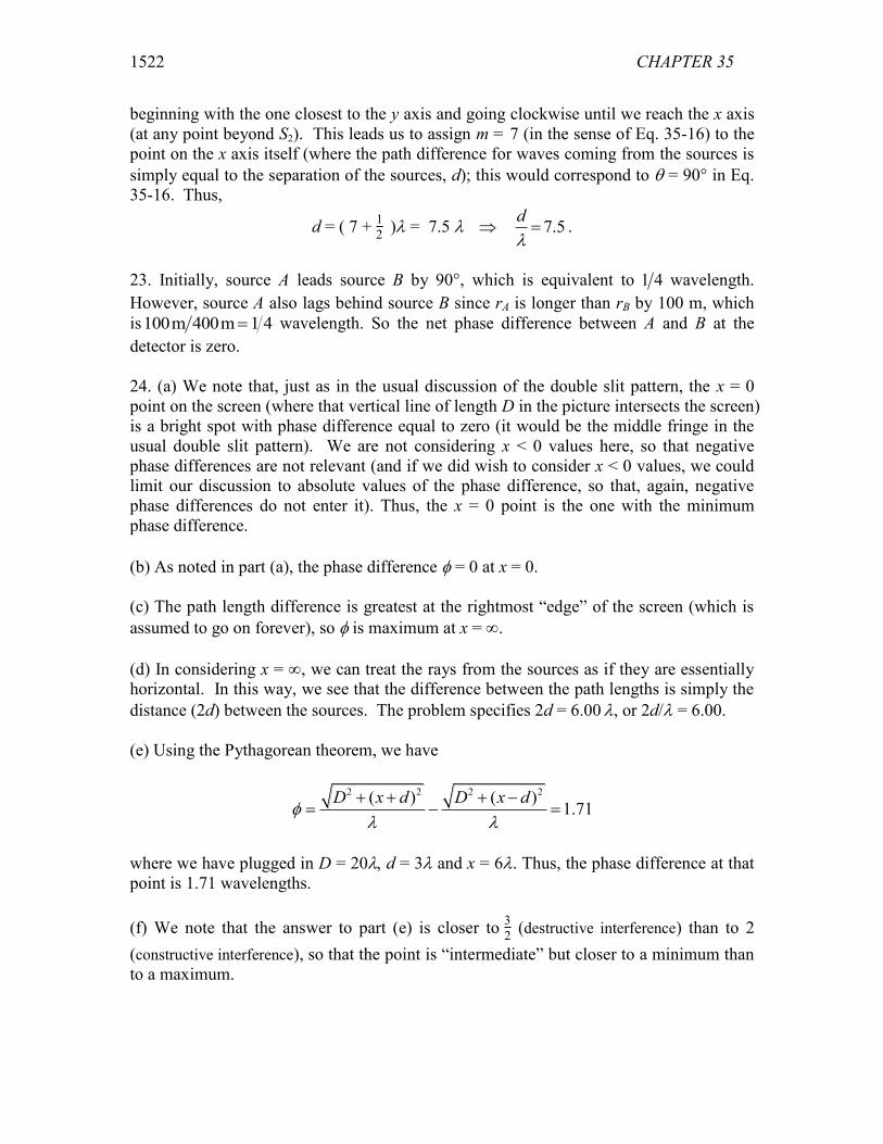
beginning with the one closest to the y axis and going clockwise until we reach the x axis (at any point beyond S2). This leads us to assign m = 7 (in the sense of Eq. 35-16) to the point on the x axis itself (where the path difference for waves coming from the sources is simply equal to the separation of the sources, d); this would correspond to T = 90° in Eq. 35-16. Thus,
d = ( 7 + 12 )O = 7.5 O��� 7.5dO
� .
23. Initially, source A leads source B by 90°, which is equivalent to 1 4 wavelength. However, source A also lags behind source B since rA is longer than rB by 100 m, which is100 1 4m 400m wavelength. So the net phase difference between A and B at the detector is zero. 24. (a) We note that, just as in the usual discussion of the double slit pattern, the x = 0 point on the screen (where that vertical line of length D in the picture intersects the screen) is a bright spot with phase difference equal to zero (it would be the middle fringe in the usual double slit pattern). We are not considering x < 0 values here, so that negative phase differences are not relevant (and if we did wish to consider x < 0 values, we could limit our discussion to absolute values of the phase difference, so that, again, negative phase differences do not enter it). Thus, the x = 0 point is the one with the minimum phase difference. (b) As noted in part (a), the phase difference I = 0 at x = 0. (c) The path length difference is greatest at the rightmost “edge” of the screen (which is assumed to go on forever), so I is maximum at x = f. (d) In considering x = f, we can treat the rays from the sources as if they are essentially horizontal. In this way, we see that the difference between the path lengths is simply the distance (2d) between the sources. The problem specifies 2d = 6.00 O, or 2d/O = 6.00. (e) Using the Pythagorean theorem, we have
2 2 2 2( ) ( )1.71
D x d D x dI
O O� � � �
�
where we have plugged in D = 20O��d = 3O and x = 6O. Thus, the phase difference at that point is 1.71 wavelengths. (f) We note that the answer to part (e) is closer to 32 (destructive interference) than to 2 (constructive interference), so that the point is “intermediate” but closer to a minimum than to a maximum.
1523
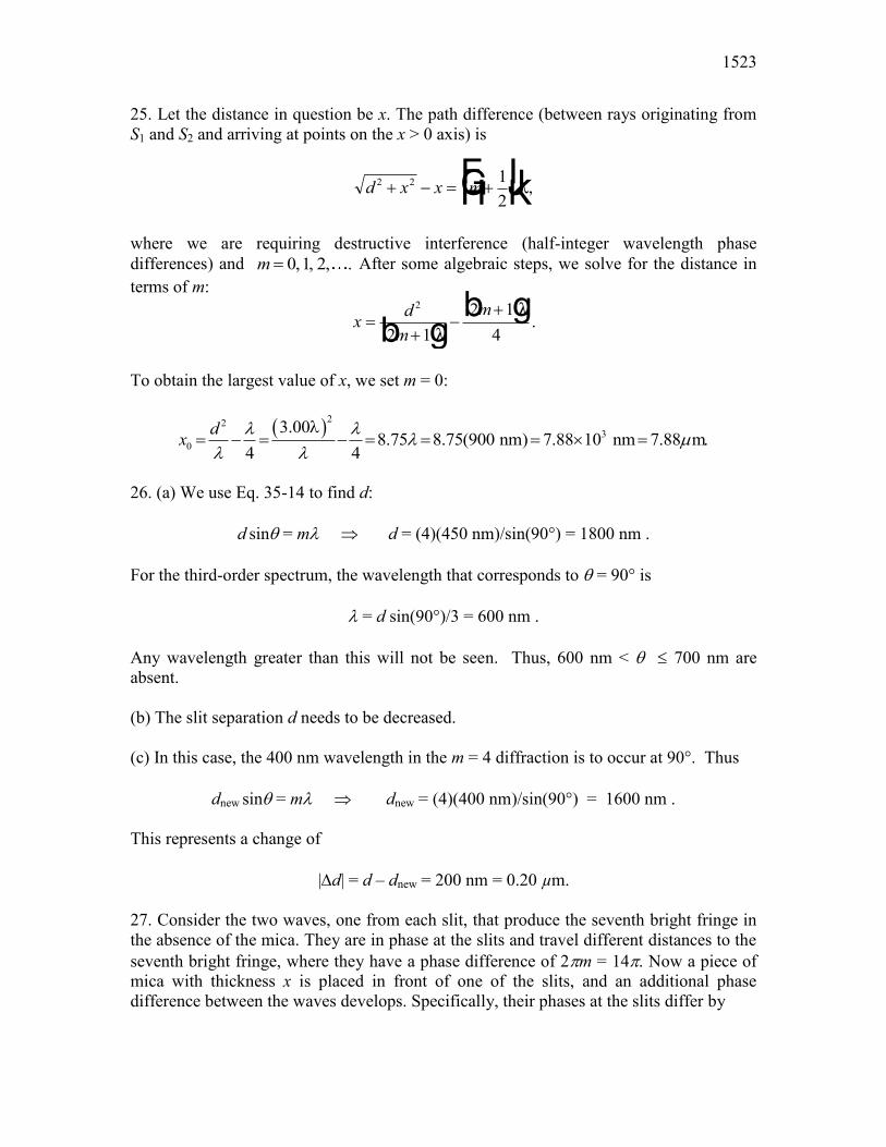
25. Let the distance in question be x. The path difference (between rays originating from S1 and S2 and arriving at points on the x > 0 axis) is
d x x m2 2 12
� � �FHG IKJO� where we are requiring destructive interference (half-integer wavelength phase differences) and 0,1, 2, .m After some algebraic steps, we solve for the distance in terms of m:
x dm
m
��
�2
2 12 1
4b gb g
OO
.
To obtain the largest value of x, we set m = 0:
� �223
0
3.008.75 8.75(900 nm) 7.88 10 nm 7.88 mdx O O O P
O OO
� � u �� �
26. (a) We use Eq. 35-14 to find d:
d sinT = mO � d = (4)(450 nm)/sin(90°) = 1800 nm . For the third-order spectrum, the wavelength that corresponds to T = 90° is
O = d sin(90°)/3 = 600 nm . Any wavelength greater than this will not be seen. Thus, 600 nm < T d 700 nm are absent. (b) The slit separation d needs to be decreased. (c) In this case, the 400 nm wavelength in the m = 4 diffraction is to occur at 90°. Thus
dnew sinT = mO � dnew = (4)(400 nm)/sin(90°) = 1600 nm . This represents a change of
|'d| = d – dnew = 200 nm = 0.20 µm. 27. Consider the two waves, one from each slit, that produce the seventh bright fringe in the absence of the mica. They are in phase at the slits and travel different distances to the seventh bright fringe, where they have a phase difference of 2Sm = 14S. Now a piece of mica with thickness x is placed in front of one of the slits, and an additional phase difference between the waves develops. Specifically, their phases at the slits differ by

CHAPTER 35 1524
2 2 2 1SO
SO
SO
x x x nm
� �b g where Om is the wavelength in the mica and n is the index of refraction of the mica. The relationship Om = O/n is used to substitute for Om. Since the waves are now in phase at the screen,
2 1 14SO
Sx n� b g
or
xn
�
u
� u
��7
17 550 10
158 16 64 10
96O mm.
c h.
.
28. The problem asks for “the greatest value of x… exactly out of phase,” which is to be interpreted as the value of x where the curve shown in the figure passes through a phase value of S radians. This happens as some point P on the x axis, which is, of course, a distance x from the top source and (using Pythagoras’ theorem) a distance d2 + x2 from the bottom source. The difference (in normal length units) is therefore d2 + x2 – x, or (expressed in radians) is
2S�O ( d2 + x2 – x) .
We note (looking at the leftmost point in the graph) that at x = 0, this latter quantity equals 6S, which means d = 3O. Using this value for d, we now must solve the condition
� �2 22 d x xS SO
� � .
Straightforward algebra then leads to x = (35/4)O, and using O = 400 nm we find x = 3500 nm, or 3.5 Pm. 29. THINK The intensity is proportional to the square of the resultant field amplitude. EXPRESS Let the electric field components of the two waves be written as
1 10
2 20
sinsin( ),
E E tE E t
ZZ I
�
where E10 = 1.00, E20 = 2.00, and I = 60°. The resultant field is 1 2E E E � . We use phasor diagram to calculate the amplitude of E. ANALYZE The phasor diagram is shown next.

1525
The resultant amplitude Em is given by the trigonometric law of cosines:
� �2 2 2
10 20 10 202 cos 180 .mE E E E E I � � q�
Thus,
Em � � q 100 2 00 2 100 2 00 120 2 652 2. . . . cos . .b g b g b gb g
LEARN Summing over the horizontal components of the two fields gives
10 20cos0 cos60 1.00 (2.00)cos60 2.00hE E E � q � q ¦ Similarly, the sum over the vertical components is
10 20sin0 sin60 1.00sin0 (2.00)sin60 1.732vE E E � q q� q ¦ . The resultant amplitude is 2 2(2.00) (1.732) 2.65mE � , which agrees with what we found above. The phase angle relative to the phasor representing E1 is
1 1.732tan 40.92.00
E � § · q¨ ¸© ¹
Thus, the resultant field can be written as (2.65)sin( 40.9 ).E tZ � q 30. In adding these with the phasor method (as opposed to, say, trig identities), we may set t = 0 and add them as vectors:
yy
h
v
q� q q� q
10 0 8 0 30 16 910 0 8 0 30 4 0
cos . cos .sin . sin .
so that
y y y
yy
R h v
v
h
�
FHGIKJ q�
2 2
1
17 4
133
.
tan . .E
Thus, y y y y t tR � � � q1 2 17 4 133sin . sin .Z E Zb g b g.

CHAPTER 35 1526
Quoting the answer to two significant figures, we have � �17sin 13y tZ| � q . 31. In adding these with the phasor method (as opposed to, say, trig identities), we may set t = 0 and add them as vectors:
yy
h
v
q� q� � q
q� q� � q
10 0 15 30 50 45 265
10 0 15 30 50 45 4 0
cos cos . cos .
sin sin . sin .b gb g
so that
2 2
1
26.8 27
tan 8.5 .
R h v
v
h
y y y
yy
E �
� |
§ · q¨ ¸
© ¹
Thus, � � � �1 2 3 sin 27sin 8.5Ry y y y y t tZ E Z � � � � q . 32. (a) We can use phasor techniques or use trig identities. Here we show the latter approach. Since
sin a + sin(a + b) = 2cos(b/2)sin(a + b/2), we find 1 2 02 cos( / 2)sin( / 2)E E E tI Z I� � where E0 = 2.00 µV/m, Z�= 1.26 × 10¹⁵ rad/s, and I� �39.6 rad. This shows that the electric field amplitude of the resultant wave is
02 cos( / 2) 2(2.00 V/m)cos(19.2 rad) 2.33 V/mE E I P P . (b) Equation 35-22 leads to
20 04 cos ( / 2) 1.35I I II
at point P, and
2center 0 04 cos (0) 4I I I
at the center. Thus, center/ 1.35/ 4 0.338I I . (c) The phase difference I�(in wavelengths) is gotten from I in radians by dividing by 2S� Thus, I� �������S� ���� wavelengths. Thus, point P is between the sixth side maximum (at which I� �� wavelengths) and the seventh minimum (at which I� ��1
2 wavelengths). (d) The rate is given by Z�= 1.26 × 10¹⁵ rad/s.

1527
(e) The angle between the phasors is I� �39.6 rad = 2270° (which would look like about 110° when drawn in the usual way). 33. With phasor techniques, this amounts to a vector addition problem
G G G GR A B C � �
where (in magnitude-angle notation) G G GA B C � q � q �� q10 0 5 45 5 45b g b g b g, , ,and
where the magnitudes are understood to be in PV/m. We obtain the resultant (especially efficient on a vector-capable calculator in polar mode): G
R � q � � q � �� q � q10 0 5 45 5 45 171 0b gb gb gb g. which leads to
E tR 171. sinP ZV mb g bg where Z = 2.0 u 1014 rad/s. 34. (a) Referring to Figure 35-10(a) makes clear that
T = tan�1(y/D) = tan�1(0.205/4) = 2.93°. Thus, the phase difference at point P is I = dsinT��O = 0.397 wavelengths, which means it is between the central maximum (zero wavelength difference) and the first minimum ( 12 wavelength difference). Note that the above computation could have been simplified somewhat by avoiding the explicit use of the tangent and sine functions and making use of the small-angle approximation (tanT | sinT). (b) From Eq. 35-22, we get (with I = (0.397)(2S) = 2.495 rad)
20 04 cos ( / 2) 0.404I I II
at point P and 2
center 0 04 cos (0) 4I I I at the center. Thus, center/ 0.404/ 4 0.101I I . 35. THINK For complete destructive interference, we want the waves reflected from the front and back of the coating to differ in phase by an odd multiple of S rad. EXPRESS Each wave is incident on a medium of higher index of refraction from a medium of lower index, so both suffer phase changes of S rad on reflection. If L is the thickness of the coating, the wave reflected from the back surface travels a distance 2L farther than the wave reflected from the front. The phase difference is 2L(2S/Oc), where Oc is the wavelength in the coating. If n is the index of refraction of the coating, Oc = O/n, where O is the wavelength in vacuum, and the phase difference is 2nL(2S/O). We solve

CHAPTER 35 1528
2 2 2 1nL mSO
SFHGIKJ �b g
for L. Here m is an integer. The result is Lm
n
�2 14
b gO .
ANALYZE To find the least thickness for which destructive interference occurs, we take m = 0. Then,
� �9
7600 10 m 1.20 10 m.4 1.25
Ln
��u
ul4
LEARN A light ray reflected by a material changes phase by S rad (or 180°) if the refractive index of the material is greater than that of the medium in which the light is traveling. 36. (a) On both sides of the soap is a medium with lower index (air) and we are examining the reflected light, so the condition for strong reflection is Eq. 35-36. With lengths in nm,
O = 2n2Lm + 12
=
°°®°°̄
3360 for m = 01120 for m = 1672 for m = 2480 for m = 3373 for m = 4305 for m = 5
from which we see the latter four values are in the given range. (b) We now turn to Eq. 35-37 and obtain
O = 2n2L
m =
°°®°°̄
1680 for m = 1840 for m = 2560 for m = 3420 for m = 4336 for m = 5
from which we see the latter three values are in the given range. 37. Light reflected from the front surface of the coating suffers a phase change of S rad while light reflected from the back surface does not change phase. If L is the thickness of the coating, light reflected from the back surface travels a distance 2L farther than light reflected from the front surface. The difference in phase of the two waves is 2L(2S/Oc) – S, where Oc is the wavelength in the coating. If O is the wavelength in vacuum, then Oc = O/n, where n is the index of refraction of the coating. Thus, the phase difference is

1529
2nL(2S/O) – S. For fully constructive interference, this should be a multiple of 2S. We solve
2 2 2nL mS S SOFHGIKJ�
for L. Here m is an integer. The solution is
Lm
n
�2 14
b gO .
To find the smallest coating thickness, we take m = 0. Then,
Ln
u
u�
�O4
560 104 2 00
7 00 109
8m m.
. .b g
38. (a) We are dealing with a thin film (material 2) in a situation where n1 > n2 > n3, looking for strong reflections; the appropriate condition is the one expressed by Eq. 35-37. Therefore, with lengths in nm and L = 500 and n2 = 1.7, we have
O = 2n2L
m =
°°®°°̄
1700 for m = 1850 for m = 2567 for m = 3425 for m = 4
from which we see the latter two values are in the given range. The longer wavelength (m=3) is 567 nm.O (b) The shorter wavelength (m = 4) is 425 nm.O (c) We assume the temperature dependence of the refraction index is negligible. From the proportionality evident in the part (a) equation, longer L means longer O. 39. For constructive interference, we use Eq. 35-36:
2 1 22n L m �b gO . For the smallest value of L, let m = 0:
� �0
2
624nm 117nm 0.117 m.2 4 1.33
Ln
PO �
(b) For the second smallest value, we set m = 1 and obtain
CHAPTER 35 1530
� � � �1 02 2
1 1 2 3 3 3 0.1173 m 0.352 m.2 2
L Ln n
O O P P�
40. The incident light is in a low index medium, the thin film of acetone has somewhat higher n = n2, and the last layer (the glass plate) has the highest refractive index. To see very little or no reflection, the condition
� �12
22 where 0,1, 2,L m mn � l
must hold. This is the same as Eq. 35-36, which was developed for the opposite situation (constructive interference) regarding a thin film surrounded on both sides by air (a very different context from the one in this problem). By analogy, we expect Eq. 35-37 to apply in this problem to reflection maxima. Thus, using Eq. 35-37 with n2 = 1.25 and O = 700 nm yields
0, 280nm, 560nm, 840nm,1120nm,L for the first several m values. And the equation shown above (equivalent to Eq. 35-36) gives, with O = 600 nm,
L 120nm,360nm,600nm,840nm,1080nm,! for the first several m values. The lowest number these lists have in common is
840 nm.L 41. In this setup, we have 2 1n n� and 2 3n n! , and the condition for destructive interference is
2 2
1 12 , 0,1, 2,...2 2 2
L m L m mn nO O§ · § · � � � ¨ ¸ ¨ ¸
© ¹ © ¹
The second least thickness is (m = 1)
1 342 nm1 161 nm2 2(1.59)
L § · � ¨ ¸© ¹
.
42. In this setup, we have 2 1n n! and 2 3n n! , and the condition for constructive interference is
2
2
412 , 0,1,2,...2 2 1
LnL m mn mO O§ · � � ¨ ¸ �© ¹
Thus, we get
1531
2
2
4 4(285 nm)(1.60) 1824 nm ( 0)4 / 3 4(285 nm)(1.60) / 3 608 nm ( 1)
Ln mLn m
O
® ¯.
For the wavelength to be in the visible range, we choose m = 1 with 608 nm.O 43. When a thin film of thickness L and index of refraction n2 is placed between materials 1 and 3 such that 1 2n n! and 3 2n n! where n1 and n3 are the indexes of refraction of the materials, the general condition for destructive interference for a thin film is
2
2
22 , 0,1,2,...LnL m mn mO O �
where O is the wavelength of light as measured in air. Thus, we have, for 1m 22 2(200 nm)(1.40) 560 nmLnO . 44. In this setup, we have 2 1n n� and 2 3n n� , and the condition for constructive interference is
2 2
1 12 , 0,1, 2,...2 2 2
L m L m mn nO O§ · § · � � � ¨ ¸ ¨ ¸
© ¹ © ¹
The second least thickness is (m = 1)
1 587 nm1 329 nm2 2(1.34)
L § · � ¨ ¸© ¹
.
45. In this setup, we have 2 1n n! and 2 3n n! , and the condition for constructive interference is
2 2
1 12 , 0,1,2,...2 2 2
L m L m mn nO O§ · § · � � � ¨ ¸ ¨ ¸
© ¹ © ¹
The third least thickness is (m = 2)
1 612 nm2 478 nm2 2(1.60)
L § · � ¨ ¸© ¹
.
46. In this setup, we have 2 1n n� and 2 3n n! , and the condition for destructive interference is

CHAPTER 35 1532
2
2
412 , 0,1,2,...2 2 1
LnL m mn mO O§ · � � ¨ ¸ �© ¹
Therefore,
2
2
2
4 4(415 nm)(1.59) 2639 nm ( 0)4 / 3 4(415 nm)(1.59) / 3 880 nm ( 1)4 / 5 4(415 nm)(1.59) / 5 528 nm ( 2)
Ln mLn mLn m
O
° ®° ¯
.
For the wavelength to be in the visible range, we choose m = 3 with 528 nm.O 47. THINK For a complete destructive interference, we want the waves reflected from the front and back of material 2 of refractive index n2 to differ in phase by an odd multiple of S rad. EXPRESS In this setup, we have 2 1,n n� so there is no phase change from the first surface. On the other hand 2 3n n� , so there is a phase change of S rad from the second surface. Since the second wave travels an extra distance of 2L, the phase difference is
2
2 (2 )LSI SO
�
where O2 2/ nO is the wavelength in medium 2. The condition for destructive interference is
2
2 (2 ) (2 1) ,L mS S SO
� �
or 2
2
22 , 0,1, 2,...LnL m mn mO O �
ANALYZE Thus, we have
2
2
2 2(380 nm)(1.34) 1018 nm ( 1)(380 nm)(1.34) 509 nm ( 2)
Ln mLn m
O
® ¯
For the wavelength to be in the visible range, we choose m = 2 with 509 nm.O LEARN In this setup, the condition for constructive interference is
2
2 (2 ) 2 ,L mS S SO
�
or

1533
2
12 , 0,1, 2,...2
L m mnO§ · � ¨ ¸
© ¹
48. In this setup, we have 2 1n n� and 2 3n n� , and the condition for constructive interference is
2 2
1 12 , 0,1,2,...2 2 2
L m L m mn nO O§ · § · � � � ¨ ¸ ¨ ¸
© ¹ © ¹
The second least thickness is (m = 1)
1 632 nm1 339 nm2 2(1.40)
L § · � ¨ ¸© ¹
.
49. In this setup, we have 2 1n n! and 2 3n n! , and the condition for constructive interference is
2 2
1 12 , 0,1,2,...2 2 2
L m L m mn nO O§ · § · � � � ¨ ¸ ¨ ¸
© ¹ © ¹
The third least thickness is (m = 2)
1 382 nm2 273 nm2 2(1.75)
L § · � ¨ ¸© ¹
.
50. In this setup, we have 2 1n n! and 2 3n n� , and the condition for destructive interference is
2 2
1 12 , 0,1,2,...2 2 2
L m L m mn nO O§ · § · � � � ¨ ¸ ¨ ¸
© ¹ © ¹
The second least thickness is (m = 1)
1 482 nm1 248 nm2 2(1.46)
L § · � ¨ ¸© ¹
.
51. THINK For a complete destructive interference, we want the waves reflected from the front and back of material 2 of refractive index n2 to differ in phase by an odd multiple of S rad. EXPRESS In this setup, we have 1 2n n� and 2 3n n� , which means that both waves are incident on a medium of higher refractive index from a medium of lower refractive index.

CHAPTER 35 1534
Thus, in both cases, there is a phase change of S rad from both surfaces. Since the second wave travels an additional distance of 2L, the phase difference is
2
2 (2 )LSIO
where O2 2/ nO is the wavelength in medium 2. The condition for destructive interference is
2
2 (2 ) (2 1) ,L mS SO
�
or 2
2
412 , 0,1,2,...2 2 1
LnL m mn mO O§ · � � ¨ ¸ �© ¹
ANALYZE Thus,
2
2
4 4(210 nm)(1.46) 1226 nm ( 0)4 / 3 4(210 nm)(1.46) / 3 409 nm ( 1)
Ln mLn m
O
® ¯
For the wavelength to be in the visible range, we choose m = 1 with 409 nm.O LEARN In this setup, the condition for constructive interference is
2
2 (2 ) 2 ,L mS SO
or
2
2 , 0,1, 2,...L m mnO
52. In this setup, we have 2 1n n! and 2 3n n! , and the condition for constructive interference is
2
2
412 , 0,1,2,...2 2 1
LnL m mn mO O§ · � � ¨ ¸ �© ¹
Thus, we have
2
2
2
4 4(325 nm)(1.75) 2275 nm ( 0)4 / 3 4(325 nm)(1.75) / 3 758 nm ( 1)4 / 5 4(325 nm)(1.75) / 5 455 nm ( 2)
Ln mLn mLn m
O
° ®° ¯
.
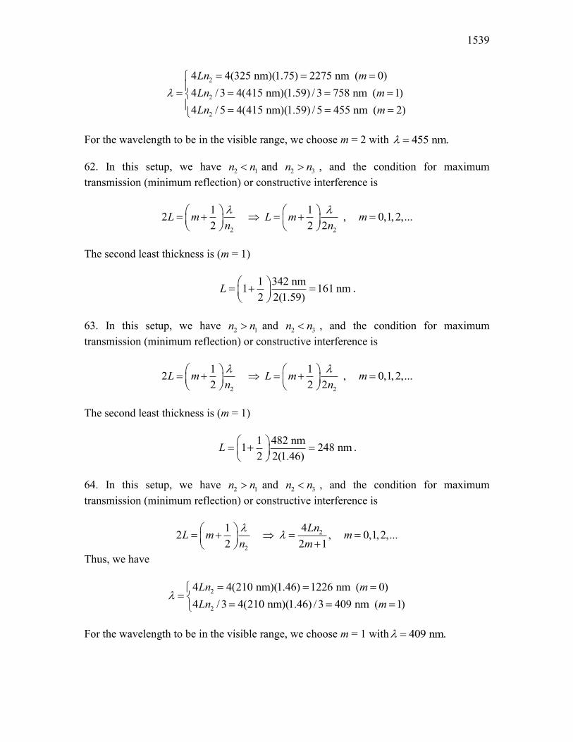
For the wavelength to be in the visible range, we choose m = 2 with 455 nm.O 53. We solve Eq. 35-36 with n2 = 1.33 and O = 600 nm for m = 1, 2, 3,…:

1535
113 nm, 338nm, 564nm, 789nm,L
And, we similarly solve Eq. 35-37 with the same n2 and O = 450 nm:
0,169nm, 338nm, 508nm, 677nm,L The lowest number these lists have in common is L = 338 nm. 54. The situation is analogous to that treated in Sample Problem — “Thin-film interference of a coating on a glass lens,” in the sense that the incident light is in a low index medium, the thin film of oil has somewhat higher n = n2, and the last layer (the glass plate) has the highest refractive index. To see very little or no reflection, according to the Sample Problem, the condition
2
12 where 0,1, 2,2
L m mn
§ · � ¨ ¸© ¹
l
must hold. With O = 500 nm and n2 = 1.30, the possible answers for L are
96nm, 288nm, 481nm, 673nm, 865nm,...L And, with O = 700 nm and the same value of n2, the possible answers for L are
135nm, 404nm, 673nm, 942nm,...L The lowest number these lists have in common is L = 673 nm. 55. THINK The index of refraction of oil is greater than that of the air, but smaller than that of the water. EXPRESS Let the indices of refraction of the air, oil and water be n1, n2, and n3, respectively. Since 1 2n n� and 2 3n n� , there is a phase change of S rad from both surfaces. Since the second wave travels an additional distance of 2L, the phase difference is
2
2 (2 )LSIO
where O2 2/ nO is the wavelength in the oil. The condition for constructive interference is
2
2 (2 ) 2 ,L mS SO
or

CHAPTER 35 1536
2
2 , 0,1, 2,...L m mnO
ANALYZE (a) For 1, 2,...,m maximum reflection occurs for wavelengths
� �� �2 2 1.20 460nm2 1104nm , 552nm, 368nm...n Lm m
l
We note that only the 552 nm wavelength falls within the visible light range. (b) Maximum transmission into the water occurs for wavelengths for which reflection is a minimum. The condition for such destructive interference is given by
2 12
42 12
2L mn
n Lm
�FHG IKJ � �
O O
which yields O = 2208 nm, 736 nm, 442 nm … for the different values of m. We note that only the 442 nm wavelength (blue) is in the visible range, though we might expect some red contribution since the 736 nm is very close to the visible range. LEARN A light ray reflected by a material changes phase by S rad (or 180°) if the refractive index of the material is greater than that of the medium in which the light is traveling. Otherwise, there is no phase change. Note that refraction at an interface does not cause a phase shift. 56. For constructive interference (which is obtained for O�= 600 nm) in this circumstance, we require
22 2nk kL
nOO
where k = some positive odd integer and n is the index of refraction of the thin film. Rearranging and plugging in L = 272.7 nm and the wavelength value, this gives
(600 nm) 0.554 4(272.7 nm) 1.818k k kn k
LO
.
Since we expect n > 1, then k = 1 is ruled out. However, k = 3 seems reasonable, since it leads to n = 1.65, which is close to the “typical” values found in Table 34-1. Taking this to be the correct index of refraction for the thin film, we now consider the destructive interference part of the question. Now we have 2L = (integer)Odest /n. Thus,
Odest = (900 nm)/(integer).

1537
We note that setting the integer equal to 1 yields a Odest value outside the range of the visible spectrum. A similar remark holds for setting the integer equal to 3. Thus, we set it equal to 2 and obtain Odest = 450 nm. 57. In this setup, we have 2 1n n! and 2 3n n! , and the condition for minimum transmission (maximum reflection) or destructive interference is
2
2
412 , 0,1,2,...2 2 1
LnL m mn mO O§ · � � ¨ ¸ �© ¹
Therefore,
2
2
4 4(285 nm)(1.60) 1824 nm ( 0)4 / 3 4(415 nm)(1.59) / 3 608 nm ( 1)
Ln mLn m
O
® ¯
For the wavelength to be in the visible range, we choose m = 1 with 608 nm.O 58. In this setup, we have 2 1n n! and 2 3n n! , and the condition for minimum transmission (maximum reflection) or destructive interference is
2 2
1 12 , 0,1,2,...2 2 2
L m L m mn nO O§ · § · � � � ¨ ¸ ¨ ¸
© ¹ © ¹
The third least thickness is (m = 2)
1 382 nm2 273 nm2 2(1.75)
L § · � ¨ ¸© ¹
.
59. THINK Maximum transmission means constructive interference. EXPRESS As shown in Fig. 35-43, one wave travels a distance of 2L further than the other. This wave is reflected twice, once from the back surface (between materials 2 and 3), and once from the front surface (between materials 1 and 2). Since 2 3n n! , there is no phase change at the back-surface reflection. On the other hand, since 2 1n n� , there is a phase change of S rad due to the front-surface reflection. The phase difference of the two waves as they leave material 2 is
2
2 (2 )LSI SO
�
where O2 2/ nO is the wavelength in material 2. The condition for constructive interference is

CHAPTER 35 1538
2
2 (2 ) 2 ,L mS S SO
�
or 2
2
412 , 0,1,2,...2 2 1
LnL m mn mO O§ · � � ¨ ¸ �© ¹
ANALYZE Thus, we have
2
2
2
4 4(415 nm)(1.59) 2639 nm ( 0)4 / 3 4(415 nm)(1.59) / 3 880 nm ( 1)4 / 5 4(415 nm)(1.59) / 5 528 nm ( 2)
Ln mLn mLn m
O
° ®° ¯
.
For the wavelength to be in the visible range, we choose m = 2 with 528 nm.O LEARN similarly, the condition for destructive interference is
2
2 (2 ) (2 1) ,L mS S SO
� �
or 2
2
22 , 0,1, 2,...LnL m mn mO O �
60. In this setup, we have 2 1n n� and 2 3n n� , and the condition for maximum transmission (minimum reflection) or constructive interference is
2
2
22 , 0,1,2,...LnL m mn mO O �
Thus, we obtain
2
2
2 2(380 nm)(1.34) 1018 nm ( 1)(380 nm)(1.34) 509 nm ( 2)
Ln mLn m
O
® ¯.
For the wavelength to be in the visible range, we choose m = 2 with 509 nm.O 61. In this setup, we have 2 1n n! and 2 3n n! , and the condition for minimum transmission (maximum reflection) or destructive interference is
2
2
412 , 0,1,2,...2 2 1
LnL m mn mO O§ · � � ¨ ¸ �© ¹
Therefore,
1539
2
2
2
4 4(325 nm)(1.75) 2275 nm ( 0)4 / 3 4(415 nm)(1.59) / 3 758 nm ( 1)4 / 5 4(415 nm)(1.59) / 5 455 nm ( 2)
Ln mLn mLn m
O
° ®° ¯
For the wavelength to be in the visible range, we choose m = 2 with 455 nm.O 62. In this setup, we have 2 1n n� and 2 3n n! , and the condition for maximum transmission (minimum reflection) or constructive interference is
2 2
1 12 , 0,1,2,...2 2 2
L m L m mn nO O§ · § · � � � ¨ ¸ ¨ ¸
© ¹ © ¹
The second least thickness is (m = 1)
1 342 nm1 161 nm2 2(1.59)
L § · � ¨ ¸© ¹
.
63. In this setup, we have 2 1n n! and 2 3n n� , and the condition for maximum transmission (minimum reflection) or constructive interference is
2 2
1 12 , 0,1,2,...2 2 2
L m L m mn nO O§ · § · � � � ¨ ¸ ¨ ¸
© ¹ © ¹
The second least thickness is (m = 1)
1 482 nm1 248 nm2 2(1.46)
L § · � ¨ ¸© ¹
.
64. In this setup, we have 2 1n n! and 2 3n n� , and the condition for maximum transmission (minimum reflection) or constructive interference is
2
2
412 , 0,1,2,...2 2 1
LnL m mn mO O§ · � � ¨ ¸ �© ¹
Thus, we have
2
2
4 4(210 nm)(1.46) 1226 nm ( 0)4 / 3 4(210 nm)(1.46) / 3 409 nm ( 1)
Ln mLn m
O
® ¯
For the wavelength to be in the visible range, we choose m = 1 with 409 nm.O

CHAPTER 35 1540
65. In this setup, we have 2 1n n� and 2 3n n� , and the condition for minimum transmission (maximum reflection) or destructive interference is
2 2
1 12 , 0,1,2,...2 2 2
L m L m mn nO O§ · § · � � � ¨ ¸ ¨ ¸
© ¹ © ¹
The second least thickness is (m = 1)
1 632 nm1 339 nm2 2(1.40)
L § · � ¨ ¸© ¹
.
66. In this setup, we have 2 1n n� and 2 3n n� , and the condition for maximum transmission (minimum reflection) or constructive interference is
2
2
22 , 0,1,2,...LnL m mn mO O �
Thus, we have (with m =1) 22 2(200 nm)(1.40) 560 nmLnO . 67. In this setup, we have 2 1n n� and 2 3n n� , and the condition for minimum transmission (maximum reflection) or destructive interference is
2 2
1 12 , 0,1,2,...2 2 2
L m L m mn nO O§ · § · � � � ¨ ¸ ¨ ¸
© ¹ © ¹
The second least thickness is (m = 1)
1 587 nm1 329 nm2 2(1.34)
L § · � ¨ ¸© ¹
.
68. In this setup, we have 2 1n n! and 2 3n n! , and the condition for minimum transmission (maximum reflection) or destructive interference is
2 2
1 12 , 0,1,2,...2 2 2
L m L m mn nO O§ · § · � � � ¨ ¸ ¨ ¸
© ¹ © ¹
The third least thickness is (m = 2)
1 612 nm2 478 nm2 2(1.60)
L § · � ¨ ¸© ¹
.
1541
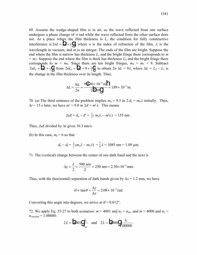
69. Assume the wedge-shaped film is in air, so the wave reflected from one surface undergoes a phase change of S rad while the wave reflected from the other surface does not. At a place where the film thickness is L, the condition for fully constructive interference is 2 1
2nL m �b gO� where n is the index of refraction of the film, O is the wavelength in vacuum, and m is an integer. The ends of the film are bright. Suppose the end where the film is narrow has thickness L1 and the bright fringe there corresponds to m = m1. Suppose the end where the film is thick has thickness L2 and the bright fringe there corresponds to m = m2. Since there are ten bright fringes, m2 = m1 + 9. Subtract 2 1 1
12nL m �b gO from 2 92 1
12nL m � �b gO to obtain 2n 'L = 9O, where 'L = L2 – L1 is
the change in the film thickness over its length. Thus,
'Ln
u
u�
�9 9 630 102 150
189 109
6O�
mm.
c hb g.
.
70. (a) The third sentence of the problem implies mo = 9.5 in 2 do = moO initially. Then, 't = 15 s later, we have mc = 9.0 in 2dc = mcO. This means
|'d| = do � dc = 12 ( moO�� mcO) = 155 nm . Thus, |'d| divided by 't gives 10.3 nm/s. (b) In this case, mf = 6 so that
do � df = 12 (moO�� mf O) = 74 O = 1085 nm = 1.09 µm. 71. The (vertical) change between the center of one dark band and the next is
4500 nm 250 nm 2.50 10 mm.2 2
y O �' u
Thus, with the (horizontal) separation of dark bands given by 'x = 1.2 mm, we have
T T| u �tan .''
yx
2 08 10 4 rad.
Converting this angle into degrees, we arrive at T = 0.012°. 72. We apply Eq. 35-27 to both scenarios: m = 4001 and n2 = nair, and m = 4000 and n2 = nvacuum = 1.00000:
2 4001 4000Ln
L b g b gO O�������air
and 2 .
CHAPTER 35 1542
Since the 2L factor is the same in both cases, we set the right-hand sides of these expressions equal to each other and cancel the wavelength. Finally, we obtain
nair 100000 40014000
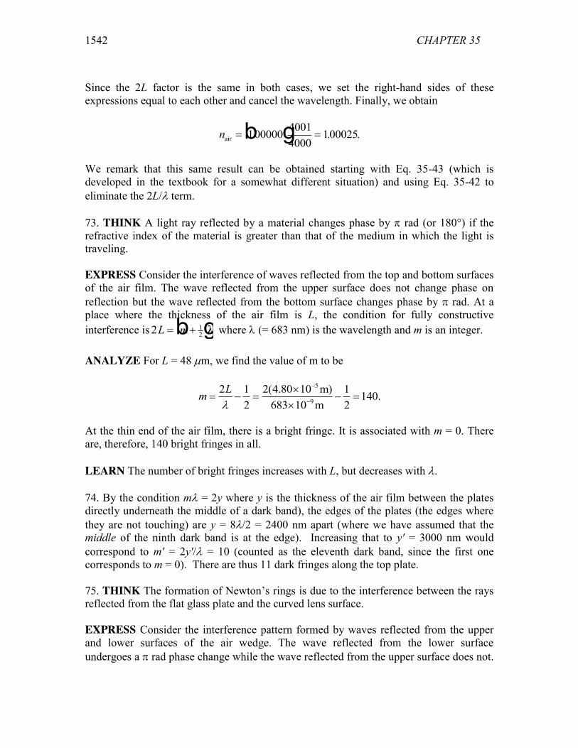
100025. . .b g
We remark that this same result can be obtained starting with Eq. 35-43 (which is developed in the textbook for a somewhat different situation) and using Eq. 35-42 to eliminate the 2L/O term. 73. THINK A light ray reflected by a material changes phase by S rad (or 180°) if the refractive index of the material is greater than that of the medium in which the light is traveling. EXPRESS Consider the interference of waves reflected from the top and bottom surfaces of the air film. The wave reflected from the upper surface does not change phase on reflection but the wave reflected from the bottom surface changes phase by S rad. At a place where the thickness of the air film is L, the condition for fully constructive interference is 2 1
2L m �b gO where O (= 683 nm) is the wavelength and m is an integer. ANALYZE For L = 48 Pm, we find the value of m to be
5
9
2 1 2(4.80 10 m) 1 140.2 683 10 m 2
LmO
�
�
u � �
u
At the thin end of the air film, there is a bright fringe. It is associated with m = 0. There are, therefore, 140 bright fringes in all. LEARN The number of bright fringes increases with L, but decreases with O. 74. By the condition mO = 2y where y is the thickness of the air film between the plates directly underneath the middle of a dark band), the edges of the plates (the edges where they are not touching) are y = 8O/2 = 2400 nm apart (where we have assumed that the middle of the ninth dark band is at the edge). Increasing that to y' = 3000 nm would correspond to m' = 2y'/O = 10 (counted as the eleventh dark band, since the first one corresponds to m = 0). There are thus 11 dark fringes along the top plate. 75. THINK The formation of Newton’s rings is due to the interference between the rays reflected from the flat glass plate and the curved lens surface. EXPRESS Consider the interference pattern formed by waves reflected from the upper and lower surfaces of the air wedge. The wave reflected from the lower surface undergoes a S rad phase change while the wave reflected from the upper surface does not.
1543
At a place where the thickness of the wedge is d, the condition for a maximum in intensity is 2 1
2d m �b gO� where O is the wavelength in air and m is an integer. Therefore,
d = (2m + 1)O/4. ANALYZE As the geometry of Fig. 35-46 shows, d R R r � �2 2 , where R is the radius of curvature of the lens and r is the radius of a Newton’s ring. Thus, 2 1 2 2m R R r� � �b gO � . First, we rearrange the terms so the equation becomes
� �2 2 2 1
.4
mR r R
�� �
l
Next, we square both sides, rearrange to solve for r2, then take the square root. We get
rm R m
�
��2 1
22 1
16
2b g b gO O�
.
If R is much larger than a wavelength, the first term dominates the second and
rm R
�2 12
b gO.
LEARN Similarly, the radii of the dark fringes are given by
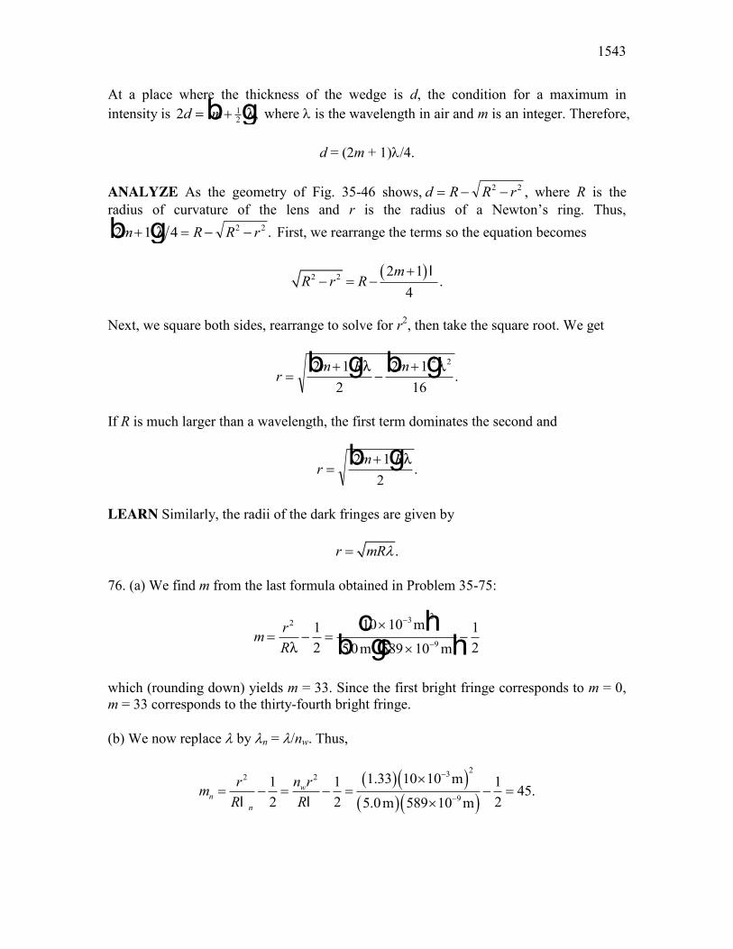
.r mRO 76. (a) We find m from the last formula obtained in Problem 35-75:
m rR
� u
u�
�
�
2 3 2
9
12
10 10
50 589 1012O
m
m mc h
b gc h.
which (rounding down) yields m = 33. Since the first bright fringe corresponds to m = 0, m = 33 corresponds to the thirty-fourth bright fringe. (b) We now replace O by On = O/nw. Thus,
� �� �� �� �
2322
9
1.33 10 10 m1 1 1 45.2 2 25.0m 589 10 m
wn
n
n rrmR R
�
�
u � � �
ul l

CHAPTER 35 1544
This corresponds to the forty-sixth bright fringe (see the remark at the end of our solution in part (a)). 77. We solve for m using the formula r m R �2 1b gO � obtained in Problem 35-75 and find m = r2/RO – 1/2. Now, when m is changed to m + 20, r becomes r', so
m + 20 = r' 2/RO – 1/2. Taking the difference between the two equations above, we eliminate m and find
R r r
c �
�
u
�
2 2 2 2
7200 368 0162
20 546 10100
O. .cm cm
cmcm.b g b g
c h
78. The time to change from one minimum to the next is 't = 12 s. This involves a change in thickness 'L = O/2n2 (see Eq. 35-37), and thus a change of volume
'V = Sr²'L =2
²2rn
S O � 2
²2
dV rdt n t
S O
' = S(0.0180)² (550 x 10-9)
2(1.40) (12)
using SI units. Thus, the rate of change of volume is 1.67 × 10�11 m3/s. 79. A shift of one fringe corresponds to a change in the optical path length of one wavelength. When the mirror moves a distance d, the path length changes by 2d since the light traverses the mirror arm twice. Let N be the number of fringes shifted. Then, 2d = NO and
O u
u �
�2 2 0 233 10792
588 10 5883
7dN
..
mm nm .
c h
80. According to Eq. 35-43, the number of fringes shifted ('N) due to the insertion of the film of thickness L is 'N = (2L / O) (n – 1). Therefore,
L Nn
�
�
O'
2 1589 7 02 140 1
52b gb gb gb g
nmm
..
. .P
81. THINK The wavelength in air is different from the wavelength in vacuum. EXPRESS Let I1 be the phase difference of the waves in the two arms when the tube has air in it, and let I2 be the phase difference when the tube is evacuated. If O is the wavelength in vacuum, then the wavelength in air is O/n, where n is the index of refraction of air. This means
I I1 2 2 2 2 4 1� �LNM OQP
�L n n LS
OSO
SOb g

1545
where L is the length of the tube. The factor 2 arises because the light traverses the tube twice, once on the way to a mirror and once after reflection from the mirror. Each shift by one fringe corresponds to a change in phase of 2S rad, so if the interference pattern shifts by N fringes as the tube is evacuated, then
4 12
SO
Sn L
N�
b g .
ANALYZE Solving for n, we obtain
n NL
� �u
u
�
�1
21
60 500 10
2 50 10100030
9
2
O m
mc hc h.
. .
LEARN The interferometer provides an accurate way to measure the refractive index of the air (and other gases as well). 82. We apply Eq. 35-42 to both wavelengths and take the difference:
1 22 2 1 12 .L LN N L� � � �
§ ·� � �¨ ¸O O O O© ¹
We now require N1 – N2 = 1 and solve for L:
1 151 1 1 1 1 1 2.91 10 nm 291 m.
2 2 588.9950 nm 589.5924 nmL P
� �
� �
§ · § · � � u ¨ ¸ ¨ ¸O O © ¹© ¹
83. (a) The path length difference between rays 1 and 2 is 7d – 2d = 5d. For this to correspond to a half-wavelength requires 5d = O/2, so that d = 50.0 nm. (b) The above requirement becomes 5d = O/2n in the presence of the solution, with n = 1.38. Therefore, d = 36.2 nm. 84. (a) The minimum path length difference occurs when both rays are nearly vertical. This would correspond to a point as far up in the picture as possible. Treating the screen as if it extended forever, then the point is at y = f. (b) When both rays are nearly vertical, there is no path length difference between them. Thus at y = f, the phase difference is I = 0. (c) At y = 0 (where the screen crosses the x axis) both rays are horizontal, with the ray from S1 being longer than the one from S2 by distance d.

CHAPTER 35 1546
(d) Since the problem specifies d = 6.00O, then the phase difference here is I = 6.00 wavelengths and is at its maximum value. (e) With D = 20O��use of the Pythagorean theorem leads to
I = L1 � L2
�O = �d² + (d + D)² � d² + D²
�O = 5.80
which means the rays reaching the point y = d have a phase difference of roughly 5.8 wavelengths. (f) The result of the previous part is “intermediate” — closer to 6 (constructive interference) than to 5
12 (destructive interference).
85. THINK The angle between adjacent fringes depends the wavelength of the light and the distance between the slits. EXPRESS The angular positions of the maxima of a two-slit interference pattern are given by sinL d mT O' , where 'L is the path-length difference, d is the slit separation, O is the wavelength, and m is an integer. If T is small, sin T may be approximated by T in radians. Then, T = mO/d to good approximation. The angular separation of two adjacent maxima is 'T = O/d. When the arrangement is immersed in water, the wavelength changes to O' = O/n, and the equation above becomes
dOTc
c' .
ANALYZE Dividing the equation by 'T = O/d, we obtain
''
c
c
TT
OO
�n
.
Therefore, with n = 1.33 and 'T = 0.30°, we find 'T�' = 0.23°. LEARN The angular separation decreases with increasing index of refraction; the greater the value of n, the smaller the value of 'T. 86. (a) The graph shows part of a periodic pattern of half-cycle “length” 'n = 0.4. Thus if we set n = 1.0 + 2'n = 1.8 then the maximum at n = 1.0 should repeat itself there. (b) Continuing the reasoning of part (a), adding another half-cycle “length” we get 1.8 2.2n�' for the answer.
1547
(c) Since 'n = 0.4 represents a half-cycle, then 'n/2 represents a quarter-cycle. To accumulate a total change of 2.0 – 1.0 = 1.0 (see problem statement), then we need 2'n + 'n/2 = 5/4th of a cycle, which corresponds to 1.25 wavelengths. 87. THINK For a completely destructive interference, the intensity produced by the two waves is zero. EXPRESS When the interference between two waves is completely destructive, their phase difference is given by (2 1) , 0,1, 2,...m mI S � The equivalent condition is that their path-length difference is an odd multiple of / 2,O where O is the wavelength of the light. ANALYZE (a) Looking at Fig. 35-52, we see that half of the periodic pattern is of length 'L = 750 nm (judging from the maximum at x = 0 to the minimum at x = 750 nm); this suggests that 'L = O/2, and the wavelength (the full length of the periodic pattern) is O�= 2'L = 1500 nm. Thus, a maximum should be reached again at x = 1500 nm (and at x = 3000nm, x = 4500 nm, …). (b) From our discussion in part (a), we expect a minimum to be reached at odd multiple of O/2, or x = 750 nm + n(1500 nm), where n = 1, 2, 3 … . For instance, for n = 1 we would find the minimum at x = 2250 nm. (c) With O�= 1500 nm (found in part (a)), we can express x = 1200 nm as x = 1200/1500 = 0.80 wavelength. LEARN For a completely destructive interference, the phase difference between two light sources is an odd multiple of S; however, for a completely constructive interference, the phase difference is a multiple of 2S� 88. (a) The difference in wavelengths, with and without the n = 1.4 material, is found using Eq. 35-9:
( 1) 1.143LN nO
' � .
The result is equal to a phase shift of (1.143)(360q) = 411.4q, or (b) more meaningfully, a shift of 411.4q � 360q = 51.4q. 89. THINK Since the index of refraction of water is greater than that of air, the wave that is reflected from the water surface suffers a phase change of S rad on reflection.

CHAPTER 35 1548
EXPRESS Suppose the wave that goes directly to the receiver travels a distance L1 and the reflected wave travels a distance L2. The last wave suffers a phase change on reflection of half a wavelength since water has higher refractive index than air. To obtain constructive interference at the receiver, the difference L2 – L1 must be an odd multiple of a half wavelength. ANALYZE Consider the diagram below.
The right triangle on the left, formed by the vertical line from the water to the transmitter T, the ray incident on the water, and the water line, gives Da = a/ tan T. The right triangle on the right, formed by the vertical line from the water to the receiver R, the reflected ray, and the water line leads to / tanbD x T . Since Da + Db = D,
tan .T �a xD
We use the identity sin2 T = tan2 T / (1 + tan2 T) to show that
2 2sin ( ) / ( )a x D a xT � � � . This means
L a a D a xa xa2
2 2
� �
�sinTb g
and
� �22
2 .sinb
x D a xxLa xT� �
�
Therefore,
L L La x D a x
a xD a xa b2 2 2
2 22 2 �
� � �
� � �
b g b g b g.
Using the binomial theorem, with D2 large and a2 + x2 small, we approximate this expression: � �2
2 / 2 .L D a x D| � � The distance traveled by the direct wave is

1549
L D a x12 2 � �b g. Using the binomial theorem, we approximate this expression:
� �21 / 2 .L D a x D| � � Thus,
L L D a ax xD
D a ax xD
axD2 1
2 2 2 222
22
2� | �
� �� �
� � .
Setting this equal to m� 1
2b gO , where m is zero or a positive integer, we find
� �� �12 2x m D aO � .
LEARN Similarly, the condition for destructive interference is
2 12 ,axL L mD
O� |
or
, 0,1, 2,...2Dx m ma
O
90. (a) Since P1 is equidistant from S1 and S2 we conclude the sources are not in phase with each other. Their phase difference is 'Isource = 0.60 S rad, which may be expressed in terms of “wavelengths” (thinking of the O � 2S correspondence in discussing a full cycle) as
'Isource = (0.60 S����S)�O = 0.3 O (with S2 “leading” as the problem states). Now S1 is closer to P2 than S2 is. Source S1 is 80 nm (� 80/400 O = 0.2 O ) from P2 while source S2 is 1360 nm (� 1360/400 O = 3.4 O ) from P2. Here we find a difference of 'Ipath = 3.2 O (with S1 “leading” since it is closer). Thus, the net difference is
'Inet = 'Ipath – 'Isource = 2.90 O, or 2.90 wavelengths. (b) A whole number (like 3 wavelengths) would mean fully constructive, so our result is of the following nature: intermediate, but close to fully constructive. 91. (a) Applying the law of refraction, we obtain sin T2 / sin T1 = sin T2 / sin 30° = vs/vd. Consequently,
� �1 12
3.0m s sin30sin30sin sin 22 .4.0m s
s
d
vv
T � � qª º§ ·q q¨ ¸ « »
© ¹ ¬ ¼

CHAPTER 35 1550
(b) The angle of incidence is gradually reduced due to refraction, such as shown in the calculation above (from 30° to 22°). Eventually after several refractions, T2 will be virtually zero. This is why most waves come in normal to a shore. 92. When the depth of the liquid (Lliq ) is zero, the phase difference I is 60 wavelengths; this must equal the difference between the number of wavelengths in length L = 40 µm (since the liquid initially fills the hole) of the plastic (for ray r1) and the number in that same length of the air (for ray r2). That is,
plastic air 60Ln LnO O
� .
(a) Since O�= 400 × 10�9 m and nair = 1 (to good approximation), we find nplastic = 1.6. (b) The slope of the graph can be used to determine nliq , but we show an approach more closely based on the above equation:
plastic liq 20Ln LnO O
�
which makes use of the leftmost point of the graph. This readily yields nliq = 1.4. 93. THINK Knowing the slit separation and the distance between interference fringes allows us to calculate the wavelength of the light used. EXPRESS The condition for a minimum in the two-slit interference pattern is d sin T = (m + ½)O, where d is the slit separation, O is the wavelength, m is an integer, and T is the angle made by the interfering rays with the forward direction. If T is small, sin T may be approximated by T in radians. Then, T = (m + ½)O/d, and the distance from the minimum to the central fringe is
1tan sin2
Dy D D D mdOT T T § · | | �¨ ¸
© ¹,
where D is the distance from the slits to the screen. For the first minimum m = 0 and for the tenth one, m = 9. The separation is
1 1 992 2
D D Dyd d dO O O§ ·' � � ¨ ¸
© ¹.
ANALYZE We solve for the wavelength:
O u u
u u
� �
��d y
D'
9015 10 18 10
9 50 106 0 10 600
3 3
27
..
m m
mm nm.
c hc hc h

1551
LEARN The distance between two adjacent dark fringes, one associated with the integer m and the other associated with the integer m + 1, is
'y = DT = DO/d. 94. A light ray traveling directly along the central axis reaches the end in time
t Lv
n Lcdirect
1
1 .
For the ray taking the critical zig-zag path, only its velocity component along the core axis direction contributes to reaching the other end of the fiber. That component is v1 cos T�', so the time of travel for this ray is
� �1
zig zag 21 1cos 1 sin /
n LLtv c nT T
c �
using results from the previous solution. Plugging in sinT �n n1
222 and simplifying,
we obtain
t n Lc n n
n Ln czig zag 1
2 1
12
2/.b g
The difference is
21 1 1 1
zig zag direct2 2
1n L n L n L nt t tn c c c n
§ ·' � � �¨ ¸
© ¹ .
With n1 = 1.58, n2 = 1.53, and L = 300 m, we obtain
81 18
2
(1.58)(300 m) 1.581 1 5.16 10 s 51.6 ns3.0 10 m/s 1.53
n L ntc n
�§ · § ·' � � u ¨ ¸ ¨ ¸u © ¹© ¹.
95. THINK The dark band corresponds to a completely destructive interference. EXPRESS When the interference between two waves is completely destructive, their phase difference is given by (2 1) , 0,1, 2,...m mI S � The equivalent condition is that their path-length difference is an odd multiple of / 2,O where O is the wavelength of the light.

CHAPTER 35 1552
ANALYZE (a) A path length difference of O/2 produces the first dark band, of 3O/2 produces the second dark band, and so on. Therefore, the fourth dark band corresponds to a path length difference of 7O/2 = 1750 nm = 1.75 Pm. (b) In the small angle approximation (which we assume holds here), the fringes are equally spaced, so that if 'y denotes the distance from one maximum to the next, then the distance from the middle of the pattern to the fourth dark band must be 16.8 mm = 3.5 'y. Therefore, we obtain 'y = (16.8 mm)/3.5 = 4.8 mm. LEARN The distance from the mth maximum to the central fringe is
bright tan sin Dy D D D mdOT T T | | .
Similarly, the distance from the mth minimum to the central fringe is
dark12
Dy mdO§ · �¨ ¸
© ¹.
96. We use the formula obtained in Sample Problem — “Thin-film interference of a coating on a glass lens:”
� �min
min2
0.200 0.200.4 4 1.25
LLn OO O
O �
97. THINK The intensity of the light observed in the interferometer depends on the phase difference between the two waves. EXPRESS Let the position of the mirror measured from the point at which d1 = d2 be x. We assume the beam-splitting mechanism is such that the two waves interfere constructively for x = 0 (with some beam-splitters, this would not be the case). We can adapt Eq. 35-23 to this situation by incorporating a factor of 2 (since the interferometer utilizes directly reflected light in contrast to the double-slit experiment) and eliminating the sinT factor. Thus, the path difference is 2x, and the phase difference between the two light paths is 'I = 2(2Sx/O) = 4Sx/O. ANALYZE From Eq. 35-22, we see that the intensity is proportional to 2cos ( / 2).I' Thus, writing 4I0 as Im, we find
I I I xm m FHGIKJ FHG IKJcos cos .2 2
22'I SO
LEARN The intensity / mI I as a function of /x O is plotted below.

1553
From the figure, we see that the intensity is at a maximum when
, 0,1, 2,...2mx mO
Similarly, the condition for minima is
� �1 2 1 , 0,1, 2,...4
x m mO �
98. We note that ray 1 travels an extra distance 4L more than ray 2. For constructive interference (which is obtained for O�= 620 nm) we require
4L = mO������ where m = some positive integer.
For destructive interference (which is obtained for Oc�= 4196 nm) we require
4L = k2 Oc����� where k = some positive odd integer.
Equating these two equations (since their left-hand sides are equal) and rearranging, we obtain
k = 2 m O�Oc = 2 m 620496 = 2.5 m .
We note that this condition is satisfied for k = 5 and m = 2. It is satisfied for some larger values, too, but recalling that we want the least possible value for L, we choose the solution set (k, m) = (5, 2). Plugging back into either of the equations above, we obtain the distance L:
4L = 2O � L = O2 = 310.0 nm .
99. (a) Straightforward application of Eq. 35-3 /n c v and v = 'x/'t yields the result: pistol 1 with a time equal to 't = n'x/c = 42.0 u 10–12 s = 42.0 ps.

CHAPTER 35 1554
(b) For pistol 2, the travel time is equal to 42.3 u 10–12 s. (c) For pistol 3, the travel time is equal to 43.2 u 10–12 s. (d) For pistol 4, the travel time is equal to 41.8 u 10–12 s. (e) We see that the blast from pistol 4 arrives first. 100. We use Eq. 35-36 for constructive interference: 2n2L = (m + 1/2)O, or
O �
�
�
21 2
2 150 4101 2
12301 2
2n Lm m m
.,b gb gnm nm
where m = 0, 1, 2, …. The only value of m which, when substituted into the equation above, would yield a wavelength that falls within the visible light range is m = 1. Therefore,
O �
12301 1 2
492nm nm .
101. In the case of a distant screen the angle T is close to zero so sin T | T. Thus from Eq. 35-14,
sin ,m md d dO O OT T § ·' |' ' ' ¨ ¸
© ¹
or d | O/'T = 589 u 10–9 m/0.018 rad = 3.3 u 10–5 m = 33 Pm.
102. We note that 'I = 60° = S3 rad. The phasors rotate with constant angular velocity
1516
/ 3 rad 4.19 10 rad/s2.5 10 st
I SZ �
' u' u
.
Since we are working with light waves traveling in a medium (presumably air) where the wave speed is approximately c, then kc = Z (where k = 2S�O), which leads to
O�= cSZ� = 450 nm.
103. (a) Each wave is incident on a medium of higher index of refraction from a medium of lower index (air to oil, and oil to water), so both suffer phase changes of S rad on reflection. If L is the thickness of the oil, the wave reflected from the back surface travels a distance 2L farther than the wave reflected from the front. The phase difference is 2L(2S/Oo), where Oo is the wavelength in oil. If n is the index of refraction of the oil, Oo =

1555
O/n, where O is the wavelength in vacuum, and the phase difference is 2nL(2S/O). The conditions for constructive and destructive interferences are
� � � �12
2constructive : 2 2 2 , 0,1,2,
2destructive : 2 2 1 2 , 0,1,2,
nL m nL m m
nL m nL m m
S S OOS S OO
§ · � ¨ ¸© ¹§ · � � � ¨ ¸© ¹
Near the rim of the drop, / 4 ,L nO� so only the condition for constructive interference with m = 0 can be met. So the outer (thinnest) region is bright. (b) The third band from the rim corresponds to 2 3 / 2.nL O Thus, the film thickness there is
3 3(475 nm) 594 nm.2 2(1.20)
LnO
(c) The primary reason why colors gradually fade and then disappear as the oil thickness increases is because the colored bands begin to overlap too much to be distinguished. Also, the two reflecting surfaces would be too separated for the light reflecting from them to be coherent. 104. (a) The combination of the direct ray and the reflected ray from the mirror will produce an interference pattern on the screen, like the double-slit experiment. However, in this case, the reflected ray has a phase change of S, causing the locations of the dark and bright fringes to be interchanged. Thus, a zero path difference would correspond to a dark fringe. (b) The condition for constructive interferences is
122 sin ( ) , 0,1,2,h m mT O �
(c) Similarly, the condition for destructive interference is
2 sin , 0,1,2,h m mT O 105. The Hint essentially answers the question, but we put in some algebraic details and arrive at the familiar analytic-geometry expression for a hyperbola. The distance d/2 is denoted a and the constant value for the path length difference is denoted I:
r1 – r2 = I�
(a+x) ² + y² - (a-x)² + y² = I Rearranging and squaring, we have

CHAPTER 35 1556
( )(a+x) ² + y² ² = ( )(a-x)² + y² + I ² a² � 2ax + x² + y² = a² � 2ax + x² + y² + I² + 2�I (a-x)² + y² Many terms on both sides are identical and may be eliminated. This leaves us with
�2�I (a-x)² + y² = I² � 4ax at which point we square both sides again:
4�I²a² �8�I²ax + 4�I²x² +4�I²y² = I4�8�I²ax +16a²x² We eliminate the �8�I²ax term from both sides and plug in a = 2d to get back to the original notation used in the problem statement:
I²d² + 4�I² x² + 4�I² y² = I4 + 4 d² x² Then a simple rearrangement puts it in the familiar analytic format for a hyperbola: I²d² � I4 = 4(d²� I²)x² ���4�I² y² which can be further simplified by dividing through by I²d² � I4:
2 22 2 2
4 41 x ydI I
§ · § · �¨ ¸ ¨ ¸�© ¹ © ¹
.