chapter 3 - GradeBuddy
37
C C H H A A P P T T E E R R 3 3
-
Upload
khangminh22 -
Category
Documents
-
view
8 -
download
0
Transcript of chapter 3 - GradeBuddy

CCHHAAPPTTEERR 33


PROPRIETARY MATERIAL. Copyright © 2015 McGraw-Hill Education. This is proprietary material solely for authorized instructor use.
Not authorized for sale or distribution in any manner. This document may not be copied, scanned, duplicated, forwarded, distributed, or posted
on a website, in whole or part.
261
T
18 mm
PROBLEM 3.1
Determine the torque T that causes a maximum shearing stress of 70 MPa in the steel cylindrical shaft shown.
SOLUTION
4max
3max
3 6
;2
2
(0.018 m) (70 10 Pa)2641.26 N m
TcJ c
J
T c
641 N m T

PROPRIETARY MATERIAL. Copyright © 2015 McGraw-Hill Education. This is proprietary material solely for authorized instructor use.
Not authorized for sale or distribution in any manner. This document may not be copied, scanned, duplicated, forwarded, distributed, or posted
on a website, in whole or part.
262
T
18 mm
PROBLEM 3.2
For the cylindrical shaft shown, determine the maximum shearing stress caused by a torque of magnitude T 800 N m.
SOLUTION
4max
max 3
3
6
;2
2
2(800 N m)
(0.018 m)
87.328 10 Pa
TcJ c
JT
c
max 87.3 MPa

PROPRIETARY MATERIAL. Copyright © 2015 McGraw-Hill Education. This is proprietary material solely for authorized instructor use.
Not authorized for sale or distribution in any manner. This document may not be copied, scanned, duplicated, forwarded, distributed, or posted
on a website, in whole or part.
263
2.4 m
30 mm
45 mmT
PROBLEM 3.3
(a) Determine the torque T that causes a maximum shearing stress of 45 MPa in the hollow cylindrical steel shaft shown. (b) Determine the maximum shearing stress caused by the same torque T in a solid cylindrical shaft of the same cross-sectional area.
SOLUTION
(a) Given shaft: 4 42 1
4 4 6 4 6 4
6 63
3
2
(45 30 ) 5.1689 10 mm 5.1689 10 m2
(5.1689 10 )(45 10 )5.1689 10 N m
45 10
J c c
J
Tc JT
J c
T
5.17 kN mT
(b) Solid shaft of same area:
2 2 2 2 3 22 1
2
43
36
3
(45 30 ) 3.5343 10 mm
or 33.541 mm
2,
2
(2)(5.1689 10 )87.2 10 Pa
(0.033541)
A c c
Ac A c
Tc TJ c
J c
87.2 MPa

PROPRIETARY MATERIAL. Copyright © 2015 McGraw-Hill Education. This is proprietary material solely for authorized instructor use.
Not authorized for sale or distribution in any manner. This document may not be copied, scanned, duplicated, forwarded, distributed, or posted
on a website, in whole or part.
264
3 in.
4 ft
T
PROBLEM 3.4
(a) Determine the maximum shearing stress caused by a 40-kip in. torque T in the 3-in.-diameter solid aluminum shaft shown. (b) Solve part a, assuming that the solid shaft has been replaced by a hollow shaft of the same outer diameter and of 1-in. inner diameter.
SOLUTION
(a)
4
(40 kip in.)(1.5 in.)
(1.5 in.)2
7.5451 ksi
Tc
J
7.55 ksi
(b)
4 4
(40 kip in.)(1.5 in.)
[(1.5 in.) (0.5 in.) ]2
7.6394 ksi
Tc
J
7.64 ksi

PROPRIETARY MATERIAL. Copyright © 2015 McGraw-Hill Education. This is proprietary material solely for authorized instructor use.
Not authorized for sale or distribution in any manner. This document may not be copied, scanned, duplicated, forwarded, distributed, or posted
on a website, in whole or part.
265
T = 40 kip · in.
T'
3 in.T'
T = 40 kip · in.
T
4 in.
(b)
(a)
PROBLEM 3.5
(a) For the 3-in.-diameter solid cylinder and loading shown, determine the maximum shearing stress. (b) Determine the inner diameter of the 4-in.-diameter hollow cylinder shown, for which the maximum stress is the same as in part a.
SOLUTION
(a) Solid shaft:
4
1 1(3.0 in.) 1.5 in.
2 2
2
c d
J c
max
3
3
2
2(40 kip in.)
(1.5 in.)
7.5451 ksi
Tc
JT
c
max 7.55 ksi
(b) Hollow shaft: 1 1
(4.0 in.) 2.0 in.2 2
oc d
4 42
max
4 4
max
4
4
2
2(40 kip in.)(2.0 in.)(2.0 in.)
(7.5451 ksi)
9.2500 in 1.74395 in.
and 2 3.4879 in.
o i
o o
oi o
i
i i
c cJ T
c c
Tcc c
c
d c
3.49 in.id

PROPRIETARY MATERIAL. Copyright © 2015 McGraw-Hill Education. This is proprietary material solely for authorized instructor use.
Not authorized for sale or distribution in any manner. This document may not be copied, scanned, duplicated, forwarded, distributed, or posted
on a website, in whole or part.
266
60 mm30 mm
D200 mmT � 3 kN · m
PROBLEM 3.6
A torque 3 kN mT is applied to the solid bronze cylinder shown. Determine (a) the maximum shearing stress, (b) the shearing stress at point D which lies on a 15-mm-radius circle drawn on the end of the cylinder, (c) the percent of the torque carried by the portion of the cylinder within the 15-mm radius.
SOLUTION
(a) 3
4 3 4 6 4
3
3 36
6
130 mm 30 10 m
2
(30 10 ) 1.27235 10 m2 2
3 kN 3 10 N
(3 10 )(30 10 )70.736 10 Pa
1.27235 10m
c d
J c
T
Tc
J
70.7 MPam
(b) 315 mm 15 10 mD
3 6
3
(15 10 )(70.736 10 )
(30 10 )D
D c
35.4 MPaD
(c) 3
2D D D D
D D D DD D
T JT
J
3 3 6
3
(15 10 ) (35.368 10 ) 187.5 N m2
187.5100% (100%) 6.25%
3 10
D
D
T
T
T
6.25%

PROPRIETARY MATERIAL. Copyright © 2015 McGraw-Hill Education. This is proprietary material solely for authorized instructor use.
Not authorized for sale or distribution in any manner. This document may not be copied, scanned, duplicated, forwarded, distributed, or posted
on a website, in whole or part.
267
4 in.
8 in.
ds
t 5 in.14
3 in.
D
C
A
B
T
PROBLEM 3.7
The solid spindle AB is made of a steel with an allowable shearing stress of 12 ksi, and sleeve CD is made of a brass with an allowable shearing stress of 7 ksi. Determine (a) the largest torque T that can be applied at A if the allowable shearing stress is not to be exceeded in sleeve CD, (b) the corresponding required value of the diameter sd of spindle AB.
SOLUTION
(a) Analysis of sleeve CD:
2
1 2
4 4 4 4 42 1
33
2
1 1(3) 1.5 in.
2 21.5 0.25 1.25 in.
= (1.5 1.25 ) 4.1172 in2 2
(4.1172)(7 10 )= 19.21 10 lb in.
1.5
oc d
c c t
J c c
JT
c
19.21 kip in.T
(b) Analysis of solid spindle AB:
33 3
3
3
=
19.21 101.601 in
2 12 10
(2)(1.601)1.006 in. 2s
Tc
J
J Tc
c
c d c
2.01 in.d

PROPRIETARY MATERIAL. Copyright © 2015 McGraw-Hill Education. This is proprietary material solely for authorized instructor use.
Not authorized for sale or distribution in any manner. This document may not be copied, scanned, duplicated, forwarded, distributed, or posted
on a website, in whole or part.
268
4 in.
8 in.
ds
t 5 in.14
3 in.
D
C
A
B
T
PROBLEM 3.8
The solid spindle AB has a diameter ds 1.5 in. and is made of a steel with an allowable shearing stress of 12 ksi, while sleeve CD is made of a brass with an allowable shearing stress of 7 ksi. Determine the largest torque T that can be applied at A.
SOLUTION
Analysis of solid spindle AB: 1
0.75 in.2 sc d
3=2
Tc JT c
J c
3 3 3(12 10 )(0.75) 7.95 10 lb in.2
T
Analysis of sleeve CD: 21 1
(3) 1.5 in.2 2
oc d
1 2
4 4 4 4 42 1
33
2
1.5 0.25 1.25 in.
(1.5 1.25 ) 4.1172 in2 2
(4.1172)(7 10 )19.21 10 lb in.
1.5
c c t
J c c
JT
c
The smaller torque governs. 37.95 10 lb in.T
7.95 kip in. T

PROPRIETARY MATERIAL. Copyright © 2015 McGraw-Hill Education. This is proprietary material solely for authorized instructor use.
Not authorized for sale or distribution in any manner. This document may not be copied, scanned, duplicated, forwarded, distributed, or posted
on a website, in whole or part.
269
6.8 kip · in.
72 in.
C10.4 kip · in.
3.6 kip · in.
B
48 in.A
PROBLEM 3.9
The torques shown are exerted on pulleys A, B, and C. Knowing that both shafts are solid, determine the maximum shearing stress in (a) shaft AB, (b) shaft BC.
SOLUTION
(a) Shaft AB: 33.6 10 lb in.ABT
4
max 3
33
max 3
1 1(1.3) 0.65 in.
2 2
22
(2)(3.6 10 )8.35 10 psi
(0.65)
c d
J c
Tc T
J c
max 8.35 ksi
(b) Shaft BC: 3
4
33
max 3 3
6.8 10 lb in.
1 1(1.8) 0.9 in.
2 2
2
2 (2)(6.8 10 )5.94 10 psi
(0.9)
BC
BC
T
c d
J c
T
c
max 5.94 ksi
PROPRIETARY MATERIAL. Copyright © 2015 McGraw-Hill Education. This is proprietary material solely for authorized instructor use.
Not authorized for sale or distribution in any manner. This document may not be copied, scanned, duplicated, forwarded, distributed, or posted
on a website, in whole or part.
270
6.8 kip · in.
72 in.
C10.4 kip · in.
3.6 kip · in.
B
48 in.A
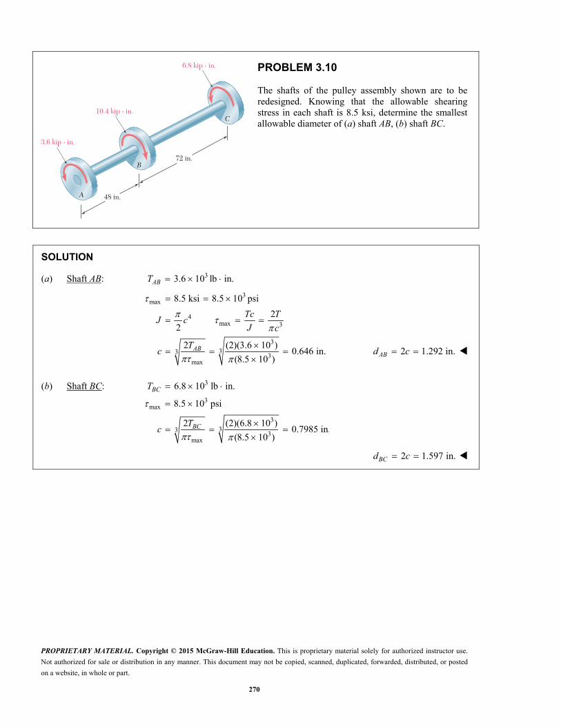
PROBLEM 3.10
The shafts of the pulley assembly shown are to be redesigned. Knowing that the allowable shearing stress in each shaft is 8.5 ksi, determine the smallest allowable diameter of (a) shaft AB, (b) shaft BC.
SOLUTION
(a) Shaft AB: 33.6 10 lb in.ABT
3max
4max 3
333
3max
8.5 ksi 8.5 10 psi
2
2
2 (2)(3.6 10 )0.646 in.
(8.5 10 )AB
Tc TJ c
J c
Tc
2 1.292 in.ABd c
(b) Shaft BC: 3
3max
333
3max
6.8 10 lb in.
8.5 10 psi
2 (2)(6.8 10 )0.7985 in.
(8.5 10 )
BC
BC
T
Tc
2 1.597 in.BCd c

PROPRIETARY MATERIAL. Copyright © 2015 McGraw-Hill Education. This is proprietary material solely for authorized instructor use.
Not authorized for sale or distribution in any manner. This document may not be copied, scanned, duplicated, forwarded, distributed, or posted
on a website, in whole or part.
345
d1 � 38 mm d2
PROBLEM 3.82
A 1.5-m-long tubular steel shaft (G 77.2 GPa) of 38-mm outer diameter d1 and 30-mm inner diameter d2 is to transmit 100 kW between a turbine and a generator. Knowing that the allowable shearing stress is 60 MPa and that the angle of twist must not exceed 3°, determine the minimum frequency at which the shaft can rotate.
SOLUTION
3
2 1
4 4 4 4 9 42 1
1.5 m, 3 52.360 10 rad
1 119 mm 0.019 m, 15 mm 0.015 m
2 2
(0.019 0.015 ) 125.186 10 m2 2
o i
L
c d c d
J c c
Stress requirement. 6 260 10 PaTc
J
9 6
2
(125.186 10 )(60 10 )395.32 N m
0.019
JT
c
Twist angle requirement. TL
GJ
9 9 3(77.2 10 )(125.186 10 )(52.360 10 )
337.35 N m1.5
GJT
L
Maximum allowable torque is the smaller value. 337.35 N mT
Power transmitted: 3100 kW 100 10 W 2P P f T
Frequency: 3100 10
47.2 Hz2 2 (337.35)
Pf
T
47.2 Hzf

PROPRIETARY MATERIAL. Copyright © 2015 McGraw-Hill Education. This is proprietary material solely for authorized instructor use.
Not authorized for sale or distribution in any manner. This document may not be copied, scanned, duplicated, forwarded, distributed, or posted
on a website, in whole or part.
346
d1 � 38 mm d2
PROBLEM 3.83
A 1.5-m-long tubular steel shaft of 38-mm outer diameter d1 is to be made of a steel for which all 65 MPa and G 77.2 GPa. Knowing that the angle of twist must not exceed 4° when the shaft is subjected to a torque of 600 N m, determine the largest inner diameter d2 that can be specified in the design.
SOLUTION
2
6 3
4 42 1
11.5 m 19 mm 0.019 m
2
65 10 Pa 4 69.813 10 rad
2
oL c d
J c c
Stress requirement.
2 24 42 1
2Tc Tc
J c c
4 424 41 2 6
3
2 (2)(600)(0.019)0.019
(65 10 )
11.6889 10 m 11.6889 mm
Tcc c
Twist angle requirement. 4 4
2 1
4 44 41 2 9 3
31
2
2 (2)(600)(1.5)0.019
(77.2 10 )(69.813 10 )
12.448 10 m 12.4482 mm
TL TL
GJ G c c
TLc c
G
c
Use smaller value of c1. 1 11.6889 mmc 12 23.4 mmid c

PROPRIETARY MATERIAL. Copyright © 2015 McGraw-Hill Education. This is proprietary material solely for authorized instructor use.
Not authorized for sale or distribution in any manner. This document may not be copied, scanned, duplicated, forwarded, distributed, or posted
on a website, in whole or part.
347
90 mm45 mm
r
PROBLEM 3.84
The stepped shaft shown must transmit 40 kW at a speed of 720 rpm. Determine the minimum radius r of the fillet if an allowable stress of 36 MPa is not to be exceeded.
SOLUTION
Angular speed: 1 Hz
(720 rpm) 12 Hz60 rpm
f
Power: 340 10 WP
Torque: 340 10
530.52 N m2 2 (12)
PT
f
In the smaller shaft, 45 mm, 22.5 mm 0.0225 md c
63 3
2 (2)(530.52)29.65 10 Pa
(0.0225)
Tc T
J c
Using 6max 36 MPa 36 10 Pa results in
6
max6
36 101.214
29.65 10K
From Fig 3.32 with 90 mm
2, 0.2445 mm
D r
d d
0.24 (0.24)(45 mm)r d 10.8 mmr

PROPRIETARY MATERIAL. Copyright © 2015 McGraw-Hill Education. This is proprietary material solely for authorized instructor use.
Not authorized for sale or distribution in any manner. This document may not be copied, scanned, duplicated, forwarded, distributed, or posted
on a website, in whole or part.
348
6 in.5 in.
r
PROBLEM 3.85
The stepped shaft shown rotates at 450 rpm. Knowing that 0.5 in.,r determine the maximum power that can be transmitted without exceeding an allowable shearing stress of 7500 psi.
SOLUTION
5 in.
6 in.
0.5 in.
61.20
50.5
0.105
d
D
r
D
dr
d
From Fig. 3.32, 1.33K
For smaller side,
3
3 33
12.5 in.
22
(2.5) (7500)138.404 10 lb in.
2 (2)(1.33)
450 rpm 7.5 Hz
c d
KTc KT
J c
cT
K
f
Power. 3 62 2 (7.5)(138.404 10 ) 6.52 10 in. lb/sP f T
Recalling that 1 hp 6600 in. lb/s, 988 hpP

PROPRIETARY MATERIAL. Copyright © 2015 McGraw-Hill Education. This is proprietary material solely for authorized instructor use.
Not authorized for sale or distribution in any manner. This document may not be copied, scanned, duplicated, forwarded, distributed, or posted
on a website, in whole or part.
349
2 in.
1.5 in.r
T
T'
PROBLEM 3.86
Knowing that the stepped shaft shown transmits a torque of magnitude 2.50 kip in., T determine the maximum shearing stress in the shaft when
the radius of the fillet is (a) 18 in.,r (b) 3
16 in.r
SOLUTION
3 3
22 in. 1.5 in. 1.33
1.51
0.75 in. 2.5 kip in.22 (2)(2.5)
3.773 ksi(0.75)
DD d
d
c d T
Tc T
J c
(a) 1
in. 0.125 in.8
r r
0.125
0.08331.5
r
d
From Fig. 3.32, 1.42K
max (1.42)(3.773)Tc
KJ
max 5.36 ksi
(b) 3
in.16
r 0.1875 in.r
0.1875
0.1251.5
r
d
From Fig. 3.32, 1.33K
max (1.33)(3.773)Tc
KJ
max 5.02 ksi

PROPRIETARY MATERIAL. Copyright © 2015 McGraw-Hill Education. This is proprietary material solely for authorized instructor use.
Not authorized for sale or distribution in any manner. This document may not be copied, scanned, duplicated, forwarded, distributed, or posted
on a website, in whole or part.
350
60 mm
30 mm
T
T'
PROBLEM 3.87
The stepped shaft shown must rotate at a frequency of 50 Hz. Knowing that the radius of the fillet is 8r mm and the allowable shearing stress is 45 MPa, determine the maximum power that can be transmitted.
SOLUTION
3
3
3
2
2
130 mm 15 mm 15 10 m
260 mm, 8 mm
60 82, 0.26667
30 30
KTc KT cT
J Kc
d c d
D r
D r
d d
From Fig. 3.32, 1.18K
Allowable torque. 3 3 6(15 10 ) (45 10 )
202.17 N m(2)(1.18)
T
Maximum power. 32 (2 )(50)(202.17) 63.5 10 WP f T 63.5 kWP

PROPRIETARY MATERIAL. Copyright © 2015 McGraw-Hill Education. This is proprietary material solely for authorized instructor use.
Not authorized for sale or distribution in any manner. This document may not be copied, scanned, duplicated, forwarded, distributed, or posted
on a website, in whole or part.
351
60 mm
30 mm
T
T'
PROBLEM 3.88
The stepped shaft shown must transmit 45 kW. Knowing that the allowable shearing stress in the shaft is 40 MPa and that the radius of the fillet is
6r mm, determine the smallest permissible speed of the shaft.
SOLUTION
60.2
3060
230
r
dD
d
From Fig. 3.32, 1.26K
For smaller side, 1
15 mm 0.015 m2
c d
3
3 3 6
3
3
3
2
(0.015) (40 10 )168.30 N m
2 (2)(1.26)
45 kW 45 10 2
45 1042.6 Hz
2 2 (168.30 10 )
KTc KT
J c
cT
K
P P f T
Pf
T
42.6 Hzf

PROPRIETARY MATERIAL. Copyright © 2015 McGraw-Hill Education. This is proprietary material solely for authorized instructor use.
Not authorized for sale or distribution in any manner. This document may not be copied, scanned, duplicated, forwarded, distributed, or posted
on a website, in whole or part.
352
r � �
D
(D d)12
d
Full quarter-circular filletextends to edge of larger shaft.
PROBLEM 3.89
A torque of magnitude 200 lb in.T is applied to the stepped shaft shown, which has a full quarter-circular fillet. Knowing that 1 in.,D determine the maximum shearing stress in the shaft when (a) 0.8 in.,d (b) 0.9 in.d
SOLUTION
(a) 1.0
1.250.81
( ) 0.1 in.20.1
0.1250.8
D
d
r D d
r
d
From Fig. 3.32, 1.31K
For smaller side, 1
0.4 in.2
c d
3
33
2
(2)(1.31)(200)2.61 10 psi
(0.4)
KTc KT
J c
2.61 ksi
(b) 1.0
1.1110.91
( ) 0.0520.05
0.051.0
D
d
r D d
r
d
From Fig. 3.32, 1.44K
For smaller side, 1
0.45 in.2
c d
33 3
2 (2)(1.44)(200)2.01 10 psi
(0.45)
KT
c
2.01 ksi

PROPRIETARY MATERIAL. Copyright © 2015 McGraw-Hill Education. This is proprietary material solely for authorized instructor use.
Not authorized for sale or distribution in any manner. This document may not be copied, scanned, duplicated, forwarded, distributed, or posted
on a website, in whole or part.
353
r � �
D
(D d)12
d
Full quarter-circular filletextends to edge of larger shaft.
PROBLEM 3.90
In the stepped shaft shown, which has a full quarter-circular fillet, the allowable shearing stress is 80 MPa. Knowing that 30 mm,D determine the largest allowable torque that can be applied to the shaft if (a) 26 mm,d (b) 24 mm.d
SOLUTION
680 10 Pa
(a) 30 1 2
1.154 ( ) 2 mm 0.076826 2 26
D rr D d
d d
From Fig. 3.32, 1.36K
Smaller side, 1
13 mm 0.013 m2
c d
3
3 3 6
2
(0.013) (80 10 )203 N m
2 (2)(1.36)
KTc KT
J c
cT
K
203 N mT
(b) 30 1 3
1.25 ( ) 3 mm 0.12524 2 24
D rr D d
d d
From Fig. 3.32, 1.31K
3 3 6
112 mm 0.012 m
2
(0.012) (80 10 )165.8 N m
2 (2)(1.31)
c d
cT
K
165.8 N mT

PROPRIETARY MATERIAL. Copyright © 2015 McGraw-Hill Education. This is proprietary material solely for authorized instructor use.
Not authorized for sale or distribution in any manner. This document may not be copied, scanned, duplicated, forwarded, distributed, or posted
on a website, in whole or part.
354
r � �
D
(D d)12
d
Full quarter-circular filletextends to edge of larger shaft.
PROBLEM 3.91
In the stepped shaft shown, which has a full quarter-circular fillet, 1.25 in.D and 1 in.d Knowing that the speed of the shaft is 2400 rpm and that the allowable shearing stress is 7500 psi, determine the maximum power that can be transmitted by the shaft.
SOLUTION
1.25
1.251.01
( ) 0.15 in.20.15
0.151.0
D
d
r D d
r
d
From Fig. 3.32, 1.31K
For smaller side, 1
0.5 in.2
c d
3
33
2
(0.5) (7500)1.1241 10 lb in.
(2)(1.31)
2400 rpm 40 Hz
KTc J cT
J Kc K
T
f
3
3
2 2 (40)(1.1241 10 )
282.5 10 lb in./s
P f T
42.8 hpP

PROPRIETARY MATERIAL. Copyright © 2015 McGraw-Hill Education. This is proprietary material solely for authorized instructor use.
Not authorized for sale or distribution in any manner. This document may not be copied, scanned, duplicated, forwarded, distributed, or posted
on a website, in whole or part.
355
c � 32 mm
T
T'
PROBLEM 3.92
The solid circular shaft shown is made of a steel that is assumed to be elastoplastic with Y 145 MPa. Determine the magnitude T of the applied torques when the plastic zone is (a) 16 mm deep, (b) 24 mm deep.
SOLUTION
6
3 3 6
3
32 mm 0.32 m 145 10 Pa
(0.032) (145 10 )2 2
7.4634 10 N m
Y
YY Y
c
JT c
c
(a) 16 mm 0.016 mpt 0.032 0.016 0.016 mY pc t
3 33
3 3
3
4 1 4 1 0.0161 (7.4634 10 ) 1
3 4 3 4 0.032
9.6402 10 N m
YYT T
c
9.64 kN mT
(b) 24 mm 0.024 mpt 0.032 0.024 0.008 mY pc t
3 33
3 3
3
4 1 4 1 0.0081 (7.4634 10 ) 1
3 4 3 4 0.032
9.9123 10 N m
YYT T
c
9.91 kN mT

PROPRIETARY MATERIAL. Copyright © 2015 McGraw-Hill Education. This is proprietary material solely for authorized instructor use.
Not authorized for sale or distribution in any manner. This document may not be copied, scanned, duplicated, forwarded, distributed, or posted
on a website, in whole or part.
356
PROBLEM 3.93
A 1.25-in.-diameter solid rod is made of an elastoplastic material with 5 ksi.Y Knowing that the elastic core of the rod is 1 in. in diameter, determine the magnitude of the applied torque T.
SOLUTION
3
3 3 3
3
3 33
3 3
3
10.625 in.
2
5 10 psi
10.5 in.
2
(0.625) (5 10 )2 2
1.91747 10 lb in.
4 1 4 1 0.51 (1.91747 10 ) 1
3 4 3 4 0.625
2.23 10 lb in.
Y
Y Y
YY Y
YY
c d
d
JT c
c
T Tc
2230 lb in.T

PROPRIETARY MATERIAL. Copyright © 2015 McGraw-Hill Education. This is proprietary material solely for authorized instructor use.
Not authorized for sale or distribution in any manner. This document may not be copied, scanned, duplicated, forwarded, distributed, or posted
on a website, in whole or part.
357
3 in. T
4 ft
PROBLEM 3.94
The solid shaft shown is made of a mild steel that is assumed to be elastoplastic with 611.2 10 psi G and 21 ksi. Y Determine the maximum shearing stress and the radius of the elastic core caused by the application of torque of magnitude (a) 100 kip in., T (b) 140 kip in.T
SOLUTION
4 41.5 in., 7.9522 in , 21 ksi2 Yc J c
(a) 100 kip in.T
4
(100 kip in.)(1.5 in.)
7.9522 in
mTc
J 18.86 ksim
Since ,m Y shaft remains elastic.
Radius of elastic core: 1.500 in.c
(b) 140 kip in.T
(140)(1.5)
26.4 ksi.7.9522
m Impossible: 21.0 ksim Y
Plastic zone has developed. Torque at onset of yield is 7.9522
(21 ksi) 111.33 kip in.1.5Y Y
JT
c
Eq. (3.32): 3
3
4 11
3 4Y
YT Tc
3
1404 3 4 3 0.22743 0.6104
111.33Y Y
Y
T
c T c
0.6104 0.6104(1.5 in.)Y c 0.916 in.Y

PROPRIETARY MATERIAL. Copyright © 2015 McGraw-Hill Education. This is proprietary material solely for authorized instructor use.
Not authorized for sale or distribution in any manner. This document may not be copied, scanned, duplicated, forwarded, distributed, or posted
on a website, in whole or part.
433
A1b1
A2
a2
B2
B1
An
an
Bn
bn –1
T0
PROBLEM 3.C2
The assembly shown consists of n cylindrical shafts, which can be solid or hollow, connected by gears and supported by brackets (not shown). End 1A of the first shaft is free and is subjected to a torque 0 ,T while end nB of the last shaft is fixed. The length of shaft i iA B is ,iL its outer diameter ,iOD its inner diameter ,iID and its modulus of rigidity .iG (Note that IDi 0 if the element is solid.) The radius of gear iA is ,ia and the radius of gear iB is .ib (a) Write a computer program that can be used to determine the maximum shearing stress in each shaft, the angle of twist of each shaft, and the angle through which end iA rotates. (b) Use this program to solve Probs. 3.41 and 3.44.
SOLUTION
Torque in shafts. Enter 0
1 1( / )i
i i i i
T T
T T A B
For each shaft, enter
i i i iL OD ID G
Compute: 4 4( /32)
( /2)
i i i
i i i i
i i i i i
J OD ID
T OD J
T L G J
Angle of rotation at end 1:A
Compute rotation at the “A” end of each shaft.
Start with angle n and update from n to 1, and add .i
1 1Angle Angle( )/i i iA B
Program Output
Problem 3.41
Shaft No.
Max Stress (ksi)
Angle of Twist (degrees)
1 9.29 1.493
2 12.16 1.707
Angle through which A1 rotates 3.769
PROPRIETARY MATERIAL. Copyright © 2015 McGraw-Hill Education. This is proprietary material solely for authorized instructor use.
Not authorized for sale or distribution in any manner. This document may not be copied, scanned, duplicated, forwarded, distributed, or posted
on a website, in whole or part.
434
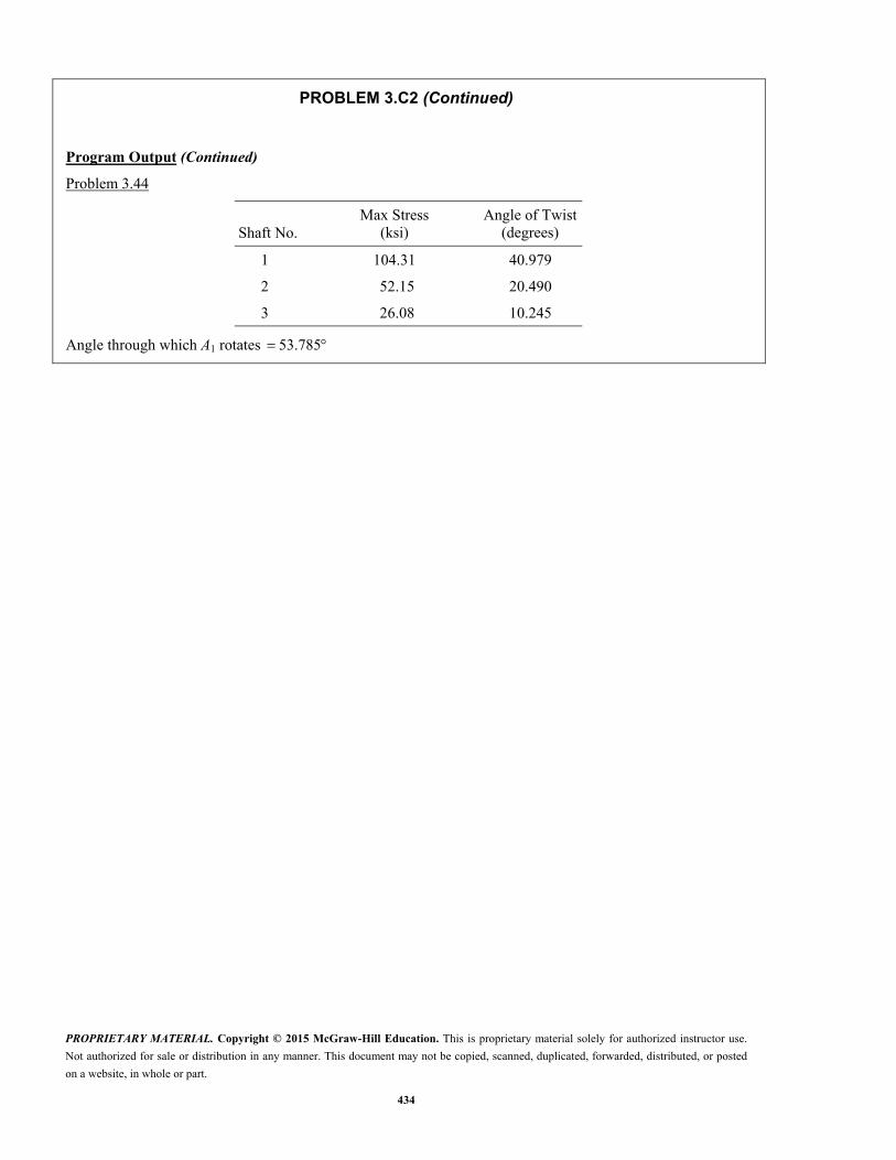
PROBLEM 3.C2 (Continued)
Program Output (Continued)
Problem 3.44
Shaft No.
Max Stress (ksi)
Angle of Twist(degrees)
1 104.31 40.979
2 52.15 20.490
3 26.08 10.245
Angle through which A1 rotates 53.785

PROPRIETARY MATERIAL. Copyright © 2015 McGraw-Hill Education. This is proprietary material solely for authorized instructor use.
Not authorized for sale or distribution in any manner. This document may not be copied, scanned, duplicated, forwarded, distributed, or posted
on a website, in whole or part.
435
Element 1
Element n
A
BT2
Tn
PROBLEM 3.C3
Shaft AB consists of n homogeneous cylindrical elements, which can be solid or hollow. Both of its ends are fixed, and it is subjected to the loading shown. The length of element i is denoted by ,iL its outer diameter by ,iOD its inner diameter by
,iID its modulus of rigidity by ,iG and the torque applied to its right end by ,iT the magnitude iT of this torque being assumed to be positive if iT is observed as counterclockwise from end B and negative otherwise. Note that 0iID if the element is solid and also that 1 0.T Write a computer program that can be used to determine the reactions at A and B, the maximum shearing stress in each element, and the angle of twist of each element. Use this program (a) to solve Prob. 3.55 and (b) to determine the maximum shearing stress in the shaft of Sample Problem 3.7.
SOLUTION
We consider the reaction at B as redundant and release the shaft at B.
Compute with 0:B BT
For each element, enter
, , , ,i i i i iL OD ID G T 1Note: 0 BT T
Compute
4 4( /32)( )i i iJ OD ID
Update torque
iT T T
And compute for each element
( /2)
/i i i
i i i i
T OD J
TL G J
Compute :B Starting with 0 and updating through n elements,
:i i i B n
Compute due to unit torque at .B B
Unit /2
Unit /i i i
i i i i
OD J
L G J
For n elements,
Unit ( ) Unit ( ) Unit B B ii i

PROPRIETARY MATERIAL. Copyright © 2015 McGraw-Hill Education. This is proprietary material solely for authorized instructor use.
Not authorized for sale or distribution in any manner. This document may not be copied, scanned, duplicated, forwarded, distributed, or posted
on a website, in whole or part.
436
PROBLEM 3.C3 (Continued)
Superposition:
For total angle at B to be zero, (Unit ( )) 0B B BT n
/(Unit ( ))B B BT n
Then ( )A BT T i T
For each element: Max stress: Total (Unit ) i i B iT
Angle of twist: Total (Unit ) i i B iT
Program Outputs Problem 3.55 0.295 kN m
1.105 kN mA
B
T
T
Element max (MPa)
Angle of Twist (degrees)
1 45.024 –0.267
2 27.375 –0.267
Problem 3.05 51.733 lb ft
38.267 lb ftA
B
T
T

PROPRIETARY MATERIAL. Copyright © 2015 McGraw-Hill Education. This is proprietary material solely for authorized instructor use.
Not authorized for sale or distribution in any manner. This document may not be copied, scanned, duplicated, forwarded, distributed, or posted
on a website, in whole or part.
437
B
L
A
T
PROBLEM 3.C4
The homogeneous, solid cylindrical shaft AB has a length L, a diameter d, a modulus of rigidity G, and a yield strength .Y It is subjected to a torque T that is gradually increased from zero until the angle of twist of the shaft has reached a maximum value m and then decreased back to zero. (a) Write a computer program that, for each of 16 values of m equally spaced over a range extending from 0 to a value 3 times as large as the angle of twist at the onset of yield, can be used to determine the maximum value mT of the torque, the radius of the elastic core, the maximum shearing stress, the permanent twist, and the residual shearing stress both at the surface of the shaft and at the interface of the elastic core and the plastic region. (b) Use this program to obtain approximate answers to Probs. 3.114, 3.115, 3.116.
SOLUTION
At onset of yield:
3
2Y Y Y
Y Y YY
JT c
cT L T J LL
GJ c GJ cG
Loading: > .m YT T
3
4 11
3 4Y
m mm
T T
Eq. (1)
YY
m
c
Eq. (2)
Unloading (elastic):
1 1
2 1 2
Angle of twist for unloading
at
at
mu u
m
YY
T L
GJc
T cJ
c
Superpose loading and unloading for 0 to 3 Y using 0.2 Y increments.
1When < :
2Y m Y Y m YY Y
T T d
When > : , use Eq. (1). , use Eq. (2). Y m YT
1 1 2 2Residual: m u R Y R Y

PROPRIETARY MATERIAL. Copyright © 2015 McGraw-Hill Education. This is proprietary material solely for authorized instructor use.
Not authorized for sale or distribution in any manner. This document may not be copied, scanned, duplicated, forwarded, distributed, or posted
on a website, in whole or part.
438
PROBLEM 3.C4 (Continued)
max maxInterpolate between values at the values of or indicated,T
Problems 3.114 and 3.115
PHIM deg
TM kip in.
RY in.
TAUM ksi
PHIP deg
TAUR1 ksi
TAUR2 ksi
0.000 0.000 1.200 0.000 0.000 0.000 0.000
7.878 11.943 1.200 4.400 0.000 0.000 0.000
15.756 23.886 1.200 8.800 0.000 0.000 0.000
23.635 35.829 1.200 13.200 0.000 0.000 0.000
31.513 47.772 1.200 17.600 0.000 0.000 0.000
39.391 59.715 1.200 22.000 0.000 0.000 0.000
47.269 68.101 1.000 22.000 2.346 1.092 –3.090
55.147 72.366 0.857 22.000 7.411 2.957 –4.661
63.025 74.761 0.750 22.000 13.710 4.786 –5.543
70.904 76.207 0.667 22.000 20.634 6.402 –6.076
max 75 kip in.T
78.782 77.132 0.600 22.000 27.902 7.792 –6.417
86.660 77.751 0.545 22.000 35.372 8.980 –6.645
94.538 78.181 0.500 22.000 42.967 9.999 –6.803
102.416 78.488 0.462 22.000 50.642 10.878 –6.916
110.294 78.714 0.429 22.000 58.371 11.643 –6.999
118.173 78.883 0.400 22.000 66.138 12.313 –7.062

PROPRIETARY MATERIAL. Copyright © 2015 McGraw-Hill Education. This is proprietary material solely for authorized instructor use.
Not authorized for sale or distribution in any manner. This document may not be copied, scanned, duplicated, forwarded, distributed, or posted
on a website, in whole or part.
439
PROBLEM 3.C4 (Continued)
Problem 3.116
PHIM deg
TM kN m
RY mm
TAUM MPa
PHIP deg
TAUR1 MPa
TAUR2 MPa
0.000 0.000 16.000 0.000 0.000 0.000 0.000
0.807 0.187 16.000 29.000 0.000 0.000 0.000
1.614 0.373 16.000 58.000 0.000 0.000 0.000
2.421 0.560 16.000 87.000 0.000 0.000 0.000
3.228 0.746 16.000 116.000 0.000 0.000 0.000
4.036 0.933 16.000 145.000 0.000 0.000 0.000
4.843 1.064 13.333 145.000 0.240 7.198 –20.363
5.650 1.131 11.429 145.000 0.759 19.486 –30.719
6.457 1.168 10.000 145.000 1.405 31.542 –36.533 max 6
7.264 1.191 8.889 145.000 2.114 42.197 –40.046
8.071 1.205 8.000 145.000 2.859 51.354 –42.292
8.878 1.215 7.273 145.000 3.624 59.184 –43.794
9.685 1.221 6.667 145.000 4.402 65.901 –44.837
10.492 1.226 6.154 145.000 5.188 71.699 –45.583
11.300 1.230 5.714 145.000 5.980 76.739 –46.132
12.107 1.232 5.333 145.000 6.776 81.152 –46.543

PROPRIETARY MATERIAL. Copyright © 2015 McGraw-Hill Education. This is proprietary material solely for authorized instructor use.
Not authorized for sale or distribution in any manner. This document may not be copied, scanned, duplicated, forwarded, distributed, or posted
on a website, in whole or part.
440
L
A
2cB
c
B
L
A
2c
r1L/n
ri
rn
T
A
T
c
PROBLEM 3.C5
The exact expression is given in Prob. 3.158 for the angle of twist of the solid tapered shaft AB when a torque T is applied as shown. Derive an approximate expression for the angle of twist by replacing the tapered shaft by n cylindrical shafts of equal length and of radius
12( )( / ), ir n i c n where 1, 2, . . . , .i n Using for T, L,
G, and c values of your choice, determine the percentage error in the approximate expression when (a) 4,n (b) 8,n (c) n 20, (d) 100.n
SOLUTION
From Problem 3.158, exact expression:
4
7
12
TL
Gc
or 4 4
70.18568
12
TL TL
Gc Gc
Consider typical ith shaft:
Enter unit values of T, L, G, and c.
(Note: Specific values can be entered).
Enter initial value of zero for .
Enter number cylindrical shafts.n
For 1 to ,i n update .

PROPRIETARY MATERIAL. Copyright © 2015 McGraw-Hill Education. This is proprietary material solely for authorized instructor use.
Not authorized for sale or distribution in any manner. This document may not be copied, scanned, duplicated, forwarded, distributed, or posted
on a website, in whole or part.
441
PROBLEM 3.C5 (Continued)
Program Output
Coefficient of 4/ :TL Gc
Exact coefficient from Problem 3.158 is 0.18568.
Number of elemental disks . n
n Approximate Exact Percent Error
4 0.17959 0.18568 –3.28185
8 0.18410 0.18568 –0.85311
20 0.18542 0.18568 –0.13810
100 0.18567 0.18568 –0.00554

PROPRIETARY MATERIAL. Copyright © 2015 McGraw-Hill Education. This is proprietary material solely for authorized instructor use.
Not authorized for sale or distribution in any manner. This document may not be copied, scanned, duplicated, forwarded, distributed, or posted
on a website, in whole or part.
442
t
L
A
c
2cB
T
PROBLEM 3.C6
A torque T is applied as shown to the long, hollow, tapered shaft AB of uniform thickness t. Derive an approximate expression for the angle of twist by replacing the tapered shaft by n cylindrical rings of equal length and of radius 1
2( )( / ),ir n i c n where 1, 2, . . . , .i n Using for T, L, G, c and t values of your choice, determine the percentage error in the approximate expression when (a) 4,n (b) 8,n (c) 20,n (d) 100.n
SOLUTION
Since the shaft is long, c << L, the angle is small, and we can use t as the thickness of the n cylindrical rings.
For << ,
tan
c L
zc c c
L L
1
2ic
r n in
2 2 3(Area) (2 ) 2
( / )i i i i i
i
J r r t r tr
T L n
GJ
Enter unit values for T, L, G, t, and c.
(Note: Specific values can be entered is desired).
Enter initial value of zero for .
Enter number of cylindrical rings.n
For 1 to ,i n update .

PROPRIETARY MATERIAL. Copyright © 2015 McGraw-Hill Education. This is proprietary material solely for authorized instructor use.
Not authorized for sale or distribution in any manner. This document may not be copied, scanned, duplicated, forwarded, distributed, or posted
on a website, in whole or part.
443
PROBLEM 3.C6 (Continued)
Program Output
Coefficient of 3/ :TL Gtc
Exact coefficient from Problem 3.153 is 0.05968.
Number of elemental disks . n
n Approximate Exact Percent Error
4 0.058559 0.059683 –1.883078
8 0.059394 0.059683 –0.483688
20 0.059637 0.059683 –0.078022
100 0.059681 0.059683 –0.003127