Chapter 3 Data Protection: RAID
20
51 Chapter 3 Data Protection: RAID I n the late 1980s, rapid adoption of comput- ers for business processes stimulated the growth of new applications and databases, significantly increasing the demand for storage capacity. At that time, data was stored on a sin- gle large, expensive disk drive called Single Large Expensive Drive (SLED). Use of single disks could not meet the required performance levels, due to their inherent limitations (detailed in Chapter 2, Section 2.4, “Fundamental Laws Governing Disk Performance”). HDDs are susceptible to failures due to mechanical wear and tear and other environmental factors. An HDD failure may result in data loss. The solutions available during the 1980s were not able to meet the availability and perfor- mance demands of applications. An HDD has a projected life expectancy before it fails. Mean Time Between Failure (MTBF) measures (in hours) the average life expectancy of an HDD. Today, data centers deploy thousands of HDDs in their storage infrastructures. The greater the number of HDDs in a storage array, the greater the probability of a disk failure in the array. For example, consider a storage array of 100 HDDs, each with an MTBF of 750,000 hours. The MTBF of this collection of HDDs in the array, therefore, is 750,000/100 or 7,500 hours. This means that a HDD in this array is likely to fail at least once in 7,500 hours. RAID is an enabling technology that leverages multiple disks as part of a set, which provides data protection against HDD failures. In general, RAID imple- mentations also improve the I/O performance of storage systems by storing data across multiple HDDs. In 1987, Patterson, Gibson, and Katz at the University of California, Berkeley, published a paper titled “A Case for Redundant Arrays of Inexpensive Disks KEY CONCEPTS Hardware and Software RAID Striping, Mirroring, and Parity RAID Write Penalty Hot Spares
-
Upload
khangminh22 -
Category
Documents
-
view
5 -
download
0
Transcript of Chapter 3 Data Protection: RAID
51
Chapter 3Data Protection: RAID
In the late 1980s, rapid adoption of comput-ers for business processes stimulated the growth of new applications and databases,
significantly increasing the demand for storage capacity. At that time, data was stored on a sin-gle large, expensive disk drive called Single Large Expensive Drive (SLED). Use of single disks could not meet the required performance levels, due to their inherent limitations (detailed in Chapter 2, Section 2.4, “Fundamental Laws Governing Disk Performance”).
HDDs are susceptible to failures due to mechanical wear and tear and other environmental factors. An HDD failure may result in data loss. The solutions available during the 1980s were not able to meet the availability and perfor-mance demands of applications.
An HDD has a projected life expectancy before it fails. Mean Time Between Failure (MTBF) measures (in hours) the average life expectancy of an HDD. Today, data centers deploy thousands of HDDs in their storage infrastructures. The greater the number of HDDs in a storage array, the greater the probability of a disk failure in the array. For example, consider a storage array of 100 HDDs, each with an MTBF of 750,000 hours. The MTBF of this collection of HDDs in the array, therefore, is 750,000/100 or 7,500 hours. This means that a HDD in this array is likely to fail at least once in 7,500 hours.
RAID is an enabling technology that leverages multiple disks as part of a set, which provides data protection against HDD failures. In general, RAID imple-mentations also improve the I/O performance of storage systems by storing data across multiple HDDs.
In 1987, Patterson, Gibson, and Katz at the University of California, Berkeley, published a paper titled “A Case for Redundant Arrays of Inexpensive Disks
KEY CONCEPTSHardware and Software RAID
Striping, Mirroring, and Parity
RAID Write Penalty
Hot Spares

52 Section I n Storage System
(RAID).” This paper described the use of small-capacity, inexpensive disk drives as an alternative to large-capacity drives common on mainframe computers. The term RAID has been redefined to refer to independent disks, to reflect advances in the storage technology. RAID storage has now grown from an academic concept to an industry standard.
This chapter details RAID technology, RAID levels, and different types of RAID implementations and their benefits.
3.1 Implementation of RAID
There are two types of RAID implementation, hardware and software. Both have their merits and demerits and are discussed in this section.
3.1.1 Software RAID
Software RAID uses host-based software to provide RAID functions. It is imple-mented at the operating-system level and does not use a dedicated hardware controller to manage the RAID array.
Software RAID implementations offer cost and simplicity benefits when com-pared with hardware RAID. However, they have the following limitations:
Performance:n Software RAID affects overall system performance. This is due to the additional CPU cycles required to perform RAID calculations. The performance impact is more pronounced for complex implementa-tions of RAID, as detailed later in this chapter.
Supported features:n Software RAID does not support all RAID levels.
Operating system compatibility:n Software RAID is tied to the host operat-ing system hence upgrades to software RAID or to the operating system should be validated for compatibility. This leads to inflexibility in the data processing environment.
3.1.2 Hardware RAID
In hardware RAID implementations, a specialized hardware controller is imple-mented either on the host or on the array. These implementations vary in the way the storage array interacts with the host.
Controller card RAID is host-based hardware RAID implementation in which a specialized RAID controller is installed in the host and HDDs are connected to it. The RAID Controller interacts with the hard disks using a PCI bus. Manufacturers also integrate RAID controllers on motherboards. This integra-tion reduces the overall cost of the system, but does not provide the flexibility required for high-end storage systems.

Chapter 3 n Data Protection: RAID 53
The external RAID controller is an array-based hardware RAID. It acts as an interface between the host and disks. It presents storage volumes to the host, which manage the drives using the supported protocol. Key functions of RAID controllers are:
Management and control of disk aggregationsn
Translation of I/O requests between logical disks and physical disksn
Data regeneration in the event of disk failuresn
3.2 RAID Array Components
A RAID array is an enclosure that contains a number of HDDs and the support-ing hardware and software to implement RAID. HDDs inside a RAID array are usually contained in smaller sub-enclosures. These sub-enclosures, or physical arrays, hold a fixed number of HDDs, and may also include other supporting hardware, such as power supplies. A subset of disks within a RAID array can be grouped to form logical associations called logical arrays, also known as a RAID set or a RAID group (see Figure 3-1).
Logical arrays are comprised of logical volumes (LV). The operating system recognizes the LVs as if they are physical HDDs managed by the RAID control-ler. The number of HDDs in a logical array depends on the RAID level used. Configurations could have a logical array with multiple physical arrays or a physical array with multiple logical arrays.
RAID
Controller
Host
Physical
Array
Logical
Array
RAID Array
Hard Disks
Figure 3-1: Components of RAID array
54 Section I n Storage System
3.3 RAID Levels
RAID levels (see Table 3-1) are defined on the basis of striping, mirroring, and parity techniques. These techniques determine the data availability and per-formance characteristics of an array. Some RAID arrays use one technique, whereas others use a combination of techniques. Application performance and data availability requirements determine the RAID level selection.
3.3.1 Striping
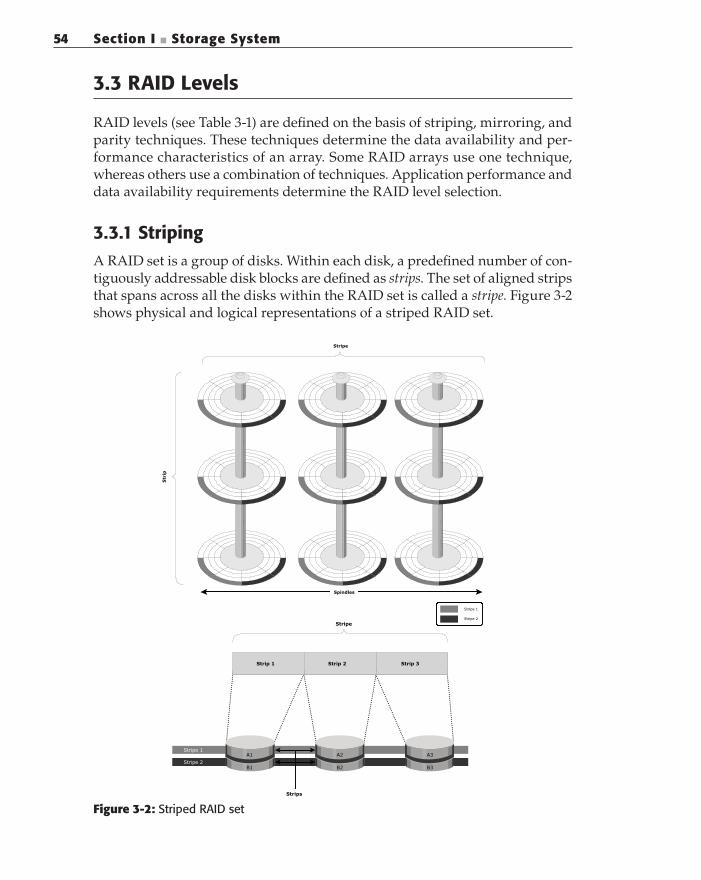
A RAID set is a group of disks. Within each disk, a predefined number of con-tiguously addressable disk blocks are defined as strips. The set of aligned strips that spans across all the disks within the RAID set is called a stripe. Figure 3-2 shows physical and logical representations of a striped RAID set.
Strip 1 Strip 2 Strip 3
Strips
Stripe 1
Stripe 2
A1
B1
A2
B2
A3
B3
Stripe
Stripe 1
Stripe 2
Spindles
Stripe
Figure 3-2: Striped RAID set

Chapter 3 n Data Protection: RAID 55
Strip size (also called stripe depth) describes the number of blocks in a strip, and is the maximum amount of data that can be written to or read from a single HDD in the set before the next HDD is accessed, assuming that the accessed data starts at the beginning of the strip. Note that all strips in a stripe have the same number of blocks, and decreasing strip size means that data is broken into smaller pieces when spread across the disks.
Stripe size is a multiple of strip size by the number of HDDs in the RAID set. Stripe width refers to the number of data strips in a stripe.
Striped RAID does not protect data unless parity or mirroring is used. However, striping may significantly improve I/O performance. Depending on the type of RAID implementation, the RAID controller can be configured to access data across multiple HDDs simultaneously.
3.3.2 Mirroring
Mirroring is a technique whereby data is stored on two different HDDs, yield-ing two copies of data. In the event of one HDD failure, the data is intact on the surviving HDD (see Figure 3-3) and the controller continues to service the host’s data requests from the surviving disk of a mirrored pair.
A
B
C
D
E
A
B
C
D
E
A
B
C
D
E
A
B
C
D
E
Disks
Mirroring
Figure 3-3: Mirrored disks in an array
When the failed disk is replaced with a new disk, the controller copies the data from the surviving disk of the mirrored pair. This activity is transparent to the host.
In addition to providing complete data redundancy, mirroring enables faster recovery from disk failure. However, disk mirroring provides only data protection and is not a substitute for data backup. Mirroring constantly captures changes in the data, whereas a backup captures point-in-time images of data.
56 Section I n Storage System
Mirroring involves duplication of data — the amount of storage capacity needed is twice the amount of data being stored. Therefore, mirroring is con-sidered expensive and is preferred for mission-critical applications that cannot afford data loss. Mirroring improves read performance because read requests can be serviced by both disks. However, write performance deteriorates, as each write request manifests as two writes on the HDDs. In other words, mirroring does not deliver the same levels of write performance as a striped RAID.
3.3.3 Parity
Parity is a method of protecting striped data from HDD failure without the cost of mirroring. An additional HDD is added to the stripe width to hold parity, a mathematical construct that allows re-creation of the missing data. Parity is a redundancy check that ensures full protection of data without maintaining a full set of duplicate data.
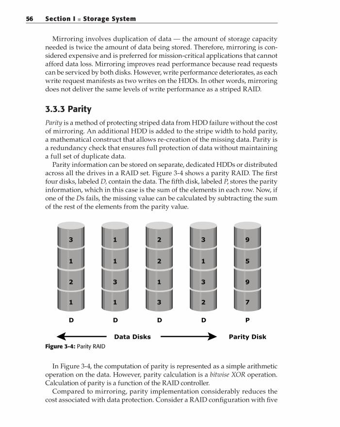
Parity information can be stored on separate, dedicated HDDs or distributed across all the drives in a RAID set. Figure 3-4 shows a parity RAID. The first four disks, labeled D, contain the data. The fifth disk, labeled P, stores the parity information, which in this case is the sum of the elements in each row. Now, if one of the Ds fails, the missing value can be calculated by subtracting the sum of the rest of the elements from the parity value.
3
1
2
1
1
1
3
1
2
2
1
3
3
1
3
2
9
5
9
7
D D D D P
Data Disks Parity Disk
Figure 3-4: Parity RAID
In Figure 3-4, the computation of parity is represented as a simple arithmetic operation on the data. However, parity calculation is a bitwise XOR operation. Calculation of parity is a function of the RAID controller.
Compared to mirroring, parity implementation considerably reduces the cost associated with data protection. Consider a RAID configuration with five

Chapter 3 n Data Protection: RAID 57
disks. Four of these disks hold data, and the fifth holds parity information. Parity requires 25 percent extra disk space compared to mirroring, which requires 100 percent extra disk space. However, there are some disadvantages of using parity. Parity information is generated from data on the data disk. Therefore, parity is recalculated every time there is a change in data. This recalculation is time-consuming and affects the performance of the RAID controller.
Table 3-1: Raid Levels
LEVELS BRIEF DESCRIPTION
RAID 0 Striped array with no fault tolerance
RAID 1 Disk mirroring
RAID 3 Parallel access array with dedicated parity disk
RAID 4 Striped array with independent disks and a dedicated parity disk
RAID 5 Striped array with independent disks and distributed parity
RAID 6 Striped array with independent disks and dual distributed parity
Nested Combinations of RAID levels. Example: RAID 1 + RAID 0
3.3.4 RAID 0
In a RAID 0 configuration, data is striped across the HDDs in a RAID set. It uti-lizes the full storage capacity by distributing strips of data over multiple HDDs in a RAID set. To read data, all the strips are put back together by the controller. The stripe size is specified at a host level for software RAID and is vendor spe-cific for hardware RAID. Figure 3-5 shows RAID 0 on a storage array in which data is striped across 5 disks. When the number of drives in the array increases, performance improves because more data can be read or written simultaneously. RAID 0 is used in applications that need high I/O throughput. However, if these applications require high availability, RAID 0 does not provide data protection and availability in the event of drive failures.
3.3.5 RAID 1
In a RAID 1 configuration, data is mirrored to improve fault tolerance (see Figure 3-6). A RAID 1 group consists of at least two HDDs. As explained in mir-roring, every write is written to both disks, which is transparent to the host in a hardware RAID implementation. In the event of disk failure, the impact on data recovery is the least among all RAID implementations. This is because the RAID controller uses the mirror drive for data recovery and continuous operation. RAID 1 is suitable for applications that require high availability.

58 Section I n Storage System
A4
B4
C4
D4
E4
A5
B5
C5
D5
E5
A3
B3
C3
D3
E3
A2
B2
C2
D2
E2
A1
B1
C1
D1
E1
E
D
C
B
A
RAID Controller
Data from host
Disks
Figure 3-5: RAID 0
E
D
C
B
A
J
I
H
G
F
RAID Controller
Data from host
A
B
C
D
E
A
B
C
D
E
A
B
C
D
E
F
G
H
I
J
A
B
C
D
E
F
G
H
I
J
Disks
Mirror Set Mirror Set
Figure 3-6: RAID 1
Chapter 3 n Data Protection: RAID 59
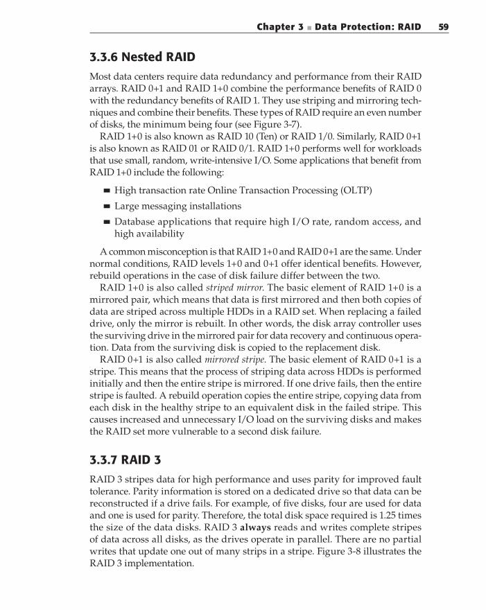
3.3.6 Nested RAID
Most data centers require data redundancy and performance from their RAID arrays. RAID 0+1 and RAID 1+0 combine the performance benefits of RAID 0 with the redundancy benefits of RAID 1. They use striping and mirroring tech-niques and combine their benefits. These types of RAID require an even number of disks, the minimum being four (see Figure 3-7).
RAID 1+0 is also known as RAID 10 (Ten) or RAID 1/0. Similarly, RAID 0+1 is also known as RAID 01 or RAID 0/1. RAID 1+0 performs well for workloads that use small, random, write-intensive I/O. Some applications that benefit from RAID 1+0 include the following:
High transaction rate Online Transaction Processing (OLTP)n
Large messaging installationsn
Database applications that require high I/O rate, random access, and n
high availability
A common misconception is that RAID 1+0 and RAID 0+1 are the same. Under normal conditions, RAID levels 1+0 and 0+1 offer identical benefits. However, rebuild operations in the case of disk failure differ between the two.
RAID 1+0 is also called striped mirror. The basic element of RAID 1+0 is a mirrored pair, which means that data is first mirrored and then both copies of data are striped across multiple HDDs in a RAID set. When replacing a failed drive, only the mirror is rebuilt. In other words, the disk array controller uses the surviving drive in the mirrored pair for data recovery and continuous opera-tion. Data from the surviving disk is copied to the replacement disk.
RAID 0+1 is also called mirrored stripe. The basic element of RAID 0+1 is a stripe. This means that the process of striping data across HDDs is performed initially and then the entire stripe is mirrored. If one drive fails, then the entire stripe is faulted. A rebuild operation copies the entire stripe, copying data from each disk in the healthy stripe to an equivalent disk in the failed stripe. This causes increased and unnecessary I/O load on the surviving disks and makes the RAID set more vulnerable to a second disk failure.
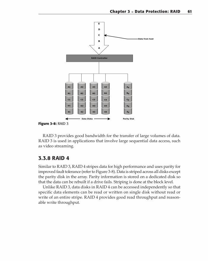
3.3.7 RAID 3
RAID 3 stripes data for high performance and uses parity for improved fault tolerance. Parity information is stored on a dedicated drive so that data can be reconstructed if a drive fails. For example, of five disks, four are used for data and one is used for parity. Therefore, the total disk space required is 1.25 times the size of the data disks. RAID 3 always reads and writes complete stripes of data across all disks, as the drives operate in parallel. There are no partial writes that update one out of many strips in a stripe. Figure 3-8 illustrates the RAID 3 implementation.

60 Section I n Storage System
Str
ipin
gS
trip
ing
Mir
ro
rin
g
A1
B1
C1
D1
E1
A2
B2
C2
D2
E2
A3
B3
C3
D3
E3
A1
B1
C1
D1
E1
A2
B2
C2
D2
E2
A3
B3
C3
D3
E3
Mir
ro
rin
gM
irro
rin
g
Str
ipin
g
Mir
ro
rin
g
A1
B1
C1
D1
E1
A2
B2
C2
D2
E2
A3
B3
C3
D3
E3
A1
B1
C1
D1
E1
A2
B2
C2
D2
E2
A3
B3
C3
D3
E3
E D C B A
E D C B A
Data
fro
m h
ost
Ste
p 1
Ste
p 2
Co
ntr
oller
Dis
ks
(a) R
AID
1+
0(b
) R
AID
0+
1
Dis
ks
Figure 3-7: Nested RAID
Chapter 3 n Data Protection: RAID 61
A1
B1
C1
D1
E1
A2
B2
C2
D2
E2
A3
B3
C3
D3
E3
A4
B4
C4
D4
E4
Ap
Bp
Cp
Dp
Ep
E
D
C
B
A
Parity Disk
RAID Controller
Data from host
Data Disks
Figure 3-8: RAID 3
RAID 3 provides good bandwidth for the transfer of large volumes of data. RAID 3 is used in applications that involve large sequential data access, such as video streaming.
3.3.8 RAID 4
Similar to RAID 3, RAID 4 stripes data for high performance and uses parity for improved fault tolerance (refer to Figure 3-8). Data is striped across all disks except the parity disk in the array. Parity information is stored on a dedicated disk so that the data can be rebuilt if a drive fails. Striping is done at the block level.
Unlike RAID 3, data disks in RAID 4 can be accessed independently so that specific data elements can be read or written on single disk without read or write of an entire stripe. RAID 4 provides good read throughput and reason-able write throughput.

62 Section I n Storage System
3.3.9 RAID 5
RAID 5 is a very versatile RAID implementation. It is similar to RAID 4 because it uses striping and the drives (strips) are independently accessible. The difference between RAID 4 and RAID 5 is the parity location. In RAID 4, parity is written to a dedicated drive, creating a write bottleneck for the parity disk. In RAID 5, parity is distributed across all disks. The distribution of parity in RAID 5 overcomes the write bottleneck. Figure 3-9 illustrates the RAID 5 implementation.
A4
Bp
C3
D3
E3
Ap
B4
C4
D4
E4
A3
B3
Cp
D2
E2
A2
B2
C2
Dp
E1
A1
B1
C1
D1
Ep
E
D
C
B
A
RAID Controller
Data from host
Disks
Figure 3-9: RAID 5
RAID 5 is preferred for messaging, data mining, medium-performance media serving, and relational database management system (RDBMS) implementations in which database administrators (DBAs) optimize data access.
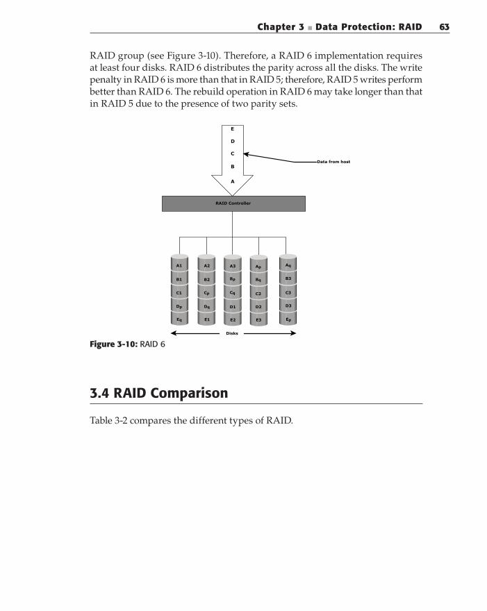
3.3.10 RAID 6
RAID 6 works the same way as RAID 5 except that RAID 6 includes a second parity element to enable survival in the event of the failure of two disks in a
Chapter 3 n Data Protection: RAID 63
RAID group (see Figure 3-10). Therefore, a RAID 6 implementation requires at least four disks. RAID 6 distributes the parity across all the disks. The write penalty in RAID 6 is more than that in RAID 5; therefore, RAID 5 writes perform better than RAID 6. The rebuild operation in RAID 6 may take longer than that in RAID 5 due to the presence of two parity sets.
Ap
Bq
C2
D2
E3
Aq
B3
C3
D3
Ep
A3
Bp
Cq
D1
E2
A2
B2
Cp
Dq
E1
A1
B1
C1
Dp
Eq
E
D
C
B
A
RAID Controller
Data from host
Disks
Figure 3-10: RAID 6
3.4 RAID Comparison
Table 3-2 compares the different types of RAID.

64 Section I n Storage System
Tab
le 3
-2:
Co
mp
ari
son o
f D
iffe
ren
t R
AID
Typ
es
RA
IDM
IN. D
ISK
SS
TO
RA
GE
EFFIC
IEN
CY
%C
OS
TR
EA
D
PE
RFO
RM
AN
CE
WR
ITE
PE
RFO
RM
AN
CE
WR
ITE
PE
NA
LTY
02
10
0Lo
wVery
go
od f
or
bo
th r
an
do
m
an
d s
eq
uen
tial
read
Very
go
od
No
12
50
Hig
hG
oo
d. B
ett
er
than a
sin
gle
d
isk.
Go
od
. Slo
wer
than a
sin
gle
d
isk, a
s eve
ry
wri
te m
ust
be
com
mit
ted t
o a
ll d
isks.
Mo
dera
te
33
(n-1
)*10
0/n
w
here
n=
nu
m b
er
of
dis
ks
Mo
dera
teG
oo
d f
or
ran
-d
om
read
s an
d v
ery
go
od
for
seq
uen
tial
read
s.
Po
or
to f
air
fo
r sm
all
ran
do
m
wri
tes.
Go
od f
or
larg
e, s
eq
uen
tial
wri
tes.
Hig
h
43
(n-1
)*10
0/n
w
here
n=
nu
m b
er
of
dis
ks
Mo
dera
teVery
go
od f
or
ran
do
m r
ead
s.
Go
od t
o v
ery
go
od f
or
seq
uen
tial
wri
tes.
Po
or
to f
air
fo
r ra
nd
om
wri
tes.
Fa
ir t
o g
oo
d
for
seq
uen
tial
wri
tes.
Hig
h
Continued

Chapter 3 n Data Protection: RAID 65
RA
IDM
IN. D
ISK
SS
TO
RA
GE
EFFIC
IEN
CY
%C
OS
TR
EA
D
PE
RFO
RM
AN
CE
WR
ITE
PE
RFO
RM
AN
CE
WR
ITE
PE
NA
LTY
53
(n-1
)*10
0/n
w
here
n=
nu
m b
er
of
dis
ks
Mo
dera
teVery
go
od
for
ran
do
m
read
s. G
oo
d f
or
seq
uen
tial re
ad
s
Fair
fo
r ra
nd
om
w
rite
s. S
low
er
du
e t
o p
ar-
ity
ove
rhead
. Fa
ir t
o g
oo
d
for
seq
uen
tial
wri
tes.
Hig
h
64
(n-2
)*10
0/n
w
here
n=
nu
m b
er
of
dis
ks
Mo
dera
te b
ut
mo
re t
han R
AID
5Very
go
od
for
ran
do
m
read
s. G
oo
d
for
seq
uen
tial
read
s.
Go
od f
or
small,
ra
nd
om
wri
tes
(has
wri
te
pen
alt
y).
Very
Hig
h
1+
0 a
nd
0+
14
50
Hig
hVery
go
od
Go
od
Mo
dera
te
Tab
le 3
-2 (
con
tin
ued
)

66 Section I n Storage System
3.5 RAID Impact on Disk Performance
When choosing a RAID type, it is imperative to consider the impact to disk performance and application IOPS.
In both mirrored and parity RAID configurations, every write operation translates into more I/O overhead for the disks which is referred to as write
penalty. In a RAID 1 implementation, every write operation must be performed on two disks configured as a mirrored pair while in a RAID 5 implementation, a write operation may manifest as four I/O operations. When performing small I/Os to a disk configured with RAID 5, the controller has to read, calculate, and write a parity segment for every data write operation.
Figure 3-11 illustrates a single write operation on RAID 5 that contains a group of five disks. Four of these disks are used for data and one is used for parity.
The parity (P) at the controller is calculated as follows:
Ep = E
1 + E
2 + E
3 + E
4 (XOR operations)
Here, D1 to D4 is striped data across the RAID group of five disks. Whenever the controller performs a write I/O, parity must be computed by
reading the old parity (Ep old
) and the old data (E4 old
) from the disk, which means two read I/Os. The new parity (E
p new) is computed as follows:
Ep new
= Ep old
– E4 old
+ E4 new
(XOR operations)
Ep new Ep old E4 old E4 new+-=
Ep oldEp new E4 old E4 new
RAID Controller
2 XORs
A1
B1
C1
D1
Ep
A2
B2
C2
Dp
E1
A3
B3
Cp
D2
E2
A4
Bp
C3
D3
E3
Ap
B4
C4
D4
E4
Disks
Figure 3-11: Write penalty in RAID 5

Chapter 3 n Data Protection: RAID 67
After computing the new parity, the controller completes the write I/O by writing the new data and the new parity onto the disks, amounting to two write I/Os. Therefore, the controller performs two disk reads and two disk writes for every write operation, and the write penalty in RAID 5 implementations is 4.
In RAID 6, which maintains dual parity, a disk write requires three read operations: for E
p1 old, E
p2 old, and E
4 old. After calculating E
p1 new and E
p2 new
, the controller performs three write I/O operations for E
p1 new
, Ep2
new
and E4 new
. Therefore, in a RAID 6 implementation, the controller performs six I/O opera-tions for each write I/O, and the write penalty is 6.
3.5.1 Application IOPS and RAID Configurations
When deciding the number of disks required for an application, it is important to consider the impact of RAID based on IOPS generated by the application. The total disk load should be computed by considering the type of RAID configura-tion and the ratio of read compared to write from the host.
The following example illustrates the method of computing the disk load in different types of RAID.
Consider an application that generates 5,200 IOPS, with 60 percent of them being reads.
The disk load in RAID 5 is calculated as follows:RAID 5 disk load = 0.6 × 5,200 + 4 × (0.4 × 5,200) [because the write penalty
for RAID 5 is 4]
= 3,120 + 4 × 2,080
= 3,120 + 8,320
= 11,440 IOPS
The disk load in RAID 1 is calculated as follows:RAID 1 disk load = 0.6 × 5,200 + 2 × (0.4 × 5,200) [because every write mani-
fests as two writes to the disks]
= 3,120 + 2 × 2,080
= 3,120 + 4,160
= 7,280 IOPS
The computed disk load determines the number of disks required for the application. If in this example an HDD with a specification of a maximum 180 IOPS for the application needs to be used, the number of disks required to meet the workload for the RAID configuration would be as follows:
RAID 5: 11,440 / 180 = 64 disksn
RAID 1: 7,280 / 180 = 42 disks (approximated to the nearest even n
number)
68 Section I n Storage System
3.6 Hot Spares
A hot spare refers to a spare HDD in a RAID array that temporarily replaces a failed HDD of a RAID set. A hot spare takes the identity of the failed HDD in the array. One of the following methods of data recovery is performed depend-ing on the RAID implementation:
If parity RAID is used, then the data is rebuilt onto the hot spare from the n
parity and the data on the surviving HDDs in the RAID set.
If mirroring is used, then the data from the surviving mirror is used to n
copy the data.
When the failed HDD is replaced with a new HDD, one of the following takes place:
The hot spare replaces the new HDD permanently. This means that it is n
no longer a hot spare, and a new hot spare must be configured on the array.
When a new HDD is added to the system, data from the hot spare is n
copied to it. The hot spare returns to its idle state, ready to replace the next failed drive.
A hot spare should be large enough to accommodate data from a failed drive. Some systems implement multiple hot spares to improve data availability.
A hot spare can be configured as automatic or user initiated, which specifies how it will be used in the event of disk failure. In an automatic configuration, when the recoverable error rates for a disk exceed a predetermined threshold, the disk subsystem tries to copy data from the failing disk to the hot spare automati-cally. If this task is completed before the damaged disk fails, then the subsystem switches to the hot spare and marks the failing disk as unusable. Otherwise, it uses parity or the mirrored disk to recover the data. In the case of a user-initiated configuration, the administrator has control of the rebuild process. For example, the rebuild could occur overnight to prevent any degradation of system per-formance. However, the system is vulnerable to another failure if a hot spare is unavailable.
Summary
Individual disks are prone to failures and pose the threat of data unavailability for applications. RAID addresses data availability requirements by using mir-roring and parity techniques. RAID implementations with striping enhance I/O performance by spreading data across multiple HDDs in addition to redun-dancy benefits.

Chapter 3 n Data Protection: RAID 69
This chapter explained the fundamental constructs of striping, mirroring, and parity, which form the basis for various RAID levels. Implementation of RAID lev-els depends on application requirements for performance and data protection.
RAID is the cornerstone technology for several advancements in storage. The next generation of storage systems are intelligent storage systems that implement RAID along with a specialized operating environment that offers high performance and availability. Intelligent storage systems are detailed in the next chapter.
EXERCISES
1. Why is RAID 1 not a substitute for a backup?
2. Why is RAID 0 not an option for data protection and high availability?
3. Explain the process of data recovery in case of a drive failure in RAID 5.
4. What are the benefits of using RAID 3 in a backup application?
5. Discuss the impact of random and sequential I/O in different RAID
configurations.
6. An application has 1,000 heavy users at a peak of 2 IOPS each and 2,000
typical users at a peak of 1 IOPS each, with a read/write ratio of 2:1. It is
estimated that the application also experiences an overhead of 20 percent
for other workloads. Calculate the IOPS requirement for RAID 1, RAID 3,
RAID 5, and RAID 6.
7. For Question 7, compute the number of drives required to support the
application in different RAID environments if 10K RPM drives with a rating
of 130 IOPS per drive were used.