CHAPTER 21 - Magnetism - Copyright © by Holt, Rinehart and ...
28
Copyright © by Holt, Rinehart and Winston. All rights reserved. Copyright © by Holt, Rinehart and Winston. All rights reserved.
-
Upload
khangminh22 -
Category
Documents
-
view
0 -
download
0
Transcript of CHAPTER 21 - Magnetism - Copyright © by Holt, Rinehart and ...

Copyright © by Holt, Rinehart and Winston. All rights reserved.Copyright © by Holt, Rinehart and Winston. All rights reserved.
Copyright © by Holt, Rinehart and Winston. All rights reserved.
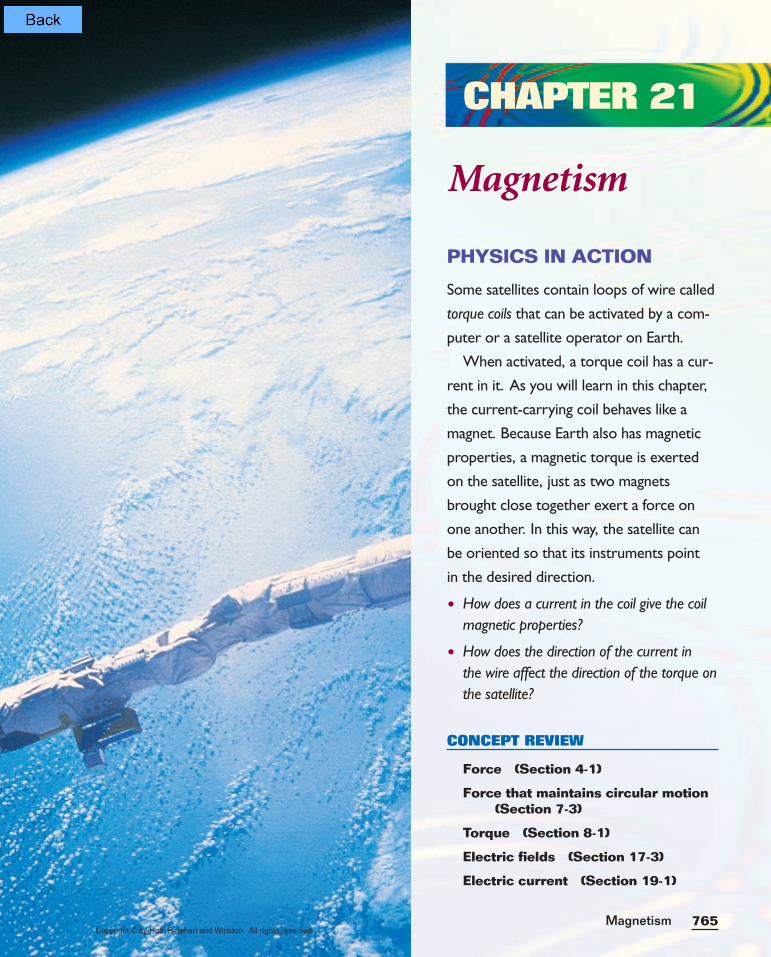
PHYSICS IN ACTION
Some satellites contain loops of wire called
torque coils that can be activated by a com-
puter or a satellite operator on Earth.
When activated, a torque coil has a cur-
rent in it. As you will learn in this chapter,
the current-carrying coil behaves like a
magnet. Because Earth also has magnetic
properties, a magnetic torque is exerted
on the satellite, just as two magnets
brought close together exert a force on
one another. In this way, the satellite can
be oriented so that its instruments point
in the desired direction.
• How does a current in the coil give the coilmagnetic properties?
• How does the direction of the current in the wire affect the direction of the torque onthe satellite?
CONCEPT REVIEW
Force (Section 4-1)
Force that maintains circular motion(Section 7-3)
Torque (Section 8-1)
Electric fields (Section 17-3)
Electric current (Section 19-1)
CHAPTER 21
Magnetism
Magnetism 765Copyright © by Holt, Rinehart and Winston. All rights reserved.
Copyright © by Holt, Rinehart and Winston. All rights reserved.Chapter 21766
21-1Magnets and magnetic fields
21-1 SECTION OBJECTIVES
• For given situations, predictwhether magnets will repelor attract each other.
• Describe the magnetic fieldaround a permanent magnet.
• Describe the orientation ofEarth’s magnetic field.
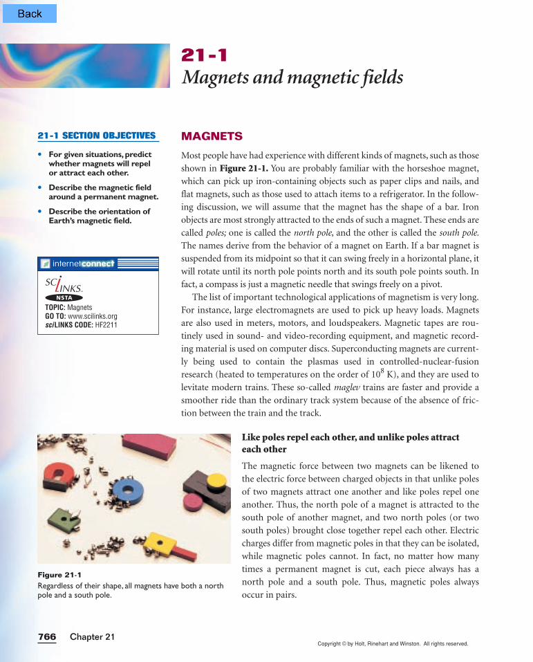
MAGNETS
Most people have had experience with different kinds of magnets, such as those
shown in Figure 21-1. You are probably familiar with the horseshoe magnet,
which can pick up iron-containing objects such as paper clips and nails, and
flat magnets, such as those used to attach items to a refrigerator. In the follow-
ing discussion, we will assume that the magnet has the shape of a bar. Iron
objects are most strongly attracted to the ends of such a magnet. These ends are
called poles; one is called the north pole, and the other is called the south pole.
The names derive from the behavior of a magnet on Earth. If a bar magnet is
suspended from its midpoint so that it can swing freely in a horizontal plane, it
will rotate until its north pole points north and its south pole points south. In
fact, a compass is just a magnetic needle that swings freely on a pivot.
The list of important technological applications of magnetism is very long.
For instance, large electromagnets are used to pick up heavy loads. Magnets
are also used in meters, motors, and loudspeakers. Magnetic tapes are rou-
tinely used in sound- and video-recording equipment, and magnetic record-
ing material is used on computer discs. Superconducting magnets are current-
ly being used to contain the plasmas used in controlled-nuclear-fusion
research (heated to temperatures on the order of 108 K), and they are used to
levitate modern trains. These so-called maglev trains are faster and provide a
smoother ride than the ordinary track system because of the absence of fric-
tion between the train and the track.
Like poles repel each other, and unlike poles attracteach other
The magnetic force between two magnets can be likened to
the electric force between charged objects in that unlike poles
of two magnets attract one another and like poles repel one
another. Thus, the north pole of a magnet is attracted to the
south pole of another magnet, and two north poles (or two
south poles) brought close together repel each other. Electric
charges differ from magnetic poles in that they can be isolated,
while magnetic poles cannot. In fact, no matter how many
times a permanent magnet is cut, each piece always has a
north pole and a south pole. Thus, magnetic poles always
occur in pairs.
Figure 21-1Regardless of their shape, all magnets have both a northpole and a south pole.
TOPIC: MagnetsGO TO: www.scilinks.orgsciLINKS CODE: HF2211
NSTA
Copyright © by Holt, Rinehart and Winston. All rights reserved.767Magnetism
Some materials can be made into permanent magnets
Just as two materials, such as rubber and wool, can become
charged after they are rubbed together, an unmagnetized piece of
iron can become a permanent magnet by being stroked with a
permanent magnet. Magnetism can be induced by other means
as well. For example, if a piece of unmagnetized iron is placed
near a strong permanent magnet, the piece of iron will eventu-
ally become magnetized. The process can be reversed either by
heating and cooling the iron or by hammering.
A magnetic piece of material is classified as magnetically hard
or soft, depending on the extent to which it retains its magnet-
ism. Soft magnetic materials, such as iron, are easily magnetized
but also tend to lose their magnetism easily. In contrast, hard
magnetic materials, such as cobalt and nickel, are difficult to
magnetize, but once they are magnetized, they tend to retain
their magnetism.
MAGNETIC FIELDS
You know that the interaction between charged objects can be described using
the concept of an electric field. A similar approach can be used to describe the
magnetic field surrounding any magnetized material.
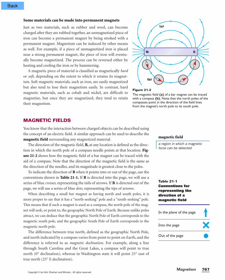
The direction of the magnetic field, B, at any location is defined as the direc-
tion in which the north pole of a compass needle points at that location. Fig-ure 21-2 shows how the magnetic field of a bar magnet can be traced with the
aid of a compass. Note that the direction of the magnetic field is the same as
the direction of the needles, and its magnitude is greatest close to the poles.
To indicate the direction of B when it points into or out of the page, use the
conventions shown in Table 21-1. If B is directed into the page, we will use a
series of blue crosses, representing the tails of arrows. If B is directed out of the
page, we will use a series of blue dots, representing the tips of arrows.
When describing a small bar magnet as having north and south poles, it is
more proper to say that it has a “north-seeking” pole and a “south-seeking” pole.
This means that if such a magnet is used as a compass, the north pole of the mag-
net will seek, or point to, the geographic North Pole of Earth. Because unlike poles
attract, we can deduce that the geographic North Pole of Earth corresponds to the
magnetic south pole, and the geographic South Pole of Earth corresponds to the
magnetic north pole.
The difference between true north, defined as the geographic North Pole,
and north indicated by a compass varies from point to point on Earth, and the
difference is referred to as magnetic declination. For example, along a line
through South Carolina and the Great Lakes, a compass will point to true
north (0° declination), whereas in Washington state it will point 25° east of
true north (25° E declination).
N S
(a)
(b)
Figure 21-2The magnetic field (a) of a bar magnet can be tracedwith a compass (b). Note that the north poles of thecompasses point in the direction of the field linesfrom the magnet’s north pole to its south pole.
magnetic field
a region in which a magneticforce can be detected
Table 21-1Conventions forrepresenting thedirection of a magnetic field
In the plane of the page
Into the page
Out of the page

Copyright © by Holt, Rinehart and Winston. All rights reserved.
Note that the configuration of Earth’s magnetic field, pictured
in Figure 21-3, resembles the field that would be produced if a bar
magnet were buried within Earth.
If a compass needle is allowed to rotate in the vertical plane as
well as in the horizontal plane, the needle will be horizontal with
respect to Earth’s surface only near the equator. As the compass is
moved northward, the needle will rotate so that it points more
toward the surface of Earth. Finally, at a point just north of Hudson
Bay, in Canada, the north pole of the needle will point directly
downward. This site is considered to be the location of the magnet-
ic south pole of Earth. It is approximately 1500 km from Earth’s
geographic North Pole. Similarly, the magnetic north pole of Earth
is roughly the same distance from the geographic South Pole. Thus,
it is only an approximation to say that a compass needle points
toward the geographic North Pole.
Although Earth has large deposits of iron ore deep beneath its surface, the
high temperatures in Earth’s liquid core prevent the iron from retaining any
permanent magnetization. It is considered more likely that the source of Earth’s
magnetic field is the movement of charges in convection currents in Earth’s
core. Charged ions or electrons circling in the liquid interior could produce a
magnetic field. There is also evidence that the strength of a planet’s magnetic
field is related to the planet’s rate of rotation. For example, Jupiter rotates at a
faster rate than Earth, and recent space probes indicate that Jupiter’s magnetic
field is stronger than Earth’s. Conversely, Venus rotates more slowly than Earth,
and its magnetic field has been found to be weaker. Investigation into the cause
of Earth’s magnetism continues.
Naturally occurring magnetic materials, such as magnetite, achieve their
magnetism because they have been subjected to Earth’s magnetic field over very
long periods of time. In fact, studies have shown that a type of anaerobic bac-
terium that lives in swamps has a magnetized chain of magnetite as part of its
internal structure. (The term anaerobic means that these bacteria live and grow
Chapter 21768
N
S
Magnetic south pole
Magnetic north poleGeographic South Pole
Geographic North Pole
Figure 21-3Earth’s magnetic field has a configu-ration similar to a bar magnet’s. Notethat the magnetic south pole is nearthe geographic North Pole and thatthe magnetic north pole is near thegeographic South Pole.
Magnetic Field of a File Cabinet
M A T E R I A L S L I S T
compass
metal file cabinet
Stand in front of the file cabinet, andhold the compass face up and parallel tothe ground. Now move the compass fromthe top of the file cabinet to the bottom.Making sure that the compass is parallel tothe ground, check to see if the direction ofthe compass needle changes as it movesfrom the top of the cabinet to the bottom.If the compass needle changes direction,the file cabinet is magnetized. Can you
explain what might have caused the filecabinet to become magnetized? Remem-ber that Earth’s magnetic field has a verti-cal component as well as a horizontalcomponent.
Try tracing the field around some largemetal objects around your house. Can youfind an object that has been magnetized bythe horizontal component of Earth’s mag-netic field?
Copyright © by Holt, Rinehart and Winston. All rights reserved.769Magnetism
without oxygen; in fact, oxygen is toxic to some of them.) The magnetized
chain acts as a compass needle, enabling the bacteria to align with Earth’s mag-
netic field. When they find themselves out of the mud at the bottom of the
swamp, they return to their oxygen-free environment by following the magnetic-
field lines of Earth. Further evidence of their magnetic-sensing ability is the dis-
covery that the bacteria in the Northern Hemisphere have internal magnetite
chains that are opposite in polarity to that of similar bacteria in the Southern
Hemisphere. This is consistent with the fact that in the Northern Hemisphere
Earth’s magnetic field has a downward component, whereas in the Southern
Hemisphere it has an upward component.
Section Review
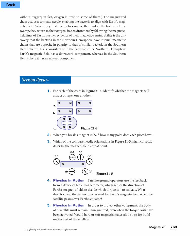
1. For each of the cases in Figure 21-4, identify whether the magnets will
attract or repel one another.
a.
b.
c. Figure 21-4
2. When you break a magnet in half, how many poles does each piece have?
3. Which of the compass-needle orientations in Figure 21-5 might correctly
describe the magnet’s field at that point?
Figure 21-5
4. Physics in Action Satellite ground operators use the feedback
from a device called a magnetometer, which senses the direction of
Earth’s magnetic field, to decide which torque coil to activate. What
direction will the magnetometer read for Earth’s magnetic field when the
satellite passes over Earth’s equator?
5. Physics in Action In order to protect other equipment, the body
of a satellite must remain unmagnetized, even when the torque coils have
been activated. Would hard or soft magnetic materials be best for build-
ing the rest of the satellite?
(a)
(b) (c)
(d)
(f) (e)
S N
S
N
N
S
S S NN
S SNN
Copyright © by Holt, Rinehart and Winston. All rights reserved.Chapter 21770
MAGNETIC FIELD OF A CURRENT-CARRYING WIRE
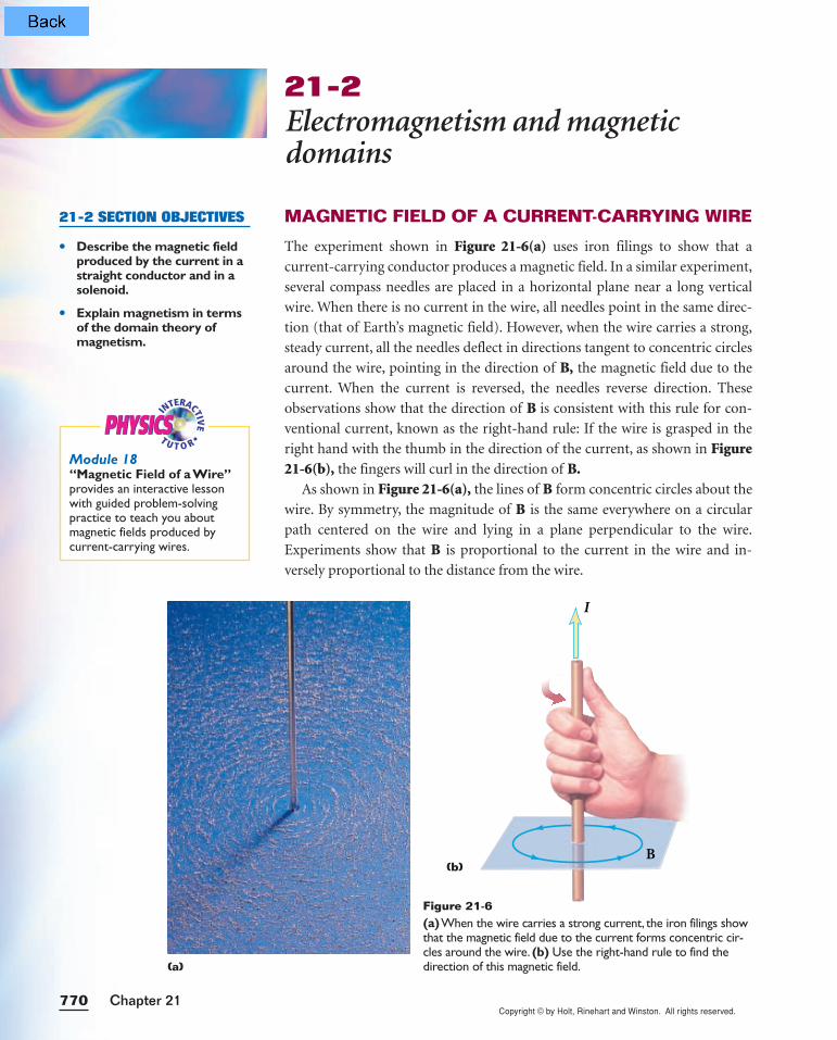
The experiment shown in Figure 21-6(a) uses iron filings to show that a
current-carrying conductor produces a magnetic field. In a similar experiment,
several compass needles are placed in a horizontal plane near a long vertical
wire. When there is no current in the wire, all needles point in the same direc-
tion (that of Earth’s magnetic field). However, when the wire carries a strong,
steady current, all the needles deflect in directions tangent to concentric circles
around the wire, pointing in the direction of B, the magnetic field due to the
current. When the current is reversed, the needles reverse direction. These
observations show that the direction of B is consistent with this rule for con-
ventional current, known as the right-hand rule: If the wire is grasped in the
right hand with the thumb in the direction of the current, as shown in Figure21-6(b), the fingers will curl in the direction of B.
As shown in Figure 21-6(a), the lines of B form concentric circles about the
wire. By symmetry, the magnitude of B is the same everywhere on a circular
path centered on the wire and lying in a plane perpendicular to the wire.
Experiments show that B is proportional to the current in the wire and in-
versely proportional to the distance from the wire.
21-2Electromagnetism and magneticdomains
21-2 SECTION OBJECTIVES
• Describe the magnetic fieldproduced by the current in astraight conductor and in asolenoid.
• Explain magnetism in termsof the domain theory of magnetism.
B
I
(b)
(a)
Figure 21-6(a)When the wire carries a strong current, the iron filings showthat the magnetic field due to the current forms concentric cir-cles around the wire. (b) Use the right-hand rule to find thedirection of this magnetic field.
INTERACTIV
E•
T U T O RPHYSICSPHYSICS
Module 18“Magnetic Field of a Wire”provides an interactive lessonwith guided problem-solvingpractice to teach you aboutmagnetic fields produced bycurrent-carrying wires.
Copyright © by Holt, Rinehart and Winston. All rights reserved.
Electromagnetism
M A T E R I A L S L I S T
D-cell battery 1 m length of insulated wire large nail compass
Wind the wire around the nailas shown below. Remove the insula-tion from the ends of the wire, andhold these ends against the metal
terminals of the battery. Use thecompass to determine whether thenail is magnetized. Next, flip thebattery so that the direction of thecurrent is reversed. Again bring thecompass toward the same part ofthe nail. Can you explain why thecompass needle now points in a different direction?
771Magnetism
MAGNETIC FIELD OF A CURRENT LOOP
The right-hand rule can also be applied to find the direction of the magnetic
field of a current-carrying loop, such as the loop represented in Figure 21-7(a).Regardless of where on the loop you apply the right-hand rule, the field within
the loop points in the same direction—upward. Note that the field lines of the
current-carrying loop resemble those of a bar magnet, as shown in Figure 21-7(b). If a long, straight wire is bent into a coil of several closely spaced
loops, as shown in Figure 21-8, the resulting device is called a solenoid.
Solenoids produce a strong magnetic field by combining several loops
A solenoid is important in many applications because it acts as a magnet when
it carries a current. The magnetic field inside a solenoid increases with the cur-
rent and is proportional to the number of coils per unit length. The magnetic
field of a solenoid can be increased by inserting an iron rod through the center
of the coil; this device is often called an electromagnet. The magnetic field that is
induced in the rod adds to the magnetic field of the solenoid, often creating a
powerful magnet.
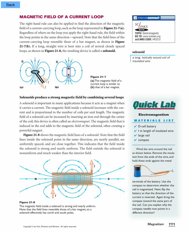
Figure 21-8 shows the magnetic field lines of a solenoid. Note that the field
lines inside the solenoid point in the same direction, are nearly parallel, are
uniformly spaced, and are close together. This indicates that the field inside
the solenoid is strong and nearly uniform. The field outside the solenoid is
nonuniform and much weaker than the interior field.
B
(a) I
I
B
(b)
N
SFigure 21-7(a) The magnetic field of acurrent loop is similar to(b) that of a bar magnet.
solenoid
a long, helically wound coil ofinsulated wire
SN
I
I
Figure 21-8The magnetic field inside a solenoid is strong and nearly uniform.Note that the field lines resemble those of a bar magnet, so asolenoid effectively has north and south poles.
TOPIC: ElectromagnetsGO TO: www.scilinks.orgsciLINKS CODE: HF2212
NSTA
Copyright © by Holt, Rinehart and Winston. All rights reserved.Chapter 21772
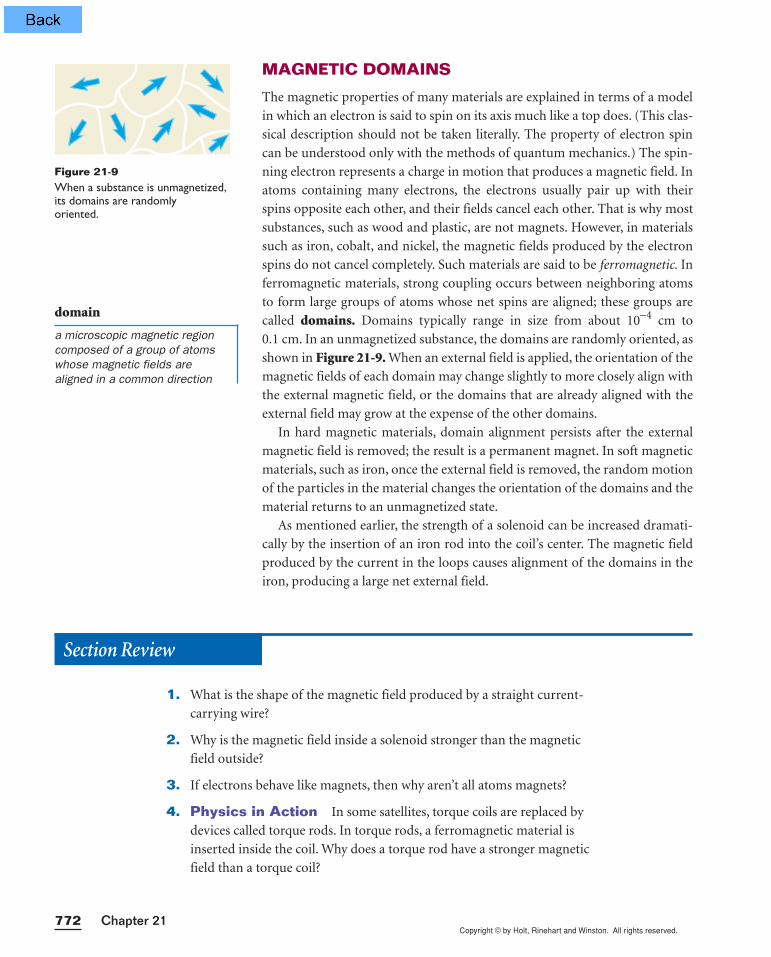
MAGNETIC DOMAINS
The magnetic properties of many materials are explained in terms of a model
in which an electron is said to spin on its axis much like a top does. (This clas-
sical description should not be taken literally. The property of electron spin
can be understood only with the methods of quantum mechanics.) The spin-
ning electron represents a charge in motion that produces a magnetic field. In
atoms containing many electrons, the electrons usually pair up with their
spins opposite each other, and their fields cancel each other. That is why most
substances, such as wood and plastic, are not magnets. However, in materials
such as iron, cobalt, and nickel, the magnetic fields produced by the electron
spins do not cancel completely. Such materials are said to be ferromagnetic. In
ferromagnetic materials, strong coupling occurs between neighboring atoms
to form large groups of atoms whose net spins are aligned; these groups are
called domains. Domains typically range in size from about 10−4 cm to
0.1 cm. In an unmagnetized substance, the domains are randomly oriented, as
shown in Figure 21-9. When an external field is applied, the orientation of the
magnetic fields of each domain may change slightly to more closely align with
the external magnetic field, or the domains that are already aligned with the
external field may grow at the expense of the other domains.
In hard magnetic materials, domain alignment persists after the external
magnetic field is removed; the result is a permanent magnet. In soft magnetic
materials, such as iron, once the external field is removed, the random motion
of the particles in the material changes the orientation of the domains and the
material returns to an unmagnetized state.
As mentioned earlier, the strength of a solenoid can be increased dramati-
cally by the insertion of an iron rod into the coil’s center. The magnetic field
produced by the current in the loops causes alignment of the domains in the
iron, producing a large net external field.
Figure 21-9When a substance is unmagnetized,its domains are randomly oriented.
domain
a microscopic magnetic regioncomposed of a group of atomswhose magnetic fields arealigned in a common direction
Section Review
1. What is the shape of the magnetic field produced by a straight current-
carrying wire?
2. Why is the magnetic field inside a solenoid stronger than the magnetic
field outside?
3. If electrons behave like magnets, then why aren’t all atoms magnets?
4. Physics in Action In some satellites, torque coils are replaced by
devices called torque rods. In torque rods, a ferromagnetic material is
inserted inside the coil. Why does a torque rod have a stronger magnetic
field than a torque coil?

Copyright © by Holt, Rinehart and Winston. All rights reserved.773Magnetism
21-3Magnetic force
21-3 SECTION OBJECTIVES
• Given the force on a chargein a magnetic field,determine the strength ofthe magnetic field.
• Use the right-hand rule tofind the direction of the forceon a charge moving througha magnetic field.
• Determine the magnitudeand direction of the force ona wire carrying current in amagnetic field.
CHARGED PARTICLES IN A MAGNETIC FIELD
Although experiments show that a stationary charged particle does not inter-
act with a constant magnetic field, charges moving through a magnetic field
do experience a magnetic force. This force has its maximum value when the
charge moves perpendicular to the magnetic field, decreases in value at other
angles, and becomes zero when the particle moves along the field lines. For the
purposes of this book, we will limit our discussion to situations in which
charges move parallel or perpendicular to the magnetic-field lines.
A charge moving through a magnetic field experiences a force
In our discussion of electric forces, the electric field at a point in space was
defined as the electric force per unit charge acting on some test charge placed
at that point. In a similar manner, we can describe the properties of the mag-
netic field, B, in terms of the magnetic force exerted on a test charge at a given
point. Our test object is assumed to be a positive charge, q, moving with veloc-
ity v. It has been found experimentally that the strength of the magnetic force
on the particle moving perpendicular to the field is equal to the product of the
magnitude of the charge, q, the magnitude of the velocity, v, and the strength
of the external magnetic field, B, as shown by the following relationship.
Fmagnetic = qvB
This expression can be rearranged as follows:
If the force is in newtons, the charge is in coulombs, and the speed is in
meters per second, the unit of magnetic field strength is the tesla (T). Thus, if
a 1 C charge moving at 1 m/s perpendicular to a magnetic field experiences a
magnetic force of 1 N, the magnitude of the magnetic field is equal to 1 T. Note
that 1 C is a very large amount of charge, so most magnetic fields are much
smaller than 1 T. We can express the units of the magnetic field as follows:
T = N/(C•m/s) = N/(A•m) = (V•s)/m2
MAGNITUDE OF A MAGNETIC FIELD
B = Fma
q
g
v
netic
magnetic field =magnetic force on a charged particle(magnitude of charge)(speed of charge)
Copyright © by Holt, Rinehart and Winston. All rights reserved.Chapter 21774
Conventional laboratory magnets can produce magnetic fields up to about
1.5 T. Superconducting magnets that can generate magnetic fields as great as
30 T have been constructed. These values can be compared with Earth’s mag-
netic field near its surface, which is about 50 mT (5 × 10⁻⁵ T).
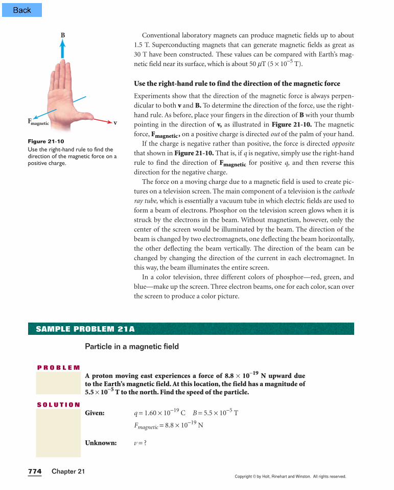
Use the right-hand rule to find the direction of the magnetic force
Experiments show that the direction of the magnetic force is always perpen-
dicular to both v and B. To determine the direction of the force, use the right-
hand rule. As before, place your fingers in the direction of B with your thumb
pointing in the direction of v, as illustrated in Figure 21-10. The magnetic
force, Fmagnetic , on a positive charge is directed out of the palm of your hand.
If the charge is negative rather than positive, the force is directed opposite
that shown in Figure 21-10. That is, if q is negative, simply use the right-hand
rule to find the direction of Fmagnetic for positive q, and then reverse this
direction for the negative charge.
The force on a moving charge due to a magnetic field is used to create pic-
tures on a television screen. The main component of a television is the cathode
ray tube, which is essentially a vacuum tube in which electric fields are used to
form a beam of electrons. Phosphor on the television screen glows when it is
struck by the electrons in the beam. Without magnetism, however, only the
center of the screen would be illuminated by the beam. The direction of the
beam is changed by two electromagnets, one deflecting the beam horizontally,
the other deflecting the beam vertically. The direction of the beam can be
changed by changing the direction of the current in each electromagnet. In
this way, the beam illuminates the entire screen.
In a color television, three different colors of phosphor—red, green, and
blue—make up the screen. Three electron beams, one for each color, scan over
the screen to produce a color picture.
F
B
vmagnetic
Figure 21-10Use the right-hand rule to find thedirection of the magnetic force on apositive charge.
SAMPLE PROBLEM 21A
Particle in a magnetic field
P R O B L E MA proton moving east experiences a force of 8.8 × 10⁻¹⁹ N upward due to the Earth’s magnetic field. At this location, the field has a magnitude of5.5 × 10−5 T to the north. Find the speed of the particle.
S O L U T I O NGiven: q = 1.60 × 10⁻¹⁹ C B = 5.5 × 10⁻⁵ T
Fmagnetic = 8.8 × 10⁻¹⁹ N
Unknown: v = ?
Copyright © by Holt, Rinehart and Winston. All rights reserved.775Magnetism
Use the equation from page 773. Rearrange to solve for v.
B = Fma
qg
vnetic
v = Fma
qg
Bnetic
v = = 1.0 × 10⁵ m/s
The directions given can be used to verify the right-hand rule. Imagine stand-
ing at this location and facing north. Turn the palm of your right hand upward
(the direction of the force) with your thumb pointing east (the direction of the
velocity). If your palm and thumb point in these directions, your fingers point
directly north in the direction of the magnetic field, as they should.
8.8 × 10⁻¹⁹ N(1.60 × 10⁻¹⁹ C)(5.5 × 10⁻⁵ T)
1. A proton moves perpendicularly to a magnetic field that has a magnitude
of 4.20 × 10⁻² T. What is the speed of the particle if the magnitude of the
magnetic force on it is 2.40 × 10⁻¹⁴ N?
2. A proton traveling to the right along the x-axis enters a region where
there is a magnetic field of magnitude 2.5 T directed upward along the
y-axis. If the proton experiences a force of 3.2 × 10⁻¹² N, find the speed
of the proton.
3. If an electron in an electron beam experiences a downward force of
2.0 × 10⁻¹⁴ N while traveling in a magnetic field of 8.3 × 10⁻² T west,
what is the direction and magnitude of the velocity?
4. A uniform 1.5 T magnetic field points north. If an electron moves verti-
cally downward (toward the ground) with a speed of 2.5 × 10⁷ m/s
through this field, what force (magnitude and direction) will act on it?
5. A proton moves straight upward (away from the ground) through a uni-
form magnetic field that points from east to west and has a magnitude of
2.5 T. If the proton moves with a speed of 1.5 × 10⁷ m/s through this
field, what force (magnitude and direction) will act on it?
6. An alpha particle (the nucleus of a helium atom, carrying a charge of
3.2 × 10⁻¹⁹ C) moves at 5.5 × 10⁷ m/s at a right angle to a magnetic field.
If the particle experiences a force of 1.5 × 10⁻¹⁴ N due to the magnetic
field, then what is the magnitude of the magnetic field?
Particle in a magnetic field
PRACTICE 21A

Copyright © by Holt, Rinehart and Winston. All rights reserved.Chapter 21776
A charge moving through a magnetic field follows a circular path
Consider a positively charged particle moving in a uniform magnetic field so
that the direction of the particle’s velocity is perpendicular to the field, as in
Figure 21-11. Application of the right-hand rule for the charge q shows that
the direction of the magnetic force, Fmagnetic , at the charge’s location is to the
left. This causes the particle to alter its direction and to follow a curved path.
Application of the right-hand rule at any point shows that the magnetic force
is always directed toward the center of the circular path. Therefore, the mag-
netic force is, in effect, a force that maintains circular motion and changes
only the direction of v, not its magnitude.
Now consider a charged particle traveling through a uniform magnetic
field with a velocity that is neither parallel nor perpendicular to the direction
of the magnetic field. In this case, the particle will follow a helical path along
the direction of the magnetic field.
MAGNETIC FORCE ON A CURRENT-CARRYINGCONDUCTOR
Recall that current is a collection of many charged particles in motion. If a
force is exerted on a single charged particle when the particle moves through a
magnetic field, it should be no surprise that a current-carrying wire also expe-
riences a force when it is placed in a magnetic field. The resultant force on the
wire is due to the sum of the individual forces on the charged particles. The
force on the particles is transmitted to the bulk of the wire through collisions
with the atoms making up the wire.
Consider a straight segment of wire of length l carrying current, I, in a
uniform external magnetic field, B, as in Figure 21-12. The magnitude of the
total magnetic force on the wire is given by the following relationship.
This equation can be used only when the current and the magnetic field are
at right angles to each other.
The direction of the magnetic force on a wire can be obtained by using the
right-hand rule. However, in this case, you must place your thumb in the
direction of the current rather than in the direction of the velocity, v. In Fig-ure 21-12, the direction of the magnetic force on the wire is to the left. When
the current is either in the direction of the field or opposite the direction of
the field, the magnetic force on the wire is zero.
FORCE ON A CURRENT-CARRYING CONDUCTOR PERPENDICULARTO A MAGNETIC FIELD
Fmagnetic = BI l
magnitude of magnetic force = (magnitude of magnetic field)(current)(length of conductor within B)
v
B
qFmagnetic
+
Figure 21-11When the velocity, v, of a chargedparticle is perpendicular to a uni-form magnetic field, the particlemoves in a circle whose plane isperpendicular to B.
B
IFmagnetic
l
Figure 21-12A current-carrying conductor in amagnetic field experiences a forcethat is perpendicular to the direc-tion of the current.
INTERACTIV
E•
T U T O RPHYSICSPHYSICS
Module 19“Magnetic Force on a Wire”provides an interactive lessonwith guided problem-solvingpractice to teach you about the magnetic force on current-carrying wires that are not per-pendicular to the magnetic field.
Copyright © by Holt, Rinehart and Winston. All rights reserved.777Magnetism
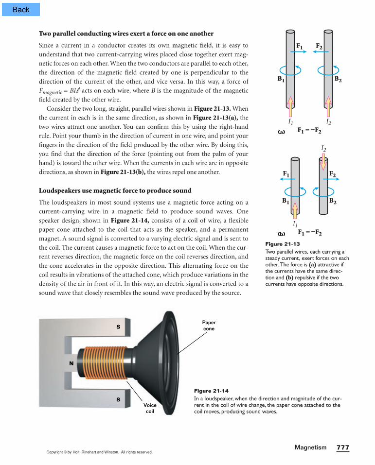
Two parallel conducting wires exert a force on one another
Since a current in a conductor creates its own magnetic field, it is easy to
understand that two current-carrying wires placed close together exert mag-
netic forces on each other. When the two conductors are parallel to each other,
the direction of the magnetic field created by one is perpendicular to the
direction of the current of the other, and vice versa. In this way, a force of
Fmagnetic = BI l acts on each wire, where B is the magnitude of the magnetic
field created by the other wire.
Consider the two long, straight, parallel wires shown in Figure 21-13. When
the current in each is in the same direction, as shown in Figure 21-13(a), the
two wires attract one another. You can confirm this by using the right-hand
rule. Point your thumb in the direction of current in one wire, and point your
fingers in the direction of the field produced by the other wire. By doing this,
you find that the direction of the force (pointing out from the palm of your
hand) is toward the other wire. When the currents in each wire are in opposite
directions, as shown in Figure 21-13(b), the wires repel one another.
Loudspeakers use magnetic force to produce sound
The loudspeakers in most sound systems use a magnetic force acting on a
current-carrying wire in a magnetic field to produce sound waves. One
speaker design, shown in Figure 21-14, consists of a coil of wire, a flexible
paper cone attached to the coil that acts as the speaker, and a permanent
magnet. A sound signal is converted to a varying electric signal and is sent to
the coil. The current causes a magnetic force to act on the coil. When the cur-
rent reverses direction, the magnetic force on the coil reverses direction, and
the cone accelerates in the opposite direction. This alternating force on the
coil results in vibrations of the attached cone, which produce variations in the
density of the air in front of it. In this way, an electric signal is converted to a
sound wave that closely resembles the sound wave produced by the source.
I2I1
B1
F1 F2
B2
F1 = −F2(a)
Figure 21-13Two parallel wires, each carrying asteady current, exert forces on eachother. The force is (a) attractive ifthe currents have the same direc-tion and (b) repulsive if the twocurrents have opposite directions.
I2
I1
B1
F1 F2
B2
F1 = −F2(b)
N
S
S
Papercone
Voicecoil
Figure 21-14In a loudspeaker, when the direction and magnitude of the cur-rent in the coil of wire change, the paper cone attached to thecoil moves, producing sound waves.
Copyright © by Holt, Rinehart and Winston. All rights reserved.Chapter 21778
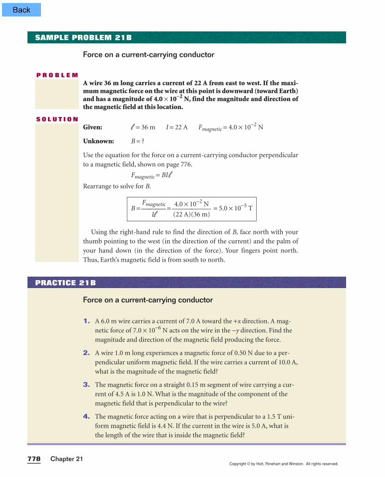
S O L U T I O NGiven: l = 36 m I = 22 A Fmagnetic = 4.0 × 10⁻² N
Unknown: B = ?
Use the equation for the force on a current-carrying conductor perpendicular
to a magnetic field, shown on page 776.
Fmagnetic = BI lRearrange to solve for B.
Using the right-hand rule to find the direction of B, face north with your
thumb pointing to the west (in the direction of the current) and the palm of
your hand down (in the direction of the force). Your fingers point north.
Thus, Earth’s magnetic field is from south to north.
B = Fma
I
g
l
netic =
(
4
2
.
2
0
A
×)
1
(
0
3
−
6
2
m
N
) = 5.0 × 10⁻⁵ T
1. A 6.0 m wire carries a current of 7.0 A toward the +x direction. A mag-
netic force of 7.0 × 10⁻⁶ N acts on the wire in the −y direction. Find the
magnitude and direction of the magnetic field producing the force.
2. A wire 1.0 m long experiences a magnetic force of 0.50 N due to a per-
pendicular uniform magnetic field. If the wire carries a current of 10.0 A,
what is the magnitude of the magnetic field?
3. The magnetic force on a straight 0.15 m segment of wire carrying a cur-
rent of 4.5 A is 1.0 N. What is the magnitude of the component of the
magnetic field that is perpendicular to the wire?
4. The magnetic force acting on a wire that is perpendicular to a 1.5 T uni-
form magnetic field is 4.4 N. If the current in the wire is 5.0 A, what is
the length of the wire that is inside the magnetic field?
Force on a current-carrying conductor
PRACTICE 21B
SAMPLE PROBLEM 21B
Force on a current-carrying conductor
P R O B L E MA wire 36 m long carries a current of 22 A from east to west. If the maxi-mum magnetic force on the wire at this point is downward (toward Earth)and has a magnitude of 4.0 × 10⁻² N, find the magnitude and direction ofthe magnetic field at this location.
Copyright © by Holt, Rinehart and Winston. All rights reserved.779Magnetism
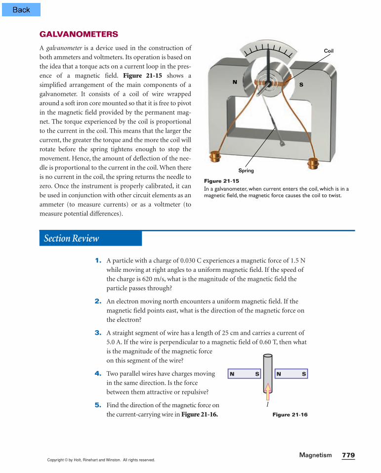
GALVANOMETERS
A galvanometer is a device used in the construction of
both ammeters and voltmeters. Its operation is based on
the idea that a torque acts on a current loop in the pres-
ence of a magnetic field. Figure 21-15 shows a
simplified arrangement of the main components of a
galvanometer. It consists of a coil of wire wrapped
around a soft iron core mounted so that it is free to pivot
in the magnetic field provided by the permanent mag-
net. The torque experienced by the coil is proportional
to the current in the coil. This means that the larger the
current, the greater the torque and the more the coil will
rotate before the spring tightens enough to stop the
movement. Hence, the amount of deflection of the nee-
dle is proportional to the current in the coil. When there
is no current in the coil, the spring returns the needle to
zero. Once the instrument is properly calibrated, it can
be used in conjunction with other circuit elements as an
ammeter (to measure currents) or as a voltmeter (to
measure potential differences).
Section Review
1. A particle with a charge of 0.030 C experiences a magnetic force of 1.5 N
while moving at right angles to a uniform magnetic field. If the speed of
the charge is 620 m/s, what is the magnitude of the magnetic field the
particle passes through?
2. An electron moving north encounters a uniform magnetic field. If the
magnetic field points east, what is the direction of the magnetic force on
the electron?
3. A straight segment of wire has a length of 25 cm and carries a current of
5.0 A. If the wire is perpendicular to a magnetic field of 0.60 T, then what
is the magnitude of the magnetic force
on this segment of the wire?
4. Two parallel wires have charges moving
in the same direction. Is the force
between them attractive or repulsive?
5. Find the direction of the magnetic force on
the current-carrying wire in Figure 21-16.
N S
Spring
Coil
Figure 21-15In a galvanometer, when current enters the coil, which is in amagnetic field, the magnetic force causes the coil to twist.
I
N N SS
Figure 21-16
Copyright © by Holt, Rinehart and Winston. All rights reserved.Chapter 21780
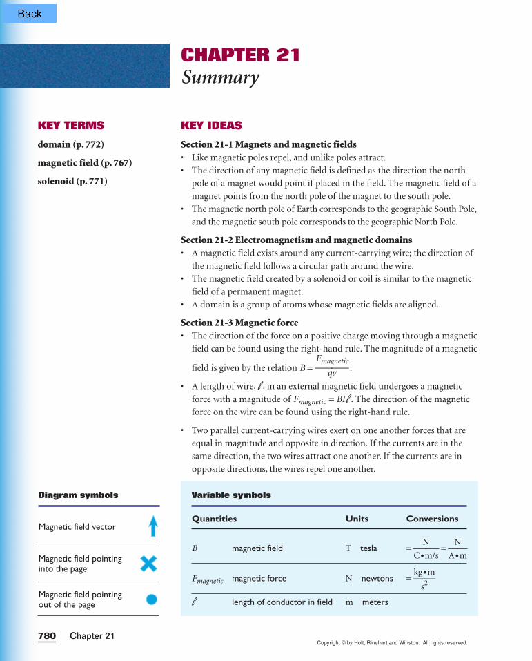
KEY IDEAS
Section 21-1 Magnets and magnetic fields• Like magnetic poles repel, and unlike poles attract.
• The direction of any magnetic field is defined as the direction the north
pole of a magnet would point if placed in the field. The magnetic field of a
magnet points from the north pole of the magnet to the south pole.
• The magnetic north pole of Earth corresponds to the geographic South Pole,
and the magnetic south pole corresponds to the geographic North Pole.
Section 21-2 Electromagnetism and magnetic domains• A magnetic field exists around any current-carrying wire; the direction of
the magnetic field follows a circular path around the wire.
• The magnetic field created by a solenoid or coil is similar to the magnetic
field of a permanent magnet.
• A domain is a group of atoms whose magnetic fields are aligned.
Section 21-3 Magnetic force• The direction of the force on a positive charge moving through a magnetic
field can be found using the right-hand rule. The magnitude of a magnetic
field is given by the relation B = Fma
qg
vnetic .
• A length of wire, l , in an external magnetic field undergoes a magnetic
force with a magnitude of Fmagnetic = BI l . The direction of the magnetic
force on the wire can be found using the right-hand rule.
• Two parallel current-carrying wires exert on one another forces that are
equal in magnitude and opposite in direction. If the currents are in the
same direction, the two wires attract one another. If the currents are in
opposite directions, the wires repel one another.
CHAPTER 21Summary
KEY TERMS
domain (p. 772)
magnetic field (p. 767)
solenoid (p. 771)
Variable symbols
Quantities Units Conversions
B magnetic field T tesla = C•
N
m/s =
A
N
•m
Fmagnetic magnetic force N newtons = kg
s
•2
m
l length of conductor in field m meters
Diagram symbols
Magnetic field vector
Magnetic field pointinginto the page
Magnetic field pointingout of the page

Copyright © by Holt, Rinehart and Winston. All rights reserved.781Magnetism
MAGNETS AND MAGNETIC FIELDS
Review questions
1. What is the minimum number of poles for a magnet?
2. When you break a magnet in half, how many polesdoes each piece have?
3. The north pole of a magnet is attracted to the geo-graphic North Pole of Earth, yet like poles repel.Can you explain this?
4. Which way would a compass needle point if youwere at the magnetic north pole?
Conceptual questions
5. You are an astronaut stranded on a planet with no testequipment or minerals around. The planet does noteven have a magnetic field. You have two iron bars inyour possession; one is magnetized, one is not. Howcan you determine which one is magnetized?
6. In Figure 21-17, two permanent magnets withholes bored through their centers are placed oneover the other. Because the poles of the upper mag-net are the reverse of those of the lower, the uppermagnet levitates above the lower magnet. If theupper magnet were displaced slightly, either up ordown, would the resulting motion be periodic?Explain. What would happen if the upper magnetwere inverted?
Figure 21-17
ELECTROMAGNETISM AND MAGNETICDOMAINS
Review questions
7. What is a magnetic domain?
8. Why are iron atoms so strongly affected by mag-netic fields?
9. When a magnetized steel needle is strongly heatedin a Bunsen burner flame, it becomes demag-netized. Explain why.
10. What indicates that a piece of iron is magnetic, itsattraction to or repulsion from another piece of iron?
11. Why does a very strong magnet attract both poles ofa weak magnet?
12. A magnet attracts a piece of iron. The iron can thenattract another piece of iron. Explain, on the basisof alignment of domains, what happens in eachpiece of iron.
13. When a small magnet is repeatedly dropped, itbecomes demagnetized. Explain what happens tothe magnet subatomically.
14. A conductor carrying a current is arranged so thatelectrons flow in one segment from east to west. If acompass is held over this segment of the wire, inwhat direction is the needle deflected?
15. What factors does the strength of the magnetic fieldof a solenoid depend on?
Conceptual questions
16. A solenoid with ends marked A and B is suspendedby a thread so that the core can rotate in the hori-zontal plane. A current is maintained in the coil sothat the electrons move clockwise when viewedfrom end A toward end B. How will the coil alignitself in Earth’s magnetic field?
CHAPTER 21Review and Assess
Copyright © by Holt, Rinehart and Winston. All rights reserved.Chapter 21782
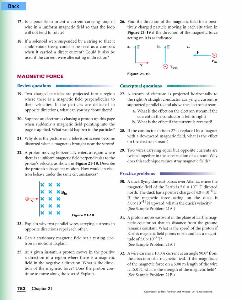
26. Find the direction of the magnetic field for a posi-tively charged particle moving in each situation inFigure 21-19 if the direction of the magnetic forceacting on it is as indicated.
Conceptual questions
27. A stream of electrons is projected horizontally tothe right. A straight conductor carrying a current issupported parallel to and above the electron stream.
a. What is the effect on the electron stream if thecurrent in the conductor is left to right?
b. What is the effect if the current is reversed?
28. If the conductor in item 27 is replaced by a magnetwith a downward magnetic field, what is the effecton the electron stream?
29. Two wires carrying equal but opposite currents aretwisted together in the construction of a circuit. Whydoes this technique reduce stray magnetic fields?
Practice problems
30. A duck flying due east passes over Atlanta, where themagnetic field of the Earth is 5.0 × 10⁻⁵ T directednorth. The duck has a positive charge of 4.0 × 10⁻⁸ C.If the magnetic force acting on the duck is 3.0 × 10⁻¹¹ N upward, what is the duck’s velocity?(See Sample Problem 21A.)
31. A proton moves eastward in the plane of Earth’s mag-netic equator so that its distance from the groundremains constant. What is the speed of the proton ifEarth’s magnetic field points north and has a magni-tude of 5.0 × 10⁻⁵ T?(See Sample Problem 21A.)
32. A wire carries a 10.0 A current at an angle 90.0° fromthe direction of a magnetic field. If the magnitude of the magnetic force on a 5.00 m length of the wireis 15.0 N, what is the strength of the magnetic field?(See Sample Problem 21B.)
Figure 21-19
F F
vvin
vout
F
17. Is it possible to orient a current-carrying loop ofwire in a uniform magnetic field so that the loopwill not tend to rotate?
18. If a solenoid were suspended by a string so that itcould rotate freely, could it be used as a compasswhen it carried a direct current? Could it also beused if the current were alternating in direction?
MAGNETIC FORCE
Review questions
19. Two charged particles are projected into a regionwhere there is a magnetic field perpendicular totheir velocities. If the particles are deflected inopposite directions, what can you say about them?
20. Suppose an electron is chasing a proton up this pagewhen suddenly a magnetic field pointing into thepage is applied. What would happen to the particles?
21. Why does the picture on a television screen becomedistorted when a magnet is brought near the screen?
22. A proton moving horizontally enters a region wherethere is a uniform magnetic field perpendicular to theproton’s velocity, as shown in Figure 21-18. Describethe proton’s subsequent motion. How would an elec-tron behave under the same circumstances?
23. Explain why two parallel wires carrying currents inopposite directions repel each other.
24. Can a stationary magnetic field set a resting elec-tron in motion? Explain.
25. At a given instant, a proton moves in the positive x direction in a region where there is a magneticfield in the negative z direction. What is the direc-tion of the magnetic force? Does the proton con-tinue to move along the x–axis? Explain.
Figure 21-18
+ v
Bin
a. b. c.
Copyright © by Holt, Rinehart and Winston. All rights reserved.783Magnetism
33. A thin 1.00 m long copper rod in a uniform mag-netic field has a mass of 50.0 g. When the rod carriesa current of 0.245 A, it floats in the magnetic field.What is the field strength of the magnetic field?(See Sample Problem 21B.)
MIXED REVIEW
34. A proton moves at 2.50 × 10⁶ m/s horizontally at aright angle to a magnetic field.
a. What is the strength of the magnetic fieldrequired to exactly balance the weight of theproton and keep it moving horizontally?
b. Should the direction of the magnetic field bein a horizontal or a vertical plane?
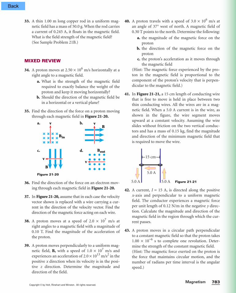
35. Find the direction of the force on a proton movingthrough each magnetic field in Figure 21-20.
36. Find the direction of the force on an electron mov-ing through each magnetic field in Figure 21-20.
37. In Figure 21-20, assume that in each case the velocityvector shown is replaced with a wire carrying a cur-rent in the direction of the velocity vector. Find thedirection of the magnetic force acting on each wire.
38. A proton moves at a speed of 2.0 × 10⁷ m/s at right angles to a magnetic field with a magnitude of0.10 T. Find the magnitude of the acceleration ofthe proton.
39. A proton moves perpendicularly to a uniform mag-netic field, B, with a speed of 1.0 × 10⁷ m/s andexperiences an acceleration of 2.0 × 10¹³ m/s2 in thepositive x direction when its velocity is in the posi-tive z direction. Determine the magnitude anddirection of the field.
Figure 21-20
v
Bout
v
B
vB
v
Bin
40. A proton travels with a speed of 3.0 × 10⁶ m/s at an angle of 37° west of north. A magnetic field of0.30 T points to the north. Determine the following:
a. the magnitude of the magnetic force on theproton
b. the direction of the magnetic force on theproton
c. the proton’s acceleration as it moves throughthe magnetic field
(Hint: The magnetic force experienced by the pro-ton in the magnetic field is proportional to thecomponent of the proton’s velocity that is perpen-dicular to the magnetic field.)
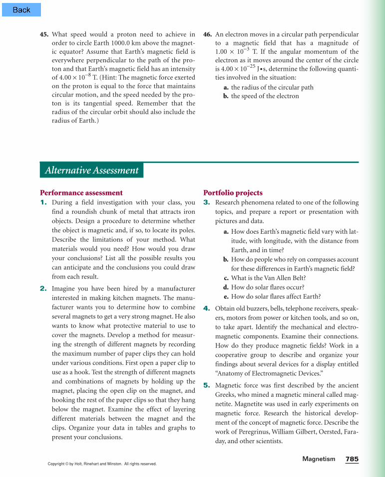
41. In Figure 21-21, a 15 cm length of conducting wirethat is free to move is held in place between twothin conducting wires. All the wires are in a mag-netic field. When a 5.0 A current is in the wire, asshown in the figure, the wire segment movesupward at a constant velocity. Assuming the wireslides without friction on the two vertical conduc-tors and has a mass of 0.15 kg, find the magnitudeand direction of the minimum magnetic field thatis required to move the wire.
42. A current, I = 15 A, is directed along the positive x-axis and perpendicular to a uniform magneticfield. The conductor experiences a magnetic forceper unit length of 0.12 N/m in the negative y direc-tion. Calculate the magnitude and direction of themagnetic field in the region through which the cur-rent passes.
43. A proton moves in a circular path perpendicular to a constant magnetic field so that the proton takes 1.00 × 10⁻⁶ s to complete one revolution. Deter-mine the strength of the constant magnetic field.(Hint: The magnetic force exerted on the proton isthe force that maintains circular motion, and thenumber of radians per time interval is the angularspeed.)
Figure 21-21
5.0 A
5.0 A5.0 A
15 cm
a. b.
d.c.
Copyright © by Holt, Rinehart and Winston. All rights reserved.Chapter 21784
field. (Hint: The magnetic force exerted on the pos-itive ion is the force that maintains circular motion,and the speed given for the positive ion is its tan-gential speed.)
44. A singly charged positive ion that has a mass of6.68 × 10−27 kg moves clockwise with a speed of1.00 × 104 m/s. The positively-charged ion moves ina circular path that has a radius of 3.00 cm. Find thedirection and strength of the uniform magnetic
Clear the data lists by pressing Π4 @
¡ e and Œ 4 @ ™ e. Press
Π1, and enter the current data into the list
¡ and the magnetic field data into the list ™.
(Remember to use @„ to enter exponents
and the _ key to enter negative numbers.) Press
@ q to exit the stat list editor.
Execute “Chap21” on the p menu, and press
e to begin the program. Enter the value for the
current in amperes, and press e. Once you have
entered the value for the current in the solenoid, the
calculator will fit that current to the line and display
the magnetic field strength of the solenoid in units
of teslas. Once you have finished using the graph for
one situation, press ı to end the program. Then
enter the data for the next situation and run the
program again.
Determine the magnetic field strength for the
solenoid with the following current and magnetic
field strength/current data points:
b. a current of 2.37 A in a solenoid that has a mag-
netic field strength of 2.54 × 10⁻² T when the cur-
rent is 3.35 A and 5.20 × 10⁻² T when the current
is 6.90 A
c. a current of 3.54 A in a solenoid that has a mag-
netic field strength of 5.50 × 10⁻³ T when the cur-
rent is 1.25 A and 1.74 × 10⁻² T when the current
is 3.80 A
d. Solenoid A and B carry the same current. Sole-
noid A produces a magnetic field of 1.5 × 10⁻² T,
and solenoid B produces a magnetic field of 2.5 ×10⁻³ T. Based on this information, which sole-
noid has more turns per length?
Graphing calculatorsRefer to Appendix B for instructions on downloading
programs for your calculator. The program “Chap21”
allows you to find the magnetic field of a solenoid
given the amount of current in the solenoid.
The program “Chap21” stored on your graphing
calculator makes use of line-fitting techniques to
find the magnetic field of a solenoid when the
amount of current in the solenoid in known. Before
executing the program “Chap21,” you will enter two
sets of data for the magnetic field strength and cur-
rent in a specific solenoid. Then, when you run the
program “Chap21,” your graphing calculator will
use this data to draw a straight line using the follow-
ing equation:
Y1 = aX + b
Next, your calculator will ask you for the value of
the current (X) in the solenoid. The calculator will
then find the point along the line that corresponds
to that current and report the y value. This y value is
the magnetic field strength (Y1) that corresponds to
the current (X) that you input. Remember that this
magnetic field strength corresponds to that current
only for the solenoid described by this line; new
data must be entered into the calculator when you
want to analyze the current and magnetic field of a
different solenoid.
a. Which letter in the above equation corresponds
to the slope of the line?
Copyright © by Holt, Rinehart and Winston. All rights reserved.785Magnetism
45. What speed would a proton need to achieve inorder to circle Earth 1000.0 km above the magnet-ic equator? Assume that Earth’s magnetic field iseverywhere perpendicular to the path of the pro-ton and that Earth’s magnetic field has an intensityof 4.00 × 10⁻⁸ T. (Hint: The magnetic force exertedon the proton is equal to the force that maintainscircular motion, and the speed needed by the pro-ton is its tangential speed. Remember that theradius of the circular orbit should also include theradius of Earth.)
46. An electron moves in a circular path perpendicularto a magnetic field that has a magnitude of1.00 × 10−3 T. If the angular momentum of theelectron as it moves around the center of the circleis 4.00 × 10⁻²⁵ J•s, determine the following quanti-ties involved in the situation:
a. the radius of the circular pathb. the speed of the electron
Performance assessment1. During a field investigation with your class, you
find a roundish chunk of metal that attracts iron
objects. Design a procedure to determine whether
the object is magnetic and, if so, to locate its poles.
Describe the limitations of your method. What
materials would you need? How would you draw
your conclusions? List all the possible results you
can anticipate and the conclusions you could draw
from each result.
2. Imagine you have been hired by a manufacturer
interested in making kitchen magnets. The manu-
facturer wants you to determine how to combine
several magnets to get a very strong magnet. He also
wants to know what protective material to use to
cover the magnets. Develop a method for measur-
ing the strength of different magnets by recording
the maximum number of paper clips they can hold
under various conditions. First open a paper clip to
use as a hook. Test the strength of different magnets
and combinations of magnets by holding up the
magnet, placing the open clip on the magnet, and
hooking the rest of the paper clips so that they hang
below the magnet. Examine the effect of layering
different materials between the magnet and the
clips. Organize your data in tables and graphs to
present your conclusions.
Portfolio projects3. Research phenomena related to one of the following
topics, and prepare a report or presentation with
pictures and data.
a. How does Earth’s magnetic field vary with lat-
itude, with longitude, with the distance from
Earth, and in time?
b. How do people who rely on compasses account
for these differences in Earth’s magnetic field?
c. What is the Van Allen Belt?
d. How do solar flares occur?
e. How do solar flares affect Earth?
4. Obtain old buzzers, bells, telephone receivers, speak-
ers, motors from power or kitchen tools, and so on,
to take apart. Identify the mechanical and electro-
magnetic components. Examine their connections.
How do they produce magnetic fields? Work in a
cooperative group to describe and organize your
findings about several devices for a display entitled
“Anatomy of Electromagnetic Devices.”
5. Magnetic force was first described by the ancient
Greeks, who mined a magnetic mineral called mag-
netite. Magnetite was used in early experiments on
magnetic force. Research the historical develop-
ment of the concept of magnetic force. Describe the
work of Peregrinus, William Gilbert, Oersted, Fara-
day, and other scientists.
Alternative Assessment
Chapter 21786
MAGNETIC FIELD OF A CONDUCTING WIREIn this lab, you will study the magnetic field that occurs around a current-
carrying wire. You will construct a circuit with a current-carrying wire and
use a magnetic compass needle or a CBL and magnetic field sensor to investi-
gate the relationship between the magnetic field and the current in the wire.
You will be able to determine the magnitude and direction of the magnetic
field surrounding the wire.
PREPARATION
1. Determine whether you will be using the CBL and sensors procedure or
the compass procedure. Read the entire lab for the appropriate proce-
dure, and plan what steps you will take.
2. Prepare a data table in your lab notebook.
• CBL and sensors Prepare a table with four columns and thirteen
rows. In the first row, label the columns Trial, Current Direction, ∆VR
(V ), and BMeasured (T). Label the 2nd through 13th rows 1 through 12.
• Compass Prepare a table with four columns and nine rows. In the
first row, label the columns Turns, Current (A), Current direction, and
Compass reading. In the first column, label the second through ninth
rows One, One, Two, Two, Three, Three, Four, and Four.
Compass procedure begins on page 788.
CHAPTER 21Laboratory Exercise
OBJECTIVES
•Use a compass or magnetic field sensor to explore the existence,magnitude, and directionof the magnetic field of acurrent-carrying wire.
•Analyze the relationshipbetween the magnitudeof the magnetic field of aconducting wire and thecurrent in the wire.
•Analyze the relationshipbetween the direction ofthe magnetic field of aconducting wire and thedirection of the currentin the wire.
MATERIALS LIST 1 Ω resistor galvanometer insulated connecting wires
and bare copper wire masking tape power supply switch
PROCEDURE
CBL AND SENSORS
alligator clips CBL CBL magnetic field sensor CBL voltage probe graphing calculator with link
cable support stand and clamp
COMPASS
compass multimeter or dc ammeter
SAFETY
• Never close a circuit until it has been approved by your teacher. Neverrewire or adjust any element of a closed circuit. Never work with elec-tricity near water; be sure the floor and all work surfaces are dry.
• If the pointer on any kind of meter moves off scale, open the circuitimmediately by opening the switch.
• Do not attempt this exercise with any batteries, electrical devices, ormagnets other than those provided by your teacher for this purpose.
• Wire coils may heat up rapidly during this experiment. If heatingoccurs, open the switch immediately and handle the equipment with ahot mitt. Allow all equipment to cool before storing it.
Copyright © by Holt, Rinehart and Winston. All rights reserved.

787Magnetism
Magnetic field strength
3. Set up the apparatus as shown in Figure 21-22. Use
1 m of copper wire to make a square loop around
the coil support pins on the galvanometer appara-
tus. Attach alligator clips to the ends of the wire.
Label one clip A and label the other B. Place the
galvanometer apparatus so that you are facing the
plane of the coil.
4. Use masking tape to mark a line on the stand of the
galvanometer directly under the top of the coil.
Make another tape line perpendicular to the first, as
shown in Figure 21-22. The two tapes should cross
in the middle of the apparatus. On the second tape,
on the side away from you, mark the point 2 cm
from the center. Using this point as the center point,
draw a circle with a 1 cm radius.
5. Construct a circuit that contains the power supply
and a 1 resistor wired in series through the mid-
dle set of posts on the switch. Place the switch so
that it moves from left to right. Connect the front
right post of the switch to the end of the coil
marked A and connect the rear right post of the
switch to the end of the coil marked B. Now con-
nect the front left post of the switch to the end of
the coil marked B and the rear left post of the
switch to the end of the coil marked A. Do notclose the switch or turn on the power supplyuntil your teacher has approved your circuit.
6. Connect the CBL to the calculator with the unit-to-
unit link cable. Connect the CBL voltage probe to
the CH1 port on the CBL and the magnetic field
probe to the CH2 port. Connect the CBL voltage
probe to measure the voltage across the resistor.
• Turn on the CBL and the graphing calculator.
Start the program PHYSICS on the calculator.
Select option SET UP PROBES from the MAIN
MENU. Enter 2 for the number of probes.
Select MORE PROBES from the SELECT
PROBE menu. Select the VOLTAGE probe
from the list. Enter 1 for the channel number.
• Select MORE PROBES from the SELECT
PROBE menu. Select the MAGNETIC FIELD
probe from the list. Enter 2 for the channel
number. From the CALIBRATION menu,
select USE STORED. For the MAGNETIC
FIELD SETTING, select HIGH (MTESLA).
7. Select OPTIONS from the MAIN MENU. Select
option ZERO SENSOR from the PHYSICS
OPTIONS menu. Select CHANNEL 2 to zero the
magnetic field sensor.
8. Hold the magnetic field sensor vertically with the
white dot facing north. The CBL will display the sen-
sor readings in volts. When the CBL displays a con-
stant value for the field strength, press TRIGGER on
the CBL to zero the sensor.
9. Select the COLLECT DATA option from the MAIN
MENU. Select the MONITOR INPUT option from
the DATA COLLECTION menu. The graphing cal-
culator will begin to display values.
PROCEDURE
CBL AND SENSORS
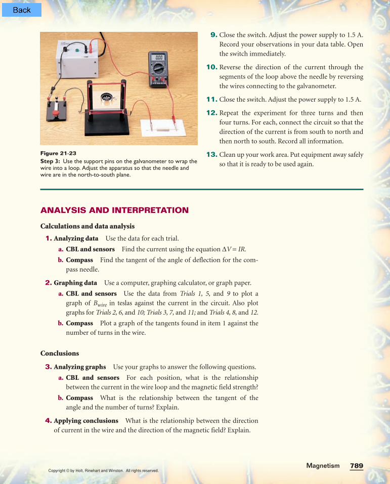
Figure 21-22Step 3: Loop the copper wire around the support pins andattach alligator clips to the ends. Place the galvanometer withone support pin on the left and one on the right.Step 4: Use two pieces of tape to mark perpendicular lines,and mark a circle to use as a reference for placing the sensor.Step 5: Place the switch in front of you so that it moves fromleft to right. Check all connections carefully.
Copyright © by Holt, Rinehart and Winston. All rights reserved.
Chapter 21788
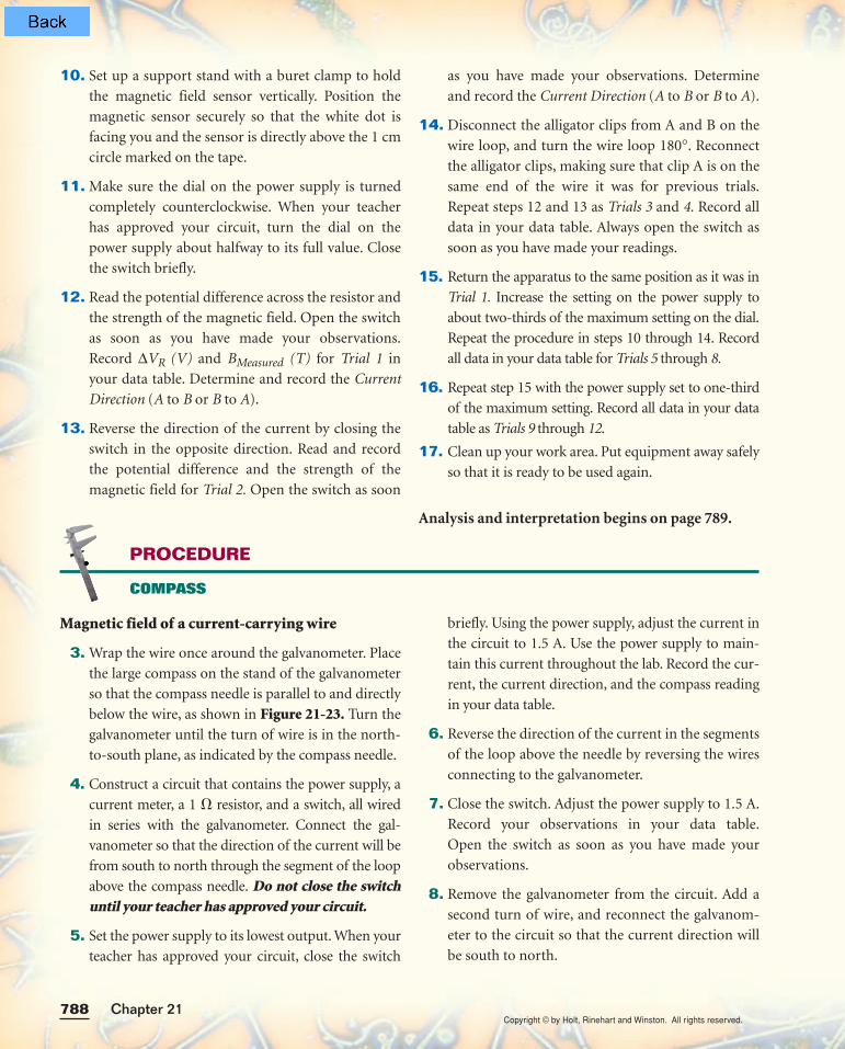
10. Set up a support stand with a buret clamp to hold
the magnetic field sensor vertically. Position the
magnetic sensor securely so that the white dot is
facing you and the sensor is directly above the 1 cm
circle marked on the tape.
11. Make sure the dial on the power supply is turned
completely counterclockwise. When your teacher
has approved your circuit, turn the dial on the
power supply about halfway to its full value. Close
the switch briefly.
12. Read the potential difference across the resistor and
the strength of the magnetic field. Open the switch
as soon as you have made your observations.
Record ∆VR (V) and BMeasured (T) for Trial 1 in
your data table. Determine and record the Current
Direction (A to B or B to A).
13. Reverse the direction of the current by closing the
switch in the opposite direction. Read and record
the potential difference and the strength of the
magnetic field for Trial 2. Open the switch as soon
as you have made your observations. Determine
and record the Current Direction (A to B or B to A).
14. Disconnect the alligator clips from A and B on the
wire loop, and turn the wire loop 180°. Reconnect
the alligator clips, making sure that clip A is on the
same end of the wire it was for previous trials.
Repeat steps 12 and 13 as Trials 3 and 4. Record all
data in your data table. Always open the switch as
soon as you have made your readings.
15. Return the apparatus to the same position as it was in
Trial 1. Increase the setting on the power supply to
about two-thirds of the maximum setting on the dial.
Repeat the procedure in steps 10 through 14. Record
all data in your data table for Trials 5 through 8.
16. Repeat step 15 with the power supply set to one-third
of the maximum setting. Record all data in your data
table as Trials 9 through 12.
17. Clean up your work area. Put equipment away safely
so that it is ready to be used again.
Analysis and interpretation begins on page 789.
Magnetic field of a current-carrying wire
3. Wrap the wire once around the galvanometer. Place
the large compass on the stand of the galvanometer
so that the compass needle is parallel to and directly
below the wire, as shown in Figure 21-23. Turn the
galvanometer until the turn of wire is in the north-
to-south plane, as indicated by the compass needle.
4. Construct a circuit that contains the power supply, a
current meter, a 1 resistor, and a switch, all wired
in series with the galvanometer. Connect the gal-
vanometer so that the direction of the current will be
from south to north through the segment of the loop
above the compass needle. Do not close the switchuntil your teacher has approved your circuit.
5. Set the power supply to its lowest output. When your
teacher has approved your circuit, close the switch
briefly. Using the power supply, adjust the current in
the circuit to 1.5 A. Use the power supply to main-
tain this current throughout the lab. Record the cur-
rent, the current direction, and the compass reading
in your data table.
6. Reverse the direction of the current in the segments
of the loop above the needle by reversing the wires
connecting to the galvanometer.
7. Close the switch. Adjust the power supply to 1.5 A.
Record your observations in your data table.
Open the switch as soon as you have made your
observations.
8. Remove the galvanometer from the circuit. Add a
second turn of wire, and reconnect the galvanom-
eter to the circuit so that the current direction will
be south to north.
PROCEDURE
COMPASS
Copyright © by Holt, Rinehart and Winston. All rights reserved.
789Magnetism
9. Close the switch. Adjust the power supply to 1.5 A.
Record your observations in your data table. Open
the switch immediately.
10. Reverse the direction of the current through the
segments of the loop above the needle by reversing
the wires connecting to the galvanometer.
11. Close the switch. Adjust the power supply to 1.5 A.
12. Repeat the experiment for three turns and then
four turns. For each, connect the circuit so that the
direction of the current is from south to north and
then north to south. Record all information.
13. Clean up your work area. Put equipment away safely
so that it is ready to be used again.
Figure 21-23Step 3: Use the support pins on the galvanometer to wrap thewire into a loop. Adjust the apparatus so that the needle andwire are in the north-to-south plane.
ANALYSIS AND INTERPRETATION
Calculations and data analysis
1. Analyzing data Use the data for each trial.
a. CBL and sensors Find the current using the equation ∆V = IR.
b. Compass Find the tangent of the angle of deflection for the com-
pass needle.
2. Graphing data Use a computer, graphing calculator, or graph paper.
a. CBL and sensors Use the data from Trials 1, 5, and 9 to plot a
graph of Bwire in teslas against the current in the circuit. Also plot
graphs for Trials 2, 6, and 10; Trials 3, 7, and 11; and Trials 4, 8, and 12.
b. Compass Plot a graph of the tangents found in item 1 against the
number of turns in the wire.
Conclusions
3. Analyzing graphs Use your graphs to answer the following questions.
a. CBL and sensors For each position, what is the relationship
between the current in the wire loop and the magnetic field strength?
b. Compass What is the relationship between the tangent of the
angle and the number of turns? Explain.
4. Applying conclusions What is the relationship between the direction
of current in the wire and the direction of the magnetic field? Explain.
Copyright © by Holt, Rinehart and Winston. All rights reserved.

Copyright © by Holt, Rinehart and Winston. All rights reserved.790
In the 1970s, many
people became concerned
about the electromagnetic
radiation being produced by
electric devices they used at work
and at home. People already knew that microwaves
could cook food and that exposure to ultraviolet light
contributed to skin cancer. So if all these effects were
possible, people reasoned, couldn’t electromagnetic
radiation given off by standard 60 Hz alternating
current also cause harm?
Electromagnetic waves are produced when a charged
particle undergoes acceleration. Accordingly, a 60 Hz
alternating current in a wire produces 60 Hz
electromagnetic radiation. This is fairly low on the
electromagnetic spectrum, considering that AM radio
waves have frequencies around 106 Hz, which is itself
fairly low on the electromagnetic spectrum. The region
of space through which electromagnetic radiation
passes is an electromagnetic f ield. Electromagnetic
waves produced by 60 Hz alternating current produce
what is called an extremely low frequency
electromagnetic f ield, or ELF.
Problems with power linesIn 1979, scientists reported that children who lived
near high-voltage power-transmission lines were twice
as likely to suffer from childhood leukemia as children
who did not live near power lines. In 1986, another
study seemed to confirm that occurrences of leukemia
and other childhood cancers were linked to the
presence of power lines. There were concerns that the
60 Hz electromagnetic f ields from the power lines
might be responsible.
Many scientists criticized these studies because the
researchers did not measure the strengths of the f ields
the people were exposed to. Instead, they had estimated
the amount of exposure from the way the power lines
were arranged, the current running through the lines,
and the distance of the lines from each house. Critics
also pointed out that the research consisted only of
epidemiological studies, which mathematically
correlate the frequency of an illness to factors in
the surroundings.
Partly as a result of this criticism, researchers were
challenged to discover a mechanism (a specif ic
biological change that would lead to the development
of cancer) by which ELFs could affect biological
systems. Soon, researchers began to report that ELFs
could damage cell membranes, cause unusual
expression of genes, increase the production of the
hormone estrogen, and reduce the pineal gland’s
production of melatonin, a hormone that can limit
the growth of cancerous cells.
From 1991 to 1995, scientists conducted another
epidemiological study to relate the health problems of
130 000 electric utility workers to their on-the-job
exposure to ELFs. The researchers made a few
measurements of f ield strength in order to estimate the
amount of exposure for each type of job. To their
surprise, they did not f ind an increased risk of
leukemia, as they had expected. Instead, they found that
brain cancer occurred more than twice as often among
these workers as it did among other kinds of workers.
However, two other studies conducted at nearly the
Science • Technology • SocietyScience • Technology • Society
ELECTROMAGNETIC FIELDS: CAN THEY AFFECT YOUR HEALTH?
Copyright © by Holt, Rinehart and Winston. All rights reserved.Science • Technology • Society 791
same time found the opposite results or no correlation
at all. In these last two studies, scientists measured the
ELF exposure of every worker.
A need for conclusionsBy 1995, several billion dollars had been spent on
research that essentially provided no conclusive results,
so government and other institutions were becoming
wary of pouring more money into further study. The
public was also becoming increasingly uneasy over the
conf licting claims about ELFs. In addition, a whole
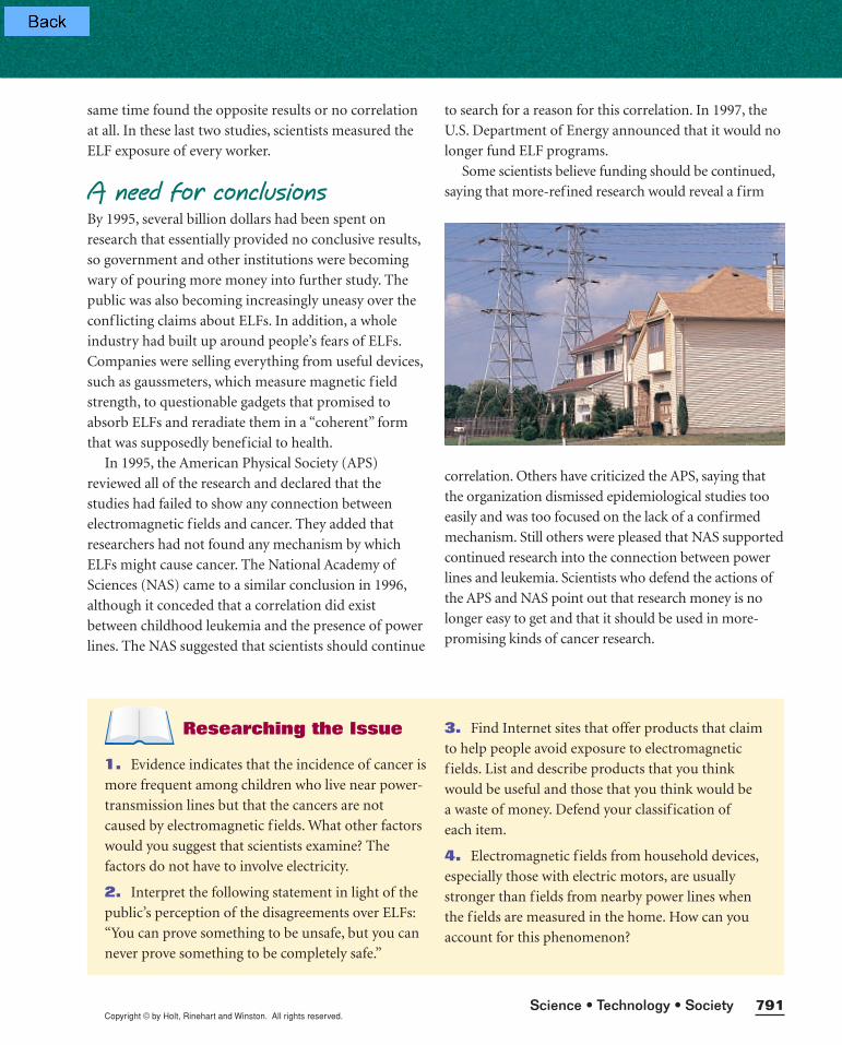
industry had built up around people’s fears of ELFs.
Companies were selling everything from useful devices,
such as gaussmeters, which measure magnetic f ield
strength, to questionable gadgets that promised to
absorb ELFs and reradiate them in a “coherent” form
that was supposedly benef icial to health.
In 1995, the American Physical Society (APS)
reviewed all of the research and declared that the
studies had failed to show any connection between
electromagnetic f ields and cancer. They added that
researchers had not found any mechanism by which
ELFs might cause cancer. The National Academy of
Sciences (NAS) came to a similar conclusion in 1996,
although it conceded that a correlation did exist
between childhood leukemia and the presence of power
lines. The NAS suggested that scientists should continue
to search for a reason for this correlation. In 1997, the
U.S. Department of Energy announced that it would no
longer fund ELF programs.
Some scientists believe funding should be continued,
saying that more-refined research would reveal a f irm
correlation. Others have criticized the APS, saying that
the organization dismissed epidemiological studies too
easily and was too focused on the lack of a confirmed
mechanism. Still others were pleased that NAS supported
continued research into the connection between power
lines and leukemia. Scientists who defend the actions of
the APS and NAS point out that research money is no
longer easy to get and that it should be used in more-
promising kinds of cancer research.
Researching the Issue
1. Evidence indicates that the incidence of cancer is
more frequent among children who live near power-
transmission lines but that the cancers are not
caused by electromagnetic f ields. What other factors
would you suggest that scientists examine? The
factors do not have to involve electricity.
2. Interpret the following statement in light of the
public’s perception of the disagreements over ELFs:
“You can prove something to be unsafe, but you can
never prove something to be completely safe.”
3. Find Internet sites that offer products that claim
to help people avoid exposure to electromagnetic
f ields. List and describe products that you think
would be useful and those that you think would be
a waste of money. Defend your classif ication of
each item.
4. Electromagnetic f ields from household devices,
especially those with electric motors, are usually
stronger than f ields from nearby power lines when
the f ields are measured in the home. How can you
account for this phenomenon?