Chaos-based crypto and joint crypto-compression systems for ...
211
HAL Id: tel-01179610 https://hal.archives-ouvertes.fr/tel-01179610 Submitted on 23 Jul 2015 HAL is a multi-disciplinary open access archive for the deposit and dissemination of sci- entific research documents, whether they are pub- lished or not. The documents may come from teaching and research institutions in France or abroad, or from public or private research centers. L’archive ouverte pluridisciplinaire HAL, est destinée au dépôt et à la diffusion de documents scientifiques de niveau recherche, publiés ou non, émanant des établissements d’enseignement et de recherche français ou étrangers, des laboratoires publics ou privés. Public Domain Chaos-based crypto and joint crypto-compression systems for images and videos Mousa Farajallah To cite this version: Mousa Farajallah. Chaos-based crypto and joint crypto-compression systems for images and videos. Engineering Sciences [physics]. UNIVERSITE DE NANTES, 2015. English. tel-01179610
-
Upload
khangminh22 -
Category
Documents
-
view
1 -
download
0
Transcript of Chaos-based crypto and joint crypto-compression systems for ...
HAL Id: tel-01179610https://hal.archives-ouvertes.fr/tel-01179610
Submitted on 23 Jul 2015
HAL is a multi-disciplinary open accessarchive for the deposit and dissemination of sci-entific research documents, whether they are pub-lished or not. The documents may come fromteaching and research institutions in France orabroad, or from public or private research centers.
L’archive ouverte pluridisciplinaire HAL, estdestinée au dépôt et à la diffusion de documentsscientifiques de niveau recherche, publiés ou non,émanant des établissements d’enseignement et derecherche français ou étrangers, des laboratoirespublics ou privés.
Public Domain
Chaos-based crypto and joint crypto-compressionsystems for images and videos
Mousa Farajallah
To cite this version:Mousa Farajallah. Chaos-based crypto and joint crypto-compression systems for images and videos.Engineering Sciences [physics]. UNIVERSITE DE NANTES, 2015. English. �tel-01179610�

Thèse de Doctorat
Mousa FARAJALLAHMémoire présenté en vue de l’obtention dugrade de Docteur de l’Université de Nantessous le label de l’Université de Nantes Angers Le Mans
École doctorale : Sciences et technologies de l’information, et mathématiques
Discipline : Electronique/spécialité: Traitement du signal et des imagesUnité de recherche : Institut d’Electronique et de Télécommunications de Rennes UMR CNRS 6164(IETR)
Soutenue le 30 Juin 2015
Chaos-based crypto and jointcrypto-compression systems for images and
videos
JURY
Présidente : Mme Danièle FOURNIER-PRUNARET, Professeur des universités, INSA de ToulouseRapporteurs : Mme Christine GUILLEMOT, Directrice de Recherche, IRISA, Rennes
M. Thomas GROSGES, Professeur des universités, Université de Technologie de TroyesExaminateurs : M. Pascal MOLLI, Professeur des universités, Université de Nantes
M. Calin VLADEANU, Professeur des universités, University Politehnica of BucharestDirecteur de thèse : M. Safwan EL ASSAD, Maître de Conférences, HDR, Université de NantesCo-encadrant de thèse : M. Olivier DEFORGES, Professeur des universités, INSA de Rennes
charlier-s
Zone de texte
ED STIM 503
charlier-s
Note
Accepted définie par charlier-s


Contents
I Chaos-Based Cryptosystems 13
1 Introduction 151.1 Cryptography based chaos . . . . . . . . . . . . . . . . . . . . . . . . . 161.2 Thesis contributions . . . . . . . . . . . . . . . . . . . . . . . . . . . . . 17
2 chaos-based cryptosystems, related work and measurement tools of perfor-mances 192.1 Chaos-based cryptosystems, related work . . . . . . . . . . . . . . . . . 19
2.1.1 Confusion and diffusion in chaos . . . . . . . . . . . . . . . . . 202.1.2 State of the art . . . . . . . . . . . . . . . . . . . . . . . . . . . 20
2.1.2.1 Fridrich cryptosystems . . . . . . . . . . . . . . . . . 202.1.2.2 A symmetric image encryption scheme based on 3D
chaotic cat maps . . . . . . . . . . . . . . . . . . . . . 212.1.2.3 Enhanced 1-D Chaotic Key-Based Algorithm for Im-
age Encryption . . . . . . . . . . . . . . . . . . . . . . 212.1.2.4 Chaotic block ciphers: from theory to practical algo-
rithms . . . . . . . . . . . . . . . . . . . . . . . . . . 212.1.2.5 A fast image encryption and authentication scheme based
on chaotic maps . . . . . . . . . . . . . . . . . . . . . 222.1.2.6 An image encryption scheme based on new spatiotem-
poral chaos . . . . . . . . . . . . . . . . . . . . . . . . 222.1.2.7 A new chaos-based fast image encryption algorithm . . 222.1.2.8 Zhang et al cryptosystem . . . . . . . . . . . . . . . . 23
2.2 Common and standard security evaluation tools . . . . . . . . . . . . . . 242.2.1 Cryptanalysis attacks . . . . . . . . . . . . . . . . . . . . . . . . 242.2.2 Plain-text sensitivity attack . . . . . . . . . . . . . . . . . . . . . 242.2.3 Key sensitivity attack . . . . . . . . . . . . . . . . . . . . . . . . 262.2.4 Histogram analysis . . . . . . . . . . . . . . . . . . . . . . . . . 272.2.5 Correlation analysis . . . . . . . . . . . . . . . . . . . . . . . . 272.2.6 Information entropy . . . . . . . . . . . . . . . . . . . . . . . . 282.2.7 Measurement of encryption quality . . . . . . . . . . . . . . . . 282.2.8 Time performance . . . . . . . . . . . . . . . . . . . . . . . . . 29
3 First Contribution: Design and Realization of Efficient Chaos-based Cryp-tosystems 313.1 Cryptosystem-A: Chaos-based substitution permutation network . . . . . 32
3.1.1 Encryption structure . . . . . . . . . . . . . . . . . . . . . . . . 323.1.1.1 Substitution layer . . . . . . . . . . . . . . . . . . . . 32
3

4 CONTENTS
3.1.1.2 Pre-diffusion . . . . . . . . . . . . . . . . . . . . . . . 403.1.1.3 Permutation layer . . . . . . . . . . . . . . . . . . . . 40
3.1.2 Proposed chaotic generator . . . . . . . . . . . . . . . . . . . . . 413.1.3 Decryption structure . . . . . . . . . . . . . . . . . . . . . . . . 43
3.1.3.1 Reverse Permutation Layer . . . . . . . . . . . . . . . 443.1.3.2 Inverse Pre-diffusion layer . . . . . . . . . . . . . . . . 453.1.3.3 Inverse Substitution layer . . . . . . . . . . . . . . . . 45
3.2 Cryptosystem-B: Chaos-based SPN with authentication process . . . . . 453.3 Cryptosystem-C: Binary diffusion layer and a bit-permutation layer cryp-
tosystem . . . . . . . . . . . . . . . . . . . . . . . . . . . . . . . . . . . 493.3.1 Description of the encryption process . . . . . . . . . . . . . . . 49
3.3.1.1 Diffusion layer . . . . . . . . . . . . . . . . . . . . . . 503.3.1.2 Permutation Layer . . . . . . . . . . . . . . . . . . . . 51
3.3.2 Description of the decryption process . . . . . . . . . . . . . . . 563.3.2.1 Reverse of the new formulation based on the modified
2-D cat map . . . . . . . . . . . . . . . . . . . . . . . 563.3.2.2 Inverse Diffusion Layer . . . . . . . . . . . . . . . . . 57
3.4 Time performance and security analysis . . . . . . . . . . . . . . . . . . 573.4.1 Performance of the speed of calculations . . . . . . . . . . . . . 573.4.2 Plain-text sensitivity attack . . . . . . . . . . . . . . . . . . . . . 583.4.3 Key sensitivity attack . . . . . . . . . . . . . . . . . . . . . . . . 593.4.4 Correlation analysis . . . . . . . . . . . . . . . . . . . . . . . . 593.4.5 Histogram analysis . . . . . . . . . . . . . . . . . . . . . . . . . 64
3.5 Conclusion . . . . . . . . . . . . . . . . . . . . . . . . . . . . . . . . . 67
4 Second Contribution: Partial Cryptanalysis of Zhang cryptosystem and de-sign of a very fast and secure cryptosystem 694.1 Partial cryptanalysis of the first Zhang cryptosystem . . . . . . . . . . . . 69
4.1.1 The first Zhang cryptosystem . . . . . . . . . . . . . . . . . . . . 704.1.2 Partial cryptanalysis of the Zhang cryptosystem . . . . . . . . . . 71
4.1.2.1 Decreasing the dynamic key space of the whole cryp-tosystem . . . . . . . . . . . . . . . . . . . . . . . . . 72
4.1.2.2 Chosen plaintext attack on the first Zhang cryptosystem 734.1.2.3 Combination of brute force and chosen plaintext attacks 80
4.1.3 Decreasing the UACI and NPCR values significantly . . . . . . . 804.2 Designe and realization of very fast and secure cryptosystems . . . . . . . 86
4.2.1 General concepts . . . . . . . . . . . . . . . . . . . . . . . . . . 864.2.2 General differences of the proposed cryptosystem with the Zhang
one . . . . . . . . . . . . . . . . . . . . . . . . . . . . . . . . . 864.2.3 First proposed cryptosystem . . . . . . . . . . . . . . . . . . . . 87
4.2.3.1 Encryption scheme of the first proposed cryptosystem . 884.2.3.2 Decryption scheme of the first proposed cryptosystem . 914.2.3.3 Analysis of the first proposed cryptosystem . . . . . . . 934.2.3.4 Dynamic key space analysis of Fridrich, Zhang and our
cryptosystems . . . . . . . . . . . . . . . . . . . . . . 934.2.3.5 Chosen-plaintext attack . . . . . . . . . . . . . . . . . 944.2.3.6 Some specific differences in the diffusion process . . . 95
4.2.4 Second proposed cryptosystem . . . . . . . . . . . . . . . . . . . 95

CONTENTS 5
4.2.4.1 Finite Skew Tent Map as diffusion layer . . . . . . . . 954.2.4.2 Analysis of the second proposed cryptosystem . . . . . 974.2.4.3 Dynamic key space analysis . . . . . . . . . . . . . . . 974.2.4.4 Chosen-plaintext attack . . . . . . . . . . . . . . . . . 97
4.2.5 Time and complexity analysis . . . . . . . . . . . . . . . . . . . 974.2.6 Plain-text sensitivity attack . . . . . . . . . . . . . . . . . . . . . 994.2.7 Key sensitivity attack . . . . . . . . . . . . . . . . . . . . . . . . 1004.2.8 Correlation analysis . . . . . . . . . . . . . . . . . . . . . . . . 1024.2.9 Histogram analysis . . . . . . . . . . . . . . . . . . . . . . . . . 103
4.3 Example of a real-time application . . . . . . . . . . . . . . . . . . . . . 1064.3.1 Real-time computing . . . . . . . . . . . . . . . . . . . . . . . . 106
4.3.1.1 Issues in conventional real-time computing systems . . 1064.3.1.2 The deadline mechanism . . . . . . . . . . . . . . . . 1074.3.1.3 Scheduling framework . . . . . . . . . . . . . . . . . . 107
4.3.2 Security in energy harvesting systems . . . . . . . . . . . . . . . 1074.3.2.1 System model . . . . . . . . . . . . . . . . . . . . . . 1074.3.2.2 The scheduling issue . . . . . . . . . . . . . . . . . . . 108
4.4 Conclusion . . . . . . . . . . . . . . . . . . . . . . . . . . . . . . . . . 109
II Joint Crypto-Compression 111
5 Video coding and crypto-compression stat of the art 1135.1 Video compression steps . . . . . . . . . . . . . . . . . . . . . . . . . . 113
5.1.1 Prediction . . . . . . . . . . . . . . . . . . . . . . . . . . . . . . 1145.1.2 Transform . . . . . . . . . . . . . . . . . . . . . . . . . . . . . . 1145.1.3 Quantization . . . . . . . . . . . . . . . . . . . . . . . . . . . . 1145.1.4 Entropy coding . . . . . . . . . . . . . . . . . . . . . . . . . . . 114
5.2 H.264/Advance Video Coding (AVC) and scalable extension . . . . . . . 1155.3 High Efficiency Video Coding (HEVC) standard . . . . . . . . . . . . . . 116
5.3.1 HEVC partitioning . . . . . . . . . . . . . . . . . . . . . . . . . 1175.3.2 HEVC Intra prediction . . . . . . . . . . . . . . . . . . . . . . . 1185.3.3 HEVC Inter prediction . . . . . . . . . . . . . . . . . . . . . . . 1185.3.4 HEVC transformation and quantization . . . . . . . . . . . . . . 1235.3.5 CABAC entropy coding . . . . . . . . . . . . . . . . . . . . . . 123
5.4 Video encryption algorithms - related works . . . . . . . . . . . . . . . . 1265.4.1 MPEG Video encryption algorithms . . . . . . . . . . . . . . . . 127
5.4.1.1 I-frames encryption . . . . . . . . . . . . . . . . . . . 1285.4.1.2 A non-compatible four level of security . . . . . . . . . 1285.4.1.3 Zig-Zag permutation algorithms . . . . . . . . . . . . . 1285.4.1.4 Change the sign bits or the values of DCT coefficients . 128
5.4.2 AVC and SVC encryption algorithms . . . . . . . . . . . . . . . 1295.4.2.1 Transparent encryption techniqes for AVC and SVC . . 1295.4.2.2 Digital video scrambling method using Intra prediction
mode . . . . . . . . . . . . . . . . . . . . . . . . . . . 1305.4.2.3 Entropy coding encryption in AVC . . . . . . . . . . . 1305.4.2.4 Selective video encryption based on AVC . . . . . . . . 1315.4.2.5 Fast protection of the AVC by selective encryption . . . 131

5.4.2.6 Fast protection of AVC by reduced selective encryptionof CAVLC . . . . . . . . . . . . . . . . . . . . . . . . 131
5.4.2.7 Design of new unitary transforms for perceptual videoencryption . . . . . . . . . . . . . . . . . . . . . . . . 132
5.4.3 HEVC encryption algorithms . . . . . . . . . . . . . . . . . . . 1325.5 Conclusion and discussion . . . . . . . . . . . . . . . . . . . . . . . . . 134
6 Third Contribution: Selective encryption algorithms for Video 1356.1 Selective video encryption based on chaos system for SHVC . . . . . . . 136
6.1.1 Encryptable bit . . . . . . . . . . . . . . . . . . . . . . . . . . . 1376.1.2 Chaotic encryption system . . . . . . . . . . . . . . . . . . . . . 1426.1.3 Synchronization problem . . . . . . . . . . . . . . . . . . . . . . 1446.1.4 Experimental configuration . . . . . . . . . . . . . . . . . . . . . 1456.1.5 Objective quality and Encryptable Bit (EB) . . . . . . . . . . . . 1456.1.6 Visual quality . . . . . . . . . . . . . . . . . . . . . . . . . . . . 1526.1.7 Security analysis . . . . . . . . . . . . . . . . . . . . . . . . . . 154
6.1.7.1 Encryption Quality . . . . . . . . . . . . . . . . . . . 1546.1.7.2 Edge differential ratio . . . . . . . . . . . . . . . . . . 1566.1.7.3 Key sensitivity test . . . . . . . . . . . . . . . . . . . . 1566.1.7.4 Histogram analysis . . . . . . . . . . . . . . . . . . . 1576.1.7.5 Known plain-text attack . . . . . . . . . . . . . . . . . 1586.1.7.6 Brute force attack . . . . . . . . . . . . . . . . . . . . 1596.1.7.7 Complexity analysis . . . . . . . . . . . . . . . . . . . 159
6.2 Encryption of ROI in HEVC . . . . . . . . . . . . . . . . . . . . . . . . 1646.2.1 A brief state of the art . . . . . . . . . . . . . . . . . . . . . . . 1646.2.2 AES in cipher feedback mode . . . . . . . . . . . . . . . . . . . 1656.2.3 ROI encryption solutions in the HEVC . . . . . . . . . . . . . . 165
6.2.3.1 TSE-HEVC EB . . . . . . . . . . . . . . . . . . . . . 1666.2.3.2 MV restriction in the background tile . . . . . . . . . . 1676.2.3.3 Encryption process based on AES-CFB mode . . . . . 167
6.2.4 Results and analysis . . . . . . . . . . . . . . . . . . . . . . . . 1676.2.4.1 Experimental configuration . . . . . . . . . . . . . . . 1676.2.4.2 Results . . . . . . . . . . . . . . . . . . . . . . . . . . 168
6.3 Conclusion and discussion . . . . . . . . . . . . . . . . . . . . . . . . . 169
III Conclusion and Future Works 171
7 Conclusion and Future Work 173
Appendix A: Synthèse des travaux réalisés 189
Appendix B 197
6

* Say, "Indeed, my prayer, my rites of sacrifice, my living and my dying are for Allah ,Lord of the worlds". (Surat Al-’An ’am 6.162).
I would like to dedicate this Doctoral dissertation to my sons Mohammed and Omar, mywife, my father , and my mother for their endless love, encouragement and help, to
Martyrs of Palestine.
7


Acknowledgements
Special thanks to my supervisor, Dr. Safwan El Assad, for instructions, guidance, and forhis efforts to orient my thinking. You have been a tremendous mentor for me. I wouldlike to thank you for encouraging my research and for allowing me to grow as a researchscientist. Your advice on both research has been invaluable, specially in publications.I would like to express my special appreciation and deepest gratitude to my co-supervisorProf. Olivier Deforges for his support, providing me with an excellent atmosphere fordoing research.I would like to to thank Dr. Wassim, was always help me and work hard with me speciallyin the compression part.I acknowledge and thank my IETR lab for allowing me to conduct my research and pro-viding any assistance requested, specially image team.I won’t forget the French government scholarship department. They gave me the oppor-tunity to pursue my education that improve my academic. REZE municipality where theygave me a good and comfortable accommodation during this three years. Finally, TheEuropean Celtic-Plus project 4KREPROSYS - 4K ultraHD TV wireless REmote PRO-duction SYStems
9

Personal Publications
Published Journal paper:
1. Farajallah Mousa, El Assad Safwan and Deforges Olivier, " Fast and secure chaosbased cryptosystem for images", International Journal of Bifurcation and Chaos(IJBC), Accepted in 15-June-2015, (Q1 journal, H Index: 65).
2. Chetto Maryline, El Assad Safwan, and Farajallah Mousa, "A lightweight chaos-based cryptosystem for dynamic security management in real-time overloaded ap-plications." International Journal of Internet Technology and Secured Transactions,5, no. 3 (2014): 262-274, (Q4 journal, H Index: 4). .
Published and accepted Conference papers:
1. Farajallah Mousa, Hamidouche Wassim, Deforges Olivier, and El Assad Safwan,"ROI Selective Video Encryption in the HEVC Video Standard", International Con-ference on Image Processing (ICIP) 2015 to be held from the 27th 30th September2015, Quebec City, Canada. Accepted in 29-Avril-2015, (H Index: 40).
2. Hamidouche Wassim, Farajallah Mousa, Raulet Mickaël, Deforges Olivier, and ElAssad Safwan, "Selective video encryption using chaotic system in the SHVC ex-tension," in 40th IEEE International Conference on Acoustics, Speech and SignalProcessing (ICASSP), 19th 24th April 2015, Brisbane, Australia, April 2015, Bris-bane, Australia, 5 Pages, (H Index: 70).
3. El Assad Safwan, Farajallah Mousa, and Calin Vladeanu, " Chaos-based BlockCiphers: An Overview”, IEEE, 10th International Conference on Communications,COMM-2014, Bucharest, Romania, May 2014, pp. 23-26.
4. Farajallah Mousa, El Assad Safwan, and Chetto Maryline, "Dynamic adjustment ofthe chaos-based security in real-time energy harvesting sensors." In Green Comput-ing and Communications (GreenCom), 2013 IEEE and Internet of Things (iThings/CPSCom),IEEE International Conference on and IEEE Cyber, Physical and Social Comput-ing, pp. 282-289. IEEE, 2013, (H Index: 2).
5. Farajallah, Mousa, Fawaz Zeinab, El Assad Safwan, and Deforges Olivier, "Effi-cient image encryption and authentication scheme based on chaotic sequences." InSECURWARE 2013, The Seventh International Conference on Emerging SecurityInformation, Systems and Technologies, pp. 150-155. 2013, (H Index: 1).
6. Fawaz Zeinab, El Assad Safwan, Farajallah Mousa, Khalil Ayman, Lozi René, andDeforges Olivier, "Lightweight chaos-based cryptosystem for secure images." InInformation Science and Technology (ICIST), 2013 International Conference on,pp. 26-30. IEEE, 2013.
7. Chetto Maryline, Noura Hassan, El Assad Safwan, and Farajallah Mousa, "Howto guarantee secured transactions with QoS and real-time constraints." In InternetTechnology And Secured Transactions, 2012 International Conference for, pp. 40-44. IEEE, 2012.
10

Submitted Journal papers:
1. Hamidouche Wassim, Farajallah Mousa, Raulet Mickaël, Deforges Olivier, and ElAssad Safwan, "Real Time Selective Video Encryption based on stream cipher inthe Scalable HEVC Extension", IEEE Transactions on. Circuits and Systems forVideo Technology, Submission date:23-Dec-2014, 13 Pages.
2. Farajallah Mousa, El Assad Safwan and Deforges Olivier, "Partial cryptanalysis ofthe first Zhang algorithms", International Journal of Bifurcation and Chaos (IJBC),Submission date:27-Mar-2015, 17 Pages.
3. El Assad Safwan and Farajallah Mousa, "A New Efficient Structure of a Cryptosys-tem based on Two Chaotic Layers: a Binary Diffusion Layer and a Bit-PermutationLayer", IEEE Systems Journal. under submission, 13 Pages.
11


IChaos-Based Cryptosystems
13


1Introduction
The root of Cryptology is coming from the Greeks; it is the science that studies the theo-retical and practical techniques for secure communications. It is divided into two relatedbranches: cryptography and cryptanalysis. The cryptographer tries to find some tech-niques to guarantee the message secrecy and sometimes to ensure the authenticity of thatmessage, while the cryptanalyst tries to cancel the cryptographer’s work by breaking thesecrecy of the message to retrieve the original one or by forging a message to be acceptedas authentic one.
By using cryptography many goals can be achieved, and these goals can be all achievedat the same time in one application, or only some of them can be achieved. The main goalsare [85, 4]:
• Confidentiality: ensuring that nobody can understand the received message except-ing the authorized persons.
• Authentication: confirming and testing the identity of an entity, by assuring that thecommunicating entity is the one that it claims to be.
• Integrity: ensures that the received message has not been altered in any way fromits original form.
• Non-Repudiation: a mechanism to prove that the sender really sent the message, sothe recipient cannot claim that the message was not sent.
• Access Control: the process of preventing unauthorized use of resources, i.e., itcontrols who can have access to the resources, when he can access, under whichrestrictions and conditions the access can be granted, and finally, what is the per-mission level of a given access.
• Signature: a method to link or bind information to an entity or to prove the entityauthorship.
• Authorization: the owner gives the authority for someone to do something on behalfof him.
15

Until the 1970s, cryptography was the exclusive domain of the military and governments.Nowadays, with the development of both computer and Internet technology, and withthe globalization of the exchanges (Internet, email, e-business,etc.) of multimedia datasuch as: images, videos, audios, etc., is being used more and more widely used in manyapplications, including banks, commerce, education, hospitals, mobile communications,wireless sensor networks (WSNs), etc. These applications often include sensitive data tobe protected before transmission, and only authorized users can have access (by using asecret key) to the useful information at any time. The confidentiality of data is mainlyassured by encryption, which transforms the data from the original form (plaintext) intounreadable and non understandable form (ciphertext). A universal assumption of cryp-tography established by A. Kerckhoffs in the nineteenth century is that the secrecy mustreside entirely in the secret key [108]. This means that the cryptanalyst has full access tothe cryptographic algorithm and its implementation.The cryptography field also includes, in addition to the encryption/decryption algorithmsthat can be Symmetric (Secret Key)/Asymmetric (Public-Key), protocols that deal withthe application of cryptographic algorithms. The Transport Layer Security (TLS) and itspredecessor, Secure Sockets Layer (SSL), which are used by web browsers to connectsecurely to web servers, are cryptographic protocols.In order to secure a communication over public networks, cryptography techniques, suchas symmetric and asymmetric key encryption can be used. In a few words, in the sym-metric key encryption, the same encryption and decryption key is shared by both of thesender and the receiver.Asymmetric or public key encryption has a pair of public and private keys, i.e., one at thesender and the other at the receiver. Symmetric encryption has two man advantages overasymmetric encryption: it is faster, since it does not consume large time in the encryptionand the decryption processes, the key generation is less complex. However, the prob-lem of sharing the secret key between the sender and the receiver is more complicatedin symmetric encryption. In fact, public key cryptography is used to solve the problemof sharing the secret key, which is produced by symmetric key encryption. Symmetricalgorithms are divided into two types: stream and block ciphers. The former operates onthe plaintext as a single bit or byte or N-bit sample at a time. While the latter operates onthe blocks of the plaintext, having a fixed size of Nb (NB is the block size in bits) bits.Over the time, cryptanalysis on Internet and Internet-attached systems is rapidly growing,and attack techniques become more automated, causing significant damage. Moreover,these days, the hackers are able to penetrate systems with less information. The designerof a cryptosystem tries to increase its resistance against cryptanalysis techniques: thepenalty is in increasing calculus time and the complexity structure of the designed cryp-tosystem. Besides, for many applications which demand both real-time performance andhigh level of security, such as: private multimedia data exchanged by portable devicesover the wireless networks and sensitive data exchanged in wireless sensor networks, weneed to design cryptosystems with some constraints, such as: low complexity, small mem-ory, and limited energy resources. Designing cryptosystems to secure multimedia data,by taking into account the previous constraints, is a big challenge [70, 151, 106].
1.1 Cryptography based chaosToday, based on some important properties of chaos, such as ergodicity, quasi-randomness,high sensitivity to the changes of control parameters and initial conditions, etc., chaos
16

is a hot research field in secured communications. Recently, a variety of chaos-basedcryptosystems have been investigated. Most of them are based on the Fridrich structure[44], which is based on the traditional confusion-diffusion architecture proposed by Shan-non, [8, 28, 22, 14, 21]. Compared to the conventional cryptographic algorithms (DES,3DES, AES, etc.), the chaos-based cryptosystems provide several advantages, such as:very high security level, high speed especially in stream ciphers, increased flexibility,increased modularity, low computational overheads and computational power, and eas-ier to be implemented. These features make them more suitable for large scale-dataencryption, such as images and videos. Indeed, with a fixed block size, the advancedencryption standard (AES) is not suitable for selective video encryption and stream ci-phers, [108, 36, 104, 96, 49]. For example, in selective encryption of the real-time videoapplications, we need to wait to have 128 bits before the starting of encryption process.This is an inconvenience for the latency of the system. Experimental results show that thechaos-based encryption algorithms can achieve security issues in efficient and adaptiveways, [2, 46, 69, 52, 15, 80, 16, 22, 129, 45, 44, 165, 84, 83]. Generally, different algorithms encrypt different data volumes and thus get different se-curity and efficiency (computational time). In direct encryption, the multimedia contentor compressed content is encrypted directly with a novel or traditional cipher directly. Inpartial encryption, only some significant parts of the multimedia content are encrypted,while the others parts are lefts unencrypted. In joint compression encryption, the en-cryption operation is combined with a compression operation, and they are implementedsimultaneously. Naturally, direct encryption often encrypts the largest data volumes, andthus, it has the highest security and lowest efficiency. Partial encryption and joint com-pression encryption, reduce the encrypted data volumes, and thus, get higher efficiencyand necessary level of security for a given application [70]. In perceptual encryption, mul-timedia content is encrypted under the control of the encryption strength that determinesthe perceptibility of the encrypted multimedia content. A typical case of perceptual en-cryption is secure multimedia preview, in which the multimedia content is first encryptedwith slight encryption strength and decrypted after payment. In scalable encryption, thescalable multimedia content is encrypted layer by layer, in a progressive manner, accord-ing to the significance of the layers. It can be used in secure media trans-coding. Whenthe encrypted media content is transmitted from the Internet to bandwidth-limited mobilenetworks, the significant layers can be cut off directly without decryption [70].
1.2 Thesis contributionsIn this study, we designed, implemented, and evaluated the performance in terms of thesecurity level and of the structure complexity (speed of calculus) of some chaos-basedcryptosystems for images and videos. All of them have a high security level, while keep-ing high throughput encryption compared to most chaos-based cryptosystems of the lit-erature. We analyzed the security level of the proposed cryptosystems, relative to thedifferent types of well-known attacks. Normally, with enough effort, any practical cryp-tosystem can be cryptanalyzed. The question is how much effort it takes to cryptanalyze asystem. An easy way to quantify the workload of an attack is to compare it to an exhaus-tive search. That means the attacker tries all possible values for some target objective,like the key. If an attack requires 2120 steps of works, then this corresponds to an ex-haustive search for 120-bit value. Any cryptosystem designed nowadays needs at least2128 steps in order to resists this type of trivial attacks. Notice that, for some multimedia
17

encryption applications, the encryption algorithm may be regarded as secure if the costfor breaking it is no smaller than the one paid for the multimedia content. For example,in broadcasting, the news may be of no value after an hour. Thus, if the attacker cannotbreak the encryption algorithm over the course of an hour, then the encryption algorithmis regarded as secure in this application [41, 70], which means the cryptanalysis shouldbe on the given time. Otherwise, it will be useless because is not a real-time cryptanalysis.
This thesis is organized in two parts. In the first part of this thesis, including chap-ter 2, there are introduced the concepts, the state of the art, and the common securityevaluation tools and efficiency tools. In chapters 3 and 4, we propose four efficient chaos-based cryptosystems, defined on finite numbers, for real-time applications on images andvideos. All of them are blocks ciphers and the first two cryptosystems are based on thesubstitution-permutation network (SPN). The substitution layer is achieved by a proposedmodified Finite Skew Tent Map (FSTM) to overcome following problems: fixed point,restriction of the key space and limitation of mapping between plaintext and ciphertext,and vice versa. The structure of the third cryptosystem is new and efficient. It is basedon two chaotic layers: a binary diffusion layer of pixels, followed by a bit-permutationlayer. The permutation process is achieved by a proposed formulation of the 2-D cat mapthat allows an efficient implementation in C code. The fourth cryptosystem, which is4 times faster than the other cryptosystems, with a very high security level is designed,based on a partial cryptanalysis that we performed against one of the best chaos-basedcryptosystems, recently published by Zhang in 2013. In this cryptosystem, the confusionprocess (based on the modified 2D-cat map) and the diffusion process (based on the mod-ified FSTM as a generator) are performed simultaneously, in a single scan of plain-imagepixels. In the second part, (chapter 5), we introduce all necessary concepts and defi-nitions to understand the High Efficiency Video Coding (HEVC) and its scalable version(SHVC), for a cryptographer researcher working on video encryption. Chapter 6 describesin details our contribution on designing two fast and secure selective chaos-based crypto-compression systems to encrypt and secure the HEVC and its scalable version SHVC. Inthe first crypto-compression system, we propose a new algorithm to define the encrypt-able bit in the bit stream of the HEVC and the SHVC. The proposed solution encrypts aset of sensitive SHVC parameters with a minimum delay and complexity overheads. Theencryption process is performed at the CABAC bin string level and fulfills both constantbit rate and format compliant video encryption requirements. It preserves all SHVC func-tionalities, including bit stream extraction for mid-network adaptation, error resilience,and real-time SHVC decoder. The second crypto-compression system protects the Re-gion Of Interest (ROI) of the HEVC based on the tile concept. It performs encryptionat the bit stream level by encrypting all HEVC syntax elements within the ROI tiles, ora selective encryption of the ROI tiles under constant bit rate and format compliant re-quirements. To avoid temporal propagation of the encryption outside the ROI boundariescaused by inter prediction, the motion vectors of non ROI regions are restricted inside thenon encrypted tiles in the reference frames.
18

2chaos-based cryptosystems, relatedwork and measurement tools ofperformances
In section 2.1 of this chapter, and also in chapter 3, we give a very brief description ofthe main recent chaos-based cryptosystems of the literature, which have a direct rela-tion to our contributions. Section 2.2 presents some metrics and measurement tools ofperformances that are used to quantify the resistance of cryptosystem’s and of crypto-compression systems against some typical attacks and for evaluating their efficiency.
2.1 Chaos-based cryptosystems, related workIn any public communication network, such as satellite, mobile-phone, and the Internet,it is almost impossible to prevent unauthorized people from eavesdropping. To use the al-ready existed public communication networks and to maintain the secrecy, cryptographictechniques are applied [109]. The security of image and video content has become in-creasingly important for many applications, including video conferencing, medical imag-ing, industrial, military imaging systems, private multimedia messages exchanged byportable devices over the wireless networks and sensitive data exchanged in wireless sen-sor networks, etc.Chaos theory has been established since 1970s [89], it is a field of mathematics and hasmany applications in different branches of knowledge, including engineering, physics,economics, philosophy, and biology.A chaotic system is a deterministic system, but it has a pseudorandom behavior. It is anonlinear system that has a large sensitivity to the initial conditions and control parame-ters [59]. Matthews has published a first paper on the derivation of a chaotic encryptionalgorithm in 1989 [146].Today, chaos-based encryption algorithms have been widely used in image and video en-cryption systems. Research has shown that chaotic systems are extremely sensitive to thechanges of control parameters and initial conditions. They have a pseudorandom behav-
19

ior for non authorized parties [8, 57, 28, 22, 14, 150, 21]. Experimental results show thatthe chaos-based encryption algorithm can achieve security issues in efficient and adap-tive ways as compared to the classical encryption algorithms (such as DES and AES)[2, 46, 69, 52, 15, 80, 16, 49]. Thus, chaos has become a hot research topic over thelast decades, and many chaos-based encryption algorithms have been recently introduced[22, 129, 45, 44, 165, 84, 83, 36].Most of described chaos-based encryption-decryption schemes are blocks ciphers andthey are based on the substitution-permutation network (SPN). In a chaos-based encryp-tion algorithm, the substitution and the permutation operations are done in accordancewith chaotic sequences to achieve the required diffusion and confusion effects.
2.1.1 Confusion and diffusion in chaosIn order to be robust against several types of attacks, any cryptosystem must achievethe confusion and diffusion effects. This has been explained in Shannon’s famous paper[123] "In a strongly ideal cipher all statistics of the cryptogram are independent of theparticular key used". Confusion property aims to make the statistical relationship betweenthe cipher-image and the secret key as complex and involved as possible, whereas thediffusion property aims to make the statistical relationship between the plain image andthe cipher-image as complex as possible. The confusion principle can be described as:the key should not relate to the cipher-text and each bit/byte of the cipher-text shoulddepend on a complex mathematical relation of the key. The diffusion effect principle canbe described as: each plain-text byte/bit affects many cipher text bytes/bits. The formercan be achieved using chaotic maps for permutation and/or substitution, whereas the lattercan be achieved using chaotic maps to transfer the single byte/bit effect to other bytes/bits.
2.1.2 State of the artThe idea of using chaos for image encryption has become a hot research topic during thelast two decades, but in fact, the basic and the definition of this idea is very old and itwas founded in Shannon’s paper [123]. A large number of chaos-based cryptosystems forimage encryption were introduced during the last decade. The most cited and importantchaos-based stucture was introduced by Fridrich in his research from 1997 [44].
2.1.2.1 Fridrich cryptosystems
In 1997, a chaos-based encryption scheme was introduced by Fridrich [44, 45]. It becamethe core structure of the most chaos-based cryptosystems and it has been widely refer-enced since 1997. The general architecture of such cryptosystem is shown in Fig.2.1.
Figure 2.1: Encryption scheme of Fridrich
20

In Fridrich scheme, the confusion is achieved by permuting all the pixels as a whole,using one of the three types of 2-D chaotic maps, namely, Standard map, Cat map, andgeneralized Baker map. For example, using the 2-D BAKER chaotic map, the new byteposition is given by (2.1) :
B(x′, y′) = (2x, y2) when 0 ≤ x < 1
2
B(x′, y′) = (2x− 1, y2
+ 12) when 1
2≤ x ≤ 1
(2.1)
The diffusion process changes sequentially the pixel values, in such a manner that thechange to a particular pixel depends on the accumulated effect of all previous pixel values.It is implemented using the following mathematical equations:
vk = vk +G(vk−1)Mod 256v−1 = initial value
(2.2)
The function G is an arbitrary function of the gray level. It was chosen as a fixed randompermutation, which can be implemented using a simple lookup table.
In [74], Lian et al., analyzed the security level of the Fridrich scheme. They foundsome weaknesses and proposed some improvements to overcome these security failures.In 2010, the Fridrich encryption algorithm was broken by Solak et.al., [132]. It has beenproved that the Fridrich algorithm could be broken using a chosen cipher-text attack. Us-ing this type of attack, some secret permutation of the algorithm has been revealed.
2.1.2.2 A symmetric image encryption scheme based on 3D chaotic cat maps
Guanrong et al, introduced a symmetric image encryption scheme based on 3D chaoticmaps. They generalized the 2D into 3D chaotic maps to shuffle the pixel positions and toconfuse the relationship between the plain and the cipher images. However, the speed oftheir algorithm is not high for real time applications. Also, the propagation error is large,since it works in cubes and each cube affects all the others [22].
2.1.2.3 Enhanced 1-D Chaotic Key-Based Algorithm for Image Encryption
In [129], a robust image encryption algorithm called Enhanced 1-D Chaotic Key-BasedAlgorithm for Image Encryption (ECKBA) was proposed. The algorithm performs rrounds of an SP-network on each pixel. Two PWLCM maps are used, one in the sub-stitution process (addition modulo 256 and bitwise operations) and the other one in thepermutation process. The permutation is of degree 8, and its index in the full symmet-ric group S8 is sorted in lexicographical Cartesian of i order (see appendix of reference[129]). The weakness of this algorithm is the error propagation caused by the used per-turbation technique and the low encryption speed.
2.1.2.4 Chaotic block ciphers: from theory to practical algorithms
Masuda et al., [84] considered two classes of chaotic finite-state maps: key-dependentchaotic S-boxes and chaotic mixing transformation. They proposed two chaotic blockciphers, i.e., uniform and Feistel. In fact, they estimated bounds for differential and linear
21
probability to make their cryptosystems resistant to differential and linear cryptanalysis.They proposed an interesting nonlinear map, namely "Skew tent map" and its two ver-sions as a substitution layer. In chapter 3, we present, analyze, and point out in detailssome existing drawbacks of their Skew tent map and we propose a modified version thatovercomes the previous drawbacks.
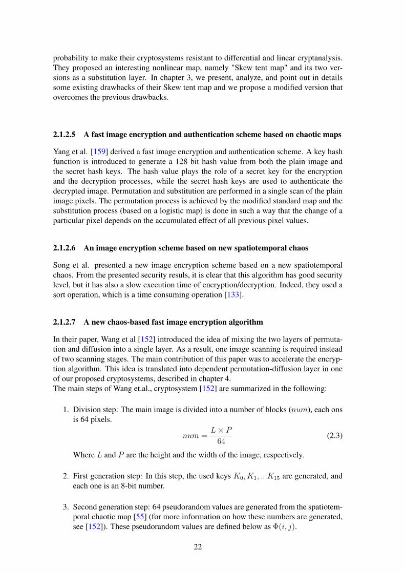
2.1.2.5 A fast image encryption and authentication scheme based on chaotic maps
Yang et al. [159] derived a fast image encryption and authentication scheme. A key hashfunction is introduced to generate a 128 bit hash value from both the plain image andthe secret hash keys. The hash value plays the role of a secret key for the encryptionand the decryption processes, while the secret hash keys are used to authenticate thedecrypted image. Permutation and substitution are performed in a single scan of the plainimage pixels. The permutation process is achieved by the modified standard map and thesubstitution process (based on a logistic map) is done in such a way that the change of aparticular pixel depends on the accumulated effect of all previous pixel values.
2.1.2.6 An image encryption scheme based on new spatiotemporal chaos
Song et al. presented a new image encryption scheme based on a new spatiotemporalchaos. From the presented security resuls, it is clear that this algorithm has good securitylevel, but it has also a slow execution time of encryption/decryption. Indeed, they used asort operation, which is a time consuming operation [133].
2.1.2.7 A new chaos-based fast image encryption algorithm
In their paper, Wang et al [152] introduced the idea of mixing the two layers of permuta-tion and diffusion into a single layer. As a result, one image scanning is required insteadof two scanning stages. The main contribution of this paper was to accelerate the encryp-tion algorithm. This idea is translated into dependent permutation-diffusion layer in oneof our proposed cryptosystems, described in chapter 4.The main steps of Wang et.al., cryptosystem [152] are summarized in the following:
1. Division step: The main image is divided into a number of blocks (num), each onsis 64 pixels.
num =L× P
64(2.3)
Where L and P are the height and the width of the image, respectively.
2. First generation step: In this step, the used keys K0, K1, ...K15 are generated, andeach one is an 8-bit number.
3. Second generation step: 64 pseudorandom values are generated from the spatiotem-poral chaotic map [55] (for more information on how these numbers are generated,see [152]). These pseudorandom values are defined below as Φ(i, j).
22

4. Diffusion step: The pixel values inside each block are modified based on the fol-lowing equation:
Gt(i, j) = cycl{X, Y }X = [Pt(i, j)⊕ Φ(i, j) + Ct(i− 1, j)]Mod GY = LSB3(Ct(i− 1, (j − 1)mod 8)⊕ Φ(i, j))
(2.4)
Where:Gt(i, j) is the number of levels in the gray image (here is 256 levels) and is per-formed for all pixels in the tth block.Pt(i, j) and Ct(i, j) are the plain and the ciphered pixels at i and j positions, re-spectively.Ct(i − 1, j), Ct(i, j − 1) and Ct(i − 1, (j − 1) mod 8) are the previous cipheredpixels. The values of ciphered pixels at the negative indexes are set into Kj+8.cycl{X, Y } is a function to perform a left cyclic shift of X by Y .LSB3(f) denotes the three least significant bits of f .
5. Moving block positions: A block at the position t is moved to a new position ac-cording to the following equation:
tnew = bX(0)× numc (2.5)
X(0) is a generated value from the used chaotic map. If the tnew is a non-visitedplace, then the block is moved to this place; otherwise, the tnew is incremented untilthe new value point to a non-visited place. As not all pixels inside a given blockare permuted, this step is necessary to increase the security of this model to thestatistical analysis attacks.
6. Exchanging lattice values: The pixelsC(7, i) andC(7, (i+d)mod 8) are exchanged,where d is calculated as:
d = LSB3(C(7, 0)) (2.6)
7. First Block pixel exchange: C0(0, s) is exchanged with Ckl(7, 7) where:s = LSB3(kl)
kl =⌊[K0⊕K1⊕K2⊕...K15]×num
256
⌋Steps, 3→ 6 are performed for all blocks, and repeated R rounds until the required secu-rity level is reached.
2.1.2.8 Zhang et al cryptosystem
Finally, two fast and secure cryptosystems were proposed by Zhang et al., [166]. Tothe best of our knowledge, these cryptosystems renowned very secure against attacks,and faster than the previous chaos-based cryptosystems. In chapter 4, first, we describe,analyze and partially break the first Zhang cryptosystem. Second, we design and realizea very robust and fast chaos-based cryptosystem.
23

2.2 Common and standard security evaluation toolsIn this section, we give the definition of the main known attacks and then, we describein detail the well-known statistical security measurements and evaluation tools. Thesemeasurements and tools are used in the chapters 3, 4, and 6.
2.2.1 Cryptanalysis attacksBased on Kirchhoff’s principle, the security of the encryption algorithm should only bebased on the secret key and all other system parts should be known for the public [54]. Acryptanalyst tries to break the cipher without knowing the secret key, and this with severallevels of difficulties based on the available resources:
1. Cipher-text only attack: A group of cipher-texts is available for the attacker; hewins the game if he finds the corresponding plain-text. It is logical that this type ofcomplexity is based on the amount of available cipher-texts (i.e., the difficulty forthe attacker is increased when the cipher-text is decreased).
2. Known plain-text attack: It is easier for the attacker to use it. To put it simply, theattacker has a group of plain-texts and the corresponding cipher-text; by the way,this type includes the previous one.
3. Chosen plain-text attack (the easiest one for the attacker): The attacker has access tothe system without knowing the secret keys. Then, he has the possibility to choosea plain-text message and to encrypt it.
4. Chosen cipher-text attack: The attacker chooses the cipher-text and obtains thecorresponding plain-text using the decryption system, without knowing the secretkey. In this type of attack, the attacker’s objective is to find the secret key.
The cryptanalysis research papers show that the security of ciphers, which is based onlyon statistical analysis, can be partially or completely broken down [93, 101, 150, 132, 56,47, 9, 131, 29, 102].
2.2.2 Plain-text sensitivity attackA cryptosystem should be sensitive to one bit change in the plain-text. This requirementis the most important to resist the known and the chosen plain-text attacks [74, 81]. In achosen plain-text attack, more than one plain-text (with one-bit changes between them) isselected to analyze the difference between their corresponding cipher-texts. The measure-ment tool to test the sensitivity of any cryptosystem to these attacks is carried out basedon the following procedure:
1. Select P1 as the first plain image.
2. Change one bit in P1 and name it as P2. (i.e., P1 and P2 are exactly the same exceptfor one bit; this bit is chosen to be located in the beginning, middle or the end of thefirst block; the plain-text results are calculated as an average of these three cases).
3. Both images (P1 and P2) are encrypted using the same secret key.
4. The previous encryption process produces two cipher images C1 and C2.
24

5. Then, a group of statistical security tests is applied on the ciphered imagesC1 andC2.
Most researchers use two security parameters to measure the resistance of any chaos-based cryptosystem for plain-text sensitivity attacks. These parameters are: the Numberof Pixel Change Rate (NPCR) and the Unified Average Changing Intensity (UACI); theyare given by the following equations, respectively:
NPCR =1
L× C × P×
P∑p=1
L∑i=1
C∑j=1
D(i, j, p)× 100% (2.7)
where
D(i, j, p) =
{0, if C1(i, j, p) = C2(i, j, p)
1, if C1(i, j, p) 6= C2(i, j, p)(2.8)
UACI =1
L× C × P × 255×
P∑p=1
L∑i=1
C∑j=1
|C1(i, j, p)− C2(i, j, p)| × 100% (2.9)
In the previous equations, i, j and p are the row, column, and plane indexes of the image,respectively. L, C and P are, respectively, the length, width, and plane sizes of the image.Figure.2.2 shows a schematic view of the plain-text sensitivity attack.
Figure 2.2: Plain-text sensitivity attack
The optimal NPCR value is 99.61%, and the optimal UACI value is 33.46% [79, 157].The above two metrics (NPCR, UACI) are usually used to measure the resistance of aproposed cryptosystem against the differential attacks introduced by Eli Biham and AdiShamir [17].The previous metrics are necessary but not sufficient to ensure that the proposed cryp-tosystem is resistant against plain-text sensitivity attacks. Then, a new metric mea-surement, the Hamming Distance (HD) is used to quantify the avalanche effect. TheAvalanche effect is achieved for any block cipher, when a small change (for example,flipping a single bit) in either the plain-text or the secret key, causes a drastic change inthe cipher-text (e.g., half of the output bits are flipped), [82]. Therefore, this evaluationtest is used to measure the resistance of any cryptosystem to the plain-text and the key
25

sensitivity attacks.The HD is defined by:
HD(C1, C2) =1
|Ib|
|Ib|∑K=1
(C1(K)⊕ C2(K)) (2.10)
where |Ib| = L × C × P × 8, is the size of the image in bits. The optimum HD valueis 50%. A good block cipher should produce an HD close to 50% (probability of bitchanges, which means that a one bit difference in plain-image will make every bit of thecorresponding cipher-image change with a probability of a half [150]). Therefore, theplain-text sensitivity attack would become a useless attacking method.
2.2.3 Key sensitivity attack
Key sensitivity is extremely crucial for any cryptosystem. A cryptosystem has a highsecurity level relative to the key sensitivity attack if a slight change in the secret key willproduce a completely different ciphered image [94]. The scenario of the key sensitivityattack, which is almost identical to the plain-text sensitivity attack, is as follows:
1. Only one plain-text is used for encryption process P1 = P2 = P .
2. Two secret keys (i.e., K1 and K2) which different in one bit are used.
3. P is encrypted using K1 to obtain C1.
4. P is encrypted using K2 to obtain C2.
5. Then, the equations of the NPCR, UACI and HD(2.7, 2.8 and 2.10) are used toevaluate the key sensitivity attack.
Figure.2.3 shows a schematic view of the key sensitivity attack.
Figure 2.3: Key sensitivity attack
26

2.2.4 Histogram analysis
One of the most common cryptosystem attacks is the one based on statistical analysis.A cryptosystem is considered to be strong against these attacks, if the encrypted imagehistogram is uniformly distributed.The visual test is necessary, but it is not sufficient. To ensure image uniformity, the chi-square test is applied (see equation (2.11)) to statistically confirm the uniformity of thehistogram:
χ2exp =
Q−1∑i=0
(oi − ei)2
ei(2.11)
In equation (2.11),Q is the number of levels (hereQ = 256), oi is the observed occurrencefrequency of each color level (0-255) on the histogram of the ciphered image, and eiis the expected occurrence frequency of the uniform distribution, given here by ei =L×C×P
Q. For a secure cryptosystem, the experimental chi-square value must be less than
the theoretical chi-square one, which is 293 in case of α = 0.05 (α here is the level ofsignificance) and Q = 256 [66].
2.2.5 Correlation analysis
Correlation analysis is also one of the statistical attacks that are used to cryptanalyze thecryptosystem. It should not give any information of the used secret key or any partialinformation of the original plain image. This means that the encrypted image should begreatly different from its original version. Correlation analysis is one of the regular andstandard methods to measure this property. Indeed, it is well-known that adjacent pixels inthe plain images are very redundant and correlated. So, in the encrypted images, adjacentpixels should have a redundancy and a correlation as low as possible. To test the securityof any new algorithm, regarding to this type of attacks, first N pairs of adjacent pixelsin vertical, horizontal, and diagonal directions are selected from the plain image and itsciphered version. Then, the following mathematical equations are used to calculate thecorrelation coefficient [133]:
ρxy =cov(x, y)√D(x)
√D(y)
(2.12)
Where
cov(x, y) =1
N
N∑i=1
([xi − E(x)][yi − E(y)]) (2.13)
D(x) =1
N
N∑i=1
(xi − E(x))2 (2.14)
E(x) =1
N
N∑i=1
(xi) (2.15)
In the above equations, xi and yi are the values of the two adjacent pixels in the plainimage or the corresponding ciphered image.
27

2.2.6 Information entropyThe image pixel values are ranging from 0 up to 255. In a robust cipher algorithm, theoccurrence probability of any pixel should be the same (or almost the same). The randombehavior of the encrypted message can be evaluated using the entropy information definedby:
H(C) =
Q−1∑i=0
Pro(ci)× log2
1
Pro(ci)(2.16)
Where H(C) is the entropy of the ciphered image C, Pro(ci) is the occurrence numberof each level (i = 0, 1, 2...255).In case of equal probability levels (Pro(ci) = 2−8), the information entropy is maximal,H(C) =
∑256−1i=0 2−8 × log2 256 = 8, according to (2.16).
2.2.7 Measurement of encryption qualityThe difference between the frequency of occurrence for each byte level before and afterencryption is called Encryption Quality (EQ), and is defined by [6]:
EQ =
∑255i=0 |oi(P )− oi(C)|
256(2.17)
where oi(C) are the observed occurrence for the byte level i in the ciphered image C, andoi(P ) are the observed occurrences of the same byte level i in the plain image P .Thus, the larger the value of EQ, the higher the level of security of the cryptosystem. Fora need of comparison, it is necessary to estimate the optimal value of EQ. For that, belowwe propose a derivation from equation 2.17 to find the maximal value of EQ, denoted asEQmax:
EQmax =510× L× C
2562(2.18)
where L and C are the line and the column of the gray image/frame. The maximal valueof the EQ is derived, based on the following two assumptions:
1. For an encryption algorithm, the bad original image is the one that has a very lowentropy, and the worst case is when all pixels have the same value, for example, allpixels are black or white. Therefore, the total number of occurrences of the pixeli1 in the original image P is oi1(P ) = L × C, where i1 ∈ {0, 255}. Moreover, thetotal number of occurrences of the pixel i2 (i2 is any pixel except i1) in the plainimage P is oi2(P ) = 0, where i2 ∈ {0, 255} and i2 6= i1.
2. A very secure algorithm should produce a ciphered image in which all pixels areequally distributed. Therefore, the total number of occurrences of any pixel i in theciphered image is oi(C) = L×C
256, where i ∈ {0, 255}.
Based on these two assumptions and using equation (2.17), we derive EQmax as follows:
EQmax =|L×C256− L× C|+ |L×C
256− 0| × 255
256(2.19)
After simplification, we find:
EQmax =510× L× C
2562(2.20)
28

2.2.8 Time performanceTo quantify the time performance of any cryptosystem, first, we have to analyze the com-plexity of the algorithm in terms of the used logical and mathematical operations, andread-write memory operations. Second, the performance is determined by evaluating therunning speed that can be measured by: the average encryption/decryption times, the en-cryption throughput, and the needed number of cycles to encrypt one byte. The encryptionthroughput (ET) and the number of cycles, which are required to encrypt or decrypt onebyte, are defined as:
ET =ImageSize(Byte)
EncryptionT ime(second)(2.21)
Number of cycles per Byte =CPU Speed(Hertz)
ET(Byte)(2.22)
The last equation permits to compare the running speed of different cryptosystems work-ing on different platforms.
29


3First Contribution: Design andRealization of Efficient Chaos-basedCryptosystems
The process of designing and developing a chaos-based cryptosystem, starts by identi-fying the needed requirements of the application: degree of the security level, time andmemory consuming, and if it is designed to support a real time application.In this chapter three chaos-based cryptosystems to secure transmitted images are designedand realized. The realized cryptosystems are very secure and they are faster than manychaos-based cryptosystems of the literature. All of them are defined on finite numbersand can be used for real time applications.The first and the second cryptosystems use the same substitution process, based on Fi-nite State Skew Tent Map (FSTM), and the same process of pixel-permutation, basedon 2-D cat map. The main difference between these two cryptosystems is that, the firstcryptosystem uses a pre-diffusion process to enhance and accelerate the process of diffu-sion while the second cryptosystem uses a hash function. The hash function generate thesecret key of the chaotic generator that provides the dynamic keys for the substitution-permutation layers, and the secret hash key is used to authenticate the decrypted image.The first cryptosystem is faster than the second one, while the later is very immune againstchosen plaintext attack. The structure of the third proposed cryptosystem is new and ef-ficient. It is based on two chaotic layers: a binary diffusion layer of pixels, followed bya bit-permutation layer. Moreover, the permutation process is achieved by a proposedformulation of the 2-D cat map that allows an efficient implementation in C code. Thethree realized cryptosystems use an implemented simple version of a chaotic generatorpublished by El Assad et Noura in a Patent [37]. Below we describe in details the realizedthree cryptosystems. The first cryptosystem (Crypto-A) is introduced in details in sec-tion 3.1, [38]. the implemented chaos-based generator for all cryptosystems is presentedin section (3.1.2). The second cryptosystem, (Crypto-B) is presented in section 3.2, [39].The third cryptosystem (Crypto-C) is described in details in section 3.3, [35]. A compara-tive study of performance, in terms of security and calculation time, of the three proposedcryptosystems, is given in the section 3.4, before concluding in section 3.5.
31

3.1 Cryptosystem-A: Chaos-based substitution permuta-tion network
The proposed cryptosystem consists of four components: a substitution layer, a diffusionlayer, a permutation layer, and a chaotic generator. The structure of the cryptosystem isshown in Figure.3.1, for the encryption part and in Figure.3.4, for the decryption part.
3.1.1 Encryption structureDuring the encryption process, the plain image is divided into N blocks, with N =imagesize/blocksize, where the block size value is chosen to be a square value. The im-age size must be a multiple of the block size, so, in case of that image size is not a multipleof the block size, we pad the last block by (block size−mod (image size, block size))bytes. The divided blocks are ciphered one by one by applying the substitution layer onthe block for rs times to achieve the confusion effect. Next the diffusion layer is used tospread a single byte effect to the other bytes in the same block, this layer is repeated rdtimes. Then the output of this layer is forwarded to the permutation layer to exchange thebyte position inside the same block to add more confusion effect. The permutation layeralso is repeated rp times. These three layers are repeated r rounds to get the requiredsecurity level. For each round r, new necessary dynamic keys are produced by a robustchaotic generator [37]
Figure 3.1: Encryption part of Crypto-A
3.1.1.1 Substitution layer
Substitution is the process of replacing a single byte value by another byte value basedon a mathematical equation. The substitution layer is based here on the Finite State SkewTent Map (FSTM). This layer performs a nonlinear transformation in the image data,and so the cryptosystem becomes more resistant against differential cryptanalysis attacks.
32

This layer works on byte-by-byte transformation and it changes the value of the bytedepending on a chaotic parameter which comes from a robust chaotic generator. Themathematical model of the FSTM as one-to-one map for the substitution is introducedby[84, 83]:
Y = FA (X) =
⌈QA×X
⌉if 1 ≤ X ≤ A
⌊Q×(Q−X)Q−A
⌋+ 1 if A < X ≤ Q
(3.1)
with Q = 256, and X,A, Y ∈ {1, 2, ..., Q}, note that, the value 0 is not included.
The inverse of equation (3.1) was calculated as:
X = FA−1 (Y ) =
X1 if m(Y ) = Y and X1
A> Q−X2
Q−A
X2 if m(Y ) = Y and X1
A≤ Q−X2
Q−A
X1 if m(Y ) = Y + 1
(3.2)
Where
X1 =
⌊A× YQ
⌋(3.3)
X2 =
⌈(A
Q− 1)× Y +Q
⌉(3.4)
m(Y ) = Y +
⌊A× YQ
⌋−⌈A× YQ
⌉+ 1 (3.5)
Note that the inverse substitution equation is introduced in this section because they arerequired to describe the FSTM and its modifications.Shifted Masuda equationsTo use the previous equations for image encryption/decryption process where a byte isrepresented in eight bits, the authors include 0 and exclude Q from the domain. Then, theobtained equations are:
Y = FA (X) =
⌈QA× (X + 1)
⌉− 1 if 0 ≤ X < A
⌊Q×(Q−X−1)
Q−A
⌋if A ≤ X < Q
(3.6)
with Q = 256, X, Y ∈ {0, 1, 2, ..., Q− 1}, and A ∈ {1, 2, ..., Q}.
The inverse of the shifted equation (3.6) is calculated as:
X = FA−1 (Y ) =
X1 − 1 if m(Y + 1) = Y + 1 and X1
A> Q−X2
Q−A
X2 − 1 if m(Y + 1) = Y + 1 and X1
A≤ Q−X2
Q−A
X1 − 1 if m(Y + 1) = Y + 2
(3.7)
Where
X1 =
⌊A× (Y + 1)
Q
⌋(3.8)
X2 =
⌈(A
Q− 1)× (Y + 1) +Q
⌉(3.9)
33

m(Y + 1) = Y +
⌊A× (Y + 1)
Q
⌉−⌊A× (Y + 1)
Q
⌉+ 2 (3.10)
We found some drawbacks on the previous substitution and inverse substitution equa-tions:
1. It is written in the original paper that A = Q is one of the possible values, but inthis case the second part of equation (3.6) has a division by zero.
2. For some output values (Y ), it is easy to decrease the possibilities of guessing theinput value (X); indeed, let take the following example:
• To have Y = 0, there are only two values of the input X , these values are:X = 0 or X = 255, because:When X < A, then the first term of the equation (3.6)
⌈256A×X
⌉− 1 = 0,
that means, 0 < 256×X+1A
≤ 1. The only solution of the previous inequalityequation is possible if the term X+1
Ais less than or equal to 1
256. This is only
achievable for X = 0 and A = 256.When A ≤ X , then the second term of the equation (3.6)
⌊256×(256−X−1)
256−A
⌋=
0, that means, 0 ≤ 256×(256−X−1)256−A < 1. The only solution of the previous
inequality equation is possible if the term 256−X−1256−A is less than 1
256. This is
only achievable for X = 255 and any given A.
• To have Y = 1, for any given A, there are only three values of the input X ,these values are: X = 0 at A = 256, X = 1 at A ∈ {128, 129, 130, ..., 256}or X = 254 at A ∈ {1, 2, 3, ..., 127}.When X < A, then the first term of the equation (3.6)
⌈256A×X
⌉− 1 = 1,
that means, 1 < 256×X+1A
≤ 2. The only solution of the previous inequalityequation is possible if the term X+1
Ais less than or equal to 2
256and more than
1256
. This is only achievable for X = 0 at A ∈ {128, 129, 130, ..., 255} orfor X = 1 at A = 256.When A ≤ X , then the second term of the equation (3.6)
⌊256×(256−X−1)
256−A
⌋=
1, that means, 1 ≤ 256×(256−X−1)256−A < 2. The only solution of the previ-
ous inequality equation is possible if the term 256−X−1256−A is less than 2
256and
more than or equal to 1256
. This is only achievable for X = 254 at A ∈{1, 2, 3, ..., 127}.
• To have Y = 255, there is only one solution which is X = A− 1.
3. Some input values (X) don’t have the possibility to map them to all output values(Y ). For example when X = 255 the output can be only Y = 0 or Y = 255because:The first term of the equation (3.6) at X = 255 is only used with A = 256 and sothe value of the term
⌈256×(255+1)
256
⌉− 1 is 255.
The second term of the equation (3.6) at X = 255 is used when A ≤ X and so thevalue of the term
⌊256×(256−255−1)
256−A
⌋is 0 for any given A.
To increase the security level of the above equations, the authors impose A and Q tobe co-prime, so, the model become:
34
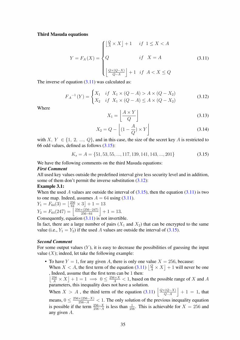
Third Masuda equations
Y = FA (X) =
⌊QA×X
⌋+ 1 if 1 ≤ X < A
Q if X = A
⌊Q×(Q−X)Q−A
⌋+ 1 if A < X ≤ Q
(3.11)
The inverse of equation (3.11) was calculated as:
FA−1 (Y ) =
{X1 if X1 × (Q− A) > A× (Q−X2)
X2 if X1 × (Q− A) ≤ A× (Q−X2)(3.12)
Where
X1 =
⌊A× YQ
⌋(3.13)
X2 = Q−⌊
(1− A
Q)× Y
⌋(3.14)
with X, Y ∈ {1, 2, ..., Q}, and in this case, the size of the secret key A is restricted to66 odd values, defined as follows (3.15):
Ks = A = {51, 53, 55, ..., 117, 139, 141, 143, ..., 201} (3.15)
We have the following comments on the third Masuda equations:First CommentAll used key values outside the predefined interval give less security level and in addition,some of them don’t permit the inverse substitution (3.12):Example 3.1:When the used A values are outside the interval of (3.15), then the equation (3.11) is twoto one map. Indeed, assumes A = 64 using (3.11).Y1 = F64(3) =
⌊25664× 3⌋
+ 1 = 13
Y2 = F64(247) =⌊256×(256−247)
256−64
⌋+ 1 = 13.
Consequently, equation (3.11) is not invertible.In fact, there are a large number of pairs (X1 and X2) that can be encrypted to the samevalue (i.e., Y1 = Y2) if the used A values are outside the interval of (3.15).
Second CommentFor some output values (Y ), it is easy to decrease the possibilities of guessing the inputvalue (X); indeed, let take the following example:
• To have Y = 1, for any given A, there is only one value X = 256, because:When X < A, the first term of the equation (3.11)
⌊QA×X
⌋+ 1 will never be one
, Indeed, assume that the first term can be 1 then:⌊256A×X
⌋+ 1 = 1 =⇒ 0 ≤ 256×X
A< 1, based on the possible range of X and A
parameters, this inequality does not have a solution.When X > A , the third term of the equation (3.11)
⌊Q×(Q−X)Q−A
⌋+ 1 = 1, that
means, 0 ≤ 256×(256−X)256−A < 1. The only solution of the previous inequality equation
is possible if the term 256−X256−A is less than 1
256. This is achievable for X = 256 and
any given A.
35

• To have Y = 2, the first term of the equation (3.11), can be 2 with probability of3266
, since:⌊256A×X
⌋+ 1 = 2 −→ 1 ≤ 256
A× X < 2, this relation has only solution for
A = A1 ∈ {139, 141, 143, ..., 201}, at X = 1 where the size of A1 is |A1| = 32.The last term of the equation (3.11), can be 2 only at X = 255, with probability of3466
, since:⌊256×(256−X)
256−A
⌋+ 1 = 2 −→ 1 ≤ 256×(256−X)
256−A < 2, this relation has only solution forA = A2 ∈ {51, 53, 55, ..., 117}, at X = 255 and for A2 with the size of |A2| = 34.This means that, when the output of the STM is (Y = 2), then the probabilityX = 1 is 32
66, and the probability X = 255 is 34
66. For all other values of {X} the
probability is zero.
Third CommentSome input values (X) don’t have the possibility to map them to all output values Y . Forexample when X = 1 the output can be only Y ∈ {2, 3, ... 6} because:Y =
⌊256A× 1⌋
+ 1, so for all A values:1 ≤
⌊256A× 1⌋≤ 5, then 2 ≤ Y ≤ 6, with
Pr(Y = 2) = 3266
.Pr(Y = 3) = 16
66.
Pr(Y = 4) = 1166
.Pr(Y = 5) = 6
66.
Pr(Y = 6) = 166
.and for all other Y values there probability is zero that means, Pr(Y = i) = Zero, withi ∈ {1, 7, 8, ... 255}.Furthermore, using the same previous analysis, we can find that for:X = 2, Y ∈ {3, 4, ..., 11}.X = 254, Y ∈ {3, 4, ..., 10}.X = 255, Y ∈ {2, 3, 4, 5}.
For overcoming the drawbacks of the first and the second Masuda equations (3.1,3.6,3.11 and there inverse) and for expanding the size of the key, we propose the followingequations for the substitution and the inverse substitution:
Equations of the modified FSTM
Modified equation of the substitution:The modified equations of the substitution used at the encryption part is:
U = FA (X) =
⌈QA× (X + 1)
⌉Mod Q if 0 ≤ X < A
⌊Q×(Q−X)Q−A
⌋+ 1 Mod Q if A ≤ X < Q
(3.16)
where X,U ∈ {0, 1, 2, ...255}, A ∈ {1, 2, ...255}, and Q = 256.Then,
Y = (U +B) Mod Q (3.17)
36

where B is also a dynamic key as A, supplied by the chaotic generator, and B, Y ∈{0, 1, 2...255}.So, Y can be written as:
Y = FA, B (X) =
⌈QA× (X + 1)
⌉+B Mod Q if 0 ≤ X < A
⌊Q×(Q−X)Q−A
⌋+ 1 +B Mod Q if A ≤ X < Q
(3.18)
where X,B ∈ {0, 1, 2...255}, Q = 256 and A ∈ {1, 2, 3...255}.
Modified equation of the inverse substitution:
The modified equation of the inverse substitution used at the decryption part is:
X = F−1A (U) =
A if U = 1
ζ1 − 1 if θ(U) = U + 1
ζ1 − 1 if θ(U) = U and ζ1A> Q−ζ2
Q−A
ζ2 if θ(U) = U and ζ1A≤ Q−ζ2
Q−A
(3.19)
whereU = (Y −B) Mod Q (3.20)
Remark: if U = 0, then in the following equations we have to replace it by U = Q.
ζ1 =
⌊A
Q× U
⌋(3.21)
ζ2 =
⌈(A
Q− 1)× U +Q
⌉(3.22)
ζ3 =
⌈A
Q× U
⌉(3.23)
θ = U + ζ1 − ζ3 + 1 (3.24)
Below we give some examples to demonstrate that all previous drawbacks are over-come:Example 3.2:In the encryption part, for a given A, let us take the following values for (X) and thencalculate the corresponding values (Y ).A = 64, X1 = 0, X2 = 1, X3 = 2, X4 = 3, X5 = 244, X6 = 245, X7 = 246 andX8 = 247. Using (3.18), we obtain:Y1 = F64,B(0) =
⌈25664× 1⌉
+B Mod 256 = (4 +B) Mod 256.Y2 = F64,B(1) =
⌈25664× 2⌉
+B Mod 256 = (8 +B) Mod 256.Y3 = F64,B(2) =
⌈25664× 3⌉
+B Mod 256 = (12 +B) Mod 256.Y4 = F64,B(3) =
⌈25664× 4⌉
+B Mod 256 = (16 +B) Mod 256.
Y5 = F64,B(244) =⌊256×(256−244)
256−64
⌋+ 1 +B Mod 256 = (17 +B) Mod 256.
37

Y6 = F64,B(245) =⌊256×(256−245)
256−64
⌋+ 1 +B Mod 256 = (15 +B) Mod 256.
Y7 = F64,B(246) =⌊256×(256−246)
256−64
⌋+ 1 +B Mod 256 = (14 +B) Mod 256.
Y8 = F64,B(247) =⌊256×(256−247)
256−64
⌋+ 1 +B Mod 256 = (13 +B) Mod 256.
with the same secret key A, it is clear that there are no two input values (X1 and X2) thatgive the same output (i.e., Y1 = Y2).Now at the decryption side, for a given value Y = Y1 and a given B, such thatU1 = (Y1 −B) Mod 256 = 4then, using equations (3.19-3.24), we obtain:ζ1 =
⌊64256× 4⌋
= 1ζ2 =
⌈( 64256− 1)× 4 + 256
⌉= 253
ζ3 =⌈
64256× 4⌉
= 1.θ = 4 + 1 − 1 + 1 = 5. According to the equation (3.19), only the second term is validand so the original value is ζ1 − 1 which gives X1 = 0.The same procedure are used for Y ∈ {Y2, Y3, Y4}, such that U ∈ {8, 12, 16}, usingthe same value of B Let us consider now Y5, and a given B, such thatU5 = (Y5 −B) Mod 256 = 17Then using (3.19-3.24), we obtain:U5 = (Y5 −B) Mod 256 = 17ζ1 =
⌊64256× 17
⌋= 4
ζ2 =⌈( 64256− 1)× 17 + 256
⌉= 244
ζ3 =⌈
64256× 17
⌉= 5.
θ = 17 + 4− 5 + 1 = 17.According to the equation (3.19), the first three terms are false, while the last term is cor-rect, so the original value is ζ2 which gives X5 = 244.The same procedure are used for Y ∈ {Y6, Y7, Y8}, such that U ∈ {15, 14, 13}, usingthe same value of B.
The remaining drawbacks are solved by introducing the parameter B which insuresthat all input values of (X) can be mapped to any output value (Y ). Especially, we solvethe problem of the critical points of the input values X = 0 and X = 255, in Masudaet.al., maps. To illustrate our says we give the following examples:Example 3.3:Assume X = 0, using equation (3.18):Y =
⌈QA× (0 + 1)
⌉+ B Mod Q, then, it is clear that all Y values are achievable in this
case.Example 3.4:Now assume X = Q− 1, using equation (3.18):Y =
⌊Q×(Q−Q+1)
Q−A
⌋+ 1 + B Mod Q =
⌊Q
Q−A
⌋+ 1 + B Mod Q, also, it is clear that all
Y values are achievable.Example 3.5:Assume X = A− 1, using equation (3.18):Y =
⌈QA× (A− 1 + 1)
⌉+ B Mod Q = B, also, it is clear that all Y values are achiev-
able, since B has all possible values.Example 3.6:Assume X = A, using equation (3.18):Y =
⌊Q×(Q−X)Q−A
⌋+ 1 +B Mod Q = B + 1 Mod Q, all Y values are achievable.
38

In order to reduce the execution time of the substitution and the inverse substitution,equations (3.16) and (3.19), each can be implemented as a lookup table; the first one (forthe substitution operation) is used to find U from X for a given A, and the second one(for the inverse substitution) is used to retrieve X from U based on a given A.The lookup function of the equation (3.16) is:
U = Lookup[A,X] (3.25)
A part of the lookup table of equation (3.16) is presented in Table (3.1).The inverse lookup function of the equation (3.19) is:
X = Lookup−1[A,U ] (3.26)
Also, a part of the inverse lookup table of equation (3.19) is presented in Table (3.2).
Table 3.1: Lookup table based on the equation (3.16)HHHH
HHAX
0 1 2 . . . 149 . . . 255
1 0 1 255 . . . . . . . 22 128 0 1 . . . . . . . 23 86 171 0 . . . 109 . . . 2....255 2 3 4 . . . . . . . 1
Table 3.2: Inverse lookup table based on the equation (3.19)HHH
HHHAU
0 1 2 . . . 109 . . . 255
1 0 1 255 . . . . . . . 22 1 2 255 . . . . . . . 33 2 3 255 . . . 149 . . . 4....255 254 255 0 . . . . . . . 253
Example 3.7: Substitution operation:For X = 149, A = 3, then by using equation (3.16) or lookup Table (3.1), we findU = 109:Now, with, B = 19, then, Y = 128 based on equation (3.17) or (3.19).Inverse Substitution operation:With Y = 128, A = 3 and B = 19, we find U = 109 by equation (3.20), then by usingequation (3.19) or the inverse lookup Table (3.2), we find X = 149:
39

Moreover, to increase the security level of our modified substitution/inverse substitu-tion equations we can choose Q value to be prime (i.e., Q = 257) and shift all parametersto meet this modification, without restricted the size of the key A. We are working on thisenhancement.Structure of the dynamic keyThe structure of the dynamic key during the substitution process and the inverse one is:
Ks =[Ks0 ‖ Ks1 ‖ Ks2 ‖ · · · ‖ Ksr−1
](3.27)
Where r is the number of rounds of each block, and inside each round the substitutionlayer is repeated rs times. The proposed chaotic generator produces a 32 bit samples (thisgenerator is described in section 3.1.2), whereas, the substitution layer key is 8 bit for Aand 8 bits for B. Each sample of the implemented chaotic generator is used to providethe required A and B bits for one encryption round.In terms of time complexity, the both versions (Crypto-A1:implement the substitutionlayer based on a predefined lookup table, Crypto-A2:implement the substitution layerbased on a mathematical calculations without using lookup table) are evaluated, whereasthe security evaluation results are identical for the both versions.
3.1.1.2 Pre-diffusion
Diffusion is defined as the process of spreading single bit/byte effect over other bits/byte(s).It is needful to make the relationship between the plain and the corresponding cipheredimage as complex as possible [123]. The permutation layer alone is not sufficient for dif-fusion effect, for that and to transfer the diffusion effect of each byte we introduce a newsimple and fast diffusion layer according to equation (3.28):
Zi = Mod ((Yi + Zi−1), Q)Zi = (Yi + Zi−1) AND (Q− 1)i = 0, 1, 2...M ×M − 1
(3.28)
Where Zi is the current diffused byte, Zi−1 is the previous diffused byte, Yi is the currentsubstituted byte (the output of equation 3.18),M is the square root of the block size, ANDis the logical and operator, Mod is the modular operator, regarding to the first byte (i.e., ati = 0) Z−1 is equal to initial value (a dynamic key value) supported by the implementedchaotic generator.In our implementation, to speed up the encryption process, we replace the modulus oper-ation by the AND operation according to the following mathematical rule:
Mod(A,B) = A AND (B − 1) if B = 2i
i = 1, 2, 3, .....(3.29)
Where i is any integer value. in our implementation i = 8 since each image pixel isrepresented by 8 bits. Before applying the permutation process, each block is convertedonto a square matrix of size M ×M .
3.1.1.3 Permutation layer
The permutation process changes the pixel position inside the block/image under the testwithout changing its value. In our proposed cryptosystem, the permutation process is
40

based on the modified version of the basic 2-D Cat Map, given by equation (3.30), [143,45]: [
injn
]= Mod
([1 uv 1 + u× v
] [ij
]+
[rx + ryry
],
[MM
])(3.30)
Where (i, j) and (in, jn) are the original and the permuted byte-positions of the datapixel-matrix of the size M ×M ; and u, v, rx, and ry are the dynamic system parametersin the range of [0,M − 1]. The last two parameters are added to the basic 2-D cat mapmodel to overcome the fixed point problem and to extend the key space. The structure ofthe dynamic keys is:
Kp =[Kp0 ‖ Kp1 ‖ Kp2 ‖ · · · ‖ Kpr−1
](3.31)
Kpj =[uj ‖ vj ‖ rxj ‖ ryj
](3.32)
The required dynamic keys bits for the permutation layer, supplied by the chaotic gener-ator, are giving by the following equation:
4× q × r (3.33)
Where q = log(M), is the number of required bits for each sub dynamic key.
We implemented the modified 2-D cat map, as done usually in the literature, by swapoperation as in algorithm 1, and also by copy operation as in algorithm 2. Indeed, sincethe 2-D cat map is one-to-one function (bijective), which means every point of the squarematrix can be transferred to exactly one unique point, from this fact we can replace theswap operation by the copy operation to reduce the execution time.The swap code is shown in algorithm.1 for the encryption side:
Algorithm 1 Permutation steps of the 2-D cat map based on swap operation1: for k = 0: rp− 1 : step = 1 do2: for i = 0: M − 1 : step = 1 do3: for j = 0: M − 1 : step = 1 do4: in = (i+ u[k]× j + ri[k] + rj[k])Mod M5: jn = (v[k]× i+ (1 + v[k]× u[k])× j + rj[k])Mod M6: Temp = Data_matrix(i, j)7: Data_matrix(i, j) = Data_matrix(in, jn)8: Data_matrix(in, jn) = Temp9: End j
10: End i11: End k
Permutation based on copy operation instead of swap operation for fast imple-mentationThe copy code of the 2-D cat map is shown in algorithm.2 for the encryption side: At thebeginning of each code, the initial matrix content are saved in Temp matrix.
3.1.2 Proposed chaotic generatorTo generate a chaotic sequences, a process of discretization is used. Therefore, a smallperiodicity of the trajectory could appear, depending on the initial conditions and the
41

Algorithm 2 Permutation steps of the 2-D cat map based on copy operation1: for k = 0: rp− 1 : step = 1 do2: for i = 0: M − 1 : step = 1 do3: for j = 0: M − 1 : step = 1 do4: in = (i+ u[k]× j + ri[k] + rj[k])Mod M5: jn = (v[k]× i+ (1 + v[k]× u[k])× j + rj[k])Mod M6: Data_matrix(i, j) = Temp(in, jn)7: End j8: End i9: End k
parameters of the generator. This is a dangerous weakness that must be avoided. Theproposed generator of a discrete chaotic sequences in this cryptosystem (and in otherproposed ones) is a simplified version of the one proposed by El Assad and Noura in apatent [37]. It consists of two chaotic maps (i.e., Skew tent and PWLCM), connectedin parallel as shown in Fig-3.2. Each component generator is perturbed using a LinearFeedback Shift Register (LFSR). This ensures a very large periodicity for all generatedsequences. The discrete Skew Tent Map and the Discrete Piece-wise Linear Chaotic Map
Figure 3.2: Proposed chaotic sequence generator
(PWLCM) are respectively defined as follows [84, 72]:
X1[n] = F [X1[n− 1]] =
⌊2N×X1[n−1]
P
⌋if 0 < X1[n− 1] < P1
2N − 1 if X1[n− 1] = P1⌊2N×(2N−X1[n−1])
2N−P1
⌋if P1 < X1[n− 1] < 2N
(3.34)
Where P1 is the control parameter and is ranging from 1 to 2N−1, and the finite precisionN = 32 bits.
42
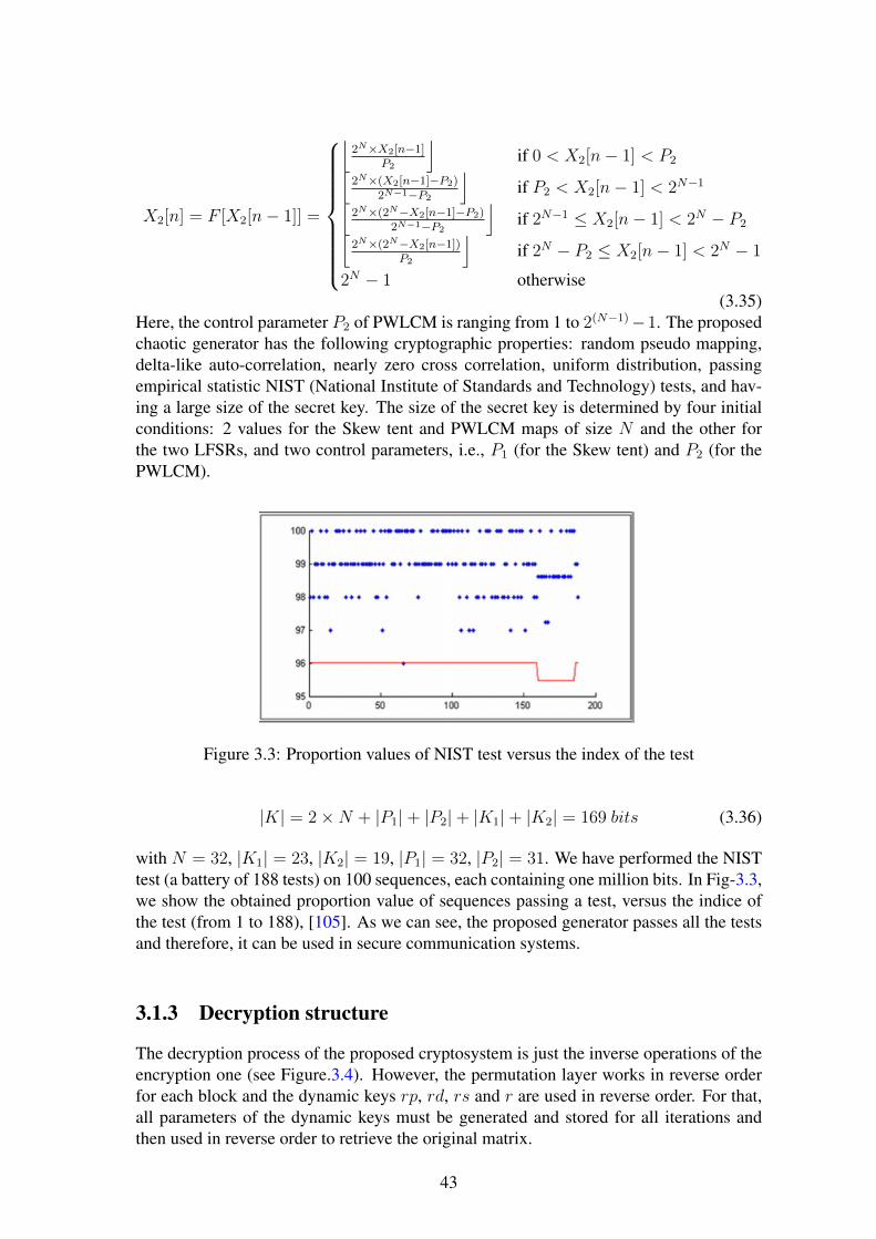
X2[n] = F [X2[n− 1]] =
⌊2N×X2[n−1]
P2
⌋if 0 < X2[n− 1] < P2⌊
2N×(X2[n−1]−P2)2N−1−P2
⌋if P2 < X2[n− 1] < 2N−1⌊
2N×(2N−X2[n−1]−P2)2N−1−P2
⌋if 2N−1 ≤ X2[n− 1] < 2N − P2⌊
2N×(2N−X2[n−1])P2
⌋if 2N − P2 ≤ X2[n− 1] < 2N − 1
2N − 1 otherwise(3.35)
Here, the control parameter P2 of PWLCM is ranging from 1 to 2(N−1)−1. The proposedchaotic generator has the following cryptographic properties: random pseudo mapping,delta-like auto-correlation, nearly zero cross correlation, uniform distribution, passingempirical statistic NIST (National Institute of Standards and Technology) tests, and hav-ing a large size of the secret key. The size of the secret key is determined by four initialconditions: 2 values for the Skew tent and PWLCM maps of size N and the other forthe two LFSRs, and two control parameters, i.e., P1 (for the Skew tent) and P2 (for thePWLCM).
Figure 3.3: Proportion values of NIST test versus the index of the test
|K| = 2×N + |P1|+ |P2|+ |K1|+ |K2| = 169 bits (3.36)
with N = 32, |K1| = 23, |K2| = 19, |P1| = 32, |P2| = 31. We have performed the NISTtest (a battery of 188 tests) on 100 sequences, each containing one million bits. In Fig-3.3,we show the obtained proportion value of sequences passing a test, versus the indice ofthe test (from 1 to 188), [105]. As we can see, the proposed generator passes all the testsand therefore, it can be used in secure communication systems.
3.1.3 Decryption structure
The decryption process of the proposed cryptosystem is just the inverse operations of theencryption one (see Figure.3.4). However, the permutation layer works in reverse orderfor each block and the dynamic keys rp, rd, rs and r are used in reverse order. For that,all parameters of the dynamic keys must be generated and stored for all iterations andthen used in reverse order to retrieve the original matrix.
43
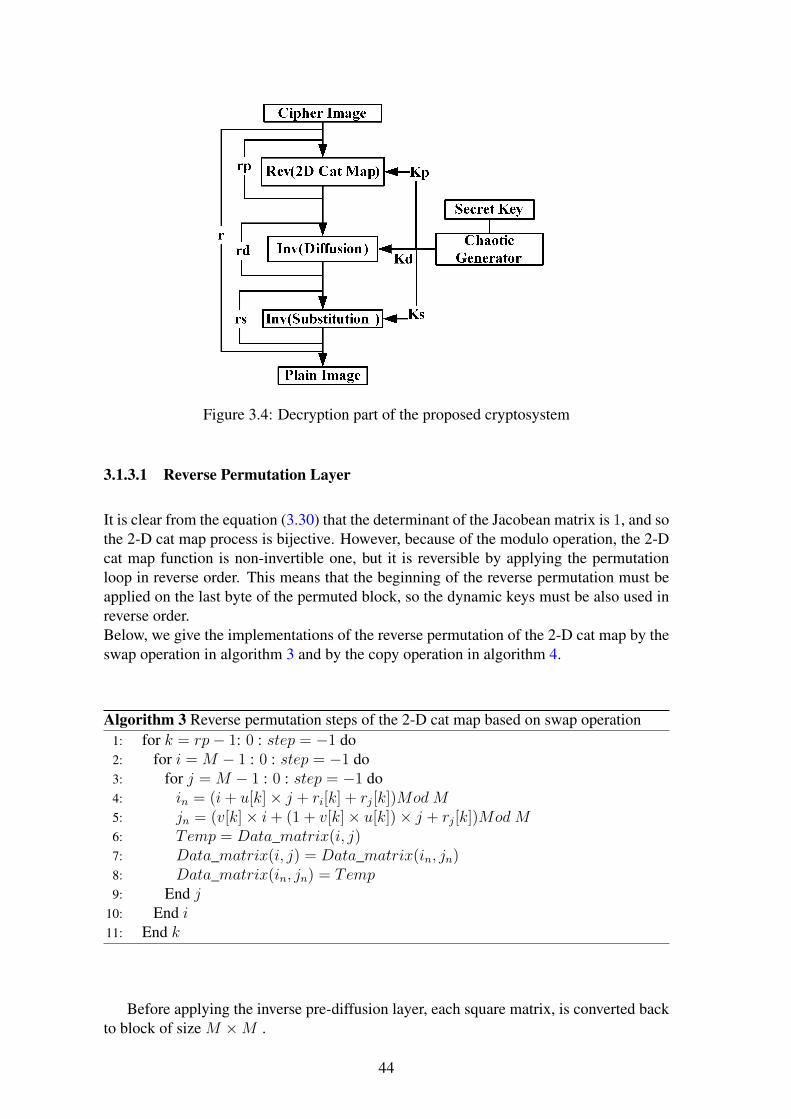
Figure 3.4: Decryption part of the proposed cryptosystem
3.1.3.1 Reverse Permutation Layer
It is clear from the equation (3.30) that the determinant of the Jacobean matrix is 1, and sothe 2-D cat map process is bijective. However, because of the modulo operation, the 2-Dcat map function is non-invertible one, but it is reversible by applying the permutationloop in reverse order. This means that the beginning of the reverse permutation must beapplied on the last byte of the permuted block, so the dynamic keys must be also used inreverse order.Below, we give the implementations of the reverse permutation of the 2-D cat map by theswap operation in algorithm 3 and by the copy operation in algorithm 4.
Algorithm 3 Reverse permutation steps of the 2-D cat map based on swap operation1: for k = rp− 1: 0 : step = −1 do2: for i = M − 1 : 0 : step = −1 do3: for j = M − 1 : 0 : step = −1 do4: in = (i+ u[k]× j + ri[k] + rj[k])Mod M5: jn = (v[k]× i+ (1 + v[k]× u[k])× j + rj[k])Mod M6: Temp = Data_matrix(i, j)7: Data_matrix(i, j) = Data_matrix(in, jn)8: Data_matrix(in, jn) = Temp9: End j
10: End i11: End k
Before applying the inverse pre-diffusion layer, each square matrix, is converted backto block of size M ×M .
44

Algorithm 4 Reverse permutation steps of the 2-D cat map based on copy operation1: for k = rp− 1: 0 : step = −1 do2: for i = M − 1 : 0 : step = −1 do3: for j = M − 1 : 0 : step = −1 do4: in = (i+ u[k]× j + ri[k] + rj[k])Mod M5: jn = (v[k]× i+ (1 + v[k]× u[k])× j + rj[k])Mod M6: Data_matrix(in, jn) = Temp(i, j)7: End j8: End i9: End k
3.1.3.2 Inverse Pre-diffusion layer
The inverse diffusion layer is achieved as follows:
Yi = Mod ((Zi − Zi−1), Q)Yi = (Zi − Zi−1) AND (Q− 1)i = 0, 1, 2...M ×M − 1
(3.37)
Equation (3.37) is used to implement the inverse diffusion layer in a fast manner.
3.1.3.3 Inverse Substitution layer
The inverse of the modified FSTM is implemented using equations (3.19-3.24), (3.26)and by a lookup table.
Crypto-A is implemented in two versions: Crypto-A1, where the substitution/inversesubstitution layers are achieved by the implemented lookup tables, and Crypto-A2, inwhich the substitution/inverse substitution layers are achieved by using the mathematicalequations.
3.2 Cryptosystem-B: Chaos-based SPN with authentica-tion process
The general structure of the proposed cryptosystem is presented in Figure.3.5 for theencryption and in Figure.3.6 for the decryption. The encryption schema is chaos-basedsubstitution permutation Network, that includes a process of source authentication. Theprocesses of substitution and permutation are similar to the ones used in cryptosystem-A,and they are implemented using the same chaotic maps: the skew tent and the 2-D catmaps. The authentication process is based on a hash function, implemented by SHA-256 [42], whose inputs are the secret hash key and the plain image and its output isthe key of the chaotic generator. As we can see from the encryption scheme, a one bitchange in the plain image changing the dynamic keys of the processes of substitution andpermutation and then the encrypted image become completely different from the previousencrypted one. So, the confusion-diffusion properties of the cryptosystem are reached andthe immunity against known-chosen plain-text attack is obtained.The decryption process (see figure.3.6), is based on inverse permutation layer achievedby the same 2-D cat map, following by the inverse substitution achieved by the inverse
45

skew tent map. During this decryption process the rounds of each layer are starting inreverse order and also the dynamic keys are using in reverse order. Notice that, from theestimated plain-image and the hash secret key we can determine whether the estimatedplain-image (the decrypted image) is the correct one.
Figure 3.5: Encryption Parts of Crypto-B
Figure 3.6: Decryption Parts of Crypto-B
The encryption steps are described in details in Figure.3.7. The plain image is dividedinto NB blocks, each one contains BS bytes. The first step is to generate the dynamicalkeys for the substitution-permutation layers. To do this, the plain image and the secrethash key are used as input for the hash function, and then the hash function produces thesecret key of the chaotic generator, that provides the dynamic keys at each round of thecryptosystem. After that, for each plain block, first we use the CBC mode [58] (bit-wiseXOR operation between the current plain block and the previous ciphered one, while inthe first block the previous ciphered block is the initial random block IV) and then weapply the substitution layer rs times and the permutation layer for rp times. Finally theseprocesses (CBC, substitution, permutation) are repeated r rounds and for each round anew dynamic keys are generated from the chaotic generator to be used in both layers, andso on.
Figure.3.8, shows the decryption part of the proposed cryptosystem. The decryptionprocess is similar to the encryption one; the differences are in the inverse substitution andthe reverse permutation layers, first of all, the dynamic keys are used in reverse order inboth layers. Second, the permutation layer is starting the recover process from the lastbyte of the current block until the first one. Third, all counters will be starting in reverseorder. Finally, the CBC mode function is used at the end of decryption of each block. Theinverse substitution layer is starting as normal from the first to the last byte. The receiveruses the decrypted image to test the authentication source, and to test the integrity of themessage.The decryption and authentication processes suppose that the secret hash key SK0, andthe secret key SK of the chaotic generator are known (transmitted in secret manner by
46

Figure 3.7: Encryption Components of Crypto-B
47

Figure 3.8: Decryption Components of Crypto-B
48

the sender to the receiver). The secret key of the chaotic generator is only required fordecryption process, and the secret hash key is used to authenticate the sender and to testthe integrity of the encrypted image according to Figure 3.9. Indeed, at the receiver, the
Figure 3.9: Authentication process at the decryption
same hash function is used to calculate the estimated secret key SKe from the decryptedimage and the secret hash key SK0. If the estimated secret key SKe is equal to the sharedSK, then the integrity of the transmitted encrypted image and the authentication of thesender are valid. The required time to perform the hash operation is a part of encryptiontime, while, it is not the case in the decryption process. The needed time to perform ahash operation over an Lina image of size 256× 256× 3 is 1.27ms [30].Crypto-B is implemented in two versions: Crypto-B1, where the substitution/inverse sub-stitution layers are achieved by an implemented lookup tables, and Crypto-B2 in whichthe substitution/inverse substitution are achieved by using the mathematical equations.
3.3 Cryptosystem-C: Binary diffusion layer and a bit-permutation layer cryptosystem
In this section, we propose a new efficient chaos-based cryptosystem structure and weanalyze its performances. The cryptosystem uses a binary diffusion layer followed by abit-permutation layer, instead of byte-permutation, to shuffle the positions of the imagepixels. Moreover, the permutation layer is achieved by a new proposed formulation of the2-D cat map that allows an efficient implementation, measured by the time complexity, interms of arithmetic and logic operations, and also, in terms of clock cycles, of the key-dependent permutation process in comparison with the standard one. Hence, it providesa fast diffusion process to spread the influence of a single bit over the others, but at theprice of a more calculation time in comparison with the pixel-permutation. The cryp-tosystem is implemented in CBC mode, and its speed is faster than many of chaos-basedcryptosystems, while having a very high security level. The security analysis and the ob-tained simulation results show that the proposed cryptosystem is resistant to various typesof attacks and it is efficient for hardware and software implementation (using FPGA cardor an ASIC).
3.3.1 Description of the encryption processThe encryption part of the proposed cryptosystem (see Fig-3.10) consists of: Firstly, adiffusion layer based on a binary matrix of size 32 × 32 is considered. This process isrepeated rd times. In the next step, the data is prepared for the permutation layer using theinteger to binary number converter function Int2Bin(). The permutation layer is basedon a new modified 2-D cat map, working at the data bit level, and it gets the dynamic
49

parameters from the proposed chaotic generator (see section 3.1.2). It is iterated rp times.The advantage of the bit permutation layer is that it produces a higher security than bothseparated permutation and substitution layers based on bytes. Indeed, theoretically, whena bit permutation layer is applied on a block, it performs, on one scan, a substitution and adiffusion operations on the bytes. As a byte contains 8 bits, then, 8 bit permutations pos-sibly will affect 8 bytes, and then each byte (8 bit permutations) possibly will transfer theeffects of the confusion and of the diffusion to other 8 bytes. As a result, the effects of theconfusion and of the diffusion are better than in the case of byte permutation followed bybyte substitution, because in this last case one byte affects only one byte. In the proposedcryptosystem, 6 encryption rounds based on byte permutation and on the byte substitutionare needed to produce the same level of security as a process of bit-permutation which isexecuted in only one round. At the end of the first iteration, a binary to integer converterfunctionBin2Int() is used to prepare the data for the next iteration. The whole process isrepeated r times until it reaches the required avalanche effect and therefore the maximumsecurity level.
Figure 3.10: Description of the encryption process of Crypto-C
3.3.1.1 Diffusion layer
The diffusion layer works on blocks of 32 bytes each, it achieves a local diffusion, and itis defined by the following equation.
Od0Od1
...Od31
=[DM
]�
O0
O1...O31
(3.38)
Where Odi, Oi ∈ [0, 255] are the output and the input bytes of the diffusion process,[DM
]is the binary diffusion square matrix of 32 × 32, which must be invertible but
not self-invertible. Indeed, the self-invertible matrix is one of the weak points of anycryptosystem. We implemented the diffusion layer using the binary matrix proposed in[63]. The number of branches obtained from this matrix is 10 and therefore, the diffusionpower is important. Actually, the maximum branch of 32 × 32 binary matrix is regardedto be 12, but those matrices of branch 12 do not meet the following criteria [63]: efficientimplementation in 8-bit processor; secure against truncated and impossible differential
50

attacks; the branch number is equal or bigger than 10. The branch number BDM of thediffusion layer DM is defined by:
BDM = minx6=0
[wH(x) + wH(DM(x))
](3.39)
where wH(x) = card{i/0 ≤ i < n, yi 6= 0} is the Hamming weight of n dimentionalvector x. In order to define the � matrix operator in (3.38), we write the first output Od0in an equivalent extended form as:Od0 = O0 ⊕O2 ⊕O3 ⊕O4 ⊕O5 ⊕O8 ⊕O9 ⊕O10 ⊕O12 ⊕O13 ⊕O17 ⊕O18 ⊕O19 ⊕O24 ⊕O25 ⊕O29 ⊕O31
Where ⊕ is the bitwise operator (xor).
3.3.1.2 Permutation Layer
The permutation layer here, is achieved by a new formulation of the modified 2-D catmap. For that, from the mathematical model of the modified cat map, (3.30), first werewrite the 2-D cat map as (3.40) [143], and then we derive the new formulation, for anadequate implementation in C code.
Permutation layer based on the modified 2-D cat mapThe modified 2-D cat map is given by (3.40).
Mln = mod(Ml + u×Mc+ LC,MM)Mcn = mod(v ×Ml + (v × u+ 1)×Mc+ C,MM)
(3.40)
Where Ml, Mc, LC, and C are square matrices (M ×M ) given by the following forms:
Ml =
1 1 · · · 12 2 · · · 2...
... . . . ...M M · M
(3.41)
Mc =
1 2 · · · M1 2 · · · M...
... . . . ...1 2 · M
(3.42)
LC =
rl + rc rl + rc · · · rl + rcrl + rc rl + rc · · · rl + rc
...... . . . ...
rl + rc rl + rc · · · rl + rc
(3.43)
C =
rc rc · · · rcrc rc · · · rc...
... . . . ...rc rc · · · rc
(3.44)
and MM is a square matrix (M ×M ), in which all its elements have the same value M .Mln and Mcn are the permuted bit positions of the Ml and Mc matrices.
51

New formulation of the modified 2-D cat map for an adequate implementation in CcodeThe mathematical form of (3.40) takes a lot of time in matrix multiplication to find theMln and Mcn matrices, it needs much more memory for matrix’s data. For that, wederive a new formulation to reduce the consumed time and memory. The new formulationis derived from (3.40) and (3.41-3.44) as follows:
Mln = mod(
1 1 · · · 12 2 · · · 2...
... . . . ...M M · M
+
1× u 2× u · · · M × u1× u 2× u · · · M × u
...... . . . ...
1× u 2× u · · · M × u
+ LC,MM)
(3.45)Let us assume that:
Mv =[1 2 · · · M
]Mv =
[Mv(0) Mv(1) · · · Mv(M − 1)
] (3.46)
UMv = u×Mv =[u 2× u · · · M × u
]UMv =
[UMv(0) UMv(1) · · · UMv(M − 1)
] (3.47)
Then, (3.45) can be rewritten as:
Mln = mod(Mv(0) Mv(0) · · · Mv(0)Mv(1) Mv(1) · · · Mv(1)
...... . . . ...
Mv(M − 1) Mv(M − 1) · · · Mv(M − 1)
+
UMv(0) UMv(1) · · · UMv(M − 1)UMv(0) UMv(1) · · · UMv(M − 1)
...... . . . ...
UMv(0) UMv(1) · · · UMv(M − 1)
+ LC,MM)
(3.48)
Now, let us suppose that:
UMvn =[u+ rl + rc 2u+ rl + rc · · · Mu+ rl + rc
](3.49)
ThenMln(i, j) = mod(Mv(i) + UMvn(j),M) (3.50)
To save memory and time in the implementation, (3.50) can be equivalently written as:
xrow = mod(Mv(i) + UMvn(j),M) (3.51)
Mcn is derived in a similar procedure as above:
Mcn = mod(
1× v 1× v · · · 1× v2× v 2× v · · · 2× v
...... . . . ...
M × v M × v · · · M × v
+
u× v + 1 2× u× v + 2 · · · M × u× v +Mu× v + 1 2× u× v + 2 · · · M × u× v +M
...... . . . ...
u× v + 1 2× u× v + 2 · · · M × u× v +M
+
C,MM)
(3.52)
52

Let us assume that:
VMv = v ×Mv =[v 2× v · · · M × v
]VMv =
[VMv(0) VMv(1) · · · VMv(M − 1)
] (3.53)
UVMv = (u× v + 1)×Mv =[u× v + 1 2× u× v + 2 · · · M × u× v +M
]UVMv =
[UVMv(0) UVMv(1) · · · UVMv(M − 1)
] (3.54)
Also, (3.52) can be equivalently written as:
Mcn = mod(VMv(0) VMv(0) · · · VMv(0)VMv(1) VMv(1) · · · VMv(1)
...... . . . ...
VMv(M − 1) VMv(M − 1) · · · VMv(M − 1)
+
UVMv(0) UVMv(1) · · · UVMv(M − 1)UVMv(0) UVMv(1) · · · UVMv(M − 1)
...... . . . ...
UVMv(0) UVMv(1) · · · UVMv(M − 1)
+
C,MM)
(3.55)
let us suppose that:
UVMvn =[vu+ 1 + rc 2uv + 2 + rc · · ·M × u× v +M + rc
](3.56)
ThenMcn(i, j) = mod(VMv(i) + UVMvn(j),M) (3.57)
To save memory and time in the implementation, (3.57) can be equivalently written as:
ycol = mod(VMv(i) + UVMvn(j),M) (3.58)
The pseudo C code implementation of (3.51) and (3.58) is given in algorithm-5.where data_bit_2(xrow, ycol) is the source matrix (the one contains the data bits of
the image after diffusion), and data_bit_1(i, j) is the destination matrix (the permuteddata bits).
Time Complexity AnalysisWe propose below a comparative theoretical analysis of the time complexity in terms ofarithmetic, logic operations and clock cycles of our new formulation of the modified 2-Dcat map and the standard cat.Assume X1 is the addition operation, X2 is the multiplication operation and X3 is themodulus operation.Remark:
1. The analysis is carried out for a block of size M×M and for one encryption round.
2. The assign operation (see line 14 in algorithm 5) is identical in both implementa-tions. It requires M2 assign operations and M2 memory locations.
53

Algorithm 5 Pseudo C code for the implementation of the new 2-D cat map formulation1: for i = 0 to M − 12: Mv[i] = i+ 13: End i4: for k = 0 to r − 15: for i = 0 to M − 16: UMvn[i] = Mv[i]× u[k] + rl[k] + rc[k]7: VMv[i] = Mv[i]× v[k]8: UVMvn[i] = u[k]× VMv[i] +Mv[i] + rc[k]9: End i
10: for i = 0 to M − 111: for j = 0 to M − 112: xrow = mod(Mv[i] + UMvn[j],M)13: ycol = mod(VMv[i] + UVMvn[j],M)14: data_bit_1(i, j) = data_bit_2(xrow, ycol)15: End j16: End i17: End k
Time complexity of Eq(3.30)The time complexity of Eq(3.30) is derived based on the following assumptions:
1. The v × u + 1 value is calculated one time per block and it is saved in a register(Reg1) to be used.
2. The rx+ ry is calculated one time per block and it is saved in a register Reg2 .
The time complexity of Eq(3.30) is given by:TCEq(3.30) = TCin + TCjnwhere TCin and TCjn are the time complexity of calculating in and jn parameters respec-tively:TCin = 2M2 ×X1 +M2 ×X2 +M2 ×X3TCjn = 2M2 ×X1 + 2M2 ×X2 +M2 ×X3TCEq(3.30) = 4M2 ×X1 + 3M2 ×X2 + 2M2 ×X3In terms of memory, Eq(3.30) needs M2 locations.
Time complexity of the proposed implementation given by Eq(3.51) and Eq(3.58)Based on the previous assumptions 1) and 2) and on the following two assumptions inalgorithm 5:
1. The array Mv[i] of lines 6, 7, 8 and 12 is replaced by Reg1 = i+ 1.
2. The value rl[k] + rc[k] is calculated once for the loop begins at line 5 and saved ina register (Reg2).
The time complexity of Eq(3.51) and Eq(3.58) is derived as follows:
1. Line 6: M addition operations are needed to calculate Mv[i], M multiplication op-erations are needed to evaluate Mv[i]× u[k] and M addition operations are neededto add the value of the Reg2. The total required operations are:TC6 = 2M ×X1 +M ×X2.
54

2. Line 7: Only M multiplication operations are needed to compute Mv[i] × v[k],because Mv[i] was already calculated in the previous line. The total needed opera-tions are:TC7 = M ×X2.
3. Line 8: M multiplication operations are needed to compute u[k] × VMv[i], and2M addition operations. The total required operations are:TC8 = 2M ×X1 +M ×X2.
4. Line 12: M addition operations are needed to calculate Mv[i], M2 addition oper-ations are needed to calculate Mv[i] + UMvn[j], and M2 modulus operations areneeded. The total required operations are:TC12 = M ×X1 +M2 ×X1 +M2 ×X3.
5. Line 13: M2 addition operations are needed to evaluate VMv[i]+UVMvn[j], andM2 modulus operations are needed. The total required operations are:TC13 = M2 ×X1 +M2 ×X3.
The time complexity TCProposed is:TCProposed = TC6 + TC7 + TC8 + TC12 + TC13
TCProposed = (2M2 + 5M)×X1 + 3M ×X2 + 2M2 ×X3Table 3.3, presents the comparative of the time complexity in terms of arithmetic andlogic operations. It is clear from table 3.3 that the time complexity of the proposed im-plementation is less than the standard one given by Eq(3.30). Indeed, for the proposedimplementation, the required multiplication operations is M times less than the standardimplementation. And, the required addition operations is less than the standard imple-mentation ( for M > 2).
Table 3.3: Time complexity of arithmetic and logic operationsX1 X2 X3 TC
Eq(3.30) 4M2 3M2 2M2 4M2X1 + 3M2X2 + 2M2X3
Ours 2M2 + 5M 3M 2M2 (2M2 + 5M)X1 + 3MX2 + 2M2X3
Moreover, for a fair comparison, we give in table 3.4, the time complexity in terms ofclock cycles (TCC) for the operations: addition, multiplication, modulus, Read (R) andWrite (W). For each operation, the TCC is calculated according to the published manual
Table 3.4: Time complexity in clock cycles for all operationsX1 X2 X3 R W Total
Eq(3.30) 2M2 3M2 2M2 0 0 7M2
Ours M2 + 2.5M 3M 2M2 4M 3M 3M2 + 12.5M
of the instruction table in pages 159-160 of [43]. The Microprocessor version (SandyBridge Microprocessor code) of [43] is close to the used one in our simulation tests. Theaddition operation (X1) takes 0.5 clock cycle, the multiplication operation (X2) takes 1
55

clock cycle, the modulo operation (X3) takes 1 clock cycle, the read operation (R) takes1 clock cycle, and the write operation (W) takes 1 clock cycle. Then, according to table3.4, for M > 3, the proposed implementation consumes less number of cycles than thestandard implementation. As an example, for M = 16, the proposed implementationrequires 968 cycles while Eq(3.30) requires 1792 cycles. However, compared with thestandard implementation, the proposed implementation needs of M2 + 3M locations ofmemories instead of M2 and also, 3 operations of writing (in lines, 6, 7 and 8) and 4operations of reading (in lines 8, 12 and 13), of the algorithm-5.
3.3.2 Description of the decryption process
Figure 3.11: Description of the decryption process
The decryption process is almost similar to the encryption one. From Fig-3.11, firstof all, the bytes in a ciphered block are converted into a stream of bits using an Int2Bin()function. Then the inverse permutation layer is applied in reverse order from the last pairof bits into the first pair. The Bin2Int() function is used to convert the resultant bits frompermutation layer into a stream of bytes. Finally, the inverse diffusion layer, based onthe inverse matrix, is used. All previous processes are repeated r times. Furthermore, thedecryption process uses the same chaotic generator as in the encryption part.
3.3.2.1 Reverse of the new formulation based on the modified 2-D cat map
The cat map is a non-invertible function because of the modulus operation, but it is areversible one. For that, all the parameters of the dynamic keys Kp = u, v, rl, rc must begenerated and stored for all iterations and then used in reverse order to retrieve the originalmatrix. The reverse permutation based on the derived formulas, is implemented using thepseudo C code as in algorithm-6. As we can see, the first two parts of the code are similarto those given by the permutation layer of algorithm-5, while the last part (nested loops)is achieved in reverse order.
56

Algorithm 6 Algorithm in pseudo C code of the reverse operation of the new permutationformula
1: for i = 0 to M − 12: Mv[i] = i+ 13: End i4: for k = r − 1 to 05: for i = 0 to M − 16: UMvn[i] = Mv[i]× u[k] + rl[k] + rc[k]7: VMv[i] = Mv[i]× v[k]8: UVMvn[i] = u[k]× VMv[i] +Mv[i] + rc[k]9: End i
10: for i = M − 1 to 011: for j = M − 1 to 012: xrow = mod(Mv[i] + UMvn[j],M)13: ycol = mod(VMv[i] + UVMvn[j],M)14: data_bit_2(xrow, ycol) = data_bit_1(i, j)15: End j16: End i17: End k
3.3.2.2 Inverse Diffusion Layer
The inverse diffusion layer is achieved by the inverse binary matrix as:O0
O1...O31
=[DM
]−1 �Od0Od1
...Od31
(3.59)
Where Odi, Oi ∈ [0, 255] and [DM ]−1 is the inverse of the binary diffusion square matrixof size 32× 32 [68]. We develop the calculation of the first byte O0 from (3.59) as:O0 = Od0⊕Od8⊕Od9⊕Od10⊕Od16⊕Od17⊕Od19⊕Od20⊕Od22⊕Od23⊕Od24⊕Od25 ⊕Od27 ⊕Od29 ⊕Od31
3.4 Time performance and security analysisIn this section, we evaluate the performance of time and the level of security againstknown cryptographic attacks for the realized cryptosystems and we compare the resultswith some known cryptosystems in the literature. To this end, analysis methods and toolsthat was described in chapter 2, will be used here.
3.4.1 Performance of the speed of calculationsThe performance of the speed of calculations of our proposed cryptosystems (Crypto-A1,Crypto-A2, Crypto-B1, Crypto-B2 and Crypto-C) is evaluated, on different images ofdifferent sizes, in terms of mean encryption/decryption times, encryption throughput andneeded number of cycles per byte. All results are carried out by using a C compiler, on a
57

PC with 3.1 GHz processor Intel Core i3-2100 CPU, 4GB RAM, and Windows 7, 32-BitOperation System.
Table 3.5: Average encryption/decryption Time of the proposed cryptosystems and someknown cryptosystems (in milli-seconds)
Algorithm Name Encryption Decryption
Crypto-A1 6.1 6.2
Crypto-A2 9.9 32.4
Crypto-B1 7.2 5.8
Crypto-B2 10.5 31.6
Crypto-C 8.38 8.48
Zhang et al [166] 7.5 8.25
Wang et al [152] 7.79 8.39
Akhshani et al [8] 14.4 −
Wong et al [155] 15.59 16.77
Yang et al [159] 23.45 25.65
Lian et al [73] 87.25 89.5
Pareek et al [94] 160 −
Socek et al [128] 294 294.3
Table 3.5 presents the obtained average encryption/decryption times of the proposedcryptosystems (Crypto-A, Crypto-B, and Crypto-C) on Lena color image of size (256 ×256×3). We also give, in the same table, the average encryption/decryption times of someknown chaos-based algorithms. The average time is calculated as follows: we execute thealgorithm 100 times and for each time we compute the encryption/decryption times forthe whole image, and then, we evaluate the average time. Table 3.6 presents the obtainedresults of some of the above cryptosystems in terms of encryption throughput and needednumber of cycles per byte.
From these tables, it is clear that, the efficiency of proposed cryptosystems are betterthan some known cryptosystems, that are reputed very efficient.
3.4.2 Plain-text sensitivity attackTo achieve the plaintext sensitivity attack, we apply all steps of the procedure describedin section (2.2.2) of chapter 2. Table.3.7, presents the obtained results of the averagevalues of the NPCR, UACI and HD parameters, for 1000 different secret keys, and dif-ferent images of various sizes, and this for various chaos-based cryptosystems includingours. As we can see, from this table, the obtained values of the NPCR, UACI and HDparameters by the proposed cryptosystems are very close to the optimal values, which areNPCRoptimal = 99.61%, UACIoptimal = 33.46% and HDoptimal = 50%. .
58

Table 3.6: Encryption throughput and number of cycles per byte of the proposed cryp-tosystems and some known cryptosystems
Type ET (MBps) Cycles per Byte
Crypto-A1 Chaos 30.737 96.2
Crypto-A2 Chaos 18.93 156.2
Crypto-B1 Chaos 26.04 113.52
Crypto-B2 Chaos 17.85 165.62
Crypto-C Chaos 22.37 132.2
Zhang et al [166] Chaos 25 122
Socek et al [129] Chaos 0.63 1977
Lian et al [73] Chaos 2.09 772
Yang et al [159] Chaos 7.31 287
Wong et al [155] Chaos 7.19 417
Pareek et al [94] NOT 0.39 2445
3.4.3 Key sensitivity attack
To evaluate the key sensitivity attack, we apply the described procedure in section (2.2.3)of chapter 2. Three parameters : NPCR, UACI and the Hamming distance HD (2.7-2.10) are used for this evaluation. Table 3.8, presents the results of the key sensitivityattack, for some known cryptosystems including ours.From Table 3.8, it is clear that all proposed cryptosystems have a high security level forone bit change on the secret key. This result is predicable because of the properties ofchaotic signals.
3.4.4 Correlation analysis
To evaluate the security of the proposed cryptosystems regarding to the correlation analy-sis, we randomly selected N = 10000 pairs of adjacent pixels in vertical, horizontal, anddiagonal directions from the plain image and its ciphered one. Then the correlation coef-ficient is calculated according to the equations (2.12-2.15), of section (2.2.5) of chapter 2.1. Figure.3.12 shows the correlation coefficients of the adjacent pixels in horizontal, ver-
1
H= Horizontal direction, V= Vertical direction, and D= Diagonal direction1 = Barbara 512× 512× 12 = Lena 512× 512× 13 = Lena 128× 128× 14 = Barbara 256× 256× 15 = Lena 256× 256× 16 = Boat 256× 256× 37 = Boat 256× 256× 1
59

Table 3.7: NPCR and UACI for the plaintext sensitivity test
Algorithm Name Image Name Image Size UACI NPCR HD
Crypto-C Lena.bmp 512× 512× 3 33.462 99.609 0.499912
ECKBA [129] Lena.bmp 512× 512× 3 33.36 99.612
Crypto-C Lena.bmp 512× 512× 1 33.463 99.607
Ahmed et al [2] Lena.bmp 512× 512× 1 33.4 99.6
Yang et al [159] Lena.bmp 512× 512× 1 33.479 99.618
Wong et al [155] Lena.bmp 512× 512× 1 33.427 99.609
Lian et al [73] Lena.bmp 512× 512× 1 33.419 99.587
Crypto-C Barbara.bmp 512× 512× 1 33.463 99.607
Chen et al [22] Barbara.bmp 512× 512× 1 25.200 -
Crypto-C Barbara.bmp 256× 256× 1 33.452 99.597
Behnia et al [14] Barbara.bmp 256× 256× 1 33.25 0.41962
Crypto-C Boat.bmp 256× 256× 1 33.448 99.596
Crypto-A Boat.bmp 256× 256× 1 33.418 99.631 0.500009
Crypto-B Boat.bmp 256× 256× 1 33.420 99.598 0.499798
Song et al [133] Boat.bmp 256× 256× 1 33.453 99.625
Akhshani et al [8] Boat.bmp 256× 256× 1 33.200 - 0.499900
Crypto-C Lena.bmp 256× 256× 1 33.44 99.58
60
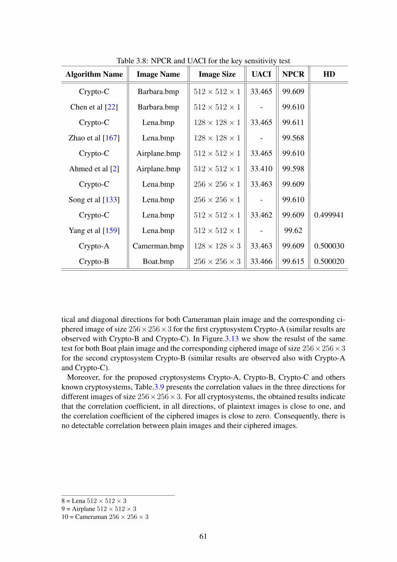
Table 3.8: NPCR and UACI for the key sensitivity test
Algorithm Name Image Name Image Size UACI NPCR HD
Crypto-C Barbara.bmp 512× 512× 1 33.465 99.609
Chen et al [22] Barbara.bmp 512× 512× 1 - 99.610
Crypto-C Lena.bmp 128× 128× 1 33.465 99.611
Zhao et al [167] Lena.bmp 128× 128× 1 - 99.568
Crypto-C Airplane.bmp 512× 512× 1 33.465 99.610
Ahmed et al [2] Airplane.bmp 512× 512× 1 33.410 99.598
Crypto-C Lena.bmp 256× 256× 1 33.463 99.609
Song et al [133] Lena.bmp 256× 256× 1 - 99.610
Crypto-C Lena.bmp 512× 512× 1 33.462 99.609 0.499941
Yang et al [159] Lena.bmp 512× 512× 1 - 99.62
Crypto-A Camerman.bmp 128× 128× 3 33.463 99.609 0.500030
Crypto-B Boat.bmp 256× 256× 3 33.466 99.615 0.500020
tical and diagonal directions for both Cameraman plain image and the corresponding ci-phered image of size 256×256×3 for the first cryptosystem Crypto-A (similar results areobserved with Crypto-B and Crypto-C). In Figure.3.13 we show the resulst of the sametest for both Boat plain image and the corresponding ciphered image of size 256×256×3for the second cryptosystem Crypto-B (similar results are observed also with Crypto-Aand Crypto-C).
Moreover, for the proposed cryptosystems Crypto-A, Crypto-B, Crypto-C and othersknown cryptosystems, Table.3.9 presents the correlation values in the three directions fordifferent images of size 256×256×3. For all cryptosystems, the obtained results indicatethat the correlation coefficient, in all directions, of plaintext images is close to one, andthe correlation coefficient of the ciphered images is close to zero. Consequently, there isno detectable correlation between plain images and their ciphered images.
8 = Lena 512× 512× 39 = Airplane 512× 512× 310 = Cameraman 256× 256× 3
61

Table 3.9: Correlation coefficient values of two adjacent pixels in the plain and the cipherimages
Algorithm Name Image Plain image correlation results Ciphered image correlation results
H V D H V D
Crypto-C 1 0.89538 0.95887 0.88304 0.00155 0.00163 0.00148
Chen et al [22] 1 0.91765 0.95415 0.90205 0.01183 0.00016 0.01480
Crypto-C 2 0.98071 0.98214 0.96547 0.00131 0.00121 0.00114
Pareek et al [94] 2 0.78200 0.59220 0.64240 0.00310 -0.00160 0.00670
Crypto-C 3 0.91019 0.96104 0.87166 -0.00622 0.00611 -0.00626
Zhao et al [167] 3 0.94800 0.88510 0.85460 0.02480 -0.00940 -0.01830
Crypto-C 4 0.92287 0.95024 0.91523 0.00317 -0.00326 -0.00309
Behnia et al [14] 4 0.95740 0.93990 0.91830 0.00380 0.00230 0.00040
Crypto-C 5 0.97165 0.98730 0.95440 0.00312 -0.00317 -0.00310
Wu et al [158] 5 - - - 0.00533 -0.00276 0.00166
Song et al [133] 5 0.96592 0.94658 0.92305 0.00550 0.00411 0.00021
Crypto-B 6 0.93622 0.94419 0.89243 0.00868 0.00864 0.00837
Crypto-C 7 0.94417 0.95263 0.90701 0.00320 -0.00309 -0.00306
Akhshani et al [8] 7 0.95160 0.94470 0.90590 0.00650 0.00550 0.00820
Crypto-C 8 0.99233 0.99649 0.98712 -0.00158 0.00159 -0.00147
Yang et al [159] 8 0.98022 0.98663 0.96468 -0.00209 -0.01618 0.01780
Wong et al [155] 8 0.97510 0.98892 0.96704 0.00681 0.00782 0.00323
Crypto-C 9 0.96606 0.96384 0.93674 0.00157 -0.00151 -0.00158
Ahmed et al [2] 9 0.96775 0.95753 0.93002 0.00247 0.00182 0.00038
Crypto-A 10 0.89849 0.92518 0.85137 0.01052 0.01065 0.01084
62

(a) Horizontal correlation of the plain image (b) Horizontal correlation of the ciphered image
(c) Vertical correlation of the plain image (d) Vertical correlation of the ciphered image
(e) Diagonal correlation of the plain image (f) Diagonal correlation of the ciphered image
Figure 3.12: Correlation analysis of Boat and its ciphered image in threedirections:Crypto-A
63

(a) Horizontal correlation of the plain image (b) Horizontal correlation of the ciphered image
(c) Vertical correlation of the plain image (d) Vertical correlation of the ciphered image
(e) Diagonal correlation of the plain image (f) Diagonal correlation of the ciphered image
Figure 3.13: Correlation analysis of Cameraman and its ciphered image in threedirections:Crypto-B
3.4.5 Histogram analysis
The histograms of the plain images and their ciphered ones are presented in Figures(3.14) for Crypto-A (similar results are obtained with Crypto-B), and in Figures (3.15)for Crypto-B and Crypto-C (similar results are obtained with Crypto-A). It is clear thatthe pixel values show a pattern in part c), which presents the histogram of the plain imageof each figure, while in part d) the distribution of the pixel values of the ciphered imageare almost uniform and significantly different from the histogram of the plain image.
64

Remark: In figure (c) of Figures (3.15), for more clarity, we limit the maximum value ofthe y-axis to 500. Indeed, the histogram values for all colors (except the black and whitecolors) are less than 500. We found that the white color is repeated more than 7500 times(16%) and the black color is repeated more than 3300 times (7%). The previous visualtest of the histogram is necessary but not sufficient for confirming the uniformity of theciphered histogram. For that, the chi-square test is applied (see (2.11)) for statisticallyconfirming the uniformity of the histogram: For the proposed cryptosystems, we presentin Table 3.10 the obtained results of the Chi square test of histograms for five cipheredimages of three different natures (i.e., Boat, Airplane, Cameraman, Peppers and Parrots).All experimental values of the chi-square are less than the theoretical value, which is 293,and so, the uniformity of the histograms are verified.
(a) Plain Boat image (b) Ciphered Boat image
(c) Histogram of the plain Boat image (d) Histogram of the ciphered Boat image
Figure 3.14: Plain and ciphered Boat images and their histograms:Crypto-A
65

(a) Plain Cameraman image (b) Ciphered Cameraman image
(c) Histogram of the plain Cameraman image (d) Histogram of the ciphered Cameraman image
Figure 3.15: Plain and ciphered Cameraman images and their histograms:Crypto-B
Table 3.10: Chi-Square Results
Image name Crypto-B Chi-square Crypto-A Chi-square Crypto-C Chi-square
Cameraman 255.74 255.12 /
Boat 255.43 255.12 /
Jet 253.787 253.78 /
Peppers 261.17 260.36 253.5
Parrots 260.07 259.44 /
Lena / / 252.1
Baboon / / 256.1
66

3.5 ConclusionIn this chapter, we designed, realized and tested three efficient chaos-based cryptosys-tems, defined on finite numbers, for securing images, in real-time applications. All ofthem are blocks ciphers and the two first cryptosystems crypto-A and Crypto-B are basedon the substitution-permutation network (SPN). The substitution layer is achieved by aproposed modified Finite Skew Tent Map (FSTM) to overcome the problems of : fixedpoint, restriction of the key space and limitation of mapping between plaintext and cipher-text and vice versa. Crypto-B is rather used for some applications that need two securityrequirements: confidentiality and authentication.The structure of the third cryptosystem is new and efficient. It is based on two chaoticlayers: a binary diffusion layer of pixels, followed by a bit-permutation layer. The per-mutation process is achieved by a proposed formulation of the 2-D cat map that allows anefficient implementation in C code. Experimental results show that the proposed chaos-based cryptosystems are faster than many chaos based cryptosystems of the literature,while keeping a very high security level. Indeed, the proposed encryption/decryptionschemes are robust against all known attacks in the literature.
67


4Second Contribution: PartialCryptanalysis of Zhang cryptosystemand design of a very fast and securecryptosystem
In this chapter, a new category of cryptosystems, which are faster than the previous cryp-tosystems with a very high security level, are introduced. In such cryptosystems, theconfusion and diffusion layers are combined, and then, they are performed simultane-ously in a single scan of plain-image pixels. The chapter is splits into two related parts. Inthe first part (section (4.1), we describe and partially break one of best chaos-based cryp-tosystem recently published by Zhang in 2013, namely, the first cryptosystem of Zhang etal., model [166]. To that end, a mathematical model is introduced to remove the dynamickey space of the diffusion effect. In the second part (section (4.2), based on the previousanalysis a very fast and very secure cryptosystem is designed, realized with two versionsof the diffusion layer, and tested. The diffusion layer of the first version is achieved bya discrete Logistic map, while the diffusion layer of the second version is achieved by afinite skew tent map. In section (4.3) an example of real-time application is described.The conclusion of this chapter is presented in section (4.4).
4.1 Partial cryptanalysis of the first Zhang cryptosystem
In this section, we address some weaknesses in the first Zhang et al., algorithm "An imageencryption scheme using reverse 2-dimensional chaotic map and dependent diffusion",and we propose methods for breaking it partially. Moreover, the differential attacks anal-ysis, based on the proposed partial cryptanalysis equation, are reevaluated. As a result,the obtained average values of NPCR and UCAI parameters become small, as comparedto the optimal values, and in addition, they are very low for specific pixel position attacks.
69

4.1.1 The first Zhang cryptosystemIn Zhang’s paper [166], two cryptosystems were designed based on Fridrich’s architec-ture. The first one consists of a dependent diffusion layer based on the reverse 2-D catmap. The second algorithm presents new mapping from a pseudo-random position toanother pseudo-random one for the confusion effect. The diffusion layer in the cryptosys-tems is based on the logistic map. In these versions, Zhang tried to achieve the confusionand the diffusion effects sequentially. Then, the effect of one ciphered pixel is transferredto the next one and so on. From this idea, only two rounds (in the first version) and oneround (in the second version) of the diffusion-confusion process are/is needed instead ofmany rounds of separated confusion and diffusion processes used in the traditional struc-tures such as Fridrich cryptosystem and other cryptosystems. In the following, our workis directed to the first Zhang cryptosystem. The mathematical model of the first Zhangalgorithm is:(Enc=the encryption process).
Enc =
[x′
y′
]=
[1 piqi piqi + 1
] [xy
] (ModN
)ciph(x, y) = arr(x′, y′)⊕ f(t)
t = ciph(x, y)
(4.1)
The general block diagram of the first Zhang cryptosystem is shown in Figure. 4.1. Itconsists of the following steps iterated n times (with n > 0):
Figure 4.1: Zhang image encryption cryptosystem architecture
1. Selection: this step generates a random pair arr(rxj, ryj) from the whole image.The values of rxj and ryj are calculated using equation (4.2) and equation (4.3),where j is a counter ranging from 0 to n− 1 encryption rounds.
rxj = (SQ1(2000 + 100 + j)× 109)mod 512 (4.2)
ryj = (SQ2(2000 + 100 + j)× 109)mod 512 (4.3)
2. Array exchanges: the second step is to exchange the first byte arr(0, 0) with therandom byte from the previous step arr(rxj, ryj).
3. Dependent diffusion: then the cryptosystem goes to the dependent diffusion layerform rounds (m = 2 in the Zhang algorithm case), which also includes three stages.
(a) New position estimation: in the dependent diffusion layer the first step is tocalculate the new byte position (x′, y′) from the old byte position (x, y) usingequation (4.4). [
x′
y′
]=
[1 piqi piqi + 1
] [xy
] (ModN
)(4.4)
70

whereN is the size of the square test image.pi and qi are calculated using the following equations:
pi = (SQ1(2000 + i)× 109)mod 512 (4.5)
qi = (SQ2(2000 + i)× 109)mod 512 (4.6)
The variable i in the last equations is a counter ranging from 0 to m− 1. Thetwo sequences SQ1 and SQ2 as can be seen in equations (4.2, 4.3, 4.5, and4.6) are calculated using the following equation:
f(xn) = α× xn−1(1− xn−1) (4.7)
With the initial values x−1=0.12345678912345 for SQ1, and x−1=0.67856746347633for SQ2. The value of α is set to 3.99999.
(b) Calculation of the local ciphered pixel: the next step of the dependent diffu-sion layer is to calculate the ciph(x, y) value using the following equation:
ciph(x, y) = arr(x′, y′)⊕ f(t) (4.8)
wheref(t) = [α(
t
1000)× [1− t
1000]× 1000]mod 256 (4.9)
(c) Update of t: the last step of the dependent diffusion layer is to change thevalue of the t variable using equation (4.10).
t = ciph(x, y) (4.10)
The initial value t0 is defined by the following equation:
t0 = [4× keyd × (1− keyd)× 1000]mod 256. (4.11)
WhereThe initial value of the keyd=0.33456434300001.
4.1.2 Partial cryptanalysis of the Zhang cryptosystemOur contribution in this work focuses on partial cryptanalysis of the first Zhang cryptosys-tem. Also, in the case of one encryption round and two dependent diffusion rounds, wehave broken it completely. Moreover, the partial cryptanalysis equation will be used tosignificantly decrease the robustness of the cryptosystem for two encryption rounds andtwo dependent diffusion rounds. In fact, the dynamic key space of the diffusion functionf(t) (see equation 4.9)can be removed from the calculation of the total dynamic key spaceindependently of the used key, because the t values are clearly presented in the cipheredimage. To prove the correctness of the above assumptions, we derive the following sce-nario: The encrypted data of the Zhang cryptosystem are obtained by equation (4.1), thenwe can write the following sequence:ciph0 = arrk′0 ⊕ f(t0)ciph1 = arrk′1 ⊕ f(t1) = arrk′1 ⊕ f(ciph0)ciph2 = arrk′2 ⊕ f(t2) = arrk′2 ⊕ f(ciph1)
71

ciph3 = arrk′3 ⊕ f(t3) = arrk′3 ⊕ f(ciph2)ciph4 = arrk′4 ⊕ f(t4) = arrk′4 ⊕ f(ciph3)ciphk = arrk′k ⊕ f(tk) = arrk′k ⊕ f(ciphk−1)Where arrk′0 is the plain image of the current encryption round, as an example forn = 1, m = 1 it is the original plain image (arr(x′, y′)), for n = 1, m = 2 it isthe encrypted image which is the output of equation (4.1) (i.e ciph(x, y)) and so on.From the last equation in the previous sequences, we can write the main partial cryptanal-ysis equation of the Zhang cryptosystem as:
arrk′k = ciphk ⊕ f(ciphk−1) (4.12)
where k = x×N + y and k′ = x′ ×N + y′ (see equation (4.4)), arrk′k is the input pixelof the last dependent diffusion round (m) in the last encryption round (n) and ciphk is theciphered pixel. As the function f(t) is known, then equation (4.12) can be used to removethe diffusion effect of the last (m and n) rounds from the ciphered pixels. This allowsrecovery of a permuted version of the previous ciphered image. This removal gives theattacker the possibility to:
1. Decrease the dynamic key space of the whole cryptosystem.
2. Perform partial cryptanalysis of the Zhang cryptosystem for (n = 1, m = 1) and(n = 1, m = 2).
3. Decrease the UACI and NPCR values significantly.
4.1.2.1 Decreasing the dynamic key space of the whole cryptosystem
The brute-force attack is the basic attack that can be used against any cryptosystem. Ittrys all possible keys until the correct one is founded. In the worst case, all possiblekeys in the key space are tested[125],[108]. From equation (4.4), it is clear that the keyspace of the 2-D cat map for the Zhang cryptosystem is N2 for one encryption round andone dependent diffusion round (n=1, m=1) where N is the square root of the image size.In equation (4.9), the key space of the function f(t) is independent of the image size,and it is 28 for (n=1, m=1). The brute force attack time on the Zhang cryptosystem is:KS = (S1×S2)
n×m whereKS is the total dynamic key space, S1 represents the dynamickey space for the standard 2-D cat map, and S2 represents the dynamic key space for thelogistic map implemented by a lookup table, then S1 = N2, S2 = 28, and so, KS =(N2× 28)n×m For one encryption round, one dependent diffusion round (n=1, m=1), and(N = 512) KS = (218 × 28)1, then, the cryptanalysis time is: CT ime = 10 × 226 ms≈ 186.4135 hours = 7.77 days.Notice that equation (4.12) can be used to find the permuted plain image which means thatthe dynamic key space of the t parameter can be removed from the dynamic key spaceanalysis as: KS = (218)1, then, the cryptanalysis time: CT ime = 10×218 ms≈ 186.4135hours = 43.6907 minutes.For one encryption round, two dependent diffusion rounds (n=1, m=2), and (N = 512) ifwe assume that the Zhang cryptosystem encrypts P to C1 in the first dependent diffusionround, and then encrypts C1 to C2 in the second dependent diffusion round, then usingequation (4.12) we can at least find non-order C1 pixels easily with 10 ms. To find theoriginal plain image (at n = 1, m = 2), the cryptanalytic system needs 10 ms to obtainC1 from C2. Then, for each possible value of p2 and q2 the C1 is decrypted using the brute
72

force attack for all possible values of p1 and q1: KS = (S1)2, S1 = 236, CT ime = 10× =
236 ms, CT ime ≈ 21.79 years.For one encryption round, one dependent diffusion round (n=1, m=1), and (N = 256)
KS = (S1)1, S1 = 216, then: CT ime = 2.5× 216 ms ≈ 39.32 seconds
For one encryption round, two dependent diffusion rounds (n=1, m=2), and (N = 256)KS = (S1)
2 S1 = 232 CT ime = 2.5× 232 ms ≈ 124.27 days
4.1.2.2 Chosen plaintext attack on the first Zhang cryptosystem
The chosen plaintext attack is defined as a cryptanalysis model when the adversary has thecapability of choosing some plaintexts and encrypting them. Then, the adversary studiesthe corresponding ciphertexts to obtain some information of the used keys or even to re-duce the security level of the cryptosystem[11],[58]. From this well-known definition, wecan choose a plaintext and encrypt it without knowing the dynamic keys, and our objectiveis to calculate the dynamic keys. The following scenario describes the proposed partialcrytpanalysis of the first Zhang cryptosystem. The chosen plain image is used to find thedynamic keys (q1, p1) of the first dependent diffusion round and then using these keys wecan decipher any ciphered image with the same keys (this scenario is only applicable inthe case where n = 1,m = 1). We choose a specific plain image P of 512× 512× 1 size.This plain image is chosen to help us in the process of finding the dynamic keys (q1, p1).Indeed, we try to fill each position with a predefined value to decrease the range valuesof the dynamic keys q1 and p1. For example, assuming that the decrypted value is 5, wecan be sure that only rows (1, 3, 9 or 10) contain this value. This will be helpful in theprocess of finding q1 and p1 values as illustrated below. The image P is encrypted, andthe ciphered image (C1) is obtained. Then, a group of ciphered pixels is used to analyzethe encryption process and to try to recover the dynamic keys. For this we introduce thefollowing steps:
P =
0 1 2 ··· 254 255 ··· 509 510 511
0 0 1 1 · · · 1 1 · · · 1 1 11 1 2 3 · · · 255 1 · · · 255 1 22 2 2 2 · · · 2 2 · · · 2 2 23 3 4 5 · · · 2 3 · · · 2 3 44 1 1 1 · · · 1 1 · · · 1 1 15 3 3 3 · · · 3 3 · · · 3 3 36 3 3 3 · · · 3 3 · · · 3 3 37 4 4 4 · · · 4 4 · · · 4 4 48 4 4 4 · · · 4 4 · · · 4 4 49 5 5 5 · · · 5 5 · · · 5 5 510 5 5 5 · · · 5 5 · · · 5 5 511 6 6 6 · · · 6 6 · · · 6 6 612 6 6 6 · · · 6 6 · · · 6 6 6...
......
... . . . ...... . . . ...
......
507 254 254 254 · · · 254 254 · · · 254 254 254508 254 254 254 · · · 254 254 · · · 254 254 254509 255 255 255 · · · 255 255 · · · 255 255 255510 255 255 255 · · · 255 255 · · · 255 255 255511 1 1 1 · · · 1 1 · · · 1 1 1
73

First dynamic key calculations (q1)To find the value of q1 (which refers to the column position) two steps are carried out:First StepUsing the ciphered pixel at position (x = 1, and y = 0), the plain pixel position (x′, y′) iscalculated using equation (4.4):x′ = 1× x+ p1 × y = 1 + 0 = 1 =⇒ x′ = 1y′ = q1 × x+ (q1 × p1 + 1)× yy′ = q1 × 1 + (q1 × p1 + 1)× 0 =⇒ y′ = q1
This means that from the value of the ciphered pixel ciph(1, 0), the value of the plainpixel arr(1, q1) can be easily calculated using equation (4.12) as:arr(1, q1) = ciphk ⊕ f(ciphk−1)where ciphk = ciph(1, 0) and ciphk−1 is calculated using equation (4.13).
if k is a multiple of N thenxprevious = x− 1yprevious = N − 1elsexprevious = xyprevious = y − 1
(4.13)
So, arr(1, q1) = ciph(1, 0)⊕ f(ciph(0, 511))Now, the ciphered pixels (ciph(1, 0) and ciph(0, 511)) are known, also the function f(t)is known (see equation 4.9), and the plain pixel value arr(1, q1) is located in row number1 of the plain image P . The only unknown parameter is the column position which is q1,ranging from 0 to 511. The following equation (4.14) is used to decrease the key space ofthe dynamic key q1.
if arr(1, q1) == 0 skip this valueelse if arr(1, q1) == 1 thenq1 ∈ {0, 255, 510}else if arr(1, q1) == 2 thenq1 ∈ {1, 256, 511}elseq1 ∈ {arr(1, q1)− 1, arr(1, q1) + 254}
(4.14)
Firstly, assume that arr(1, q1) = 0, then it is skipped since it can be in any positionof the P image (Figure.4.1 justifies this, since the first pixel is swapped with a randompixel from the whole image). Secondly, assume that arr(1, q1) = 1, this value can belocated in one of three positions on row number 1: [(1, 0), (1, 255) or (1, 510)]. Thirdly,assume that arr(1, q1) = 2, this value can be located in one of three positions on rownumber 1: [(1, 1), (1, 256) or (1, 511)]. Finally, assume that arr(1, q1) > 2, thisvalue can be located in one of two positions on row number 1: [(1, arr(1, q1) − 1) or(1, arr(1, q1) + 254)] which are the positions containing the arr(1, q1) value.Second StepTo further decrease the range values of q1, another ciphered pixel at (x = 3, and y = 0)position is considered. The position (x′, y′) of the corresponding plain pixel is calculatedusing equation (4.4):x′ = 1× x+ p1 × yx′ = 3 + 0 = 3 =⇒ x′ = 3y′ = q1 × x+ (q1 × p1 + 1)× yy′ = q1 × 3 + (q1 × p1 + 1)× 0 =⇒ y′ = 3q1
Using equations (4.12) and (4.13)arr(3, 3q1) = ciph(3, 0)⊕ f(ciph(2, 511))
74

The second decrypted pixel arr(3, 3q1) is located at row number 3, and the columnposition 3q1, with 0 ≤ 3q1 ≤ 511. Then the following equation (4.15) is used to decreasethe key space of the dynamic key q1.
if arr(3, 3q1) == 0 skip this valueelse if arr(3, 3q1) == 1 then3q1 ∈ {253, 508} =⇒ q1 ∈ {255, 340}else if arr(3, 3q1) == 2 then3q1 ∈ {254, 509} =⇒ q1 ∈ {426, 511}else if arr(3, 3q1) == 3 then3q1 ∈ {0, 255, 510} =⇒ q1 ∈ {0, 85, 170}else if arr(3, 3q1) == 4 then3q1 ∈ {1, 256, 511} =⇒ q1 ∈ {171, 256, 341}elseq1 ∈ {a, b}
(4.15)
if((arr(3, 3q1)− 3) MOD 3 == 0)Then
a = arr(3, 3q1)−33
else if((arr(3, 3q1)− 3 + 512) MOD 3 == 0)Then
a = arr(3, 3q1)+5093
else
a = arr(3, 3q1)−3+512+5123
= arr(3, 3q1)+10213
if((arr(3, 3q1) + 252) MOD 3 == 0)Then
b = arr(3, 3q1)+2523
else if((arr(3, 3q1) + 252 + 512) MOD 3 == 0)Then
b = arr(3, 3q1)+7643
else
b = arr(3, 3q1)+252+512+5123
= arr(3, 3q1)+12763
Equation (4.15) is used to decrease the number of possible column positions (i.e., therange of the q1). Using the P matrix, the row of the arr(3, 3q1) is 3. Firstly, assumethat arr(3, 3q1) = 0, then, this value is skipped. Secondly, assume that arr(3, 3q1) = 1,then, this value can be located in one of two column positions in row number 3 [(3, 253)or (3, 508)] (see P matrix for more details). Thirdly, assume that arr(3, 3q1) = 2, then,this value can be located in one of two column positions in row number 3 [(3, 254) or(3, 509)]. Fourthly, assume that arr(3, 3q1) = 3, then, this value can be located in oneof three column positions in row number 3 [(3, 0), (3, 255) or (3, 510)]. Fifthly, assumethat arr(3, 3q1) = 4, this value can be located in one of three column positions in rownumber 3 [(3, 1), (3, 256) or (3, 511)]. Finally, for all arr(1, q1) > 4, these valuescan be located in one of two column positions in row number 3 [(3, arr(3, 3q1) − 3) or(1, arr(1, q1)+252)]. Now, let us take the case when the arr(3, 3q1) = 4 as an example,without loss of generality, i.e., 3q1 ∈ {1, 256, 511}Firstly, 3q1 = 1; to solve this equation, which contains the module operation, q1 is calcu-lated as:q1 =the integer value of (1
3, 1+512
3, 1+512+512
3) =⇒ q1 = 171.
Secondly, 3q1 = 256, then q1 =the integer value of (2563
, 256+5123
, 256+512+5123
) =⇒ q1 =256.
75

Finally, 3q1 = 511, then q1 =the integer value of (5113
, 511+5123
, 511+512+5123
) =⇒ q1 =341
For all other values (arr(3, 3q1) > 4), there is a general scheme to calculate the rangeof q1 values (i.e., a and b parameters in equation (4.15)). Now, let us take arr(3, 3q1) = 5as another example. i.e., 3q1 ∈ {2, 257}Firstly, 3q1 = 2, then: q1 =the integer value of (2
3, 2+512
3, 2+512+512
3) =⇒ q1 = 342.
Secondly, 3q1 = 257, then q1 =the integer value of (2573
, 257+5123
, 257+512+5123
) =⇒ q1 =427. From previous developments, we can deduce the following rules for equation (4.15):
1. In the case where arr(3, 3q1) ∈ {1, 2}, then we have two positions given by:arr(3, 3q1) + 252 or arr(3, 3q1) + 507.
2. In the case where arr(3, 3q1) ∈ {3, 4}, then we have three positions given by:arr(3, 3q1)− 3, arr(3, 3q1) + 252 or arr(3, 3q1) + 507.
3. In the case where arr(3, 3q1) > 4, then we have two positions given by: arr(3, 3q1)−3 or arr(3, 3q1) + 252.
Now, from the four previous ciphered pixels (ciph(1, 0), ciph(0, 511), ciph(3, 0) andciph(2, 511)), the exact value of the dynamic key q1 is calculated by finding the overlapvalues between the first and the second step.Second dynamic key calculations (p1)To find the value of p1 (which refers to the row position), at least two steps are needed:First StepFrom the ciphered pixel at (x = 0, and y = 1) position, the plain pixel position (x′, y′) iscalculated using equation (4.4):x′ = 0× x+ p1 × 1x′ = 0 + p1 = p1 =⇒ x′ = p1
y′ = q1 × x+ (q1 × p1 + 1)× yy′ = q1 × 0 + (q1 × p1 + 1)× 1 =⇒ y′ = q1 × p1 + 1Using equation (4.12), the value of arr(p1, p1q1 + 1) is calculated as:arr(p1, p1q1 + 1) = ciph(0, 1)⊕ f(ciph(0, 0))The decrypted pixel arr(p1, p1q1 + 1) is located at row number p1 of the plain image P .Here we focus on finding the p1 value (p1 ranges from 0 to 511). Equation (4.16) is usedto decrease the dynamic key space p1 as:
if a == 0 skip this valueelse if a == 1 thenp1 ∈ {0, 1, 3, 4, 511}else if a == 2 thenp1 ∈ {1, 2, 3}elsep1 ∈ {1, 3, a× 2− 1, a× 2}wherea = arr(p1, p1q1 + 1)
(4.16)
To justify the equation (4.16), firstly, assume arr(p1, p1q1 + 1) = 1, from the plain imageP , the plain pixel value 1 is located in five rows [0, 1, 3, 4, 511], and so, the possiblevalues of the dynamic key p1 is: [0, 1, 3, 4, 511]. Secondly, assume the arr(p1, p1q1 +1) = 2, then this value is located in three rows: [1, 2, 3], and so, the possible values ofthe dynamic key p1 is: [1, 2, 3]. Thirdly, assume the arr(p1, p1q1 + 1) = 3, then this
76

value is located in four rows [1, 3, 5, 6], and so, the possible values of the dynamic keyp1 is: [1, 3, 5, 6]. Finally, for any value such that arr(p1, p1q1 + 1) > 2, this value canbe located in one of four rows [1, 3, arr(p1, p1q1 + 1) × 2 − 1, arr(p1, p1q1 + 1) × 2],and so, the possible values of the dynamic key p1 is [1, 3, arr(p1, p1q1 + 1) × 2 − 1,arr(p1, p1q1 + 1)× 2].Second StepTo further decrease the range values of p1, another ciphered pixel at (x = 0, and y = 2)position is considered. The position (x′, y′) of the corresponding plain pixel is calculatedusing equation (4.4): x′ = 1× x+ p1 × y =⇒ x′ = 0 + 2p1 = 2p1 =⇒ x′ = 2p1
y′ = q1×x+(q1×p1+1)×y =⇒ y′ = q1×0+(q1×p1+1)×2 =⇒ y′ = 2(q1 × p1 + 1)Again, using equation (4.12) the value of arr(2p1, 2p1q1 + 2) is calculated as:arr(2p1, 2p1q1 + 2) = ciph(0, 2)⊕ f(ciph(0, 1))This pixel arr(2p1, 2p1q1 + 2) is located at row 2p1 of the plain image P . The followingequation (4.17) is used to decrease the key space of the dynamic key p1 as:
if a == 0 skip this valueelse if a == 1 thenp1 ∈ {0, 2, 256, 258}else if a == 2 thenp1 ∈ {1, 257}elsep1 ∈ {a, a+ 256}wherea = arr(2p1, 2(p1q1 + 1))
(4.17)
To justify equation (4.17), we consider the following cases: Firstly, assume that the de-crypted pixel is arr(2p1, 2p1q1 + 2) = 1, so from the plain image P , the plain pixel value1 is located in five rows [0, 1, 3, 4, 511], and the possible values of the dynamic key p1are:2p1 = 0 =⇒ p1 ∈ {0, 256}2p1 = 1, 2p1 = 3 and 2p1 = 511 cannot have an integer solution, since the right-handside is odd and the left-hand side is even and the modulus value is even. 2p1 = 4 =⇒p1 ∈ {2, 258}. Secondly, assume the decrypted pixel is arr(2p1, 2p1q1 + 2) = 2, thenthe plain pixel value 2 is located in three rows [1, 2, 3], and the possible values of p1 are:2p1 = 1 and 2p1 = 3 cannot have an integer solution.2p1 = 2 =⇒ p1 ∈ {1, 257}.Thirdly, assume the decrypted pixel is arr(2p1, 2p1q1 + 2) = 3, then the plain pixel value3 is located in four rows [1, 3, 5, 6], and the possible values of p1 are: 2p1 = 1, 2p1 = 3and 2p1 = 5 cannot have integer solution. 2p1 = 6 =⇒ p1 ∈ {3, 259}. Finally,for any arr(2p1, 2p1q1 + 2) > 2 the possible values of p1 are arr(2p1, 2p1q1 + 2) orarr(2p1, 2p1q1 + 2) + 256.Note that in most cases the first and the second steps are sufficient to find the dynamickey value of p1. However, if the overlap between the obtained range values of p1 in thefirst step and the obtained range values of p1 in the second step is not a single value, thenwe use the following calculation.Extra StepTo find the exact value of p1, the plain pixel position (x′, y′) is calculated from the ci-phered position pixel at (x = 0, y = 3), using equation (4.4):x′ = 1× x+ p1 × y = 0 + 3p1 = 3p1 =⇒ x′ = 3p1
77

y′ = q1× x+ (q1× p1 + 1)× y = q1× 0 + (q1× p1 + 1)× 3 =⇒ y′ = 3(q1 × p1 + 1)Again, here the plain pixel arr(3p1, 3(q1×p1 +1)) is calculated from the ciphered pixelsciph(0, 3) and ciph(0, 2) using equation (4.12). Now equation (4.18) is used to decreasethe dynamic key space of p1. To simplify the notation of the calculations, assume:T = arr(3p1, 3(p1 × q1 + 1))
if T == 0 skip this valueelse if T == 1 then3p1 ∈ {0, 1, 3, 4, 511} =⇒ p1 ∈ {0, 1, 171, 172, 341}else if T == 2 then3p1 ∈ {1, 2, 3} =⇒ p1 ∈ {1, 171, 342}else3p1 ∈ {1, 3, T − 1, T} =⇒ p1 ∈ {1, 171, a, b}
(4.18)
whereif((T × 2− 1) MOD 3 == 0)Then
a = T×2−13
else if((T × 2 + 511) MOD 3 == 0)Then
a = T×2+5113
else
a = T×2+10233
if((T × 2) MOD 3 == 0)Then
b = T×23
else if((T × 2 + 512) MOD 3 == 0)Then
b = T×2+5123
else
b = T×2+10243
To justify equation (4.18), assume that the ciphered pixel value is one (i.e., T = 1 inequation (4.18)). From the plain image P , the value 1 is located in five rows, actually inpositions [0, 1, 3, 4, 511], and so: 3p1 ∈ {0, 1, 3, 4}.Firstly, 3p1 = 0; to solve this equation, which contains the module operation, p1 is calcu-lated as: p1 =the integer value of (0
3, 0+512
3, 0+512+512
3) =⇒ p1 = 0.
Secondly, 3p1 = 1, then p1 =the integer value of (13, 1+512
3, 1+512+512
3) =⇒ p1 = 171.
Thirdly, 3p1 = 3, then p1 =the integer value of (33, 3+512
3, 3+512+512
3) =⇒ p1 = 1.
Fourthly, 3p1 = 4, then p1 = the integer value of (43, 4+512
3, 4+512+512
3) =⇒ p1 = 172.
Finally, 3p1 = 511, then p1 = the integer value of (5113
, 511+5123
, 511+512+5123
) =⇒ p1 =341.p1 ∈ {0, 1, 171, 172, 341} The same analysis is used for the other values of T , wherefor T = 2, there are only three possible rows, and for T > 2, there are four possible rows.Example 4.1:calculation of p1 and q1An original P image is encrypted using 3 random values of the secret key of the Logisticmap, namely: [x−1, SQ1 ], [x−1, SQ2], [keyd, t−1]. The following values are obtainedfrom the Lena encrypted image for: [n = 1, m = 1]ciph(1, 0) = 190ciph(0, 511) = 27ciph(3, 0) = 149
78

ciph(2, 511) = 159ciph(0, 1) = 132ciph(0, 0) = 165ciph(0, 2) = 140ciph(0, 1) = 132For the first decrypted pixel, using equation (4.12) we obtain:arr(1, q1) = ciph(1, 0)⊕ f(ciph(0, 511))arr(1, q1) = 190⊕ f(27)arr(1, q1) = 190⊕ 105arr(1, q1) = 215Using equation (4.14), q1 values are restricted to:q1 ∈ {215− 1, 215 + 254} =⇒ q1 ∈ {214, 469}For the second decrypted pixel, using equation (4.12) we obtain:arr(3, 3q1) = ciph(3, 0)⊕ f(ciph(2, 511))arr(3, 3q1) = 149⊕ f(159)arr(3, 3q1) = 149⊕ 22arr(3, 3q1) = 131Using equation (4.15), q1 ∈ {a, b}.To find the value of the parameter a of equation (4.15), the following conditions are per-formed:((131− 3) MOD 3) = 2((131 + 509) MOD 3) = 1((131 + 1021) MOD 3) = 0The last condition allows us to calculate the value of parameter a:a = arr(3, 3q1)+1021
3=⇒ a = 384
To find the value of the parameter b in equation (4.15), the following conditions are per-formed:((131 + 252) MOD 3) = 2((131 + 764) MOD 3) = 1((131 + 1276) MOD 3) = 0The last condition allows us to calculate the value of parameter b:b = 469, so, q1 ∈ {384, 469}The overlap between the first range {214, 469} and the second {384, 469}range givesthe exact value of q1: q1 = 469
To calculate the exact value of the dynamic key p1, we consider the third decryptedpixel and equation (4.12), then:arr(p1, p1q1 + 1) = ciph(0, 1)⊕ f(ciph(0, 0))arr(p1, p1q1 + 1) = 132⊕ f(165)arr(p1, p1q1 + 1) = 132⊕ 39arr(p1, p1q1 + 1) = 163Now by using equation (4.16), p1 values are restricted to:p1 ∈ {1, 3, 163× 2− 1, 163× 2} =⇒ p1 ∈ {1, 3, 325, 326}Finally, the exact value of p1 is obtained by using the fourth decrypted pixel and equation(4.12), as follows:arr(2p1, 2p1q1 + 2) = ciph(0, 2)⊕ f(ciph(0, 1))arr(2p1, 2p1q1 + 2) = 140⊕ f(132)arr(2p1, 2p1q1 + 2) = 140⊕ 202
79

arr(2p1, 2p1q1 + 2) = 70Using equation (4.17):p1 ∈ {70, 326}The overlap between the first range ({1, 3, 325, 326}) and the second range ({70, 326})gives the exact value of p1: p1 = 326Remark: the above procedure can be used to find any used p1 and q1 parameters.
4.1.2.3 Combination of brute force and chosen plaintext attacks
In the case where n = 1, m = 2 which is assumed be a secured case as it is writtenin[166] at page 2074 "In Algorithm 1, the round numbers m and n as shown in Figure.7are selected as 2 and 1, respectively", we will show that the algorithm can be partiallycryptanalyzed. A combination of the aforementioned attacks are used to find the dynamickey pairs (p1, q1, p2, q2) and then to find any plain image, ciphered by these pairs of keys.First, the plain image P, is encrypted in the first dependent diffusion round (n = 1, m = 1)with the dynamic key parameters (p1, q1) to obtain the middle cipher image (C1). Then,in the second dependent diffusion round (n = 1, m = 2), the image (C1) with parameters(p2, q2) is ciphered to obtain (C2). The cryptanalysis scenario is carried out as follows:
1. Using equation 4.12, and (C2), we can find the permuted version of (C1) in 10 ms.
2. We guess the pairs (p2, q2), and for each guess, the image pixels C1 are reordered.Then, the proposed chosen plaintext attack of section (4.1.2.2) is used to find thepair (p1, q1) at (n = 1, m = 1). In the worst case, this process requires less thanone hour to find (p1, q1) and (p2, q2) (for the image of size 512× 512) since:The number of all possible dynamic keys (p2, q2) is 218 keys. The total time to find(p1, q1) and (p2, q2) is referred to Tn=1, m=2: Tn=1, m=2 = T1+T2+T3
T1 is the required time to calculate (C1) from (C2) which is 10 ms.T2 is the required time to guess the second dynamic key (p2, q2) and to order C1
pixels. It is equal to 5 ms for each try. In the worst case it requires 218 × 5 ms.T3 is the required time to achieve the proposed attack of section 4.1.2.2, which isless than 1 ms for each guess. Tn=1, m=2 =10+218 × 5+218 × 1= 30.583 minutes.
As a result, the zhang cryptosystem is secure against the previous proposed attacks, if thenumber of encryption rounds is more than or equal to (n = 2, m = 2, i.e., the dependentdiffusion round is at least equal to 4). However, in this case, the Zhang algorithm is timeconsuming, because each dependent diffusion round needs 10 ms. The total time requiredis 40 ms, which means that the Running Speed (RS) of 512 × 512 gray image is:RS =512×5120.040
= 6.25 Mega bytes per second which is not suitable for real-time application.
4.1.3 Decreasing the UACI and NPCR values significantlyA cryptosystem should be sensitive to one-bit changes in the plaintext. This requirementis most important to resist the known plaintext and the chosen plaintext attacks[74][81].In a chosen plaintext attack, more than one plaintext (with one-bit changes between them)are selected to analyze the difference between their corresponding ciphertexts. The mea-surement tool to test the sensitivity of any cryptosystem of these attacks is presented anddescribed in section (2.2.2) of the chapter 2. We try to reproduce the NPCR and UACI re-sults of the Zhang cryptosystem using exactly the same tested image (i.e., Barbara 512×512 × 1 gray-scale image), the same secret keys (i.e., x−1=0.12345678912345 for SQ1,
80

Table 4.1: Sample of NPCR and UACI results under the same parameters and conditionsin the original research paper for all pixel positions)
Row Position Column Position UACI NPCR UACIp NPCRp
0 0 33.529 99.624 31.747 93.872
14 103 33.299 98.883 11.950 35.471
26 476 33.212 98.569 07.313 21.654
39 98 32.987 97.865 05.073 14.990
97 475 32.699 96.828 03.425 10.135
125 87 33.473 99.611 33.171 98.668
296 337 32.797 97.139 04.482 13.224
471 375 33.151 98.256 07.441 22.040
511 511 33.478 99.611 33.034 98.057
x−1 =0.67856746347633 for SQ2. α is set to 3.99999, and keyd=0.33456434300001),and with (n = 2, m = 2). We performed the following steps:
1. Encrypting the Barbara image using the first Zhang cryptosystem and using thesame secret keys mentioned above to obtain C1. Then, encrypting the Barbaraimage with a one-bit change to obtain C2. Then UACI and NPCR are calculatedbetween C1 and C2.
2. The ciphered imagesC1 andC2 are used as input for a process based on the equation(4.12) to remove the diffusion effect in less than 1 ms, then the UACIp and NPCRp
are calculated.
The results obtained in Table 4.1.1, measured by the UACIp and the NPCRp, show that forsome pixel positions [(511, 511), (0, 0) and (125, 87)], with a one-bit change value (theLSB bit), the Zhang cryptosystem is not so secure. We have done the same experimentalready explained above, for two pixel positions, but in relation to the nature of the imageand also in relation to the secret key of the Logistic map. The results given in Table 4.2, ofthe parameters UACIp, NPCRp, show the sensitivity of the Zhang cryptosystem regardingthe image under test and the used secret key of the Logistic map.
In Table. 4.2, the following keys are usedKey 1:x−1=0.4251533555101169 for SQ1, and x−1=0.80288094729453419 for SQ2, theinitial value of the keyd=0.2251045258949553.Key 2:x−1=0.96368297372356337 for SQ1, and x−1=0.80925931577501753 for SQ2,the initial value of the keyd=0.50190740684224977.We show the Graphical User Interface (GUI) of our demonstration to test the weaknessesof the first Zhang cryptosystem, using our cryptanalysis based on the equation (4.12). Inthese Figures (4.2, 4.3 and 4.4), the results of parameters NPCR and UACI before andafter differential attack, are given in relation to the nature of the image and also in relationto the secret key of the logistic map. Figure. 4.5, 4.6 and 4.7 concern the results of pixelpositions (511, 511), (0, 0) and (125, 87) respectively, In that figures:
81

Table 4.2: Sample of NPCR and UACI results
Row,Column Positions UACI NPCR UACIp NPCRp Key used image
511, 511
33.000 97.859 15.223 45.221
1
Barb
27.184 80.579 13.366 39.665 Lena
33.286 99.026 23.934 71.059 Boat
27.486 81.781 14.083 41.806 Baboon
0, 0
30.730 91.057 14.557 43.183
1
Barb
33.258 98.777 20.295 60.161 Lena
28.804 85.552 15.665 46.507 Boat
27.244 81.135 11.233 33.308 Baboon
125, 87
32.670 97.047 18.440 54.797
1
Barb
33.575 99.580 30.954 91.762 Lena
30.940 92.003 14.789 43.671 Boat
32.443 96.348 18.876 56.158 Baboon
511, 511
5.979 17.734 3.453 10.269
2
Barb
6.838 20.343 2.993 8.883 Lena
6.217 18.449 3.820 11.314 Boat
7.504 22.371 4.578 13.579 Baboon
0, 0
7.691 22.753 5.039 14.939
2
Barb
7.065 20.919 4.524 13.484 Lena
8.048 23.861 3.575 10.585 Boat
6.434 19.092 3.985 11.753 Baboon
125, 87
05.737 17.081 02.746 08.123
2
Barb
08.885 26.581 03.950 11.695 Lena
06.510 19.318 04.538 13.546 Boat
07.970 23.809 04.533 13.369 Baboon
82

• Number of encryption rounds n, and number of dependent diffusion rounds m.
• Image name.
• Number of planes in the image, where 1 refers to the gray-scale and 3 to colorimage.
• Way of obtaining the secret key, 1, means that the user wants to use the same secretkeys of the Zhang paper, and 2, means that the user wants to insert keys manually.
• Row position, column position of the pixel that will be changed by one bit (LSBbit).
Then, the Graphical User Interface (GUI) of the demo shows the calculated results ofparameters UACI and NPCR before and after using our cryptanalysis equation (Equation(4.12)).
(a) Barb using the same Zhang key (b) Lena using the same Zhang key
(c) Barb using key1 (d) Lena using key1
Figure 4.2: Results concerning pixel position (511, 511)
83

(a) Barb using the same Zhang key (b) Lena using the same Zhang key
(c) Barb using key1 (d) Lena using key1
Figure 4.3: Results concerning pixel position (0, 0)
84

(a) Barb using the same Zhang key (b) Lena using the same Zhang key
(c) Barb using key1 (d) Lena using key1
Figure 4.4: Results concerning pixel position (125, 87)
85
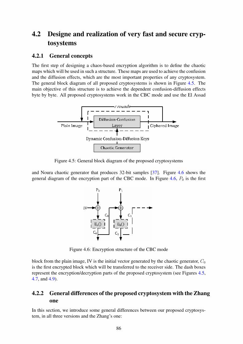
4.2 Designe and realization of very fast and secure cryp-tosystems
4.2.1 General conceptsThe first step of designing a chaos-based encryption algorithm is to define the chaoticmaps which will be used in such a structure. These maps are used to achieve the confusionand the diffusion effects, which are the most important properties of any cryptosystem.The general block diagram of all proposed cryptosystems is shown in Figure 4.5. Themain objective of this structure is to achieve the dependent confusion-diffusion effectsbyte by byte. All proposed cryptosystems work in the CBC mode and use the El Assad
Figure 4.5: General block diagram of the proposed cryptosystems
and Noura chaotic generator that produces 32-bit samples [37]. Figure 4.6 shows thegeneral diagram of the encryption part of the CBC mode. In Figure 4.6, P0 is the first
Figure 4.6: Encryption structure of the CBC mode
block from the plain image, IV is the initial vector generated by the chaotic generator, C0
is the first encrypted block which will be transferred to the receiver side. The dash boxesrepresent the encryption/decryption parts of the proposed cryptosystem (see Figures 4.5,4.7, and 4.9).
4.2.2 General differences of the proposed cryptosystem with the Zhangone
In this section, we introduce some general differences between our proposed cryptosys-tem, in all three versions and the Zhang’s one:
86

• In the Zhang cryptosystem, a simple implementation of the logistic map was usedto generate and manage the dynamic keys. In all versions of our proposed cryp-tosystem, a strong and robustness tested chaotic generator [37] is used to manageand generate the dynamic keys. These dynamic keys are used for the dependentconfusion-diffusion layer.
• To overcome the fixed-point problem of the standard 2-D cat map, the Zhang cryp-tosystem selects a random pixel arr(rxj, ryj) and swaps it with the first pixel inthe plain image arr(0, 0). In our proposed cryptosystem this problem is solved byusing the modified 2-D cat map. This modification of the standard 2-D cat map alsoenhances the security of the proposed cryptosystem. Indeed the number of dynamickeys in the 2-D cat map increases from two dynamic keys to four. The first pixel(0, 0) can be mapped to any new position (in, jn).
• The Zhang cryptosystem works on the whole image. It is well known that theimage encryption algorithms that work on the whole image give bad results for errorpropagation. The influence of one error bit of the ciphered data (due to the channel)on the decryption algorithm depends on the cryptographic modes. All versions ofour proposed cryptosystem perform the encryption/decryption operations based onthe Cipher-Block Chaining (CBC) mode [34].
• One of the most important differences between our proposed cryptosystems and theZhang cryptosystem is in the structure of the dynamic keys. In the Zhang cryp-tosystem, the dynamic keys consist of two keys (qi, pi) for the reverse 2-D cat map.These key values are changed just twice for the whole encryption process. For thelogistic map, t is the initial value. The value of t is changed in each byte. Whencomparing with our proposed cryptosystem, in the 2-D cat map, four keys are used(v, u, ri, and rj). These keys’ values are changed for every new encryption roundand also for every new block.
• All chaos-based cryptosystems that use more than one encryption round (i.e., r > 1)to reach the required security level, must save their dynamic keys for all rounds inorder to use them later in the decryption process. From a security point of view, itis normal that the security level of any cryptosystem is strongly related to the envi-ronment where these dynamic keys have been temporarily saved. To the best of ourknowledge, the only possible method to manage the dynamic keys in the decryp-tion process in case of more than one decryption round is to save them temporarily,since the decryption process is achieved by starting from the last decryption roundand finishing with the first decryption round. It is important to note that the chaoticgenerator has to be a non-invertible generator. To obtain the current key, the chaoticgenerator should generate all previous keys and use them in the reverse order.
All previously mentioned points are taken into consideration in the design process of afast and secure cryptosystem, and it should use only one encryption round(r = 1), toobtain the required security level.
4.2.3 First proposed cryptosystemThe first proposed cryptosystem has some similarity to the Zhang cryptosystem [166].In this cryptosystem, the two dependent confusion-diffusion layers are the modified 2-D
87

cat map (used to achieve the confusion effect) followed by the discrete logistic map (toachieve the diffusion effect). Using this structure, the required confusion-diffusion effectsare obtained by one encryption round, and hence the execution time is decreased.
4.2.3.1 Encryption scheme of the first proposed cryptosystem
In the encryption scheme (see Figure 4.7), for the first block, each pixel from the plainblock (p0(k)) is XOR-ed with the initial byte (iv(k)) from the initial vector (IV ), then theoutput is XOR-ed with the discrete logistic map output to carry out the diffusion process.Then, the 8 least significant bits resulting from the diffusion process (LSB8(y0(k)) arerelocated using the modified 2-D cat map to obtain the ciphered pixel at the new position(c0(kn))[39, 38]. It is important to note that the input of the discrete logistic map is basedon the previous ciphered pixel (since c0(kn) = LSB8(y0(k)) and the input of the discretelogistic map is 32 bits and the ciphered pixel is 8 bits. That is why the cryptosystem takes(y0(k− 1)) before the LSB8 function and not after. For the first encrypted byte, the inputof the discrete logistic map is Kdm, and this value is re-initialized every new encryptionround. Because the c0(kn) is only a part of the logistic map input, it is impossible torecover y0(k− 1) from c0(kn) only. The encryption of the next blocks is almost the same.Each pixel from the plain block (pl(k)) is XOR-ed with ciphered byte from the previousblock at the same position(i.e., cl−1(k) to achieve the CBC mode). Then the rest of theoperations are the same as in the first encryption block. The 2-D cat map was tested and
Figure 4.7: Encryption structure of the first proposed cryptosystem
analyzed by [45] and [155]. To overcome the fixed-point problem of the Arnold cat mapmodel, the parameters ri and rj are added to the standard model. Also, in our schemethe elements of the square matrix and the parameters ri and rj of equation (4.19) becomedynamic, they form the dynamic keys of the permutation process.[
injn
]= Mod
([1 uv 1 + uv
] [ij
]+
[ri+ rjrj
],
[MM
])(4.19)
88

Equation (4.19) is a one-to-one function, which means that each point of the square matrixcan be transferred to exactly one unique point. So, instead of exchanging the values at thenew position (in, jn) with the old one (i, j), we use a transfer operation because of itsspeed compared to the swap operation that is usually used. The block size bs is M2 (M isthe square root of the block size in our proposed cryptosystem). The system parametersu, v, ri and rj are in the range of [0, M − 1]. The structure of the dynamic keys whichare produced by the chaotic generator during the permutation process is:
Kp =[Kp0 ‖ Kp1 ‖ Kp2 ‖ · · · ‖ Kpr−1
]Kpm =
[um ‖ vm ‖ rim ‖ rjm
] (4.20)
The modulo operation of equation (4.19) makes it a non-invertible equation. But it is stilla reversible one. Thus, in the decryption part of the proposed cryptosystem, the reverselayer is also achieved by equation (4.19).The implementation of this modified 2-D cat map is carried out by an optimized process,indeed:- the value of Z1 = ri+ rj is calculated once per round.- the value of Z2 = u× v + 1 is calculated once per round.- the value of Z3 = v × i+ rj is calculated M times per round.Then the modified 2-D cat map is implemented as:[
injn
]= Mod
([i+ u× j + Z1
Z3 + Z2 × j
],
[MM
])(4.21)
The Logistic map is a non-linear chaotic discrete function that produces random se-quences. In the proposed cryptosystem, the logistic map is used as a diffusion function toachieve the diffusion effect, by transferring the effect from one byte in the block to otherbytes in the same block. This structure makes the proposed cryptosystem highly sensitiveto the plaintext. The mathematical model of the discrete logistic map is:
Xk+1 =
⌊Xk×(2N−Xk)
2N−2
⌋ifXk 6=
[3× 2N−2, 2N
]2N − 1 ifXk =
[3× 2N−2, 2N
] (4.22)
where Xk+1 is the new value calculated from the previous one Xk. N is the number ofbits representing the integer output of the discrete logistic map, which is equal to 32 bitsin all versions of our proposed cryptosystem. Figure 4.7 shows the block diagram of theencryption part of the first version of the proposed cryptosystem. From the figure, wewrite the encryption mathematical model as:
cl(kn) = LSB8[yl(k)] (4.23)
yl(k) = pl(k)⊕ sl−1(k)⊕ f(yl(k − 1)) (4.24)
where yl(k) is a 32-bit variable, pl(k), sl−1(k) are 8-bit variables and f is the logisticmap. The following remarks should be considered:
1. During the encryption, equation (4.24) should be evaluated before equation (4.23),for each byte of a block and for all blocks.
2. The input of the logistic map for k = 0 is kdm when l = 0 and it is yl−1(bs − 1) forl > 0.
89

Algorithm 7 Encryption steps1: Generate the IV values using the chaotic generator to encrypt the first block of the
image.2: for m = 0: r − 1: step = 1 do3: Generate the values of Kdm and Kpm using the chaotic generator to encrypt the
first block.4: k = 05: for i = 0: M − 1: step = 1 do6: for j = 0: M − 1: step = 1 do7: Initialize the value of s−1(k) = iv(k)8: Calculate (in, jn) using equation (4.19)9: Calculate kn = in ×M + jn
10: Calculate y0(k) value using equation (4.22) and equation (4.24)11: Calculate c0(kn) value using equation (4.23)12: k = k + 113: End j14: End i15: End m16: for l = 1: bn − 1: step = 1 do17: for m = 0: r − 1: step = 1 do18: Generate the values ofKpm using the chaotic generator to encrypt the current block
of the plain19: image.20: k = 021: for i = 0: M − 1: step = 1 do22: for j = 0: M − 1: step = 1 do23: Initialize the value of sl−1(k) = cl−1(k)24: Calculate (in, jn) using equation (4.19)25: Calculate kn = in ×M + jn26: Calculate yl(k) value using equation (4.22) and equation (4.24)27: Calculate cl(kn) value using equation (4.23)28: k = k + 129: End j30: End i31: End m32: End l
90

3. For k > 0 and for all l, the input of the logistic map is the result of equation (4.24)and not the previous output (see equation 4.22).
Note that:k = i×M + jkn = in ×M + jnin and jn are calculated using equation (4.19). The sequence sl−1(k) is given by thefollowing equation:
sl−1(k) =
{iv(k) if l = 0
cl−1(k) if l > 0(4.25)
wherel = 0, 1, 2, ...bn − 1k = 0, 1, 2, ...bs − 1IV = {iv(0), iv(1), iv(2), ..., iv(bs − 1)}bs is block size in bytesbn = image size
block size = L×C×Pbs
, is the number of blocks.with, L, C, and P are the number of lines, the number of columns, and the number ofplanes of the image respectively.In algorithm-7, we describe in detail the exact steps to achieve the ciphering process forall blocks.
4.2.3.2 Decryption scheme of the first proposed cryptosystem
The decryption scheme of the first proposed cryptosystem is almost identical to the en-cryption one. Figure 4.8 shows the decryption structure of the CBC mode in all proposedcryptosystems, while Figure 4.9 shows the decryption structure of the first proposed cryp-tosystem.
The decryption equation resulting from the encryption equations is: (4.23) and (4.24):
Figure 4.8: Decryption structure of the CBC mode
pl(k) = cl(kn)⊕ sl−1(k)⊕ LSB8[f(yl(k − 1))] (4.26)
whereyl(k) = pl(k)⊕ sl−1(k)⊕ f(yl(k − 1)) (4.27)
As we can see, equation (4.26) is firstly evaluated followed by equation (4.27) for eachbyte of a block and for all blocks.
91

Algorithm 8 Decryption steps1: Generate Kdm, Kpm for all m values (i.e., m = 0, 1, ...r − 1) and IV using the
chaotic generator to decrypt the first ciphered block.2: for m = r − 1: 0: step = −1 do3: k = 04: for i = 0: M − 1: step = 1 do5: for j = 0: M − 1: step = 1 do6: Initialize the value of s−1(k) = iv(k)7: Calculate (in, jn) using equation (4.19)8: Calculate kn = in ×M + jn9: Calculate p0(k) value using equation (4.26)
10: Calculate y0(k) value using equation (4.22) and equation (4.24)11: k = k + 112: End j13: End i14: End m15: for l = 1: bn − 1: step = 1 do16: Generate the Kpm for all m values (i.e., m = 0, 1...r − 1)17: using the chaotic generator to decrypt the current block from the ciphered image.18: for m = r − 1: 0: step = −1 do19: k = 020: for i = 0: M − 1: step = 1 do21: for j = 0: M − 1: step = 1 do22: Initialize the value of sl−1 = cl−1k23: Calculate (in, jn) using equation (4.19)24: Calculate kn = in ×M + jn25: Calculate pl(k) value using equation (4.26)26: Calculate yl(k) value using equation (4.22) and equation (4.24)27: k = k + 128: End j29: End i30: End m31: End l
92

Figure 4.9: Decryption structure of the first proposed cryptosystem
In reality, as we can see in Figure 4.9, equation (4.27) is implemented as follows:yl(k) = cl(kn)⊕ sl−1(k)⊕ LSB8[f(yl(k − 1))]⊕ sl−1(k)⊕ f(yl(k − 1))
yl(k) = cl(kn)⊕ LSB8[f(yl(k − 1))]⊕ f(yl(k − 1) (4.28)
4.2.3.3 Analysis of the first proposed cryptosystem
Lian et al., in their paper [74], analyzed the Fridrich model, and they pointed out somepossible attacks on that model. We apply and analyze these attacks on our proposedcryptosystem to ensure its robustness against them.
4.2.3.4 Dynamic key space analysis of Fridrich, Zhang and our cryptosystems
Lain in his paper assumes that the dynamic key space of the whole Fridrich cryptosystemis Sr = (S1 × S2)
r, where S1 is the dynamic key space of the confusion layer, S2 is thedynamic key space of the diffusion layer, and r is the number of iterations.The total dynamic key space of the Frdirich model can be calculated as:S1 = (N2)r
S2 = Lr
KSFridrich = (N2)r × Lr = (N2 × L)r
where M is the square root of the tested image size and L = 256, is the number of graylevels.In the Zhang cryptosystem, the first algorithm has q1, q2, p1 and p2 in the range [0, 511],and also t0 which is 8 bits, so:KSZhang1 = (N4 × 28)r.The second algorithm has q1, q2, p1 and p2 in the range [0, 511], and also temp1 andtemp2 of 8 bits each, so:
93

KSZhang2 = (N4 × 216)r.In our proposed cryptosystem, the total dynamic key space is defined as:Sr = (S1 × S2)
r where S1 is the dynamic key space of the confusion layer (the modified2-D cat map), S2 is the dynamic key space of the diffusion layer (the logistic map).The total dynamic key space of our proposed cryptosystem can be calculated as:
1. The whole image is divided into a number of blocks and the dynamic keys arechanged for every new encryption round and every new block.
2. Dynamic keys for the confusion layer are (u, v, ri and rj: in the range of [0, M −1]). Then, the confusion key space is M4.
3. The diffusion key space (S1) is 32 bit instead of 8 bit as in the Fridrich or the Zhangcryptosystems.
4. The total number of blocks is bn where bn = L×C×Pbs
= L×C×PM2 .
KS = (S1 × S2)r × bn
S1 = M4
S2 = 232
For r = 1:KSProposed = (M4 × 232)× L×C×P
M2
As an example and to make the comparison between cryptosystems, of Zhang, Fridrichand ours, the gray-scale Lena image of 512 × 512 is taken, and then for one encryptionround (remark, for our proposed cryptosystem M = 32):KSFridrich = 5122 × 256 = 226
KSZhang1 = 5124 × 28 = 244
KSZhang2 = 5124 × 216 = 252
KSProposed = (324 × 232)× (512×512322
) = 260
It is clear from the previous calculations that the dynamic key space of our proposedcryptosystem is 216 times more than the first Zhang cryptosystem, and 28 times morethan the second Zhang cryptosystem.
4.2.3.5 Chosen-plaintext attack
Fridrich proved that his proposed model is secure against a chosen-plaintext attack basedon the fact that the difference between the ciphertexts encrypted by the same key fortwo plaintexts differs on one bit is large enough to keep a high security level against thechosen-plaintext attack. However, Lian in [74] pointed out another kind of attack that canbe used to cryptanalyze the Fridrich model. Since the fixed-point problem was not solvedin the 2-D cat map, Baker or standard maps were used in the Fridrich model, and so thecipher of the first plain pixel of any image will remain in the first position (that means c0is the encryption of the p0, and so, no permutation is done on the first pixel). Then it iseasy to find the initial value of the diffusion key (Q−1) in the Fridrich model (more detailsof this attack are in [74]).
In Zhang cryptosystems, a simple solution to overcome this problem is introduced,the solution is carried out by swapping the first pixel with a random pixel from the imagebefore starting the encryption process.
94

In our proposed cryptosystem, the first kind of chosen-plaintext attack is solved, and itsatisfies a high security level. This is well stated by our proposed cryptosystem in section(4.2.6).The fixed-point problem does not exist in our proposed cryptosystem, since it is solvedby adding the ri and the rj dynamic keys to the original 2-D cat map, and the chaoticgenerator insures that ri and rj will never be zero at the same time.Our solution has two advantages, first, it increases the dynamic key space of the 2-D catmap, second, any pixel can be mapped to any position with the same probability.
4.2.3.6 Some specific differences in the diffusion process
Zhang cryptosystems implement the logistic map based on 8 bits. This means, that theinput and the output of the logistic map for all operations are in 8 bits, whereas in ourproposed cryptosystem, the logistic map is implemented to receive 32 bits as input and toproduce 32 bits as output. As a result, the dynamic key of the logistic map is increasedfrom 8 bits to 32 bits, and the security level of the overall cryptosystem is increased.Finally, it is well known that the implementation of the logistic map based on 8 bits hassome security weaknesses and failures.Finally, as the proposed cryptosystem uses new dynamic keys for each new block, then,the cryptosystem is secure against the chosen-plaintext attacks, according to the fact thata chosen-plaintext attack will be useless if different keys are used to encrypt differentplaintexts in the same message.
4.2.4 Second proposed cryptosystemThe construction and design process of the following cryptosystems begins by keepingin mind the structure of the first proposed cryptosystem. As we know, there is always atrade off between the security level and the encryption time. Increasing the security levelin general leads to making the system more complex, and then adding some additionaldelays on the encryption operations. For this reason, two sub-versions of the secondversion are described in this section. These sub-versions have the same structure as thefirst proposed cryptosystem, but using a different diffusion layer, namely the Finite SkewTent Map (FSTM) as a generator instead of the logistic map.
4.2.4.1 Finite Skew Tent Map as diffusion layer
The diffusion layer is implemented using a modified version as a generator of the originalFSTM in [84], [83], based on a lookup table of 8 bits for the first subversion and on amathematical calculation of 32 bits for the second subversion (see equation (4.29)). TheFSTM has a better non-linear transformation than the logistic map and so its diffusion isstronger than that of the logistic map. This implies that the cryptosystem is more resistantagainst differential cryptanalysis attacks. So, using the FSTM as a dependent diffusionlayer increases cryptosystem sensitivity to plain sensitivity attacks. The mathematicalmodel of the modified FSTM generator is [39]:
F (X) =
⌊QAm×X
⌋+ A0m Mod Q 0 ≤ X ≤ Am
⌊Q×(Q−X)Q−Am
⌋+ 1 + A0m Mod Q Am < X < Q
(4.29)
95
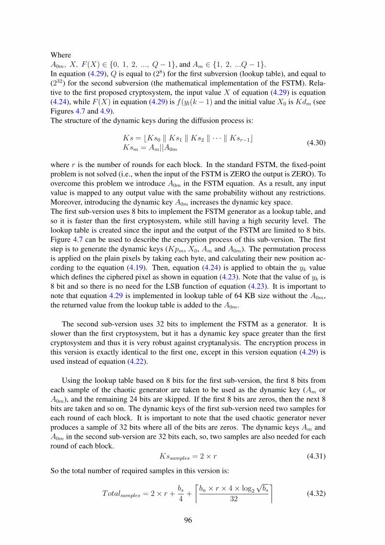
WhereA0m, X, F (X) ∈ {0, 1, 2, ..., Q− 1}, and Am ∈ {1, 2, ...Q− 1}.In equation (4.29), Q is equal to (28) for the first subversion (lookup table), and equal to(232) for the second subversion (the mathematical implementation of the FSTM). Rela-tive to the first proposed cryptosystem, the input value X of equation (4.29) is equation(4.24), while F (X) in equation (4.29) is f(yl(k− 1) and the initial value X0 is Kdm (seeFigures 4.7 and 4.9).The structure of the dynamic keys during the diffusion process is:
Ks = bKs0 ‖ Ks1 ‖ Ks2 ‖ · · · ‖ Ksr−1cKsm = Am||A0m
(4.30)
where r is the number of rounds for each block. In the standard FSTM, the fixed-pointproblem is not solved (i.e., when the input of the FSTM is ZERO the output is ZERO). Toovercome this problem we introduce A0m in the FSTM equation. As a result, any inputvalue is mapped to any output value with the same probability without any restrictions.Moreover, introducing the dynamic key A0m increases the dynamic key space.The first sub-version uses 8 bits to implement the FSTM generator as a lookup table, andso it is faster than the first cryptosystem, while still having a high security level. Thelookup table is created since the input and the output of the FSTM are limited to 8 bits.Figure 4.7 can be used to describe the encryption process of this sub-version. The firststep is to generate the dynamic keys (Kpm, X0, Am and A0m). The permutation processis applied on the plain pixels by taking each byte, and calculating their new position ac-cording to the equation (4.19). Then, equation (4.24) is applied to obtain the yk valuewhich defines the ciphered pixel as shown in equation (4.23). Note that the value of yk is8 bit and so there is no need for the LSB function of equation (4.23). It is important tonote that equation 4.29 is implemented in lookup table of 64 KB size without the A0m,the returned value from the lookup table is added to the A0m.
The second sub-version uses 32 bits to implement the FSTM as a generator. It isslower than the first cryptosystem, but it has a dynamic key space greater than the firstcryptosystem and thus it is very robust against cryptanalysis. The encryption process inthis version is exactly identical to the first one, except in this version equation (4.29) isused instead of equation (4.22).
Using the lookup table based on 8 bits for the first sub-version, the first 8 bits fromeach sample of the chaotic generator are taken to be used as the dynamic key (Am orA0m), and the remaining 24 bits are skipped. If the first 8 bits are zeros, then the next 8bits are taken and so on. The dynamic keys of the first sub-version need two samples foreach round of each block. It is important to note that the used chaotic generator neverproduces a sample of 32 bits where all of the bits are zeros. The dynamic keys Am andA0m in the second sub-version are 32 bits each, so, two samples are also needed for eachround of each block.
Kssamples = 2× r (4.31)
So the total number of required samples in this version is:
Totalsamples = 2× r +bs4
+
⌈bn × r × 4× log2
√bs
32
⌉(4.32)
96

4.2.4.2 Analysis of the second proposed cryptosystem
In this section, we analyze the dynamic key space and the chosen-plaintext attacks.
4.2.4.3 Dynamic key space analysis
In our proposed cryptosystem, the total dynamic key space is:KS = (S1 × S2)
r × bnFor one encryption round (r = 1):First subversion key space:S1 = M4
S2 = 224, because X0, Am and A0m are 8 bits each.KSSubversion1 = M4 × 224 × L×C×P
M2
Second subversion key space:S1 = M4
S2 = 296, because X0, Am and A0m are 32 bits each.KSSubversion2 = M4 × 296 × L×C×P
M2
Again, to make the same comparison between our proposed cryptosystem, the Zhangand the Fridrich cryptosystems, the Lena image of 512× 512 bytes is taken, then for oneencryption round (remark, for our proposed cryptosystem M = 32):KSFridrich = 226
KSZhang1 = 244
KSZhang2 = 252
KSSubversion1 = (324 × 224)× 512×512322
= 252
KSSubversion2 = (324 × 296)× 512×512322
= 2124
It is clear from the previous calculations that the dynamic key space of the first subver-sion is 28 times more than the first Zhang cryptosystem, and the same as the second Zhangcryptosystem, whereas the dynamic key space of the second subversion is 280 times morethan the first Zhang cryptosystem, and 272 times more than the second Zhang cryptosys-tem.
4.2.4.4 Chosen-plaintext attack
In this cryptosystem version, the modified 2-D cat map is the same as before, and so theanalysis of the chosen-plaintext attack is the same. The FSTM is enhanced by adding theparameter A0. This means that the fixed-point problem is solved also for the diffusionlayer, and so, this type of attack will be useless.
4.2.5 Time and complexity analysisThe speed evaluation of our proposed cryptosystem in all versions is carried out using thesame environment and parameters which are used in section (3.4.1). It encrypts differentimages of different sizes. (256×256×3, 512×512×3 and 1024×1024×3). We comparethe speed of our proposed cryptosystems with the fastest chaos-based cryptosystems. Inparticular, the security and the performance analysis of the proposed cryptosystems arecompared with [166] cryptosystem, since, to the best of our knowledge, Zhang cryptosys-tem is the fastest chaos-based cryptosystem.Table 4.3 presents the encryption and the decryption times for our proposed algorithms,
97

based on two different block sizes (bs = 256 and bs = 1024 bytes) and the image undertest was Lena. The time calculation process of encryption and decryption is evaluated asfollows: the test image (Lena with block size 1024) is encrypted for 1000 different secretkeys, then the average of these executions is calculated. From Table 4.4, it is clear
Table 4.3: Average encryption/decryption time of the proposed algorithm(in milliseconds)
Our Cryptosystem Ver-sion
bs 256× 256× 3 512× 512× 3 1024× 1024×3
Proposed V1 256 2.21/2.82 8.75/11.16 34.87/44.34
Proposed V1 1024 2.04/2.68 8.08/10.57 31.85/41.83
Proposed V2-8bit 256 1.73/1.78 6.82/7.10 27.01/28.04
Proposed V2-8bit 1024 1.38/1.45 5.42/5.74 21.17/22.39
Proposed V2-32bit 256 4.57/5.24 18.29/20.89 73.05/83.43
Proposed V2-32bit 1024 4.15/4.79 16.56/19.08 66.12/76.17
Table 4.4: Encryption/decryption time of different algorithms(in milliseconds)
Proposed Cryptosystem 256× 256× 3 512× 512× 3 1024× 1024×3
Proposed V1 2.04/2.68 8.08/10.57 31.85/41.83
Proposed V2-8bit 1.38/1.45 5.42/5.74 21.17/22.39
Proposed V2-32bit 4.15/4.79 16.56/19.08 66.12/76.17
Zhang 1[166] 7.5/7.5 30/30 120/120
Zhang 2[166] 7.5/8.25 30/33 120/132
Wang [152] 7.79/8.39 31.16/33.54 124.64/134.16
Akhshani [8] 14.4 57.6 230.4
Wong [155] 15.59/16.77 62.37/67.11 249.48/268.44
Pareek [94] 160 920 5650
that our proposed cryptosystems are faster than both of the Zhang algorithms and otherknown cryptosystems. Table 4.5 presents a comparison of performance of our proposedcryptosystem with some known recent cryptosystems in the literature. The performanceis evaluated in terms of encryption throughput (running speed) in Mega Byte Per Second(MBps) and number of needed cycles to encrypt/decrypt one byte. As it can be seen inTables (4.3-4.5), our proposed cryptosystem in all proposed versions is faster than theother chaos-based cryptosystems.
98

Table 4.5: Encryption throughput and Number of cycles for one encrypted byte
Proposed Cryptosystem ET in MBps Number of cycles per byte
Proposed V1 93.817/71.486 31.51/41.35
Proposed V2- 8 bits 140.776/133.114 21/22.21
Proposed V2-32 bits 45.347/39.359 65.19/75.11
Zhang 1 [166] 25/25 122.07/122.07
Zhang 2[166] 25/22.72 122.07/134.27
Wang [152] 24.06/22.35 122.85/132.24
Akhshani [8] 13.02 194.83
Wong [155] 12.03/11.18 245.7/264.38
Pareek [94] 0.39 2445
4.2.6 Plain-text sensitivity attack
The mathematical equations of chapter 2 (see section 2.2.2) are used to produce thepresented results of Table 4.6. All versions of our proposed cryptosystem achieve theavalanche effect from the first round (r = 1) and then, they overcome the plaintext sen-sitivity attacks. The plain images under test were Lena, Barb, and Boat images of thesame size 512 × 512 gray scale images (the selected images are chosen like those in theliterature). Moreover, Lena and Peppers color images of the same size were used on thesame test. Table 4.6 presents all of these results, and it is clear that the HD value isvery close to the optimal value of 50% for the three proposed cryptosystems. Also theUACI and NPCR values are close to optimal. These values indicate that the proposedcryptosystems are very sensitive to one bit change in the plaintext. Hence, a high securitylevel is reached.
99

Table 4.6: HD, UACI and NPCR plaintext sensitivity tests
Proposed Cryp-tosystem
Image Name Image Size HD UACI NPCR
Proposed V1 Barb 512× 512× 1 0.499630 33.438 99.532
Proposed V2-8 bit Barb 512× 512× 1 0.499975 33.462 99.611
Proposed V2-32 bit Barb 512× 512× 1 0.499978 33.460 99.609
Zhang 1 [166] Barb 512× 512× 1 / 33.475 99.663
Zhang 2 [166] Barb 512× 512× 1 / 33.420 99.582
Proposed V1 Lena 512× 512× 1 0.499587 33.437 99.521
Proposed V2-8 bit Lena 512× 512× 1 0.499986 33.463 99.611
Proposed V2-32 bit Lena 512× 512× 1 0.499975 33.459 99.609
Pareek [94] Lena 512× 512× 1 / 31.79 99.6
Wong [155] Lena 512× 512× 1 / 32.82 99.44
Wang [152] Lena 512× 512× 1 / 33.435 99.607
Proposed V1 Boat 256× 256× 1 0.499576 33.434 99.524
Proposed V2-8 bit Boat 256× 256× 1 0.499993 33.461 99.611
Proposed V2-32 bit Boat 256× 256× 1 0.499955 33.466 99.609
Song [133] Boat 256× 256× 1 33.453 99.625 /
Akhshani [8] Boat 256× 256× 1 0.499900 33.200 /
Proposed V1 Lena 512× 512× 3 0.499823 33.454 99.579
Proposed V2-8 bit Lena 512× 512× 3 0.500001 33.466 99.611
Proposed V2-32 bit Lena 512× 512× 3 0.499981 33.466 99.610
Proposed V1 Peppers 512× 512× 3 0.499853 33.451 99.576
Proposed V2-8 bit Peppers 512× 512× 3 0.500035 33.466 99.610
Proposed V2-32 bit Peppers 512× 512× 3 0.500001 33.463 99.609
4.2.7 Key sensitivity attack
To evaluate the proposed cryptosystems in terms of key sensitivity attacks, the previousdescribed equations of the NPCR, UACI and HD(see section 2.2.3) are used.
Table 4.7presents the results obtained from the key sensitivity attack test for the threeversions of the proposed cryptosystem using the same parameters as were used in Ta-ble 4.6. From Table 4.7, it is clear that the proposed cryptosystem has a high security
100

Table 4.7: HD, UACI and NPCR key sensitivity tests
Proposed Cryp-tosystem
Image Name Image Size HD UACI NPCR
Proposed V1 Barb 512× 512× 1 0.500029 33.464 99.610
Proposed V2-8 bit Barb 512× 512× 1 0.499980 33.463 99.609
Proposed V2-32 bit Barb 512× 512× 1 0.499989 33.461 99.609
Proposed V1 Lena 512× 512× 1 0.500014 33.463 99.610
Proposed V2-8 bit Lena 512× 512× 1 0.499995 33.464 99.608
Proposed V2-32 bit Lena 512× 512× 1 0.499952 33.465 99.608
Proposed V1 Boat 256× 256× 1 0.500015 33.462 99.609
Proposed V2-8 bit Boat 256× 256× 1 0.499988 33.462 99.608
Proposed V2-32 bit Boat 256× 256× 1 0.499995 33.460 99.609
Proposed V1 Lena 512× 512× 3 0.500007 33.464 99.610
Proposed V2-8 bit Lena 512× 512× 3 0.499992 33.463 99.609
Proposed V2-32 bit Lena 512× 512× 3 0.499994 33.465 99.609
Proposed V1 Peppers 512× 512× 3 0.500001 33.465 99.609
Proposed V2-8 bit Peppers 512× 512× 3 0.499987 33.461 99.610
Proposed V2-32 bit Peppers 512× 512× 3 0.499998 33.465 99.609
101

level relative to the key sensitivity attacks.
4.2.8 Correlation analysis
To test the correlation between adjacent pixels, the following procedure was carried out.Firstly, 8000 pairs of two adjacent pixels are selected randomly in vertical, horizontal, anddiagonal directions from the original and the encrypted images. Then, the correlation co-efficient is computed according to the equations (2.12-2.15), of section (2.2.5) of chapter2.
(a) Horizontal correlation of the plain image (b) Vertical correlation of the plain image
(c) Diagonal correlation of the plain image (d) Horizontal correlation of the ciphered image
(e) Vertical correlation of the ciphered image (f) Diagonal correlation of the ciphered image
Figure 4.10: Correlation analysis of Lena and its ciphered image in three directions
102

One example of this extensive study is the Barb gray scale image of 512 × 512 × 1.The obtained results are shown in Table 4.8 and Figure 4.10. These results demonstratethat the correlation coefficient, in all directions, of the plain images is close to one (seeFigure 4.10), and the correlation coefficient of the encrypted images is close to zero. Thismeans that there is no detectable correlation between the original and its correspondingciphered image, and also, there is no relation between pixels of the ciphered image.
Table 4.8: Correlation Analysis Results
Cryptosystem Name Horizontal Vertical Diagonal
Proposed Algorithm V1 0.0085 0.0097 0.0092
Proposed Algorithm V2-8 bit 0.0087 0.0098 0.0096
Proposed Algorithm V2-32bit
0.0087 0.0098 0.0096
4.2.9 Histogram analysisIn Figure 4.11, we show some visual results obtained with the third version of the pro-posed cryptosystem (similar results are obtained for the other versions): a) the plain Lenaimage of size 512 × 512 × 3, b) the corresponding cipher image, c) the histogram of theplain image, and d) its corresponding cipher image. The histogram of the encrypted im-age is very close to the uniform distribution and completely different from the plain imagehistogram. This means that there is no visual information than can be observed from theciphered image of the proposed cryptosystem.
Table 4.9: Chi-Square Results
Crypto version Ciphered image Chi-square
Proposed V1
Lena 256.27
Boat 262.46
Baboon 259.91
Proposed V2-8bit
Lena 259.63
Boat 254.69
Baboon 258.78
Proposed V2-32bit
Lena 253.12
Boat 252.44
Baboon 253.14
The visual test is necessary but is not sufficient. To ensure uniformity, the chi-squaretest is applied to statistically confirm the uniformity of the histogram.
103

(a) Plain Lena image (b) Ciphered Lena image
(c) Histogram of the plain Lena image (d) Histogram of the ciphered Lena image
Figure 4.11: Lena image and its ciphered version and their corresponding histograms
104

We present in Table 4.9 the results obtained from the chi-square test of histograms forthree ciphered images of different nature (i.e., Lena, Boat, and Baboon). All of them havethe same size of 128× 128× 3, with a significant level of 0.05. From the obtained values,we can observe that χ2
exp < χ2th(255, 0.05) = 293, and then the tested histograms are
uniform and do not reveal any information for statistical analysis.
105

4.3 Example of a real-time applicationAn example of a real-time application of all realized chaos-based cryptosystems could bein real-time energy harvesting sensor.A wireless sensor network consists of sensor nodes deployed over a geographical area formonitoring physical phenomena like temperature, humidity, vibrations, seismic events,and sensitive information such as enemy movement on the battlefield or the location ofpersons in a building. Typically, a sensor node is a tiny device that includes four ba-sic components: a sensing subsystem for data acquisition from the physical surroundingenvironment, a processing subsystem for local data processing and storage, a wirelesscommunication subsystem for data transmission, and a power source to supply the energyneeded by all the subsystems to perform the programmed tasks. The power source oftenconsists of a battery with limited life time. In many applications, it is impossible or costlyto recharge the battery because nodes may be deployed in hostile or unpractical environ-ments. The sensor network should have a lifetime long enough to fulfill the applicationrequirements. Therefore, the question is how to prolong the network lifetime to such along time [10].Sensors communicate broadcasted messages to each other which makes them vulnerableto different types of attack, such as eavesdropping, malicious modification on insertionof unauthorized data in packages [151]. To prevent attacks, we should implement secu-rity services in WSNs. Among them, the most important are confidential, authenticationof nodes as well as data integrity. Most of traditional security mechanisms are not suf-ficiently efficient. All existing algorithms including cryptographic algorithms adaptedto WSNs aim to reduce the energy consumed and thus to maximize the lifetime of thenetworks. Nevertheless, in the paradigm of energy harvesting sensor networks, the com-puting/communication system needs to be energy-neutral i.e. to consume as much energyas harvested. In this context, new algorithms have to be developed for power manage-ment, routing and other networking issues.In this section, we address the question of security in new embedded systems which aresupplied by ambient energy. A variety of techniques are available for energy harvest-ing, including solar and wind powers, piezoelectricity, thermoelectricity, and physicalmotions. Energy harvesting is perfectly convenient for wireless electronic devices thatotherwise rely on battery power. In the energy harvesting paradigm, the lifetime of anetwork can be considered as infinite. A central question that remains open is about thepossibility of fully secure communications with energy harvested sensors.We propose an on-line strategy based on software redundancy which, at any time per-mits to select the adequate encryption algorithm so as to optimize the resulting Quality ofService measured in terms of security and rapidity. Further, we propose a security-awarescheduling strategy which Quality of Service measured in terms of security and rapidity.Further, we propose a security-aware scheduling strategy which incorporates the EarliestDeadline First (EDF) scheduling algorithm.
4.3.1 Real-time computing4.3.1.1 Issues in conventional real-time computing systems
Data sensing and retrieval in wireless sensor systems have a widespread application. Thesoftware on a node generally comprises a set of periodic tasks that consist of streams ofjobs. Task periods are usually set by the application requirements. Every job is char-
106

acterized by a release time, an execution requirement and a deadline. The goodness ofsuch real-time system depends on whether all the jobs of all the tasks can be guaranteedto complete their executions before deadlines. If they can, then we say the task set isfeasible.It has been established for about forty years that the EDF scheduling policy which as-signs priorities according to urgency is optimal [75]. In case of timing constraints cannotbe met, one way is to trade computation quality for timeliness. This is often achievedwith software redundancy in order to provide a graceful degraded mode. Indeed, a real-time system should continue to operate even in the presence of time starvation or energystarvation with a lower but acceptable Quality of Service.
4.3.1.2 The deadline mechanism
The so-called Deadline Mechanism (DM) provides software redundancy in hard real-timeperiodic task systems [24]. Each task has two versions: primary and alternate (also calledback-up). The primary version contains more functions and produces good quality re-sults, but requires high computation time (and high energy requirement). The alternateversion contains only the minimum required functions and produces less precise resultswith minimum execution requirements. However, if the primary of a task fails (due totime or energy starvation), the execution of the associated alternate should be guaran-teed before deadline. The challenge in the implementation of the deadline mechanism isconsequently twofold:
• How to guarantee that either the primary or the alternate version of each task becompleted in time and.
• How to complete as many primaries as possible to optimize the quality of service.
4.3.1.3 Scheduling framework
In [25] the so-called last chance strategy is proposed to maximize the number of success-ful primaries. An offline scheduler reserves time intervals for the alternates. Each intervalis chosen so that any alternate starts execution at the latest possible time. At run-time, theprimaries are processed during the remaining intervals before their respective alternate.Alternates can preempt any primary when a time interval reserved for the alternates over-laps the execution interval of primaries. Whenever a primary completes successfully, theexecution of its corresponding alternate is no longer needed. Hence, the online schedulingalgorithm dynamically rearranges the alternate schedule so as to increase processor timeavailable for the execution of primaries (see Figure.4.13).
4.3.2 Security in energy harvesting systems4.3.2.1 System model
Our system consists of four components: the energy source, the energy harvester, the en-ergy storage and the sensor node as it is seen in Figure.4.12. The ambient energy sourceis characterized by an instantaneous charging rate Pr(t) that incorporates all losses. Weassume that energy production times can overlap with the consumption times. The energyproduced by the source is not considered as controllable and not necessarily predictable.Our system uses an ideal energy storage unit that has a nominal capacity, namely C. Let
107

define E(t) as the residual capacity of the storage unit at time t. We consider a uni-
Figure 4.12: Framework of the energy harvesting system
processor sensor node that consumes negligible energy in idle state. Transactions requireto be performed periodically. We assume that two encryption algorithms are available.The first one is characterized by a very low execution time and energy requirement, calledby the alternate in energy starvation situations. The second one has a greater executiontime and greater energy requirement but provides the highest quality of security. Con-sequently, every encryption task τi is modeled by a five-tuple (Cpi, Cai, Epi, Eai, Ti)where it is denoted:
• Cpi respectively Cai: the Worst Case Execution Time (WCET) of the primaryrespectively the alternate of τi with Cpi > Cai.
• Epi respectively Eai the Worst Case Energy Consumption (WCEC) of the primaryrespectively the alternate of τi with Epi > Eai.
• Ti the period of τi.
We assume that Ei is not necessarily proportional to Ci. Moreover the average incomingpower is higher than or equal to the average power consumed by the alternates. And theprocessor utilization rate due to the alternates is less than one.
4.3.2.2 The scheduling issue
The introduction of energy harvesting capabilities in sensor networks has introduced addi-tional design questions. How to intelligently use the ambient incoming energy to optimizethe QoS of the system measured in terms of security? Furthermore, how to adapt the pro-cessing activity so as to subsist perennially on a given energy source?We need a scheduling algorithm which:
1. Guarantees either the primary or alternate version of each encryption task to becompleted in a time.
2. Attempts to complete as many primaries as possible.
Our basic strategy uses Earliest Deadline as late as possible to pre-allocate time intervalsto the alternates. Even if EDF is not the optimal scheduler in energy harvesting systems,we proved recently that EDF is the optimal non idling scheduler [26]. In contrast to an
108

optimal scheduler, EDF is no clairvoyant and consequently easy to implement. Here, wewant to delay execution of alternates as much as possible to save both time and energy. Atrun-time, it attempts to execute primaries first. An alternate will be executed only (1) ifits primary fails due to lack of time, lack of energy or manifestation of bugs, or (2) whenthe latest time to start execution of the alternate without missing the corresponding taskdeadline is reached. This algorithm has been shown to be effective and easy to implement.
Figure 4.13: The Deadline Mechanism
Figure.4.13, depicts a very simple example where two periodic tasks of respectiveperiods 3 and 9 have to execute before deadline. The Last chance strategy attempts toexecute the primaries first. From time 0 up to time 3, primaries execute timely because ofsufficient energy available in the storage unit. When primary τ1 succeeds at 2, the intervalreserved for the alternate is removed and additional time could be used for primaries.Here, we do not illustrate the process for reserving energy that should guarantee feasibilityof all alternates. Second primary τ1 fails before completion due to depletion of the storageunit. The primary is aborted and the storage starts recharging since we let the processorinactive until the storage fully replenishes. That permits primary τ2 and alternate τ1 tocomplete successively as third primary τ1.
4.4 ConclusionIn the first part of this chapter, we studied and analyzed one of the best chaos-based cryp-tosystems of the literature, namely Zhang cryptosystems. We have partially cryptanalyzedthe first Zhang cryptosystem by using a combination of a chosen plaintext attack, and abrute force attack, for (n = 1, m = 2). Also, after removing the diffusion effect usingequation (4.12), we succeeded in decreasing the security level, measured by means of pa-rameters NPCR and UACI, by applying the differential attacks for (n = 2, m = 2). Then,in the second part of the chapter, based on a similar structure of the Zhang cryptosystem,we designed two versions, with two different implementation of the second version, of achaos-based cryptosystem. We have shown that all versions of our proposed cryptosys-tem are faster and more secure than Zhang and many chaos-based cryptosystems. The
109

time performance is carried out using average encryption/decryption times, encryptionthroughput, and the number of cycles needed to encrypt or decrypt one byte. The lastmeasure is necessary to compare different cryptosystems working on different platforms.All versions of our proposed cryptosystem are implemented using the CBC mode and arobust chaotic generator to produce the dynamic keys for each new encryption round andnew block. The high security level of all versions of the proposed cryptosystem is verifiedby testing them for different kinds of known attacks, and by using the well-known statis-tical analysis. Finally, all results prove the superiority of the proposed cryptosystems foruse in secure and real-time applications.
110

IIJoint Crypto-Compression
111


5Video coding and crypto-compressionstat of the art
A general overview of the video compression is introduced in the first section, with somedetails on the last two video coding standards in sections 5.2 and 5.3. Related works onvideo encryption algorithms are presented in Section 5.4. Finally, section 5.5 concludesthis chapter.
5.1 Video compression stepsThe video consists of successive pictures captured at a specific frequency called framerate. For instance, a color video in High Definition (HD) resolution captured at 24 pic-tures per second (1920x1080p24) requires a bit-rate of around ≈ 600 Mbps in case of4:2:0 color format. Therefore, it is difficult to deliver video in real-time over Internet andwireless networks without compression.Video compression consists in removing spatial and temporal redundancies in the videoand thus, it considerably decreases the required data to represent the video. The gen-eral block diagram of video compression processes is shown in Figure 5.1. The videocompression processes can be classified into lossy and loss-less compression. The conse-quence of the lossy compression is that it is not possible to recover, at the decoder side,the original video. During the compression process, the loss of information is mainly dueto the quantization step. It consists in reducing the dynamics of the encoded coefficients,and then the reconstructed video at the decoder is not identical to the original one.
Figure 5.1: General block diagram of the video compression at the encoder
In loss-less compression, the non-invertible steps are not involved (i.e., all steps duringthe compression process are reversible ones). Therefore, a loss-less compression process
113

enables to recover at the decoder side the original video, without any loss of information.In terms of compression ratio (which is defined as uncompressed over compressed videosize), the lossy compression enables higher compression ratio than the loss-less one. Forinstance, typical values for compression ratio in the HEVC ranges from 300 to 1000 whilein loss-less compression scheme the compression ratio at max can be 4 [139].In the following, we give a brief description of the video compression steps.
5.1.1 Prediction
The video consists of a set of pictures, with high spatial and temporal redundancies. Pre-dictions in video are used to remove spatial (called Intra prediction) and temporal (calledInter prediction) dependencies present in the video. Intra prediction is carried out be-tween blocks of pixels within the same picture, while Inter prediction is carried out be-tween the current block and the best match of the predicted or reconstructed block thatcan be in the previous or the future decoded frames. The difference between the originaland the predicted blocks (i.e., prediction error) is forwarded to the transform process.
5.1.2 Transform
The transform allows to de-correlate the pixels of an image and to compact the energyin a restricted number of coefficients. The choice of the transform method is an es-sential step during the design process of a new compression encoder. The propertiesof the chosen transform characterizes the performances and the characteristic of the en-coder. Several reversible transform methods are used in the field of image and video com-pression, The widespread ones are: Karhunen Lovev (KL), Discrete Cosine Transform(DCT), Integer Wavelet Transform (IWT), Hadamard Transform (HT), also known as theWalsh–Hadamard transform and Discrete Wavelet Transform (DWT), etc [60, 77, 99].
5.1.3 Quantization
The quantization step assigns values, taken from a finite countable set, for all of the trans-form coefficients. Unlike the previous steps, the quantization step is irreversible and in-troduces distortion, so this step is only applied to a lossy coding. There are several typesof quantification, such as uniform and non-uniform, Scalar Quantization (SQ) and VectorQuantization (VQ).
5.1.4 Entropy coding
The entropy encoding operates on the statistics of the quantized coefficients to removethe statistical redundancy between them. Moreover, an entropy coder uses the VariableLength Code (VLC) for code-words, such that the most occurrences coefficients are rep-resented by the short binary codes, and the lowest occurrences coefficients are representedby the long binary codes. Consider a discrete random (unpredictable) variable X with re-alization xi where i = 1, 2, ... n which correspond to the coefficients of the transformedimage, and P (xi) is the probability of appearance of the coefficient xi. The entropy ofthe transformed image is defined by the expected value of the quantity of information
114

associated with each coefficient, known by the theoretical limit of the Shannon entropy:
H(X) = −n∑i=1
P (xi)log2 (P (xi)) (5.1)
There are several entropy coder who allows to approach at best the theoretical limit of theShannon entropy such as: Huffman Coding (HC), Arithmetic Coding (AC), Lempel-Zivcoding.
5.2 H.264/Advance Video Coding (AVC) and scalable ex-tension
The AVC has been introduced in 2003 as a joint project of the International StandardsOrganization (ISO) and the International Telecommunications Union (ITU). The AVC isalso known as H.264 and MPEG-4 Part 10 [154]. In this thesis, for simplicity, MPEG-4/H.264 is referred as AVC. This standard is developed to achieve low bit rate visual
Figure 5.2: Typical AVC video encoder (from [127])
communication, with better video compression efficiency than previous ITU-T and ISOstandards. The basic encoder structure of this standard is described in Figure 5.2. Forfurther details on the AVC standard, the reader can refer to [153].On the one hand, the AVC encoder compresses a video to decrease the required capacityfor transmission or even for storage, while the decoder decompresses the AVC bit-streamto reconstruct an estimation of the original video. The AVC encoder and decoder structureis similar to the previous video coding structures (i.e., H.263, H.262...). At the encoderside the compression steps are the following: [20, 103]:
115

1. Prediction: each frame is partitioned into a number of processing units namedMacro Blocks (MBs) of size 16 × 16 pixels. The prediction in the AVC for eachMB is carried out through:
• Intra prediction: the current MB can be encoded using coded MB within thecurrent frame (i.e., the both MBs are in the same frame). Intra prediction uses(4× 4 or 16× 16) block sizes to perform the prediction.
• Inter prediction: the current MB can be encoded using similar previous codedMBs outside the current frame. Note that previous coded MBs can be beforeor even after the current frame in display order. Inter prediction uses (4 × 4,4 × 8, 8 × 4, 8 × 8, 8 × 16, 16 × 8 or 16 × 16) block size to perform thisprediction. More details of Intra and Inter predictions are described in section5.3.
2. Transform: the error prediction block (i.e., residual block) is transformed usinginteger DCT transform to produce the transform coefficients. The residual blocksize can be (4× 4, 8× 8 or 16× 16) values. One of the major enhancement of theAVC is that the primary block size can be 4 × 4 values. Finally, the result of thetransform step is forwarded to the next step to rescale them down.
3. Quantization: this step rescale (reduce) the value of coefficients based on a Quan-tization Parameter (QP). All coefficients of the MB (16 coefficients in case of 4×4,64 in the case of 8 × 8 and 256 in case of 16 × 16 MB size) are mapped to thecorresponding level based on the QP value and then, they are rounded to the nearestinteger. The QP can take 52 possible values, raning from {0, 1, 2, ...51}.
4. Encoding : In the AVC two entropy coding methods are used: Context-AdaptiveVariable-Length Coding (CAVLC) and Context-Adaptive Binary Arithmetic Cod-ing (CABAC). In this step, syntax elements (i.e., all values that should be encodedincluding: coefficients after quantization, and all necessary information for the de-coding process...) are converted into a binary representation form during the encod-ing process.
The Scalable Video Coding (SVC) is the scalable extension of the AVC standard. SVC en-ables temporal, spatial and quality scalability [110]. Moreover, this extension introducessignificant improvements regarding to the coding efficiency with respect to the AVC.
5.3 High Efficiency Video Coding (HEVC) standardThe first version of the HEVC standard has been finalized in January 2013 by the ITU-TVideo Coding Experts Group (VCEG) and the ISO/IEC Moving Picture Experts Group(MPEG) under a partnership known as a Joint Collaborative Team on Video Coding (JCT-VC).The HEVC has the basic structure (see Figure 5.3) of the previous video coding standardswith new coding tools that enable up to 65% bit-rate reduction compared to the AVC stan-dard: [100, 48, 62, 92, 138]. These new tools are listed bellow:
• More flexible and efficient block partitioning structure.
116

Figure 5.3: Typical HEVC video encoder (from [138])
• More angular Intra prediction modes.
• More flexibility in the transform block sizes.
• More acuurate interpolation filters.
• Better prediction and signaling of modes and Motion Vectors (MVs).
• New Sample Adaptive Offset (SAO) filter.
As a result of these new technologies of the HEVC, it becomes more suitable for parallelprocessing and for different kinds of applications.
5.3.1 HEVC partitioning
Figure (5.4) illustrates picture partitioning process in the HEVC standard. The partition-ing steps are detailed in the following:
• Each video picture is partitioned into N_CTU Coding Tree Units (CTU), and theCTU size can be M ×M where M = 16, 32 or 64.
N_CTU =Frame Size
CTU Size(5.2)
• Each CTU has luma block, called Coding Tree Block (CTB) and also two CTBchroma blocks. The size of luma CTB is identical to the CTU size, whereas eachchroma CTB size depends on the input video representation, and in case of 4:2:0color format, it is equal to M/2×M/2.
117

• Each CTB is further divided into a number of Coding Blocks (CBs), where the sizeof each CB can be 8× 8, 16× 16, 32× 32 or 64× 64. Then a Coding Unit (CU) isformed using three CBs (luma CB, and two chroma CB) and their associated syntaxelements. The CUs are reading in Z-scan order as illustrated in Figure 5.5.
• Each Inter prediction CB can be one Prediction Block (PB) of M ×M size, or 2PBs of sizes M/2×M or M ×M/2, or four PBs with size M/2×M/2 and otherPB sizes as given in Figure 5.4.The Intra predictions CB is formed by one PB of size M ×M or four PBs of sizeM/2×M/2.
• Finally, the CB has another partitioning structure relative to the transformation pro-cess, each CB can be one TB of size M×M , or four TBs of size M/2×M/2 each,or sixteen TB of size M/4×M/4 each.
5.3.2 HEVC Intra prediction
The intra prediction modes in the HEVC are increased from eight in the AVC up to 35modes. These modes are classified into: 33 Intra_Angular prediction modes (from 2 →34), and the Intra_Planer mode (mode 0) and the Intra_DC prediction mode (mode 1)[64]. Note that with the same PB only one intra prediction mode can be used.
The Most Probable Mode (MPM) concept, in all video coding standards is usuallyused to decrease the required bits during the encoding process and then, to improve thecoding efficiency. It is derived from the Intra-prediction modes of the neighboring blocks.During the intra prediction in the AVC, only one MPM is defined, while in the HEVC,three MPM are defined and so, the remaining Intra modes in the HEVC are 32, whichmeans 5 bits are required to binarize the selected mode. This binarization is carried outusing Fixed Length Coding (FLC).Three syntax elements ( prev_intra_luma_pred_flag,mpm_idx, rem_intra_luma_pred_mode)are used to specify the Intra prediction mode for PB luma. The prev_intra_luma_pred_flagis a syntax element used to specify if the luma intra mode is one of the MPM or not. In thecase that prev_intra_luma_pred_flag is one, then the mpm_idx parameter is parsed toindicate which mode from the MPM list is used for the current luma intra prediction mode.In case prev_intra_luma_pred_flag is zero, then the rem_intra_luma_pred_mode isencoded using the FLC.Figure 5.6 shows the derivation process of the MPM. Unlike the AVC, in the HEVC, thechroma intra prediction mode is derived from the luma one. The derivation process of thechroma intra prediction mode is described in Table 5.1, it works based on if the derivedchroma intra mode is identical to the initial chroma intra mode, then the Intra angularmode (i.e., mode-34) is used for the chroma, otherwise, the derived one is used.
An adaptive scanning method is applied in the HEVC, and it is used with the blocksizes of 4× 4 and 8× 8 to benefit from the statistical distribution of the active coefficientsin 2-D transform blocks. The scan is selected according to Table 5.2.
5.3.3 HEVC Inter prediction
The inter prediction in the HEVC is carried out by:
118

Figure 5.4: Typical HEVC partitioning process
119
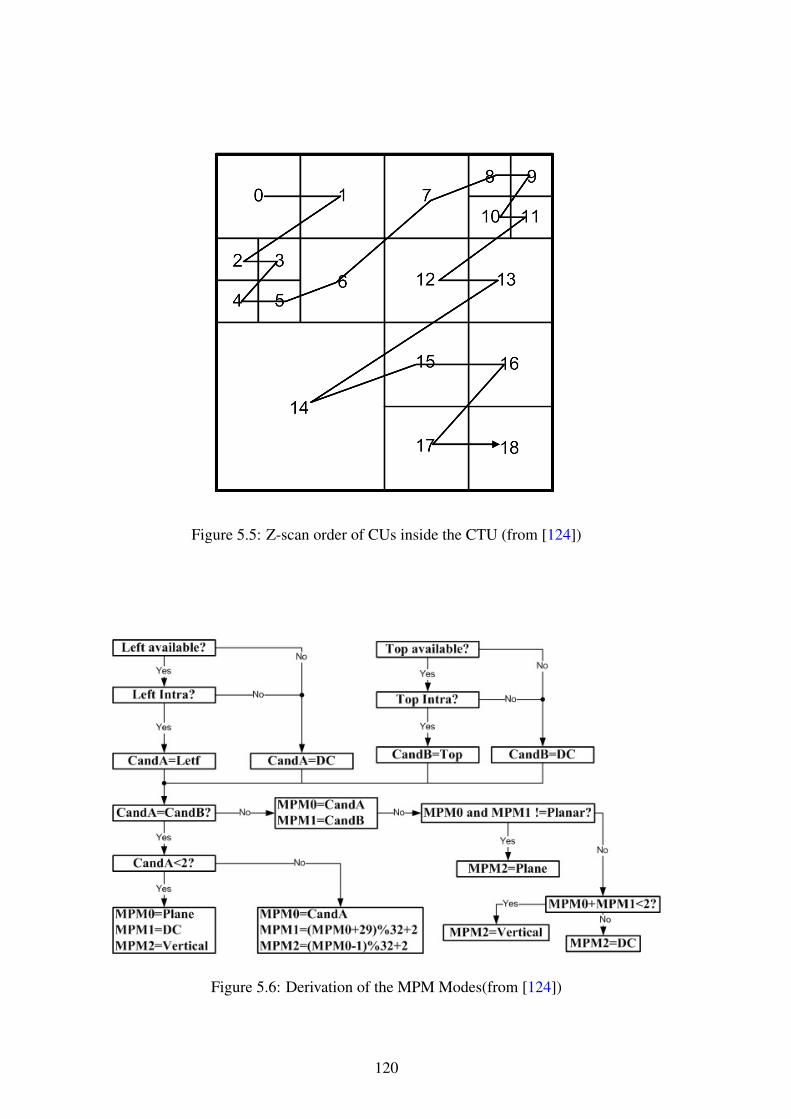
Figure 5.5: Z-scan order of CUs inside the CTU (from [124])
Figure 5.6: Derivation of the MPM Modes(from [124])
120

Table 5.1: Derivation process of the chroma intra prediction mode (from [124])
Intra_chroma_pred_modeLuma Intra Pred Mode
0 26 10 1
0 (i.e., mode-0) 34 0 0 0
1 (i.e., mode-26) 26 34 26 26
2 (i.e., mode-10) 10 10 34 10
3 (i.e., mode-1) 1 1 1 34
4 (i.e., use the luma mode) 0 26 10 1
Table 5.2: Mapping between Intra prediction mode and coefficient scanning order
Intra prediction mode Coefficient scanningfor 4× 4 and 8× 8
Coefficient scanningfor 16× 16 and 32× 32
Angular (6-14) Vertical Diagonal
Angular (22-30) Horizontal Diagonal
All other modes Diagonal Diagonal
• Motion Estimation (ME): is an inter prediction process to find the best match be-tween the current processing unit(such as PB1) and a region in a previous or afuture frames (such as PB2). The output of this process are: MV information, skipmode information or merge mode information.
• Motion Compensation (MC): is the process of generating the identical interpictureprediction signals using the output of the previous step (i.e., MV and the modeinformation) calculating the difference between PB1 and PB2.
The MV is a vector information indicating the moving direction of the PB by calculat-ing the offset between the current PB and the reference PB. The Inter-prediction of eachPB is predicted using a bi-prediction or a uni-prediction. In uni-prediction the smallestPB luma size is 4 × 8 or 8 × 4 whereas for bi-directional the smallest PB luma size is8× 8.As this part of the HEVC compression process is used in our next contribution, the usedparameters in inter prediction step are described in details. In Inter-prediction, the mainmodes are Merge and Skip, for which the MV and reference index information are derivedfrom spatially or temporally neighboring blocks. In merge mode, the current block andthe neighbor block(s) have a shared region that contains the required motion information,and so, the coding efficiency is improved since no need to transmit the motion informationfor each block. The equivalent structure of this mode in the AVC is the skip and directmodes. Anyway, there are two main differences between the HEVC and the AVC for thismode: the index information is transmitted in order to identify one of available indepen-dent candidates. Moreover, it identifies the references of the available picture in the listpicture index, while in the AVC direct mode, part of predefined values already exist.
121

In Figure 5.7, the current PB is D, and so, the same MV information of B,C or Dt−1prediction blocks are available. Assumes that the merged block with D is X whereX ∈ {B,C,Dt−1}, in this case only one MV information is required for the both Dand X blocks, and there is a flag used to determine that the D prediction block is mergedwith block X [138].The HEVC is divided into frames and slices, the frame can be I, P or B frame. The pre-diction in I frames is intra prediction, while in P frames the intra and inter predictions areused. The inter prediction in P frames uses only one MV per PB, in B frames inter andintra predictions are used and the inter prediction uses one or two MVs for each PB. TheMotion Vector Differences (MVD) is a difference between the Motion Vector Predictor(MVP) and the actual motion vector used to predict a current block [164].
Figure 5.7: Merge mode example
The sign of the MVD is indicated by mvd_sign_flag, when this flag is one the MVDhas a negative value, whereas the MVD has a positive value when this flag is zero. Thisflag sets to zero in case of it is not signaled in the bits-stream. In P frame, there is only oneMVD in the both horizontal and vertical directions. The parameter abs_mvd_minus2specifies the absolute value of an MVD minus 2. This means, if the absolute value ofthe MVD is zero or one, the previous parameter is not signaled. Hence, two parame-ters are used, abs_mvd_greater0_flag to specify if the absolute value of an MVD isgreater than 0 or not. abs_mvd_greater1_flag to specify if the absolute value of anMVD is greater than 1 or not. In case the abs_mvd_greater1_flag is not present, itis set to 0. In case of B frame, we have two MVD and for each one, we have the fol-lowing flags: mvd_sign_flag, abs_mvd_greater0_flag and abs_mvd_greater1_flag.Finally, in Inter prediction there are List0 and List1. The former uses the parametercalled ref_idx_l0 to indicate the reference picture index of the current prediction unit.The later uses ref_idx_l1 for the same function. In case ref_idx_l0 or ref_idx_l1 arenot signaled, they are considered equal to 0.
122

5.3.4 HEVC transformation and quantizationAccording to Figure 5.3, the predicted residual values are grouped in TB to perform thetransformation process using integer transform blocks of four sizes (4× 4, 8× 8, 16× 16and 32× 32) the last three sizes are derived from a DCT, where the derivation process ofthe 4× 4 luma intra-prediction is based on the Discrete Sine Transform (DST). The usedinteger transforms in the HEVC have a better approximations than the used ones in theAVC.The quantization process in the HEVC uses the same scheme as the one used in the AVC:Uniform Reconstruction Quantization (URQ) scheme. This scheme is controlled by theQuantization Parameter (QP), the QP range is defined as QP ∈ {0→ 51}.The output of the quantization process is forward to be encoded using Entropy Coding(EC) step.
5.3.5 CABAC entropy codingIn the HEVC, comparing to the AVC, only CABAC entropy coding is used and the maincontribution of our proposed work of the crypto-compression systems are based on theCABAC steps, that we describe them in details. In general, CABAC process consists ofthree steps as illustrated in Figure 5.8:
• Binarization is used to convert the Quantized Transform Coefficients (QTCs), intobin strings using one of five basic binarization methods: Unary code, TruncatedUnary (TU) code, Fixed Length Code (FLC), Kth order Exp-Golomb (EGK) codeand Truncated Rice code with context p (TRp).
• Context modeling is used to perform two functions: context model selection andcontext model access. It uses the statistics of the coding symbols to update theirprobabilities.
• Binary Arithmetic Coding (BAC) is applied on each bin according to the selectedprobability model[138], and it consists of:
1. Context coding: it provides an estimation of the conditional probabilities ofthe coding symbols.
2. Bypass coding: this mode permits equal probability (0.5 for each bin).
Figure 5.8: Three main functions in the CABAC
The binarization processThe binarization process in the CABAC consists of five basic methods, that we describebellow:
123

1. Unary Code (U): The non-binary value Y is coded into binary form by formulatingit with Y ones and ending by zero. For example, the binary code of 4 is 11110,while for 7 is 11111110.
2. Truncated Unary Code (TU): It is almost identical to the previous one, it is definedfor any Y value such that 0 ≤ Y ≤ S (where S = cMax in our work). For allY < S the TU code is exactly same as the Unary code, while for Y = cMax, theending bit (i.e., the 0) is removed.
3. Fixed Length Code (FLC): the inputs of this process are a syntax element and thecMax parameter. The output is the FL binarization code based on arithmetic binaryrepresentation(see equation 5.4). The length of the code-word, called fixedLength,is derived from the cMax by using equation (5.3).
fixedLength = dlog2(cMax+ 1)e (5.3)
andFLC(Y ) = arithmetic binary(Y ) (5.4)
Example 5.1: Assume the syntax element is Y = 3, and cMax = 4, then:fixedLength = dlog2(4 + 1)e = 3, which means three bits is required to representthe FLC binary value and soFLC(3)=011.
4. Truncated Rice Code with context p (TRp): this method of binarization is intro-duced for the first time in the HEVC. It consists of prefix and suffix terms. Thecode of the prefix term is given using equation (5.5) if the condition of the equation(5.6) is valid, otherwise, the prefix bin strings are b cMax
pc ones. Where cMax is an
input, p is given by equation (5.8) and the cRiceParam parameter is determinedaccording to the algorithm 10 and its value is ranged {0, 1, 2, 3, 4}.
TRp(Y )_Prefix = Unary code(bYpc). (5.5)
bYpc < bcMax
pc. (5.6)
p = 2cRiceParam (5.7)
The suffix code (if presents) is given using the equation (5.8). The length of thiscode is calculated by the equation (5.3), in which cMax is replaced by cMaxSdefined by the equation (5.9).
TRp(Y )_Suffix = FLC(Y Mod p). (5.8)
cMaxS = p− 1 (5.9)
Finally, the code-word of the TRp is a concatenation of the prefix and the suffixcodes.Example 5.2: Assume Y = 7, cMax = 8 and cRiceParam = 1, then:p = 2, b7
2c < b8
2c:
TRp(7)_Prefix = Unary binary(b72c) = 1110.
124

For the suffix, cMaxS = 21 − 1 = 1, fixedLength = dlog2(1 + 1)e = 1. whichmeans one bit is required to represent the arithmetic binary for the suffix value andso,TRp(7)_Suffix = FLC(7 Mod 2) = 1.The word-code is 11101.Example 5.3: Assume Y = 7, cMax = 7 and cRiceParam = 1, then:p = 2, b7
2c is not less than b7
2c:
Consequently, the TRp prefix is b cMaxpc ones=111.
For the suffix, cMaxS = 21 − 1 = 1, fixedLength = dlog2(1 + 1)e = 1. whichmeans one bit is required to represent the arithmetic binary for the suffix value andso,TRp(7)_Suffix = FLC(7 Mod 2) = 1.The word-code is 1111.Example 5.4: Assume Y = 8, cMax = 10 and cRiceParam = 1, then:p = 2, b8
2c < b10
2c:
TRp(8)_Prefix = Unary binary(b82c) = 11110.
For the suffix, cMaxS = 21 − 1 = 1, fixedLength = dlog2(1 + 1)e = 1. whichmeans one bit is required to represent the arithmetic binary for the suffix value andso,TRp(8) Suffix = FLC(8 Mod 2) = 0.The word-code is 111100.
5. Kth Order Exp-Golomb Code (EGK): The EGk code is also a concatenation of pre-fix and suffix terms. The prefix term of the EGk code is the U representation ofl(Y ) calculated based on equation (5.10). The suffix term is the arithmetic binaryrepresentation of the (Y + 2k(1− 2l(Y ))) using k + l(Y ) significant bits.
EGK(Y )_Prefix = Unary code(l(Y )).l(Y ) = blog2(
Y2k
+ 1)c. (5.10)
Example 5.5: Assume Y = 7, and we want to binarize it using EG0 and EG1, then:For k = 0l(7) = blog2(
720
+ 1)c = 3.Prefix of EGK(7)_Prefix = 1110.The length of the suffix code is 0 + 3 = 3, thenEG0(7)_Suffix = arithmetic binary(7 + 20 − 20+3) = 000.The code-word is 1110000 For k = 1.l(7) = blog2(
721
+ 1)c = 2.Prefix of EGK(7)_Prefix = 110.The length of the suffix code is 1 + 2 = 3, thenEG1(7)_Suffix = arithmetic binary(7 + 21 − 21+2) = 001.The code-word is 110001.
The following programming code is published in the last drift of the JCT standard(High Efficiency Video Coding (HEVC) text specification draft 10 [61]), and isused to simulate the previous mathematical equations.
125

Algorithm 9 [K-th order Exp-Golomb binarization process (from [61]])Y =abs(Syntax Element)stopLoop=0do
{if (Y >= (1 << K))
{put(1)Y = Y − (1 << K)K + +
}else
{put(0)while(K −−)
put((Y >> k) & 1)stopLoop=1
}}while(!stopLoop)
5.4 Video encryption algorithms - related worksVideo encryption is a hot research topic in the last decades [5]. The security and confiden-tiality of video coentent are very important in commercial applications. In this section,related works of video encryption techniques are presented.
A traditional algorithm, such as AES and DES, were originally used to encrypt texts.Their usage for video encryption in most of the time is done in a naive way. Thus, thisclass of encryption methods is called Naive Encryption Algorithm (NEA) [12, 144]. In theNEA, the video bit-stream is encrypted based on a straight-forward method, encryptingeach bit. In fact, the NEA manages the video bit-stream as text without using the specialstructure of the compressed video [70, 156]. However, NEA is not suitable for videoencryption (a justification is given later).To encrypt the video contents, there are three main possible approaches, see Figure 5.9:
• Encrypt the video at position 1, and then compress it.
• Compress the video and then encrypt it at position 9.
• Joint encryption-compression video between position 7 and 9 included (to haveinvertable encryption).
Confidentiality of multimedia contents should be considered with a particular attentionfrom both point of views: compression and encryption requirements. Several encryptionsolutions are used to encrypt the video, either before or after the compression process. Ingeneral, separating encryption and compression processes is not a good solution for video.In deed, the encryption at position 1 (before compression) has the following obstacles:
1. First of all, the compression process is usually a lossy one based on a non-reversibleoperations; which led to incorrect decryption.
126

2. Secondly, encrypt the whole bit of the video is a time consuming process, whereas,the decoder should be fast to be used for real-time applications.
3. Thirdly, when the encryption process is achieved using a robust encryption algo-rithm, the ciphered data becomes a random or a pseudorandom data. That meansthe redundancy between data bit is removed and therefore the compression schemebecomes not efficient (i.e., the compression rate is significantly decreased).
The encryption at position 9 (after the compression process) consists of encrypting allcoded bit stream. This scenario, that usually used has the following drawbacks:
1. Firstly, the coded bit-stream are random and then the encryption scheme becomesless efficient
2. Secondly, this solution is a time consuming since all bits must be encrypted andthen the bit-rate is increased, especially for high quality and resolution video.
3. Thirdly, the encrypted video bit-stream desynchronizes the decoder since the en-crypted coded bit-stream is not conforming with the video bit-stream syntax stan-dards( a non format compliant encryption scheme).
Figure 5.9: Different possible encryption positions in the video compression process
Joint Encryption compressionThe joint encryption compression schemes are mainly classified into:Selective Encryption (SE): encrypts some parts of the video content (sensitive content)to achieve the required security level with a minimum extra computation cost during thevideo compression process.Perceptual Encryption (PE): encrypts some parts of the video content (sensitive content)to degrade the quality of the video according to the quality requirements, with a minimumextra computation cost. The other video content parts are left as plain video for non-authorized users. In fact, the difference between SE and PE is depends on the target andthe application of each one, while the encryption method is almost the same, since theboth are used to encrypt some parts of the video content.In general, encryption algorithms for video can be used for several purposes based on thetarget applications.
5.4.1 MPEG Video encryption algorithmsIn this section, we briefly present some encryption algorithms of the video standardsbefore the AVC standard.
127

5.4.1.1 I-frames encryption
The security of MPEG-I video stream was proposed by [134], and the basic idea of thiskind of algorithms is to encrypt the most important frames in the video which are I-frames,because P and B frames are useless without knowing the corresponding I-frames. How-ever, Agi and Gong [5], have demonstrated that some of important parts of the encryptedvideo can be recovered independently of I-frames, as the encryption scheme does notconsider the I-blocks in the P and B frames, and other important factors. Moreover, thecompression ratio decreases significantly when the I-frame values are encrypted (i.e., theI-frames coefficients are encrypted before the entropy coding stage). Finally, encryptionof I-frame values increases the bit rate significantly, while one of the most important re-quirements of the video compression is to decrease the bit rate. To preserve the same bitrate, the encrypted value and the original one should have the same length, and also theencrypted value should not affect the length for the other values. This requirement (con-stant bit rate) is more complex to achieve if the encryption process is performed outsideor independent of the entropy coding unit.
5.4.1.2 A non-compatible four level of security
Based on the previous work of Agi, Meyer and Gadegast [86] have implemented fourlevels of video encryption algorithm. The first level is to apply the encryption process onall frame headers. The second level includes the first level task and it encrypts the DC andAC values of the I-blocks. The third level is to encrypt I-frames and I-blocks in P and Bframes. The fourth level is to encrypt all data. The implemented video encryption algo-rithm uses DES standards to encrypt MPEG-1. One of the drawbacks of this algorithm isthe compatibility problem with the standard encoder/decoder (i.e., it is not a format com-pliant algorithm). It needs a specific decoder to deal with the encrypted bit stream, sincethe encrypted bit stream crashes the decoder. Moreover, the compression ratio decreasessignificantly and the bit rate increases in this algorithm.
5.4.1.3 Zig-Zag permutation algorithms
More encryption algorithms in MPEG-1 are developed based on a permutation scanningmethod instead of the zig-zag one. The main steps of this algorithm are [142]:
• Formulating a one denominational vector of 64 value , where the first value is theDC and the remaining 63 values are the ACs and the last AC value is zero.
• The first value of the previous vector is the four Least Significant Bit of the DC,LSB4(DC), and the last value is the Most Significant Bit of the DC, MSB4(DC).
• A random permutation process is applied on the 64 values of the previous vector.
It is proved in [98] that this algorithm is susceptible to the known plaintext attack and theciphertext only attack. Furthermore, it is not a format compliant, decreases the compres-sion ratio and increases the bit rate.
5.4.1.4 Change the sign bits or the values of DCT coefficients
Tosun and Feng in [145], have designed three levels of security for the MPEG-2 videostream. The designed algorithm is based on the 64 coefficients of the DCT. A joint en-
128

cryption and compression algorithm is proposed. It divides the 64 values into three in-tervals: the first range is [0, ..., x1], the second range is (x1, ..., x2], and the last range is(x2, ..., 63]. Based on the required security level, we encrypt the first range or the first tworanges or all ranges. Since the proposed scheme encrypts coefficients before the entropycoding, it decreases the compression ratio, increases the execution time and also the thebit rate.
Further work on the frequency domain is carried out by Zeng and Lei [163]. Theyhave proposed a selective joint encryption and compression scheme (SEA) for H.263.The proposed scheme flipping the sign of the DCT coefficients. The encryption of thesign for any value does not affect the compression ratio and the bit rate. Moreover, it isa format compliant encryption. However, it is not sufficient to achieve a good securitylevel. The proposed SEA shuffles some blocks of the DCT coefficients and/or MotionVectors (MV). This operation decreases the compression ratio and then increases the bitrate. Finally, in case of performing blocking shuffling between non-zero and zero DCTcoefficients, the output bit-stream will not be format compliant.
In [15], Bharat et. al, have proposed a SEA for MPEG-1 bit-stream. The proposedSEA uses the secret key bits to change the sign bits of the DCT coefficients and the signbits of the MV. This encryption method should be fast, but the authors stated, that thecoding complexity is increased by about 2.55%. Moreover, the encryption process of thesign bit of the DCT and the MV does not enable a high security level.
Lian et. al., [72], have constructed a chaotic stream cipher to protect video content.This work is directed to the MPEG-2 video codec. The scheme is similar to the previousones, encrypts the DCT coefficients and the MV sings of the MPEG-2 videos. In fact, thiskind of encryption decreases the compression ratio and corrupts the standard decoder.
5.4.2 AVC and SVC encryption algorithmsMost of the proposed schemes are developed to provide a high security level for the videoas a target. In perceptual/transparent encryption, the coded part without encryption can bedecoded for any user to get a low quality preview of the video content. While the codedand encrypted part can not be decrypted for none authorized user.
5.4.2.1 Transparent encryption techniqes for AVC and SVC
Magli et al.,[78] have proposed a perceptual (transparent) encryption techniques for theAVC and the SVC video. The proposed encryption algorithms were classified into threejoint encryption and compression categories:
• First category: Encoding with drift control to decrease the video quality. This canbe achieved by encrypting the DCT coefficients of I Macro Blocks (MB) in I andP frames. The Least Significant Bit (LSB) of the chosen DCT coefficients is re-moved by right-shift, then all removed bits are collected and compressed using thearithmetic coding revisited [87]. At the end, the compressed file is encrypted usingstream cipher in feedback mode before sending to the decoder. One of the majordrawback of this scheme is the removing LSB bit, since this affects the compres-sion ratio, and the side information (the collected, encrypted and compressed LSB
129

bits) must be sent to the decoder, which is not preferable in video compression andtransmission.
• Second category: is used to degrade the video quality, and two quality level of Iframes are created, one is the correct encoded and not encrypted I frames, while theother is the incorrect (encrypted and encoded) I frames. The clear drawback of thisversion is the redundancy, and also it needs a specified decoder since it corrupts thestandard decoder.
• Third category: Encryption of the enhancement layers (SVC) using AES algorithm.The base layer is not encrypted, thus it can be used as a preview. To decode theenhancement layers the user should have the secret key. Since the AES is used toencrypt the enhancement layer at position 9 of the figure 5.9, as the author wrote,the encrypted enhancement layer is not format compliance.
5.4.2.2 Digital video scrambling method using Intra prediction mode
In [7], Ahn et. al., have proposed a simple and fast scrambling method for Intra predic-tion mode of the AVC video. The basic idea of this scheme is to change the 3-bits of theprediction mode by x-oring them with a 3 bits of a random sequence, in case of the MBsize is 4× 4.Indeed, the intra prediction modes are nine modes and so four bits are required to en-code the intra prediction modes. However, only eight modes are encoded using theprev_intra4x4_pred_mode parameter, which means one mode of the nine modes is ex-cluded and it is signaled by MPM parameter.In case of Intra 16×16 MB size, only four modes are available. The Intra prediction modeis encoded using VLC, and is jointly coded with luma and chroma coded block patternvalues. The encryption process should be performed with ensuring that the Coded BlockPatterns (CBP) does not change. One bit from the random sequence is used to encrypt theprediction mode based on: if this bit is 1 the mode is changed to the value which preservesthe CBP, otherwise the mode is not changed (for more details on the CBP refer to [7]).The process of changing only the I-frames as discussed and proved does not guarantee ahigh security level. Moreover, the process of changing the prediction mode decreases thequality of the prediction process, but it does not cause a completely incorrect prediction.Finally, this method can be a format compliant encryption scheme for the AVC, but notfor the HEVC decoder, because of the scanning direction.
5.4.2.3 Entropy coding encryption in AVC
AVC uses CAVLC and CABAC to accomplish the entropy coding step. Lie et. al.,[65],have introduced a selective encryption scheme to encrypt the CABAC bit stream using achaotic stream cipher based on the discrete Piece-Wise Linear Chaotic Map (PWLCM).In this proposed selective encryption scheme, each binarization process has a specific en-cryption and decryption operation. It is a format compliant, but it affects the compressionratio and the bit rate since it encrypts the Unary Code (UC), Truncated Unary code (TU),and Fixed Length Code (FLC). Finally, not all parameters during the binarization processcan be encrypted while preserving the format compliance property.
130

5.4.2.4 Selective video encryption based on AVC
Lian et. al., [71], have proposed an encryption scheme for the AVC. This scheme has fourparts:
1. Partial Encryption of Intra-prediction Mode: it encrypts the suffix term of the EGKcode of the intra-prediction mode. The suffix term is encrypted using a streamcipher algorithm [85].
2. Partial Encryption of Coefficients: the DCs are encoded with VLC and then en-crypted using the same stream cipher algorithm proposed in [85] based on cipher-text feedback mode. While the sign of ACs is firstly encrypted and then encodedby VLC.
3. Partial Encryption of Motion Vectors: encryption the sign of the motion vectordifferences is fast and format compliant without effecting the compression ratio.
4. Key Generator:all previous encryption methods in this scheme are controlled bydifferent sub-keys. The needed sub-keys are generated using key generator.
The proposed scheme has a good performance in terms of the encryption overhead whichis less than 1.1%. Moreover, it introduces a new idea to encrypt the suffix of some valuesto preserve the format compliant and constant compression ratio.
5.4.2.5 Fast protection of the AVC by selective encryption
To preserve the format-compliant and for a minimal impact on the compression perfor-mance, only the encoded suffix bits in bypass mode during the CABAC entropy encodingprocess can be encrypted [135].Shahid et. al., [118], proposed a fast protection for the AVC using selective encryption ofCABAC bin strings for I and P frames. The encryption process is performed as follows:
y = (x+ γ) mod log2(x+ 1) (5.11)
where γ is given by:γ = rand() mod log2(x+ 1) (5.12)
The x parameter is the suffix of the exponential-Golomb code, and y is the encryptedvalue of x.Later, Shahid et. al., [115] enhanced this encryption scheme to encrypt CAVLC bit streamand CABAC bin strings of I and P frames using Cipher feedback (CFB) mode of the AESalgorithm.Asghar et. al., [13], present some encryptable parameters in the SVC that guarantee aconstant bit rate and format compliant video encryption, such as: UEG3 suffix (whereUEG3 is a concatenation of the Unary code and the EGK code when K = 3), UEG0suffix and sign of all none zero QTCs.
5.4.2.6 Fast protection of AVC by reduced selective encryption of CAVLC
Fast protection of the AVC video content, based on a selective encryption for a subset ofcode-words/bin-strings of the CAVLC entropy coding is introduced by Dubois et. al.,[31].This encryption scheme, like others uses the AES based on the CFB mode to encrypt a
131

subset of equal length code-words/bin-strings in the CAVLC entropy stage. Five syntaxelements are used in the CAVLC entropy stage to code levels and runs: coeff token, signsof trailing ones, remaining non-zero levels, total number of zeros and runs of zeros. Theencryptable parameters of this scheme are the sign of the trailing ones and the remainingnon-zero levels to preserve the format compliance.Nothing new in this scheme except that it analyses the level of the prediction error todecide which MB should be encrypted, but the selected encryptable parameters are notsufficient to provide a high security level and it affects the compression ratio.
5.4.2.7 Design of new unitary transforms for perceptual video encryption
A New and different approach of applying selective encryption for the AVC content hasbeen proposed by Yeung et. al.,[160, 161]. The proposed scheme selects one out ofmultiple transform matrices based on the secret key bits. The proposed perceptual videoencryption scheme introduced a new transformation matrices to be used instead of theDCT and DST matrices, during the transformation stage. Moreover, the sign of DCs isincluded in this encryption process. It is clear that this process requires to include thesealternating transformation matrices in the standard encoder and decoder.
5.4.3 HEVC encryption algorithmsA perceptual encryption scheme has been introduced in [148] for the HEVC to degrade thevideo quality, whereas the full quality version is only permitted for authorized customers.The proposed scheme uses a similar encryption techniques that have been proposed inthe previous video standard such as: encrypting the sign of the residual information, theMVD, the MV prediction index and the MV reference index.
Wallendael et. al., extended their previous research [148] to identify the HEVC syntaxelements which can be changed/encrypted and preserved the format-compliant for theHEVC decoder as[147]:
• Short-term reference picture set (RPS).
• QP information (initial QP, Chroma delta QP, Slice delta QP, CU delta QP).
• Inter information (reference picture indices, MV prediction indices, motion mergeindices, MVDs).
• Residual information.
• Deblocking filter parameters.
• Sample adaptive offset parameters.
Later, Shahid et. al., [121] proposed a selective encryption scheme to protect the HEVC.Most of Shahid works [120, 119, 117, 3, 116, 122, 114, 113, 112] has the same idea, whichintroduces a joint encryption and compression system based on CABAC bin-strings, seeFigure 5.10.In Shahid et.al., research, the sign bit of the QTCs, the suffix of the TRp, EG0, EG1,and the sign bit of the MVDs are the selective encryption scheme inputs. The encryptionprocess of the sign bit is straightforward, while the encryption process of TRp, EG0 and
132

EG1 suffix codes needs a specific attention to preserve the format-compliance and to keepthe bit ratio almost the same as compression without encryption.
Figure 5.10: Basic structure of selective encryption scheme for the HEVC
Shahid et. al., define three basic requirements for SEA [121].
1. Preserve the same bit rate: the encrypted bin strings must have the same length asthe unencrypted bin strings.
2. Preserve the format-compliant: the encrypted bin strings must be valid and decod-able by any standard decoder.
3. Encrypt the dyadic encryption space: the author defines the dyadic encryption spaceas the one that its range is multiple of 2 (i.e., 7 is not a dyadic space where 8 is adyadic one).
As described before, the binarization step is carried out based on five methods. Shahidet. al., work assumes that the first two methods (unary code and truncated unary code) donot fulfill the first requirement.Then, they assume that the FLC does not fulfill the second requirement, since differentbits in the FLC indicate different information regarding the header. However, the FLCbinarization is not restricted to the header only, since the FLC is used in the suffix of TRpand EGk codes.Finally, they assume that the suffix of the fourth (TRp) and fifth (EGk) codes can beencrypted without violation of any requirements.The proposed encryption algorithm in Shahid et. al., [121] encrypts the suffix of the TRpand EGk codes except two cases:
1. In case of p = 0 in the TRp code, since the binary representation is identical to thetruncated unary code, and so TR0 does not fulfill the first requirement, as a resultTR0 is not encryptable.
133

2. In case of the last equal-length group of the TRp code, in this case, two binary codesare identical whether EG0 code is appended or not, and so, the encryption of thisbin strings violates the format compliance requirement.
The encryption and decryption schemes use the AES algorithm in CFB mode [33].Theprocess of encryption is done by grouping the EGk and TRp suffixes bits to prepare the128 encryptable bits as a plaintext for the AES CFB algorithm.
Bellow, we address some comments on the Shahid et. al., work:
1. Binarization process of the residuals: Shahid et. al., in their work assume that thebinarization of residuals is carried out using TRp and EG0. However, in the HEVCstandard, as it is clear in algorithm 10, the EG0 will never be used. Consequently,this assumption is not valid.
2. In their encryption mechanism, it is obligatory to wait until the plaintext is com-pletely filled or the slice boundary is reached (as they wrote "we fill with Xi en-cryptable bits until either the vector is completely filled or the slice boundary isreached."). This mechanism includes additional delay in the latency of the systemand uses more memory to fill the plaintext vector (this is clear in the time complex-ity analysis of Shahid et. al., paper). Notice that, the decoder is working based ona prediction of unit by unit, and in most cases, one prediction unit is not sufficientto obtain a plaintext vector of 128 encryptable bits. Therefore, more memory andmore delay are needed.
3. The number of encryptable bits in Shahid et. al., method is smaller than the num-ber of encryptable bits that are obtianed in our proposed work (see algorithm 12in chapter 6). In addition, their method does not compatible with the last HEVCstandard.
5.5 Conclusion and discussionIn this chapter, a state of the art of video encryption and compression schemes is brieflyintroduced, to help researcher in cryptography to understand the critical and importantproperties of the video encryption standard.Encryption and compression should be designed jointly to make sure that the encryptionsolution is compatible with any standard video decoder. In the last video standard (theHEVC) not all parameters are encryptable (in terms of format compliant). For instance,in the HEVC, three MPMs are defined instead of one MPM in the AVC. This differencehas an important for instance for encryption systems previously defined for the AVC, thatwill be no longer compliant with the HEVC. Notice that, the encryption of some HEVCparameters is format compliant but they affect the compression ratio and the bit-rate, sothe choosing of the HEVC parameters for encryption process depends on the target appli-cation.Finally, to the best of our knowledge, there is no published work to identify the encrypt-able bin-string of the HEVC and of its scalable extension SHVC. Moreover, there is nopublished work in selective encryption algorithm for the HEVC or the SHVC in real-timeapplications.
134
6Third Contribution: Selectiveencryption algorithms for Video
In this chapter, two fast and secure selective chaos-based crypto-compression systems arerealized to encrypt the HEVC and its scalable version (SHVC). In the first section 6.1, wepropose a new algorithm to identify the encryptable bits in the bin-string of the HEVCand the SHVC. Most of the encryption process is performed at the CABAC bin stringlevel and it preserves all SHVC functionalities.In the second section 6.2, the Region Of Interest (ROI) of the HEVC is encrypted basedon the tile concept. The encryption is achieved at the bin-string level by encrypting allHEVC syntax elements within the ROI tiles, or by using a selective encryption of the ROItiles under constant bit rate and format compliant requirements.
In fact, the design process of the video encryption algorithms should be compatiblewith any standard decoder and it should be fast to meet the real time application at thedecoder side. Therefore, the most important requirements that should be taken into con-sideration during the designing process of any selective video encryption algorithms are:
1. Format Compliance: the proposed selective encryption algorithm should not violatethe decoder, i.e., the encrypted video bit-stream must remain compliant under thestandards of the video decoder.
2. Secure and fast encryption (low delay and low complexity): the proposed selectiveencryption should be secure and not increase the complexity or introduce addi-tional delay to the original execution time of the real time encoding and decodingprocesses without encryption.
3. Constant bit-rate or at least no significant increasing of the compression ratio: inoptimal video encryption, the encryption algorithm should not affect the originalbit-rate. Otherwise, the increasing of the compression ratio should be small aspossible.
4. Maintain the scalability features of the video.
135

6.1 Selective video encryption based on chaos system forSHVC
SHVC is the scalable extension of the HEVC standard. SHVC extension enables spatial,temporal, quality (SNR); bitdepth and color ghamut scalability. All defined technolo-gies and techniques in the HEVC standard are also used in the SHVC: quadtree-basedblock partitioning, large transforms and prediction blocks, accurate intra/inter predictions,in-loop sample adaptive offset filter, highly adaptive entropy coding, CABAC binariza-tion [137] and many more. Moreover, the HEVC standard uses the concept of dQP toadapt the QP value at the coding unit level for visual quality optimization and rate con-trol. The SHVC extension encodes the original video in several layers corresponding todifferent spatial and quality representations of the video. The SHVC extension is de-fined to provide spatial, fidelity, bit depth and color scalability with a simple and efficientcoding architecture [136, 23]. SHVC extension adopts an inter-layer prediction to take
Downsampling
Upsampling
& scaling MV
Entropy
coding
BL bitstream
EL bitstream
Original video SHVC EL encoder
HEVC BL encoder
T/Q
T /QLoop filter
MC/Inter-layer
prediction
Picture
buffer
Intra
prediction
Entropy
codingT/Q
T /QLoop filter
MC/Inter-layer
prediction
Picture
buffer
Intra
prediction
-1 -1
-1 -1
SHVC
bitstream
HD
4K
Figure 6.1: Block diagram of the SHVC encoder encoding two spatial scalability layers
advantage of spatial correlation and improve the rate-distortion performance compared toindependently encoding of the layers. The SHVC encoder consists of L layers HEVCencoders, (one encoder by layer): one Base Layer (BL) and L − 1 Enhancement Layers(EL). In the case of spatial scalability, the BL HEVC encoder encodes a down-sampledversion of the original video and feeds the first EL encoder with the decoded picture andits MVs. The enhancement layer encoder encodes a higher resolution video with using thedecoded picture from lower layer as an additional reference picture. The inter-layer refer-ence picture is up-sampled and its MVs up-scaled to match with the resolution of the ELbeing decoded. Figure 6.1 shows an example of the SHVC encoder encoding two layersin spatial scalability configuration. In the case of SNR scalability, the encoding processremains unchanged except that the picture used for inter-layer prediction is used withoutbeing up-sampled and its MVs up-scaled. The binary arithmetic coder can be performedeither by an estimated probability of a syntax element (context coded) or by consideringequal probability of 0.5 (bypass coded). The three main functions of the CABAC at eachSHVC layer are illustrated in Figure 5.8. The CABAC engine at each SHVC layer isinitialized at the start of each frame and then the frame of each layer is encapsulated in
136

independent slice. The CABAC arithmetic coder in SHVC is similar to the one in theHEVC which is described in the previous chapter (see section 5.3.5). The proposed selec-tive encryption algorithm is implemented using a chaos-based stream cipher (see Figure6.2). A group of sensitive SHVC parameters is selected to be used as input for this se-lective encryption solution, the selected parameters meet the defined requirements in thebeginning of this chapter. As it has been mentioned before, the encryption solution pre-serves all SHVC functionalities such as bit-stream extraction for mid-network adaptationand error resilience (i.e., enable the compressed bit-stream to resist channel errors so thatthe impact on the reconstructed frame is minimal).A selective encryption scheme of SHVC is presented in this work: and it is applied on
Figure 6.2: Encryption part of Crypto-A
three different stages: In the first stage, we encrypt only the lowest SHVC layer whichis called SE-SHVC-BL, in the second one we encrypt all layers (SE-SHVC-ALL) and inthe last stage we encrypt all layers except the base one (SE-SHVC-EL). Notice that, Theencryption of the base layer (i.e., SE-SHVC-BL) will also affect the quality of the ELssince the decoded BL picture and its MVs are used as reference for inter-layer predic-tion at the EL encoders. Therefore, SE-SHVC-BL stage can achieve a high security levelof encryption. The SE-SHVC-All stage achieve a very high security level of encryptionas all layers are encrypted in this stage. Only end-users holding the secret key have theability of the higher quality of the video. A comprehensive study is performed to assessand evaluate the performance of the proposed scheme on the three stages: different videoencryption criteria, different scalability configurations and various High Definition (HD)video sequences.
6.1.1 Encryptable bit
The proposed encryption solution is SHVC format compliance and does not affect thecompression ratio of the SHVC encoder. Therefore, only syntax elements binarized infixed code are encrypted and then bypassed. The selective encryption is performed atposition 1 in the CABAC process as illustrated in Figure 5.8.The CABAC uses EG1 code for the binarization of MV differences which are then by-passed. Thus, the suffix part of the MV difference is safely encrypted since:
• The EG1 suffix has a fixed number of bits and encrypt them to the same number ofbits, so this operation does not impact or violate any requirements defined require-ments in the beginning of this chapter.
• The encrypted bins MV difference change 1 to 0 or vise verse and the result isbypassed, and so the compression ratio does not affected.
137

The sign of the MV difference is also encrypted since it is binarized in FL code withcMax = 1 and bypassed. The absolute value of the dQP is context coded so its en-cryption will affect its probability and so the compression ratio. We propose to encryptonly the dQP sign which is bypassed in the SHVC. Concerning the TCs, they are bi-narized with a combination of TRp with cRiceParam ∈ {0, 1, 2, 3, 4} and EGk codes(k = cRiceParam+ 1), encrypted and then bypassed.The binarization process for non-zero QTC which is called coeff_abs_level_remainingin the JCT standard report [61], is carried out using the Truncated Rice Code with con-text P and (if presents) the Kth Order Exp-Golomb Code. The binarization process forthe non-zero syntax element (coeff_abs_level_remaining) is described in algorithm 10.The binarization bin strings are formulated by a concatenation of prefix bin strings andsuffix (if it is existed) bin strings.
Algorithm 10 [Binarization process for non-zero coefficient, [61]]if this process is invoked for the first time for the current sub-block scan index i then
cLastAbsLevel = 0.cLastRiceParam = 0
elsecLastAbsLevel = cAbsLevel.cLastRiceParam = cRiceParam
end if
cAbsLevel = baseLevel + coeff_abs_level_remainingif cLastAbsLevel > (3× (1 << cLastRiceParam)) then
cLastRiceParam+ +end ifcRiceParam = Min(cLastRiceParam, 4)cMax = 4 << cRiceParamprefixV al = Min(cMax, coeff_abs_level_remaining)Called Trp function for prefixV al using cMax and cRiceParamif Binarization(prefixV al) = 1111 then
suffixV al = coeff_abs_level_remaining − cMaxCalled EGK function for suffixV al using K = cRiceParam+ 1
end if
The suffix of the EGk code can be safely encrypted, while encrypt the TRp suffix is nota format compliance since, it affects the cRiceParam parameter value and consequentlythe compression ratio.A proposed algorithm is introduced to accurately determine the bins of the TRp suffix thatcan be encrypted without changing/updating the value of the cRiceParam. The proposedalgorithm is tested and evaluated to be sure that the defined bins are safe to encrypt whilepreserving the defined requirements. The cRiceParam parameter value is updated afterthe binarization of each TC depending on its absolute value cAbsLevel, based on thefollowing algorithm.
where cRiceParam is initialized to 0 at the start of each transform sub-block [1].The absolute value of the QTC (which is here cAbsLevel) is composed of the baselevel named baseLevel plus the remaining part of the QTC named Coef (i.e., Coef =cAbsLevel−baseLevel). The value of the baseLevel is computed depending on the value
138

Algorithm 11 [Update the cRiceParam parameter in TRp code]if (cAbsLevel > 3× 2cRiceParam) then
cRiceParam = min(cRiceParam+ 1, 4)end if
cAbsLevel and the position of the QTC in the transform sub-block where baseLevel ∈{1, 2, 3} before applying the previous equation. The base level value is first signaled inthe bit-stream with a specific syntax elements and then only Coef different from 0 is bi-narized in TRp and EGk codes.We propose Algorithm 12 to identify the bit positions (from the least significant bin) ofthe encryptable bins in the TRp suffix. This algorithm is compatible with all encoderversions of the HEVC standard. In general, the original and the encrypted QTC, bothshould be less than the threshold (i.e., 3 × 2cRiceParam) or both should be more thanthe threshold.In the case of base level equals to 1, the whole suffix of the binarized QTC can be en-crypted since the Coef value plus 1 (the baseLevel here is 1) never exceeds the thresholdto update the cRiceParam for all possible suffix values. Indeed3 × 2cRiceParam − baselevel gives the maximum possible suffix of the cAbsLevel value(see tables 1-5 of appendix Appendix 2). The cRiceParam parameter (see algorithm11) is never updated in case of the baseLevel is 1 since the encrypted Coef plus 1 is≤ 3 × 2cRiceParam. The following examples are given to illustrate that when the base-Level is 1 then the whole suffix part of the QTC is encrypted safely, the binarization ofthe QTC is based on the algorithm 10 using TRp and EGK binarization methods.Example6.1: Assume that cAbsLevel = 6, cRiceParam = 1 and baselevel = 1 (notethat the threshold in this case is 6), then the binary code-word of 6 is 1101 (see line 6 ofTable 1 in the appendix 2) with one bit as suffix, so the possible encryption of the suffix bitis 1 or 0, and consequently binary code-word are:{1101 or 1100}. As the both encryptedvalues less than the threshold there is no update on the cRiceParam. The same producercan be applied for cAbsLevel = {1, 2, 3, 4, 5}.Now under the same previous parameter but with cAbsLevel = 7, then the binary code-word of 7 is 11100 (see line 7 of Table 1 in the appendix 2) with one bit as suffix, sothe possible encryption of the suffix bit is 1 or 0, and consequently binary code-wordare:{11100 or 11101}. As the both encrypted values more than the threshold there is noupdate on the cRiceParam. The same producer can be applied for cAbsLevel > 7.The same derivation of Example6.1 can be used when the cRiceParam is 2, 3 or 4.
In the following we discuss the encryption configurations provided in Table 6.1 forbase level different from 1. Table 6.1 provides the encryptable bins in the suffix of the TCbinarized in TRp code with cRiceParam = 3. The threshold computed by Algorithm 11to update the parameter cRiceParam = 3 is equal to 24 (i.e., 3 × 2cRiceParam). Whenthe Coef value is less than 16 or greater than 23 the three bins of the suffix can be safelyencrypted since, in the first case (Coef less than 16) then the encryption is less less than16 which is less than the threshold, while in the second case (Coef more than 23), thenthe encryption is more than 23 which is more than the threshold.When the Coef value is equal or bigger than 16 and less than 20, only the first two binsof the suffix can be encrypted for the baseLevel ∈ {2, 3}. Because encrypting the thirdbin (the not bold one) can increase the cABsLevel to be greater than the threshold whichmeans the cRiceParam parameter is updated in this case, while the non encrypted value
139

Algorithm 12 [Encryptable bins in the TRp suffix of TCs]if (baseLevel == 1) then
The whole suffix is encryptable.else if (cRiceParam == 1) then
if (baseLevel == 2 AND (Coef == 4 OR Coef == 5)) thenNo encryption.
elseThe whole suffix is encryptable.
end ifelse if (cRiceParam == 2) then
if (Coef ≤ 7 OR Coef ≥ 12) thenThe whole suffix is encryptable.
else if (baseLevel == 2 AND (Coef == 10 OR Coef == 11)) thenNo encryption.
elseThe first bin of the suffix is encryptable.
end ifelse if (cRiceParam == 3) then
if (Coef ≤ 15 OR Coef ≥ 24) thenThe whole suffix is encryptable.
else if (Coef ≤ 19) thenThe first two bins of the suffix are encryptable.
else if (baseLevel == 2 AND (Coef == 22 OR Coef == 23)) thenNo encryption.
elseThe first bin of the suffix is encryptable.
end ifelse if (cRiceParam == 4) then
if (Coef ≤ 31 OR Coef ≥ 48) thenThe whole suffix is encryptable.
else if (Coef ≤ 39) thenThe first three bins of the suffix are encryptable.
else if (Coef ≤ 43) thenThe first two bins of the suffix are encryptable.
else if (baseLevel == 2 AND (Coef == 46OR Coef == 47)) then
No encryption.else
The first bin of the suffix is encryptable.end if
end if
140

Table 6.1: Encryptible bins in bold font of the TC suffix binarized in TRp code withcRiceParam = 3 and cABsLevel=baseLevel+Coef
Coef
baseLevel
Preffix Suffix2 3
cAbsLevel
14 16 17 10 110
15 17 18 10 111
16 18 19 110 000
17 19 20 110 001
18 20 21 110 010
19 21 22 110 011
20 22 23 110 100
21 23 24 110 101
22 24 - 110 110
22 - 25 110 110
23 25 - 110 111
23 - 26 110 111
24 26 27 1110 000
141

cABsLevel is less than the threshold (see Table 3 in appendix 2). As an example, assumesthe binary code-word of the original cABsLevel is 110001 which is 19 or 20 based onthe baseLevel = 2 or = 3. The suffix consists of the last three bits, now assumes thatthe encryption of the last three bits is 111, then the encrypted cABsLevel is 25 or 26 (theboth are bigger than threshold which is 24), which means, the both encrypted cABsLevelupdate the cRiceParam while the original cABsLevel (less than the threshold ) does notupdate the cRiceParam.In case of the Coef is 20 or 21, only the first bit (LSB) is safely encryptable. The possibleencryption of Coef = 20 is 20 or 21 and the possible encryption of the Coef = 21 isalso 20 or 21. To justify the restriction (only one encryptable bit) on the encryptionof Coef = 20 or Coef = 21, let us consider the suffix part [100,101] of each onerespectively. We have three possible encryption scenario:
• Encrypt one bit (the LSB one), this is a safe encryption since, the both cABsLeveland the encrypted cABsLevel are less than the threshold.
• Encrypt 2 bits, the possible encryption of the suffix term is [100,101,110,111], thenas the last term (111) gives an encrypted cABsLevel = 25 which is bigger than 24consequently, this scenario of encryption is rejected.
• Encrypt 3 bits, this scenario is rejected, because scenario two is is included in it.
In the case of Coef value is equal to 22 or 23 with base level equals to 2, the two suffixescan not be encrypted since, changing one bin in the suffix producesa cABsLevel on theother side of the threshold.Algorithm 12 enables to encrypt in a format compliance all possible bins of the suffix ofthe TCs binarized in TRp code, which maximize the number of the encryptable bits.
Table 6.2: Encrypted syntax elements in the proposed SHVC selective encryption solu-tion, all theses syntax elements are bypass coded
Syntax elements Binarization Encrypted part
MV dif. EG1 Suffix
MV dif. sign FL 1 bin
TCs TRp and EGkEGk suffix and TRp
suffix as in Alg. 12
TC sign FL 1 bin
dQP sign FL 1 bin
Finally, the sign of the TC is encryptable. Table 6.2 summarizes the encryptableparameters in the proposed selective encryption solution of the SHVC.
6.1.2 Chaotic encryption systemThe principle of the chaotic encryption/decryption stream cipher system is illustrated inFigure 6.3. The encryption process is carried-out, syntax element by syntax element usinga simple xor and addition operations.
142

(a) Encryption process
(b) Decryption process
Figure 6.3: Chaos-based video encryption/decryption stream cipher
143
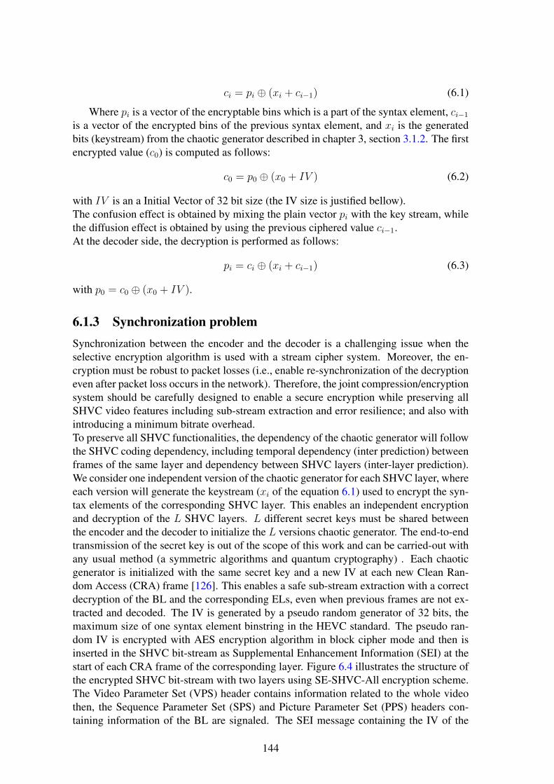
ci = pi ⊕ (xi + ci−1) (6.1)
Where pi is a vector of the encryptable bins which is a part of the syntax element, ci−1is a vector of the encrypted bins of the previous syntax element, and xi is the generatedbits (keystream) from the chaotic generator described in chapter 3, section 3.1.2. The firstencrypted value (c0) is computed as follows:
c0 = p0 ⊕ (x0 + IV ) (6.2)
with IV is an a Initial Vector of 32 bit size (the IV size is justified bellow).The confusion effect is obtained by mixing the plain vector pi with the key stream, whilethe diffusion effect is obtained by using the previous ciphered value ci−1.At the decoder side, the decryption is performed as follows:
pi = ci ⊕ (xi + ci−1) (6.3)
with p0 = c0 ⊕ (x0 + IV ).
6.1.3 Synchronization problemSynchronization between the encoder and the decoder is a challenging issue when theselective encryption algorithm is used with a stream cipher system. Moreover, the en-cryption must be robust to packet losses (i.e., enable re-synchronization of the decryptioneven after packet loss occurs in the network). Therefore, the joint compression/encryptionsystem should be carefully designed to enable a secure encryption while preserving allSHVC video features including sub-stream extraction and error resilience; and also withintroducing a minimum bitrate overhead.To preserve all SHVC functionalities, the dependency of the chaotic generator will followthe SHVC coding dependency, including temporal dependency (inter prediction) betweenframes of the same layer and dependency between SHVC layers (inter-layer prediction).We consider one independent version of the chaotic generator for each SHVC layer, whereeach version will generate the keystream (xi of the equation 6.1) used to encrypt the syn-tax elements of the corresponding SHVC layer. This enables an independent encryptionand decryption of the L SHVC layers. L different secret keys must be shared betweenthe encoder and the decoder to initialize the L versions chaotic generator. The end-to-endtransmission of the secret key is out of the scope of this work and can be carried-out withany usual method (a symmetric algorithms and quantum cryptography) . Each chaoticgenerator is initialized with the same secret key and a new IV at each new Clean Ran-dom Access (CRA) frame [126]. This enables a safe sub-stream extraction with a correctdecryption of the BL and the corresponding ELs, even when previous frames are not ex-tracted and decoded. The IV is generated by a pseudo random generator of 32 bits, themaximum size of one syntax element binstring in the HEVC standard. The pseudo ran-dom IV is encrypted with AES encryption algorithm in block cipher mode and then isinserted in the SHVC bit-stream as Supplemental Enhancement Information (SEI) at thestart of each CRA frame of the corresponding layer. Figure 6.4 illustrates the structure ofthe encrypted SHVC bit-stream with two layers using SE-SHVC-All encryption scheme.The Video Parameter Set (VPS) header contains information related to the whole videothen, the Sequence Parameter Set (SPS) and Picture Parameter Set (PPS) headers con-taining information of the BL are signaled. The SEI message containing the IV of the
144

VPS SPS PPS SEI BL SPS PPS EL
BL ELBL EL
Video headers
Frame 1
Frame n-1 Frame n
Encrypted data
SEI
BL
Figure 6.4: Structure of the encrypted SHVC bit-stream with two layers using SE-SHVC-All encryption scheme
first BL frame is inserted before the BL slice. The SPS and PPS headers of the EL aresignaled before the SEI message containing the IV of the second chaotic generator thenfollowed by the first EL slice. The encrypted data at both the BL and EL slices in theSE-SHVC-All stage is highlighted by red segments, referring to the selective encryption.Therefore, the proposed selective encryption scheme does not encrypt the video headersincluding slice headers, information usually used for mid-network adaptation. The SEImessages containing the IV of 32 bits introduces rate distortion overhead. However, thisoverhead remains very low since the SEI are inserted only before CRA frames and thesize of this SEI message is much lower than the size of the BL plus EL slices.
6.1.4 Experimental configurationThe proposed encryption scheme is implemented in the Scalable Reference softwareModel (SHM) encoder version 4.1 [51]. The decryption algorithm is implemented underthe optimized 1 SHVC decoder OpenHEVC [50]. This allows to assess the complexityoverhead of the decryption process in the context of the real time SHVC decoder. Weconsider the common SHVC test conditions [111]. The configuration of the test videosequences is provided in Table 6.3. These video sequences are encoded in low delay Pconfiguration (I frame followed by P frames), with two layers (L = 2) and three scalabil-ity configurations: two spatial configurations with ratios 2x, 1.5x and one fidelity (SNR)configuration. We consider three QP configurations: EL QP is QPEL ∈ {22, 26, 34} andthe corresponding BL QP which is equal to the QPEL in spatial scalability configurationsand QPBL ∈ {26, 30, 38} in SNR scalability. We use both Peak Signal to Noise Ration(PSNR) and the Structural SIMilarity (SSIM) criteria to assess the quality of the decodedof the correct and incorrect decryption of the videos.
6.1.5 Objective quality and Encryptable Bit (EB)Tables (6.4-6.6) present the average performance in terms of PSNR of the Y component,SSIM and EB respectively, using the proposed encryption scheme of the three stages, for
1Optimized software refers in this work to a code-source written in Single Instruction Multiple Data(SIMD) operations.
145

Table 6.3: Video sequences considered in the experiments
Class Sequences Resolution Frame duration
rate (Hz) (second)
B
Kimono
1920x1080
24 10
ParkScene 24 10
Cactus 50 10
BasketBallDrive 50 10
BQTerrace 60 10
ATraffic
2560x160030 5
PeopleOnStreet 30 5
video classes A and B at one particular EL QP configuration (QPEL=22). The encryp-tion of the BL of both stages SE-SHVC-BL and SE-SHVC-All, encrypting only the BLand both layers respectively, drastically decrease the objective quality of the video se-quences. Indeed, the obtained average PSNR Y values are below 10 dB and their averageSSIM values are below 0.2 in all scalability configurations. The encryption scheme SE-SHVC-BL considerably decreases the objective quality of both layers since the inter-layerprediction used in the SHVC extension propagates errors that resulted from the encryptedinformation of the base layer.
Table 6.4: Video quality PSNR Y of the proposed SHVC encryption scheme of the threestages
Class Scalability QPBL-QPEL No EncBL
PSNR
ALL
PSNR
EL
PSNR
A
SNR 26-22 41.12 8.28 8.25 23.69
2X 22-22 41.3 9.04 8.96 17.72
HEVC .-22 41.25 - - 8.55
B
SNR 26-22 39.54 9.18 9.13 25.77
2X22-22
39.6 9.82 9.66 18.65
1.5X 39.57 9.11 9.03 21.97
HEVC .-22 39.6 - - 9.29
In fact, the EL decoder uses reconstructed samples of the BL picture as reference forthe inter-layer prediction and also uses the encrypted BL MVs in the inter layer merge
146

Table 6.5: Video quality (SSIM) of the proposed SHVC encryption scheme of the threestages
Class Scalability QPBL-QPEL No EncBL
SSIM
ALL
SSIM
EL
SSIM
A
SNR 26-22 0.95 0.16 0.13 0.69
2X 22-22 0.95 0.14 0.1 0.48
HEVC .-22 0.95 - - 0.1
B
SNR 26-22 0.91 0.18 0.15 0.69
2X22-22
0.91 0.19 0.14 0.42
1.5X 0.91 0.18 0.15 0.6
HEVC .-22 0.91 - - 0.14
Table 6.6: Video quality (EB) of the proposed SHVC encryption scheme of the threestages
Class Scalability QPBL-QPEL No EncBL
PSNR
ALL
PSNR
EL
ES
A
SNR 26-22 0 7.27 15.06 7.79
2X 22-22 0 5.62 16.61 10.98
HEVC .-22 0 - - 17.83
B
SNR 26-22 0 6.23 15.72 9.49
2X22-22
0 4.11 17 12.89
1.5X 0 6.31 16.41 10.1
HEVC .-22 0 - - 18.27
147

mode2. We can also notice that the SE-SHVC-All encryption scheme enables to furtherdecrease the objective quality of the SHVC video by 0.1 dB to 0.2 dB with respect to theSE-HEVC-BL encryption scheme.The SE-SHVC-EL encryption scheme (encrypting only the EL) slightly decreases theobjective quality of the EL video. This is because the most part of the information is pre-dicted from the clear BL while only details (difference between BL and EL) of the videoare encoded and encrypted at the EL.The EB of the SE-SHVC-BL remains in average less than 8% of the whole SHVC videobit-stream including BL and EL. This low ES is obtained thanks to the selective encryp-tion and the proposed algorithm 12, where only the most sensitive syntax elements areencrypted and also because of the size of the BL bit-stream which is lower than the sizeof the non-encrypted EL, particularly in spatial scalability configurations. The EB in theSE-HEVC-EL stage is around 11% of the whole SHVC video bit-stream and encryptionof both layers with SE-SHVC-All stage increases the EB to 16% in average. The increas-ing in the EB (from 8% to 11% to 16%) introduces an extra complexity regarding thebrute force attack.The PSNR Y and the SSIM performance of the three considered scheme in all scalabilityconfigurations is provided in Table 6.7 for the 1920 × 1080p50 Cactus video sequenceat different QP configurations. We can notice, that the proposed encryption scheme ofthe three stages decreases the objective quality of the video to the same low quality level,whatever the QP values and the corresponding initial quality of the video.
Table 6.8, presents the EB of the same parameter that used in the previous Table(6.7).We observe that, the EB is slightly decreased with high QP values in SE-SHVC-Allencryption scheme since less syntax elements are present at low bit-rate configuration.Moreover, in the SE-SHVC-BL and SE-SHVC-EL encryption stages, the EB depends,not only on the QP but also on the scalability configuration which changes the resolutionof the BL and the correlation degree between the two layers (related to the video sequence,the scalability configuration and the QP used at each layer). Tables (6.9-6.10) show theBL and the EL PSNR of the three color components (Y, U and V) of the 2560× 1600p30Traffic video sequence, encrypted with the SE-SHVC-BL encryption stage at differentscalability and QP configurations. Table6.10 shows that the SE-SHVC-BL encryptionstage decreases the PSNR of both layers to the same PSNR value in different QP andscalability configurations. The PSNR of the BL and EL is decreased to around 8.5 dB forluminance Y component and 13 dB and 15 dB for U and V color components, respec-tively.
Table 6.11 gives the contributed of the EB of each SHVC syntax elements for thethree stages of the Traffic video sequence in two QP configurations. for high and low bitrate configurations, the TC sign represents the most encrypted syntax element with morethan 85% and 73% in the two cases of the bit rate configurations for the SE-SHVC-Allencryption scheme.
2Merge mode in the SHVC inter-layer prediction uses the MVs from the BL for motion compensation.
148

Table 6.7: Video quality of the three proposed SHVC encryption schemes for the 1080p50Cactus video sequence
QPBL-QPEL Sca.No encryption SE-SHVC-BL SE-SHVC-All SE-SHVC-EL
PSNR SSIM PSNR SSIM PSNR SSIM PSNR SSIM
26-22 SNR 38.65 0.9 8.69 0.19 8.65 0.16 24.68 0.7
22-222x 38.68 0.9 8.72 0.2 8.63 0.14 17.5 0.47
1.5x 38.66 0.9 9.27 0.21 9.17 0.16 20.25 0.6
.-22 HEVC 38.68 0.9 - - - - 9.04 0.14
30-26 SNR 37.09 0.87 8.78 0.25 8.73 0.21 23.25 0.66
26-262x 37.16 0.88 8.99 0.27 8.83 0.18 17.79 0.49
1.5x 37.10 0.88 8.68 0.2 8.67 0.17 21.76 0.64
.-26 HEVC 37.15 0.88 - - - - 8.81 0.2
38-34 SNR 33.66 0.82 7.75 0.29 7.75 0.27 24.51 0.69
34-342x 33.78 0.82 8.28 0.23 8.28 0.2 19.73 0.55
1.5x 33.66 0.82 9.61 0.25 9.59 0.24 22.97 0.66
.-34 HEVC 33.92 0.83 - - - - 8.31 0.26
149

Table 6.8: Encryptable bit of the proposed SHVC encryption scheme for the 1080p50Cactus video sequence
QPBL-QPEL Scalability SE-SHVC-BL SE-SHVC-All SE-SHVC-EL
26-22 SNR 4.97 14.99 10
22-222x 3.38 16.39 13.01
1.5x 5.23 15.6 10.37
.-22 HEVC - - 16.91
30-26 SNR 6.86 14.16 7.3
26-262x 4.92 15.61 10.69
1.5x 7.28 14.64 7.36
.-26 HEVC - - 16.66
38-34 SNR 6.66 12.41 5.74
34-342x 4.69 13.63 8.93
1.5x 6.69 12.58 5.61
.-34 HEVC - - 14.69
Table 6.9: BL PSNR of the Traffic video sequence in different scalability and QP con-figurations: SE-SHVC-BL encryption scheme
QPBL-QPEL Scalability
BL PSNR (dB)
No encryption SE-SHVC-BL
Y U V Y U V
26-22 SNR 39.46 39.98 42.45 8.29 12.78 14.12
22-22 2x 40.77 42.42 44.25 8.78 13.96 14.42
.-22 HEVC - - - - - -
30-26 SNR 37.37 38.87 41.3 8.96 12.36 13.7
26-26 2x 38.04 40.55 42.51 8.46 15.68 17.15
.-26 HEVC - - - - - -
38-34 SNR 33.06 36.92 39.28 8.36 14.52 20.29
34-34 2x 32.98 37.46 39.76 9.11 16.36 18.11
.-34 HEVC - - - - - -
150

Table 6.10: EL PSNR of the Traffic video sequence in different scalability and QPconfigurations:SE-SHVC-BL encryption scheme
QPBL-QPEL Scalability
EL PSNR (dB)
No encryption SE-SHVC-BL
Y U V Y U V
26-22 SNR 41.60 41.46 43.86 8.08 13.53 14.62
22-22 2x 41.67 41.50 43.96 9.44 12.49 14.61
.-22 HEVC 41.69 41.52 44.05 8.39 13.19 14.66
30-26 SNR 39.31 39.85 42.24 8.40 14.01 19.92
26-26 2x 39.41 39.91 42.32 9.21 16.97 17.54
.-26 HEVC 39.46 39.98 42.45 8.29 12.78 14.12
38-34 SNR 34.96 37.47 39.83 8.40 14.01 19.92
34-34 2x 35.06 37.50 39.84 8.84 14.03 14.83
.-34 HEVC 35.23 37.66 40.00 8.08 16.41 19.68
Table 6.11: Repartition of the encrypted SHVC syntax elements in the proposed schemefor Traffic video sequence
Syntax element QPELSE-SHVC-BL SE-SHVC-All SE-SHVC-EL
SNR 2x SNR 2x SNR 2x HEVC
MV diff.
22
2 0.68 3.15 2.88 1.15 2.2 3.22
MV diff. sign 3.45 1.75 6.61 6.91 3.15 5.1 6.36
TCs 3.66 3.01 3.67 3.4 0.01 0.38 7.39
TC sign 34.53 24.17 85.74 86.28 51.2 62.06 82.52
dQP sign 0.33 0.11 0.81 0.55 0.48 0.44 0.49
Sum 43.98 29.73 100 100 56.01 70.26 100
Bitrate (Mbit/s) 12.6 9.4 28.66 31.63 16.05 22.22 29.03
MV diff.
34
5.67 2.73 9.59 9.27 3.91 6.53 7.62
MV diff. sign 5.94 4.33 12.06 13.48 6.11 9.14 9.37
TCs 2.94 1.76 2.94 1.79 0 0.02 6.39
TC sign 44.89 32.75 73.56 74.05 28.66 41.3 75.53
dQP sign 0.86 0.31 1.83 1.39 0.96 1.07 1.07
Sum 60.32 41.90 100 100 39.67 58.09 100
Bitrate (Mbit/s) 1.8 1.25 2.99 3 1.18 1.74 3.28151

The proportion of the TC sign is higher than the TC, since the most part of the TCvalues x are different from zero and lower than the base level (baseLevel) which are notbinarized (i.e., remaining part Coef is equal to 0) while their sign is signaled. We canalso notice that the proportion of the MVs difference sign and the MVs difference areslightly increased at low bit rate configuration. The EB of the encryption scheme forSE-SHVC-BL and SE-SHVC-EL shows that the scalability configuration impacts the ESre-partition, mostly caused by the resolution of the BL and the correlation between thesetwo layers. Finally, the dQP sign represents less than 1% and 2% of the encrypted syntaxelements in SE-SHVC-All scheme at high and low bit rate configurations, respectively.
6.1.6 Visual quality
Figure 6.5 shows the visual quality of the frame #9 of BasketballDrive video sequence. Itis encrypted by the proposed scheme for the BL and the EL. Figure 6.5(a) shows the effect
(a) BL PSNR Y = 8.97 dB (b) EL PSNR Y = 8.98 dB
(c) BL PSNR Y = 8.97 dB (d) EL PSNR Y = 8.88 dB
(e) BL PSNR Y = 39.35 dB (f) EL PSNR Y= 17.59 dB
Figure 6.5: Visual quality of frame #9 of the BasketballDrive video sequence in SNRscalability configuration (a) (b) SE-SHVC-BL, (c) (d) SE-SHVC-ALL and (e) (f) SE-SHVC-EL)
152

of applying the encryption scheme (SE-SHVC-BL) on the base layer, while Figure 6.5(b)shows the effect of applying the same encryption scheme (SE-SHVC-BL) on the en-hancement layer. Figure 6.5(c) shows the effect of applying the encryption scheme (SE-SHVC-ALL) on the base layer, while Figure 6.5(d) shows the effect of applying the sameencryption scheme (SE-SHVC-ALL) on the enhancement layer. Figure 6.5(e) shows theeffect of applying the encryption scheme (SE-SHVC-EL) on the base layer, while Fig-ure 6.5(f) shows the effect of applying the same encryption scheme (SE-SHVC-EL) onthe enhancement layer. It is clear that, applying the encryption scheme (SE-SHVC-EL)does not affect the base layer (see Figure 6.5(f)) and it remains without encryption.We can notice that SE-SHVC-BL scheme encrypts only the BL which affects the visualquality of the EL. The inter-layer prediction using the decoded BL picture and its MVspropagates the errors to the EL. However, SE-SHVC-EL scheme encrypts only the EL,while the BL remains clear and the quality of the EL is slightly decreased compared tothe BL. This is because the most part of information is predicted from the base layer andonly details (encrypted data) are encoded at the level of the EL. We can notice that theproposed SE-SHVC-EL encryption scheme leads to a perceptual (transparent) encryptionsolution by decreasing the visual quality of EL below the quality of the BL while the ELvideo is still recognized. However, the SE-SHVC-BL encrypting scheme enables a moresecure encryption solution by drastically decreasing the visual quality of all layers. Ad-ditional analysis on security parameters of these proposed selective encryption scheme ofthe three stages are investigated in the next paragraph.
153

6.1.7 Security analysis
The evaluation process of the selective encryption is a little bit different from the evalua-tion process of the standard encryption algorithms. Normally, the expected security levelof the stream selective encryption algorithm is less than the expected security level of thefull stream encryption algorithms (and also, it is less than block encryption algorithm).In this section different types of attacks and security parameters are used to evaluate therobustness of the proposed stream selective encryption scheme.
6.1.7.1 Encryption Quality
The difference between the frequency of occurrence for each byte with and without en-cryption is called Encryption Quality (EQ), which is defined in section 2.2.7 of chapter 2.Based on the equation (2.20), we calculate the maximum EQ value for a frame of Kimonoand PeopleOnStreet video sequences which are equal to 16136.7 and 31875, respectively(all frames for each video sequence have the same maximum EQ) . We can notice from Ta-ble 6.12 that SE-SHVC-BL and SE-SHVC-All reach in average EQ value around the halfof the maximum EQ value in all scalability configurations for the both video sequences.However, the SE-SHVC-EL gives low EQ value, that corresponds to the perceptual videoencryption target. In Figure 6.6, we give the curves of the Cumulative Distribution Func-tion (CDF) of the EQ for Kimono (a) and PeopleOnStreet (b) video sequences. We cannotice that all frames of Kimono video sequence have an EQ higher than 38.69% of itsmaximum EQ. While all frames of the PeopleOnStreet video sequence have an EQ valuehigher than 41.08% of its maximum EQ.
Table 6.12: Encryption Quality forKimono andPeopleOnStreet video sequences atQPEL=22
Video Sca. SE-SHVC- SE-SHVC- SE-SHVC-
BL All EL
Kim
ono
SNR 9025 8996 684
2x 7651 7675 1101
1.5x 9895 9900 571
HEVC - - 9355
Peop
le-
OnS
tree
t SNR 14833 14884 3355
2x 14528 14739 5161
HEVC - - 14129
154

0 20 40 60 80 1000
0.2
0.4
0.6
0.8
1X: 70.44Y: 0.9958
Encryption Quality (EQ)−The scale is 1:161.367
Cum
ulat
ive
Dis
trib
utio
n F
unct
ion
(CD
F)
X: 55.71Y: 0.4991
X: 38.69Y: 0.004167
X:70.44Y:0.9999
X:55.71Y:0.4999
X:38.69Y:0.0004
(a) Kimono
0 20 40 60 80 1000
0.1
0.2
0.3
0.4
0.5
0.6
0.7
0.8
0.9
1X: 57.69Y: 0.9933
Encryption Quality (EQ)−The scale is 1:318.75
Cum
ulat
ive
Dis
trib
utio
n F
unct
ion
(CD
F)
X: 46.68Y: 0.4998
X: 41.08Y: 0.0006669
X:57.69Y:0.9999
X:46.68Y:0.4999
X:41.08Y:0.0006
(b) PeopleOnStreet
Figure 6.6: CDF of the EQ for Kimono and PeopleOnStreet video sequences in SNRscalability, QPEL=22 and SE-SHVC-BL encryption scheme
155

6.1.7.2 Edge differential ratio
Edge Differential Ratio (EDR) evaluates the edges differences between the original andthe encrypted frame [141, 140]. The encryption solution is more efficient when the theedges of the encrypted frames are not detectable. The EDR is calculated as:
EDR =
∑h−1i=0
∑w−1j=0 |PE(i, j)− CE(i, j)|∑h−1
i=0
∑w−1j=0 |PE(i, j) + CE(i, j)|
(6.4)
Where PE andCE are the edge detected binary matrix for the plain-frame and the ciphered-frame, respectively, produced by using the Laplacian of Gaussian method [53].Table 6.13 presents the average evaluation results of the EDR for the proposed scheme ofall stages.When the average EDR values are close to 1, means that the encryption solution of SE-SHVC-BL and SE-SHVC-All have a high ability to hide the edges of the encrypted framesand so a high security level is reached.In fact, the structural information (edges...) of the encrypted frame by the SE-SHVC-BLand SE-SHVC-All are completely hidden and becoming useless by the attacker.Figure 6.7 shows the edges of frame #8 of Kimono video sequences. It confirms theobtained results of Table 6.13, calculated based on the equation (6.4).
(a) Original (b) SE-SHVC-BL
(c) SE-SHVC-All (d) SE-SHVC-EL
Figure 6.7: Edges illustration of frame #8 Kimono video sequence of the proposed en-cryption scheme with SNR scalability and QPEL=22
6.1.7.3 Key sensitivity test
The testing scenario of the key sensitivity is described in section 2.2.3 based on equa-tions that given in section 2.2.2. As it is mentioned before, the optimal values of the
156

Table 6.13: Edge differential ratio for Kimono and PeopleOnStreet video sequences atQPEL=22
Video Scalability SE-SHVC-BL SE-SHVC-ALL SE-SHVC-ELK
imon
oSNR 0.95 0.95 0.78
2x 0.96 0.95 0.88
1.5x 0.96 0.95 0.78
HEVC - - 0.95
Peop
le-
OnS
tree
t SNR 0.93 0.93 0.54
2x 0.93 0.92 0.81
HEVC - - 0.92
block encryption algorithms of the NPCR and the UACI are 99.61% and 33.46%, respec-tively [162]. While theoretically, in the selective encryption algorithms achieving theseresults is impossible.
Table 6.14: Average performance of Key sensitivity attack over all frames of Kimonoand PeopleOnStreet video sequences: SE-SHVC-BL, QPEL=22
Sca.Kimono PeopleOnStreet
UACI NPCR UACI NPCR
SNR 31.74 97.02 35.36 98.29
2x 36.75 98.98 39.34 98.37
HEVC 34.87 98.44 36.06 97.76
The obtained values of the UACI and the NPCR given in Table 6.14 by SE-SHVC-BLare not so far from the optimal. Moreover, the average Hamming Distance (HD) betweenthe two encrypted frames are 49.69 and 50.87 for Kimono and PeopleOnStreet, re-spectively. These HD values are too close to the optimal value of 50%. All these resultsindicate that the proposed chaos-based stream selective encryption is sensitive to the onebit change in the secret key.
6.1.7.4 Histogram analysis
Figure 6.8 shows the histograms of the frame #8 of the PeopleOnStreet video sequence atQPEL=22 in SNR scalability for the proposed selective encryption scheme of all stages: InFigure 6.8(a), we present the histogram of the original frame; in Figures 6.8(b) and 6.8(c)we present the histograms of the frame encrypted by SH-SHVC-BL and SE-SHVC-All,respectively. As we can see, the previous histograms are more uniform and differentfrom the original one. However, the histogram given in Figure 6.8(d) representing theencrypted frame by SH-SHVC-EL is not uniform since the total number of the encrypted
157

bits is smaller than the total number of the encrypted bits of the other stages. This resultis compatible to the transparent encryption.
(a) Original (b) SE-SHVC-BL
(c) SE-SHVC-All (d) SE-SHVC-EL
Figure 6.8: Histograms of frame #8 Kimono video sequence in the three encryptionschemes with SNR scalability and QPEL=22
6.1.7.5 Known plain-text attack
This kind of attack is described in details in chapter 2 for full encryption algorithm. Whenit is used to cryptanalysis the selective encryption algorithms for video, the Known plain-text attack is evaluated using PSNR and SSIM values over the whole frames of the testedvideo. For that, we calculate the average of the PSNR and SSIM for three cases:
1. PSNR1 and SSIM1 between the original video (the not compressed video) and thedecoded video (without encryption).
2. PSNR2 and SSIM2 between the original video and the decoded hacking bit-stream,where the hacking bit-stream consists of replacing each encrypted bit by zero.
3. PSNR3 and SSIM3 between the original video and the decoded of the encryptedbit-stream (Tables (6.4-6.5) present the average over the both classes of the PSNR3and SSIM3 respectively).
In Table 6.15, we present the average of PSNR1, SSIM1, PSNR2 and SSIM2 values(using the VQMT tools from [88]) over the whole frames of Kimono and PeopleOnStreetvideo sequences after replacing all encrypted bits by zeros for the BL.
158

Table 6.15: Average PSNR and SSIM for replacing encrypted bits by zero: QPEL=22,SE-SHVC-BL
Sca. Kimono PeopleOnStreet
PSNR1 PSNR2 PSNR1 PSNR2
PSNR (dB)
SNR 41.55 7.82 40.64 9.2
2x 41.63 7.87 40.92 9.05
1.5x 41.51 8.47 - -
HEVC 41.66 8.75 40.8 9.01
SSIM1 SSIM2 SSIM1 SSIM2
SSIM
SNR 0.93 0.17 0.95 0.17
2x 0.93 0.24 0.95 0.16
1.5x 0.93 0.2 - -
HEVC 0.92 0.2 0.95 0.09
It is clear from Table 6.15, that the average of PSNR2 and SSIM2 values remain lowcompared to PSNR1 and SSIM1. This results confirm the robustness of the proposedschemes against this scenario of the known plain-text attacks.
6.1.7.6 Brute force attack
It breaks the cryptosystem by trying a large number of possible keys until the correct one isfound. In the worst case, all possible keys in the practical key space are tested [125], [108].Encryption of MVD and residual signs was classified by [107] to be secure selectiveencryption algorithms. In our proposed cryptosystem extra parameters as the sign of dQPtogether with suffixes of the MVD and residuals are increasing the complexity of the bruteforce attack.
6.1.7.7 Complexity analysis
In this section, we assess the computational complexity of the encryption scheme in thecontext of a real time SHVC decoder. We use a computer fitted with an Intel Core i5processor running at 2.5 GHz.Table 6.16 presents the Decoding Time (DT) and the Complexity Overhead (CO) of theproposed encryption scheme, and Table 6.17 presents the results obtained by the AESalgorithm in Counter (CTR) mode. The CO is defined by the difference between DT withencryption and DT without encryption over the DT without encryption.The both implementations are carried out using 1080p50 Cactus video sequence at differ-ent QP configurations.
We can notice the high CO at high bitrate configuration (QPEL=22) with respect to lowbitrate configuration (QPEL=34). This is mainly caused by the encryption of more syn-tax elements, including the complexity introduced by Algorithm 12 to safely encrypt the
159
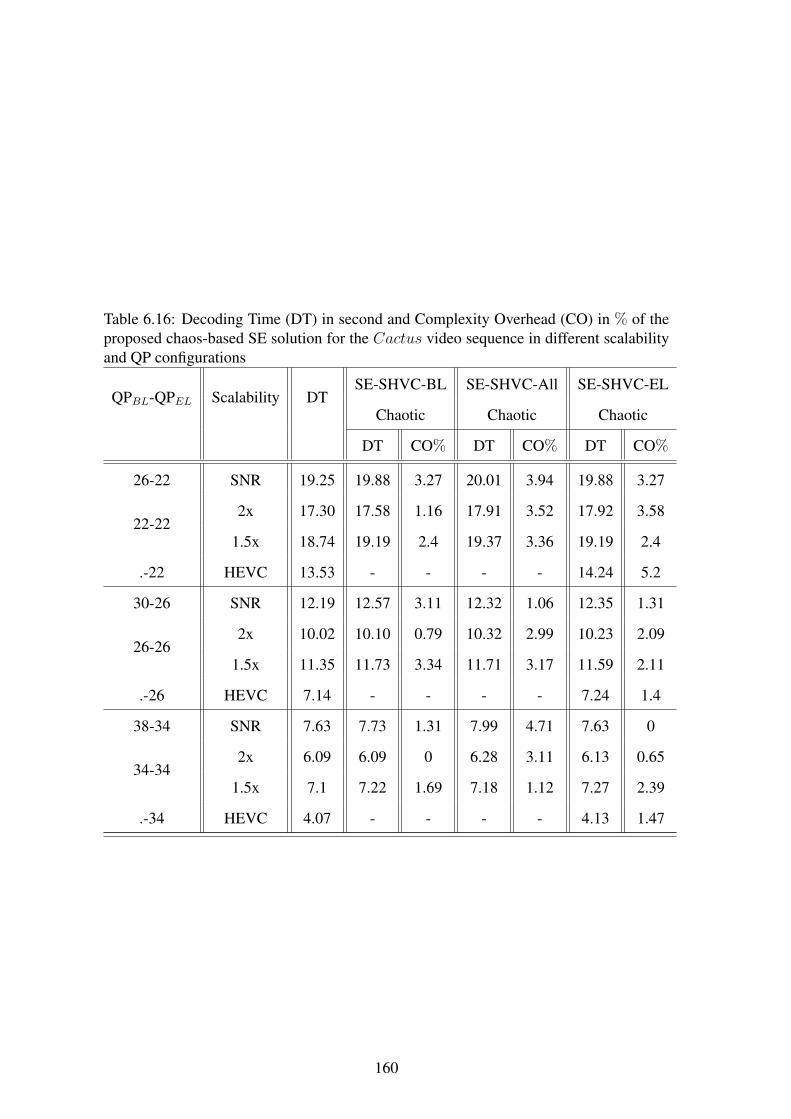
Table 6.16: Decoding Time (DT) in second and Complexity Overhead (CO) in % of theproposed chaos-based SE solution for the Cactus video sequence in different scalabilityand QP configurations
QPBL-QPEL Scalability DTSE-SHVC-BL SE-SHVC-All SE-SHVC-EL
Chaotic Chaotic Chaotic
DT CO% DT CO% DT CO%
26-22 SNR 19.25 19.88 3.27 20.01 3.94 19.88 3.27
22-222x 17.30 17.58 1.16 17.91 3.52 17.92 3.58
1.5x 18.74 19.19 2.4 19.37 3.36 19.19 2.4
.-22 HEVC 13.53 - - - - 14.24 5.2
30-26 SNR 12.19 12.57 3.11 12.32 1.06 12.35 1.31
26-262x 10.02 10.10 0.79 10.32 2.99 10.23 2.09
1.5x 11.35 11.73 3.34 11.71 3.17 11.59 2.11
.-26 HEVC 7.14 - - - - 7.24 1.4
38-34 SNR 7.63 7.73 1.31 7.99 4.71 7.63 0
34-342x 6.09 6.09 0 6.28 3.11 6.13 0.65
1.5x 7.1 7.22 1.69 7.18 1.12 7.27 2.39
.-34 HEVC 4.07 - - - - 4.13 1.47
160

Table 6.17: Decoding Time (DT) in second and Complexity Overhead (CO) in % ofthe proposed SE solution for the Cactus video sequence in different scalability and QPconfigurations based on AES in CRT mode
QPBL-QPEL Scalability DTSE-SHVC-BL SE-SHVC-All SE-SHVC-EL
AES AES AES
DT CO% DT CO% DT CO%
26-22 SNR 19.25 19.71 2.38 20.02 4 19.97 3.74
22-222x 17.30 17.53 1.32 17.95 3.75 17.84 3.12
1.5x 18.74 19.20 2.45 19.48 3.94 19.33 3.14
.-22 HEVC 13.53 - - - - 14.06 3.9
30-26 SNR 12.19 12.28 0.73 12.38 1.55 12.67 3.93
26-262x 10.02 10.57 5.48 10.33 3.09 10.31 2.89
1.5x 11.35 11.79 3.87 12 5.72 11.63 2.46
.-26 HEVC 7.14 - - - - 7.27 1.82
38-34 SNR 7.63 8 4.84 7.69 0.78 7.76 1.7
34-342x 6.09 6.2 1.8 6.18 1.47 6.34 4.1
1.5x 7.1 7.25 2.11 7.32 3.09 7.48 5.35
.-34 HEVC 4.07 - - - - 4.18 2.7
161

TCs, which are increasing at high bitrate. The encryption scheme SE-SHVC-BL enablesthe lowest CO since only syntax elements of the BL are encrypted; and more especiallyin spatial scalability configurations where the resolution of the BL is lower than the ELresolution. On the other hand, the CO using either chaotic or AES encryption systemsremains low in the context of real time SHVC decoder and varies between 0% to 5% ac-cording to: the bitrate, the scalability configuration and the used encryption scheme. ThisCO performance is obtained thanks to the low EB of the proposed selective encryptionsolution where less than 17% of the whole video size is encrypted. The maximum bitratein Table 6.11 of the encryptable bits for the high resolution 2Kp30 Traffic video sequenceare 31.63 Mbit/s and 28.66 Mbit/s in 2x and SNR scalability configurations, respectively,with the encryption scheme SE-SHVC-All at high bitrate (QPEL=22). These bitrates re-main very low with respect to the Chaotic and AES generators bitrates which are equal to823.9 Mbit/s and 888 Mbit/s 3, respectively. The low EB not only decreases the complex-ity of the encryption/decryption (which is convenient for battery-operated devices) butalso decreases the end-to-end delay for live and real time video streaming applications.Table 6.18 compares the SE-SHVC-BL and SE-SHVC-EL encryption schemes with thestate of the art on different video encryption criteria. The proposed schemes fulfill for-mat compliance and constant bitrate video encryption requirements. Moreover, the pro-posed encryption scheme is compatible with any stream cipher encryption algorithm. TheSE-SHVC-BL and SE-SHVC-EL enable secured and perceptual video encryption, re-spectively; and can be applied on different SHVC scalability configurations: temporal,spatial, fidelity, bit depth and color gamut. In respect to transcoding capability, the SE-HEVC-BL scheme is robust to transcoding on all ELs while the SE-HEVC-EL encryptionscheme is robust for BL transcoding. Finally, the SE-HEVC-EL encryption scheme canalso be applied to the single layer HEVC standard corresponding to simulcast HEVCconfiguration.
3This performance is obtained on a Core-i5-4300M CPU @ 2.6 GHz, using the Cryptopp [91] imple-mentation of the AES encryption algorithm
162

Tabl
e6.
18:C
ompa
riso
nof
the
prop
osed
encr
yptio
nsc
hem
efo
r(SE
-SH
VC
-BL
and
SE-S
HV
C-E
L)w
ithth
est
ate
ofth
ear
t
SEsc
hem
esFo
rmat
Con
stan
tE
ncry
ptio
nE
ncry
ptio
nR
obus
tto
Vid
eoSu
ppor
t
com
plia
nce
bitr
ate
algo
rith
mdo
mai
ntr
ansc
odin
gst
anda
rdsc
alab
ility
Lie
tal.
[67]
No
Yes
Lea
kE
xtra
ctio
nN
AL
No
H.2
64/S
VC
Yes
(Str
eam
ciph
er)
Car
rillo
etal
.[19
]Y
esN
oPs
eudo
rand
omPi
xel
Yes
Inde
pend
ent
RO
Ipi
xelp
erm
utat
ion
Van
etal
.[14
7]Y
esN
oA
ES
asTr
ansf
orm
No
HE
VC
No
stre
amci
pher
Shah
edet
al.[
116]
Yes
Yes
AE
SB
inst
ring
sN
oH
EV
CN
o(b
lock
ciph
er)
SE-S
HV
C-B
LY
esY
esC
haot
icB
inst
ring
sY
esfo
rEL
sSH
VC
Yes
(str
eam
ciph
er)
SE-S
HV
C-E
LY
esY
esC
haot
icB
inst
ring
sY
esfo
rBL
HE
VC
&Y
es(s
trea
mci
pher
)SH
VC
163

6.2 Encryption of ROI in HEVCIn this section, we investigate the protection of Region Of Interest (ROI), (privacy) for theHEVC standard based on the tile concept. Tiles in the HEVC enable the video to be splitinto independent rectangular regions. Two solutions are proposed to encrypt the tiles con-taining the Region Of Interest (ROI). The first solution encrypts the whole bit-stream ofthe ROI. The second solution enables a selective encryption for the encryptable bits (ver-ifying constant bitrate and format compliant requirements) of the ROI tiles. The HEVCstandard was designed with a particular attention to complexity, where several steps canbe easily performed in parallel. Three high level parallel processing approaches, includingindependent slice, tile, and wavefront, can be used in the HEVC to simultaneously processmultiple regions of a single picture [27]. The tile concept splits the picture into rectangu-lar groups of CTBs, called tiles. The ROI is included in a set of Tiles (called ROI tiles)and the background is within the rest of non ROI tiles. Tiles break the CABAC and theintra prediction dependencies that each tile can be independently processed. Figure 6.9illustrates a HEVC picture composed of 15 tiles (red rectangles), where each tile consistsof 9 CTBs. These tiles represent independent and contiguous regions of the HEVC frame.Figure 6.10 illustrates the same idea composed of 4 tiles.
Figure 6.9: Tile concept in the HEVC standard composed of 15 tiles (red rectangles)
6.2.1 A brief state of the artUsually the most important part of the video (ROI). In some special application, fast en-cryption algorithms are required to preserve the privacy of the moving objects in the videowith a lower overhead charge. The ROI encryption can be treated in the same manner asthe video encryption in the previous chapter (i.e., is it a NEA or Selective encryption,a format compliance encryption, a constant bit-rate encryption, a fast and a secure en-cryption, etc). Authors in [95] proposed a selective encryption solution of ROI based onFlexible Macroblock Ordering (FMO) concept in the H.264/AVC and chaos encryptionsystem. The macroblocks of each frame are mapped into two slices, one regroups mac-roblocks within the ROI and the other slice regroups the macroblocks outside the ROI.
164

Figure 6.10: Tile concept in the HEVC standard composed of 4 tiles with ROI
Therefore, only the ROI slice is encrypted with a selective encryption solution based onchaos system. The ROI represents human faces which are detected in the video based onthe skin color model [76].Dufaux et al. [32] proposed a solution to hide ROI in MPEG-4 video content for privacyprotection in video surveillance. This encryption solution is carried out at the transformdomain by pseudo-randomly flipping the selected Transform Coefficient (TC) signs. Toavoid the propagation of the encryption outside of the ROI, the macroblocks using theencrypted ROI as reference for inter prediction are rather Intra coded.Work in [90] enables rectangular region privacy by de-identifying faces. This solutionguarantees that, face recognition software cannot reliably recognize the de-identified faceseven though if part of the facial details are preserved.Authors in [130] investigated privacy protection in the H.264/SVC (Scalable Video Cod-ing). This solution first detects face regions (ROI) and then encrypts these ROI in thetransform domain by scrambling the sign of the non-zero TCs at all SVC layers.
6.2.2 AES in cipher feedback modeThe AES encryption system [40] is used in cipher feedback (CFB) mode to encrypt theHEVC syntax elements. As shown in Figure 6.11, the AES in CFB mode introducesinternal diffusion inside the cipher block encryption and external diffusion by using theprevious ciphered block as input for the encryption of the current plain block. The AESin CFB mode enables to produce the 128 bits (Xi) which can be than used to perform theselective encryption of the HEVC syntax element by syntax element on the fly and thensend to the Bypass coding step. However, the size of the ciphertext Ci that is required forthe encryption of the next block is 128 bits,
6.2.3 ROI encryption solutions in the HEVCAs mentioned before, we propose two solutions based on the tile concept to protect pri-vacy in the HEVC standard. The first common step of the both solutions consists of the
165

Initialization Vector (IV)
Block cipher encryption
Plaintext
Key
Ciphertext
Block cipher encryption
Plaintext
Key
Ciphertext
External diffusion
(P0)
(C0)
(X0) (X1)(P1)
(C1)
Figure 6.11: AES encryption system in CFB mode
identification and tracking of the ROI in the video. This can be done in real time by anyexisting algorithm such as face identification and tracking for video surveillance applica-tions [76, 97]. The second common step uses information of ROI localization in the frameprovided by the first step to split the HEVC frame into tiles where all ROI are included inROI tiles and the background in separated non ROI tiles. In Figure 6.9, tiles 1, 2, 6 and 7including human face represent the ROI tiles and the other tiles represent the backgroundtiles. Note that the tile repartition provided in Figure 6.9 with red edges is not optimalin terms of coding rate-distortion performance. In fact, more efficient tile repartition canbe defined to minimize the number of tiles in the frame where all ROI and backgroundregions are included in a minimum number of tiles. For this example, the human facecan be represented in one ROI tile which regroups only parts of tiles 1, 2, 6, 7 and therest of tiles will represent the background. This repartition will provide more efficientcoding performance since it reduces the number of tiles from 15 to only 6 tiles in the newrepartition illustrated in Figure 6.9: ROI tile is highlighted in green dashed rectangle andnon ROI tiles in blue dashed rectangles.The first proposed encryption solution, called Tile Naive Encryption - HEVC (TNE-HEVC), encrypts all syntax elements coded in CABAC within the ROI tiles. The en-cryption is performed at the bit-stream level while the video headers, including VPS,SPS, PPS, and slice headers are not encrypted since they are not entropy coded with theCABAC.The second proposed encryption solution, called Tile Selective Encryption - HEVC (TSE-HEVC), performs a selective encryption of ROI tiles in format compliant and at constantbitrate. The encryption is performed at the CABAC binstring level (see Figure 5.8) byencrypting only the most sensitive HEVC syntax elements to decrease the visual qualityof the ROI.
6.2.3.1 TSE-HEVC EB
The TSE-HEVC solution encrypts only syntax element binarized in FL code and thenbypassed. This restriction enables the TSE-HEVC solution to perform at the CABACbinstring level constant bitrate and format compliant encryption. The proposed algorithm(algorithm 12) is used to select the encryptable bits under the format compliance and theconstant bit-rate. The selected syntax parameter for the encryption process inside the ROI
166

are:
• MVD suffix.
• MVD sign.
• TC sign.
• TC based on algorithm 12.
6.2.3.2 MV restriction in the background tile
In the two ROI encryption solutions, the decoding of the background tiles can use someinformation (inter layer prediction) of the encrypted tiles. Moreover, the encrypted MVscan also be used by the background tiles for inter layer prediction in the HEVC mergemode. Merge mode in the HEVC derives the MVs information from a list of spatialneighbor and temporal candidates [137]. Therefore, when of the ROI is not correctlydecrypted, the two decoding operations can propagate the effect of the encrypted tiles tothe background tiles. In the case of merge mode, we restrict the temporal candidates ofthe background tiles to be inside the background zone in the reference frame. In the caseof regular inter prediction, the MVs differences are signaled. Therefore, we restrict theresearch window of the temporal candidates to be in the background tiles of the referenceframes. Note that the boundary of the research window is equal to non ROI boundariesnarrowed by 3 pixels and 1 pixel in luma and chroma components, respectively. Thisenables to perform a safe interpolation process at the tiles boundaries. Finally, the in-loopfilters (deblocking and SAO) are disabled at the tiles boundaries.
6.2.3.3 Encryption process based on AES-CFB mode
In the TNE-HEVC solution, the bit-stream within the ROI tiles is encrypted block byblock (Pi of 128 bits) as follows:
Ci = Ek(Ci−1)⊕ Pi (6.5)
where C−1 = IV , Ci is the encrypted bits in the current ciphered block, Ci−1 is theprevious ciphered-block and Ek is the encryption function. The decryption at the decoderside is achieved with XOR operation in reverse using the same encryption algorithm:
Pi = Ek(Ci−1)⊕ Ci (6.6)
cj = xj ⊕ pj (6.7)
6.2.4 Results and analysis6.2.4.1 Experimental configuration
The HEVC reference software model version 15 (HM 15.0) is used to encode and decodethe video sequences. Encryption and decryption algorithms are integrated into the codec.We consider three HD video sequences (Kimono, ParkScene and BQTerrace) from thecommon HEVC text conditions [18]. These video sequences are coded in the low delayP-configuration at different quantization parameters QP ∈ {22, 27, 32, 37} with enablingthe tile tools.
167

6.2.4.2 Results
Figure 6.12 shows the average Rate Distortion (RD) performance of the three video se-quences in three coding configurations: 1, 15 and 6 tiles with MVs limitations and dis-abling the in-loop filters across the tile edges. The RD loss of the two tiles configurationsis provided in Table 6.19 in terms of Bjontegaard’s difference (Matlab function). In the 6tiles repartition, the RD loss, caused by these limitations, remains low and does not exceed2.5% in the three video sequences. Figures 6.13(a) and 6.13(b) illustrate the visual quality
Figure 6.12: Rate distortion performance
of frame #1 of Kimono video sequence where the ROI is encrypted with the TNVE-HEVCand TSE-HEVC solutions, respectively. In both solutions, the visual quality is drasticallydecreased with a PSNR value of the ROI less than 11 dB, while the background regionremains clear. However, the TNE-HEVC solution is not HEVC format compliant, thus
Table 6.19: Bjontegaard’s difference of HEVC tile repartitions
Schemes 15 tiles per frame Optimal (6 tiles)
Y U V Y U V
Kimono -3.27% -3.26% -3.03% -1.49% -1.63% -1.56%
ParkScene -1.41% -2.34% -2.07% -0.51% -1.21% -1.09%
BQTerrace -1.37% -3.89% -5.09% - 0.5% -1.64% -2.54%
the encryption desynchronizes the decoder inside the ROI (the desynchronization of theCABAC is presented in the green part of the ROI in Figure 6.13(a)). The decoder is re-synchronized at the next not encrypted tile thanks to the access points at the non encryptedslice header signaling tiles position in the bit-stream.
168

(a) TNE-HEVC PSNR1=10.95, PSNR2=42.07,PSNR3= 21.15(dB)
(b) TSE-HEVC PSNR1=7.78, PSNR2=42.07,PSNR3=18.01 (dB)
Figure 6.13: Visual quality of frame #1 in the Kimono video sequence QP = 27(PSNR1: PSNR Y ROI, PSNR2: PSNR Y background, PSNR3: PSNR Y frame ).
Table 6.20 gives the average PSNR Y and the EB of the three video sequences. Theaverage PSNR inside the ROI remains low for all sequences and does not exceed 11.5dB. The EB of the TNVE-HEVC solution on average is equal to 14.28% since all syntaxelements in the ROI are encrypted while it represents on average only 2.5% in the TSE-HEVC solution.
Finally, face recognition in the Kimono video sequence is assessed with using Princi-pal Components Analysis (PCA) algorithm [149] based on Mahalanobis Cosine (MAH-COS) distance using the first rank. This rank corresponds to the best match of the testimage compared to the training one. The recognition rate decreases from 68% in theoriginal video to 0.5% in the video encrypted with TSE-HEVC solution.
Table 6.20: EB and PSNR of the ROI encryption solutions
Schemes TNVE-HEVC TSE-HEVC PSNR2
QP=22 PSNR 1 (dB) ES (%) PSNR1 (dB) ES(%) (dB)
Kimono 9.04 9.82 10.18 2.05 41.67
ParkScene 10.91 12.7 11.27 2.02 39.81
BQTerrace 10.79 20.32 10.89 3.42 38.72
6.3 Conclusion and discussionIn the first section, we have investigated a selective video encryption based on chaoticsystem in the scalable HEVC extension. A selective encryption solution is proposed toencrypt the most sensitive syntax elements in the SHVC bit-stream at the CABAC binstring level. This encryption solution is SHVC format compliant and does not impact theSHVC compression ratio. The encryption is applied on the SHVC bit-stream in three dif-ferent configurations: encryption of only the BL, encryption of all layers and encryptionof only the highest EL resulting in three encryption stages SE-SHVC-BL, SE-SHVCAll
169

and SE-SHVC-EL, respectively. The first two stages enable a high security level withdrastically decreasing the visual quality of the video, while the third stage performs per-ceptual video encryption. The three stages preserves all SHVC functionalities includingbit-stream extraction and error resilience. This enables the untrusted milde-box to per-form network adaptation on the bit-stream and further decrease the end-to-end delay. TheEB of SE-SHVC-BL stage remains low and does not exceed 8% of the whole SHVC bit-stream and this stage also passes all security encryption tests. In terms of computationalcomplexity, the SE-SHVC-BL encryption stage introduces a low complexity overhead,which remains lower than 3% of the whole SHVC decoding time of HD video sequencesat high bitrate.In the second section, two encryption solutions are proposed based on the HEVC tile con-cept and the AES algorithm in CFB mode to protect privacy in the HEVC video content.The first solution performs encryption at the bit-stream level while the second solutioncarries out format compliant encryption at the CABAC binstring level. Restrictions areintroduced in the HEVC coding process to prevent the propagation of the encryption out-side the ROI region but at the expense of rate-distortion loss. Experimental results showedthat both solutions perform a secure protection of privacy in the HEVC video content; andthe TSE-HEVC solution has a low EB and prevents unexpected behavior of the decoderwhile TNE-HEVC is not format compliant solution.
170

IIIConclusion and Future Works
171


7Conclusion and Future Work
In this thesis, we mainly study the problem of achieving the confidentiality of transmittedimages and videos over public channels, by using chaos-based cryptosystems and jointcrypto-compression systems. These systems are designed and implemented for real-timeapplications with a very high security level.In chapter one, we introduced the context of the study, the main goals of the cryptography,the concept of the chaos-based cryptography, the motivation of this study, and the thesiscontributions.In chapter 2, first, we presented in a brief manner the main recent chaos-based cryptosys-tems of the literature that have a direct relation to our contributions. Then, we intro-duced some metrics and measurement tools, which permit to quantify the performance ofthe proposed crypto and joint crypto-compression systems in terms of robustness againstknown and statistical attacks, and in terms of average encryption/decryption times, en-cryption throughput, and the needed number of cycles to encrypt/decrypt one byte.The main contributions of the thesis are described in two parts.In the first part (chapter 3 and chapter 4), we designed, implemented, and tested four effi-cient chaos-based cryptosystems, defined on finite numbers, for real-time applications ofimage and video transmissions. All of them are blocks ciphers and the two first cryptosys-tems (crypto A and crypto B) are based on the substitution-permutation network (SPN).We proposed a modified Finite Skew Tent Map (FSTM) that permitted to overcome theproblems of the classic FSTM, namely: fixed point, restriction of the key space and lim-itation of mapping between plaintext and ciphertext and vice versa. The structure of theproposed third cryptosystem (crypto C) is new and efficient. It is based on two chaoticlayers: a binary diffusion layer of pixels, followed by a bit-permutation layer. We pro-posed a new formulation of the 2-D cat map that allows an efficient implementation inC code of the permutation process. The fourth cryptosystem (chapter 4), which is fasterthan the other cryptosystems with a very high security level, is implemented based on apartial cryptanalysis that we performed for one of best chaos-based cryptosystems, re-cently published by Zhang in 2013. In this cryptosystem, the confusion process (basedon the modified 2D-cat map) and the diffusion process (based on the modified FSTM asa generator) are performed simultaneously in a single scan of plain-image pixels.In chapter 5 of the second part, we have introduced the main notions of the selective en-
173

cryption of the High Efficiency Video Coding (HEVC) and its scalable version (SHVC).Then, in chapter 6, we realized two fast and secure selective chaos-based crypto compres-sion systems to encrypt and secure the HEVC and its scalable version SHVC. In the firstcrypto-compression, we proposed a new algorithm to define the encrypt-able bit in thebit stream of the HEVC and the SHVC. The proposed solution encrypts a set of sensi-tive SHVC parameters with a minimum delay and complexity overheads. The encryptionprocess is performed at the CABAC bin string level and fulfills both constant bit rate andformat compliant video encryption requirements. It preserves all SHVC functionalitiesincluding bit stream extraction for mid-network adaptation, error resilience, and real-timeSHVC decoder. The second proposed crypto-compression system protects the Region OfInterest (ROI) of the HEVC based on the tile concept. It performs encryption at the bitstream level by encrypting all HEVC syntax elements within the ROI tiles, or a selectiveencryption of the ROI tiles under constant bit rate and format compliant requirements. Toavoid temporal propagation of the encryption outside the ROI boundaries caused by inter-prediction, the motion vectors of non ROI regions are restricted inside the non encryptedtiles in the reference frames.
Our future works will focus on:
• A prime reversible chaotic map (as FSTM) to be used as substitution and irre-versible, i.e., to be used as generator.
• Designing a separated and selective joint encryption-compression system.
• Designing chaos-based stream ciphers.
• A joint compression and watermarking solution for the new generation of videocoding systems (HEVC, SHVC, MVHEVC and 3D-HEVC).
174

Bibliography
[1] High Efficiency Video Coding. In Rec. ITU-T H.265 and ISO/IEC 23008-2. Sap-poro, JP, January 2013. 138
[2] Ahmed A Abd El-Latif, Xiamu Niu, and Mohamed Amin. A new image cipher intime and frequency domains. Optics Communications, 2012. 17, 20, 60, 61, 62
[3] Ala Abu-Zahra, Zafar Shahid, Amjad Rattrout, and William Puech. Independentprotection of different layers in spatially scalable video coding. procedia computerscience, 10:240–246, 2012. 132
[4] Mohammed AbuTaha, Mousa Farajallah, Radwan Tahboub, and Mohammad Odeh.Survey paper: cryptography is the science of information security. InternationalJournal of Computer Science and Security (IJCSS), 5(3):298, 2011. 15
[5] Iskender Agi and Li Gong. An empirical study of secure mpeg video transmissions.In Network and Distributed System Security, 1996., Proceedings of the Symposiumon, pages 137–144. IEEE, 1996. 126, 128
[6] H. E H Ahmed, H. M. Kalash, and O.S.F. Allah. Encryption Efficiency Analysisand Security Evaluation of RC6 Block Cipher for Digital Images. In InternationalConference on Electrical Engineering (ICEE), pages 1–7, April 2007. 28
[7] Jinhaeng Ahn, Hiuk Jae Shim, Byeungwoo Jeon, and Inchoon Choi. Digital videoscrambling method using intra prediction mode. In Advances in Multimedia Infor-mation Processing-PCM 2004, pages 386–393. Springer, 2005. 130
[8] A Akhshani, A Akhavan, S-C Lim, and Z Hassan. An image encryption schemebased on quantum logistic map. Communications in Nonlinear Science and Nu-merical Simulation, 17(12):4653–4661, 2012. 17, 20, 58, 60, 62, 98, 99, 100, 190
[9] Gonzalo Alvarez and Shujun Li. Some basic cryptographic requirements forchaos-based cryptosystems. International Journal of Bifurcation and Chaos,16(08):2129–2151, 2006. 24
[10] Giuseppe Anastasi, Marco Conti, Mario Di Francesco, and Andrea Passarella.Energy conservation in wireless sensor networks: A survey. Ad Hoc Networks,7(3):537–568, 2009. 106
[11] Ross Anderson. Security engineering: A guide to building dependable distributedsystems. 2001, 2001. 73
175

[12] Mamoona N Asghar, Mohammed Ghanbari, Martin Fleury, and Martin J Reed.Confidentiality of a selectively encrypted h. 264 coded video bit-stream. Journalof Visual Communication and Image Representation, 25(2):487–498, 2014. 126
[13] M.N. Asghar, M. Ghanbari, and M.J. Reed. Sufficient encryption with codewordsand bin-strings of h.264/svc. In Trust, Security and Privacy in Computing andCommunications (TrustCom), 2012 IEEE 11th International Conference on, pages443–450, June 2012. 131
[14] S Behnia, A Akhshani, H Mahmodi, and A Akhavan. A novel algorithm for im-age encryption based on mixture of chaotic maps. Chaos, Solitons & Fractals,35(2):408–419, 2008. 17, 20, 60, 62, 190
[15] Bharat Bhargava, Changgui Shi, and Sheng-Yih Wang. MPEG video encryptionalgorithms. Multimedia Tools and Applications, 24(1):57–79, 2004. 17, 20, 129
[16] Gaurav Bhatnagar and QM Jonathan Wu. Selective image encryption based onpixels of interest and singular value decomposition. Digital Signal Processing,22(4):648–663, 2012. 17, 20
[17] Eli Biham and Adi Shamir. Differential cryptanalysis of DES-like cryptosystems.Journal of CRYPTOLOGY, 4(1):3–72, 1991. 25
[18] Frank Bossen. Common Conditions and Software Reference Configurations. Doc-ument JCTVC-H1100, JCT-VC of ITU-T SG 16 WP 3 and ISO/IEC JTC 1/SC29/WG 11, San Jose, CA, February 2012. 167
[19] Paula Carrillo, Hari Kalva, and Spyros Magliveras. Compression Independent Re-versible Encryption for Privacy in Video Surveillance. EURASIP Journal on Infor-mation Security, 2009(5):1–13, 2009. 163
[20] SGXV CCITT and H Recommendation. 261-video codec for audiovisual servicesat px64 kbit/s. The International Telegraph and Telephone Consultative Committee,1990. 115
[21] Wei-Der Chang. Digital secure communication via chaotic systems. Digital SignalProcessing, 19(4):693–699, 2009. 17, 20, 190
[22] Guanrong Chen, Yaobin Mao, and Charles K Chui. A symmetric image encryptionscheme based on 3d chaotic cat maps. Chaos, Solitons & Fractals, 21(3):749–761,2004. 17, 20, 21, 60, 61, 62
[23] J. Chen, J. Boyce, M. Hannuksela Y. Ye, G. J. Sullivan, and Y. K. Wang. HEVCScalable Extensions (SHVC) Draft Text 7. In Document JCTVCR100. Sapporo, JP,July 2014. 136
[24] Houssine Chetto and Maryline Chetto. Some results of the earliest deadlinescheduling algorithm. IEEE Transactions on Software Engineering, 15(10):1261–1269, 1989. 107
[25] Houssine Chetto and Maryline Chetto. An adaptive scheduling algorithm for fault-tolerant real-time systems. Software Engineering Journal, 6(3):93–100, 1991. 107
176

[26] Maryline Chetto and Audrey Queudet. A note on edf scheduling for real-time en-ergy harvesting systems. IEEE TRANSACTIONS ON COMPUTERS, 63(4):1037–1040, 2013. 108
[27] C. C. Chi, M. Alvarez-Mesa, B. Juurlink, G. Clare, F. Henry, S. Pateux, andT. Schier. Parallel Scalability and Efficiency of HEVC Parallelization Approaches.IEEE TCSVT, 22:1827–1838, December 2012. 164
[28] Franco Chiaraluce, Lorenzo Ciccarelli, Ennio Gambi, Paola Pierleoni, and Maur-izio Reginelli. A new chaotic algorithm for video encryption. Consumer Electron-ics, IEEE Transactions on, 48(4):838–844, 2002. 17, 20
[29] Cahit Cokal and Ercan Solak. Cryptanalysis of a chaos-based image encryptionalgorithm. Physics Letters A, 373(15):1357–1360, 2009. 24
[30] Wei Dai. Crypto++ 5.6.0 benchmarks. http://www.cryptopp.com/benchmarks.html. Accessed: 2015-04-08. 49
[31] Loïc Dubois, William Puech, Jacques Blanc-Talon, et al. Fast protection of h.264/avc by reduced selective encryption of cavlc. In EUSIPCO’11: 19th EuropeanSignal Processing Conference, 2012. 131
[32] F. Dufaux and T. Ebrahimi. Scrambling for Privacy Protection in Video Surveil-lance Systems. IEEE Transactions on Circuits and Systems for Video Technology,18(8):1168–1174, 2008. 165
[33] Morris J Dworkin. Sp 800-38c. recommendation for block cipher modes of opera-tion: the ccm mode for authentication and confidentiality. NIST Special Publication800-38C, 2004. 134
[34] William F Ehrsam, Carl HW Meyer, John L Smith, and Walter L Tuchman. Mes-sage verification and transmission error detection by block chaining, February 141978. US Patent 4,074,066. 87
[35] Safwan El Assad and Mousa Farajallah. A simple introduction to the klt(karhunen—loève transform). A New Efficient Structure of a Cryptosystem basedon Two Chaotic Layers: a Binary Diffusion Layer and a Bit-Permutation Layer,page 13 Pages, under submission. 31
[36] Safwan El Assad, Mousa Farajallah, and Calin Vladeanu. Chaos-based block ci-phers: An overview. In Communications (COMM), 2014 10th International Con-ference on, pages 1–4. IEEE, 2014. 17, 20
[37] Safwan El Assad and Hassan Noura. Generator of chaotic sequences and corre-sponding generating system, March 28 2011. US Patent App. 13/638,126. 31, 32,42, 86, 87
[38] Mousa Farajallah, Safwan El Assad, and Maryline Chetto. Dynamic adjustmentof the chaos-based security in real-time energy harvesting sensors. In GreenComputing and Communications (GreenCom), 2013 IEEE and Internet of Things(iThings/CPSCom), IEEE International Conference on and IEEE Cyber, Physicaland Social Computing, pages 282–289. IEEE, 2013. 31, 88
177

[39] Mousa Farajallah, Zeinab Fawaz, Safwan El Assad, and Olivier Deforges. Effi-cient image encryption and authentication scheme based on chaotic sequences. InSECURWARE 2013, The Seventh International Conference on Emerging SecurityInformation, Systems and Technologies, pages 150–155, 2013. 31, 88, 95
[40] N. Ferguson, B. Schneier, and T. Kohno. Cryptography Engineering: Design Prin-ciples and Practical Applications. In Wiley Publishing Inc.,. ISBN 978-0-470-47424-2, 2010. 165
[41] Niels Ferguson, Bruce Schneier, and Tadayoshi Kohno. Cryptography Engineer-ing: Design Principles and Practical Applications: Design Principles and Practi-cal Applications. John Wiley & Sons, 2011. 18
[42] PUB FIPS. 180-1. secure hash standard. National Institute of Standards and Tech-nology, 17, 1995. 45
[43] A Fog. Lists of instruction latencies, throughputs and micro-operation breakdownsfor intel, amd and via cpus. Copenhagen University College of Engineering, 2012.55
[44] Jiri Fridrich. Image encryption based on chaotic maps. In Systems, Man, andCybernetics, 1997. Computational Cybernetics and Simulation., 1997 IEEE Inter-national Conference on, volume 2, pages 1105–1110. IEEE, 1997. 17, 20, 190
[45] Jiri Fridrich. Symmetric ciphers based on two-dimensional chaotic maps. Inter-national Journal of Bifurcation and Chaos, 8(06):1259–1284, 1998. 17, 20, 41,88
[46] B Furht and D Socek. Multimedia security: Encryption techniques. IEC Compre-hensive Report on Information Security, pages 335–349, 2003. 17, 20
[47] Xin Ge, Fenlin Liu, Bin Lu, and Wei Wang. Cryptanalysis of a spatiotemporalchaotic image/video cryptosystem and its improved version. Physics Letters A,375(5):908–913, 2011. 24
[48] Dan Grois, Detlev Marpe, Amit Mulayoff, Benaya Itzhaky, and Ofer Hadar. Per-formance comparison of h. 265/mpeg-hevc, vp9, and h. 264/mpeg-avc encoders. InPCS 2013 30th Picture Coding Symposium, San Jose, California, Dec 8-11, 2013.116
[49] W. Hamidouche, M. Farajallah, M. Raulet, O. Déforges, and S. El Assad. SelectiveVideo Encryption using Chaotic System in the SHVC extension. In 40th IEEEInternational Conference on Acoustics, Speech and Signal Processing (ICASSP),Brisbane Australia, April 2015. 17, 20
[50] Wassim Hamidouche, Mickael Raulet, and Olivier Deforges. Real time SHVCDecoder: Implementation and Complexity Analysis. In IEEE International Con-ference on Image Processing (ICIP), October 2014. 145
[51] Fraunhofer Heinrich Hertz Institute. Shvc reference software model (shm).https://hevc.hhi.fraunhofer.de/svn/svn_SHVCSoftware/.145
178

[52] Guo J.-I and Yen J.-C. A new chaotic key-based design for image encryption anddecryption. In Circuits and Systems, 2000. Proceedings. ISCAS 2000 Geneva. The2000 IEEE International Symposium on, volume 4, pages 49–52. IEEE, 2000. 17,20
[53] Rajan L Joshi and Thomas R Fischer. Comparison of generalized gaussian andlaplacian modeling in dct image coding. Signal Processing Letters, IEEE, 2(5):81–82, 1995. 156
[54] David Kahn. The Codebreakers: The comprehensive history of secret communica-tion from ancient times to the internet. Simon and Schuster, 1996. 24
[55] Kunihiko Kaneko. Pattern dynamics in spatiotemporal chaos: Pattern selection,diffusion of defect and pattern competition intermettency. Physica D: NonlinearPhenomena, 34(1):1–41, 1989. 22
[56] Lutful Karim, Alagan Anpalagan, Nidal Nasser, Jalal Almhana, and Isaac Woun-gang. Fault tolerant, energy efficient and secure clustering scheme for mobilemachine-to-machine communications. Transactions on Emerging Telecommuni-cations Technologies, 25(10):1028–1044, 2014. 24
[57] Ali Kassem, Hussein Al Haj Hassan, Youssef Harkouss, and Rima Assaf. Efficientneural chaotic generator for image encryption. Digital Signal Processing, 25:266–274, 2014. 20
[58] Jonathan Katz and Yehuda Lindell. Introduction to modern cryptography. CRCPress, 2008. 46, 73
[59] Stephen H Kellert. In the wake of chaos: Unpredictable order in dynamical sys-tems. University of Chicago press, 1994. 19
[60] Syed Ali Khayam. The discrete cosine transform (dct): theory and application.Michigan State University, 2003. 114
[61] IK Kim, K McCann, K Sugimoto, B Bross, WJ Han, and GJ Sullivan. High ef-ficiency video coding (hevc) test model 10 (hm10) encoder description. In JointCollaborative Team on Video Coding (JCT-VC) of ITU-T SG16 WP3 and ISO/IECJTC1/SC29/WG11, 12th Meeting: Geneva, 2013. 125, 126, 138
[62] Il-Koo Kim, Junghye Min, Tammy Lee, Woo-Jin Han, and JeongHoon Park. Blockpartitioning structure in the hevc standard. Circuits and Systems for Video Technol-ogy, IEEE Transactions on, 22(12):1697–1706, 2012. 116
[63] Bon Wook Koo, Hwan Seok Jang, and Jung Hwan Song. On constructing of a 32×32 binary matrix as a diffusion layer for a 256-bit block cipher. In InformationSecurity and Cryptology–ICISC 2006, pages 51–64. Springer, 2006. 50
[64] J. Lainema, F. Bossen, Woo-Jin Han, Junghye Min, and K. Ugur. Intra coding ofthe hevc standard. Circuits and Systems for Video Technology, IEEE Transactionson, 22(12):1792–1801, Dec 2012. 118
179

[65] Bai-Ying Lei, Kwok-Tung Lo, and Jian Feng. Encryption techniques for h. 264video. The Handbook of MPEG Applications: Standards in Practice, page 151,2010. 130
[66] Michael S. Lewis-Beck. Data analysis: An introduction. Number 103. Sage, 1995.27
[67] Chunhua Li, Xinxin Zhou, and Yuzhuo Zhong. NAL Level Encryption for ScalableVideo Coding. Advances in Multimedia Information Processing (PCM), 5353:496–505, 2008. 163
[68] Ruilin Li, Bing Sun, and Chao Li. Impossible differential cryptanalysis of spnciphers. Information Security, IET, 5(2):111–120, 2011. 57
[69] Shujun Li, Guanrong Chen, and Xuan Zheng. Chaos-Based Encryption for Digi-tal Image and Video. Multimedia Encryption and Authentication Techniques andApplications, page 129, 2006. 17, 20
[70] Shiguo Lian. Multimedia content encryption: techniques and applications. CRCPress, 2008. 16, 17, 18, 126, 189, 190
[71] Shiguo Lian, Zhongxuan Liu, Zhen Ren, and Zhiquan Wang. Selective video en-cryption based on advanced video coding. In Advances in Multimedia InformationProcessing-PCM 2005, pages 281–290. Springer, 2005. 131
[72] Shiguo Lian, Jinsheng Sun, Jinwei Wang, and Zhiquan Wang. A chaotic streamcipher and the usage in video protection. Chaos, Solitons & Fractals, 34(3):851–859, 2007. 42, 129
[73] Shiguo Lian, Jinsheng Sun, and Zhiquan Wang. A block cipher based on a suitableuse of the chaotic standard map. Chaos, Solitons & Fractals, 26(1):117–129, 2005.58, 59, 60
[74] Shiguo Lian, Jinsheng Sun, and Zhiquan Wang. Security analysis of a chaos-basedimage encryption algorithm. Physica A: Statistical Mechanics and its Applications,351(2):645–661, 2005. 21, 24, 80, 93, 94
[75] Chung Laung Liu and James W Layland. Scheduling algorithms for multiprogram-ming in a hard-real-time environment. Journal of the ACM (JACM), 20(1):46–61,1973. 107
[76] E. N. Lorenz. Deterministic Nonperiodic Flow. Journal of Atmospheric Sciences,20:130 – 141, 1963. 165, 166
[77] Claudio Maccone. A simple introduction to the klt (karhunen—loève transform).Deep Space Flight and Communications: Exploiting the Sun as a GravitationalLens, pages 151–179, 2009. 114
[78] Enrico Magli, Marco Grangetto, and Gabriella Olmo. Transparent encryptiontechniques for h. 264/avc and h. 264/svc compressed video. Signal Processing,91(5):1103–1114, 2011. 129
180

[79] Farhad Maleki, Ali Mohades, S Mehdi Hashemi, and Mohammad E Shiri. Animage encryption system by cellular automata with memory. In Availability, Re-liability and Security, 2008. ARES 08. Third International Conference on, pages1266–1271. IEEE, 2008. 25
[80] Ismail Mansour, Gerard Chalhoub, and Bassem Bakhache. Evaluation of a fastsymmetric cryptographic algorithm based on the chaos theory for wireless sen-sor networks. In Trust, Security and Privacy in Computing and Communications(TrustCom), 2012 IEEE 11th International Conference on, pages 913–919. IEEE,2012. 17, 20
[81] Yaobin Mao, Guanrong Chen, and Shiguo Lian. A novel fast image encryptionscheme based on 3D chaotic Baker maps. International Journal of Bifurcation andChaos, 14(10):3613–3624, 2004. 24, 80
[82] Phyu Phyu Mar and Khin Maung Latt. New analysis methods on strict avalanchecriterion of S-boxes. World Academy of Science, Engineering and Technology,48:150–154, 2008. 25
[83] Naoki Masuda and Kazuyuki Aihara. Cryptosystems with discretized chaoticmaps. Circuits and Systems I: Fundamental Theory and Applications, IEEE Trans-actions on, 49(1):28–40, 2002. 17, 20, 33, 95
[84] Naoki Masuda, Goce Jakimoski, Kazuyuki Aihara, and Ljupco Kocarev. Chaoticblock ciphers: from theory to practical algorithms. Circuits and Systems I: RegularPapers, IEEE Transactions on, 53(6):1341–1352, 2006. 17, 20, 21, 33, 42, 95
[85] Alfred J Menezes, Paul C Van Oorschot, and Scott A Vanstone. Handbook ofapplied cryptography. CRC press, 1996. 15, 131
[86] Jürgen Meyer and Frank Gadegast. Security mechanisms for multimedia data withthe example mpeg-1 video. Project Description of SECMPEG, Technical Univer-sity of Berlin, Germany, 1995. 128
[87] Alistair Moffat, Radford M Neal, and Ian H Witten. Arithmetic coding revisited.ACM Transactions on Information Systems (TOIS), 16(3):256–294, 1998. 129
[88] Lausanne Switzerland Multimedia Signal Processing Group, Swiss Federal Insti-tute of Technology (EPFL). Vqmt: Video quality measurement tool. http://mmspg.epfl.ch/vqmt. 158
[89] Dhinaharan Nagamalai, Eric Renault, and Murugan Dhanuskodi. Trends in Com-puter Science, Engineering and Information Technology: First International Con-ference, CCSEIT 2011, Tirunelveli, Tamil Nadu, India, September 23-25, 2011,Proceedings, volume 204. Springer Science & Business Media, 2011. 19
[90] E. M. Newton, L. Sweeney, and B. Malin. Preserving Privacy by de-identifyingFace Images. IEEE Transactions on Knowledge and Data Engineering, 17:232 –243, February 2005. 165
[91] NIST and CSE-FIPS 140-2 level 1 conformance. Cryptopp: C++ software encryp-tion library. http://www.cryptopp.com. Accessed: 2014-06-30. 162
181

[92] J Ohm, Gary J Sullivan, Heiko Schwarz, Thiow Keng Tan, and Thomas Wiegand.Comparison of the coding efficiency of video coding standards-including high ef-ficiency video coding (hevc). Circuits and Systems for Video Technology, IEEETransactions on, 22(12):1669–1684, 2012. 116
[93] Fatih Ozkaynak, Ahmet Bedri Ozer, and Sirma Yavuz. Cryptanalysis of a novel im-age encryption scheme based on improved hyperchaotic sequences. Optics Com-munications, 285(24):4946–4948, 2012. 24
[94] Narendra K Pareek, Vinod Patidar, and Krishan K Sud. Diffusion–substitutionbased gray image encryption scheme. Digital Signal Processing, 23(3):894–901,2013. 26, 58, 59, 62, 98, 99, 100
[95] Fei Peng, Xiao wen Zhu, , and Min Long. An ROI Privacy Protection Schemefor H.264 Video Based on FMO and Chaos. IEEE Transactions on Circuits andSystems for Video Technology, 8(10):1688–1699, October 2013. 164
[96] Fei Peng, Xiao-wen Zhu, and Min Long. A roi privacy protection scheme for h.264 video based on fmo and chaos. Information Forensics and Security, IEEETransactions on, 8(10):1688–1699, 2013. 17
[97] M. Qi, X. Chen, J. Jiang, and S. Zhan. Face Protection of H.264 Video Based onDetecting and Tracking. In International Conference on Electronic Measurementand Instruments (ICEMI), pages 172 – 177, July 2007. 166
[98] Lintian Qiao and Klara Nahrstedt. Comparison of mpeg encryption algorithms.Computers & Graphics, 22(4):437–448, 1998. 128
[99] Julien Reichel, Gloria Menegaz, Marcus J Nadenau, and Murat Kunt. Integerwavelet transform for embedded lossy to lossless image compression. Image Pro-cessing, IEEE Transactions on, 10(3):383–392, 2001. 114
[100] Martin Rerábek and Touradj Ebrahimi. Comparison of compression efficiency be-tween hevc/h. 265 and vp9 based on subjective assessments. In SPIE Optical En-gineering+ Applications, pages 92170U–92170U. International Society for Opticsand Photonics, 2014. 116
[101] Rhouma Rhouma and Safya Belghith. Cryptanalysis of a new image encryptionalgorithm based on hyper-chaos. Physics Letters A, 372(38):5973–5978, 2008. 24
[102] Rhouma Rhouma, Ercan Solak, and Safya Belghith. Cryptanalysis of a newsubstitution–diffusion based image cipher. Communications in Nonlinear Scienceand Numerical Simulation, 15(7):1887–1892, 2010. 24
[103] Iain E Richardson. The H. 264 advanced video compression standard. John Wiley& Sons, 2011. 115
[104] Ronald L Rivest, Matt JB Robshaw, Ray Sidney, and Yiqun L Yin. The rc6 blockcipher. In in First Advanced Encryption Standard (AES) Conference. Citeseer,1998. 17
182

[105] Andrew Rukhin, Juan Soto, James Nechvatal, Miles Smid, and Elaine Barker. Astatistical test suite for random and pseudorandom number generators for crypto-graphic applications. Technical report, DTIC Document, 2001. 43
[106] El Assad Safwan. Master 2. Nantes University, 2015. 16, 189
[107] A. Said. Measuring the Strength of Partial Encryption Schemes. In IEEE In-ternational Conference on Image Processing (ICIP), volume 2, pages II–1126–9,September 2005. 159
[108] Bruce Schneier et al. Applied cryptography: protocols, algorithms, and sourcecode in C, 1996. 16, 17, 72, 159
[109] Daniel Schonberg, Stark C Draper, Chuohao Yeo, and Kannan Ramchandran. To-ward compression of encrypted images and video sequences. Information Foren-sics and Security, IEEE Transactions on, 3(4):749–762, 2008. 19
[110] Heiko Schwarz, Detlev Marpe, and Thomas Wiegand. Overview of the scalablevideo coding extension of the h. 264/avc standard. Circuits and Systems for VideoTechnology, IEEE Transactions on, 17(9):1103–1120, 2007. 116
[111] V. Seregin and Y. He. Common SHM test conditions and software reference con-figurations. In document JCTVC-O1009. Geneva, Switzerland, November 2013.145
[112] Zafar Shahid, Marc Chaumont, and William Puech. Fast protection of h. 264/avcby selective encryption of cabac. In Multimedia and Expo, 2009. ICME 2009. IEEEInternational Conference on, pages 1038–1041. IEEE, 2009. 132
[113] Zafar Shahid, Marc Chaumont, and William Puech. Selective and scalable encryp-tion of enhancement layers for dyadic scalable h. 264/avc by scrambling of scanpatterns. In Image Processing (ICIP), 2009 16th IEEE International Conferenceon, pages 1273–1276. IEEE, 2009. 132
[114] Zafar Shahid, Marc Chaumont, and William Puech. Selective encryption of c2dvlcof avs video coding standard for i & p frames. In Multimedia and Expo (ICME),2010 IEEE International Conference on, pages 1655–1660. IEEE, 2010. 132
[115] Zafar Shahid, Marc Chaumont, and William Puech. Fast protection of h. 264/avcby selective encryption of cavlc and cabac for i and p frames. Circuits and Systemsfor Video Technology, IEEE Transactions on, 21(5):565–576, 2011. 131
[116] Zafar Shahid, Marc Chaumont, and William Puech. Fast protection of h. 264/avcby selective encryption of cavlc and cabac for i and p frames. Circuits and Systemsfor Video Technology, IEEE Transactions on, 21(5):565–576, 2011. 132, 163
[117] Zafar Shahid, Marc Chaumont, and William Puech. Considering the reconstructionloop for data hiding of intra-and inter-frames of h. 264/avc. Signal, Image andVideo Processing, 7(1):75–93, 2013. 132
[118] Zafar Shahid, Marc Chaumont, William Puech, et al. Fast protection of h. 264/avcby selective encryption of cabac for i & p frames. In EUSIPCO’09: EuropeanSignal Processing Conference, 2009. 131
183

[119] Zafar Shahid, Marc Chaumont, William Puech, et al. Joint entropy coding andencryption in avs video codec. Recent Trends in Image and Video Processin, 2013.132
[120] Zafar Shahid and William Puech. Investigating the structure preserving encryptionof high efficiency video coding (hevc). In IS&T/SPIE Electronic Imaging, pages86560N–86560N. International Society for Optics and Photonics, 2013. 132
[121] Zafar Shahid and William Puech. Visual protection of hevc video by selectiveencryption of cabac binstrings. IEEE Transactions on Multimedia, 16(1):24–36,2014. 132, 133
[122] Zafar SHAHID, William Puech, and Marc Chaumont. Real-time selective encryp-tion of avs for i & p frames. In European Signal Processing Conference. AalborgUniversity, 2010. 132
[123] Claude E Shannon. Communication theory of secrecy systems. Bell system tech-nical journal, 28(4):656–715, 1949. 20, 40
[124] Riabtsev Shevach. Detailed overview of hevc/h.265. 2013. 120, 121, 205, 208
[125] Simon Singh. The code book: the science of secrecy from ancient Egypt to quantumcryptography. Random House Digital, Inc., 2011. 72, 159
[126] R. Sjoberg, Y. Chen, A. Fujibayashi, M. M. Hannuksela, J. Samuelsson, T. K.Tan, Y.-K. Wang, and S. Wenger. Overview of HEVC High-Level Syntax andReference Picture Management. IEEE Transactions on Circuits and Systems forVideo Technology, 22:1969–1684, December 2012. 144
[127] snipview. H.264/avc. http://www.snipview.com/q/H.264/AVC. Ac-cessed: 2015-03-25. 115, 207
[128] Daniel Socek, Shujun Li, Spyros S Magliveras, and Borko Furht. Short paper: En-hanced 1-d chaotic key-based algorithm for image encryption. In Security and Pri-vacy for Emerging Areas in Communications Networks, 2005. SecureComm 2005.First International Conference on, pages 406–407. IEEE, 2005. 58
[129] Daniel Socek, Shujun Li, Spyros S.Maglivera, and Borko Furht. Short Paper: En-hanced 1-D Chaotic Key Based Algorithm for Image Encryption, Sep. 2005. 17,20, 21, 59, 60
[130] H. Sohn, E.T. AnzaKu, W. De Neve, and Y. M. Ro. Privacy Protection in VideoSurveillance Systems Using Scalable Video Coding. In IEEE International Con-ference on Advanced Video and Signal Based Surveillance (AVSS), pages 424 –429, September 2009. 165
[131] Ercan Solak and Cahit Çokal. Algebraic break of image ciphers based on dis-cretized chaotic map lattices. Information Sciences, 181(1):227–233, 2011. 24
[132] Ercan Solak, Cahit Çokal, Olcay Taner Yildiz, and Türker Biyikoglu. Cryptanalysisof Fridrich’s chaotic image encryption. International Journal of Bifurcation andChaos, 20(05):1405–1413, 2010. 21, 24
184

[133] Chun-Yan Song, Yu-Long Qiao, and Xing-Zhou Zhang. An image encryptionscheme based on new spatiotemporal chaos. Optik-International Journal for Lightand Electron Optics, 2012. 22, 27, 60, 61, 62, 100
[134] George A Spanos and Tracy Bradley Maples. Performance study of a selectiveencryption scheme for the security of networked, real-time video. In icccn, page0002. Published by the IEEE Computer Society, 1995. 128
[135] Thomas Stutz and Andreas Uhl. A survey of h. 264 avc/svc encryption. Circuitsand Systems for Video Technology, IEEE Transactions on, 22(3):325–339, 2012.131
[136] G. J. Sullivan, J. M. Boyce, Y. Chen, J. R. Ohm, and A. Vetro. StandardizedExtensions of High Efficiency Video Coding (HEVC). IEEE Journal of SelectedTopics in Signal Processing, 7(6):1001–1016, 2003. 136
[137] G. J. Sullivan, J. R. Ohm, W. J. Han, and T. Wiegand. Overview of the highefficiency video coding standard. IEEE Transactions on Circuits and Systems forVideo Technology, 22:1648–1667, December 2012. 136, 167
[138] Gary J Sullivan, Jens Ohm, Woo-Jin Han, and Thomas Wiegand. Overview ofthe high efficiency video coding (hevc) standard. Circuits and Systems for VideoTechnology, IEEE Transactions on, 22(12):1649–1668, 2012. 116, 117, 122, 123,207
[139] GJ Sullivan and JR Ohm. Meeting report of the 13th meeting of the joint collabora-tive team on video coding (jct-vc), incheon, kr. doc. jctvc-m1000. In 13th meeting:Joint Collaborative Team on Video Coding (JCT-VC) of ITU-T SG, volume 16,2013. 114
[140] Nidhi Taneja, Balasubramanian Raman, and Indra Gupta. Chaos Based Partial En-cryption of SPIHT Compressed Images. International Journal of Wavelets, Mul-tiresolution and Information Processing, 9(02):317–331, 2011. 156
[141] Nidhi Taneja, Balasubramanian Raman, and Indra Gupta. Selective Image Encryp-tion in Fractional Wavelet Domain. AEU-International Journal of Electronics andCommunications, 65(4):338–344, 2011. 156
[142] Lei Tang. Methods for encrypting and decrypting mpeg video data efficiently.In Proceedings of the fourth ACM international conference on Multimedia, pages219–229. ACM, 1997. 128
[143] Relu Laurentiu Tataru, Dalia Battikh, S El Assad, Hassan Noura, and Olivier Dé-forges. Enhanced adaptive data hiding in spatial lsb domain by using chaoticsequences. In Intelligent Information Hiding and Multimedia Signal Processing(IIH-MSP), 2012 Eighth International Conference on, pages 85–88. IEEE, 2012.41, 51
[144] Lo’ai Tawalbeh, Moad Mowafi, and Walid Aljoby. Use of elliptic curve cryptogra-phy for multimedia encryption. IET Information Security, 7(2):67–74, 2013. 126
185

[145] Ali Saman Tosun and W-C Feng. Efficient multi-layer coding and encryption ofmpeg video streams. In Multimedia and Expo, 2000. ICME 2000. 2000 IEEEInternational Conference on, volume 1, pages 119–122. IEEE, 2000. 128
[146] J Vahidi, M Gorji, and Iran Mazandaran. The confusion-diffusion image encryptionalgorithm with dynamical compound chaos. Journal of Mathematics and ComputerScience (JMCS), 9(4):451–457, 2014. 19
[147] Glenn Van Wallendael, Andras Boho, Jan De Cock, Adrian Munteanu, and RikVan de Walle. Encryption for high efficiency video coding with video adaptationcapabilities. IEEE Transactions on Consumer Electronics, 59(3):634–642, 2013.132, 163
[148] Glenn Van Wallendael, Jan De Cock, Sebastiaan Van Leuven, Andras Boho, PeterLambert, Bart Preneel, and Rik Van de Walle. Format-compliant encryption tech-niques for high efficiency video coding. In Image Processing (ICIP), 2013 20thIEEE International Conference on, pages 4583–4587. IEEE, 15-18 Sept, 2013.132
[149] V. Štruc and N. Pavešic. The complete gabor-fisher classifier for robust face recog-nition. EURASIP Advances in Signal Processing, 2010:26, 2010. 169
[150] Xingyuan Wang, Dapeng Luan, and Xuemei Bao. Cryptanalysis of an image en-cryption algorithm using chebyshev generator. Digital Signal Processing, 25:244–247, 2014. 20, 24, 26
[151] Yong Wang, G. Attebury, and B. Ramamurthy. A survey of security issues inwireless sensor networks. Communications Surveys Tutorials, IEEE, 8(2):2–23,Second 2006. 16, 106, 189
[152] Yong Wang, Kwok-Wo Wong, Xiaofeng Liao, and Guanrong Chen. A new chaos-based fast image encryption algorithm. Applied soft computing, 11(1):514–522,2011. 22, 58, 98, 99, 100
[153] Thomas Wiegand, Gary J Sullivan, Gisle Bjontegaard, and Ajay Luthra. Overviewof the h. 264/avc video coding standard. Circuits and Systems for Video Technology,IEEE Transactions on, 13(7):560–576, 2003. 115
[154] Thomas Wiegand, Gary J. Sullivan, Gisle Bjontegaard, and Ajay Luthra. Overviewof the H.264/AVC Video Coding Standard. IEEE Transactions on Circuit andSystems for Video Technology, 13(7):560–576, July 2003. 115
[155] Kwok-Wo Wong, Bernie Sin-Hung Kwok, and Wing-Shing Law. A fast image en-cryption scheme based on chaotic standard map. Physics Letters A, 372(15):2645–2652, 2008. 58, 59, 60, 62, 88, 98, 99, 100
[156] Chung-Ping Wu and C-CJ Kuo. Design of integrated multimedia compression andencryption systems. Multimedia, IEEE Transactions on, 7(5):828–839, 2005. 126
[157] Yue Wu, Joseph P Noonan, and Sos Agaian. NPCR and UACI randomness testsfor image encryption. Cyber Journals: Multidisciplinary Journals in Science andTechnology, Journal of Selected Areas in Telecommunications (JSAT), pages 31–38, 2011. 25
186

[158] Yue Wu, Yicong Zhou, Joseph P Noonan, and Sos Agaian. Design of image cipherusing latin squares. Information Sciences, 264:317–339, 2014. 62
[159] Huaqian Yang, Kwok-Wo Wong, Xiaofeng Liao, Wei Zhang, and Pengcheng Wei.A fast image encryption and authentication scheme based on chaotic maps. Com-munications in Nonlinear Science and Numerical Simulation, 15(11):3507–3517,2010. 22, 58, 59, 60, 61, 62
[160] Siu-Kei Au Yeung, Shuyuan Zhu, and Bing Zeng. Partial video encryption basedon alternating transforms. Signal Processing Letters, IEEE, 16(10):893–896, Oct2009. 132
[161] Siu-Kei Au Yeung, Shuyuan Zhu, and Bing Zeng. Design of new unitary trans-forms for perceptual video encryption. Circuits and Systems for Video Technology,IEEE Transactions on, 21(9):1341–1345, 2011. 132
[162] Wu Yue, Noonan Joseph P, and Agaian Sos. NPCR and UACI randomness testsfor image encryption. Cyber Journals: Multidisciplinary Journals in Science andTechnology, Journal of Selected Areas in Telecommunications (JSAT), pages 31–38, 2011. 157
[163] Wenjun Zeng and Shawmin Lei. Efficient frequency domain selective scramblingof digital video. Multimedia, IEEE Transactions on, 5(1):118–129, 2003. 129
[164] Li Zhang, Ying Chen, and Marta Karczewicz. Disparity vector construction methodfor 3d-hevc, March 13 2013. US Patent App. 13/802,344. 122
[165] Linhua Zhang, Xiaofeng Liao, and Xuebing Wang. An image encryption approachbased on chaotic maps. Chaos, Solitons & Fractals, 24(3):759–765, 2005. 17, 20
[166] Wei Zhang, Kwok-wo Wong, Hai Yu, and Zhi-liang Zhu. An image encryptionscheme using reverse 2-dimensional chaotic map and dependent diffusion. Com-munications in Nonlinear Science and Numerical Simulation, 2013. 23, 58, 59, 69,70, 80, 87, 97, 98, 99, 100
[167] Liang Zhao, Avishek Adhikari, Di Xiao, and Kouichi Sakurai. On the securityanalysis of an image scrambling encryption of pixel bit and its improved schemebased on self-correlation encryption. Communications in Nonlinear Science andNumerical Simulation, 17(8):3303–3327, 2012. 61, 62
187


Appendix A: Synthèse des travauxréalisés
A.1 Crypto-systèmes basés chaos et systèmes de crypto-compression conjoints pourles images et les vidéos
La cryptologie est divisée en deux branches liées: la cryptographie et la cryptanalyse.Le cryptographe tente de trouver des techniques pour garantir le secret de messages trans-mis et parfois assurer aussi leur authenticité. A l’inverse, le cryptanalyste tente de casserle cryptosystème pour récupérer le message original, ou bien élabore un faux message etcherche à le faire passer comme authentique par le destinataire. En utilisant la cryptogra-phie, plusieurs services (confidentialité, authentification de source, intégrité des données,non-répudiation, contrôle d’accès, signature numérique, etc.,) peuvent être, tous ou uncertain nombre, réalisés en même temps dans une application donnée. Jusqu’aux années1970, la cryptographie était le domaine exclusif des militaires et des gouvernements. Denos jours, avec le développement de la technologie tant informatique qu’Internet, nousassistons à l’explosion et à la mondialisation des échanges (Internet, courrier électron-ique, commerce électronique, . . . ). Des données multimédia: fichiers audio, images, etvidéos, sont fréquemment utilisées dans des domaines d’applications diverses: banques,commerce, éducation, santé, communications mobiles, réseaux de capteur sans fil, etc.De nos jours, un nombre croissant d’applications requièrent de la protection en temps réelsous contraintes (faible complexité, petite mémoire, ressources énergétiques limitées), etavec un niveau de sécurité élevé comme par exemple des données multimédia privéeséchangées par des dispositifs portables sur les réseaux mobiles et des données sensibleséchangées entre réseaux de capteur sans fil. Concevoir et réaliser de cryptosystèmes ca-pables de protéger (par chiffrement) des données multimédia (images et vidéos), tout entenant compte des contraintes précédentes, est un grand défi et constitue l’objectif princi-pal de ce travail [70, 151, 106].Récemment, pour la protection des données, de nombreux travaux de recherche ont mon-tré l’apport et l’intérêt d’utiliser des signaux chaotiques. En effet, des caractéristiquestrès intéressantes de ces séquences telles que bonnes propriétés cryptographiques, repro-ductibilité à l’identique, large bande, et surtout très grande sensibilité à la clé secrète, in-
189

citent à leur utilisation en cryptographie. Un nombre important de cryptosystèmes baséschaos ont ainsi été publiés récemment. La plupart d’entre eux sont basés sur la struc-ture de Fridrich [44], qui intègre les propriétés de diffusion et de confusion définies parShannon, [8, 14, 21]. Comparée à la cryptographie classique, la cryptographie baséechaos peut apporter quelques avantages en termes de robustesse et de rapidité, surtout enchiffrement symétrique par flux. De plus, la cryptographie basée chaos est plus flexibles,plus modulaire, et facile à mettre en œuvre, ce qui la rend appropriée pour le chiffrementdes images et des vidéos.Généralement, les algorithmes de chiffrement traitent différents volumes de données, etobtiennent ainsi des efficacités modulables en termes de degré de sécurité et de temps decalculs. Contrairement au chiffrement dit direct où tout le contenu multimédia compresséou pas est chiffré, le chiffrement partiel opère seulement sur quelques données significa-tives du contenu multimédia compressé, les autres données étant laissées en clair. Dansun schéma de crypto-compression conjoint, l’opération de chiffrement est combinée avecl’opération de compression, avec une mise en œuvre simultanée. Le chiffrement partiel etle crypto-compression conjoint réduisent le volume de données à chiffrer, et permettentainsi d’obtenir pour un niveau de sécurité exigé et pour une application donnée, une ef-ficacité plus importante en terme calculatoire [70]. Le chiffrement vidéo scalable a pourobjectif de fournir un contenu multimédia adaptable ou échelonnable (scalable).
A.2 Résumé des travaux
En résumé, dans cette thèse nous nous sommes intéressés à la problématique de la sécu-rité des images et des vidéos pour les applications qui nécessitent du temps réel et un hautniveau de sécurité. Dans ce contexte, dans la première partie de ce travail, quatre cryp-tosystèmes basés chaos flexibles, efficaces et très robustes contre la cryptanalyse, sontconçus et réalisés.Les deux premiers s’appuient sur le réseau de substitution-permutation (SPN). La sub-stitution est réalisée par une carte Skew tent (FSTM) modifiée pour surmonter différentsproblèmes : point fixe, restriction de la taille de la clé et limitation de la cartographie entreles textes d’origines et chiffrés. Le troisième cryptosystème est de structure nouvelle etégalement efficace. Il est basé sur une couche de diffusion binaire de pixels, suivi par unecouche de permutation des bits. La permutation est réalisée par une nouvelle formulationefficace de la carte 2-D Cat.Le quatrième cryptosystème est plus rapide que les autres avec un niveau de sécuritétrès élevé. Sa conception s’appuie sur une cryptanalyse partielle que nous avons réal-isée, de l’algorithme de Zhang. Dans la deuxième partie de ce travail, deux crypto-compression basés chaos sélectifs et rapides sont réalisés pour sécuriser le flux HEVCet SHVC. Dans le premier crypto-compression, un nouvel algorithme pour définir les bitschiffrables dans le flux binaire du "High Efficiency Video Coding" (HEVC) et sa version"Scalable" (SHVC) est proposé. La solution proposée chiffre un ensemble de paramètresSHVC sensibles au niveau du codeur entropique (CABAC), tout en préservant l’ensembledes fonctionnalités SHVC.Basé sur le concept de tuile, le deuxième crypto-compression proposé permet une protec-tion de la vidéo au niveau d’une Région d’Intérêt (ROI) définie dans le standard HEVC.
190

A.3 Contributions
Dans la suite, nous résumons l’essentiel de notre contribution.Première contribution : Equations améliorées de la substitution par la carte Skewtent, utilisées dans les crypto A et crypto BLa première contribution concerne la modification des équations de la substitution directeet de la substitution inverse, réalisées par la carte Skew tent. Par rapport aux équations debase, les améliorations apportées par les équations modifiées sont l’ajout d’un paramètresupplémentaire dans la clé secrète, permettant ainsi de résoudre le problème de la divi-sion par zéro, d’augmenter la taille de la clé secrète, et de réduire significativement lalimitation de la cartographie entre les textes d’origines et chiffrés. Nous donnons et com-mentons ci dessous les équations de base et celles modifiées utilisées dans les crypto A etCrypto B.Equations de bases : carte Skew tentLes équations de base de la carte Skew tent sont rappelées ci dessous, réf 1. L’équationde substitution directe est donnée par:
Y = FA (X) =
⌈QA× (X + 1)
⌉− 1 if 0 ≤ X < A
⌊Q×(Q−X−1)
Q−A
⌋if A ≤ X < Q
(1)
Avec Q = 256, X, Y ∈ {0, 1, 2, ..., Q− 1}, and A ∈ {1, 2, ..., Q}.A est le paramètre de la substitution, la "clé dynamique".L’équation de substitution inverse est donnée par:
X = FA−1 (Y ) =
X1 − 1 if m(Y + 1) = Y + 1 and X1
A> Q−X2
Q−A
X2 − 1 if m(Y + 1) = Y + 1 and X1
A≤ Q−X2
Q−A
X1 − 1 if m(Y + 1) = Y + 2
(2)
Où:
X1 =
⌊A× (Y + 1)
Q
⌋(3)
X2 =
⌈(A
Q− 1)× (Y + 1) +Q
⌉(4)
m(Y + 1) = Y +
⌊A× (Y + 1)
Q
⌉−⌊A× (Y + 1)
Q
⌉+ 2 (5)
Commentaires des équations précédentes:
1. Dans le cas où A = Q, qui est une des valeurs possibles, il Y a une division parzéro dans le deuxième terme de l’équation (1).
2. Pour quelques valeurs de la sortie Y , il est facile de monter, que seules quelquesvaleurs de l’entrée X sont possibles. Exemples:
• Pour avoir Y = 0, il existe seulement deux valeurs possibles pour l’entrée X ,et ces valeurs sont:X = 0 ou X = 255. En effet : Quand X < A, alors le premier terme de
191

l’équation (1),⌈256A×X
⌉− 1 = 0, cela signifie que 0 < 256×X+1
A≤ 1, et la
seule solution possible est que le terme X+1A
soit inférieur ou égale à 1256
. Cecipeut se réaliser seulement pour X = 0 et A = 256.Quand A ≤ X , alors le second terme de l’équation (1),
⌊256×(256−X−1)
256−A
⌋= 0,
cela signifie que 0 ≤ 256×(256−X−1)256−A < 1, et la seule solution possible est que
le terme 256−X−1256−A soit inférieur ou égale à 1
256. Ceci peut se réaliser seulement
pour X = 255, quelque soit A.
• Pour avoir Y = 1, quelque soit la valeur de A, nous pouvons montrer (enutilisant le même raisonnement que précédemment) que seules 3 valeurs dif-férentes pour l’entrée X sont possibles, à savoir: X = 0 et A = 256, X = 1et A ∈ {128, 129, ... , 256} ou X = 254 et A ∈ {1, 2, ..., 127}. Et ainsi desuite, pour d’autres valeurs de Y .
3. Certaines valeurs de X ne produisent que quelques valeurs possibles de Y . Parexemple pour X = 255, les valeurs possibles de Y sont seulement, Y = 0 ouY = 255. En effet:Pour X = 255:
• le premier terme de l’équation (1) est seulement valide pour A = 256, et doncla valeur du terme en question est
⌈256×(255+1)
256
⌉− 1 = 255.
• le second terme de l’équation (1) est valide pour A ≤ X < Q et donc, lavaleur du terme
⌊256×(256−255−1)
256−A
⌋est 0, quelque soit la valeur de A. Et ainsi
de suite, pour d’autres valeurs de X .
Equations modifiées proposées de la carte Skew tent Afin de résoudre les problèmesprécédents causés par les équations de base, nous avons proposé, les équations modifiéesde la carte Skew tent.
U = FA (X) =
⌈QA× (X + 1)
⌉Mod Q if 0 ≤ X < A
⌊Q×(Q−X)Q−A
⌋+ 1 Mod Q if A ≤ X < Q
(6)
Avec X,U ∈ {0, 1, 2, ...255}, A ∈ {1, 2, ...255}, et Q = 256.Puis,
Y = (U +B) Mod Q (7)
où B est comme A, un paramètre ajouté, faisant partie de la "clé dynamique", et qui estaussi fourni par le générateur chaotique. B, Y ∈ {0, 1, 2...255}.L’équation de substitution proposée précédente, peut s’écrire:
Y = FA, B (X) =
⌈QA× (X + 1)
⌉+B Mod Q if 0 ≤ X < A
⌊Q×(Q−X)Q−A
⌋+ 1 +B Mod Q if A ≤ X < Q
(8)
192

L’équation de substitution inverse proposée s’écrit:
X = F−1A (U) =
A if U = 1
ζ1 − 1 if θ(U) = U + 1
ζ1 − 1 if θ(U) = U and ζ1A> Q−ζ2
Q−A
ζ2 if θ(U) = U and ζ1A≤ Q−ζ2
Q−A
(9)
où:U = (Y −B) Mod Q (10)
Remarque: si U = 0, nous remplaçons dans les équations suivantes U = Q
ζ1 =
⌊A
Q× U
⌋(11)
ζ2 =
⌈(A
Q− 1)× U +Q
⌉(12)
ζ3 =
⌈A
Q× U
⌉(13)
θ = U + ζ1 − ζ3 + 1 (14)
Deuxième contribution: Crypto C, basé une matrice de diffusion binaire et unecouche de permutation, réalisé par une nouvelle formulation de la carte 2D Cat pourune implantation optimale en code CLe troisième cryptosystème conçu et réalisé, est basé sur une couche de diffusion bi-naire suivie par une couche de permutation des bits, au lieu d’une permutation des pixels(octets). La structure est nouvelle et efficace. En effet, la couche de permutation est réal-isée par une nouvelle formulation proposée de la carte 2D cat, qui permet une mise enœuvre efficace, mesurée en termes d’opérations arithmétiques et de logique, mais aussien termes de cycles d’horloge, en comparaison avec l’implantation de la carte 2D stan-dard. Avec cette structure, le processus de diffusion, qui étale l’influence d’un bit sur lesautres bits, devient plus rapide et plus efficace, mais au prix de plus de temps de calculen comparaison avec la permutation des pixels. Ci dessous nous donnons l’équation de lacarte 2D cat standard, incluant les paramètres rx, ry permettant de contourner le problèmede la permutation du point (0, 0), mais aussi d’augmenter l’espace de la clé dynamiqueformée par les paramètres dynamiques de la carte: {u, v, rx et ry}, et dont l’intervallede variation de chacun d’eux est [0, M − 1]:[
injn
]= Mod
([1 uv 1 + u× v
] [ij
]+
[rx + ryry
],
[MM
])(15)
où (i, j) et (in, jn) sont les positions originales et permutées des bits des données misessous forme matricielle de taille M ×M .La nouvelle formulation proposée de l’équation précédente, pour une implantation opti-male en code C, est donné par:
xrow = mod(Mv(i) + UMvn(j),M) (16)
193

ycol = mod(VMv(i) + UVMvn(j),M) (17)
avecMv = [1, 2, 3, ... M ]
UMvn = [u+ rx + ry, 2u+ rx + ry, 3u+ rx + ry, ..., Mu+ rx + ry]
VMv = v ×Mv
UVMvn = [uv + 1 + ry, 2uv + 2 + ry, 3uv + 3 + ry, ..., Muv +M + ry]
Troisième contribution : Cryptanalyse partielle du premier algorithme de Zhang etréalisation d’un cryptosystème encore plus efficace que les autresDans cette contribution, nous avons d’abord partiellement cryptanalysé un des meilleursalgorithmes de la littérature récente, à savoir le premier algorithme de Zhang. En se bas-ant sur cette cryptanalyse, nous avons ensuite réalisé un cryptosystème (avec plusieursvariantes) qui est plus robuste contre les attaques cryptographiques que le premier algo-rithme de Zhang, et aussi plus rapide.Partie 1 : Cryptanalyse partielle du premier algorithme de ZhangL’algorithme de Zhang utilise une structure basée sur une permutation 2D inverse des pix-els, suivie par une diffusion non linéaire, réalisée par une carte Logistique dont les échan-tillons sont quantifiés sur seulement 8 bits. Nous avons proposé une équation de crypt-analyse partielle permettant d’enlever l’effet de la diffusion de l’algorithme de Zhang.Suite à cette attaque, l’image obtenue n’est autre qu’une version permutée de l’imaged’origine. Aussi, basée sur cette équation de cryptanalyse partielle, nous avons réaliséune attaque différentielle, qui a permis de réduire les valeurs moyennes des paramètresNPCR et UCAI.Partie 2 : Réalisation d’un cryptosystème très efficace avec 3 variantesLa structure du cryptosystème proposé en mode CBC (voir figure ci-dessous) est com-posée d’une couche de permutation réalisée par la nouvelle formulation de la carte 2Dcat, suivie par une couche de diffusion non linéaire réalisée en tant que générateur, selonla variante : soit par une carte Logistique discrétisée sur 32 bits, soit par une carte Skewtent discrétisée sur 8 bits (pour une implantation par une table de correspondance), soitpar une carte Skew tent discrétisée sur 32 bits. Même si la structure semble similaireà celle proposée par Zhang, l’équation de chiffrement donnée ci dessous est néanmoinsnettement plus robuste.
cl(kn) = LSB8[yl(k)] (18)
yl(k) = pl(k)⊕ sl−1(k)⊕ f(yl(k − 1)) (19)
Avec:yl(k) est une variable à 32 bits, pl(k) et sl−1(k) sont des variables à 8 bits, f est la fonctionnon linéaire qui peut être la carte Logistique ou la carte Skew tent.La séquence sl−1(k) est donnée par:
sl−1(k) =
{iv(k) if l = 0
cl−1(k) if l > 0(20)
oùIV = {iv(0), iv(1), iv(2), ..., iv(bs−1)} est le vecteur initial, fournit par le générateurde séquences chaotique. Quatrième contribution: Chiffrement des flux vidéos HEVCet SHVC
194

Figure 1: Encryption structure of the first proposed cryptosystem
Dans cette contribution, nous avons réalisé deux crypto-compression basés chaos, sélec-tifs, rapides, et robustes pour chiffrer les flux HEVC et sa version scalable SHVC. Lesdeux crypto-compression développés, satisfont les exigences suivantes:
• Conformité de Format: le chiffrement ne doit pas violer le décodeur, le flux chiffrédes bits de la vidéo doit rester conforme aux normes du décodeur vidéo.
• Rapidité (latence faible) et sécurité: le chiffrement/déchiffrement ne dois pas aug-menter la complexité du système avant chiffrement et assuré la protection des fluxbinaires.
• Peu d’ impact de l’altération de taux de compression.
• Taux de compression constant: le chiffrement ne doit pas affecter le taux de com-pression vidéo original.
• Scalabilité maintenue du flux binaire de la vidéo d’origine.
Dans le premier crypto-compression, un nouvel algorithme pour définir les bits chiffrablesdans le flux binaire de HEVC et du SHVC est proposé. La solution de base proposéede chiffre un ensemble de paramètres HVC sensibles au niveau du codeur entropique(CABAC), tout en préservant l’ensemble des fonctionnalités citées ci-dessus. Pour l’extensionscalable SHVC , qui est considère généralement une couche de base (SE-SHVC-BL) etune couche de rehaussement (SE-SHVC-EL), trois scénarii ont été proposés pour répon-dre à différents objectifs applicatifs : le cryptage uniquement de la couche de base, lecryptage uniquement de la couche de rehaussement, le cryptage des deux couches. Basésur le concept de tuile, le deuxième crypto-compression proposé permet aussi une protec-tion de la vidéo au niveau d’une Région d’Intérêt (ROI) définie dans le standard HEVC.Il permet d’éviter la propagation du chiffrement à l’extérieur des frontières ROI.
195


Appendix B
Tables (1-5) present the the decimal value of residuals and their binarization format. Thefirst column (named as 3) contains the cAbsLevel value, where cAbsLevel = baseLevel+Coef , and the baseLevel = 3. The second column (named as 2) contains the cAbsLevelvalue, where cAbsLevel = baseLevel+Coef , and the baseLevel = 2. The third column(named as 1) contains the cAbsLevel value, where cAbsLevel = baseLevel+Coef , andthe baseLevel = 1. Coef column contains the remaining value of the residuals. R con-tains the cRiceParam value, P contains 2cRiceParam, Pre column represents the decimalform of the prefix part, BPre represents the binary form of the prefix part, Suf representsthe decimal form of the suffix part, EGK represents the EGK value (if it is present), BSufrepresents the binary form of the Trp suffix part (if it is present). Finally, Binary columnrepresents the binary representation of the cAbsLevel value (i.e., the residual). To illus-trate the presented tables, some examples are given.Example1: Assume the residual is: cAbsLevel = 4 , cRiceParam = 1 and the baseLevel =2, According to the TRp , EGk and algorithm-10:Coef = 4− 2 = 2.Pre = b2
2c = 1
BPre =Unary binary of(1) = 10Suf = (2 Mod 2) = 0The rice parameter is 1, and so the length (number of bits) of the suffix is 1 bit then:BSuf = FLC(0) = 0Since the BPre is not 1111, the EGK code is not exist.The Binary representation of (4) is:100, to verify see line 3 of Table 1.
Example2: Assume the residual is: cAbsLevel = 7 , cRiceParam = 1 and the baseLevel =1, According to the TRp , EGk and algorithm 10:Coef = 7− 1 = 6.Pre = b6
2c = 3
BPre =Unary binary of(3) = 1110Suf = (6 Mod 2) = 0The rice parameter is 1, and so the length (number of bits) of the suffix is 1 bit then:BSuf = FLC(0) = 0
197

Since the BPre is not 1111, the EGK code is not exist.The Binary representation of(7) is:11100, to verify see line 7 of Table 1.
Example3: Assume the residual is: cAbsLevel = 11 , cRiceParam = 1 and thebaseLevel = 3, According to the TRp , EGk and algorithm 10:Coef = 11− 3 = 8.Pre = b8
2c = 4
BPre =Unary binary of(4) = 1111Since the BPre is 1111, as a result the EGK code is invoked with the remainder (in thiscase the remainder is 0).EGK(0)=000.The Binary representation of(11) is:1111000, to verify see line 9 of Table 1. Note in thiscase there is no TRp suffix.
198

Table 1: The binary of residuals for Rice=13 2 1 Coef R P Pre BPre Suf EGK BSuf Binary3 2 1 0 1 2 0 0 0 NO 0 004 3 2 1 1 2 0 0 1 NO 1 015 4 3 2 1 2 1 10 0 NO 0 1006 5 4 3 1 2 1 10 1 NO 1 1017 6 5 4 1 2 2 110 0 NO 0 11008 7 6 5 1 2 2 110 1 NO 1 11019 8 7 6 1 2 3 1110 0 NO 0 1110010 9 8 7 1 2 3 1110 1 NO 1 1110111 10 9 8 1 2 4 1111 0 000 No 111100012 11 10 9 1 2 4 1111 1 001 No 111100113 12 11 10 1 2 5 1111 2 010 No 111101014 13 12 11 1 2 5 1111 3 011 No 111101115 14 13 12 1 2 6 1111 4 10000 No 11111000016 15 14 13 1 2 6 1111 5 10001 No 11111000117 16 15 14 1 2 7 1111 6 10010 No 11111001018 17 16 15 1 2 7 1111 7 10011 No 11111001119 18 17 16 1 2 8 1111 8 10100 No 11111010020 19 18 17 1 2 8 1111 9 10101 No 11111010121 20 19 18 1 2 9 1111 10 10110 No 11111011022 21 20 19 1 2 9 1111 11 10111 No 11111011123 22 21 20 1 2 10 1111 12 1100000 No 1111110000024 23 22 21 1 2 10 1111 13 1100001 No 1111110000125 24 23 22 1 2 11 1111 14 1100010 No 1111110001026 25 24 23 1 2 11 1111 15 1100011 No 1111110001127 26 25 24 1 2 12 1111 16 1100100 No 1111110010028 27 26 25 1 2 12 1111 17 1100101 No 1111110010129 28 27 26 1 2 13 1111 18 1100110 No 1111110011030 29 28 27 1 2 13 1111 19 1100111 No 1111110011131 30 29 28 1 2 14 1111 20 1101000 No 1111110100032 31 30 29 1 2 14 1111 21 1101001 No 1111110100133 32 31 30 1 2 15 1111 22 1101010 No 1111110101034 33 32 31 1 2 15 1111 23 1101011 No 1111110101135 34 33 32 1 2 16 1111 24 1101100 No 1111110110036 35 34 33 1 2 16 1111 25 1101101 No 1111110110137 36 35 34 1 2 17 1111 26 1101110 No 1111110111038 37 36 35 1 2 17 1111 27 1101111 No 1111110111139 38 37 36 1 2 18 1111 28 111000000 No 111111100000040 39 38 37 1 2 18 1111 29 111000001 No 111111100000141 40 39 38 1 2 19 1111 30 111000010 No 111111100001042 41 40 39 1 2 19 1111 31 111000011 No 111111100001143 42 41 40 1 2 20 1111 32 111000100 No 1111111000100
199

Table 2: The binary of residuals for Rice=23 2 1 V R P Pre BPre Suf EGK BSuf Binary3 2 1 0 2 4 0 0 0 NO 00 0004 3 2 1 2 4 0 0 1 NO 01 0015 4 3 2 2 4 0 0 2 NO 10 0106 5 4 3 2 4 0 0 3 NO 11 0117 6 5 4 2 4 1 10 0 NO 00 10008 7 6 5 2 4 1 10 1 NO 01 10019 8 7 6 2 4 1 10 2 NO 10 101010 9 8 7 2 4 1 10 3 NO 11 101111 10 9 8 2 4 2 110 0 NO 00 1100012 11 10 9 2 4 2 110 1 NO 01 1100113 12 11 10 2 4 2 110 2 NO 10 1101014 13 12 11 2 4 2 110 3 NO 11 1101115 14 13 12 2 4 3 1110 0 NO 00 11100016 15 14 13 2 4 3 1110 1 NO 01 11100117 16 15 14 2 4 3 1110 2 NO 10 11101018 17 16 15 2 4 3 1110 3 NO 11 11101119 18 17 16 2 4 4 1111 0 0000 No 1111000020 19 18 17 2 4 4 1111 1 0001 No 1111000121 20 19 18 2 4 4 1111 2 0010 No 1111001022 21 20 19 2 4 4 1111 3 0011 No 1111001123 22 21 20 2 4 5 1111 4 0100 No 1111010024 23 22 21 2 4 5 1111 5 0101 No 1111010125 24 23 22 2 4 5 1111 6 0110 No 1111011026 25 24 23 2 4 5 1111 7 0111 No 1111011127 26 25 24 2 4 6 1111 8 100000 No 111110000028 27 26 25 2 4 6 1111 9 100001 No 111110000129 28 27 26 2 4 6 1111 10 100010 No 111110001030 29 28 27 2 4 6 1111 11 100011 No 111110001131 30 29 28 2 4 7 1111 12 100100 No 111110010032 31 30 29 2 4 7 1111 13 100101 No 111110010133 32 31 30 2 4 7 1111 14 100110 No 111110011034 33 32 31 2 4 7 1111 15 100111 No 111110011135 34 33 32 2 4 8 1111 16 101000 No 111110100036 35 34 33 2 4 8 1111 17 101001 No 111110100137 36 35 34 2 4 8 1111 18 101010 No 111110101038 37 36 35 2 4 8 1111 19 101011 No 111110101139 38 37 36 2 4 9 1111 20 101100 No 111110110040 39 38 37 2 4 9 1111 21 101101 No 111110110141 40 39 38 2 4 9 1111 22 101110 No 111110111042 41 40 39 2 4 9 1111 23 101111 No 111110111143 42 41 40 2 4 10 1111 24 11000000 No 111111000000
200

Table 3: The binary of residuals for Rice=33 2 1 V R P Pre BPre Suf EGK BSuf Binary3 2 1 0 3 8 0 0 0 NO 000 00004 3 2 1 3 8 0 0 1 NO 001 00015 4 3 2 3 8 0 0 2 NO 010 00106 5 4 3 3 8 0 0 3 NO 011 00117 6 5 4 3 8 0 0 4 NO 100 01008 7 6 5 3 8 0 0 5 NO 101 01019 8 7 6 3 8 0 0 6 NO 110 011010 9 8 7 3 8 0 0 7 NO 111 011111 10 9 8 3 8 1 10 0 NO 000 1000012 11 10 9 3 8 1 10 1 NO 001 1000113 12 11 10 3 8 1 10 2 NO 010 1001014 13 12 11 3 8 1 10 3 NO 011 1001115 14 13 12 3 8 1 10 4 NO 100 1010016 15 14 13 3 8 1 10 5 NO 101 1010117 16 15 14 3 8 1 10 6 NO 110 1011018 17 16 15 3 8 1 10 7 NO 111 1011119 18 17 16 3 8 2 110 0 NO 000 11000020 19 18 17 3 8 2 110 1 NO 001 11000121 20 19 18 3 8 2 110 2 NO 010 11001022 21 20 19 3 8 2 110 3 NO 011 11001123 22 21 20 3 8 2 110 4 NO 100 11010024 23 22 21 3 8 2 110 5 NO 101 11010125 24 23 22 3 8 2 110 6 NO 110 11011026 25 24 23 3 8 2 110 7 NO 111 11011127 26 25 24 3 8 3 1110 0 NO 000 111000028 27 26 25 3 8 3 1110 1 NO 001 111000129 28 27 26 3 8 3 1110 2 NO 010 111001030 29 28 27 3 8 3 1110 3 NO 011 111001131 30 29 28 3 8 3 1110 4 NO 100 111010032 31 30 29 3 8 3 1110 5 NO 101 111010133 32 31 30 3 8 3 1110 6 NO 110 111011034 33 32 31 3 8 3 1110 7 NO 111 111011135 34 33 32 3 8 4 1111 0 00000 No 11110000036 35 34 33 3 8 4 1111 1 00001 No 11110000137 36 35 34 3 8 4 1111 2 00010 No 11110001038 37 36 35 3 8 4 1111 3 00011 No 11110001139 38 37 36 3 8 4 1111 4 00100 No 11110010040 39 38 37 3 8 4 1111 5 00101 No 11110010141 40 39 38 3 8 4 1111 6 00110 No 11110011042 41 40 39 3 8 4 1111 7 00111 No 11110011143 42 41 40 3 8 5 1111 8 01000 No 111101000
201

Table 4: The binary of residuals for Rice=43 2 1 V R P Pre BPre Suf EGK BSuf Binary3 2 1 0 4 16 0 0 0 NO 0000 000004 3 2 1 4 16 0 0 1 NO 0001 000015 4 3 2 4 16 0 0 2 NO 0010 000106 5 4 3 4 16 0 0 3 NO 0011 000117 6 5 4 4 16 0 0 4 NO 0100 001008 7 6 5 4 16 0 0 5 NO 0101 001019 8 7 6 4 16 0 0 6 NO 0110 0011010 9 8 7 4 16 0 0 7 NO 0111 0011111 10 9 8 4 16 0 0 8 NO 1000 0100012 11 10 9 4 16 0 0 9 NO 1001 0100113 12 11 10 4 16 0 0 10 NO 1010 0101014 13 12 11 4 16 0 0 11 NO 1011 0101115 14 13 12 4 16 0 0 12 NO 1100 0110016 15 14 13 4 16 0 0 13 NO 1101 0110117 16 15 14 4 16 0 0 14 NO 1110 0111018 17 16 15 4 16 0 0 15 NO 1111 0111119 18 17 16 4 16 1 10 0 NO 0000 10000020 19 18 17 4 16 1 10 1 NO 0001 10000121 20 19 18 4 16 1 10 2 NO 0010 10001022 21 20 19 4 16 1 10 3 NO 0011 10001123 22 21 20 4 16 1 10 4 NO 0100 10010024 23 22 21 4 16 1 10 5 NO 0101 10010125 24 23 22 4 16 1 10 6 NO 0110 10011026 25 24 23 4 16 1 10 7 NO 0111 10011127 26 25 24 4 16 1 10 8 NO 1000 10100028 27 26 25 4 16 1 10 9 NO 1001 10100129 28 27 26 4 16 1 10 10 NO 1010 10101030 29 28 27 4 16 1 10 11 NO 1011 10101131 30 29 28 4 16 1 10 12 NO 1100 10110032 31 30 29 4 16 1 10 13 NO 1101 10110133 32 31 30 4 16 1 10 14 NO 1110 10111034 33 32 31 4 16 1 10 15 NO 1111 10111135 34 33 32 4 16 2 110 0 NO 0000 110000036 35 34 33 4 16 2 110 1 NO 0001 110000137 36 35 34 4 16 2 110 2 NO 0010 110001038 37 36 35 4 16 2 110 3 NO 0011 110001139 38 37 36 4 16 2 110 4 NO 0100 110010040 39 38 37 4 16 2 110 5 NO 0101 110010141 40 39 38 4 16 2 110 6 NO 0110 110011042 41 40 39 4 16 2 110 7 NO 0111 110011143 42 41 40 4 16 2 110 8 NO 1000 110100044 43 42 41 4 16 2 110 9 NO 1001 110100145 44 43 42 4 16 2 110 10 NO 1010 110101046 45 44 43 4 16 2 110 11 NO 1011 110101147 46 45 44 4 16 2 110 12 NO 1100 110110048 47 46 45 4 16 2 110 13 NO 1101 110110149 48 47 46 4 16 2 110 14 NO 1110 110111050 49 48 47 4 16 2 110 15 NO 1111 1101111
202

Table 5: The binary of residuals for Rice=43 2 1 V R P Pre BPre Suf EGK BSuf Binary51 50 49 48 4 16 3 1110 0 NO 0000 1110000052 51 50 49 4 16 3 1110 1 NO 0001 1110000153 52 51 50 4 16 3 1110 2 NO 0010 1110001054 53 52 51 4 16 3 1110 3 NO 0011 1110001155 54 53 52 4 16 3 1110 4 NO 0100 1110010056 55 54 53 4 16 3 1110 5 NO 0101 1110010157 56 55 54 4 16 3 1110 6 NO 0110 1110011058 57 56 55 4 16 3 1110 7 NO 0111 1110011159 58 57 56 4 16 3 1110 8 NO 1000 1110100060 59 58 57 4 16 3 1110 9 NO 1001 1110100161 60 59 58 4 16 3 1110 10 NO 1010 1110101062 61 60 59 4 16 3 1110 11 NO 1011 1110101163 62 61 60 4 16 3 1110 12 NO 1100 1110110064 63 62 61 4 16 3 1110 13 NO 1101 1110110165 64 63 62 4 16 3 1110 14 NO 1110 1110111066 65 64 63 4 16 3 1110 15 NO 1111 1110111167 66 65 64 4 16 4 1111 0 000000 No 111100000068 67 66 65 4 16 4 1111 1 000001 No 111100000169 68 67 66 4 16 4 1111 2 000010 No 111100001070 69 68 67 4 16 4 1111 3 000011 No 111100001171 70 69 68 4 16 4 1111 4 000100 No 111100010072 71 70 69 4 16 4 1111 5 000101 No 111100010173 72 71 70 4 16 4 1111 6 000110 No 111100011074 73 72 71 4 16 4 1111 7 000111 No 111100011175 74 73 72 4 16 4 1111 8 001000 No 111100100076 75 74 73 4 16 4 1111 9 001001 No 111100100177 76 75 74 4 16 4 1111 10 001010 No 111100101078 77 76 75 4 16 4 1111 11 001011 No 111100101179 78 77 76 4 16 4 1111 12 001100 No 111100110080 79 78 77 4 16 4 1111 13 001101 No 111100110181 80 79 78 4 16 4 1111 14 001110 No 111100111082 81 80 79 4 16 4 1111 15 001111 No 111100111183 82 81 80 4 16 5 1111 16 010000 No 111101000084 83 82 81 4 16 5 1111 17 010001 No 111101000185 84 83 82 4 16 5 1111 18 010010 No 111101001086 85 84 83 4 16 5 1111 19 010011 No 111101001187 86 85 84 4 16 5 1111 20 010100 No 111101010088 87 86 85 4 16 5 1111 21 010101 No 111101010189 88 87 86 4 16 5 1111 22 010110 No 111101011090 89 88 87 4 16 5 1111 23 010111 No 111101011191 90 89 88 4 16 5 1111 24 011000 No 111101100092 91 90 89 4 16 5 1111 25 011001 No 111101100193 92 91 90 4 16 5 1111 26 011010 No 111101101094 93 92 91 4 16 5 1111 27 011011 No 111101101195 94 93 92 4 16 5 1111 28 011100 No 111101110096 95 94 93 4 16 5 1111 29 011101 No 1111011101
203


List of Tables
3.1 Lookup table based on the equation (3.16) . . . . . . . . . . . . . . . . . 393.2 Inverse lookup table based on the equation (3.19) . . . . . . . . . . . . . 393.3 Time complexity of arithmetic and logic operations . . . . . . . . . . . . 553.4 Time complexity in clock cycles for all operations . . . . . . . . . . . . . 553.5 Average encryption/decryption Time of the proposed cryptosystems and
some known cryptosystems (in milli-seconds) . . . . . . . . . . . . . . . 583.6 Encryption throughput and number of cycles per byte of the proposed
cryptosystems and some known cryptosystems . . . . . . . . . . . . . . . 593.7 NPCR and UACI for the plaintext sensitivity test . . . . . . . . . . . . . 603.8 NPCR and UACI for the key sensitivity test . . . . . . . . . . . . . . . . 613.9 Correlation coefficient values of two adjacent pixels in the plain and the
cipher images . . . . . . . . . . . . . . . . . . . . . . . . . . . . . . . . 623.10 Chi-Square Results . . . . . . . . . . . . . . . . . . . . . . . . . . . . . 66
4.1 Sample of NPCR and UACI results under the same parameters and con-ditions in the original research paper for all pixel positions) . . . . . . . . 81
4.2 Sample of NPCR and UACI results . . . . . . . . . . . . . . . . . . . . . 824.3 Average encryption/decryption time of the proposed algorithm(in mil-
liseconds) . . . . . . . . . . . . . . . . . . . . . . . . . . . . . . . . . . 984.4 Encryption/decryption time of different algorithms(in milliseconds) . . . 984.5 Encryption throughput and Number of cycles for one encrypted byte . . . 994.6 HD, UACI and NPCR plaintext sensitivity tests . . . . . . . . . . . . . . 1004.7 HD, UACI and NPCR key sensitivity tests . . . . . . . . . . . . . . . . . 1014.8 Correlation Analysis Results . . . . . . . . . . . . . . . . . . . . . . . . 1034.9 Chi-Square Results . . . . . . . . . . . . . . . . . . . . . . . . . . . . . 103
5.1 Derivation process of the chroma intra prediction mode (from [124]) . . . 1215.2 Mapping between Intra prediction mode and coefficient scanning order . . 121
6.1 Encryptible bins in bold font of the TC suffix binarized in TRp code withcRiceParam = 3 and cABsLevel=baseLevel+Coef . . . . . . . . . . . . 141
6.2 Encrypted syntax elements in the proposed SHVC selective encryptionsolution, all theses syntax elements are bypass coded . . . . . . . . . . . 142
6.3 Video sequences considered in the experiments . . . . . . . . . . . . . . 1466.4 Video quality PSNR Y of the proposed SHVC encryption scheme of the
three stages . . . . . . . . . . . . . . . . . . . . . . . . . . . . . . . . . 1466.5 Video quality (SSIM) of the proposed SHVC encryption scheme of the
three stages . . . . . . . . . . . . . . . . . . . . . . . . . . . . . . . . . 1476.6 Video quality (EB) of the proposed SHVC encryption scheme of the three
stages . . . . . . . . . . . . . . . . . . . . . . . . . . . . . . . . . . . . 147
205

6.7 Video quality of the three proposed SHVC encryption schemes for the1080p50 Cactus video sequence . . . . . . . . . . . . . . . . . . . . . . 149
6.8 Encryptable bit of the proposed SHVC encryption scheme for the 1080p50Cactus video sequence . . . . . . . . . . . . . . . . . . . . . . . . . . . 150
6.9 BL PSNR of the Traffic video sequence in different scalability and QPconfigurations: SE-SHVC-BL encryption scheme . . . . . . . . . . . . . 150
6.10 EL PSNR of the Traffic video sequence in different scalability and QPconfigurations:SE-SHVC-BL encryption scheme . . . . . . . . . . . . . 151
6.11 Repartition of the encrypted SHVC syntax elements in the proposed schemefor Traffic video sequence . . . . . . . . . . . . . . . . . . . . . . . . 151
6.12 Encryption Quality forKimono andPeopleOnStreet video sequences atQPEL=22 . . . . . . . . . . . . . . . . . . . . . . . . . . . . . . . . . . 154
6.13 Edge differential ratio for Kimono and PeopleOnStreet video sequencesat QPEL=22 . . . . . . . . . . . . . . . . . . . . . . . . . . . . . . . . . 157
6.14 Average performance of Key sensitivity attack over all frames ofKimonoand PeopleOnStreet video sequences: SE-SHVC-BL, QPEL=22 . . . . 157
6.15 Average PSNR and SSIM for replacing encrypted bits by zero: QPEL=22,SE-SHVC-BL . . . . . . . . . . . . . . . . . . . . . . . . . . . . . . . . 159
6.16 Decoding Time (DT) in second and Complexity Overhead (CO) in % ofthe proposed chaos-based SE solution for the Cactus video sequence indifferent scalability and QP configurations . . . . . . . . . . . . . . . . . 160
6.17 Decoding Time (DT) in second and Complexity Overhead (CO) in % ofthe proposed SE solution for the Cactus video sequence in different scal-ability and QP configurations based on AES in CRT mode . . . . . . . . 161
6.18 Comparison of the proposed encryption scheme for (SE-SHVC-BL andSE-SHVC-EL) with the state of the art . . . . . . . . . . . . . . . . . . . 163
6.19 Bjontegaard’s difference of HEVC tile repartitions . . . . . . . . . . . . 1686.20 EB and PSNR of the ROI encryption solutions . . . . . . . . . . . . . . . 169
1 The binary of residuals for Rice=1 . . . . . . . . . . . . . . . . . . . . . 1992 The binary of residuals for Rice=2 . . . . . . . . . . . . . . . . . . . . . 2003 The binary of residuals for Rice=3 . . . . . . . . . . . . . . . . . . . . . 2014 The binary of residuals for Rice=4 . . . . . . . . . . . . . . . . . . . . . 2025 The binary of residuals for Rice=4 . . . . . . . . . . . . . . . . . . . . . 203
206

List of Figures
2.1 Encryption scheme of Fridrich . . . . . . . . . . . . . . . . . . . . . . . 202.2 Plain-text sensitivity attack . . . . . . . . . . . . . . . . . . . . . . . . . 252.3 Key sensitivity attack . . . . . . . . . . . . . . . . . . . . . . . . . . . . 26
3.1 Encryption part of Crypto-A . . . . . . . . . . . . . . . . . . . . . . . . 323.2 Proposed chaotic sequence generator . . . . . . . . . . . . . . . . . . . . 423.3 Proportion values of NIST test versus the index of the test . . . . . . . . . 433.4 Decryption part of the proposed cryptosystem . . . . . . . . . . . . . . . 443.5 Encryption Parts of Crypto-B . . . . . . . . . . . . . . . . . . . . . . . . 463.6 Decryption Parts of Crypto-B . . . . . . . . . . . . . . . . . . . . . . . . 463.7 Encryption Components of Crypto-B . . . . . . . . . . . . . . . . . . . . 473.8 Decryption Components of Crypto-B . . . . . . . . . . . . . . . . . . . . 483.9 Authentication process at the decryption . . . . . . . . . . . . . . . . . . 493.10 Description of the encryption process of Crypto-C . . . . . . . . . . . . . 503.11 Description of the decryption process . . . . . . . . . . . . . . . . . . . 563.12 Correlation analysis of Boat and its ciphered image in three directions:Crypto-
A . . . . . . . . . . . . . . . . . . . . . . . . . . . . . . . . . . . . . . 633.13 Correlation analysis of Cameraman and its ciphered image in three directions:Crypto-
B . . . . . . . . . . . . . . . . . . . . . . . . . . . . . . . . . . . . . . . 643.14 Plain and ciphered Boat images and their histograms:Crypto-A . . . . . . 653.15 Plain and ciphered Cameraman images and their histograms:Crypto-B . . 66
4.1 Zhang image encryption cryptosystem architecture . . . . . . . . . . . . 704.2 Results concerning pixel position (511, 511) . . . . . . . . . . . . . . . . 834.3 Results concerning pixel position (0, 0) . . . . . . . . . . . . . . . . . . 844.4 Results concerning pixel position (125, 87) . . . . . . . . . . . . . . . . 854.5 General block diagram of the proposed cryptosystems . . . . . . . . . . . 864.6 Encryption structure of the CBC mode . . . . . . . . . . . . . . . . . . . 864.7 Encryption structure of the first proposed cryptosystem . . . . . . . . . . 884.8 Decryption structure of the CBC mode . . . . . . . . . . . . . . . . . . . 914.9 Decryption structure of the first proposed cryptosystem . . . . . . . . . . 934.10 Correlation analysis of Lena and its ciphered image in three directions . . 1024.11 Lena image and its ciphered version and their corresponding histograms . 1044.12 Framework of the energy harvesting system . . . . . . . . . . . . . . . . 1084.13 The Deadline Mechanism . . . . . . . . . . . . . . . . . . . . . . . . . . 109
5.1 General block diagram of the video compression at the encoder . . . . . . 1135.2 Typical AVC video encoder (from [127]) . . . . . . . . . . . . . . . . . . 1155.3 Typical HEVC video encoder (from [138]) . . . . . . . . . . . . . . . . . 1175.4 Typical HEVC partitioning process . . . . . . . . . . . . . . . . . . . . . 119
207

5.5 Z-scan order of CUs inside the CTU (from [124]) . . . . . . . . . . . . . 1205.6 Derivation of the MPM Modes(from [124]) . . . . . . . . . . . . . . . . 1205.7 Merge mode example . . . . . . . . . . . . . . . . . . . . . . . . . . . . 1225.8 Three main functions in the CABAC . . . . . . . . . . . . . . . . . . . . 1235.9 Different possible encryption positions in the video compression process . 1275.10 Basic structure of selective encryption scheme for the HEVC . . . . . . . 133
6.1 Block diagram of the SHVC encoder encoding two spatial scalability layers1366.2 Encryption part of Crypto-A . . . . . . . . . . . . . . . . . . . . . . . . 1376.3 Chaos-based video encryption/decryption stream cipher . . . . . . . . . . 1436.4 Structure of the encrypted SHVC bit-stream with two layers using SE-
SHVC-All encryption scheme . . . . . . . . . . . . . . . . . . . . . . . 1456.5 Visual quality of frame #9 of the BasketballDrive video sequence in
SNR scalability configuration (a) (b) SE-SHVC-BL, (c) (d) SE-SHVC-ALL and (e) (f) SE-SHVC-EL) . . . . . . . . . . . . . . . . . . . . . . . 152
6.6 CDF of the EQ for Kimono and PeopleOnStreet video sequences inSNR scalability, QPEL=22 and SE-SHVC-BL encryption scheme . . . . . 155
6.7 Edges illustration of frame #8 Kimono video sequence of the proposedencryption scheme with SNR scalability and QPEL=22 . . . . . . . . . . 156
6.8 Histograms of frame #8 Kimono video sequence in the three encryptionschemes with SNR scalability and QPEL=22 . . . . . . . . . . . . . . . . 158
6.9 Tile concept in the HEVC standard composed of 15 tiles (red rectangles) . 1646.10 Tile concept in the HEVC standard composed of 4 tiles with ROI . . . . . 1656.11 AES encryption system in CFB mode . . . . . . . . . . . . . . . . . . . 1666.12 Rate distortion performance . . . . . . . . . . . . . . . . . . . . . . . . 1686.13 Visual quality of frame #1 in the Kimono video sequence QP = 27
(PSNR1: PSNR Y ROI, PSNR2: PSNR Y background, PSNR3: PSNR Yframe ). . . . . . . . . . . . . . . . . . . . . . . . . . . . . . . . . . . . 169
1 Encryption structure of the first proposed cryptosystem . . . . . . . . . . 195
208


Thèse de Doctorat
Mousa FARAJALLAH
Crypto-systèmes basés chaos et systèmes de crypto-compression
Chaos-based crypto and joint crypto-compression systems for images andvideos
RésuméLa sécurité des données images et vidéos estimportante pour beaucoup d’applications qui exigentdu temps réel et un haut niveau de sécurité. Dans lapremière partie de ce travail, quatre cryptosystèmesbasés chaos flexibles, efficaces et très robustes contrela cryptanalyse sont conçus et réalisés. Les deuxpremiers s’appuient sur le réseau SPN. La substitutionest réalisée par une carte Skew tent (FSTM) modifiéepour surmonter différents problèmes : point fixe,restriction de la taille de la clé et limitation de lacartographie entre les textes d’origines et chiffrés. Letroisième cryptosystème est de structure nouvelle etégalement efficace. Il est basé sur une couche dediffusion binaire de pixels, suivi par une couche depermutation des bits. La permutation est réalisée parune nouvelle formulation efficace de la carte 2-D Cat.Le quatrième cryptosystème, est plus rapide que lesautres avec un niveau de sécurité très élevé. Saconception s’appuie sur une cryptanalyse partielle,que nous avons réalisée, de l’algorithme de Zhang.Dans la deuxième partie, deux crypto-compressionbasés chaos sélectifs et rapides sont utilisés poursécuriser le flux HEVC et SHVC. Dans le premiercrypto-compression, un nouvel algorithme pour définirles bits chiffrables dans le flux binaire du HEVC et duSHVC est proposé. La solution proposée chiffre unensemble de paramètres SHVC sensibles au niveaudu codeur entropique (CABAC), tout en préservantl’ensemble des fonctionnalités SHVC. Basé sur leconcept de tuile, le deuxième crypto-compressionproposé permet une protection de la vidéo au niveaud’une Région d’Intérêt (ROI) définie dans le standardHEVC.
AbstractThe security of image and video data is important formany applications which require in real-time a highsecurity level. In the first part of this work, fourchaos-based cryptosystems, flexible, efficient, andmore robust against cryptanalysis, are designed andrealized. The first two cryptosystems are based on thesubstitution-permutation network. The substitution isachieved by a proposed modified Finite Skew TentMap (FSTM) to overcome various problems: fixedpoint, key space restriction, and limitation of mappingbetween plaintext and ciphertext. The thirdcryptosystem is a new and efficient structure. It isbased on a binary diffusion layer of pixels, followed bya bit-permutation layer. The permutation is achievedby an efficient proposed formulation of the 2-D catmap. The fourth cryptosystem is faster than theothers, having a very high security level. Theconfusion and the diffusion are performed in a singlescan. Its design is based on a partial cryptanalysisthat we performed on the Zhang algorithm. In thesecond part, two fast and secure selectivechaos-based crypto-compressions are designed andrealized to secure the High Efficiency Video Coding(HEVC) and its scalable version. In the firstcrypto-compression, a new algorithm is proposed todefine the encryptable bits in the bit stream of theHEVC and the SHVC systems. The proposed solutionencrypts a set of sensitive SHVC parameters at theentropy encoder (CABAC), while preserving all SHVCfunctionalities. Based on the tile concept, the secondproposed crypto-compression provides protection ofthe ROI defined in the standard HEVC.
Mots clésCryptosystèmes basés chaos, Systèmes decrypto-compression conjoints, HEVC, SHVC,Chiffrement sélectif basé chaos, Performances
Key WordsChaos-based cryptosystems, Chaos-based jointcrypto-compression systems, HEVC, SHVC,Chaos-based selective encryption, Performances
L’UNIVERSITÉ NANTES ANGERS LE MANS