
Chains and Sprockets - Ramsey Products
32
INVERTED TOOTH Chains and Sprockets FOR POWER TRANSMISSION
-
Upload
khangminh22 -
Category
Documents
-
view
16 -
download
0
Transcript of Chains and Sprockets - Ramsey Products

INVERTED TOOTH
Chains and Sprockets
FOR POWER TRANSMISSION

Ramsey Silent ChainsFor Power Transmission
Ramsey Products specializes in the design, manufacture,and application of silent chain drives, also known as inverted tooth or toothed chain drives. For more than 80years this has been our focus, and today we remain committed to providing our customers with the world'swidest range of top quality silent chain products.
Because we specialize in silent chain, we understand howimportant it is to choose the right chain and sprockets foreach application. Whether selecting components for a newapplication, replacing an existing chain, or custom designing a chain, our goal is to provide our customers withthe most practical and cost effective solutions. If a job canbe done with silent chain, we will help find the best chainfor the job, at the lowest possible cost.
Many companies sell silent chain, but no one offers theproduct range, quality, and support provided by Ramsey. Inaddition to our extensive standard product line, we offerreplacements for most competitors' chains, as well as custom designed chains. We also provide free consultationand drive selection assistance through our staff of experienced designers. Whether your requirement is a singlechain, or a much larger volume, our sales and engineeringstaff has the experience to assist you. With warehouses andrepresentatives around the world, we welcome the opportunity to serve you.
ABOUT THIS CATALOGRamsey manufactures three different silent chain productlines for general power transmission. Each has uniquefeatures and advantages:
RPV seriesRPV chain and sprockets are high performance productsoffering maximum speed and power handling capability.RPV is usually the choice for challenging applications,particularly where space is limited and power or speedrequirements exceed the capacity of other products.
RP seriesRP or RamPower silent chain provides approximately twotimes the power capacity of standard silent chain. RPchain operates on sprockets having an ASME Standardtooth profile and is well suited for new or replacementapplications.
SC seriesSC silent chain and sprockets are manufactured to comply with the ASME Standard for silent chain. SCproducts have been around the longest, are used primarily in replacement applications, and are often themost economical.
1
Many of the products listed in this catalogare successfully employed in applicationsother than power transmission. For additional information regarding othersilent chain applications, such as conveying,or for details on specialty silent chain
products, please call Ramsey or visitour website: www.ramseychain.com.

2
CONTENTSSilent Chain Fundamentals.............2-3Applications................................... 4RPV............................................ 5-7RP............................................ 8-10SC.......................................... 11-14Sprockets................................. 15-21
Ordering Information......................22Drive Selection.......................... 23-25Lubrication............................... 26-27Installation.................................... 28Connection................................... 29Service Factors............................... 30Maintenance and formulas...............31
WHY SILENT CHAIN?Silent chain offers today’s drive designer unique advantages and options for transmitting powersmoothly, efficiently, and economically. Capable oftransmitting loads and speeds that exceed the capacityof all other chains and belts, silent chain providesproven technology that is found in applicationsthroughout modern industry. Silent chain also produces very little vibration or noise, and operates atefficiencies as high as 99%. Add to these features awide range of standard chain and sprocket sizes andthe result is an extremely flexible and powerful systemfor power transmission.
Silent Chain Drives compared with belts
1.Significantly higher speeds and power capacity 2.Greater efficiency 3.Larger ratios possible 4.No slippage 5.Withstands heavier overloads 6.Higher drive ratios at short center distances 7.Less affected by temperature or humidity 8.Lower bearing loads 9.Detachable and therefore more easily installed 10.Effective in oil filled gear boxes
Silent Chain Drives compared with roller chain
1.Significantly higher speeds and power capacity2.Much quieter 3.Transmits power more smoothly, less vibration4.Lower impact load during sprocket engagement 5.Higher efficiency (as high as 99%) 6.Longer sprocket life
Silent Chain Drives compared with gears
1.Quieter than spur gears 2.Center distance much less restricted 3.Shaft parallelism tolerances are broader 4.Lower bearing loads 5.No end thrust as with helical gears 6.Greater elasticity to absorb shock
CHAIN CONSTRUCTIONRamsey silent chains are made from hardened alloysteel components consisting of flat tooth shaped driving links, guide links and pins that form the chainjoint. The driving links engage sprocket teeth muchthe way a rack and pinion mesh. Guide links serve toretain the chain on sprockets and pins hold the jointtogether and allow the chain to flex.
Driving LinksDriving links, also known as plainlinks, engage sprocket teeth withless sliding and less impact thanother types of chain. This results inquieter operation and longersprocket life. Reduced impact loading also allows for higher operating speeds.
Guide LinksGuide links maintain proper tracking of the chain on sprockets.They can be positioned on theouter edges of the chain in sideguide or nearer to the middle ofthe chain with center guide. Widerchains will often have two rows of center guide links,commonly referred to as two center guide.
Pins and JointsRPV, RP, and SC chains use highly specialized two-pinjoints that have been developed to maximize chainload and speed capacity, while reducing friction andwear. RPV and RP use case hardened "crescent" shapedpins, while SC chains contain the original "D" shapedRamsey pin profile, also case hardened for maximumwear resistance. The one exception is SC 3/16" pitchchain, which due to relatively light loading, is produced with a single pin joint.
SC chain joint with “D” shaped pins
RPV and RP chain joint with “Crescent” shaped pins

3
Silent Chain Fundamentals
HOW TWO PIN JOINTS WORKThis figure shows how the Ramsey two pin joint works. As a chain engages the sprocket, and moves from position A to position B, the convex surfaced pins roll upon one another. This rolling action eliminates the slidingfriction and galling that occurs in other types of chain. Pin action also minimizes the effects of chordal action byslightly increasing chain pitch and internally moving the pitch point up to coincide with the sprockets pitch circle. As a result, the chain smoothly and efficiently engages the sprocket, very nearly tangent to the pitch circle.The smoothness and lack of vibration results in a quiet drive with higher load and speed capability.
Direction of chain travel
Chain Guide TypeChain guide type describes the placement of guide links within the chain. The most common guide types are,one center guide, two center guide, and side guide.
Side Guide
One Center Guide
Two Center Guide
Ramsey Two Pin Joint
AB
A Ramsey Silent Chain operating at high speed. Note thesmoothness and lack of vibration.

Applications
4
Transmission for mobile power supply
Transfer case for glass bottle take out armMain drive on plastic film extruder
Diesel powered highway snow blower Centrifugal blower drive

5
RPV SERIES CHAINRPV is high performance inverted tooth chain, specificallydesigned to meet or exceed the capability of all other high performance chains. RPV is capable of speeds in excess of 7000 fpm and loads exceeding 3000 hp..
RPV's strength and load capacity comes from improved link andsprocket designs. Links are designed to minimize stress concentrations and to increase the amount of steel in the line ofchain pull. Innovative stamping methods maximize the amountof load bearing surface in each link and greatly reduce the rateof chain elongation during operation. All links are shot peenedto improve fatigue strength and produce a uniform, highquality finish.
RPV sprockets employ an involute tooth profile todecrease impact loading and vibration during chainengagement. RPV chain engages sprockets nearly tangent to the sprocket pitch circle, reducing the velocityvariation produced by chordal action. Reduced velocityvariation creates less vibration and translates directly toless wasted energy and higher load carrying capacity.
RPVHigh Performance Silent Chain
Thick Waist
Shot Peened Full Radius
Shaved Aperture
Special Two Pin Joint
2000 4000 6000
40
80
120
160
200
RPM
HORSEPOWER CAPACITY
Power ratings are based on 33 tooth sprockets
RPV404
#40 Roller chain
Toothed belt14mm x 25mm wide
The...RPV....Advantage
Pitch circle
Sprocket rotation

Other chain widths are availableUnless indicated, all dimensions are in inches3/4” and 1” pitch is also available in Type 115 link style
1 1/2” and 2” Pitch3/8” through 1”” Pitch
RPV Side Guide Assemblies
Width Width Width Width Between Over Over At Breaking Pitch Part Nominal Guides Heads Links Connector Weight Load h d t Number Width WBG WH WL WC (Lbs/ft) (Lbf) RPV303 3/4 0.69 0.90 0.81 1.03 0.7 6,000 RPV304 1 0.93 1.15 1.05 1.28 0.9 8,000 3/8" RPV306 1 1/2 1.43 1.65 1.55 1.79 1.3 12,000 0.43 0.17 0.06 RPV308 2 1.93 2.16 2.05 2.29 1.8 16,000 RPV312 3 2.93 3.16 3.05 3.29 2.6 24,000 RPV404 1 0.93 1.15 1.05 1.28 1.2 11,000 RPV406 1 1/2 1.43 1.65 1.55 1.78 1.8 16,500 1/2" RPV408 2 1.93 2.16 2.05 2.29 2.4 22,000 0.57 0.23 0.06 RPV412 3 2.93 3.16 3.05 3.29 3.5 33,000 RPV416 4 3.93 4.16 4.05 4.29 4.7 44,000 RPV606 1 1/2 1.43 1.77 1.63 1.91 3.1 24,750 RPV608 2 1.93 2.31 2.14 2.45 3.7 33,000 RPV612 3 2.93 3.31 3.14 3.45 5.3 49,500 0.85 0.34 0.08 3/4" RPV616 4 3.93 4.31 4.14 4.45 7.0 66,000 RPV620 5 4.93 5.31 5.14 5.45 8.7 82,500 RPV808 2 1.89 2.40 2.23 2.51 5.0 44,000 RPV812 3 2.89 3.40 3.23 3.51 7.2 66,000 1” RPV816 4 3.84 4.40 4.23 4.51 9.5 88,000 1.14 0.45 0.12 RPV820 5 4.89 5.40 5.23 5.51 11.7 110,000 RPV824 6 5.89 6.40 6.23 6.51 14.1 132,000 RPV1212 3 2.53 3.32 2.77 3.35 10.4 99,000 1-1/2" RPV1216 4 3.53 4.32 3.77 4.35 13.8 132,000 1.65 0.81 0.12 RPV1220 5 4.53 5.32 4.77 5.35 17.3 165,000 RPV1224 6 5.53 6.32 5.77 6.35 20.7 198,000 RPV1616 4 3.37 4.40 3.69 4.42 18.4 176,000 2" RPV1620 5 4.37 5.40 4.69 5.42 23.0 220,000 2.19 1.08 0.16 RPV1624 6 5.37 6.40 5.69 6.42 27.6 264,000 RPV1632 8 7.37 8.40 7.69 8.42 36.8 352,000
Pitch
hd
WHWLWBGWC
t
WC
tWBG WL WH
h
Pitch
d
Type 139 Type 115
6

RPVCenter Guide Assemblies
3/8” through 1” Pitch
Other chain widths are availableUnless indicated, all dimensions are in inches3/4” and 1” pitch is also available in Tupe 115 link style
Width Width Width Over Over At Breaking Pitch Part Nominal Heads Links Connector Weight Load h d t Number Width WH WL WC (Lbs/ft) (Lbf) RPV3-025 1.0 1.28 1.07 1.33 1.0 8,000 RPV3-030 1.2 1.52 1.32 1.58 1.2 9,600 3/8" RPV3-040 1.6 1.78 1.58 1.84 1.4 12,800 0.43 0.17 0.06 RPV3-050 2.0 2.27 2.07 2.35 1.9 16,000 RPV3-065 2.6 2.76 2.56 2.84 2.3 20,800 RPV4-325 1.0 1.30 1.09 1.40 1.3 11,000 RPV4-330 1.2 1.54 1.34 1.63 1.6 13,200 RPV4-340 1.6 1.82 1.60 1.88 1.9 17,600 1/2" RPV4-350 2.0 2.31 2.09 2.37 2.5 22,000 0.57 0.23 0.06 RPV4-365 2.6 2.78 2.60 2.85 3.0 28,600 RPV4-375 3.0 3.33 3.12 3.40 3.6 33,000 RPV4-3100 3.9 4.30 4.14 4.38 4.7 42,900 RPV6-535 1.4 1.70 1.38 1.83 2.6 23,100 RPV6-540 1.6 1.97 1.72 2.11 3.2 26,400 3/4" RPV6-550 2.0 2.31 2.03 2.44 3.7 33,000 0.83 0.41 0.08 RPV6-565 2.6 2.98 2.68 3.10 4.8 42,900 RPV6-585 3.4 3.65 3.33 3.71 6.0 56,100 RPV6-5100 3.9 4.30 3.98 4.39 7.1 64,350 RPV8-640 1.6 2.01 1.64 2.13 4.0 35,200 RPV8-650 2.0 2.43 2.13 2.57 5.1 44,000 RPV8-665 2.6 2.94 2.64 3.07 6.3 57,200 1" RPV8-675 3.0 3.45 3.13 3.57 7.4 66,000 1.10 0.54 0.12 RPV8-6100 3.9 4.43 4.14 4.56 9.7 85,800 RPV8-6125 4.9 5.44 5.14 5.57 12.0 107,800 RPV8-6150 5.9 6.44 6.15 6.57 14.3 129,800
RPV Center Guide Assemblies
WC
tWL WH
hd
Pitch
7
Type 139
Type 115
3/4” through 2” PitchPitch
hd
RPRamPower Silent Chain
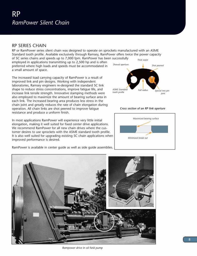
RP SERIES CHAINRP or RamPower series silent chain was designed to operate on sprockets manufactured with an ASMEStandard tooth profile. Available exclusively through Ramsey, RamPower offers twice the power capacityof SC series chains and speeds up to 7,000 fpm. RamPower has been successfullyemployed in applications transmitting up to 2,500 hp and is oftenpreferred where high loads and speeds must be accommodated ina small amount of space.
The increased load carrying capacity of RamPower is a result ofimproved link and pin designs. Working with independent laboratories, Ramsey engineers re-designed the standard SC linkshape to reduce stress concentrations, improve fatigue life, andincrease link tensile strength. Innovative stamping methods werealso employed to maximize the amount of bearing surface area ineach link. The increased bearing area produces less stress in thechain joint and greatly reduces the rate of chain elongation duringoperation. All chain links are shot peened to improve fatigueresistance and produce a uniform finish.
In most applications RamPower will experience very little initial elongation, making it well suited for fixed center drive applications.We recommend RamPower for all new chain drives where the cus-tomer desires to use sprockets with the ASME standard tooth profile. It is also well suited for upgrading existing SC chain applications whenimproved performance is desired.
RamPower is available in center guide as well as side guide assemblies.
8
Thick waist
Shot peened
Full radius
Shaved aperture
Special two pin joint
ASME Standardtooth profile
Rampower drive in oil field pump
Cross section of an RP link aperture
Minimized break out
Maximized bearing surface

RPCenter Guide Assemblies
RP Center Guide Assemblies
Width Width Width Over Over At Breaking Pitch Part Nominal Guide Heads Links Connector Weight Load h d t Number Width Type WH WL WC (Lbs/ft) (Lbf) RP302 1/2 CG 0.64 0.53 0.69 0.5 3,750 RP303 3/4 CG 0.89 0.77 0.94 0.7 5,625 RP304 1 CG 1.14 1.01 1.20 0.9 7,500 RP305 1 1/4 CG 1.39 1.25 1.45 1.1 9,375 3/8" RP306 1 1/2 CG 1.64 1.48 1.70 1.4 11,250 0.42 0.22 0.06 RP308 2 CG 2.14 1.96 2.20 1.7 15,000 RP310 2 1/2 CG 2.64 2.44 2.71 2.2 18,750 RP312 3 2CG 3.12 2.91 3.21 2.5 22,500 RP316 4 2CG 4.12 3.86 4.22 3.4 30,000 RP403 3/4 CG 0.94 0.78 1.00 0.8 7,500 RP404 1 CG 1.18 1.02 1.27 1.1 10,000 RP405 1 1/4 CG 1.43 1.27 1.50 1.4 12,500 RP406 1 1/2 CG 1.68 1.51 1.75 1.6 15,000 RP408 2 CG 2.18 1.99 2.25 2.2 20,000 1/2" RP410 2 1/2 CG 2.68 2.48 2.76 2.7 25,000 0.56 0.30 0.06 RP412 3 CG 3.22 2.96 3.26 3.3 30,000 RP414 3 1/2 CG 3.69 3.45 3.76 3.8 35,000 RP416 4 2CG 4.19 3.93 4.26 4.4 40,000 RP420 5 2CG 5.20 4.90 5.27 5.5 50,000 RP424 6 2CG 6.16 5.86 6.25 6.5 60,000 RP504 1 CG 1.32 1.01 1.40 1.8 12,500 RP506 1 1/2 CG 1.82 1.48 1.90 2.3 18,750 RP508 2 CG 2.30 1.95 2.38 3.0 25,000 RP510 2 1/2 CG 2.76 2.42 2.84 3.1 31,250 5/8" RP512 3 CG 3.25 2.88 3.33 4.8 37,500 0.70 0.37 0.08 RP514 3 1/2 CG 3.73 3.35 3.81 5.3 43,750 RP516 4 CG 4.22 3.82 4.30 6.0 50,000 RP520 5 2CG 5.18 4.75 5.26 7.6 62,500 RP524 6 2CG 6.18 5.69 6.26 9.0 75,000
h
Pitch
d
WHWLWC
t
WC WL WH
h
Pitch
d
Other chain widths are availableUnless indicated, all dimensions are in inches
3/8” and 1/2” Pitch 5/8” through 2” Pitch
t
9

RP Center Guide Assemblies
Width Width Width Over Over At Breaking Pitch Part Nominal Guide Heads Links Connector Weight Load h d t Number Width Type WH WL WC (Lbs/ft) (Lbf) RP604 1 CG 1.32 1.01 1.40 1.8 15,000 RP606 1 1/2 CG 1.82 1.48 1.90 2.6 22,500 RP608 2 CG 2.30 1.95 2.38 3.5 30,000 RP610 2 1/2 CG 2.80 2.42 2.88 4.4 37,500 RP611 2 3/4 CG 2.96 2.57 3.04 4.8 41,250 3/4" RP612 3 CG 3.21 2.88 3.29 5.3 45,000 0.84 0.43 0.08 RP616 4 CG 4.21 3.82 4.29 7.0 60,000 RP620 5 CG 5.18 4.75 5.26 8.8 75,000 RP624 6 CG 6.26 5.69 6.34 10.5 90,000 RP628 7 2CG 7.26 6.63 7.34 12.3 105,000 RP632 8 2CG 8.15 7.56 8.23 14.0 120,000 RP808 2 CG 2.26 1.79 2.37 4.2 40,000 RP812 3 CG 3.19 2.73 3.35 6.3 60,000 RP816 4 CG 4.23 3.66 4.34 8.4 80,000 RP820 5 CG 5.18 4.60 5.29 10.5 100,000 1" RP824 6 CG 6.14 5.85 6.29 12.6 120,000 1.12 0.60 0.12 RP828 7 2CG 7.43 6.70 7.54 14.7 140,000 RP832 8 2CG 8.41 7.72 8.52 16.8 160,000 RP836 9 2CG 9.24 8.58 9.35 18.9 180,000 RP840 10 2CG 10.38 9.51 10.49 21.0 200,000 RP848 12 2CG 12.44 11.54 12.56 25.2 240,000 RP1212 3 CG 3.32 2.87 3.32 9.4 90,000 RP1216 4 CG 4.28 3.87 4.28 12.3 120,000 RP1220 5 CG 5.18 4.77 5.18 15.4 150,000 1-1/2" RP1224 6 CG 6.28 5.87 6.28 18.5 180,000 1.68 0.90 0.12 RP1228 7 CG 7.28 6.89 7.28 21.5 210,000 RP1232 8 2CG 8.29 7.90 8.29 24.6 240,000 RP1236 9 2CG 9.32 8.92 9.32 26.3 270,000 RP1240 10 2CG 10.42 10.00 10.42 30.8 300,000 RP1616 4 CG 4.34 3.67 4.34 16.4 160,000 RP1620 5 CG 5.34 4.62 5.34 20.5 200,000 RP1624 6 CG 6.34 5.56 6.34 24.6 240,000 2" RP1628 7 CG 7.34 6.51 7.34 28.7 280,000 RP1632 8 2CG 8.34 7.46 8.34 32.8 320,000 2.25 1.20 0.12 RP1640 10 2CG 10.34 9.36 10.34 41.0 400,000 RP1648 12 2CG 12.34 11.25 12.34 49.2 480,000 RP1656 14 2CG 14.59 13.39 14.59 57.4 560,000 RP1664 16 2CG 16.59 15.04 16.59 65.6 640,000
Other chain widths are availableUnless indicated, all dimensions are in inches
10

SCIndustry Standard Silent Chain
SC SERIESSC series chain is available in center guide and side guide assemblies. Center guide assemblies are fully compliant withthe ASME Standard for silent chain. Both side guide and center guide operate on industry standard sprockets.
SC chain can accommodate speeds approaching 6500 fpm and loads in excess of 1000 hp. Utilizing the patentedRamsey roller bearing joint, SC chain is Ramsey's most popular industrial chain.
We recommend SC chain primarily as a replacement chain for existing power transmission applications where it hasbeen successfully employed in the past. SC chain weighs less than an equal width of RPV or RP chain, and it typically costs less.
SC Center Guide Assemblies
Width Width Width Over Over At Breaking Pitch Part Nominal Guide Heads Links Connector Weight Load h d t Number Width Type WH WL WC (lbs/ft) (lbf) SC302 1/2 SG 0.52 0.41 0.57 0.4 1,970 SC303 3/4 CG 0.77 0.65 0.82 0.5 2,950 SC304 1 CG 1.02 0.89 1.08 0.7 3,940 SC305 1 1/4 CG 1.27 1.13 1.33 0.9 4,920 3/8" SC306 1 1/2 CG 1.52 1.36 1.58 1.1 5,910 0.37 0.18 0.06 SC308 2 CG 2.02 1.84 2.08 1.4 7,880 SC310 2 1/2 CG 2.52 2.32 2.59 1.8 9,840 SC312 3 2CG 3.00 2.79 3.09 2.1 11,810 SC316 4 2CG 4.00 3.74 4.10 2.8 15,750 SC402 1/2 SG 0.55 0.42 0.63 0.5 2,620 SC403 3/4 CG 0.81 0.66 0.88 0.7 3,940 SC404 1 CG 1.06 0.9 1.13 0.9 5,250 SC405 1 1/4 CG 1.31 1.14 1.38 1.1 6,560 SC406 1 1/2 CG 1.56 1.39 1.63 1.4 7,870 SC408 2 CG 2.06 1.87 2.13 1.8 10,500 1/2" SC410 2 1/2 CG 2.56 2.35 2.63 2.3 13,120 0.47 0.21 0.06 SC412 3 CG 3.07 2.84 3.14 2.7 15,750 SC414 3 1/2 CG 3.57 3.32 3.64 3.2 18,370 SC416 4 2CG 4.07 3.81 4.14 3.6 21,000 SC420 5 2CG 5.08 4.77 5.15 4.5 26,250 SC424 6 2CG 6.09 5.74 6.16 5.4 31,500 SC428 7 2CG 7.09 6.71 7.16 6.3 36,750
Other chain widths are availableUnless indicated, all dimensions are in inches
11
hd
Pitch
WHWC
t
WL
WHWL
t
WC
One Center Guide
Two Center Guide

SC Center Guide Assemblies
Width Width Width Over Over At Breaking Pitch Part Nominal Guide Heads Links Connector Weight Load h d t Number Width Type WH WL WC (lbs/ft) (lbf) SC504 1 CG 1.21 1.01 1.28 1.2 6,250 SC506 1 1/2 CG 1.54 1.33 1.61 1.8 9,370 SC508 2 CG 2.03 1.79 2.10 2.4 12,500 SC510 2 1/2 CG 2.53 2.26 2.60 3.0 15,620 5/8" SC512 3 CG 3.02 2.73 3.09 3.6 18,750 0.65 0.33 0.08 SC516 4 CG 4.01 3.67 4.08 4.8 25,000 SC520 5 2CG 5.00 4.60 5.07 6.0 31,250 SC524 6 2CG 5.99 5.54 6.06 7.2 37,500 SC532 8 2CG 8.14 7.56 8.21 9.6 50,000 SC604 1 CG 1.22 1.01 1.35 1.5 7,870 SC606 1 1/2 CG 1.57 1.33 1.68 2.3 11,810 SC608 2 CG 2.05 1.79 2.18 3.0 15,750 SC610 2 1/2 CG 2.54 2.26 2.67 3.8 19,690 3/4" SC612 3 CG 3.04 2.73 3.17 4.5 23,620 0.80 0.41 0.08 SC616 4 CG 4.03 3.66 4.16 6.0 31,500 SC620 5 CG 5.02 4.60 5.15 7.5 39,370 SC624 6 CG 6.01 5.54 6.14 9.0 47,250 SC628 7 2CG 7.16 6.63 7.29 10.5 55,120 SC632 8 2CG 8.15 7.56 8.28 12.0 63,000 SC808 2 CG 2.06 1.78 2.17 3.6 21,000 SC812 3 CG 3.05 2.72 3.17 5.4 31,500 SC816 4 CG 4.04 3.67 4.16 7.2 42,000 SC820 5 CG 5.03 4.62 5.15 9.0 52,500 1" SC824 6 CG 6.05 5.56 6.16 10.8 63,000 0.98 0.48 0.12 SC828 7 2CG 7.04 6.51 7.16 12.6 73,500 SC832 8 2CG 8.04 7.46 8.16 14.4 84,000 SC836 9 2CG 9.03 8.41 9.15 16.2 94,500 SC840 10 2CG 10.03 9.36 10.15 18.0 105,000 SC848 12 2CG 12.02 11.25 12.14 21.6 126,000 SC1212 3 CG 3.34 2.72 3.34 9 47,250 SC1216 4 CG 4.34 3.67 4.34 12 63,000 SC1220 5 CG 5.34 4.62 5.34 15 78,750 SC1224 6 CG 6.34 5.56 6.34 18 94,500 SC1228 7 CG 7.34 6.51 7.34 21 110,250 1-1/2" SC1232 8 2CG 8.34 7.46 8.34 24 126,000 1.50 0.71 0.12 SC1236 9 2CG 9.34 8.41 9.34 27 141,750 SC1240 10 2CG 10.34 9.36 10.34 30 157,500 SC1248 12 2CG 12.34 11.25 12.34 36 189,000 SC1256 14 2CG 14.59 13.39 14.59 42 220,500 SC1264 16 2CG 16.59 15.28 15.28 48 252,000
Other chain widths are availableUnless indicated, all dimensions are in inches
12

SCSide Guide Assemblies
Other chain widths are availableUnless indicated, all dimensions are in inches
SC Side Guide Assemblies
Width Width Width Width Between Over Over At Breaking Pitch Part Nominal Guides Heads Links Connector Weight Load h d t Number Width WBG WH WL WC (lbs/ft) (lbf) DSG302 1/2 1/4 0.58 0.48 0.63 0.4 1,970 DSG303 3/4 1/2 0.84 0.71 0.89 0.6 2,950 3/8" DSG304 1 3/4 1.09 0.95 1.15 0.8 3,940 DSG305 1 1/4 1 1.34 1.19 1.40 0.9 4,920 DSG306 1 1/2 1 1/4 1.59 1.43 1.65 1.1 5,910 0.37 0.18 0.06 DSG308 2 1 3/4 2.09 1.90 2.15 1.7 7,880 DSG310 2 1/2 2 1/4 2.58 2.38 2.65 1.9 9,840 DSG312 3 2 3/4 3.09 2.86 3.16 2.2 11,810 DSG316 4 3 3/4 4.10 3.81 4.16 3.3 15,750 DSG402 1/2 1/4 0.62 0.48 0.68 0.5 2,620 DSG403 3/4 1/2 0.87 0.73 0.94 0.8 3,940 DSG404 1 3/4 1.12 0.97 1.19 1.0 5,250 DSG405 1 1/4 1 1.38 1.21 1.45 1.2 6,560 1/2" DSG406 1 1/2 1 1/4 1.63 1.45 1.70 1.5 7,870 0.47 0.21 0.06 DSG408 2 1 3/4 2.12 1.94 2.19 2.0 10,500 DSG410 2 1/2 2 1/4 2.63 2.42 2.69 2.5 13,120 DSG412 3 2 3/4 3.13 2.90 3.20 2.9 15,750 DSG416 4 3 3/4 4.14 3.63 4.21 3.9 21,000 DSG504 1 3/4 1.21 1.01 1.28 1.2 6,560 DSG506 1 1/2 1 1/4 1.70 1.48 1.77 1.8 9,840 DSG508 2 1 3/4 2.28 2.03 2.35 2.5 13,130 5/8" DSG510 2 1/2 2 1/4 2.77 2.50 2.84 3.1 16,410 0.65 0.33 0.08 DSG512 3 2 3/4 3.27 2.96 3.34 3.7 19,690 DSG514 3 1/2 3 1/4 3.76 3.43 3.83 4.3 22,970 DSG516 4 3 3/4 4.34 3.98 4.41 4.9 26,250 DSG520 5 4 3/4 5.33 4.91 5.40 6.1 32,810 DSG606 1 1/2 1 1.55 1.33 1.68 2.2 11,810 DSG608 2 1 1/2 2.05 1.79 2.18 2.9 15,750 DSG610 2 1/2 2 2.54 2.26 2.67 3.7 19,690 DSG612 3 2 1/2 3.04 2.73 3.17 4.4 23,620 3/4" DSG614 3 1/2 3 3.53 3.20 3.66 5.1 27,560 0.80 0.41 0.08 DSG616 4 3 1/2 4.03 3.67 4.16 5.9 31,500 DSG620 5 4 1/2 5.02 4.60 5.15 7.4 39,370 DSG624 6 5 1/2 6.01 5.54 6.14 8.8 47,250 DSG628 7 6 1/2 7.16 6.63 7.29 10.3 55,120
13
h
Pitch
d WHWLWBGWC
t

SC 3/16” PITCH CHAINRamsey 3/16" pitch chain is manufactured to ASME standards and will operate on standard sprockets. Chains aremade entirely of 304 stainless steel and are available in side guide or center guide assemblies, depending on chainwidth.
SC Side Guide Assemblies
Width Width Width Width Between Over Over At Breaking Pitch Part Nominal Guides Heads Links Connector Weight Load h d t Number Width WBG WH WL WC (lbs/ft (lbf) DSG808 2 1 1/2 2.18 1.90 2.30 3.9 21,000 DSG810 2 1/2 2 2.68 2.37 2.79 4.8 26,250 DSG812 3 2 1/2 3.17 2.84 3.29 5.9 31,500 1” DSG816 4 3 1/2 4.29 3.91 4.41 7.8 42,000 0.98 0.48 0.12 DSG820 5 4 1/2 5.28 4.86 5.40 9.8 52,500 DSG824 6 5 1/2 6.30 5.81 6.41 11.7 63,000 DSG828 7 6 1/2 7.42 6.87 7.53 13.7 73,500 DSG832 8 7 1/2 8.41 7.82 8.53 15.7 84,000
SC 3/16” Pitch Chain
Width Width Width Width Between Over Over At Pitch Part Nominal Guide Guides Heads Links Connector Weight h d t Number Width Type WBG WH WL WC (oz/ft) SC0305 5/32 SG 3/32 0.22 0.16 0.22 1.2 SC0307 7/32 SG 5/32 0.27 0.22 0.27 1.6 SC0309 9/32 SG 7/32 0.34 0.28 0.34 1.9 SC0311 11/32 SG 9/32 0.40 0.35 0.40 2.4 SC0315 15/32 SG 13/32 0.53 0.48 0.53 3.2 3/16" SC0315A 15/32 CG 0.53 0.48 0.53 3.2 0.20 0.10 0.03 SC0319 19/32 CG 0.65 0.61 0.65 4.3 SC0319A 19/32 SG 17/32 0.65 0.61 0.65 4.3 SC0325 25/32 CG 0.86 0.81 0.86 5.4 SC0325A 25/32 SG 23/32 0.86 0.81 0.86 5.4 SC0331 31/32 CG 1.03 0.98 1.03 6.7
14
Pitch
dh
Pitch
hd
WHWLWBGt
WCWHWLt
WC
Center Guide Side Guide

Ramsey offers a full range of stock and made to ordersprockets. Because they are produced in larger quantities, stock sprockets are often the most economical choice. Made to order sprockets provide awider range of drive ratio options and are a large partof our daily production.
All sprockets can be fully machined to your specifications or you can request they be supplied withan unfinished bore to allow secondary machining.Ramsey also supplies sprockets to replace most competitors' products. We welcome all inquiries.
MaterialsRPV, RP and SC sprockets are typically made from carbon steel or ductile iron, with sprocket teeth hardened to Rockwell hardness of Rc 50. For RP and SConly, some sprocket sizes are available in class 30 grayiron with unhardened teeth. Other materials are available subject to customer preference, sprocket size,cost, and availability.
Performance GuidelinesIn general, larger sprocket diameters will provide forsmoother operation, less vibration, and longer life. Werecommend using sprockets with at least 21 teethwhenever possible. Also, to assure proper meshing ofsprockets and chain we recommend they be purchasedfrom the same source.
Guide TypeSimilar to chains, sprockets can be grouped into twobroad categories: center guide and side guide.
Center Guide A groove machined in the centerof the sprocket face accepts the chain's centerguide link. Two grooves are machined for two centerguide.
Side Guide The sprocket fits between the chain's sideguide plates.
Sprockets
15
Pitch 3/16” 3/8” 1/2” 5/8” 3/4” 1” 1-1/2” 2” GW 0.050 0.125 0.125 0.156 0.156 0.250 0.250 0.250 S* 1.0 1.0 2.0 4.0 4.0 4.0 4.0
Sprocket Face Profiles
One Center Guide Two Center Guide
Center Guide Groove Width and Guide Spacing
Table values in inches*Only applies to sprockets for two center guide chains
Side Guide
Wmax = WBG - X
WBG = Chain width between guides (See Chain data tables)
Table values in inchesConsult Ramsey for RPV Sprocket Dimensions
Pitch 3/16” 3/8” 1/2” 5/8” 3/4” 1” 1-1/2” X 0.020 0.060 0.060 0.060 0.060 0.125 0.125 R 0.030 0.190 0.250 0.310 0.375 0.500 0.750
Sprocket Width and Chamfer Data for RP and SC Sprockets
F
S
GW
F
15˚
4mm
GW
F15°
GW
W
1.6mmR6.3mm
W
R
F = Face Width, the same as the nominal chain width

19 RPV304-19 2.278 2.138 0.50 1.16 1.63 1.63 1.1 21 RPV304-21 2.516 2.381 0.50 1.28 1.88 1.63 1.4 23 RPV304-23 2.754 2.624 0.50 1.38 2.13 1.63 1.8 25 RPV304-25 2.992 2.866 0.75 1.63 2.38 1.63 2.1 27 RPV304-27 3.230 3.111 0.75 1.75 2.63 1.63 2.6 29 RPV304-29 3.468 3.353 0.75 1.81 2.81 1.63 3.1 31 RPV304-31 3.707 3.594 0.75 2.13 3.06 1.63 3.6 38 RPV304-38 4.541 4.435 0.75 2.88 3.94 1.63 5.8 42 RPV304-42 5.018 4.915 0.75 3.31 4.41 1.63 7.4 57 RPV304-57 6.807 6.712 1.25 4.50 6.00 1.63 13.7 76 RPV304-76 9.074 8.984 1.25 4.50 6.00 1.63 20.6
16
Hub Types
Type A Type B Type C Type D
1” Nominal Face Width-Type B Hub Actual Face Width = 0.90”
Number Part Pitch Outside Minimum Maximum Hub Length Approximate of Teeth Number Diameter Diameter Plain Bore Bore Diameter Thru Bore Weight (lb) 19 RPV303-19 2.278 2.138 0.50 1.16 1.63 1.41 0.9 21 RPV303-21 2.516 2.381 0.50 1.28 1.88 1.41 1.2 23 RPV303-23 2.754 2.624 0.50 1.38 2.13 1.41 1.5 25 RPV303-25 2.992 2.866 0.75 1.63 2.38 1.41 1.8 27 RPV303-27 3.230 3.111 0.75 1.75 2.63 1.41 2.2 29 RPV303-29 3.468 3.353 0.75 1.81 2.81 1.41 2.6 31 RPV303-31 3.707 3.594 0.75 2.13 3.06 1.41 3.1 38 RPV303-38 4.541 4.435 0.75 2.88 3.94 1.41 5.0 42 RPV303-42 5.018 4.915 0.75 3.31 4.41 1.41 6.3 57 RPV303-57 6.807 6.712 1.25 4.50 6.00 1.41 11.7 76 RPV303-76 9.074 8.984 1.25 4.50 6.00 1.41 16.7
3/4” Nominal Face Width-Type B Hub Actual Face Width = 0.66”
RPV Stock Sprockets
3/8” pitch
F
LTB
OD HDB
BushingF
OD BOD B
LTB & F F HP
HD
LTB L
B
LTB
HDB
F HP HPF
HD OD
LTB
B
LTB
ODHD B
F HP
F = Nominal Chain Width HD = Hub DiameterB = Bore LTB = Length Through the BoreOD = Outside Diameter HP = Hub Projection
Unless indicated, all dimensions in inches

17
RPV Stock Sprockets
Number Part Pitch Outside Minimum Maximum Hub Length Approximate of Teeth Number Diameter Diameter Plain Bore Bore Diameter Thru Bore Weight (lb) 19 RPV306-19 2.278 2.138 0.50 1.16 1.63 2.16 1.5 21 RPV306-21 2.516 2.381 0.50 1.28 1.88 2.16 1.9 23 RPV306-23 2.754 2.624 0.50 1.38 2.13 2.16 2.4 25 RPV306-25 2.992 2.866 0.75 1.63 2.38 2.16 2.8 27 RPV306-27 3.230 3.111 0.75 1.75 2.63 2.16 3.4 29 RPV306-29 3.468 3.353 0.75 1.81 2.81 2.16 4.1 31 RPV306-31 3.707 3.594 0.75 2.13 3.06 2.16 4.8 38 RPV306-38 4.541 4.435 0.75 2.88 3.94 2.16 7.8 42 RPV306-42 5.018 4.915 0.75 3.31 4.41 2.16 9.7 57 RPV306-57 6.807 6.712 1.25 4.50 6.00 2.16 18.2 76 RPV306-76 9.074 8.984 1.25 4.50 6.00 2.16 28.9
3/8” pitch1 1/2” Nominal Face Width-Type B Hub Actual Face Width = 1.40”
1” Nominal Face Width-Type B Hub Actual Face Width = 0.90” Number Part Pitch Outside Minimum Maximum Hub Length Approximate of Teeth Number Diameter Diameter Plain Bore Bore Diameter Thru Bore Weight (lb) 19 RPV404-19 3.038 2.851 0.50 1.44 2.22 2.00 2.5 21 RPV404-21 3.355 3.175 0.50 1.69 2.50 2.00 3.3 23 RPV404-23 3.672 3.498 0.75 1.81 2.88 2.00 4.0 25 RPV404-25 3.989 3.821 0.75 2.13 3.19 2.00 4.9 27 RPV404-27 4.307 4.149 0.75 2.38 3.50 2.00 5.9 29 RPV404-29 4.625 4.47 0.75 2.56 3.81 2.00 7.0 31 RPV404-31 4.942 4.792 0.75 2.75 4.16 2.50 10.1 38 RPV404-38 6.055 5.913 0.75 3.75 5.28 2.50 16.1 42 RPV404-42 6.691 6.553 0.75 4.38 5.94 2.50 20.2 57 RPV404-57 9.076 8.949 1.25 4.50 6.00 2.50 27.1 76 RPV404-76 12.099 11.978 1.00 2.50 3.63 2.00 31.1
1/2” pitch
Unless indicated, all dimensions in inches

Number Part Pitch Outside Minimum Maximum Hub Length Approximate of Teeth Number Diameter Diameter Plain Bore Bore Diameter Thru Bore Weight (lb) 19 RPV406-19 3.038 2.851 0.50 1.44 2.22 2.50 3.3 21 RPV406-21 3.355 3.175 0.50 1.69 2.50 2.50 4.3 23 RPV406-23 3.672 3.498 0.75 1.81 2.88 2.50 5.1 25 RPV406-25 3.989 3.821 0.75 2.13 3.19 2.50 6.3 27 RPV406-27 4.307 4.149 0.75 2.38 3.50 2.50 7.6 29 RPV406-29 4.625 4.47 0.75 2.56 3.81 2.50 9.0 31 RPV406-31 4.942 4.792 0.75 2.75 4.16 3.00 12.3 38 RPV406-38 6.055 5.913 0.75 3.75 5.28 3.00 19.7 42 RPV406-42 6.691 6.553 0.75 4.38 5.94 3.00 24.6 57 RPV406-57 9.076 8.949 1.25 4.50 6.00 3.00 35.4 76 RPV406-76 12.099 11.978 1.00 2.50 3.63 2.50 46.1
18
1/2” pitch1 1/2” Nominal Face Width-Type B Hub Actual Face Width = 1.40”
19 RPV408-19 3.038 2.851 0.50 1.44 2.22 3.00 4.1 21 RPV408-21 3.355 3.175 0.50 1.69 2.50 3.00 5.2 23 RPV408-23 3.672 3.498 0.75 1.81 2.88 3.00 6.3 25 RPV408-25 3.989 3.821 0.75 2.13 3.19 3.00 7.7 27 RPV408-27 4.307 4.149 0.75 2.38 3.50 3.00 9.2 29 RPV408-29 4.625 4.47 0.75 2.56 3.81 3.00 10.9 31 RPV408-31 4.942 4.792 0.75 2.75 4.16 3.00 12.7 38 RPV408-38 6.055 5.913 0.75 3.75 5.28 3.00 20.1 42 RPV408-42 6.691 6.553 0.75 4.38 5.94 3.00 25.1 57 RPV408-57 9.076 8.949 1.25 4.50 6.00 3.50 43.6 76 RPV408-76 12.099 11.978 1.00 2.50 3.63 3.00 60.7
2” Nominal Face Width-Type B Hub Actual Face Width = 1.90”
3” Nominal Face Width-Type B Hub Actual Face Width = 2.90”
19 RPV412-19 3.038 2.851 0.50 1.44 2.22 4.00 5.3 21 RPV412-21 3.355 3.175 0.50 1.69 2.50 4.00 6.9 23 RPV412-23 3.672 3.498 0.75 1.81 2.88 4.00 8.6 25 RPV412-25 3.989 3.821 0.75 2.13 3.19 4.00 10.5 27 RPV412-27 4.307 4.149 0.75 2.38 3.50 4.00 12.6 29 RPV412-29 4.625 4.47 0.75 2.56 3.81 4.00 14.7 31 RPV412-31 4.942 4.792 0.75 2.75 4.16 4.00 17.3 38 RPV412-38 6.055 5.913 0.75 3.75 5.28 4.00 27.2 42 RPV412-42 6.691 6.553 0.75 4.38 5.94 4.00 33.9 57 RPV412-57 9.076 8.949 1.25 4.50 6.00 4.50 60.2 76 RPV412-76 12.099 11.978 1.00 2.50 3.63 4.00 83.2
RPV Stock Sprockets
Unless indicated, all dimensions in inches

19
RP and SC Stock Sprockets
F = Nominal Chain Width HD = Hub DiameterB = Bore LTB = Length Through the BoreOD = Outside Diameter HP = Hub Projection
Number Part Pitch Outside Hub Minimum Maximum Hub Length Approx Material of Teeth Number Diameter Diameter Type Plain Bore Bore Diameter Thru Bore Weight(lb) 17 SC304-17 2.041 1.987 B 0.50 0.88 1.44 1.75 0.9 Steel 19 SC304-19 2.278 2.23 B 0.50 1.25 1.63 1.75 1.2 Steel 21 SC304-21 2.516 2.473 B 0.50 1.31 1.88 1.75 1.6 Steel 23 SC304-23 2.935 2.716 B 0.50 1.50 2.13 1.75 2.0 Steel 25 SC304-25 2.992 2.959 B 0.50 1.75 2.38 1.75 2.5 Steel
3/8” pitch
1” Nominal Face Width
1/2” pitch1” Nominal Face Width
Unless indicated, all dimensions in inches
Type A Type B Type C Type D
F
LTB
OD HDB
BushingF
OD BOD B
LTB & F F HP
HD
LTB L
B
LTB
HDB
F HP HPF
HD OD
LTB
B
LTB
ODHD B
F HP
Number Part Pitch Outside Hub Minimum Maximum Hub Length Approx Material of Teeth Number Diameter Diameter Type Plain Bore Bore Diameter Thru Bore Weight(lb) 17 404-17 2.721 2.649 B 0.75 1.38 1.88 1.75 1.5 Steel 19 404-19 3.038 2.973 B 0.75 1.63 2.25 1.75 2.0 Steel 21 404-21 3.355 3.297 B 0.75 1.88 2.56 1.75 2.8 Steel 23 404-23 3.672 3.621 B 0.75 2.13 2.88 1.75 3.5 Steel 25 404-25 3.989 3.945 B 0.75 2.38 3.19 1.75 4.5 Steel 38 404-38 6.055 6.038 B 1.00 2.50 4.00 1.75 8.0 Steel 38 404-38 TLB 6.055 6.038 B 1615 TLB 4.00 1.50 6.0 Steel 57 404-57 9.076 9.077 C 1.00 2.50 4.00 2.00 19.0 Steel 57 404-57 TLB 9.076 9.077 D 1615 TLB 4.00 1.50 16.0 Steel 76 404-76 12.099 12.108 C 1.00 2.50 4.00 1.50 29.5 Cast Iron 76 404-76 TLB 12.099 12.108 D 1615 TLB 4.00 2.00 32.0 Steel 95 404-95 15.122 15.135 C 1.13 3.00 5.00 2.00 52.5 Cast Iron 95 404-95 TLB 15.122 15.135 D 2517 TLB 5.00 1.75 40.0 Cast Iron 114 404-114 18.146 18.162 C 1.13 3.00 5.00 2.00 33.0 Cast Iron 114 404-114 TLB 18.146 18.162 D 2517 TLB 5.00 1.75 28.5 Cast Iron

1/2” pitch2” Nominal Face Width
Number Part Pitch Outside Hub Minimum Maximum Hub Length Approx Materialof Teeth Number Diameter Diameter Type Plain Bore Bore Diameter Thru Bore Weight(lb) 17 408-17 2.721 2.649 B 0.88 1.38 1.88 2.75 2.5 Steel 19 408-19 3.038 2.973 B 0.88 1.63 2.25 2.75 3.5 Steel 21 408-21 3.355 3.297 B 0.88 1.88 2.56 2.75 4.5 Steel 23 408-23 3.672 3.621 B 0.88 2.13 2.88 2.75 5.5 Steel 25 408-25 3.989 3.945 B 0.88 2.38 3.19 2.75 7.0 Steel 38 408-38 6.055 6.038 B 1.00 2.50 4.00 2.75 16.0 Steel 38 408-38 TLB 6.055 6.038 D 1615 TLB 1.50 9.0 Steel 57 408-57 9.076 9.077 C 1.00 2.50 5.00 3.00 38.0 Steel 57 408-57 TLB 9.076 9.077 D 2517 TLB 1.75 25.0 Steel 76 408-76 12.099 12.108 C 1.25 2.50 5.00 3.00 41.0 Cast Iron 76 408-76 TLB 12.099 12.108 D 2517 TLB 5.75 2.50 36.0 Cast Iron 95 408-95 15.122 15.135 C 1.25 3.00 5.00 3.00 41.5 Cast Iron 95 408-95 TLB 15.122 15.135 D 2525 TLB 5.00 2.50 36.0 Cast Iron 114 408-114 18.146 18.162 C 1.25 3.00 5.00 3.00 47.0 Cast Iron 114 408-114 TLB 18.146 18.162 D 2525 TLB 5.00 2.50 40.0 Cast Iron
3” Nominal Face Width
3/4” pitch3” Nominal Face Width
17 412-17 2.721 2.649 B 1.00 1.38 1.88 3.75 3.0 Steel 19 412-19 3.038 2.973 B 1.00 1.63 2.25 3.75 4.0 Steel 21 412-21 3.355 3.297 B 1.00 1.88 2.56 3.75 5.5 Steel 23 412-23 3.672 3.621 B 1.00 2.13 2.88 3.75 7.0 Steel 25 412-25 3.989 3.945 B 1.00 2.38 3.19 3.75 9.0 Steel 38 412-38 6.055 6.038 B 1.00 2.50 4.00 3.75 22.0 Steel 38 412-38 TLB 6.055 6.038 D 2517 TLB 1.75 10.0 Steel 57 412-57 9.076 9.077 C 1.25 2.50 4.50 4.00 53.0 Steel 57 412-57 TLB 9.076 9.077 D 2525 TLB 2.50 37.0 Steel 76 412-76 12.099 12.108 C 1.25 2.50 4.50 4.00 36.5 Cast Iron 76 412-76 TLB 12.099 12.108 D 2525 TLB 4.50 2.50 27.5 Cast Iron 95 412-95 15.122 15.135 C 1.38 3.00 6.00 4.00 74.0 Cast Iron 95 412-95 TLB 15.122 15.135 D 2525 TLB 6.00 2.50 47.5 Cast Iron 114 412-114 18.146 18.162 C 1.38 3.00 6.00 4.00 68.5 Cast Iron 114 412-114 TLB 18.146 18.162 D 3030 TLB 6.00 3.00 53.5 Cast Iron
Number Part Pitch Outside Hub Minimum Maximum Hub Length Approx Materialof Teeth Number Diameter Diameter Type Plain Bore Bore Diameter Thru Bore Weight(lb) 17 612-17 4.082 3.974 B 1.25 2.06 2.88 3.75 8.0 Steel 19 612-19 4.557 4.46 B 1.25 2.38 3.38 3.75 11.0 Steel 21 612-21 5.032 4.946 B 1.25 2.75 3.88 3.75 14.0 Steel 23 612-23 5.508 5.432 B 1.38 3.25 4.38 3.75 18.0 Steel 25 612-25 5.984 5.918 B 1.38 3.63 4.81 3.75 22.0 Steel 38 612-38 9.082 9.058 C 1.38 3.00 4.50 4.00 50.0 Steel 38 612-38 TLB 9.082 9.058 D 2525 TLB 6.00 2.50 36.0 Steel 57 612-57 13.615 13.616 C 1.38 3.50 6.00 4.00 58.0 Cast Iron 57 612-57 TLB 13.615 13.616 D 3030 TLB 6.00 3.00 41.0 Cast Iron 76 612-76 18.149 18.162 C 1.38 3.50 6.00 4.00 65.5 Cast Iron 76 612-76 TLB 18.149 18.162 D 3030 TLB 6.00 3.00 52.0 Cast Iron 95 612-95 22.684 22.703 C 1.50 4.50 7.75 4.00 100.0 Cast Iron 95 612-95 TLB 22.684 22.703 D 3535 TLB 7.75 3.50 96.0 Cast Iron 114 612-114 27.219 27.243 C 1.50 4.50 7.75 4.00 131.5 Cast Iron 114 612-114 TLB 27.219 27.243 D 3535 TLB 7.75 3.50 121.5 Cast Iron
RP and SC Stock Sprockets
20
Unless indicated, all dimensions in inches

21
Sprocket Diameters
CALCULATING OUTSIDE DIAMETERSIn the tables below, locate the diameter factor that corresponds to the number of teeth in your sprock-et. Multiply this factor by the sprocket pitch (in inches) to obtain the outside diameter in inches.
18 5.623 19 5.947 20 6.271 21 6.595 22 6.919 23 7.243 24 7.568 25 7.890 26 8.213 27 8.536 28 8.859 29 9.181 30 9.504 31 9.828 32 10.150 33 10.471 34 10.793 35 11.115 36 11.437 37 11.757 38 12.149
39 12.397 40 12.717 41 13.037 42 13.357 43 13.677 44 13.997 45 14.317 46 14.637 47 14.957 48 15.227 49 15.597 50 15.917 51 16.236 52 16.556 53 16.876 54 17.196 55 17.515 56 17.834 57 18.154 58 18.473 59 18.793
60 19.112 61 19.431 62 19.750 63 20.070 64 20.388 65 20.708 66 21.027 67 21.346 68 21.665 69 21.984 70 22.303 71 22.622 72 22.941 73 23.259 74 23.578 75 23.897 76 24.216 77 24.535 78 24.853 79 25.172 80 25.491
81 25.809 82 26.128 83 26.447 84 26.766 85 27.084 86 27.403 87 27.722 88 28.040 89 28.359 90 28.678 91 28.997 92 29.315 93 29.634 94 29.953 95 30.271 96 30.590 97 30.909 98 31.228 99 31.546 100 31.865
Number Diameterof Teeth Factor
Number Diameterof Teeth Factor
Number Diameterof Teeth Factor
Number Diameterof Teeth Factor
RP and SC Sprockets-Outside Diameter Factors
Unless indicated, all dimensions in inches.
RPV Sprockets-Outside Diameter Factors Number Diameter Factor of Teeth Type139 Type 115
Number Diameter Factor of Teeth Type139 Type 115
Number Diameter Factor of Teeth Type139 Type 115
Number Diameter Factor of Teeth Type139 Type 115
18 5.376 5.652 19 5.701 5.977 20 6.027 6.301 21 6.349 6.625 22 6.675 6.948 23 6.997 7.271 24 7.320 7.593 25 7.643 7.916 26 7.976 8.237 27 8.296 8.559 28 8.619 8.880 29 8.941 9.201 30 9.261 9.521 31 9.584 9.843 32 9.904 10.163 33 10.224 10.483 34 10.547 10.803 35 10.867 11.124 36 11.187 11.444 37 11.507 11.763 38 11.827 12.083
39 12.147 12.403 40 12.467 12.723 41 12.787 13.041 42 13.107 13.361 43 13.427 13.681 44 13.747 14.000 45 14.067 14.320 46 14.384 14.639 47 14.704 14.959 48 15.024 15.277 49 15.344 15.596 50 15.664 15.916 51 15.981 16.235 52 16.301 16.553 53 16.621 16.872 54 16.941 17.192 55 17.259 17.511 56 17.579 17.829 57 17.899 18.148 58 18.216 18.467 59 18.536 18.785
60 18.856 19.104 61 19.173 19.424 62 19.493 19.743 63 19.811 20.061 64 20.131 20.380 65 20.451 20.699 66 20.768 21.017 67 21.088 21.336 68 21.405 21.655 69 21.725 21.973 70 22.045 22.292 71 22.363 22.611 72 22.683 22.929 73 23.000 23.248 74 23.320 23.567 75 23.637 23.884 76 23.957 24.203 77 24.275 24.521 78 24.595 24.840 79 24.915 25.159 80 25.232 25.477
81 25.552 25.796 82 25.869 26.115 83 26.189 26.433 84 26.507 26.751 85 26.827 27.069 86 27.144 27.388 87 27.464 27.707 88 27.781 28.025 89 28.101 28.344 90 28.419 28.661 91 28.739 28.980 92 29.056 29.299 93 29.373 29.617 94 29.693 29.936 95 30.011 30.255 96 30.331 30.572 97 30.648 30.891 98 30.968 31.209 99 31.285 31.528 100 31.605 31.847

22
Ordering Information
CHAIN ORDERING INFORMATION
SPROCKET ORDERING INFORMATION
If you know the chain's part number …Simply supply the part number along with the chain length in pitches, feet or meters.
If you have a chain description, but do not know the part number…Please specify the following details.o Product type: For example, RPV, RP, SC or competitors product typeo Pitch: Best determined by measuring across 3 pin heads and dividing the measurement by 2.o Chain width across the links and across the headso Guide typeo Chain length in pitches, feet or meters
If you have an engineering drawing…Simply fax, email, or mail the drawing to Ramsey.
If you are uncertain about what you need...Contact Ramsey. Our experienced sales engineers will be pleased to assist you in identifying a chain for your application.
If you know your sprocket part number…Simply supply the part number along with the following details:o Hub type A, B, C or Do Hub projectiono Bore diametero Keyway sizeo Hub diameter
If you know your chain part number…A compatible sprocket can be identified by the chain part number followed by the number of sprocket teeth.For example a 21 tooth sprocket for a RamPower 1/2" pitch by 1” wide chain can be specified as RP404-21.Also please supply the following machining details:o Hub type A, B, C or Do Hub projectiono Bore diametero Keyway sizeo Hub diameter
If you have an engineering drawing…Simply fax, email, or mail the drawing to Ramsey. After a review of the drawing we will respond to your inquiryand supply a quotation if desired.
If you are uncertain about what you need...Contact Ramsey. Our experienced sales engineers will be pleased to assist you in identifying sprockets for yourapplication.

Sprockets. For long life, sprockets should have a minimum of 21 teeth. For smoother, quieter drives use alarger number of teeth.Drive Ratios. Ratios of 12:1 or greater are possible,but above 8:1 it is usually desirable to make the reduction in two steps.Shaft Center Adjustment. Center adjustment toallow for wear is always desirable. It is particularly impor-tant in vertical center drives. Typically the amount ofadjustment should equal at least 1% of the center dis-tance.Shaft Center Distance. The center distance shouldbe great enough that the chain wraps the small sprocket at least 120 degrees. Center distances shouldgenerally not exceed 60 pitches.
Chain Length. Whenever possible, chain lengthshould be an even number of pitches so an offset section can be avoided.Tensioning Devices. An idler sprocket or shoe canoften be used to maintain tension on fixed center drives.Chain Width. The use of a wider than recommendedchain will result in a more rugged drive and improveddrive life.Drive Enclosures. Fully enclosed drives with proper lubrication are desirable for maximum service lifeand personnel safety.Non-horizontal And Vertical Shafts. Drivesusing non-horizontal shafts often work best with sideguide chain and an automatic tensioner. Consult Ramseyfor specific recommendations.
Engineering Information
DESIGN SUGGESTIONS
DRIVE POSITIONSThe preferred position for a drive is where a line betweenshaft centers is horizontal or inclined not more than 45degrees. Under ordinary conditions the slack strand maybe either on the upper or lower side of the drive.Vertical drives should be avoided if possible. They must be
run fairly taut which means frequent adjustment of centersas the chain elongates due to normal wear. Less care andadjustment will be required if the drive can be positionedslightly off the vertical.
Where the center distance is comparatively short, slack onthe lower strand is preferable. With the slack on the upperstrand there is a tendency for the chain to be forced outof proper engagement with the sprockets.
Drives with long center distances and small sprocketsshould have the slack strand on the bottom. With theslack on top there is danger of the upper strandhitting the lower as the chain elongates.
Acceptable
Avoid
Acceptable
Acceptable
Acceptable
AcceptableAvoid
23Acceptable

Follow These Steps1. Choose a service factor(SF) from the table on page 30
2. Compute the design horsepower(Wd) by multiplying the powerto be transmitted(W) by the service factor.
3. Use the speed of the faster moving shaft(N1) to make a tentativepitch selection(p) from the chart below.
4. Select the number of teeth in the small sprocket(Z1), making surethe sprocket can accommodate the shaft diameter.See maximum sprocket bores in sprocket tables.
5. Use the following equations to calculate the required chainwidth(Cw). If the required chain width is not readily available it may be necessary to go to a wider chain or a larger sprocket.
For RPV and RP .......... Cw = 22.3( Wd ) p.V.R (1- V2(1.34 x 10⁻⁸))
For SC .......................... Cw = 18,000 (Wd) p.V (425 - V/(Z1-8))
Cw= required width (inches), Wd= design power (hp)R= factor from table, p= pitch (inches), V= chain speed (ft/min)
Table of R Values*
6. Select the large sprocket (Z2) by multiplying the number of teethin the small sprocket by the desired shaft speed ratio.Z2 = Z1 x N1/N2
7. Compute the chain length using the table provided on page 25. If the computed length is fractional, round off to the nearest whole number of pitches. An even number of pitches isalways preferable to an odd number of pitches which requires anoffset section. If an offset section is required it will be necessary toincrease the width of the chain by 25% to account for the offsetsreduced tensile strength. Note: offset sections are not available forRPV chain.
8. Compute the new center distance (Cd) for the rounded off chainlength. The following formula provides an approximate center distance. When fixed center drives are used or extremely accurate center distance is required consult Ramsey.
9. Select a method for lubricating the drive.Forced feed lubrication will provide optimum results and is recommended whenever chain speeds exceed 2500 ft/min. Drip orbath type lubrication may be acceptable at lower speeds. Additionalinformation on lubrication is given in the section describing lubrica-tion. Also, if the drive will not operate inside a housing, a chainenclosure is recommended.
DRIVE SELECTION-STEP BY STEPDrive selection consists of choosing the appropriate chain and sprockets for the space, loads, and speeds involved. Often more than one pitch and width will work in a given situation. In such cases one may choose two or three possibleselections and base the final choice on factors such as cost, stock availability, ruggedness or space availability. Contact Ramsey for a computer program that simplifies the drive selection process.
Information Needed• Type of power source and application • Shaft center distance(CD)• Power to be transmitted(W) • Shaft diameters and keyway sizes• RPM of shafts(N1=faster shaft speed, N2=slower shaft speed)
24
500
750
1000
1250
1500
1750
2000
2500
3000
4000
5000
6000
7000
8000
9000
3/8” 1/2” 5/8” 3/4” 1” 1 1/2” 2”Trial Pitch
RPV
RP
SC
RPM of Faster Shaft
Cd = CL- ( Z1+Z2 ) + SQRT ( CL- Z1+Z2 )2 - 8( Z2-Z1 )2
2 2 4p2 4Where:Cd = corrected center distance in pitchesCL = chain length in pitchesZ1 = number of teeth in smaller, faster moving sprocketZ2 = number of teeth in larger, slower moving sprocket
* Tabulated values for RPV based on Type 139 link design for 3/8”through 1” pitch and Type 115 link design for 1 1/2” and 2” pitch
Pitch 3/8” 1/2” 5/8” 3/4” 1” 1 1/2” 2”RPV(SG) 1.5 1.8 na 1.6 1.5 1.1 1.0RPV(CG) 1.5 1.8 na 1.3 1.2 1.1 1.0RP 0.922 1.0 1.0 1.0 1.0 1.0 1.0

25
Drive Selection Example
Information Needed:CD = center distance (inches) Z2 = number of teeth in large sprocket Z1 = number of teeth In small sprocket p = chain pitch (inches)
Procedure1. Calculate C, where C = CD/p2. Calculate A, where A = Z1+Z23. Calculate S, where S = Z2-Z1 4. Refer to the adjacent table and find the T value
corresponding to the calculated S value.5. Chain length in pitches, CL = 2C + (A/2) + (T/C)
Note: If chain length is fractional round off to the nearest whole num-ber of pitches. An even number of pitches is always preferable to anodd number which requires an offset section.
An offset section (also called a hunting link section) must be usedwhen a chain contains an odd number of links. If an offset section isrequired, it will be necessary to increase the width of the chain by 25%to account for the reduced tensile strength of the offset.
1 0.032 0.103 0.234 0.415 0.636 0.917 1.248 1.629 2.0510 2.5311 3.0612 3.6513 4.2814 4.9615 5.7016 6.4817 7.3218 8.2119 9.1420 10.1321 11.1722 12.2623 13.4024 14.5925 15.8326 17.1227 18.4728 19.8629 21.3030 22.8031 24.3432 25.9433 27.5834 29.28
35 31.0336 32.8337 34.6838 36.5839 38.5340 40.5341 42.5842 44.6843 46.8444 49.0445 51.2946 53.6047 55.9548 58.3649 60.8250 63.3351 65.8852 68.4953 71.1554 73.8655 76.6256 79.4457 82.3058 85.2159 88.1760 91.1961 94.2562 97.3763 100.5464 103.7565 107.0266 110.3467 113.7168 117.13
69 120.6070 124.1271 127.6972 131.3173 134.9974 138.7175 142.4876 146.3177 150.1878 154.1179 158.0980 162.1181 166.1982 170.3283 174.5084 178.7385 183.0186 187.3487 191.7388 196.1689 200.6490 205.1891 209.7692 214.4093 219.0894 223.8295 228.6196 233.4497 238.3398 243.2799 248.26100 253.30
S T S T S T
CHAIN LENGTH CALCULATION
DRIVE SELECTION EXAMPLEFan( centrifugal)Power source: electric motor Power: 35 hpShaft RPM: 1750 RPM (N1), 800 RPM (N2) Center distance: 28 inches, adjustable centersShaft diameter = 1.500 inches
1 Determine the service factor(SF), using chart on page 30 Service factor = 1.3 2. Calculate the design power(Wd) Wd = W x SF = 35 hp x 1.3 = 45.5 hp
3. Choose an initial pitch (p) Entering the pitch selection chart (page 24) at 1750 rpm, select 1/2” pitch RP series chain. Note, SC or RPV chain could have been selected.
4. Select the number of teeth in the small sprocket(Z1). A minimum of 21 teeth is recommended. From the sprocket table on page 19, the maximum bore for a 21 tooth sprocket is 1.88 inches. This is greater than the shaft diameter, so the sprocket choice is acceptable.
5. Calculate minimum chain width(CW)
Wd = 45.5 hp R = 1.0, from table on page 24 V = pZN = (0.5 x 21 x 1750)/12 = 1,531 fpm
Cw = (22.3 x 45.5) (0.5 x 1,531 x 1.0 ) x (1-[(1,531)2x(1.34 x 10-8)])
Cw = 1.37 inches The nearest larger standard chain width ,from page 9, is 1.5 inches wide, RP406.
6. Calculate the number of teeth in the larger sprocket(Z2) Z2 = Z1 x (N1/N2) = 21 x 2.19 = 46 teeth
7. Calculate the chain length(CL) C = 56, A = 67, S = 25 From table below T = 15.83, and CL = 145.8 pitches Round to even number of pitches, CL = 146 pitches
8. Calculate the new center distance(Cd) From page 24, Cd = 56.109 pitches or 28.054 inches.

Lubrication
Type I - Manual And Drip Lubrication
Oil is applied periodically to the inside of the chain with a brush, drip tube, or oil can. With a drip feed system, one oil drop opening should be provided for each 0.75 inches of chain width. The volume and frequency of lubrication should be enough to prevent chain overheating or discoloration.
This method may be suitable for applications involving low speeds and loads, or short duty cycles. It is not generally recommended for chain speeds exceeding 1,000 ft/min.
Proper drive lubrication is essential for a long service life. In sufficient quantities a lubricant penetrates chainjoints to protect against corrosion, dissipate heat, cushion impact, and flush away debris. The chain width equations on page 24 presume that adequate lubrication is used.
For most applications a good grade of non-detergent petroleum based oil is recommended. Multiviscosity oilsare not recommended. Generally greases and high viscosity oils are too thick to penetrate chain joints andshould be avoided.
A chain which does not receive sufficient lubrication will wear prematurely. An early indication is the appearance of a reddish brown,iron oxide deposit on the chain. When this is found the method and/orquantity of lubricant should be improved.
Chain drives should also be covered or enclosed in a manner that willprotect the oil from contamination by dirt or moisture. For best resultsoil should be filtered and cooled when necessary.
LUBRICATION METHODS
CHOOSE THE PROPER LUBRICANT
Warning: Do not attempt to manually lubricateor service any chain drive while it is operating.Serious injury could result.
26
Ambient Temperature Recommended (° F) Lubricant
< 40 SAE 5*
40-90 SAE 10*
> 90 SAE 20
* Type A or B Automatic Transmission
Fluid may be substituted

27
Type II - Bath and Disc Lubrication
Bath-The lower strand of chain runs through an oil bath. The oil level should be such that the pitch line of thechain is just submerged. Also, to prevent excessive heat generation, only a short section of chain should runthrough the bath.
Disc-A rotating disc picks up oil from a reservoir and directs it to the chain by means of a baffle or trough.The chain is not submerged in oil. This method requires that the disc rim speed be between 800 ft/min and8,000 ft/min.
These methods may be suitable for chain speeds up to approximately 2,500 ft/min.
Lubrication
Type III - Force Feed Lubrication
Lubricant is supplied in a continuous stream by a circulating pump and distribution pipe. The oil should bedirected to the inside of the slack strand with one oil stream for each 1 inch of chain width. This is the preferred method of lubrication, particularly for drives with heavy loads or speeds greater than 2,500 ft/minRecommended oil flow rates will vary depending on the application. The equation below lists minimum recommended flow rates based on the power transmitted. In general, oil flow rates should be 1 gallon perminute, for every 1 inch of chain width.
F = Pw + 0.5 200 Where: F = Flow rate in gallons per minute Pw = Power transmitted in horsepower
Minimum Flow Rates

DRIVE INSTALLATION
Shaft Parallelism Shaft parallelism should be checked before installing sprockets. Typically shafts should be parallel to within 0.005 inches per foot. Ramseyshould be consulted for applications where shafts are not horizontal.
Sprocket AlignmentSprockets should be aligned on the shafts so there is little or no lateral offset between sprocket faces. Excessive wear will result if the sprockets are not properly aligned.
Chain ConnectionA variety of connector styles are used in Ramsey chain, depending on the chain type and customer preference.See page 29 for illustrations of the most common styles.
During connection, It is very important that the ends of the chain be properly laced together and that the pins beinserted with their convex surfaces facing one another.
Installation Guidelines
Symmetric chain lacing during connection
Chain clamped to the sprocket to simplify connection.
28
TensioningChains must be properly tensioned at installation and checked periodically. Chain life will be shortened both by running too tight and running too loose. A chain which is too tight has an additional load imposed on it whichwill accelerate wear and increase noise. A chain which is loose enough to whip or surge can be subjected toshock loads and excessive wear.
On drives where the line between shaft centers is horizontal or inclined as much as 60 degrees from horizontal,the chain should be tensioned to allow a sag in one strand equal to approximately two percent of the shaft center distance. The chain should be taut in vertical or fixed center drives, and on drives subject to shock loads,reversing, or dynamic braking.

29
CONNECTIONOnce the links in each end are properly laced together, chain connection is completed by first inserting thelonger pin and then the shorter pin. Position the pins so that the convex surfaces contact one another.Complete the connection by putting a washer or side link on the long pin where appropriate and then fasten with a spirol pin or cotter. Optional annealed connecting pins are available that are secured by peening over the pin end. The illustrations show the most common connection methods; other methods areavailable upon request.
Chain Connection
For SC Chains 3/8” - 1” pitch
For RPV and RP chains 3/8” - 1/2” pitch
For RPV and RP chains 5/8” - 2” pitch
Bring the ends of the chain togetherso the holes are aligned
Bring the ends of the chain togetherso the holes are aligned
Insert longer pin throughthe chain.
Insert longer pin throughthe chain.
Insert longer pin throughthe chain.
Bring the ends of the chain togetherso the holes are aligned
Insert short pin so convex pinsurfaces are in contact
Insert short pin so convex pinsurfaces are in contact
Insert short pin so convex pinsurfaces are in contact
Put washer on long pin andinstall cotter.
Install spirol rollpin
Put washer on long pin andinstall cotter or spirol roll pin
Other chain connections are available

30
Service Factors
Service factors are used during drive selection to compensate for less than optimum drive conditions. The chainwidth formulas on page 24 are based on the following drive conditions:* Power source = electric motor, hydraulic motor, turbine, or engine with fluid coupling* Proper lubrication
For conditions that differ from those listed above, the power to be transmitted must be multiplied by a service factorto obtain the design power. The design power is then used to calculate the required chain width.
Select an appropriate service factor from the service factor table, then add one or more of the additional factors list-ed here:Fixed center distance =0.2 Engine with mechanical coupling =0.2Inadequate lubrication =0.2 to 0.5
AGITATORS (paddle or propeller) Pure liquid 1.1Liquids (variable density) 1.2BAKERY MACHINERY Dough Mixer 1.2BLOWERS See FansBREWING & DISTILLING EQUIPMENT Bottling Machinery 1.0Brew Kettles, cookers, mash tubs 1.0Scale Hopper (Frequent starts) 1.2BRICK & CLAY EQUIPMENT Auger machines, cutting table 1.3Brick machines, dry press, granulator 1.4Mixer, pug mill, rolls 1.4CEMENT PLANTS Kilns 1.4CENTRIFUGES 1.4COMPRESSORS Centrifugal, rotary (lobe) 1.1Reciprocating (1 or 2 cyl.) 1.6Reciprocating (3 or more cyl.) 1.3CONSTRUCTION EQUIPMENT OR OFF-HIGHWAY VEHICLES Drive line , power take-off Consult RamseyAccessory drives CONVEYORS Apron, bucket, pan, elevator 1.4Belt (ore, coal, sand, salt) 1.2Belt (light packages, oven) 1.0Screw, flight (heavy duty) 1.6CRANES & HOISTS Main hoist (medium duty) 1.2Main hoist (heavy duty), skip hoist 1.4CRUSHING MACHINERY Ball mills, crushing rolls, jaw crushers 1.6
DREDGES Conveyors, cable reels 1.4Jigs, screens 1.6Cutter head drives Consult RamseyDredge pumps 1.6FANS & BLOWERS Centrifugal, propeller, vane 1.3Positive blowers (lobe) 1.5GRAIN MILL MACHINERY Sifters, purifiers, separators 1.1Grinders, hammer mills 1.2Roller mills 1.3GENERATORS & EXCITERS 1.2ICE MACHINES 1.5LAUNDRY MACHINERY Dampeners, Washers 1.1Tumblers 1.2MACHINE TOOLS Grinders, lathes, drill press 1.0Boring mills, milling machines 1.1MARINE DRIVES Consult RamseyMILLS Rotary type: Ball, Pebble, Rod, Tube, Roller 1.5Dryers, Kilns, tumbling barrels 1.6Metal type: Draw bench carriage, main drive 1.5FORMING MACHINES Consult RamseyMIXERS Concrete 1.6Liquid, Semi-liquid 1.1OIL INDUSTRY MACHINERY Compounding Units 1.1Pipe line pumps 1.4Slush pumps 1.5
Draw works 1.8Chillers, Paraffin filter presses, Kilns 1.5PAPER INDUSTRY MACHINERY Agitators, bleachers 1.1Barker( mechanical) 1.6Beater, Yankee Dryer 1.3Calendars, Dryer, Paper Machines 1.2Chippers,winder drums 1.5PRINTING MACHINERY Embossing, flat bed presses, folders 1.2Paper cutter, rotary press, linotype 1.1Magazine, Newspaper Presses 1.5PUMPS Centrifugal, gear, lobe, vane 1.2Dredge 1.6Pipe line 1.4Reciprocating (3 or more cyl.) 1.3Reciprocating (1 or 2 cyl.) 1.6RUBBER & PLASTICS EQUIPMENT Calendars, rolls, tubers Tire-building, Banbury Mills 1.5Mixers, sheeters 1.6Extruders 1.5SCREENS Conical, revolving 1.2Rotary, gravel, stone, vibrating 1.5STOKERS 1.1DYNAMOMETERS Consult RamseyTEXTILE INDUSTRY Spinning frames, twisters, Wrappers 1.0
Batchers, calendars, looms 1.1
Service Factor Table

Drive MaintenanceInspectionPeriodic drive inspection and adjustment will often result in increased service life and lower costs. An inspection shouldinclude sprocket alignment, tension, lubrication, and the general condition of chain and sprockets.
Tensioning and ElongationAs a chain wears, its pitch will elongate and the chain will wrap an increasingly larger pitch circle. Re-tensioning of thechain will normally eliminate problems associated with excess chain slack Also, with Ramsey chains this elongation occurs uniformly throughout the length of the chain so efficient, smooth operation is maintained.
However, when elongation becomes excessive the chain can skip teeth and damage the sprocket. It is best to replacethe chain before this happens. The size of the large sprocket will limit the allowable elongation of the chain. In general,a chain will not properly wrap sprockets when it has elongated by 200/N % where N = the number of teeth in thelarger sprocket. Other application related considerations may further limit the amount of acceptable elongation.
AlignmentSprocket alignment must be maintained for optimum drive performance and chain life. Examine the sides of the chainguide links for excessive wear or gouging; these are often symptoms of misaligned sprockets.
Periodically check that sprockets are securely fastened. If sprocket position has changed since installation go throughthe alignment procedure used during installation.
ENGINEERING FORMULAS
p = pitch in inches Z = number of teeth in sprocket V = chain speed in feet per minute W = power in horsepower N = revolutions per minute Pd = pitch diameter in inches L = working load in pounds T = torque in inch pounds
W = TN L = 396,000W T = LPd 63,025 pZN 2
W = VL L = 33,000W T = 63,025W 33,000 V N
Pd = p V = pZN Sin(180/Z) 12
Ramsey EuropeGermany Tel: +49 151 24042790Great Britain Tel: +44 (0) 7824 814116 [email protected]
Ramsey Products CorporationP.O. Box 668827Charlotte, NC 28266-8827Ship To: 135 Performance DriveBelmont, NC 28012Tel: (704) 394-0322 Fax: (704) [email protected]
Catalog 319