Certification Test Report - MorS0 Jemst0beri A/S
235
Certification Test Report MorS0 Jemst0beri A/S Freestanding Wood Stove Model: 7900 Series Prepared for: Prepared by: Test Period: Report Date: Report Number: Morso Jemstoberi NS Furvej 6 7900 Nykobing Mors Denmark OMNI-Test Laboratories, Inc. 13327 NE Airport Way Portland, OR 97230 (503) 643-3788 March 18-25,2013 April 19,2013 192-S-23-8.3 All data al/{I ill/ormatioll cOlltailled ill this report are cOllfidelltial alld proprietary to Morso Jertlstoberi AlS. Its sigllificallce is sllbject to the adequacy alld represelltative character of the samples al/{Ito the comprehellsivelless 0/ the tests, e.xamillatiolls, or surveys made. The cOlltellts of this report call1lot be copied or quoted, except ill/ull, without specific, writtell autllOrizatioll/rom Morso Jertlstoberi AlS al/{I OMNI-Test Laboratories, Illc. No use o/the OMNI-Test Laboratories, Illc. lIame, logo, or registered mark (O-TL) is permitted, except as e.r:presslyauthorized by OMNI-Test Laboratories, Illc. ill writillg. DArN/-Test Laboratories. Inc. (~rllficarlO" T~sl Repon ';'/1,'<1 May :01 J: "om>ri_.'M'rv' U$('r.~Fifes SHOP Clle1lf File'lI/or.w - /911t5"''1: Proj«ts',/9}.S-2J./J.J M<N.w 79()O Wood SIOIT;Rtp"rl,1 <t CtnificUlltS {Drafts Oil!>'/', 191-S-2J../i J.Joc 10f3
-
Upload
khangminh22 -
Category
Documents
-
view
4 -
download
0
Transcript of Certification Test Report - MorS0 Jemst0beri A/S

Certification Test Report
MorS0 Jemst0beri A/SFreestanding Wood Stove
Model: 7900 Series
Prepared for:
Prepared by:
Test Period:
Report Date:
Report Number:
Morso Jemstoberi NSFurvej 67900 Nykobing MorsDenmark
OMNI-Test Laboratories, Inc.13327 NE Airport WayPortland, OR 97230(503) 643-3788
March 18-25,2013
April 19,2013
192-S-23-8.3
All data al/{I ill/ormatioll cOlltailled ill this report are cOllfidelltial alld proprietary to MorsoJertlstoberi AlS. Its sigllificallce is sllbject to the adequacy alld represelltative character of thesamples al/{I to the comprehellsivelless 0/ the tests, e.xamillatiolls, or surveys made. ThecOlltellts of this report call1lot be copied or quoted, except ill/ull, without specific, writtellautllOrizatioll/rom Morso Jertlstoberi AlS al/{I OMNI-Test Laboratories, Illc. No use o/theOMNI-Test Laboratories, Illc. lIame, logo, or registered mark (O-TL) is permitted, except ase.r:presslyauthorized by OMNI-Test Laboratories, Illc. ill writillg.
DArN/-Test Laboratories. Inc.(~rllficarlO" T~sl Repon ';'/1,'<1 May :01 J: "om>ri_.'M'rv'U$('r.~Fifes SHOP Clle1lf File'lI/or.w - /911t5"''1: Proj«ts',/9}.S-2J./J.J M<N.w 79()OWood SIOIT;Rtp"rl,1 <t CtnificUlltS {DraftsOil!>'/', 191-S-2J../i J.Joc
10f3

Model: 7900 SeriesMorso Jerns/oberi AlSFurvej 67900 Nykobing MorsDenmark
: .':
AUTHORIZED SIGNATORIES
This report has been reviewed and approved by the following authorized signatories:
~ '2)---Chuck Burns, Accreditation & QA ManagerOMNI-Test Laboratories, Inc.
Ken organ, Testin anagerOMNI-Test Laboratories, Inc.
I , missions Testing Specialistest Laboratories, Inc.
OMNI-Test Laboratories, Inc.Certification Test Report cJu/ed May 201J: l'omni-se","Users FilesSHOP Cliem FileMono. /91'TeSllng Projn:tsl/92-S-2J.8.J Marso 7900 Wood S/m'f!'.&ports & Cenljicales [DraftsOnlyf,J92.$-2J-8.J.doc
20/3

Model: 7600 SeriesMarso Jernstoberi AlSFun'e} 67900 "lykobing MorsDenmark
TABLE OF CONTENTS
PREFACE (3 pages)
I. FUEL PHOTOGRAPHS/APPLIANCE DESCRIPTION/DRA WINGS I-I (125)Photographs 1-2Appliance Description 1-5Manufacturer Design Drawings (K List) 1-6Manufacturer Design Drawings (Remainder) 1-47
2. QUALITY ASSURANCE/QUALITY CONTROL 2-1 (56 pages)Sample Analysis.. 2-3Calibrations - Methods 28 and 5G 2-26Example Calculations 2-48
3. OWNER'S MANUAL.. 3-1 (II pages)
4. TEST DATA BY RUN 4-1 (30 pages)Run I 4-3Run 2 4-10Run 3 4-1 7Run 4 4-24
5. SAMPLING PROCEDURES AND TEST RESULTS 5-1 (8 pages)Introduction 5-2
Summary TablesTable 1.1 - Particulate Emissions Results 5-3Table 1.2 - Test Facility Conditions 5-3Table 1.3.1 - Fuel Measurements and Crib Descriptions - Pretest 5-4Table 1.3.2 - Fuel Measurements and Crib Descriptions - Test 5-4Table 1.4 - Dilution Tunnel Gas Measurements and Sampling Data 5-5Table 1.5 - Heater Operation 5-5Table 1.6 - Pretest Configurations 5-6Table 1.7 - Run Data 5-6Table 1.8 - Test Configurations 5-7
Test Results and Discussion , 5-8
OUNI-Test Laboratories, Inc.C"nifi<'UlwR r"sf R"p'>rl dal"'; Ju,,,, :OIJ: i'omm.suv',lIsus FlfesSHOP Cfltll/ F,ltMOf'SO - ISll',T"."mx I'raj"cls'191-S-1J-IJ.J M"'5lJ 7900 Woocis,,~Reports &- C"nijir;ol<,s IDrafISOn1)J"/Sll-S.1J-IJ.J.dtN:
3 of3

lifode/: 7900 SeriesMorso Jernstoberi AlSFUM-ej 67900 ,"'ykobing MorsDenmark
Section 1
Fuel Photographs/Appliance Descriptionillrawings
OMNI~Test Laboratories. Inc.C~rflfi,"UfiOlI T~SfR~port dated May 10JJ: 1\t"""i-,wrv'UJn'$ F;I~J;SHOPCJie'" FileMQf'JO - /91' TUfmg /'rnfrcu\/91-S-1J-IU M",JO 7900 Woad SIUI'f!ReptH"Lf cf C~rtJjklJlU IDrQjt.fOnly!, /92-S-23-1l. J.doc
I-I.of 1-126

Model: 7900 SeriesMorso Jernstoberi AlSFurwj67900 Nykobing MorsDenmark
Morso Jernstoberi AfS7900 Series
Test Dates: March 18-25,2013
OMNI.Test Laboratories, Inc.CrrfljicotiOl1 Tnl Rrpc"" .hId .Hay 101} .•\lvmll/.srn'UsNs Fi/r.fSlIOP Cflem Filr'/f,(ors(/. /91\Tr.\fillg Pro}I!'Cl.1'/91-S-1J-s.J AJor,'iO 7900 WQodStm~ Rep<Jru of Crrfljicatrs /DrafrfOlllyf/92-S-2 J-& J.doc
1-2pj 1-126

,\fodel: 7900 SeriesMorso Jernstoberi AlSFurvej 67900Nykobing MorsDenmark
Morse Jernsteberi AlS7900 Series
Run 1- Fuel Run 1 - Newly Loaded Stove
Run 2 - Fuel Run 2 - Newly Loaded Stove
OUN/-Test Laboratories, Inc.CtrlljkulIlJIl Tt .•t RtpqH JaIN May lOIJ: l'omm •.wrY'UMr" Fllo!$SHOPClio!/l1 Fi/d.lar,'fO. f91\To!!>tll/[:Prrl)tcu',I91-$.lJ-/J.J Marso 7900 Wood SllI'I,'t'Ro!/'''rl.' cf CtmfkUle$ [Drafts(Jllly!, 19l-S-l J-IJ.J.doc
1~3Of 1~726 .

.\/ode/: 7900 SeriesMorso Jernsloberi ,USFurvej 67900 /I,'ykobing MarsDenmark
Morso Jernstoberi A/S7900 Series
Run 3- Fuel Run 3 - Newly Loaded Stove
Run 4- Fuel Run 4 - Newly Loaded Stove
OllIN/-Test Laboratories, Inc.CtrnfiCQlitHI TtSl Rep"" J(lIcJ May )013: \1om1l""i~fV'UMrsFiles~HOP'C1it'" F;ld.torw _191;TtMIft[( PrQ}u:t.f'192-5-23-8.3 Mono 79(10WoodSt~Rtpot"LS &- Ctrtlficalt .•[DrafuOn/yj'./91-S-2 3-8. 3.Joc
1-40! 1-126

Model: 7900 SeriesMorso Jemsfoberi AlSFun'e} 67900 Nykobing JlorsDenmark
WOOD HEATER DESCRIPTION
Appliance Manufacturer: Mors0 Jemst0beri AlS
Wood Stove Model: 7900 Series
Type: Freestanding, radiant-type room heater
WOOD HEATER INFORMATION
Materials of Construction: The unit is constructed primarily of cast iron. The firebox islined with vermiculite. The door features a curved panel of 5mm borosilicate glassmeasuring 17" x 14". Two additional glass panels, each measuring 17" x 7", aremounted in the sides of the unit. The door and glass panels are all sealed with fiberglassrope gasketing.
Air Introduction System: Air enters the firebox through an opening located at thebottom of the appliance. Secondary air enters the appliance through the back and ischanneled internally to a hollow, sloped baffle with four rows of holes.
Combustion Control Mechanisms: The combustion air inlet is controlled by a handlelocated above the fuel-loading door in the center of the appliance.
Combustor: N/A.
Internal Baffles: A hollow, sloped baffle is mounted in the upper portion of the firebox.The flame path is forced to the front of the firebox where it travels up through theopening between the baffle and primary air manifold.
Other Features: None
Flue Outlet: The 6-inch diameter Ilue outlet is located in the top of the unit.
WOOD HEATER OPERATING INSTRUCTIONS
Specific Written Instructions: See Section 3 of this report. All markings andinstruction materials were reviewed for content prior to printing.
OMNJ.Tesf lAborafories, Inc.Certljicuti"" Tes' Report duud All{>' 201J: l'~Jm"i-S<"rv',UM'.~Flle.f',SHOP Che/lf F,/eMonQ. /91',Tnrmg P,oje,",s 19].S-1)..<J.) ,H"r.'ltl 7900 Wood Sfl7l'f!'ReptXts d: Certtfl<"(Jte.1(Drafts0"1)" 191-S-1J-/l..J..ro.:
1-5.of 1-126

Model: 7900 SeriesAlorso Jems/oheri AISFurvej 67900 ,\'ykohing MarsDenmark
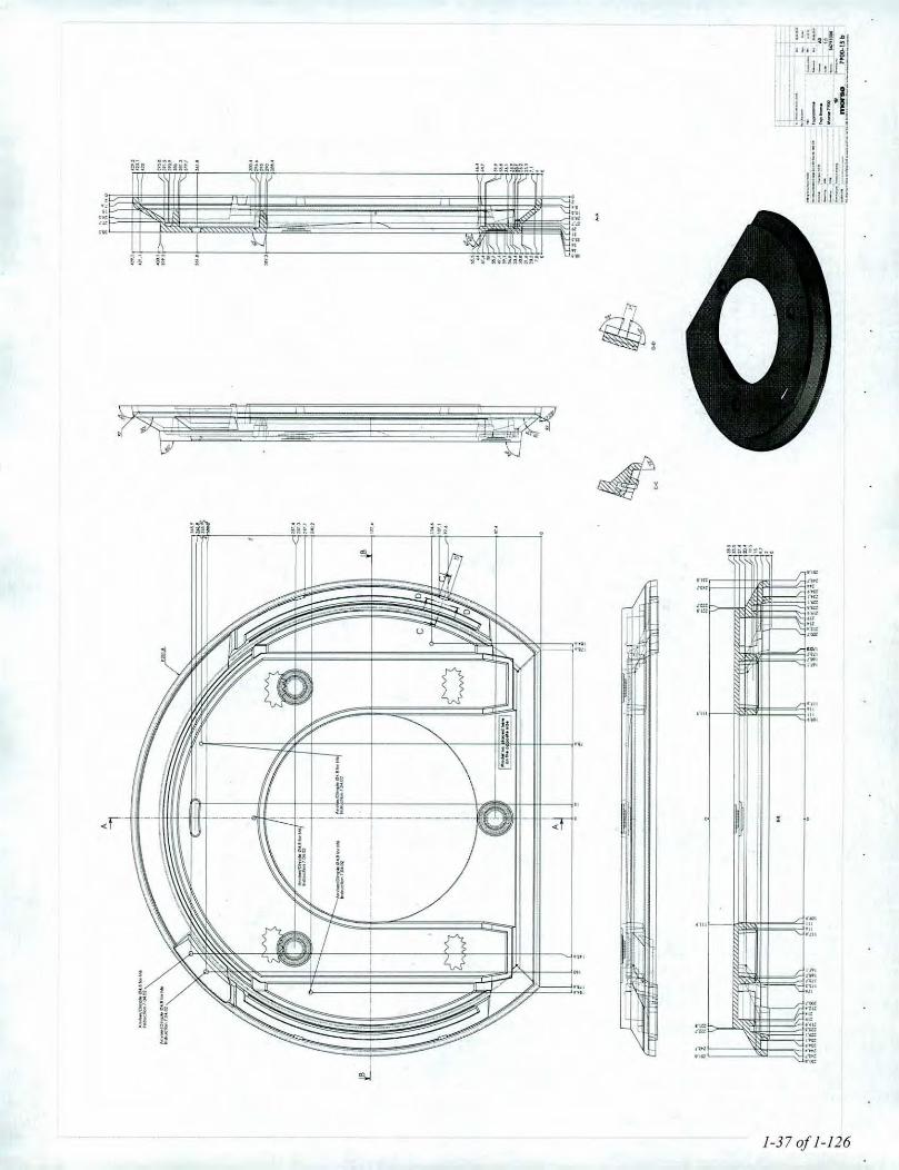
Engineering DrawingslBlueprints (K List)
OMNI-Tes/ Labora/ories, Inc"Cern/kuliotl T~."Rqx"t aauJ M<1)I].O/J: i'o()mlll_J<'rl',UMfS FifesSHOP'Cfiell/ Fife Mono - 19].ITtJtmg Projecu',19l..S-1J-IJ,J M/H'so i900 Wood SAA'tI<tports & Cemjit"Ult-J IDrufuOnly}' 192-S-2J-IJ.J.Joc
1-6.011-126

II -I
",,, ! Dal",
1-'".21:10
''',0-..]... e-uo""",Reservedelstegnlng NA --
Exploded drawing NA ,,.-,••Morse 7900
Side plate righllLa plaque lah~roledrolleP- 44790500y. 54790521107
Washer/Rondelle791891SCrew731625
Tope/Ruban odhe~if79074200Glms/Vitre79790000Holder I. bolllelmuloire pour deflecteur71794361
,
Screw/Yis_ 731635
Wa~her/Rondetle746206
Screw/yis731640
WasherlRondelle791891
.'
rClIo__ "__ ._1"'.
'-,!=':',,= j ~ 7900-501 a•••••_ ••••••••__ •••0.4._ ••.__•••.••_ ••••••,_"' __ "". •••••••••.......-
Sorl/Black = 21BrunlBrown = 07
P; Produktionsnr./Producllon no.y; Vorenr./Producl no.Ash pan fronl}
Cendlier superieureP.44791500Y.4479152107
8ma Dlate/Plaque de baseP- 44790100V.44790121 07
Tebe5434900)Washer/Rondefle791891
A~hpan/Cendrier71790200
w/Yis
Screw/Yis73&0800
G1a~~fittinglRoccord vlh71814561Vefmlcu~teFrontlSUp8lieule
Tube 79792400Pilotow/Air pilo!e71794161
Grale/Grile34791400
Screw/Yis 731• 173961300 • _!.- . ~ .r Washor/Randelle. ~ ( ! ! -"""'791891
Closingmechoni~mlMecanisme de fermeture54791100
Frontfrome/Cadre ovontP.44794200V.44794221
....,- •• Boffte/Denectur
79792OCi)Aircanol hon"Conduit air. avant34791200
Tpbe 5:1349000AScrew/Vls731612;::----.
,"Nut/~crou
Screw/Vis 791158731625
Cover/CouvercleP- 34790900
~
.4479092107Top plate/Plaque SUp8lieureP.34790600 Screw/yisV.44790821/07 _~=:.__ 738610c0
Draught control/ T~ :4 1~~2500~f?9~~irage ~ _..-
Woshef/RondelleScrew/Yi~ 73610674340804 Washer/Randelle
~ 79189700~ Screw
~.~~':::_~,.;~-... • )"'~ Wa~her/ Y.5479092107
ScrewlVl~Z-~ Randelle W sh /74162000 791891 Rande~
--f I Wn<J1erl 7,0'8'.' e. !'-.Randelle /7: 7,36106 •
ScrewNis~31625 I •
waSher/Randel: t •191891 -:J t~~,~fiS ....---' I SctewfVls
73861001
TebeTube 7181020071810300
J •
SprifIQ:~Goupille73530700
/ScrewNI5547014()()Sctew/Vis73851100
SCrew/Yis7387200)
WmhellRondePe791691
~~l/~crou Closingmechanism/5006 ~Mecanisme de fermetUfeinge fitti~i """"_5_4_79_'_'_00 _oecord chorniere Tube1793000 Wr-eloc~/ 71793561
Screw/Yis Serrurede Fil Wire/Fil74150804 79082011 79082004
• Washer/Rondelle ~ ~736106 Scre:':f'f.!F"--.....~
ScrewIVis Nul} crou 739603007 9 735005
Draughl canfroll~f¥Jg~~wageTop plale InsidelPlaque Superieure. inlerieureP.44790700V.44790721107
Glass/Yitre79790200
Handle f. drou~ht conlrol}j~~b~ilpoureglogelirogeTop frome/Cadre. hautP.447910c0V.44791021107
FlueCaflarlC0ffi6fdese~ogetuyoup.34Ioo200V-441OO22107
ScrewlVis73851100
GlossfittirlQ/
~?il~~f.vltfe ~::~~~~?teScraw/Vis 7181456173850800 Hinga filtingl
Raccord cnarniere71791(0)
Wa~her/RondeBe791891ScrewIYis731625
Sideplate leftl~~ ~.g.~~~~terale gaucheV.54790421 07
Tape/Ruban odhesif79074200 _Glas~/Vitre _
~Holdel f. bafflel~1:~~f6four dellecteur /'
ScrewlVj~73950500
Wa~/Rond(:De746106
Basic 7900

J-------
d• II• i (II I
Ii', 'I'I" ! 'I1'1"1'["• 11 !
.~,
o
"
1-8 of 1-126

-1-----------------
E-. 3 .
•••
1-9 of 1-126
---.----------.------ -- .----.---.----- -_.--t--,--- ----~----------- __ ----_ ....._- _._----------- ----_._-----127,4
Do! ••:
2H19.2012
1306.2012
02.02.12 .-- ...-----l
0'2-05.'201'2
A31 :1
71791300
osvosvSign.:
Eller bukning slibes der hertil oprindelig bredde opnas/Aller bending, Sondedhere until original width.
- I
-~---:=-- ~.._- =r.~::=+=:~c Divene mOlOIrOel.
b Moved IloIe M4lrom 6,4 10 ~..smm from edge.
o
Eller bukning slibes der hertil oprindelig bredde opnas/Aller bending, Sondedhere until original width.
4030
50
80
RIO
$8,2
d<Xl 0
RIO
------ ------- --- ------- - --- --,,,
5l'"<rio-0
R3,1
~
'"~~
~<Xi'z
'"
(I>
r--- --- --- ---- ---- --- ---UNFOL
,I,
I ~! ::> 8 I '/lev~l!evisiomI 1..... ..._. ---- .------ ~---- --..'1----I I __._________ __TIlle: ! Cons!rucllon~ lAH.
I ./ lom.WlIoA~d~"1C£.t>0SAS02168.1m LlIftregulerlngshOndtagpladedel'l!elemed: t-;;~1 0 I_Mo_'"",,~._'_. - ----- AlrregutatlonhondlePlafeport L~I:•.••••~I lWetQhlkg 010 ~
~ gil 0 U') -.0 ("') -0.-.- -0 -0 IModel no Morse 7900 ~c _ u1""': M r-..: N N '" 0: Dfawlnglype f'rodu<;:tet'owWlg 3 ~---"''''''''''~
~ ~: .- N It) -0 r-.... co ~ l I _ "--'--- I.....8<- -~---~-~==,-_=--.--J""'••"•. I===----=-- _morso~7_~O_O-79 c., ThIs drowong Is Morl.0 Jemst"beri "IS prope<f)'ond must no' be soId.1enoed Of copied Wllhout orrot WlitTen OU!hOrllOI>on "om 'he COIl"POny,.....'"0-

I,I
i~! , i
~n~ iiit;~ii:;iiat~~~~.
~,,-I
,"',.,'.'
~,
~~ Im,
I~i~,~,
I
r:~'::' .......
,..I
....,.0
I-~<1'-
!0
1-11 of 1-126

------ --_._- ----_._-_.-
u
\fI ? T 7:'7' '7' '7' '7' '7' '7' '7' '7' '7' '7' '7' '7' '7' '7' '7' '7' '7' '7'? I
:.' 0
6Ul
..,'Hill
~J / !
i I0 0 0- ". - ... ., ".
-, i I i i i i ! i i i!
I ! I j I i i I i i ii ,i i I i I i i i i i i ii i i i i i i i i i i
i i I I i i i i i I-~
i i I j i ! i I.i i iI I I I I
~ i i i i i i i ii i i ! ! i i i i Ii I i I i i i i ii i i i i i i i i !i i i I i i i i i Ii I i i i I I I i i I ii i i i I i i i i
!llilli
i ii i i i i i i i i i ii i i i i i I ! i I ii I I I I i i I i ii i i I I ! i i i ii I i i i I I i i i i
<I I I 1 I I I I ! ! I <!i i i I i i i I I Ii i ! i I i i i i I I! i i i i i i i i i I
I i i i I i i i i I II i i I I i i i i i II i i i i i i i i i I
I i i i i i i i i I ii i i i i I i i i i
i i i i i i i i ii i ! i i i i i i
~ I i i I i i i i i i/ I i I i i i j ! I
~i i i i i I I I i,i i i i i i i i ii
i i i i i i i i i II i i i i i i i ii i I I, i I i i i i i i i I I-I I I i i ! I I i i i i j ! i i ii i i -
i I~ -~
\ ~
'"""'"n:lt
./
,,,
.
.' .,
:--------- -----1-12 of 1:126

1,5
10Z'69
l'6a
Ol
v'£6
---\b;/ ! \
\ ,'[:7",
\ \\ \-----1--- \ --
, 1 <{
\ \\ \\ \\ \\ \
________J,"'" \"\.{'
-----~"'."'\ III
___________ "_-_--11-13''0/1'-126
~I
I".
I
I
~.•N
~..,
~ N-
;
III •~
"

;d"m,,,mmm,m~=_ -==--==--==--==-lP
'1i
."".....r:
..o - I
I1-14 of 1-126

79.2 ---.'0
I1
~~
e:~
i.>r-~w
2069,2
,I ~I~,- ~...I ~
I-
53.9
1
. ,
40.2
...
15.2
93.4
r
. ",.: "
...", " .~~.~, ~.'.. ,
"., ,',' " ,,.". "
24.2

87,6
A 79,8
76.2
31.3
27,2
161.3
319.6
25 .2
iiIIii
~
152,5
, I /',----------------------------------------)---------------------------------------------
A.A 34.5--------_.

-;-.-------------.- -----.---l25.714.410.910.77.52.5o5.5
10.4R1et> 16
05.6
et> 43
---- + ----N
M5
Sign.: Dal••,
mill;""""---,-- .__ .•._-- -~--
Dm.WItlo<fl'ldiQlbono/rnafiWlICC.Io0Sr1S02763-1m fod handtag NA fleleo\ed:
Mal~ 'fllAlfrisI6l-AA!:ll).4 d h 'fomlCIl: A3w•••• ,.o,---r.;=' ...---.--- ~Fee andle NA ~-- 1:1""""'~. --_. Morsl2li 7900 E~-'-'"-'-~--Drawnglype: --~ JOrowIngno.:
......••.._-=._':::=--rriOiSG-L~90o.:J 63Thk dfO'Wl"lg Is MOI'\.a Jeml10berl AIS' properly and!I'Ml not be sold. fended or copied wllhoul onywrlUenouthortra!ion from the compon ••••

7970
•••
Vermiculite
Vermiculite
Askeskufle/ASh Troy:100'0'.: 265x257/3OOx30.5 mm
V rmiculite
7
'.
BL
2248
265.1
A.A
0152
E
Vermiculite
Vermiculite
26.5
D
C
C!J503.6
rI' ~ .1t
-r-
31 ,I
8•Ct----- --- --
j<
~
:<1-
A-Vermicu~te
'21:5
--,--~-.......-. .•...r' -; ConoIrIo<""",.W DlOoIlO'lia..-_~ __ .DWSOI,,""'. Godk.I~n, 7970 NA ._
i- App. DfClwlng 7910NA -r=.:' MOrllll 7900 -.i~ _~__ I~""
-.. '--- rnorsp 7900-155 aTN._ •••••••__ >JfI._""" •••"' ••••••d.I_""' .• ••_ •••.••••~
60 70 60
E-E ~
Primary Air:Min.: 3 x 228mm':: 6B5mm'Mox.:3x 73Omm':: 219Omm~D-D
Vermlcu~te
Vermiculite
vermiculite,

-.--lI
II
.000
25 60
94
---------------_._._---------------
0,7
( ,----- '.. "
, ,,, :------
7,840
------- -~---------
187.7
183
182.7
58
r--.------.----------------.---------------------
I
ThisdrowW>gIs~ Jernstl/lberlA'S p1Qpertyancl musl 001be sold.••••nded Ofcopied wlthoul any WlI!!enavlhOfliatlon from the CO""f>Ony.
Sign.: Date:
IConllrUl::!lon:, RSV 10_00013 I
.~:~Ifoonal: A3Scole: 1:1,~---7,-79-416o-----'- -
iDrowlrlg no.:
I 7900-146
A-A
Rev. Revlllom
1 •. " .... ""7 ••• "'~.""SO"":~_ _ r~7JotluIlSr ••r NA~~~t_IMat9ril:Jl"'nol.pM:l"-.ed,. --i Pilot AIr Tube NA!Welghl kg' j.O'089
~
---------------.----. Mars •• 7900Model 00.
Drowlrlgtype: -"""""--,,-, ••••--:-------+-----'llF ---ltocmnolllt, 1.,--.....- ..__ -.._ II'iQriSe
A

I
Ii I1':I
I.,.
'"...•.n,
'"..,.0-'...
m '"-:r . ,
:~::1"
:~:
::
,I,
'".,.,
~- ••'-J
,~~
'01
,
,
,
I' ..I -on
!o.m
'""
....
.....
"JI
1-200flo:l 6

, I% I
,!! '
--~
Ii,I,
II"-II ---"I,
1-21 of 1-126

..'.•.
"I.,1I
1-22 of 1-126
. ~~~-
: .7LJL "_I ..
-=:::: :,"
- -\''"
'r- i/- .
I '~"""':::::
..
,...,..
~-.:::
.-.~~I"
«-II
,
j ""iill w_.
I!ImIII
I '.~.-
~
.,;~ I~::::~"
"i- .
," .
l•i.IjI
.fc::---~~-
l•i.IiI
ibt.=.r:-I
JJ
IJ
iiJ
~:>; -_._._._._--,_._-_._._._._.!,.._._._._._._._._._._._._._.- --_ ..J!J
iiiiiiiiiii
iiI
-'-'--'-'--'-'-'-'-'-'--'-'-'-f-'-'--'-'-'-'-'---'-'---. __ ._.
u

...~
~..
-,I
...........v:l ~l • ..~
• ...;= ~~
=.. • .....~~.:;
I;
II;m~.~
....................
...g:
.-
jJ
,
?
n
,•"Il , .II
~ ,~
•i ~ 'I
I!II
ri_. -_.- --_.- -'--'-'I_.::..vl<:_l -------=c ~i at--I '= r-----,:~
•I,\ I I!~
I :I II:• II, I I!II I II,I I
I-- .__~_.~__.~___.__~______ l_______ ._.___._.__ ._.__--:I
, ,• •I, "I! I!)1 I .j
i~I
/ "-,I []
IL I,
wI
1-23 of 1-126

....:'E.~.....o'
o'~o.....
...,.,......'...,.,.......'"t?"
..,-.!:1
.".":'
,...o..,".
.....'"
,..~
...n,n,
1-24 of 1-1-6
..""
.-n"."~,,.'..,'"....,:::'---,,,
-
-'-'<>
\~I•i,I'II
i~
ul
I•h z, til h
1l11'!i II
Ii
--_.-1-.=..'"':-1--.-- ~iIii
,•"Ii1I

'.'"..""'..,.,..''...•.'no'n"'.
-~------
".,~.''"n'n.
......".~:
...; ;u
I
!'JI~J
"
I
~
",
~ • 0-;,
(:-OM... !--,....~
jj
~
,,
I :
I;, .
"- --'•.... j--., .....
Ij I
"- =-.""i"::'...... I -_ ••••• ~~ 1]-- 'e_._._. ._._.__ ._._._---_._---_._._._._._._._.,.----_._._._.- - ~--.!~"'--_. _. _._._._. --'- .'=-.,"'7::',...... i II
I.~;
/~, •.•.:.u .•...• I Jjj .-..~/ j _''''''' I
~
/=,:;-,..: ...• I j
, / /=~:!.....• I II
V :./ ! -, ....• I.
d..r I
E.

,~
A
~Iiiiiii
,
."
=---- --~ 7900-03 a..-...._-- ...•_ .•..•-...•.__ ._--------

.-..~-«'" ~
~yl---_.oop"'.------------.:::::::-1
•
!
III
; Ii
iit---------------- ----------------!
I!
1i!
I---~-~.-- ..----------i!
I
I
I
I
1
I
I
II
i
!:
I
I!
II,
1-27 of 1-126

ti: Itt
1-28 of 1-126

Date:Sign,:
7600-62 aDrawtlg no.:*-I110ISG
T1IIe: CoruInJctlc>n: WU 06.03.08
Mont.plade I. skuffesektlon7600~;;;;:- lDU 07.0'.06
forrrol: A~ _-, 1:2"~'--71760900Mors" 7600
/- 105.5106.5
___ -- 106.5----t 105.5
I
o
A-A
Materot SPDPlode
Weight O.S ~g
Drawlnglype: Emnetegnlng
bI
CD 7.5 .
.: 'J4.2.- ~\
f~1==i-1- ?o ~! _1 _
o '" '"'"N
0+--/--+--
(/)7.5
85~--¥==I I
l06.5~1 I
i>o
0U 04.2o~ ,'-- ---~.i~t--__~-J--------------~- I
II Uo '"
AI106.5.
85 !----<i{----I-----p\. C."7,~ j ..•"7,5 ,/
,I,I,II,I,I,II
~

o
()F----E-390
70
R15
If)
Dote:
17.01.11
2011.02.11
A41:1
79612400
RSVReleased:
Sign.:
Construction: RSV
Format:
ltemno.:
Scale:
Drawing no.:
Varmeakk. hcindtagHeat ace. handle
MorsI<l6100
Title:
Rev. Revisions
DIN 931
0.086Weight kg.:
Dim. without indication of margin ace. lo DSIISO 2768-1 m
o Malerial:
~'E Model no.8-'0 Drawinglype: Product Drawing ~.2 •.__ •.•._ ..••-g Location,.", ,-,_"_,~,,,_,__ morse 6100.167 a
Thisdrawing is MorS0Jemst0beri AlS' properly and musl not be sold, lended or copied without any wrillen authorization from the company.
1-30 of 1-12(j

A--
n for ramme identjs~ med model 2627
/.
~ ., a :\tj. ~
~ ~N
.., ,.;
6 B ~ ~ ~
\r\
~ \/ 7/. \1>.\
~ \""e30 8 J43 ---A--A-A
12
138
112
s
lign.: i l><>k>.
t:onoo, "''' t IJ.I:utIX>
~~~2~r- "2
-- 1:1~34344100--.,.~I 3400-97 a
Il-B
114,3
128.3131
....
Inden for ramme Identisk med model 2627
......-~. 'e.G" -llllol'.
~~ I 11."'" -.;..- ! ~. R~tud USA~1 I ••••.;~~~==~~'--._._.-_'-.:1 IMort.34DO..._"---=-~-1-~8, __ .••.•. ,1_"'VW'9_ .• __ •• ..,,"90'06 ••• ._ •••••••• _ ••__

.'..,r"".",..,'..,...• '.•..,".,,'""...
......•..•........... ,.•.
~
'I. _._._._._._. ._._._._.__._. .. - . I, '-''I <1I
~.•..•.
•.,',U
1-32 of 1-126

• • a ~~ ~ ~;~!!!H~~iiilliii~~--I' '''''.,'h.« • b.. , . ,. ~
~
"SIIS
, , ,
;i~ijf!
I~.#;~I,i,,Iiiiii,ii;
..i"
........":~;
.... ,:~:
. _._.:1
~:::::.-,",ot~..::=:OM
::::... II
1-33 if 1-126

" I
., I
.1
I
...701 ..
_::: ;,- -==::::
r "\:'"
I
IJ
!II
, I -,
I ,,~ I i/----,~
l ..
..."
~~..'
.•..
-y ""-1I!11 ..,
~ ..'f-
-
~
. -/~>:l-"'"":2:-- ..
....•.o..J .
. ,
, ,~i.
I -1111 "-"'-',~"'"...•.:- -_ .....
i
r" ~_._._._._._.~._.__ ._._-_.- ._._._._._._._._-_._._._._._._._.-
•r-' -_._._._._._._. __ ._._._._---~-- _._---"_._._._._._._._._._._ .
I ,I, ,
i, i,r Ii)1 \f---------;--- ....• ~ ---.- F
P\lr - '\._-,,"-C_>"
"I,
ITT;llTl -".d nL 1.
u
1-34 of 1-126
_..--- -..-.•.
~ ----I c.....--..-, ---. -, ~-I .'---..--
-_._._.-1-0-'-'-'---'-
. \, , ._._.-,.
I~--.. --- ---,
.. . . 0
.to
"
""
~~ a a a aI! - - - -!~~• ~~< •~ , , ,i ,~~~•~ < . u 0
."
/-35 of /-/26

'"
'l91,.'"
o
'--
'"
", .~••......~.---
I ,,,.'-". ------0 ....i.•...•---
"!. --.." -'. ~•..•.• -.~~~.,
nl.,-----------,-! ,.--- -
,.< .- - .'-- •
I~ ------vr---
\ - .• ~~ , • •• • ~
ijaaaaIL _
~~
If~~H
i'H~
,ot~!
1-36 of 1-I16
;\ ':r
liJ.i.1"! ;II It I I ~'
Ii J;t;d
J I 1~lI, I!"II'-_..",,1'1[:
. I! I, I'!I .I Iljl"l!
I, J 111l!
,-1.'"
"<I -~.I!-,Ii/
;;.., I II.,I
~,
/-37 of /-/26

~ --------------------FIRE BOX VOLUME A
Oo!&:Sign.:
FOfrTlCIt:
Jill""Brcendkammervolume NA
A-A
I,[lim. II!1houl"""'" aI "_QlllIOC.IIl os.tso 2t&$.1 Inr -_ .. -_ ...!-.Mot"'lal _._, .. __ ..~I Fire Box Volume NA_Weighlkg: Scale:
1....-00. --- -- Mars" 7900 '''~.'
:"'''"'''" •. I......,.''''d-,...,-, I --~-- il"'~""7°09.0' 0.145 a:l.ocdcnolfile: j<"O '__ morseINs drawing a Mo<l0 JIIHMt ••beti AIS' P'operly ond mull no! b •• .aId Iondltd ()t copied wllhout any WlI'''''" outhorlzollon "om It>e corr~xmy.
.-'
Volume = 21.470.439 mm'
v = 21 470439 mm3
= 0.758221 ff3
=> 4 pieces @ 8.5"
=> fuel load = 4.78 Ib -'5.84 lb.
.-'
RIB9.1
o
404.4
o
60
300.7

SKAMOL V-1100 (600) vermiculite insulating boardlor back-up insulation up to 1100'C (2012'F)
Grade V.ll00 (600)
~aximum service lempenture'C 1100'F "'''Bulk density, dry (EN 1094-4)
kg/m3 '00Ibs/cu.ll. 31.5
~p:ressive strenmh ~N 1094.5:1~
@ room temperaMe MPa "Ibslsq.in. 609Modulus of llJP!!!!!.iEN 993-6:1995)
MPa l'Ibs/sq.in. 131
Total ~i!Y ~N 1094-4:199~
% 76Specific heat
kJl~g'K) 094BT\JI(lb' 'F) 0.224
Coefficient of reyersible ~ennal ex~nsion (BS 1902: section 5.3: 1990)@20;C-7SO'C(G8'F.1382'F) 1(' lblO"
'F' 6.b10"
Resistance to !hennal shock (EN 993-11: 1998)heating to 950'C (1742'F) cycles ,Jj)Unear renaat shrinkage {EN 1Q94.=6;1999}12 h at 1000'C (1B32'F) % 1.12 h at 1100'C (2012'F)eYrometric cone esuivalent (ASTM C2":S9 ORJ.PN cones)
'C 1300'F 2372
Thennal conductivity (';STM C:182)mean temp.@ 200'C W/(mxK) 0.16
@ 400'C 0.18@ 6OO'C ..'"@ BOO'C 0.12
@ 392'F BTUf(sq.ft.xhxQFlin; 1.11
@ 752'F 1.25
@1112'F 1.39@ 1472'F 153
Ch~mlcal analY'cis, typical %Silica Sio, 46
Titanium dioxide "0, 0.7
Ferric oxide Fe2~ 5.5
Alumina Aloo, 7.0
Magnesium oxide MgO 19Calcium oxide GaO 15
Sodium oxide Na,O 0.'
Potassium oxide K,O 10loss on ignition 1025.C (187rF) LOI 7.'Colour SAND
HS Tarin number
(Hannonized Commodity Description and Coding System) 6006.90.00
Data are average results of tests conduded under standard procedures and are subject 10variation. Data contained in this dalasheet are supplied in good faith as a technical service and are subject to change without notice. Misprint and errors excepted.
October2012
~;wnol AJSis ~ ISO 9001 eertfied
{f3skamol~amoiAlS ""stergade 56-60OK-7900 NykllbirJg M:nOenmwkTet +45gn21533Fu: +459n2497Sinsulalion@$ll.amol.dk
VNNI.sllamol.com
1-39 of 1-126

- vi vii kendes pa den gode service
4108 - 0 8mm Dark grey / Round
The basic material of 4108 consists of 6-9 microns texturised E-glass fibre yarns.The product is inorganic, sterile, incombustible, totally asbestos-free, and containsno toxins or heavy metals. 4108 is a knitted glass fibre packing without core, madeof E-glass. It is a very stable packing because it is relatively heavy, and istherefore suited as stove door packing and suitable for fire tube sealing purposes.
Prod uct infoDimension
Length
Material
Temperature
Colour
Application
Combustibility
08mm
100m
E-Giass
550°CCoke
Packing/ Sealing
Incombustible
S~EFFCAAS. Rorrs0iej 24. DK-5.0 Nyborg. A/S Reg-rr 2~ 1493. CVR-'1 0 20 ~6 85 09Telef n +- "65313 02. Tel fa< 4156531 '3502'1fo>i!s.efka.dk W .ste ca.dk. v / ' ISJcar-e.dk
1-40 of 1-J26

- vi vii ken des pa den gode service
2608 - 8x3mm. Self-adhesive glass fibretape
The basic material of 2608 consists of 6-9 micron texturised E-glass fibre yarns.The product is inorganic, sterile, incombustible, totally asbestos-free, and containsno toxins or heavy metals. 2608 is a knitted glass fibre tape. It has a big.packingsurface and minimum packing thickness which makes it ideal for packing of glass inovens with limited space for round packings. The packing has double-sidedadhesive for easy assembling.
Product info
Dimension
Length
Material
Temperature
Colour
Application
Combustibility
8x3mm
100m
E-Glass
550°C
Black
Packing/ Sealing
Incombustible
STFFF-A ArS P msovel • DK-S800 N,Dorg A/S Reg-nc. 'f 4"1 93 -:: IR-rc C 20'6 850'lTele'or ~ 65::" 2 • Te "fa +~5 F.) 5r 2i flJi,<1~teffca dl( \ W .st", ca dk • 'SlJCA e ~k
1-.Jl 0/1-126 .

- vi vii ken des pa den gode service
,
5005 - Heat-stable silicone - red
5005 is an acetic thixotropic silicone that cures at contact with the humidity of air.This silicone is particularly developed to withstand temperatures up to 350°(,
Product info
Quantity
Material
Temperature
Colour
Application
Combustibility
300ml
Silicone
270°(, - temporary 300°C
Red
Sealing/Glueing
Incombustible
eJ '" • OK-58 ()el' ~ 5 65
In u.:g>"tdtLa.dk
ytJorg • A S eg" 3' '12. Ie axv stef1~o Ok •
r2 '493.(4C: 6511 I-'C;CJ2
• o(:a, ~.d
R-r 'u ~fi 85 09
1-42 of 1-126

c. SKAMOL Vlp.12for back-up insulation up to 1100 'C (2012 'F)
«3skamol
~~1."!1um~I\'icete~pera~u~SP.!EN:14306:2002)'C 1100'F 2012
Bulk density, dry (EN 109>b4)kg/m] 1200lbsJcu.fl 15
~~sive strenQU! (EN 1094=5: 1995)@ room temperature MPa 9.5
Ibslsq.ln. 1318Moou us of rup.ture (EN 993:'7:1998)
MPa 2.5IbsJsq.in. 363
~~orosity(E~t094-4'1995)% 56
S~iicheatkJI(kg'K) 1.08nJ1Qb"F) 0.24
Coefficient of reversible thennal expansion (BS=t902: secti0l15.3: 1990)@20'C-I50'C(68'F.1382'F) 1(' 10x10-$
of' 5.6x10"linear reheat shrinkage {EN 1~6: 1999112 h at l000'C (1832'F) % 1.0eY.rometric cone ~uivalent (ASTM C24:a9 ORTQ~_cooes
'C 1330'F 2426
Thermal conductivity -(ASTMCJ82)mean temp. @ 2OO'C W/(mllK) 0.25
@ 400'C 0.21@ 6OO'C 0.29@ 8OO'C 0.30
@ 392'F BTUI(sq.flxhllGFlin) 1.73@ 152'F 1.87@1112'F 2.01@ 1472'F 2.08
Chemical ana~sls.~p,jcal %Silica Sio, 52Titanium dioxide '[;0, 1.6Ferric oxide Fe,o, 3.8Alumina A,a, 23Magnesium oxide MgO 8.9Calcium oxide Cao 1.5Sodium oxide Na,O 0.2Potassium oxide 1<,0 5.6loss on ignition 102S-C (18n°F) LOI 3.0Colour SAND
~~~~ffnumber6806.90.00(Harmonized CorrYnodity Description and Coding System)
Data are average results?, tests conducted under standard procedures and are subject to variation. Data contained in this datasheet are supplied in good faith as a technical service and are subject to change without noijce. Misprint and errors excepted.
October 2012
Sllamol AIS Is OSIEN ISO 9CXIIC*1ified
""""AiS...,......,DK-7900 Nykoblng M:n
""'mnTel: ~ 97721533Fax: ~ 9772 [email protected]
_skamol.COl'l1
1-43 of 1-126

t HOME TECH
I ROBAX@Glass Ceramic Panels
Technical Delivery Specification TL 1000551 .00
2. Technical Features
2.1 General Remarks
I Page 5 I 24
All data stated in this technical delivery specification are to be seen as guideline values.
Those values, for which no generally valid measuring method exist or which are notgenerally defined (e.g. by a technicai standard), are specified and explained.
2.2 Appearance
• Transparent, slightly coloured due to the material composition and production process• Surface appearance: plane, slightly textured due to the production process
2.3 Mechanical Characteristics
2.3.1 Density
p
2.3.2 Modulus of Elasticity
E
2.3.3 Poisson's Ratio
approx. 2.6 g I em'
approx. 93 x 10' MPa
approx. 0.25
2.3.4 Bending Strength
The bending strength testing is to be accomplished according toDIN EN 1288 part 5 (R45).
approx. 35 MPa
2.3.5 Impact Resistance
The impact resistance of ROBAX"' depends on the kind of installation, the size andthickness of the panel, the kind of impact, the geometry of the panel and especiallyhere on the drilled holes and their position on the ROBAX"' panel.
Therefore information regarding the impact resistance can only be given withknowledge of the respective application (especially in combination with thetechnical standards regarding impact resistance that have to be met for singleapplications). Corresponding guideline values on request.
ROBA)("registered lrademar1((s) of SCHOTT AG, Mainz. Germany.
Passing this on or copying without authorization, even pol1ions thereof.may be grounds lor damage proceedings and criminal proceedings.
Copyright protected. Slatus: 10104 replacing: 07/97
SCHOTTglass made of ideas
1--/4.0/1-126

~ HOME TECH .
I ROBAX@Glass Ceramic Panels
Technical Delivery Specification TL 1000551 .00
2.4 Thermal Characteristics
2.4.1 Coefficient of Mean Linear Expansion
Q(20 - 700"C)
2.4.2 Mean Specific Thermal Capacity
I Page
(0 t 0.5) x 10" IK
6 I 24
Cp{20 - 100'C)
2.4.3 Thermal Conductivity
"""C)
approx. 0.8 x 10³ J I (kg. K)
approx. 1.6 W I (m . K)
2.4.4 Resistance to Temperature Differences (RTD)
Resistance of the panel to temperature differences between heated zone and coldpanel edge (room temperature).
No cracking due to thermal stress at Too,"..1) S 700.C
2.4.5 Thermal Shock Resistance
Resistance of the panel to thermal shock when the hot panel is quenched with coldwater (room temperature).
No cracking due to thermal stress at Too.m••l) S 700.C
2.4.6 Temperature I Time Load Capacity(under consideration of items 2.4.4 and 2.4.5)
The temperature I time load capacity specifies the maximum permissibletemperature for given load times for the fireplace panels, below which no crackingdue to thermal stress occurs.
The value pairs specified in the following table 2.1 are relevant to the practical useof the glass ceramic material as fireplace panel. The temperature values refer tothe hottest point on the exterior side of the panel (Too,m•• ) because this temperaturecan be measured more easily and more reliably.
1) T•••.max: Maximum temperature on the exterior side of the panel. that means the reverse side of theheat source, at the hottest point
ROBAX'"registered trademar1l.(s) of SCHOTT AG, Maioz. Gennany.
Passing this on or copying without authorization, even P'Ortions thereof,may be grounds lor damage proceedings and csiminal proceedings.
Copyrighlprotected. Slaws: 10104 replacing: 07/97
SCHOTTglass made of ideas
}.45 of }.}26

I ROBAX@Glass Ceramic Panels
Technical Delivery Specification TL 1 000551 - 00
Load temperature Tn, ",•••1)
560'C (1040'F)610'C (1130'F)660'C (1220'F)710'C (1310'F)760'C (1400'F)
I Page 7 I 24
Load time
5000 hr1000 hr100 hr
10 hr
5 hr
Table 2.1: Temperature I time load capacity for ROBAX~ panels
Note:
For ROBAX~ fireplace panels the temperature I time load capacity specified intable 2.1 must be maintained. It must be ensured that this temperature I time loadcapacity is not exceeded during use, to prevent cracking due to thenmai stress.
The temperature I time load data for even temperature distributions within an entireglass ceramic panel (e.g. homogeneous heating conditions in a testing fumace) aregiven in table 2.2. This data is to be seen purely as characteristic data for the glassceramic material itself. It is not typical for use of the glass ceramic material asfireplace paneis. which have a temperature distribution totally different fromevenness. The temperatures refer to the homogeneous heating of the ROBAX~panel (Thorn).
load temperature Thom 2)
700'C (1292'F)750'C (1382'F)775'C (1427'F)800'C (1472'F)825'C (1517'F)
load time
6000 hr750 hr275 hr100 hr
35 hr
Table 2.2: Temperature I time load capacity for unifonmly heated ROBAX~ panels
1)T •••.••.•••: Maximum temperature on the exterior side of the panel, that means the reverse side of theheat source, at the hottest point
2) T~ Homogenous temperature, i.e. maleriallemperature under homogeneous heating conditions
ROBAX'"registered lI'ademaf1<.(s) 01 SCHOTT AG. Mainz, Germany.
Passing this on or copying wiU'1oul authorization, even portions thereof,may be grounds for damage proceedings and criminal proceedings.
Copyrightprotected. Status: 10104 replacing: 07197
SCHOTTglass made of ideas
1-46 of 1-126

Model: 7900 SeriesMorso Jemstoberi AlSFurvej 67900 Nykobing MorsDenmark
Engineering DrawingslBlueprints (Remainder)
-.
OMNI-Test Laboratories. Inc.CerlJjiCtJlwII Tesl Report ooted May lQlJ: l'omm-stn"Usen Fifes'SHOP'Cheni FiJe MQl'So. J91',Twillg PrCftcts' J91-S.1)..H.J MvrvJ 7'J()QWI)(iJ SlVt't Repon.1 & Certifi<'altS fDruflsO"ly!IJ91-S-1J-S. J.dor::
1-47 of 1-126

1:10
Screw/Vis73860800
Option:BoxFresh Air/Air fralsV.54793321/07
Option:Soapstone/SteatiteV.797906oo
_.-
I"pr OuHel follow top Moduli Tpp OuHeHor low Top Moduli If,hoppement ,ull'orrlfle E,hoppemenl ,ur Ie deuu' IaYe<: module ,uperle •••bal ay..c: modulflo lupe.leut ba, !
V.54793121/07 I
~iECJj:
:
:
1.--. ::servedelSlegnlng NA. ~~
I E.ploded drawIng NA ""'-"i::':- Moul1l 7900 ::.,
i~ .~_~_. "'-v .••.:u.:-.~. rnorso 7900-501 a..•..•._._-- ..•..•""_ .•.•........•..•...•._ ..__ ...,_-.._ •...--
Screw{Vis731612 .--!
Washer!Rcndelle791891
ScrewlVis731612
Top modulelHoul module d'P-71792700V.54792721 07
Option:Tap Modules
Option:Heat Storage/Accumulateur de chaleur
SocleP.71792100V.54792121
Nut/l:crou735008
Flange/Bride71]93200Screw/VIS73881200
RadiationPiole/Plaque71793300 ,
WasherlRandelle736110
7990 BasesHigh/Grand
I
Pipes I. pldeslallDes lu .••au~ pour pideslolP-71793100V - 54792921 07
v • 54793421/07
794BPedestailPldestal
ScrewNlS731616
WasherlRondeRe79189\
Screw{Vis73861800
Filling I. Filling t. wolllMonfogeou.montage au mur71791500
Wosherl~9n:c!~ne _
~~6108 -'ScrewlVis731820
Fi!tinR r. wolll~?91~?f~murV-54791421/07
7970Wall Mounted/Montage muralv - 54791421/07
SCrewfVis73982500
Wo'i.herlRolldelle736108
~a Nut/l:crou
735008
SClewNis73860800
Washerlli'ondeRe791891
Option:Drawer /T1rolrV.54792321/07
7940 BaseLaw/FoibleV.54791721/07

A-A
2870°
i~l.-1U
RO,5
34
47,9
c-c
RO,5RO,5
~
R~O~~_\, ,
~ __ ::;•• c.::' __
------------
20
,
2~B
B
B-B
7900-51 a
SiQn.: Dale:
Conllruction "" 18.01.12
RelecNod- OSV IS.08.2012
fOOTlOt: A3SCOIe': 1 :1l!efTY'lO~ 75790261Clfowngno.:
Reguleringshcindtag
Regulatlonhandle
Mars" 7900
--~--
Drn.'""""-t1nclcalclf1 ~ rNrVil..,;, 10 DSASOl18e-l m
Materiol Rustfrl1161- ,o,ill3O<l
Welghlkg: 0.06
Model no.

f.__ __-18
II
••M ••
""m,~2!o ,S2M
16/.8
61cww
,-,
'"
"
8-=--- -- ) ....1::=:--.._~.....~.:,":,,::,[••• __ • __ • __ • . l.oI<k.l :1.15....... ••• ~"' ••• ,
,- I.ocle 215 mrn - .••,
I::::~"'- --- ~ _1900 __ '.'1';~'700j!_. -..._~ . WI _.. J'::-..:..:....__,... .....__~ __-l!~.:~,
'"
'"
•
"•••
• 131.111.1.8,~11H1
~ ~'"<::>.Q,...•~~-------'"'"

,-.,
•i,1H'IIi'I"h"fiII!!
m
'",.,10",..,,~
---~ I
,~,..,';I:'~!.,
----------- ------
I i
I :iiIiiiI
i [ I
~
UE'1 r
II
<
:'""p-..,..,~
0
.l::::i
I'-
",Iuu ~
) ~•...
Iii~ I
1-51 of 1-126
-
L- -'---.J-I.j
--.-i~i--'
:.S.H':~~l, "I! iJ 1111
; IIII . Ii1..I : III I 1"II ' , .=!:!."lllk-!
I iI, r'P'~II,Iill !
1-52 of 1-126

•
J .
(
1--~i-
Q
I,I,i,,,i
IiiI,,I~
ur-I,,I1"-..----1 -
=-
...~,.".~ ,
,"-"-
II I,l-
I J.
I
•• !i!!!
e., . "
" 0
<,
1-53 of 1-126
lII,i!II
iIIi
1.-----------.-----------.-----.-1------
!i
Ii,
I'!.J
~.,"',~",.,
1 I/
/
.n'H1ft~-:'............,._- -:::J:1Il!" ~~'
: 11111i I, II I'
I' I I '1''I ", II J '. I....-...-.•• 1' j J J I--- .'1!i II! 'IilLll,!IIilli
I
1-54 of 1-126

o
."
•
."
•
••
o
o
""".'",~
•
v.----.---j-----.-.-- --IA
•
'"'M,.,
'"'"~H~,
"'--'-_.__ . """.k"... •.••••llo •
_ •• 7tOO••"717tnOO
900.59 e

r-I
. . 1
•
<L ._. . ._.__~~
1 .=
-' - ---------_._--_ ..._----~---------_._-----~----
I
I1-560/ T-726

,~
17a.~
o
.,.
.,.
••
JdI
B
"U113.6170.61~_~'~HUUua
Ar
7900. 3.... _------'--- •••....-_ ..•..-
.._-- ..•.-.__ . lopmDdui ItO """ ljIIal _
''''-...'00'''''' __ =-,~ "1:27Uf2lOO

,
tit
II
,._. _._._._._._._._. -_._-_._._._._._._._. .- ..,~,
1-58 of 1-126

-,
I i I
I:-i'I
\];;l-""
A
IOJ,S
113,5
,~
,.,
-...-_v._. -_.--'--
V,.",...kt .• I..,"..., •••"'.110,,",-.. noD
",7f1to1OO

I,I
II
~L5
/
l
~I
C')
I-I!
. I
~\0Qi
IQ"C>~
\\0'0 I"5..,,0C
'0SCO ---I II =l--- -l !
Rev Revisions Sign.: Dote:
TItle: IConstruction~ LAH 10.04.2013
Dim."";lhout indication of margin ace. to DSASO 271)8.1 m Pin handtag NA I Released: I,Maleriol: Materiol <not specified> Pin handle NA I Forma': I A4
II Weight k:g.: 0_02 , Scale: 2:1Model no. Mars" 7900 Iltemno.:
, W ! Drawing no.:
1
I Drawingtype: •._----- ,location of file: c..••--'"g\1'l'», •••••!.~_1'OCO ••.•.Sl.CHT ~ I 7900-164
This drawing is MorsQl Jemst0beri AIS' property and must not be sold.lended or copied without any written authorization from the company.
1-60 of 1-126

--- --_ .._-------- -"""""-- ..•.._-----_ ..._------------,-----ITEM NO. PART NUMBER DESCRIPTION QTY.
200 7900-162 Handlag Handtag fyrd0r NA 1lyrd0r 7900 NA
201 7900-163 B0sn. f. Fad handtag NA Ihandlag 7900 NA7900-164 Pin f.
202 handlag fyrd0r 7900 Pin handtag NA INA
203 C03600381OOOS- Compression-Spring ISodemann
Rev,l<"vi$lom Sign.; Do!e"
~~'''' ••;.~~;~.""", ••~:=-r;nd,ag Iyrd0r NA -f~=,...:-LA" -:'"''''''~MO'1l<1oI H~~________ Handle flredoor NA FormoI; __ A3WolghHg -40398 ,SCOIe: 1:1 I
[
':';;;;;;;;- --- ------ Mars0 7400 r~--..--.----.-Dr~1yp& -- ~ - OrOl'o1flgflO.:
L-,•• --=...-=:::...-== --- niOI_SCJ Z900:166~Thilod'awlnQ Is Moow Jem,l.:tbe!l ,,",S'Pfoperty and rrMl nol be !oOlcI.laoded or eopled wilhoul any 'M'lU"n oulhOO10lion from the compony.

~
I
""

( 01
.c,,.,,u,u,,.,""..,
'5,'C,.,,',5,,5'5, .'.., ..'
5,,..,5''.,00'..''C'•....n"
1-63 of 1-126

OJI,
II
-.-.--.----.-.-.-.-.---.-.--.-.- .-.- - rQ .. -cl1fT <I
~....,.''.'
~'"'",'",
~l
1-64 of 1-126

---------,.,----,._ .._-----
A34
A
A-A
R7.5
Dol",.....-4
06,052013
SIgn.:
",v
lIemno.:
5col&:
. format.
Mers" 7900
Risteramme
Grate frame
7'13
Ccd,"ooGG15
5_'"
Re".'Re"~---------~ .._---,--------.-+---'---Till8:
A31:3__
44791300~ 'Drawing no.:
1'I'iOi"Sel-.-l13.:.44Z9NOlL atrvs dr~ GMOI\0 JemstaberiAIS'prope<Ivand IT"I\nI001be~,!ended Ofcopied ..,.;lhoulany'M1lTenouthorirolior\ from the company
Material:15

-----------------------------------------t----------------------- ----...------ ... _
90
300
90
ThIIO'awWIg II Mon.c!Jemsl0bert AIS' p<opertyoncl must nol be sold. I&nded c;:copied will'loul ony wr1tllln oulhorilotion "om the company.
d_._-- .._---._.__ .._-- ;
- -------- -
..,_ ~evisiorn '•." Dote:..,--C~~-~
-----ntlo: 15.05.2013
Afdceknlngsplade NA-- --11~:
Caver plate NA formal: A3---t--,---I Morss 7~~~_
""'" 1:]~
i~900:~;:~~I moIS)D ------
~;~;~~~:--fWeigh1kg: 0.275
MOd.~

70,6
,"
'" ",., ~
M.' ••73.1 "93.3 ••108.1
,~
"., '"I~J.1 '"
"" 'M11&1 '"
18.5'
'"
162.1
/I
,i
!
A
iii
~on •.•• op _
i.
----_ ..._----~.)
..... -\!.----'1'-------- ..--.-- "
i
A
I.1.... --- ... _ ... _._._-_ ... _._-
j
,; .._._------_.\.
i.----- - ---i..------
(
----_._---_ .._---i_____. L.__.._..__._._.__..._..« I )--..-------.r!
______ . ._. ~i
-_._---------- ._-_._----_._-_._-«
\I
.\iI
\\
,
m.e
o
\ I I, III
Material: GG 15 Crome.,
-" - ...-- 7900.180--.,.._-- ---_..... ~_-...._- _ ..-.
RIO
8.5
.,''3 '3
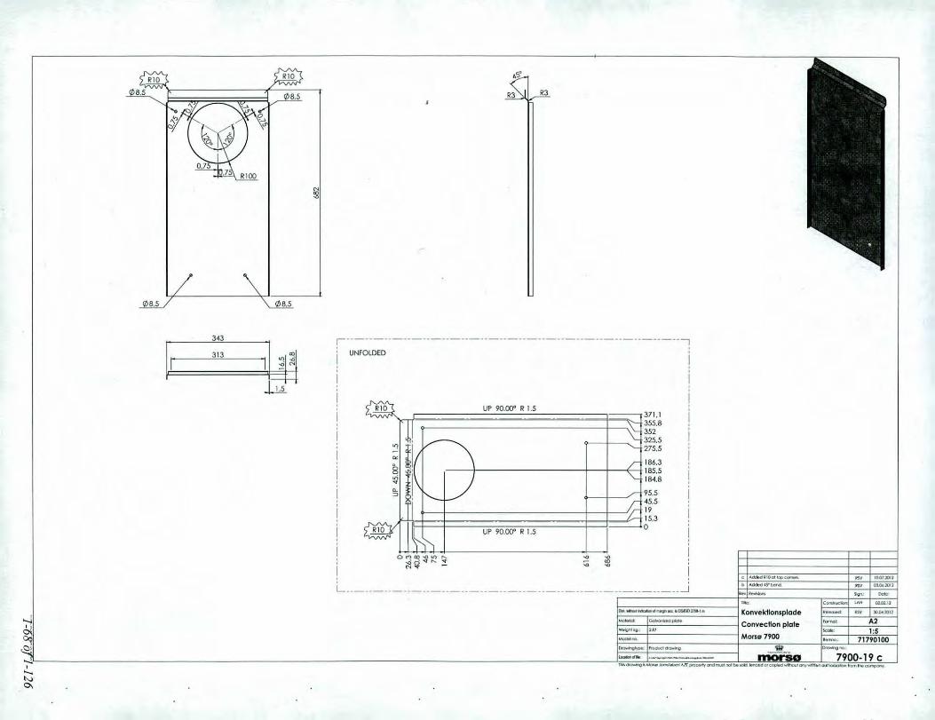
371.1355.8352325.5275.5
186,3185,518-4.8
95.545.5
I'15,3o
UP 90.00" R 1.5
UP 90.00" R 1.5
,------------------------------------------------------,i UNFOLDED i. i
!I
!ii
343
11£1\,1313
Li
._.10"' .•.••..,.... .. 1lllII.:~1I1
t>_oIS'_ .. _lOll
"'" -- ~ ~.o:l-'~
Konvektlonsplade .- .. lD(I<Xlll
Convecflon plate ~- .2- 1:5MonGl7900 •....." 717'0100
-~- .....•-7900.19c
OOo. __ ~ __ .DIoIIOI •• '.
~--_ ..••••_ ••.••••••_AJS._""' __ •••__ "' "'...- ••..••_~
L ..J

3075 II ';:.' ~~~ f '6' u~~,--~ __ LJJj t ~
UNFOLDED
I~. -- -~!!~~ __ -'I,~"".»,,=,_.,. __ ". -t"OU.'J" ;Choogoo<l""""" •• " J''''JIlIJ
~'~,,",",,~"f1''''''''' ow ~""'lG"••••••••••••• SO> _
1 ••• , C""""""'" 1..0" CIt;»l)'DIa__ " C6olMl"". Askeskufle _"''' lJUlillll'JI ,- ~- Ash tray ,,,,,......~ A21_.. '" 1 - I ,.,1_.... __. ~ors"7900 _ ••••••" 71.!.!~200~ _,_ '"' 0._"", ._,l-~..... -. Il'iCWSo 7900-20 d I. 0"'~. __ I'H_""""""""''''~.'_'' __ ~' C<ft"f••••
328.3320,5299.3297.6
30.7297 .•a
•
~~
~~
"!
; ~gN N
"!UE9Q..QQ"_,R, l,5 ,_,;;
8~
_______ R225.8
8'~9Q.OOO R.I,5. :i
~~
"!
"!
~~
"!
!I
1'5
o ;~
a
32.329
299,3 0
295.91~
I,!
bjl"C\i~:.....•,•....'"0.

IDimple 04,81, , 11)......... <1)11)U1 ooilfiaj•.•..N_N<OO"" •..• NM"'''''LI)
~
, I ,1 / ri In
..- -r!> -- -I' I M-Ode; no. ~ac-e;h-e,e~n Ih~S51;.1 -1- - t=~
o12.813.91821.740.541.644.245.2SOSO.5
SO.548
35.934.632.S21.2
131.2
o
~SO.5
32.\14.28.''.35.34.50.5o
~ 0- ~ '" •.;0
~ ~ ;!~ . . ~
.m~]l: I :tb I f~.817
"52.857.562.8
U i(\ I~B t I /\\ ll\
::1; ~ ~:rl~ ~ ~ MM"" MOO'"N ~ ~~~~~~~- ~ -- ~
"'" -'- .' ~".- ., l'Oa.lOlJ- .2- 1:1-,: 347"500.....-.
-=_.('....•... ('''''....•..
~.Ic",,,,,,~
_.~ Askeskulte fronlAshlTay Iront
MorSG 7900
ill- •• 1- I ~ I 7900.21 a_<h.-.g ••__ •• ~ __ ••••_tood' •••.•••••••__ -._..-. ••••••.••__
~"""""",,,I"'=1lIo__ "_ ••••• l$Cl_ ••••_Cll-
•...,~
,<Q,•..., .•....",':'"

110.6
60
o
60
110.6
0-8
1151---1--------'123 :.-
60
87
~
IS.5
--- 015.5
60I
87 !ii
____ 90- __ ,. __
I•• I~i~I
60
87.587
253239.4230.4228
r--------------------------- -----------------------------------------l~.:<i 0-"" ""0- € -o~ :~~ t;;t;~ 0 ~t;i;; v. ?-. ~ ~ J
~ !l'J I
I
!iiii!
I228I 230.4
239.4I 253L . J

===~
R15
67
o
o

R5.8
II f/J95
f/J 98
b Cho~~, '" 18.12.:1012Rev l/ev$ons
"""Dole:
0TlIle: CQn$1lvC1ion "'" 11.10,11
om, \Oiflcullrdl:8liclndlfllr9llaa:.bos..s02768-1m R0rstUtSfrlskluHboks I!elerned: '" 02.05.2012M<JIerioI: SPO. DC01AM/EN1Ol30
Pipe Airtight Box formal: A3w&lQhrkg: 0.20 Scale: 1:1Model no. MOrs07900 Ilernt"oO.: 71790500Dr~type: "'oducldr~ .__'!i'.._ OI'awIng no.:
~ ... .---_ ..---- mo 7900-24 b

r
I
II
R52
(/)7
o o-<l
Rev Revisions
I.. .. ,
Title: Construction: LAH 11.10.11 I, I
02.05.20 12 1,Prop airtight boks Ii Dim. .,.,;lhout indication of margin ace. to DSJlSO 2768.1 m Released: RSV
Moteriol: SPD Plade Stopper airtight Box Format: A4 ,
I Weight kg.: 0.13 Scale: 1:2 IMadel no. Mors" 7900 Itemno.: 71790600 I
i Drowingtype: Product drawing ~ :Drowing no.; !~.••.-.~_.•_- I 7900-25location of file: 1~,~1I'<V'\>tOC>Z1_"'~ mo~se a I
"E'5-(;2g
Thisdrawing isMars0 Jemst",ben AlS' property and must not be sold. lended or copied without any written authorization from the company.
1-7441~[26
o......-.oulllxlueon DllNIgI'l.,;c, to OS1S027ti8-1 m
Motl!lial: SPOPIode
W&i(lhHg: 0.51
"""",00.
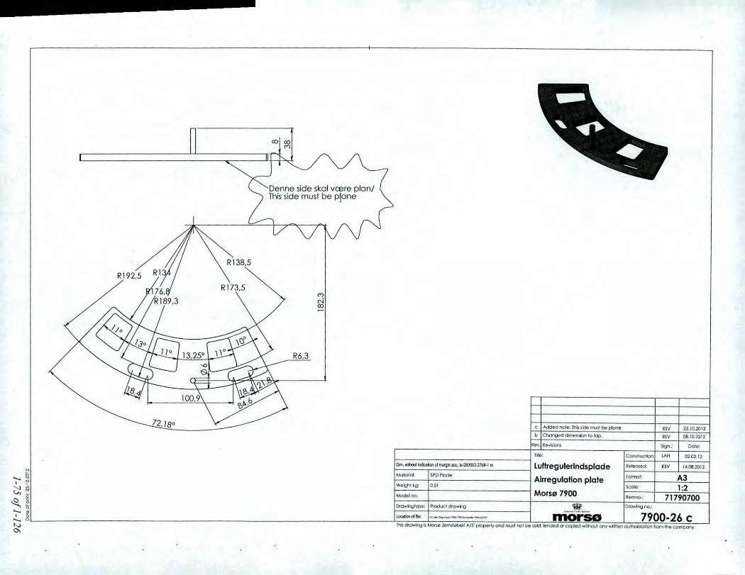
c "'OOeo nole: lhb $ide tnlJSlbe pIo:;Jr>e
b OlOr>geddmr:ornionto lop,
Rev Rev~
nile;
luHregulerlndsplade
Alrregulatlan plate
Mars" 7900.__'l!!__morse
." 25.10.2012
OSV CtI.10.2012
~.; Oo!e:
C~Trvcllon "'" 0'2.02.12.."',,'"" OSV 14.08.2012
Formal: A3Scole: 1:2Itemno.: 71790700Drov-ing no.:
7900-26 C

.._-_ ..__ .._,--_._."------_._---- ..__ .._-, .._------,-,-_._-_ .._-+---_ .._--~_._-------,---".,.__ ._-------_ ..,---_._---------_.-
ijII
Denne side skal vaere planlThisside must be plane
06-05.2013
25-10.2012
06.10.2012
U.Q8.2012.S'
._--_ ..•._----,- ...._-1-.
d ChongedIhc~~-~'ovoi'~-:- --;svc "'dded nole:Tnk1lde!I'MI be pIone RSVb Changeddlmen!kJr110tap. RSV
C. _Drowi'lgtype: PfOducl dovmg------------
A31.:2
71790700W ,Clf<JlW>g rlC).:
_rriOi .,-L79QO:..26 dThh drlJ\o04olgIs Mona Jemsllllbe<l AlS' p<operty and fWS! nor toe KlId,!ended 01 copl&d w;ll1out any""";I1,," oulhOrllolion Irom!he compon~.
R" .••, l/evisJonl, ~.: Date:
1 __ "._. __ .. -=====t~~---------'---rc~~Iioo. _CA_._"_ =02_..-":_"-::-Om. wrh:U.hlitalioIIc1~1CC.1D O5nSO.2768-1m Luftregulerlndsplade l/elemed:
Material; SPD~~ . . Alrregulation plate f.ormol;
IWelghl kg: 0.51 Scal6:
Modelno, Mors" 7900 IterMO.:

Model no. placed hereon this side
13--'7~.2-
","": '"",0 N- <>- <>-0 - -0 0
<1J 192.5
I<e~I<ev~ Sigtl.: Dole:
A,Wil.ef eifEl( inllrulttion: 1.(;.1.02 6or&aomer Me: Conlllucllon <sV 08,02.12
Om. ,,,l'louI~ rlfIliII9I'I-.;c.1O lSONOIlIl No.:IlO62en Top dooksel i~: <sv 29.os.2012
Matllliol: COIl~onGG'~Top cover fOfmOl: A3
Welghl kg" 1.~1 $cOle: 1 :1""""'~ "" MorsllJ 7900 llemno.: P • 34790900DrmWig!'ypo: P!'O<M:! dtOwFog ~ Ofowlng 1'10.:
I.<aIon 01rM: ~--_._-•..... mo 7900-28 a

;,
•.:."....
"
I~
r!
ii,!,- .••.~,'~.'.
.', ".,
.:. .....:"
.' '"~ :
;. :..... ;::-.,
.~ .~. <" .....,' .: ..'.; ::1
,';. ~.~.-~,
.."
...
""~t--1-"""
I
1-78 of 1-12

r-- --- -+.,._- - -"-' - _...- - "._._..- --_._---_. ---~----_._-----_.,,---
r,1J200
===I~:
--- --- - --T- -,-~'_ ..- - - -- - -)"-- _. ----- ---~------ -
nllll:
Blindplade r~gtud
Blind plate splgat
Mars~ 79000.97
------.---
-.--.--- IComlruc LAH- '--0;;:1;:'-1-- .."., Ileleo..ed IlSV 0'2.05.2012
l~!:- A3>_.: kale" 1:2i'''=, 71790~00_,
~_-.l3J_OO:39 ojThis dtowinO Is Mon0 .!e<m1",berI A/S. p!opeOy ond I'llIAt no' be 1OId.lended 01" copIe(l without onywnlten oulhorila1loo from the company.
Model no.
G--==---~=-omdo.CirdocltbI~IIIiJVIlacc.100&\S0216e-' 1\1
Material: SPD.DCOlAMlEN10130~:••...• ';"~ ~j
'0;;1~~......•~ 8: _
'"~

• •
••I. ' ,'!' ,• I
H 'IIpulllliili'
CLlEeuLl)•...•ClCl
..
I'U
.W'5
tOil
l"Oll
nil!
""'"
"'"~'101
1-80 of 1-126

7o
5453,5
342922Rl
It\0/,I
R6
C/J 5,5
C/J 5,5
Rev. Revisions Sign.; Dale:
Title: Construction" LAH 02-02-2012
16.08.2012
A41 :1
71791000
RSVReleased:
Ilemno.:
Format:
Scale:
Drawing no.:
Hcengsel i topTop Hinge
MorslII 7900
1-81 of 1-126
SPDPlode
0.036Weight kg.:
Dim. 'Nithout indication of margin ace. 10 DSnSO 2768-1 mN
~ Materiel:
~c Model no."5-'0 Drawingtype: Product Drawing <iM'~ localiono'.' _, __ ~_ II'iOiSe 7900-43aThis drawing is MOrs0 Jemst0beri A/S' property and must nol be sold.lended or copied without any written authorization from the company.

14
7
o
18
o 0Ll) C")
o
!?l6,1
b Changed 2 holes 05.5 to 06. RSV 13.08.2012
Rev. Revisions Sign.: Date:
Title: Construction" RSV 02-07.2012
Hcengsel i bund Released: RSV 09.08.2012
Bottom Hinge Formal: A4Scale: 1:1
Mors" 7900 Itemno.: 71793000
Dim. ,,"thoul indication of margin ace. to DSilSO 2768-1 m
"0 Orowingtype: Product Drawing ~ Drovving no.:
~ locatioooffile ~,_____ niOrSe 7900-44 bThis drawing is MOrs0 Jemst"beri A/S' property and must not be sold,lended or copied without any written authorization from the company.
N
<5 Molerial: SPD P!odeN
~ Weight leg.: O.OIB
'E Model no..8.
1-82 of 1-126

c..E&'.co0-0-•...
og:•...
c..E>.Q..,.••.0-•...
o.••.0-•...
o
50,
1-83 of 1-126

7940 7948 7943 7943 7943 7970 7990 7990 7990
with ploln base with log storoge with drawer with plain bose wilh log storage with drawer
54790021 54790021 54790021 54790021 54790021 54790021 54790021 54790021 54790021
A A A A A A A A
+ + + + + + + + +B C D E E IF H H
54791721 54793421 54791821 54792021 54792021 54791421 54791921 54792121 54792121+ +
Note: K KFor brown versionreplace 21 in theend with 07. 54792321 54792321
TOP MODULES AIR TIGHT BOX SOAP STONE HEAT STORAGE HEAT STORAGE HEAT STORAGEPLUG BRICK
lOW TOP HIGH TOP
•@-•... Q ~,
00 ~ .~--L. . -==---=:::::::: --
~ -_. .-•... 54793321 79790600 54793121 79790800 79790700 --, 54792621 54792721•... . ;'" !....'"

0174
A~
I I
Ak-
01$4
150
10
o
AistandsmlZllril: FZ Ml0)(3Q
A-A II: 1)
0a __ ••_ •••.• 1I6II01"'"'.
_ .. -------Prop varmeakk.
Plug heal acc.
Motu' 7900
--~-
••••• , DaIoe•••__ •.••• 04-'00"
_ II$V 09'*:11>1>
••••mar. A2k""', 1:2~ 79790800
7900-71 a

<Xl
-(")'<t
<Xl
\R244
~365
-I!
I
t I
l ,
I- - --l---"-.;I
Sign.: I Date: II Rev. Revisions
I.•.•. "."
02.03.2012 !Title: Construction: RSV."-
Glasband m. tapei Dim. without indication of margin ace. to DSllSO 2768-1 m Released: I
1 Moleriol: Moterial <not specified> Glass gasket tape Format: A4 !Weight kg.: 0.39 Scole: 1:5Model no. . Morsl2l 7900 Iitemna.: 79074200
I Drawingtype: Product drawing W \ Drawing no.:._-_ ••..•.•.•llocalion of file: """"""~~n~ __JUl"IT I(I'IOt:$Q i 7900-72 a i
'";~15•15o
This drawing is MOrs0 Jemst"beri AIS' property and must not be sold, lended or copied without any written authorization from the company.
1-86 of 1-126

III
I
<Xl
<XlN"<t
l
<Xl
\R241
-------174
II ,
----- Ii J II
"--"--,t !
I - -_. - I IRev. Revisions Sign.: Date:
,
IOim."thout .'ication of "",y. acc.l~ osnso 2;66-1 m
Title: Construction~ RSV 24.04.2013
Glasband m. tape Released:
I Material: Moterial <not specified> Glass gasket tape Format: A4\ Weight kg.: 0.29 Scale: 1:5! Model no. Mors" 7900 Ilemno.: 79074200 II Drawingtype: Product Drawing W Drawing no.: i
--~"-"'.- 7600-73 a !I location of file: C.~_1'IOO-1;l~_~ ~
M;~15•g
This drawing is M0rs0 Jemst0beri A/S' property and must not be sold. lended or copied without any written authorization from the company.
1-87 of 1-126

Rejfes 0,5mm x 45 grader po begge sider.
Chamfered 0,5mm x 45 degrees -Both sides,
Cut Ql 5 R15,9Drill rj) 9
M4
32,5
R4,2 30,8
M420,812,2
R4,26,30,5
°R2 R4,1 JL0(")0000
C"5 N 0 cON N
b A:ndret det store hul t~09. + pof0rt vorenummer TOl 20.02.20 13
Rev Revisions Sign.: Date:
05.02.2013
30.08.2012
A41: 1
71793800
RSV
Construction TOL
Formal:
Released:
Itemno.:
Scale:
Drawing no.:
Lukkekrog
Closing hook
MofSl" 7900
Title:
SPD. DC01AM/EN10130
0.Q3Weight kg.:
Dim. without indication of margin ace. to DSIISO 2768-1 mM
;:; Moteriol:
~i Model no..~
'0 Dfowingtype: *Q) ., ••• -._-~-
g locationoffilec,_,_ ••_._ mar 7900-76 bThisdrawing isMOrs0 Jemst0beri A/S' property and must not be sold.lended or copied without any written authorization from the company.
1-88 of 1-126

R6 R117,6
56,1R4,4
43,2
M438,7
27,3
16,39,86,80
lliII II
b Hu1cendret fro 05 til M6..•. POtli.lrt varenummer TOL 20.02.2013
Rev Revisions Sign.: Dote:
Title: Construction: LAH 02.02.12
30.08.2012
A41:1
71793700
RSV
Itemno.:
Released:
Scale:
Drawing no.:
MorslIl 7900
Formal:Plate for closing mechanism
Plade for lukkebeslagSPD. DC01AM/ENIOI30
0.05
Dim. without indication of margin ace. to 051150 2768-1 mM
~ Material:
~ Weight kg.:
c Model no.Iio Drowingtype: ~
~ Loca'ooo'"' ~_n_._ morSe 7900-77 bThis drawing is Mors0 Jemstl2lberi AlS' property and must nol be sold, lended O( copied without any wrillen authorizotion from the company.
1-89911-126

o o
Material eRINI SteelRev Revisions
Tille:
Sign.:
Construction: LAH
Date:
16-05-2012
30.08.2012RSV
A42:1
Part of 71791100
Released:
Scale:
Itemno.:
Format:
Drejepunkt lukket"j
Turning point Closing
Mors" 7900
Ni I Crsteel
0.003
c Model no.is.- D . type r('t'h Drawing no.:o rowing : 'm"~ l",tiono/file _'_=__b_ IriOrse 7900-78a
Thisdrawing isMom;, Jemst0beri A/S' Pfoperty and must not be sold. lended or copied without any written authorization from the company.
N
~ Moteriol:
g Weight leg.:
1-90.of 1-126

o o
. -
104
388o
Dm.,,'''lt.holl(:akwlol~lIC&.b0s.1S02763-\m Mellem plade frlskluft boks RelecI.ed: I1W 30,0..2012
:::,oJ:7""'~. Middle plale alrtlghlbax ::' -f ~:;Model00:..- 1---- ------- Mors" 7900 ~emno -' Port of 71790300DrCJ"o'l.T\gIype: ~,-""-",,,-~- ••••••--_. --- '1-W - 0I0'Mr0g no -- ]
'""""...J~=-~==~-=-_niOrso--l_7900-S0 blhk. dfowng Is MOrl.0 .lefmtebefi AIS' propertyond rno,nl not be sold.lended 01 copied w;1t'>Oul onv 'Millen OUU"Ol'izolion!rom the company,
b I11!fl'1C1W!dthel0M6
l1e~~1 _
fJlle:
osvSIgn,:
C~lrvcllon: LAH
11.09.2012
Date:
03,01.12

40
20
45
ll)
co
ll)
co
R5
600<: 450.0 30ci0- 15a... 0
cOll)
b Changed dimension from 12to 9. RSV 18.10.2012
Dote:
06.02.12
30.04.2012
A41:2
71791500
RSV
Format:
Scale:
Released:
Sign.:
Construction' LAH
Itemno.:
Drawing no.:
Vinkel f. vcegbeslagFitting f. wall fitting
Morslil 7900
ntle:
Rev Revisions
SPD Plode
0.2
Dim, 'Nithout indication of margin ace. to DSJlSO 2768-1 mN
~ Malerial:
~ Weight kg.:
.~ Model no.0.'0 Drawingtype: Productdrawing W~ locatianoffile ._' '_b_ moi'-- 7900-81 bThis drawing is MOrs0 JemslQlberi A/S' property and must not be sold.lended or copied without any written authorization from the company.
1-92 of 1-126

13
142
574.1~
0 0 0 0
" ~M l'>
0 0 0 0
5
631.1,.
,..__ •__ o.tr_<nd•••.••_ •••_ ••••_ ••__ •.••••__ "',.__ ••••~_
~ __ )]"':Il ., "Hl~I)b __ •••. _ .' "'OX"1.•. -- C".. __
_.11oo. __ " ___ OIaOI,,",'_
Vcegbeslag - .' (1).11$''''1- ~- Wall mllng - '2-'(1' ,,~ - 1:5-~ Morslll 7900 _.
P.717914oo•...•--,- -~- •...•-_ .. --- 7900.82 c
o
o
o
UP 90.00" R 10
o
120159.8189.6209.6
R5
209.6189.6159.8
120
,--------------------------------------------------------lUNFOLDED :
~ R5 I'IS
!147i142.5.
i!!
"'.5i1047 :
!i
I oo .....~ "" I/') ",co <0 I. MUll/):: R ~ ~~;t ~~~ 'L .._ .._. .._ .._.__.._.__. -= __-.::_~ .. __ .J

1948.10
0-,-
10
0-0-r-..."<t
-
0-
II
III
i
==~
--I
I - ------------ --
!
I -------- ---- i-Rev. Revisions Si~ Oofe:
Title: Construction~ RSV ,24.04.2013 I.._.
IDim. 'Nithool indication of margin ace. to DSJlSO 2768-1 m Glasband m. tape Indv. side Released:
Material: I ~Glass Fiber Glass gasket tape Inner sideFennet: A4
Weight kg.: 0.11 Scale: 1 :5Modetno. . Mars" 7900 Ilemno.: I 79074200 I
I Drowingtype: Product drawing 'Q? loro~n7900.83 I"--~'-"'~-location of file: C;\_,l'tC:CJ.&~ •.•••_.JI.OI'OI ~ a
M
~N
~8-'0•8
This drowing;s Mom;, Jemstl2lberi A/S' property and must not be sold. lended or copied without any written authorization from the company.
1-94 of 1-126

nl•• i! ~::::!i ~~
06''''zat0
~----------,C"'LC~-------

I-:r:::::=-_--=::::==:::::::::.I i----'---:-==::::::::::::-...::::=.::::I:-.:
!
Denne node slcalvcere plonlThis surface musl be f101
2530
o
79Q0.80Mellem p1ade frlsl:luft bo~s/Middle plore Ai,!ighl 60x
A
1
o
7900-22 fth~lufl boh/Arrighl Box
A-A
:.:::=,::~~'"~~::p:::::~-=:::':'::::="-i:-f~::::l--- J ~ 0.-r-: C<ita>u<""""'" '0,10."
IFrl$kluH boks sve]s! __ I 0$... ~ lOlJ
. AIrtight BOll welded"""'" A210<_ 1:1
Mors" 7900 _, 71190300
01.5
01.5
,..,",., ..-....._--_._-_ ....-- ..•,""/ ",/! \\
o I I 0\ is: }'
',------.- ..-.-~.
01.5
01.5 IIDot.-"_" __ ."""l,","'.1= ~-;~ """"'"'_ W ""-'a .••,1-;. ------- mOi'Sa 7900.87 9""'_.""""'_NS._"'"' •••..••""'•••__ "' ~ •••.•••.••oomo.<I"r

10
Ingen grater
It)
"-N
<f-\
5 7,5
Q)
~
Rev.! Revisions I Sign.: Date:- ,
-, Construction~nile: RSV 21.11.05
I Mal uden loleronceongivelse i,h.t. D5/150 2768-1 m Glasclips 8100 Released: KDU 06.03.06
I Material: Rustfri stal Format: A41 Weight: O.kg Scale: 2:1I Model no. MorSlll 8100 Itemno.: 71814561 iI Drawingtype: Emnetegning morse~Dmwingno.: Illocatlon of file: 1t\UOV\~'<:lI\II(I;I;n~"CI;I:llCPO' ._."._-~ 8100.132 a
M
~
~a2g
This drawing is Mors0 Jemsf(2lberi AIS' property and must not be sold. tended or copied without any written authorization from the company.
1-97 of 1-126

30
3o
11
B-B
37.42511.5o
B TRUE R3,2
ANSI Inch1/4-20
R286
R274
1--.-.----.----- ----------------- ...----.....----...-.--+-- .....----.-----------".---- ...--.-.,"------------ ...--..--
I
A-A
I1lW~Revi$iOnS Sign.: DoTe:
I . nH"'a:-ndlag !yr'" d", NA':fc':~d"'.',~_!~.. 1(l.()4.2013Din. WIhlo.CJm:alionollflal'9lnICe.I00&1S02r;:;'~- ~
~i Materiel: • lMtMdl!ll-Alsl.»4 . Handle door NA k>rmot; _,_~~ __ •
';"'"~I welgt1tkg: 0.3 SCole __ 1:2~ ~i ;;;;;;;;;- Mors" 7900 =Euemroo-~~: E._ ~----"' ~.2: ~: ~.. ===--==.:=-. mo.$8 7..llQ.O.:l62'" ~----------------------------------- Thbaawhg~Morl4 Jemslll>be<tA/S'pfOpe<tyand mvslnolbe'Old.1&ndedorcopleodwflhoulorrywr1tlenovthot1zolionlrom thec~,
0\

A21:5
=
o7943. Drawerw Top low
o
= =
=
7943. Drawer
7943 -open
It'--60
I
I7943. open I- Top low
-rOo)i-:,j_
c_~ nv c1wuouI ,....-rla __ oI__ "OUSOZ"". IGO'.k. legn. 7U3"'''
1- AppDrawlng7U3N" ::I::.:' Mors" 7900 _,1-....- _'N?__ '~"".I~..... I'1"IOrSO 7900.152 a.•...-...... •••....•.••...•,.._~--..-_ ..•"" ...._"'--"'''--- ••...._~
7060
Vermiculite
Asl:esk:ulte/Ash Troy:
~6~~~57/3OOx30.5mm
VermiCulite
Primary Air:Min.: 3 x 228mm' = 685mm' •MOll.:3x 73Omm'= 2190mm
D-D
==-••• - 0D
Secondo13Air:27x 04: 9.3mml
---= ---=-ermiculi!e
7943 7943. Top low
Vermiculite
VefmicuHle
C
0503 6
4.
.,' '.-.,.....,"
,-" ~ Ltf
,-I
vI
Ii
3.!hl
I 8.~ •~ CL I l'--- -i--- ---
II
I?ll I
,III
I
iiI
I iL I J
~J
c-c
Vermiculite
•..., ,'01:'0 I' Vermiculite
~li•... :, 'j•... ''"0-

7948
o
Vermiculite
Askeslc:uffe/Ash Tray:Indv.: 265x257/3OOx30.5 mm
Br-I
152
Er
elmiculile
ermiculile
D
C
05036
'" ~~- w
•••••
!II
316,1
I ~
C.l ! lC-----,- _.~_.
""!ill
iIII
0sb3.6I I
-0000.11:1']
.21:5
.-••• hYN<w'o
'-,--
607060
B-B
11'00 ••_ •••.••••••• ,_,. j ~k.l.gl'l. 7,.8 HA
'"",_ App. Ofowlng 790la NA """.,.lw""",'9o s.:-1Mors" 7900 _;!=..., I _~_, -.-1_.. __ InOI"SG 7900-153a
••••~.~_ ••• M' __ "" •• _ •••__ •• ••••-.. •••••••• ~
Primary Air:Min.: 3 ~228mm':c 685mm'Max.: 3)( 730mmo", 219Omm'
BA-A
D-D
E
Rl38.5
VermiculiteVermiculite

'21:5-"*
o7950
1he soapestone top is an oplionand eon be used on M0f50 variantseither Mor\o 7940. M0f50 7943.MorSO 7948. Morso 7970 or MOfSO7990 sloves. where the eml ~O" topplate is replaced by a top plale 01soapstone.
Mor5111 7900
Godk. '.gn. 1tSO NA
App. Dfawlng 1'50 NA
'.-
..
.-.
o
6070
..
'0
._~_.I11OI"SO 7900.154 a......._._-->$ ..__ "''''''~ ,.._--.",,--- ""-
Vermiculile
Askeskulfe/ASh Troy:Indll.: 265x257/3OOlc30.5 mm
B
Primary Air.Min.: 3 x 228mm' '" 665mm'Max.:3x 730mm' '" 219Omm"
Br
2651
A-A
1S2
D-D
E
Er
R136.5
Vermlculile
VermicuHte
Vermiculite
C
111503.6
A In'
f
-I
II
31~<1
! ~
C.l I l'- -----1--- ----
J
iill
II
I I

-7940
.-.
Vermiculite
Vermiculite
Ask:esk:ulfe/AshTroy:Indv.:265x257/3CXb::30.5mm
IIII
Li
Vermlculile
VermicuUle
D
C
r!J503.6
~ ~~W ,
!-,III
3p .. l: !I
C.l I~II-~-._~_.-~---
I'll -II
:: I
_ A2
- 1:5
Godk. l"gn. 7"'0 NA
App. llfawlng 7940 NA
-It.•.•..-
Mors" 7900i=- ,..~~_ ~~_.. I11OI"SO 7900.151 altf>_ •••••••••_"-IS ••__ ••..•,_•.•__ '"_-... """•..•~
rIO-' __ "_ •••.••~I ••••.,.
,--'<>'
60 70 60
Primary Air:Min.: 3 x 228mml '" 685mm~Max.: 3 x 73Omm~= 2190mm~
Vermiculite

=
0~-
o
7990-open• Top high
T-:[.-'-- L0.,001.10')
t '2 I- 1:5- I~_.
7900.156 a
=
0,-
o
7990-open• Top low
7990
, ....,Godk. le-gl'l. 7990 NA
•••.pp. DfClwtng 7no HA
MOrle 7900
.._~_.rnorso
o
7990. Drower 7990. Drawer 7990. Drawer- Top low ~Top high
7990-open
60
r.• __ ••_ ••. "OOOII)_'.1-1--.,!_ •••.r---,_.-
B-B
7060
Vermiculite
Vermiculite
Plimary Air:Min.: 3)( 228mm' = 685mm'Max.: 3)( 730mm' '" 2190mm'
Askeskv1fefA$h Troy:Indv.:265)(257/300)(30.5 mm
II
B
270
Doub<.radiation shield
E
Vermiculite
Vermicuflt
D
Vermicutit
c
;vermiculite
4
311
A
..".:.;;-.,.c-e
c
D
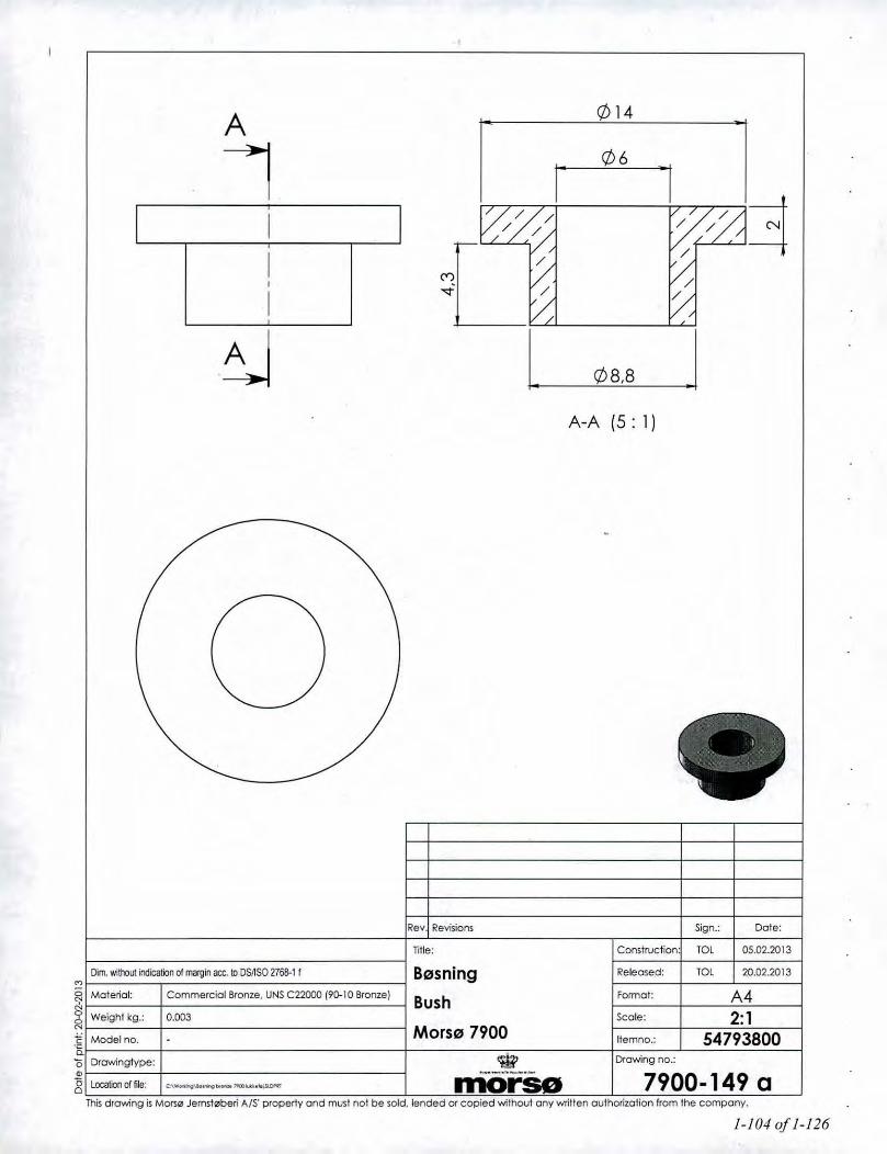
A Q) 14
I Q)6
I
II
I
.~ Q)B,B
A-A (5: 1)
Rev Revisions
Title:
Sign.:
Construction TOl
Date:
05.02.20'3
20.02.2013
A42:1
54793800
TOLReleased:
Format:
Itemno.:
Scale:
Drowing no.:
B/lJsning
BushMors/IJ 7900
Commercial Bronze, UNS C22000 (90-10 Bronze)
0.003Weight I::g.:
Dim. with:lut indcalion of margin oct. 10DSIISO 2768-11
'"~ Malerial:
~c Model no.'c0.15 Drawingtype: W~ LocationoTfi. ~._--~ ••_ rriO-rSe 7900-149 aThis drawing is MOfSI2IJemst0beri AIS' property and must nol be sold, lended or copied 'Nithout any written authOrization from the company.
1-104 of 1-126

Heat ace.stone,3 pes.
Pedestal base
7940 -7943 -79487950 -7970-7990 -
=~~. ~~-~~"III-' .~ Air regulation~ for
"~".~ ",,"
~~. I ;,,1 ill Base400 mm. Base600 mm.
•....w.ith drawer _ with drawer
Top module 460 mm. ~~, Heat ace. ~, i
~~ stone ~ ,I~\~ • Ii II ,I i,'
~~Q, • 1Top module 190mm. ~ '. I, Wall filting . / m'l f
"', '" ! .111; :;::""m I.~,'. ...• •. / m I =~mm
"..mmm./'_'~""m 1/,.....'mm.~ ~~
~-~ 1~-~
Top cover,
~
~Top coversoapstone
- -.. , ..-- 0_;:.._--~----.-_'":"~-':":,-~t:.~
~-=~_L_,""",, _

269257 t
07
o
•
Oote:
The <i'awing 1:1"""" •• JIlm$!0bttr1A/S prQpelly and rro.Ilt 001 be $Old. "'oded Of copied wllt\Ovl ony WI~len oulhortrolion!tom the COlT1X>ny.
18.10.12
28.02..2013.".Cons!rl)(;!lof'l: ~
IR~:r:-----
J.'~__A3------,
S<:O.: 1:2~ors" 7900__ 7,.~--'----..- 71793900-----<-----=-~_=_ - rDrow;,goo.:
morso I 7900-131 a
1.231 .•. _
Bile:
~~.UI~Qfm ••~acc.l:lOSllS027l;&.\~ BogpladeMolerlat SPO-DO:llAMlfNl0130 _--< Plate rear

Cb8
b JEndrellcengde fro 8 lif IOmm.
Rev. Revisions
RSV
Sign.:
14.08.2012
Dale:
nile: Construction: RSV 09.08.2012
A42:1
71793661
Released:
Scale:
Itemno.:
Format:
Drawing no.:
Afstandsr"r
08/05,2Mors07900
0.002
Dim. wittXlUt indication of mal"gin ace. to DSIISO 2768-1 m
Rustfn HydroulilcrQlr
.~ Model no.0.'5 Drowinglype: Productdrawing c;J.1~ Localioooffile "_,.~ __ ~w~._._~_, Iri()-'- 7900-126 b
Thisdrawing isMO~0 Jemst",beri AIS' property and must not be sold. lended or copied without any written authorization from the company.
N
~ Material:
J; Weight kg.:
1-107 of 1-126

33,6
30
Lt)
c5 , ,, ,
Dote:
07.08.2012
13.08.2012
A41:1
54701400
RSV
7900-124 a
Fonnol:
Sign.:
Construction' RSV
Scole:
Released:
Itemno.:
Dro'Ning no.:
Title:
06x30 Din 660med 01,5 hul
MorslII 7900
Rev. Revisions
Aulomolsl61
8.2
Dim. without indicaten of margin ace. 10DSJ1S0 2768.1 mN
~ Material:
~ Weighl kg.:
'E Model no.B.15 Drowinglype: Product Drawing *Q) ••__ •••••••.•• _ .•••
8 locatioooffile: ••\w<Mt \t:e<_ ••• lW.lIICIr.~ InOrsGThis drawing is Mors/2l Jemst"beri A/S' property and must not be sold. lended or copied without any written authorization from the company.
1-108 of 1-126
oN
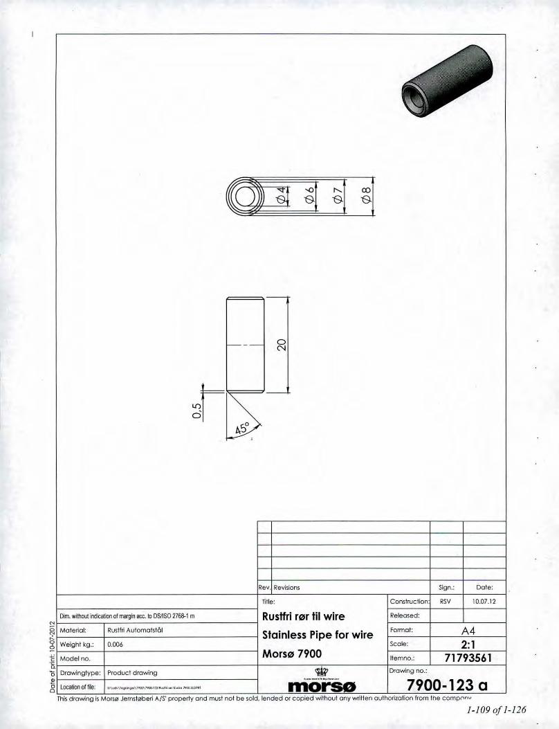
Rev. Revisions
Title:
Sign.:
Construction: RSV
Dote:
10.07.12
A42:1
71793561
7900-123 a
format:
Released:
llemno.:
Scale:
Drawing no,:
Rustfri r"r til wire
Stainless Pipe for wire
Mors" 79000.006Weight kg.:
Dim. without looitation 01 margin oct. to DSilSO 276t).1 m
RustfriAutomalst61N
~ Material:
~.g Model no.'-'"15 Drawinglype: Product drawing ~Ql '._-'''--~8: localionoffile: ~_...-.r,""",-\1OlI7>-"'l:I"""'_M"","""aDNl morse
Thisdrawing is MorS0Jemst0beri A/S' property and must not be sold, tended or copied without any written aulhorization from the comprlnV
1-109 of 1-126

CI==~~~M~-_
~!
\m,
I ". .
~
-~
;\ • ~-._._._--~_.- _._._._._._-------- -
,
••••
"*"~
n .'7-d
r-, -."
f...... I
)/
-I
,
- ---- ~
-~
1-110 of 1-126

ITEMNO. PARTNUMBER DESCRIPTION OTY.200 7900-85 R0l"for piedestal R0I'lor piedestal 1
201 79(X).I02Toppiode for piedestal Topplode lor piedestal 1
202 7900-103 Flange I mr for piedeslal Flange I r0l"Piedesial 1
0- I 0-
!0 0IA I .-.-tA1--.
I1
0- I ~
~.Rolled pipe welded and grinded.with no edges
c3 ~
A21:2
717'3100
O$v l'CU)lI
.."., 0cNc
<;0<0__ 7".1:11.')--,.....-Piedeslal
Pedestal-----< Morse 7900•• -,0.-_ _ ....~ _
_ •• -_.- morso 7900.105 b••••_"". M •••••••••••••••_' ••••t>- __ ••• _..-...t ..... •.........-A.A

, , , ,
Thisd,awng Is""""$0 Jernslebfl'rl A/S p'ope<1y and mull roor be K>Id.IendBd Ofcopied wlthOl,lIany _Itt"n oul'hoftzolion /Tom lt1e c~ny.
, Chonged~ .S' 14,08.2012
Rev I/e>'lsions Sign.: Do"',~. ",", CONtrvetOn '" 24.05.12
[lom.••olIlDul_olm.""m:.tlDS'lS02763.1 m Monl.flonge piede,tal l/eloKJ>ed: OS' U.oe.2012
Material SPO - DCOl"MlfNl01JO Mount. flange Plede,lal format: A3W~I~~: " Scale- 1:2Mod<o<M. Mors~ 7900 I"'mno~ 71793200Dl'awngtype; PrQdI,l(:! dfowng ~ Drowing 00.:...-... .----"'- mo 7900-104 a
~/' "-
/ "-,
II R
" 0 0
" 0
/~N
S S
120'
'-
....,........'"~....,....'"'"

. 001
~=====================================I~
o00
\/
(
,& ~::.v 00
\ I
'''>,M8 M8,,7"
Melerial:
~ttlghlkg
Model 00.
SPO. DC01AMlEN10130
\..
Re~Rev~ Sign.: Dole:
",", Consllucllon "'" 2•. 05,12
Flange I "or Pledestal Roloo-:l: "" 3O.oe.2012
Flange In pipe Pedestal forrrot. A3Scole: 1:2
Mars" 7900 Ilemno.: Part of 71793100Drawing 00.:
7900-103 a

001
-~~ ~ __ I.=+ II
R12
<Z>10
o
100
88
o
72
84
b Moveda lop !TomDOg10Iron!. iN 11803.2013
lie••..I1l!vilbru . Sign,:. Date:
"" •••••_._ ••~.OS1SO"..'m ;:PPlade for pledeslal i::':"'" : l~:~:,.~~D.DC01"~E"~~ ..,_ Topplate for Pedestal I FOfmal; A3-----1W&lQhlkg 2.21 ~~---"-i-:2MOdel no i "."."-_ .._--"-"- Mors" 7900 'l!l!mno~ Partof71793iOo
'0<0.;"""" "-,-;;;~;" - n1O--~rso-- 1&--7"9°'0'0-102...-....1,'"----- b'1M drawlng IsMorslll Jemsleberl MS property ond I'rlJst nol be s.old. tended Of cop~ wtlhoul ony wrm'm o<Jlhorllatioo!rom thtt eOfTl'Ony.

{=CI =========
,.------~,~,,~,-----
, . , .",
1-115 of /-125

CJ
.""::
I I• •i~ ill
I! Ii
i1.:;.,,*:::':'1
!Iiiii
IiiiIiiiiIiiiiiIiIii!Ii
...._.. -;f
.n
1-116 of 1-126

290
~'2'60
290~2841-------
\1)4,2
\1)4,2
-r
I\:M6 ~ressm"frik
M'~"~'''~
'"
M6 pressm0trik\
/M6 Pressm"trik,j
I ,_
30
o
----.290~284
\1)4,2
\1)4,2
10-11--123
-10
o
INJ dtow'ng Is Mol'I0 JerMt ••beli "IS ptoperty coo roost 001 be sold. !ended or copied without ony wl1fTen oulhotlroliQn 110m 1ne corrpat't)'.
b P6Illlftud<l:(Bringlor monle<hQ" 1900.
20.01.05
OlD'!llI
RSY 10.06.2012
Sign.: Dole
trernno.:
ConstnK:flon: (Of.I
7600-63 b
_'_._~_'_' A3 _$colli: 1.:2
71761000Mors" 7600~
morse
Afstandsplade skuffe 7642 Rel9Q.e(t:
Tille:
Rev. Revlslord
Om. "lII'OUt "**'" clm_lI"l ~ tI OSrlSO V6&-1 m
MQlerlol SPDPlade
MOdel no,
<Xl'" "'<Xl"":-.0 -.or..::
'" '"<Xl <Xl
EJ 0 D•...,••.•••.•"-Q.,-••.. ,~d
'"'"

08
I
15
'I06 •
I
/? ~ \-- --
I
Rev ~ Revisions Sign.: Dale:
Title: Construction RSV 24.09.03
M6t uden toleronceongivel'Sei.h.f. DS/ISO 2768-1 m Afstandsr"r "Sx1 L= 15 Released: RSV 24.09.03
Moterial: Hydraulikr"r galv. Format: A4
Weight: O.kg Scale: 5:1Model no. Mars" 3400 Itemno.: 54349000Drawingtype: Emnelegning morse Drawing no.: Side 1 of I
localioo of file: u.""""' __ "--"""''''''_'.'h1 __ '.ll.DI'*I tl_ • ., ••""",~~ 3400-120 a
15is.'0•g
This drawing is Mars0 Jemst"beri A/S' property and must no be sold, lended or copied wilhout any written authorization from the company.
1-118of 1-126.
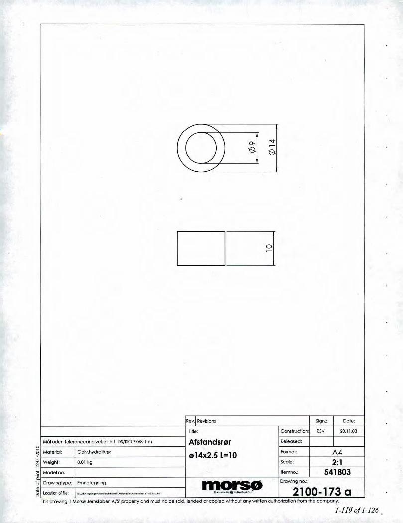
.....•.•.••.
/ ): "<t
( 0- ~0 0
\.../'
•
0~
Rev~ Revisions Sign.: Date:
Tille: Construction RSV 20.11.03
M61 uden toleronceongivelse i.h.l. DS/ISO 2768-1 m Afstandsr0r Released:
Malerial: Galv .hydrolikr0f 014x2.5 L=10 Format: A4Weight: O.QI leg Scale: 2:1Madel 00. Ilemnc.; 541803Drawingtype: Emnelegning morse Drawing no.:
location of file: ".-.\'. __ ""'_"""'_".'''utUlI''Ol 1Ir_ ••,,;,••__ r- 2100-173 a
'Ea(;
~Thisdrawing is Mars" Jernst"beri A/S' property and must no be sold. lended or copied without any wrillen authorization from the company.
I-fig of 1-126.

0806 5,5
/-
"/' -....;
'- /A'-.:. :--', A-A-
•
b Ilcengde cendref fro 3,5mm KDU 30.04.03
Rev. Revisions Sign.: Dale:
Title: Construction RSV 06.03.03
Afstandsrlllr 1Il8x1L=5,5 Released: RSV 06.03.03
Malerial; 08 x I mm hydraulikn.'lr gal'o'. Format; A4Weight: 0,7 9 Scale:" 2:1Madel no. Itemno.: 54202500Orowingtype: Emnetegning morse Drawing no.:
location of file: 1t","",,1.~-'-"VI>_•."""'_"".JlOf'III.._ .."" ..__ •... 2000-185 b
c"5-15og
This drawing is MO~0 Jemst0beri A/S' property and must not be sold, lended or copied without any written authorization from the company.
1-120 of 1-126

~ ~
,
I,I
~
~I~~
I,I08
V1 010 20i'J
,
Malr:lOxl HydraulikrQJrgalv. varenr.712602litel: Afstandsr0r Sign.: Data: Revision Sign. oto
RS 97011301Ox1
Tegn.form.: Malforhold
L=20 A4 2:1Tegningsnummer: Vorenummer:
1400-302-4 542635
morso / Filnavn:1400-302
Jemsleberi A'S
L I1-121 of 1-126

•
A 12~ /M6~
a/tf ~\ - C"l --- sl'~ ,jJ -
//A A-A-
~ ~A31.5 '--zc.- vv,
I D 13
•c JEndrel kengde tilbage til31 ,5 mm. RSV 13.11.2008
b Qlgellcangde. RSV 11.04.2008
Rev. Revisions!ek:st: Sign.: Dato:
Maleriole: Sort fladjem Tilel: Konslr.: RSV 03.03.2000•, Vcegt: 0,015 kg. 1 Beorbejdes: Lusmed gevind Frigivet:
~ Overfladebeh.: m' Tegn.format: A'•M6ltoleronce: M~)I~dentoleronceongi"else M6lforhold: 2:1• DS ISO 2768-1 m
Mors", 1400~ Ruhedslolerance: Vorenr.: 44256700VcerkI0jsnr.: morse Tegningsnr.:
Tegningstype: Emnelegning ""•••••••• _., """"llno_ 1400-204 C
u
u
Denne tegning lith0rer Mom!! Jemst0beri A/S og ma ikke afhcendes. udl6nes eller kopieres uden firmoeis skriflrtgelillodelse
1-122 of 1-126
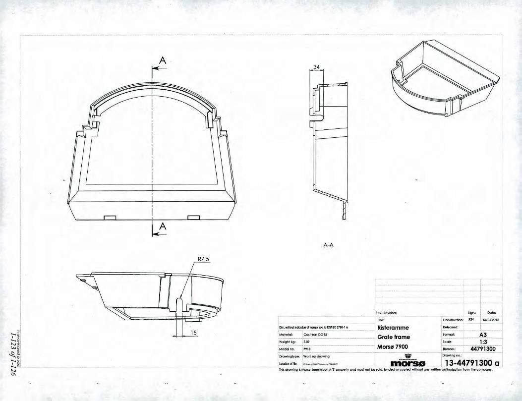
A 34
15
R7.5
A-A
Rev. R,,\fII.lon$ Sign.: . Date:
I TIlle: ;Constn>cliorl; RSV -j- 06.05.2013
lllm.••'Il.'luh.**"'ol ••••.gilEe.tlDSAS0276&-1m I Risteramme IReleowd i -l
1~~Cmt~onOG1S -< Grate frame ~~_' ~~----,WelghHg: ,5.09 : seal8: 1:3~~7r13 Mors" 7900 ! ttemno.: «7"91300IOra.mg';~~ drowlng.,._---- ----- ...,...........-----~------ ~[)"awlngno.:
,"""""'."jo,"_-__ I1'ior'So L13-44791300 aThis aawing Is Mofl.0 Jemstebeli AIS P<opetty end mJo! not be wlc:llended 01 copled wl1hovl any wrWlenaulhOOzation tlom the co~ny-:--

---------"---------------""._--"---"----- ----------- ---------"."------------- "----------------------,
M6 Dim iel Anviser
M6 Dim le/AnviserM6 Dim le/Anviser
M6 Dim le/Anviser
1--1<Z> 16 0:r I, ~"i ~<Z> 16
M6 efter skabelon,
~ o! ,I
<Z> 16 I T- M6 efler skabelon
~, ,
i 0 i, ,M6 efter skabeion
<Z> 16, ,I .rta- , \, ,I I:0L__
\M6 Dim leI Anviser
The four holes will be covered by a platelDe fire huller biiver lukket med en plode
RSV I JO.()(..2013
I Sign.:,' Dote:
. Dun.,,,1JlOUIincIcatonol m.gIlI&C. tI DSllSO 216M m TIlle; ,Cons1nlcIion; liS'" 03,05.:2013
,Motllllol" jeostronCG15 Bagplade Indv. NA IRelea1ed: J
Welght~g.: !11.9~ . -, Rear plate Inside NA j~~_, ~~._.~. Model no. 17904 . IScale: 1:2.5!loIe!b1lxltl': :lf06Skabelon --------., Morse 7900 ~no--,--P-.-4-4794000IOrownglype: ,Wort up dtowlng .....--....--..---._~- :Orowlng no~
"'_ ••• j< .. _-,--- morso L12-4479.4000 aIhG drowlng 6 MoI''0 J",ru' ••b<r<!AIr PKlpotlly and mull nol De wid. \Pndotd or copied .•••Ithout any wrltl&n outrlo<lzallon!Tom "'" COrTpony.

~----------------------~--------------------_._----_."""._-----------------
-o~--"" .----
, M-M,"',
o30.1
M6 Anviser
o
M5 Etter sk belon
"" M5 Etter sk4belon,I,I
\~
24
M6 Anviser
M5 Etter skabelon
TIII8:DrIl.iflol.tlldleallotlol .••• g,n 1lX. tI DSllSO 2768-1 m,: CC>51ron G015Material:
Sign.: I DaTe:
ConslrUCllon: I1SV_..J ~.D5.2013
l?..m<ed: i
~2:::~:::_'''_'" ~::~::r;9:: ~;---347~1~:r;;-OWi'Itltype; \VortlJP~ ~ 'DrowlnQno~
"""""'''_"---'- morse 111-44794200 a ITn6 dtawlng Ii t./IOIS0 Jenu, ••bell AIS' prOPf!'l'1y ond """,I' nol be sold. !ended or eopBd without ony wrltlom ovlhotlzoliofl flom the eorrcony.

M6 Anviser
M6Anviser o o
M6 Anviser
M6 Anviser
M6AnviserlleY. ll••vbIon$ Sign.: Do'"
M6 Anviser 'wth. ",_mtcaonclm.~ __kIDMSO2168.1'" Title: Conllrvclion; 13.05 2013
Mo!•••k>l Cm!ton GG1S Lu"kanal bag NA Ilele<ned: ,W 28.08.2012
Wfl'ightkg.: 7.15Air Canal Rear NA
Fonna!- A3Mod9lnQ, 7911 Sc<;I1 •• ; 1:38orel\lturef: Enef onVltef pa plan Ma"" 7900 1!••mtlO.: 44794100OrawlnglyPft: Wort up drawing 'til' jDrowr.g no,:
Co •••• "". .0::"____ morse 104.44794100Tillsdrawing 11M<m", 1l!'fMt",bftflAIS PlOP"'tv ond mull no! b •• 'Old. !ended Ofeoplotd wilhovl onv VOflll••n ou!hofllo!ion from !he c:orrponv

Jfodel: 7900 SeriesMarso Jemsroberi AlSFun'ej 67900 Nykobing MorsDenmark
Section 2
Quality Assurance/Quality Control
OAfNI- Test Laboratories, Inc.Ceni/kari,,,, Te.</R.:pon daled .l,.f~ JoIJ; \'(•••",;~re,..,'US<'rJ NlesSHOP ell"lII F;I,,}.f<xJO _ 191' TeS/lII}: Pro}ff:f.1'.191-S-1J-!J,J /l,f<xJO 7900 Wood Sf<J'l~Rep0rlJ,{ C.:nificuln {DraflsOnlyfoI91-S-lJ.Jt Moe
2-10f2-57

.".Iodel: 7900 SeriesMorso Jemstoberi AlSFurvej 67900 Nykobing JJorsDenmark
QUALITY ASSURANCE/QUALITY CONTROL
OMN! follows the guidelines of ISOIlEC 17025, "General Requirements for the Competence ofTesting and Calibration Laboratories," and the quality assurance/quality control (QNQC)procedures found in OMNFs Quality Assurance Manual.
OMNFs scope of accreditation includes, but is not limited to, the following:
• ANSI (American National Standards Institute) for certification of product to safetystandards.
• To perform product safety testing by the International Accreditation Service, Inc.(formerly ICBO ES) under accreditation as a testing laboratory designated TL- 130.
• To perform product safety testing as a "Certification Organization" by the StandardsCouncil of Canada (SCC).
• Serving as a testing laboratory for the certification of wood heaters by the U.S.Environmental Protection Agency.
This report is issued within the scope of OMNFs accreditation. Accreditation certificates areavailable upon request.
OMNl~ Test Laboratories. Inc.Ctrlifi,'utilNl T~MRtpot"t JaltdMay 201J: \"..mnlli•.\ervUSf!'.~FlIts SHOP CIi~1I/I"'tM'''SlI. 192'T~s'mg Proftctsi/91-S-23-8.J ,\,for.V} 7900 WflfldSIOO't Rq'(}rI.~& Ct'tifiml~S IDraftsOnlyjll91-S-1J-8.J.Joc:
2-2 of2-57

,\lodel: 7900 SeriesAforso Jernstoberi AlSFurwtj 67900 ,'l'ykobing A/orsDenmark
Sample AnalysisAnalysis Worksheets
Tared Filter and Beaker DataSolvent Blank Data
DUN/-Test Laboratories, Inc.Ct:rlljkaflon Tt:5t Report dalt:d.\/~ 20/J: l'omni-servIUMr' Fil...,SHO/"Cfienl FiteiMono - /92!,Tt:MlIlg ProJel;u'/92-S-U-8.J f',/'''JO 7900 IfOod StUl'l!'Reporu & Cutifi<:a/e5 fDrafI5Only!' /92-S-2JJI, Moe
2-30f2-57

OMNI- Test Laboratories, Ii ... )Portland, OR
Filter Train Analysis Worksheet
Client: MarsoModel: 7900Project #: 192-5-23-8.3 Tracking #: 1847 J1 1/ .L 'Date: l]ijJn ~ __ Test Crew:~r~v'1 T v Run#: ~ _Sample Train #: =-::& Train assembled by:~~Ku~ •.~o/~/~r~z _Balance ID #: OMNI - 00023' Thermo/Hygrometer ID #: ~O~M~N~I_-~3~'1_3~ _Audit weight ID #: OMNI- 00131 (Balanceaudit mfr. std: 500:t 0.72 mg)
Page 1of 12-4 0/2-57
9ontlOf No. L-SFZ-0006. Effective date: 1012612011
Weighing RecordTrain Part
Weight Audit Temp.Date Time(grams) (grams) RlH %
(F) Initials
Front Filter3fZ7..fl1 lUlu • IJ qq "1.1 4-.Lab/IO#: (,~S~ .SOD I H,t
Tare wt.: ,1171'1/ls/n .11'17 . \Cv l «.~ {j./ kOIT in desiccators: O~OO
31 "'U}Preliminary wt.:
-
Rear Filter . 3/l,z./n poo .11 7' q.~ CfA..""l... /hLablJO #: (j 8S-"1 <7vll
Tarewt.: .Il(,q 31z.r/T7 O"Ofl .111•. .rOdl r,(.~ {~ I k,OIT in desiccator:1("l;()//.,
Prelimi~ary wt.: ,,-
Probe ,fV-/n (I(~I/IO SDU' 't.} ttL. -+Lab/IO#: l'> \"l.b(}
Tare wt.: i1~.1'I\J1I 3/1-f/ll 0'106 11'1.~'111 . rO(), I!,(.i f.t1 hCleaned by: :£OIT in desicca r:
'[ /?<'(I"}PreliminarY wt.:
-O-Rings(ASTM E2515 Only)
Lab/iO #:-.i;./.A-Tare wt.:OIT in desiccator:
Preliminary wt.:
d /~l2.-r,!pTechnician signature: tv I ./ d ') Date:
/1 V{..--/

OMNI-Test Laboratories, Inc.
Final Laboratory Report - Method SG Dual TrainDilution Tunnel Particulate Calculations
Client Name: Mo,"oModel: 7900-----------
Project No.: 192-S-2_3_-8_.3 _Tracking No.: 1847 _
Equipment Numbers: 23,131,343 RunN: 1Train #: ADate: 03/18/13
Sample Component Reagent Filter # or Weights IProbe # Final. mg Tare. mg !Particulate. mg
A. Front filter catch Filter G858 119.7 117.1 2.6
B. Rear filter catch Filter G859 117.2 116.9 0.3
C. Probe catch Probe 15 114341.1 114340.8 0.3
Total Particulate, mg: 3.2
Comnnnent Eauations:A. Front filter catch Final (mil) - Tare (mil) = Particulate, milB. Rear filter catch Final (mil) - Tare (mil) '- Particulate, milC. Probe catch Final (mil) - Tare (mil) - Particulate. mil
Oocum.nl COnlrol No. P.S$X.()OQ3, Erredlve Dille: 81712006
Analyst:
Page 1 of 1
lWo Date:
Lal) 1A
2-5 of2-57

OMNI- Test Laboratories, Ir". iPortland. OR
Filter Train Analysis Worksheet
Client: MarsoModel: 7900Project#: 192-S-23-8.3 Tracking#: 1847 Jl // .L'Date: I{1g /I}. Test Crew:~rA.v'1 r v Run #: _'__ '~I _Sample Train#: 13 Train assembled by:~~I&.~ ••~{~'/~t~7 _Balance ID #: OMNI- 00023 Thenno/Hygro meter ID #: =O~M~N~I_-~3~1(~3~ _Audit weight ID #: OMNI- 00131 (Balance audit mfr. std: 500:l: 0.72 mg)
Control No. L-SFZ-COO6. Effective date. '0126/20" Page 1 of 12-6 of2-57
Weighing RecordTrain Part
Weight Audit Temp.Date Time(grams) (grams) RlH%
(F) Initials
Front Filter*2.(13 11 t. 'I .50(/1 q.1 4-..Lab/iD #: C ~, r. l"UJu (", .7.-
Tare wt.: .113' 3 /7.,r 111 O~f)( I ./1(.'1 . rou I n a.1 ~DIT in desiccators:3 {bJ/n
Preliminary wt.:-Rear Filter .
3/1U'l 11-<10 .1111 .~O()l t/.?> (1.Z. A"Lab/iD #: GUITare wt.: .rlU ?h(/n o~a() • J 11 () .51>01 ~,~ (,'~.I '"DIT in desiccator.
3&{gPreliminary wt.: - --
•
Probe'1h:z.!p. Mll/Ii • ~()O , q.3 n.1.. . ~Lab/iD #: TL (WO
Tare wt.: I/lf.1W 'l/'LsIIJ OG.or. 1\ ~.1~/i' . ruo I u {~.I AI-Cleaned by: .A~DIT in 1esiccator:
3 ?:!J6~PreliminarY wt.:-O-Rings(ASTM E2515 Only)
Lab/iD #:--M.!JL--'Tare wt.:DIT in desiccator:
Preliminary wt,:
/J /
Technician signature: /L /~ ~ Date: ?!?r/p/ tJ ~ L-/.
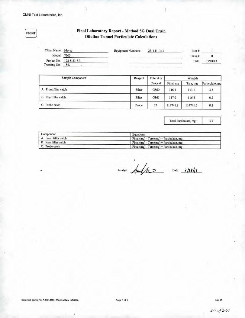
OMNI-Test Laboratories. Inc.
Final Laboratory Report - Method SG Dual TrainDilution Tunnel Particulate Calculations
Client Name: _M_o_rs_o _Model: _7_9_00 _
Project No.: _1_9_2-_S_-2_3_-8_.3 _Tracking No.: _1_8_4_7 _
Equipment Numbers: 23,131,343 Run#:
Train #:
Dale:
I
B
03/18/13
Sample Component Reagent Filter # or Weights IProbe # Final.mg Tare. mg lParticulate, mg
A. Front filter catch Filter 0860 116.4 113.1 3.3
B. Rear filter catch Filter 0861 117.0 116.8 0.2
c. Probe catch Probe 32 114741.8 114741.6 0.2
Total Particulate, mg: 3.7
Com nentA. Front filter catchB. Rear filter catchC. Probe catch
uations:Final m - Tare m ) ""Particulate, mFinal (m • Tare m ""Particulate, mFinal m - Tare m ) ""Particulate, m
Document Contrlll No. P-SSX-0003, ErfedJve Date: 811/20016
Analyst: _~
Page 1 of 1
Date:
lab 16
2-7 of 2-57

, IOMNI- Test Laboratories, In".Portland, OR
Filter Train Analysis Worksheet
Client: MarsoModel: 7900Projecl#: 192-S-23-8.3 Tracking #: 1847 J1 I, .L -, I
Dale: 3(J-'l.lu-,.~__ Tesl Crew: ...L:/. • !t:r~,/,T v Run #: _'__ '--=-- _Sample Train #: ~ Train assembled by: A. 1(,,,,,,.t7Balance ID #: OMNI - 00023 Thermo/Hygro meIer ID #: ~O=M~N~I_-~3~'1~3~ _Audil weighllD #: OMNI- 00131 (Balance audil mfr. sId: 500:1:0.72 mg)
2-8 0/2-57
Weighing RecordTrain Part
Weight Audit Temp.Date Time(grams) (grams) RlH%
(F) Initials
Front Filter 3fz.~/J1 . 11.'1.S e.K ('i'. , .i.ALab/iD #: GII'~ Ol\()v ""II
Tare wt.: . !/" I 1MJJ I t30 d1.1.lf £'001- ti. \ '1/.7 kDIT in desiccators:Jfzt./P mo
Preliminary wt.:.n:V{
Rear Filter .3/1SIIJ . I[ '\1.1 . fuc,' t.'6 ($./ LLLab/ ID #: [,7" O~fJr
Tare wt.: .IWI 3h/n !nO .\Iq'l _ "}O01--'" of. I 1/.7 ~DIT in desiccator:1/:2.1/13
-,1330 .Preliminary wt.: .
II'! 1
Probe1/u11J oGtuo II u. z.~1.~ . fU''/ 55 .j( 6 r./ 4.Lab/ ID #: 12.
Tare wt.: /I q.1.8l.' 3/Ulo WO '1'/.1."30 . ':>041... q.1 "1/.7 7Cleaned by: ---At:!....-DIT in desiccator:~""I \ 1116Prell Inary wt.:
II <f. 2.ll1,
Q-RingsCASTM E2515 Only)
Lab/ ID #: ----N.IA-Tare wt.:DIT in desiccator:
Preliminary wt.:
/
/1 //
Tech~re; "'/ .l--. "// ./ '~ate: 3/Up5Control No. L-8FZ-0006, Effective date: 10t26i2~ Y T7 Page 1of 1

OMNI-Test Laboratories, Inc.
Final Laboratory Report - Method 5G Dual TrainDilution Tunnel Particulate Calculations
Client Name: Morso-----------Model: 7900-----------
Project No.: _1_9_2,_5_,2_3_,8_.3 _Tracking No.: _1_8_47 _
Equipment Numbers: 23,131,343 Run #: 2
Train #: A
Dale: 03/22/13
Sample Component Reagent Filter # or Weights
Probe # Final. mg Tare, mg lParticulate, mg
A Front filter catch Filter G865 122.4 119.1 3.J
B. Rear filter catch Filter G866 119.8 119.8 0.0
C. Probe catch Probe 12 114283.0 114282.6 0.4
Total Particulate, mg: 3.7
f~c~o~m~~~"ne~n~t~~~~~~~~~~~~~~~~~~tjEa~uu~at~io~n~s:~~ji~~~~~~~~~~~~~~~A. Front filter catch Final (mil). Tare (ma', Particulate. milB. Rear filter catch Final (mil) - Tare (ma' '- Particulate, muC. Probe catch Final (mg) - Tare (mil) - Particulate, mil
Document Control Ng. P-SSX.ooo3. Effective Dale: 81712006
Analyst ~_
7
Page 1 of 1
Date:3/U1fJ
lab 2A
2-9 of 2-57

. IOMNI- Test Laboratories, In".Portland, OR
\
Filter Train Analysis Worksheet
Client: MorsoModel: 7900Project #: 192-S-23-8.3 Tracking #: 1847 A II .L .Date: 3tXlJn . Test Crew:~rlil.v'1 Tv Run #:. 2-Sample Train #: l3 Train assembled by:~~KrA~o/"...i~t~7 _Balance 10 #: OMNI - 00023 Thermo/Hygro meter 10 #: ~O~M~N~I-~3_1(_3 _Audit weight 10 #: OMNI- 00131 (Balance audit mfr. std: 500:t 0.72 mg)
Page 1of 12_10 of2-57Control No. L~SFZ..ooo6. Effective date: 1012512011
Weighing RecordTrain Part
Weight Audit Temp.Date Time (grams) (grams) RlH%(F) Initials
Front Filter .••hr/n ./1'2.' .\1,01 ~ f(./ kLab/iD #: &~~1 Oll,ur r.~Tare wt.: . lit? ?/ulr~ IW) .{217 .Cno,- t{.l 11.7. ~DfT in desiccators:
1{2."l..11l mo,Preliminary wt.:
'/.~ .) 1.'2.'1
Rear Filter .1hfltl 0\ 0(, . .Il'l If .fool 'Fr./ kLab/iD #: <.-~,1I s.x
Tare wt.: .Il'i/ "'/,"/0 [hJO .It '13 .saUL I{. \ 1/,7 >hDfT in desiccator: .3/?2.hi (33rJ
., .
Preliminary wt.: - -Ao.jj;ftt? ! 1l'l7
Probe1M!I] m.lm . r~CJI g,j ,r./ . ;?Lab/iD #: . )) U'l66
Tare wt.: l1.3bj'" J/ufo 'HO fl,.~:)Sn . )(X)1..-- I.{. ( '11.7 '&Cleaned by:DfT in desiccator:
3/7.7-/1l WIJ
Preliminary wt.:12.}. 2.333
O-Rings(ASTM E2515 Only)
Lab/ID#:~'Tare wt.:DfT in desiccator: -
Preliminary wt.:
/'
I ff
'Jl~!IJTechnician signature: ,; /' , "). Date:/.~ L/v-- •

OMNI.Test Laboratories, Inc.
[PRINT) Final Laboratory Report - Metbod 5G Dual TrainDilution Tunnel Particulate Calculations
Client Name: cM~o~r~so~ _
Model; ~7~90~0~ _
Project No.: ~1~9~2-~S~-2_3_-8~J~ _Tracking No.: ~1~8_47~ _
Equipment Numbers: 23,131,343 Run #: 2
Train II: B
Date: 03/22/13
Sample Component Reagent Filter #- or Weights IProbe # Final, mg Tare, mg articulate, rng
A. Front filter catch Filter G867 122.7 118.7 4.0
B. Rear filter catch Filter G868 119.3 119.1 0.2
C. Probe catch Probe 55 123233.3 123232.9 0.4
Total Particulate, rng: 4.6
Co~nent Enuations:A. Front filter catch Final (rna' - Tare rna) - Particulate, rnaB. Rear filter catch Final (rna) - Tare rna' "- Particulate, rnaC. Probe catch Final (mIl1- Tare mil) :- Particulate, mil
Documellt COI'lIrol No. P-SSX-QOO3. Etfeeuv. Olle: 81712OOl1
AnalYst~
Page 1 of1
Date J/zg!t7
lab 28
2-11 0/2-57

IOMNI- Test Laboratories, In".Portland. OR
Filter Train Analysis Worksheet
Client: MorsoModel: 7900Project#: 192-5-23-8.3 Tracking #: 1847 A II .L.Date: 3b1JlL.,, Test Crew: ...L:f.-<-J"::r&l.,/I I v Run #: _._~3_' _Sample Train'#:.."..-4 Train assembled by:=r~Ku~..~~~/~+_~7 _Balance JD#: OMNI - 00023 Thermo/Hygro meter 10 #: ~O~M~N~I_-~3~'1~3~ _Audit weight 10 #: OMNI- 00131 (Balance audit mfr. std: 500;!: 0.72 mg)
2-12 0/2-579C t
Weighing RecordTrain Part Weight Audit Temp.Date Time
(grams) (grams) RlH%(F) Initials
Front Filter3hrh"? . SOOI n '~.I 4Lab/iD #: 6 ZlA O~Ofl .tllJlJ
Tare wt.: . /14, I3ruIn { L10 . 11'42- ~C7<l'L '1.\ ~1.1 xh,DIT in desiccators:
3hz/n ' .Preliminary wt.:-
Rear Filter ."? /1-ffls .1I1W rq [~.I ~Lab/tD #: enO 6PtOO •<;001
Tare wt.: WIO ]/Uk~ l']O . [I'H' _ ('C>ot... ~.l 11.7 ~DIT in desiccator:1/nlt3
Preliminary J..t.: - .-Probe
1hr/n ()qnn tH./liOI. . )(Jrli U b&. \ ~Lab/iD #: 57Tare wt.: IU.I1QL 3(2(//1 W{) 113.I¥ocJ ..r6Ov a. \ 1(.7 ..4iCleaned by: -=:&=DIT in desiccator: •
3!'? 1../13Preliminary wt.:
-
Q-Rings(ASTM E2515 Only)
Lab/iD #:....iJJIl-Tare wt.:DIT in desiccator:
Preliminary wt.:
/ -Id j }/{'p3Technician signature: :77 A /\ Date:
on raj No. L-5FZ-COO6 Effective date: 10126/2011 y C/...-Pae1of1
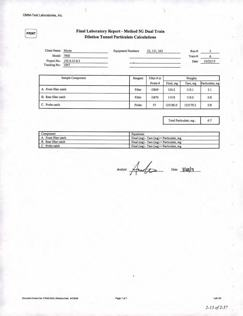
OMNI-Test Laboratories. Inc.
(PRINT) Final Laboratory Report - Method 5G Dual TrainDilution Tunnel Particulate Calculations
Client Name: Morso Equipment Numbers: 23,131,J43 Run#: JModel: 7900 Train #: A
Project No.: 192-S-2J-8.3 Date: OJI22J1JTracking No.: 1847
Sample Component Reagent Filter # or Weights IProbeN Final, mg Tare, mg lParticulate, mg
A. Front filter catch Filter G869 124.2 119.1 5.1
B. Rear filter catch Filter G870 119.8 119.0 0.8
C. Probe catch Probe 57 123180.0 12J179.2 0.8
Total Particulate, mg : 6.7
Comnonent Equations:A. Front filter catch Final (mg) - Tare (mil) - Particulate, mli!B. Rear filter catch Final (mg) - Tare (mil) - Particulate, rollC. Probe catch Final (m~) - Tare (mil) - Particulate, mil
Oocumel'lt COtllroI No. P~SSX-ClOO3.E.rrectlve Dale: 8/712006
Analyst:UI
Page 1 of1
Date; lfzR/l3
lab 3A
2-13 0/2-57

IOMNI- Test Laboratories, Inc-.Portland, OR
\
\Filter Train Analysis .worksheet
Client MarsoModel: 7900Project#: 192.5-23-8.3 Tracking#: 1847 A II .L'Date: 3/'l1..b1 Test Crew:..L=j., rt::r&\.v'/ T v Run #:. '3Sample Train #: l3 Train assembled by:=:::21=_Ka_"_/_t_7 _Balance ID #: OMNI - 00023 Thermo/tiygro meter ID #: _O_M_N_I._3_V_5 _Audit weight JD#: OMNI- 00131 {Balance audit mfr. std: 500:t 0.72 mg}
2-1-10/2-57
Weighing RecordTrain Part
Weight Audit Temp.Date Time (grams) (grams) RlH %(F) Initials
Front Filter 3h(lt~ t740u .Wd\ g.~ &'&.1 ~Lab/iD #: (VI .11.' 0Tare wt.: .11-& 5' ~h"ltl I~?f\ . !lSI( Scxn... t(. ( ...,{.7 ~DIT in desiccators:
7/2:1../13Preliminary wt.:--Rear Filter . ~h(!J~(')~DO "'2Jl!J ' .~OOI t.lI ~~,I 4t.Lab/ID#: GiTLTare wt.: .IlWl. ?I7A, (00 . 11.01 .5001-. t{.( 11,1 J0DIT in desiccator.
3In InPreliminary wt.: .. ..-Probe
-s(z..r 10 OGoo . roo ( g,~ '1'.' . A-Lab/iD #: C~ n.'13rQTare wt.: 1'2.1..~JVO
lluh L'JO 11.'vl}J1 .'jvo1- q. { -1 (.7~Cleaned by: h
DIT in desiccator.3h."l.f/~
Preliminary wt.:--O.Rings(ASTM E2515 Only)Lab/ID#:~' '.'Tare wt.:DIT in desiccator.
Preliminary wt.:
/l A
// /#' 7> Date: JI}...(,InTechnician signa /
. . ?- /j I./~Page 1of 1Control No. L-5FZ",{)OO6. Effective date: 1012612011

OMNI-Tesl Laboratories, Inc.
Final Laboratory Report - Metbod SG Dual TrainDilution Tunnel Particulate Calculations
Client Name: Morso Equipment Numbers: 23,131,343 Run#: 3
Model: 7900 Train #: BProject No.: \92-S-23-8.3 Dale: 03122Jll
Tracking No.: \847
Sample Component Reagent Filter # or Weights IProbe # Final, mg Tare, mg articulate, mg
A. Front filter catch Filter G87\ \25.8 120.5 5.3
B. Rear filter catch Filter G872 \20.1 119.2 0.9
C. Probe catch Probe 68 122438.7 \22438.0 0.7
Total Particulate, mg: 6.9
Co~nent Enuations:A. Front filter catch Final mD)- Tare (mo' - Particulate, mgB. Rear filter catch Final mo). Tare (mo' - Particulate, mDC. Probe catch Final mil) - Tare (mil) = Particulate, mil
Doeument Conlrol No. P.SSX.ooo3. Elfectl\le Dele: 81112006
Analyst ~I
Page 1 or 1
Date: I/zr/ll
Lab 38
2-150/2-57

iOMNI- Test Laboratories, It,,,.Portland, OR
Filter Train Analysis Worksheet
Client: MorsoModel: 7900Project #: 192-8-23-8.3 Tracking #: 1847 A I, .L u'Date: ) hWL~__ Test Crew: ...L:f. • ~r/.\v',r v Run#: __ :r~ _Sample Train #: ~ Train assembled by: A. Kr"",/tzBalance 10#: OMNI - 00023 Thermo/Hygro meter 10#: _O_M_N~I_-~3_'I~5~ _Audit weight 10#: OMNI- 00131 (Balance audit mfr. std: 500:t 0.72 mg)
Weighing RecordTrain Part
Weight Audit Temp.Date Time (grams) (grams) RlH%(F) Initials
Front FilterJhL/I~ 16111 .1'1..3 'f . Soo'l- 4.( 1/.7 b,Lab/iD #: uem
Tare wt.: .lIB 3/1.71H V~3(/ ./U1 .\v() I 4.'1 {q.'{, xt.DIT in desiccators:~MlI! (yoo
Preliminary wt.:
"13'
Rear Filter , ~1_.' , 1630 .1'20q .500L 'to \ 1/.7 ~Lab/iD #: GnlfTare wt.: ,('206
3{Z.1/IJ Onll .IL09' .lorl1 '\.'\ ,q,~ ~DIT in desiccator:"'(-l,'/n r<{<Jo
Preliminary wt.: ... 1'1. II
Probe'/ubJ ( ''30 (\C.OI~~ • SO<l"l.. "'.1 11.7 ~Lab/iD #: 3
Tare wt.: 116.o/i1- 3{'I..7/0 unO ((.011'1 . >vD \ ~-" i"{.r 4-Cleaned by: kJDIT in desiccator: ')!7-,/n lIt3U IIILoll1 .Sou I to,l 70.'6 kJlvdS "MPrelimin'ary wt.:
-Q..Rin'gs(ASTM E2515 Only)
Lab' ID #: ----4I.f.ft--Tare wt.:DIT in desiccator:
Preliminary wt.:
.1 /JL/ // 3C-7/tJTechnician signature: .L..---7' / ::::> Date:./ 1 (/
Control No. L-SFZ-oOOG,Effective date: 1012612011 Page 1of 12-/6 0/2-57

OMNI-Test Laboratories, Inc.
Final Laboratory Report - Method SG Dual TrainDilution Tunnel Particulate Calculations
Client Name: Morso Equipment Numbers: 23,131,343 Run#: 4Model: 7900 Train #: A
Project No.: 192-8-23-8.3 Date: 03125113Tracking No.: 1847
Sample Component Reagent Filter # or Weights IProbe # Final, mg Tare, mg !Particulate, mg
A. Front filter catch Filter G873 123.3 119.8 3.5
B. Rear filter catch Filter G874 120.8 120.6 0.2
C. Probe catch Probe 3 116011.8 116011.2 0.6
Total Particulate, rng : 4.3
Component Elluations:A. Front filter catch Final rna) - Tare (m~) - Particulate, mRB. Rear filter catch Final (m~) - Tare (m~) ""Particulate, m~C. Probe catch Final (mll.) - Tare (mil) - Particulate, mil
DocUlTMlnt COfItrol No, P-SSX.ooo3. Effective Ollie: 811!2006
Analyst: ~
"
Page 1 of 1
Date: Sll.t!o•
lab 4A

1OMNI- Test Laboratories, In".POrlJand, OR
FilterTrain Analysis WorksheetClient MarsoModel: 7900Project#: 192-8-23-8.3 Tracking#: 1847 A II ,L.Date: J /1,~li1 Test Crew:~rel.';( I v . Run#: _._._'1 _8ample Train #: f3 Train assembled by: =:::21=~Ku_•._{_,._t_7 _Balance ID #: OMNI - 00023 Thermo/Hygrometer ID#: _O_M_N_I-_3_'1_3 _Audit weight ID #: OMNI- 00131 (Balanceaudit mfr. std: 500:!: 0.72 mg)
Weighing RecordTrain Part
Weight Audit Temp.Date Time(grams) (grams) R1H%
(F) Initiais
Front FilterIht,II ~ IqD . 1130 ..(011.. 'to I 11.1 Lh.Lab/iD #: mr \/ . f
Tare wt.: II \11/1. 7#1 o'l1d . hJ I . SDul 1."1 {I!l.v xfrtOfT in desiccators:
3{7..~ltl ('1<10 I
Preliminary wt.:p..31
,
Rear .Filter . 3/u/g (Or) . 1\ftej su<)-z.. 1, • \ ., 1.7 ~Lab/iD #: G'67' ..Tare wt.: ,'116 3/n//? (}'r~(, . II 'IV . roO 1 1/.'\ , t/.~ MOfT in desiccator:1{g{/J ( YDq ,
Preliminary wt.: .. ... (IIll,
Probe3/u/13 1'30 1/ 'j.1'l ~'1 • S"Oo"l. 4., 11.1 . LLab/iD #: 5
Tare wt.: m.1;g 1h,/n O'li3d 11~.H~I . r'Od' 1(.'1 6'( .<J. ~Cleaned by:OfT in desiccator:
ih11t'l W30 li 1/. 1~'11.. . '00 I [0,1.. 10.~ ..>h. "J(z.rbj 1MPreliminary wt::
~
Q-Rings(ASTM E2515 Only)
Lab/iD #:----iJ./IL-Tare wt.:OfT in desiccator:
Preliminary wt.:
Technician signature:
Control No. L-8FZ-DOO6. Effective date: 10126/2011
Date:
Page 1of1 2-180j2-57

OMNI-Test Laboratories, Inc.
Final Laboratory Report - Metbod SG Dual TrainDilution Tunnel Particulate Calculations
Client Name: MorsoModel: 7900 .
Project No.: 192-5-2_3_-8_3 _Tracking No.: 1847
Equipment Numbers: 23,131,343 Run #: 4
Train #: BDate: 03/25/13
Sample Component Reagent Filter # or Weights IProbe # Final, mg Tare, mg lParticulate, mg
A. Front filter catch Filter 085 123.1 119.1 4.0
B. Rear filter catch Filter 0876 119.8 119.6 0.2
C. Probe catch Probe 5 114784.2 114783.8 0.4
Total Particulate, mg : 4.6
Com nentA. Front filter catchB. Rear filter catchC. Probe catch
uations:Final m ) - Tare m ""Particulate, mFinal m - Tare (m ) ""Particulate, mFinal m - Tare m ) ""Particulate. m
Document Contrtll No. P-SSX-oooJ, Effective Dale: Bnl2OO6
Analyst:
Page 1 of1
7/tvp.2 Date:
Lab 48
2-19 of2-57

Technician:
PROBE TARES
Date Placed in Desiccator: 'i1'1~J1_.. _Thermo/Hygro meter ID#: 1H "Audit Weight ID# 13 I-------- -----------
Balance ID# ~1-----------(Balance audit mfr. Std.:"SOO~ 0.72)
.. j
~I
}
Project No. Run No.Manufacturer Appliance
(
'>/".1-Date:~
Probe Date: ~(r(l1. Date: S{ll1r',' Date: Date:Size/ID# TIme: ll~o TIme: '",\, Time: TIme:
f) RH%: s.'! RH%:1.0 RH%: RH%:T (F):11.1 T (F): 7'1.3 T (F): T (F):inltials:,4. Initials: A-.. Initials: Initials:
Final Technician"~ignature: /?A=

PROBE TARES
Date Placed in Desiccator:,_~IJ. •.•l~IO-,,{I~'L~ _
The'rmo/Hygro meter ID #:._----<.~.•..~~~ _
Technician:, __ ~A~fk..~>J~II-~l..~_
Audit Weight ID # /7>_, _
Balance ID #_~2_3~ _
(Balance audit mfr. Std.: 500,j, 0.72)
.,
Project No. Run No. .
In-S-lHI.3
ApplianceManufacturer
Date:Time:RH%:T (F):Initials:
Date: rz,/£lI/n.I
Date: 1l.111/'"'-Time: tlOoRH%: 'i.I
T (F):1l-,)Initial
t;.?,~5'1'1 p.n.~
1.1.1'11
Date: 1"1..111/1'1-Time: 1100RH%: ~•.,T (F): 11..\Initials:A.
Date: IlIMn..TIme: 10uoRH%:~.fT (F): l'i.1Initials: 4-
11..7.. ~3~IHI
~8
2.,q
1-52
01
2
Probe
Size/ID#
47
/l • itS b
IIY. '1. 'USO' 11.1. ,,'I,r I1.1..J.f 1.
~ ll~.¥o-SC OJ. 0$5 I Il~.O&5
",,' ,,,hold ••",,,'",,4~

PROBE TARES
Date Placed in Desiccator:--i!l~I1~I_I1. _
ThermojHygro meter ID#:_~'1~2~ _Technician:
Audit Weight ID#~1~1~) _
Balance ID#_~J...~3 _(Balance audit mfr. Std.:.SOO", 0.72)
.-
Project No. Run No.
. -. - .
;4. 1~1.-- 'l..1-t.7J Lf
J''; •
l<\."2. - ~-1.J.83
~ :3o
Appliance
. --,-
l~oo
"1100
1••.••
" .
Manufacturer
'. M..
Date:Time:RH%:T (F):Initials:
Date: q f1.s-/l-t ..•.Time: ll)dORH%: ~.7T (F):1 \.7Initials:
Date: '1/]. 'l/lz.Time: 1'100RH%: 1/."T(F):lHInitials:"
Date: 'l(z,l/I1-Time: ('/'1.RH%:l.'T (F): 1'l'liInitialsA<-
ProbeSizejlD#e
551
501.~
6S'fISlot
1..

.;'
FILTER. TARES
Date Placed in Desiccator:~. _3~P_6~/t_3 _Thermo/Hygro meter ID#: 3'i~--~-----
...-,-...
,{ I, _,'1-..Technician:.--LJ:_' _~~~~~_~ _
Audit Weii# iD# IS 1 _
--.. L
Balance ID# 2.'3------------(Balance audit mfr. Std.: SOO,j,0.72)
<.
D rie,6 pe/ P1vt-W 5 Z~,oVWtII ,.
Filter Date.:l/t$/IJ Date: .Size/ID# Tlme:l'ob Time:102@ RH%: lU.1 RH%:
110 55 .T (F): 70.'7 T (F):.- Initials:~ Initials:
Date:TIme:RH%:.T (F):Initials:
Date: .TIme:RH%:T (F): .Initials:
Manufacturer Appliance Project No. Run No.
G~7' ./146(.'/,77 .IZOI\
J-"'~G?>7$ .II'W6~7"i . II q 4
G$'lO . 1'2.0 3 ..6~gl . IIQ2.f~glS':L .. /In
..
G~~) . IlD~
6 'b<z.'1 .liD' .-:lIqlj,g~S
(,f~% • ("l..Oq
(.,CbYJ1- .U0.3G'6l6<6 . II ~ 4
G~~'\ .n ,,'f
Final Technl~ian sJgnat~re: .~4Z. . / Date: ? Itt /I~:
1400

...-- -,
Balance ID #~2_.~3 ~ _
(Balance audit mfr. Std.: SODoh0.72)(.
h J
Audit Weight ID #
'.Technician: .' 4.Date Placed In Deslccator:,~,' .••3.•..I_l'6~lJ~3 _
Thermo/Hygro meter ID #: 's ~)-------DlA ~JS-U
FILTER TARES
r, !/(' /~ 6Vw-, 7- I, iU~.~rFilter Date,: ;/Isll'l- Date:. ' Date: Date:
Size/ID# TIme:. 1'00 TIme: TIme: Time:
102 ~RH%: (l}.1 RH%: RH%:. RH%: Manufacturer Appliance Project No. Run No.
110 S,T (F): '/D.? ' T (F): T (Fl: T (F):Inltlals:A.l.. Initials: ' Initials: Initials:
G~G"2.." . .11 r:::'fC '66S . II 4(, -
I
(, rt,C'1 1 .. 1 -- ,I I . - 1_1l5'j
(. '61: S- . II 'II - JIll",.; " 7'10(/ IQ7.-C-z'3-R'.3 . '2..(, 'ilG G ./11 II •. .GI6~7 .lInG&'Cg . /11./ I • • .~j,
G ri'q I/q/ ,Mo,..;" 1liCi& '",2-' s- 2}-P '3G'670 .llql') .
~9,11 ~lW 5 ..
(,<672.. • Ill{ 2- "6~7, .Ilq)? A. 1'1.o(J . (tll- ~7,.'l.1 'f(, '01 'f .n.o& .I I I IG C67-C;- ./1'\\ . ~ .L oj'
Final Technician signature:' ~ Gb . Date: ~({t/tJ

.:.•- ..•..•.'. '
FILTER TARES
Date Placed in Desiccator: 2(\111'7,-~------Thermo/Hygro meter ID#:__ ?~ln _
"Technician:_~A- l}fA/" h
Audit Weight iD #
Balance ID# ' 'l Y iJ .-~---------(Balance audit mfr. Std.: 500", 0.72)
(,
Filter Date.:1./ n/n Date:lll)l/~ Date: Date:Size/ID# TIme:'6 ••o~ TIme: (,'1.00 TIme: TIme:102 e RH%: V.~ RH%: ~.o RH%: RH%: Manufacturer Appliance Project No. Run No.
.T (F): 1".~ T (F): 1(.1- T (F):' T (F): .110 55L initials: ,A... Initials:,d.. Initials: Initials:
6'6'1'1> .. .I/</If .IIH6'N'I . II ~ 7 .IIHG~So .[(('~ . fIr'>, L,(,~'S'I ' II,'! II" J
., ., '.,
(,&51. . It~I . II ~D..6'tG .//1'6 . '11] , \
&CfSLj .1/3t: . Ii ~••,
(,~K .1I7~ .1[1&Ggn . 1177 ' . II~ (,
'- :;g)7 I'll ;;),I-
oo./1 2'\G~S~ .111l{ ~ III I ftlore- ' '1'\00 1'l1-S~Z3-~.3 IG~).q : I, '7 0 . III••'Q
(,'bC6 .I(h . In \(,~Cl . It ~q . II'\( ~
. . ~' ' '~~----Final Technician signature:' ~C --......,... 7 Date: -z!rr{u:

Model: 7900 SeriesJlorso Jernsloberi AlSFur...ej 67900 Nykobing MorsDenmark
CalibrationsMethods 28 and 5G
10# Lab NamefPurpose Log Name Attachment Type23 Scale/Analytical Balance Analytical Balance - Mettler Instrument Calibration Cenificate
13I 500 mg Weight Standard Weight, 500 mg - Ohaus Calibration Cenificate
132 10 Ib Weight Standard Weight, 10 lb. Calibration Log185 Weight Indicator Platform Scale - Weigh-Tronix Service Work Order
209 Barometer Barometer - Princo Manual Cover
335 Control Module Automated Emissions Sampling Box - Apex Calibration Logs
336 Control Module Automated Emissions Sampling Box - Apex Calibration Logs
340 Moisture Meter Wood Moisture Meter - Delmhorst See Fuel Data Sheets343 Hygrometer/Thermometer Digital Thermometer - Omega Calibration Cenificate
410 Microtector Microtector - Dwyer Manual
417 Anemometer Vane Thermo-Anemometer - Extech Calibration Cenificate
420 Gas Analyzer Inrrared Gas Analyzer - Fuji Electric Manual Cover
431 Wood Moisture Calibrator Wood Moisture Calibrator - Delmhorst Calibration Log
O,'vIN"I-TestLaboratories, Inc,CutljiCQ/IOII Test &port Jared May ]01J: l'o"mi-serv',U5<!rs FilesSIfOl"Cllem File _\,fono _ /9]' T""II11gProj<'<"t.f,/91-S-1J-R.J Mor,\O 7900 W£><J<1SI//'I'rReports &, C••rtificotts {DraftsOlllyf /91-,.')-1 J-8. J.d£><:
2-26 oi2-57

It0723.01Calibration
J.TCalibrations, Inc.7007 SE Lake Rd .Portland, OR 97267-2105Phone 503.786.3005FAX 503.786.2994
01/28/201307/28/201320°C 32%RHOut of ToleranceWithin ToleranceAdjusted53
OnSite
Technician:
PO; OTL-13-001OrderDate; 01/28/2013
Authorized By: N/ACalibrated on:
*Recommended Due:Environment:As Received:As Returned:Action Taken:
Certificate of CalibrC'iionCertificate Number: 524447
Property#;OMNI-00023User:N/A
Department: N / AMake: MettlerModel; AE200Serial#;E17657
Description: Scale 2059Procedure;DeN 500818/500887Accuracy;;1:0.0004g i:l LSD
Remarks: • Any number of factors may cause the calibration item to drift out of calibration before the recommended interval has expiredReceived uut out of tolerance by as much as -.0013g. Adjusted to tolerance.
Omni.Tesl Laboralories13327 NE AirportWayPortland,OR 97230
Sid 10 Manufacturer503A Rice Lake
ModelImg-200g (Class 0)
Standards UsedNomenclatureMass Set Due Date Trace ID
12/07/2013 517746
ParameterMeasurement DescriptionBeforeForce
Range UnitMeasurement DataReference UUT Variance Min
x = OOT conditionMax Uncertainly
Accredited = ./
9 1.00000 1.0001 -0.00010 0.99950 '.00050 0.016 0/----------------------------g------------i~00066-----266601---~00610--19~99S0--2060056---06225---;/-----------------------------g------------s~00066-----499998---0006io--49999S0--5060056---06357---;/-----------------------------g-----------106.00066-----999995---000650--9999950--16060056---06731---;/-- - - --- - - - - - - - - - - - - - -- - - - - - - - 9 - - - - - - - - - - - 1so:0-0066----'149.9989"--0:00110---149.999S0--15660056 --- 6.109---;/-- - - - - - - - - - -- - - - - - - - - - - - -- - - - 9 - - - - - - - - - - - 18-0:00066----179.9987,,--0-00130---'79999S0--18660056 ---6.131- --;/-- - - -- - - - - - - - - - - - - - - -- - - - - - - - 9 - -- - - - - - - - -ioo:00066----1999988"- -o-o01io---199.999S0--26060056 ---6.041---;/-----------------------------mg-----------l:00066------69999---000610---6~99S0---f60056---S8E-5---;/-----------------------------rr;9-----------1~00066------99999---000610---9~99S0--1660056--577E~---;/------ ----- ------ ---- --- -----m-9----------100:0-0066----'1666600---0:00660---9999950--166.00056 -- 5:77E:5---;/-)(fter--------------------------------------------------------------------------------A~~~~~d~:7
9 1.00000 1.0000 0.00000 0.99950 1.00050 0.016 0/----------------------------g------------i~00066-----266600---000660--'19999S0--2060056---06225---;/-----------------------------g------------s~00066-----499998---0006io--49999S0--5600056---06357---;/-- - - - - - - - - - - - - - - - - - - - - - - - - - - - 9 - - - - - - - - - - - 100:0-0066-----99.9998---a -006io---99.999S0-- lOa 00056---0:6i31-- -;/-------------- --------- ------g- ----------1so:0-0066----'150.6000---0-00660---149.99950--156.66056--- 6.'109---;/-- - --- - -- - - - - - - -- - - - - - - - - - - - - 9 - - - - - - - - - - - 18-0:00066----'179.9999---0:00610---'79.99950--186.60056- --6.131---;/-- - - -- - - - - - - -- - - - - - - -- - - - - - - - 9 - - -- - - - - - - -ioo:00066-- --'199.9999---0:00610---199.99950--26660056 ---6.041 ---;;------------------------------mg-----------l:00066------f6600---000660---699950---foo056---5.8&5---;/-----------------------------mg-----------1000066-----166000---000660---9~9950--1600056--577E:5--;/-::::::::::::::::::::::::::::~~::::::::::!~~~o~~~::::)~~~~02:::~2~~~~::~~~~~~~:!~~q~0~~::~:i7~:~::?:
/d:~LReviewer
JJ Calibrations. Inc. certifies that this instrument has been calibrated in accordance with the 11 Calibrations Quality Assurance Manual with the stated procedure usingstandards that are traceable to the National Institute of Standards and Technology (NISn, or other National Measurement Institutes (NMl's). or by using naturalphysical constants, intrinsic standards or ratio calibration techniques. The quality system and this certificate are in compliance with ANSUNCSL Z540.1-1994,ISOIIEC 17025-2005. ISO 10012-1, the ISO 9000 family and QS 9000, The expanded uncertainties of measurements for this calibration are based upon 95%(2 sigma) confidence limits. Unless otherwise stated, a test accuracy ratio (TAR) of 4:1, if achievable, is maintained. The results reported herein apply only to the
calibration of the item described above, This report may not be reproduced, except in full, without prior written consent of JJ Calibrations,Inc.11 Calibrations, Inc. quality system has been assessed and accredited to ISOIIEC 17025:2005.
3 Issued02108/2013 Rev # 14 Inspe~
Certificate: 524447

I <'l •
Supplemental CalibL'tion ReportCertificate Number: 413631
JJ Calibrations, Inc.7007 SE Lake RdPortland, OR 97267-2105Phone 503.786.3005FAX 503.786.2994
PO:OTL-08-490Order Date: 11/04/2008Procedure: DCN 500901
Calibrated on: 11/05/2008Technician: 92
Customer: Omni-Test LaboratoriesProperty ID: OMNI-00131
Make: OhausModel: 50 Omg
Serial #: 27503Description: 500mg WEIGHT
ParameterMeasurement Description Range Unit
I Before/After IMass
Reference UUT Variance Min Max UncertaintyAccredited Cl ./
mg 500.0000 500.123 .0.1230 499.28 500.72 0.00011
Supplemental Calibration Report rage I of 1 Certificate Number: 413631 2-28 0/2-57
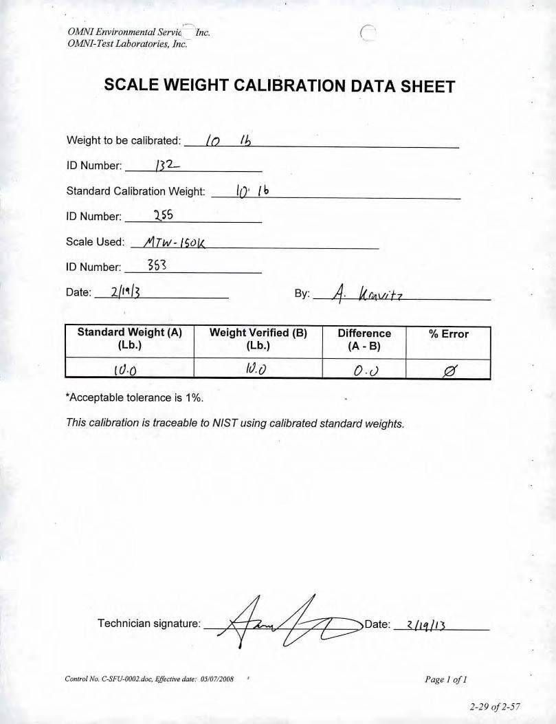
OMNI Environmental Servi~ Inc.OMNI- Test Laboratories, Inc~
SCALE WEIGHT CALIBRATION DATA SHEET
Weight to be calibrated: /0 Ib
10' [b
ID Number: __ .•.13~'L _
Standard Calibration Weight:
ID Number: 'US--~-------Scale Used: ATw-15VL<
ID Number: ~5~-~~-------
Date: 2{1113 By:
Standard Weight (A) Weight Verified (8) Difference % Error(Lb.) (Lb.) (A - 8)
(().o [J.e) O.cJ 0'Acceptable tolerance is 1%.
This calibration is traceable to NlST using calibrated standard weights.
Technician signature:~~Date;7 "
Control No. C-SFU.0002.doc, Effective date: 05/07/2008 ' Page I of I
2-290f2-57

/II II
PAGE 01
--.JOB No. J I /10/1;cusm"'£R No.Or'd'er Daftt
S",rt 0•••Com let. Dat. J
P.O.No.99-007
:ZIP 97075
ZIP
~JEIGH ffiONIX~c..t. 'U\-W'( ..~....
.., ~
WEIGH-TRONIX
STATE
5B364Z9!i44.~I .•.. U\ \ .
:l -- \ \\,J ~
05/18/200B .B8:B9
'Neigh-Tro~. fnc.7933-5W NImbus :.I"". 1/28Baaverton. OR 97005500-626':lO'On . ,1-600'678-3006
S NAM£OMNI ENVIRONMENTAL SERVICESH MO~~S5465 SW WESTERN AVE~ cn-'pE.AVERTON ORPHONE503 •. 643-3788 STA'tE
T FAX
o GONTA(,'T Bruce aT !Hehard
B NAMI;I T AODR£SSPO BOX 743LOl CITY
ATTN:
I
R"'nta.l 1 Month
.~~.A.lliP:~!1NT~:SIN Locstlon Typo Cap. Reoommendamns and Remarks1t:;t:.'rJ ..- ."'" 1'-" ,
?JI.'-JJ... ~.."
. COMME'NTS'" -
l/ I
2 -S-Qly. 09$ctiplion Price Total
WNE VEHICLE _
rEcHNlcIAN:J:D_. _
SERVICE SUMMARV
Reg. I Allro•. I Prel. I Insl.
H•••----..•__ .•._ ..•.•__ .._.P••••-_ .._----_ .._------Shop~ .__ .._-------_._-Ohlr •.•_•._.•_ ...___ .......__.......•.••
TOTAL
..•. THIl'>1~ NOT AN INVOICF.
I acknowledge all service has been perlonneo' satisfactorily. as stateo' above. All parts Installed are walTanted tor thirty days~omIhis dllts.
WEI(i;H-TRONIX
AaNIlII SaIM 1 SaMee
AllIhorlzedSignature &c
Prinl Name
DAMAGE TO RENTALIDEMO EQUIPMENT IS SOLELY THE RESPONSIBILITY OF THE USER WHILE IN THEIR POSSESSIONl
DlSTRI9UTlON: WHITE- OFFICE VEl.11lW - FIl£ PINK - CUSTOMER
2-30 0/2-57

OMNI-Test Laboratories, Inc.
Thermal Metering System CalibrationY Factor
Previous Calibration Comparision
Manufacturer: ApexModel: XC-60Serial Number:OMNI Tracking No.: 336Calibrated Orifice: o v",
OrificeAverage Gas Meter y Meter
Factor dH@
'1.013 N/ACalibration Date: 11130/12Calibrated by: A. KravitzCalibration Frequency: 6 MonthsNext Calibration Due: 5/3012013Instrument Range: 1.000 cfmStandard Temp.: 68 ofStandard Press.:
299~"Hg
Barometric Press., Pb: "JIgSignaturelDate:
29.6~, •.goltl...
7
AcceptableDate 5121/2012 Deviation (5%) Deviationy Factor 1.01 0.0505 0.003Acceptance Acceptable
Current Calibration
Acceptable y Deviation 0.020
Maximum y Deviation 0.002Acceptable dH@ Deviation N/AMaximwn dH@ Deviation N/AAcceptance I Acceptable
Reference Standard.Standard Model Standard Test MeterCalibrator SIN 1
Calib. Date 22-Aug-llCalib. Value 0.9980 y factor (ref)
Calibration Parameters Run I Run 2 Run 3
Reference Meter Pressure ("H2O). Pr 0.00 0.00 0.00DGM Pressure ("H20l, Pd 0.85 2.40 1.28Initial Reference Meter 545.905 551.973 558.562Final Reference Meter 551.973 558.562 567.703Initial DGM 0 0 0Final DGM 6.121 6.637 9.214Temo. Ref. Meter (of), Tr 68.0 68.0 68.0Temnerature DGM (OFl, Td 82.0 82.0 82.0Time (min) 40.1 27.1 50.3Net Volume Ref. Meter, Vr 6.068 6.589 9.141Net Volume DGM, Vd 6.121 6.637 9.214G•• MOI.d,F.m.""","""'" ::::~~~::~::~;:;:;: ;; ;.. ""tol3' .' --"J;llW< ::"'1,013 ';:.'.:.,.:.,. :.:,: ::: :.:.:
Gas Meter y Factor Deviation (from avg.) 0.001 0.002 0.001O.il1 •• dH ""','N/A"",, -"",-NfA:::-'" '<'-N/k- n~:Orifice dH@Deviation (from avg.) N/A N/A N/A
where:1. Deviation = IAverage value for all runs - current run valuel
•• 2. y = [Vr x (y factor (ret)) x (Pb + (Pr/13.6)) x (Td + 460)]1 [Vd x (Pb + (Pd 113.6» x (Tr + 460)]•• 3. dH@= 0.0317 x Pd 1 (Pb (Td + 460)) x [ (Tr + 460) x time) 1Vr ]'2
• Reference calibration is traceable to NIST through NISTTest # 40674, Kimble ASTM £1272, or NIST traceable laboratory~. Equations come from EPA Method 5The uncertainty of measurement is %0.14 feimin. This is based on the reference standard having a TAR (Test Accuracy Ratio) of at least 4:1.
Control No. C-558-OOO5, Effective Dote: 7/7/2011 2-31 0/2-57
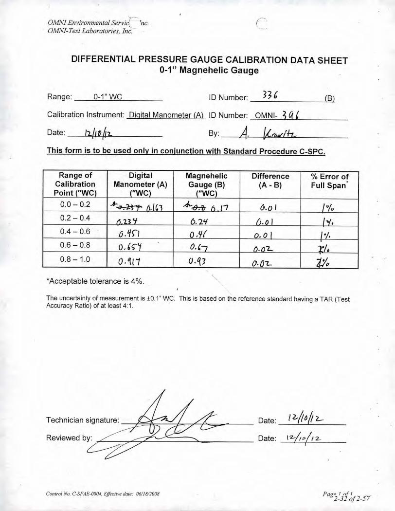
',-OMNI Environmental Servia 'ne.OMNI.Test Laboratories, In~.-
DIFFERENTIAL PRESSURE GAUGE CALIBRATION DATA SHEET0-1" Magnehelic Gauge
Range: 0-1"WC ID Number: (B)
Calibration Instrument: Digital Manometer (A) ID Number: OMNI- 3 q ,Date: By:_4. Urr..•dh.This form is to be used only in conjunction with Standard Procedure C-SPC.
Range ofCalibrationPoint "we0.0 - 0.2
0.2 - 0.4
0.4 - 0.6
0.6- 0.8
0.8 - 1.0
.n
Difference(A - B)
6.0 I
.0 I0.0
.'2....().O'L
% Error ofFull Span'
'Acceptable tolerance is 4% ..
The uncertainty of measurement is :to.1" we. This is based on the reference standard having a TAR (TestAccuracy Ratio) of at least 4: 1.
Technician signature:
Reviewed by:
Control No. C-SFAE.0004, Effective dale: 0611812008
Date:
Date:
I z./t 0(;2.-17--6"'/12-.
I
Pag'" 1 n{ J2-320f2-57"

1OMN/.Test Laboratories, Inc.
~(., . ('
Thermal Metering System CalibrationY Factor
Previous Calibration Comparision
ApexXC-60
Manufacturer:Model:
Serial Number:OMNI Tracking No.: ~3",3~5 _CalibratedOrifice: Dyes
AcceptableDate 5/2 InOl2 Deviation (5%) Deviationy Factor 1.01 0.0505 0.005Acceptance Acceptable
Current Calibration
Average Gas Meter yFactor
1.005Calibration Date:Calibrated by:Calibration Frequency:Next Calibration Due:Instrument Range:Standard Temp.:Standard Press.:Barometric Press., Pb:SignatureIDate:
11/30/12A. Kravitz6 Months5130/20131.0006829.922;kFIt ..
OrificeMeterdIl@
N/A
cfinof"lIg"Hgl7.b0II7.-•
Acceptable y Deviation 0.020
Maximum y Deviation 0.002Acceptable dH@ Deviation N/AMaximum dH@ Deviation N/AAcceptance I Acceptable
Reference Standard.Standard Model Standard Test MeterCalibrator SIN 1
Calib. Date 22-Aug-11Calib. Value 0.9980 y factor (ref)
Calibration Parameters Run 1 Run 2 Run 3
Reference Meter Pressure ("H2O. Pc 0.00 0.00DGM Pressure "H2O, Pd 2.64 0.92Initial Reference Meter 530.372 535.73Final Reference Meter 535.73 540.862Initial DGM 0 0Final DGM 5.375 5.205Tem . Ref. Meter (OF. Tf 64.0 68.0Tern eralUre DGM oF), Td 74.0 80.0Time (min) 23.3 37.8Net Volwne Ref. Meter. Vr 5.358 5.132Net Volume DGM, Vd 5.375 5.205GO$MelefFo'IQh;i,,;;;,,! ;"!:: :;;;:::::::,:;:':,: ;;;: ;'tomu' ;:"'l,OIW:':Gas Meter y Factor Deviation (from avg.) 0.002 0.001O'iOoedH;-::N/A;:;U ;:;-;:;NfM'::Orifice dB@} Deviation (from avg.) N/A N/A
where:
0.001.57
540.862545.905
o5.11469.082.028.5
5.0435.114
;:;;::1;004;:;;::0.001
;:;:;:;:l'<lk ;:;;N/A
I. Deviation = IAverage value for all runs - current run valuel•• 2. Y- [Vr x (y factor (re!)) x (Ph + (Pr/13.6)) x (Td + 460) JI [Vd x (Ph + (Pd 113.6)) x (Tr + 460)]•• 3. dll@=0.0317xPd/(Ph(Td+460))x[(Tr+460)xtime)/Vr]'2
• Reference calibration is traceable to NlST through NIST Test # 40674. Kimble ASTM E1272, or NlST traceable laboratory•• Equations come from EPA Method 5 .The uncertainty of measurement is %0.14 fe/min. This is based on the reference standard having a TAR (Test Accuracy Ratto) of alleast 4:1.
Control No. C-SSB-OOOS,Effective Date: 7/7/2011 2-33 of2-57

OAINI Environmenlal Servit=/nc.OMNI-Tesl Laboralories, Inc:"
DIFFERENTIAL PRE.SSURE GAUGE CALIBRATION DATA SHEET0-1" Magnehelic Gauge
This form is to be used only in conjunction with Standard Procedure C-SPC.
Difference % Error of(A - B) Full Span
.
.IS (;.00 o .~0.2 - 0.4 .'1.S D.oo0.4 - 0.6 .S o. '\0.6 - 0.8 D.no In0.8 -1.0 O. ~"l'i o.SI ~ {j.o""L Z .,
-Acceptable tolerance is 4%.
The uncertainty of measurement is :!:0.1"we. This is based on the reference standard having a TAR (TestAccuracy Ratio) of at least 4:1.
Date: (l- / (" If.l-r /
Technician signature:
Reviewed by:
Date: fLit 0 /1'1--
Control No. C.sFAE-0004, Effective date: 06/1812008 Paf" I nt ~r2 -72-34 OJ -)

GMNI-Test Laboratories, Iner-I..,
Temperature CalibrationEPA Method 28 and 5G
BOOTH: TEMPERATUREMONITORTYPE: IDENTIFICATIONNUMBER:
Emissions I T~,...'U- Te. 01'1411 H~IH6REFERENCETEMPERATUREMONITORTYPE: IDENTIFICATIONNUMBER:
o.••~ (,1..2.'3.4- Otl'lN I ~73CALIBRATION PERFORMEDBy: DATE: AMBIENT BAROMETRIC
TEMPERATURE: PRESSURE:A, VvNlih- /llw liz.. H ~ 2J(.60
Reference Point . Temperature Monitor (EF)Source Method 5G Dilution TunnelOMEGA Method ~fo.vc...
Thermocouple 28 Meter Filters Tunnel Bryer DBSimulator Serial Room (Tm) ,1 (Tt) ij (Tt) (Ts)
# ,f R0 0 0 () V I () 0
100 /;IJe) [0° lvo luo f U\ luo (ue)300 5l!1 ")00 300 "/'01 1uI >ti() fOr]500 'iUl S"o 0) ,'(/6 tvl SUI rou )00
700 10 I 100 llXJ lUI 1ul 71/(j 10n
Conrrot No. C-8FK-0004.doc, Effective dale: 05/0712008
Date:
Pagelofl
2-35 012-57

(~.OMNI Environmental, Inc.OMNI- Test Laboratories, Inc.
VWR Temperature Hygrometer Calibration- --.P...rocedureand Data Sheet.
Frequency: Every Two Years
Step 1: Locate NIST traceable standard.
Step 2: Place unit to be calibrated, tracking No. OMNI- ()O '!>'-I1 . inside OMNI desiccate boxon the same shelf with the NIST traceable standard.
Step 3: After a period of not less than four hours record the temperature and humidity of bothunits in the spaces provide below.
Step 4: If the unit to be calibrated matches the NIST standard within :t 4%, it is acceptable. Ifnot, the unit needs to be sent to a repair company or replaced. .
Verification Data:
Date: .fl..,..,p1••.•...U1--__ Technician: -.1_,~~~~'h..----~ _Time in desiccate: OZ,').) Recording time: -.J~3~:_2_7 _
11...CI?-.'I
NIST Standard Humidity:OF'1S.3NIST Standard Temperature:
Test Unit Temperature Reading: 1,.2. OF Test Unit Humidity Reading:
Test unit OMNI- 3'13 is /' or was not _ within acceptable limits.
T.olm;"" S;g",Wrn, 4, tt;::c::>Comments: _
Control No. C-SPE-0003.doc, Effective date: 04/29/2008 Page 1of 1 2-36 0/2-57

.'
IilJ!letlO U.tj'.
MICROTECTOR@Operating and Maintenance Instructions
MICROTECTOR@Specifications and Features •
.. Time Proven Hook Gage Manometer Combined with Modern Electronics For Easier,Faster, more Accurate Precision Pressure Measurements.
~'1tcpca [lIbtO"fl.rilif;QWZ::nulullci'WZft5!'oC::01tIlhn (.000009 P.$.t).---::.......,..~Prcssurc Rangc 0.2"' w.c. Positivc. Negative or Differential Pressures.Non Toxic and Inexpensive Gage Fluid Consists of Distilled Water Mixed with a
Small Amount of Dwyer Color and Wetting Agent Concentrate.Convenient, Portable, Light Weight, and Self-Contained, the Unit Requires No
External Power Connections and is Operated by a I y, Volt Penlight Cell.A.C. Detector Current Eliminates H.ook Plating, Fouling and Erosion.Micrometer Complies with Federal SpeCification GGG-C-IOSA and is Traceablo to aMaster at the National Burcau of Standards.
Three Point Mounting with Dual Leveling Adjustment and Circular Level ,~.Assure Rapid Set Up. , )
Dur~block@Precision Machined Acrylic Plastic Gage Body.Sensitive 0.50 Microamp D.C. Meter Acts as Detector and Also Indic<ltes Batteryand Hook Probe Condition.
Heavy One Half Inch Thick Steel Base Plate Provides Steady Mounting.Top Quality Glass Epoxy Circuit Board and Solid State-Integrated CircuitElectronics.
Electronic Enclosure of Tough Molded Styrene Acrylonitrile Provides M<lximumProtection to Components Yet Allows Easy Access to Battery Compartment.
Rugged Sheet Steel Cover and Carrying Case Protects the Entire Unit When Not inUse.
Accessories Included are (2) 3 Foot Lengths Tygon Tubing, (2) liB" Pipe ThreadAdapters and 3/4 oz. bottle of FJuorscein Creen Color COncl.:lllratr: with Welting Agr:nl.
I38.440190.00
"Microtector" '8lA Produce From
Dwyer Instruments, Inc. 0
i7he Low Pressure People"
electronic enclosure. Cover (9) will comeoff exposing the battery. Pull the oidbattery out and push a new battery intothe battery holder with the positive (cen-ter) terminal to the right (to the endmarked with a + on the holder).If the fluid becomes contamin<lted andrequires replacement; empty old fluidfrom gage; flush out with clear water andreplace with distilled water and Dwyer IAJ 26 Fluorescein Green Color Concen.trate mixed 3/4 oz, concentrate to each Iquart of water. ,(CAUTION: Do notsubstitute other gage fluids as proper gageoperation depends on use of the specified Ig<lge fluid to provide proper surfacetension, wetting ability and electrolytecapability with unity specific gravity.) IIf the gage bore is very dirty, a mild soapsolution may' be used to aid in cleaning jprior to nushing with clear water.(CAUTION; Do not clean with liquidsoaps. special solvents, degreasers, aro-matic hYdro-earbons, etc, Such cleaners<lnd solvents frequently c0!1tain. C!:l1o~41eJ_._fluorine, Ul:t:tone and related compounds r .which will permanently damage the gage,and prevent proper operation.)
If meter ,becomes inoperative and cannotbe made to opera te properly by cleaninguhook" tip or replacing battery, returnthe entire gage to Dwyer Instruments,Inc., for service.
lVIalntenance Instructions•.•t""IQUIl~
>yriyht 19?O. Dwyer Instruments, Inc.@
;:Negative Pressureor ,vacuum Measurement
~t:ro the g<lgc. Connect the SOurce of'aCUUm or;incgative pressure to the rightide gage connection (5) and proceed ascscribell under Positive Pressure Mea-urement Section above. Remember thathl.: pressure measured in this way iscgati~c. :;
Storage:Jrn meler, 'circuit switch to "orr" posi.)n :Jnd \l(ithdraw "hook" point wellcar of fluid (by turning Micrometerlunter-elockwise) when guge is not in.e. This will conserve the batteries andinimize bUild.up of oxides, etc., on thelook." Ke:ep the unit covered and in an~:. rice -of:;strong sv:-W'Cflt fUilles.
o Maintenancehen the meter reading becomes reduced
the pointer movement gets sluggish'ith circuit on and "hook" point inlid), the fOllowing should be done:
Remove the hook point (by unscrew-inc) <lnd clean the tip lightly usingfinc crocus cloth. Wipe off all grit anddirl with a clean rilg, reassemble andrcchcck':meter operation.If the ~eler oper<ltion continues tobe sluggish, replace the size AA, llhvolt battery. (Replace the battery atleast once a year to avoid deteriora-lion of'baltery and damage 10 gage.Le<lkproof alkaline battery is rCCOm.mt:nded.)
replace:: the battery, remove center'w (I oli: located in the back of the
Differenlial Pressure Measurementliffcrentiur pressures'may be measuredY connccfing lhe higher (more positive)rCSSUrcto" the left connection (2) andIe lower pressure to the right connection;).

MICROTECTOR@ GAGE
Bulletin 0.57"\ Pagll3
"hook" position where lhc.: meter pOJOlerbegins to mOve up scale is the zeroposition. This position should correspondto the zero reading on the Micrometer.Adjust the hook in relation to the Mi-crometer barrel by turning the top knobwhile holding the barrel steady. Repeatlowering the hook, watching the meterfor contact, and adjusting the hook untilthe zero position and zero reading exactlycoincide. The gage is now zeroed anushould not-be moved.
An alternate method of zeroing anureading can be used wherein, instead ofzeroing the gage completely, a zero cor-rection reading is taken and recordedthen subtracted from the' final read"--'-,Comparable results can be obtaineu (--..\ .either method. •
Positive Pressure MeasurementWith the fluid at 'its proper level, apressure of 2.0" water coJumn maximumcan be measured. Positive pressure should
. be applied to the top left connection (2)with the Micrometer zeroed as describedabove. This will permit simple directreadings to be faken.
After an unknown preSSure has beenapplied at the top left connection, th~fluid level will drop in the left bore andrise Over the "hook" point in the rightbore. Note the indicating meter pointerhas moved upsc ••le becuuse the "hook" isimmersed in the fluid. Turn the Microm-eter counter-clockwise until the "hook"point leaves the nuid as indicated by ~meter pointer dropping to zero a!" Iscale. Then slowly turn the Microml. .I.:f
down until its point or "hook" justtouches the fluid surface c••using move.ment of the meter pointer. Withdraw thehook and repeat several times noting eachtime the Micrometer reading where themeter pointer movement begins. The>Ivernge of lhese readings multiplied hytwo is the pressure upplicd to the gagc.(A vg. rc ••ding x 2 = pressure :1pplied ininches w.c.)
When the readings urc complete the pres-sure should be removed and Ihe zero-set-ting of the Microlector@rechecked. Anychange in the zero position will indicatein ••ccurcite readings. Should this happenthe UfO-set and .preSSure meilsurementprocedure should be repe ••ted. "
Fluid LevelLevel the gage by adjusting the two frontleveling screws (Item 8 on drawing) untilthe bubble in the spirit level is centered inthe small circle. After leveling the gage,open both rapid shut off valve tubeconneclors (2 and 5). Back' off theMicrometer (4), if necessary, to makesure that the point or "Hook" is notimmersed in the gage fluid. The fluid levelin the gage should now coincide with themark on the right hand bore plus orminus approximately 1/32 inch (6). If thelevel of fluid is too high, fluid can beremoved with an eye dropper, pipette orcarefully poured out of the right connec.tion (5). If the level is too low, removethe top left rapid shut off v••lve tubeconnector (2). and add distilled waterpre-mixed with the proper amount ofDwyer green concentrate. (See main.tenance instruction for proportions.)After correcting the fluid level, reinstallthe rapid shut off connectors and withthem in the ~pen position, relevel theMicrotector. The gage is now ready to bezeroed.
Z.:roingTurn the Micrometer barrel (4) until itslower end just coincides 'with the zeromark on the internal vertical scale and thezero on the barrel scale coincides with thevertical line on the internal scale. Notethat the internal scale is graduated every.025" from 0 to 1.00 inch and the barrelsc ••le is graduated in one thousandthsfrom a to .025." Turn the meter circuitswitch at the top of gage to the "on"position. While holding the barrel at thezero position (and with the gage leve!),raise or lower the "hook" by turning thetop knurled knob (3) until the "hook" orpoint is above, but near the fluid.
Check to be sure that the meter (I)registers zero. Watch the meter, hold thebarrel (4) and lower the hook slowly byturning the top knurled knob (3). As theknob is turned, the point of the "hook"will contact the fluid and the meterpointer will move from zero to someupscale position. After making contact,turn the hook out of the fluid by turningthe Micrometer barrel counter--clockwiseto a reading of .0 I 0 or more. Again watchthe meter and, this time, lower the hoo.kby turning the Micrometer barrel. The
0--
)lertz. Completion of the A.C. circuitactivates a bridge rectifier which providesthe signal for indication on a sensitive (0to 50 mjcroamps) D.C. microammetcr.On indication of contact the oper ••torstops lowering the hook and rc ••ds themicrometer which indicates one half theapplied pressure. By reading the microm-eter to the closest .000 125 inches a totalaccuracy of .00025. inches w.c. is easilyachieved. The micrometer complies withFederal Specification GGG-<:-1 05A and istraceable to a master at the NationalBureau of Standards.
Locating and OpeningStand the Microtector and case on a firmflat level surface. Remove the cover byreleasing the latches and lifting straightup. If it is necessary to move the gagewithout case, handle only the base plateor clear acrylic block. (CAUTION: Donot handle gage by grasping meter-elec-tronic package housing Item 7' ondrawing.)
,
--._---,--------._--
_0
IMICIfOHCTORI
_.-'-
---'.
Principles of Operationressure to be measured is applied tomanometer fluid which is displaced inI leg of the manometer by an amount]1 to Y2 the applied' pressure. A mi-ncter mounted hook is then loweredI it cont<lcts the manometer gage1. The instant of contact is detected~ mplction of a low power A.C.~ Current for this circuit is supplieda Y1 volt, penlight cell feeding two~ mductor amplifiers which act as a(, nning multivibrator operating at a--J u:y of <Ipproximalely two kilo-
Precision Pressure MeasurementDwyer Microtcctor@ combines the
e proven principles of the Hook Gagec manometer <Jnd modern solid state:gralcd circuit electronics. It providesinexpensive means of achieving ac-ICY "nd rcpeatability within :t .00025lCS w<ltcr column throughout its 0 tonchcs W.C. range. It is truly a new.dard in precision preSSure measuring'ces.

WITH THE DWYER PITOT TUBE( !
'cBULLETIN
AIR VELOCITIESNO. H-l1
AI R VELOCITYThe total pressure of on oir stream flowing in a duct is the sum of the static or bursting pressure exertedupon the sidewalls of the duct and the impact or velocity pressure of the moving air. Through the use of apitot tube connected differentially to a manometer, the velocity pressure alone is indicated and the cor.responding air velocity determined.
.""""'''M!
• 0 0 0
0 0 0 0
0 0 • 0
0' r, 0 ..\ ..r-'-l
,
J0""'"••• rJ ' •••
H•••••"'''''''"'<..
For accuracy of plus or minus 2%, as in laboratory applications, extreme core is required and the followingprecautions should be observed:
1. Duct diameter 4" or greater.2. Make an accurate traverse per sKetch-at
right, calculate the velocities and av-erage. the readings.
3. Provide smooth, straight duct sectionsa minimum of BY.z diameters in lengthupstream and 1 ~ dia":leters down-stream from the pitot tube.
4. Provide an egg crote. type straightenerupstream from the pitot tube.
(
In. making on air velocity check select a location as suggested above, connect tubing leads from both pitottube connections to the manometer and insert in the duet with the tip directed into the air stream. If themanometer shows a minus indication reverse the tubes. With a direct reading manometer, air velocities willnow be shown in feet per minute. In other types, the manometer will read velocity pressure in inches ofwater and the corresponding velocity will be found from the curves in this bulletin. If circumstances do'not permit on accurate traverse, center the pitot 'tube in the duct, determine the center velocity and multi.ply by a factor of .9 for the approximate average velocity. Field tests run in this manner should be ac.curate within plus or minus 5%.
The vel~'city indicated is for dry air at 70°F., '29.911 Barometric Pressure and a resulting density of .075/1/cu. ft. For air at a temperature other than 70°F. refer to the curves in this bulletin. For other voriationsfrom these conditions, corrections may be based upon the following data:
A;r Velodty= 1096.2 ~ P;where Pv = velocity pressure in inches of water
D=:=Air density in :;'/cu. ft.Pa
Air Density = 1.325 x.T
where PIl = Barometric Pressure in inches of mercuryT= Absolute Temperature (indicated temperature of
plu, 460)Flow in cu. ft. per min. = Duct 'crea in square feet x air velocity in ft.
per min.
STAINLESS STEELPI TOT TUBES'
AIR VELOCITYCALCULATOR
Computes velocity bondon air density correctedfor candilioru of tempera-ture and pressure. Elimi-nOles tedious calcu-lations. Rorlliles from .01to to" water correspond-ing 10 400 to 20,000 FPM.Furnished with eoch pitotlube.
Test .confirmed unity co.efficient ond lifetime con-ilruction of No. 304 stoin~Jells sleel.lnch grodu-ations show depth of in-sertion fa, troversin~.Complies wi If, AMCA andASH RAE specificolions.Sizes 12" to 60" lon~.'Hand or fixed moul)lingtypes.-,
UTHCiGRA-PHEO .'N U.S.A. 3/84 -t"- COPYRIGHT 1984 DWYER INSTRUMENTS, INC.
~i~~~]r~i¥!~~~~~~Y~:@2.~~~j~~i~:~~~:~:~~~~~~~1:~~~I'~;$~1S~~.~ii~~~~~!l/:~j1~5!J~~~~:.
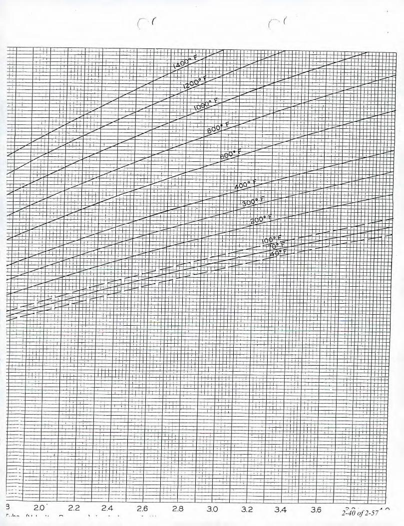
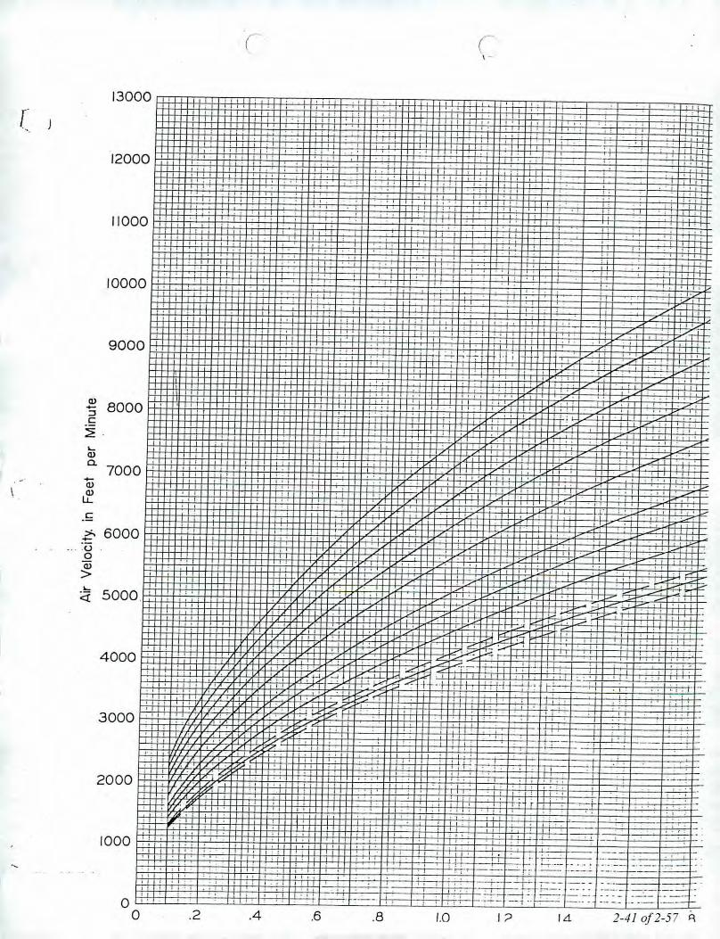

2600
2400
2200
2000
1800
, ,". "
) 1600 ., ,1
jL 1400 , , , .
, ,
(, ,
"., /200
1000
800
600R~
400
200
~ +-C~r
I
.~~"'~I-, ,
t'
t=;
, , ,, "
" ,
oo .02Gage
.04Reading
.06with
H+:-.08
Pitat Tube.10
(Velocity.12
Pressure) in.14Inches
.16of Water
.18
, "
.20 l "
.i
2-42 0/2-57

,-.
Bulletin 0-57Page 2
---~)
.. I--w-
Fluid LenlLevel the gage by adjusting the two frontleveling screws (Hem 8 on drawing) untilthe bubble in the spirit level is centered inthe small circle. After leveling the gage,open both rapid shut or! valve tubeconnectors (2 and 5). Back off theMicrometer (4),' if necessary, to makesure lhat the point is not immersed in lhegage fluid. The fluid level in the gageshould now coincide with the mark on theright hand bore plus or minusapproximately 1/32 inch 16l. If the level offluid is too high, fluid can be removed withan eye dropper pipette or carefully pouredout of the right connection lSI. If the lcvclis too low, remove the top left rapid shut offvalve lube connector t2l, and add distilledwater pre-mixed with the proper amountof Dwyer green concentrate. lSeemaintenance instruction for proportions.lAlter correcting the fluid level, reinstallthe rapid shut off connectors and •••..iththem in the open position, relevel theMicrotector. ,~,The gage is now ready 10b('zeroed.
.-
Bulletin 0.57P"Oe 3
should correspond to _ lero reading onthe Micrometer. Adjust the point inrelation lo the Micrometer barrel byturning the top knob while holding thebarrel steady. Repeat lowering the point.watching the meter Cor contact, andadjusting the point until the lero positionand lero reading exactly coincide. Thegage is no•••..zeroed and should nol bemoved.An alternate method of zeroing andrcading can be used wherein, instead ofleroing the gage completely, a z~'--correction reading is laken and recor~then subtr<lcted from the final read'.,' )Compur<.lble results can be obtained WlIll'f'i1her method.
Positive Pressure Measurement
With the fluid at its proper level. apressure of 2.0" water column maximumcall be measured. Positive pressure shouldbe applied to the top left connection t2lwith the Micrometer zeroed as describedabove. This will permit simple directreading to be laken.
MICROTECTOR@GAGE
Precision I'rc:\:\ure MeasuremenlTIll' IJwv('r ~1inutl'l'lor'combinl's tht..'lin\{' pro~'t..'nprindplt.'s of t.he Hook (inJ.{elYPl' lllllnOlnl'll'r and modern solid st.ateinll'~rillt'd l'ireuill,ll'ctrnnic5, It prm'idesan illt'xpt'nsi\'t' lIWllnSuf achil'\'ing- ilt.t.U'rll('Y and rt'pt'Ulllhilit!. within:!: .00025indll's wutt'r ('olumn throughoul its 0 to 2inl.hl's W.l". runge. Il is lruly a new stan.dard in pn'('isinn pressun' measuring dt •."iel's.
Principles or Operation
A pressure to be measured is applied to thern.mometer fluid which is displaced ineach leg' of the manometer by an amountequal to I: the applied pressure. Amicrometer mounted point is Ihen lowereduntil conUtels the manometer gage fluid.The instant of contact is detecled bycompletion of a low power A.C. circuil.Current for lhis circuit is supplied by a III'lvolt penlight cell feeding two semi-conductor amplifiers which act as a free-running multivibrator operating at a. fretJucncy of approximately "twokiJoherll.
Completion of the A.C. cireuil activates abridge rectifier which provides the signalfor indication on a sensitive 10 to 5Umicroamps) D.C. microammeler.
On indication of contact the uperator~tups lowering the point lind reads lhl'micromet.er whieh indicalt..'s one half lhl'applied pressure. By interpolating- eil-{htdivisions. leach being- .000125" w.c.1 hl"tWt'en .001 micrometer g-rllduut.ions. a to-tul accurac\-, of .UD02!") t'an easilv heDehiE,'"e(1.The micrometer complies -withFederal Specification GG(;.C.105A andis traceable to a master at the NationalBUtl'DU(If Stundarus.
Locating and Opening
Stand the Microtector"'anrJ l:••••e on a firlllflal level surface. Hemove the cover byreleasing the latches and lilting straightup. If it is necessary to move (he gagewilhout case, handle only the base plale orclear acrylic block. (CAUTION: Do nothandle gage by grasping meter.electronicpackagehou'sing Item 7 on drawing. ,. '
Zeroin~Turn Ihe Micrometer barrel 14; until itslower end just coincides with the zeromark on the internal vertical scale tlnlt thelero on the barrel scale coincides with thevertical line on the internal scale. Notethai the internal scale is graduated every.025" from 0 to 1.00 inch and lhe barrelscale is graduated in one thousandths fromo to .025." Turn the meter circuit switch atlhe (op of gage lo the "on" position. Whileholding the barrel at the lcro position lllndwith the gage levell, raise or lower thepoint by turning the top knurled knob 131unlillhe poinl is above, but ncar the rJuid.Check (0 be sure that the meter 11J
registers zero. Walch the meter, hold thebarrel (41 and lower the point slowly byturning the top knurled knob (3), As theknob is lurned, the point will contacl thefluid and the meler pointer will move fromzero to some upscale position. Aftermaking contact, turn the point out or thefluid by turning the Micrometer barrelcounter-clockwise lo a reading of .010 ormore. Again watch the meter ,lnd, thistime, lower the point by turning lheMicrometer barrel. The point positionwhere the met«;r pqinter begins to move upscale is the lero position. This position
After an unknown pressure has beenapplied allhe lop left connection, tne Jluldlevel will drop in the lett bore and rise overlhe point in the right bore. No(e theindicl.lting meter point has moved upscalebecause lhe point is immersed in the fluid.Turn tht, Micrometer counter.clockwi5cuntil the point leaves the fluid as indicatedby the meter pointer dropping lo zero or ..scale. Then slowly lurn the Microm,-"~c10wnunlil its point just touches the fl. )surface l'l.Iusing movcmen~ of lhe meterpointer. Withdraw the point and repeatseveral times noting eAch time thet\licrmllett..'r n~ading where the meterpointer movement begins. The average ofthl.~e readings multiplied by two is .lhepressurc applied 10 the gage. (Av~.reading x 2 = pressure applied in inchesw.c. The degree of uncertainly Cor theoperator and instrument is indicated bythe dirrC'rf'nce in !he$e readings. lWhen lhl' readill~s ilre complete thepressure should be removed and the zero-selling of the Microtl.'Ctor'~' rechecked.Any Ch,lfl~C in thl' lero position willilldicittc imtCCUmle rCCJdings.Should lhishappen the zero-set and pressure.measurement procedl)re, should berepeatC'd .


JJ Calibrations, Inco7007 SE Lake RdPortland, OR 97267-2105Phone 503.786.3005FAX 503.786.2994
2/7/20132/7/201420°C 40%RHWithin ToleranceWithin ToleranceCalibrated112
PO: OTL-13-003OrderOate: 2/6/2013
Authorized By: N/ACalibrated on:
.Recommended Due:
Environment:As Received:As Returned:Action Taken:Technician:
Certificate of CalibCtionCertificate Number: 525343
Property#: OMNI-00417User: N/A
Department:N/ AMake: ExteehModel: 451126Serial#: 08120397
Description: AnemometerProcedure:DeN 404947/400331Accuracy: :t 3 % READ ING
Remarks: • Any number of factors may cause the calibration item to drift out of calibration before the recommended interval has expiredReturned/returned in case.
Omni.Test Laboratories13327 NEAirport WayPortland, OR 97230
Std 10568497AGOlA
ManufacturerTSIHart ScientificBurns Engineering
Model87051502A200G05B085
Standards UsedNomenclatureDP-CALCPrecision Digital ThermometerINDUSTRIAL PRT
Due Date9/10/20138/14/20132/7 /2014
Trace 10513436511627496515
ParameterMeasurement DescriptionBefore/AfterAir Velocity
Range UnitMeasurement DataReference OUT Variance Min Max
FPM 545.0 541 4.0 529.0 561.0- - - - - - ---- - - - -- - -- - - - - - - - - - - FP~'--- --- - --- - - 940~0-- - - - - - -925-- - - - -15~0-- - - - -912~0-- -- - 968.0- - - - - - - - - ---- - - --- -- - - -- - -- - - - - ---- -- - - - FP~'-- - --- -- - - -15900 - - - ---- 16fi- - -- - :22-0-- -- -j542~0---- -1638.0- -- - - - - - - ---Tempe~~relAmb~nt-------------------------------------------------------------------------------
OF 72.280 71.72 0.580 70.280 74.280-----------------------------------------------------------------------------------------------
JJ Calibrations, Inc. certifies that this instrument has been calibrated in accordance with the JJ Calibrations Quality Assurance Manual with the stated procedure usingstandards that are traceable to the National Institute of Standards and Technology (NISl), or other National Measurement Institutes (NMl's), or by using naturalphysical constants, intrinsic standards or ratio calibration techniques. The quality system and this certificate are in compliance with ANSIINCSL 2540-1-1994,ISO/IEC 17025.2005, ISO 10012-1, the ISO 9000 family and QS 9000. The expanded uncertainties of measurements for this calibration are based upon 95%(2 sigma) confidence limits. Unless otherwise stated, a test accuracy ratio (TAR) of 4:1, if achievable, is maintained. The results reported herein apply only to the
calibration of the item described above. This report may not be reproduced, except in full, without prior written consent of JJ Calibrations.lnc.JJ Calibrations, Inc. quality system has been assessed and accredited to ISOIIEC 17025:2005.
ReView~ Issued218/2013 Rev#14 Insp~
Certificate: 525343

I
I
I
III
: IIIIII
II
I
I
I
I
. ,
Fuji Electric Systems Co.,Ltd.
Instruction" :)Inual
.NDIRTYPEINFRARED GASANALYZER
TYPE: ZRE
...-~.
INZ-TN1ZREc-E
2-46 0/2-57

r-',OMNI Environmental, Ina, _,OMNI-Test Laboratories, Inc.
r"""""',(, -'
WOOD MOISTURE CONTENT CALIBRATION WORKSHEET
Moisture Content Standard OMNIID #: D......,.,-.)~- 00 ..j~\ «..-.\.c 1'\
Reference Moisture Content Standard: OMNI # 00430~~~~~~---------][ 30 I.
, ,~Y~OI
Date Tem~.Barometric Fixed Fixed Observed Moisture
Initials(OF It',I..P~~sure Moisture % Moisture % % ~'HI]'1Lt.."1 (L.. ~O.~ 22% 12% ~ ~ ~l( 12.'t". 1z.70'5"0 ~ r£ 7q,~ 22% 12%
~ ~ ~IZ~/o
\ \\1.0'\ 1..'S '?-D\~ 22% 12%~ ~ ~v.. ,1- '~c.
Ul'lfl1..- ,I :to.1-\ 22% 12% 11.."{. (u.v'{' IJ_<J '//1.1.,111. kq/ \'1 / 'l-O'l- 1-4 's.o. "2.D 22% 12% \"2.. 0h:z..o {Z,o/" de2,,0
i2./3'/'-'L (;1"" F" '30.t." .'~1-10 22% 12% \2..0 Z-t. • <:> ~
'/1<&/"4,~ ':1-' •F >0.1° :,I!., 22% 12% 1'2.,0 '22..<:> cr<..22% 12%
22% 12%
22% 12%
22% 12%
22% 12%
22% 12%
22% 12%
22% 12%
22% 12%
22% 12%
22% 12%
Notes: _
Technician~ignature: ,a..2/"' . Date:~
Control No. C-5FAI-OOOJ,doc. Effective date: 06114120/0 Page 1 of t2-47 of 2-57

Model: 7900 SeriesMarso Jernstoberi AlSFurvej 67900 Nykobing ,\,forsDenmark
Example Calculations
a.HIIl/-Test Laboratories. Inc.C~rtlji<:QII<1t1T~sl R.:p<wtdJ.u••dMay 101J: i'omIll-S<'f\",UMr,f Fil ••sSH01"C"~", Fi/~'Mor.w' 191:T~Sl"'K Pruft~rs',I<)l-S-]J-R.J Marso 791HIWood Sf("~ R~p<JrIS&: umjicm ••s [DraftsO"ly/lI91-S-1J-B.J.Joc
2--18 0/2-57

Equations and Sample Calculations - Method 5G
Equations used to calculate the parameters listed below are described in this appendix. Samplecalculations are provided for each equation. The raw data and printout results from a sample run arealso provided for comparison to the sample calculations.
BR Dry bum rate, kg/hr
m. Total particulate matter collected, mg
Vm( ••d) Volume of gas sampled corrected to standard conditions, dscf
v, Average dilution tunnel gas velocity, ftlsec
C, Particulate concentration, gldscf
Q,d Average dilution tunnel gas flow rate, dscf/min
E Particulate emission rate, Ibs/hr
PR Proportional rate variation, %
2-49 0/2-57

Dry Bum RateUsing equation 28-3:
60 x W",d 100 - 'YoMBR = --- x ----'"a 100
Where,
BR =Wwd
a%M. =
Dry bum rate, lb/hr
Mass of wood burned (wet basis) during test run, lb
Total time of test run, minutes
Average moisture content of test fuel charge, wet basis percent
Sample Calculation:
Dry basis moisture of fuel = 20.03%
Using the equation 28-2 for converting dry basis moisture to wet basis moisture,
%M ='"
20.03 x 10020.03 + 100
%M", = 16.69%
The wet weight of the fuel charge was 7.8 pounds. Converting pounds to kilograms yields a weight
of 3.538 kg. The run time for this run was 180 minutes. Therefore, the bum rate equation appears
thus:
BR = 60 x 3.538 x (100 - 16.69)180 x 100~
BR = 0.98 kglhr = 2.17 lblhr
2-50 0/2-57

Total Particulate Matter Collected
Where:
m"
F,F,R
V,B,
==
=
Total particulate matter collected, mg
Particulate matter collected on front filter, mg
Particulate matter collected on rear filter, mg
Residue from evaporated probe and filter holder acetone rinse, mg
Volume of acetone evaporated probe and filter holder actone rinse, ml
Acetone blank value, mg/ml
Sample Calculation:
m" = 12.6 - 0.4 + 4.7 - (180 x 0.0040)
m" = 16.2 mg
2-510/2-57

Volume of Gas Sampled Corrected to Dry Standard Conditions
Using equation 5-1:
TVm(.zd) = V•• x y x (p8td) x
8td
t1H(P+-)b 13.6
T••
Where:
K
Ts'd
PstdVm =
y
Pb =
IlH =
Tm
Sample Calculation:
17.64 oR/in. Hg
528 oR
29.92 in. Hg
Volume of gas sample measured at the dry gas meter, dcf
Dry gas meter calibration factor, dimensionless
Barometric pressure at the testing site, in. Hg
Average pressure differential across the orifice meter, in. H20
Absolute average dry gas meter temperature, oR
V.••.~'" = 98.434 x 1.01 x ( 528 ) x.",._, 29.92
30.03 + 0.713.6
532.5
2-52 0/2-57

Dilution Tunnel Gas VelocityUsing equations 2-7 and 2-6, calculated at each recorded interval:
-y = k x C x {M x, p pT«avg)
pxM, ,
Where:
v, Average dilution tunnel gas velocity, ft/sec
= Pitot tube constant:
185.49 It [(1Mb-mole) x (inches Hg)]2
sec ("R) x (inches H20)
Cp
LlP
Ph
PgP,M,
T,
=
=
=
===
Pitot tube coefficient (0.99 for standard pitot tube; 0.84 may be used for
S-type pitot tubes constructed according to Method 2 procedures), unitless
LlP measured during the pre-test flow traverse of the dilution tunnel; the
square root of the LlP values are averaged for this calculation, in. H,o
Barometric pressure at test site, in. Hg
Static Pressure of tunnel, in. Hg
Absolute tunnel pressure, = Ph+ PgMolecular weight of tunnel gas; assume Md =29 lb/lb-mole (per method 5G)
Moisture content of dilution tunnel gas, ratio; assume 4% (per method 5G)
Dilution tunnel temperature, OR; (OR = OF + 460)
Sample calculation:M, = 29 x (1 - 0.04) + 18.0 x 0.04 = 28.56
Y, = 85.49 x 0.99 x {0.0351 x
Y, = 12.69 Itsec
(30.03 +
(548)
-0.45) x (28.56)13.6
2.530/2-57

Particulate ConcentrationUsing equation 5G-2:
g m.C = 0001- x __, . mg Vm(,tdl
Where:
C,
=Vm(std) =
Sample calculation:
Concentration of particulate matter in stack gas, dry basis, corrected to
standard conditions, g/dscf
Total mass of particulate matter collected in the sampling train, mg
Volume of gas sampled corrected to dry standard conditions, dscf
0.001 x 16.299.116
C, = 0.000163 g/dscj
2-54 0/2-57
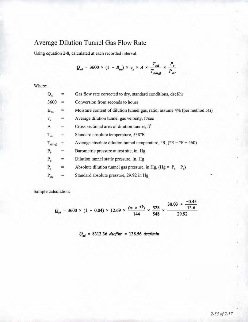
Average Dilution Tunnel Gas Flow RateUsing equation 2-8, calculated at each recorded interval:
Qui = 3600 x (1 - Boo) x v, x A
Where:
Q,d = Gas flow rate corrected to dry, standard conditions, dscf7hr
3600 = Conversion from seconds to hours
Bw, Moisture content of dilution tunnel gas, ratio; assume 4% (per method 5G)
v, Average dilution tunnel gas velocity, ftlsec
A = Cross sectional area of dilution tunnel, ft'
Ts'd Standard absolute temperature, 538°R
Ts(avg) Average absolute dilution tunnel temperature, OR,COR= OF+ 460)
Pb = Barometric pressure at test site, in. Hg
Pg = Dilution tunnel static pressure, in. Hg
P, Absolute dilution tunnel gas pressure, in Hg, (Hg = Pb + Pg)
PS1d = Standard absolute pressure, 29.92 in Hg
Sample calculation:
(11 x 32)Qui = 3600 x (1 - 0.04) x 12.69 x 144528x __ x548
30.03 + -0.4513.6
29.92
Qui = 8313.36 dscjlhr = 138.56 dscjlmin
2-55 of2-57

Particulate Emission RateUsing equation 5G-3 and 5G-4:
E = C. x Q.rd
E - K x EO.13.,q- 3
Where:
E
=Particulate emission rate, g!hr
Particulate emission rate, adjusted, g!hr
I
C, = Concentration of particulate matter in the stack, corrected to dry, standard
conditions, g/dscf
Q,d Average dilution tunnel gas flow rate, dscfi'hr
K, Constant, 1.82 for metric units, 0.643 for English units
Sample calculation:
E = 0.000163 x 8313.36
E = 1.36 glhr
E = 2.35 glhr
2-560/2-57

Proportional Rate VariationUsing equation 5H-9, calculated at each recorded interval:
Where:
PR a x (V••, x=
10 x (V•• x
VxTxT), •• ,I
V'i X T, x Tmi)x 100
Vmi(std) =
Vm
Vsi
V, =Tmi =
TmTsi
T,
PR8
= Percent proportional rate
Time of test, min
Measured tracer gas concentration for the "i'b" interval, in this case, the
inverse of the calculated flow in the stack based on CO, concentrations in
the stack and in the dilution tunnel
Volume of gas sample measured by the dry gas meter during the "i'b" 10
minute interval, dscf
Volume of gas sample as measured by dry gas meter, dscf
Average gas velocity in the dilution tunnel during each 10 minute interval, i,
of the test run, m1sec
Average gas velocity in the dilution tunnel, m1sec
Absolute average dry gas meter temperature during each 10 minute interval, i,
of the test run, OR
Absolute average dry gas meter temperature, OR
Absolute average gas temperature in the dilution tunnel during each 10
minute interval, i, of the test run, OR
Absolute average gas temperature in the dilution tunnel, OR
Sample calculation (for the reading at 50 minutes into test run I):
PR =180 x 5.6 x 12.69 x 533 x 55210 x 98.434 x 12.63 x 548 x 532
PR = 103.8%
x 100
2-57 of2-57

JJodel: 7900 SeriesAtorso Jernstoberi AlSFurvej 67900 l'I)'kobing MorsDenmark
Section 3
Owner's Manual(s)
GAIN/-Test Laboratories, Inc.CtrtifiwlWn TtJ;l Rtport dated May 1013: \'vml/i.snv',US<!rs F,lts'SHOPC/it/ll FiltMvrso. 19111't.mrrg Prop;'t.u.JIJ1 ..•.'1-1J-8.J .\JvrOW} 7900 Wood StUl'l! Reports & C'eHlfia1le" I&"!'"Olll}"! JIJ1..•.'\-.1J-.H.J,dot'
3-1 of 3-11

~----Byappointmentto The RoyalDanishCourt
Installation and Operating Instructions
7900 seriesFor use in North America
Marso 7943Read this entire manual before you install and use your new room heater. If this room heater isnot properly installed, a house fire may result. To reduce the risk of fire, follow the installationinstructions. Failure to follow instructions may result in property damage, bodily injury, oreven death.Contact local building officials about restrictions and installation/inspection-requirementsin your area.
Save these instructions
MORS0 JERNSTlIIBERI A!S . DK-7900 NYKlIIBING MORSE-Mail: stoveslamorsoe.com . Website: www.morsoe.com
3-2 of 3-11

We congratulate you on your choice of a Morso stove. Morso has beenproducing some of Ihe world's besl sloves since 1853.11 you follow Ihisinstallation- and operating instruction carefully, we can assure youmany years of warmlh and pleasure. CONTENTS:
Optionat AccessoriesAwide range of accessories [such as handling gloves. fireside toots, glass cleaner and heatproolpaintl are available for use with your MorS0 stove. They help with day-to-day running andmaintenance. Contact your MorS0dealer for more information.
The MorS0 7900 series meets the U.s. Environmental Protection Agency's emission limits forwood heaters sotd on or after Juty 1. 1990
N.l.TKltlAL We luggestthl'll our woodbuming hearthr,:t~'lproducts bo installed and serviced by
IIprofessionals who are certified in the U.s.by the Nalional Fireplace In&titlJt~ INFlllllNFl Woodbuming Speeiali~s or who Irecertified in Canada by ~
CERtlAm Wood Energv Technical -.HI__ •• Tl1linlng Mint ~~
The Mors0 7900 series have been tested byOMNI-Test Laboratories. Inc. The test standards areANSI/UL-1482 for the Uniled Stales and ULC5627 for Canada.
The stove is listed for burning wood only. Donot burn other fuels.
Under specific test conditiOns this healer has been shown to deliver heat at rates ranging from11 600 - 26 700 BTU/hr.
cast ironCast iron is a live material. There are no two ovens that are identical. This is partly due to thetolerances of the casting process. partly because Ihe ovens are a work of craftsmanship.Minor unevennesses may also occur in the cast iron surface.
2
1.0
2.0
3.0
Inslallalion of your Morse slove1.1 Checking loose parts in the stove1.2 The chimney I flue system1.3 Flue Connection1.4 Connection to existing chimney1.5 Positioning the stove1.6 Positioning the 7970 stove model
Operalion2.1 Before you start firing2.2 Lighting and loading intervals
Maintenance3,1 Exterior maintenance3.2 Internal maintenance3.3 Cleaning the stove and the flue3.4 Leaving the stove lor extended periods3.5 Parts diagram
44566810
111112
161616181920
3

11.0 Installation of your Morso stove
Installation of woodburning stoves must be safe and legal.
If your Mors" slove is not Instalted correctly. II may cause a house fire. To reducethe risk of fire, the Installation instructions must be followed carefully. Contact thelocat building officiats about restrictions and installation inspection in your area.
Before you start installing your slove, make sure thai:
- The stove and chimney connection are placed far enough from combustible materials to meetall clearance requirements.• The floor protection must be adequate and must be made correctly according to 'the f
requirements.All neccessary approvals are needed from the local building officials.
The data plate. which is located on the back of the stove, prOVidesinformation regarding safetytesting information, name of certified testing laboratory, and installation requirements.
Installation requirements vary in different districts, and Ihe local building officials have the finalauthorization to approve your installation. Youshould discuss the installation with them beforebeginning. Please ask your dealer for further information.
Do not connect to any air distribution duct or system.
Important: If the installation instructions are not followed carefully, it may causedangerous situations like chimney - and house fires. Follow the instructionscarefully and do not deviate from them as It may cause injuries to people orproperty.
1.1 Checking loose parts in the stoveAfter unpacking, check that the fire bricks are firmly in position and have not shifted in transil.Check also that the-air control works freely.
Before starting the initial lire. make sure that the baffles is placed correctly.
Standard AccessoriesA Mors", glove and ceramic flue connection gasket are standard accessories that usually can befound in the ashpan or firebox area.
1.2 The chimney I flue systemNote that the flue system must be independently secured and must not rely on the stove for support.
The stove must not be connected to a chimney flue serving any other appliance.(Several flues may run up a single chimney stack; use one flueway per appliancel.
Use a residential type masonry or listed type HT factory. built chimney.
High Temperature IH.T.1Chimney Standard UL-103-1985 12100° F.I or a code-approvedmasonry chimney with flue liner for the USA, and High Temperature 16500CI Standard ULS-629 for Canada.
The internal dimensions of the chimney connector and chimney must not be less than 6 inchesdiameter lor equivalent cross sectionl. and should not besignificantly larger than this. Too large asection will tend to allow the flue gases to coolexcessivety. causing sluggishness or unpredictabilityin the stove's performance.
We recommend the length of the chimney system should be at least 16 feet Inot requiredl abovethe stove in normal domestic situations, measured from the Huecollar to the top of the chimney.Local conditions like for example. roof constructions, large trees nearby and high altitude, mayinfluence the chimney draft and heigh!. Therefore, contact the local professional chimney sweepor your MorS0 dealer.
Typical Factory-Built or Masonry Chimney Installations
Day"''''•••••• hog'
"
4 5

D Soli!1 iosulHled. lisled faclory-built chimneylenglh wilh an inside diameter 2.in. larger thanthe cbimney connector and having I-in. Of moreof insula lion. serving as a pas~-lhrough for Hsinglewall shed sleel chimney cooneclor of minimumH gauge Ihickn~ss, with a minimum 2.in. air spacebelwtc'n the outer wall of chimney seclion llnd'umbustibles. Minimum lenglh of chimney sectionshall be 12.in. chimney section spaced I.in. awayfrom connector using sheet Sled .support plaleson both c:nds of chimney seclion. Opening shall be .covered, and chimney section supported on bothsides Wilh sheet Meel supports securely fastened towall surfaces of minimum 24 gauge thickness.Fastenen llsed to secure chimney section shall nOIper,elrate chimney flue liner.
7
B Solid-insulated. lisled faclory.buill chimneylength of the same inside diameter as thechimney conneclor and having I-in. or mon:of insulation wilh a mioimum 9-in. a:r spacebetween the ouler wan of the chimney lenglhand combustibte~.
C Sheel sleel chimney conned or, minimum 24gauge in lhickness, wilh a venillated (himble,minimum 24 gauge in thickness, having twoI-in. air channels, s~p~rdl~ from combusliblesby a minimum of 6-in. of glass fiber insulalion.Optning shall be covered. and thimble SUf'fIOI1edwilh ~ she.:l sl.:0:1support, minimum 24 gauge inthicLness.
A Minimum 15.in thick brick masorny all fl'Mledinto combuscible wall with a minimum of !2-inbrick separalion from clay Iinl:T10 combustibles.The fireclay tioa shall ruo from OUlt'\'surface ofbrick wall 10, bul not beyood.llte inner surfaceof chimney flue rin~r amI shall be finnlycemented in plate
~M••.....,"'''''''''Y Sl'tol,lto!"",.""' ..~ ,~IONfPAall
I.w.-CIIotrI'>eI' •••.,.no:o~_••••• ""lo.h •• l.iHi'''\lPO'U.01$ •••••••••• ./110.2 ••. 111"""')--0""''''''j •.•.(~n•.•••)
I0Io..-.-..,,1000'''''U1 ••••Ulll.o;.-'>...:_"'I~ •• aln.ISI""'l
I
•.•........... .......,..,..,. ..."".10 ,I>t.l11I1Il.,","","'~._._. ~ •.••...-a2 "'l~l """I I 2111lSI """I
1-111. (~,. .••••• )
.1, '''''''' III'''''''-'lY1o''QUI
1Mmoooo-"IutIlQl~b!tk
'~-~'i"".:~.~.• Il"'-I:105mml
1 .-f _.D _,I.,____ ,..<1.1;
1oIo"""'Y_, 1.,Of"",,1'lJ(itdlO"'~PA21l
Chlmaty Connec!or Syslems and Cluunct'S from r.nmbll~liblt W~lJs for R~sidl'nliallll'lIling Applillnct'S
l ••••• nlIlolO<l •• 'clII •••••IJ ••• ~I~ t<'S1"""~~_..1'>0.1> •••.••
p
1.3 Flue ConnectionThe slove is supplied from the factory with a round blanking plate blocking off the top and rearflue exit Ibehmd the rear shield platel. A flue collar are placed in the lire box area.
Use a 24 MSG black or blue chimney connector or listed double wall chimney connector. Referto local codes and the chimney manufacturer's instructions lor precautions required lor passinga chimney through a combustible waH or ceiling. Remember to secure the chimney connectorwith a minimum of three screws 10 the product and to each adjoining section.The coltar can be 'Itted to the rear outlel. Simply knock out the round panel on the rear heal shieldplate 10 reveal the cast iron plate. Untwist the blanking plate and the Hue collar and swap theirpositions. Re-secure by pushing down and lighten the enclosed screws.Position the stove and connect to the flue system.
Wear gloves and protective eyewear when drIlling, cutting or joIning sections of chimneyconnector
1.' Connection to the existing chimneyA chimney connector is the double-wall or single-walt pipe thai connects the stove to the chim-ney. The chimney itself is the masonry or prefabricated structure thaI encloses the Hue. Chim-ney connectors are used only to connect the stove 10 the chimney.
Double-walt connectors musl be tested and listed for use with solid-fuel burning appliances.Single-walt connectors should be made of 21. gauge or heavier gauge steel. Do not use galvanizedconnector; it cannotwilhstand the high-temperatures that smoke and exhaust gases can reach. andmay release toxic fumes under high heat. The connector must be 6 inches 1150mm! in diameter.
If possIble, do not pass the chimney connector through a combustible wall or ceiUng.If passage through a combustible wall is unavoidable, refer to the sectlons on WallPass- Throughs. Do not pass the connector through an attic, a closet or sImilarconcealed space when installing the chimney connectors.
It is important to keep the tlue gases moving smoothly in Ihe right direction, Do not vent into alarge void at this location; rather form one continuous section all the way up. Use mild bendsle.g. 450 vs. 90°) rather than sharp angLes where a change 01 direction is required. All parts ofthe venting must be accessible for cleaning purposes.In horizontal runs of chimney, maintain a distance 0118 inches from the ceiling. Keep it as shorland direct as possible. with no more than two 90 degree turns. Slope horizontal runs of connectorupward 1/4 inch per foot [20 mm per metre! going from the stove toward the chimney. Therecommended maximum lenglh of a horizontal run is 3 feetl1 metre!. and the IOlallenglh shouldbe no longer than 8 feet 12.5 metres!.Information on assembting and installing connectors IS provided by the manufacturer's instructionsexactly as you assemble Ihe connector and attach It to the stove and chimney.
Be sure the installed stove and chimney connector are correct distances from near bycombustible materials. See the clearance paragraph page 8.
Where passage through a wall or partition 01 combustible construction is desired, the instal-
lation shall conform 10 CAN/CSA.B365.
6
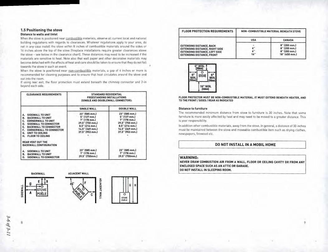
FLOOR PROTECTION REQUIREMENTS NON -COMBUSTIBLE MATERIAL BENEATH STOVE
USA CANADA
EXTENDING DISTANCE. BACK . S" [200 mm.1EXTENDING DISTANCE. RIGHT SIDE
,.. S" 1200 mm.1EXTENDING DISTANCE. lEFT SIDE
,.. 8"!200mm.!EXTENDING DISTANCE. FRONT 16" 18" (450 mm.l
1.5 Positioning the stoveDistance to walls and lintelWhen the stove is positioned near combystible materials, observe all current locat and nationalbuilding regulations with regards 10 clearances. Whatever regulations apply 10 your area, donot in any case inslalilhe stove within 8 inches of combustible materials around the sides or16 inches above the top of the stove llireplace installations require greater clearances abovethe stove - see below in the clearance chartl. These distances may need 10 be increased if thematerials are sensitive 10 heat. Nole also that wall paper and other decorative materials maybecome detached with the effects of heat and care should be laken to ensure that they do not falltowards the stove in such an event.When the slove is positioned near non-combuslible maleriats. a gap of '" inches or more isrecommended for cleaning purposes and to ensure that heal circulales around the slove and
out into the room.It using rear exit, the Hoor protection must extend benealh the chimney connector and 2-inbeyond each side.
-6"MIN.(200"'"1
6"MIN.(mMlJ
16/1 MIN.('-1
CLEARANCE REQUIREMENTS STANDARO RESIDENTIALFREESTANDING INSTALLATIONS
(SINGLE AND DOUBLEWALL CONNECTOR!:
SINGLE WAll DOUBLE WALL
A. SIDEWAll TO UNIT 23"1585 mm.J 23" 1585 mm.1
B. BACKWALL TO UNIT 5"1127 mm.l 5"(127 mm.1
c. CORNERWALl TO UNIT T1178mm.1 7"1178 mm.1o. SIDEWALL TO CONNECTOR 29.5"1750 mm.1 29.5"1750 mm.1
E. BACKWALL TO CONNECTOR 8.5"1216 mm.) 8.5" [216 mm.)
F. CORNERWALL TO CONNECTOR 14.5"1369 mm,l 14.5"1369 mm.)G. UNIT TO CEILING 37.5"1953 mm.1 31.5"1953 mm.)
H. FLOOR TO CEILING . .
REAR VENT OUT THEBACKWAll CONFIGURATION
A. SIDEWALL TO UNIT 23" [5S5 mm.1 23" 1595 mm.1B. BACKWAll TO UNIT 1"1118 mm.) TI118mm.)
D. SIDEWALL TO CONNECTOR 29.5"1150mm.J 29.S"1150mm.)
FLOOR PROTECTOR MUST BE NON-COMBUSTIBLE MATERIAL. IT MUST EXTEND BENEATH HEATER, ANDTO THE FRONT ISIDESI REAR AS INDICATED
Distance 10 furnitureThe recommended minimum distance from stove to furniture is 30 inches. Note that somefurnilure is more easily affected by heat and may need to be moved to a greater distance. Thisis your responsibility.
In addition other combustible materials. away from the stove. In general, a distance of 30 inchesmust be maintained between the stove and moveable combustible item such as drying dothes,newspapers. firewood etc.
DO NOT INSTALL IN A MOBIL HOME
WARNING:NEVER DRAW COMBUSTION AIR FROM A WAll. FLOOR OR CEILING CAVITY OR FROM ANYENCLOSED SPACE SUCH AS AN ATIrCOR GARAGE.DO NOT INSTALL (N SLEEPING ROOM.
BACKWALL ADJACENT WALL
~E B E'
~ D ~n~ m~ STOVE z
'" ~w A PO~LE "0 ~in ~~
G H
G,~""""
B 9

1.6 Posilioning lhe 7970 slove modellwallmounledl
The stove must be installed on a non-combustible wall
The walt-mounting fixture is provided with four holes for mounting expansion bolts in the wall.The bolts must be sized to secure that the wall and the materials it is made from are capableof supporting the stove. If in doubt. conlacl an expert. The weight of the empty slave is approx.160 kg 1353 lbs.l. The wall-mounting fixture may be used as drilling tempLate.
Mount the wall-mounting fixture on the wall. If the flue exit is wanted to the rear, build a wallbushing correctly into the wallisee illustration!.
Lilt the wood stove in ptace so that it rests on the bottom pari of the walt-mounting fixture,and secure it again to the fixture by means olthe screws included.
10
Nole:Acid Protection
If acid-washing the masonry around the slove, protecllhe slove surface with an acid-prool coverFresh Air InLet
Unless there is deemed 10besulficient ambienlleakage of air into the room via doorways, windowsand the like, a dedicated fresh air inlet will be needed. This inlet should have 2 square inches11250 square mml of free air space. This is particularly important where the room is well seated,or where an extractor hood or ventilation system disturbs the natural air pressure. Such an inletshould not be on a wall that is usually subject to negiJtive pressure from normal wind pallern.Avoid placing the inlet directly across the room from Ihe slove, thus causing a cold air draft.
12.0 Operation
2.1 Before you slar! firing
For Use with Solid Wood Fuel Only. Do Not Overfire, If Heater or Chimney Connector GlowsYou Are Overfiring. Inspect and Clean Chimney Frequently. Under Certain Conditions of usecreosote buildup may occur rapidLy. Because of risk of smoke and flame spillage, operate onlywith door fully closed.
CAUTION:Hot while in operation. Keep children, clothing and furniture away. Contact may cause skin burns.DO NOT USE CHEMICALS OR FLUIDS TO START THE FIREDO NOT BURN GARBAGE OR FLAMMABLE FLUIDS
DO NOT USE A GRATE, ANDIRONS, OR OTHER WAYS OF ELEVATING THE FIRE - BUILD FIREDIRECTLY ON HEARTH.DO NOT USE GASOLINE, GASOLINE-TYPE LANTERN FUEL, KEROSENE, CHARCOAL LIGHTEROR FlUID OR SIMILAR LIQUIDS TO START OR FRESHEN UP A FIRE IN THIS HEATER. KEEP
ALL SUCH L10UIDS AWAY FROM THE HEATER WHILE IT IS IN USE
11

Choosing your fuelAll types of natural wood can be burned on your stove, but they must bewell seasoned and dry.Once the wood is cut to length, it should be spill down middle ~to suit the dimentions given below~Ioatlowmoislure to evaporate.
Cut the wood to a length of max 12inches 130em] and approx. 3 10 3.5 inches 17-8cml in section. I
If you can weigh your wood, aim for around 2lbs. For correct combustion and heat output. woodfuel should contain no more than 20% moisture; this can easily be checked by using the MarSiliMoisture Meier [pari /I 629299001
To naturally season wood fuel. stack and store It under cover in an all'Ylocation where fresh aircan move through each piece. Some soft woods may take as little as one good summer 10 seasonwhereas harder woods such as oak. maple, and elm may require seasoning up 10 18 months.Avoid overly dry wood thai is gray in color as under certain conditions it Cancause performanceproblems. such as back-puffing and sluggishness. Well seasoned wood will be light 10 hold andwill show signs of cracking from the center.oul in the ends. If your wood spilS or sizzles whenburnt. and your stove's door glass persistently mists up. your wood is not properly seasoned.Never use drift wood Urom the seal. whose sat! content may calise corrosion, nor constructionwood that may have been impregnated with chemicals.
CAUTION Do not place fuel within the installation clearances for the stove or within thes ace re uired for (oadin fuel and ash removal.
Starting the First FireThe initial fire should be small, so that the stove paint can cure and the main plates of thestove can settle into position. Some fumes wilt be given off by the paint. Ventilate the roomduring this phase.The setting of the air control, lighting techniques and loading intervalswitl depend on chimneydraft. the fuel used, the heat required and so on, Some basic techniques are outlined below.
In principleYour stove should bewith Primary and Secondary air and Pilot air intels.Primary Air is controlled using the l~ver situated over the door. Moving the control lever to rightposition will open the air inlet and will allow a supply of preheated air to enter the firebox via the'airwash' system situaled inside the stove and above the glass.
Thesecondary air ISinjected into the flue gasesabove the fire resulting in a cleaner. more ellicientcombustion process. The supply of secondary air and Pilot air is fixed open and is not adjustable.For exlra safety. your slove should be with a removable handle.
2.2 Lighting and Loading intervaLsWhen first lighting the stove, a large volume of air is needed.When the slave is cold, you shouldleave the door open an inch or two for the first few minutes and open the primary air supplycompletely. While the door is open, do not leave the slave unattended.
To form a reasonable bedof ash on the floor olthe slave, you should use 2-4 pounds of dry kindlingallhe initial lighting. If possible, maintain a 1.1.5 inch 12-3cmllayer of ash on the floor 01 thecombustion chamber lor added insula lion.
Step-by.step procedure
1. Theair supply must be fully open. Movethecontrol lever to the right position
2. For lighting the fire use 3-5 pounds of drykindling wood.
3. Light the fire. An ember bedwill quickly beformed by lighting with firestarters. MarSilikindling bags or 7~10 pieces of twistedpaper under the dry kindling wood.
4. After lighting. partially close the door,leaving it open an inch or two 10 allow inplenty of combustion air.
5. When the chimney is warm after about5-10 minutes, the door should be closed.
12 13

6. A suilable layer of ember witl be formedafter about 15-20 minutes.
7. When ready to reload, use a poker tospread the embers across the firebox floor,bnnging plenty towards the front 01 thestove.
7. Lay2 piecesofwoodonto theembers. Leavehalf an inch or more between each piece.Max. luelload 4.0 pounds/h.
Do not for any reason attempt to increase the firing of your heater by altering the air contra!adjustment range outlined in these directions.
Warning: Fireplace stoves must never be left unattended with the door open.
If the door is left partly open, gas and flame may be drawn out of the fireplace stoveopening, creating risks from both fire and smoke. We recommend that you fitasmoke detectorin the room where the stove Is installed.
DONOTOVERFIRETHISHEATER.Overfiring may causeahouse fire. orcan result in permanentdamage to the stove. If any part of the stove glows, you are overfiring.
The maximum recommended weight of wood luel per load is 4.0 Ibs/hr.12.0 kg/hllapprox 3 splittogs!.
Under normalliring, the average flue temperature in the slove pipe, measured 20 em above thestove, is approx. 300° C1550°F!.The maximum flue temperature in the stove pipe must not exceed450° C 1750°Fl. If the flue temperature exceeds 450°C [750°FI. il is considered as over firing andmay cause premature wear and tear 01the stove.
To help gauge the correct running temperature of your stove, we recommend you use the MorS0Flue GasThermometer [part # 629012001.The Flue GasThermometer magneticaUyatlaches onlothe stove pipe approx 20em [8~Jabovethe stove's top plate and measures the surface temperatureof the stove pipe. Please see your authorized Mors" Dealer for availability.
8. Close the door. Leave the primary airsupply lully open.II it does not light. leave the door slightlyajar to allow the necessary amount of airin to ignite the wood.Close the door again once the wood haskindled.After a fewminutes, adjust the primary airsupply 10suit your heating requirements.Make sure thallhere is always enough airto sustain clear, endunng flames when youreduce the amount of combustion air. amiafterwards.
9. For refueling, add a layer of wood whilethere are still plenty of live embers, repeatsteps 7.8.
14
Draft conditionsIf smoke or fumes come out of your stove when lightning up and reloading, or jf the fire simplywill not respond, a poor draft is almost certainly to blame. lin a very few cases, there may beinsulhcient fresh air gellmg into the room - see instaHation advice above!. Take advice from yourstove supplier on how best to upgrade your flue system to improve draft.
Rules 01woodburningIf you want less heat. put fewer logs on the stove and reduce the amount of air. It is still importantto maintain a good layer of embers.
Less heat - less wood ~ less airGreater heat - more wood ~more airSool deposits will settle on the glass if the stove is run too slowly or if your woodis not well seasoned.
Wewould strongly recommend that you do not leave your stove alit at night. It harms the envi~ronment. and constitutes very poor use of the wood. as the gases in the wood do not ignite atthe low temperature, but settle as soot [unburned gasesl in the chimney and stove instead.
15

13.0 MAINTENANCE I .When petfomlng maintenance on your stove, always protect yourself, using safety gogglesand gLoves.
3.1 Exterior MaintenanceThe stove sur/ace is painted with heat.resistant Senotherm paint. II is best kept clean by vacuumingwith a 50ft brush allachrnenl or by wiping with a tint-Iree cloth.Over a period 01 time, the painted surface may become slightly grey. A can of Morse louch-upspray paint should be available from your stove supplier. This can be applied. in accordance withthe instructions - in just a few minutes. When first firing after touching up, the stove will give offa slight smell as the paint cures. Make sure to ventilate the room well during this phase.
3.2 Internal maintenanceGlassIf the slove is generally run at the correcltemperatures, there should be little or no dirt on the glass.If dirt does seltle during lighting. most will burn off as temperatures increase. For heavier depositsIhat will not burn off, use morS0 glass cleaner, applied when the glass is cold. in accordance withthe instructions. Never use abrasive cleaners on the glass surface.
Reasons for dirty glassFuel too wetLogs too large or not splitCombustion temperatures too lowLogs to close to glass lside windows)
Replace broken glass immediately.Do not operate your stove if the glass in the door is damaged.
If you need to repLace the glass. it should be replaced with the high temperature ceramic class
supplied by Mors0, conlact your MorS0 dealer.
Installing the glass
Never Install the glass when tke stove Is in function.
Ceramic glass replacementCeramic glass canna I be recycled because it has a higher melting point that ordinary glass. Ifceramic glass is mixed with ordinary glass, Ihe raw material is spoiled, and the reclaiming pro-cess may be halted. Take care that the ovenproof glass does nol end up among ordinary recycledwasle. That will be a great benefillo lhe environment.
Note: Should be handed in 10 a recycling slation as ceramic glass.
Door glass replacement.
1. When you open the door, you will find two hinge pins, one in each hinge. Remove the twohinge pins, lift the door off the hinges and place it face down on a sheet 01 cardboard or othernonabrasive labric.
2. Unscrew the" bolts that secure the glass. fln the event that a bolt sheers off when being
unscrewed, remove the remaining body of the bolt by drilling down its centre with 1/8 inch high
speed steel drill bit. Smaller drill bits may be successful. but do nol use a lager bit. Make sure
Ihe bit stays away from the edges of the bolt - Ihis may damage the thread in the cast ironl.
3. Remove the old ceramic gaskets and clean up the surface underneath with wire wool or emerypaper to remove loose particles.
t.. Place the new gasket materiaL in position around the perimeter 01 the window area. making
sure to pinch them to the length in such a way that they make a continuous seal. Leave no gaps.
5. Place the new glass in position on the strips and screw home the fresh bolts and fitting by hand.
6. Finally, give each ollhe bolts an extra half turn or 50. The glass should held tight enough by that
cleaning will not disLodge it. Do not over-tighten the bolts as Ihis may put excessive pressureon the glass, resulting In cracking - important!
o reduce the risk of breaking the glass, avoid striking the glass or slamming the door.
Inlernal service parts
The Hame-path equipment - consisting 01 the ashpan. grate. firebricks. Cast iron 'Ire plales.glass, baIlie and flue collar - are subject to lhe extremes of heat produced by the fire. Fromtime 10 time. one or other of these parts may need replacing as a matter of routine maintenance.
NOTE: The flame-path equipment, the ceramic rope and the paint finish are not coveredby guarantee.
All of these service parts can be bought from your mars", deaLer. and we recommend that damagedparis are replaced as soon as possibLe 10 avoid collateral damage.Should the baffle be distorted by an overfire. the slove will slill function. although its efficiencymay be compromised. Replace it as soon as possible.
Reasons for 'ast internal wear and tearPersistent heavy 'iringSoot and ashes telt to accumulate
16 17

GasketThe gasket around the perimeter of the door may harden over a period of time. II should bereplaced If it becomes dllficut! to close the doors or ir air slarts to leak in around the perimeterof Ihe doors. causing Ihe lire to become a lillie less controllable. A mors~ rope gasket kit isavailable from your slove supplier.
3.3 CLeaning the Stove and the FlueCheck for soot above Ihe baffle plale and around the flue outlet every month or so to start with.lithe stove suddenly becomes sluggish, check for a soot fall around lhe Ilue collar or in the flue!chimney.
The chimney and chimney connector should be inspected at least once every two monthsduring the heating season to determine if a creosote buildup has occurred. If creosote hasaccumulated, it should be removed to reduce the risk of a chimney tire.
Clean the fLuelchimney - aU the way from the stove to the Ilue terminal point above the house.
A good routine is to clean the Ilue alter each heating season in any case, and inspect prior 10theseason to ensure that bird's nests or other blockages have not occurred during Ihe 011season.
Ash disposalEmpty the ashpan on a daily basis or as needed. Ash allowed to build up towards the undersideof the grate will trap heat and could cause premature failure of the grate.
Empty the ashpan according 10this procedure:Openthe fronl door, and use a shovel or poker to slir excessash through the ash slots in the gratedown into the ash pan. Take oul the ash pan. making sure to keep .tlevelto avoid spilling ash.
Chimney sweepingInspect Ihe system regularly during the healing season as part of a regular maintenance schedule.To inspect the chimney. let the stove cool completely. Then. using a mirror, sight up through theflue collar into thl:! chimney flue. if you cannot inspect the HUl:!system in this fashion, the stovemust be disconnected to provide better viewing access.Clean the chimney using a brush the same size and shape as the flue liner. Run Ihe brush upand down the liner, causing any deposits to fall to the bottom of the chimney where they can beremoved through the clean-oul door.Clean the chimney connector disconnecting the sections. taking them olJtside, and removing anydeposits with a stiff wire brush. Reinstall the connector sections alter cleaning. being sure tosecure the Joints between individual sections with sheet metal screws.if you cannot inspect or clean the chimney yourself, contact your local Morse Dealer or aprofessional chimney sweep,
if you do experience a chimney tire, act promptly and:Close the air conlrol.Get everyone out 01the house.Call the Fire Department.
Annual maintenanceBefore the heating season. perform a thorough cleaning, inspection and repair:Thoroughly clean the chimney and chimney connector.Inspect the chimney lordamageand deterioration. Replaceweak sections of prefabricated chimney.Havea mason make repairs to a masonry chimney.Inspect the chimney connector and replace any damaged sections.Check gasketing lor wear or compression, and replace if necessary.Check the glass lor cracking; replace if needed.Check door and handle for tightness. Adjust if needed.
Dispose the ash in a metal contalOer with a tight fitling lid.
The closed conlainer of ashes should be placed on 'a noncombustible floor or on the ground,well away from all combustible materials. pending final diSposal. If the ashes are disposed of byburial in soil or otherwise locally disperded. they should be retained in the closed container untilall cinders have thoroughly cooled.
Return the ash pan 10its original position in the stove, and close the door.
CAUTION,Never empty a stove In operation.Never use your household or shop vacuum cleaner to remove ash from the stove:always remove and dispose ot the ash properly.
Creosote - formation and need for removalWhenwood is burned slowly, it produces lar and olherorganic vapors,which combinewith expelledmoisture to form creosole. The creosote vapors condense in the relatively cool chimney Hueof aslow-burning fire. As a result, creosote residue accumulates on Ihe flue lining. When igniled thiscreosote makes an extremely hot fire. When burning wood, the chimney and chimney connectorshould be inspected at least once every two months during the heating season to determine ifa creosole buildup has occurred. If creosote has accumulated, it should be removed to reducethe risk of a chimney fire.
18
3.4 Leaving the stove for extended periodsImportant:If the stove is to be left unused for any period of time. clean it out thoroughly and leave the aircontrol slightly open to allow airflow. Make sure that the flue does nol allow rainwater to comeanywhere near the stove; insta1l a chimney cap, but do not block oll the flue completely.These measures should ensure there is a slight movement of air through the slove, and thai thcbody of the stove remains dry, right into the corners.Anyash left within an unfired slove can allract moisture like blotting paper. If moisture is altowedto seute within the stove, rust wiH form. Rust expands as it takes a grip. This can lead to unduepressure on the stove jomts, and this in turn may result in damage to the stove.
NOTE: It is best to thoroughly clean Ihe stove after Ihe heating season has concluded. Adding adessicant. such as killer litter, into the ash pan helps absorb moisture during the summer months.Be sure to remove Ihis prior to Ihe heating season.
We hope you have many years of carefree warmth in its company. Some initial experimentationwilh loading and running techniques will decide your normal routine. If you have any problemsafter this short learning phase, please refer to your slove dealer. Should they be unable to helpfor any reason. please contact us in writing at the address on the front of this publication.
19

Model: 7900 SeriesMorso Jernstoberi AlSFurvej 67900 h'ykobing MorsDenmark
Section 4
Test Data by Run
OMi'tjJ.Tesl Laboratories, Jnc.Crrri/iwfwII Tr51Rqx>rfJeJlrdMuy lOJJ: \'.omm-sen;,UMrs Fi/e .•'SHOPCJi('III Fi/('Af",.w. /91',T('5II/I}: i'r"J«n,/91-S-1J-8.J Mano 7900 WooJSI(J\~Rq>l,>rrs& C('mjkuflts {Droft~O,'/yf1J91-S--1J-8. J.Joc
~-l of 4-30

)
OMNI-Test Laboratories. Inc.
EPA Weighted Average EmissionsEPA Method 28
Page 1 of 1
Client: MorsoStove Model: 7900Test Dates: 3/18/13-3/25113
Project Number: 192-S-23-8.3Tracking Number: 1847SignaturelDate:
Status: FinalStove Type: Non-Catalytic Stove
Wei2bted Avera2e(wbr)4.0
Emission Rate Plot
Bum Rate (kglhr dry)
~
!II~•,Ca'in•EUJ
fjII 0,00
'f! 0.00 0.50~"-
Run # 3Bum Rate (dry kglhr) 0.96Category 2Overall Efficiency (%) 63%Emissions (gIhr) 4.01Cap (gIhr) 15.00Weigbting Factor 0.559Heat Output (BTUlhr) 11600
Run # 2Bum Rate (dry kglhr) 1.22Category 2Overall Efficiency (%) 63%Emissions (gIhr) 3.23Cap (gIhr) 15.00Weigbting Factor 0.362Heat Output (BTUIhr) 14742
Run # 4Bum Rate (dry kglhr) 1.41Category 3Overall Efficiency (%) 63%Emissions (gIhr) 4.09Cap (gIhr) 15.00Weigbting Factor 0.378Heat Output (BTUlhr) 17038
Run # IBum Rate (dry kglhr) 2.21Category 4Overall Efficiency (%) 63%Emissions (gIhr) 4.58Cap (gIhr) 18.00Weigbting Factor 0.300Heat Output (BTUIhr) 26705
1.00
34.96%
22.65%
23.65%
18.74%
1.50 2.00
•
2.50
Document Control No. P.SSF-0008 (EPA Method 28 Weighted Average Emissionsl.xls. enective Dale: 1211512010 Weighted Average
4-2 of 4-30

Alodel: 7900 SeriesMorso Jernsloberi AlSFurvej 67900 Nykobing AlorsDenmark
Run 1
OMNI-Test Laboratories. Inc.Ce"'fiootiotl Test Rep<K' dated May 101J: 1IomlU- .••.•.""U .••...rs Fifes'SHOP ClJefll f'jfe MIXS<' - 191'TeMmg ProJects' f91-S-1U.J Mono 7900 Wood S/lwe'Rep<Kts &- CeTflfiootn [Draft .•On{v}\/91-S-2J../I. J.dor:
4-3 of 4-30

OMNI-Tesl Laboratories, Inc.
Wood Heater Test Data - EPA Method 50
Manufacturer:Model:
Project No.:Tracking No.:
Run:Test Date:
Bum Rate
Average Tunnel TemperatureAverage Gas Velocity in Dilution Tunnel- vsAverage Gas Flow Rate in Dilution Tunnel. Qsd
Average Delta pAverage Delta HTotal Time of Test
Marso7900192-S-23-8.31847103/18/13
2.21 kg/hr dry
107 degrees Fahrenheit11.9 feet/second
7611.9 dscflhour
0.030 inches H200.93 inches H2060 minutes
AVERAGE SAMPLE TRAIN 1 SAMPLE TRAIN 2
Total Sample Volume. Vm 8.63 cubic feet 8.25 cubic feet 9.01 cubic feetAverage Gas Meter Temperature 80 degrees Fahrenheit 79 degrees Fahrenheit 82 degrees FahrenheitTotal Sample Volume (Standard Conditions) - Vmstd 8.6 dscf 8.2 dscf 9.0 dscf
Total Particulates - mn 3.2 mg 3.7 mgParticulate Concentration (dry-standard) 0.00040 gramsldscf 0.00039 gramsldscf 0.00041 gramsldscfParticulate Emission Rate 3.04 gramslhour 2.96 gramslhour 3.12 gramslhourAdjusted Emissions 4.58 grams/hour 4.47 gramslhour 4.68 gramslhour
Difference from Average 0.10 gramslhour 0.10 gramslhour7.5% of the average emission rate 0.34Weighted Average Emission Rate limit 4.10 gramslhour7.5% of the weinhled averane emission rate limit 0.31
Results Are Acceptable
Page 1 of 1 Run 1 elTlissklns
4-4 of 4-30