CERTIFICATE OF APPROVAL - Lumsden
64
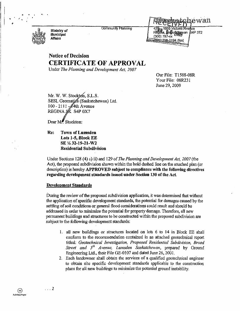
Acid·rree Paper Ministry of Municipal Affairs Notice of Decision Community Ianning CERTIFICATE OF APPROVAL Under The Planning and Development Act, 2007 / Mr. W. W. Stock oil, S.L.S. SESL Geomat' t(Saskatchewan) Ltd. l 00 - 2111 i · '4th Avenue REGINA j5j. S4P OX7 Dear Mlstockton: Re: Town of Lumsden Lots 1-5, Block EE SE Y.i 32-19-21-W2 Residential Subdivision Our File: Tl588-08R Your File: 08R231 June 29, 2009 Under Sections 128 (4) c) ii) and 129 of The Planning and Development Act, 2007 (the Act), the proposed subdivision shown within the bold dashed line on the attached plan (or description) is hereby APPROVED subject to compliance with the following directives regarding development standards issued under Section 130 of the Act. Development Standards During the review of the proposed subdivision application, it was determined that without the application of specific development standards, the potential for damages caused by the settling of soil conditions or general flood considerations could result and should be addressed in order to minimize the potential for property damage. Therefore, all new permanent buildings and structures to be constructed within the proposed subdivision are subject to the following development standards: .. '2 1. all new buildings or structures located on lots 6 to 14 in Block EE shall conform to the reconunendation contained in an attached geotechnical report titled: Geotechnical Investigation, Proposed Residential Subdivision, Broad Street and 5 111 Avenue, Lumsden Saskatchewan, prepared by Ground Engineering Ltd., their File GE-0107 and dated June 26, 2001. 2. Each landowner shall obtain the services of a qualified geotechnical engineer to obtain site specific development standards applicable to the construction plans for all new buildings to minimize the potential ground instability.
-
Upload
khangminh22 -
Category
Documents
-
view
1 -
download
0
Transcript of CERTIFICATE OF APPROVAL - Lumsden
Acid·rree Paper
Ministry of Municipal Affairs
Notice of Decision
Community Ianning
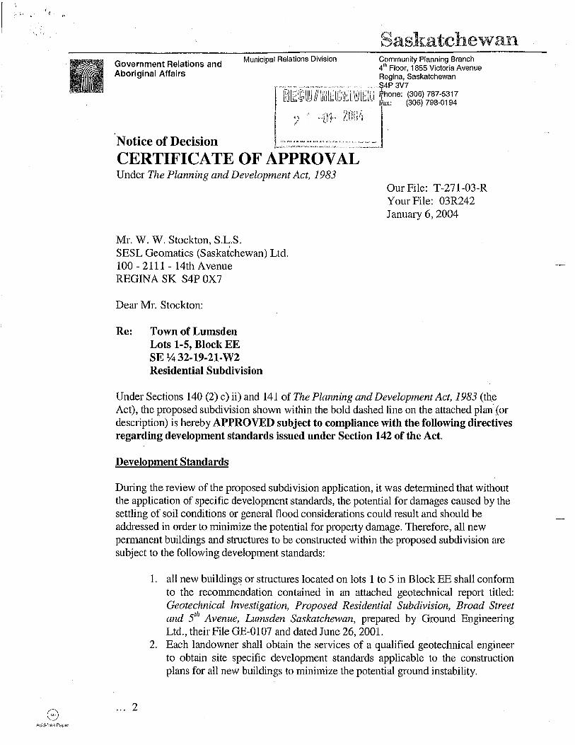
CERTIFICATE OF APPROVAL Under The Planning and Development Act, 2007
/ Mr. W. W. Stock oil, S.L.S. SESL Geomat' t(Saskatchewan) Ltd. l 00 - 2111 i · '4th A venue REGINA j5j. S4P OX7
Dear Mlstockton:
Re: Town of Lumsden Lots 1-5, Block EE SE Y.i 32-19-21-W2 Residential Subdivision
Our File: Tl588-08R Your File: 08R231 June 29, 2009
Under Sections 128 (4) c) ii) and 129 of The Planning and Development Act, 2007 (the Act), the proposed subdivision shown within the bold dashed line on the attached plan (or description) is hereby APPROVED subject to compliance with the following directives regarding development standards issued under Section 130 of the Act.
Development Standards
During the review of the proposed subdivision application, it was determined that without the application of specific development standards, the potential for damages caused by the settling of soil conditions or general flood considerations could result and should be addressed in order to minimize the potential for property damage. Therefore, all new permanent buildings and structures to be constructed within the proposed subdivision are subject to the following development standards:
.. '2
1. all new buildings or structures located on lots 6 to 14 in Block EE shall conform to the reconunendation contained in an attached geotechnical report titled: Geotechnical Investigation, Proposed Residential Subdivision, Broad Street and 5111 Avenue, Lumsden Saskatchewan, prepared by Ground Engineering Ltd., their File GE-0107 and dated June 26, 2001.
2. Each landowner shall obtain the services of a qualified geotechnical engineer to obtain site specific development standards applicable to the construction plans for all new buildings to minimize the potential ground instability .
Darcie Cooper
Cross-Out
Darcie Cooper
Text Box
Should be Lots 6-15 Block EE
I I
Mr. W. W. Stockton, S.L.S. Page 2 Tl588-08R June 29, 2009
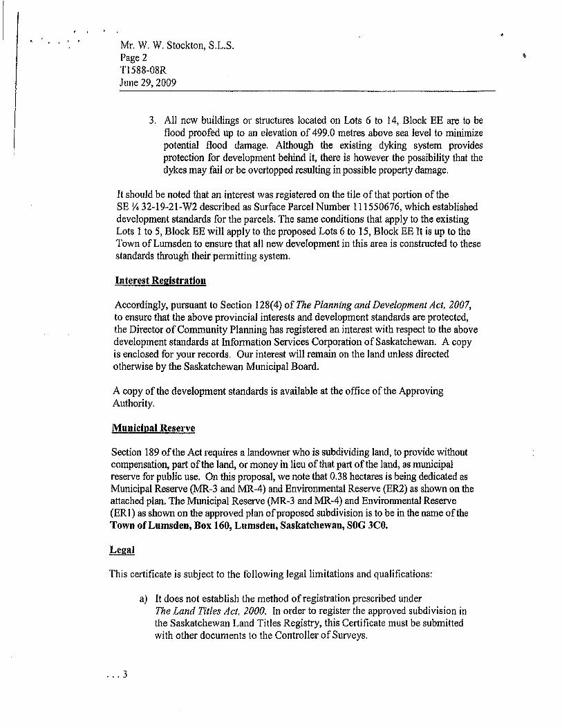
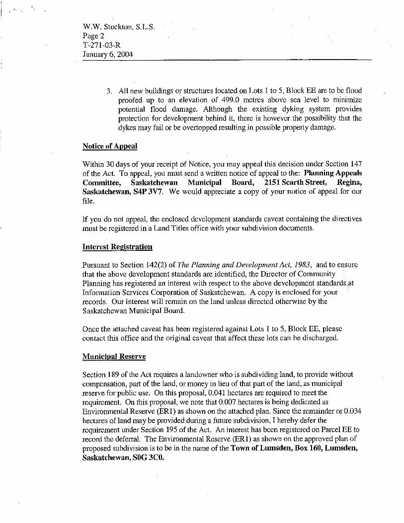
3. All new buildings or stmctures located on Lots 6 to 14, Block EE are to be flood proofed up to an elevation of 499.0 metres above sea level to minimize potential flood damage. Although the existing dyking system provides protection for development behind it, there is however the possibility that the dykes may fail or be overtopped resulting in possible property damage.
It should be noted that an interest was registered on the tile of that portion ofthe SE Y4 32-19-21-W2 described as Surface Parcel Number 111550676, which established development standards for the parcels. The same conditions that apply to the existing Lots 1 to 5, Block EE will apply to the proposed Lots 6 to 15, Block EE It is up to the Town of Lumsden to ensure that all new development in this area is constructed to these standards through their permitting system.
Interest Registration
Accordingly, pursuant to Section 128(4) of The Planning and Development Act, 2007, to ensure that the above provincial interests and development standards are protected, the Director of Community Planning has registered an interest with respect to the above development standards at Information Services Corporation of Saskatchewan. A copy is enclosed for your records. Our interest will remain on the land unless directed otherwise by the Saskatchewan Municipal Board.
A copy of the development standards is available at the office of the Approving Authority.
Municipal Reserve
Section 189 of the Act requires a landowner who is subdividing land, to provide without compensation, part ofthe land, or money in lieu of that part of the land, as municipal reserve for public use. On this proposal, we note that 0.38 hectares is being dedicated as Municipal Reserve (MR-3 and MR-4) and Environmental Reserve (ER2) as shown on the attached plan. The Municipal Reserve (MR-3 and MR-4) and Environmental Reserve (ERl) as shown on the approved plan of proposed subdivision is to be in the name ofthe Town of Lumsden, Box 160, Lumsden, Saskatchewan, SOG 3CO.
This certificate is subject to the following legal limitations and qualifications:
.. . 3
a) It does not establish the method of registration prescribed under The Land Titles Act, 2000. In order to register the approved subdivision in the Saskatchewan Land Titles Registry, this Certificate must be submitted with other documents to the Controller of Surveys .
, '
• Mr. W. W. Stockton, S.L.S . Page3 Tl588-08R June 29, 2009
b) It is valid for 24 months from the date of issue. If requested before the expiry date, it may be reissued for a fee of$25.00. After the expiry date, such a request must be considered a new application subject to the full examination fees.
c) It does not eliminate the need to comply with the requirements of any other govenunent department or authority, or with the municipality's building, zoning or other bylaws.
General Comments
If any digging or excavating is to be done SaskTel, SaskPower, and SaskEnergy must be contacted for a free cable, power, and pipeline location service. Please contact SASK 181 CALL at l-866-828-4888 for line locates. If any construction plans conflict with these facilities, the owner will be required to contact the corporation to discuss details regarding the possibility of moving the facilities and related costs.
Saskatchewan Watershed Authority has reviewed the proposal and has indicated that any development on these lots should be carried out in accordance with the geotechnical recommendations provided in GE Ground Engineering Ltd.'s Jqne 2001 report.
Our examination and approval fees total $1, 150.00. Our Invoice is enclosed.
cc: S (Schmidt - File LMSD 4035) SaskPower (Crerar- File 26404) SaskEnergy (McNaughton- File 08-12275) Saskatchewan Environment (Dennis Perras) Sask Watershed Authority (Yorkton- File F8-3-3/Lumsden, Town of)
Note:
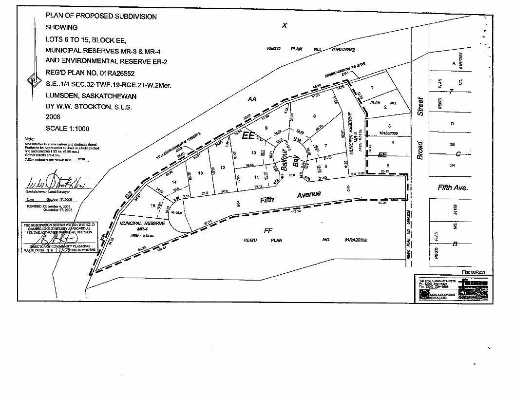
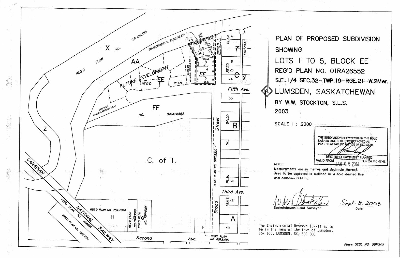
PLAN OF PROPOSED SUBDIVISION
SHOWING
LOTS 6 TO 15, BLOCK EE,
MUNICIPAL RESERVES MR-3 & MR-4
AND ENVIRONMENTAL RESERVE ER-2
REG'D PLAN NO. 01 RA26552
S.E .. 1/4 SEC.32-TWP .19-RGE.21-W.2Mer.
LUMSDEN, SASKATCHEWAN
BY W.W. STOCKTON, S.L.S.
2008
SCALE 1:1000
Measurements are ln metres and decimals therof. Portion to be Approved Is outl1ned in a bold dashed line and c:anlalns 1.82 ha. (4.50 acs.) Comer cutoffs are 4.5m.
7 .62m setbacks are shown thus _ 1~ _
lu.w~ Saskatchewan land Surveyor
Date October 17, 2008
REVISED: December 4, 2008 December 17, 2008
X
REG'D PLAN
FF REG'D PlAN NO.
4
I 5
9-ll s.m1L.. ~12-
g JJ I --- I
01RA26552
~I ~,
gl ~I ~I
~
~rm m fa .::::: Q:!
(/)
"t:l ~ [ij
I
<>
·-
<:i
""
D
25
24
Fifth Ave.
~ ~
~ ~
--B [:1
fil Q:!
File: 08R231
'-

'' Troubleshooting Tips - City of Regina
Assessment & Tax
Building & Demolition
Bylaws
Cemeteries
City Administration
City Council & Committees
Culture & Arts
Emergency Planning
Employment & Careers
Environment
Fire Services
Garbage
Grants & Social Programs
Heritage & History
Housing
Licences & Permits
Parking
Parks
Pollee Services
Real Estate
Recreation
Regina Facts
Roads & Traffic
State of the City
Transit services
Tree & Yard Care
Urban Planning
Water & sewer
You are here: > Residents > Water & Sewer > Protect your house from noodlng >Troubleshooting tips ·----··············-------~-----~-.. ------------- ~---·-·--·---·· .................. , .. __ , ...
Troubleshooting tips In this approach, a process Is used to Identify flood water sources. Once these sources are verified, the most cost-effective plan Is devised to stop water from entering the basement.
Remember, you must obtain a City of Regina Building Permit If you Intend to Install a backflow valve so that the City of Regina can Inspect the work to ensure that the job has been done according to the Plumbing Code. A permit Is not required for adding a sump pump.
Problem #1: Water entering at the basement walls and concrete floor
Symptoms
Probable causes and solutions
Wet carpets and floors along basement walls.
Cause: Downspouts are too short and water Is percolating through the backfill zone Solution: Extend downspouts so that they discharge rainwater at least 2 m from the foundation onto a splash pad. Also position a rain barrel to catch rooftop water, ensuring Its overflow spout discharges water away at least 2 m away from the foundation
Cause: Downspouts and/or eavestroughs are clogged and rainwater Is spilling onto the ground around the foundation and percolating Into the backfill zone Solution :Clean and leak proof eaves and downspouts each spring. If your underground yard pipe Is burled, It may be blocked with roof debris. Disconnect your downspout the next time It rains. If there Is a sudden, strong, steady flow that quickly slows after a few minutes, the underground yard pipe Is plugged. You need to redirect the downspout to the surface. This will require adding an extension and splash pad.
Cause: Low spots on the backfill zone are allowing water to pool next to the foundation Solution: Add soli over the backfill zone, sloping It away from the foundation.
Problem #2: Water entering the basement from under the basement floor from the sump pit (no sump pump is installed)
Symptoms
Probable causes and solutions
Water flowing from sump pit onto basement floor or heaving basement floor Cause: Water being collected by the weeping tile Is accumulating In the sump pit with P-trap cap In place Solution: Remove the P-trap cap to drain water from the sump pit Into the domestic sewer. If you are unable to remove the Ptrap cap and weeping tile water Is filling the sump pit, hand balling Is another way to dispose of the rainwater. Install a proper sump pump to move water outside the house and away from the foundation, as shown below. This Is the recommended solution.
Cause: Sump pump failure Solution: Repair sump pump
Problem #3: Water enters the basement from the sump pit (sump pump in place)
Symptoms Probable causes and solutions
Water flowing onto the basement floor out of the sump pit.
Cause: The sump pump has failed Solution: Exercise extreme care when around the sump pump, as you will be working with electricity near water. Follow the Instruction manual supplied with the sump pump. If In doubt, call a plumber.
http://www.regina.ca/Page2309.aspx
Page 2 of4
Home I Index 1 Contact Us
~ Printer Friendly
Flooding cause - backfill zone
Flooding cause - clay soil
Flooding cause -downspouts
Flooding cause - no weeping tile
Flooding cause -rainwater draining into sewage system Comprehensive flood proofing tips
Troubleshooting tips
Professional flood proofing services
14/08/2009
,. Troubleshooting Tips - City of Regina
If your basement Is flooding with weeping tile water, replace the sump pump as soon as possible. A call to a plumber may be the quickest answer. Replacing the failed pump with a new one Is also an option. Meanwhile, If your basement Is flooding, you may need to hand ball the sump pltto prevent overflow.
Another option Is opening the P-trap by removing the cap. Remember, If the sewer Is surcharged, there Is a risk of sewer backup In addition to the weeping tile flooding.
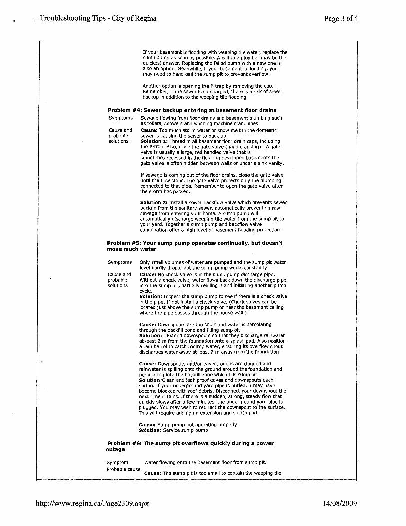
Problem #4: Sewer backup entering at basement floor drains Symptoms
Cause and probable solutions
Sewage flowing from floor drains and basement plumbing such as toilets, showers and washing machine standpipes. Cause: Too much storm water or snow melt In the domestic sewer Is causing the sewer to back up Solution 1: Thread In all basement floor drain caps, Including the P-trap. Also, close the gate valve (hand cranking). A gate valve Is usually a large, red handled valve that Is sometimes recessed In the floor. In developed basements the gate valve Is often hidden between walls or under a sink vanity.
If sewage Is coming out of the floor drains, close the gate valve until the flow stops. The gate valve protects only the plumbing connected to that pipe. Remember to open the gate valve after the storm has passed.
Solution 2: Install a sewer backflow valve which prevents sewer backup from the sanitary sewer, automatically preventing raw sewage from entering your home. A sump pump will automatically discharge weeping tile water from the sump pit to your yard. Together a sump pump and backflow valve combination offer a ·high level of basement flooding protection.
Problem #5: Your sump pump operates continually, but doesn't move much water
Symptoms
cause and probable solutions
Only small volumes of water are pumped and the sump pit water level hardly drops; but the sump pump works constantly. Cause: No check valve is in the sump pump discharge pipe. Without a check valve, water flows back down the discharge pipe into the sump pit, partially refilling It and Initiating another pump cycle. Solution: Inspect the sump pump to see if there Is a check valve In the pipe. If not install a check valve. (Check valves can be located just above the sump pump or near the basement ceiling where the pipe passes through the house wall.)
Cause: Downspouts are too short and water Is percolating through the backfill zone and filling sump pit Solution: Extend downspouts so that they discharge rainwater at least 2 m from the foundation onto a splash pad. Also position a rain barrel to catch rooftop water, ensuring its overflow spout discharges water away at least 2 m away from the foundation
Cause: Downspouts and/or eavestroughs are clogged and rainwater is spilling onto the ground around the foundation and percolating Into the backfill zone which fills sump pit Solution:Ciean and leak proof eaves and downspouts each spring. If your underground yard pipe is burled, It may have become blocked with roof debris. Disconnect your downspout the next time it rains. If there Is a sudden, strong, steady flow that quickly slows after a few minutes, the underground yard pipe Is plugged. You may wish to redirect the downspout to the surface. This will require adding an extension and splash pad.
Cause: Sump pump not operating properly Solution: Service sump pump
Problem #6: The sump pit overflows quickly during a power outage
Symptom Water flowing onto the basement floor from sump pit. Probable cause
Cause: The sump pit is too small to contain the weeping tile
http://www.regina.ca/Page2309.aspx
Page 3 of4
14/08/2009
Basement Flooding: City of London Solutions Page 1 of2
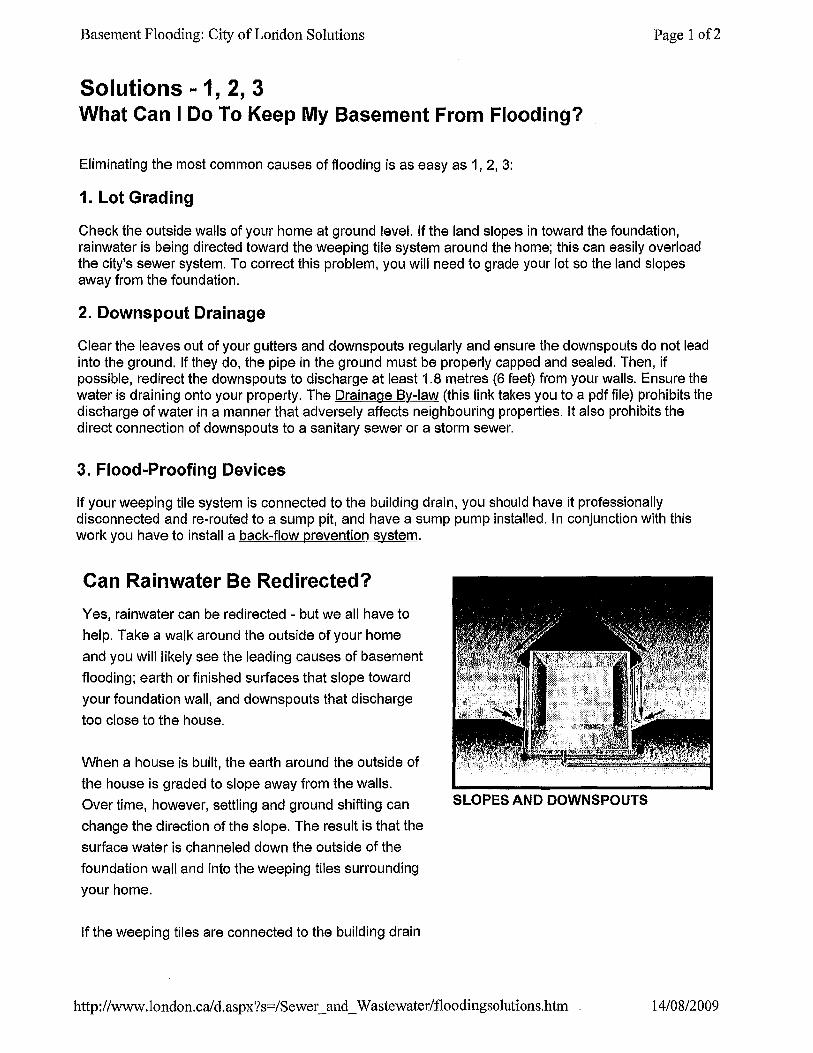
Solutions - 1, 2, 3 What Can I Do To Keep My Basement From Flooding?
Eliminating the most common causes of flooding is as easy as 1, 2, 3:
1. Lot Grading
Check the outside walls of your home at ground level. If the land slopes in toward the foundation, rainwater is being directed toward the weeping tile system around the home; this can easily overload the city's sewer system. To correct this problem, you will need to grade your lot so the land slopes away from the foundation.
2. Downspout Drainage
Clear the leaves out of your gutters and downspouts regularly and ensure the downspouts do not lead into the ground. If they do, the pipe in the ground must be properly capped and sealed. Then, if possible, redirect the downspouts to discharge at least 1.8 metres (6 feet) from your walls. Ensure the water is draining onto your property. The Drainage By-law (this link takes you to a pdf file) prohibits the discharge of water in a manner that adversely affects neighbouring properties. It also prohibits the direct connection of downspouts to a sanitary sewer or a storm sewer.
3. Flood-Proofing Devices
If your weeping tile system is connected to the building drain, you should have it professionally disconnected and re-routed to a sump pit, and have a sump pump installed. In conjunction with this work you have to install a back-flow prevention system.
Can Rainwater Be Redirected?
Yes, rainwater can be redirected - but we all have to
help. Take a walk around the outside of your home
and you will likely see the leading causes of basement
flooding; earth or finished surfaces that slope toward
your foundation wall, and downspouts that discharge
too close to the house.
When a house is built, the earth around the outside of
the house is graded to slope away from the walls.
Over time, however, settling and ground shifting can
change the direction of the slope. The result is that the
surface water is channeled down the outside of the
foundation wall and into the weeping tiles surrounding
your home.
If the weeping tiles are connected to the building drain
SLOPES AND DOWNSPOUTS
http://www .london. cal d.aspx?s=/Sewer _and_ Wastewater/floodingsolutions.htm 14/08/2009
Comprehensive Flood Proofing Tips - City of Regina
~ \( , ;;,c·;s;i ?.:~:J: :.:~~~;;i, :~. : ~,._ ·~:J:;:,, <:·~~ ;:_;_;::~· . .--~:;_:~·.s':;.":; : ~ .. ::.:~· .. : -~:·::·;~:.:;.;;··;L,".:>:··t;:,. ·:r ... '.'T<:· ·:.:·:;?:·;~:· :r.~:·?:' ::~c · ~~~ /:~·;~ ::r:~ ~. -~~w~~:::rt Assessment & Tax
Building & Demolition
Bylaws
Cemeteries
City Administration
City Council & Committees
Culture & Arts
Emergency Planning
Employment & Careers
Environment
Fire Services
Garbage
Grants & Social Programs
Heritage & History
Housing
Licences & Permits
Parking
Parks
Pollee Services
Real Estate
Recreation
Regina Facts
Roads & Traffic
State of the City
Transit Services
Tree & Yard care
Urban Planning
Water & Sewer
You are here: > Residents > Water & Sewer > Protect your house from flooding > Comprehensive f.~~od_P.r~~!ll1!tips --------- _ _ _ ___ ·--· ___ __ ________ _ ___________ . _
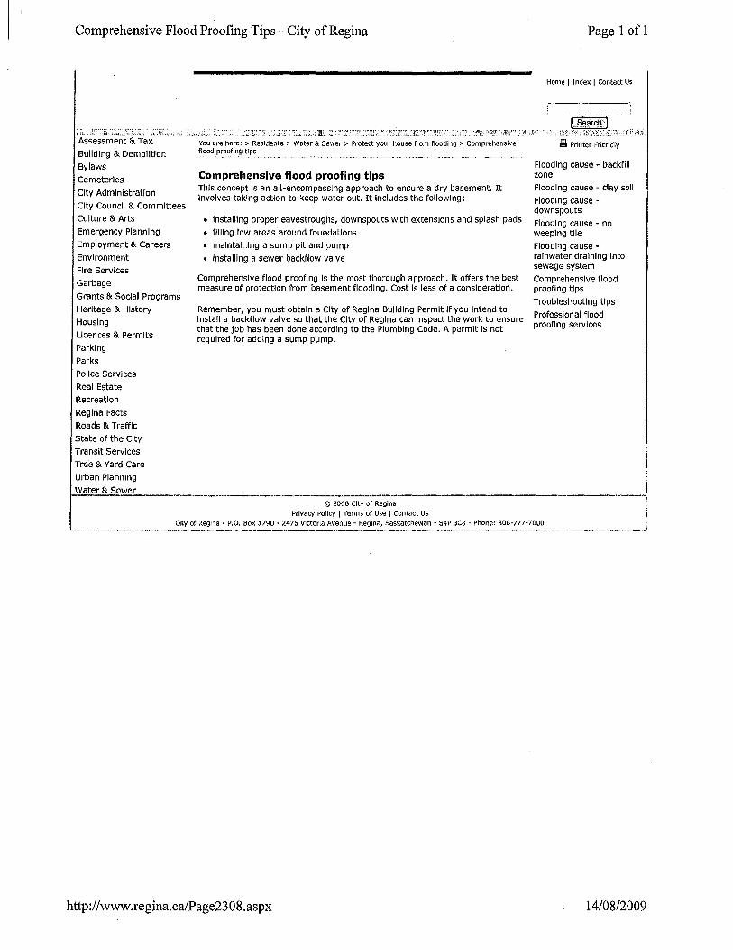
Comprehensive flood proofing tips This concept Is an all-encompassing approach to ensure a dry basement. It Involves taking action to keep water out. It Includes the following:
• Installing proper eavestroughs, downspouts with extensions and splash pads
• filling low areas around foundations
• maintaining a sump pit and pump
• installing a sewer backflow valve
Comprehensive flood proofing Is the most thorough approach. It offers the best measure of protection from basement flooding. Cost Is less of a consideration.
Remember, you must obtain a City of Regina Building Permit If you Intend to Install a backflow valve so that the City of Regina can Inspect the work to ensure that the job has been done according to the Plumbing Code. A permit Is not required for adding a sump pump.
© 2008 City of Reg! na Privacy Polley 1 Terms of Use 1 Contact Us
Page 1 of 1
Home 1 Index 1 Contact Us
~ Printer Friendly
Flooding cause - backfill zone
Flooding cause - clay soil
Flooding cause -downspouts
Flooding cause - no weeping tile
Flooding cause -rainwater draining Into sewage system
Comprehensive flood proofing tips
Troubleshooting tips
Professional flood proofing services
City of Regina· P.O. Box 1790 • 2476 Victoria Avenue· Regina, Saskatchewan· S4P 3C8 ·Phone: 306-777-7000
http:/ /www.regina.ca/Page23 08 .aspx 14/08/2009
The Backfill Zone & Flooding - City of Regina Page 1 of 1
Home I Index I Contact Us
--------·-~
··L$~a(cij,] ,:;-~!~; ... ::cZL -~·t;t.;:.::K~L2.i·l~:T:L_~-:~~:.~:~~-lL(~iil.'~:~~~:;~j:_:J,_._ .. ,,". i.:.:... .' ~:. ·::{~- •
1 • ·'"" •• · •. ,_,,,. ,c.,.L .1~,.:~;'D .'';~·:"~Ll'::r~-~~:JL"T.;;_';r;;~L;;j(,,:·. : ....... :':~:- 1
.• ~·- ~-.--·::~.~ :__, __ ,.~ .. _i~:~~:JL~~: .. ~;_:;~f~->,':"::::2N~;_::;~~;:·_;J:L ~~ .. :. _ ..:.. Assessment & Tax
Building & Demolition
Bylaws
Cemeteries
City Administration
City Council & Committees
Culture & Arts
Emergency Planning
Employment & Careers
Environment
Fire Services
Garbage
Grants & Social Programs
Heritage & History
Housing
Licences & Permits
Parking
Parks
Pollee Services
Real Estate
Recreation
Regina Facts
Roads & Traffic
State of the City
Transit Services
Tree & Yard Care
Urban Planning
Water & Sewer
-------
You are here: > Residents > Water & Sewer > Protect your house from flooding > Flooding cause -backfill zone
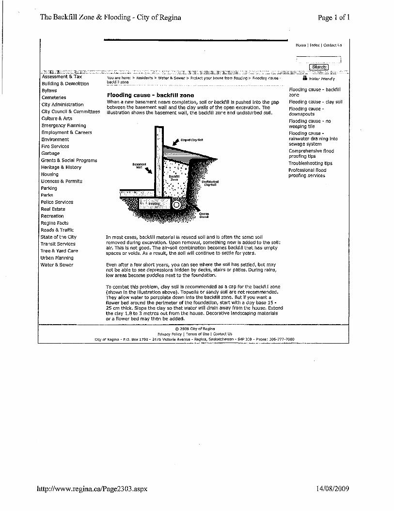
Flooding cause - backfill zone When a new basement nears completion, soli or backfill Is pushed Into the gap between the basement wall and the clay walls of the open excavation. The Illustration shows the basement wall, the backfill zone and undisturbed soil.
In most cases, backfill material Is reused soli and Is often the same soil removed during excavation. Upon removal, something new Is added to the soil: air. This Is not good. The air-soli combination becomes backfill that has empty spaces or voids. As a result, the soli will continue to settle for years.
Even after a few short years, you can see where the soil has settled, but may not be able to see depressions hidden by decks, stairs or patios. During rains, low areas become puddles next to the foundation.
To combat this problem, clay soli Is recommended as a cap for the backfill zone (shown In the Illustration above). Topsoils or sandy soil are not recommended. They allow water to percolate down Into the backfill zone. But If you want a flower bed around the perimeter of the foundation, start with a clay base 15 -25 em thick. Slope the clay so that water will drain away from the house. Extend the clay 1.8 to 3 metres out from the house. Decorative landscaping materials or a flower bed may then be added.
© 2008 City of Regina Privacy Polley 1 Terms of Use I Contact Us
li Printer Friendly
Flooding cause - backfill zone
Flooding cause - clay soli
Flooding cause -downspouts
Flooding cause - no weeping tile
Flooding cause -rainwater draining Into sewage system
Comprehensive flood proofing tips
Troubleshooting tips
Professional flood proofing services
City of Regina- P.O. Box 1790- 2476 Victoria Avenue- Regina, Saskatchewan- S4P 3C8 -Phone: 306-777-7000
http://www .regina.ca/Page23 03 .aspx 14/08/2009
Regina Clay Soil - City of Regina
Assessment
Building & Demolition
Bylaws
Cemeteries
City Administration
City Council & Committees
Culture & Arts
Emergency Planning
Employment & Careers
Environment
Fire Services
Garbage
Grants & Social Programs
Heritage & History
Housing
Licences & Permits
Parking
Parks
Pollee Services
Real Estate
Recreation
Regina Facts
Roads & Traffic
State of the City
Transit Services
Tree & Yard Care
Urban Planning
Water & Sewer
L .:t:: . .'.:'~ ~: ~ 'L ~-~1 .. ".2. ··-~- _., . c· "' _ 1.:.::. ~~- _, . : ·;~\-· . . . . _ .: ~~:;~:J:}.':~· .. You are here: > Residents > Water & Sewer > Protect your house from flooding > Flooding cause -~l~y_s?~l__ ___ _ __ _ ______ __ _ _ _______ _
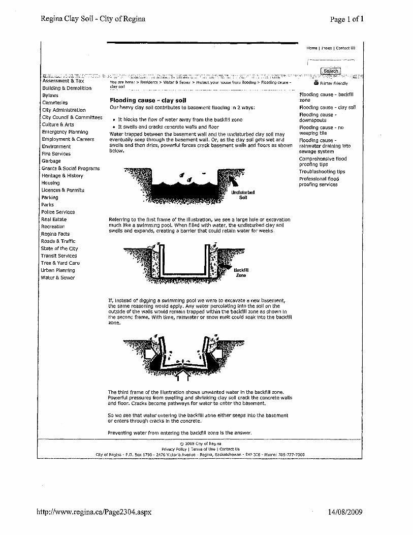
Flooding cause - clay soil Our heavy clay soil contributes to basement flooding In 2 ways:
o It blocks the flow of water away from the backfill zone
o It swells and cracks concrete walls and floor
Water trapped between the basement wall and the undisturbed clay soli may eventually seep through the basement wall. Or, as the clay soli gets wet and swells and then dries, powerful forces crack basement walls and floors as shown below.
Referring to the first frame of the Illustration, we see a large hole or excavation much like a swimming pool. When filled with water, the undisturbed clay soli swells and expands, creating a barrier that could retain water for weeks.
If, Instead of digging a swimming pool we were to excavate a new basement, the same reasoning would apply. Any water percolating Into the soil on the outside of the walls would remain trapped within the backfill zone as shown In the second frame. With time, rainwater or snow melt could soak Into the backfill zone.
The third frame of the Illustration shows unwanted water In the backfill zone. Powerful pressures from swelling and shrinking clay soli crack the concrete walls and floor. Cracks become pathways for water to enter the basement.
So we see that water entering the backfill zone either seeps Into the basement or enters through cracks In the concrete.
Preventing water from entering the backfill zone Is the answer.
© 2008 City of Regina Privacy Polley I Terms or Use I Contact Us
Page 1 of 1
Home I Index 1 Contact Us
~ Printer Friendly
Flooding cause - backfill zone
Flooding cause - clay soli
Flooding cause -downspouts
Flooding cause - no weeping tile
Flooding cause -rainwater draining Into sewage system
Comprehensive flood proofing tips
Troubleshooting tips
Professional flood proofing services
City of Regina- P.O. Box 1790- 2476 VIctoria Avenue- Regina, Saskatchewan- S4P 3C8- Phone: 306-777-7000 ·-----------------------·----'
http://www.regina.ca!Page2304.aspx 14/08/2009
Downspouts - City of Regina
7;· ~,;:~_;r.rr.< ·;_t:. :: ;,: . ~ ·: .. :: i. ~y ;_· '~:~.·.':L·~--::' lL . Assessment & Tax
Building & Demolition
Bylaws
cemeteries
City Administration
City Council & Committees
Culture & Arts
Emergency Planning
Employment & Careers
Environment
Fire Services
Garbage
Grants & Social Programs
Heritage & History
Housing Licences & Permits
Parking
Parks
Pollee Services
Real Estate
Recreation
Regina Facts
Roads & Traffic
State of the City
Transit Services
Tree & Yard Care
Urban Planning
Water & Sewer
You are here: > Residents > Water & Sewer > Protect your house from flooding > Flooding cause -downspouts ~-----···-·-- -----~--- -···---·------·-··. ___ , ____ .
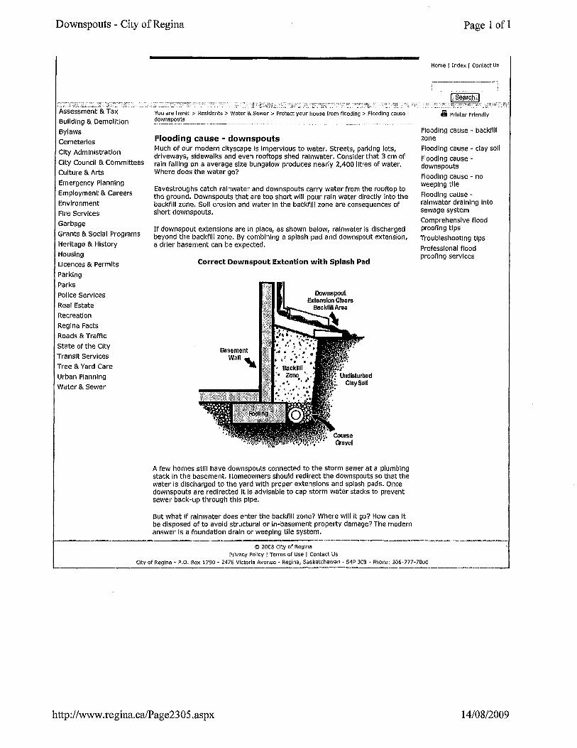
Flooding cause • downspouts Much of our modern cityscape Is Impervious to water. Streets, parking lots, driveways, sidewalks and even rooftops shed rainwater. Consider that 3 em of rain falling on a average size bungalow produces nearly 2,400 iltres of water. Where does the water go?
Eavestroughs catch rainwater and downspouts carry water from the rooftop to the ground. Downspouts that are too short will pour rain water directly Into the backfill zone. Soli erosion and water In the backfill zone are consequences of short downspouts.
If downspout extensions are In place, as shown below, rainwater Is discharged beyond the backfill zone. By combining a splash pad and downspout extension, a drier basement can be expected.
Correct Downspout Extention with Splash Pad
A few homes still have downspouts connected to the storm sewer at a plumbing stack In the basement. Homeowners should redirect the downspouts so that the water Is discharged to the yard with proper extensions and splash pads. Once downspouts are redirected It Is advisable to cap storm water stacks to prevent sewer back-up through this pipe.
But what If rainwater does enter the backfill zone? Where will it go? How can It be disposed of to avoid structural or In-basement property damage? The modern answer Is a foundation drain or weeping tile system.
© 2008 City of Regina Privacy Policy 1 Terms of Use I Contact Us
Page 1 of 1
Home I Index 1 Contact Us
L':::::::~~',:J:':''······ ~ Printer Friendly
Flooding cause - backfill zone
Flooding cause - clay soli
Flooding cause -downspouts
Flooding cause - no weeping tile
Flooding cause -rainwater draining Into sewage system
Comprehensive flood proofing tips
Troubleshooting tips
Professional flood proofing services
City of Regina- P.O. Box 1790- 2476 Victoria Avenue- Regina, Saskatchewan- S4P 3C8 -Phone: 306·777-7000
http://www.regina.ca/Page2305.aspx 14/08/2009
Weeping Tiles - City of Regina
1:•• ',"O"I'''-'''''-''''•1'''" ····· ,; ·,'.-..:,1, · .:i,:-~;. ''": !. :11. :-: ,}1: •'!J;i :~ :
Assessment & Tax
Building & Demolition
Bylaws
Cemeteries
City Administration
City Council & Committees
Culture & Arts
Emergency Planning
Employment & Careers
Environment
Fl re Services
Garbage
Grants & Social Programs
Heritage & History
Housing
Licences & Permits
Parking
Parks
Pollee Services
Real Estate
Recreation
Regina Facts
Roads & Traffic
State of the City
Transit Services
Tree & Yard care
Urban Planning
Water & Sewer
You are here: > Residents > Water & Sewer > Protect your house from flooding > Flooding cause --~weepln~_l'.l.: ________________ ·- _____________________ -··. -~---------- .. --·-·· __________ _
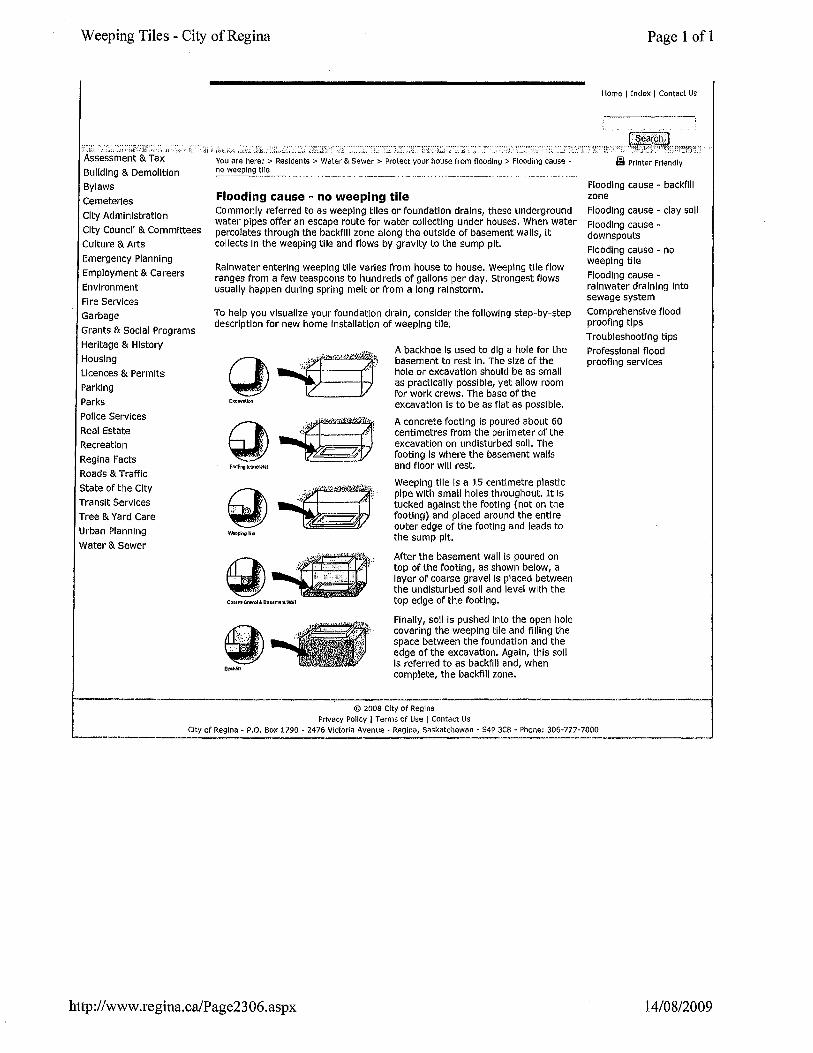
Flooding cause - no weeping tile Commonly referred to as weeping tiles or foundation drains, these underground water pipes offer an escape route for water collecting under houses. When water percolates through the backfill zone along the outside of basement walls, It collects In the weeping tile and flows by gravity to the sump pit.
Rainwater entering weeping tile varies from house to house. Weeping tile flow ranges from a few teaspoons to hundreds of gallons per day. Strongest flows usually happen during spring melt or from a long rainstorm.
To help you visualize your foundation drain, consider the following step-by-step description for new home Installation of weeping tile.
1/c ,. (}\ :.· ~ .
EMtWlliiOn
Footlng(conctd.E)
Coa111 ORI'Itll & Buemem Wil
A backhoe Is used to dig a hole for the basement to rest ln. The size of the hole or excavation should be as small as practically possible, yet allow room for work crews. The base of the excavation Is to be as flat as possible.
A concrete footing Is poured about 60 centimetres from the perimeter of the excavation on undisturbed soli. The footing Is where the basement walls and floor will rest.
Weeping tile Is a 15 centimetre plastic pipe with small holes throughout. It Is tucked against the footing (not on the footing) and placed around the entire outer edge of the footing and leads to the sump pit.
After the basement wall Is poured on top of the footing, as shown below, a layer of coarse gravel Is placed between the undisturbed soli and level with the top edge of the footing.
Finally, soli is pushed Into the open hole covering the weeping tile and filling the space between the foundation and the edge of the excavation. Again, this soli Is referred to as backfill and, when complete, the backfill zone.
© 2008 City of Regina Privacy Polley 1 Terms of Use 1 Contact Us
Page 1 of 1
Home I Index 1 Contact Us
~ Printer Friendly
Flooding cause - backfill zone
Flooding cause - clay soli
Flooding cause -downspouts
Flooding cause - no weeping tile
Flooding cause -rainwater draining Into sewage system
Comprehensive flood proofing tips
Troubleshooting tips
Professional flood proofing services
City of Regina- P.O. Box 1790- 2476 Victoria Avenue- Regina, Saskatchewan- S4P 3C8- Phone: 306-777-7000
http://www .regina.ca/Page23 06.aspx 14/08/2009
Rainwater Draining into Sewage System - City of Regina
~:·· ,1;;~~;-:i : ;c;,;_; .'L :~:~,-- <i:: :;_, · .. -, .1 ···;l·: . ... :-.. ;:, .. ·. :r,;_; ·,~~~~~~;_:;,, :_;:,·:·::~; ~-;~·:;;:,/'1.!-:i. :.~:~,.:··:;J~-~}.!_?'':i.:jj:;-:::;...;·;i ... 'T .. .":~·~::;--··~:::=:~;:-;:··;~. ··r ... . :~· __ ;· 11'.::· . '1 ··
Assessment & Tax
Building & Demolition
Bylaws
Cemeteries
City Administration
City Council & Committees
Culture & Arts
Emergency Planning
Employment & Careers
Environment
Fire Services
Garbage
Grants & Social Programs
Heritage & History
Housing
Licences & Permits
Parking
Parks
Pollee Services
Real Estate
Recreation
Regina Facts
Roads & Traffic
State of the City
Transit Services
Tree & Yard Care
Urban Planning
Water & Sewer
You are here: > Residents > Water & Sewer > Protect your house from fioodlng > Flooding cause -
~~n_l'/a.~e_':~~lnlng in~o__s::V.~~:s_y~~'::':'. _ .... ·----·- ___ . ·-·--·--····- ___ ...
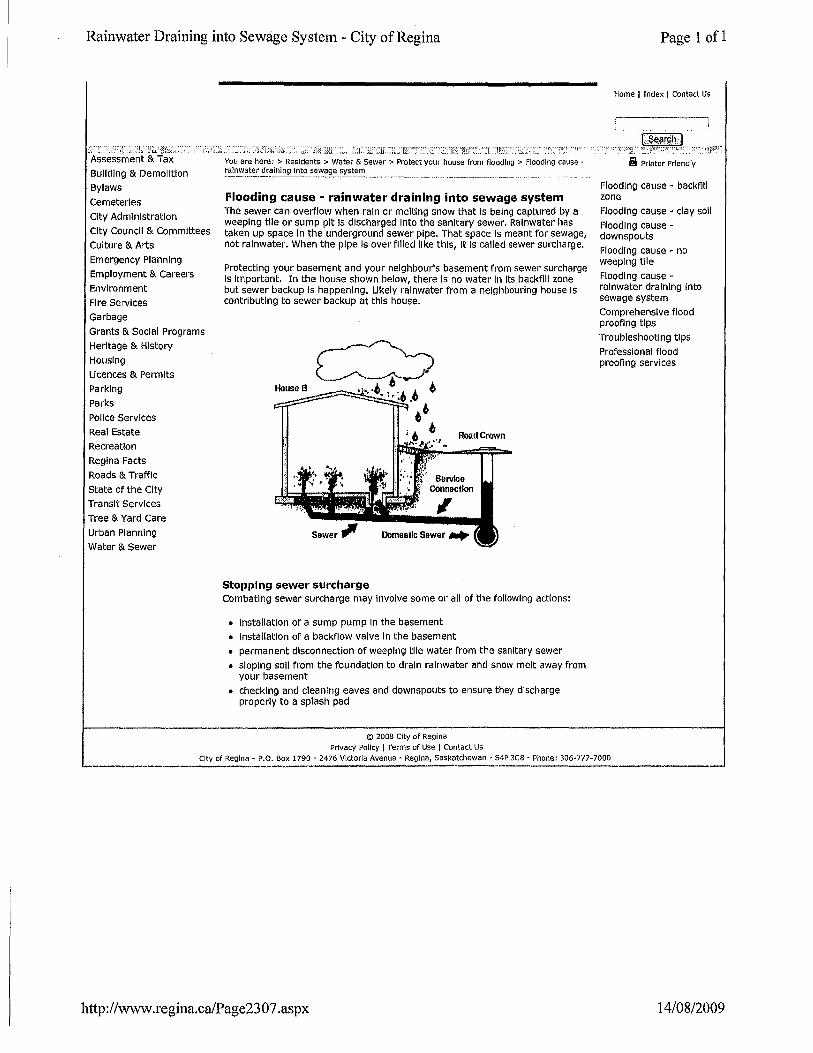
Flooding cause - rainwater draining into sewage system The sewer can overflow when rain or melting snow that Is being captured by a weeping tile or sump pit Is discharged Into the sanitary sewer. Rainwater has taken up space in the underground sewer pipe. That space Is meant for sewage, not rainwater. When the pipe Is over filled like this, It Is called sewer surcharge.
Protecting your basement and your neighbour's basement from sewer surcharge Is Important. In the house shown below, there Is no water In Its backfill zone but sewer backup Is happening. Likely rainwater from a neighbouring house Is contributing to sewer backup at this house.
Road Crown
Stopping sewer surcharge Combating sewer surcharge may Involve some or all of the following actions:
• Installation of a sump pump In the basement
o Installation of a backflow valve In the basement
o permanent disconnection of weeping tile water from the sanitary sewer
o sloping soli from the foundation to drain rainwater and snow melt away from your basement
• checking and cleaning eaves and downspouts to ensure they discharge properly to a splash pad
© 2008 City of Regina Privacy Polley I Terms of Use I Contact Us
Page 1 of 1
Home I Index 1 Contact Us
~ Printer Friendly
Flooding cause - backfill zone
Flooding cause - clay soli
Flooding causedownspouts
Flooding cause - no weeping tile
Flooding cause -rainwater draining into sewage system
Comprehensive flood proofing tips
Troubleshooting tips
Professional flood proofing services
City of Regina- P.O. Box 1790- 2476 Victoria Avenue- Regina, Saskatchewan- S4P 3C8- Phone: 306-777-7000
http://www .regina.ca/Page23 07 .aspx 14/08/2009
Flood proofing Your Riverside Home Page 1 of 1
Wet floodproofing your house
Wet floodproofing is a method that relies on the walls of the house to hold the water out while allowing flood waters to enter and exit the enclosed areas of your house through wall openings. Literally, the river flows through your house. This means that all construction and finishing material in the house that might possibly be flooded must be resistant to damage caused by water. The most important aspect of this technique is that it equalizes the effects of hydrostatic pressure, which is the most destructive factor in a flood. Hydrostatic pressure is the force the flood water will place on or under walls and floors. More pressure on one side than the other will cause a wall to collapse or a floor to buckle.
The following things should be considered:
• ensuring that flood waters enter and exit the house
• ensuring that flood waters inside the house rise and fall at the same rate as flood waters outside (hydrostatic pressure)
• protecting the areas of the house that are below the flood level from damage caused by contact with flood waters
• protecting service equipment
• relocating any personal belongings that would be damaged by flood waters.
Another consideration is the post-flood cleanup. Flood waters are rarely clean. They usually carry sediment, debris and corrosive or hazardous materials such as solvent, oil, sewage, pesticides, fertilizers and other chemicals.
http://www.cacaponriver.org/hopacket/floodproofing.htm 14/08/2009
Freshwater Website: Flood Damage Reduction Program (Saskatchewan) Page 1 of3
••• Environment Canada
Environnomont Canada Canadft
The Management
of Water Bulk Water Removal and
Water ExP-Q[! Floods
Water Efficiency/ Conservation
Water Modelling Walfll.P..Q.!MiQn
Water Quality Water Resource
Economics Water Use
· Freshwater Home·.
Events Calendar Freshwater Maps
General Links Publications
Teacher's Corner
About Us
TheN!Itura ot Wat~r . ' '
Topics
Saskatchewan
Publications
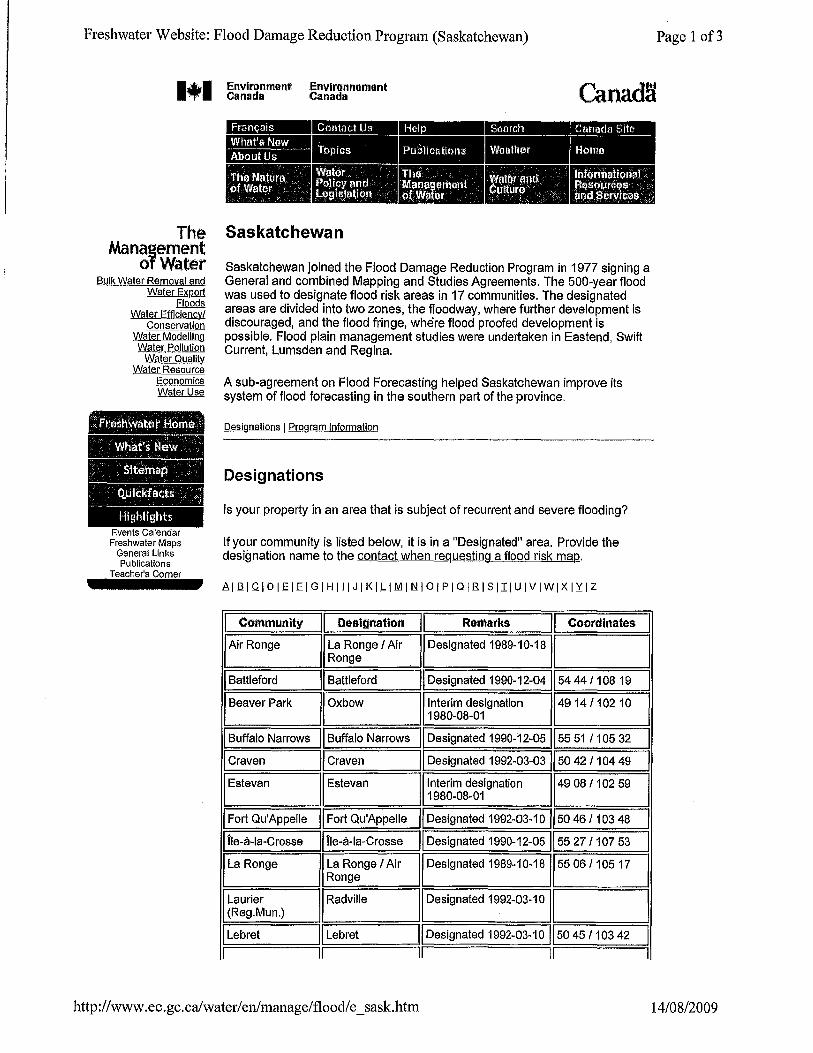
Saskatchewan joined the Flood Damage Reduction Program in 1977 signing a General and combined Mapping and Studies Agreements. The 500-year flood was used to designate flood risk areas in 17 communities. The designated areas are divided into two zones, the floodway, where further development is discouraged, and the flood fringe, where flood proofed development is possible. Flood plain management studies were undertaken in Eastend, Swift Current, Lumsden and Regina.
A sub-agreement on Flood Forecasting helped Saskatchewan improve its system of flood forecasting in the southern part of the province.
Designations
Is your property in an area that is subject of recurrent and severe flooding?
If your community is listed below, it is in a "Designated" area. Provide the designation name to the contact when requesting a flood risk map.
816IC.I D I.E lEI G I HIll J I KI.LIMI.t::ll 0 I PI a lEIS III U IVIWIX IYI Z
I Community II Designation II Remarks II Coordinates
Air Ronge I La Range I Air I Designated 1989-1 0-18 I Ronge
Battleford II Battleford II Designated 1990-12-04 1154 44 11 08 19
Beaver Park II Oxbow !Interim designation 149 141102 10 1980-08-01
Buffalo Narrows II Buffalo Narrows II Designated 1990-12-051155 51 1105 32
Craven I/ craven I/ Designated 1992-03-031150 421104 49
Estevan II Estevan 'Interim designation 149 081102 59 1980-08-01
Fort Qu'Appelle II Fort Qu'Appelle II Designated 1992-03-10 1150 46 11 03 48
I ile-a-la-Crosse Tie-a-la-Crosse II Designated 1990-12-05 Iss 271107 53
!La Range La Range I Air Designated 1989-10-18 55 06/10517 Ronge
Laurier Radville I Designated 1992-03-10 (Reg.Mun.)
I Lebret Lebret II Designated 1992-03-10 50 451103 42
II II II II
I I I
I
I I I I
http:/ /www.ec.gc.ca/water/ en/manage/flood/e _ sask.htm 14/08/2009
Freshwater Website: Flood Damage Reduction Program (Saskatchewan)
The Green Lane™, Environment Canada's World Wide Web site Last updated: 2008-07-23 Last reviewed: 2008-07-23
URL of this page: http:l/www.ec.gc.ca/water/en/manage/flood/e_sask.htm
http://www.ec.gc.ca/water/enlmanage/flood/e_sask.htm
Page 3 of3
14/08/2009

___________________________ ijlfijijii;ll
Wet Floodproofing Introduction
This guide describes two types of flood proofing: wet and dry. As its name implies, wet flood proofing allows flood waters to enter the enclosed areas of a house. In contrast, dry flood proofing (Chapter 7) prevents the entry of flood waters. The benefit of wet flood proofing is that if flood waters are allowed to enter the enclosed areas of the house and to quickly reach the same level as the flood waters outside, the effects of hydrostatic pressure, including buoyancy, are greatly reduced. As a result, the loads imposed on the house during a flood, and therefore the likelihood of structural damage, may be greatly reduced. Wet floodproofing is generally used to limit damages to enclosures below elevated buildings, walkout-on-grade basements, below-grade basements, crawlspaces, or attached garages. It is not practical for areas that are to be used as living space.
Successful wet floodproofing involves the following:
• ensuring that flood waters enter and exit the house
• ensuring that flood waters inside the house rise and fall at the same rate as flood waters outside
• protecting the areas of the house that are below the flood level from damage caused by contact with flood waters
• protecting service equipment inside and outside the house
• relocating any materials stored below the Flood Protection Elevation (FPE)
This chapter describes the modifications that must be made to a house as part of a wet floodproofing project, and it discusses the most important considerations regarding wet flood proofing. Protection of service equipment is discussed in Chapter 8.
HOMEOWNER'S GUIDE TO RETROFITTING
WARNING
If your house has been substantially damaged or is being substantially improved, your community's floodplain management ordinance or law will restrict the use of wet flood proofing to attached garages and enclosed areas below the Base Flood Elevation (BFE) that are used solely for parking, storage, and access. For more information, refer to Federal Emergency Management Agency (FEMA) Technical Bulletin 7-93, Wet Flood proofing Requirements for Structures Located in the Special Flood Hazard Area.
4". DEFINITION
Service equipment includes utility systems, heating and cooling systems, and large appliances.
~,~ ~ ~ •
NOTE
Flood-resistant materials are discussed later in this chapter.
WARNING
If you are retrofitting a house that has been substantially damaged or is being substantially improved, your community's floodplain management ordinance or law will not allow you to have a basement, as defined under the NFIP. The NFIP regulations define a basement as "any area of the building having its floor subgrade on all sides." If your house has such a basement, you will be required to fill it In as part of any wet floodproofing project. Note that the NFIP definition of basement does not include what Is typically referred to as a "walkout-ongrade" basement, whose floor would be at or
Considerations Flood Protection Elevation
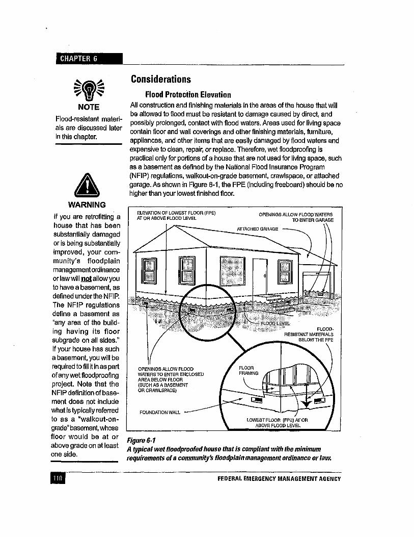
All construction and finishing materials in the areas of the house that will be allowed to flood must be resistant to damage caused by direct, and possibly prolonged, contact with flood waters. Areas used for living space contain floor and wall coverings and other finishing materials, furniture, appliances, and other items that are easily damaged by flood waters and expensive to clean, repair, or replace. Therefore, wet flood proofing is practical only for portions of a house that are not used for living space, such as a basement as defined by the National Flood Insurance Program (NFIP) regulations, walkout-on-grade basement, crawlspace, or attached garage. As shown in Figure 6-1, the FPE (including freeboard) should be no higher than your lowest finished floor.
ELEVATION OF LOWEST FLOOR (FPE) AT OR ABOVE FLOOD LEVEL
OPENINGS ALLOW FLOOD WATERS TO ENTER ENCLOSED AREA BELOW FLOOR (SUCH AS A BASEMENT OR CRAWLSPACE)
FOUNDATION WALL
OPENINGS ALLOW FLOOD WATERS TO ENTER GARAGE
Figure6-1 above grade on at least A typical wet floodproofed house that is compliant with the minimum one side. requirements of a community's floodplain management ordinance or law.
FEDERAL EMERGENCY MANAGEMENT AGENCY
WET FLOODPROOFING
If your FPE is above the elevation of your lowest finished floor, you should consider one or more of the other retrofitting methods described in this guide, such as elevation (Chapter 5). If you read Chapter 5, you will note that most of the elevation methods incorporate the principles of wet flood proofing. They raise the living space above the flood level and allow flood waters to enter the areas of the house below the living space.
Hazards Wet flood proofing protects a house from the effects of hydrostatic pressure but not from other flood hazards. such as the hydrodynamic force of flowing water, erosion and scour. the impact of ice and other flood borne debris, and damage from flood borne contaminants. If you have seen evidence of these hazards in past floods in your area, or if your community officials confirm that your house may be affected by these hazards, you should consider an alternative retrofitting method, such as relocation (see Chapter 7) or elevation on an open foundation (see Chapter 5). Wet floodproofing a house does not change its vulnerability to damage from high winds or earthquakes.
Post-Flood Cleanup Remember that flood waters are rarely clean. They usually carry sediment, debris, and even corrosive or hazardous materials such as solvents, oil, sewage, pesticides, fertilizers, and other chemicals. Allowing areas ·of a house to flood exposes those areas to whatever is in the flood waters. Cleaning up a wet flood proofed house after a flood may therefore involve not only removing mud but also washing, disinfecting, and decontaminating walls, floors, and other surfaces. This is another good reason why wet floodproofing is inappropriate for areas used as living space and, in some circumstances, why it may be inappropriate for any part of a house.
Modifications Required for Wet Floodproofing Wet flood proofing requires a variety of modifications to your house, including its walls, construction and finishing materials, and service equipment.
Installing Openings The most important part of a wet floodproofing project is installing wall openings that will allow the entry and exit of flood waters. The openings must be installed in foundation walls and in garage walls as appropriate, below the expected flood level (see Figure 6-1 ). The goal is not simply to allow the entry and exit of flood waters but also to ensure that the water
HOMEOWNER'S GUIDE TO RETROFITTING
~,~ ~~~ •
NOTE
For more information about openings requirements for wet floodproofing, refer to FEMA Technical Bulletin 1-93, Openings in Foundation Walls for Buildings Located in Special Flood Hazard Areas, and FEMA 259, Engineering Principles and Practices for Retrofitting Flood Prone Residential Buildings.
-
idi61Qdi-~--------------------------------~----------------
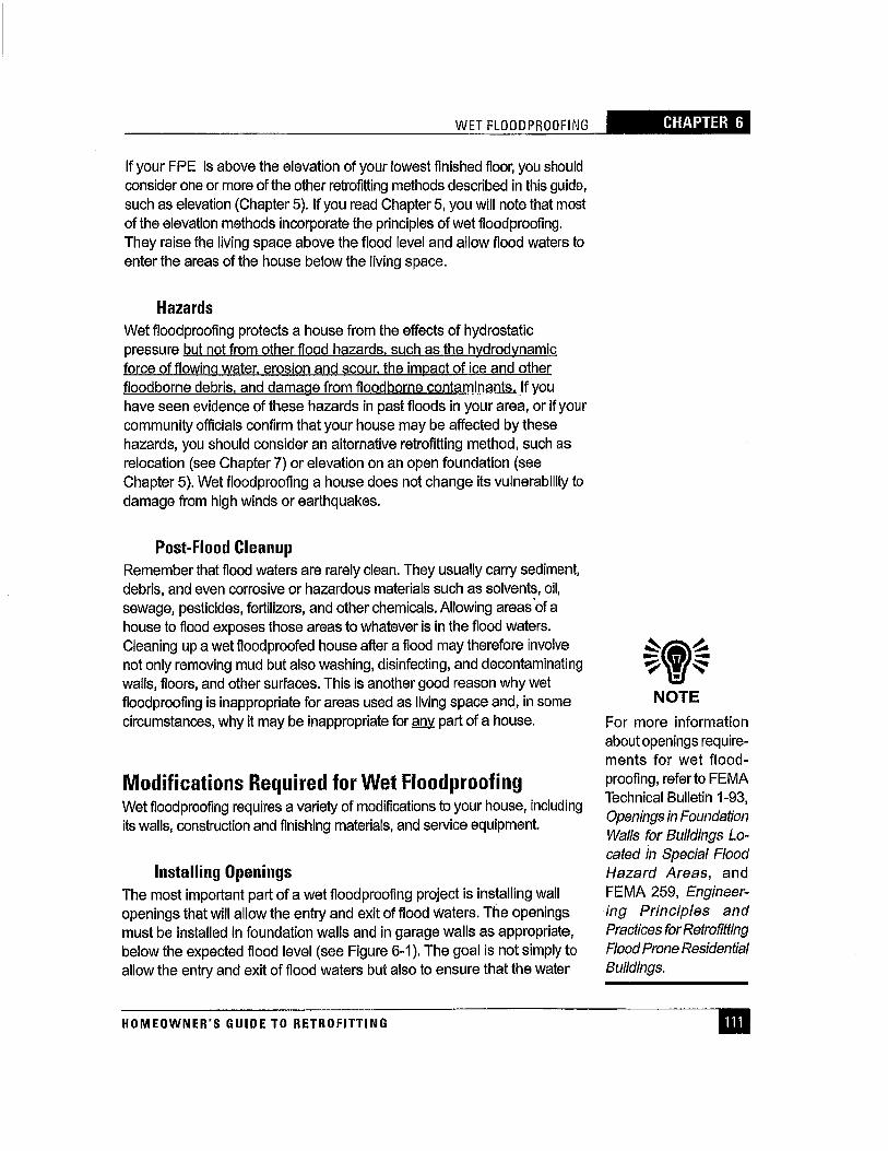
Figure6-2 Wall openings must allow flood waters not only to enter the house but also to rise and fall at the same rate as flood waters outside.
level inside the house rises and falls at roughly the same rate as the water level outside so that hydrostatic pressures inside and outside are continually equalized. As shown in Figure 6-2, large differences in the interior and exterior water levels allow unequalized hydrostatic pressures and therefore defeat the purpose of wet flood proofing.
FLOOR OF HOUSE
FOUNDATION ---o.-1 WALL
B.
FLOOR OF HOUSE
GROUND
When the number and/or size of openings in foundation walls are inadequate (A), interior flood levels cannot rise or fall as fast as exterior flood levels. As a result, hydrostatic pressures, as indicated by the horizontal arrows, are not equalized. When the number and size of openings are adequate (B), interior and exterior flood levels rise and fall at the same rate and hydrostatic pressures are equalized.
FEDERAL EMERGENCY MANAGEMENT AGENCY
WET FLOODPROOFING -9Ut!ijfi;J!I
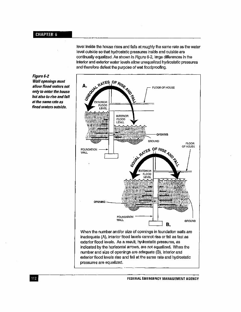
For equal water levels to be maintained, both the size and number of openings must be adequate. Otherwise, when flood waters are rising and falling, water will not be able to flow Into or out of the house fast enough. The number of openings required and their size will depend on the rate of rise and the rate of fall of the flood waters (see Chapter 2) and on the size of the area that is being allowed to flood. In general, the faster the rates of rise and fall and the larger the flooded area within the house, the larger the number and size of openings required.
If you are wet floodproofing areas below the BFE in a substantially damaged or substantially improved house, your community's floodplain management ordinance or law will require you to install openings in the exterior walls of all enclosed areas below the BFE. The minimum requirements are as follows:
• You must provide at least two wall openings for each enclosed area -- one in each of two different walls. In other words, you cannot put both openings in the same wall.
• If your house has more than one enclosed area, you must install openings in the exterior walls of each enclosed area so that flood waters can enter directly from the outside.
• The total area (size) of all openings for each enclosed area must be equal to at least 1 square inch for every square foot of floor space in the enclosed area. For example, if the enclosed area is 25 feet by 40 feet ( 1 ,000 square feet), the total area of the openings must be at least 1 ,000 square inches, or roughly 7 square feet. In this example, you could meet the size requirement by providing two 3 1/2-square-foot openings or several smaller openings whose total area equals 7 square feet.
• The bottom of each opening must be no higher than 1 foot above the ground directly below the opening.
• Flood waters must be able to flow in and out of enclosed areas automatically. If you place louvers, screens, or other types of covers over the openings (which many homeowners do to prevent animals from entering the enclosed areas) they must not block the flow of water. Because the need for human intervention reduces the reliability of wet floodproofing, you may not install any type of electrically, mechanically, or manually operated cover.
FEMA developed these requirements to provide homeowners with a straightforward means of determining where and how to install wall openings without the aid of an engineer or design professional. The
HOMEOWNER'S GUIDE TO RETROFITTING
~~~ NOTE
If you cover wall openings with louvers or screens, keep in mind that the more restrictive they are the more likely they are to become clogged with debris during floods and to prevent the flow of water. Make sure that any screens or louvers you use will allow the passage of water that contains suspended sediment and other small debris. After flood waters have receded, screens and louvers must be cleaned of any other debris that may have accumulated.
trilb1Qi§HIHIIIIII~-------------------------------------------------
~~~ ~m~ • NOTE
For more information about flood~resistant materials, refer to FEMA Technical Bulle~ tin 2~93, Flood-Resistant Materials Requirements for Buildings Located in Special Flood Hazard Areas. This bulletin in~ eludes a detailed list of common floor, wall, and ceiling materials cat~ egorlzed according to their applicability for use in areas subject to inun~ dation by flood waters.
requirements provide a margin of safety for wet floodproofed houses subject to flooding with rates of rise and fall as high as 5 feet per hour. If you wish to install openings that do not meet one or more of the requirements listed above, your design must be certified by a registered engineer or other licensed design professional and approved by your local officials. See FEMA's Technical Bulletin 1~93, Openings in Foundation Walls for Buildings Located in Special Flood Hazard Areas, for more information about openings requirements.
Using Flood~Resistant Materials In the areas below the FPE, any construction and finishing materials that could be damaged by flood waters must be either removed or replaced with flood-resistant materials as required by your community's floodplain management ordinance or law. Vulnerable materials include drywall, blown~in and fiberglass batt insulation, carpeting, and non pressuretreated wood and plywood. Flood-resistant materials are those that can be inundated by flood waters with little or no damage. They include such materials as concrete, stone, masonry block, ceramic and clay tile, pressure-treated and naturally decay-resistant lumber, epoxy paints, and metal. In addition to resisting damage from flood waters; these materials are relatively easy to clean after flood waters have receded.
Protecting Service Equipment When you wet floodproof a house, you must also protect the service equipment below the FPE, both inside and outside the house as required by your community's floodplain management ordinance or law. Service equipment includes utility lines, heating ventilation and cooling equipment, ductwork, hot water heaters, and large appliances. Chapter 8 describes a variety of methods you can use to protect Interior and exterior service equipment.
FEDERAL EMERGENCY MANAGEMENT AGENCY
FLASH: Federal Alliance for Safe Home Page 1 of2
Extreme Temperatures
Flood
Hail
Hurricanes Learn About Hurricanes
A Hurricane Overview Anlmacl6n del dueno de una casa:
Entablado de emergencla'.eJ!il Animated How-To: TADD:~: FLASH Card: Turn Around, Don't
Drown lit Flood Insurance -- How to Purchase Hurricane Names Hurricane Ratings H11rrlr!'lnP W;,trh ;,nrl W;>rnlnn --
Lightning
Power Outage
Rip Currents
Terrorism
Thunderstorms
Tornadoes
Tsunami
Wildfire
' :'
Floodproofing -- Wet
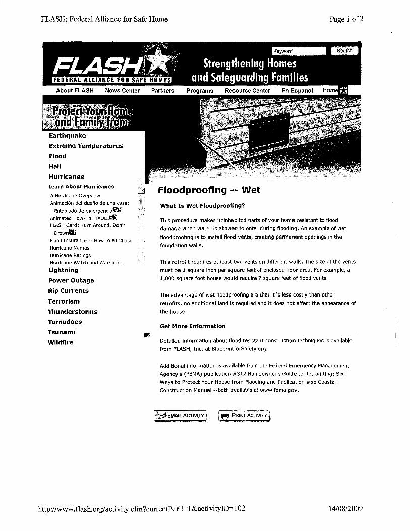
What Is Wet Floodproofing?
This procedure makes uninhabited parts of your home resistant to flood
damage when water is allowed to enter during flooding. An example of wet
flood proofing Is to install flood vents, creating permanent openings in the
foundation walls.
This retrofit requires at least two vents on different walls. The size of the vents
must be 1 square inch per square feet of enclosed floor area. For example, a
1,000 square foot house would require 7 square feet of flood vents.
The advantage of wet flood proofing are that it is less costly than other
retrofits, no additional land is required and it does not affect the appearance of
the house.
Get More Information
Detailed information about flood resistant construction techniques is available
from FLASH, Inc. at BlueprintforSafety.org.
Additional Information Is available from the Federal Emergency Management
Agency's (FEMA) publication #312 Homeowner's Guide to Retrofitting: Six
Ways to Protect Your House from Flooding and Publication #55 Coastal
Construction Manual --both available at www.fema.gov.
!··-~ E.WJ'~e AG1wrji} J .MWTMfh &Wifi I
http://www.flash.org/activity.cfm?cutTentPeril=l&activityiD=102 14/08/2009
FLASH: Federal Alliance for Safe Home Page 2 of2
1427 E. PIEDMONT DR, SUITE 2 TALLAHASSEE, FL 32308 (877) 221-SAFE CONTACT FLASH SITE MAP DISCLAIMER
© 2009 Federal Alliance for Safe Homes, Inc. - FLASH. All Rights Reserved.
http://www.flash.org/activity .cfin ?currentPeril= 1 &activity ID= 102 14/08/2009
l I . I ' 1
:I
' l 1
: l ~ I ']
. I .1
. j
' j
. I I
.I
FILE: GE-0107
TITLE: GEOTECHNICAL INVESTIGATION PROPOSED RESIDENTIAL SUBDIVISION BROAD STREET AND 5TH A VENUE LUMSDEN, SASKATCHEWAN
CLIENT: TOWN OF LUMSDEN
FILE NO: GE-0107 DATE: JUNE 26,2001
GE GROUND ENGINEERING LTD.
June 26, 2001
l . J
c l
l
FILE: GE-0107
TABLE OF CONTENTS
1.0 INTRODUCTION
2.0 DESCRIPTION OF SITE
3.0 FIELD AND LABORATORY INVESTIGATION
4.0 GEOTECHNICAL ANALYSIS 4.1 Stratigraphy 4.2 Groundwater
5.0 DISCUSSION 5.1 Fill Materials 5.2 Alluvial Sediments
6.0 FOUNDATION CONSIDERATIONS 6.1 Spread Footings and/or Post and Pad 6.2 Driven Timber Piles
7.0 EXCAVATION CONSIDERATIONS
8.0 OTHER
9.0 CLOSURE
Site Plan
DRAWINGS
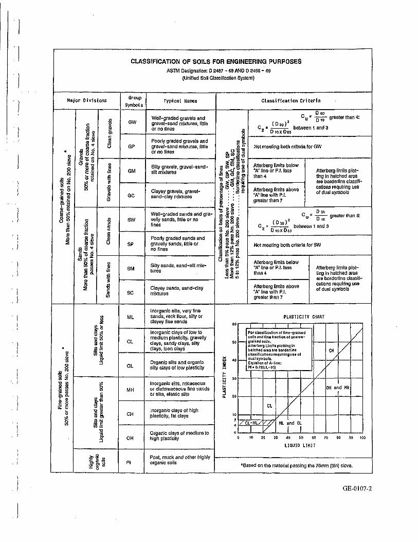
Classification of Soils for Engineering Purposes Symbols and Terms Used in the Report Test Hole Logs Guide for the use of Sulphate Resistant Cement
GE GROUND ENGINEERING LTD.
June 26, 2001
PAGE NO.
2
2
4 4 4
5 5 5
5 6 6
7
8
9
GE-0107-1 GE-0107-2 GE-0 107-3 to -4 GE-0107-5 to -24 GE-0107-25
l l
' l I
'J
.l l
'l
. j
GROUND ENGINEERING LTD .. CIVIL & GEOENVIRONMENTAL ENGINEERS
415 · 7th AVENUE • REGINA • SASKATCHEWAN • CANADA • S4N 4P1 TELEPHONE: (306) 569·9075 FAX: (306) 565·3677 EMAIL: [email protected]
FILE: GE-0107
Town of Lumsden Box 160 LUMSDEN, Saskatchewan SOG3CO
ATTENTION: MR. BOB SCHULTZ
Dear Sir:
SUBJECT: GEOTECHNICAL INVESTIGATION PROPOSED RESIDENTIAL SUBDIVISION BROADSTREETAND5T8 AVENUE LUMSDEN, SASKATCHEWAN
1.0 INTRODUCTION
June 26, 200 1
This report presents the results of a site specific subsurface soils investigation and geotechnical
analysis carried out at the site of the above captioned residential development located in the
Town of Lumsden, Saskatchewan. It is understood that the proposed subdivision consists of 13
residential lots with associated infrastructure including roadways, sewer and water.
The objectives of this investigation were to provide the following information:
~ @A MEMBER ORGANIZATION OF THE ASSOCIATION OF CONSULTING ENGINEERS OF CANADA AFFILEE A LA FIDIC MEMBER li'IDIC
~ ~-r.:.:-.,..!:.lC.."';'(:I':~LC:%T..~~-~-=====:::!'.o..~-'FL""l""'rn=rmnu;;;===~~·=-r=~.;:-.r=~-=;:~-=._..-==--~:.:::~-=:::;'J
0 SOIL MECHANICS AND FOUNDATION CONSULTANTS 0 SITE INVESTIGATIONS 0 FOUNDATION DESIGN 0 SPECIFICATIONS 0 CONSTRUCTION SUPERVISION 0 INSPECTION AND LABORATORY TESTING SERVICES 0 SOILS 0 CONCRETE 0 ASPHALT 0 PAVEMENT DESIGN AND EVALUATION 0 SLOPE STABILITY 0 REPORTS 0 SEEPAGE CONTROL BARRIERS FOR MUNICIPAL AND INDUSTRIAL WASTE CONTAINMENT 0 ENVIRONMENTAL STUDIES
') l
'·' J
' 1
, I
'l , I
' J
~ l ~ !
:]
: l ' i ' l
. ' l 'j
' l l
FILE: GE-0107 2 June 26,2001
.1
. 2
.3
.4
To define the subsurface soil stratigraphy at the site with particular reference to
determining the location ofthe former Qu' Appelle River channel on the property.
To identify suitable building locations at the site .
To provide design and installation recommendations for the most suitable and
economical type of foundation system to support the proposed residential buildings.
To provide recommendations on pertinent geotechnical issues identified during the
subsurface investigation.
Authorization to proceed with this work was received verbally on March 28, 2001.
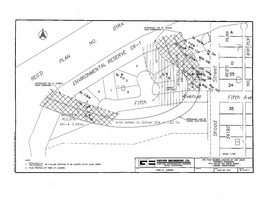
2.0 DESCRIPTION OF THE SITE
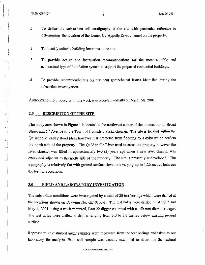
The study area shown in Figure 1 is located at the northwest comer ofthe intersection of Broad
Street and 51h A venue in the Town of Lumsden, Saskatchewan. The site is located within the
Qu' Appelle Valley flood plain however it is protected from flooding by a dyke which borders
the north side of the property. The Qu' Appelle River used to cross the property howev~r the
river channel was filled in approximately two (2) years ago when a new river channel was
excavated adjacent to the north side of the property. The site is presently undeveloped. The
topography is relatively flat with ground surface elevations varying up to 1.26 metres between
the test hole locations.
3.0 FIELD AND LABORATORY INVESTIGATION
The subsurface conditions were investigated by a total of 20 test borings which were drilled at
the locations shown on Drawing No. GE-0107-1. The test holes were drilled on April 2 and
May 4, 2001, using a truck-mounted, Brat 22 digger equipped with a 150 mm diameter auger.
The test holes were drilled to depths ranging from 3.0 to 7.6 metres below existing ground
surface.
Representative disturbed auger samples were recovered from the test borings and taken to our
laboratory for analysis. Each soil sample was visually examined to determine the textural
GE GROUND ENGINEERING LTD.
' l J
l 1
FILE: GE-0107 3 June 26, 2001
FIGURE 1
LOCATION OF STUDY AREA
GE GROUND ENGINEERING LTD.
'l 'l ' 1
'l . ··j
'l l
' J
' )
' J
FILE: GE-0107 4 June 26, 2001
classification and a natural moisture content test was performed on each sample. Atterberg
Limits, sulphate content and unconfined compressive strength tests were performed on selected
representative soil samples. Details of the soil profile, samples taken, laboratory test results
and stratigraphic interpretations of the subsoils are appended to this report on Drawing Nos.
GE-0107-5 to -24, inclusive .
The ground surface elevations at the test hole locations were established by representatives of
GE Ground Engineering Ltd. and are referenced to an assumed datum of 100.00 metres
described as the top of the fire hydrant located at the intersection of Broad Street and 51h
Avenue.
4.0 GEOTECHNICAL ANALYSIS
4.1 Stratigraphy
The drilling information indicates that the surficial topsoil is underlain by stratified alluvial
deposited sediments consisting of interbedded layers of clay, sand and silt. Numerous organics
were noted in the soil samples. The alluvial sediments extend to the maximum depth
penetrated in the test borings (7.6 metres).
Fill materials were encountered in Test Holes 107, 108, 109, 110, 114, 115, 116, 119 and 120
to depths ranging from 1.8 to 4.9 metres below existing ground surface. The fill consists
predominantly of silty clay (alluvium) with variable amounts of sand, organics and wood
debris.
4.2 Groundwater
The drilling information indicates that there is a shallow groundwater table at this site. The
alluvial sediments generally became saturated below a depth of 4.0 metres. Piezometers were
not installed to monitor the long term groundwater levels, however on the basis of the drilling
information, the water levels measured at the time of our investigation are probably close to the
stabilized levels. During periods of heavy rainfall or spring run-off, the water table within the
flood plain could rise.
GE GROUND ENGINEERING LTD.
I ' I ' J
l ' I
l ' l
I
'l l
FILE: GE-0107 5 June 26, 2001
5.0 DISCUSSION
5.1 Fill Materials
The fill materials within the fonner river channel were encountered in Test Holes 107, 108,
109, 110, 114, 115, 119 and 120. Infonnation obtained from a review ofhistorical air photos of
the area indicates that the fill materials encountered in Test Hole 116 were placed to fill a
f01mer low area (meander scar) which was not as deep as the fonner river channel. It is
understood that the fonner river channel and low area were filled in approximately two (2)
years ago when the new river channel was excavated adjacent to the north side of the property.
The soil which was excavated for the new channel was used to backfill these areas. The limits
of the fonner channel and low area are shown on Drawing .No. GE-0107-1. It is understood
that the trees and vegetation within the limits of the former channel and low area were not
removed prior to placing the fill materials. It is not known if the fill was compacted during the
time of placement, however you have indicated that it was spread in lifts and nominally
compacted with the earthmoving equipment. On the basis of the information available at this
time, future settlement should be expected as the fill materials consolidate and the organics
decompose. The amount of expected settlement will be related to the depth of fill material. In
areas of deep fill, the amount of settlement could be significant. Some allowance should be
made for settlement in the design of roadways and underground utilities.
5.1 Alluvial Sediments
The alluvial soils encountered at this site are normally consolidated, relatively weak foundation
soils. Organic horizons and layers of soft organic clays and silts can be expected in this type of
deposit. The loose to medium dense sands are typically wet, cohesionless and subject to
sloughing.
6.0 FOUNDATION CONSIDERATIONS
Bored concrete piles are not recommended at this site due to the shallow water table and
cohesionless soils present. The residential buildings at this site may be designed to be
supported on shallow footings which are founded in the undisturbed alluvial soils. Due to the
deep fill within the former river channel, shallow footings are not recommended within the
limits shown on Drawing No. GE-0107-1. Alternatively, buildings which are designed to be
GE GROUND ENGINEERING LTD.
: l : J
. l ' l ' l .l
' j
l l
FILE: G E-0 I 07 6 June 26, 2001
supported on a driven timber pile type of foundation system would have no restriction placed
on location. Our specific recommendations for both types of foundation systems are provided
below:
6.1 Spread Footing and/or Post and Pad Type Foundation System
.1 The proposed buildings may be supported on shallow concrete footings founded in the
undisturbed alluvium. The footings may be designed for a safe net bearing pressure of
95 kPa {2,000 psf). Maximum toe pressure under wind loading may exceed the average
pressure by no more than one-third (1/3). Regardless of footing pressure
considerations, the minimum width of footings should be 450 mm .
. 2 The footings should be placed at a minimum depth of 1.8 metres below finished grade
elevation in the undisturbed alluvium to ensure that the footings are bearing on soil with
adequate bearing capacity and below the maximum depth of frost penetration. The
basement excavations on Lots 1, 2, 3 and 4, Block 9 and Lots 1, 2, 3 and 9, Block 10
should be inspected by qualified geotechnical personnel to ensure the foundation soils
consist of undisturbed alluvial soils. All footings should be reinforced with a generous
amount of steel to resist localized stresses .
.3
.4
6.2
.1
The alluvial soils at this site are highly susceptible to disturbance by the movement of
workmen, equipment, etc., particularly when wet. In this regard every effort should be
made to pour the footings as soon as possible after excavation is completed. The steel
reinforcing mats should be made up in advance to minimize the possibility of soil
disturbance during placement.
ALL LOOSE OR DISTURBED MATERIAL AT THE BASE OF THE FOOTING
EXCAVATIONS SHOULD BE REMOVED OR COMPACTED PRIOR TO
PLACEMENT OF FORMS, REINFORCING STEEL AND CONCRETE.
Driven Timber Piles
Soil conditions at this site are suitable for driven timber piles designed to carry the
building loads on the basis of side friction between the pile surface and the surrounding
GE GROUND ENGINEERING LTD.
l I
I i
' )
, I ' l
I
. !
: l l ' l
'l l ' l
FILE: GE-0107 7 June 26, 200 I
.2
.3
.4
.5
7.0
soil. An average allowable side friction design value of 14.4 kPa (300 psf) may be used
for the alluvial soils at this site. The upper 1.8 metres of pile length or maximum depth
of fill, whichever is greater, below the final ground surface elevation should be
discounted in determining the pile load capacity. The piles should be driven to a
minimum depth of six (6) metres below existing grade to prevent frost jacking of the
piles.
Timber piles should conform with the requirements of Subsection 4.2.3 of the National
Building Code.
Timber piles should not be installed at a centre to centre spacing of less than 2.5 times
the average pile diameter.
A potential problem associated with the installation of timber piles is the splitting and
brooming of the pile tip and the head during driving. To avoid this, the following steps
are recommended:
the driving energy per blow (Joules) should be limited to: SOD
where Dis diameter of the pile tip, in inillimetres, and the maximum driving energy per 25 mm (Joules) be limited to:
320D
that driving be stopped immediately when abrupt high resistance to penetration is encountered.
Pile inspection by a qualified inspector is recommended during the pile driving
operations to ensure that the piles have been driven to the design length or that the
specified refusal criteria has been met.
EXCAVATION CONSIDERATIONS
Building excavations at this site will be in the surficial alluvial sediments and fill materials.
Contractors should be aware that wood debris (trees, bush, etc.) may be encountered in the fill
materials. Occupational Health and Safety Regulations require that any trench or excavation in
GB GROUND ENGINEERING LTD.

' l I
I
. I
. I
l ' l l l l
FILE: GE-0107 8 June 26, 2001
which people must work, must be cut back at least one (1) horizontal to one (1) vertical or a
temporary shoring system must be used to support the sides of the excavation.
8.0 OTHER
.1 The Owner should be aware that any pennanent development on a flood plain involves
some risk due to the possibility of flooding .
. 2 Test results on selected samples indicate that the soluble sulphate contents in the soil are
in the order of 0.03 to 0.30 percent by dry soil weight. Therefore, Class 2 Concrete, as
specified in the Guide for Use of Sulphate Resistant Cement on Drawing No. GE-0107-
25, should be used for all concrete in contact with the native soil. Type 50 cement is
recommended for use in concrete used to construct bored concrete piles.
.3
.4
It is recommended that GE Ground Engineering Ltd. be retained to provide inspection
services during construction of the foundation systems for this project. This is to
observe compliance with the design concepts, specifications or recommendations and to
allow design changes in the event that the subsurface conditions differ from what was
anticipated .
This report has been prepared for the Town of Lumsden and is intended for the specific
application to the design of the proposed residential subdivision to be located in the
Town of Lumsden, Saskatchewan. The analysis and recommendations are based in
part on the data obtained from the test hole logs and a review of historical air photos of
the area. The boundaries between soil strata have been established at bore hole
locations. Between the bore holes, the boundaries are assumed from geological
evidence and may be subject to considerable error. Contractors bidding on the project
works are particularly advised against reviewing the report without realizing the
limitations of the subsurface infonnation. It is recommended that Contractors should
make such tests, inspections and other on-site investigations as is considered necessary
to satisfy themselves as to the nature of the conditions to be encountered.
Gil GROUND ENGINEERING LTD.
j
. )
,/
FILE: GE-0 I 07 9 June 26,2001
.5
.6
It is recommended that the geotechnical workscope. include the following services in
addition to subsurface exploration and development of foundation design
recommendations. These two services are:
i) geotechnical review of other design professionals' plans relative to their interpretation of geotechnical findings and recommendations, and;
ii) construction monitoring, to observe construction activities in light of plans and specifications, and to help assure that unforeseen conditions are detected quickly, to pennit prompt corrective action and thus prevent minor problems from growing to major proportion.
The samples from this site will be retained in our laboratory for 90 days following the
date of this report. Should no instructions be received to the contrary, these samples
will then be discarded.
9.0 CLOSURE
We trust that this report is satisfactory for your purposes. Should you require further
information, please contact this office.
Yours very truly
~- ~-" .,.,~·-;-~-· >P: •• ·. ·.·r. ~ ~ ~- .... .,--: ~ ··, .,.,,..,"!-:· .. ~.•u ~.-.- ..... "'- "~.- ... -Ju .• ~:·.<t~Jo..:.•; :·.tr.>":>"...: • ..:~•:.-·:.,.:r.:::::,;;."t::.r, .t <,.:.:;.
, ~ N;SOGii;.llON OF F'IWH.·S:~lONi\L EI\JGINW1S 1 u m· ;;/~:;:<;n,·cl;t!:Y!f\~.l ·
· 1
{ (~~r:~I-li/l;~;-··T:;_ <L ~~ tJ-·I;</"f~::~9.~~~~!!~~:f(U~JJ~\1 ~ C~: (._;·.:_::·:<:~!) k~')-~~~J~::·iE~:,~Li fXf.)u
· r-:· :!. · , :;,1 n ·>,·&~:.:~ PWi\·iiSS:OiJ fO COiiStllT ~JEW BY:
DISCIPliNE Sf1SK :lEG. No. ti·:.!,~'lfi!'IJIH:
'·{f?Zf€:.~.!~{,.~,.ofil~~=:Lt.~" .. ~,~ ' , ~f.lu-r.il':'l:'i'
~ ·-""""'~.~~''"""'v~,.o .. ,"N•~"''''·''·"·'"'''·"·"'"·~-.'~,'-'C$CO~>o''"'·'='"''''"'·' I
~ ~-~·~1~,'.'.'.',\~'lt:<::.""<"l,':'·:i'•'~'T.::.>i''l'i:N'!I"VI'.:l\.,<l~~:•.<!·•:.li'<Y.i.'~':'l.":;l:f/.!'•:l"'-.":(lo•".'r.t.~~.rl-ll.'.(!::H~:;.:-~~J..r;.;n.·, ·•
SH:mw Distribution: Town of Lumsden (3 copies) sh360 Office (1 copy)
GE GROUND ENGINEERING LTD.
?'--~~
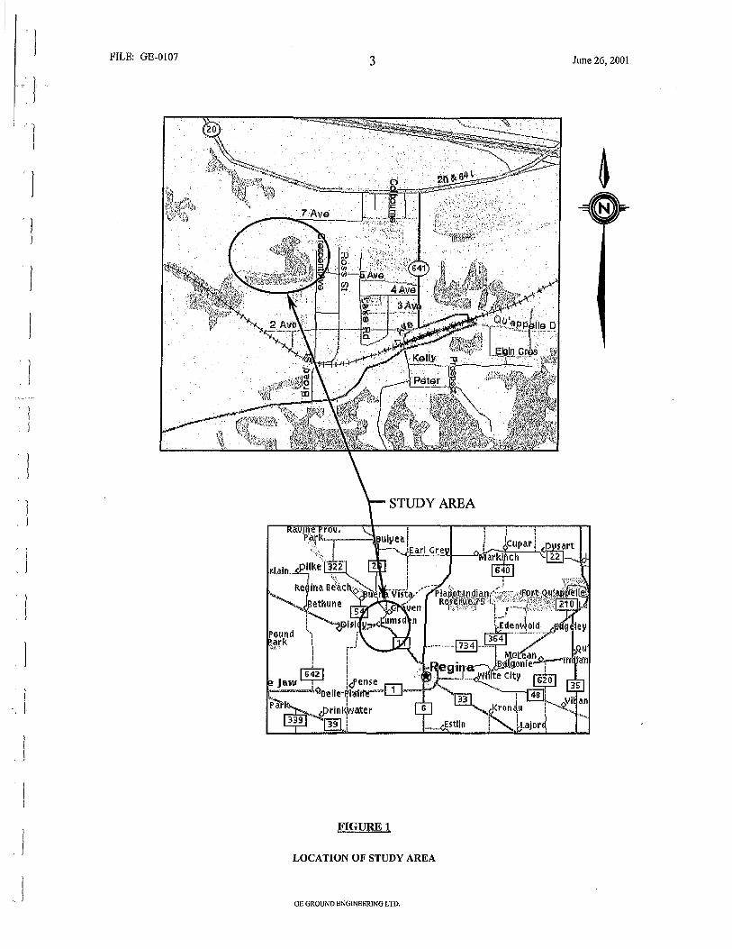
~~c;o APPROXIMATE TOP OF FORMER RIVER EMBANKMENT
~0·
-..\\ ~\, ~\'J\~\'1
\J\~0 t,~
o"~~
£_~\,)t, ~t,S
~~/:\
_.....,...---- --------------------------
APPROXIMATE ----RIVER EMBAN TOP OF F~R KMENT MER
APPROXIMATE UMIT OF FORMER R!VER BOTTOM
-------------------------
~~A I I f;) a: ~ ....... -0::: ....... t.Q
il-D
~ ~
~25 -
24 L
Fifth AvE
35
C\j :: 0) ~
~~ B.
SCALE: 1:1 000
NOTE:
1. ~ NO SHALLOW FOOTINGS TO BE LOCATED WITHIN THESE AREAS. I 1:1 :.:= GROUND ENGINEERINC LTD~
CONSULTING GEOENVIRONMENTAL ENGINEERS REGINA. SASKATCHEWAN
SITE PLAN SHOWING LOCATION OF TEST HOLES PROPOSED SUBDMSION
FIFTH AVENUE AND BROAD STREET LUMSDEN, SASKATCHEWAN
2. PLAN PROVIDED BY TOWN OF LUMSDEN. DVC..No:
TOWN OF LUMSDEN JUNE 26, 2001 GE-0107-1
'l I
«
Major Divisions
CLASSIFICATION OF SOILS FOR ENGINEERING PURPOSES ASTM Designation: D 2487 - 69 AND 0 2466 - 69
Group Symbols
GW
GP
GM
GC
(Unified Soil Classification System)
Typical Names
Well-graded gravels and gravel-sand mixtures, little or no fines
Poorly graded gravels and gravel-sand mixtures, little or no fines
Silty gravels, gravel-sandsilt mixlures
Clayey gravels, gravelsand-clay mixtures
Classification Criteria
D so C u " 01'0 greater than 4:
( 0 3o) 2 C z = --- between 1 and 3
..!!! D1oxOao B ~------------------------------~ ~E
010' o.o~g
Not meeting both criteria for GW
(J)(/)U"Il "' ~~J ~ f-A-tt-e-rb-e-rg-1-im-it-s-ba-1-ow-....---------~ :!l a:O ~ :;, "A" line or P.l. less Atterberg llmils plot-:: CJ e1.,.. !r than 4 ling In hatched area o ·::!: !i:i :; are borderline classlfi-fc ~. CJ.: ~ ~ 1-A-tt-e-rb-e-rg-1-lm-lt_s_a-bo_v_e--1 cations requiring use
"A" line with P.l. of dual symbols ~ : : greater than 7 8. :!!! : 0 ~~~~-! : 0 BO Well-graded sands and gra- "' ·- .. •
e til SW velly sands, little or no ~ til ~ !!! .g ~ fines IJ ~ • ~
C u = -0- greater than 6:
( D 30) 2 10
@ 1----11-----------1 g 0~ ~ -~~~ ij cZ~N
C z = --- between 1 and 3 DtoKOeo
~ > 111 Poorly graded sands and ~ !!l ill fa '* 0 SP gravelly sands, little or ·B 01 c..~
"' 8 "" no tines "" c..~ Y.l "g 0 zo 1---+---+-----------1 ·~ ~ ~ C\1
Not meeting both criteria for SW
"' - c 0.. w~tll u~~~ ~ m J SM Silty sands, sand-silt mix- ... ;; ~ S c.. ~ tures ~ ~ ~
Atterberg limits below "A" line or P.l. less than 4
Atterberg limits plotting In hatched area are borderline classifications requiring use of dual symbols
* .. ~ ~
(/) sc
ML
CL
OL
MH
CH
OH
PI
Clayey sands, sand-clay mixtures
Inorganic silts, very fine sands, rock flour, silty or clayey line sands
Inorganic clays of low to medium plasticity, gravelly clays, sandy clays, silty clays, lean clays
Organic slits and organic silty clays ot low plasticity
Inorganic slits, micaceous or diatomaceous fine sands or silts, elastic silts
Inorganic clays ot high plasticity, fat clays
Organic clays ot medium to high plasticity
Peat, muck and other highly organic soils
Atterberg limits above "A" line with P.l. greater than 7
PLASTICITY CHART
For classification of fine-grained / soils and fine frac11on of coarse- /
so - gralnod soils, A1terberg Limits plo1tlng In v halchod areaare borderline CH cla.ssifica.1ions requiring use of /
~ ~0 _ dualsymbols, /_ o Equation of A-line: / ;!; PI• 0.73(LL-20)
§ 3or-~r--;---t---l----l---~~~;---+---t--; § v ~ 2or---r--;---+---l---~---r--;---+---+-~
/v tor-~r-~---+~-1----1----1---;---+---t--;
OH and MH
CL
: / CL-ML/V //
0 v 0 10 20 30 40 50 60 70 eo 90 100
LIQUID LIMIT
*Based on the material passing the 75mm (31n) sieve.
GE-0107-2
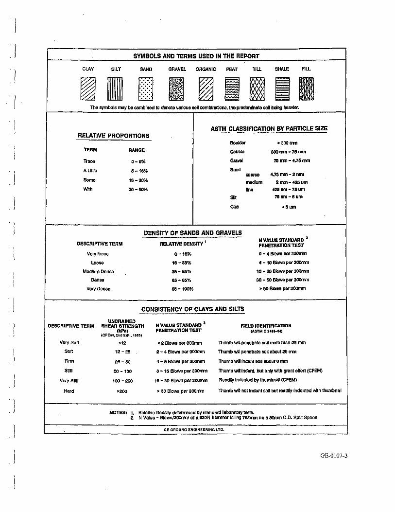
. l
l
c l
,. l
l L J
' }
' l
CLAY SILT
SYMBOLS AND TERMS USED IN THE REPORT
SAND
~ .... . . . . . . . . . . . . . . . . . L..!....!..!..
GRAVEL ORGANIC PEAT TILL SHALE
The symbols may be combined to denote various soU comblnatlons, the predomnate eoll being heavier.
FILL
ASTM CLASSIFICATION BY PARTICLE SIZE RELATIVE PROPORTIONS
Boulder >300mm
TERM RANGE Cobble 300mm•75mm
Trace 0-5% Gravel n~ nm- 4,715 mm
A Utile 15-16% Sand coarse 4.7Dnm-2mm
Some 16- 30"k medium 2mm·425um
Wrth 30-50% nne 425um•7Sum
Silt n~um-sum
Clay <!Sum
DENSITY OF SANDS AND GRAVELS
DESCRIPTIVE TEAM RELATIVE DENSITY 1 N VALUE STANDARD 2
PENETRATION TEST
Very loose 0-16% 0 - 4 Blows per 300rrin
Loose 15-35% 4 - 10 Blows per 300rnm
Medium Dense 35-65% 10 - 30 BloWS per 30DnVn
Dense 65•65% 30 - 60 Blows per 30DnVn
Very Dense 65-100% > 50 Blows per 30011Vn
CONSISTENCY OF CLAYS AND SILTS
UNDRAINED DESCRIPTIVE TERM SHEAR STRENGTH N VAI.UE STANDARD
2
PENETRATION TEST FIELD IDENTIFICATION
(ASTM D 24tt--M)
Very Soft
Soft
Firm
Stiff
Very Stiff
Hard
(kPa) (CFEM, 2nd Edt., 1US5)
<12
12-25
25-50
50 •100
100-200
>200
NOTES: 1. 2.
< 2 Blows per 3oomm
2 - 4 Blows per aoomm
4 - 8 Blows per 3CIOnm
8 ·15 Blows per 3CIOnm
15 - 30 Blows per 300mm
> 30 Blows per 300mm
Thumb WIU penetrate soU more than 25 mm
Thumb will penetrate soli about 25 mm
Thumb Will Indent soli about 6 mm
Thumb will Indent, but only With great effort (CFEM)
Readily Indented by thumbnail (CFEM)
Thumb WIU not Indent soU but readily Indented with thumbnail
Relative Density determined by standard laboratory tests. N Value - Blows/300rnm or a 620N hammer faJUng 762mm on a 50nm 0.0. Split Spoon.
GE GROUND ENGINEERING LTD.
GE-0107-3
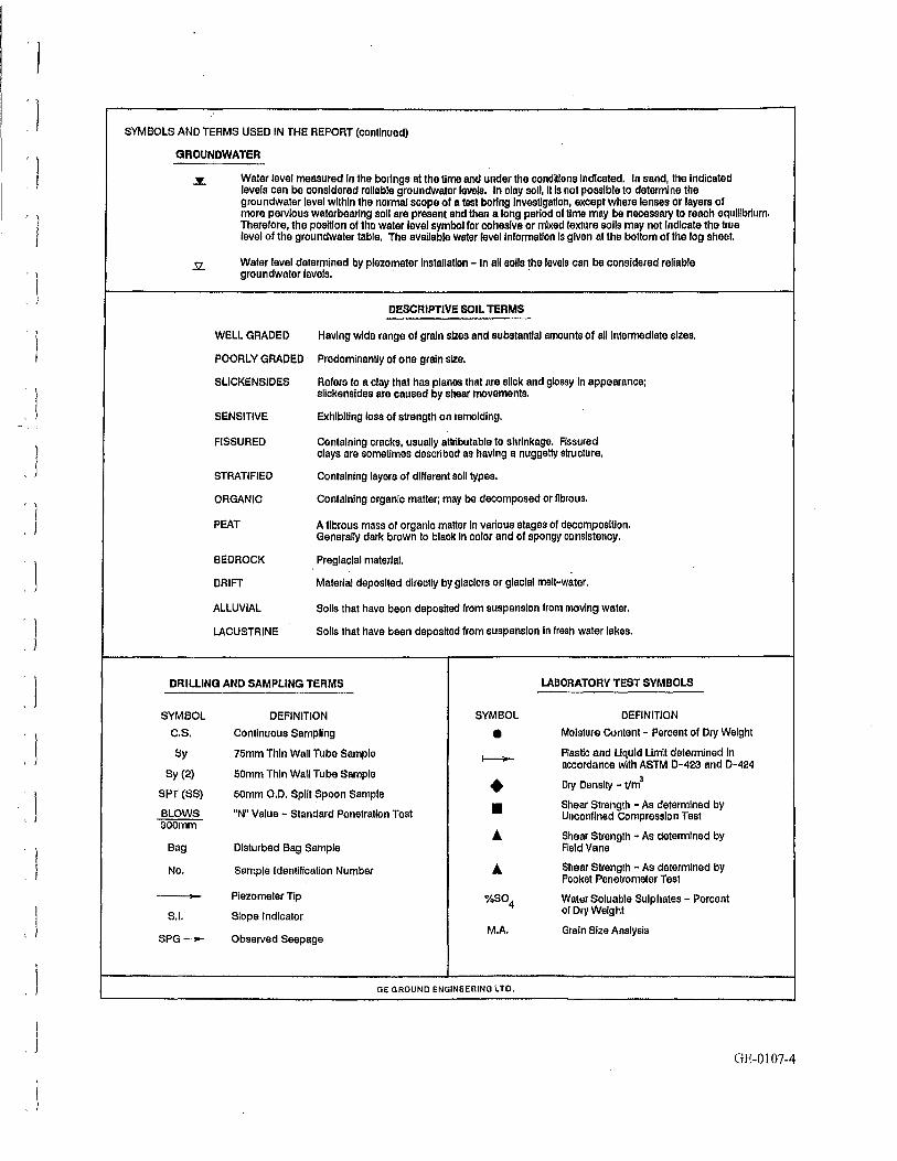
SYMBOLS AND TERMS USED IN THE REPORT (continued)
GROUNDWATER
Water level measured In the borings at the tlme and under the conditions indicated. In sand, the Indicated levels can be considered reliable groundwater levels. In clay soil, It is not possible to determine the groundwater level within the normal scope of a test boring investigation, except where lenses or layers of more pervious water bearing soU are present and then a long period of lime may be necessary to reach equilibrium. Therefore, the position of the water level symbol for cohesive or mixed texture soils may not Indicate the true level of the groundwater table. The available water levellnformatlon Is given at the bottom of lhe log sheet.
Water level determined by piezometer Installation - In all soils the levels can be considered reliable groundwater levels.
DESCRIPTIVE SOIL TERMS
WELL GRADED Having wide range of grain sizes and substantial amounts of all inlennedlate sizes.
POORLY GRADED Predominantly of one grain siZe.
SLICKENSIDES Refers to a clay that has planes that are slick and glossy In appearance; slickensides are caused by shear movements.
SENSITIVE EKhlbltlng loss of strength on remolding.
FISSURED Containing cracks, usually attributable to shrinkage. Fissured clays are sometimes described as having a nuggetty struclure.
STRATIFIED Containing layers of different soil types.
ORGANIC Containing organic matter; may be decomposed orflbrous.
PEAT A fibrous mass of organic maHer in various stages of decomposition. Generally dark brown to black in color and of spongy consistency.
BEDROCK Preglacial material.
DRIFT Material deposited directly by glaciers or glacial melt-water.
ALLUVIAL Solis that have been deposited from suspension from moving water.
LACUSTRINE Solis that have been deposited from suspension In fresh water lakes.
DRILLING AND SAMPLING TERMS LABORATORY TEST SYMBOLS
SYMBOL DEFINITION SYMBOL DEFINITION
c.s. Continuous Sampling • Moisture Content - Percent of Dry Weight
Sy 75mm Thin Wall Tube Sample ~
Plastlc and Uquld Umlt detennlned in accordance with ASTM 0-423 and D-424
Sy (2) 60mm Thin Wall Tube Sample • Dry Density - t/m3
SPT (SS) 50mm 0.0. Split Spoon Sample
BLOWS "N" Value - Standard Penetration Test • Shear Strength - As determined by
300mm Unconfined compression Test
• Shear Strength - As determined by Bag Disturbed Bag Sample Field Vane
No. Sample Identification Number • Shear Strength - As determined by Pocket Penetrometer Test - Piezometer Tip %804 Water Soluable Sulphates - Percent
S.l. Slope Indicator of Dry Weight
SPG- Observed Seepage M.A. Grain Size Analysis
OE OAOUND ENGINEERING LTD.
GE-0107-4
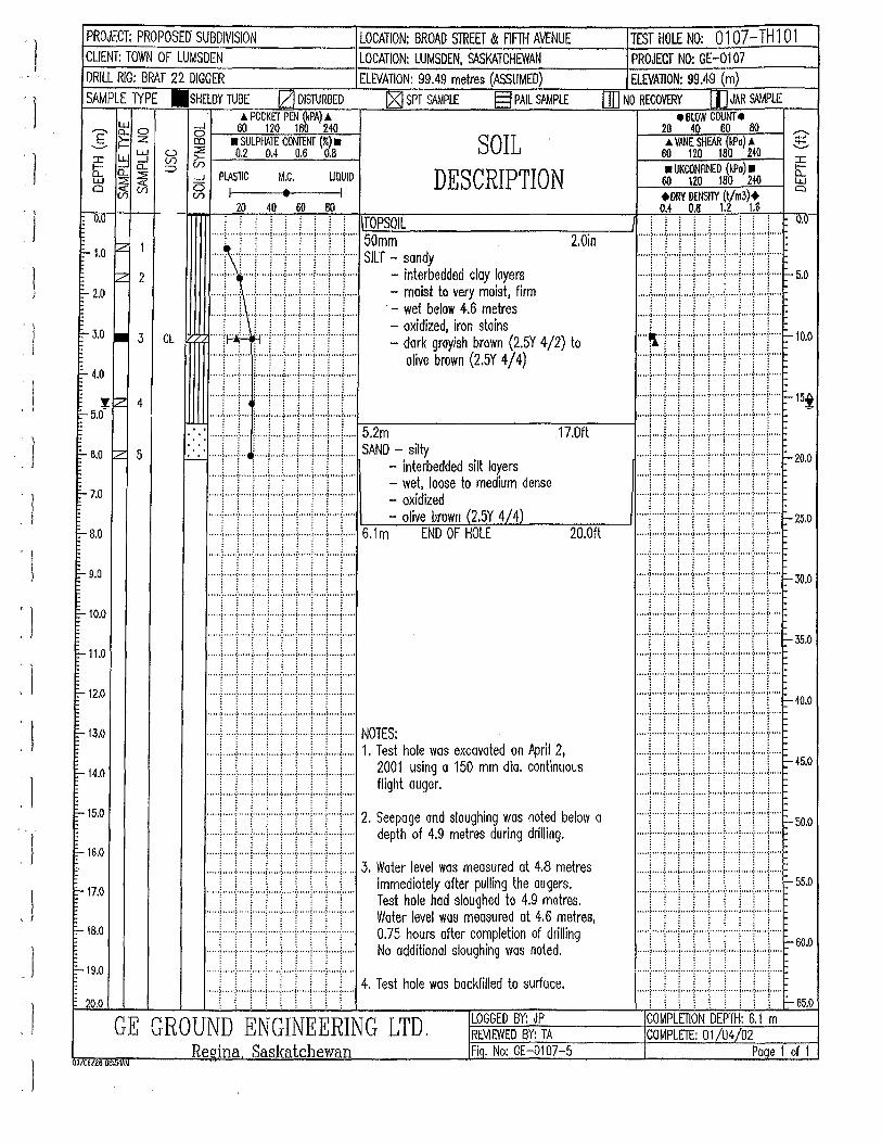
l . \
I I
' l ) I
'J
'1 'I
'l 'J
'J
' )
\
' J
' l
PROJECT: PROPOSED" SUBDIVISION CLIENT: TOWN OF LUMSDEN DRILL RIG: BRAT 22 DIGGER
SAMPLE TYPE .SHELBY TUBE IZJ DISTURBED A POCKET PEN (kPA) A
,-.... g: 0 c5 60 120 180 24<1 _§_ f:: Z co • SULPHATE CONTENT (%) •
~ ~ ~ ~ 0.2 0.4 0.6 0.8 ~w o... o... ::::> ....... :::?! ~ _J
Cl tJ5 (/) ~ PlASTIC M.C. UQUID
I • I 20 40 60 80
LOCATION: BROAD STREET & FIF1H AVENUE LOCATION: LUMSDEN, SASKATCHEWAN ELEVATION: 99.49 metres (ASSUMED)
rgj SPT SAMPlE §PAIL SAMPlE
SOIL DESCRIPTION
TEST HOLE NO: 0107-TH1 01 PROJECT NO: GE-0107 ELEVAliON: 99.49 (m)
OIJ NO RECOVERY [JJ JAR SAMPLE e BlOW COUNT •
20 40 60 80 A VANE SHEAR (kPo) i
60 120 180 240 • UNCONFINED {kPa) •
60 12.0 180 240 +DRY OENSriY (t/m3)+ OJ 0.8 1.2 U
0.0 ' ' ' . . i i II'::'TiO:::-P=SO=IL'-----------::-:-:------' ..... \ .... ( ... j" ... j ..... j ..... i ..... j .... ·t· ... j ..... 50mm 2.0in f'- 1.0 ~
z 2 E- 2.0
1:- 3.0 • 3 CL
E-4-.0
JZ 4 E- 5.0
E- 6.0 rz 5
F-7.0
~
E- B.O
E- 9.0
E-10.0
E-11.0
E-12.0
~13.0
~14.0
:-15.0
E-16.0
E-17.0
f-18.0
E-19.0
20.0
..... , .... : ... -+ .. +· .. -: .... + .. -+ .. + .. .;.. ... SILT - sandy
..... ; .... t .... j ..... j ..... [ ..... j ..... j ..... ~ .... j..... - interbedded clay layers
.. .) ..... , ) ..... ! .. ) .. ) .. .) ... ) .. )..... - moist to very moist, firm i i i i i i i i i - wet below 4.6 metres
• • •· ·~· • · • •:• • • • {• • • • •I • • • • •:• • • •• (• • • • ·I·····~ • .. • (• .. • •
: i i i i i i i i - oxidized, iron stains .. ... ~~~ ... ( ... i" ... t' .. ! ..... : .... f.... - dark grayish brown (2.5Y 4/2) to ..... ( .. 1"" j .. · .. :· .. ·i"·"j'""!'""f""i""' olive brown (2.5Y 4/ 4) ··· · ·r ·····I···· ~·····i····t····1·····~·····t····~····· ·····!····-t .. ·~ ;·····i····r· .. ·J·····!·····I····J·····
. :. : ::::r::r:: r::::r:::r::r::r::r:::r:::l-:5:--:.2:-m--------1:;-::;7;-;;:.o-;;-ft _ __,
20.0ft
~ ..... ; ..... ! ... /. ) .. .) .. .) .. ) ..... ~ .... ) ..... SAND -. silty . i i i i ! i i ! i - Interbedded s1lt layers
.... T .. T"T"T .... f ... T ... ! ..... ! .... !"... - wet, loose to medium dense ·····[ ..... 1 .... -j ..... ! .... ·:· .... i .... ·!·· .. ·?· .. ·j .... · - oxidized ..... i .... ( ... i ..... : ..... : ..... ; ..... : ..... j .... ;..... - olive brown (2.5Y 4L4) ..... L .... L. .. L ... L.. .. L ... L .. i ... ..L ... L.. .. 6 1m END OF HOLE
..... i .... -1--···l .. ···I····J .... J·····i···+···!····· .
.... ·f .... •1• ... ' 1• .... i .... 'l' ... ~· .... i .... ·~ .... ~· .... "'''i····}····j·· .. ·!····}····)·····:···"l'"'l····· .... ·J .... ·~· .... f· .... j .... ·j· ...• ~· .... i .... ·t .... i· ....
''"'f·····:······i· .. ··l· .. ·-i- .. ··l····-!-· .. ·!····1····· .... 'l' ... '!' ... 'l' .... ~ ... ''1' ... •[•• .. -~· ... ·~ ... '1' ....
:::::r::::I::::r::::r:::I::::r::::~:::::r::::r::::
:::::t·:::J:::::l.::::l::::r:::r:::·r::::j::::l::::: NOTES: .... L .. l.. ... L .. ! ..... L ... L .. L .. L .. L ... 1. Test hole was excavated on April 2, .... .l. .... L ... L ... \ ..... \ ..... L .. L .. L .. L... 2001 using a 150 mm dia. continuous
i i i i : ! ! ! ! flight auger.
::::r::r::r:::c:r:::r:::r::r:::r:::: 2. Seepage and sloughing was noted below o ..... l ..... , ..... j ..... 1 ..... , ..... l ..... l ..... [ .... J'.... depth of 4.9 metres during drilling.
::::r::r:::r:::r::r:::r::r:T:::L:: 3. Water level was measured at 4.8 metres
·····i····l· .. ·l··· .. [····-1-· .. ·l·····:·····f .... j..... ~~~e~~~~e~t~f~u~~~~~gt;h:.9°~:~~~s. ..... 1 ..... ! .. ·j ..... ! .... ·(·"i ..... i ..... t .... 1..... Woter level wos measured at 4.6 metres, ..... i ..... ; .... -j-- ... j ..... : .... +-+ .. "1- .. +·.. 0.75 hours after completion of drilling ..... l ..... j ..... L .. "l-.... J ..... j .. ·"i' .... [ .... j..... No additional sloughing was noted.
... T ... f ... ! ... T .... j ..... f" .. T .... f .... )' .... 4. Test hole was backfilled to surface. ·· ·· ·l· ··· r· ··· r ····\···· ·r····r····l ·· · ··~ · ··· r· ···
LOGGED BY: JP GE GROUND ENGINEERING LTD. REVIEWED BY: TA Regina Saskatchewan Fiq. No: GE-0107-5
1/06/26 08:MAM
::::J::::J.::::::::::t::::I::::r:::::::::I::::r::::
..... l .. ··-l-·· .. l···"l"··-1-·· .. l·····l····l ..... J- .... ~ss.o ::::r::::::::r::l::::r:::r:::::::::r:::r:::: _ 60.0
''"'J'"'':'"''''"")ooo••:oo•••i•••••l•••••:•••••<••ooo
..... ! ..... 1·····1··· .. !····-l-····]·····1 .. ··-l-····1· .. ..
. .... ; ..... ! ..... i ..... ~ ..... ~ ..... i ..... i ..... 1 ..... i ... .. l [ : \ ! : : : : ,.--65.0 COMPLETION DEPTH: 6.1 m COMPLETE: 01/04/02
Paqe 1 of 1
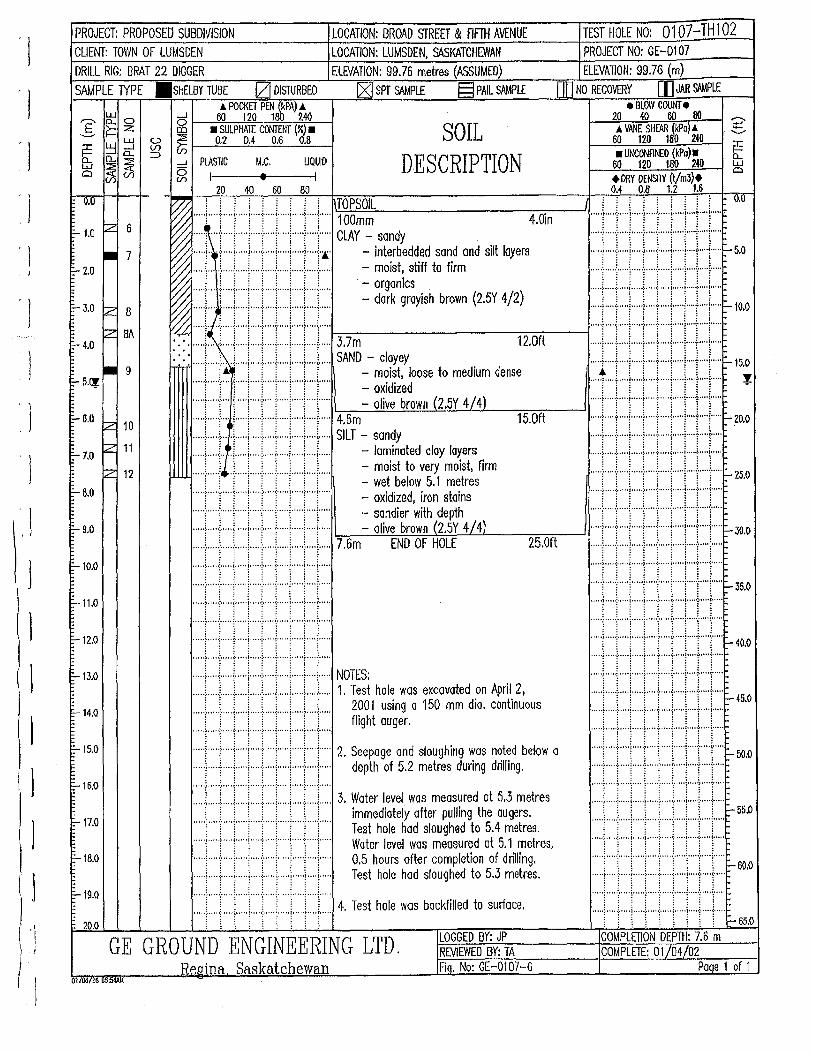
'j
r 1
. I
l ' 1
. J
'I
PROJECT: PROPOSED SUBDIVISION LOCATION: BROAD STREET & fiFTH AVENUE TEST HOLE NO: 0107-THl02 CLIENT: TOWN OF LUMSDEN LOCATION: LUMSDEN, SASKATCHEWAN PROJECT NO: GE-0107 DRILL RIG: BRAT 22 DIGGER ELEVATION: 99.76 metres (ASSUMED) ELEVATION: 99.76 (m) SAMPLE TYPE .SHELBY TUBE !ZJ DISTURBED !XI SPT S<I.MPLE §PAIL SAMPLE QD NO RECOVERY [[I JAR SAMPLE
& POCKET PEN (kPA) & e BLO'W COUNT e ,---._ g: 0 c5 ~---~60<-,---,..,:,:12,0~1~80~::,:240~-1 20 40 60 80 ._§_ f:: Z 00 • SULPHATE CONTENT(%) • S Q JL A VANE SHE'AR {kPa) .& :J:: ~ ~ &;; ~ ~---~0.2::,___:::0:_,_.4___;0::.:::.6,__.::.:.0.8::,_-l 60 120 180 240
b:: n.. o... :::::> DESC IPTJQN •UNCONFINED (kPa)• w ~ ~ _J PlASTIC M.C. LIQUID . R 60 12.0 180 2.411 a (/)< (/) o(/)- I e I ( l ) +DRY DENSITY t1m3 +
2.0 40 60 80 0.4 0.8 1.2 1.6 ~ j j j ! j ! ! ! j TOPSOIL : : : : : : : : : o.o
I••J·;~~~~····~~ I I; \!.6~~...:::;..::::~:::::..~-~-~d-f-~d-ti~-f -t~a-~-i~m-o-nd_s_il_t 1-ay_e_rs 4-.0~in-----~ •......•.•.••• ~ .•.•..•. ·.:=;············,:.···········:•i············=!············.:,i.·.·.·····i,i .•..•.. :.l.•· .... ··.:,!.•.·····:·:l- 5.0
~ .... L. !.. .. .L .. L ... i ..... !.. ... i .... L .. !..... · - organics .. ~ LJ ! ! )) ! i L - dork grayish brown (2.5Y 4/2) !+J++l i+i·~lo.o
~ i Flit! ! I t ~N~- cloyey 12.0fl : i -'', : : : : 1 i - moist, loose to medium dense
.... T .. T" j""'J""f""l""T"'{'"]"'" - oxidized
..... r ... T .. 1" ... ! ..... !" ... ! .... ! ..... r .. ·-r·.. - olive brown (2.5Y 4/4)
t t j ! llJ j ( ti~P- sandy .::.!.-!.L.:..L--c-:15,.....,.0....,fl----l
... + .. ·+· +·+ .. ; .... +·+ .. + .. +... - la~moied cloy lo~e;s f' .·::::.~.,i·::::.;.:; .. l::::·'':.:l:::: .. ·,l.' ... ::.~ ... =:.::·::: ... =' .... :···'r:: .. :::~ .. ,i::::J ... ·'!. ~z5.0 ..... L .... : .. ! ... ..L .. .i .... !... .. i.. ... L ... !..... - mo1st o very mo1s , 1rm ,-: : : i 1 : : i 1 - wet below 5.1 metres ..... ( .. '( ... j"' .. i·····( .. ·(··:· .... r .. ··i·.... - oxidized, iron stains ..... , ..... , ..... , ..... , ..... , ..... , ............... , .... .
..... i ..... ; ..... ~ ..... [ .... { .... .;.. ... [ .. "'f· ... \..... - sandier with depth i i .. i. ! .. !. · ! . .. .L .. L ... L ...
..... i ..... j ..... ! ..... ! ... ..[. .. ) ..... : ..... : .... ;..... - olive brown (2.5Y 4/4) ::·::;.,:.,.::::.: ... ·'::::::;:: .. ,'::.J .... ' . .':::~:i .. :':.J .... =':::J ... '!::::t ... '~::::l .. ·'::::::- 30.0 ..... , ..... l ..... ! ..... I ... + .. ·J .... '!".+ .. ·l· .... 7.6m END OF HOLE 25.0ft ••• ••)··· • ·:·····<····•1•• •• •:•• ···~··•• •I•• •••J ''" (••••• •••••)• .. ••:•••• •1•••••)•••••:••••• i••"•l•••••:•••••{•••••
·····l····J····l·····l····-i-· .. ·1·····!··· .. 1····! .. ··· ..... ; ..... , ..... , ..... !····f····i ..... , ... l··-1- .... - 35.0 • · · • .; . · • • .~. · · · .j. · • · . i ..... ~ .. · • · i. • • • • i • • • .,; • • " i .. • • , " • • •) • • • • •:• • • • •I " • • •) • • • • •:• • • • • {• • • • •I• • • • •:0" " {• ' " ' ..... ! .... ( ... j ..... j ..... [ .... j ..... : ..... ! ..... ,..... : ! i ! : l l : l
, , = : j ! : . ~ ! :.::· .... =r:-:~r .... =::::.r .... '::::.r .... '.::: .... =r::::.:.t.: ... =::r-: ... '::,.r...,·~r ... =::.~ 40.0 •I••I!•r•;•••·~~~··r NOTES·
iJ j ! Til ! t 1. ~:t~:~la: ~~a~~d~n ~~~in2~ous ~:t ... ' 1'.: .. = !• ... '=······:,' ... '·. ;.:' .... =·!.'i.= ~ .. ··'!:; .... ·' ir ... ·' ~ ~o .......... .: ........... ; ..... : ........... ; ..... ; ... ,, ... .. ...... ;.! ..... ;.i ..... ;.: ....... l ..... ;.: ...... ! ..... :.1· .... i.~ ...... ! ..... 2. Seepage and sloughing was noted below a ..... , .... , ..... , ..... , ..... , ..... , ..... , .... , .... , .....
..... :.: .... L ... : .... L .. .L ... L .. L..l....L. .. ~- 5o.o ..... ) ... + .. +·+ ... .:-- .. +·+ .. + .. +... depth of 5.2 metres during drilling. ·
::::L:T:::L:J::::I:::::\:::::I:::J::J:::: 3. Water level was measured at 5.3 metres :::::r:::J:::r:J:::::i:::::r:::t::::l::::l::::: 1 ) i ) \ \ \ \ \ immediately after pulling the augers. .. ... ,[ ..... ,~ ..... 'i,· .... ,[ ..... ,· ...... ,! .... ·l, .. · .. !, ...... ,! .... _l-- 55
•0
.... T .... ( .... )" ... ! ..... {" .. ) .... T ... i ... T.... Test hole had sloughed to 5.4 metres .
..... \ ..... ( ... ( ... ! ..... \ .... \ .. ! ..... \ .... \..... Water level was measured at 5.1 metres, ..... , ..... , ..... , ..... , ..... , ..... , ..... , ..... , ..... , .... .
..... ~ ..... ; .... + .. ·1· .... ; .... -j-- ... j ... + .. +... 0.5 hours after completion of drilling. .. .. .'.. ... ! ..... ~ ..... l .... ·l .... + ... : .... -[ ... + ... 1-SO,O
..... ; .... ·l· ... + .. ·!· .... l .... + .. ·! ... + .. +... Test hole hod sloughed to 5.3 metres. .. ... , ..... , ..... , ..... , ..... , ..... , ..... , ..... , ..... , ... ..
..... ; ..... : ..... ~ ..... \ ..... : ..... : ... \ .. ·+· .. \ ... 4 T t h I b kfll d t rf ..... ~- .. ) ..... : ..... l .......... j ..... ~ ..... l .... + .. .
..... l ..... !.. .. .i.. ... i ... ,.! ..... L. ... i ..... L ... i..... . es o e was ac 1 e o su ace. .. ... ; ..... ; ..... j ..... ; ..... : ..... , ..... j ..... ; ..... j ... .. i i \ \ \ ! \ i : \ \ \ \ \ ! : \ \ 1- 65.0
u.u
F- 1.0 IZ 6 .. 7 !::- 2.0
~
!::- 3.0 ~ 8
~ BA 1:- 4.0 .. 9 1:- s.ar
E-- 6.0 lz 10
F-7.0 z 11
z 12
F-8.0
I:- 9,0
I:- 10.0
t:-11.0
F-12.0
E-13.0
t::-14.0
F-15.0
E-1&.0
F-17.0
t::-18.0
F-19.0
20.0 LOGGED BY: JP COMPLETION DEPTH: 7.6 m GE GROUND ENGINEERING LTD. REVIEWED BY: TA COMPLETE: 01/04/02
Reaina Saskatchewan Fiq. No: GE-01 07-6 Paqe 1 of 1 01/00tz6 !Rl:54AM
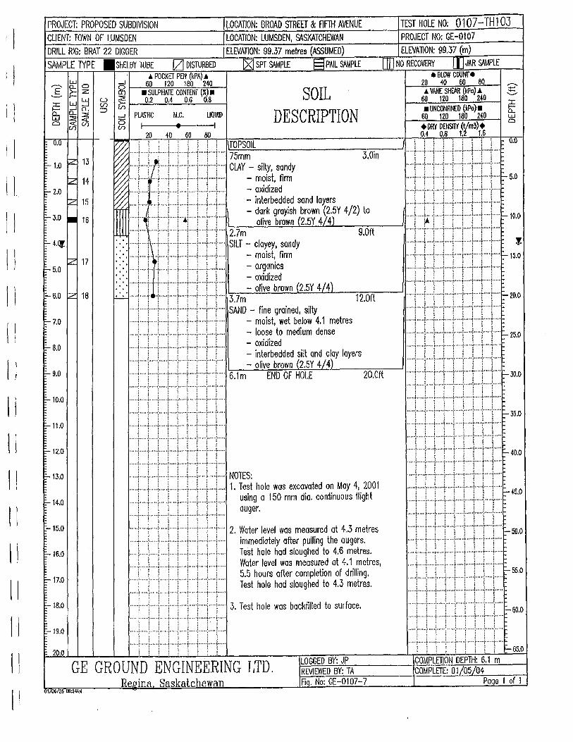
1\
11
11
I
! I
I
I ; II II ll II ll II ll II I i
PROJECT: PROPOSED SUBDIVISION ~OCATION: BROAD STREET & Flffil AVENUE CLIENT: TOWN OF LUMSDEN LOCATION: LUMSDEN, St\SKATCHEWAN
DRILL RIG: BRAT 22 DIGGER ELEVATION: 99.37 metres (ASSUMED)
SAMPLE 1YPE .SHELBY TUBE IZJ DISTURBED ~ SPT So\\lPLE §PAIL SAMPLE _. POCKET PEN (kPA) •
w 0 _J 60 120 180 240 ? 0... 0 ~--~-::-=~~~~--~ 5 f':: Z ~ • SULPHAlE CONTENT (r.) • SOIL
DESCRIPTION :c ~ ~ V5 ij; ~---~0~.2_0~.4:__.:!::,0.::_6 ~0.:!:..8 --1
Wb: n... o... ~ ''"T ~ :=?: _J PLJ\J IC M.C. a(}5(7i ~I •
UQUID
I 20 40 60 80
TEST HOLE NO: 0107-TH1 03 PROJECT NO: GE-0107 ELEVATION: 99.37 (m)
ffi] NO RECOVERY [)]JAR SAMPLE e BLOW COUNT e
~~2~0--~~~oo~=ao--~ ~ _. VANE SHEAR (kPo) _. ..,_
60 120 180 240 ..._...
• UNCONRM:D (kPo)• ~ 60 1ZO 180 240 w +DRY DENSITY (t/m3}+
0
0.4 0.8 1.2 T.6 0.0 W ' ' ' ' ' ' ' ' ' TOPSOIL % ·····!·····i·····i·····i·····i·····i·····!···+· .. i ..... l":7~5m-=.:m:;.;:._ ______ --=3-=:.0i:--n --'
% ..... / .... } .. ·j .... y ... ; ..... ) .. · .. j· .... / .... )..... ClAY - silo/, sondy
!:
~ .... r ..... : ... j ..... 1" ... !" ... j ..... i ..... i .... j..... - m~1~t, firm % ..... ) .... .: .... ~ .... ·j· .... }"·-\-- .. -: ... + .. +... - OXIdized /"* ~ ..... \.. ..... L .. i .... L ... L .L ... L ... L.. - interbedded sand layers 1 , 1 1 l 1 i : 1 - dark groyish brown (2.5Y 4/2) to
.... !"~·:· ... )" ... )" .. j"•!" ... i"' .. (T ... I\ olive brown (2.5Y 4f4) .t ..... t .... · ..... j .... ·j· .... j ..... j" ... \ ..... ( .. j" ... 2.7m 9.0ft
::::••J•J•·I•••r··rrrrl SilT~ if~f:. . ,., ·. ·. : ~ ~ ~ ~ : ~ ~ ~ - ohve brown \2.5Y 4!4 J
~ :::J:::r.:r::::r:::r:::r::::r:::r:::r:::: ~JN~ -fine grained, silty 12.0ft
..... f ... ·}· .. +·+· .. -i- .. +·+ .. + .. +... - moist, wet below 4.1 metres
.. ) ..... : ..... ! .. ) .. ) ..... \ ... ) ..... \ .. )..... - loose to medium dense
..... i .... L ... L .. L ... L .. .i.. .. .L .. .L .. L... - oxidized 1 1 l i i 1 1 i i - interbedded silt ond cloy layers
..... (."!"""("( ... ( ... (f"'("j·.... - olive brown (2.5Y 4/4)
..... i .. ·"("'j"·"!· .... : ..... j ..... \ ..... \ .... j ..... 6.1 m END OF HOLE 20.0ft : : : : : : : : :
:::::t::::r:::r::::l::::t::::r:::::::::r:::~::::: ..... 1····-l-····l·····I·· .. J····I··· .. I .. ··l· .. l·· .. . . . .. . ; ..... l ..... ~ ..... ; ..... l ..... i ..... ; ..... i .... i .... .
•tJJl•riJlt NOITS: .. ) .. ) .. ) .. .) .. .) .... { ... ..[ .. ) .... { ..... 1. Test hole was excavated on May 4, 2001 ..... [ ..... f .... j .... j ..... j ..... j ..... j .... l ... j..... using a 150 mm dia. continuous flight ..... : .... L .... i ..... : .... .i. .... L ... l ..... [ .... i..... auger .
..... ! .... f .... j ..... , ..... [ .... j ..... j .... -!- ... j ..... 2. Water level wos measured at 4.3 metres
jjl:tf:l\1 ~::: • • • • •t • · • ··!· • • • •I· • • .. )• • • • -:· · ·• • i·• • ••I• • • • ·~· •• • • (•• • ••
. .... j .... -:- .... : ..... I .... .: .... J..· .. I····-!- .. ··1··· .. • •• ••)•••••:•••••!•••• •)•••• •:-••••i•••••J•••oo;ooo ''~'' "'
l : l l l i i i i -65.0
..... ; ..... : .... +·+ .... J .... + .. + .. + .. .;..... immediately after pulling the augers.
..... \ ..... ~ .. ·l .... -! .... ( ... i ..... i ..... ~ .... ~..... Test hole hod sloughed to 4.6 metres .
..... \.. .. .L ... L ... i .... .L .. l... .. L. ... l .... L.. Water level was measured at 4.1 metres, :· ! ! ! ! ! ! ! ! 5.5 hours after completion of drilling .
..... f .... f' .. T'"T'"f'"T""j""'i"")"'" Test hole had sloughed to 4.3 metres. , •, • -~ • • • •0:• • • ··~·,,.·I· • • • ·:· • • • • <· • •• •I• • • • •t • • • • {•• • ••
..... j .... L ... j ..... j .. ) ..... j ..... j .. .,.\ .... j ..... 3. Test hole was backfilled to surface. ~ 1 l i l l ; 1 ~
.... -~ ... ··:· .... ~-. ' .. ! ..... : ..... ~- ... '! ... ··t .... ~- ....
..... ; .. ···i·····l··· .. l····-1-····l·· .. ·i·····! .. ···i··· .. ' .. ··~· .. ·+···· ~-· ... ! . '···~· ···~····· !·····!····~·····
j l ~ j ~ j ~ i 1 COMPLETION DEPTH: 6.1 m LOGGED BY: JP GE GROUND ENGINEERING LTD. COMPLETE: 01/05/04 REVIEWED BY: TA
Re12ina Saskatchewan FiQ. No: GE-01 07-7 Paqe 1 of 1
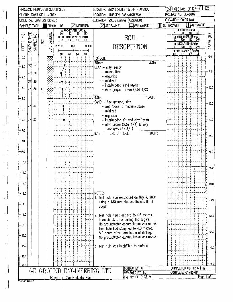
. I
]
' 1
-I
l l
'l
' 1
'l l
'1
l I
_J
0 [D
u ::!: (/) iii ::::>
CL
75mm
SOIL DESCRIPTION
ClAY - silty, sandy - moist, firm - orgamcs
·- oxidized - interbedded sand layers - dark grayish brown (2.5Y 4/2)
3.0in
4.0m 13.0ft SAND - fine grained, silty
- wet, loose to medium dense - oxidized - organics - interbedded silt and cloy layers - olive brown (2.5Y 4) to very
dark 6.1m 20.0ft
NOTES: 1. Test hole was excavated on May 4, 2001
using a 150 mm dia. continuous flight auger.
2. Test hole had sloughed to 4.6 metres immediately after pulling the augers. No groundwater accumulation was noted. Test hole had sloughed to 4.0 metres, 5.0 hours after completion of drilling. No groundwater accumulation was noted.
3. Test hole was backfilled to surface.
GE GROUND ENGINEERING LTD.
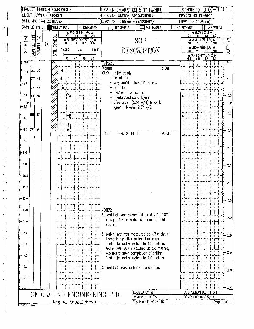
' )
J
')
J
' 1 ' J
'l ' J
I
J
PROJECT: PROPOSED SUBDIVISION LOCATION: BROAD STREET & flFTH AVENUE TEST HOLE NO: 0107-TH1 06 CUENT: TOWN OF LUMSDEN LOCATION: LUMSDEN, St\SKATCHEWAN PROJECT NO: GE-0107 DRILL RIG: BRAT 22 DIGGER ELEVATION: 99.55 metres (ASSUMED) ELEVATION: 99.55 (m) SAMPLE TYPE .SHELBY TUBE !ZJ DISTURBED IZI SPT SIWPLE § PAIL SAMPLE (JD NO RECOVERY [I] JAR S<\MPLE
e BLOW COUNT e & POCKET PEN (kPA) &
...---- Ei: o B t---'6:::::-0~Ic;.:20,__.:.,;180;:.,....,~l40"'---l _§_ ~ :z ID • SULPHATE CONTENT (%) • SOIL
DESCRIPTION
20 40 60 60 .6. VANE SHEAR (kPo) .A
:J:: ~ ::J ~ ~ 1--'0:,:.:.2_0::,:_.4:....__~0.6=--..:::0·:::..8 --1 l:i:: D.. a.. :::::>
:r: b:
60 120 180 240 • UNCONFitf:D (kPo) • w ~ ::;;:; __. PLASTIC M.C.
O(%Ul ~ 1 t UQUID
I 60 120 16(} 240 LJ.J a
0.0
1'- 1.0 ~ 33
lz 34 =- 2.0
tz 35
1'-J.O ~ 36
!: E- 4.0-
E- 5.0 • 37
E- 6.0 rz 38
F-7.0
F- 8.0
F- 9.0
F-10.0
F-11.0
1-12.0
-13.0
F-14.0
E-15.0
E-- 16.0
F-17.0
-18.0
F-19.0
20.0
20 40 60 80 +DRY DENSflY (t/m3)+ OA 0.8 1.2 1.6
V'7: : i, ·.'. .:. :,. i, ,: .:.· i, T:QPSOIL . . . . . . . . . o.o ~ ·····r·····r····r····:····r···r····:· .. ··:· .. -r·· .. '::'~5:::-m-=-m::.:..=....---------,3::-.o=:-in----'1'· .... l ... ..!. .... i ..... [ .... L .. .! ... ..i ..... L ... i..... ·
~ ~' rr r rt rrr ClAY:~:~.~:!' .. · .. ·.:·:·j· ... ·'··.: .. · .. ·.:.: .. :l.::·: .. · .. · .. ·.:.: ... ,:.· .. ·.: .. · .. ·;;·'··'·.:.: .. · .. · .. ·i····':.· .. · .. · .. ·.:·i····': .. ·.:·:·:·:·:····':.·.: .. ·: .. l ... ·'·:·: .. · .. · .. · .. : ... ·': .. · .. · .. · .. ·.:,_ 5.0 ~~ ..... ' ..... ~ ..... ; ..... / ..... : ..... ; ..... / ... ! .. )..... -very moist below 4.6 metres r
~ : i i i i : i i i - organics ~ ..... i ·r"T"T""i""T"T"T"T''" - oxidized, iron stains ..... , ........... , ..... , .......... , ..... , ..... , ..... , .... .
~ .... ! .... 1"' ·;· .... !" .. 1""T ... ! ..... i .... 1'.... - interbedded sand layers :.~ ..... ·:·[······':· .. ·:.:.~.f_ ... ··':·:·:·:·'······':·:.:.:·:·1 ... ''.,:·:·:·:·~.: ... ··':·:·:·:·:·:':···'.·.:·:·:·:·i·'·····':·:·:·:·:·1:~ ... '·:·:·:·:·:·:···:':·:·:·:·:·1-
10
:_ ~ .. T""(' \ ..... 1 .... !" .. \" ... l ..... ( .. j.... - olive brown (2.5Y 4/ 4) to dark :%.
~ ..... ; ..... ! .... j ... ..;. .. + .. +·+ .. + .. +... grayish brown (2.5Y 4/2)
I••IJ:.rr;Iil•r .. 1m END OF HOLE 20.0ft ~i••••rrllllll••·•~::: ·· ·· ·1· · ·· ·r · · · · r · · · · ~ · · · ·1· · · · r · · · ·1·· ·· -~ · ·· ·r· · ·· ·· · ··~ · · · · r · · · ·~ · · · · ·! · · · ·r·· · · r · · ··~ ·· · ·r ·· ··1· ·· · · , '.' ·f· .. , ·t,,. • f·,,,, j .. , . ·1·. •.' ~· • ... j ., , • ·~' ·•' i·' •'' ·• ·• ·• ''''·:·''''I·'" •l''' •·:· •. '' ("' '' 1"'' -:·' '' •(•"''
! : : : 1 : : : 1 ..... ,f ..... ,l .. · .. ,i ........ f ..... ,f .... ·.l· ..... I ...... L .... ~ ..... I--25.0 ..... f .... 'f .... ~ .... 'l' ... "f .... ·~ .... 'l' .... f .... } ..... .... ·~ ... , + .. , ·~·, .. ,!, .. , + .... {··, .. !· ... ·? .. •, {•.... "• • •i • • • • ·~· • • • •I• •" •) • •• .. ; .. • • • (• • •• •I• • • • .; ... • • (• • • • •
•.. ·!J·i I tJ !Lt. ::,: ~: .. , : ... ,i,, ·i, i.,J,.J,. :.: ~ ~.o ..... f ... + .. +·+ .... l .... + ... f ... + ... l ..... :: :::r,,,·· ·. · ...... ·,,,i.' .·:: ::,,,1: .·: :.· =:,,i····· ..... ·,,1.'.'.·.·.·.· '.1':.~.·: .·: ::1:.!:: :.·:.t,, ..... : ::,:.:::: :.· '•" ·~ '''' •:•.,. ·I·'. ••i • •• ··:·.,., (•,,. ·I· ·•· ·:···' •(• • •. •
::::::.:::::::.::::::i,:::::::.~::::t:::.:::::r::::!:::::l:::::~- 35.0 .... '1' .. ··j· .... j'' '''j .. ··j·· ... j· ... '1'""1''''~'''" .
•••·r1.•1 I•J•.••l••·•: T• L.• ~.':.J,:J,;l.:.:i,, i,, l:,l,,J.~. ~ ,., ::::]:::::l:::::r:::::::::r:.:r:::.I::::I:::J:::: NOTES: ..... L ... L ... L .. L. .. L .. L .. .L ... L ... L ... 1. Test hole was excavated on May 4, 2001 ::::r::r::r::r:r::r::r::rr::: -45.0
... ) ..... : ..... , ..... ! ..... : .... , ..... ! ..... ~ .... !..... using o 150 mm dia. continuous flight ..... , ..... , .... , ..... , .... , .... , ..... , .... , .... , ..... : ; : ; 1 ; : ; : auger. : : : : : : i : :
~ FI II I i ff 2 · ~~~:J:~Iy ·~~,~~~;~:~d t~! ~~~,%~Ires ·····~ ... '·[';····'i; ... ·'.[[···' •. ;: ... ' •... ·'' ~' ... ·' 1: ... ·' ·.:;···' -
000
..... f ..... f ..... j ..... j ..... j ... ) ... ) .. ) .... j..... Test hole had sloughed to 4.9 metres.
..... L .. ..!. .... L .. L .. .J. .... L .. .L. ... L...L... Water level was measured at 3.8 metres, ..... , ..... , ..... , ..... , ..... , ..... , ..... , ..... , .... , .... . i i i i i : i i i 4.5 hours after completion of drilling. .. .. .i,( .. :.:.· ..... :,i"' .. :,!" .. .i,( .. !,( .. i,i ..... i,( ... ! ... ; ..... - 55.0 ..... ! .... ! ...... !. · T'"':' ..... [' .... [ ..... f .... )"... Test hole had sloughed to 4.0 metres.
· · · · ·~ · · · · ·1· · · ·· r · · · ·1· · · · T · · · · r · · · ·1· · · · ·t .. · · ~ .. · · · · · · · ·r · · · · -r· · · ·l· · · · ·r · ... -r · · · · r · · · · r · · · T ... · r · · ·· ..... ( ..... i ..... j" ... j ..... i .. · .. j· .... j ..... i .... j ..... 3. Test hole was backfilled to surface. .. ... f ..... i ..... , ..... [ .... '[ .......... , .... '\ ..... 1 ..... ~ oo.o
:::: :i,,.::::: .1,,.·:: :::1,,.::::: ·:.i:: :: j',.:::: ::J,,.::::: :,,.1: ::: ::,,:.: :::: ;,,.r:::: · · · · ·~ · · · · ·:· · · · ·: · · · · ·~ .. · ·t · · · ~· · · .. ! ... ·t · · · · :· · · · ·
"'"f""'i'"+"+'"'i""+·+ .... : .... + .. . ... ",~: ..... :.~.· .... ~,,'· ..... ~:, ... ":,,:· .... ~,.'." ... ·:': .... -~': .... ~,,· . . . . . .... ; ..... : ..... i ..... ; ..... : ..... ( ..... i ..... ; ..... ( .... .
: i i i i ! ! i i ~65.0 LOGGED BY: JP COMPLETION DEPTH: 6.1 m GE GROUND ENGINEERING LTD. REVIEWED BY: TA COMPLETE: 01/05/04
Re,qina Saskatchewan Fiq. No: GE-0107-10 Paae 1 of 1 01/06/26 08:54AU
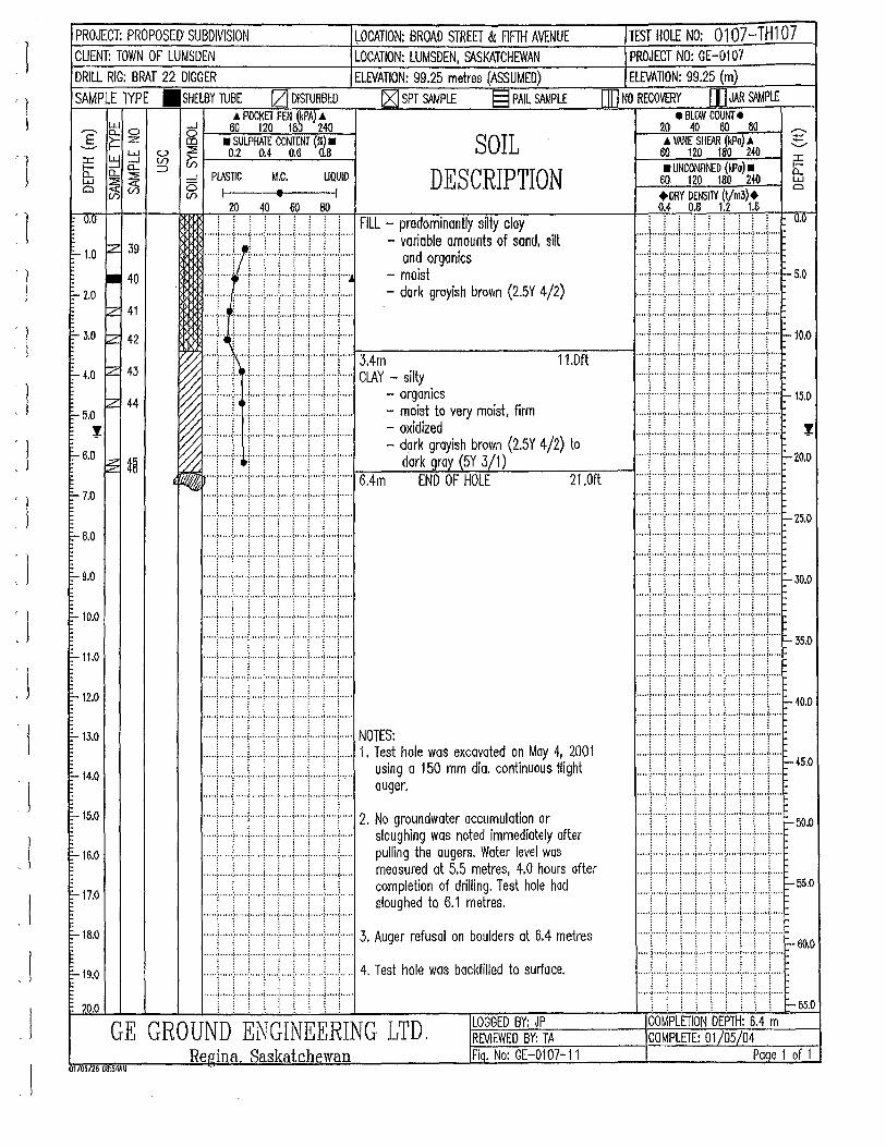
~ l ' l ' 1
' l ' J
'l
'J . J
')
' l J
: l ~ l
' l
....J 0 co
u :::l: (f) (/) ::l
SOIL DESCRIPTION
FILL- cloy - variable amounts of sand, silt
and organics - moist - dark grayish brown (2.5Y 4/2)
3.4m CLAY - silty
- organics - moist to very moist, firm -oxidized - dork grayish brown (2.5Y 4/2) to
dark
NOTES: 1. Test hole was excavated on May 4, 2001
using a 150 mm dia. continuous flight auger.
2. No groundwater accumulation or sloughing was noted immediately after pulling the augers. Water level was measured at 5.5 metres, 4.0 hours after completion of drilling. Test hole had sloughed to 6.1 metres.
3. Auger refusal on boulders at 6.4 metres
4. Test hole was backfilled to surface.
GE GROUND ENGINEERING LTD.
.--.. ...... '+-........... :::c b: L1J Cl
J
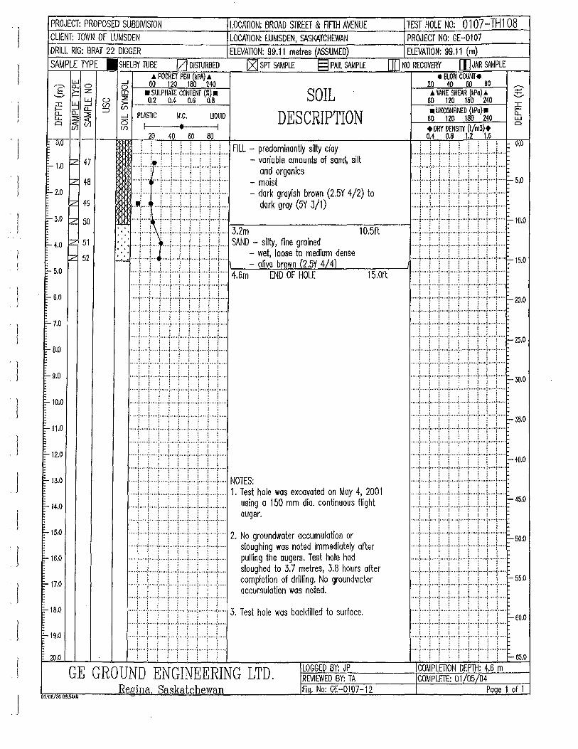
1 ' J
' l ' l I
1
PROJECT: PROPOSED' SUBDIVISION CUENT: TOWN OF LUMSDEN DRILL RIG: BRAT 22 DIGGER
SAMPLE lYPE .SHELBY TUBE IZJ DISTURBED ..\ POCKET PEN (kPA) ..\
,.--.. l5:: o 5 6o 120 1ab 2-10 S f= Z co • SULPHA1E C~TENT (%) •
~ ::J ~ ~ 0.2 0.4 0.6 0.8 ~ 0..0.. :::> ...... ::::i: ~ -l PIASliC M.C. UQUID Cl(J5(/) ~I • I
20 40 60 80
~OCATION: BROAD STREET & FlfTH AVENUE LOCATION: LUMSDEN, St\SKATCHEWAN ELEVATION: 99.11 metres (ASSUMED)
~ SPT SAMPLE § PAIL SAMPLE
SOIL DESCRIPTION
0.0 .... L .. L ... L ... L .. L ... L .. .l.. .. L .. L .. FILL - predominantly silty cloy
F- 1.0 z 47 j i i j j j j j j - variable omaunts of sand, sill
tz 48 ~2.0
~
:::::t::::·i·.:::r::::r::::-:::::r::::i::::]::::J::::: - ~~1stgonics ..... ; ......... ! ..... j ..... : ..... ! ..... j ..... ; .... !..... - dark grayish brown (2.5Y 4/2) to .. 1!!\ ....... ..j ..... j ... ) .. ..j ... ) ... ) .. ..j..... dark groy (5Y 3/1) 49
F-J.O z 50
F- 4.0 lz 51
~ 52
E- 5.0
. 1'-- 6.0
F-7.0
F- 8.0
F- 9.0
F-10.0
F-11.0
1-12.0
F-13.0
;:...14.0
:-15.0
;:... 1&.0
F-17.0
E-18.0
F-19.0
20.0
·. ·. :::::!::::t:·t:J:::f::::J::::r:::l::::l::::: 3.2m 1 o.5n :::: .... L .. .L ... ' ... .i.. ... L ... L .. .L .. .L .. i... .. SAND - silty, fine grained > > ! ! . ! i i ! i ! - wet, loose to medium dense
~-'--' ..... [ .... T .. : .... : .... T .... 1"' .. : ..... 1 .... 1"' .. Jt - olive brown (2 SY 4/ 4) ... ·1 ..... ! .... +·+ .... 1 .... + .. + .. + .. + ... 4.6m END OF HOLE
::::r::::j:::::r:::::::::r:::r:::r:::r:::r:::
:::::1::::t:::t::::l:·:::t:::·t::::!:::::l::::t::::
·····I····J····l .. ···l·····l·····l·····!··· .. l····l··· .. . .. .. i ..... l ..... ~ ..... i ..... ~ .... ~ ..... j ..•.. ; ••.• ~ ••.•.
..... ! ..... ! ..... j ..... j .... ./. .... j ..... j ..... ! .... j .... .
.... J ..... t .... J. .... ~ .... J. .... i ..... l ..... ~ .... !. ... .
::::r:::l:::::r::r:::c::J:::::.:::::/::::1::::: · · · ·l· · · · ·~· · · · · J. ····I·····!· .. · ·I··· .. i ·····f .. · ·I··· .. .... '~"'"i'·"' ~· ... ·!." ·+" .. ~-·' .. ! ..... ~ .... ~ .....
••••l••·•l.••Li tfl••!r••· :::::r:::::.:::::J::::::::::J::::l:::::j:::::;::::t:::: NOTES:
15.0ft
... ) ... ) .... ; ..... ; ..... ~ .... ( .. ) ..... ~ .... ; ..... 1. Test hole was excavated on May 4, 2001
..... ; ..... : ..... ) ..... i .. ) ... ..j ..... [ ..... l .... )..... using a 150 mm dia. continuous flight
..... l .... J. .... ) ..... l ..... l. .... ! ..... l. ... .l .... i..... ouger .
... .l.. ... , ..... j ..... , .... l .... j ..... ~ ..... I ... .J.. ... 2. No groundwater accumulotion or
..... f .... + ... + .. + ... + ... + .. ·! ... + .. +·.. sloughing was noted immediately after
... ..\ ..... [ ... ..j. .... j ..... j ..... ] ..... j ..... ; .... ]..... pulling the augers. Test hole had
..... L .... L ... L. .. .L. .. .L .. .i.. ... i ..... L...L.. sloughed to 3.7 metres, 3.8 hours after
..... L ... L ... i.. .. .f.. .. .\.. ... i.. ... l ... ..l .... L.. completion of drilling. No groundwater : : ! : : l ! l : accumulotion was noted.
..... i ..... ; ..... ( ..... j •.••. : ••.•. ( ..... j .••.• ; .... ( ••.••
..... : ..... ! ... ) ..... \ .... ! ... ..\. .... j ..... ! ..... j ..... 3. Test hole was backfilled to surface.
..... ~. ' .. J ..... i ..... l ..... t .... l. ... 0 ~ ••••• t .... 1 .... .
..... ! ..... ! ..... i ..... l ..... : ..... .:, .... i ..... \ .... j ... ..
..... ~ .... .t .... I ..... ~ .... J .... L .... ·l ..... t .... l .... . l 1 ~ l j ~ ~ i i
LOGGED BY: JP GE GROUND ENGINEERING LTD. REVIEWED BY: TA Regina Saskatchewan Fiq. No: GE-0107-12
U06126 08:54AM
TEST HOLE NO: 0107-TH 1 08 PROJECT NO: GE-0107 ELEVATION: 99.11 (m)
Q0 NO RECOVERY [)]JAR S<IMPLE eBLOW COUNT e
~~2~0~4~0~~00~780~~ ~ .6 VANE SHfAR (kilo) A ~
60 120 lBO 240 • UNCONFINED {kPa) •
60 120 180 240 +DRY D£NSJ1Y (t/m3)+ 0.4 0.8 1.2 1.6
I
I:L w a
IIII 11ill ~::
:::::f::::f::::,:::::,::::r:::r::::l::::f::::r::: ~ zo.o
::::I:::::::::::::::::~:::::r::::r::::~::::r:::r::: ..... , .... { .. ··: ..... , .... -j- ... +···1····{ .. ··1"'" ~ 25.0 ..... , ••.•• ; ..... , .••.• ; ..... ; .. •••{••·"1"'"; ..... , .....
·····f····J .. ··I .. ···I·····!· .. ··l-···-1-···I· .. ·l·····
::::r::;.:::::::::r:::I::::r::::l::::r:::r::::~ 30.0
:::::r:::::::::::r::::~:::::.:::::r::::r:::l::::r::::~ 35
·0
. .... )·····:·····1·····)· ····:·····~·····1·· .. ·:····•(••••.
ill1ft 1 1i ~~.o ·• 1••·•rt 11• r 1 rr~ .. , lJI1I! ltl ~oo· ·· .. ·l····}· .. ·l·····t .. ··-1-·· .. l .. ···l·· .. ·r· .. ·l· .... ~ ss.o · · · · -~ · · · · ·j· · · · ·!· · · · ·r · · · · ·l· · · · · ~-· · · · i · · · · -~· · · · ·l· · · · · .. .. -t·····J·· .. ·j·····t·····J·····J·····!····t· .. ·J· .. ··-60.0 oOooo}ooooo!oooo•l.,•o•)•••••:•••••(oooool•••••:•••••(oOoOO
:::::l::::r::r::r:::.:::::t::::!::::r:::l::::: ! i i : i i ! i i ~65.0
COMPLETION DEPTH: 4.6 m COMPLETE: 01/05/04
Paqe 1 of 1
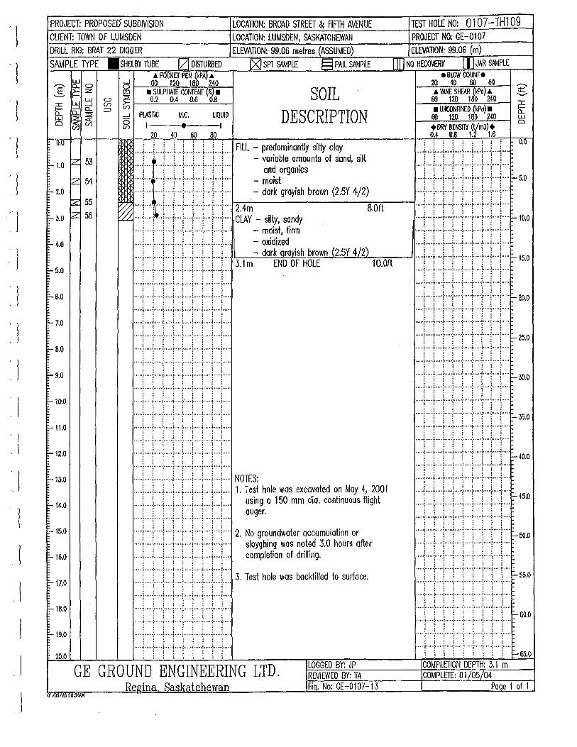
' l
' l I
' ! ' l l
'l
PROJECT: PROPOSE(} SUBDIVISION LOCATION: BROAD STREET & FIFTHAVENUE CLIENT: TOWN OF LUMSDEN LOCATION: LUMSDEN, SASKATCHEWAN DRILL RIG: BRAT 22 DIGGER ELEVATION: 99.06 metres (ASSUMED) SAMPLE lYPE .SHELBY TUBE IZJ DISTURBED [ZJ SPT S<\MPL£ § PAIL SAMPLE
.A POCKET PEN (kPA) -" ~ 0 __J 60 120 180 240
]: ~ z: g • SULPHAlE CONTENT (%) • ~ ~ ~ ~ 0.2 0.4 0.6 0.8 SOIL
DESCRIPTION iii: 0.. 0.. ::::J w :::::!!: ~ ....J PIJ\STIC M.C. UQUID 0(%(1) ~I t I
u.u
E-- 1.0 ~ 53
rz 54 1:- 2.0
~ 55
b- 3.0 ~ 56
1:- 4.0
,-- 5.0
-6.0
=-7.0
~6.0
1:- 9.0
~10.0
::- 11.0
:--12.0
1:--13.0
1:- 14.0
E--15.0
t:-16.0
E-17.0
t:--18.0
E-19.0
20.0
20 40 60 80
..... ( ..... L .. L ... i .... L .. J. .. L .. L .. L .. FILL - predominantly silty cloy ! • ! ! ! ! ! ( ! - variable amounts of sand, silt ..... i .......... ( ... T ... r .. T···r ... i ... T... and organics
..... ~ ... ~ ..... j ..... i ..... )" ... j ..... ! ..... ! .... 1..... - moist
..... ~ ........ ; .... + .... ; .... + .. + .. + .. .;..... -dork grayish brown (2.5Y 4/2)
V/ ... + ... r ... + .. +· .. ·!- .. ·+·+ .. + .. + .. -2.4m a.on ~ ..... ; .... ;t .. ; ..... : .. + .. + ... + .. + .. +· .. CLAY - silly, sandy
..... j ... ..t- ... j ..... j ..... [ .... j ..... : ... + .. +... - moist, firm
.... .L ... L ... i.. ... i .. .J .... L .. .L. .. .L ... i..... - oxidized i i i ! \ \ \ \ \ - dark aravish brown (2.5Y 4/2) ..... i .... f .. T ... f .... '[" .. ("'T .... f ... T ... 3.1 m END OF HOLE 1 O.Ofl
· ····r·····r····1···· ·~ ····r· ···r····1·· ···r ····r··· ·
•J••••r•lt••••rr:J•• 1•·•· .... ·~' .. ·t ... '1''' ··i .... '1'' ... ~- .. ''i' ····~····i····. .... ·f ... ··~· ... ·1· ... ·1· ... ·~· .... ~- ... ·1· ... ·f ... -~· ....
::::t::r:::c:r::r:::r::r::r::r:::: •••••••.••. : .•••• ( ..... j •.••. : .•••• ( ..... j ••••• ; •••• { ••.••
........... : ..... ! ... ..j. .... : .... + .. ·l ... + .. ·l""' ::::r:::.:::::r:::r::t:::r::r::t::t::::
:::::t::::r:::t:::r:::r:::r::r::r::t:::: ·····I···· ·j· · · · ·1· · · · ·1· ·· · ·!· · · · ·1· · · ··1··· · -~ · ·· ·1· · ·· ·
:::::r::::t::::r::::!::::t::::j:::::::::::l::::l::::: NOTES: .. ) .. .) ..... ) ..... [ ..... [ .. ,..! .. ) ..... ~ .. ) ..... 1. Test hole was excavated on May 4, 2001 ..... \ ..... L. .. i.. ... : .... .L ... L. .. \.. .. .\.. .. L.. using a 150 mm dia. continuous flight ..... ~ ..... f ..... ) ..... ) .... J .... J,.. .. j, .... ~ .... j..... auger .
..... , .... .j. .... j ..... , ..... ~ ..... j ..... : ..... , .... j ..... 2. No groundwater accumulation or
..... f .... ] .... ·] .... ·] .... ·l- .... ] .... ·l ..... f .... J..... sloyghin~ was n~t~d 3.0 hours after
..... ; ..... ~ .... j ... + ... .:- ... .;.. ... : ... + .. +... completion of dnlhng. : : : : : : : : :
. ' .. -~· ,, ··1· .... i··· .. ! .. ···l·····i·. ''. j·····~···' i· ... .
..... 1 ..... \ .... } ... 1 .... ·! .... + .. ·1 .. ·+ .. + ... 3. Test hole was backfilled to surface.
·····~····+· ... ~-····!···. + .... ~-·· .. !···. -~··· ·!··· ..
·····l····-:-····l· .. ··f····I·--·1·····1·····1 .. ··1·····
:.::r:.r:::r::r::r:::r::r::r::r:::: ·····:····t···•j••••·!··"t''"!''"'!'''''t''''j'"''
LOGGED BY: JP GE GROUND ENGINEERING LTD. REVIEWED BY: TA Reeina Saskatchewan Fiq. No: GE-0107-13
01/06/tG 08:54AM
TEST HOLE NO: 0107-TH1 09 PROJECT NO: GE-0107 ELEVA110N: 99.06 (m)
DD NO RECOVERY [I] JAR SAMPLE t BLOW COUNT e
20 40 60 80 .i. VANE SHfAR (kPo) .A
60 t20 180 240 • UNCONFINED {kPa) • ro no 1ao 240 +DRYVt:NSHY (t/m3)+ 0.4 0.8 1.2 1.&
[ : i i i i : i i o.u ""')'"'':"'''l"''')•••••:•••••(o .. ool••••'.•••"(ooooo
JJitlllttH· ..... l .... t .... l ..... , .... f··"l'"'~-"''f· .. ·l····r-tO.O .... ·:····:····:·····:····:·····:·····:· .. ·:····:·····
I j·j !•!••••! I l••••f~ !0.0
::::r::r::r::r::I::::r::::r:::I::::r:::r- zo.o ·····~····r····~·····~·····r· ·· · r ····~····r····r···· ..... ; ••••• : ••••• j ••••• ; ••••. : ••••. .c ••••• j ••••• : ..... r ..•••
..... , .... .;. ... .j.. ... [ .. ··J· .. ·l-· .. ·l· .. ·f .. ··l· .. ··l:- 25.0
.... -~ ... ··~. "'! .. ···~ .... ·:· .... ~· .... ! ... ··:· .... ~- ... .
..... l ... + .. ·l ... + .... l .... + .. ·l ..... i .... + .. . "'"t'"''f""i""''l'"''i'"'j'"''i"'"!'"''j""' f-- 30.0 .... -~ .... ·j· .... ~ ·····~· .. ··;· ... 'l' ... 'l' ... -~·· .. ·j· .... • • • • -~ ••••• : ..... j ••••• ; •• 0 •• : ..... ( ••••• j ..... : ..... ( •••.•
..... !····-1-· .. ·I .. · .. I··· .. :····J.·· .. I .. ··-1- .... 1 ..... r 35.0
... ··• .... -: ..... , .... ·•· ... ·=· .... ~· .... , .... ·:· •• '. t•• .. .
····l····[ ... l .. ·l····-i-····1··· .. 1 .. ···l .. ···l·· ... r ····'['···t"·t"t···t····j·"··:····t"''j""' r- 40.0
::::r::rr:::r:::r::r::r::Fr::: '""\""t"'T'"'\"'"(""1"'"\""(""1'"" f-- 45.0
::::r:r::r:::r:r::r::r::r::r::: ""("j' "j""'l""'\'"''l'""i""t""j"'"r- 50.0
::::r::rr::r:::r:::r::r::r:::r::: ..... :····t·"'l'"''t'"'t····j·····:····t····:·····~ 55.0 ..... ~ .... 'i' .... ~ .... '1' ... 'i' . ' . 'l' ... 'l' ... 'i' .... ·t ..... ..... ; .... ~ ..... i ..... ; ..... : ..... ( ..... j ••••. : ..... <·····
: : : : : : : : :
..... , .... I .... ! .. ···!· .. -I----l·····i .... I- ... ·1····· f-- 60.0
.... '! ..... ~ ..... ~-· .. '? .... -;- .... ~- ... 'l' ... 'l' .... ~- ....
····-!-·"-1-'"'''"''1''''-l'····:··"-1-····:·····l····· ..... ; •.••. : ..... j ..... ; ..... ; ..•.. c .•... j ••••• ; ••••. .( •••••
\ \ \ ! ! j i i i r- 65.0 COMPLETION DEPTH: 3.1 m COMPLETE: 01/05/04
Paqe 1 of 1
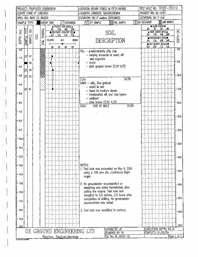
' l
l 'l
J
'l ~ l
1 ' !
l : l
. I
PROJECT: PROPOSED SUBDIVISION LOCATION: BROAD STREET & nFTH AVENUE TEST HOLE NO: 0107-TH110 CUENT: TOWN OF LUMSDEN LOCATION: LUMSDEN, St\SKATCHEWAN PROJECT NO: GE-0107
DRILL RIG: BRAT 22 DIGGER ELEVATION: 99.17 metres (ASSUMED) ELEVAllON: 99.17 (m)
SAMPLE 1YPE .SHELBY TUBE IZJ DISTURBED [ZJ SPT S<WPLE § PAll SAMPLE (]] NO RECOVERY [)]JAR SAMPLE 4 POCKET PEN (kPA) 4
,--... ~ 0 ....J 60 120 180 2.40 _§. j::: Z ~ • SULPHAlE CONTENT (~) • SOIL
DESCRIPTION
• BLOW COUNT • ~--~2""'-0..,..,~40~~60f:-=-;..::..:80'----j -:::>
4 VANE SHEAR (kPo) 4 ~ 60 12.0 180 240 :c w ~ ~ ~ 0.2 0.4 0.6 0.8
b:: 0: ~0.. :::> ~ • UNCONF!tf:D {kPo) • w :::1: .....1 PlASTIC M.C. UQUID 0 .(75 g I t I
60 12.0 180 2.40 w a
0.0
~ 1.0 z 57
• 58 =- 2.0
~ 59
::- 3.0 ~ 60
b- 4-.0
IZ 61
b- 5.0
=- 6.0
E-7.0
b- 6.0
=- 9.0
i=-10.0
E-11.0
E ~12.0
E-13.0
E-14.0
b-15.0
~16.0
;:... 17.0
=-18.0
=-19.0
20.0
+DRY DENSITY (t/m3)+ 0.4 0.8 1.2 1.6 20 40 60 80
.... L ... !.. ... L .. .i.. ... \ ..... J... .. i.. .. L .. L .. FILL - predominantly silty cloy .... .L ... l.. .. i ... J .... L .. .L .. .L .. J.. ... L... o.o
~~tiiJJ til; -~~~~~~:nls of sond, sill ·.· .. ·: ... ·:··,': ..•... · .. · .. · .. ·:·· ..• ':,.: .. · .. ·: ... ·l' .. ·',':·:·:·:·:·~: ... ·'···.··.··.··.·:·.';.::.·:·:·:·,··,:~ .. :·: ... · .. · .. ·';· .. ··''.J'· ... ''i ... ''.:: .. :-s.o ..... 1 .... { ... -j- .... I .... J .... I ..... : ..... ) .... J..... = dark grayish brown (2.5Y 4/2) , .. , .j .. ,, , .;.~,. ~·,,,,!,,, ·+,,,, ~·,, .. !,,,, •} .,,, !•,,., , , , ••J,,., •:•,,, •I,.,, ·~,,, · .;. , .. •f• •, ool• •, .. ;. • '" (• • •"
:. :. ::::I:::! :::r::r.:LJ::::J::J:::J::::f-c:3-::.2-m---------:-1 o::-:.5:-::ft:-------l· .. ··l····l····!·····l····-t .. ··j····l-+···1·· ... -lo.o . • ' ' ' ' ' ' ' ' ' SAND 'It fi ' d ·. · ...... : ... ..:. ... ! ..... i .... l....! ..... : ..... : .... i..... - s1 y, me gr01ne
· · · · ! ! ! ! ! ! ! ! i - moist to wet ,:_,_:.., ..... ! ..... ~ .. j" ... j" ... ( .. j""'j""'("\""' - loose to medium dense ..... [ .... 1 ..... \ ..... [ .... '[ .... j .... ·[· .... [ .... \..... - interbedded silt and cloy layers ..... ; ..... ~ .... ; ..... ; ..... ! ..... ; ..... ; ..... ; .... ;..... - oxidized ..... i ..... ~ .. ) .. ) .... ] ..... !, .... j ... ) .. ).... - olive brown (2.5Y 4/ 4) ..... ~ .... , ..... j ..... , ..... , .... .j.. ... , ... + .. -1-- ... 4.6m END OF HOLE 15.0ft ..... f .... 1"' .. j"'"[""'[""j""'j""l"'T'" ..... ; . , . , .. ~.,., ~ ..... i ..... ~., .. , ~., ... i,,, .. ; .... i .. ,,, , · · · •) · •, · ·:· · · · •I• • • • •l• • • • ·:· • • • • (• • '"'' •" •:•" •• {• • •"
..... l·· .. ·!·····l·····l· .. ·-1-····l·····l·····l····l .. ··· ·· .. ·1····-f····l··· .. l ..... : ..... j ..... I .. ··I- .... l .. ···- 25.0 "" .; • • oo!. • • • • L,, o ,j, o, •• ~. • • •, L,, o, i .. ,, ,~ o, o .i., o,. o oo • ·~ o" oo;. o • o •I o • • ") • o o • •:• o o o • ~· • • tojo .... ;," "(o • • • o
~ ~ l l l i 1 l ~ ....... ; ... J ....... ~.; ..... :.~ ..... :.~ ..... :.; ..... : ....... ~.~ ....... ~ ... .. . . .. . ; .... -~· ... ··~· ... -~ .... -~·. ' .. ~· ... ·1· ... ·f ... ·1·· ...
··· :····i···t···i··+ +· :··· (····\· • t••1•• r i.I•lll•i····-"·' :::::r::::r:::t::::j:::::;::::r::::::::::l::::r:::: ..... , ................. , ....................... , .......... . ..... t. ... .:. .... ! ..... : .... .: ..... ! ..... i ..... \ .... !..... . .... f .. ··{····j····-!-· .. -1-· .. ·J-····l .. ·+···\·· ... r 35.o .... .l ..... l ..... l ..... ! .... J .... ! ..... i ..... ~ .... )..... , .... , ..... , ..... , ..... , ..... , ..... , ........... , ..... , .... .
. . . . . . . . . ; l l i ~ 1 ~ 1 l
:::::t::::t::::r:::r:::::::::l:::::l:::::l::::J:::::: .:.::.: .. _.: .. :::r.:.:·:·,·.:.:.:::,_: .. :· .. :.:,:.··.:.· .. :.r:-.·.:.:.~~.:·:···.:E··r:.::~40.0 ..... t .... L ... L .... l .... .L ... L .... ~ ..... ~ .... L.... .. ~
..... \ .... j ..... j ..... j ..... ~ .... j ..... ; .... [ .... ! ..... NOTES: [ j. L \ ; ~ ... L .L .. L ..
..... : .... ~ .. ) ..... j .. .) .. .) ..... j ..... : .. .,i ..... 1. Test hole was excavated on May 4, 2001 ::::r::r,:::, .. :::r::.r:::r ... j .. :.} .... j ..... ~ 45
.0
::::r::r:::J:::::I::::.r:::;:::::r:::r:::J::::: ~~~;r.a 150 mm dia. continuous flight :::::l:::J::::i:::::I:::J:::J::::I::::L::J::::: ... -<.=.' ..... :,' .... ·:.'.· ..... :.'.· ..... ,.'.' .... :,' .... ·!.·.' ..... ~.' .... :.' ...... 2. No groundwater accumulot1'on or .... .l ..... l ..... i .... J .... J .... J ..... i .... l .... ] ..... \ l i : i \ i ! i -50.0 .... : ..... : ..... j .... .j. ... ; .... +·+ .... : .... ;..... sloughing was noted immediately after ..... , .... , ..... , ..... , ..... : ..... , ..... , .... , .... , ... .. ..... ~ ..... j ..... ) ..... [ .. ..j ..... ) ..... [ ... .,f .... ;..... pulling the augers. Test hole hod ..... f .... J ..... ~ ..... ~ .... j .... j .... -1- .. l ... J .... .
..... L .... L ... L .. L. .. .L ... L. .. L. .. .L ... L.... sloughed to 4.0 metres, 2.5 hours after ..... [ ..... : .... t .... [ .... ( .. \· .... j .... t ... ·j· .... r- ss.o
.... .! .... }····:·····l····r····j·····i·····l····l····· ~~~J~e~:~~0~f ~;~li~;te~~ groundwater ·····:·····;·····:-····:··· .. ;·····:··· .. 1 ..... ;·····r····
..... ; ..... : ..... i ..... i ..... ; ..... { ..... i ..... ; .... i· . . . . • ... 'l' ... -~· ... "l' ... '1' ... ·j· ... 'l' ' ... ~ .... ·j· ... '1' .. "
.... ! ..... ! ..... J ..... ! ..... : ..... J .... .i.. .. ( .. ! ..... 3. Test hole was backfilled to surface. .. ... l ..... j" ... ( ... j ..... ( .. ("'j""'j"'"j"'" ~ 60
,0
.. · · -~· · .. ( .. · ~ .... ·1 · · · .. ~ ..... { ... · .[ ..... } .... {..... . .... ! .... ·1· ··· ·1 · · · · ·r ..... j ..... t· .. !· ... r ... r .. ..
.. .) .... .: ..... ! .. ...! ... ) .... ! .. ... I ..... j ... .. !.. . .. . .... L :. .. .. \.· .... :.L. ... L :.· ... ii ....... ::." .. ·:! ...... !:." .. 'li ..... . ~ ! ~ ~ i i ~ l j
..... ; ..... ; .... '{ ..... i ..... ; ..... i· .... i ..... ; .... ~..... . .... ; ..... : ..... j .... -~ .. ' .. : ..... ( ..... i ..... : ..... ( ..... : . : . . . . . . .: '.: ·.: .: .: .: .: ·.: .: -65.0 l 1 1 j ~ l j ~ ~
LOGGED BY: JP COMPLETION DEP1H: 4.6 m GE GROUND ENGINEERING LTD. REVIEWED BY: TA COMPLETE: 01/05/04
Re.Qina Saskatchewan Fio. No: GE-0107-14 Paqe 1 of 1 01106/26 08:li4AI.I
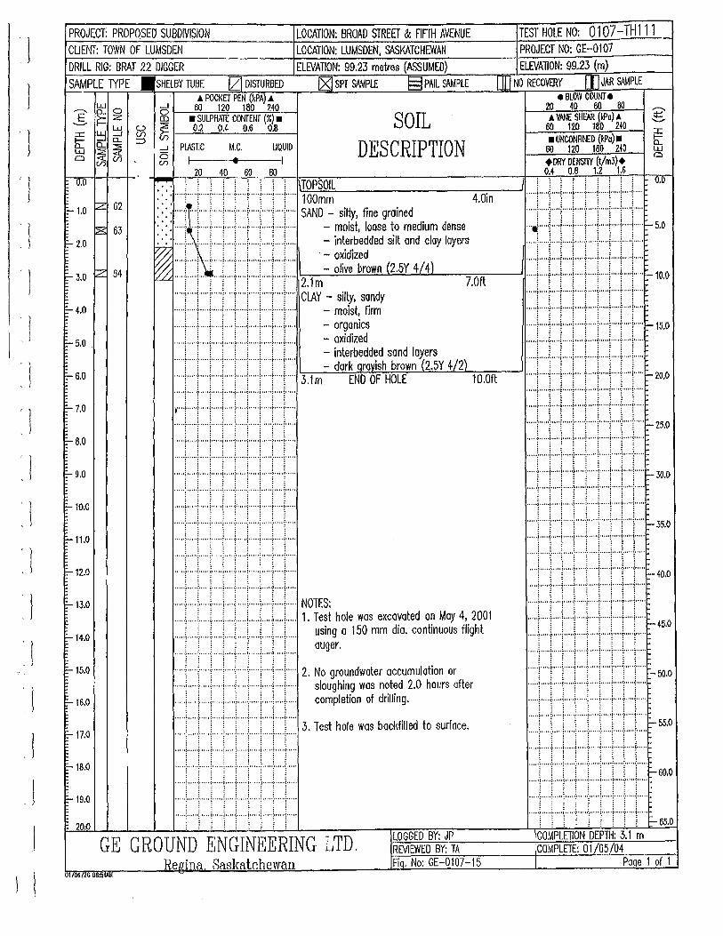
. I
J
' 1
1
I I
. I
·' ' I l
'l ' 1
'J
' l ·. l
'l
'l .l
l I
PROJECT: PROPOSED SUBDIVISION LOCATION: BROAD STREET & FIFTH AVENUE CUENT: TOWN OF LUMSDEN LOCATION: LUMSDEN, SASKATCHEWAN DRILL RIG: BRAT 22 DIGGER ELEVATION: 99.23 metres (ASSUMED)
SAMPLE lYPE .SHELBY TUBE I2J DISTURBED IX) SPT SAMPlE § PAIL SAMPLE 4 POCKET PEN (kPA) £
....-... lf 0 _J 1--..._::::60'---~12~0 --l18!'.!:0~2::;.40~-l __s f=: Z g • SULPHA1E Ccr-.JTENT (~) • SOIL
DESCRIPTION :c ~ ~ fA ~ l-_;0::.::.2:._..!!.:0.c::_4 ___::0:,::::.6_0~.8!....--l e; Q_ ~ :::> ...J
a~0!J 6 (/) (/)
PLASTIC
I 20
M.C.
• 40 60
UQUID I
80
TEST HOLE NO: 0107-TH111 PROJECT NO: GE-0107 ELEVAliON: 99 .. 23 (m)
[]] NO RECOVERY I1J JAR ~PLE e BLOW COUNT e
20 40 60 80 .A VANE SHE'AR (kPo) 4
60 120 180 240 • UNCONRf'.£1> {kPo) •
60 120 160 240 +DRY DENSilY (t/m3)+ 0.~ 0.6 1.2 1.6
~ : : ! . . . , , \!.!TO::::P~SO~IL'---------~-..-l
~: ~: ::::r::r:::t:::r:::·:::::j::::r::r:r::: ~~~~~ silty, fine grained 4
.0in
o.u 0.0
10- 1.0 tz 62
~ 63 10- 2.0
r- 3.0 ~ 64
1-4.0
f:- 5.0 .
c- 6.0
"- 7.0
;.... 6.0
;.... 9.0
;....10.0
c-11.0
:;_ 12.0
10- 13.0
F-14.0
E-15.0
F-16.0
1-17.0
10-18.0
1-19.0
~ 20.0
• • • • ..... ; ... f ..... j ..... j ..... f .... ;...+ .. + ... j..... - moist loose to medium dense : : : : : : : : : J
;.;,; .... (. ~ ..... ~ ..... : ..... ; ..... ; .... -!-.... ) .... ;..... - interbedded silt ond cloy layers ~ ! ' : ! ! ! : ! ! · - oxidized ~ ::::r:::r.::·:·:::r:r::r:::r::r:::;::::: -olive brown (2.5Y 4/4)
! ! ! : : ! : ! ! 2.1m 7.0ft
::::r::r:::r::r::r::r::r:::r:::r:::: ClAY~ ~~Yst, s~~ ..... [ .... 'j' ... ')' .... ! ..... [ .... )" ... j .... T .. T... = ~~f~~~cds .. ... 1 ..... 1 .... T ... l ..... i .... 1" ... l .... T .. T"' - interbedded sand layers ..... f ..... \ .... '\' ... T .... \ .... T ... 1 .... T' .. 1""' - dark grayish brown '(2.5Y 4/2) ..... l .... '\' ... \" ... \ ..... \" ... ( ..... j ..... l .... \" ... 3.1 m END OF HOLE 10.0ft · · · · ·1· ·· · ·t· · · ·~· · · · ·1·· ·· ·r· · · ·1· · · · · ~ · ·· · ·l·· · ·1· · · · · ;····r·····l· ·· · ·1··· ··~··· ··~···· · ~·····!···· ·t····~····· ·····i·····:·····j·····i····:·····j·····!·····t····j··· .. ..... ~ ..... l··· .. ~ ..... ! ..... ~ .. ". ~ ..... ! ..... ~ .... ~ ... ..
••••• } ••• ··~· •••• { ••••• ~ •••• ·~· •• 0' ~·' ••• ~ ••••• ! ..... ~ .... . .... ·1· ... ·l· .... ~· .... ! .... ·~' ... ~· .... ~ .... ·~ .... ~·· .. . ·····!····I····!·····!·····!·····!·····!··· .. !·· .. ! .. ··· .... ·t .... ·i· . ' .. ~' .... ! .... . ~: .... ~- .. ' . ! ..... ? 0 ••• ~ .... .
..... ; ..... ( ..... ; ..... i····,l, .... j ..... , ..... ; .... j .... . ·····[·····i·····i·····\·····:·····i·····i .. ···!····i·····
:::::.::::r:::.:: .. :,.::.:,::::r::::,:::::\::::.:::::
:::::r:::t::::r::·:i:::::::::::r::::r::::~::::r:::: NOTES: ..... \ ..... \ ..... ( .. ..,! .... .L..,! .. .) ..... ~ .... ) ..... 1. Test hole wos excavated on May 4, 2001 ..... ~ ..... t .... j ..... j ..... : ..... j ..... j ..... \ ... .j..... using a 150 mm dia. continuous flight ..... \ .... !.. ... ; ..... [ .. ) ..... [ ..... \ ..... \ .... ;..... auger.
· ... , ..... f .... ( ..... : ..... , .... j ..... l ..... ! .... j ..... 2. No groundwater accumulation or ..... f ..... : .... + ... ; ..... : .... j ..... ! ... + .. +... sloughing was noted 2.0 hours after ..... ! ... , ..... j .. + .... , .... + ... ! ... + .. +... completion of drilling.
..... [.""[""!""'!"'"("\ .... ! ..... ! .... \ ..... 3. Test hole was backfilled to surface.
.... '1' ... 'i' .... ·~ .... '1' ... '( ... '1' ... ' j .... '1' ... ~ .... '
..... t ... ·t····r···:····'!'····j·····t .. ···t····t···· '''''f'''''(''''1'''''j'''' '{'''''1'''··~···"1'"''1'''"
:::·:;::::r:::r::::::·::I::::r::·:l:::::r::::r:::: . ' ... t .... ·~· ... ·i· .... ! .... -~· . ' . ·i· .... ~ ..... ~ ... ·1· ....
1 ; ; ~ l ~ ; l 1 LOGGED BY: JP GE GROUND ENGINEERING LTD. REVIEWED BY: TA
Reaina Saskatchewan Fiq. No: GE-0107-15 01106126 08:.!i4AU
..... j ..... j ..... j .... l···l· .. ·l·····l····-1-··"1·····~- 25.0
i\lltiltt.••••-~·· :::::::::::t::::~:::::r::J::::r:::r::r::r::::- 35.0
..... , ..... :···"1""'}''''':·····(·• .. •1""':'""(•• ...
i!!+li il\ -~· 1!\l\iil\HSO rrrrl••·r+rl·•··c- ~·
:::::!:::::r::::!::::I::::J::::r:::r:::r:::r::::- 55.0
... ··~·· .. ·:· ...... ····>·····=·····<···· ·1·····:···'"(·····
·····l·· .. }····l·· .. ·l····-1-····l·····j·· .. }····l· .. ··~- 60.0 • • • • ·~ • • • • .;. • • • •I• • • • ·~ • · • •• ; .. • • •I• • • • •I• • • • •:• "• •<• ""
.... .f. .. ..:. .... !·····I····-l-····\ .... ·1·····!·····1·····
. ' .. ·~ ... ' .( ..... ~ ..... } .... -~ .... { ..... ~ ..... j .... '{ ..... i : i ! 1 : ! : 1 1- 65.0
COMPLETION DEPTH: 3.1 m COMPLETE: 01/05/04
Poqe 1 of 1
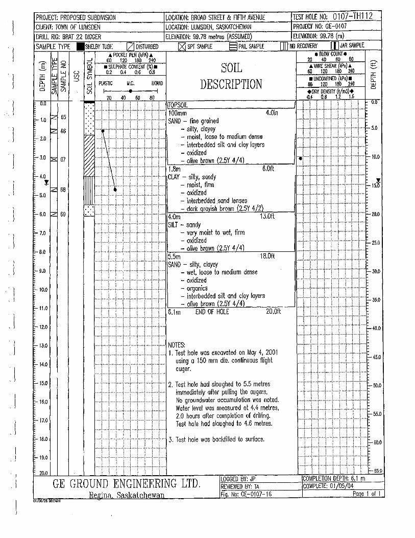
')
j
. ' t j
' l
'l .· l
' \
'1 ' I
' l
l
PROJECT: PROPOSED SUBDIVISION ~OCATION: BROAD STREET & FIFfH AVENUE CLIENT: TOWN OF LUMSDEN LOCATION: LUMSDEN, SASKATCHEWAN DRILL RIG: BRAT 22 DIGGER ELEVATION: 99.76 metres (ASSUMED)
SAMPLE 1YPE .SHELBY TUBE [Zj DISTURBED IZ] SPT S4.MPL£ § PAIL SAMPLE & POCKET PEN (kPA) .&
LJ.J _.J 60 120 180 240 r-..E o.. o o !----=---'=--'-=-~~-! .._.. ~ z co • SULPHATE CONTENT (%) • SOIL
DESCRIPTION ::c ~ ~ ~ ~ 1--_;0::::,2;___:::0•::.._4 _..:-.0~.6_0::::.8:....__-l l:i:: 0.. 0.. ::;l
::s ~~ 6 V) (f)
PlASTIC I
20
M.C.
• 40 60
UQUiD I
80
TEST HOLE NO: 0107-TH112 PROJECT NO: GE-0107 ELEVAllON: 99.78 (m)
OJ] NO RECOVERY [I] JAR S!IMPLE • BLOW COUNT •
20 40 60 80 A VANE SHEAR (kPo) .&
60 1ZO 1 80 240 • UNCONFINED {kPa) •
60 1ZO 180 240 +DRY DENSITY (t/m3)+ M o.a 1.2 u
0.1} ~ : : : TOPSOIL :::: ..... r ..... l ..... ! ..... !"" ... ( ... i ..... ( .. ( .. ! ..... ~1o::.::o=-=m.::;m:.:._ ________ ---:-4-::.o.,....in _ ___,
~: ~: ::::r::r::r::r:::r::r:::r::::j:::r::: SAND--sfi~~ ~~~~~;d . ~ ... + ... ; ..... 1 .. -+ .... } ... .;.. ... ; ... ..;. .. +... - mo1st, loose to med1um dense '% ..... i .. ·l ..... l ..... j ..... j ..... j ..... l ..... ~ .... ;..... · - int~~bedded silt and cloy layers
~ .. -+ ... ' .... -j-- .. -! ... + .. -J--· .. 1 ... + .. +... = ~~~~z~~own (2.5Y 4/4)
~ ::::r::t. .. :r::::r::r::r::::r:::r::r::: 6~~- silty, sandy 6.0ft
..... 1 .... j .... i ..... ! .... + .... j ..... i ..... i .... j..... - moist, firm
..... L .. .i .... , .... .i. ... .L .. .L ... L.. .. L ... L.. - oxidized ~ : : \ ! ! ! ! ! - interbedded sand lenses
: : ..... [ ..... [ .... \'" ... [ .... "!" .. T .... [ ..... ! ... T.... - dark Qravish brown (2.5Y 4/2)
~ ::::r::r::r::r::r:::r::r:::r:::r::: ~i~f- sandy • . 13.0ft
..... ! ..... i ..... i ... + .... i ..... i ..... ! ..... ~ .... i..... - very m01st to wet, firm
.... L .. L ... !. .... ! ... J .... L. .. .L. .. L .. L.. - oxidized
.... .L ... l .... L .. L .. .L .. .L .. .L .. .l.. .. L... -olive brown (2.5Y 4/4)
..... l ..... : ..... L .. ! .... L ... L .. ! .... L .. L .. 5.5m • 1 ! ! 1 ! ! ! ! ! SAND - Silty, clayey
..... t ..... j ..... j ..... ! .... ( .. j ..... ! ..... i .... \..... - wet, loose to medium dense
.... y ... [ .. ··j ..... j .... -j- ... -j .. ···j .... "!"·-j--·.. - oxidized
..... ; ..... ; ..... ; ..... ; ..... ; ..... ; ..... ; ..... ; .... ;..... - organics
.. ...[ .... ( ... j ..... j ..... : ..... j .. ...j ..... ~ .... !..... - interbedded silt and clay layers
"""t"""l""""l"""l""'l"""l""l"·+"+·" 6.1m- oliv~~~o;~ ~~·cJ 414) 20.0ft
18.0ft
:::::(::::r:::r::::r::·I::::r::::r:::I::::r::::
:::::l::::r:::I:::::::::t::::I::::I.::::,::::t:::: NOTES: ..... ~ .. ) ... .,i ..... i ... ) .. .,i ..... i ..... \ .. ) ..... 1. Test hole was excavated on May 4, 2001 .... .i.. ... L .. .i.. ... L...!. .... i.. ... L .. .L .. i..... using a 150 mm dio. continuous flight
·····1····-!-····l·····!····l····{···:i·····l····l····· auger . ..... i .. """l ..... ] .... ·! ..... [ .... ] .... ·[ .... ·[ .... j ..... 2. Test hole hod sloughed to 5.5 metres ..... f ..... ; ..... j .... + .... ; .... + .. -! .. -+ .. -j..... immediately after pulling the augers. ..... f ..... j ..... j ..... f ..... \ ..... j ..... j ..... f .... j..... No groundwater accumulation wos noted . .... L ... .L .. L ... L.. .. \.. ... L ... i ..... L ... L... Water level was measured at 4.4 metres, ..... L ... L ... !.. .. .L .. L .. .L ... \ .... L .. i..... 2.0 hours after completion of drilling.
j j ! ! j j ! j j Test hole had sloughed to 4.6 metres. ..... ~. "'1' ... ·y ... 'l""'~' .. "l" ... ~ ..... ~ .... ~ ... ..
..... : .... ~ ..... ( ..... : ..... ~ ..... ( ..... \ ..... \ .... ( ..... 3. Test hole was backfilled to surface. 1 1 l l l l ; ~ ~
"" •i "" •:•"' • ~·" .. J .. • .. ; ..... ~ .. " •I•' '• ·~" '• {• ....
·····l·····i·····l···"i·····i·····l .. ···l·····!····l····· . . . . . ~ ..... : ..... ( .. ' .. i ..... ; .. ' ... ; .... ; i ..... ; .... { .....
~ ~ ~ \ \ 1 j [ l LOGGED BY: JP GE GROUND ENGINEERING LTD. REVIEWED BY: TA
Reuina Saskatchewan Fiq. No: GE-0107-16 011oono OB:li4AM
:::::c:r:::r:::I::::I.:::r::::r:::r:::r:::: ·····1·····1··· .. 1·····1·····!·····1· .... 1 .. ··}· .. ·1··· .. ~ 25.0 ..... ) ..... : ..... , .....•..... ; ..... (·····l·····:·····t·····
..... l .. ·+·+ .... l .... ·i"""!"""i"""l"""l""" :::::,::::r:::l:::::l:::::;::::r::::r:::r::r:::- 30.0
::::r:::r::::r::::l:::::_:::::r::::r::::r::::r:::: _ 35.0
........... ; ..... , ............ ; ..... , ..... , .... -:·····(•"''
111 jti \li:HOO
::::r::l::::l:::::t:::::_::::.r:::r:::l::::r:::: ~ 45.0
11 rr 11 1 ~~-~-· :.::r::rr:::r:::r:::r::r:r::r::: ::::r:::r::::i:::::1:::::-:::::r·:::r::::r::::r:::: ~ 55.0
. .......... ; ..... , ........... ; ..... , ..... , ..... ; ..... (·····
. .... \····-1-····!··· .. f··"y·· .. \·····!····-1-·· .. l····· ~ 60.0
.... '!' .... : ..... ~ ..... ~ .... ·:· .... ~· .... ! .... ~· .... ~-· .. .
"""l""":"""l"""f""""l""+·+ .. + .. + .. . . .. T .. T ... : ... T ... r ... r ... : ..... ! ... T ... - 65.o
COMPLETION DEPTH: 6.1 m COMPLETE: 01/05/04
Poqe 1 of 1
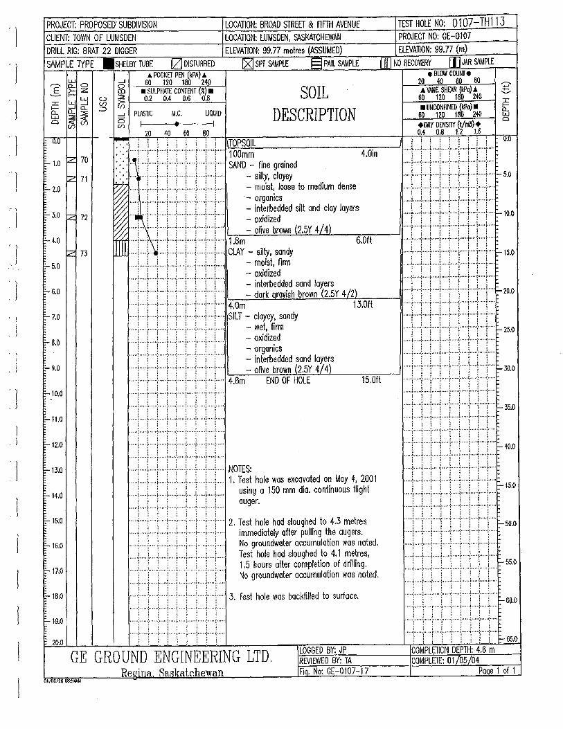
' l ' l
, I 'J
: l ' l
. J
' \
i I . )
.1 l
' J
l
PROJECT: PROPOSED' SUBDIVISION ~OCATION: BROAD STREET & FIFTI-1 AVENUE TEST HOLE NO: 0107-TH113 CLIENT: TOWN OF LUMSDEN LOCATION: LUMSDEN, SASKATCHEWAN
DRILL RIG: BRAT 22 DIGGER ELEVATION: 99.77 metres (ASSUMED)
SAMPLE lYPE .SHELBY TUBE IZI DISTURBED IZJ SPT SAMPLE § PAIL SAMPLE A POCKET PEN (kPA) .A
g: 0 ....J 60 120 180 240 g ~ Z &5 1-----.~SU'::-L-::-:-PHA~JE~CO,.,!'Nf~EN~f~(%~.) !!-•--I :J: ~ ~ ~ ~ 1--_;0:::.2'--.:::0.~4 ___::0:,::.6_0:.:;.8:._~ SOIL
DESCRIPTION b: 0..~ :::::> ....J
l:S ~~ 0 (/) (/)
UQUID M.C. PLASTIC
PROJECT NO: GE-0107 ELEVATION: 99.77 (m)
0IJ NO RECOVERY I]] JAR &\MPLE e BlOW COUNf e
20 40 60 80 .A VANE SHfi\R {kPo) A
60 120 180 2({) • UNCONFII'I£0 {kPa) •
60 120 180 240 +DRY DENSilY (t/m3)+ 0.4 0.8 1.2 1.6
:c b:: w 0
20 40 60 80 7- , , , , , , . i ! 1\\!:'TOI~P~SO~IL:...._. _______ "':""7.:--~I o.o
: ~: ~ :::·r::r:::r::r::r::r::r::r:::r::: ~~~~~ ~ine groined 4.0in
o.o
::- 1.0 ~ 70
•• • ..... 4· ..... : .... + .. ·i ..... : ..... i ..... i ... + .. +... - silty, clayey ~ .... ': ..... ; ..... j ..... i ..... ; ..... j ..... i ..... ) .... j..... - moist! loose to medium dense ~ ' : ' : : : : : : ·- orgon1cs ~ ..... i ""("T ... i .... I" .. T"T'"'!"")"'" - interbedded silt and cloy layers ~ ... ~ .... ) .... i" ... l"' .. !" ... !" ... l ..... i .... l..... - oxidized ~ ..... ! ... ·: ..... j ..... j .... j .... j ..... i ... ')' ... j..... - olive brown {2.5Y 4/ 4)
Uill Jli! Ell II 6~~: ~~ti.~~ \ ! ! ! \ \ \ \ ! - oxidized
~ 71 ::- 2.0
r-- 3.0 ~ 72
1:- 4.0
~ 73
1:- 5.0
6.0ft
E- 6.0 ..... j .. '"[""j'""j""·:·""]""T'"T"T... - interbedded sand layers ..... i ..... i" ... i" ... ! ..... ( ... f" .. !"'"!""(" - dark oravish brown-'(2.5Y 4/2) ..... f ..... j ..... i ..... i ... ·j .... i ..... f ..... i .. ·-1"· .. 4.0m 13.0ft
E-7.0 ..... f ..... ; .... + ... ! .... +- .. + .. ..J-.. + .. + ... SILT - clayey, sandy ... ) .. .) ..... ~ ..... f .. ) ... ) ..... \ ... ..\ .. )..... - wet, firm
·····f····J-····1·····1····-!-····I·····:·····f····l····· = ~~~~fcds ..... ( ... j ..... j ... "("'j""'('"j'""('"j""' - interbedded sand layers .... .L .. L ... L. .. \...) ..... 1 ..... ] ..... : ... .J .... ..... r ..... ( .. j· .... j ..... ! ..... 1 ..... ! ..... i" .. \"'.. - olive brown (2.5Y 4/ 4) .·::::
1
···'',t.·:.·:;····':::::::····':::::}···'1 .. ::::, .. ';,::::: 1···'\.:::::i:~ .. ':::::~ ... ·'::::::: ... ·'::::::r-- 30.o ..... > .. ; ..... ; ..... ; ..... : .... .;.. ... ; ... + .. .;.. ... 4.6m END OF HOLE 15.0ft : : : : : : : : :
••••·~····t····t·"·'i''''t·····i·····i·····~····i····· •••••l•••••:•••••l•"••l"''':•••••(•••••J• .. ••:•• .. •(""'
1:- 6.0
1:- 9.0
:-10.0
..... t····t····j·····l .. ···:·····l·····l·····t····j····· ···· ·1····-r····r···· t·· ·· r····r · · · · ~--· · ·1··· ·r···· 1:- 11.0
·····t··· .. i·····j·····i····t····j·····:·····t'"'j·····
•:••~••I•ir•r••i• I••r NOTES
f'-12.0
E-13.0 ..... \ ... ) .... i ... ..[ ..... j ... ,.\ ..... ! ... ) .. ) ..... 1. Test hole was excavated on May 4, 2001 ..... \ ..... [ ..... j ..... j .... ( ... j .... j ..... \ .... J..... using a 150 mm dia. continuous flight ..... L. .. .L ... L .. L ... L .... L. i .... .L. .. L.... auger .
..... L .. l .... .J.. .. -1--. ..j. .... l ..... l ..... j .... l ..... 2. Test hole had sloughed to 4.3 metres :::::l.CJ:::.I:::::I:::::t::::J:::::I::::f::::l:::::-50.o
..... 1 .... -i- ... + .. ·!· .. ·-i-- .. +·+ .. + .. +·.. immediately after pulling the augers. -
..... f .... j .... j ..... j ... ) ..... j ..... j ..... ) .... j..... No groundwater accumulation was noted. . .... l .. + ... l ..... i ... + .. + .. ·l .... ·f .. ·+· ..
..... L .... !.. ... ) ..... L.. .. \.. ... L ... L.. .. \ .... L... Test hole hod sloughed to 4.1 metres, ........... , ..... , ..... , ..... , ..... , ..... , ..... , ..... , .... . [ [ [ ~ ~ ~ \ ~ ~ 1.5 hours after completion of drilling. .. . .'t, .... .-: ....... :.: ..... ·!, ..... ~J, ..... ~.:· ...... ·J ........ i~ ...... ::.· ...... r-55.0
..... f .... 'j' ..... ! ..... !' .... ! ..... ) .... ! ..... ( .... )"... No groundwater accumulation was noted . •• I. •)• ••• ·:· •••• ~· ••• •I· .••• ; .•••. ·=·.'.·I· •.• -~ .... ,..... • .•. ·> •••• ·=· .•.• '. 0 •• •) 0 ••• -:· •••• (• ••• •I•.'' .: ..... (• ....
..... ! .... ! .... +·+ .... ( .\ ..... j .... y.+ ... 3. Test hole was backfilled to surface. ::J .... ·.:::I.::·::l.;:::::l.::::: .. i:::::·.l::::::.::::1.::::::.·::::: -60.0
.... -~·· ... ~ ..... ~ .. ···!·". -~· ... ·{··· .. ! ·····~ .... ~-·."
·····1·····.-····l·····i·····l····l···"i·····!··"j''''' ..... ! ..... \ .... j ..... ; ..... : ..... j. .... j .... .[ .... j .... . .... ·:· .... ·:· .... ~- .... ! .... ·:· .... ~- .... ! .... ·? ..•. ~-.... . .••. l .... J ..... i ..... ; .... .! ..... I ..... i .... .l ..... i. ... .
; i ; : i : : : : : : : : : : : : : -65.0
E:-14.0
1:- 15.0
I= 16.0
:-17.0
::- 18.0
:..19.0
20.0 LOGGED BY: JP COMPLETION DEPTH: 4.6 m GE GROUND ENGINEERING LTD. REVIEWED BY: TA COMPLETE: 01/05/04
Re~Jina Saskatchewan Fiq. No: GE-0107-17 Paqe 1 of 1 11/06126 08:54AM
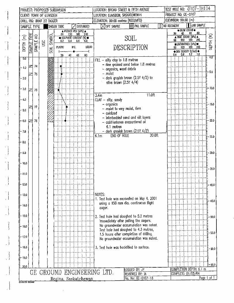
'l
'1 )
' l
: 1
: l I
'l ' 1
l ' J
. I l
PROJECT: PROPOSED' SUBDIVISION LOCATION: BROAD STREET & Flffil AVENUE CLIENT: TOWN OF LUMSDEN LOCATION: LUMSDEN, s.\SKATCHEWAN
DRILL RIG: BRAT 22 DIGGER ELEVATION: 99.68 metres (ASSUMED)
SAMPLE lYPE .SHELBY TUBE IZJ DISTURBED (g] SPT S<WPlE §PAIL SAMPLE J. POCKET PEN (kPA) &
.---, ~ 0 _.J 60 120 180 240 S ~ Z &5 I----'• "'"su""'LP-'HA"":JE'-C-ON!-"TE~NT....,(.:.;,;)~•---1
:c W LLJ (/)(.) >-::::!E 1 _ _:0::::,:,2;___:::0•,:_4 _..::0~,6 __:0:::,:,8:...__-f SOIL DESCRIPTION
_.J ~ (/) r-
b: n.. ~ ::::> _.J
w ::::!E 01 0 Cl (f; (/)
PLASTIC I
M.C. LIQUID
• I 20 40 60 80
0.0 ..... l.. .. L .. .L .. .i.. .. .L ... l.. .. .J.. .. L .. L .. FILL - silty clay to 1.8 metres
;:- 1.0 ~ 74 ..... f .. ~.:. .... j ..... j ..... : ..... J ..... f ... + .. +... = ~~o~ka~~~o:~nJe~~~ow 1.8 metres
~ 75 F- 2.0
F
..... ; .... , .... i ..... ; ..... ~ ..... ; ..... ; ..... ; .... i..... moist
..... ) .... ; ..... j ..... ! .... J .... ! ..... j .... .;, .. .J.,... = dark grayish brown (2.5Y 4/2) to
.... ) .. ( .. +·+ .... : ..... j ..... [ ..... ; .. +... olive brown (2.5Y 4/ 4) F- 3.0 z 76
F- 4.0
~ 77 E-5.0
F- 6.0 tz 78
~ iii illiff E~~- silty, so~ ~~ ..... ; .... ; .... · ..... ; .... .;. .... ; ..... ; ..... ; .... ;..... - orgamcs ~:: ,, ::::: . . . ~ ..... f ... + .. ·! .... f ... + .. +·+··+--+... - mo1st to very mo1st, f1rm ~ i ~ ~ ~ ~ ~ ~ ~ - oxidized ~ ..... ; ..... \ ......... T .... f .... l" ... \ ..... [ ... T... - interbedded sond and sill layers ~ ..... ~ ..... !"'~ .... ~ ..... ( ... 1 ..... ! ..... ~ .... \"'.. - cobblestones encountered at
11.0ft
..... r ... ·-i---·+ ... 1 .... ·\---·+· +--+ .. +... 6.1 metres I=- 7.0 ..... ~ .... : ..... j ..... [ ..... : .... + .. + .. + .. .;..... -dark qravish brown (2.5Y 4/2)
TEST HOLE NO: 0107-TH114 PROJECT NO: GE-0107 ELEVAliON: 99.68 (m)
[IIJ NO RECOVERY [)]JAR SAMPLE e BLOW COUNT • za 40 60 ao
~---~~~~~=-_, ~ A VANE SHEAR (kPo) J. ~
60. 120 180 240 • UNCONFIM:D (kPo) •
60 120 180 240 +DRY DENSfiY (t/m3)+ oJ o.a 1.2 1.&
.... L .. L .. .l. .... \ ... ..\ ..... l ..... : .... .\. .... 1.... .. O.lf
1\\\f! \JJ ~ ...
::::r:J:::r:::t::::I::::r::::~::::r:::r:::: ..... , ..... : .. --+ ... l ..... ; ..... j ..... i ... + .. +· ... 6.1 m END OF HOLE 20.0ft ..... l ..... l ..... , ... + .... ! ..... j .... L ... I ..... j ..... ~ 25.0
·····)·····:·····1·····•··"':·····\·····1·····!·•···(····· E- 8.0
E- 9.0
-10.0
F-- 11.0
::- 12.0
F--13.0
F-14.0
E-15.0
F-- 1&.0
F--17.0
F--18.0
F-19.0
20.0
..... ;. ' .. ~-· ... ( ..... j . .... : ..... ( ..... j ..... ; .... ( .... .
.. . . . ~ ..... t .... 1 .... '~ .. ' .1 .... ~ ..... ~ ..... ~ .... ~ .... .
.... -~· .. ' .1 ..... ? ..... ! ..... j .. ' .. ~ ... '. ~ .... ·~ ... 0 ~ •••• '
..... i ... ·,l·····l·····i····t···l·····l·····!· .. ·l··"' ····•}·····=··•••(• .. ••1••···=··· ••(••·· ·I·' .. ·~···· {••·•'
·····!····t···-1-····!"•"i••···l·····!·····l·"'l·"'' .... '! ·····:·····;····· !•····~···· ~··. ''!'''··~····;·····
·········!····:•••1•1+•·11•••1•• :::::t:::::~:::::l:::::i:::::r::::r::::i·::::~::::r:::: NOTES: ..... \ .. ) ..... ! ..... \ ..... ~ .. ) ..... \ ... ) .... ) ..... 1. Test hole was excavated on May 4, 2001
..... ~ .... ~ ..... j .... } .. ·l· .. ·j--·--t·+ .. -1--... ~~~;r.a 150 mm dia. continuous flight
::::r:::r:::r::r:-:-::::r::r::r::r:::: 2. Test hole had sloughed to 5.2 metres ... + ... -( .. --+--+ ·+· +--+··+ .. +·.. immediately after pulling the augers. ..... ~ .... ; ..... ; ..... ~ ..... ; .... ; ..... ; ..... ~ ... ;..... No groundwater accumulation was noted. ... ) ..... L ... L. .L ... l.. .. .L .. .L. . ..l .... L.. Test hole had sloughed to 4.3 metres, .... .!.. .. ..i. .... L .. L .. i .... i ..... ! .... .!.. ... L.. 1.5 hours after completion of drilling.
j j ! j j ! : : j No groundwater accumulation was noted. .... '? .... ·~· .... ~- ... 'l' ... -~· .... ;· ... '1' ... -~ .... ~-' ...
.... ;-----:--·--j·--+·· .. l· ... + .. ·l .... Y·+"· 3. Test hole was backfilled to surface. •.••• ; ••••. : •••.• ( .•••• j ..... ; ..... ( .. ,.,j .....••... ( .....
·····l· .. ·-l-····1·····:···-I····l·····!·····;····!-···· .... ·~ .... ·:· .... ~- .... ! .... ·:·.' .. ~- .... ! .. '. ·~' ... :· ....
i l 1 1 1 1 ~ ~ 1 LOGGED BY: JP GE GROUND ENGINEERING LTD. REVIEWED BY: TA
Re&!ina Saskatchewan Fio. No: GE-0107-18 Ol/06726 0&5®
..... ! .... l .... l ... + ......... , ..... l ..... 1 .... + ... ::::r::r::r:::1:::::r.::::r:::1::::r::r::::~ 30.0
.. •••l•···-=- .. ··1·····}·····:·····{·····1·····:·····~· ....
..... 1 ..... : .. · .. 1·····!· .. ·-l· .. ·l ..... i .. ··I· .. ·l-·· .. ~ 35.0 · • • • ·l· · ··-:- · · • ·I···· •) · · · • ·:· · · • ·~· •• · ·I•· · • ·:· ·" • t• • · ··
••l····t!Jti !tl••••e- w.o
:::::I::::I::::I:::::r:::L:r:::l::::r:::l::::: l l l l l l l : : ~ 45·0
i ll !llfll••• -oo.o ·····[·····r····1·····~···· r· · ··r· ·· ·1····-r····~·····
:::::\::::r::::;:::::~:::::r::::r::::::::::r::::r:::: , .... ) ..... i .. ···i····}· .. -t·· .. ·l·····l··· .. l··· .. 1·····-
55.0
:::::1::::r:::~::::r:::I::::r::::1:::::l:::::r:::: ~ 60.0 • •• • ·I• • • • •:0 • • • •I• • • • •l• • • • ·:· • • • • t• • • • •I• • • • .; .. • • • ~· • •• • ..... l ..... ! .... .j...+ .... : ...... ( ..... , ..... ( ..... j ..... ''"'l''"t····l·····j····t····j· .. ··:····j"'''j''"' ~ 65.0
COMPLETION DEPTH: 6.1 m COMPLETE: 01/05/04
Paqe 1 of 1
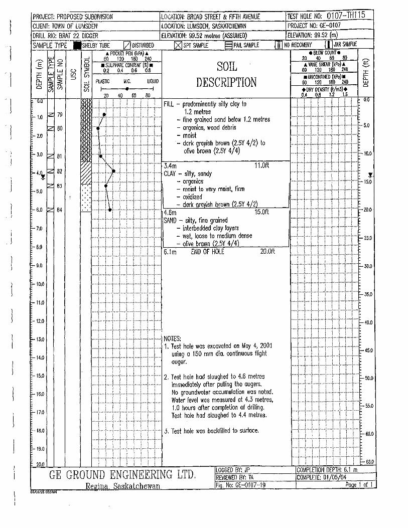
.l
1 . J
PROJECT: PROPOSED' SUBDIVISION LOCATION: BROAD STREET & FIFTH AVENUE CUENT: TOWN OF LUMSDEN LOCATION: LUMSDEN, s.\SKATCHEWAN DRILL RIG: BRAT 22 DIGGER ELEVATION: 99.52 metres (ASSUMED)
SAMPLE 1YPE .SHELBY TUBE l2J DISTURBED [g) SPT SAMPLE §PAIL SAMPLE A POCKET PEN (kPA) A
w _J 60 120 180 240 ,--...E CL 0 0 ~--~~.l.!:!!.---!.~_..,!:q:!:!--J .__... ~ :z ~ • SULPHATE CONTENT (~) • SOIL
DESCRIPTION L1.J lLJ U >- 1 __ 0::::,2~~0.~4 _..::0::,:::,6_0::!!,8:..._-j :::r: :::J ....J (/) (/) r-
wb.: CL CL ::;, M.C. UQUID :::;:~ ___J
0~(/) ~ PlASTIC
I • I 20 40 60 80
0.0
1:-- 1.0 2 79
.... .L ... f.. .. L .. J. .. L ... J... .. L ... \ .... L. .. FILL - predominantly silty clay to : ! : : : : : : : 1.2 metres
.... '!" "j"'"j"'")'""j"'"("'("'("('" - fine grained sand below 1.2 metres z 80 ... ~ ..... i···"j'""i""·i"""j"'"i""'i· .. ·j·.... - organics, wood debris
0... 2.0 .......... ; ..... j ..... : .... .;.. ... j ..... ) ..... ~ .. ·+·.. - moist
:-3.0 iZ 81
1:--4.\ jz 82
jz 63 1:-- 5.0
........ ) ... ..) ... ) .. ...j ..... j ..... ; ... ) .... j..... ·- dark grayish brown (2.5Y 4/2) to
~ l'l i ~ j I I j l3.4m oflve brown (2
.5Y 41 4
) 11.0rt
~ ..... f .... T .... ! .... j ..... f .... ) .... ·j""'["")"'" CLAY - silty, sandy ~ ..... ~ .... + ... \ .. ·+·+ .. +·+ .. + .. +... - organics
: ::::::: "tt 'tfi . :. : ..... 1 .....
1 .... l" ... i .... t' ... l ..... i ..... [ .... j"... = :~~~ze: very m01s , 1rm
'- 6.0 iZ 84 · · · · ..... f .. 'T 'T""j""]"'"]""T'"'\'"T'" - dark Qravish brown (2.5Y 4-/2) ~ ..... t ..... 1" ("1"'"('"1" ... ! ..... ! .... 1" ... 4.6m 15.0ft
=-7.0
..... f ..... f .... l ..... [ .... ·[""'["· .. !· .... i .... i ..... SAND - silty, fine grained
..... f ..... j ..... i ..... ; ..... j ..... j ..... ; ... + .. .j..... - interbedded clay layers
... ) ... ) ..... ! ..... ! ... ) .... ) ... ) .. ) .. )..... - wet, loose to medium dense
..... L .. .L .. .!.. .. .i.. ... L .. .i.. .. .i.. .. .L .. i..... - olive brown (2.5Y 4-/4)
TEST HOLE NO: 0107-TH115 PROJECT NO: GE-0107 ElEVATION: 99.52 (m)
[[jNO RECOVERY (I] JAR S<\MPLE e SLOW COUNT e
l---'2~0 _ _,40"----=60.;,-.-'80"'---1 -:;::; A VANE SHfAR (kPo) .l ~
60 120 180 240 • UNCONRt£0 {kPo) •
60 120 180 240 +DRY DENSilY (t/m3)+ 0.4 0.8 1.2 1.5
0.0
::tJlllJltJ:HSO 8.0
..... L..!... .. i .... L .. i .... i... .. i ..... L . .i ..... 6.1 m END OF HOLE 20.0ft ..... ~ ..... l·····l .. ···l····r··+···l· .... l .... l···
:-9.0
:--10.0
:-- 11.0
0...12.0
I= 1:-13.0
t-14.0
I= 1:--15.0
t-16.0
:-17.0
-18.0
o-19.0
20.0
1I~1i~~~~ ••••·~·· •·0:·•···~·· •••I••· ••:••• •• t•••••l••• ••)••••(• ••••
..... f .... .:. .... J ..... j ..... ; ..... j ..... j ..... l····l·····
.... -~· ... ·} .... ~· .... ~ .... ·f .... ~· 0. 0. ~- ••• ·~ •••• !· ....
·····i····t····j·····i····{·· .. j··"·i·····l····j····· • • • • ·~· • • • ·> • • • • !• •,, •I• • • • •:0 • • • • (• •• • • I• •• • ·~ • •• • ~· • • ••
::::r:::r:::l:::::r::::.:::::r::r:::l::::l:::::
:::::t:::J::::;:::::~::::t::::r::::::::::f::::r:::: NOTES: .. ...} ..... f .... j ..... i .. .) .. ). .. ) .. ) .... ; ..... 1. Test hole was excavated on May 4, 2001 ... ,\ ..... L ... ) ..... L .. L ... ).. ... l ..... \, ... i,.... using a 150 mm dia. continuous flight .... .l ..... l ..... i. .... l ..... ! .... !. .... i ..... \ .... L... auger.
..... ! .... .[ .... j ..... ! .... f. ... J .... J. ... ! .... J ..... 2. Test hole had sloughed to 4.6 metres
..... f .... ; ..... ~ ..... ! .. -+ .. + .. + .. + .. +·.. immediately after pulling the augers .
..... 1 ..... [ .... { ..... \ ..... : ..... ; ... \ ..... \ .. ..(..... No groundwater accumulation was noted.
..... L ... L .. L .. .i.. ... \ ..... L .. .L. ... L ... L.... Water level was measured at 4.3 metres, ! : ! j : i ! ! ! 1.0 hours after completion of drilling. ..... i ..... i ..... ) ..... ( ... { .... ( ... T .... f .... )"... Test hole had sloughed to 4.4 metres.
.... ·~ .... ·:· .... ~" ... ! .... ·:· .... ~- .... ! .... 'l' ... ~ .... .
..... ~ ..... ~ .... J ..... ' ..... :- ... + ... 1 .. ·-} ... j ..... 3. Test hole was backfilled to surface.
::::1:::::::::::r::::·:::::j:::::;:::::·:::::!::::t:::: : : : : : : : : :
'"''t····-r····j'····:·····i'''''l'''''l'''··:····:·····
GE GROUND ENGINEERING LTD. LOGGED BY: JP RE.VIEWED BY: TA
Re.Qina Saskatchewan Fia. No: GE-0107-19 01/0ii/26 08:54AM
•••• 1 Jt•••tl••:•l ! ll ~:: jlllli ill-"·'
:::::1::::t::::l:::::l::::l::::r::::~::::t:::r::: ~ 45.0
i!!]Jlillr~.o ·····1····r ····i·····r···· r····I·· ·· ·~····1····r····
::::r::r::r::r::r:::;::::r::r:::r:::- 5S.O
:::::!::::r:::·:::::1::::r:::r::::1::::I::::r:::: "-- 60.0
• •• • ·~ "'' •:• • • • •I• • • • •J• • • · ·:· • •• · <· • • • •I• • • ••:-• • •• (• •" •
""'l'""!'""l· .. + .... · ..... j ..... i ..... l ..... J ..... 0 0 0 ' ,; ' ' ' 0 ,;, ' ' ' ' i o o " o) o o ' o ;,, 0 o o 0 t' " o 'i o o o o ,; .. 0 o 0 ~ 0 o " I
~ : : : : : : : i ~ 65.0 COMPLETION DEPTH: 6.1 m COMPLETE: 01/05/04
Paqe 1 of 1
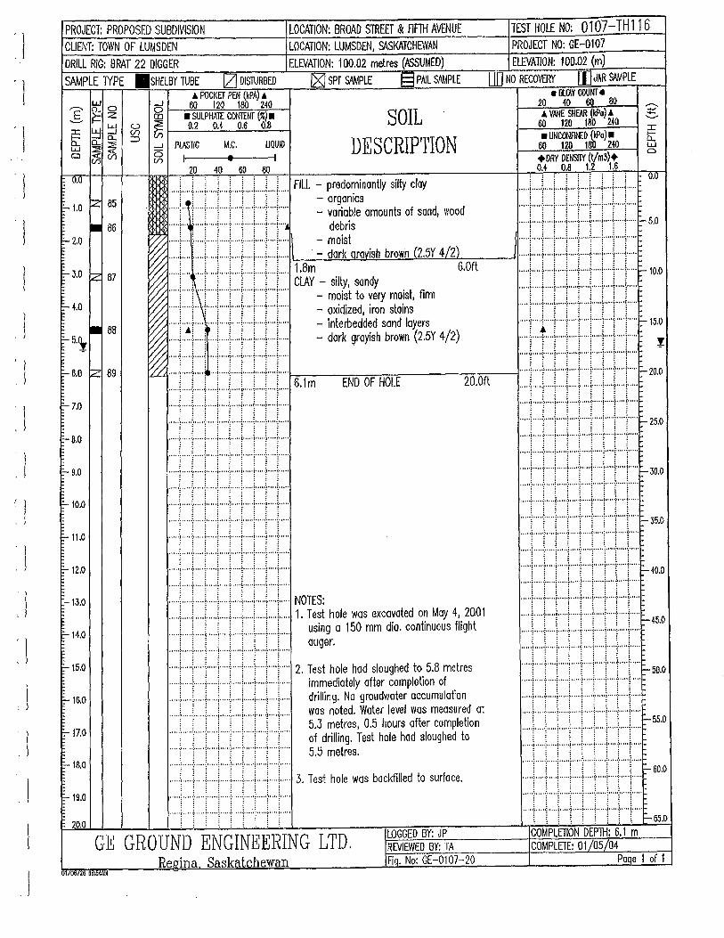
' l l
'l 'l
j 'J
' 1
' l
'l
PROJECT: PROPOSED SUBDIVISION LOCATION: BROAD STREET & fiFTH AVENUE CUENT: TOWN OF LUMSDEN LOCATION: LUMSDEN, Sl\SKATCHEWAN
DRILL RIG: BRAT 22 DIGGER ELEVATION: 100.02 metres (A)SUMED)
SAMPLE TYPE .SHELBY TUBE !ZJ DISlURBED ~ SPT S.WPLE §PAIL SAMPLE A POCKET PEN (kPA) ..t.
~ 0 __J. 60 120 100 240 g j::: Z @ • SULPHA1E CONTENT (r.) • ::J ::J ~ ~ 0.2 0.4 0.6 0.8
SOIL DESCRIPTION ~ ~ ~ ::::> ......1 PlASTIC M.C. UQUID
CJ <( c?i 0 (/') en I t I 20 40 6{) 80
..... l ..... ! ..... L ... ) ... ..! ..... J.. ... L .. L .. J.. ... FILL - predominantly silty clay ! 1 ! ! ! ! i ! ! ! - organics
..... \ .. ·j" .. ·j·····j .... ·j"·"]""'!"'"("i'"" - variable amounts of sand, wood
0.0
1:-- 1.0 lz 85
~ ::::t:~:::J:::J:::r:::t::t:::t:::L~. - ~~~;~s ~ ..... f .... · .... j ..... i ... + .. + .. ·i· .. +· .. J- .... 11 - dark orovish brown (2.5Y 4/2)
~ .... (·"" ... + .. +· ... ; .... + "("·+"+·" 6&~ 'I d 6.0ft ~ra/. .... .L ... ;, ... L . .L .. L ... !.. ... i ..... L..L... - Sl ty, son y ~ ! ! ! ! ! ! 1 ! ! - moist to very moist, firm ~ ..... !' .... ! ... ·t"'("'("'('"!""T'"\""' - oxidized, iron stains ~ ..... j .. ;,J ...... ·j""f· "j"'"\"'"1'"'(" - dintekrbedd~dhsband lay(e
2rs5y
4/2)
• 86 1:-- 2.0
F- 3.0 lz 87
1:- 4.0
• 86
TEST HOLE NO: 0107-TH 116 PROJECT NO: GE-0107 ELEVATION: 100.02 (m)
OIJ NO RECOVERY [)]JAR S4MPLE e BlOW COUNT •
20 40 60 80 A VANE SHfAR (Jdlo) .l
60 120 180 240 • UNCONFlf<.£0 {kilo) •
60 120 180 240 +DRY DENSIJY (t/m3}+ M 0.8 1.2 1.&
~ w Cl
0.0
1:- 5.~
1:- 6.0 ~ 89
~ ..... l ... ('"j .... ! .... t .... j ..... f ..... 1 .... j"'.. - or groy1s rown .
~ ····~ ++•i••F! iF·l··~-=6....,....1 m---=EN=o-=-o:--,FH=o=tE---=2o~.o-:;-rt ----i ·····i·····r····r····l·····r····r····~·····l····r····
F-7.0
1:- 8.0
1:- 9.0
F-10.0
1:-11.0
F-12.0
F-13.0
I:- 14.0
t:-15.0
F-16.0
I:- 17.0
F-18.0
1:-- 19.0
20.0
' ... ·~ ... ·t .... ~· .... ~- .. ' t .. ''1' .... ~-. ···i .... ~·· ... • ' •• -~ •••• ·~·· •• 0 ~00 •• '~- 0 00 ·i· '0.' ~0 ••• -~ ••••• ~ ····{ •••••
·····!····I·· .. l·····!····I····l· .. ··! .. · .. l·· .. !· .. ·· .... -~··· ··1··· ··~··· ··l·o···r····~· ····~·····r···l····· ..... ~ .... y· .. '10 .... r 0 •• ':' .... ~- .... l. 0 .. ·? ... ·~· .• 0.
··· .. f····l····l·····I····J-····l·· .. ·i···+···l·· .. . ooooo}oo•••: ••••• ( •• o •• j ••••• ?, •••• i ..... j •.••• ; •.•. ( .... .
, .... [ .... .:. .... j ..... l····"-···{·· .. i···+"·l····· ..... ; .... -~- .... ~- .... i ..... ~ .. ' .. i .. ... i ..... ; .... ~ .....
···i••••i••l····l·i····!••ij••••i• :::::l:::::~:::::;::::r::r::::r::::r:)::::r::: NOTES: .. ..,\ ..... j .. .) ... ) ..... ~ .... i .. ...\ ... ,.\.) ..... 1. Test hole was excavated on May 4, 2001 ..... [ .... t .... j ..... : ..... ~ .... j ..... j ..... [ .... j..... using o 150 mm dia. continuous flight ..... l ..... l .... L ... : ..... :. .... L .... :. .... l .... L.... auger .
..... f ..... j ..... j ..... i .... .j. ... -1-- .. ·i ..... ~ ... .j.. ... 2. Test hole had sloughed to 5.8 metres
..... 1 .... j .... j ..... : .... : .... + .. + .. + .. .j..... immediately otter completion of
..... f ..... : ..... j ..... j ..... : ..... j ..... j ... ) .... j..... drilling. No groudwoter accumulation
..... \ .... L ... L ... i .... .L ... L .. L. . ..\. .. .L... was noted. Water level was measured at ! j ! j ) j j ! j 5.3 metres, 0.5 hours ofter completion
..... i ..... f .... )" .. T ... '!" ... ) ..... i ... T .. T.... of drilling. Test hole hod sloughed to
..... r .. ··r···r .. T ... I .... t" .. !" ... f ... T.... 5.5 metres.
..... • ..... : .. ... : • .... : .... : .. ... : • .... : ..... ~ 0 ... : ... ..
..... \ ..... ! ... j ..... j ..... ! ..... l ..... ! ..... ! .... L ... 3. Test hole was backfilled to surface.
·····l····}····~·····!····-1-····l···": ..... f ... ·l····· .... r .. ( ... l ..... l .... 'i' ... 'J" ... l"''l ... l" ... LOGGED BY: JP GE GROUND ENGINEERING LTD. REVIEWED BY: TA
Regina Saskatchewan Fiq. No: GE-0107-20 01/06126 08:54AM
:::::l:::t::l::::r::t::::r:::l::::i::::l:::::
IT\ il1ili ~:: ··"·l·····:·····l·····)""':•••"\ .. •••1'"'':· .. ··(···"
:::::l:::::l:::::r::::l::::t::::r:::l::::r:::l::::: \ \ \ \ \ : l \ : 1-- 65.0
COMPLETION DEPTH: 6.1 m COMPLETE: 01/05/04
Paqe 1 of 1
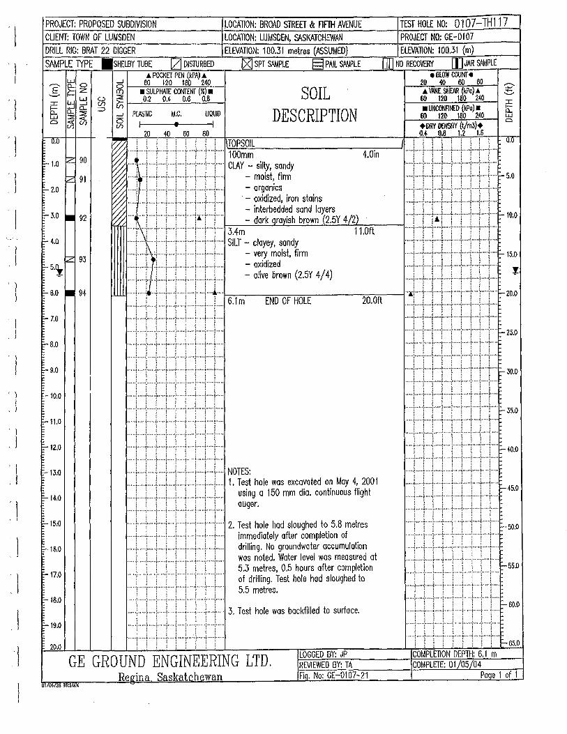
I
: I
' l . I
PROJECT: PROPOSED SUBDIVISION LOCATION: BROAD STREET & FlFTH AVENUE TEST HOLE NO: 0107-TH117 CLIENT: TOWN OF LUMSDEN LOCATION: LUMSDEN, SASKATCHEWAN PROJECT NO: GE-0107
DRILL RIG: BRAT 22 DIGGER ELEVATION:. 100.31 metres (ASSUMED) EL£VA110N: 100.31 (m) SAMPLE lYPE .SHELBY TUBE [2] DISTURBED iZj SPT SAMPLE § PAIL SMIPLE [[I NO RECOVERY I]] JAR SAMPLE
e BlOW COUNT • A POCKET PEN (kPA) A ,..-... t:\: 0 5 . 60 120 100 2.40 _§_ ~ Z co • SULPHAl£ CONTENT (%) • SOIL
DESCRIPTION
20 40 60 80 A \\W: SHfAR (kPo) .6
:c ~ ~ ~ ~ 0.2 M 0.6 0.8
8; ~ ~ => ....J PlASliC M.C. UQUID
60 120 180 240 • UllCOOFitiED {kPa) •
av-;<ll ~I t I 60 120 180 240 +DRY DfllSilY (t/m3)+ 0.4 0.8 1.2 1.6 20 40 60 80
0.0
1:-1.0 ~ 90
~ 91 rZ.O
E- 3.0 • 92
E-4.0
fZ 93 1'- 5.~
E- 6.0 • 94
f-7.0
I:'"" 8.0
:-9.0
!:- 10.0
:-11.0
::..12.0
1'-13.0
E-14.0
E-15.0
1'- 16.0
E-17.0
E-18.0
1:-19.0
20.0
~ ' ' : ' ' ' ' ' ' TOPSOIL I .. : .. : .1 ',; '.; .1 ·.: '.' '.' 0•0
f0 ..... ; ... ..:. .... i ..... i ..... ! ... .,l ..... i. .... ; .... L. .. l~.:.:10:::.:..;0==--------:-:-------l ..... , ..... , ..... , ..... , ..... , ..... , ..... , ..... , ..... , ..... !/;%: : ! ! ; : ! ! ! ; mm 4.0in ' ' ' ' ' ' ' : : ~~V /) ..... ! ..... ( .. ("j"·"i"·"j""·( ... j .... j ..... ClAY - sil~y,t sfiondy ..... t ... .i.. ... L .... ~ .... L ... L ... \ ... ..: ..... 1 .....
~ "'"1f'i"""l""'!"""i"""!"""!"""!""!""' - mOis ' rrm ...... ·.·.;·:_ .... '~.·.·.·.·.··l::····';·········;·' .... ··';·_·.·.·.··.;.·':.:;············:i_ ... :r.·.·.·.·.'.i .. ': .. ::·.·.·.·.·.l·······'!·.·.·.·.·.',: ... '!.·.·.· .. ".'_
1_.'· .. ::·.·.·.·.·.1- 5.0 ~ ..... ~ .... l ... ..) ..... , ..... l .... + .. ·i .. ·+"+"· · = ~~~~~~~s iron stoins
~ ......... r ... : ..... ! ..... j" .. T'"T'"'j"'T"" - interbedded sand layers ..... , ..... , ..... , ..... , .... , ..... , ..... , ..... , ..... , .... .
~ .... ~ ..... !" .. T'"'!""!""l""·!• .. !"'T"" - dark oravish brown '(2.5Y 4/2) ..... l .... ( .. l·j+"+ .. l ..... j ... -( .. j ..... l-lO.o
..... !. "t""("!""'('"j"'"f""'t"(" 3.4m 11.0ft ..... i'"'Y""l"'''1""Y""1"'"!""T"'T'"
•••. i•••·r~l····l·l··· !••r••r••F• SILT = :::~f-Ldi;rm ••111'1 r I i rr·e-"; ·.::.·· ... ::.:,:_ ... ···'' ·.: ·.: .. :.·y. •' ... ·····'·.·. : .. · :_:.:_::: .... ··'··· ._: .. ·.·.:'.····'·., .... _::_· : .... ;,_.';; ... :·:······ :.·,.1 __ .. ··'.·.: ·.: ._:._: ·,;_ .. ··': .. _: __ :._: .. ::_;······';.:' :_ .. _:_· .. ~.·.:·······'·.··:.·······
6.1 m- oliveENb
0ro
0wFn H(2
0.L5EY 4/4) ..... ! .... ~ .. ·-:- .... , ..... ,. .... 1
..... ! ....
7
....
1
.....
. 20.0ft J.:.:. !.: i.: l,;J,! i,: ! .. : .. ::,~ -10.C • •• • ·~ • • • • •:• • • • • <· • • • •1• • • • ·:· • • • • \" • • • I• ·• • •) • • • • (• • • • • •
\ \ \ \ \ i \ ! .... 1 ..... j .... .;. .... , ... +·+"·1""''""'l""+'"~25.0 ::::I::::I::::r:::::::::I::::r:::::::::J ... J:::: ..... , ..... , ..... , ..... , ..... , ..... , ........... , ..... , ... ..
Jll!i IJLI !.J. J .. i. t·,:i.J. ~-~., :::::,:::J::::l:::::l:::::-:::::t::::l:::::;::::l::::: .
i i ! j ! i j i j ..... l .. -"l- .. + .... l ..... l ..... j ..... , ..... l .... ·l"·"r-35.0 :::::r:::::::::::r::::!:::::::::::r::::1:::::r::::r::: ........... , ................ , ..... , ........... , .... , .... .
···+···l···+··i···l··~····i···+···i····· •• tti i•••rtttte- ~., 1 111 r 1 r 1 1 NOTES: . . . . • . • • .
Li ; i ; L[ [ [ 1. Test hale was excavated on Moy 4, 2001 j !Ill I Ill H5.0
..... ! ..... j ..... J .. -"1- .. + .. +·+ .. + .. +... ~~~ir.a 150 mm dia. continuous flight :::::r:::L:L:L::L::r:::T::T:T:::
::::r:::r:::r:::r:::,::::r::r:::r:::r::: 2. Test hole hod sloughed to 5.8 metres :::::l.·.·:::i::::i.;:::J:::J:::::l::::::::::t:::r::::r- 50.0 ..... f .. ·+·+ .. .j.. ... j ..... ; ..... j ... + .. +·.. immediately after completion of · ..... f ..... f .... ) ..... f ..... f .... ) ..... f ..... f .... j..... drilling. No groundwater accumulolion ... + .. ..f. .. -1--· .. f ..... : .. ··+ ... : .... -[ .... j .... . .... L . ..l ..... L .. L. .. .L ... l ..... l.. ... L ... i..... wos noted. Water level was measured at ..... , ..... , ..... , ..... , ..... , ..... , ..... , ..... , ..... , .... .
( \ j \ ! \ \ \ \ 5.3 metres, 0.5 hours after completion .... .'l, .... .',i ..... ·_:\_ .... .'j, .... .'i, ...... _·i_ ..... ,) .... .'j, ...... ,! ..... r- 55.0 ..... f .... ! .... T ... ! .... '!" .. T"T .... f ... T... of drilling. Test hole hod sloughed to
• I · ~ 1 t ( "• oo) ••• • •:•" • •I• •" •t • •• .. :. ·" •<•" • •l• • •• •:• • •" (•" • •
::: ::r:::::r::::r:·::l::::::::: ::.1:::::1::: ::r::::1::::: s.s metres. ·····!····{· .. ·!·· .. ·I··· ·-1-· .. ·l· · · · ·l .. ··-1-····l-····~- 60.0 ..... ; ..... ~ ..... ; ..... ; .. .:. .... ; ..... ; ..... ; .... ! ..... 3 Test hole was backfilled to surface. .. ... , ..... , ..... , ..... , ..... , ... , ..... , ..... , .... , .....
..... ; ..... : ..... J ..... j ..... : ..... j ..... j ..... ; .... J..... . ·····l····I- ... ! .. ···1····-l-····l·····l····I····l·····
..... ~ ... ..\. .... L. ... L. .. L ... t ..... ~ ..... L ... L... ·····1 ..... ; .... +·· .. ~·····~-· .. -~ ..... J ..... j ..... ~ ..... : : j : : : : : : : : : : j : : : : t- 65.0
LOGGED BY: JP COMPLETION DEPTH: 6.1 m GE GROUND ENGINEERING LTD. RE.VIEWED BY: TA COMPLEfE: 01/05/04
Reeina Saskatchewan Fiq. No: GE-0107-21 Paqe 1 of 1 01 {06126 D8<54AU
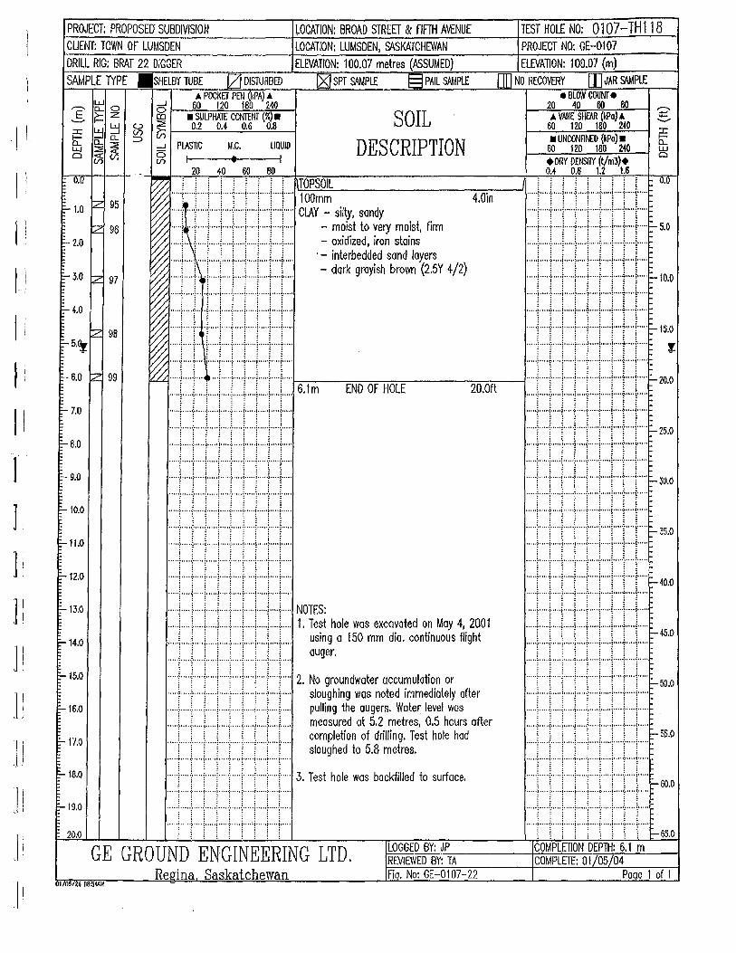
J :
II 1
J I
] (
J i
] !
] ]
J j
.II
PROJECT: PROPOSEIJ SUBDIVISION ~OCATION: BROAD STREET & FIFTH AVENUE TEST HOLE NO: 0107-TH118 CUENT: TOWN OF LUMSDEN LOCATION: LUMSDEN, SASKATCHEWAN PROJECT NO: GE-0107 DRILL RIG: BRAT 22 DIGGER ELEVATION: 100.07 metres (ASSUMED) ELEVATION: 100.07 (m) SAMPLE 1YPE .SHELBY TUBE [ZJ DISTURBED ~ SPT SAMPLE § PAIL SAMPLE IJD NO RECOVERY [)]JAR SM4PLE
e BLOW COUNT' e A POCKET PEN (kPA) A w _J 60 120 180 240 E CL 0 g l-~-::-==-~~2i-':--l r--=2"'-o =~:":o=:::;oo:-::-.--:"ao'---"1 -:;:;-
___. ~ z ::::!: • SULPHATE CONTENT(%) • ::c: ~ ~ ~ &:; 1----'0=.2'----=0.4'---.;;.;0 . .;;_6 __..;;.0';.;:..8 --t SOIL
DESCRIPTION
A VANE SHfAR (kPo) A .::!::;.. 60 120 180 240
b: 0... a.. :::::> LLJ::::i:~ -l Cli)!j(f) ~
PlASTIC I
M.C. UQUID • UNCONFI~I> (kPo) •
60 120 180 240
0.0
::.... 1.0 1Z 95
tz 96 1:- 2.0
~J.O z 97
=-to
fz 95 1:-5.~
!:- 6.0 z 99
'-- 7.0
1:- 8.0
E-- 9.0
::- 10.0
1:- 11.0
1:--12.0
1:--13.0
::-14.0
-15.0
E-- 16.0
E-17.0
1:- 18.0
::- 19.0
20.0
t I 20 40 60 80
+DRY DENSITY (t/m3)+ 0.4 0.6 1.2 1.6
~ ! ! [ ! ! ! [ [ [ 1\I~TO·_-::,.;PS=OI=-L ------~,----___;11 ! ! i ! [ ! i i i o.o '% .... T .... i ..... 1' .... ! ..... [ .... 1"' .. !" ... l .... l"' .. Tbomm 4.0in ..... , ..... , ..... , ..... , ..... , .... , ........... , .... \ .... . ~ ..... ~ ... ; ..... ) .. ·"i'""i"·")""'l"'"f""l'"" CLAY - silty. sandy ..... L .. .!.. ... l.. .. .L .. .!.. ... L .. L ... L .. L .. ~ ..... !• .. -! ..... 1 ... + .. ·}· .. +·+ .. + .. +... - moist to very moist, firm ·.·.· ..... '.'1_,· ....... ·.·· .. ·'! .... ·.·.·.·.'_ ... ·'!·.·.·.·.·.·.:_.·'; ... ·.·.·.: ... '1_,:::::;··':,::::::,1 __ ,:::::~ ... '~ .. ::::::: .. ,=:::::1-- s.o ~ ..... ! .... ~ ..... j .... ·!"·"l'""l"'"I""'I .... J..... · = ~1~:~:~d::~as~~i~~ ers ~ ... T .... \ .... ]" ... ! ..... !" .. T""j"'T"T"" - dark rayish brown ~2.5Y 4/2) ..... , ..... , ........... , .... , ..... , ..... , ..... , .... , ... .. ..... , .... l .. ·-1-····l .... t ... ·l .. ··l·+ .. ·l""' ~ 10'0
I!JJ!ll!:r~ ''; 6 1 END OF HOLE 20 .Oft :_:_:_:·:· ... '1,: :.:.:_ .... ,: __ ,f.:_ .. ·:_:·:,:_ ... ::·:·:·:·:·:_ ... ':.:.:·:·:·~ ... :!.: : ... ·:.:.:_:_ ... '1:.:·:·:·:·,! .. ,::::::.::.:. ::::: ... :: .. :·:·: ~ zo.o ..... ! ... + .. +·+ .. + .. +·+ .. + .. + .... m . ..
'""l""j""'j"'"l"'"t""j'""i'"'l'"j"'" ..... , ..... , ..... , ..... , .... , ..... , ............... , ... .. ... ".. . .. . .. ... ...... . .. . ...... :_:" .... i_' ...... i.~ ...... :.~ ...... i.' ..... ·.:.: ...... i.: ...... ~_1" ..... ;,1
..... I- 25.0 l .. ; ... -r··· ~ ···r· .. l .. T ... ~ l .. ,,,,,; • •••~•••••i•••••i•••••=••• ,,(.,,,,j,,,,,),,,,i,,.,, •••••J •••• o;ooooofoooooJooooo;"'''~"'''looooo;o .. oo(ooooo
.... f .... I ..... J .... -1-- .. ·I ..... f .... l .... -l .... l .... - ..... , ..... ! ..... ( ..... ! ..... 1 .. -+ .. ·l ..... l .... J .....
·· .. ·r·····:·····j·····r·····:·····j·· .. ·l·····r .. ··j· .. ·· :::::.:f,;:::::'_.:~_;::::!_ .. ,c::: __ ,~.:::::! __ .,::::::~ __ ,~.::::::i···'c::~ ... 'c:~ .. :i·:::::: ~--- 30.0 ... ·t··· ··~·····l· ... ·j···· -~·····j·····t·····~ ····j····· •• •• •• •• ·.·,.~'.· •• •• • •• • ' •• ~:,···. •• •• •• •• '.::,::, •• •• •• •• •• :':.;: • ..... •• ··;:::: .... •• •• •• ~.~':, .. ' •• •• • •• • ~':,, •• •• •• •• • •• ~:,'·. •• •• • •• • '.::.:'.·. •• •• •• •• • • , • •J •. • • -!· ' • , ·I· . , • •J • • ' , .;. ' ••• (• .. • , J • •• ' -:-. •. , (• •• ..
·····1·····!·····1· .. ··1····-1-·· .. J· .... I .... .f. .... j ..... F- 35.0 : : : : : : : : : .... : : : : : ·····r·····r····r····i····r····r· .. ·I·····i· ... r .. ·· ..... j. ..... : ..... j ..... ; ..... ; ••••• , •.••• ~ ..... ;. ••.• , .....
·····j"···:·····j·····j····t···:·····j·····j····j···.. ::.::.:i __ .. ~_.·',:·· .. ·':.: .. ::·· ..... ~!t_ .. ·'·.,:.,:··:·:.'i ... '::.,.'! 'i ... ·' r ~0 ::::r:t::r:::r::r:::r:::r::::r:::r::: ~ ~ ..... ) ..... : ..... j ..... j ..... [ ..... j ..... j ..... ) .. ..j ..... NOTES: · - · ..
J•••tl• tJ•••tJ IE 1. :~~£~'·1;3'm%c::~~~~"~"~'~' ~~:h~1 ·~~ f ! ! f! ff -.. , ..... , ..... j ..... j ..... , ..... r .... j ..... ! .... .j. ... j ..... 2. No groundwater accumulation or .......... , ............... .-........... , ..... , .... , .... . ..... f .... + ... + .. + .. + .. .j.. ... ! ... + .. +... sloughing was noted immediately after ..... i ..... f .... , ... + ... J ..... j ..... , .. + .. + ... ,.... 50
'0
..... ; ..... [ .... j .... j ..... : .... j .... ) ..... t .... j..... pulling the augers. Water level was ..... 1 ....
1 ..... l' .. "!"'T'")""T'T"T ...
..... i ..... ) .... .j...+ .... [ ..... ; ..... i ..... f .... ;..... meos~rt~d at f 5l11r:netr~s, t; 1ho~r~ after ..... ( .... '\" ... ! ..... ( .... 'f' .. T"T .... r .. T ... r-55
.0 ..... \ .... .i.. .. .L .. .L .. J.. ... L .. L....\ .... L.. comp e 1on o n 1ng. es o e o . . . . . . . . .
..... ! .... ·1- .... l ..... ! ..... , ..... j ..... ! ..... ! .... J..... sloughed to 5.8 metres. ::::r:::r::::::::r:::r:::r::r::r:::c::
..... ~ ..... ; ..... ~ ..... ; .... ; ..... ; .... ; ... + .. + ... 3. Test hole was backfilled to surface. .. .... i_ ...... ~ ..... ·i,! ..... :,: ..... ;,! ..... i,! ..... i,1"·"i,1· .... i,: ..... I--60.0 : : : : : : : : :
.... ·t · · · · ·~· · · · · t· ····I·····!····· f· · · · · 1· · · · ·t · · · ·1· · ·.. · · · · ·! · · · · ·:· · · · · !· · .. ·~ · · · · ~- .. · ·~· · · · ·! 0
• • • ·: .. • •
0 ~- • .. •
·····!··· .. j······j·····:·····j·····:·····:·····!· .. ·('·· ·····!·····!·····1·· .. ·1· .. ·-1- .. ··l·····i····I····l .. ··· .•• '.; •. ' .. :. '.'. ,: •• ' .. j ••.•. :. ' .•. ( ..... j .. ' .• ; .... (, 0.'. • • '. ·~ .... ·:· ••• •!.' .. ·~ .... ·:· ... ' ~· .... ! ... 0 ·:·· •• ' ~·. O•.
i : : i : i ! i : ~ : : : : : : : : I- 65.0
GE GROUND ENGINEERING LTD. LOGGED BY: JP COMPLETION DEPTH: 6.1 m REVIEWED BY: TA COMPLETE: 01/05/04
Re,gina Saskatchewan Fiq. No: GE-0107-22 Paqe 1 of 1 01/0on6 08:54AM
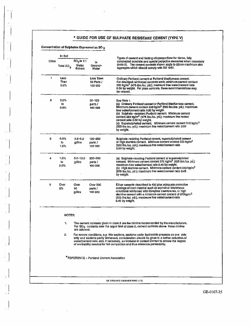
c l
I ' I
"' GUIDE FOR USE OF SULPHATE RESISTANT CEMENT (TYPE V)
Concentration of Sulphates Expressed as SO 3
Class
2
3
4
5
In Soil Types of cement and ilm!Ung mix proportions for dense, fully
so31n 1:1 In compacted concrete and special protective measures when necessary Total so3
Water Ground- (note 2). The cement contents shown apply to 20mm maximum size Extract Water aggregate which should comply with BS 1047.
Less Less Than Ordinary Portland cement or Portland blastrurnace cement. Than 30 Parts I For structural reinforced concrete work; minimum cement content 0.2% 100 000 280 kg/m3 (4751bs./cu. yd.); maximum free water/cement ratio
0.55 by weight. For plain concrete, these recommend allons may be relaxed.
0.2% 30-120 See Note1. to parts I (a) Ordinary Portland cement or Portland blastrurnace cement.
0.5% 100000 Minimum cement content330 kg/m3 (560 lbs./cu. yd.); maximum free water/cement ratio 0.50 by weight. (b) Sulphate -resistant Portland cement. Minimum cement content 280 kg/m3 (4751bs./cu. yd.); maximum free water/ cement ratio 0.50 by weight. (c) Supersulphated cement Minimum cement content310 kg/m3
(525 lbs./cu. yd.); maximum free water/cement ratio 0.50 by weight.
0.5% 2.5-5.0 120-250 Sulphate-resisting Portland cement, supersulphated cement to g/litre parts/ or high alumina cement. Minimum cement content 330 kg/m3
1.0% 100 000 (560 lbs./cu. yd.); maximum free water/cement ratio 0.50 by weight.
1.0% 5.0-10.0 250-500 (a) Sulphate-resisting Portland cement or sufersulphated . to g/litre parts I cement Minimum cement content370 kg/m (625 lbs./cu. yd.)
2.0% 100000 maximum free water/cement ratio 0,45 by weight. (b) High alumina cement. Minimum cement content 340 kg/m3
(5751bs./cu. yd.); maximum free water/cement ratio 0.45 by weight.
Over Over Over500 Either cements described In 4(a) plus adequate protective 2% 10 parts I coatings of inert material such as asphalt or bituminous
g/lltre 100 000 emulsions reinforced with flbreglass membranes, or high alumina cement with a minimum cement content ol 370kg/m3 (625 lbs./cu. yd.); maximum free water/cement ratio 0.40 by weight.
NOTES:
1. The cement contents given In class 2 are the minima recommended by the manufacturers. For S03 contents near the upper limit or class 2, cement contents above these minima are advised.
2. For severe conditions, e.g. thin sections, sections under hydrostatic pressure on one side only and sections partly Immersed, consideration should be given to a further reduction of water/cement ratio and, if necessary, an Increase In cement content to ensure the degree of workability needed for full compaction and thus minimum permeability.
*REFERENCE- Portland Cement Association
GE GROUND ENGINEERING LTO.
GE-0107-25