CERTAIN DATA CONTAINEDINTHIS DOCUMENTMAY BE ...
492
CERTAI N DATA CONTAINED INTHIS DOCUMENT MAY BE DIFFICULTTOREAD IN MICROFICHE PRODUCTS.
-
Upload
khangminh22 -
Category
Documents
-
view
0 -
download
0
Transcript of CERTAIN DATA CONTAINEDINTHIS DOCUMENTMAY BE ...

CERTAIN DATACONTAINEDINTHISDOCUMENTMAY BEDIFFICULTTOREAD
IN MICROFICHEPRODUCTS.

!
II
JU 0 _ I@_ DOEAqIPP--91-005-Vol.4-Rev'I'0
DE92 016819
Resource Conservation and Recovery ActPart B Permit Application

APPENDIX D2
ENGINEERING DESIGN BASIS REPORTS

CONTENTS OF APPENDIX D2
I• Paper DesignConsiderationsfor the Waste Hoist of the
Waste IsolationPilot Plant(WIPP)
Report A Site-Specific Study of Wind and TornadoProbabilitiesat the Wipp Site in Southeast NewMexico
Report SeismicEvaluationReportof UndergroundFacilities
Calculations:
CS-41-D-006 Analysisof Wind Loads forWHBCS-41-D-007 Analysiso; Tornado Loads for'WHBCS-41-D-486 (2 sheets) SeismicCalculation (On Microfiche)CS-41-D-487 SeismicCalculation "CS-41-D-,488 SeismicCalculation "
CS-41-D-489 (9 sheets) SeismicCalculation "CS-41-D-490 SeismicCalculation "CS-41-D-491 SeismicCalculation "CS-41-D-492 (9 sheets) SeismicCalculation "
O CS-41-D-495 (14 sheets) SeismicCalculation "SPEC. No. D-0077 VOC-10 MonitoringSystemSPEC. No. E-S-357 VOC MonitoringStations Locatedin Panel 1SPEC. No. E-S-362 VOC MonitoringStation Located in the Exhaust
Shaft at StationA

0DESIGN CONSIDERATIONS FOR THE WASTE HOIST
OF THE WASTE ISOLATION PILOT PLANT (WIPP)
P. K. Frobenius and C. L. WuBechLel National, Inc.
San Francisco, California
G. L. TileyTiley and Associates, Ltd.Hamilton, Ontario, Canada
ABSTRACT
The U.S. Department of Energy is currently constructing the Waste Isolation Pilo'L Plantnear Carlsbad, New Mexico. The full-scale pilot plant will demonstrate the feasibility ofthe safe disposal of defense-related nuclear waste in a bedded salt formation at a depth of2160 feet below the surface. WIPP will provide for the permanent storage of 25,000 cu ftof remote-handled (RH) transuranic waste and 6,000,000 cu ft of contact-handled (CH)transuranic waste. The technical and operational principles of permanent isolation of defense
waste in the geologic medium will alse be demonstrated.
The waste containers are received in the waste handling building where inspections andmechanical processes are conducted. Then they are taken to the waste hoist tower above thewaste shaft and loaded into a waste conveyance which is lowared down to the underground
facility level by the waste hoist. The waste hoist and conveyance also transport undergroundpersonnel and equipment during routine operations.
This paper covers the major mechnaical/structural design considerations for the waste
_t and its hoist tower' structure. The design of 'the hoist system components is described
ch includes 'the direct-drive friction hoist, conveyance, counterweight, ropes and guides,the conveyance chairing device. Arrestors, crash beams and catch-gears are also dis-
.sed. The design of the hoist system and safety features incorporates state-of-the-arttechnology developed in the hoist and mining industry to ensure safe operation fortransporting nuclear waste underground.
INTRODUCTION waste shaft, the construction and salt-handling shaft, and the exhaust shaft.
In parallel with the program dealingwith disposal of waste from nuclear power The CH waste drums and RH wasteprojects, the U.S. Department of Energy (DOE) canisters are received in separate parts ofis constructing the Waste Isolation Pilot the waste handling building where inspectionsPlant (WIPP) to demonstrate the feasibility and mechanical processes are. conducted. Thenof the safe disposal of defense-related the waste containers are taken to the wastenuclear waste in the bedded salt deposits of hoist tower above the waste shaft and loadedthe Delaware Basin near Carlsbad, N.M. This into a waste conveyance which is loweredfull-scale pilot plant facility will provide down to the underground facility level by thefor the permanent storage of 25,000 cu ft of waste hoist. The waste hoist and conveyanceremote-handled (RH) transuranic (TRU) waste also transport underground personnel andand 6,000,000 cu ft of contact-handled (CH) equipment during routine operations. Thus,TRU waste in deep underground salt beds. the waste hoist performs an important opera-The WIPP facility will also demonstrate the ring function of the facility.technical and operational principles ofpermanent isolation of the defense waste in This paper covers the major mechanical/an underground salt formation° As a secon-, structural design considerations for thedary objective, it will provide an experi- waste hoist and its headframe structure. _hemental facility for the further understanding design incorporates state-of-the-art techn,-of the behavior of high-level waste in this fogy 'in the hoist and mining industry to
geologic medium. This informatiow_ will be ensure safe operation for transportinguseful for the future development of per- nuclear waste underground. At present, themanent repositories for defense and commercial hoist and headframe are under constructionnuclear waste, with completion of the work anticipated in
1986.
The underground facility of WIPP is_60 ft below ground and near the middle of GENERAL DESCRIPTIONalt formation 2,000 ft thick. The com- OF THE HOIST AND WASTE HOIST TOWER
, _ted facility will contain a network ofaccess drifts and storage roo_.mssThe under- The waste hoist will lower or lift. the
ground facility is conne.c_-_ecj_t_ s_,fc_.Z'_'_w_c_.r_'_ .c__' .c_nt_,,' t,_
facilities by three verti_--_k__s:, i l_ j--BV_r_,_ _ _._ S_ Or__ , _s_'_,i_t'_below__ _,, _ the

surface. A tower-mounted friction hoist was Operating speed ofdesigned. The direct drive hoist is mounted conveyance 500 ft/min
on e steel headframe (waste tower) over the Acceleration rate 1.0 ft/sec/secwaste shaft. The hoist headwheel is 12 ft Creep speed .67 ft/seein diameter end equipped with disc brakes. Guide entry speed 4.0 ft/secSix hoisting ropes are I-3/8 in. in diameter, Deceleration rate 1.0 ft/sec/seceach end fastened to the conveyance and Rest time (minimum) 5.5 mincounterweight. The three tailropes are Conveyance weight2-_ in. in diameter. Rope guides are pro- (w/rope fittings) 33 tonsvided for a smooth vertical ride. At the Counterweight (w/ropeshaft collar and underground station, spear fittings) 52 tonsguides are installed for accurate landing of Weight of headropes 32 tonsthe conveyance, The waste tower (headframe) Weight of tailropes 32 tonsis fabricated of structural steel and en- Maximum design pay-closed with insulated metal siding and roof load (RH Waste) 45 tonsdecking. Deflection sheaves for the hoisting Maximum payloads/8 7 tripsropes are provided to minimize the diameter shift normal operation 23 tons (lowered)of the waste shaft. The waste tower and the 2 tripsshaft sump are furnished with wood arrestors, 45 tons (lowered)catch-gears, crash beams, and other safety 2 trips (manload)installations. The general arrangement of 5 tonsthe waste hoist, waste tower, and waste I round tripshaft is shown in Figs. i and 2. Founded on empty conveyancereinforced concrete collar structure, the
waste tower supports the hoist equipment and HOIST COMPONENTSalso functions as a transfer station for the
waste and personnel. The major components of the WIPP wastehoist system are as follows:
The conveyance and counterweight arelocated and dimensioned to ensure free o Direct-Drive Friction Hoist
passage during the hoist cycle in the 19 ft o Conveyanceinner diameter waste shaft, as shown in Fig. o Counterweight3. The clearance between the conveyance and o Hoisting Ropes and Guide Ropesthe shaft wall or shaft installations is 9 in. o Conveyance/Counterweight Guidesexcept in the region of the fixed guides, o Conveyance Chairing DeviceThe clearance between the conveyance and the
counterweight is at least 20 lr,. Direct Drive Friction HoistOPERATING DESIGN PARAMETERS The waste hoist is a 6 rope friction-type Koepe hoist, lt is mounted on the waste
Operational design parameters for the tower over the waste shaft, and is directlywaste hoist system are as follows: driven by a 600 hp DC motor. The armature of

the motor is directly mounted on the maximum horizontal loads imposedextension of the hoist wheel shaft. In order on the conveyance is estimated toto ensure that the hoist support possesses be equivalent to 0.25 g from theadequate rigidity, and to reduce interface fixed guides in the station areas
O between the design of the headframe structure during travel and 10% of the pay-and design of the hoist, a hoist bedplate load during loading and unloading.is specified to be supplied by the hoistmanufacturer. The bedplate is supported o,1 (3) Emergency Condition: In the eventthe steel floor framing by three steel bear- of emergency stops or the con-ings. The steel floor framing for the hoist veyance engaging the arrestors,machinery room is designed to provide a stiff all members and connections maysupport structure for the hoisting equipment, be stressed up to full AISC
allowable stresses.Conve.yance.
(4) Accident Condition: In the un-The waste hoist conveyance has two likely event of an overtravelling
levels. The platform level of the conveyance conveyance crashing into the crashis used only for material transport. Approx- beams, which might result in break-imately 15 feet above the platform level, ing of the headropes, local yield-a removable deck with wire mesh on four sides ing or buckling in the conveyanceis provided. This deck has a mandoor and will is acceptable. However, the fourbe used for personnel transport_ safety catch lugs and their support
members on the conveyance must re-The conveyance is a steel structure of main undistorted and operable after
subassemblies that are field bolted together, an ascending crash. These lugsas shown in Fig. 4. The design of the con- and supports must be capable ofveyance meets the follo.wing requirements: holding a conveyance drop equiva-
lent to 2.0 g, distributed to two(I) Load Combinations: The conveyance lugs and two support members only.
is designed for the vertical load
combination of deadload, maximum Counterwei h_._.payload, and forces transmitted
from the hoisting ropes and tail- The counterweight consists of steelropes during normal operations, frames. The weight compartments of theThe allowable stresses for all the frames accepts removable steel or cast ironsteel members and connections are weights. The weight of the counterweight islimited to 25% of AISC allowable approximately equal to the weight of thestresses z to allow for accelera- empty conveyance plus one-half the weight of
O tions, decelerations, impact load- the maximum payload. The weight of the
ing, and fatigue.
(2) Operational Condition: The
conveyance is designed for hori- 'r---.................zontal loads resulting from loading _:...........@ . _,,-O,',,L,,,NO,A,_Sand unloading the payload, and the .... ":interaction between the conveyanceand rigid guides during normaloperation. The magnitude of the .- ':
IcO-vI Ya_cl I_ _ P|R _,ONN|LL O_CK
l JaM
• " -- _ waste _,Ma_I & I " : " !
i . IUN YO_ + -"
..L,_. ......... i 1 _ a "" C.aRRVlNG CART
111O" ii . ,l F-_ . , Pt,_TPOI_I
', • ' " CO,WIVEVAhPC|
0 ' ._ 'f'l_._._ _,,,_........ M'(_lnGUID|' _I "_" '_ l
1 Ftg. 3. WasteShaft ,rF, O_R,,. I I,_ EO R M"A"T"ION"C_'N LY

conveyance rope fittings and of the counter- conveyance is lowered and approaches theweight rope fittings is included in these underground station at a reduced speed ofweight summaries. 40 ft/min, it will be stopped 5 ft above
the station by applying the brakes activatedHoisting Ropes and Guide Rope_Es by a magnetic proximity switch. The chairswill be automatically moved into the chair-
Full locked coil hoist headropes are ing position under the conveyance. Afterused. Guide ropes are of half-lock coil con- the chairs are fully deployed, the convey-struction. Tail ropes are a nonrotating type ance will be automatically lowered at thewith a synthetic fiber core. All ropes are same creep speed until it contacts thegalvanized and fabricated with internal lubri- buffers. The buffers absorb the shock andcation for corrosion protection. For fire slow the conveyance until the conveyanceprotection only mini_al manual lubrication or comes to rest on the chair. The hoist willdressing may be applied after installation, continue to operate in a downward direction
to raise the counterweight and release the
For the conveyance with the maximum headrope tension until about 150 percent ofdesign payload, the factor of safety of the the hoist motor full-load torque is reached.hoisting ropes is at least 5.9 as determined By this chairing method, the headrope tensionby ANSI MII.I 2 according to the depth of the is reduced sufficiently to assure that thewaste shaft, and both the hoisting ropes and conveyance does not bounce upward when thetailropes have a minimum endurance limit of heavy waste cask or other loads are removed400,000 loading cycles. Each guide rope has from the conveyance. At this point, thetensioning cheeseweights of at least 18,000 current limiter will stop the hoist motorpounds. To reduce the tendency of the guide and apply hoist brakes. When this occurs_ropes to vibrate in unison, the amount of the indicating lights at the storage leveltensioning load on each of the guide ropes control station and master control stationdiffers by about 10%. The guide ropes have shall signal the completion of chairing anda minimum factor of safety of 5.0. The el- unloading may proceed.fect o_ the Coriolis force on the waste hoistsystem and specifically the lateral deflec- Upon initiation of an up-travel signal,tion of the guide ropes, as determined by the brakes will be released, and the hoistthe following formula, is considered to be will turn slowly to lower the counterweightnegligible due to the relatively slow speed: and restore tension in the headropes on the
conveyance side. Then the hoist can besafely accelerated to raise the conveyance.
2 W__..%V w cose (I) When the conveyance passes the chairing :Fcproximity switch, the chairs will be with-
= Coriolis force (Ib) drawn automatically.where Fc = total weight of conveyance andWt payload (156,000 'Ib) HOIST OPERATION, CONTROL AND SAFETYV = operating speed of conveyance
(8.33 ft/sec) Major components of WIPP waste hQistw = angular velocity of earth (7.37 operational system are:
x 10 r/see) -se = latitude of the WIPP site (33 °) o Hoist Control System
The stretch and associated vibration of o Brake Systemthe head ropes under acceleration and dece-leration conditions were analyzed so that the o Wood arrestorssystem was designed to keep the rope stretchwithin safe operating limits, o Crash beams and catch-gears
Convey_ance/Counterwei_ht Guides The system is designed to provide the-_ required operational flexibility and effi-
The rigid guides are designed for a ciency. Incorporated into the system are I
horizontal force from the conveyance or redundant features to ensure operational Icounterweight equivalent to 0.25 g. The safety during hoist operation against over_total horizontal force from the conveyance or speed and overtravel Five levels of safe ycounterweight is distributed equally by top redundancy are provided. In order of their Iand bottom guide shoes only. In both the activation, in case of overs#eed or over-north-south and east-west directions, only travel, the features are I) speed programmertwo fixed guide rails are assumed to be and the proximity switches in the shaft,
time. 2) the Lil_ controller, 3) the track limitengaged at oneswitches, _ the wood arrestors, 5) the crash
_e Chairin 9 Device beams• In addition_ fault detection devicesare provided for all operational systems.
A chairing mechanism is provided at the Jamming of the conveyance or rope slip atunderground storage level station to support the conveyance or rope slip at the hoistthe conveyance during the unloading and load- wheel is automatically detected and safetying of the waste or material and thus to interlocks are provided for operational
prevent the sudden movement of the conveyance conditions.due to changes in the conveyance payload.The chairing mechanism consists of two Hoist Control Systems
movable structural memt_L_,4'wtit_W_pne,_ti_Cpo R_AtT_ _ i_ 0 _'_ _ay
buffers The chairing I_e(_ha_,_il_is_o|_la fj_i_r_c%ntroLs_ations for the
92

located in the hoist control room, one local, control station at the waste shaft collar,
and another local control station at the _..r_g...
o control ts provided in the conveyance through _--an FM transmitter as shown in Fig. 5. The
hoist can be operated manually or semiauto- /o,,L_C,,O_=.,.v,,LOO.,L,,,'.'.,mattcally. When transporting waste, only thesemiautomatic mode will be used. In the PH _,,,.,o_,,...,manual mode the hoist operation is monitored _o_.,_;_., I- ---.-=o.,o.o,c..=._.=,L,._;,,._oo_.E,._c,,..c.u.,,,.,,_
and controlled by a hoist man located at the _ , ._--.o_..L,=.master control station. Upon transfer of .__: ................ ,command from the master control station, the ;i_.L=r. L__local.control stations and the conveyance ===only operate the hoist in the semiautomatic _ ---- ..... --mode. The hoist operation is continuouslymonitored by the central monitoring system inthe WIPP central monitoring room with alocal processing unit located in the hoist FPlJ
,ooo Y -.L21,i l FI_I
In the semiautomatic mode the hoist r_ t _.a_-_-_---=Fm,operation ts monitored and controlled by a " U__ , "L,L_O_,.,.v,L ,-'-digital speed programmer connected to a _-_ MaD_,.hoist-driven pulse generator. It is equip-
ped with a transmitter for depth indication .L| _--_,T_M.,o.=ou_.mm._r.cKu.,_,_=.and over:peed protection. It is also pro- ,_1_,) _....o.,.._vided in each slowdown zone to monitor the Jlql_ --,o,o.c._.._=
conveyance speed and position. The speed _,| :programmer facilitates control of two dif- rrr_,ferent operating levels of the conveyancefor transportation of materials and ipersonnel. Figure 6 shows the speed-distanceprofile and control points for the semiauto-matic bperatlon. Fig. 6. Speed-Distance Proflle for Semi-
Automatic Operation.A hoist-drlven Lilly Controller (Model
C) is provided to initiate an emergency stop Mechanical track limit switches are
e if the conveyance should travel at 15% over provided beyond the normal travelling zonesthe design speed at any point in the hoisting which will actuate emergency stop functionscycle, or when the conveyance is beyond the on the hoist drive.limits of normal travel.
B.rake Sxstem
The brakes on the hoist are sized to becapable of stopping the conveyance at a
--7 specified deceleration during operation.
| ..---_,_,_,,_ When the brakes are applied to the friction.o,,,,_oo_ _-" ,o,_.,_,oo_,_ hoist system (Fig. 7) the equation of
equilibrium can _z written as follows:
_jzz.N,_,,_oo_, _ s,.,,o_ _ $ (C,¢I)_o - w + u_ - e - 0
,,.,,.'°'_°"_,Loo,_"'"_''' __-. or,-(_, + ZW_WC +C + ,)_' (W - C -,)
! where B : effective braking force
I = mass moment of inertia of hoisthead wheel
,.co.,_,.._ r = radius of hoist head wheelW = weight of the suspended ropes on
one sideC = weight of conveyanceM = weight of material or men ,_
._,,_=u=_._=_ conveyanceSTOR_| LIV|L
_,_o_,_.,<._ W = weight of counter weightL,_,=,,_.;_-_,___, gC, gravitational constant 32.Z. ft/sec 2
do- specified deceleration.
_,' The upper sign represents the case of
e the ascending conveyance and the lower signrepresents the case of the descendingconveyance.
Fig. 5. Location of Hoist Control Stati_onsjL
FORINFORMATll)NOIliLY

The brakes are caliper type multiple disc brake shoes and the support frames aredisc brakes. They are operated by hydraulic supported by the hoist bedplate and the steelcylinders and are designed to automatically floor in the waste tower. These structural
O apply in the event of a loss of electrical steel members are designed to accommodate thepower or working fluid pressure. Furthermore, sudden exertion of forces from the brakea partial failure of the brake system during system.an emergency is usually assumed in the design.For the WIPP waste hoist, three basic design Arrestorsrequirements for the brakes are described asfollows: 0vertravel arrestors are installed in
the hoist tower to stop the ascending con-(1) In the event of a 50 percent loss veyance (and counterweight) in the event of
of total braking effort, the re- an overtravel. Similarly, undertravelmaining brake units shall be arrestors are installed in the shaft sump,capable of retarding the conveyance to stop undertravel of the conveyance andat not less than 3 ft/sec 2, within counterweight. The arrestors are made ofthe normal deceleration zone, when long dressed wood timbers and placed verti-the maximum design payload is cally. There are retarder beams resting inlowered to the maximum hoisting notches at the end of the wood arrestors.depth. They contain deceleration knives that are
forced into the arrestors when an over-
(2) When the conveyance carries a traveling conveyance or counterweight strikesmaximum design payload traveling the retarder beams. Typical details of theat 500 ft/mEn, 50 percent of the wood arrestors and retarder beams aretotal braking system shall be illustrated in Fig. 8.capable of safely stopping theconveyance within a 30-ft travel The maximum deceleration of the ascend-distance, ing conveyance due to the overtravel ar-
restors and the brakes (if not failed)
(3) During an emergency stop, with all should not be greater than the gravitational•brakes applied, deceleration of acceleration g. Otherwise, the content of
the conveyance shall not exceed the conveyance will lift off the floor of16 ft/sec when personnel are the conveyance which is particularlycarried, unacceptable for the waste cask. The tail
These requirements determine the total ropes will pile up under the conveyance and
braking effort (Bt) of the brake system, may then fall back with enough force tobreak the headropes. For the design purpose,
O Since the discs are normally built to the maximum deceleration to be imparted bythe flanges of the hoist head wheel, the the arrestors for the ascending conveyanceis set at d _ 30 ft/sec 2.
411J_ENOiieGCONVE WUq_C| OEgCENDING CONVE V&NCE DEFLECTION W#_'TE EI_AF¥ •
JL)e'Ll_'l IO_114E/W| __IleIGt.IECTE 0)
• _ ARME_FTOPiS_..
_JltFI DlltNk
(3_eVlV_ _ IT|EL IPJIN_O_I N
ENQEL_'E OF
Q w.t, CONV,..NCE ---_
l IJi ¥&t1_il _llLNIF Iii
. _ ?..........-f•,Ra_OR _.,"_'r' "'"_*..L'...
COUN Ti RWElo_rr
R|'IAROE INbEJ_'b
I _,_._, _' _ _ _I,MRESTOh .""-- I W#k_tl CONVIEYIE
)NFORMA IO],4eNiL'YFig. 7. 6rak . 1 of s. I
t

The maximum safe operating speed forhandltng the waste is specified asVo " 500 ft/mtn, according to the rate of
production. The maximum entry speed, Ve into f,_//---.,_-_,,Lthe overtravel arrestors, could be about 15% _ -
e OEFLECTt__IAV, %higher. This is due to the fact that when ,.=.,o.c._,\ _._W
properly adjusted, the Lilly controller _\'_i!
should limit the hoist operating speed to c_vE.._, -
115%. "'""°'s_...Z '
Therefore, co..y._,¢,----{]
ve • 11s_vo (3) i _ _ ""°""_'
Then, the minimum length of the overtravel "_- _rmrr_arrestors is _ !
Ve 2 ,.,L_._, ., .h - _B- (4) _
£
The relative position of the overtravel c _- _'_
arrestors in the headframe and the under- __I-m_r_'°_*travel arrestors at the bottom of the shaft ,,m_,_,.,
are arranged so that the descending counter- -- -----_.,,_,_,.,,,_o.weight or conveyance will enter the under- Jtravel arrestors before the ascendingconveyance or counterweight enters the over- _
travel arrestors (see Figs. 6 and 9). This _,is to ensure that the headropes at the lower
end will slack and the descending counter- Fig. g Overtravel Arrestors.weight or conveyance will not imposeadditional kinetic energy through the head-rope to the ascending conveyance or counter- The length of the conveyance overtravelweight during such an overtraveling situation, arrestors, h, is checked against the safeFor an overtraveling conveyance (Fig, 9), the man speed:total retarding force, R , due to the brakes
and arrestors can be expressed as follows: V = 2 d_i n h x 85% (g)
e R - I d + W (l + _) - W(I - _) - (C + M) (I - _) The safe man speed may be increased to meetoperational requirements by increasing thet r-'2_ g g g length of the overtravel arrestors.
.( -lm+ 2 w) d dr2 _ - (C + N) (l - _) (5) During an unQertravel, the decelerationof a descending conveyance could be larger
The required arrestor drag is the dif- than the gravitational acceleration withoutference of the total retarding force and the adverse effect. When men are carried, thetotal braking effort: empty conveyance may be decelerated at ap-
proximately 3,0 g, As the conveyance entersR = R - B (6) the undertravel arrestors at the bottom ofr t t the shaft, the counterweight also approaches
the counterweight overtravel arrestors up in
The governing case in this calculatioi_ the hoist headframe. Furthermore, the con-is when the ascending conveyance only carries veyance is decelerated at a decelerationone person. The arrestor drag and the greater than g, and there will be slacking inminimum arrestor length are the basic data the headFopes above the conveyance. At thisrequired For the selection of overtravel moment, the conveyance is actually isolatedarrestors for the conveyance, from the ropes and counterweight (Fig. lO).
Therefore, the undertravel arrestor drag is
Suppose the brakes failed to apply and determined by the weight of the conveyancethe overtravel arrestors are solely relied and the maximum permissible deceleration.
upon to stop the conveyance, then the
equation of equilibrium can be written as Rr = C x 4 (10)follows:
When the conveyance is loaded with pay-T
Rr- (r'_+ 2W + C + N) dm- (C + M) (7)load, the maximum deceleration which the
g undertravel arrestor could provide is:
Therefore, the minimum deceleration (due
to arrestors alone) becomes: (II)du- --_-g- 4_!_Lg
C+R C+Ndm_n . Rr + C + R g ft/sec 2 (8)
iNFORMATIOI'OI'4L''

The undertravel arrestors should be long If the breaking strength of the head-enough to stop a fully loaded conveyance, ropes is represented by PI, the equation of
equilibrium can be written as follows
e ye2 (Fig. II):h- (12)
(;3)The undertravel arrestors are supported where P2 " W (l + _)by structural steel members which are in turn W
fastened to the shaft wall near the bottom.The overtravel arrestors are supported by The substitution leads to the decelera-steel members which are part of the hoist tion of the conveyance during the impact:headframe. These structures are designed tobe capable of resisting the arrestors' drag d - Pi - W (14)as calculated by the formulas shown above. TTr_ +w ....
Crash Beams The rope breaking force P1 applies as arDinternal force among the hoist floor, the
The crash beam is the last line of de- crash beams, and the column struts betweenfense against an overtraveling conveyance or them. The crash beams themselves are sub-counterweight crashing into the headframe or jected to direct impact of the conveyance.the sump structures. If the control devices Due to the rarity of such a catastrophe, thesuch as the Lilly Controller and proximity crash beams are allowed to reach yield pointswitches as well as the brakes and over- and permanent deformation of the crash beamstravel arrestors should fail or partially is expected. The deformed crash beams shouldfail, the ascending conveyance should be be replaced after the overtravel accident.stopped by the crash beams before the rope The force resulting from the change ofattachments enter the deflection sheaves, momentum of the suspended headropes, P2,The crash beams are located above the arres- is the net downward load on the hoist floortors and below the deflection sheaves inside and on to the headframe columns. The steel
the hoist headframe. Normally, the crash hoist floor and columns are designed to with-beams are steel beams which will deform on stand this load with an increase in the
heavy impact and absorb kinetic energy. The allowable stress due to the unlikelihood ofinvestigation of overtravel accidents indi- such an event occurring.cares that the hoist headropes caused by thecontinued motion of the head ropes and hoist The crash beams are also provided at the
e after the conveyance is stopped by the crash bottom of the shaft to stop the undertravel-beam. Therefore, it is common practice to ing counterweight or conveyance. Similardesign the crash beams and the hoist head- to the arrestors, the relative position offrame to withstand the effects of broken the crash beams is arranged in such a wayheadropes, that the descending counterweight or
I HitOlOtl II

conveyance wlll crash into the lower crashbeams before the ascending conveyance or Interlocks are provided at each stationcounterweight crashes into the respective level to insure that the hoist cannot becrash beam in the headframe This is to operated _)_eforethe conveyance is fully
" loaded or unloaded.
revent an early crash or a premature rope•eak in the headframe. Investigation of mine accidents indica-
Catch-Gears ted that most have resulted from improperoperation or poor maintenance. One good
Both the conveyance and counterweight example is the use of electrical jumper wiresare provided with stationary lugs that will for repair. These jumpers if not removedengage the dogs of catchgear units in the may short-circuit the safety devices andwaste hoist tower, if the accllental over- thus enhance the possibility of an accident.travel and fall-back of either should occur. Therefore, a stringent procedure forThls will preven_ their falling down tna full operation and maintenance is an integraldepth of the hoist shaft if the hoist ropes part of the safety program.break. At its b_se, the catch-gear issupported by a shock absorber that fastensto the support framing. The live load CONCLUSIONS
transmitted to e;ch shock absorber support The WIPP waste hoist is equipped withmember is limited to 2°0 g. the most advanced digital control and n;nnl-
Other Safety Features toting systems available. The hoist opera-tion is also continuously monitored by the
In addition to the conveyance overspeed central monitoring system. The hoist c_ntroland overtrave!, Jam uf the conveyance at the system is provided with overspeed and over-
travel protection. In addition, Lillystations or o'ther locations will also impose Controller and mechanical track limita safety hazard. If _ descending conveyanceJams. without being _etected, the hoist wheel switches are provided as redundant safetywould continue to rotate, payout ropes t_ devices to prevent the conveyance from over-the top of the conveyance and lift up the speeding or overtraveling. Furthermore,tatlropes. As the w_ight on the conveyance arrestors, crash beams, and catch-gears areincreases, the conveyance might unjam and installed above and below the limits ofsuddenly drop down a_d thus break the head- regular travel of the conveyance and arrangedropes. In order to prevent such an accident, to prevent overtravel in the event of failurea trip wlre is installed through the tail- of other devices. The major components ofrope loops and linked to a magnetic switch the hoist system such as the conveyance and
' hoisting ropes and headframe structure areShould the tallrope loops be elevated _,ecause
Ohe conveyance jammed, it would trigger the designed according to the code requirementsand conservative design practice in the
ire and switch to initiate an emergency stop industry to provide ample margin of safety., the hoist. If the ascending conveyancejams without being detected, excessive pull lt is believed that the WIPP waste hoistwould normally result in slippage of the system satisfiec the operational and safetyheadropes over the hoist headwheel. A rope- requirements for transporting nuclear wastedriven tachogenerator is provided near the into the underground facility.
headwheel. By comparing the voltages from REFERENCESthe rope-driven tachogenerator and from a
motor-drlven tachogenerator, which is part I. American Institute of Steel Construction,of the speed control programmer, the rope Manual of Steel Construction, AISC-M011-80,slippage is detected and the emergency stopis initiated. In the event that the head- 8th Edition.
ropes are somehow caught by the headwheelduring a conveyance jam, the motor torque and 2. American National Standards Institute,current would increase rapidly. A stall Wire Rope for Mines, M11.1-1980.switch is provided for the hoist motor tolimit the current to 200% of the normal loadand initiate an emergency stop°
• FORINFORMATIONONLYg7
i

LITE & MESOMETEOROLOGY __.... RESEARCH PR OJECT
: "_ Department of the Geophysical Sciences
• ]. \ \ _. . The University of Chicago.
• \ \ -_
' I \ \ ' "_,_,,,,,_' .., _
/ Asrm-smetFms-rt_YoF -./ WIND AND TORNADO PRO_ITIES
l AT THE WIPP SITE IN SOUTHF2kST NEW MEXICO
.,. ...,, )
l T. Theodore FuJita ,;
/ .-:.

J
'. ----.Ta'hie of Contents-.----
_.EXE CU T I V E ,_ U MM 6 R Y__
Pages
Introduction I
' WIPP Site location a_ Surrounding Areas i
Si_tfic_nt Assumptions 2
Site-specific Wind &hd Toz_ P_o_bilitles 2
Most Severe _red/hle Tornado
(One in one-_.llion-year tornado) 4
..T...EC H N I C A L R E P.O R T..
Introduction 4
Non=tornado Wind Analysis
• Straight-line Winds 6e Probabilities of Straight-llne Winds 9
Data Base for Tornado Study® Rsported Tornadoes in Study Area 13• Annual and Diurnal Variations 14
• Path Lengths in 1.5 xlS'-min Sub-boxes 17• Population Corrections 22• Po_ulation-corl_cted Path Lengths 28• Computation of Probabilities by DAPPLE,,Method 31
" Probability Calculations- • Probabilities by Circular-area Method 33
• Probabilities by Pecos Valley Metho_ 36
C o _,c,I,u s I ,0....s
" Probabilistic ¥ind_tora Model for WIPP.Site 38
Most Severe _redible Torna_
° (One in one-aillton-year, to_o) 42
:e. 'O,KINt:ORMA]'ION_ONL-

• A SITE-SPECIFIC STUDY OFWI/4D AND TORNADO PR_ILITIES
AT THE WIPPSITE IN SOUTHEAST NEW MEXICO
by1". Theed_'e Fujim
Professor of Meteorology_he Unlversity ct Ch/cago •
EXECUTIVE SUMMARYI ii i lH .
Introduction
"/he Waste/solation Pilot Plant (WIPP) will be the first facility designed and
constructed to gather dam and demmsn-a_, on a large scale, the feas/bil/ty of dis-
posal of radioactive waste in bedded salt. This study was undertaken to determine
the characteristics of the most severe tornado which is credible at the WIPP site. The
study is based upon the reported tornado h/stm-y of the Pecos River Valley watershed
and the adjacent areas of west Ter_.asand central New Mexico.
WIPP Site Location and Surrounding Areasi i i H ...... i i lr i . ' ............ i ii i i
The proposed site for the WIPP facility Lies apprax/mately 26 miles east of the
city of Car]shad, New Mex/co, in an area known as Los Medanos -- "the dunes". The
surrounding area considered is the Pecos River Valley watershed extending from
30.0"N lazlmde to 35.5°N latitude (see Figure I ).
0,1 FORINFOR-MA'IIONONLY

Significant Assumptions
e TWo major difficulties were involved in assessing the tornado hazard at the site.They are: (1) the low population density withJ.u the statistical area, and (2) the ral_d
decrease in tornado activity as one proceeds west across eastern New Mexico. "[hese
difficulties were overcome by the adoption of following assumptions, which are believed
to be conservative:
(a) The path lengt_s of aU reported tornadoes were corrected
based upon the population of the reporting location; i.e., the
path length was increased for low population areas.
Co) "fheoverall probabilitiesof tornado occurrences withinthe
' Pecos Valley have been applied m the WIPP site.
Site-speclfic Wind and Tornado Probabilities'"" " :......... - _ - i i ,, ,,
The site-specificstz'aight-linewind and tornado probahilitleswhich are
applicable for use in risk assessment studies relating m the WIPP operatlons are
e- FORINFORMATIONONLY

3 =-shownin Figure II. "/he straight-llne wind pro_lltles were derived from cUmato-
_oglcal smtim dam recorded at Roswen, New Mexico, l_b_, Midland, and El Paso,
Texas.
The sit_-speciflctornado probabilitieswere derived using the Pecoe Valley
method developedby theauthor for _Ls study and theDAPPLE (D_amage Area Per Path
LEngth) method devised by Abbey and Fujim (I975).
Figure II. Probabilities of stralght-llne winds and tor-
n_does at the W_ site.J
FORINFORMATION(_NLYIb

4
Most Severe Credible Tornado (One in one-miLllon-year tornado)
Based upcm the results of this study, the most severe credible tornado which
O could be, expected to occur at the WIPP site can be characterized by:
Maximum Wind Speed 183 mph
Translational Velocity 37 mph
Tangential Velocity 146 mph
Pressure Drop 0.69 psi
Rate of Pressure Drop O.08 psi/sec
Return Period One million years
O TECHNICAL REPORT.... in ,i i i, i i i i_
Introduction
The Waste Isolation Hlot Plant (WIPP) situ tn southeast New Mexico is
located at 32"22'30" N and I03"48'W with an elevation of 3,414 ft IviSL.
The environmental topography of the site is shown in Figure I where
elevations are coatoured at I00' intervals. The western side of the site slopes
down to the Pecos River, southeast of Carlsbad, N.M. There is a 3,800 ft hiU on
the east side of the site. The area under a si_e-speciflc study is hil.ly, but it is
by no means mountainous.
Tornado risk of the southernmost Rockies was studied by PuJlta (I 972),
who reached a conclusion that the tornado risk decreases rapidly toward the west
from the Texas plains and plateau.
O FORINFOR.MATIONONLY• D

%
I
I_, _ _ ,_ _ 17_I
Figure i. Locationof the w_ste isolationpilot plant
(WIPP) site, 25 miles east-southeastof Carlshad,New Mexioo.Its geo6raphiccoordinatesar_ 32"22'30" N and 103"48'Wwithelevation,3,414ft MSL.
The WIPP site is located in a transition zone in which tornado frequency,
as weU as intensity, _mdergoes sig_ficant changes, especially with respect to
elevation and longitude.
The site-specific study presented fn this analysis was performed based on
the DAPPLE Method of ri_k computations devised by Abbey and Fujita (I 975). Since
the environmental areas Qf this site are sparsely pol_lated, the original path
lengths of the tornadoes were prorated by u_ing "correction factors " which vary 1
with population within a 15-minute square sub-b_ Qf longitudes and latitudes.
Semi-square areas bounded by latltades and longitudes of a specific
Interval are called "Marsden squares". I0", 5", and I" are used to show
distribution of meteorological data, especially over the oceans. The/
minute square used in the DAPPLE Method is called the "S_b-bax"
FORINFORMATION"GIxlLYIb

6
Probabilities of stralght-llne winds were aiso computed in an attesnlX to
estimate the maximum windspeeds corresponding to shorter reU_'n periods or
Results of these analyses revealed that the probabilities of straight-Line
winds at the WIPP site are higher than those of tornadoes when the design-basis
, windspeed is lower than about 125 mph or when the probabilities of interest
is greater than 2 _ 10"*.
Non-tornado Wind Anal_
• s totte. Statistics of severe local storm occurrences by Pautz (1959) revealed that
the frequencies of windstorms 50 km and greater by 2-degree square during the 13-
year period, 1955 - 67, decrease westward across the state of New Mexico, from
about 40 to less than 5. HIS statistics are based on the SELS (_vere Local _torms)
Log collected operationally at the National Severe Storms Forecast Center (lqSSFC)
at City,Kansas _tssou__.
There are four climatological stations widen a 160-mile range of the WIPP
site. These stations are RosweU, N.IVl., Lubbock, Midland, and El Pasol Texas.
According to Pautz' statistics mentioned above, it is likely that the risk of 50 kts
or greater winds w_ll decrease in the order, Lubbock (highest) to Midland to
RosweLl to El Paso (lowest).
The mean values of fastest-rLLile windspeeds, given in Table I, from these
four stations decrease, however, from E1 Paso (fastest) to RosweU to Lubbock to
• Midland (slowest). This order is entirely different from that expected from Pautz'
statlstics.d
lt is suspected that _ unexpected variation of mean wtndspeeds is the
result of anemometer environment, such as height, exposure,s, etc. at each clhnaeo-
logical station.
Since the WIPP site is located near the geographic center of these four
-1 stations, _ attempt was made to normalize the windspeeds from each station with
FORINFORMATIONONLY

T_hle 1. Fastes%-milewin_peed of the yeaz &% El l_ao,Tax., Lubbock, T_¢., Midland, Tex., and Roswell,N.M. Fz'onCllm_%ologlo_lData, 1950-76.
Stations 1950 1951 19N 1959 1954 1955 1956 1957 1958 1959
EZ _,o 70 66 59 61 66 56 57 61 66 56=_h3 Lubbock 64 60 70 50 50 63 58 69 9) 58
Mid_nd ........ 4'5 _o 40 58 52: Roswell 59 61 65 75 61 73 65 72 69 68
Stations 1960 1961 1962 1963 1964 1965 1966 1967 1968 1969, , . , ,, , _ i , l,, ,,, ,, , ,,
E1 l_so 69 57 61 57 56 56 68 61 61 53 mph ,,Lubbock ;'_ 5?. 58 ' .52 ,.58 59 46 _ 51 /44,Mldland 67 44 46 49 38 41 58 _ 48 41
Roswell 70 45 50 59 49 42 48 45 41 36 ,
, ,, -- i ,' 'I'tT ' , i , [i '"
Sta%iomus 1970 19'71 1972 19'23 1_74 19'75 19'76 Mean sl_Kts=
,,,,,, _ _ ,,,, • i _ __
_'3.:_,::, 66 ...=9 5? _ 59 48 _Z=ph 99.3=t_Lubbock 43 _0 Lp+ 51 53. 53 _8 53.6
-A, ._= _ _ _ _ _ _ _ ,.,.._.:_
._ - __,o..e_,,50 _ -- _ m _ _ 44 ,,,_i_ ._,i: " U 'i"l lUK..iI IF VII

8
respect to the mean speed of all four stations. Thus, the wtndspee_ in Table 1
were normal/zed by multiplying the following ratio or normalization factor applicable.
to each stolon. This po/mm bynormaRzation increases dam for statistics
the factor of 4, under the assumption that the distribution of windspeeds at
these stations are more or less uniform. If not, we have to use Roswell
only, because it is closest to WIPP.
Mean of4 stations 53.9.........= ---- = 0.91 (forElPaso) (I)
Mean ofE1 Paso 59.3
Mean of4 smtlons 53.9Men _ _- : s3.-"g = 1.ol (_oz-_) (2)
Mean of4 stations = 53.9 _.19 (forMt_) (3)Meanofsu_ _. 3
Mean of4 smtlons 53.9= ------ = 0.96 (for Roswell) (4)and Mean of RosweU 56. I
.."
These nozmaUzation factors along with othex parameters are given in Table 2.
Wlndspeeds computedby multiplyingeachoftheseratiosby thefastest-milespeedsfrom eachstationare calledthe "normalizedfastest-milewindspeeds".
Table 2. Mean windspeedsand norm_llzationfactorsap-plicable to climatologicalstationsin Tsble 1.
, ,'_I ,,, ,, r '_ : ,, ,' ,,,,r
Stations Distancefrom WIPP Mean windspeeis Normalizationfactors,
E1 Paso 152 miles 59.3 mph O.91Lubbock 149 53.6 1.01
' Midland 105 45.3 1.19Roswell 76 56.1 O.96
6
The probabilltiesoftheoccurrenceofmaximum wlndspeedsatclimatological
smtlonsshouldbe defineddifferentlyfrom thoseofmzuadoes, becausewlndspeedB
at each station are measured in time domain at a fixed point. Their spatial variationsaround the anemometer are usually unknown.
FORINFOR.MATIONONLY• 8

For tornadoes, the NaUonal Weather Service lists ali reported storms
based on _he best possible information. Tornadoes are lis_d separately, even
O if they occur on the same day or even one hour later, hitting the same spot again.
The maximum fastest-mile speeds are listed in "Climatological Dam" by
month and by year. There is no menUon as to how often the maximum speed occurred
within one month or one year. "lhe period of straight-line winds, especially the
ones caused by continental cyclones, are long, lasUng for hours or even days. There
will be numerous maxima during such a long period. We should, therefore, define
the following terms:
Fastest-mile day -- the day cn which the speed occurred
Pastest-mlle month -- the month in which the speed occurred
Fasuest-nzile year -. the year in which the speed occurred
'Ihese are similar to the term
Tornado Day -- the day on which one or more tornadoesoccurre_l.
Ohi all of these cases, the number of occurrences of a specific event is not important.
The probability of the fastest-mile year can be computed from
Ps Number of fastest°mile years with specific speed and lar_Ter= Total number Qf years used in statistics -- (5)
where Ps denotes the probability of fastest-mile years with a specific win#speed
or larger.
• Probabilities of Straight-line Winds
If the causes of stralght-llne winds affec_ng the WIPP site are identical
throughout the enrlre year, we could es_huate the probabillty by combining ali
normalized wind speeds into a data set.
The number of occurrences by month, shown in Figure 3, reveals, however,
O_.at there are significant seasonal variations. The _.re year was divided into two
o-month periods April- Septe_n_./:?eTZ__m.ontt_)__i_, 2_M_, ._ ?b,_' _t y
.

I0
months). The former period is characterized by caDvective acUvi_es, spawn_gI
93_ of the annual tornadoes, while the latter, by continental cyclones with gusty
e winds. 'og.
Wind-dlrecUaa dlsU'_ution in Figure 4 show clearly a concentral_on af
wind directions in cold months Ln westerly _recUons. During warm months,
' _LrecUcns of strong winds spread out on both sides of the maximum frequency.
Probabill_es of fastest-mlle years were computed from Eq. (5) as a function
of wind speeds normalized by Eqs. (I) through (4). The results in Table 3 and Pigu_ S
show that the maximum speeds were 72 mph in warm months and 80 mph in cold
months, with the occurrence probability of 0.01 year" (return period af 100 years).
,, ,
ooLoF wA,ML ooLo.oNTHs[ .ONT.S] MO.T.'20- .
•I0 - _ "\\ \\\_\\'_ ,_xx,_
x\ x, \\\'_ ....
. ,\\ '-\\_ .... X\'_,.,x.x. \\\_...
. .\\ \\\_ .... \\\, _\ -x \\\'_ .... \\\
, JAN FEB MAR APR MAY dUN JUL AUG SE]:' OCT NOV DEC
Figure 3. Frequenciesof =aximua fastest-_dle_Indspeedof the year by month. Fo_ statisticalpurposes_one year isdivide_l into two 6-=onth periods, _ased on 1950-76 data fromE1 Paso, Lubbock,Midland, and Roswell.
e- FORINFO tMATIONOilILY

S_' S SW W NW N NE IZt
COLD MONTHS
S( . S SW W NW N N(
Figure 4. Distribution of the d_-_otio_s of _stest-ad_ewt_ds of the year ft'oa E1 Pa_o, Lubbock, Hid_nd, and Ro_e]..1.,19_-76. Since 8-polnt (every 45°) dizectlons are reportedmore frequently than 16-point (every 22.5") directions, curves
" of the 8-point running average we.re added in this figure.
These dam pofum with 0.01 year _ probability be re]table becausemay not alwsys
they represent the maximum values in 100 statistical years generated by combining
four climatological stations. The normalized windspeeds are accurate, but the
occurrences of windspeedG in future years are uncertain. Namely, we do not know
how many years we have to wait before experiencing the same or a larger maximum
windspeed. During these "waiting" years, the probability of the maximum speed
decreases con_Lnuous ly.
As it turned out, the trends of windspeed with probability in warm and cold
months are not too different from each other, lt should be noted that trends aret
significantly different in other parts af the U. S., especially those in the Midwest.
"fhe pr_llties for two periods were combined into the all-year probability
in Ft&_re 5. The smoothed curve of the aU-year probability gives 60 mph (10-year),
79 mph (100-year), and 88 mph (1,000-year reun_ period).
ltis recommended thatthe deslgn-basisstralght-line winds,
Design-has fs speed = I. 25 x Fastest-mile speed.(s)
be used at the WIPP site°
r-" R ATi. 0 _0

12
T_hle 3. P_o_billties of i_test-mile wi_peeds of t_year obtained,by co=blnlngthe correctedwi_peecls fromfouz', stationsin Table i.
, Qorrected Warm months Colclmonths Ali yea__peeds (Apt - Sep) (Oct - Mar) (Jan - Dec)
• 35 mph 0.50.5 o. 4c)5 1.oo038 0.505 o._5 0.99o39 O.505 0.476 O.981
_o 0.505 0.466 o.gTA41 o._5 o.4._ o.951_, o._5 o._7 o.9__3 o._85 o._7 0.932
o._6 o._.27 0.893
_5 o._y? o._o8 o.8_5z_6 0._7 0.398 0.825_8 0.4.17 0.379 0.767.9 0.388 o._o o.728
50 o.3",'9 o.3Ol o. 68o51 0.359 0.282 0.6#152 0.350 0.233 0.58353 0.272 0.21/_ 0._86._ o.26z o.2o# 0.466
55 0.252 0.165 0._175? o.21_ o.1_ 0.36058 0.18/+ 0.146 0.33059 o.146 0.126 0.272
60 o.136 0.106 0.24262 0.126 0.068 0.19_63 O.OCp 0.058 - 0.1556_ 0.087 0.0_8 o.135
65 0.068 o.oz_8 o.11666 0.068 0.038 O.lO66? 0.058 0.038 0.09669 0.058 0.029 0.087
g
70 0.038 0.010 0.0_8?2 0.010 0.010 0.020
" 80 --- 0.010 0.010,m.:: ........ ,, ,,,,,,, , ,, . ,, , , , , , ,
e. FORINFORMATIONONLY

Cold Months
Warm Months
Figure 5 l_bilities of fastest-milewind of the yearobtainedby ooabinin8the data from four clim_tologic_lsta-tions in Figure 2. Note that speeds in wars months increaseslightlymore than those in cold months.
Data Base for Tornado Study_.
@ Reported Tornadoes in Study Area
Two major di_culUes involved in assessing the tornado risk at this slte are
(I) ]ow populaticm density within smtisUcal areas and (?) rapid decrease in tornado
activities across eastern New Mexico.
It is necessary, therefore, to investigate _e statistical relationship between
tornado data and POl_alatton before obtaining a best possLble answer to this question.
As pointed c_t by Fujita (1972), tornado frequencies and intensities in the
southernmost Rockies are influenced by topog_raphic factors as weil. Topogra_hic
factors investigated are mean heisht of the terrain and height variations. Since the
suldy of the southermmost Rockies was aimed at the si_e-speciflc evaluation of the
Los Alamos facillties, the statistical areas are high in elevation and large in height
.,tr/attons. Most of the statistical results at the Los Alamos site cannot be used
FOR!h!FORivit TlOi ,1 .... C?L¥"-
_iii , ,,,, , ' ,,_",_'I ,, ...... ' "_lll '_, ',,' ' _ll_U, "llJ!"ll "", ' "III "'Jlp' ,i, "I' UJl_..... ' ........ ' "_IIFr " "' '" "' _II '_' H'u_'I,lun ...... .l_""tl' _'_'u-

14
for the WIPP slt_ located over the terrain with low elevat/on and small height
variations.
®.
' '.% _-: _ _' '" ./" ._"_"--'_','i _"'" ' ' "_
• _ ,Al...i '' . '", itl ,..";;'.' i_._l'-""_Tt'" il'lit'_;I ,... " ...... .@..
' .il_i/.,.,'_, :,:,.,.':;.,,",' ,i_-.' Ir:1_'• :" _" ' , i
• > i'_.J".:___.'"..' : ":--'t" ° |de " * " "ii I'
• ':" .i_'"['t" "e • .,._.'.,." '.l• • •. .' . .--',,. ".i•"". . " ia. _ .... .,,_.. • y. ..
""./_/" . °., :'_ ..-":/• Q, • ,li " " '....::_'" ' : ' / ' "'i" '
' _---'J %'x.. "_'''.,. ' ""''d__: ,, . _ •
l/llO_tllflel I tr3)'re '_ "
.... _ _ , _" - .,. .. ,ii , ,','- "-'-:...s.... ...Figure 6. Distributionof tornadoes in three categoriee
within about 300-milerange of the WIPP site. Froa Fujitaar__earson(1976).
Annual and Diurnal Variations
"fhe peak mon_ of tornado activities within 144-mile range of the WIPP site
are May and June whe_ moist-air inflow from the Gulf generates frequent thlmderstorms.
, As the seasc_ progresses,mois_Lre passes over the area, moving deep into
the Kin Grande Valley and mounmfns. Upon the onset of the rainy season in thesei
areas, tornado activities around the site decrease rapidly (see Figure 6).
The bi-monthly dtsu-lbu_oa of the _3 tornidoe_ in Figure 7 reveals a rapid
decrease in the tornado frequencies during the month _f June. Table 4 shows that a
total of 101 tornadoes in 1950-75 occurred in June. However, 74 occurred _rlng
. the first half of the month whlle 27 occurred theonly during second half,
F)R INFORMATIONONLY• ii

i
S_g straight-llne winds occur frequently during December through
March. Occurrences of tornadoes during these months are rare, however. Hlgh
winds In early spr_g atre by storms rarely by storms.characterized dust but toz'l_c
f
....... 80
---- 563 TORNADOES(1950- 1975)
. -- ,, ii " ' _'- " - 60
m
........ '] 20
7J_F"EBI.AnAPRMAYJUNOULAUO_PIOCTINOVID_0
Figure 7. FTequenciesof tornadoeswithin 144-miler_ngeof the WIPP site by bi-month. Based on the NSSFC Tornado
: Table 4. Frequenciesof torn_oes within 144 miles (125 n.m,)from the WIPP site. Based on 363 tornadoesin NSSFC Tape (1950-75).
'"'"'"" ' ' " ,,, i i
Months Jan Feb Mar Apt May Jun Jul Aug Sep Oct Nov Dec
Frequencies 0 I 8 51 126 I01 28 22 9 14 2 I........ m
@
Diurnalvariationsoftornadotime (touchdown)wascomputed based on the
NSSFC TornadoTap_ (1977).The r_sulusare shown ]-Table5 and Figure8.
The peakoccurrence_ne between2 and 4 PM MST isapparentlyearner
thanthatexperiencedIntheMidwest. Recently,KeUy etal.(I977)ob_Ined _he
-,_mktLmeaveragedover theentLreMidwest ofbetween4 and 5 PM, wh/ch Isone60two hours _aterd_anthataroundtheWIPP slte.
i I:OR i0 ,,, ,,(@
-

_O
Physlcal meanings of these early peak occurrences have no¢ been fuUy
understood. It Is likely, however, that the parent clouds which spawn tornadoes,t
near this slte are, on the average, younger than those of other tornado-spawning
thunderstorms. Statistics show, nonetheless, the following facts
a. 345 tornadoes (95_o) occur during the 12-hour period, 10 AM to 11 PM
b. 249 tornadoes (68_0) occur during the 6-hour period, 1 PM to 7 PMq
c. 153 tornadoes (42_o) occur during the 3-hour period, 2 PM to 5 PM
T_ble 5. Frequenciesof tornadoesby touch-downhour inMST. Based on 36-5tornadoeswith known time in NSSFC Tape
AFtHours 12 1 2 3 4 .5 6 7 8 9 10 ll 12_
Frequencies 2 1 1 0 1 2 1 0 0 3 .5 8 13
PRHours 12 1 2 3 4 -5 6 ? 8 9 10 11 12
• Frequencies 13 26 .54 5_ 4-5 38 32 23 31 13 18 2 2
-1365 TORI__,_o
(1950 -1976)
"2
- ,, ....... , ----- I_
_
- m
-__--30_
- Fi
_
: •.
T--] O 2 4 6 8 I0 Noon 2 4 6 8 I0 12
O.- Figure 8. Diurnal variationof ton_adoeswithin 14A-aile
range of the W_ s_te._,Note Chs l_ak occurrencesbejtweeni

i7 wr-
@ Path Leng,hs in 15x 15- minute Sub-boxes
The NSSFC Tornado Tape has been made and is being updated at the National
O Severe Storms Forecast Center (NSSFC) under the direction of Allen D. Pearson."fhe mpe includes:
m
* Year, month, date, time, weather event
* Longitudes and latitudes of beginning and ending point
* Type of paths, per cent on the ground, storm types and rotational sense
* Path length and mean path width
* Fatalities, injuries, and damage class
* Affected states and counties
* FPP scale
A copy of the up-to-date tape may be obtained from Pearsou.
The DAPPLE (Damage Area Per Path LEngth) mpe has been made and is
being updated now at the UniversiW of Chicago under We direction of T. "fheodore
O Fujita under NRC Couu'act No. AT(49-24)-0239. The cape includes
* Year, month, date and time
* F scale
* Fatalities and injuries
* Affected boxes identified by I x I degree of longitudeand la_vade boxes, each subdivided into 15-minute sub-boxes
* Pauh length, path types, and direction within each sub-bax
A copy of the up-to-date tape may be obtained from Fujim._b
lJ
For this site-specific study, a seml-recmngular area in Figure 9 was
selected. There are 22 x 40 = 880 sub-boxes (less those in Medico) in _is
rectangular area.
®- FOR1" - ::,,r FORMAi

E AS
Figure 9. An area bounded by 99° and 109eW iongit_ee and30° and 35.5°N latltuSeewhich w_e sub-dlvldedinto 15'X 15'sub-boxes. The DAPPLE Tape lists _e path length of tornadoesin each sub-boxby F s_le.
@
'Ihe DAPPLE tape was used to determine the path lengths of tornadoes in
three categories within each sub-bux. The _zee categories are
Weak tornadoes ( F0 and F 1 ),
Str_g tornadoes ( F 2 and F 3 ), and
" Violent tornadoes ( F 4 and F 5 ).
- The path lengths Qf tornadoes in three categories are given in Tables 6, 7, and 8,
the area of which covers a 5 x 5 degree square which fs less than _at of Figure 9.
.e FORINFORMATIONO;.ILY

19
, _e 6. _th len&_h_ of .e_k (_3+FI) tornadoes .i_Ln15-rainsub-boxes, longitudes and latitudes are suh_ivid_i
A(6o'-_5'), z3(_5'-3o'), c(3o'-15'), =_ D(15'-oo').
(u_it _ _les)
,e
Io¢w lO_'v Io3"w 1o2"w IoI"wA B C D A B C D A B C D A B C D A B C D
P
B 0 0 0 0 0 0 0 l o61_ 013 I .z3 _ 6 21 2 0C 1 1 0 0 0 0 0 0 0 1 /+ ,12 10 1 4 22 1 2 2o o i o z o o o O=_i:"_ z , ii_Io2_ 9 _ _ o
New Mexico_'A _ o o o o o o o o o o 3 l_z_ 8_ _ 5 _ _
13 0 0 0 0 0 0 0 0 0 0 0 0 ', ? 6 51/+ 20 0 6 _o _o o o _z o o ___ :,z 3 _ ?,-_z :o o o o : o o o o I ? o _ : ? tt z :o _
Texas
.,,', o o'_'joo o _ _+o o _._.LL o.;,_ o _ o _ oB 0 0 0 0 J 0 1 0 0 1 0 t t_ 0 8 13 t 50 ,0 0 0 0 L.O 1 11 ® 0 0 2 6:12 1 1 9 3 t 0
D 0 0 O 0 _O__Jl 0 0 1 0 ? 13 "_1 _. 0 3 _ 0
- -o-io; ; i; o32" A 0 3 0 3 _ I 1 oL_._.l._ 2 o oo o o I o oi..9..oo o _. I o I o-o--o_] o o I
c _o_o o o o ojo o _ ? 4, z o o 2 o L.A.o _ o
• °,,,ooOOoOO o,;,oL__ s Va,/ley,, ,, ,,' .......31" A M M LO 0 0 0 0 0 6 .) u. u u u 0 0 0
, _ _-_-]o t 1_"i'-l_o_o _ t 9000 o o o oc Mexico _ L_o_o _ o --o-lo o o o o o o o o o o
. . . . -_n,o Io, o o_o o o o o o o o o o....... :,, , , , , --
@ _enotes the WIPP site and M, the sub-box in Mexico.
• FORINFOR T

20
Table 7. Path lengthsof strong (F2+F3)tornadoeswithin15-mln sub-boxes. Longitudesand latitudes are subdivided._AC6O'-_5'),_(_5'-3o'),c(3o'-15'),andD(15'-oo')
(unit in rail )e8
•' lO.5"w Io4"w lO3"W IO2"W 1oi"wA B O D A B C D A B C D A B C D A B O D
35" A 0 0 0 0 0 1 0 0 L_p__o 0 11 I 0 0 8 2 7 0 8 17
]3 0 0 0 0 0 0 0 0 _0 0 7i4 ',0 216 0 1 41117'O 0 0 0 0 0 0 0 0 810 ',83812 19 91528 0D o o o o o o o o o o _ _, o __530 3B _ o o
New Mexico34" A 0 0 0 0 0 0 0 0 0 0 0:1.2 I 0 1 19 11 1 4 1 3
]3 0 0 0 0 0 0 0 0 0 0 0 0 0 925 1 6 8 lO oO 0 0 0 0 0 0 0 0 0 0 0 0 2 015 7 323 4 3D o o o o o J. o o oool lo3;, B _ _ _
Texas33" A 1 O--'l_O_____O___0 0 0 0 0 0 2 0 0 2 0 1 0 0 0 1
"o o o_--'6-'1 o o o o o o_ t 4. t t o o o oc o o o o !__o o o o • o o.-o-- o o o o 0 1 0 1D 0 0 0 0 ---6"10 0 0 0 0 0 0 i"--07:1. 1 1 ' 0 0 0 0
32" A "0 0--0" ";-0- l ............... 'o o o o.o o o o o o..o oIs o o o o o OL._Oo o o o 2 o o o-o_ I o o o oC =0_ 0 0 0 0 0-0-70 0 2 9 3 0 0 1 0 0 _0 0 0D _io o o o OlO o o o o o o o o o o-io o o
'--_ _, Peco_ Va lle v L____31" A M ML0_ _0, 0 0 0_0' 0 0"0 2 3 0"/4 0 0 0 0
5_ M'_i _ I o o o o"T--I o o o 1 o o 1 o o o o 2
c Mexico. L._o_.oo o o"-_LLo o o o o o o o o oD M M M M M_0 0 0 0 0 0 0 0 0 1 10 0 .0 0 0
@..denotesthe WIPP site and M, the sub-boxin Mexico.
rl
t
_. , ,- . :,. ?"
@

21 I"
Table 8. Path lengths of violent (F_FS) tornadoes within15-_Lu sub-boxes. Longitudes _ latitudes are subdivided
A(60'-_+5'),B(_5'-30'), C(30'-15'), _ _(15'-00').
los"w lo_'w Io3"_ ioz'w Ioi"wA B C D A B C D A B C D A B O D A B C D
,I35" A 0 0 0 0 0 0 0 0 oLg__o o o o o o o o o o o
B o o o o o o o o _o o o o i o o o o o 0 2 oc ooo o oa oa ooZoooo ooi?oD o o o o o o o o o o o o,o o o z _ i_ o o
New Mexico_'A o o o o o o o o o o o o'o o o_ _o o o
B 0 0 0 0 0 0 0 0 0 0 0 0 I 0 0 0 0 8 0 0 0C 0 0 0 0 0 0 0 0 0 0 0 0 ' 0 0 0 0 0 0 0 0D 0 0 0 0 0 0 0 0 0 0 0 0 I 0 0 0 0 0 0 0 0
' Texas33" A 0 0_0 ,,0. 0 0 0 0 0 0 [0 0 ! 0 0 0 0 0 0 0 0
o o o"o IO o o o o o o"Lg_o o o o o o o oc o o o o I_.Oo o o eoo o L.O..Oo o o o o o
_'AO 0 0 0 00 0 0 0 _O_J00 0-O-IO 0 0....... 0 0 00"I _ I0 0 0O 0 0 0 ' _ 0 0 0 00 0 0 0I
"13 o o o o o o1_o o o o o o o o o o IO o o oc o o o o o o lo o o o o o o o o o L..9..oo o
I) "'M'1oo o o OLeO _ecO _ Ova_ eOyOo o___.'---, 0 I31"A M M',00 00001.2__ 00000000 0000
M M M M i 0000 L.9_o o o o o o o o o o oc Mexico _ i..o..o o o ool.p__oo o o o o o o o o
. . . . o o oo--loo o o o o o o o o• denotes the WIPP site and M, the sub-box in Mexico.
FORINFORMATIONONLY@

22
Because of the small nmnber of violent tornadoes compared with the occur-
rence af strong and weak tornadoes, the stronger the tornadoes the shorter the
O total path mileage. The total path length of weak tornadoes in Table 6 is 914 miles,while that_fstrong tornadoes in Table 7 is 668 miles. The totalpathmileage Qf
_ violenttornadoesinTableS turnedout robe only67 rniles.
J 1 AlthoughTables6, 7 and8 includerely400 sub-boxes,tornadostatisticsinv
this paper were performed over the area of Figure 9 which is much larger than that
shown in these rabies.
@ PopulationCorrecticzts
The path lengths of tornadoes by F scale in each sub-box are available in
O the DAPPLE However, the actual population for each sub-box is not available,mpe.
A breakdown of the population into 15-rninute sub-baxes was performed by
a. Obtainingcountyand town(city)populationfrom the1970census
b. Drawing 15-minutegridon 250,000scaleU.S.G.S. map whichcoversthearea ofI*latitudeand 2* longitude
c. Hacin8 theknown populationofcitiesand townson themap andsubtractingthem from thecountypopulation
d. Distributingthebalanceofthepopulationinto15-minutesquares
_ withinthe county,rakingintoconsiderationthe distribution
• ,J ofcommunities,farm roads,and ranchhouses.' "Ibis is a rather difficult and time-consuming method. However, We author found
no other way except to use the original census dam from the Census Bureau. This
attempt,nevertheless,generatedthesub-boxpopulationwithestimated50_ accuracy
over sparselypopulatedareasand with90_oaccuracyincityareas.

2123
After completing _e sub-lx_x pol_latioa, the path length of all tornadoes
each sub-lx_x Was sorted against the populatlon to compute the mean path length
e within sub-lx=es of various populaticB ranges.
"[he results, thus obtained, are presented in Figure I0. Since the population
categories were selected to be (0-200), (200-500), (500-1,000), (1,000-2,000),
(2,000-3,000) ..., (10,000-20,000), (20,000-30,000) etc., both linear and log
scales were used in this figure.
lt is seen that the mean path length is extremely short when the population
in a sub-bc_ is less than 200° Then it increases rapidly to become more or less
constant after 3,000 to 10,000 population per sub-bc_.
0 I 2 3 4 5 6 7 8 cj I0 20 _lO 40 50 I00 X t000 l_ul=tl_
_e- LINEAR SCALE LOG SCALE±T
Fi6ure 10. Averase path lens%hsof all tor_does plottedas & function of the pepula%lonwithin 15-rainsub-boxes. Thenumbers by each l_in%ed circle denote the number of sub-boxesused in compilingthe sta%is%ics.
• FORII,FOR ATiO :O ,, LY

24
A curve fl_tng was arcempted, keeping in mind the ult_nam use of the fitted
curve for gr_s population correc_on of the path length. This is why the curve
" was not brought down ro zero path length when the sub-l>c_ population approaches
zero. The analytical eq_,_.._, obtz_ed is!
Lp = L [ 1 - e"°'°°°stp +soo_] (7)
where Lp denotes the "original path length" reported by the existing population;
L, the "population corrected path length '° reported ff there were _te population;
and P, in parenthesis, the population within the sub-box, FAo (7) shows that
L. = L when P ts infinity
and Lp = 0.221 L when P -- 0 , (8)
indicating thit 22_o of the path length is mapped ff there were no population Withini
a sub-lmx. This means that tornadoes in the zero-population sub-box are assumed
tO be observed from oumide the bax and/or reported by someone who enters the
sub-box later. "lnls result suggests that the original path length must be multiplied
by a correction factor in order to obtain the population corrected path length
(path length which would be reported ff there were infinite population).The correction factor which is defined as the rstio, ume path length divided
by apparent pal:h length, can be expressed by
L 8C, = -- = -o.ooos,,+,oO_ (9)I... I- e
where C. is "population correction factor" which varies with P, the population.
Special values of the correction factor are
C, = 1 when P is in_ty
, C_ = 4. 52 when P = 0 . (10)
Shown in Figure II is the variation of C. as a function of sub-bcz population.
In vlew of a possibly large error in path length when the sub-bc_ population ts low,
the correction factors were chosen to be coarse when population is low,
FORINFORMATIONONLY

The population scale in Table 9 was produced to result in such a variation
in the correction factor. For instance. C, = 4. 0 fs chosen when the sub-lxxx
population fs less than 200 (population scale 0) while C, = 3.0 applies to population
scale 1 (200 to 399 population). The correction factor is designed to decrease by one-
tenth when the sub-box pol_latlon exceeds 2,000. NaturaUy, the minimum value of
Cs fs 1.0 which is reached when the sub-box population is 5,500 or greater.
The polroJation scale (PS), applicable to each sub-box, is plotted |n Figure 12.
lt should be noted that there are a large number of PS-0 sub-bozes in New Me, co
and southwestern Texas. Scattered PS-0 also are found near the Oklahoma border
where tornado frequencies in Figure 6 are apparenu'y low.
, 'd -- I_ _ i;_ _'',_._. "" ,_-

26
Table 9. Range of populationaz_ potation correctionfor each populationseLle. Populatlon-eozmected_th lengthis obtained _s a l_coduct of o_isin_l path length and. C,, the
po_ulat ion-co=ce ction '_ctor.
Population Range of Population Correction factorscale population Cp
0 0 - 199 4.0I 200 - 399 3.02 _00 - 699 2.53 ?00- 1,099 2.04 1_100- 1,499 1.75 1,5oo- 1,999 1.56 2,000 - 2,699 t.3? 2,?00- 3,_) 1.28 3,500- 5,Z_)9 1.19 5,500 o= =o_e 1.0
Figure 1_. Distribution of population scale for l_-=in.
sub-boxes. No e_tim_te of _oFu_tlon in Mexico was attempted
beca_me no to=outdo relx_rts, if any, could be obtained.
• FORINFORMATIONON-

2127
Widdn the 880 sub-boxes in Figure 9, 783 are in the U.S., allow_g us co
make reasonable esttmates of the sub-box polmlation. Of these, 271 sub-boxes
(35_) are characterized by PS-O, resulting in a serious problem in assessing the
tornado risk at the WIPP site (see Table 10 and Figure 13). There are only 75
sub-boxes (less than 10_o) with PS-9 (5,500 or more popula_on). This number is
considerably smaller than tt_at in _e Midwest plains where over 70_ of sub-boxes
are regarded as PS-9.
lt should be noted, however, fl_at the sub-boxes located both east and west of the
WIPP site have slgniflcant popula_ons. The sub-boxes to the north of the WIPP site and
the sub-box conmlning the WIPPsite are populated. The large number of zero poi_la_on
sub-boxes have been introduced in this model by the inclusion of southwestern Texas
and the western _-o-ddrds of New Mexico.
Sub-boxes500 .................. -- := "
27'1
TotalNumberof Sub-boxes,785
133---!
103Jo0 - t-"- .
i Ii i 54
00 I 2 5 4 5 6 7 8 9
POPULATIONSCALE
Figure 13, Number of su_boxes shown as a func-
tion of populationscale. Only 205 sub-box_ (26_)
axe PS-.5 (I.5 poF_l_tioncorrectionfactor) oz_more. ,
i _'.,, I_ _v_% [: ' = = "J' ' _" "

2S
Table 10. Distributionof populationscale within 10 X._degreesof longitudesand latitudesaround the WIPP site.
L,,,,, ,i , , ,
PopulAtion scale (0-9)0 I 2 3 _ 5 6 ? 8 9
.,,mm. ,, i',,
PopulationrmM_ein each e_le 200 200 300 400 400 500 700 800 2,000 Inflnity
ofthe Number of Sub-boxes 271 133 103 54 17 39 41 26 24 75(_%) (35) (_7)(_3)(7) (2) (5) (5) (3) (3) (_0)
:eand ...................................................
;as
• Popo_tim-con+ectm:L Path Lmgths
According to above derivations, populacica corrections can be obtained
simply through a multiplication process:.,
L = C, L,
where C,, the correction factor is obtained from Table 9 as a functlon of the population
scale for each sub-box.
When pol_latiou-corrected lengths were plotted (Figure 14) it turned out that
there were a large number of sub-boxes which would have to be left 'blank" because
no tornado was reported from these sub-baxes.
Can we use thee blank sub-boxes as evidence of no tornado? The answer
is either '_es" or "no", depending upon the population in each sub-box. If the
sub-box includes sufficient population t.o observe tornadoes, we should use the "yes"
category. If not, the answer should be be "no" category because tornadoes in a
sparsely populated area may never be reported, unless meteorological methods can
be advanced for identifying torzuadoes at remote locations. Based on these considera-
tions, a sub-l_x with "zero" path length was categorized as:

2J29
Category 1 -- Zero Path L_.ugth category if the population scalets 5 or larger. Shown with • In Figure 14, 15
O and 16.Category 2 -- Unknown Pa_ _ng_.... category if the population
scale is 4 or smaller. Sub-baxcs In Figure 14,15, and 16 are left: blank.
The " zero path length" can be used as evidence of no tornado, but the "unknown path
length" should be treated as ff there were no data at all. The areas of the sub-box
with unknown path length are thus eltmLuated entirely, thus regarding them as water
areas or Mexican territory.
Figures 14 through 16 tnclude concentric circles and zigzag boundaries.
Taey are later used in assessing tornado probabilities at the WIPPslte indicated by
"+" symbol'in these figures.
Pi,guz_i_. Population-oorrect_i_ath length of Weak (FO_FI)torruuloeain miles. Sub-boxes.lth • are re_rded a_ those ofno to_es durO.ag_-9_-7.5,
e- FORINFORMATIONON!.Y

Figure 16. Population-oorrected path length of Violent
(F_+FS)tornadoesin mile_. Sub-_xes with • are re__&s those of no torna_es during 1950-75,

2]'
31
• Ccmpumtim.of Prolm_ilities by DAPPLE Method
In general, tornado probability, Pr, at a given site can be computed as the ratio,
A tornadoarea (11)P' = " B X Y " = -l_:larea'xyears
where _ A denotes the total area of tornadoes inside B, the land area during Y,
the number of statistical years.
Since sub-boxes in category 2 are regarded as equivalent to water areas,
Eq. (I 1) can be modified into
£AP, = ¥ _'-"=-'_
where _ b is the total area of sub-boxes excluding those of category 2.
" In order to obtain the probability as a function of wtndspeed, we have toI
estimate tornado areas as a function of windspeed. This can be done by applying
O the DAPPLE method devised by Abbey and Fujim (1_75).
In their method, it is assumed that _amage _rea _er _ath L_ (DAPPLE)
varies with the F scale intensity of tornadoes. A set of DAPPLE curves for each
• F scale tornado can be obtained analytically as a function of windspeed. DAPPLE
values have been computed for tornadoes divided into three categories, Weak(F0+F1),
Strong(F2+F3), and Violent (F4+FS).
Available DAPPLE values, so far, are those computed from the April 3- 4,
1974 super-outbreak. These DAPPLE values will, nevertheless, result in conserva-
tive values when applied to probability computations at most sites outside the
highest tornado-risk areas.
By applying _hese DAPPLE values, we replace vague tornado areas with
those given as flmcticns of wlndspeed. For details of computation steps, see
Abbey (I976). Now we express the tornado probabilityby
e_ FORINFORMATIOF,I ONLY

32
ev = _ D, _b'---';4.. D,_ -I-D, _ (1_)te ratio,
whe_'e D denotes DAPPLE value and L, path length. Suffixes, w, s, and v(..) indicate Weak, s_ong, and violent tornadoes, respectively. It should be noted that
the DAPPLE value, D, varies with windspeed as well as fllree-categories of tornadoes.
The ratio of total area of o_e-category tornado and l_at of sub-b_es can be
appraxlmated by
_L _L-------'- " "--------- (14)PLD = _b nxb
where P LD /s called the path-leagth density; n, the number M sub-baxes; and b,
(12) the area of each sub-bax wh/ch may be assumed consl_snt. The sub-bax area, w/th-
ou_ water area/n It, varies aaly w/th latitude.
At 32"22' 30", the latlmde M WIPP, b is 252 sq. mi. Between extreme
latlmdes of 30"N and 35.5"N, b decreases from 258 to 243 sq. mi or between
+2.4_ and -3. 6_ of the value at the WIPPlatltude. In view of possible errors in
tornado path lengths which, iu most cases, exceed variations in b, gq., (14) can
be used unless the range of latt_des is excessive.
The path-length density in Eq. (14) ts characterized by the dimensioa,
)71), ( PLD) dimension = mile e = ( mile -| ). (15)
Now we combine F,qs. (13) and (14) 1hto
a- P'r = (D-a,-PPLE) X (PLD) (16)y
the dimension of which ts
(1)1')dimension - ( X = ( Year" ). (17)
FORINFORMATIONONLY=

j !$3
Probability Calculatl0ns
Q Probabilities by CirculAr=area Method
The accuracy of probability c_npumtioms is dependent upon that of PLD, the
path-length density. If we selec_a small area around the site to obtain tornado
data, we will end up with a small value of ]_L divided by a small value of n. "l_is
would result in a situation to compute a value, "zero over zero" which is quite
often indeterminate.
By selecling a large area around the site we definitely increase the accuracy
af PLD, but the area could extend into that of non-representative tornadoes.
Table 11 was prepared to show the effects of ranges upon three parameters: Z L,
the total path length; n, the number of sub-boxes; and PL]:), the path-length density.
PLD of weak tornadoes Increazes gradually from about 20 mi" t_ over
30 mi" as the range increases to 250 miles. Both strong and violent tornadoes are
characterized by zero PLD at the WIPP site but the values begin showing up at
about 50 and 100 miles, respectively.
Table 11. Population-corrected path lengths within various• ranges of the WIPP site, during the 26-year period, 1950-75.
Path-length density represents the value for 26 years.
,,,, - .
Ranges (in miles)50 IO0 150 2O0 250
wnK To.AtomTotal path length 94 317 948 1,570 2,203 milesNumber of sub-boxes 15 55 124 202 292 boxesP_th-length density 24.7 22.8 30.4 30.8 29.9 x 10"smi"
smoNc TORDOmTotal path length 4 94 435 856 1,455 milesNumber of sub-boxes 8 31 85 144 207 boxesPath-length density 2.0 12.1 20.3 23.6 27.9 XlO "smi"a
VIOLENT (F4+FS) TORNADOESTotal path length 0 0 25 62 129 miles
Number of sub-boxes 8 23 68 109 152 boxes- Path-length density 0 0 1.46 2.26 3.37 x 10"smi"
FOR[NFOR.MATiONOIliLy

34
Path-length densities in Table 11 were plotted as functions of the range
from the WIPP site. Results in Figure 17 indicate t/zet violent tornadoes were
nor reportsd inside the 100-m/le range of the WIPP sire.
the
x,o".,_I.4._ zs v.a- F 4 "/"5 I_:y lO -_'_oL-__-- _ _ 1--'------l'--_--
.Lp '=
. 30-
20- 3are
lo- '
_-L _ i , I0
@ "2{1
FO+II0-
= I , _i I I I ....06 50 I00 150 200 250 miles
Figure 17. Variation of path-length density, PLD as afunction of the z_nges from the WIPP site. PLD were computedfor 3-category tornadoes by varing ranges between 50 and 250
smi" miles.
e- FORINFORMATION0 :'JlJl: L' ;

35
TAble 12. Path-lengthdensitywithin lO0-milerange ofthe WIPP site. Smoothed v_lue from Figure 17.
.Tornado Path-lengthdensities(I00 mile range)
(eo+_) 25.6xio"=.L'Le'' 0.98x10"'=Ale"Tc"STRONG(,F2+F3) 12.1 xl0"" 0.47 xl0"vioz_ _,F_-5) o.o o.oo
Figures 14 through 16 reveal that the 50 mile range is too small to include
tellable tornado dam. A 150-mile range ts cermlnly too large, thus including1
hlgh-rlsk areas around Lubbock, Texas, which should not be extrapolated to the
WIPP slw based onmeteezologlcalgrounds.
ltiscuswmary touse a lO0-milerangesfgivenslteincomputingslte-spec_c iA
pzobabiUGes. Becauseofa largegradlemtofPLD across_e WIPP sl_e,ltisvery
dlf_culttojustifythelO0-mllerangeas themost represemmtiverangeforproba-
blUtycompumGQas.
Under these circumstances an attempt was made to comlmte probabilitieswidun the customary 100-mile range. Path-leng_ densiUes and their per-year
values, thus computed, are given fu Table 12.
From these figures, the tornado probabillUes were computed from F.xt. (16)
by using DAPPLE values for every 50 mph increment of windspeed. Note r/mt there
are no violent tornadoes within the 100-retie range of the WIPP site (see Toble 15).
T_ble 13. Probabilitiesof tornadoeswithlm 100-milerange of the WIPP site. Valueswere computed from thepath-lengthdensitiesper year in T_ble 12.
Windspeed WEAK TORNADOES STRONG TORNADOES ALL TORNADOES(m_) _ Probabilities _ Probabilities l>z_b_billtles
.50 0,074 7,2.5 xlO" yr" 0,43 2,02 XlO'* yr" 2.7.5 xlO "4yr"100 0.0028 2.74 xl0-' 0.062 2.91 xl0" 3.18 xl0 "=1.50 0,0000.52 -5,10 xlO "e 0,0098 4,61 xlO "e 4.66 xlO "_200 0.000000 0.00 0.0012 -5.6# x10 "T 5.64 x 10"T2,50 0.000000 0.00 0.000087 4.09 x 10"e 4.09 x 10"e
....
......... "_,,,,,OI,,L _ ,,,,,,
o
•

' 36
4) Probehil/Ues by Pecos Valley Method
An arhiu'ary selectlm of the 100-mile range discussed/n the previous
sec_0n resulted in a set of probabillties as a ftmctton of wLudspeeds, b'nttl another
m
method is .t_sted these values are not Justifiable because af the large PLD variations
across the WIPPsite.
To overcome this diff_culzy an independent method was devised. The
statistical area was divided into four regions:
Rio Grande Valley --- Rio Grande watershed and west
de ,, Pecos Valley --- Pecos Valley watershed
Plateau --- west of the 2,000 ft contour llueb
" Plains --- east of _e 2,000 ft cczztom- I/he
_he boundaries of these four regions are shown in Figure 18.pectflc
L-h

$7
Nonnal_ed paths of the three=category tornadoes in Fi_._res 14 through 16
are divided Into four regions, lt is seen _at tornado dis tribu_ cns are separated bythree boundaries reasonably weil
After determining the sub-boxes belonging to each region, path-length
densities of the three-category tornadoes within each region were computed and
plotted tn Figure 19. From _ figure the path length density at the WIPPsite was
. es_mated for each category of tornadoes (see Table 14).
"r40 .
@ •
30 .
2o *'P' F2 + 3 "O0
0 ,,, I
@ ,40,
" t20- 1
FO+II0-
O- I , i I lRio@_e_te Pe¢oiValley Pleteeu Plel_
Figure 19. East-westvariationsof path-lengthdensitiesof three-cate_ry tornadoes. The WIPP site is located to theeast of the center line of Peoos Valley.
Table 14. Path-lengthdensity at the WIPP site obtainedby Pecos Valley method. Values were estimatedfrom Figure19 by plaeiz_ the site on the east side of the va_ey.
, , ,
Tornado Path-lengthdensitiesat WIPP site
._mmmmm_r --, ,, ,, j _.j__
WP,AX (FO+IPI) 26.8 xlO" allY' 1.03 xlO" aile" yx"'" STEDNG (F2+F_) 14.3 XlO-' 0,55 X!O"='VIOIaINT(FL_+FS) 0.0 0.00
- ORrdATION ONLYiq i

t38
Then the probabilities of various wlndspeeds were computed h'mn Eq. (16),
y using Table 14 as input data. As shown in Table 15, probabilities computed by
thls method (Pecos VaLley method) are slightly larger than those of the 100-mllerange values. If we choose either the II0- or 120-tulle range, the probabilities
wlll become very close to those obtained by the Pecos Valley method.
Table 15. Probabilities of toz_loes at the VZI_ site.Values were coaput_ifrom the p_th-len_ densitiespar yea¢in Table lt_.
, , ,,,, ,-- , , i
V_:l_l_eo(]. _ '_3RN/_O_ STRONGIDRNAID_ ALL TORNAIX)BS(al_) _ l>=o_bilitles DAPP_ PzoIBbilltles l>=o_billties
,,,, i , , ,,, ,,, i ,,,,,, ,,|, ,i,
5o xlo"-' o. 3 xlo-'. -° 3.13xlo100 0.0028 2.88 xlO'" 0.062 3.41 xl0 "° 3.?0 xl0"15o o.oooosz 5.36 x 1,o4 o. 0098 5.39 xlO" 5. _ x 104200 0.000000 0.00 0.00t2 6,60 xlO"T 6.60 xl0 "tzSo o.oooooo o.oo 0.00008? _.79 xlo" _.79 xlo"e
@C01'ICLUSiONS
..
Probabilistic Wind Storm Model for WXP,P Site
ProbablUties of su-aight-ltne winds were computedby multiplying thefastest-mile
winds in T_ble 3 by the factor of 1.25 as recommer_dedin F-xi. (6). The l_'obabtlicy
curve, thus obtained, was combined with the tornado probabilities in Table 15 obtained
by the Pecos Valley method.
Two probabilt_ curves in a semi-log diagram (see Figure 20) represent the
probable windspeeds at the WIPP site as a function of probabilities ranging between-I -7
10 and 10 per year.
The combined results in Table 16 reveal that the speeds of straight-line gusts
are higher than those of tornadoes when probabilities are higher than about 2 x 10⁴
year" (return period, 50,000 years ). The maximum wind speeds of tornadoes
are computed to be 136, 183, and 228 mph, corresponding to 10", 10"e , and 10"_
year" probab_Ities.
FORINFORIATIONONLY

39
@0 50 K)O 150 200 250
year
I0"° - 83m1_ ........
l(_l . - ,,_gmph ,. .
.._....Straight-line Gustsfl.25 X Fntest Mile)
.. 104 ......... _ i lOmph .... ,.....
'0o'*....; _ \j ,_emph ......
I0 ''a ............ i_ ,, I83mph-
Torn°does I
idT (Petal Valley Method) , _,_ 228mph
......
W l PP Site, W
Figure 20° Probabilities of straight-line winds and tor-
nadoes at the WIPP site located 25 miles east-southeast of
Carlsbad, New Mexico.
FORINFORMATIONONLYO-

!,i
" 40
Table 16. Characteristicsof storms correspondingtoseven probabilities. Air densityof the stAnd_z_at=o-sphere &t 3,414ftis 1.108 kg/m_. The z_ullusof =_xlaua
wln_ was &ssum_i 1.50mfor computatior_lpurposes,SLG---Straight-linegust. TOR---TozT_io.
__ . • _ii.ii..i. i ijl. lql.llL I II I.I..!!I_ I I I.III !..._III , I i__ li ..... i l l ii ii i : Ji l
Prob_b_.litles(year")
10" lO'lt 10"= 10-4 10" 10"e 10-7,., , . , ,,, u. ,,
¥iz=istoras SLG SLG Sl_ SI_ TOR _DR TOR83 99 11o1,9 136 183
Tz,,,_lattonal veil. (=ph) ........ 27 3?Max. ta=gentlalveZ. (aph) ........ 109 ItH_ 1821,._=suz-e¢.---_(ab) ........ 2.6.3 _?.3 73._
(_) ........ 0.38 0.69 t.o6
........-....... 0.03 0.08 0.15___LU . , , ,,,,' ,,, ,,, ,,, , , ,-,,, ,, ,,
q'ne maxtmtnu windspeeds of tornadoes are assumed to be the sum,
_'. = Vo + C (18)
where T= denotesthemaximum totalvelocity(maximum windspeed);V., the
maximum tangential velocltT;and C, thetranslationalvelocity.For convenienceboth
verticalvelocityand environmentalflowvelocityare neglected.
For design-baslstornadoes,C isregardedas 20_0ofthemaximum windspeed
or
c = 0.2T. (19)
thuswe have
V= = 0.8 T,,. (20)
By assuming the radius of maxLmmu wind to be
R. = 150m , (21)
we areabletoesrimam boththetotalpressuredropand therateofpressuredrop
_omlt
AP = p v. (22)and
_. d C =di--"_P = "_, P V. (23)E'/%r3 IP_ll-t_l'31_/1._Tlf'_l ,_1_11 _./rurt IitiUl%lVl i IUII Ui'tL T

41
where A p denotesthedeficitpressureat: thevortexcenter and p, thedensity
of air..Eq. (23) ts identical to Eq. (3) Qf WASH-1300 by Markee et al. (1974).Parameters computed from these equations are given in Table 16. The author
recommends that these parameters be used in evaluating risks of s_'aight-llne
winds and tornadoesat theWIPP site.
As shown in this ruble, the deslgn-basts windspeeds increase from 83 mph
to 228 ml_ as the probability decreases from I0" co 10-7 per year. Meanwhile,
the type of windstormsinducing damaging winds changes from scralght-line wind
to tornado.
lt ts recommended that the level of a proper probal_lity be selected for each
structure. Then the storm type and parameters corresponding 1:othe spec|ttc
probabiUt 7 be used as design criteria in assessing existing structures or those to
be constructed at the WIPP site.
7,000
_°°° I
5,000__
"°°°__LL__J_!°1 _, 3,,4'
,..1 ,oI,,I ,oI
_ _t'tl"l L--j i --_ 1 ...... l,, . J : ---:=
.... "o - lO 2o 30ror_s
Figure 21. Frequency distributionof various F-ecLle tor-haloes within Peooa Valley. The elevationof the EXPP siteis not high enough to exclude the possibilityof F3 tornado.
e- FORINFORMATIONONLYi
_
i,_ ,f ,,_,

I_- N(YTIC_ -- Development o4 the [_.,sil_-13asisTornado, Iq78 (DIIT-78) now pcrmi,:¢
r us to c_putc improved dcsig_-basis l_ramcters. Pages 40 and 41. wirl,the exception of Figure 2L, are to be replaced by the following text. fig_zrc_.and tables.
O.tlor
* O00*OOeOOOOOO_
Ipb Figure 20 reveals the maximum windspee¢isat the WIPP site,corresixondi,,i4
fie, to I0" _o 10" per year i:_robabtlil:les. The results, also su,n,narized in '['able 16.,i
td indicate that straight-line gusts are stronger than tornado winds when probabililie._
are equal to or higher than 10"" per year.
each When probabilitiesare equal to or lower than I0"s pcr ycar, tornadoes will
induce winds higher @tsh straight-llnewinds. "l'hesetornadoes arc r_tuxallycllarac-
to terizedby both tran_la_lonaland swirling moclons, the combtnaOon of which Induces
d_e pressure drop as well as the time rate of pressure drop. Comput,atioru_of these
values for design purposes require a model oi design-basis tornadoes which repre-
scnts conservative airflow of ton_adocs.
!
Tablo 16. Maximum windspoeds and storm types correspondin_to I0" to 10"v ]:)ez'year pxohabillties. ZI_,--Str_i_t-llnegusts. TOR--Tornadoes.
Protatbtltt_os (per yc_r)
10" 10"_ 10"_ I0"" I0"5 10" 1
S torm types SIX] SLG SLG SLG TOR TOR
Max. w_mdspeeds (mph) 83 99 110 119 136 183 2
Under an NRC con_ac( (Robert Abbey, contract momtor). Fujita is now in
tt,e process of tluprov[ng a generalized design-basis tornado model which includes
multiple vor_ces. The initial model was presented in the DOE sponsored Tornadoes
aj_5__d_[zh Winds Workshop a_ Argonne National Laboratox 5, (July 10-12, 1978).
A testappUca_on of thismodel to the WIPP sitehas been approved by the
NRC contractmo_itor under the conditionthat thc model be subject to necessary
O- revisionsas morc tornado data bccixne availnblc En futureyears.
l:: DIikl'hDl/iATIOthl Ct[ll VI %31% IIII UI%i¥I/'tLi IUII UEIL. i
......

F
The generalized design-basis tornado model 0DBT-78) is characterized I,y tltc.
radtt, s of outer core (R.) and Utat of inner core (R.). A horizdntally-unift_rtn vc'rtt-
cal motion exists only la'side tire outer corc. While the torrmdo rotates wit]_ it_ Ill.lXt-
O mum tu.ngenUal velocity (_v_), its center travels at translational velocity (T).St,ct:ion vortices, assumed Identical in sizes and airflow charactcri_ti_.._, art,
circular in shape, occupying t/to space between R. ind R.. Eaclx suction vort(-x
spirts arctand with its maximum tangential velocity 0_'.) while orbit:lng around tits,o
tortmdo center at the translational velocity (T), see Figure 20A.
V,, LIrrY (roe( tDw 1r_( COer
, ' l ",/.L_ I "..: _. '.., ,o,,,oo ,,,,,..,'b,':_. ", , .', " °.', .'" -
\.u-..r,y ........... -............... ",,_,;,",d,'& "1,;,i"_o'.f ...........
O Figure 20A. Features of the desi_a-bssls tornado, 1978 (DBT-7[_)by FuJlta, which includes suctlon vortices embedded inside the o_Itc_OOr'O.
Basic asstanixlons are summarized in EquaUcaxs (18) through (,'_). A merc
complete description of DBT-78 will be available a/ter the Second Workshop on
Tornadoes and High Winds during the Latter part of September. 1978.
Maximum horizontal velocity (M,) ts defined as
M. = T+ V. (i,_
while the two velocities on the right side are assumed to be
T = 0.25M. and V. = 0.75M.. (19
The toraado's core radius (R.) is assumed to increase in proportion to V.. ot
R. = 0. SV, (R. ln meters and Vm luml:h) (20
e-- FORINFORMATIONONLY

Core radius of the embedded suction vortcx Is computed from
I
_" = T (Ro- R,) (21)
O and themaximum mngentlalvelocity(V.) isasstuuedtobc one-haLlof V,.,_orlD I
V,, - T V.. (22)
The maximum vertical velodty of a tornado (W,,) and of a suction vortexID
ON, ) are computed from
W,, = 0.397 V= and W,, -" 0.397 V,, . (23)
"Ilae translational velocity, (T), of a suction vortex around a tornado is
assumed as the mean tangential velocity Inside the tornado's outer core. Namely.
I R,+ R_... _e't" - 2 R. Vm h'_dh
: R. (2,1)
where h denotes the normalized height above the surface, h = l is reached at tJ_e
top oi' the Inflow layer.
O "lhemaximum totalvelocity(Mr) Insidethe tornado is thevectorsum ol
both horJ.zont_l and vertical velocities. 'The values are computcd from
|
Mtr = Or. + T) + W'.. (25
l_Id_ suctionvortices,themlur,.Lmttmtotalvelocity(l_Ir)Includesthernaxi-®
mum translationalvelocity(T + T). "llatm,we write
I_I' lD' .*r = (T + _" + V.) + W o (26
Numerical computationsshow thatl_Irfsalways largerthan Mr, buttheir
differenceisnegligiblysmall forweak tornadoes which are characterizcdby small
core radiiInthisDIJT-78model.
For violent (F 4 and F 5) tornadoes, the dLfference increases to 20 to 30 mph
suggesting that the maximum wind effects In suction vortices are 15 to 30% larger
(see Table 17).
o- FORINFORMATIONONLY

"_ 40d
T_ble 17. Maxtmm total velocltte._ insldo torn.:Ldo (M,) andthese inside embeddod suctton vortices (M,). The highest F-scale
wlndspeeds In tornado occur in rho _%tl_sof suction vortices.:: _v will, thus, represent the maximum F-scalo w$ndspeed.
)'z _=z_ A, M, _,-M, (_,lM, R.
0,2 50 mph 50 mpa 0.4 mph 1.02 29 m1.7 10o 9? 3.1 1.o7 %2.8 150 143 7.3 l.tO 823.8 200 187 12.7 I,lk 1084.8 29) 2_0 t9.1 1.17 1.325.7 300 274 26.2 1,20 [57
.'[he maximum pressure drop due to the tnrnado vortex is computed from
AP, = p V t . _ (2
Bccause embedded suction vortices are much smaller than thcEr parent tornadoes
wc compute the maximum pressure drop due to sucUon vortex £rom
• "t t E
AP,, = p V, = ---, pV.. (;
The rate of pressure drop due to tornado vortex and suction vortex are
expressed, respectively, by
R'--?Pv. (:
,+, .,=_ev. (
where p is the air densitywhich ts assumed constant for integrationpurposes.
Equations (18) through (30) were used Ln computing the design-basis tor'nad
parameters in Table 18. The input dam for _ree-probability tornadoes are the ma
mum total wind.speeds trom Figure 20. These maximum wlndspeeds denote MT ,
the maximum total velocity in the path of embedded suction vortices. Table IB shc_@ @
the breakdown oi the maximum total velocity into V., V., T. and T.
®- FORINFORMATIONONLY
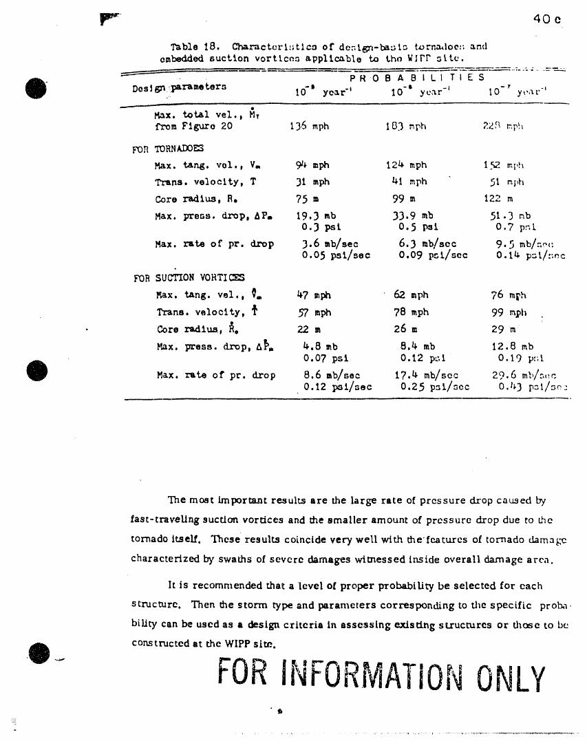
lpr 40e
Table 18. Charactcri:;tlca of dc:.tgn-ba:;tz tornmloe:_ antiembedded euct%on vortices applicable to the WIPP zttc,
PR 0 B A B I LI T I E S
" 10-' year" 10 "1 yc,_r -a I0- r"Design .:parameters
y _,,'t.,.
Max. total vel., M,from Figure 20 136 mph 183 mph 22,qrp_
FOR TORNADOma-
Max. tang. vel., V, 94 mph 124 mph I.%2ml,h
Trans. velocity, T 31 mph 41 mph 51 ml,h
Core radius, R. 75 m 99 m 122 m
Max. press, drop, AP. 19.3 mb 33.9 mb 51.3 mb0.3 psi 0.5 psi. 0.7 pz[
Max. rate of pr. drop 3.6 mb/see 6.3 mb/see 9.5 mb/a_:0.05 psi/see 0.09 pr,t/see 0.14 p,_t/zrc
FOR SUCTION VORTICES
r_ax.tang. vel., _. 47 mph 62 mph 76 m_h
Trans. veloclty, _ 57 mph 78 mph 99 ml_i*
. Core radius, _e 22 m 26 m 29 m
Max. press, drop, A_, 4.8 mb 8.4 mb 12.8 mb0.07 psi 0.12 p".l 0.19 p:;t
Max. rate of pr. drop 8.6 ab/Bcc 17.4 mb/sec 29.6 mll/,-,,,c
The most important results are the large rate of pressure dxop caused by
fast-traveLing suction vortices and the smaller amount of pressure drop due to bhe
tornado Itself. These results coincide very well with the'features of tornado damage
characterized hS' swaths of severe damages wimessed Inside overall damage area.
lt is recommended that a level o! proper probability be selected for each
structure. Then the storm type and parameters corresponding to the specific proba
biUty can be used as a design criteria In assessing existing structures or those to be
constructed at the WIPP sire.
O.- FORINFORMATIONONLYl
=
=

40f
__ iiiiii - i J ]1 i i ii i i i _l i
_ ,..-.:,.. DESIGN-BASIS TORNAD_OES AT WIPP SITE
I (_tylOt'l I C_eyeot "e I 0 "r yeo, "'
= 13,6 mph ,'_, ,,,,,,tS3 m,o,_ ,_, - 2'28 mp_
• bi
L-- . [ II II ]1 ..... lalllj
Ft_:ure 2OB, ]:)_:n-bcs_s ¢oz_doe_ at the tel:EP s_.te, e,_ch ,:cha._ct, erczed _ suctlon voz-tlcos orbitcr_K around Lr_side theouter core of the parent tornado. Core rad¢_ are proportlona.lto the _.Im_ tan_entlal veloc_.tJ.ee,
• "
FORINFORMATIONONLY.

r42
Most Severe Cr,,edi, hie Tornado (One in cme-mtUiea-year tornado)
Although the probabilities by the Pecos Valley method are reasonable, we must
s_II cousld_ the e_fecm of elevation upon tornado IntelLsiCtes in order to determine the
most severe sWrm which is credible at the WIPP site. For this purpose, the Vouch-
down elevations within the Peco6 Valley were obtained by plotting all reported tornadoes
on 1:250,000 USGS topographic maps. Their disu-flmflon by P-scale and elevation at
500oi_intervalsare presentedinFigure21.
The elevation of the WIPP site, 3,414 ft MSL, is apparently not high enough to
el/m/hate the possibilitles of .F 3 tornadoes, lt is reascuble to select the F 3
tornado as being the most severe credible tornado applicable to this site.
@
Acknowledgement:-
The sice-specif_c study presented in this paper was sponsored by Sandia
Laboratories, Albuquerque, New Mexico. Basic research of populatiou correction
was sponsored 13/U.S. Nuclear Regulatory Commission under Contract No.
AT(49-24)-0239.
FORINFORMATIONONLY

2', 4S
• REFERENCES
.__'_..
_, IL F., Jr., (1976): Risk probabilities associated with tornado windspeeds.Proc. of Symposium on Tornadoes, Assessment of Knowledge and Implica-
_ tlou for Man. Texas Tech. Univ., pp 197-236.L
I •
!i _ Abbey, R. F., Jr. and T. T. Fujita (I 975): Use of tornado path lenglhs and• , i gradations of damage to assess tornado intensity probabilities._ t Preprlnts of 9rh Conf. on Severe Local Storms, pp 286-293. i
_': "Climatological Data." A NOAA publication. Published monthly with an AnnualSummary. May be obtained from Environmental Data Service, National I
Climatic Center, Federal Building, Asheville, N.C. 28801. i!
DAPPLE Tornado Tape (1977). List of tornadoes 1950-1975. May be obtained
{ from T. T. Fujita, The University of Chicago, Chicago, Illinois..
FuJita, T. T. (1971): Proposed characterization of tornadoes and hurricanesby area and intensity. SMRP Res. Paper No. 91, 42 pp.
FuJita, T. T. (1972): Estimate of maximum windspeeds of tornadoes insouthernmost Rockies. SMRP Res. Paper No. 105, 47 pp.
O Fujita, T. T. and A. D. Pearson (1976): U. S. Tornadoes, 1930-74. The UniversityofChicago.
Kelly,D. L., J.T. Schaefer,R. P.McNulty, C. A. DoswellIII,and R. F.Abbey,Jr.,(1977):Presentationand interpretationofan expendedtornadoclimatology.Preprintof10thConf. ofSevere LocalStorms.pp 186-193.
Markee, E. H., Jr.,J.G. Seckerley,and K. E. Sanders(1974):Technicalbasisforinterimregionaltornadocriteria.WASH-1300. Govt.PrintingOffice,23 pp.
NSSFC Tornado Tape (1977):Listoftornadoes1950-75. May be obtainedfromA. D. Pearson,NsSFC, Kansas City,Mo.
Pautz,M. E., Editor(1969):Severelocalstorm occurrences,1955-1967.ESSA Tech. Memo. WBTM FCST 12, 77 pp.
INFORMATIONONLY.0

i Jl iii i • li ii gl ii i mi
• ,..
0
SE2SMIC EVALUATION REPORT
OF
UNDERGROUND FACILITIES
WASTE ISOLATION PILOT PLANT
SOUTHEASTERN NEW MEXICO
_)_,, _o _''2'
.FORINFOR[ , ]2,T:9''",' I ,,, '...... .......:', .... ::' --7-- i': .... ,, ,,
_ , u,,,, i i , i , lm,, ...............
.... DF_iGN ENG'R DOEI_.o. 0"':' ,. ,._..,,!,',',o,,........... ,,, :,.,,<'o......su,.,,.............. ,l
•_ WA,,TTEISOLATION PILOT PLANT DOCUMENT NO':' REV.
SEISMIC h-_(_ RKPO_ OF UNDERG_ FACI'I_ 76D510AA-000 ' 0,,u
i,i , u i L

i i ii i i i ii ii i . ii i i_1 i i
SEISMIC EVALUATION REPORTi ii
O o!UNDERGROUND DR I FTS FAC I L I T I ES
WASTE ISOLATIO N .....PILOT ,pLANT
TABLE OF CONTENTS
Paqe
1.0 INTRODUCTION 4
1.1 Task 41.2 Method 41.3 Performance Assessment Criteria 4
2. O CONCLUS IONS 6
2.1 Study Results 62.2 Recommendations 6
3.0 ASSUMPTIONS AND QUALIFICATIONS 8
e 3.1 General 8
3.2 Design Ground Motions B3.3 Input Ground Motions 93.4 Physical Properties of Underground Site
Media i03.5 Analytical Approaches i0
4.0 ANALYSIS II
4.1 General Ii
4.2 Free-Field Underground Earth Responsesto the Prescribed Design Ground Motions 12
4.3 Methods of Analyzing Underground SeismicStructural Responses 13
4.4 Seismic Response of Shafts 164.5 Seismic Response of Drifts 214.6 Structural Stability Evaluation 224.7 Comparison of Static and Dynamic Design
Stresses 29
= _ 5.0 REFERENCES 32w-w
iii mm ,. iii i i
DOCUMENTNO. 76D510,_-000 REV. 0 SHEET 2 OF 98

! i iiii i i......... ii i i i ul
SEISMIC EVALUATION REPORT
OUNDERGROUND DRIFTS FACILITIESt
WASTE ISOLATION PILOT PLANTiii i H m,
TABLE OF CONTENTS
6. I Notations 356.2 List of Tables 376.3 List of Figures 58
w
"T
4
DOCUMENTNO. 76D510AA-O00 REV. 0 SHEET 3 OF 98

•_ ,i . i i ii i
1.0 INTRODUCTION
1.1 Task
The objective of this study is to determine whetherthe current designs for the WIPP undergroundfacilities are adequate to withstand the effects of
• postulated seismic events without failure as definedby performance assessment criteria identified in thisreport.
The underground facilities of the Waste IsolationPilot Plant (WIPP) are located in New Mexico saltformations. These facilities include multipleunlined drifts (unlined tunnels) 2162 feet below thesurface and four vertical shafts connecting thesurface facilities and the drifts. The completedshafts are lined with unreinforced concrete for theupper 820 feet of overburden and unlined for thelower 1342 feet in the salt formation.
This study evaluates the seismic structural
performance of these underground facilities subjectedto two postulated earthquake levels. The first isbased on the requirements of the Uniform BuildingCode (UBC-1979_ for Zone I and has a maximum
" • horizontal and ve_tlcal ground accelezation of
O ' 0.05 g. The second is based on a Design BasisEarthquake (DBE, Refo 3) with a maximum free-field
horizontal and vertical ground acceleration of 0.1 g,based on a 1000-year recurrence period.
The UBC earthquake is the specified earthquake usedto design the shafts and drifts, lt is used toassess the structural performance with respect topersonnel safety during plant operation. The DBE isthe specified earthquake used to design the criticalsurface confinement structures and components for theWIPP. It is used in this study as an extraprecaution to assess the structural performance ofthe shafts and drifts with respect to accessibilityand retrievability under the most severe seismicevent DOStulated for the WIPP facility.
1.2 Method,,
The analytical method used to evaluate the seismic
structural performance was based on the followingprimary considerations:
(I) Two ground motion records were selected to
- simulate the ground motions at the site, since
O 7 earthquakes near the WIPP site available for
" l FOR ....• _ ; _i _ ' '"'_" "" " ;_
._ : 7
DOCUMENTNO. 76D510,6d_-OO0 REV. 0 SHEET' 4 OF 98 ....

i.i i i L. u,i .i i .u., i , i , i in|iu iiB
study. These are the 1952 Kern County and 1971San Fernando records.
O (2) The study approach to obtain undergroundstructural responses was to modify the free-field stresses/stralns obtained using thecomputer program SHAKE with dynamic stress/-strain concentration factors.
(3) The standards used to assess structural
stability of the shafts and drifts, as relatedto stress and strain, are the Griffith and
Newmark rock failure criteria. In addition,particle velocity criterion based on observedseismic damage and calculated peak particlevelocities is used to assess structuralstability.
1.3 Performance ,Assessment Criteria
(I) For the UBC earthquake, performance assessmentcriterion for personnel rafety is based on thecapacity of the underground facilities toresist minor and moderate earthquakes without
structural damage. Structural damage for thisreport refers to spalling and rock falls.Spalling is co_-sidere_ tc be _xfcl_ation ofrelatively thin, sharp edged pieces of rock.
O (2) For the DBE, performance assessment is based onthe capacity of the underground facilities toresist major earthquakes by maintainingaccessibility to the underground facilitiesand retrievability of personnel and storedwaste.
m.
e_
" |l I Vi& I1 il Vi%IYIr't, IIUI i k/JiLl" '........ . i i i ______ ii IlL] i ittlI ii ---: ?z i ,
_ DOCUMENTNO. 76D510.,_,-- REV. 0 _HEET 5 OF Q8r

i i . i i i ii li Jill -- m .......
r •
2. o zONS
2.1 Study Results
• 'The following conclusions can be drawn from thisstudya
(1) For the upper portion of the shafts which arelined with unrelnforced concrete:
(a) With respect to the UBC earthquake, thecalculated particle velocity is less thanthe empirical particle velocitycriterion, the calculated shear stressesare less than the Griffith stresscriterion and the free-field strains areless than Newmark's strain criterion. Nospalllng is expected to occur as a resultof the UBC earthquake and personnelsafety should be maintained.
(b) With respect to the DBE, the calculatedparticle velocity is less than the
empirical particle velocity criterion forthe threshold of 4amage and thecalculated shear stresses are less thanthe Griffith stress criterion.
' ' Tl_erefore, no spalling is uxpected under
these criteria. However, the free-fieldstrains in the upper 200 feet of theshaft exceed the Newmark strain
(spalling) criterion. Therefore,according to this criterio alone,spalling may occur in this portion of theshafts. It is not expected that drops ofsufficient magnitude to cause closure orblockage of the shaft will occur. Thus,accessibility and retrievability shouldbe maintained.
(2) For the unlined portion of the shafts anddrifts, subjected to the UBC or DBE earthquake,the calculated particle velocity and free-fieldstrains are less than the associated empiricalevaluation criteria, and the dynamic stressesare only a small fraction of the staticstresses. No spalling is expected to occur,provided normal required maintenance isperformed. Therefore, accessibility, terrier--ability and personnel safety should be assured.
2.2 Recommendations
T The following recommendations are made for the final
" 'ii ana lysi_ ani detailed design of the sh ai ts:
: L - "" "',ii i __i iiii i
: DOCUMENTNO. 76DSlOAA-O00 REV. 0__._______. SHEET 6 OF 98=_

(1) For the shaft key, it is expected that therelative vertical movement between the surfacelevel and the top of the shaft key will causestress concentrations. Therefore, there may becracking at the transition between therelatively more rigid shaft key and theconcrete lining. This area should receivespecial consideration in final design.
(2) For the transition of the shaft lining to theshaft collar, special consideration should begiven to providing a seismic Joint toaccommodate the different rigidities andstructural performance during ground motion.
FORINFORI' A.I!aN_ ....
- ul ii i r

L i I i i . . ii ,, , , ,---., i
e 3.0 ASSUMPTIONS AND OUALIFICITIONS
3. I General
The variation of earthquake ground motion responsewith depth is both site and earthquake dependent.The ground motion at a particular site ts stronglyinfluenced by the mechanisms of reflection,refraction, and transmission through anonhomogeneously layered media; by surfacetopographyt and by details of the local site geology.In addition, the frequency content of the groundmotion at a particular site is strongly sitedependent (Section 4.2) and the amplitudes of theinput motion at the frequencies of interest may beappreciably modified by the Iocalsite conditions.Therefore the results obtained in this study arequalitative rather than quantitative.
Seismic response and analysis of undergroundfacilities differs from surface facilities in thefollowing ways:
(I) Underground structures hzv_ fully earth-contacteo boundaries, while surface or
partially embedded structures have partiallyground-contacted boundaries.
(2) The seismic behavior of underground structuresis not as well understood and documented bycase histories as that of abovegroundstructures.
(3) The intensity of the underground structureresponses to earth excitation is difficult todetermine because it varies with the source,depth, site media, and structuralcharacteristics.
The effects of earthquakes on facilities maygenerally be grouped into two categories, faultingand shaking. This study does not address thestructural effects due to faulting. Geological andgeophysical surveys indicate no capable faults orfissures in the area of the underground excavations.
3.2 Design Ground M_otions
The DBE peak ground acceleration is defined: probabilistically for a 1,000-year recurrence period.
i " lt has been estimated conservatively as 0.10 g, based
W on current knowledge of the geologic and dynamicz characteristics of the site region This is
_ dis_e_e4k i_ _herwI_Pp._SAR ::(Ref-. 3_ , This. definitiOnrp
i ii iii - iii i u iii i i[ ,[,,: --'-- m_-- -
DOCUMENTNO. 76D'5"'l'0AA-O00 REV, 0 _t_r_T _ n_ Q_

..... ii iii ii , i _ i ,i r--- i ,, i i i MI ,I
Regulatory Commission's concept of a design basisearthquake.
O The UBC recommended design levels are not directlycomparable to recorded or estimated peak groundaccelerations from earthquakes. However, therelationship can be derived through the Seismic RiskMap of the U.S. that is part of the UBC. This mapstates that for zone 1, one would expect, "Minordamage.., corresponds to intensities of V and Vl onthe Modified Mercalli Intensity Scale (MM Scale)".These intensities may, in turn, be related to -accelerations. Both Neumann (Ref. 27) and Trifunac
and Brady (REf. 28) relate MM intensities to near-source accelerations. Intensity V correspondsroughly to an acceleration of 0.03 g while VlcorresEx)nds to about 0.07 g. Thus, an approximateacceleration value for UBC Zone 1 is the average ofthese extremes, or 0.05 g.
AS a final point of interest, Figure C1-3 of ATC 3-06(Ref. 29) shows contours of Aa (effective peakacceleration) for the U.S. The WIPP site is justoutside the 0.05 g contour of the acceleration with a90 percent chance of not occurring in a 50 yearperiod. This is equivalent to about the 475 year
• , event. Thus, ATC 3-06 shows that thc WIF_ site i_as a
O 475 year acceleration of Just under 0.05 g. This isin good agreement with the mid range of the casesconsidered in the WIPP SAR. Figure 28-20 of thatdocument shows a 500 year site peak dynamicacceleration of between 0.035 g and 0.07 g. Thus,the specification of a UBC equivalent site designacceleration amounts practically to the use of a 500year rather than a 1000 year site acceleration.
3.3 Input ....Ground MOtions
The selection of hypothetical input ground motionsfor seismic investigation of shafts and driftsinvolves careful study and comparison of earthquakeand geologic dynamic characteristics. These dynamiccharacteristics include peak ezcitation, frequencycontent, and period of excitation. The importance offocus depth, slant distance, and magnitude of theselected earthquake should also be considered.
Two sets of ground motions records were selected,including both horizontal and vertical timehistories. They represent motions of either largemagnitude, distant earthquakes or small magnitude,
ii near earthquakes; and they agree with the geologicO and seismic characteristics of the site regiondescribed in Reference 3. These records are:
FORINFORMATu:......................- L -,....... "
.........76s'"i'o 0 .....- " ---- : :: : ----11 m,,.... i
DOCUMENTNO. D AA- O0 REV. 0 SHEET Q OF 98

i III I '1 ___ I --I ....... II I
(I) Kern County, California earthquake,
July ,21 1952
Station- Hollywood Storage P.E. LotComponents- SO0 W and VERT
(2) San Fernando, California earthquake,February 9, 1971Station - Lake Huges No. 4Components- S 21 W and VERT
The recorded accelerograms of these earthquakes wereused in the study by scaling the peak accelerationsto 0.10 g and 0.05 g for both horizontal and verticaldirections without modifying the time scales. Theoriginal earthquake records are shown in Figures 3-Ithrough 3-4. Both earthquakes occured in rock orhard stiff soil considered to be rock.
The Kern County earthquake of 1952 had a maximumground velocity consistent with, or in fact a littlegreater than, the average ground velocity used in astudy which forms the basis for the NuclearRegulatory Commission's Guide 1.60, "Design ResponseSpectra For Seismic Design of Nuclear Power Plants."Thus: the use of the Kern County time history is
•" conslde_ed 5o add to the conservatism of this study.
3.4 physical Propertie s O f Un derqround Site Media
Almost all pertinent dynamic material properties ofthe site media were derived from specific gravitymeasurements and estimates of the compressive wave(P-wave) velocities obtained from data of severalbore holes at the site. Shear wave (S-wave)velocites are generally derived from the P-wavevelocities and an assumed Poisson ratio of 0.30.
Other relevant properties, such as the shear modulus(G) and the constrained modulus (D), can be computedfrom formulas of the theory of elastic wavepropagation along with known or assumed data. Theseare: C. the shear wave propagation velocity, Cp thecompressive wave propagation velocity, the massdensity, and the Poisson ratio of the material.
Table 3-I presents physical properties of the WIPPsite geologic profile and formulas used forcomputation of shear and constrained moduli.
3.5 Ana!ytical Approache_ss
_! The following assumptions were made:I
-- ..................... V: ----- ...................= DOCUMENTNO. 76DSIOAA-000 RE 0 SHEET 10 OF g8

ii H i . i i i ii i nii ii miilli i,q mi iiiil n
; t
prevent differential movement between thelining and the surrounding media. In otherwords, the structures move along with theground media at all times, so no rock-structural interaction was considered. This isa conservative assumption.
(2) The shaft linings are fully bonded to thesurrounding rock.
(3) Each stratified layer of soil or rock wasassumed to be a homogeneous isotroplc elasticsolid.
(4) No effects of end-bearing boundaries wereconsidered. These include shaft collars atnear-surface, intersections between lined andunlined shafts, and interconnections betweenshafts and drifts and between drifts.
(5) No effects of multiple or interconnected shaftsor drifts were considered.
(6) Frequency-independent stress concentration
O ..... factors %'er= used in thr a:_alysis and desl_n.Thus, the ratio of wavelength to the size ofcavity was not considered directly.
(7) No other structural effects that may interactwith the seismic problem were considered, suchas creep and high temperatuLe in the salt andgroundwater in the rock.
: (8) No internal structural elements were considered
in this analysis, such as fixed shaft guidesupports and mechanical devices.
= (9) Only vertically propagating P-waves and S-waveswere considered for the shafts.
4.0 ANALYSIS,,11, i
4. I Genera 1= H --
The problem of evaluating seismic structureperformance of shafts and drifts was solved in twomajor steps, based on the assumptions outlined inSection 3.5.
First, an assumed unit column of underground media in
@_] a vertical direction waz analyzed, under conditions_ . that assumed that no structures or cavities were
zI present, and subject to the prescribed earthquake
U •H,, j, ,, , .
DOCUMENTNO. 76DSIOAA-000 RFV 0 .,,rFT _ ,r _=

ii i , in , __ n, i , II - I
Included in tbls report. They are similar to thoseof 0.1 g, but with one half the intensities.
Table 4-I shows acceleration, velocity, anddisplacement at various depths for 0.1 g and 0.05 gmaximum accelerations. Figures 4-6 through 4-8represent envelopes of these peak responses. Theapplication of the results presented in these figuresand table are discussed in Sections 4.4 and 4.5.
4.3 Methods of AnaIyzinq Underground .Seismlc StructuralRLes nes
4.3.1 General
Structural effects due to ground shaking areassociated with stresses Iresulting from thepropagation of seismic elastic compressive waves(P-waves), shear waves (S-waves), and different kindsof surface waves such as Rayleigh waves (R-waves) andLove waves (L-waves). Only p-waves and S-waves wereconsidered in this study because of the complex wavepropagation phenomenon in layered elastic media.
For the analysis of the drifts, the horizontalcomponent of the shear wave (SH) was used and for theanalysis of the shafts the vertical component of theshear wave (SV) was used. _-wdves p=up_gaLing
vertically were considered by replacing theappropriate constants (modulus and wave propagationvelocity). All waves considered are sinusoidalincident waves that induce simple harmonic (steady-state) loads. Effects of surface waves were
neglected.
Three types of underground structural responses dueto P-waves and S-waves were examined:
(I) Flexural, representing the direct imposition ofthe media curvature on the structure, whichmust be able to absorb the resulting strains.
(2) Shearing, representing the response lag of themedia to input acceleration.
(3) Extension or shortening, representing the axialdeformation of the structure and the media, forwhich the slippage between the structure andthe supporting media can be neglected underrelatively small excitations.
General strain and stress formulas for these three= types of responses near the opening, due to the
i obliquely impinging P-waves and S-waves, are briefly, described in the following paragraphs.
FORINFORNIATIOfONLY'i|,l - i ,
DOCUMENT NO, 76D510AA-O6'0'" BEV. O _t,FFT ]3 nF _R

l iiII l , ,, l II .......
Q and applicable formulas derived from the theory ofelastic wave propagation, the site media strainsunder earthquake eicltatlons can be calculated.
Second, dynamic stress concentration factors(Ref. 11) of the openings were obtained to establishthe maximum dynamic deslqn stresses. An assumed unitslice between sections of the shafts or drifts was
analyzed by a classical theory of elasticity. Theanalysis was treated as a two-dlmenslonal planestrain problem of a deflned-shape opening in aninfinite elastic plate subject to simple harmonicloads.
The following sections discuss the seismic analysisof shafts and drifts, in accordance with thismethodology°
4.2 Free-Field Underground Earth Responses to the Pre-scribed Design Ground Motions
The responses of the stratigraphic column shown inFigure 4-I were analyzed with SHAKE. SHAKE computesthe'responses in a system of homogenous, viscoelastic
• lay=rs of infinite horizontal extent subject oniy to
O vertically traveling waves. The maximum number ofsublayers in a model is 20 and the maximum number ofspecified sublayers for computed motions is 15. Themodel chosen is shown in Figure 4-I. The program iswell documented in Ref. 17.
The input motions described in Section 3°3 wereapplied in sublayer 2 (5 feet below the surface).The upper 820 feet of the soil-rock profile wasmodeled with finer mesh to accommodate the abruptchanges in physical properties of the media.
A speclal-purpose computer program (BASE) wasdeveloped to process response data calculated bySHAK_. BASE generates and plots the time historyresponses of the velocity and displacement of eachsublayer by double integration of the acce]eratlontime histories computed by SHAKE° Small errors inthe initial velocity and displacement can lead tolarge errors in the determination of velocity anddisplacement time histories. Therefore, base-llnecorrection methods were used in combination withleast-square-flttlng methods (Ref. 7). Figures 4-2through 4-5 show the acceleration, velocity, anddisplacement time histories of sublayers I, 10 and
:_ 20, subject to each prescribed input ground motion
O [ scaled to 0.1 g maximum peak ground acceleration.Figures for the response time histories for 0.05 g
i . __ iiiii _-- _ ---._ s --- ;
_UCUMENTNO. 76D=_ _ n__ _ Urtt_-uuu _V n qlI_FT ] t r_r _

.... iii III I I ii iii Sill i 111 I 11111
4.3.2 Free-field Strains Due to Oblique P-Waves
' Figure 4-9 shows a P-wave impinging on a structurewith amplitude of ¥p and incident angle e. Thecalculated axial, flexural, and shearing strains dueto this oblique P-wave are (Ref. 23):
Axial ca = ± (Vpecos2e)/Cp2 (4-I)
Flexural "Cb" ± (R Ape sine Cos e)IC2p (4-2)
Shear _ - (Vpe Sine Cose)/C (4-3)P
From this set of equations, maximum strains due to anoblique P-wave are:
- ±Vp8/C 8 = 0o (4-4)Axial ca P
Flexural zb - ±0.3849 RA 6/C 2 e = 35016 ' (4-5)P P
Shear _" Vp6/2c p 0 = 45 ° (4-6)
The notations for all equations are described inAttachment 6. I.
4.3.3 Free-Fiel 9 Straln_ss Due to Oblique s-waves
Figure 4-10 shows an S-wave impinging on a structurewith an incident angle 0 and excitation amplitude Vs.The axial, flexural, and shearing strains due to thisoblique S-wave are:
Axial c - _ ( Sln8 rose)/c (4-7 )a - Vuo 2s
Flexural cb = ± (R Ase2Cos3e)/C s (4-8)
Shear y- (Vso Cos 6)/Cs (4-9)
From this set Of equations, maximum strains due tooblique S-wave are:
Axial e = 450 (4-I0)c - ±vsel2Csa
±RAsg/CB 2 e " 0 ° (4-11)Flexural£b
==
Shear Y " vse/Cs e - 0 ° (4-12)
4.3.4 DynamlcStress Concentration Factors
Dynamic stress concentration in an elastic media is alocalized dynamic stress increment, produced by
_' interrupted propagating seismic waves around= obstacles. Obstacles that induce interruptions of
wave propagation are cavities, cracks, and any rigid_ or flexible inclusions. Interruptions of seismicz
nnP!,_cluT _n 7 r_ql 0AA-C)00 [_:v e,,CCT 14 nr qo_

- ii i i i, l, , =ii i ,,i
O waves around an obstacle are mainly due todiffraction (the deviation of waves from theiroriginal path) and scattering (the outward radiationof secondary waves from the obstacle). Ref. I0provides detailed discussions of diffraction,scattering, and dynamic stress concentrations ofelastic waves.
The ratio of the dynamic stress caused by interruptedwaves to the stress caused by uninterrupted waves atthe same location is known as the Dynamic StressConcentration Factor (DSCF). The DSCF generallydepends on the type of seismic wave, the wavepropagating medium, and the obstacle. For instance,it can vary according to the following factors:
(I) Type and predominant frequency of the incidentwaves
(2) Wave length
(3) Angle of incidence
(4) Physical properties of site medi,_
O (5) Physical and geometric properties of theobstacle
Detailed discussions of the effects of these
parameters on the DSCF are given in Ref. 11.
Most of the knowledge about DSCF concerns incidentwaves propagating in a direction that isperpendicular to the axis of the obstacle (Ref. 11).Although some analytical solutions for determiningDSCF's of oblique incident plane waves can be foundin Ref. 11, no detailed numerical calculations orexplicit solutions are given. Moreover, in mostcases, explicit solutions are given only forobstacles of circular cross sections.
However, despite this, approximate solutions forother cross sections can be reasonably obtained byincorporating appropriate shape factors into thesolutions available for circular sections.
Reference 11 cites cases of incident plane P-waves(Figure 4-11) and S-waves (Figure 4-12) impingin_ on
a circular cavity or a circular-lined cylinder in aperpendicular direction, where amplification due to
_i dynamic effects was approximately 10 to 15 percent
O _ over static values. This suggests that dynamicamplificatio/) _actors obtained for circular sections
i ,th a pt %at|-- ,,,, ,
--- _ _ i i i| i ,i i ,, ,,.... , ,,,i, _i
DOCUMENTNO. 76D510AA-000 REV. 0 _HEET.............! 5 OF . 98

• iii i fill i i i I i i , ,,- i , ,m,, ii i
The following paragraphs summarize DSCF's and shape
O factors relevant to the design of the WIPPunderground facilities.
(I) Drifts: The following equations for driftswith a rectangular shape and rounded cornersassume incident waves normal to the cavity.(See Figures 4-13, 4-14, 4-15 and Paragraphs4.3.1 and 4.5.1)(Refs. 5 and 8)
P-waves nscz - KI[0.6 + (b)2/3) (4-13)
S-waves DSCF - K2[0.6 + (b)2/3) (4-14)
(2) Shafts: The following equations for shaftsassume incident waves parallel to the cavity orlined cylinder. (See Figure 4-16 andParagraphs 4.3.1 and 4.4.1),
- (a) Unline_ Shaft:
O For Polsson's ratio - 0.3
P-waves DSCF - 1.0 (4-15)
S-waves DSCF = K, (4-16)
where K3 - 4.7.
(b) Lined Shaft:
For Poisson's ratio = 0.3
P-waves DSCF = 1.0 (4-17)
S-waves DSCF = K, (4-18)
where K, is obtained from Figure 4-17 forhoop stresses.
4.4 Seismic Response of Shaftsm , ,
4.4.1 Descriptlon of Shafts
_ There are four shafts connecting the surfacei facilities to the underground repository level, as
O _ shown in Figure 4-18. Each shaft was designedaccording to its specific function. Ali shafts
zI consist of three major portions:i FORINFORMATIONONLYI __, _ ,lilll __ ill
,,_,,,._,_,,_ 76DSIOM-000 _, _ _l,_rT __ -_ Q_

O (I) The concrete shaft collar near the surface(level 0'0")
(2) The portion lined with unreinforced concreteconnectln_ the shaft collar to the top of thesalt bed (level 843'0")
(3) The unlined portion from the top of the saltbed to the experimental level (level 2162'0")
Zach shaft is briefly described below as follows=
(I) Waste Shaft (FiQure 4-19): This shafttransports radioactive waste to theexperimental level and iE consists of thefollowlnQ parts:
(a) A concrete shaft collar located betweenthe Qround surface and level 27_9 ".
(b) A lined portion with an inner diameter of19'0" consisting of the upper 537 ft with10 inch unreinforced concrete and overbreak and the lower 265 ft with IB in
, c:ncrete and overbreak
O (c) An unlined portion with a diameter of20 ft.
(d) A reinforced concrete key and water ring(approximately 50 ft. long) is located atthe rock and salt interface.
(2) Storage Exhaust Shaft: This shaft is forstoraQe exhaust. Its design is similar to thatof the waste shaft except for the liner, whichis steel enclosed by cement grout. The lineris made of steel plate, and has a 10 ft innerdiameter. The cement grout is approximately8 inch thick plus overbreak. Circumferentialsteel rlnQs are welded to the steel liner atintervals. The unlined portion of the shafthas a diameter of 11'8".
(3) Ventilation Supply and Service Shaft: Thisshaft is for ventilation supply and services.Its desiQn is similar to the waste shaftdesign. The concrete liner has a 16'0" innerdiameter and varies in nominal thickness from 8
to 14 inches plus overbreak. The unlined- portion of the shaft has a diameter of 17'0".
O z (4) Construction Exhaust and Salt Handling Shaft:_I This shaft is for construction exhaust andsalt
N,mrl, l H ,J ___ i --
DOCUMENTNO. 76DSlOAA-O00 REV, O SHEET........17'i........... OF __?_.....

O waste shaft design e,cept that the concreteliner has a 14'0" inner diameter and a nominalthickness that varies from 8 to 14 inches, plusoverbreak. The unlined portion of this shafthas a diameter of 15'0".
The waste shaft was selected for a typical shaft
study in this report for the following reasons:
(I) Similarity of construction schemes in allvertical shafts
(2) Largest diameter in both lined and unlinedportions.
4.4.2 Seismi c Responses . of Shafts
Since only vertically propagating P-waves and S-waveswere considered in this study, dynamic stresses ofvertical shafts induced by the prescribed groundmotions can be determined from the equations inSection 4.3 by letting the incident angle e - 0°.Maximum response shaft strains, including dynamic
,. stress concentration effecLs: can bp obtained by' ' incorporating the results of these equations as
O follows:
(I) Axial Strains: Tor lined and unlit_ed portions,from equations 4-I and 4-15,
ca . Vpo/C p x DSCF = Vpo/C p (4-19)
(2) Fie=ural Strains: For lined portion, fromequations 4-11 and 4-18,
cb " KA_oICs 2 x DSCF = KdRAs0/Cs 2 (4-20)
For unlined portion, from equations 4-11 and4-16,
2£b " KAso/Cs2x DSCF - 4.YKAso/C s (4-21)
(3) Shear Strains: For lined portion, fromequations 4-12 and 4-18,
T - Vio/Cs x DSCF - K4VsO/C s (4-22)
For unlined portion, from equations 4-12 and
4-16,
: _I y - VsolC s x DSCT - 4.7Vs0/C s (4-23)
i Equations 4-19 through 4-23 are used to compute the j
L; " _ L___ lr I II
._........_ ... 76_51 n ..... "

i i i i i ii i i, ii ml m|, .... ..=...................... .. . .......... . , ,,i m !
Table 4-2. The shear wave velocity used in the
e program to produce these calculations is the shearwave velocity characteristic of each individual soillayer.
4.4.3 Alternate Approac h
An alternate approach for determining the responseshaft strains is to use the displacement responsetime histories of the stratiQraphic column. (SeeFigure 4-1). In this figure, the column is analogousto a cantilever pendulum subject to the prescribedmotions; and it is apparent that only sheardeformations occur under the S-wave excitation
(Figure 4-20a), and that only axial deformations takeplace under the P-wave ezcitation (Figure 4-20b).
For any sublayer of the stratigraphic column, maximumresponse strains caused by seismic wave excitationscan be approximated by the strains obtained from thedeformed geometries multiplied by the dynamic stressconcentration factors. The response strains aredescribed below.
(I} Axial Strain: This strain is mainly caused byP-waves or vertical motions. (See F1aure
e 4-20b).For any sublayer, (ai " _vl/lll (4-24)
Total axial strain stratigraphic column,
n
ca "_cal " (4-25)
and, av - _V i (4-26)
Maxlmum azial strain,
(2) Shear Strain: _his, strain is mainly caused byS-waves or horizontal motions. (See Figure4-20a).
AUt+I " _Ut
For any sublayer, _i " i_'------_ (4-28)
Q- r_
FORINFORMATIONONLY-
_ : -- ._. ii ._LI Ullll_ , , • - _ _m

. ii i i i i J 11,. iii i,,,, i ii, iii,i
Total shear deformation of the stratlgraphlccolumn,
Au- (4-29)i
Maximum shear strain,
I7_lmax. I _Ut+l " _Ui 14-3o)To calculate maximum response strains of the shafts,the dynamic stress concentration factors discussed inParagraph 4.3.4 must be appILed to the aboveequations. This implies no amplifications for axialstrains, K_ for shear strains of the lined portion,and K_ for shear strains of the unlined portion.
Response strains of the shafts from the obtaineddisplacement response time histories (Section 4.2)were calculated from equations 4-24 through 4-30.These results are presented in Table 4-3. Evaluationof structural stability of shafts from Tables 4-2 and
• 4-3 is presented in Section 4.6.
O . 4.;.4 Comparison of the Two Me.__thodsFollowing are some observations drawn from comparingthe free-fleld axial strains and shear strains
obtained by the dynamic theory to those obtained bythe alternate deformed structure method.
(1) In general, results of these two methods agreevery well in order of magnitude of thecalculated strains. The alternate method shows
f}uctuating time responses, which reflects thelocal site media property changes; the dynamictheory only predicts the peak envelope ofmaximum responses.
(2) Peak enevelope results obtained from thedynamic theory may be sufficient for designpurposes° However, the time history responses(Table 4-3) also provide valuable informationrelevant to the prediction of rock crackpropagation and spalllng.
(3) lt is consistently shown in both Tables 4-2 and4-3 that the largest axial, flexural, and shearstrains are present in the upper portion of the
" _ shafts.
0:" "7
°t: FORINFORMATIONONLY

4.5 .Seismic Response of Drifts
4.5.1 _Descrlptign of Drifts
Drifts, located on the experimental level at 2162feet below the surface, are rectangular openings withrounded corners. The ratio of fillet radius to shortdimension is approximately one to six. The typicalheight of drifts is 12 to 13 feet, with variouswidths. (See Figure 4-21 for a typical section ofunderground drifts). Multiple openings at theexperimental level are arranged in orthogonaldirections.
Rock bolts and wire mesh are used as a means of
ground support in the roof and sidewalls of thedrifts as required to provide structural adequacy ofthe rock salt locally in areas of weakness ordiscontinuity.
4.5.2 _Seism!c Responses of Drift__S
Seismic responses of drifts are highly dependent onthe characteristics of the ground excitations andsite media, as well as mn the fmcus depth and slant
' ' distance. The first two factors are discussed in
The latter two factors can beSection 4.2.
considered by evaluating the effects of shallow-nearand deep-distant earthquakes.
For shallow-near earthquakes, either P-waves orS-waves may be assumed to propagate in a directionparallel to the axis of the drifts, and therefore theincident angle is 8 - 0 °. For deep-distantearthquakes, either P-waves or S-waves may be assumedto impinge on the drifts normally at 8 - 90 ° . Basedon the available seismological data in the vicinityof the WIPP site, it is reasonable to assume theincident angle is O - 45 ° .
At an oblique incident angle e - 45 ° the earthquakewould produce maximum design stresses if P-waves andS-waves propagate in the same direction. Although nonumerical dynamic stress concentration factors areavailable for the case of incident angle e - 45 ° , itappears r'easonable to use the DSCF's obtained inParagraph 4.3.4. For rectangular drifts with roundedcorners, the following maximum seismic responses aregiven:
: g f:ORII, FORNAiiOt'ON V"

O (I) Axial Stralns. From equations 4-I0 and 4-14,
ca - ±(V.el2C ,) Cvscr) (t-31 )
( )(-, E2 0.,+ 1_12/3 v,e/2c(2) Flexural Strains: From equations 4-5 and 4-13,
" (pstr)
(3) Shear Strains'. From equations 4-6 and 4-13,
T = (VpB/2Cp)(DSCF)
Results of maximum seismic responses of driftscalculated from equations 4-32 through 4-34 andSection 4.2 are presented in Table 4-&. The
O evaluation of structural stabiliLy_u[ dLifh_ _u mTable 4-4 is presented in Section 4-6.
4.6 Structural stability E y aluation
4.6.1 Failure Theory Based on Stress
lt has been shown (Ref. 8) that the Coulomb
criterion, the Mohr's hypothesis, and the Grlfflthcriterion provide the most useful theories offailure. These theories are discussed in detail in
many texts of rock mechanics (Refs. 8 and I0).
The Grlffith criterion is based on the premise thatfracture is caused by stress concentrations at thetips of minute "Grlfflth cracks", which are supposedto pervade the material, and that fracture isinitiated when the maximum stress near the tip of the
most favorably oriented crack reaches a valuecharacteristic of the material. In other words, thetheory assumes that failure of the material, or crackpropagation, takes place where the maximum tensilestress around the most dangerous crack reaches one oral! of the the following conditions:
(I) Tensile conditions:
®ii (oi-a2)2 - 8T (a + o2) - 0 ii aI + 3a2 > 0 14-35)o I
i: F R'o N ORmATIONONlY

- , ,
_=Nii_iiiililiO_Jd iii i ilii i I I III ,iii ii iiadu
(2) Compressive conditions:
°1[(_2 + 1) 1/2 - _] -o2[(_2 + 1) 1/2 + _] . (4-37)0
C/z 2.2u o if o - 0 then4zo [1 + ] c _ '0
2 112Ol[(U + I) -_] -o2[(_ 2 + I) 112 + _] -kTo (4-38)
Where the notations ol, o2, To. u, and oc arethe first and second principal stresses,uniaxlal tensile strenght, material internalfriction coefficient, and normal stress to acrack, respectively.
The principal stresses can be determined by analvzlngMohr's Circle and are given by.
01 " 1/2(o x + Oy,) + [Tx_12+1/4 (o x - oy)211/2 (4-39)
2+1/4 (o - o )211/202 - 112(o x + Oy) - [_xy x y (4-40)
Note that under uniaxial stress conditions (o 2 - 03 -0} equation 4-35 becomes.
O Co " 8To
This indicates that the unlaxial compressive strengthis eight times greater than the uniaxial tensilestrength under the Grlffith hypothesis.
Detailed studies of failure or crack propagation ofrock media (Ref. B) reveal that once failure has
begun at certain values of the applied stresses, itwill continue at the same, or lower, value of thesestresses. In terms of the concept of cracks, thisimplies that as the stresses applied to the rockexceed the Grlffith stresses, failure starts from thecrack with the most dangerous orientation. Anincrease in the applied stresses is required toextend this crack.
Any stresses in excess of the Griffith stressesnecessary to produce crack extension can cause therock to partially cleave in a direction parallel tothe direction of the major principal stress. As aresult of this increase, failure starts from othercracks with less dangerous orientations. If thiswere to result in the extension of the crack in its
_! own plane, as is the case in tension° the condition
ability of a rock media containing such a crack to7 resist load would diminish with continued crack
width. This situation is unstable, and an extension

_I_,%%'_%_,,_i
_- LIIII _ Ulll ii iii i i i i|iii i, i i ,, ,i, ,,, ,, ,l i, ,i i
O Compression Grlffith crack propagation, followingcrack initiation, appears to be stable and does notlead to complete failure, as does the unstablepropagation of Griffith cracks in tension.
In Ref. 18, Serata has clted the octahedral shearingi strength for weak :salt as 600 psl, and for strong, f,
•,, salt as 750 psi. The octahedral shearing; strength/stress is defined as.I
Toct -'_ O1 - 02)2 + (o 2 - O3)2 + (0 3 - o 1)
1
" -_[°12 + °22 + °32 " °1_2 - o2o3- _3_1]' (_-41)
4.6.2 Empirical ....Failure Cri_e_rtaBased on Strain
Newmark (Ref. 9) has cited the following empiricaldesign criteria for rocks:
(I) Minor spalls will occur up to a distance fromthe source at which free field strains are from
0.02 to 0.06 percent.
O (2) At a distance from the where the localsource
compressive strain is equal to the failurestrain (say a net strain of from 0.5 to Ipercent), serious damage will occur in the formof local crushing and rock drops. Although theopening may stay substantially unfilled, therewill be large areas of rock drops and localcrushing around the sides of the cavity.
(3) In general, the maximum local strains are aboutthree times the free-field strains for acircular hole, and from five to six times thefree-fleld strains for a rectangle with roundedcorners.
It is recognized that different types of rock exhibitdifferent mater, S.al properties and therefore havedifferent failure or fracture criteria. The above
mentioned criteria do not attempt to determine thefailure of rock salt in thls _tudy, but they doprovide useful information in the evaluation of
seismic performance of underground openings. Sincethe strength of rock salt is generally lower than forother types of rocks, like shale or dolerlte(Ref. I0), it is conservatively assumed the lower
O : bound of Newmark criteria (i.e., 0.02 percent) to bethe upper bound criteria for rock salt. For theupper portion of the shafts 0.05 percent is assumedz
[Ui II[UR h liUl UtLI

i i olmamli li iii i nun ii i, ill iii li ml iiii i
O No other relevant empirical data or experimentalinformation was identified in the literature surveyto determine failure/fracture of salt rock in this
study (Refs. 6, 13, 14, 16, 19, 20, 21).
4.6.3 .Emplrical Damage Crlterla Based on Pa[ticle Velocity
The references discussed in this section, dealingwith the response of rock tunnels to seismic andexplosion induced ground motions, are not directlyapplicable to the shafts and drafts for the WIPPfacility. This is due to differences in geology,depths of structures, orientation and direction ofpropogating waves, structural configurations, etc.,of the WIPP and the areas studied. However, theconclusions the authors have drawn from their
observations of the response of tunnels to dynamicground motions are consistent and form the basis fora qualitative guideline for accessing structuralresponse and explaining the good performance,relative to surface structures, of deep undergroundstructures subjected to dynamic motions.
Although the authors refer to tunnels and do notspecifically mention shafts, mine portals, surface
O ' openings for horizontal, inclined oL ve_Liu_l sh_ft• passageways to the underground tunnels, are referredto.
Dowding (Ref. 24) compares observed rock tunnelresponses to earthquake motions and the calculatedpeak ground accelerations. In all, 71 tunnelssubjected to shaking and distortion located inCalifornia, Alaska, and Japan were studied. Damage,ranging from cracking to closure occurred in 41 casesstudied. The majority of the tunnels were 9 to18 ft. in diameter. Thirteen different earthquakeswere involved. The Richter magnitude varied from 5.8to 8.3 and the focal depths varied between 8 and25 miles. Six of the earthquakes were in California,slx in Japan and one in Alaska. Of the 24 tunnelswhere linings were described, two were unlined, twowere timbered, seven were lined with brick or masonryand 13 were concrete lined.
The average depth of the rock tunnels studied was300 ft. The median depth was 150 ft. However, thedepths vary radically along the alignment from zeroat the portals to 1800 ft. Portal damage was notincluded because of the close relationship with land-sliding. The following summarized describes the
"0 i relevant conclusions:Z
a:i Rti iJR..M.AiiOr Lfi

(I) There were no reports of even falling stones inunlined tunnels up to an acceleration of .19 gand a particle velocity of 8 in/ser.
(2) "Up to .25 g acceleration and 15 in/ser velocitythere are only a few incidences of minorcracking in concrete lined tunnels.
(3) The report equates the "no damage zone" at.19 g acceleration with the ModifiedMercalli VIII level.
(4) Comparatively, tunnels are less susceptible todamage from shaking than above-groundstructures at the same intensity level asdetermined from surface motions.
(5) Since the variation in present attenuationrelationships for surfaces motion fs so large,it weuld seem that prediction of subsurfacemotions through present surface attenuationrelationships in combination withdeamplification factors for motions at depthwould only serve to increase uncertainty.
(6) lt is this deamplification effect that _orlr.=
of the lines of underlying theone reasoningrelative stability of tunnels with respect ofsurface structure.
(7) Increased damage to shallow tunnels anddeamplification of Rayleigh or surface waveswith depth point to increasing stability of agiven diameter opening with increasing depth.
(8) During shaking, high frequency compressivewaves can be reflected off the surface of thetunnel in the form of tensile waves and causeslabbing when the tensile strength of the rockmass or liner is exceeded. This is most
important with the high frequency wavesassociated with explosives. Therefore, it isunlikely to have a predominant effect in rocktunnels stability due to earthquake shakingexcept at very small focal distances wherehigher frequencies predominate.
The results of a Bechtel study (Ref. 32) in whichDowding's work was revised to include only tunnels inrock and exclude damage to underground openings inunconsolidated materials, displacement, portal areas
: and those with shallow cover shows, in general,_I negligible damage even at accelerations exceedin_' 0.50 g and particle velocities exceeding
""TIO' °INFORMATI0N 0NLYq
=
...... _ I_", _r' ,I, ' "lr 1li 'l,q', ,' ..... "'rP"_l ' '1_,;,I "'" _"" ,_llll"", ,,,,111 ,, ','r'l.... ,rill, 'n'_l,qlql'' Ill' ,, ,,l_,lpp, "'Irl " 'lli"' q,ill" I,,, rl, ....i

O (REf. 15) cites work done by Langefors andHendronKehlstrom (Ref. 26) who _Ive particle velocitycriteria for damage to tunnels in rock. A particlevelocity of 12 IFt/sec is given as a criterion for the"fall of rock in unlined tunnels," and a particle
velocity of 24 in/sec is correlated with theformatlon of new cracks in rock. Hendron states thatthese criteria are consistant with his own experiencefor unlined tunnels near nuclear detonations,"Unlined tunnels rarely experience visible damage at
ranges when free-field ground motions are on theorder of I-2 ft/aec, unless a loosened piece of rockis detached from the roof by shaking." Hendron alsosyntheslsed the results of the explosion testing oftunnels and found that dynamic strains, calculated asa ratio of particle velocity divided by celerity forexplosion induced pulses of high frequency, needed tobe at least 0.0004 to cause intermittant falling ofstones in an unlined, 15 ft. diameter tunnel insandstone.
Based on Bechtel's experience, a particle velocity of8 in/sec is a reasonable and acceptable criterion ofthe peak particle velocity at the threshold ofdamage, in view of the above referenced works,8 in/sec is also considered to be a conservative
O criterion.
4.6.4 Assessment of UnderGround Structural Stabilit'_
Calculated strains and stresses are presented inTables 4-5 and 4-6 for the drifts and unlinedsections of the shafts respectively. The conclusionsreached with respect to performance assessment,including those pertaining to the concrete linedsection of the shafts, have been made based on thestress, strain and particle velocity criteriapresented in Paragraphs 4.6.1, 4.6.2 and 4.6.3 as itapplies to the rock and salt. The presence of theunreinforced concrete lining has not been considered
in the analysis, lt is recognized that the concrete
lining will reduce spalling.
(I) For the maximum peak ground acceleration of0.05 g, the free-field strains in the shaft anddrifts are generally less than Ne_nark's straincriteria and the maximum particle velocity of3 in/aec is less than Dowding's 8 in/see. Thecombined static and dynamic shearing stressesin the lined portion of the shaft are less thanthe Griffith criterion and in the salt are
O : approximately equal to or greater than theoctahedral and Griffith criteria. But again,as in the case of 0 I0 g below, the dynamicZ
_ __s_S ir_o___a_ tact ionMA.[ ifN lle_staNi_' I Y- _e..w u . w _ _ V w m W V WI B | U _ | _ quiP'I '_ Ibw |

ii........ i u u iii inn i i , 11 lull mu Illl I
O stresses. Therefore, no spalllng is expectedin the shafts or drifts as a result of the
0.05 g maximum acceleration design earthquakeand personnel safety should be maintained.
(2) For the DEE maximum peak ground acceleration ofO. 10 g:
(a) In the lined portion of the shafts thepeak particle velocity does not exceed6 in/ser. This is less than Dowdlng's8 in/ser criteria, and the calculatedshear stress is less than the Grifflth
criterion. Therefore, no spalling isexpected under these criteria. Thefree-fleld strains in the upper 200 feetof rock exceed the Newmark strain
criteria. However, if the apparent shearwave velocity of the material at thepoint where the energy is released wasused in the analysis, as suggested byNewmark (Ref. 31), instead of using theshear wave velocities characteristic ofeach individual layer, then thefree-fleld strains would oenerally not
' ' exceed the Newma_k stLai,, urih_la.
O Blockage of the shafts is not expected.Thus, accessibility and retrievabilityshould be maintained.
The storage exhaust shaft's steel lineroffers an additional factor of safetyagainst failure and provides an emergencyescapeway.
(b) In the lower unlined portion of theshafts and drifts, the static stressesare generally much larger than thedynamic stresses, and the combined staticand dynamic shearing stresses exceed theGriffith and octahedral stress criteriaof tl_e salt. However, the free-fielddynamic strains are less than the Newmarkcriteria and the peak particle velocitybelow the lining is less than 5 In/ser.Therefore stress criteria alone does not
appear to be adequate as a means ofpredicting overstressinq due to dynamicground motions. Static stresses aloneappear to be of sufficient magnitude tocause cracking and spalling in the rock
: salt. After a state of staticequilibriun is reached in the salt and
periodic maintenance, such as scaling, isperformed, the dynamic stresses are not
FORINFORMATIONONLY

iii i ii1.1 i,ii i i ii i i i, i i i i i i
likely to cause any additional
O overstressing leading to spalllng.Again, accessibility and retrievabilityshould be maintained.
(c) Flexural strains in both the unlinedshaft and the drifts are small and can beneglected.
4.7 Comparlson of Static and Dynamic Design Stresses
4.7.1 Sta%ic Stress Concentrationsiiii iii i n
Static stress concentrations of underground openingslargely depend on the shape of openings and thePoisson's ratios of the medium. These concentrations
are unlike dynamic stress concentrations that dependon opening size, shape, and other dynamiccharacteristics of site medium and excitationsources.
The size of the opening has relatively little effecton static stress concentrations; however, mechanicaldefects (faults, shear zones, joints etc.) preventmaking very large openings in any rock formation.
Prior to the excavation of openings, the vertical
O stress on a unit horizontal section rockthrough a
media is equal to the rock weight above this section.That is,
a - (4-42)Y i
o where
a - vertically applied stress (also known asY lithostatic stress)
Pl - density of i th sublayer of rocks or soilsabove the opening
Hi - vertical thickness of i th sublayer
Assuming linear elasticity of the medium,horizontally applied stresses are obtained with thefollowing relationship:
v (4-43)-- X
(I - v) Y
ii FORiNFORMATIONONLY_ Ji,m-,------
: DOCUMENTNO. 76D510AA-000 REV. 0 SHEET 29 nF qS....

i u l i i li ,, , , , .,.., J ,.,u , , --,, i
O whereox - horizontal applied stress
= Poisson's ratio of the immediate surroundingmedium of the opening
Note that this case has been reduced to a two-
dimensional plane strain problem by considering theinfinite length of the single opening. Critical
design stress values can be obtained when verticallyapplied stresses and static stress concentrationfactors are determined.
Static stress concentrations around openings ofvarious cross sections (circular, elliptical,ovaloid, or rectangular shapes) can be found inRefs. 5, 8, and 10. Several figures presented inRef. 5 are reproduced to compare static and dynamicstress concentrations. Figures 4-22 through 4-25show boundary stress concentrations for circular,elliptical, ovaloid, and rectangular cross sections,respectively. Figures 4-26 through 4-29 presentcritical compressive and tensile stresses for thesevarious cross sections.
Note that the parameter M used in Ref. 5 is identicalto the coefficient used in equation 4-42; thus,M = w/(1-w). For design and comparison purposes,linear interpolation of various values of M(Poisson's ratio) is reasonable.
For the purposes of this report, the calculatedstatic stresses have been assumed equal to thosecalculated by using equations 4-42 and 4-43 withoutany applied concentration factor.
4.7.2 Comparison 0f Static an d Dynamic Desion Stresses
The maximum stress concentration factors around the
circular openings can be approximated by lettingu. 0, and _- 0. Probable maximum static anddynamic stress concentration factors are also _hownin Figures 4-14 and 4-15.
Examination of these figures reveals that the dynamicstress concentration factors ace 10 to 15 percent ofthe static factors in all cases. A similarconclusion can be reached in the case of a circular
lined cavity as shown in Figure 4-17. Therefore, for= design purposes it appears practical and justifiable
to use appropriate factors of safety on static
_I results of traditional rockmechanics.
..... FORINFORMATIONONLYDOCUMENTNO. 76DS10AA-0'O0 REV. Q...... SHEET 30 0F___,98

A detailed study of Figures 4-22 through 4-29 and ofthe static design stress calculation procedures(Paragraph 4.7.1) reveals that, for deep undergroundcavities, static concentrated stresses may be highenough to cause local rock cracking and spalllngregardless of whether dynamic stresses are includedor not. However, the results of studies by Bechtel(Ref. 30) indicate that in most areas at the driftlevel, the static stresses are significantly reducedin a relatively short period of time afterezcavatlon. This reduction is due to salt creep,relaxation, and deterioration and is influenced byitems such as salt properties, room configuration anddrift layout. Thus, in a material such as saltsubject Po creep, the relationship between the staticand dynamic stresses is difficult to determine.
• ii _ORNFORM TOO Ly• i
g-Cd_v_o 0 .... - _-_ -- _ ,nn. _uc:_l"r'lun 76D 0 I:IFV n SitEET 31 OF ........9.n

LI i ,ilii i i i i i ii , m n ,,, ii mnii li,iii i
A
W s. o(I) =Year End and Fourth Quarter Technical Progress
Report, Fiscal Year 1979", SAN/I011-203,Section 5, Agbabian Associates, El Segundo, CA90245.
(2) =Earthquake Engineering and Soil Dynamics",Proceedings of the ASCE GeotechnicalEngineering Division Specialty Conference,June 19-21, 1978, Pasadena, CA.
(5) "Waste Isolation Pilot Plant Safety Analysis= U S Department of Energy,Report, . .
September 1980.
(4) Chang, C-Y, and Nair, K., "Development andApplication of Theoretical Methods forEvaluating Stability of Openings in Rock",Woodward-Lundgren & Associates, Oakland, CA,December 1973.
(5) "Design of Underground Installations in RockTunnels" U S Army Corps of Enuin_er_; _anual, o •
• _ 1i10-345-432, January 1961.
O =Tunnel Support Loading(6) Daemen, Jaak J.K.,Caused by Rock Failure", Department of theArmy, Technical Report MRD-3-75, May 1975.
(7) Hudson, D.E., "Reading and Interpreting StrongMotion Accelerograms =, Division of Engineeringand Applied Sciences, California Institute ofTechnology, July 1979.
(8) Jaeger, J. D. and Cook, N. G. W., Fundamentals
of ....Rock .Mechanics, John Wiley & Sons, Inc.NoY., 1976.
(9) Newmark, N. M., "Design of Structures forDynamic Loads Including the Effects ofVibration and Ground Shock", Symposium ofScientific Problems of Protective Constructions
at the Swiss Federal Institute of Technology,Zurich, July 25-30, 1963.
(10) Obert, L. and Duvall, W., Rock Mechanics andthe Desiqn of Structures in Rock, John Wiley,
N.Y., 1967.
= (11) Pao, Y. H., and Mow, C. C., Diffraction of
_ Elastic Waves and DTnamic. Stress Concentrations,z Crane, Russak & Company, Inc., 1972.
FORINFORMATIONONLYiii ii i
DOCUMENTNO, 76D510AA-OO0 REV ,_ :_. SttEET 32 OF o_' ,ll,_pdq _1 ,, p( P *'ll'llql i 11' 'r =

....i i i ii I _l I ] . i --_, ..... j ....... ii i i i ill l , LI __ ".............
O "Dynamical Stress Concentration in(12) Pao, Y. S.,and Elastic Plate", _ournal of ApplledM echanlcs, June 1962.
(13) Petter, W. R., "Free-Field Ground Motion inGranite", Project Officer Report -Project 1.2a, Operation Flint Lock-Shot PileDriver, FOR-4001 (WT-4001)r SandiaLaboratories, Albuquerque, New Hezico 87115,September 1968.
(14) Petter, W. R., and Bass, R. C., "Free-FieldGround Motion Induce4 by UndergroundExpolosions", SAND 74-0252, SandiaLaboratories, Albuquerque, New Mexico 87115,November 1975.
(15) Richter, C. F., Elementary Selsmoloqy, w. H.Freeman and Company, 1958.
(16) Russell, P. L., "Pre- and Post-Shot MineSurvey, Final Report, Project GNOME", U.S.Bureau of Mines, May 22, 1962.
.... (17) Schna_¢l, P.B., Lysmer, J., and Seed_ H. B0,
O "SHAKE - A computer Program for EarthquakeResponse Analysis of Horizontally LayeredSites", EERC-72-12, University of California,Berkeley, CA.
(18) Serata, Shosei, "Geomecllanical Basis for Designof Underground Salt Cavities", The AmericanSociety of Mechanical Engineers, PubllcatlonNo. 78-Pet-59, 1978.
(19) Wahlstrom, E. C., Tunnelin_a InRog _, ElsevierScientific Publishing Company, 1973.
(20) Wawersik, W. R., and Hannum, D. W., *MechanicalBehavior of New Mexico Rock Salt in Triaxial
Compression Up to 200oC ", Sandia Laboratories,Albuquerque, New Mexico, February 1963.
(21) Weart, W. D., "Particle Motion Near a NuclearDetonation in Halite, Project GNOME", PNE I08F,Project 44.1 and 1.1, Sandia Laboratories,Albuquerque, New Mexico, February 1963.
_! (22) White, J. E., Seismicwaves, McGraw-Hill Book' Company, 1965.
_ (231 Yeh, G. C. K., "Seismic Analysis of Slenderz Buried Beams', Bulletin of the Seismological
-------_ "76D510/M,...,,....,..,. -000 .............................. _

(24) Dowding, C. H., "Earthquake Stability of RockTunnels", Tunnels and Tunnelling, June 1979,
O pp. 15-20.
(25) Rendron, A.J. =Engineering of Rock Blasting onCivil Projects = Structural and Geotechn!calF
Hechanics, Ed. W.J. Hall, Prentice - Wall,Englewood Cllffs, N.J., 1977, pp. 242-277.
(26) Langefors, U., and B. Kihlstrom,
The Modern Technique of Rock _lastlng, Wiley,New York, and Almquist and Wiksell, Stockholm,1963, 405 pp.
(27) Neumann, F., Earthquake Intensity and RelatedGround Motion, University of Washington Press,s'eattl6, 195, 75 pp.
(28) Trlfunac, M.D., and A.G. Brady, "On theCorrelation of Seismic Intensity Scales withthe Peaks of Recorded Strong Motion", Bulletinof the Seismiological Society of America, Vol.65, No. I, Feb. 1975, pp. 139-162.
(29) "Tentative Provision for Development of SeismicRegulations for Buildings", Applied Technology
• CouPcil (ATC 3-06), June 1_'B.
O (30) =Stability Analysis of Underground Openings,RMC-II=, Bechtel, Document He. 51-R-510-04,WIPP Project.
(31) Newmark, N.M. (1968), "Problems in WavePropagation in Sell and Rock," Proceedings,International Symposium on Wave Propagation andDynamic Properties of Earth Materials,Albuquerque, New Mexico.
(32) McClure, C.R., =Damage to UndergroundStructures During Earhtquakes"_ Bechtel Civiland Minerals, Inc., San Francisco, 15 pp.
, iiii FORINFORMATIONONLYDOCUMENTNO. 7665].'OAA-00'O - ' ..............REV. O SHEET 34 OF__Q__9.8___

6.o ATT qH TS
O 6. I NOTATIONS
Des iqna tion De scr ipt ion
¢a - Azlal strain, in micro-straln
- Flexural strain, in mlcro-straln
_ = Shear strain, in mlcro-strain
Cp - Compressive wave velocity, ft/sec
Cs = Shear wave velocity, ft/see
Vpe = Compressive wave particle velocity, in/secInciden% an qle is equal to e
Vse = Shear wave particle velocity, in/secIncident angle is equal to e
Ap_ . Compressive wave particle acceleration, in/sec=Incident angle is equal to e
As e = Shear wave particle acce!eraticn, _.-J_ec 2
O Incident angle is equal to eB_ = Thickness o£ sublayer i, ft
_U_ = Horizontal displacement of sublayer i, in.
AVi - Vertical displacement of sublayer i, in.
_i = Unit weight of sublayer 3, ib/ft*
"_oct = Octahedral shear stress/strength, psi
o 1,2,3 = Principal stress, psi
Ox " Horizontal applied stress, psi
oy ,= Vertical applied stress, psi
To - Unlazial tensile strength, psi
Co - Unlaxial compressive strength, psi
So - Unlaxlal shearing strength, psi
v . Poisson's ratio
_I _ t Materlal Internal friction coef f icient
_qp,!
_. R . Distance from structural axis_ t_.the_boundarvo
FORINFOR-MAi]ONONLY.... _........" -c.C_ '__ .... ' ........... - -
DOCUMENT ,=u. -....... ---'- ,,ev.... ,.iHEET ....-.- OF ........_ ........

- iii __1 [ i iii i ,__ llll iii illllnlll ....,,,, i__ i - li I ilpll ii B
6.0 ATTACHMENTS
O 6.1 NOTATIONS
_.__si,__nat Ion Descr iptl on
¢a - Axial strain, in micro-straln
cb = Flexural strain, in micro-straln
- Shear strain, in mlcro-straln
Cp - Compressive wave velocity, ft/sec
Cs = Shear wave velocity, ft/ser
VpO - Compressive wave particle velocity, in/serIncident angle is equal to e
vse - Shear wave :particle velocity, il%/secIncident angle is equal to e
Ape = Compressive wave particle acceleration, In/ser zIncident angle is equal to e
_e = Shear wave particle acceleratlcn, i._/sec =Incident angle is equal to e
Hi - Thickness of sublayer I, ft
6Ui = Horizontal displacement of sublayer i, in.
_vl = Vertlcal displacement of sublayer i, in.
nl = Unit weight of sublayer i, lh/ft z
't'oct - Octahedral shear stress/strength, ps:L
o 1,2_,3 = Principal stress, psi
• °x - Horizontal applied stress, psi
oy = Ver tlcal applled stress, psi
To - Unlaxial tensile strength, psi
Co = Unlaxlal compressive strength, psi
So - Unlaxlal shearing strength, psi(:ni
,-, v - Poisson's ratio_.w
iii "?
. . . FUi,o. . .,._ - ...........
DOCUMENT,,u. "...... '" " - - ,_cv. ,_ SHEET -" OF_ 98

, i i i 111 la i iii il i i ii linU i i llnl i i ii I '-- ii
9) of the cavity, ft:.Yp ,, P-wave excitation amplitude, in.
Ts " S-rave excltatlon amplitude, in.

__ _i , __ [ i i i i iiinl i Nllll UUUl .....
6.2 Lis_t of Tab!e_s
O 3-I Physical Properties of the WIPP Site GeologicProfile
4-Ia Peaks of Maximum Design Accelerations,Velocities, and Displacements, Horizontal
• Motion, Maximum Acceleration - 0.10 g
4-Ib Peaks of Maximum Design Accelerations,Velocities, and Displacements, Vertical Motion,Maximum Acceleration = 0.10 g
4-Ic Peaks of Maximum Design Accelerations,Velocities, and Displacements, HorizontalMotion, Maximum Accelerations - 0.05 g
4-Id Peaks of Maximum Design Accelerations,Velocities, and Displacements, Vertical Motion,Maximum Acceleration - 0.05 g
4-2a Typical Seismic Responses of Vertical Shaftsfor 1952 Kern County, California Earthquake,Maximum Acceleration - 0.10 g
4-2b Typicai Seismic Responses of Vertical Shaftsfor 1952 Kern County, California Earthquake,
O Maximum = gAcceleration 0.05
4-3a Seismic Responses of Vertical Shafts, 1952 KernCounty, Callfornla Earthquake, HorizontalMotion (Free-Field, Alternate Solution),Maximum Acceleration =, 0.10 g
4-3b Seismic Responses of Vertical Shafts, 1952 KernCounty, California Earthquake, Vertical Motion(Free-Field, Alternate Solution), MaximumAcceleration = 0.10 g
4-3c Seismic Responses of Vertical Shafts, 1971 SanFernando, California Earthquake, HorizontalMotion (Free-Field, Alternate Solutlon),Maximum Acceleration - 0.I0 g
4-3d Seismic Responses of Vertical Shafts, 1971 SanFernando, California Earthquake, VerticalMotion (Free-Field, Alternate Solution),Maximum Acceleration = 0.10 g
i-3e Seismic Responses of Vertical Shafts, 1952 Kern_: County, California Earthquake, Horizontal= Motion (Free-Field, Alternate Solutlon),
ii i iw, i 't! i,j ,,,iii lp H ,. _. IIIH -- .___
DOCUMENTNO. 76D510"'--_-000 REV.__m sHEET 37 ":: OF_.

7 ......... 11 iJ i _ i iiJi iii i iiiii ii ii ii iiiii1,11I
4-3f Seismic Responses of Vertical Shafts, 1952 KernCounty, California Earthcluake, Vertical Motion(Free-Field, Alternate Solution), MaximumAcceleration = 0.05 g
4-4a Typical Seismic Responses of Horizontal Driftsfor 1952 Kern County, California Earthquake,Maximum Acceleration - 0.10 g
&-4b Typical Seismic Responses of Horizontal Driftsfor 1952 Kern County, California Earthquake,Maximum Acceleration - 0.05 g
4-5a Assessment of Underground Drift Stability,Maximum Accelerator - 0.10 g
4-5b Assessment of Underground Drift Stability,Maximum Acceleration - 0.05 g
4-6a Assessment of Unllned Vertlcal Shaft Stability,Maximum Acceleration = 0.10 g
4-6b Assessment of Unlined Vertical Shaft Stability,Maximum Acceleration = 0.05 g
@
o ....o oIL_IL .... I IIII I III I I I II I II II I I IIII _ III I ,
.............. _n_n^_ nan ..... -_

i i iii , ..... iiii ...... iii iii i iii i I
0.ni
ai
"" d1....... ii illlll .,m, _
n
I
.d
0
,,a • • • * ,, o . . _ o e, i. • a. • . _, a. • i,
_ am ame lm* ml em
-.-.---- _ - • ,;
ell
.............. , .......... _,x_.-_
-.'--_,AA,A _A ,_ AAA A _ l , •
ii i i H ..........
': . '_
• _ _ e_ _ '_ i _*_,
, , nii ..... .----
" 1 i"-_ _ • -
.ii .. '
ai_malmlmllmal_-............ ii i i i ii, ii j i l _
DOCUMENTNO, 76DSIOAA_O REV........... 9_ 1 ._;4rFT 39 • n¢ q_

i ii rl i ..... I I I IIIIII I
O
qB * * * * . * • * • ,, ,, • o •
1[--.;., ...........
I
I_ _ r i| ii i ii
• q
II • -- . . . • . • • ,, . . • • • . J
_ _o • i
• • _°° ' -!!g_ ......."4' _ O
(,ni:: • _ _*
a,., o - _ ........ -. .......
Ne,.,t ell Dm e,,a .....
i
a
O' FORINFORMATIONONLY
..... i lUml i i i i , i
............... ,_v._. ,_, • _HEET "*_ 0F---98 _ .,,

i|111 iiii iii i i illlii _ i ii iii ii . ii
,!!_ ............U i i i .uuu iu, i
0 u
I {,_ I_ (.11_ ,, , , . _ ,_n allII
I_ 1_4 I;= ...... '_O I
iiii ,ini ,, ,,i,, i i i LI i I I I II i
• .1 ,al _11
_
I
eL FORINFORMATIONONL{i l i i i " i iii,ii i i i i ii
r_flr.oo_cuuY _e_ 7_T_I _ __r_nr_ q
". "";'..- • ,,mgg __ '" ur _,6

I I I I ii ii I • 11 I I
en,
D
_o
O!l_1 FORINFO'RMATiONONLY........
. ._ . i i ii iiiiiii ___ i i i i i i
............... " _" _' " ..... ZiHEET OF

, • o
I I ill in i i i i iii ii i
i i iii i u ,
N N _ V'_ If_ # _(r Ip ) N N N _ _) N_ _
,_,_ ........
u ii li
0q aral a0 q4) _0 _0 V't _ _ V'_ _ V_l Vet V'_ ',4' '41'
M_ ....
_,,.4
d_,a qll _ l,,0 lh,, "q_
,_.= ,. - . =
_ ...i IHI I _ I m
_=,o=_.,,, = . _ = = =.,., = _ :_ ,,., .,,, _, o = o ,,,,-,,,
• I III II
l,
,.1,
|
• ii FO -INF'.ORN ATtON..0N,LtiI, Jllll ii i i li i i i ii ii i , •
uOI_UMENT NO. ' _,.s_._ts,,s,_-,-uuu REV. 0 --.,,-. SHEET 43 OF _ 98

- " ii . ] , i ......... - ........ _ ............... inmr l n IIn a _ linlnnlaL . adamI I
ema_m,,mo:).0! I rama_+,P_ ..IV .O,Oit
o .0,0,I - .tw"_ l=0,1t "" .r_ ,,+',m_aill
+pml_ =; q'fl.Spms"t para+T_t __ ii ] ] ii] i ............ --mm_lllWZ,llllmWA_
+ jg - ,! .... r ....
+ ...... ? ii i i i_ li?tllm
-++_:.,.. | . ==_'-:-t'--". .......1hi
...... ii ii i _ ......... 5+_JlllUllm_ m,l.UllN
• r
++ + ,+.,+.,_mlm,,.,,.+,i_ +_,mm_rli,
•, ,,, + ; =g....m.... =a=__ _.1,,_+,o _ p_=.+ o_. ie,. -- i_ .,, ,+ - ._ +lw _ _ _ _+] . +.... ..... i ,t , , ,
= _,j +, _+_ o+ooo010oooo,',o0ooe m .m l
+++ - , ....O " _ " "+'""+"++ _" g ". 5 = _ + _o o - o., ,.,,.,,.,..+.. ++ _ " . ,+,++ +_' ,+,+._,_ o'-' < i -"1"
_m - i ;,i
I, ml0il
I "-+."v, .; = ,,+ +,,+,_ ..... _'-- ., , , , , .. , , . . , , ., . . , lP II
•. • +,-
............... i' __,__.._-_, lm
" !+
"!i °"°°°+°'°._,,,,+ .,, ,.,t_ 4P
I| e Oi
+ "+, I "i " t
_+ .. . ........ iiii li i 11 , , ,
+
_
• FORINFORP ATION+1.............+.....................+ __..................................0P Ln,ocumEN'rmo._++_o+_-,+,u+__++.Ev._ s._+t +' OF 9++ l llll I _ + II _lmllm

. . ii iii aim-.., i i i 1. ,.., -- . _,_ ,..... i . [I i n
• "" _T'I I _ ml,,_:r_ °OT.| me_uaO .Jt .O.OZ
| II I II
r;j .'-_-- j | _
. I
i &...........
• .-- I
=;_" =- I ......_" II I II IIII .......
" .,9.,.: ....,,J
......._ , .
g_ .1.i41 _I _'_ • , . . . .,_ •. • ,,, ,,, ,.,,,., ,,, . ..; _ .: ..; .: " ..; - ..'_'"r"
..... _4_dat
........ l,,, -'7".... ._,I
ill ... o,,.L., o...,.,.... ° "
_ •
elI Foa NFOR AT ONONlY," III I I I I - II_l_ __. .... _.__ I ............ II
.......

..
lip I i III I iiii iiii iiii ....... i
II
--.--lr---------- - ,, ,t J,., , ,,, j, .
q _f ".f •. .'lm, • i i i,,i i i, t, ,, .......
; _ ' ,,,, ,,,, + , , , + +II li I I II il i i I ..... J
W
l",d ..,1 '4' .,.I. 110
+ + + + @ + @ • + _ _ + + + + +
! "
- . . _._. _.-: _ _ _,_ +_v ,iii iml ,ml
g ,
++. - .p. ,_ _ , o , + + . . + , o , , , . .
I._ I II
!
Ill ,. i ii H,m,H,,.I, ' I -
Ill v
+_+- .......g ,-
I_ t-. I _ l l I I I I I I I l I I l !
,,,,,, __J . Ill Ill J I J
.I+ |- ;- + ,..-++ ..._ .g _ ", '? +. +. + ,,. , +. , + .,+llJ m , i,,., ,,.lm
5 +
,+, ++..+++ ..-= . _", . _. • ...... ....
t III [] l ,,,,,,,tt, tl l I
t .. . +.m,,, i i , , ,
• e,. I_ lP' ,4'
_': }_ ................,_ - ++ e+ ._ ,_ _ +- .. _ _ ,+ ,, ._ _ ..o_ -ul ell,m, lm
,_++.,,u+,+',"_,_. . ........... .-_--

O
a
u
: _1 FORiNFORMATIONONLY ,millI III iiii I I I ' II i
° DOCUMENTNg., 76_}SIOAA--O00,, , REV.. 0 ,, SHEET 47 OF _8 .....
, , ,_ , , , ....., , ,

iii iiii L_ . ml i I iiii I iii ilmR i iiii I1
0
• FORINFORMATIONONLY

ii ii ii
- |
g_ ,41 _ qP_ 0
3i :, .. - •,,, ,.,,,,, • ,_L---- _i_ II I I IIIII
ii ++.+='-'*++++++.'++=+_'.+. . . . - + . + ",; .
_, 3_ . ,+,+-,q'_s'+_'+_''P+_+'_'+• "; _, _" .,, "- +" o 2 * +' " " " " °°_. _+.11 ,m g+ 0
ii _ W ,m_. _B = _* ' ' 0 0 ' * ' ' ' ' + '
ll_ t_+ II I I I Ii+ III
Ii" + "
_ =o..,,_ .:_.._ . .
i -o .. .,, o ,+o o..,,, .,, _
+" |_ "_ " " " m ,,+_
_m _ _ ,_ 01_ _ll lm. 181 _P_ 0 aN ,,al ul_ P,,,. ,lP+t_ "
....
FO' INFORMATIONONLY 'I -

.ii .,. .....
I I III i [i ii I I i _11 ___
ll_! FORINFORMATIONONLY 'iL_ -
_ II liNe iRl i I IlL lI ........... i_ii --IllIii II _ -- IIIii llli L ..... ill2 -
.._6D510&k-O00 a|V _ SHEET 50 oF 98_OCU._.T.O...........

I
o _ FORINFORMATIONONLY .......... , .... _-_ ....DOCUMENTNO. ,,76DS10,k.A-"O00., .REV.._.Q___... SH ,,, I _ OF ,, O_ ___

.... _ l i l l II lll"l" ...... °, --k
e i
e
'Ii' 0 g'_
m mmII
4' I I I
I _ I. l
ll,, _llm ili
O . - .......
,lm _.,
mim I_II li
_- :,., _ _Q t_ _l
Q
_i _ ' '
lp
D, ,w
. _- . ,, _ _° tl
_.__
il FORINFORMATIONONLYl i i Illll II IIII IIII Ifll[ II -'_---I .__11 IIIII II -- ] II III I I 1 IIIrll II II
DOCUMENT NO. _ 76DJlOJl_lOOOrillli Iii ---- I REV. O_ SHEET__ .... 52 OF _B ........

ql t 0
......-- _. _--,,.
• ! -_'_o-_-_....
i",2_ -
.,ii i ii |
o _ _ _ _. -- "_ "
0 "_j ...........
'i _ I
li. ,_l
- '2.
I_ ,0
....
• ii FORINFOR[,4A[iO!'_ONLY'_L/ ,, ,...... ,,
DOCUMENT NO._ 76D51_-OO0 _ REVo. 0 SHEET .53 OF_. 98

, i jl,
iiiii i iii I i i ......... ill i i IpI m i
i
,,
fii
I Iii
ii' _ JPl JPl iiiiii
__[ II L .... .
i
__ ,_ ,,,,
Iii _ii
rf' - o- - _f _ I I !
tiill
IL IIll[ I iL IIII
° Iii
M II
U'te Ok _ ,a 44 ,iii
I
• ._ _" == _ ",,_ _.I1_ _ • , _,,.o
, i_. " - - " i.i.., I ?
,li .! ..........: ;:o..iiO
_ iii i"l i " 5==Ill '--!
i,,,,i, iii
i v ii ,N m _.
= _-_ .
l _ J IIIIIII I J
mi
,.. , : - _
• _l,-i i iiiii iii -
--_¢<, _ . . .., i
_ _ _ . _
, "i"+.r,'. - "' "I_, .....
I
Ill FORINFORMATIONONLY.... i IIH i L . I ii iii
DOCUMENT NO...76D510 _.-00011lllI -- REV._ SHEET 54 OF ,,__ , 98 ___

p
e .mi,tamm
g'mm
i i1| i
1114
lr
0 _ 104
,mm NI
EP vtn$
i i i i
IV w
J;_ ,.L .,S ..= .° Z§411 m_
, , , i._
3 .J ..... =".
,; ; .o
!:; ' =;' : r. - -
L " " ; "
ml
. _ ||."._ :r ", *;' ? ?1¢ Ill
"; w
| ......
el' I FORINFORMATIONONLY 'i ii1 i I ii i iii I i ii til -
: OOCUMENT NO, -76:O$I0_--0l:)O _ REV, 0 _ SHEET .5.5 OF- 98 _


• __ ", a ,,_.. _ _. i ii i .....
iii
li,n I ii ,
i
JIl
_ ' i li , i.i cl -
l- - ,, :. -
Ul) -,,.-
.. __ ,
| - ..... --!o,
_ _;_:;_ _I _I _ _ _ '
,...... -.__t q_ _i
_ ",2lm
,m
; F
I
III
t
e FORINFORI ATIONONLY- _ i ......" i _ u , _ .i - ii ........
DOCUMENTNO. iGDSIOAA-OOO __FIEV.__,.0.._,_ SHEET ,57 OF______

--' ........... i __. IIH__ II IIII i III iii I L. III I I " III liP. I ii I,,I _ II i L I I I III , , ,,,=,,
6.3 List of FiouresFigureNo. _scri_tio n
3-1 Kern County, Cali£ornia Earthquake, 1952,Bori_ontal Component
3-2 Kern County, California Earthquake, 1952,Vertical Component
3-3 San Fernando, California Earthquake, 1971,Horizontal Component
3-4 San Fernando, California Earthquake, 1971,Vertical Component
4-1 Stratigraphic Column of _he WIPP Site Media
4-2 Time History Responses, 1952 Kern CountyEarthquake, Horizontal Motion, MaximumAcceleration = 0.10g
4-3 Time History Responses, 1952 Kern CountyEarthquake, Vertical Motion, Maximu_Acceleration = 0.10g
4-4 Time History Responses, 1971 San FernandoEarthquake, Borizontal Motion, MaximumAcceleration - 0.10g
4-5 Time History Responses, 1971 San FernandoEarthquake, Vertlc and Statical Motion, MaximumAcceleration - 0.10g
4-6a Peak Acceleration Envelopes, Maximu_Acceleration = 0.10 g
4-6b Pe_k Acceleration Envelopes, MaximumAcceleration = 0.05 g
4-7a Peak Velocity Envelopes, Maximum Acceleration -0.10 g
4-7b Peak Velocity Envelopes, Maximum Acceleration -0.05 9
4-8a Pe, k Displacement Envelopes, Mazimum
Acceleration - 0.10 9
= 4-8b Peak Displacement Envelopes, Maximum= Acceleration = 0.10 g
°1: DOCUMENTNO.76DSlOAA'OUU_._ REV. 0 SHEll " ur _g_ ....=
,_

--. i ii 'I' ii iii _ ii . illl L Plllll ii I
Figure._o. Descri_tlon .
4-9 Oblique Impinging P-waves
4-10 Oblique Impinging S-waves
4-11 The Mazimu_ Dynamic Stress Concentration" Factors, P-waves
t
4-12 laeeJ Versus I a for Various v (Cavity Case),S-Waves
4-13 Underground Drifts Subject to Earthquake Waves
4-14 Dynamic and Static Stress Concentration Factorsfor Cylindrical Cavity Versus Poisson Ratio(Compressional Wave)
4-15 Dynamic and Static Stress Concentration Factorsfor Cylindrical Cavity Versus Poisson Ratio(Shear Waves)
4-16 Vertical Shafts Subject to Earthquake Waves
4-1_ Maximum Dimensionless Tangential StresGesVersus _a and Various .
4-18 Schematic of WIPP Underground Facilities4-19 Details of Vertical Shafts
4-20 Original and Deformed Stratigraphic Column
4-21 Schematic of Typical Section of UndergroundDrifts
4-22 Boundary Stress. Concentration for CircularTunnels
4-23 Boundary Stress Concentration for EllipticalTunnels
4-24 Boundary Stress Concentration for OvaloidTunnels
4-25 Boundary Stress Concentration for RectangularTunnels with Rounded Corners
4-26 Critical Compressive Stress Concentration for
Tunnels of Various Cross Sections,= Unidirectional Stress Field, s_ - sv. sb- 0
f,. II ......... I I I II I iii1,1 ii iiii i III lt
DOCUMENT NO. 76DSI0#A-000- REV. _ _ SHEET _ OI: __ _ -=
_" " II'II,' ,,,li _rl, ,%,,11_', , , ' r, ,_ , _l_ ,''l,_l' ' I?..... I_, ,,,,' ,r 'lll'"q_"*"''* ,I, ,. '_,lll,,_,,I I' "'_ " 'nI 'I1"_;11_11I'II<''' *_qnIi" _'"IIl_"I_ "

i li..... •.......... , i i Rill
FigureNo., .... Description
• "4-27 Critical Compressive Stress ConcentrationTunnels of Various Cross Sections, Tvo-Directional Stress Field (s h - 1/3 sv)
4-28 L'_itical Compressive Stress Concentration forTunnels of Various Cross Sections, HydrostaticStress F2eld (sb - sv )
. 4-29 Critical Tensile Stress Concentration forTunnels of Various Sections, Two Types ofStress Fields (M - o, M - 1/3)
O
...... n_ na_-O00 .......


i ii iii ii ilil ii i,i I i .... e iii II I ii ' I
" (_ sr-ii, m
N
I!
rl
_cD _a.
" _) " _ - _ _-____"_Eq
aN
Z
I
i,i
0 m: a2 Q _
rr->.'..
Z m
Z __ _ ag
._J
rr" :_
_- t C__._ L_.. 1
iiii .... i_.. --- i i i iii i , i iii -- i ....
DOCUMENTNO.'"'76D.5i0._--000 REV. 0 SHEET 6?. OF._


___I i i i i ii ml j i, i i , I
IZ..v/
_-- _-_ l900
/.IB_./
--- ._ _ 2260
/
L ., _ 2620ZO
--it_jl
FIGURE 4-I STRATIGRAPHICCOLUMN OF THE WIPP SITE_M._DIA,_ ,
..... .-- m_ , _. _ _ _n,_
BOBUMF._TNO 76DSIOA_k-O00 REY. 0 SXEET '65 - OF:


ii iii ......... : -- : : - ,, ii _ -- - -...... ii
d
(:: .0 t( _
_n in _n
e

mN ii nnnnnn I I mill lilllll I mura i i li i ii i ilUll i nn i i i iiii llnl .... I
I
,


i Illlll I Ilia II IIIII I I I I III I III I IIII I I II I IIHIII I I I I i iii

i i i i i i i i,m p,i i iiiiii


- ,,,, ,,, p iiLr ,a I i||lr i i , ii i i ,lUll ii i


.............. 76"D510AA-,O00 mcu n l_lrT 78 OF 98UU_ UI_r,.N I I11.1. ''''" _ ................
=

i i _ _ lr iii i1__ - i IN I I i li Ilinr I iii I |1 III I IIII


r ii i i ii iii ii i n nii iliumI I I llnl

,LLulII i • ii i i ii


i AXIS OF STRUCTURE
DIRECTION OF P-WAVEY
YpCose ..... PROPAGATIONI
• III
YpSinO
QWHERE:
e . INCIDENT ANGLE
Y = PARTICLE EXCITATIONAMPLITUDEP
, Cp ,,WAVE VELOCITY
YpCose = APPARENT COMPRESSIVEWAVE
YpSine = APPARENT SHEAR WAVE
eJ
FIGURE 4-9 OBLIQUE IMPINGINGP-WAVES
• chp I _! ,,-,--',1}/i i i i _ Ill --i iii
DOCUMENT NO. 76D,51°A-_"_)_°o__REV.._.._,Q._ SHEET 85 OF 98

e AXIS OF STRUCTURE
1i ._ I / PROPAGATION')IRrCTIONOF S-WAVE
WHERE:
B = INCIDENT ANGLE
Ys " PARTICLE EXCITATION N.IPLITUDE
Cs = WAVE VELOCITY
YsCose. APPARENT SHEAR(SH)WAVE
YsSine = APPARENT COMPRESSIVE(SV)WAVE
FIGURE 4-I0 OBLIQUE IMPINGINGS-WAVESa
w,,e,
ee
z
• ii FORINFORMAT!ONONLY_lm__, --- iJJJ -] --__ .............. _:-'T/ _'1___. II • I I II __ [ --h
: OOCUMENTtt--O_L,76D51,,O_,,,,'.,'000 ,.,,. RIrV.O_ SHEET B6 OF 98 ..__.,[

L ,, ,_ ..... .,_ ,,,
e 3 _ .........
Io.I_ L'i.l 1 ii
' 0.200.25
2 _ 0,30 ......
0.35 _-"_1 ' O.4O ....
0.45
LI
...... --
0 1 2 3
FI _. 4-11 _ _ _,_o $_.toa Co._-,m_._©_o_raQ_o_(._jo_u_ Val._e of oee/oo _¢ e - _/_)
_r
_HERE: lobe l " DYNAHIC HOOP STRESS CONCENTRATIONFACTOR
(;Be" DYNAMIC HOOP _.'rR£_SAT A SPECIFIC LOCATION
oo .,STATIC HOOP STRESS AT SA_IESPECIFIC LOCATION
Cir,q1• COMPRESSIVE WAVE NUH.3ER _=
Ba - SHEAR '._AVE_UMBERI
.5.0 ...... _,.5 -- ........
' I_eel 4.0 ...........t
_.o _ ........ Ioeel
,Oll.2.0 -
2,0 3.15mmmmmmamlmmm,,
0 1.0 2.0 3,0 0 ] .0' 2.0 3.0
_ FIG. 4-'12(a)loeelv,r,_,_ .roJ. FIG. 4-12(b) lo0elv,_r_ _/'o_.lm1
°[__® Fui INFORMATIONONL *_

y
DRIFT ............ " Z _¢ X
.... 15 "---- U "....... II III
DRIFT CAVITY _11/7/ ....INCIDENT (S-WAVEsIP'WAVESl DRIFT CROSS SECTION !_
FIGURE 4..13 UNDERGROUNDDRIFTS SUBJECT TO
EARTHQUAKEWAVES
mi.,J
e_
T
e _ FORINFORMATIONONLY_____- DOCUMENTNO. 76D51OAA-000 REV..___o..___ SHEET _e OF_--.--==,
=

5.03s/_ fr_ clue _scid_nc 81d.
mmmm--- mmmm_m l e mmmmmm _mmm u
' _ w/_ from clue ilzcidenC side4.0 .....
K S_t:i ' 8o_uci,m iX 2 .... s , ,, _
3.0 ..... -II..
__ 0 0.1 0.2 0.3 0.4 vo
CliZ'/,_,'_o_zZC_.,'¢Rt Ve_ Zb_lon R<_c¢o(,.c7_¢z0W<z_)J
mm,zm
ml,
• iI FORINFORMATIONONLY ,_i i iiiiii i
__ DOCIj.MEUTMO"76DSIOM_-O00 REV. 0 SHEET_,_ ,._89 OF_ . 98 -_

I I II | I I I IIr]l I II I " I|1 I II ii I II Ii III II II II I
y
; X
Z
' _'_,LINED SHAFT
. _AXIS OF SHAFT
UPLIMED SHAFT
0Y
_TTT_
P-WAVESINCIDENT S-WAVES
FIGURE 4-16 VERTICAL SHAFTS SUBJECT TO
EARTHQUAKE WAVES
_, ,
* }li ,FORINFORMATIONON[._'DOCUMENT NO._TGDSIOAA-O00____FI£V._ SHEEr, 90 OF 98

iii i! ii iii iii i IIIBE I II I q I 1 ..... Iii I III
O
i IIIIII I I I i o 1111, i
O 1.0 , " II ii 3.0 3.0F'I _, ,4-'17 MAXIMUM DIMENSIONLESS TANGENTIAL STRESSES
VERSUS B a ANl;) VARIOUS !1
. WHERE :
O Ba = SHEAR WAVE NUMBERn " b/a RATIO OF OUTER RADIUS TO
INNER RADIUS OF LINERS
• i uRIix FORIViATIO':''°- ml ' i [ i i i i ......... T ............... . __ JlmW
........ wlilllmll_o _:: ,nn i tw,.. _,.w. _, .

O
FIGURE 4,+i8 SCHEMATIC OF WIPP UNDERGROL_D FACILITIES
. .++'++ + + /! ++..'+..,. _ t++,+ . .+ .' ""'" ..+ i" , J" +u../"', ,,,
i II Iii I I I .... lm 111 .... ;'_ I -- --_
DOCUMENTNO. 76D510____-000___,REV. 0.... SHEET 92 OF.___.,9,E.__
1

. ...... . I lilt I I " L'" : ..... . -........ . ......... ,,,, _ .. ....
!
.... _F
T
_-L_o......i__
I iIt!r_,"::;r,? ,,' < L i
i -_(,I _..... _-_'_ .....'_ii _'. _----_ ,li '_.. .._._._' ........ , ..... . _........... , I1'
_:_..--:-- _._-_-,- -._, ..__ , - . ----_--_._. _ .,
,'- _-_" I iii!', it;! IIIt.,g I I il:i_i ":'- li
; FORINFORMATIONONLY• _
FIGIYRE 4-19 DETAILS OF _E WASTE SHAFT• i
-- l III I IINIIII I ,Inn, ....... n li IIII I nrel --,, ,.mnu
DOCUMENT Ii0. 76DSlOAA"000 iqEV. 0 SHEET 93 OF 98

'" _¢................... irL III I_ I I . I JiB .. i _ i ii i ii i i i ii irl i ii | , iniilr....... -- . ___
._i_T i_i! rti,li ii_ -- ,-_
::ii, I.ii1,_ "lm! • :t.' I ].........11!__, ,11""" I I
'_"!;'["T! _ i II1 i, ' 1
ii I
, _ t i!,11ti
V/I 2_ .,;lit i ,/_r\ , i
ill '_ l!l !_ e,, illI!t I I!H
,i i_ li'ww ,p oaew '
I l!i ,II t . I
li MP,- i. de IRI e I
I _,l _ el _._ '7" 7,-
_ - = m .
i
FORII,,IFORMATIONO[tl..k"
_l .... , ............ . .... .......... _................
DOCUMENT NO. - ,--'70bSlOi_t"600,,, '_ REY. 0 SHEET 94 OF 98

UNIT
UNITL.WIDTH _--=4+tj_
F - J' GROUND SURFACE. p ,,_
" _ i-i -_ _ :__--__-::.......Z _ ......!
DEFORMED PROFILE--..____,,,,
| i rT"-'._ORIGINALPROFILE-, _i
_ I - I
Q' I I
S- WAVES P- WAVES
' (a) HORIZONTAL EARTHQUAKE (b) VERTICAL EARTHQUAKE .
FIGURE 4-20 ORIGINAL AND DEFORMED STRATIGRAPHIC COLUMN
J
++;° FORINFORMATIONO_!LY0_ i
i i n i i i ....... ii illL_liL i i lm,-- -- ......
DOCUMENTNO. 'TBD510A.A-OOO REV. 0 SHEET 9'5 OF 98

' li

,... ,;

_1_1 I III II I I II I IIII I I IIII I I|1111',,o ,-.,
O_oll.<m o_ _ i,.,eN MoO --
-0.1 _ ¢ ....
_ _l -0,I ----" -
b_ tlm li -O,T .....
i ,-' -oi
! -,. -0,$ /'+ ] -0.I
! ,,,u.. . : /I] .o,,:,.. 0 • '
, I 3 4 0 03 1,0 0.5 _.0 I.$ ),O' ].S 4,0
; _0 _Piq_ wwrae,,._o-.+.,qlm+nrel
lr._4 ri4m n.I _ntq0m l.==_,.i._ ,i_ i (o rl} s .,_,o.,_ u, o
m lwermenm cooe time 1_ • _¢,P_._, li.OI ,,l_l,,_e u,li$
, _-i FIG. 4-2B Crit_¢M compre=z_ive_Xre=J FIG. 4-29 Crilicaller=_ilescre_conce_-
" g+'l"°"°"''o"*FOR'+"'f,.,.l.p_._OR ___+(_,N_0[,(LyJ,.,++.+:o.,w:1/3i i i i di':" -- Ill i,,,, _. i ii
DOCUMENTMO....._61p,SloA_-ooo REV.. 0 SHEET 9B OF_ _)8 ,

Ji_! C.ICXilD _ ¢l_i_l(li ttl01) _/_ IAIt CtIAIIQI IllOUill lilt ..... _--
i 'Iol.mCtl ol, _O_IaULAI
i _IFI_IN¢II I
|,
TITLI OiI _ll II_)_illlll UIID
_U_II_II_OE D --
IIIIPli_IIICII P l I0_III_,ilOAqV. NO, II_lT_lO
Ir_FORMATION0'_ ' 1F"__,'' 11,; ,., .: ', it; :,.."
A........ I | I I I
lH Ill I I I _1_


----" II I ii iiiiiiiii ii
_._. ce. f/-_-oO_ .
Im_LIIAR I_tIL MY. NO. 0OPliI_TIOM
__o' -ro._t)' 4 '_i 49 ,, _4-.....
._,_.ro ,_.,_ _ .4_--_. .'_ -


-- L I ................. IIII i ...... I j II
.............. . ................ ___ '" ........ _m iii,, , i Ullll _ __ 11 "'

_.,,_z,4P_oo,._°';. /sao._ _'_r_. J-I_-4'_. ,.::I_.,'..._r.'._'""-'-*_ e...................,_.......,......,s
-. ©Au,_._o._,_- 's/l-O - _o 7
, CALCULATIONSHEET ocmaN_aa
6 -........ ii
._,_,_L Nit_ _. " cSq_qlnA1100_ _ _ .... ,, - .......
MCIIlllL ,liOi la_l04hAnllU_' Of IiI_I_Y
ITATliMINT Q41IqlQlllld
OF POn_I.AI
TITI.| Oil _lli%TIrIR I,t_O(M_A_It U88D
_1_ l_O(l_latl_l VSIUFt_TtOIt ....
_OID ......
lilP_l_l_e 1_I_l_W_, NO_IV,IlO. g_Trr__, • . qp


.Lll-lJ_..'_rJLII-LJi_'W.1 _--l_,._'l|.lI._iv: ii_ I 1.4._.L_,., I .*" - . ,' • _, . ' ' : '_,I '
_ iiii iiiiiii -
Iii
OIIIIAI'I_ ........
- --- ,, , ,, ,, ,, -- 1,, ,,,
_.'__,_,_,I
, i
......... I_._, -_'..0,_ " ".
_' ,r',_ 08 1,10 _:o ,
,i' , | $
' _.-_.. , • I- ' ' ,
',_-_ • , , ; _,_,,._..... _. , , I
,,-._; ,. _' .. ' ....
i ' INFORMATION0 LT• ' t " ' ' _ '_ _ . ,..
_'""_",....."_"P"""'_;....""*.... !" "_ _ __, ' ' i _,_,..,_ ._.,f,_,-_ _-.-._.-_, _ -, tl,-_ _. _ .... _ .... -
_- JL_L .................... - :.._,-:- .._ -4._ _. _I_ _-_,'


=
_.
z
_
:..,..-,.......FOR.INFORMA rlOi,• --_-_.......- - _i_ ,

SPEC. NO. D-0077
REVISION NO. 4
REVISION DATE 9/.18/91i_'105
VOC-lO MONITOKING SYSTEM
t'_N-Ippie;
WASTE ISOLATION PILOT PLANT
Westinghouse Electric CorporationCarlsbad, New Mexico 88220
-e FORINFORMATIONONLY_
m,....... : " _L. ' . ," rmmm
--
' 11,li, , m, , , , , ,

ENGINEERING CHANGE ORDERUSE BLACK INK Page 1 of_u i .
< ''_ j _
1, ECONo.: _" i. 2. Impact Level 1[_ 2 _ 3[_ 4 F"] "7-'
_' nitialsr,( CC&D Review: _"_,__ I 3. System: _.k_. _ Equipment No Building:
O Posted 4. Associated Documents, 5. Document Type:
PWR 'I'd,!,_._ t Drawing t_5..-&.,_:_. _I
ECP Specification _)"_'1'7 I_
PO Vendor Data r'l
Others SDD [_
Others
6. Title of Change: ._:_ _"_-_x'_.£&',_._.. _bc..,.,_:_,,_."_t',_t_%
7. Originator: (print) Ext. No.: Department: Date: 8. Cognizant Engineer: (print)
9. Description of Change:Yes No
, Component indices change required(_¢_,._ q'Oe_.,,e&_,_.,rv_% %r.t.Ck_.,,x.\,_. _" _ "1_"(7 "t'_ \_..__ _ (if yes, attachsheets)
,3c.. - ;{,r..,c_e
' _ 9a Drawing Change Shee_'a_ac'7tle_"£' D 90 Vendor Data Change Sheet attached
9b Design Documentation Sheet attached _":b_e...&('.J_ ___ -5'x,_ c'_.'k"_,..,. 5
10. Yes No
[_ ,,_ MODIRCATION IN PROGRESS -] ECO will be
--- E_ Modification complete: ............... / ..J.- incorporated after, s_,,,_,o _=, M.I.P. signed complete[_ Change drawing per as-built markup dated:J_ Change drawing per ECO-provided dataE_ Temporary modification
11. Design Verification Requirements: (per WP 09-018) EDT No.:
" _,--__.__.... 1. Requirementssatisfiedby review/approvalof design documentij
2. Independentreview
3. Alternatecalculations
°° FORMATI01'40[4L',:e, PO,e. n I6. Other:
WP Form 1200; 12/29/9.0 1190B:0005-
P_ge 1 of 3, ' l,Ir_ h>l_ I(i , , I_ li , , i [i I ii i11, I h i 4 _illI

U,S. DEPARTMENTOF ENERGY
WASTEISOLATIONPILOT PLANT
SPECIFICATIOND-0077ENGINEERINGDESIGNSPECIFICATIONSFORVOC-.IOMONITORINGSYSTEM
Table of Contents
Sect i on Ti_,_ttl__ee
1.0 SCOPE ....................... 1
1.2 Definitions .............. - • - 11.3 System Purpose and Design Objectives ........ 11,4 System Description ................. 2
1.4,1 Manifold ............ 21.4.2Helium..k.-up ........ 21.4.3 Carbon Sorption Unit ............. 31,4.4 VOCSampler Unit ............... 3
1.5 System Operation ................ 31.6 Program Re:,;ponsibii i_;y ............... 4
2.0 APPLI CABLEDOCUMENTS ................. 4
2.1 Order of Precedence 42.2 Codes, Standards, and Practices ........... 42.3 Reference Documents .................. 5
3.0 DESIGNREQUIREMENTS.................... 63,1 General Requirements ................ 63.2 Process Control Requirements ............ 7
3.2.1 Normal Operation ............... 93.2.2 Abnormal Operation .............. 93.2.3 Sampler Unit Restart ............. 103.2.4 Sample System Certification ......... 10
3.3 Instrumentation Requirements ............ 113.4 Maintenance Requirements .............. 113,5 Electrical Power Requirements ............. 123.6 Failure Analysis .................. 123.7 Personnel Requirements ............... 123.8 Material Requirements ................ 123.9 Fabrication Requirements .............. 12
'e FORINFORI ATIONONLY-i-.. D-0077 Rev. 4
,,

U.S. DEPARTMENTOF ENERGY
WASTEISOLATIONPILOT PLANT
SPECIFICATIOND-0077ENGINEERINGDESIGNSPECIFICATIONSFORVOC-lO MONITORINGSYSTEM
Table of Contents(Continued)
Sect i on Ti t I e Pa_ag.e.
4.0 FIELD EXECUTION.................... 124.1 System Instailation ............. 124.2 Field Inspection and'lesting ............. 13
4.2.1 Leak Test , ................ 134.2.2 Acceptance Test ............... 13
4.3 Personnel Training ................. 13r
5.0 QUALITY ASSURANCEREQUIREMENTS.............. 13
FORINFORMATIONONLYQ
-ii- D-0077 Rev. 4

Q
U.S. DEPARTMENTOF ENERGY
WASTEISOLATIONPILOT PLANT
SPECIFICATIOND-0077ENGINEERINGDESIGNSPECIFICATIONSFORVOC-lO MONITORINGSYSTEM
Table of Contents(Continued)
Li st of Attachment_Es
Attachment Title
A VOCMonitoring System, P&I Diagram
B Technical Validation of Design
C VOCSystem Tolerances
FORINFORIMATiOkONLY0--_ iii _ ^_ "-'" "_ -- - IJ-UU/ I rt_V . "t_
c
_

1.0 SCOPE
O 1.1 Descriptionof Work
This designspecificationis for the samplingof volatileorganiccompounds(VOC)which may be emitted from the test waste bins to the mine ventilationsystem.The t_st v/astebins are to be placed undergroundin Rooms i and 2 of Panel I.The _,_,,_s_v_nconcept of the VOC SamplingSystem presented in the VOC MonitoringPlait,,'_a,_,JteIsolationPilot Plant (WIPP)was preparedjointlyby Waste IsolationDivis'ion,(WID) EnvironmentalPermittingGroup, Electrical Engineering,Radio-activeWaste HandlingEngineering,and ITCorporation. This designaccomplishesthe objectiveof the VOC MonitoringPlan,meets the design interfacingrequire-ments o.fthe waste bins,and meets the requirementsidentifiedinthe EPA FederalRegister,Vol. 55, No. 220 dated 11/14/90.
1.2 Definitions
The followingdefinitionsclarifycertainterminologythat might not be readilyunderstandableto the reader.
Bi___nn-Specially designed, transportable,sealed metal box equipped withsamplingports and instrumentation,and containingspeciallypackaged andprepared TRU waste.
Matrix Dup!icate Sampling - A sampling event where the sampler unitsimultaneously fills two sample canisters.
P_LC_-Programmable Logic Controller
Sorption System- A bed of activated carbon acting as an adsorbent forVOCs.
Spiked Matrix Duplicate Samp]_jn__.q-The act of sampling a known volume ofgas with known concentrations of five target VOC's in a Matrix DuplicateSample canister.
Suppliers .- Ali vendors supplying any equipment or part thereof for the VOCmonitoring system.
V__OC- Volatile Organic Compound
VOST- Volatile Organic Sampling Train
1.3 System Purpose and Design Objectives
The main purposeof the VOC MonitoringSystem is to fulfil the requirementsof40 CFR 268.6,which allowsthe disposalof wastes otherwiseprohibitedfrom landdisposal,only if a demonstrationcan be made that, to a reasonabledegree ofcertainty,there will be no migrationof hazardousconstituentsin excess of anyhealth based criteria from the disposal unit for as long as the waste remainshazardous. CertainVOCs are consideredto be hazardousconstituentsand there-fore a monitoring Klp'_mr_ed_ &o_b_w.i_l_eI_te.ci_,t_the_WIPP facilitywhich is
0 capableof detecti_r_e|4m_Wes|f_C_,._r_xn_L_,lh_n_x_i_,_i__nd_,r_l_iv'e_Yproviding evidencel-o_-Jn| _ig|a|_FJ o_V_)(_|_r_t_W_P_R_ c_e_n_rEions
-i- D-0077 Rev. 4--
--
_i .... Iii1_,,r m r,l, , 'Ill,, _i_ ,lm',II, "*p, 'I__iI,,_,,_',,, H_....... I_ _.,'q'_ '_I " ,. Irl.... 'r'llllIr "_" ....... _II'F_"II"III,* '_"' ' p _ _'_'_ II'l"In'i'II rII_I__' _I"' _r"II' ' _'lllI'_,',_" II lllI_l " '...... I.ll'I_,_ ...... ' Ilflr

exceedtng health-based criteria. Thus, a VOCMonitoring System is absolutely
mandatory to enable the WIPP No-Migration Variance Determination to fulfill therequirements of 40 CFR 268.6. Atiditional VOCmonitoring will be performed toquantify background concentrations and to monitor emissions from other testprograms. This will be addressed in a separate specification.
The primary objectives of the monitoring design are'
a. To successfully demonstrate that there is no migration of specific VOCtarget compounds above any health-based criteria in the ventilationexhaust airstream.
b. To provide data for validation of the proposed monitoring method forthe WIPP operational phase.
However, in the course of accomplishing the above objectives, the design alson_eds to satisfactorily meet the following criteria for the test bin interface"
a. The VOCmonitoring system should have no impact on the gas analyses,control, or release of gases from the bin experiments, as described inthe Test Plan and Test Plan Addendum (Section 2.3).
b. Each bin shall exhaust into a volume at approximately atmosphericpressure.
c. The volume shall be large enough to accept approximately 2 liters ofgas per minute per bin. The gas will be released from the bin at a
maximum pressure of 0.5 psig.d. The volume shall be available for venting each bin at any time.
e, The system volume shall attach only to the bin outlet tube/pipe.Q
1.4 System Description
Figure I shows a one-linerepresentativeillustrationof the VOC 10 Bin-ScaleTest MonitoringSystem. The system essentiallyconsistsof the waste bins, themanifold, a Helium make-up gas subsystem, the sorption unit, and the samplerunits. The following subsectionsdescribe the various components and theiroperations in more detail.
1.4.,I Manifold
The manifold is constructedof stainlesssteel tubing. All gaseous flow fromeach bin will be directedthrough a riser and into the manifold. The manifoldvolumewill be approximately440 liters. This volumeand the controlschemewillbe sufficientto maintain stability,given the bin worst case gas generationcalculations. The binsworst case dischargevolumehas been calculatedto be 139liters per day based on 76 bins (see AttachmentB).
1.4.2 Helium Make-Up Gas Subsystem
0 The make-up gas used FOll_%Ultlral_lil_W#li_Irli,llWi(l#zlP_ a_s1__a_o4_.g_cad__.)9!)99percent) hel ium with _ur|t|_ll _ l@e|s|_l_n_'_._a_ _p_r_J_ iop drEa_:_on
-2- D-0077 Rev. 4

less than one part per million. The helium make-up gas subsystem consists of a
helium supply tank, a pressure regulator, a flow meter and an air operated flowcontrol valve. The configuration of this equipment shall be such that the flowfrom the helium supply bottle can be regulated and monitored. The PLC willcontrol the pressure by determining when the manifold requires the addition ofhelium and will actuate the air operated flow control valve accordingly.
1.4.3 Carbon SorptionUnit
All gaseous flow from the manifold will be directedthrough a carbon sorptionunit. The sorption unit will consist of a main carbon bed and a series ofVolatile OrganicSamplingTrain (VOST)tubes connectedin parallel.
The main carbon bed shall be constructedof a 6" O.D. tube packedwith 26.4 Ib/ft_ of carbon and fittedwith 20 mesh steel screenon both ends. The VOST tubeswill consist of three smaller tubes, in series with each other, packed withapproximately8 grams of carbon material identicalto that found in the maincarbon bed. The sorptionunit's pipingwill be configuredso that gaseous flowfrom the manifoldmay be directedeitherthroughthe main carbon bed or the VOSTtubes via threeway hand operatedvalves. One placedat the inlet and the outletof the sorption unit. At specifiedtimes, and when the bins start to generategas, flowwill be directedthroughthe VOST loop for a predeterminedtest period.The durationof the test periodwill be determinedby the amountof carbon in thetubes and the quantityof gas anticipatedto flowthroughthem during this time.The flow will then be redirectedthrough the main carbon bed, the VOSI"tubesdisconnectedfrom the loop and sent to an independentlaboratoryfor analysis.This analysis of the VOST tubes will provide data as to the validity of the
sizing of the main carbon bed.
1.4.4 VOCSampler Unit
The VOCsampler will use four 6 liter passivated stainless steel canisters to ob-tain regular samples of the gas exiting the carbon sorption unit. Each canisterwill be filled in a 24 hour period by sampling at regular intervals and directinga portion of the gas to one of the sample canisters,. The PLC will control thefilling of each canister and operate the appropriate solenoid diversion valvesto start filling the next canister as each canister is filled.
1.5 System Operation
As shown in Figure I, all bins discharge into a manifold of approximately440liters by volume. The bins are configuredsuch that when the internalpressurereaches0.5 psid a reliefvalve will open. This valve will remainopen for twominutes and close, leavingthe bin pressureat approximately0.4 psid. (Actualbin configurationand operationare described in detail in a Sandia NationalLaboratoriesTest Plan" WIPP Bin-ScaleCH TRU Waste Tests and its addendumlabeledSAN90-2082,dated December,1990.) After a period of time (detailedinSection3.2) or if the manifoldpressurereachesa predeterminedlimit (detailedin Section3.2.2) the PLC will startthe samplepump and pull the gas throughtheCarbon Sorption Unit. After the gas is "scrubbed"of VOCs by passing throughthe carbon sorption unit, it will flow into the samplerwhere a portionof theflow will be directed into a sampler canister for collection (and subsequent
testing) and the remainder exhausted into the ventilation system.
FORINFORMATION= ,11
,' ,,,,,,,,,'u_,t_,,, ",'WKB.......... ,_,,r,,,,,, ,, ...... , ," _,_,'',"" _, .....,',_rlrllllllll'I]1'"IIH'_,I'' '_',l_l_,p' __r '"' ,' _t,r,'"'_,1'll'l....... """ '_",' I_' ',

The PLC will be programmed to operate the sampler and associated valves. The
mass flowmeter in the samplerandmanifoldpressuresignalswill be continuouslymonitoredby the PLC. This will allow the PLC to maintain continuous controlas the system dynamics dictate. The manifold pressure will be maintained atapproximatelyatmosphericpressure.
During sampleroperation,there will be a reductionof pressurein the manifold.This reductionin pressurewill be sensed by the differentialpressure trans-ducer. If at the end of the samplercycle, the manifold is below0.0 psig, thePLC will open the helium make-upgas flow control valve and hold it open untilthe systemreturns to equilibrium.
1.6 ProgramResponsibilit__
The responsibilitiesassociatedwith the design, installation,and operationofthe VOC MonitoringSystem are as follows:
Sandia National Laboratories(SNL) will have full responsibilityfor thebin pressure release manifold argon purge system and oxygen getteringsystem. WestinghouseCorporationwill have full responsibilityfor the VOCmanifold system which includesall the components of the sampling systemwith the exception of the VOST tubes. IT Corporationis responsiblefordesigning'theVOST tubes. Westinghouse-WIDpersonnelwill be responsiblefor operating and maintainingthese units.
2.0 APPLICABLEDOCUMENTS
2.1 Order of Precedence
Unless otherwisespecifiedfor the VOC Monitoring System,this design specifi-cation shall take precedenceover any of the documentslisted in this section.Specific interfacesare noted elsewhere.
a. WP 02-10, WIPP VOC MonitorinqProqram Manual, (Draft)
2.2 Codes, Standards,and Practices
The followingcodes, standards,and practicesshall be considereda part of thisspecification. Unless otherwisestated,the latest revision of each documentshall apply.
AmericanNational StandardsInstitute
ANSI/ASMENQA-I QualityAssuranceProgram for Nuclear Facilities
American Society for Testingand Materials
ASTM A269 Seamless and Welded Austenitic StainlessSteel Tubingfor GeneralService

, _-..._*,_*'"_ '; ,ld , ,L._,,_,,LI,, IU.,* _l,I, ,,I.h,_,,
Code of Federal Regulations
O Title 29, OccupationalSafetyand HealthAdministrationStandardsPart 1910 (OSHA)(29 CFR 1910)
U.S. EnvironmentalProtectionAqency
SW-846 Test Methods for Evaluating Solid Waste, Physical/Chemical Methods,Third Edition (1986)
Compendium The Determinationof VolatileOrganicCompounds (VOC)Method T0-14 in Ambient Air Using SUMMA PassivatedCanisterSampling
and Gas ChromatographicAnalyses,May 1988
National Fire ProtectionAssociation
NFPA 70 National ElectricCode
WID Specificationsand Procedures
E-P-242 Basic ElectricalMaterial and MethodsE-P-243 Conduit and FittingsE-P-244 TerminationsE-P-245 Cable (600V)E-P-247 GroundingE-P-309 InstrumentsCabinetsand Panels
O E-Q-281 InstrumentationCablesWP 09-021 EquipmentNumbering
2.3 ReferenceDocuments
The followingdocumentshall be considereda part of this specification. Unlessotherwisestated, the latest version shall apply.
Test Plan: WIPP Bin-Scale CH TRU Waste Tests, M. A. Molecke, SandiaNational Laboratories,Albuquerque,New Mexico,January,1990 and addendumlabeled SAN90-2082dated December, 1990.
VOC Monitoring Plan Waste Isolation Pilot Plant, IT Corporation datedDecember I, 1990.
Formulas for calculationscome from the followingreferencedocuments:
Flow of Fluid Through Valves, Fittings,and Pipes, Crane Technical PaperNo. 410
Handbook of Chemistryand Physics,Weast
Standard Handbook for Mechanical Engineers,Baumeister& Marks
O TechnicaloFORooiNFO __?ie _ U _:"{__sp_.c_,!_ and._,.#.__',jInsurance=_::_,B_,,_#..,,.?,Co.-B-

3.0 DESIGN REQUIREMENTS
This section describes the requirements for the design, maintenance, personnelprotection, material fabrication, packaging, and shipping, and also presents afailure analysis.
3.1 General Requirements
The design of the monitoring system shall to the maximumextent possible: I) bebased on existing technology, maximizing the use of standard available com-ponents, and standard design and construction for the service specified; 2) beengineered, designed, built, and/or finally assembled by the organizations listedin Section 1.6; 3) conform to this specification; 4) comply with recognizedindustrial standards and practices; and 5) be ,_f sound quality.
Safety features shall be incorporated to provide for personnel protection duringtesting, installation, and system operation.
There is a possibility that the gas atmosphere within the test bins may containsmall amounts of radioactivity coming from the waste contained in the wastebins. The design of these bins is required to provide for adequate particulatefiltering of all gas lines which come from the bins.
Ali materials of construction will be suitable for use in the WIPP salt mineand capable of performing their intended functions over the duration of the binexperiments.
The manifold system must be closed to the atmosphere and controlled at atmo-spheric pressure. The sample system will sample all gasses released from thebins or the helium make-up system. The sample rate will be adjustable toaccommodate all scenarios of sampling requirements. The sample rate, undernormal operation, will support the gas generation calculated by the worst casescenarios and achieve normal sample requirements.
Alarm conditions, which impact operability, will be indicated on the surface inthe Central Monitoring Room (CMR). A two level alarm, with priority, will beused t_ notify of an impending emergency situation or an emergency situation.An impending emergency situation will be one in which an abnormal condition hasoccurred or is occurring that will not detrimentally effect system operation ordoes not require immediate attention. This impending emergency situation alarmwill be low priority. An emergency situation will be one in which an abnormalcondition or a system failure has occurred in which the system's ability tocontrol manifold pressure has failed. This emergency situation requiresimmediate attention and will be high priority.
Manifold pressure will be read by the pressure differential transducer and con-trolled, by the PLC to satisfy normal operation conditions as well as abnormalconditions.
The helium system will be controlled by the PI.C to maintain manifold pressure.The status of the helium flow control valve will be monitored by the system.
0 The PLC will be anFn__ _ea___e __n_a_.#_l_ Lt'_i_tW,,re_f_reuired that the_e _'a_ ..req _e_. P_[_jy_"_m __W_ ._t_l 1
-6- D-0077 Rev. 4

times. These units shall have sufficient capabilities to monitor and act on all
required digital and analog signals, and have the ability to be expanded forfuture requirements. The I/0 cards that are to be used inthe PLC shall have thequick disconnect type terminal board on the face of the cards to minimize downtime ii_ the event of card failure. The system will have the capability of beingprogral_med on-line and off-line by; hand-held programmer and through the use ofa portable Personal Computer (PC) with the proper programming software andcabling. The unit shall have a battery integral to the processor that is capableof maintaining the integrity of the CPU's program during a power failure, andthat battery shall be replaced annually. Rack slot fillers are required forall empty I/0 slots. The I/0 modules shall be of sufficient current carryingcapacity to meet the requirements of the field and local devices. Below arelisted the minimum requirements for each module type'
Diqital Input Modules - Nominal 120 VAC input range with ten percent overand under range input capabilities. Provide 1000 volts RMSminimum opticalisolation between field devices and logic circuitry of PLC.
Diqital Output Modules - Nominal 120 VACoutput range. Each channel mustbe isolated from the other. Provide I000 volts RMSminimum optical isola-tion between field devices and logic circuitry of PLC. Must provide 2.0amperes (internally fused) output capacity per channel,
Analog Input Modules - Must be capable of accepting a--i0 to +I0 VDC inputrange. Minimum resolution of 25 mV per bit (least significant bit).Provide I000 volts RMSminimum isolation between field devices and logiccircuitry of PLC.
3.2 P.rocess Control Requirements
The VOC samplingsystemdesignshall satisfyall the requirementsof the test bininterfaceas mentioned in Section 1.3. This design satisfactorilymeets thecriteriamentioned in Section 1.3, and the technicalvalidationis presented inAttachmehtB. The technicalvalidationconclusivelyproves that the monitoringsystem will have no impacton the bin experiments.
The following calculationsprovide the technical basis on which the systemscontrol scheme is based. The value of worst case bin gas generation was takenfrom the first two documentslisted in Section 2.3.
I. Worst case per bin gas generationper year is = 670 liters.
2. 670 liters/year*76 bins = 50,920 liters/year.
3. (50,920liters/year)/ 365 days = 139.5 liters/day.
4, (139.5 liters/day)/ (60 minutes * 24 hours) = 0.0969 liters/minute.
5. Manifold volume - 440 liters.
_ 0 6..0969liminutes, tenon R wii INaiFORMATsemaRlfold pressuie_y 1_ ' psi giI0 3LO'_-7- D-0077 Rev. 4

o
f
7. The sample pump discharges approximately three liters/minute when
operating with a 20 psig back pressure. Therefore the pump willdecrease the pressure in the manifold .I psig after approximately oneminute of operation.
The sample pumpwill be turned on by the PLC once every 30 minutes for a durationof one minute. This will _cause the pump to run for a total of 48 minutes overa 24 hour period, pumping a total of 144 liters of gas from the manifold. Thiswill ensure that a volume greater than worst case bin gas generation is dis-charged from the manifold every day based on calculation #3 and #7. Also becausethe pump is cycled every 30 minutes, the manifold pressure will never exceed.I psig during worst case bin gas generation based on calculation #6.
The sampler unit will divert 12 liters of this total daily flow to a sample bot-tle. 12 liters will fill one sample bottle to a two atmosphere capacity. Toaccomplish this 250 milliliters of the sampler pump's output will be sent to asample canister (250 milliliters/minute* 48 minutes : 12 liters). The remainderof the sampler pump flow will be exhausted to the ventilation system.
Calculations #3 and #7 dictate that during worst case bin gas generation, themanifold pressure will be returned to approximately atmospheric every 30 minutes.In actuality the bins will probably generate little if any gas, 'leaving themanifold pressure somewhere between 0.0 psig and +0.1 psig over a 30 minuteperiod. Now, when the sampler pumpruns for its one minute cycle, decreasing themanifold pressure by 0.1 psig (calculation #7), the resultant pressure at the endof that cycle will be between -0.i psig to 0.0 psig. Whenthis is the case, thePLC (which constantly monitors the manifold pressure via the PDTcell) will open
the helium flow control valve to bring the manifold back up to equilibrium. Oncethe manifold pressure is sensed as being at approximately 0.00 psig, the PLCwillclose the helium flow control valve and continue to monitor the system until thenext cycle is scheduled to start.
Each of the four sample canister solenoid valves will have an associated pushbutton and status light on the control cabinet. Each light and push button willbe labeled and numbered in succession to reflect the order in which the bottleswill be filled. When the fourth bottle is filled the PLC will then cycle backto start filling the first bottle again. As each bottle is being filled, the PLCwill flash the corresponding light to alert the operator that the solenoid valvefor that bottle is open. Once the bottle is determined to be full, the PLC willstop flashing the light and hold that light on steady. This will alert theoperator that bottle corresponding to that light is full, the solenoid valve isclosed and the bottle is ready for removal. Once the bottle is removed and a newbottle is placed on that sample port, the operator will depress the push buttoncorresponding to that bottle, informing the PLC that the bottle is available forfilling.
If the operator wishes to stop the filling of a bottle that is currently beingfilled, he may, at any time, depress the push button corresponding to that bot-tle. The PLC will then close the respective solenoid and proceed to fill thenext available bottle.
This system will also be capable of taking a Matrix Duplicate sample when
0 tl'hh_cOls_ _CNs__R_e__i_ing the_ample canisternecessary, et ' _he _i_Imf_l_ eachpreviousto '

canister in sequence, i.e. #I, #2, #3, #4, back to #I, #2, and so on. If the PLC
was presently filling canister #4, the operator would place the duplicate samplecanister at position #3. If the PLC was presently filling canister #I, theoperato'r would place the Matrix Duplicate canister at position #4, and so on.)The operator will then be required to depress the button for that canister andhold that button until the light starts to flash. This will take approximately15 seconds during which time the light will come on steady warning the operatorthat he is about to initiate a sample cycle on a bottle. This is done to ensurethat a solenoid valve is not inadvertently opened without a bottle beingattached.
The system shall be capable of allowing a Spike Matrix duplicate sample to betaken. The system will be required to be able to perform a ten minute purge onan operator selected sample canister port. The system shall also h_ve theability to suspend it's control over the sampler unit allowing the operator tocontrol the sampler unit remotely. There shall be a Spike Matrix status lighton the control panel that will inform the operator as to the mode of operationthat the system is in. If the status light is off, that will indicate that thesystem is in it's normal or Matrix Duplicate mode of operation. If the statuslight is on steady that will indicate that the system is performing a ten minutepurge on the operator selected sample bottle port. A Spike Matrix flashingstatus light will indicate that the system has suspended it's control ov_.r thesampler unit to allow for remote operation. The operator will also have a SpikeMatrixlpushbutton to initiate a ten minute purge and the suspended mode ofoperation. If the status light is off and this pushbutton is depressed, thesystem will suspend it's control over the sampler unit and the Spike Matrixstatus light will flash. When the operator is ready to perform a ten minute
he will the sample bottle pushbutton to thepurge, depress corresponding samplebottle connection port that the purge is to be performed on. The operator willthen be able to depress the Spiked Matrix pushbutton to allow the system to startthe purge cycle. After the ten minute purge is complete, the Spiked Matrixstatus light will again start to flash, denoting that the system has againsuspended it's control over the sampler unit. During this time the sampler unitmay be disconnected from the system and the sampler may be operated by means ofa remote control unit. Once the operator has completed his work he will depressthe Spike Matrix pushbutton again, returning the system back to a normal modeofoperation.
e3.2.1 Normal Operation
When the system is operating normally, the PLC will control the process andmaintain status lights for operator interface. Software status may be checkedby use of a hand-held programmer or a portable PC.
3.2.2 Abnormal Operation
High priority and low priority alarms will be sent to the CMRby the PLC. Therewill also be a local alarm light found on the control cabinet that will flash oneither of the two priority alarms. The operator may distinguish which prioritycondition has caused tile local alarm by contacting the CMR. However, the CMRwill not be al_l.e,J_o_!jstinguish the cause of the alarm, a .system diagnosis mustbe performed _e _re_v#_!_iltl_i_._ ,W:mye,_larmcondition must be reset at the control
cabinet via tile li_]_n_Res_J_k _u_t_ l_h_ej_y,a,1_o clearing the alarms sent to

the CMR. The PLC will not allow the local alarm to be reset until the fault has
O been corrected.The PLC will maintain the VOC monitoring system in all control modes. If thesystem approachesoverpressurization,+0,3 psig, a high priorityalarm will besent to the CMR. If an under pressurizationof the manifold occurs,-0.3 psig,(i.e. pump running too long), the sampler unit will be disabled and the highpriority alarm will be activated.
The PLC will also monitorvarious parts of the system's activitiesfor abnor-malitiesand malfunctions. The samplepump'smotorcurrentwill be monitoredviaa current transformer(CT), for an over-currentor an under-currentcondition,If the sample pump draws more currentthan 1.9 amperes_the samplerunit will bedisabledand a high priorityalarm activated. If the samplepump is in an under-currentcondition,less than 0.2 amperes,the PLC will assume the motor is notrunning,disable the samplerunit and activate the high priority alarm,
The positionof the helium flow controlvalve will be monitoredby the PLC. Ifthe PLC has requestedthe valve to open and it has not opened in a 2.0 secondtime period, the high priority alarm will sound and the sampler will not beallowed to cycle as long as the manifold pressure is below 0.0 psig. If thehelium valve is called to close by the PLC and does not do so in a 2.0 secondtime period,the high priorityalarm will sound. If this conditionis sensedthePLC will enablethe samplerunit to run as necessaryto ensure that the manifoldpressuredoes not exceed +0.4 psig,
The mass flow meter that measuresthe flow to the sample canistersis monitored
by the PLC. If the sampler unit is called to run and 'this measured 'flow deviatesplus or minus 100 milliliters per minute from the expected flow, (250 millilitersper minute), the low priority alarm will be activated. If a "no flow"' conditionis sensed by the PLC and the sampler unit has been called to run, the samplerunit will be disabled and the high priority alarm will be activated.
An alarm will also be generated if the PLC has determined that there are not anymore available bottles to be filled. If the last bottle is being filled and thePLC senses that there are not any more available bottles, the PLC will activatethe low priority alarm. If the PLC has finished filling the last bottle, andit senses that there are not any more available bottles to fill, the PLC willactivate the high priority alarm.
3.2.3 Sampler Unit Restart
As stated in Section3.2.1,the PLC has a batterythat will ensure that the pro-, gram is not lost during a power'failure. This batterywill also enable the PLC
to retain the accumulatedvalues in all of its timersand counters. The PLC willthereforeresume its action from where it left off when the power was lost.
3.2.4 jSample System Certification
The sample systemwill be certified "'clean"of VOCs, This will be accomplishedby laboratory analysis of an initial samples taken once the system isoperational,
le FORINFORMATIONONkY e.,5-
*' ,, , i, ,, rra,, , ,, "r' ' "( .......... ' ..... "'_r'" ...... _lr-'_l_r"'_"Yr" _-

,-
Subsequent certifications will be performed by obtaining a system sample by
injecting a known gas into the system and having that sample analyzed. If theanalysis shows that the system requires further inspection and/or cleaning, thatwill be performed by sending the system to an independent laboratory for recerti-fication. Operability of all components, within this document's tolerances, willbe ensured by the laboratory before the equipment is returned to the site.
3.3 _Instrument.ationRequirements
A mass flow meter is requiredto measurethe total flow out of the system. Thetotal flow from the systemis requiredto determineconcentrationof detectablecompoundsin the sample canister. By rationing,the amou_)tof compoundsin thetotal mine ventilationflow can be calculated. A record of the mass flow mustbe made and is required by paragraph6.1.5.2 of the VOC MonitoringPlan.
A record of the measured system pressure shall be made on the local chartrecorder. These data are required in order to have informationon the systemoperation. This will give an indicationof the amount of bin gas generation,show when a part fails, and show the effects of valve operationand helium gasinjection.
A currenttransmitterwill be used to monitor the sampler motor current. Thetransmitterwill be used to track pump performance. Transmitteroutput will bemonitoredby the PLC and recordedby the chart recorder.
The recordswill be kept by strip chart recorder. The recordershall be capableof keeping the record for severalweeks without replacingthe paper. A spare
channel shall be provided.6
An enclosureis requiredfor the electronicinstruments. The enclosureshall belarge enoughto house the PLC, chart recorder,amplifiersfor mass flow and DPT,current indicators,and other components,as required. The enclosureshall becorrosionresistant and equippedwith a fan and filtersto cool the instrumentsand keep dust out.
Air to operatethe valveswill be obtainedfrom the plant air system. To assurethat the air is clean and at the right pressure,a drier and a pressureregulatorwill be provided.
3.4 MaintenanceRequirements
The pressure irl'thehelium cylindershall be checked regularlyto ensure there= is adequate helium for normal operation. If the pressure falls below 50 psig,
the cylinder shall be replacedwith a full cylinder.
Maintenancefor the remainderof the systemwill consistof'componentreplacementwith a few exceptions. On the valvesthe seals can be replaced as well as someother parts which may wear. Pens and chart paper will be replacedas they are
, needed.
The carbon sorption bed is expectedto be replaced once a year. A greater orlesser frequencywill be determinedfrom the VOST tube measurements.
• FORINFO I ATIO0. ' l_)LTy Rev. 4
=

3.5 ElectricalPower Requirements
A 110/120 VAC, 15 ampere, 60 Hz power supply will be adequate for operatingall the units which need electrical power. Upon failure of site power, thesurfacediesel back-uppower systemwould be energized,supplyingpower to thissystem. Extended loss of power would be covered in Section 3.6, FailureAnalysis.
3.6 Failure.Analysis
The PLC will maintain the VMS in all controlmodes. If the system approachesoverpressurization,an alarm will be sent to the CMR. If pressurecontinuestoincrease,a mechanical pressure relief valve will open at .8 psig. If under-pressurizationoccurs as the result of the pump runningtoo long, the PLC willsend an alarm and disable the pump. A loss of power undergroundwill cause anunderv_Itagetrip, whichwill be resetmanuallyfrom the surface. A diesel back-up generatorwill be able to supplypower for an extendedperiod to Room I in theevent of an extendedpower outage.
3.7 P'ersonnelRequirements
SpecificWestinghousepersonnelwill be trainedin the operationand maintenanceof the'system.
3.8 Material Requirements
The material chosen for all piping and instrumentationis stainless steel.
Although there is an abundanceof chlorine in the mine atmosphere,there is nohigh temperatureor high stress environmentfor this system. For this appli-cation,wh,ichrequiresa five-yearlifetime,316 stainlesssteel is acceptable.
All stainlesssteel fittingsand valveswill be orderedwith the requirementthatthey be cleaned to ensure that they are VOC free. The stainlesssteel tubingwill be passivatedor be of chromatographicquality.
3.9 FabricationRequirements
The only specialfabricationrequirementsfor assemblyof the whole systemon thesite is that the fabricationpersonnelbe trained in installationof the lit-'tings. The system shall be assembledon the site using standard maintenancetools except for a hydraulic swagingunit required for one-inch and two-inchtubing connections.
4.0 FIELD EXECUTION
4.1 S__Ls_temInstallation
The overallVOC sampling system includingall instrumentationand piping down-stream,'ofbin relief valves shall be installedaccordingto work instructionsprepared by Westinghouse. All work activitywill use WID procedures.
• FORINFORI_ ,4ATIOI,J
....... , ,, , nr t ' _1 nl_ ' _1 II ,rlI,H r I' ' IIII II .... n, ' ' " " r'lll' ' Cr_' ,r, , , , ', ' ,, _f,, . , .... ,nilt

4.2 Field Inspectionand Testing
Two types of tests shall be performed by the organizations responsible for partsof the monitoring system as mentioned in Section 1.6.
4.2.1 Leak Test
A leak test on the manifold piping shall be performed in accordance with workinstructions prepared by Westinghouse.
4.2.2 StartupTest
An acceptancetest shall be conductedto demonstratethat all design operatingcriteria have been met and the monitoring system performs satisfactorilywithrespect to meetingdesign objectivesmentioned in Section 1.3.
4.3 PersonnelTraini.n_q
All associatedpersonnelshall undergospecialtrainingto become Familiarwiththe system,know the operatingmanualsfor variousequipment,and learn the stepsto be taken during failurescenarios. All personneldirectly involvedwith theoperationand maintenanceof this system shall be trainedto understandand dealwith the hazardousnature of VOCs.
5.0 QUALITY ASSURANCEREQUIREMENTS
In additionto to all WID proceduresand/orproceduresapprovedby WID,adheringthe followingproceduresshall be followed"
I. Pressureand leak test results shall be documented in a report.
2. Acceptance test results shall be documentedin a StartupReport.
3. Any changes to the design shall be verified through a design reviewprocess by individuals excluding those who prepared the originaldesign.
4. All test procedures and conditions shall be established jointly byWestingheuse,IT Corporationand SandiaNationalLaboratoriesto theirmutual satisfaction.
5. Review and approvalprocedureswill involveall contractorsasappropriate.
6. Sampl_esshall be taken, handled, and analyzed in accordance with• requirements specified in the WIPP VOC Monitoring Program Manual,
WP 02-10.
7. The testing specifiedin Section4.2 shall be witnessedby WID QA.
e FORIKFORMATSONONLYB
-13- D-0077 Rev. 4


ATTACHMENT B
" Page I of 4
TECHNICALVALIDATIONOF DESIGN
This attachment will demonstrate that the VOCMoni_,oring System will have noimpact on the ability of the bins to release generated gasses,
of VOCMonitorinq Desian on Bins
Any potential impact or interference with the bin experiments has been overcomeby using a manifold between bins and the VOCMonitoring System. The manifoldwill be of sufficient volume to accumulate all gasses expected to be generatedin one day, worst case scenario. The manifold is of 2.00" OD316 stainless steeltubing.
The calculations are as follows"
Reference CH TRUTest Plan dated 1-90
Gas released from bins = 670 I/yr each
Gas released per bin per day = 67___00= 1.835 I/day365
76 'bins in RoomI 76(1.835) = 139.46 I/day total gas generation worst case
From the above calculations the manifold should be of a volume at least equal to
139.46liter. For ease of calculationsliters will be convertedto ft3.I liter : .3531 ft3 139.46L(.03531)= 4.924 ft3
To determine the manifold volume the followingcalculationsare used.
The I,D. of 2.00" OD tubing is"
2°00" OD- 2(0.188wall thickness)= 1.624" ID
The manifold consistsof 1044 ft of 2.00" tubing
3 (212 ft runs) = 636 ft38 ( 9 ft risers)= 342 ft (for 76 bins)2 (33 ft runs) = 6___._66ft
1044 ft
Volume is calculatedas shown below"
Va- volume total in ft3r - radius of tubingL- length of tubing in ft
Va = zrr2L = _(.812 in) 2 ((1044 ft)(12 in/ft)): n(.812 in) 2 (12528 in) : 25950.377 in g
25950 in 3 = 15.017 ft 3 15.017 ft 3 (28.32 liters/ft 3) = 425.281 liters
1728 (in3/ft _)
m_" _'_i"_ : Rev 4FOR ONtt'l' •

ATTACHMENTBPage 2 of 4
From the above calculations it can be seen that the manifold volume is sufficientto both accommodate worst case bin gas generation and dampen any pressure spikesthat might be developed.
Minimum manifold volume to accept worst case gas generation is 139.46 liters.Actual manifold volume is 425.281 liters,
The large manifold volume will ensure that the suction of the small diaphragmpumpwill not be felt by the bin relief valves. In addition the sorption chamberwill act as a buffer or snubber to prevent the manifold from sensing any pressuredeviations caused by the stroke of the diaphragm pump.
The preceding calculations are based on 2.00" tubing upstream of the sorptionunit. This is the large volume chamber that the bins will initially dischargeinto, For purposes of this attachment, this volume of tubing is referred to asthe manifold. To fully understand the control scheme, as dictated by systemdynamics, total system volume will now be calculated.
2.00" tubing in the manifold - 1044 ft. = 425.281 litersAdditional2.00" tubing in system- 2 ft. = .815 liters1.00" tubing in system - 10 ft. = .869 litersI/2" tubing in system - 3 ft. = .087 litersi/4" tubing in system - 10 ft. = .053 litersTotal volume of tubing - 427.105 liters
Volume of the sorptionunit is as follows-o
6.33 ft. in length = 75.96 in.6.00 in. OD- 2(.250wall thickness)= 5.50 in I.D.
Va = nr2L _(2.75)2 75.96 = 1804.680 in3
1804.680 in3 = 1.044 ft3 1.044 ft_(28.32liters/ft3) = 29.566 liters1728 (ing/ft3)
We know.thevolume of carbonin the filterto be 13.90 liters. (VOCMonitoringPlan dated December, ].990by IT Corporation.)
29.566 Iiters-13.900 liters (VOCMonitoring Plan, pg. 21)15.666 liters volume availablein sorptionunit
427.105 liters+ 15.666 liters442.771 liters total volume in the system. For clarificationthis total
volume will be referred to as accumulatorvolume.
PressureDrop Due to Helium Flow
The helium used as a make-up/transportgas will only flow through a portionofthe 2.00" tubing. The 38 nine ft riserswill not have helium flow throughthem.
In addition flow will be divided between 2 of the 212 ft runs. So for purposes
FORINFO

o
ATTACHMENTB
; Page 3 of 4
of these calculations 424 ft will be used as a representative number. The flowrate generated by the sample pumpwill be approximately 3000 ml/min. To deter-mine the pressure drop in the accumulator due to this flow rate the followingcalculations are used" (First the mean velocity will be calculated.)
V - mean velocity of flow in ft per minqm - rate of flow in cubic ft per min at standard flow conditionsA - cross sectional area of tubing in square ftd - internal tubing diameter in inches
The formula for velocity is"
V=_I_A
I ml = 3.5315xi0 s ft 3 3000 ml/m (3.5315xi0 s ft 3) = .016 ft3/minqm = 016 ft3/min
A = rrd_____ IT(1.624) 2 = 2.071 in. 2 = .0144 ft 2 A = .014 ft 24 4
V = .016 ft3/min : 1.143 ft per min.014 ft 2
Using the velocity determined from above, an approximation of the pressure drop
due to helium flow through 424 ft of 2.00" tubing can be calculated. Helium at3000 ft above sea level and 68 degrees fahrenheit has a kinematic viscosity (v)of 1.2566xi0 3 ft2/sec. To determine this pressure drop due to friction theReynolds number first must be calculated.
Re - Reynolds number- internal diameter of pipe in ft
v- mean velocity in ft per secv- kinematic viscosity, square ft per sec
Re : D_v D = 1.624 in : .135 ftv 12
v = 1.143 ft per min = .019 ft per sec60
v = 1.2566xI0 "3 ft2/sec
Re : .135 ft(.019 ft/.sec) = 2.0521.2566x10 .3 ft2/sec
A Reynolds number of less than 2000 indicates a laminar flow condition ;',dimplies very low friction losses. With a Reynolds number as low as 2.052 a_essentially frictionless flow can be assumed. However, pressure loss will becalculated using this number.
e FORINFORMATION

, ATTACHMENTBPage 4 of 4
D The fr_ctionfactor for laminar flow is calculatedas follows"f- frictionfactor f = 6_44= 64 = 31.189
Re- Reynolds number Re 2.052
Darcy's formulaprovides the general equationfor pressure drop.
hL- loss of static pressure head due to flow of fluid, in ft. of fluidf- frictionfactorL- length of tubing in ft.
v2 - mean velocity of flow in ft. per sec. squaredD- internaldiameter of pipe, in ft.g - accelerationof gravity (32.2 ft. per sec. per sec.)
Darcy's formula is hL = fL_ i ft H20 = .434psigD2g
31.!89(424ft)(.019 ft/sec_ (.434 psig) : .238 psig pressuredrop(.135 ft)(32.2)2
Actual pressuredrop throughthe carbon sorptionchamberis estimatedto be .072psig. Combine this estimatedpressure drop with the calculatedpressure dropthrough the tubing and it becomes evident that the helium make-up system caneasily overcomethe effects.
D .238 psig +.072 psig = .31 psigI,
¢_I_T _:. ,
D FORINFORMA111
[1-0077 Rev. 4
',111' ,p " hill,Fir le _ ,irqP,, .iHql , li,Ilmr ,1_ ,, ,_ ,_p_ ,,'

ATTACHMENT CPage I of 1
VOC SYSTEM TOLERANCES
Pressure
Pump start .I psig ± .05 psigHigh pressure alarm - .3 psig ± .05 psigLow pressure alarm - -,3 psig ± .05 psigPump discharge pressure- 20 psig ± I psig
Flow
Sample flow - 250 ml/m ± 20 ml/m
Curr ent AI arms
Pumpovercurrent - l.ga ± .laPumpundercurrent - .2a ± .ia
Priority I Over/underpressureOver/underpump currentHelium FCV failureNo flow
No bottle
Priority 2 Mass flowOn last bottle
• FORINFORMATION ;D-0077 Rev. 4

SPEC. NO. E.-S-351
REVISION NO. 0
REVISION DATE 9-o4-9 !- KM05
VOC MONITORING STATIONS LOCATED IN PANEL ]
WASTE ISOLATION PILOT PLANT
Westinghouse Electric CorporationCarlsbad, New Mexico 88220
O
j _ FORINFORMATIONONLYi l Jl i ii i --

PACE _ or 2zL..
tl ENGINEERING CHANOE ORDER (_) cc_ REv,Ew_:_--(.useBLACK,,K) ECO-......,_Z/___(2) IMIs'ACT LEVEL (5) SYS/EOUIP NO./BLDG (4.) ASSOCIATED DOCUMENTS[] LEVEL.,-'i [] ,LEVEL- 3 _M,G_
LEVEL- 2 030
.(SEE SiDE 2 FOR APP_R.,OV&LS)_ RELATED ECO ....
(5) DOCUMENT NO. 1(6) SHEET (7) REVISION ADVANCED EDT ........ ____
S_EC _/ --- _Ro_,i_: 7oi_"- ' .......O,t_vI MANU,_L [] I'_) ' DOCUMEN Tt_E: " "- --"-"-"-'--_,ID
I ......(9) DESCRIPTION OF CHANGE Y/N
, _, ._., lD _ ELECTRICAL LOAD LIST (25-X-OO1-W)E£vo'ipl_e.Ql _ee..Cl_;C_\,ol_ gP _lOC C] PANEL SCHEDULE (INCLUDE MARK-UP)
_L _,,
liYEs _ No
,,,,, MODIFICATION IN PROGRESS
(ECO NOT TO BE INCORPORATED)
MODIF!CATION COMPLETE
(ECO RELEASED FOR INCORPORATION)
(10) JUSTIEICATION , ,_, _%
(11) ORIGINATOR (PRINT) (12) PHONE (13) ORGANIZATION (14) DATE
__L__S_ __._ __,C_L_¢.__L.__/_/qo____I (15) CO(:;, ENGINEER (PRINT) (12) PHONE (16) DRAFTING REQUIRED DATE
____ ...._w'_F.I)R,__a:_.;RZvm,l_OZ,"S,'IO (Side 1)
i _l,, ' I1' , , , , ,, i_ ,, , ,_1,,, , ,_ ,1_1ii n 111111i i1_i hU ,Ill, IU ,li Iltl pit ' _'* "'_ ,I, .....

U.S. DEPARTMENTOF ENERGYHASTEISOLA'FIONPILOT PLANT
..S_PEC!__N_ E.S.-_3SZENGINEERINGDESIGN SPECIFICAT!ONSFOR_VO__MONITORINGSTA.TI_A__T_ED IN_PANEL_I
TBble.ofConten__L_
1.o scoPE_.. ..................... 11.1 Description of tRork, ........... l1.2 Definitions.................- -. 11.3 System PurposearidDesign Objectives ........ 11.4 System Description ................. 2l.5 System Operation ................. 41.6 ProgramResponsibiiity ................ 4
2.0 APPLICABLEDOCUMENTS.................. 5
2.1 Order of Precedence .............. 52.2 Codes, Standards,and D __r:c_ices ........... 52.3 ReferenceDocuments ................. 5
3.0 APPLICABLE DOCUMENTS ................... 53.1 General Requirements ............- . . 63.2 Instrumentation and Controi Requirements ...... 63_3 Maintenance Requirements .............. 63.4 Electrical Requirements ............... 63,5 Personnel Requirements ............... 63.6 Material Requirements ................. 73.7 Fabrication Requirements ........ 73.8 Packaging,Shipping,and Han(_liniRequiremenl;s, . • ?
4.0 FIELD EXECUTION.................... B4.1 System Instailation ................. 84.2 Personnel Training ................. 8
5.0 QUALITY ASSURANCEREQUIREMENTS.............. B
® FORINFORMATIONONLY-i- E-S-357 Rev. 0

__P_ECIFICATION E-,S,-,357ENG.!N,,EERINGDESIGN.SP_ECIFICATIONSFOR VOC_M_ON_I_T_Q_R!_.NG_:STA:!IONS!OCATEDIN PANEL l
Table o,f,,,,Co__n.ten_(Continued)
.Listof Figure.
l Schematic Diagramfor VOC Sampling Stations ........ 9I
2 Layout and ConstructionDrawingfor SamplingStationsVOCn8 and VOC-9 ...................... lO
3 Sampler ShelterBox with Samples Inside .......... II
4 Tubing InterconnectionsBetween PrimarySampler andSecondaryModule ..................... 12
5 Layout of Tubing Inlet and Outlet From Sampling Station . . 13
6 Air SamplerUnit ..................... 14
7 FabricationDrawing for SamplerShelterBox
,qp (Components- Top, Back, and Bottom) ............15
B FabricationDrawing for Sampler ShelterBox(Components- Left and Right Sides) ............ 16
9 Details of Filter Frame and AssociatedMounting ...... 17
lO Fabricationand Mounting Drawing for Shelter Box Doors . . 18
II FabricationDrawing for ShelterBox Leg Stiffener ..... 19
12 Assembled View of ShelterBox (ShownNithout Legs) .... 20
-.e FORINFORMATIONONLY-ii- E-S-357 Rev. 0

SPECIFICATION E-S-357_ENGINEERING DESIGN SPE_E_CIFICATIONSFOR VQ__
MONITORING STATIONS LOCATED IN PANEL 1
Table of Contents(Continued)
i_ t_t_ hm___
Number
Attaqhmen_ Ti_i_ l__e. of Pages
A Table 1 - Equipment Cost and Delivery Information 1
B Copy of Meeting Minutes Dated 4/3/90 2
O FORINFORMATtO._O_LY-ill- E-S-357 Rev. 0

l.0 SCOPE
l.l Descriptionof Work
This design specificationis for the monitoring of volatile organic compounds(VOCs) at two locations; Panel l-Room l (S1950) and Panel l-Room l (Sl600).These two locationsare shown in Figure l as Station VOC-B, and Station VOC-9.The design is based on the concept presentedin the VOC MonitoringPlan, WasteIsolation Pilot Plant prepared by InternationalTechnology Corporation ofAlbuquerque,New Mexico, dated January 1990. It meets the samplingrequire-ments outlined in the VOC MonitoringPlan and accomplishesthe objective ofsatisfactorymonitoringof VOCs at the aforementionedsamplinglocations.
1.2 _Definitions
The following definitions clarify certain terminology contained in thisdocument.
Volatile Organic COmpound (VOC) -Organic compounds having saturatedvaporpressuresat 25°C, greater than lO-_ mm Hg.
Sampler and A.qcessories- Air sampler unit with all the supporting itemsrequiredfor its installationand operation(as describedin a later section).
Secondary Module- Unit containing two sampling canisters used to increase
sampling capacityof the air samplerunit.Suppliers- All vendors supplying any equipment or part thereof for thesamplerand accessories.
].3 .SystemPurpose and Design Ob.iective__
The main purpose of the VOC MonitoringSystem is to fulfillthe requirementsof40 CFR 268.6, which allows the disposal wastes otherwise prohibited from landdisposal only if a demonstrationcan be made that, to a reasonabledegree ofcertainty,there will be no migrationof hazardous co;istituentsfrom the dis-posal unit for as long as the wastes remain hazardous. VOCs are considered ashazardousconstituents,and thereforea monitoringprogram will be implementedat the WIPP facility which is capable of detecting releasesof VOCs from thebin and alcove experimentsand conclusivelyproviding evidence of no-migrationof VOCs from the WIPP in concentrationsexceedinghealth-basedcriteria. Thus,a VOC MonitoringSystem is mandatoryto enable the lIIPPNo-MigrationVariancePetitionto fulfill the requirementsto 40 CRF 268.6.
The specificpurpose of air samplingat these 'twolocationsis describedbelow:
a. Station VOC-8 will monitor VOC target compound concentrationsatPanel l-Room l (S1950)in order to measure the background concentra-tion of VOCs already existing in the ambient air drawn into Panel lin the underground. Monitoringbackground concentrationsat the airintake shaft collar area is not sufficientbecause certain lubricants,
solvents, etc. (unrelatedto the waste, but used in the WIPP under-ground)may also release additionalVOCs to the repositoryatmosphere.
FORINFORMA I!Oi.........................................................?_.....

O b. Station VOC-9 will be deployed downstream in the Panel l-Room 1(S1600) passageway and will monitor any VOC emissions potentiallyreleased from any leaks in the bin or alcove ducting systems. Sub-traction of the VOC target compound concentrations measured by StationVOC-8 from those measured in Station VOC-9 will yield an estimate ofVOCs released from the bin rooms and alcoves through leaks in theducting system.
1.4 .,SYstemDescription
The two sampling locations are shown in the general layout of VOCMonitoringSystem Locations in Figure I. This section describes the components of eachsampling station and their precise location within the repository. The sam-pling system includes the primary sampler with all controls and the secondarymodule. The secondary module is used for increasing sampling capacity, and forextended automated sampling up to four days (if necessary, during weekends,holidays, etc.).
1.4.] Panel ] Air Intake and Outlet (Stations VOC-8 and VOC-9)
The components of Stations VOC-8 and VOC-9 as well as their arrangement areshown in Figure 2.
As shown in Figure 2, Stations VOC-8 and VOC-9 are recessed in the ribs. Thesampler and the secondary sampling module are housed within a stainless steelshelter box, and the entire system is Kept within the recess excavated in the
O in Sections and B-B. The size of the recess is approxi-r I b s as shown A-A,mately 75" x 70" x 30" and the size of the shelter box is 65" x 30" x 18"without the supporting iegs. A clearance space of approximately I0 inches hasbeen maintained between the shelter box and the walls of the recess to fa-cilitate easy dismantling of the system, if and when necessary. The samplershelter box must be kept within the wall recess to ensure that the samplingstation does not interferewith normal traffic, ventilation,or become damaged.
The assembly of the samplerand the secondarysamplingmodule within the shel-ter box is shown in Figure 3 with the shelter doors kept open. The primarysampler and the secondarymodule are roughly of the same size (20" x 18.5" xlO"), and sit side by side within the shelter box. Clearance of 5" betweenthe samplers,and at least lO" between the samplersand the shelter box provide
= for adequate ventilation,connection of fittings,and for easy access duringroutine service or maintenance_ Once the samplers are in place inside the
=
__ shelter box with all inlet and outlet lines properly connected, the shelterdoors will be kept closed. The doors will be weather stripped to prevent anydirt or salt particulatesfrom entering the protective shelter and damagingthe sampling system or its parts. Flexible stainless steel metal hoses in-
: serted through 3/4-inch holes drilled through the sides of the shelter boxprovide connection to the sampler inlet and outlet. The I/4-inch flexiblemetal hoses will be inserted into the shelter box through a I/4-inch openingin a 3/4-inch rubber grommet mounted on the shelter box. This will provide areasonable tight seal in order to prevent any salt dust from flowing throughthe 3/4-inch hole. An exhaust fan mounted on the inside of tileshelter box
ensures that adequate air circulation takes place around the samplers for
_ dissipationF_)h_t yr_a__r_ vaIyes"_AT I 0landsample_ pumpo_'q"__-_5|_°perati°n"All air- ! 7 Pev 0
,,,_ Hl I1 i, I' , lP lP h Irl '_ li ', ,rl _tln,_ ,'Ii ', ........ 'lqi" "_ ,,"_""_,',lI'l,_i-',_]Fl',_lh'rl'_'_r'_Tre_l_"tl=_,P'_'t'_"1"_ _

D filter mounted on the shelter box side opposite to that of the exhaust fan,ensures that air drawn in by the exhaust fan will not contain any salt dustfrom the drift.
The tubing interconnections between the primary sampler and the secondarysampling module are shown in Figure 4.. The primary sampler has one inlet forsampling and 'three pathways for exit air in the form of bleed air, purge air,and a connection port for expansion. Ali connections are made by flexiblestainless steel metal hoses for ease of assembly, and also to facilitate easydismantling whenever needed. The expansion port is used to connect thesecondary module. The bleed air is taken out through a flexible stainlesssteel metal hose out of the shelter box. No fittings are necessary on thepurge air connection because the low flow rate of purge air will be easilywithdrawn by the exhaust fan. Detailed description of the sampling unit isdiscussed later in this section.
The layout of tubing inlet and outlet from the sampling stations are shown inFigure 5. The flexible metal hose connected to the sampler inlet in Figure 4is taken out through the 3/4-inch hole on the shelter box side and supportedon the drift wall by means of a supporting bracket. Thereafter, I/4-inchstraight tubing is connected to the flexible metal hose and is made to projectthree feet into the drift passageway at a height of approximately nine feetfrom the drift floor, and flagged for easy identification. The outlet sidedoes not have any need to exhaust away from the drift walls. Therefore, theflexible metal hose from the secondary sampler outlet is withdrawn through the
D 3/4-inch hold in the shelter box. lt is then supported on the drift wall withsix feet of straight tubing added so that the exhaust air is downstream enoughnot to be recycled back into the sampling system.
The VOC sampling unit is shown in Figure 6. lt is essentially an automatedfour canister air sampler with the capacity to fill four 6-1iter samplecanisters. The sampler can collect up to four samples in 6-1iter samplingcontainers (two in the primary sampler and two in the secondary module) usingseparate timing channels for each container. The sampling pump and the inletand bleed air solenoid valves are operated by the third timing channel. Aproprietary design feature allows operation by the third timing channel. Aproprietary design feature allows separation of the three-way solenoid valvefor both the purge mode and actual sample collection. The unit will be op-erated from a 120V AC power supply. Under normal operating conditions, thesampler utilized normally closed solenoid valves that are energized and remainenergized in their open position. The valves do become warm but do not pose afire hazard. Ali pneumatic and electronic components are housed in the controlmodule and are accessible either from the control panel or upon removal of thecontrol module from the container housing.
Details of the sampling method and frequency of sampling are provided in thedocument "VOC Monitoring Plan" listed in Section 2.0.
The sampler will also have a real-time clock which will have the provision ofshutting off if a power failure occurs. Thus, in case of a power failure goingundetected for any length of time, the real-time clock will give an indication
D of how many of the 24 hours of required sampling were actually carried out.Once this is known, adjustments will be made to compensate for the lost time.
FORINFORNCATIONONb1,,evo

1.5 S_.ystemOperation.
Once the system has been properly assembled, the only operating component isthe sampleritself as shown in Figure 6. The sampler is set for a samplingcycle by plugging the unit into an available120V AC power outlet. The actualclock time is set first and then the unit is programmedfor the sample col-lectionof as many as four canisters. The sample collectioninto containernumber one is operated by timing channel number one, and the correspondingsample collection into container number two is operated by timing channelnumber two. Timing channel number three operates the sampling pump and theinlet and bleed air solenoid valves which open and remain open whenever thesampling pump is operating. The secondarymodule also has a three-channeltimer for similar purposes.
The seven-day, three-channeldigital timer allows independentcontrolof thesampling pump with the inlet and bleed air solenoid valves, and dedicatedtiming of each of the two sampling channels. The three-waypurge solenoidvalve is operated separately by _ach sampling channel. The timer has abatterybackup for memory, large LC display, and is easily programmable.
Purge air flow exits via the three-waysolenoidvalve purge port on top of thecontrolpanel. This port is also used to set the flow and to calibratetheflow controller. When samplinginto containernumber one or number two begins,the sample air flow is diverted into the samplingcontainerat the flow thathas been set by the flow controller. The bleed air adjustment,and the related
pump head pressure (read by the 0-30 psig pressure gauge) are controlledby theneedlevalve locatedon the upper right side of the control panel. The flowadjustmentis done via the set screw on the tamper proof flow controller lo-cated on the upper left side of the controlpanel. The inlet plug, bleed air,and purge air plugs are removed prior to sampling. The samplingcontainerslocatedin the bottom case are connectedto the solenoidvalve outlets labeledsample #1 and sample #2 with the connectingtubes suppliedwith the sampler.The digital timer LED lights up when a given channel is in use. The samplingcontainervalves should be open prior to the beginningof the sampling cycle.
After completing the sampling cycle the container valves are closed usingextension handles. The connecting tubes are disconnectedand the samplingcontainersremoved and replacedwith new ones.
1.6 Pr__Kg_gramResp_on_sibility
The responsibilities(see Attachment B, Meeting Minutes, 4/3/90) associatedwith the design, installation,and operation of the sampler and accessoriesare as follows:
a. Systems Design - HID/IT will provide technicalsupportto Regulatoryand EnvironmentalPrograms.
b. Systems Installation - Facilities Engineering will provide therequired supportfor installationof the VOC monitoring systems.
c. Systems Operation - Operation and maintenance of VOC monitoring
""eF:ORINFORMATION

I. Surface sample collection willbe performed by Facilities
Operations Technicians.
2. Underground sample collection will be performed by a WasteHandling Operations Technician.
3. Handling and storage of used and new canisters, and shipmentof canisters to off-site laboratory for analyses will beperformed by an Environmental Monitoring Technician.
d. Program Management and receipt of analytical data from the laboratorywill be performed by the Environmental Compliance Section ofRegulatory and Environmental Programs.
2.0 APPLI_BLE DOCUMENT_
2.1 Order of Preceden__e
Unless otherwise specified, this design specificationshall take precedenceover any of the documentslisted in this section.
2.2 g_.#_es,Standards_an__dP_ractice_s
The following codes, standards, and practices shall be considereda parc ofthis specification. Unless otherwise stated, the latest revision of each
docume:_tshall apply.
ASTM American Society for TestingMaterials,ASTM A269
SH846 EPA and RCRA Sampling Standards
CompendiumMethod TO-14 EPA Procedure for VOC sampling
2.3 ..ReferenceDocuments
The following documents shall be considered a part of this specification.Unless otherwise stated,the latest versionof each shall apply.
VOC Monitoring Plan, Waste IsolationPilot Plant, DOE, January 1990
HP-090-21, WIPP EquipmentNumberingProcedure
SpecificationNo. D-0077, EngineeringDesign Specificationfor VOC MonitoringSystem, March 8, 1990
3.0 ._DESIGNR.EQUIREMENT_S
This section describes the requirements for the design, maintenance,
personnel, material fabrication,packaging,shipping,and handling.
FORINFOI MATION oI
I

3.1 General R.equirements
The design of the system shall be to the maximum extent possible" l) be basedon existing technology,maximizing the use of standard available componentsand standard design and constructionfor the service specified; 2) be engi-neered,designed, built and/or finally assembled by the organizationslistedin Section 1.6; 3) conform to this specification;4) comply with recognizedindustrial standardsand practices;and 5) be of sound quality.
Any filters connectedupstreamof the sampler inlet shall not absorb or removecomponentgases like volatileorganic compounds.
All materials of constructionfor the sampler and its accessoriesneed to besuitable for use in the HIPP undergroundenvironmentand for performing theirintended functionsover the durationof the test phase.
3.2 I__ns.trumentationand Control,Requirements
All the equipment required as shown in Figures 3 through 12 are listed inTable l in Attachment A. Unless otherwise specified,any original equipmentlisted can be substitutedwith an equivalent. Table l also lists the costsand delivery time for each item. In some cases the total number of items havebeen multiplied by two accountfor the two samplinglocations.
3.3 _Mai.ntenanceRequiremen_
The sampling personnelwill have complete responsibilityfor routinesamplermaintenance. This includesbut is not limited to replacementof damaged ormalfunctioning parts, filter changes, leak testing, and any minor cleaning.All major cleaning and sampler cleanlinesscertificationwill be the respon-sibility of the laboratorycontractedfor post-samplinganalyticel'procedures.
Two complete spare units and a spare parts inventorywill be maintainedon-siteto mini_nizedown time due to malfunctionof any sampler.
The sampling system at each location will include sufficient collection can-isters (approximately20) so that any delays due to laboratoryturn around timeand canister cleaning and certificationwill not result in canistershortages.
3,,4 Electrical.Requirements
A ILO/120 VAC, 60 Hz, 15A power supply is required for operating the sampler.Therefore, app';opriatepower outlets are requi:'edin the vicinity of bothsampling locationsdescribedrarlier.
3.5 Personnel Requirements.
During installation,skilledpersonnelwill be required to drill and excavatethe small cavities in the repositorywalls to accommodatethe samplerand itsaccessories.
Once in operation, the system can be programmed to be completely automatic
except for r°_i__nteianceN cFecksoR_NATandcanistei 0_''change°ut'I:_I_,_'_-b _ Rev. 0_'_,_.,_- ? | ' 'Once a sampling

is stored in that control will be executed until it isprogram memory, programchanged, cancelled, or a complete power loss occurs.
3.6 Material Requirements.
All piping and instrumentation will be made of stainless steel. The possibil-ity of associated stress corrosion cracking is remote due to the nonexistenceof a high temper_.ture and/or a high stress environment.
Ali stainless steel tubing and piping shall be cleaned by the following pro-cedure. The tubing shall be cleaned (passivated) be a nitrlc/hydrofluoricacid wash at a maximumtemperature of 130°F and a minimum temperature of 70°Ffor I0 to 15 minutes. The solution shall be made to the following concentra-tions: nitric acid (HNO3) at 12 percent or 0.5 percent by volume; hydrofluoricacid (HF) at 3 percent or 5 percent be volume. To inhibit the solution, 7 toI0 grams per liter of iron may be added. The acid wash shall be followedimmediately with a demineralized water wash until the solution indicates aneutral pH. (Reference: MIL-T-23226E Tube and Pipe, Corrosion ResistantSteel, Seamless.)
Westinghouse Quality Assurance shall witness cleaning of the tubing. Thesupplier shall notify 141Dwhen they are ready to perform.the cleaning process.
3.7 F__aabrjcationRequirements
The recessed area in the ribs will be mined _.ndleveledto accommodate theplacement of the sampler shelter as shown in the design in Figure 2. Theshelter box shall be fabricatedaccording to Figures 7 through 12. No otherspecial fabrication requirementsare necessary. The entire system excludingthe SIS Model TGS-2/A samplers shall be assembled on.-siteusing standardmaintenancetools.
3.8 Packaging. Shipping.and Handling Requir_m_e__n_ts
In general, all suppliers shall ensure that the componentsare packaged andshipped such that they do not suffer any damage during shipment. All supplierswill be responsiblefor any damage to componentsprior to installation.
Any tubing should be cleaned prior to packagingand shipment. All greaseand foreign substances shall be removeduslng the proceduresdescribed inSection 3.6.
The suppliersshall ship the componentsto the addressprovided in the purchaseorder.
Each crate or package shall be marked with ink, paint, or other indeliblematerial to indicate the equipment number, purchase order number, and de-scription of the equipment. Weight, center of gravity,and liftingpoints ofpackages shall be clearlymarked for fragileor heavy materials.
The suppliers shall assure that the size, weight, and configuration of
components shipped will fit within the WIPP C&SH shaft engineering accessrequirementsand requirementsfor transportationin the WIPP facility.
FORINFORMATIO " , Rev. O

4.0 FIELD EXECUTION
4.1 System Installation
The sampling systems shall be installedaccording to work instruction pre-pared by the WestinghouseEnvironmentaland RegulatoryCompliance Section inconformancewith the responsibilitiesoutlined in Section 1.6.
In addition,the followingprocedurewill also be followed:
a. Prior to use, the sampler collection units must be laboratorycertifiedto demonstratethat they are free of any contamination.
b. Prior to initiationof sampling,a StandardOperatingProcedure (SOP)will be prepared by the contractedlaboratoryto describe the cleaningand certificationprocedures for the sampling units both before andafter each samplingusage.
c. The system will be tested for leaks using a leak detector systemsimilarto Snoop. Any detected leads will be appropriatelyrectified.
d. A performancetest shall be carried out after complete installationof the system to the satisfactionof the responsibleparty listed inSection 1.6.
4.2 PersonnelTraining
All sampling personnel shall undergo special training to become familiarizedwith the system, the standard operating procedures,and all emergency pro-cedures wherever applicable. They should also be trained to understand thehazardousnature of VOCs.
5.0 U{ZU___L_ITYASSURANCEREQUIREMENTS
All procedureswill adhere to the Quality Assurance Project Plan (QAPP) whichis presently under preparation. In addition,the followingprocedureswill befollowed:
a. All QA procedures already in place at the NIPP site will be strictlyfollowed.
b. All QA procedures will be consistentwith the QA objectives outlinedin the VOC MonitoringPlan document mentioned in Section 2.3.
*349+
-_-_• FORINFORMATIONONLY: -8- E-S-357 Rev. 0_
_
_
, , , .... ,, ,, _.... ,., , , , ....... .--_- ..... _.,_,.._r_r_l_-rl_,,_,._,_,_..-p,,-,. _ -

r""" "li m "_ w a _lll "_' "_ll' m m m "li e o I ', • i_,_ _,,_ i
|
.--Itl :iii
--/i:i "1-]"fir_! _| uI u / /1_ :--;t.-ll,,,.,
- i i .: : Ii----mi"'
_, "'" : _/ ,111| tl = /_'_ :._l_-.l!,,m.,• ,. _ ;rl I
."---- _-"_' " !_ _ "f'-_"IIII ._,F--qi[ ]rF--. \ . _ _,_'_!t il i._I!?1!! ii • ,I
ii '",L_.A_.L..J__i'!111_tlli =-// _ (
IIIII i I |
i,I.... iO !lt _ ,; -i--,i-j: !STATION B B STATION
VOC-9 VOC.,8
cz= E-300 =
...........--_-- IIII I I II ] _- II __
, NOT TO SCALEiii -- i
di
• • a, , I I ,i _ • i, ,* , • _ • , _1 o o • o ,i, t 6 ,* . eoel to • • • • _1 e t e t , • • • eql e e • • • • • • e e# 4 e Q
le n • • • a e e • e# I ! e e ee • ee_ e • • • ee _ • • e • e e _ i ° t •\
:"" ' 3°" DRIFT "
/,N WA_.CAV,_ :.'/.
'. . _ SHELTER BOX LEGS .. .,.;.!.: -- . , ., . ,, / , , . inl. _ ,q . _, _,_r .,_ , ; .
• jSECTION A-A
.,.--.._._.__.__ ..:.., _....._-..-:-_-, .,--.,• • i _' * • (' e ql eo i • e _, • • • • • • e_l _ • • " • • _
l e_ • • • • • t • • e et' e • • _ ao • • * • _ • • lt •
u ¢ • _ • • o° egl e le • • • • • e ° • o 141 ql • • e _ • _ _IQ •a, li e . • , o • _ - o ._ • o o e • • l • t o 0, ,,
i • • • li • • • e _ • • o le e I • • • tla_ I e • o ee _1 • • e • _ • (_ _ I• e • t • . l O 4. • e i le e 06 t e • • • , I # • pl I _II 8 • _ _ • i e • f ,
_c_ss-%..g___!_''':_.._ ,'_,,, - ; _:;,-_ , _- ;"H I S_U_S_ELT_RBox I i I I /
i i1|71_ • I \_n, ..... , , ,, ,,,,,
....:...,,..._._r_.........,.....,.,_.... ...... ..,...._'_._t-,: .".".".,:,'..,,',,,,",'..,"...:'.'....:'..',,'.,.,",',',',:"",".":•:".'t .""'"" 'i "" """"' 2.."""
SECTION B-B
FIGURE 2. Layout and Construction Drawing for
O laI_l_ic Stail°ns VOC-B and VOC:I_C_FOR ORNATIO v-- " _:_-_l_o_.o

FIGURE3. Sampler Shelter Box with Samplers Inside**(Shelter Box Legs Not Shown)
e FORINFORM-ATIOI_OI_L-¥,ov.o=
_

FIGURE4. TubingInterconnectionsBetweenPrimarySampler and Secondary Module
• FORINFORMATION
!' ,_r II ..... _, IP ' 'll_Ir.... 1pl', 'l .... I,rl _llH I,ipl .... r'' II!1 _lr _l'r,lr,",, ql_ll'H .... ii ,11, ,l_,lrllllrl ,,,,m, li i'1' Iii i,_,,ilIlirl iii1,11 iii lip,ii, , ,llq_s_,_, _l_lpl,,1I,,I,,, 'l,ltlllllrl 'lqS'l_'lll lIl'lrlIl'l'rl'_'_llr'lll,'l_l'_'"'"''_'rl ''''II'

• /": ' "" : :" " "" ""' :i ....',,.......,'.....,.. ,'......., ,..,, ,.:......... -..... ,,,,,,,...:...,.,....,.-.. ........ , ,,, ........... , ..... . : ..... lira
I 4,
I ' " ' _ ....... _ - I -" I:3' I
, ,, _..... ;- - _ _ __ -- --..-,._ :_ , .I I " 1 _ li _,,,,,,,,,. , - ,,. . --A i i. I! _,""-+'-"-_ ! / _,'-,
\ I ,I..... +r ,J'i. ':'...'",': .":.";'.:.".'.2',. ::..".'...":..:".'./.".'.2'i .' ::Y.'."."".:'.;.i...";.;'.".::i ."_'U.."_'::..'..:...
_::':.".::::.".;.::;...:;.:.::.;".i.:.::.:.::'i,:::.:.:.:;.;.::;".:i"i.,:)..:.,.:i.:i:{.:".:..2:;-:.:.:',.:.........".":/rt • o og o o • • . e. • , ee o " t J . " • " ' _ • ' • " *! • " o I o , . • , , . ", • •
NCTTC}SCALE .....__.._.._.._........_._..__..-_.JILL_____ "1 i e ' J ' ' "_ ' ' " • I t. ,, t el, • • •
f............_..,,.......,,......,.....,.:".\,/.. ' .' ' '* .... _': ' " ,,_ , 1iii
• ,. !
N.'.,".'. _' )• I I . ..... •
• _ ,i .t 6 . l . I
_<._._._...- -..,,_'....... ----_.._"" ....._._- . ,' ,.._,,.,,._.
SSCTtCHC-¢
LEGENOaammlmaaml_nml_
A,. 114"O.D. X 0.0_r WALJ._T'AINL,E_S3IT'_I_,,Tr,JOulEASTML SWA_ 1/4" UNION _C. FL_QBLE k_"TAL _ INI.¢'_ SI[_F..1/4"X 32" _ 5W_ S_O. FL,E:XIBI._METAL _ _ SIDE. 1/4"X 32" LON(3_SWAGELCK _-44.10.4k_F_ klEl'AL FRAMtN_ CHANNEL. B-LINE b'W_TEM_.
O FIGURE5. Layout of Tubing Inlet and Outlet From Sampl_,ngStatfon
FORv
" ........... " ",'-_' :;{, ,, ,:,u.........: ....

SAMm,,_
TG_2J'A
_ v_vE
B 8U_X_f.A_
e FIGURE6. Air Sampler Unit", S..,-57 Rev.0
FORINFOR Vi,ATIO{'........... " " " ' .... " '_' ' ' " ' r_-_'........._rI'_"'_*'_T_'_-'"_""_"__':::,? -_-'_-'*-T -__ ............... i ,'JT'T:".-'7"T*7 _,- :'-'_T'Z: i..... , , ........... illlll .............. _=

iii
ii
u..
>++_ I iI i ++_I ! -_.=+,--<
+-.r--.-,,-i--+.. . ra,/ : I +_\
O FIGURE 7. FabricationDrawing for SamplerShelterBox(Components - Top, Back., and Bottom)
FORINF,."RPVIATION0[__lg R e V ' 0

FIGURE8. FabricationDrawingfor SamplerShelterBox
(Components- Left and Right Side)
tOR!NFOR__ATi_}I"_O_',_L'_-................ , i,, ,II '' .......... .lr JIII IIIIII 1 ..... =

• -17- E-S-357 Rev. 0


FIGURE II. Fabrication Drawing for Shelter Box Leg StiffenerFORINFOR_AT!ONO_LY_V.°


ATTACHMENTAE-S-357, Rev. 0Page 1 of l
Table 1
EQUIPMENTCOSTANDDELIVERYINFORMATION
Item _Quantity at Unit Price T9ta! Cost
Air Sampler, SIS Model TGS-2/A 2 at $9,000.00 $18,000.00together with Secondary (These samplers have beenSampling Module ordered by Purchase
Requisition No. 41205)
Shelter Box, 65" x 18" x 30", 2 at $1,773.00 $ 3,546.00stainless steel, fabricated
Exhaust Fan Dayton, Model,2C634 2 at $67.69 $ 135.38
Flexible Metal Hose, I/4 x 32' 12 at $110.60 $ 1,327.20Swagelok, SS-4HO-6-L4
I/4 Union Elbow, Swagelokl 4 at $27.25 $ 109.00SS-400-4
Brackets for Wall Mounting, 50 ft. at $1.60 $ BO.O0
B-Line Systems, Formed Channel,B22SH
I/40.D. x 0.028 Wall 316 40 ft. at $3.94 $ 157.60Stainless Steel Tubing, ASTMA269, Degreased, Solvent Free,ends capped for shipping
Disposable Glass Fiber 1 dozen at $15.22 $ 15.22Air Filters, Size I0" x I0"
3/4" Rubber Grommet I0 at $ $_
I" Rubber Grommet 5 at $ $_
D_li very Schedu!_s
The first three items on the list will take 3 to 4 weeks. Ali other itemswill be available within 1 week.

ATTACHMENTBE-S-357,Rev, 0Page 1 of 2
MEETINGMINUTESi r,l -- iii I Iiir' i , ,u
NameOr_Jhll'l_ZJIIlOl_l _[,tl,_allll _I_ I ------
+
W. _. _O+r+er , WID L.R. F+_:_I
C. E. Conway WID T.W. MalversonS. C. Coo=sr WID R. KuginskieL, Frank WID J.R. Wallsj. J. Gar_ia RWHE O.L. CortesR. F. Kehrman WID T.F. KocialskiC. R. Kelley WID L.L. ReedM. W. King RWHE "'R. J. Ro_riguez RWMES. C. $ethi RWHE
-- --- , (w_ _ m
, ,,,_ -_ , ..................... _;q;,i "_ _]_/,_e• i L "l_
Smoiec_ mr P_roose o¢ _Htl_ 1 _TtOn L O+te
VOC MONITORING_YSTEM - OPERATIONi STAFFING SCF ¢I_I_.C.i{am ,iill, llli i Iii Iii i i i I . ii II II -- i I I _I N_rm_ Oil+_.,,li_o_ or _es_clctns Action av _8_CI
This meeCln+was called _:o assign resl_onsibilltlesfor o=eraclngand maintainingRe VOC Monil:orlngSys=em and establisBs_afflngre(luiremen=s(Ref.
Lec_:ar no. HA:90:7096of March 15, 1990). I_resultedin _:_e followingdecisions:
l PWR's (030s)on all VOCMona=ors recluire_,boc_ on Kehrmansurfaceand unCerground,will be Issued by R. F.Ke_rman. Does no_ _eed to Include_anel i Room _.
Z FacilitiesEngineerin_s_all _rovi_e _he re_uir_ Kocialsklsu=_or_for ins_alla_Ionof the VOC:Monitors.RWHE is alreadywor_ingon the Room _-_anel i VOCMonitorlngSys=em,
In a_ition '_o Room l-_aneli VOC Monitors,RWME Garciawill also_rocure.all o_er. moni_orswit_ _wos=are uniCs.
£valuatlons_all be _erformedby M_. Kenrman's Kenrman ,greu_ on: •
a) The need for =rovidlngaB alarm or alarms in_e _R in case of failureof any of _e VOC
. Monlt_rs.
b) Re_luiredcorrec=iveac=ion in case of failureof VOC Monitors individually/and collec=ively.
:0' _"E_I_ _,_ev 0
,'+ _, ,,,'_:_'.,,_ ,
_:i.+--_: ...... T,.+....... , ; ..........................

ATTACHMENTBE-S-357,Rev. 0Page 2 of 2
e MEETINGMINUTES(Continued)
i ii - ii I II ii i iii ii i 1 il|l _
•ettonav _a_e
:) _ossibilil:yof es=ablishinga teml=oraryon-siam gas analysis facility.
d) [s'cablishimgt_e aI:=r,oI:riatmnumberofsamI:lingbo==]esrecluirmd.
5. Was=m Han_lingOl:eratlonswill be rlsl:onsibl'efor Kuginskie/ol:erating an:i main1:aining =be VOCMona=orang KemrmanSys1:mm. Samgling bo::les shall be toilet=rod byWas1:aHam:ling O:erati=ns in accordancowii:l_al_l:r:ved=rocsdures(to be devmlol:ed)anddeliveredto MP. Kehrman'sgroul:for analysis.Mr. Ke#_rmanwill c=ordlna:icallec=lamandtransmi=:alof alI tesi;results.
6. The systm shill _rovide for automa:ic toilet':Ion Gar:la
e of 1 for 4 ta 11 weei_-en: andSamll es ul: to days a ow
. holiclaycoverage.
7. a) Was:e Handling"O=s. :ball detarminesi:afflng Kuginskio,rI¢lu_rement;$and I:len=Ifyal:l:v'ol:Pia:m:'rainingfora_era=Ingand main_emanclpersonnel.
b) Regula:ory& [nvir=nmen=alI}r:gramswall ,ave Kehrmana Systems[xI:er=.
c) Englneeringwill assign a Cognizan=Enginlev' Halversonres=onsible for t_e sys=m.
• ' '''t '
' '" ' E S Rev 0" ':" ' ' "..... ' -' -357 .
ii

SPEC. NO. E-S-362
REVISION NO. o
O REVISION DATE lo-lo-9oSYSTEM EM05
VOC MONITOEING STATION LOCATED IN THE EXHAUSTSHAFT /LT STATION A
WASTE ISOLATION PILOT PLANT
Westinghouse Electric CorporationCarlsbad, New Mexico 88220
OFORINFORMATIONONLY
J ,.._,mwi,
,. , , li ii _ .,, , .m ,

, PAGE I OF
ENGINEERING CHANGE ORDER (i) cC&=D REVIEWS__
@ (USE BLACK INK) ECO- __,_#
LEVEL I 13)SYS/EOUIP NO,/BLDG 4) SOCIATED(2) IMPACT ( AS DOCUMENTS[]LEVEL-.I--D-['EVEL-3 IE_OS"
LEVEL-2 1 O30_.(SEES,DE 2 FOR APPROVALS),I RELATED ECO
(5) DOCUMENT NO. (6) SHEET (7) REV_IO_ ADVANCED EDT
DRAWING I::3 FROM _'___"TO- P.O,SPEC _ -- FROM --- TO --"O,_,dvlMANUAL []SDD [] (8).DO,CUMENT TITLE,
I
(9) DESCRIPTION O_.CHANGE Y/N
_x:_j, pfY'#.._--_s_...__,'_'lc,_"[Tol_ ;::_b¢'")f'_E rl _ ELECTRICALLOAD LIST (25-X-001-W)D _ PANEL SCHEDULE (INCLUDE MARK-UP)
@[[_ YES _ NO
•-.-MODIFICATION 11'4PROGRESS
(ECO NOT TO BE INCORPORATED)
MODIFICATION COMPLETE _______
________- (ECO RELEASED FOR INCORPORATION)0) JUSTIFICATION , _,"_
[(11) ORIG,IN,_TOR(PRINT) (12) PHONE I (13) ORGANIZATION (14) DATE
(15) COG ENGINEER (PRINT)I(12) PHO'N_,.} 16) DRAFTINGI

U.S. DEPARTMENTOF ENERGY
WASTEISOLATIONPILOT PLANT
SPECIFICATIONE-S-362ENGINEERINGDESIGNSPECIFICATIONSFORTHE VOCMONITORING
STATIONLOCATEDIN THE EXHAUSTSHAFTAT STATIONA
Table of Contents
Section Title Pa_EE.q__
1.0 SCOPE ......................... I1.1 Descriptionof _Vork ................. I1,2 Definitions ..............- - - - - I1.3 System Purpose an(_DesignObjectives ........ I1.4 System Description ................. 21.5 System Operation .................. 31,6 ProgramResponsibility ............... 4
2.0 APPLICABLEDOCUMENTS ................... 42.1 Order of Precedence ............... 42.2 Codes, Standards,and Practices .......... 4
2.3 ReferenceDocuments 5
3.0 DESIGN REQUIREMENTS.................... 53.1 General Requirements ............_ . . 53.2 Instrumentationand Control Requirements....... 53.3 MaintenanceRequirements............... 53.4 ElectricalRequirements ............... 63.5 PersonnelRequirements................. 63.6 Material Requirements................. 63.7 FabricationRequirements ......... 63.8 Packaging,Shipping,and Handiing Requirements. . . 7
4.0 FIELD EXECUTION .................... 7.I System Instaliai.ion................. 7
4.2 PersonnelTraining .................. 7
5.0 QUALITY ASSURANCEREQUIREMENTS .............. 8
0 FORINFORMATIONOi' LY_

SPECIFICATIONE-S-362
ENGINEERINGDESIGN SPECIFICATIONSFOR THE VOC MONITORINGSTATION LOCATED IN THE EXHAUSTSHAFT AT STATIONA
Table of Contents(Continued)
List of Fiqure_
Fi_ Title
I SchematicDiagram for VOC SamplingStations ........ 9
2 Tubing InterconnectionsBetweenPrimary Sampler andSecondaryModule ..................... 10
3 Layout of Tubing Inlet and Outlet From the SamplingUnit toSkid A in StationA .................... 11
4 Air SamplerUnit ..................... 12
.e FORINFORMATIONONLY-ii- E-S-362 Rev. 0
g
' l't h_ir tll,_ pl, + li ,lllip i ,+i ,rpl

SPECIFICATIONE_zS-362
ENGINEERINGDESIGN SPECIFICATIONSFOR THE VOC MONITORINGSTATION LOCATED IN THE EXHAUSTSHAFT AT STATION A
Table of Contents(Continued)
List of Attachments
Attachment Title
A Table I. EquipmentCost and Delivery Information
B Copy of MeetingMinutes Dated 4/3/90
:O FORINFORMATIONONLY-iii- E-S-362 Rev. 0
E
, l, ''11' '"'_' ,,rl' II_llliH" 'i"l II!li'h_''i'r-_''l-li'l''_`_'TF''T'__

1.0 SCOPE
1.1 Descriptionof Work
This design specificationis for the monitoringof volatileorganiccompounds(VOCs) in the exhaust shaft at StationA. This location is shown in Figure Ias StationVOC-I. The design is based on the concept presentedin the VOCMonitoringPlan, Waste IsolationPilot Plant (WIPP)prepared by InternationalTechnologyCorporationof Albuquerque,New Mexico, dated January 1990. ltmeets the sampling requirementsoutlined in the VOC MonitoringPlan and accom-plishes the objective of satisfactorymonitoring of VOCs at the repositoryunit boundary.
1.2 Definitions
The followingdefinitionsclarify certainterminologycontainedin thisdocument.
Sampler and Accessories- Air samplerunit with all the supportingitemsrequired 'forits installationand operation (as described in a later section).
SecondaryModu]_ee- Unit containingtwo sampling canistersused to increasesampling capacity of the air samplerunit.
Su__g.p_p_!jelier_.ss- All vendors supplyingany equipment or part thereoffor thesamplerand accessories.
Q Volatile Orqanic Compound (VOC_ - Organic compoundshaving saturatedvaporpressuresat 25' C, greaterthan 10"Imm Hg.
1.3 System Purpose and DesignObjectives
The main purpose of the VOC MonitoringSystem is to fulfill the requirementsof 40 CRF 268.6, which allows the disposalof wastes otherwiseprohibited fromland disposal only if a demonstrationcan be made that, to a reasonabledegreeof certainty,there will be no-migrationof hazardousconstituentsfrom thedisposal unit for as long as the wastes remain hazardous. VOCs are consideredas hazardousconstituents,and thereforea monitoring programwill be imple-mented at the WIPP facilitywhich is capable of detectingreleasesof VOCsfrom the bin and alcove experimentsand conclusivelyproviding evidence ofno-migrationof VOCs from the WIPP in concentrationsexceedinghealth-basedcriteria. Thus, a VOC MonitoringSystem is mandatory to enable the WIPPNo-MigrationVariance Petitionto fulfillthe requirementsof 40 CFR 268.6.
The specific purpose of air samplingat this location is describedbelow"
• StationVOC-I will be deployedat Station A in the exhaustshaft areato monitor detectablequantitiesof the target compoundsin the airwhich will be exhaustedinto the ambient atmosphereoutside of thefacility at WIPP. Monitoringat the exhaust shaft is required todemonstrateno-migrationof VOCs from the waste storedundergroundat
the WIPP. This will be demonstratedby quantitativelyshowingthat
-I- E-S-362 Rev, 0

not greater than backgroundconcentrationsresultingfrom sources
other than the waste stored underground.
1.4 System Description
The samplinglocation is shown in the general layout of VOC MonitoringSystemlocations in Figure i. This sectiondescribesthe componentsof this samplingstations and its preciselocation at the WIPP facility. The samplingsystemincludes only the primarysampler with all controls and does not requirethesecondary samplingmodule. The secondarymodule is used for increasingsampling capacity,and for extended automatedsampling up to four days (ifnecessary,during weekends, holidays,etc.). Station VOC-I will be sampledonly once per week and does not requireextended sampling capabilities.However, the sampling system design will allow for the expansionof samplingcapabilitiesif becomesdesirable in the future.
1.4.1 ExhaustShaft at StationA (StationVOC-I)
The assemblyof the sampler and a potentialsecondarysamplingmodule inStation A at the exhaustshaft will not require a protectiveshelterbox. Theprimary samplerand the secondarymodule are roughly of the same size(20"xIB.5"x10"), and will sit side by side behind the existinglocationofSkid A. lt is anticipatedat this time that the sampling unit(s)will sit onthe floor againstthe back wall of StationA. "Theprotectivestructurenowhousing the monitoringequipment in StationA is climate controlledandprotectedfrom the weather, dust, and moisture. No additionalprotectionfor
_ the samplingequipmentis required.
The tubing interconnectionsbetween the primary samplerand a potentialsec-ondary samplingmodule are shown in Figure 2. The primary samplerhas oneinlet for samplingand three pathways for exit air in the form of bleed air,purge air, and a connectionport for expansion. All connectionsare made byflexible stainlesssteel metal hoses for ease of assembly,and also to facil-itate easy dismantlingwhenever needed. The expansion port is used to connectthe main samplingunit to the secondarymodule if desired. The bleed air istaken out of the main samplerthrough a flexible stainlesssteel metal hoseand is routed back to the exhaust air stream of the sampling systemof Skid A.No fittings are necessaryon the purge air connection. The purge air out con-nectionwill be capped after flow to the sample canister loop has beenadjusted to the desired volume using the mass-flow controller. Detaileddescriptionof the samplingunit is discussedlater in this section.
The layout of tubing inlet and outlet from the sampler to Skid A is shown inFigure 3. The sampler inlet line will be attached using a SwagelokT justupstream of the vacuum pump now installedin Skid A. Air will be drawn intothe sampler from the airstreamthat is now monitored by Skid A in Station A atthe exhaust shaft. The outlet airflowfrom the bleed port on the VOC samplerwill be routed back to the exhaust airstreamon the downstreamside of the
vacuum pump.
; lhe VOC sampling unit is shown in Figure 4. lt is essentiallyan automatedtwo canister air samplerwith tilecapacity for four 6-1iter samplecanisters
to be filled when the secondarysamplingmodule is utilized. The samplercancollect up to four samples in 6-1iter samplingcontainers (two in the primary
sampler andu_w_i_he __b_m,._),euThin._ separate timing channelsfor
,ui'

each container. The samplingpump and the inlet and bleed air solenoidvalves
O are operated by the third Liming channel. A proprietarydesign feature allowsoperationof the three-waysolenoidvalve for both the purge mode and actualsample collection. The unit will be operated from a 120V AC power supply.Under normal operatingconditions,the sampler utilizednormally closed sole-noid valves that are energizedand remain energized in their open position.The valves do become warm but do not pose a fire hazard. All pneumaticandelectroniccomponents are housed in the controlmodule and are accessibleeither from the controlpanel or upon removal of the control module from thecontainerhousing.
Detailsof the samplingmethod and frequencyof sampling are provided in thedocument "VOC MonitoringPlan" listed in Section2.0.
The samplerwill also have a real-timeclock which will have the provisionofshuttingoff if a power failureoccurs. Thus, in case of a power failuregoing undetected for any length of time, the real-timeclock will give anindicationof how many of the 24 hours of required samplingwere actuallycarriedout. Once this is known adjustmentwill be made to compensatefor thelost time.
1.5 System Operation
Once the system has been properly assembled,the only operatingcomponentisthe sampler itself as shown in Figure 4. The sampler is set for a samplingcycle by plugging the unit into an available120V AC power outlet. The actual
O clock time is set first and then the unit is programmedfor the samplecol-lectionof as many as four canisters. The sample collection into container#Iis operated by timing channel#I, and the correspondingsample collection intocontainer#2 is operatedby timing channel#2. Timing channel#3 operated thesamplingpump and the inlet and bleed air solenoidvalves which open andremain open whenever the samplingpump is operating. The secondarymodulealso has a three-channeltimer for similarpurposes if needed.
The seven-day,three-channeldigital timer allows independentcontrolof thesamplingpump with the inlet and bleed air solenoidvalves, and dedicatedtiming of each of the two sampling channels. The three-waypurge solenoidvalve is operated separatelyby each samplingchannel. The time has a batterybackup for memory, large LC display, and is easily programmable.
Purge air flow exits via the three-waysolenoid valve purge port on top of thecontrol panel. This port is also used to set the flow and to calibratetheflow controller. When the sampling into container#I or #2 begins, the sampleair flow is diverted into the samplingcontainerat the flow that has been setby the flow controller. The bleed air adjustment,and the related pump headpressure (read by the 0-30 psig pressuregauge) are controlled by the needlevalve located on the upper right side of the control panel. The flow adjust-ment is done via the set screw on the tamper proof flow controllerlocated onthe upper left side of the control panel. The inlet bleed air and purge airplugs are removed prior to sampling. After the sampling flow rate isadjusted,the plug or cap for the purge air port will be reinstalledtopreventany air from being dischargedto the atmosphere in StationA. The
O samplingcontainers located in the bottom case are connectedto the solenoidvalve outlets labeled sample#I and sample #2 with the connectingtubessuppliedwith the sampler. The digital timer LED lights up when a given
FOR..INFORIVlATiOi

channel is in use. The samplingcontainervalves shouldbe open prior to the
beginningof the samplingcycle.After completingthe samplingcycle the containervalves are closed usingextensionhandles. The connectingtubes are disconnectedand the samplingcontainersremoved and replacedwith new ones.
1.6 ProqramResponsibility
The responsibilities(see AttachmentB, Meeting Minutes,4/3/90) associatedwith the design, installation,and operationof the samplerand accessoriesare as follows"
• Systems Design - Waste IsolationDivision/InternationalTechnologyCorporation (WID/IT)will providetechnicalsupportto Regulatory andEnvironmentalPrograms.
® Systems Installation- FacilitiesEngineeringwill providetherequired support for installationof the VOC monitoringsystems.
• Systems Operation- Operationand maintenanceof VOC monitoringsystems:
- Surface sample collectionat StationVOC-I will be performedbyWaste HandlingOperationsTechnicians.
e - Undergroundsample collectionwill be performedby a WasteHandling Operations"Technician.
- Handling and storageof used and new canisters,and shipmentofcanistersto an off-site laboratoryfor analyseswill beperformedby an EnvironmentalMonitoringTechnician.
• Program Managementand receiptof analyticaldata from the laboratorywill be performedby the EnvironmentalComplianceSectionofi
Regulatory and EnvironmentalPrograms.
2.0 APPLICABLEDOCUMENTS
2.1 Order of Precedence
Unless otherwisespecified,this design specificationshall take precedence: over any of the documents listed in this section.
2.2 Codes, Standards_ and Practices
The followingcodes, standards,and practicesshall be considereda part ofthis specification. Unless otherwisestated,the latest revision of eachdocument shall apply.
=
ASTM A269 American Society for Testing Materials
_ SW846 EPA and RCRA SamplingStandards
i FORINFOt MATiON=
.... iii i i, i,, IIIF tilkl H i_ ii1, , ,

Compendium
Method T0-14 EPA Procedurefor VOC Sampling
2.3 ReferenceDocuments
The followingdocuments shall be considereda part of this specification.Unless otherwisestated, the latest versionof each shall apply.
VOC Monitoring Plan, Waste IsolationPilot Plant,DOE, January1990
WP 090-21 WIPP EquipmentNumberingProcedure
D-0077 EngineeringDesign Specificationfor VOC MonitoringSystem,March 8, 1990.
3.0 DESIGN REQUIREMENTS
This sectiondescribesthe requirementsfor the design, maintenance,personnel,material fabrication,packaging,shipping,and handling.
3.1 GeneralRequirements
The design of the system shall be to the maximum extent possible: I) be based
on existingtechnology,maximizingthe use of standard availablecomponentsand standarddesign and constructionfor the service specified;2) be engi-neered, designed,built, and/or finallyassembled by the organizationslistedin Section 1.6; 3) conformto this specification;4) comply with recognizedindustrialstandardsand practices;and 5) be of sound quality.
Any filtersconnected upstreamof the sampler inlet shall not absorb or removecomponentgases like VOCs.
All materialsof constructionfor the samplerand its accessoriesneed to besuitable for use in the WIPP undergroundenvironmentand for performingtheirintended functionsover the duration of the test phase.
3.2 Instrumentationand Control Requirements
All the equipmentrequired as shown in Figures 2 through 4 are listed inTable I in AttachmentA. Unless otherwisespecified, any originalequipmentlisted can be substitutedwith an equivalent. Table I also lists the costsand deliverytime for each item.
3.3 MaintenanceRequirements
The samplingpersonnelwill have completeresponsibilityfor routine samplermaintenance. This includes but is not limited to replacementof damaged ormalfunctioningparts, filter changes,leak testing, and any minor cleaning.All major cleaning and samplercleanlinesscertificationwill be the respon-
sibility of the laboratory contractedfor post-samplinganalyticalprocedures.
FORINFOR[v.IATIOIONLY'o, ev.o

Two complete spare units and a spare parts inventorywill be maintained on
I site to minimize down time due to malfunctionof any sampler.
The sampling system at this locationwill includesufficientcollectioncanis-ters (approximatelyten) so that any delays due to laboratoryturn around timeand canister cleaning and certificationwill not result in canister shortages.
3.4 ElectricalRequirements
A 110/120VAC 60 Hz, 15A power supply is requiredfor operatingthe sampler.Therefore,appropriatepower outlets are required in the vicinity of theexhaust shaft sampling location.
3.5 PersonnelRequirements
Trained personnelwill be required to operate sampling equipment,maintain andrepair equipment, and to collect qualityassurancesand other air samples.
Once in routine operation,the system can be programmedto be completelyauto-matic except for routinemaintenancechecks and canister changeout. Once asamplingprogram is stored in memory, that control programwill be executeduntil it is changed, canceled,or a completepower loss occurs.
3.6 Material Requir.ements.
All piping and instrumentationwill be made of stainlesssteel. The
possibilityof associatedstress corrosioncracking is remote due to thenonexistenceof a high temperatureand/or a high stress environment.
All stainlesssteel tubing and piping shall be cleaned by the followingpro-cedure. The tubing shall be cleaned (passivated)by a nitric/hydrofluoricacid wash at a maximum temperatureof 130oF and a minimum temperatureof 70oFfor 10 to 15 minutes. The solution shall be made to the followingcon-centrations: nitric acid (HN03)at 12 percentor 0.5 percent by volume;hydrofluoricacid (HF) at 3 percent or 5 percent by volume. To inhibitthesolution,7 to 10 grams per liter of iron may be added. The acid wash shallbe followed immediatelywith a demineralizedwater wash until the solutionindicatesa neutral pH. (Reference: MIL-T-23226ETube and Pipe, CorrosionResistant Steel, Seamless.)
WestinghouseQuality Assuranceshall witness cleaning of the tubing. Thesupplier shall notify WID when they are ready to perform the cleaningprocess.
3.7 FabricationRequirements
There are no special fabricationrequirementsfor the VOC monitoringsystem tobe installed in StationA. The only requirementis attachmentof the samplinginlet and outlet tubing to the existingmonitoringequipment on Skid A inStation A.
® FORINFORMATIONOi;LY-6- E-S-362 Rev. 0

3.B Packaqinq.Shipping.and HandlingRequirements
.......In general, all suppliersshall ensure that the componentsare packaged andshippedsuch that they do not suffer any damage during shipment. Allsupplierswill be responsiblefor any damage to componentsprior to installation.
Any tubing should be cleanedprior to packagingand shipment. All greaseand foreign substances shall be removedusing the proceduresdescribed inSection3.6.
The suppliersshall ship the componentsto the addressprovided in thepurchaseorder.
Each crate or package shall be marked with ink, paint, or other indeliblematerial to indicate the equipment number, purchase order number, anddescription of the equipment. Weight, center of gravity, and 'lifting pointsof packages shall be clearly marked for fragile or heavy materials.
4.0 FIELD EXECUTION
4.1 System Installation
The sampling system shall be installedaccordingto work instructionspre-
pared by the WestinghouseEnvironmentaland RegulatoryComplianceSection inconformancewith the responsibilitiesoutlined in Section 1.6.
In addition,the followingprocedurewill also be followed:
• Prior to use, the sample collectionunit must be laboratorycertifiedto demonstratethat they are free of contamination.
• Prior to initiationof sampling,Standard OperatingProcedures (SOPs)will be prepared by the contractedlaboratoryto describe thecleaning and certificationproceduresfor the samplingunits andsample canisters both before and after each samplingusage.
• The sampling systemwill be tested for leaks using a leak detectorsystem similar to Snoop. Any detected leaks will be appropriatelyrectified.
• A performancetest shall be carriedout after complete installationof the system to the satisfactionof the responsibleparty "listedinSection 1.6.
4.2 PersonnelTraining
All sampling personnelshall undergo special trainingto become familiar withthe system, the standardoperatingprocedures,and all emergency procedures
: wherever applicable. They should also be trained to understandthe hazardous
nature of VOCs and the sensitivenature of the T0-14 samplingmethod.
FORINFORMAT)ONONLv-7- E-S-362 Rev. 0

5.0 _QUALITYASSURANCE REQUIREMENTS
All procedures will adhere to the Quality Assurance Project Plan (QAPP) whichis presently under preparation. In addition, the following procedures will befol I owed:
® Ali Quality Assurance procedures already in place at the WIPP sitewill be strictly followed.
• Ali Quality Assurance procedures will be consistent with the QualityAssurance objectives outlined in the VOCMonitoring Plan documentmentioned in Section 2.3.
S00406
0 FORINFORMATIO "JOI ,# o

e
1#
\
8IN, OUCT-_
""_,0_.,.,!,,',°ONiOO-,_ FI_''" _ F'-'-'_ ""J - "" ''" -, )'" III'AI"IONiN_I,C-3JVOC-i I --I I | .ll._ .i ___., .....
I I DETAIL • .... l. , _.._._.l I,-,[J _ ,TAI,O_ _ - i ii 71
il I % , i_--.....--, I ;::::: I
,.Lec'r,l_l ' " \ I__HAFT / sl'Al'IONI I[ I =, " ,oo,, /I --." II/. t.__,,,,,o.vo., ,oo_,t_,_ _.=.. ,,
.,,..// o _ c \ =1 II;/ // STA'riON; |li// " ,_'1- . WASTESHAFT ""! I/'" II ,oc., iim .,,_ i _ I / ¢-1o0 _ t[-I00 i _ i! I !"_ =/ _ .......... . ....... t.{ t-,0o A.'I. .-.....
I-"
ll .....i " ......,..,,oiiP-_ll ']["" ...:,L {k J ....'> *__>
I _: \ AIR INTAKE, --_ I_,;_ SHAFT
LEGEND....... _ r'"' l VOC SAMPliNG STATIONIIII
===_ F===Iii..,.__
e FIGUREI. SchematicDiagramforVOCSampling.Stations
FORINFORMATIONONLY-9- E-S.-362 Rev. 0

z_ Ai0'
r_
A SEALEDEXPANSION
'1"OSKiDA 111_ SECONDARY ,N ,,SAMPLING SAMPLE O PURGE PORTMODULE INLET
(IF NEEDED) (GAPPED) A
SAMPLEPRIMARY INLET
•, SAMPLER
LEGEND,o
A. FLEXIBLEMETALHOSE,t/4"X32"LONG_-4t-tO.,6-L4 TOSKIDA
FIGURE 2. Tubing InterconnectionsBetween Primary
Sampler and SecondaryModule , _,,:.,I_• FORiNFORr" ATIO 'I-I0- E-S-362 Rev. 0

O
INLETCONTROLLER
FIXEDSAMPLER
CAM
ISPUTTER
@ ,,OUTLET
BETACAM
VOC
VACUUM 3AMPLERPUMP
INLE'T-.---,,---._
OUTLET
BULKHEAD
8TO EXHAUST
SHAFT
FIGURE 3. Layout of "TubingInlet and Outlet From
the Sampling Unit to Skid A in Station A
% rUh I1_1 U[_|¥1r3 1 t_fN W_'_L I-11- E-S-362 Rev. 0
" ' ' ', '" _, , , , tq i_1, , ,_, _1 , ,, ,1_1 _1,, ,r in, III "' ,_1 , ,li lllt_ll rl ' 'PI ItJll _1_ ,11'1i, '

_EO puP_d_
li I ,BRIM = I I .
._,.,,,uE t t tINLET
PRIMARYSAMPLINGMOGUL5
p I I I I Illl . I i I __ELL
B,mAN_tK:_I
.......... i ...... i I ...... J -'-
!
J _ SECONDARYMODULE
_ VALVE
_, WAY LATCHIN_ _LEN_ VALVE
(_1 FLOWCONt_U._
U 8ULk'_EAORTrtN_.
• FOR ONLY-12- E-S-362 Rev. 0
.

ATTACHMENTAPage I of I
Table IEQUIPMENTCOSTANDDELIVERY INFORMATION
, ............. , ,, ,,,, "i' ' i" ' ' ,,
Quantity atItem Unit Price Total Cost
ii t ' , , ,t ,, ,, , ,, . , i I ' ',"_'"' ,..,,,,,,'"""
Air sampler, SIS Model TGS-.2/A I at $g,O00.O0 $9,000.00together with secondarysampling (These samplers havemodule been ordered by Pur-
chase RequisitionNo. 41205.) ......... ,. i _ ,.i i,
Flexiblemetal hose, I/4 x 32 4 at $110.60 $442.40Swagelok, SS-4HO-6-L4.......... ....
]./4union elbow.,.Swagelok,,Ss-400.4 4 at.$27.25 . . $!09.00
I/40.D. x 0.028 Wall 316 stainless 15 feet at $3.94 $59.10steel tubing, ASTM A269, degreased,solvent free, ends capped for
z
shipping ................
Deliver..y.Sched.ules
The first item on the list will take 3 to 4 weeks for delivery. All other
items will be availablewithin I week........ Z ' i_ I I I I III I I I I[ I I I I I 'I I I I II I [ ....... " r , ', I .......... I IIII I i , li _I II
e FORINFORMATiOi ,ON"- LY- E-S-362 Re,;. 0

ATTACHMENTB
Meeting Minutes Page I of 2
MEETING MINUTES Page 1 of .---------Atlenaees DismDut_on
Name (Drgan_zatJon Attenoees Plus
W. P. Poirier WID L.R. Fitch
C. E. Conway WID T.W. HalversonS. C. Cooper WID R. KuginskieL. Frank WID J.R. WallsJ. J. Garcia RWHE O.L. CordesR. F. Kehrman WID T.F. Kocialski
C. R. Kelley WID L.L. Reed
M. W. King RWHER. J. Rodriquez RWHES. C. Sethi RWHE
"_'re_arecl BV i Da{:
Sethi I 4/3/90
iii i I
VOC MONITORING SYSTEM - OPERATION & STAFFING SCR } 4
i%_m Numoer O_suc$1_on$or F_osolutton$ AcI_on By
This meeting was called to assignresponsibilities for operating and
maintaining the VOC Monitoring System andestablish staffing requirements (Ref.
O Letter no. HA:90:7096 of March 15, 1990).it resulted in the following decisions:
1. PWR's (030s) on all VOC Monitors requiredr Kehrmanboth on surface and underground, will beissued by R. F. Kehrman. Does not need toinclude Panel 1 Room 1.
2. Facilities Engineering shall provide the Kocialski
recszired support for installation of theVOC Monitors. RWHE is already working onthe Room 1-Panel 1 VOC Monitoring System.
3. In addition to Room 1-Panel I VOC Monitors, Garcia
RWHE will also procure all other monitorswith two spare units.
4. Evaluation shall be performed by Mr. KehrmanKehrzLan' s group on:
a) The need for providing an alarm oralarms in the CMIR in case of failure of
any of the VOC Monitors.
b) Required corrective action in case offailure of VOC Monitors individually and
collectively.
®
!N{--UR,, ,-"--\-=
_

ATTACHMENTBMeeting Minutes Page 2 of 2
(Continued)
O MEETING MINUTES o,_:Item Number Action By Date
c) Possibility of establishing atemporary on-site gas analysis facility.
d) Establishing the appropriate numberof sampling bottles required.
5. Waste Handling Operations will be Kuginskieresponsible for operating and maintaining Kehrmanthe VOC Monitoring System. Samplingbottles shall be collected by Waste
Handling Operations in accordance withapproved procedures (to be developed) anddelivered to Mr. Kehrman's group for
analysis. Mr. Kehrman will coordinatecollection and transmittal of all testresults.
6. The system shall provide for automatic Garciacollection of samples for up to 4 days toallow week-end and holiday coverage.
7. a) Waste Handling Ops. shall determine Kuginskiestaffing requirements and identify
O appropriate training for operating andmaintenance personnel.
b) Regulatory & Environmental Programs Kehrmanwill have a Systems Expert.
8. c) Engineering will assign a Cognizant Halverson
Engineer responsible for the system.

APPENDIX D3
DETAILED PLANS AND DRAWINGS

WIPP RCRA Part B PermitApplicationDOE/WIPP 91-005
O Revision1
CONTENTS OF APPENDIX D3
Drawing or Report Number Title
DOE-WIPP 91-059 (Report) WIPP Underground Storage Area, Panel 1, Room 1
WP-04-ED1341 (Report) Site Backup Power System
23-C-001-022 Project Location Maps
23-C-003-003 North Access Road, Orientation Plan (Sh 01 of 02)
23-C-004-003 North Access Road, Orientation Plan (Sh 02 of 02)
23-C-014-003 Access Roads, Details
23-C-161-05A Access Railroad, Plan & Profile
24-C-140-022 Site Work, Finish Grading & Paving, Overall Plan
24-C-145-022 Site Work, Finish Grading and Paving Plan
O 24-C-147-022 Site Work, Fencing Plan24-C-149-022 Site Work, Finish Grading and Paving Sections & Details
25-J.-015-W1 Yard Electrical, Area Sub No 3 and On Site Power, 48OV SWGR25P-SWG04/3, Electrical Diagrams & Details
25-J-020-W1 WIPP Site Primary Power Distribution-One Line Diagram
25-J-020-W6 Selected Load System Operations-Surface & U/G
25-F-003-W Yard Piping - Fire Water System Plan
41-F-082-014 Waste Handling Building 411, Fire Protection Floor Plan (Sh 1 of 4)
41-F-087-014 Waste Handling Building 411, Firewater Collection System, FlowDiagraJ'n
41-S-003-Wl Waste Handling Building 411, Fire Protection Sprinkler SystemP&ID
41-S-003-W2 Waste Handling Building 411, Fire Protection Sprinkler SystemP&ID
41-S-003-W3 Waste Handling Building 411, Fire Protection Sprinkler SystemP&iD
41-S-003-W4 Waste Handling Building 411, Fire Protection Sprinkler SystemP&ID
O Unlessotherwisespecified.1
Chapter[')PTB-177.D1 ,"_V92
rl, _'Pl '= "'_n_ _¢ Ipnl, '_I ,I lllr,II r,l 'I'_'" ¢" '"'_I_II' 'lqmm'111 II_'_ 'PIIn'IP "I'Hq"qi1"llllIPe'"lr'' IpunI_I,'_' ' '_I[I'"' "

WIPP RCRAPartB PermitApplicationDOE/WIPP9143O5
O Revision1CONTENTS OF APPENDIX D3
(CONTINUED)
Drawlng or Report Number Title
53-S-002-W UndergroundFuel Stations 1 & 2, Dry Chemical Fire SuppressionSystemsP&ID
53-J-039-W UndergroundUtilities Fire Panel 534-FP-0320
53-J-040-W UndergroundUtilities Fire Panel 534-FP-14001
53-J-041-W UndergroundUtilities Fire Panel 534-FP-14002
53-J-042-W UndergroundUtilities Fire Panel534-FP-00601
53-J-051-W UndergroundUtilities Fire Panel 534-FP-033
53-J-054-W UndergroundUtilities Fire Panel 534-FP-0315
41-E-008-019 ExhaustFilter BuildingNo. 413, Architectural,Plan Elevation&Schedules
41-F-026-019 ExhaustFilter Building413, UndergroundExhaustSystem, FlowDiagram
O 41-D-002-014 Waste HandlingBuilding411, FoundationPlan41-D-003-014 Waste HandlingBuilding411, FoundationPlan
41-D-006-014 Waste HandlingBuilding411, GroundFloorSlab, Plan El. 100'-0"
41-D-010-014 Waste HandlingBuilding411, FoundationDetails
41-D-016-014 Waste HandlingBuilding411, HeistTower Foundation,Plans El.76'-0" & 89'-0"
41.D-017-014 Waste HandlingBuilding411, HoistTower Floor Slab, Plan El. 100'-0"
41-D-117-014 Waste HandlingBuilding411, Steel Framing,Elevation Line F
41-D-118-014 Waste Handling Building411, Steel Framing, ElevationLine "E"
41-D-119-014 Waste HandlingBuilding411, Steel Framing, ElevationLines 3, 5,and 7
41-E-003-014 Waste HandlingBuildingNo. 411, Architectural,C.H. Area-Plan atEl. 100'0"
41.E-005-014 Waste HandlingBuildingNo. 411, Architectural,RH Area- Plan atEl. 100'-0"
41.E-006-014 Waste HandlingBuildingNo. 411, Architectural, Mech. Equip. Rm.Plan at El. 123'-0"
O Unlessotherwisespecified.1
ChapterDPTB-17"I.D1 3/92

WIPP RCRAPartB PermitApplicationDOEANIPP91-005
Revision1
O CONTENTSOF APPENDIXD3(CON'nNUD)
Drawing or Report Number Title
41-E-063-014 Waste HandlingBuilding411, Architectural,Plansat Tower
41-F-022-014 Waste HandlingBuilding411, CH Area HVAC, Flow Diagram
41-F-025-W TRUPACT Dock Vacuum/Monitoring,EquipmentLocation,DrawingEquipmentNo. 41-D-047
41-A-001-W ExhaustFilter Bldg413, UndergroundExhaustand VentilationSystem P&ID
41-B-001-W1 Waste HandlingBldg411, CH Area HVAC Pipingand InstrumentDiagram
41-B-001-W2 Waste HandlingBldg411, CH Area HVAC Pipingand InstrumentDiagram
41-B-001-W3 Waste HandlingBh:lg411, CH Area HVAC Pipingand InstrumentDiagram
41-B-003-W ExhaustFilterBldg413, HVAC System Piping& Instrument
O Diagram31-R-001-O1D Waste Shaft 311, Shaft DevelopmentSections
31-R-O02-O1D Waste Shaft 311, Shaft Uning and Key, Sectionand Details
31-R-006-O1D Waste Shaft 311, GeornechanicaiInstrumentations,InstallationDetails
35-R-001-01D ExhaustShaft351, Shaft Development,Plan, Sectionsand Detail
35-R-004-01D ExhaustShaft 351, General Arrangement,Plans and Sections
41-D-011-W Waste HandlingFacilities,FacilityPalletAssembly,Eqpt. No. 52-Z-002- C,D
165-F-001-W TRUPACT II StandardWaste Box Assembly
54-W-001-W UndergroundMine, VentilationSystem
54-W-002-W UndergroundVentilationPlan, Waste HandlingMode
54-W-004-W UndergroundVentilationPlan, FiltrationMode
54-W-O09-W UndergroundMine Plan, Shaft and Ddft Dimensions
24-D-001-W Tech Devel. Trailer, Basefor Radio AntennaTower
73-E-001-W UndergroundUtilities,EvacuationWarning Layout(2 sheets)
73-J-010-W UndergroundUtil_es,PublicAddressSystem Layout
O Unlessotherwisospecified.1
ChapterDPTB-177.D1 3/92

WIPP RCRAPartB PermitApplicationDOE/WIPP91-O05
O Revision1CONTENTS OF APPENDIX D3
(CONTINUED)
Drawing or Report Number Title
73-J-011-W UndergroundUtilities,Mine PagingSystem Layout
73-J-014-W Surface Layout, Plant Communications
73-J-025-W PublicAddressand Intercom,BlockDiagramand Master ControlConsoleWiring Diagram73-P-006
51-W-102-W UndergroundDevelopment
54-D-O03-W1 SupplementaryRoofSupport,Room 1, Panel 1 GeneralArrangement
54-D-O03-W2 SupplementaryRoof Support,Room 1, Panel 1 Steel Set Locations& Details
54.D-O03-W3 SupplementaryRoof Support, Room 1, Panel 1 Steel SetFabrication
54-D-O03-W4 SupplementaryRoof Support Room 1, Panel 1 Cross Section
O 54,-D-O03-W5 SupplementaryRoof SupportRoom 1, Panel 1, Wire Mesh andLacing Detail
412-F-017-W Bin-ScaleTests, DryTest BinDetails (2 sheets)
412-N-002-W Bin-Scale Tests, Dry Test BinAssembly
412-N-009-W Bin Scale Tests, SWB Lid Modificationfor RCB Lid AssemblyandDetails
52-L-O01-W Bin-ScaleTests, VOC MonitoringSystem P & I Diagram
52-L-O02-W1 Bin-ScaleTests, VOC Monitoringand Helium Stations,Details
52-L-O02-W2 Bin-ScaleTests, VOC Monitoringand Helium Stations,Details
52-L-O02-W3 Bin-ScaleTests, VOC Monitoringand Helium Stations,Details
52-L-O02-W4 Bin-ScaleTests VOC Monitoringand Helium Stations,Details
52-L-O02-W5 Bin-Scale Tests VOC Monitoringand HeliumStations, Details
52-L-O02-W6 Bin-ScaleTests VOC Monitoringand Helium Stations,Details
52-L-O02-W7 Bin-ScaleTests, VOC Monitoringand HeliumStations, Details
52-L-O02-W8 Bin-ScaleTests, VOC Monitoringand Helium Stations,Details
: 52-L-O02-W9 Bin-Scale Tests VOC Monitoringand Helium Stations,Detail_
52-L-O02-W10 Bin-Scale Tests VOC Monitodngand Helium Stations, Details
O Unlessotherwisespecified.1
ChapterD= PTB,1TI.D1 3/92
e_

WIPP RCRA Part B PermitApplicationDOE/WIPP 91-005
e Revision1CONTENTS,OF APPENDIX D3
(CONTINUED)
Drawing or Report Number Title
105-F-013-W VOC (10) Monitoring System, Air Sampler Unit Assembly 105-S-008
412-M-003-W Bin-Scale Tests, VOC Monitoring System, Carbon Sorption System
• e 1Unless otherwisespecified.
= ChapterDPTB-177.D1 3/92
J, ,pl il_lllP,ilj_[ ,r[ ,fn,,,_,, ,, '_,lljll','''rT CTr_'+-"('f_l,_--'_=_"r_r

DOE/WIPP 91-057
Revision 0
Waste Isolation Pilot PlantSupplementary Roof Support System
Underground Storage AreaPanel 1, Room 1
I October 1991
Waste Isolation Pilot Plant
I1091W:O0002

()DISCLAIMER
ThisdocumentwaspreparedasanaccountofworksponsoredbyanagencyoftheUnitedStatesGovernment.Neither the UnitedStatesGovernmentnor anyagencythereof,nor anyof their employees,makesanywarranty,expressor implied,or assumesanylegal liabilityor responsibilityfor the accuracy,completeness,or usefulnessof anyinformation,apparatus,productor processdisclosed,or representsthat its usewouldnot infringeprivatelyownedrights. Referenceshereinto anyspecificcommercialproduct,process,or service by trade name,trademark,manufacturer,orotherwise,does not necessarilyconstituteor implyits endorsement,recommendation,or favoringby the UnitedStatesGovernmentor anyagencythereof. The viewsandopinionsofauthorsexpressedhereindo not necessarilystateor reflectthoseof the UnitedStatesGovernmentor anyagency thereof.
This document has been reproduced directly from the best possible copy. lt isavailable to DOE and DOE contractors at the following address:
Office of Scientific and Technical Information _ IllP.O. Box 62
Oak Ridge, TN 37831
Prices available from (615) 576-8401; FTS 626-8401
Available to the public from theNational Technical Information Service
U.S. Department of Commerce
5285 Port Royal Road
Springfield, VA 22161
292B:3942a

WASTE ISOLATIONPILOT PLANTSUPPLEMENTARYROOF SUPPORT SYSTEMUNDERGROUNDSTORAGEAREA
PANEL I, ROOM I
Table of Contents
Section Title
1.0 EXECUTIVESUMMARY ..................... I-I
2.0 INTRODUCTION ....................... 2-I
3.0 DESIGN REQUIREMENTS.................. 3-I3.1 Design Criteria/Considerations ........... 3-I3.2 Design Specifications................ 3-I3.3 Design Bases .................... 3-I
3.3.1 General ................... 3-I3.3.2 Rock Mechanics ................ 3-23.3.3 System Design ............. 3-23.3.4 Installationand Maintenance ......... 3-33.3.5 Testing and Monitoring ............ 3-3
g 40 sYTEMDESIGN................. 4-I4 _ Geology an(_ Rock Mechanics ............. 4-I
4.1.1 Rock Mechanics ................ 4-I4.1.2 Stratigraphy ................. 4-34.1.3 Vertical Movements .............. 4-34.1.4 Lateral Movements .............. 4-3
; 4.1.5 Anchor Horizoll ................ 4-64.2 Design Evaluation ................. 4-64.3 Design Description ................ 4-8
4.3.1 Steel Channels ............... 4-94.3.2 Rockbolts . . ... . ........... 4-104.3.3 Wire Mesh and Lacing ............ 4--104.3.4 Rib Support ................ 4-10
4.4 Design Calculations ................ 4-10
5.0 DESIGN IMPLEMENTAIION ................ 5-I5.1 Surveying and Marking . . . . . . 5-I5.2 Relocation of Instrumentation, Cabies and Piping . , 5-I5.3 System Installation ................. 5-]_
5.3.1 Rock Drilling ................ 5-I-
5.3.2 Installation Sequence ............ 5-2

WASTE ISOLATIONPILOT PLANTSUPPLEMENTARYROOF SUPPORTSYSTEMUNDERGROUNDSTORAGEAREA
PANEL I, ROOM I
'Tableof Contents(Continued)
Section TitIe P___ag_e.
6.0 'TESTINGAND MONITORING .................. 6-I6.1 Testi ................. 6-I
6.1.1ngMo -upi ....... 6-I6.1.2 Quality ControlTesting" i i i ...... 6-i6,1.3 DestructiveTests ............ 6-2
6,2 Monitoring _ . . ............. 6-26.2.1 GeotechnicaiMonitoring .......... 6-26.2.2 SupportSystem Monitoring ......... 6-36.2.3 Instrumentation .............. 6-4
7.0 ADDITIONALREQUIREMENTS.................. 7-I

WASTE ISOLATIONPILOT PLANTSUPPLEMENTARYROOF SUPPORT SYSTEMUNDERGROUNDSTORAGEAREA
PANEL I, ROOM I
Table of Contents(Continued)
List of Appendices
_x Title
A Geology and Rock Mechanics
B DestructiveTests
C Support System Design
D GeomechanicalMonitoringProgram ,,

WASTE ISOLATIONPILOT PLANTSUPPLEMENTARYROOF SUPPORTSYSTEMUNDERGROUNDSTORAGEAREA
PANEL I, ROOM I
Table of Contents(Continued)
List of Figures
Figure. Title
I-I IsometricView Room I, Panel i, SupplementaryRoofSupport System ...................... I-4
2-I Room I, Panel I, Roof SupportSystem Design andImplementation ...................... 2-2
4-I KinematicMovement of the Rock,Wedge ........... 4-2
4-2 GeneralizedSite Stratigraphy............... 4-4
4-3 Stratigraphyof the WIPP RepositoryHorizon ........ 4-5
®
-iv-l

WASTE ISOLATIONPILOT PLANTSUPPLEMENTARYROOF SUPPORTSYSTEMUNDERGROUNDSTORAGEAREA
PANEL I, ROOM ]
Table of Contents(Continued)
List of Drawing
Drawinq Number .TitIe
54-D-OO3-WI Supplementary Roof Support Room I, Panel I, GeneralArrangement
54-.D-OO3-W2 SupplementaryRoof Support Room I, Panel I, Steel SetLocationsand Details
54.-D-OO3-W3 SupplementaryRoof Support Room I, Panel I, Steel SetFabrication
54,-.D-OO3-W4 SupplementaryRoof SupportRoom 1, Panel I, Room I Cross-section
54-D-OO3-W5 SupplernentaryRoof SupportRoom I, Panel i, Wire Mesh and
Lacing Detail
- mV4_ L
111111,......

DO.WIPP 01-057 , EXE__CU__T_T!VESUMMARY
1.0 EXECUTIVESUMMARY
WIPP is designed to provide a full-scalefacility to demonstratethe technicaland operational principles for permanent isolation of defense-generatedtransuranicwaste, lt is also designedto provide a facility in which studiesand experimentscan be conducted.
Dry Bin-Scale Tests are being planned as a portion of the WIPP Test PhasePerformance Assessment Program described in the WIPP Test Phase Plan'PerformanceAssessment (DOE 1990 b). TheseTests are anticipatedto be conductedfor a periodof up to sevenyears. Room i of Panel I of the UndergroundStorageArea is to be used as the location of the Bin Scale Tests to investigatethegenerationof gas from the waste that is proposedto be storedat the WIPP in thenear future.
The originaldesign for the waste storagerooms in Panel I provided for a limitedperiod of time during which to mine the openings and to emplace waste. Room Iwas scheduled to be filled in fewer than five years before being sealed.Initiallymined to rough dimensionsin 1986, Room I was later mined to finisheddimensionsin 1988. Informationobtained from the Site and PreliminaryDesignValidation (SPDV) program indicatesthat the rooms in Panel i should remainstablewithoutground supportand that creep closurewould not adverselyaffectequipmentclearancesduring at least five years followingexcavation.
The demonstrationphase was later deferredand an experimentalprogramincludingBin Scale Tests was added for Panel I. Delays in the test schedulehave revised
the date for first waste receipt. Therefore,based on the timing and scope of'thetest phase, an additional seven years of useful life may be required tocompletethe tests in Room I, Panel I.
To assessthe long term stabilityof Panel I, a panelof geotechnicalexpertswasconvened in April, 1991. The final report of the panel was issued on June 5,1991. The panel agreed that the WIPP geotechnicalmonitoringprogramas used inthe SPDV Test Rooms is adequate to provide early warning of deterioratingconditionsin Panel I. The panel reviewedthe design and stabilityof the roomsin Panel I and concludedthat these rooms could be expectedto provide a usefullife of at least seven years from the time of excavation(up to 11 years with adecreasinglevel of confidence)with routinemaintenance(DOE, 1991). However,the panel also agreedthat groundsupportmeasurescouldbe used that would allowthe Bin Scale Tests to be carriedto completion. The test period as currentlydefined is up to seven years, thus requiringa room life of'up to 12 years fromwhen the roomwas mined. The followingoptionsor their combinationsrecommended
• by the Expert Panel have been evaluatedto extend the life of Room I of Panel Io and to provideadded confidencein its ability to supportthe test program'
• Relying on the currently installedrock bolt system and upgrading, ifnecessary,basedon the resultsof the geomechanicalmonitoringprogram.
• A ground supportsystem using resin anchoredrock bolts.
" • Interlaced grout anchoredwire cables and wire mesh to control rockfalls.
• Cutting slots in the back and/or floor to relievethe lateral stresses.z
]-i
z

DOE/WIPP 91-057 EXECUTIVE SUMMARY
• Yieldingsupportsystemsuch as timbercribs or steelyielding supports.
• Roof truss system.
• Mine new rooms.
In order to extend the life of Room 1, Panel i, a ground supportsystemneeds toconsider the past historyof Room I, the on-goingdeformationsin the room, andthe potentialroof failuremode. Also, the supportsystem must be designed toaccommodate the bins and test equipment, including forklift access for bininstallationand subsequentmonitoringactivities.
To be acceptable,the ground supportsystem must:
• Be capableof fully supportingthe anticipatedroof wedge such as thatproduced in SPDV Room I.
• Be capable of yielding in a manner which would accommodatethe futureclosure and deformationof the roof rock.
• Accommodatethe bin scale equipment,includingforkliftsand ancillaryequipment.
• Extend the life of Room I to allow completionof the experiments,foran additionalperiod of up to seven years (from July 1991).
The initialroof supportconceptdevelopedfor Room i of Panel I involvedtimber"cribsets"with interconnectedsteelbeams. After furtheranalysis,timbercribsupportswere abandonedin favor of yieldableroof supportswhich would providemore uniformroof support. These supportsconsistedof resin anchoredsteel rockbolts and steelcross beams,with yieldingsteel columnsas commonlyused in thecoal mining industry. More importantly,the rock bolts could be continuouslymonitoredusing load cells and adjustedto accommodateFurther room creep.
As the design processproceeded, it became clear that the majority of the loadwould be carried by the rock bolts. The yielding columns were thereforeeliminated. The steel beam was modified from an initialI beam configurationtoan inverted channel, thus eliminatingthe complex attachment plate structureneeded for the I beam.
The final roof supportdesign contained in this document consists of 8.23m (27feet) long 15 x 40 steel channelsupportsets installedlaterallyacross Room Ion 2.44m (8 feet) to 3.05m (10 foot) centers. Each channel set is divided intothree nine footlong segmentswhich are boltedtogetherin place usingconnectingplates. Each supportset is securedby eleven3.96m (13 feet) long Dywidag steeltendons (anchorbolts)that are resin anchoredin relativelystableground abovethe Anhydrite "b" clay horizon. [he channel support anchor bolts are designedso that their loads can be monitoredand adjustedto accommodatecontinuingroofdeformation. To allow for differentia) lateral deformations, each tendon islocated in an oversized .076m (3 inch) diameter hole which extends from the holecollar to the Anhydrite "b" clay horizon.
The area between the channel support sets is covered by a network of steel wirelacing cables underneath a mat of steel welded wire mesh and expanded metal.This mat is held in place by the channel support sections. Its function is tocontain loose rock in between the channel support sets.
I-2

DOE/WIPP 91-057 EXECUTIVE,.SUMMARY.
Chainlink wire mesh pinned to the ribs (sidewalls), is provided to contain any
minor spallingdown to approximately2.13m (7 feet) above the floor.Aconservative approachhas been used throughoutthe design process. Areas wherethis has been done includethe following:
® A minimum .76m (3 Foot) grouted bolt length has been used where testshave shown 18 inchesto be sufficient.
• The manufacturer'sminimum yield load has been used for bolt design -tests give results22-28% higher.
® The supporteffectof the existing3.04m (10 feet) mechanicallyanchoredrockboltsand the meshing and lacinghas been disregarded.
• The wedge-shaped salt beam has inherent strength which has beendisregarded.
As designed, the supplementaryroof support system incorporatesthe four ac-ceptance criteria stated above as well as five out of the seven Expert Panelrecommendations.The supportsystem can also be installedconcurrentlywith binoperations. Figure I-I provides an isometricview of the support system forRoom I, Panel I.
The geomechanicalmonitoring system represents an integral part of the roofsupport system design. The monitoring system is designed to monitor loads oneach rock bolt, measurecontinuingcreep and deformationin and aroundthe room,
identifystress loadson the rock and deflectionsof the steel channelsupports.The monitoring system allows for adjustment of loads irlthe rock bolts toaccommodateroom creep and to provide early indicationof any unusual closureactivity.
The test bins, within the standardwaste boxes, are stacked two high along theribs of the test room. The spacing is sufficientto allow personnel accessbetweenthe bins for groundsupportinstallation,inspection,and routinegroundcontrol maintenancetasks.
In addition to the monitoring program, a testing program was implementedtoconfirm the validityof rock anchor calculationsand 'installationprocedures.
The testing program includeddestructivetestingof rock anchors and a mock-upinstallationof a portionof the entire system.
The WIPP is committedto safely providinglong term roof support.o
I-3


"" SUPPLEMENTARY ROOF SUPPORT SYSTEM" UNDERGROUND STORAGE AREA.
PANEL 1, ROOM 1
FIGUREl--]. Isometric View Room l, Panel l, Supplementary Roof Support System
=- 1--4 .

DOE/WIPP gi-057 INTRODUCTION
2.0 INTRODUCTION
WIPP is designed to provide a full-scalefacilityto demonstratethe technicaland operational principles for permanent isolation of defense-generatedtransuranicwaste, lt is also designedto providea facility in which studiesand experimentscan be conducted.
Bin Scale Tests are being planned as part of the WIPP Test Phase PerformanceAssessmentProgramdescribed_n the WIPPTest Phase Plan: PerformanceAssessment(DOE 1990 b). These Tests are anticipatedto be conductedover a period of upto seven years.
Room I of Panel i of the UndergroundStorageArea is to be used as the locationof the Bin-ScaleTests to investigatethe generationof gas from the waste thatis proposed to be stored at the WIPP in the near future•
The originaldesignfor the waste storagerooms in Panel I providedfor a limitedperiod of time during which to mine the openingsand to emplacewaste. Room Iwas initiallymined to rough dimensionsin 1986. Informationobtainedfrom theSite and PreliminaryDesignValidation(SPDV)programshowedthat the roomswouldremain stable withoutground supportand that creep closurewould not adverselyaffect equipmentclearancesduring at least five years followingexcavation•
The demonstrationphasewas later deferredand an experimentalprogramincludingBin Scale Tests was added for Panel I. Delays in the test schedulehave revisedthe date for first waste receipt. Therefore,based on the timing and scope of
the test phase, up to seven years of useful life are required to complete thetests in Room I, Panel I. This documentpresentsthe design for a supplementaryroof support system for Room i of Panel I of the UndergroundStorage Area.System design and its implementationprocess is presented in Figure 2-I.
2-I

DOE/WIPP91-057 INTRODUCTION
0
ct)LU
a: I0
m
8rr"
FIGURE2-i. Roof Support System Design and ImplementationRoom I, Panel I
2-2

DOE/WIPP 91-057 DESIGN REQUIREMENTS
3.0 DESIGN REQUIREMENTS
3.1 DESIGN CRITERIA/CONSIDERATIONS
The supportsystem must be designedto accommodatethe followingcriteria'
I) Providea suitablesupplementaryroof supportsystemto ensure that theBin Scale Tests conducted in Room I, Panel I, of the UndergroundStorage Area will not be interruptedduring the seven year periodstartingJuly 1991.
2) The basic design parameters are determined by geotechnicalconsiderationssuch as the age of Room I, existing and future grounddeformationsin and aroundRoom I, and the prevailingstratigraphyandstress conditions.
3) l'hesupport system takes cognizance of the recommendationsof theGeotechnicalExpert Panel.
4) The support system takes cognizanceof Design Spec. No. D-0087.
3.2 DESIGN SPECIFICATIONS
Design specificationsare contained in Document entitled "Design Spec., No.D-0087, SupplementaryRoof Supportfor Room i of Panel I."
3.3 DESIGN BASESThe SupplementaryRoof SupportSystem for Panel i, Room I, is a yieldabletypesupportthat consistsof evenly spaced sets of 15 x 40 inverted steel channelsectionssupportedby eleven rock anchors.
z
The design for the SupplementaryRoof Support System for Room i, Panel I, isbased on the following"
3.3.1 General
® The support system is able to be installed concurrently with binoperations.
• Safe access is providedfor a minimum of seven years from July 1991.
• A minimum access heightof 3.45m (11 feet, 4 'inches),is providedafterz
seven years.
• Support installationprocedures take into account working within RMAboundaries.
• Corrosion 'isa non.-impactivefactor for the duration of the systeminstallation,based on experiencegained at the WIPP and in the potashbasin mines.
_ • Because of accessibilitylimitations and RMA requirementsduring thetesting program, only the center portion of Room I located between theventilation bulkheads has been considered in this supplementaryroof
3-I=

DOE/WIPP 91-057 DESIGN REQUIREMENTS
support design. Roof control for the remainder of the room will beaddressedelsewhereat a later date.
rill
3.3.2 Rock Mechanics
. The zone of rock betweenAnhydrite"b" and Anhydrite"a" is sufficientlystable to provide a good anchoring base for the support system rockanchors.
• Horizontal and vertical virgin stresses are equal at the repositoryhorizon of 655m (2,150feet).
® The geology and stratigraphyat Room I, Panel I, are similar to thosein the SPDV Test Room area.
• Observationsand measurementsfrom the SPDV Test Rooms will be used asthe bases for describingthe deformationmechanisms occurring in RoomI, Panel I.
• Creep deformationsarise from differentialstressescreatedas a resultof excavatingan opening of the given shape.
• Low-angle shear fractures will occur in the immediateroof rock, andonce these have formed, roof movements into the excavation areincreasinglyassociatedwith gravityrather than salt creep.
• The supplementary support system accommodates past and future room
deformations. 0• The roof failure mode is expected to be that of a detaching wedge,
triangularin section,10m (33 feet)wide and 2.13m (7 feet) high at thecenter. However,the designwill accommodate,as a worst-casescenario,a rectangularsection33 feet wide and 7 feet high.
• The densityof the immediateroof rock above Room I, Panel i, is 2,160kg/m3 (135 pound per foet 3) for all calculations.
• The rock anchor holes have a 7.6mm (3 inch) reamed-out section below thegrouted portion that will be sufficient to prevent shearing of thetendons that may arise from differential lateral deformations that mighttake place in the roof rock.
• 'The roof expansion between the anchor horizon and hole collar is assumedto be 38mm(1.5 inch) per year.
• The maximum lateral differential deformation below Anhydrite "b" isassumed to be 12mm(0.5 inch).
3.3.3 System Design
• The systemof rock anchorsconsistof resin grouted rock anchors,grade60 steel, anchored above Anhydrite"b" horizon.
• Minimum resin bond length between anchor and salt is 0.91m (3 feet). I
• The steelchannel set assemblywould act as a surfaceplate systemthat:
3-2

DOEJW!PP 91-057 DESIGN REQUIREMENTS
- Is capableof accommodatingthe design load
O - Is capableof accommodatingmonitoringdevicesthat would allowcontinuousmonitoringof bolt load
- Allows detensioningof anchorloads as and when required
- Assists in distributingthe load betweenbolts
- Is capable of supporting the lacing and meshing.
• Each rock bolt anchor extends downwards through the channel sectionplate for a distance of 18 inches to provide for a downward adjustmentlife of seven years. This accommodates the expected 38mm(1.5 inches)per year of roof expansion as well as the bearing plates and load cellassembly. If required, couplings will provide for additionaladjustment.
• Rock spalling in between sets is controlled by a system of wire mesh andlacing.
® Floor maintenance will be carried out as and when required.
® The transverse 16 mm (5/8 inch) diameter wire lacing ropes will beadjustable.
o Rib spalling that may occur is contained by a wire mesh system that
O extendsdown to a heightof approximately2.1m (7 feet) above the floor.• No stabilityproblems are expected from fracturing of the ribs, based
on experiencegained at the WIPP since the opening of the project.
3.3.4 Installationand Maintenance
• The bolt loads are readjustedwhen the load on a bolt reaches 1.1 timesthe design load.
• Existing3.04m (10 foot) rockboltsmay be removedin order to facilitateinstallation of the supplemental rockbolt supports.
• Existing instrumentation fixtures, installed cables, and piping will berelocated to the sides of the room to avoid damage during systeminstallation and maintenance.
• Rock anchor holes will be drilled vertically with a tolerance of + 2degrees measured in such a way that the ends of the holes will not becloser than O.5m (20 inches).
• Drilling tolerance for the depth of tile hole is + 25mm(I inch).
3.3.5 Testing and Monitorin_q
• A completefull-scalemock-uptest will be carriedout in Room 2. This
will have at least five channel sets.
3-3

DOE/WIPP 91-057 DESIGN REQUIREMENTS
• Quality controland creep tests will be carried out on each bolt. Thetest load will be taken to 1.33 times the maximumdesign load.
• The monitoreddata from Room I will be evaluatedon an ongoing basis.
• The design loads for the rockboltsand associatedanchoringsystem havebeen confirmedby the destructivetests that have been conducted.
® The geomechanicalmonitoringsystem is designed as an integralpart ofthe supportsystem and will:
- Monitor tileload on every rockbolt
- Measure ongoingcreep and deformation
-Allow an assessment of the length of room life that might beobtained beyond seven years.

DOE/WIPP91-057 SYSTEMDESIGN
4.0 SYSTEM DESIGN
4.1. GEOLOGYAND ROCK MECHANICS
4.1.1 Rock Mechanics
Much of the understandingre_ardingthe performanceof excavationsin salt at theWIPP has been gained from observationstaken in the Site and PreliminaryDesignValidation(SPDV)Test Rooms. The case study presentedby the roof fall in SPDVTest Room I, togetherwith numericalmodellingresults,providesthe informationfor de'Finingthe size and shape of the rock wedge that must be supportedby roofsupportsystem. This is assumedto have a triangularcross-sectionas shown inFigure4-I.
The virgin in-situstresses are one of the basic determiningfactors governingthe rate of deformationin and around the mined opening.
The initialstressstate at the repositoryhorizonis establishedfrom Helms Rulefor weak rocks (Hoek and Brown, 1980). This ruleestablishesthe verticalstressas dependent on the depth of overburden and its average density, and thehorizontal stresses to be equal to the vertical stress. Taking the averagedensityfor the overburdenat the WIPP site as 2160 kg/m3 (135 pound/foot_),theinitialstresses at the repositoryhorizonare about 2000 psi.
When a room is excavated "insalt, the local virgin in-situ stress field isdisturbed. The immediateinitialresponseof the rock is to set up stress as i'F
it were in an elastic rock, the so-called "time zero" response. Differentialstressesare created aroundthe excavationand it is these stress differencesthat drive the subsequentcreep deformationsthat.result in closureof the room°
With time, the stressesclose to the excavationare relievedby creep of the saltintothe excavation. Shear stressesdevelopat the stratainterfacesdue to thedifferencesin the mechanicalpropertiesof the differentrock types and lead toslippageat these contacts and eventuallyto bed separation. The presence ofthese strata interfacesfurtherleads to the concentrationof lateral stressesin the roof and floor beams "leadingultimatelyto the developmentof low angleshear fractures. Once the s!_earfractureshave developed,roof movements in anexcavationare increasinglyassociatedmore with gravityeffectsthan with saltcreep. At this stage there are two processes at work in the strata above theexcavation. These are"
• Creep of the salt - Salt creep is still occurringin the competentsaltabove the rock wedge and above the ribs.
• Kinematic movement of the immediate rock due to gravity - The rockwedge, if it is unsupported,will move down under its own weight.Figure 4-I.
Inclinometermeasurements, in vertical and horizontal boreholes, give thehorizontaland verticaldeflections of these boreholesin tilerooms roof andribs respectively. The effect of the 2.13m (7 foot) clay seam can clearly beseen as a large relative horizontal difference in the movement of the salt
immediatelybelow the clay seam.
4-I.
,,, '_,i , _ , ..... J,',,-.i, .....if, " '' I'_,'_-,_,i--_,,_tii_l_r-__

_Dg£/WIPP 91-057 SYSTEM DESIGN
_"-""I....._ - _
_:.-L=-::_.:_-"'i---_<,-=_;-'_:{"_'_
, ...%° .*., . ,o. #,,- .,,.,-.• _,.- ,.,, ..:--,.,,.w,.-,..,o,. me,._,,,,/T-w__, .,,._ ,..
".'_.-..'-r',';..,'.".T.....,',_. • ..... ,''' -'_' - ...." ..... _........,..... . .... .',.....; ....."_...... .A_-..,'.'"L... ,......_>._.,,._.,.-...... ' .". .....;--.:', ....,_: .......:..... ." --2-.._,,,.,-......... r.-- _ ...._.'- '
/ / _ _.,.,_,_,..
,,,_r{._,,_rft_f ' . ._ I • "
--___,.... '_-- / ___:-.'_";"_-.....\ SE:':ION A-_ I_ W,h-,_,,_,,,-."7 SE "r,C_, __.-_
FIGURE 4-I. Kinematic Movement of the Rock Wedge @
4-2 _-

DOE/WIPP 91-057 SYSTEM DESIGN
Extensometerslocated in the roof, ribs and floor measure the extensions atdifferentdistancesalongthe lengthsof their boreholes. Closuremetersmeasure
closure of the either between roof and floor rib to rib. Athe rooms, or
compositepictureof how the rock is deformingand moving into the excavatedroomis obtained when inclinometer,extensometer,and closure measurementsare puttogether. The ExpertPanel unanimouslyagreedthat the mechanismof deformationat Room I, Panel I would be very similarto that experiencedat the SPDV TestRooms. For furtherdetailed discussion and information on Geology and RockMechanics at WIPP, refer to Appendix A.
4.1.2 Stratigra__b_
The proposedundergroundstoragefacilityis located655m (2,150feet) below thesurface in bedded salt of the PermianSaladoFormation. This formationconsists
primarilyof halite,argillaceoushalite,minor anhydrite,and minor polyhaliticunits. Over 365m (1,200feet) of impermeableevaporiticdeposits separatethefacilityhorizonfrom the first overlyingsedimentaryrocks and 620m (2,034feet)of evaporites lie below the facility horizonand provide a barrier to Permianlimestones and sandstones. Figure 4-2.
The facility horizon lies within a 12m (39.4 feet) thick unit consisting ofhalite, argillaceoushalite,and polyhalitichalite (Figure4-3). A thin, O.3m(.98 feet) to O.Sm (1.64 feet) thick layer consisting of anhydrite andpolyhalite,and identifiedas Marker Bed 139 lies about 1.5m (4.92 feet) belowthe floor level. Anhydrite beds (less than 10mm [.03 feet] thick), calledanhydrite"a" and "b" occur about 4m (13.12feet) and 2m (6.56 feet) above theroof. Thin clay seams called Clay G and Clay H are associatedwith 'thebottom
of these beds. In addition,an intermittentthin clay layer identifiedas ClayF is Found in the immediateroof of excavations.
The anhydrite and clay layers have a significant impact on the mechanicalperformanceof excavations. The clay layersprovideinterfacesalongwhich slipcan occur whereasthe thick layerscan providea stiff anhydritebandwithin thestratasequencethatdoes not deform plasticallywith time. For furtherdetaileddiscussion and informationon Geology at the WIPP, refer to Appendix A.
4.1.3 Vertical Movements
The vertical movementthat the roof supportmust accommodateare a combinationof salt creep, dilation of the salt due to fracture development,and gravityeffects once fractureshave formed.
The total roofexpansionthat has to be accommodatedhas been taken as 38mm (1.5inches)per year at r,lidspan.
4.1.4 LateralMovements
Lateral displacementsoccur at strata interfacesand within the immediateroofbeam where discrete fractures have formed. These lateral differentialdisplacementshave been observed up to 15m (50 feet) into the roof at stratachangesparticularlythe clay/saltcontacts. The largestshiftsare found at theclay/salt contact below the Anhydrite "b" layer. Lateral shifts can also beexpectedwithin the immediateroof beamwhere fracturesform. The supportsystem
has been desi]nedto accommodatea lateralshift of 12mm (.5 inch) per year andbed separation of 25mm (I inch) per year at the clay/salt contact below theAnhydrite "b" layer once the bond at the interfaceis disrupted.
4-3
_' ' " '* ,'_' Iplrp, _ ,, _, ,, , pt tIiK ' t_ L ,lffhrllt Itri" _t,I , Ir,wqI qr , , l_tllt_lllt,r 'tin, ,i lib lt_ III N'"

DOE/WIPP 91-057 SYSTEM DESIGN
FIGURE 4-2. Generalized Site Stratigraphy I

D,OE/WIPP gi-057 SYSTEM DESIGN

DOE/WIPP 91-057 SYSTEM DESIGN
4.1.5 Anchor Horizon
The zone in which rock anchors were to be installedhad to satisfy three main _hcriteria'
® lt had to be relativelystable,in thatthe creep deformationsoccurringin it should be low.
. The effect of installing anchors in it should not induce loadingconditionsthat would increasethe creep deformationssignificantlyorreduce the overall strata stabilityat that horizon.
• Penetrationof roof stratigraphyshouldbe kept to a minimum.
The reasons for going into the zone above Anhydrite "b" can be summarized asfollows:
• Rock mechanics data from extensometers,inclinometers and boreholesurveys have shown that the zone above Anhydrite "b" is relativelystable. This was in part due to the fact that the well-definedclayseam associatedwith Anhydrite "b" served to concentratedifferentialstressesin the immediateroof rock below Anhydrite"b". The reasonForthis phenomenon arose from the inabilityof the clay seam to sustainshear stress.
• Large numbersof 3.04 m (10 feet) mechanicallyanchored rock bolts hadbeen installedat a fairly preciselydefined horizon,some .91m(3 feet)above Anhydrite"b". After more than two years of installation,duringwhich time the rock bolts were known to have developedload, there was Ino evidencefrom rock mechanicsmeasurementsof roof stratadeformationsthat this concentrationof anchoringloadwas causing any separationtooccur.
• Sandia National Laboratoryhas a requirementthat Anhydrite "a" shouldnot be penetrated if this can be avoided.
• No separationhas been observed to date across the Anhydrite"a" layer.
• The difficultiesinvolvedin drilling,reaming,and installingthe groutanchored rockbolts increase rapidlywith depth. In order to meet therequireddesign requirementswith a highdegree of confidencethe anchorhorizon chosen is that above Anhydrite"b".
4.2 CONCEPTUALDESIGN
Room I of Panel i is currentlyfive years old and must remain accessiblefor anadditionalsevenyears in order to supportthe Bin Scale Testingprogramwithoutinterruption. In order to extend the life of Room I, a supplementaryroofsupport system has been developed to minimize the possibilityof any roof fallduring testing.
On February 4, 1991, a substantialsectionof roof fell in Room I of the SPDVarea. Geotechnicalinstrumentationhad indicatedacceleratedroomclosureratesfor some time, and the roof fall had been anticipated for several months. Atthat time, the room had been open for almost eight years. Tile four SPDVroomshad been mined to exactly the samedimensions as the waste storage (and disposal)

D__OOE/WIPP91-057 SYSTEM DESIGN
rooms 91.4m (300 feet) long, I0.05m (33 feet) wide, 3.96m (13 feet) high inPanel I, in order to simulate,monitor, and studytheir behavior in responseto
lithostatic(overburden)pressure over time. No ground support, such as rockbolts, had been installed.
In responseto the rooffall in SPDV Room I and to assess the long-termstabilityof Panel I, Westinghouseconveneda panel of geotechnicalexperts in April 1991.The final report of this panel was releasedon June 5, 1991. The expert panelagreed that the WIPP geotechnicalmonitoring program as used in the SPDV TestRooms is an adequatetool for giving early warning of deterioratingconditionsin Panel I. Based on collectedgeotechnicalmonitoring data, panel membersconcludedthat the rooms in the panel are likelyto have a total life of sevento eleven years from the time of excavationusing the currently installedroofsupport system, consistingof 3.04m (10 feet) long mechanicallyanchored rockbolts. Mining of Room I, Panel I, began during the second half of 1986."Therefore,as of July 1991, the remaininglife of Room I is anticipatedto bebetweentwo and six years. However, the panel agreed that measures could betaken in Panel I that would give a reasonableassurancethat the Bin Scale"Testscould be carried out to completion. In order to carry out the Bin Scale Tests,a solutionto the supportproblemhad to be found to extend the requiredlife ofPanel I for up to seven years. The expert panel suggestedalternativeactionswhich includeduse of the following:
® The use of full column resin or resin anchor bolts;
® Grout anchored cable with lacing and wire mesh;
® Slotting and/or relief entries;® Yielding support;
• Rely on currentlyinstalledsupportand upgradewhen necessary;
• Roof trusses;
® Mining new rooms.
They also indicatedthat the measuresshouldbe augmentedby a monitoringprogramthat would regularlyassess the geomechanicalconditions and that maintenanceshould be carried out as a routine activity in the rooms as they aged.
The WIPP projecthas evaluatedthe supportsystemssuggestedby the GeotechnicalExpert Panel.
The initialevaluationslooked at support systems (woodencribs, wooden cribswith steel beams) that could be installedwithin the room and would provide apassivesupportas the rockdeformsinto the room. These systemswere eventuallyabandonedbecausethey interferedwith the functionaluse of the room largelyasa result of the physicalsize of the supports. They limitedthe number of binsthat could be placed in the rooms and more importantly,the supportcould not beplaced where it was most needed (i.e., midspan where the largest loads aredeveloping)without eliminatingequipmentaccess to the bin locations.
Another form, a yielding support system,was then considered. This eliminatedany need for bin removaland provideda more uniformsupportof the roof strata.The yielding system consistedof deep grout anchored rock bolts supporting a
4"7

4
D__OEIWIPP91-057 SYSTEM DESIGN
steel cross beam with supplementalsupport being provided by yielding steelcolumns. The beam anchor bolts were designed so that their loads could be
monitored and adjustedto accommodateroom deformationby lowering Icontinuallythe beam. As the design processbecame more detailed,it became clear that the
v
major share of the load was carried by the beam support bolts; the yieldingcolumnswere in fact unnecessaryand were thereforeeliminatedfrom the design.The beam itselfwas also modified from an initial I-beamto a more structurallyconvenientinverted channel section. This eliminatedcomplexattachment platestructures needed for the I-beam suspension system. Any roof rock spallingbetween the steel sets is contained by a network of steel wire rope lacingunderneatha mat of steel meshing and expandedmetal.
As designed,roof supportfor Room I, P_nel i, is providingthe following:
® Progressivesupport of the detaching triangularwedge of roof rock asit develops.
• Containmentof the detachingwedge of roof rock and safe controlof therate at which the detachingsection moves downward based on the creeprate produced by the roof strata above.
• Accommodationof lateralmovements in the roof strata above.
Throughoutthe design process,a conservativeapproachwas used. The design islargelybased on the room deformationsand subsequentroof fall that took placein SPDV Test Room I, which is seen as a worst case scenario. Previous resingrout anchor tests ilaveshown that an eighteen inch bond length of grout wouldbe sufficient,whereas a minimum .91m (3 feet) bond length is used in thisdesign. The rock bolt design is based on the manufacturer'sminimum yieldstrengthof 209,000N (47.4 kips),whereas the destructivetests carried out inRoom 2, Panel 2 gave actual minimum yield strengths 22% to 26% higher. Acontinuouschannelsectionbeam is used where individualplates would have beensufficient. Very little supportcapabilityhas been assignedto the meshin(ijandlacing,whereas it is certainthat this will be capableof a considerableloadcarryingcapacity. No strengthhas been assignedto the wedge-shapedrock saltbeam formed as a result of roof fractureformation, lt will have an inherentstrength,thiseffect beingenhancedby the existing3.04m (10 foot) mechanicallyanchoredrockboltsas well as the steel meshingand lacing° The existingsystemof 3.04m (10 foot) mechanicallyanchoredrockbolts,installedon a 1.2m (4 foot)by 1.5m (5 foot) spacinghave considerableload bearingcapabilitywhich has beendisregardedin the design.
The net effectof all the above factorswhen addedtogethermeans that 'thedesignis very conservative,thus reducingthe risk of potentialfailures.
4.3 DESIGN DESCRIPTION
The yieldingroof supportsystemfor Room I of Panel 1 is designed to contain andsupportthe det_,chingload while allowing it to be lowered. The system is notdesigned in any _vayto preventthe creep of rock into the room. The roof supportconsistsof 27 steel channelsupportsets installedlaterallyacross the room on2.37m (7.8feet) to 3.04m (10 foot) centers. The actuallocationof the channelsets will be determined in the Field during their installationbased on thelocation of the existing roof bolts which are installedon a 1.2m (4 foot) by].Sm (5 foot) pattern. This is to minimize interferencewith the existing roofbolts.
4-B

>':/WIPP91-057 SYSTEM DESIGN
Each supportset is securedby 11 Dwyidagsteel tendons (anchorbolts)that are4.0m (13 feet) long. The resin groutedanchor bolts are anchoredin betweenthe
Anhydrite "a" and the Anhydrite'°b"horizons. The channel supportanchor boltsare designed so the load of each bolt can be monitored and adjusted toaccommodatecontinuousroof deformation. System adjustmentis accomplishedbykeeping the tension on each anchor bolt within the design limits which arecalculatedto supportthe detachingload. Once the tension in the anchor boltreaches the design limits, the bolt load is then relieved. Each anchor boltextends .46m (18 inches) below the roof to accommodate downward movement of theroof due to creep. Roof strata extension measurements have shown that the anchorbolts will have to accommodate approximately 38mm(1.5 inches) of movement peryear. To allow for differences in lateral deformations, each tendon is locatedin an oversized .08m (3 inch) diameter hole extending from the hole collar to theAnhydrite "b" clay horizon.
In order to cater for the possibility of shear and bending at Anhydrite "b"exceeding these limits, a set of five test anchors and four observation holeswill be installed in Room2 as a part of a mock-up. Periodic proof testing ofthe test anchors would be conducted when observations indicate that shearing andbending of the anchors are occurring.
The roof area between the channel sets is covered by a network of steel wirelacing cables underneath a mat of steel wire mesh and expanded metal. This matis held in place by the channel support sets. Its function is to contain anyrock spalling in between the channel support sets.
4.3.1 Steel Channels
Eachroof supportset consistsof a structuralsteel channelplacedwith the webflat againstthe roof, running across the room (rib to rib) and 11 rock anchorbolts. The set is designed to accommodatethe triangularlydistributedwedgeload. Eleven rock anchor bolts are required to support the channel. In theunlikelyevent that the roofdetachesas a rectangularshapedsection,the anchorcapacitiesare sufficientto cater for this extra load.
The support channel is a 15 x 40 channel section 8.2m (27 feet) long. Eachchannelset consistsof three 2.7m (9 foot)long sectionsconnectedtogetherwithfour .19m (7.5 inch) by .0Sm (3 inch) spliceplates. Two of these splice platesare welded to each end of the section center. The other channel is thenconnectedby a .02m (.625 inch) bolt passingthrough the un-weldedend of theplate and through the flange. The plates are placed on the outside of eachflange and have a .04m (1.5 inch) long slot in which the bolt passes through;this allows for a small horizontalmovement in each of the sections withoutaffecting its performance. The channel has been divided in to three equalsections for ease of transportand installation.
The rock anchors are fastened through the centerline of each channel. Theanchorsare spaced every .61m (2 feet) in the middle of the roomand every .76m(2.5 feet) or .91m (3 feet) near the ribs, Each rock anchor passes through a.04m (1.5 inch)diameterhole in the channelwhich allows for a .O06m (.25 inch)tolerance in placingthe anchors in the salt.
Each rockboltwill be tested to ensure its qualityof installation.These tests
are described in section 6.1.2.Detailed channel supportcalculationsare given in Appendix "C",
4-9

DO_QE_/WIPPgi-057 SYSTEM DESIGN
4.3.2 Rockbolts
The rock anchorsthat supportthe roof load are the most criticalelementof thedesign. The rockboltsare 4.0m (13 feet) long threadedNo. 8 Dywidagrods witha 209,000N (47,400pound)minimumyield strength. The rock anchorsare inserted3.5m (11.5 feet) into the roof and anchoredbetweenAnhydrite"a" and Anhydrite"b" horizons. The rock anchorsare anchoredby resin which bonds at least o91m(3 feet) of the bolt to the salt using one .84m (33 inch) long resin cartridge.Each rockboltextends .46m (18 inches)below the roof to allow the back to expanddownwardswhile supportingthe load.
Since the assumedpatternof the detachingload is uneven_the design tensionineach rockbolt is different. However, the suspensioncapacity of the rockboltsis such that all bolts can handlethe maximumloadwhich would be the case if thedetachedwedge was rectangularin section. Each anchor is 'tobe monitoredtoensure that the nuts are relieved before the tension rises above the designedlimit. Further details regardingthe design of the rockbolts are provided inAppendix "C".
4.3.3 Wire Mesh and Laci.n_
A mat of wire mesh and lacing is installedbetweenthe channel sets. The primaryfunctionof the mesh and lacing is to keep smallpieces of salt from fallingdownfromthe roof. The lacing ismade of .02m (.625inch)diameterwire ropes placednot more than .91m (3 feet) apart in both the longitudinal and transversedirections.Above this, a layer of .10 x .10m (4 inchx 4 inch) welded wire meshis placed.And lastly,a 10 gauge small apertureexpandedmetal is placedagainst
the salt. 0The transversewire lacingropes are approximately9.1m (30feet) long and extendfrom rib to rib. Each rope is anchoredin place by 2.4m (8 feet) resin anchoredrockbolt. For ease of channelinstallation,the wire mesh and expandedmetal aretemporarily attached to the existing 3.0m (10 foot) roof bolts and/or Hiltibolts.
4.3.4 Rib S_ort
The fracturingwhich is occurringin the ribs along potentialfailureplanes,issimilar to those in the roof. However, based on experience elsewhere at theWIPP, this fracturingis not expectedto resultin any seriousstabilityproblemsover the anticipatedworkinglifeof Room I. Small scaleflakingand peelingoffof small pieces of rock will take place, these being expected to have a nuisancevalue as well as posing somethingof a threat to installedpiping and cabling.
Wire mesh is thereforeextendedfrom the end of the channels in the roof, aroundthe corners, and down the rib to a height of approximately2.13m (7 feet) abovefloor level. This extra wire meshing is pinned to the wall with 1.2m (4 feet)mechanical rock bolts. The mesh and bolts do not prevent the flaking fromoccurringbut contain it and allow subsequentremovaland maintenance. This isstandardpractice in the WIPP undergroundto accommodaterib spalling.
4.4 DESIGN CALCULATIONS
Detailed design calculationfor the Room i of Panel I roof support system areincluded in Appendix "C".
4-10

.DOE/WIPP91-057 DESIGN IMPLEMENTATION
5.0 DESIGN IMPLEMENTATION
5.1 SURVEYINGAND MARKING
The locationsof currentlyinstalledrock bolts, and instrumentationequipmentthat may interferewith supportinstallationhas been accuratelysurveyedand isshown on a map of Room I (Drawing No. 54-D-OO3-WI and 54-D-OO3-W2). Thesedrawingswill be used to locate the positionsof the channel support sets andtheir associatedrock anchors. Roof profileswill be determinedat each channelsupportset location. Once the channel set locationshave been plotted on theroom map, they will be transferredundergroundand marked on the roof and ribsof the room. Individualrock anchor holes will thenbe accurately'markedtodetermine precise locationsof the anchor bolts. Experiencehas shown that a
: minimum accuracy of + .063m (.25 inch) will be achieved while marking thepositionsof the boreholes.
5.2 RELOCATIONOF_F_INSTRUMENTATION,CABLES AND PIPING
Any damage to the existing instrumentationinstallationsconsistingof electriccables, gas piping, distributionboxes and lighting fixtures must be avoidedduring installationof the support system. For that reason, the suspendedcablingwill be moved to the side of the room and attachedto the rib, and thepipingwill be lowered. Relocationof these fixtureswill not affectthe testingand monitoring program. Conveyorbelting suspendedfrom the rib will also beused to provide additionalprotectionto the existing equipment.
5.3 SYSTEM I_._NSTALLATION5.3.1 Rock Drillinq
5.3.1.1 Steel Channel Anchor Bolts
° Each channel set has been designed for 11 bolt anchor holes which are to beinstalledvertically, lt is requiredthat all bolt anchor holes are drilledtca specified depth of 3.55m (11.5 feet), measured from the hole collar. Anallowable vertical alignmenttoleranceof 2 degrees and a depth tolerance of.025m (I inch)are expected. Deviationsof anchorbolt holes are to be addressedon a hole-by-holebasis so that the distanceapart at hole ends will not be lessthan 20 inches. In order to achievethe specifiedverticaltolerance,collaringalignment holes are required. The holes shall be drilled as accurately aspossible to vertical and to a minimum depth of .076m (3 inches). Aftercompletingthe collar alignmentdrilling, a .035m (1.375 inch) diameter pilot
-- holes of the correctlengthwill be drilled. These will then be reamedto .076m(3 inch) diameter to a depth of app_'oximately2.13m (7 feet). To ensure thatthere is an acceptableannulus in the anchoragezone, all .035m (I.375 inch)
__ I{).030 diameter finishing bits will be properly gauged. Drawing No. 54-D--OO3-W2provides details of the drilled hole.
5.3.1.2 Cable Lacing Anchors
- The support system requires that lacing across the room width and length be= terminated with resin grouted rock anchors and be provided with means for= _ tensioningthe cables. Lacingcable terminationanchorswill consistof a truss
plate fastenedto the roofby a .016m (5/8 inch) diameterand 2.4m (8 feet) long= resingrouted bar. An adjustableeyeboltwill pass througha truss plate and the
5-I=

DOE/WIPP91-057 DESIGN IMPLEMEEN_NTATION
lacing cable will be terminated through this eyebolt as shown on Drawing No.54-5-003-W5. The terminationanchor holes will be drilled at 45° angle to adepth of 2.4m (8 feet) with drilling accuracy of ±.025m (I inch). Drillingdetail for lacing holes anchorsare shown on DrawingNo. 54-5-0003-W4.
5.3.1.3 Rib SupportAnchors
The rib anchorsare installedto hold the chainlinkwire mesh against the ribfrom the top corner down to approximately2.13m (7 feet) above the floor. Thechainlinkmeshing is installedto supportsmall pieces of loose or broken salt.Chainlinkmeshing is currentlyused at the WIPP as a standardpractice for ribmaintenance underground. The rib anchors are standard 1.22m (4 feet) longmechanicalanchors. Rib supportanchorholes are drilledon approximately1.52m(5 foot) pattern and are 1.22m (4 feet) deep to accommodatethe anchors.
5.3.1.4 RecoveryOperations
In the event that drilling tolerancesor anchoragecapacitiesare not met, thehole depth will be extended an additional .91m (3 feet). The anchor will bereinstalledat this depth.
5.3.2 InstallationSequence
5.3.2.1 Steel Anchor Bolts
Installationof the roof support system in Room I, Panel I, will commence withdrilling of the steel channel anchor holes and installationof Dywidag anchor
bolts.
Correct installationof the Dywidag anchors is critical to the whole supportsystem. The minimum bond length of .91m (3 feet) is required in order tomaintaindesign load capacityof the supportsystem. This has been confirmedbythe destructivetests describedin AppendixB of this report. Aminimum of .457m(18 inches)of the anchor bolt measuredfrom the hole collar will protrudefromthe mouth of the drill hole. Both the Dywidag tendons and the resin will beinstalled according to the manufacturers specifications. Following anchorinstallation,each bolt will be quality checked to confirm its anchoragecapacity. Details regarding quality control testing are included in Section6.1.2.
5.3.2.2 Wire Mesh and Lacing
The wire mesh and lacingwill be installedafter testing of the anchor bolts iscompletedand advanced enough to provide adequateworking space for wire meshhangingoperations. Thiswould allowfor simultaneousinstallationof wiremesh,cable lacing,and drillingof anchorholes. The wire mesh systemconsistsof twolayers, a layer of .10m x .lOre(4 inch x 4 inch) welded wire mesh and anotherlayer of expandedmetal which is installeddirectly against the salt and abovethe welded wire mesh layer.
Both layers are attached to the existing 3.04m (10 foot) rock bolt plates inorder to provide temporary suspension until the lacing and channel supports arefinally installed. Drawing No. 54-D-OO3-W5shows the installation detail of themeshing and lacing. The wire lacing rope will be doubled back through one of theeyebolts attached to the anchor plate, and the free end clamped with three crosbyclamps. The loose end will then be passed through the opposite eyebolt and snug
5-2

D__QE/wIPp91-0_ DESIGN IMPLEMENTATION
tensioned by means of a come-along and clampedwith three crosby clamps. Thetransverselacing will be installedbefore the longitudinalropes.
5.3.2.3 Steel Channel Sets
The .381m (15 inch)by 177.92N(40 pound)channelsteel set will be installedinthree 2.74m (9 foot) long sectionswith the flangesdown. Each sectionwill bejoined in place by the splice plates located along the flanges. An .356m (14inch) wide by 2.743m (9 foot) long by .0191m (.75 inch) thick treated plywoodgasket will be placed on top of the channelwith .038m (1.5 inch) holes drilledto coincidewith the hole patternof the channel. The plywoodgasketwill firstbe fitted over the anchor bolt ends, thus forcingthem to be correctlyalignedbefore installationof the steel channel is attempted. The steel channelsectionswill be installednext, by passingthe protrudingDywidag anchor endsthrough the .0381m (1.5 inch) pre-drilledholes. The final step will be theinstallationof the fasteningnut assemblies,together with their associatedplates and load cells. Drawing No. 54.-D-OO3-W3shows the channel supportdetails. A settingload of 4448.22N(1000pound)will be appliedto the anchors.Steel spacerswill be used to ensure contact at the rock anchor positions.
5.3.2.4 Rib Support
Installationof the rib support system will commence witlldrilling of the ribanchor holes followed by hanging of the chainlink mesh together with anchorinstallation.ApprovedcurrentWIPP installationproceduresfor rib boltingwillbe followed.
Since the rib support system is intended for protection against small scaleflakingand peelingof small rock which are of nuisance value, its installationsequencewill depend more on conveniencethan on a rigid schedule.
5-3

DOE/WIPP91-057 TESTING AND MONITO_
6.0 TESTING AND MONITORING
The most importantcomponentof 'theroof supportsystemdescribedherein is the 0rock anchor system. After each Dywidag rock anchor is grouted, both in themock-uptest as well as duringactual Room 1 installations,the rock anchorswillbe subjectedto performancetests. The testingwill be carried out using as aguidelinethe specificationslaid down in "RecommendationsFor PrestressedRockAnd Soil Anchors", 1989, produced by the Post-TensioningInstituteof Phoenix,Arizona.
Monitoringof the loads on the rock anchorswill be done during the test phaseas well as prior to the actual installations. The informationwill be used todeterminewhen and by how much the loads shouldbe adjustedin order to keeppacewith the deformationof the salt rock into the room. In addition to monitoringrock anchor loads,deformationsin and aroundthe room as well as deflectionsofthe supportingchannelswill also be monitored. These measurementswill enablea clear picture of the room stabilityto be obtained.
Three inchdiameter,12 foot long observationholeswill be 'installedto monitorthe development of shear offsets within the immediate roof, particularlyinrelationto the potentialimpactof such shearingon rock bolt performance. Anyinstrumentationthat is destroyedor becomesdefectiveduring the operationofRoom I will be replaced.
6.1 TESTING
6.I.1 M_)ck-upTest
A mock-up test will be performed in Room 2 of Panel I and will includeinstallationof five completechannelsets. The objectivesof the mock-uptestsare as follows:
• Provide informationnecessaryto evaluateexisting equipment;
• Establishpracticaland safe installationprocedures;
• Installand test monitoring equipment;
• Check the performance of the overall system as well as individualcomponerts;
• Establishproceduresfor rock anchor performancetests, and ensurethatpersonnelare proficient in the use of these tests.
-(
6.1.2 uQ_u_a].__rol Testin9
The purpose of Quality Control testing is to ensure that every rock anchorinstalled is capable of handling at least 1.1 times the maximum design load.Becauseof the large numberof bolts (approximately300) to be installed,thesetests have to be done as quickly as possible.
After a rock anchor has been installed for a minimum of 8 hours, it will beloadedto 26 kips (1.1 times the design load). The 'loadingarrangementis shownin Drawing No. 54--D-OO3-W2.The load will be measured by the load cell andconvenientlydisplayedduring loading. After reaching26 kips, the nut will be
6-'I

_E/WIPP 91-057 TESTINGAND MONITORING
tightenedand the loading ram removed. The load will be continua'flymonitoredfor a minimum of I hour to checkwhether there is any loss of load due to creep.
If there is load loss, the loadwill be reappliedand monitored. This will bea
repeateduntil all "slack"in the system has been removed,or the rock anchorinstallationis deemed to be unsatisfactory. Recoveryoperationsas detailedinSection 5.3.1.4 may then be instituted. The above proceduremay be modifiedbased on field experience.
6.1.3 DestructiveTests
The main componentof the supportsystemdescribedin this designdocument istherock anchor system.
The primaryemphasisof the anchoragesystemtestingprogramis to guard againstthe most probablemodes of movementthatmay lead to its failure. The importanceof field validation tests of the anchorage system has been recognized asessentialto the successof the whole supportsystem.
The rock anchor system was tested by loading correctly installed bolts todestruction. These destructivetests determinedthat the anchoragecapacityofthe No. 8 Dywidag rockboltstested in Room 2 of Panel i, are equal or greaterthan guaranteedmanufacturersspecificationof (47.4 KIPS) yield load or (71.1KIPS) of ultimateload used for supportsystemdesign. Detailsof the tests andthe resultsobtained are given in Appendix B.
6.2 MONITORING
Since the support system will be adjusted during its operational life, it isessentialto ensure that the loads on the anchorsdo not exceed the working loadsspecifiedby the design. The two main parts of tilemonitoringprogram will beobservationsof room performanceand of support performance.
Room stability will be determined from data that will establish the rockmechanics performance of the excavations in terms of room closure, rockdeformationsin and aroundrooms,the developmentof fracturesand bed separationat strata interfaces.
The supportsystem performancewill be determined from tests that will provideinput data from field tests for the design, from tests to prove quality duringinstallation,and from a programthatwill monitorloads thatdevelop in the rockanchorsand on the lacingduringthe workinglifeof the support. The evaluationof the rock mechanics data characterizingroom performanceand of the supportperformancedata will establish the effectivenessof the support system. Adescriptionof the GeomechanicalMonitoringProgramincludingspecificationsforthe instrumentsis given in Appendix "D".
6.2.1 GeotechnicalMonitorinq
Geomechanical instrumentationcan adequately establish the performance ofexcavationsat the WIPP and provideadequatewarningof deterioratingconditions.This has been demonstratedby the early warnings provided in SPDV Test Room Iprior to its roof fall, and was confirmed by the views expressed by theGeotechnicalExpert Panel convened to establish an estimate of the life of
Panel I (US DOE, 1991 91-023). The geomechanicalinstrumentationfor Room I,Panel I, has been upgraded based on a monitoring program presented to the
6-2

DOE/WIPP 91-057 TESTINGAND MONITORING
GeotechnicalExpert Panel (US DOE, 1991 91-.023). The basis of the revisedmonitoring program is"
® The measurementof deformationsacrossthe Anhydrite "a" and "b" layersin the roof in order to assess the developmentof bed separationsatthese strata interfaces.
• The measurementof room closure in order to assess the developmentofclosure rates that exceed bounding levels and to establish thedevelopmentof asymmetric room closure that may be an indication offracturedevelopmentalong one rib and rotationof the roof slab. Thesemeasurementswill be made by convergencemeasurementsof roof/floorandwall/wallclosure.
• The observationo'Fconditionsin the roof in observationboreholes inorder to establishthe extent of fracturingand bed separation.
• The measurementof lateraldeformationswithin the pillarsto establish'thecompetencyof the pillars. 'Thesemeasurementswill be made by meansof boreholeextensometers.
6.2.2 Support System Monitoring
Monitoring of the support system under working conditions in the field is anintegralelement to ensure its successfulperformance. The moI_itoringprogramconsists of measurementof:
• The load that develops in each rock anchor. This providesthe basis foradjustingthe tension on the anchor so that the load build-up does notexceed the design limits of 1.1 times the design load whileaccommodatingthe continuedmovements of the salt. The load will bemeasured by means of load cells locatedat the anchor nut.
• The load that develops on the lacing and mesh. This will be evaluatedover selected lengthsof the room. The load will be measured by meansof hydraulicflat jacks locatedat cross-overpoints of the lacing.
• The extensionof the cables due to the developmentof the load due tothe detachingwedge. The cable deformationwill be measured by meansof a calibratedstandard length and dial indicator.
® The deflection of the channel support arising from the action of therock anchor supportsand the load transferredby the lacingand meshing.Tiledeflectionwill be measured by precise surveyingtechniques.
The purpose of the monitoring of lacing and meshing loads and extensions is togather informationfor later analysis. Initially,the monitoringwill be carriedout daily but this frequencywill be adjusted as data becomes availableon tlleload changeswith time. The measurementfrequencywill be based on observingload changesequivalentto 2 percentof maximum workingload. The measurementsof the loads will be compared with the criteria presented in Appendix "D" toestablishwhen loads in the rock anchorsmust be adjusted,and the extent of thatadjustment:
®6-3

DOE/WIPP 91-057 TESTING AND MONITORING
lt should be noted that these criteria are preliminary. Field tests andanalytical computationswill be performed in order to more effectivelydefine
Q these criteria and the method of load adjustmentthat will be based on them.
The criteria and the adjustmentto the loads will be reviewed as data becomesavailableand may be changedto be more effective. The process by which thesefactorsbecome adjustedwill requireapprovalby the manager of EngineeringfortheManaging and Operating Contractor with concurrence from the managers ofOperationsand Safety.
6.2.3 Instrumentation
GeomechanicalInstrumentationinstalledin Room I of Panel I will include:
• Beam supportrock bolt load cells - Rock bolt load cells will be usedto monitor the axial loadingon the rock bolts. Loads on the cells aremeasured by means of resistancestrain gages bonded to the cell in afull bridge configuration. The load cells are capable of monitoring'loadsof up to 444,800N (50 tons) with an approximate instrumentsensitivityof 88.9N (20 pounds). In order to maximize the adjustmentrange of the support system,a low profiletype cell will be used.
• Pressurecells or flat jacks - will be used to monitor loadingon thecable lacing and mesh as a resultof creep displacement. Pressurecellswill be constructedof stainlesssteel and be capableof monitoringtherange from 0 to 70 MPa (0 to 10,000 psi) with sensitivityof 0.4 percent.
• Extensometers-- Five borehole extensometers are installed in Panel I,Room I, to monitor rock mass deformation adjacent to the excavation.Three extensometers are installed in the roof to monitor possible bedseparation within the roof beam. These extensometers are installedalong the centerline in the middle at approximately I/4 length locationsof the room. Horizontal extensometers are installed in each wall at thecenter' of the room.
• Convergence points - Convergence measurements will be taken frominstalled convergence points throughout the room. These measurementsare used to determine the amount and rate of closure at selected points.Monitoring of horizontal and vertical convergence will allow for acomparison of the performance of the support system in response to theactual room closure.
® Level survey - Changes in elevation will be monitored at selectedlocations along the support beams and the rock surface. The elevationsurveys will identify areas of differential movement which, in additionto the results from installed geomechanical instrumentation, willestablish the response of the system to creep closure.
Due to the large number of instruments, a data acquisition system will beinstalled. [his system will be capable of monitoring up to 330 resistance straingaged rock bolt load cells. The data loggers will be incorporated into theGeomechanical Instrumentation System which will allow for timely monitoring and
reporting.
6-4

D__OE/WIPP91-057 ADDITIONALREQUIREMENTS
7.0 ADDITIONALREQUIREMENTS
Quality of instal'lationand monitoring is of key importanceto the successfulperformanceof the supportsystem.
• In order to providecontinuityto all the activitiesand assure futuresystemperformancea ProjectControlGroup shall be assembledto overseeall installationand monitoring activities. This group shall includerepresentativesfrom Mine Engineering,GeotechnicalEngineering,MineOperations,QualityControl,Safety and an outside i_rojectconsultant.
• Collected monitoring data shall be routinely reviewed and resultscomparedwith design parameters.
• Periodic progress reviews shall be conducted to evaluate systemperformanceand to define possible changes to the system not Foreseenduring design stage.
• Possible further testing might be required to define performanceofindividualcomponents.
• Further steps shall be taken to develop and validate a mathematicalornumerical model which would more easily describe the behavior of thesupport system.
02080 0
0
7-I

WASTEISOLATIONPILOT PLANTSUPPLEMENTARYROOFSUPPORTSYSTEM
DRAWINGS
Westinghouse Electric CorporationWaste Isolation Division
Carlsbad, New MexicoOctober 1991
®

e 1 ; 1 s I
_ !
......
................I ....................:'.............i..... _ 6..................................I..............................: B
_; ,,

1__..__ 4 [ "_ I 2 L..................................
- _,'ES;
1. LOP_IlCll O_ III Ii0111'I:[_ lO III Ol'rlgl_l_ II _OJl).
- | ,00111111OI_ _ _ 110I _ IN tl_
B
'_............. .. _.--_:-.:L..--_"_-.- ...............
_--._......_. _ ........_"_i_ _ @--_- _ _ _ _ ..........
__ :,_.,_::__ .......u:d._ _fi_-__ -........_, • __ _ ......................................
__-_r-.._-,_..... _--____I-- .........................................................̂
"'-__--'___..__!_,____ l'l_f ld[SH tl L.I_CIt"IG DIr'TA,II.S
- . ® ---. ._ _:_ _ _ ..... _-_..: ................. _._._ -.:
- '- :L-.--::'Y_...... '_..._..-:,D.:::D___,::__._..--_,-..__i-::.-,=, ......_.........................,..................._..................................;........................................._ }-____._I ,
-

LG
LO_llDI_OI_TION ZOnE
r* olr

--* . ,-__=_ ._'I.....................
c
- _'"_- _ _ I_u _) El
.... " _ _ em _
m mm um_vu_, _
,_ _ _ _ _"'__ _ _'_'e_.,_ -_M.Z.-._.._.__ /,__-_ _ --. _m= __._._
--_-----------__o_ _,r_. _ !
..............................................T.................................................._ _---=='---"-, '-'"___, "-'"-"'_


1 2 1 '
| t ii! It I1 I I! Qi ,I I . " .I, i
_,_,..... _ : . ; . . _ .- , '., . ¢,_ /
i '• ,,_=. _-= ---_" __= , • ,--' ; ..i....l
' F
• ____2/1 ATPN,_2L1
t
!111111li _ __-_\E
?-B "

oi
[
T
- l..2"
C
'r'.4
_IU Q
8
tl._............................................ ---TTT..............................................................._.i_.........
f-

t
C
a
z ---..
8
......"................................_F........................................T ..............................T ............................;I:C'TK:)_A .- A)&dI A! P_,_E[I ----
_ ._.,_ _ m-_m,_,,,,,,_ "_mm m, ...... i"'J'--
_ E_ __ _-E_llml '_"_ "_'_ _ /__L--V_-_T-_._ __.@k_'_..'ll '_" _'_" _ "_ /.--?-1"'.'-1-?-I"_ ___.L_."2_'._v__JiI ............. _.__:_._._,_..__.,,__.............. j
---""-- " ----_-"[_"';7-_-="7-_"_'0 I- 1.__ _..--__t--.::__._.[._T_.,_-]--_.................----;............................T _ _ ,
=_

lull ._ II il4,411
T-F--= ____=-__..........................................
/
: C (1.;t T-"T_"
]1
II I/I 11411J
: D_t 2 Q.... f° .,if"
B
l ..............................................................
.... r ,-o" (Jlu) ............................................................
A l__.
(:=


WASTE ISOLATIONPILOT PLANTSUPPLEMENTARYROOF SUPPORT SYSTEM
APPENDIXAGeologyand Rock Mechanics
WestinghouseElectricCorporationWaste IsolationDivisionCarlsbad,New Mexico
October1991

WASTEISOLATIONPILOT PLANTSUPPLEMENTARYROOFSUPPORTSYSTEM
APPENDIXAGeology and Rock Mechanics
Westinghouse Electric CorporationWaste Isolation Division
Carlsbad, NewMexicoOctober 1991

GEOTECHNICAL DESIGN SUMMARY REPORT
FOR ROOFSUPPORT SYSTEM IN ROOM 1, PANEL 1
i

TABLE OF CONTENTS1.0 Introduction
2.0 Stratigraphyof RepositoryHodzon
3.0 Propertiesof Rocksat RepositoryHodzcm
4,0 In SituStressRegime,
5,0 StructuraJResponseofExcavatedRoom
5.1 RoofDeformation
5.2 RockDeformationsAboutRoom
5.3 StressesAroundRoom
6.0 PerformanceRequirementsforSupporl System
6.1 Performance
6.2 GeotechnicalDesignBasisfor the Roof SupportSystemforRoom1, Panel1
6.2.1 RockloadTo BeSupported6.2.2 VerticalMovements
6.2.3 LateralMovements

GEOTECHNICAL DESIGN SUMMARY REPORT
1.0 INTRODUCTION
The purposeof this report Isto providethe geotechnlcalbasis forthe des3gnof a systemto supportthe rock in the roofof Room 1, Pan_ 1. The system mustensurethat the roommeetsthe functloru_Jrequirementsnecessa_ to supf:x_ Its use as snundergroundlaboratoryfor thestudy of gas generationh'omCH TRU radioactivewaste (Molecko,1990).researchprogram, calledthe BinScaJeTestlr_ Program, Is underdevelopmentat the_eserltameand theexpedmentsare expectedto startIn the secondhaft of 1991. Room 1 of Pa_tI fscurrently5 yearsdd andmustremainaccessiblefora _rther7 yearsInordertosupporttheblnscaJetestingprogram.
' The GeotechnlcaJDesign SummaryRepo41Interpretsthe geologic and rockmechank_ datapresentedIn the annual GeotechnlcaJRe4dDataand A__r'sls Reports(USDOE, 1991==;US DOE,1990) andother occaslonaJreports (US DOE, 1991b) and presentsthe geotechnlcalassumptk_that have been made for thedesign. The geotechnlcslInvestlgatlor_at the WiPP a_comprehensiveand provide deta_edInforrnatJc_on the site conditk'_ that ksno( typtcalyavallableforan englneerlngdeslgn.Thlshasenableda phenomenologlcaJmodeltobeestabllshedthatex_alnstheperformanceofopenings.Thismodelestablishesthemechanlsmsthatmust be addressedbythedesignofthesupportsystemInordertocontroltheroofcondltlor_InRoom I,PanelI.
Followingthecollapseon February4rh,1991oftheroofIntheSiteandPre_ImlnaryDesignValidatlon(SPDV)TestRoom Ithatconfirmedthec-o,_ernsralseclbytheGemechnicalEnglneedngSectionconcemlngthecapabl_ItytomalntalnthePanelIroom forthepedodoftheblnscaletests,a panelofGeotechnJcaJexpertswas formedtoevaluatethelifeexpectancyoftheundergroundroom Inwh}:;,_zi_etestswglt.-_kepiace.ThepanelconcludedthatIfnoadditlonalremedialmeasuresweretaker,,therooms InPanelIarellkelytohavea totalllfeofseventoelevenyearsfromthetlmeofexcavationusingthecurrentJyInstalledroofsupportsystem,consistingofrockbolts.MinlngofRoom I,PanelIbegandufingthesecondhalfof1986,Thereforetheremainingllfeofthlsroomfsanticipatedtobe between_o and stxyears(US DOE, 1991b),The mostcurrentgeotechnlcaJf_ datafrthisroomdoes notindicatethatItsgeomechanlc..aJperformancediffersslgnlficantlyfromthatobservedinSPDV TestRoom I.On thlsbasis,theremaininglifeforRoom Iascurrentlysupportedfsabouttwotothreeyears,
The panelmembers agreedthatmeasurescouldbe takenthatwouldprovldereasor_bleassurancethatthebinscaletestscouldbe carriedouttocompletloninPar'elI.Theysuggesteda number of alternativeactionsthat could be taken and recommendedthatthe WiPPproject evaluate the alternativesand select one, or a combination, of measuresthat wouldassure continued use of the roomsover the pedod of the tests. TheyalsoIndicatedthatthe measuresshould be augmented by a monitoring program thatwould regularly assessthegeomecl_anicalconditions and that maintenanceshould becardedout asa routineactivityIt=the roomsas they aged.
, @

2.0 STRATIGRAPHYOF REPOSITORYHORIZON
The proposedundergroundstoragefacllty 18located 655m (2150feet) below thesurfaceIn
beddedsattof the PermianSsJadoFormattork A gene_lzed _mtlgmphy l_lng thefacllty level Is givenIn Figure2.1. Over300m (1000 feet) of Impem'_bledepositsseparatethe facl_ hodzon fromthe ovedyln9 sedlrnenta_/rocksand 6_Om(2000feet)of evaporitesliebelow the facilityhorlzo_and prov_e a barrierto Permianlimestonesand sandstones,
HalitefsthemostabundantmineralintheSaladoendoccursinthickbedsintercaJatedwiththinnerbedsofpo4yt_tteand anhydrite.SaladohaJltefsrarelypureand usuallycontalnltraceand mlnoramountsofforelgnmaterialtncludlngclay,anhydrlteand pdyhaJlte,Halltecrystalslz__nd morphdogyvaryconslderab_,andvariouslargeandsmalle<_JesedlmentaryfeaturesareabundantthroughoutoutagoftheSaladoSalt.A detaleddlscusslonoftheGeologyofthe8aladoformatloncanbefoundIntheGeo_oglcMapplngoftheAfrIntakeShaftattheWasteIsolationPllotPlant(U,S.DOE, 1991c).
Thefacgltyhorizonlleswlthlna 12m (40feet)thickunitconsistlngofhallte,arglllaceoushalite,andpo_yhalitlchallte.Figure2.2Identlflesthetypicalgeologywithinthisunlt.ObservationsIndicatethatthesegeologicconditionsareconsistentacrossthesltcattherepositoryhorizon.Rgure2.3a,b,andc providethestratigraphyexposedinRoom I,PanelI.
A 0.5m(20inches)to0.8m(32inches)thickpersistentbed ofsulfate(anhydriteandpolyhaJlte),_3antlfledasMarkerBed 139liesaboutI.Sm (5feet)belowthefloorlevel,Conslderablelater_vadabiZltyIncompositionandthicknessexistswlthlnthlssulfatebed
- at boththe regional_ndrepositorys_':J'e.The varla_tty in thiclmessIs associatedwtththe top of the depositand undulationsupto 150mm(6 Inches)havebeen observedin 100mm(4Inch)diameterbore (Holt,1991). The bottomof the MarkerBedissubhorizontaland 18
O by Clayunderlain lIE1 °
Anhydritebeds,caJledAnhydrites"a"and "b"occurabout4m (13feet) _.nd2m (6.5feet)abovethe roof. Thinday seamscalledClay G andClay H areassociatedwiththebottomofthese beds. In addition,a thinday layerIdentifiedas Clay F IsfoundIntermittentlyInthe immediateroofof excavat_
TheMarkerBed 139 andthe day layerscan havea significantImpacton the rnechanlcalperformanceof excavations.Theclaylayersprovidesurfacesalongwhichslipcan occurwhereasthe MarkerBedacts asa unitthat does not deformptaslk:_Jlywithtime. Inaddition,the undulatingnatureof thetop of the Markerbed winresistshearmovementsalongthe interfacewiththe overlyingsaJt.
3.0 PROPERTIES OF ROCKSAT REPOSITORY i-_ORIZON
The referencemateda]propertiesfor therepositoryhortzonrocksare providedinTable3.1, Thesepropertiesare basedonlaboratorytestscarried outduringthe sitecharacterizationphaseof theWiPPProject(Kreig, 1983). Thetestshavedemonstratedtherangeof mechanicalpropertiesassociatedwith theWIPP strata,and in particularhavedefinedthetime dependentbehaviorof the salt.
Salt isa materialthat flowswhensubjectto highconfiningpressuresanddeviatoricstresscond_tlons.Thisbehav'lo_has longbeen recognizedtn the miningindustry(Ba.ar,1977;Dreyer,1981)and consIderableeffortshave been made to characterizethisresponsefromlaboratorycreeptests. However,extensiveexperiencewtthlnthemining Industryhas
O demonstratedthedifficultiesInvolvedin establishingIn situpedormancebasedonthelaboratorycharacterizationof saltcreep(Baer, 1977).2

,J
PROPF.J:tTIESOF THEREPOSITORYHOJ_IZON
DIMENSIONS _ _
.'DHERMALPROPERTIES 0Therm¢ConducUvCyW/(m,K) S.O 4._' 1.4
SpecificReid J/(kg.K) 860 860 860
Coef_k_ ofUrw_rE.xp_nston K-1 45.0E.8 20.E6 24E-8
MECHANICALPRO_[IF._
Young'aModulus Po 3.1E+ 10 7.5E+10 5.5E+ 10
Polsson'sRatio dlmensloNeu 0.25 0.35 0.38
BulkModulu= Pa 2.1E+10 8.3E+10 6.6E+10
Shea.rModdus PI 1.2E+10 2.8E+ 10 2.0E+ 10
Denstty Mg/m3 2.3 2.3 2.3
_PROPERTIESFOR SECONDARY(_REEPFOR $AL!
= O_ ne'Q/RT
Where: _ = effectivecreepstrainrate 0
= effectivestress
T = temperatureindegreesKelvinD, n are empiricalconstants
D = 5.79E..36Pa"4'g/secn=4.9
QIR= r_OKWhere: Q = the effectiveactivationenergyforsail
(caJ/mole)R -theuniversaJgasconstant,(caJ/rr_e.K)
FurtherexplanationofthedefinltlonsforeffectivecreepstralnrateandeffectivestressareprovidedinDOE.WIPP-8_-010,theDesignV_Idatk_FlnaJRei:x:x'LAppendb<C.
Referenceparametervaluesarebasedon:Bransterter,LJ., "SecondReferenceCalculationfor theW1PP"SAND83-2461,SandiaNationalLaboratorie.,Albuquerque,New Mexico.
Krleg,R.D., ReferenceStratigraphyand RockPropertiesforthe WasteIsolationPilotPlant(WIPP)Project"SAND83-1908,Sandia NationalLaboratories,Albuquerque,New Mexico.
0

The _ responseo__ MJtatthe WIPP hasbeen chamct_ed by lt tie.:b/mcreep lawthat_ dwelop,d Inrho _ lt_O'e tWlabo_tor_ creeptem ontheMit (Hanu_ 19'/_; Hanson and M_egcrd, 1979; Herm_nn _ al, 1980). 1"hbconCJtutlvelaw re_atu creep _J'alrt=to otrou and tom_raturo. The r_dat_p Ignore=transte_creepeffect=thai wl I,nfluencoe,arlytime defotrr_tlo_ and doe= no(Includedlattonof
O the _ that_ occurwhen the rockIs _Ject to devlatortcstressesandlowpressure=.The _eady statecreeptawhaz been usedIn the model=_udleeto estab_lzhpcedictlor_of thestructuralperformanceof the opening=,
Reid observationsat theW1PP(CookandRoggenthen,1991) and intheCadsbadPotashBasin(Greenwaldand Howarth,1938) haveshownthatthe brlttJebehaviorof saltunderdevialod¢stresseswlthlowconfinementcanbe a slgnlflcantfactorcomrlb_Ingtothemechar_performancecloseto excavatton¢ This bdttlebehaviorof saltIs generagynotcharacterizedby laboratorystudies,andtherefore,the constitutivelawdevelopedto definethe creepbehaviorof salt at theWIPP does not Includefracturedevelopmentor rockdilation. Theevaluatk:)nof performancemusttake Intoconsiderationthelimitationsof theconstitutivelawappliedto thesalt. ProvidedthattheseIlmltatlonsareunderstood,andthe structuralresponsesof otherstratigraphlczonesare propedyrnod_ed, ltwlflbepossibleto establishusefulmodelswith whichto predict the structuralperformanceofexcavationsat theWIPP.
4.0 IN SITU STRESSREGIME
The Initialstressstateat the repositoryhorizonisestablishedfromHelmsRuleforweakrocks(Hoekand Brown,1980). Thisruleestablishesthe verticalstressasdependentonthedepthof overburdenend Itsaveragedensl_/,and thehodzontaJstressesto be equalto theverticalstress.Takingthe averagedensttyfor theoverburdenat theWIPPsite as 2130kg/m"O (135Ib/ft_), the Initialstressesat the repositoryhorizonare about14MPa (2000ps).
O Measurementsof virginin sJtustressin saltare difficultto achievesincethe measuringtechniquesassumethat rock behavesinan elasticmanner(HoekandBrown,t980) whereassaltdeformsplastically.However,hydraulicfracturingtestshavebeencardedoutin boreholesin salt at the WIPP inorderto estimatethe stresses(Wawersikand Stone,1986). Althoughdata Interpretationwasdifficult,lt wasconcludedthat the virgininsitustressstateatthe WiPPis approximatelyuniforminalidirectionsandthat thes_ressmagnitudescorrespondto the weightof the overburden. Thisconclusionconfirms,theassumptionsusedfor designpurpo_s at the WiPPProject (US DOE, 1986).
5.0 STRUCTURALRESPONSEOF EXCAVATEDROOM
Field obsentatlonsform the basisfora phenomenologtcalmodel of tl_ structuralperformanceof the undergroundexcavations.This performanceisbest characterizedby datafrom theSPDVTest RoomPanel. These testroomsare amongthe oJdestexcavatk>nsunderground,havingbeenconstructedin MarchandAprl, 1983. Therooms havethe samesizeandshapeas thoseIn the proposedwastestoragepanelsandare locatedat the samegeologichorizon.They arerelativelylargeexcavationswitheachroomhavinga nominalhelghlof3.95m,(13feet)widthof 10m (33 feet),and a lengthof 91m (300 feet). The roomsare separatedby30m(100feet)wide pillars. This configurationresultsinan extractionratioIn the TestRoompanelofabout 25 percent.The roomswere excavatedIn orderto confirmthegeology,validatedesignassumptionsfor the underground,and providedata,where necessaryforrevisionof thedesign.

-- i J
o • e
N {%1

Observation=of the performanceof these roomaI'=vt beenroutinelymade ovw the pe.styear¢ They havees_t_iahed room performance In t_rn= of room ¢k_gJ_, rock movwt_erUthe developmen_of fracturesIn the knmediatevicinityof openings(US DOE, lgSO;US DOE,1990; Cook and Roggenthen,1991), SPDVTest Room1 hasprovidedthe most ten.ere pictureof the structuralperformanceof an excavation. Measurementsweretaken In thls room overa
O period of aJmosteightyears,from Immediatelyf_owing It=excs'vatlonuntila majorroofoccurred. Differentstages In theperfcxmanceof theroomcan be relatedto broof/floor closurehistory(seeRgure 5.1), Otherrooms8re showingthe =mmsgener_behaviorbut noneothers(outsideof the SNLexperimentalarea wheredlffere_ conditionsexist)have yet failed, SPDVTestRoom I providesthe mostdetaled example of theperformancethat canbe expected from otherroomshavingsimilargeometrk_.
Inaddition,numedcaJanalyseshavebeencardedouttoevaluatethestructuralper_om_nceintermsofstressandstrainredlstrlbutlontaklngpiaceaboutexcavatlonswlthtlrne.Theanalyseshaveusedthe nearreposltoryhorizonstratigraphydescrroedInSectlon2.0and themechanicalpropertiesof the rocktypesprovidedInSection3.0. Of particularsignificanceto the Interpretationof the model,are:
o the timedependentrelationshipgoverningthemechanicalresponseof the salt
o the propertiesthatcontro_bed separationsat thestratainterfaces
The field observationsand the numericalanalyseshavebeen usedto develop8 modelof themechanismsthat occurInthe roofof an excavationwtthtime, The model ispdrnarllybasedon the performancemonitoredinSPDVTest Room1, Itsvariousstagesare shownInFigure5.2. The field and analyticaldata supportingthisphenornenologlcalmodel are givenInthefoflowlngsectionsof the report.
lt is expectedthat roomshavinga geometrysimilarto theSPDVTest Roomsandthe wastestorageroomswill eventuallypassthroughali thestagesidentifiedinRgure5,2 unless
O remedial actions aretakento controlroofdeteriorationand roof movements,The roofsupportsystemforRoom 1, Panel 1 is basedonthe controtof the conditionsidentifiedbythe model.
5.1 ROOM DEFORMATION
Roomswith similargeometrieshave shownrelativelyconsistentdeformationcharacteristics.AlthoughactuaJmagnitudesof the roomclosuresshowa rangeof values. The variabgityinthe closureratesisdemonstratedinTable5.1 whichlistsratesof closure at mid room,midspanfor the SPDVTestRoomsand the roomsinPanel1 ali ofwhichhavesimgargeometries.The highestclosureratesappearto be relatedto the roomsclosestto the banderpillarsand are lowerinthemiddleof panelsandatthesotidabutments.At present,nocorrelationhasbeenestablishedbetweenc_osurerateand variablessuchas excavationsequenceandvariationsin stratigraphythat mightexplainthesedifferences.
The changesin roofproRehavebeen correlatedwith time,basedon data fromSPDVTestRoom 1. The roomdeformationisinltiaJiysymmetricalaboutthe roomcenterbutafter aboutfive years,the roof/floorclosure,become assymmetdcwithone sideclosingfasterthantheotherside. Thisbehavioridentifiedfrom$PDVTest Room1 hasbeen measured inotherlocationswilhinthefacgity,andmay beconsideredtypicalof the performanceinthe widerspannedexcavationsat theWIPP.

$._ ROCK DEFORMATIONS ABOUT ROOM
Deformationmeasurementsshow that the rock mesade_orTnSwith time and that rockmoverne_generaJlyreducewlthdistance froman excavatk>nsurfaceaJlhoughthb behaviorlomodlf'_dat strataIrrterfaces.Movements occurbothnormaland parallelto excavationsurface¢ In
,' particular,the Anhydrite'b' Inthe roofand theMarkerBed 139 inthe floorsre associatedwithrelativelylargevertical and lateraJdeformatlon¢ T_ inclinometerdata fromaroomcrosssectionare shownin Rgure 5.3 coved_ the period from 1983to 1967. Figure5.4 providesthe datafor roof extensometer=.
Bedseparationhas been identifiedat the Anhydrite'b' In _ roofafterapproxlrr_tetythree yesrs. Verticalseparationat the clay/_dl Interfacebeneaththe a_ydrfto 'b'appearsto Increaseat a rate of about25rnmper year once the bond acro_ the interfacebbroken.
The geotechnlcaldata showthat theroofandfloorof an excavationact as a earle=offlexingbeams separatedbyzones or _anes acrosswh_ lateraldifferentialmoverne_occurs. This islargestat the Anhydrite'b'but doesoccur at otherhorizonsaboveandbelow the excavationsin associationwithstrataInterfaces,generallyclay/saltinterfaces. LateraJshiftsIn the roofIndicatethat beam flexurewasstilloccurringat =depthof 15m. In the floor,deflectionswerenot as pranced, and have largelydisappearedat a depth of 1Sm. DtflerentlaJlate,,almovementsof about 12 mm peryear havebeenmeasuredinthe Immediateroof beam,fiveyears after excavation. Theseratesofmovemerrthavebeen confirmedbythe monitoringof lateraldisplacementsInoldexcavatlomz(U.$. DOE, 1991a), Rock deformationsabouta room alsoIs governedbyfracturedevelopment.Thetypical fracturedevelopmentobservedIn thewide excavationsIsshowninRgure 5.5. Themostsignificantfracturesare lowangled shearfracturesdevelopat therib/roof interfaceof excavations. In SPDVTestRo,(:_'n1,these fracturesbecamesufficientlypersistentandcontinuousthat a detachedwedge formedin theroof of SPDVTestRoom1.,dh,Thiswedgefelleightyears after the excavationof the room. Precisesurveysof the roof qlPin SPDVTestRoom 1 followingtherock fallare shown in Rgure5.6 and Indicatethegeometryof the roofcross-sectionsto be archshaped. The conditionof the roofinRoomt,Panel'i LsshowninFigure5.7 as of thesummer1991.
M_DEL DATA
Roof/floorclosurefor the model is comparedwiththe field datain Figure5.8. Roof/floorclosureratets0.1 rnper year (4 Inchesperyear)and does notvary significantlywithtime. This ts probablydue to the limitationsofthe steady stateof thecreep lawusedforthe calculations.A more sophisticatedconstitutivelaw that Includestransientcreepeffectshasbeendeveloped by$NL andwouldprovidea moreaccuratesimulationof theearlytimeperformanceof the excavations.
Bedseparationprovidedby the modelat theAnhydrite'b' levelindicate that theeaparat]onksat a maximumabove the mid spanof the excavaUonand increasesat about12rnmperyear.Themodel iscomparedwith the fielddata inFigure5.8b. Themodel alsoshowsthatbedseparationIsoccurringat the clay beneaththekJ'lhydr#e'a' layer. ThisIs not conslstentwiththefieJdobservationswhichdo notindicatebed separationatthis level. Furtherlrwelstigationsof the performanceatthis layerare required.

The shear=tmlm w'= _ in Figtn S.9. _ buld up wth tln'_ u u'Np oocu_ underre_atk,o_ycons_r_ commie _ in _ _Jato roof besm and the co_o4_ ofeffectivestralnsindicatepotentialfalum _ These_ 8_ conststen_wtth thefracturedevelo_ thatoccursIntheroofofexcavat_ withtim4,
5.3 STRESSES AROUND ROOM
Pr_:xto excavation,the strataat the reposltory horizonare subject to an In81tustressfieldthat tsuniform InaJ1directionsand hcs a vaJueof about 14MPa(20(X)psi)which ISequlvaJentto the oved_Jrdenloading. I_lately the excavationb made,thestres_adjust to an elastic distrlbutk)n. Of partict,darImportancesuet_e high shearstressconcentrations that develop In the comersof the excavaUon(ME_, 1991), These mayprovideincipient fracturingthat later developIntodiscretefracture_ WithUme,the stressesIn the immediate',4clnltyof the excavation reducedueto stressrdlef as thesaltmoves Intothe opening. TheexcavaUondisturb=the stressesand the redistributioncontinuesover time dependentpropertiesof the sail The principalmaximum_ minimumstressesInduced atO,3 and5 yearsfollowlr_",xcavatlonsreshown_nFigures5.10and5.1I.TheseplotsindlcatethechangesInstru_thattakeplscewithUme.
The Influenceof the stratigraphyon thestressdistributionsIsevidentImmediatelytt_tthe excavationisformed. The MarkerBed 139 modifiesthestructuralperformanceof thefloorand the anhydrtte'b' effectsthe stressdistdbutlonIntheroof.
In the floor, the MarkerBed 139actsas a stiffunit whichdoesnot exhibittime dependentbehavior. The variable elevationinthe upper boundaryof the MarkerBedIndicatesthat ahlgh resistanceto shearmovementsat this boundarydevelops. These Immediateeffectswerealso observedin numericaJanalysespresentedby Mcklnnon(U.S.DOE 1991b)at theGeotechnlcaJExpertPanelMeeting Thesaltaboveand belowtheMarkerBedwilldeformwithtime anddepending onthe slippagebetweenthe saltandtheanhydritewill maintainhigh
compressivestressintothe MarkerBed. These high stressesmaycausebrittlefractureofthe MarkerBed 139anditsfailurewhichwouldresultin floorheave.
The clay beneaththe anhydrite'b' Introducesa plane of lowfrictior_l resistanceintothestratasequence. Theplanewillnot support shearstresses,andthis isolatesthe Immediateroof beam. The plasticflowofthe clayensuresthat high shearstressescannotdevelopatthe interfaceandthe lowbond strengthbetween the clayandthe saltleadsto separatk_natthe Interface. OncetheImmediateroof beam becomesisolated,the lateralmovementsof thepillarsmaintainthe lateralstressesin the beam. With time, theshearstrainsbuildup inthe beam and eventuallyresultin thedevelopmentof failurealongparticularsurfaces.Thishai]ureInitiallyoccursat roommidlength. TheiocaJLzedfailurerelievesthelateralstressesin the beam. However,due to the continuedlateralcreepof the salt,theroofbeam continuesto be subjectto compressivestress. The failurespropagate_nthelongitudinaldirection,gravttyeffectstake over,andthe weightofthe unsupportedsecttortof the roof spanningIncreases.At somecrttica]length,thestrengtho_the beam crosssectiontsexceededandtherooffallsas a unlL
6
_I lh ' , 11 '_lql=11_ 'li i'rll lit" _' "'Iii ' ,,qpi_,' ,r ,, ,,,

(LO PERFORMANCE REOUIREMEN'TS FOR SUPPORT BYgTEM
A geotechnk_aldesignbasishasbeendev,Wopmdfromthed_DcuuJon#presentedInSectionS.Thedesignprovk_esm systemsupportoftheroofInRoom I,Pane/Itorneelthefunctlonj
requirementsdescribed inSection & 1. The geo_echntcaJdetdgnbasisisas follows: i
o The supportsystem shagsupporttheweightot thedetached rockwedge that fo_ns inthe roof as a resultof the developmert of low tangledfracturesfrom the dbs.
o The supportsystemshallaccomn'Kx_teverticalmovementsof the roofthai Indude bochdlfferentlaJandtoUddlsp_acementz,
o The supportsystemshagaccommodatelateralshlft=
TheserequirementsarediscussedInthefollowlngsectionsinterm=oftheboundingvaluesthat encompassthe condltl<_s _ed to be encounteredIn the fletd.
ROCKLOADTO BE SUPPORTED
The weightof the detached rock wedge that formsIn the roofdepends on the orientationofthe fracturesthat develop. The estimateIsbasedon the _tton8 of the rockfaageometryseenin SPDVTest Room I andthe interpretationcontoursof shearstrain intheroo_('Miller,1991). Thewedge geometryconslstsof an archedortriangularshapethatforms fromlowangledfractures startingat the the dbewhose propagatk_ is boundedandcontrolledbythe bed separationoccurringat the Anhydrite'b°.
VERTICAL MOVEMENTS
Theverttca.Imovementsthat the roofmustaccommodateare a combinationof saltcreep,dnationof the saltdueto fracture development,andgravityeffectsoncefractureshave
•, formed.
Theto_ dis_acementhasbeentakenas38mm peryear(1.5inchesperyear)vertk::aJloweringoftheroofatmidspan.Thedifferent_movementistakenasthedifferencebetweendisplacementoftheroofatmidspanand thatclosetothedbs.Thedifferentialmovementtobeaccommodated bythedesignhasbeentakenasa maximum of25mm peryear(Iinchperyear).Roofdlsp_acementsarenotalwaysa maximum atmidspan.OncefracturingbecomesvislbleIntheroofalongonerib,thenthefielddatashowsthattheroofdeformsasymmetrlcaJwithonesideloweringmorerapk:flythanmidspanortheotherside.
LATERAL.MOVEMENTS
Thelateraldisplacementsoccuratstrata Interfacesandwithintheimmediateroofbeamwherediscretefractureshaveformed.Thesetater-alshlftsmay be associatedwlththewideningo(fractureaperturesand bedseparation,ThelateraldifferentlaJdlsplacernentshavebeenobservedup to15m (50feet)Intotheroofat,stratachangespartlc_arlytheday/saltcontacts.The targestshiftsarefoundattheclay/selfcontactbelowtheAnhydrite'b'layer.LateralshiftscanaJsobeexpectedwlthlntheimmediateroofbeamwherefracturesform.The supportsystemshouldbedesignedtoaccommodatea lateralshlltof12mm peryear(05inchesperyear)and bedseparationof25fT_nperyear(Iinchperyear)attheclay/saltcontactbelowtheAnhydrite'b'layeroncethebond attheInterfacedlsrupted.
, @

REFERENCES
BaM C. A., 1977,"App_k)dS_.R_k Mechanics 1,The In SituBehavkxof SaltRocks',E]l_er Sck_ Pu__ Company.
Cook,R. F.andW, M. Roggenthen,1991,"FracturingAroundExcavationsinEarlat theWIPP',U.S, Sympo_umon RockMechanlcl, OldahomaCity.
DreyerW., 1972,TheScience of Rock Mechanics,Part 1,The StrengthPropertiesof Rocks,TraPsTechPubllcatton¢
GreenwaJd,H. P. and H. C, Howarth, 1938,"CompressionTem of Roof.saltSlabsbyPotashSaltPillars',Reportof Investlgation¢U. $. Bureauof MinesRI 3386.
HansenF.D.,'1979 Qua.si-staticCompressionand CJ'eepBehaviorof BeddedSaltfromSoutheasternNew Me0d¢o,'SAND79-7045,preparedby SandiaNatlonaJLaboratories.
Hansen F.D.and K.D.M_egard, 1979,"CreepBehavk:xof Bedded Saltfrom SoutheasternNewMexk_ atElevatedTemperature,'SAND79-7030,preparedbySandiaNatlonaJLaboratode¢
HerrmannW.,W.R.Wawerslk,and H.S.Lawson,1980,"AnalyslsofSteadyStateCreepofSoutheasternNew MexicoBeddedSalt,"SANDS0-05.58,preparedbySandiaNationalLaboratode¢
Herrm,annW.,W.R.Wawerslk,and H.S.Lawson,1980,"CreepCurvesand FlttlngParametersforSoutheasternNew MexicoBeddedSalt,"SANDS0-0087,preparedbySandiaNatlonalLaboratories.
Hoek andE.T.Brown,1980,"UndergroundExcavationsInRock',InstitutionofMlnlngandMetallurgy.
Ho_tR.M.,1991,PersonalCommunication.
Kreig R.D.,1983,"ReferenceStratlgraphyand RockPropertiesfor the Waste IsolationPtotPlant (WIPP)Project,"SAND83-1908,prepareclbySandiaNationalLaboratodes.
Miller, H. D. $., 1991PersonalCommunication.
Molecke M.A., 19cJ0,"TestPlan:WiPP Bin.ScaleCH TRUWasteTests',preparedbySandiaNationalLaboratoriesforthe U.S. Departmentof Energy.
U.S. Departmentof Energy,1986,The DesignValidationRna] Reportpreparedby Bechtel,DOE/WIPP 86-010.
U.S. Departmento_Energy, 1989"TheGeotechnlcalReidData and AnalysisReport,July1987to June 1988=preparedbyWestinghouseE]ectdcCorporation,Waste IsolationDMsk_DOE/WIPP 89-0090.
U.$. Departmentof Energy, 1990,"TheGeotechnicaJFieldDataand AnalysisReport,July1988to June 198g',preparedbyWestinghouseElectricCorporation,WasteIsolationDMslon,DOE/WIPP 90-006.
8 '

U.$.Deparu'ner_of Energy,lggla. 'TheGeocechnk_FI_ Dataa_ An_Jy__eportJub/19e_toJunoI_0", prepst_ byWestk_ghouseE1ect_Coq)omtk)n,Wastel_tk)n DMsk_DOE/WIPPgI,0_2.
'$. De_ o_Energy,1991b*Reportof theGeolechnk_Par_ onthe Effecth/eUf0ofRoomshnPar_ I', preparedbyWesJlnghouseE]ectdcCorpo_tk)n,WasteIs_4atk:>nDk,bk)n, IFDOE/WIPPg1.023.
U.S.DepartmentofEnergy,1991c,*Gec_oglcMappingoftheAirIntakeShaftattheWas_Isc_atk3nPlot Plant',preparedbyrTCorporatk)n,DOE/WIPP90-051,
Wawersik,W.R.andC.M.Stone,1966,Experiencew_hHydrauJk_FractudngTestsfor$tr_Measurement=intheWIPP,Proceedingsofthe27rhU.S.SymposiumonRockMechanics,SocietyofMiningEnglneer¢
, @


,, ,.. _ ,, ,,,, ii - i,, i,i i. ,,,,,L ,.,, L J J,.., , ,


\ I /"_ _; --:'-* '" " --,'L" .... ?,'' , . .,,., . , L .. ._ "'--_"'_--'. ;'_ _%._'._ "_ _'." _,'-'--.'_ _'_', _r.'.
_'.'Z;:_' "' '.'_A'_,_''''?_ ' ' ' ', ..... "" :'''"'':',''--';d'_" ".'.'_';'''.'.''',',_'''C_2_'_._T."._=_'_T_._._'t'O._''"
_'_;.',_.., ,.;.,'_ *' _ .. _ ....... " .... '",.., ,-':i..... ,_, .... .- ,. _.*._/_,_.r.e.._._ .... - ............... ,
' '_ *'' ', ''''._._.,",' '-,' '7%'',- "_'_,_-r_',-t,_"_.._ ,,_ ".-_'_" G' • ._'*'
.. , . ,,..' _ . -* .... .L.% " -- . _,,_ . •..... _b_ _ ._e ............. ,r__ .-.
/
-"-:---,,, e'."::,.=,_.-',_.',:.,-:,_,5;',,.._.. ,,- .':. .___, ..::..,.),.,- .,, . ........,, ..,,. .... . ._..,..:,._,._.,,,..:...... , .... -..., .:._.,,,•_,_ci*_rrt" "'" ' -'" '"- "- \- , ,.:.' '.: ,. ,:,'.'.;, .' ,' ,,,'-- .: .... .,.,',",_'.;-,_" ._:'.-r;:'.,:"%'..':' ".",_.-:" "": -_ .,e-- _;_ _:..:,_,-.-:- __:.,.v{.
F-"2___.'--: - -- ----
O _..,.:.-_ _- - ._a._ ,.'.,:'.;. ,., = . . • __,;'-,'_=a'.',v"._ •
. , ,. . , ,,., , • .. ._ _, ._, , , ..., , ,.. ,
:?':>: ",:'"' ,'-'-,Cz.';- ... .., . ...... _,,,;-.,, ,.__ .,, ,±,,,. _.,._ ............. ........
_,'--- ,__- ' ,,, "'.'.,',-,'- ;. 7:.._L'T ,."r 1'.,. --,7. --''_- ..... ' ..... - ,-, _ -'-
_'_'_ .... : --"- ..... . ' .:;" -e--- ,......-_G".... L'.','"T..:'":-'-_... ,....,.,_',':_: .... "':" '".._ :_-......_ : ...... .....-- _._ ..,._i'.a, ,"'. '.'",',.,' '.. .... , ...... . , '- . C':.- " .-
.... :_.'..._-,_%'-._..,._. %;.... ,-.::_ .,- _.. _.,::,._..'%% ..... -,..,. _ - ;. ,... -_-'.,. ,... =....,-, .":•...., - ,.,7. ....
_.a_T_V "''" " ".... "...... ' "' ,-," .a..'%.,.--. _? ..... ,..... ",.. ,, ----. , ,,. . ,_"".,,-,'..-,._.,_g.. ,; ........
n _
..... ' - _.a,.._E_:,,,--_" _!, .,.''_, ,,."" .._-"'_"" '_"
"-" ._ .... _" _..¢-;- .¢_. ,,o..., , .... .. .-. ;_ .. _ -... . . ., .._.-..,-.....- :....., ....._. ,_ .,¢ , _ ,o- _ ,,.-' ¢-,...._ ,, ._-_--,'. ,,.._ ,,.,--,..,-': ..... '" L--_ -_- ...... ---- ----- ".... :---' - " '__-
,_ ,_-_-____. -.=-_:._: -*_ .... -- .... . _ -.......
. _ I,IPL_t_t_ON
/ /
' , ,
O ' . ' 'PHENOMENOLOGICAL k',ODEL OF
FIGURE 5.2 ROOF F.LL DEVELOPMENT

' ' i t,q •
D _0 iii
• il_! --
!ii_,_
1!!
I iI _ I_
I: li!i!' II/-, lilil: ' 'I !,!1 °
Ln Ii, i ml! iiiIIi! ,--If .
! ev
, _- O! w t
_ o
l"II J]'II, l I " II"I Il ,uI " " I_ ,_, I_"_" _''---"'_[ "I_N N,KX I_I_!,?1 Utll t11111', _. ,c
I11 I Itl i(iiI iI iI _ II(IiiIli ii .•I I I I I -_ _-_
I I I I,( _.
. I I I x N N ' "/
',,',1_w-...__ " , __, _ ._

i
I t:_ 0.O4, A-B,.. c.E_.ST_X:_'m COL-A EXTENSOME'TE
51X GE-0020.02
B-C:-D
0 0 ¢00 800 1200 1600 2000TIME FROM EXCAVATION(DAYS)
0.06 ....
_ ,,
m
z 0.04 --A-B
_: - b.MIDROOF" COL-A EXTENSOMET_- 5_x GE-002
m 0.02_ B-Cm
O C-D
0 0 400 8OO 1200 1600 2000TIME FROM EXCAVATION(DAYS)
°°'i ........... -i_ o.o,_ co__A_...,.
P" a.WESTRO(_(,n_ EXTENSOME'__
0,02. _ 51X GE-O0_A-B _
- _.___.,____.__, r_-c --C-D1 _,,-0 ''
0 400 800 1200 1600 2000
TIME FRC)MEXCAVATION(DAYS) 129o_0
Figure 5.4 Extensometer Data trom SPDV Test Roomsi ,


STATION (FEET)
RH_ (I_=L_MEN'r
,, , , 1 | JL J | . 1 ii ....... • I i n U[
D luuD_ •
I" , t....,=. • ,_' /
0° _
_ 0 |
_e° 0 ,,lp0,
qL,_. AR_A WITH SEVERAL. S;MALL S;PALI,3
m eleq'o .eemp ___ alii .... i i i i li i.: irl l[I I ii IU n RRUin i ii UNtil i1,1
0
B - " n, ,, ,- . _ ._ . n. .....T'RANS_O,R'MER.4P''" "") '- " A
I °"
I e! !
a, _" #
, I0!
,,,w %
RA.S'ORN'E".,_ 'w, "--a 4...... ..... ..........__---wE@° I IIII r iu, :---- I i : II i_l"
AJ--. ............. ' .... _ - , ....... ! ,, __--,.L..- ............ j_
" BULKHEAD f ,,,, , .."_
!%%
ULm<HEAD "-............. " ..........
%
891BX_2L
Figure 5.7 Back Fractures,Panel1,Room1 mappedon 2112191 O
=.

........... -- I . ..n_ -,.,.,--.,,......,...,.,.,._-- ...... iiII
O-- -- ii ..... , , " , mm ii ill
lOi -_.w ; I
- " _ I I !
]
OIi _, " ---- - ...... \ .,_. "ii ,,,, •
| I I I ! " ! I i s i •I_l t,ll_lvilv¢35 Oil
I_) 3:)_)_i'),blO_ tO0"_,sOOi
" ...... '" ,',' '* Irl '" "' ," ,, I, . ,,I .... ,


,,-I,
0 cn., " CO9
• IX: 0
- $ 0I,,-
_I :loo_! :1 o
,- 'i''°
' (w) ._d:)o I,,I.

WASTE ISOLATIONPILOT PLANTSUPPLEMENTARYROOF SUPPORTSYSTEM
APPENDIX BDestructiveTests
WestinghouseElectric CorporationWaste IsolationDivisionCarlsbad,New Mexico
October 1991

eiNTERNATIONAL MINING SERVICES INC.
RETYPED FAX RECEIVED FROM HAMISH MILLER
._ONCLI._ION_; FROM DESTRUCTIVE ROCKBOLTTESTS
The curvesofloadvs. extensionwere plottedfor the 10 roc_ thatweretestedto "hilum'.Thepointsbeyondwhich non-linearbehavioroccurred,were notedandthesevaluesare givenInTable 1 below.
TABLE1
TEST NO. "YIELD"LOAD BOLTSTRESSAT"YIELD"
X t,O00LB PSIX 1,000
1 58.045 73.4752 58.045 73.4753 56.81 71.9114 58.81 71.9115 60.52 76.6086 58.045 73.4757 58.045 73.4758 58.045 73.475
e 58.045 73.475910 58.04.5 73.475
NOTE: "Yield"representsthe point on the LOAD-EXTENSIONcurveswherethe curvedepartedfromIineartty.(seeattachedtest results).The manufacturersof theDywldagboltsgivethe"YieldLoad"as 47.4 KIPS,whichwitha cross-sectionalarea of 0.79 sq.Ins.,givesa yieldstressof60,000 psi.
The resultsthusIndicatethat the modeof failureisthat of boltyieldand notfailureof theresinanchorbond,
Thereare dight kclicationsof non-Iinearityinsome of the test rest_ butlt isfeltthattheseare dueto deformationsof theplateandthe "bedding-lh"of theplateonthe sail
Thetest "yield"stressesare between22% and28% higherthanthe ASTMyieldstressof 60,000 psL

IKLT 'I'ID_XON _ EX'II_ZO0_ ,
O I_¢)0_ I _ A,_X 10000)
...... . ......... • .......... , ............_.._ ........... , .
(IXlltitliIl)
AHO :_ _YS CU_

O BOL,,TTENSZOI,,IUI[IWdK,JI _Oi_l ,
EXTIENSZON (&rml-_o)

e IKLT TI[NSZON _ EXTE_ZON
m
_ -• r _-_-,_ ............. ' • * ........... _ .................. _ ..... * .......... ,_ ................ • ................. * ...........
,2: ....................... :................/- :i:" .............-....... ".................-
I , ......................................_../:i.......:-,a---/..................,._ _.sTa_.:..........: ._
-- :° r q t _ / '
-- _*** I I 1II /
3 ......................................_---_,-'--f-----...........-............................../ III ' ,
- , ,,'// ;_ 4,* t_ IQt_/I 0 t I I
, .. I,l_f , i! s / I '
,' • e
I .....................7"...._ - " .............................................._..........
,*
. e , 'J i
. ,,' p
- / i i
I ..........? ..... :...................................................................
L .
I 0.1 t,l i,_ t,i t,6 l,O 0,7 I,O I,I
EXTE_SZCI_ (,Lrchem)

q w,P'' ' _ i ,,,,_ b ,, .j #w-
O ....... ,.. ..................,m_._L,,,%_._a: l::>,,.,,d,i ,,'('"Z,
Rock Bolt No. Pr_ 7WI ..?P ..... lq=,c.,k _t..r"rG .... Hole Locativn p_ n
I I _111 ]
_it _- _Feo ,. _- _-__ __ Oi_-_t_ ......St_aZZManufacturer - I_/A ...... Model - 14/_, DiammCe.r- _/A _
umet.h- _n/._. _..... ,, ,, , ....... ,, ,
- t, i ii , , ' ' 1
_atiQn Da_ - _/'--_l Tima- tI:I¢,W _ - _ et/tbl)a_ - _:' 1' & 1_ [. Tires - _, 0 S_ _ "r -t4/&: :' ft/lh
uza_ /nuaca_ --_$ " - _ .--__ " CaJ.,,_rat,4_ - Dun; 1o'- 4'-_1Press_ C,auc_ - e,s,..o...._,__sn _..._n _ i i caJ._-at._ - _/=c/_-'",, :T7 ' ; , " :, ,----" :........ ,, --' ', ,, _ ',' ,, ' .... ,, t
_r_l_o '_' :!" "" ' ".... _"" ' .... "....................- ., ,-- ,,, , . ...... , ,,. ,
al. 4e_e . F2._/JF- ........G _4 _o _. ,-_" ..... _' -
O I_ _'z,.1,,,._, ;._. ,c_,_',_£" .................._qzD _ _. //_-. .......... "' .........
_ " _m_. /._,r n_, _ ........Ii,.' . _,_--_. _ZC_ .... .,.-.' ................
__.?._ _. _-;_r ...... ,_ ........._.'__ ,_. _ .... _ ......................zz 2.1"I-io .,__ _.',_3t ..........................
" _," _',6,_P,, 2_. - ....................
...._:_'_ :_ -_J .......... i - - ' ..... _....._'_:_ ,_- _._X .......
_i ._ t _ _ .t_,_ - .... ' ' ._.._.... ................&_ _ _, _F_ ............... '" i,. " .' ..'.'..". ..
_____ 4_i&_" _. _'_ .............._,:,_o. _,,,_. i_ " ........"i,. i,,, '_.",,' "
• _ _:&_" !m' _,4_" .............• _ -sf. $7_ _. __¢_/ ................................, . .,, . , . ,, ., , ,
¢_.. S-&'lwa" __ _,>P'j
.......................A_ .%_._7_- br_7: .........___ -__:•m ¢_ j-/-/ ,_/_.12 r__, ._-__/___'I _'__)' C_.*" _ _ _ ..... J -
• ., _ ,.--'r/r'--, ,],,,-J', ._,_,_' .... ,,trz.,__.__,r'_;_- _, .P,--P,.'v.v.,,_c=_, ..¢ _,. -.- .......
A- %_6¢' 1;_ 7F
' : " - I ' _ "
0 Results- _ ...... __ Pull Force - _2Di.spla_ _at:_ Pull Force - AP#Z_X. Z.&_ )n. ._
Native of Failure/x;Leld - _ _1_ Cii M14o P_._ '_.nmrJcs,('t,,d_._ _ _,_ -,,.___ \ . .._ -i"-,i_ I_ ..........


k
AI"rACI_ENT'EP 09-009
' Page ) of Z
e "UND'ER_RO4JNDDRILt.tNGHOLEFIELD DATASHEET
eoom/Ortft: .....__ "_-P,_._.. 1.....
\e " Depth mt Completion: 11"-'_"
Diameter: _ , - --------------
Approximate Collar Coordinates ............ _._.
Vertical Angle: VE_. ::,,_° -__
DirectionAzimuth: ...... -
Remarks: ___.Z / "12C_:-_._Cl-_o_._ _-T" a_'T'- _i 0..___ ('...........
WPForm 2014; 10/15/90
Page Iof l


i
ma_ salt
Dolt No.Rc_ ._:te r.oc,a_on _.
,,.,.,_,_ __/------;-____-- 1,].ar 'Or_.enl:.aUic_ - _ _ " ,, ,,
:_,Zj-_-J--_--:--- _ - _ __ Di_ - -
__ -- -.-----
Test - -_'_. J .__ T,_-t,Pu_"= -- ,. "--- ....m_ _'r..or - cai__eo ; ......_-'ressu:__uc_ - ca.u.tra_ - .- - ::
,, ',,,
Pump Bolt meterPressure T_n.sfonR_ad3_ Remarks
_ --- • "/ \ i. _ _,_w. _1: • _ . .
1 .'.' .. ' _ .,cZ_o' .d_-_2,_,. _"F _:_z:>_ _ F_."_ X:_:-
...,__. _ --.,........__-_--___-........ :,o....-.__,;.. ?, . _ -_
..... "_,_-_x.:_7'._-.... 47-/;c_x_ '.,,t.,Q-_;-_r.._ .x,,yx,-,,_q_
.. , I . .. "_'_ '_.,,,/._;¢..AI,_,.,-'2,oo _ J. _rl._P_--_r_
.... /'_b__ ........
..... ,
.............. ! ......... , _._ , ,,,,
, ,
. ,,_ .... , , , .... , ,,, ,
_ ...............
, : : i: """ i _@ ' ' l,.... ....... ,, -- ,,'r' 'Test l_e_ult_ - __ ,---"_--- _' or(:_- 'm_._, a_-'_:-.:.::__ ...... ------ -Na_e c_fP_lt_e/_e_ .... , --_ " _.Z
- .__,,_'- _ • " "life --_ _ _ .T - " , -- "_ _ "-"r---"_ _- __---_

• 't
, _k
AT'IACHIJJI](T1WPO9-OO9
O Page | of ;I•UND'ERGROUNDDRILLINGHOLEFIELDDATASHEET
Room/Drift: p._,,_z..! - _ ._'2_.......
Location: _ F._P 4_/_. !_c_-LC_ _ "_O_F_'. _o_,I _. _LI_I-_'LC_
0 \" Depth ,t CompletIon: t l' - "'7 "
ApproximateCollarCoordinates
VerticmlAngle: ....
Olrection/Azlmuth:_V_T_. {_ "/I:___
Remarks: _-_t_ / _ ,_,_kz_.k:_rc _ A,-t-- I_.1FO _'_'_"
$,,n.turelDep.rtme,,%':'' _'__.._=_ -_/_/(_' "
e WPFore 2014; 10/15/90Page 1 of !

O
soltNo._>_s__I_ IPP Rock __ rr__ __ .Hole I_.atic_ y_, _ _ -
'' '"" '" ' " _ , ' ' " _ ' ' '"" e e
•i ,,,,,, , , ,
S__L_Ma__e= - _/A _ _ -. _'A Di_ - WA
Diameter - IP_'--- _ iz, -_i__JNo. cart:ri_ " 3 _ - ,
z_stailar.ion D_ - _ Time - Ic,:Ib_ _ - ,VA _:/'_
Dial /mo_cator - _ 4_ _ -_,4,, L_.L__ - _S _ ..o_- _Pressure Gauge - _¢_ _ _,m,l _ _ _-_LiLx-_ted-_-_--'
.... , , , , , , ,, ...... ,
.. . D_.r_la(::__Te.r_.cn _ R_ax'_2,o,, a _._V ._,,/_,._ .__
O _ ...'TJ',cl_ o.c_'/_ ................_ I_-l,o _,._ .......... Lo_._ ! _z_'_ _. IU_ ................
_zoo . _,,;_,"_,_ o .%._ .....
,c, I_ "jt,,a_ O.[_k_ .........z_.-z_p o. _94"ii!...... . ...... "" ......
___ .,a_-tm,' o. ;_0 ......................
-- _, _I_ o_l,_l_, ........._'_ _'_010 _ ._ ........
_l-lemo P .:_,)gs ' ......... '..............._o_ a_ |25, _. "_t"_ .....
- !K._,- _i__ O.'IS'_! ,,--_' X_ ¢,I_.. o .',_, _ ...............
x_- _. _ _,.._,_1 ........ - , ,i-_41_ .,_;e,_,,}ar. o,,_,& .........
- /k /?_ _o._> G,,-e _ "_ ,P_c>_
O --_e_> _ ....k, " " "1_. _.'e._l_T_:>c,4 I-L;_ _'_-DisPlaY. at-_ Pull.Force - __u_.___v__"....... _ .............
_ks -D_._ z9 ._/jf___ __ ..... _ ,, _. n _.TestedBY - ___5_&____.__---- Approve:,Sd -__,_ ,____
_
_

ATTAC_gCENT|WPog-o09
e Pige I of i
•UNDERGROUNDDRILLINGHOLEFIELD DATASHEET
Date: l 18_J/,_I ..... _ _
Room/Drift: PA_s_ I . _,,o_ "L .... ----_
Purpose of Hole: ...1_ _-r. ¢_es,_fe_-r:V_...... _P_,_ I_c,l'_) ....
Prc_13_l - I
Locatlon:_J.G,_ _,_,_-.,n,4_ _,-,',_,A,pv_z,,_.4-; _-\
e Depth at Complet|on:Lt t ,,7i'
'e ,, m
Approximate Collar Coordinates
Verttcal Angle: v_er. C_'xDum_ce_ -.
Dt rect i on/Aztmuth:.
IWPForm 201_; 10/15/90 !
e Page I of I t


ATIACHN[NT!WP og-o_
Pagl I of 2
•UNDERGROUNDDRILLINGHOLE FIELDDATA SHEET
Date: ¢ It3/_
Purpose of Hole" l:_u_. _ : _>Gr>-r___ CI>_.,Iz l'Lot"l_" )
, ,,. , , _- -
Location: FI, _np ._J'Po_ 4 +' _ oF _ _ AP_ 17 r-_r _n_,_ _, _.'.-_-_b"\'" Depth at Completion: lt'-1"
ApproximateCollarCoordinates
VertlcalAngle: V__._rcr.(S° "___
Olrectlon/Azl_uth:
Remarks: _ _/IZz:_cY..At4_._K)ot__"11_;_'T_bAT I._'__q_"e,,
Signature/Department: .... "
WPForm2014; lO/lS/gOPage I of 1

eSkh_T
Bolt No. FT_I I_ -, , _ ,, ,
II I
iii
Bolt Grads - C_z&_ ...... _ - 15'_B" Diameter - _1
_ Manuf_er - IVA __ Model- _42A Diameter -_/A_-. _/_
Resin Manufactumsr - _.-T,'rz Model - H_ -pZo_ Di_ - I'_"- _ ___ ,, No. cartr,idges - s- ........ '"
zr_ta.].la_ Da_ - _ T_ - .._:41 .... _ - __/A, ._c/.._Date- T_- ; _'_ _m _ -_ _/,4.._s4.....
.Test -Dial - A_,_ _D .De,_,_, _ ."' ,, . ., , ' i '
--F%'-essureTension R_ Remarks" , ,,,, ....
_J,, '_ _- _/l ,,,
_ ,_ _ _-_._;_f" .._1o _:9 .c_ ....... '........._ I_ _ .............. ........ .... ._ ,7_ _ *,_o --_, - '_- n_ _. -/zg_ .... , _
_._ _,_-_ ,,-_. /_i i ".... , ,',,',', ......... •______,._,, 1..__._ .._.z z,_no, 1_. /F_' ,,. "
_lm O" _1_.t_ ...• $ _ -,_.. -_ ......._o_.
• _,_ _.'_"Z.- ,,_'. 313. ........ ..... ".... . -
...._-_,_.L_:_,:.7,,,,,_, ,_ c'._. __._,'_ .......
_,_._ o, _;,_ ...............
-_-'_- ,_,.,,,,__,. _,_._ _l_ _. a_ _/_- r',_ ,rr_,_,-._ _..... _......_1__ ¢_,......_/.sT! ..
____ _]i/iii_l_lO _, F_ : .........,_l$ -- 1 .......'_ I-_" _, _"_ .....
" 4_[ 5_SiI;" _. 99'_ ....--41_ . .,_1_ '_. 3"-J_ / xr_,_' 7"_ __ _: ......
._ _ .... a",'_' _ - ' ....._I_ .....
_: , _ _./_ .-.___ , .I
- /_L. X ............ ,
___ - _ _ _ _ - __DiSp_a_.at--_ _lF6_-" _'___LI:_a_____._ .....Na_ of Failure/Yield- _ N__I_I_/ _ _ ___
_-_,7._._es___ ,._%-r,_a _ " .. _ - n

AI"rACHI_ IWP 09-_
Page % of 2
•UNDERGROUNDDRILLINGHOLE FIELD MTA SHEET
o t,: ......... _Roo_DrIft: p_ju_ I - _
Purposeof Hole: _?_u- "l'¢_'r', "[;>_;_>_'rPJ._-r,v,____P__J'_. r'z=s_"r_
F,'ro_!_,,_t- IS..........
Location: _. _N_ ___o_ 4 +l v_ P_oo_ cE A_Pr_,x. IS" F-T _._,_,'_ 1_._r.,A¢::,
0 \" Depth at Completion: II'-3"
Diameter: I"_/t)' " _ Co_w(A;'T_mJ
ApproximateCollarCoordinates
_ VertIcalAngle: Y__J1-T. (.,%-o__ . _-
Olrection/AzImuth:
Remarks: . Iz_;51_/.1_.. Ap4c_eQ _ST AT_2,'_'_P OPk/,_L ._" 7.'
II
O WP Form 2014;10115/90Page 1 of l

! •
@ROCK BOLT C__CR TEST
Bolt No. _rc,_13_l- 4 _Mine _ll'p RDck ....i.lai.1"rll ,li>le _tian i>,i4r,_.1 ._2..
Bolt Grade - _CIIZio ___ _ - l_'"o" ___ Diam_ - __ii
s_.n Sanufa=turer- _ _/* _ - _2 _, DiameV__r- _'J,
InstallationDate-_ Time - 1o:s16_ _ - _ IJ/A, f-ill.b:
_e -=_c_. _ _'_, : c_".n__ -,, ,
.mex-_lon Reading .... ,e " 4..4, _,_7 ....... ..15 4¢t0 o ._'_w#-_ , ,,,
I_ _ __ _i1_ ...........I_ I_, _,_ #_ lr................1_ ,_l. _. /l__ .....
._____ __,li _I • ,......2¢/<r
,_ --- z_'hx_,_i 2_. .... ',/',,'ii _nl'i,_ ,o, V 7_I'zl _i_l_ _ J -,i"7 ...............
,, _ _ _i'_ .................'......._-'_, "9_, .el J,;l_'.-_.. _
• iii_'i. _i_ .a_.ad,_" ......S_ 4_'1_ ,_t_ _-.7.?" ,..............._ - _1_ __ _.Jl_ _
_,' 4_ _ ._ , _ ,. , , ",','",............. ,_l_ _ .X_i- ,,. _ _ _,_ .........
_ _ _: -",'_
4__ "_ .......
_. _-_,_ ..............._I',_".9 ..........
I
, ,
'---__ __--_. _2_ ,, i,,, , ............
I &ni '___i__,_ _7- _ :a@--"Di.splacament.at _ i:%zll_Force_.- _,_,,T_-_..I ...................
Nat_re of F-_t_u_e/_,iel._ - _. ",h(,_¢_ _ a !_',,_ _ ....Ot.J'_e.r_]_ -Xi-¢ ,.I,V,__ _ _-.. w -_ _ .__TestedBy - ____./_ _oved By - -_._._x_.. _-.-....

ATTACHMENT!kdP09-009
' Page | of
•UNDERGROUNDDR|LL]NGHOLEF|ELD DATASHEET
Room/Drift: PA_.. t .-_:_o_
Purpose of Hole: P_tLt. To_-'r , "p_-__v¢, [ pvo_ I_._T_)
_ _
\ Location: _J, eeJt>..4 +t.... vO _,,_,_ _- A_en.p,_.___ ?_9-_:, p_ F_,_,_ _L. I_uJcqe_:_
" Depth at Completion: ..til "7"Diameter: l _/$ r,_ CC)_c'¢,L
ApproximateCollarCoordinates
Vert|calAngle: '_je_-l-,, _._ _o(_/L,__
Oirectlon/Azlmuth:, ,, _ ...........
Remarks: _=._,}.1kt,/'_ _C(-IoI_..'_.. _ ,=kT'. '2. : _.__--.--_
Signature/Department: _, _C_t_ _//_/_/
WPForm 2014; 10/15/90Page I of l

@ ,,.I
...... ,,,_ , ,,,, , ,
Hole _ - 18_' Dia. - @ _C_p/@ midpointS@ coilarUJ&_
Resin Manuf_ - ¢_-_ _ _ - _ .pZ-_ Diame_ - tv_''I_ - l_" -_ No. CazCridges - S ....
- ...Lm_-,,'7,,:_ ..To_u_- _/_ _t/_bTes_J_a_.-.__._,_,_'__i _ pump- .'_.c_ ,. N - ' --:
, , ' :, ,, , -- ,
_-e_sureTensionReading,,, , ,,,, , ,, ,
7- =_'_, (P0_ .............494o (_ r'af,,'_ .......
-I_- _ _.3 _ ........... .,111; t_ 'i_ /_I ..........
_ '_ "____L ___ 2, ...' ...................................rz. 'I _ _'I_, ,_. _-,..¢'I .........Zq- _I_ <I 2.74_ ..........
.. _. _.._I_ (_, 31']_ ...
_- _ i_:& -_ ............._ _k_1_ _C_ ._ ...................._ - _ _ _ .... _ ....._' 4_ _-, 31'_'/ ............
_'_ _Yg_F _L . #_/ ....._,,_ Z4_ OI _.,_../ .............._ ,i Ikl-l,g'- ,_. _Jl'_,,, ..........
_ __0_ :_o (/_J:......
i 4_r _1,,(" _" ,v.r_ ' ..
'_s w} _ . _",r_::_ ..... .............
. -_,_ _'_ /_ _g_- .,_ ....
i_,._,,_i _._ r_ _ _ __F 2: F,F/_,_i" I
DisplaY. at _ _ Force.- . 19. _5_Na_ of Fad..cure/[email protected] w._u.I" ',/u_t._ L_ ¢lr'Iw_ P,_,
Remarks 2r k .... ,NU_. - 0 .... _r_By - _X.v./._}'_ ,,_'_ "By "..._,_,_

ATTACHMENT!WPO9-OO9
' Page ! of 2
' .UNDERGROUNDDRILLINGHOLEFIELD DATASHEET
RoooVOrlft:__;L. l-_ Z _,_ ,-....
Purpose of Hole: p_t.L. "T¢;_7 " _P_%_IL4_'I_,_ (. PI, OT_ )_ol "1T')
_roi'L_ I-"s"
Location: _,. E;_ 4t' _ _ _. _o-'_,'_" e:'r. ,r-.'rc,o,,.,_ d. i__'_b
_ Depth at Complet4on: _I L-1 "
Diameter: I_/$ "_ Col_ eC.L"'T'_'_
ApproximateCollarCoordinates
VerticalAngle: _VerLT. /_.Sc'_e.,_r,J_).
Ot rect $on/Azimuth: i
Signature/Dep,rtment: /,___ll_j__ _//__/_/
WP Form 2014;10/15/90Page I of I

• "Q
#

O . _ _ , , m n ..... "''- ,_. , ' n" _ - _L , " i T "_ml
............. - ,- ..... ,, ' :: -,, 71- _ .............
, ', _. ___ _ ,,.... ,
..... T_- _ _ ..... ft/Ib
,_u_- . c__t._ -_ -- .... ,,., ,,• •......... , . ". . : : __; .......... . ....
• _ _._ar_
__" i_ .........©.,_,_-_.........._I' _._"............;2___'A__C,-i.__s_:X_.'o_........... .............. _ '- _ _
O ' _,_-_" Yt'_-J__L_-_- _L/[m l
.............. . __t_" ________.......... _ __ _,
- ..... 11
,.... , ,, . , .......
. . -- _ .... , ,, , -
• , ._., ,, _ ,, - _.... _
_ • _ ,..
.... _ ., . ,., --
, . , , ...... , .._ ......
.......
, ., ,,, ., ....
,. -. , ,.,
.... ,, ,_, ,.,
........
..... ,- ,,, ,
....
.... e . . : .... -- ,,,
Nature of Failure/Yield - _._,--__ ,_-_,_./ ............... ___

,,,e
....... _ . .... . . AI"tACI_IENT..I-. .• i ........... '': , *. lllr III_ IkI(_ "_"_"-_Jj_ t_ml_jqllllJ'_11L_", "'
. -. - • - " Pago l'of Z""° • .,b " ' ° " ,' " '°"
" " •• •UNI::)'E'RGROUND]Li ING " " "' "'""'-" "" --"" : ' """, ..._ ,. DR F SHEET... -"-_" ",'. ..... ',, , • _ .&,. ,,,, v ," " ... o-. %,.2.._} qp
° ..... . ...,... , . .. ,* , .' . ..._.:._. i., * . .. ,..... . .i _aa'..,..... . . .. _ .. .. --
.... _._, "-,,t_-'-'o--- L"- " :- .... " " "",, -- . . . u , Pw _
, . . iml ." ... • ,m o
....- _oo_/o_ft. _,_,_{ ,.e,_--L,- ..... " . ...--.- ".-.. ':- _"-.--,o ...... ;.-
• ii I lln ii I_
_ ,
" P'r__l_ -, - " "" - - "'
,°
-. . ,. _ , _._, .. ,.
Location"_ _3 _ep_x. 4_........'_ oF1__ APprox._o.n_"\
O '" Depth at Completion: tr-' t_._" _.t °' -o_ |l'-G.S" _t_e--r_ _u_Diameter: JlPI_ C_l-,_u_r_, _
ApproximateCollArCoordinates
VerticalAnGle" ____c.._ _"TO-G'_C._
Direction/Azimuth:
-Remarks: 1_-i I _, 91 _'r- I;VS
41, ''
Sign_ture/_epartment",
WP Form201_; 10/15,'90/
O PageI of I


?
- " ...ATTACHMENT l'.... ' ' " " ......" " " ' WP 0'_. 00_" ...... .,, .o . • -. _ ,. •., - .,
. , , . ' .Pige 1 of Z
• ..... -:--i_:" ":": ': '' '" "_:'-: ' ": - H ' ....... :"_'- ":.: --...,.. RC, O 11:1,ING .. , lE OAT $ EET., .-.-:-'.....:..: . ........., -..- ..-.__.,,4
. • t.. ' ' . .
-. - ._._o_/_/_ _ ...... .t'e .........._ . . ., .....• • r . .' ,..._. ....
. ... . . ..Q...
0 r ft: " •._l,"
.::.F'urposeof Hole:- '1_.c."T_wt : 1:>_:s,Tltve_r,vm: (P_ v'__j"1_'_• ..
l_-o_,,p[__ --_ .--.. • .
' Depth _t Completion: |1 _ /s,_l,, -0":) I i''7_
Diar,,eter: .. _._}_ w tc, _-,'K>L,_,'__,d
Appr:xi_ateCollar Coordinates .
ve_tica_Ar,_e"_-___(_5"_ -__h_
Direction/Azimuth: " _ ;5:5".p',,, • -Remarks: _--l_-_/_--l_tl_._____ _ _'_'e_l /_'_:___.____
I
....._..,_:_,_b _r _ "_:o__---_ _,=,_,_-ri.J.
'_PForm2014;10/15190 ;](
Page I of 1 /

•
Bolt No.
' i._ _ ' _ oi=.- ______j_ _¢:_ ,w___ =zz=Bolt Grac_- L,_ _t_ -- b_r_jtn-__ Di_- _ . .
,,. , ,,, ...... - _ , ,.
zn_iia_on m_-- - ja._/_,_L 'z'_ - I" _._,,,__ _ - _/_ _./zb_t _t_- o.Io_I_ _ _ - _:%_T__' __ 'Dial Ind_ica_r- .'_'_E__'_]_ . r.._.,.,_-._",__'¢_'-'_"'-- _,_.a.a.a.a.a.a.a.a..F_=c._- _,_4.._
.
Pressure Te.r_i(In _ I___ - . III i l "iiII_ i i I i i I
I:)_ I I_ lm ................... ,. ___ _,_ o.,,, ......................"lo,i_ .... _, 1&_..........
Bm:_ :1_ o.I.,_1_____ ,._iz* ,o. _. ................
........ _.., _17 ..........__e_m___ _ . ,,o,.._._ ..........
z.'zoo z117o _,,._ ....
o° _,41, ....................
,- _=__ .__ _; _,-_, -i_ _,_ ._,,_:.. ._ ...i ". _o ,¢:_1_._ o . "_ _, _._,'.._ ..
41_ o ,,q=,s-14-_.'_ e,...,_IS i_-._,i._ __ 3___-I_ - "
..._,4_, _,.% a,_ __ ,_.
__ o. ¢_
_--2_._,_i o._l_ ...... _., --;..,. ....,.o.._.. " ,_. '...........-_ I_:-'_-I-°'_'_ ...._,_,,_,, -,_-_ 1_ ....._. _ ........ "______ ...... _---_.-_-,_c_---- _ _f>_,_lO;! ..o, sS._ ..... _..._ _ _ _ _ '_"
II
_.t..e__1_._,__________I__,_ c_- " _ , q____,,_c_
........ ,,,. _._ , _,,_. ,. . ,,, .;,= , .....,_
,,........ .... IDisPlaoementat Ma___.. Pui F - _ -._ I .-
• "_-_ F_._."_.r._s T i__---__;_: _z-_...,,_ ..... •.... ,..,,,_.-_ w._ ___._ ........ ;
-_ 'rest.._ By - "_A,n--.l__td_- _i_rov_ By - _ F._,_,,___=

• . .. • A'rTACi.g_E_-i.... -" " " ".... " WP.O9-OOg"_..... ,,
• ." ' , Page l..of..i,.-
i . ,; ,. , . ...- :;.,-- .._,.-_...'" '.... -" '-.':='" UND'ERGROUNDDRILLI :'_:"'" IELD DAT_ :::' -.:" "..,_::,._::" "" "" "_ '_"" NG HOLE'F 'SHEET.:'_c-...:..... ..... _ _: • ".- :., -,,.:, _:: _;_:_-.-
" ., "-C '- . .... • . ' _ .," ','. " ._-,,_,.' ., qme_._4o,-• . .I' "". " ..;" - -,,_ o . .. . .* _ I w.. , ,',,, . • d.o-
' Da"t ' ' " " ' ..... " " _ "- '., .. . _ • - ..o,
Pu,-poseofHole:P .... -:_oE_OtSe_ l - _ - , ' -:..
.o
• ,,.. . ,• ° .,,_ _i--
• , _=_
.._
Location: _=,_'r_ _o. A_..=,_o 4.+_ _: or=" l_,m_¢_l:" _1_. 'Z.o-z._F'r"\ l=rte,,.__m,,re _iU..l£._+_=_'
" Depth at CompleLion: I1'-_, '_4 Iu -0). II'- "#"
i Diameter: I _}_"
Apprcxi_,;ateColl_r Coordinate_ __
Vertical Angle" V_,_'_C-Z_._ "_'__L._,g_L___
Direelion/Azimuth: ..,.
Remarks" ____._ X_4w)_ v-F--_"_I)___ _,._'__._I___ _1 _ _.._
c_,_._..r_..__-_-i_:_" _,. _ .c____./ _ ___ ., ,
Signature/De_ii,t_ent" Z._. _T_t_4__-c_
IWP Form 2014; lOllS/g0 i/"Page 1 of l /
®

7. 8. L__._c OESIG_-'----'-Reason for Change: .__ _ _ _s IIo¢III.__A_ nlBorNon-Fac=T_y
.'T"o ,_ c¢..o ,_o _,_ _"_/t.. ,,_.,¢.A_, ¢._ g" RequiredAlSproval "---'--...... . _ ,.
Signature Date ]Ilittll
AmC_ .__.._ lt...........
[, _, ,#
tio,IrL* /,J/. _ . . .............
= WP Form 1192; 8/'.3i¢_3 290B:391'
Paae 1 of I

O Deserve _%ST_ OF RESlhlAN_P_e 1 of 7
1.0i
A representative sample of resin anchored D_'lda8 tendons will be
pull tested to destruction. This will be achieved by installingthe rock anchors in Room 2, Panel 1 in conditi_s as simi/ar to
chose in Room 1 as possible. The results will be used as basic
input data in the deslsn of the supplemental support systemproposed for Room i, Panel I.
2.0
The objectives of the destz_tlve testtn_ are expected to yieldresults that:
o pro_-Ide data on both the mode and load at failure of the
halite/resin/tendon bond.
o establish the allowable design load for the rock ar_hor
system.
_ In addition, other in situ tests are expected to provide resultsthat:
0 check for interaction effects between rock a_chors.
o provide short term creep response of the rock anchor system.
3.0 SAFETY _,IEI_rI'S
3.1 Persom_l Safety - Ali personnel participatia_ in or observingdestructive testing shall be properly equipped.
3.2 For the safety of observers, personnel not actively paz-ticipatlng
in the destructive testing are requested to stay outside the
designated work a1"ea. The __ for a desi_ated work area igto be established at least fifty (.SDS)feet away.
3.3 During the performance of tl_ dest_Jctive tests, safety chain orcables shall be attached to each item of test equipment weig_Lng
more than 10 lbs. t_mt =my be violently released or fall as aresult of testing.

P44&e 2 of 7
4.0 TEST }t__
4.1 Resin: Geltlte Lockset Polyester Resin C_'tridge
High Viscosity, Code (H) =_,_Gel Time, Two-to-Four Minutes Code (90) O_O&
Cartrld&e, 3212
, QA Verification: __ __.
For ackiitional Information refer to Attachments 1, 2, and 3 forMaterial Safety Data Sheets, installation instructions, and
product Information.
4.2 Tendons: Dywidag Post-Tensionin& System_ _ (LHT), AS_ A615 G_ 60F_L LOADA_ NUTS FOR _DE 60 THR.EADtt,_
, qA Verification: _/_ // , ._
5.0 TEST EO_XPF_T AND TEST ._
5.1 A minimum of ten (i0) rock anchors shall be installed, and loadedto failure. Initially, only one set (of five) rock anchorinstallations shall be tested in any given twenty-four (24)
hours. The losd will be recorded ali the _._y to failure.
5.1.I The la flute mode is to De determi_d by pulling terdor_completely of the bole.
5.1.2 Foc the pu_se of destructive testing, faGure is
defined as sn increasing or conti_ous deformation withno £ncre_e of the applied load.
.5.2 There is to be a _Itlr_ period of at least C_enCy-£_ (24)hours between resirVanchor activation and the commencement of
destructive t.estln_. The waitin_ period _ssu_es that the resin
has cured and is app_oachln_ ulti_ste strength. Fully curedresin develops compressive stren6th of 14,000 psi and tensile
strength of 5,000 psi or more.
QA Verification: "_,I___.._,_
5.3 The testing equipment includes a hydraulic ram _th a 60 toncapacity, a pressure _U_e readable in 200 psi increments, and a
® -dial indicator _t_e for a_-_tsuringdeformation in increments of0.001 inch. Rock/resin a_chor deformation will be .measured bymeans of the dial indicator.
" QA Verification: _____n

° p."
_F_TRUCTIVE TESTING OF RESIN AN_ ,
Page 3 of 7
5.4 Installation of properly calibrated Geotechnical Instrumentati_may be used where required.
5.5 All instru_nts m_i devices used for ._asurir_ or recording loadsor deformation during the temt shall have been properly
calibrated with tags affixed indicating calibration due date.
_ Verification: __
6.0 r_jLLXNG AND AN_SIN m_AI_TIC_ XN_TRUCTIO_S
6.1 Drill each test hole as per Attachomnt 6 in accordance with
applicable sections as prescribed in WF 04-220 and provided by
factory representative's instructlons.
6.1.1 Test bole locations shall have non less than four (4)
feet. spacings.
6.1.2 The 1-3/8 inch diameter bits shall he 5auged prior to
drilling above Anhydrite "b'. Gauging assures the
O snr_ar tolerance needed for a mirdm_ bond ler_th of,) three (3) feet.
6.1.3 Holes s|mll he drilled to a depth of II feet 6 inches
with I inch tolerance, for test purposes only,
6.1.4 The perperKilcular bole tolerance shall be 5 de_rees ass_ _m Attachment 6.
6.2 Initially, only one set (of five) rock anchor installations shall
he tested in any given twenty-four (24) bo_rs. This may he
changed sub,ect to improved installation performance 5aired layexperience and sisTed by cognizant er_eer or his designee.
6.3 Resin and threadhar will be ir_talled in accordance with t_e
marL_acturers' re_ommendatlons. A manufacturer' s representative
will be present during resin/anchor installation and destructive
testin(_.
6.4 Insert required number of resin cartridges (3 _) through
plastic or steel pipe and fsd into the end of the hole. The resin
is then followed by t_ threadbar with spin adapter.
Care must be taken to avoid rupturin_ the resin cartridges,
6.5 Start rotation at about 50 rpm or more and 5radually insert the
thremdhar bolt into t/leresin cartridge to rupture the cartridge.
6.5.1 Advance threadhar bolt at an approximate rate of 2 to 4
i_ches per second or as recomerded by the factory
, representative.
_

7 • -
DES'I_,UCTIVETESTING OF RESIN ANOK]_
• -P_e 4 of 7
6.5.2 Hold bolt in the bole and hold until the resin sets,
approximately for two (2) to four (4) minutes.
6.5.3 Threadhar should have approximately ei_iteen (18)inches of thread protn,ding from the hole in its final
positlo_.
6.5.4 Thorough mixlng of the resin Ingredients is essential.
6.6 There is to be a waiting period of at least t_en_-four (24)
hours bet_'eenresin/anchor activation and destructive testis.
A waitin6 period assures that the resin has cured and is
approachln_ its ultimate strength. W_en fully oared, the resindevelops a compressive stre,_th of 14,000 psi and tensile
strength of 5,000 psi or more.
QA Verification: _,_
7.0 _ TEST INR_RUCTIONS
7.I Preparation for tests
7.1.i Al/ instruments and devices used for measuring or
recording loads or deformation during the testing shall
have been properly calibrated with tags affixed
indicating calibration due date.
7. I.2 Prepare data sheets. Applicable information and test
data shall be recorded on data sheets, Attachment 7.See Section 8 for QA verification.
7.1.2.1 Record at least the follow_,_: rock bolt
r_mber (i. e., _)7"@); mine; rock type;hole location; orientation; hole length and
diameter; bolt gracle, length, and diameter;installation date and time; test date and
time; resin type, ms.,_act_'er, r_,,_,_ber of
resin cartridges; and, identify testequipment by serial number and indicatecalibration due date.
7.1.2.2 Measure the hole length and record.
7.1.2.3 When testir_ is complete, sulmKt the data
sheet to Mine Engineering.
7.1.2.4 k_en testir_ is complete, submit WP Form 2014
to Mine Er_ineering, Attachment 8.

DES'I_UCT:_VETESTINGOF RESIN A_]QtOI_ ,
O P_e 5 of 7
7,1.2.5 Mark the final depth of the threadbar at 11, feet, 6 inches with 1 inch tolerance frm the
anchor end and record.
7.1.2.6 Estimate hole orientation and rouf)e_sl(i,e., vertical and smooth) and record.
7.2 PULL TEST
7.2.1 Install a bearing plate a_alnst the rock followed byplacing the ram over the threa_har followed by anotherbearlr_plateand load cell and bearingplate,andfinally torquethe anchor nut.
The anchor nut shall be ti_tened to the nutnufacturer'srecommendedtorquevalues (150 ft-lbs to 300 ft-lbs),
7.2.1.1 Fasten safety chain or cable to all equipmentw_ighir_ more than I0 Ibs and anchor toadjacentrock bolt plates.
O 7.2.2 The ram alignment should be near parallel to the axisof the testedbolt and within the limits allowed by theinstallation.
7.2.3 Make hose connections from the hydraulic pump to therare.
7.2.4_ Hake load cell and other instrumentationconnectionstodata lof_er.
7.2.4 _ Apply 1,000 Ib load on the ram to eliminate apparatusslack.
7.2.5 Attach a ms_et mounted dial indicator gauge on the ramwith the point set in place on the bolt or to a f"ixedreferencepoint in the salt. _Just the dial indicatorgauge to zero.
7.2.6 Test loading shall continue to be applied starting with1,000 lbs end increased by 1,000 lb ir_:reaents up to_0,000 lbs. Loads are to he held for approximately one(I) minute before recording the load and deformsti_data. Record the test data, Attachment ?.
7.2.7 From 40,000 Ibs, the load shall be applied in 500 Ibincrements. While approachln_failure, data readings
I be taken often.ma}, more
7.2.8 Testin 8 the resin/rock anchor to failure is theacceptan_ criteria. The test is accepted as completeat failure.

DESTRUCTIVETESTING OFRESLNAlsI_ ,
O P_e 6 of 7
7.2.8.1 For the purpose of destructive testing,failure is defined as an increasing orconti_muousdeformation with _o Incre_useof
applied load.
7.2,9 Terminate testing.
7.2.10 Remove equipmentand pull bolt frc_ hole, if possible
7.2.1l Continue testingof the next installation.
8.0 TESTDATA. IIIJJS'I_ATIONSAND REPORTS
8.i The data sheet form (Attachment 7) shall be filled out for each
test.bolt installation. The data sheet shall be keyed tO matchthe rock anchor pull test number (Fl_yy-@).
QA Verification:____
8.2 Each test shall he identified by rock anchor number and plotted
O on an appropriate scale. Each data point s_mll he plotted withthe horizontal (x) axis s_-_r_ displacement_hLle the vertical(y) axis in ,Icates load.
8.3 Pl_tographs of a typical rock anchor installation shall bereferencedto the rock anchor test nuaber0
B.4 A report shall he prepared by Mine Engineerin_ summarizing thetest results and certifying the i,_tallation procedures andresin/rock anchors that have been tested and approved forinstallationat the WIPP.
8.5 The resultswill be used as basic inst data in the design of thesupplemental sut>poz_ system proposedfor Ro_ I, Panel I.

f
]_TRUCTTYE TEST:Z_'_OF eZSL_._]CH(ZLS ,
O P_® 7 of 7
Mine Kngineering Mine
S. C Sethi, ManagerMine Er_Ineeri,_
Iv

SECTION: _ " PRODUCT IDENTIFICATION _D USE
MANUFACTURER: CELTITE TECHNIK USA CANADIAN CONTACT: FOSECO CANADA INC.
150 CARLEY COURT GUELPH, ONTARIOGEORGETOWN, KY 40324(502) 863 - 6800
MANUFACTURERS IDENTIFICATION CODE:
20, 35, 37, 40, 45, 50,70,90, 0204, 0510,1530PRODUCT NAME: LOKSET POLYESTER RESIN CARTRIDGE
CHEMICAL FAMILY: Polyester Resin & CatalystPRODUCT USE: Anchorlng CompoundWHMIS CLASSIFICATION: Class D, Division 2AI Class B, Division 3
SECTION 2 - HAZARDOUS INGREDIENTSACGIH/OSHA TLV NTP IARC
INGRED IENT % TW A STE___LL,CAR C CAR C CAR.___CCPolyester resin I0-30 N.E. N.E. NO NO NOCAS| N.R.
Styrene monomer 5-10 50P 100P NO NO 2BCAS# 100-42-5
Benzoyl Peroxide .5-1.5 5M N.E. NO NO NOCAS# 94-36-0
Calcium Carbonate 60-100 N.A. N.E. NO NO NOCAS| 471-34-i
Propylene Glycol .5-1.5 N.E. N.E. NO NO _OCAS# 57-55-6
units - P suffix denotes PPM and M suffix denotes rag/m3
suffix denotes and c suffix denotes valuemppcf ceilingm
N.A.- Not Applicable N.E.- Not Established N.D.- Not DeterminedCARC- Carcinogen N.D.F.- No Data Found N.R.- Not Reported
NOTE: See SUPPLEMENT for SARA Section 313 reporting information.
This document is prepared pursuant to the OSHA Hazard CoamunicatlonStandard (29 CFR 1910.1200) and the Canadian Workplace HazardousMaterials System [WHMIS). In addition, other ingredients not'Hazardous' per these standards may be l lsted.
SECTION 3 - PHYSICAL DATA
APPEARANCE: Tan or black re:_in mortar and white paste catalyst inplastlc package.ODOR: N.A. ODOR THRESHOLD: 0.I ppm as StyrenePERCENT VOLATILE: ii SOLUBILITY IN WATER: N.A.VAPOR PRESSURE(mm}Ig): 4.5 @ 20C(Styrene)SPECIFIC GRAVITY: 1.75-1.85VAPOR DENSITY: 3.6 as Styrene EVAPORATION RATE: N.D.BOILING POINT: 29_F FREEZING POINT: N.D.
pH: Acidic COEF. OF WATER/OIL DISTRIBUTION: NPHYSICAL HAZARDS: Organic peroxide; Combustible Liquid
LOKSET POLYESTER RESIN CARTRIDGE PAGE I OF 4
@ATTACHMENT 1
_.__

0
SrC "ON ") - PREVENTIVE MEASUR¥"
SPECIAL PROTECTION ZNFORMATION:RESPIRATORY: Use MSHA (NIOSH) approved respirator if applicationproduces vapors, mists, or fumes above the TLV.
VENTILATION: to prevent build-up above the TLV.Adequate vapor
PROTECTIVE GLOVES: Chemlcal resistant polyethylene or equivalent.EYE PROTECTION: Safety glasses or goggles as required to prevent eyecontamination.OTHER: Use protective clothing to minimize contact vlth skin. Washcontaminated clothing before reuse.
SPILL OR LEAK PROCEDURES:
SPILL: Ventilate area. Remove all sources of ignition. Absorb vlth inertmaterial and collect.
WASTE DISPOSAL METHOD: Dispose of in accordance wlth Federal, State, andlocal regulations.STORAGE: For maximum shelf-llfe avoid storage in direct sunlight,elevated temperatures or near sources of heat such as steam pipes and_adlators. Store in a cool, dry yell-ventilated area.OTHER: Since the product is a sealed cartridge, handling hazards areminimal unless product is damaged or nisused.SHIPPING INFORMATION: Not Applicable
SECTION 8 - FIRST AID MEASURES
EYES - Flush wlth water for at least 15 mln. Consult a physician.SKIN - Wash thoroughly vlth soap and water.INGESTION -Consult a physician immediately.INHALATION - Remove to fresh air if effects occur. Call a physician if
effects persist.SECTION 9 - PREPARATION DATE OF MSDS
Revision date: 12/11/89Previous revision date: 01/01/89For further information contact: Leo HickamPhone number: (502) 863 - 6800
SUPPLEMENT:
HAZARDOUS INGREDIENTS Continued_,,
The following chemicals are subject to the reporting requirements ofSection 313 of Title III of the Superfund Amendments and ReauthorizatlAct of 1986 (SARA) and 40 CFR PaCt 372,
Maximum
Chemlcal Na;_e CAS# , %_ by w__ei_q_ht_.
Benzoyl Peroxide 94-36-0 1,5%Styrene 100-42-5 i0,0%
@LOKSET POLYESTER RESIN CARTRIDGE PAGE 3 Of 4 --
--_
L

:
e GEORGETOWN, KY : 150 CARLEY CT. 403245021863-6800PRINCETON, WV' Rogers St. ii, Capeflon Ave. 24740 _04-42_7501
GRAND JUNCTION, CO 144_0Winters Ave. 81501 303.245-4007
INSTALLATION INSTRUCTIONS FOR CELTITE RESIN CARTRIDGES
1 Measure am0 merk 0rill steel 1" tOn_ll.rthin boll tenglh. Note Th_ bo<l I. AJwly_ wear sJfoty gLMMtSO_eye shekel when in_allm_ retonbolts.hoaeshould be Ihortene¢l acco_00nglywhen hea0ert or thsk plaN.| areutal_.
2 Inlet, reou,wK r,uml_r Of cart;,Oge$arC Sacs _ ,nlo the bin of the 9 To sth,eye mai0mum I;NlrlofmsnCeleteclion of boll dtame:e_,csrlr_og_el'_el:_h,n¢;r_erlsln, l)_ en¢lret,ile_.1ho_ed_srr,e_e,srevery*mDortant. CalRIIe' tKhntCl I
ropre_entjlfves are Ovl*laL_ to aSSISt I('1 _ _NI¢I1011 O_ Ih4D ¢Ofre¢l
3 With lt_ betel of tl_eboll placKI firmly =nthe ShuCkSt the boiler o__na b,.st<m of components, basso on specff,c SpplicatK_S.i_n_n wrench, push th_boilinistheI'_ Slowro_st_'_iirecommen_e¢ but not requ[rKI fO_a0equate m_x,ng.
10 Noto Iof_tol_r ConlaCl Cell_te_ techncal reprHantahve.4. When the bolt reach(ta just below the roof,SlO_ul:_.er¢lmovement an_
I_n the _ raptly tot five 10ten =o(:¢,r_ (See IH:Hetor |tOpee.)
S. _oo ro(stes &n_ _ the bo_ upwarOw_, the_ thruslfio_ the machittO 11. Fo__.___ap._licetio_tsother than ful!y groule¢l boris, Celtit_ lech_c.alreprelentat[m will inSlru¢l m[n_ pOrlla>nn_lm ¢0--eCl m=tallalK>n
ar_ head until the ream letS. proce0ure,
6 H th_ beetter_s tOdrop Out_ the holeIfle_ the Shuckof ldapler is red'KN.
@0 Simply push _1back UP mis the h_e an0 hO_ until the res,n letS. 12. Canr_d_s sr;ouk:lbe slued _nI ¢ooi. well.ventilated an_ d_yarea awayfiO_ dirl¢1 I.unhghl. H_ghtemDeralureco,ndot_onsP..41nt_luce sh,tri hfs
7 NEVER re-rotsle the beetafle_ the final t_n, as damage tO the parlially, of canrK_eS Slock retie,on =SrecommenOe¢lso that o_deslSlo,c_ tsse_ ret,_n may occur, used hfir.
CAUTION: Dc) r;ol open or punct_t,_e'ca,lrtd_e$ Contents of canridges may cause mild _rrital,onarcl I_hOuldbe evo_(_e0Eye lxotect[o_ shout0 ak,,.eysbe use0_hen bo_t[r_ If t_=_ r_ontacts[f_ tyes. flush tmrneOiately w_th water for at teul 15 mmute$ C_II s phy_¢mn.
We t>ehevethat the inlorma_iOncOnt_ne,_herein(w_¢h supersedes ali prewOus inlosmst_onon thissubjecl) istrue lhd reliable. We cannot be held respo_,ibaetor any k:_. Injury, Ordamage r¢*$ulhngfrom d$ use. as. of necesttty, the ,nf_mat_on g_ve_is of I general nature, sothat users are adviseOto c_nsullus abouttheirl_ctl,r,p_obiems.
C_l,te* _ar-a'll$ that tta Dro0uCt$al _hetime of sh,pment, conform to the apphcable descr=pIK>_shereir, en0 a:e free from 0elects in mater=alsen_ workman.Sh*p %0 OTHERWAR_ANTY. WHETHER EXPRESS. IMPLIED OR STATUTORY. iNCLUDING ANY WARRANT OF MERCHAN'_ABILITY OR FITNESS FOR
e A PAR'rlCULAR PURPOSE SH/_LL EXIST IN CONh,ECTION WITH THE SALE OR USE OF ANY CELTITE_ PRODUCT, AND ALL SUCH WARRANTIES ARE
HEREBY EXPRESSLY EXCLUDED.
IN NC_EVENT SHALL CELTITE_ BE LIABLE FOR INJURY TO PERSON OR PROPERTY, LOSS OF BUSINESS OR PROFIT ON ANY OTHER DIRECT,INDIREC1. INCIDENTAL. SPECIAL OR CONSEQUENTIAL DAMAGES,
U S P6'en; Nos 3731791. 3¢3152'97Ca",aca N¢ 872075 Othe, Wor_ Pal@nta 00.-00-030_.2;.BE

The Lokset' PolyesterResin Ca ....... ge Anchor System •......... rtrid_
This system 's slmplicity of "l'_e retting time of the resin ADVANTAGESlt/on enables bolts components can be controlled. A -
_,arious lengths to be combination of fast and slc_'._rtingcartridges makes possible the sin,ml. Accuracy, Ali Anchorages can no_anchored and grouted in taneous operation of anchoring, he accurately designed with Celtit¢one easy operation, with grouting and tensioning a rockboh. Technik resins having reproducibkno need for injection Th_ simplici_ of this method of strength characteristics.
equipment, anchoring'grouting eliminates theneed for cumbersome injectionThe Cehite Technik system con- equipment. Speed. The fast.gelling LoksetS re.
sists of an easib_'handled "cartridge," sins enable rapid installation to hecontaining a highly reinforced poly. carried out, a significant advantageester resin component, together with APPLICATIONS in the area of tunnel bolting and rockiu catalyst, in accurateb¢ measured slope stabilization. Application dquantities. The components are iso- • Rock bolting in mines and load can be completed within mi.lated from each other by a physical, tunnels, nutes.
_- emicM harrier _ich prevents
_. reaction _een the components • Perrn;_nent rock reinforcement Permanence. The resins protect the;. until required. The cartridges are on highway rock cuts, dams embedded bolt from corrosion due
sau_ge.shaped and designed for and underground rock strut.rapid insertion into a range of bore tufts (power-houses and ma- to acid.bearing water, sea or groundhole sizes, where th_' may be readily chinerb' galleries), water. Atmosphere is precluded frompushed to d'_e extremitb' at any angle the bore hole, preventing further dc.above or belc_ the horizon. There. • Integral ties between reinforced terioration of the strata.fore, optimum bolt anchorage in a concrete and rock faces abovewide range of rock or concrete or below water.strengths is easihr' achieved simph' by Safety. Millions of Lo'ksets resinadjusting the length of the resin art- * Vibration resistant anchorages anchors are used every year for celt.chor :one. /or attachment of "critical" ical jobs such as roof suppor_ or
No reaction takes place until the equipment to concrete or rock. permanentmines,tunnelsr°Ckandreinf°rcementfoun,htions,inroof or roc"ld_oh is rotated through • Anchorage for electrical trans.the cartridge, mixing the compon- mission tower_. Vibration. Cehite Technik anchorsent._ and initiating the curing action.
are not affected by vibration and rt-The chemical nature (thixotropy) of • Uplift ancho_ges for near sur- quire no rttensioning even after clo_the Lockset t cartridge allo_'s the face structures.contents to be easily mixed yet proximiW blasting.
minimizes resin displacement after • Immediate post.tensionlng ofmixing is complete, steel reinforcements in to,ck or Stress-free. No internal stresses are
The mixed resin totally fills the concrete structures, set up in the rock or concrete by resinarea (annulus) around the bolt, anchors.
which for standard "point" anchor ___
ages will be firmly bonded to the sub-_, str'ate and bolt within minutes. TECHNICAL SERVICE
Celtite Technik isavailabk to discuss¢" with you both installation techniques
and the .,.election of proper Lok.,,et"
representatives art reach' to re_'iewyour applications and help you to
"_ develop successful, economicalanchorir_g _'stems.
ATTACHMENT 3

Ar choring ...............................dlib..,i.. A
--- Jill i -- L -I III I ......... i ii ilpl i r
Installation of Cela'te To nchieve maximum anchora_ !.£_,,¢t' cartridges can he applied
Technik polyester resin car, strength btt_ctn bolt and concrete in underwa_t anchora_ a_-or rock, the difference in diameter cations over 24 inch_ in hni_h, in
t_'dge_, in rock and concrete between ho|e and boh should be kep_ both concrtt_ and rock. Conmk
!. ,g_,_'e,'rangg'd,t ." from appb'catJoa,, r to a minimum. This aho insures CELT1TE ° TECHNIK fla"_,:tfs_t_ot't._J4 rech rebar stane better mixing of both catahtst and s_'cificj_ requitemenrJ.I J'AIP' ' PPI b._ taro concrete to I 3/8 resin.
diameter bolts for rock rein. Standard gebarorThreadl',arbolts APPLICATION EQUIPMENTforcemenl, measur/ng 55' in (conforming to ASTM A.615
specifications) art u_d without Thehole.drillingequipmentmtn-length, weighinfl over 300 further refinement. Deformations tioned in this brochure h gene_l_pounds and f-u//)' embedded in on the bar serve to _fl_,xtivelv mix suitable for spinnin| in bolu.ect.s/n! the cartridge components during the equipment should be rotary l_rcut-
"spin-in"or insertion cycle. (SEE sire and have ptm'ision for indepen.BOLT SELE£'TION ON PAGE 6). dent rotation to maintain 100 rpm
Spin adapton are available from under load. Under no circumstanc_several manufacturers. Consult should the bolt bc dmpb/ pmhcdCELTITE a TECI'E_K /'or source through the resin caru'idges as ira-information, proper mixing can result, proviellnl
for possible anchora_ failure.
RESIN ANCHORAGE CHARTSTypical anchorage loadings" in rock for point anchored rocld.,ohs u_d in accordance with the manuf_-turer's recommendations. Intended as a guide for site a'ials, which _-ill establish the working specit3cadons
O _ ....... - ---- A_, ';000PSI A,.e,_eStr_nlth._.Bond1.*arch(C,o_N'm
- _l : ...... - ..... C.rbonifcrous . : - .. ]
.__s...... ..__._..._ _ A,S._4Z_ PSl a:iS-_-- -.... : Gr_niws II_ - --
O =-=/__
Avemlle Anchorage Lo_dh_ • Maximum (Ki_) • .....
_ __ MNIm _ < ........
Weak ¢ompacl_l
.....
0 0 A.'er_e /_n<hor, e I_.dlnl • M...|mum (K/p0)Roci_ _lrrr_rh_ an_ Jn unia._f_l compression |erm_. Informs._,n I_a_J on _ coe_d.,'led b}' lml'a'rf_l CoBe_r. [_.ndfon
(197Ob, J, A. Ftan/,/in, B,5.C., M.$c., Ph.D, D.I.C.
O"_" '_'_'_"_- ':_" "1. ",i_ ____,_
- _.-. ;,..?._:z'._,"._- ." .. _
-- '.._;,,-".,'.:g,y..'...,;4_.:"-'_'/'" c-.:.,;_. ,..-:_.._, :_.,_._' _"" , _." .._,• ' . . _ r,,.. ,.'-. , ...., .


O' 3e3241_M,e, i)YIIIDAO _+'12,_| 10:i_ Pill
,' -
0*1
LEFTHANDTHREAD
. . - _ --..., ..........._ ILJL --,
PHYSICALPROPERTIES
lt EFFECTIVEAREA: 0.79 SO.IN.ULTIMATESTRENGTH:90 KSI -
ULTIMATELOAD: 71.1 KIPS
YIELDLOAD:47.4 KIPS+ WEIGHT:2.67 LBS./FT.
MAX. BAR_ INCL.RIBS: 1.1Z IN.
, AVERAGECORE_: 0.95 IN.
| PITCH: 0.49?. IN.]
L-_ ....
' ATTACHNENT 4,
DVt'!DAGPQ_T-TE_ONL_3YSTEi_ _ _ _ at,v _ J -__J BOS.K)
_ t.II-- , IB IL_'L+_I II ,
o_.,_-,m _;: _. _ _TU A6tS. G_60 --___ ,=
I" ,m,, ' ',lprll'e_," tinlr,, ,111 ,I W'l'"" _"IF1NIIIIIII' 'f11 rq'lt_lIrl '11111!" "1+'j' I, I1_,1' ,,,I I_, '_lr +, ,' ,,,11pl';li ' I_Pl ,,lr, ,,, rllteis,£1'll r, "_11" '+'1_"' " '"+'

O 3e324;3_e8 DYWIDAG e'7/12_! ;e,_ti
Ov_illO&G SYSTEMS INTERNATIONAL U.S,A., IN¢./
e
TABLE: COMPARISON OF BAR MECHANICAL PROPERTIES
i
Bar Size/Grade #7/GR 60 #7/GR 7S _8/GR 60ASTI¢ A 615 F 43Z A61S
e -- _ Imll _ ........ "" ....... _. _" _ I' L 'I I, II I I , | , .
Yteld Tenstle Elong. Yield Tensile Elong. Yield Tenslle Elong.(kips) (klps) (t[) (ktps) (klps) (Z) (ktps)(ktps) (|)
Guaranteedper ASTM 36 54 8 45 60 8 47,4 71.1 8
e Avg. actualDer mill cert. 42 65 12 4? 72 9 55 B3 ]3
6/24191
ATTACHMENT /,.1
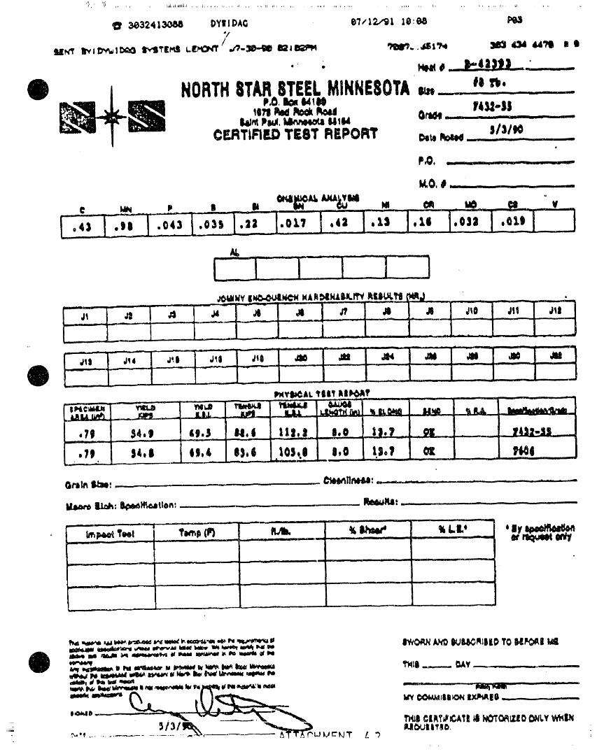
_ _ ill ld J, , , , i IL _111 _1 1,,
_324 I_ I)YIII DAG eT/12,/'91 10:68o!
__"W NORTH8T_ 8TEELMINNESOTA_ _ "_* -
LI i lilLE_2 ......
'era_ _ _ ltr'e,a_e-- f414-|1 ....
CF.J:ITIFIEDTE8T REPORT _ _ L _- 1 -- -- -- ' --
. _ u
-- , -. _ , -
.,, - _ - .......
I-.;,-I-., _LI,,.,.-, ,,,_.,_1,:0 ,,,_l.,,.
Gr, lh IJ:m,...----. ........ . C_i_II_: ,..--,_--= ....... - - _ .... -- .....
IIa_t_:Ilk_14_tc_!lon:........ .. ,__ tte,l_Jqa:_............. - .....
. ._-_-:__ --_-- _ ,, _ ........... -- -_ .,.
- __'"' 1 .... -........ ................. -- ]1 __ ] _ i L _ - --T
___1 ---- JI, -.L--
.... , ... _ ......... 1_ I _ m__l_ __
I I .................
,_ # _,_ _ _ _ ......... - .......
._,f .................

3_324131_1_ DYW,IPAG 0'/,'1219:1 10:0"7 P_I?
. _ ,, J_ ....... , _ _ ,_ UraL._ ,., .,., • -- :_::_- ,mall--_ _ ,__ -" - t ii __ - lr-
4"-- SEE NOTE Z'
'_P THREADFORM'" R SEENOTESI&Z
F &D x x
FOUNDRYL SYMBOL: NOMINAL SIZE
ImELtml,_
-_T_ ,_ZE t _ z_ rP.... _ f+ .......#io_ _:_P_,_-m/+_ _uz_io ezomemm_em_o e+,+u_6-B_zeelo s_ze++oel_t__
t.E.X1 [IN./rr_) i
-- __ -- . ,. ,,
+-:__ _1,. ;4 _4 " :_ _4 _4 ..... 14 _4_om_: ++4_/ 7_ +_ls ...."r44..... t4+..... 74+ "m...... _4- ......._-z..__mm-im.],,_o.m/;+.+.+m]_+.+o.+s_,,z_.+_.O:i;+4/z,L_i:m;,Z'_.o_.zm]+_.4:.m+._
• I_. ilm,....mml o.+Z_;e,O_.7mrtO.+zlio]mr/Z.OJO._//+,oi[_.im_oi!l+iZ_.,,=t,o.l.,zo_.:_;l:_1' L_ O.Z'/ O._,t 0._ O.'/Z 0.1t9 _.ZO 1.7"/
-_ L FOef_. ANOWE_-ffSFO__.f_O _t_t _.
AL,_'TE),_J:_[:)UCTLE_ F_ HEXl.I'ElZ,R,D: 1. _OR_ A__P_ClrIF__TH_C_T_I_OF_'¢0_ORC_T STEFJ. ,0/-o.0_0" D;J_=T__0_ t_l _ iS_ECF_ _ 1kSLE.),llN.YIELI):!00 _1 Z. ATDOTH_ OFNUTT).I:F.AII:OPNISMODIFIEDMIN.Ti_: lZO_ FORL:_. IZ5/-,0" OVid_LASTlfr _ ASFOLLOWS:_UIN.EL.INt': _ _ UPTOI_JO__ ATCO_Tk_P,_15.
FOe_:_l"
ATTACHNENT 5DTW_DAOPO$1-TEHStO_IGSY_TFJ,IS 1
....... : " } +-' ++ _ "_-m-toj[=.t.-
I I) lo,-!_-_l t._..-._ - ........... l D-10"rH'] =_. :
_

8X8 PLATE
1'-9" J_ _ORAULI______C___M
'1 I __- ..'_ ..,_._ L CABLEj _ _ HOLE
• ROOFBOLTDETAILVERTICAL ALIGNMENT-.(TOL. 5°)
I T 'T'A t_LI 1 _l_. LIT I_

.,....--.,,....,....-- .,-..,,._
+__
Maximm Pull Fc¢oe -
I Displ t _ Pul ForceTest Resulr.s - _ ...... i _ .... "---"ace_ a _ -_ --Na_ of Failure/Y'+.-e_- _ ....
Other _ks- _ +----'---_-- + -_-ei::l -- -
ATTACHMENT ?

AT_ACHNENT1WP og-oog
Pagm I of 2
•UNDERGROUHDDR;LL]NGHOLE F%ELD DATA SHEET
Date: ............
Room/Oftft: - -
Purpose of Hole: ...............................
, ,,,, _ , ........ :__ _L .... _ -- __ _ _ J _ ,, ._
Location:\
\ Depth at Completion: ......... -Diameter: .........
ApproximateCollar Coordinates
VerticalAng]e:
Direction/Azlmuth:__ ------
Remarks"
Signature/Department:
!_P Form2014; lO/15/go
Q Page I of I /
ATTi_CHI_EHT "e

WASTEISOLATIONPILOTPLANTSUPPLEMENTARYROOF SUPPORTSYSTEM
APPENDIXCSupportSystemDesign
WestinghouseElectricCorporationWasteIsolationDivisionCarlsbad,New Mexico
OctoberIg91

WE|TINONOAJII|wkJrT| 18Qt,.&TIONDI¥11_ON _ ",:-

0
,_++++ ,,+ ,,,,-..y,.,+.+..°,,,.i,,.°,+........mlv "Iv ' " _L'wm_W+_ " '

W|STINOktOU$11 W.,IJIITll IIOI,_TION DIV|It.ION
W-FV

),|.S |travel|eS ehel| petnL_ oeflye8neee_'a°t_lls_leRemeeeemev_ile eteemO_ uD e! etpoltmes_e |J emse|eevol|e| reaL|ave0 LN _be re_dis_ee e| the
e_ ORQ _&& jt| efd ke&_ verse and neJ_eetsetpe|neo&41 oleae.
]. I Cenftlvti_Lta d t®een_Lat_lPaitUl, ea
3,_,.& Oeaeee_ t_oel_|e_ VnielStlreuRi
&_ 4eetbe lemuRS |p_U_ No. 9 4¢|11 I_ele e_¢|eeee_evet|en ts 411_._le. Title |e 1401 ft shove seen ees|eve1.
The e&etege oleo _81001 tO 6pFles, 8,&_O f& be%ev _helEeua4 eur_ece. T_O flnal !sre| e_ the eseavetteneshell le ae 4e_,e_m_ne4lr/ tbr eeatleoslJ_ oiliest.A|_ eaeevet|e_e e_ell be pelelle| &e &he esle_lmgbeedin_ p_eaee vt_htn elleve)le &oleraneee. To _heesten_ plastisol, e nnr_er bcl in the eseevetlen¢_bv&ll be 4et_ne4 oa &be reference pions frn vt_telmLheezeave_eo shell be eoa_nued. Zm eidt_en, _e_qee_oll _e dr|lieS Into _he f&ee| e_d _eef of lhrexcavationfor de&srm|nea&enof the &eee_|ea et
Nar_or |oi t- 1,3t) en_ &be olaf eeeu a_eve _ho _eef.O_8' coring of _eee solos m_ell beV|m before sheeelt_inu®_e,il_etaivoaeee Rote &he_ 810 feet fire| the
"" |eees_el_,
lasso e_ &he el|l&|alo &he sterile 4|p o| &heeed|nente_y bode in _ho _nOer_Eeund arose viii beeppres|ne_ely t persons &e the eeu_ reel.
,.J.8 s81; ceopesl_&em en_ nenei;y
The b_lite |e _eles|vely fees ef loputl_tee vl_ _eesee_Ltea of eeeamtoael shin bus separate l_yefe e_&&s_s|7 iatelepeteed ergll_seeeue uesertale (rF &oes) end of pely_el|_e Circe _hel &_), Hall_O _e elsev&dely in_er_eeOoe v&t.tJ leye_e of e_yi_i_e leaf|ag_e_ e fe_ _seheo to eevetel feel In _te_aeee. T_eeverell selectee eem_e_ _e e.e_.
Fe_ _u_peeee of eseevet_en esleule_leae _be el& tinpiace le oeeuned _e have e eene_y ef _S II) _eu f qP
(%.Olt_ &e_|/e_J MO).
)._.) Creep Al&eraser
Sseavatton dtmene|ene shell Include oa el&evener ees
O i_ salt eeeep et I £_ titeke vo|&tei| _&nene&ea and ninethebes In _e _o_vlre4 t_t4tsof a11 seeM.
D-$_-V-O& Rlrv. | lheet _ e_ 141
....... ,*,,,,p,l .... I¢ lrllI, ' l +ifr llq i '' 91' '11li li , _P"'M l'_l ..... li_ NII .... ?l....... lpq' ' lpl .... PiP'Ii'+_ _.... lllll li +I ' I"' _PIilllp' 'II 'I' "' Plll l ' ` _I_iilll'II1 Ill' +ll,p,ll '

WtllllIQttOtlll WIIIII PtlOI,AYiQII DlVlllOil
O'klO _LGS? r _ ..... _..... . _ , _ _ .... --..--_
_11_" kimOiill r0_i llltlliill

li
W||TINO_|| W_T| ISOLATIONOIVlIIO_


4_ AGIS
e ."._IL| _ 7,efa,_'eaIii' _lllII_.ir_It:gfl idi_i_llfl, N6 _IIIl_81 '611_OJlllk|11, _IQi_ItRlll _,ImllllRlle.,flll, If'Icl _IOfO F_I|IGI_ lli_i, latllmi_llli i i -
:r "'; )J"ll eP '." J '.e_..r_ V_eI _tClI,_l_. _,tli_'_¢ 'q _J"m_i,, _ :,ii :''.t_
_..¢t "- _P4r_' _:e,11 IrOa =_e'_"iltllr s,_.;),;_) ._,e.',';l ,,s ';': I, ,_l,i e
e__ il;ac r :I -, 'r, ,.t- r.
• _ i......, i ._
' .._ ) .._ : ..... _ , _;, , .,_ ,.
) ) S?O •.'CO :,'1 ,I'_2 , I"_.0 !_!0 ".'S=) : ¢0 ' ';._ ' "0 l :_4 ),'_ ;:!_ ,_J,',) ¢ Jt3 ',;'" _ _" ) _00 2J_tl :.;_a "_(I"' ' SJ"3 ' ¢',1 ' !(% _ _:0 _ td; : =,"" " _40'_ " _S ' _.;: _ :li S.12 ' '.'S : :tS "_tl
3 kn `1na[ys_smay E,: ,'nndeb.v :he purch_cr frcm 6._ The sl:ac;n;,_e:ght, and _=pof d_formationssl_=":,,_,_,¢o_.,_rs.Th_::ncsphor'd4content:busdc:¢,"mzncdshall conform lo the ."J:,uirQments0rc,_:_l:edm Tat)lc ;.:_,,[,x,:;::d that ,¢ec_liedin :_.l laymerethan ,:_ %
". 'klca_urgmcnfso#')[:_i',_rm_liuns
n. R,',_um:m©ntsf,)r Defornuzfion.,i ".[ The ,_vc.-'a;cspac_ni[of d¢fi_rmauonslh_&[b_ dozer-|s I
6' Oe='oralation=shallN sra_.'lalo,ilg:hebaratsul::stan.,,'n,nedbydividin;=measured,=n!I,hoi_c ha('i_¢:;mcn)yt);_{iv'jni|'o_ll_istanc_,The def_r,'naticnsono_:¢csn¢s_dc_ th_nunlbcr06mehv_dualO:|'ormationsandfractionalparts
• ofd_:tbrma(ionson any one sidectt1_)atsc,:c_mcn,.kJ('eh,:iearshallL'_sz=afar_nsl_,ea,_ds_ape.61 T'_edc,eormauonsshaiIN ;lacedw_threspecttothe measuredl¢ng:hcffl_e)atslxcsn_cnsh:II)ec_nsldc-cd(he
,_:(,s_,"ehebars.thattheinclude_zngte:sno(h.'.'.'_than,II'. distanc_froma pointcn a defonllntionto,Icorrespondinipoint on _nyoi!eord_:)brmaz*onon the s_.'ncsi,". ,_.the_,ar.
O _,_,h¢_thelinecfdeform=uons_u,,_s._n',ncludcdan{lc '_w,h Seac;ngmcasu;,.'mcn'ssi_l| nutt:_ma_ overa _arareathe axLs of lhc iear 0£ from 4) tc TO" incius/ve, If'le conia/nin$ i_r .T.arki,i symL_ols(nvoi_n) Ic:tc,"sor _um-_:,"orma'ionsshall alternalelyreverie in direc::cn on eachs_¢c.or _hoseon one sidesh:dibe rever,,ed:n dir_:tion from _,'1.,,e "1,... Tllca,,¢rn;eh,:i;ht0("d|:x-ormat;.cnsshall_ dcter-[[Ics¢on theo$:)_c;siteside.Whe_ thelineox-dc(or_atit:nis ro*redfromme.'uur_menisrhodeonnot:cssthanr,wo t?p_caiover"0'.,_reversalindir_zion_ ,_otrequired, det'ormai)nns.)cir,'n,_mal)onssllail)e)_d cn fllrce):ca.5.3T;)caveragespacin;or distance_.c:'.c=ndex-ormationssuremcnts;ct¢c:_n_at;.on,one atthe_,".tcrct"t[-eovcr:_II
on eachsideo( the)arsMIInote.xcecdwen tenthso("abc lengthandtheo(h_:rv.voaith_:quarter;,.;imsoftheover:iii:lomh",nldiameterox-the._ar.len_lh.
6.4 Th_ over_IIeMthot'deformatio_ _all_ sucht_t %3 Insu(li¢icnt h¢:Ght,insu:lic(¢ntc;.'¢uni('¢r_:ntialc:,v-th_;=p_cv.vecntheendso_"thede£ormatio_cn opposite eraGc,orc._ccssi_cs{:ac_nlaGdc;'or'_a::c.".ashallnotconst:.s)dcsoi"the _ar sha)l not exc=_ l)'/_ % OX-lhc nominal tute c_us¢for _)ection .'_':es__,,has_c=n,f.eart.vcsta_:l',shc_;c,-,m_:t:roi"the _ar,Where the earlsterminatein m hy _c:.'r,.'mrationscn eachlot (Nob:J):eszed',haz(':;:,:ai:ong::udinaihb..'.e .aqdthof the long:v,._dinalrib rJ-,al]t:c de:',.)rr:-.,aucnh,:ight.;:.lp).ct seat;riGConot conform :o :.".e:,:r,s_de_¢thela;).Whore ,,"ao__a.-itwo|onsitudinalr;,l:sminl,"...urnretie;rcn:ca,ts:re.s_:ni:cdm S_:Lon_,No re:ca'ten:zr::nvoi'.c_the:o(;I|',vic_thof;iJ|!onlpv,_dir.a[nl:sshallno(Jxccu'.,l._.__ Of the nam|nai penme'cr oX"_e bar, fur',hef n,ay )c ._lad,::,n :he_'asis;X-,"neasurcmenU:X-:'c'._crthan :er.._'kore.the .iummatio,,,.oX-laPSb_allnot exc,"t'd:5 % oX-the :_."_:_centd,¢','orm.ltionson :ach side oz"the tearar_ =eas_r¢.:.-_:.-:na[ ;cr,..,nc:_:roi",h__ar T'ncnominal;e,"imeter,=fthc ._r,-_ _,.-._ Inr ..I ,:'¢_r,cd _ _il :::¢ jars :£ ._ _.lr _u,._cr _.',,::at s;_a,| _ ,_.' .1,;i_,lP.._:he _ol'll:rlaJ Ji;l_o:,_. _a:_crn oCJc_rmat;cn "¢._z.iar_<_l:n .1_ .n,J,,,:J,4i s_;¢c,rt.,&re:¢.'um¢Jr
g_¢C_ntor:ct.
T,l,_Ll_ 2 Tensile RilCia,romllnla _l. Tensile R_quircm_:n,_" i,.xco _" ;..mea,,'.. _¢nca "S_ - _].', T:'_e r:'..:,t:.".l[..is "'-rest"'-'......... ":'.. t.',_ *_s;*.::."r.¢_.3.",, ;:, ;:_erq:; .-,",. :_ "q XO kO tC,: ':¢ :_ _ha_] ,:cn:'_,.-ll ",- t_¢ :¢qt;_::._:c_._,; ",;: t_:ns_:: pr£,;¢:"..'.i
Ece,;.'mcnn ii n.. _. t.=_,_, 3" The ' 'y:c,,.,;,.:l:'.tcr v_c:,ds,tc._Gthshall )c Ze'e.._.._r.c'.
1 '_ ) _v _.n¢ Of/he : '.ci,owir.g m¢ih_:_:' _ '_ "_ ) ; :. l Th,: ',lcld pc_:',tsl:aft _e Cc:¢,.'-.,:_cCb_.Zr:l: "( the- ] ] • .
• _ .... _r ..=,t:_ the _ =.) : ....... "1"" :f the tCS;',._g?.t:J.".,.'.e.
:,.:ce,: :,,rs:.,,_,.r'._e_:_vr :,:am: "':.,;- : .':_d ;:'_.".t.the ' 'e'g _;r:,";,'.h $_,;.1-.c ._et.',".-r.:.".¢__t :x:':'.
D , - .a ._._o "_.::.r_ _,_ _--.;st4,c:r_ n :.:ts " ._ _'.: • J _:J,"..;_¢: '.C'_ _s_,'._;4_ :,".;t ,: ,;?__ ,',;.; :.:_.',_,_', -'.,,,' ,:_ _.,- ,1,"


#|_INOINOUS| WAIITIItSOI.ATIONDIVI|II_
O ?,?k,E lh&C)|
_-ho_! -w-_,,On -- o_Tm'_em_ • ev" • OATtl !4;NRkJ iv gaTt
11111 • i | in n - l i m i n in
,,_ , ii ---- II iii , •

W|IITtNOMOI,_,|W_dITI111106ATt¢_DIVIItION
_-h_O_|_r " " - [AIJ_'_Om m, Davlri_N"_ li" - .OM.vtl¢"I'D i v DATE
]'-" _:tJx_c.X.II='_ll:/_tlL_P...W,,,_,._.,,_'Y_A 'iQ,.G.j_-
............. III'I_LT_]qAII' " - ,,w -- ' - - _--__-_' [
l"O..... ....... li:air: I_l_ -- 11,_1_,,t I .... " "L.... _ l -- ....... : -- Z IIIIIm_--_--'_7 : : ---- __ I -- _ ?__-- Ii _ .... -- _ fl J II III -- L I I I

WlITINOI'IOUU WAITI IIOt.ATIO I glVlli|¢ l
O i TIg_.| _ "' ' PT_ _
-- --- -- " --- D -: mml II _ II llnl II I I _ ".......
li _'F I¢A_.¢ ,_ _L,P_0" {IlUlOUP
"_ -,.v *O.v --- ,.mn ........... --- '" _ _,.: -
_+ • ' --- : - _ -11_1 __. " ..... _. .- - iq_[_ _ _ = ....


RECOMMENDATIONS COMMENTARY
3.2.3 F_:torl of Safety
The Oes4gn IOaO ;_ fOr the anc-or eauals the T_e e,'g,,"eer snou_cl ',ct comoou,,o ,4,0_,_ax,mumant|c_pateoloaOaDpl,ec'ot_eancnor fao:ors of _a'etv _nen ce$,g,',n_ an t"c-:.,,,-
e t:mes the factor of safety useO ,r, ",e :es,gr_ O_ st'.Jcture "r-e .,rce"a,_". 3_'c - _. !=.':¢ t'_-'"e a_cr'oreO structure The val..e -f _re'3c'3, cf ._,.'_ '"e ,..-',, .:- :.. = =" . ..-.; - --- :.=..;- --=a'e,v =eoe_cs.._or_:'e_vc'e"' .:,:=" c3T :" '"e ':e'e ....... _ :.-: -- "a:':"-- .-. ..... ._
S:'.,C:.,'e 3r: "-= " ,:,, ,-.a 3,23 _." "3"_ '"e -,=c ,7" .:._:':''--_ : ....
3"._ '"e 3"C ''r '-.'S" .Ga: '"9 3"'.,3 ":. ......
sa'e', 'ct '-ea_c-or _,,, _'a.e :-:-:,- --, ... .--"eS_it,r_ ,_ a_ o_,erlv cc_ser.3,..e :es ;-
3.2.4 Anchor Tendon Design
1"_etenaon s_ze,sc:eterm,ne0such t,atthe ,"'_eload ,n an anchor tendon _av e,t-eraes_gn lOaoa for theanchor ODes not e_ceea 60 ,ncreaseor aecreasew,tnt,meoeoeno,ng:r,t"epercent of t_e guarantee(:ult,matetens,le :,enav,oroftnestructurestrengm (GIJTS)ofme tenoaonT_e Ioc_offlOaClW_CR sr_all De Oeterm_neoa Oy the Oes,gnengineer, may De larger or Smaller than theoes|gn load The recommenoaahons for Corros_o_protection g,ven ,n Sect,on 6 0 CorrosionProtect,on ' slnall Decons,oereo
3.2.S Free Stressing Length
The free stressing lengt_ s_oulO not _e _esst_an T_e m_n,mum stressing lengt_ recommenOeoa,s15 feet [4 572m ] to prevent s_gn,f,cant reoauct_ons_ntransfer load
cl_etOstress,ng anchorage losses or move,",ent
3.2.S Bond LengthThe boncl length can oe est,matec_ _y t_e T_'e_oncl_e,',gtnnorma_ly,snotlesst_.an_0fee;follow=ng equat=on P'or -3rma= aol3_cat_ons the _onc =e;wee" t_e
:enCon ar_c:arc_.3r _rOU: ,S "Ct _r:_,cal
p P..i!.O_: :es:s "'av :e '..se_ ": :e:e'',"e "-_LO =rr ® : L r. ..,:.'-ate,r's_'._ oc"c s:ress ce'.,_ee" '-e ":c,_ -_""
:-ea"=."cr:,':." ; ..,-,':_,:"es:s .s.,a,. ,es."e= :"at "e re'-",""acac:, CS eC'e=.S,9,=", "'=
W_ere :cno e"_:" "=".ce..." r, o,:e."._'a,: "'=a'C'O'_'.,ll'Out ',es' "_'C_C "C_*` _e -e_:.,,ec ' :-e
LD : Don(: length anchors are "este-'. as cescr,cec ,,',_ec':o," 3 "P = Oes|gn toao for tlneanchorrr : 3.14C_ : oa|ameter of tl_eoar=li_'o_er. : worK,rig hondastress ,n the ,nterface
between rOCKar_oa grout
The working Dc-C Stress usecl to _e!erm,ne the Wtne,n se_ec: "; :"e _,_,,_ _ -. : _'--:s.= "-_OOnOlength _s orma==y25 tO 50 percent of tlne eng;reer src==: c=_s,=er ""e :,,;,ca, "a:..'e -ultimate bona stress t",e anc,*'or ac=.,cat,on var,a:,crs _" ""e "3c,
croDer_tes ZnC"-e r'sta,,a: c,r :':.ce.:._'esT",e ult=mate Donc_stress ae_encs or_t,"e
1 Shearstrengt;,of :herCCK
2. _,scont_r",u_t,es,n"_e,ocw,"n.ass
"0• ,- .

tl
O ,.,,
Tibt,e _. R_m,0 rort 1)o_4 .elvi wq_eul_ .eye 6_en fNOmmoa_6od tel dm,e- e*_e. A. t'. e,o -_ eH 0, .,oi ')""
t_ml ono_l ot td_o_
- | :% mm %._m
MOOivm _O_a Ue_l _ 93 3 4 |_4,e dll_ ,'g641
WeetP_e,o0 0re_,t e 1 SO to _ 1,0 Jo4p(l_ Svs_e, et e, (lJ?21
lie_o_t _ 3_tOt 39 3|0 _8_012 O_*te,_ Wvc:,t_e,o_e_,_9?41
G#Ip_o_O t _0 to I SS • 03 ] I 1o 3 J ,' Of'U*e WVC',ftlI,JO_(N 1|9741
n S,e_l)e*_t,n4 _ 65 to 0 Sg t SJ , _ ii to 3 J ll_,t_n o'Vvc.PPJ,,Io_4¢ o' .,94_
! C_t,,,,te e_,0 DIo_ t 9_ to 3 lO , ! t to _ S , _JSA PCI 1_|94!, ..
q..__, ,n
, i
' _e_evve_,et O ?O ? lO 4 O I _SA W_,lollI?I)
,.. -_. :i__ .
_OIIt - _rl4lOI *) Iii _ _t 40 _ _ tO I v_? 1 I_ tO _ 0 Ir*tli0a _,lt*OlOn_ 15t?01
_% • SP_ n ,?I_OOrO_vl
i Vo._,o,. ,--.to.e 0|3;0099 2 ?l 2Sto_3 i,,to,n _c,,.e..o_,0tl?a!
; ¢_0,1_ **_ntO_O _ II tO I O0 2 ?J _ I tO _) ] O_,teo_ Wvcnf_o..,Oe, u _10741Se*_aom--,ene _ _3 tO _ 52 ! S t025 U3_ PCIl_J?4!
,,. .. ,
_a,O ¢_rsO._ee,_e_l lenOStO_t 2 45 t ?_ _#_e_e Cocci1 ,11701
I _IomOtO ¢O_0_ I_loa41
-_,a t,_e Je.eolo,e _ ii to O 83 I 24 2 ? *o : ] 9,,,a°_ _.c ,"o .o-o, ,'_74_
Se_eslo_e * 003toI ?] ' 5'o25 .SA *C_ '97_,................
(,*_o_. ,'_e., _ _9 'o g :S _J0 9.,'.," .. '"e,o'- ,*97gl
,0a5_'., -". , .'c'o -e_ :=.eo,o_
5ql f_ _l-_s;o*| e-4 J_ioe 0 ?0 to0.t I 037 " " "g _ ? |_,;i,n #.¢,,-g._o-fl _tO?4t
Go-e,a,
Comoete-_ ,ocm _,,_,,.,_ _J.,¢,,., _ I*,ti,- ' ,t1'e_o_n ,I_721
• _trI _l t ,r_ II O ¢O_t_l_ll,_@ .* Ornl_ IWI,vO ;O_l _ tlS*v_i
'_O "0 lD 'rO :0 O
• 0,.O oi .e_ve OI
4 %.',._,_: _ 4 2 % ""'" '
_ee, ,9c_ :, _ 'o 3 ?'_ - - ,_,,st,a,,e <_¢'* ,19721
S'._I ,oc, ' :5 :o ' a0.....
_V*Qi _t,*lt_ O! SPIOVi iso _ _S ; ,kwitrihO S¢_¢QI#_J CA_S t|O?_;
O "" _ '_ O' ."',¢ '_COt •
J
i ,1 n_ ,i_i, ,, ,ii, ,i , , _ii, rll_, i,, ....... _i 15 "Idl, _)Iill i,','li' ',,r ,llrla,i IWI,,, tr'toni ',,-I ITI, F)))IrI,)i,,, lm,, ' 'llrllr_,, _l '_,rl<_lllqr _

BSe'e
J

W|$TtNGHOUS| WAIT| IIOI.ATION DIVIIION

WEBTINONOUSE WAST| IWt,,ATION DIVIIICH_
E _T Awvm
I _,__ ",'_.,/,,,._a_,,,..._.',_/,,to' .._, ,,, . .... iii l i li . _ i t ....... _ . _
__, :1.

n_V_ ' . 1 . , _._
lP
W|STINQHOUU WA,rI'E 10OI,,ATIONDIVI|ION
o
.5- A'r_. e

WEIITINQHOUIIIIW,_II IItOl.ATIl_ DIVItiON
ni'
__" "":"_ -- ' ^uvuon _lrL eN_,'ll, II, _ iIM+l£_mll O,-IIV DIYlll
---_ II _ I I IN - __ II I
IV CK_ _0, SlbI _0 UIIOUP
...... . ....... , . , "-- U " -_ I nu --
S •Li (-_'Xs.s'Xz.'_+c_..f'_'X::_,s"_'s_'._.-r..,Gb
i
+O- ---;,o,, - +,,.,,r.,,,,.U-......---- +_ttlc,,,_,'r+,;, • ,_+o,al,,
+= m +I,,._iL +-- _ ...... ' III ......
WI_T_NUmflt,_IIII ._m_ 411II;III&
.....
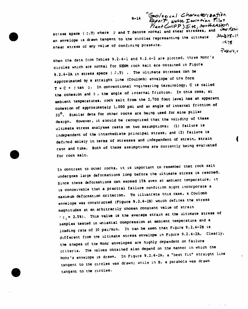
t-ll __#lt_', IQ.mt-_.. _il,ol-_ll,,.i llP_'lt_
stress space (:,T) where _ and T denote normal a6d shear stresses, and v_k4/r_'csn envelope Ls drawn tangent to the circles representing the u_tlmati -_A,d_)7_-#_,
shear stress o6 any value ol conlininq pressure. 1f'7tf
When the data l!romTables 9.2.4-I and 9.2.4-2 are p_otted, three Monc's
circles which a_e normai for SE:_M cock salt are ol_talned In Figure
902.4-2A in stress space (:,Z) . The ultimate stresses can be
apptox_ated by a straight line (Coulomb) envelope of ti_ form
T • C • : tan :. in conventional -ngineering terminology, C Is called
the cohesion and _ , the anqle ol internal friction. In this case, at
ambient temperatures, rock salt from the 2,100 foot level hal an apparent
cohesion ol aRprox_ately 1,000 psi and an angle ol internal friction ol
]3 ° . Similar data for other rocks are being used _or mine pilltr
design. _iowever, it s_ould be reco<jnized that the v_lidity ol these
ultimate stress analyses rests on two assumptions. (1) failure ii
independent ol the intermediate principal stress, and (2) failure is
de_i.._.=d solely in terms ol stresses and Independen_ o_ strain, strain Irat_*, and t_e. Both oi these ass_ptions are currently bein(3 evaJ.ated
_o_ rock salt.
In cont=ast to other _ocks, it _s important to remember that cock salt
undergoes large deformations lon_ before the ultimate stress is reached.
S_nce these deformations ca_ exceed 1St even at ambient temperature_ _t
_s conceivable that a practial _ailure condition ._ght incorporate a
._axzmu_ delormation criterion. _o Illustrate t._is case, i Coulomb
envelope was constructed (Figure 9.2.4-2B) whic._ defines t._e stress
magnitudes at an arbitrarily chosen _onstant value ol st._ain
_ _- 2.5t). This value is the average strain at the ultimate stress ot
samples tested in uniaxial compression at ambient temperature and a
loading rate o_ 30 ps_/min. _t can be seen that F_gu:e 9.2.4-2B is
different from the ultimate stress envelope _n _igure 9.2.4-2/_. Clearly,
t_e shapes o_ the bloh_ envelopes a_e hig_ly dependent on _silure
criteria. The values obtained also depend on the manner _n which the
_o_r's envelope is drawn. In Figure 9.2.4-2A, a "best _It" straight line
tangent to the clrcles _as drawn; ,_i-. in B, a parabola was drawn
tangent to t_e circles.

O APPENDIX C - CHANNEL SUPPORT DESIGN
The finaldesignof the steelbeamsupportsystemwasthe resultof anevolutionaryprocessthatstartedby consideringan I beam. The originalconceptcalledfor an I beamthat wouldbe hek_Inpiace byeightrockanchorsandfour yleldablesteetpos_ Thisdesignhad severaldlfflcultkmwith It:
o Each I beamwouldweighabout2,000 pounds,makingthe installationprocessdifficultlindpotentiallydangerous.
o The supportingrock anchorscouldno( beattachedto the centedineofthe I bearRInstead,therock anchorswouldhave to beattachedby means of a separateplateto theflangesofthe I beam. Thiswould havegeneratedexcessmomentsinthe beam u wellslintroducingtorqueforces,whichwould havebeendifficultto calculate,
o The yleldableposts would have been difficultto test,andas theywere not performinganyfunctionthatthe rock anchorscouldnot provide,theywere eliminatedfromthe design,
The finaldesigncallsfor a 15x 40 channelwith11 rock anclx)rsthat are fastenedthroughthecentedineof the channet.
The channelwillbe made ofthree9 foot sectionsbo_edtogetherwithfour7.5 inchby3 inchsplice plateswhichallowforgreaterease inthe handlingandplacementof the channel.
O The beam hasbeen designedto accommodatethe unequaldistributionof the rock load, and the rockanchorswillbe tensionedto accountfo_"the fact that mostofthe detachedload is inthe middleof the room.
The supportchanneldesigncalculationsare givenbelow.
O


WESTINGHOUSEWASTE ISOLATION DIVISION
t.
.,,<, __.,_/,,_5...r....o.16-9/- ¢_,(,"...... ....
ii(-
,,<,<_e_,._,if vA ,,_..-......-, . ---_. '
::
i ii iii IlL ....... ii II ............. ii
" _srkl ,_:I<- _,...& _, . Jl,.__ ',_,:_-
O_. r_.-_,,+-,/_,,,__,.x4._'_7I,,,,. 1,<,,,.<>"-'-<>"'1°"=''>.'*....... _'>'"!°",''>.,* oA._- ["°. 1',''i ! l. . • - . .......


,.,o,', ' . :.;.,,l. ,,'. ._. _ .. .!l'
WESTINGHOUSE WASTEISOLATION DIVISION
-. . , ° .
....'"°"°'"..... r_;;_" °"°°""°_"" _ ""h'/,_l'p,'lt,_ /_/6_j ' °"''°''-'!¢-_/- _,yk /,e_
i ' -- ">'_" _ . . - . ,h: " ' " .£..l__ q" /II " - _ '- i'- II'"_ "" 'I y
' • '1 I_...... _ .... __-,_ "_._
" =='--- ._1"_!_ _ t............ "f"' $ ...... I r ..... :1- '
................. --- ,: _:.i_.;-"_. ...... _ _,,_. i/
........ -_-,,_ o-__o_,_ o_,_.s-. .....................
............................! I"..... 1'--....'r1_._,.--_>t., _ _'i" v f ,T _- ......
• c; _5,,<,<,-_d' e,_,,.:<__<¢/,,,_,._,. i t/ - I t• ,,
NO, ,, !DA'I'E-: WlfSTINOHOtJlti lIOllihl 411)2:IQA
-


WESTINGHOUSE WASTE ISOLATION DIVISION
. :...... _,_... ,,. .. .. "q_ :_............ •.,,
l,,",_"/,.'/,,J,_ %/4)'r'°°'I,O. ICAiC2' NO2 -- ' ' |FILl Nii, ' .......
l' _ ' , t I _, I !
....... 3,z/ ....=/_ g""/ _ '_r._- -- __x-
O _ .................._ _'_/ .................-.......... ' "-.... p',r_,_,_".................. ___
ii;.ii....'ill............ .i- _ '/._"__4. , _
._--_,_-_-,_-____ "_.//_-i_#__.__ -_-;-_
"o('/r'o,_y"/r,_, , _ |.................... '...._.;,;2,;.- ............ ..._ ,-.;i.',,,,,,,,-ii-_,_-_
" _ " _xO # ....
-- i ,, '
" ?,.
i,,o. lO_'r__EgITINOHOUIE FORM _liI_:I_A
-

• t
WEST_NGHOU_I PORM 41)2=I_A

OL:NO.
WEITINOHOUIE FORM 49239A "

O (,.
NO.REV, DATEWEv. i AuTM°R OATIC. WD.ElY OAT EICH K'D. _W OATWESTINOHOUSE FORM 49239A

WASTE ISOLATIONPILOT PLANTSUPPLEMENTARYROOF SUPPORTSYSTEM
APPENDIX DGeomechanicalMonitoringProgram
WestinghouseElectricCorporationWaste IsolationDivisionCarlsbad,New Mexico
October 1991

_b i ¸
,I
AGEOTECHNICALMONITORINGPROGRAM
FORROOFSUPPORTSYSTEMIN ROOMI, PANEL.I

GEOTECHNICALMONITORINGPROGRAMFOR ROOF SUPPORTSYSTEM IN ROOM I, PANEL I
Table of Contents
Section Title
1.0 INTRODUCTION ....................... D-I
2.0 MONITORINGOF ROOM PERFORMANCE ............. D-22.1 Room ConvergenceMeasurements ........... D-22.2 ExtensometerMeasurements.............. D-32.3 Survey Measurements ............ D-32.4 FractureMapping of ObservationBoreholes ..... D-32.5 Data Acquisition .................. D-4
3.0 Monitoringof SupportSystem Performance ......... D-43.1 Rockbolt Load Cells ................. D-53.2 Pressure Cells ................... D-53.3 Cable Elongation ................ D-63.4 Data AcquisitionSystem ........ D-6
4.0 Adjustmentof SupportSystem ............... D-74.1 Criteria for Load Adjustment ........ D-84.2 AnalyticalEvaluationfor Load Adjustments ..... D-9
REFERENCES........................ D-lO
D-i

GEOTECHNICALMONITORINGPROGRAM A
FOR ROOF SuPPq_;__YSTEM IN ROOM I, PANEL I UTable of Contents
(Continued)
List of Appendices
Appendix Title
A GeomechanicalInstrumentationSystem Specifications
D-ii

D GEOTECHNICALMONITORINGPROGRAMFOR ROOF SUPPORTSYSTEM IN ROOM I, PANEL I
Table of Contents(Continued)
.Listof Fiqures
Title
2-I Room PerformanceInstrumentation ............. D-112-2 Wire ConvergenceMeter Cabling .............. D-122-3 ExtensometerCabling ................... D-132-4 Typical Radial ConvergencePoint .......... D-142-5 Typical Rod-ExtensometerInstallation .......... D-152-6 Support System PerformanceInstrumentation ........ D-162-7 Rockbolt Load Cell Cabling ................ D-172-8 PressureCell Cabling. . ................. D-182-9 Wire Rope Strain Gage Cabling .............. D-192-10 Typical Load Cell Installation .............. D-202-11 Typical PressureCell Installation ............ D-212-12 Typical CrackmeterInstallation.............. D-224-I Rockbolt LoadingRedistribution.............. D-23
I
ID-iii

GEOTECHNICALMONITORINGPROGRAM
FOR ROOF SUPPORTSYSTEM IN ROOM I, PANEL I
Table of Contents(Continued)
Ust of Tables
Ta_a_b]_ Title
2-I Panel I Room I GeomechanicalInstrumentationSpecifications D-24
0l
- D-iv

1.0 INTRODUCTION
A system to supportthe roof in Room I, Panel I has been designed on the basisof the rock mechanicsdata that is given in Appendix A. The design itself,ispresented in Chapter 4 SupportSystem,UndergroundStorageArea, Panel I, Room1. The supportsystem accommodatesa controlledyield of tileroof rock as thecreep of the salt takes place. The successof the plannedsystemreliesheavilyon a monitoring program that will determine not only the geomechanicalperformanceof the room but will also assessthe structuralperformanceof thesupport system.
The supportsystem is designed to carry the dead weight of a rock wedge that isforming in the roof of Room i. The development of this wedge has beenestablished from the rock fall that occurred in SPDV Test Room I and fromobservationsof fracturedevelopmentinother parts of the undergroundfacility.The wedge is not yet fully formedbut experiencein would indicatethat it willform within the next 7 years in Room I, Panel I unless fracturedevelopmentinthe roof can be controlled. The supportsystem in Room I has two purposes, ltis designed to minimize the development and propagation of roof fracturesthereby,ensuringthat the rock remainsself supportingfor as long as possible,and secondlythe systemmust have a capacityto carry the dead weight of the rockwedge once it forms in the roof while accommodatingboth vertical and lateraldisplacementsdue to far field creep effects.
The geotechnicalmonitoringprogramwill establishthe loads that are developing
in the supportand the deformationsof the rock that are takingplace around theroom. The geotechnicaldata will be used to ensure that the supportsystem isperformingin a controlledmannerand to establishthe load adjustmentsrequiredto the support system in order to accommodatethe creep movementsof the salt,and to confirm that room performance remains within satisfactory bounds.Geomechanicalmonitoring of a room can give indicationsof its deterioration.Monitoring of the performanceof excavationsat the WIPP has already providedearly identificationof such conditions. SPDV Test Room I showed evidence ofworsening conditionsat least 3 years prior'to the roof failure in that room.In addition, the Geotechnical Expert Panel has expressed confidence thatinstrumentationin Panel I can give adequate notificationof deterioratingconditions (US DOE, 1991).
This plan describesthe geotechnicalmonitoringprogramthat will be implementedto evaluateboth the room performanceand the performanceof the supportsystem.The plan describesthe instrumentationthat will be installedin the room, andit discussesthe criteriathatwill be appliedto ensurethat the supportsystemis adjusted in a controlled manner and that room performance remainssatisfactory, lt shouldbe noted that asmore data becomesavailable,especiallyon the interactionof the supportwith the room, then the criteriathat are thebasis for adjustingthe loads on the supportmay requiremodification.
The plan has been developed and will be implemented in accordance with thegeneral requirementsFor the control of test activities as described in theGeotechnicalEngineeringProgramPlan (Westinghouse,1991a). The Geotechnical
EngineeringProgram Plan supportsthe QualityAssuranceProgram implementedatthe site (Westinghouse,i991b)and covers the eighteencriteriathat arc,definediN the Q,,__!ityAssur_nrpPrngramfor NuclearFacilities(ANSI/ASMENQA-I-1989).
D-I

2.0 MONITORING OF ROOM PERFORMANCE
The program for monitoring room performance has already been developed andimplemented in Room I, Panel I. The basis for the monitoring is that themeasurementsand observationsare simple to make; that minimal maintenanceofinstrumentation is required; that instrumentationis easily replaced if itmalfunctions;and thatconditionsthroughoutthe room are known. The data shouldprovide data on geomechanicalperformance features that have been identifiedelsewhere in the undergroundfacility, especially in the SPDV Test Rooms asfeatures that should be comparedwith other data collected at the site. Roomperformanceis being characterizedfrom the following"
• The developmentof bed separationsand lateralshifts at the interfacesof the salt and the clays underlyingthe anhydrites"a" and "b".
® The establishmentof the room closure rates and determinationif theyare acceleratingwith time or exceedingexpected rates.
• The assessmentof the behaviorof the pillars.
® The assessmentof fracturedevelopmentin the roof and floor.
The instrumentationin Room I, Panel I was upgraded during the summer of 1991from the originalmonitoringprogramestablishedfor the panel in 1988. At thattime, limitationswere imposedon penetrationsthrough the Anhydrite"b" in theroof° These limitations were in effect for waste storage considerations and nolonger apply to the use of the room as the location for the bin scale tests.Roof conditions are now assessed from observation boreholes and from extensometermeasurements. Measurements of room closure, rock displacements and observationsof fracture development in the immediate roof beam can now be made and used toevaluate the performance of the room. The upgraded monitoring program waspresented to the Geotechnical Expert Panel who considered that it was adequateto determine deterioration within the room and could provide early warning ofdeteriorating conditions in the room (US DOE, 1991).
The location of the instrumentation monitoring room performance is shown inFigure 2-I. The specifications for the instruments are given in Table 2.1. Asummary of the installation requirements including tolerances, workmanship andnational codes and standards that the instrumentation monitoring system must meetare given in Appendix A. Figures 2-2 and 2.-3 provide the instrumentation cablinglayout for the convergence meters and extensometers respectively°
2.1 RoomConvergence Measurements
Vertical and horizontal convergence stations will be installed at seven crosssections throughout the room to monitor roof/floor and wall/wall room closure.The locations for the instruments are provided in Figure 2-i. At each crosssection, roof/floor convergence will be measured at mid span and at room quarterpoints and wall/wall convergence will be measured at mid wall height, 'Theconvergence measurements will establish the rates of room closure for comparisonwith predicted rates and will be evaluated to determine asymmetric roof/floorclosure of the room. W
- D-2

Each convergencestationwill consistof a mechanicalanchor fixed about 150 mmbelow the rock surface. Detailsof a typicalconvergenceanchor installationaregiven in Figure 2-4. An extensometerconsisting of a wire or tape stretchedunder a constant tension and an accuratedistancemeasuringdevice is attachedbetweenthe anchors . Changes in length betweenthe anchorswill be monitoredperiodicallyto determineroomclosure. The convergencemeasurementscan be mademanuallyor remotely. For manualmeasurementsthe extensometeris put in placeonly for a reading and is subsequentlyremoved. For the remote readings,theextensometerremainsin positionand the manual extensometermeasuringdevice isreplacedby a electronicdevicecapableof measuringlengthchanges. In Room I,a potentiometerreadout with a range of 36 inches will be used where remotereadings can be obtained. Remote readings cannot be made at all locationsbecausethe permanentinstallationof wires across the room will interferewithaccess into the room.
2.2 ExtensometerMeasurements
Boreholeextensometerswill be installedin the roof and the walls of Room I.Roof extensometerswill monitorbed separationsat anhydrites"a" and "b", anddilation and creep movements within the immediate roof beam of salt. Wallextensometerswill monitor the lateraldeformationswithin the pillars.
Within each borehole, five measuring points will be anchored to the rock tomonitor rock movements towards the room. Details of a typical boreholeextensometerinstallationare shown in Figure 2-5. In the roof holes, theanchors are nominally fixed at depths into the hole of O, 2m (6.5 feet), 2.3m
(7.5 feet),4m (13 feet), and 4.3m ( 14 feet), for the purposeof monitoringbedseparationacrossthe anhydrites"a" and "b". In the wall holes, the anchorsarefixed at depthsof O, 1.5m (5 feet),3m (10 feet),4.6m (][5feet), 7.6m (25 feet)and 15m (50 feet). The specificationsfor the drilling of boreholes, theinstallationof extensometersand for the instrumentsare given in Table 2.2.
Calibrationof the measuringdevice for the multiplepoint extensometerswill becarried out either by the manufactureror by the Site CalibrationLaboratory.Calibrationwill be traceableto National Instituteof Standards and Testing
• (NIST).
Readingswill either be taken manually with a readout device provided by themanufactureror will be performedremotelythroughthe automaticdata acquisitionsystemthat ismaintainedin the underground.Measuringfrequency,once the roomis in use as a laboratoryfor the bin scaletests will be carriedout every week.This frequencymay be adjustedto meet any changesthat develop.
2.3 Survey Measurements
Survey measurements will be made in the room by the surveyors from MineEngineering. These measurementswill be used to separate roof and floordeformations. The measurements will be taken on a routine basis, probably atintervals of about 3 months.
J 2.4 FractureMapj)jn_.qof ObservationBoreholes
Three observation boreholes have been drilled into the roof of Room I, Panel I.Additional boreholes will be installed at the existing locations to monitor thebehaviorof the roof cross-section. Observationsof bed separationand lateral
D-3_
_=
=,, ,

strata shifts will be made on a routine basis at intervalsof about 3 months.The boreholeswill be monitoredusing a scratchprobe that has been used for theExcavationEffect Program (U.S. DOE, 1986). The holes can also be viewed witha borehole camera if the fracturesrequirevisual observation_
In addition,the boreholesfor the rock anchorswill be observed for fracturesimmediatelyfollowingtheir drilling. Thiswill be carriedout using the scratchprobe and the boreholecamera.
2.5 Data Acq.u!sition
The instrumentationmonitoring room performance, is currently read manually.Conversionto remotereadingof instrumentationisplanned. This conversionwilltake place once the data acquisitionsystem for the monitoringof the supportsystem is installed in the room. lt may not be practical to convert all theinstrumentationto remote readings. The roof extensometerswill be convertedtoremote reading. The ancillaryequipmentto allow remote readingof the quarterpoint convergencestationswill be installedbut a finaldecisionon installationof the wires will depend on establishingthat they will not be damaged bypersonnelmaintainingor samplingthe bins. The roof/floorconvergencestationsat midspan i.e. down the middle of the central access way and the wall/wallconvergencestationswill not be monitoredremotely as theywould interferewithaccess,
Remote instrumentation will be monitored from a data logger located in an alcovein S1950 of Panel i between Rooms 4 and 5. The data logger is part of theGeomechanicalInstrumentationSystem installedin the underground. The systemis controlledfrom a computerlocatedon the surface. The data loggerthat willbe used to remotelyread the instrumentationmonitoringroom performancein RoomI is already in place. The specifications to which the datalogger ismanufacturedare provided in AppendixA.
The results from the instrumentationin the room will be evaluated on acontinuousbasis. Documentationof the resultswill be providedannuallyin theGeotechnicalField Data and Analysis Reports.
3.0 MONITORINGOF SUPPORTSYSTEM PERFORMANCE
The monitoringof the support systemperformanceprovides an assessmentof themanner in which the support is controllingroof movements includingthe breakupof the immediateroof. The monitoringprogram in Room I, Panel I will evaluatethe following:
• The performanceof the structuralsystem that supportsthe roof.
• The load that develops in each rock ar_chorfor the purposeof adjustingloads so that the build up is controlledin a consistentmanner.
The basis for the instrumentationwill be that the measurementsare simple;thatinstrumentationis easily replacedif it malfunctions;and that the performanceof each anchor can be continuously monitored and readily compared withperformanceof other anchors. The instrumentationlayout for monitoring the g
D-4

support system performance is provided in Figure 2-6. Cabling layouts areprovided in Figures2-7, 2-8, and 2-9.
The most importantof these measurementsare those that determine the anchorloads. These measurementswill be used to adjustthe anchorsto ensurethat theyare not stressed beyond the allowableworking stresses and that the roof isloweredin a controlledmannerthat accommodatesthe continuedcreep of the solidsalt.
The measurementsof cable elongation and pressuresdeveloping on the sheetingwill be taken to determine how these components of the support system areperforming. No adjustmentsare planned on the basis of these measurements.However,if they show load buildup,additionalactionsmay be considered, lt isnot expected that breakupof the roof rock will be excessive, it appearsmorelikely that the rock will remain primarilyself supportinguntil the detachedwedge in the roof fully forms, lt is not expectedthat this will occur withinthe next two years based on the experience obtained from SPDV Test Room ITherefore, it is not believed that loads approachingthe full weight of thedetachedwedge will developon the expandedmetal sheeting and the cables.
3.1 Rockbolt Load Cells
The rockbolt load cellswill monitorthe axial loadingon the rock anchors. Themeasurementswill be made on each anchor and will be the basis for adjustingtheload on each anchor, should an adjustmentbecomenecessary.
Each load cell consistsof a cylindricalbodywith a centralannulusfor the rockanchor. The loadmeasuringelementis a spoolof high strengthsteelor aluminumon which electrical resistance strain gauges are bonded in a full bridgeconfigurationthat providestemperaturestabilityand compensatesfor off centerloading. A steel outer cover and 0 ring seals protect the strain gauges frommechanicaldamage and water penetration.
The load cells shall have sufficientcapacity to measure up to 50 kips with asensitivityof 0.02 kips. In order to maximize the vertical adjustmenton thetendons,the heightof the load cells shall not exceed 75 mm. The typicalloadcell installationis shown in Figure 2-10.
3.2 Pressure Cells
PressureCells willmonitorthe pressuresthatdevelopbetweenthe expandedmetalsheeting and the salt roof. The measurementswill be made in selected areaswithin the room that are expectedto have the greatestroof movementsand hence,be more susceptible to the development of loads due to the breakup of theimmediateroof rock. Typicalpressurecell installationis shown in Figure2-11.
Each pressure cell is manufacturedfrom two steel plates welded together. Thespace between the two plates is filled with de-aired antifreeze solution orhydraulic fluid and is connectedvia a high-pressurestainlesssteel tube to apressuregage and/orpressuretransducer. A pump is used to inflatethe pressurecell and press the cell against the rock. A change in load on the cell will
cause a deflection of the diaphragm which results in a change in the fluidpressure. The pressurecells, in Room I, will be installedbetweenthe rock andthe mesh to monitor the pressuredistributionon the cable lacing and mesh.

The pressurecells will be constructedfrom corrosionresistantmaterialssuchas stainlesssteel. The pressurecell can be modified for remote monitoringbyreplacingthe pressuregage with or adding a pressuretransducer.
The pressurecells will be placed betweenthe rock surfaceand supportmesh. Animportantfactor to take into considerationwhen installinga pressure cell isto ensure good contactwith the surroundingmaterial and to avoid localizedorpoint loading of the cell. To avoid point loading,each pressure cell will beencapsulatedwith a concrete based grout. After the grout has set up, thepressure cell will be placed between two steel plates in order to evenlydistribute the load on it. The pressure cells will be pumpedup so that the cellis completely filled with fluid.
Pressure in the cells will be monitored using pressure gages. Monitoring of thepressure cells can be changed from manually read to remotely read with theaddition of a pressure transducer to the cell.
3.3 Cable Elonqation
Crack meterswill monitorthe elongationof the cablesthat supportthe mesh andexpanded metal sheeting. The measurementswill be made at selected sectionswithin the room that are expected to have the largest deformations andsubsequentlyload the mesh an cables. Typicalcrack meter installationis shownin Figure 2-12.
3.4 Data AcquisitionSystem
The data acquisitionsystem shall provide for remote multiplexingof the loadcells at locationswithin the room. The data acquisitionsystem shall be capableof handling the requirednumber of multiplexers. The data acquisitionsystemshall be configured to monitor 33 rows of load cells, each row containing 11loads cells.
The data loggerwill consistof a programmablecontroller,switchingunits, anda readoutdevice. To prevent thermal deterioration,the switching units mustmultiplex all signal functions for each instrument. Continuous connection to aconstant-voltage power bus is not allowed.
The data logger will include a Racai-Vadic Model VAI251G/K modemfor data linkconnection to the surface data logging computer.
To facilitate compatibility with existing GIS equipment, existing communicationparameters, protocol, and programming must be incorporated into the data loggingcomponents.
A Racal-Vadic ModemModel VAI251G/K will exchange ASCII character data over thedatalink cable via the following parameters:
• Baud Rate - 300• Parity - Even® Stop Bits - One
• Word Length - Seven BitsIF
The two panel switcheson the Racal-VadicModem are to be set as follows"
D-6
z

® Analog/DigitalLoopback - OFF• Transmit Reversal - OFF
The modem's RS-232 interface will connect with the supplier-providedcontrolunits to ensure proper data communications.
The surface dataloggingcomputer has been programmed to communicate with allundergroundcontrol units through an exchange of ASCII character data. Thecomputersends a two characteraddresssequencedown the datalink cable throughthe surfacemodem. Each control unit then demodulatesthe character sequencethrough its modem. Each controlunit is uniquely programmed(via a PROM chip)to respondto its own addresssequence. Upon receiptof its address sequence,each control unit will poll its instruments, perform any necessary datareduction,and send instrumentreadingsthrough the modem as a string of ASCIIcharacters.
4.0 ADJUSTMENTOF SUPPORTSYSTEM
The anchorswill be set to a nominalload of 500 kg (1000Ib) after proof testingto 1.33 times their working load. The purposeof the preload is to ensure thatthe lacing and meshing under the channelis secured firmly in position. As theloads changetheywill be comparedwith an estimateof conditions. There are twocases to be considered. These are the controlof load during the detachmentofthe wedge when the full loads have not developedand the case when the wedge hasdetachedand the workingloads havebeen reachedand any continuedbuild up would
be dependenton the creep of the solid salt onto the wedge that createsa stressbuild up in the support systemthat must be relievedby the controlledyield ofthe support.
Initially, the roof will be self supporting as the fractures will not havedeveloped sufficientlyto define a detached wedge, lt is likely that thisconditionwill be maintained for a period of years, especially if the boltingsystemsare able to reducethe wideningand propagationof the fracturesthatdodevelop. However, for worst case conditions,it will be assumedthat fractureswill propagateand that graduallythe degreeof self supportof the roof will belost. As this occurs,the rock anchorswill provide increasingroof supportandloads will build up in the anchors. Once the roof wedge becomesdetached,thenthe rock anchorswill be fully supportingthe wedge and will have reachedtheirworking loads. Control of anchor loads must consider the adjustmentsneededduring load build up when the wedge is not fully detachedand load distributionsmay not be as expected, and those requiredonce the wedge has detached and issubject to both vertical and lateralmovements due to the creep of the solidsalt.
In addition,the wedge shape must be taken into account when estimating theadjustmentsthat must be made to the anchorloads. Two possiblegeometricshapeshave been proposedto definethe wedge that develops in the roof of excavations.A triangulardistributionidentifiedfrom visualobservationof the roof fall inSPDV Test Room I, and a parabolicdistributionbased on surveydata of the roofof the room after the fall. For the purposeof assessingthe adjustmentsto the
anchors in Room I, both distributionswill be compared with the field data todeterminewhich is more appropriate.The comparisonwill be carriedout on a rowby row basis and also over time since the geometry of the wedge may depend on
D-7

locationwithin the room and load distributionwithin a row of anchorsmay changewith time as fracturesdevelop.
4.1 Criteria for Load Adjustment
The preliminarycriteria for adjustingthe loads in the anchors are as followsfor the two cases 'thathave been identified:
CASE I: Load distributionbelow Maximum Working Load
This case will occur as the load develops from the nominallyapplied loads dueto the increasingsupportprovidedto the wedge as the fracturesdevelop. Duringthis stage it is not obvious preciselyhow the loads will build up, but it isexpectedthat theywill developslowlybecausethe rock is still self supporting.Based on these assumptions,the following criteria will be applied to loadadjustmentsfor a row during the build up to maximum working loads:
• No adjustmentswill be considerednecessaryto a row of anchors untilthe load in one anchor exceeds 27.5 MPa (4 kips.)
• If the load distributionwithin a row of anchors is consistentwith atriangular or a parabolic load distribution, then no adjustment isnecessary. Consistent is taken to mean, variations from the loaddistributionof less than 20 percentfor all anchors in the row.
• If the loadingfor a row of anchors is consistentwith a triangularora parabolicdistributionbut with a variationfrom 20 to 25 percentforan individualanchor, then no adjustmentis necessary,but an analysisshall be made to establish the rate of load increase for all anchorswithin the row and to estimatewhetherthe variation is increasingandthe time that it will take to reach a value of 25 percent above theremainderof the distribution.
• If the load distributionfor a row of anchors is consistent with atriangularor a parabolicload distributionbut with a variationof 25percentfor an individualanchor,then an adjustmentto that anchor willbe carriedout. The load on the anchorwill be reducedby not more than50 percent.
• I'Fthe load in one anchor exceeds 27.5 MPa (4 kips) and the loaddistributionwithin the row is not consistentwith either a triangularor a parabolic distribution, then a study will be carried out toestablish whether an alternative plausible load distribution can beestablished. If this is possible,then this distributionwill be usedto determinethe adjustmentto the anchor load.
For example, if the loads developon one sideof the room due to asymmetricroomclosure, then an asymmetric load distribution may be found to be a moreappropriatebasis for load redistribution.
CASE 2: Load Distributionat Maximum Working Loads
Load distributionat maximum working load is consideredto have developedwhen 0controlled adjustment of a row of bolts cannot reduce the anchor loads below
D-8

levelsthat are consistentwith the weight of a detachedrock wedge. Once thisstage has been reached,then the followingcriteriawill be used to adjust theanchors in each row:
• If the measured load in an anchor is 10 percent or more over theallowableworkingload for that anchor,an adjustmentto the load willbe made. The load on the anchor will be reduced by not more than 50%of its allowableworking load.
• If the load distributiondoes not conformwith a triangularor parabolicdistribution, a study will be carried out to determine whether themeasured distributionis reasonableand can be explained in terms of ageometricwedge shape that is appropriate.
These criteriaare based on our expectationof the performanceof the roof rockand of the support system and their interaction. A mock up demonstrationisplanned in another room in Panel I. During the demonstration,loads in theanchors will be adjusted to establish the effects of changing loads by acontrolled amount on the loads that develop on nearby bolts. Should the datafrom the demonstrationindicatethat the criteriado not provideadequatecontrolfor supportsystemadjustments,then alternativecriteriawill be developed. Theapplicationof the modifiedcriteriato the adjustmentof the supportsystem inRoom I will requirethe approvalof the Managerof Engineeringfor the Managingand Operating Contractor for the WIPP with concurrencefrom the Managers ofOperations,Safety, and QualityAssurance.
4.2 ANALYTICALEVALUATIONFOR LOAD ADJUSTMENTSIn parallelwith the monitoringof actualloads in the rock anchors,a studywillbe carried out to determinethe load transferthat can occur between anchors.The studywill includefield tests and analyticalcomputations. The field testswill investigate how load changes in one bolt affect adjacent bolts.Computationalanalyseswill look at load transfereffectsbetweenbolts. Thesestudieswill be completedbeforeadjustmentsto anchorloads are requiredinRoomI, Panel I.
Computer simulationswill assess the effectsof adjustingthe loads within thetendons . This will be done on a row basis, since the availablesoftwarecodesare based on two dimensionalmodelling. This assumesthat interactioneffectsbetweenrows spacednominally10 feet apart will not be significant, lhe codesthatwill be used are VISCOT,a finiteelementcode and FLAC, a finitedifferencecode. Both codes were developedfor the structuralanalysisof geologicmedia.The VISCOT code which is a version of a publicly available code originallydevelopedby Owen and Hinton (1980)was modifiedfor used in the Salt RepositoryProgram for the disposal of high level radioactivewastes. The FLAC code(ITASCA,1991) is a proprietarycode developedby ITASCA, Inc. to simulatethebehaviorof geotechnicalmaterialswhich may undergoplastic flow.
The codes will be used to determineinteractioneffectsbetweenbolts supportingthe isolatedrock wedge. They will establishif adjustingthe load in one anchorwithin a row will changethe loads in other boltswithin the row and by how much.
They will also assess whether asymmetricload distributionscan developdue tolateralor differentialverticaldisplacementsof the salt and how these effectscan be compensatedfor or minimizedby adjustingthe anchor loads.
D-9

A preliminary assessment of load redistributionhas been carried our using _&VISCOT. For the case of the fully detachedwedge reductionis bolt loading ofwill be redistributedamong the other bolts in a row without overloadingof anybolt. The redistributionsfor a number of cases are shown in Figures4-I. ltshould be noted that the study of bolt load adjustment will be an ongoingactivityand that field data will be assessedto determinethe effectivenessofthe analyticalevaluationsfor load adjustments.
REFEREN=ES
ANSI/ASME,1989, "QualityAssuranceProgramfor NuclearFacilities,NQA-I-1989.
ITASCA, Consulting Group, Inc., 1991, "Fast Lagrangian Analysis of Continua(FLAC),Version 3.0", Minneapolis,Minnesota.
Owen, D. R. J., and Hinton,E., 1980, "FiniteElementsin Plasticity: Theory andPractice", PineridgePress Limited,U.K.
U.S. Department of Energy, 1991, "Report of the Geotechnical Panel on theEffectiveLife of Rooms in Panel I", DOE/WIPP 91-023
U.S. Departmentof Energy, 1986, "InterimField Data Report",DOE-WIPP 86-012.
WestinghouseElectric Company, 1991a, "GeotechnicalEngineeringProgram Plan,WP-07", Waste IsolationDivision,Carlsbad,New Mexico.
A_
Westinghouse Electric Company, 1991b, "Quality Assurance Program," WP-13-I, _PRevision 13, Waste IsolationDivision,Carlsbad,New Mexico.
D-lO

I
• q il-- l |
! /_q J !
o_-:-r--_I
i
t.i
: _ o
i
FIGURE2-I. Room PerformanceInstrt_mentation
D-II

D-12

-- iI
i
FIGURE 2-3. Extensometer Cabling
D-13

FIGURE 2-4. Typical Radial Convergence Pointz
___ D-14

- _ FIGURE2-5, Typicai Roa-Type ExtensomuLer _,,_:,_:_,_,,
:z D-15_=


!
II
I
O_W¢' "_ ""J' i
N "Q ._ , , i
__ o
" III
I
l
O FIGURE 2-7. Rockbolt Load Cell Cabling--
-
D-17-
_

IIII_I ,_II ,.-.-,._
i' llhl_,,ll lm
Oi-,ll N
• lll_-,ll _
.ql:_=_: =mn=Emam,
• .illl::Z:llm= =Inlll_ ,'
- -41R:I=_ =llilll_
I
,,-,.-,-- _-_-L__ _ !ll I
. !_ tI_W° O
__J ,1-,-.-- [ :
1 '!
2_ !
.I.
____ ,II
I
I L___
FIGURE2-8. Pressure Cell Cabling
D-18

- D19=
__
=

II
i,
I 11 3" DIA. BF.]REHDLE
! INC_ DIA. BOLT_,., /
, , )/
s /,, / WIRE MESH -,ALT /z / _ /
_\x___%z%.,_\]: t I l>C\\.,_,×\,,×\.,./_Z___
CHANNEL /..,.,1-.......... :kSTEEL PLATES _ C//Y/I/M _ _
__ LE]AD CELL
FIGURE 2-I0. Typical Load Cell Installation 0
U-LU

FIGURE 2-11. Typical Pressure Cell Installation
D-21

FIGURE2-12. Typical Crackmeter Installation 0
D-22
=4 •

'l_'
,:.....,...,,.. ....,. . ._!=.....,.....' .,...,.,_'._ : '. : _. : : ,_._ .....
• o o ,
O FIGURE4-I. Rock Bolt Loading Redistribution
D-23

Table 2-1
PANEL 1 ROOM1 ' 0GEOMECHANICALINSTRUMENTATION SPECIFICATIONS
-- , ,' ' ..... :- :! r_,l ' ,, ...... /'" ' . , II1_ J ' : ..... :: ' '- "' "......• _ _, '.,,
w,
.:o-. mkW i,,._ IL. I,.,I _ i_
_ , , , , .... __ _-- , ..... ,,: , '_, , ,.... , , _, _::_ ._:_ ..., .................. . _ _ ,,
D--24

O
O APPENDIXA
D-25
,p

U') U')t,l.l ILl,.,,J ..Jrn< <
0 O L)Z Z Z< 0 0z _- r-ow <: <:
LuZ Z Zr_.{ w w
zO t_.-Li_ _- I--
_ z_ z


<;
u.:>
0 _C3
zu.z _o<
I = ":_ @


WASTE ISOlaTION PILOT PLANT PAGE 1 of 36
FACILITY OPERATIONS WP 04-ED1341
eSR/SAIL 2 Rev. 0
O TITLE: SITE BACKUP POWER SYSTEM
RECORD OF REVISION
Rev.ApCN No. Reason for Revision/Chanqe
0 New procedure written from WP 04-110/WP 04-INO042
INFORMATIONONLY
, " , ' ' ,_, ,,._ ',I, ,,, __ ,L,,II'--, , ,,,' , ',-'' " '.... '....'""
TECHNICAL REVIEW ORGANIZATIONS (check as applicable)............ ,,, , ..... ,,, ,..
Facility X Mining N/A Engineer=ng X Radiological N/AOperat=ons Operations Eng=neertng
Underground X Hoist=ng N/A Quality N/A Env=ronmental N/AOperations Operations Assurance
,, , ,,,, _ , ,, ,
Waste Handling N/A Safety N/A Regulatory N/A Sandia National N/AOperations Assurance Laboratories __
' ,.,.. '"' ,,,L ,=, ,,, ..',, , ,', '" ' " ,_'.', ,, ,i , ,,
Ini_:iated By : Bert E. Ma.rk_i!l_.ie .____!/_26/91Name Date
OPSRC Approval: _ /_{__Z_',,_. ........... Si_knature Date
Approved By: _,_ ,, 4"17-@1
Q signature Date
Effective Date: 04/17/9!m- ,.. , ,,,,, ,,L..... , ,. ,....... ,, ,
-q
= CONTROLLED COPY
-
=

WASTE ISOLATION PILOT PLANT PAGE 2 of 36
FACILITY OPERATIONS WP 04-ED1341
OSR/SAIL 2 Rev. 0
O TITLE: SITE BACKUP POWER SYSTEMTABLE OF CONTENTS
1.0 PURPOSE and SCOPE ................... 4
2.0 REFERENCES ...................... 4
2.1 BASELINE DOCUMENTS ............... 4
2.2 REFERENCED DOCUMENTS .............. 4
3.0 DEFINITIONS ...................... 4
3.1 ACRONYMS .................... 4
4.0 EQUIPMENT LIST .................... 5
5.0 PRECAUTIONS AND LIMITATIONS .............. 5
6 0 INITIAL CONDITIONS 6
7,0 PROCEDURE ....................... 7
7.1 ENERGIZING SITE WITH BACKUP POWER USING 13.8 Kv
CABLES (NOT using PS) .............. 7
7.1.i0 Line Up Sub 2 .............. 7
7.1.12 Line Up Sub 6 .............. 8
7.1.13 Line Up SB Sub ............. 8
O 7.1.14 Line Up Sub 1 .............. 97.1.16 Line UP Sub 3 .............. i0
7.2 RETURNING SITE TO UTILITY POWER ......... 12
7.3 OPTION 1 ENERGIZING SITE WITH BACKUP POWER,USING PS .................... 13
7.4 RETURNING SITE TO UTILITY POWER AFTER
PERFORMING OPTION 1 ............... 18
7.5 OPTION 2 ENERGIZING SITE WITH BACKUP POWER,USING PS BUS A ................. 20
7•5.9 Line Up Sub 2 ............. 21
7.5.11 Line Up Sub 6 .............. 21
7.5.12 Line Up SB Sub ............. 227•5.13 Line Up Sub 1 .............. 22
7•5.15 Line Up Sub 3 .............. 23
7.6 RETURNING SITE TO UTILITY POWER AFTER
PERFORMING OPTION 2 ............... 25
7.7 OPTION 3 ENERGIZING SITE WITH BACKUP POWER,USING PS BUS B ................. 27
7.7.12 Line Up Sub 2 .............. 28
7.7.14 Line Up Sub 6 .............. 29
O 7.7.15 Line Up SB Sub ............. 297.7.17 Line Up Sub 1 .............. 30
_. 7•7.18 Line up _ub 3 .............. 31
=
- INFORMATIONONLY co.T.OU. Dcopy
, , ,,,..............

WASTE ISOLATION PILOT PLANT PAGE 3 of 36
FACILITY OPERATIONS WP 04-ED1341
OSR/SAIL 2 Rev. 0
O TITLE: SITE BACKUP POWER SYSTEM7.8 RETURNING SITE TO UTILITY POWER AFTER
PERFORMING OPTION 3 ............... 33
7.9 OPTION 4 ENERGIZING PS BUSES USING PS TIE CB-9 . 34
8.0 REVIEW ........................ 34
9.0 RECORDS ........................ 34
ATTACHMENT 1 - BACKUP POWER LOAD LIST ............ 35
ATTACHMENT 2 - ADDITIONAL LOAD REDUCTION LIST ........ 36
O
- INFORMATION :- ONLY coN'r.oL,_ocoPY

WASTE ISOLATION PILOT PLANT PAGE 4 of 36
FACILITY OPERATIONS WP 04-ED1341
OSR/SAZL 2 Rev. 0
O TITLE: SITE BACKUP POWER SYSTEMi. 0 PURPOSE and SCOPE
i.I The purpose of this procedure is to provideinstructions for Facility Operations to operate the
Site Back Up Power System during loss of (UtilityPower) Public Service Power at the Waste Isolation
Pilot Plant (WIPP).
1.2 The scope of this procedure includes safe operation
of the following:
• The Site Back Up Power System during loss of
(Utility Power) Public Service Power
• Alternatives for energizing the site with andwithout the Plant Sub buses
2.0 REFERENCES
2.1 BASELINE DOCUMENTS
25-J-020-W, (Sheets 1-9) WIPP Site Primary PowerDistribution - One Line Diagram
O 2.2 REFERENCED DOCUMENTS• WP 04-EDI021, Site Surface Electrical
Distribution System
• WP 04-ED1221, Operation of Site SurfaceElectrical Distribution Breakers
• WP 04-ED1301, Operation of Diesel GeneratorNo. 1
• WP 04-ED1321, Operation of Diesel GeneratorNo. 2
• WP 04-ED1621, Normal Underground Electrical
Distribution Lineups
3 .0 DEFZNITIONB
3.1 ACRONYMS
• CAM - Continuous Air Monitor
• CB - Circuit Breaker
• CMRO - Central Monitoring Room Operator
O • DG - Diesel Generator
- e LTS - Load Interrupter Switch
INFORMATION -: ONLY CO.TROLLEOCOPY .--

WASTE ISOLATION PILOT PLANT PAGE 5 of 36
FACILITY OPERATIONS WP 04-ED1341
OSR/SAIL 2 Rev. 0TITLE: SITE BACKUP POWER SYSTEM PCN 00-02
O • OPS - Operations
• PS - Plant Sub
e SUB - Substation
• U/G - Underground :
• VIS - Vacuum Interrupter Switch oO
4.0 EQUIPMENT LIST
NONE
5.0 PRECAUTIONS AND LIMITATIONS
5.1 High Voltage is present in switches and breakers; use
CAUTION when positioning these devices.
5.2 LIS(s) SHALL NOT be operated from CLOSED to OPEN
position with a connected load.
5.3 Under NO circumstances SHALL an attempt be made to
override or defeat KEY interlocks without Engineeringconcurrence.
O 5.4 Operation of Site CBs SHALL be performed inaccordance with WP 04-ED1221.
5.5 U/G Switching and lineups SHALL be performed byProcedure WP 04-ED1621.
5.6 Breaker and system interlocks SHALL NOT be relied
upon for safe operation of site Electrical Systems.
5.7 Utility Sub CB-I SHALL NOT be CLOSED paralleling 1 or
2 diesel generators with Utility Power.
5.8 The sequence of CB operation OR substation
energization will be at the FOSS's discretion.
5.9 Any CB or switch which is Danger Tagged or Locked Out
SHALL NOT be operated.
5.10 When starting or energizing equipment identified in
this procedure use the specific procedure for thatequipment.
5.11 Inspect for missing or improperly installed panels,doors or hardware.
O 5.12 Inspect relays for flags and ground loss indications(95 relay light normally ON).
5 __ _ n_ _nm _T._ _ _ that has a f la_.
- INFORr ATIC;"IONLY CONTROLLED COPY

WASTE ISOLATION PILOT PLANT PAGE 6 of 36FACILITY OPERATIONS WP 04-ED1341
OSR/SAIL 2 Rev. 0TITLE: SITE BACKUP POWER SYSTEM PCN 00-02
O 5.12.2 DO NOT energize equipment being served by the
tripped CB with a flag.
5.12.3 Notify the FOSS of any relay flags found.
5.12.4 Reset relay flags after Maintenance and
Engineering concur, with the exceptions ofthe following:
A) When a 27 (under voltage) relay flag and
a 86 (lockout) relay flag are BOTH
present due to a known power outage,AND
NO other flags are present.
B) Make only one attempt to RESET 86
(lockout) relay.
C) When an 81 (Under Frequency) relay flag I_
is present, due to a known power outage, l_JI
5.12.5 Plant Sub 13.8 Kv breakers feeding U/G will o
NOT CLOSE if the U/G 13.8 Kv switchgear panel *_is OPEN. This will cause the 95 (ground
check) relay light on corresponding PS CB to
O be OFF.
5.13 The performance of this procedure requirescoordinated activities between Surface Facility
Operations and U/G Operations. The Central
Monitoring Room Operator (CMRO) will be the contact
point and coordinate these activities.
5.14 Perform Section(s) of procedure as directed by theFOSS.
6.0 INITIAL CONDITIONS
None
INFORr ATiO I- 0 LY CON'r,o.LEocop,,
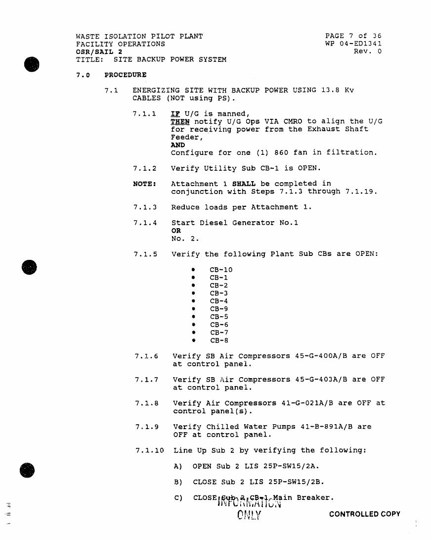
WASTE ISOLATION PILOT PLANT PAGE 7 of 36
FACILITY OPERATIONS WP 04-ED1341
OSR/SAIL 2 Rev. 0
O ITLE: SITE BACKUP POWER SYSTEM7.0 PROCEDURE
7.1 ENERGIZING SITE WITH BACKUP POWER USING 13.8 Kv
CABLES (NOT using PS).
7.1.1 IF U/G is manned,
THEN notify U/G Ops VIA CMRO to align the U/G
for receiving power from the Exhaust Shaft
Feeder,
Configure for one (I) 860 fan in filtration
7.1.2 Verify Utility Sub CB-I is OPEN.
NOTE: Attachment 1 SHALL be completed in
conjunction with Steps 7.1.3 through 7.1.19.
7.1.3 Reduce loads per Attachment 1.
7.1.4 Start Diesel Generator No.1
OR
No. 2.
7.1.5 Verify the following Plant Sub CBs are OPEN:
O • CB-10• CB-I
• CB-2
• CB-3• CB-4
• CB-9
• CB-5
• CB-6
• CB-7
• CB-8
7.1.6 Verify SB Air Compressors 45-G-400A/B are OFF
at control panel.
7.1.7 Verify SB Air Compressors 45-G-403A/B are OFF
at control panel.
7.1.8 Verify Air Compressors 41-G-021A/B are OFF at
control panel(s).
7.1.9 Verify Chilled Water Pumps 41-B-891A/B areOFF at control panel.
7.1.10 Line Up Sub 2 by verifying the following:
O A) OPEN Sub 2 LIS 25P-SWI5/2A.B) CLOSE Sub 2 LIS 25P-SWI5/2B.
C) CLOSE; _b_ _, CB, l:Main Breaker.
0 t"_[ _ CONTROLLED COPY

WASTE ISOLATION PILOT PLANT PAGE 8 of 36
FACILITY OPERATIONS WP 04-ED1341
OSR/SAIL 2 Rev. 0
O TITLE: SITE BACKUP POWER SYSTEMD) CLOSE Sub 2 CB-2.
Water Chiller, 41-B-890A.
E) CLOSE Sub 2 CB-3.
Air Handling Unit CH Area,4I-B-812.
F) CLOSE Sub 2 CB-4.
Air Handling Unit CH Area,41-B-813.
G) CLOSE Sub 2 CB-5.
WHB Overpack, 41P-MCC04/5.
H) CLOSE Sub 2 CB-6.Water Chiller, 41-B-890B.
I) OPEN Sub 2 CB-7 (Spare) .
J) CLOSE Sub 2 CB-8.Mech. Equip. Room WHB,
41P-DPO4/3.
7.1.11 OPEN Sub 4 CB-I Main Breaker.
Q 7.1.12 Line Up Sub 6 by verifying the following:
A) OPEN Sub 6 LIS 25P-SWIS/6A.
B) CLOSE Sub 6 LIS 25P-SWI5/6B.
C) CLOSE Sub 6 CB-I Main Breaker.
D) OPEN Sub 6 CB-2.
Switchrack 7, 24P-SWRO4/'7.
E) CLOSE Sub 6 CB--3.
Hoist, 33P-HMO4/i.
F) OPEN Sub 6 CB-4 (Spare).
G) CLOSE Sub 6 CB-5.
Switchrack, 33P-SWRO4/I.
7.1.13 Line Up SB Sub by verifying the following:
A) OPEN SB Sub LIS 45P-SWIS/IA.
B) CLOSE SB Sub LIS 45P-SWI5/IB.
C) CLOSE SB Sub CB-I Main Breaker.
O D) CLOSE SB Sub CB-2.
Elect. Equip. Room SB,
ONL", __ co,=,v.... '.... ,, ,i, , , ,, , . rl,_

WASTE ISOLATION PILOT PLANT PAGE 9 of 36
FACILITY OPERATIONS WP 04-ED1341
OSR/SAIL 2 Rev. 0
O TITLE: SITE BACKUP POWER SYSTEME) CLOSE SB Sub CB-3.
Mech. Equip. Room WHB,
41P-MCCO4 /6.
F) CLOSE SB Sub CB-4.
Hoist Control Room WHB,
3 IP-MCCO4 /I.
G) Verify SB Sub CB-5 is OPEN and LOCKED.Tie to Sub 3 CB-I.
7.1.14 Line Up Sub i by verifying the following:
A) CLOSE Sub i LIS 25P-SWIS/IB2.
B) CLOSE Sub 1 LIS 25P-SWIS/IBI.
Tie To Sub 3 Top Side of the
LIS 2SP-SW15/3B.
C) CLOSE Sub 1 CB-I Main Breaker.
D) CLOSE Sub 1 CB-2.
SB, 45P-MCCO4/3 .
O E) CLOSE Sub 1 CB-3.RH Waste Area, 41P-MCCO4/I.
F) CLOSE Sub I CB-4.
Operating Gallery,
4IP-MCCO4/2.
G) CLOSE Sub 1 CB-5.Mech. Equip. Room WHB,
4 IP-MCCO4/3.
H) CLOSE Sub I CB-6.
Air Handling Unit RH Area,41-B-803.
I) CLOSE Sub I CB-7.
Air Handling Unit RH Area,41-B-804.
J) Verify Sub 1 CB-8 is OPEN and LOCKED.Tie to Sub 3 CB-18.
K) CLOSE Sub 1 CB-9.
Bldgs 482, 41P-MPC03/3
and EOC 462, 45P-DP04/27.
0

WASTE ISOLATION PILOT PLANT PAGE i0 of 36
FACILITY OPERATIONS WP 04-ED1341
OSR/SAIL 2 Rev. 0
O TITLE: SITE BACKUP POWER SYSTEM PCN 00-027.1.15 Verify CLOSED LIS 25P-SW15/11 Exhaust Shaft
Feeder.
7.1.16 Line UP Sub 3 by verifying the following:
A) CLOSE Sub 3 LIS 25P-SWI5/3A.
B) CLOSE Sub 3 LIS 25P-SWIS/3B.
C) OPEN SUB 3 CB-8 Main Breaker.
D) OPEN Sub 3 CB-10 Main Breaker.i
E) OPEN SUb 3 CB-5.
EFB, 41P-MCC04/7.
F) OPEN SUb 3 CB-6o
Safety and Emergency Bldg.,
45P-DPO4/25A and 45P-DPO4/25B.
G) OPEN Sub 3 CB-12.
Engineering Bldg. 486
45P-DP04/50.
Q H) OPEN Sub 3 CB-13.Switchrack 6, 25P-SWR04/6.
I) Verify Sub 3 CB-I is OPEN and LOCKED.Tie CB to SB Sub CB-5.
J) Verify Sub 3 CB-18 is OPEN and LOCKED.Tie to Sub 1 CB-8.
K) CLOSE either Sub 3 CB-7 if DG 1 is
operating,OR
CB-II if DG 2 is operating.
L) CLOSE locally Sub 3 CB-9 tie breakerbetween Sub 3 Buses A and B.
M) CLOSE Sub 3 CB-5.
EFB, 41P-MCC04/7.
7.1.17 I__PU/G is manned,
THEN notify U/G Ops VIA CMRO that Exhaust
Shaft Feeder can be energized.
7.1.18 CLOSE SUB 3 CB-8 Main Breaker, energizing "Izo!0
Exhaust Shaft Feeder. 6
O 7.1.19 Verify Attachment 1 is complete.
O ',ILY CONT.OLLEDCOP,,

WASTE ISOLATION PILOT PLANT PAGE Ii of 36
FACILITY OPERATIONS WP 04-ED1341
OSR/SAZL 2 Rev. 0
Q TITLE: SITE BACKUP POWER SYSTEM PCN 00-017.1.20 CLOSE Sub 3 CB-10 Main Breaker energizing
Subs 1, 2, 6 and SB.
7.1.21 Start Air Compressor 41-G-021AOR
41-G-021B.
7.1.22 Start EFB Air Compressors 41-G-022AAND
41-G-022B (as required).
7.1.23 Verify LPUs 835 and 836 are operational.
7.1.24 verify UPSs 335 and 336 are operating with
invertor supplying load. t_
7.1.25 Start the Underground Ventilation and _
Filtration System (UVFS)in accordance with "]_WP 04-VUI001.
7.1.26 Start the following:
• Start Vacuum Pump 41-G-040AOR
O 41-G-040B• Start Vacuum Pump 41-G-040C
OR
41-G-O40D
• Start WHB Exhaust Fan(s) as directed bythe FOSS
• Start SB Zone 6 HVAC
7.1.27 I__F<900 Kw on operating DG,
H_ AIS Hoisting operation may begin as
required.
7.1.28 Perform load reduction list Attachment 2 as
required.
= 7.1.29 Perform the following:
® Shut down EFB Air Compressors 41-G-022AAND
41-G-022B
• Verify Diesel Fire Pump Shut down MODE
switch in AUTO/TEST position.
0INFORMATION
ONLY CO.T.O,,EDCOPY

WASTE ISOLATION PILOT PLANT PAGE 12 of 36
FACILITY OPERATIONS WP 04-ED1341
OSR/SAIL 2 Rev. 0
O TITLE: SITE BACKUP POWER SYSTEM7.1.30 At the completion of hoisting, pick up
available perimeter lighting.
7.1.31 Experimental loads and additional equipment
may be energized at the direction of theFOSS.
7.2 RETURNING SITE TO UTILITY POWER.
7.2.1 I_FFU/G is manned,
THEN notify U/G Ops VIA CMRO that Exhaust
Shaft Feeder is being de-energized.
7.2.2 Shut down filtration.
7.2.3 Shut down operating fan 41-B-860AOR
41-B-860B
OR
41-B-860C.
7.2.4 Shut down the following:z
• Shut down operating Air Compressor41-G-O21A
O OR41-G-O21B
• Shut down operating Vacuum Pumps
• Shut down operating WHB Exh. Fan(s)
® Shut down Zone 6 SB HVAC
7.2.5 OPEN Sub 3 CB-8, Main Breaker de-energizingExhaust Shaft Feeder.
7.2.6 OPEN Sub 3 CB-10 Main Breaker de-energizingSubs i, 2, 6 and SB.
7.2.7 OPEN Sub 3 CB-5.
EFB, 41P-MCCO4/7.
7.2.8 OPEN Sub 3 CB-9.
TieBreaker.
7.2.9 OPEN either Sub 3 CB-7 if DG 1 is operating,OR
CB-II if DG 2 is operating.
IL 7.2.10 Shut down operating DG No.l
g OR
DG No. 2.J
__'
WASTE ISOLATION PILOT PLANT PAGE 13 of 36FACILITY OPERATIONS WP 04-ED1341
OSR/SAIL 2 Rev. 0
O TITLE: SITE BACKUP POWER SYSTEM PCN 00-017.2.3.1 Realign substation CBs and LISs in accordance
with procedure WP 04-ED1021.
7.3 OPTION i ENERGIZING SITE WITH BACKUP POWER, USING PS.
7.3.1 IF U/G is manned,
THEN notify U/G Ops VIA CMRO to align the U/G
for receiving power from the Exhaust ShaftFeeder,AND
Configure for one (1) 860 fan in filtration.
7.3.2 Veri_y Utility Sub CB-I is OPEN. -_
NOTE_ Attachment 1 SHALL be completed in
conjunction with Steps 7.3.3 through 7.3.22.1
7.3.3 Reduce loads per Attachment i. _
7.3.4 Start Diesel Generator No.lOR
No. 2.
7.3.5 Verify the following Plant Sub CBs are OPEN:
O e CB-10• CB-I
• CB-2
• CB-3
• CB-4
• CB-9
• CB-5
• CB-6
• CB-7
• CB-8
7.3.6 _II Sullair Air Compressors are NOT to be
operated, skip Step 7.3.7 and proceed to Step7.3.8.
7.3.7 Perform the followzT_g lineup:
A) Verify Sullair Air Compressors 45-G-009AND
45-G-010 are OFF at control panel(s).
B) Verify Sullair Air Dryer 45-K-001 is OFF
at control panel.
D) CLOSE Sub 5 CB-I Main Breaker.
_
-- !! 'YORI,, ,'Jlgi't=
CONTROLLED COPY
.... '._P' hl" ', "lr, lr "_lPilll I_ '"ri ' Vl " ' ]_"_ '_' " 'v_ I_111,, 'I1' " "lf|l,_V,_h'-,"7,_I[irlr-'r;-_'_.,_-

WASTE ISOLATION PILOT PLANT PAGE 14 of 36
FACILITY OPERATIONS WP 04-ED1341
OSR/SAIL 2 Rev. 0
O TITLE: SITE BACKUP POWER SYSTEMq
E) OPEN Sub 5 CB-'2.
Switchrack I, 24P-SWR04/I.
F) OPEN Sub 5 CB-3.
Salt Handling Hoist House.
G) OPEN Sub 5 CB-4.
Switchrack 2, 24P-SWR04/2.
H) OPEN Sub 5 CB-5.
38P-DP04/i.
I) OPEN Sub 5 CB-6 (Spare).
J) OPEN Sub 5 CB-7 (Spare).
K) OPEN Sub 5 CB-8.
Switchrack 3, 24P-SWRO4/3
L) OPEN Sub 5 CB-9.
Bldg 485, 45P-MPCO4/I.
M) OPEN Sub 5 CB-10.
Perimeter & Street Lights.
O N) OPEN Sub 5 CB-II........ Switchrack 8, 24P-SWR04/8.
O) OPEN Sub 5 CB-13.Switchrack 9, 24P-SWRO4/9o
P) CLOSE Sub 5 CB-14.
Compressor, 45-G-010.
Q) CLOSE Sub 5 CB-15.
Compressor, 45-G-009.
7.3.8 Verify SB Air Compressors 45-G-400A/B are OFF
at control panel.
7.3.9 Verify SB Air Compressors 45-G-403A/B are OFF
at control panel.
7.3.10 Verify Air Compressors 41-G-021A/B are OFF at
control panel(s).
7.3.11 Verify Chilled Water Pumps 41-B-891A/B are
OFF at control panel.
7.3.12 OPEN Sub 4 CB-I Main Breaker.
'0 7.3.13 Verify CLOSED LIS 31P-SWIS/I Waste ShaftFeeder.
I. FORr...ATiCL= ONLY co.'r.oLLEDcoPY
,, ,,, ,, . ,,, .... .,

WASTE ISOLATION PILOT PLANT PAGE 15 of 36
FACILITY OPERATIONS WP 04-ED134 1
OSR/SAIL 2 Rev. 0
O TITLE: SITE BACKUP POWER SYSTEM PCN 00-02
7.3 .14 Verify CLOSED VIS 25P-VISI5/II Exhaust Shaft InFeeder. c
7.3.15 Line UP Sub 3 by verifying the following: _
A) CLOSE Sub 3 LIS 25P-SWI5/3A.
B) CLOSE Sub 3 LIS 25P-SWI5/3B.
C) OPEN Sub 3 CB-8 Main Breaker.
D) OPEN Sub 3 CB-10 Main Breaker.
E) OPEN Sub 3 CB-5.
EFB, 41P-MCC04/7.
F) OPEN Sub 3 CB-6.
Safety and Emergency Bldg.45P-DP04/25A and 45P-DPO4/25B.
G) OPEN Sub 3 CB-12.
Engineering Bldg. 486
45P-DP04/50.
O H) OPEN Sub 3 CB-13.Switchrack 6, 25P-SWR04/6.
I) Verify Sub 3 CB-1 is OPEN and LOCKED.Tie CB to SB Sub CB-5.
J) Verify Sub 3 CB-18 is OPEN and LOCKED.Tie CB to Sub 1 CB-8.
K) CLOSE either Sub 3 CB-7 if DG 1 is
operating,OR
CB-II if DG 2 is operating.
L) CLOSE locally Sub 3 CB-9 tie breakerbetween Sub 3 Buses A and Br
M) CLOSE Sub 3 CB-5.
EFB, 41P-MCC04/7.
7.3.16 I_FFU/G is manned,
notify U/G Ops VIA CMRO that U/G Feeders
can be energized.
7.3.17 CLOSE Sub 3 CB-8 Main Breaker EnergizingExhaust Shaft Feeder.
-g 7.3.1,8 Start EFB Air Compressors 41-G-u2zAAND
41-G-022B (as required).--
I FOR,',,ATIO'-Ip y CONTROLLEDCOPY

WASTE ISOLATION PILOT PLANT PAGE 16 of 36
FACILITY OPERATIONS WP 04-ED1341
OSR/SAIL 2 Rev. 0TITLE: SITE BACKUP POWER SYSTEM PCN 00-01
O 7.3.19 verify LPUs 835 and 836 are operational.
7.3.20 Verify UPSs 335 and 336 are operating with
invertor supplying load. 1___
7.3.21 Start the UVFS in accordance with
WP 04-VUIO01.
7.3.22 Verify Attachment 1 is complete. ._
7.3.23 CLOSE Sub 3 CB-10 Main Breaker energizing SBSub and Waste Hoist Sub.
7.3.24 Verify OPEN PS CB-9.Buses A & B tie breaker.
7.3.25 CLOSE PS CB-4..... Energizing PS Bus A.
'7o3.26 CLOSE PS CB-3.
Energizing Subs 2 and 6.
7.3.27 CLOSE PS CB-2.Salt Handling Shaft Feeder.
O 7.3.28 CLOSE PS CB-7. Energizing PS Bus B.
7.3.29 CLOSE PS CB-6.
Energizing Sub i.
7.3.30 CLOSE PS CB-5.Waste Shaft Feeder.
7.3.31 CLOSE PS CB-8 IF Sullair Air Compressor is to
be operated.
=
- 0t LY CONTROLLED COPY

WASTE ISOLATION PILOT PLANT PAGE 17 of 36
FACILITY OPERATIONS WP 04-ED1341
OSR/SAIL 2 Rev. 0
O TITLE: SITE BACKUP POWER SYSTEM7.3.32 Start the following:
• Start one Air Compressor 41-G-021AOR
41-G-O21B
OR
41-G-009OR
41-G-010
• Start Vacuum Pump 41-G-040AOR
41-G-O40B
® Start Vacuum Pump 41-G-040COR
41-G-O40D
• Start WHB Exhaust Fan(s) as directed bythe FOSS
• Start SB Zone 6 HVAC
7.3.33 IFF <900 Kw on operating DG,
TXEN AIS Hoisting operation may begin as
O required.
7.3.34 Perform load reduction list Attachment 2 as
required.
7.3.35 Perform the following:
• Shut down EFB Air Compressors 41-G-O22AAND
41-G-O22B
• Verify Diesel Fire Pump Shut down MODE
switch in AUTO/TEST position
7.3.36 At the completion of hoisting, pick up
perimeter lighting.
7.3.37 Experimental loads and additional equipment
may be energized at the direction of theFOSS.
Qv
- |'','": "..'b',[,,"
. _e ,,:, CONTROLL£D COPY._ = ; ,.

WASTE ISOLATION PILOT PLANT PAGE 18 of 36
FACILITY OPERATIONS WP 04-ED1341
OSR/SAIL 2 Rev° 0
O TITLE: SITE BACKUP POWER SYSTEM7.4 RETURNING SITE TO UTILITY POWER AFTER PERFORMING
OPTION i./
7.4.1 IF U/G is manned,
' THE____Nnotify U/G Ops VIA CMRO that U/G Feeders
/ are being de-energized.
7.4.2 Shut down filtration.
7.4.3 Shut down operatir_q fan 41-B-860AOR
41-B-860BOR
41-B-860C.
7.4.4 Shut down the following:
• Shut down operating Air Compressor41-G-021A
OR
41-G-021B
OR
41-G-009
OR
O 41-G-010® Shut down operating Vacuum Pumps
• Shut down operating WHB Exhaust Fan(s)
• Shut down Zone 6 SB HVAC
7.4.5 OPEN the f.±lowing PS CBs:
• CB-2
• CB-3
• CB-4
• CB-5• CB-6
• CB-7
• CB-8 (_f CB was closed)
"7.4.6 OPEN Sub 3 CB-8 Main Bre_:Ker de-energizingExhaust Shaft Feeder.
7.4.7 OPEN Sub 3 CB-10 de-energizing SB and WasteHoist Sub.
7.4.8 OPEN Sub 3 CB-5
EFB, 41P-MCC04/7.
O 7.4.9 OPEN Sub 3 CB-9.Tie Breaker.
-O[',;LY CONTROLLED COPY
I,'f_._)lp'ql r i,,, ,,I_ r, ..... i' II1,_ I_11%".... i"i' • qll_lD ,,' ,., ,,illll "1,1"1." ll_li/ ,","_-,, i_.-1--_- 1,q-]T-_]frr_,._..

WASTE ISOLATION PILOT PLANT PAGE 19 of 36FACILITY OPERATIONS WP 04-ED1341
OSR/SAIL 2 Rev. 0
O TITLE: SITE BACKUP POWER SYSTEM'7.4.10 OPEN either Sub 3 CB-7 if DG 1 is operating,
OR
CB-II if DG 2 is operating.
7.4.11 Shut down operating DG No.lOR
DG No. 2.
7.4.12 Realign substation CBs and LISs in accordance
with procedure WP 04-EDf021.
IICFORIAATIONONLY CONTROLLEDCOPY

WASTE ISOLATION PILOT PLANT PAGE 20 of 36
FACILITY OPERATIONS WP 04-ED1341
OSR/SAIL 2 Rev. 0
O TITLE: SITE BACKUP POWER SYSTEM PCN 00-027.5 OPTION 2 ENERGIZING SITE WITH BACKUP POWER, USING PS
BUS A.
A) IF U/G is manned,
THEN notify U/G Ops VIA CMRO to align the
U/G for receiving power from the ExhaustShaft Feeder
Salt Handling Shaft FeederAND
Configure for one (i) 860 fan infiltration.
7.5.1 Verify Utility Sub CB-I is OPEN.
NOTE: Attachment 1 8_LL be completed in
conjunction with Steps 7.5.2 through 7.5.19. I_
7.5.2 Reduce loads per Attachment i.
7.5.3 Start Diesel Generator NOolOR
No. 2.
O 7.5.4 Verify the following Plant Sub CBs are OPEN:......... • CB-10
• CB-I• CB-2
• CB-3
• CB-4
• CB-9
• CB-5
• CB-6
• CB-7
• CB-8
7.5.5 Verify SB Air Compressors 45-G-400A/B are OFF
at control panel.
7.5.6 Verify SB Air Compressors 45-G-403A/B are OFFat control panel.
7.5.7 Verify Air Compressors 41-G-021A/B are OFF at
control panel(s).
7.5.8 Verify Chilled Water Pumps 41-B-891A/B are
OFF at control panel.
O
-- _}.'} V CONTROLLED COPY

WASTE ISOLATION PILOT PLANT PAGE 21 of 36
FACILITY OPERATIONS WP 04-ED1341
OSR/SAIL 2 Rev. 0
O TITLE: SITE BACKUP POWER SYSTEM7.5.9 Line Up Sub 2 by verifying the following:
A) OPEN Sub 2 LIS 25P-SWI5/2B.
B) CLOSE Sub 2 LIS 25P-SWIS/2A.
C) CLOSE Sub 2 CB-I Main Breaker.
D) CLOSE Sub 2 CB-2.
Water Chiller, 41-B-890A.
E) CLOSE Sub 2 CB-3.
Air Handling Unit CH Area,41-B-812.
F) CLOSE Sub 2 CB-4.
Air Handling Unit CH Area,41-B-813.
G) CLOSE Sub 2 CB-5.
WHB Overpack, 41P-MCC04/5.
H) CLOSE Sub 2 CB-6.
Water Chiller, 41-B-890B.
O I) OPEN Sub 2 CB-7 (Spare).
Ji_ CLOSE Sub 2 CB-8.
Mech. Equip. Room WHB,
41P-DPO4/3.
7.5.10 OPEN Sub 4 CB-I Main Breaker.
7.5.11 Line Up Sub 6 by verifying the following:
A) OPEN Sub 6 LIS 25P-SWI5/6B.
B) CLOSE Sub 6 LIS 25P-SWIS/6A.
C) CLOSE Sub 6 CB-I Main Breaker.
D) OPEN Sub 6 CB-2.
Switchrack 7, 24P-SWRO4/7.
E) CLOSE Sub 6 CB-3.
Hoist, 33P-HM04/I.
F) OPEN Sub 6 CB-4 (Spare).
G) CLOSE Sub 6 CB-5.
O Switchrack, 33P-SWR04/I.

WASTE ISOLATION PILOT PLANT PAGE 22 of 36FACILITY OPERATIONS WP 04-ED1341
OSR/SAIL 2 Rev. 0
O TITLE: SITE BACKUP POWER SYSTEM7.5.12 Line Up SB Sub by verifying the following:
A) OPEN SB Sub LIS 45P-SWI5/IB.
B) CLOSE SB Sub LIS 45P-SWI5/IA.
C) CLOSE SB Sub CB-I Main Breaker.
D) CLOSE SB Sub CB-2.Elect. Equip. Room SB,45P-MCC04/4.
E) CLOSE SB Sub CB-3.Mech. Equip. Room WHB,
41P-MCC04/6.
F) CLOSE SB Sub CB-4.Hoist Control Room WHB,
31P-MCC04 /i.
G) Verify SB Sub CB-5 is OPEN and LOCKED.Tie CB to Sub 3 CB-lo
7.5.13 Line Up Sub 1 by verifying the following:
O Sub 1 LIS 25P-SWI5/IBI is OPEN.A) Verify
B) OPEN Sub 1 LIS 25P-SWI5/IB2.
C) OPEN Sub i CB-I Main Breaker.
D) CLOSE Sub 1 CB-2.SB, 45P-MCC04/3.
E) CLOSE Sub 1 CB-3.RH Waste Area, 41P-MCC04/I.
F) CLOSE Sub 1 CB-4.Operating Gallery, WHB41P-MCC04/2.
G) CLOSE Sub 1 CB-5.
Mech. Equip. Room WHS,41P-MCC04/3.
H) CLOSE Sub 1 CB-6.Air Handling Unit RH Area,41-B-803.
I) CLOSE Sub 1 CB-7.
O Air Handling Unit RH Area,41-B-804.
.p.T,:!..y co,'r,oL,Eocopy

WASTE ISOLATION PILOT PLANT PAGE 23 of 36
FACILITY OPERATIONS WP 04-ED1341
OSR/SAIL 2 Rev. 0
e TITLE: SITE BACKUP POWER SYSTEM PCN 00-02J) UNLOCK and CLOSE Sub 1 CB-8.
Tie to Sub 3 CB-18.
K) CLOSE Sub 1 CB-9.
Bldgs 482, 41P-MPC03/3
and EOC 462, 45P-DP04/27.z
7.5.14 Verify CLOSED VIS 25P-VIS15/II Exhaust Shaft 19Feeder.
19
c
7.5.15 Line Up Sub 3 by verifying the following:
A) I_FFU/G is manned,
THEN notify U/G Ops VIA CMRO that U/G
Feeders can be energized.
B) OPEN Sub 3 LIS 25P-SWIS/3B.
C) CLOSE Sub 3 LIS 25P-SWIS/3A.
D) OPEN Sub 3 CB-8 Main Breaker.
E) OPEN Sub 3 CB-9.Tie Breaker.
e F) OPEN Sub 3 CB-10 Main Breaker.
G) OPEN Sub 3 CB-5.
EFB, 41P-MCC04/7.
H) OPEN Sub 3 CB-6.
Safety and Emergency Bldg.
45P-DP04/25A and 45P-DPO4/25B.
I) OPEN Sub 3 CB-12.
Engineering Bldg. 486,45P-DPO4/50.
J) OPEN Sub 3 CB-13.
Switchrack 6, 25P-SWR04/6.
K) Verify Sub 3 CB-I is OPEN and LOCKED.Tie CB to SB Sub CB-5.
L) UNLOCK and CLOSE Sub 3 CB-18.Tie to Sub 1 CB-8.
INFORMATION--- ,o'_ l e q %0
UI_LI CO._T-n,,_n r.npY

WASTE ISOIJ_TION PILOT PLANT PAGE 24 of 36
FACILITY OPERATIONS WP 04-ED1341
OSR/SAIL 2 Rev. 0
O TITLE: SITE BACKUP POWER SYSTEM PCN 00-01M) CLOSE either Sub 3 CB-7 if DG 1 is
operating,OR
CB-11 if DG 2 is operating.
N) CLOSE locally Sub 3 CB-9 tie breakerbetween Sub 3 Buses A and B.
O) CLOSE Sub 3 CB-5.
EFB, 41P-MCC04/7 .
P) Start EFB Air Compressors 41-G-022AAND
41-G-O22B (as required).
7.5.16 Verify LPUs 835 and 836 are operational.
7.5.17 Verify UPSs 335 and 336 are operating with
invertor supplying load. _I
[!Z
7.5.18 Start the UVFS in accordance with
WP 04-VUI001.
7.5.19 Verify Attachment 1 is complete.
i 7.5.20 IF U/G is manned,TH___ENnotify U/G Ops VIA CMRO that U/G Exhaust
Shaft and Salt Handling Shaft Feeders can be
energized.
7.5.21 CLOSE Sub 3 CB-8 energizing SB Sub, WasteHoist Sub and Exhaust Shaft Feeder.
7.5.22 CLOSE PS CB-4.
Energizing PS Bus A.
7.5.23 CLOSE PS CB-3 energizing Subs 2 and 6.z
7.5.24 CLOSE PS CB-2 Salt Handling Shaft Feeder.
_,; .: ,: CONTROLLED COPYi
Jt ' _l_il", t# ' lr ' _1 lt i iii lie, ii_1 i_I , i _, i i i , ,, ,11v_l ir

WASTE ISOLATION PILOT PLANT PAGE 25 of 36
FACILITY OPERATIONS WP 04-ED1341
OSR/SAIL 2 Rev. 0
O TITLE: SITE BACKUP POWER SYSTEM7.5.25 Start the following:
• Start Air Compressor 4 I-G-02 IAOR
41-G-021B
• Start Vacuum Pump 41-G-040AOR
4 I-G-040B
• Start Vacuum Pump 41-G-040COR
41-G-040D
• Start WHB Exhaust Fan(s) as directed bythe FOSS
• Start SB Zone 6 HVAC
7.5.26 I_FF<900 Kw on operating DG,
THE___NAIS Hoisting operation may begin as
required.
7.5.27 Perform load reduction list per Attachment 2,
as required.
O 7.5.2B Perform the following:
• Shut down EFB Air Compressors 41-G-022AAND
41-G-022B (as required).
• Verify Diesel Fire Pump Shut down MODE
switch in AUTO/TEST position.
7.5.29 At the completion of hoisting, pick up
perimeter lighting.
7.5.30 Experimental loads and additional equipment
may be energized at the direction of theFOSS.
7.6 RETURNING SITE TO UTILITY POWER AFTER PERFORMING
OPTION 2.
7.6.1 IFF U/G is manned,TBEN notify U/G Ops VIA CMRO that U/G Feeders
are being de-energized.
7.6.2 OPEN PS CB-2 Salt Shaft Feeder.
O 7.6.3 Shut down filtration.
INFO,,,,',,J,ONONLY CONTROLLED COPY

WASTE ISOLATION PILOT PLANT PAGE 26 of 36
FACILITY OPERATIONS WP 04-EDf341
OSR/SAIL 2 Rev. 0
O TITLE: SITE BACKUP POWER SYSTEM7.6.4 Shut down operating fan 41-B-860A
OR
41-B-860BOR
41-B-860C.
7.6.5 Shut down Air Compressor 41-G-021AOR
41-G-021B.
7.6.6 OPEN PS CB-3 de-energizing Subs 2 and 6.
7.607 Shut down the following:
• Shut down operating Vacuum Pumps
• Shut down operating WHB Exh. Fan(s)
• Shut down Zone 6 SB HVAC
• OPEN PS CB-4 de-energizing PS Bus A
7.6.8 OPEN Sub 3 CB-8 Main Br,eaker de-energizing SBSub, Waste Hoist Sub and Exhaust Shaft
O Feeder.7.6.9- OPEN Sub 3 CB-5.
EFB, 41P-MCCO4/7.
7.6.10 OPEN Sub CB-9.Tie Breaker.
7.6.11 OPEN either Sub 3 CB-7 if DG 1 is operating,OR
CB-II if DG 2 is operating.
7.6.12 Shut down operating DG No. 1OR
DG No. 2.
7.6.13 Realign substation CBs and LISs in accordance
with procedure WP 04-ED1021.
Ot'JLY' co.'r.oLL.EDcoP'

WASTE ISOLATION PILOT PLANT PAGE 27 of 36FACILITY OPERATIONS WP 04-ED1341
OSR/S_IL 2 Rev. 0
TITLE: SITE BACKUP POWER SYSTEM
7.7 OPTION 3 ENERGIZING SITE WITH BACKUP POWER, USING PSBUS B.
7.7.1 _ U/G is manned,
T_EN notify U/G Ops VIA CMRO to align the U/Gfor receiving power from the Waste Shaft
Feeder,AND
Configure for one (I) 860 fan in filtration.
7_7.2 Verify Utility Sub CB-I is OPEN.
NOTE: Attachment 1 SHALL be completed in
conjunction with Steps 7.7.3 through 7.7,20.
7.7.3 Reduce loads per Attachment I.
7.7.4 Start Diesel Generator No.lOR
No. 2.
7.7.5 Verify the folLlowing Plant Sub CBs are OPEN:
• CB-10
O • CB-I• CB-2
• CB-3
• CB-4• CB-9
• CB-5
• CB-6
• CB-7
• CB-8
7.7.6 _]_ Sullair Air Compressors are NOT to be
operated, skip Step 7.7.7 and proceed to Step7.7.12.
7.7.7 Perform the following lineup:
A) Verify Sullair Air Compressors 45-G-009AND
45-G-010 are OFF at control panel(s).
B) Verify Sullair Air Dryer 45-K-001 is OFF
at control panel.
C) CLOSE Sub 5 LIS 25P-SWIS/5.
D) CLOSE Sub 5 CB-I Main Breaker.
O E) OPEN Sub 5 CB-2.Switchrack i, 24P-SWR04/1.
A,': rL,_"_,_.ii.h ! _LJ__, CONTROLLED COPY

WASTE ISOLATION PILOT PLANT PAGE 28 of 36
FACILITY OPERATIONS WP 04-ED1341
OSR/SAIL 2 Rev. 0
O TITLE: SITE BACKUP POWER SYSTEMF) OPEN Sub 5 CB-3.
Salt Handling Hoist House.
G) OPEN Sub 5 CB-4.
Switchrack 2, 24P-SWR04/2.
H) OPEN Sub 5 CB-5.
38P-DP04/I.
I) OPEN Sub 5 CB-6 (Spare).
J) OPEN Sub 5 CB-7 (Spare).
K) OPEN Sub 5 CB-8.
Switchrack 3, 24P-SWRO4/3.
L) OPEN Sub 5 CB-9.
Bldg 485, 45P-MPCO4/1.
M) OPEN Sub 5 CB-10.
Perimeter & Street Lights.
N) OPEN Sub 5 CB-11.
Switchrack 8, 24P-SWR04/8.
O O) OPEN Sub 5 CB-13.Switchrack 9, 24P-SWRO4/9.
P) CLOSE Sub 5 CB-14.
Compressor, 45-G-010.
Q) CLOSE Sub 5 CB-15.
Compressor, 45-G-009.
7.7.8 Verify SB Air Compressors 45-G-400A/B are OFF
at control panel.
7.7.9 Verify SB Air Compressors 45-G-403A/B are OFF'
at control panel.
7.7.10 Verify Air Compressors 41-G-O21A/B are OFF at
control panel(s).
7.7.11 Verify Chilled Water Pumps 41-B-891A/B are
OFF at control panel.
7.7.12 Line Up Sub 2 by verifying the following:
A) OPEN Sub 2 LIS 25P-SWI5/2A.
O B) CLOSE Sub 2 I_TS 25P-SWI5/2B.
C) CLOSE Sub 2 CB-I Main Breaker.
.... "" _'_*:+_: P"J' +" CONTROLLED COPYm,,r V

WASTE ISOLATION PILOT PLANT PAGE 29 of 36
FACILITY OPERATIONS WP 04-ED134 1
OSR/SAZL 2 Rev. 0
O TITLE: SITE BACKUP POWER SYSTEMD) CLOSE Sub 2 CB-2.
Water Chiller 41-B-890A.
E) CLOSE Sub 2 CB-3.
Air Handling Unit CH Area,41-B-812.
F) CLOSE Sub 2 CB-4.Air Handling Unit CH Area,4 I-B-813.
G) CLOSE Sub 2 CB-5.
WHB Overpack, 41P-MCC04/5.
H) CLOSE Sub 2 CB-6.Water Chiller, 41-B-890B.
I) OPEN Sub 2 CB-7 (Spare) .
J) CLOSE Sub 2 CB-8.
Mech. Equip. Room, 41P-DP04/3.
7.7.13 OPEN Sub 4 CB-I Main Breaker.
O 7.7.14 Line Up Sub 6 by verifying the following:A) OPEN Sub 6 LIS 25P-SWIS/6A.
B) CLOSE Sub 6 LIS 25P-SWI5/6B.
C) CLOSE Sub 6 CB-I Main Breaker.
D) OPEN Sub 6 CB-2.
Switchrack 7, 24P-SWRO4/'7.
E) CLOSE Sub 6 CB-3.
Hoist, 33P-HM04/I.
F) OPEN Sub 6 CB-4 (Spare).
G) CLOSE Sub 6 CB-5.
Switchrack, 33P-SWR04/I.
7.7.15 Line Up SB Sub by verifying the following:
A) OPEN SB Sub LIS 45P-SWI5/IA.
B) CLOSE SB Sub LIS 45P-SWI5/IB.
C) CLOSE SB Sub CB-I Main Breaker.
O D) CLOSE SB Sub CB-2.Elect. Equip. Room SB,
45P-MCC04/4 .
t" pl! V CONTROLL,:u COPY

WASTE ISOLATION PILOT PLANT PAGE 30 of 36
FACILITY OPERATIONS WP 04-ED1341
OSR/SAIL 2 Rev. 0
O TITLE: SITE BACKUP POWER SYSTEME) CLOSE SB Sub CB-3.
.... Mech. Equip. Room WHB,41P-MCC04 /6.
F) CLOSE SB Sub CB-4.
Hoist Control Room WHB,
31P-MCC04/I.
G) Verify SB Sub CB-5 is OPEN and LOCKED.Tie CB to Sub 3 CB-I.
'7.7.16 Verify CLOSED LIS 31P-SW15/1 Waste ShaftFeeder.
7.7.17 Line Up Sub 1 by verifying the following:
A) Verify LIS 25P-SWI5/IBI is OPEN.
B) CLOSE LIS 25P-SWIS/IB2.
C) CLOSE Sub 1 CB-I Main Breaker.
D) CLOSE Sub i CB-2.
SB, 45P-MCC04/3.
O E) CLOSE Sub 1 CB-3.RH Waste Area, 41P-MCC04/I.
F) CLOSE Sub I CB-4.
Operating Gallery, WHB.
41P-MCC04 /2.
G) CLOSE Sub i CB-5.
Mech. Equip. Room WHB,
4IP-MCC04 /3.
H) CLOSE Sub 1 CB-6
Air Handling Unit RH Area,4 I-B-803.
I) CLOSE Sub I CB-7.
Air Handling Unit RB Area,4 I-B-804.
J) Verify Sub 1 CB-8 is OPEN and LOCKED.Tie to Sub 3 CB-18.
K) CLOSE Sub 1 CB-9.
Bldgs 482, 41P-MPC03/3
and EOC 462, 45P-DP04/27.
0

WASTE ISOLATION PILOT PLANT PAGE 31 of 36
FACILITY OPERATIONS WP 04-ED1341
OSR/SAIL 2 Rev. 0
O TITLE: SITE BACKUP POWER SYSTEM
7.7.18 Line Up Sub 3 by verifying the following:
A) OPEN Sub 3 LIS 25P-SWIS/3A.
B) CLOSE Sub 3 LIS 25P-:_WI5/3B.
C) OPEN Sub 3 CB-8 Main Breaker.
D) OPEN Sub 3 CB-10 Main Breaker.
E) OPEN Sub 3 CB-5.
EFB, 41P-MCC04/7 .
F) OPEN Sub 3 CB-6.
Safety and Emergency Bldg.45P-DP04/25A and 45P-DP04/25B.
G) OPEN Sub 3 CB-12.
Engineering Bldg. 48645P-DPO4/50.
H) OPEN Sub 3 CB-13.
Switchrack 6, 25P-SWR04/6.
O I) Verify Sub 3 CB-I is OPEN and LOCKED.Tie to SB Sub CB-5.
J) Verify Sub 3 CB-18 is OPEN and LOCKED.Tie CB to Sub 1 CB-8.
K) CLOSE either Sub 3 CB-7 if DG 1 is
operating,OR
CB-II if DG 2 is operating.
L) CLOSE locally Sub 3 CB-9 tie breakerbetween Sub 3 Buses A and B.
M) CLOSE Sub 3 CB-5.
EFB, 4IP-MCC04 /7 .
7.7.19 Start EFB Air Compressors 41-G-022AAND
41-G-O22B (as required).
7.7.20 Verify Attachment 1 is complete.
7.7.21 CLOSE Sub 3 CB-10 Main Breaker energizing SBSub and Waste Hoist Sub.
O Energizing PS Bus B.
7.7.22 CLOSE PS CB-7.
7.7.23 CLOSE PS CB-6 energizing Subs i, 2 and 6.
I_'i_"_'_ '_',",_"",_i"I"I_i'_J, CONTROLLED COPY

WASTE ISOLATION PILOT PLANT PAGE 32 of 36
FACILITY OPERATIONS WP 04-ED1341
OSR/SAIL 2 Rev. 0
O TITLE: SITE BACKUP POWER SYSTEM PCN 00-017.7.24 IF U/G is manned,
notify U/G Ops VIA CMRO to align the U/G
for receiving power from the Waste ShaftFeeder.
7.7.25 CLOSE PS CB-5 Waste Shaft Feeder.
7.7.26 Verify LPUs 835 and 836 are operational.
7.7.27 Verify UPSs 335 and 336 are operating withinvertor supplying load. z
7.7.28 Start the UVFS in accordance with
wp 04-vu1o01.
7.7.29 CLOSE PS CB-8 IF Sullair air compressors are
to be operated.
7.7.30 Start the following:
• Start Air Compressor 41-G-021AOR
41-G-021BOR
O 41-G-009OR
41-G-010
• Start Vacuum Pump 41-G-040AOR
41-G-040B
• Start Vacuum Pump 41-G-040COR
41-G-040D
• Start WHB Exhaust Fan(s) as directed bythe FOSS.
• Start SB Zone 6 HVAC
7.7.31 IF <900 Kw on operating DG,
THEN AIS Hoisting operation may begin as
required.
7.7.32 Perform load reduction list per Attachment 2,
as required.
,_ :::i_# CONTROLLED COPY

WASTE ISOLATION PILOT PLANT PAGE 33 of 36FACILITY OPERATIONS WP 04-ED1341
OSR/SAIL 2 Rev. 0
O TITLE: SITE BACKUP POWER SYSTEM7.7.33 Perform the following:
• Shut down EFB Air Compressors 41-G-022AAND
41-G-022B
• Verify Diesel Fire Pump Shut down MODE
switch in AUTO/TEST position
7.7.34 At the completion of hoisting, pick up
perimeter lighting.
7.7.35 Experimental loads and additional equipment
may be energized at the direction of theFOSS.
7.8 RETURNING SITE TO UTILITY POWER AFTER PERFORMINGOPTION 3.
7.8.1 IF U/G is manned,
THEN notify U/G Ops VIA CMRO that Waste ShaftFeeder is being de-energized.
7.8.2 Verify OPEN PS CB-5 Waste Shaft Feeder.
O 7.8.3 Shut down operating fan 41-B-860AOR
41-B-860B
OR
41-B-860C.
7.8.4 Shut down filtration.
7.8.5 Shut down Air Compressor 41-G-021AOR
41-G-021B.
7.8.6 Shut down the following:
• Shut down operating Vacuum Pumps
• Shut down operating WHB Exh. Fan(s)
• Shut down Zone 6 SB HVAC
7.8.7 OPEN PS CB-6 de-energizing Subs 1 and 6.
7.8.8 OPEN PS CB-7 de-energizing PS Bus B.
7.8.9 OPEN Sub 3 CB-10 Main Breaker de-energizing
Sub 2, 4, SB Sub and Waste Handling Sub.
O 7.8.10 OPEN Sub 3 CB-5.
EFB, 41P-MCC04/7.
I tFOR, ,ATIOrt CONTROLLED COPY• , .

WASTE ISOLATION PILOT PLANT PAGE 34 of 36FACILITY OPE_LATIONS WP 04-ED134!
OSR/SAIL 2 Rev. 0TITLE: SITE BACKUP POWER SYSTEM
O 7.8.11 OPEN Sub 3 CB-9.Tie Breaker.
7.8.12 OPEN either Sub 3 CB-7 if DG I is operating,OR
CB-II if DG 2 is operating.
7.8.13 Shut down operating DG No.lOR
DG No. 2.
7.8.14 Realign substation CBs in accordance with
procedure WP 04-EDf021,
7.9 OPTION 4 ENERGIZING PS BUSES USING PS TIE CB-9.
NOTE: This note applies to option 4. Option 4 MAY
BE used with Options 2 or 3.
7.9.1 PS tie breaker CB-9 MAY BE used if the
following conditions exist.
A) Both PS Buses are in a condition to be
energized.
O B) PS CB-9 can be CLOSED IF ONE or more ofthe following CBs or LISs are open:
i) Sub 3 CB-10.
2) Sub 3 CB-9.
3) Sub 3 CB-8.
4 ) PS CB-7.
s) PS CB-4.6) Sub 3 LIS 25P-SWI5/3B.
7) Sub 3 LIS 25P-SWI5/3A.
7.9.2 CLOSE PS CB-9.Tie Breaker.
7.9.3 At the direction of the FOSS available PS CBs
MAY BE operated.
8.0 REVIEW
None
9.0 RECORDS
No Quality Assurance records are generated by this
procedure.
0
' ,',.',._.I I _',_ CONTROLLED COPY

WASTE ISOLATION PILOT PLANT PAGE 35 of 36
FACILITY OPERATIONS ' WP 04-ED1341
OSR/SAIL 2 Rev. 0
O TITLE: SITE BACKUP POWER SYSTEMATTACHMENT 1 Page 1 of 1
BACKUP POWER LOAD LIST
NOTE: De-energize Attachment 1 in any order or concurrently ifdesired.
1.0 SB Elevator at 45P-DP04/2 (Room 226).
2.0 SB HVAC System at the Local Control Panels.
3.0 WHB HVAC System at the Local Control Panels.
4.0 Vacuum Pumps 41-G-040A, B, C & D at the Local ControlPanel.
5.0 WHB Lighting Panels at 41P-MCC04/6.
6.0 Forklift Battery Recharging Station Dist.
Panel 41P-DP04/21 at 41P-MCC04/5.
7.0 Perimeter Lights in 45P-LP04/5 CB 8/10, 16/18, 22/24 and
21/23 (Overpack & Repair Room).
8.0 Trupact Maintenance Facility 41P-DP04/4 at 41P-MCC04/5.
O 9.0 Safety Building Chiller 45-E-646 atLocal Control Panel.
i0.0 Engineering Building Chiller 45-E-407 at Local ControlPanel.
I"FOR ., ATIONC' t, 'I., V, CONTROLLED COPY

WASTE ISOLATION PILOT PLANT PAGE 36 of 36
FACILITY OPERATIONS WP 04-ED1341
OSR/SAIL 2 Rev. 0
O TITLE: SITE BACKUP POWER SYSTEMATTACHMENT 2 Page 1 of 1
ADDITIONAL LOAD REDUCTION LIST
NOTE: De-energize Attachment 2 in any order or concurrently ifdesired.
1.0 SB Water Heater 45-E-402 at 45P-DP04/I (RM 116).
2.0 SB Lighting Panels at 45P-DP04/I (PM 116).
3.0 SB Cart Chargers at 4SP-DPO3/11 CB26, 32 and 36 (RM 116).
4.0 WHB Mech. Room Unit Heaters 904, 905, 906, 907 and 908 at
41P-DP04/3.
5.0 CH Area Unit Heaters 935, 938, 939 and 941 at 41P-MCC04/5.
6.0 Met Tower At 41P-MCC04/7 (EFB).
7.0 Perimeter Lighting at 41P-LP04/11 CB-8/10 and CB-9/11
(EFB).
O
_,_'_ V CONTROLLED COPY;,..